Corrour Station is near Loch Ossian on the Corrour Estate. It is the highest mainline railway station in the United Kingdom at an elevation of 1,340 feet (410 m) above sea level. It is located between Rannoch and Tulloch, and is sited 71 miles 54 chains (115.3 km) from Craigendoran Junction, near Helensburgh. In the 21st century, ScotRail manages the station and provides the most services, along with Caledonian Sleeper. [2]
The featured image for this article is from a video of steam at work on Rannoch Moor not far from Corrour. The video can be watched here. [7]
Corrour Railway Station “has a passing loop around an island platform with a siding on the east side. In common with the line’s two other remote passing places, Gorton and Glen Douglas, it was built with a tall signalbox and an adjacent low building in which the signalman lived. The adjacent low building (in Corrour’s case) was also used as a sub post office from 15th December 1896 and a Post Office telegraph office from 16th August 1898; Corrour even qualified as a post town. Later, the railway constructed a station house for the signalman on the east side of the tracks, and the original building became purely office accommodation for the railway and the post office.” [2]
When the North British Railway opened the West Highland Lines to Fort William in 1894, it had been forced to build a station at Corrour, ten miles from the nearest road. Sir John Sterling-Maxwell permitted the line to be built across the Corrour Estate on the proviso that this Railway Station would be built to serve the estate.
McGregor tells us that only 48 miles of the 100 mile line lay within lands belonging to firm supporters of the new railway:
“There was assured passage from Craigendoran to Inverarnan, through the Colquhoun estate, and from Inverlair (Tulloch) to Fort William, through The Mackintosh’s Brae Lochaber property and Lord Abinger’s Inverlochy. But between Glen Falloch and Glen Spean the landowners in question (Breadalbane, Menzies, Walker and now Stirling-Maxwell) had to be variously cultivated or won over.
“Facilities were a matter for the North British. General Manager John Walker, who died in 1891 with the West Highland still three years from completion, had begun negotiations with his namesake Colonel Walker, on the basis that the then Corrour lodge, on the ridge east of the railway, could be accessed from a simple halt or private platform near Lubnaclach. His successor, John Conacher, looked to conclude a formal agreement with Stirling-Maxwell, by which time it had been decided that the passing place to break the long section between the stations at Rannoch and Inverlair would be sited at the summit of the line and named ‘Corrour’. With a siding for coal and other deliveries, the passing loop would be convenient for the larger, up-to-date lodge which the new proprietor planned to build beside Loch Ossian. Request-stop rights were confirmed, while Stirling-Maxwell, for his part, permitted railway-builders Lucas & Aird to take sand and gravel free of charge; this outcropped in useful quantities across the wet, peaty heights of Rannoch which he now owned. George Malcolm, long-established factor for the Glen Garry and Glen Quoich estates and a notable West Highland campaigner, became Corrour factor as well – surely no coincidence? He may have helped frame the agreement, which he vigorously upheld after the railway opened for traffic in August 1894.
“Ambiguities remained … while Conacher and his deputy David Deuchars [head of the North British traffic department and ‘superintendent of the line’], less sanguine about the prospects of the West Highland than John Walker, were determined to keep North British obligations within bounds. Much conflict ensued, beginning with the unfinished state of Corrour passing place that first autumn, gates had not been installed in the railway fence and the siding lacked buffer stops. When Stirling-Maxwell was in residence, a mail pouch went to and fro, but the regulations governing postal traffic, at first strictly interpreted, meant that it was dropped and collected at Rannoch, entailing a 7-8 mile pony trip.
“The early months of operation saw vulnerable consignments (nursery-grown trees for planting out, young fish to stock Loch Ossian) carried past Corrour, to be “lost” in Fort William goods yard. Cheap weekend tickets to Glasgow, for the sizeable workforce employed on building the new lodge, were only grudgingly conceded. And strife repeatedly arose over the cumbersome request-stop procedure on which Deuchars insisted, involving the North British district superintendents at Glasgow and Fort William. (The Corrour signalman risked being disciplined if he used his own discretion.)
“Some relaxation came for Stirling-Maxwell personally, after he was elected to Parliament in 1895 and made regular journeys to Westminster. Nevertheless, strict conditions remained – for estate workers, Fort William tradesmen and even Corrour guests, while brake-van passes for travel by the daily goods trains were not willingly issued, despite the slender passenger timetable. A festering grievance was the imposition of ‘next station’ fares standard North British practice in respect of unadvertised halts with a restricted passenger-and-parcels traffic; these were calculated to Tulloch (northbound) or to Rannoch (southbound). Returning from Corrour one evening, Malcolm at last refused to pay the excess and a fractious correspondence followed, verging on the ludicrous, before the North British solicitor advised that the trivial sum was best forgotten.” [1: p27-28]
Video of Steam on Rannoch Moor. [7]
Beyond its role as a halt serving the Corrour Estate, Corrour Railway Station was intended to be a passing place named Luibruaridh (sic) after the nearest habitation Luibruairidh, on the old drove road between Rannoch and Spean Bridge (1 1⁄2 miles (2.4 km) northwest). The Station broke up what would have been an excessively long stretch between passing places at Rannoch and Tulloch on the railway.
Wikipedia tells us that the halt was used “as a station, and the name ‘Corrour’ was also used although Corrour Lodge at that time was where the drove road crossed Coire Odhar, some 5 miles (8.0 km) southeast of the station (marked Corrour Old Lodge on the OS map). However, when the station opened, estate traffic was facilitated by the building of a mile-long (1.6 km) track connecting the station to the old drove road as it passed near the head of Loch Ossian. … In the early days, there was so much estate business that the railway employed an extra [clerk] during the grouse season. It was theoretically a private station for the use of the estate, but it was also used by the public from the start, despite its not appearing in public timetables until September 1934.” [2]
McGregor tells us that the solution to all of the early bickering was finally agreed. Full public station status was approved by the Board of Trade with no onerous conditions. [1: p28]
Wikipedia continues: “In 1897, the estate built a new lodge at the foot of Loch Ossian, 4 1⁄2 miles (7.2 km) northeast of the station. There was, however, no vehicular access to the lodge from the public road system, so all goods (including vehicles) had to come and go by rail via Corrour station. Until the track along the south shore of Loch Ossian was built, the estate ran a small steamer from the lodge to the head of Loch Ossian (where Loch Ossian youth hostel is now), from which the station was only a little over a mile (1.6 km) away. In 1972, the Forestry Commission built a private macadamized road from the A86 at near Moy Lodge to Corrour Lodge, so for the first time there was vehicular access to the station, via Corrour Lodge and Moy Lodge – a total distance of 15 miles (24 km).” [2]
We noted earlier that circumstances improved significantly for Sterling-Maxwell when he became an MP. Whatever deal was actually done, Sterling-Maxwell “gave his support to the much-contested Treasury Guarantee on which the West Highland Mallaig Extension depended. By virtue of his lesser property at Morar, he had a personal interest in the Mallaig line. Stirling-Maxwell later became a North British director, a “West Highland voice” on the board. Of a younger generation that the familiar landed “names” behind the West Highland project, he would live on into the mid-20th century, and his paternalist concern for successive railway families at isolated Corrour is well attested.” [1: p28]
Corrour Railway Station was just to the South of the summit of the line – the highest point on the railway network in the UK. Its sub post and telegraph office closed on 5 March 1977. [8]
In the 21st century, specifically in the year from April 2018, the station was the most used on the line North of Crianlarich with the exception of Fort William and Mallaig. [9] In recent years passenger usage has been:
In the mid-21st century, Corrour is unstaffed and there are no ticket-issuing facilities. There are no departure announcements but there is WiFi, a telephone help point, an electronic departure display and a Caledonian Sleeper digital information point. There is a shelter with bench seats and cycle racks. The station is lit by electric lights. [2][10]
I saw the featured image in a photo book compiled by Alton Douglas for Beacon Radio in 1987, ‘Memories of the Wrekin and Beyond’. It shows Lilleshall Estate’s 2ft-gauge railway in actionin 1933. [1: p47]
The Lilleshall Estate in Shropshire featured a historic 2-foot gauge miniature railway that operated from 1928 until the onset of World War II. Built to entertain tourists, the line used unique petrol-powered, steam-outline locomotives manufactured by E.E. Baguley Ltd.
Opened in 1928 and closed in 1939.
In 1917 the Duke of Sutherland sold the Hall and and Gardens. Eventually these were acquired by Herbert Ford who developed the site into a tourist attraction.
A map of the Lilleshall Hall and its grounds which shows the route of the railway. [3]
“The guide book was titled ‘Lovely Lilleshall’, adding ‘see Lilleshall and know the thrill of living’. On offer to visitors were: lunches & teas in the Hall, tennis courts, putting greens, archery, bowling greens, children’s playground, formal gardens, abbey ruins and a 2ft gauge railway. Opened on Easter Saturday, 7th April 1928, the line was a balloon loop of 1 mile, giving a full ride of 1¼ miles. Stations were provided at ‘Lilleshall Hall’ (the terminus) and ‘Abbey’ on the return loop in the woods. Apparently, internal combustion motive power was chosen to protect valuable plants alongside the line from damage by a steam locomotive. The line was presumably a success as a second steam outline locomotive was ordered from Baguley, arriving in May 1929. The Hall and railway were closed at the outbreak of the Second World War on 3rd September 1939.” [2]
Baguley 1695 (1928): The first locomotive delivered to Lilleshall, it is fully preserved and operates at the Apedale Valley Light Railway in Staffordshire.
Baguley 1769 “Altonia” (1929): A larger locomotive purchased to boost capacity was later moved to Alton Towers, and is now preserved at the Old Kiln Light Railway in Surrey.
References
Alton Douglas; Memories of the Wrekin and Beyond; Beacon Broadcasting, Wolverhampton, 1987.
I have just been given a small pamphlet style paperback book compiled and published in June 1920 by W.G. Tilling.
The featured image for this article comes from the frontispiece of Tilling’s book. It is a picture of the Class L 4-6-4T superheated large tank locomotive ‘Charles C. Macrae’. [1]
Tilling’s forward to the book states:
“For many years particulars of the locomotives running on our railway lines were difficult to obtain, but the Great Western Railway Company a year or two back broke through the usual official reticence by publishing a list of all their named engines. This was doubtless done to interest the general public in that railway, and I believe has proved a successful advertisement.
“Unofficial lists have also been published of the engines of the London and North Western Railway and a few of the smaller lines. Following these examples, I am prompted to deal with the locomotives of the London Brighton and South Coast Railway. This Company’s engines have probably had a larger circle of admirers than those of any other railway of similar size. The influence on locomotive design of the genius of the late William Stroudley (locomotive superintendent from 1871 until 1889) has appealed to the technical mind; whilst many, unconnected with railways, first attracted in their boyhood to this Company’s locomotives by their bright yellow livery and the fact that nearly all bore distinctive names, continue to take a keen interest in them long after their school days; and even now, when the engines are painted in less attractive colours, and the Stroudley classes are passing to the scrapheap, I feel sure there is a sufficiently large number interested to warrant the publication of this little book, and moreover, I am sanguine enough to hope that it may be of some use to many in the Company’s service.” [1: p3]
There were six hundred and six locomotives on the company’s roster in 25 different classes at the time that Tilling was writing these were:
The locomotives of the London, Brighton & South Coast Railway in 1920. [1: p4]
There were 172 tender engines and 434 tank engines (all of the side tank variety). In addition, Tilling writes, there were four tank engines attached to the Locomotive Department for shunting in the Locomotive Works and the three principal steam sheds.
Class B1 0-4-2 Express Passenger Locomotive. [1: facing p4]
Tilling continues:
“All engines are fitted with the Westinghouse brake, whilst a few running in conjunction with ‘foreign’ lines have the automatic vacuum brake in addition. These latter engines proved extremely useful during the war in dealing with the large amount of other Companies’ rolling stock that passed over the Brighton system.
“The passenger engines are painted umber colour lined out with two yellow lines with the Company’s arms in colours on the splashers and gold lettering, whilst the goods engines are painted black with red lining and gold lettering.” [1: p5]
There were seventeen Locomotive Depots on the system. …
Locomotive Depots of the LB&SCR. [1: p5]Class B4 4-4-0 Express Passenger Locomotive. [1: facing p5]Class A1x 0-6-0T Rail Motor Engine. [1: facing p9]
Tilling describes the various classes of locomotive:
“CLASS A: are small six-coupled side tanks with 4-ft. wheels, usually known as ‘Terriers’. They were designed [in 1872] years ago for working passenger trains on the South London and East London lines. Fifty engines were built in all, originally Nos. 35-84; several have been sold to other Companies, others scrapped, whilst the remainder are now used on rail motor work, excepting Nos. 642 and 682, which are yard engines at Battersea shed and Brighton works respectively.
“During the war several were taken over by the Government for working on light military lines in England and Scotland, for which their light weight only 27 tons 10 cwt. in working order made them very suitable. Although the oldest class now running on the line they are still very useful little engines, and several have recently been rebuilt with new boilers, etc., and are now classed A1x.
“CLASS B: include Stroudley’s and R. J. Billinton’s four-coupled passenger express engines, subdivided into B1 (‘Gladstones’), B2 (‘Grasshoppers’), B3 (one engine only-213 ‘Bessemer’) and B4 (‘Scotchmen’). The B2 and B3 engines are now all rebuilt with larger boilers of the C3 type and classed B2x.
The Bl’s are front-coupled non-bogie engines, and they for many years worked the bulk of the express traffic between London and Brighton until superseded by the B4’s in 1901. The majority of the survivors are now employed on work usually done by tank engines, and several are now stationed at Tunbridge Wells shed. ‘Gladstone’ itself, after thirty-seven years, is still in evidence working slow trains between Brighton and the Metropolis. No. 172 is the only one of the class not fitted with Stroudley’s pumps and arrangement for utilising part of the exhaust steam to heat the water in the tender.
“The B2’s were the first express engines with a leading bogie to run on the LBS&CR. They were built to supersede the old single wheelers on the London-Portsmouth road with its many curves, and the first batch, Nos. 314-324, were all sent to Fratton shed, except No. 323, which worked from St. Leonards.
“No. 206 was badly damaged in the Wivelsfield accident of December, 1899, and also has the distinction of having worked the first sixty-minute Pullman train from Victoria to Brighton on 2nd October 1898.
“Several of the B2x’s have had wells fitted to their tenders to increase their water capacity, whilst Nos. 204, 206-209, 211, 212, 314, 323 and 324 now have the large tenders formerly on the C3 goods engines.
“The B4’s were nearly all built in Glasgow at the time of the Boer War, and many carried names reminiscent of that campaign, until Mr. Marsh, with a few exceptions, abandoned the naming of engines.
“The B4’s have been used for a number of trials at one time and another. No. 45 ran from 1902 till 1911 with a Drummond water-tube fire-box. No. 48 worked for some time early in 1905 fitted with templates over the boiler to test the clearance of the newly designed ‘Atlantics’. When Mr. Marsh decided to do away with the old yellow livery in 1905, he painted experimentally two of this class (Nos. 50 and 52) dark green. No. 52 also ran for some time in 1902/3 fitted with Holden’s oil fuel apparatus (as did also some of the B1, B2 and E5 classes). No. 53 ran for several years fitted with the Hotchkiss water circulator, whilst No. 59 worked with a ‘Phoenix’ superheater from 1912 to 1915.
“No. 54 formerly bore the name ‘Empress’, and was at one time used for all Royal specials. She carried the name ‘La France’ for a week in August, 1905, when working special trains in connection with the visit of the French fleet to Portsmouth.
“Several of this class have now been fitted with extended smokeboxes.” [1: p6-8]
A Class B2x 4-4-0 Express Passenger Locomotive. [1: facing p12]A Class C3 0-6-0 Main Line Goods Locomotive No. 301. [1: p46]Class D1 0-4-2T Passenger Locomotive. [1: facing p8]
Tilling next focused on Class C locomotives:
“Class C: are the tender goods engines, of which there are four varieties.
“The C1 class, when built, were amongst the largest goods engines in the country. Only two survive, No. 428 stationed at Fratton and No. 430 at Brighton. They have both recently had the Stroudley patent brake gear removed and the standard arrangement substituted, in order to cope with heavier goods trains. No. 430 in the early days of the war worked a troop special through to Doncaster.
“The C2’s were all built by the Vulcan Foundry Co. They are now being reconstructed as C2x’s, having the larger C3 boiler. Like the B4’s they have makers’ plates on the back of the tenders, but as the tenders have been interchanged at various times, the works numbers on the plates do not necessarily apply to the engines to which the tenders are now attached. Two of the C2x’s, Nos. 524 and 546, are at present (June 1920) on loan to the Great Western Railway; they are stationed at Old Oak Common depot and regularly work through onto the Brighton line.
“The C3’s are nearly all at present attached to the Horsham depot; they were an advance on the C2 class in boiler power, but the first five only had 174-inch cylinders, though the remaining five have 18 inch cylinders. They originally had 3112 gallon tenders, but latterly these large tenders have been transferred to engines of the B2x class and the C3’s now have the smaller ones formerly on the B2x engines.” [1: p8-9]
Tilling continues:
CLASS D: “The D1 class is Stroudley’s well-known front-coupled tank engine. Mr. Stroudley built no fewer than 125 of these engines, distributed over practically the whole period of his rule at Brighton. Whilst designed for the London suburban traffic they have been used on every class of work, and some of them are to be found at every shed on the system. Perhaps Fratton has seen the least of them, but Nos. 254 and 356 are there at present for working the Portsmouth-Chichester rail motor. No. 248 has side tanks with rounded ends as in the Marsh engines.
“No. 625 of this class was the first engine on this railway to be fitted with the Westinghouse brake; and 233 is noteworthy as having been for many years stationed at East Grinstead, being, in fact, the only engine ever stationed there.
“The D3 class is Mr. R. J. Billinton’s four-coupled bogie tank. Having a greater coal and water capacity than the D1’s, they are used on the longer routes. The valve gear and cylinders of this class are interchangeable with those of the C2 goods engines. Two of the D3’s (Nos. 396 and 397) have been rebuilt with the larger boiler of the I2 class.” [1: p9-10]
He continues:
Class E: “The ‘E’ CLASSES are the six-coupled side tanks, the oldest being Stroudley’s E1’s. The first of these appeared in 1874, and the last were turned out in 1891 by Mr. R. J. Billinton, who fitted his own design of boiler which added slightly to the weight. No. 689 has been entirely rebuilt, having new tanks, cab and boiler.
“No. 157 differs from all the other engines of its class. It was built for, and has worked all its life on the difficult Eastbourne-Tunbridge Wells line. It has side tanks and bunker slightly larger than the other E1’s, cylinders 18.25in × 26in, motion as Classes B1 and C1, and weighs 46 tons 18 cwt. in working order.
“Several of the E1’s were condemned for scrap in 1912, and Mr. L. B. Billinton designed an entirely new class to take their place. These are the E2’s. There are ten of this series, the second five having longer side tanks than the others. For a short time, when new, Nos. 103 and 104 worked in the centre of six coaches as a rail motor between London Bridge and Crystal Palace via Forest Hill.
“When Mr. Stroudley died in December 1889, an experimental six-coupled radial tank was in hand. This engine – No. 158 – did not commence work until just two years after his death, and while it had Stroud let’s standard 18.25in × 26in cylinders, it was essentially ‘Billinton’ in appearance. This engine weighed 52 tons 14 cwt. When Mr R. J. Billinton subsequently built sixteen others, they had his standard 18in x 26in cylinders. They are Class E3.
A Class E2 0-6-0T Goods Tank Locomotive, No. 100. [1: facing p36]A Class E5 0-6-2T Mixed Traffic Tank Locomotive, No. 587. [1: facing p37]
Tilling continues:
“The E4’s and E5’s are similar to the E3’s but with larger driving wheels for mixed traffic and passenger work respectively, the capacity of the tanks is, however, larger. Twelve of the E4 class served on active service in France. They were Nos. 470, 481, 498, 504, 506, 516, 518, 562-565 and 580, and were chiefly employed banking trains on the St. Pol-Amiens line. They have all now been returned, and having been overhauled are back in service, painted black and unlined. They still bear the small plate inside the cab with which they were supplied before going overseas, to the effect that they are the property of the LB&SCR. of England. They were the only Brighton engines that were sent overseas during hostilities.
“Four engines of Class E4 have been rebuilt with the larger 12 class boiler and are now classed E4x, whilst four of the E5’s and two of the E6’s have been fitted with the larger C3 boiler and are now class E5x and E6x respectively.
No. 591, one of the E5’s, for some years regularly worked the 8.00 p.m. Grande Vitesse train from London Bridge to Newhaven; this engine is also noteworthy in having retained its name ‘Tillington’ and its yellow livery until 1917, over four years after all other ‘yellow’ engines had disappeared. Several of the E3’s and E4’s have been fitted with circular smokeboxes supported on a saddle, but when they retain the original sized boiler they are not classed E3x or E4x.” [1: p11]
Again, Tilling continues
Class H: This class “consist of the ‘Atlantics’, eleven in number. Mr. Marsh came to Brighton from Doncaster, and the first engine he designed for this railway was based on the familiar G.N. standard express type. Five were at first built by Messrs. Kitson of Leeds (Class H1). The H2’s were built at Brighton some years later; they have super-heaters which allow larger cylinders and lower boiler pressure to be used. Ten of them are stationed at Brighton and one at Eastbourne, and in conjunction with the ‘J’ and ‘L’ tanks they work all the heaviest expresses between London, Brighton and Eastbourne. No. 39 is frequently used for Royal specials, and bears the name ‘La France’. [1: p11-12]
A Class H2 Superheated 4-4-2 Express Passenger Locomotive No. 421. [1: facing p13]
The next class of locomotives that Tilling covers are:
Class I: “The ‘I’ class consist of the ten-wheeled tanks. The I1’s suffer from having too small boilers, but the later I3’s built for express work are very successful engines.
“No. 21 differs from the others in having 6 ft. 9 in. drivers, and the same cylinders and motion as the B4’s; it was fitted with a superheater during 1919. Twenty others of the I3’s are fitted with superheaters but have 21 in. x 26 in. cylinders.
“The I1’s are used on various local services; the I2’s and I4’s (which are the same as the I2’s, but with 20 in. cylinders and superheated) on such services as the London-Tunbridge Wells trains; whilst the I3’s work chiefly between London and the Coast on fast trains.
“No. 23 worked regularly for some weeks during 1909 in conjunction with the LNWR engine No. 7, ‘Titan’, on the ‘Sunny South Special’, running from Brighton through to Rugby one day and returning the next.” [1: p12]
A Class I1 4-4-2T Passenger Tank Locomotive No. 597. [1: facing p20]A Class I3 Superheated 4-4-2T Express Tank Locomotive No. 22. [1: facing p21]
Class J: “The ‘J’ Class consist of two experimental tank engines built by Mr. D. Earle Marsh for the express service between London and the Coast. They are of the ‘Pacific’ or 4-6-2 type with 21 in. × 26 in. cylinders, driving wheels 6 ft. 7 in. diameter, and superheated. No. 325 is fitted with Stephenson’s valve gear, whilst No. 326 was the first engine on this line to be fitted with the Walschaert pattern valve gear.
A Class J Superheated 4-6-2T Express Tank Locomotive – N0.326 ‘Besborough’. [1: facing p28]
Tilling continues:
Class K: “The ‘K’ Class are the latest heavy goods engines designed by Mr. L. B. Billinton for the traffic between London and Newhaven. They are tender engines of the ‘Mogul’ or 2-6-0 type, superheated. The first of these was put into service in September, 1913. To meet the greatly increased goods service to Newhaven, due to the war, another five were built in 1916; they are fitted with top feed to the boilers and have Belpaire fireboxes, and having proved so successful in service others with an improved top feed system are now under construction at Brighton. No. 339, one of the earlier engines, was fitted with this new arrangement in April, 1920, and is illustrated in these pages.” [1: p13]
A Class K Superheated 2-6-0 Fast Goods Locomotive No. 337. [1: facing p29]
He also notes that in 1920 there were:
“Seven engines of the K class … under construction at Brighton, they will be numbered 347 to 353. The engines at present numbered 347 to 353 will in due course be re-numbered 214 to 220; and engines at present numbered 214, 217 and 219 will be re-numbered 618, 619 and 620.” [1: p46]
Another Class K Superheated 2-6-0 Fast Goods Locomotive, No. 339, which was fitted with the, then, latest arrangement of Top Feed (April 2020). [1: p45]
Class L: “The ‘L’ Class consist of two tank engines of the ‘Baltic’ or 4-6-4 type. These are the largest express tank engines in Britain, and were built by Mr. L. B. Billinton to work the fast non-stop service between London and the coast towns at an approximately uniform speed, and so save racing on the down grades. These engines have cylinders of 22 in. diameter and 28 in. stroke, and the boiler which is of ample capacity is fitted with a superheater. The driving wheels are 6 ft. 9 in. diameter, and sufficient water and coal is carried for the longest non-stop run between London and Portsmouth.” [1: p13]
In the years prior to 1920, the LB&SCR had locomotives not recorded by Tilling, these include:
LB&SCR Richmond class: This class was a series of 0-4-2 express passenger locomotives, designed by William Stroudley in 1877. They were a larger version of his “Lyons” class (D2) which were in turn developed from his successful ‘D-tank’ class of 1873. [2]
The six locomotives in this class were built at Brighton railway works and appeared in traffic between October 1878 and March 1880, intended to replace earlier classes designed by John Chester Craven on the heaviest express trains between London and Brighton. They performed well on these duties for a decade but were eventually replaced by Stroudley’s larger “Gladstone” class (B1). They were then transferred to Eastbourne and St Leonards to work on expresses from those towns. During the winter of 1900/01 members of the class were transferred to the duplicate list. Withdrawal commenced in April 1901 and was completed by November 1904. No examples were preserved. [2]
They were originally classified as “B class” together with the members of the larger “Gladstone class”. As all six locomotives had been withdrawn before D.E. Marsh introduced his letter/number classification scheme, they were never officially allocated a new class designation. They were, however, described as ‘D3 class’. [2]
Diagram of a Richmond class 0-4-2, (c) F. Burtt and Public Domain. [2]
Locomotives designed by and built during the tenure of John Chester Craven between his appointment in 1847 and his retirement in January 1870. A full list of these locomotives can be found here. [3]
The ‘Jenny Lind’: The ‘Jenny Lind’ was built in 1847 after a relatively complicated gestation by E. B. Wilson and Company. [4] But it proved to be so successful that the design was used by Wilson & Co. as their standard design and more than seventy examples were built for various railways, including twenty-four for the Midland Railway. It could be said to be the first to be mass-produced to a consistent pattern. Indeed, the manufacturers charged a hefty premium for variations, although in response to pressure, they later built a number of “large jennies”. [4]
Other manufacturers and railways also adopted the type. John Chester Craven, Kirtley’s successor at Brighton, built a class of five similar “Jenny Lind singles” from 1853 to 1854. [4] An enlarged type was also built by Beyer, Peacock and Company in 1860 for the Portuguese South Western Railway. [4]
The original Jenny Lind, (c) Public Domain. [4]
Class G: A prototype single locomotive, No. 151 Grosvenor, was designed by Stroudley and produced by Brighton railway works in December 1874. This was extensively tested before a second, scaled down locomotive No. 325 Abergavenny, was ordered in June 1876 and completed in January 1877. Both locomotives performed adequately, but Abergavenny was significantly less powerful than Grosvenor. A modified design was developed and twelve further locomotives were built between December 1880 and November 1881. The members of this class worked express trains between London and South Coast towns such as Portsmouth, Brighton and Eastbourne, and covered large mileages. The introduction of the Billinton B2 class made the singles redundant on the Portsmouth line and so several were transferred to Tunbridge Wells. … Withdrawals began in May 1907, and the last locomotive survived until May 1914. No examples have been preserved, but there is a model of No. 331 Fairlight in the museum at Sheffield Park on the Bluebell Railway. [5]
London Brighton and South Coast Railway Class G 2-2-2 Locomotive. 26 locomotives were produced in this class. ‘Grosvenor’ was the first, ‘Abergavenny’ was the second (with alterations) and subsequently 24 more were produced, (c) Public Domain. [5]
Very Early Locomotives of the LB&SCR: Wikipedia also provides a list of all the locomotives owned by the LB&SCR from its inception (1846) until 1849. [6] That list includes a significant number of locomotives built by a series of specialist locomotive builders including: Sharp, Roberts & Co.; Jones, Turner and Evans; G and J Rennie; Edward Bury & Co.; William Fairbairn; George Forrester & Co.; Sharp Brothers; R and W Hawthorn Ltd.; Jones & Potts; John George Bodmer; Timothy Hackworth; and Stothert & Slaughter. Many of these were built for companies which formed the LB&SCR in 1846 and were built as early as 1838.
The majority of the locomotives acquired were owned or ordered by one of the three constituent railways, but some had been ordered by the Joint Committee. After the Joint Committee’s dissolution, some locomotives were ordered by John Gray, the new locomotive superintendent, from Timothy Hackworth and delivered during 1847 and 1848. Others were purchased from Stothert & Slaughter between 1847 and 1849. After this date the railway’s new locomotives were designed and built by John Chester Craven, usually at Brighton railway works. [6]
A List of Locomotive of the LB&SCR in 1920: Tilling provides a detailed list, locomotive by locomotive, of locomotives in use by the LB&SCR in 1920 to complete his book. These tables can be found here.
References
W.G. Tilling; The Locomotives of the London, Brighton & South Coast Railway; Tilling, London, 1920.
The travel section of the Saturday Guardian Magazine on 23rd May 2023 included a few pages about train journeys in Europe (pages 72 to 77). This is the fifth part of a look at those pages. …
The two pages of Nicky Gardner’s article. [1: p76-77]
Nicky Gardner, lead co-author of the guidebook ‘Europe by Rail’, has championed slow travel across the continent’s most scenic routes. Her writings highlight sea-hugging railways where travellers can take in spectacular coastal panoramas, deep fjords, and dramatic cliffs right from the carriage window. The short Guardian article featuring a few such routes was written by her and is directly quoted here.
5. Europe’s Best Coastal Train Lines
A. Scotland: Coast to Coast
The first line Nicky Gardner chooses to highlight is operated by ScotRail. Travelling the Inverness to Kyle of Lochalsh line will set you back £32 for a single ticket The journey is 83 miles and takes 2hrs 40mins. There are 4 trains a day (only two on Sundays). Sit on the right side first and then switch to the left. …
Nicky Gardner writes:
“There is only one rail route in Britain offering views of both the west and east coasts from a regular local train, and that’s the line from Inverness to Kyle of Lochalsh. For the east coast, look out for Cromarty Firth away to the right as the train approaches Dingwall, about half an hour after leaving Inverness. Later, you have good views of west coast sea lochs as the train runs down to the Atlantic coast at Kyle. And in between you’ll find alliterative desolation aplenty as it pauses at Achnashellach, Achnasheen, Achanalt and Attadale.
“The last 20 minutes down to Kyle bring a magic panorama of coast, headlands and islands. The sun sparkles on Loch Carron with glorious views north to the wild Applecross peninsula. Seals shuffle for safety as we approach Duncraig and all too soon we are pulling into Kyle of Lochalsh.” [1: p76]
“The Kyle of Lochalsh line is a primarily single-track railway line in the Scottish Highlands, from Dingwall to Kyle of Lochalsh. Many of the passengers are tourists, but there are also locals visiting Inverness for shopping, and commuters. All services are provided by ScotRail and run beyond Dingwall to Inverness. In the past there were some through services to and from Glasgow, Edinburgh or Aberdeen. None of the 63-mile (101 km) line is electrified, and all trains on the line are diesel-powered, as are all other trains in the Scottish Highlands.” [2]
When the first section of the Dingwall & Skye Railway opened on 19th August 1870 the area around Strathpeffer area became much better connected. However, because of the resistance of a local landowner, the Dingwall & Skye railway was pushed further North and had to run up a steep gradient (1 in 50) to a much higher line on the valley side. The new line had a station named ‘Strathpeffer’ but it was 2 miles from the spa on a relatively steep road. It would have been so much better had the line been able to follow the valley floor. With Strathpeffer’s rise in popularity it became necessary to build a branch line into the village.
The former station at Achterneed. [Google Maps, June 2026]Looking back towards Dingwall from the road-crossing at Achterneed. [Google Streetview, September 2025]Looking ahead along the line towards Kyle of Lochalsh from the road-crossing at Achterneed. [Google Streetview, September 2025]
The railway bridge over the Black Water at the East end of Loch Garve. The line runs along the South shore of the loch before turning Northwest and running into Garve Railway Station. [Google Maps, June 2026]
Garve Railway Station. [Google Maps, June 2026]
Two Class 158 Diesel Multiple Units (158701 and 158704) operated by Abellio ScotRail pass each other at Garve station’s passing loop, with services bound for Inverness and Kyle of Lochalsh respectively, (c) Sexy Simon and licensed for reuse under a Creative Commons licence, (CC BY-SA 4.0). [3]Looking back into Garve Railway Station from the A835 level-crossing. [Google Streetview, September 2025]
Looking ahead along the line towards Kyle of Lochalsh from the level-crossing on the A835 at Garve. [Google Streetview, September 2025]
The line runs alongside the A835 and then the A832. Alongside the A832, it crosses this forestry access road. A short distance to the West of this crossing the A832 turns away to the Northwest. [Google Streetview, September 2025]
The line then turns to the Southwest to meet the North shore of Loch Luichart and runs West along the North shore before crossing the outfall from Mossford Hydroelectric Power Station. The line can be seen in the bottom-right of this satellite image. [Google Maps, June 2026]
Loch Luichart Railway Station seen from the approach road looking Southwest towards the station. The station sits above the North shore of the Loch at its western end. [Google Streetview, December 2021]
The original station at Lochluichart (called Lochluichart High) was opened by the Dingwall and Skye Railway in August 1871. It sat at a lower level than the present station.
Soon thereafter the line crosses the River Bran. In the 1950s the Conon Valley hydro-electric scheme raised the water level of Loch Luichart which required the railway line to be diverted onto higher ground and a new station to be erected. [Google Maps, June 2026]
The new line was known as the Lochluichart Diversion. It required a replacement bridge over the river. This image shows construction work on the bridge in the 1950s, (c) Am Bailie. [4]
The line ran on the South shore of Loch a’ Chuilinn before turning Northwest to cross the channel of the River Bran at its western end.A satellite image is below. [Google Maps, June 2026] The adjacent image is a drone’s eye view of the same bridge, (c) Brian McInally (August 2021). [Google Maps, June 2026]
Now on the North bank of the River Bran, the line runs West passing Loch Achanalt and through then request stop of the same name.
Achanalt Request stop and the A832. The River Bran runs just below the bottom of this image and just intrudes into it at the bottom-left. From this point on for a reasonable distance the line runs on the South side of the A832, with the River Bran to the South of the line. [Google Maps, June 2026]The next railway station is at Achnasheen just before the next bridge over the River Bran. [Google Maps, June 2026]
Achnasheen Railway Bridge spans the River Bran at the Southwest end of Achnasheen Railway Station. It is a single lattice-girder span of unusually light construction, with masonry abutments. [5]
Then, parallel to the A890, the line runs down the East side of Loch Gowan and continues to follow the River Bran upstream, crossing the River once again on a much smaller structure.
After the line bridges a tributary of the River Bran, this next bridge over the River Bran itself encounters a much smaller river! [Google Maps, June 2026]
The A890 runs to the North of Loch Scaven, the railway on the South side of the Loch. Both continue West-southwest across moorland and woodland.
The former Glencarron Railway Station is surrounded by woodland. The station was known as Glencarron Platform. [6]
Glencarron Platform was opened in 1873 on the Highland Railway’s line from Dingwall to Kyle of Lochalsh, this remote station closed in 1964. It had originally been for the sole use of the landowner but was later opened to all travellers. [7]
Southwest of Glencarron Platform the railway followed the A890 down the valley of the River Carron. The Road was Northwest of the line, the river was to the Southeast of the line.
Further Southwest, a forest access road crossed the line at a level-crossing. [Google Maps, June 2026]The level-crossing seen from the A890. [Google Streetview, September 2025]River, road and railway continue West from the crossing. [Google Maps, June 2026]Further West again, the A890 passes under the railway. [Google Maps, June 2026]This view looks South through the underbridge which was designed only for a single line of traffic. [Google Streetview, September 2025]This view looks North through the same bridge. [Google Streetview, September 2025]
The valley of the River Carron is heavily wooded and the line disappears at times under the canopy. Even Achnashellach Railway Station is difficult to make out from above!
The A890 and the railway run to the Northwest of Loch Dugaill at the Southwest end of the loch the railway crosses the A890 again.
The road crossing to the Southwest of Loch Dugaill. [Google Maps, June 2026]Looking Northeast along the Carron valley towards Dingwall. [Google Streetview, September 2025]Looking Southwest along the Carron valley towards Kyle of Lochalsh. [Google Streetview, September 2025]
The road and the railway run in close proximity for quite a distance.
Both road and rail are close once again at Attadale Railway Station which served/served the Attadale Estate and Attadale Gardens. [Google Maps, June 2026]
Attadale Railway Station. [Google Streetview, September 2025]
The road and railway remain close together for a distance to the South of Attadale Station, passing through Stromeferry Tunnel.
The Strathcarron Tunnel was designed to provide protection for both the railway and the A890. Current arrangements mean that the road is close and traffic diverted to run through the rail tunnel under strictly controlled traffic arrangements. [Google Streetview, September 2025]
The tunnel is a concrete structure which covers both the railway and A890, it protects the railway and road from the cliff above. The tunnel was built in the 1970s. When the Stromeferry Bypass road opened, it met the older road from Strathcarron and in doing so resulted in the closure of the Strome Ferry crossing from Stromeferry to North Strome Pier. [10]
The cutting back of the cliff face for the road resulted in instability and the surface was netted to prevent rockfalls. [11]
Work became necessary on the cliff face, the space for doing this needed the road traffic to be diverted onto the line of the railway. Matting was placed on the railway to allow this and an arrangement that interlocked the railway signalling with the road traffic lights. [11][12]
Looking Northeast through Strathcarron Tunnel during traffic restriction in place in 2018. In this photograph we see that vehicles are running over the line of the railway and controlled by interlocked traffic lights and railway signals. [12]
Since 2012, the Highland Council have been consulting with local people and drawing up a number of plans to alleviate the rockfall problem in the future. “Widening the existing route is now seen as a complete non-starter, although netting on the cliff faces, and regular monitoring of their condition, have kept the road open. The two main proposals remaining are … to redirect the road around the back of the hills from Attadale to Glen Udalain, or to build a bridge at Strome. This second option would also see the pretty lochside village of Lochcarron bypassed, with a new road around the back on the hillside, although doubtless this could be put back as a long term aspiration, with the bridge still built. In both of these options the present road below the cliff would then be converted to a rock trap to protect the railway, with the two ends remaining open for local access.” [13]
Southwest of the Strathcarron Tunnel road and rail run close together along the shore of the loch. [Google Streetview, September 2025]
The close alignment continues for some distance further to the Southwest. [Google Streetview, September 2025]
With the A890 now a little further inland the railway approaches Stromeferry. This view looks back along the line to the Northeast. [Google Streetview, May 2010]Looking ahead towards Stromeferry Railway Station at the same location. [Google Streetview, May 2010]Stromeferry Railway Station. [Google Maps, June 2026]Stromeferry Railway Station seen from the West. [Google Streetview, April 2009]A little further down the coast an approach road to the shore passes under the line by means of a low arch bridge. [Google Streetview, September 2025]The line bridges the mouth of Abhainn Srath Ascaig. [Google Maps, June 2026]It also crosses the mouth of a small lagoon. [Google Maps. May 2026]And then it enters Duncraig Railway Station and across the mouth of another lagoon. [Google Maps, June 2026]Duncraig Railway Station seen from the access road bridge. [Google Streetview, June 2025]The arch bridge over the mouth of the lagoon to the Southwest of Duncraig Station. [Google Streetview, June 2025]Another bridge (smaller this time) over the mouth of another lagoon formed by an embankment carrying the line. [Google Maps, June 2026]The next significant location along the line is Plockton Railway Station. [Google Maps, June 2026]Looking back East along the line from the road bridge over the railway station. [Google Streetview, September 2025]Plockton Railway Station as seen from the road bridge over the Northeast end of the station site. [Google Streetview, September 2025]The Station building seen from the Northeast on Station Road. [Google Streetview, November 2021]The line then crosses another stream as it flows into the loch. [Google Maps, June 2026]The embankment at this location is relatively significant in height, the steam passes under the line via a stone-arched culvert. [Google Streetview, September 2025]At Duirnish Railway Station the line crosses a minor road serving a few properties on the loch shore. [Google Maps, June 2026]Looking Northeast from the road-crossing. [Google Streetview, September 2025]Duirnish Railway Station seen from the Northeast. [Google Streetview, September 2025]Shortly after passing through Duirnish Railway Station the line is bridged by another minor road. [Google Maps, June 2026]Another embankment takes the line across an inlet from the loch. [Google Maps, June 2026]A more substantial structure, this time a steel girder bridge spans the channel through this embankment. [Google Streetview, May 2026]
Looking North from Main Street Bridge. [Google Streetview, September 2025]Looking South from Main Street Bridge. [Google Streetview, September 2025]Two images looking North from The bridge carrying Station Road across the two arms of the railway entering Kyle Station. [Google Streetview, September 2025]
Looking South at the lines to the West of Kyle of Lochalsh Railway Station’s island platform. [Google Streetview, September 2025]A view of the West side of the station in 1939. The ferry to Kyleakin is off scene to the right. A train is leaving for Dingwall and Inverness, with an ex-Highland 4-6-0, (c) Walter Dendy and licensed of reuse under a Creative Commons licence (CC BY-SA 2.0). [14]Looking South at the lines to the East of Kyle of Lochalsh Railway Station’s island platform. [Google Streetview, September 2025]
Sheep ready to be loaded onto a train in the years between WWI and WWII. This is one of a number of images of the Kyle line held by the Museum in Kyle of Lochalsh station building. [15]
B. Ireland: Dublin to Wicklow
Irish Rail operates the Dublin Connolly to Arklow line. The 50 mile journey takes 1hr 45mins and costs only €8.85. There are 6 trains each day with 3 on Saturday and Sunday. Make sure to sit on the left.
Nicky Gardner writes:
“Londoners may be surprised to read that Dublin had commuter trains earlier than the UK capital. Ireland’s first railway ran from Westland Row to Kingstown (now Dún Laoghaire), a stretch of track that is now the prelude to a fine route that extends right down to Wexford and Rosslare in the south-east corner of Ireland. The spectacular coastal section just south of Dún Laoghaire is a remarkable piece of engineering as the railway cuts under Bray Head. It was designed by none other than Isambard Kingdom Brunel, and in many ways resembles his celebrated coastal railway at Dawlish in Devon.
“South of Bray Head, the railway hugs the coast, with fine views of the Wicklow Hills well off to the west and the Murrough Wetlands closer to hand. Coastal purists may opt to stop at Wicklow, but I recommend staying on board to enjoy a short foray through the hills and down the Vale of Avoca, with its lush woodland. Alight in Arklow where the railway regains the coast again.” [1: p76]
The line to Dún Laoghaire (and beyond) is part of the Dublin DART network. It is a fast, frequent, and electrified commuter rail system. Originally it ran only along the coast of the Irish Sea, connecting Malahide and Howth in north County Dublin through the city centre down to Greystones in County Wicklow. The DART servesd32 stations and consisted of 53 route kilometres of electrified railway (46 km (29 mi) double track, 7 km (4.3 mi) single), and carried to up 23 million passengers per year. [16] That original network ahs been expanded.
The adjacent image shows the expanded DART network with the original line shown in green. The route that Nicky Gardner highlights is the line shown Magenta and Green to the South of the centre of Dublin with its terminus at Greystones in Co. Wicklow. [16][17]
Leaving the centre of Dublin, the Southbound DART follows the coast closely all the way to Greystones. Each of the stations on the route South from Connolly Street Railway Station is shown on the extract from Dublin’s schematic transport map above. [17]
Connelly Street Railway Station – the DART platforms serving the line to the South are those at the top-right of the image, with the DART leaving the image on the lower left. The DART runs on a viaduct above the city streets. [Google Maps, June 2026]
Leaving Connolly Street Station heading South, trains on the DART cross the River Liffey at high level The Bridge is known as the Cumann na mBan Bridge, this utilitarian steel-truss viaduct connects Connolly Station on the northside to Pearse Station on the southside. Designed by John Chaloner Smith (engineer to the Dublin, Wicklow and Wexford Railway), the bridge was built between 1889 and 1891. It consists of wrought iron lattice girders on a double row of piers with five spans. The viaduct is approximately six metres above street level and supports two railway tracks. [18]
The bridge carrying the DART over the River Liffey (c) YvonneM and licensed for reuse under a Creative Commons Licence (CC BY-SA 3.0). [20]
A closer photograph of the bridge taken in 2008, (c) KGGucwa (Public Domain) [19] and (below) a satellite image showing the bridge. [Google Maps, June 2026]
After crossing the River Liffey, the DART runs through Tara Station (top-left) and Pearce Station towards the bottom of the image at the centre. [Google Maps, June 2026]
The line continues heading Southeast through Grand Canal Dock Station and Lansdowne Road Station. Just to the South East of Lansdowne Road Station the DART crosses the River Dodder (just off the image to the bottom-right). [Google Maps, June 2026]
The next two stations are Sandymount (top-left) and Sydney Parade (bottom-right). [Google Maps, June 2026]
Nicky Gardner’s focus is on the length of the line to the South of Dún Laoghaire. Immediately to the Southeast of the Station the line passes in tunnel under the central sea front area of the town.
This OpenStreetMap extract shows the tunnel more clearly than some mapping. [21]
Leaving the tunnel to the South East of Dún Laoghaire, the line first head South and passes through Sandycove & Glasthule Station. [Google Maps, June 2026]
Sandy Cove and Glasthule Station facing South, (c) Autarch and licensed for reuse under a Creative Commons licence (CC BY-SA 3.0). [23]Turning Southeast the line continues through Glenageary Station. [Google Maps, June 2026]
Glenageary Railway Station looking Southeast, (c) Doug Lee and licensed for reuse under a Creative Commons licence (CC BY-SA 2.0). [24]
The line continues Southeast through Dalkey Railway Station. [Google Maps, June 2026]
Dalkey Railway Station seen from the Southwest, (c) Andrewrabbott and placed in the Public Domain. [25]
South of Dalkey the line turns through South to South West and follows the coast towards Killiney, shown below. [Google Maps, June 2026]
Killiney Station facing South, (c) William Murhy and licensed under a Creative Commons licence. (CC BY-SA 2.0). [26]
Further to the South the line passes through Shankill Railway Station heading South. [Google Maps, June 2026]
The line continues South from Shankill Railway Station through Woodbrook Railway Station and then Bray Daly Railway Station.
Woodbrook Station is at the top of the first of these images, Bray Daly in the top half of the second. [Google Maps, June 2026]
Woodbrook Railway Station looking South with a Northbound service sitting at the platform. [27]
Bray Daly Railway Station looking South with an IE 29000 Class DMU heading South across the level-crossing at the North end of the Railway Station. [28]
South of Bray Daly Railway Station trains run through storage sidings which hold trains during off-peak hours to provide a peak hour service North through Dublin. As the line heads South through these sidings the line become a single track and heads East at first to run alongside the sea and then curving around Bray Head. The single-track line clings to steep cliffs, offering dramatic views of the Irish Sea as it weaves through historic tunnels. A series of photographs of this next length of the line can be found here. [29]
“The route around the headland was surveyed and engineered by … Isambard Kingdom Brunel, who at the time was engaged with the construction of the Dublin & Wicklow Railway’s line from Bray to the county town of Wicklow further south. The section of line around the headland from Bray to Greystones was first opened in 1855. The line featured several engineering structures, including tunnels and several wooden trestle built viaducts. High maintenance costs and constant damage from the sea resulted in several deviations from the original 1855 route, the first of which involved the construction of new tunnel (No.1) in 1876, however a section of the 1855 alignment was retained as ‘Worthington Siding’ until 1882. The second occurred in 1879 between No.2 and 3 Tunnels, and the final deviation was implemented as late as 1917, which involved the construction of the longest tunnel (No.4) at 1,042 yards long at the southern end of the headland.” [29]
“All of the deviations eliminated the Brunel’s viaducts and cliff sections, the line now taking on the name Brunel’s Folly due to the route’s reconstructions. Today there are four tunnels in total, including some smaller nameless ones. A well maintained pathway between Bray and Greystones overlooks the majority of the railway line.” [29]
Bray Head: the railway ran close to the sea around the headland. [Google Maps, June 2026][30]
The railway around Bray Head, (c) Stuart Fisher (2008) and licensed for reuse under a Creative Commons licence (CC BY_SA 2.0). [31]
The railway is somewhat less dramatically sited as it heads further South, through Greystones and on to Wicklow. [Google Maps, June 2026]
Perhaps it is worth noting that this journey only costs €8.85 single or €17.70 return!
C. Germany: Over the Sea to Sylt
Nicky Gardner suggests that it is best to sit on the left of the train as it leaves Husum to travel to Keitum. A 44 mile journey will cost €21.60 single and take an hour to complete. Trains on the Marschbahn line run hourly and are operated by Deutsche Bahn (DB). [32]
She writes:
“One cannot fail to be impressed by the determination of the Weimar Republic’s engineers and planners who needed to build a railway to Sylt. This sandy outpost of German territory is the largest of the North Frisian Islands. The traditional route to Sylt relied on a ferry from a mainland port on territory which was ceded to Denmark after the first world war. So a causeway was constructed across the Wadden Sea to reach Sylt. It opened in 1927, and a century later the Hindenburg causeway is still car-free – and since mid-April this year it is for the very first time possible to ride a posh ICE train over the sea to Sylt.
“Leaving Husum, a coastal town shaped by the herring trade, we sweep over the town’s harbour on a high bridge. There’s a cluster of fishing boats at the quayside below. Then we glide north over marshlands and meadows, all protected by high dykes to prevent the area from being inundated.
“From the train, you get a real feel for these landscapes with their distant horizons. But the sea seems far away, held at bay by dykes. That changes after Klanxbüll, where the railway turns west and crosses salty mudflats to reach the open sea. Check tide tables and make this journey at high tide – ideally on a stormy day. In such conditions, this is an unforgettable experience. Alight at Keitum, to my mind the nicest village on Sylt. From the station, it is an easy stroll into the village with several cosy cafes and a feast of fine Frisian thatch and gables.” [1: p76-77]
The line to Sylt runs North out of Hamburg. As the train glides gently through the flat expanse of Schleswig-Holstein, picturesque views of green meadows and the Kiel Canal open up. Shortly before arrival, the route offers an unforgettable panorama: the Wadden Sea stretches out before you with its characteristic tidal creeks. [32]
Husum (Nordsee) Railway Station. [Google Maps, June 2026]Husum Railway Station Building is a substantial structure, (c) Mef.ellingen and licensed for reuse under a Creative Commons licence (CC BY-SA 4.0). [34]Hattstedt Railway Station. [Google maps, June 2026]Hattstedt Station seen from the level-crossing at the West end of the station site. [Google Streetview, August 2022]
The next station on the line is in Struckum – although, as can be seen below it appears no longer to be in use as a station. [Google Maps, June 2026]
Looking South through the site of the station from Brückenstraße which bridges the line just off the top of the satellite image of the site. [Google Streetview, May 2022]Looking North from the bridge on Brückenstraße. [Google Streetview, May 2022]
The next station is only a short distance further North in Bredstedt. [Google Maps, June 2026]
Bredstedt Railway Station building seen from the West [Google Streetview, September 2023]
Theis view looks back towards Bredstedt from the bridge carrying Margarethenberg over the line. [Google Streetview, September 2023]Turning through 180°, this view shows the line heading North towards Langenhorn. [Google Streetview, September 2023]Looking back South towards Bredstedt from the level-crossing at Beekensweg. [Google Streetview, May 2022]The line ahead to the North from the same level-crossing. [Google Streetview, May 2022]
The next station is at Langenhorn. [Google Maps, June 2026]
Langenhorn Railway Station seen from the level-crossing at its South end. [Google Streetview, September 2023]
The line continues on a straight alignment just to the West of North. The next image shows the view North along the line at the Dorpstraat level-crossing in Bargum.
Looking North at the Dorpstraat Level-Crossing in Bargum. [Google Streetview, September 2023]
The view North from the railway-crossing on Dorfstraße at Stedesand. [Google Streetview, June 2022]
Looking Southeast from the level-crossing on Dorfstraße in Risum-Lindholm. [Google Streetview, September 2023]
Looking Northwest at the same level-crossing. [Google Streetview, September 2023]
Further Northwest, this is the view along Legerade with the railway alongside. [Google Streetview, September 2023]
The next railway station at Niebüll is in two parts. There is the normal passenger facility towards the top of the adjacent satellite image. To the South of this station is the loading point for the SyltShuttle at Niebüll – Niebüll Autoverladung. It is the point that vehicles travelling to Sylt are loaded onto the shuttle trains – ‘Blue’ or ‘Red’ [Google Maps, June 2026]
Niebull Railway Station building seen from the West. [Google Streetview, May 2022]Looing East across the level-crossing on Gather Landstraße at the North end of the Railway Station site. [Google Streetview, September 2023]Looking Southinto the Station site from the crossing at Gather Landstraße [Google Streetview, September 2023]
North of the Railway Station in Niebull a junction divides the single line heading North from the line serving Sylt which head Northwest. [Google Maps, June 2026]
The line to Sult heads to the left (Northwest) after crossing Gather Landstraße [Google Streetview, September 2023]
Looking Northwest from the level-crossing at Süderende. [Google Streetview, September 2023]The w ide-open, expansive and flat countryside is once again emphasised by this view North from the level-crossing at Süderdeich. [Google Streetview, September 2023]
Klanxbüll, Schleswig-Holstein is the final station on the mainland before the embankment/causeway that takes the railway across the Wadden Sea. [Google Maps, June 2026]
Klanxbüll, Schleswig-Holstein as seen from the level-crossing at the Southeast end of the station site. [Google Streetview, September 2023]
Wide open flat lands on the approach to the Wadden Sea. [Google Streetview, September 2023]
A drone’s eye view of the shuttle service operated by DB (the Red Train) which crosses the embankment leading to Sylt. [35]
The Blue Train covers the same route – it is operated by RDC Deutschland (Railroad Development Corporation). [36]
A drone’s eye view of the shuttle service operated by DB which crosses the embankment leading to Sylt. [35]The first railway station on Sylt is Morsum. [Google Maps, June 2026]Morsum Railway Station seen from the level-crossing at the West end of the station site. [Google Streetview, March 2022]Keitum Railway Station. [Google Maps, June 2026]Train sitting at Keitum Railway Station enroute to Westerland Railway Station. [Google Streetview, August 2025]
Westerland Railway Station on Sylt. Car trains unload and load here. [Google Maps, June 2026][Google Streetview, March 2022]
Westerland is the end of the line and the last kilometre or two from Keitum to Westerland are not particularly scenic. It seems as though Nicky Gardner is happy to get off the train at Keitum. The flat landscape and the significant crossing of the Wadden Sea by train are positive attributes of a line, that to me at least, seems to be less than Nicky Garner promises it will be.
The next article in this series will be the last. It focuses on a line in Northern Spain and a line in Southern Italy.
References
Nicky Gardner; Over Land & Sea: Magical Views and Sea-Hugging Routes on Europe’s Best Coastal Train Lines; in Saturday(the Guardian Magazine), 23rd May 2026, p76-77.
This is the second in a series of articles about the railways of West Cumberland. The first can be found here. [3]
This article is based around the potted history of West Cumberland’s railways written by C. A. Knight and included in his article in The Railway Magazine of November 1954. [1]
Knight explains that the growing importance of Carlisle as a railway centre, sitting as it did on the natural route between England and Scotland and already the terminus of existing and proposed railways meant that it was:
“the obvious route for the improvement of communications between West Cumberland and the rest of the country, in comparison with the alternative route to the south involving the crossing of several estuaries. The Maryport & Carlisle Railway was incorporated in 1837, and was constructed in stages between 1840 and 1845, to provide communication between the points named and also to develop the coalfield between Maryport and Aspatria by facilitating the shipment of coal through Maryport Docks and the transport of coal to other parts of the country through Carlisle. The company enjoyed prosperity from the beginning, and was one of the few early railways to retain its individuality until the Railways Act of 1921. The original single-platform station at Maryport is still in use as part of the [coastal] through route from Carlisle to Carnforth.” [1: p757]
“The extension of railway communication to Workington and Whitehaven was the logical development to connect these two towns with Carlisle. This railway, known as the Whitehaven Junction, and incorporated in 1844, was the result of the enterprise of the second Earl of Lonsdale. It cut across several existing tramways from collieries to the sea, and the rights of passage were protected under the Act of Incorporation. Leaving Maryport in a southerly direction, the line traversed the level sea-shore to cross the River Derwent at Workington, crossing a colliery tramway on the level immediately after leaving Maryport. The mining village of Flimby was the only intermediate station between Maryport and Workington, the station at Siddick Junction was not built until the construction of the Cleator & Workington Junction Railway.”[1: p757 & p759]
“From Workington to Whitehaven, the line, although continuing level, followed the natural line of the coast, involving heavy engineering work in maintaining a formation at the foot of the high ground which runs to the sea. The terminus at Whitehaven was at Bransty, at the north end of the town, and the original station [was, at the time of Knight’s article, used] for carriage cleaning, with the exception of one platform, which [had] been extended to form one side of what is in effect an island platform, and [was] still used for trains to and from the North starting or terminating at Whitehaven.” [1: p759]
“Crossing the line immediately north of Bransty Station, from William Pit on the east to Whitehaven Harbour on the west side, is the sole surviving, [in 1954,] colliery tramway, which [was] still in daily use. In 1848, the railway was extended along the west side of Bransty Station to serve Whitehaven Harbour, and in 1858, a branch was constructed from a junction immediately north of Workington Station to serve Workington Harbour, now known as Merchants’ Quay. Maryport Docks were originally connected to the Maryport & Carlisle Railway, but the Whitehaven Junction constructed its own line to the docks in 1865, thus giving access from the south, and, following an era of amalgamation by the large railway companies, the whole line was absorbed by the London & North Western Railway in 1866.” [1: p759]
“By 1845, the only important place in West Cumberland without railway communication was Cockermouth, a pleasant town serving an agricultural community. The opening of the Cockermouth & Workington Railway in 1847 extended the network of railways which was taking shape. Leaving the Whitehaven Junction Railway [to the] North of the bridge over the River Derwent, this line followed the natural route eastwards along the valley, with many crossings of the winding river. but no other substantial engineering work. The line opened up the coalfield in the Camerton area, and used Workington Station jointly with the Whitehaven Junction. The terminus at Cockermouth was at the east end of the town and [was, in 1954,] the site of the goods station. The extension of the railway in an easterly direction was delayed by reason of the difficult country beyond Cockermouth, but the importance of the line was increased in 1861 by the construction of the Cockermouth, Keswick & Penrith Railway, when it became part of the direct route between the Durham coalfield and West Cumberland.” [1: p759]
“In 1863, the Cockermouth & Workington Railway was extended to the new Workington dock system on the North side of the River Derwent by means of a level crossing at Derwent Junction over the Whitehaven Junction line, and connection was also given by a private line running on the east side of the Whitehaven Junction, from St. Helens Colliery, Siddick, to Workington Dock. The railway was the first in West Cumberland to come into the hands of the London & North Western Railway, in 1866, and with the absorption of the Whitehaven Junction in the following year, the LNWR controlled the whole of the existing West Cumberland lines, although they were isolated from the rest of [their] system and reached by running powers.” [1: p759]
“The extension of railway facilities in a southerly direction from Whitehaven was again largely the result of the enterprise of the second Earl of Lonsdale, who held large interests in a number of collieries in Whitehaven and district, and was anxious to open up communication with other parts of the country. The Whitehaven & Furness Junction Railway. incorporated in 1845, originally was proposed to run from a terminus at Preston Street, Whitehaven, [the goods station in 1954] to a junction with the Furness Railway near Askam, but the scheme was modified in favour of a junction at Broughton, some six miles north of Askam. The railway was completed to Broughton in 1850, but for some years was in financial difficulties. It ran through sparsely populated agricultural country, and the remunerative iron ore traffic from the Cleator and Frizington district, which became such an important factor in the future prosperity of the line, was still undeveloped. In 1852, the single-line tunnel between Corkickle and Bransty Stations, Whitehaven, was opened, and Bransty Station was extended to cope with the influx of traffic from the south. There already existed a physical link between the Whitehaven & Furness Junction and the Whitehaven Junction by a line from Preston Street terminus along the streets of the town to Whitehaven Harbour, thence by the Harbour Commissioners’ lines to the junction with the Whitehaven Junction at Bransty, but this was never used for through traffic.” [1: p759-760]
“With the completion of the encirclement of West Cumberland by coast lines, the possibility of developing the rich iron ore deposits a short distance to the east of Whitehaven, particularly at Egremont and Cleator Moor, came under review. These deposits had been known for many years, but transport difficulties and inadequate mining facilities had restricted their output to the small quantity of ore which could be carted to Whitehaven for shipment. In 1857, the Whitehaven, Cleator & Egremont Railway was opened from Mirehouse Junction, a mile south of Corkickle, on the Whitehaven & Furness Junction Railway, to Moor Row, and thence … to Frizington to the north-east, and Egremont to the south. The result was an immediate improvement in the fortunes of the Whitehaven & Furness Junction Railway, which hauled the traffic from Mirehouse Junction, although it is probable that much of the traffic was short-hauled to Whitehaven Harbour for shipment, thus repeating the history of the coal industry by retaining the same port of shipment but extending the area of operations. The Whitehaven, Cleator & Egremont Railway surmounted the high-lying country by a series of easy curves to Moor Row on a final gradient of 1 in 52.” [1: p760]
“The continued prosperity of the iron ore industry made possible the extension in 1864 of the Whitehaven, Cleator & Egremont Railway from Frizington to Lamplugh. This is even more difficult country, and the improvement in the tractive effort of locomotives would no doubt have had some influence in endeavouring to overcome the gradients from Frizington, where the rise steepens to 1 in 44. Fortunately, the main flow of traffic was downhill, but with the locomotives available there must have been some struggles up the winding approach to Yeathouse, through a wooded cutting. The circle was completed in 1866 by an extension from Lamplugh to Marron Junction, between Brigham and Workington, where the Whitehaven, Cleator & Egremont Railway joined the Cockermouth & Workington Railway, which had been taken over by the L.N.W.R. in the previous year.” [1: p760]
“Development of the iron ore deposits in the Beckermet area, south of Egremont, followed the extension of the line from Egremont to Sellafield in 1869, to form a junction with the Furness Railway. That company was still anxious to carry a greater share of the remunerative iron ore traffic over its own lines, and strongly opposed this extension because it had previously sought powers to extend its own line to Egremont. This last major extension of the Whitehaven, Cleator & Egremont Railway was a fortunate one, as the mines at Ullcoats and Beckermet have been very productive, and now remain as the only iron ore mines still in operation in the area. Its success emboldened the company to seek a further extension from Ullock, between Rowrah and Marron Junction, to Distington, subsequently extended to form a junction with the L.N.W.R. at Parton. The development of the iron ore field in the Lamplugh area had been disappointing, no doubt partly as the result of the circuitous haul to the furnaces, and the new route reduced the distance considerably. A small colliery was opened at Wythmoor, West of Ullock Junction, but the only intermediate station between Ullock Junction and Parton was Distington, where an ironworks was established.” [1: p760]
The Whitehaven, Cleator & Egremont Railway was confident in its own success, rebuffing takeover approaches from the LNWR until the arrival of the Cleator & Workington Junction Railway in 1876.
Knight continues:
“For some time there had been growing concern in the area in view of the virtual monopoly of transport for the heavy industries which was in the hands of the London & North Western and the Whitehaven, Cleator & Egremont Railways. Both served different parts of the district, so that no effective competition between them was possible, and an increase in rates in 1873 brought forward several proposals for competitive lines, notably one from Cleator Moor to Workington. These developments were received with composure by the existing companies, as all the apparently obvious routes were already occupied. There is little doubt that the strongly individualistic traders in the area did not relish the remote control exercised from Euston, and much preferred to deal with locally controlled railways, whose directorate was often identical with their own, possibly to some extent to their mutual advantage.” [1: p761]
“The prospect of a competitive route caused considerable alarm to the directors of the Whitehaven, Cleator & Egremont Railway and in the following year amalgamation with the LNWR was accepted. The Furness Railway, still unable to get a substantial foothold in the area, objected strongly, and in 1878 both sides were more or less satisfied by joint acquisition of the Whitehaven, Cleator & Egremont by the Furness and the London & North Western Railways.” [1: p761]
The Cleator & Workington Junction Railway was essentially built to provide competition to effective monopoly companies in the area.
Knight continues:
“With the exception of two collieries, at Walkmill, between Cleator Moor and Moresby Parks, and later at Oatlands, between Rowrah and Distington the line did not open up any new industrial territory, and was almost entirely, and for obvious reasons, financed from local business sources.
“Construction commenced immediately and the line ran from a junction with the deviated Whitehaven, Cleator & Egremont Railway at Cleator Moor, to a junction with the LNWR at Siddick, north of Workington. It is probable that the promoters would have liked to avoid the LNWR altogether, and make a junction with the Maryport & Carlisle Railway, but even they were daunted by the formidable country to be traversed north of the Derwent valley. As this railway was the last in the field, it was left with little choice in the matter of route, with the result that it was constructed through scarcely populated country involving 11½ miles of line almost entirely on a gradient of 1 in 70. Its purpose was to provide a competitive route from the many small furnaces which were in existence at that time, but the difficult country through which it ran necessitated the main line running past even these, and the works were served by small branches. The headquarters and principal station at Workington were centrally situated, but long-distance passengers were more adequately catered for by the LNWR, which had a more direct route north and south, and the passenger business was principally local.” [1: p761-762]
Workington Central Railway Station which closed to passenger traffic on 13th April 1931 and closed completely to freight traffic in May 1964. The station site included two platforms and a bay platform, serving the Cleator and Workington Junction Railway. It was situated approximately half a mile closer to the town centre than the alternative Workington railway station. The site is now a car park, although the bridge remains.. [1: p762]
Immediately north of Workington Central, a short connection was made from Cloffocks Junction across the River Derwent to the LNWR at Workington Bridge, on the Cockermouth and Workington line, and a little further north, at Dock Junction, a branch diverged in westerly direction, crossing the LNWR and describing an almost complete circle to reach Workington Docks and the Oldside Works.
Knight continues:
“Pursuing its aggressive policy, the Cleator & Workington Junction Railway next turned attention to the limestone so necessary in the production of iron, of which large deposits existed at Rowrah, the summit of the Whitehaven, Cleator & Egremont Railway between Moor Row and Marron Junction. The construction of the Oatlands branch in 1877 gave a much more direct route to Workington, and it was built from a junction at a point just south of Distington, to Rowrah, a distance of some 6½ miles.
“The branch diverges to the west of the main line, but immediately crosses it by an overbridge, and commences to climb in a southerly direction on a gradient of 1 in 44 for two miles. At Oatlands there was a station and the small colliery previously referred to, and the gradient continues for another mile at 1 in 52, when the first summit is reached. A mile and a half falling at 1 in 60 follows, succeeded by another climb just short of a mile at 1 in 46 to reach Arlecdon, the last station on the branch. A little further on the line crosses the Whitehaven, Cleator & Egremont Railway by an overbridge, and turns northwards parallel with it, thus effectively cutting off that line from the quarries at Rowrah Hall and Rowrah Head, and finally making an end-on junction with the little-known Rowrah & Kelton Fell Railway, a private undertaking owned by quarry interests, and serving iron ore mines and limestone quarries to the east of Rowrah.” [1: p763]
“The enterprising spirit of the Cleator & Workington Junction still chafed at the necessity for handing over traffic to the LNWR at the north end of the line, and in 1883, the company reverted to the original proposal to give traffic direct to the Maryport & Carlisle. Proposals were put forward for a line from Workington to Brayton, to exchange traffic at that point with the Solway Junction Railway. This proposal was later modified, no doubt as a result of opposition by the other railway companies, and construction of a line was commenced from Calva Junction, between Workington and Siddick Junction, to a junction with the Maryport & Carlisle at Linefoot, on the branch between Bullgill and Brigham. This had the same effect, except that the Cleator & Workington Junction haulage was slightly shorter, and a small proportion was left to the Maryport & Carlisle.
“The route also was influenced by the prospect of developing the southern fringe of the Maryport – Aspatria coalfield, and collieries were served at Camerton and Buckhill, between Seaton and Great Broughton, and at Alice Pit, near Linefoot Junction. Intermediate stations were at Seaton, now practically a suburb of Workington, and Great Broughton, and the line ran almost parallel with but northward of the LNWR from Workington to Brigham, but at a much higher level. Once again, the Cleator & Workington Junction was faced with the occupation of the obvious route, and heavy gradients and sharp curvature were involved in crossing the area north-east of Workington.” [1: p763-764]
Knight goes on to describe the decline of the local rail network:
“The heyday of the West Cumberland railways was the latter part of the nineteenth century, when the iron ore mines and the small iron works supplied by them were literally in ‘full blast’. In spite of temporary trade recessions from time to time, this situation continued with little diminution during the first two decades of the 1900s. Practically all the lines had passenger services, and even those which had no advertised timetable had workmen’s trains to serve the various works. The services on the interior lines certainly look sparse compared with the present bus timetable, but conditions were vastly different in those days. With the exception of workmen’s travel, which was regular, and the extent of which was known in advance, there was little demand for casual or pleasure travel, and the agricultural workers and the iron-ore miners in the pits, remote from the civilisation of the coast towns, preferred to rely on local relaxation.
“It is not surprising, therefore, that the lines which were built followed the pattern of small railways in other parts of the country. Commencing as a series of local lines to give facilities for the conveyance of traffic to ports for shipment, most of them ultimately became part of larger systems, and lost their highly individual existence. Passengers were usually a secondary consideration, and the lines followed the coastwise routes and the few intersecting river valleys to obtain the easiest formation compatible with the development of the natural resources of the area, sometimes apparently without much regard to the situation of the villages on the route, with the result that some of the stations were a considerable distance from the communities which they served, and this became obvious with the development of passenger road services.
“At the time when the railways were built, the iron industry was spread over a large number of small furnaces, most of which had been sited with a view to the proximity of local ore, but the increased use of imported ore, and improved methods of production in large furnaces, led to the gradual absorption of the small furnaces through their inability to compete, resulting in their closing down and eventual demolition. The industry is now, [in 1954,] centralised at Workington, which is largely supplied with imported ore. The importance of these interior lines has, therefore, largely decreased, and many of the areas served by them became distressed because no alternative employment was available to those whose work had come to an abrupt conclusion.
“The amalgamation of the railways in West Cumberland following the passage of the Railways Act of 1921 was the cause of far-reaching changes. Local management disappeared, and while some local tradition went with it, the railways were enabled to operate as a whole, rather than for the benefit of the constituent companies. Amalgamation, with the consequent cessation of inter-company competition, meant, however, [a new] monopoly against which local industrialists previously fought so strongly, and the prospect of which was, to a large extent, the justification for the construction of the Cleator & Workington Junction, and there is little doubt that the outlook was viewed with somewhat mixed feelings.” [1: p764-765]
“The gradual centralisation of the iron industry was economically sound, but its disadvantages were accentuated by the trade depression of the early 1930s. The smaller furnaces which had survived were closed one by one, and the inhabitants of the locality found their livelihood completely gone, and were without any prospect of employment. Places like Frizington and Egremont, almost entirely dependent upon the iron industry, were particularly hard hit.
“The interior railway lines, immediately affected by any recession in the iron ore industry, became redundant, and the small amount of passenger traffic was quite inadequate to keep them remuneratively employed, with the result that passenger services were withdrawn from all except the coast line north and south and the branch from Workington to Cockermouth. The last-named was retained to serve Cockermouth and Keswick, and to connect these two towns with the main line at Penrith. The steeply-graded Rowrah-Distington branch of the Cleator & Workington Junction was completely removed, as the colliery at Oatlands had been closed, and it was found possible to make a connection between the limestone quarry at Rowrah Hall and the Whitehaven, Cleator & Egremont Joint line, with a consequent increase in the train loading because of the easier gradients. The same connection allowed part of the Cleator & Workington Junction branch from Harrington Junction to Derwent Works, Workington, to be removed, as the heavy limestone traffic was worked through the LNWR connection.
“Apart from the closing of some of the smaller stations for passenger traffic, the situation since the withdrawal of the passenger services on the interior lines has ,[in 1954] remained unchanged, except for the institution of workmen’s services on the Moor Row – Egremont – Sellafield line. The area is now served by the Cumberland Motor Services buses, which provide for local traffic. Great changes have taken place, however, in the economic position of the district. After the depression of the 1930s, strenuous efforts were made to attract light industries, and the success may be measured by the number of firms which have commenced business in many kinds of industry.
“Generally, it may be taken that coal was the driving force, in both an economic and a literal sense, behind the railways of West Cumberland, and although this industry retains an economic importance, the use of coal for locomotives is diminishing. It is, therefore, appropriate that the first use to be made of main-line diesel units in the north-west should be in West Cumberland, where lightweight diesels are to operate between Carlisle, Workington and Penrith. In many ways the district is a microcosm of railway developments in other parts of the country, present or future, for it was first served by small independent local lines, afterwards amalgamated into a larger system, and finally became part of an area suitable for the operation of diesel units, with their facilities for rapid acceleration and quick turn-round at terminals.” [1: p765]
A mix of legacy, pre-grouping, LMS, and early BR standard locomotives worked the region in the 1950s:
Mixed Traffic & Freight Locomotives: LMS Stanier Class 5 ‘Black 5’ 4-6-0s were the undisputed backbone of both passenger excursions and heavy freight along the Cumbrian Coast. LMS ‘Jubilee’ Class 4-6-0s handled principal passenger and express services. WD ‘Austerity’ 2-8-0s & 2-10-0s were deployed for the transport of coal and iron ore from local pits. LMS Ivatt Class 4 2-6-0s & Class 2 2-6-0s were regularly used for lighter passenger duties and banking on steep gradients. [8]
Mineral & Branch Line Engines: LMS Fowler 3F ‘Jinty’ 0-6-0Ts were used for shunting and short-haul mineral trains in the heavy industrial zones of Workington and Whitehaven. LNWR Super D’ Class 0-8-0s were a frequent sight on slow-moving freight trains in the early BR era. [8]
Early BR Region Innovations: BR Standard Class 3 2-6-2Ts were introduced in the early 1950s as modern mixed-traffic branch line tanks. They were utilized across the region’s secondary and cross-country routes. [8] Derby Lightweight DMUs were introduced in the mid-1950s to reduce operating costs and increase passenger numbers on quiet branch lines. [7]
The development of British Rail’s Derby Lightweight diesel multiple units (DMUs) were a significant milestone in UK railway history. They were introduced to West Cumberland in late 1954 as part of the London Midland Region’s modernization scheme. They were the first diesel multiple units built en-masse for British Railways. “Thirteen power trailer sets were built specifically for the West Cumberland area … to operate on three lines: Carlisle to Silloth; … the Carlisle – Maryport – Workington – Whitehaven line; … and the Workington, Cockermouth, Keswick & Penrith line. All would be delivered to Carlisle Upperby depot, some would move to Workington. They would be joined by more sets moved from other LMR schemes. By the time of their replacement by Class 108s in 1969 around 75% of all LMR Derby Lightweight (79xxx series) power cars would have spent time allocated to Carlisle, some of the original routes had closed and their use would spread to other routes from the city.” [7]
Further details of the history of the Derby lightweight DMUs in West Cumberland can be found here. [7]
The sleek, wide-windowed design was highly popular with tourists, and the introduction of these DMUs led to an 80% growth in passenger ticket receipts on some Cumbrian routes. [9]
Metropolitan-Vickers, – Metrovick – was a British heavy electrical engineering company of the early-to-mid 20th century formerly known as British Westinghouse. Highly diversified, it was particularly well known for its industrial electrical equipment such as generators, steam turbines, switchgear, transformers, electronics and railway traction equipment. Metrovick holds a place in history as the builders of the first commercial transistor computer, the Metrovick 950, and the first British axial-flow jet engine, the Metropolitan-Vickers F.2. Its factory in Trafford Park, Manchester, was for most of the 20th century one of the biggest and most important heavy engineering facilities in Britain and the world. [1]
Stuart Yearsley tells me that “The Metrovick (English Electric/AEI/GEC) trams were not actually produced at the Trafford Park works, on Westinghouse Road, but at the Dick Kerr works, on Strand Road in Preston. This factory continues production of rail vehicles, under the Alstom brand, since the collapse of GEC” – see the comments below.
Metrovick took out a full page advert in The Modern Tramway Volume 15 No. 173, May 1952 [2] and no doubt in other journals as well. Its advert celebrated two significant contracts with which it had been involved:
100 new tramcars for Glasgow; and
35 new tramcars for Rotterdam.
The Metrovick advertisement in The Modern Tramway. [2]
100 New Tramcars for Glasgow
Glasgow Corporation Transport placed an order for 100 new streamlined “Coronation Mk II” (or “Cunarder”) tramcars in May 1946. These iconic double-deck trams, built at the Coplawhill works, began entering service in December 1948. The last of these trams entered service in 1952. They were the last double-decker trams built in Britain and we’re still in service when the Glasgow tram network was finally closed in 1962.
A Glasgow Coronation Mk II (or Cunarder) tram at work in Glasgow in 1952. [2]
Developed from the pre-war Coronation Mark I class, they were slightly longer to allow extra seating. Each car seated 70 passengers (40 upper, 30 lower). They were dubbed “Cunarders” because their sleek, rounded, aerodynamic styling and luxurious interiors resembled the famous Cunard ocean liners. They featured Maley & Taunton bogies, Metropolitan Vickers (Metrovick) electrical equipment, and Fischer bow collectors.
In their advert, Metrovick says that the whole of the electro-pneumatic control equipment and the 400 resiliently-mounted axle-hung motors and resilient gears were supplied by Metrovick.
“Electro-pneumatic control equipment combines the precision of electrical controls with the power of pneumatics. When paired with resiliently-mounted axle-hung motors and resilient gears in railway or heavy transit applications, this system effectively isolates track vibrations and minimizes shock damage, significantly extending the lifespan of the drivetrain.” [5]
Two Mark II Coronation cars survive in preservation:
No. 1297: Preserved and frequently operational at the National Tramway Museum at Crich, Derbyshire.
No. 1392: The final tram of the batch and the last new double-decker built in Britain is preserved as part of the collection at the Riverside Museum in Glasgow.
Between 1950 and 1952, the Rotterdam Electric Tram (RET) modernized its fleet by taking delivery of 35 new single-directional tramcars (numbered 102–135) and 36 matching trailers. Built by the Rotterdam-based manufacturer Allan of Rotterdam, these iconic post-war vehicles were affectionately nicknamed ‘Allans’ by locals.
Unlike older hand-operated cars, they were fitted with modern electrical controls. They were the first series of trams in Rotterdam to provide a designated seat for the driver. They retained the classic design with open central platforms to help with passenger flow. The units’ electrical systems were supplied by the British firm Metropolitan-Vickers (Metrovick). [6]
Most of the 1950-1952 Allan cars were retired around 1970. However, a few preserved units survive today as functioning museum trams, which are occasionally showcased by transit enthusiasts. Four of this series are in the collection of the Rotterdam Public Transport Museum – Nos. 109, 115, 123 and 130. [7]
This short article shows a number of intriguing advertisements from The Modern Tramway magazine in 1951.
There were only a few different UK companies in the early 1950s who took out advertisements in The Modern Tramway. These advertisements are of interest for the wider perspective on the industry that they provide. …
1. Crompton Parkinson
One of these advertisers was Crompton Parkinson (Chelmsford, Essex) whose Traction Division placed advertisements in most of the journals during the year. These usually included details of work done by the company for a UK tram network.
This from the January 1951 issue of The Modern Tramway. [1]This from the February 1951, March 1952 and May 1951 issues of The Modern Tramway. [2][3][5]This from the April 1951 issue of The Modern Tramway. [4]This from the June 1951 and July 1951 issues of The Modern Tramway. [6][7]This is from the December 1951 issue of The Modern Tramway. [8]
Crompton Parkinson Tramcar Equipment was also the subject of the first article in The Modern Tramway of May 1951. [5: p94-95]
The short article was entitled, ‘Crompton Parkinson Tramcar Equipment at the Festival South Bank Site’.
The Modern Tramway commented:
“Those who try to argue that the tramcar has ‘had its day’ should note that in the Transport Pavilion on the Festival South Bank site there is an exhibit of traction equipment for the modern tramcar selected as representing a notable achievement of British engineering. This equipment, supplied by Crompton Parkinson Ltd. is a new development that, in conjunction with car bodies now being built, provides for tramcars with standards of performance and passenger comfort unsurpassed by any, and superior to most, other passenger transport vehicles.
“The equipment (Exhibit No. 1240) is arranged as a working demonstration that can be operated by any visitor.” [5: p94
“The equipment consists of a bogie fitted with two traction motors; a ‘Vambac’ accelerator unit and a driving control panel. Motors and control gear are wired-up and connected to a D.C. supply, and the bogie raised slightly so that visitors can observe the acceleration or retardation of the wheels in response to movements of the single driving control lever.
“The D.C. power supply is obtained from a metal rectifier unit of the type normally used for operating C.P. stud welding equipment.
“The ‘Vambac’ system of control has been developed to obtain really smooth vehicle motion with high rates of acceleration and braking. The car is driven by a single lever which is pushed forward for acceleration and pulled back for electric braking. The rate of acceleration or braking is determined by how far the control lever is moved; but when it is left in a particular position this rate is then maintained automatically. Automatic safeguards prevent rates of acceleration that would overload the equipment. The only other control is a reversing switch.
“Both the smooth acceleration and braking result from the design of the accelerator unit which switches the resistance in steps small enough to prevent current peaks from one step to the next so that there is no tendency to jerky motion whether accelerating or braking. What is equivalent to more than 90 notching positions is obtained by resistor grids arranged in a circular bank. A contact arm, rotating within the bank to switch the resistor steps, is driven by a small motor under the control of automatic relays regulating its speed in accordance with the setting of the control lever and the load on the equipment.
“It is claimed that this system of control gives acceleration and braking at higher rates far smoother than are obtainable with any other road vehicles to-day.
“The bogie is fitted with two motors driving through propeller shafts and is designed to eliminate the pitching and rolling that often occurs with rail vehicles.
“The wheels are of the resilient type, developed by Crompton Parkinson Ltd., with a rubber sandwich arranged so that there is no metal connection between the tyres and the hub, the torque being transmitted by [the] rubber sandwich.
“The sandwich damps out vibration from the track, reduces the stresses imposed on the car and stops the transmission of noise to the interior. Several years’ operating experience has proved that [this] resilient type of wheel effectively reduces wear and tear on the equipment with a saving in maintenance charges.
“Tramcars equipped with ‘Vambac’ control equipment and bogies with resilient wheels are superior in passenger comfort and operating performance to any other British public transport vehicle.
‘For this equipment, Allen West Ltd. built the control gear and Maley & Taunton Ltd., the bogie, in co-operation with Crompton Parkinson Ltd. The equipment has been loaned for the duration of the Festival by Mr. W. Luff, transport manager, Blackpool Corporation, and it is one of … eighteen equipments now being supplied to the Corporation for their new single deck tramcars.” [5: p94-95]
Crompton Parkinson was a British electrical manufacturing company. It was formed in 1927 by the merger of Crompton & Co. with F. & A. Parkinson Ltd. The brand is now part of Brook Crompton. [9]
“Crompton & Co. was a lamp manufacturer founded by R. E. B. Crompton in 1878. The company was widely known for installing the first electric lighting in Windsor Castle, Holyrood Palace and other prominent buildings.” [10][11]
“F. & A. Parkinson Ltd. was a successful electric motor manufacturing company founded by two brothers, Albert and Frank Parkinson, who was a former student of (and later a major benefactor of) Leeds University. The university’s Parkinson Building, opened in 1951, is named in his honour.” [11]
“As well as making significant commercial contributions to the tramway industry, Crompton Parkinson made a wide range of electrical goods including electric motors, ceiling fans, electric generators, light bulbs, power cables and batteries. Some British Railways diesel locomotives (e.g. British Rail Classes 26, 33, 44 and 45) were outfitted with their electrical equipment. The company also produced an extensive range of electrical measuring instruments including voltmeters, ammeters and current transformers, and for a brief time at the beginning , made spark plugs.” [11]
2. Edgar Allen & Co. Limited
This from each of the January to July 1951 issues of The Modern Tramway. [1][2][3][4][5][6][7]This from the December 1951 issue of The Modern Tramway. [8]
“Edgar Allen and Company was a steel maker and engineer, which from the late 19th century was based at Imperial Steel Works, Tinsley, Sheffield, South Yorkshire. The site was bounded by Sheffield Road, Vulcan Road and the Sheffield District Railway to which it was connected.” [12]
Their Imperial Works site eventually closed in 1989. After a number of proposals for the site failed to come to fruition, it now is used as an overflow car park for the Meadowhall Shopping Centre, used only at Christmas and the January sales period. [12]
3. Electro-Mechanical Brake Co. Ltd.
This from the January, March, May and July 1951 issues of The Modern Tramway. 1][3][5]]7]
The Electro-Mechanical Brake Co. Ltd., was a West Bromwich engineering firm founded in 1908. The company is historically renowned for manufacturing electric tram and railway control gear, air brakes, and later die-casting and injection moulding machinery.
Much of its output served the tramway industry in the UK. As the tramway network declined, the company successfully diversified into heavy industrial equipment, manufacturing air presses, and die-casting and injection moulding machines.
It ceased operating in the late 20th century.
4. Samuel Osborn & Co. Ltd.
This from each of the January to June issues of The Modern Tramway. [1][2][3][4][5][6]
It seems as though insufficient trade was generated by the company’s advertising in The Modern Tramway because the July 1951 issue of the magazine carried this advertisement. …
Samuel Osborn & Co. Ltd. placed this advert in the July 2952 issue of The Modern Tramway. [7]
Samuel Osborn & Co. Ltd. was a steelmaker and engineering tool manufacturer situated in Sheffield.
“In 1870, Osborn met Robert Forester Mushet, an iron master working in the Forest of Dean where he was producing a new alloy steel, considered far superior to crucible steel. Osborn bought the sole rights to manufacture ‘R. Mushet’s Special Steel’ (R.M.S) and Mushet’s two sons, Henry and Edward, moved up to Sheffield to oversee its manufacture. Business was booming with orders created by the Franco-Prussian War and the development of the railways.” [13]
“The bubble, however, burst and in 1874 Osborn was forced to file for liquidation. ” [13]
However, “with industrial development, a new market for Mushet’s Self Hardening Steel was found in America and the company opened a London Office. Taking on new partners and making connections in continental Europe he paid off all his creditors within ten years, the company being registered as the second largest private enterprise in the Sheffield & District Steel & Allied Trades Association. Expanding again, in 1885 he bought and expanded the Rutland Works, in the Neepsed area of the city.” [13]
After Samuel Osborn died in 1891, the company sought other markets for its products in the UK and abroad. It was a significant supplier of steel rails for tramway trackwork.
5. The Crown Spring Co. Ltd.
This from The Modern Tramway in each month of 1951. [1][2][3][4][5][6][7][8]
There were once more than 30 spring manufacturers in West Bromwich, selling products that were well known throughout much of the world. The demand for springs rapidly increased with the development of the motorcar, aeronautics, wireless, electricity and engineering. [14]
The Crown Spring Company Limited, was associated with the production of helical and volute springs for heavy industries, rolling mills, pipe supports and valves etc. Other products included valve springs to fine loading limits, diesel engine valve springs from specially prepared materials, upholsterers’ springs for furniture and tension springs for the mattress trade. [14]
6. The National Rail & Tramway Appliances Co. Ltd.
This from each of February, April, June, August, October and December issues of The Modern Tramway. [2][4][6][8]
The National Rail & Tramway Appliances Co. Ltd. was a British engineering firm founded in 1902 and historically based at 12–18 Taylor Street, Liverpool. It specialized in manufacturing brake blocks and ancillary components for the railway and tramway industries. They supplied essential mechanical items, track brakes and various truck components, which were vital for the safe operation of street tramways and early light railways across the UK.
A couple of earlier adverts for their products are shown below. … [15]
The Company is, however, more generally remembered today because of a landmark 1966 English tort law case, ‘O’Reilly v National Rail and Tramway Appliances Co. Ltd.’ The case remains a key fixture in UK law curricula regarding employers’ liability and negligence.[16]
The lawsuit involved an employee injured by a co-worker’s practical joke. It is widely cited in UK law courses regarding an employer’s threefold common-law duty of care: providing competent staff, safe equipment, and a proper system of work.In this specific ruling, the court found the employer not liable for the employee’s injuries. The judge established that the company was not in breach of its duty of care, as the employer had no prior knowledge or warning of the offending employee’s tendency to play practical jokes. [16]
References
The Modern Tramway, Volume 14, No. 157, January 1951.
The Modern Tramway, Volume 14, No. 158, February 1951.
The Modern Tramway, Volume 14, No. 159, March 1951.
The Modern Tramway, Volume 14, No. 160, April 1951.
The Modern Tramway, Volume 14, No. 161, May 1951.
The Modern Tramway, Volume 14, No. 162, June 1951.
The Modern Tramway, Volume 14, No. 163, July 1951.
The Modern Tramway, Volume 14, No. 168, December 1951.
Ronachan Point, located on the Kintyre peninsula, features remnants of an industrial limestone quarry and a 19th-century tramway used to transport materials to a nearby slipway.
Three seams of limestone were being quarried here by 1898 and transported via a tramway to the nearby purpose-built slipway for export. On the ground and from the air the quarries are all visible, as well as the route of the tramway leading up to the pier. There are iron bolts on the pier for the tramway tracks, and iron rings and chains on the north side of the slipway where vessels could be tied up alongside to transport the limestone by sea. On the tramway is a W & T Avery Ltd. Weighbridge. The limestone quarried at this location was probably ground down for agricultural use. A few more photographs can be found here. [6]
I have not been able to establish the track-gauge of the tramway.
The location is mentioned in the SCAPE survey of the coast of the Kintyre Peninsula. [2] The notes included in that survey are provided as an appendix to this very short article below.
A closer view of the short tramway at Ronachan Point, as it appears on the 2nd Edition 25″ Ordnance Survey, revised 1898, (NLS). [3]Another view of the short tramway at Ronachan Point, as it appears on the 25″ Ordnance Survey, revised 1915 and published 1923, (NLS). The tramway has been extended to access a processing building which has appeared on site since the prior survey. [4]The same location on the ESRI satellite imagery provided by the NLS the remains of the pier sit at the centre of this image. [5]
Appendix 1: An extract from the Coastal Zone Assessment Survey of Kintyre by Paul Murtagh, Joanna Hambly – Scottish Coastal Archaeology and the Problem of Erosion (SCAPE) – The SCAPE Trust and the University of St Andrews, November 2024.
A long-lived industrial landscape comprising the remains of historic limestone quarries, a lime kiln and associated coastal infrastructure was recorded around Ronachan Bay and Ronachan Point. The occurrence of limestone in the area was noted in both the Old and New statistical accounts of the parish of Kilcalmonell and Kilberry, in which Ronachan is located, where there was an:
“abundance of limestone … but that there was a scarcity … of coal to burn the limestone.” (OSA 1794; Gordon 1999, 409) and that “there are beds of limestone from north-east to south-west (but of inconsiderable thickness) to be found in several localities in the parish.” (NSA 1845; Sinclair 1999, 62).
The historical Geological Survey of Britain, One-Inch to the Mile map of the region shows that the area around Ronachan had several seams of limestone (Figure 38), and the area appears to have become the focus of extraction for a period in the 19th and early 20th centuries.
Figure 38: Geological Survey of Britain, One-Inch to the Mile, Sheet 20, Killean. Solid and drift edition. Published: 1896 (National Library of Scotland) with limestone seems highlighted in purple. [2: p32]
The early phase of limestone quarrying seems to have been focused near the present-day lodge house. Here we recorded a one-arched, single-draw, stone-built, rectangular lime kiln, around which there are remains of a quarry (SCAPE ID: 16992). The kiln is depicted on the first edition OS map of 1873 (Figure 39) with a coal yard on the present site of the lodge, as well as a track leading down to the beach, where a cleared slipway was recorded (SCAPE ID: 16936), probably used to bring coal ashore for use in the kiln. The kiln appears to have gone out of use by the time the second edition OS map was surveyed in 1898 when it is referred to on the 25-inch map as an Old Limekiln, while the coal yard is built over by the lodge and current house. On the third edition six-inch OS map of 1924 an Old Quarry is also illustrated next to the kiln (Figure 39).
The three map extracts below constitute figure 39. Development of Ronachan limestone quarrying landscape in the 19th and 20th centuries. [2: p33]
Argyllshire and Buteshire CCXXIII.4 Ordnance Survey 25 inch 1st edition Scotland, surveyed 1867, published 1873. [2: p33]Argyllshire CCXXIII.4 – Ordnance Survey 25 inch 2nd edition Scotland, revised 1898. [2: p33]Argyllshire CCXXIII.4 – Ordnance Survey 25 inch 3rd edition Scotland, revised 1915. [2: p33]
Of the three images immediately above, the second two of 1898 and 1915 show the tramway heading towards the sea on the North side of Ronachan Point. Enlarged extracts are included in the article above.
By 1898, three large quarries were being worked at Ronachan Point (SCAPE ID: 16939, Figure 40). They are oriented north-south, following seams of limestone through the surrounding rock. Debris from the quarries lie scattered around the site including large blocks of stone with chisel marks. A track, tramway and jetty (SCAPE ID: 16940) associated with the quarries are depicted on the second and third edition OS Map of 1899 and 1915. The slipway is defined by a rock-cut area with a concrete surface and iron fittings for the tramway extending to the end of the slip. A weighbridge made by W&T Avery Ltd is still in situ on the track next to an area of concrete hardstanding which marks the site of a large building depicted on the 1915 OS map. To the south of this site, at the northern end of Ronachan Bay is another more substantial concrete jetty and slipway with an associated boat house (SCAPE ID: 16989, Figure 41). The track links the concrete slipways at Ronachan Point and Ronachan Bay and it is probable that both were used by the quarry according to the weather and tide conditions. Another cleared slipway and the ruins of a boat house on the eastern side of Ronachan Point (SCAPE ID: 16991) are still used as a small harbour and boat laying up area and is associated with Ronachan House.
Figure 40: Aerial shot of the Limestone quarry at Ronachan point (SCAPE ID: 16939). [2: p34]Figure 41: Concrete Jetty at Ronachan Bay (SCAPE ID: 16989) looking west. [2: p34]
The article is interesting even if just for an insight into the relative value of money in 1951 compared to 2026.
In 2026, an adult single bus fare for a 5-mile journey in Glasgow is typically between £2.90 to £3.25. Using First Bus Tap On Tap Off (contactless), a 4–5 mile journey is listed at £2.90, while a standard on-bus ticket can be higher. Prices vary between operators, with First Bus and McGill’s being the primary carriers.
Back in 1951, a 5 mile journey on Glasgow’s trams would set you back 3d, about 1.25p.
£1 in 1951 is equivalent in purchasing power to approximately £40.77 in early 2026, according to the UK Inflation Calculator, [2] 1.25p on the general inflation index would, in 2026, be worth about 51p. This means that when general inflation is taken into account, today’s traveller on public transport is paying the equivalent of around 6 times as much as a traveller on Glasgow’s trams at the start of the 1950s!
F. J. Mayhew wrote:
“In 1872, the first tramway route was opened between St. George’s Cross and Eglinton Toll on which the through fare was 2d. with a 1d. stage from either end to the top of Union Street. On the steam tramway between Paisley Road Toll and Govan the fare inside was 2d. but it was only 1d. on the top, with the doubtful pleasure of cinders and smoke.
“When Glasgow Corporation took over the tramways from the Glasgow Tramways & Omnibus Company and commenced operating in 1894, the fares were soon reduced and were extremely reasonable. The following examples are taken from the 1914 list: for [a half-penny] one could travel 1.15 miles or 2 stages, a penny fare doubled the distance, 1.5d. fare carried you 3.75 miles, and the fares increased by [a half-penny] for every 2 stages right up to a fare of 7d. for 14.48 miles.
“After the first world war the fares were revised with a minimum of Id. for 2 stages and rising by [a half-penny] every two stages. The Corporation issued a 1d. token which cost 9d. [per] dozen and entitled one to travel 2 stages, and it was a very useful concession.
“In 1926, owing to severe competition by private buses the Corporation took the drastic action of introducing a maximum fare of 2d. on 1st July, 1926, for any distance, so that there were only three fares in operation, 1d. for 2 stages, 1.5d. for 4 stages, 2d. over 4 stages, and these fares applied all day without restriction. It was an immediate success and the trams were packed to capacity. This is the nearest to a simple system of fare collection ever tried out in Glasgow. The maximum of 2d. was not a mere experiment as it lasted for 5 years and on 31st January, 1932, the maximum was increased to 2.5d. with a new fare of 2d. covering 8 stages. This new maximum lasted till the commencement of the second world war when the new maximum was 3d.
“The rising costs of war years and after have made various alterations necessary. and the maximum was fixed at 4d. for over 10 stages and decreasing by [a half-penny] for every two stages down to the minimum fare of Id. for two stages. A popular fare of 1.5d. for 4 stages was an early casualty as it was first reduced to 3 stages and then abolished altogether.
“On 31st December, 1950, Glasgow Corporation abolished the 1d. ticket which has been the backbone of the fare system with the exception of two periods when a [half-penny] fare was in operation. The scale today is 2 stages 1.5d., 3 stages 2d., 6 stages 2.5d., 9 stages 3d., and over 9 stages 4d.
“In Glasgow, the fare system did not allow of concessions to workers at special rates as the whole scale of fares was very low. The same scale of fares applied to all routes, without the annoying exceptions some cities have for various routes and this has contributed in no small measure to the esteem in which the tramways are held by the travelling public. …
“All stages are clearly marked by the sign ‘Fare Stage’ painted red and by a red band on the pole; a small plate is fastened to the sign indicating the number of the stage. The stages are so numbered that where services converge together in the city the same number applies to the fare stage for all services. In the case of circular services or services not proceeding through the city centre, the stage numbers are apt to vary from the through routes. It is interesting to know that No. 1 stage is at Renfrew Ferry, as trams could run through from there to Milngavie, via Paisley, Barrhead, Shawlands, Glasgow, Hillfoot, and the stage number at Milngavie terminus is No. 41, a distance of 22.73 miles. Unfortunately, this through route has been severed between Paisley and Barrhead at Glenfield a short time ago. The stages in the city centre run between numbers 25 and 30 and either decrease in the east and south routes or increase in the west and north routes. The stage numbers are shown against the appropriate names of streets which are shown on the fare lists inside the trams on both decks and the fare between any two points can be very easily ascertained.
“Prior to the second world war 6d. evening tourist tram tickets were available on all tram services from 5 p.m. to midnight on any weekday, and on Sundays a 1s. ticket all day took in the bus services and underground as well. In 1950, an experimental 1.5d. voucher was issued for use between 10 a.m. and noon and 2.30 p.m. and 4.30 p.m. for any distance, valid from Monday to Friday, to encourage travel at off-peak periods. This was withdrawn after a six months trial, but a new 2d. voucher is to be introduced shortly for any distance, from Monday to Friday, between 10 a.m. and noon and 2.30 p.m. and 4 p.m. Thus the 2d. maximum fare returns after twenty years although restricted to set times.
The Transport Committee are investigating the collection of fares so as to minimise the considerable loss caused through uncollected fares every day. The red box is fitted to all trams on the platforms to allow passengers to pay their uncollected fares when leaving the tram, but unfortunately many citizens fail to realise that by not placing their uncollected fares in the boxes they are injuring their own transport system.” [1: p60-61]
In 1951, Glasgow’s extensive tram network was still a dominant, well-loved, and bustling part of city life, despite a report in October of that year signaling its eventual decline. There were sleek, new-looking trams on routes like the Service 14 to Speirsbridge and busy, often crowded, scenes in central areas such as Renfield Street and Paisley Road. [3]
Glasgow Corporation Tramways were heavily used and, in 1951, remained an essential, iconic part of the city’s transport infrastructure, even as city officials began planning for their replacement. [3]
Although the system was in the early stages of a phased transition towards buses, it still operated a vast network, including high-traffic routes like the ‘Goldmine’ service.
Photographer Peter Mitchell captured over a thousand images of the city’s trams during this period (1951-1962), showcasing Standards, Coronations, and Cunarders in operation. [4]
Tramcars in service also included in operation also included the ‘Kilmarnock bogies’ (built 1927/28). These trams were a batch of 50 maximum-traction, eight-wheeled trams (Nos. 1091–1140) featuring bogies supplied by the Ayrshire-based Kilmarnock Engineering Company. Though technologically advanced with wider interiors, they were prone to derailing on tight curves and were restricted to flatter, straighter east-west routes. [6]
References
F. J. Mayhew; Glasgow Tramways Fare System; in The Modern Tramway, Volume 14, No. 159, March 1951, p60-61.
The featured image for this article is a line drawing of a drive system from a Hamburg Metro Car, an SKF DT4. [5] … AC traction motors (commonly induction motors) are the standard for modern trams, replacing older DC motors to provide higher efficiency, better reliability, and reduced maintenance. These motors, often running at 60–200 kW, power the bogies and enable regenerative braking to feed energy back into the overhead line. They are controlled by variable-frequency inverters for smooth acceleration.
The Modern Tramway of February 1951 carried an article by ‘Eltee’ entitled ‘Traction Motor Trends’ about the recent changes in electric motors in trams. [1: p33-34]
“The present trend towards the use of lightweight high-speed electric motors for traction purposes, a trend exemplified at its best by the motors used in in the P.C.C. cars in America, and those of similar design now being introduced at Blackpool and and Glasgow and on the Continent, justifiably prompts the query as to why motors were not, in the past, built as they are today. There are actually several reasons for this, some highly technical, but one of the more important is that the need for efficient ventilation of motors was not sufficiently appreciated in the early days.
“When a motor is running and current is passing through its conductors these conductors are heated by the passage of current, just as are the conductors of an electric stove though much less so. The power represented by this heat is lost to the motor, and called the ‘copper loss’. Another source of loss is the rotation of the armature in the motor magnetic field; the alternating magnetism through the armature caused by its rotation brings about power losses in armature iron, which also appear as heat. In running, then, the motor gets heated, and if there were no means of dissipating this heat the motor would get hotter and hotter until something melted.
“In practice this does not happen, as the motor casing is in contact with the air around it, and when the casing is hot it loses heat to this air, doing so all the more readily when the car it is driving is moving and there is a certain amount of draught. Many years ago this was the only way of cooling the tramway motor, hence a large motor had to be used simply to ensure that there was enough casing area to dissipate the heat generated. Some additional armature cooling was given by the provision of axial ducts in the armature, aided by a few radial ducts. In this way some slight fanning action was given by the moving armature, swirling the air in the motor casing and conveying the heat from the armature more readily to the outside casing for dissipation into the atmosphere.
“A later development introduced what is now known as ‘series ventilation’, the self-ventilated motor being introduced about 1910. In such a motor a fan is mounted on the non-commutator end of the armature, and two sets of openings are made in the same end of the motor casing. The fan draws air through the armature axial ducts when the motor is running and expels it through one of the casing openings; this assists to keep the armature cool. This air, in the first place, is drawn in through the other set of openings and over the field coils before turning round and entering the armature ducts; in this way the field also is kept cool, but the ventilation of the armature suffers because the air is already somewhat warmed by its passage over the field coils.
“A further development, common from about 1920 onwards, is known as ‘parallel ventilation’, in which there are two parallel air streams through the motor. A twin fan is fitted to the non-commutator end of the armature, and openings made in both ends of the motor casing. The fan draws a stream of cool air over the commutator, round the armature surface and over the field coils before expelling it. The other half of the fan draws an air stream under the commutator and through the armature axial ducts, thus keeping the interior of the armature cool and dissipating most of the iron losses effectively.
“With a motor as efficiently ventilated as this it is possible to ‘force’ the motor more without its getting too hot; that is, in more technical language, a motor can have a higher rated power. Consideration of the above method of ventilation readily shows that if the motor armature rotates more quickly the attached fan will draw more air through it, ventilate it even more thoroughly, and permit even more ‘forcing’ by the passage of greater currents. This, in essence, explains the present trend towards motors of high rotational speed; the efficient ventilation possible on such motors permits more power to be passed through them than through motors of similar size with less effective ventilation.
“The above being understood, two further points are worthy of emphasis. One is that the greatest losses occur in a motor when it is starting and running slowly; the best ventilation occurs when it is running quickly. Cars on a town route will thus need bigger motors than similar cars on an interurban route on which there is a lot of free running, providing their maximum speeds are equal. The second point is that, if motors have been used on a service on which their capabilities are being fully employed the gear ratio must not be altered, because, although the speed of the cars can thereby be improved, such a measure will not only increase the currents passed through the motor (for more power will be required from the motor) but will also decrease the average speed of rotation of the motor. resulting increased “losses” and impaired ventilation will both tend to raise the operating temperature of the motor. and so reduce its life, unless it was known that hitherto it had been used well below its capacity and was operating at relatively low temperatures.” [1: p33-34]
Since ‘Eltee’ was writing at the beginning of the 1950s, much has changed!
Improvements in the ventilation of tramcar electric motors since 1950 have centred on a move away from traditional forced-air cooling in direct current (DC) motors to advanced, sealed, and integrated systems used with modern AC traction, enhancing reliability and reducing maintenance. [2][3]
Modern three-phase AC motors allow for lighter, more compact, and more powerful motors. These motors are often less sensitive to heat and easier to cool than older designs. [2][3]
Modern tram design integrates motors directly into the bogies, with ventilation systems designed as part of the overall low-floor, compact carriage architecture, ensuring better cooling airflow in restricted spaces. [3]
Many modern motors are now completely enclosed, utilizing improved heat sinking and specialized cooling fan designs rather than drawing in outside air, reducing the impact of dust and water on electrical components. [2][3]
The use of GTO-inverters and modern power electronics reduces motor heat generation compared to older resistor-controlled DC motors, reducing the load on ventilation systems. [2][3]
Improved insulation materials allow motors to operate safely at higher temperatures, reducing the strain on the cooling systems and improving longevity. [2][3]
Modern electric trams utilize motors to generate electricity during braking, returning power to the grid or charging on-board batteries/supercapacitors. The use of battery-power and on-board storage can allow trams to pass through city centres or other sensitive areas without overhead wires. [3][4]
Electric motors are ideal for rapid urban transport because their higher torque at low speeds allows speedy departures from stops on a network. It also allows tramcars to handle hilly terrain better than internal combustion engines.
Electric motors are roughly 90% efficient at converting energy into motion. In contrast, diesel engines lose about 60-70% of fuel energy as heat. [4]
Additionally, unlike internal combustion engined vehicles that consume fuel while stopped, electric trams use virtually no power when stationary. [4]
AC motors have been shown to improve reliability and decrease downtime compared to traditional DC motors. But they have significantly lower maintenance needs than internal combustion engines, having far fewer moving parts and not needing oil changes, spark plugs, filters, and complex exhaust systems. The high torque of electric motors at low speeds eliminates the need for heavy, expensive multi-stage gearboxes common in internal combustion engined vehicles. [4]
Trams typically have a service life of about 30 years, roughly double that of diesel-powered buses. They typically produce no local pollutants like nitrogen oxides or particulates, which is critical for city air quality and meeting climate targets. Electric propulsion is significantly quieter than internal combustion engines, reducing noise pollution in densely populated areas. In addition, electricity can be generated from various sources, including renewable energy (wind, solar, hydro), making the system future-proof as the power grid decarbonizes. [4]
Increasingly in an urban environment public transport is heading underground. Because they emit no exhaust fumes, electric trams can safely operate in tunnels and underground stations where diesel engines cannot.
Internal flexibility is increased as the need for bulky and heavy engines and fuel tanks is eliminated. The net gain is a more friendly user experience, faster loading and unloading at stops and increased passenger capacity. [4]
It is not surprising that many cities around the UK, and across the world, are seeking to reintroduce trams and to increase the size of their networks.
References
‘Eltee’; Traction Motor Trends; in The Modern Tramway Volume 14 No. 158; The Tramway and Light Railway League, February 1951, p33-34.

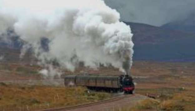
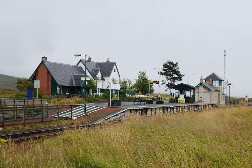
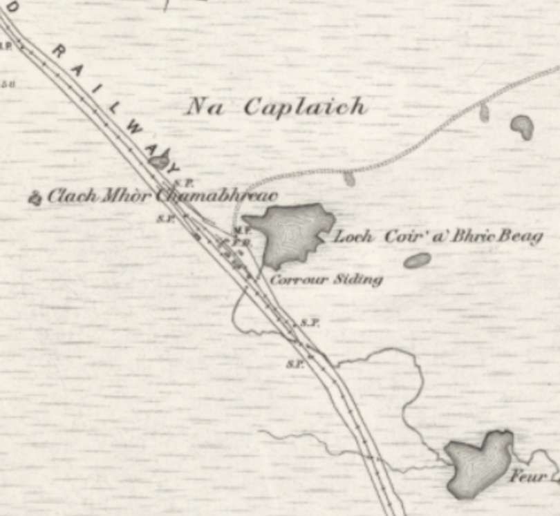
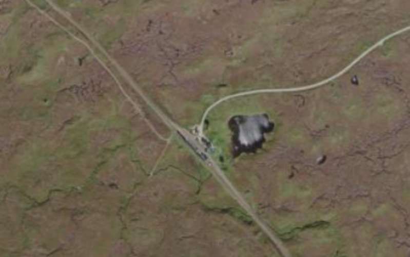
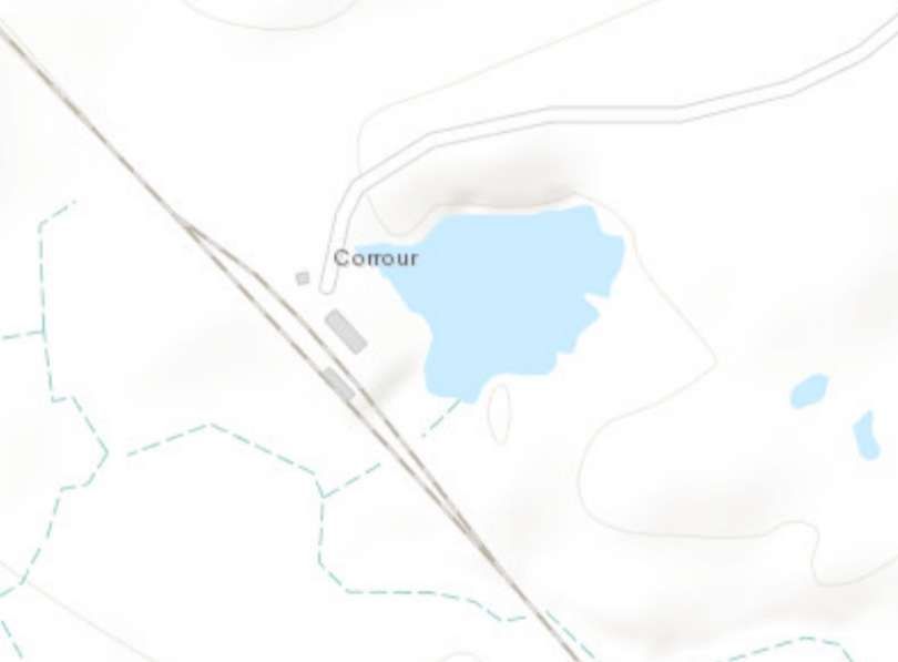
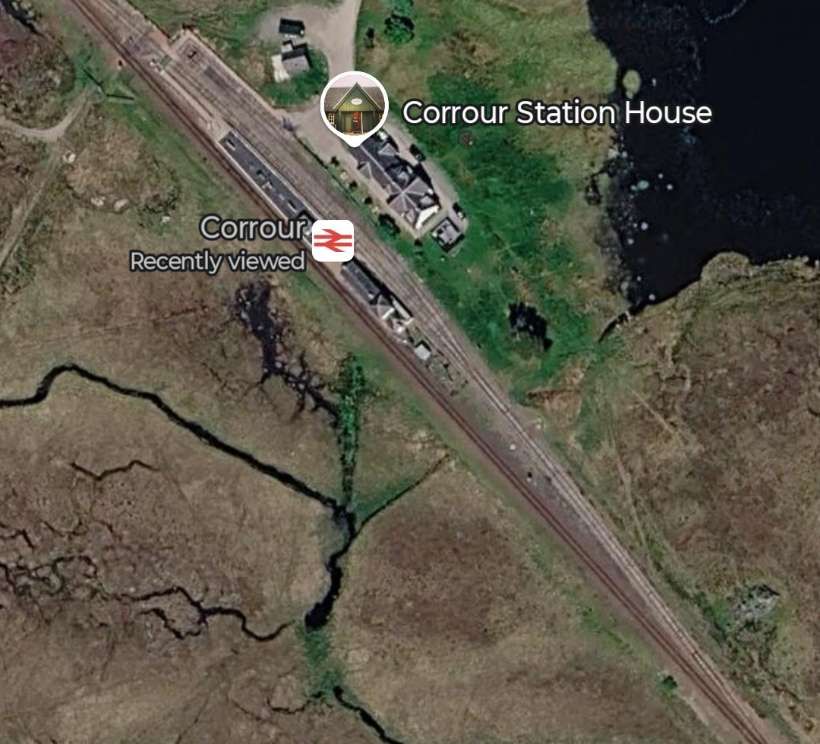
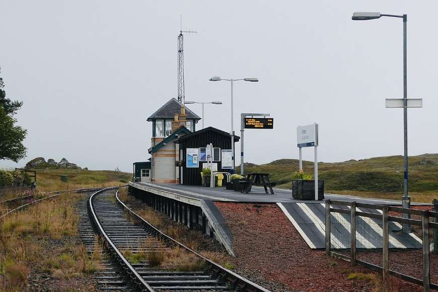
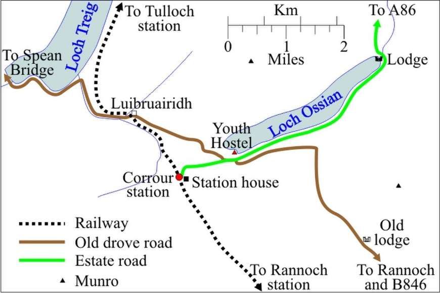
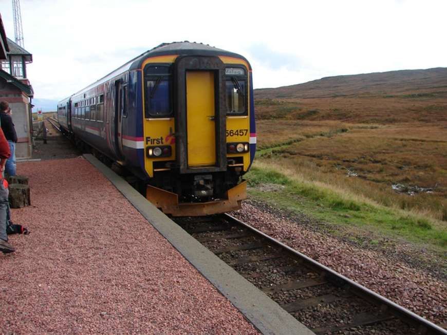
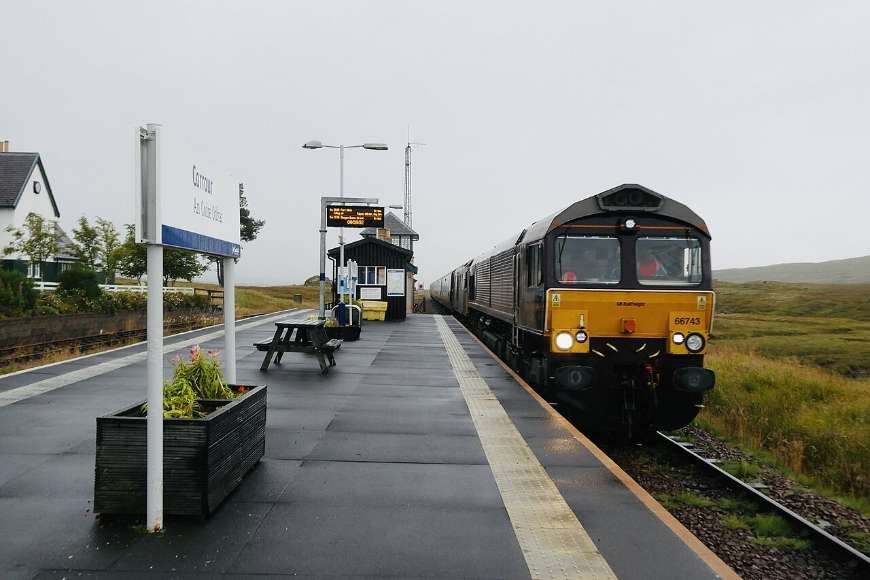
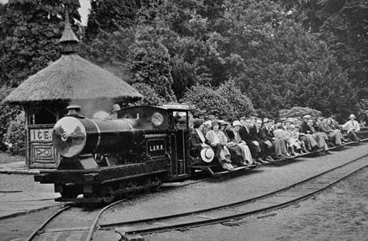
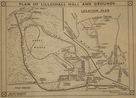
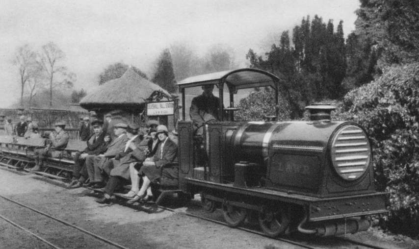
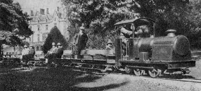
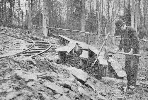
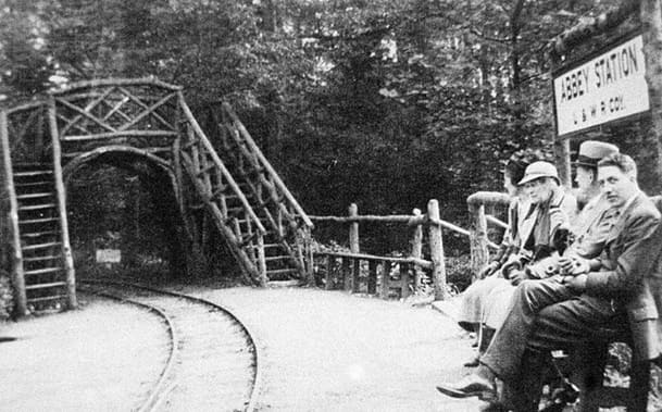
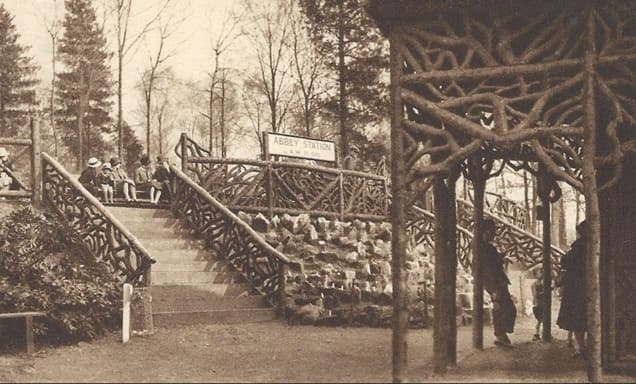
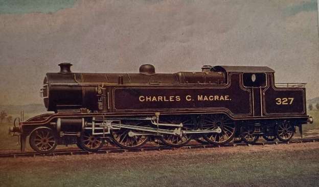
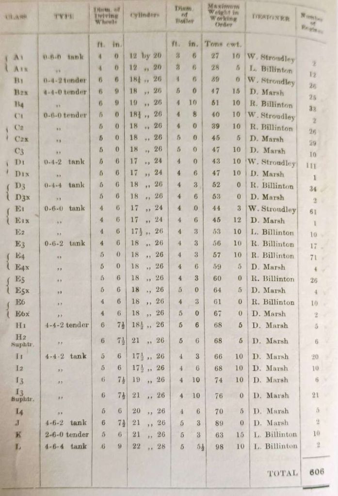
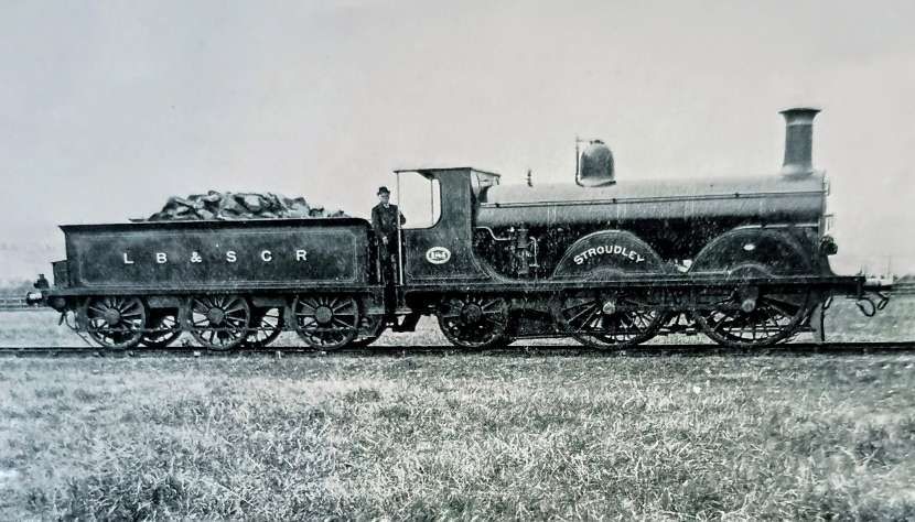
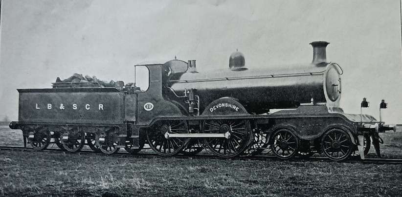
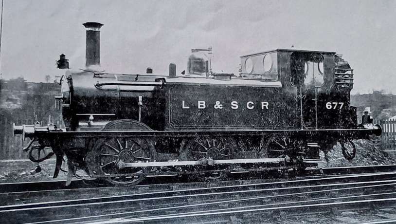
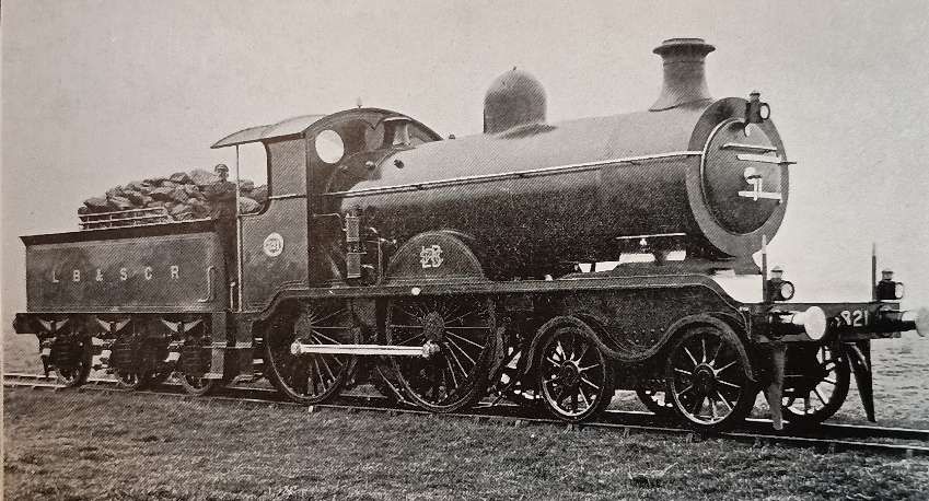
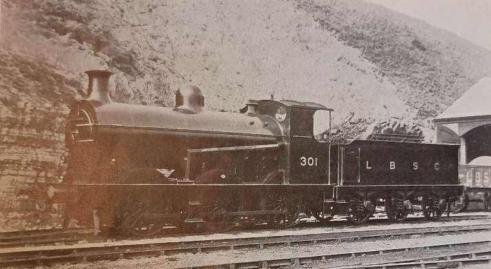
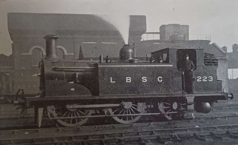
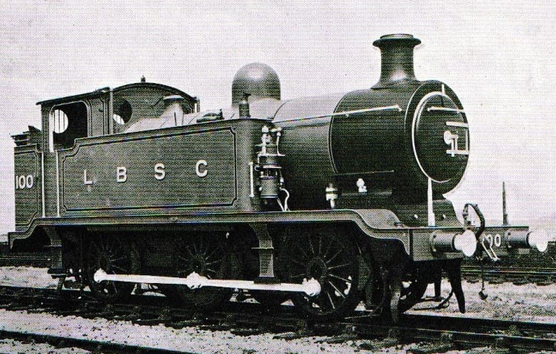
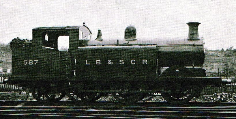
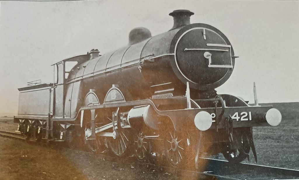
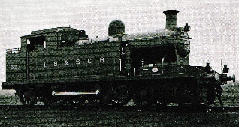
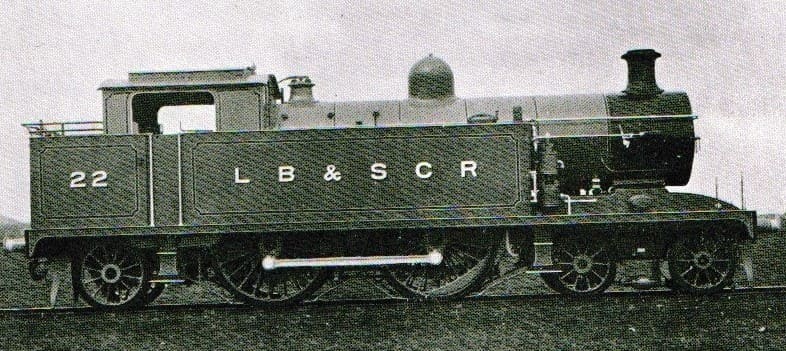
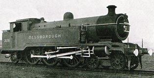
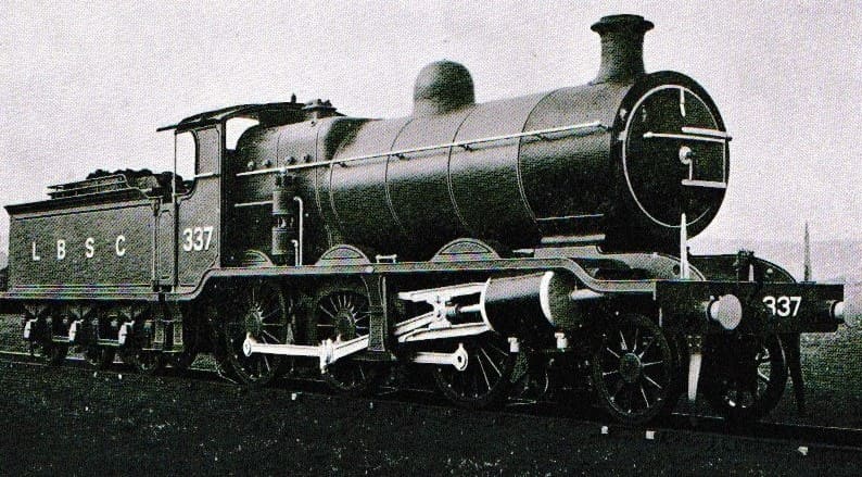
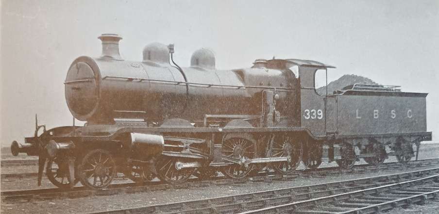
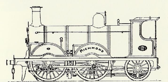
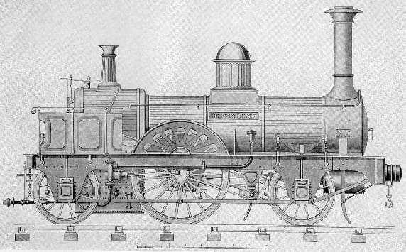
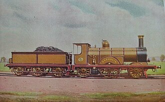
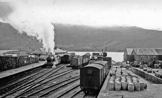
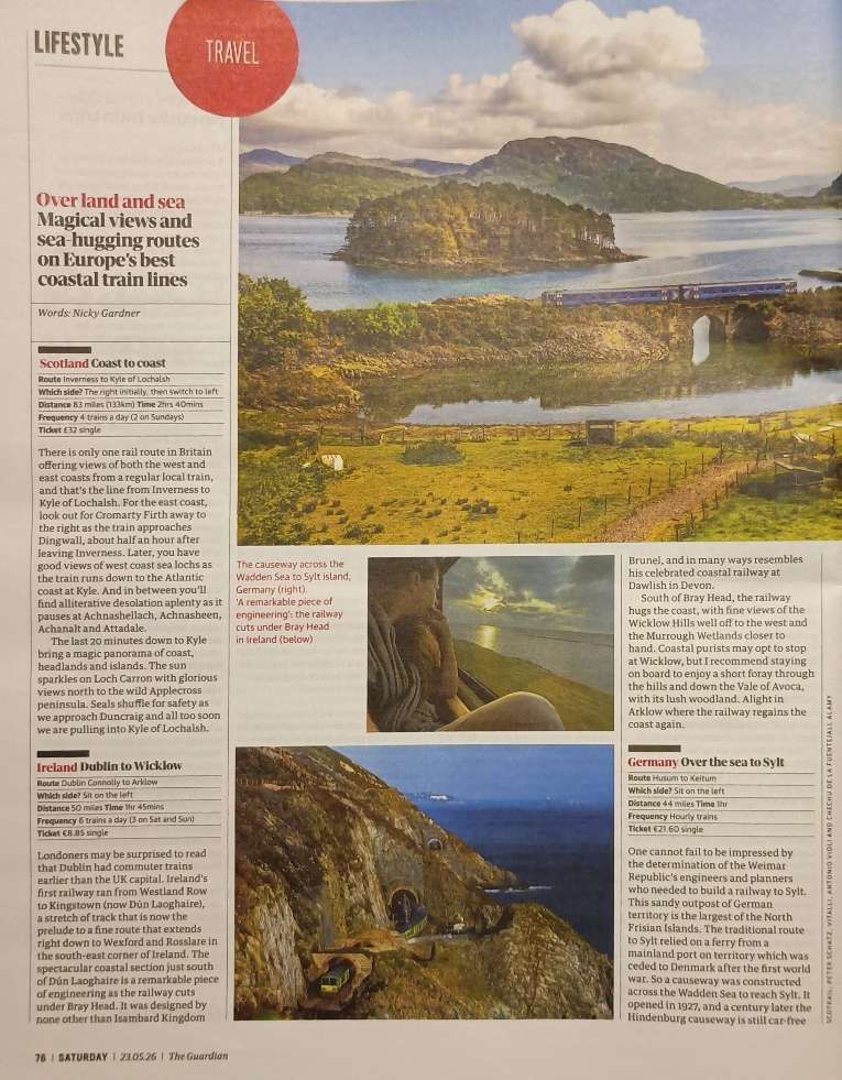
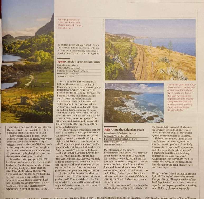
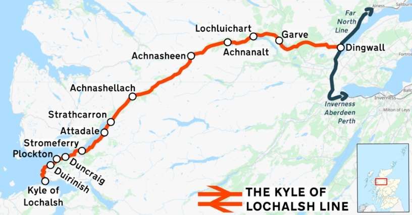
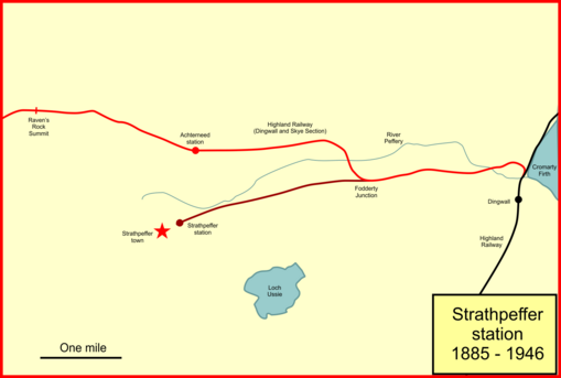
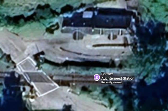
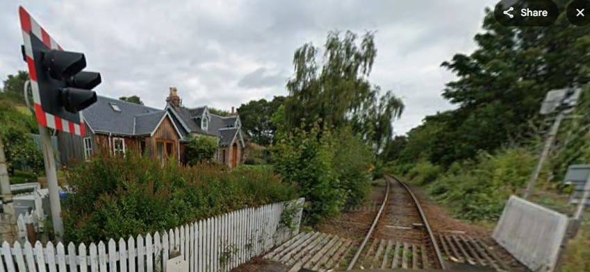
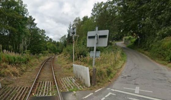
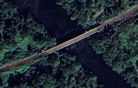
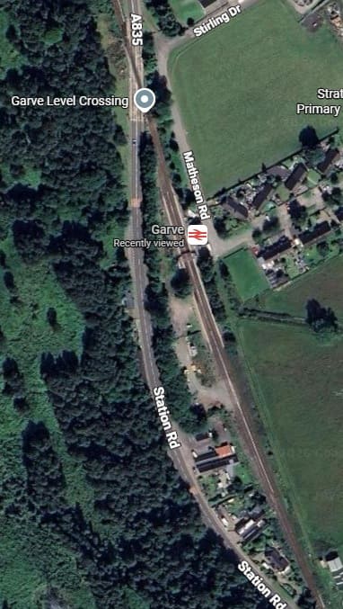
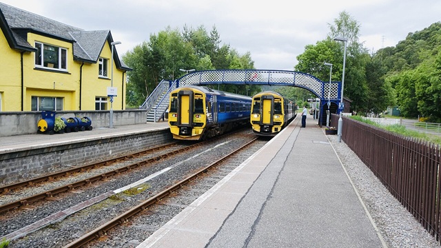
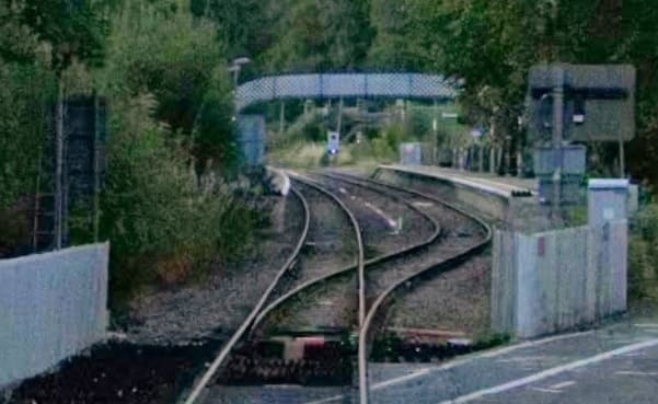
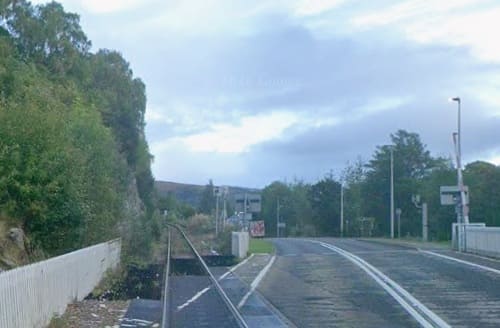
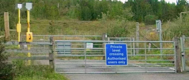
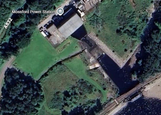
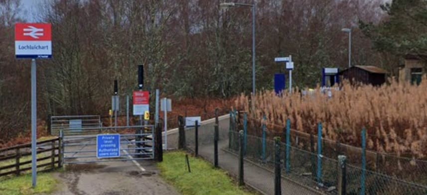
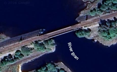
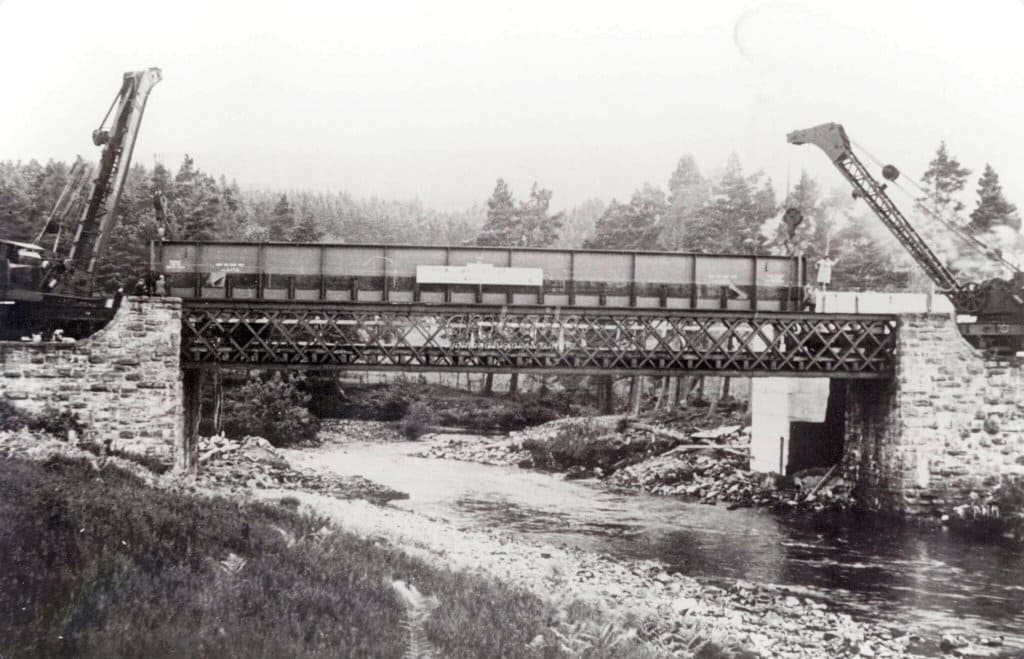
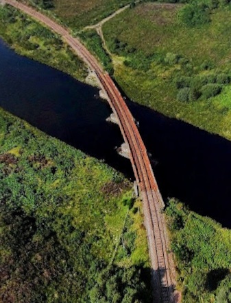
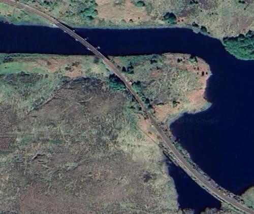
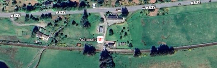
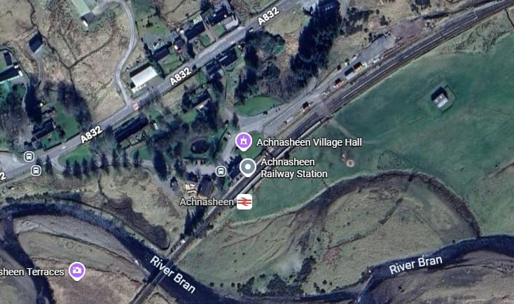
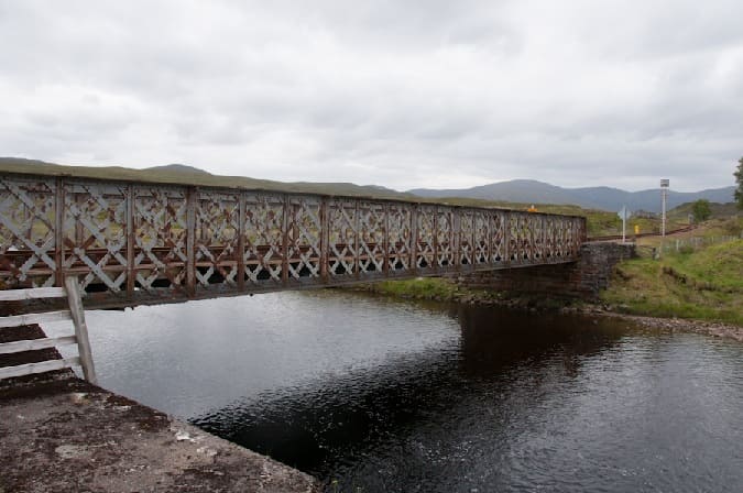
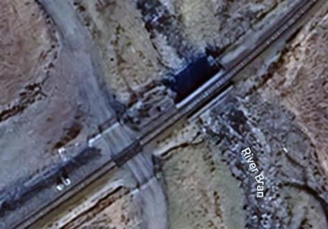
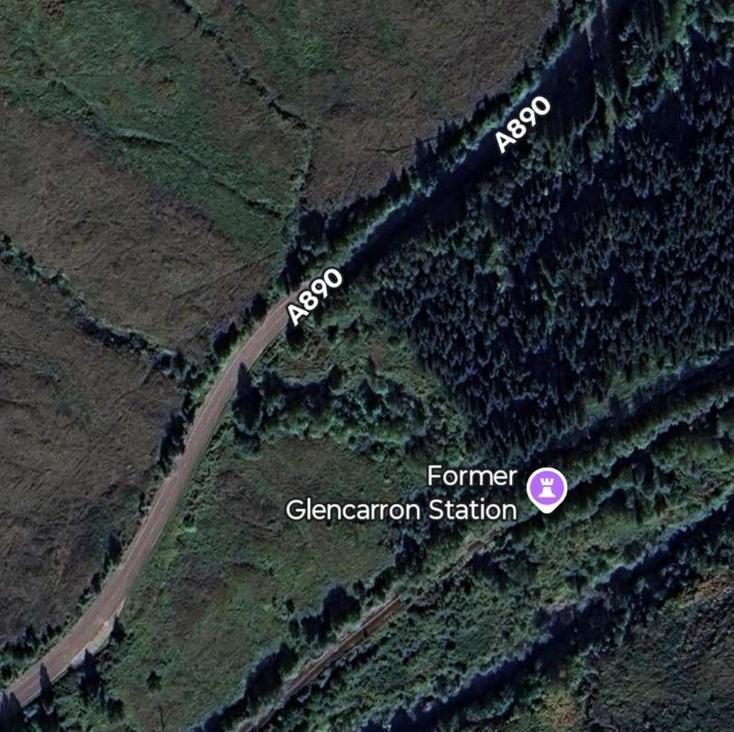
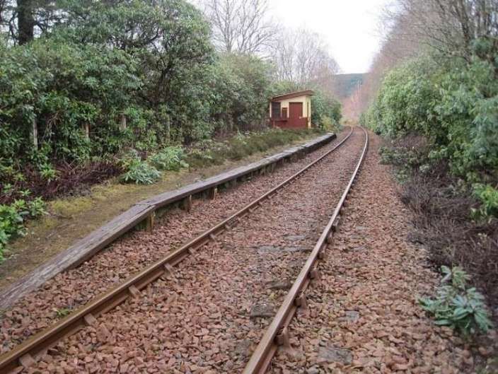
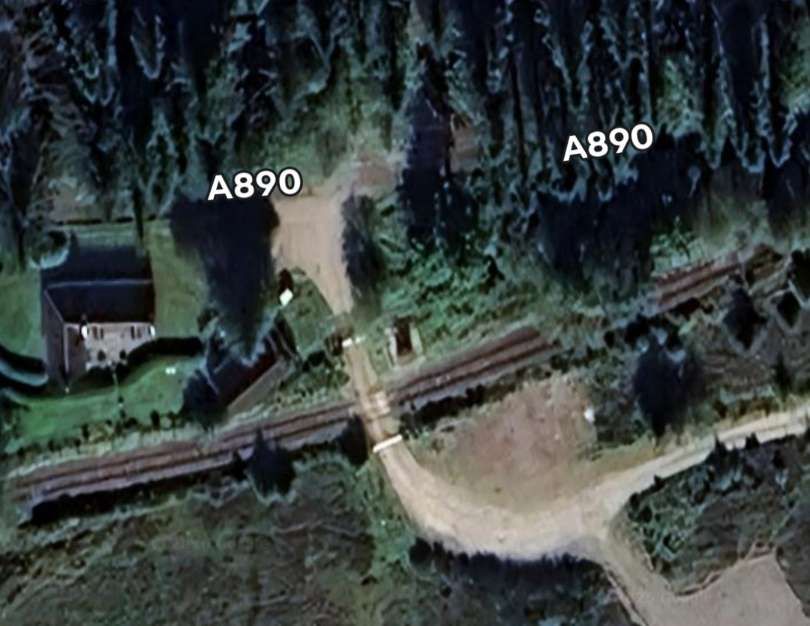
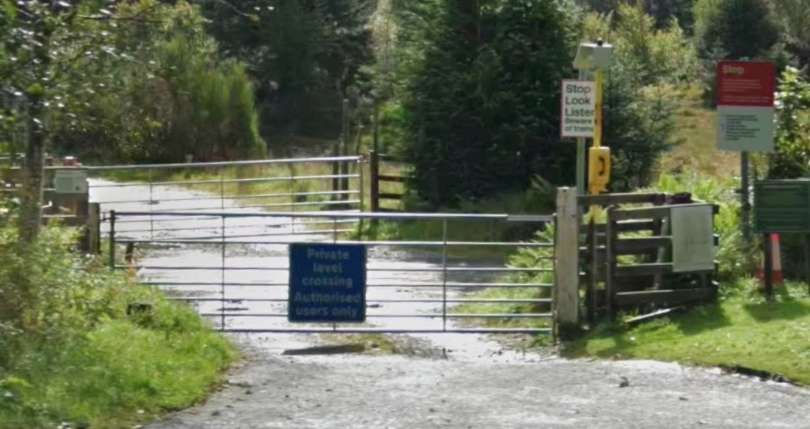
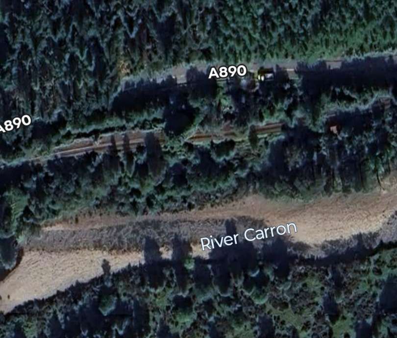
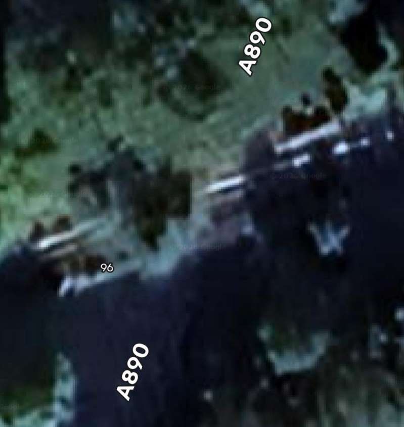
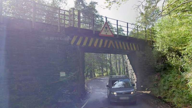
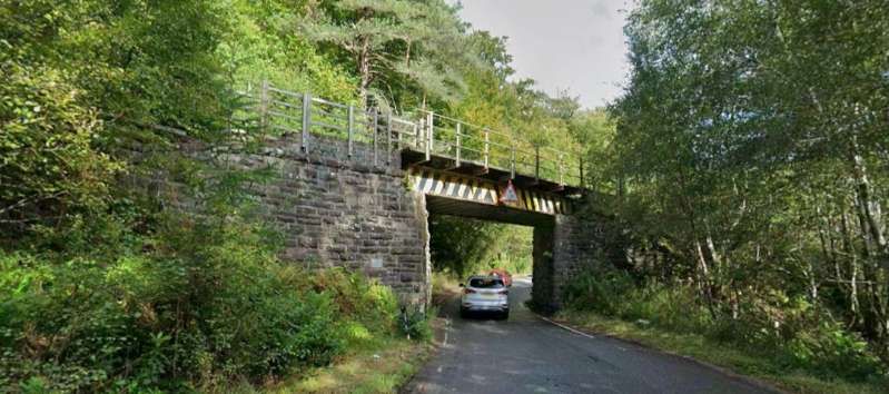
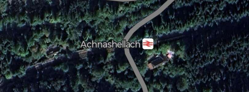
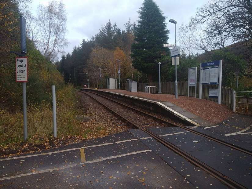
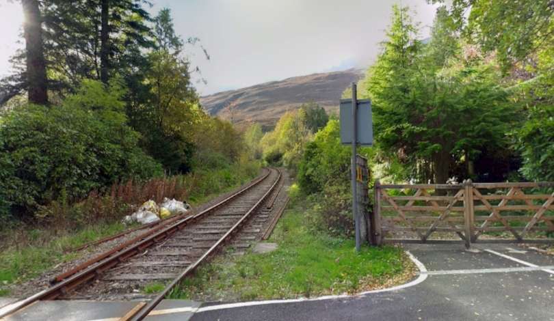
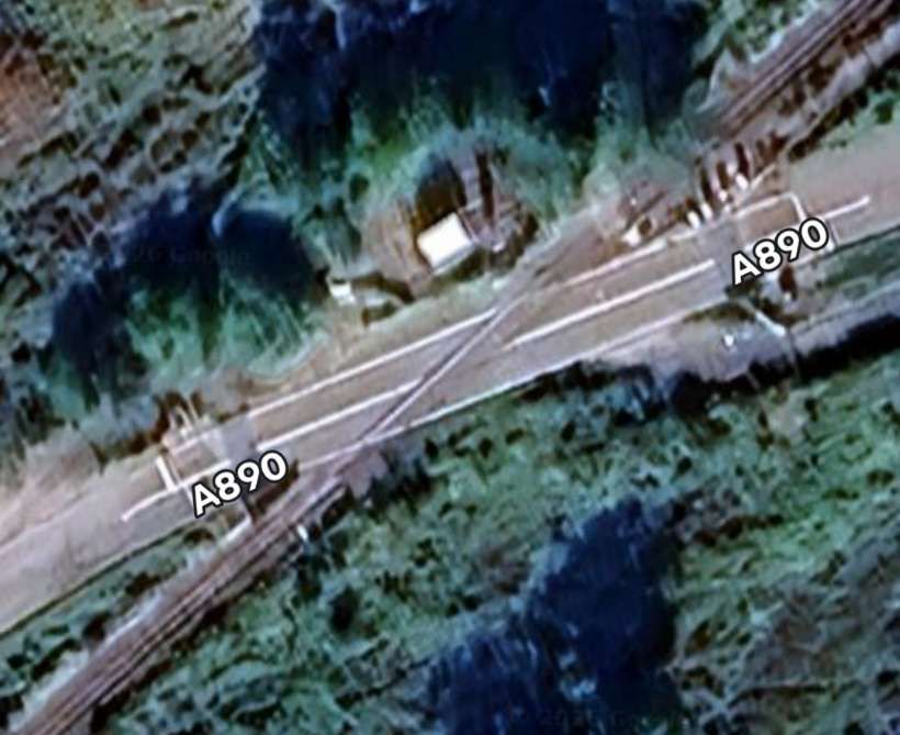
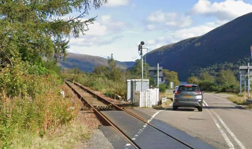
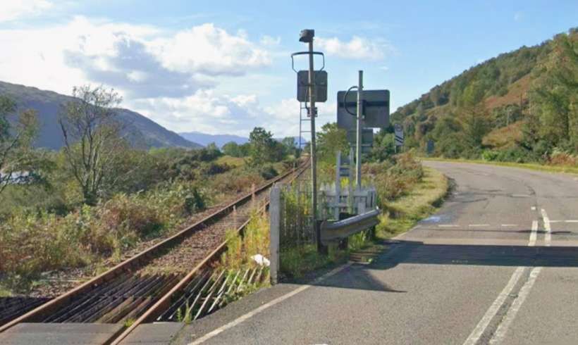
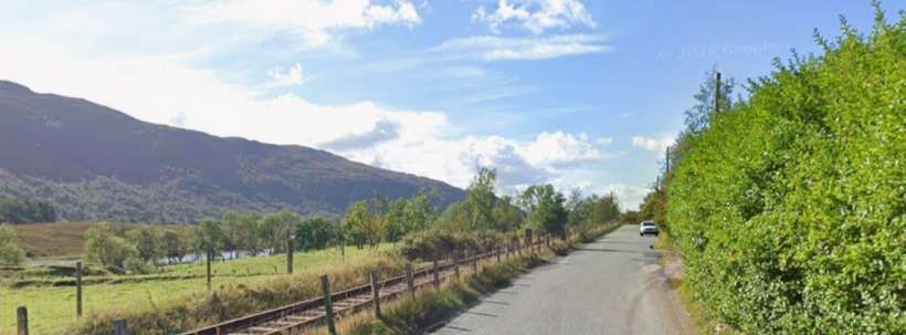
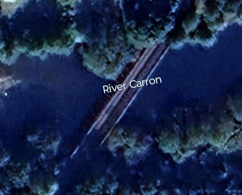
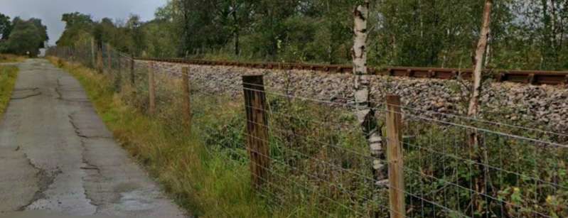
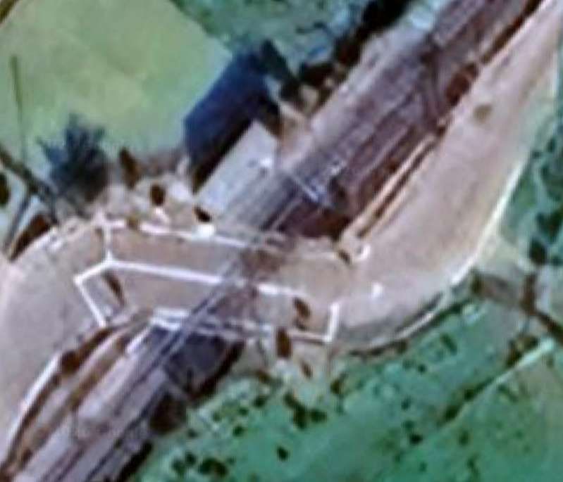
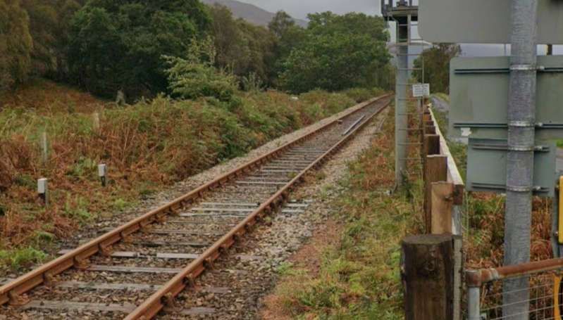
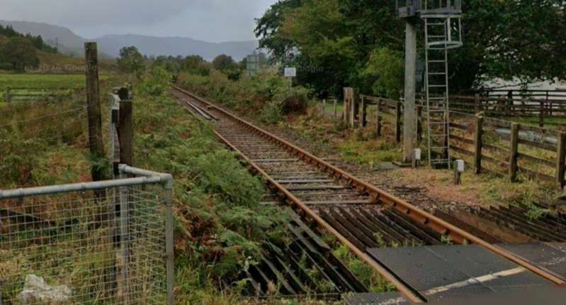
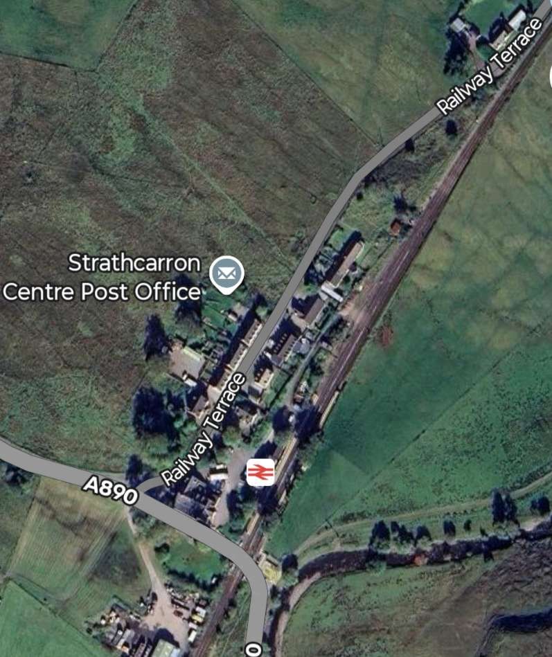
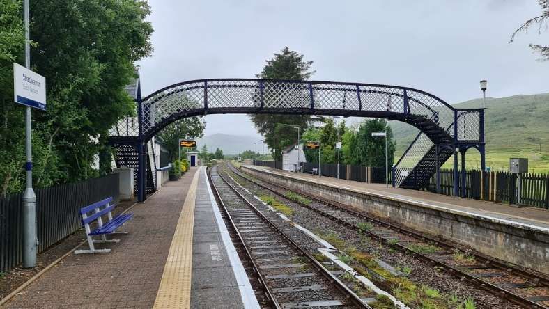
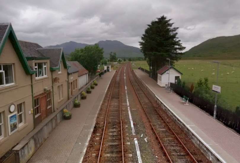
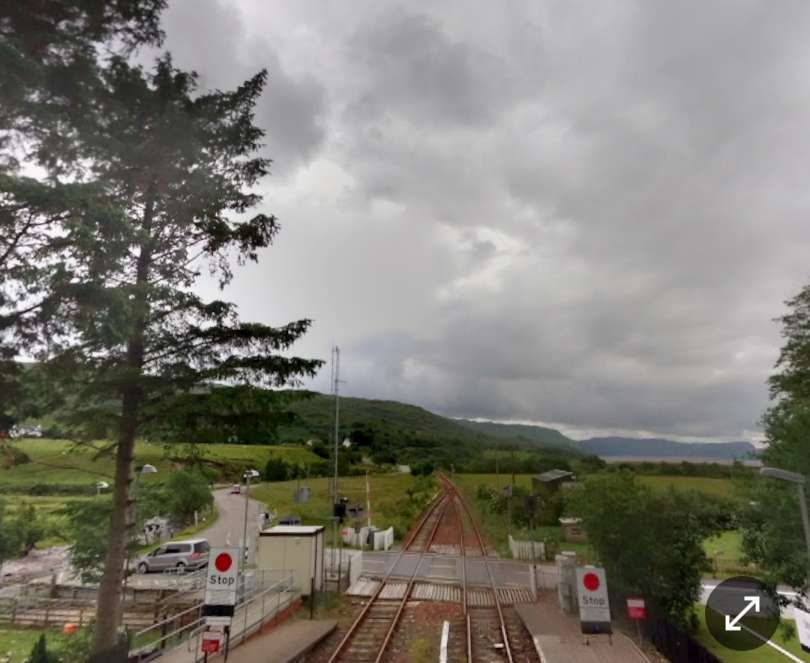
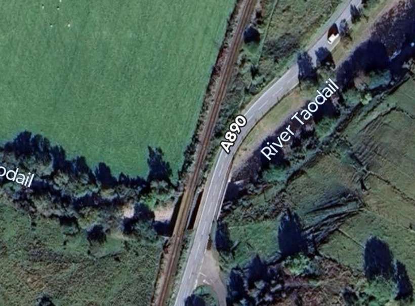
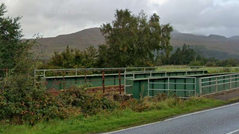
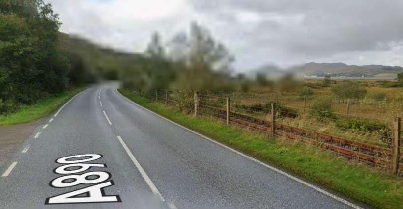
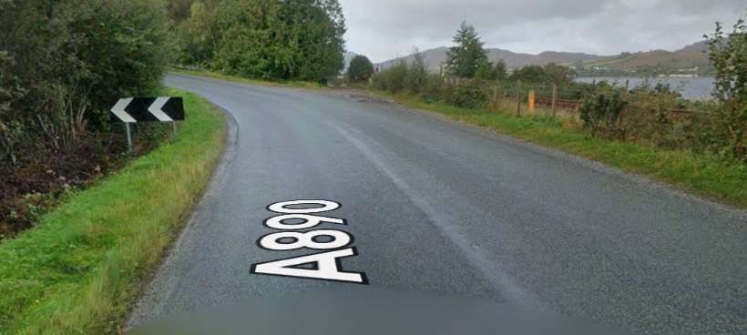
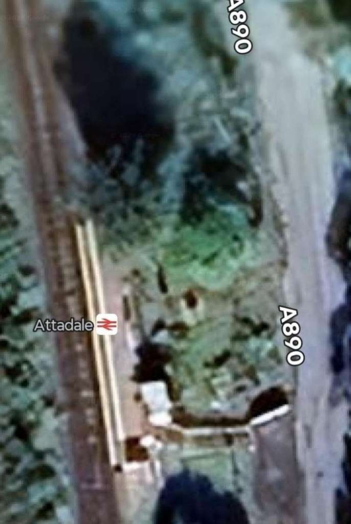
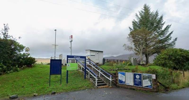
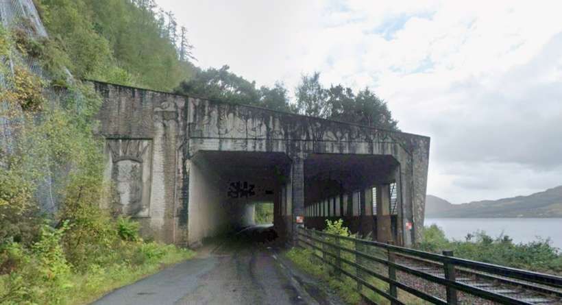
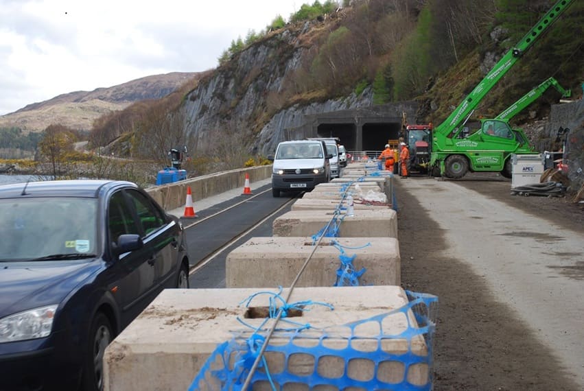
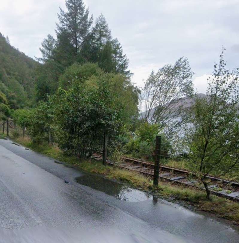
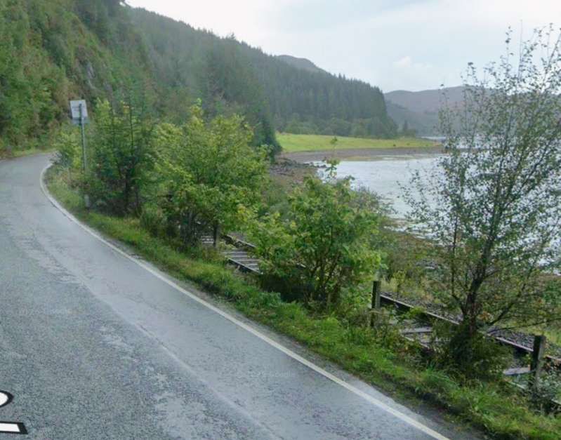
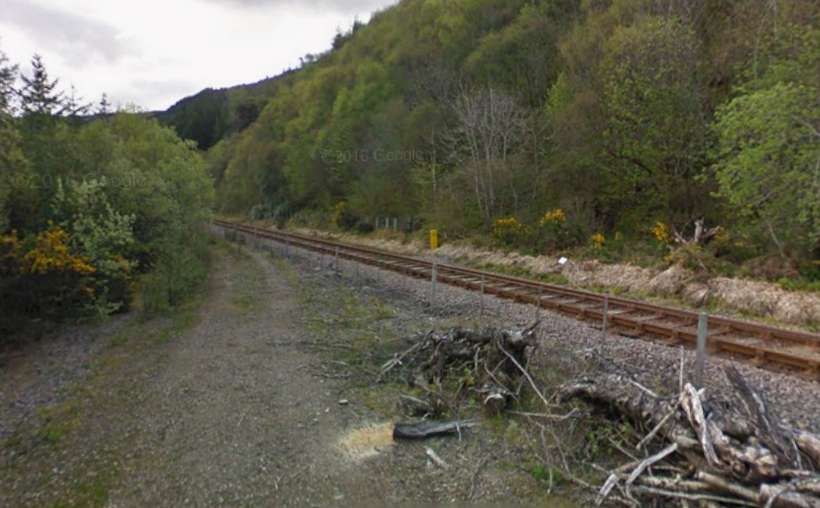
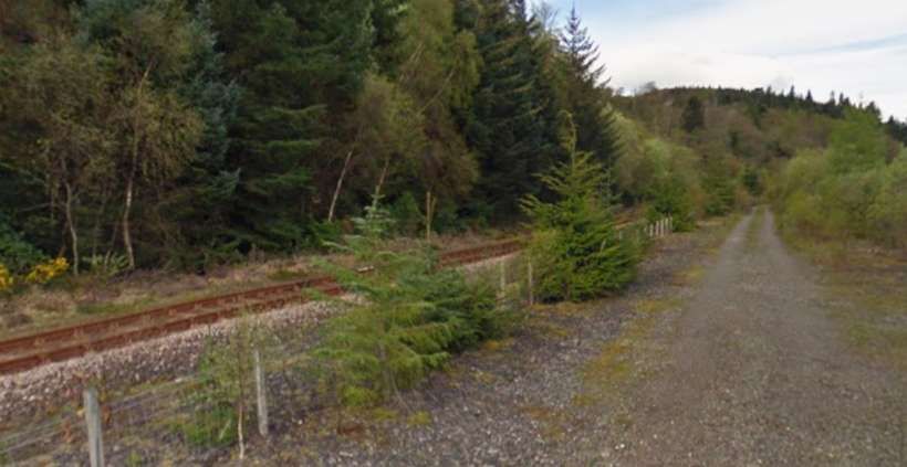
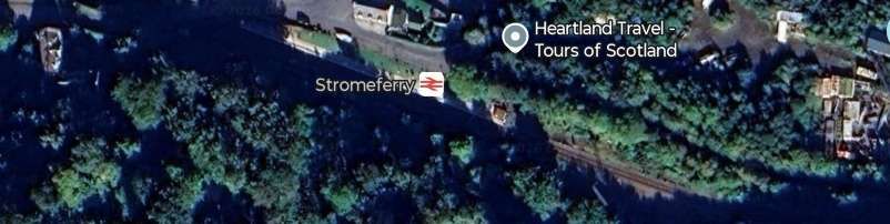
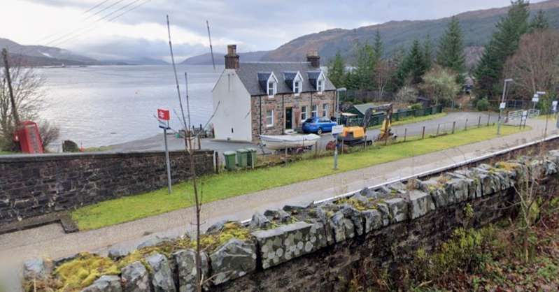
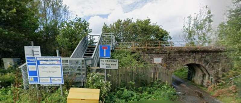
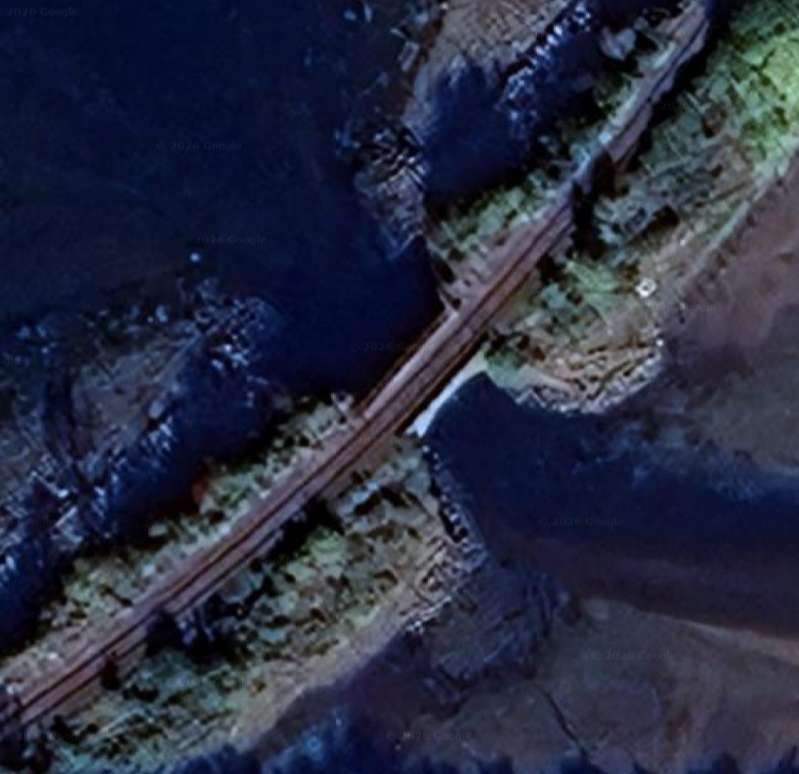
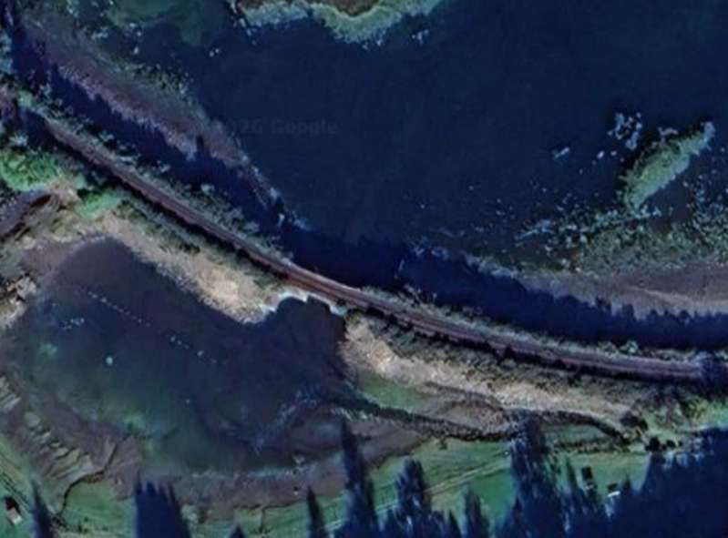
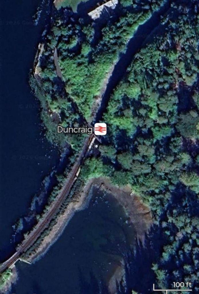
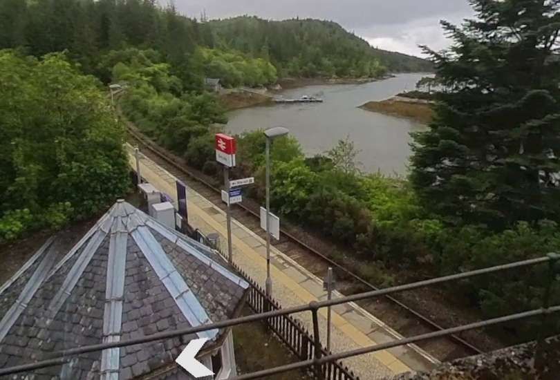
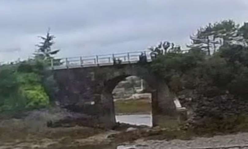
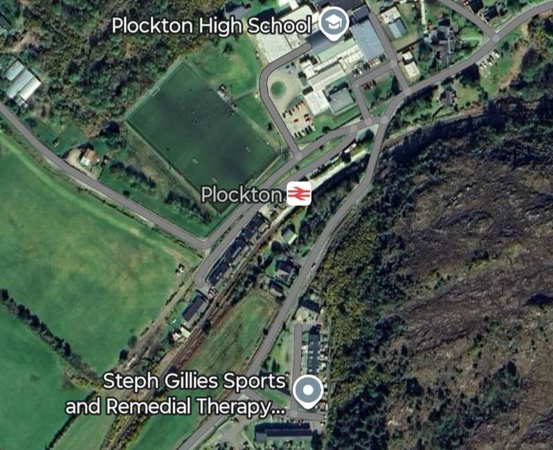
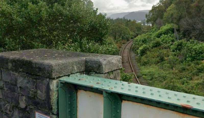
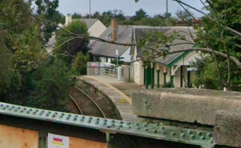
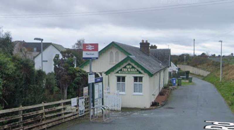
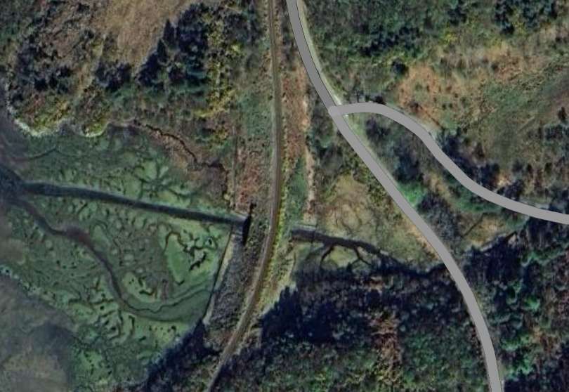
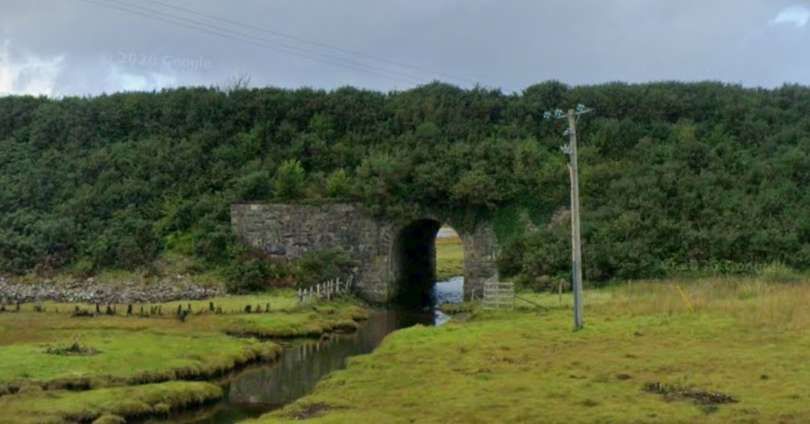
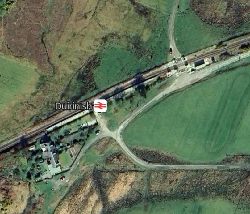
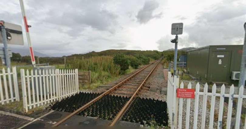
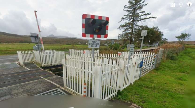
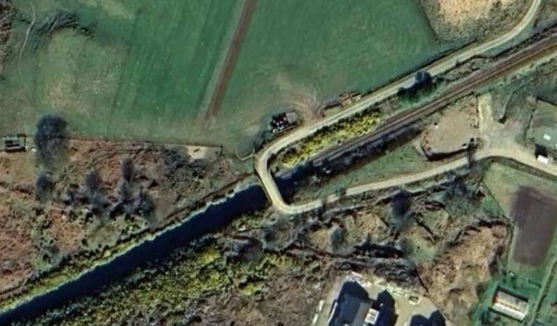
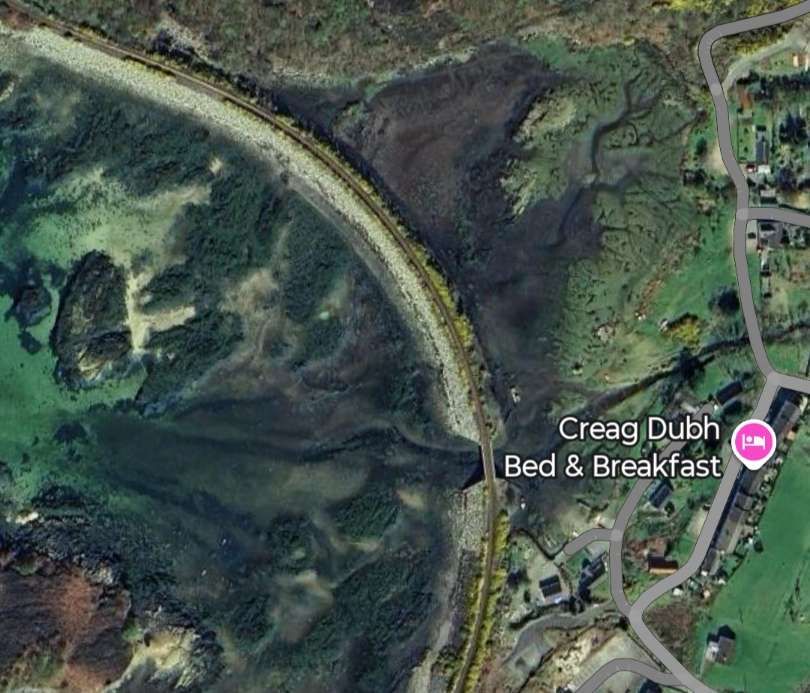
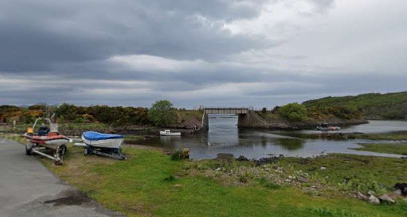
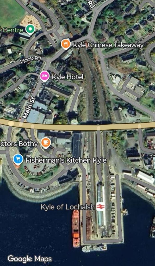
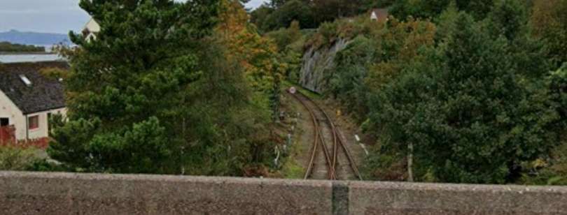
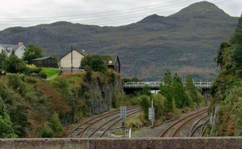
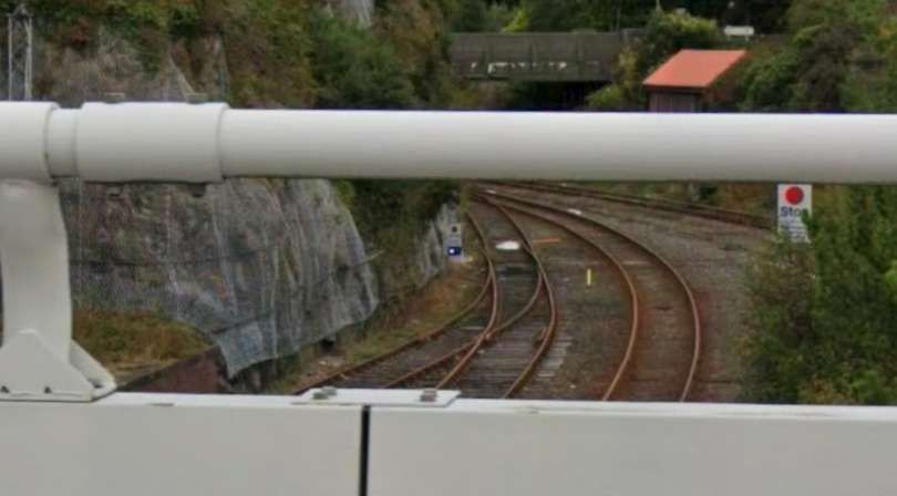
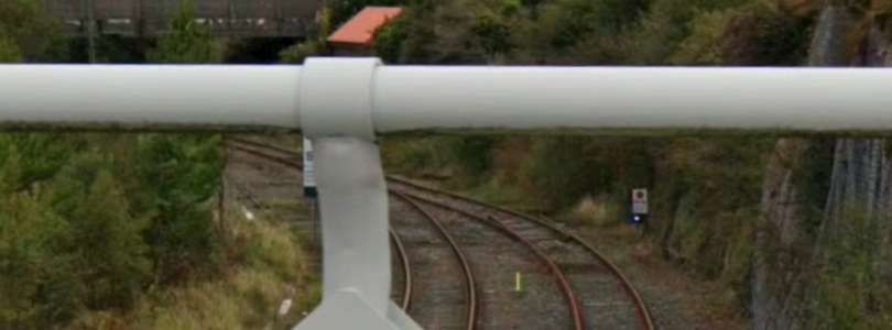
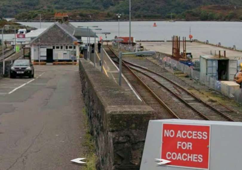
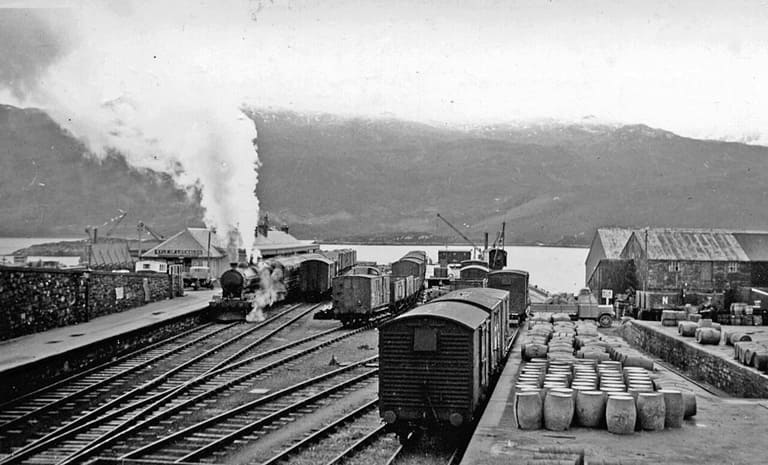
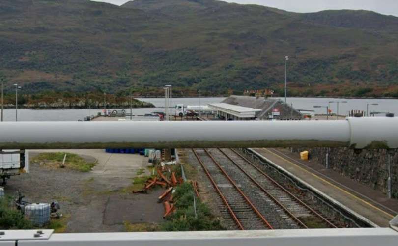
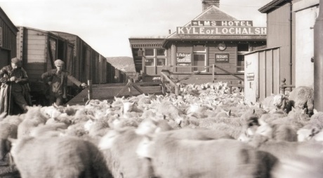
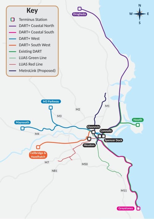
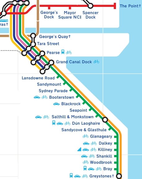
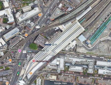
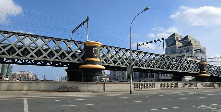
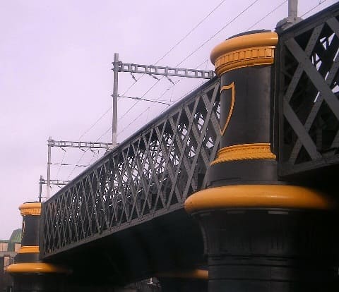
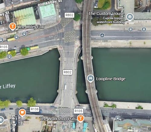
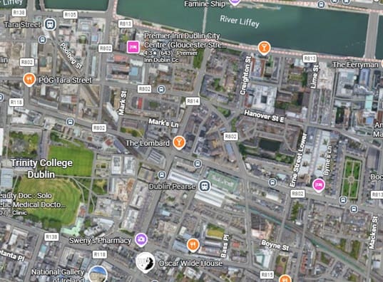
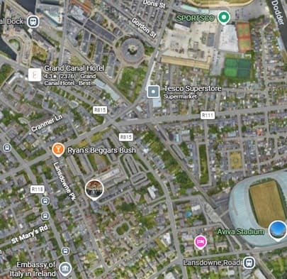
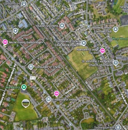
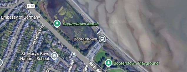
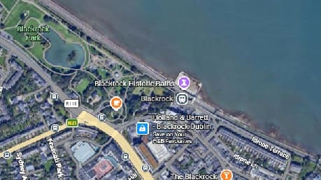
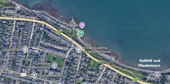
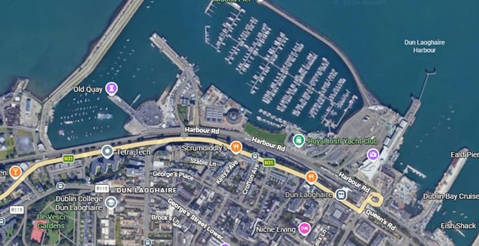
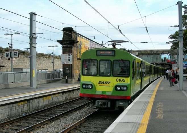
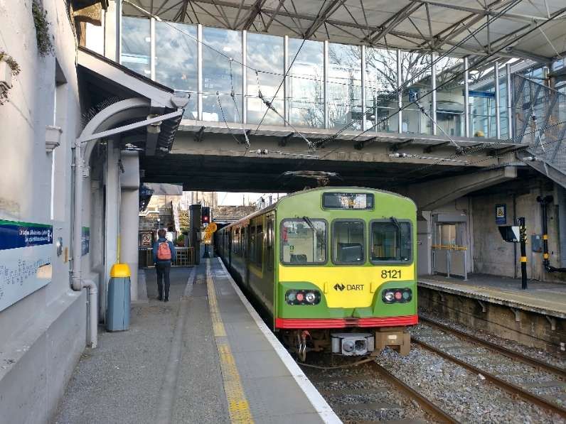
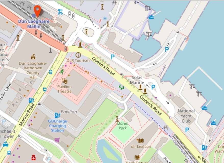
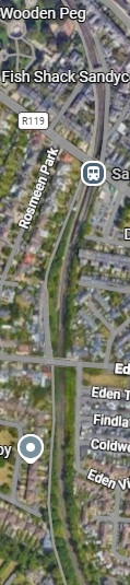
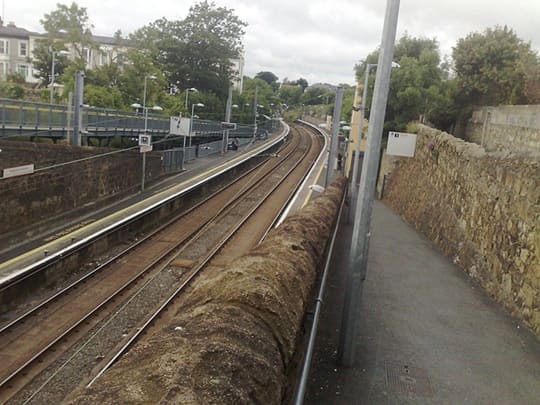
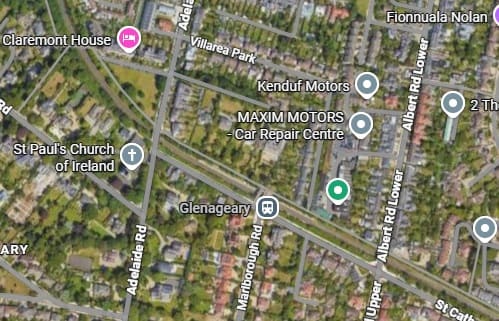
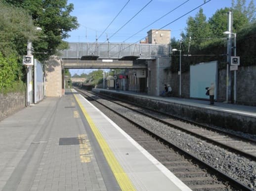
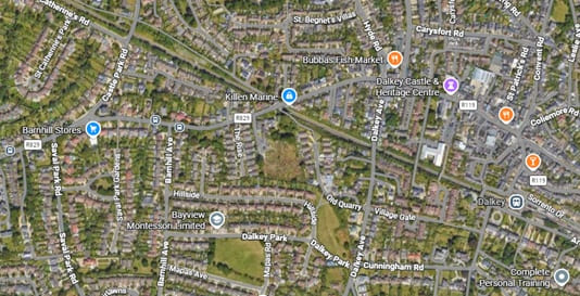
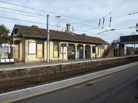
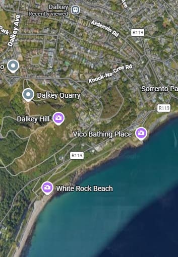
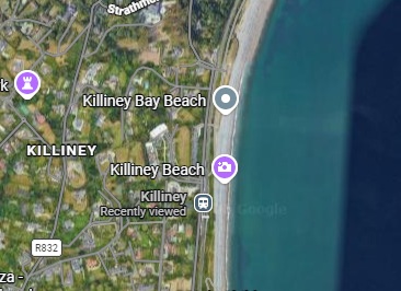
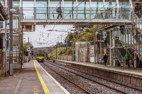
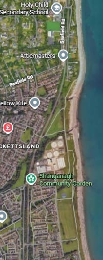
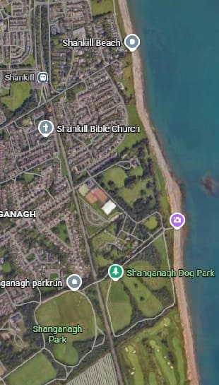
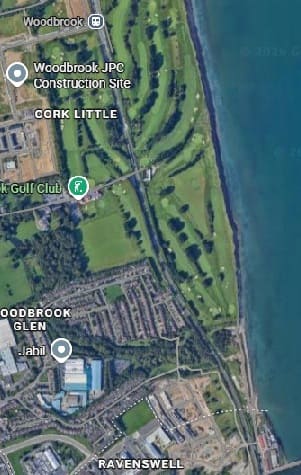
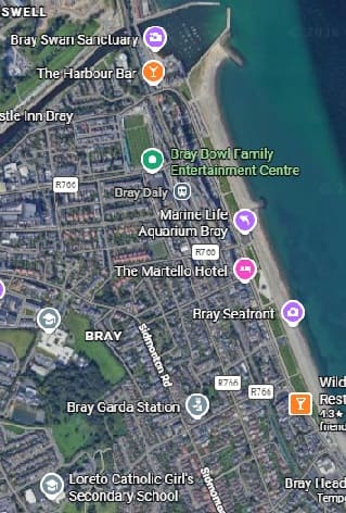
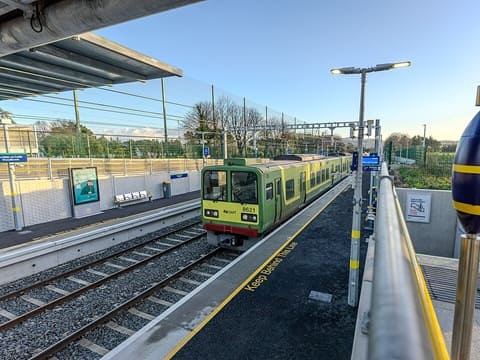
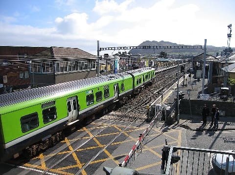
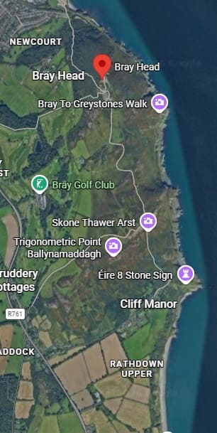
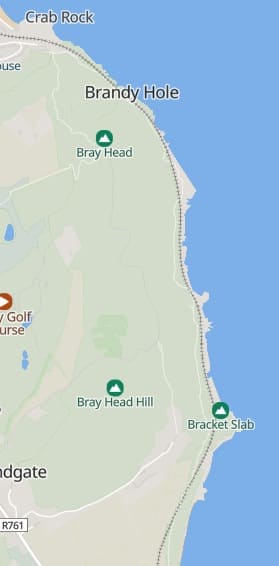
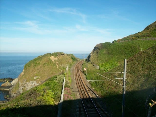
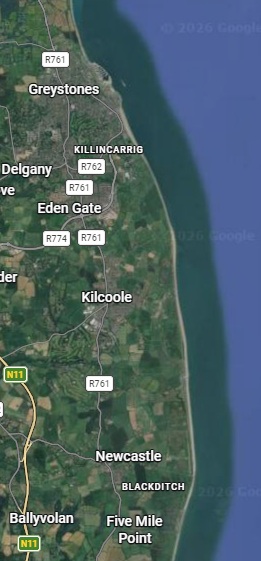
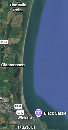
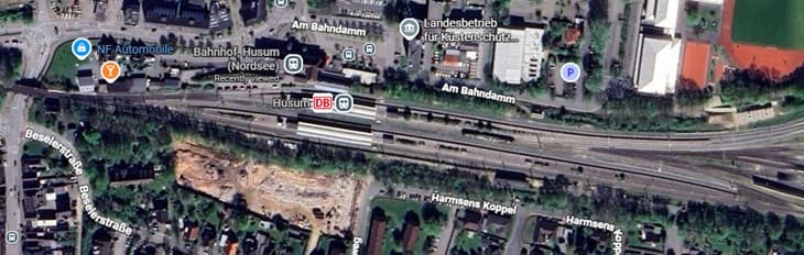
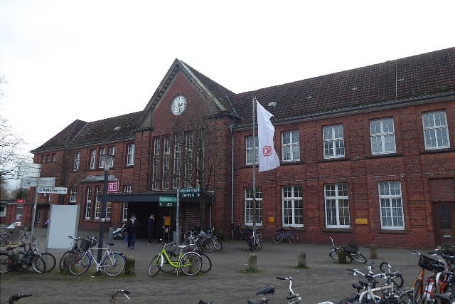
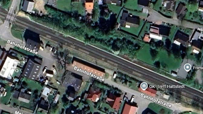
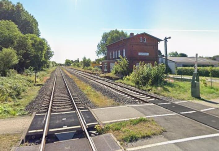
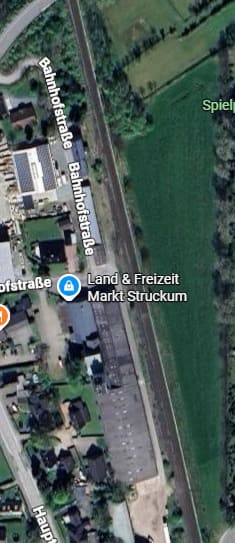
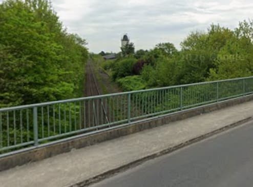
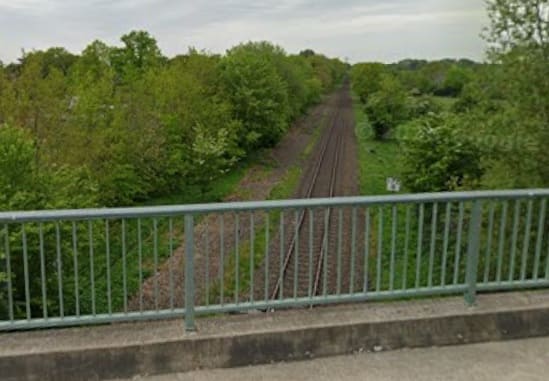
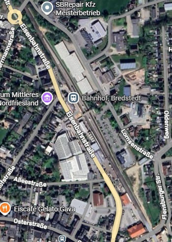
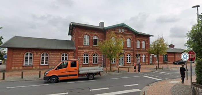
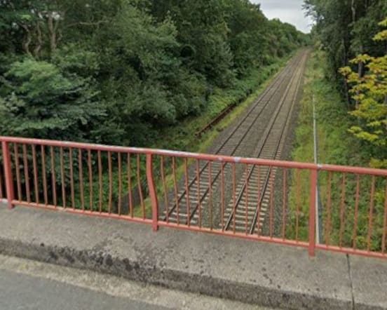
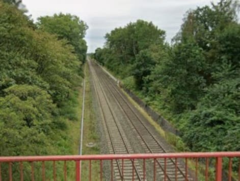
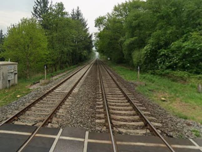
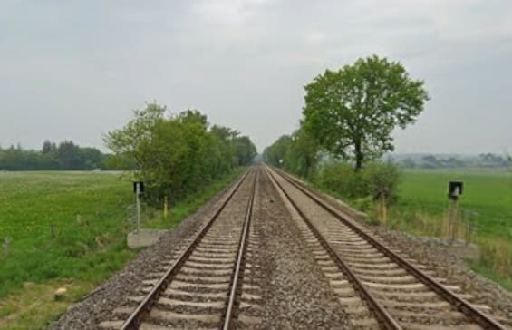
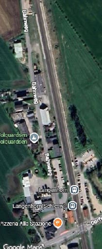
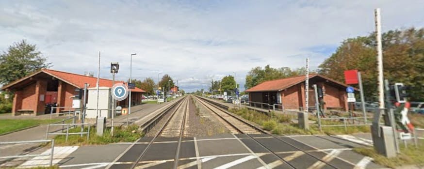
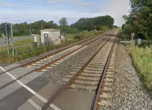
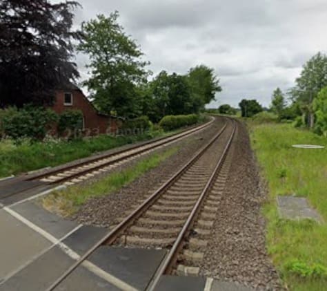
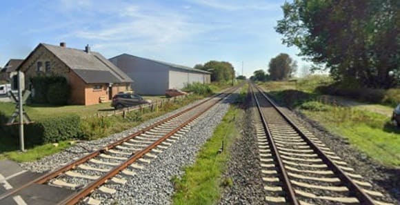
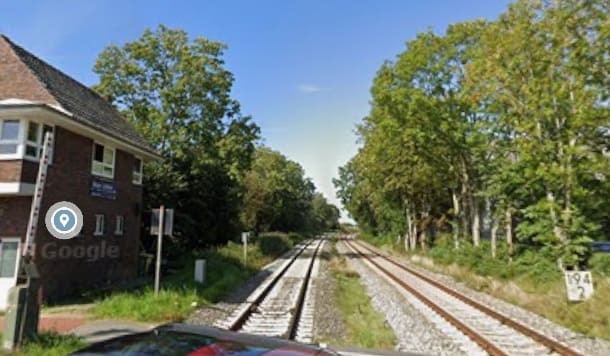
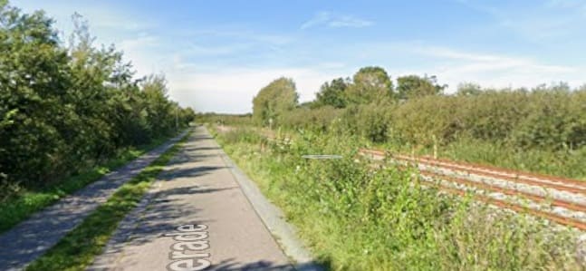
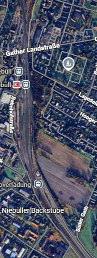
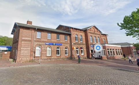
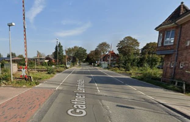
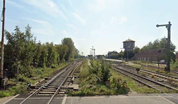
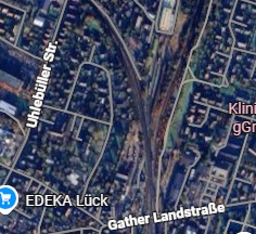
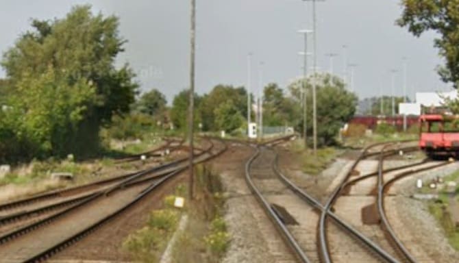
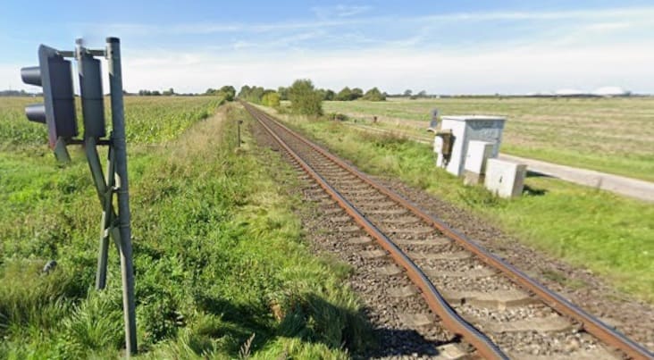
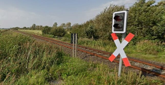
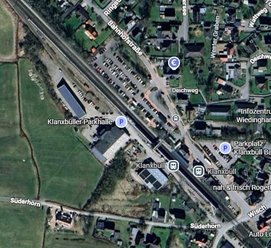
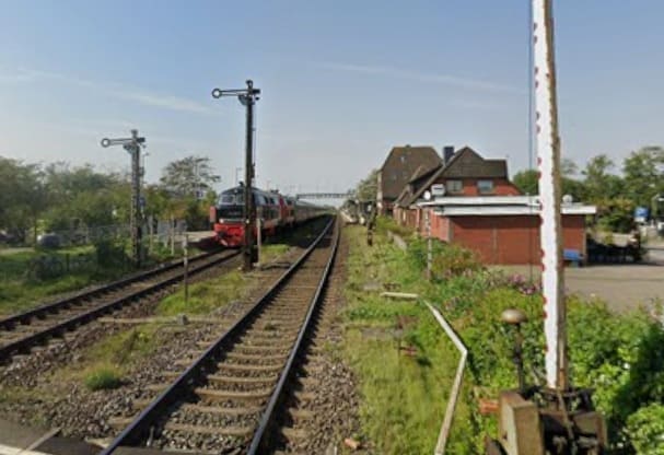
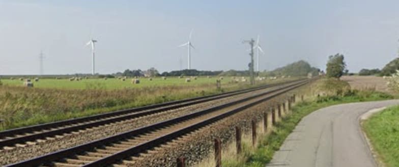
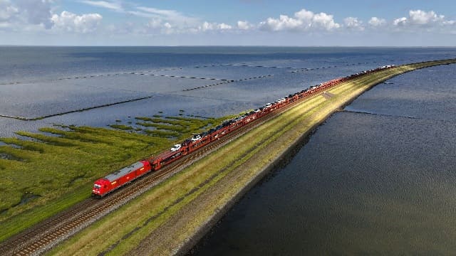
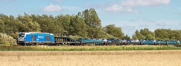

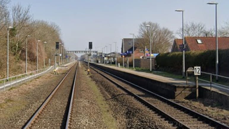
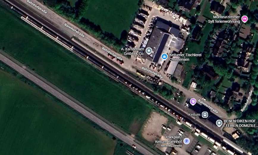
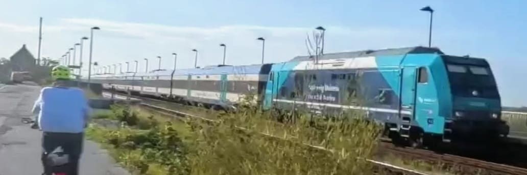
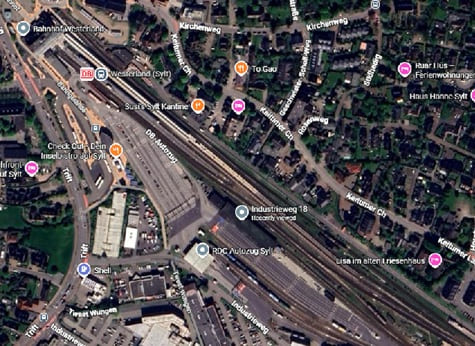
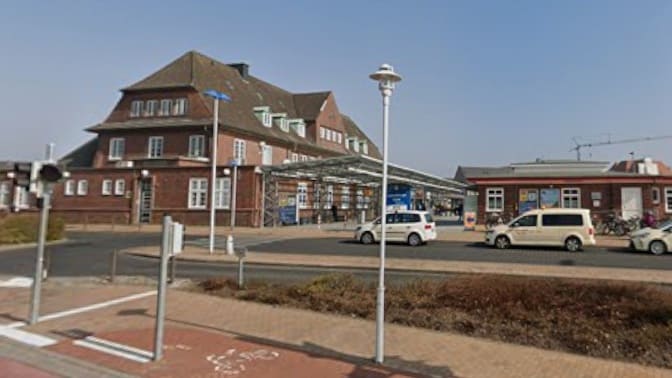
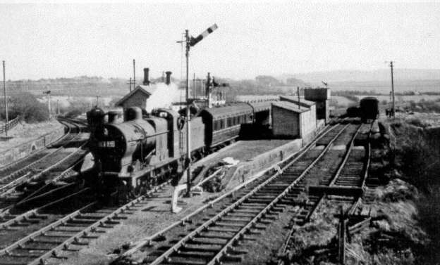
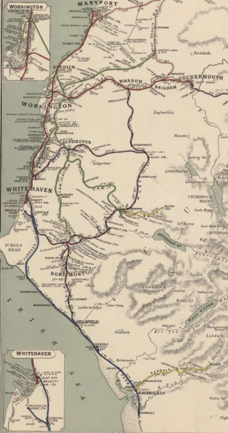
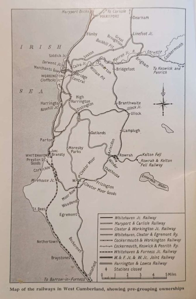
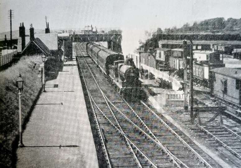
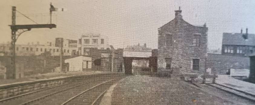
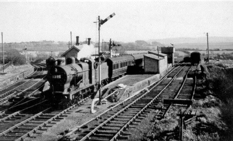
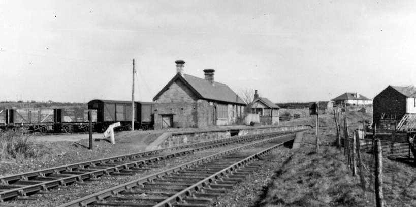
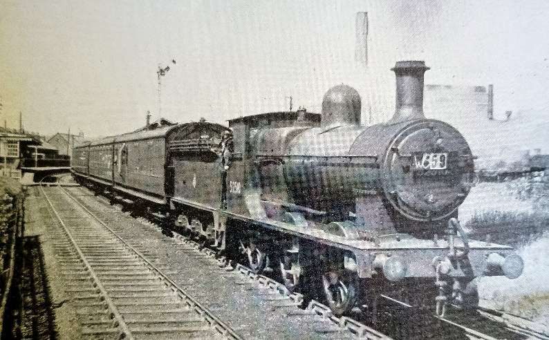
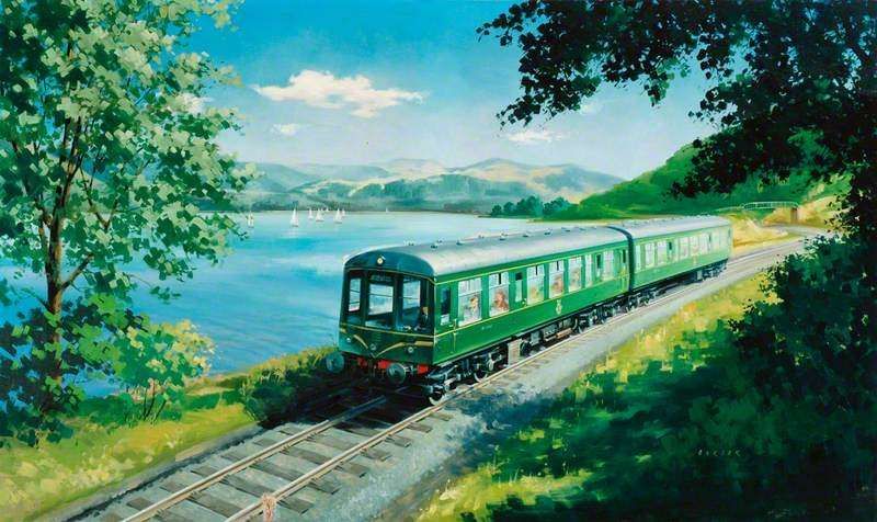
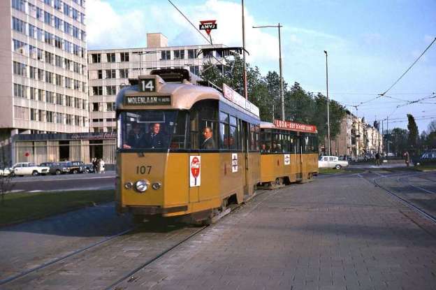
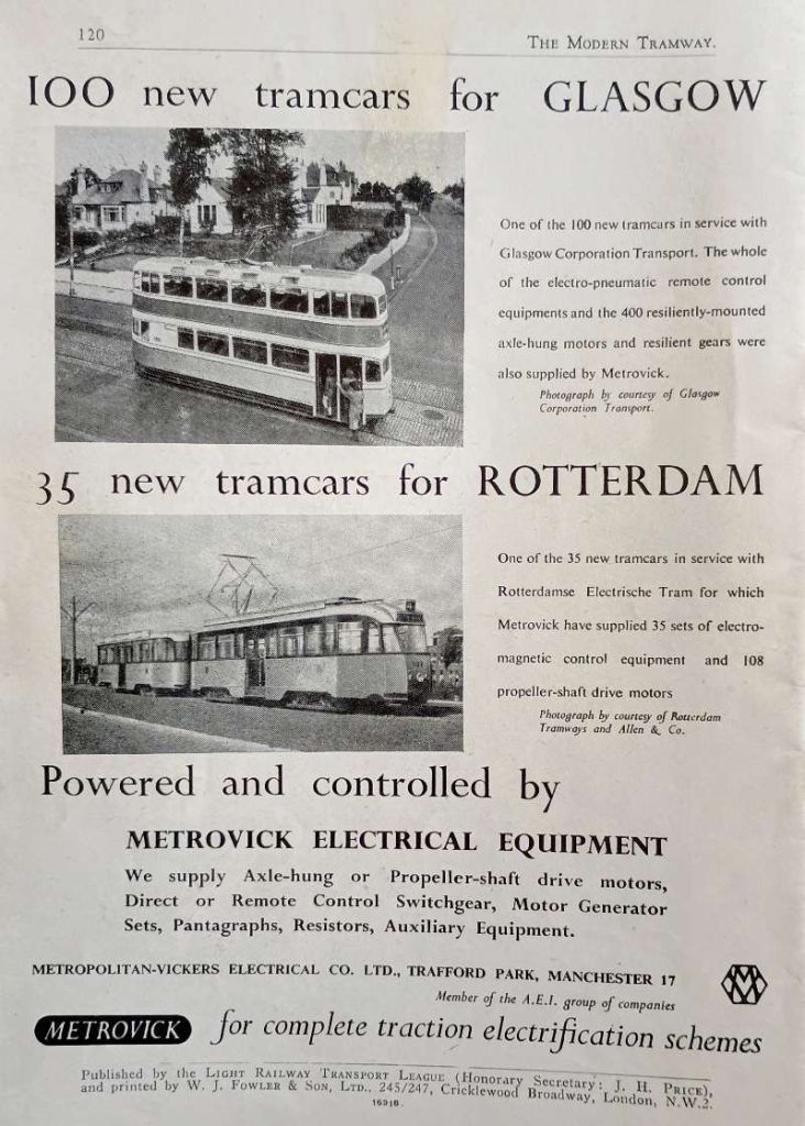
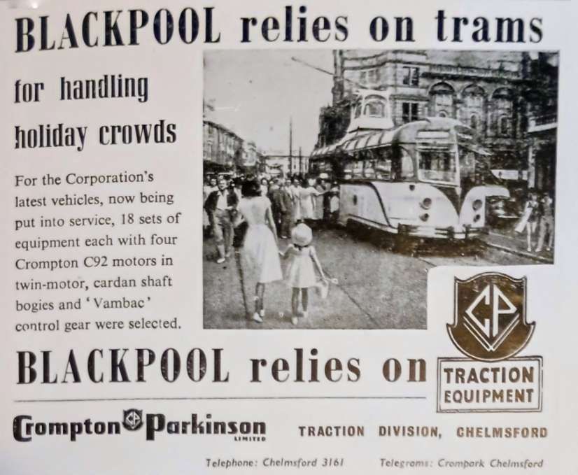
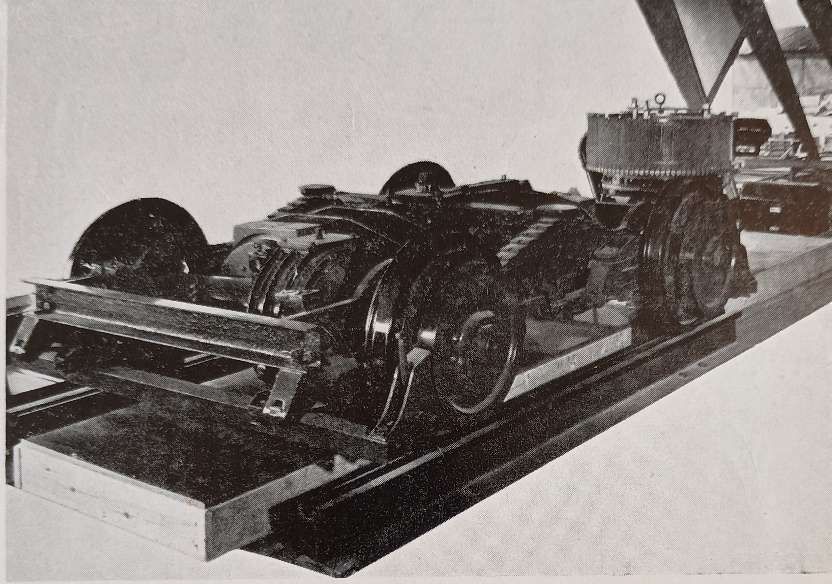
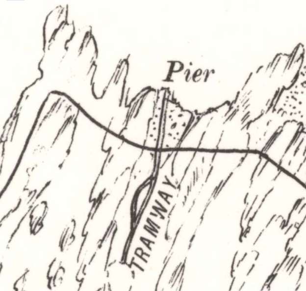
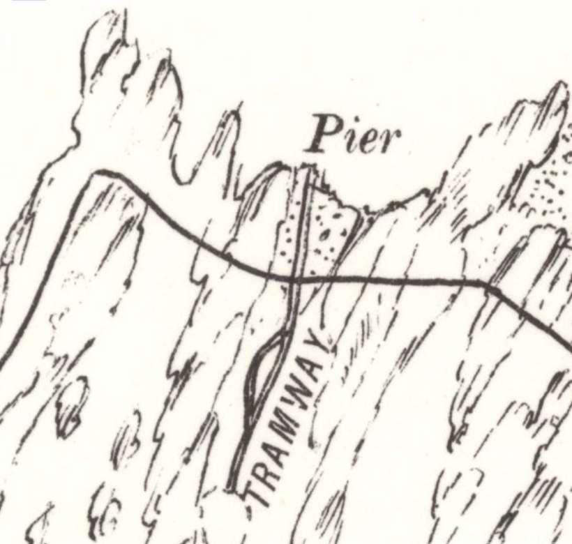
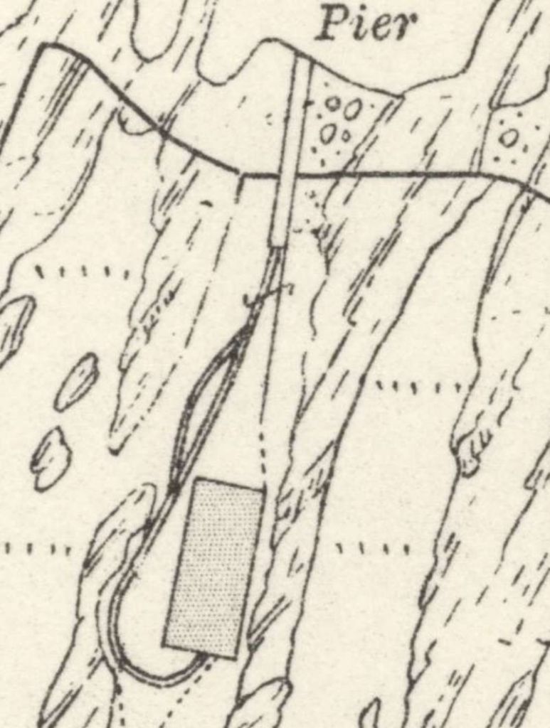
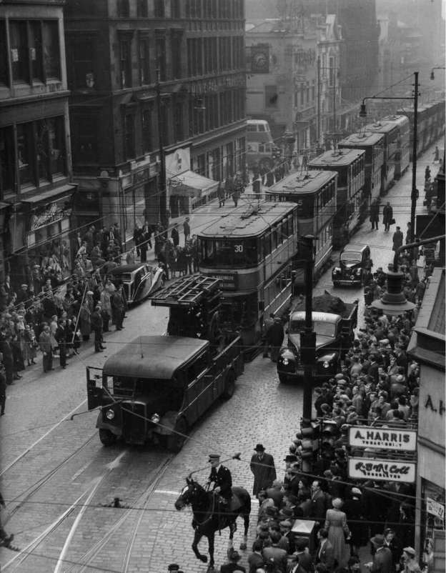
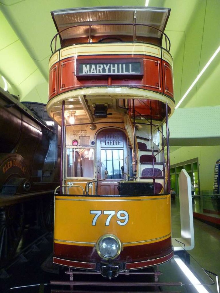


.jpg)


.jpg)


#/media/File:P1020943_Bahnhof_Husum_2019.jpg)


