The featured image for this article shows an unidentified 0-4-0ST (Peckett?) in charge of a train at the Washmills associated with Bevan’s Cement Works. After 1926, these were sited to the South of Northfleet and works trains required tunnels under the High Street in order to gain access to the Works. This image was shared by Andy Howdle on the Industrial Locomotive Enthusiasts Page Facebook Group on 28th August 2025 and is shared here with his kind permission. [10]
Knight, Bevan & Sturge Ltd. was established in 1853 between the River Thames and the centre of Northfleet. Although Thomas Bevan became sole proprietor, the firm continued to operate as Knight, Bevan & Sturge until it became one of the constituent companies of APCM in 1900. [1: p54]
Quarries were opened to the South of Northfleet and a 2ft 8.5in gauge linked them to the Works. Northfleet High Street runs along a ridge of high ground and as a result a tunnel was needed to allow access by rail between the Works and the quarries. [1: p54]
This further extract from the 25″ Ordnance Survey of 1895 shows the tunnel which took narrow-gauge engines and wagons through the ridge between the Chalk Pits and Bevan’s Works. [8]
One of the four tunnel mouths on the narrow-gauge. All of which are on the map extract above. [11]
Stoyel & Kidner list the locomotives that operated on the narrow-gauge network. [1: p60]
Three locomotives built by Neath Abbey Ironworks are recorded by Stoyel & Kidner as being in use at the Works. [1: p60]
Neath Abbey Ironworks Commenced locomotive building in 1829 to designs of Henry Taylor. The Ironworks ceased manufacturing locomotives in 1880 after having built around 35 locomotives. Henry Taylor was works manager when the firm went out of business. [5][6]
Two of the three Neath-built locomotives were built in 1874, the third was built in 1880, all had 8″ x 16″ cylinders. Stoyel & Kidner could only name the third, Comet.
The next locomotive listed is an unnamed Aveling & Porter, Works No. 952. It was a one cylinder (6″ x 10″) 4 hp 0-4-0WTG engine with 3ft wheels built in 1873.
The other narrow-gauge locomotives were all 0-4-0ST engines:
Meteor – built in 1893 by Black Hawthorn, Works No. 1085, had 8.5″ x 16″ outside cylinders and 2′ 6″ wheels.
Aerolite – built in 1894 by Black Hawthorn, Works No. 1107, had 8.5″ x 12″ outside cylinders and 2′ 6″ wheels.
Satellite – built in 1894 by Chapman & Furneaux, Works No. 1182, had 8.5″ x 16″ outside cylinders and 2′ 6″ wheels.
Planet – built in 1902 by Hudswell Clarke, Works No. 631, had 8.5″ x 16″ outside cylinders and 2′ 6″ wheels.
Rocket – built in 1906 by Hawthorn Leslie, Works No. 2649, had 8.5″ x 16″ outside cylinders and 2′ 6″ wheels.
Comet – built in 1921 by Hawthorn Leslie, Works No. 3506, had 8.5″ x 16″ outside cylinders and 2′ 6″ wheels.
Tolfa – little detail is available about this engine possibly employed by Bevan’s.
Rota – little detail is available about this engine possibly employed by Bevan’s.
Stoyel & Kidner note that all these locomotives were purchased new, two were scrapped circa 1926 when the rail network was re-gauged. Meteor, Planet and Comet were transferred to Alkerden Clay Pits in 1928. [1: p60]
The Standard Gauge Network
The Works were rebuilt in 1925 and a standard-gauge rail network replaced the narrow-gauge one. A new tunnel to the East of the narrow-gauge tunnel was constructed. The new network also connected with the Perry Street sidings of the former LCDR Gravesend West branch. [1: p60]
The Works seen from the North. This image was shared by Andy Howdle on the Industrial Locomotive Enthusiasts Page Facebook Group on 28th August 2025 and is shared with his kind permission. [10]The Chalk Pits were sited to the South of Northfleet. Washmills were built in the quarries and trains transported chalk from the quarries via a tunnel (as shown) to Bevan’s Works. Careful inspection of the map extract will show a line leaving to the right. This line connected with the Perry Street siding of the former LCDR Gravesend West branch. [9]The full length of the line to the Perry Street siding of the former LCDR Gravesend West branch to the Southwest of Rocherville Halt. [9]
Steam navvies were put to work in the quarries and for some time the chalk was transported to the works via the Washmills shown below. Much later, the chalk was slurried to allow it to be pumped to the Works by pipeline. [1: p60]
Chalk was excavated by steam excavator (navvy) and loaded directly into waiting wagon s which would take the chalk to the washmills shown below. This image was shared by Andy Howdle on the Industrial Locomotive Enthusiasts Page Facebook Group on 28th August 2025 and is shared with his kind permission. Gavin Phillips comments that it looks as the steam navvy could be a Ruston No.25 and with only around 8 of those being built, a rare machine by all accounts. [10]
Footage of Steam Navvies at work in one of the chalk pits along the South side of the River Thames can be seen here. [12]
The Washmill plant in the Chalk Pits with a train waiting to depart for the Works, This image was shared by Andy Howdle on the Industrial Locomotive Enthusiasts Page Facebook Group on 28th August 2025 and is shared with his kind permission. [10]
Closer views of the Washmills. These images were shared by Andy Howdle on the Industrial Locomotive Enthusiasts Page Facebook Group on 28th August 2025 and are shared with his kind permission. [10]
The locomotives on the standard gauge system were as follows:
No. 1 – 0-4-0ST built in 1926 by Peckett, Works No. 1701, supplied new but fitted at Northfleet with an ‘Aquastatic’ water softener. It had outside cylinders (14″ x 22″), 3′ 2.5″ wheels. It was transferred to the West Thurrock Works of BPCM in 1934. [1: p60,61]
No. 2 – 0-4-0ST built in 1926 by Peckett, Works No. 1899, supplied new but rebuilt with a rear bunker which upset its balance. It was again re uilt in 1946. It had outside cylinders (14″ x 22″), 3′ 2.5″ wheels. It went to Kent Works at Stone. [1: p60,61]
No. 3 – 0-4-0ST built in 1899 by Peckett, Works No. 759, outside cylinders (12″ x 18″), 2′ 9″ wheels. This locomotive came second-hand from Hilton’s Works, Halling and was transferred to the Crown & Quarry Works at Frindsbury in 1934. [1: p60,61]
No. 4 – 0-4-0ST built in 1900 by Peckett, Works No. 829, outside cylinders (12″ x 18″), 2′ 9″ wheels. This engine came second-hand from Lee’s Works at Halling and was scrapped in 1966. [1: p60,61]
No. 5 – 0-4-0ST built in 1902 by Peckett, Works No. 967, outside cylinders (10″ x 14″), 2′ 6.5″ wheels. This locomotive came second-hand from New Globe Works, Greenhithe in 1933 (their No. 4) and was scrapped in 1966. [1: p60,61]
No. 3 – 0-6-0ST built in 1931 by Avonside, Works No. 2001, outside cylinders (14″ x 22″), 3′ 6″ wheels. This locomotive was purchased second-hand via Messrs Cohen in 1934. Previously it worked on the Southampton Docks extension works for the joint contractors Nuttall and Mowlem. It did not last long at Bevan’s. As a six-coupled engine it was not suited to the site. It was broken up in 1951. [1: p60,61]
Duvals – 0-4-0ST built in 1899 by Bagnall, Works No. 1583, outside cylinders (10″ x 15″), 2′ 6″ wheels.. This engine came second-hand from Gray’s Chalk Quarries Co. Ltd. in 1951 and was scrapped in 1958. [1: p60,61]
An unnamed 0-4-0ST built in 1940 by Peckett, Works No. 1985, outside cylinders (14″ x 22″), 3′ 2.5″ wheels, was borrowed from Kent Works in 1945. [1: p61]
An unnamed 0-4-0ST built in 1929 by Hawthorn Leslie, Works No. 3719, outside cylinders (15″ x 22″), 3′ 5″ wheels, was borrowed from Swanscombe Works in 1955. [1: p61]
Stoyel & Kinder tell us that the railway was last used in September 1964, being replaced by conveyor-belting. The Works closed in 1970.
It is worth noting that the Works never had a “rail link for product, and used the river for most of its transportation, maintaining the best deep water jetty on the south bank. There was no main line rail link at all until 1915, when the loss of sea-borne coal supply led to a hurried connection of the plant to the Rosherville branch line.” [4]
2ft Narrow Gauge Line on the Riverside Wharf
A 2ft narrow-gauge railway served the Work’s wharves on the River Thames.
This image was shared by Andy Howdle on the Industrial Locomotive Enthusiasts Page Facebook Group on 28th August 2025 and is shared with his kind permission. [10]
Miscellaneous!
Film of a visit to Bevan’s site during demolition work. This will have been filmed after the closure of the New Northfleet cement Works. ,The remains visible seem to be historic, part of the older Bevan’s Cement Works! [13]
References
B. D. Stoyel & R. W. Kidner; The Cement Railways of Kent; Oakwood Press, Headington, Oxford, 1973, 1990, p54-62, page numbers are from the 2nd Edition.
East African Railways and Harbours was formed in 1949 through the amalgamation of Kenya and Uganda Railways and Harbours and Tanganyika Railways and Ports. Some locomotives which were ordered by Tanganyika Railways were delivered after the amalgamation. One of the EAR’s first actions was to develop a new numbering system which was applicable across East Africa. “Under the new system, tank engines were allotted Class number 10-19, tender engines 20-49 and Garratts 50 upwards. Diesels, then still only on order, were to become 80 upwards. Similar locomotives in service on both systems were taken together in one class, as was the case with the ED1 (KUR) and St (TR) classes, both becoming Class 11, Nos. 1105-1131 and 1101-1104 respectively.” [1: p70]
After initial experiments with the Giesl ejector from 1957 a large-scale programme was initiated in the early 1960s to fit all post-war main-line engines with this equipment.
Early EAR locomotives:
EAR 10 Class (formerly KUR EE Class) 2-6-4T Locomotives
These locomotives were retained on the lines of the old KUR.
EAR 11 Class (formerly TR ST Class and KUR ED1 Class) 2-6-2T Locomotives
In 1930, the TR received four 2-6-2T shunters (the same type as the KUR ED1 Class). These were designated as the ST Class. They initially had running numbers TR Nos. 11-14, later TR Nos. 103-106. The locomotives were supplied by Vulcan. Under EAR control the locomotives were numbered EAR Nos. 1101-1104. [1: p60]
TR No. 12 was later designated TR No. 104 and later still, EAR No. 1101. This is an ex-Works photograph taken at the Vulcan Works in the UK, (c) Public Domain. [31]
Many of the EAR Class 11 locomotives were adapted to burn oil fuel rather than wood or coal and were still in use in 1972. [1: p60]
EAR 12 Class (formerly TR SS Class) 2-6-2T Locomotives
These two locomotives were ordered by Tanganyika Railways but not delivered until 1950. They were the first superheated piston-valve shunters in East Africa and were a generally updated and modernised version of the EAR 11 Class. [1: p70]
A TR SS Class 2-6-2T locomotive delivered in 1950 became one of the EAR Class 12 locomotives. – No. 1202. It is seen here in its altered form with Giesl ejector shunting at Tabora, (c) Public Domain. [1: p69]
The two engines in this Class were “put to work in the harbour area in Dar es Salaam, from where they were transferred to Morogoro in the mid 1950s and eventually to Tabora in the early 1960s, where they are still in service. The 12 class are the only shunters with Giesl ejectors.” [1: p70]
EAR 21 Class (formerly TR RV Class) 4-8-2 Locomotives
For more details of this class of steam locomotive please click here. [28]
EAR 22 Class (formerly TR G Class) 4-8-0 Locomotives
TR Class G 4-8-0 Locomotive No. 210 (later 22 Class) – these locomotives entered service in1928. Hill tells us that these locomotives were obtained to work two specific lengths of railway – the Tanga Line and the Mwanza branch off the Central Line, (c) Public Domain. [9: p299]
For more details of this class of steam locomotive please click here. [28]
EAR 22 Class (formerly TR NZ Class) 4-8-0 Locomotives
The 24 Class were a larger and modified version of the experimental UR GC Class. [26]
EAR 25 Class (formerly TR MK Class) 2-8-2 Locomotives
The TR Mk Class was renumbered by the EAR to become the EAR 25 class, the eleven members of the class were built by Vulcan Foundry, in Newton-le-Willows, Lancashire, for the Tanganyika Railway (TR). They entered service on the TR in 1925–1927. [10] All of them were transferred to the EAR.
The eleven members of the Class were:
The eleven members of the original TR MK Class. [2]Vulcan Foundry ex-Works photo of TR MK 206. [2]
This class was a great success and the Class were still in use at the time Ramaer wrote his book, although he notes that they were now on borrowed time. “One problem with the design of the MK was the fact that the leading pony truck provided insufficient guidance on the sharp curves on the Dar-es-Salaam-Morogoro and the Malagarasi-Kigoma sections.” [1: p57]
EAR 26 Class (formerly TR ML Class) 2-8-2 Locomotives
The six members of the ML class (an improved MK design) were built in 1947 by W. G. Bagnall, in Stafford, England, and delivered to the TR. They were later operated by the TR’s successor, the East African Railways (EAR), as its 26 class. In 1952, six further members of the 26 class were delivered to the EAR. They had been built by Vulcan Foundry, of Newton-le-Willows and Robert Stephenson & Hawthorns of North East England and were numbered EAR Nos 2607-2612. [7]
The new locomotives were intended for use on the flatter sections of the Central Line between Dodoma and Tabora. According to Ramaer, these locomotives were still in use in 1972, provided with larger tenders than the MK/25 Class. However, they were “relegated to secondary duties, but their service record proved less favourable than that of the older 25s. They [were] definitely heavier on maintenance and their active life would probably end shortly, together with the 25 class, when both were replaced by new diesel locomotives.” [1: p70]
Former TR ML Class 2-8-2 No. 2608 with Giesel ejector and air brakes, one of the last designs of the TR, is seen heading a goods train out of Tabora, (c) Public Domain. [1: p71]
EAR 27 Class (formerly TR MR Class) 2-8-2 Locomotives
These locomotives were American-built. Many of these engines were built by various American manufacturers, including: Alco; Baldwin; and Davenport. These locomotives were known as ‘MacArthurs’. Those which ended up working on the Tanganyika Railways were manufactured in 1944. [1: p70] and arrived from Malaya in 1949. There were eight locomotives bought in this way which became the MR Class, running numbers 800-807. They were built by three different manufacturers and as a result had minor differences: Alco Nos. 800-802; Baldwin Nos. 803-805; Davenport Nos. 806-807. [1: p70]
TR 2-8-2 No. 802 of the MacArthur austerity class at Tabora in the early 1950s before its conversion to oil fuel. [1: p68]
Ramaer tells us that, “At first there were problems, and modifications were needed to water tanks and reversing gear, which was undertaken at Nairobi works because of the limited capacity of the shops at Dar-es-Salaam. An additional difficulty was posed by the fact that the engines had not been designed to burn wood fuel. Grates were rather small and no rocking or dropping equipment was available. This circumstance gave rise to criticism because of the high ash residue of the wood fuel and only after the locomotives were converted to burn oil was the problem satisfactorily solved. After conversion the MacArthurs by then classified EAR 2701-8, did reasonably well.” [1; p69] The class was expanded in 1950 under EAR control when eight more were purchased from Malaya and one in parts from Nigeria. The last of these locomotives in service was based at Tabora and had been kept running by cannibalising other members of the class.
Early Beyer-Garratt locomotives:
EAR 4-8-2+2-8-4 Garratt 53 Class (formerly TR GA Class)
Built in 1931 by Beyer, Peacock & Co., these 4-8-2+2-8-4 locomotives were the first Garratts on the Tanganyika Railway. Two of this Class continued in service during EAR years. In EAR days the two 53 Class locomotives “went to the northern part of the now united system, to be replaced on the Central Line by the newer 60 Class, but later they returned to Tanzania for transfer work in Dar-es-Salaam, where they were scrapped in the late 1960s.” [1: p61]
East African Railways publicity photograph of no. 5302 Iringa, c. 1953, (c) Public Domain. [3]
EAR 4-8-2+2-8-4 Garratt 55 Class (formerly TR GB and KUR EC1 Class) Locomotives
The Tanganyika Railway (TR) GB class were 4-8-2+2-8-4 Beyer-Garratt steam locomotives were originally ordered by the British War Department for service in Brazil, although not built. Later the design was used for locomotives for India and Burma. Four were acquired by the TR in 1946 from Burma. They later became members of the East African Railways (EAR) 55 class. [13][1: p64]
GB Class Garratt locomotive No. 753 entered service in 1948 immediately prior to the amalgamation of the TR and the KUR. [9: p307]
The Garratt locomotives that eventually made up the full 55 Class list were in use on the KUR and the TR. The full list is shown below:
The full EAR 55 Class list: as can be seen 4 of the Class served in Tanganyika, one of which (EAR No. 5505, ex-TR No. 752) is preserved at Nairobi Railway Museum. When serving in Tanganyika before the amalgamation of the two networks, these locomotives were numbered TR 750 – TR 753. [4]
EAR Designed/Purchased Steam Locomotives:
Despite having access to a broad spectrum of different locomotives from the two networks, the EAR was clearly in need of locomotives. It had available Class 54, 57 and 58 Locomotives but these were unsuitable as a base for further development [1: p71] Fuel was also a problem, wood was still in extentives use and coal supplies during WW2 were of relatively poor quality. The EAR decided that it should focus on oil-burning locomotives. Ramaer says that conversions started almost immediately, all EAR engines “were gradually converted to burn oil, a job which was completed by 1955.” [1: p72]
EAR made an initial decision to focus on steam-power for the immediate future.
EAR 13 Class 4-8-2T/4-8-4T Locomotives
These locomotives were probably not used to any great extent of the historic TR network within the EAR.
EAR 13 Class 4-8-2T Locomotive No.1301 as supplied in 1953. [1: p78]
Eighteen of these tank locomotives were built by North British and entered service in 1953. All of these locomotives were initially 4-8-2T locomotives but their performance was poor. They were prone to frequent derailments in sidings. The decision was taken to adapt them to be 4-8-4T locomotives.
The trailing ponies were changed to bogies recovered from old 50 Class Garratts from the KUR which were being withdrawn from that network. At the same time the side tanks were extended and lined up with the smokebox door. This required the repositioning of the compressor and the opportunity was also taken to enlarge the rear fuel tank slightly. [1: p78]
A superb study of a 13 Class 4-8-4T modified locomotive, (c) ETH-Bibliothek Zürich, Bildarchiv / Fotograf: Schmid, Walter / Com_L25-0840-0013-0008 and licensed for reuse under a Creative Commons licence (CC BY-SA 4.0). [6]
After Class 13, plans were in place for a further Class of shunting locomotive – the 14 Class but none were built in the end as a result of research into Diesel Shunters which could produce a greater tractive effort with a lower fuel consumption.
EAR 29 Class 2-8-2 Locomotives
Along with 30 Class and 31 Class locomotives and the 59 and 60 Class Garratts these were the last steam locomotives built for the EAR.
EAR 29 Class 2-8-2 Locomotive No. 2904 is an oil-burning locomotive built by the North British Locomotive Company in Glasgow. This photo was taken at the Moshi depot in Tanzania in 1968, (c) Basil Roberts and licensed for reuse under a Creative Commons licence (CC BY-SA 4.0). [7]
The 29 Class were derived from the Nigerian ‘River’ Class 2-8-2 Locomotives which were built to operate with low grade coal. The EAR version was oil-burning. Crews at times called these locomotives ‘Nigerians’. Two arrived with the EAR in 1951 and a further eighteen in 1952. These were reliable and effective locos with an axle load of thirteen tons and designed to be freight locomotives on the main line. Their performance gave rise to another order for eleven further 29 Class locomotives from North British in 1955. Ramaer tells us that, “These newer locomotives differ[ed] from the earlier ones in that they ha[d] spring-loaded intermediate buffing gear, later standardised on the 31 class 2-8-4s, and larger injectors than the first twenty engines. Externally, they [were] easily distinguishable for a larger smokebox door has been fitted than on the earlier engines. To reduce the weight on the trailing pony truck, already heavily stressed by the big Belpaire firebox, the compressors were repositioned to be in line with the smoke-box door, and in consequence some minor changes had to be introduced to the leading pony truck.” [1: p80-81]
One of the later 29 Class locomotives Ear No. 29 which shows the larger smokebox door, (c) Alexander Leisser and licensed for reuse under a Creative Commons licence (CC BY-SA 4.0). [8]
Ramaer says that “A point of some concern in the design of the 29 class was the relatively high axle load on the trailing pony, which caused the engines to lean back with heavy trains, with consequent loss of adhesive weight. To remedy this shortcoming, the EAR went in following designs to a wheel arrangement with a bogie under the fire-box, considered by many engineers to be the best possible solution for locomotives with a big and heavy firebox, as it improves riding and, indirectly, eases maintenance. The 2-8-4s thus evolved belong to two classes, 30 and 31, introduced in 1955-6 and built by North British and Vulcan, respectively.” [1: p81]
The 29 Class was ubiquitous across different sheds throughout the EAR territory. [1: p81-81]
EAR 30 Class 2-8-4 Locomotives
The 30 class is heavier than the 31 Class and is directly derived from the 29 Class. It has the same boiler, although adhesive weight is slightly lower than the 29 Class “as a result of the introduction of the bogie under the firebox. The bogie has American-inspired cast steel outside frames and was introduced following the example of the Canadian Pacific type 59 to improve riding. For the same reason, compensated spring gear on the coupled axles was reintroduced following the example of the pre-war 28 Class Mikados. These changes certainly resulted in better riding qualities.” [1: 81]
EAR 30 Class 2-8-4 Oil-burning Locomotive No. 3019 ‘Nyamwezi’ sitting at Tabora depot. The 26 members of the Class served their entire careers in Tanganyika/Tanzania. [9: p83] The Class was built in 1955 by the North British Locomotive Company in Glasgow, These locomotives primarily served on the Central Line in Tanganyika, now Tanzania, (c) Basil Roberts and licensed for reuse under a Creative Commons licence (CC BY-SA 4.0). [10]
The 30 class design included a large cast steel tender, running on six-wheel bogies, having a capacity of 1,950 gallons of fuel oil and 7,000 gallons of water. This, with Timken roller bearings [11][12] throughout has resulted in an engine capable of running long distances over the Central Line of Tanzania, on sections with unreliable water supplies, like Morogoro-Tabora. The 30 Class spent their full working life in Tanganyika/Tanzania. [1: p81-82]
EAR 31 Class 2-8-4 Locomotives
The EAR 31 class was a class of oil-burning 2-8-4 steam locomotives. The 46 members of the class were built in 1955 by Vulcan Foundry, in Newton-le-Willows, Lancashire, for the EAR. They were a lighter, branch-line version of the EAR 30 class, and worked from various sheds throughout the EAR system.[1: p80-82][9: p83][13]
EAR 31 Class 2-8-4 Oil-burning Locomotive No. 3110 ‘Bakiga’ at Nairobi in 1968. The 46 members of the Class served on branch lines across the full EAR network. The Class was built in 1955 and 1956 by the Vulcan Foundry in Newton-le Willows, Lancashire, (c) Basil Roberts and licensed for reuse under a Creative Commons licence (CC BY-SA 4.0). [13]
The Vulcan Works Magazine carried this ex-Works image of a 31 Class locomotive. The locomotives were Vulcan Foundry Works Nos. 2576, 2578-81 and 2583 & 84. [14]
The Vulcan Foundry magazine notes that these engines were designed for the lightest tracks on the EAR network: “The locomotives are required for universal use throughout East Africa, but in the first place are to be placed for duty in Kenya and Uganda. All are oil fired and forty-one have Westinghouse brakes, the other five being dual fitted with Westinghouse and Vacuum Brake Equipment, so that they will be available for service in Tanganyika when required. The locomotives will negotiate with ease, curves of 330ft radius, with 0.5in gauge widening and also I in 7.5 turnouts (equivalent to a curve of 350ft radius without gauge widening) and are suitable for operating on 3% gradients. … As on all recent East African orders, the locomotives are so arranged that they can be converted to 36in gauge in accordance with requirements for the future standardisation of the East African Railways. For the same reason the dragboxes [15][16] have been made to suit both the MCA Coupler (as fitted) and the Knuckle type Coupler. Wherever possible, detail parts have been made interchangeable with the “29” and “30” classes, but a smaller boiler and slightly smaller cylinders have been provided.” [14]
Later Beyer Garratt Locomotives:
EAR 57 and 58 Class
These locomotives were not used in Tangayika/Tanzania. For more detail, please click here. [17]
EAR 59 Class
The axle loads of these locomotives were too high for the relatively light rail used in Tanganyika/Tanzania. They were used, as intended, on the old KUR network. For more detail, please click here. [17]
EAR 60 Class
Introduced in 1953, these 4-8-2+2-8-4 locomotives were used extensively on the Central Line between Dar -es-Salaam and Morogoro
Class 60 Garratt 4-8-2+2-8-4 locomotive No. 6019 at Tabora depot, Tanzania, in 1968. [5]
The EAR 60 class, also known as the Governor class, was built for the EAR as a development of the EAR’s earlier 56 class. The 29 members of the 60 class were ordered by the EAR from Beyer, Peacock & Co. The first 12 of them were built by sub-contractors Société Franco-Belge in Raismes (Valenciennes), France, and the rest were built by Beyer, Peacock in Gorton, Manchester. The class entered service in 1953-54. Initially, all members of the class carried the name of a Governor (or equivalent) of Kenya, Tanganyika or Uganda, but later all of the Governor nameplates were removed. [5]
Initially, the first locomotives were ordered as an extension to the 56 Class – 5607 – 5618. Compared with the 56 Class, the Franco-Belge locomotives had more water and less oil capacity. It was only just before delivery that it was decided to classify them separately. As we have noted, the remainder of the Class was built in the UK by Beyer-Peacock. Raemer reports:
“With an axle load of only eleven tons, the 60 class is, with the 55 and 56 classes, the standard light Garratt on the system, taking all the lighter mixed traffic. It was on one of these engines, No 6029, that the first test with the Giesl ejector was made, No 5805 following suit. Today, all 60s have this equipment. Originally the 60 class carried the names of the Governors of Kenya, Tanganyika and Uganda, but later the nameplates were removed. At present, [1972] only No. 6001 still carries a name Umoja (Unity). They are straightforward engines, with the well-tried Belpaire firebox, a working pressure of 200lb/sq in and 16×24in cylinders, developing a tractive effort of 43,520lb. They, too, have roller bearings on all axles, but somewhat surprisingly plate frames of wartime origin were retained, like the 55 and 56 classes. Although the 60s are quite good engines, they never came came up to the level of the 56s, especially where the free steaming quality of the boilers is concerned.” [1: p78]
EAR Diesel Locomotives used in Tanganyika/Tanzania
I have written extensively on the various Diesel locomotives used on the EAR network, for more detail, please click here. [18] The EAR operated a progressive fleet of diesel locomotives in Tanganyika (now Tanzania) starting in the 1950s, featuring key classes such as the 83, 84 & 85 Class hydraulic shunters and later mainline diesel-electrics.
There were a significant number of different diesel locomotive classes on the EAR , but records that I have come across do not specify which of these locos were stabled at which depots. It is difficult in many cases, to be sure which classes of loco were used on the lines in Tanganyika/Tanzania. The fleet included:
32 Class (previously 80 Class): please see notes below about the 80 Class locos.
33 Class (previously 81 Class): please see notes below about the 81 Class locos.
34 Class (previously 82 Class): please see notes below about the 82 Class locos.
35 Class: Andrew Barclay 0-6-0 locomotives.
61 Class: These locomotives were supplied by the German manufacturer Henschel & Son.
71 Class (previously 91 Class) Diesel-Electric Locomotives: supplied by English Electric.
72 Class (previously 92 Class) Diesel-Electric Locomotives: supplied by English Electric.
79 Class Locomotive: only one of these locomotives was built.
80 Class (later 32 Class):
81 Class (Later 33 Class): Supplied by the Drewry Car Co., these versatile internal combustion locomotives handled secondary and transfer tasks during the early phase of internal combustion transition.
82 Class (Later 34 Class):
83, 84, 85 & 86 Classes (Later 43, 44, 45 & 46 Classes): Introduced from 1955 onwards, these light and medium diesel-hydraulic locomotives (built by manufacturers like Hunslet, Andrew Barclay, and North British Locomotive Company) took over shunting and lighter duties on the Tanganyika Central Line.
86 Class (later 46 Class):
90 Class (later 87 Class) English Electric types: from around 1960, powerful diesel-electric units gradually supplemented and replaced heavy steam power (like the 30 and 60 classes) on main trunk routes connecting Dar-es-Salaam, Tabora, and Kigoma. Dieselization in Tanganyika in the late 1950s and 1960s dealt a blow to the continued use of steam-power as they were more effective on handling steep gradients and overcame water scarcity issues inherent to steam operations across the territory.
91 Class (later 71 Class) Diesel-Electric Locomotives: supplied by English Electric
88 & 92 Class Canadian supplied Diesel Electric locomotives, of which there were 20 No. 88 Class and 15 No. 92 Class locomotives.
More about each Class of Diesel Locomotive
A little more information about each of these classes of diesel locomotive can be found in the paragraphs below. For more information and more images than are included in this article please click here. [18]
EAR 35 Class Locomotives
These were Andrew Barclay 0-6-0 diesel shunters.
The EAR 35 Class of 0-6-0 shunters had a cast list of at least eight. This is EAR No. 3508. The photographer is not known. [18]
EAR 43 Class (originally 83 Class) Locomotives
These locos were built by the North British Locomotive Company.
EAR 83 Class 0-8-0 Locomotive, EAR No. 8306. The photographer is not known. [18]
EAR 44 Class (originally 84 Class) Locomotives
This 0-8-0 class was also built by the North British Locomotive Company.
EAR 84 Class 0-8-0 Locomotive, EAR No. 8401. The photographer is not known. [18]
EAR 45 Class (originally 85 Class) Locomotives
Still another North British 0-8-0 class of loco.
EAR 85 Class 0-8-0 Locomotive, EAR No. 8504. The photographer is not known. [18]
EAR 46 Class (originally 86 Class) Locomotives
The 46 Class (originally 86 Class) 0-8-0 central cab locos were built for the EAR by Andrew Barclay Sons & Co.
EAR 86 Class 0-8-0 Locomotive, EAR No. 8619. The photographer is not known. [18]
EAR 61 Class Locomotives
Once the decision had been taken not to build a new class of Beyer Garratt locomotives which would have been 61 Class locomotives. The Class number was used for a series of Henschel-built Bo-Bo shunters.
61 Class Henschel-built Bo-Bo shunting locomotive, EAR No. 6107, photographer not known. [18]
EAR 71 Class (previously 91 Class) Locomotives
See the 91 Class below.
EAR 72 Class (previously 92 Class) Locomotives
The East African Railways (EAR) 72 Class consists of 10 diesel-electric locomotives built by English Electric at the Vulcan Works in Newton-le-Willows in 1971 and 1972. They featured a 1-Bo-Bo-1 wheel arrangement and a 1,240 horsepower rating tailored for lightweight tracks across the whole EAR network. For more details about this locomotive please click here. [24]
EAR 72 Class (previous 92 Class) Locomotive No. 7209, photographer not known. [18]
79 Class Locomotive
Only one of these Co-Co locomotives was built. No. 7901 was supplied as an experimental type by AEI Lister-Blackmore. Looking at the export market in the late 1950s British Tomson-Houston (BTH), with Clayton and Lister-Blackstone commissioned the Explorer CM-gauge prototype, which was ready in 1959. This featured a Lister-Blackstone engine, BTH electrical equipment and mechanical parts by established partner Clayton. [25]
EAR 79 Class Locomotive No. 7901, photographer not known. [18]
80 Class (later 32 Class)
The Class 80/32 0-6-0 locos were built for the EAR by John Fowler & Co Engineers of Leathley Road, Hunslet, Leeds, West Yorkshire.
[18]
81 Class (Later 33 Class)
Supplied by the Drewry Car Co., these versatile internal combustion locomotives handled secondary and transfer tasks during the early phase of internal combustion transition.
[18]
82 Class (Later 34 Class)
[18]
83, 84 & 85 Classes (Later 43, 44 & 45 Classes)
Introduced from 1955 onwards, these light and medium diesel-hydraulic locomotives (built by manufacturers like Hunslet, Andrew Barclay, and North British Locomotive Company) took over shunting and lighter duties on the Tanganyika Central Line. Please see 43, 44 and 45 Classes above.
86 Class (later 46 Class)
Please see the 46 Class above.
EAR 88 Class Locomotives
There were 20 diesel-electric locomotives built by the Montreal Locomotive Works (MLW) in this Class. These were lighter weight versions of the 92 Class. These locomotives had a 1-Co-Co-1 wheel arrangement and were designed to handle intense tractive effort demands across the challenging terrain of Kenya, Uganda, and Tanzania.
EAR 88 Class Locomotive built by Montreal Locomotive Works (MLW). These locomotives worked across the whole EAR network, photographer not known. [18]
EAR 90 Class (later Class 87) Locomotives
There were 44 of this Class built by English Electric by the end of the 1960s. They worked across the whole EAR network.
Masai tribesmen inspect an English Electric-AEI Class 90 diesel electric loco, East African Railways No. 9007, 1960. This image was shared on the Commonwealth Heritage Forum on Facebook on 6th October 2023. [19]
Some notes about English Electric Twelve cylinder diesels and the EAR 90 class written by Steve Palermo: [20]
“EE generally designed locomotives to meet individual railway requirements, using standard components. Nevertheless, established designs were often adapted for other customers, and this is apparent in the 12-cylinder sequence, which accordingly could be described as being a series of quasi-standard locomotives. A greater degree of standardization is apparent in EE’s sequence of 6-cylinder models, though.
“The list of EE 12-cylinder models, in chronological order of first appearance, is:
1. Queensland Railways (QR) 1200 class, 10 built. 2. New Zealand Railways (NZR) Df class, 10 built 3. Malayan Railways (KTM) 20 class, 26 built 4. QR 1250 class, the first EE Australia variant, 17 built 5. Sudan Railways 1000 class, 65 built 6. East African Railways 90 (later 87) class, 44 built 7. British Railways (BR) 37 class, 309 built 8. Western Australian Government Railways (WAGR) C class, 3 built 9. Rhodesian Railways DE3 class, 16 built 10. QR 1270 class, 30 built 11. WAGR K class, also Goldsworthy Mining A class, 17 built 12. QR 1300 class, 45 built 13. WAGR R and RA classes, 18 built 14. AIS D34 class, 1 built 15. Ghana Railways & Harbours 1851 class, 16 built 16. Tasmanian Government Railways (TGR) Z class, 4 built 17. QE 2350 class, 16 built 18. TGR ZA class, 6 built
“The total number of EE 12-cylinder locomotives built was thus 653, of which 496 were of UK origin, and 157 came from Australia. …
“BR, with 309 of its 37 class, was the biggest user of EE 12-cylinder models. Next came QR, with a total of 118 spread over 5 basic models, although there were subvariants. QR was also the first operator to buy 12-cylinder EE locomotives, so are more detailed study of the group logically starts with the QR 1200 class, which then conveniently links to both the later UK and the Australian models. At least basic information on most classes is reasonably available, and of course the BR 37 has been the subject of many treatments in the literature.
“The EAR 90 class was the second English Electric 12CSVT-engined model to be delivered, but the first to be ordered. The initial order, for 8 units was announced in October 1958, and an increase to 10 units was announced in March 1959. This was EARH’s first order for line-service diesel locomotives. A 13.5 ton maximum axle loading was imposed, to enable the locomotives to work northwest of Nairobi to Nakuru and Kampala [and elsewhere on the EAR network], as well as between Mombasa and Nairobi, which section alone would have allowed a higher axle loading. This axle loading constraint required a multi-axle design, as it is unlikely that EE could have built a compliant 12-cylinder Co-Co model. Unsurprisingly, EE used a 1-Co-Co-1 wheel arrangement. The resulting locomotive was largely a new design, although it included features drawn from the QR 1250 class (body style and general layout) and the Rhodesian Railways (RR) 16-cylinder DE2 class (running gear and in-frame fuel tank). What it was not, though, was simply a 1-Co-Co-1 variant of the QR 1250 with 12CSVT in place of 12SVT engine.
“Nevertheless, the QR 1250 makes a useful yardstick for comparison purposes. The EARH 90, at 51’0″ over headstocks, was a little longer than the QR 1250, at 49’6”. This extra length was most likely required to accommodate the more complex running gear, although it probably also gave a bit more space to accommodate the dynamic braking unit and a higher capacity cooling group. The total wheelbase was 41’6″, as compared with 40’0″ for the QR 1250. The equipment layout for the most part followed established EE practice. The nose compartment housed the leading bogie traction motor blower, which was motor-driven. The T-shaped main equipment cubicle was immediately behind the cab; then came the dynamic braking unit, which was mounted high & just below the cantrail – with a crosswise orientation, fan-shaft horizontal. Then came the generators, the engine, followed by the radiator compartment with mechanically-driven vertical-shaft fan, and finally the rear-compartment, housing the air compressor, mechanically-driven from the radiator fan gearbox, and the trailing bogie traction motor blower.
“The running gear was based upon that of the RR DE2, which had proved successful in service. Thus, the bogie frames were one-piece castings by Henricot. Because the EARH 90 was shorter, the axle spacings were all reduced by 6 inches. Each bogie had an overall wheelbase of 17’6″, with a rigid wheelbase of 12’0″ equally distributed, and the two inner bogie axles were separated by 6’6″. The pivot centres, placed between the pilot and outer driving axles, were 37’10” apart. Consistent with EE’s thinking about maximizing the advantages obtainable from the 1-Co-Co-1 wheel arrangement where it was necessary to use same, the axle spacings were chosen to obtain maximum bending moment relief, so reducing vertical railhead forces. As this required relatively close coupling of the bogies, a conventional suspended fuel tank was precluded, hence the use of an in-frame fuel tank, an EE feature that went back at least as far as the New Zealand Railways De class. The main bogies were interconnected by a lateral spring control mechanism that helped ensure optimum wheel flange angles in curves, so reducing lateral railhead forces. One way of looking at this is that the coupling allowed the leading bogie to pilot the trailing bogie into curves, the leading bogie itself being guided by its own pilot truck. Wheel diameters were the same as on the DE2, namely 28½” pilot and 37½” driving. The main bogies had three-point load transfer from the mainframe, with a resiliently mounted pivot between the pilot axle and the outer driving axle, and a pair of coil spring bearers between the centre and inner driving axles. Equalization for each bogie was continuous from pilot truck axle to inner driving axle. This was a change from the DE2 bogie, which was equalized in two groups, although the casting did make provision for full equalization should it have been required. As with the DE2, the driving axle springs were of the leaf type interconnected by equalizing bars, but at the fixed attachment points, rubber bushes were used in place of the auxiliary coil springs used on the DE2. All three traction motors on each bogie faced outwards, consistent with high-adhesion bogie practice. EE claimed that this bogie design virtually eliminated intra-bogie weight transfer, whilst the wide pivot spacing minimized inter-bogie weight transfer. I have never seen the benefit quantified in the same way that EE Australia did for its high-adhesion Co bogie first used on the Western Australia Government Railways R class, but taking the latter as indicative, EE’s view could well have been that a 1-Co-Co-1 locomotive with 81 tons adhesive weight would for practical purposes match a similarly-powered 90 ton Co-Co with more-or-less conventional bogies, whilst offering lower dynamic railhead forces as well as (fairly obviously) lower static railhead forces. EE certainly made much of the capabilities of it own-design 1-Co-Co-1 running gear (here one needs to be careful to exclude the non-EE design bogie that it was forced to use, against its better judgement, for the British Rail 40 class) and noted that its good performance had been verified by the railway administrations using it.
“The 12CSVT Mk II engine had three manually adjustable governor power settings that allowed optimization for altitude, bearing in mind that the route embraced the range from sea level to 9136 ft elevation. 1840 hp (gross) was available up to 5500 ft, 1800 hp up to 7800 ft, and 1775 hp up to 9136 ft. One assumes that the settings were chosen according to which part of the EARH system the locomotives were assigned. The main generator was the EE822 model, and the six traction motors were the new EE537 4-pole model, connected in permanent series-parallel (2S3P) with two stages of field weakening. I have not been able to verify the gear ratio, but most probable was 72:15, fairly standard for the EE537 motor. The 45 mile/h maximum service speed would not have required faster gearing. The overhung auxiliary generator, model number unknown, was of 48 kW capacity.
“The EARH 90 was fitted with the by-now standard EE air-throttle control system, with the EE governor and the new hydraulically operated load regulator. The two driving stations were fitted with EE’s then-standard two-lever control stands. The throttle lever also operated the dynamic brake according to the standard EE 3-notch protocol. The main driving station was on the right hand side. There was a second driving station on the left-hand side, but this was not diagonally opposite and reversed as might have been expected. Rather it seems to have been arranged to allow bidirectional operation during shunting operations.
“The braking system was air for the locomotive and train, EARH being an air-braked road. However, the design made provision for the retrofitting of vacuum train brake equipment if required. At the time, it was evidently still thought possible that the EARH system would be converted from metre to Cape gauge to align with the rest of Southern Africa. The same conversion would also have required a (retrograde) change from air to vacuum brakes, the latter being the Southern African standard, with at least a period of dual-braking capability being required. One can wonder how vacuum brakes would have performed at 9000 ft altitude. Also, it is not immediately apparent as to where the vacuum exhausters would have been accommodated on the 90 class, bearing in mind that both the large compressor and the dynamic braking equipment would have been retained. Perhaps EE was thinking in terms of using a combined exhauster-compressor unit in place of the air compressor.
“I have not been able to find definitive information about the type of air braking system fitted to the EARH 90 class, other than that the initial batch had Westinghouse UK equipment. Had an American-type “schedule” system been fitted, most likely it would have been noted in the trade press descriptions. So more likely is that the braking system followed British precepts, with physically separate driver’s valves for independent and train brake control, and an electrically operated. independent-release-after-automatic-application function. Certainly EARH did not have a history of using schedule systems on its steam locomotives, late examples of which were fitted with Westinghouse No. 4 automatic brake valves and Gresham & Craven Mk IV locomotive steam brake valves. The layout diagrams show that the two driver’s brake valves are somewhat separated, with that for the automatic brake being to the driver’s right, and that for the independent brake a little to the left, ahead of the control stand. Clasp brakes were fitted to the driving wheels, withy one brake cylinder per wheel. The pony truck wheels were unbraked.
“Another unknown is the electrical capacity of the dynamic brake unit. For the second series, the peak braking effort is shown as 30 000 lbf at approximately 21 mile/h, which suggests around 1200 kW. The second series is said to have had a greater dynamic braking range than the first series, so it is possible the latter had a smaller capacity unit. As described, it is stated that the locomotive brake is interlocked with the dynamic brake so that both cannot be applied simultaneously. A literal interpretation suggests that the 90 was fitted with a conventional lockout system. But if so, it was a departure from established EE practice. In its previous diesel-electric locomotive dynamic braking installations, EE had used an anti-compounding system, in which the dynamic brake was released if locomotive brake cylinder pressure reached a predetermined level, typically 23 lbf/in².
“The EAR 90 was equipped for multiple unit operation. There was a central EE elbow-style jumper socket at each end on the front sheet, along with three “plug-in” hose connections arranged in a triangle. Most probably these were for respectively main reservoir, engine speed control and independent brake. The 90 was MU compatible with the later and smaller EE-built 91 (71) and 72 classes, but beyond that EAR did not seem to be concerned to establish a single common MU standard. Later diesel locomotives from other builders were equipped with control and MU systems that were more-or-less their respective builder’s standards.
Notwithstanding the 13.5 tons axle loading specification, the first series were built to a slightly lower 12.8 tons number, giving an adhesive weight of 76.8 tons. The total weight was 97.5 tons. The continuous tractive effort is consistently quoted as 44 500 lbf, although there is some variety in the corresponding minimum continuous speed, which is variously reported as 11.5, 11.7 and 12¼ mile/h. The top speed is usually reported as 45 mile/h, but this would have been a track limited speed, as the expected 72:15 gearing would have allowed 60 mile/h, and there is no reason why the running gear would not have accommodated this on suitable track.” [20]
EAR 90 Class Locomotive on an East African 70c Stamp, issued on 5th April 1971; size: 44 x 28 mm; designer: Rena Fennessy; printers: Harrison & Sons Ltd. [21]
EAR 91 Class (later 71 Class) Class Locomotives
Built in 1967/1968, these locomotives were powered by an 8CSVT MkII engine with 1350hp for traction and weighed 68 tons. 10 were built. two batches of 10. In 1971-72, another 10 similar, but slightly heavier, units arrived, and were denoted the 92 class (later known as the 72 class). All were used in branch line service. These had a 1-Bo-Bo-1 a drawing of the side elevation of these locomotives can be seen here. [23]
EAR 91 Class (later 71 Class) locomotive No. 9101, photographer not known. [18]
Original EAR 92 Class Locomotives
See 72 Class above.
EAR 92 Class Locomotives
There were 15 locomotives in the Class. They were Canadian-built 1-Co-Co-1 diesel-electric locomotives manufactured by Montreal Locomotive Works (MLW) – heavier versions of the 88 Class! They were not suitable for the lighter rails in Tanganyika/Tanzania.
EAR 92 Class: These locomotives were purchased specifically for work only on the line West from Mombasa.
In this image the locomotive is in charge of a rake of empty tanks heading for Mombasa. [22]
Other locomotives in Tanzania
The Tazara Line operated independently from the metre-gauge network in Tanzania. It will be covered in another article. Writing in 2026, I am aware of the progress being made in Tanzania to develop a standard-gauge railway network. This too will be the subject of a future article.
References
R. Ramaer; Steam Locomotives of the East African Railways; David & Charles, Newton Abbot, 1974.
The Timken Roller Bearing Company was one of the first to introduce roller bearings for railroad cars. Railroad cars owned and operated by the Atchison, Topeka and Santa Fe Railway were some of the first to use roller bearings rather than “oil waste journal” boxes. Henry Timken, a German immigrant, invented an improved bearing and founded the company in 1899. It was later renamed The Timken Company. The first locomotive to use roller bearings made by Timken was Timken 1111, a 4-8-4 built by Alco in 1930. The locomotive was used on 15 American railroads for demonstration runs, and was purchased by the Northern Pacific Railroad, the last railroad to try the specially-built locomotive, in 1933. It operated in regular service on the NP until retirement in 1957 and was subsequently scrapped. Some British steam locomotives also used roller bearings. The LMS Turbomotive was fitted with Timken roller bearings, and they were also retrofitted to some of the LMS Coronation class. [12]
A dragbox is a substantial, often cast metal, part of a locomotive to which the coupling mechanism is attached to allow the locomotive to pull a train. [16]
The featured image for this article shows a brand new standard-gauge locomotive – 0-6-4T Mersey Railway No. 1 ‘The Major’. It had not yet received its nameplates when it posed in ‘works grey’ at the Beyer, Peacock works at Manchester in 1885. The locomotive served on the Mersey Railway until that line decided on electrification. Four engines from the line, including ‘The Major’ found employment in Australia, on John Brown’s private light railway – the Richmond Vale Railway in New South Wales. The image comes from “Light Railways – Australia’s Magazine Industrial and Narrow Gauge Railways.” It is included here as an example of a standard gauge locomotive employed on an industrial line recognised as a light railway by ‘The Light Railway Research Society of Australia’. Not all ‘Light railways’ were narrow gauge, nor were their locomotives small 0-4-0T or 0-6-0T locomotives. [7]
W.J.K. Davies tells us that in the 1870s, it became apparent both in the UK and other countries that “many districts, while they would benefit immensely from the facilities afforded by a railway, just could not maintain a line built and operated to main line standards. And so, gradually, during the 1870’s and 1880’s, the concept of the light railway was formulated; a sub-standard means of bringing the advantages of rail transport into rural districts with the deliberate intention of opening them up and improving them. It must be made clear that this concept was different both from the idea of a standard gauge branch line which, although single track, was built and equipped in such things as signalling, stock and staffing to the same standards as the main lines, and from those narrow gauge lines already in existence which had been constructed in difficult country for a specialized purpose, normally the carriage of minerals; the best example of which was the Ffestiniog Railway, in Wales. These lines were not light railways in the true sense of the term.” [1: p24]
“The true light railway developed first beyond the confines of the UK, “while at home even the minor railways, both standard and narrow gauge, were still largely restricted by custom which demanded such things as raised station platforms, separate goods yards and elaborate signalling arrangements; and by Board of Trade regulations framed for more ambitious projects. Even abroad, ideas developed in various ways in different countries, usually by trial and error methods, and it was not until the 1890’s, when the International Railway Congress debated the situation at several of their annual conferences, that anything resembling a clear picture of what constituted a light railway emerged.” [1: p24-25]
“The term, as might be expected, proved difficult to define, for what was a light railway in one country, might be considered main line in another; it might be of standard or narrow gauge depending on the circumstances. In Britain, a light railway usually meant a light branch line of an average length of about ten miles, while on the other hand, in France, metre gauge lines substantially built with considerable engineering works and often fifty miles or more in length were also classed as light railways as indeed they were in comparison with the cost of building and maintaining a standard gauge line in the same circumstances. Perhaps the best definition is that a light railway is a line of railway constructed deliberately below the standard of a country’s main line railways for the sake of economy in construction and working and intended to open up a poor district, at the same time producing additional traffic for the main lines. It must, if it is to obtain all the advantages of being a light railway, be freed from many restrictions imposed on main lines for safety reasons, such as elaborate signalling, manning of level crossings, etc. It must be able to throw off sidings at convenient points and even perhaps have portable tracks laid right into the farms. In order to have these advantages, it will also have to put up with some restrictions the imposition of a low maximum speed, the need often for special light locomotives and rolling stock so as not to strain a light trackbed, a lower standard of comfort, and problems of interchange of goods with the main line.” [1: p25]
In the 1890s, a light railway was seen as having desirable and undesirable features. “It must be borne in mind that some of the theories have been disproved in practice over the years and also that subsequent developments in road-motor transport particularly have invalidated many of the points put forward as advantageous for instance, no minor line could now tolerate the somewhat slow and leisurely method of operation which some of the ideas presupposed – but, nevertheless, at the time all the arguments for light railways had validity and much construction was based on them. Even now in remote, hilly districts such as one finds in Austria, or under special conditions (e.g. concentrated agricultural traffic such as sugar beet) they may have relevance.” [1: p25]
“The basic tenet of all light railway theory was that the line must be suited to the traffic it was to carry initially and for a period of some years after the opening. Remember that, ipso facto, light railways were to open up poor districts – if the district was rich it could support a full-scale railway from the beginning – and so traffic would have to be generated by the railway. Thus, the argument ran, if a district was estimated to support a traffic of, say, 10,000 tons a year, then it was foolish initially to lay down a railway with a capacity of 50,000 tons a year. Track and equipment would be uneconomically used and, more important, the original capital outlay with its interest charges would be unnecessary and perhaps even fatally large, whereas if the line was constructed in a manner suited to the traffic available it stood a much better chance of paying its way and building up a strong reserve. Then, if and when the increase in traffic caused by its construction warranted the improvement of the railway to higher standards, perhaps even to main line standards, this could be undertaken with evidence of a solid backing, and a considerable amount of goodwill already gained; while if no development occurred, the capital loss was smaller.” [1: p25-26]
The question of suitability for the traffic expected, prompts a consideration of the type of railway required. “Once the traffic was estimated, the best and most economical way of handling it had to be considered, and immediately the problem of track gauge arose. Now this comes only third in the International Railway Congress’s [IRS] table of conditions influencing the cost of railways in easy country.” [1: p26] The conditions were:
the axle-load, on which the weight of rail depends;
the speed of trains;
the gauge;
the station accommodation. [1: p26] cf. [2]
“Nevertheless the gauge is a very important factor and in hilly or otherwise difficult country its importance becomes paramount. There were two schools of thought, the supporters of the standard gauge (of the country concerned, whether it was 5ft 3in, 4ft 8lin, or 3ft 6in) and those of the narrow gauge, the latter being somewhat divided among themselves by the multiplicity of gauges in use. The proponents of the standard gauge suggested that this was most convenient in all respects, particularly in ‘easy’ country where extensive earthworks were unnecessary. The railway, they said, could at first be laid with light rail and worked by specially designed light locomotives and stock until traffic had increased sufficiently for it to be brought up to ordinary branch line standard. To the objection that such stock would not remove the need for transhipment since light waggons could not be worked in with main line equipment, they suggested that the line could be made just strong enough so that the lighter types of main line stock, in particular goods waggons, could be worked over it, and then, when the time came for upgrading, the trackbed was already there. They pointed out that the narrow gauge had several major disadvantages. First there was the problem and expense of transhipment of goods; then there was the problem of maintaining enough rolling stock for peak periods without too much lying idly by at other times; and thirdly there was the need to maintain expensive separate workshops to service the line’s equipment.” [1: 26]
“The narrow gaugers retorted that there was a considerable difference in capital cost, which might often mean the difference between success and failure; that the transhipment bogey was greatly overrated; that, especially in agricultural country, the narrow gauge had the advantage of being able to use sharper curves and thus to run right into the very farms and warehouses it served, and down the streets of towns if necessary; and that with small railways extensive workshops were not required. Running repairs could be carried out by a competent fitter and the engine crews, and for all heavy repairs it would be more economical to send the stock away to a main line depot. They pointed out, moreover, that the standard gauge had an additional disadvantage that its users might demand an improvement in standards without the necessary traffic to justify these and public opinion might force the railway company to comply. This did in fact happen in several places such as South Australia, where feeder lines were constructed on the standard gauge of 5ft 3in with 40 lb rails, a maximum axle load of 7 tons, 20-ton locomotives and a maximum speed of 20 mph; a set of conditions eminently satisfactory for economical working. Unfortunately, public opinion forced successive increases in weight and speed until the railways were running 35-ton locomotives with a 9-ton axle-load at speeds of up to 35 mph on the original track, which was certainly not a satisfactory state of affairs! As the narrow gauge protagonists said, this was unlikely to happen on the narrow gauge where customers would cheerfully put up with conditions which, on a standard gauge line, would draw forth howls of wrath.” [1: p26-27]
No clear-cut conclusions were possible. The International Railway Congress concluded after meetings over several years, that, “while light railways on the standard gauge might very well serve for fairly short distances over easy ground, there was nothing to be lost from a break of gauge should circumstances require it and indeed in many cases it would be advantageous, through leading to a substantially lower capital cost with consequently lower interest charges and lower maintenance costs. The following Table drawn up by the Congress may be of interest.” [1: p27]
Table 1: Construction Costs per Mile (in £ sterling) in the 1890s. [1: p27]
The cost difference rises rapidly under certain conditions. This is particularly true as the length of line increases or the topography becomes more difficult. Davies notes that Mackay [2] quotes instances of construction costs from: the Indian Sub-continent (one, 17 miles in length) and Australia (one, 6 miles in length and one, 16 miles in length).
India:
Standard-Gauge (5ft 3in): £2,927 per mile
Metre-Gauge: £1,969 per mile
2ft 6in-Gauge: £1,817 per mile
Queensland, Australia:
Standard-Gauge (4ft 8.5in): £46,000 per mile
3ft 6in-Gauge: £15,000 per mile
Davies observes: “there is not a very great difference in the lndian figures, though the difference will become more important as the line lengthens, ln the case of the Queensland line, however, the adoption of a narrower gauge with its sharper curves and smaller road-bed allowed a tremendous reduction in initial cost which would, no doubt, be also reflected in the maintenance costs. If this is considered to be rather an extreme example, then the case of the Styrian Local Government railways in Austria may be of interest. Here the light railway on the standard gauge from Cilli to Woollan cost £9,000 per mile, while the cost of several narrow gauge lines constructed by the same concern in similar terrain averaged under £4,000 per mile and even the 750mm gauge railway from Kapfenberg to Seebach (still in service [in 1964] for goods) which ran through very difficult country cost only £4,265 per mile, including the provision of stock.” [1: p28]
The figures quoted “could of course only be realized if the narrow gauge line was planned to take full advantage of economies in route layout and construction. The IRC pointed out that not too much notice need be taken of laying out the track for easy conversion to a standard gauge railway for, if the expected traffic materialized, then capital could be found to make any modifications to the route that were found necessary; thus if a district would only support a narrow gauge line, it would be folly to make the substructure similar to that of a standard gauge one.” [1: p28]
“The IRC also pointed out, and its opinion was endorsed by many authorities, that even the lightest standard gauge line would often be of too great capacity for the needs of a district and that by adopting a gauge in accordance with the estimated capacity required, all interests would be better served. The Indian railway system, then being extensively developed, is a good example of the sound reasoning behind this theory. In India, the main arteries were built to a gauge of 5ft 6in. Larger areas which were poorly developed but which had a definite potential, were served by metre gauge lines substantially laid and worked to high standards but with a considerable saving in costs these were secondary systems rather than true light railways. Poor or isolated districts, or those in which difficult country made a broader gauge financially impossible, were served either by sub-standard metre gauge lines or by what were termed ‘special gauge’ railways, normally on the military 2ft 6in gauge but occasionally, if conditions warranted it, on the 2ft gauge. It is interesting to note that, except where military expediency decided the gauge (not always 2ft 6in) the gauges chosen seemed well proportioned to their work. A survey in 1895-96 showed that in practice traffic and costs decreased proportionally with each narrowing of gauge, as long as each railway worked within its calculated capacity, and most of the railways are still in use at the present time; [1964] many indeed having been extended and otherwise improved.” [1: p28-29]
The IRC did, however, disapprove of the wide variety of narrow gauges being put into operation. It was considered that: “in order to encourage the development of light lines, the greatest possible liberty should be left them to choose the width of their gauge. … But, it is also advantageous to keep to certain recognised patterns which practice has already approved. … The four ordinary standards, 4ft 8.5in; metre;2ft 6in; and 2ft are only ones which ought to be recommended.” [1: p30]
Davies points out that “It was considered that this would help to increase standardization in the event of lines connecting or the authorities concerned wishing to re-use material. This latter possibly requires a little explanation. One of the points put forward in support of building the smallest possible line to start with was that, if traffic developed to the extent where the railway had to be rebuilt, the original material could be taken away and used again to open up a new district; this of course presupposed some kind of central or local authority control over the construction and working of light railways.” [1: p30]
Davies notes that, “in common with many engineers of the time, members of the International Railway Congress considered that the 2ft gauge was really too narrow, leading to unnecessary slowness and problems of stability. (Those who cited the Festiniog in reply were told quite truly that this was not really a good example; it merely proved that the gauge could, if the need arose, bear a heavy traffic but that no one would suppose it to be ideal for a heavily engineered line carrying some 150,000 tons a year.) The gauge had its champions, however, particularly the Decauville Company in France, who advocated it as very suitable for light roadside tramways, in particular in agricultural areas where sharp curves and many side lines were desirable. This company later built up several quite extensive systems. … It was also used further afield, a typical example being the Darjeeling-Himalaya line in India. The South African Railways especially have shown that the 2ft gauge is by no means a toy [cf. 3] if properly handled.” [1: p30]
Davies says that a narrower gauge was advocated by some for specialized purposes such as estate railways or agricultural lines. Decauville produced the 500mm gauge (about 16in) and in England Sir A. P. Heywood’s pioneering work with the 15in gauge is noted by Davies. Smaller gauges did not, however, catch on and 2ft/600mm remained the smallest gauge in general use. [1: p30]
Whatever the width of the narrow gauge, there was one thing which exercised the minds of all light railway theorists in the 1880s and into the 1890s – “that of transhipment of goods between main line and light railway. It was, of course, a major argument for those who advocated light standard gauge lines but, after considerable study, the experts, both amateurs like Sir Arthur Heywood and professionals like the members of the International Railway Congress came to the conclusion that the problem was not nearly so serious as it seemed. They pointed out that transhipment was taken as a matter of course in other circumstances, that goods were freely transferred from waggons to railway trucks and vice versa without any complaints. A survey of methods in various countries showed that at that time (mid-1890’s) it could be economically done for between 1 1/2 d and 3d a ton; where rates were higher than this, they considered that the procedure should be overhauled and greater co-operation secured between the companies concerned. Co-operation, in fact, was rightly considered the most important factor in transhipment. It was emphasized that the main line concern should encourage the light railways in every possible way since it was to their own advantage to stimulate as much traffic as possible. Several continental countries, such as Austria and Hungary, wrote into their light railway Acts clauses which compelled the main line concerns to give their smaller neighbours every facility and encouraged the initiation of partnership arrangements.” [1: p31]
As to the actual arrangements for transhipping goods, the IRC considered that: “Several special cases may justify the erection of special transhipment fittings but apart from these exceptional cases, as a general rule the most ordinary and most simple methods of transhipment from waggon to waggon, on roads at the same level, should be recommended.” [1: p31]
Davies says that, “A transhipment shed with the lines so arranged that waggon floors were on the same level with a platform between them, or even with the light railway on a slightly higher level so that the interchange platform sloped gently down to the standard gauge, was thought to be the most sensible arrangement and was widely adopted. Considering the basic idea behind a light railway, that it was intended for a comparatively light, general traffic in both directions and including much agricultural produce which would be difficult to tranship in bulk anyway, this was undoubtedly a sound idea, since the capital cost of gantry cranes, tipplers, etc., would only be justified if there was a fairly large, one-way flow of bulky traffic. This did apply in many cases, particularly overseas and when mineral traffic was an important feature of the railway’s economy. Our own Glyn Valley Tramway, for example, although very much a rural steam-worked light railway as far as general traffic was concerned, had a big outgoing granite and slate traffic which justified the installation of fairly elaborate loading banks and two waggon tipplers.” [1: p31]
The considerations around this subject were very different depending on ‘light railway’ practice in any particular country. French metre-gauge light railways could be many kilometres in length and were at least equivalent to a busy shorter branch line in the UK. Traffic generated could be significant. Davies notes: “Here the cost of transhipment became a more important factor than the theorists of the 1890’s realized, especially as road transport with its ‘door-to-door’ capabilities became more competitive. They had advocated the container system as the most suitable but somehow this idea was never widely adopted, while the transporter waggon which allowed standard gauge trucks to be ferried over narrow gauge lines and which had been thought uneconomical because of the time a standard gauge waggon was out of traffic, saw a great development in the [1920s and 1930s]. ” [1: p32-33]
“Success appears to depend largely on the relationship between the gauges involved; 2ft is too narrow to take a 4ft 8 in gauge waggon safely, but with 2ft 6in and metre gauge the system is quite satisfactory and has been extensively used in Belgium, Germany, Austria and other continental countries. Provided the main line is well equipped with rolling stock, the ‘time-out-of-traffic’ problem has not proved important. Its main drawback is that the narrow gauge railway must have sufficient clearances to enable standard gauge stock to pass over it, and this means that many earthworks and all bridges, tunnels, etc., must be to the main line loading-gauge or even slightly larger. In practice this has restricted the use of transporters to lines passing through fairly easy country where such obstructions are at a minimum and the extra cost involved is therefore low. In hilly districts even such considerable systems as the French Vivarais system must keep to the traditional methods with straightforward interchange sidings.” [1: p33]
“The gauge to be used and its associated problems were, however, only one of the factors that had to be taken into account. There were many other considerations, particularly with regard to where economies could safely be practised; and most of these were greatly influenced by the second basic tenet of light railway theory which was that the line should serve the district it ran through otherwise its potentialities would be largely wasted. This axiom may appear self-obvious but it was often neglected with dire results, especially in this country. If it was heeded, it largely determined the theoretical course of a railway, for such a line might well not be able to follow the most direct course or the easiest one from the engineering point of view. For example, a line might be projected to join A and B, some 50 miles apart by the most direct route. Then the promoters would have to consider whether a deviation to serve C, involving about 4 miles extra track mileage would be justified from the point of view of the additional traffic it would create, or the benefit it would give to the district. If it was being sponsored by a local authority specifically to open up a district the line would probably go the long way round but if it was being privately financed this was a major problem, for mileage was inevitably an important factor in determining the cost of the line. The IRC needless to say had very definite views on the subject. A light railway, in its opinion, should provide transport virtually from door to door, or at least from farm to market, and should be laid out to facilitate this in every possible way.” [1: p33]
“But if this was to be done, other problems immediately arose. Laying out a line on the route best calculated to serve the countryside inevitably meant that obstacles that could otherwise have been avoided had to be surmounted. Steep gradients, river and road crossings, sharp curves, particularly where the railway followed a road, were all likely to occur more frequently. Here, incidentally, the narrow gauge scored on all counts; it could take sharper curves, it took up less space on a roadside verge, the proportion of dead to live weight hauled was lower than on a standard gauge line, so that better payloads could be hauled up the gradients, and it was easier to run off both permanent and temporary sidings. Whatever gauge was to be used, however, the problems remained. Was it better to have a shortish, steep gradient or to make a deviation round the rise? Should the railway run along a public road or on its own right of way? Opinions differed, but obviously the need for economy often dictated the final decision. Quite elaborate Tables were calculated to show the effect of varying gradients on working and one is given below.” [1: p33-34]
Estimates provided by Davies of the effect of various gradients: Davies says that “No real account need be taken of gradients of less severity than 1 in 200 but that the stiffer the gradients that were encountered, the more economical it would be to avoid them, particularly as the carrying potential of a train would be determined to some extent by the stiffest gradient of any length found on the railway.” [1: p34]
“Thus one or two fairly steep gradients could be tolerated providing, first, that they were short enough to be rushed, and second that the ruling gradient was sufficiently gentle so as not to exhaust the steaming powers of the locomotives. A ruling gradient of not more than 1 in 80 was recommended but 1 in 50 was, it appears, more often accepted as the maximum in practice.” [1: p34]
This table shows the sharpness with which load hauling powers drop off as the gradient increases. Taken from a thesis of the period, it assumes locomotives with a tractive force of about 321 Ib per ton weight (then thought to be the optimum for light railway engines) working at a maximum speed of 7 mph on gradients of any reasonable length. It will be seen how quickly, proportionately, the tonnage which can be hauled drops away once the ruling grade exceeds about 1 in 80. [1: p35]
Roadside running “was recommended wherever possible, especially for the smaller lines, both because it was economical in first cost, the land involved already being in most cases the property of the local authority, and because it was the route most likely to serve the community.” [1: p34]
Davies goes on to say that, “On one thing … all were agreed whatever was done about the route, economies should not be practised on the track itself. The initial cost of a well-built trackbed, with an adequate weight of rail, would pay for itself many times over in reduced maintenance costs and smoother running; and an interesting sidelight – many authorities, from Decauville to Sir A. P. Heywood, recommended steel sleepers rather than the usual wooden ones, as being stronger and longer lasting. This last suggestion was not widely adopted, although it proved its worth on light lines but the consequences of neglecting the earlier warning soon became all too plain. Minimum recommended rail-weights per yard for the various gauges were:” [1: p34-35]
2ft gauge: 25 lb
2ft 6in gauge: 30 lb
Metre gauge: 50 lb [1: p34-35]
“These proved satisfactory in practice providing that adequate sleeper spacing and ballasting was provided, since these two factors have a considerable influence on the axle-load a given weight of rail will safely bear. The troubles of many light railways in their later years sprang from a parsimonious outlook when they were built, which compelled their constructors to use too few sleepers and very inferior ballast, often containing a high proportion of earth. … The main economies which it was felt could be effected came under three headings: accommodation, working arrangements, and manning, the first one of these being the most controversial, especially in this country. Collectively they make up the third tenet of light railway theory as propounded in the 1890s, which might well be summed up in Henry Ford’s famous slogan ‘Simplify and add Lightness’. All unnecessary frills were to be omitted. Complex signalling, interlocking of points and signals, gated level crossings, fencing, even the normal staff and token system used on single line railways, virtually all the safety measures so dear to the administrators, should be ignored and, indeed, were forgotten in most countries where the light railway idea took firm root. A system of train orders and, later, telephone communication, proved perfectly satisfactory for the slow and infrequent trains of such lines and could well have functioned over here, as was proved by the Glyn Valley Tramway which was a roadside light railway of continental type but which profited by its official classification to run its operations in a very free and easy manner without any serious mishap. As for gated level crossings, when these theories were being worked out, there was, of course, very little traffic on the roads and many lines were roadside anyway; even now [1964] the majority of continental lines do without gates. They have the occasional accident but rarely one sufficient to disturb anyone’s equanimity for long.” [1: p35-36]
“This urge for economy extended, too, to the lineside buildings which, it was stressed, should be of the simplest and of a limited number of standard patterns. … Such things as raised platforms were considered unnecessary and, indeed, an encumbrance as, in order to increase the economy of working at wayside stations, goods and parcels sheds were often combined with the station house and the very sensible plan adopted of having a siding or loop directly in front of these for goods waggons, the main running line being a short distance away.” [1: p36]
The diagrams below illustrate the difference between UK practice and that on the continent.
Typical layouts of stations on light railways in the UK (A and B) and on the Continent (C and D). A and C represent typical intermediate stations, B and D represent passing/crossing places. Davies suggests that it is important to note the differing arrangements of goods facilities and the usual practice on continental railways of providing toilets at stations, something that was unusual for lines in the UK. [1: p41]
“Places of little importance were to have halts only, which, on the Continent at least, were and are often just a nameboard at a level crossing, with the possible addition of a small shelter.” [1: p36]
There was also the question of staffing. The IRC claimed that, in effect, railwaymen should be able to put their hands to almost everything. Among other things they suggested:
The possibility of giving up the fireman, or, at all events, being enabled to make him assist in other work apart from the engine, and engaging him as a simple fireman apprentice.
The use of carriages with a central gangway which allows of their being looked after by a single guard to examine tickets even in trains of as many as eight carriages.
Allowing the train staff (brakesmen of goods trains and firemen) to share in working points, handling baggage, etc., at the stopping places and intermediate stations.
People other than railway employces being engaged to look after stopping places of small importance.
Station-houses could be inhabited by men employed at various jobs on the railway, the stations being looked after by their wives, and it was even proposed that the wives should issue and collect tickets on trains. (In practice many light railways employed far too large a staff, although in later years, as competition grew, and conditions worsened, the staff numbers were of necessity reduced. Davies says that “Regrettably, it was often in the essential posts such as gangers that economies were made rather than in the more expendable administrative personnel.”) [1: p37]
In respect of the trains, “economies could, it was considered, be obtained by such devices as composite carriages for the lesser used classes, reduction of the number of classes, waggons of similar capacity to those on the main line if this was practicable, and particularly by careful study of the maximum axle-load and the maximum speed required, both of which, if kept to a reasonably low figure, would ease maintenance all round. A prominent supporter of this view was E. R. Calthrop, who advocated a uniform axle-load for all vehicles on a railway, adopting in practice a maximum load of 5 tons for a 2ft 6in gauge line laid with 30 lb rail, with a relatively low maximum speed of 15 mph; that his theory was sound is indicated by its success on the Barsi Light Railway in India; and by the Leek & Manifold Valley Light Railway in Staffordshire, the track of which needed no replacement at all during the thirty years life of the line.” [1: p37
However, that the track of many light railways lasted as long as it did was due not so much to careful planning as to infrequency of traffic. “Generally speaking it was considered that two trains a day would meet the requirements of most districts. ‘Transport‘ commented in 1894: ‘Almost all the places where light lines are asked for have at present only two connections by public vehicle each way daily, one in the morning and one in the evening. It would therefore be reasonable for poor lines to have only two trains each way daily’.” [1: p37]
Davies goes on to note that “it is of interest … that the same Journal also advocated the introduction of ‘motor trains’ or, as the French call them, ‘trains legères’ if circumstances justified additional services over busy parts of the line. These in practice, in the early years, usually consisted of an engine hauling one or two coaches but later on, of course, railcars were used. When one considers cases like that of the all-stations mixed train on the ‘Le Blanc-Argent’ line in Touraine, which took 14 hours to cover its 191 kilometres and was indicated on the public timetables as three separate trains, one realizes why such trains legères were considered desirable. Admittedly the [Le Blanc-Argent] train had to struggle through no less than four standard gauge junctions with their attendant complications but it was by no means alone in its tardiness. Even in the 1890s, however, the disadvantages of mixed trains had been recognized and the IRC recommended that, as soon as traffic on a line justified it, they should be abolished.” [1: p37-38]
Davies concludes that the theorists’ arguments of the 1890s, before the Light Railway Act of 1896 were that a line should be:
suitable for the traffic expected;
of service to the community; and
simple in construction and operation.
The theorists thought “of light railways as sub-standard lines designed to open up a district and to contribute traffic to the main line railways; they were to be constructed on the simplest pattern compatible with operating efficiency. This … entailed a number of restrictions in carrying power, train size and speed, but did not mean that the railway should be a ramshackle concern. If it was properly suited to its traffic there should be sufficient capital to build it substantially in comparison with that traffic it was to carry. Economies were to be realized mainly through throwing overboard all the elaborate trappings and working practices of the main lines and, depending on its circumstances, a line classed as a light railway might range from a 2ft gauge steam tramway only a few miles long to a fully equipped metre or 3ft 6in gauge line up to or even exceeding 100 miles in length. Standard gauge lines rarely came within this category unless they were of feeble length and laid with very light rails and equipment, since narrow gauge lines offered economies in capital cost which out-weighed their disadvantages.” [1: p38]
In practice, the UK was a relatively late adopter of light railway schemes. “A fair amount of legislation for, and, indeed, construction of local railways had already taken place by the end of the 1880s in various countries. But development was very patchy and the lines that had been built tended to adhere to the physical conditions governing the main line railways in their own country, more from lack of fresh thoughts on the subject than for any other reason. Thus, in Britain, for example, minor lines had high platforms, and goods sheds detached some distance from the main station buildings, neither of which practices, as we have seen, was considered necessary by the theorists. Indeed as late as 1902 there was so little clearly formulated planning on the subject in Britain that an eminent practising engineer found it necessary to write a manual to inform his colleagues of the practical principles involved in laying a light railway.” [1: p39][3]
There was “a surprising amount of agreement among existing continental light railway builders as to the basic requirements of a light railway except, of course, in the always invidious matter of gauge; and it was on the basis of existing practice that the theorists of the 1890’s were able to formulate their ideas. Nor was the considerable body of light railway theory so built up entirely the work of amateurs. The professional ‘International Railway Congress Association’,† an official body set up by most European and some other countries, maintained a standing committee to consider the subject of light railways and to sift out the best elements of existing practice.” [1: p39]
The recommendations relating to light railways by the 19th century theorists were followed to a significant extent. A good example is the case of railway gauges, always a thorny problem. Before the 1890’s there was a multitude of gauges in use, but very few light railways built after about 1895 did not conform roughly to one of the IRC’s four recommended gauge groups. There was general agreement over fencing, signalling and standardisation, although the rigour with which standardisation was persued depended on the country concerned. Davies highlights a problem experienced in France during WW1. … “France, merely laid down general rules and left individual companies to produce their own detailed specifications. The disadvantages of this were not apparent while vehicles remained on their home lines, but became plain when they had to run on other railways, as the French found out when the 1914-18 War forced them to strengthen their north-eastern light railways with stock from lines all over the country. The variations in coupling and braking systems in particular were numerous and severely taxed the ingenuity of the operating staff; while the Austrians, who had standardized with just this eventuality in mind, were able to reinforce their military railways with no trouble at all. The disadvantages also showed in peace-time when railways started to close down and other lines wished to buy their equipment.” [1: p40]
Steam Locomotive on the Tramway de Royan at the turn of the 20th century, (c) Public Domain. [5]
Davies highlights a few interesting matters:
A. Rather hazy distinctions between ‘light railways’ and ‘tramways’ – Tramways were usually lines of only local interest and running for the most part alongside public roads, these were typically exempt from state railway laws. Promotion and control were usually left in the hands of local authorities. “Yet these lines might not be ‘tramways’ in the generally accepted sense of the term today, but true light railways which just happened to run by the roadside. Indeed some considerable systems of what were officially classed as tramways arose, a typical example being the Tramways de la Sarthe in France, operating 20 connected lines of metre-gauge track, with a total length of 406.1 kilometres. Such lines usually had … wayside stations, … steam traction, and carried goods as an integral part of their traffic.” [1: p40,42] Ultimately, the only distinction between such tramways and a ‘light railway’ would be the likelihood that the light railway probably mainly kept to its own right-of-way.
B. The use of ‘concessions’ in most countries in Europe for their light railways – this practice was unusual in the UK in respect of light railways. It was, however, relatively commonplace in respect of tramways built in local roads in the UK. These were granted a fixed length of operation by a contractor with a first refusal for the local authority when the term came to an end.
In Europe, almost every country used some form of ‘concession’ system, “whereby companies did not simply go out and buy land with the right to build a railway on it and use it in perpetuity after an initial authorization, but were simply given powers to build a railway and run it for a fixed period as contractors, after which the position would be reviewed. Alternatively they might operate a railway already constructed by the state or by some other organization; and often the state reserved to itself the right to purchase the line at a specific time after construction. These concessions were of two main types which may conveniently be referred to by their French titles of ‘concessionaire’ and ‘fermier’.” [1: p42]
Davies tells us that “The ‘concessionaire’ company normally undertook to work a railway or railways ‘at their own risks and perils’. In other words. it had to pay its way or close. This was not quite so bleak a prospect as it might seem since the operation of the railway was often subsidized by a state or local authority and guaranteed interest might even be paid on the capital of the railway company concerned. Such companies often built their railway(s) in the first place and provided their own rolling stock.” [1: p42]
“The ‘compagnie fermière’ on the other hand, was solely an operating company and worked a railway on behalf of an owning organization, usually a local or municipal authority. It worked either as a completely controlled subsidiary to the authority, in which case profit did not come into the matter, or else contracted to operate the line for a fixed percentage of the gross receipts. This type of concession was used frequently in later years when the railway concerned was almost certain to make a loss but was considered of sufficient benefit to the community for its continued operation to be worth while.” [1: p42]
Davies continues: “It was in the granting of these concessions and in the various ways by which the concessionary companies were helped, that the attitudes of different countries showed themselves; and it was the terms under which such concessions were granted that often determined whether the light railway network of a country was a success or a failure. Where the state organized its secondary rail system, either by judicious financing or by direct control, lines were built sensibly and with reasonable success; a fruitful co-operation grew up between the State and the concessionaries. But where the State was not quite sure what it wanted, or where local authorities were allowed to have the major say in authorizing and constructing systems of any importance, the results, generally speaking, were not so good. This was probably due mainly to over-enthusiasm and to the desire to meet the demands of poor districts which felt the need of a railway as much as their more prosperous neighbours. The result in both cases was that promoters tended to be offered unduly favourable terms, with insufficient security on their part in return. Hence many lines were built that were of very doubtful viability under any circumstances and certainly unlikely to be a paying proposition. The construction of these uneconomic lines was often justified by the explanation that they were not expected to pay their way, initially at any rate, but were designed to benefit a region by opening up new districts, the local authority being quite willing to pay a subsidy to achieve this end. This argument was possibly valid where the operating company did not make a considerable profit out of the situation but such lines inevitably had to be offered under guaranteed terms which cost the local authority dearly. Moreover, the lines concerned were naturally very vulnerable to any improvements in road transport.” [1: p42-43]
C. Other Factors – affecting the viability of ‘light railways included:
Prestige: “The local company usually had its pride, and this led to considerably more expenditure on lineside fittings than was strictly necessary. In particular, station buildings tended to be substantial, … often of brick and stone, and of two stories where a simple hutment would have sufficed. Too often, also, unnecessarily elaborate workshops were provided for each small company although big private concerns, to give them their due, often had a central workshop where all heavy repairs were done.” [1: p43]
An operational problem: often ignored by early theorists. For “minor railways which formed dead-end branches, the obvious place for the operational headquarters and running sheds was at or near the junction with a main line railway. Yet traffic flow usually required the first train out in the morning to be from the far terminus to the junction. Hence a sub-shed, capable of storing one or two locomotives, and equipped with fuelling facilities, and even at times living accommodation, had to be provided at the far terminus. On a system with several branches this could well be a considerable expense.” [1: p43]
Staffing: was often on a more lavish scale than the theorists or IRC would have liked. Dvvies, in 1964 writes: “It was far more lavish in many cases than was strictly necessary, as has been shown by a number of French minor lines in recent years. Such lines as the CFD du Vivarais, or the late-lamented CFD du Tarn have, since the war, cut their personnel by almost half; and for a 55 miles system like the Tarn this meant a decrease of some forty men. It is being wise after the event, but it is plain that the fortunes of some minor concerns would not have been so bad, had they controlled their staffing ratios more realistically in the first place.” [1: p43]
Dual Effects of Traditional Ideas of Railway Building: Davies sees these as a ‘standard gauge mentality’ and a failure to appreciate the results of improvements in road transport. Both, he says, led to stagnation of ideas: “The standard gauge mentality was, as the name implies, a fixed idea among officials involved in planning light railways, to avoid the, as they saw them, disruptive effects of a multiplicity of gauges and standards. It implied a large degree of conformity with main line standards in signalling and other matters as much as conformity in the actual gauge. It was by no means always destructive but in many cases a railway built on these principles meant one far too large and elaborately equipped, hopelessly uneconomic for the traffic it was to carry and for the revenue which could be expected. In extreme cases it simply meant that no railway was built at all.” [1: p44] … Davies goes on to say that on the Continent and in Britain from about 1910, the “light railway builders of the period often stuck too closely to the mass of theoretical dicta which had appeared about the turn of the century. In France especially, but also in other countries they went on planning tortuous roadside lines, designed for slow and infrequent trains, without realizing that road competition was becoming even then a very real factor. The theorists had not visualized motor transport; the builders of the 1910’s seem to have ignored its presence to a surprising degree. The result was the construction and operation of such systems as the Tramways de la Corréze in central France. This was an extensive system of no less than five separate lines on the metre gauge, totalling 179.5 km and opened as late as 1913-14. Yet it was for the most part roadside, serving small communities, laid with light rail and equipped with 4-wheel stock of a pattern already outdated. Even the locomotives were small 0-6-0T’s designed for the haulage of light trains at slow speed. Even after the 1914-18 War some of the light railways that were promoted then followed much the same pattern and it is all the odder that, while sticking religiously to what were becoming, in the circumstances, outmoded concepts, the builders of such lines were not afraid of constructing considerable engineering works if the need arose. The TC [Tramways de la Corréze] mentioned above had, for example, the viaduct of La Roche Taillade, a huge suspension bridge noted throughout France for its superb design, … while the Côtes du Nord system, which was building such lines as late as 1925, was also a pioneer in the use of pre-stressed concrete structures and used the material extensively for viaduct work.” [1: p44]
Viaduc de Roche-Taillade sur la Luzege 92 metres high, 160 metres long with piers/stanchions of 126 metres in height. [4]
Conclusions
The success of a light railway was likely to vary in practice with the conditions it encountered rather than its adherence to a particular set of ideas. Davies concludes that “in virgin territory overseas, the light railways had ideal conditions for survival; long hauls; great potential for traffic development; and a fair chance of expansion provided the ‘standard gauge mentality’ of colonial administrators could be overcome. On the Continent and at home, on the other hand, they were more hidebound by traditional ideas, problems of prestige, etc., and were far more subject to competition which developed from other forms of transport. ” [1: p45]
A short article picks up on a short piece in The Railway Magazine of August 1905 which reflected on the early years of Light Railways after the 1896 Act. This can be found here. [6]
References
W. J. K. Davies; Light Railways: their rise and decline; Ian Allan, London, 1964.
J. C. Mackay; Light Railways for the United Kingdom, India and the Colonies; Institution of Civil Engineers (facsimile ed.), London, 2011.
The travel section of the Saturday Guardian Magazine on 23rd May 2023 included a few pages about train journeys in Europe (pages 72 to 77). This is the third part of a look at those pages and focuses on some reader’s recommendations of journeys by train. It includes a few more uploaded by the Guardian online.
“I love the surprise of urban rail. Porto’s metro D line heading south emerges from mundane darkness underground to suddenly skim rooftops and then rattle across the fantastic Eiffel-inspired Dom Luís I bridge. Choosing to walk back across the metal deck is a completely different experience.” [1: p75][12][Reader: Amy]
A map of the Metro in Porto. The yellow line is line D. It runs from Hospital Sãn João to Santo Ovidio. It is the one Metro line that crosses the Rio Douro. [2]
The Porto Metro (Portuguese: Metro do Porto) is the light rail network in Porto. It runs underground in central Porto and above ground into the city’s suburbs. The first parts of the system have been in operation since 2002. The network uses low-floor tram vehicles. [3]
“The Socimi Eurotram (later sold as the Bombardier Flexity Outlook (E)) is an electric tramcar originally designed for the tram system of Compagnie de Transports Strasbourgeois (CTS). Initially produced by Socimi, after the company became bankrupt Eurotrams were manufactured first by ABB Group’s transportation division, then by Adtranz and finally by Bombardier Transportation, who marketed the tram as part of their Flexity Outlook range.” [4]
The bridge was designed by Theophile Seyrig and opened at the end of October 1886. In the 21st century, “the bridge’s upper level is used by pedestrians and by line D of the Porto Metro, whilst the lower level is used by buses, taxis, cyclists and pedestrians. The lower level links to the Porto waterfront, including the Praça da Ribeira and the lower station of the Guindais Funicular, at its northern end, and to Gaia waterfront, with its Port wine lodges, at its southern end. The upper level connects to Porto city centre and São Bento station at its northern end, and adjoins the Serra do Pilar Monastery and the upper station of the Gaia Cable Car at its southern end.” [6]
“In 1879, Gustave Eiffel presented a project to construct a new bridge over the Douro, with a high single deck in order to facilitate ship navigation. This project was rejected due to dramatic growth of the urban population, which required a re-thinking of the limits of a single-deck platform. … A competition was initiated in November 1880, in order to construct a double-deck metal bridge, which included projects by Compagnie de Fives-Lille, Cail & C., Schneider & Co., Gustave Eiffel, Lecoq & Co., Société de Braine-le-Comte, Société des Batignolles (which submitted two ideas), Andrew Handyside & Co., Société de Construction de Willebroek (also two projects) and John Dixon. It was in January of the following year that deliberations by the committee supported the project of Société de Willebroek, a design that cost 369,000 réis and provided better carrying capacity. On 21st November 1881, the public work was awarded to the Belgian Société de Willebroek, from Brussels, for 402 contos. It was to be administered by Théophile Seyrig, the former partner of Gustave Eiffel and author of the project. Seyrig had also designed the Maria Pia bridge that was constructed by Eiffel & cie, hence the resemblance of his new bridge to the Maria Pia bridge. Construction began on the Luis I bridge alongside the towers of an earlier suspension bridge, the Ponte Pênsil, which was disassembled.” [6]
“By 26th May 1886, the first weight experiments began, with the transport of a 2,000 kilograms (4,400 lb) per metre. On 30th October construction of the main arch and upper deck were concluded, resulting in its inauguration the very next day. On 1st November, a toll system began to operate under the administration of the winning company, that was equal to 4 reís per person. The following year the lower deck was inaugurated, completing the project. During its ceremonies, the bridge was blessed by Bishop D. Américo.” [6]
Line D (yellow line) opened on 17th September 2005 between Câmara de Gaia in Vila Nova de Gaia and Pólo Universitário in the North. At the northern end, the São João Hospital and IPO stations, were not brought into service until March 2006 due to safety concerns. At the southern end, the line was expanded until D. João II in May 2008 and then to Santo Ovídio in October 2011. In June 2024, the line was extended southwards by 3.15 km with three new stations added, Manuel Leão, Hospital Santos Silva and Vila d’Este. [3]
The Guardian reader (Amy) speaks of the tram emerging from the darkness of the tunnel before crossing the bridge. The tunnel mouth can be seen in the satellite image immediately below.
This satellite image shows the location mentioned above. Trams emerge from underground on the North side of the Rio Douro and are soon high above city streets such as Escardas do Codecal and Av. Gustavo Eiffel and then crossing the river. [Google Maps, May 2026]
On the South side of the river trams fly over R. da Cabo Simeo and Calcada da Serra before meeting and crossing R. Rocha Leao at level.
Metro line D runs North to South, crossing R. Rocha Leao at level. [Google Maps, May 2026]Looking North towards the Rio Douro from R. Rocha Leao. [Google Streetview, June 2025]Turning through 180°, this is the view South along Metro Line D from R. Rocha Leao. [Google Streetview, June 2025]
The Guardian reader talked of crossing the bridge on the Metro and then walking back over it afterwards!
B. Fjords and Waterfalls in Norway
“I travelled across Norway by rail on the spectacular Bergensbanen, running between Oslo and Bergen, and the unforgettable Flåmsbana branch line. The Bergensbanen crosses the high mountain plateau of Hardangervidda, passing lakes, forests and snow‑covered peaks before descending toward the fjords of western Norway. At Myrdal, I transferred on to the steep Flåmsbana, which drops dramatically to Flåm on the Aurlandsfjord, with waterfalls and sheer-sided valleys at every turn.” [1: p75][12][Reader: Daniel]
The Bergensbanen is a spectacular 496-kilometre railway connecting Oslo and Bergen in Norway. Taking approximately 7 hours, it is Northern Europe’s highest mainline railway, reaching 1,237 metres above sea level. The line runs 4 to 6 times daily, offering stunning views of Hardangervidda mountain plateau and deep fjords.
Trains on the Bergensbanen are operated by Vy. [7] Highlights along the way include Finse (the highest station), Myrdal (transfer to the Flåm Railway), and Voss (a major skiing hub).
The Bergensbanen is actually a 371-kilometre (231 mile) long scenic standard-gauge railway line between Bergen and Hønefoss, Norway. However, the name is often applied to the entire route from Bergen to Oslo, including the Randsfjord and Drammen lines between Hønefoss and Oslo, covering a total distance of 496 kilometres (308 miles). [8]
An article about the Flam railway can be found here. [11]
C. An Electric Gem in Germany
“I took the RB26 train from Berlin-Lichtenberg to Müncheberg and changed for the Buckower Kleinbahn historic narrow gauge railway. Opened in 1930 as an early electric railway, it closed its regular service in the late 1990s. It is now volunteers who run the line that takes you through the rolling hills of Märkische Schweiz in Brandenburg to the pretty spa town of Buckow. Here, I visited the residence of Bertolt Brecht and Helene Weigel on the peaceful reedy shores of Lake Schermützel, before returning refreshed to the Berlin bustle.” [1: p75][12][Reader: Rachael]
The Buckower Kleinbahn railway runs from Buckow to/from Müncheberg a round journey of close to 10km.
The blue line approxi.ates to the route of the preservation railway line. [14]
“The little railway museum in Buckow’s train station building illustrates the history of Buckow’s narrow-gauge railway, as well as of other private and secondary railways, such as the Müncheberg narrow-gauge railway, the Oderbruch train and the ‘Royal Prussian Eastern Line’ (now the RB 26). There are also many exhibits of all sizes and ages, relating to general railroading in Germany.” [13]
“A range of diesel and electricity-powered vehicles from the time between 1920 and 1986 are presented in the outdoor area of the Buckow train station. In addition to this, the old rectifier facility of Buckow’s narrow-gauge railway is home to an exhibition about railway power technology, as well as railway signalling and safety.” [13]
“Buckow’s narrow-gauge railway (Buckower Kleinbhan) with historic vehicles operates on weekends from April to October, and it is inseparably linked to the railway museum. Visitors coming from Berlin can board the museum train at Müncheberg station and are taken to Buckow via Waldsieversdorf with very friendly assistance. Children of all ages get to look over the train driver’s shoulder and interested adults can take part in a training course and obtain a certificate as an honorary train driver of the Buckow narrow-gauge railway.” [13]
“When time is not important, a little-known French railway line allows you to enter Switzerland through the valley of the watchmakers. The line from Besançon in France drifts through the beautiful Jura foothills to Le Locle, a Swiss watchmaking town. No one got on or off at L’Hôpital-du-Grosbois, a byway station en route named after a leprosy hospital. A line that Dr Beeching would probably have closed still delivers you into Switzerland on time. [1: p75][12][Reader: Martin]
The “Watchmakers’ Line” (La Ligne des Horlogers) is a historic cross-border railway connecting Besançon, France, to La Chaux-de-Fonds/Le Locle, Switzerland. Named in honour of the region’s rich horological heritage, it spans the Jura mountains
Winding through the rugged terrain of the French Pays Horloger (Watchmaking Country) and the Swiss canton of Neuchâtel, the line is a marvel of 19th-century railway engineering. It features numerous tunnels and viaducts built to conquer the steep alpine inclines. The route is actively served by TER (Transport Express Régional) trains on the French side and connects seamlessly with the Swiss rail network.
The TER (regional) train takes approximately 1 hour and 15 minutes to cover the 48-kilometre distance. There are around 9 direct trains per day in both directions.
A standard train on the route between Besançon, France and La Chaux-de-Fonds/Le Locle, Switzerland. [16]
From 1st March to 31st October 2021, SNCF Réseau carried out major modernization work on the Horlogers line, a century-old mountain line, which connects Besançon (25) to La Chaux-de-Fonds in Switzerland for a budget of €55.5 million. These works reinforced structures (bridges, tunnels, walls, and trenches), renewed 35 km of track for €49 million (€19.4 million from the French State, €19.4 million from the Bourgogne-Franche-Comté Region, €6 million from INTERREG, and €4.2 million from SNCF Réseau), made the Morteau and Valdahon stations accessible to all for €1.5 million (€0.75 million from the French State and €0.75 million from the Bourgogne-Franche-Comté Region), and modernized the signaling system to allow TER regional trains in the Bourgogne-Franche-Comté Region to continue operating in Switzerland for €5 million (€2.5 million from the French State and €2.5 million from the Bourgogne-Franche-Comté Region). After a complete eight-month service interruption on the line, traffic between Besançon and Morteau resumed on 31st October, and between Morteau and La Chaux-de-Fonds on 23rd December 2021. [15]
The site of La Chaux-de-Fonds/Le Locle consists of two towns situated close to one another in a remote environment in the Swiss Jura mountains, on land not particularly suited to farming. Planned in the early 19th century, after extensive fires, the towns owed their existence to the watchmaking industry. Their layout along an open-ended scheme of parallel strips on which residential housing and workshops are intermingled reflects the needs of the local watchmaking culture that dates to the 17th century and is still alive today.
E. Charmed by the Vienna to Zagreb train
“The journey from Vienna to Zagreb saw mountainous central Europe relax into Balkan charm. Stunning Alpine scenery melted into forest, settling down into rolling hills as we passed through Graz and reached the Slovene border, stopping for an hour’s changeover at the tiny Zidani Most station, where we enjoyed afternoon beers gazing over lush Slovenian countryside. The connection to Zagreb boasted dramatic lake scenery that gave way to farm land, golden in evening light, as we passed into Croatia, soon rattling into its underrated capital. We booked this through Omio, which came in relatively cheaply at £41.” [12][Reader: Matt]
It is possible to get a direct train. According to thetrainline.com, the journey takes about 6 to 6.5 hours, covering roughly 370 km. Tickets can start around €25 to €35. There are normally 11 trains per day travelling from Vienna to Zagreb and tickets for this journey start from £25.89 when you book in advance. [17] The raileurope.com website quotes a lowest fare at under £22.00. [18]
The train journey from Vienna to Zagreb transitions from spectacular Alpine peaks to lush river valleys and rolling Balkan countryside. The journey takes you through southeastern Austria and northern Slovenia before arriving in Croatia. To catch the best views, sit on the left side of the train when departing Vienna to look down into the Semmering valleys. When traveling through Slovenia, sit on the right side to enjoy the best riverside views.
Shortly after leaving Vienna (Wiener Neustadt), the train climbs the Semmering Pass. This is a UNESCO World Heritage site, famous for winding viaducts, tunnels, and panoramic views of steep mountain valleys and dark pine forests.
As you descend from the mountains, you’ll pass through the rolling, green agricultural landscapes and vineyards surrounding the city of Graz.
Crossing the border, the scenery becomes dramatic. The train tracks hug the winding Savinja and Sava rivers, passing through deep gorges and canyons flanked by dense forests and rural villages.
The rugged terrain flattens out into the golden farmlands and charming countryside of northern Croatia before pulling into Zagreb’s main station, Zagreb Glavni Kolodvor.
Further suggestions for rail journeys from Guardian readers can be found in the fourth of this series of articles based around the Guardian Saturday Magazine of 23rd May 2026.
References
Readers’Travel Tips: Favourite Train Trips; in Saturday (the Guardian Magazine), 23rd May 2026, p75.
The first of the articles, written by Sophia Seymour picks up on a new film about the region around Naples which “reveals rarely visited villas, seismic landscapes and a ‘civilisation buried mid-sentence’ – all accessible by train.” [1: p72]
The article by Sophia Seymour describes a journey made on the ‘Circumvesuviana’ a narrow gauge line around the Bay of Naples. A journey that she chose to make after watching a Gianfranco Rosi film ‘Pompei: Below the Clouds. [1: p72-73][2]
The film had its world premiere in the main competition of the 82nd Venice International Film Festival on 30th August 2025, where it won the Special Jury Prize. It was theatrically released in Italy by 01 Distribution on 18th September 2025. [2][3]
Peter Bradshaw of The Guardian rated the film five stars out of five, calling it “utterly distinctive” and “a ghostly yet luminous cinematic mosaic.” [2]
Sophia Seymour chose to experience the Naples portrayed by Gianfranco Rosi by travelling on the ‘Circumvesuviana’ a narrow gauge line around the Bay of Naples, a train which Rosi says, is “my time machine“.
Rosi chooses to travel on the ‘Circumvesuviana’ beyond the tourist route to Pompei and Herculaneum. “He stays on the train, camera in hand and traverses this seismic landscape – from the Sorrentine peninsula, crowned by Vesuvius in the east, to the lesser-known crates of the Phlegraean Fields in the West.” [1: p72]
The Bay of Naples, Naples, Pompei Herculaneum, Sorrento and Vesuvius. [1: p72]
Sophia Seymour writes:
“Before the Circumvesuviana reaches the archaeological site of Pompei, it skirts the Gulf of Naples, passing through a number of overlooked towns characterised by a stratification of history visible in the architecture. Drawing into the station of Torre Annunziata, Rosi holds the camera on the visible layers of the town’s history: diamond-patterned Roman brickwork cut from nearby volcanic quarries, Doric columns from an excavated Roman villa, and the still-lived-in mid-century housing blocks rising above them. That Roman villa is worth stopping for. Believed to have been built for Poppaea Sabina, the second wife of Emperor Nero, Villa Oplontis feels like a secret discovery. Its frescoes are almost untouched, its colonnade pristine, and on this day, as always, there was scarcely another soul in sight.
Back on the Circumvesuviana, I head east to Somma Vesuviana. A team from the University of Tokyo has been excavating here for decades, slowly uncovering the Villa Augustea, the imperial estate where the Emperor Augustus is believed to have died in AD 14. It was not the great eruption of AD 79 that buried the villa, but a later one in AD 472. The archaeological treasures still buried across the region are so numerous that tomb raiders have long burrowed into the soft volcanic stone looking for loot to sell on.
A second train line, the Cumana, runs in the opposite direction. It departs from Montesanto station in central Naples and heads west, reaching Pozzuoli in 25 minutes. At the end of the line lies a working port city of 75,000 people living in the basin of one of the world’s most geologically active calderas (volcanic craters). The lore surrounding Vesuvius has long overshadowed the dangers posed by the Phlegraean Fields, which rumble daily beneath the city’s foundations.
Stepping off the train at Pozzuoli, I was hit by the pungent sulphuric smoke drifting over the port. I had timed my arrival for a simple lunch at Abbascio ù Mare (a local favourite serving fish landed from the boats that morning) before visiting the Macellum of Pozzuoli, a 2nd-century Roman market near the harbour. Here, I found the clearest record of what is known as bradyseism, the movement of magmatic fluid and gas beneath the surface of the Earth that lifts and lowers the land, sinking entire towns and raising them again centuries later.
Halfway up the ancient columns, I spotted bands of small holes in the stone. These were bored by molluscs when the columns once stood metres below the bay. Rosi’s camera follows the phenomenon underwater, descending into the submerged ruins of nearby Baia, where robed marble figures stand upright on the seabed as shoals of fish drift over mosaics and between their feet.
Between east and west, at the intersection of the Circumvesuviana and the Cumana, lies Naples – known to the Greco-Romans as Neapolis (the new town) because it was new compared with Pompei and Baia. In the centre of the city, at the Museo Archeologico Nazionale di Napoli, Rosi films Maria, the museum’s archaeologist, deep in the storage vaults. This is what he calls the casaforte (the safe of memory) – shelf upon shelf of fragmented marble torsos, legs and busts, the overflow of 2,000 years of excavation.” [1: p72-73]
The Circumvesuviana and the Cumana are two essential, distinct commuter rail networks operated by the Ente Autonomo Volturno (EAV) in the Naples metropolitan area. They serve completely different regions and purposes for both commuters and travelers.
The Circumvesuviana is a 950 mm gauge railway network radiating east and south of Naples, circling Mount Vesuvius. It operates 142 km (88 mi) of route on six lines. It is entirely separate from other national and regional railway lines. It has 96 stations with an average inter-station distance of 1.5 km. [4]
It is the primary way for tourists to reach major archaeological sites like Pompei (Pompei Scavi station) and Herculaneum (Ercolano Scavi station). It also runs to Sorrento, making very busy during the tourist season.
Main departures are from Napoli Porta Nolana, though trains stop at Napoli Garibaldi (underneath the main Centrale station).
Because regular Circumvesuviana trains are heavily used by locals, frequently crowded, and lack air-conditioning, EAV operates the Campania Express during the peak tourist season. This premium service guarantees seating, is air-conditioned, and makes far fewer stops between Naples and Sorrento.
The Cumana is a standard-gauge commuter railway that heads west from central Naples, traveling through the Phlegrean Fields (Campi Flegrei) along the coast to Torregaveta. [6]
It runs through the western districts of Naples (Fuorigrotta and Bagnoli) out to Pozzuoli, Baia, and Fusaro. It is popular for accessing coastal views, the port for ferries to the islands, and local archaeological spots like the Flavian Amphitheater.
The main city centre station is Napoli Montesanto. The Cumana is typically more modern, less crowded, and used more by local commuters than the chaotic, tourist-heavy Circumvesuviana.
Sophia Seymour; Time Travel on the Naples Line; in Saturday (the Guardian Magazine), 23rd May 2026, p72-73.
Peter Bradshaw; Pompei: Below the Clouds review – a ghostly yet luminous cinematic mosaic of Naples crowns a superb trio; in Saturday (the Guardian Magazine), 30th August 2025.
The November 1954 issue of The Railway Magazine included an article by C. A. Knight about the railways between Sellafield and Maryport and inland as far as Cockermouth and Kelton Fell.
The featured image at the head of this article (and the article by C. A. Knight) shows an early 1950s image of Workington Station with a train to Euston ready to depart behind a ‘Royal Scot’ loco. [1: p757]
Reading Knight’s article encouraged me to begin a review of the different railways and tramways of the area. This article is the first of a series. …
Knight says: “Travellers to Keswick by the ‘Lakes Express’ during the summer [of 1954] may have speculated on the country to the west of that delectable town which is served by the train in the final stages of its journey. Some may venture as far as Cockermouth, but few will follow the train to its terminus at Workington, that product of Victorian enterprise in industry, as there is little in the area to attract the tourist from the delights of the Lake District. To the student of railway history, however, its tangle of intersecting railways holds promise of interest.” [1: p757]
Knight tells us that, “The early evolution of the railways of West Cumberland was not marked by the contentious episodes which frequently characterised railway development in the mid-nineteenth century; rather [it could] be described as a process of peaceful penetration. … The narrow belt of agricultural land on the western edge of Cumberland was for many years practically isolated by the difficulties of travel through the mountains of the Lake District. The discovery of rich seams of coal, and the improvement of mining technique which enabled coal to be won from under the sea-bed, led to development of shipping facilities, and the economic factor became the distance from the port of shipment. Tramways in various forms were installed to enable coal to be brought from more distant pits, and on these, horse-drawn vehicles were no doubt used.” [1: p757]
The Early Tramways of West Cumberland
Early tramways in West Cumberland were primarily focused on moving industrial goods—specifically coal and iron ore—rather than passengers. Online references to Industrial Waggonways and Tramways in the 19th Century include:
Woodagreen Pit to Whitehaven Harbour: a crude wooden waggonway built at the Ginns as early as 1683. [9]
Seaton Tramroad: A 3 mile wooden waggonway built from Seaton pit to Workington, in the early 1730s. [6]
Harrington Harbour/Bain’s Tramway (c. 1760/1840s): A wagonway was established at Harrington Harbour as early as 1760. Later, it became known as “Bain’s Tramway,” which is shown on an 1864 OS map connecting Harrington Harbour with mines at John Pit and Hodgson Pit, passing through Rose Hill.
Whitehaven Harbour: A horse-drawn tramway was completed in 1854, authorized by the Whitehaven and Furness Junction Railway Amendment Act 1853. It allowed goods wagons to travel from Preston Street to the south end of the harbour.
Mr. Curwen’s Waggonway: A significant waggonway owned by Henry Curwen of Workington, which necessitated a bridge for the Whitehaven Junction Railway to pass over it in 1844.
Colliery Lines: These include: Waggonways from Lonsdale Collieries on Broughton Moor; Howgill Colliery Waggonway; and Whingill Colliery Waggonway.
Whitehaven Mineral Lines: The rapid development of haematite deposits in the Cleator Moor and Egremont districts in the 1840s led to numerous industrial lines and tramroads, later absorbed by the Whitehaven, Cleator & Egremont Railway (opened in parts from 1857).
The First Howgill Incline: constructed by 1813 in Whitehaven. [22]
Rowrah & Kelton Fell Mineral Railway: A significant line developed to serve the limestone quarries and iron ore mines near Rowrah, with development occurring through the 1860s and 1870s.
Jane Pit to Quayside (Workington): saw horses towing basic coal trucks from the pit down and over the railway, along to Chapel Bank and on to the Quayside. [8]
Cleator & Workington Junction Railway (1879): While technically a later railway, it was built to connect the existing iron and coal mining infrastructure (early pits and associated wagonways) with the coast to break existing transport monopolies.
Harrington and Lowca Light Railway: (commonly known as the Lowca Light Railway or LLR)
Lowca: An early locomotive works was established at Lowca, lasting until 1926, its business was fatally undermined by a disastrous fire in which the wooden patterns used during manufacture were burned. [5]
Corkickle Brake: A standard-gauge rope-worked incline survived as late as 1986, which was a remnant of early industrial transport methods, handling 500,000 tons of traffic at its peak.
These early, often private, waggonways generally used iron rails (replacing wooden ones) to connect pits to collieries or directly to the rapidly developing ports of Workington, Harrington, and Whitehaven.
Main Line and Branch Line Railways
There were a surprising number of standard-gauge railway companies operating in West Cumberland, as the maps above show.
The Whitehaven Junction Railway
The Whitehaven Junction Railway (WJR) was a historic English railway company sanctioned in 1844 to connect the town of Whitehaven with the Maryport and Carlisle Railway, facilitating industrial growth in West Cumberland. It played a crucial role in linking local coal mines and ironworks to broader transport networks. [10]
The Whitehaven & Furness Junction Railway
The Whitehaven & Furness Junction Railway (W&FJR) was established to connect the town of Whitehaven with the Furness Railway at Broughton-in-Furness. [11]
The Whitehaven, Cleator & Egremont Railway
The Whitehaven, Cleator and Egremont Railway (WC&ER) was built to open up the hematite orefield to the south-east of Whitehaven. It opened for goods traffic in 1855 and for passenger traffic in 1857. [12]
The Maryport & Carlisle Railway
The Maryport and Carlisle Railway (M&CR) was incorporated in 1837 to connect the two towns of Carlisle and Maryport. George Stephenson was the engineer of the line, which opened fully on 10th February 1845. [13]
The Cleator & Workington Junction Railway
The Cleator and Workington Junction Railway (C&WJR) served the towns of Cleator Moor and Workington and intermediate villages. It was mainly used for coal, limestone and iron ore traffic for the local industries. [14]
The Cockermouth & Workington Railway
The Cockermouth and Workington Railway (C&WR) was established by act of Parliament in 1845. The railway opened for service in 1847, and ran from the Whitehaven Junction Railway station at Workington to a station at Cockermouth near the bridge over the Derwent. [15]
The Cockermouth, Keswick & Penrith Railway
The Cockermouth, Keswick and Penrith Railway (CK&PR) was incorporated by Act of Parliament on 1st August 1861, to build a line connecting the town of Cockermouth with the London and North Western Railway (LNWR) West Coast Main Line at Penrith. [16]
The Whitehaven & Furness Junction & Whitehaven Junction Joint Railway
While they were separate companies, the W&FJR and the WJR worked together, particularly around Whitehaven. By 1852, a connecting line (including the Bransty tunnel) linked the W&FJR from the south with the WJR from the north. From the mid-1850s, the two companies merged their efforts to focus passenger traffic at Whitehaven Bransty Station (jointly managed) and goods traffic at Preston Street. [17]
The Harrington & Lowca Light Railway
The Harrington and Lowca Light Railway (commonly known as the Lowca Light Railway or LLR) was a short railway close to the coast on the South side of Harrington. Rosehill Junction was the junction between Bain’s Tramway (later known as the Harrington and Lowca Light Railway) and the Cleator and Workington Junction Railway’s Harrington Branch (later known as the Rosehill Branch). [18][19
Tramways
A Proposed Electric Tramway for West Cumberland– 1901
At the turn of the 20th century, the Cleator Moor Electric Tramway was planned and Acts of Parliament were sought for its construction. [3] Sadly, this standard-gauge tramway was not built, even though three different enabling Acts of Parliament were sought and passed (1901, 1903 and 1905). [3]
The tramway was to be operated by the ‘West Cumberland Power & Tramway Company Limited’ [4]
Later Industrial Railways
These railways include:
The CORUS Works Tramroad: a 3 ft-gauge works railway. [7]
Whitehaven Harbour: by the late 19th century, almost all of the harbour had a rail network. Locomotives were first introduced in 1848, the last locomotive being disposed of in 1986. [20]
Various Inclines and Other Lines: in addition to the Corkickle Break mentioned above (which lasted until 1986) there was a second Howgill Incline built by 1923 and of which remains can be found adjacent to Wellington Lodge. The Howgill Incline(s) have been out of use since 1972. [23][24]
References
C. A. Knight; Railways of West Cumberland; in The Railway Magazine, November 1954; Tothill Press, London, 1954, p757-765.
Just a snap shot of the things appearing in the March 1959 issue of The Railway Magazine. [1]
1. There were adverts on the inside of the front cover – 5 of them. …. [1: pii]
Page ii of the March 1959 Railway Magazine.
The 34th Model Railway Club Model Railway Exhibition was due to take place in Easter Week. It would run from Tuesday March 31st to Saturday April 4th at Central Hall Westminster. On Tuesday provision appears to have been made for the final setting up of layouts, with the exhibition not opening until 12 noon, but the show was to be open until 9.00 pm each evening with an opening time of 10.30am for the remainder of the week.
I wonder what today’s exhibitors and exhibition managers would feel about a show that was 5 days long and a total of 52 hours of operating time? Much of the work setting up for the exhibition must have taken place on the Bank Holiday Monday and dismantling may well have taken place on the Sunday. There must have been quite a few people who gave up a full week’s leave for the sake of the show! Think too of the logistics of providing refreshments for a week-long show!
Getty Images hold a picture of two young boys enjoying a close interaction with some large scale model trams. The image can be found here. [2]
Three of the five adverts on page ii of the magazine related to books. One was for Foyles Bookshop and their newly opened travel bureau in London. Another was for the 5th Edition of ‘World Railways’ – 1,500 railways in 100 countries, 33 underground systems, 291 major manufacturers – published by Sampson Low, London. [3]
Just published in 1959 was O. S. Nock’s, ‘Historical Steam Locomotives’ – An illustrated history of British Locomotives down to the time of the grouping. [4]
And the remaining advert was for the Railway Correspondence & Travel Society’s ‘The Railway Observer’. The advert also highlighted the activities of the RCTS – branches throughout the country, a rail tours library, visits to depots and installations, affiliations to societies overseas and photographic & technical sections!
2. Metrovick Diesel-Electric Traction
Metropolitan Vickers Electrical Co. Ltd took out a full page advert for their new Co-Bo Diesel Electric Locomotive under a banner headline of “Chosen for Midland Region Modernisation.”
The Metrovick Co-Bo Locomotives were assembled at the Company’s Trafford Park works. The motors, generators and auxiliaries were made at their Sheffield works, the control gear at Trafford Park and mechanical parts at the Metropolitan-Vickers-Beyer-Peacock-Ltd., Stockton-on-Tees. [1: piv]
3. Editorial Notes highlight some of the concerns over the readership at the time and changes in the railway world. These included:
Open-Type Coaches on BR – In the correspondence columns of the January issue of the magazine there was a letter critical of the British Transport Commission decision to build no more corridor-compartment stock. The March editorial reflects the magazine’s post bag which asks BR to think again! [1: p147] Wikipedia suggests that the corridor stock was still being built until the mid-1960s, so perhaps campaigners were successful. It is also interesting to note that the Mk 1 corridor-compartment stock were in use on BR lines well into the 1980s and are still in use on heritage lines. … “The British Railways Mark 1 SK was the most numerous carriage design ever built in the United Kingdom. The original number series carried was 24000–26217. From 1983, those carriages in the 25xxx and 26xxx series were renumbered 18xxx and 19xxx. … There were two variants, those built for the Midland, Scottish, and Eastern / North Eastern regions had six seats per compartment, with fold-up arm-rests which folded into the seat-back, while those built for the Southern and Western regions, with their heavy commuter loadings into London, had eight seats in each compartment, and no arm-rests. Seating was of the interior sprung bench type.” [5]
Reservation of Sleeping Berths – apparently, by 1959, it had become common practice for passengers to reserve berths on a number of different sleeper services on British Railways, before finally deciding which service to use. Br brought in revised arrangements on 1st February 1959 which were designed to eliminate disappointment for those who were definitely planning to use a specific service. From February 1959, “Reservations [were] made only on payment of the full fees for the berths required, and three-quarters of this amount [would] be refunded to those who cancel before 4 p.m. on the day before that for which the berths have been booked. No refund [was] be made if cancellations [were] received after that time, except to those whose names [had] been placed on the waiting list, and from whom fees [had] been accepted subject to accommodation being available. Full repayment [was] made to those travellers if berths [did] not become vacant. … The new arrangements [ended] the selfish practice of making alternative reservations on different trains or days.” [1: p147]
London Midland Region Freight Traffic – “At the end of 1958, two-thirds of the business of the London Midland Region of British Railways [was] derived from freight. To attract new – and regain lost – traffic, a comprehensive short-term plan [was] evolved to streamline the whole of its freight transport. [It was planned that, before the mid-1960s, freight handling would] be speeded by [a] reduction in the number of marshalling yards, … from the [then] 111 to 46, and of depots for traffic from 170 to 48; many of those remaining [would] be extensively modernised. The value of the growing door-to-door service, with railhead collection and delivery by road vehicles, [would] be enhanced by the implementation of the plan. There already [were] about 600 regular overnight express freight trains in the Region, and movement [would] be further accelerated as more wagons [were] fitted with vacuum brakes, and diesel locomotives introduced. [It was thought that] if traders and manufacturers [could] be assured of new standards of service and reliability, the plan should show an early and satisfying financial return.” [1: p147] At a similar time, containerised freight was being developed. Wikipedia tells us that “the marshalling yard building programme was a failure, being based on a belief in the continued viability of wagon-load traffic in the face of increasingly effective road competition, and lacking effective forward planning or realistic assessments of future freight.” [6][7]
Handling of Mail/Parcels at Euston – in March 1959 structural alterations were underway which would love facilities for handling outward parcels traffic at Euston Station. By the end of 1959, passengers would be able to approach the booking offices and departure platforms without being delayed/impeded by long trains of barrows. Post Office lettermail , under new arrangements would be brought direct to the parcels office on No. 11 platform for loading into vans. The Railway Magazine reported that “A new building [was] to be provided above the station for the sorting and despatch of railway parcels, which [would] be sent by overhead lifts to the platforms for loading. An overhead conveyor, spanning the main departure lines, [would] take parcel post to the platforms from a new G.P.O. sorting depot.” [1: p148] One wonders whether the proposed arrangements would be similar to the ‘telpher‘ which for a time served Manchester Victoria Station. [8]
Diesels for Scotland – the editor also heralded and welcomed Diesel motive power on the East Coast Main Line North of Newcastle. The welcome was based on the likely acceleration of many services in the Scottish Region. “Between Edinburgh and Aberdeen, for example, almost every start from the principal intermediate stops has to be made up a sharply rising gradient, on which the high starting tractive effort of diesel locomotives would be most welcome. The maximum mileage for diesel power could be obtained by basing the locomotives on Edinburgh, and using them at night for the heavy traffic to and from Newcastle. By day they could work on the Newcastle and Aberdeen services, and perhaps between Edinburgh, Perth and Inverness. The last-named, with its long and steep gradients, is yet another route on which the high tractive effort of diesel locomotives could be used to advantage.” [1: p148]
Improvements to the Hertford North Line – work that could well have taken two or three years had been condensed into the first half of 1959, with a likely completion date in June 1959. Off-peak services between Wood Green and Hertford North had been replaced by buses. Work was phased so that the 6.5 miles from Wood Green to Crews Hill was undertaken in March, the next 8 miles to Hertford being worked on in April, May and June. All services on the branch would then be DMU.s or diesel-hauled “and maximum speeds of 70 mph … permitted. Improvement of the track is an essential preliminary to electrification.” [1: p148]
London Underground – apparently delays to some services had been caused by passengers refusing to move from one train to another when equipment failure has occurred or because a train was running far behind schedule. Lack of information was cited as the cause. London Underground was, in March 1959, installing new train information systems, a move welcomed by The Railway Magazine. [1: p148]
1910 – Rail versus Air – the editor also looked back to 1910 and specifically to the fist flight between London and Manchester. Which was a competitive exercise with a large prize of £10,000 offered by The Daily Mail. The two competitors, Louis Paulhan and Claude Grahame-White, chose to follow the LNWR main line. The company assisted by painting distinctive marks on sleepers to show where branch lines diverged (presumably to ensure the aeroplanes continued on the main line). Apparently, The Railway Gazette at the time said: “The flying machine may possibly become a serious competitor of the railway before very many years. … Both the aviators have been aided and abetted by the Premier Line in such ways as the provision of inspection cars in which to travel over the route beforehand, whilst a special train followed Mr. Paulhan all the way.” [1: p148][1: p167-168, 200]
The route of the London to Manchester flight – along the LNWR main line. [1: p167]
4. Railbuses on Western Region Branches
A short note appeared at the bottom of the pages proceeding the central photographic pages of the magazine. That note marked the introduction of diesel railbuses on the Kemble to Cirencester and Kemble to Tetbury branches of the Western Region on 2nd February 1959. These were the first sections of the Western Region to be served in this way. The railbuses accommodated “48 passengers with a small area for luggage. The services over both branches [had] been intensified. In addition, new halt facilities [were] afforded at Chesterton Lane on the Cirencester branch, and at Church’s Hill, Culkerton and Trouble House on the Tetbury branch.” [1: p172]
The Railway Magazine of March 1959 also included substantial articles:
The Railways of Barrow by Dr M.J. Andrews, [1: p149-157, p200];
Farewell to the ‘Leicesters’ by R.S.McNaught, [1: p158-160, p192];
The first part of Reminiscences of a Locomotive Engineer by George W. Mcard, [1: p161-165]; With 4 ft 7.25 in Wheels by K. Hoole, [1: p168-172];
British Locomotive Practice and Performance part of a long series by O.S. Nock, [1: p185-192];
The second part of Railway Development in Liverpool by M.D. Grenville & G.O. Holt, [1: p193-200];
New Railways in Quebec, [1: p201-203, p206]; and
A full list of British Railways Motive Power Depots. [1: p204-206]
6. Notes and News
Notes & News fill eight pages [1: p210-217] after three pages of letters. [1: p207-209] The Railway Magazine reported that:
Cheaper first class fares on Saturdays would be extended, after an experimental period on services between London and Manchester, to journeys between London and Liverpool, London and Glasgow and London and Edinburgh until the end of April. Return journeys could only be made on the next day or the following Saturday with no breaks in journeys permitted. [1: p210]
Little still remained, in 1959, of the Saundersfoot Railway other than tunnels and a few ruined buildings. Reference was made to an article in The Railway Magazine’s November-December 1946 issue. More can be found about this narrow gauge line in two articles, here [10] & here. [11] There is also a note about the Cambrian Hotel at Saundersfoot. The hotel’s sign bore a shield which contained a gold 2-2-0 tender loco with a wagon on a red background. [1: p210]
Construction work had just commenced on the new Oxford Road Station in Manchester [1: p210-211] and on major alterations to Dover Marine Station in Kent. [1: p211]
Some Western Region Train Services had seen timetable alterations as of January 1959. [1: p211]
More Diesel Services on the North Eastern Region – January 1959 saw the introduction of many additional diesel-powered workings on local services. The early 1959 introductions meant that the switch from steam to diesel on local services was almost complete. [1: p211]
From 2nd February, the 8.15 am up and the 4.45 pm down services between St. Pancras and Nottingham Midland Station were named the ‘Robin Hood‘. [1: p211]
2nd February saw five station closures on the Eastern Region: Offord & Buckden, near Huntingdon; Sturton, and Blyton, between Retford and Barnetby; and Haxey & Epworth, and Walkeringham, between Doncaster and Gainsborough. Greenock Princes Pier and Greenock Lynedoch Stations on the Scottish Region also closed on 2nd February. As did the Upper Port Glasgow goods depot. In the North Eastern Region, from 16th February, Gristhorpe Station, on the Hull-Scarborough line, was closed. On 28th February, the service from Acton Town to South Action was withdrawn and the Station at South Acton was closed to passengers. [1: p211, p212]
The South Wales Transport Bill permitting the closure of the Swansea & Mumbles Railway had its second reading in the House of Lords in February. [1: p212]
The 3 ft gauge Cavan and Leitrim Railway would close on 1st April. More about this line can be found here, [12] here, [13] here, [14] here, [15] here, [16] here, [17] here, [18] here, [19] here, [20] and here. [21] [1: p212]
The Bluebell Line – efforts were being made to establish a preservation society to reopen the Lewes to East Grinstead branch. Volunteers were being sought and an inaugural meeting arranged on 15th March in Haywards Heath. [1: p212] The Bluebell Line became the UK’s first preserved standard-gauge line in 1960, starting with the Sheffield Park to Horsted Keynes section, and later extended to East Grinstead. The first public service ran on 7th August 1960. [22]
Other items included details of: an educational tour by the Scottish Region’s Television Train, [1: p212]; new Electrically-Operated Train Departure Indicators at Shenfield [1: p212-213]; the LNWR Royal Saloon which had been on display at the Furniture Exhibition (January 28th to February 7th) at Earls Court, [1: p213]; the Golden Jubilee of the Stephenson Locomotive Society, [1: p213]; the AGM of the Festiniog (STET) Railway Society and the special trains being organised across the country to get delegates to and from the meeting, [1: p213]; Railway Enthusiasts’ Club Tours, [1: p213-214] news associated with Locomotives. [1: p214-217]
7. The Why and the Wherefore [1: p218-219] includes a series of replies to readers’ letters, particularly:
The North Sunderland Railway – which opened in August 1898 for goods and December 1898 for passengers, and closed on 27th October 1951. [1: p218] The branch ran from Chathill to Seahouses, with an intermediate station at North Sunderland. Chathill was on the main line of the North Eastern Railway between Morpeth and Berwick. The branch was four miles in length and standard-gauge single track. [23]
Water Troughs on the Southern Region – the former Southern Railway had no water Troughs as none of its non-stop runs were long enough to warrant replenishment of water levels. [1: p218-219]
Chalvey Halt (GWR) – was on the G.W.R. branch from Slough to Windsor. It had only a short life: opened on 6th May 1929, and closed on 7th July 1930.
Proposed New Branch to Looe – “a new seven-mile branch from St. Germans to Looe was projected by the Great Western Railway under the £30 million Government scheme of November, 1935, for the construction and improvement of railways, to alleviate unemployment. The branch was to leave the main line to Penzance about 13 miles west of St. Germans Station, and terminate at a station on the high ground at East Looe. The engineering works were heavy, and included a tunnel 2,288 yd. long, west of Downderry, two shorter tunnels, and long viaducts at Keveral and Mildendreath. The construction of the four miles from Looe to Keveral (which included both viaducts and the long tunnel) had been begun by the autumn of 1937, but this section was far from complete, and the remainder of the line had not been begun when the outbreak of war, in September, 1939, caused the works to be suspended.” [1: p219] Early in 1959, construction had not been resumed, and there appeared to be little prospect that the scheme would be revived. The new line was intended to replace the existing line from Liskeard to Looe. [24]
TheStirling & Dunfermline Railway – “was authorised on 16th July 1846, and was opened from Dunfermline to Alloa on 28th August 1850, and from Alloa to Stirling on 1st July 1852. Powers for branches from Alloa to Tillicoultry and to Alloa Harbour were included in the Act of Incorporation, and these lines were brought into use on 3rd June 1851, the former to a temporary terminus at Glenfoot, about half a mile short of Tillicoultry. The line probably was completed in December 1851, but a record of the exact date of opening to Tillicoultry Station does not appear to have survived. The Alloa Harbour branch had passenger services (to Alloa Ferry) only from its opening until the main line was completed to Stirling, some twelve months later. Provision was made in the Act of 1846 for the Stirling & Dunfermline Railway to be leased by the Edinburgh & Glasgow Railway … the lease came into effect on 5th December 1850. The Stirling & Dunfermline Railway was vested in the Edinburgh & Glasgow as from 4th June 1858, under powers obtained on the 28th of that month.” [1: p219] The line was completed throughout in 1952. “A predecessor line, the Alloa Waggonway, had been developed as a horse-operated waggonway in the 18th century, bringing coal from the hinterland to Alloa and Clackmannan harbours; in its day th[at] line was technologically advanced, but it was eclipsed by the modern Stirling and Dunfermline line.” [25]
Closure was a drawn out affair – passenger trains on the Alva branch ceased to run from 1st November 1954. A limited service to Menstrie continued until complete closure on 2nd March 1964. The S&DR Tillicoultry branch, by then regarded as part of the Devon Valley line, closed to passengers on 15th June 1964 and to goods traffic on 25th June 1973.
NBR route passenger trains over the Alloa Viaduct were withdrawn from 29 January 1968, and through goods train operation ceased in May 1968. A limited goods service to supply coal to the stationary steam engine that operated the Forth Swing Bridge from Alloa continued until May 1970.
Passenger services on the Stirling to Dunfermline main line were closed on 7th October 1968; through goods services were closed on 10th October 1979. West of Dunfermline, the line through Dunfermline Upper station served Oakley Colliery until 1986 when the pit closed. The line remained in place as far as Oakley until 1993, but subsequently the majority of the route became Cycle paths in 1999 as National Route 764. Shortly afterwards, studies began for the reopening of the western end of the line from Stirling to Alloa, as part of the Stirling-Alloa-Kincardine rail link. [25]
Enginemen’s Wages and Duties – In March 1959, wages of a first class driver and fireman on British Railways were £11 9s and £9 10s respectively. These rates were the same inside London as outside the London area. “A good day’s work for an engine crew [was] considered to be 140 miles, and on stopping trains most men did] considerably less. If they [did] more than 140 miles, they receive[d] an hour’s pay for each additional 15 miles. They also receive[d] overtime at the usual rate of time-and-a-quarter for time worked over their normal hours of duty, and night pay at time-and-a-quarter, and Sunday pay at time-and-three-quarters, if applicable. The standard basic turn of duty [was] eight hours. At all main-line depots, the duties of drivers and firemen [were] arranged in links, progressing from junior work, such as shunting, to express passenger trains. On the West of England line of the Western Region … a typical example of a week’s roster for a driver [was]:- Monday: 9.30 a.m., spare; Tuesday: 3.30 p.m., Paddington to Plymouth; Wednesday: 8.30 a.m., Plymouth to Paddington; Thursday: 3.30 p.m., Paddington to Plymouth; Friday: 8.30 a.m., Plymouth to Paddington; Saturday: 9.30 a.m., spare. The driver therefore works between Paddington and Plymouth, 225 miles.” [1: p219] £11 9s had the same buying power as approximately £234.50/wk (£12,194/annum) in 2025. [26] (Train driver pay in the UK for 2025 varies significantly by operator, but generally falls between £30,000 and £80,000 annually, with averages around £50,000-£70,000, influenced by experience and location, with London roles and newer deals (like TfL’s £80k for Tube drivers) pushing higher! [27]
References
The Railway Magazine, Tothill Press Ltd, London, March 1959.
I was asked to do a talk for the Association of Shrewsbury Railway Modellers in November 2025. These are the notes and images pulled together for that talk. In many cases, the images included have been used in other articles and rather than creating new image files a link to the original image has been provided in these notes. ………
The featured image above is a view of the NCB-built engine shed near Granville Colliery. After the NCB took over the collieries owned by the Lilleshall Company, Granville Colliery supplied coal to Buildwas Power Station and the coal trains were worked by a range of locos down the 1.5 miles to Donnington. Granville Colliery had a decent sized shed and in later years used Austerity 0-6-0ST tanks but in Lilleshall Company days the bigger engines were the ex-TVR and Barry railway engines. This image and the accompanying text were shared by Marcus Keane on the Telford Memories Facebook Group on 15th September 2015. [38]
The Lilleshall Company
Sir John Leveson became Earl Gower in 1746. His son Granville Leveson Gower became the second Earl in 1754. They owned limestone quarries and coal mines in Shropshire and had significant land holdings across the country.
Granville Leveson Gower was elected to Parliament in 1744. With the death of his elder brother in 1746, he became known by the courtesy title of Viscount Trentham until he succeeded his father as Earl Gower in 1754. He built the earlier Lilleshall Hall, converting a 17th-century house located in the village of Lilleshall into a country residence around the late 1750s. [1]
He remained active in politics until his retirement later in 1794. In 1786, he was created Marquess of Stafford as a reward for his services. He dies in 1803. [1] He took an active interest in the efficient running of his local estates, including those at Sherrifhales, Lilleshall, Donnington Wood, St Georges, Priorslee, Wombridge and Snedshill. [2]
The second Earl’s brother-in-law was Francis, 3rd Duke of Bridgewater, who was the originator of the Bridgewater Canal which carried coal out of his mines in the Manchester area. Earl Gower was introduced to the brothers Thomas and John Gilbert John Gilbert was instrumental in the construction of the Bridgewater Canal. Along with the Gilbert brothers, the second Earl formed the Lilleshall Partnership in 1764. Initially, it focused on improving the extraction and supply of lime for use in agriculture and as a flux in iron-making. [2]
The Earl had a vested interest in producing and delivering limestone as cheaply as possible. The Lilleshall Partnership recognised that a better communication system was required between its widely dispersed sites and in 1765 began the construction of a 5.5 mile long canal. It ran from the Earl’s holdings in Donnington Wood to wharves at Pave Lane and was known as the Donnington Wood Tug Boat Canal.
Large scale iron making began in the parish of Lilleshall in 1785 when a blast furnace was operating at Donnington Wood. The works was started by William Reynolds and Joseph Rathbone. By 1802 there were two furnaces and a third was added in that year.
By 1802, the partnership and its associated companies were dissolved and replaced by The Lilleshall Company which over time developed interests in mechanical engineering, coal mining, iron and steel making and brickworks. The company was noted for its winding, pumping and blast engines and operated a private railway network. It also constructed railway locomotives from 1862 to 1888. [2]
In 1880, the Lilleshall Company became a Public company. After the Second World War its mines were nationalised as was the Lilleshall Iron and Steel Co under the Iron and Steel Act but then denationalised in 1954 and sold back to Lilleshall Company. The company’s railways were closed in 1969. [2]
The Mines
The Friends of Granville Country Park tell us that the Lilleshall Company “sank its first deep mine at Waxhill Barracks in 1818 and another the Freehold pit, at about the same time. The Muxton Bridge pit was opened by 1840. There were over 400 acres of coalpits and waste tips in the area in the 1840s. Their production was running at some 100,000 tons of coal a year with 50,000 tons of iron ore. ” [2]
Map of Muxton Bridge, Waxhill Barracks and Barnyard Collieries. This image was shared by Brian Edwards on the Granville Colliery Facebook Group on 29th September 2022. It shows the rail network prior to the installation of the cutoff line, Granville Colliery sits off the bottom of this image, (c) Unknown. [14]
Granville Colliery
“By 1860, the Granville pit had been sunk and sinking of the Grange (originally the Albert and Alexander) pit began in 1864. Grange Colliery, Granville Colliery, The Muxton Bridge, Woodhouse and Stafford Collieries were known as the Deepside Mines.” [2]
Granville Colliery was nationalised after the Second World War. It remained under National Coal Board control until closure in 1979. At the time of closure it was employing 560 people. This image was shared on the Granville Colliery Facebook Group by Sharon Bradburn on 10th July 2018, (c) Unknown. [4]
“From the late 19th century, coal mining gradually declined. The Waxhill barracks colliery ceased production in 1900 and Muxton Bridge soon after. The Freehold colliery closed in 1928 and only the Grange and Granville collieries survived until nationalisation in 1947. In 1951 the two were connected underground and from 1952 the Grange served mainly to ventilate the Granville. In 1979 the Granville colliery, which employed 560 men, was closed. It was the last coal mine in Shropshire.” [2]
Bob Yate tells us that, “The most prolific of the collieries, [Granville Colliery] supplied the LNWR, GWR and Cambrian Railways with locomotive coal, and latterly also to Ironbridge ‘B’ Power Station. In 1896, there were 177 underground and 67 surface workers. Later the pit had a fairly consistent workforce of around 300 men, but after the closure of the nearby Kemberton colliery in 1967, this grew to 900 men, but shrank again to around 600 in the early 1970s. Meanwhile, the annual output had grown from around 300-350,000 tons to 600,000 tons in the late 1960s.” [25: p16]
An early photograph of Granville Pit, taken from the West in around 1900. This image was shared on the Granville Colliery Facebook Group by Ray Robinson on 20th May 2024, (c) Unknown. [6]
This extract from the 25″ Ordnance Survey of 1881/1882 shows the full length of the Mineral Railway branch from the East side of the map extracts above which show Old Lodge Furnaces. It is worth noting the loop which allowed locomotives to run round their trains just to the West of the Colliery site. [26]
An extract from the ERSI satellite imagery provided by the National Library of Scotland. The two lanes which appear on the map extract above can easily be seen on this satellite image. The line of the old Mineral Railway is also easy to make out. Nothing remains of the old colliery buildings. [27]
A similar extract from the 25″ Ordnance Survey of 1901/1902. In 20 years some changes have occurred. The more southerly of the two colliery buildings has been enlarged and the new tramway/tramroad has been provided onto the spoil heap North of the standard-gauge mineral railway terminus, [28]
This map extract comes from the 1925/1927 edition of the 25″ Ordnance Survey. The screens have been built and some modifications to the internal tramway layout have occurred. [19]
The Colliery site on the 1:10,000 Ordnance Survey published in 1954. The tramway to the spoil heap has been relocated and the buildings on site have been altered. [30]
The colliery site on the 1:10,000 Ordnance Survey published in 1967. A complete refurbishment of the buildings above ground has taken place. The screens building is different and the area to the East of the railway has seen significant reconstruction. An internal tramway can now be seen to the South and East of the standard gauge line. [31]
This extract from the same Ordnance Survey sheet of 1967 shows the wider area close to Granville Colliery and the rationalisation which had by then taken place. The line North off this extract heads for the site of Muxtonbridge Colliery where trains to the Donnington Sidings would once have reversed. The line leaving the extract to the West runs on to the rest of the Lilleshall Company’s network. [31]
By 1970, this was the layout of the lines between the mainline at Donnington and the Colliery. This hand-drawn image appears in Bob Yate’s book. [25: p119]
Having looked at maps showing the Granville Colliery site at different points in its history, some photographs will help us better to envisage the site.
The picture referred to by Cliff Hewitt in his notes above. The image was shared by Cliff Hewitt on the Telford Memories Facebook Group on 1st October 2017. [44]
What appears to be a train of empties at the screens at Granville Colliery. [11]
The same location but after the rail link was severed. This image was shared on the Granville Colliery Facebook Group by Linda Howard on 9th March 2014. [18]
A view of the screens from behind. This image was shared on the Granville Colliery Facebook Group by John Wood on 30th January 2015. [43]
Granville Colliery had its own 2ft 3in narrow gauge railway/tramway underground and close to the main shafts, battery powered locomotives were used below ground. …
Under the head gear at Granville Colliery. Coal was lifted up the shaft and run off to left to what appears to be a tippler. From there the coal went down to the screens. This image was shared on the Granville Colliery Facebook Group on 1st March 2014 by Marcus Keane. [20]
The same lines seen from the opposite direction and from above. This image was shared on the Granville Colliery Facebook Group on 1st March 2014 by Marcus Keane. [21]
Two of the tubs/wagons used underground are seen in this image which was shared by John Wood on the Granville Colliery Facebook Group on 30th January 2015. [23]
Underground, there was an extensive network of 2ft 3in gauge lines which were initially served by horse power but which were later to see a number of dedicated battery-powered locomotives in use.
The underground workshop/garage at Granville Colliery in 1958. Granville had three English Electric battery locos and the garage had battery charging benches on either side of the rails. This image was shared by Cliff Hewitt on 22nd November 2015 on the Granville Colliery Facebook Group. [24]
Granville Colliery had English Electric battery locos, picture is of the loco garage with the 3.3kv battery chargers to the left of frame switchgear to the right & a loco in the background ready for a battery change. This image was shared by Cliff Hewitt as a comment under a post by Ray Pascal, dated 18th November 2015, on the Granville Colliery Facebook Group. [24]
A loco battery changeout. This image was shared on the Granville Colliery Facebook Group on 18th November 2015 by Cliff Hewitt. [24]
Old Lodge Furnaces
In 1824 the company commissioned two new blast furnaces. They were named the Old Lodge furnaces because of their proximity to the site of an old hunting lodge which was demolished in 1820. In March 1825 the Lilleshall Company paid the Coalbrookdale Company £2,392 for the works. George Roden, a stonemason from the Nabb, was paid £425 in 1825 and just over £777 in 1826 for erecting loading ramps and the retaining walls. In 1830 the Donnington Wood and the Old Lodge ironworks together produced 15,110 tons. A third furnace was added in 1846 and two more in 1859. New blast beam engines, manufactured by the Lilleshall Company, were installed in 1862 and the height of the furnaces was increased from 50 to 71 feet at about the same time.
Limestone came, via the canal, from the Lilleshall quarries and the coal (coke) and iron stone from the local pits via an extensive system of tramways, some of which, were later converted to standard gauge railways.
The Old Lodge Furnaces produced cold-blast pig iron of the finest quality, but eventually it could not compete with cheaper iron made elsewhere and in 1888 the last of the Old Lodge furnaces was blown out. The furnaces were demolished in 1905 by Thomas Molineaux Jnr, including a tall chimney 140 feet high by 13 feet diameter, known locally as “The Lodge Stack”. In 1956 the stone was reused for St Mathew’s Church. Thereafter the company concentrated all its iron and steel making at Priorslee.
An artist’s impression of what the Old Lodge Furnaces site would have looked like in its heyday. The view is from the Northeast. The canal arm which served the furnaces can be seen entering the sketch from the bottom-right (the North). The image is a little misleading as it shows narrow-boats on the canal when in fact tub-boats would have been used. The tub-boats would have been drawn by horses. The rails shown as a schematic representation of the rails on the site throughout its history and show an engine shed on the North end of the fun of furnaces. [My photograph, 27th July 2023]
This map extract is taken from the 25″ Ordnance Survey of 1881/1882. The canal arm enters from the top of the extract and railways/tramways are shown in preponderance, with the furnaces themselves in a row running North-South just above the centre of the extract. The line running off the extract to the East heads towards Granville Colliery. The line running off the extract to the South runs to Dawes Bower and Grange Colliery. Of the lines exiting the extract to the West, one, running Northwest (at the top corner of the lower image) is the old tramway link to Lubstree Wharf. There are also two lines leaving the bottom-left corner of the lower image, the lower line runs towards collieries/shafts local to the furnaces and is probably a tramway at a higher level than the upper of the two lines which is in cutting and is the connection from Old Lodge Furnaces into the wider Mineral Railway network belonging to the Lilleshall Company. [46]
This extract from RailMapOnline.com’s satellite imagery shows the area of the furnaces in the 21st century, a little more of the area immediately to the North than appears on the OS map extract above and less on the East-West axis. The turquoise lines are symbolic representations of the tramway network which preceded the mineral railway which is represented by the purple lines. The two tramway routes leading North out of this and the map extract served, from the left: Meadow Colliery (which appears in the first map extract below); Barn Colliery; Waxhill Barracks and Barracks Colliery; and Muxton Bridge Colliery. (That line, from Muxton Bridge Colliery to the site of Old Lodge Furnaces is illustrated on the map extracts which follow the one covering Meadow Colliery). [47]
A view of Old Lodge Furnaces from the East. [4] (This image was first produced in the ‘London Trade Exchange’ of 2nd January 1875. Some of the tramways are visible, as are the coke ovens in the distance, and the engine house on the right, although the engraver has omitted the chimney beside the engine house.) [25: p11]
The site of the furnaces became the main marshalling are for coal wagons from a number of the collieries, but particularly Granville Colliery
The Lilleshall Company Tramway and Railway Networks
A significant network of tramways and later railways served the Lilleshall Company’s interests in East Shropshire.
Bob Yate provides a sketch of the whole of the Lilleshall Company’s network of railways. This extract from the sketch map shows the length of their railways between the Humber Arm and Granville Colliery. The locations shown on this extract are: 3. Old Lodge Furnaces; 8. The Humber Arm Railway; 9. Lubstree Wharf; 10. The Donnington (LNWR) exchange sidings and the Midland Ironworks; 13. Lodge Trip; 19. Granville Colliery; 20. Barn Pits Colliery; 21. Waxhill Barracks Colliery; 22. Muxton Bridge Colliery; 23. Freehold Colliery; and 24. Shepherd Slag Crushing Plant. Yaye does not record Meadow Colliery which was close to the Donnington Wood Canal to the Southwest of Muxton Bridge Colliery and apparently tramway served until its closure. [2: p38]
The northernmost point on the network of tramways/tramroads was a wharf on the Humber Arm of the Newport Branch of the Shropshire Union Canal. That short branch canal ran from Kynnersley to Lubstree close to The Humbers, a hamlet located to the North of the old LNWR mainline through Donnington and on the North side of Venning Barracks, the present base of the 11th Signal Brigade and Headquarters West Midlands, part of the British Army’s 3rd UK Division. The early tramroad North of the old LNWR line was later replaced by a standard-gauge line. The length of tramroad to the South of the LNWR line was eventually abandoned in favour of a standard gauge line to the East.
Approximately the same area as shown on the map extract above, as it appears on the RailMapOnline.com satellite imagery. The purple lines are the approximate line of the Mineral Railway that replaced the tramway we will following first. Satellite imagery shows nothing of the Canal Arm to the North of this image. Heading to the North from here, the line of the canal traverses open fields and then Aqueduct plantation. The trees in the plantation obscure any direct evidence of the old canal arm from above and, similarly, the location of its junction with the Shropshire Union Canal Newport Branch. Significant work has taken place at this location to convert derelict buildings to housing. [47]
The modern home created from the goods shed at Lubstree. [48]
As shown on Yate’s sketch plan above, the line ran South towards the LNWR main line, passing under it by means of the bridge. The LNWR line has been replaced by the A518.
This extract from the 1882 25″ Ordnance Survey shows the point at which the LNWR bridged the Lilleshall Company’s tramway/railway. It also shows the old tramway route continuing to the South-southeast and the later standard-gauge mineral railway curving round to the Northeast to run parallel to the LNWR main line. [49]
This RailMapOnline satellite image shows the features noted on map extract above and shows the dramatic changes which have occurred in the immediate vicinity of the old tramway. The tramway route is not followed by RailMapOnline South-southeast of Wellington Road. It runs Southeast towards Old Lodge Furnaces. [47]
After passing under the LNWR main line, the Lilleshall Company’s Mineral Railway turned Northeast to run alongside the LNWR for a short distance.
This map extract shows the mineral railway curving away from the LNWR mainline. There were exchange sidings at this location and lines which accessed a Timber Yard and the Midland Ironworks, both on the East side of the LNWR mainline. [50]
On the curve on Donnington Sidings looking East. This is the same train as shown on the next picture. This image was shared by Carole Anne Huselbee on the Telford Memories Facebook Group on 14th September 2014. [51]
Donnington Sidings looking Northwest. A rake of empties setting off for Granville Colliery behind an 0-6-0ST locomotive. Wellington Road Crossing is a short distance ahead of the locomotive. This photograph was shared by Carole Anne Huselbee on the Telford Memories Facebook Group on 5th October 2014. [52]
This next extract from the 25″Ordnance Survey of 1882 shows the mineral railway heading Southeast and crossing, first, what is now Wellington Road, and then running parallel to the modern Donnington Wood Way and crossing School Road. [49]
The route of the old mineral railway runs parallel to Donnington Wood Way, approximately on the line of the footpath shown on this Google Maps extract. The red flag marker highlights its route. [Google Maps, July 2023]
A closer view of the point where the mineral railway crossed the old Wellington Road. The photograph below shows a locomotive approaching the level-crossing from the Southeast. [47]
Wellington Road Crossing. The photograph below shows a locomotive entering the level-crossing from the Southeast. This picture was shared by Carole Anne Huselbee on the Telford Memories Facebook Group on 5th October 2014. [53]This crossing was located at what was called the Coal Wharf on the old Wellington Road just over & up from the now Ladbrokes Bookies. The line ran from the pit and approached it via what is now a footpath between “The Fields” (a lane to the houses at the bottom of bell rec.) and Donnington Wood Way then across the first gated crossing at the bottom of School Road and on past the end of what is now Van Beeks Motor Spares to the second crossing. The road was wide so gates with supporting heavy caster type wheels allowed them to open seperately. The photograph shows NCB loco No 10 crossing the main Telford to Newport road (A518) at Donnington in 1975 with a trip working from Granville Colliery to the exchange sidings which were just the other side of the road. The MGR hopper wagons would then be moved by a Class 47 to Ironbridge, with run rounds at both Wellington and Madeley Junction. This image was shared on the Granville Colliery Facebook Group by Peter Bushell on 21st August 2023, The gates in this image are now in use by Telford Steam Railway. (c) Unknown. [7]
Possibly the same locomotive, definitely at the same location as the image above. This image was shared by Phil Neal on the Granville Colliery Facebook Group on 8th August 2017, (c) Unknown. [12]
Locomotive No. 10 (a Hunslet 0-6-0 ) waiting with its train to cross Wellington Road. This photo was shared by Lin Keska on the Telford Memories Facebook Group on 2nd May 2017. [54]
Another view of the School Road Crossing. This photo was shared on the Telford Memories Facebook Group by Carole Anne Huselbee on 8th September 2014. [57]
An 0-6-0ST pulls a train of empties back from Donnington to Lodge and Granville Colliery. It is seen here crossing School Road. This image was shared on the Granville Colliery Facebook Group by Jim Walton on 16th August 2023, (c) Unknown. [13]
From the School Road Crossing the line ran Southeast. Its route is now a public footpath separated from the modern Donnington Wood Way by a hedgeline.
Somewhere Southeast of School Road on 8th September 1969, this view looks Northwest and shows NCB Loco No. 8 hauling empty hopper wagons towards Granville Colliery. This image was shared on Telford Memories Facebook Group by Carole Anne Huselbee on 14th September 2014. [58]
Heading up hill from Donnington towards the Lodge and Granville Colliery. [11]
An 0-6-0ST (possibly No.8) pulls is train of hopper wagons up the direct route from Coal Wharf (Donnington) to Granville Pit (not going via the location of Muxton Bridge Pit) .This image was shared on the Granville Colliery Facebook Group on 10th March 2020 by John Wood. [36]NCB 0-6-0ST No. 8 taking a train of empty hoppers up the line from Donnington. This appears to have been taken on the cutoff link avoiding the need for reversing at Muxonbridge Colliery. This image was shared on the Granville Colliery Facebook Group by John Wood on 20th March 2020. [8]This photograph shows ‘The Colonel’, an 0-6-0ST, running down to the Sidings at Donnington. The image was shared on the Telford Memories Facebook Group by Clive Sanbrook on 27th March 2020. [32]
A later locomotive crossing the same road. This image was shared on the Telford Memories Facebook Group by Carole Anne Huselbee on 15th September 2014. [35]
Having climbed up from the exchange sidings trains of empties entered the area of what was once Old Lodge Furnaces.
By 1970, this was the layout of the lines between the mainline at Donnington and the Colliery. This hand-drawn image appears in Bob Yate’s book. [25: p119]
Granville Colliery’s Diesel Loco (NCB No. 2D?) hauling a rake of empty coal hopper wagons on the lines to the West of Granville Colliery. This photo was shared on the Telford Memories Facebook Group by Carole Anne Huselbee on 5th October 2014. [33]
The original engine shed. This building was demolished and the NCB built a replacement some distance away. It looks in a poor condition. The loco on the left looks like the 0-6-0 Barclay tank No 11 or one of the large ex Taff Vale locos. The one on the right is an unidentified Saddle Tank. This image was sent to me by David Clarke the author of a book about Telford’s railways, (c) Unknown. [37]
A view of the NCB-built engine shed noted in the image above. After the NCB took over the collieries owned by the Company, Granville Colliery supplied coal to Buildwas Power Station and the coal trains were worked by a range of locos down the 1.5 miles to Donnington. Granville Colliery had a decent sized shed and in later years used Austerity 0-6-0ST tanks but in Lilleshall Company days the bigger engines were the ex-TVR and Barry railway engines. This image and the accompanying text were shared by Marcus Keane on the Telford Memories Facebook Group on 15th September 2015. [38]Possibly locomotive No. 8 on shed. This image was shared on the Granville Colliery Facebook Group by John Wood on 20th March 2020. [8]
This view from a location on the spoil heap to the South of the last image shows the later engine shed, built by the NCB, and two locomotives in steam marshalling wagons. The wagons closest to the camera appear to be empties which will probably be pushed towards the colliery screens which are a distance off to the right of this image. The photograph was shared on the Telford Memories Facebook Group by Paul Wheeler on 25th May 2018. [34]
The ‘Colonel’, with a train of full wagons having left Granville Colliery and about to marshall its train for onward movement to Donnington Sidings. [11]
‘The Colonel‘ again! ‘The Colonel‘ was named after Colonel Harrison, Chairman of Harrison’s Grove Colliery. He was also Chairman of Cannock & Rugeley Colliery. After a spell at Area Central Workshops – May 1960 to June 1961, ‘The Colonel‘ went back to Grove Colliery then to Coppice Colliery at Heath Hayes for a few months in 1963 before transfer to Granville Colliery in November 1963. This image was shared on the Telford memories Facebook Group by Metsa Vaim EdOrg on 24th October 2020. [41]
Towards the end of steam, this loco is bringing its train South from the Depot towards the location of the engine shed which is off the picture to the left beyond the stored coal. The locomotive is ‘Granville No. 5‘. This image was shared on the Telford Memories Facebook Group on 15th February 2017 by Lin Keska. [40]
This photograph was taken at a similar location to those above. At the centre of the image is the weighbridge. Granville Colliery itself can be made out on the horizon. The image was shared by John Wood on the Granville Colliery Facebook Group on 30th January 2015. [42]
The Lilleshall network continued to the West and Southwest of Granville Colliery and Lodge Sidings. These next photographs cover the length of the line through Oakengates to Hollingworth Sidings and Stafford and Dark Lane Collieries.
The dotted lines on this sketch map are private railways. The Lilleshall Company’s main line runs from Granville and Grange Collieries in the top-right of the sketch map via Old Lodge Ironworks and Priorslee Furnaces down to Hollinswood. This sketch map was included on the Miner’s Walk website which provides information about the local area. [10]
Grange Colliery, close to Granville Colliery operated independently at first and along with Granville Colliery survived to be nationalised in 1947. In 1951, the two were connected underground and from 1952 Grange Colliery served mainly to ventilate Granville Colliery. [2]
The monochrome photographs included here were taken by a number of different photographers. Where possible permission has been sought to include those photographs in this article. Particularly, there are a significant number of photographs taken by A.J.B. Dodd which appear here which were first found on various Facebook Groups. A number were supplied direct by Mike Dodd, A.J.B. Dodd’s son, who curates the photographs taken by his father. Particular thanks are expressed to Mike Dodd for entering into email correspondence about all of these photographs and for his generous permission to use them in this article. [59]
Grange Colliery as it appears on the 25″ Ordnance Survey of 1901, published in 1902. The railway lines shown in the immediate area of the shafts and slag heaps were internal lines unconnected to the wider Lilleshall Company network. A single line ran to Dawes Bower where transshipment to the standard gauge Lilleshall Company network took place. [60]
The same area as shown on the OS map extract above. This image comes from Google Maps. What appears to be a caravan park on the site of the old colliery is Telford Naturist Club. The buildings to the top-right of the image are the Cottage Boarding Kennels and Cattery. [Google Maps, September 2025]
This extract from the 25″ Ordnance Survey of 1901 shows the point where the branch-line to Grange Colliery met the main Lilleshall line. The line from Grange Colliery enters bottom-right. At the top-right of this extract two sets of lines are shown. The upper lines run towards Donnington sidings, the lower lines connect to Granville Colliery. The lines leaving the top of the extract are local lines serving the area immediately around what were Old Lodge Furnaces. The line leaving the west (left) edge of the extract is the Lilleshall Company mainline to Priorslee and Hollinswood. As can be seen at the centre of the extract, a loco bringing wagons from Grange Colliery would need to cross the mainline before reversing its wagons onto the mainline and, depending on its destination, then head for Donnington or Hollinswood. The sidings shown on this extract were also used for storing wagons before onward transit to their ultimate destination. [61]
A short distance to the West of the sidings at Lodge, a line running North from Donnington Wood Brick and Tile Works met the Lilleshall Company’s main line at a triangular junction. [62]
Donnington Wood Brick & Tile Works were conveniently sited next to reserves of Clay. The Works had their own internal railway with a Self-acting Inclined Plane. [63]
Donnington Wood Brick & Tile Works seen from the air, from the Northeast. This image was shared on the Telford Memories Facebook Group by Marcus Keane on 27th March 2019. [64]
A much closer view of the circular Hoffman Kiln taken in 1966. This image was shared by Marcus Keane on the Telford Memories Facebook Group on 23rd September 2017. [65]
The location of the Donnington Wood Brick and Tile Works plotted on modern satellite imagery from Google Maps. Properties on Cloisters Way sit directly over the site of the Hoffman Kiln. [Google Maps, December 2023]
West along the main line from the short branch to Donnington Wood Brickworks there were sidings adjacent to Rookery Road. I have not been able to find them on any maps.
This extract from the 25″ Ordnance Survey shows the Lilleshall Mainline running South West from the junction which served the Donnington Wood Brick & Tile Works and covers the approximate location of the Rookery Road Sidings. [66]
This view looks East towards the triangular junction serving Donnington Wood Brick Works, (c) A. J. B. Dodd. [59]An 0-6-0ST Saddle Tank participating in track removal at Rookery Road Sidings. This image was shared on the Granville Colliery Facebook Group by John Wood on 28th June 2020, (c) A. J. B. Dodd. [9]
I believe this photograph was taken from a point close to the bridge over Gower Street. It looks East and shows Rookery Road Sidings in the distance, (c) A. J. B. Dodd. [59]
Moss Road/Gower Street Railway Bridge before demolition. This is a photo of a photo which was behind glass, hence the glare. It was shared by Gwyn Thunderwing Hartley on the Oakengates History Group including surrounding areas Facebook Group on 17th July 2018. [68]
The junction for New Yard Engineering Works was adjacent to Wrockwardine Villa. The engine shed is visible bottom-centre of the extract. One of two bridges which crossed the Lilleshall Company’s Railway appears towards the bottom-left of the image. I believe that this was known as the ‘Tin Bridge’. [69]
A very similar area to that covered on the map extract above. The image comes, again, from RailMapOnline.com’s satellite imagery. Wrockwardine Villa is centre-top in this image. [47]
New Yard Engineering Works. … Gower Street runs North-South on the right of the map extract New Works buildings faced East onto the road. The locomotive shed can be seen to the top-left of the image. The workshops which stood alongside it were not built by the time of the Ordnance Survey (1901). [72]
Sketch Railway Plan/Map of New Yard Engineering Works, Gower Street, St Georges showing the layout in 1959. The workshops adjacent to the Engine Shed are shown, top-left. This image was shared on the Oakengates History Group Facebook Group on 1st April 2023 by Gwyn Thunderwing Hartley. [73]
A aerial postcard image of New Yard Engineering Works, the camera is to the Southeast of the Works and as a result shows, at the top-right, the Engine Shed and Workshop. This image was shared on the Oakengates History Group Facebook Group by Gwyn Thunderwing Hartley on 17th February 2019. [74]
The Lilleshall Company mainline curves to the South through the area known as ‘The Nabb’. Two bridges are shown. The one just visible top-right is the ‘Tin Bridge. Prior to the construction of the standard gauge mineral railway a horse-drawn tramway ran North-South through this location, running down the side of the terraced housing adjacent to the bridge. The second bridge appears bottom-left. It was a more substantial structure. [75]
The Tin Bridge again with Diamond Row above and to the right. This photograph was taken during the Lilleshall Company’s last run on their Mineral line, with the Engine ‘Alberta’ in 1959. The Photo was taken by the late Edgar Meeson, cousin of Frank Meeson. The image was shared in the Oakengates History Group and surrounding areas Facebook Group by Gwyn Thunderwing Hartley on 27th January 2021. [78]
This is the second of the two bridges which crossed the Lilleshall Main Line in ‘The Nabb’.The picture looks to the Southwest and comes from the Howard Williams Collection and was shared on the Oakengates History Group including surrounding areas Facebook Group on 27th February 2014 by Frank Meeson. [79]
From this location the Lilleshall Company’s line curved round to the South and crossed Station Hill, Oakengates.
Station Hill, Oakengates at the turn of the 20th century. This postcard view looks West across the Lilleshall Company’s line down the hill towards the centre of Oakengates. The crossing keeper’s beehive hut is visible to the left of the road. This image was shared on the Oakengates History Group Facebook Group on 24th October 2018 by Gwyn Thunderwing Hartley. [81]
Two further images of the Station Hill Crossing. …
Looking South across Station Hill. The beehive keeper’s hut stands across the road from the camera. This image was shared by Gwyn Thunderwing Hartley on the Oakengates History Group Facebook Group on 16th May 2021. [82]
The line crossed Station Hill in Oakengates on the level with the old canal running beneath the road. Looking West from the crossing, train crews would have had a glimpse of Oakengates (Market) Railway Station on the LNWR/LMS/BR Coalport Branch. The station appears on the left of this map extract. [83]
South of Station Hill the line ran at a high level above sidings which served Snedshill Ironworks. The next few images are relatively grainy as they are enlargements from aerial images from 1948. …
The Lilleshall main line runs across the top of the first of these images and behind the house at the top-right of the image. Wagons sit in the sidings associated with Snedshill Ironworks. [84]
On the South side of Canongate, Snedshill Ironworks dominates this map extract. The Shrewsbury to Birmingham main line can be seen entering a tunnel at the bottom-left of this image. Towards the left edge of the extract, the LNWR Coalport Branch runs in cutting crossed by a number of footbridges/access bridges. The Works sidings on the West of the Works terminate on the site, whereas those to the East of the building run off the bottom of the extract to make a junction with the Coalport Branch. The old canal was in use as a reservoir alongside the Works and the Lilleshall Company’s mainline runs alongside that reservoir to its East. [87]
Two further extracts from Image No. EAW013746 taken in 1948 looking East, which show the mineral railway running South passing the Snedshill Ironworks (at the bottom of the first image).
The darker area above the Ironworks is a remaining length of canal with a retaining wall immediately beyond which supports the Lilleshall Company’s main line. [85]
The Lilleshall Company’s main line is on the right side of this image. Canongate can be seen at the top of the image with the reservoir which was once a length of the Shropshire Canal to the South of Canongate alongside the Lilleshall main line. Snedshill Ironworks sidings pass under Canongate and run towards the bottom-left of the image. [86]
Another extract from an aerial image which was taken shortly after those above. The wagons on this image are in the same location as those on the image above. This extract from EAW013752 on the Britain From Above website looks over Snedshill Ironworks (bottom-left), with the short length of canal behind them, towards Priorslee. The Lilleshall Company’s mainline enters just below centre-left and runs at an angle towards the top-right of the image. The Greyhound bridge on the old A5 is alongside the level crossing which took the mineral railway across the A5. The Greyhound bridge took the A5 over the LNWR Coalport Branch (in deep cutting) and a feeder line from/to the sidings at the Snedshill Ironworks which met the Coalport Branch just beyond the bridge. [88]
Lines from Snedshill Ironworks join the Coalport Branch in passing under what became the A5 a little to the South of the Works themselves. The Lilleshall Company mainline crosses the road at level. A short branch runs off towards the Snedshill Brickworks. The GWR line from Shrewsbury to Wolverhampton runs in tunnel from top to bottom of the map extract. [90]
In the 21st century the area covered by the 25″ OS Map extract above has changed considerably. Only the GWR mainline from Shrewsbury to Wolverhampton remains of the lines on the OS Map extract. On this satellite image it is represented by the turquoise line and is running in tunnel. The Greyhound Roundabout has replaced what was the A5 (B5061 in 21st century) bridge over the Coalport Branch. The level crossing shown below, is long gone. The Lilleshall Company buildings have been replaced by Wickes and Aldi! The A442 dual carriageway dominates the area. [47]
This photograph looks across the roof of the Snedshill Brick and Tile Works towards Priorslee Furnaces. This image was shared on the Oakengates History Group Facebook Group on 24th November 2015 by Gwyn Thunderwing Hartley. [92]
Priorslee Furnaces and Steel Works in 1901. The Lilleshall Company’s main line runs diagonally across this map extract from the top-left corner to the bottom-right corner. [93]
Priorslee Furnaces viewed from the Southeast. This image was shared by Paul Wheeler on the Oakengates History Group Facebook Group on 28th November 2017. [94]
An aerial image of the extensive steelworks and slag reduction plant at Priorslee. The blast furnaces were decommissioned in 1958 and the internal system closed. This image was shared on the Oakengates History Group Facebook Group by Lin Keska on 22nd February 2017. [95]
This postcard view of Priorslee Furnaces was taken in 1899. The rail access to the plant is emphasised by the locomotive and wagons in the foreground. The image was shared on the Telford Memories Facebook Group by Lin Keska on 27th June 2020. [96]
Two Lilleshall Company locomotives (Peckett 0-4-0ST No.10 and 0-6-2T No. 3 which was once GWR No. 589) in attendance at the demolition of a 98ft high concrete coal bunker at Priorslee Furnaces circa 1936. This work was taking place as part of the demolition of the former steelworks site. The image was shared on the Oakengates History Group Facebook Group by Gwyn Thunderwing Hartley (courtesy of John Wood) on 1st December 2019. I understand that the original image is held in the Archives of the Ironbridge Gorge Museum Trust. [97]
This extract from the 1882 25″ Ordnance Survey shows the area immediately Southeast of Priorslee Furnaces The Lilleshall Company’s main line split in three directions – to the South it runs into Hollinswood Sidings and up to Hollinswood Junction, where it joins the GWR mainline, Southeast it continues towards Stafford Colliery, and Northeast towards Woodhouse and Lawn Collieries. [98]
The remaining length of the Lilleshall Company’s mainline served Stafford Colliery (passing Darklane Colliery on its way East. This extract is taken from the 1901 25″ Ordnance Survey. Hollinswood Junction on the GWR mainline between Shrewsbury and Wolverhampton just sneaks into the bottom-left corner of this map extract. [99]
Hollinswood Sidings and Hollinswood Junction, to the South of Priorslee Furnaces and Steelworks. The GWR line between Shrewsbury and Wolverhampton runs from the top-left to the bottom-right. The LNWR Coalport Branch enters top-left and leaves the map extract to the left of centre at the bottom of the image. The line turning off the GWR mainline to the South served a series industrial undertakings to the East of the old Shropshire Canal. The Lilleshall Company’s sidings enter the map extract centre-top and meet the GWR mainline at Hollinswood Junction. [100]
This is another area of Telford which has seen dramatic change. The GWR line ‘turquoise’ remains, the LNWR Coalport branch (thicker purple) has long gone. As have all the Lilleshall Company’s lines (thinner purple). The M54, the A442, Queensway and Hollinswood Interchange dominate the modern image. [47]
Locomotive 48516 heading what seems to be a train of empty coal wagons and facing towards Wolverhampton. Hollinswood Sidings can be seen beyond the locomotive. The image was shared on the Telford Memories Facebook Group by Lin Keska on 4th April 2018. [101]
Lilleshall Company Locomotives
The Lilleshall Company operated a number of steam engines which it picked up from various sources and some of which it built itself. The remainder of this article is no more than a glimpse of these locomotives on the Lilleshall Company’s network. The authoritative treatment of the motive power on the Lilleshall Company network is the book by Bob Yate, “The Railways and Locos of the Lilleshall Company.” [25]
Yate tells us that, because the Lilleshall Company’s network was extensive, it needed a considerable number of locomotives to operate it. He continues: “Much of the traffic was heavy, so it comes as no surprise to find that the company turned to acquiring former main line company locomotives for some of their more arduous duties. The total number of locomotives rose from four during the mid-1850s to eight by 1870, down to five by 1875, then six by 1886, increasing to nine in 1900 until 1920 when there were eleven. By the 1930s the number was back down to nine.” [25: p67] After WW2, numbers were reduced to five, and once closure was approaching all five were scrapped and two other locomotives were purchased.
Peckett 0-4-0ST, Lilleshall Locomotive No. 10 at Priorslee, (c) Industrial Railway Society, Ken Cooper collection. This photograph was shared by Andy Rose on the Telford Memories Facebook Group on 29th September 2019. [103]
Former Barry Railway ‘B1’ Class 0-6-2T No. 60 (also ex-GWR No. 251) which when purchased by the Lilleshall Company was given No. 5, photographer not known. This photograph was shared by Andy Rose on the Telford Memories Facebook Group on 29th September 2019. [103]
Lilleshall Company No. 9, an 0-6-0ST locomotive built by Robert Stephenson & Co. Ltd. It was bought by the Lilleshall Company in 1904 and lasted until 1929, (c) F. Jones Collection. This photograph was shared by Gwyn Thunderwing Hartley on the Oakengates History Group Facebook Group on 27th November 2017. [104]
Lilleshall built 0-4-0ST, Constance and Andrew Barclay 0-6-0T No. 11 at New Yard Locomotive Shed. The image was shared on the Oakengates History Group Facebook Group by Gwyn Thunderwing Hartley on 4th April 2021. [105]
Lilleshall Company Locomotive No. 12, (ex-GWR No. 2794) 0-6-0PT sits a New Yard. This photograph was shared by John Wood on the Oakengates History Group Facebook Group on 28th June 2020. [107]
Lilleshall Company Locomotive, Prince of Wales (ex-Lever Brothers, Port Sunlight Railway) 0-4-0ST also sits a New Yard This photograph was also shared by John Wood on the Oakengates History Group Facebook Group on 29th March 2018. [107]
National Coal Board Locomotives
With nationalisation, the NCB took over Granville and Grange pits and continued to use the northern length of the Lilleshall Network until closure of Granville Colliery in 1979. Granville Colliery supplied coal to Buildwas Power Station and the coal trains were worked by a range of locos down the 1.5 miles to Donnington. Austerity 0-6-0ST steam locomotives were the most common form of motive power until steam was replaced by diesel locomotives.
Between 1948 and 1964, 77 new “Austerity” 0-6-0ST locomotives were built for the NCB.
NCB Hunslet Austerity 0-6-0ST Granville No. 5 at School Road Crossing. [108]
When steam was replaced by diesel, the NCB deployed Hunslet 0-6-0DH locos at Granville Colliery. Between 1965 and 1989 well over 50 0-6-0DH shunters were built by Hunslet (Leeds) for the British market. More were also built to a variety of gauges for users abroad in South America, Africa, Europe and the Indian subcontinent. The Hunslet 0-6-0DHs were surprisingly powerful for their size, and their short wheelbase enabled them to operate in locations where other locomotives may struggle. [109]
Typical NCB Hunslet 0-6-0DH locomotives. [110]
Models of the Hunslet 0-6-0DH are produced in OO gauge by Revolution Trains and in N gauge by the N Gauge Society.
CAD 3/4 image of Hunslet 0-6-0DH in 00 Gauge. [110]
What can be seen today?
All of the Granville Colliery buildings have been removed.
All that remains of the Old Lodge furnaces after extensive dismantling and site restoration involving raising of the ground levels are parts of the brickwork of the first three furnaces.
The high walls behind the furnaces are the remains of the furnace loading ramps. On the right of the ramp walls hidden in the trees is a retaining wall in front which was the blowing house. Behind the loading ramps were calcining kilns which were added in 1870 to improve the quality of the iron ore. Remains of the Lodge Furnaces, Tug Boat Canal and other buildings can be seen around Granville Country Park.
The Lilleshall Company Railways have disappeared completely.
G. F. R. Barker; Leveson-Gower, Granville (1721-1803); in Sydney Lee, (ed.); Dictionary of National Biography. Vol. 33; Smith Elder & Co., London, 1893.
The Jim Clemens Collection No. 2 – Steaming Through Shropshire Part 1; B&R Videos; and can be seen on Facebook at https://www.facebook.com/groups/265906436919058/search/?q=locomotive&locale=en_GB. B & R Video Productions produce a series of DVDs which have primarily been created by converting cine-film. One part of their library is the Jim Clemens Collection. These stills from the video are shared here with permission from Michael Clemens who holds the copyright on his father’s work. Michael is an author in his own right and maintains a website: https://www.michaelclemensrailways.co.uk. On that website there are details of all of the books he as published together with quite a bit of downloadable material including working timetables. His most relevant publication to this current article is: Michael Clemens; The Last Years of Steam in Shropshire and the Severn Valley; Fonthill Media Ltd, Stroud, Gloucestershire, 2017. That book contains two photographs which are similar to two of the images shown above (p67).
Many of the photographs taken by A.J.B. Dodd which appear in this article were first found on various Facebook Groups. A number were supplied direct by Mike Dodd, A.J.B. Dodd’s son who curates the photographs taken by his father. Particular thanks are expressed to Mike Dodd for entering into email correspondence about all of these photographs and for his generous permission to use them in this article.
On 27th September 2025 we marked the bicentenary of the Stockton & Darlington Railway which is accepted the world over as one of the most significant developments in the history of railways, the precursor of all that was to follow in the development of railway networks throughout the world. That day, Locomotion No. 1 (a replica appears in the featured image above) pulled a long train along the Stockton and Darlington Railway. …………
The logo for the series of events across the country to mark this significant anniversary. [46]
Andrew Wilson, writing in 2002, said that the Stockton & Darlington Railway (S&DR) “was incorporated in 1821. With the line from Stockton to Shildon opening on 27th September 1825. The S&DR became the world’s first steam-operated railway, although passenger services were initially horse-drawn; regular steam-powered passenger services commenced in 1833. In 1843 the line was extended to Bishop Auckland, and Barnard Castle was reached in 1856. Additional lines were soon planned, and one of these the South Durham & Lancashire Union Railway sought to link Bishop Auckland and Tebay so that coke from the Durham coalfields could be easily moved to the Furness ironworks, and iron-ore moved back to Cleveland.” [1: p13]
The Institution of Civil Engineers says that “The Stockton and Darlington Railway (S&DR) was the first passenger railway to use steam trains to transport passengers.” [4] The Company started operations at the end of September 1825 and was eventually taken over by the North Eastern Railway in 1863 when “it consisted of 200 route miles (320km) and around 160 locomotives.” [4]
Network Rail says: “On 27th September 1825, the world’s first passenger train, hauled by George Stephenson’s Locomotion No.1, carried more than 400 people along the Stockton and Darlington Railway. The landmark event drew crowds of up to 40,000 people and marked the birth of modern passenger train travel.” [46]
Darren Caplan, chief executive of trade body the Railway Industry Association, said: “It is hard to overstate the benefits that the railway has brought, and continues to bring, not just to the UK, but also globally, since 1825. Rail networks don’t just keep people connected, they also play a crucial role in spurring economic growth, creating jobs, boosting sustainability, and bringing together local communities.” [46]
The Encyclopedia Brittanica speaks of the S&DR as “first railway in the world to operate freight and passenger services with steam traction.” [6]
The Friends of the Stockton & Darlington Railway say that the S&DR “demonstrated to the wider world that such a railway could be a technical and financial success. The S&DR made possible the railways that were to follow such as the Liverpool & Manchester Railway. … It was therefore the birthplace of the modern railways that we know today.” [5]
Asked, ‘What’s so special about the S&DR?’ Neil Hammond, the Chair of the Friends of the Stockton & Darlington Railway, said, “We would argue that it’s the railway that got the world on track.” [7]
J. S. Jeans, writing in 1875, somewhat effusively called the S&DR, “the greatest idea of modern times.” [9] (His book appears in the adjacent image.)
According to Hammond, the S&DR, for the first time, brought together various elements of engineering and ideas for what a railway could be, which gave the rest of the world a blueprint for how to build a recognisably modern railway. Anthony Coulls of the National Railway Museum said that, “It set the DNA for the railway system.” [7]
From the outset, it was much more than just a way of conveying coal, unlike many of the other early railways. Transport of other goods and regular passenger services were intrinsic to its operation and purpose. “It used a combination of horses, stationary steam engines and steam-powered locomotives to pull wagons along its 26 miles, from the coalfields of County Durham to the port on the River Tees at Stockton, via the then-village of Shildon and market town of Darlington. Signalling systems, timetables and the idea of stations were all developed by the S&DR.” [7]
“While there had been earlier wooden waggonways, metal plateways and the use of steam engines, it was the coming together of engineering excellence with the motivation, vision and financial backing, mainly from Darlington’s Quaker families, in particular Edward Pease, which made the S&DR a significant milestone in the creation of what we now think of as the modern railway system. It required business people to recognise the potential role of the railway for communities and businesses beyond the mineral industries and to invest in a service that anyone (the public) could buy into and make use of. In return, unlike earlier mineral waggonways, the rail infrastructure would be a permanent fixture with a regular service linking populated areas and so attract additional businesses and industries resulting in population growth and movement. … By 1830, the S&DR was already a network of main and branch lines and had demonstrated to others building railways elsewhere in the UK and abroad, the model of a permanent, profitable steam powered public railway.” [8]
Coulls said that “Engineers travelled from across Britain and the world to see the the railway in action, to replicate its successes and learn from its mistakes. Bigger railways, such as the Manchester to Liverpool line, followed soon after and within a decade there was a global ‘railway mania’, akin to the rapid development and impact of the internet in the 20th Century.” [7]
He continued: “The S&DR was not the first railway and it was rapidly eclipsed. But it proved the practicality of the steam locomotive pulling trains over long distances.” [7]
There have been quite a number of detractors over the years and questions have been raised about the true place of the S&DR in railway history. As Coulls said, “it was not the first railway and it was rapidly eclipsed.” [7]
What we do know is that at least 400 people (maybe 600) travelled by train on the Stockton and Darlington Railway on 27th September 1825 and we know that around 40,000 people turned up to witness the event. [46] What is it that makes that event remarkable enough to be seen as the moment that the modern railway was born?
Lets first, make sure that we have understood the story on the Stockton & Darlington Railway Company: …
A Short History of the Stockton & Darlington Railway
Coal Reserves in Co. Durham
Coalfields in the United Kingdom in the 19th century. [103]
The Durham Coalfield is continuous with the Northumberland Coalfield to its North. It extends from Bishop Auckland in the South to the boundary with the county of Northumberland along the River Tyne in the North, beyond which is the Northumberland Coalfield. [106]
The two contiguous coalfield areas were often referred to as the Durham and Northumberland Coalfield(s) or as the Great Northern Coalfield. [108]
Three major ‘measures’ of Coal exist(ed) in the Durham Coalfield:
A closer focus on the Durham Coalfield: from a pamphlet printed by the National Coal Board in the 1950s, courtesy of ‘Mining History UK’, www.mhuk.org.uk. [106]Early Collieries tended to be sited as close as possible to major rivers. This is true of the Durham Coalfield – along both the Tyne and the Wear. The Tees appears bottom-right in this sketch map and was outside the extent of the Durham coalfield. [104]The Durham Coalfield: showing the mining areas developed before 1800. Proximity to river courses was paramount in keeping transport costs as low as possible. It is noticeable again that the River Tees and Stockton and Darlington were well outside the coalfield to the South. [104]This drawing highlights the extended areas of coal mining in 1800-1825 and 1825-1850. The areas concerned remain significantly to the North of the River Tees (and, indeed, Darlington and Stockton). [104]A cross-section of the Coalfield looking North. [104]
THe UK was the first country to develop its coal resources to any appreciable extent. The Durham Coalfield was among the first to be worked. The initiative came largely from the Bishops of Durham. The accounts of the See of Durham between 1274-1345 include a reference to the profits of the Bishop’s coalmines. By the middle of the fourteenth century mining had become well established at Whickham and Gateshead on the south side of the Tyne. “In 1366-1367 coal from Winlaton was bought by Edward III for the works at Windsor Castle. Coalpits were also in operation at Ferryhill, Hett and Lanchester before 1350. However, the cheapness of transport enjoyed by the pits close to the rivers gave them a big advantage and even at the beginning of the seventeenth century, almost all the large collieries were along the Tyne. Development of the Wear valley reserves led to the increasing importance of Sunderland as an exporting port, and by the time of the Civil War, the town had become, next to Newcastle, the biggest centre of the trade in the British Isles. The growth in the trade from the Tyne was phenomenal. In the year ended at Michaelmas, 1564, almost 33,000 tons of coal were shipped from Newcastle: in 1685, the tonnage was 616,000 almost 19 times as much.” [106]
Development of the industry in South Durham did not lag much behind the rest of the County. “As far back as the fourteenth century, part of the Bishopric of Durham south of Bishop Auckland was being successfully worked for coal. The Upper Wear Valley between Durham City and Bishop Auckland was in the Middle Ages the most populous part of the county because of the lead mines in the district. The coal consumed came from small workings sprinkled all through the valley and J. U. Nef, in his book ‘The Rise of the British Coal Industry’, estimates that by the middle of the seventeenth century there must have been twenty or thirty pits within an area of about 150 square miles. Every manor of any size had its own pits.” [106]
In more recent times, production from the Durham coal mines increased from about 26 million tons in 1877 to the highest recorded figure of almost 56 million tons in 1913. Just after the 1st World War there were 170,000 miners at work in the Durham coalfields. Since then, however, production has declined significantly. By the late 20th century production, with the closure of mines during the middle years of the century, production fell rapidly. The last mine in the Durham Coalfield closed in 1994. [107] The last in the Northumberland Coalfield (Ellington Colliery) closed in 2005. [108]
A few things to note:-
Coal Output – according to Sunnyside Local History Society, prior to the introduction of tramroads and then railways the combined output of the Northumberland and Durham coalfields was around 2,000,000 tons of coal per annum. [109] By 1850, the output was around 5,800,000 tons. By 1865, the coal exported from the combined coalfield was about 6,400,000 tons per annum. The railways and, prior to them, the tramroads enabled this dramatic increase, markedly increasing productivity and reducing costs. [110]
The location of Darlington and Stockton – both are some distance outside the Durham Coalfield. It is reasonable to ask what it was that meant that a railway route via Darlington to Stockton on the River Tees was considered to be the best route for the export of coal from the Southwest area of the coalfield. In practical terms, although the River Wear penetrated the Durham Coalfield close to the deposits in the Southwest, it was not navigable for much of its length. This meant that the distance to the port at Stockton (where the Tees was navigable) was shorter than the distance to Sunderland. The coal that was produced in the Southwest of the coalfield was either for local use or travelled by pack horse routes across the higher ground between the River Wear and the River Tees, or were carted on poorly surfaced roads to Stockton. It was natural, therefore to look to improve the route already used, rather than seek out significantly different alternative routes to the North and East. Landowners in the Southwest of the coalfield would only be able to exploit the coal reserves under their land once an economically sustainable transport method could be devised.
Pack horses – could carry about an eighth of a ton each. [111]
Tramroads – dramatically increased the capacity which a single horse could pull, from around 1 ton over uneven and poorly maintained roads to around 10 tons/horse. The problem, in the early 1800s, was to cost of horses and fodder. The Napoleonic Wars resulted in a dramatic increase in the cost of fodder and horses became more scarce as a result of the demands made by the wars. Landowners needed cheaper ways to transport coal to the ports for onward transport to London and the South. [112]
Canals – a number of different schemes were considered but foundered because of cost or the level differences involved in reach mines in the Pennine hills. If viable, they would have dramatically increased the load which could be pulled by one horse to as much as 30 tons! [111]
Steam railways – initially saw the amount of freight carried as 80 tons/locomotive (the amount pulled by Locomotion No. 1 on its inaugural trip on the Stockton and Darlington Railway). [113] And would go on to be able to move 100s of tons in single trains as the technology improved.
The Development of the Stockton & Darlington Railway
Until the 19th century, coal from the inland mines in southern County Durham used to be taken away on packhorses. Then later by horse-drawn carts as the roads were improved. [47]
A number of canal schemes failed.
Promoters included George Dixon, John Rennie, James Bradley and Robert Whitworth. [117]
The River Tees was straightened in the early 19th century through the creation of two cuts, the Mandale Cut (1810 – 220 yards long, saving over 2 miles of journey) and the Portrack Cut (1831 – 700 yards long), significantly improving access to Stockton’s port. [47]
Also in the early 19th century, another canal was proposed to take coal from the mines in the Southwest of Co. Durham to Stockton. The proposed route bypassed Yarm and Darlington and the scheme was resisted by Edward Pease and Jonathan Backhouse, both of Darlington. [47] It was at a meeting held in Yarm to oppose the construction of the canal that a tramroad was proposed. [48: p16] The Welsh engineer George Overton advised building a tramroad. He carried out a survey [49: p45-47] and planned a route from the Etherley and Witton Collieries to Shildon, and then passing to the north of Darlington to reach Stockton. The Scottish engineer Robert Stevenson was said to favour the railway, and the Quaker Edward Pease supported it at a public meeting in Darlington on 13th November 1818, promising a five per cent return on investment. [48: p16-17][49: p55 & 63] Approximately two-thirds of the shares were sold locally, and the rest were bought by Quakers nationally. [50: p33, 52, 79–80, 128][51][52][53: p223] A private bill was presented to Parliament in March 1819, but as the route passed through Earl of Eldon’s estate and one of the Earl of Darlington’s fox coverts, it was opposed and defeated by 13 votes. [11][54]
This plan, drawn by George Stephenson shows the original tramroad proposed by George Overton and George Stephenson’s own proposals for a railway. [118]
The first submission of a bill for what became the Stockton & Darlington Railway was deferred because of the death of George III. A revised bill was submitted on 30th September 1820. The route had to avoid the lands of Lord Darlington and Viscount Barrington. [49: p64-67][54]
The railway was unopposed this time, but the bill nearly failed to enter the committee stage as the required four-fifths of shares had not been sold. Pease subscribed £7,000; from that time he had considerable influence over the railway and it became known as “the Quaker line”. The Stockton and Darlington Railway Act 1821 (1 & 2 Geo. 4. c. xliv), which received royal assent on 19th April 1821, allowed for a railway that could be used by anyone with suitably built vehicles on payment of a toll, that was closed at night, and with which land owners within 5 miles (8 km) could build branches and make junctions;[49: p70][50: p37] no mention was made of steam locomotives. [48: p19][54]
What does seem significant, with the benefit of hindsight, is the way that this new railway initiated the construction of more railway lines, causing significant developments in railway mapping and cartography, iron and steel manufacturing, as well as in any industries requiring more efficient transportation. The railway(s) produced a demand for railway related supplies while simultaneously providing the mechanisms which brought significant economies of scale and logistics to many manufacturers and businesses [54][56][57]
This graph shows just how significant industrial growth was in the period before 1870 The vertical scale is logarithmic and we are focussing only on the period from 1800 to 1870. Each element of the industrial economy is set to a value of 100 in the year 1700. By 1800 the metals and mining sector had grown to 4.6 times its value in 1700, by 1870 it had risen to 618 times the 1700 value. The very rapid rise is due primarily to improvements in technology of which the railways were a dominant part. [119]Edward Pease and George Stephenson, (c) Public Domain.
“Edward Pease (1767-1858) was the chief inspiration and founder of the S&DR, in choosing a railway rather than a canal, in promoting its route, via Darlington, and adopting steam locomotive power.” [58: p13] Edward Pease had some concerns about George Overton’s competence in respect of railway construction. He turned to George Stephenson who had proven himself to be an excellent engine-wright at the Killingworth collieries, for advice. [54] In addition, Pease invested £7,000 (as much as £750,000 today) of his own money to overcome cashflow problems
A early share certificate (1823) for the Stockton and Darlington Railway. [127]
Pease also undertook, with fellow Quakers, what was perhaps the first targeted national sale of shares. They sought a wider involvement in share ownership beyond those immediately involved with their project.
On 12th May 1821 the shareholders appointed Thomas Meynell as chairman and Jonathan Backhouse as treasurer; a majority of the managing committee, which included Thomas Richardson, Edward Pease and his son Joseph Pease, were Quakers. The committee designed a seal, showing waggons being pulled by a horse, and adopted the Latin motto Periculum privatum utilitas publica (“At private risk for public service”).[49: p73][50: p184] By 23rd July 1821, it had decided that the line would be a railway with edge rails, rather than a plateway, and appointed Stephenson to make a fresh survey of the line, [49: p74][54]
The seal of the railway company was designed in 1821. It is clear that, at that time at least, the planned railway was not intended for steam propulsion or passenger use.
The Latin motto is Periculum privatum utilitas publica (At private risk for public service). [54]
Stephenson recommended using malleable iron rails, even though he owned a share of the patent for cast iron rails. Malleable iron rails formed about 65% of the railway but cast iron rails were used at junctions and on the remainder of the line. [4][59: p74][60]
By the end of 1821, Stephenson “had reported that a usable line could be built within the bounds of the Act of Parliament, but another route would be shorter by 3 miles (5 km) and avoid deep cuttings and tunnels.” [48: p20]
“Overton had kept himself available, but had no further involvement and the shareholders elected Stephenson [as] Engineer on 22nd January 1822, with a salary of £660 per year. [49: p79-80] On 23rd May 1822 a ceremony in Stockton celebrated the laying of the first track at St John’s Well, the rails 4 ft 8 in (1,422 mm) apart, [61] the same gauge used by Stephenson on his Killingworth Railway.” [48: p20][54] This was altered to 4 ft 8½ in to reduce binding on curves. [120: p19]
“Stephenson advocated the use of steam locomotives on the line. [48: p19] Pease visited Killingworth in mid-1822 [62: p154] and the directors visited Hetton colliery railway, on which Stephenson had introduced steam locomotives. [49: p83] A new bill was presented, requesting Stephenson’s deviations from the original route and the use of “locomotives or moveable engines”, and this received royal assent on 23rd May 1823 as the Stockton and Darlington Railway Act 1823 (4 Geo. 4. c. xxxiii).[49: p85-86] The line included embankments up to 48 feet (15 m) high, and Stephenson designed an iron truss bridge to cross the River Gaunless. The Skerne Bridge over the River Skerne was designed by the Durham architect Ignatius Bonomi.” [59: p75][65][54] George Stephenson’s bridge over the Gaunless suffered flood damage and had to be rebuilt – the directors of the railway company instructed Stephenson to consult Bonomi about the construction of Skerne Bridge – Bonomi designed a stone arch bridge, with a single arch spanning the river and two smaller flood arches over the paths either side. Bonomi’s bridge is still in use today. “Being the oldest railway bridge in continuous use in the world, it is a Grade I listed building.” [68]
By 1823, Stephenson and Pease had opened Robert Stephenson and Company, a locomotive works at Forth Street, Newcastle, from which the following year the S&DR ordered two steam locomotives and two stationary engines. [49: p95-96][54]
This highlights another way in which the S&DR was very much of its time and looked different from a modern railway: It only used locomotives (or horses) on the level sections of the line. Inclines were operated by a combination of gravity and steam-power from stationary engines.
“On 16th September 1825, with the stationary engines in place, the first locomotive, ‘Locomotion No. 1’, left the works, and the following day it was advertised that the railway would open on 27th September 1825.” [49: p105][54]
The Opening of the Line
Wikipedia tells us that “the cost of building the railway had greatly exceeded the estimates. By September 1825, the company had borrowed £60,000 in short-term loans and needed to start earning an income to ward off its creditors. A railway coach, named Experiment, [71] arrived on the evening of 26th September 1825 and was attached to Locomotion No. 1, which had been placed on the rails for the first time at Aycliffe Lane station following the completion of its journey by road from Newcastle earlier that same day. Pease, Stephenson and other members of the committee then made an experimental journey to Darlington before taking the locomotive and coach to Shildon in preparation for the opening day, with James Stephenson, George’s elder brother, at the controls. [49: p105-106] On 27th September, between 7 am and 8 am, 12 waggons of coal [74] were drawn up Etherley North Bank by a rope attached to the stationary engine at the top, and then let down the South Bank to St Helen’s Auckland. A waggon of flour bags was attached and horses hauled the train across the Gaunless Bridge to the bottom of Brusselton West Bank, where thousands watched the second stationary engine draw the train up the incline. The train was let down the East Bank to Mason’s Arms Crossing at Shildon Lane End, where Locomotion No. 1, Experiment and 21 new coal waggons fitted with seats were waiting.” [49: p109-110]
Between 450 and 600 people travelled behind Locomotion No. 1, most in empty waggons but some on top of waggons full of coal. Wikipedia tells us that “brakesmen were placed between the waggons, and the train set off, led by a man on horseback with a flag. It picked up speed on the gentle downward slope and reached 10 to 12 miles per hour (16 to 19 km/h), leaving behind men on field hunters (horses) who had tried to keep up with the procession. The train stopped when the waggon carrying the company surveyors and engineers lost a wheel; the waggon was left behind and the train continued. The train stopped again, this time for 35 minutes to repair the locomotive and the train set off again, reaching 15 mph (24 km/h) before it was welcomed by an estimated 10,000 people as it came to a stop at the Darlington branch junction. Eight and a half miles (14 km) had been covered in two hours, and subtracting the 55 minutes accounted by the two stops, it had travelled at an average speed of 8 mph (13 km/h). Six waggons of coal were distributed to the poor, workers stopped for refreshments and many of the passengers from Brusselton alighted at Darlington, to be replaced by others.” [49: p110-112][54][59: p85]
Wikipedia continues: “Two waggons for the Yarm Band were attached, and at 12:30 pm the locomotive started for Stockton, now hauling 31 vehicles with 550 passengers. On the 5 miles (8 km) of nearly level track east of Darlington the train struggled to reach more than 4 mph (6.4 km/h). At Eaglescliffe near Yarm crowds waited for the train to cross the Stockton to Yarm turnpike. Approaching Stockton, running alongside the turnpike as it skirted the western edge of Preston Park, it gained speed and reached 15 mph (24 km/h) again, before a man clinging to the outside of a waggon fell off and his foot was crushed by the following vehicle. As work on the final section of track to Stockton’s quayside was still ongoing, the train halted at the temporary passenger terminus at St John’s Well 3 hours, 7 minutes after leaving Darlington. The opening ceremony was considered a success and that evening 102 people sat down to a celebratory dinner at the Town Hall.” [49: p112-114]
The story of the opening day illustrates effectively that the line was not hauled throughout by steam locomotives and relied significantly on stationary steam engines for managing movements on steep inclines.
Early Days
“The railway that opened in September 1825 was 25 miles (40 km) long and ran from Phoenix Pit, Old Etherley Colliery, to Cottage Row, Stockton; there was also a 1⁄2 mile (800 m) branch to the depot at Darlington, 1⁄2 mile (800 m) of the Hagger Leases branch, and a 3⁄4 mile (1,200 m) branch to Yarm. [49: p106] Most of the track used 28 pounds per yard (13.9 kg/m) malleable iron rails, and 4 miles (6.4 km) of 57 1⁄2 lb/yd (28.5 kg/m) cast iron rails were used for junctions.” [49: p89-90][54][79] To put this in context, modern railway rails typically weigh between 40 to 70 kg/m (88 to 154 lb/yd), with heavier rails used for higher speeds and axle loads. In Europe, a common range is 40 to 60 kg/m, while in North America, it’s more common to see rails in the 55 to 70kg/m (115 to 154 lb/yd) range. The heaviest mass-produced rail was 77.5 kg/m (171 lb/yd). [78][79][80]
The full length of the Stockton & Darlington Railway in 1827 – modern railways are shown as red lines. [54][81]
The S&DR was “single track with four passing loops per mile; [48: p27] square sleepers supported each rail separately so that horses could walk between them. [59: p74] Stone was used for the sleepers to the west of Darlington and oak to the east; Stephenson would have preferred all of them to have been stone, but the transport cost was too high as they were quarried in the Auckland area. [49: p91] The railway opened with the company owing money and unable to raise further loans; Pease advanced money twice early in 1826 so the workers could be paid. By August 1827 the company had paid its debts and was able to raise more money; that month the Black Boy branch opened and construction began on the Croft and Hagger Leases branches. During 1827, shares rose from £120 at the start to £160 at the end.” [49: p138-140][54] Horses could haul up to four waggons. Dandy Waggons were introduced in mid-1828. A Dandy Waggon “was a small cart at the end of the train that carried the horse downhill, allowing it to rest while the train descended under gravity. The S&DR made their use compulsory from November 1828.” [48: p27][49: p154-156][54]
“The line was initially used to carry coal to Darlington and Stockton, carrying 10,000 tons [82] in the first three months and earning nearly £2,000. In Stockton, the price of coal dropped from 18 to 12 shillings, and by the beginning of 1827 was … 8s 6d.[49: p117, 119] At first, the drivers had been paid a daily wage, but after February 1826 they were paid 1⁄4d per ton per mile; from this they had to pay assistants and fireman and to buy coal for the locomotive. [49: p132] The 1821 Act of Parliament had received opposition from the owners of collieries on the River Wear who supplied London and feared competition, and it had been necessary to restrict the rate for transporting coal destined for ships to 1⁄2d per ton per mile, which had been assumed would make the business uneconomic. There was interest from London for 100,000 tons a year, so the company began investigations in September 1825. In January 1826, the first staith opened at Stockton, designed so waggons over a ship’s hold could discharge coal from the bottom. [49: p120-121] About 18,500 tons of coal was transported to ships in the year ending June 1827, and this increased to over 52,000 tons the following year, 44.5% of the total carried.” [49: p136][54]
Locomotives
“The locomotives were unreliable at first. Soon after opening, Locomotion No. 1 broke a wheel, and it was not ready for traffic until 12th or 13th October; Hope, the second locomotive, arrived in November 1825 but needed a week to ready it for the line – the cast-iron wheels were a source of trouble. [49: p118-119, 142] Two more locomotives of a similar design arrived in 1826; that August, 16s 9d was spent on ale to motivate the men maintaining the engines. [49: p118-119, 142] By the end of 1827, the company had also bought Chittaprat from Robert Wilson and Experiment from Stephenson. Timothy Hackworth, locomotive superintendent, used the boiler from the unsuccessful Chittaprat to build the Royal George in the works at Shildon; it started work at the end of November.” [49: p116, 142-143][54] A drawing of the Royal George appears below.
The boiler was a plain cylinder 13 ft. long and 4 ft. 4 in. in diameter. There were six coupled wheels 4 feet in diameter, and the cylinders, which were placed vertically at the end opposite to the fire place, were 11″ diameter, the stroke of the piston being 20 inches. The piston rods worked downward and were connected to the first pair of wheels. [122]
Problems with the locomotives may have seen the railway reverting to the use of horses but for the fact that Pease and Thomas Richardson were partners with Stephenson in the Newcastle works. Locomotives were clearly superior to horses when they were working. In his book, Tomlinson showed that coal was being moved by locomotive at half the cost of using horses. Rolt could not imagine the company reverting to horses. [83] Robert Young states that the company was unsure as to the real costs as they reported to shareholders in 1828 that the saving using locomotives was 30 per cent. Young also showed that Pease and Richardson were both concerned about their investment in the Newcastle works and Pease unsuccessfully tried to sell his share to George Stephenson. [50: p61-63][54][84]
“New locomotives were ordered from Stephenson’s, but the first was too heavy when it arrived in February 1828. It was rebuilt with six wheels and hailed as a great improvement, Hackworth being told to convert the remaining locomotives as soon as possible. In 1828, two locomotive boilers exploded within four months, both killing the driver and both due to the safety valves being left fixed down while the engine was stationary.” [49: p146-148][54]
Hackworth redesigned locomotive wheels – cast-iron wheels used to fracture too easily. His solution was the first use of “a system of cast iron wheel with a wrought iron tyre shrunk on. The wheels were made up in parts because the lathes in the Shildon workshops were too small to turn up the rims when fixed upon the axle. They were dotted with plug holes to ensure sound castings and reduce unnecessary weight. This new wheel type was very efficient and so was used on nearly every engine on the S&DR and on other railways for many years.” [124: p157-8][125: p30].
He designed the spring safety valve. He perfected the blast pipe and again it was to be used on many engines subsequently. Perhaps the most important invention was the blast pipe which ensured that boiler pressure was always maintained; thus curing the lack of steam found in Stephenson’s earlier engines.
Hackworth lagged Royal George’s boiler with strips of mahogany to insulate it. “Royal George” was built for coal traffic and so was designed to be strong and with good tractive adhesion suitable in all weathers and the blast pipe doubled the amount of useful work [it] could do.” [124: p228]. The ‘blast pipe’ discharged exhaust steam through a converging nozzle blast pipe in the chimney, greatly increasing combustion intensity and steam production.
“The S&DR was designed to be operated by travelling locomotive and through the skills of Timothy Hackworth, it was here that the locomotive engine became reliable and efficient. Through his work for the S&DR, confidence in the use of locomotives was gradually built up so that other embryonic railway companies were also prepared to embark on their use. By the time the Liverpool and Manchester line opened in 1830 the S&DR had 12 locomotives and by 1832 it had 19.” [125: p2]
“The surviving documentation suggests that without Hackworth’s promotion of the locomotive and his key developments such as the plug wheel and blast pipe which allowed the practical and ultimately successful implementation of locomotive power on the S&DR for all to see, then the railways that followed would have significantly delayed the use of travelling locomotives. Hackworth cast enough doubt in the Director’s minds of the Liverpool & Manchester Railway about the dangers and short comings of rope pulled inclines, that they organised the Rainhill Trials only months before opening in order to test the power and efficiency of various locomotives. … From 1828 when the locomotives were proven technology (thanks to Hackworth’s design of the Royal George the previous year), there was a growth in locomotive engineering companies in England, and by 1830, also in America and France.” [125: p3]
“Perhaps there was no man in the whole engineering world more prepared for the time in which he lived. He was a man of great inventive ability, great courage in design, and most daring in its application…” (The Auckland Chronicle, 29th April 1876 referring to Timothy Hackworth)
Passengers
Wikipedia tells us that “passenger traffic started on 10th October 1825, after the required licence was purchased, using the Experiment coach hauled by a horse. The coach was initially timetabled to travel from Stockton to Darlington in two hours, with a fare of 1s, and made a return journey four days a week and a one-way journey on Tuesdays and Saturdays. In April 1826, the operation of the coach was contracted for £200 a year; by then the timetabled journey time had been reduced to 1 hour 15 minutes, and passengers were allowed to travel on the outside for 9d. A more comfortable coach, Express, started the same month and charged 1s 6d for travel inside. [49: p122-126] Innkeepers began running coaches, two to Shildon from July, and TheUnion, which served the Yarm branch from 16th October. [49: p126-127] There were no stations: [87: p117] in Darlington the coaches picked up passengers near the North Road Crossing, whereas in Stockton they picked up at different places on the quay. [49: p130] Between 30,000 and 40,000 passengers were carried between July 1826 and June 1827.” [49: p131]
“The Union” started operating on 16th October 1825 and ran between Stockton and Yarm. [121]
Innovation occurred relatively quickly, the company decided that it needed to provide hostelries (pubs) close to its coal depots. Tickets were sold in various locations but, significantly, in the pubs closest to pick up points. The practice mirrored what happened with stagecoaches.
Perhaps a more significant change seems to have happened almost organically. … Some of the buildings at coal depots began to provide space for passengers to wait along with other goods to be carried by the railway. … Heighington was a wayside location on the railway. It had a coal depot, and the S&DR built a public house in 1826-1827 to oversee the coal depot. Historic England describe the building as a proto-railway station, built before the concept of the railway station had fully developed. [123] This was the first such structure on the railway.
This was one among a number of loading and unloading depots which would evolve into the now familiar railway architecture such as goods and passenger stations. [125]
Developing Understanding
In truth, a lot of work went into getting three different forms of traction to harmonise – horse, inclined plane and locomotives on a single line. This was further complicated by the fact that it was a public railway that anyone could use subject to payment and an agreement to abide by any rules. The increasingly popular use of the single line also meant that rules had to be established for giving way and the ‘first past the post’ system was adopted. Signalling considered (but blocked by local landowners), [128: p12] warnings were sounded on the approach to level crossings, braking systems improved and sleepers made heavier. There was no past experience to learn from, no book to consult and the duties of railway officials had yet to be clearly defined. [124: p121]
“The S&DR led the way in devising a system to run a public railway. It was here that passenger timetables evolved, baggage allowances were created, rules made regarding punishment for non-purchase of tickets, job descriptions for railway staff evolved and signalling and braking developed and improved for regular use. The S&DR also recognised the need for locomotives of a different design to haul passengers rather than heavy goods and the need to provide facilities for passengers and workers at stations – all before 1830.” [125: p2]
The Stockton & Darlington’s regulations were initially laid down in ten ‘rules’ set out in the company’s Act of Incorporation of 19th April 1821, which established fines for those failing to preserve order and security on the railway. These were of a fairly general nature. [128: p12-13]
Two rules had attached to them the massive (for the day) fine of £5, these required wagons to be especially constructed for the railway, to bear the owner’s name and wagon number in 3-inch high lettering, and to allow the company to gauge wagons if it felt necessary.
By July 1826, these rules were supplemented by 24 byelaws and rules concerning wagons taking to sidings, all of these suggesting that there were shortcomings in the original rules which were discovered as an early result of operational experience. [128: p67-68]
After the launch date in 1825, other advances followed rapidly. “The growth of health and safety, the administration of running a regional railway, … and, [critically,] commercial success that would reassure other investors that it was safe to invest in their own regional railway that would soon form part of a national and then international railway network. The first purpose-built goods station (as opposed to coal and lime which went to the depot down the road) was opened in Darlington 1827. … [It formed] the inspiration for the later 1830 warehouse at Liverpool Road Station in Manchester which still survives.” [125]
“Many aspects of the line were still unproven technology when they came to be used in the context of a public regional railway. Until it could be proven (and the launch of 1825 went some way to do that with enough customers ready to pay for the service to immediately allay fears of money losses), that the line had to work first before it could be expanded. It was up to the S&DR to find a way forward as new problems arose. [Much of that responsibility fell on Timothy Hackworth’s shoulders.] … Through the hard knocks of money shortages, operating difficulties and the limitations of contemporary engineering, the S&DR had discovered what would be necessary [to run a railway] by the start of 1829, at a time when the L&MR was still vacillating over vital traction and operating decisions.” [126: p11-12]
A Change in Passenger and Goods Services
It was 1833, before the passenger railway service began to become something like we would recognise today. By 1833, it had become obvious that the competing needs of passengers and goods under an open access model needed to be managed. Network management, capacity and overall co-ordination were increasingly seen as important. As the network expanded, the conflicts increased. Until 1833, passenger services were run by external contractors. In 1833, the S&DR took on this responsibility directly.
The railway changed from a kind of ‘public road’ on which all-comers could transport goods and passengers to a system where services were co-ordinated, managed, timetabled and run by the Company.
The S&DR established a permanent rail infrastructure providing a regular service transporting both goods and passengers. In this particular sense, the S&DR was truly the launch of a modern railway network. Managed, timetabled services for passengers and goods made possible the rapid expansion of railways in the 19th century across the globe, together with attendant huge worldwide social and economic change.
In a railway context, everything was being done for the first time:
the keeping of general records; various statistical and financial records; employment of staff and rules; at first all drivers were self-employed and paid their firemen themselves.
Engine shed maintenance records; the need for dedicated general goods facilities; all arrangements for passengers; the management and supply of first coke and then coal for use by steam engines. ….
The S&DR, from the official launch in September 1825, “was at the forefront of technology in terms of operating locomotives regularly and over a relatively long stretch of line, it was to the S&DR that other embryonic railway companies looked to. Railway engineers and promoters from other parts of the UK, France, and the USA attended the opening ceremony in 1825. Two of those distinguished French guests went on to found France’s first public railway. Others were to visit the S&DR Works in the years that followed including engineers from Prussia who took copious detailed notes on Hackworth’s experiments. Hackworth himself shared his results widely (often at the request of Edward Pease) and organised trials at the request of engineers from other companies who were torn between the use of canal versus railway, or horse versus locomotive, or stationary versus travelling engine. The S&DR was at its most influential until around 1830.” [125: p2] A very short period of time!
Beyond 1830, “there were significant technological achievements … such as the delivery of Russia’s first locomotives to the Tsar in the 1840s from Hackworth’s Soho Works in Shildon, the continuing evolution of the first railway towns at New Shildon and Middlesbrough and the delivery of gas to the works in New Shildon in 1841 before anywhere else in the country apart from Grainger Town in Newcastle. Further the grouping of internationally important structures with later pioneering structures (such as at North Road in Darlington or at Locomotion in Shildon) provides an insight into those rapidly developing days of the early railway and add value to each other.” [125: p3]
The First ‘Railway’ Town – New Shildon
Shildon was, at the start of the 1820s, just a tiny hamlet, (c) National Library of Scotland. [105]The same area South of Bishop Auckland as it appears on Stephenson’s survey of 1821. Shildon still appears as a tiny hamlet. [118]On Dixon’s Plan of 1839, there is new housing, the S&DR’s Shildon Works, bottom left, and Timothy Hackworth’s Soho Works, top right. [129]New Shildon has developed significantly by the time of this map extract. A significant number of streets are now present, and both the railway works and Hackworth’s Soho Works have expanded. Note Shildon’s Railway Station at the right side of the image. [130]By the 21st century New Shildon has completely swallowed the original hamlet of Shildon and urban sprawl has devoured all of the land North to Bishop Auckland. [Google Maps, August 2025]
The Second ‘Railway’ Town – Port Darlington and Middlesbrough
The ongoing story of the railway company is one of strong growth particularly in the carriage of goods. It opened its own port near the mouth of the River Tees.
The S&DR played a significant role in the rapid expansion of Middlesbrough. Initially a farming community of around 25 people at the beginning of the 19th century, it transformed into a major iron and steel producer, “spurred by the arrival of the Stockton and Darlington Railway and the discovery of iron ore in the Cleveland Hills. This rapid expansion led to a significant population increase and the development of a new town, planned by Joseph Pease and others, centred around a gridiron street pattern and a market square. [85][86] Middlesbrough had only a few houses before the coming of the railway, [87] but a year later had a population of over 2,000 and at the 2011 census had over 138,000 people. [88][89] Port Darlington was first established, as shown on the left of the image below, which also shows the gridiron street pattern in what would become Middlesbrough, the new town on the right of the image. [95]
Port Darlington’s staithes are on the left of this development plan, the fan of sidings and the staithes can be seen close to the red dot. This plan also shows the planned gridiron street pattern in the new town, on the right of the image behind the wharfs where ships could be loaded and unloaded. [95]The same area in the 21st century, the red dot provides continuity between these two images. A single rail siding still serves the area which had the staithes and some of the gridiron pattern of streets remains. The first house was completed in the New Town in the Spring of 1830. [Google Maps July 2025]
We have already noted the staithes built at Port Darlington to allow more mechanised loading of ships. These staithes were ingeniously designed, even if health and safety was not as paramount as perhaps it should have been. The Port of Middlesbrough describes the operation: “Staithes were elevated platforms for discharging coal and other materials from railway cars into coal ships for transport. … A steam engine hoisted a wagon full of coal off the line and about 20 feet into the air, where it landed on a gantry. A horse then pulled the wagon along the gantry and out over the water. At the end of the gantry, the wagon was strapped into a cradle and, with a man clinging to it, was swung in an arc on to the ship below. Here, the man unbolted the bottom of the wagon and the coal fell into the hold. Finally, the weight of the next full wagon swinging downwards caused the empty wagon and the man to swing upwards back to the gantry.” [95]
Plans from the port authority are shown below. It is difficult to imagine the process described from looking at these plans. It may be that the plans show a later design of staithe.
One of the staithes at Port Darlington/Middlesbrough Dock. [95]A closer view of the staithe shown in the image above. [95]
The years after 1827 (once Company finances were on a sound footing)
A series of different extensions and branches to the S&DR appeared over the period from 1827. [54] “In 1830, the company opened new offices at the corner of Northgate and Union Street in Darlington. [49:p189] Between 1831 and 1832 a second track was laid between Stockton and the foot of Brusselton Bank. Workshops were built at Shildon for the maintenance and construction of locomotives. [49: p235-236] In 1830, approximately 50 horses shared the traffic with 19 locomotives, but travelled at different speeds, so to help regulate traffic horse-drawn trains were required to operate in groups of four or five.” [54] The rule book stated that locomotive-hauled trains had precedence over horse-drawn trains. Even so, accidents and conflict occurred. The practice was to allow private use of the line by industries that it served, “some horse drivers refused to give way and on one occasion a locomotive had to follow a horse-drawn train for over 2 miles (3 km). [49: p383-384][50: p91-94] The committee decided, in 1828, to replace horses with locomotives on the main line, starting with the coal trains, but there was resistance from some colliery owners.” [54]
“After the S&DR bought out the local coach companies in August 1832, a mixed [locomotive-hauled] passenger and small goods service began between Stockton and Darlington on 7th September 1833, travelling at 12–14 miles per hour (19–23 km/h); locomotive-hauled services began to Shildon in December 1833 and to Middlesbrough on 7th April 1834. [49: p384-385][50: p68] The company had returned the five per cent dividend that had been promised by Edward Pease, and this had increased to eight per cent by the time he retired in 1832.” [50: p87-88][54]
In 1835, the S&DR partnered with the York & North Midland Railway (Y&NMR) to form the Great North of England Railway (GNER) to build a line from York to Newcastle which along the would run along the line of the S&DR’s Croft branch at Darlington. Pease specified a formation wide enough for four tracks, so freight could be carried at 30 miles per hour (48 km/h) and passengers at 60 mph (97 km/h), and George Stephenson had drawn up detailed plans by November 1835. [48: p64-65][54] The Acts of Parliament enabling the scheme were given royal assent on 4th July 1836 (Darlington to Newcastle) and 12th July 1837 (Croft to York). The railway opened for coal traffic on 4th January 1841 using S&DR locomotives, and to passengers with its own locomotives on 30th March 1841. [48: 67-69][54][87: p93-94]
A patchwork of different schemes was to follow:
By February 1842, a passenger service between Darlington and Coxhoe supported by an omnibus service to Shincliffe on the Durham & Sunderland Railway. [87: p165]
Early in 1842, the Shildon Tunnel Company opened its 1,225-yard (1,120 m) tunnel through the hills at Shildon to the Wear basin and after laying 2 miles (3.2 km) of track to South Church station, south of Bishop Auckland, opened in May 1842. [49: p435-437]
In 1846, the S&DR installed Alexander Bain’s “I and V” electric telegraph to regulate the passage of trains through the tunnel. [90: p52-53]
The SD&R provided a 3 1⁄4 hour service between Darlington and Newcastle, with a four-horse omnibus from South Church to Rainton Meadows on the Durham Junction Railway, from where trains ran to Gateshead, on the south side of the River Tyne near Newcastle. [48: p74]
By 1839, the S&DR track “had been upgraded with rails weighing 64 lb/yd (32 kg/m). [91: p415] The railway had about 30 steam locomotives, most of them six coupled, [91: p419] that ran with four-wheeled tenders with two water butts, each capable of holding 600 imperial gallons (2,700 L; 720 US gal) of water. [91: p422] The line descended from Shildon to Stockton, assisting the trains that carried coal to the docks at a maximum speed of 6 mph (9.7 km/h); the drivers were fined if caught travelling faster than 8 mph (13 km/h), [91: p415, 422] and one was dismissed for completing the forty-mile return journey in 4 1⁄2 hours. [59: p136-137] On average there were about 40 coal trains a day, hauling 28 waggons with a weight of 116 tons. [91: p423] There were about 5,000 privately owned waggons, and at any one time about 1,000 stood at Shildon depot.” [54][91: p417-418]
Wikipedia continues: “The railway had modern passenger locomotives, some [still] with four wheels. [91: p421-422] There were passenger stations at Stockton, Middlesbrough, Darlington, Shildon and West Auckland, and trains also stopped at Middlesbrough Junction, Yarm Junction, Fighting Cocks and Heighington. [91: p416] [A significant improvement on early passenger practice.] Some of the modified road coaches were still in use, but there were also modern railway carriages, some first class with three compartments each seating eight passengers, and second class carriages that seated up to 40. [91: p416][92] Luggage and sometimes the guard travelled on the carriage roof; [49: p423] a passenger travelling third class suffered serious injuries after falling from the roof in 1840. [49: p400] Passenger trains averaged 22–25 mph (35–40 km/h), and a speed of 42 mph (68 km/h) was recorded. Over 200,000 passengers were carried in the year to 1st October 1838, [91: p419] and in 1839 there were twelve trains each day between Middlesbrough and Stockton, six trains between Stockton and Darlington, and three between Darlington and Shildon, where a carriage was fitted with Rankine’s self-acting brake, taken over the Brussleton Inclines, and then drawn by a horse to St Helen Auckland. [91: p418] The Bradshaw’s railway guide for March 1843, after South Church opened, shows five services a day between Darlington and South Church via Shildon, with three between Shildon and St Helens. Also listed were six trains between Stockton and Hartlepool via Seaton [94] over the Clarence Railway and the Stockton and Hartlepool Railway that had opened in 1841.” [87: p146-147][54]
During the 1830s, Port Darlington quickly became overwhelmed by the volume of traffic (both imports and exports) and work started in 1839 on Middlesbrough Dock which was laid out by William Cubitt and capable of holding 150 ships! It was “built by resident civil engineer George Turnbull. [89] … After three years and an expenditure of £122,000 (equivalent to £9.65m at 2011 prices), the formal opening of the new dock took place on 12 May 1842. [49: p437][89] The S&DR provided most of the finance, and the dock was absorbed by the company in 1849.” [49: p508][54] The S&DR was, by 1849, a well established and very significant company.
Ongoing Developments
Political manoeuvring to secure a route from London to Scotland via the Northeast continued during this period and the S&DR saw its stocks in the GNER increase in value before a new concern, the Newcastle and Darlington Junction Railway (N&DJR) bought out the GNER.
The S&DR also secured interests in the Wear Valley, [4] [54] a line to Redcar and Saltburn, a branch to a mine at Skelton, [4][54] a line to Barnard Castle, a route (South Durham and Lancashire Union Railway (SD&LUR)) over Stainmore Summit to Tebay, [54] and, through running rights over the Eden Valley Railway (EVR) and the Lancaster & Carlisle Railway (L&CR), to Penrith. “The S&DR opened a carriage works south of Darlington North Road station in 1853 [98] and later it built a locomotive works nearby to replace its works at Shildon [which was] designed by William Bouch, who had taken over from Hackworth as Locomotive Supervisor in 1840, it completed its first locomotive in 1864.” [54][87: p8][99] The inclines, built when stationary engines were used, were bypassed by lines on gentler grades. By the early 1860s, the S&DR had a significant network, even having absorbed the EVR and the SD&LUR. [54]
“With 200 route miles (320 km) of line and about 160 locomotives, [100: p167] the Stockton and Darlington Railway became part of the North Eastern Railway on 13th July 1863. Due to a clause in the North Eastern and Stockton and Darlington Railways Amalgamation Act 1863 (26 & 27 Vict. c. cxxii) the railway was managed as the independent Darlington Section until 1876, when the lines became the NER’s Central Division. [87: p9][48: p133] After the restoration of the dividend in 1851, by the end of 1854 payments had recovered to 8 per cent and then had not dropped below 7 1⁄2 per cent.” [50: Appendix 1][54]
I guess that we might easily be able to agree that the Stockton & Darlington Railway was of great local significance. It significantly reduced the cost of coal supplied to Stockton and Darlington. It temporarily enhanced the Port at Stockton before moving that trade downstream to Middlesbrough. It dramatically improved the speed of supply of larger quantities of coal. It made the town and Port of Middlesbrough. It linked the industries of Cumbia and Cleveland allowing speedy transport of coal and iron-ore to the different industries. It improved passenger travel East-West and began with others the development of North-South travel freight and passenger train travel. ……
But how has the Stockton & Darlington Railway transcended the local and become internationally significant? ……
Why Is the Stockton & Darlington Railway So Important?
So, what is the case? Was the S&DR the first real railway?
As 2025 got underway, this question prompted me to look at what is known of railway history in the period from 1800 to 1850, and led to the writing of an article (online) about railway developments during that period. The article is entitled ‘The Mother of All Inventions‘. [2]
September 2025 marked the bicentenary of the Stockton & Darlington Railway (S&DR) and, very naturally and most appropriately, major events were planned across the UK, and enthusiasts across the world planned their own commemorations. In this context, it is, at the very least, worth considering what the S&DR can and cannot justifiably claim for itself. In fact, Anthony Dawson in an article in Steam Railway Magazine in February 2025 suggested that we best get to understand the importance of the S&DR, perversely, by considering what cannot be claimed for it. [3] What follows below is based around that article by Anthony Dawson.
Dawson says: “while every enthusiast would arguably agree that the [S&DR] is special and that the bicentenary of its opening is a landmark worthy of celebration, how many of us truly understand why the [S&DR] is so momentous? Indeed, putting the Stockton & Darlington’s importance into context isn’t exactly straightforward, nor can it be boiled down to a particular ‘first’. Therefore, to understand why the Stockton & Darlington is so important, we need to look at what it wasn’t.” [3]
He goes on to suggest that, to paraphrase Winston Churchill, “while the [S&D] was not the beginning, it was the end of the beginning. Although it wasn’t the first of anything, as early railway historian the late Andy Guy put it, it was ‘better than the first’.” [3]
Was the Stockton & Darlington the first railway?
Perhaps that question can only be answered once we have agreed a definition of a ‘railway’. Collins Dictionary offers three definitions: a railway is the steel tracks that trains travel on; a railway is a company or organization that operates railway routes; and, a railway is the system and network of tracks that trains travel on. [10] Accepting these definitions would rule out a number of early ‘railway-like’ systems based on stone and wood.
The Collins dictionary definitions are very narrowly drafted. Dawson points us to Dr Michael Lewis’ definition: A railway is “a prepared track which so guides the vehicles running on it that they cannot leave the track”. [3][11] This short, simple definition allows for the inclusion of the Diolkos and other rutways of the Classical World, [12][13] possible rutways in Wiltshire (circa 300CE), [13] Cornwall (circa 1550s), [13][14] rutways in 19th century Australia, [15] and the guide-pin railways developed in Germany and Austria in the Middle Ages. Lewis’ definition includes ‘railways’ “before the late 18th Century, [often] private … with rails essentially of wood or occasionally of stone, with carriage only of goods in vehicles propelled by horse- or by man-power, and with a variety of methods of guiding the wheels. ” [11]
Dawson comments that, “The earliest evidence for ‘railways’ in this country comes from the Lake District when German-speaking immigrants led by Daniel Hochstetter introduced them to silver mines at Caldbeck during the reign of Elizabeth I. These railways consisted of longitudinal planks which guided an iron pin secured to the bottom of a four-wheel mine cart, working rather like a slot-car. … But the first [‘true’] railway in England was very likely that built by Huntingdon Beaumont in 1604 to carry coal from his pits at Wollaton near Nottingham down to the River Trent. It was made entirely from wood and greatly improved the transport of coal for onward shipping by water. So pleased was Beaumont with this new technology, he invested heavily in four similar railways around Newcastle, which were built to carry coal down to the Tyne. Beaumont, however, failed to break into the local market. This, coupled with heavy investment in his new railways and his lavish lifestyle, led him to being declared bankrupt, ending his days in a debtors’ prison.” [3]
Dawson goes on to say that, “following the turmoil of the English Civil War and Commonwealth period, wooden railways began to spread across Shropshire where they took on the name ‘Railed Way’ and the North-East where they were known as ‘Waggonways’ – two different names for the same idea. Indeed, as excavations on the first railway in Scotland – the Tranent to Cockenzie Waggonway of 1722 – have shown, there was very little new in the technology of a wooden railway. It [was] essentially a giant ladder laid on the ground. They used old ideas to provide a solution to a new problem.” [3]
The coming of the 18th century heralded a transport revolution. Dawson says: “The early waggonways carried largely coal and other minerals down to a staithe or wharf on a river or canal for onward shipping. Thus, they grew hand in hand with the canal network and many canal companies even owned their own waggonways as feeder lines. There was a transport revolution on the roads as well with the growth of turnpikes. Taken together, [these events] … fed and fuelled industrialisation and growing urbanisation, particularly in the North of England. Improved transport links meant coal could go to market quicker. It meant it was cheaper at the point of sale, which meant greater profits and, in turn, greater demand.” [3]
Various forms of ‘railway’ were clearly well established by the advent of the 19th century. The S&DR was clearly not the first railway.
If not the first ‘railway’, was the Stockton & Darlington the first to use iron rails?
Iron was first used in a ‘railway’ context as protective plating for the early wooden ‘railways’. Lengths of cast iron plate were nailed to the running surface of wooden rails, probably first in Coalbrookdale. Wooden rails were wearing too quickly and the iron covers improved longevity. It was a simple logical next step to move from cast-iron plate to cast-iron bars and then to either cast iron edge rails or cast iron L-shaped ‘tram-plates’. Cast-iron rails were common by the 1790s, their only real fault was that they were brittle and often broke under load. Indeed, when Trevithick’s early locomotive ‘Pen-y-darren’ made its maiden run on the Merthyr Tramroad in 1804, it was noted that the cast-iron rails were not robust enough for the heavy locomotive and a number broke. [16]
Dawson says that “What was needed was a superior type of rail … made from wrought iron. First rolled in any quantity in 1820 at Bedlington Iron Works, the Stockton & Darlington was probably the first railway to use wrought-iron rails on a large scale. Due to distrust of the new material, half of the line was laid with cast iron and half with wrought. It was a major technological breakthrough and one crucial to the development of the locomotive.” [3]
It may well be that around two thirds of the length of the railway used wrought iron rails and one third had cast iron rails. Cast iron was used for the chairs which sat on the sleepers.
A section of the original Stockton & Darlington Railway track, including the rail, chairs and sleepers, at Preston Park Museum circa. 1962 (c) Bruce Coleman, courtesy of the Shildon Archive [133]
So, it seems that the Stockton & Darlington was not the first to use iron rails but that it was important in the taking of the next technological step of employing wrought-iron rails. “Bedlington Ironworks, in Blyth Dene, Northumberland … is remembered as the place where wrought iron rails were invented by John Birkinshaw in 1820, … with their first major use being [on] the Stockton and Darlington Railway. [17] Birkinshaw’s wrought-iron rails were rolled in 15ft lengths.
If not the first railway and not the first to use iron, was the S&DR the first railway authorised by Act of Parliament?
The first Act of Parliament for a railway was obtained by Charles Brandling for what became the Middleton Railway. It ran from coal pits at Hunslet down to the River Aire. The Act received Royal Assent in 1758. A significant number of Acts of Parliament relating to railways preceded the S&D, including this small selection: [18]
The Llanelli Railway and Dock Act, 1802 and the Monmouth Railway Act 1810. [134][135]
1802: The Llanelly Railway and Dock Act;
1803: The Croydon, Merstham and Godstone Iron Railway Act;
1804: The Ellesmere Canal, Railway and Water Supply Act;
1805: The Surrey Iron Railway Act;
1808: The Kilmarnock and Troon Railway Act;
1809: The Bullo Pill Railway Act; the Gloucester and Cheltenham Railway Act; the Lydney and Lidbrook Railway Act;
1810: The Monmouth Railway Act; the Severn and Wye Railway and Canal Co. Act; The Severn Tunnel Act;
1811: The Hay Railway Act; the Llanvihangel Railway Act; the Penclawdd Canal and Railway or Tramroad Act; the Severn and Wye Railway and Canal Co. Extension Act;
1812: the Anglesey Railway Act;
1813-15: the Usk Tram Road;
1817: the Mansfield and Pinxton Branch;
1818: the Kidwelly and Llanelly Canal and Tramroad Company Act; the Kington Railway Act;
1819: the Leeds and Liverpool Canal Branch and Railway Act; the Plymouth and Dartmoor Railway Act;
1820: the York and North Midland Railway Act; and the Plymouth and Dartmoor Railway (Crabtree and Sutton Pool Branch) Act. [18]
All these and more received their Royal Assent in advance of the S&D at some great expense. Dawson explains that “getting such an Act was very expensive and required having a Parliamentary Agent and introducing a Private Members’ Bill. It would then have to go through both Houses and committee stage and, unless the Bill could demonstrate it was for the public good, could be thrown out at any stage. It was a big risk, but ultimately worth it. Even though the Middleton had an Act, it didn’t mean it was a public railway. It was owned by the Brandlings, to carry their coal to market. It wasn’t open to any other users, and wasn’t a public right of way.” [3]
Not the first railway, not the first to use iron, not the first railway to received Royal Assent through an Act of Parliament. …Was, then, the S&D the first public railway?
All the railways built in the 17th and 18th centuries were private railways, built over private land. Dawson notes that, “or a railway to be public – to be public right-of-way – that meant it needed an Act of Parliament. It also meant that, until 1825 when the law was changed, an Act was also needed to form a joint-stock company.” [3]
Lake Lock Rail Road was the first public railway in England. It opened in 1798. [132]
The first public railway in England was the Lake Lock Rail Road (LLRR), which opened in 1798. It linked collieries near Wakefield to the Aire & Calder Navigation. The LLRR qualifies as a public railway “because it was open to any user upon payment of a toll and because its capital was held in publicly traded shares. … The LLRR didn’t operate the railway itself, but rather allowed colliery owners to run their own trains on it, for which a toll was paid.” [3] The LLRR can claim another first! As well as being “probably the world’s first public railway, it was also owned … by the world’s first public railway company.” [21]
If you are unhappy with the idea of the LLRR being the first public railway, Then perhaps you would have to accept the Surrey Iron Railway as the next contender for the title – It required an Act of Parliament and incorporated in 1803 and fully open at the latest by 1806.
The first public railway carrying passengers – The Swansea and Mumbles Railway. [131]
The first passenger-carrying public railway in the United Kingdom was opened by the Swansea and Mumbles Railway at Oystermouth in 1807, using horse-drawn carriages on an existing tramline. [19][20]
The first public railway in Scotland was the Kilmarnock & Troon Railway (K&TR) which finally opened in 1812. Like the LLRR, it operated as a toll road, so that independent carriers could place wagons on it, and pay for the facility. [22]
We have established that the Stockton & Darlington was not the first public railway. Given what we have already discovered, our next question needs to be one about the intentions of the designers and directors of the Stockton & Darlington.
Was the Stockton & Darlington the first to be designed and built with mechanical operation in mind?
Here we have to start from an ambivalent position. … It depends! … Do you see hydraulic power as a form of mechanical power? If your answer is ‘Yes’, then the first length of railway to be operated mechanically is one known to have existed in Sweden in the late 1600s, where a waterwheel was employed to haul wagons up an incline. By the end of the 1700s, this technology was in use in Mas-sachusetts (on the South Hadley Canal) for a rail-based lift for canal boats linked with practice at Ketley, Shropshire at that time but assisted by power from a water wheel. There was another ex-ample at Bad Gastein in what is now Germany. [114][115: p87 & p337][116] The water-powered haulage of wagons up an inclined plane in the UK was initially limited to one location in Devon alt-hough the practice was used much later in North Wales. [115: p87-88]
If we set aside waterpower, perhaps the S&DR could stake a claim to be the first publicrailway designed to be worked mechanically. But it definitely was not the first to be operated mechanically. … (More of that later).
Setting aside waterpower, was the S&DR the first railway designed to be operated mechanically? … Again the answer is ‘No!’ … Early inclines were self-acting, water power could support this but, as Gwyn tells us, experience on the Ketley Incline led Reynolds, when carrying out a survey for a canal to connect the Oakengates collieries with the River Severn, to conclude that the wastage of water from locks “would be prohibitive, and after much hesitation and a public competition, he and the other shareholders resolved on a modification of the Ketley system, but with fixed steam engines on its three inclined planes, at Donnington Wood, Windmill Farm and Hay. Instead of locks at the summit as at Ketley, reverse railed slopes were constructed into docks permanently kept in water, and the cradles were equipped with overlapping wheels which ran on ledges on the docksides to maintain them in a horizontal position. The engines were used to draw boats and cradles out of the docks and to haul up the main incline if necessary. All three were built to a hybrid design by Reynold’s protégé, Adam Heslop. These were the first locations in the world where railed vehicles were moved by steam. They were operational by 1793.” [115: p89]
The top of the Hay Inclined Plane as drawn by Agustín de Betancourt. [136]Rendered isometric views of the 3D CAD model of the top area/winding house of the Hay Incline. [136]
This was followed by a significant section of the Lancaster Canal crossing the Ribble Valley. In 1803, steam-powered inclines were used “to connect the northern and southern ends of the Lancaster Canal. Its three inclined planes were each equipped with a high-pressure 6-horsepower 13-inch cylinder engine costing £350 and made by Summerfield and Atkinson, a local foundry which offered ‘patent steam engines’, and which also built the waggons. The first was installed in May of that year. In June, a 6-horsepower steam engine was installed on a plateway incline to haul spoil on the construction of London Docks.” [115: p89]
From the turn of the nineteenth century a number of shorter inclines were being steam-operated or steam-assisted. Examples include: an incline at Wellington Quay on the North bank of the Tyne (where George Stephenson was employed for a time), 1802/1803; an incline at Glynneath, connecting Aberdare Ironworks with Neath Canal, 1805; Bewicke Main (Urpeth) Colliery, 1805. [115: p89-91]
Three years prior to the opening of the Stockton & Darlington Railway George Stephenson designed and built another railway (the Hetton Colliery Railway) which, like the Stockton & Darlington “used a combination of stationary engines, rope haulages and level sections worked by locomotives.” [3] However, the Hetton Colliery Railway was a private, not a public railway:- “The Hetton Colliery Railway was an 8-mile (13 km) long private railway opened in 1822 by the Hetton Coal Company at Hetton-le-Hole, County Durham. … The Hetton was the first railway to be designed from the start to be operated without animal power, as well as being the first entirely new line to be developed by … George Stephenson.” [25]
Again, if we set aside hydraulic and discrete uses of stationary steam-power, it seems that the Stockton & Darlington was the first ‘public‘ (rather than ‘private‘) railway to be designed and built with steam power in mind. This, perhaps, feels as though we are making some headway. … The Stockton & Darlington was the first ‘public‘ railway to be designed and built with steam power in mind. … That is definitely a ‘first’ isn’t it. ….
Was the Stockton & Darlington the first railway to use steam power?
Surely, given that the S&DR was the first public railway designed for mechanical operation, that must mean that it was the first to use steam-powered engines. Mustn’t it?
Nothing is that simple!
The Middleton Railway in Leeds, was using steam power by 1812: “In 1812, it introduced the worlds first commercially successful steam locomotives which were designed and built in Leeds. These locomotives incorporated one of the most significant advances in the design of the steam locomotive – namely the twin cylinder engine which eliminated the need for the cumbersome flywheel employed on earlier single cylinder engined locomotives.” [24][34][35][36]
Incidentally, because it was the first railway to regularly use steam locomotives, the Middleton Railway also “lays claim to other firsts; they employed the first regular professional train driver in the world, a former pit labourer named James Hewitt. More tragically, a 13 year old boy called John Bruce was killed in February 1813 whilst running along the tracks – almost certainly the first member of public killed by a locomotive.” [36]
The Kilmarnock & Troon Railway first used steam power in 1817: in 1817 the Duke of Portland acquired a locomotive for the K&TR named ‘The Duke‘, which was the first use of steam locomotive power in Scotland. Its use was however discontinued in view of frequent breakages of the cast-iron rails on the line. [23] … Notes in The Railway Magazine of January 1950, suggest that this was only a hiatus in the use of this locomotive on the K&TR: In his ‘Story of the Life of George Stephenson‘, Samuel Smiles noted the discontinued use of ‘The Duke‘, but later, in his ‘Lives of the Engineers Volume III’ he appears to have secured further information, viz: “The iron wheels of this engine were afterwards removed, and replaced with wooden wheels, when it was again placed upon the road and continued working until the year 1848.” [43: p59][44: p139] This is supported by W. J. Gordon, writing in 1910, who says of the K&TR: “on it was placed the Killingworth engine with the chain gearing bought by the Duke of Portland from George Stephenson in 1817. The iron wheels of this remarkable engine broke down the cast-iron rails, for it thumped horribly, but, instead of being withdrawn from duty, as usually reported, it had its iron wheels taken off and replaced by wooden ones; and with wooden wheels it worked the traffic-mineral, goods and passenger-until 1848, for so many years in fact that it has been confused with or mistaken for the old St. Rollox, one of the first engines of the Glasgow & Garnkirk, which it in no way resembled.” [43: p59-60][45: p188-190]
Gordon appears to “have picked up and recorded a local railway tradition about the locomotive. It is difficult to credit that an old Killingworth-type engine was re-furbished in 1839 or later, after two decades of disuse, but this seems to be the only way of reconciling the various scraps of evidence. No trace has been found of any other Kilmarnock & Troon locomotive.” [43: p60]
It would be impossible to argue that the K&TR was built with steam power in mind, however, the K&TR was definitely the first use of steam-power on a public railway in Scotland. It could also be argued that this was the first use of steam power on a public railway in the United Kingdom. This was eight years before the Stockton and Darlington first used steam-powered trains.
However, neither of these could justifiably make a claim to be the first to use steam on a revenue earning railway. That accolade must go to the Merthyr Tramroad (otherwise known as the Pen-y-Darren Tramway and associated with the Pen-y-darren Ironworks, in Merthyr Tydfil) a bit earlier in the 19th century, on 21st February 1804 to be more precise, and to a locomotive designed by Richard Trevithick.
“In 1802, Trevithick took out a patent for his high-pressure steam engine. To prove his ideas, he built a stationary engine at the Coalbrookdale Company’s works in Shropshire in 1802, forcing water to a measured height to measure the work done. The engine ran at forty piston strokes a minute, with an unprecedented boiler pressure of 145 psi.” [26]
It seems that the experiment in Shropshire led to Trevithick experimenting with creating steam railway locomotives. He had already designed and built a road locomotive, ‘Puffing Devil‘. [27]
In 1802, the Coalbrookdale Company in Shropshire built a rail locomotive for him. [28] The death of a company workman in an accident involving the engine is said to have caused the company to not proceed to running it on their existing railway. [29]
The drawing above has been used as the basis of all images and replicas of the later ‘Pen-y-darren’ locomotive, as no plans for that locomotive have survived. It cannot be an exact sister of the later locomotive because there is a tunnel on the Pen-y-darren Tramway which would have required a lower chimney and a smaller flywheel. [3]
The S&DR was not the first railway to use a steam locomotive. However, the S&DR saw a step change in the use of steam power. … “Prior to 1825 no one had ever attempted to run a locomotive as far as George Stephenson did; the furthest they had ever run was a few miles.” [3] George Stephenson had such faith in steam power “that he designed and built a steam railway to be worked by locomotives not just for a couple of miles but for tens of miles” [3] – twenty six miles in all!
We have established that the S&DR was the first ‘public‘ (rather than ‘private‘) railway to be designed and built with steam power in mind. We have seen that while not the first to use steam-power, it was the first to be so confident in the new technology to believe that it could be used over significant distances.
We have noted, in passing, that the majority of different railways in use prior to 1825, were designed to carry coal or iron ore and some other ancillary forms of freight.
Can we say that the Stockton & Darlington was the first to carry fare-paying passengers over any significant distance?
Dawson tells us that “unofficial passenger carrying goes back into the 18th Century, on what were private mineral lines. The first public railway, as authorised by an Act of Parliament and which authorised the railway to do so was the Swansea & Mumbles Railway of 1807. This was a horse-drawn service, working to a timetable and, in 1812, saw the first railway station open in Swansea.” [3]
He continues: “The first passenger service on a public railway in Scotland was in 1813, on the Kilmarnock & Troon [Railway]. Again, it was horse-worked but like the Stockton & Darlington tickets could be bought from local inns along the line – as well as refreshments and parcels left there to be carried by the railway as well. There was a long history of public passenger railways before 1825. … Therefore, the Stockton & Darlington was tapping into an existing idea.” [3]
David Gwyn says: “In April 1807 the first known public railway passenger service was inaugurated, enabling tourists to enjoy the beauties of Swansea Bay along a plateway opened the previous year to carry limestone from the Mumbles to the copper smelters, and coal and manure in the opposite direction. Such services were soon found on railways in the border country, Scotland and the English West Country. Some carriers offered pleasure carriages for hire. Well-heeled people could now make railway journeys in order to enjoy attractive scenery, and humbler folk could travel by train to buy and sell – both Dr Griffiths plateway from the Rhondda to Pontypridd and the rail section of the Somerset Coal Canal to Radstock were used by women taking farm produce to market.” [115: p71-72]
Gwyn goes on to say that, “Carriers offering passenger services for wealthy tourists built specially designed vehicles, including long-wheelbase carriages on the Sirhowy, hauled at 6 or 7 mph, and on the Oystermouth.” William Chapman suggested in 1813 that ‘long carriages, properly constructed, and placed on two different sets of Wheels, viz. 8 in all, may take 30 or 40 people with their articles to market’.” A ‘market caravan’ on the Plymouth and Dartmoor had fireplaces to keep passengers warm, and there was also an open carriage with an awning. The Kilmarnock and Troon had a coach called ‘the Caledonia’, another called ‘the boat’, then one variously described as ‘an enormous Gypsy caravan’, ‘the Czar’s winter sledge’ and a ‘Brobdingnagian diligence’.” On other systems, humbler passengers rode on unconverted waggons, perhaps for the price of some beer money to the haulier or some other acknowl-edgement, or paid a fare to travel in a coal waggon which had been brushed out, and had planks inserted to serve as seats.” [115: p73]
Let’s tighten up the question. …
Was the S&DR the first to use steam for passenger trains?
Again we have to ask what criteria this should be judged by. Dawson says, “Yes, the opening train of the Stockton & Darlington was indeed pulled by a locomotive, and … included a purpose-built passenger carriage and passengers travelling in coal waggons, but that was a one-off event. It wasn’t the start of a regular steam-worked passenger service. Indeed, the Stockton & Darlington’s passenger service was horse-worked until 1833.” [3]
It was only after a number of years of operating passenger services that the economic potential for steam powered passenger services was recognised by the S&DR and it introduced its own steam hauled passenger services in 1833. It should be borne in mind that, “Although the S&DR made use of steam locomotives from its opening day, it can also be seen to represent a transitional stage of railway development in which stationary engines and horse-drawn vehicles were also utilised. Although [George Stephenson’s] ‘Locomotion’ represents a notable development [in] the earlier pioneering work of George Stephenson and others, it is fair to say that the subsequent work of Timothy Hackworth, the first Superintendent Engineer of the S&DR, proved the supremacy of the steam locomotive over other forms of motive power.” [37]
We have already noted in passing that passengers were carried on a number of earlier steam powered trains:
on 21st February 1804, Trevithick’s locomotive pulled a train of coal wagons which carried workmen (over 11 tons of coal, five wagons and 70 men) over the length of the line and it was also proposed to couple a private carriage begin the engine; [38][39]
Trevithick’s ‘Catch Me Who Can‘ of 1808 was pioneering in two ways – it was the first purpose-built passenger locomotive, as well as the first to haul fare-paying passengers; [33] and,
steam-powered trains on the Middleton Railway and associated lines also carried passengers, informally from very early days, formally by around 1834. [40]
We also have to note that the first regular steam-worked passenger service was to be established in May 1830 on the Canterbury and Whitstable Railway, which incidentally issued the first ever season tickets in 1834. [41] That line “was worked by a combination of stationary engines and a single locomotive – the now preserved Invicta, designed and built by Robert Stephenson & Co in Leeds immediately after Rocket.” [3]
In September 1830, the Liverpool and Manchester opened with a timetabled steam-powered passenger service. So, the S&DR cannot claim to be the first steam-powered passenger service.
If we accept that all of this is true, that the S&DR was not the first in any of the ways already discussed. What can we say about the S&DR which justifies the place it holds in the popular mind and in the eyes of technical specialists, journalists and railway enthusiasts around the world?
What is so special about the Stockton & Darlington Railway?
It is clear that the Stockton & Darlington Railway would not have existed without the, at least, two centuries of railway development which came before it. As Dawson says, “During those two centuries, crucial ideas and crucial technologies were worked out from the track to locomotives, to carrying passengers and legal structures. So, while the Stockton & Darlington wasn’t really the first of anything, it was the culmination of that previous development and evolution. It represents the bringing together and synthesising of existing ideas into a new concept. A public railway, authorised by Act of Parliament, to carry passengers, to use steam locomotives and use iron rails. In many ways it was, as Andy Guy noted in 2016, ‘better than the first’.” [3]
The Museum at Hopetown, Darlington says that, “The Stockton & Darlington was by no means the first railway, but its opening in 1825 marked a very significant step in the development of railways by bringing together two features for the first time:the concept of a public railway, available to all, for transport of passengers and goods; andthe use of steam locomotives.” [37]
On that first journey on 27th September 1825, made by the locomotive, ‘Locomotion No. 1‘, driven by George Stephenson, a large number of wagons filled with coal, flour and passengers were hauled along the line. There was a passenger carriage called ‘Experiment’ present which carried the railway’s directors. 300 passenger tickets were sold officially. However, a total amount of nearly 700 passengers were crammed into the wagons and the total load on that day was about 80 tons! [42]
There was clearly a sense that something momentous was happening that day and history has proven that to be the case.
And that initial success, together with that of the neighbouring Hetton Colliery Railway, meant that George Stephenson had demonstrable experience in the use of steam locomotives and places on which to trial his continued development of the technology.
As Dawson says, the S&DR “wasn’t the first. It wasn’t the first railway, it wasn’t the first steam railway, nor was it the first main line railway. But what it did do was put the railway squarely on the map and in the public consciousness showing what a steam-worked railway could do, laying the foundations for everything that came afterwards.” [3] It was a critical link in the chain of developments that brought about our modern railways. “The Liverpool & Manchester and the birth of main line railways as we know them simply wouldn’t have happened without the Stockton & Darlington Railway.” [3] It placed George Stephenson at the forefront of the development of railway technology and gave him space to test and modify locomotive design.
In that context, However, we must acknowledge the strength of debate underway between 1825 and 1829.
In this four-year period there was an intense debate about whether locomotive power or stationary engines were best.
Stephenson ascribed to the use of fixed engines where gradients were both short and steep. Others argued for the use of a variety of different fixed engines. The directors of the Liverpool & Manchester Railway challenged Stephenson’s proposals for the use of locomotives. This resulted in a number of studies taking place. The first of these took place on the S&DR and reported that rope haul-age would be suitable for the Liverpool & Manchester, with the proviso that it could cause problems at level crossings and at junctions.
A second study based at the Bolton & Leigh Railway and at the Middleton Railway also found in favour of the use of stationary engines for the Liverpool & Manchester spaced at no more than 2-mile intervals, with goods and passengers changing from one system to another at locations dictated by the gradient or by the length of rope in use. That study saw the value of locomotives for light loads but estimated that the rate per ton per mile for heavier loads would be 2/3 of a penny cheaper with stationary engines rather than locomotives.
There was a worldwide proliferation of the use of stationary engines from the second half of the 1820s into the 1830s.
The complexity of use of the stationary engines over significant distances, the necessary transshipment of goods and passengers to suit the technology eventually brought the director of the Liverpool & Manchester to the conclusion that provided locomotives could meet specific criteria then they should be used for the longer lower gradient length (35 miles) of the railway.
There is little doubt that the experience of working the S&DR and the rapid development in loco-motive technology which resulted gave Stephenson and Hackworth a clear advantage over any competition. But it must be remembered that the ‘ordeal’ at Rainhill was as much about the choice between stationary engines and mobile locomotives as it was about which was the best locomotive.
Both Hackworth and Stephenson entered locomotive for the Rainhill Trials Stephenson’s expertise, honed by experience on the S&DR and built on a fastidious attention to detail which saw all parts of Rocket tried and tested as part of a component review, resulted in Rocket significantly out-performing all its competitors (including Hackworth), but perhaps of greater significance, the debate over the use of locomotives or stationary engines had been conclusively resolved in favour of the locomotive.
Locomotive design was developing so quickly that after 1831, Rocket became design-expired and was only used on engineers’ trains and for other secondary duties! [137] [115: p144-171]
To summarise, … the S&DR:
Was a significant step forward on a journey to technological advancement and in the history of transport. The S&DR made a critical contribution to the history of the world, not just to the development of railways. It:
Demonstrated the Feasibility of Steam Railways as a means of transport of goods and passengers over significant distances. It proved that steam-powered trains could be a practical and profitable means of transport, not just for coal but also for passengers.
Inspired Global Growth: The S&DR’s success led to a surge in railway construction both in Britain and around the world, as other countries sought to replicate its model. Initially, it gave confidence to a number of investors in railways. After the opening of the S&DR, people knew that they would be investing in proven technology, not risking their money on what was no more than an experiment.
Brought About Technological Innovation: The S&DR pioneered various railway technologies, including signaling systems, timetables, and station layouts, which became standard practices in the railway industry.
Had a Significant Economic Impact: The railway transformed the Tees Valley into an industrial powerhouse, facilitating the transport of goods and people, and contributing to the growth of new industries and towns.
Had a Manifest Social Impact: The S&DR made travel more accessible to people of all classes, leading to increased social mobility and cultural exchange.
Created a Legacy: The S&DR is considered the “birthplace of the modern railway system” and its legacy continues to be celebrated through museums, heritage sites, and ongoing research.
By the time Richard Trevithick died in 1833 the first main lines were extending across Britain. By the time of George Stephenson’s death in 1848, the railway mania was in full swing. Soon the world would be crisscrossed by parallel iron rails, and nothing would ever be the same again. Places once considered perilously distant could be reached in hours.
However, if the S&DR had not opened in 1825, somewhere else would have taken its place as the birth-place of modern railways within a matter of a few short years. It was however, the tipping point when one excellent technology of tramway and tramroad gave way to what we now call the railway..
Industries would soon transport their goods across the globe with ease.
Industrial output grew exponentially. … Cities were reshaped now that people didn’t have to live within walking distance of work.
Businesses could be more productive than ever before with reliable means of communication. News of events in far-off places could be on the breakfast table the following day.
Railways would drive wars and revolutions.
Railways also made going on holiday accessible to ordinary people.
Railways were celebrated in literature music and film.
The new need for consistent timekeeping across the country meant that Greenwich Mean Time (GMT) was adopted as standard – even time itself would be spiked to the iron way.
And here we are, 200 years later in a world that Trevithick and Stephenson would barely recognize. Perhaps the best way to end would be with a quote attributed to Stephenson found in Smile’s biography of George Stephenson and told to Smile by John Dixon. …
“The time will come when railways will supersede almost every other form of conveyance in this country when mail coaches will go by railway and railroads will become the great highway for the king and all his subjects. I know there will be great and almost insurmountable difficulties to be encountered but what I have said will come to pass as sure as you live.” [George Stephenson]
References
Andrew Wilson; The Stainmore Route and the Eden Valley Line; in Rex Kennedy (ed.); Steam Days, Red Gauntlet Publications , Bournemouth, Forest, January 2002, p13-30.
J. S. Jeans; Jubilee Memorial of the Railway System. A History of the Stockton and Darlington Railway and a Record of Its Results; Longmans, Green & Co., London, 1875. (later 1974 ed., p74).
M. J. T. Lewis; Railways in the Greek and Roman World, in A. Guy & J. Rees, J. (eds.); Early Railways. A Selection of Papers from the First International Early Railways Conference; (PDF); Newcomen Society, London, 2001, p8–19; via https://web.archive.org/web/20110721083013/http://www.sciencenews.gr/docs/diolkos.pdf, accessed on 26th March 2025.
David Gwyn and Neil Cossons; Early Railways in England: Review and summary of recent research; Historic England, Discovery, Innovation and Science in the Historic Environment Research Report Series No. 25-2017; via
“The first railways in England probably date, at earliest, from the second half of the 16th century and were associated with mines where German-speaking miners were employed. Smith-Grogan 2010 suggests that several Cornish rutways might date back to the 1550s and be associated with Burchard Cranich and Ulrich Frosse. The West-Country mining engineer Sir Bevis Bulmer (1536-1615) was familiar with Agricola’s De Re Metallica (Skempton 2002), and another possible literary conduit is Sebastian Munster’s Cosmographia Universalis, published in German in 1544 and in Latin in 1550. This includes a woodcut of a hund on flanged wooden rails in a mine at Ste Marie/Markirch in Alsace (Lewis 1970, 51).” [12: p20]
G. Smith-Grogan; Rutways in Cornwall; in Early Railways 4, Fourth International Early Railways Conference; Newcomen Society, London, 2010.
J. Longworth and P. Rickard; Plateways, Steel Road Rails, Stoneways, and Rutways in Australia; in Early Railways 6, Sixth International Early Railways Conference; Newcomen Society, London, 2016.
“Designed and built by Matthew Murray, four of these locomotives were built for use in Leeds, where they lasted – despite one blowing up – until the early 1830s. Three were built for use around Newcastle-upon-Tyne; three under licence for use near Wigan, and one for service in South Wales. A working model was sent to the Tsar of Russia and copies were built in modern-day Belgium and Poland. This means not only were they the first locomotives in commercial use, but the first built in any number and the first to be used in many countries around the world.” [3]
The design of this early locomotive address one particular problem associated with these early locomotives: “Colliery manager John Blenkinsop focussed on a particular problem with locomotives on cast-iron rails, specifically that an engine light enough to run on the tracks without breaking them would have trouble with the weight of the wagons and the often steep gradients of the track. Blenkinsop relaid the track on one side with a toothed rail – patented in 1811 – and approached engineer Matthew Murray to design a locomotive with a pinion to mesh with the rail. The resulting Salamanca became the first commercial steam locomotive to operate successfully in 1812.” [36]
Maurice W. Kirby; The Origins of Railway Enterprise: The Stockton and Darlington Railway 1821–1863; Cambridge University Press. 2002.
In the 19th century members of the Society of Friends travelled to attend regular meetings and came to know Quakers elsewhere, this leading to marriages and business partnerships. The Society of Friends published guidance on conduct that included honesty in business matters, and this gave Quakers the confidence to invest in the dealings of a devout member. [50: p52, 79–80, 128]
“In the mean time, a bill is to be brought into Parliament to carry a rail-way from Bishop Auckland to Darlington and Stockton. Mr. Stevenson … has been called … to give an opinion as to the best line. The work is estimated at 120,000l., a great part of which is already subscribed.” [53: p223]
Thomas Thomson, ed.; Durham Coal Field; in Annals of Philosophy. Vol. XIII.; Baldwin, Cradock and Joy, London, March 1819.
“From [1825] on, an abundance of maps, plans, diagrams and technical drawings were created to enable railways to be planned, constructed and operated; to be changed, developed and regulated; to attract business and passengers; and to provide railway staff with a range of specialist tools.” [56]
Diana Collecott; The Arrival of Quakerism in Teesdale; in The Quaker Line: A study to understand the importance of the Quaker community to the Stockton & Darlington Railway; compiled by the Friends of the Stockton & Darlington Railway (FSDR), supported by Historic England, 2022/3, p7-14; via https://www.sdr1825.org.uk/wp-content/uploads/2023/12/The-Quaker-Line-Alan-Townsend-Ed.pdf, accessed on 14th July 2025.
L. T. C. Rolt; George and Robert Stephenson: The Railway Revolution; Penguin, 1984.
Malleable iron rails cost £12 10s and cast iron rails £6 15s per ton at that time, but malleable iron rails could be less than half the weight for the same strength. [59: p74]
“Smiles [62: p160] states that early tramroads had rails 4 ft 8 in (1,422 mm) apart, but Tomlinson [49: p82–83] questions this, stating that the most common gauge of the early tramroads and waggonways was about 4 ft (1,219 mm), and some, such as the Wylam Waggonway, had the rails 5 ft (1,524 mm) apart. The gauge of the S&DR was given in early documents as 4 ft 8 in (1,422 mm), but the distance between the rails was later measured as 4 ft 8+1⁄2 in (1,435 mm), and this became the standard gauge used by 60 per cent of railways worldwide. The difference of 1⁄2 inch (13 mm) is a mystery.” [54][63: p75][64]
“The Skerne bridge was shown on the reverse of the Series E five-pound note that featured George Stephenson, issued by the Bank of England between 1990 and 2003.[66] Allen [48: p22] and Tomlinson [49: p93–95] state that Bonomi was directly appointed by the directors after Stephenson had ignored suggestions to consult him, but Rolt [59: p75] does not mention this.” [54]
“Smiles [62: p166] has an image of this railway coach and describes it as ‘a somewhat uncouth machine’, even though the Illustrated London News had discounted in 1875 an earlier publication of Smiles’ image, stating that coach used on the opening day was a similar to a road coach. [72] Tomlinson [49: p109–110] describes the coach as having a table, cushioned seats and carpets, and criticises the Smiles image for the lack of roof seats, having the wheels outside the coach frame and says that the drawing in Smiles does not look like a vehicle that was built for £80 (approximately £8300 in 2023). [73]
Railway Jubilee at Darlington; Illustrated London News. 2nd October 1875, p342.
UK Retail Price Index inflation figures are based on data from Gregory Clark; The Annual RPI and Average Earnings for Britain, 1209 to Present (New Series); MeasuringWorth, 2017, via https://measuringworth.com/datasets/ukearncpi accessed on 15th July 2025.
“These waggons (known as wagons after about 1830) [75] were designed to carry a Newcastle chaldron (pronounced ‘chalder’ in Newcastle) of coal, about 53 long cwt (5,900 lb; 2,700 kg). This differed from the London chaldron, which was 36 bushels or 25+1⁄2 long cwt (2,860 lb; 1,300 kg). [49: p120][76]
A. A. Jackson; The Railway Dictionary: An A-Z of Railway Terminology; Alan Sutton, 1922, p322.
Bill Griffiths; A Dictionary of North East Dialect; Northumbria University Press. 2005, p30.
An imperial or long ton is the same as 1.016 metric tonnes and 1.120 short tons, the US customary unit.
Compare Tomlinson (49: p141–142) and Rolt (59: p143).
Robert Young; Timothy Hackworth and the Locomotive; Locomotive Publishing Co., London, 1923 – republished by The Hackworth Society/The Book Guild Ltd., 2000 in PB.
A. N. Mackay, ed.; A History of North Eastern Railway Signalling; North Eastern Railway Association, 2016.
Francis Whishaw; The Railways of Great Britain and Ireland Practically Described and Illustrated (2nd ed.); John Weale, London,1842.
“Passenger accommodation was sometimes classified as inside and outside following the practice on stage-coaches; express trains with premium fares were known as first-class trains. The S&DR introduced third class accommodation on some trains in 1835 as people unable to afford a second class ticket had been walking along the tracks.” [93]
Charles Edward Lee; Passenger Class Distinctions; in the Railway Gazette, London, 1946.
Bradshaw’s Monthly General Railway and Steam Navigation Guide; March 1843, p16
A. Guy; Better Than First: the Significance of the Stockton & Darlington Railway, 1821-30;(unpub paper given at the Friends of the S&DR Conference June 2015).
José Ignacio Rojas-Sola & Eduardo De la Morena-De la Fuente; The Hay Inclined Plane in Coalbrookdale (Shropshire, England): Geometric Modeling and Virtual Reconstruction; Symmetry 2019, Volume 11, No. 4, p589; https://doi.org/10.3390/sym11040589; via https://www.mdpi.com/2073-8994/11/4/589, accessed on 20th August 2025.
M.R. Bailey & J.P. Glithero; The Engineering and History of Rocket; National Railway Museum, London and York, 2000.
The featured image for this article, above is an FS Series 320 0-6-0 (030 in Italian notation) steam locomotive which was used in the early days of operation on the southern section of the Ventimiglia-Cuneo line, before the North and South sections could be linked. The locomotive depicted is FS3620 and carries a nameplate – ‘Terni’. 201 locomotives of this Class were built between 1904 and 1908. [8]
In the first four articles about the line from Cuneo to the sea we covered the length of the line from Cuneo to Breil-sur-Roya. These articles can be found here, [9] here [10] here, [11] and here. [12]
I also want to acknowledge the assistance given to me by David Sousa of the Rail Relaxation YouTube Channel https://www.youtube.com/@RailRelaxation/featured and https://www.railrelaxation.com and particularly his kind permission given to use still images from rail journeys that he has filmed on the Cuneo-Ventimiglia railway line. [35][55]
South of Breil-sur-Roya a junction allows direct access to Ventimiglia and to Nice. The map below shows the two routes as they existed prior to the alteration of the border between France and Italy after the Second World War.
The lines Nice to Tende and Ventimiglia to Tende in the period from 1928 to the Second World War, before the annexation, in 1947, of St-Dalmas de Tende and Piene to France. [40]
This article follows the line South from Breil-sur-Roya to Ventimiglia in two parts: the first as far as Airole and the second from Airole to Ventimiglia. ….
1. The Line South from Breil-sur Royato Airole
This drawing/map shows the two routes heading South from Breil-sur-Roya. [40]
As with the line immediately to the North of Breil-sur-Roya, the works to the South were constructed by the French. Both of the lines heading South from Breil-sur-Roya entered tunnels just a short distance South of Breil.
Breil-sur-Roya to Piene. [22]A colourised postcard view of Breil-Sur Roya Railway Station looking North through the station site in advance of the official opening in 1928. This colourised image was shared on the Stura-Cuneo Facebook Page on 20th February 2020, (c) Public Domain. [29]Breil-sur-Roya station during its very early operation (1928-35), before electrification, with numerous passenger carriages standing idle. The passenger building is in the background; in the foreground are the buildings on the second platform, the only ones today significantly reduced in height and length, publisher Frédéric Laugier, (c) Public Domain. [30]Breil-sur-Roya Railway Station at the height of its development, with electrification completed (1935), with the passenger building, the large freight yard filled with wagons, and the concrete sheds with arched vaults. Those in the background still exist but are used for non-railway purposes. The Breil Ecomuseum is now located on the north side, half-hidden by the foliage of the tree in the foreground. The photograph was taken from the hillside to the Northwest of the station site and faces Southeast, (c) Public Domain. [30]After the war, the line to Nice was reopened in 1947, but the station, reduced to the simple terminus of a secondary section, was greatly simplified, removing almost all the sidings (the long straight lines of which can still be made out). In the background, the line to Fontan still features the electrification poles (removed from the rest of the station), but it was naturally abandoned and remained there until its reconstruction in the 1970s. In the 21st century, platform 2, which had been removed at the time, has been restored, the buildings on the second platform have been scaled down, and the third platform has been eliminated. The turntable, which still exists, is part of the Ecomusée, publisher Lapie à Saint-Maur, 1955, (c) Public Domain.[31]Breil-sur-Roya Railway Station in 2013, (c) Gilles Tagadaand licenced for reuse under a Creative Commons Licence (CC BY-SA 3.0). [32]The southern end of the railway station site in Breil-sur-Roya. Two lines leave the station heading South-southwest. [Google Maps, August 2025]
South of the station adjacent parallel bridges cross the Voie de la Première Dfl and Vallon de la Lavina (the Lavina Bridge).
Looking East under the railway bridges (the Lavina Bridge) along Voie de la Première Dfl. [Google Streetview, October 2008]Looking West under the railway bridges (the Lavina Bridge)along Voie de la Première Dfl. [Google Streetview, October 2008]This extract from the OpenStreetMap mapping shows the close correlation of the two different routes over the first fe kilometres. The short red lines are the locations of tunnel mouths. [13]A short distance to the South the two lines can be seen to be separating both geographically and in level. This view looks Northeast with the station off to the left. [Google Streetview, October 2008]The view South from the cab of a Ventimiglia-bound train. Again, the separation in level is quite marked. [55]At the same location, this view looks Southeast. Both lines enter a tunnel just to the South. One tunnel mouth is visible on the left of the image at a lower level. The other tunnel mouth is behind the vegetation on the right of this image. [Google Streetview, October 2008]The two tunnel mouths. On the left, that of Gigne Tunnel, on the right, that of Caranca Tunnel. Left for Ventimiglia, right for Nice! [54]
The approach to the junction from Ventimiglia. The line from Nice is at the higher level on the left. [35]
The mouth of Gigne Tunnel (1188 metres in length), seen from the cab of the Ventimiglia-bound service. The tunnel is S-shaped. Trains heading South turn to the East within the tunnel and then, close to the East Portal, begin to turn to the South again. [55][1: p126]
The view North from the North Portal of Gigne Tunnel, seen from the cab of a Northbound train. [35]
The route of this tunnel crosses twice under the Caranca tunnel on the Nice line. [1: p126]
Just beyond the East Portal of Gigne Tunnel the line begins to curve South again. [55]
The East Portal of Gigne Tunnel, seen from the cab of a Northbound train. [35]
The North Portal of Sanfurian Tunnel (260 metres in length) was in deep shade when this image was taken from the cab of a Ventimiglia-bound train. [55]
The view Northwest from the same portal of Sanfurian Tunnel. [35]
The view South from the mouth of Sanfurian Tunnel. Note the high retaining walls to the right of the image. [55]
The South Portal of Sanfurian Tunnel, seen from the North end of Eboulis Viaduct. This viaduct has eight 18 metre stone arches and nine 7 metre stone arches. [35][1: p126]
The view from the North along the Route de Ventimiglia with the railway viaduct alongside the road. [Google Streetview, July 2014]
Eboulis Viaduct facing South. [55]
Eboulis Viaduct looking North, seen from the cab of a Northbound train. [35]
Eboulis Viaduct before the construction of the road between it and the River Roya. The quality of this image is not perfect but it is still possible to make out the South portal of Snfurian Tunnel towards the right of the image. [49]
The view along the E74/D6204 from the South with the viaduct to the left of the road and the river to the right below the road. [Google Streetview, July 2014]
Looking South over Bancao Viaduct. [55]
Looking North along Bancao Viaduct. [35]
Bancao Viaduct on the line from Breil-sur-Roya to Ventimiglia is close to the D6204 on this extract from OpenStreetMap. The line to the West is the line from Breil-sur-Roya to Nice which is at a much higher level. [14]
Looking West from the D6204/E74, a small culvert close to the road is dwarfed by the bridge carrying the line to Ventimiglia which in turn is dwarfed by the viaduct carrying the line to Nice. [Google Streetview, April 2008]
The bridge carrying the line to Ventimiglia is also known as the Bancao Ravine Bridge. [1: p126]
The length of the line South of Bancao Viaduct. The two rail line are still running in parallel, only beginning to separate significantly at the bottom of this extract from Open StreetMap. Cottalorda Tunnel begins towards the bottom of this map extract. [15]
The line can only be seen fleetingly from the road.
It runs in front of the terracotta-coloured building near the centre of this image. Railings at the edge of a retaining wall supporting the line can be seen to the right of the image. [Google Streetview, July 2014]
The North portal of Cottalorda Tunnel (297 metres long). [55]
Turning through 180°, this is the view North at the same location. [35]
Just a glimpse of the tunnel mouth and the associated retaining wall can be seen from the D6204/E74. [Google Streetview, July 2014]
The view South from the southern portal of Cottalorda Tunnel. [55]
The southern portal of Cottalorda Tunnel. [35]
Looking back towards Breil-sur-Roya and the mouth of Cottalorda Tunnel. Note the arcaded retaining wall on the left, typical of the retaining walls on this length of the line. The D6204 runs alongside and below the line to the right. [35]
This next length of the line from the South portal of Cottalorda Tunnel runs immediately adjacent to the E74/D6204. [16]
This smaller image, looks South along the D6204/E74. The railway can be seen adjacent to, but above the road. To the West side of the line, large retaining walls create space for the line on the steeply graded valley side. {Google Streetview, July 2014]
A little further South the Hydroelectric Plant is now visible. [Google Streetview, July 2014]
This View looks North. The building beyond the trees is Breil’s Hydroelectric Power Station (below). [35]
Now just beyond the Power Station , again looking South with a high retaining wall above the railway which sits a few metres above road level on the right. Three arcades carrying the line are followed by the three stone arches of the Riou Viaduct. [Google Streetview, July 2014]
Construction work on the Italian length of the line in the lower Roya (Roia) Valley began in Ventimiglia. Banaudo et al have chosen to follow the line from South to North to reflect the way this section of the line was constructed. We continue to follow the line from North to South.
The length of the line from the border at Piena (Piene) to Airole was completed before the first world war but traffic along this part of the line had to wait for completion of the length of the line in French territory. The Italian authorities decided that services would commence only between Ventimiglia and Airole. That length is covered later in this article.
The international border at the time of construction was just to the North of Piena (Piene). That border line remained the same through the interwar years. Services North from Airole via Piena to Breil-sur-Roya had to wait until 1928 and the opening of the full line.
The Riou Viaduct (three 6.25m masonry arches) was the location of the international boundary. Banaudo et all tell us that the point that the line crossed the boundary is marked by the letters I and F engraved in a stone on the deck of the structure. [1: p125]
The Riou Viaduct straddled the centuries old border between Genoa and Savoy which became the border between Italy and France. This view looking South along the D6204/E74 shows the arcade retaining wall (3 bays) followed by the three-arch viaduct. [Google Streetview, July 2014]This view looks North along the D6204/E74 towards Breil-sur-Roya. The three arches of the Riou Viaduct are on the left of the image. [Google Streetview, July 2014]
Immediately to the South of the Riou Viaduct, Piene (Piena) Station was built as a frontier station below the village of Piena-Alta which, Banaudo et al tell us, was for centuries the outpost of the Genoese republic and the border with the States of Savoy. [1: p125-126]
Close to the road border post at Piena-Bassa, the “Italian administration decided to establish a station intended for police and customs control operations. There were three platform faces, a two-story passenger building and a customs clearance hall of the same size for goods, comprising a warehouse, offices and two apartments on the upper floors. The site was hemmed in by the tunnel to the South, the French border to the North, the mountainside to the West, and the Roya River to the East, necessitating the construction of the station, cantilevered over a masonry gallery supported by seven arches, above the SS 20 roadway.” [1: p126]
This photograph was taken in 1925 facing upstream.. It shows Piene (Piena) Railway Station sitting at high level, above the Ventimiglia road, (Collection of J. L. Taylor) (c) Public Domain. [26]
Also facing up stream, this image shows the structures at this location in 2006, (c) Markus Schweiss and licenced for reuse under a Creative Commons Licence, (CC BY-SA 3.0). [33]
Since the photograph above was taken a netting protection has been applied to the principal buildings at rail level. This photograph taken in 2019 also faces upstream, (c) Eugenio Merzagora/Structurae and made available for reuse under their non-commercial licence. [34]
This view looks South along the D6204/E74. it is taken a couple of hundred metres South of the Riou Viaduct where the road passes what was Piene Railway Station building. The site was tight and in order to accommodate the necessary station buildings, they were built over the road. [Google Streetview, October 2008]
Piene Railway Station (closed) seen from the cab of a Southbound train. [55]
Piene Railway Station (closed) seen from the cab of a Northbound train. [35]
Writing about the length of the line between Ventimiglia and the border at Piena (Piene), Banaudo et al say: “In the lower Roya Valley, the seven tranches of the Ventimiglia – southern border section were successively awarded in 1908, 1910, 1911, 1912, and 1913. Despite the lower altitude, the route was as difficult as on the purely Alpine section of the line, with steep gorges and terrain that offered highly varied resistance to earthworks: unstable marly limestone, very hard black limestone, clayey marl, schist, sandstone, etc. Of the 17,260 m route, nearly half way to be in tunnels, with nineteen structures totaling 8,259 m, fifteen bridges and viaducts representing sixty-four masonry arches, as well as various secondary structures for crossing waterways and rural roads.” [1: p118]
Piene Railway Station to Airole Railway Station. [22]
South of Piene (Piena) a series of structures carry the line over or through the obstacles in its path:
• the Fromentino Tunnel, 645 m long; • a viaduct with three 10 m arches; • the Arme Tunnel, 333 m long; • a viaduct with four 10 m arches; • the Agrie Tunnel, 820 m long; • the Fanghetto tunnel, 419 m long, extended by a gallery (the post-WW2 border was established at the North end of this tunnel); • the Sardinesca Tunnel, 820 m long; • a single span arch bridge over the Tron valley.
These are all illustrated below.
The North Portal of Fromentino Tunnel (645 metres in length) in shade. [55]
The view from the North portal of Fromentino tunnel. [35]
It is just possible to see the tunnel mouth above, when looking up from the road. [Google Streetview, October 2008]
The view South from the D6204/E74 above the South portal of Fromentino Tunnel. Before reaching the Arme Tunnel, the line crosses a 3-viaduct of three 10 m span arches. The stone parapets of the viaduct can be seen below the top rail of the parapet immediately in front of the camera. [Google Streetview, September 2010]
The view South from the cab of a Ventimiglia-bound train at the southern portal of Fromentino Tunnel. The viaduct parapets are in the foreground. [55]
Turning round, this is the view of the South Portal of Fromentino Tunnel. [35]
Looking toward the northern portal of Arme Tunnel (333 metres long) which again is in shade. [55]
A view looking north along the railway from the road immediately above the North portal of Arme Tunnel. The parapets of the viaduct can again be seen between the two tunnel mouths. [Google Streetview, September 2010]
A similar view back towards Breil-sur-Roya from the cab of a Northbound service the mouth of Arme Tunnel. [35]
This next length of the line is heading South-southeast. Arme tunnel is at the top of this extract from OpenStreetMap. The line bridges (on a four-arch viaduct) a tributary of La Roya before being swallowed by Agrie Tunnel.
The view South from the mouth of Arme Tunnel. [55]
Turning through 180°, this is the South portal of the Arme Tunnel. [35]
The railway and the bridge are just visible over the edge of the road, looking East. The bridge is a viaduct of four 10 m spans. [Google Streetview, September 2010]
The northern portal of Agrie Tunnel (820 metres in length). [55]
The view from the cab of a Northbound service leaving Agrie Tunnel. [35]
A better view is obtained from the road above the North portal of Agrie Tunnel. This view shows the viaduct mentioned above. [Google Streetview, September 2010]
This is the view from the cab of a Southbound train at the South portal of Agrie Tunnel. The train is travelling at 68 km/hour and the still image from the video is much less distinct. [55]
A similar view but from the road. A metre high wall separates the road and the railway. [Google Streetview, July 2014]
Turning through 180°, we see the mouth of the Agrie Tunnel from the cab of the Northbound service. [35]
A similar view from the road. It is at this location that we cross into Italy! The border was adjusted as part of reparations after WW2. [Google Streetview, July 2014]
At high speed the video stills are less distinct. This is the northern mouth of the Fanghetto Tunnel which is in shade. This tunnel is 419 metres in length and trains cross the border between France and Italy as they enter it. [55]
A much more distinct view from the road of the mouth of Fanghetto Tunnel. [Google Streetview, July 2014]
Here, we are looking from Italy into France in this view back towards Breil-sur-Roya from the mouth of the Fanghetto Tunnel. [35]
The southern end of the Fanghetto Tunnel is galleried/arcaded with low level arches letting in light before the tunnel mouth is reached. [55]
The arcades close to the southern mouth of Fanghetto Tunnel seen from the East side of the valley. [Google Streetview, July 2021]
The view along the line from the southern portal of Fanghetto Tunnel. [55]
The southern portal of the Fanghetto Tunnel. [35]
With the Southbound train now travelling at 75 km/hr, small structures (like this accommodation bridge) whizz by and, certainly in this direction with the bridge face in shadow, it is impossible to make out any detail.. [55]
The structure is seen in better light, from the cab of the Northbound service. [35]
The northern mouth of Sardinesca Tunnel (820 metres long) again in shadow and indistinct because of the speed of the train. [55]
Looking back towards Breil-sur-Roya from the cab of a Northbound train at the mouth of the Sardinesca Tunnel. [35]
The view South beyond the southern portal of Sardinesca Tunnel. The parapets of a single span arch bridge are visible close to the camera. [55]
Turning through 180° we get a look at a footbridge over the line just outside Sardinesca Tunnel. [35]
The same footbridge seen from the SS20 road. the arch bridge over the Tron, a tributary of the Roya, can be seen on the left of the image. [Google Streetview, August 2021]
An extract from Google’s satellite imagery showing the same location. Note the tunnel mouth and adjacent footbridge in the top-left quadrant of the photograph. [Google Maps, August 2025]
Next comes the Olivetta-San-Michele Station and the San-Michele Tunnel (133 m long).
A very short distance South of the footbridge is Olivetta San Michele Railway Station. [Google Maps, August 2025]
Olivetta San Michele Station, seen from the cab of the Ventimiglia-bound service. [55]
A better railside view of the station building at Olivetta San Michele, this time from the cab of a Northbound train. [35]
The station building seen looking South from the SS20/E74 road. [Google Streetview, August 2021]
The station building seen from the East, (c) Pampuco and licenced for reuse under a Creative Commons Licence (CC BY-SA 4.0). [36]
The view ahead along the line towards Ventimiglia from the cab of the Southbound train as it pulls out of Olivetta San Michele Station. The tunnel ahead is San Michele Tunnel which is 126 metres in length. [55]
A view, looking South from the SS20, of the northern mouth of San Michele Tunnel with an Italian Locomotive heading into the tunnel (I may well need correcting on this) is shown in more detail below… It appears to be a Belgian locomotive (SNCB) No. 7336 with the name, ‘Mexico’. [Google Streetview, August 2021]
This picture it taken just a short distance to the South of the image above. It shows a side-on view of the same locomotive. I would not expect to see this locomotive at this location! [Google Streetview, August 2021]
This is SNCB 7304 – the image is provided by Wikipedia. The family resemblance with 7336 is manifest. The Class 73 locomotives formed the backbone of the SNCB/NMBS shunting locomotive fleet. [20]
Class 73 locomotives were built in three batches: 7301-7335 during 1965–1967, 7336-7375 during 1973-1974 and finally 7373–7395 in 1976–1977. [20]
This is the view North through the station site as seen from the cab of a Northbound service at the North postal of the San Michele Tunnel. [35]
Looking out from the Southeast portal of San Michele Tunnel, the line ahead crosses Roya IV Bridge which is 126 metres in length and then enters Mantici Tunnel which is 604 metres long. [55]
One hundred metres further South and turning through 180°, this is the view across Roya IV Bridge towards the San Michele Tunnel. Note that the road tunnel is just above the railway tunnel, although on a different line. [35]
The view from the road above the Southeast portal of San Michele Tunnel. The mouth of Mantigi Tunnel (604 metres long) can be seen at the end of the railway viaduct. [Google Streetview, August 2021]
A very short distance along the road a somewhat better view of the viaduct. [Google Streetview, August 2021] More views of the viaduct can be seen here, [17] here, [18] and here. [19]
Roya IV Bridge was also known as the San-Michele Viaduct. It was made up of five 15 metre arches. [1: p125]
The Mantigi tunnel has a short section where it is very close the the surface of the ground above, Banaudo et al, tell us that this allowed the provision of a vertical ventilation shaft. [1: p125]
Trains travelling South to Ventimiglia crossed the viaduct and ran on through Mantigi Tunnel. Airole Railway Station was originally on a large plateau beyond the Southeast portal of Mantigi Tunnel.
The original location of Airole Railway Station. The substantial passenger building remains. The walls of one other building can be seen to the Southeast of the passenger facilities. [Google Maps, August 2025]
Banaudo et al tell that “Airole station was located in an olive grove to the North of the village, in the only place where the shallower slope of the left bank of the Roya allowed the construction of a retaining wall to support all the railway infrastructure: the passenger building, three platform tracks and two freight tracks with a goods shed and high platform, as well as a water column for the locomotives.” [1: p121]
The station was built in 1914 and remained operational until, sadly, the station site was abandoned in the 1970s when it was replaced by a single platform halt in the centre of Airole. [25]
At the southern end of Mantigi Tunnel, trains enter a passing loop (Airole Loop), which is all that is left of the original railway station, before entering another tunnel! [55]
Looking back towards Breil-sur-Roya from within the passing loop. Immediately to the North of the loop, Northbound trains plunge into the Mantigi Tunnel. [35]
Looking North from the cab of a Northbound train approaching the old railway station building. It is evident from both these pictures that there were originally sidings at this location – confirmation that the station facilities at Airole were once quite significant. [35]
At the end of the passing loop trains enter Madonna Tunnel (249 metres long). [55]
Looking back towards Breil-sur-Roya from the portal of Madonna Tunnel. The passing loop is still provided at this location as there is no room at the present Airole Railway Station for more than a single track. [35]
Leaving Madonna Tunnel trains immediately pass under a local road bridge which appears as not much more than a silhouette as eyes get used to the light on leaving the tunnel. [55]
Airole Railway Station seen from the cab of a Ventimiglia-bound train passing under the accommodation bridge shown above. [55]
The view West from the bridge which carries Via Giacomo Matteotti over the line. [Google Streetview, August 2021]
Turning to face East, this is the present Airole Railway Station as seen from Via Giacomo Matteotti. [Google Streetview, August 2021]
A Northbound train is stationary at Airole Railway Station. This is the view ahead, West towards Olivette San Michele. The road over bridge sits a few metres closer to the station than the mouth of Madonna Tunnel. [35]
Airole Railway Station seen from the cab of a northbound service entering the station from the East. [35]
A similar view but this time the camera is on Via G. Biancheri which crosses the railway line above the West portal of Airole Tunnel (153 metres in length). [Google Streetview, August 2021]
This extract from Google’s satellite imagery shows the village of Airole which sits over the line. Airole Tunnel curves to the Northeast. Its West Portal is bottom-left in this image, its Northeast portal is top-right. [Google Maps, August 2025]
The view Southwest from the cab of a Ventimiglia-bound train at the Northeast portal of Airole Tunnel. [55]
The Southwest portal of Para Tunnel (754 metres long). [55]
Looking Southwest from Via Luigi Trucchi the Northeast portal of Airole Tunnel can be seen below the village of Airole. [Google Streetview, August 2021]
The view from Via Nazionale of the short bridge (Airole Bridge, one 10 metre arch) which sits to the Southwest of the mouth of Para Tunnel. The stonework of the tunnel portal can be seen above and to the right of the viaduct. Para Tunnel is over 747 metres long. [Google Streetview, August 2021]
This is the view back towards Airole Village and Railway Station from the mouth of Para Tunnel. White fencing sits on top of the parapet walls of Airole Bridge. [35]
Para Tunnel curves round to the Southeast. This is the view from the cab of the Southbound train as it exits Para Tunnel and crosses La Para II viaduct (four 10 metre arches). [55]
The viaduct mentioned above can be glimpsed from Via Natzionale. [Google Streetview, August 2021]
This is the view back into the mouth of Para Tunnel. [35]
The Northwest portal of Pian de Para Tunnel. The tunnel is 184 metres long. [55][1: p125]
A view of the Northwest portal of Pian de Para Tunnel from Via Nazionale. There is a single-span arch bridge carrying the line close to the tunnel mouth. [Google Streetview, August 2021]
The next length of the line as it appears on OpenStreetMap and annotated with the tunnel names. [21]
The Southeast portal of Pian de Para Tunnel seen from the cab of the Northbound train. [35]
Immediately to the Southeast of the tunnel portal Southbound trains cross La ParaI Viaduct. The Viaduct appears to have three 5 metre spans. This image looks Northeast from Via Nazionale. [1: p125]
The Southeast portal of Pian de Para Tunnel can be seen in the top-left of this image, looking North from a point a little further along Via Nazionale. [Google Streetview, August 2021]
The Southbound train is now travelling at over 80 km/hr. This is the portal of the next tunnel on the route – Gambetto Tunnel (173 metres in length. [55] [1: p125]
Turning through 180°, this is the view back towards Airole from the mouth of the Gambetto Tunnel. [35]
Gambetto Tunnel opens out onto the next bridge over La Roya – Roya No. III Bridge. [55] This structure is also known as the Lamberta Viaduct, it is made up of three 14 metre arches and two 10 metre arches. The gallery beyond the bridge is the route of the modern SS20. [1: p125]
Turning through 180°, this is the mouth of the Gambetto Tunnel from the cab of a Northbound service. [35]
With the railway running South-southeast towards Bevera and Ventimiglia, it alternates between tunnels and viaducts switching sides of La Roya (Roia) river. [23]
The Roya No. III bridge is also known as the Lamberta Viaduct. [1: p125]
The Roya No. II bridge is also known as the Colombo Viaduct. [1: p125]
A view of Roya No. III bridge from the bridge carrying Via Nazionale of the Roya to the West of the railway. [Google Streetview, August 2021]
The old road, Via Nazionale passes under the five stone arches of La Roya No. III bridge – three 14 metre arches and two 10 metre arches. The concrete gallery allows light into the tunnel carrying the modern SS20/E74. [Google Streetview, September 2011]
A view of La Roya No. III bridge from the Via Nazionala further to the East along the valley. [Google Streetview, September 2011]
Southbound trains then plunge into Lamberta Tunnel which is 750 metres in length. [55]
Turning through 180°, this is the view across Roya III bridge from the mouth of the Lamberta Tunnel. [35]
Leaving Lamberta Tunnel at its southern end, Southbound trains immediately crossed La Roya again on Roya No. II bridge. [55] The bridge is also known as the Colombo Viaduct. [1: p125]
Turning through 180° we see the Lamberta Tunnel Portal. [35]
Once across La Roya on No. II bridge trains ran on into Colombo Tunnel. [55]
Looking back across La Roya from the mouth of the Colombo Tunnel. [35]
Roia (Roya) No. II Bridge, seen from the viaduct carrying the SS20/E74 across the river. The old road down the valley (Via Nazionale) can be seen crossing the river at a lower level. The northern portal of Colombo Railway Tunnel can be seen on the left of this image. [Google Streetview, August 2021]A similar view, looking West from the Via Nazionale. [Google Streetview, September 2011]The view from the West of Roia No. II bridge, looking East. The tunnel mouth visible in this photograph is the southern portal of the Lamberta Tunnel. [Google Streetview, September 2011]
Looking South across Roia (Roya) No. 1 bridge (also known as the Bocche Viaduct) from the South portal of Colombo Tunnel. [55]
Roia No. I bridge, seen from the West on Via Nazionale. [Google Streetview, September 2011]Roia No. I bridge, seen from the East on Via Nazionale. The tunnel mouth visible on the left of the image is the northern portal of Delle Bocche Tunnel. [Google Streetview, September 2011]
The northern tunnel mouth of Delle Bocche Tunnel. [55]
Looking back from the Delle Bocche tunnel mouth across the Roia No. 1 bridge. [35]
Banaudo et al tell us that the length of the Roia (Roya) Valley that we have just traversed is known as the ‘Bocche’, “the wild gorges of the Roya which for a long time represented an abstacle to communications between the Ligurian lands of the Republic of Genova and the Piedmontese domain of the Kingdom of Sardinia. It was only in 1893that the … road from Ventimiglia to Breil was completed … after lengthy construction work hampered by the difficult terrain and the reluctance of the military authorities. The railway tamed this gorge through an uninterrupted succession of tunnels and viaducts.” [1: p121, 125]
Delle Bocche Tunnel (927 metres long) ends at the top of this OpenStreetMap extract. There is a short bridge which carries a length of the line before Southbound trains enter d’Allaveri Tunnel which, although it appears as one tunnel on the map extract is actually two tunnels with a very short open length in between. The Aqueduct illustrated on the map passes under the railway in that opening in pipes, (Pont sur les conduites forcées de la centrale hydroélectrique de Bevera). The first length of the tunnel is named d’Allaveri Tunnel (69 metres long), the second length is known as Serro Soprano Tunnel (245 metres long).
Once beyond these tunnels, Southbound trains have a clear run down to Bevera Railway Station. [24]
Looking South from the South portal of Delle Bocche Tunnel. [55]
Looking back to the North, this is the South portal of Delle Bocche Tunnel. [35]
A glimpse of the line from a local road (Localita Madonetta) at a point a couple of hundred metres South of the South portal of Dell Bocche Tunnel. The camera is facing Northeast. [Google Streetview, November 2011]
A short distance further South the line bridges a shallow valley and crosses a minor access road. This is the East elevation of the Varese Viaduct (three 8 metre arches) seen from Via Comunale di Varase. [Google Streetview, November 2011][1: p121]The western elevation of the same structure, seen from the Southwest. [Google Streetview, November 2011]
A little further Southwest the line is carried on a low bridge under another minor road. This view looks West from Via Comunale di Varase. [Google Streetview, November 2011]
The same structure seen from the West. [Google Streetview, November 2011]
Continuing South the line is carried alongside the River Roia (Roya) and above Via San Rocco on retaining walls and a series of nine 8 metre arches. The arches comprise one structure known as the Allaveri Viaduct. The North portal of d’Allaveri Tunnel can be glimpsed just to the right of centre in this photograph. [Google Streetview, November 2011]
The North portal of d’Allaveri Tunnel. This and the next tunnel are in the vicinity of the hamlet of Varese and the Bevera Hydroelectric Power Station. [55]
The view North from the cab of a Northbound train at the North portal of d’Allaveri Tunnel. [35]
This extract from Google’s satellite imagery shows the two tunnels at this location and Bevera’s Hydroelectric power plant which is immediately adjacent to the railway. It is the white-roofed building just above the centre of this image.
D’Allaveri Tunnel is the very short tunnel to the North of the Hydroelectric plant (71 metres in length). Serro Soprano Tunnel (244 metres long) extends South from the building to a point near to the bottom of this image.
The grey area at the bottom of the image (surrounding the tunnel mouth) is a series of greenhouses. As shown below.
[Google Streetview, July 2019]
An overexposed photograph showing the view South from the southern portal of d’Allaveri Tunnel. The Aqueduct which carries water under pressure to Bevera’s hydroelectric plant can be seen on the right. The line bridges the penstock on three 5 metre arches before southbound trains enter Serro Soprano Tunnel ahead. [55]
Another over-exposed view, this time facing North at the North portal of Serro Soprano Tunnel. The southern mouth of d’Allaveri Tunnel can be seen ahead.[35]
Looking South towards Bevera at the mouth of Serro Soprano Tunnel. [55]
The South portal of Serro Soprano Tunnel. [35]
An accommodation bridge North of Bevera Railway Station, seen from the cab of the Southbound service. [55]
The accommodation bridge, seen from above. [Google Maps, August 2025]
The same structure seen from the cab of the Northbound train. [35]
As we head South towards Bevera Railway Station, the valley of the Roia widens significantly and we enter the suburbs of Ventimiglia, of which Bevera is one part. Beverea Railway Station was built with a large “classically designed passenger building, two platform faces and and two freight tracks with a goods shed and loading platform.” [1: p121] In the 21st century Bevera is a single platform halt.
A Southbound train approaches Bevera Railway Station. [55]
Bevera Railway Station seen from above. [Google Maps, August 2025]
Bevera Railway Station building and forecourt seen from the Northwest. [Google Streetview, October 2010]Bevera Station building seen from the South adjacent to a low underpass under the railway. [Google Streetview, July 2019]A second underpass just a little further to the South. [Google Streetview, August 2021]
The Northbound service sits at Bevera Railway Station which is a single platform halt. [35]
The Southbound train, stationary at Bevera Railway Station. [55]
Bevera to Ventimiglia. [22]
Looking North into the Bevera Station site
South of Bevera Railway Station the railway bridges the Bevera River (Torrente).
The bridge over the Bevera Torrente. The river is quite a significant tributary to the Roia (Roya). [Google Maps, August 2025]The railway bridge over the Bevera, seen from the main road to the East. The viaduct has four16.35 metre arches and spans the Bevera close to its confluence with the Roia. [Google Streetview, August 2021][1: p119]
The same bridge, seen from the Northwest. [Google Streetview, August 2021]
The view North along the line from the cab of a Northbound train as it crosses the bridge over the Bevera River. [35]
The line runs on to the South on embankment through the suburbs of Ventimiglia.
The bridge over Via Madeira seen from the East. [Google Streetview, August 2021]
The same bridge seen from the West. [Google Streetview, August 2021]
Looking back along the line towards Bevera Railway Station from Pont Bevera (Viadotto Autoporto). [Google Streetview, August 2021]
Facing towards Ventimiglia this image taken from the cab of the Ventimiglia-bound service looks through Pont Bevera (Viadotto Autoporto). [55]
Facing North towards Bevera and looking under Pont Bevera (Viadotto Autoporto). [35]
Looking ahead along the line towards Ventimiglia Railway Station from Pont Bevera (Viadotto Autoporto). [Google Streetview, August 2021]
The North portal of Maneira Tunnel (171 metres in length) is in shadow and difficult to make out from the cab of the ventimiglia-bound train. [55][1: p119]
Turning through 180°, this is the view North from the cab of a Northbound service as it leaves the North portal of Madeira Tunnel. [35]
The view South from the South portal of Maneira Tunnel. [55]
Turning through 180°, this is the South portal seen fr
The line continues on embankment with low height underpasses to provide vehicular access under the line as shown below. [Google Streetview, August 2021]…
In between the second and third underpasses shown above the line passes through d’Isnardi Tunnel (168 metres in length). The North portal is so much in shade that the view from the cab of the Ventimiglia-bound service does not provide any detail. [55] That is the first image below…
The North portal of d’Isnardi Tunnel is so much in shade that no details can be made out from the cab of the Ventimiglia-bound service. [55]
Turning through 180° this is the view North from the North portal of the tunnel. [35]
The view South from the South portal of d’Isnardi Tunnel. [55]
Turning through 180° the South portal is seen from the cab of a Northbound service. [35]
The next few images come from above the level of the line further to the South – the first two from alongside to the West of the line and then from over bridges. ….
The first two of the images above look back along the line and then forward towards Ventimiglia Railway Station from Via Peglia. [Google Streetview, November 2011] The second pair of images look back and forward along the line from the bridge carrying Via Gallardi over the line. [Google Streetview, August 2021] The final par of images look back (across a curve in the line) and then forward along the line from the E80 (close to the toll booths). In the first of this pair of images the bridge carrying Via Gallardi over the line can be seen. [Google Streetview, July 2019]
The next two images show the bridge carrying Via Gallardi over the line. [55][35]…
This next pair of photos show the overbridge which carries the E80. [55][35] …
The next batch of photos continue towards Ventimiglia Railway Station. …
Two further underpasses are shown in the first two images above, the second pair of images are taken from the bridge carrying the SS20 over the line, the first looks back to the West towards the point where the double-track line from Nice begins to run alongside the single-track line from Cuneo. The second looks forward from the same bridge towards Ventimiglia Railway Station. The last two images are underpasses that the 3 lines cross on their way East. [Google Streetview, September 2024]
A cab level view of the diverging tracks seen in the third of the six views in the gallery above. The double-track line heading towards Nice diverges to the left. It is just approximately 6 kilometres to the international border. [35]
The next pair of images show the bridge carrying the SS20 as seen from cabs on services to and from Cuneo. [55][35] The first faces towards Ventimiglia, the second towards Bevera. …
The next three images show the final approach into Ventimiglia Railway Station. [55] …
The middle image above shows a shunter idling in a siding alongside the main running lines – TS D100 Shunter [Vossloh G1000 BB]. The Vossloh G1000 BB is a class of off-centre cab diesel-hydraulic B’B’ 4 axle locomotives built by Vossloh in Kiel since 2002. The class is based upon the standard Vossloh locomotives design, and they are a higher powered development of the Vossloh G800 BB which were produced mainly for the Austrian Federal Railways, with a 1.1 MW (1,500 hp) MTU engine replacing the 0.8 MW (1,100 hp) Caterpillar engine in the G800; as a result the front engine compartment is enlarged, whilst other features: bogie frame and overall dimensions remain the same. [27]
Another view of the TS D100 Shunter [Vossloh G1000 BB], this time from the cab of the Cuneo-bound service. [35]
Looking Northwest from the cab of a Cuneo-bound train about to depart from Ventimiglia Railway Station. [35]
Ventimiglia Railway Station is on a Northwest to Southeast axis. [Google Maps, August 2025]
A postcard view of Ventimiglia taken from the hillside to the Northeast of the Railway Station which features in the foreground of the image. [44]
Banaudo et al write that “the single track of the Col de Tende line runs alongside the Nice double track for a few hundred metres. [Initially] they crossed the Roya River together on a six-span metal viaduct, which was soon replaced by a new structure with eight 17-metre stone arches. Immediately beyond the bridge, the two routes separate and the Cuneo route climbs up the right bank of the river, at a gradient of 13 mm/m, the valley is still relatively wide. A bundle of three service tracks called Scalo Roia is located to the left of the main track. The Isnardi tunnel (168 m long) and Maneira tunnel (171 m long) precede a four-arch viaduct (with 6-metre arches).” [1: p119] This description assumes that the line is followed West out of Ventimiglia Railway Station.
Banaudo et al comment thatwhile construction was just beginning between“Breil and the southern border, the work begun in 1908 by the Italian companies from the coast was nearing completion. While awaiting the connection to France, the FS decided to operate the Ventimiglia-Airole section (11.970 km), which entered service on 16th May 1914. The service was provided by three round trips, including two local passenger trains and one mixed train, which covered the entire route in about thirty minutes uphill and twenty-five minutes downhill. Traction was provided by three-axle 030 locomotives with separate tenders, Group 320 (formerly the 3600 of the Rete Mediterranea), based to the newly created Savona depot.” [1: p142]
In France, WWI caused the cessation of all work on the line and in the aftermath of the conflict, “the resumption of construction proved very difficult. The PLM’s construction department received only meager allocations from the state, with priority funding being allocated to the recovery of the disaster-stricken regions of the northeast.” [1: p138]
On site, the years of inactivity had allowed serious deterioration, particularly of the tunnels on the unopened line. Following a three-day inspection tour of the entire line, the French decided to begin work once again.
The contractors made a significant investment in manpower and materials at the beginning of 1920 but discovered that rather than dealing with the PLM, the works would be directly funded by the government. The government determined that the budget for the work on French soil would be reduced from 104 to 75 million Francs and indicated that the maximum spend in 1920 would be 17 million Francs. This inevitably led to redundancies and to slower progress of the works. [1: p140]
When the authorities indicated in June 1920, that “only 700,000 Francs of credit remained to complete the year, … the elected officials of the Alpes-Maritimes immediately rushed to Paris to meet with representatives of the Ministry and the PLM management. Following discussions, a new budget was allocated by the State for railway construction. The PLM had a budget of 41 million Francs, 25 of which were allocated to the Nice-Cuneo line. Work could [continue], but the engineers and contractors in charge of it would have to take into account the irregular arrival of funds until the end when organizing their work.” [1: p140]
Work on the Nice to Breil-sur-Roya line and the remaining length of the line between Ventimiglia and Breil ran in parallel. The increased budget meant competition to attract staff was strong and people had to be hired from Italy, Spain, Portugal and Morocco. Stonemasons were in particularly short supply. We will probably see more about what this meant for the work when we follow the line from Breil-sur-Roya to Nice.
Banaudo et al note that in the early 1920s the line was opened between Ventimiglia and Airole for passengers and was used also to supply the French construction site on the length of the line between Breil-sur-Roya and Piena (Piene).
“From Breil to the southern border, the [railbed/formation]was passable by 1921 and the final track was immediately laid, while the FS did the same between Airole and Piena on the section removed during the war. On30thJanuary 1922, the Italian and French rails were finally connected on the Riou bridge, and the Borie company obtained from then on the authorization to directly route its materials from Nice to Breil by rail.” [1: p142]
Once the line opened fully between Ventimiglia and Cuneo, the line “retained the Ventimiglia-Airole service created before the war, while on the Cuneo San-Dalmazzo-di-Tenda line, the timetable included three daily three-class buses and a seasonal train running on public holidays from July to September. The 58 km journey took 2 hours 30 minutes in the north-south direction and 2 hours 10 to 15 in the opposite direction. This service included one less return journey than in 1915, because a fast Cuneo Nice bus connection was introduced in 1921 following an agreement between the FS and the Compagnia Generale dei Tramways Piemontesi (CGTP), to avoid the inconvenience of transhipment while waiting for the railway to be fully operational.” [1: p143-146]
In December 1923 it was agreed that on the length of line between the two borders, “all trains … would be hauled by the FS, including maintenance trains; in the event that they had to be exceptionally handled by a French locomotive, the latter would be accompanied by a pilot from the FS. The San-Dalmazzo Piena section would be equipped with Morse-type telegraph devices. The protection signals for Breil station on the Fontan-Saorge and Piène sides would be Italian, but the departure signals for all directions would be the PLM-type. The organization of customs controls between San-Dalmazzo, Fontan-Saorge, Breil and Piena was also [agreed].” [1: p146]
Banaudo et al provide a significant series of photographs of the construction work on the lines between Cuneo, Nice and Ventimiglia which takes up a large proportion of Volume 1 of Les Trains du Col de Tende. The photographs and drawings are predominantly from the French lengths of the line. [1: p152-311] It is a very significant collection of images which stand as a superb tribute to the amazing work of the various contractors employed on the line.
Opening of the line from Cuneo to Ventimiglia to passenger traffic had to wait for the completion of all of the French construction work. “Finally in October 1928 the lines were all completed – the celebrations must have been fantastic events. At last the small towns and villages along the route had access to jobs, schools and universities, cultural activities, hospitals … everything the cities had to offer.” [39]
The next article in this short series will look a the line heading out of Breil-sur-Roya towards Nice. It can be found here. [5]
References
Jose Banaudo, Michel Braun and Gerard de Santos; Les Trains du Col de Tende Volume 1: 1858-1928; FACS Patrimoine Ferroviaire, Les Editions du Cabri, 2018.
Jose Banaudo, Michel Braun and Gerard de Santos; Les Trains du Col de Tende Volume 2: 1929-1974; FACS Patrimoine Ferroviaire, Les Editions du Cabri, 2018.
Jose Banaudo, Michel Braun and Gerard de Santos; Les Trains du Col de Tende Volume 3: 1975-1986; FACS Patrimoine Ferroviaire, Les Editions du Cabri, 2018.
Franco Collidà, Max Gallo & Aldo A. Mola; CUNEO-NIZZA History of a Railway; Cassa di Risparmio di Cuneo, Cuneo (CN), July 1982.
Franco Collidà; 1845-1979: the Cuneo-Nice line year by year; in Rassegna – Quarterly magazine of the Cassa di Risparmio di Cuneo; No. 7, September 1979, pp. 12-18.
Stefano Garzaro & Nico Molino; THE TENDA RAILWAY From Cuneo to Nice, the last great Alpine crossing; Editrice di Storia dei Trasporti, Colleferro (RM), EST, July 1982.
SNCF Region de Marseille; Line: Coni – Breil sur Roya – Vintimille. Reconstruction et équipement de la section de ligne située en territoireFrançais; Imprimerie St-Victor, Marseille (F), 1980.


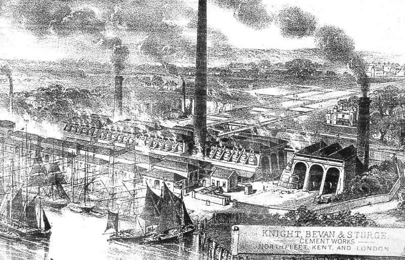

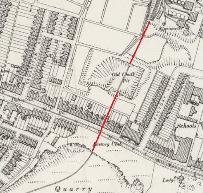
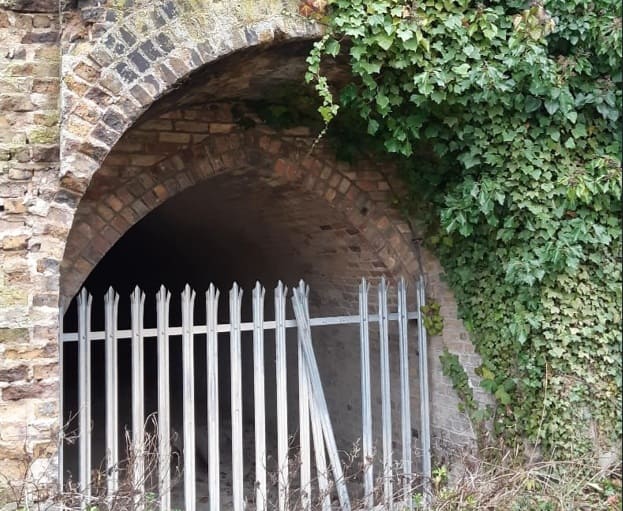
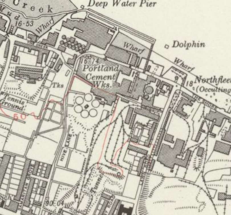
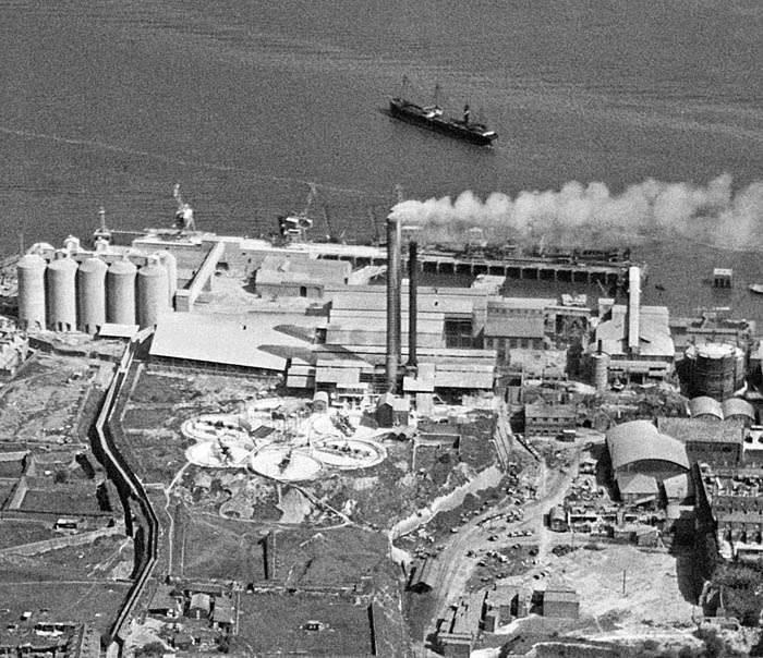
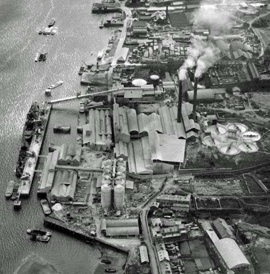
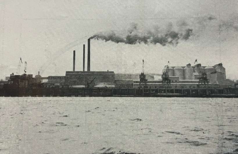
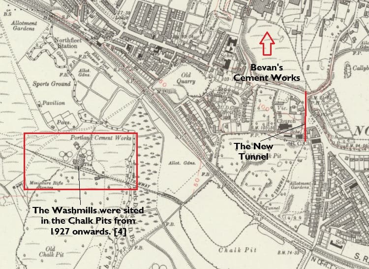
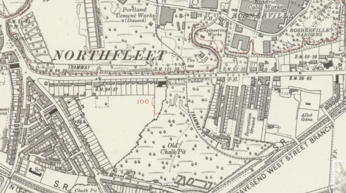
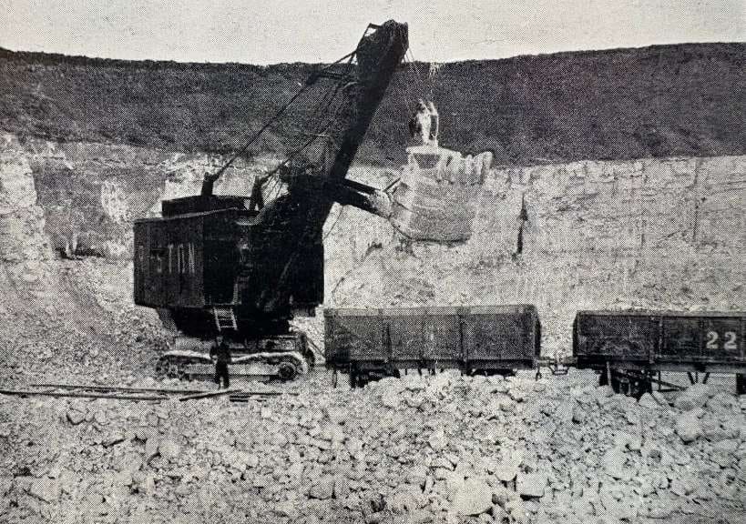
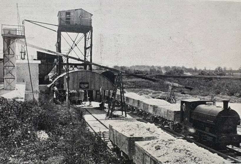
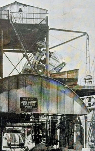
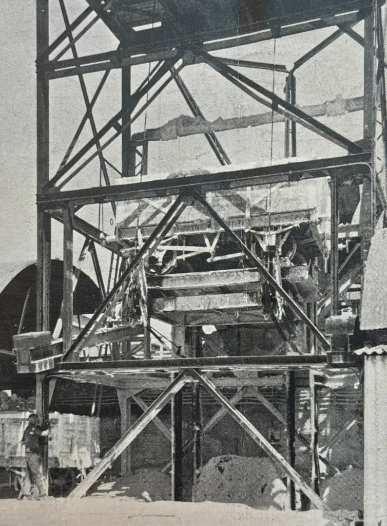
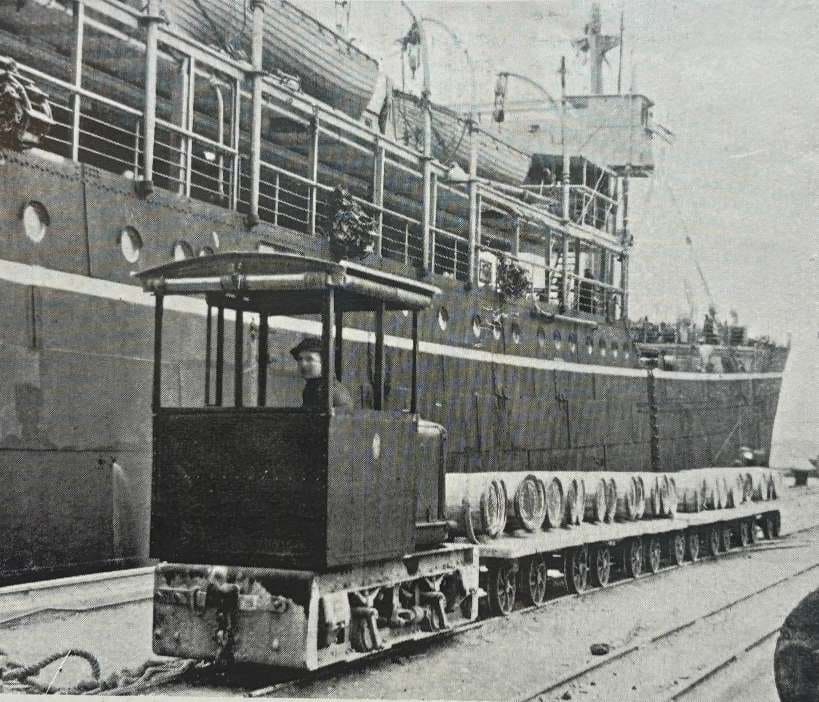
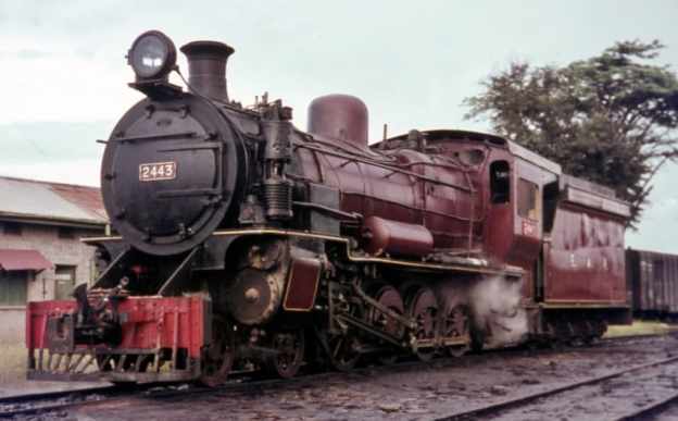
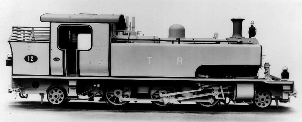
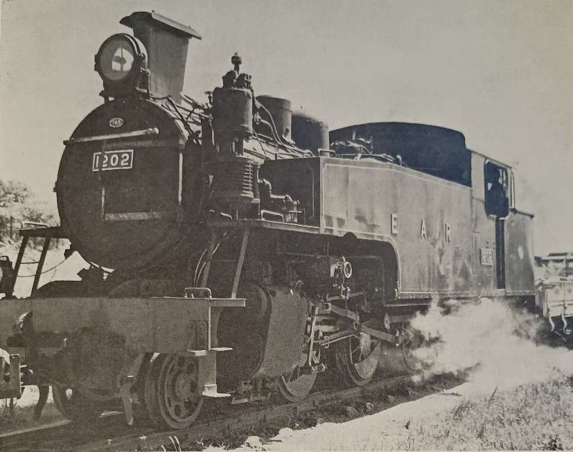
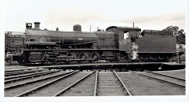
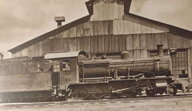
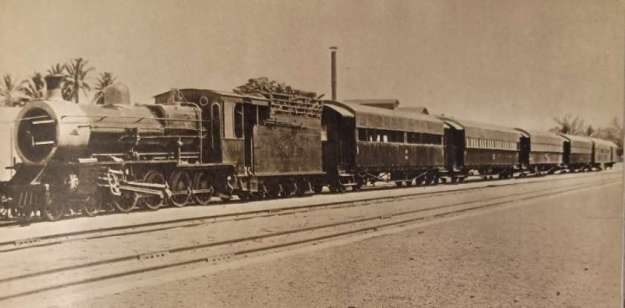
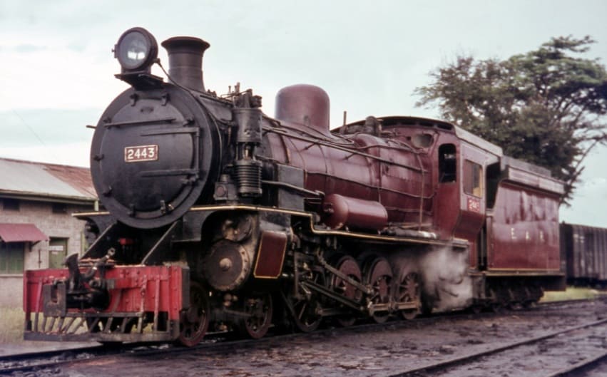
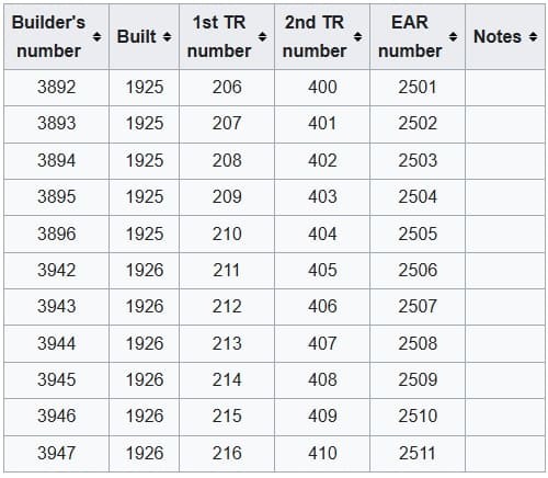
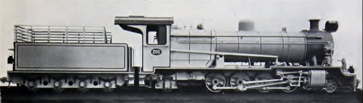
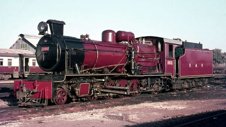
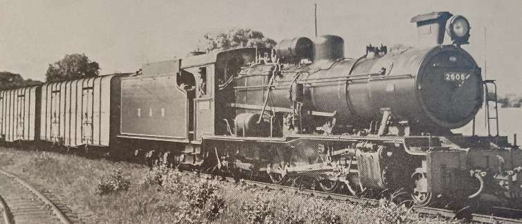
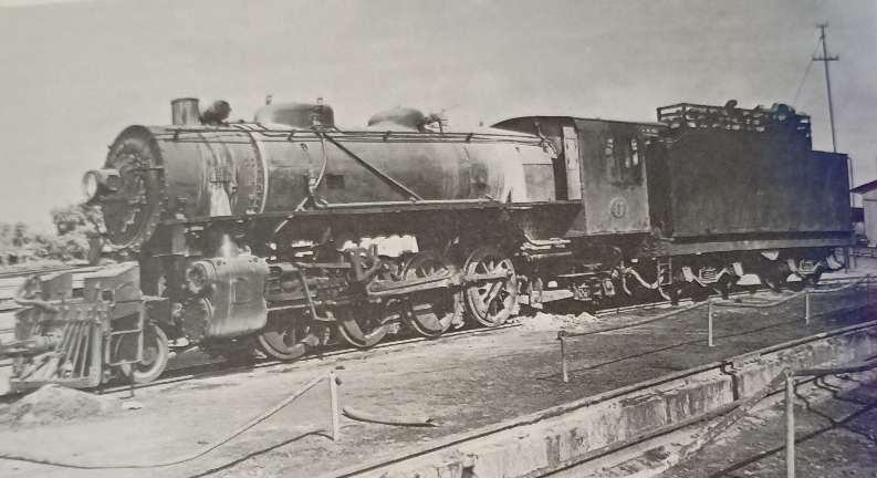
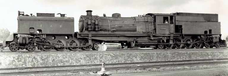
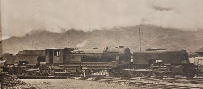
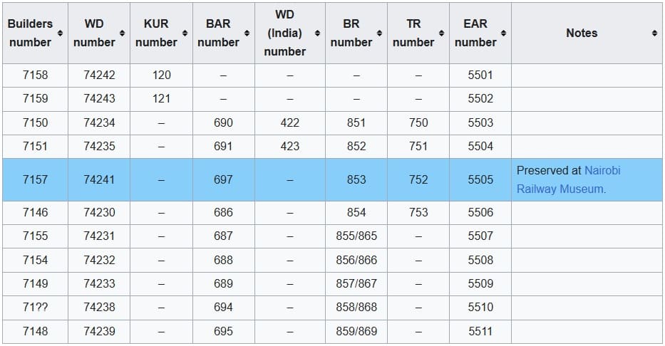
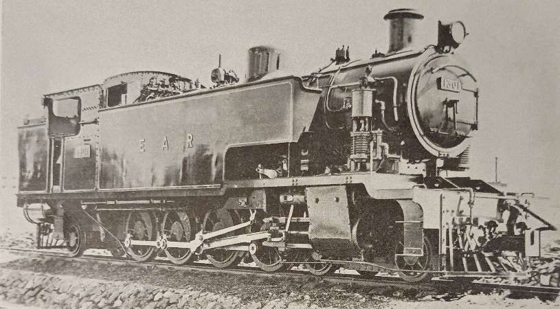
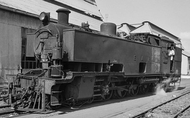
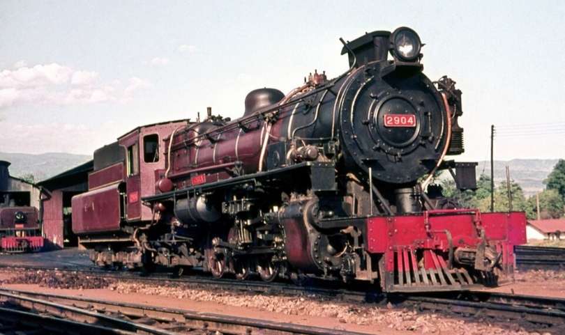
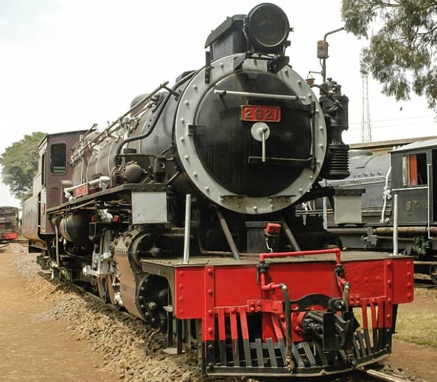
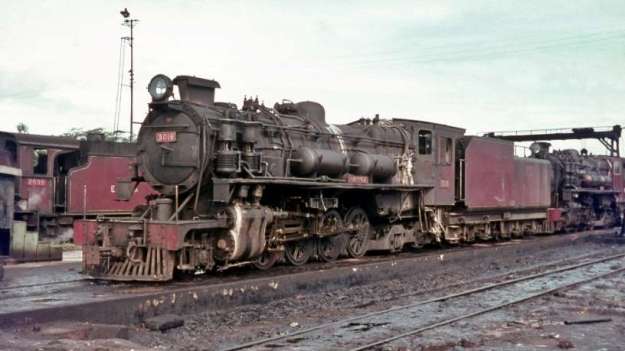
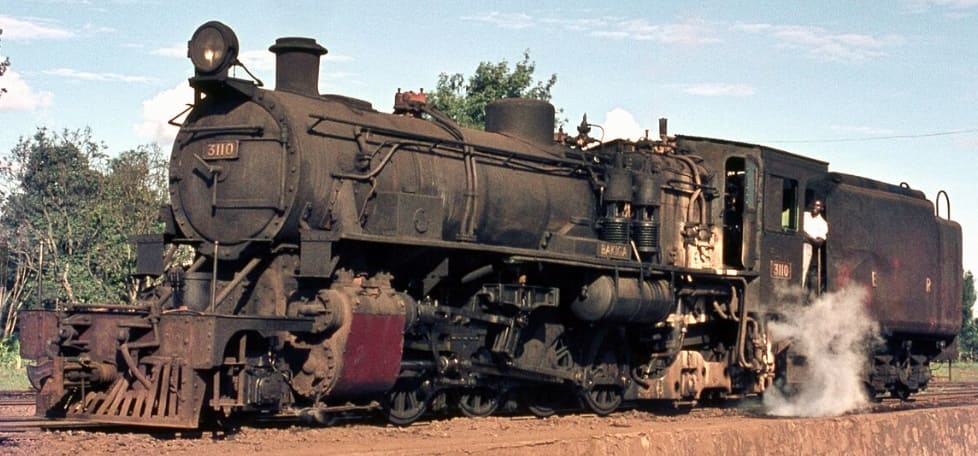
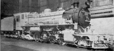
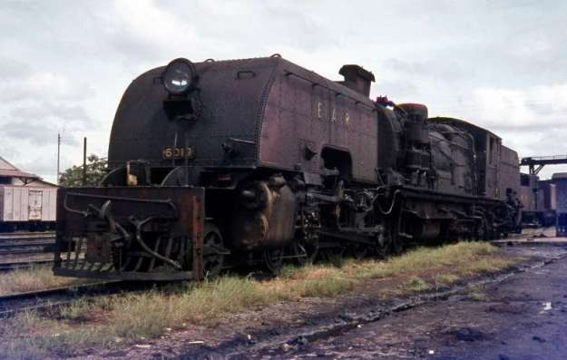
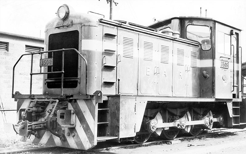
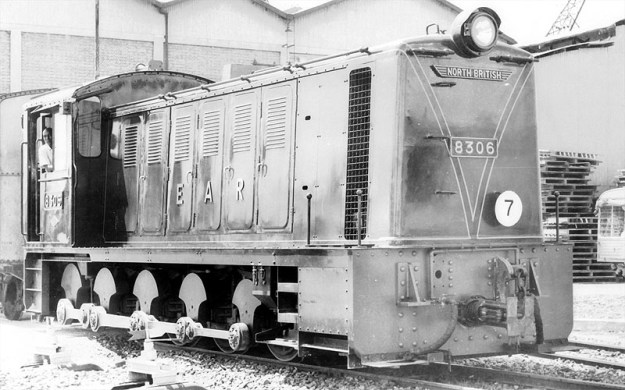
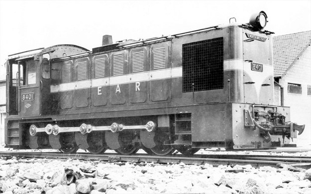
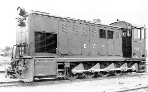
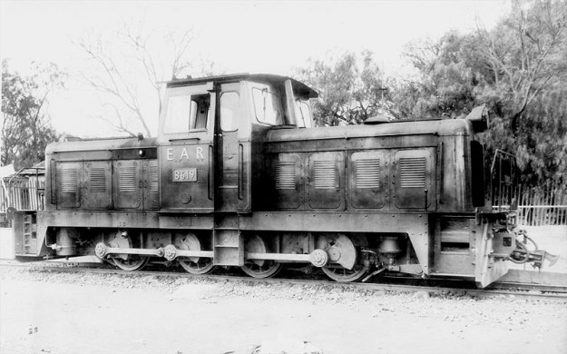
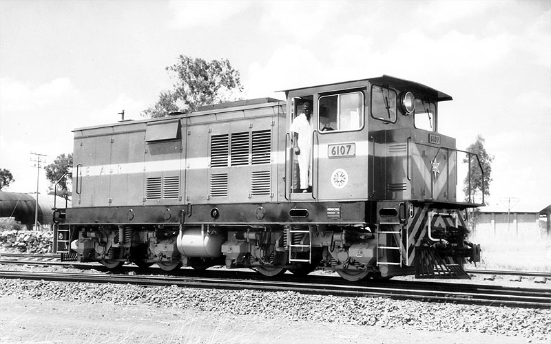
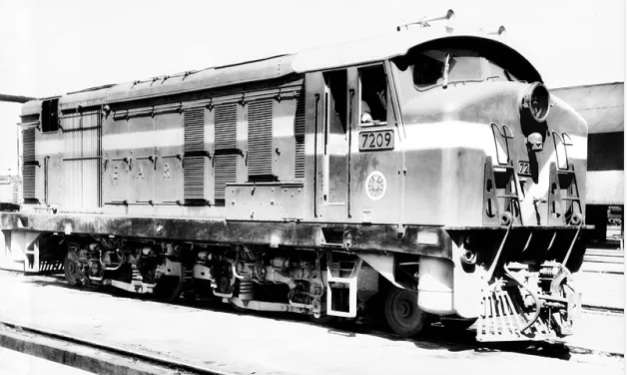
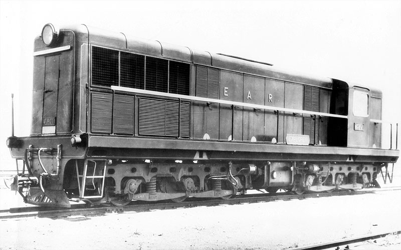
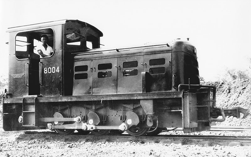
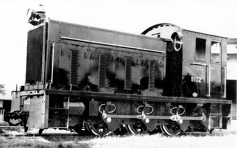
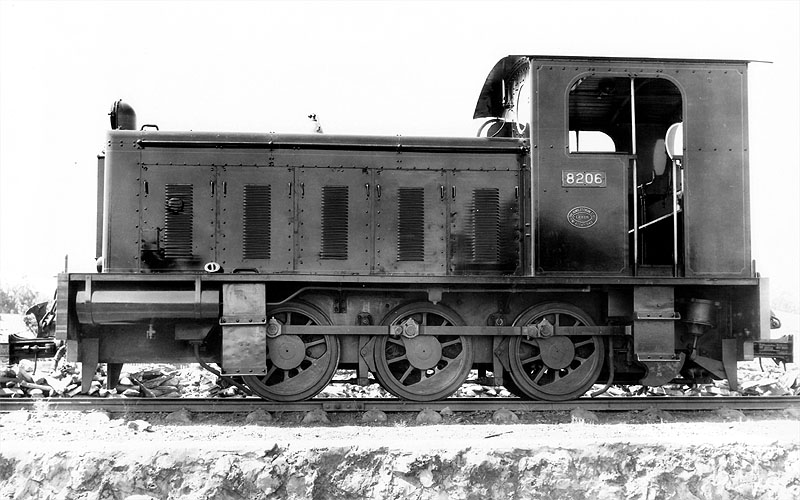
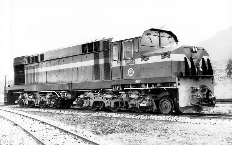
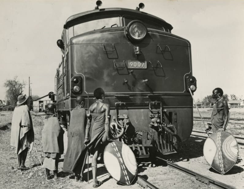
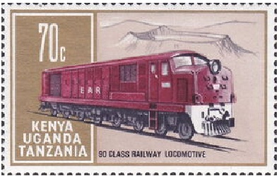
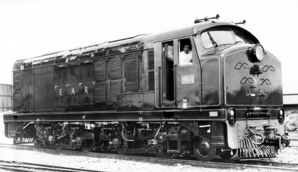
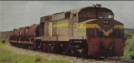
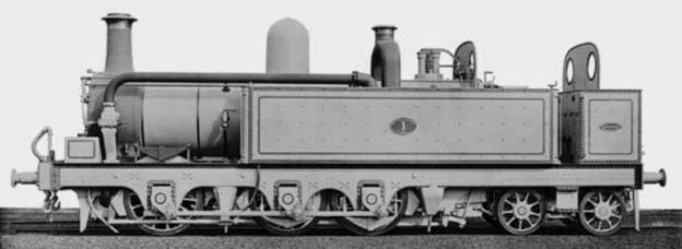

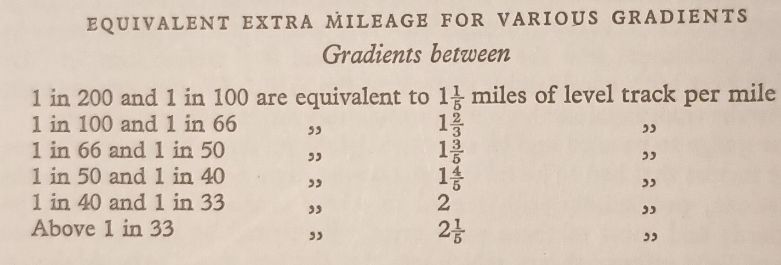


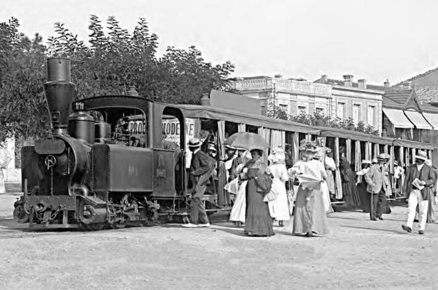
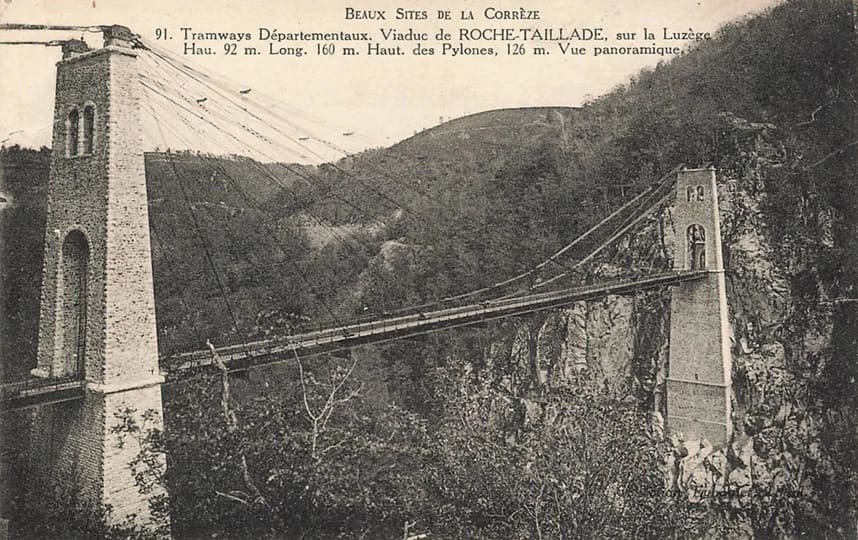
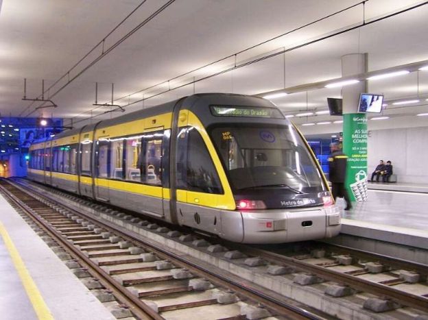
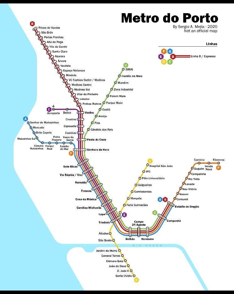
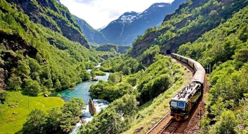
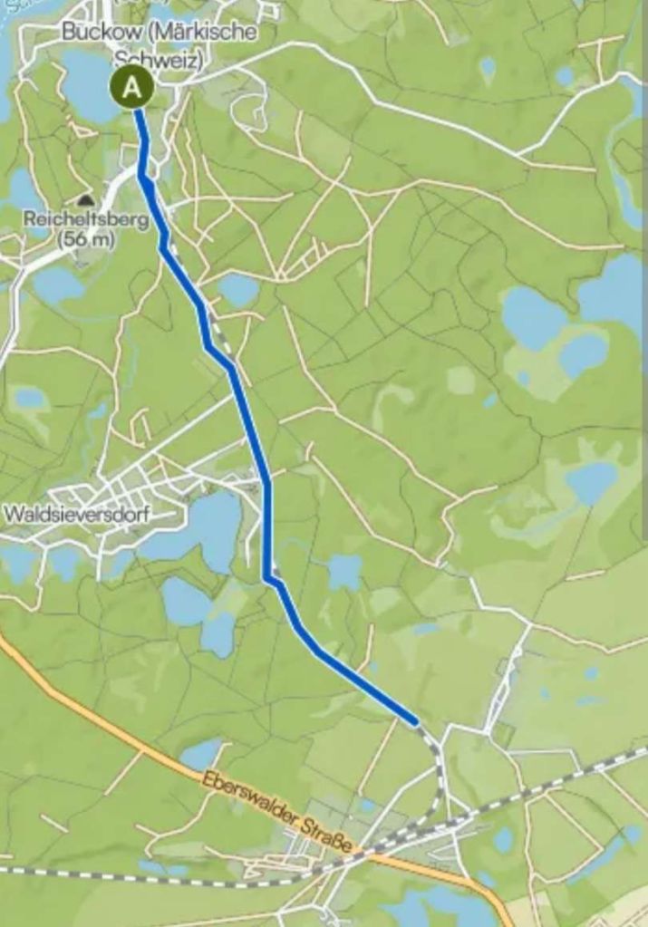
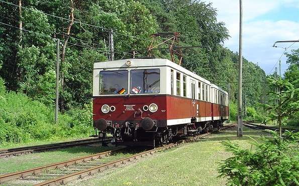
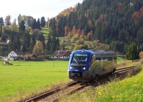
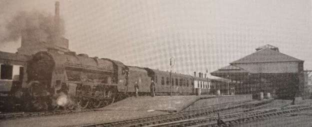
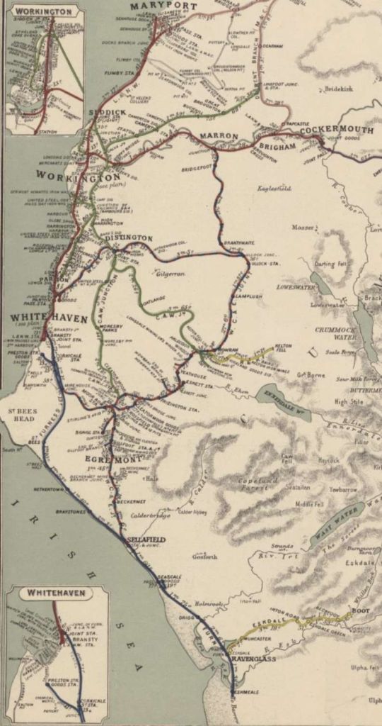
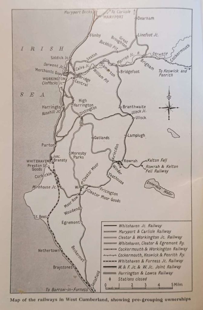
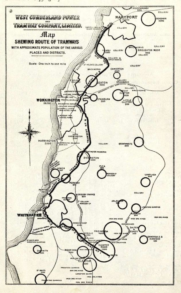


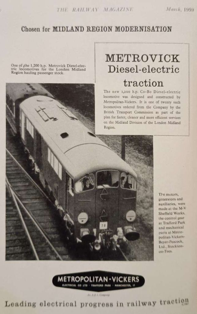

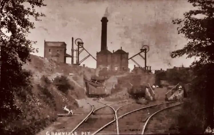
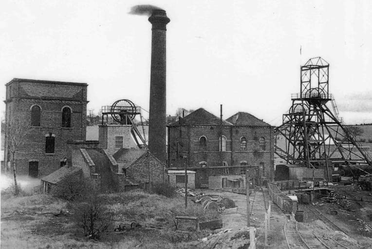
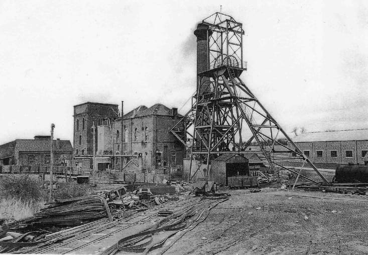
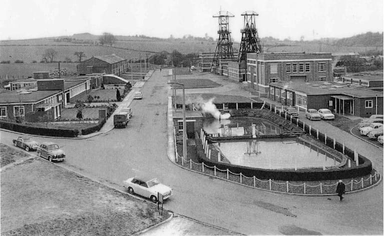
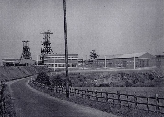
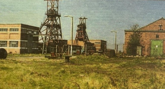
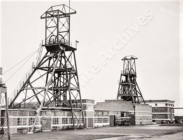
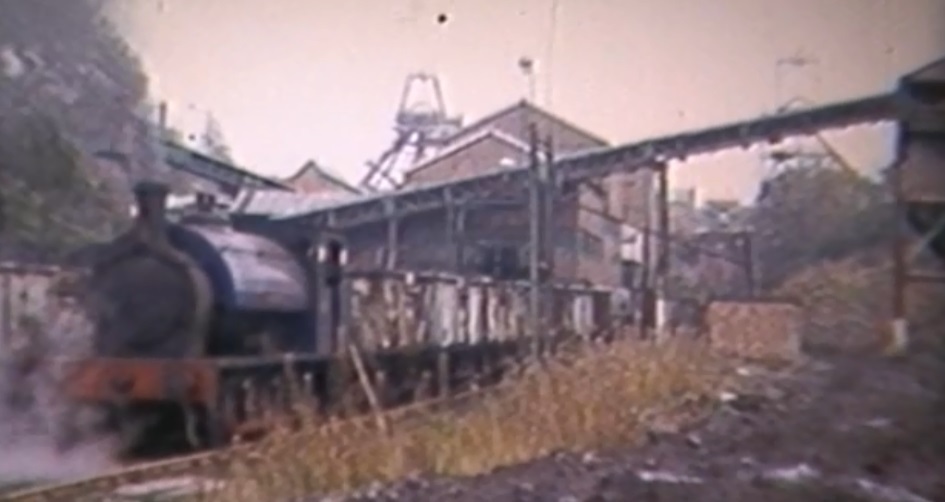
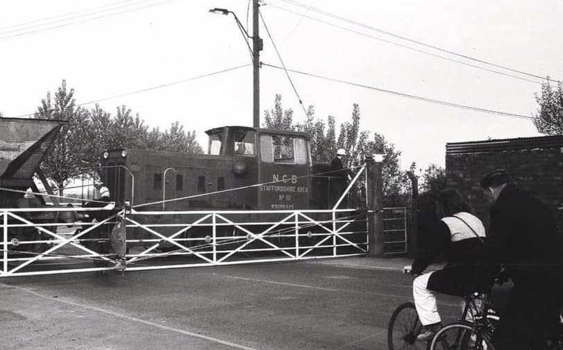
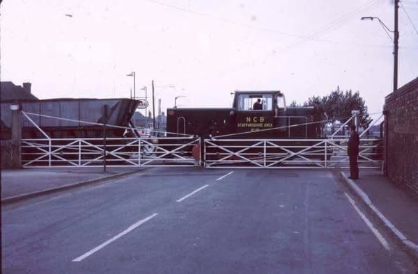
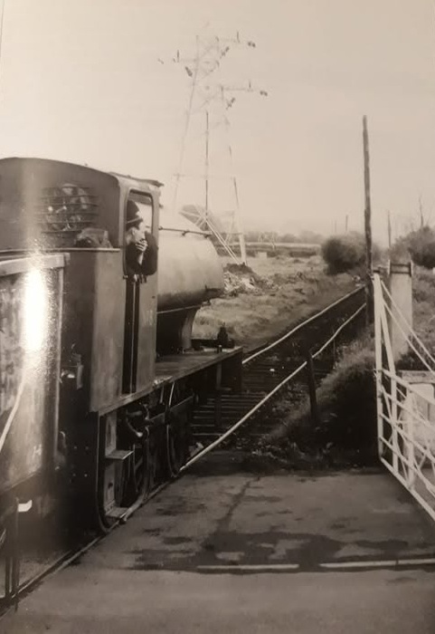
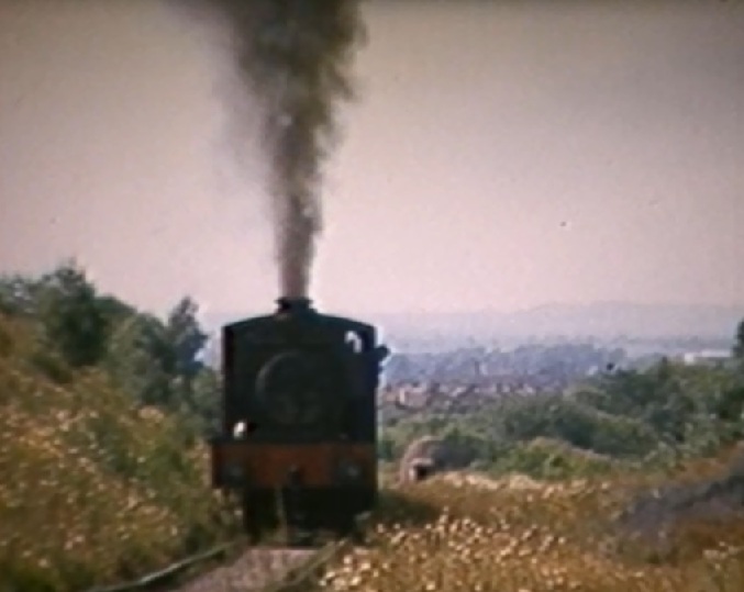
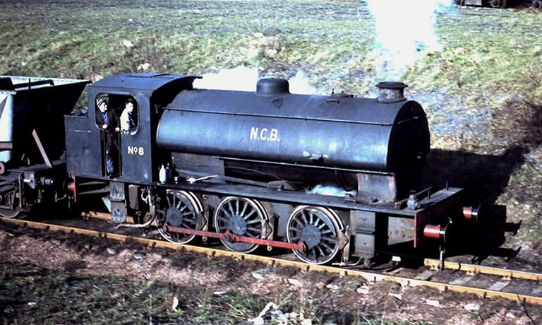
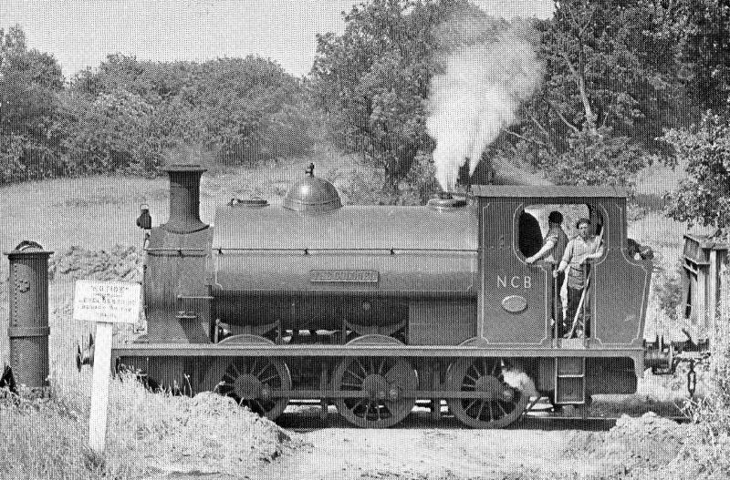
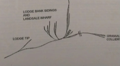
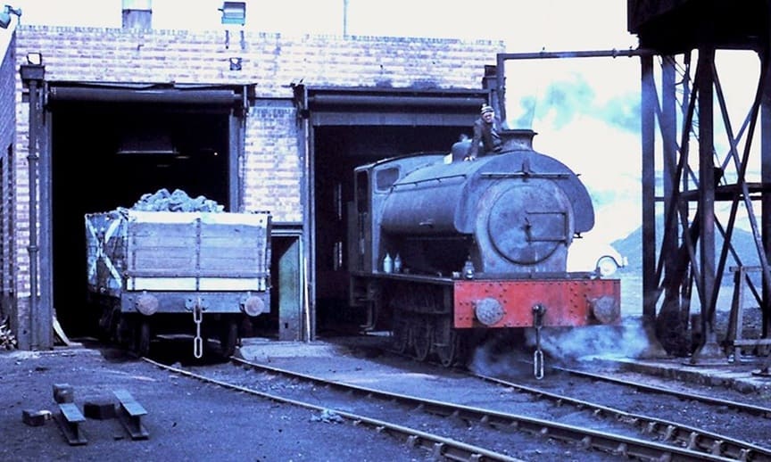
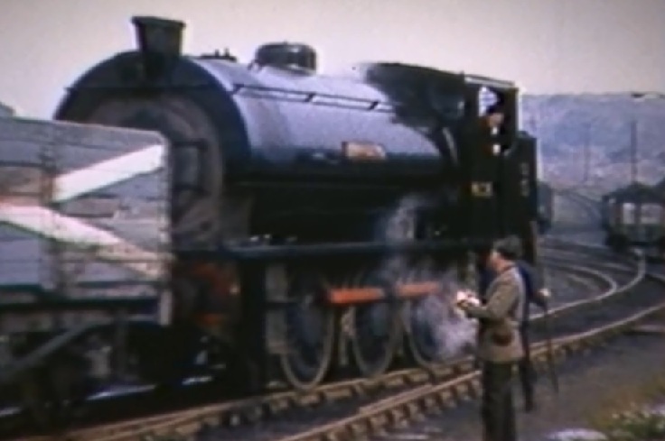
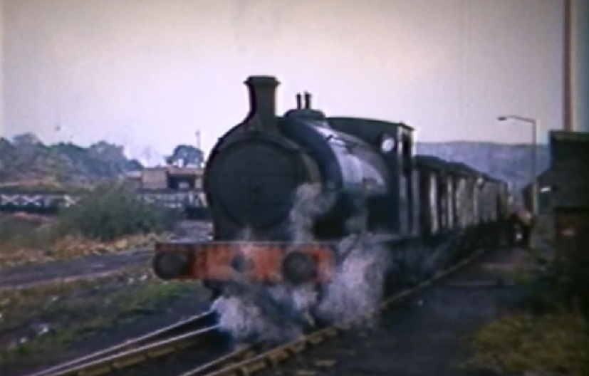

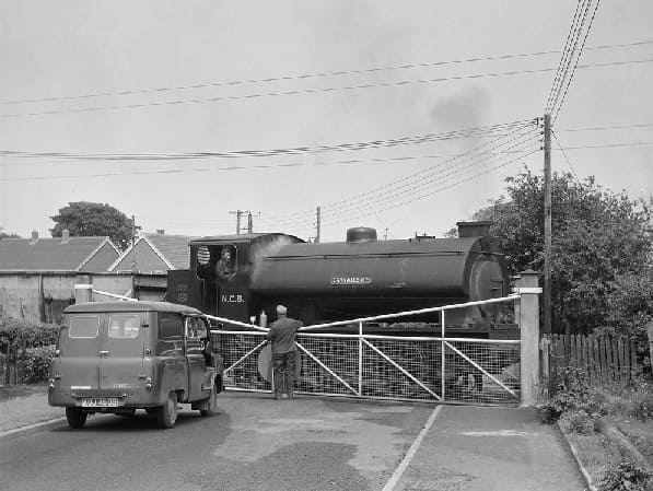
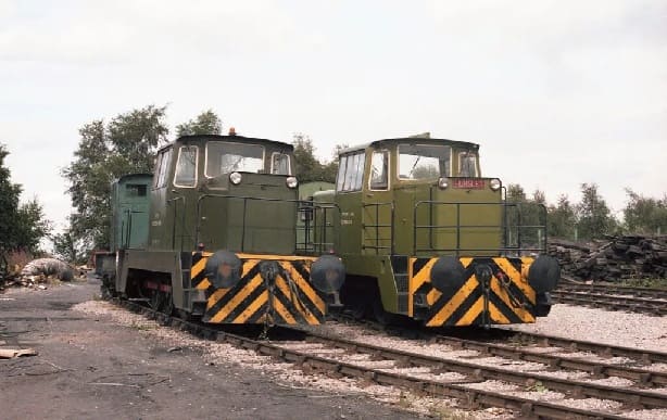
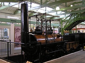

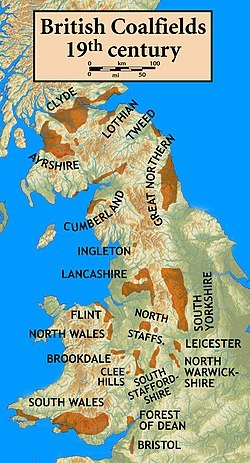
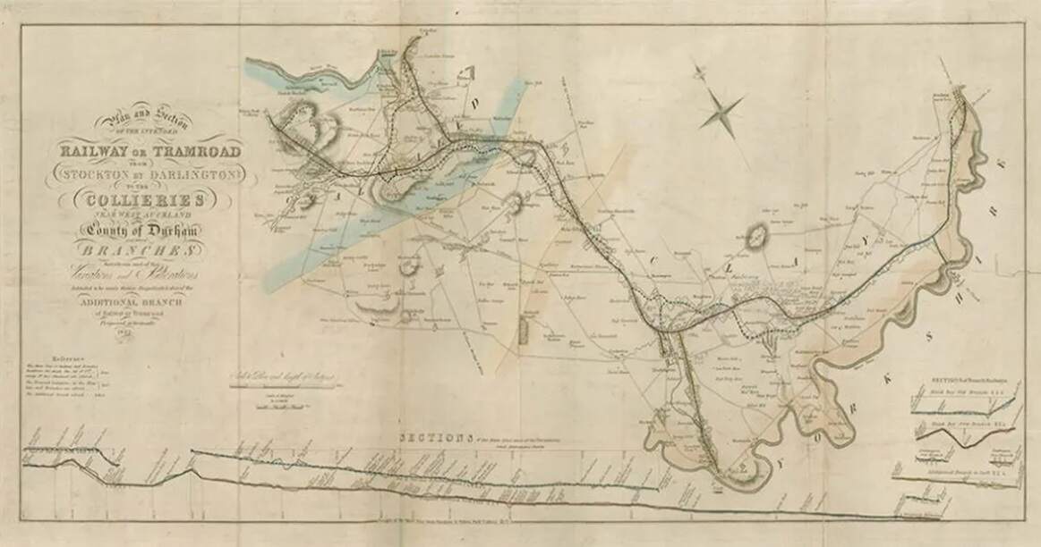
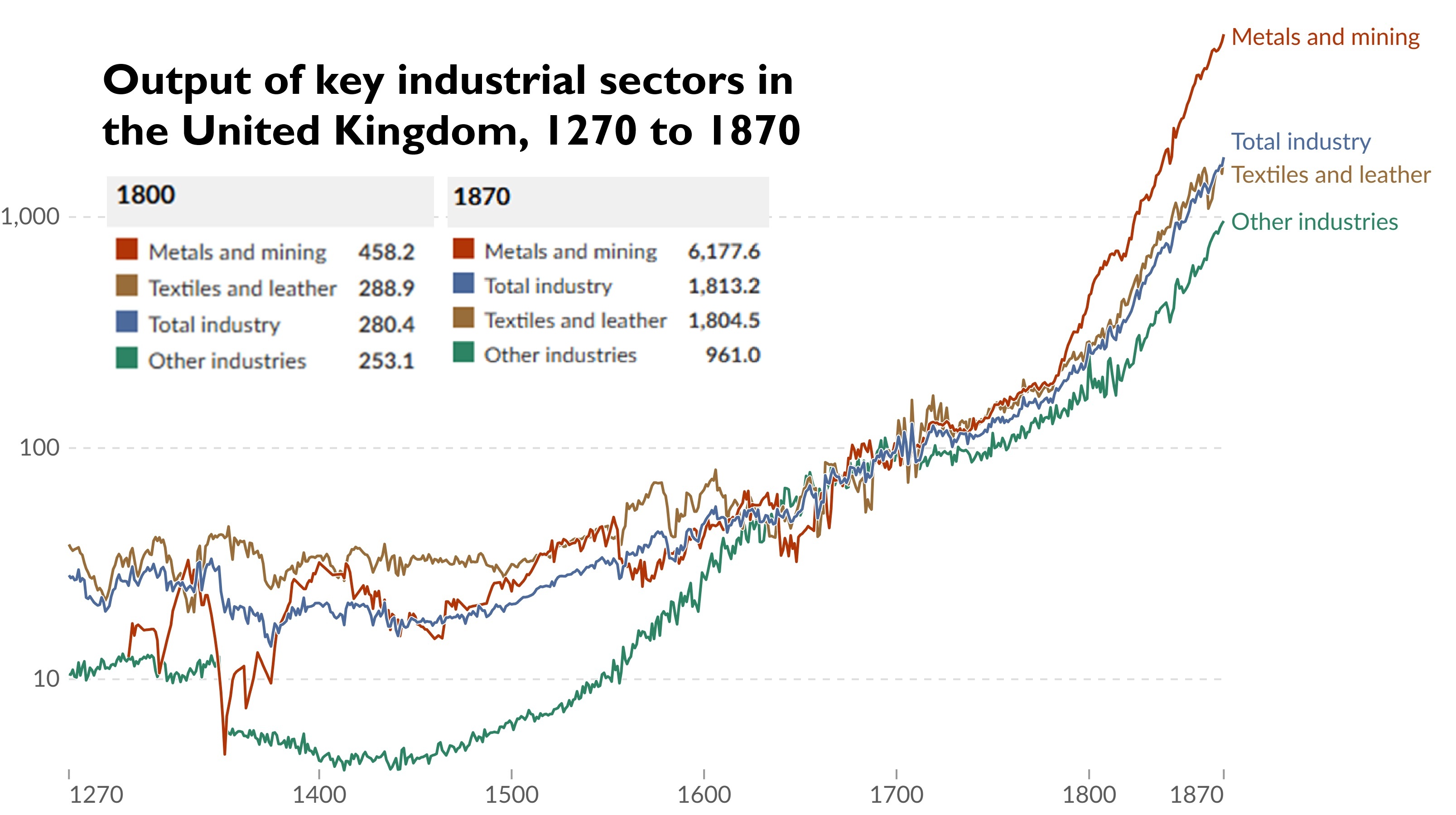
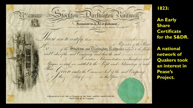
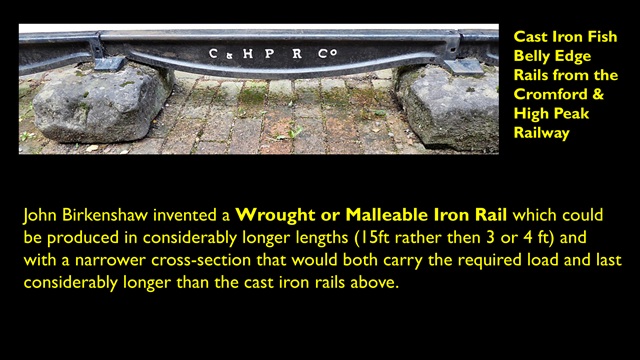
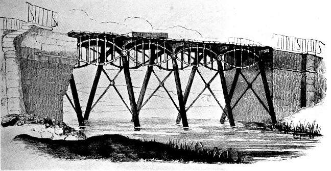
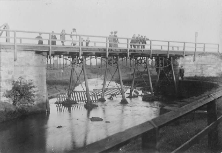
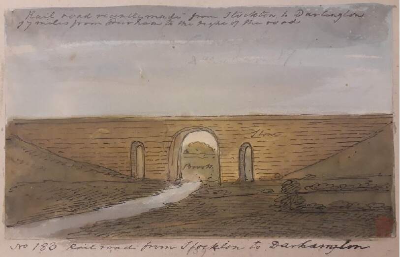
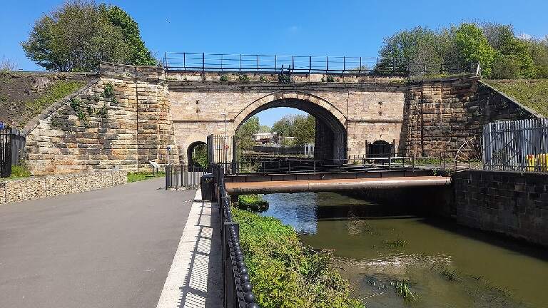
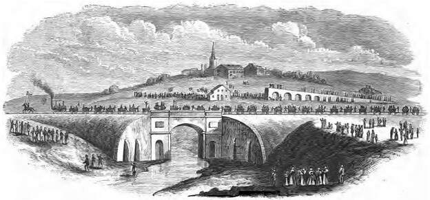
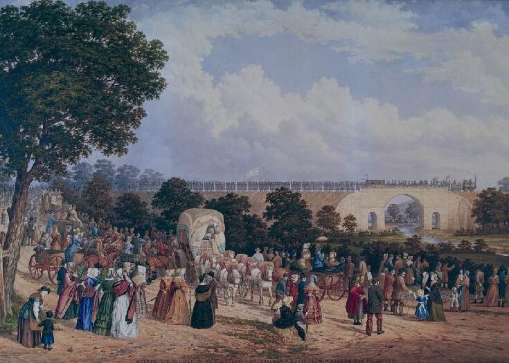
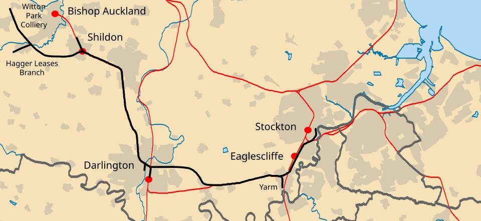
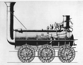
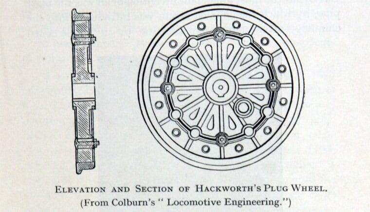
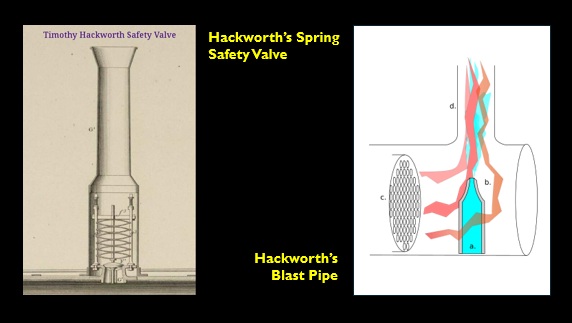
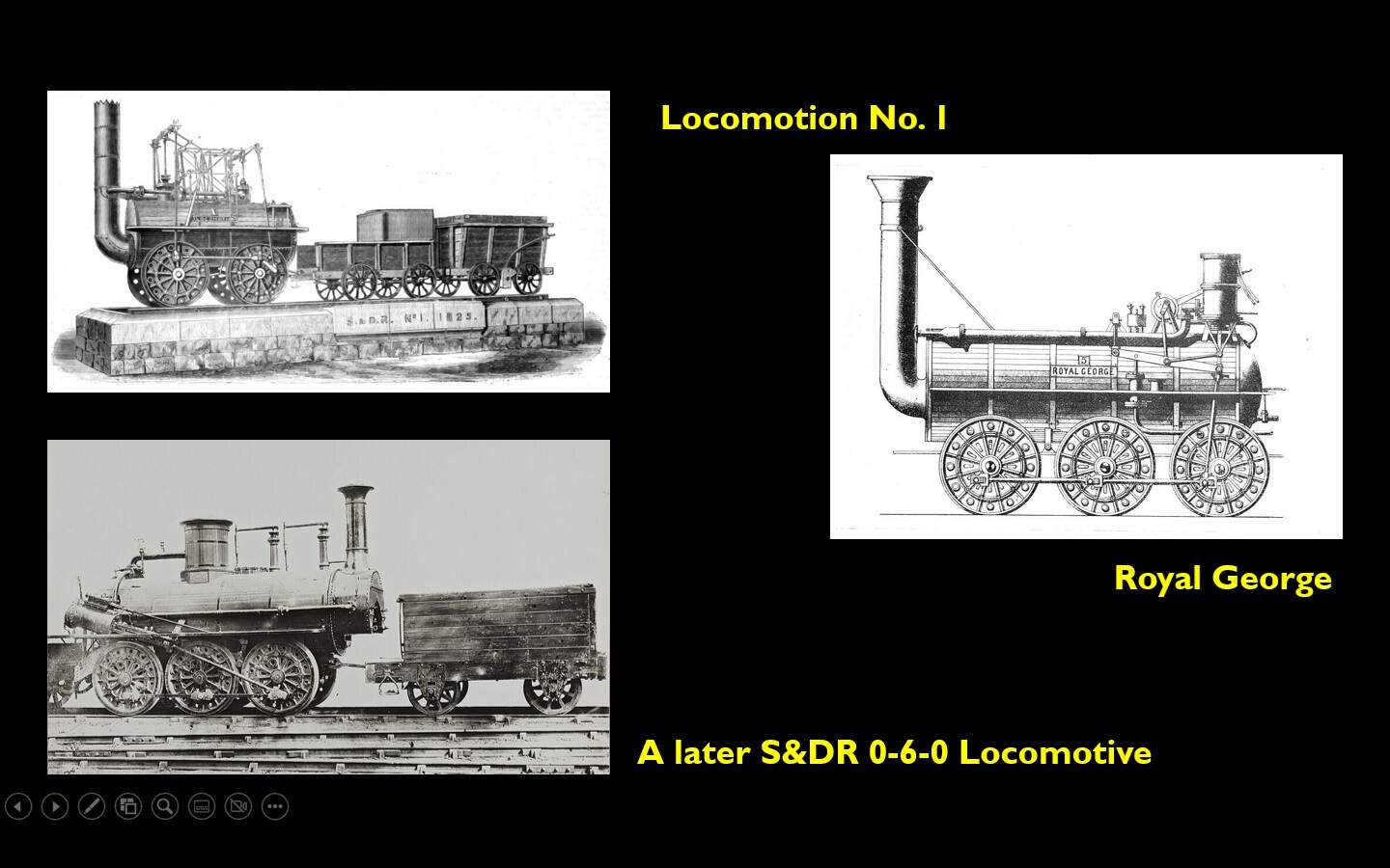
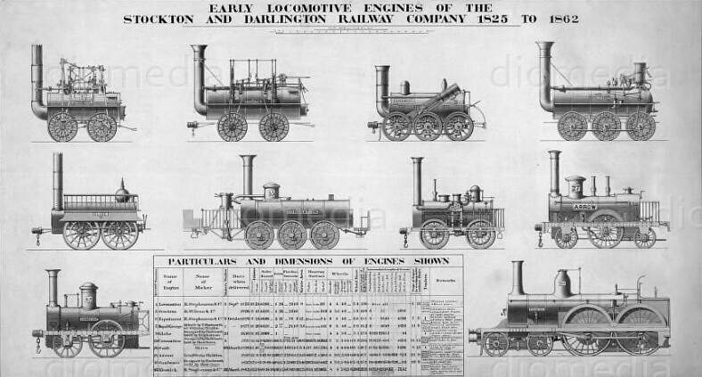
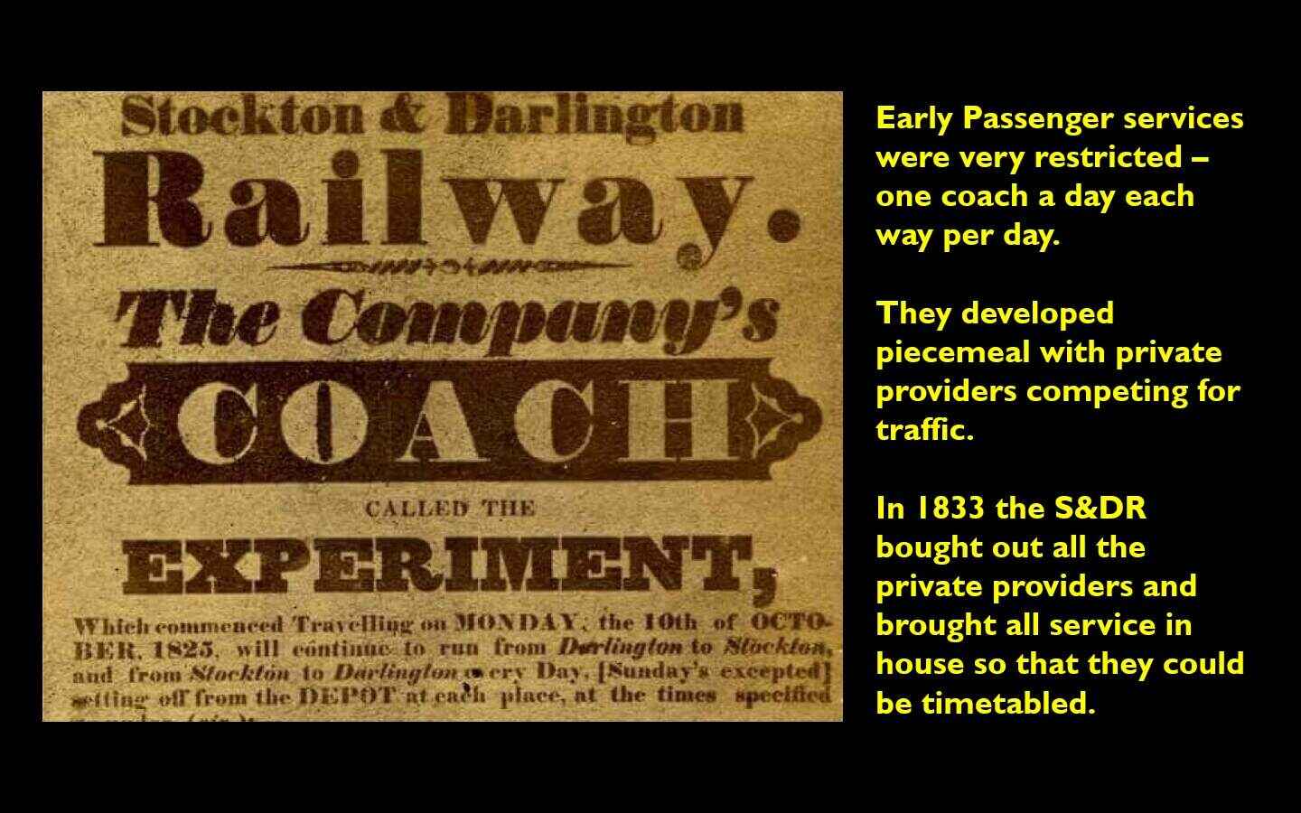
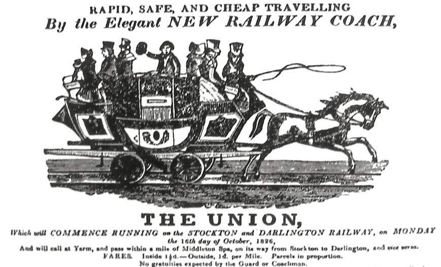
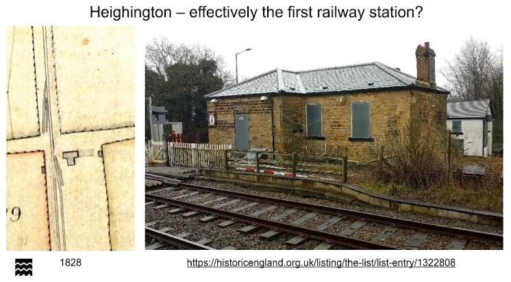
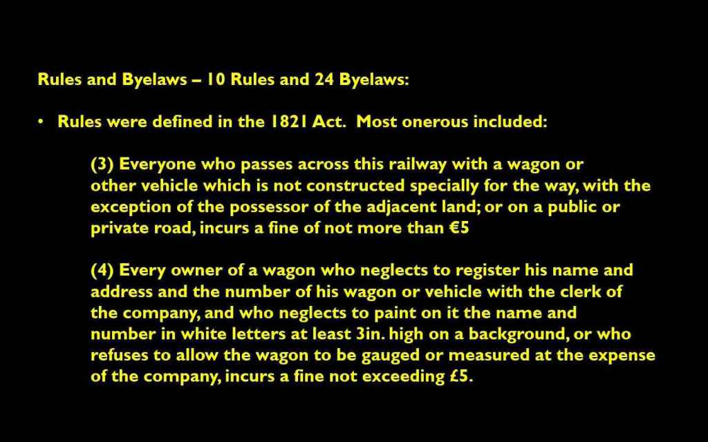
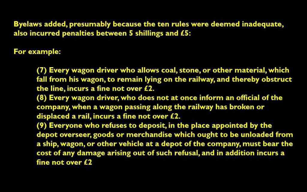
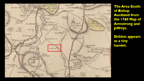
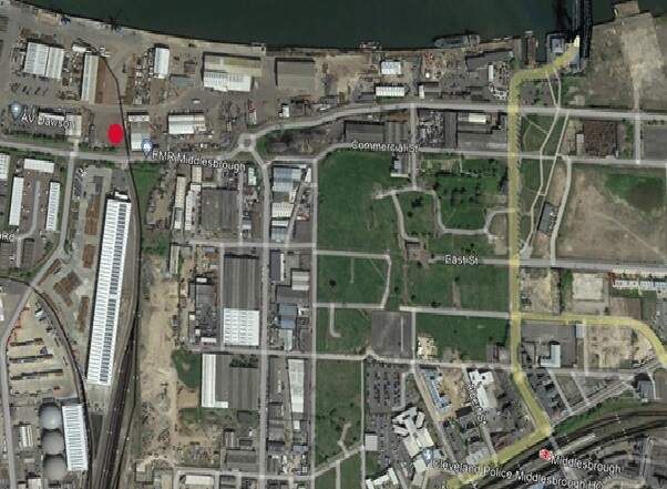
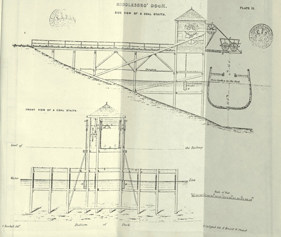
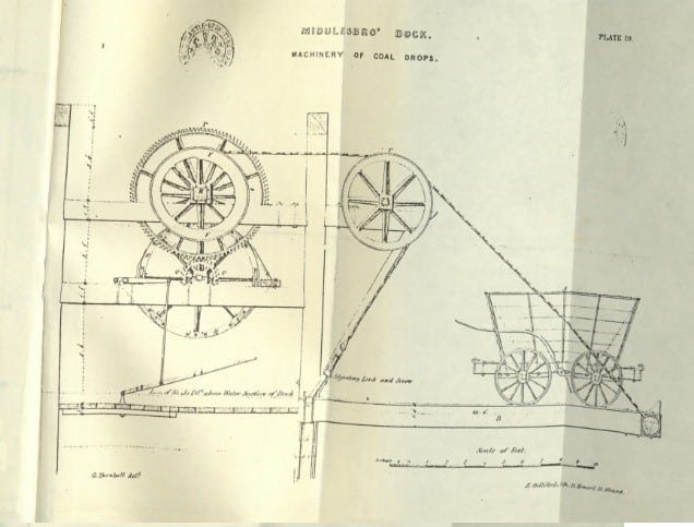
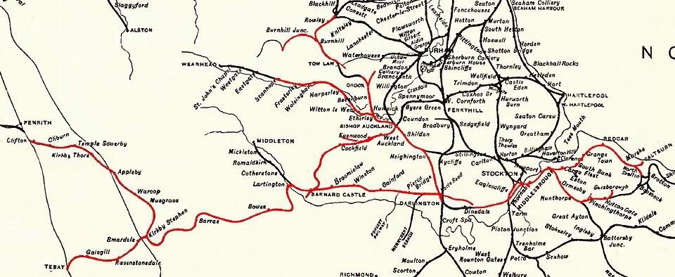
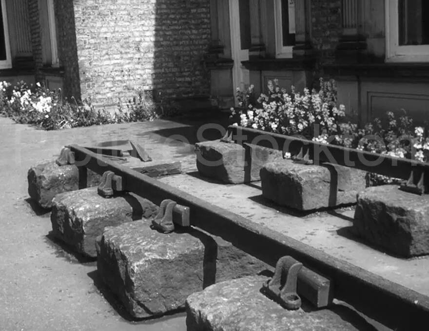
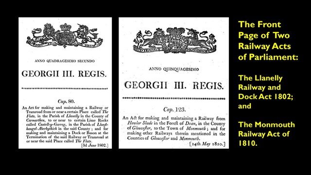
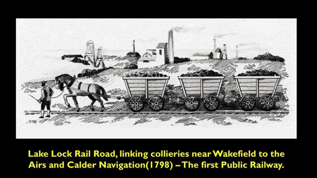
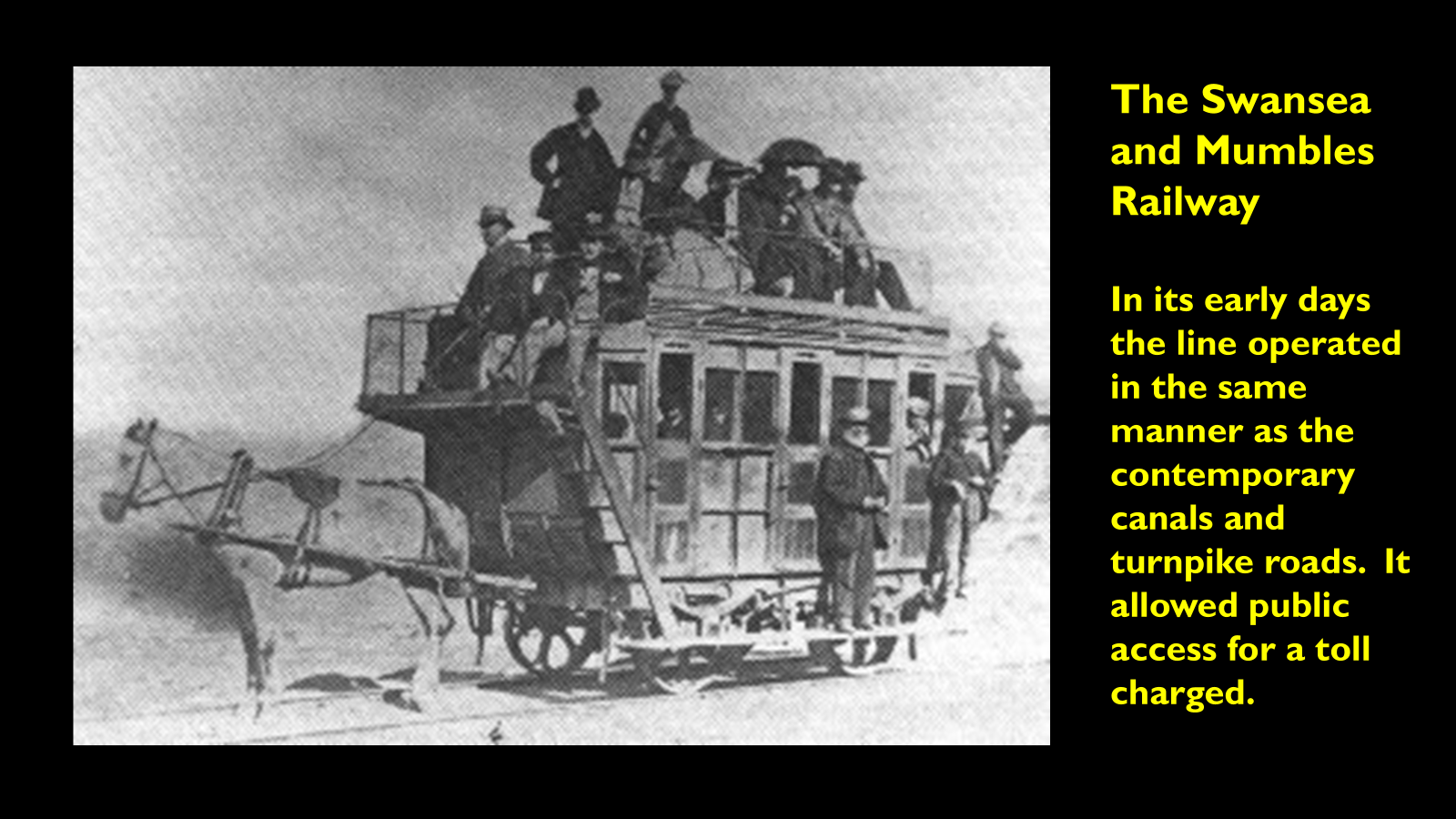
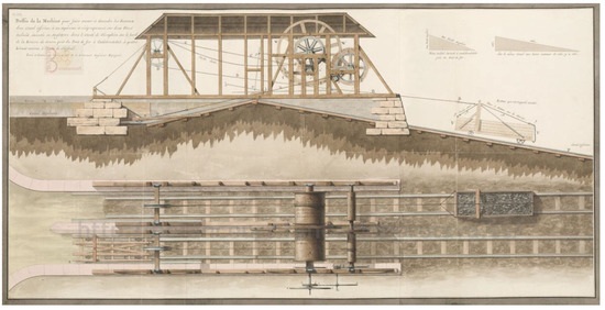
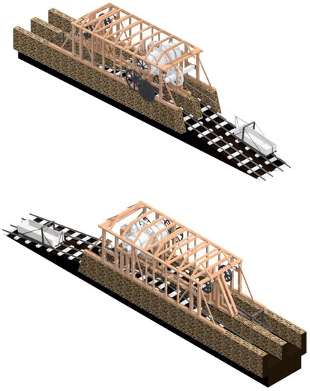
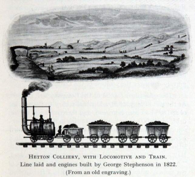
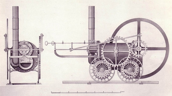
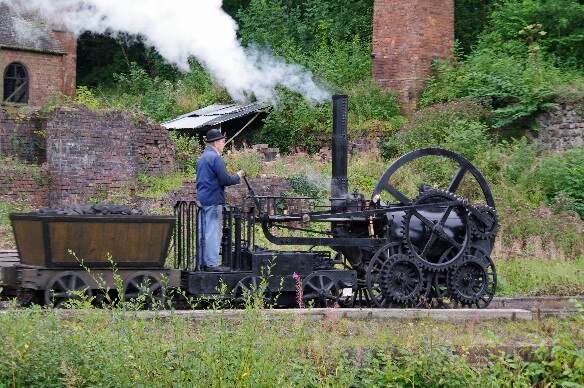
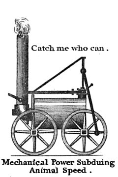
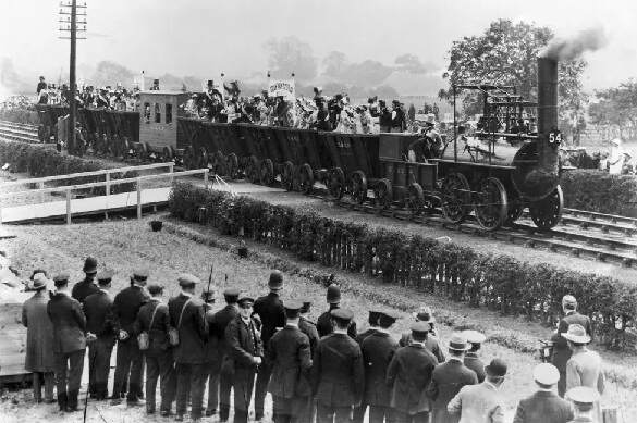
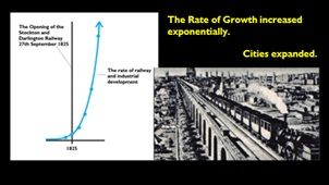
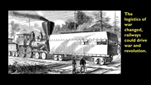
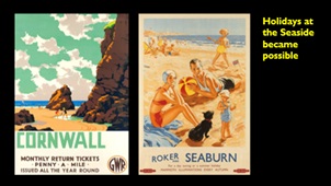
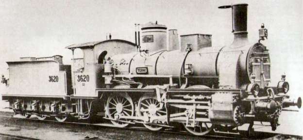
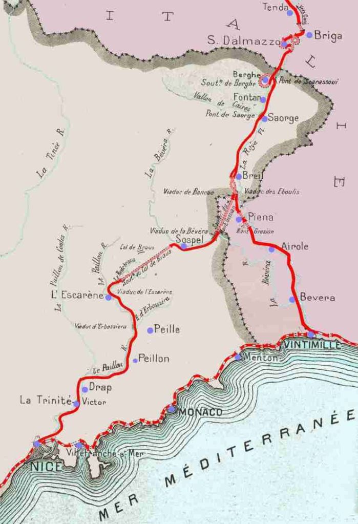
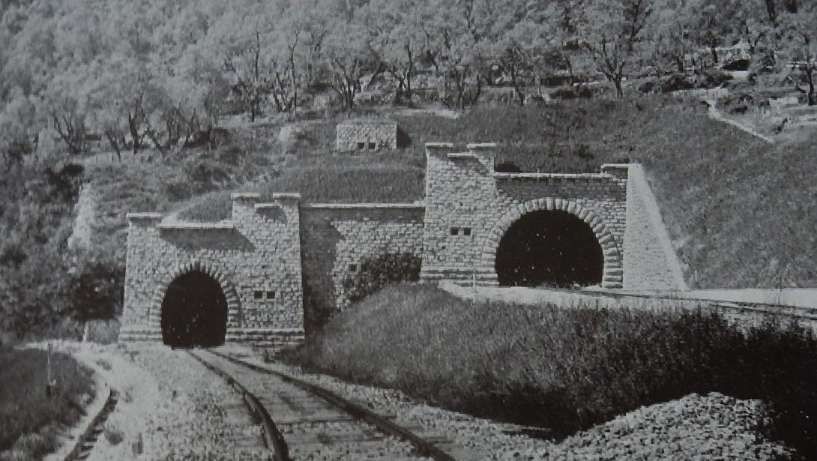
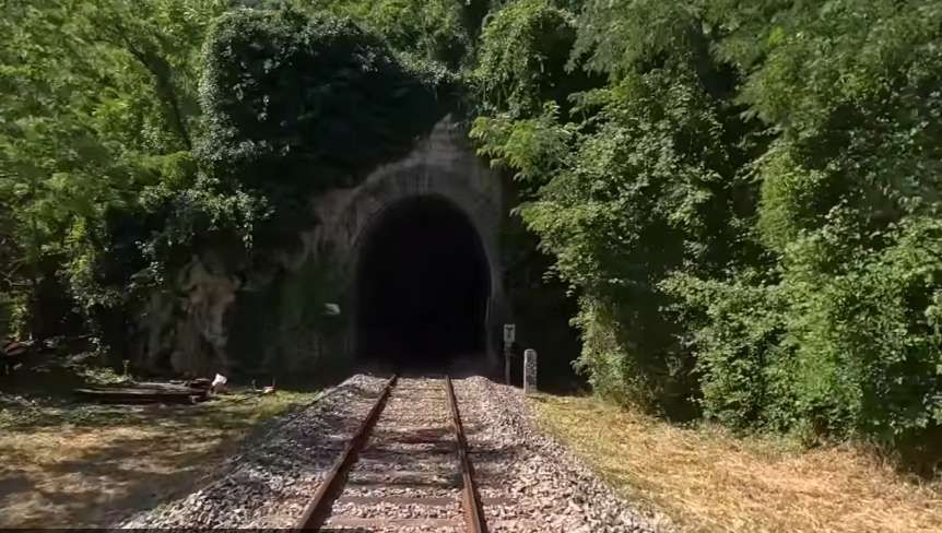
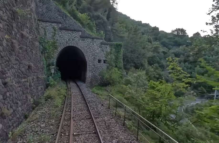
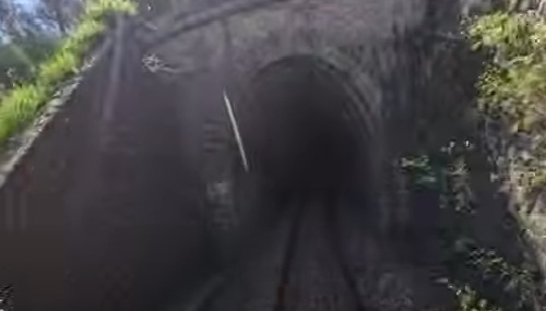

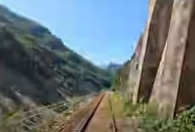
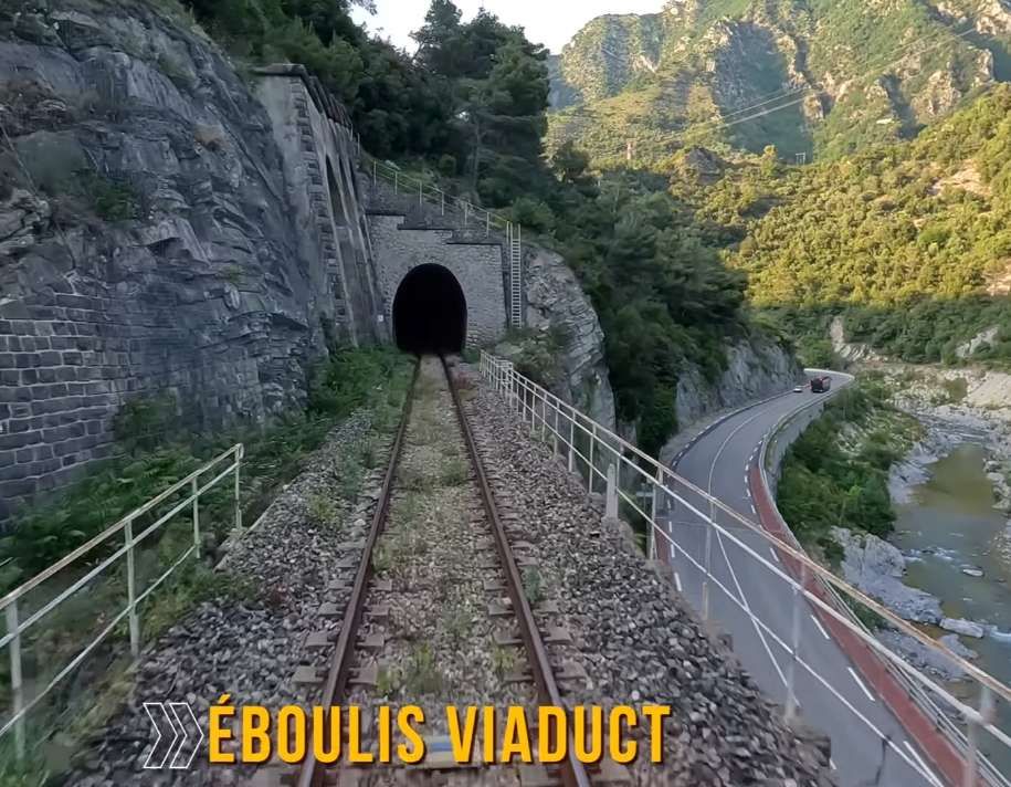
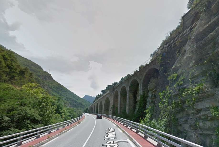


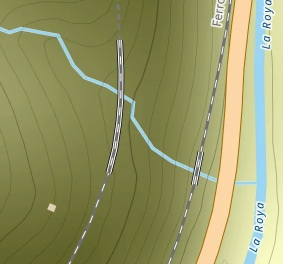
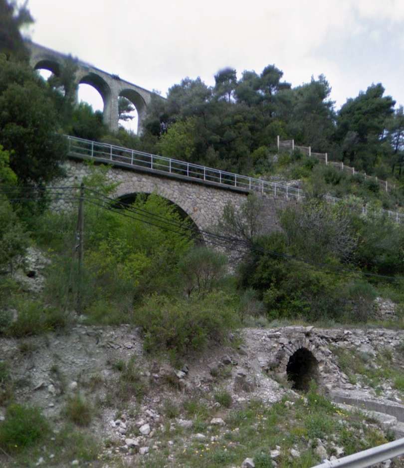

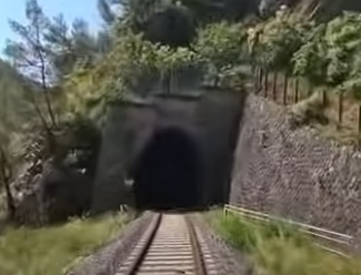
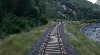
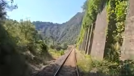
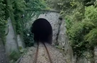

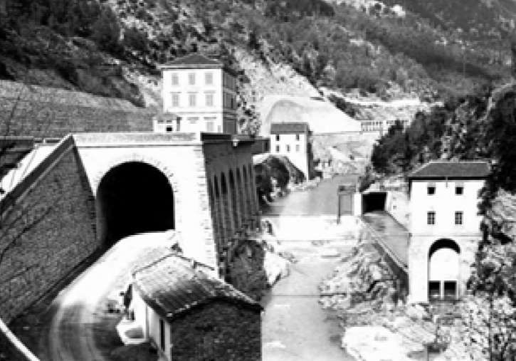
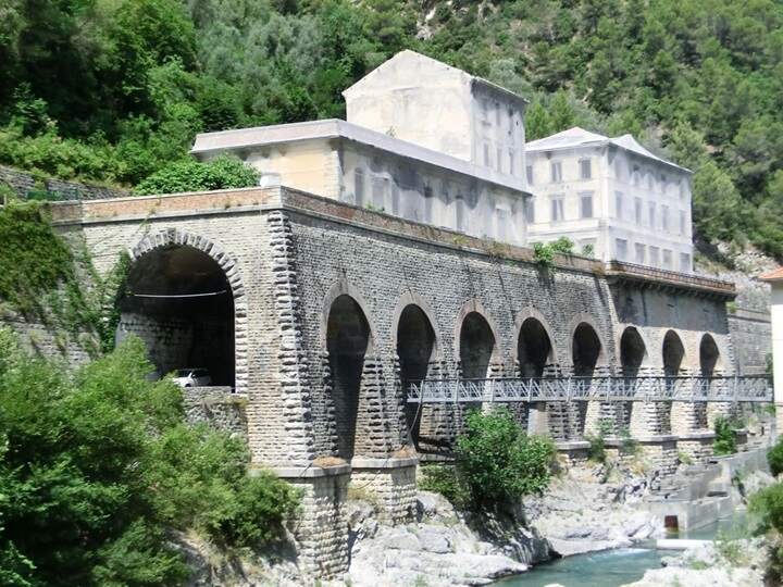
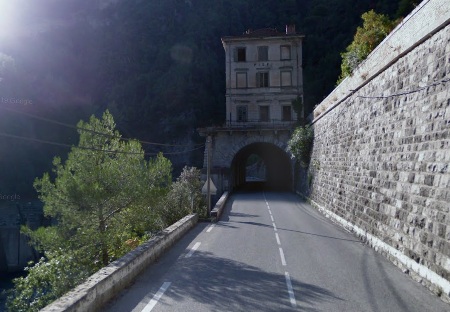
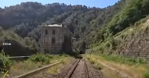
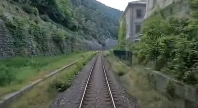
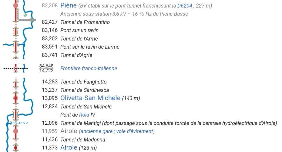
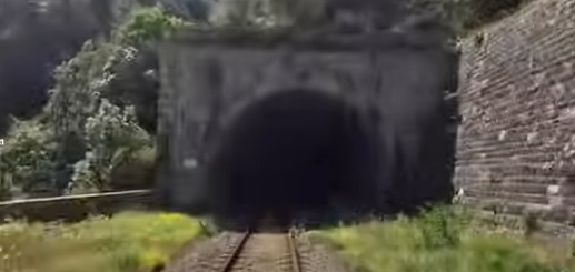
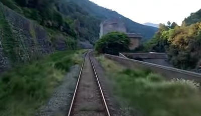
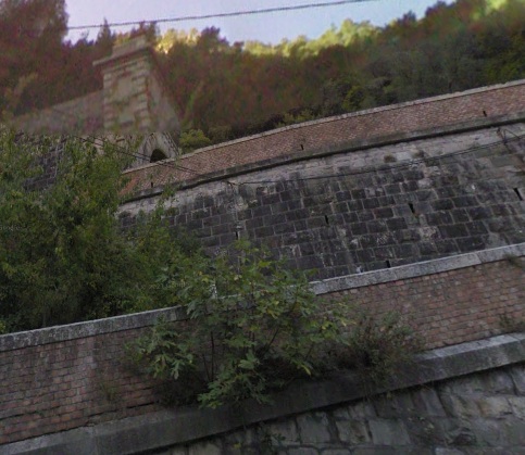
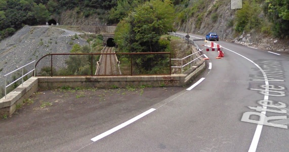
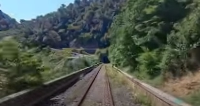
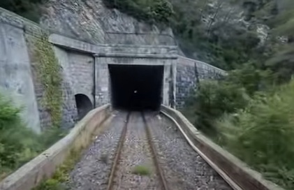
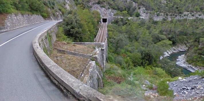
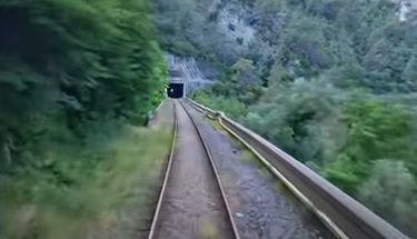
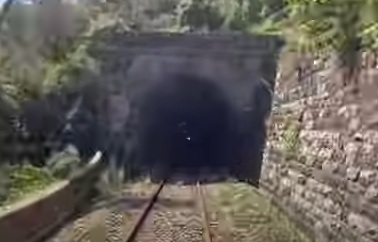
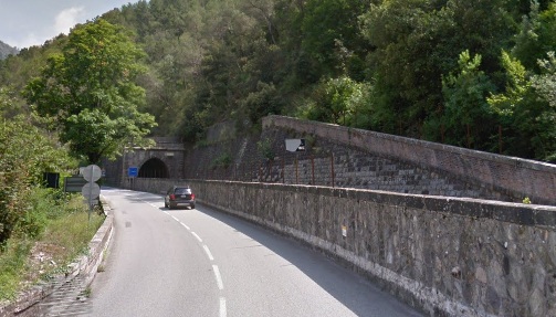
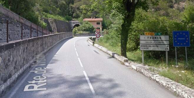
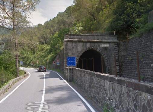
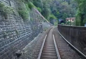
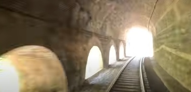
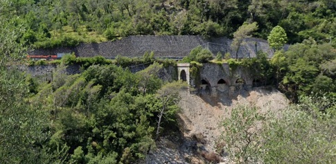
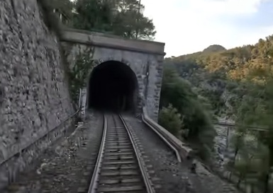
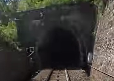
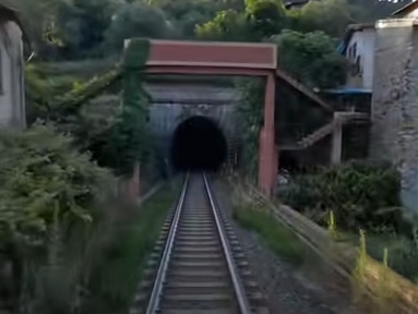

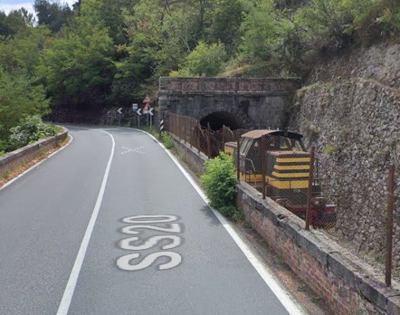
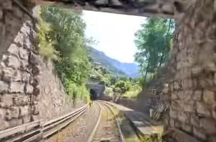
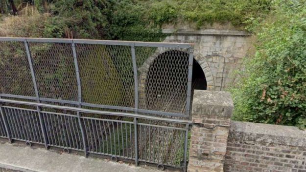
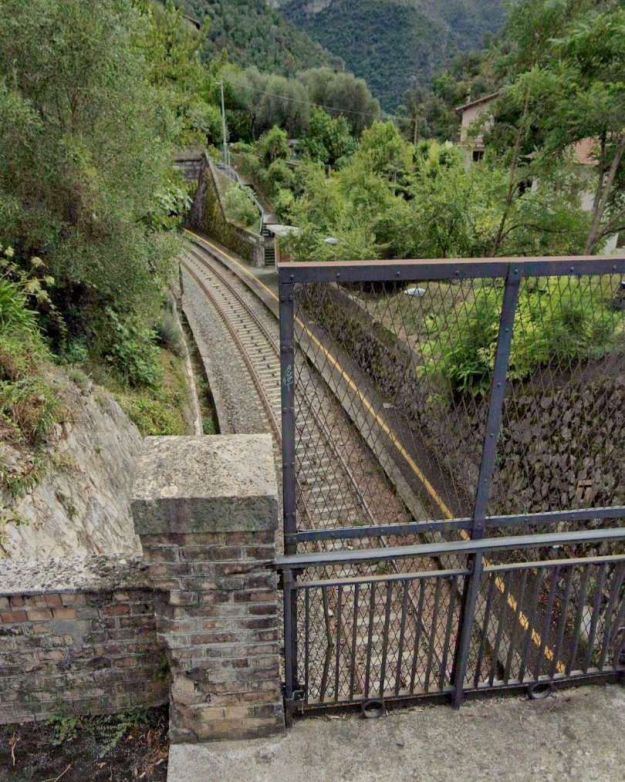
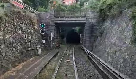
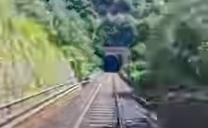
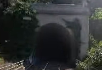
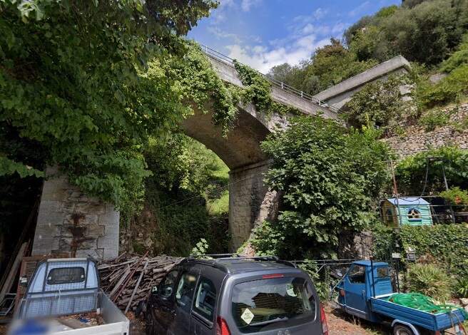
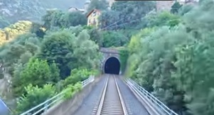
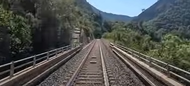
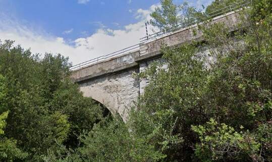
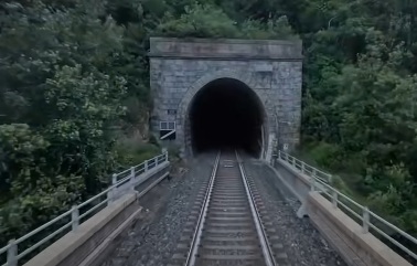
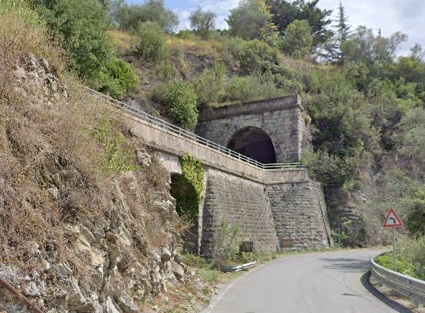

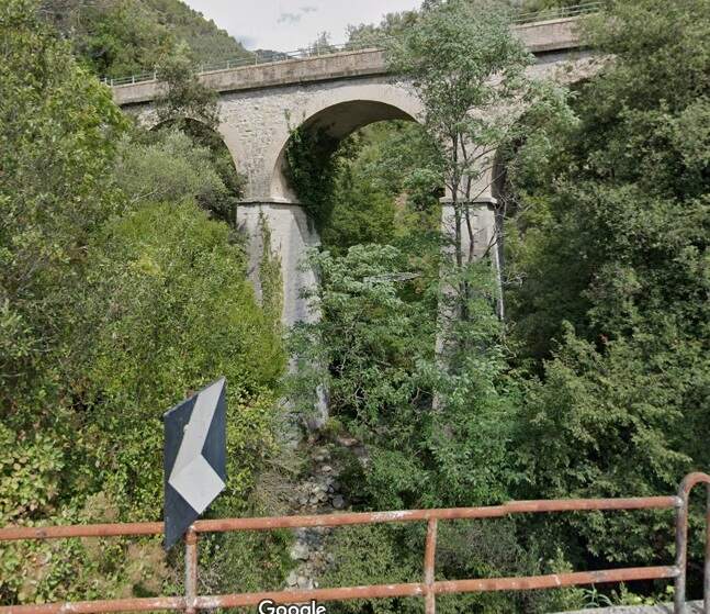
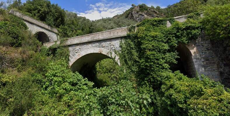
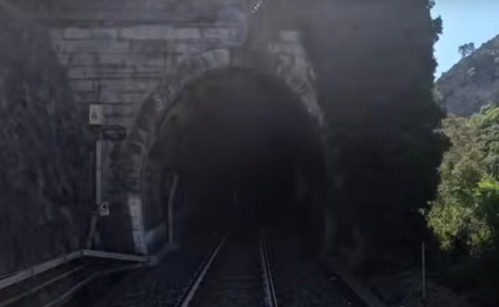

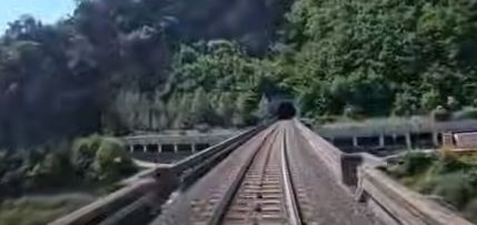
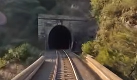
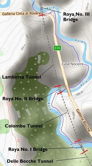
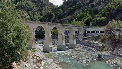
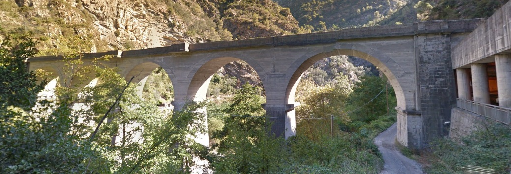
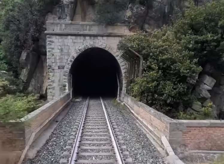
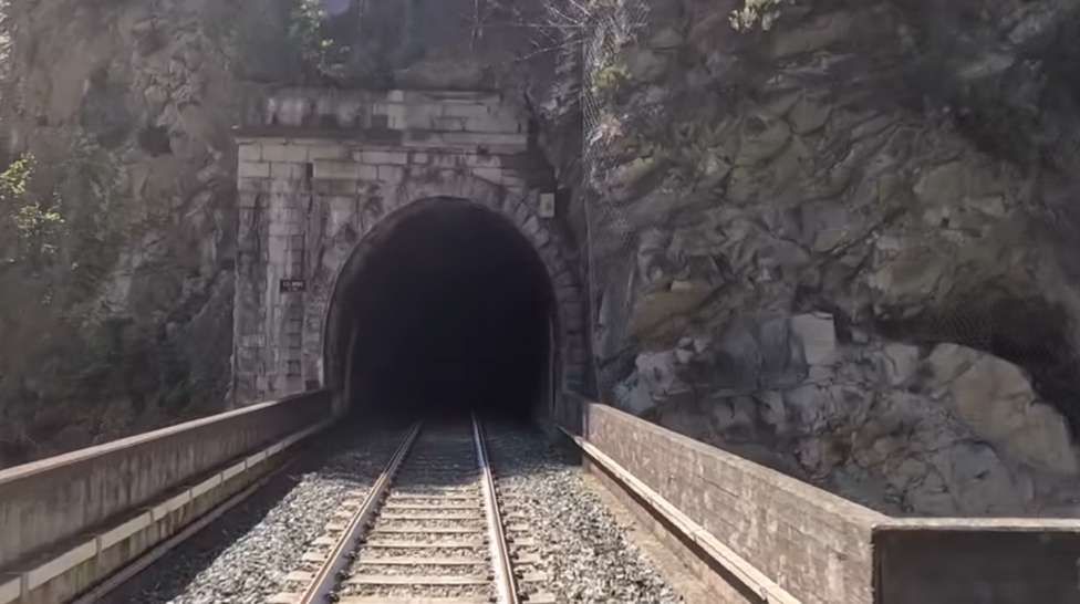
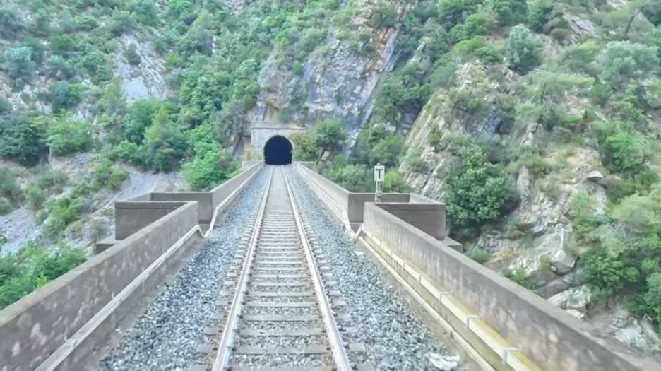
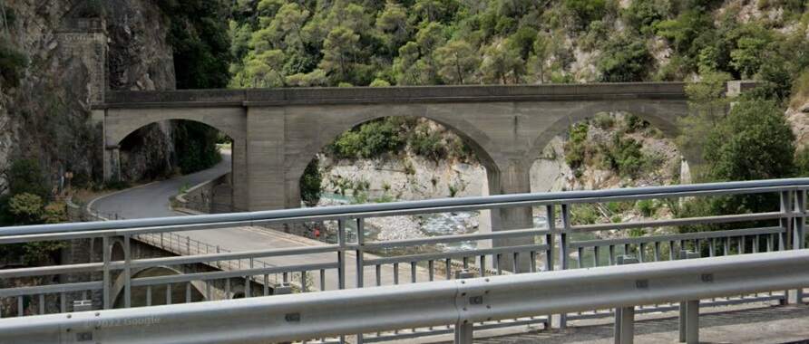
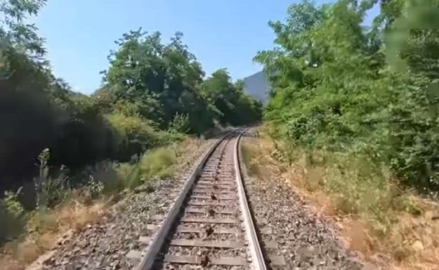
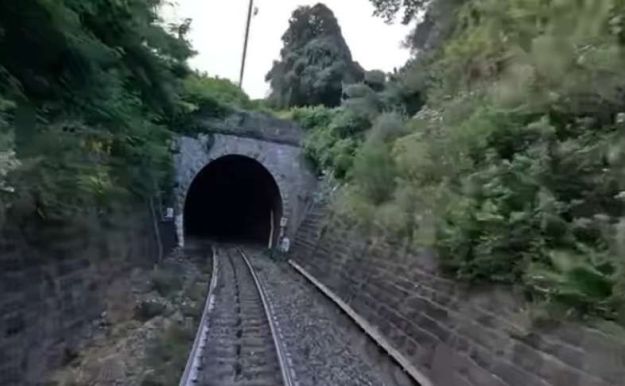
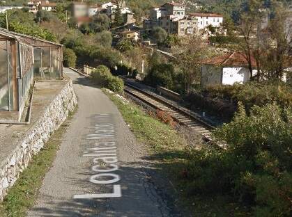
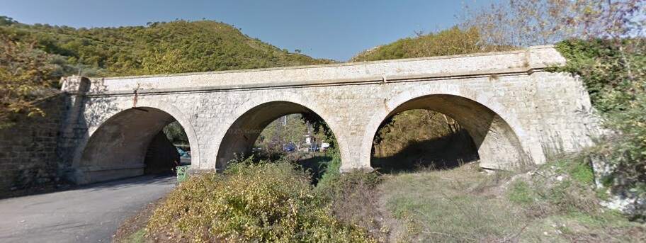
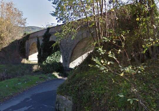
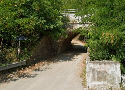
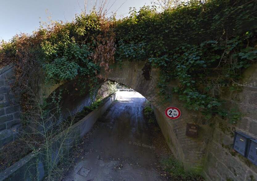

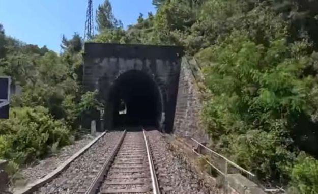
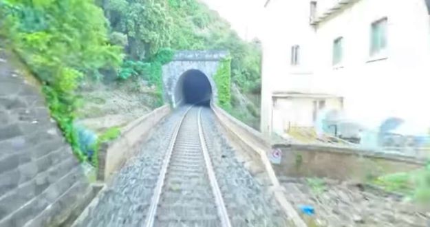
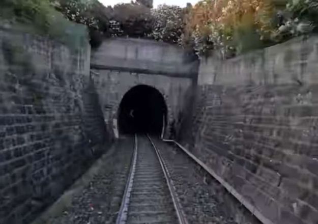
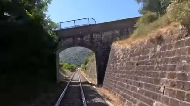
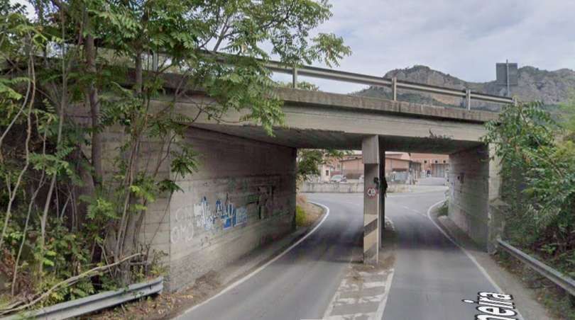
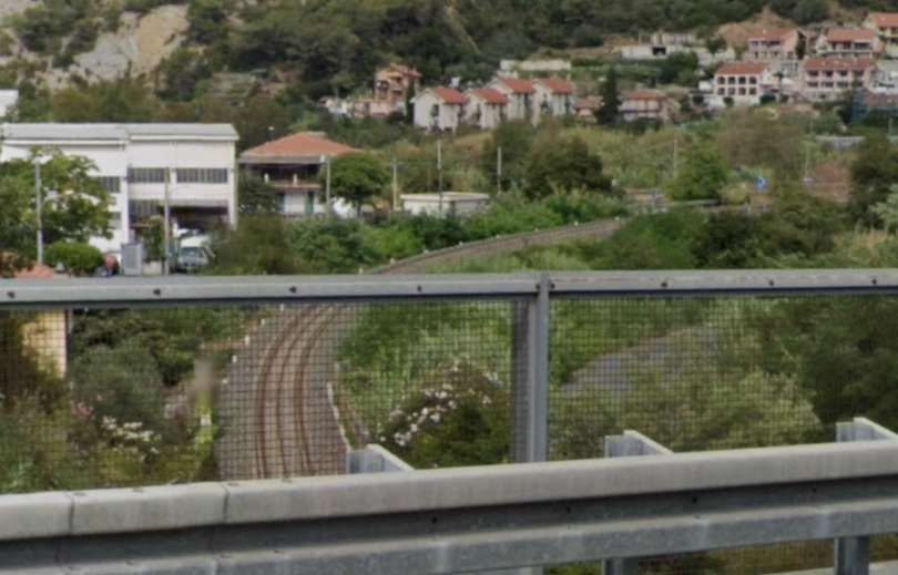
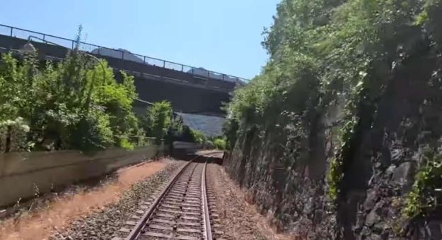
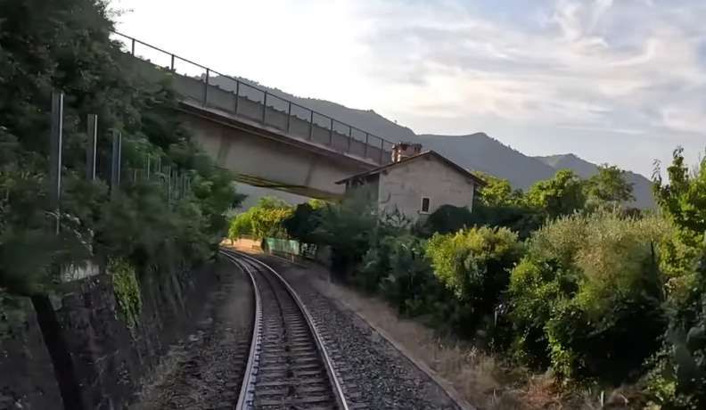
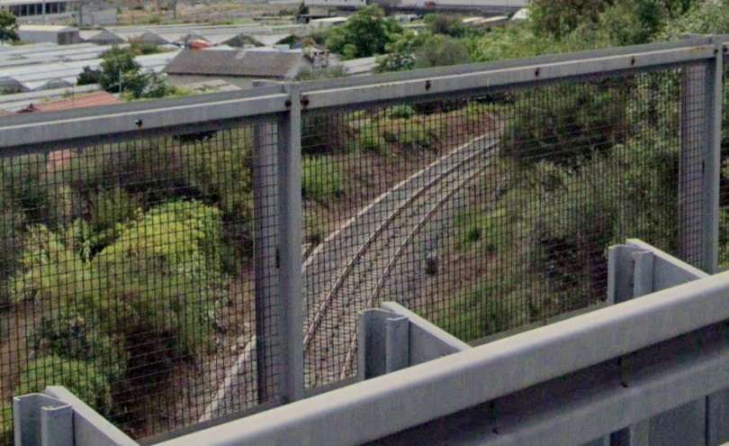
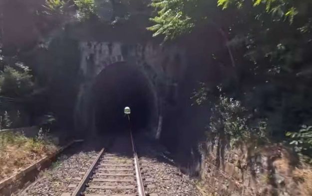
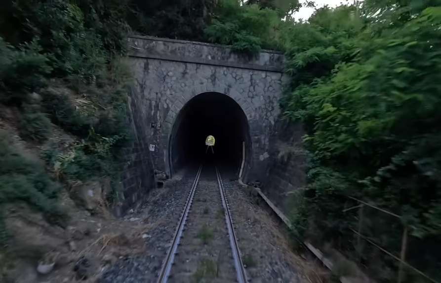
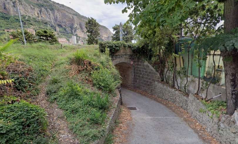
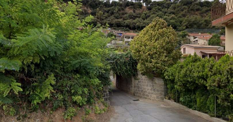
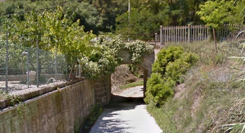
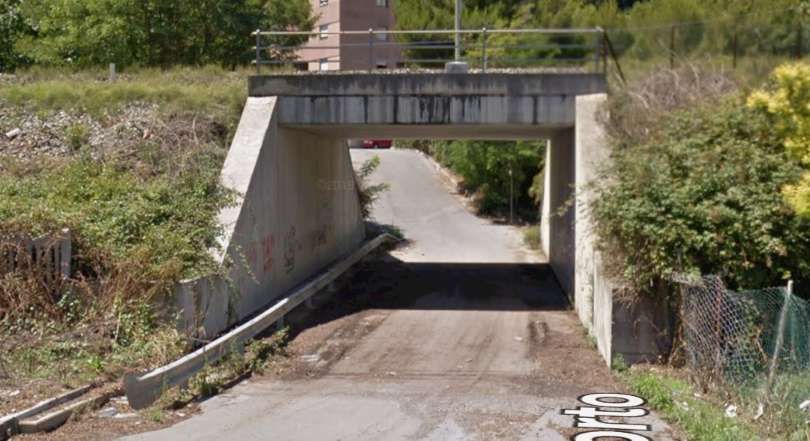
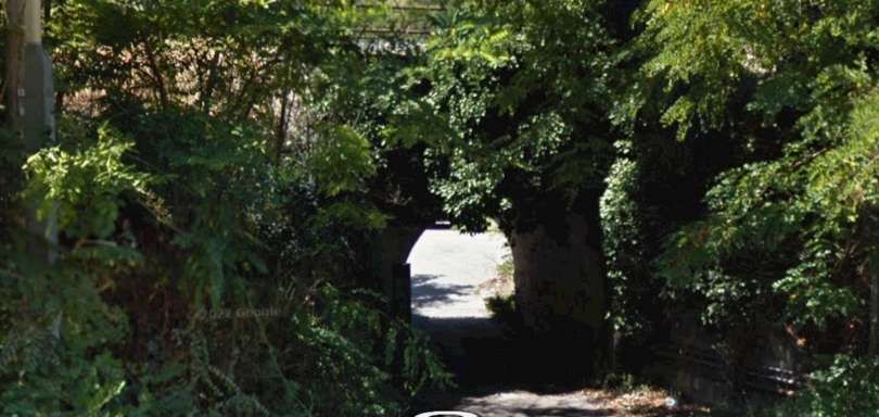
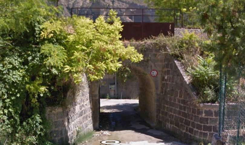
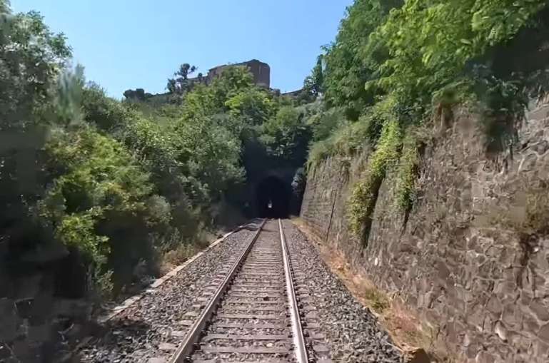
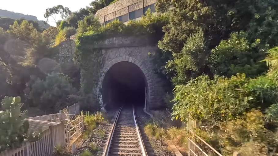

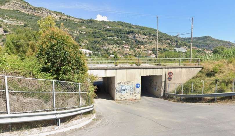
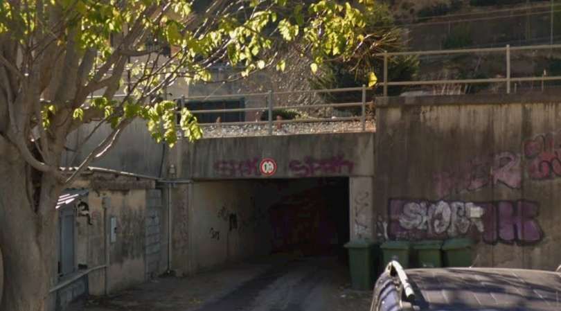
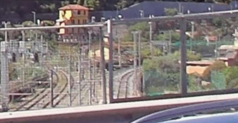
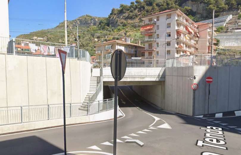



 Roger Farnworth

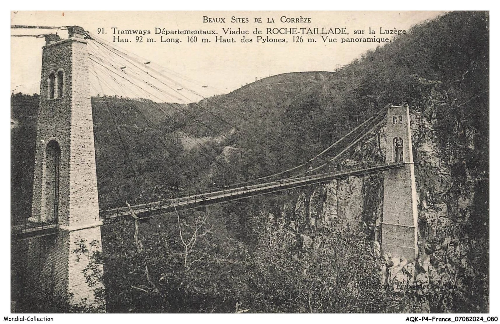

.jpg)
.jpg)


.JPG)
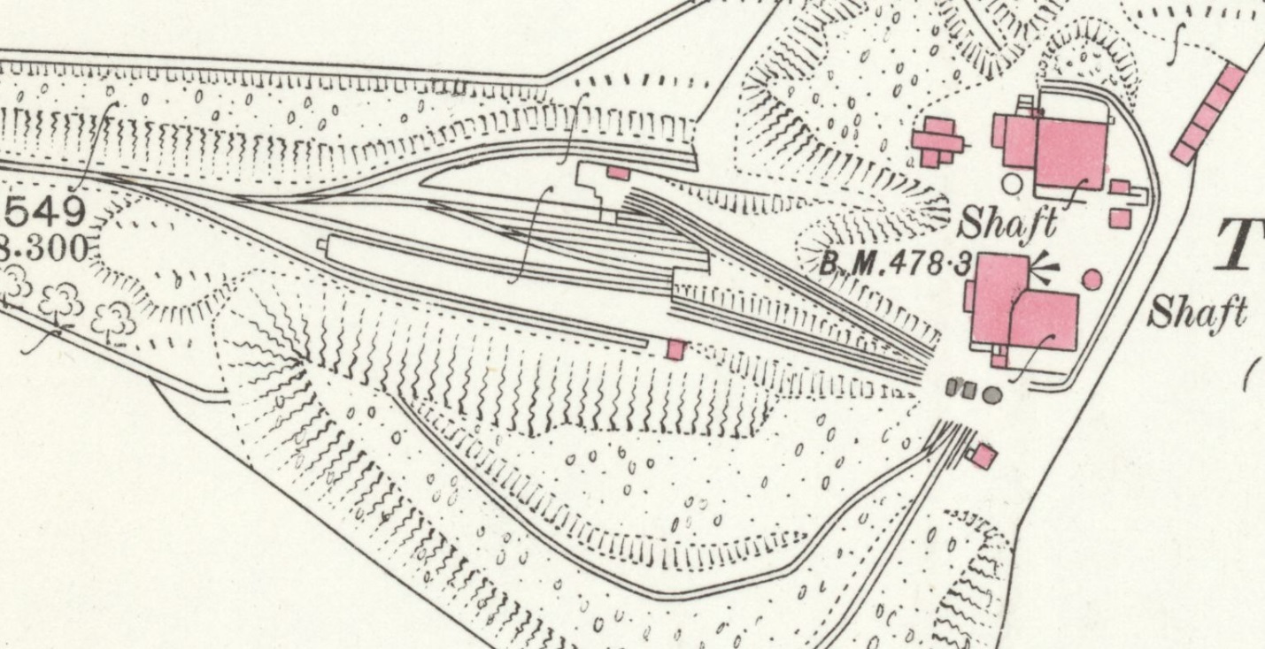

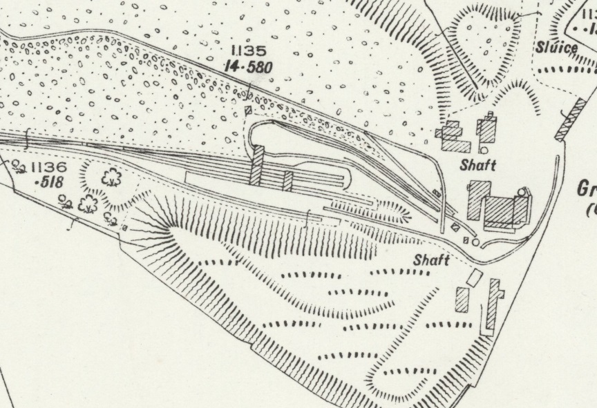
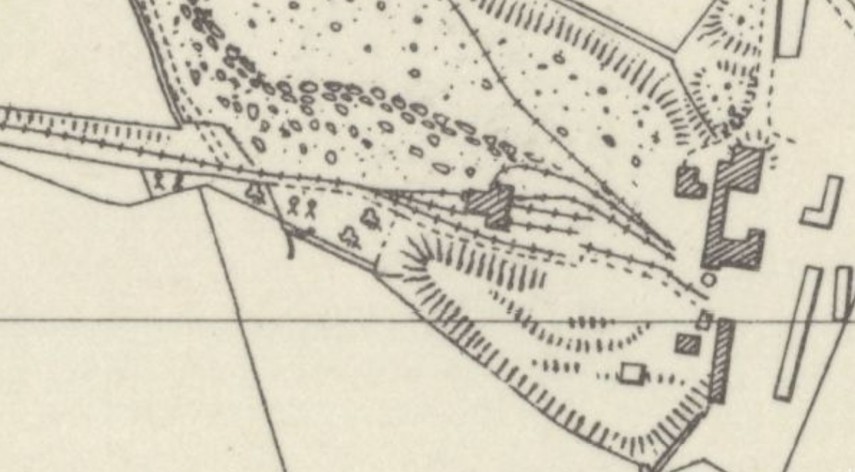
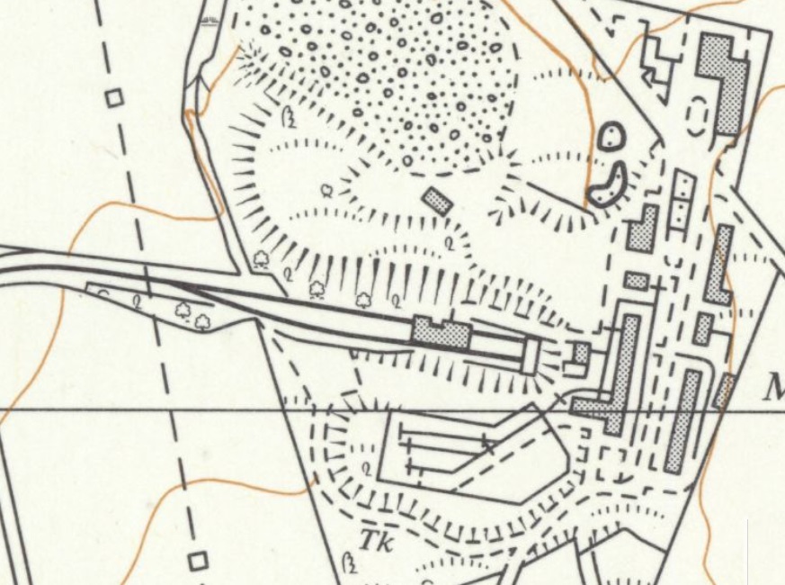






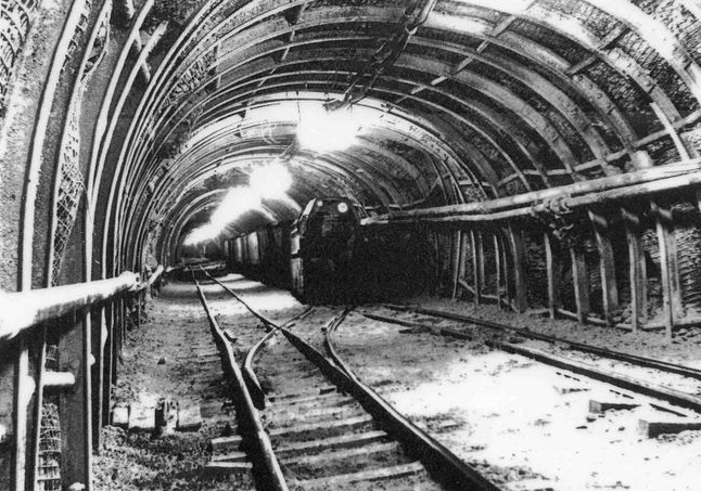
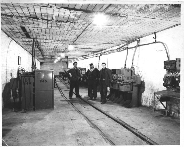
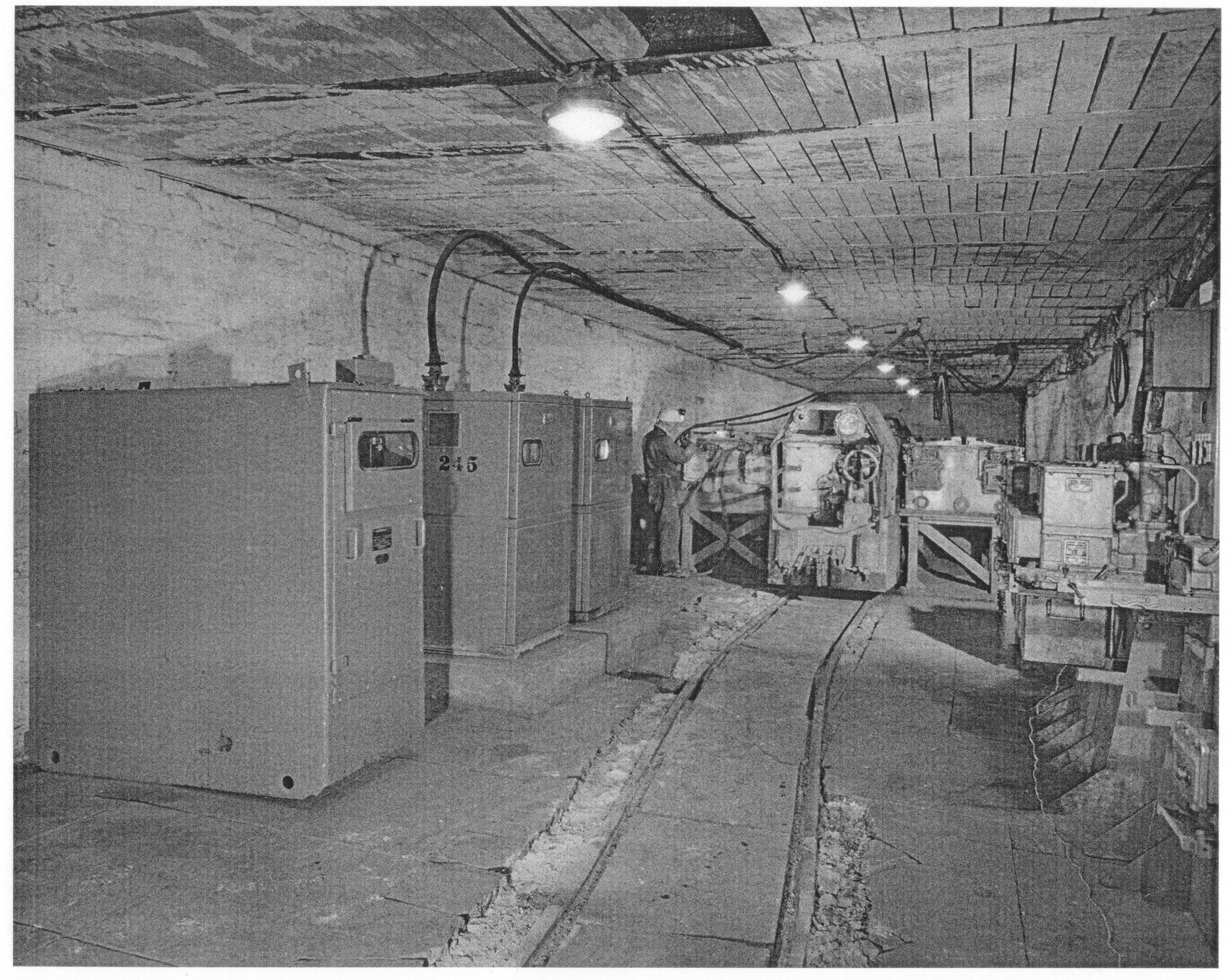
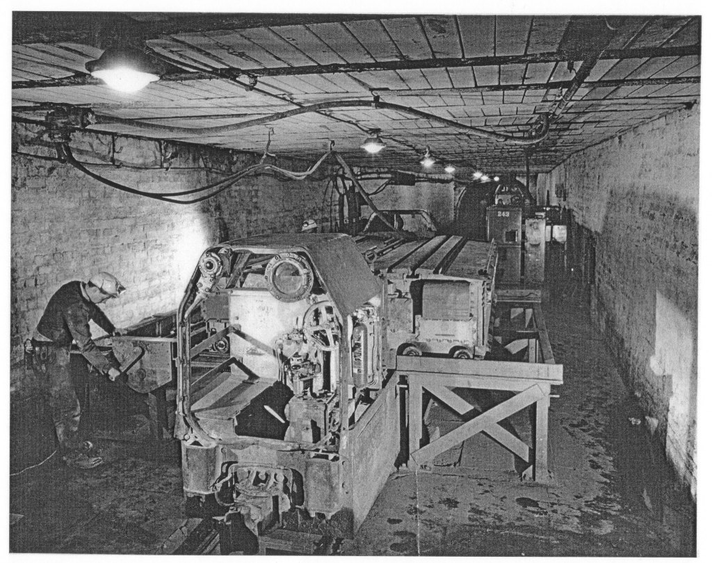
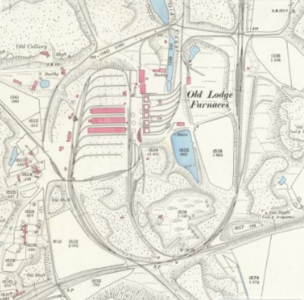

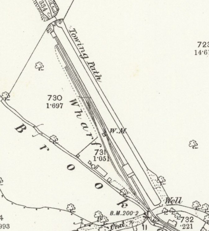
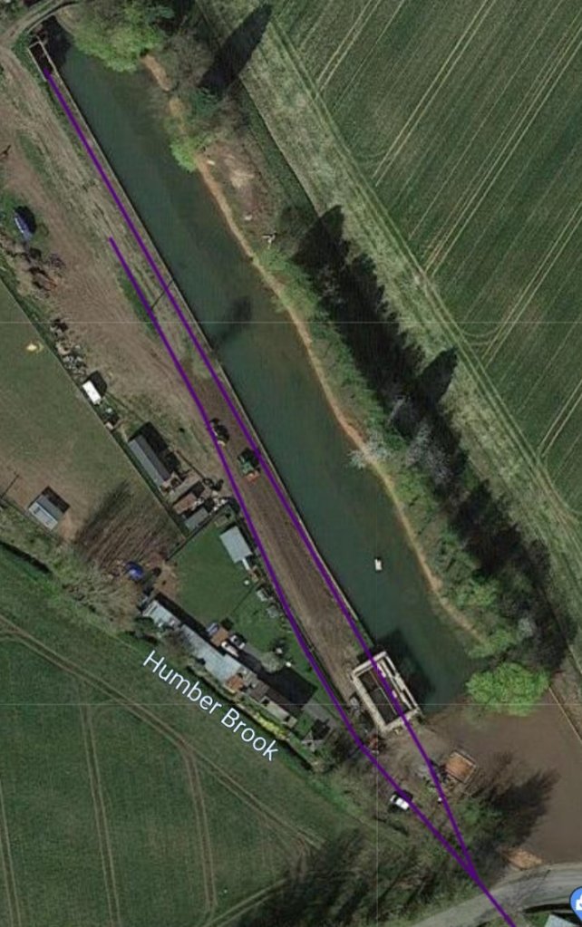

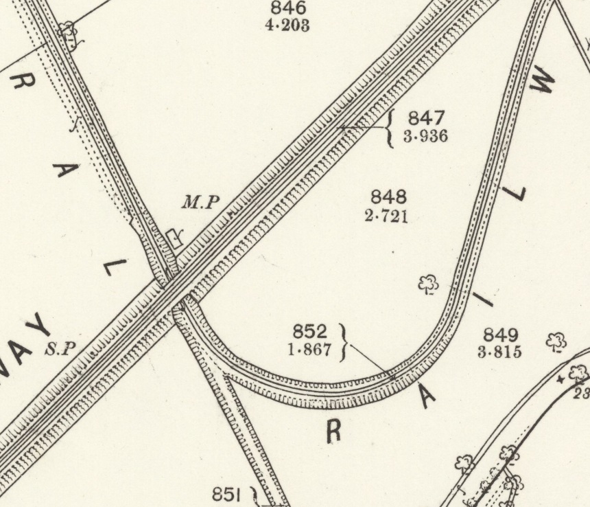
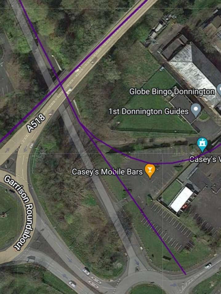
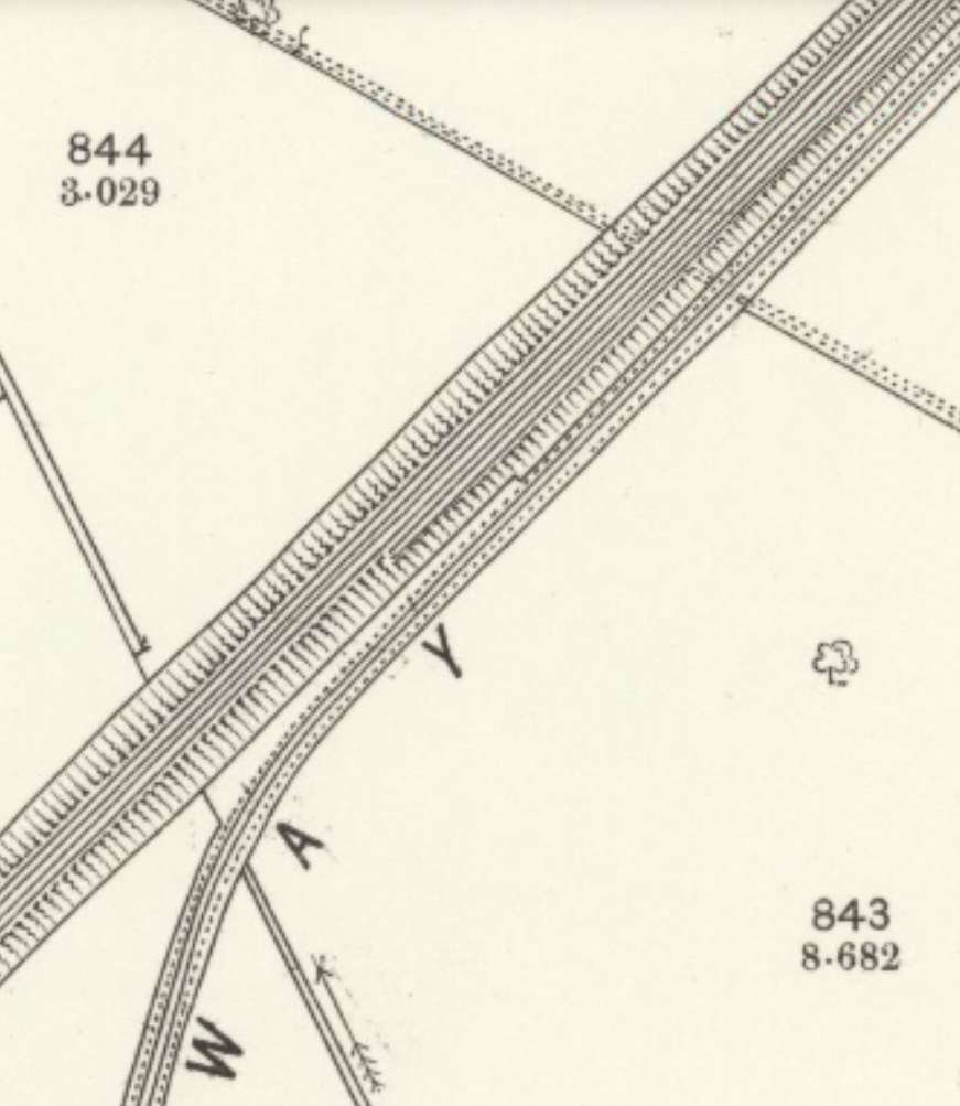
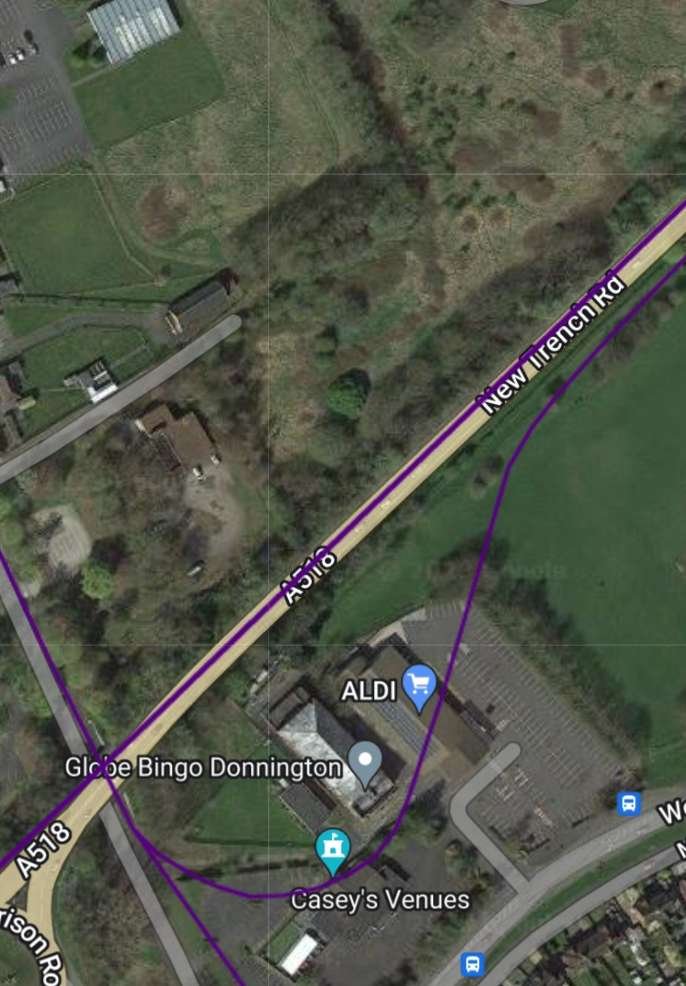
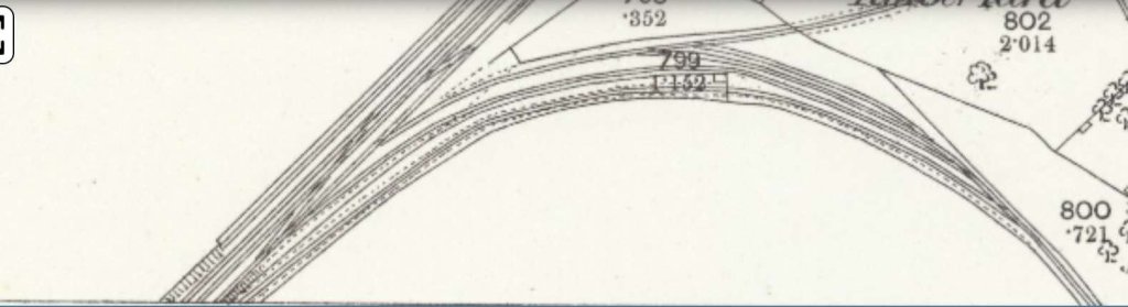
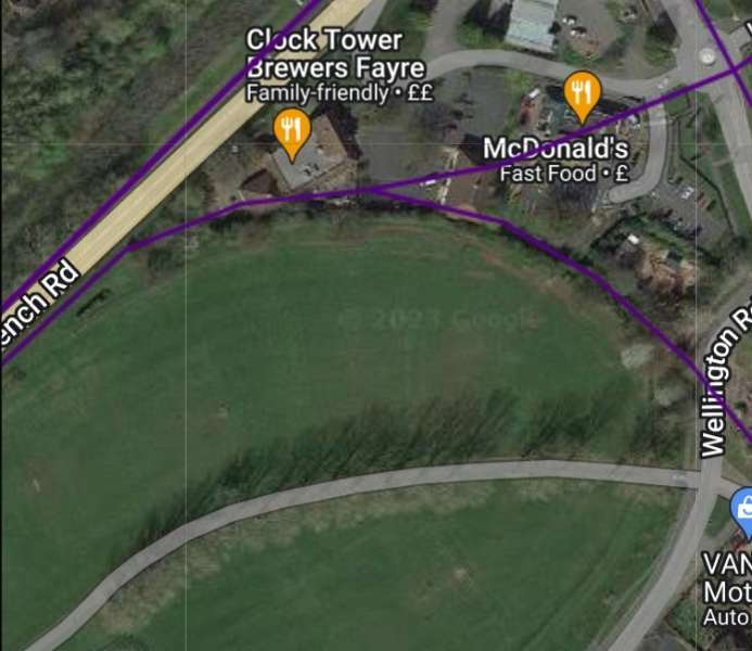

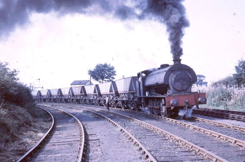
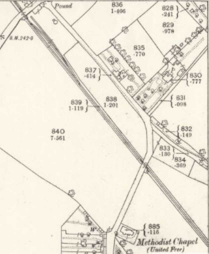
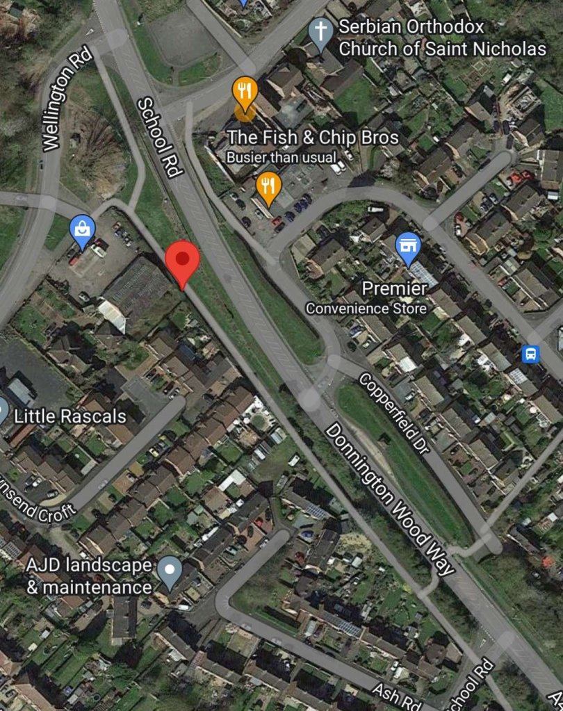
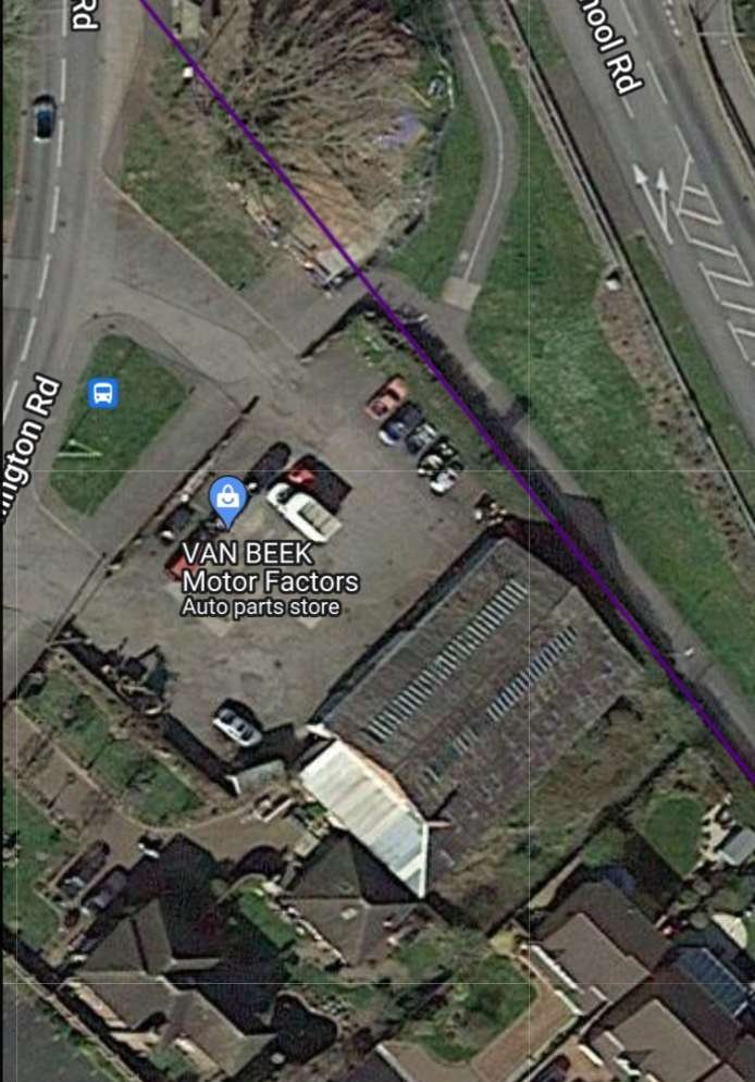
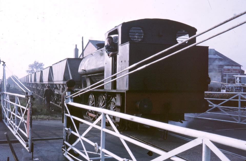
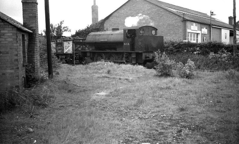

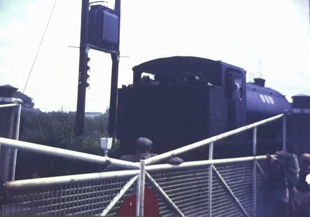
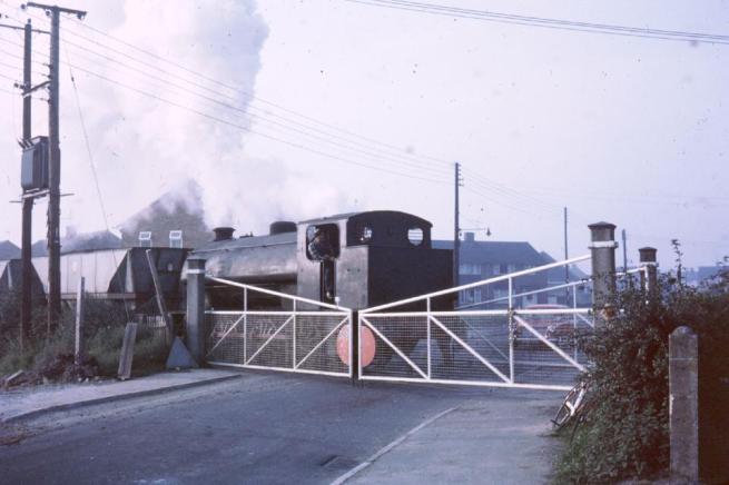


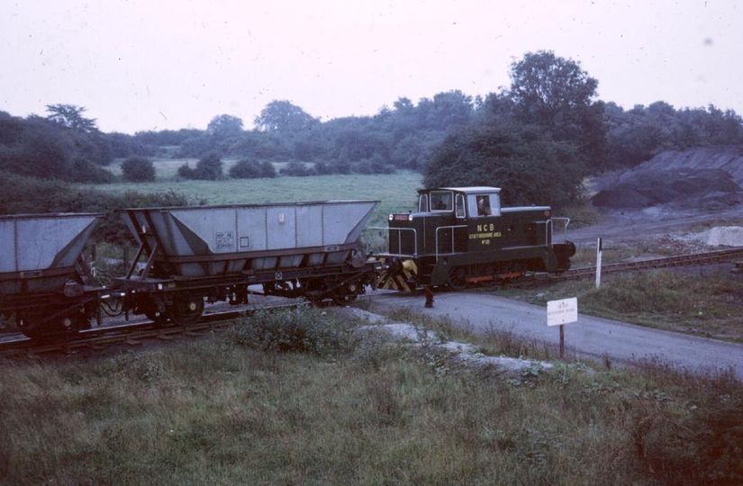
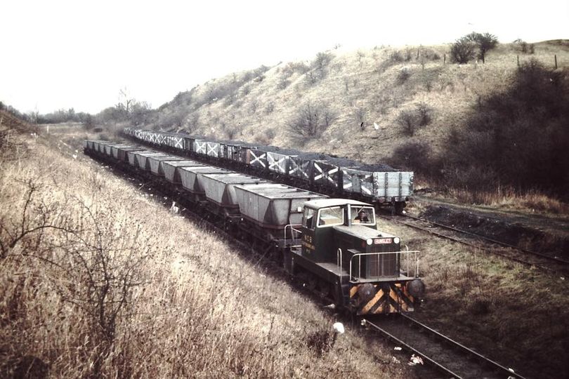


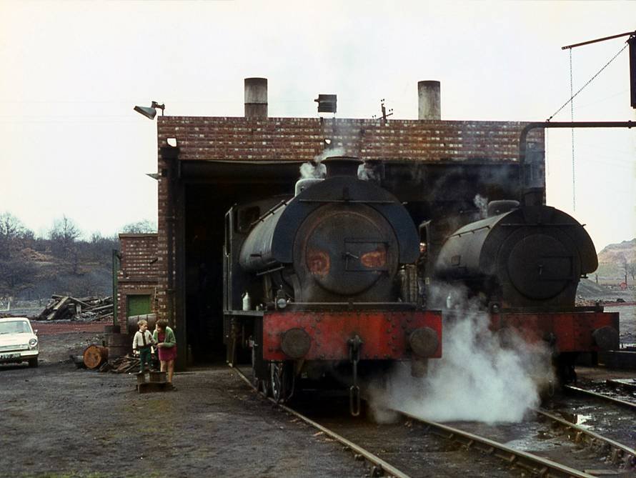

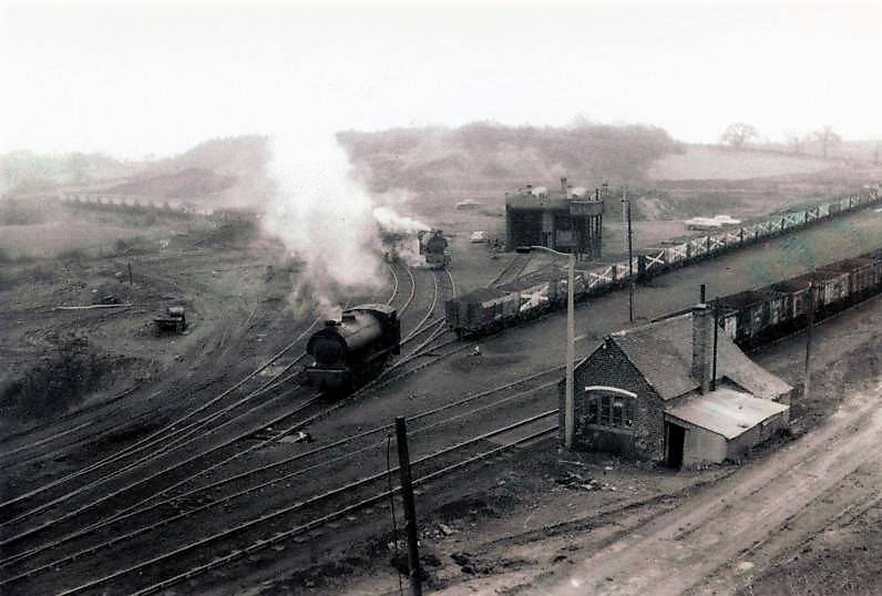
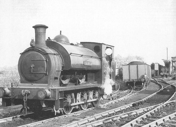
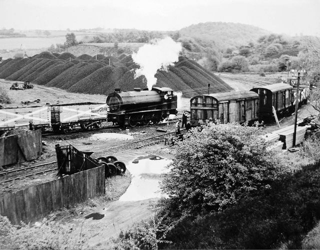



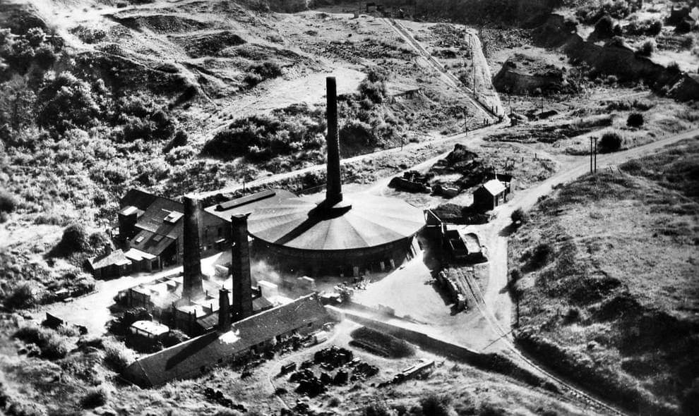


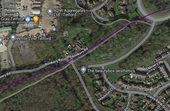
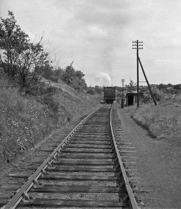


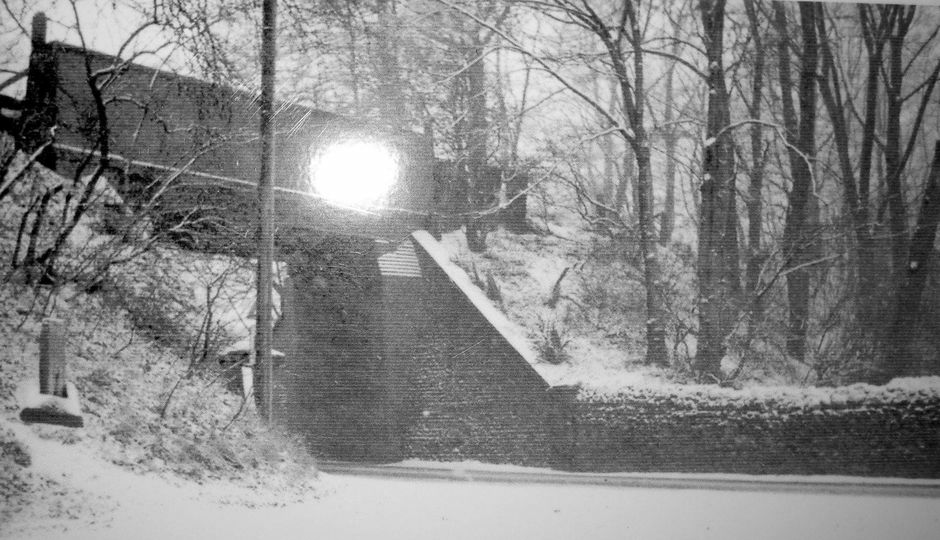
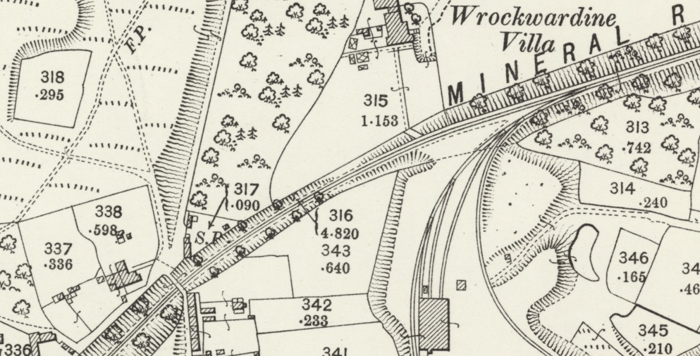
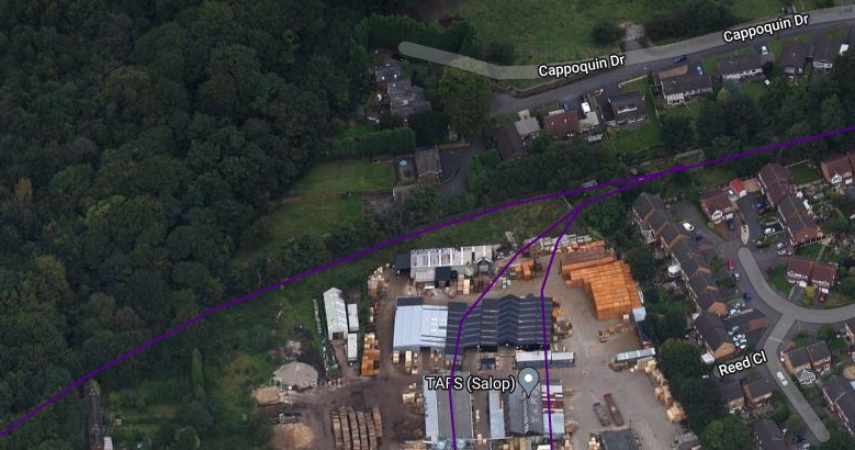


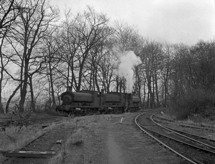
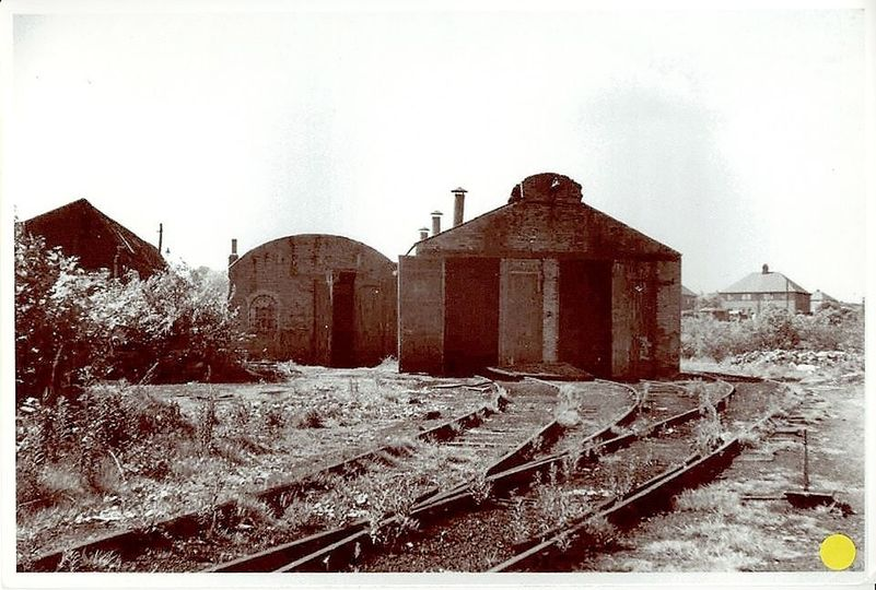
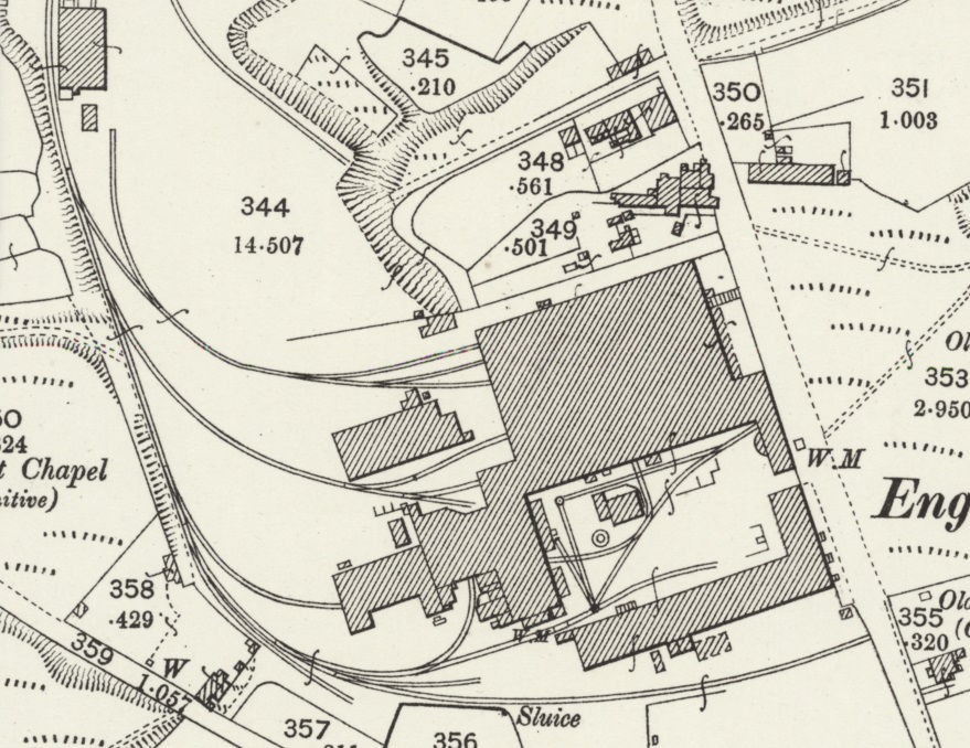
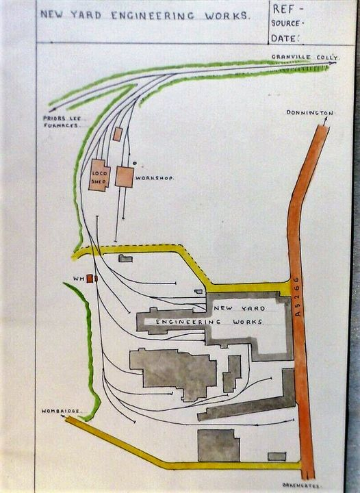
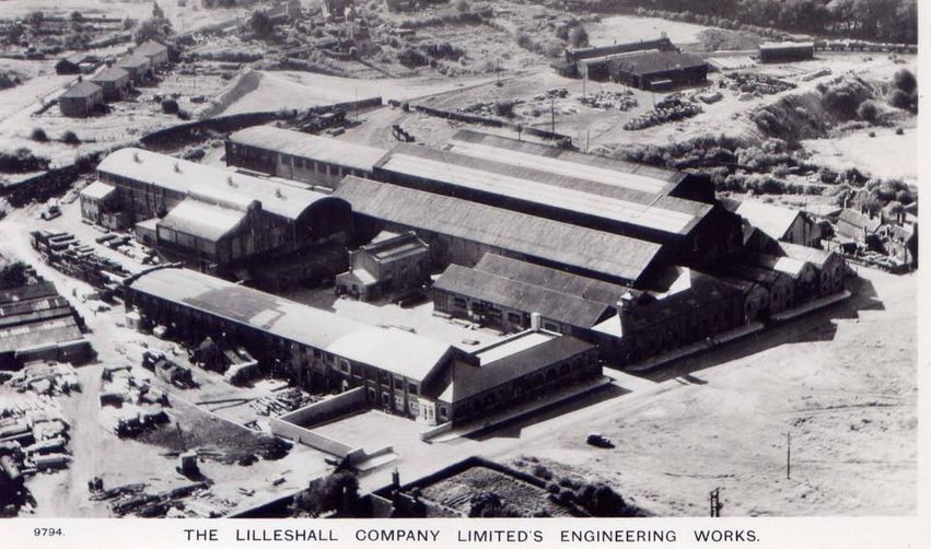
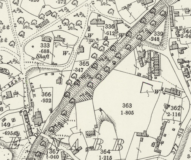

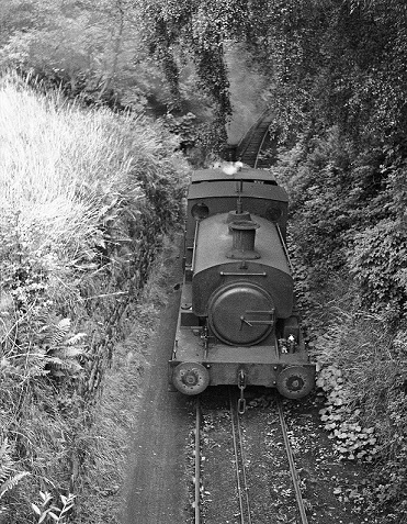
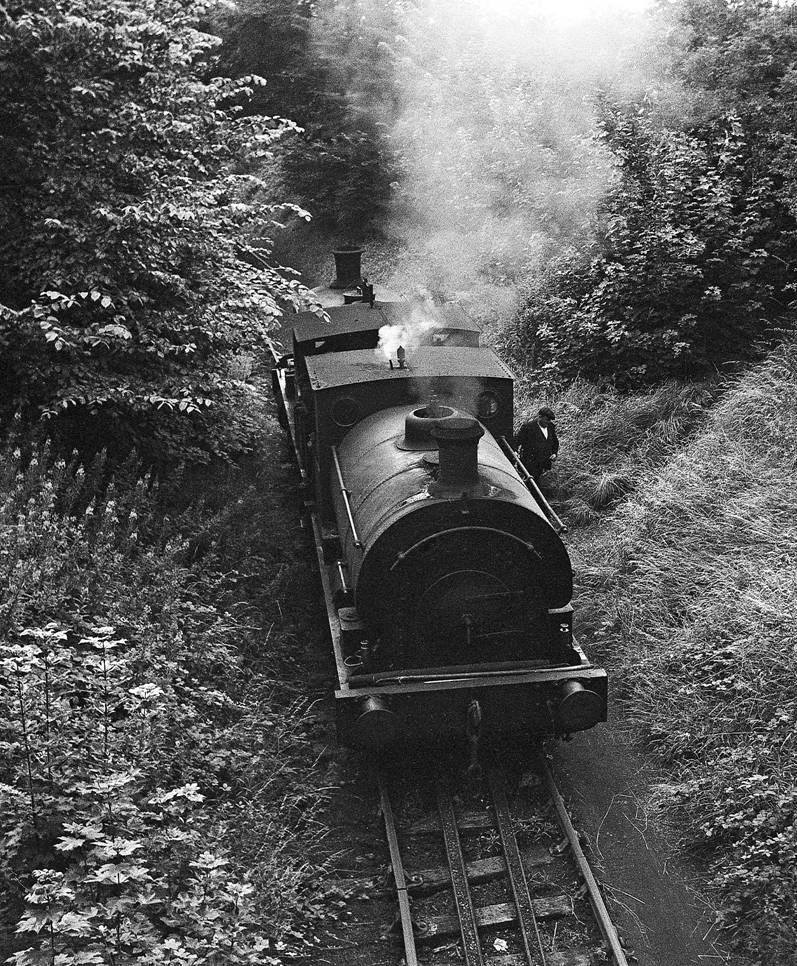
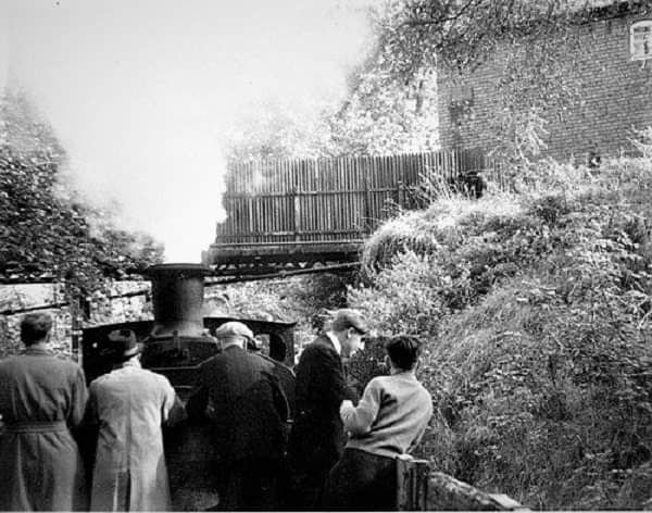
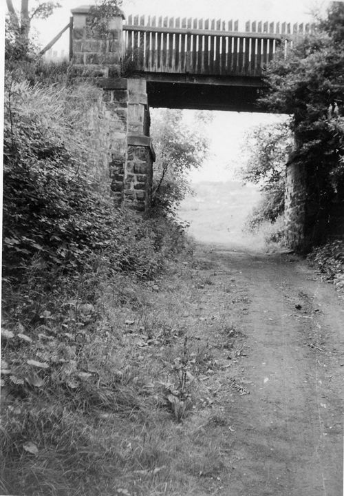
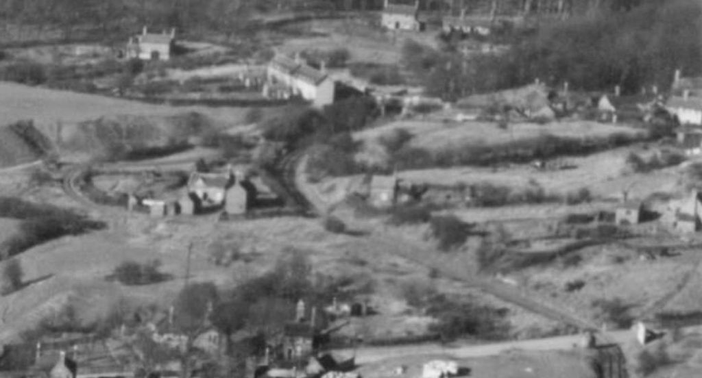
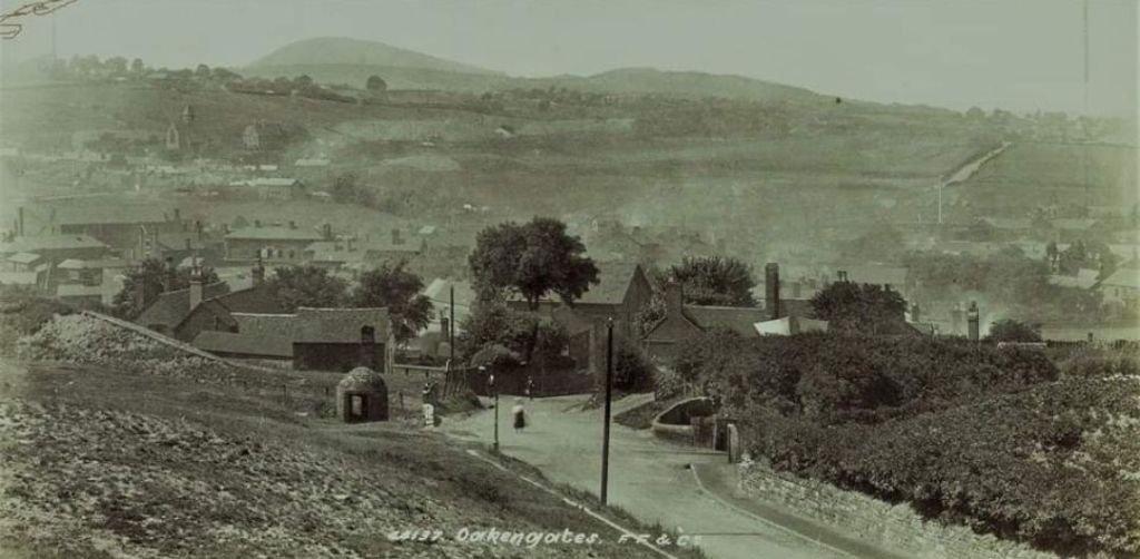

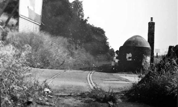
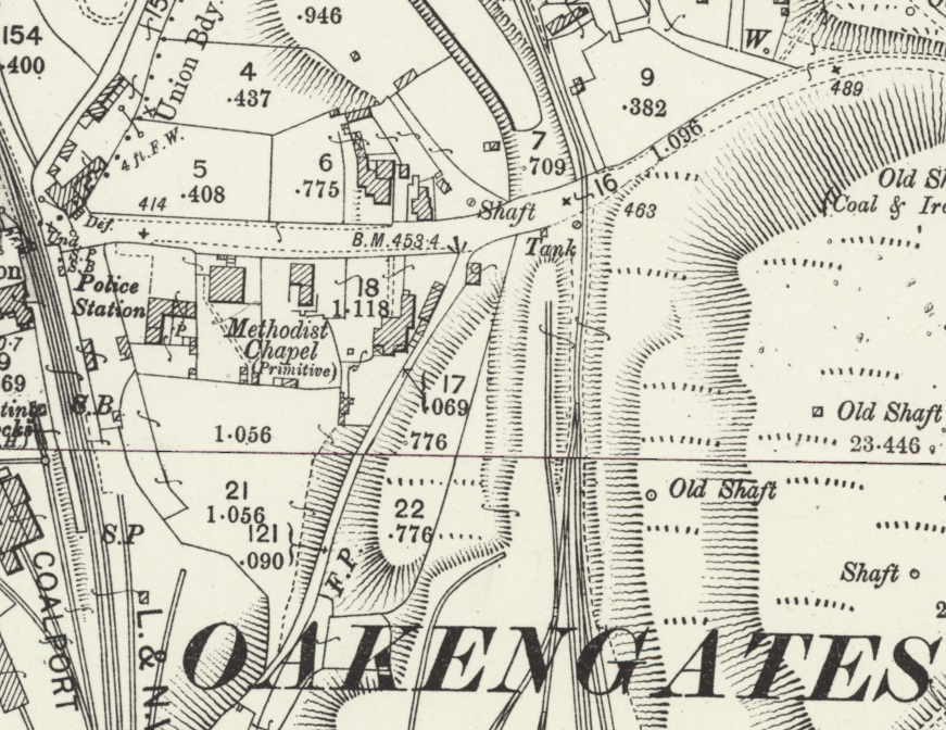
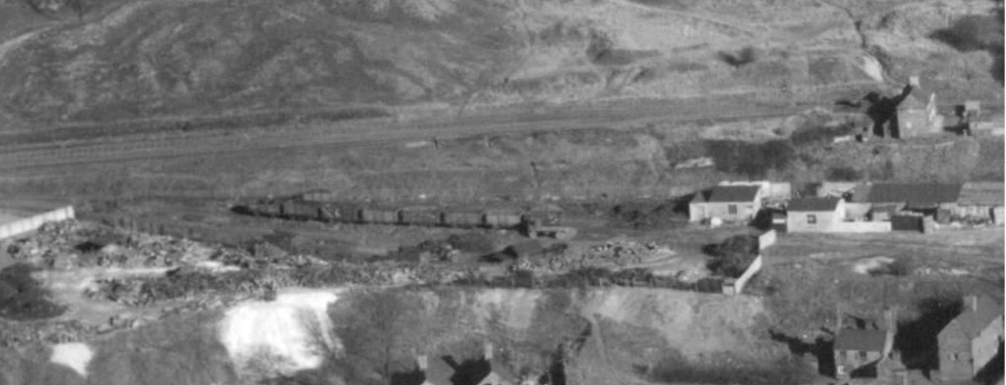
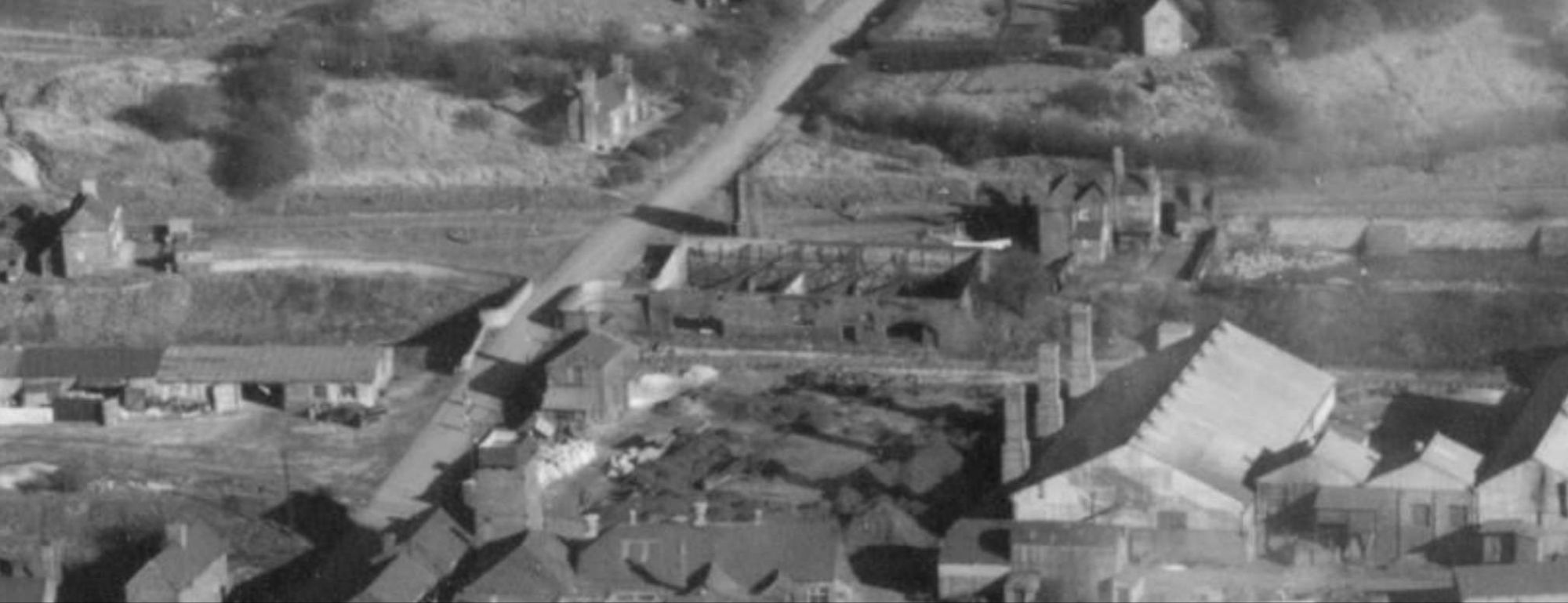

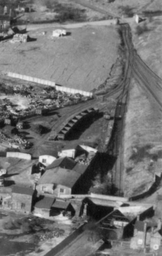


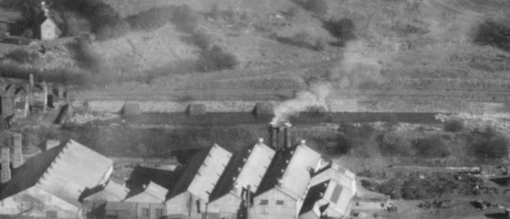
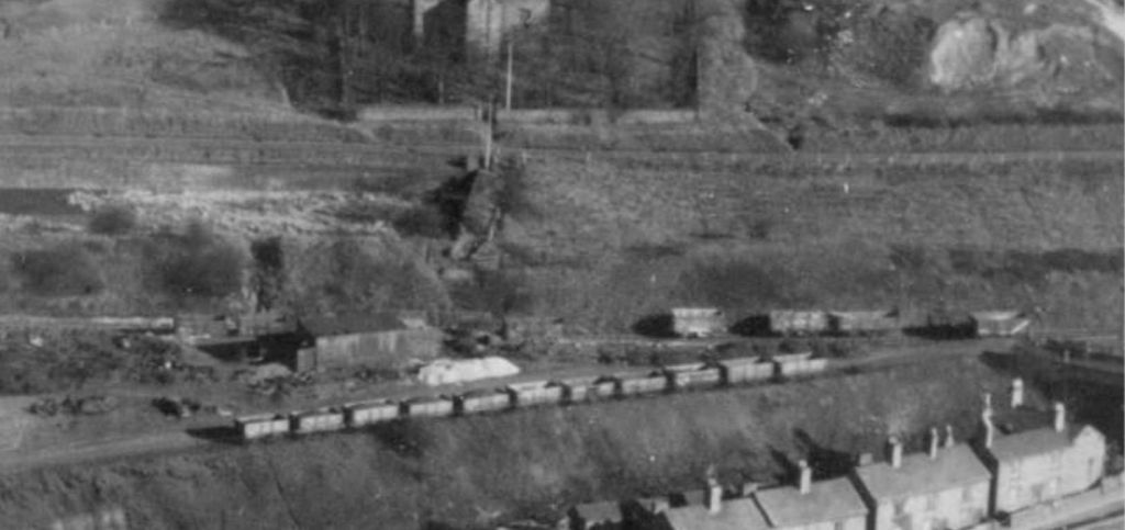
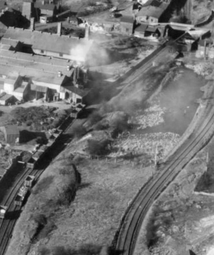


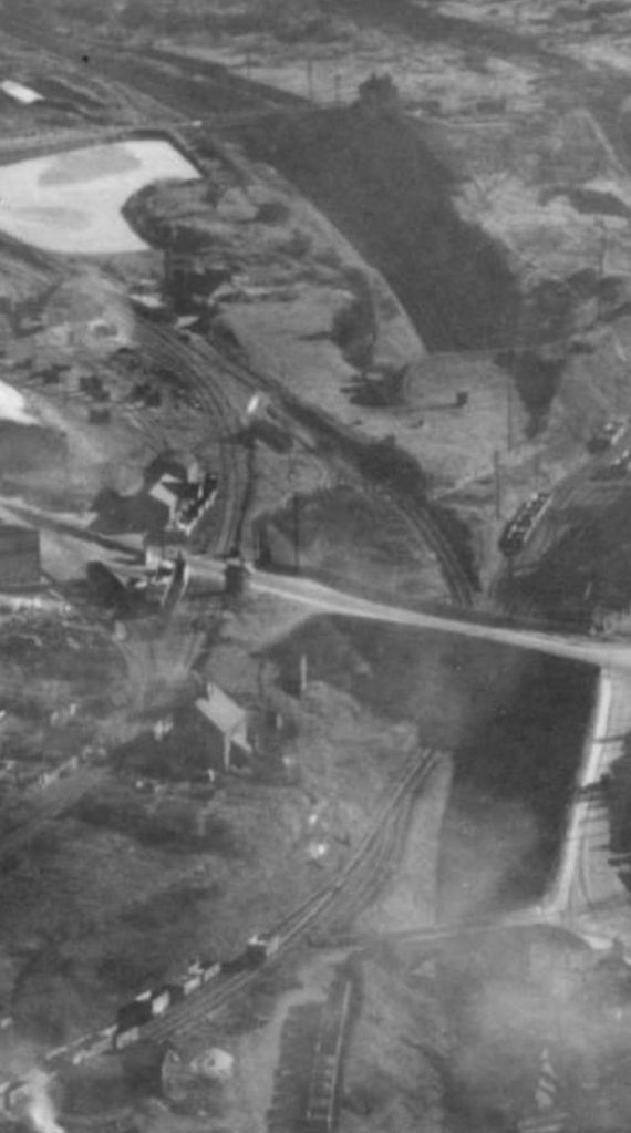
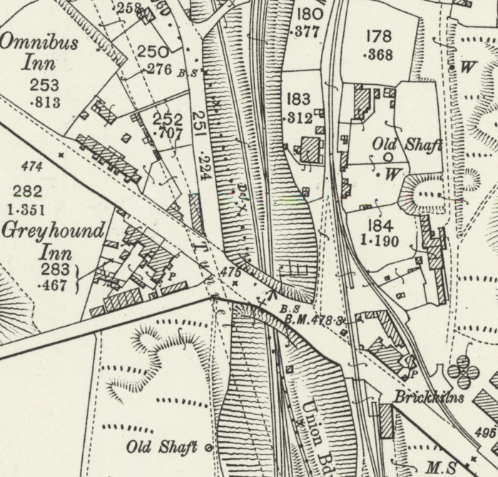
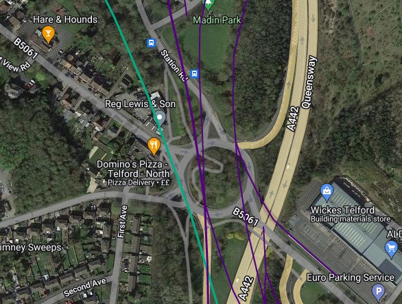
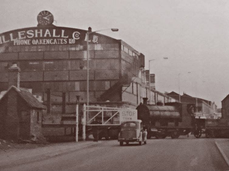


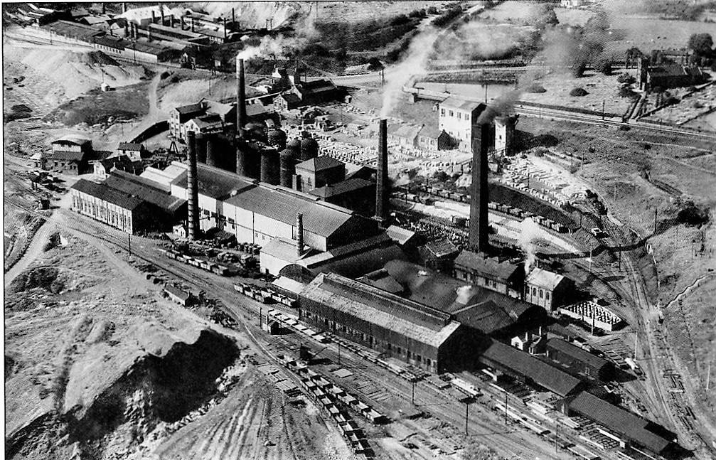
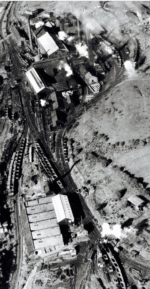
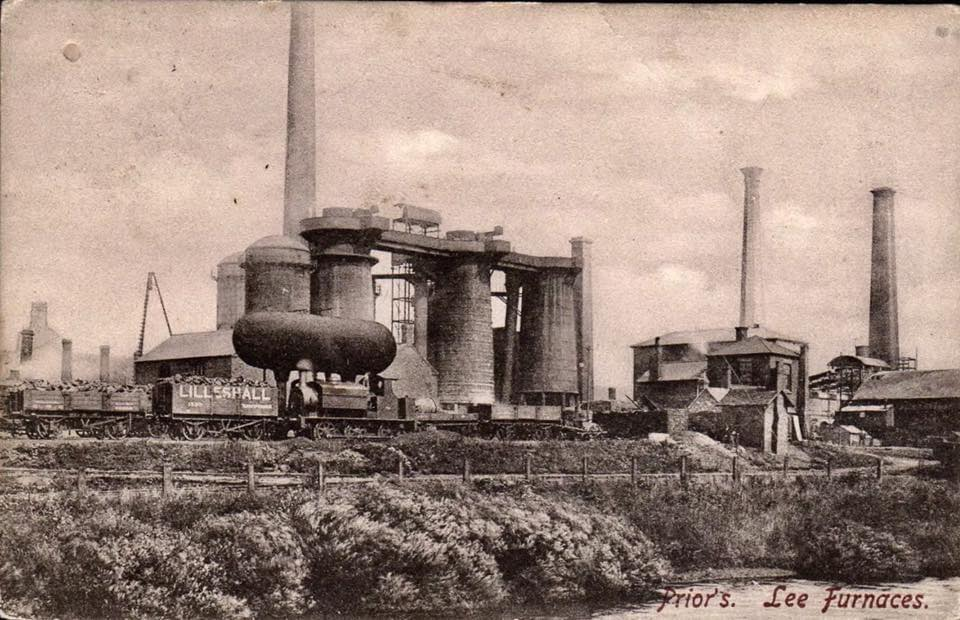

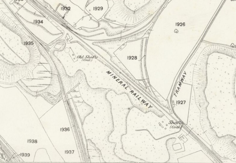
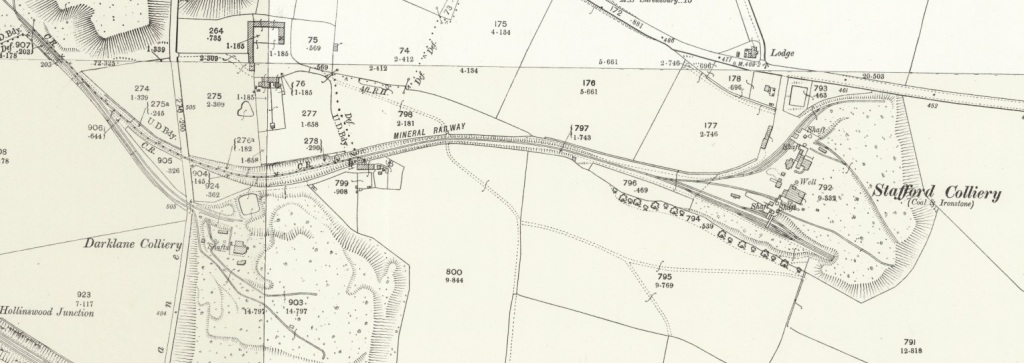

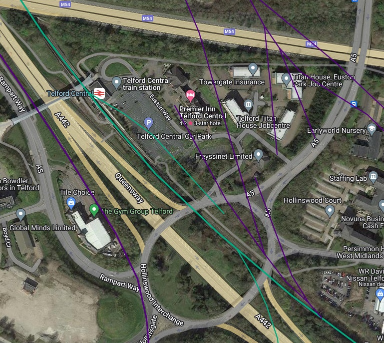


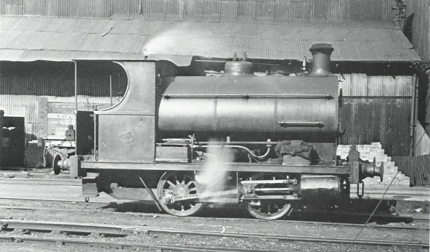

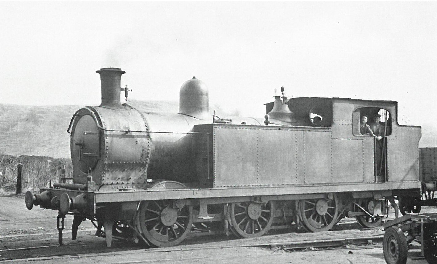
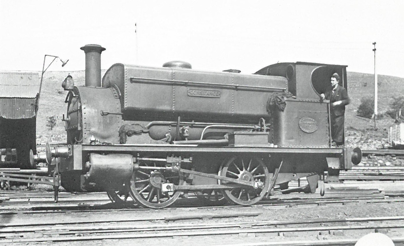
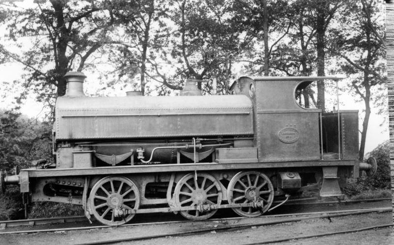
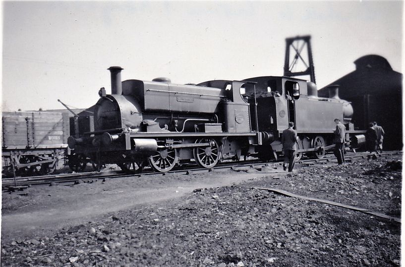

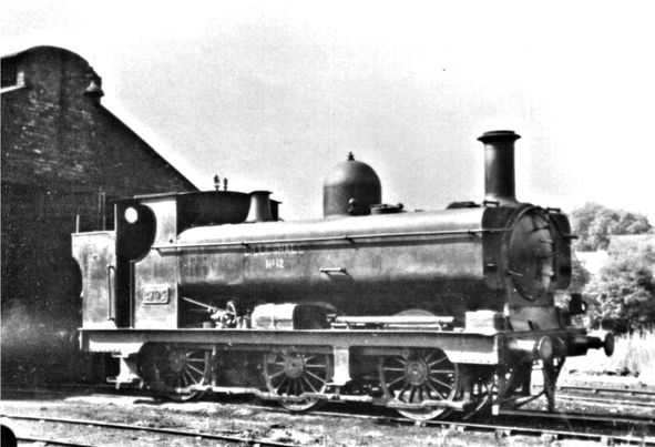
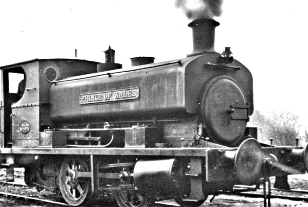


.jpg)


.jpg)