After Easter 2026, we spent a few days at Borth on Cardigan Bay, North of Aberystwyth. We took the opportunity to visit Aberystwyth and to travel on the Cliff Railway.
Aberystwyth Cliff Railway is the longest electrically operated cliff railway in the UK. It sits at the North end of Aberystwyth’s promenade. Constitution Hill provides views over the town and Cardigan Bay. On a really good day, as many as twenty-six mountain peaks can be seen from the summit. [1]
Aberystwyth Cliff Railway has been transporting visitors to the summit of Constitution Hill since 1st August 1896. It is a 778 feet (237m) long funicular railway, and is the second longest funicular railway in the British Isles after the Lynton and Lynmouth Cliff Railway. Since November 1987, the Aberystwyth Cliff Railway has been a Grade II listed structure. [1][2]
The Cliff Railway as seen on the 6″ Ordnance Survey of 1904, published in 1906. [3]
For the first 25 years of its life the railway operated via a water balance system. Electrification occurred in 1921.
The cars have a maximum capacity of 30 passengers, permanently connected via a continuous cable. The original water balance system used a Worthington Corporation compound steam engine water pump housed in the lower station to move water to the upper station. Each passenger car had a tank in its chassis that could hold 4 tonnes of water. Water was added to the tank of the top car, which descended under gravity, hauling the lighter lower car on the parallel track to the top station. [5]
The railway is straight, ascending about 430 feet (130 m) over a horizontal distance of 778 feet (237 m), a maximum gradient of more than 1 in 2 (50%). The 4 ft 10 in (1,473 mm), slightly broader than standard gauge, and laid on timber sleepers. [5]
“The unique design of the undulating track and tilted carriages is the work of George Croydon Marks. A man who played a key role in several projects during the golden age of funicular construction. He would later make his name in politics as Lord Marks, the liberal peer.” [1]
As we have already noted the railway was electrified using a 41 kW ATB AG [de] Morley DC motor in 1921. In 1934, after changes to the town’s electricity supply, a mercury arc rectifier and transformer were installed in the lower station to provide a 440V DC power output. The cars are moved using a high-tensile steel cable attached to both vehicles. It passes around a drum, mounted on a vertical axis between the tracks at the top. The motor drives the drum controlled by an automated cut-off which stops the motor and the cars when required. [5]
“The carriages are brought to the summit at a stately 4 miles per hour. They are powered by a powerful motor and high-tensile steel cables supported by a sophisticated electronic safety system. At the midpoint of the journey, the railway ventures through a deep cutting, where 12,000 tons of rock was excavated to allow the winding footpath to cross via a series of bridges overhead.” [1]
Its twin carriages are named Lord Geraint and Lord Marks. [6]
The Cliff Railway as seen on the 6″ Ordnance Survey of 1948, published in 1953. [4]
“Throughout the 1920s and 1930s, the cliff railway was popular with visitors but during and after the Second World War, passenger numbers declined significantly. In 1948, seeking to revive its fortunes, the Aberystwyth Pier Company bought it and carried out repairs and upgrades. The new owners were unable to increase passenger numbers.” [5]
In 1976, a fault developed in the railways breaking system and it was closed briefly. In the late 1970s, “a local mining company acquired a majority stake and formed the Aberystwyth Cliff Railway Company to operate it. In 1978 a new electrical system was installed which is used to the present day. It takes its power from and returns surplus energy to the National Grid.” [5]
More recent key dates:
1987 – recognised as Grade II listed structure.
1998 – purchased by Constitution Hill Ltd.
2005 – upper station refurbished (with café and gift shop).
2014 – roof repairs undertaken and ramps and other adaptations made to improve accessibility – better protection from the elements, a small car park at the station (very small!), wheelchair and guide dog friendly trains, a passenger lift providing wheelchair access from the train to the summit, and once there, wheelchair friendly pathways across the site. [1]
The featured image for this article shows a Tata Chemicals locomotive at work on the metre-gauge line near Magadi. [9][cf. 6]
A. Railways Africa recently reported:
East African Governments Ramp Up Rail Investment in 2026/27 Budgets
“East Africa’s latest budget allocations show rail moving higher up the public investment agenda, with governments linking railway development to logistics efficiency, urban mobility and regional trade competitiveness. Kenya, Uganda and Tanzania are each approaching the sector from different starting points, but the common direction is clear: rail is being positioned as a strategic infrastructure tool, not only a transport asset.
Africa Star Railway Operation Company (Afristar) is the company that runs the SGR in Kenya, it is a subsidiary of the China Road and Bridge Corporation (CRBC). It has been the operator of Kenya’s Standard Gauge Railway (SGR) since its launch. However, the Kenya Railways Corporation (KRC) has been gradually taking over these operations, with full control expected in 2027. [10][11]
“The figures also point to a wider corridor logic across the region. Uganda’s Malaba–Kampala SGR, Tanzania’s continued SGR construction and rehabilitation programme, and Kenya’s rail allocations all sit within the broader ambition of improving inland connectivity, reducing logistics costs and strengthening access between ports, production centres and landlocked markets.
“East African governments are significantly increasing investment in railway infrastructure in their 2026/27 national budgets, with Kenya, Uganda and Tanzania allocating billions of shillings to expand rail networks, modernise transport systems and improve regional trade connectivity.
“In Kenya, Cabinet Secretary for the National Treasury, John Mbadi Ng’ongo, announced a proposed allocation of KSh38.4 billion for railway projects as part of the government’s transport infrastructure programme.
From Naivasha to Malaba, construction of the SGR expansion was due to start in July 2026. [12] The project will reshape logistics, lower transport costs and boost connectivity across counties. This project stands as a symbol of progress and long-term economic planning in motion.
“The allocation forms part of a broader effort to improve public transport and logistics infrastructure.
“To improve urban mobility, the government has also proposed KSh582 million for the Nairobi Bus Rapid Transit (BRT) Project, aimed at reducing traffic congestion in the capital.
“Meanwhile, Uganda has continued prioritising railway development through substantial infrastructure spending.
“Finance, Planning and Economic Development Minister Henry Musasizi announced the commencement of the construction of the 273-kilometre Standard Gauge Railway (SGR) linking Malaba and Kampala.
“Once completed, the railway is expected to reduce the cost of transporting containers from Mombasa to Kampala from approximately US$3,500 to US$1,600, while cutting transit times from five days to one day.
“Musasizi revealed that the rehabilitation of the Tororo–Gulu Metre Gauge Railway has reached 66% completion, while works on the Kampala–Mukono section have been completed.
“Uganda has allocated Shs8.79 trillion for transport infrastructure development in the next financial year, with priority given to the construction of the Malaba–Kampala Standard Gauge Railway and completion of the metre gauge railway rehabilitation programme.
“In Tanzania, the government has allocated 1.27 trillion Tanzanian shillings for the construction and rehabilitation of railway infrastructure, including 1.12 trillion shillings dedicated to the Standard Gauge Railway programme.
“The government said construction of the Dar es Salaam–Dodoma SGR sections, covering Lots 1 and 2, has been completed and is now operational.
“According to Finance Minister Ambassador Khamis Mussa Omar, the government views the Standard Gauge Railway as a key component of its broader economic transformation strategy.
“The railway, together with Msalato International Airport, will support the development of Dodoma into a modern administrative capital, a regional transport and logistics hub and a centre for sustainable urban development.
“Tanzania also plans to continue implementing the TAZARA Railway Revitalisation Project and advance construction of the Standard Gauge Railway from Dodoma to Mwanza and Isaka to Kigoma.
“According to the government, these projects are expected to stimulate economic activity across multiple regions by improving transport efficiency, strengthening regional trade corridors and leveraging Tanzania’s strategic geographic position.” [1]
In 2009, the East African Community produced the East African Railway Master Plan, [3] a proposal for upgrading the railways serving Tanzania, Kenya, and Uganda, and building new railways to serve Rwanda and Burundi. Evidence of progress in development of SGR routes is manifest, but the pace of development has been relatively slow.
B. On Sunday 28th June 2026, The East African reported:
Uganda locks funds for joint SGR as Kenya plan stalls
President William Ruto and his Ugandan counterpart Yoweri Museveni during the official launch of the Kisumu-Malaba Standard Gauge Railway at Kibos in Kisumu County on 21st March 2026, (c) Alex Odhiambo, Nation Media Group. [2]
“Uganda expects to conclude financing arrangements for its €2.7 billion ($3 billion) standard gauge railway (SGR) project within the next few months after securing a major funding commitment from the Islamic Development Bank (IsDB), bringing the long-delayed infrastructure initiative closer to financial close than at any point in the past decade.” [2]
“But Kenya, with which Kampala is building the cross-border project, is struggling to raise about $4 billion for the extension of its line from Naivasha in the Central Rift to Malaba on the border, with the Treasury confirming the project will not proceed under public private partnership as earlier advised.” [2]
C. Magadi Soda Works and Branch line
Thanks to ‘Class442’ on RailUKForums [4] for pointing this out.
Tata-Owned Locomotive Catches Fire
A locomotive operated by Tata Chemicals Magadi Ltd, which transports soda ash from Lake Magadi to Mombasa, caught fire on 1st July 2026, at or near Simba station in Kajiado County. The branch line between Magadi and Konza where it encounters the Nairobj-Mombasa metre-gauge line is managed as a private line by Magadi Ltd. It was a company locomotive that caught fire while travelling on the main line near Simba.
This MapCarta extract shows the town of Simba at the left side of the image, with both the metre-gauge line (MGR) and the more modern standard-gauge line (SGR). The MGR railway station is in the town. The SGR station is about 4 kilometres East of the town of Simba. [5]
Online (Instagram Video) can be found on these links:
First responders were local people. They took a number of photographs of which this is one. Flames engulfed the train as emergency responders and members of the public worked to contain the fire. [6]
Kenya Digest reports:
“A cargo train fire at Simba Station has prompted investigations as authorities work to determine what caused the incident and assess the extent of the damage. The train, operated by Tata Chemicals Magadi Ltd, caught fire on June 1, 2026, leading to an emergency response along the Magadi rail corridor.
Kenya Railways confirmed the incident in a statement issued late Wednesday night, saying the cargo train burst into flames while carrying out its normal operations.
Emergency teams were quickly sent to the scene to contain the fire, support recovery efforts, and begin assessing what may have led to the incident.
According to preliminary findings released by Kenya Railways, the fire is believed to have started after mechanical damage affected the locomotive’s fuel tank.
Officials suspect the damage caused fuel to leak before it ignited, resulting in the blaze. However, the corporation stressed that these are only early findings and that investigations are still underway to establish the exact cause of the fire and the sequence of events.
Kenya Railways said investigators are examining all available evidence before reaching a final conclusion. The corporation noted that more details will be made public once the investigation has been completed.
The railway operator also confirmed that it is working closely with Tata Chemicals Magadi Ltd, the owners of the cargo train, as both parties seek to understand what happened. Management teams from both organisations are coordinating recovery operations while technical experts continue inspecting the affected locomotive.
The cargo train operates along the Magadi rail corridor, an important industrial railway that has served the region for many years.
The line plays a key role in transporting soda ash and other industrial cargo from Magadi to different parts of the country, supporting manufacturing and other economic activities.
By the time the incident was reported, no casualties had been officially confirmed. The absence of reported injuries was welcomed, although the fire has raised fresh questions about the condition of industrial locomotives and the importance of regular maintenance to reduce the risk of similar incidents.
The latest fire also comes at a time when the government is continuing efforts to revive and modernise Kenya’s metre-gauge railway network. The rehabilitation programme is intended to improve transport options for businesses and passengers while making greater use of existing railway infrastructure across the country.
Kenya Railways has assured the public that it remains committed to establishing the facts surrounding the incident.
Officials have urged patience as technical assessments continue, saying a comprehensive report will provide a clearer picture of what caused the fire and whether any additional safety measures will be required to help prevent similar incidents in the future.” [6]
‘Class442’ points out that this is not the first incident associated with Magadi Ltd. Two years ago on 9th July 2026, there was an accident on the Magadi-Konza line.
Kenya Railways noted that the train in the accident that claimed one life, was operated privately by Tata Chemicals Magadi Limited. [7]
Maria Silantoi of Swala Nyeti reported in July 2024: “According to witnesses and police, on 9th July 2024, the train carrying 59 passengers was heading towards Kajiado town from Magadi when it rolled backwards along a steep section of the track. Local residents believe the accident was caused by a combination of factors, including rampant vandalism of the railway line and poor visibility due to recent heavy rains. Concerns have been raised about the increasing frequency of such vandalism by scrap metal dealers, who reportedly evade capture by patrolling officers. … The ill-fated train service provided a vital and affordable public transport option for residents in remote villages of Kajiado West Sub-county, offering a Sh70 fare for a journey of approximately 135 kilometres. This service was established specifically to address the transportation challenges faced by these local communities. Previously, reaching Kajiado through the Kiserian-Isinya route could cost up to Sh700 and take as long as four hours. … The tragedy highlights the urgent need for improved railway infrastructure security and maintenance in the region. This incident serves as a stark reminder of the importance of prioritizing safety measures to prevent such devastating accidents on crucial public transport routes.” [8]
D. Biza Kenya reportson 2nd July 2026
Construction of the Malaba Extension Begins
The 475-kilometre Naivasha-Kisumu-Malaba SGR project forms a vital section of the Northern Corridor transport network, which is expected to boost trade with East African countries and cement Kenya’s role as the region’s logistics hub. [12][13]
Kenya Railways has officially commenced construction on the 475-kilometre Naivasha-Kisumu-Malaba Standard Gauge Railway, with the Sh700 billion project now underway in Narok County, which hosts approximately 100 kilometres of the corridor.
The project is divided into Phase 2B (Naivasha-Kisumu), covering 264 kilometres with an 8.69-kilometre branch line to Kisumu Port, and Phase 2C (Kisumu-Malaba), covering 107 kilometres through Siaya, Vihiga, Kakamega and Busia counties.
The entire Naivasha-Malaba extension is targeted for completion by June or August 2027. Land acquisition is ongoing, with compensation planned for over 3,500 landowners. [12]
The featured image for this article is a stained glass window in Emneth Parish Church which is a memorial to Revd. Wilbert Vere Awdry who served as the incumbent of the parish from 1953 to 1965. [9]
In his book ‘The World the Railways Made’, in a chapter entitled ‘The Habits the Railways Changed’, and after a discussion of the dramatic effect the railways had on the consumption of different foodstuffs, Nicholas Faith talks of the food the railways carried not only being physical:
“It was also spiritual, enabling pilgrims to travel far more easily. But there were natural hesitations before God-fearing folk were prepared to use such an obviously secular phenomenon. The Russian bishops, for instance, were afraid that ‘pilgrims would come to the monastery [Sergiev Posad (now Zagorsk), site of the sacred Troitsk monastery] in railway cars, in which all sorts of tales can be heard, and often dirty stories, whereas now they come on foot and each step is a feat pleasing to God’. Despite this reluctance, the Metropolitan himself opened the line from Moscow to the holy spot, and by the time the Trans-Siberian was opened, the church was happy to commission a splendid ‘church car’ to minister to the congregations en route. [2]
“The pattern was repeated with different religions throughout the world. The first railway in what was then called Persia was a narrow-gauge line which ran six miles from Tehran to a shrine in the village of Shah Abdul Azim. [3] In Japan at least two railways served important shrines, at Ise and a special line from Oji to the temples at Nara. By the 1890s there was a convenient stop for pilgrims to pay their homage to Mount Fuji.
“Some of the promoters of the first railways in India had hoped to spread Christianity, others were afraid that pilgrims would not use them to travel to their sacred shrines. According to Herbert Spencer, Robert Stephenson referred the matter ‘to the Dhurma Subha of Calcutta, the great sanhedrin of orthodox Hindoos, who, after consulting the sacred texts and the learned pundits, delivered it as their opinion that the devotee might ride in a railway carriage to the various shrines without diminishing the merit of the pilgrimage.’ The result was an amazing growth in pilgrimages, to the mutual advantage of the ‘Hindoos’ and the railway companies. (Quarterly Review, 1868).
“Railways could also be used for secular worship. As late as 1968 the pious Chinese built a railway sixty miles from Hangsha, the capital of Hunan province, to Shao-sha, the birthplace of Mao-Tse-Tung. Over the next decade, before the cult of Mao’s personality waned, three million passengers took the leisurely four-hour journey every year.
“Railways were obviously most suitable for mass religious movements and so concentrated attention on a small number of famous shrines, leading to the neglect of older sites. The most obvious beneficiary was Lourdes, which can truthfully be described as ‘The Shrine the Railway Made’. [cf. 19]
“Bernadette Soubirous’ visions had started in the late 1850s, before the route of the line from Bayonne to Toulouse had been decided. So the town council seized with both hands the opportunity to ensure that the line passed by Lourdes.
In October 1862, the council agreed to compensate any land-owners who suffered, even from the railways’ surveys. In May 1863, councillors asked the railway to site its station as close as possible to the centre of town and complied with every one of the company’s requests. They admitted the navvies and railway workers to the local hospital and ignored their riotous behaviour.
“Their reward came in 1866 with the simultaneous opening of the grotto and the railway from Tarbes, which connected with trains to Bordeaux and far-off Paris. Between 1870 and 1878 a total of 958 pilgrimages to Bernadette’s shrine brought 661,000 pilgrims to Lourdes, 100,000 of them on a single day, 3rd July 1876, to rejoice in the newly-proclaimed doctrine of the Immaculate Conception and affirm the idea of la France Catholique.
“At much the same time similar ideas were being spread throughout France by another railway-based religious order, the Assumptionists, who exploited the railways to assemble mass rallies, largely of the most humble of folk. The Assumptionists were a strange, and in their time highly important, sect, founded by the scion of a rich land-owning family, who acquired considerable political influence through their ability to mount mass rallies.
“But the railway’s most dramatic influence was not on Christianity, but on Islam. Throughout the 19th century increasing numbers of pilgrims had made the difficult and dangerous journey to Mecca. In September 1900, Sultan Abdul Hamid proposed to build a railway to Mecca as a pious gesture on the twenty-fifth anniversary of his accession to the Ottoman throne. The idea was immediately greeted as an important affirmation of Muslim values.
“The Sultan naturally insisted on building a purely Muslim railway. He decreed that, ‘only Muslim workers and Muslim materials ought to be employed; timber from the vast forests of Anatolia and Macedonia; ballast from the country being crossed, rails and wagons from the Imperial workshops; engineering regiments would provide the workforce, the schools of Constantinople the engineers and the foremen.’ [4]
“In the event, much of the material had to be bought in Europe, together with some skilled labour, supervised by the German engineer who had built most of the railways in the Levant. The combination of ferocious piety, the Sultan’s will-power and German organising ability ensured that this railway, nearly a thousand miles in length, was built within eight years.
“Meissner Pasha, the German chief engineer, was simply given the two terminals, Damascus and Mecca, and told to connect them by rail as best he could. He was a genius. He had to handle a huge construction force composed of a dozen nationalities. The line was built across some of the bleakest, hottest, most implacable terrain in the world, without natural resources of any kind. His worst problem was with the Bedouin, furious at being deprived of the pilgrims who had been their prey, ruffians eventually hunted down by an implacably efficient Turkish general, Kaisim Pasha.
“Meissner was not allowed to complete his work. Neither he, nor any other infidel, was allowed to venture beyond Medina Saleh, the 587th mile-post on the line. Fortunately he had trained up a highly-accomplished Turkish engineer, Muktar Bey, who brought the line into Medina in August, 1908. But then the Bedouin took their revenge, wiping out a whole construction camp, and thus scotching any idea of building the railway the final 300 miles to Mecca itself. Unfortunately the line ran for a mere eight years, until T. E. Lawrence blew it up. Since then it has lain abandoned, the break-up of the Ottoman Empire signalling the end of any hope of cooperation between the peoples along the lines.
“In Anglo-Saxon countries deep religious faith produced, not railways, but strong hostility to the very idea of running them on the Sabbath, as a serious challenge to the fundamental Sabbatarianism which was as much a feature of the age as the railways themselves.
“The famous Versailles accident of 1842 was naturally exploited by the Sabbatarians as an awful lesson meted out to the Godless foreign travellers who had dared desecrate the day. After an equally appalling accident in Clayton tunnel just outside Brighton twenty years later ‘plenty of people rushed about proclaiming the accidents as a judgment of God.’ In between times the railways’ Sunday excursions were denounced as ‘trips to Hell at 7s 6d.’ [5]
“But it was not the excursionists (who included such devout souls as Thomas Cook) who forced the railway companies to break the Sabbath. According to Michael Robbins in The Railway Age, it was the absolute need for mail trains to run on a Sunday which broke the resistance of the Sabbatarians in both Scotland and Wales. They were never as powerful as was made out, and most clerics probably reacted like Dr Grantley in Trollope’s Barchester Towers: ‘If you can withdraw all the passengers the company I dare say will withdraw the trains. It is merely a question of dividends’.
“Nevertheless the argument rumbled on. In 1883 the inhabitants of a small Highland village managed to prevent a load of fish from leaving on the Sabbath and were greeted as heroes when they returned from serving the jail sentence to which they were sent-enced. Six years later ‘the anti-Sunday Travel Union’ had 58 branches with some 8,000 adherents. Partly owing to its activities, trains on suburban lines normally ceased running on Sundays during the hours of Divine service.
“Similar battles were fought in the United States. In Galesburg, the railroad was the blunt instrument which broke the power of the Sabbatarians. The first Sunday train was boarded by the impressive figure of President Blanchard of Knox College, who was told to go to Hell when he ordered the engineer to take the engine back to the roundhouse. And that, wrote Ernest Elmo Calkins, was the end of the powerof ‘the little group of pious men who had founded Galesburg to be a Christian town after their own ideal’. [6]
In South Africa, the Reverend Van Lingen managed to prevent any Sunday trains from desecrating the Sabbath at the settlement of Paarl. After denouncing the railway from the pulpit, he founded a Sunday stage coach service for passengers from Cape Town which successfully kept the railway at bay for half a century.
“There was, and remains, a strong counter-current, a positive railway-worship among clergymen of the Church of England. Bishop Eric Treacy and Canon Roger Lloyd were famous railway writers; Canon Reginald Fellows wrote a history of Bradshaw, founding father of railway timetables (which Archbishop William Temple was reputed to know by heart); and more recently the Reverend Wilbert Awdry made a fortune by recounting the adventures of Thomas the Tank Engine and his friends.” [1: p266-270]
In 1979 LMS Stanier Class 5 4-6-0 number 45428 was named Eric Treacy. It is now preserved on the North Yorkshire Moors Railway. The Treacy Collection of 12,000 photographs forms part of the National Railway Museum’s archive of over 1.4 million images. [25]
In the 19th century, the rapid expansion of railways in the UK was met with both profound spiritual revival and fierce religious resistance. While some religious leaders initially condemned trains as ‘rank infidelity’ and decried Sunday travel, railways ultimately revolutionized religious life, opening up previously remote pilgrimage sites like Glastonbury to the masses.
The massive influx of migrant workers, known as ‘navvies’, who built the complex rail lines had squalid living conditions. In response, religious groups established dedicated missions. In the Western Dales, the construction of the Settle-Carlisle line and West Coast Mainline left behind a trail of small chapels, churches, and meeting houses dedicated to these workers. [11][12]
The Railway Mission, founded in 1881, continues to provide support and solace to everyone associated with the railways. [21]
The Railway Mission was founded in 1881. It was a Christian philanthropic organization designed to combat the ‘sinful behaviour’ of railway workers. It provided spiritual guidance, reading rooms, and temperance advocacy to railway employees. [13][14]
Spiritual Metaphors: The advent of steam engines gave birth to rich new religious vocabulary. Preachers and poets of the era often invoked railways as metaphors for salvation. In popular broadsides like ‘The Spiritual Railway’, repentance was the ‘station’, the Word of God was the ‘first engineer’, and Faith was the passenger train! [15]
Nikolaus Pevsner transcribed the following lines from a memorial in the cloister of Ely Cathedral to two victims of an accident on the Norwich to Ely railway line in 1845. Pevsner finds it “eminently characteristic of the earnestness with which this new triumph of human ingenuity was still regarded.” [9]
“The line to Heaven by Christ was made, With heavenly truth the Rails are laid, From Earth to Heaven the Line extends, To Life Eternal where it ends. Repentance is the Station then, Where Passengers are taken in ; No Fee for them is there to pay, For Jesus is himself the way. God’s Word is the first Engineer, It points the way to Heaven so clear, Through tunnels dark and dreary here. It does the way to Glory steer. God’s Love the fire, his Truth the Steam, Which drives the Engine and the Train; All you who would to Glory ride, Must come to Christ, in him abide. In First, and Second, and Third Class, Repentance, Faith, and Holiness, You must the way to Glory gain, Or you with Christ will not remain. Come then poor Sinners, now’s the time, At any Station on the Line, If you’ll repent, and turn from sin, The Train will stop and take you in.” [10]
Dedicated Chapels in entirely new settlements, such as Tebay in Cumbria, sprang up around major railway junctions. The influx of workers forced the Church of England and Nonconformists to erect new places of worship (like the 1885 Methodist chapel in Tebay) specifically to serve the growing railway community. [16]
Tebay Methodist Chapel built in 1885 to serve the railway community. [Google Streetview, September 2024]
Michael Ainsworth wrote an article in 2015 which reflected on Railways, Clergy, Religion and the Law. [17] In it he said:
“The coming of the railways in the 19th century excited deep passions among churchmen, as many novels of the time illustrate. The manner in which building was legally driven through, line-by-line, has been exhaustively documented. For some the speed, the smoke, the ‘blot on the landscape’, were unnatural and diabolical – particularly when Sunday trains broke the sabbath commandment. The vast church of St Bartholomew Brighton was built on a commanding site, and allegedly on the dimensions of Noah’s Ark, as a witness to those travelling down for ‘dirty weekends’. However, one of the most ‘proper’ films ever, Brief Encounter, takes place in a railway station … at Carnforth,” [17]
“Clergy joined with landowners in resisting encroachment. (They had limited success – note, for example, how the line curves round Sacred Trinity Church in Salford.) The perils of rail travel were brought home early by the first railway fatality, in 1830, of William Huskisson MP at the opening of the Liverpool to Manchester line: a memorial at the site, still clearly visible on the line over Chat Moss, was erected in 1913. The dangers were confirmed by the Tay Bridge disaster of 1879 which evoked what has been widely hailed as the worst poem in the English language (but curiously enjoyable) by William McGonagall.” [17]
“But others hailed railways as a godsend and a sign of divinely-blessed progress (despite blighting the urban landscape) … By the latter part of the century, they had certainly revolutionised episcopal ministry. The late 19th-century renewal of enthusiasm for confirmation would not have been possible without the railways. For example, of James Fraser, Bishop of Manchester 1870-85, it was written he spent the week travelling through his diocese, so that there were few days in which he was not somewhere on the railways.” [17]
James Fraser, Bishop of Manchester, 1870-1885, consecrated 99 new parish churches across Manchester Diocese.. He was a frequent railway passenger. [24]
Michael Ainsworth moved on to reflect on clergy interest in railways (model, real or fictional). He said:
“Among clergy who have been ‘keen on railways’, perhaps Eric Treacy, Bishop of Wakefield from 1968-76, significantly described in his Google entry as railway photographer and Anglican bishop, in that order, was pre-eminent. He died in 1978 on Appleby station awaiting a rail-tour arrival. One of the few lapses in Alan Bennett’s chronicling of northern life is in his … Bed Among the Lentils where ‘Mrs Vicar’, the alcoholic wife of a Leeds incumbent (in the diocese of Ripon, as it then was) entertains the bishop who leaves on the pretext of having to bless a steam engine in Keighley (then in another diocese: Bradford, as it then was). However both – plus Treacy’s diocese of Wakefield – are now within the diocese of West Yorkshire and the Dales, aka Leeds (whichever it has decided to call itself), so no harm is done. Appleby remains in Carlisle diocese.
“It has often been said that the reason why some clergy – probably male rather than female – and others, including church musicians, are keen on railways is because they are reassuringly ‘closed systems’, and Awdry’s setting of his railways on the Isle of Sodor confirms this. Lines and boundaries are set, detailed timetables can be pored over, structures are clear: a joy for those who run model railways in their attics for their own pleasure, or larger versions in their gardens to raise funds – both, according to various reports, threatened from time to time by health and safety regulations.
“This joy is less pronounced now that the real railways have been franchised and fragmented. Responsibility for trains, track, signalling, stations and all else is dispersed among many bodies – providing more benefit to lawyers than to passengers, or ‘customers’. Connections, where they exist at all, cannot be held because they will incur a fine for stopping too long in the station. Problems are always someone else’s fault.” [17]
In their book, ‘The Railway Station: A Social History‘, Jeffrey Richards & John M. McKenzie also make connections between Religion, the Clergy and the Railway (particularly the Railway Station):
“Many … have come to the conclusion that the role and atmosphere of the station large and small is essentially ecclesiastical. G. K. Chesterton, a self-confessed station saunterer, celebrated the station as a temple of tradition, a comforting source of continuity in a world increasingly dedicated to change:
“The only way of catching a train I have ever discovered is to miss the train before. Do this, and you will find in a railway station much of the quietude and consolation of a cathedral. It has many of the characteristics of a great ecclesiastical building; it has vast arches, void spaces, coloured lights, and above all, it has recurrence of ritual. It is dedicated to the celebration of water and fire, the two prime elements of all human ceremonial. Lastly, a station resembles the old religions rather than the new religions in this point, that people go to it. In connection with this it should also be remembered that all popular places, all sites actually used by the people, tend to retain the best routine of antiquity very much more than any localities or machines used by any privileged class. Things are not altered so quickly or coarsely by common people as they are by fashionable people. … If you wish to find the past preserved, follow the million feet of the crowd. At the worst the uneducated only wear down old things by sheer walking. But the educated kick them down out of sheer culture. I feel this profoundly as I wander about the empty railway station, where I have no business of any kind. I have extracted a vast number of chocolates from automatic machines; I have obtained cigarettes, toffee, scent, and other things that I dislike by the same machinery; I have weighed myself with sublime results; and this sense not only of the healthiness of popular things, but of their essential antiquity and permanence is still in possession of my mind.” [26: p11-12][27: p219-224]
Richards & Mackenzie note that a similar sense of ecclesiastical peace was detected by Karel Čapek in Czech country stations:
“There are little stations threaded on the lines like beads on a rosary; they stand in the solitude like places of pilgrimage, far from the profane noises of the world; they are the real chapels dedicated to the silent ceremony of Waiting. They are led to as a rule by a country lane with a straggling row of trees; the longer it is the more profound and lasting is the silence which embraces the pilgrim who comes to the station to wait. … We who are waiting, shuffle from one foot to the other and cough under our breath like worshippers in a chapel; we are dressed in clean clothes and depressed in a Sunday sort of way. … ‘Mummy!’ says the piping voice of a little girl. ‘Be quiet’, her mother reproves her in a whisper. ‘Mummy, when will the train come?’ Be quiet, little girl, we have to wait for the train to come. If you aren’t as good as if you were in church, the train won’t come, and we shan’t go away in it to the ends of the earth.” [28: p99-101]
Ricahrds & Mackenzie comment that it is appropriate that Canon Roger Lloyd spoke of the quietude of Marylebone Station:
“It is essentially peaceful and when some rather fussy penitent told his father confessor that he could find nowhere in London where he could meditate in quiet and peace, he was astonished to hear the caustic answer: ‘Have you tried Marylebone, my son?'” [29: p99]
Richards & Mackenzie argue that it is possible to extend the metaphor ad infinitum:
“For if the station is seen as cathedral or chapel, it can also be seen to possess in its heyday a Bible every bit as imposing and sometimes even as impenetrable as the Authorized Version (Bradshaw), incense (steam), and liturgical chanting (‘The train now standing at platform 3 is …’, ‘Close the doors and stand clear’, ‘All change’). In some countries nature imitates art and makes this fancy reality. In Tsarist Russia, icons were often placed in railway-station waiting-rooms and in Greece there were shrines at stations where the traveller could light candles to protect him on his journey. The ceiling of the Great Hall at the old Euston Station was deliberately modelled on that of the church of St. Peter extra muros in Rome.” [26: p12-13]
So, they go on to note that:
“Somehow sensing this connection, clerics have been drawn as if by a magnet to the rails. Bishop Eric Treacy of Wakefield, who had an engine named after him, was a tireless photographer of and writer about railways. Similarly prolific and passionate in their dedication were Canon Roger Lloyd, author of, among other works, The Fascination of Railways, Canon Reginald Fellows, researcher into the history of Bradshaw, Canon Victor Whitechurch, creator of the fictional railway detective Thorpe Hazell, and Revd Wilbert Awdrey, author of the much-loved children’s books about Thomas the Tank Engine and his friends. Archbishop William Temple when headmaster of Repton had a complete mental recall of Bradshaw and would set as an imposition for an errant boy the best way of travelling from Great Yarmouth to Exeter or Penrith to Ipswich without touching London, complete with changes and times. He would then correct it from memory. It was therefore entirely fitting that, in the celebrated Ealing comedy about the last age of steam, The Titfield Thunderbolt should be driven by the local vicar and fired by a visiting bishop.” [26: p13]
Richards & Mackenzie also talk of trainspotters taking up their hallowed places at the end of station platforms and holding well-thumbed copies of the Ian Allan Guide: “the Bible of their cult.” [26: p13]
‘The Railway Age’, according to Richards & Mackenzie had many faults. But:
“But it was an age which saw the slow, sure, and steady progress of social improvement and it was an age of hope, of optimistic belief in the future, unashamed aspiration for better days and better conditions in the world. The great stations stand, if they do still stand, as towering monuments to that belief, public meeting-places where faith in the perfectibility of man by his own ingenuity and the blessing of a divine providence was daily affirmed. In this respect, the oft-quoted cathedral metaphor is not inapt. Stations were cathedrals of the new technology. They were also places of hope, faith, and inextinguishable humanity, embodiments of that spirit that Charles MacKay captured so well in his poem ‘Railways 1846’. [26: p17]
John MacKay’s poem reads:
‘Railways 1846’ by John MacKay. [30: p69]
For a more about Clergy and Railways, please click here. [7]
It is also worth listening to Railway Mania Podcast Episode 19 to gain an understanding of the way in which Christian non-conformists in the UK were so instrumental in the development of the railways in the UK. [8]
Railway Chaplains
As we have already noted, The Railway Mission is a British mission devoted to the rail industry. It was founded in 1881 based in mission halls, and now operates a chaplaincy service across the rail network in the UK.
In the early days of the Railway Mission there were a number of mission halls at railway stations throughout the country. These days Railway Chaplains cover hundreds of miles by train. Lorraine Worsley-Carter points to one of these chaplains – Revd. Mike Roberts: “Mike works under the auspices of the Railway Mission. He covers a vast area in the North West from Stafford to Carlisle, Blackpool to the Pennines. This includes 11 Passenger and Freight Operators; Network Rail; 11 depots; over a hundred stations and 50 signal boxes. He is also a chaplain to the British Transport Police.” [20]
The Railway Mission is committed to making a real difference to the lives of people in the “railway family.” [21] The Railway Mission says this about its work on the railways:
“Every day, rail colleagues keep passengers and freight moving safely. When something difficult happens a fatality, a serious incident, an assault, a sudden death in the team – it is people who carry it home. … Railway Mission chaplains are present across the network. We offer calm, confidential pastoral support in the moment, and we stay alongside staff and managers as they take the next steps. Sometimes that is a quiet conversation at a depot or station. Sometimes it helps a manager hold a team together after devastating news. … In 2025, our chaplains recorded 9,157 support interactions across the industry. 23.5% were requested by a manager or director, a sign that chaplaincy is valued not only for individual care, but also for coordinated, time-critical support after incidents. …
“Independent social value work using RSSB’s Rail Social Value Tool has estimated that for every £1 invested in Railway Mission chaplaincy, around £3.13 of social value is generated. That is why partner support matters. It keeps chaplains present where and when staff need them most.” [22]
Lorraine Worsley-Carter says: “The introduction of railway chaplains in the United Kingdom has been a significant development in the provision of spiritual and emotional support to both railway employees and passengers. These dedicated individuals serve a crucial role in an industry that operates around the clock, often under stressful and challenging conditions. … One of the primary attributes of railway chaplains is their ability to provide emotional support to railway employees. Working in the railway industry can be physically and mentally demanding, with long hours and often unpredictable schedules. Railway chaplains offer a listening ear and a supportive presence, helping employees cope with the stresses and challenges of their jobs. They provide a safe space for employees to discuss their concerns, anxieties, and personal issues, which can have a positive impact on mental health and job satisfaction.” [20]
What About Patron Saints?
Some are highlighted by John Bull (inspired by writer Anne Thériault). [18] Here they are!
Saint Christopher – Patron Saint of Travellers – St Christopher’s sainthood is based on his, allegedly, having carried the baby Jesus across a river. As such he is the generic Patron Saint for travellers. He is also Saint Patron of Truck Drivers!
Saint Montague – Patron Saint of Railways – Montague was the abbot of a monastery, but died when he was hit by a locomotive. This is likely another of the Catholic Church’s canonisations to keep up with new transport technologies.
Saint Galthus – Patron Saint of Steam Engines – Saint Galthus is the patron of steam engines. Having run the Pope’s private rail line, he was martyred by a faulty boiler. His body was found to be incorruptible after death and he was duly canonized. Although, it is said his Pope just really loved trains.
4. Saint Catherine of Alexandria – Patron Saint of Railway Workers – Catherine was a 4th century martyr, was well educated, and is also the patron saint of philosophers and preachers. It is not clear why she was anointed Patron Saint of Railway Workers, although the social media posts of some railway workers do point to a degree of philosophising and preaching! [18]
Painting by Caravaggio (1598–99) in the Thyssen-Bornemisza Museum in Madrid. [31]
According to John Bull there are other patron saints who can be considered as being closely allied to railways. [18] Here are a few:
St Dominic de la Calzada– Patron Saint of Civil Engineers – worked on building bridges and paved causeways to help pilgrims in Spain – calzada means causeway in Spanish. [18]
St Bénézet – Patron Saint of Bridge Builders – Bénézet saw a vision during the eclipse of 1177 that propelled him to build a bridge over the River Rhône at Avignon. He built the bridge single-handedly, as church and civil authorities refused to help him, thus becoming an early advocate for community based transport planning. [18]
Saint Barbara – Patron Saint of Tunnellers (and Mining Engineers) – Saint Barbara, has often been invoked to protect diggers and mine engineers in such dangerous work, and so is also the patron saint of miners. And by extension the patron saint of railway tunnels and tunnellers. To this day, tunnels under construction often have a small alcove in which a small statue of her is placed, for her divine protection. The medieval miners also named digging equipment after women in her honour, and this tradition is still followed to the present – tunnel boring machines (TBMs) are still given female names! [18]
In addition to religious saints, John Bull also provides some suggestions for ‘Secular Saints’, including these. [18]
Thomas Rammell – Patron Saint of Pneumatic Railways – Engineer Thomas Rammell had a single-minded obsession with pneumatic railways, beginning with his London Pneumatic Despatch Railway … Although this seems more like a case for Saint Jude, the Patron Saint of Hopeless Causes.
Antonio Gaudí – Patron Saint of Trams – Architect Antonio Gaudí was struck & killed by a tram right next to his under-construction La Sagrada Familia Basílica. Unfortunately he looked quite dishevelled, so passersby thought he was a vaigrant and he didn’t get the medical help that could have saved his life.
Saint Harriet – Patron Saint of the Underground Railroad – some Anglicans consider Harriet Tubman a saint, as she was the conductor of the Underground Railroad in the US. Whilst not a physical railroad, but more a concept, Harriet deserves inclusion.
And finally … Having Faith in the Rail Industry (A Muslim Perspective)
CPMS-Egis Scheme Project Manager Farah Sajwani on the challenges to make the railways inclusive to all religions. As a Middle Eastern Muslim Farah Sajwani never thought she’d be working in the railway for a company in England. Farah’s journey into the industry began when she left Oman to pursue an undergraduate degree in chemical engineering in Australia. She then moved to Manchester, where she completed her postgraduate degree in engineering project management. It was from here that she moved to London and joined the graduate scheme at CPMS-Egis where she has been for nearly three years. [June 2021]
This is an article from RailDirector magazine: [23: p46-47]
“Landing a job in a railway-focused company was very exciting, yet overwhelming, as I came from a country that did not have a railway,” said Farah. “I was a little apprehensive at first as I was concerned about being credible and having a successful career there, not knowing much about rail, but everyone has been very welcoming and helpful and I’m really enjoying it. Another pleasant surprise was getting a graduate placement in a company that is understanding and inclusive of other cultures and religions. I’d often heard friends saying that the working environment can be tough and that people from a different ethnicity, religion, education and national origin can sometimes feel left out in the workplace, but I have been fortunate at CPMS-Egis. I have felt included from the outset of my placement and am now Scheme Project Manager. I am also actively involved in the company’s EDI and Community Kindness Groups.”
In February [2021], Farah was invited by Women in Rail (WR) to join the Equality Diversity and Inclusion (EDI) Charter Working Group created by Women in Rail (WR) and the Railway Industry Association (RIA) following its launch last November. “I’ve joined the Charter Working Group because I want to make a difference and help organisations understand better how to attract a more diverse workforce and be more inclusive,” she said. “I think every person, regardless of their ethnicity, religious beliefs and background should be able to contribute equally to the growth and wellbeing of the organisation they work for, thrive in their job and realise their full potential.”
The EDI Charter has already been signed by more than 160 organisations which demonstrate the industry’s commitment to the equality, diversity and inclusion agenda. The EDI Charter Working Group comprises young professionals in rail chosen by WR and RIA on the basis of their personal commitment and qualities and the fact that they represent a spectrum of the backgrounds, ages, genders and identities and various grades, roles and companies within the UK rail industry at this particular point in time.
“Being part of the working group is the opportunity to share my experiences and to help organisations understand better what may be holding them back from attracting a diverse workforce and being more inclusive,” she said. “It is also a way for me to be the voice of the people who share my background who may be facing challenges in the workplace but are not able or prepared to speak out. Each member of the group brings a different perspective on EDI and the challenges to inclusion so the group is not only about sharing my experiences, explaining how companies can be more inclusive of Muslim women, but also about learning about others, listening to their experiences, their challenges, and understanding how I can myself help foster better inclusion in the workplace and the railway.”
Farah is using her voice to inform the industry about what can be done to encourage more Muslims into the rail sector. Like nearly all industries in the UK, Muslims face universal barriers to employment, with prejudice believed to be a contributor as to why unemployment rates are more than double that of any other community. … “I am keen to use my voice to raise awareness to the need to create more flexibility around the working environment in the railways for people like me,” she said. “For instance, as a Muslim, I don’t celebrate Christmas and I don’t do anything special on Boxing Day, yet as an employee, it is automatically assumed that I will take those days off because it is a bank holiday. It would be good to be able to work those days and use that credit to take time off on the days I celebrate my religion such as Eid-al Fitr (Festival of Breaking the Fast) which follows Ramadan (a month of fasting).”
“Again, with Ramadan it would be good if organisations could make people more aware that they have colleagues fasting and ask them to be a little bit more understanding. I have found my colleagues at CPMS-Egis to be really supportive, but I am aware that it is not always the case for other Muslim people. … In the long term, it would be good to see employers make prayer space available for everyone. I pray five times a day so it would be nice to have a personal space to do this, but this space could also be used as a meditation room for individuals or just somewhere where anyone who needs to take a moment can decompress, … I am pregnant at the moment and flexibility is important to me, to go to hospital appointments for instance. As long as I am doing my job right and making up the working hours, that should be the main focus.”
It is these sorts of ideas that Farah hopes to promote and move forward as part of her role in the working group of the EDI Charter. “When I first joined the rail industry, I did feel a little awkward when I was taking time off to celebrate my faith and during Ramadan when I was fasting,” she said.“Organisations could look at offering more flexible hours for employees during these times, because for example I don’t take a lunch break when fasting. … A lot of it comes down to raising awareness, which is a priority for me with the EDI Charter Working Group. Inclusion is not a case of one size fits all and what works for one organisation. might not work for another. Employers need to connect with their employees, open the discussion and both need to work together to make it work for them.”
“Our role as the EDI Charter Working Group is about understanding our respective challenges and come up with ideas and suggestions as to how employers can address them so they can attract a more diverse workforce and create better inclusion. … I have really enjoyed my time in the rail industry so far and I really want to play my part in making sure I help everyone feel included, whilst at the same time encouraging others to join the industry. … Based on my overall experiences so far, I would recommend the rail industry to everyone and I would encourage everyone to speak up if they face challenges. … There are lots of opportunities to work in the railways. You just need to understand the industry and make sure the industry understands you.” [23: p46-47]
References
Nicholas Faith; The World the Railways Made; Pimlico, London, 1990, 1994, p259-270.
J. N. Westwood; A History of Russian Railways, George Allen and Unwin, London, 1964.
Michael Ainsworth; Thoughts on railways, clergy, religion and the law; in Law & Religion UK, 17th April 2015; via https://www.lawandreligionuk.com/2016/04/17, accessed on 8th July 2026.
John Eade; The Changing Role of Railways in the Life of a European Pilgrimage Shrine; via Researchgate; https://www.researchgate.net/publication/289637979_THE_CHANGING_ROLE_OF_RAILWAYS_IN_THE_LIFE_OF_A_EUROPEAN_PILGRIMAGE_SHRINE, accessed on 9th July 2026. This paper examines the changing role of the railway in the development of one of the most important Roman Catholic shrines – Lourdes in France. During the second half of the nineteenth and the first half of the twentieth century, trains were vital in establishing Lourdes’ position as a major national and international shrine. Although the expansion of car ownership and tourism after the Second World War have vastly increased, the numbers visiting the shrine, the importance of the railway has declined. This paper examines the changing role played by the railway in the shrine’s development, the declining importance of organised pilgrimage groups and the growth of individual choice and the flexibility provided by diverse modes of transport. It concludes with a consideration of the relevance of this case study to the study of pilgrimage and tourism in Europe and beyond.
The featured image for this article shows a train of oil-tanks on the Baku-Batoum Railway, part of the original Trans-Caspian network. [31]
The original Trans-Caspian Railway is a historic, 19th-century railway built by the Russian Empire across Central Asia, stretching from Turkmenbashi (formerly Krasnovodsk) on the Caspian Sea to Tashkent, Uzbekistan. Today, it serves as the foundation for the modern Trans-Caspian International Transport Route (also known as the Middle Corridor). [1]
This article looks at the developments in the Middle Corridor which have occurred from the end of the 20th century into the 21st century. A future article (or articles) will focus on the earlier line built by the Russian Empire. …
Trans-Caspian International Transport Route (in some sources TMTM as an abbreviation (Trans-Caspian International Transport Route) or TITR (Trans-Caspian International Transport Route) is a multimodal transport corridor, which connects China with the European Union through Central Asia, Caucasus, Türkiye and Eastern Europe. [2]
The modern Middle Corridor is a vital 4,000+ kilometer multimodal trade network that connects China and Central Asia to Europe via Kazakhstan, the Caspian Sea, Azerbaijan, Georgia, and Türkiye. It consists of roughly 4,256 km of rail lines combined with 508 km of sea crossings using specialized train ferries. Cargo trains can travel from the Chinese border to Eastern Europe in about 14 to 18 days. [2]
As of 2026, 86% of the work on the project has been completed. It is planned to finish the remaining 14% of the land at the expense of funds allocated by the Government of Azerbaijan. The work already undertaken includes the refurbishment of existing lines and the construction of new sections of railway line. [2]
The Russian-Ukrainian war has limited freight transport through the Northern Corridor, so the Middle Corridor is considered a great alternative in terms of distance and duration. The Middle Corridor route is around 7,000 kilometres in length compared with 10,000 kilometres by the Northern Corridor. The alternative route is the Southern Corridor which requires good to travel around 20,000 kilometres by ship and through the Suez Canal. [2]
With the Northern Corridor closed to traffic between the EU and Asia as a result of the Ukraine-Russia conflict. The remaining possible routes are the existing Southern Corridor (predominantly by sea), the Northern Sea Route (dependent on prevailing ice conditions in the Arctic). Establishing a competitive land route not directly controlled by Russia is of great geopolitical and economic significance. [2]
Wikipedia tells us, however, that:
“Obstacles to the further use of the Middle Corridor include the limited capacities of seaports and railways, the absence of a unified tariff structure and single operator, and the alignment of geopolitics along the route. [3][4]
“Since the Russo-Ukrainian war began in February 2014, cargo traffic in the Middle Corridor has grown to nearly 3.2 million tons in 2022 as goods shifted from the Northern Corridor. Turkey positions itself as a key player between China and Europe through the Organization of Turkic States for the Middle Corridor, with cargo transportation increasing six-fold in the last decade. [5] Since 2022, China also increased its involvement in the Middle Corridor projects, signing agreements with Kazakhstan, Georgia, and Azerbaijan, [6] to develop infrastructure along the route.” [3][7]
Nigar Jafarova tells us that:
“The Middle Corridor offers a route that is at least 2,000 kilometres shorter than the Northern Corridor, which passes through Russia. This translates to reduced travel time, with the potential to shorten the journey between China and Europe to as little as 12 days, while the Northern Corridor currently takes 19 days. Most importantly, the Middle Corridor helps companies mitigate risks, uncertainties, and sanctions-compliance issues associated with transit through Russia. The development phase of the route also opens up new opportunities for B2B and B2G engagements in logistics, transportation, and infrastructure construction, as the countries strive to modernize and expand their railway systems and seaports. It also offers access to new markets, with an estimated population over 80 million along the route.” [4]
Yunis Sharifli comments that:
“Amid the ongoing crisis in the Red Sea and the Russia-Ukraine war, the Middle Corridor has emerged as a stable route for China. The Middle Corridor was officially launched in 2013 through multilateral cooperation involving Azerbaijan, Georgia, Kazakhstan, and Türkiye. Its primary aim was to enhance East-West trade connectivity and facilitate the interaction of member countries with key economic hubs such as the EU and China.
“Despite the completion of critical infrastructure projects—such as the Trans-Kazakhstan railway in 2014 and the Baku-Tbilisi-Kars (BTK) railway in 2017, which significantly strengthened the corridor’s hard infrastructure—China’s engagement with the Middle Corridor remained minimal during this period. Beijing’s perception of the Middle Corridor can be divided into two phases: the first from 2013 to 2022, and the second from 2022 to the present.” [7]
Between 2013 and 2022, China’s limited involvement in the Middle Corridor could be attributed to a combination of political, security, economic, and technical factors. Politically, the Middle Corridor emerged as an alternative yet complementary route to the Northern Corridor through Russia, but China’s deepening relations with Russia post-2014 made proactive engagement with the Middle Corridor potentially risky for the Chinese.
The Chinese position was further influenced by a number of different factors:
the EU’s preference for using the Northern Corridor for trade with China – before 2022, around 90% of EU-China land-based trade passed through the Northern Corridor via Russia. [8]
Security concerns and economic factors. The volatile situation in the Nagorno-Karabakh region, marked by a fragile ceasefire between Azerbaijan and Armenia.
Despite the development of critical infrastructure the cost of using the Middle Corridor remained significantly higher than the cost of using the Northern Corridor. Sending cargo through the Middle Corridor cost between US$3,500 and US$4,500 per forty-foot equivalent unit (FEU), [9] with some estimates reaching US$5,000 per twenty-foot equivalent unit for the Urumqi-Aktau-Baku-Poti-Constanta-Burgas-EU route. [10] Contrast this with the Northern Corridor costs of between US$2,800 to US$3,200 per FEU. [9]
Technical challenges – the Northern Corridor did not require transhipment and minimised border crossings but the Middle Corridor was (and still is) a multi-modal transport route involving both land and sea travel. This complexity inherently increases cargo transit times and complicates logistics.
Hard infrastructure issues – congestion at Caspian and Black Sea ports caused significant delays, introducing uncertainty in cargo arrival times. The imbalance between rail capacities and insufficient ferry and port services on both sides of the Caspian Sea exacerbated traffic issues and delays. [11]
Soft infrastructure deficiencies – the lack of unified regulations, technical standards, and digitalization resulted in unpredictable transit times and extended waiting periods at checkpoints. The absence of coordinated tariffs for pricing increased transportation costs and made it difficult for freight forwarders to plan budgets effectively. [12]
The geopolitical shifts that unfolded after 2022 significantly elevated the strategic importance of the Middle Corridor for China. The disruption of global supply chains, primarily due to international conflicts, coupled with the growing significance of the Middle Corridor for land-based trade between the EU and China, prompted Beijing to adopt a more proactive approach in its engagement with countries along this route.
Bilateral agreements were negotiated by China with Kazakhstan (2023), Georgia (2024), and Azerbaijan (2024).
Sharifli continues:
“In addition to strengthening bilateral relations, Beijing has also expanded its engagement at a multilateral level. Notably, China’s formal involvement in the Middle Corridor Multimodal Joint Venture established by Kazakhstan, Azerbaijan and Georgia through the China Railway Container Transport Corporation (CRTC) signals Beijing’s intention to diversify its transport routes and mitigate geopolitical risks. [13]
“China’s efforts go beyond agreements and statements, encompassing tangible projects to boost the corridor’s development. A significant example is Georgia’s announcement that a Chinese group is the sole bidder for constructing a large deep-sea port in Anaklia on the Black Sea coast.”[7]
Sharifli also highlights:
The agreement between China and Kazakhstan to build the Tacheng-Ayagoz railway line and establish a third railway checkpoint between the two countries. “This new railway line is expected to increase annual rail freight capacity between China and Kazakhstan from 28 million tons to approximately 48 million tons. The new checkpoint will also ease pressure on the Dostyk-Alashankou and Altynkol-Khorgos crossings, reducing transit times in the long term. Additionally, Kazakhstan Temir Zholy and Lianyungang Port Group agreed to jointly invest in a container hub at the port of Aktau on Kazakhstan’s Caspian coast, which will boost the port’s handling capacity and further alleviate congestion.” [14][15][16]
Geopolitical developments – Sanctions imposed on Russia following the Russia-Ukraine war have led to the exit of EU companies from Russia and made transportation via the Northern Corridor more challenging. Restrictions on insurance for shipments, sanctions on Russia’s banking sector, and growing uncertainty in Russia’s domestic policy have further deterred foreign companies from using this route.
The Middle Corridor attracted the attention of major global shipping companies such as MSC (Italian-Swiss), Maersk (Denmark), CMA CGM (France), COSCO (China), and ZIM (Israel). These companies are launching new services along the Middle Corridor, primarily through Georgia’s port of Poti. [17]
Disruptions in traditional maritime routes caused by Houthi attacks on both commercial and military ships in the Red Sea have further complicated global shipping for Chinese companies. These disruptions have forced about 90% of the usual container capacity transiting through the Red Sea and Suez Canal to be rerouted around the Cape of Good Hope, South Africa, adding up to 10 extra days of transit time for shipments from East Asia to Europe. [18]
Against the backdrop of sanctions on countries like Iran and Russia, along with disruptions in both the Northern and maritime routes, the Middle Corridor has emerged as the most stable and reliable route for China and its companies. Consequently, transportation volume via the Middle Corridor surged from 784,000 tons to 2,764,000 tons in 2023. [19]
“The resolution of the Nagorno-Karabakh conflict has also contributed to a more stable environment in the South Caucasus, enhancing the security and reliability of the Middle Corridor for Chinese companies. Ongoing peace talks between Armenia and Azerbaijan are expected to promote long-term regional stability, further solidifying the corridor’s importance.” [7]
Reduction in the cost of shipping via the Middle Corridor – tariff rates for transporting cargo via the Middle Corridor have dropped from US$4,500 per FEU in 2020 to a range of US$2,500 to US$3,250 in 2024. [20][21]
Regional active investments in both hard and soft infrastructure have enabled the optimization of the Middle Corridor. Sharifli notes: the 2024 completion of the BTK railway modernization, which has increased its handling capacity from 1 to 5 million tons of cargo per year; [22] the joint investment by Kazakhstan and Georgia in a new multimodal terminal at the Port of Poti, boosting its capacity to 450,000 TEUs annually; [23] the establishment of the Middle Corridor Multimodal Joint Venture by Azerbaijan, Kazakhstan, and Georgia. [7][24]
the increasing involvement of Western countries in the development of the corridor – for example, the European Bank for Reconstruction and Development (EBRD) announced a US$103.7 million investment in Kazakhstan Temir Zholy’s bond issuance, aimed at strengthening the nation’s railway operator’s financial and operational resilience while modernizing alternative freight routes between Asia and Europe. [25]
Sharifli concludes:
“China’s evolving approach to the Middle Corridor represents a strategic shift in its Eurasian policy, driven by recent global events and changing geopolitical dynamics. The COVID-19 pandemic, the ‘Ever Given’ [26] crisis in the Suez Canal, and ongoing disruptions in the Northern Corridor and the Red Sea have underscored the risks of relying on single trade routes. In response, China has intensified its engagement with the Middle Corridor, viewing it as a stable alternative for sustainable trade with the EU. This route not only connects China to Northern and Southern European markets but also provides access to the Middle East through Türkiye. By diversifying its trade options, China aims to mitigate geopolitical risks and enhance its economic resilience in an increasingly unpredictable global landscape.
“Moreover, China’s active involvement in the Middle Corridor serves multiple strategic objectives beyond mere trade diversification. It allows Beijing to expand its economic influence across Central Asia and the Caucasus while delicately balancing its relationship with Russia. By investing in the corridor, China is helping regional countries reduce their dependence on Russian routes—a significant factor given that 80% of Uzbekistan’s trade and a large portion of Kazakhstan’s oil exports currently pass through Russian territory. This strategy not only strengthens China’s economic leverage in the region but also positions it to play a more influential role in shaping Eurasian connectivity. However, the success of this approach depends on overcoming challenges such as infrastructure development, maintaining regional stability, and ensuring the route’s economic viability. As the Middle Corridor develops, it has the potential to redraw the economic and geopolitical map of Eurasia, with far-reaching implications for global trade patterns and regional power dynamics.” [27]
But …
But, and perhaps this is a very significant proviso: …
The Much-Touted Middle Corridor Transport Route Could Prove a Dead End!
Friedrich Conradi wrote on 29th April 2026 in an online article for Carnegie Politika, [29][30] that:
“In the wake of Russia’s full-scale invasion of Ukraine and the most recent wars in the Middle East, experts and politicians expected a major transport route to emerge through Central Asia and the South Caucasus, bypassing sanctioned Russian and Iranian territory: the so-called Middle Corridor. For the EU and United States, the corridor holds dual promise: as a trade link between China and Europe and as a strategic pathway for Central Asia’s vast reserves of critical minerals, which are essential for the energy transition and defense industries.
“In 2025, the planned ‘Trump’ Route for International Peace and Prosperity (TRIPP) through Azerbaijan and Armenia further established the Middle Corridor as a widely discussed alternative to transit through Russia. But obstructive governance, persistent infrastructure gaps, climate change, and geopolitical risk stand in the corridor’s way and may impose a time horizon on its viability. Accordingly, for Central Asian states, the Middle Corridor offers not a permanent pathway to European markets, but a window of opportunity that should be leveraged strategically.
“The Middle Corridor, or the Trans-Caspian International Transport Route (TITR), is a 4,000 kilometre multimodal transport network linking western China to Eastern Europe via Central Asia, the Caspian Sea, the South Caucasus, the Black Sea, and Türkiye. In 2024, cargo volume along the Middle Corridor across the Caspian Sea increased by more than 63 percent year on year, reaching 4.1 million tons (compared with 500,000 tons before Russia’s full-scale invasion). The increased throughput of Georgia’s biggest ports, Poti and Batumi, suggests this trend continued in 2025, as the full data are not available yet.
“Historically dominated by energy products, the corridor is shifting toward containerized traffic and is increasingly promoted as a future route for Central Asia’s mineral wealth, including uranium, copper, tungsten, and titanium. For the region’s landlocked states, the Middle Corridor represents an opportunity to reduce export dependence on China by diversifying toward EU and U.S. markets. For the EU, it is a flagship project of the Global Gateway strategy, envisioned as an alternative route to diversify critical mineral and energy supply chains while reinforcing strategic autonomy and de-risking from Russian transit.
“But impressive growth rates obscure a sobering reality: the Middle Corridor remains far from competitive. It only handles about 6 percent of the Northern (Russian) Corridor’s annual capacity of 100 million tons, and while many in the West expect the Middle Corridor’s continued growth, several indicators point in the opposite direction.” [29]
Conradi points out that until the proposed TRIPP corridor becomes operational, Georgia will remain the Middle Corridor’s sole gateway to Europe. But Georgia has just cut its 2026 support for the new port at Anaklia by 66% (from 150 million lari ($56 million) to 50 million lari). Tbilisi seems uninterested in building the new port. It also seems unwilling to meaningfully expand the ports of Poti or Batumi.
Why? Perhaps lack of confidence in growth forecasts? Perhaps pressure from Russia intended to prevent the Middle Corridor replacing its Northern Corridor? Perhaps China is relatively disinterested in the completion of the new port?
Whatever the cause, the Middle Corridor’s critical infrastructure remains stalled. As a result the USA has been seeking to establish the TRIPP route through Armenia.
Conradi points out that “bypassing Georgia may mean trading one set of risks for another. Iran’s demonstrated willingness to escalate horizontally by destroying nearby infrastructure it deems tied to Western powers renders the TRIPP route through southern Armenia (27 miles from the Iranian border) contingent on a regional stability that cannot be assumed.” [29]
In short, the South Caucasus, offers no easy route east or west. “Georgia is paralyzed by political dysfunction and stalled infrastructure. Armenia offers a potential alternative, but one shadowed by Iranian volatility. For the Middle Corridor to fulfill its promises, one of these routes must become scalable. At present, neither is.” [29]
A very different matter is the drying up of the Caspian Sea. Russia has dammed and regulated the Volga River which provides about 80 percent of the sea’s inflow. Rising global temperatures are intensifying evaporation and accelerating desertification in the region. States around the Caspian sea are increasingly turning to Caspian desalination for civilian purposes. The net result has been an annual average drop in water level of 30 centimetres.
Conradi says that the drop in water levels is “already affecting operations, having reduced rail tank car ferry transport by 22 percent and wagon transport by 10 percent on the Baku–Kuryk route, according to the Azerbaijan Caspian Shipping Company. … Should this trend continue, Kazakhstan’s ports of Aktau and Kuryk could face a critical threshold: a projected sea level drop of up to 6.5 metres could leave current berths landlocked by 2045, potentially forcing a transition from shoreline operations to offshore deep-water terminals and constant multimillion-dollar dredging to remain functional.” [29]
As Conradi says, “the Middle Corridor has hard bottlenecks and likely a limited shelf life.” [29] Perhaps the most critical question is whether there is sufficient commitment from the various countries involved to sustain a converted effort to secure a second functioning east-west land-based corridor that can effectively compete with the Northern Corridor controlled by Russia.
Evgeny Vinokurov & Taras Tsukarev; The Belt and Road Initiative and the transit countries: an economic assessment of land transport corridors; Area Development and Policy 3, No. 1, 2017, p93–113, via https://doi.org/10.1080/23792949.2017.1385406, accessed on 10th July 2026.
Jakub Jakóbowski, Konrad Popławski, and Marcin Kaczmarski; The Silk Railroad: The EU-China rail connections: background, actors, interests; Centre for Eastern Studies, 28th February 2018; via https://www.osw.waw.pl/en/publikacje/osw-studies/2018-02-28/silk-railroad, accessed on 10th July 2026.
Trans-Caspian International Transport Route; Transportation volume via TITR, thousand tons; via https://middlecorridor.com/en, accessed on 10th July 2026.
The Suez Canal was blocked for six days from 23rd to 29th March 2021 by the ‘Ever Given’, a container ship that had run aground in the canal. The 400-metre-long (1,300 ft), 224,000-ton, 20,000 TEU vessel was buffeted by strong winds on the morning of 23rd March, and ended up wedged across the waterway with its bow and stern stuck on opposite canal banks, blocking all traffic until it could be freed. Egyptian authorities said that “technical or human errors” may have also been involved. The obstruction occurred south of the two-channel section of the canal, so other ships could not pass. The Suez Canal Authority (SCA) hired Royal Boskalis through its subsidiary Smit International to manage marine salvage operations. The blockage of one of the world’s busiest trade routes slowed trade between Europe, Asia, and the Middle East, tying up goods worth an estimated US$9.6 billion per day. By 28th March, at least 369 ships were queuing to pass through the canal. [28]
Carnegie Politika is a digital publication that features unmatched analysis and insight on Russia, Ukraine and the wider region. For nearly a decade, Carnegie Politika has published contributions from members of Carnegie’s global network of scholars and well-known outside contributors and has helped drive important strategic conversations and policy debates.
The featured image for this short article is a relatively poor/grainy photograph taken on Sunday 25th July 1937 at Liverpool Bank Hall Engine Shed. Prominent in the photograph and identified by the photographer, is ex-L&YR 0-8-0 7F Locomotive No. 12981. In the background LMS 4-6-0 No. 5229 can be glimpsed. [Unknown Photographer]
In June 2026, I was given an image printed on a postcard in 1937. The photograph was taken at Liverpool Bank Hall Engine Shed (Code 27A) which was in north Liverpool, located just off Stanley Road in Kirkdale/Bootle. This is a ‘down-the-rabbit-hole’ kind of article in which I follow my nose from the photograph above and see where that leads. ….
Also seen at Liverpool Bank Hall Locomotive Shed (27A) was No. 12782, another ex-L&YR 0-8-0 locomotive. No. 12782 is one of the survivors of a once numerous class of L&Y Aspinall Class 30 0-8-0 6Fs dating from 1901. It was withdrawn in 9/50, almost the last of its Class. Note the most obvious difference from No. 12981, the cab. This photograph was taken on 20th June 1948, (c) Ben Brooksbank and licenced for reuse under a Creative Commons Attribution Share-alike license 2.0 (CC BY-SA 2.0). [1]Another view of Locomotive No. 12782 at Bank Hall. On the same road is ex-L&Y 1F 0-6-0T LMS No. 11535, fitted with dumb buffers and swinging spark-arrestor for working in the Docks, (c) Ben Brooksbank and licenced for reuse under a Creative Commons Attribution Share-alike license 2.0 (CC BY-SA 2.0). [2]
Bank Hall Shed was and L&YR shed which was later operated by the LMS and later British Railways, it housed L&YR ‘Pug’ 0-4-0Ts for dock shunting, Class 02 shunters like D2852, and Stanier Class 5s for Liverpool Exchange passenger services.
Ex L&YR ‘Pug’ 0-4-0T locomotive – LMS No. 11246 at Liverpool Bank Hall Locomotive Shed on 20th June 1948, (c) Ben Brooksbank and licenced for reuse under a Creative Commons Attribution Share-alike license 2.0 (CC BY-SA 2.0). [3]
Records available online give details of the locomotives on Bank Hall Shed on Sunday 7th March 1937, Sunday 27th February 1938 and Sunday 7th September 1941 do not show No. 12981 as being on shed. This is not conclusive evidence that No. 12981 was not allocated to Bank Hall as it may, in each case, have been out on duty. However, No. 12981 is recorded as being on shed on Saturday 3rd October 1942. [4]
No. 12981 was one of a number of L&YR 0-8-0 locomotives transferred to the LMS at the grouping. L&YR Class 30 locomotives were classified by the LMS as 6F locomotives there are a couple of images of one of these locomotives above. No. 12981 was a L&YR Class 31 locomotive. This class were given a power-rating of 7F by the LMS. “The class was designed by George Hughes and introduced in 1912. The class comprised 115 new locomotives (the 1546 Class, built 1912–21) and 40 rebuilt from two other classes: the 91 Class (built 1900–08) and the 9 Class (built 1918).” [5][6][7][8]
A LMS (ex-L&YR) 7F 0-8-0 at Normanton Shed in 1947. This is No. 12928, built by Hughes c. 1920, withdrawn in September 1947 – soon after this photograph was taken. Note the style of cab on this locomotive matches the cabs on the Class 30 locomotives. (c) Ben Brooksbank and licenced for reuse under a Creative Commons Attribution Share-alike license 2.0 (CC BY-SA 2.0). [9]
This image was for sale on eBay. It shows the same cab as the featured image for this article above. The vendor describes the locomotive as LMS ex-L&YR Class 91 Loco. No. 1440 (LMS 12981). It appears that No. 12981 was a locomotive rebuilt at Horwich from a Class 91 Locomotive built between 1900 and 1908. [10]
This is also a Class 91 0-8-0 – it has the same cab as the Class 30 locomotives. [11]
Another image for sale on eBay shows another Class 31 – No. 12856. This has the same cab detail as the Class 30 locomotives. [12]
An ex-works photograph of L&YR locomotive No. 1427 which was one of the L&YR’s Class 91 locomotives. It became No. 12990 in LMS days. Note that the cab is the same as No. 12981. Given that this is an ex-works image, it is clear that this batch of locomotives were given a different of cab compared with their cousins. [13]
Bank Hall Locomotive Shed was situated off Stanley Road close to the Kirkdale tunnels. The depot was opened in 1865 and closed in 1966. At the time of closure it had two sheds – a brick-built 8-road dead-ended shed and a brick built shed with 4 through roads and 4 dead-end roads. The next two map extracts are taken from the 1st Edition 25″ Ordnance Survey. Two sheets cover the area of the Bank Hall Sheds. The locomotive depot sat to the East of the Liverpool, Crosby and Southport line and Northwest of North Docks Branch (through Kirkdale Railway Station) which were in turn alongside the Cheshire Lines Railway.
One of the two sheds at Bank Hall Locomotive Depot can be seen at the bottom left of this map extract. Immediately North of the shed is Atlantic Docks Junction (LNWR) which was established on 5th September 1881 It was the point at which the Alexandra Dock branch diverted from the original Bootle branch just east of the Canada Dock Tunnel. Stanley Road is at the bottom left of the extract, with tram lines heading North and South along it. A tramway depot is just to the North of this map extract. Northeast of Kirkdale Station which sits in the top right of this map extract. The North Docks Branch (L&YR) and the Cheshire Lines Railway (CLC) enter Kirkdale tunnels and underground separate with the CLC lines heading Northeast towards Walton-on-the-Hill Railway Station. Two turntables can be seen within the curtilage of locomotive depot. [14]The second of the two engine sheds can be see centre-top of this map extract. Bankhall station can be seen top-left with the Liverpool, Crosby and Southport line curving away to the Northwest. The 4 through roads sit on the west side of the shed. the four dead-end roads enter from the North end of the shed. A multiplicity of marshalling sidings sit to the East of the depot. Stanley Road with its tramway are to the West of the locomotive sheds. [15]
This map extract shows the depot in 1906. The OS Sheet was surveyed in 1906 and published in 1908. There are no obvious differences from the map extracts above. The next edition of the OS mapping of 1924/25 shows no further change from this map extract. [16]
The same location in the 21st century. The site is occupied by Kirkdale Traction Maintenance Depot. It is home to Mersey Rail’s 777 fleet of trains and the engineers workshop for the old 507/8s. [Google Maps, July 2026]
In 1903, the Mersey Railway was electrified; this was the world’s first full electrification of a steam railway. It was followed by the electrification of the Lancashire and Yorkshire Railway line from the Liverpool Exchange railway station to Southport railway station three years later. In 1937, electrification of the Wirral Railway lines to New Brighton railway station and West Kirby railway station enabled service into Liverpool via the Mersey Railway Tunnel. Bank Hall continued to serve and stable steam locomotives, by the 1937, it had one of the large reinforced concrete coaling stages. Shed Bash UK provides details of locomotives stabled/allocated to Bank Hall MPD in the period from 1937 to 1966 when it closed. [4]
Memories of Bank Hall Sheds (27A) in the period 1960-1966 can be found here. [17]
After 1966, with Bank Hall MPD closed remaining steam-powered services were supported from elsewhere and 1968 waw the last of regular steam use in the country.
Between 1966 and 1980, the Mersey Railway became part of the Merseyrail network which was radically transformed from a fragmented group of suburban lines into a unified, metro-style urban transit system. This era saw the introduction of the Merseyrail brand, the construction of the underground city centre tunnels, and the replacement of aging pre-war rolling stock with modern electric trains. Merseyrail made use of the older Class 502 EMU units until 1980.
The British Rail Class 502 was a n EMU originally built by the LMS at its Derby Works. Introduced in 1940 and withdrawn by 1980, they spent the whole of their working lives on the electrified railway lines north of Liverpool. Their original livery was LMS maroon. [20]
In the 21st century, modern traction on Mersey Rail includes the older Class 507/8 EMUs and the more modern Class 777 EMUs. These are maintained on the site of the old MPD at Bank Hall.
The British Rail Class 507 electric multiple unit (EMU) passenger trains were built by British Rail Engineering Limited at Holgate Road carriage works in two batches from 1978 to 1980. They are a variant of British Rail’s standard 1972 design for suburban EMUs which eventually encompassed 755 vehicles over five classes (Class 313, 314, 315, 507 and 508), (c) Vanmanyo and licensed for reuse under a Creative Commons licence (CC BY-SA 4.0). [18]
The British Rail Class 777 METRO is a class of electric multiple unit passenger trains delivered by the Swiss rolling stock manufacturer Stadler Rail, being used on the Merseyrail network, (c) Rodhullandemu (2021) and licensed for reuse under a Creative Commons licence (CC BY-SA 4.0). [19]
The featured image for this article shows a brand new standard-gauge locomotive – 0-6-4T Mersey Railway No. 1 ‘The Major’. It had not yet received its nameplates when it posed in ‘works grey’ at the Beyer, Peacock works at Manchester in 1885. The locomotive served on the Mersey Railway until that line decided on electrification. Four engines from the line, including ‘The Major’ found employment in Australia, on John Brown’s private light railway – the Richmond Vale Railway in New South Wales. The image comes from “Light Railways – Australia’s Magazine Industrial and Narrow Gauge Railways.” It is included here as an example of a standard gauge locomotive employed on an industrial line recognised as a light railway by ‘The Light Railway Research Society of Australia’. Not all ‘Light railways’ were narrow gauge, nor were their locomotives small 0-4-0T or 0-6-0T locomotives. [7]
W.J.K. Davies tells us that in the 1870s, it became apparent both in the UK and other countries that “many districts, while they would benefit immensely from the facilities afforded by a railway, just could not maintain a line built and operated to main line standards. And so, gradually, during the 1870’s and 1880’s, the concept of the light railway was formulated; a sub-standard means of bringing the advantages of rail transport into rural districts with the deliberate intention of opening them up and improving them. It must be made clear that this concept was different both from the idea of a standard gauge branch line which, although single track, was built and equipped in such things as signalling, stock and staffing to the same standards as the main lines, and from those narrow gauge lines already in existence which had been constructed in difficult country for a specialized purpose, normally the carriage of minerals; the best example of which was the Ffestiniog Railway, in Wales. These lines were not light railways in the true sense of the term.” [1: p24]
“The true light railway developed first beyond the confines of the UK, “while at home even the minor railways, both standard and narrow gauge, were still largely restricted by custom which demanded such things as raised station platforms, separate goods yards and elaborate signalling arrangements; and by Board of Trade regulations framed for more ambitious projects. Even abroad, ideas developed in various ways in different countries, usually by trial and error methods, and it was not until the 1890’s, when the International Railway Congress debated the situation at several of their annual conferences, that anything resembling a clear picture of what constituted a light railway emerged.” [1: p24-25]
“The term, as might be expected, proved difficult to define, for what was a light railway in one country, might be considered main line in another; it might be of standard or narrow gauge depending on the circumstances. In Britain, a light railway usually meant a light branch line of an average length of about ten miles, while on the other hand, in France, metre gauge lines substantially built with considerable engineering works and often fifty miles or more in length were also classed as light railways as indeed they were in comparison with the cost of building and maintaining a standard gauge line in the same circumstances. Perhaps the best definition is that a light railway is a line of railway constructed deliberately below the standard of a country’s main line railways for the sake of economy in construction and working and intended to open up a poor district, at the same time producing additional traffic for the main lines. It must, if it is to obtain all the advantages of being a light railway, be freed from many restrictions imposed on main lines for safety reasons, such as elaborate signalling, manning of level crossings, etc. It must be able to throw off sidings at convenient points and even perhaps have portable tracks laid right into the farms. In order to have these advantages, it will also have to put up with some restrictions the imposition of a low maximum speed, the need often for special light locomotives and rolling stock so as not to strain a light trackbed, a lower standard of comfort, and problems of interchange of goods with the main line.” [1: p25]
In the 1890s, a light railway was seen as having desirable and undesirable features. “It must be borne in mind that some of the theories have been disproved in practice over the years and also that subsequent developments in road-motor transport particularly have invalidated many of the points put forward as advantageous for instance, no minor line could now tolerate the somewhat slow and leisurely method of operation which some of the ideas presupposed – but, nevertheless, at the time all the arguments for light railways had validity and much construction was based on them. Even now in remote, hilly districts such as one finds in Austria, or under special conditions (e.g. concentrated agricultural traffic such as sugar beet) they may have relevance.” [1: p25]
“The basic tenet of all light railway theory was that the line must be suited to the traffic it was to carry initially and for a period of some years after the opening. Remember that, ipso facto, light railways were to open up poor districts – if the district was rich it could support a full-scale railway from the beginning – and so traffic would have to be generated by the railway. Thus, the argument ran, if a district was estimated to support a traffic of, say, 10,000 tons a year, then it was foolish initially to lay down a railway with a capacity of 50,000 tons a year. Track and equipment would be uneconomically used and, more important, the original capital outlay with its interest charges would be unnecessary and perhaps even fatally large, whereas if the line was constructed in a manner suited to the traffic available it stood a much better chance of paying its way and building up a strong reserve. Then, if and when the increase in traffic caused by its construction warranted the improvement of the railway to higher standards, perhaps even to main line standards, this could be undertaken with evidence of a solid backing, and a considerable amount of goodwill already gained; while if no development occurred, the capital loss was smaller.” [1: p25-26]
The question of suitability for the traffic expected, prompts a consideration of the type of railway required. “Once the traffic was estimated, the best and most economical way of handling it had to be considered, and immediately the problem of track gauge arose. Now this comes only third in the International Railway Congress’s [IRS] table of conditions influencing the cost of railways in easy country.” [1: p26] The conditions were:
the axle-load, on which the weight of rail depends;
the speed of trains;
the gauge;
the station accommodation. [1: p26] cf. [2]
“Nevertheless the gauge is a very important factor and in hilly or otherwise difficult country its importance becomes paramount. There were two schools of thought, the supporters of the standard gauge (of the country concerned, whether it was 5ft 3in, 4ft 8lin, or 3ft 6in) and those of the narrow gauge, the latter being somewhat divided among themselves by the multiplicity of gauges in use. The proponents of the standard gauge suggested that this was most convenient in all respects, particularly in ‘easy’ country where extensive earthworks were unnecessary. The railway, they said, could at first be laid with light rail and worked by specially designed light locomotives and stock until traffic had increased sufficiently for it to be brought up to ordinary branch line standard. To the objection that such stock would not remove the need for transhipment since light waggons could not be worked in with main line equipment, they suggested that the line could be made just strong enough so that the lighter types of main line stock, in particular goods waggons, could be worked over it, and then, when the time came for upgrading, the trackbed was already there. They pointed out that the narrow gauge had several major disadvantages. First there was the problem and expense of transhipment of goods; then there was the problem of maintaining enough rolling stock for peak periods without too much lying idly by at other times; and thirdly there was the need to maintain expensive separate workshops to service the line’s equipment.” [1: 26]
“The narrow gaugers retorted that there was a considerable difference in capital cost, which might often mean the difference between success and failure; that the transhipment bogey was greatly overrated; that, especially in agricultural country, the narrow gauge had the advantage of being able to use sharper curves and thus to run right into the very farms and warehouses it served, and down the streets of towns if necessary; and that with small railways extensive workshops were not required. Running repairs could be carried out by a competent fitter and the engine crews, and for all heavy repairs it would be more economical to send the stock away to a main line depot. They pointed out, moreover, that the standard gauge had an additional disadvantage that its users might demand an improvement in standards without the necessary traffic to justify these and public opinion might force the railway company to comply. This did in fact happen in several places such as South Australia, where feeder lines were constructed on the standard gauge of 5ft 3in with 40 lb rails, a maximum axle load of 7 tons, 20-ton locomotives and a maximum speed of 20 mph; a set of conditions eminently satisfactory for economical working. Unfortunately, public opinion forced successive increases in weight and speed until the railways were running 35-ton locomotives with a 9-ton axle-load at speeds of up to 35 mph on the original track, which was certainly not a satisfactory state of affairs! As the narrow gauge protagonists said, this was unlikely to happen on the narrow gauge where customers would cheerfully put up with conditions which, on a standard gauge line, would draw forth howls of wrath.” [1: p26-27]
No clear-cut conclusions were possible. The International Railway Congress concluded after meetings over several years, that, “while light railways on the standard gauge might very well serve for fairly short distances over easy ground, there was nothing to be lost from a break of gauge should circumstances require it and indeed in many cases it would be advantageous, through leading to a substantially lower capital cost with consequently lower interest charges and lower maintenance costs. The following Table drawn up by the Congress may be of interest.” [1: p27]
Table 1: Construction Costs per Mile (in £ sterling) in the 1890s. [1: p27]
The cost difference rises rapidly under certain conditions. This is particularly true as the length of line increases or the topography becomes more difficult. Davies notes that Mackay [2] quotes instances of construction costs from: the Indian Sub-continent (one, 17 miles in length) and Australia (one, 6 miles in length and one, 16 miles in length).
India:
Standard-Gauge (5ft 3in): £2,927 per mile
Metre-Gauge: £1,969 per mile
2ft 6in-Gauge: £1,817 per mile
Queensland, Australia:
Standard-Gauge (4ft 8.5in): £46,000 per mile
3ft 6in-Gauge: £15,000 per mile
Davies observes: “there is not a very great difference in the lndian figures, though the difference will become more important as the line lengthens, ln the case of the Queensland line, however, the adoption of a narrower gauge with its sharper curves and smaller road-bed allowed a tremendous reduction in initial cost which would, no doubt, be also reflected in the maintenance costs. If this is considered to be rather an extreme example, then the case of the Styrian Local Government railways in Austria may be of interest. Here the light railway on the standard gauge from Cilli to Woollan cost £9,000 per mile, while the cost of several narrow gauge lines constructed by the same concern in similar terrain averaged under £4,000 per mile and even the 750mm gauge railway from Kapfenberg to Seebach (still in service [in 1964] for goods) which ran through very difficult country cost only £4,265 per mile, including the provision of stock.” [1: p28]
The figures quoted “could of course only be realized if the narrow gauge line was planned to take full advantage of economies in route layout and construction. The IRC pointed out that not too much notice need be taken of laying out the track for easy conversion to a standard gauge railway for, if the expected traffic materialized, then capital could be found to make any modifications to the route that were found necessary; thus if a district would only support a narrow gauge line, it would be folly to make the substructure similar to that of a standard gauge one.” [1: p28]
“The IRC also pointed out, and its opinion was endorsed by many authorities, that even the lightest standard gauge line would often be of too great capacity for the needs of a district and that by adopting a gauge in accordance with the estimated capacity required, all interests would be better served. The Indian railway system, then being extensively developed, is a good example of the sound reasoning behind this theory. In India, the main arteries were built to a gauge of 5ft 6in. Larger areas which were poorly developed but which had a definite potential, were served by metre gauge lines substantially laid and worked to high standards but with a considerable saving in costs these were secondary systems rather than true light railways. Poor or isolated districts, or those in which difficult country made a broader gauge financially impossible, were served either by sub-standard metre gauge lines or by what were termed ‘special gauge’ railways, normally on the military 2ft 6in gauge but occasionally, if conditions warranted it, on the 2ft gauge. It is interesting to note that, except where military expediency decided the gauge (not always 2ft 6in) the gauges chosen seemed well proportioned to their work. A survey in 1895-96 showed that in practice traffic and costs decreased proportionally with each narrowing of gauge, as long as each railway worked within its calculated capacity, and most of the railways are still in use at the present time; [1964] many indeed having been extended and otherwise improved.” [1: p28-29]
The IRC did, however, disapprove of the wide variety of narrow gauges being put into operation. It was considered that: “in order to encourage the development of light lines, the greatest possible liberty should be left them to choose the width of their gauge. … But, it is also advantageous to keep to certain recognised patterns which practice has already approved. … The four ordinary standards, 4ft 8.5in; metre;2ft 6in; and 2ft are only ones which ought to be recommended.” [1: p30]
Davies points out that “It was considered that this would help to increase standardization in the event of lines connecting or the authorities concerned wishing to re-use material. This latter possibly requires a little explanation. One of the points put forward in support of building the smallest possible line to start with was that, if traffic developed to the extent where the railway had to be rebuilt, the original material could be taken away and used again to open up a new district; this of course presupposed some kind of central or local authority control over the construction and working of light railways.” [1: p30]
Davies notes that, “in common with many engineers of the time, members of the International Railway Congress considered that the 2ft gauge was really too narrow, leading to unnecessary slowness and problems of stability. (Those who cited the Festiniog in reply were told quite truly that this was not really a good example; it merely proved that the gauge could, if the need arose, bear a heavy traffic but that no one would suppose it to be ideal for a heavily engineered line carrying some 150,000 tons a year.) The gauge had its champions, however, particularly the Decauville Company in France, who advocated it as very suitable for light roadside tramways, in particular in agricultural areas where sharp curves and many side lines were desirable. This company later built up several quite extensive systems. … It was also used further afield, a typical example being the Darjeeling-Himalaya line in India. The South African Railways especially have shown that the 2ft gauge is by no means a toy [cf. 3] if properly handled.” [1: p30]
Davies says that a narrower gauge was advocated by some for specialized purposes such as estate railways or agricultural lines. Decauville produced the 500mm gauge (about 16in) and in England Sir A. P. Heywood’s pioneering work with the 15in gauge is noted by Davies. Smaller gauges did not, however, catch on and 2ft/600mm remained the smallest gauge in general use. [1: p30]
Whatever the width of the narrow gauge, there was one thing which exercised the minds of all light railway theorists in the 1880s and into the 1890s – “that of transhipment of goods between main line and light railway. It was, of course, a major argument for those who advocated light standard gauge lines but, after considerable study, the experts, both amateurs like Sir Arthur Heywood and professionals like the members of the International Railway Congress came to the conclusion that the problem was not nearly so serious as it seemed. They pointed out that transhipment was taken as a matter of course in other circumstances, that goods were freely transferred from waggons to railway trucks and vice versa without any complaints. A survey of methods in various countries showed that at that time (mid-1890’s) it could be economically done for between 1 1/2 d and 3d a ton; where rates were higher than this, they considered that the procedure should be overhauled and greater co-operation secured between the companies concerned. Co-operation, in fact, was rightly considered the most important factor in transhipment. It was emphasized that the main line concern should encourage the light railways in every possible way since it was to their own advantage to stimulate as much traffic as possible. Several continental countries, such as Austria and Hungary, wrote into their light railway Acts clauses which compelled the main line concerns to give their smaller neighbours every facility and encouraged the initiation of partnership arrangements.” [1: p31]
As to the actual arrangements for transhipping goods, the IRC considered that: “Several special cases may justify the erection of special transhipment fittings but apart from these exceptional cases, as a general rule the most ordinary and most simple methods of transhipment from waggon to waggon, on roads at the same level, should be recommended.” [1: p31]
Davies says that, “A transhipment shed with the lines so arranged that waggon floors were on the same level with a platform between them, or even with the light railway on a slightly higher level so that the interchange platform sloped gently down to the standard gauge, was thought to be the most sensible arrangement and was widely adopted. Considering the basic idea behind a light railway, that it was intended for a comparatively light, general traffic in both directions and including much agricultural produce which would be difficult to tranship in bulk anyway, this was undoubtedly a sound idea, since the capital cost of gantry cranes, tipplers, etc., would only be justified if there was a fairly large, one-way flow of bulky traffic. This did apply in many cases, particularly overseas and when mineral traffic was an important feature of the railway’s economy. Our own Glyn Valley Tramway, for example, although very much a rural steam-worked light railway as far as general traffic was concerned, had a big outgoing granite and slate traffic which justified the installation of fairly elaborate loading banks and two waggon tipplers.” [1: p31]
The considerations around this subject were very different depending on ‘light railway’ practice in any particular country. French metre-gauge light railways could be many kilometres in length and were at least equivalent to a busy shorter branch line in the UK. Traffic generated could be significant. Davies notes: “Here the cost of transhipment became a more important factor than the theorists of the 1890’s realized, especially as road transport with its ‘door-to-door’ capabilities became more competitive. They had advocated the container system as the most suitable but somehow this idea was never widely adopted, while the transporter waggon which allowed standard gauge trucks to be ferried over narrow gauge lines and which had been thought uneconomical because of the time a standard gauge waggon was out of traffic, saw a great development in the [1920s and 1930s]. ” [1: p32-33]
“Success appears to depend largely on the relationship between the gauges involved; 2ft is too narrow to take a 4ft 8 in gauge waggon safely, but with 2ft 6in and metre gauge the system is quite satisfactory and has been extensively used in Belgium, Germany, Austria and other continental countries. Provided the main line is well equipped with rolling stock, the ‘time-out-of-traffic’ problem has not proved important. Its main drawback is that the narrow gauge railway must have sufficient clearances to enable standard gauge stock to pass over it, and this means that many earthworks and all bridges, tunnels, etc., must be to the main line loading-gauge or even slightly larger. In practice this has restricted the use of transporters to lines passing through fairly easy country where such obstructions are at a minimum and the extra cost involved is therefore low. In hilly districts even such considerable systems as the French Vivarais system must keep to the traditional methods with straightforward interchange sidings.” [1: p33]
“The gauge to be used and its associated problems were, however, only one of the factors that had to be taken into account. There were many other considerations, particularly with regard to where economies could safely be practised; and most of these were greatly influenced by the second basic tenet of light railway theory which was that the line should serve the district it ran through otherwise its potentialities would be largely wasted. This axiom may appear self-obvious but it was often neglected with dire results, especially in this country. If it was heeded, it largely determined the theoretical course of a railway, for such a line might well not be able to follow the most direct course or the easiest one from the engineering point of view. For example, a line might be projected to join A and B, some 50 miles apart by the most direct route. Then the promoters would have to consider whether a deviation to serve C, involving about 4 miles extra track mileage would be justified from the point of view of the additional traffic it would create, or the benefit it would give to the district. If it was being sponsored by a local authority specifically to open up a district the line would probably go the long way round but if it was being privately financed this was a major problem, for mileage was inevitably an important factor in determining the cost of the line. The IRC needless to say had very definite views on the subject. A light railway, in its opinion, should provide transport virtually from door to door, or at least from farm to market, and should be laid out to facilitate this in every possible way.” [1: p33]
“But if this was to be done, other problems immediately arose. Laying out a line on the route best calculated to serve the countryside inevitably meant that obstacles that could otherwise have been avoided had to be surmounted. Steep gradients, river and road crossings, sharp curves, particularly where the railway followed a road, were all likely to occur more frequently. Here, incidentally, the narrow gauge scored on all counts; it could take sharper curves, it took up less space on a roadside verge, the proportion of dead to live weight hauled was lower than on a standard gauge line, so that better payloads could be hauled up the gradients, and it was easier to run off both permanent and temporary sidings. Whatever gauge was to be used, however, the problems remained. Was it better to have a shortish, steep gradient or to make a deviation round the rise? Should the railway run along a public road or on its own right of way? Opinions differed, but obviously the need for economy often dictated the final decision. Quite elaborate Tables were calculated to show the effect of varying gradients on working and one is given below.” [1: p33-34]
Estimates provided by Davies of the effect of various gradients: Davies says that “No real account need be taken of gradients of less severity than 1 in 200 but that the stiffer the gradients that were encountered, the more economical it would be to avoid them, particularly as the carrying potential of a train would be determined to some extent by the stiffest gradient of any length found on the railway.” [1: p34]
“Thus one or two fairly steep gradients could be tolerated providing, first, that they were short enough to be rushed, and second that the ruling gradient was sufficiently gentle so as not to exhaust the steaming powers of the locomotives. A ruling gradient of not more than 1 in 80 was recommended but 1 in 50 was, it appears, more often accepted as the maximum in practice.” [1: p34]
This table shows the sharpness with which load hauling powers drop off as the gradient increases. Taken from a thesis of the period, it assumes locomotives with a tractive force of about 321 Ib per ton weight (then thought to be the optimum for light railway engines) working at a maximum speed of 7 mph on gradients of any reasonable length. It will be seen how quickly, proportionately, the tonnage which can be hauled drops away once the ruling grade exceeds about 1 in 80. [1: p35]
Roadside running “was recommended wherever possible, especially for the smaller lines, both because it was economical in first cost, the land involved already being in most cases the property of the local authority, and because it was the route most likely to serve the community.” [1: p34]
Davies goes on to say that, “On one thing … all were agreed whatever was done about the route, economies should not be practised on the track itself. The initial cost of a well-built trackbed, with an adequate weight of rail, would pay for itself many times over in reduced maintenance costs and smoother running; and an interesting sidelight – many authorities, from Decauville to Sir A. P. Heywood, recommended steel sleepers rather than the usual wooden ones, as being stronger and longer lasting. This last suggestion was not widely adopted, although it proved its worth on light lines but the consequences of neglecting the earlier warning soon became all too plain. Minimum recommended rail-weights per yard for the various gauges were:” [1: p34-35]
2ft gauge: 25 lb
2ft 6in gauge: 30 lb
Metre gauge: 50 lb [1: p34-35]
“These proved satisfactory in practice providing that adequate sleeper spacing and ballasting was provided, since these two factors have a considerable influence on the axle-load a given weight of rail will safely bear. The troubles of many light railways in their later years sprang from a parsimonious outlook when they were built, which compelled their constructors to use too few sleepers and very inferior ballast, often containing a high proportion of earth. … The main economies which it was felt could be effected came under three headings: accommodation, working arrangements, and manning, the first one of these being the most controversial, especially in this country. Collectively they make up the third tenet of light railway theory as propounded in the 1890s, which might well be summed up in Henry Ford’s famous slogan ‘Simplify and add Lightness’. All unnecessary frills were to be omitted. Complex signalling, interlocking of points and signals, gated level crossings, fencing, even the normal staff and token system used on single line railways, virtually all the safety measures so dear to the administrators, should be ignored and, indeed, were forgotten in most countries where the light railway idea took firm root. A system of train orders and, later, telephone communication, proved perfectly satisfactory for the slow and infrequent trains of such lines and could well have functioned over here, as was proved by the Glyn Valley Tramway which was a roadside light railway of continental type but which profited by its official classification to run its operations in a very free and easy manner without any serious mishap. As for gated level crossings, when these theories were being worked out, there was, of course, very little traffic on the roads and many lines were roadside anyway; even now [1964] the majority of continental lines do without gates. They have the occasional accident but rarely one sufficient to disturb anyone’s equanimity for long.” [1: p35-36]
“This urge for economy extended, too, to the lineside buildings which, it was stressed, should be of the simplest and of a limited number of standard patterns. … Such things as raised platforms were considered unnecessary and, indeed, an encumbrance as, in order to increase the economy of working at wayside stations, goods and parcels sheds were often combined with the station house and the very sensible plan adopted of having a siding or loop directly in front of these for goods waggons, the main running line being a short distance away.” [1: p36]
The diagrams below illustrate the difference between UK practice and that on the continent.
Typical layouts of stations on light railways in the UK (A and B) and on the Continent (C and D). A and C represent typical intermediate stations, B and D represent passing/crossing places. Davies suggests that it is important to note the differing arrangements of goods facilities and the usual practice on continental railways of providing toilets at stations, something that was unusual for lines in the UK. [1: p41]
“Places of little importance were to have halts only, which, on the Continent at least, were and are often just a nameboard at a level crossing, with the possible addition of a small shelter.” [1: p36]
There was also the question of staffing. The IRC claimed that, in effect, railwaymen should be able to put their hands to almost everything. Among other things they suggested:
The possibility of giving up the fireman, or, at all events, being enabled to make him assist in other work apart from the engine, and engaging him as a simple fireman apprentice.
The use of carriages with a central gangway which allows of their being looked after by a single guard to examine tickets even in trains of as many as eight carriages.
Allowing the train staff (brakesmen of goods trains and firemen) to share in working points, handling baggage, etc., at the stopping places and intermediate stations.
People other than railway employces being engaged to look after stopping places of small importance.
Station-houses could be inhabited by men employed at various jobs on the railway, the stations being looked after by their wives, and it was even proposed that the wives should issue and collect tickets on trains. (In practice many light railways employed far too large a staff, although in later years, as competition grew, and conditions worsened, the staff numbers were of necessity reduced. Davies says that “Regrettably, it was often in the essential posts such as gangers that economies were made rather than in the more expendable administrative personnel.”) [1: p37]
In respect of the trains, “economies could, it was considered, be obtained by such devices as composite carriages for the lesser used classes, reduction of the number of classes, waggons of similar capacity to those on the main line if this was practicable, and particularly by careful study of the maximum axle-load and the maximum speed required, both of which, if kept to a reasonably low figure, would ease maintenance all round. A prominent supporter of this view was E. R. Calthrop, who advocated a uniform axle-load for all vehicles on a railway, adopting in practice a maximum load of 5 tons for a 2ft 6in gauge line laid with 30 lb rail, with a relatively low maximum speed of 15 mph; that his theory was sound is indicated by its success on the Barsi Light Railway in India; and by the Leek & Manifold Valley Light Railway in Staffordshire, the track of which needed no replacement at all during the thirty years life of the line.” [1: p37
However, that the track of many light railways lasted as long as it did was due not so much to careful planning as to infrequency of traffic. “Generally speaking it was considered that two trains a day would meet the requirements of most districts. ‘Transport‘ commented in 1894: ‘Almost all the places where light lines are asked for have at present only two connections by public vehicle each way daily, one in the morning and one in the evening. It would therefore be reasonable for poor lines to have only two trains each way daily’.” [1: p37]
Davies goes on to note that “it is of interest … that the same Journal also advocated the introduction of ‘motor trains’ or, as the French call them, ‘trains legères’ if circumstances justified additional services over busy parts of the line. These in practice, in the early years, usually consisted of an engine hauling one or two coaches but later on, of course, railcars were used. When one considers cases like that of the all-stations mixed train on the ‘Le Blanc-Argent’ line in Touraine, which took 14 hours to cover its 191 kilometres and was indicated on the public timetables as three separate trains, one realizes why such trains legères were considered desirable. Admittedly the [Le Blanc-Argent] train had to struggle through no less than four standard gauge junctions with their attendant complications but it was by no means alone in its tardiness. Even in the 1890s, however, the disadvantages of mixed trains had been recognized and the IRC recommended that, as soon as traffic on a line justified it, they should be abolished.” [1: p37-38]
Davies concludes that the theorists’ arguments of the 1890s, before the Light Railway Act of 1896 were that a line should be:
suitable for the traffic expected;
of service to the community; and
simple in construction and operation.
The theorists thought “of light railways as sub-standard lines designed to open up a district and to contribute traffic to the main line railways; they were to be constructed on the simplest pattern compatible with operating efficiency. This … entailed a number of restrictions in carrying power, train size and speed, but did not mean that the railway should be a ramshackle concern. If it was properly suited to its traffic there should be sufficient capital to build it substantially in comparison with that traffic it was to carry. Economies were to be realized mainly through throwing overboard all the elaborate trappings and working practices of the main lines and, depending on its circumstances, a line classed as a light railway might range from a 2ft gauge steam tramway only a few miles long to a fully equipped metre or 3ft 6in gauge line up to or even exceeding 100 miles in length. Standard gauge lines rarely came within this category unless they were of feeble length and laid with very light rails and equipment, since narrow gauge lines offered economies in capital cost which out-weighed their disadvantages.” [1: p38]
In practice, the UK was a relatively late adopter of light railway schemes. “A fair amount of legislation for, and, indeed, construction of local railways had already taken place by the end of the 1880s in various countries. But development was very patchy and the lines that had been built tended to adhere to the physical conditions governing the main line railways in their own country, more from lack of fresh thoughts on the subject than for any other reason. Thus, in Britain, for example, minor lines had high platforms, and goods sheds detached some distance from the main station buildings, neither of which practices, as we have seen, was considered necessary by the theorists. Indeed as late as 1902 there was so little clearly formulated planning on the subject in Britain that an eminent practising engineer found it necessary to write a manual to inform his colleagues of the practical principles involved in laying a light railway.” [1: p39][3]
There was “a surprising amount of agreement among existing continental light railway builders as to the basic requirements of a light railway except, of course, in the always invidious matter of gauge; and it was on the basis of existing practice that the theorists of the 1890’s were able to formulate their ideas. Nor was the considerable body of light railway theory so built up entirely the work of amateurs. The professional ‘International Railway Congress Association’,† an official body set up by most European and some other countries, maintained a standing committee to consider the subject of light railways and to sift out the best elements of existing practice.” [1: p39]
The recommendations relating to light railways by the 19th century theorists were followed to a significant extent. A good example is the case of railway gauges, always a thorny problem. Before the 1890’s there was a multitude of gauges in use, but very few light railways built after about 1895 did not conform roughly to one of the IRC’s four recommended gauge groups. There was general agreement over fencing, signalling and standardisation, although the rigour with which standardisation was persued depended on the country concerned. Davies highlights a problem experienced in France during WW1. … “France, merely laid down general rules and left individual companies to produce their own detailed specifications. The disadvantages of this were not apparent while vehicles remained on their home lines, but became plain when they had to run on other railways, as the French found out when the 1914-18 War forced them to strengthen their north-eastern light railways with stock from lines all over the country. The variations in coupling and braking systems in particular were numerous and severely taxed the ingenuity of the operating staff; while the Austrians, who had standardized with just this eventuality in mind, were able to reinforce their military railways with no trouble at all. The disadvantages also showed in peace-time when railways started to close down and other lines wished to buy their equipment.” [1: p40]
Steam Locomotive on the Tramway de Royan at the turn of the 20th century, (c) Public Domain. [5]
Davies highlights a few interesting matters:
A. Rather hazy distinctions between ‘light railways’ and ‘tramways’ – Tramways were usually lines of only local interest and running for the most part alongside public roads, these were typically exempt from state railway laws. Promotion and control were usually left in the hands of local authorities. “Yet these lines might not be ‘tramways’ in the generally accepted sense of the term today, but true light railways which just happened to run by the roadside. Indeed some considerable systems of what were officially classed as tramways arose, a typical example being the Tramways de la Sarthe in France, operating 20 connected lines of metre-gauge track, with a total length of 406.1 kilometres. Such lines usually had … wayside stations, … steam traction, and carried goods as an integral part of their traffic.” [1: p40,42] Ultimately, the only distinction between such tramways and a ‘light railway’ would be the likelihood that the light railway probably mainly kept to its own right-of-way.
B. The use of ‘concessions’ in most countries in Europe for their light railways – this practice was unusual in the UK in respect of light railways. It was, however, relatively commonplace in respect of tramways built in local roads in the UK. These were granted a fixed length of operation by a contractor with a first refusal for the local authority when the term came to an end.
In Europe, almost every country used some form of ‘concession’ system, “whereby companies did not simply go out and buy land with the right to build a railway on it and use it in perpetuity after an initial authorization, but were simply given powers to build a railway and run it for a fixed period as contractors, after which the position would be reviewed. Alternatively they might operate a railway already constructed by the state or by some other organization; and often the state reserved to itself the right to purchase the line at a specific time after construction. These concessions were of two main types which may conveniently be referred to by their French titles of ‘concessionaire’ and ‘fermier’.” [1: p42]
Davies tells us that “The ‘concessionaire’ company normally undertook to work a railway or railways ‘at their own risks and perils’. In other words. it had to pay its way or close. This was not quite so bleak a prospect as it might seem since the operation of the railway was often subsidized by a state or local authority and guaranteed interest might even be paid on the capital of the railway company concerned. Such companies often built their railway(s) in the first place and provided their own rolling stock.” [1: p42]
“The ‘compagnie fermière’ on the other hand, was solely an operating company and worked a railway on behalf of an owning organization, usually a local or municipal authority. It worked either as a completely controlled subsidiary to the authority, in which case profit did not come into the matter, or else contracted to operate the line for a fixed percentage of the gross receipts. This type of concession was used frequently in later years when the railway concerned was almost certain to make a loss but was considered of sufficient benefit to the community for its continued operation to be worth while.” [1: p42]
Davies continues: “It was in the granting of these concessions and in the various ways by which the concessionary companies were helped, that the attitudes of different countries showed themselves; and it was the terms under which such concessions were granted that often determined whether the light railway network of a country was a success or a failure. Where the state organized its secondary rail system, either by judicious financing or by direct control, lines were built sensibly and with reasonable success; a fruitful co-operation grew up between the State and the concessionaries. But where the State was not quite sure what it wanted, or where local authorities were allowed to have the major say in authorizing and constructing systems of any importance, the results, generally speaking, were not so good. This was probably due mainly to over-enthusiasm and to the desire to meet the demands of poor districts which felt the need of a railway as much as their more prosperous neighbours. The result in both cases was that promoters tended to be offered unduly favourable terms, with insufficient security on their part in return. Hence many lines were built that were of very doubtful viability under any circumstances and certainly unlikely to be a paying proposition. The construction of these uneconomic lines was often justified by the explanation that they were not expected to pay their way, initially at any rate, but were designed to benefit a region by opening up new districts, the local authority being quite willing to pay a subsidy to achieve this end. This argument was possibly valid where the operating company did not make a considerable profit out of the situation but such lines inevitably had to be offered under guaranteed terms which cost the local authority dearly. Moreover, the lines concerned were naturally very vulnerable to any improvements in road transport.” [1: p42-43]
C. Other Factors – affecting the viability of ‘light railways included:
Prestige: “The local company usually had its pride, and this led to considerably more expenditure on lineside fittings than was strictly necessary. In particular, station buildings tended to be substantial, … often of brick and stone, and of two stories where a simple hutment would have sufficed. Too often, also, unnecessarily elaborate workshops were provided for each small company although big private concerns, to give them their due, often had a central workshop where all heavy repairs were done.” [1: p43]
An operational problem: often ignored by early theorists. For “minor railways which formed dead-end branches, the obvious place for the operational headquarters and running sheds was at or near the junction with a main line railway. Yet traffic flow usually required the first train out in the morning to be from the far terminus to the junction. Hence a sub-shed, capable of storing one or two locomotives, and equipped with fuelling facilities, and even at times living accommodation, had to be provided at the far terminus. On a system with several branches this could well be a considerable expense.” [1: p43]
Staffing: was often on a more lavish scale than the theorists or IRC would have liked. Dvvies, in 1964 writes: “It was far more lavish in many cases than was strictly necessary, as has been shown by a number of French minor lines in recent years. Such lines as the CFD du Vivarais, or the late-lamented CFD du Tarn have, since the war, cut their personnel by almost half; and for a 55 miles system like the Tarn this meant a decrease of some forty men. It is being wise after the event, but it is plain that the fortunes of some minor concerns would not have been so bad, had they controlled their staffing ratios more realistically in the first place.” [1: p43]
Dual Effects of Traditional Ideas of Railway Building: Davies sees these as a ‘standard gauge mentality’ and a failure to appreciate the results of improvements in road transport. Both, he says, led to stagnation of ideas: “The standard gauge mentality was, as the name implies, a fixed idea among officials involved in planning light railways, to avoid the, as they saw them, disruptive effects of a multiplicity of gauges and standards. It implied a large degree of conformity with main line standards in signalling and other matters as much as conformity in the actual gauge. It was by no means always destructive but in many cases a railway built on these principles meant one far too large and elaborately equipped, hopelessly uneconomic for the traffic it was to carry and for the revenue which could be expected. In extreme cases it simply meant that no railway was built at all.” [1: p44] … Davies goes on to say that on the Continent and in Britain from about 1910, the “light railway builders of the period often stuck too closely to the mass of theoretical dicta which had appeared about the turn of the century. In France especially, but also in other countries they went on planning tortuous roadside lines, designed for slow and infrequent trains, without realizing that road competition was becoming even then a very real factor. The theorists had not visualized motor transport; the builders of the 1910’s seem to have ignored its presence to a surprising degree. The result was the construction and operation of such systems as the Tramways de la Corréze in central France. This was an extensive system of no less than five separate lines on the metre gauge, totalling 179.5 km and opened as late as 1913-14. Yet it was for the most part roadside, serving small communities, laid with light rail and equipped with 4-wheel stock of a pattern already outdated. Even the locomotives were small 0-6-0T’s designed for the haulage of light trains at slow speed. Even after the 1914-18 War some of the light railways that were promoted then followed much the same pattern and it is all the odder that, while sticking religiously to what were becoming, in the circumstances, outmoded concepts, the builders of such lines were not afraid of constructing considerable engineering works if the need arose. The TC [Tramways de la Corréze] mentioned above had, for example, the viaduct of La Roche Taillade, a huge suspension bridge noted throughout France for its superb design, … while the Côtes du Nord system, which was building such lines as late as 1925, was also a pioneer in the use of pre-stressed concrete structures and used the material extensively for viaduct work.” [1: p44]
Viaduc de Roche-Taillade sur la Luzege 92 metres high, 160 metres long with piers/stanchions of 126 metres in height. [4]
Conclusions
The success of a light railway was likely to vary in practice with the conditions it encountered rather than its adherence to a particular set of ideas. Davies concludes that “in virgin territory overseas, the light railways had ideal conditions for survival; long hauls; great potential for traffic development; and a fair chance of expansion provided the ‘standard gauge mentality’ of colonial administrators could be overcome. On the Continent and at home, on the other hand, they were more hidebound by traditional ideas, problems of prestige, etc., and were far more subject to competition which developed from other forms of transport. ” [1: p45]
A short article picks up on a short piece in The Railway Magazine of August 1905 which reflected on the early years of Light Railways after the 1896 Act. This can be found here. [6]
References
W. J. K. Davies; Light Railways: their rise and decline; Ian Allan, London, 1964.
J. C. Mackay; Light Railways for the United Kingdom, India and the Colonies; Institution of Civil Engineers (facsimile ed.), London, 2011.
The featured image for this article shows ‘Argyll’ (a Barclay built 0-6-2T) taking its train Southeast out of Campbeltown before turning Southwest to run round the South side of the town. This image was shared on the Machrihanish Online Facebook Page on 26th July 2023. (c) Public Domain. [22]
The Campbeltown and Machrihanish Light Railway was a 6-mile, 2 ft 3 in (686 mm) narrow-gauge railway in Kintyre, Scotland, operating between 1906 and 1934. It ran from Campbeltown’s New Quay to Machrihanish, primarily serving coal traffic while also transporting tourists and locals across the peninsula.
It replaced an earlier industrial tramway which was built in 1876 and used by the Argyll Coal and Canal Company, which before this had replaced a canal.
In 1876, the line followed the line of the old canal that used to be used to transport coal.
In 1905/6 the curves were improved and the steeper gradients eased.
Most of the output from the colliery was used locally – by residents and the 34 distilleries. The coal business was largely seasonal and the owners looked for a use during the summer months and in 1905/6 a light railway (2’3″ gauge/686mm)was built to replace the tramway and at the same time it was extended to Machrihanish and along the front in Campbeltown.
Opened in 1906, the Campbeltown and Machrihanish Light Railway was Scotland’s only passenger-carrying narrow-gauge railway and operated as an isolated line with no connection to the national rail system.
Ultimately, the railway suffered from increased road competition from bus services, financial problems, and reduced coal quality in the early 1930s, closing in 1932 (officially 1933) and being dismantled in 1934.
Stenlake Publishing has recently published a new ‘Oakwood Press’ 3rd edition of a book first published by David & Charles in 1970. A second edition was published in 1993 by Plateway Press. The new edition has minor updates and some ‘new’ old photographs. The author, now in his 90s, visited Campbeltown in the early 1930s and again in 1941 thus sparking his interest in this operation. In the 1950s he decided to build a scale model and his new bride was only too happy to accompany him to Campbeltown on their honeymoon so he could take the necessary research photographs of what was left of this line built to move coal economically from pit to ship. The route was from the colliery near Machrihanish across the Kintyre Peninsula to the pierhead at Campbeltown. Coal strikes in the 1930s, competing services from buses, financial problems and the fact that Machrihanish coal wasn’t of especially high quality, all contributed to the inevitable demise in the mid 1930s, but traces of the line remain visible along the route today.
The Route of the Line – Campbeltown to Machrihanish
The route of the line is shown below on contemporary Ordnance Survey mapping which was revised in 1914/1915 and published in 1921. These map extracts are supported by Google Maps satellite imagery and Google Streetview images. Occasionally other images illustrate the particular section of the route. …
The Railway Harbour branch ran out onto New Quay and along Hall Street. Ordnance Survey mapping revised in 1915 and published in 1921. [4]The same area in the 21st century. [Google Maps, May 2026]
The next few photographs show the site of the sidings as it is in the 21st century, beginning at the North end and wandering to the South. …
Looking South from Stewart Street, the buildings on the left straddle the top of the site. The ginnel behind the blank gates and the single-storey building to the right were present when the site was in use by the old light railway. [Google Streetview, December 2021]Looking South through the site with the arch of the modern buildings behind the camera. [Google Streetview, October 2015]Further South through the site, this view continues to look to the South. [Google Streetview, October 2015]This view from the hospital access road looks North through the site of the old sidjngs towards Stewart Street. [Google Streetview, December 2021]Turing through 180°, the view faces South from the same location as the image above. Hospital buildings sit directly over the old site. [Google Streetview, December 2021]Further to the South, peering over the wall we can see the open grass area that was once the triangular railway junction in Campbeltown. [Google Streetview, December 2021]
The line to Machrihanish set off just to the South of West and immediately crossed what is now Ralston Road at an unmanned, ungated level crossing. ….
The road crossed by the railway is now known as Ralston Road. [4]Approximately the same area as it appears on Google satellite imagery in the 21st century. The fence line on the right of this image on the North side of Limecraigs Road marks the approximate Centreline of the old railway. The line of the old railway now passes through the hosing estate on the West side of this image. [Google Maps, May 2026]Looking East from Ralston Road, the fence line sits on the line of the old railway. [Google Streetview, November 2021]Looking West from Ralston Road, the Centreline of the old light railway passed through the house at the centre of this image. [Google Streetview, November 2021]The line continues West but on a West-southwest trajectory. [4]A series of red dots give an approximation to the route of the old railway. A relatively modern housing estate sits over the old line. [Google Maps, May 2026]The old line curved round to just North of West before crossing what is now Tomaig Road. [4]Again, red dots show the approximate alignment of the old railway on this next extract from Google’s satellite imagery. The alignment becomes visible once the housing estate is left behind. [Google Maps, May 2026]A closer view of the location of the level-crossing. The red dots indicate the line of the old railway. [Google Maps, May 2026]Looking back along the line of the old railway towards Campbeltown. [Google Streetview, November 2021]Looking West from the same crossing, along the route of the old railway, towards Machrihanish. [Google Streetview, November 2021]The line ran on Northwest from the crossing at Tomaig Road. [4]The same length of railway shown on the 21st century ESRI satellite imagery provided by the NLS. Its route is easy to see. [14]
This next map extract shows the line as far West as the edge of the Ordnance Survey map sheet. [4]
A similar length of the line as it appears on the ESRI satellite imagery provided by the NLS. The resolution on this image is not as good as that on the satellite imagery provided by Google but none-the-less, the route of the old light railway can easily be made out. [15]
The line continued Northwest to another level crossing (top-left) over what in the 21st century is the B843. [5]A similar length of the line is shown in this satellite image. The route of the line can be picked out, running from the bottom-right towards the top left, where it crosses the B843. [Google Maps, May 2026]A closer view of the location of the level-crossing. The red dots approximate to the line of the old light railway. [Google Maps, May 2026]Looking back along the line of the old railway from the level-crossing at the B843, the fence line beyond the tree in the middle fairground marks the line of the railway. [Google Streetview, November 2021]Turning through 180° at the same location, the tree in the centre foreground sits on the line of the old light railway. [Google Streetview, November 2021]From the level-crossing, the line ran on to the West. [5]The field boundary running West from the location of the level-crossing marks the line of the old light railway. [Google Maps, May 2026]Two relatively tight curves on this next map extract saw the line turning to the Northwest. [5]The field boundaries running across the centre of this satellite image mark the line of the old railway. [Google Maps, May 2026] A wide sweeping curve took the line on to the West. [5]The red dots show the approximate line of the old railway. The two most westerly of these dots are perhaps a little too far to the North to actually sit over the old line. [Google Maps, May 2026]The line continued West-southwest. [5]Again, the line of red dots approximate the route of the old railway. By the 21st century, much of the formation has been ploughed into the fields surrounding it. [Google Maps, May 2026]This next map extract shows the old railway as it continued heading West-southwest. [6]A similar length of line is again shown on the 21st century satellite imagery provided by Google. The line of the old light railway is a little easier to identify running West-southwest from the top-right of the image towards the lower-left side. [Google Maps, May 2026]The line continues heading West-southwest before beginning to curve round to the West. [6]The route of the old railway follows the field boundaries which run from top-right to a little below centre-left on this Google satellite image. [Google Maps, May 2026]The line crosses this map extract from right to left at the centre of the extract. [6]Approximately the same area as it appears on Google’s satellite imagery. The line of the old railway runs East to West a little below the centre of the image. [Google Maps, May 2026]Only at the left hand side of this extract does the line turn a little towards the Northwest. [6]The route of the old railway is a little harder to make out on the satellite image. The string of red dots show it’s approximate alignment. [Google Maps, May 2026]The turn to the Northwest is much more evident on this next extract from the 25″ Ordnance Survey of 1914/15 published 1921. [6]The line of red dots on this next extract from Google’s satellite imagery is the best that I can do to show the approximate line of the old railway. Much of this length of the line has been ploughed back into the landscape. [Google Maps, May 2026]Now curving back towards the West, the line approaches the Machrihanish Water. [7]The red dots on this image mark the approximate line of the old railway at each edge of the satellite image. The field boundary between marks the line of the railway. [Google Maps, May 2026]Adjacent to West Machrihanish, Machrihanish Water ran alongside the railway. Just to the West of the access road to West Machrihanish the light railway branched to serve the colliery and the village of Machrihanish. The line to the colliery ran parallel to Machrihanish Water, that serving the village turned away to the Southwest. [7]
West Machrihanish farm in 2026, also showing the access road and Machrihanish Water. The line of the old railway turning away for Machrihanish village is marked in red. The line to the Colliery ran alongside Machrihanish Water. [Google Maps, June 2026]
The next map extract shows the site of Argyll Colliery which mined the Machrihanish Coalfield, the ‘Main Coal’ was the principal coal seam at this location and is some 3 to 4m thick. A further, higher seam known as the ‘Kilkivan Coal’ has also been worked by the colliery.
The site of Argyll Colliery. [7]
A similar area in the 21st century. The lines drawn are only approximate. [Google Maps, June 2026]
Mining was taking place at the site of the colliery “before the 16th century, largely in connection with a local sea-salt industry. Similar but very small scale activity also took place on the northeast coast of the nearby Isle of Arran. It continued at a low level through to the late 18th century when a new pit was sunk at the Argyll Colliery, ushering in the coalfield’s busiest period which lasted until the closure of the mine in 1929, following a fire in 1925. Much of the coal was used to fuel the area’s numerous distilleries. The coalfield was linked to Campbeltown by a canal from the late 18th century and by a tramway/narrow-gauge railway at the end of the 19th century.” [16]
After closure in 1929, plans were in the 1930s “to distil oil from Machrihanish coal, but they were never put into practice. The mine was reopened in 1946, … with two drift mines … serviced by modern machinery.” [17] The mine, however, closed permanently in 1967.
A colourised postcard image of the pit head at the Argyll Colliery. This image was shared on the Machrihanish Online Facebook Page on 11th August 2019, (c) Public Domain. [2]
For more about Argyll Colliery, please click here, [18] here. [19]
We continue to follow the main line through to Machrihanish Station. …
Having turned to the Southwest away from the branch into the colliery the main line then crossed the road from Campbeltown to Machrihanish. The crossing can be seen at the right side of this map extract. [7]Approximately the same area as shown on the map extract above. The red line gives the approximate route of the old railway. It is difficult to finally fix the location of the crossing as no historic features remain at the location and the caravan park post dates the line by some time. The exact location of the crossing may be as much as 50 metres to the West of the point that the red line crosses the road, perhaps not as much to the East. [Google Maps, June 2026]
Looking West along the B843 at the approximate location of the railway crossing. [Google Streetview, November 2021]
Looking East along the B843 at the approximate location of the railway crossing. [Google Streetview, November 2021]
About 50 metres to the South of the B843, the line ran parallel to the road. [7]Approximately the same area as shown on the map extract above, as it appears in satellite imagery in the 21st century. [Google Maps, June 2026]The line to the South of the relatively large homes which fronted onto the B843 in Machrihanish. [7]Roughly the same area in the 21st century. The line ran behind the properties which still face out onto the B843. [Google Maps June 2026]A coluorised postcard image showing ‘Argyll’ arriving at Mchrihanish Railway Station sometime in the 1920s. This image was share on the Machrihanish Online Facebook Page on 26th July 2019, (c) Public Domain. [25]Machrihanish Railway Station sat behind (to the South of) the village. It was a simple two road station with passing loop. [7]Again, approximately the same area as covered by the map extract above. The red lines approximate to the railway – with a simple passing loop in the old station. As can be seen a modern estate has been built over the site of the old railway station. [Google Maps, June 2026]Machrihanish: the railway sat behind the buildings shown here, (c) Public Domain. This old postcard image was shared on the Machrihanish Online Facebook Page on 8th September 2019. [
The backs of the buildings at Machrihanish in 1905, before the railway arrived in the village, (c) Public Domain. [20]
A view of Machrihanish village from the Northeast soon after the turn of the 20th century (c) Public Domain. [21]
The railway owned two large tank engines built by Barclays of Kilmarnock named the “Argyll” and “Atlantic” together with three smaller engines inherited from the colliery. Its six unique large coaches handled the passenger business and there were 150 colliery owned coal wagons.
Links to other sites, blogs, articles
https://wp.me/p7RU99-148, The Campbeltown to Machrihanish Light Railway, accessed on 13th May 2026.
The featured image for this article comes from the FEVE lines of Northern Spain. It shows a typical DMU in use on the FEVE network, together with a number of single-car units, these vehicles provide services across the network, (c) Elfo del Bosque and licensed for reuse under a Creative Commons licence (CC BY-SA 3.0). [151]
The travel section of the Saturday Guardian Magazine on 23rd May 2023 included a few pages about train journeys in Europe (pages 72 to 77). This is the sixth part of a look at those pages. …
Nicky Gardner is lead author of Europe by Rail: The Definitive Guide (Hidden Europe, £21.99). The 19th edition of the book was published on 22nd June 2026. To order a copy for £19.79 go to guardianbookshop. com. Delivery charges may apply!
The featured image for this second part of a look at the coastal routes highlighted by Nicky Gardner focusses on two railways – one in Spain and the other in Italy.
D. Spain: Galicia’s Spectacular Fjords
This railway journey runs from Ribadeo to Ferrol. Best advice is to sit on the right as the train sets out on the journey. This is a 91 mile journey which will take 3hours and 10 minutes. A single ticket will cost about €11.15 single. four trains a day are operated by Renfe.
Nicky Gardner writes:
“This is a superb short journey that follows the western extremity of Europe’s most extensive narrow-gauge rail network, which runs from the French border at Hendaye through the Basque Country and along Spain’s north coast through Cantabria, Asturias and Galicia. I have mixed feelings about the route as a whole, which veers well inland and is often quite humdrum. Hendaye to Ferrol demands 20 hours on trains, but the short ride on the final section is a slow travel adventure running west from Ribadeo, with twists and turns as the train navigates the rugged coastline around Ortigueira.” [1: p77]
“The tacky beach-front development west of Ribadeo is best ignored. Soon we cut away from the motorway and regain the coast, waves breaking to the right and rich eucalyptus forest to the left. There are superb views across the great fjords which are a hallmark of the Galician coast. These are called rías. Look out for Cape Ortegal away to the north. When I rode this route on a mid-winter morning, there were barely a dozen passengers aboard for most of the journey, although numbers picked up on the final half hour as we were joined by shoppers heading into Ferrol.” [1: p77]
“This is the humblest of local trains – those in search of luxury on rails may prefer the El Transcantabrico charter train, which includes Ribadeo to Ferrol as part of a wider seven-night itinerary – at eye-watering prices.” [1: p77]
The train operates as a slow, scenic commuter-style railcar on metre-gauge track. It offers sweeping views of the Atlantic, dramatic eucalyptus forests, and passes directly by the dramatic cliffs and rugged rias (estuaries) of the Rías Altas coast. The journey is only a part of a metre-gauge network which runs West from Bibao. Nicky Gardner suggests that the line between Bibao and Ribadeo is of lesser interest. Other commentators are more positive. “There are two outstanding sections of the Santander to Oviedo section of the railway. Firstly, between Roiz and San Vicente de la Barquera you enter a real wilderness alongside the Rio del Escudo. Secondly, climbing out of Ribadesella towards Oviedo, there is half an hour of very dramatic scenery, cliffs and drops to the river, alongside the River Sella.” [2]
Spain’s FEVE (Ferrocarriles de Vía Estrecha) was a vast,1,250-kilometre network of metre-gauge railways spanning Northern Spain. These lines are now operated by the national rail company Renfe-Feve. The network offers slow, Immersive, scenic travel from Bilbao to Ferrol through the rugged mountains and fishing villages of España Verde. [3]
This MapCarta extract shows the length of the line to the East of Ribadeo. It serves to illustrate the way in which these lines must be seen as an immersive experince of slow travel. The journey is the holiday! [4]
Staying within the length suggested by Nicky Gardner we set off West from Ribadeo. …
Ribadeo Railway Station. [Google Maps, June 2026]
Ribadeo Railway Station seen from the South from the road LU-P-5207 which bridges the line. [Google Streetview, July 2025]At the North end of the station site the line passes over the N-634. [Google Streetview, August 2019]Trains travelling West from Ribadeo set off North from the station, crossing the N-634 before heading West. [Google Maps, June 2026]
On this extract from MapCarta Ribadeo Railway Station is in the very bottom-right of the image – marked ‘A Estacion’ [4]
The line passes in tunnel under the Autovia del Cantabrico (A-8). [Google Maps, June 2026][Google Streetview, August 2023]
The photograph of the tunnel under the Autovia was taken from the minor road which bridges the line just to the East of the tunnel.
A glimpse of the line back towards Ribadeo and an even more fleeting view of the line ahead to the West. both views come from an industrial access road bridge over the line. [Google Streetview, August 2019]
The line East towards Ribadeo from the overbridge carrying the LU-P-5202 road, and the line ahead to the West. [Google Streetview, July 2025]
Typical of the construction of a number of underbridges on the line is this masonry arch structure. It spans a minor road which Goggle sees no need to name. Parapet protection is limited to a tubular steel two-bar fence on both sides of the line. This view is from the South. [Google Streetview, January 2014]
Rinlo is the first station on the route out of Ribadeo. [Google Streetview, July 2025]
The next stop on the line – Os Castros. The short platform is seen here from the Southwest on the approach to the bridge carries the LU-P-5208 road over the line. [Google Streetview, July 2025]
Our first glimpse of one of the two-car DMUs which are part of the fleet serving the line. This is the next stop – seen from the Southwest. The tram/DMU is stationary at the next station on the route – Esteiro. [Google Streetview, July 2025]
The same stop seen on another occasion from the overbridge to the West of the station. [Google Streetview, January 2014]
A little further West, the line bridges a more significant road – Praia das Catedrais. The single span bridge is of concrete construction, possibly of reinforced beams made of prestressed concrete. [Google Streetview, July 2025]
The next stop on the line is Reinante which is followed by Barreiros. [Google Maps, June 2026]
The next significant location on the line in the crossing of the estuary of the Rio Masma near Foz. This view looks from the West and shows the two span arch bridge at the western end of the embankment across the estuary. [Google Streetview, October 2013]
This extract from OpenStreetMap.org shows the immediate area of the Masma estuary/Ria del Foz. The embankment and bridge are shown clearly, so is the tunnel which trains enter soon after crossing the bridge heading Northwest. The Green flag in the top-left of the image is the location of Foz Railway Station. [5]
Foz Railway Station: This is the first passing loop on the single-track line West of Ribadeo. This is easier to make out on the extract from MapCarta. [Google Maps, June 2026]
This Mapcarta extract shows the passing loop at Foz Railway Station. [6]
The next station is just a short distance further along the line – Marzan. It is shown here on the extract from Google’s satellite imagery. [Google Maps, June 2026]
Visible also in this close up of the image is another 2-car DMU either entering or leaving the short tunnel under the N-642. [Google Maps, June 2026]
A closer view from above of Marzan Railway Station. [Google Maps, June 2026]
The station/halt seen from the Southwest on Rua Pena Parda. [Google Streetview, July 2025]
The next significant location is the rail bridge over the estuary of the Rio Ouro close to Bargado, which is one of three bridges in close proximity. [6]
Two of the three bridges are road bridges. [Google Maps, June 2026]
The three-span rail bridge over the Rio Ouro near Bargado. [Google Streetview, July 2025]
North of the Rio Ouro, the line runs through Bargado and into the station at Fazouro, as can be seen on the MapCarta extract above.
Fazouro Railway Station. [Google Maps, June 2026]
Fazouro Railway Station seen from the South. [Google Streetview, July 2025]Fazouro Railway Station seen from the Southeast. [Google Streetview, October 2013]
Looking West from the bridge carrying Camiño Praia over the railway, we can see that the line North of Fazouro begins to run closer to the coastline. [Google Streetview, July 2025]
The next stop on the route is Nois Railway Station/Halt, seen here from the road bridge over the line to the South of the station. [Google Streetview, July 2025]
The location shown by MapCarta. [6]
The line continues Northwest on a straight path. This view is taken from the bridge carrying Estrada Ribela over the line at Moreiras. [Google Streetview, July 2025]
The location shown by MapCarta. [6]
The next station/halt is at Canga de Foz, seen here from the South on Cam. Paralelo a Via. [Google Streetview, July 2025]
Northwest of Cangas de Foz, the line curves over the tightly wooded valley of Rego Real, although close to the N-642 it is well camouflaged by the vegetation. [Google Maps, June 2026]
The line then curves sharply to the North to pass under the Estrada Xeral (N-642). This photograph is taken from the N-642 and shows the line appearing from under the road and then turning back towards the Northwest. [ Google Streetview, July 2025]
The line continues heading Northwest. It is seen here from a minor road running parallel to it. [Google Streetview, August 2019]
Also facing Northwest, this view shows the line running through the eastern suburbs of Burela. [Google Streetview, August 2019]
The station at Burela is another crossing point on the line. [Google Maps, July 2026]
MapCarta also shows the existence of a single siding at the station. [6]
The station in Burela seen from the South, from Rua do Correo. [Google Streetview, August 2025
By this time trains are running very close to the coast. This view from the bridge carrying Estrada Marosa (LU-P-1510) over the line illustrates this. [Google Streetview, August 2025]
MapCarta shows the next length of the line. [6]
A little further to the West, the line dramatically bridges the estuary of the Rio Xunco (c) Jose Enrique Lopez (2018). {google Maps, June 2026]It then reaches the station/halt of Madeiro, seen here from the access road to the South. [Google Streetview, November 2013]
The next stop is in the seaside town of San Cibrao. [Google Maps, July 2026]
San Cibrao as shown by MapCarta. [7]
The station at San Cibrao seen from the Southwest on Estrada Cuina Urbana. [Google Streetview, August 2025]On the West side of the town of San Cibrao the line bridges the Rio Covo. This view is from the North on Ctra. General -San Cipri [Google Streetview, August 2025]
The next stop travelling West is Bidueiros Halt/Station. [Google Maps, June 2026]
After travelling a little further inland, the next stop is LagoHalt/Station which is seen here in a photograph looking West from the LU-P-2602 road. [Google Streetview, July 2025]
Lago Halt on Google’s satellite imagery. [Google Maps, June 2026]
Xove Railway Station is the next when travelling West along the line. [Google Maps, June 2026]
The station as it appears on MapCarta which shows that two loops leave the main running line at the station, one of which allows for passing traffic, there is also a single storage siding which is in use in the Google Maps image above. [7]
A short distance further West is Xove Apeadero Station/Halt.This halt also appears on maps as Xove-Pobo. [Google Maps, June 2026]
The view from the bridge carrying Calle Urbanizacion el Palmeiro across the line at the West end of the station site. [Google Streetview, August 2025]
A few kilometres further West after passing through a series of wooded areas the line dives into tunnel. [Google Maps, June 2026]
The view West from the bridge carrying the minor road over the line which can be seen on the right of the Google satellite image above. [Google Streetview, November 2013]
The tunnel runs almost due West as shown on this extract from OpenStreetMap.org. [8]
The western end of the tunnel is camouflaged by the tree cover and not visible on satellite imagery.
A short distance further West trains stop at Xuances Station/Halt.
Xuances Railway Station/Halt. [Google Maps, June 2026]
Xuances Halt seen from the Northeast. This image is a still from a short video and is low resolution, (c) Ezequiel Donadio, October 2013. [Google Maps, June 2026]
Beyond Xuances, the railway passes under the CG-2.3 road and runs through woods to the South of the road before passing under the LU-862 and running through the woods to the South of that road which eventually is first (according to Google Maps) given the name ‘Estrade Ribadeo’, then ‘De Viveiro a Ribadeo’. Both these lengths of road are named ‘Estrada da Marina’ on MapCarta and ‘Estrada Marina’ on OpenStreetMap.org.
The MapCarta extract below shows the line as it runs through Celeiro, Viveiro and Covas around the estuary of the Rio Landro (Ria da Viveiro).
Ria de Viveiro and the Rio Landra require the railway to run inland to a suitable river crossing point. [9]
Celeiro appears not to have its own halt on the line, Viveiro has two halts – ‘Viveiro Apeadero’ and ‘Viveiro’.
Viveiro Aperdero Railway Station seen from the North, (c) Vanbasten 23 and licensed for reuse under a Creative Commons licence (CC BY-SA 3.0). [12]
‘Viveiro Apeadero’ or ‘Viveiro Apeadoiro’ Halt. [10]
The Halt seen from the East on Camino Alamira. [Google Streetview, October 2015]Seen from the West, this is the viaduct which spans both Camino Alamira and Bo. Campo de Verdes (OpenStreetMap.org shows the second of these two roads as being named ‘Rua Campo de Urraca) to the South of the Halt. [Google Streetview, October 2015]
Immediately after crossing the viaduct to the South of Viveiro-Apeadero Station trans entered a tunnel which took the line to the station throat of the main station in Viveiro.
The tunnel between the two stations in Viveiro. [13]
The railway leaves the tunnel and curves round into Viveiro Railway Sation. The points at the throat of the station can be made out towards the top of this image. This is the view looking Southwest from Rúa Alonso Pérez. [Google Streetview, August 2023]
Viveiro’s main railway station sits to the South of the Ria de Viveiro waterfront. [11]The same area as it appears on Google’s satellite imagery. [Google Maps, June 2026]Viveiro Railway Station building. [Google Streetview, November 2013]Looking West along the platform at Viveiro Railway Station, (c) Certo Xornal and licensed for reuse under a Creative Commons licence (CC BY-SA 2.0). [14]
West of Viveiro Railway Station the line crossed the Rio Landra/Ria de Viveiro via a causeway and bridge.
The bridge across the bay/river at Viveiro. [Google Maps, June 2016
The bridge seen from the Av. Ferrol (LU-540). [Google Streetview, August 2023]
The next station on the line is at Covas (Covas de Viveiro). [15]Covas de Viveiro Railway Station. [Google Streetview, November 2013]Beyond Covas, the line runs parallel to Lugar O Cruceiro with the ocean close by, before it turns inland again to run through a short tunnel and on into forested hills. This view looks West along the line. [Google Streetview, August 2023]
After wandering through the woods, the line passes through Folgueiro Station/Halt and then into tunnel under the village of O Folgueiro. [Google Maps, June 2026]
Folgueiro Station/Halt facing Southeast. The Viaduct carrying the line over Rego de Escourido can be seen in the distance, (c) Martín Rei Leis. [Google Maps, June 2026]
The Village of O Folgueiro sits over the FEVE line’s tunnel. [16]
The next station on the line is Mosende Railway Station. [Google Maps, June 2026]
Mosende Railway Station. [Google Maps, June 2026]
Mosende Railway Station seen from the Northeast on Ave Fraderia. [Google Streetview, June 2025]
North of Mosende, the railway runs under the next forested hill-side in tunnel and wanders around above ground but heavily camouflaged by the forest, then enters another tunnel which runs North-northwest. AT the end of the tunnel trains burst out into open air just short of the LU-862 road.
The line passes under the LU-862 twice after leaving the tunnel. [17]
The tunnel mouth is there in the darkness! [Google Streetview, June 2025]
The line ahead seen from the bridge carrying Lugar O Cruceiro (LU-862). [Google Streetview, June 2025]
There is little to see from the road at the second bridge location the tree canopy obscures the view from the bridge down onto the railway.
Running on the South side of the LU-862, the line crosses the valley of the Rio Sor and enters O Porto do Barqueiro. [18]
The next Halt is at O Vicedo. [Google Streetview, June 2025]
A Satellite image of the station. [Google Maps, June 2026]
Continuing heading West, the line runs immediately alongside the LU-862/AC-862 before swinging left into a tunnel and then bridging the Rio Sor as shown below. [Google Streetview, June 2025]
A short tunnel gives way to a bridge over the Rio Sor before the line enters another tunnel and curves round to the North. [19]The three bridges over the Rio Sor: the railway bridge is furthest from the camera. The bowstring arch viaduct is a wooden deck footpath across the river. The parapets of the LU-862 road bridge can be seen in the right-foreground. [Google Streetview, June 2025]
In tunnel the line swings round through North to North-northeast, before swinging back to the Northwest and entering the Railway Station at O Barqueiro.
The station ‘O Barqueiro’ is on a Southeast-Northwest axis and has a passing loop. [20]
The station seen from the West-Northwest. [Google Streetview, June 2025]
Beyond the station the line turns West and runs in tunnel under O Barqueiro.
O Barqueiro is in the bottom-right of this next OpenStreetMap extract. [21]The line remains in the hills above the coast wandering around to follow the contours of the land. [22]
The next stop is at Loiba near Pimpin on the map extract above. [Google Streetview, December 2013]
This photograph is taken at the bottom-left of the OpenStreetMap extract above. The camera is facing Southwest from the AC-862 at O Fecellido. [Google Streetview, July 2025]
This image heralds the next length of the line on the extract from OpenStrweetMap.org below. O Fecellido in in the top-right of the extract.
The line now seems to be heading generally Southwest, another relatively long tunnel features on this section of the line. [23]On this next length of the line trains pass through Espasante Railway station and then a further tunnel. [24]
The view West from the bridge carrying Luger Abasteira over the Line. [Google Streetview, December 2013]
A short distance after the line is bridged it runs into Espasante Railway Station. [Google Maps, June 2026][25]
Espasante Railway Station, seen from the West. [Google Streetview, July 2025]
The tunnel mouth to the Southwest of Espasante. [Google Maps, June 2026]
The southern portal of the same tunnel. [Google Maps, June 2026]
Breaking out of the tunnel trains travelling West crossed the estuary of the Rio Baleo by means of a bridge and an embankment/causeway.
The Rio Baleo bridge and causeway. [Google Maps, June 2026]
The bridge over the Rio Baleo, (c) Burli 1 (October 2025). [Google Maps, June 2026]
The bridge and causeway seen from the Southeast, (c) Tom Unterwegs (2024). [Google Maps, June 2026]This extract from OpenStrretMap.org shows the route between Rio Baleo and Ortigueira Railway Station. [26]The line crossing the tidal zone of the estuary close to the shore, seen from the AC-862 near A Brea. [Google Streetview, July 2025]
On the approach to Ortigueira Railway Station the line curves to the South passing under three road overbridges. This is the view of the line ahead from the first of those bridges which carries the DR-6123 over the railway. [Google Streetview, July 2013]
This is the view of the line ahead from the second of the two bridges, in Cortés. [Google Streetview, July 2013]
The third of the overbridges carries Estrada da Praia over the line. The site of Ortigueira Railway Station can be seen opening out ahead. [Google Streetview, July 2025]
Ortigueira Railway Station. [Google Maps, June 2026]
Ortigueira Railway Station as it appears on MapCarta. This is one of the more significant stations on the route. [27]
Ortigueira Railway Station building as seen from the East on Av. Juan Luis Pía Martínez. [Google Streetview, July 2025]
To the Southwest of Ortigueira Station the line runs at high level the AC-862.
The view Southwest under the railway line on the AC-862. [Google Streetview, July 2025]
The line just to the Southwest of the bridge above, seen from Rúa Vía Feve. [Google Streetview, July 2013]
To the Southwest of Ortigueira Sation the line turns beyond South towards Southeast before crossing the next bridge and embankment/causeway. Just before reaching the water it passes under both the older and more modern AC-862. [28]
The view from the older road bridge ahead along the line. [Google Streetview, July 2025]
South of the latest bridge and embankment the line passes through Senra Halt and under a couple of accommodation bridges before once again running over an embankment (quite short this time) with the waters of the Ria de Ortigueira on either side, before passing through San Claudio Halt and then accompanying the AC-862 on its journey West. [29]A minor road runs immediately alongside the line with the AC-862 visible to the left of this image. [Google Streetview, July 2025]
The line passes through a short tunnel under the AC-862. [Google Streetview, July 2025]
And runs alongside the AC-862 heading West-northwest. [Google Streetview, July 2025]
The next length of the line turns inland following the valley of the Rio Mere. [30]
As the line turns inland it runs through A Ponte de Mera Railway Station which has a loop to allow services to pass each other. [27]
The same location as it appears on Google Maps satellite imagery. [Google Maps, June 2026]
Two views of A Ponte de Mera Station, both seen from the South. [Google Streetview, July 2013]
South of the Station, the line is carried over the River Mera on a high viaduct. These images show the North end and the South End of that viaduct both seen from the West. [Google Streetview, July 2025]
Given the density of the trees at this location, the viaduct is best seen from the air. Click here and then scroll down through the photographs. [64]
South of the Viaduct, the line continues to follow the west bank of the Rio Mera heading South. [32]
At Raxeiro de Abaixo, the line bridges a minor road, seen here from that road looking East through the bridge. [Google Streetview, July 2025]The Halt at Santa Maria de Mera is marked as ‘O Rio’ on the OpenStreetMap extract. [Google Maps, June 2026]
A short distance South of Santa Maria de Mera Halt the line crosses the steeply sided and wooded valley of Rego de Guitin (a tributary of the Rio Mera. [Google Maps, June 2026]
The line continues South through relatively dense wood land on the Westside of the valley of the Rio Mera. [33]
The line continues South through the hamlet of A Cuqueira following the valley of another tributary of the Rio Mera – Rego de Loureira. [34]
The Halt which serves the hamlet of A Cuqueira is a couple of hundred metres North of the hamlet as can be seen on this satellite image. [Google Maps, June 2026]
The view North from the road bridge over the line at A Cuqueira. The halt is visible a short distance to the North of the road bridge.
Further South, the line follows the West bank of the Rego de Loureira until close to Cerdido. The line then crosses the river before curving to the West, crossing the river again and, after a short tunnel, heading North for a short distance. The line then curves through West to Southwest and enters the station at Cerdido. [35]
The Rego de Loureira is crossed from West to East bank, then the line curves West. [Google Maps, June 2026]
The track layout at Cerdido Railway Station is shown on this MapCarta extract. [36]
The station on Google’s satellite imagery. [Google Maps, June 2026]The station building. [Google Streetview, June 2025]
The line bridges two roads to the South of Cerdido Railway Station. The arched bridge on the left spans the old road, the later bridge on the right spans the modern AC-110. [Google Streetview, June 2025]South of the bridge over the AC-110, the line heads Southwest away from the road and then turns West. [37]
The view Southwest along the line from the minor road overbridge one third in from the right side of the OpenStreetMap extract above. [Google Streetview, June 2025]
The next halt along the line is at Entrambarrias which can be seen at the bottom left of the last OpenStreetMap extract. [Google Maps, June 2026]
There is little of note along this next length of the line. [38]Approximately at the centre of this next length of the line is the hamlet of Labacengos. [39]
The hamlet of Labacengos had its own Halt. [Google Maps, June 2026]
Labacengos Halt seen from the minor road on the hillside above. This view looks Southwest through the site of the Halt which is visible in the distance. [Google Streetview, June 2025]
The bridge over the road at the East end of the halt, seen from the Northwest. [Google Streetview, June 2025]
At the centre of this next length of the line shown as an extract from OpenStreetMap.com, is the Halt at Moeche. [40]
The line heading West-northwest from the overbridge carrying the CP-4904 across the line. [Google Streetview, June 2025]
A short distance to the West this is the view of the line from the track which provides access to the East side of the track at the halt at Moeche. [Google Streetview, August 2019]
The Halt at Moeche, as it appears on MapCarta. [41]
The Halt at Moeche: seen from the East. Pedestrian access to the Halt was from the West where a gravel track left the minor tarmacked road to the Northwest of the line. [Google Streetview, August 2019]An accommodation bridge Southwest of Moeche, seen from the track to the South. [Google Streetview, September 2011]
The line turns South after passing over another local road. As it heads South it passes under another local road and then runs into the Halt at A Palia. [42]
The rail-over-road bridge mentioned first above. [Google Streetview, September 2011]The road-over-rail bridge mentioned above. Google Maps, June 2026]
Before looking at A Palia Halt, it is worth noting the single car DMU on the line just North of the minor road bridge in the last image.
The Halt at A Palia. [Google Maps, June 2026]
The Halt at A Palia seen from the North. [Google Streetview, June 2025]
The line leaves A Palia heading South but then turns first to the West and then to the Northwest before curving round to the South and then West again.
The next length of the line as described above. [43]
Just as the line turns to the North is passes over and then under access roads from the farm seen here. [Google Maps, June 2026]
This photograph is taken from the minor road running on the North side of the line at the left hand side of the image, looking back towards the structure at the centre of the image above. [Google Streetview, June 2025]
Looking back along the line from the next overbridge. [Google Streetview, June 2025]
Looking ahead along the line from the same overbridge. [Google Streetview, June 2025]
The line bridges the next minor road. [Google Streetview, June 2025]
At Vilaverde, the line passes under one village access road. [Google Streetview, September 2011]
And then a second access road bridges the line. [Google Streetview, September 2011]
The line continues heading generally in a westerly direction. [43]
The next halt is at Lamas, shown here with the bridge to its Southwest over the AC-862. [Google Maps, June 2026.
Lamas Halt next to the AC-862. [Google Streetview, June 2025]
The bridge over Rivoira (AC-862) to the Southwest of the Lamas Halt and seen from the North. [Google Streetview, June 2025]
A short distance to the West, the line is bridged by another minor road. [Google Maps, June 2026]
Then it is bridged by a farm access track. [Google Maps, June 2026]
A 180 degree loop takes the line round towards the station at San Sadurnino (just of this extract to the bottom left0. As it runs round the loop it passes under three accommodation bridges and over the Rio Aceiteiro – all shrouded in tree cover. Approaching the station, it is bridged by a minor road at A Casa da Miguela. [44]
The view Southwest along the line towards San Sadurnino Railway Station. [Google Streetview, June 2025]
San Sadurnino Railway Station sits at the top right of this next extract from OpenStreetMap.com. [45]
San Sadurnino Railway station as it is shown by MapCarta, [46] and by Google’s satellite imagery, below. [Google Maps, June 2026]
The Station seen from the South. [Google Streetview, June 2025]
Looking back towards San Sadurnino Railway Station from the bridge carrying the DP-7603 across the railway line. [Google Streetview, June 2025]
The old road bridges the line literally only a couple of metres to the West of the more modern road bridge. Theis view looks ahead down the line from the older bridge. [Google Streetview, June 2025]
Further West the line crosses a minor road by means of this arch bridge. [Google Streetview, June 2025]
Perhaps 800 metres further West the line in bridges by another minor road. This is the view West from the bridge. [Google Streetview, June 2025]
The next length of the line heads West through Pedroso de Naron Halt. [47]
A short distance before reaching Pedroso de Naron Halt the line bridges Aldea Catasol. This image is taken from a point just to the North of the bridge. [Google Streetview, December 2013]
Pedroso de Naron Halt. [Google Maps, June 2026]
The Halt seen from the East. [Google Streetview, December 2013]The Halt from the Southeast on the AC-112 [Google Streetview, June 2025]
To the West of the Halt the AC-112 (Aldea Pedra) bridges the line. This is the view East from the bridge carrying the AC-112 over the line. The halt can be glimpsed, almost hidden by trees, in the far distance. [Google Streetview, June 2025]
The line heading West relatively close to the AC-112 is seen here from the road just to the Northwest of the bridge above. [Google Streetview, June 2025]
This next length of the line shows it continuing to run West, passing through the halt at Sedes and crossing the AG-64 (Autovia Ferrol Villalba), before turning to the South [48]
This view looks back along the line to the East from the Camino da Borrallada de Sedes which runs on the South side of the line. The accommodation bridge in the picture has two ramps on the South side of the line which run parallel to it and the road. [Google Streetview, December 2013]
Further West, the line is bridged by Aldea Carbello which links the Camino da Borrallada de Sedes with the Aldea Placente (AC-112) to the North of the line. [Google Streetview, December 2013]
Looking back East along the line from the bridge carrying the Camino de Vilallonte over the line, and below, looking West from the same bridge. [Google Streetview, June 2025]
The Halt at Sedes sits to the North of the Camino da Borrallada de Sedes, which bridges the line immediately to the West of the Halt. The line then bridges the AG-64 (Autovia Ferrol Villalba). [Google Maps, June 2026]
Two views from the bridge carrying Camino da Borrallada over the line. The first shows the Halt at Sedes, the second shows the bridge over the AG-64. [Google Streetview, December 2013]
A short distance to the South of the AG-64, the line bridges Camino do Monte Aberto/ Lugar Prados. This photograph looks Southeast to Northwest under the bridge. [Google Streetview, June 2025]
As the line continues South it bridges one track and is then bridged by another beofre being crossed by, first Camino da Presa do Rei and Estrada do Trece, before passing through the Halt at As Ferrerias.
Camino da Presa do Rei bridges the line. [Google Maps, June 2026]The view of the bridge from the Northeast on Camino da Presa do Rei. [June 2025]Just to the North of the Halt the line bridges Estrada do Trece. This is a view of the bridge from the South. [Google Streetview, June 2025]
The Halt at As Ferrerias, seen from the North. [Google Streetview, August 2019].
The line continues South-southeast from As Ferrerias Halt. [49]
As Ferrerias Halt seen from the South, from the DP-5404. [Google Streetview, June 2025] The next bridge along the line carries Camino Pena Parda over the line. This view looks South from that bridge which can be found bottom-left on the extract from OpenStreetMap.com. [Google Streetview, December 2013]
Along this next length of the line it passes under another road bridge before entering the site of Xuvia Railway Station. The line is now in the suburbs of Ferrol and wanders its way into the conurbation. [50]
The rail bridge over Estrada San Xiao, seen from the Southeast. [Google Streetview, June 2025]
A satellite image of Xuvia Railway Station. [Google Maps, June 2026]
Xuvia Railway Station seen from the South on Tra. Feve. [Google Streetview, August 2022]
Xuvia Railway Station facing West, (c) Jose Abuin, January 2021. [Google Maps, June 2026]
The bridge over Rua Camino da Revolta. [Google Maps, June 2026] and seen from the South. [Google Streetview, June 2024]
Estradado Feal crosses the line just prior to the line passing through the Halt at O Ponto. [Google Maps, June 2026]
The view Southwest from the bridge. [Google Streetview, July 2025]
O Ponto Halt is at the top-right of this next extract from OpenStreetMap.com. The line continues heading Southwest towards the Ferrol terminus of the line. [51]O Ponto Halt seen from the North end of Lugar Pedregal. [Google Streetview, July 2025]
The next structure to note along the line is a road overbridge which carries Rúa Rio Deza) across the line. This image shows the line looking back towards O Ponto Halt from the bridge. [Google Maps, June 2026] The image below shows the same location from above. [Google Streetview, July 2025]
Looking back along the line from the next bridge which carries Rúa Ortega e Gasset over the line. [Google Streetview, August 2017]
The bridge location. [Google Maps, June 2026]Looking North through the bridge. [Google Streetview, August 2017]
Turning to the South, the line immediately passes through Piñeiros Halt. [Google Streetview, August 2017]
The next bridge carries the AC-566 over the line.Views from the bridge are shown below. [Google Streetview, August 2022]
Looking East and West along the railway. [Google Streetview, July 2025]
The line crosses two major modern highways before entering the O Alto do Castiñeiro Halt. It then wanders through the Ferool suburbs, through Santa Icia Halt and on Southwest towards the terminus. [52]
The line bridges a minor road and then passes over the FE-12 and the Rio de Santa Cecilia. [Google Maps, June 2026]
The bridge over the minor road (Rua Perez Arevalo) and the river. [Google Streetview, August 2022]
The rail bridge over the FE-12, seen from the South. [Google Streetview, July 2025]
The high level bridge carrying the railway also spans the AP-9/E-1 and Rua Santa Tecla before running through O Alto Do Castiñeiro Halt. [Google Maps, June 2026]
The bridge carrying the railway extends across the E-1/AP-9. It is seen here from the East. [Google Streetview, July 2025]It also crosses the Rua Santa Tecla. Seen again looking West. [Google Streetview, June 2025]
The O Alto Do Castiñeiro Halt. [Google Maps, June 2026]
One of the single-car units which provide regular service on the line is seen from the Southeast sitting at O Alto Do Castiñeiro Halt. [Google Streetview, August 2022]The O Alto Do Castiñeiro Halt seen from the bridge carrying the Rúa Bon Xesús which is to the South of the halt. [Google Streetview, June 2025]
The view South from the bridge carrying Rúa Bon Xesús over the line. [Google Streetview, June 2025]
A short distance Southwest, the line is bridged by Camiño Roibo. This is the view of the line ahead from Camiño Roibo. [Google Streetview, June 2025]
Again, only a few hundred metres Southwest the line is bridged by Av. Santa Icia. The next halt bears the same name Santa Icia Halt and is seen here looking West from the road bridge. [Google Streetview, June 2024]
A footbridge crosses the line connecting Rúa Fonte da Cruz to Rúa Estación. The line then crosses Rúa Virxen de Covadonga, seen here from the South. [Google Streetview, June 2025]
This next extract from OpenStreetMap.com shows the line meeting the standard gauge line heding West into Ferrol. [53]
The line next crosses Rúa Marina Española before passing through Virxe Do Mar Halt. [Google Maps, June 2026]
The railway bridge and Virxe Do Mar Halt seen fromt he Southeast. [Google Streetview, June 2025]
The line then crosses Rúa Illa de Arousa. [Google Streetview, June 2025]
The metre-gauge line joins the standard-gauge line to the West of Ponte das Cabras, and the lines run parallel to each other. [Google Maps, June 2026]
The line passes under both the FE-13 and Estrada San Xoan. [Google Maps, June 2026]
The view West from the bridge carrying the FE-13. [Google Streetview, June 2025]
The view West from Estrada San Xoan. Bothe this and the last image show the difference in gauge between the two railway lines. [Google Streetview, June 2025]
The next structure of note is the bridge carrying Rúa do Cabalo Branco over the line. [Google Maps, June 2026]
Looking West from Rúa do Cabalo Branco. [Google Streetview, June 2025]
The final length of the line running into Ferrol Railway Station. Top right of this map extract there are two footbridges crossing the line. These are shown on the first image below. [54]
Two footbridges span the two railways. The first encountered is Nueva Pasarela Peatonal de Santa Marina,
Nueva Pasarela Peatonal de Santa Marina, seen from the Northeast on Loureiros. [Google Streetview, August 2022]
The second footbridge to the West of the first, also seen from Loureiros. [Google Streetview, March 2014]
The station throat of Ferrol Railway Station. The metre-gauge lines remain on the Northwest of the site. The turntable and the buildings with sky-blue roofs are metre-gauge facilities. [Google Maps, June 2026]The remaining length of line can be seen splitting into two sections the first heads into Ferrol Railway Station the other runs outside, to the Northwest of, two railway buildings and an access road. [Google Maps, June 2026]This closer view highlights that the metre-gauge line has three platform faces in Ferrol Railway Station, one of which sits on the Northwest side of the main station complexe, two of which are a double bay on the Northwest side of the standard-gauge platforms. [Google Maps, June 2026]This MapCarta extract shows all of the track/platforms at Ferrol Station but does not distinguish between metre-gauge and standard-gauge lines. [55]Ferrol Railway Station seen from Calle Cardosas to the North. [Google Streetview, June 2025]The Southwest end of the loop outside the platform at the Northwest side of Ferrol Station, (c) Public Domain. [57]Ferrol Rail;way Station Building seen from the South, (c) Pepedo Couto and licensed for reuse under a Creative Commons Licence. (CC BY-SA 3.0). [56]
It is worth noting that the length of the FEVE metre-gauge line covered in this article is the Western ‘half’ of the line. The Eastern ‘half’ will need to be covered elsewhere on another occasi
E. Italy: Along the Calabrian Coast
There are two rail lines which hug the Calabrian Coast and provide a spectacular mix of dramatic cliffs, azure waters, and historic fishing villages. Two lines are worthy of note – one on the Costa degli Dei (Coast of the Gods) and the other, the remote Ionian line.
The Costa degli Dei runs along the coast of the Tyrrhenian Sea on the Northwest of the peninsula between Lamezia Terme and Rosarno, with the breath-taking town of Tropea serving as the center-piece. The line hugs the cliffs, providing uninterrupted views of white sandy beaches and rocky coves.
The Ionian Railway running along the coast of the Ionian Sea on the Southeast coast from Reggio Calabria towards Taranto, is one of the most consistently sea-hugging routes in all of Europe. The route is 473 km long running past capes and bays, passing villages like Melito di Porto Salvo and Brancaleone-Marina.
The Ionian Railway, (c) Arbalete and licensed for reuse under a Creative Commons licence (CC BY-SA 3.0). [61]
It is to a part of this line that Nicky Gardner draws our attention. … The length she recommends runs from Reggio di Calabria to Soverato – about 100 miles. It is covered in around 2hrs 20 mins. A ticket will set you back €11.90 single in 2026. Trains run every 1 to 2 hours. The best views will be seen if you sit on the right side of the carriage when leaving Reggio do Calabria!
The full length of the line was built between 1866 and 1875 to standard-gauge. It runs through the regions of Apulia, Basilicata and Calabria. The dates of opening of the different lengths of the line are tabulated below.
On 13th November 1989 the line between Taranto and Sibari was electrified. The line has also been electrified between Melito di Porto Salvo and Reggio Calabria to allow for the operation of a suburban service. [58]
On 21st February 2013 the station serving Reggio Calabria Airport opened, linking it to the city. On 9 June 2013 the station Melito di Porto Salvo opened in Annà. [58]
Nicky Gardner writes:
“Most tourists on the smart Frecciarossa train down the Calabrian coast decant at Villa San Giovanni to join the ferry to Sicily. From here it is just 15 minutes on to Reggio di Calabria where the fast trains from northern Italy and Rome all terminate. This seems to be the end of the line and the end of Italy. But not quite! For a local railway contours the coast of Calabria, leaving the Strait of Messina to reach Ionian shores.
“No other railway in Europe hugs the coast as consistently as this stretch of the Ionian Railway, part of a longer route which extends all the way to faded Taranto in Puglia, more than 290 miles from Reggio di Calabria.
“This recommended taster of the line follows the coast around the southernmost tip of mainland Italy. It is a route of capes and bays, olives and oleander, the bright drama of a changing coastline and a sharp contrast to the dark forests of Aspromonte that dominate the hills on the left. Away to the right, there is nothing but the sea between here and the Libyan coast!” [1: p77]
The journey starts at Reggio di Calabria Centrale Railway Station. [Google Maps, June 2026]
Reggio di Calabria Centrale Railway Station, (c) Simon Legner and licensed for reuse under a Creative Commons Licence (CC BY-SA 4.0). [59]
“The first station was opened on 3rd June 1866, as southern terminal of the first track of the Ionian Railway to Catanzaro, Crotone, Sybaris and Taranto. In 1881, it was linked to the port with a link from Reggio Lido to Reggio Marittima, the port station. The northern track to Villa San Giovanni, linking the station to the Battipaglia–Reggio di Calabria railway, was completed in 1884.” [60]
A new station building designed by futurist architect Angiolo Mazzoni, was inaugurated on 18th April 1938. It is a one storey structure which faces the sea shore. [60]
Looking South from Via Oronzio Pugliese along the line of the railway to the South of the Centrale Station in Reggio di Calabria. [Google Streetview, September 2024]
Looking North towards the Central Station from the level-crossing on Via Soccorso. [Google Streetview, September 2024]
Looking South along the line from the level-crossing on Via Soccorso. [Google Streetview, September 2024]
Looking South from the level-crossing at Via Gebbione through the Reggio Di Calabria Omeca station. To the left of the line is the large facility owned by Hitachi Rail Italy. {Google Streetview, September 2024]
Reggio di Calabria Aeroporto Railway Station. [Google Maps, June 2026]
The Airport Railway Station as it appears on OpenStreetMap.com. [62]
A dry river channel just to the South of the Airport Railway Station, seen from Via Nazionale S. Gregorio. [Google Streetview, September 2024]
This next OpenStreetMap.com extract shows the dry river bed pictures above and two further similar locations. Spanning the first of these next two dry river beds is another Station, Reggio Calabria San Gregorio Station. [63]
The Station at Reggio Calabria San Gregorio sits over a dry river channel. [Google Streetview, October 2024]Reggio di Calabria San Gregorio Railway Station. [Google Streetview, October 2024]The next dry river channel, seen from Via delle Industrie. [Google Streetview, October 2024]
As the line runs down the coast a series of underpasses allow access under the line. This one is on Via Torrente Filici II. [Google Streetview, October 2024]
Another relatively dry river channel is bridged by the line and by Via Nazionale. this view looks West from the road over the railway towards the sea. [Google Streetview, October 2024]
Another underpass beneath the line takes Via Industriale to the west of the line. This view looks east towards the bridge. [Google Streetview, June 2022]
Via Industriale is top-right on this extract from OpenStreetMap.com which shows the next station on the line – Reggio di Calabria Pellaro. [64]
The Reggio di Calabria PellaroStation as it appears on Google’s satellite imagery. [Google Maps, June 2026]
The Reggio di Calabria Pellaro Station seen from the Southeast, from Piazza Vittorio Veneto. [Google Streetview, October 2024]
Just to the Southwest of Reggio di Calabria Pellaro Station Via Sottolume, seen here looking Northwest towards the railway, seems to burrow under the tracks with very low headroom.It is typical of a number of low=height bridges supporting the line as it runs Southwest along the coast. [Google Streetview, October 2024]
The next length of line as far as Reggio Di Calabria Bocale Station. The underpass on Via Sottolume is just off the top-right of this extract from OpenStreetMap.com. [65]
Towards the top-right of the map extract there is another dry watercourse, seen here looking Northwest from Via Nazionale. [Google Streetview, October 2024]Reggio Di Calabria Bocale Station. [Google Maps, June 2026]
The line continues to closely follow the coast through the next Station at Motta San Giovanni Lazzaro. [66]
The Railway Station at Motta San Giovanni Lazzaro seen from the North Via degli Scalpellini. [Google Streetview, October 2024]This next length of the line continues to hug the coast. Includes one relatively significant tunnel. [67]
Towards the top-left of the map extract above and at the location of another dry river channel (which is just visible as it enters the sea on the right of this image); we see the railway and the Via Nazionale (Strada da Statale 106 Jonica) immediately alongside each other. This is the view Southeast along the line. [Google Streetview, October 2024]
The Northwest portal of the tunnel seen from the Via Nazionale (Strada da Statale 106 Jonica). [Google Streetview, October 2024]
At the Southeast end of the tunnel there is gallery with views out over the ocean. This view looks Northwest from the Via Nazionale (E90) the railway tunnel is on the left of the image below the road. The road itself is in tunnel for a short distance. That tunnel is visible on the right of the image in the distance. [Google Streetview, November 2024]
A local road (Via dei Tritoni) runs parallel to the railway and a lower level. This view looks Northwest along that road. The railway is carried on a viaduct as it approaches the tunnel noted above (which can just be seen at the end of the viaduct). The Via dei Tritoni passes under the last span of the viaduct before the tunnel portal. [Google Streetview, October 2024]
The next length of the line includes another dry river channel and a large rail-served maintenance facility – Officine Grandi Riparazioni di Saline Joniche (OGR) was a major industrial railway maintenance facility. The site was developed (perhaps as early as the 1970s) and inaugurated in 1989 It specialized in the maintenance of railway vehicles for Ferrovie dello Stato (Italian State Railways).After its closure in the early 2000s, the facility has been considered for redevelopment, including plans for a photovoltaic park as of 2024. [68]
This photograph is taken looking Northwest from a location close to the dry river channel (at Saline Joniche) and shows the railway viaduct which spans it. [Google Streetview, October 2024]
Looking Southeast along the E90 with the railway between the road and the sea. the viaduct crossing both road and railway is a rail access to the Officine Grandi Riparazioni di Saline Joniche (OGR) railway maintenance facility. [Google Streetview, June 2024]
The Officine Grandi Riparazioni di Saline Joniche (OGR) railway maintenance facility. [Google Maps, June 2026]
The plant was opened in 1989 but after 12 years of operation, the plant was closed in 2001 as a result of the rationalisation process of the maintenance facilities implemented by the Italian State Railways. The plant remained abandoned, used for some time also for the storage of rolling stock. [69]
An attempt was made to sell the site in 2017, apparently with little success. At that time a TV news report featured the site and the item can be watched on Facebook, here. The video was posted on the Associazione Ferrovie in Calabria Facebook page on 20th March 2017. [70]
Just a short distance Southeast is the Station of Saline di Reggio. [71]
Saline di Reggio Railway Station. [Google streetview, June 2022]
The platforms at Saline di Reggio Railway Station. [Google Streetview, June 2022]The next length of the laine as far as Anna di Melito di Porto Salva Railway Station. [72]The line bridges another access road to the coastal strip to the South of the line, the Northwest abutment of an older bridge can be seen here., together with a pier (to the right. A viaduct at the location spanned (and spans) another dry river bed which sits off to the right of this photograph. This view looks North under the railway line. [Google Streetview, October 2024]
This view looks South from the Via Nazionale and shows the line, running right to left (visible on the right of the image. The greenery here is within the channel of the dry river bed. [Google Streetview, October 2024]
Just a short distance prio to Anna Railway Station, another typical underpass give access to the seashore and Via Lungomare. [Google Streetview, December 2008]
Anna Railway Station. [Google Maps, June 2026]
Anna Railway Station is entered soon after crossing the dry river bed notes above. This view of the station is that seen from the North on Via Strapuntello, which, as can be seen, passes under the railway to meet Via Lungomare. [Google Streetview, October 2024]
The bridge under Anna Railway Station seen from Via Lungomare. [Google Streetview, October 2024]
The length of the line as far as the Station at Melito di Porto Salva. [73]
Another underpass to the Southeast of Anna Railway Station. [Google Streetview, October 2024]
Another dry river channel, seen from close to the seashore with the railway bridge in the distance. [Google Streetview, October 2024]
Looking East along the line from Via Marco Centola which runs parallel to the line on its North side. [Google Streetview, December 2008]
Again looking East along the line this is a view from Via Cristoforo Colombo which also runs on the North side of the railway line. [Google Streetview, November 2024]
The Railway Station at Melito di Porto Salvo. [Google Maps, June 2026]Melito di Porto Salvo railway Station looking West, (c) Benjamin Smith and licensed for reuse under a Creative Commons licence (CC BY-SA 4.0). [74]The line to the East of Melito di Porto Salvo. [75]And on through the stations at Marina di San Lorenzo and Condofuri. [76]
To the East of Melito di Porto Salvo there is another dry river bed which is crossed by the railway and Via Pilati on two adjacent viaducts. as of the mid-2020s the road bridge has been closed for safety reasons.
The road and rail bridges seen for the West in 2010. [Google Streetview, September 2010]
The same view in 2024. [Google Streetview, October 2024]
The railway viaduct seen from Via Pilati at the East end of the road bridge. [Google Streetview, October 2024]
The railway crosses another dry river channel, seen from Via Pilati. [Google Streetview, November 2024]
The railway between he road and the sea, seen from Via Pilati. [Google Streetview, November 2024]
The railway crosses another fry river channel on its approach to Marina di San Lorenzo Railway Station. [Google Streetview, November 2024]
The railway on its approach to the Marina di San Lorenzo Railway Station. [Google Streetview, November 2026]
The Station at Marina di San Lorenzo. [Google Maps, June 2026]
The Marina di San Lorenzo Railway Station seen from the Southwest. [Google Streetview, August 2022]
This is the view from the road crossing on Via Ipponatte shown on the Google Maps image above. It looks West through the Station at Marina di San Lorenzo. [Google Streetview, November 2024]
Tonthe East of Marina di san Lorenzo, the railway bridges another dry water course by means of a two span warren truss girder bridge. This view looks North from the seashore and Via Trinità. [Google Streetview, August 2022]
A number of underpasses allow dry watercourses under the line or take link roads from the coast in land. We show three of them. This the first of the three seen from Via Lungomare on the seashore and looks North. [Google Streetview, February 2021]
The second of the sample bridges. [Google Streetview, February 2021]
The third example is this structure seen from the South on Via Lungomare. [Google Streetview, October 2010]
Condofuri Railway Station. [Google Maps, June 2026]
The railway station building at Condofuri is very similar to that at Saline di Reggio, seen here from the North on Via Prassitele. [Google Streetview, November 2024]
MapCarta shows that there are a number of loops and sidings at Condofuri Railway Station. [77]The line from Condofuri to Bova Marina Railway Station. [78]
East of Condofuri another large dry watercourse is crossed.
Looking East between the viaduct carrying the SS-106 (on the left) and the railway. The length of the truss-girder viaduct is obscured by vegetation. [Google Streetview, November 2024]The length of both viaducts can be seen on this satellite image. [Google Maps, June 2026]
Further East, with road and rail in close proximity a footbridge spans both.
As the line enters Bova Marina, a footbridge spans both the E-90 (SS-106) and the railway (which is on the right of this image). This view looks East along the road.
In Bova Marina the railway bridges both a watercourse and road. The two span viaduct is seen here from the South on Via Marina. [Google Streetview, June 2024]
Another dry watercourse is crossed before trains travelling East enter Bove Marina Railway Station.
Bova Marina Railway Station. [Google Maps, June 2026]Bova Marina Station has long passing loops. [77]
The view West from Corso Umberto across the two bridges at the East end of the railway Station site. [Google Streetview, June 2024]
East of Bova Marina the line continues to hug the coast. [79]The line continues East through Palizzi. [80]It passes through Spropoli without stopping. [81]And then turns Northeast to run through Galati, Brancaleone-Marina and Spatolicchi also without stopping! [82]
Looking back to the West along the line of the railway from a point about a kilometre to the East of Bova Marina Railway Station. [Google Streetview, June 2024]
Looking East at the same location, the railway runs in tunnel through the headland ahead. [Google Streetview, June 2024]
Beyond the headland road and rail accompany each other along the coast. The view looks East from the Via Nazionale. [Google Streetview, June 2024]
Multi-span viaducts across dry watercourses are commonplace along the route. [Google Streetview, October 2020]Looking back in a westerly direction, the railway continues to trundle along the coast. [Google Streetview, June 2024]Via Nazionale enters Palizzi with the railway running alongside both here bridge the Flumara di Palizzi which has a regular water flow year round. [Google Streetview, June 2024]Palizzi Marina Railway Station. [Google Maps, June 2026]Palizzi Railway Station building. [Google Streetview, June 2024]
Looking West through Palizzi Railway Station, (c) Ndr Fnt, March 2023. [Google Maps, June 2026]
Another dry watercourse bridged by the railway. This view looks South from the Via Nazionale. [Google Streetview, June 20204]
East of Palizzi, the line enters a short tunnel under Torre Mozza. [Google Maps, june 2026]
Looking back West from the Via Nazionale above the West portal of the tunnel. [Google Streetview, June 2024]
Looking East from above the East portal of the tunnel. [Google Streetview, June 2024]
Yet another dry watercourse bridged by the line. [Google Streetview, June 2024]
Apart from a number of small dry drainage ditches this is the next significant structure on the line – seen from the E-90 – near Spropoli. [Google Streetview, June 2024]Often. along this length of the line, road and rail run in quite close proximity. [Google Streetview, June 2024]The next signific structure on the line is encountered as the coast begins to turn towards the Northeast. The dry watercourse is named ‘Torrente Aranghia’. Road an rail cross the watercourse in clos proximity. [Google Streetview, June 2026]The line now continues on a Northeast bearing along the coast through Brancalone-Marina and Brancalone. [83]
A drone’s-eye view of another drainage channel to the southwest of Brancaleone-Marina, (c) Giuseppe Billa (July 2020). [Google Maps, June 2026]
Another dry watercourse and a minor road (Traversa VIII Via Zelante) pass under the line close to Brancaleone. This view looks South towards the line along Traversa VIII Via Zelante. [Google Streetview, October 2010]
Brancaleone Railway Station. [84][Google Maps, June 2026]
A trackside view of the railway station building at Brancaleone, (c) Giovanni De Medici Dalle Bande Nere (May 2025). [Google Maps, June 2026]
A roadside view of the same building. [Google Streetview, January 2009]
The next length of the line from Brancaleone to Ferruzzano. [85]
Looking back Southwest towards Brancaleone Railway Station from the level-crossing at Via Vittorio Emanuele III. [Google Streetview, June 2024]
Turning to the northeast at the same road-crossing – this is the view ahead along the line. [Google Streetview, June 2024]
The viaduct which carries the line over Via Tripoli and a dry watercourse. This view looks West under the line. [Google Streetview, June 2024The railway and the E-90 run immediately next to each other for much of this length of the line. This is the location of another dry watercourse on the approach to Marinella looking Northeast. [Google Streetview, June 2024]
Ferruzzano Railway Station as shown on MapCarta and OpenStreetMap.com. [86][87]
Ferruzzano Railway Station. [Google Maps, June 2026]
Ferruzzano Station seen from the North on the station approach road – Via Giacomo Matteotti. [Google Streetview, June 2024]
A Regional train in the station at Ferruzzano, seen from the Northeast on Via Rossini. [Google Streetview, June 2024]
The next length of the railway heading North includes two short tunnels through small headlands. There is a Halt at Africo Nuovo. [88]
To the Northeast of the station at Ferruzzano, the line crosses Via Rossini and a watercourse. [Google Streetview, June 2024]Further to the Northeast and looking tot he Northeast, the line can once again be found in close proximity to the E-90/Strada da Statale 106 Jonica. [Google Streetview, June 2024]Around the first headland, space for the road and railway is tight and there is a short shallow tunnel which carries the road above the line. The Southwest portal of the tunnel is glimpsed here. [Google Streetview, June 2024]
The North portal of the tunnel cannot be seen from the road above it. This is what can be seen from the beach below, looking South. [Google Streetview, November 2017]
Another headland and another tunnel, the South portal is not visible from the road and can only be glimpsed from the beach. [Google Streetview, November 2017]
It is even harder to see the North portal which is hidden just to the left of the white building in this similarly zoomed and therefore grainy photograph. [Google Streetview, June 2024]
The Halt at Africo Nuovo. [Google Maps, June 2026]
The station building at the Halt appears quite run down. [Google Streetview, May 2024]
The line continues North to the next station at Bianco crossing Flumara La Verde. [89]
The rail bridge crossing Fiumara La Verde. [Google Maps, June 2026]A distant view of the bridge, seen from the E-90 to the West. [Google Streetview, June 2024]
Bianco Railway Station as shown by MapCarta. [90]
The crossing at Via Vittorai to the South of the station facing South. [Google Streetview, June 2024]The same road-crossing looking North. [Google Streetview, June 2024]Bianco Station seen from the South on Via Lungo Ferrovia. [Google Streetview, May 2024]Biaco Station building seen from the Southwest on the E-90. [Google Streetview, June 2024]
The underpass at the North end of the station site in Bianco seen from the East on Via Lungo Ferrovia. [Google Streetview, May 2024]
The railway bridge over relatively small watercourse seen from the West on the E-90 (Strade da Statale 106 Jonica). [Google Streetview, June 2024]
Also seen from the E-90 (Strade da Statale 106 Jonica) is this more significant Warren Truss viaduct which spans the Fiumara Bonamico. [Google Streetview, June 2024]Another substantial Warren Truss girder viaduct spanning the Fiumara Careri just a few hundred metres North of the structure above, also seen from the E-90. [Google Streetview, June 2024]
Seen looking Southeast from the Via degli Oleanri another rail bridge spanning an access road to the beach and a small watercourse. [Google Streetview, May 2024]
Looking Southwest from the road crossing at Via Cirillo. [Google Streetview, May 2024]
Looking Northeast from the road crossing at Via Cirillo. [Google Streetview, May 2024]
Bovalino/ bavalino Marina as shown on OpenStreetMap.com. [91]Bovalino Railway Station as it appears on MapCarta. [92]
Bovalino Railway Station. [Google Maps, June 2024]
Bovalino Railway Station with a DMU standing at the platform, seem from Via Lungomare. [Google Streetview, May 2024]
This is the location marked on Google Maps as the station. The platforms extend this far along the line. Is this an error on Google’s part, or was this once the location of the railway station? This view looks North from Via Lungomare. [Google Streetview, May 2024]
The line to the Noertheast of Bovalino Railway Station. [93]
Looking Southwest into the station site from the level-crossing at Travers I Lenza Pelaia. [Google Streetview, May 2024]
Looking Northeast along the line from the level-crossing at Travers I Lenza Pelaia. [Google Streetview, May 2024]
A very short distance Northeast this underpass takes Strade Nuova underneath the line. Low bridges like this are typical on the line. [Google Streetview, April 2021]
A typical underpass for pedestrians in Bovalino, seen from Via Sant’Elena. [Google Streetview, May 2024]
A few hundred metres to the Northeast, this structure permits vehicular access from Via Sant’Elena under the line to the beach. [Google Streetview, May 2024]
On the way Northeast out of Bovalino, the line bridges another watercourse – Vallone Pintammati, alongside Via Treccarlini Ponte. [Google Streetview, April 2024]
Another bridge over an access track and watercourse (Vallone Scio) seen from Via Giacomo Leopardi. [Google Streetview, April 2024]
The next station is in Ardore. [94][95]
The approach to Ardore railway Station seen from the level-crossing on Piazza Giuseppe Marando. [Google Streetview, April 2024]
Just a short distance to the Northeast the line bridges an access road (seen from the Southeast). [Google Streetview, April 2024]
Ardore and its railway station. [Google Maps, June 2026]
Ardore Railway Station appears to be undergoing refurbishment in this view, seen from the Southwest on Strade da Statale 106 Jonica. [Google Streetview, June 2024]
To the Northeast of Ardore Railway Station, the line crosses another access road and dry watercourse, seen here from Via Marina, looking Northwest. There are, along the route of the line, a lot of small structures providing either for pedestrians, vehicles or floodwater, not all of which are shown in this article. [Google Streetview, April 2026]
Some structures clearly need to be recorded, this is another Warren Truss girder viaduct which, alongside the E-90/Strade da Statale 106 Jonica, spans another watercourse – Fiumara di Condojanni. [Google Streetview, June 2024]
This used to be the location of the stazione ferroviaria di Sant’Ilario (Sant’Ilario Railway Station. The station is now closed. This rail side view of the building is taken from the road-crossing just to the Northeast of the building on Via Lungomare. [Google Streetview, April 2024]
The same building seen from the main road. [Google Streetview, June 2024]
The view Northeast from the crossing on Via Lungomare. [Google Streetview, April 2024]
Another significant structure – a Warren Truss girder bridge spanning Fiumara Portiglia. [Google Streetview, April 2024]
Another small structure a few hundred metres to the Northeast. [Google Streetview, June 2024]
Again, a few hundred metres to the Northeast another underpass giving access below the line to the beach. [Google Streetview, June 2024]
Another Warren Truss two-span viaduct spanning Fiumara di GeraceLocri Railway Station is the next station on the line. There are no significant structures or road-crossings between the bridge over Fiumara di Gerace and the station. [Google Maps, June 2026]
The small town of Locri and its railway station. [96][97]
The station building at Locri seen from Via Giuseppe Garibaldi. [Google Streetview, April 2024]
Looking back through Locris Railway Station site for the level-crossing on Viale della Regina. [Google Streetview, April 2024]
Looking Northeast along the line from the same level-crossing. [Google Streetview, April 2024]
Another underpass a few hundred metres along the line to the Northeast, seen from Via Arenile. [Google Streetview, April 2024]
Again, a few hundre metres t oteh Northeast, a single Warren Truss girder bridge carries the line over Via Lungomare and a dry watercourse. The view lokks towards the lien from the Southeast. [Google Streetview, April 2024]
A longer span Warren Truss girder bridge carries the line over Fiumara Novito. [Google Streetview, June 2024]
Looking Southwest from the level-crossing at Via Amedola. [Google Streetview, June 2024]
Looking Northeast from the same road-crossing. [Google Streetview, June 2024]
Looking Northeast along he line from Via Christofore Colombo. [Google Streetview, April 2024]
The town of Siderno and its railway station. [98][99]
Looking back to the Southwest along the line from the level-crossing at Via Tasso. [Google Streetview, August 2022]
Looking forward to the Northeast from the same road-crossing. [Google Streetview, August 2022]
Another road-crossing within a hundred metres of so carries Via Torquato Tasso across the line. This view looks back to the Southwest from the road-crossing. [Google Streetview, April 2024]
Turning to face Northeast, this is the view ahead along the line from the same location. [Google Streetview, April 2024]
Looking back Southeast from Via Genova. There is a track panel stored to the left of this photograph (a point). [Google Streetview, June 2024]
At the same road-crossing, this is the view Northeast towards the railway station in Siderno. [Google Streetview, June 2024]
The view Northeast into the station platforms from Via Christofor Colombo. {Google Streetview, April 2024]
Siderno Railway Station is the large building at the centre of this image, unmarked. [Google Maps, June 2026]Siderno railway Station. [Google Streetview, April 2024]
A short distance Northeast, vehicular underpass carries two lanes of traffic under the line. [Google Streetview, August 2022]
Another Warren Truss girder bridge carries the line over a local road – Lungomare del Palme and a watercourse – Torrente Lordo. [Google Streetview, April 2024]
This and the next image show two similar three-arch structures spanning watercourses. [Google Streetview, June 2024]
In this image a vehicular underpass sits alongside the water course bridges by a more modern concrete structure carrying the railway. [Google Streetview, June 2024]
The line continues Northeast still close to the coast and often flanked by the road closest to the coast. In this case the road is Contrada Grotteria Mare. [Google Streetview, April 2024]
Leaving Siderno behind the line crosses Fiumara Torbido on a multi-span Warren Truss girder viaduct, Seen here from the E-90. [Google Streetview, April 2024]The Northeast end of the same viaduct seen from the Northwest on Via Palmiro Togliatti. [Google Streetview, April 2024]The length of the line from Fiumara Torbido Northeast through the station at Gioiosa Jonica as the line curves round to the East. [100]
Looking back Southwest along the line from Piazza dei Mille in Marina di Gioiosa Ionica. [Google Streetview, April 2024]
Looking Northeast along the line from Piazza dei Mille in Marina di Gioiosa Ionica (towards the station named Gioiosa Jonica). [Google Streetview, April 2024]
Gioiosa Jonica Railway Station. [Google Maps, June 2026]Gioiosa Jonica Railway Station showing the full length of the passing loop and sidings. [101]
Gioiosa Jonica Railway Station seen from Via Fratelli Rosselli. [Google Streetview, April 2024]
An underpass just East-northeast of the station seen from Via Napoli on the North side of the railway line. [Google Streetview, April 2024]
The line ahead seen from the level-crossing on Strada Telegrafo Vecchio. [Google Streetview, April 2024]
The line is carried over another torrent which seems to be unnamed on the various online maps. The structure carrying the line is a three-arched viaduct. It is seen looking North from Via Cristoforo Colombo on the seashore. [Google Streetview, April 2024]
Another torrent is crossed as the line continues to the East-northeast – Torrente Barruca. [Google Streetview, April 2024]
The railway line from Torrente Barruca to Roccella Jonica Railway Station. [102]Along this length the railway runs immediately adjacent to the beach and is penned in by the E-90. There are a number of culverts beneath the line, most of which are camouflaged by vegetation. [Google Streetview, April 2024]
Typical of structures beneath the line on this section is this twin-arched culvert. [Google Streetview, April 2024]
Underpasses are only sufficient to accommodate the smallest of vehicles – this is Via Porto in Roccella Ionica. [Google Streetview, February 2009]
At Roccella Jonica Railway Station mouth a level-crossing takes a link road across the line. This is the view back to the West from the road-crossing. [Google Streetview, April 2024]
Looking East into the site of Roccella Jonica Railway Station. [Google Streetview, April 2024]
Roccella Jonica Railway Station. [Google Maps 2026] Roccella Jonica Railway Station seen from Piazza Mazzone. [Google Streetview, Aprilo 2024]The line to the East of Roccella Jonica Railway Station. [103]Roccella Jonica Railway Station. [104]
The underbridge immediately to the East of the Station, seen from the South on Via Marina. [Google Streetview, April 2024]
Looking East-northeast along Via Porto delle Grazie which is on the South side of the line. [Google Streetview, May 2021]
The embankment of the line is breached at various points to allow for floodwater flows. This concrete underbridge is typical, seen from Via Porto delle Grazie. [Google Streetview, May 2021]
The line Northeast to Caulonia. {105]A two-span Warren Truss girder bridge spans the Fiumara Amusa. [Google Streetview, June 2024]
Arched underpass over Via Mare Jonio, Caulonia Marina on the approach to Caulonia Railway Station. [Google Streetview, April 2024]
Caulonia Railway Station. [Google Maps, June 2026]Caulonia Railway Station building as seen from Strada da Statale 106 Jonica (E-90). [Google Streetview, June 2024]The came building seen from Via degli Emigrati, looking Northwest. [Google Streetview, April 2024]Caulonia Railway Station. [107]The line to the Northeast of Caulonia. [106]The railway spans Via Francesco Genovese and Fuimara Allaro by means of a 6-span Warren Truss girder viaduct. [Google Streetview, April 2024]The same viaduct seen from the E-90. [Google Streetview, June 2024]Another multi-span viaduct carries the railway over Fiumara Precariti. [Google Streetview, June 2024]The railway continues to the Northeast. [108]A two span concrete bridge carries the railway over Fiumara Favaco. [Google Streetview, June 2024]An access road to the E-90 crosses the railway at high level. This view looks bask Southwest along the line from the flyover. [Google Streetview, April 2024]The view Northeast along the line form the same flyover. [Google Streetview, April 2024]A flyover carries the E-90 across the line at high level. This view looks back Southwest along the line. [Google Streetview, April 2024]The view Northeast along the line form the same flyover. [Google Streetview, April 2024]The next station on the route is Riace. [109]Looking Northeast along the line from Via Pescopio. [Google Streetview, May 2021]Contrada Pipedo crosses the line at a level-crossing. This is the view Southwest from the crossing. [Google Streetview, April 2024]From the same crossing this is the view Northeast into the site of Riace Railway Station. [Google Maps, June 2026]Riace Railway Station. [110]Riace Railway Station seen from the South on the E-90. [Google Streetview, June 2024]
An arch-bridge carries the line over Fiumara Guardia – seen from the Via Nazionale. [Google Streetview, June 2024]
OpenStreetMap.com shows the line continuing Northeast alongside the SS106. [111]Contrada Ellera crosses the line at high level. This is the view Southwest from the bridge. [Google Streetview, June 2024]This is the view Northeast from the same bridge. [Google Streetview, June 2024]A short distance further Northeast the line bridges another watercourse which is not named on the online mapping. [Google Streetview, May 2011]The Warren Truss girder bridge carries the line over Fiumara Stilaro. [Google Streetview, June 2024]The same bridge seen from the Northeast (from Strada Provinciale 9) with the line heading back towards Riace. [Google Streetview, May 2024]The view North from the same bridge. [Google Streetview, May 2024]
This next extract from OpenStreetMap.com shows the line continuing to follow the coast and in doing so turning North. As it does so, it passes through Monasterace-Stilo Railway Station. [112]
Lambrosi-sottopassaggio passes under both the railway and Strada Provinciale 9. [Google Streetview, February 2011]The approach to Monasterace-Stilo Railway Station, seen from Via Aspromonte. [Google Streetview, April 2024]
An underpass on the approach to Monasterace-Stilo Railway Station, seen from Via Aspromonte. [Google Streetview, April 2024]Monasterace-Stilo Railway Station. [Google Maps, June 2026]Monasterace-Stilo Railway Station. [113]Closer to Monasterace-Stilo Railway Station, at the points which give access to the passing loop, seen from Via Aspromonte. [Google Streetview, April 2024]Still closer to Monasterace-Stilo Railway Station also seen from Via Aspromonte. [Google Streetview, April 2024]A ide-angle view of Monasterace-Stilo Railway Stationseen from Via Aspromonte. [Google Streetview, April 2024]A closer view of the Monasterace-Stilo Railway Station building seen from Via Aspromonte. [Google Streetview, April 2024]Monasterace-Stilo Railway Station building seen from the West, from Piazza Stazione. [Google Streetview, April 2024]The E-90 crosses the railway at high level to the North of Monasterace-Stilo. This is the view South from the bridge. [Google Streetview, June 2024]The view North from the same bridge. [Google Streetview, June 2024]Further North the line crosses the Fiumara Assi. [Google Streetview, June 2024]Just a short distance further North the line crosses Fiumara di Guardavalle. [Google Streetview, May 2024]The same bridge seen from the East, from the access road to the beach. [Google Streetview, February 2011]Heading North towards the railway station in Guardavalle, this photograph is taken from Via Lungomare on the East side of the line. The passing loop for the station is evident in the two tracks visible here. [Google Streetview, February 2011]
The line North through Guardavalle. [114]
Guardavalle Railway Station. [Google Maps, June 2024]Guardavalle Railway Station. [115]
Guardavalle Railway Station seen from Via Nazionale. [Google Streetview, June 2024]The level-crossing to the North of Guaravalle Railway Station on Via Lungomare, looking South towards the station. [Google Streetview, April 2024]Looking North from the same road-crossing. [Google Streetview, April 2024]A single-arched bridge carries the line over another watercourse. [Google Streetview, May 2024]Another Warren Truss girder bridge, partially hidden by vegetation, carries the line over Torrente San Giorgio. [Google Streetview, May 2024]Another access road to the seashore and another underpass. [Google Streetview, June 2024]
Santa Caterina dell’Jonio is the next station on the route. [116]
Another arched bridge carries the line over a dry watercourse on the approach to the Railway Station. [Google Streetview, June 2024]Via Giosuè Carducci Passes under the line. [Google Streetview, May 2024]Santa Caterina dell’Jonio Railway Station. [117]
Santa Caterina dell’Jonio Railway Station. [Google Maps, June 2026]
Santa Caterina dell’Jonio Railway Station seen from Strada da Statale 106 Jonica. [Google Streetview, June 2024]North of the station another dry watercourse is bridged by an arch bridge. [Google Streetview, May 2024]
Not all underpasses are easy to see on Streetview. Typically they are single-span concrete bridges. [Google Streetview, May 2024]Another typical underpass sits a few hundred yards further North. [Google Streetview, May 2024]And another typical underpass sits a few hundred yards further North. [Google Streetview, May 2024]And another underpass a few hundred yards further North. Not every underpass has been shown in this sequence of photographs. [Google Streetview, May 2024]Another Warren Truss girder bridge carries the line over Torrente Carciamite. [Google Streetview, May 2024]
Badolato is the next railway station as the line runs North. [118]
On the approach to Badolato Railway Station the crosses Torrente Voda by means of another truss bridge. [Google Streetview, May 2024]Badolato Railway Station. [Google Maps, June 2026]
Badolato Railway Station. [119]
The underpass beneath Badolato Railway Station seen from the Northwest. [Google Streetview, May 2024]Badolato Station building seen from the west on the station approach road. [Google Streetview, August 2022]North of the station, the line bridges another dry watercourse. [Google Streetview, Jun 2024]A three-span truss girder viaduct crosses the Fiumara Galliapari, seen from Via Aquilia. [Google Streetview, April 2021]
The three-span truss girder viaduct over the Fiumara Galliapari, seen from the E-90. [Google Streetview, May 2024]
The next station is Sant Andrea dell’Jonio which appears towards the bottom of this extract from OpenStreetMap.com. [120]
This next bridge carries the line over the Torrente Valle Oscura. [Google Streetview, June 2024]A long underpass takes a linkroad from Viale Francesco Lucifero under a road, the railway and then the E-90.Sant Andrea dell’Jonio Railway Station. [Google Maps, June 2026]
Sant Andrea dell’Jonio Railway Station. [121]Sant Andrea dell’Jonio Railway Station building. [Google Streetview, June 2024]
The view back South towards Sant Andrea dell’Jonio Railway Station from the next highway bridge over the line. [Google Streetview, May 2024]
The view North from the same bridge. [Google Streetview, May 2024]
Another Warren Truss girder bridge (2-span) carries the railway over the Fiumara Alaca. [Google Streetview, June 2024]
This next extract from OpenStreetMap.com centres of the Railway Station at San Sostene. [122]
Just before the line enters San Sostene Station, another long underpass takes Via delle Gardenie under the railway. This view faces West along the road. [Google Streetview, August 2022]
The location of the Station/Halt at San Sostene. [Google Maps, June 2026]
Access to the Halt at San Sostene is not celebrious! [Google Streetview, February 2009]
The final length of our journey, running into Soverato. [123]
A three-span viaduct bridges the Fiume Secco. [Google Streetview, June 2024]An overhead view of both the highway and railway bridges. [Google Maps, June 2026]An arched underpass takes Via Enrico Fermi under the line. [Google Streetview, March 2021]
Via Francesco Froiio passes beneath the line by an underpass. [Google Streetview, March 2021]
Via Grazia Deledda also runs under the line. [Google Streetview, August 2022]
A 4-span truss bridge carries the line over another wide watercourse. Much of the structure hidden from the road bridge by vegetation. [Google Streetview, September 2022]
Looking back South from the bridge carrying the SP-124 over the line. [Google Streetview, September 2022]
Looking forward towards Soverato Railway Station. [Google Streetview, July 2023]
Soverato Railway Station and the end of the journey! [Google Maps, June 2026]
The lines approaching Soverto Railway Station seen from Viale Stazione (Strada Provinciala 124). [Google Streetview, July 2023]Soverato Railway Station. [124]
Soverato Railway Station, as it appears on MapCarta. [125]
Soverato Railway Station building is hidden behind trees. [Google Streetview, September 2022]Soverato Railway Station building seen from the North. [Google Streetview, September 2022]Soverato Station, looking South, (c) Nicholas Gemini and licensed for reuse under a Creative Commons Licence (CC BY-SA 3.0)
The journey highlighted by Nicky Garner finishes at Soverato. There is more of the line to see and to write about but that is definitely for another occasion.
And Finally …
To complete this article here are some notes from Grokipedia about the whole line. … [126]
Current Usage
Passenger services on the Ionian Railway are operated by Trenitalia, providing regional (Regionali) and InterCity connections along the line from Taranto to Reggio Calabria Centrale. [129] Regional trains run frequently, with services departing every 1-2 hours during peak daytime periods on weekdays, offering local stops at coastal towns such as Metaponto, Sibari, Crotone, Catanzaro Lido, Roccella Jonica, and Locri. [130] InterCity services connect the full route from Taranto to Reggio Calabria Centrale, as well as northern and southern segments to intermediate points like Sibari or Catanzaro, with approximately 5 daily direct services end-to-end. [131] Typical journey times for the full route vary by service type: InterCity trains cover the distance in approximately 4.5 hours, while regional trains with more stops take 6-8 hours. [131]
Train types include diesel multiple units on the predominantly non-electrified single-track sections, with some electric multiple units or hybrid configurations used on electrified portions near urban areas, including hybrid InterCity services introduced in early 2024. [130][132] Services see a significant boost during peak summer tourism seasons, particularly along the coastal route serving popular destinations in Puglia, Basilicata, and Calabria, though overall ridership remains modest outside holiday periods and is concentrated in key towns like Rossano and Gioia Tauro. [133]
Ticketing is managed through the official Trenitalia app or website, allowing integrated booking for regional and InterCity services with options for digital tickets and refunds. [134] Fares for the full Taranto to Reggio Calabria route typically range from €15 to €35 for standard class, depending on advance booking and service type, with discounts available for youth, seniors, and weekend returns. [131]
Passenger and Freight Traffic
The Ionian Railway primarily facilitates regional passenger services, accounting for the majority of its traffic, while freight operations remain limited and focused on bulk commodities such as agricultural products including olives and citrus fruits, as well as minerals, cement, and cereals transported to and from coastal ports. [135] These freight movements are managed by Mercitalia, the freight division of the FS Italiane Group, which operates diesel locomotives on the largely non-electrified single-track line to handle intermodal cargo like containers and general merchandise linking ports such as those in Crotone and Corigliano Calabro. However, freight volumes have declined significantly since the 1990s, largely due to competition from road trucking and the closure of local industries, reducing the line’s role in high-volume transport. [136]
Overall, the traffic mix on the Ionian Railway is dominated by passengers at approximately 80%, with freight comprising the remaining 20% as of 2018, concentrated at key nodes like Taranto port for export-oriented goods and Crotone for regional agro-industrial shipments. [135] Annual freight tonnage stood at around 500,000 tons as of 2018, primarily supporting local bulk movements rather than long-haul international flows, though the line integrates with EU TEN-T corridors such as the Scandinavia-Mediterranean route via connections at Sibari and Gioia Tauro for Adriatic-Ionian links. [135]
Economically, the railway bolsters tourism through passenger connectivity to coastal destinations and aids agriculture by enabling the distribution of regional products, contributing an estimated indirect impact of about 0.5% to Calabria’s regional GDP as of 2018 via logistics and employment in port-related activities.[35] This role is particularly vital in underserved areas, where rail supports cabotaggio-dominated ports handling over 7 million tons of goods annually at Reggio Calabria alone as of 2018, fostering sustainable transport alternatives despite infrastructure constraints. [135]
Challenges and Future Plans
Operational Issues
The Ionian Railway, running along Italy’s southeastern coast from Taranto to Reggio Calabria, faces significant reliability challenges primarily due to its exposure to natural hazards in the seismically active and geologically unstable Calabrian region. Frequent landslides and flooding, exacerbated by heavy rainfall common in coastal areas, often disrupt operations; for instance, a landslide triggered by recent rains halted train circulation between Reggio Calabria and Melito Porto Salvo for over an hour, resulting in delays of up to 60 minutes for four regional services. [137] Similarly, severe flooding from the Ferruzzano torrent in 2015 destroyed sections of the line near Brancaleone, suspending services entirely and requiring extensive repairs. [138] The railway’s diesel-powered sections, lacking electrification in much of Calabria, are particularly vulnerable to weather-related breakdowns, as diesel locomotives struggle with wet tracks and debris accumulation, leading to prolonged outages. [139]
Underutilization stems from chronic low investment, resulting in outdated rolling stock and infrastructure that fails to attract passengers or freight. Much of the fleet consists of aging diesel trains from the 1980s and 1990s, prone to mechanical failures and offering uncomfortable travel experiences, which discourages usage despite the line’s strategic coastal route. [140] This neglect is compounded by competition from the parallel A2 Autostrada del Mediterraneo highway, which provides faster and more reliable road travel, drawing away both passenger and freight traffic; regional transport plans note that the railway’s heterogeneous track conditions prevent it from effectively competing or complementing the highway. [141] Consequently, the line operates well below capacity, with passenger numbers stagnating amid decades of deferred maintenance. [142] Safety incidents, though rare, highlight vulnerabilities inherent to the single-track configuration and level crossings. A notable 2023 collision in Cosenza province between a regional train and a truck at a level crossing resulted in the death of the train conductor, underscoring concerns over inadequate signalling and barriers on the mostly single-track line, where opposing trains must coordinate closely to avoid conflicts. [143] Reports from the 2010s also include allegations of sabotage in Calabria, such as deliberate interference with infrastructure works near local stations, which delayed operations and raised security issues along remote stretches. [144]
Socio-economic factors further exacerbate operational inefficiencies, as depopulation in the rural and coastal areas served by the railway diminishes passenger demand and complicates staffing. Calabria’s ongoing exodus, with many small towns losing residents to urban centres, has led to reduced ridership on regional services, making the line economically marginal. [142] This trend contributes to staffing shortages at remote stations, where low passenger volumes and isolation deter recruitment, resulting in unmanned facilities and reliance on centralized control that slows response times to disruptions. [145]
Proposed Upgrades
The proposed upgrades for the Ionian Railway focus on addressing infrastructure gaps through electrification, technological enhancements, and capacity improvements, primarily funded by Italy’s National Recovery and Resilience Plan (PNRR) under Mission 3, Component 1, Investment 1.7 for the potentiation, electrification, and resilience of southern railways. [146] These initiatives aim to integrate the line into the EU’s Trans-European Transport Network (TEN-T) Mediterranean Corridor, enhancing north-south connectivity and intermodality with ports like Gioia Tauro. [146]
Electrification efforts target the completion of the approximately 472 km line by 2030, with upgrades covering 573 km including transversals, aligning with EU TEN-T guidelines requiring full electrification of core and comprehensive network lines to support seamless rail operations and reduce diesel dependency. [147] Current projects include the electrification of the Sibari-Crotone section (112 km) and Crotone-Catanzaro Lido section (58 km), involving the construction of 11 electrical substations, overhead catenary installation, and trackside upgrades, with works underway since 2024 and electric train operations expected from late 2026.[128][148] This phase, valued at €438 million and partially financed by the PNRR, extends to the transversal Catanzaro Lido-Lamezia Terme Centrale line for improved regional links. [148]
Modernization includes high-speed upgrades to enable maximum speeds of up to 160 km/h in key segments through engineering adaptations, such as the Cutro Tunnel modification and axle load increases to category C3 for better freight compatibility. [127] Technological enhancements feature the implementation of the European Rail Traffic Management System (ERTMS) Level 2 over 172 km, replacing outdated signaling with computerized command systems to boost safety, regularity, and capacity on the single-track sections.[148] Track doubling initiatives are planned near Crotone and Reggio Calabria from 2025 to 2030, including the restoration of a fourth track at Melito Porto Salvo and new connections like the Sibari bypass, to eliminate bottlenecks and support higher traffic volumes. [127]
Sustainability objectives emphasize a transition to electric rolling stock, projected to cut CO2 emissions by enabling Frecciarossa high-speed services and integrating with Calabria’s regional mobility plans for low-carbon transport. [148][146]
Overall funding for these upgrades forms part of the €2.4 billion allocated by Investment 1.7 across 573 km of southern infrastructure; progress has faced delays from environmental impact assessments and site preparations. [146][149] As of December 2024, some PNRR-funded interventions on the line face cancellation risks. [150]
References
Nicky Gardner; Over Land & Sea: Magical Views and Sea-Hugging Routes on Europe’s Best Coastal Train Lines; in Saturday(the Guardian Magazine), 23rd May 2026, p76-77.
In the bookshop at Wemyss Bay Railway Station in May 2026, I picked up the Spring 2026 issue of West Highland News Plus which is the magazine of the friends of The West Highland Lines. It reminded me that 2026 is the 125th anniversary of the opening of the Mallaig Extension on 1st April 1901.
More of that later. …
Among a variety of different news reports, the magazine included:
Network Rail (NR) Contracts
In mid November 2025:
“NR completed a £15 million improvement project on the West Highland Line between Crianlarich and Fort William. … Over a nine-day closure of the line, engineers worked to deliver a series of critical upgrades, including renewing sections of track, drainage improvements and clearing hazardous vegetation to help protect the line against heavy rainfall and extreme weather conditions. Targeted track renewals, replacing around 10km of rail and more than 9,000 sleepers. Renewal of a railway bridge near Corrour, and vegetation management. Renewal of five culverts, improving drainage and ensuring structural stability and renewal of a footbridge.” [1: p4]
“While a £4.5 million project on the Kyle Line was completed in early November.” [1: p4]
In June 2025:
“NR delivered an £11.5 million upgrade on the Far North Line, while a £4.5 million project on the Kyle Line was completed in early November. Both projects involved renewing sections of track, some of which dated back almost a century.
These last two projects involved renewing sections of track, some of which dated back almost a century.
ScotRail Statistics
“ScotRail recorded its busiest day in 2025 – Friday, 12th December with 345,216 journeys, the highest daily total since services were brought into public ownership (in April 2022). The figure surpassed previous records set during major events like the Edinburgh Festivals, large concerts including Taylor Swift and Oasis, and key sporting fixtures. Removing peak fares has meant significant savings for passengers across the country, with some journeys reduced by almost 50% including those between Edinburgh and Glasgow.
“ScotRail also announced that 7,866,187 passenger journeys were made during December, making it the busiest December since Scotland’s Railway returned to public ownership. This is ten per cent (701,910 journeys) more than the 7,164,277 journeys made in December 2024, and 69 per cent more than the 4,646,072 journeys made in December 2022. Over a similar period (7th December 7 to 3rd January) ScotRail also recorded its best punctuality and reliability scores since its return to public ownership. 88.5 per cent of trains met their punctuality target, an increase of more than nine percentage points from the 79.2 per cent recorded in 2022/23.
“The ORR’s [2] figures for the period April 2024 to March 2025 showed Scotland’s busiest stations: Glasgow Central – 25.3 million, Edinburgh Waverley – 22.8m, Glasgow Queen St. – 15m, Edinburgh Haymarket – 3.3m and Paisley Gilmour St. – 3.2m. On The West Highland Lines, passenger entries/exits for 2024 to 2025 were: Oban: 201,750; Fort William: 176,226 and Mallaig: 90,476.” [1: p7]
Earth Observation Company SatSense
I am sure someone will understand this better than I do. …
“Network Rail awarded a major contract in November to the Earth Observation Company SatSense to monitor the UK’s entire rail network using satellite Interferometric synthetic aperture radar (InSAR) technology. This is a world first, as it is the first time that a major rail operator has used the technology on such a large scale. The multi-million-pound, multi-year contract will integrate data from Sentinel-1 and the upcoming NISAR mission to monitor Britain’s rail network. The process will build upon NR’s operational expertise and proven asset management processes to manage railway assets by combining regular satellite radar data with advanced analytics to map deformation, flooding and surface changes.
“SatSense will use satellites, including the Sentinel-1, NISAR, and TerraSAR-X constellations, to produce data, which it will process and integrate into NR’s earthwork asset management systems. The approach will reduce the need for costly, subjective, and untimely repeat on-site examinations.
“The technology gives a cost-effective alternative to actually visiting scheduled sites; a reduced risk to personnel, by minimising the time needed for working on the track and on slopes; faster data collection by eliminating the time constraints of ground-based surveys and high data accuracy and consistency with millimetre-level precision enable repeatable measurements over time for trend analysis while reducing human error and subjectivity. Britain’s railways are increasingly making use of satellite technology, such as providing Wi-Fi to the Scottish Highlands and on the North Yorkshire Moors Railway.” [1: p8]
Future Ferries
An artist’s impression of the new small electric ferries. [1: p17]
“The names of Scotland’s seven small electric ferries being built in Poland for CalMac have been unveiled after more than 1,000 people voted in a poll based on Scottish lochs. The Loch class ferries form the first £160 million phase of the two-part Small Vessel Replacement Programme which also includes harbour upgrades to accommodate the vessels and recharge their batteries. The vessels, which can carry up to 150 passengers and 24 cars, will serve Colintraive – Rhubodach (Bute), Lochaline – Fishnish (Mull), Tarbert (Loch Fyne), Portavadie, Fionnphort (Mull) – lona, Sconser (Skye) Raasay, Tobermory Kilchoan (Ardnamurchan) and Tayinloan (Kintyre) – Gigha, are due to start arriving in 2027.” [1: p17]
The 125th Anniversary of the Opening of the Mallaig Extension
In his article in the journal, John McGregor writes about the various machinations which preceded the construction of the 40 mile long Mallaig Extension. [3: p19-20]
The result of various negotiations was the decision of the government to support two schemes to serve the West coast of Scotland North of Oban. One of those would be the line through Fort William to Mallaig, the other would need to be selected from lines to Achnasheen, to Ullapool, to Lochinvar and to Loch Laxford.
One of these four alternatives was already authorised – the line from Garve to Ullapool. The project received approval from the Westminster Parliament by means of a local Act of Parliament, the Garve and Ullapool Railway Act 1890 (53 & 54 Vict. c. ccxxxiii), of 14th August 1890. Sadly for the folk of Ullapool there was not enough financial backing for the scheme. [5]
Those pushing for finance for the Garve to Ullapool route were to be disappointed. The directors of the Highland Railway decided to opt “for a measure of assistance sufficient to carry the Dingwall & Sky route on to Kyle of Lochalsh, the terminus originally intended.” [3: p20] 1897, saw the line to Kyle of Lochalsh extension completed.
McGregor continues:
“The proposed Treasury Guarantee for the Mallaig Extension (1892), supplemented by the assurance of a parliamentary grant for Mallaig harbour, was overtaken by the Government’s defeat in that year’s general election. … The incoming Liberals, lacking an overall majority, were variously distracted (not least by their doomed-to-fail pursuit of Irish Home Rule). Suspicious of the railway industry as an over-powerful vested interest, they eventually acknowledged their permanent civil servants’ advice that the Conservative offer was binding, but not until the Mallaig Extension Bill had passed into law (1894) – and this at the second attempt. (As a ‘late bill’ in parliamentary session 1892-93, it had met with procedural challenge from the Caledonian and Highland Companies.) When the Liberal administration retreated to opposition without securing the legislation to confirm the Guarantee, the duty fell to the returning Conservatives, who, joining with the anti-Home Rule Liberals under a common ‘Unionist’ banner, were emphatically victorious in 1895.” [3: p20]
But, there was trouble over the promised subsidy. It would be the first time that such a subsidy would be made to a commercial railway company on the UK mainland. In addition, McGregor notes, there were some constitutional issues at stake:
“Though talked up for partisan reasons, the ‘constitutional’ aspect of all this was of some importance. Besides the alleged iniquity of state-subsidised competition, it could be argued that the Treasury and the Board of Trade, which oversaw the design of Mallaig harbour, were framing policy without the initial parliamentary sanction traditionally required. A different, though related argument, alarming for the North British, held that such ‘lavish’ assistance made the Mallaig line a ‘Government road’, open to all-comers including the Caledonian if a Callander & Oban branch were to reach Fort William from Connel Ferry. And with a new Light Railways Act in prospect (it passed in 1896), other voices continued to urge that the Mallaig scheme be comprehensively reassessed, for light -and cheaper – construction.
“Finally, the North British were to the very end vulnerable in that they were known to have half-repented their West Highland involvement. Why should the taxpayer help remedy what now looked to be their burdensome and expensive mistake?” [3: p20]
McGregor draws attention to a number of different recorded statements in Parliament in the proceedings related to the West Highland Railway, Mallaig Extension Bill, Parliamentary Session 1893-94:
Cameron of Lochiel, evidence: The Promoters [of the West Highland Railway) were very much disappointed with [the] Roshven part of the line being thrown out… and…ever since I have been doing all in my power to obtain an extension to the west coast in some shape or form. [No one] would contend that Mallaig Harbour is perfect [but it] is the only one we…have left. [3: p20]
Spencer Walpole, chairman, Lothian Commission (1889-90), evidence: We recommended, in the event of the Mallaig line being made, that something should be done for the Highland [Company]…. We thought that was carrying out the spirit of our instructions. [3: p20]
John Conacher, general manager, North British Railway, submitted with his evidence a minute of the North British Railway board (1893): With reference to the proposed extension of the West Highland Railway to Mallaig…the… Company agree to guarantee the difference between the sum of £260,000 to be guaranteed by, Government and the total capital…estimated at £338,000. [3: p20]
Callander & Oban Railway/Caledonian Railway Petition Against – House of Lords: Notwithstanding the Bill originally professed to be promoted solely in the interests of the population of the Western Highlands and Islands, and for the development of the fishing industry, in accordance with [the Lothian Commission Report] it is now avowedly supported by the North British Railway Company (without whose aid it could not be made), entirely in their own interest…for purely competitive purposes. … [3: p20-21]
Highland Railway Petition Against, – House of Lords: [It is] wholly without precedent and contrary to public policy to sanction the grant of powers to construct a railway and harbour upon the anticipation that the Government may at some future time ask Parliament to subsidise the Company [in question] to a very large amount. The clear consent of Parliament to…such a subsidy…should precede the application for the grant of these powers. [3: p20]
Exchange between Committee Chairman and counsel for the North British Company, House of Commons: It places the Committee in a very unusual position, for they [become] practically a court of review of the inauguration of a new description of public policy. … Not quite so…. The Treasury [have made] it a condition [of] their obtaining power to make the subsidy that we shall obtain Parliamentary sanction to the scheme upon its merits. [3: p20]
In truth, it is unlikely that an issue of this nature would have been seen as of any real significance outside of the UK (and the USA). Government intervention in railway matters were usual, rather than exceptional.
Nicholas Faith says that:
“Almost instinctively, Britons and Americans left the shape of their [rail network] to market forces, to individual promoters. In Britain this relatively unregulated competition led merely to the duplication of a few lines. In the United States duplication ran riot. Even after the rationalisation of the 1890s there were twenty-one different routes between New York and Chicago, varying in length between 912 and 1376 miles, and no fewer than ninety ‘all-rail’ routes between New York and New Orleans.
“By contrast the Continental Europeans adopted the orderly ‘Belgian’ pattern, because they were deemed to be of crucial national interest. The pattern, by which railways were planned and regimented, government would ensure that the promoters received a ‘normal’ rate of return during construction. In return, the state ensured that the railways’ assets would revert to public ownership at the end of a specific period.
“The French went the furthest. They had planned a coherent rail system before a single mile of main-line track had been laid. As a result there is only one line between any two major towns: but because the network radiates from Paris connections between some major provincial centres – most obviously Lyons and Bordeaux – have ranged from the poor to the disgraceful.
“Planning did not preclude political conflict even before any main lines had been built. By 1848, the railways represented symbols of bourgeois capitalism powerful enough for the French revolutionaries of that year to call for their nationalisation. In the event their relationship to the state was worked out only during the reign of the Emperor Napoleon III. …
“Following the Crimean War, Haussmann’s enormously expensive reconstruction of Paris and a financial crisis in 1857, the French railway companies were forced to ask for financial help. The next year the system was divided into two, the 7,774 kilometres already built and the 8,578 kilometres of lines being promoted at the time. In a typically French carve-up, the network was divided between six great companies. The state guaranteed the interest due on loans required to build the new network, receiving a small percentage on the revenues of the railway companies, which, effectively, became the state’s partners. As usual the capital required was under-estimated and the agreement had to be revised, but it provided France with a coherent network and allowed the state to intervene if it thought rates were too high.
“However, the politicians would not let well alone. By the mid-1860s the opposition was demanding the construction of socially useful but economically marginal local lines, and the railway companies, with their close links to the Emperor, became symbols of his over-centralised regime and its grasping supporters. After the 1870 war, the opposition’s views prevailed and an elaborate network of smaller, local lines was built, largely for electoral reasons. This ‘Freycinet network’ was much abused at the time, although it made an enormous contribution to the unity of rural France. But the unfortunate Chemins de Fer de l’Ouest, which included a high proportion of branch lines running through thinly-populated rural areas, got into terrible financial trouble and had to be nationalised. The first lines to be taken over were in a poor financial and operational condition, so their nationalisation inevitably led to perfectly justified accusations of incompetence and over-manning. Nevertheless the French state gradually increased its influence until a unified network was formed under national control just before World War II.
“In Germany the individual states had originally perceived the railways as a further opportunity to assert their identity. In most cases, even when private money was involved, there seems to have been a tacit understanding that eventually the state would take over. To build the line between Cologne and Minden the government provided a guarantee that the bonds would pay 3 ½ per cent interest. The state would also buy a seventh of the original share capital, which was arranged so that eventually the government would own the whole lot. [So valuable was the railway, that its gradual sale enabled Bismarck to fund the Prussian war against Austria in 1866.]
“But arrangements varied. Baden modelled its system on that of Belgium. In the neighbouring state of the Pfalz, private enterprise held sway. One bemused observer points out that ‘both of these systems involved serious time losses and periods of indecision at the start and both slowly created a viable and profitable railroad system in the end.’ What mattered more than the system was ‘the basic determination to decisively and energetically develop the railroad through one system or another.’
“To Bismarck it was essential that the railways, the most potent symbol of German unity, should be in public hands. In 1873, he insisted on the creation of a new Imperial railway agency for the newly-united German Empire, ostensibly to work towards greater uniformity in rates, in fact to promote eventual nationalisation of the few lines in Prussia not already in the state’s hands.
“It took even the supposedly all-powerful Bismarck several years to create a Ministry of Public Works designed to take charge of the nationalisation process. Meanwhile his friend and banker, Gerson Bleichroder, was busy buying shares in lines he expected to be nationalised. In 1863 Bleichroder had enabled Bismarck to acquire cheap options on shares in a couple of railways, but his later investments were on a much larger scale. Fritz Stern, in Gold and Iron reckons that ‘at some points, roughly half of his liquid capital was invested in these shares.’ For Stern the investment represented ‘the clearest commitment to his own policy of nationalization, because failure or even undue delay in nationalizing could have cost him money.’ The commitment ‘sustained his intense interest in the nationalization of railroads. Less sympathetic commentators would simply have labelled Bismarck an ‘insider trader’.
“The truly enthusiastic railway politician, like Cavour, was less interested in the relationship between them and the state than simply in getting them built. ‘His methods were eclectic,’ wrote P.M. Kalla-Bishop in Italian Railways ‘there was a state plan and a state railway system, yes; but should a private company wish to build a railway it was encouraged, and, as well, there were railways jointly owned by a company and the state. The object was to get railways built by any means.’
“Even the knowledgeable Cavour assumed that politically-motivated lines – in his case those running down the Italian peninsula, specifically designed to encourage national unity – would also prove economically viable. They didn’t. Similar mistakes were made in Spain and Austria-Hungary, which both ‘constructed “star” systems, centring inappropriately upon their capital cities. In Austria-Hungary like Italy, a state with more ambitions than capital, government policy was often dictated by the financial needs of the Emperor. As a result the railways changed from private ownership with state guarantees, into state ownership; then, in 1885, the state lines were leased to private companies in three networks, the Mediterranean, the Adriatic, and the Sicilian. Although these corresponded to France’s six great companies, they were far less economically successful, and nationalisation was required a mere twenty years later.
“The smaller, and generally even poorer, European countries often suffered from the depredations of British promoters. Portugal had some especially unhappy experiences, while the Swedes, after experiencing the misdeeds of the unscrupulous John Sadleir, reverted to an earlier pattern by which the Gota canal had been built as a private monopoly under strict state supervision, using government-guaranteed funds.
“The pendulum swung the same way outside Europe. In Japan the Meiji Emperor was so anxious to encourage railway construction that the government’s own Railway Bureau actually surveyed and built the first lines, while the company received a guaranteed eight per cent yield on its capital. In India the first railways were built under a system which combined profit-sharing and a generous state guarantee. In 1869, an increasingly self-confident Imperial administration decided to take over the task of construction itself. The task proved too burdensome so private enterprise was allowed to enjoy the rewards from profitable lines, albeit with a smaller guarantee, while the state took on the burden of unprofitable routes. The government investment proved immensely worthwhile: by 1914, the government-owned railways were providing a fifth of India’s total government revenue, more than customs and excise combined.
“In the absence of such a firm imperial hand the whole messy process of construction, operation and attempted regulation of such natural monopolies provided innumerable opportunities for politicians to sell the valuable gifts they had in their power: construction rights, permission for compulsory land purchase, government backing for their loans, preventing competition once the lines were built. Individual politicians, or fleeting pro-railway majorities in Parliament or Congress, are sometimes denounced as corrupt, but, somewhat unfairly, the railway promoters have borne most of the blame. But the moralising was, and is, largely confined to Britain, Canadaand the United States. In non-Anglo-Saxon countries people have lower expectations of honesty from their politicians.” [7: p71-76]
Nicholas Faith focusses once again on the British situation in the 19th century:
“In Britain the railways division of the British Board of Trade dates back to 1841. However it was subject not only to politicians’ whims but also to the prevailing mood of the day, and thus swung between allowing the railways to regulate their own affairs and a mood particularly prevalent after a major crash – a determination to assert the primacy of the public interest.
“The companies became adept at delaying or evading regulations. For instance the 1844 Regulating Act provided that every company had to run at least one train every day to serve all the inhabitants along its route. The train had to stop at every station, cheap fares would be available, and the train had to average at least 12 mph. These ‘Parliamentary trains’ became a long-standing joke, famous for their inconvenience, discomfort and snail-like pace.
“The companies’ long-term rear-guard action against regulation was helped by the ‘railway interest’, the first major, organised, feared and overrated – industrial lobby. Opponents alleged that the legislature was dominated by members dedicated more to the railways than to the common good.
“On the face of it the critics seemed to have a case. For a generation after the great influx resulting from the railway boom of the 1840s there were never fewer than a hundred Members of Parliament with some railway connections. Nevertheless, … there was a gulf between appearance and reality. Most of the members of the ‘interest’ were directors of local railways; they were not tied to the major companies most likely to come into conflict with government. However, they were powerful enough to block much legislation for the twenty years after 1846, a period when Parliament was dominated by interest groups rather than parties. In this atmosphere political pressure for effective control or eventual nationalisation naturally evaporated. It was only after the Reform Bill of 1867, and the resulting reinforcement of party discipline, that Parliament started to act, albeit mainly on settlements of railway disputes. Earlier regulations had assumed that the railways would play fair, would reduce their charges in return for protection from competition. Of course they didn’t.
“Yet even after a series of crashes in the early 1870s, even after the companies had refused to accept government-imposed brakes (partly because they could not agree on the type they would fit) the Board of Trade’s inspectors were still divided as to whether legislation was needed or whether they could rely on ‘the persuasive power of public opinion as a means of securing the adoption of safety devices’. Not surprisingly, by 1884, even The Times was calling for government regulation of railways on behalf of the public.
“The laissez-faire attitude was still far more powerful than it was in Continental Europe. The British companies, for instance, waged a long campaign to avoid granting automatic protection to work men injured at work, whereas in France railway companies were bound to provide compensation even if they were in no way to blame.
“Even in Britain, however, nationalisation had had its advocates from the very beginning. John Ruskin, for one, had always believed that ‘all means of public transport should be provided at public expense, by public determination where such means are needed, and the public should be its own “shareholder”.” During the debates of the early 1840s, many pioneers, including the great contractor Thomas Brassey and, more surprisingly, George Hudson, the Railway King, testified that a controlled monopoly was the best form of railway management. Competition, Hudson pointed out – and later experience in the United States proved his point – led to ruinous undercutting of rates, inevitably succeeded by agreements not to compete, what the Americans called ‘pools’. In the United States, freight railroads are still privately owned and in Britain it took until 1923 to group the companies into four giant concerns, and a further quarter of a century before Britain followed the rest of Europe and nationalised its lines.” [7: p78-80]
Returning to the specifics of the Mallaig Extension Railway, ultimately a government subsidy was agreed. Construction started in 1897. It was entrusted to the Simpson & Wilson Engineering Partnership [8][9] with the contractors being Robert McAlpine & Sons. [10]
True to his ‘nickname’ Concrete Bob [10] made very significant use of mass concrete on the Mallaig Extension – Glenfinnan, Loch-nan-uamh, Morar and Borrodale Viaducts were built of mass concrete.
McGregor tells us that Borrodale Viaduct “had the widest concrete arch yet attempted for a railway bridge. [Mass concrete] was also used in lesser structures, accommodation works and station buildings.” [3: p21]
Initial phases of construction focused on earthworks – extensive rock cuttings totaling over 495,000 cubic yards and embankments of nearly 750,000 cubic yards.
Construction of viaducts, bridges and tunnels followed, then track laying. Subsequent phases involved the construction of viaducts and bridges, followed by track laying, “with the line featuring 11 tunnels, six major concrete viaducts, and a single-track alignment with gradients up to 1 in 48 and numerous curves.” [15]
The use of mass concrete for the structures was an innovative and cost-effective engineering in a remote setting. “The total workforce peaked at over 2,000 navvies, many of whom arrived by sea aboard the SS Clansman in December 1897. … Major works were largely completed by 1900, though the remote terrain contributed to logistical delays in transporting materials and equipment.” [15]
The article on Grokipedia continues:
“The Mallaig Extension Railway officially opened on 1 April 1901, extending the West Highland line 40 miles from Banavie near Fort William to the new fishing port at Mallaig on Scotland’s Atlantic coast. The extension, authorized by the West Highland Railway (Mallaig Extension) Act of 1894 and completed ahead of the 1902 deadline, was designed primarily to facilitate rapid transport of fresh sea fish to southern markets, transforming the small village of Mallaig into a major herring port. On opening day, arriving steamers including the SS Clydesdale from Stornoway and the SS Lovedale from Portree berthed at Mallaig, discharging passengers who boarded the inaugural train bound for Glasgow via Fort William—a journey that underscored the line’s role in integrating rail and sea travel.
Early operations combined passenger and freight services on the single-track route, with trains handling everything from local crofters’ livestock and agricultural goods to the burgeoning herring catches landed by up to 700 skiffs in nearby lochs like Nevis and Hourn. The initial timetable provided several mixed trains daily between Fort William and Mallaig, supporting connectivity to the Outer Hebrides and Isle of Skye.” [25]
McGregor tells us that:
“The first ten miles out of Corpach were constructed relatively easily, along the north shore of Loch Eil, but to the west supplies were brought in by sea direct from Glasgow. Camps had been set up near Lochailort, Loch nan Uamh and the Morar estuary. Contractors’ railways were used and where (rail) access was impossible, horses were used, up to 200 at a time.
“Excavating along the route’s bedrock, predominantly mica schist, quartz and gneiss, challenged even the sharpest steel and latest tools. Gelignite was used for blasting, causing several serious accidents. But a new style of drilling was on the way, thanks to a visit to his dentist by young Thomas Malcolm McAlpine. He noticed the dentist pressed a knob on the floor and a ‘Pelton wheel’ was driven by water. So, on the railway water-driven turbines were introduced using plentiful supplies from the local lochs. Previous methods cost large numbers of manpower, with the new hydropower, this was cut by 500-600 men.
“The use of mass concrete to build the structures on The Extension is well known, but Scottish engineer John Strain had first used it building the Callander & Oban Railway. (Mass concrete is poured or cast-in-place concrete with no steel reinforcements but large amounts of crushed stone aggregate.)
“Some of the local land owners resented the resulting appearance of the concrete, so the contractor was asked to add red colour to the mix and, by scoring the surface, emulate the look of dressed granite (from a distance). The mighty Glenfinnan Viaduct, in 1901, was the longest concrete bridge in the UK. Excavations had started in 1897 and by October 1898 a contractor’s railway was laid. By completion of the viaduct, a total of 14,914 cubic yards of concrete had been used. The contractor was paid £18,904, of which £17,883 was payment for concrete.
“A quite different problem faced the builders between Arisaig and Morar: the ground was not solid enough to carry a railway. To get the line across the soft and peaty stretch of land known as Keppoch Moss, the contractors used the same principle that had been used on the West Highland ‘main’ line across parts of Rannoch Moor- floating on a subsurface raft made from alternate layers of turf and brushwood, capped by a large quantity of cinders.
Although the first public service train ran on the new line on Monday, 1st April 1901, there had already been previous trains. The Oban Times reported that in June 1900 a ‘pioneer’ train, which was occupied by members of the contractor’s firm, engineers and railway officials and friends, completed the journey of 40 miles from Banavie to Mallaig in a little over two hours. When Queen Victoria died in 1901, the McAlpines ran a special train on Saturday, 2nd February to enable villagers of Glenfinnan to attend a memorial service at Corpach. A hoped-for official opening for late 1900 did not happen because of signalling problems and after a week of inspections by the Board of Trade’s Major Pringle in March 1901, the line was finally given the green light to open.” [3: p22][4]
In 1979, a lot of the overhead pole route to the far north of Scotland was brought down by a storm. Full replacement could not be justified and the line was at risk of closure. “The only means of providing a train service in the short term was to use the train staff and ticket system, which was both clumsy and expensive, often involving road vehicles to transport the staff to the adjacent signal box if the sequence of trains changed from the timetabled order.” [1: p23]
Chris Green, then General Manager of ScotRail, sought a solution which would be less expensive. The BR Signalling & Telecoms Department and the BR Research Group at Derby ” initially designed a system where the bell signals and token instrument controls could be sent over a radio link. … This … enabled the line to resume normal working, it did nothing to reduce the costs of operation. ” [1: p23]
RETB was the next iteration in the design process. It works by:
“Having a chain of radio transmitting (base) stations on hilltop or high-ground sites along the routes interspersed with radio repeater locations, normally sited at one of the passing loops. A radio signal sent from the first base station gives radio coverage for between 10-20 miles of line and which is picked up by the first repeater station. This repeater transposes the signal into a different frequency and sends that signal out which is picked up by the second base station, which then broadcasts that signal to the next section of line. This second broadcast is picked up by the second repeater which again transposes the signal to a third frequency and transmits it on to the third base station.
“This chain of events continues until all the line is covered. The repeater system means that no cable connection is needed to feed into the various base stations and thus no lineside cabling is required on the route. To guard against a break in the chain, a rented landline connects the far end site back to the control point so that token control data can be sent in the reverse direction.” [1: p23]
This system coincided with the introduction of Solid State Interlocking (SSI) which was installed at the central control point. “This was the first application of SSI and preceded the first main line application at Leamington Spa. The SSI is programmed for the route from which a signaller’s console enables electronic tokens to be issued and transmitted into the radio chain.” [1: p23]
The system requires that all rolling stock on the line must:
“be equipped with a mobile radio and a cab display unit on which the tokens are displayed. The signaller knows the rough position of every train by receipt of verbal messages received from the driver normally given at the passing loop locations and, under the control of the SSI, can issue a token for a train to go from one passing loop to the next. The SSI prevents the issue of any conflicting token. Once the train arrives at the passing loop the driver contacts the signaller and the token is retrieved. The system relies on verbal messages between signaller and the train drivers but normally a signaller can control up to 20 train movements dependent on traffic levels.
“The passing loop points are normally set for left hand running into the loop. There is no facing point lock, but they are controlled by train operated movements. When a train leaves a loop, it runs through the points the wrong way and pushes them over to the reverse direction. Once all wheels have passed, a stored energy device returns the points to the normal facing direction. A speed limit of 15 mph over the points ensures safe operation but increases journey times. This speed limit is an impairment for reducing journey times and NR is investigating whether the points can be changed to powered operation under the control of the token that has been issued.
“The system was first introduced on the Kyle of Lochalsh line in late 1984 and on the Far North lines to Thurso and Wick in 1985. It was deemed a success. Both routes were initially controlled from a centre at Dingwall which was subsequently moved to the Inverness signalling centre. Later it was deemed suitable for the West Highland Lines from Helensburgh to Oban, Fort William and Mallaig with a control centre at Banavie (west of Fort William) which came into operation during 1987/88. This involved BR buying a hill top for the base station at White Corries using thermocouple gas generators for power, later converted to solar panels and wind generators. Sixteen manual signal boxes were then closed on the WHLs.
“In the early days, RETB had its reliability problems often necessitating a resumption of train staff and ticket working. Some of this was due to inadequate radio coverage. Later, a change of frequency band became necessary because of European bandwidth regulation. Both aspects have caused a total rebuild of the systems in Scotland. … Two later developments have been the addition of the Train Protection and Warning System (TPWS) to prevent trains entering a single line section unless they are in possession of a token, and the introduction of a ‘Request to Stop’ system used by passengers at some rural stations.” [1: p24]
Corrour Railway Station
John McGregor included a short article about Corrour Railway Station in this copy of the magazine. [16] A separate article focusses on that Station. It can be found here. [17]
Referencesand Notes
Doug Carmichael (ed); West Highland News Plus; Friends of The West Highland Lines, February 2026.
The Office of Rail and Road.
John McGregor; 1st April Marks the 125th Anniversary of the opening of the Mallaig Extension; in West Highland News Plus; Friends of The West Highland Lines, February 2026, p19-22.
Hege Hernaes; Building the Mallaig Railway – A Photographer’s Story; Glenfinnan Station Museum, 2020.
Nicholas Faith; The World the Railways Made; Pimlico Publishing, London, 1994.
Alexander Simpson was born at Coatdyke on 1 October 1832. His early experience appears to have been as a railway engineer in south-west Scotland as he was based in Ardrossan when his elder son Robert was born in September 1859. He first came into prominence as the engineer of a railway system in San Domingo which had been financed by Glasgow investors and on his return in the early 1880s was appointed engineer to the Glasgow and City District Railway Company, a subsidiary of the North British, undertaking the tunnel from Finnieston to Bellgrove.
Later in the same decade he took Walter Stuart Wilson, some 18 years his junior (born 1850), into partnership as Simpson & Wilson. The practice was a civil engineering firm specialising in railway work and particularly tunnelling for the North British Railway and its subsidiaries. It undertook the Glasgow District Subway (1890-6) and the extension of the West Highland line from Fort William to Mallaig. An ambitious proposal for a third tier of lines at Queen Street Station, Glasgow, planned in 1898-9, was not carried out.
Simpson was for many years a director of the North British Railway. It is not yet clear when he retired, but his place was taken by his son Robert. He died on 22 May 1922 at Carbieston, Ayr, and was survived by Robert, another son and two daughters, his wife Agnes Fell having predeceased him. He was buried at Cathcart.
Wilson withdrew from the partnership in the same year (1922) and retired to Summerdell, Holme, Carnforth, Lancashire where he died on 24 October 1926.
The practice was continued by Robert Simpson who died in Glasgow on 25 June 1931 leaving the then very substantial moveable estate of £96,684 4s 3d. [9]
Sir Robert McAlpine Limited is, today, a British building and civil engineering company based in Kings Langley, England. It carries out engineering and construction in the infrastructure, heritage, commercial, arena and stadium, healthcare, education and nuclear sectors. Its founder was a risk-taker who made and lost money at different times in his career. He is known as ‘Concrete Bob’ for the fact of his use of concrete blocks as well as bricks in the building of housing estates. Later he was to use mass concrete to great effect on the Mallaig Extension Railway. [11]
Corrour Station is near Loch Ossian on the Corrour Estate. It is the highest mainline railway station in the United Kingdom at an elevation of 1,340 feet (410 m) above sea level. It is located between Rannoch and Tulloch, and is sited 71 miles 54 chains (115.3 km) from Craigendoran Junction, near Helensburgh. In the 21st century, ScotRail manages the station and provides the most services, along with Caledonian Sleeper. [2]
The featured image for this article is a video of steam at work on Rannoch Moor not far from Corrour. The video can be watched here. [7]
Corrour Railway Station “has a passing loop around an island platform with a siding on the east side. In common with the line’s two other remote passing places, Gorton and Glen Douglas, it was built with a tall signalbox and an adjacent low building in which the signalman lived. The adjacent low building (in Corrour’s case) was also used as a sub post office from 15th December 1896 and a Post Office telegraph office from 16th August 1898; Corrour even qualified as a post town. Later, the railway constructed a station house for the signalman on the east side of the tracks, and the original building became purely office accommodation for the railway and the post office.” [2]
When the North British Railway opened the West Highland Lines to Fort William in 1894, it had been forced to build a station at Corrour, ten miles from the nearest road. Sir John Sterling-Maxwell permitted the line to be built across the Corrour Estate on the proviso that this Railway Station would be built to serve the estate.
McGregor tells us that only 48 miles of the 100 mile line lay within lands belonging to firm supporters of the new railway:
“There was assured passage from Craigendoran to Inverarnan, through the Colquhoun estate, and from Inverlair (Tulloch) to Fort William, through The Mackintosh’s Brae Lochaber property and Lord Abinger’s Inverlochy. But between Glen Falloch and Glen Spean the landowners in question (Breadalbane, Menzies, Walker and now Stirling-Maxwell) had to be variously cultivated or won over.
“Facilities were a matter for the North British. General Manager John Walker, who died in 1891 with the West Highland still three years from completion, had begun negotiations with his namesake Colonel Walker, on the basis that the then Corrour lodge, on the ridge east of the railway, could be accessed from a simple halt or private platform near Lubnaclach. His successor, John Conacher, looked to conclude a formal agreement with Stirling-Maxwell, by which time it had been decided that the passing place to break the long section between the stations at Rannoch and Inverlair would be sited at the summit of the line and named ‘Corrour’. With a siding for coal and other deliveries, the passing loop would be convenient for the larger, up-to-date lodge which the new proprietor planned to build beside Loch Ossian. Request-stop rights were confirmed, while Stirling-Maxwell, for his part, permitted railway-builders Lucas & Aird to take sand and gravel free of charge; this outcropped in useful quantities across the wet, peaty heights of Rannoch which he now owned. George Malcolm, long-established factor for the Glen Garry and Glen Quoich estates and a notable West Highland campaigner, became Corrour factor as well – surely no coincidence? He may have helped frame the agreement, which he vigorously upheld after the railway opened for traffic in August 1894.
“Ambiguities remained … while Conacher and his deputy David Deuchars [head of the North British traffic department and ‘superintendent of the line’], less sanguine about the prospects of the West Highland than John Walker, were determined to keep North British obligations within bounds. Much conflict ensued, beginning with the unfinished state of Corrour passing place that first autumn, gates had not been installed in the railway fence and the siding lacked buffer stops. When Stirling-Maxwell was in residence, a mail pouch went to and fro, but the regulations governing postal traffic, at first strictly interpreted, meant that it was dropped and collected at Rannoch, entailing a 7-8 mile pony trip.
“The early months of operation saw vulnerable consignments (nursery-grown trees for planting out, young fish to stock Loch Ossian) carried past Corrour, to be “lost” in Fort William goods yard. Cheap weekend tickets to Glasgow, for the sizeable workforce employed on building the new lodge, were only grudgingly conceded. And strife repeatedly arose over the cumbersome request-stop procedure on which Deuchars insisted, involving the North British district superintendents at Glasgow and Fort William. (The Corrour signalman risked being disciplined if he used his own discretion.)
“Some relaxation came for Stirling-Maxwell personally, after he was elected to Parliament in 1895 and made regular journeys to Westminster. Nevertheless, strict conditions remained – for estate workers, Fort William tradesmen and even Corrour guests, while brake-van passes for travel by the daily goods trains were not willingly issued, despite the slender passenger timetable. A festering grievance was the imposition of ‘next station’ fares standard North British practice in respect of unadvertised halts with a restricted passenger-and-parcels traffic; these were calculated to Tulloch (northbound) or to Rannoch (southbound). Returning from Corrour one evening, Malcolm at last refused to pay the excess and a fractious correspondence followed, verging on the ludicrous, before the North British solicitor advised that the trivial sum was best forgotten.” [1: p27-28]
Video of Steam on Rannoch Moor. [7]
Beyond its role as a halt serving the Corrour Estate, Corrour Railway Station was intended to be a passing place named Luibruaridh (sic) after the nearest habitation Luibruairidh, on the old drove road between Rannoch and Spean Bridge (1 1⁄2 miles (2.4 km) northwest). The Station broke up what would have been an excessively long stretch between passing places at Rannoch and Tulloch on the railway.
Wikipedia tells us that the halt was used “as a station, and the name ‘Corrour’ was also used although Corrour Lodge at that time was where the drove road crossed Coire Odhar, some 5 miles (8.0 km) southeast of the station (marked Corrour Old Lodge on the OS map). However, when the station opened, estate traffic was facilitated by the building of a mile-long (1.6 km) track connecting the station to the old drove road as it passed near the head of Loch Ossian. … In the early days, there was so much estate business that the railway employed an extra [clerk] during the grouse season. It was theoretically a private station for the use of the estate, but it was also used by the public from the start, despite its not appearing in public timetables until September 1934.” [2]
McGregor tells us that the solution to all of the early bickering was finally agreed. Full public station status was approved by the Board of Trade with no onerous conditions. [1: p28]
Wikipedia continues: “In 1897, the estate built a new lodge at the foot of Loch Ossian, 4 1⁄2 miles (7.2 km) northeast of the station. There was, however, no vehicular access to the lodge from the public road system, so all goods (including vehicles) had to come and go by rail via Corrour station. Until the track along the south shore of Loch Ossian was built, the estate ran a small steamer from the lodge to the head of Loch Ossian (where Loch Ossian youth hostel is now), from which the station was only a little over a mile (1.6 km) away. In 1972, the Forestry Commission built a private macadamized road from the A86 at near Moy Lodge to Corrour Lodge, so for the first time there was vehicular access to the station, via Corrour Lodge and Moy Lodge – a total distance of 15 miles (24 km).” [2]
We noted earlier that circumstances improved significantly for Sterling-Maxwell when he became an MP. Whatever deal was actually done, Sterling-Maxwell “gave his support to the much-contested Treasury Guarantee on which the West Highland Mallaig Extension depended. By virtue of his lesser property at Morar, he had a personal interest in the Mallaig line. Stirling-Maxwell later became a North British director, a “West Highland voice” on the board. Of a younger generation that the familiar landed “names” behind the West Highland project, he would live on into the mid-20th century, and his paternalist concern for successive railway families at isolated Corrour is well attested.” [1: p28]
Corrour Railway Station was just to the South of the summit of the line – the highest point on the railway network in the UK. Its sub post and telegraph office closed on 5 March 1977. [8]
In the 21st century, specifically in the year from April 2018, the station was the most used on the line North of Crianlarich with the exception of Fort William and Mallaig. [9] In recent years passenger usage has been:
In the mid-21st century, Corrour is unstaffed and there are no ticket-issuing facilities. There are no departure announcements but there is WiFi, a telephone help point, an electronic departure display and a Caledonian Sleeper digital information point. There is a shelter with bench seats and cycle racks. The station is lit by electric lights. [2][10]

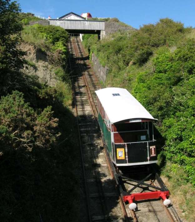
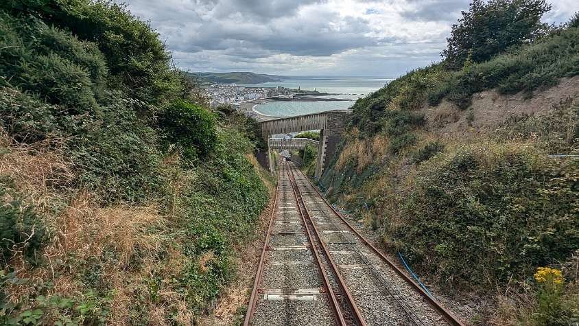
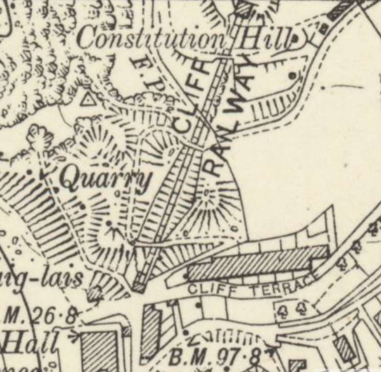
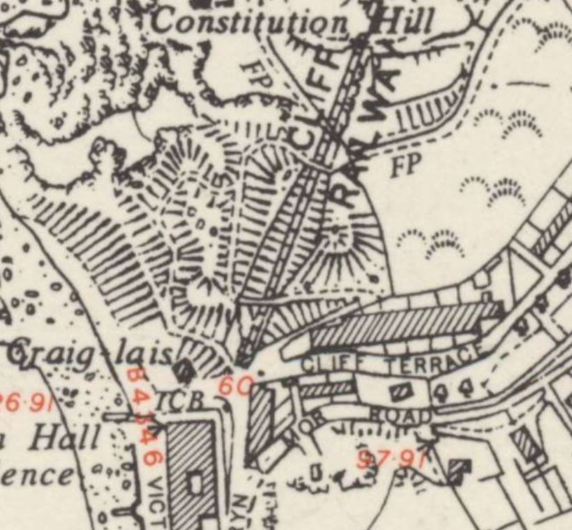
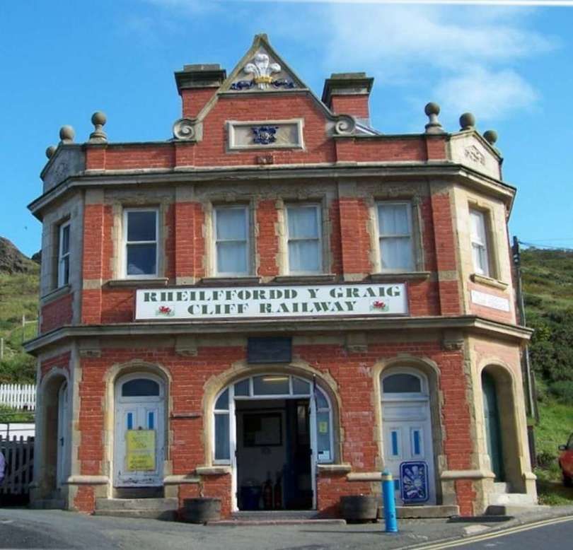
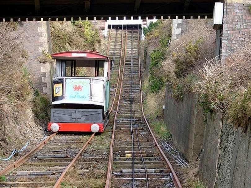
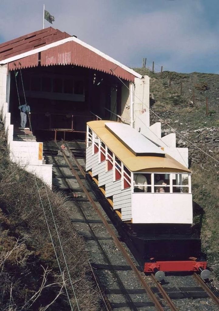


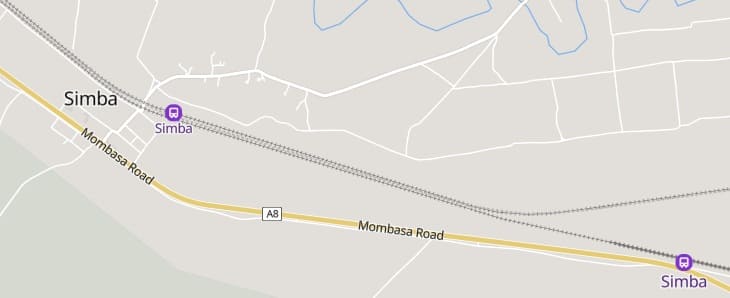


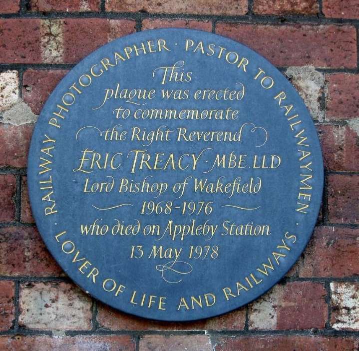


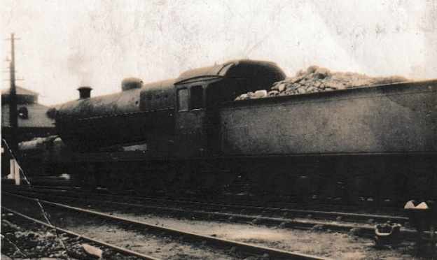
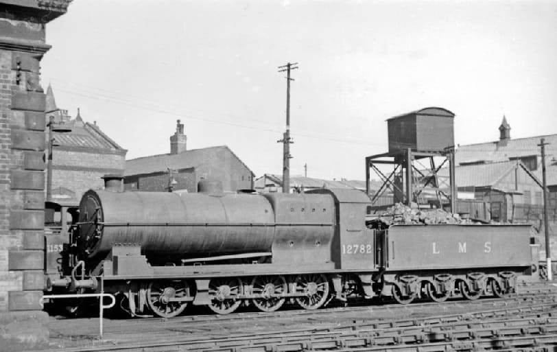
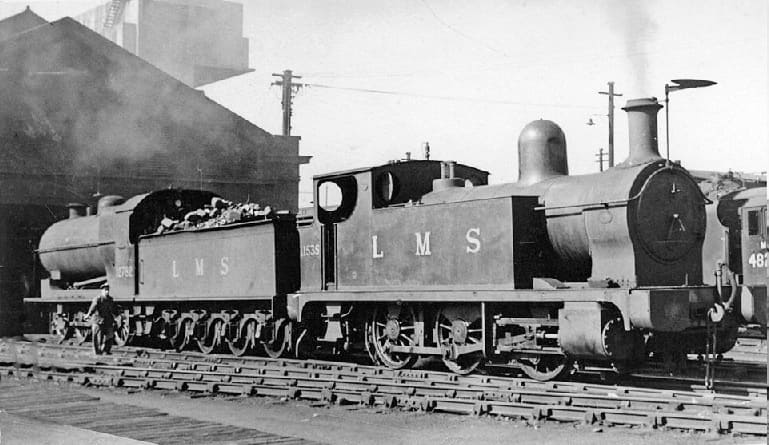
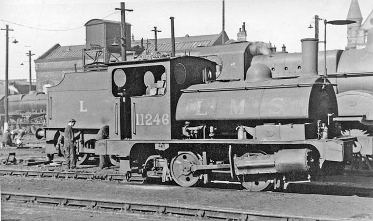
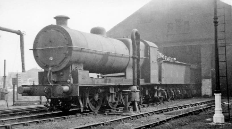
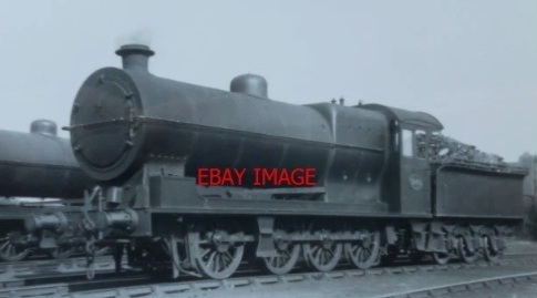
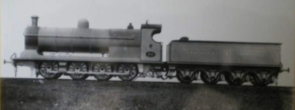
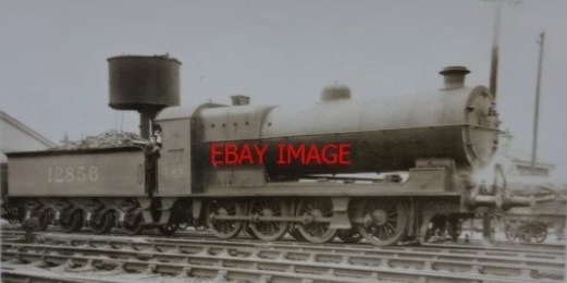
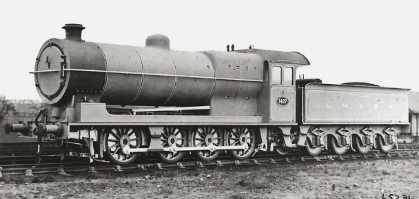
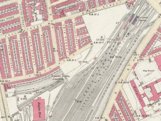
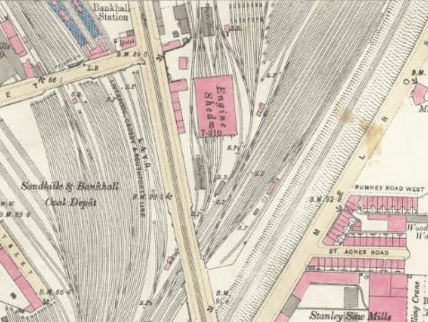
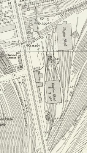
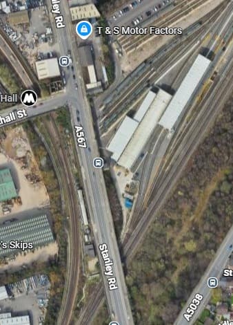
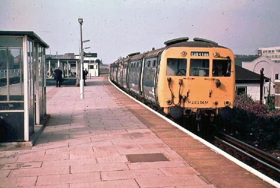
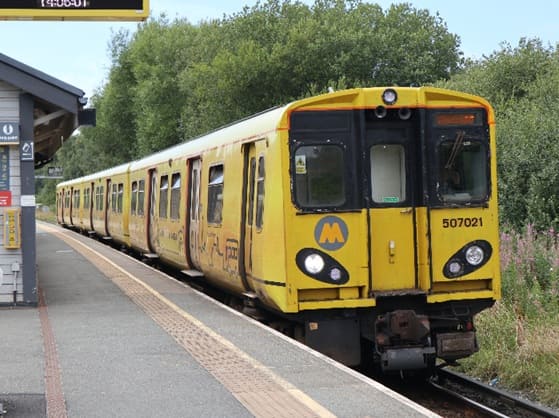
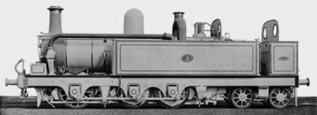

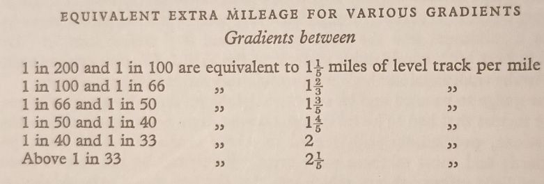


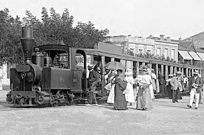
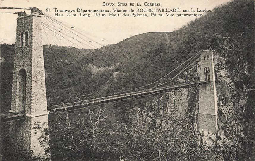
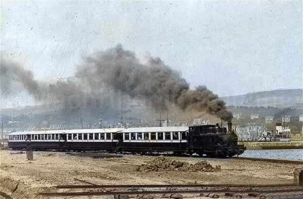
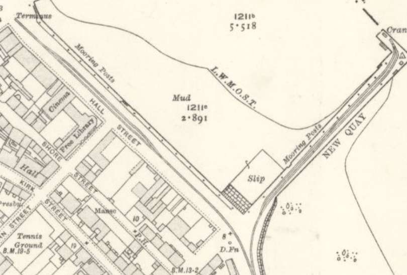
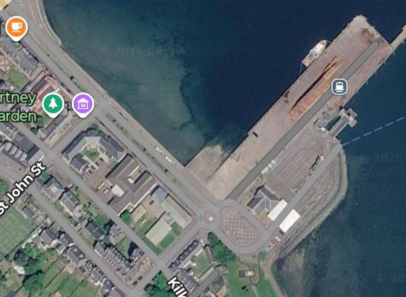
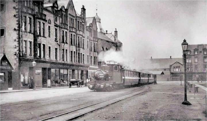
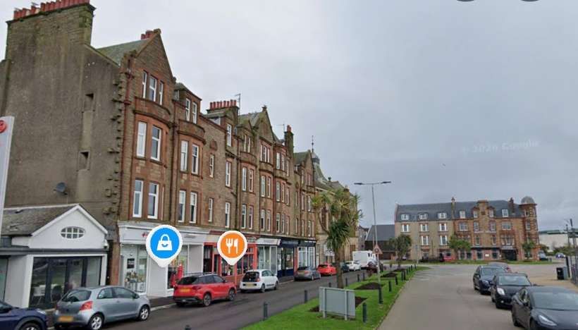
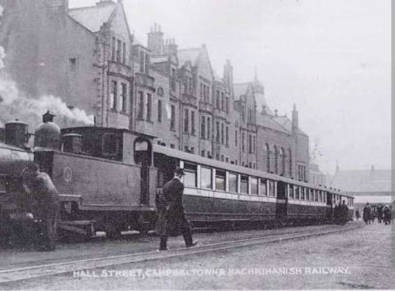
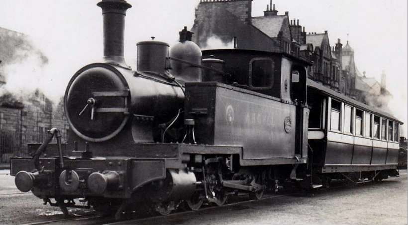
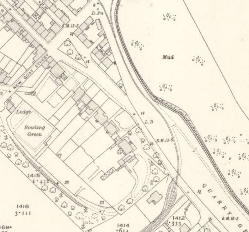

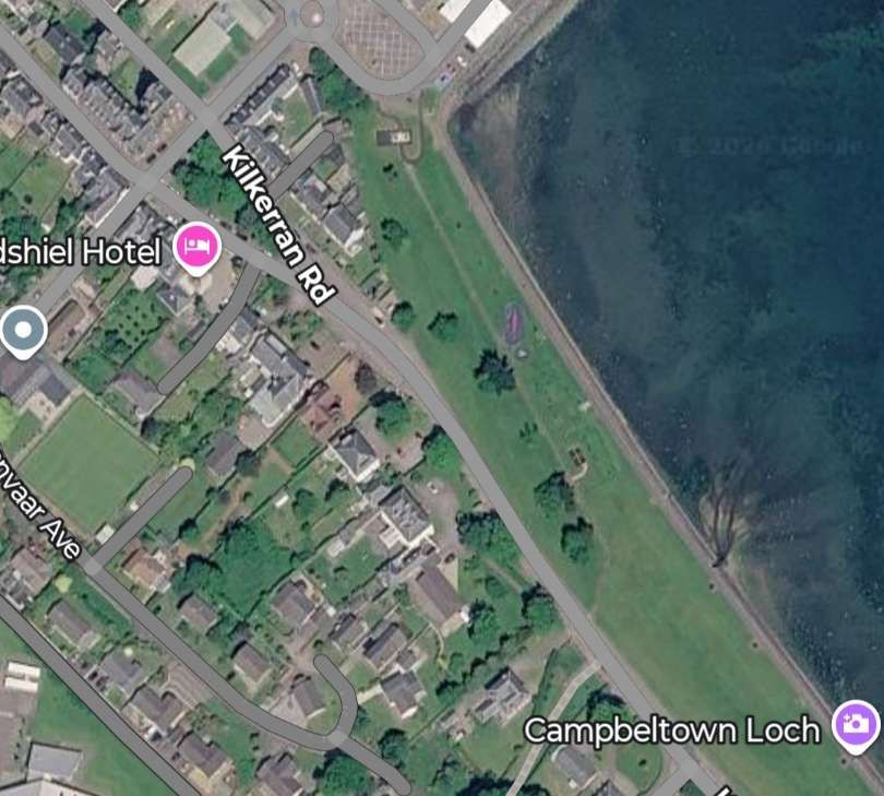
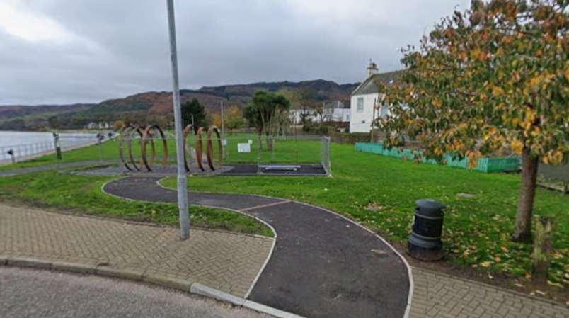
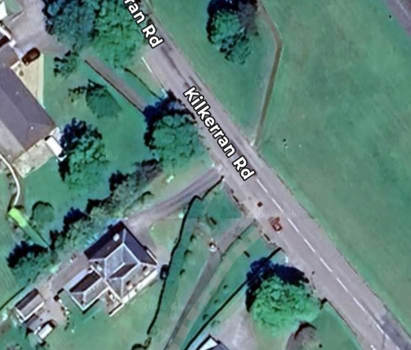
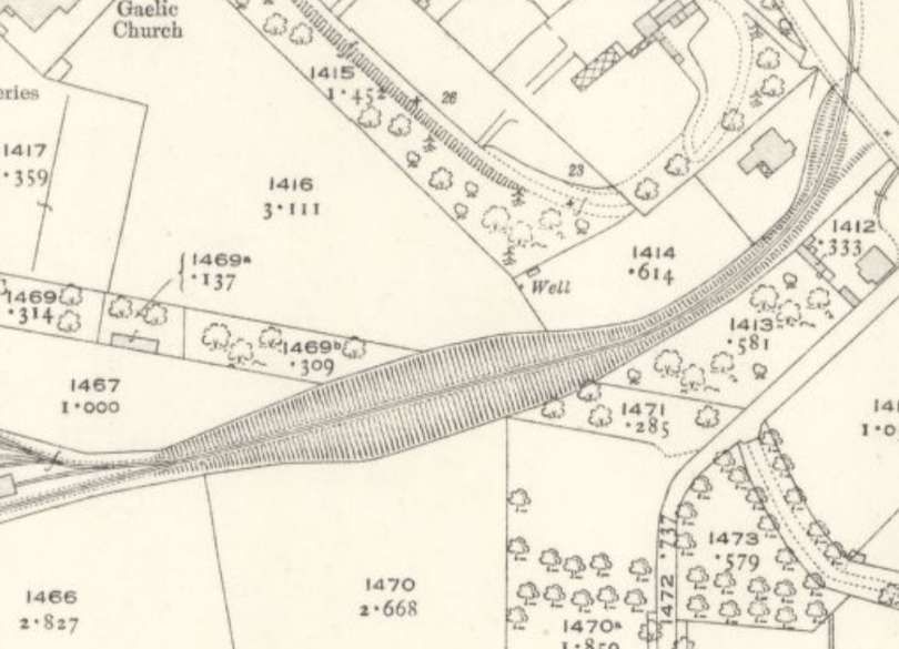
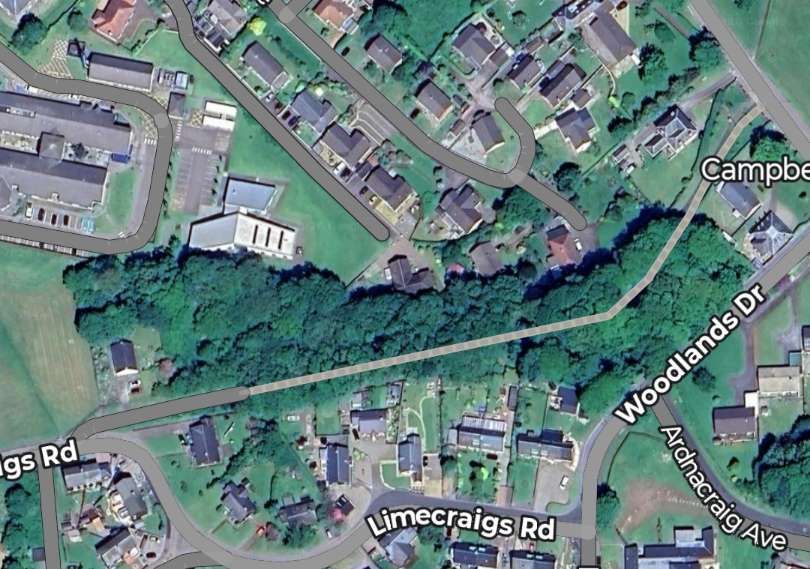
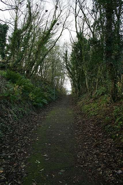
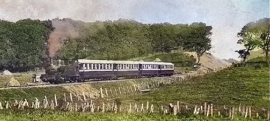
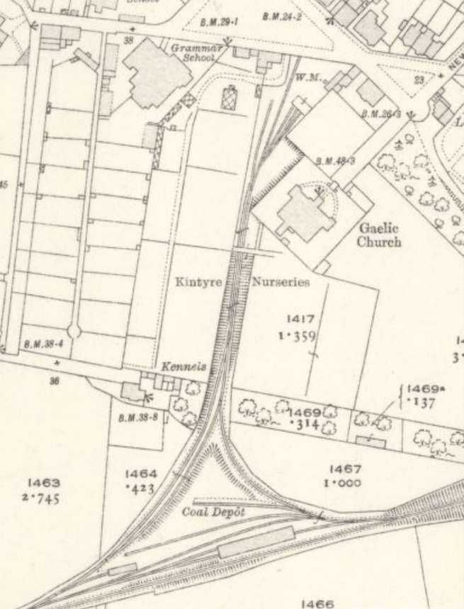
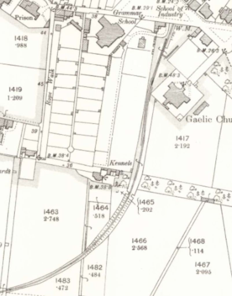
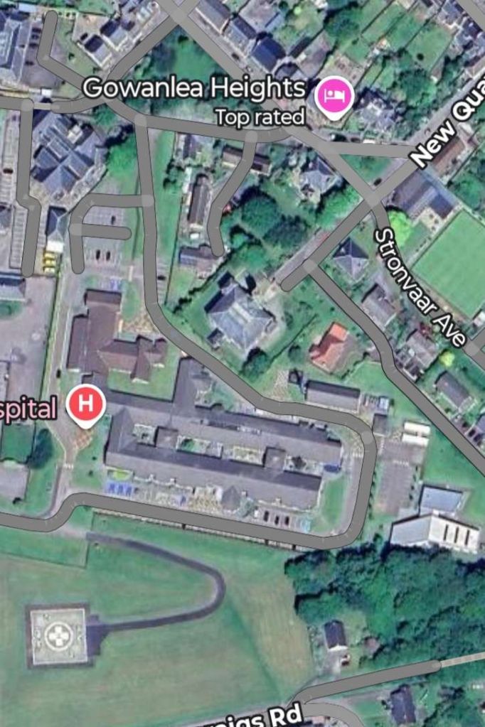
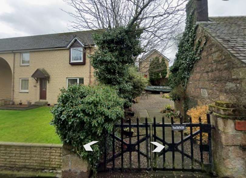
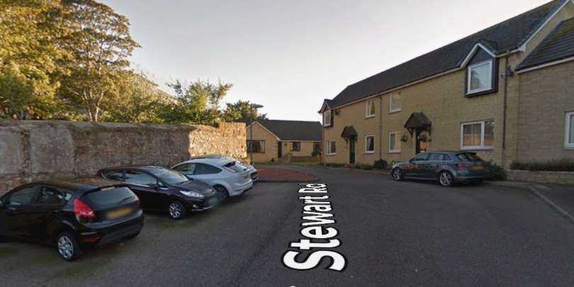
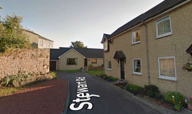
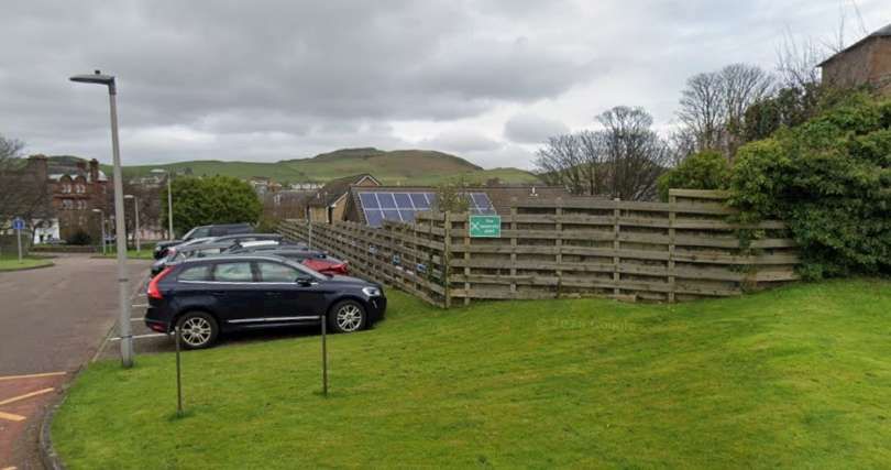
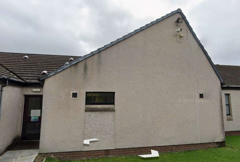
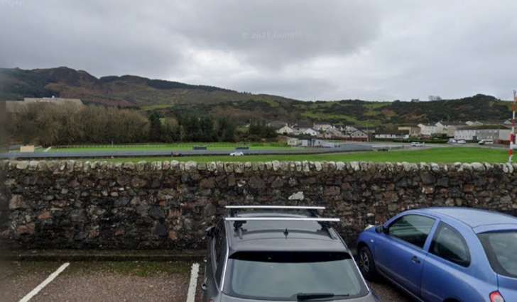
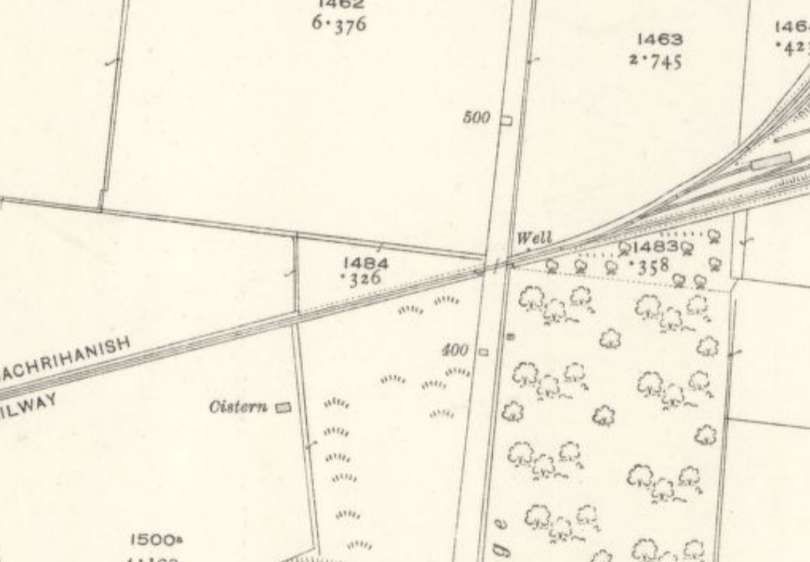
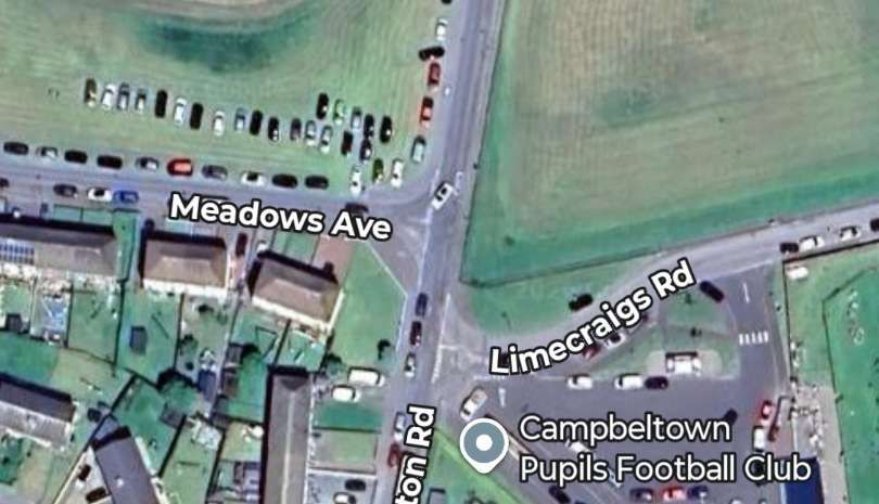
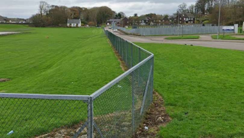
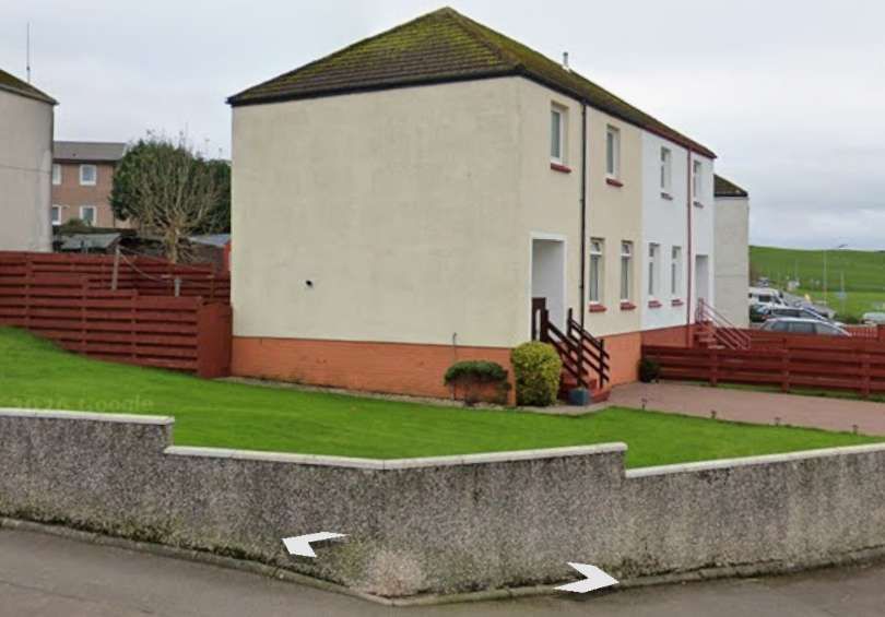
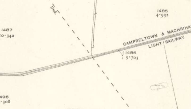
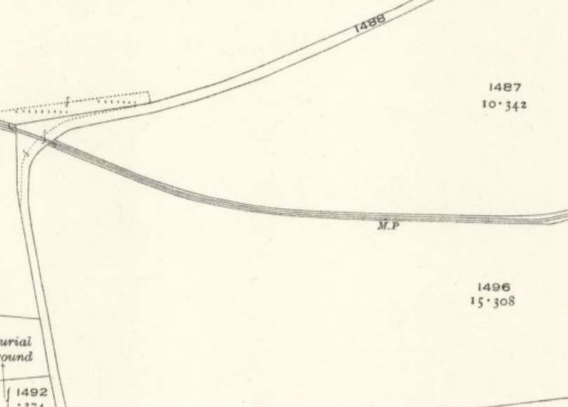
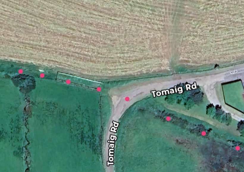
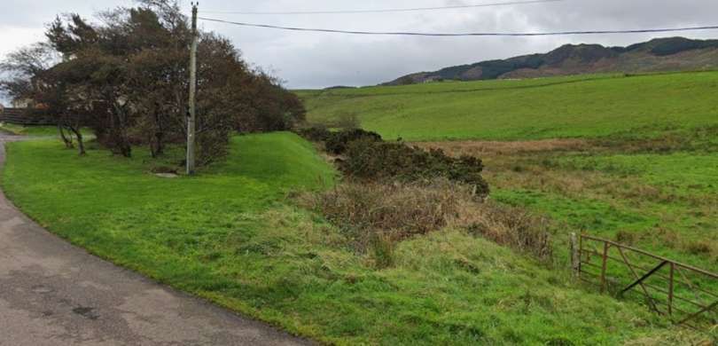
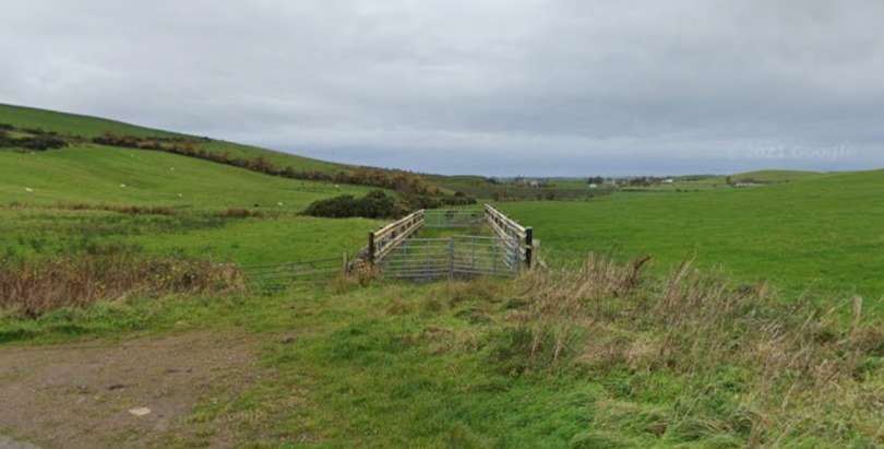
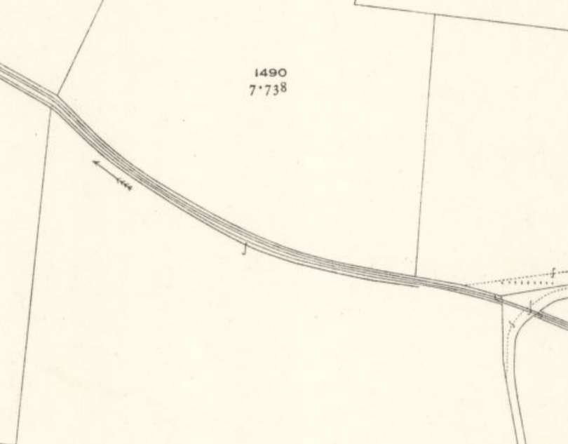
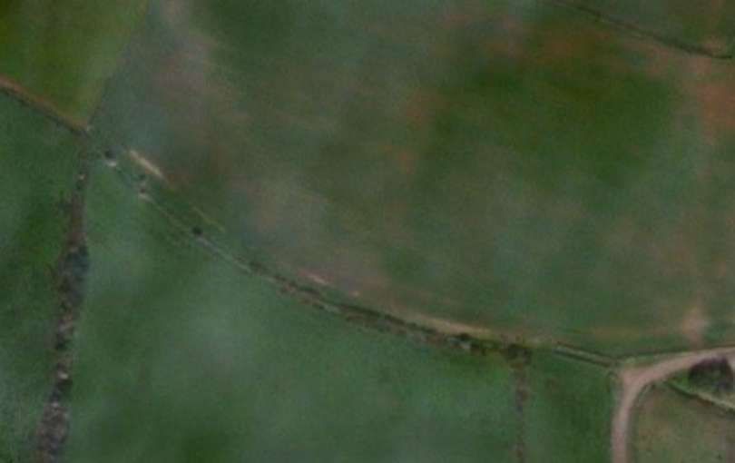
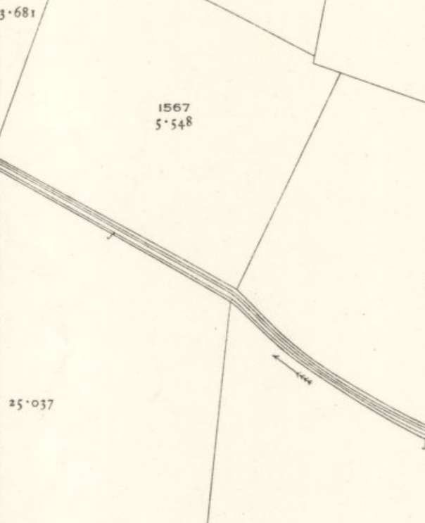
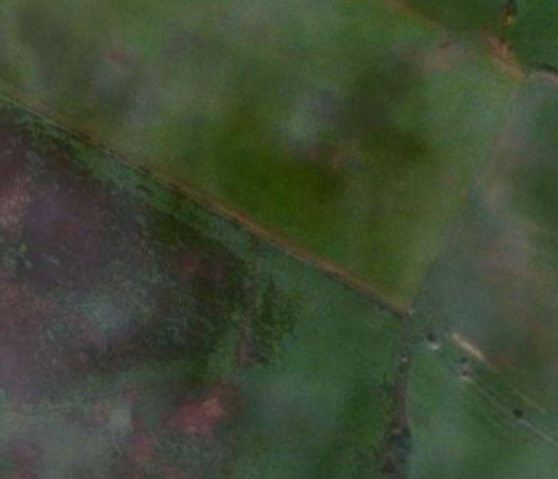
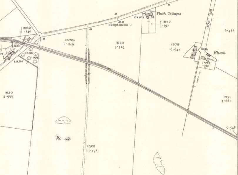
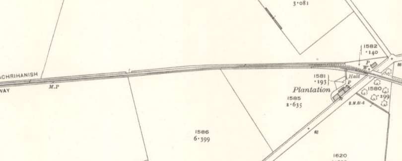
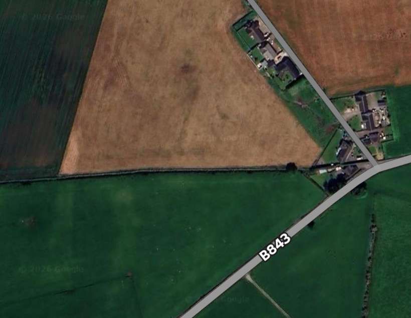
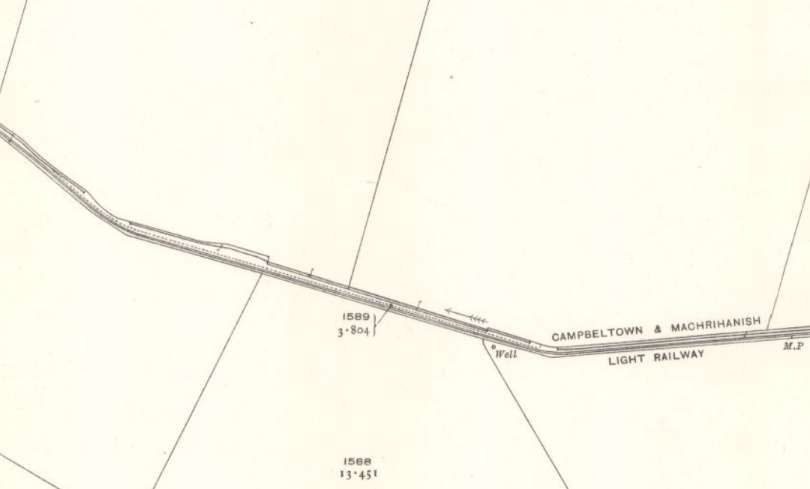
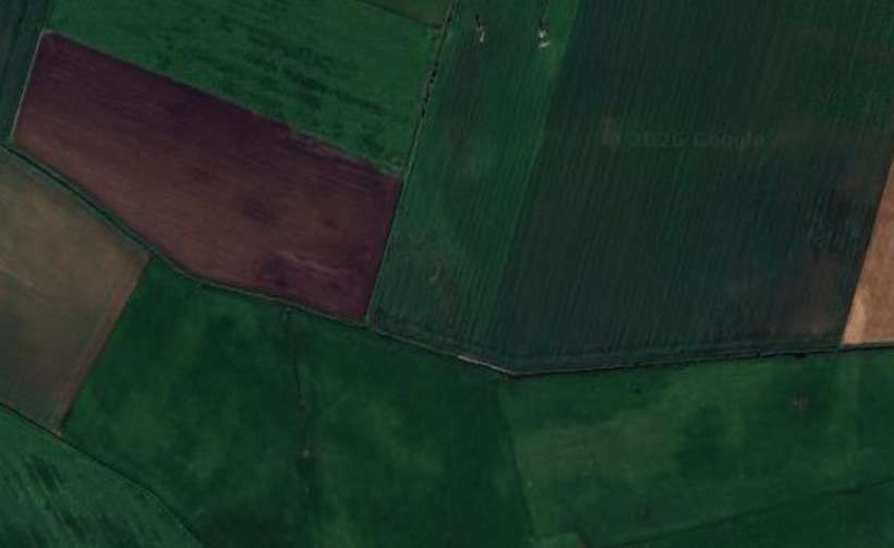
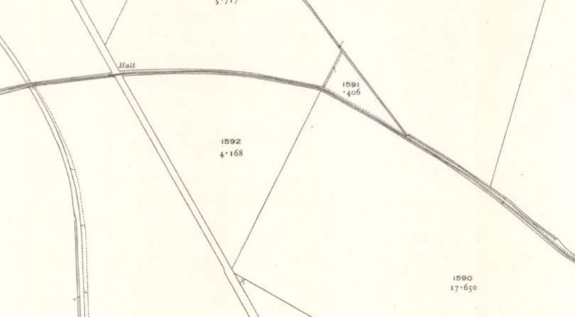
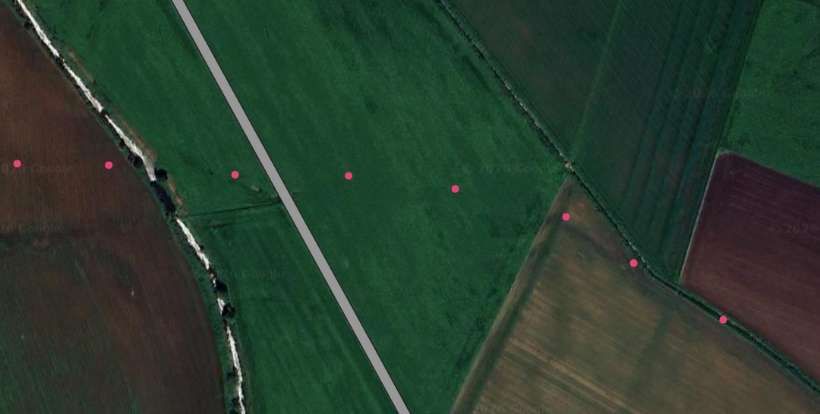
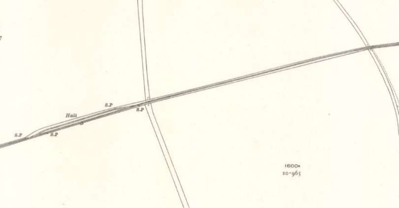
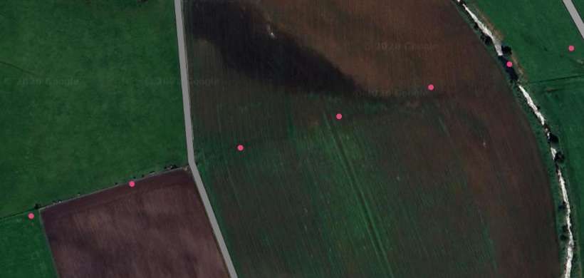
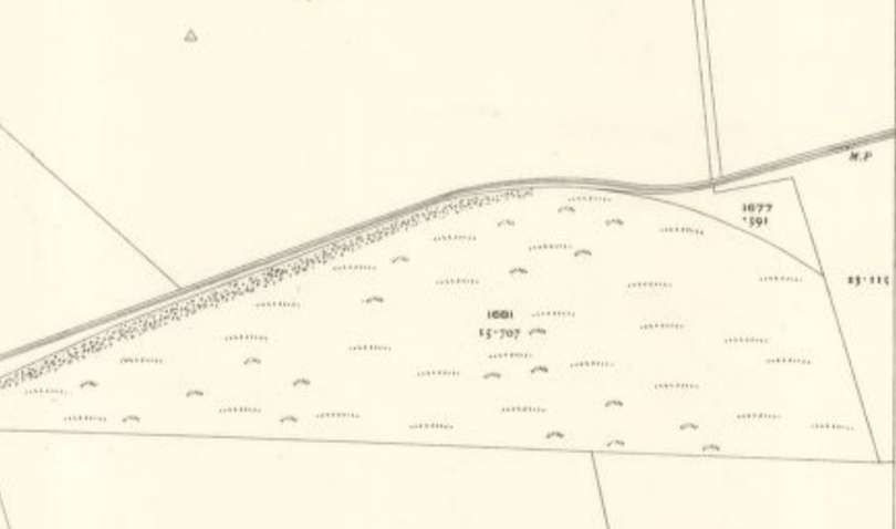
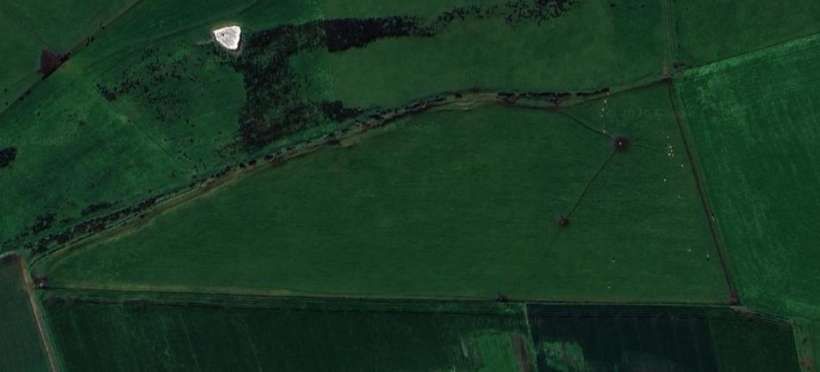
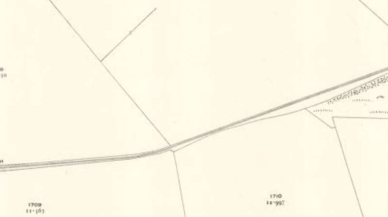
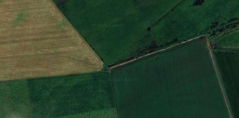
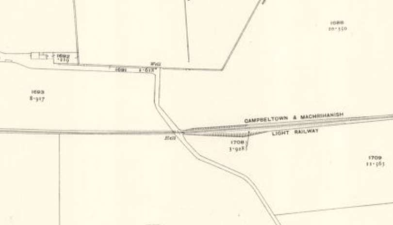
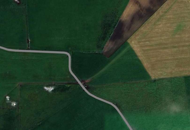
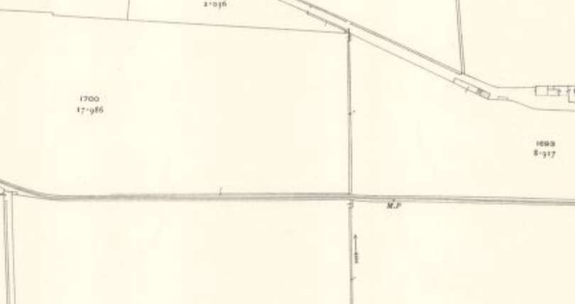
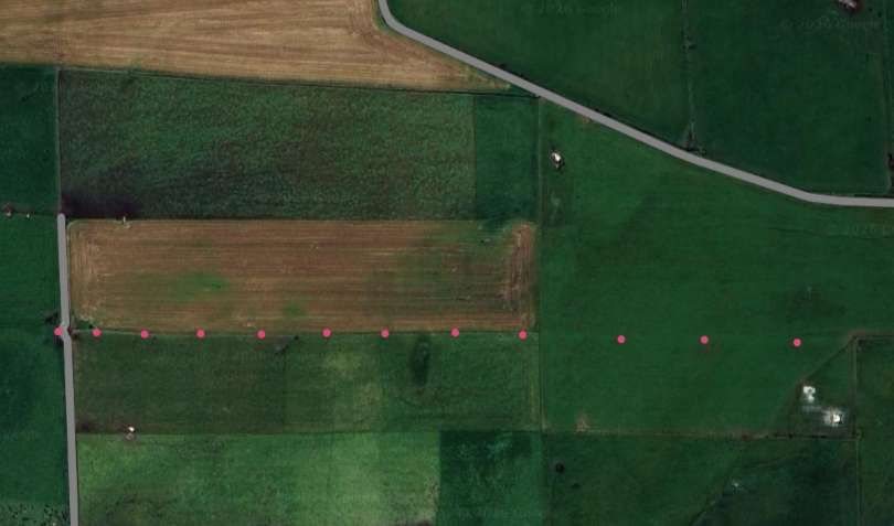
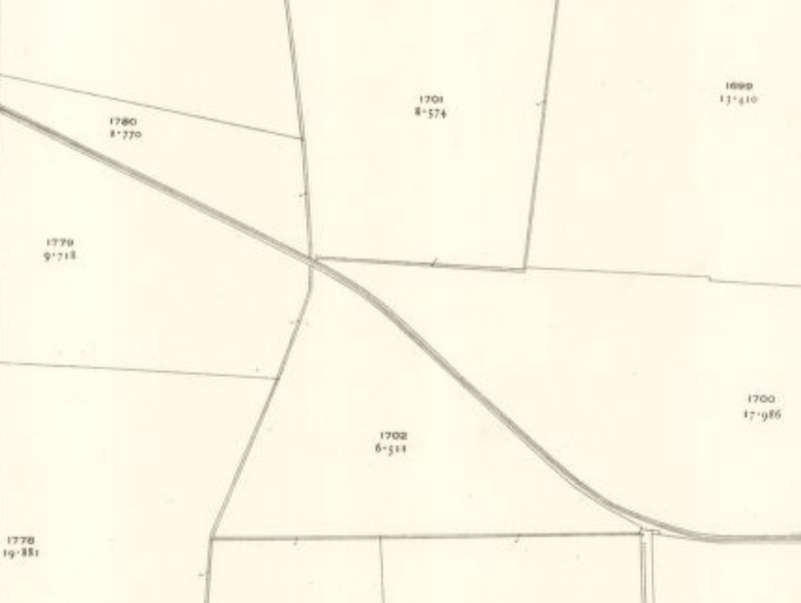
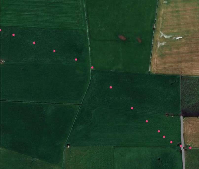
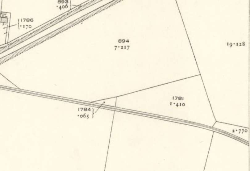
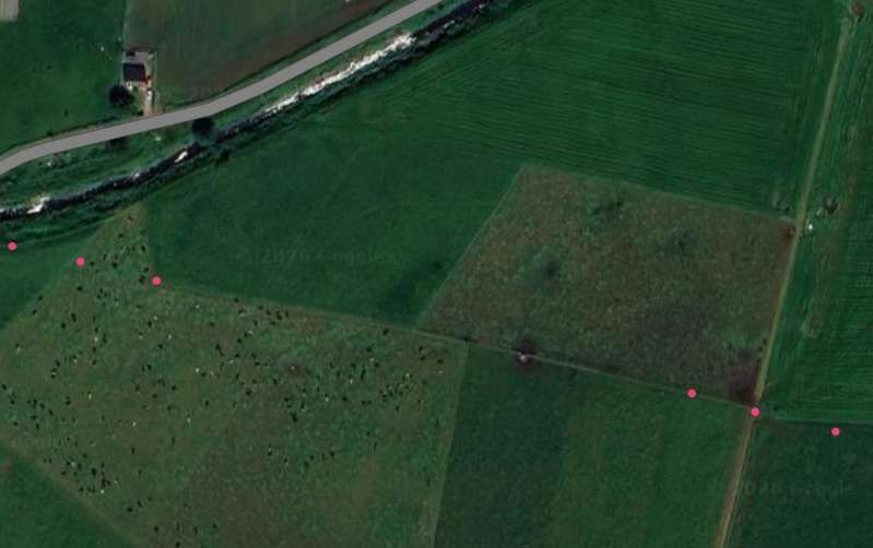
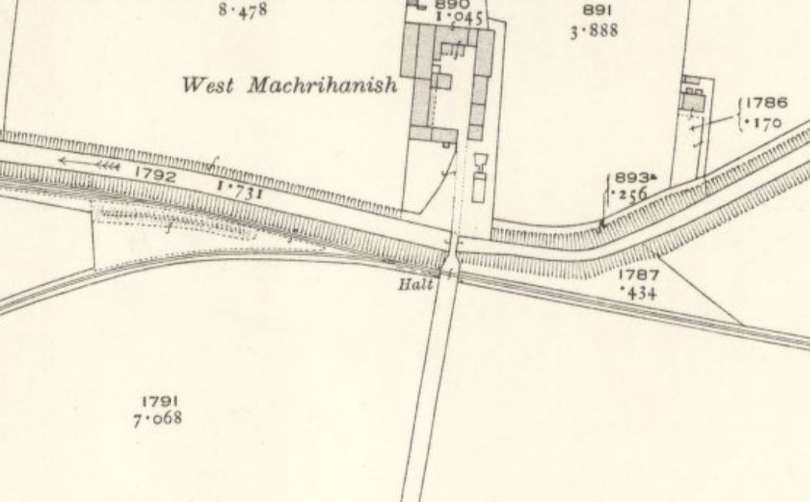
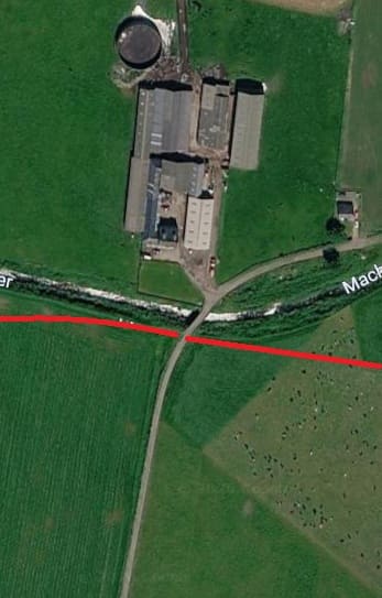
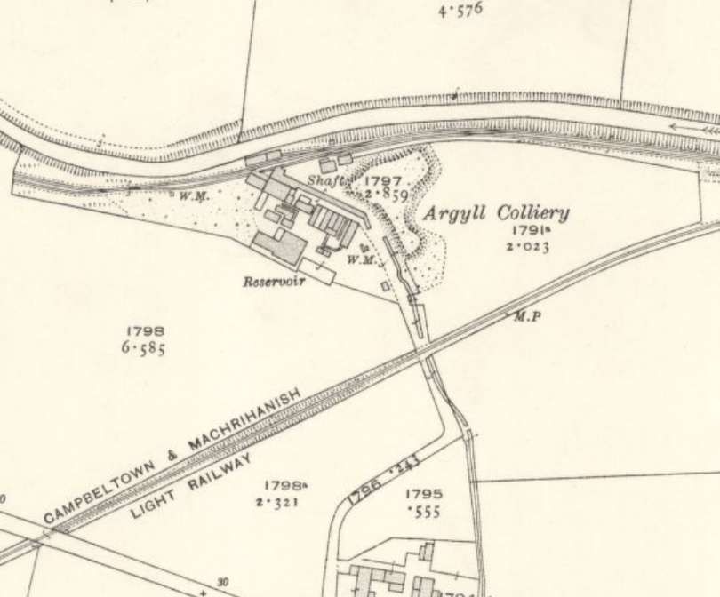
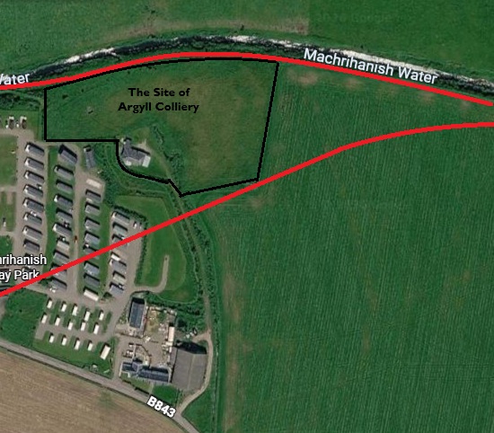
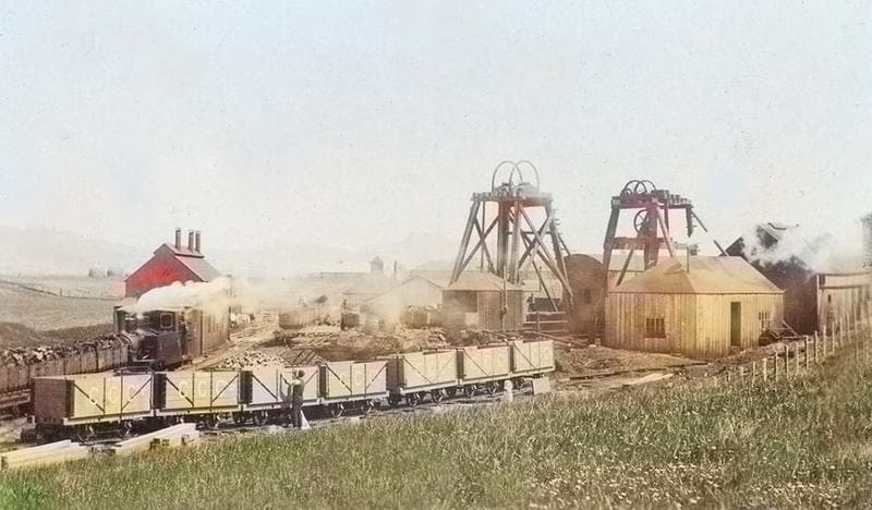
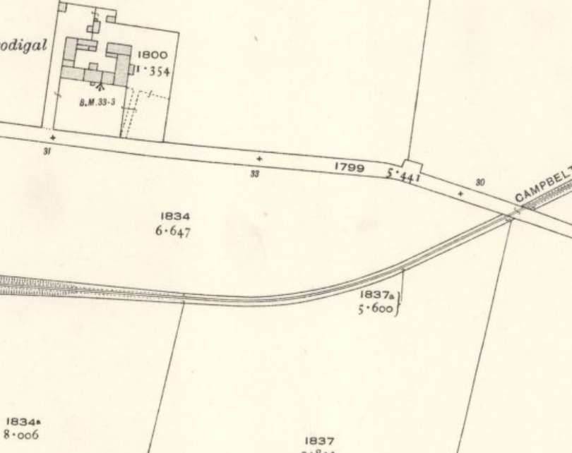
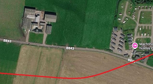
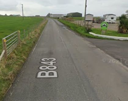
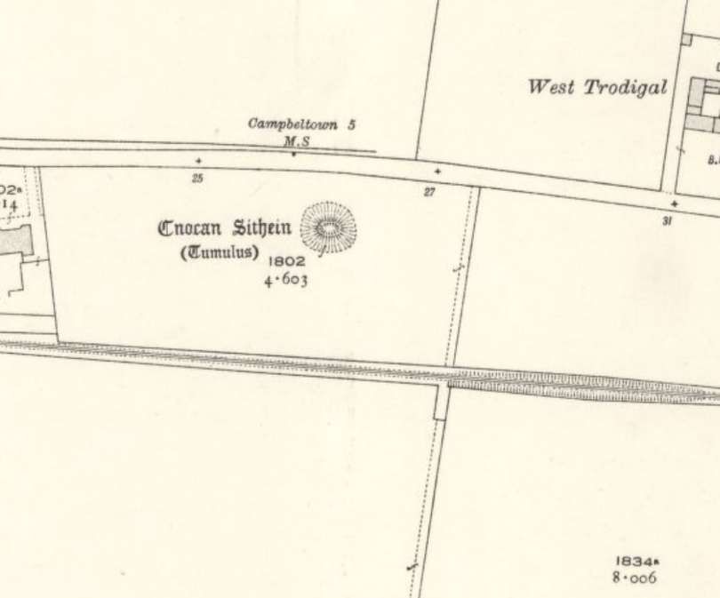
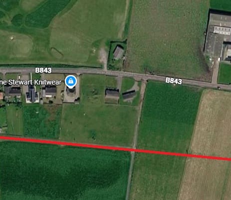
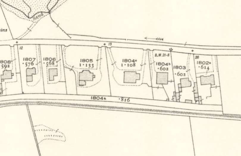
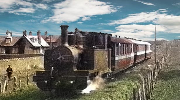
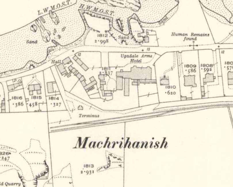
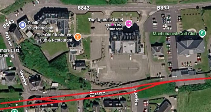
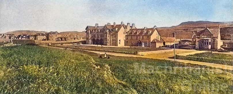
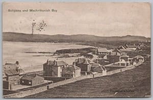
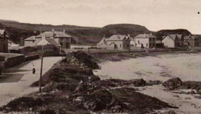
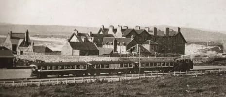
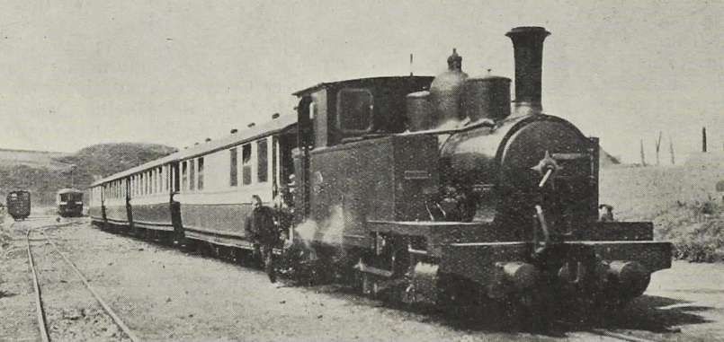

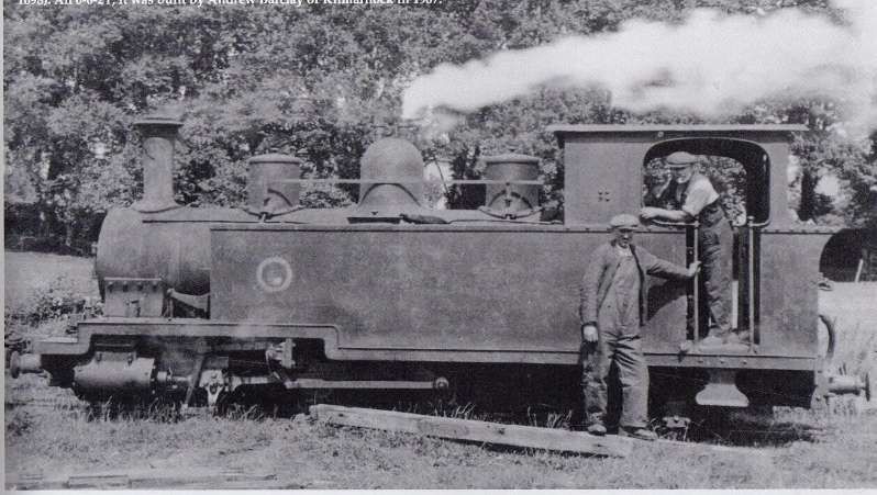
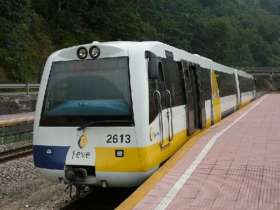
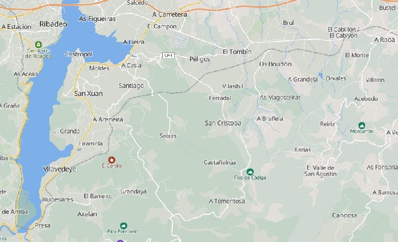
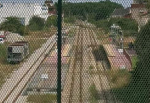
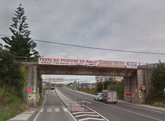
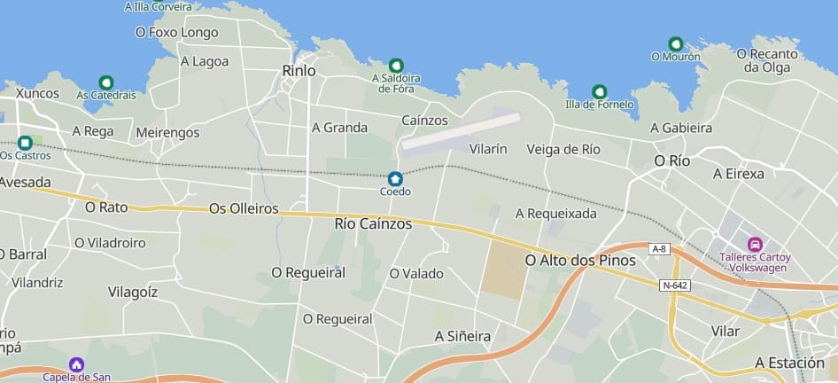
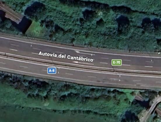
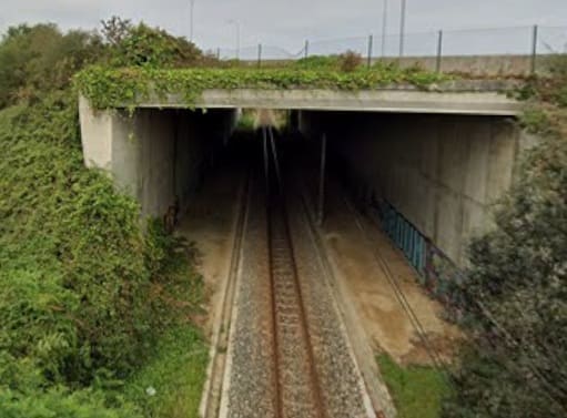
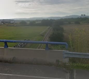
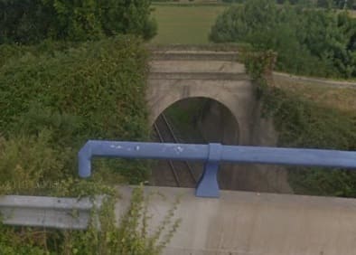
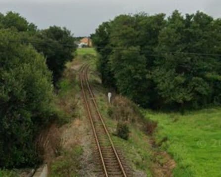
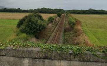
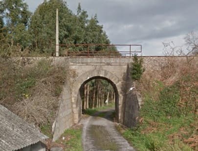
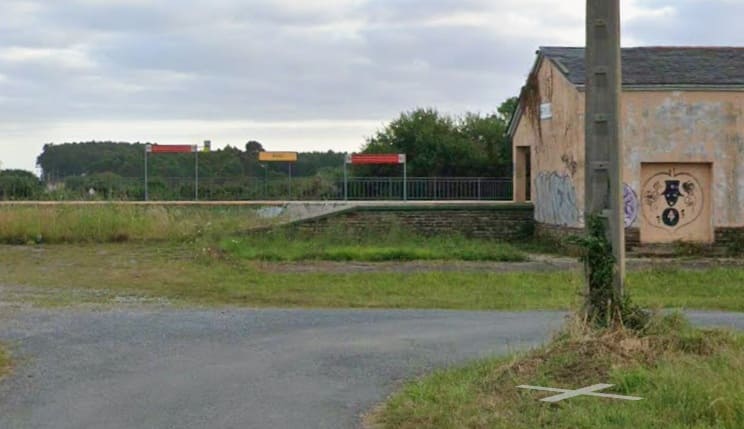
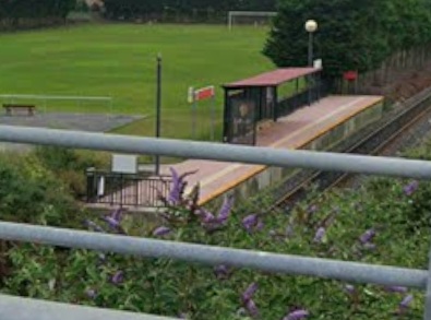
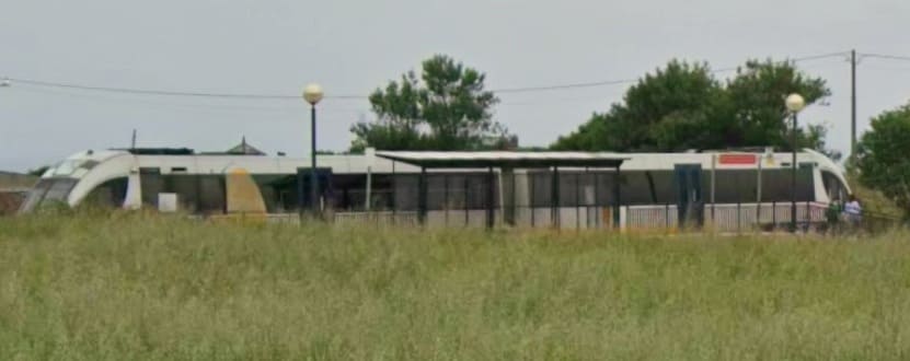
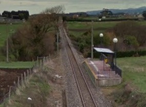
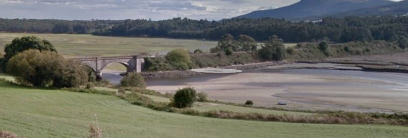
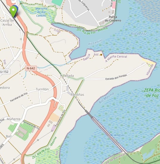
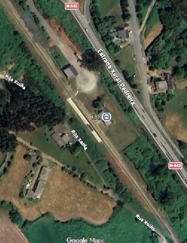
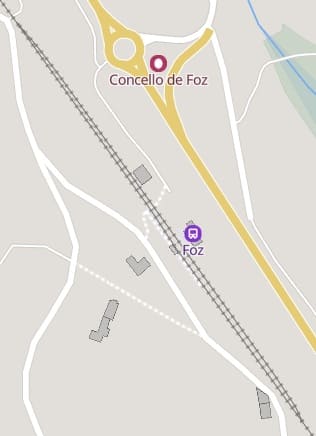
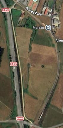
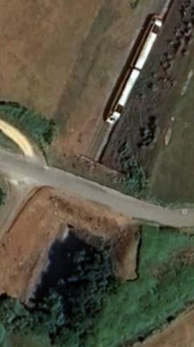

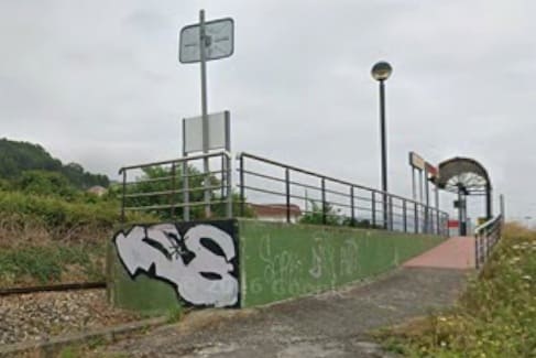
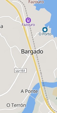
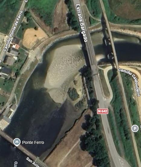
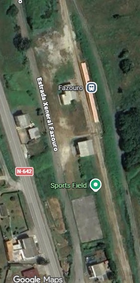

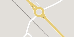
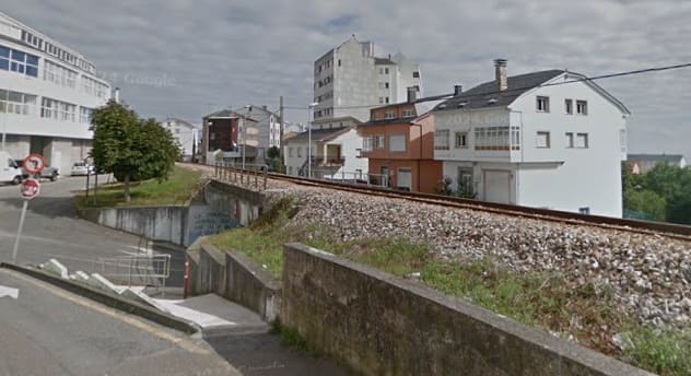
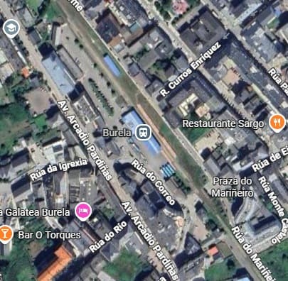
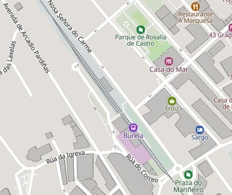
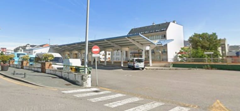
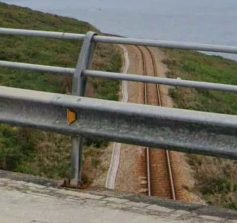
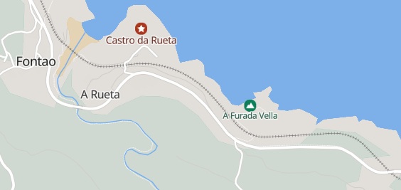
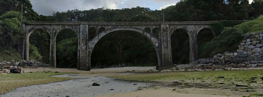
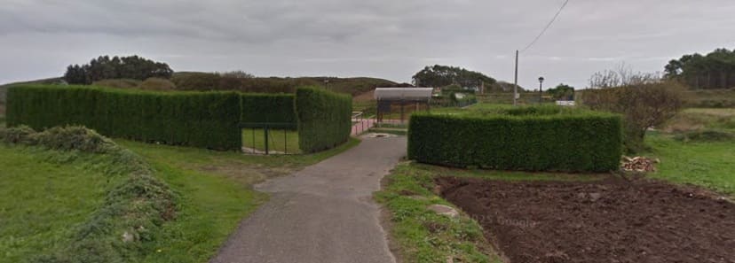
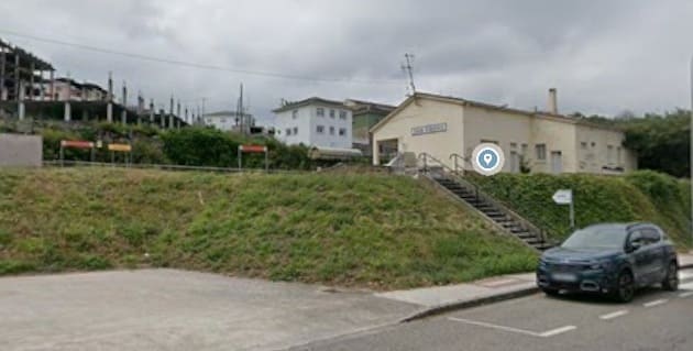
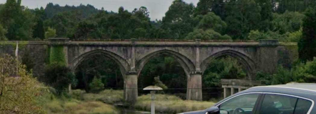
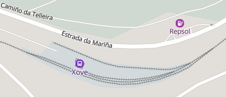
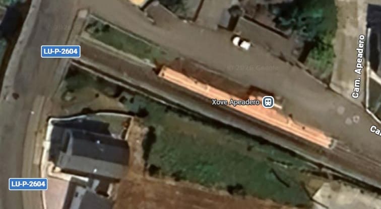
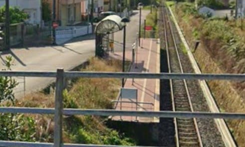
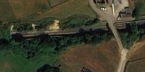
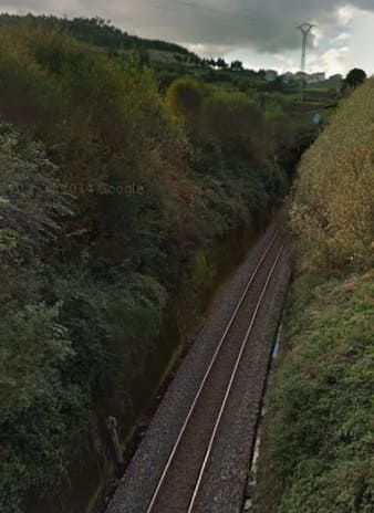
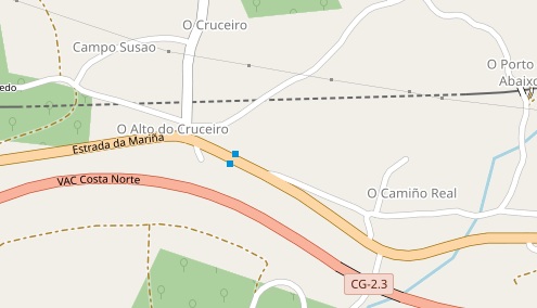
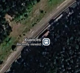
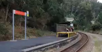
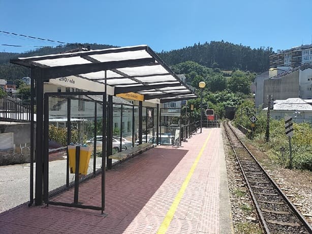
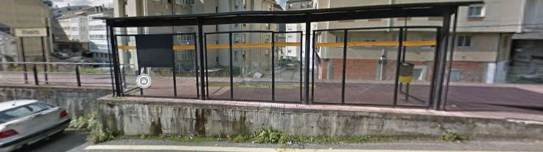
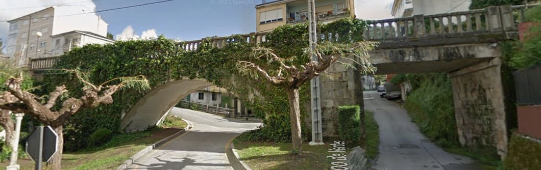
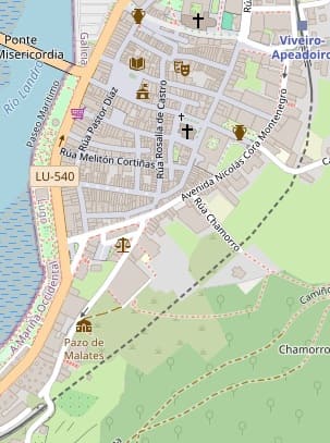
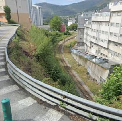
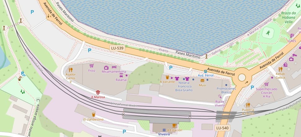

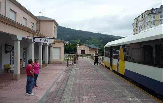
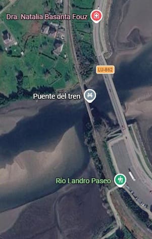
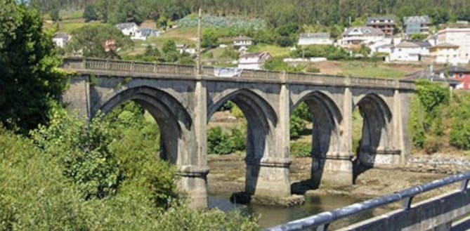
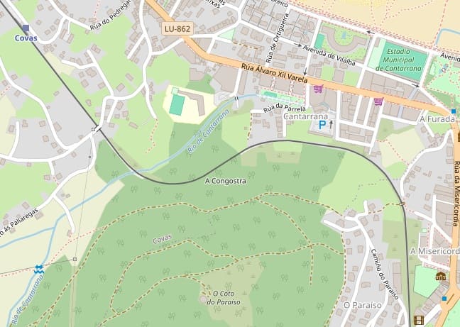
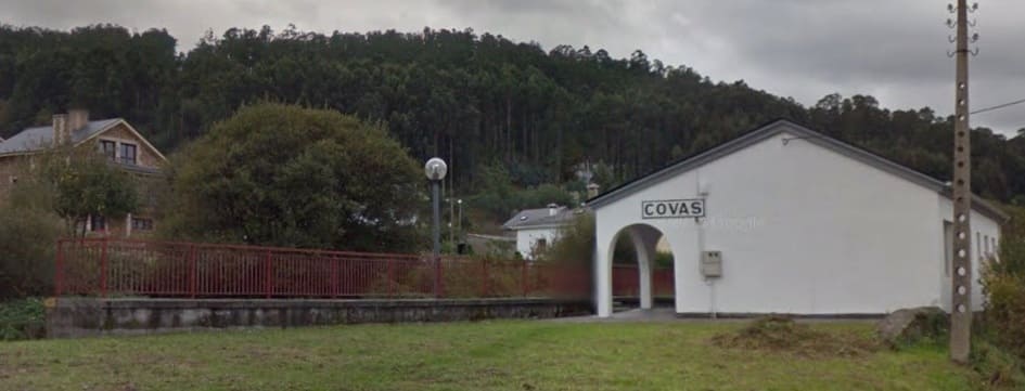
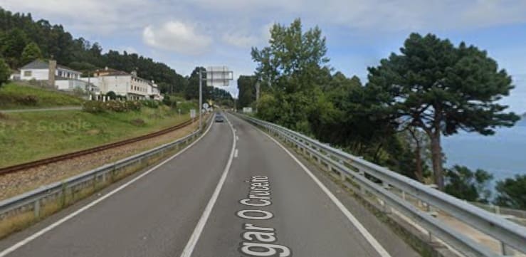
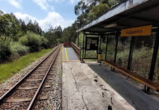
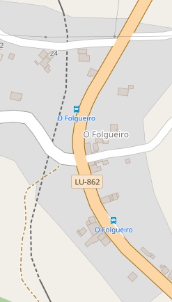
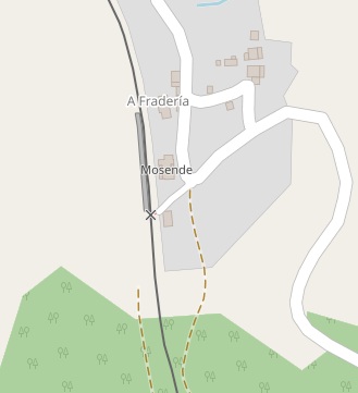
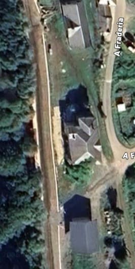
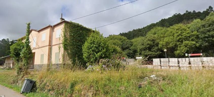
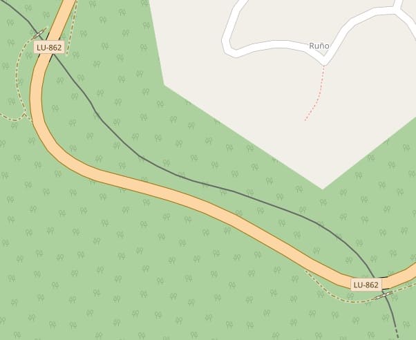
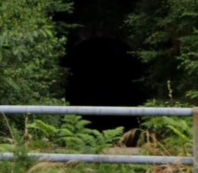
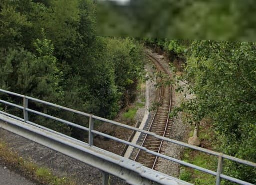


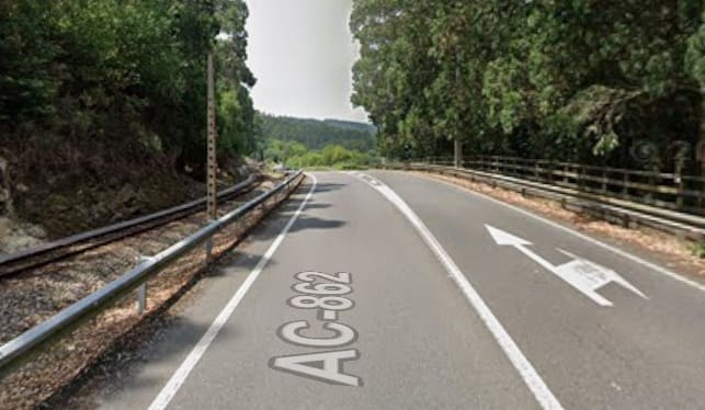
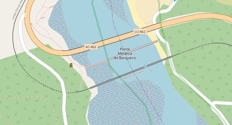
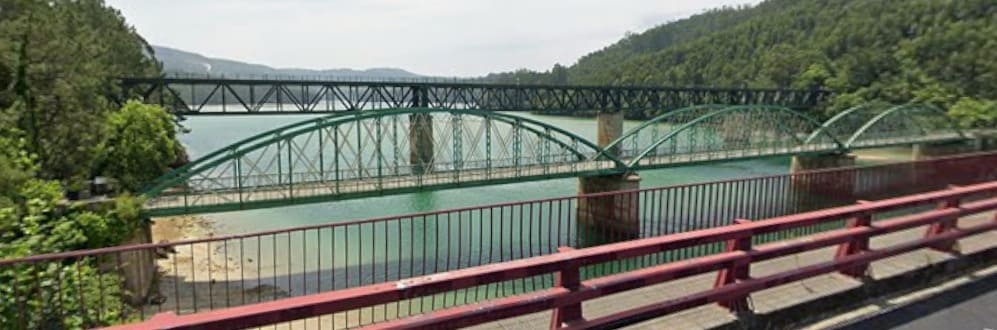
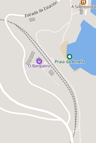
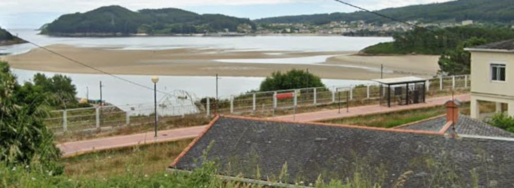
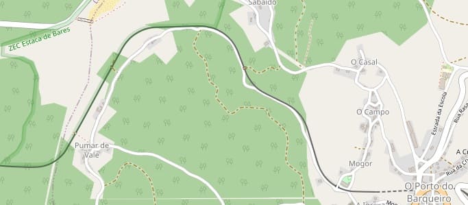
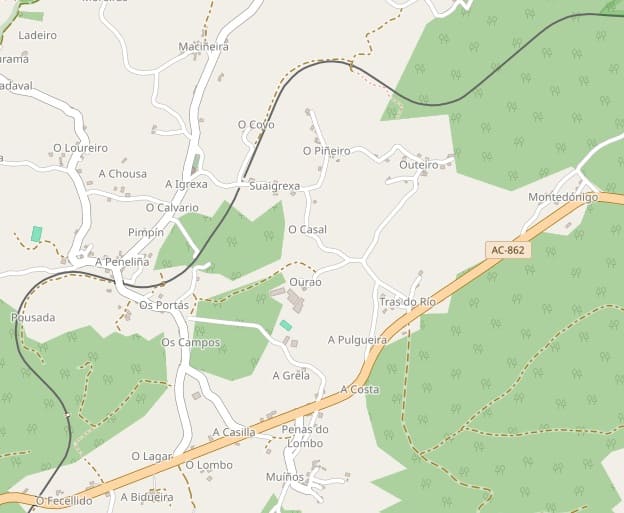
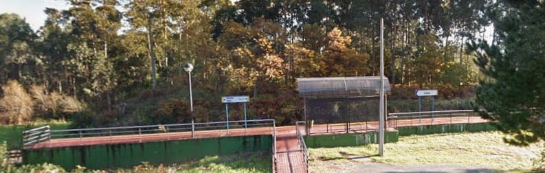
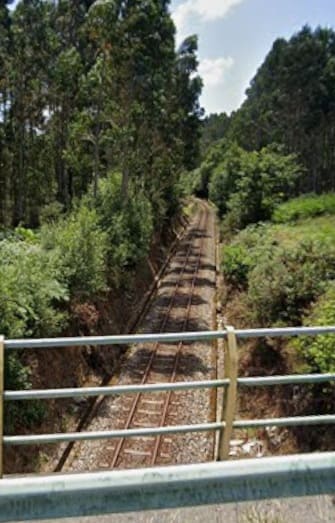
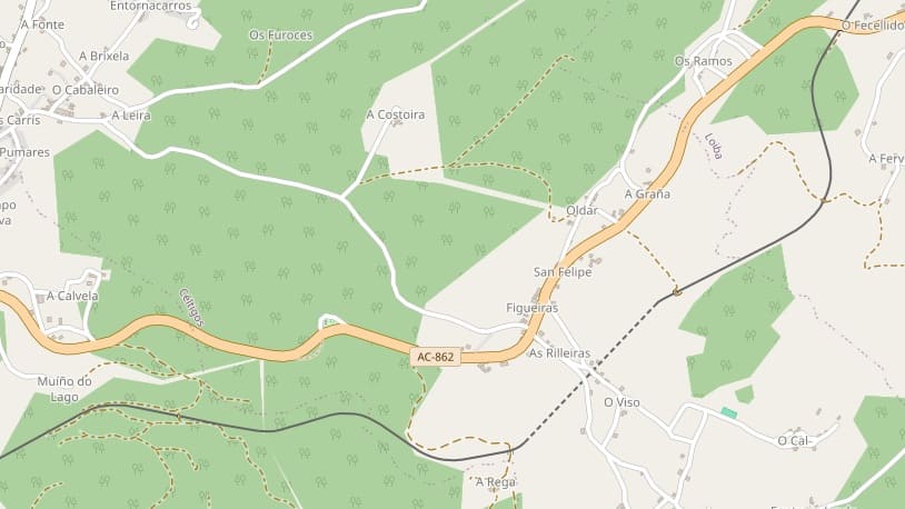
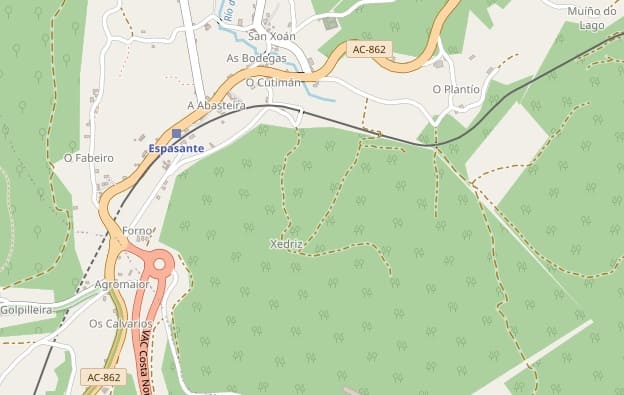
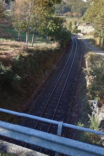
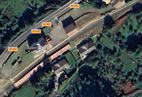
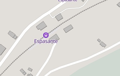
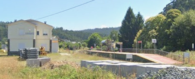
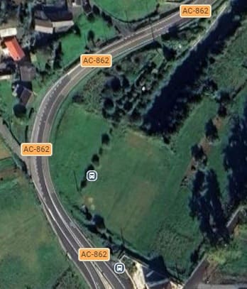
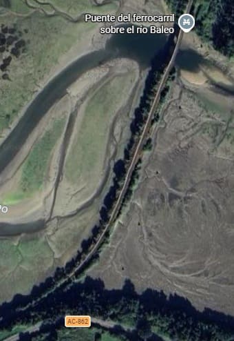
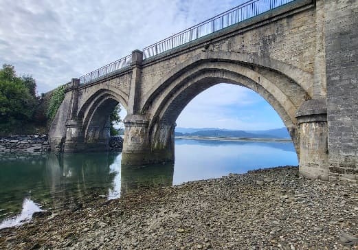
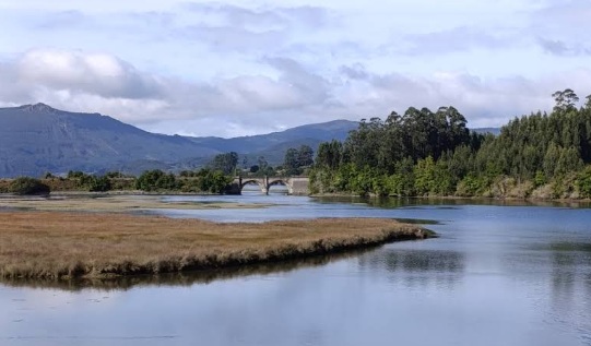
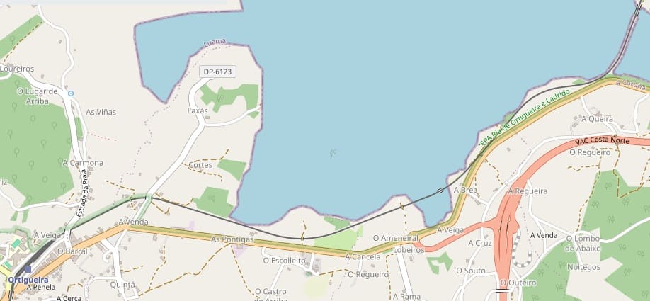
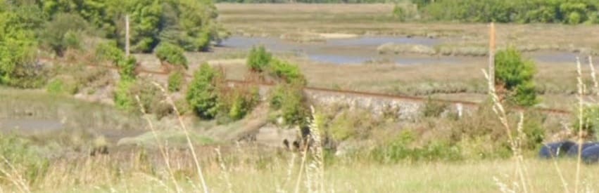
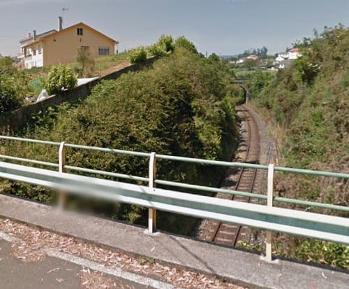
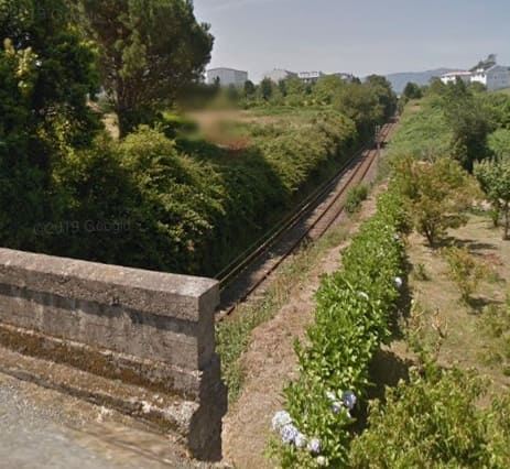
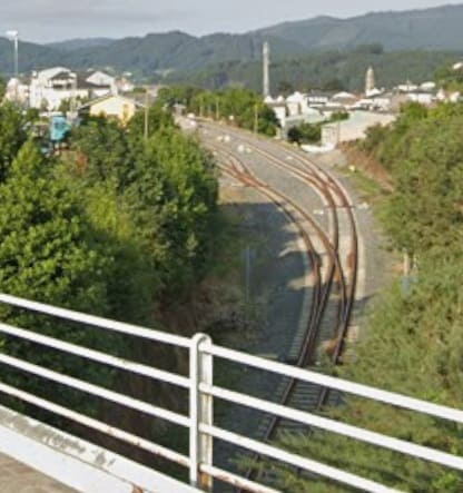

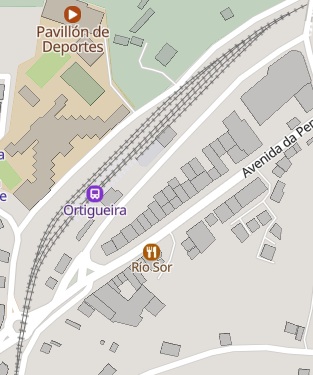
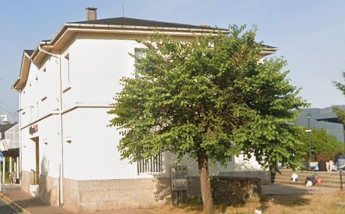

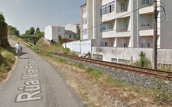
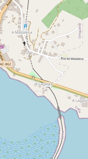
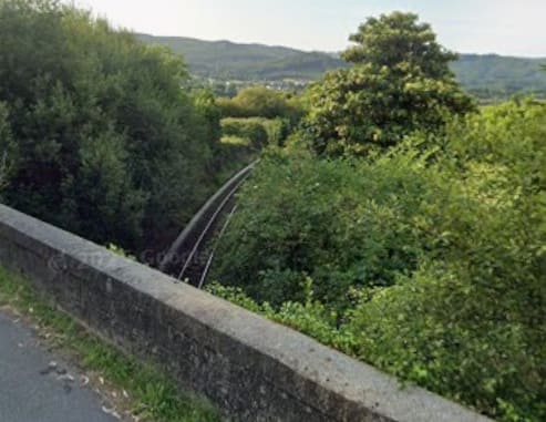
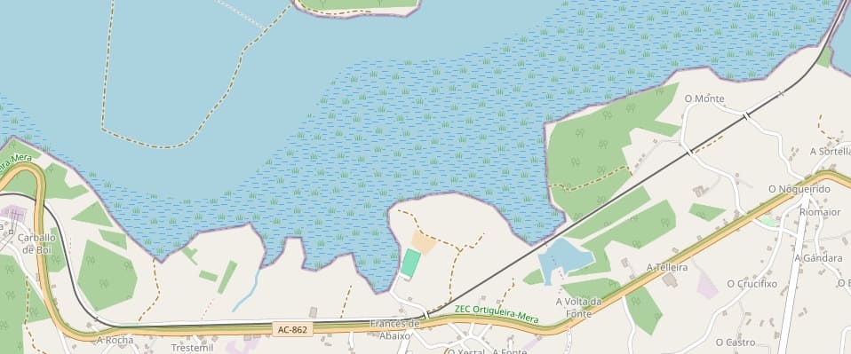
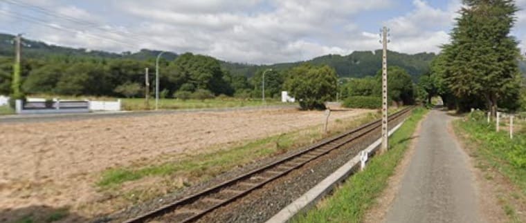
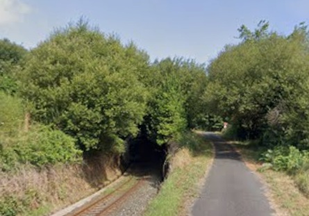
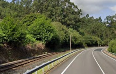
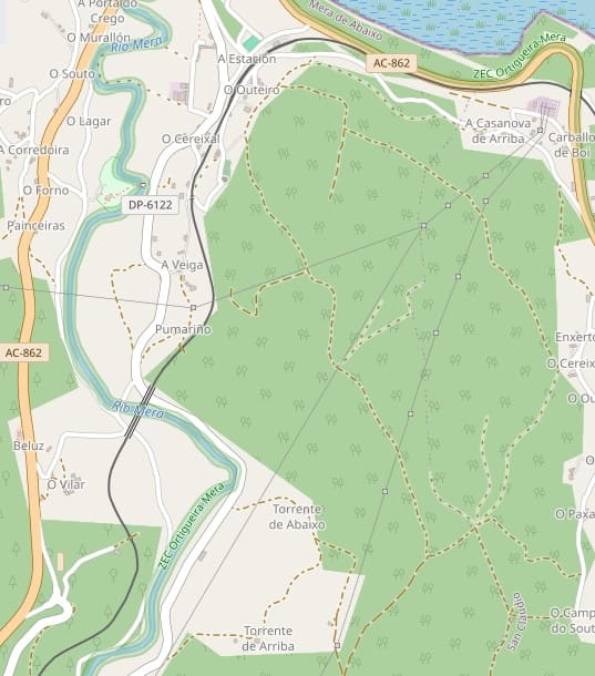
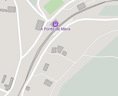
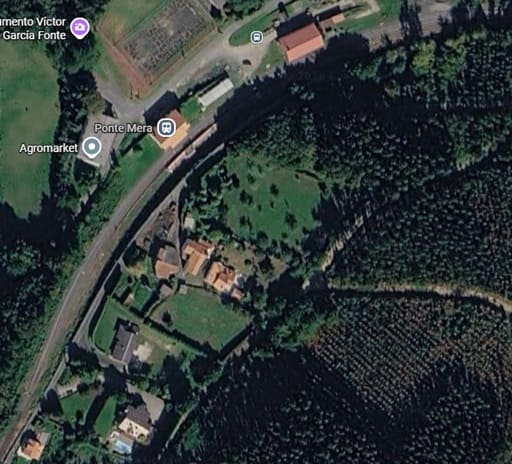
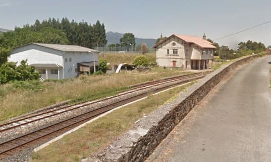
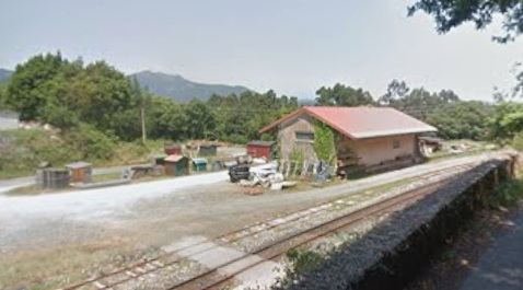
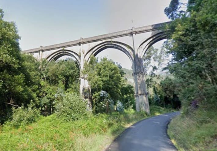

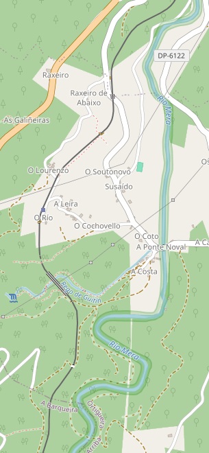
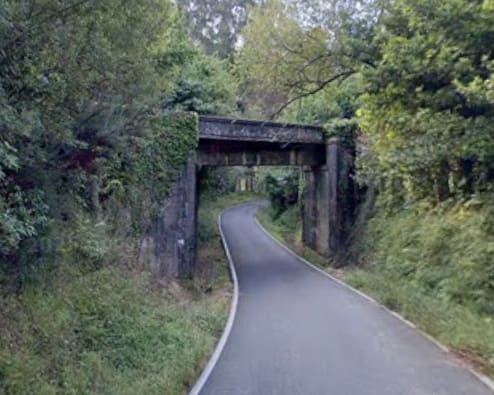
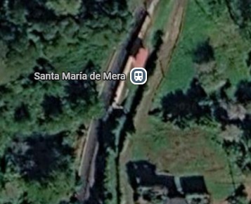
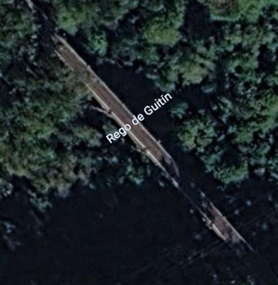
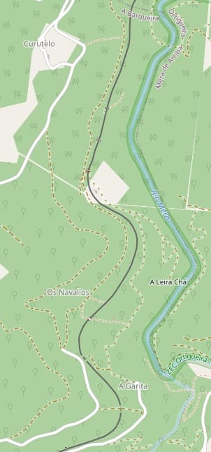
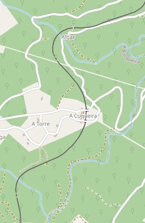
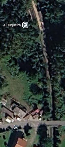
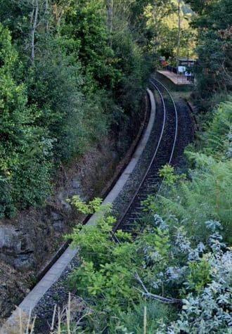
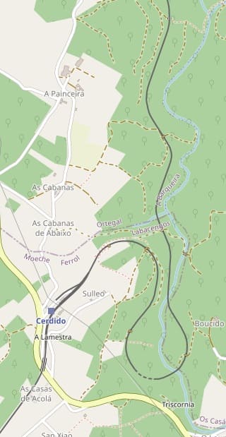

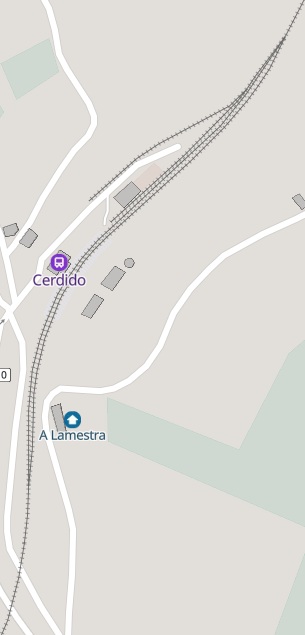
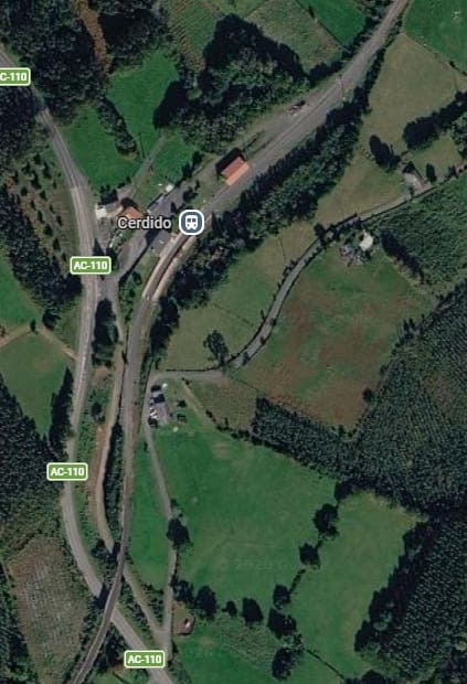
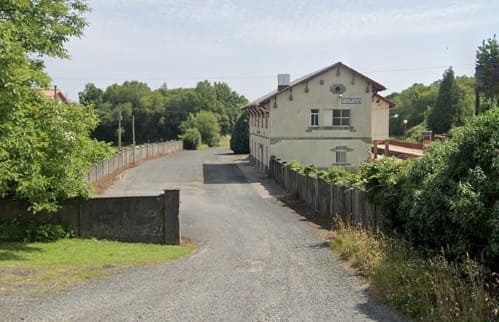
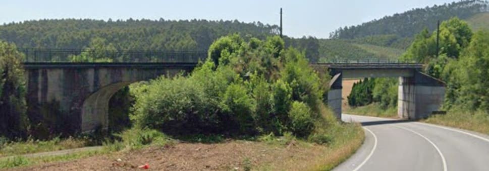
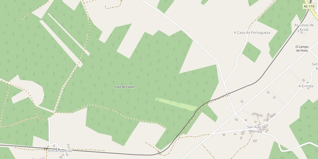
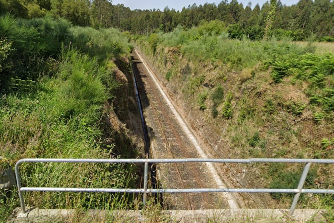
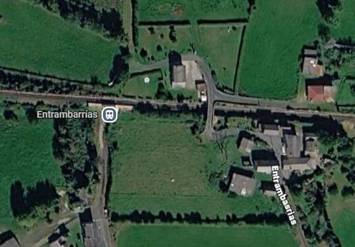
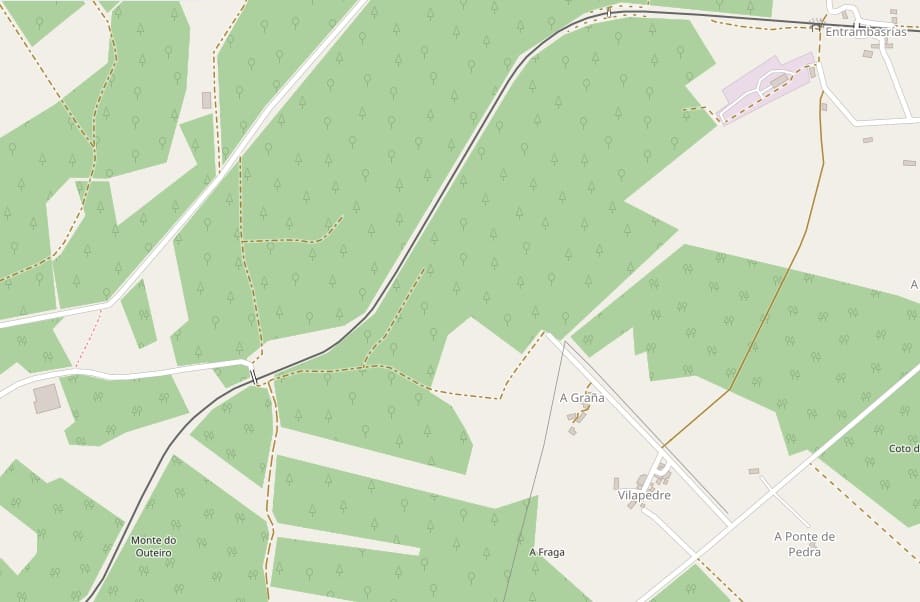
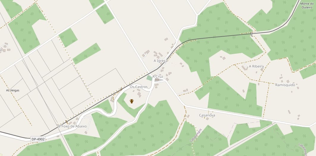
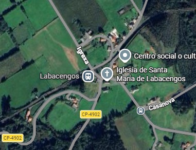
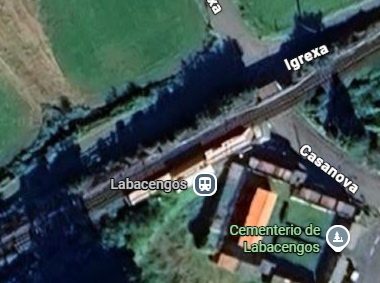
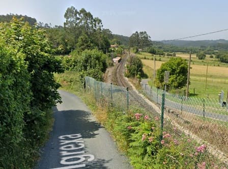
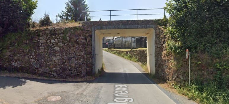
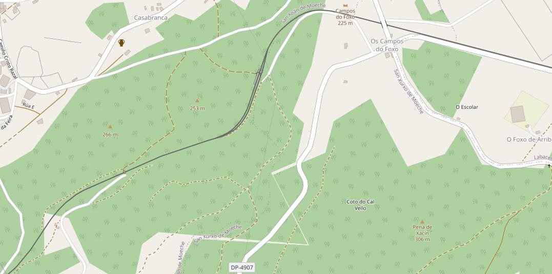
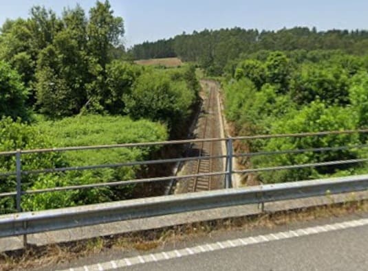
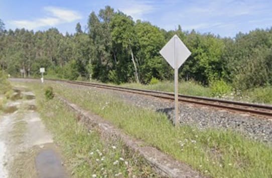
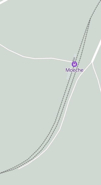
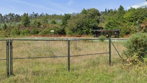
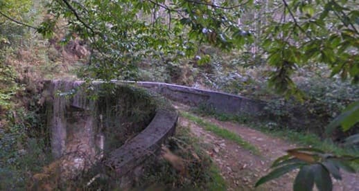
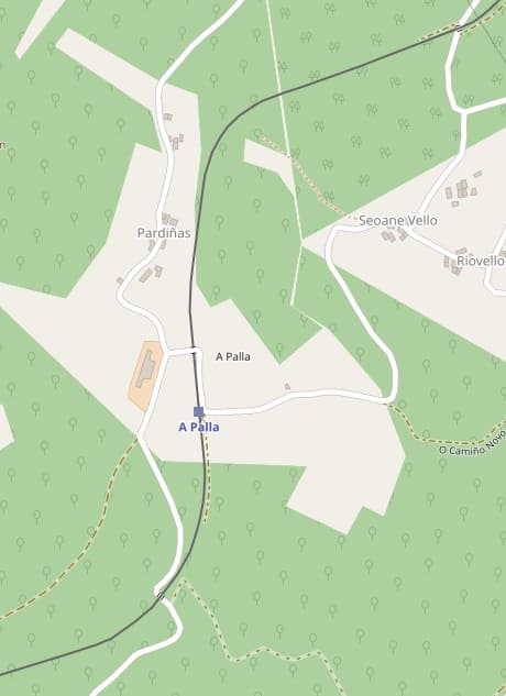
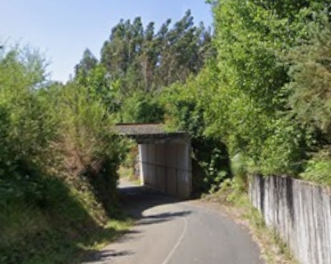
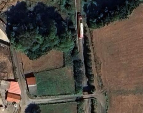
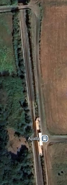
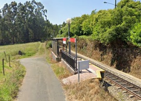
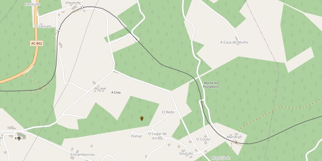
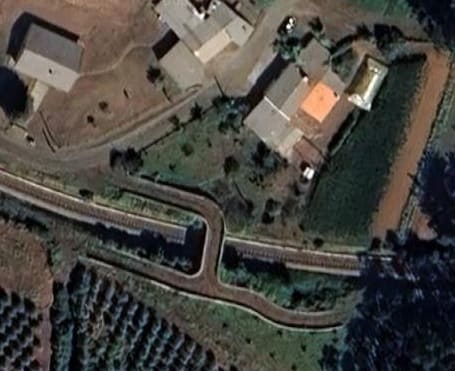
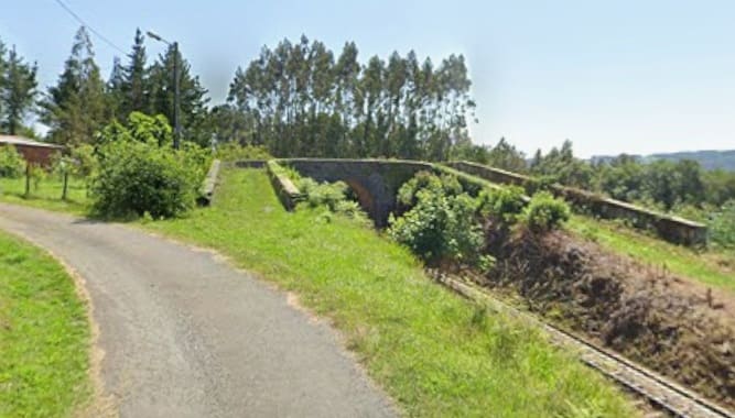
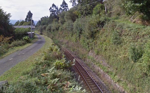
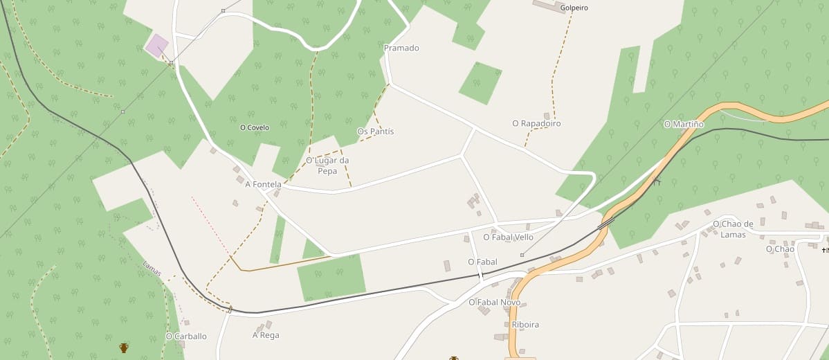
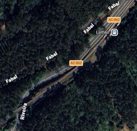
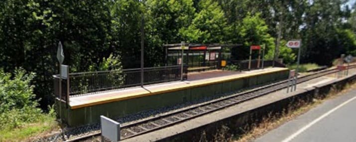

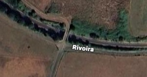
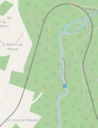
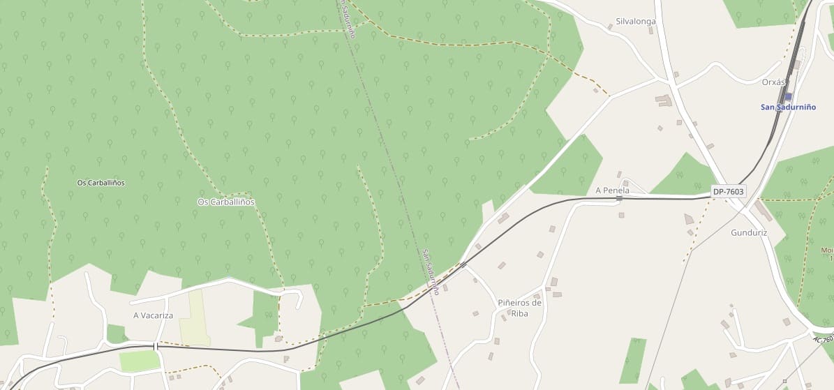

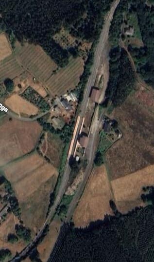
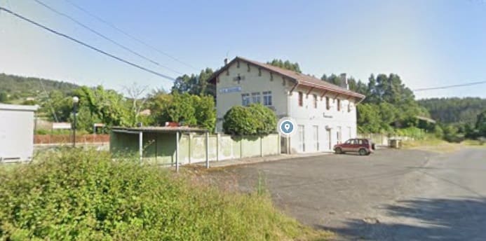
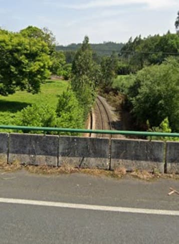
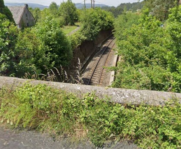
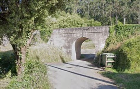
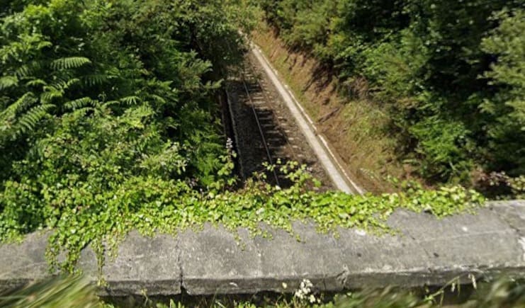
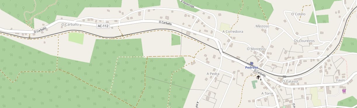
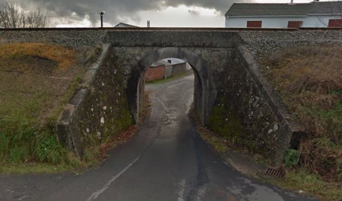
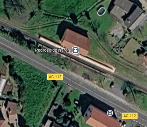
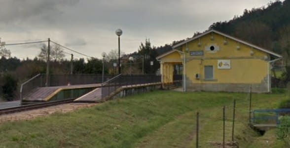
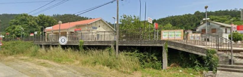

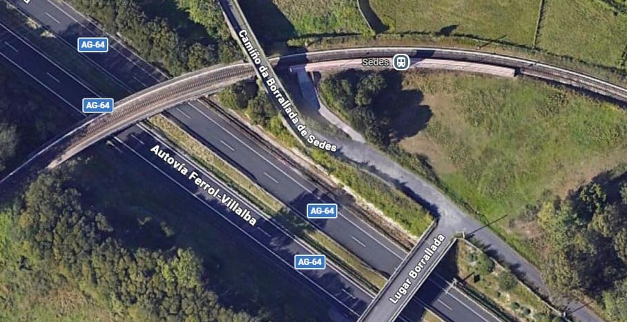
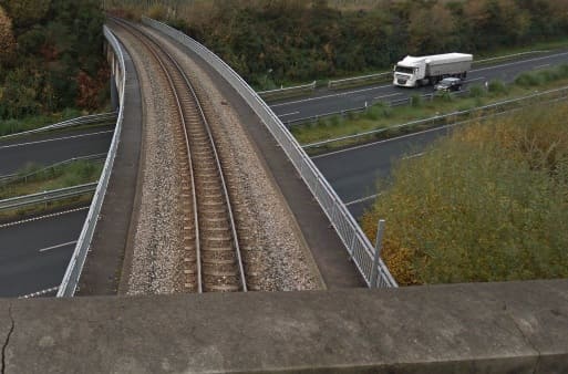
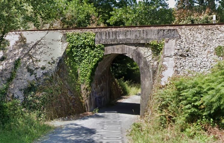
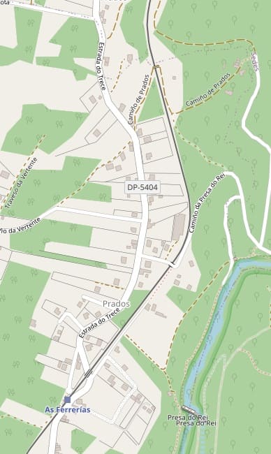
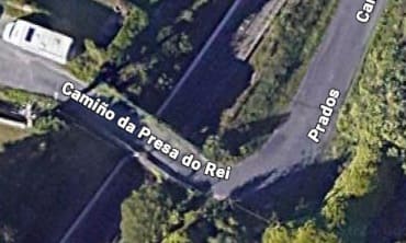
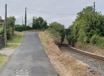
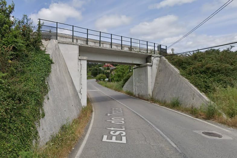
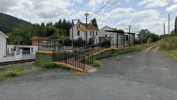
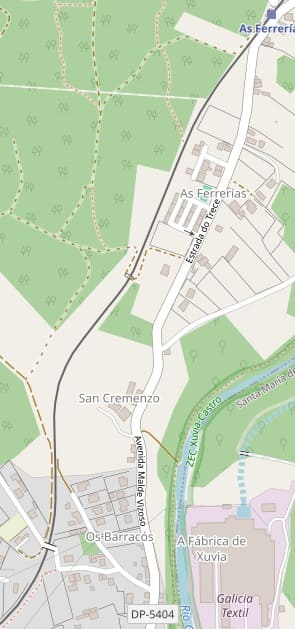

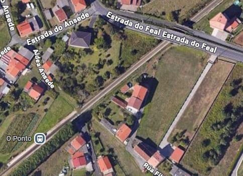
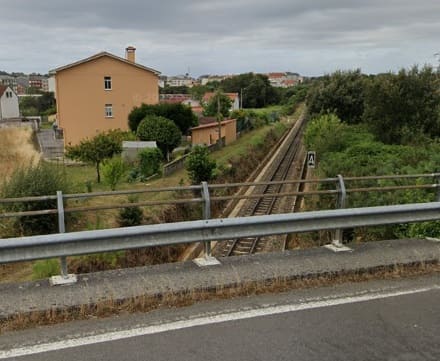
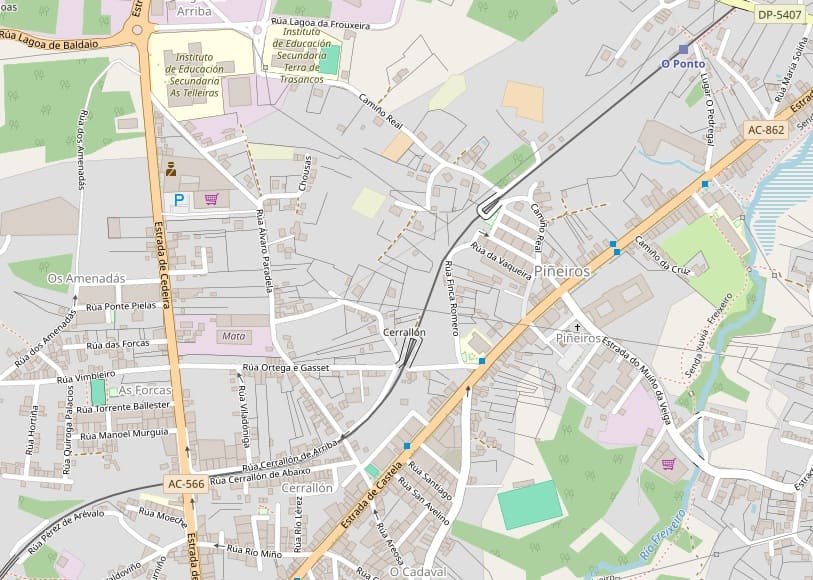
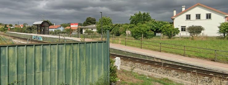
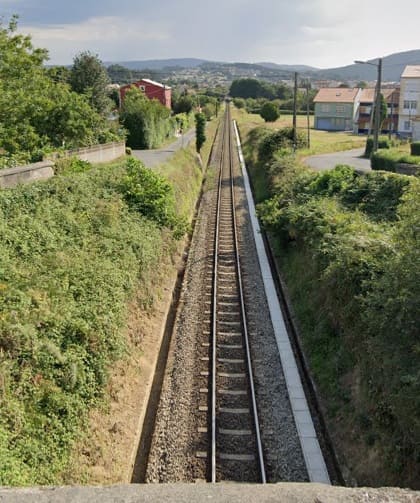
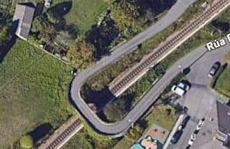
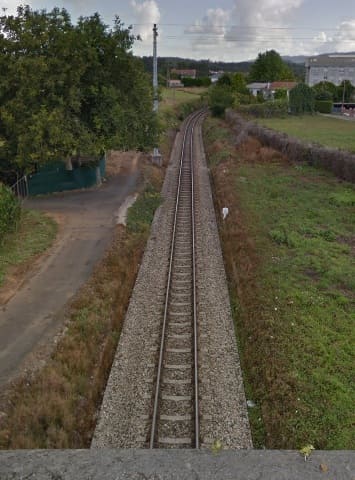
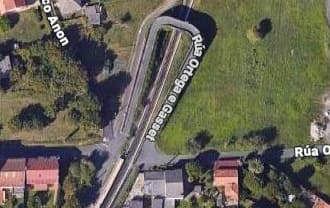


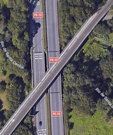
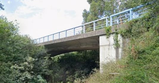
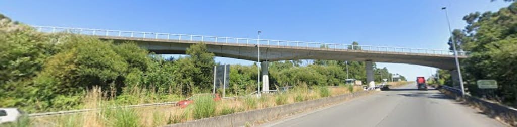
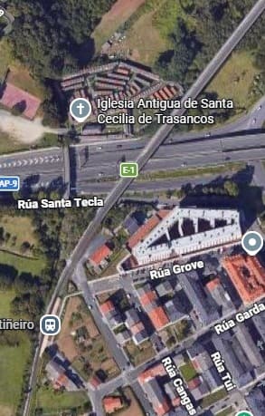
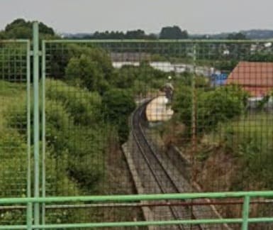
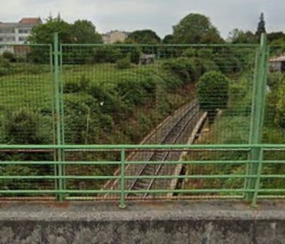
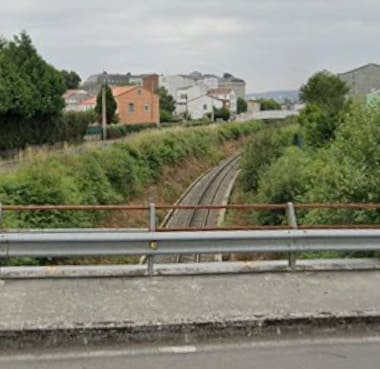
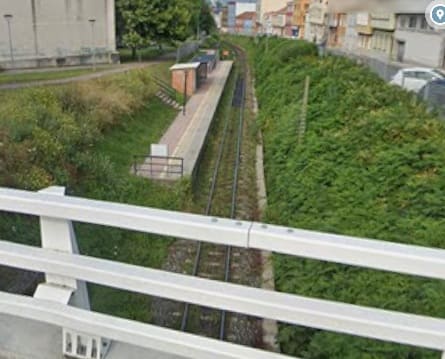
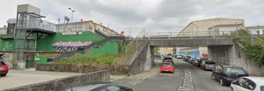
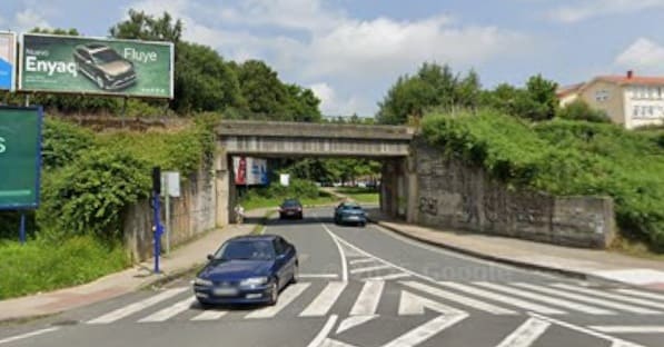
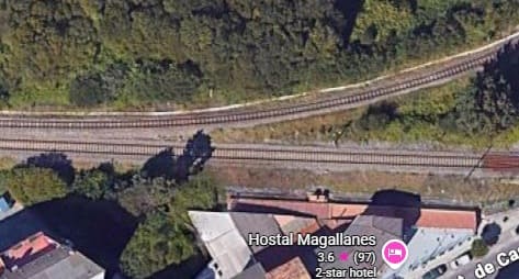

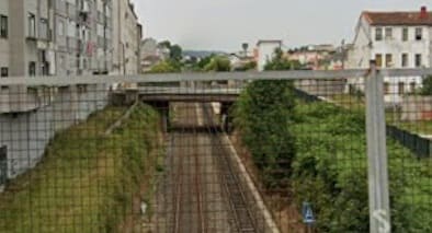
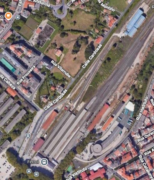
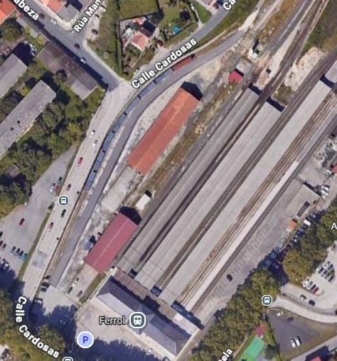
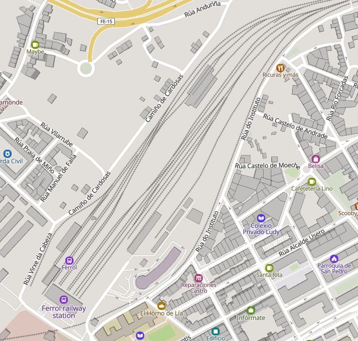
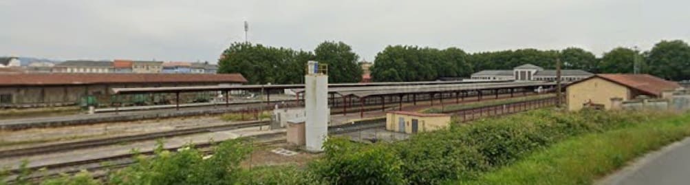
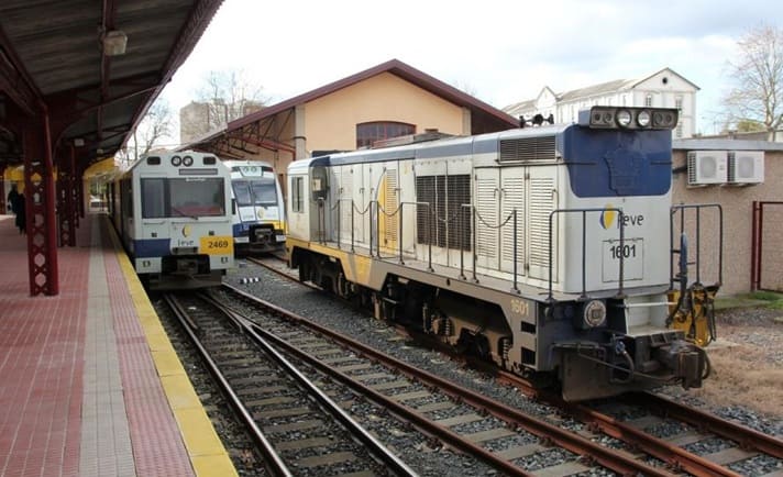
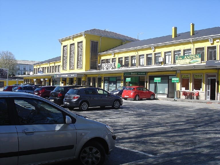
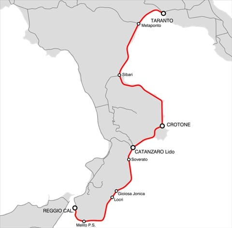
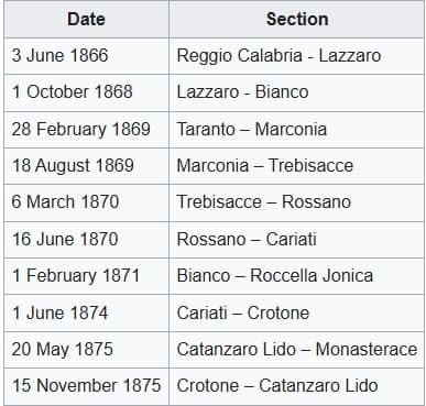
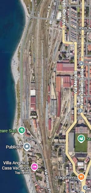
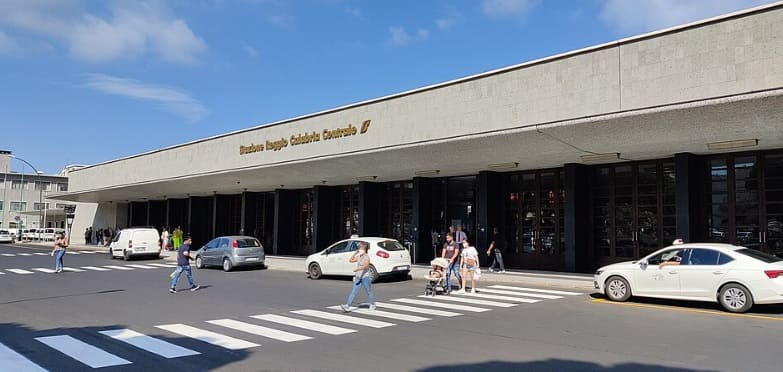
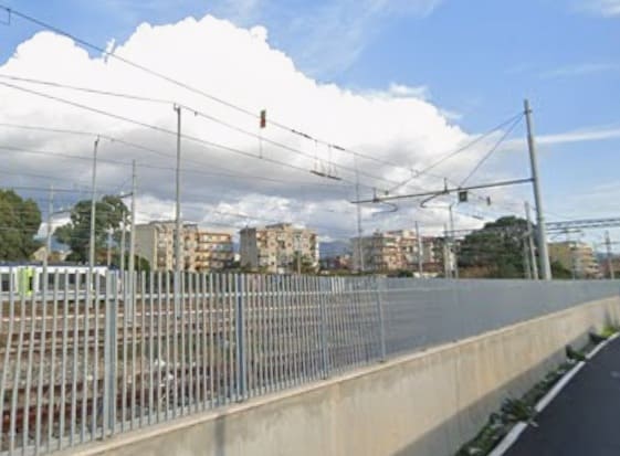
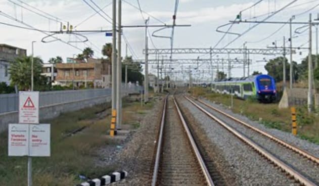
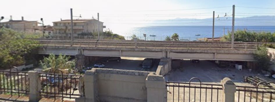
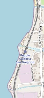
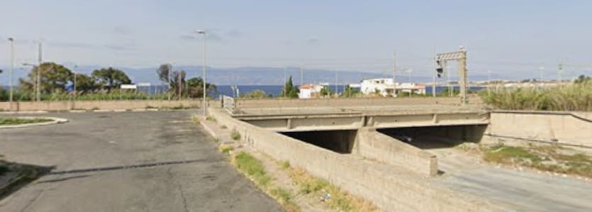
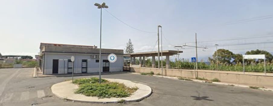


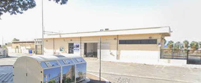
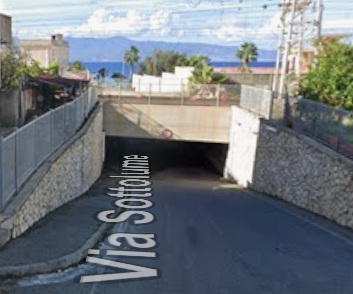
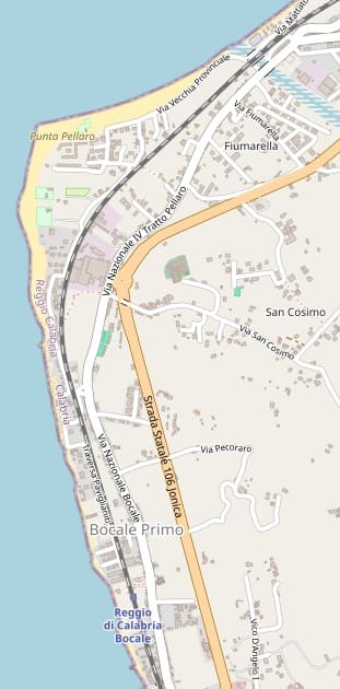
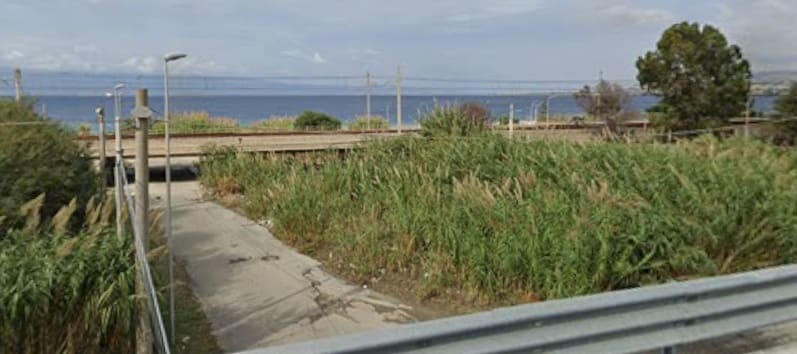
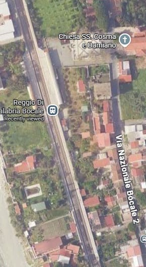
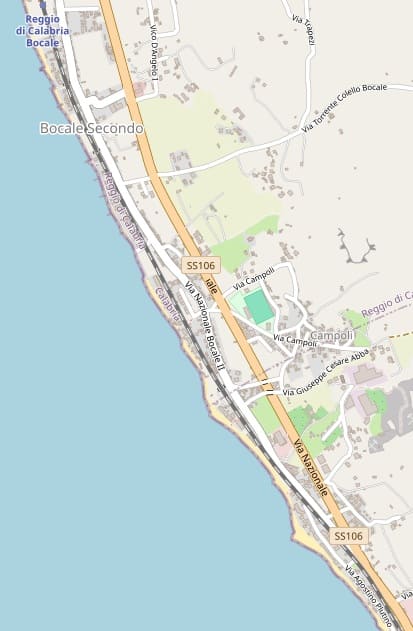
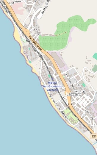
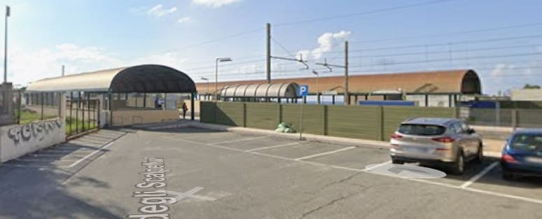
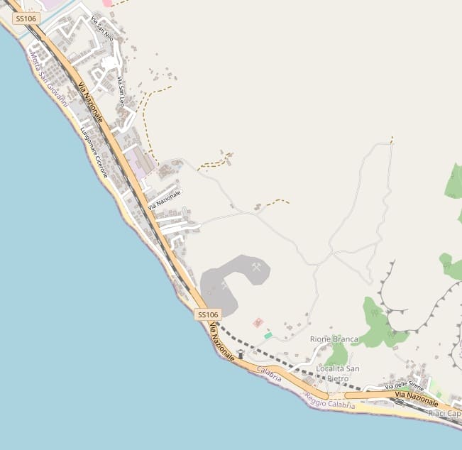
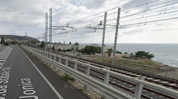
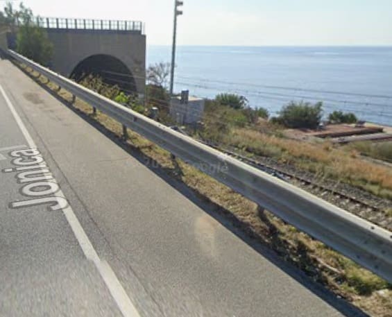
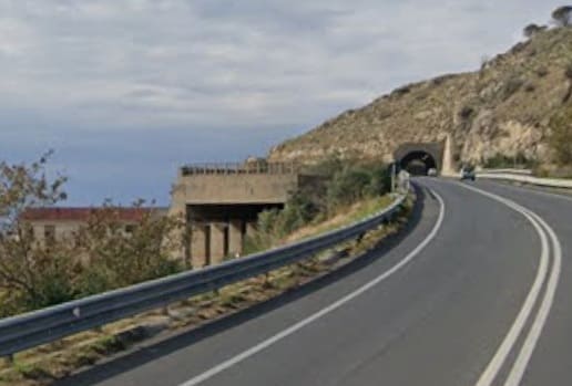
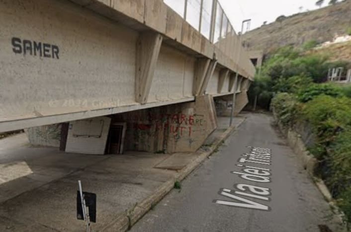
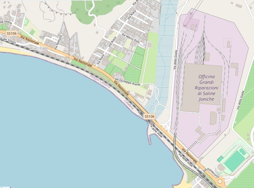

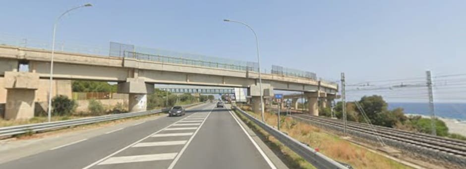
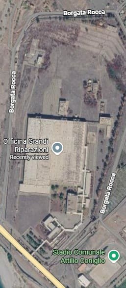
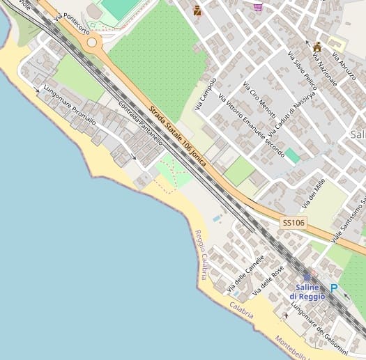
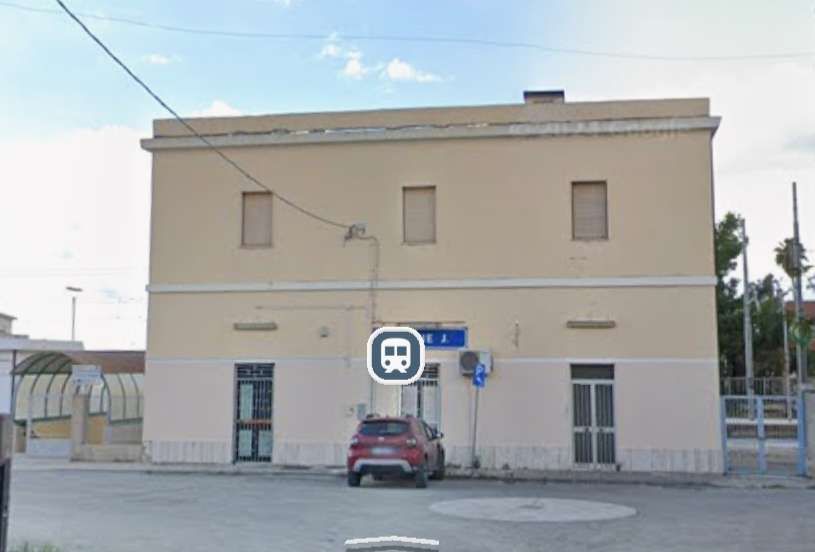
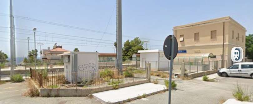
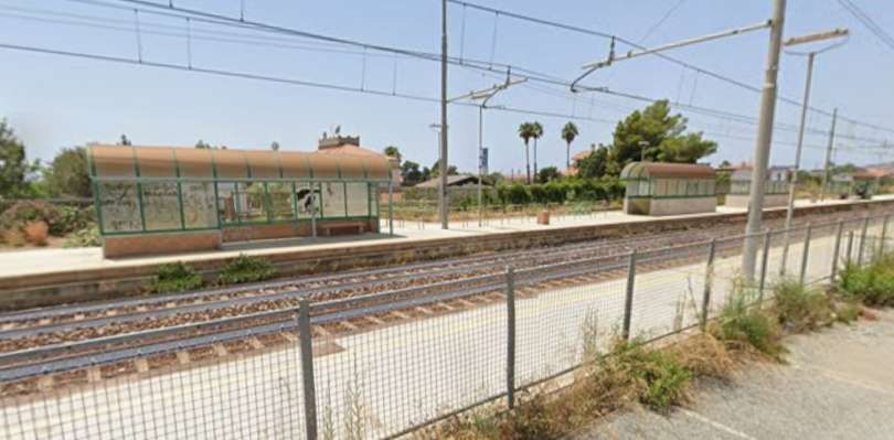
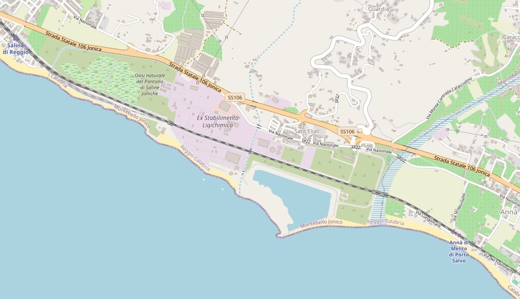
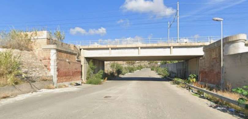
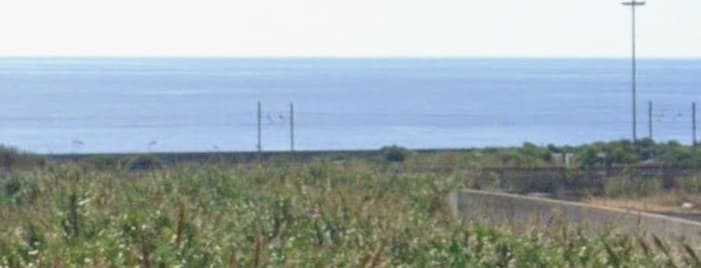
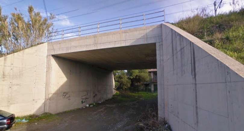
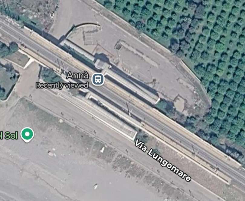
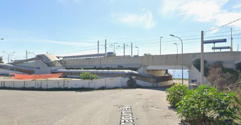
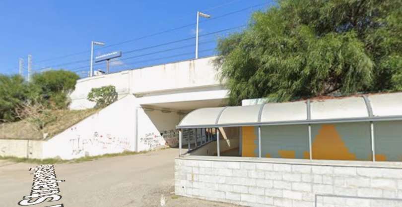
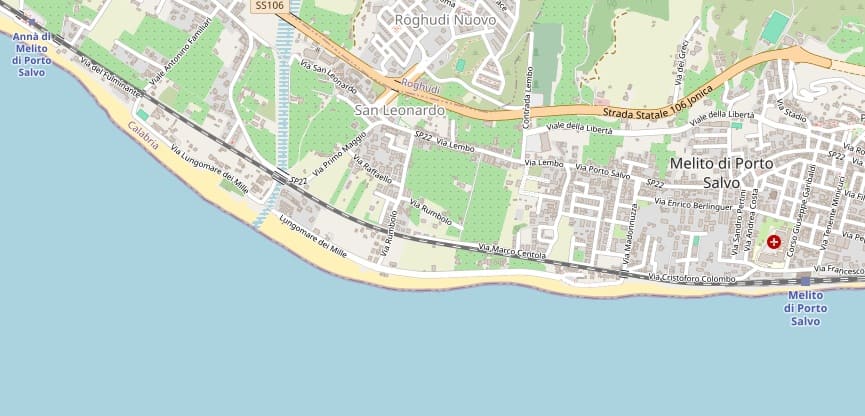
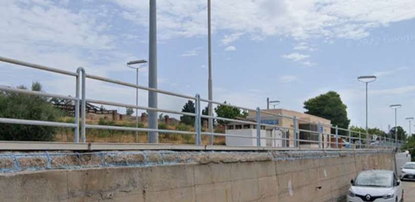
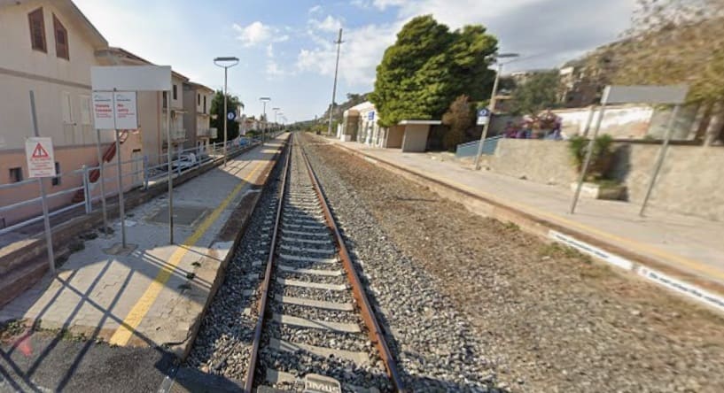
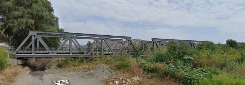
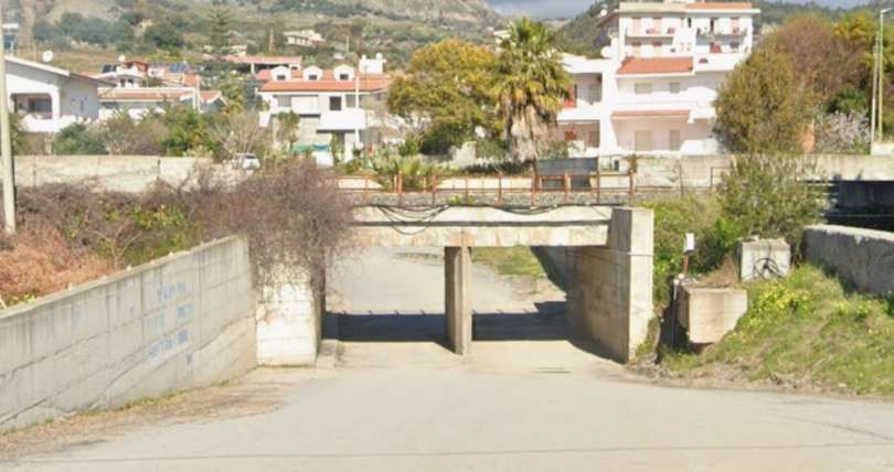
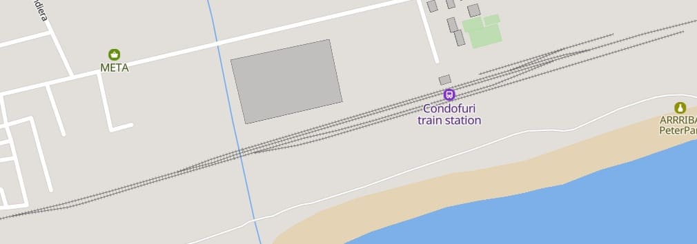
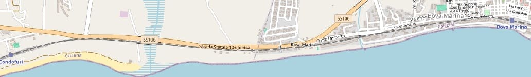
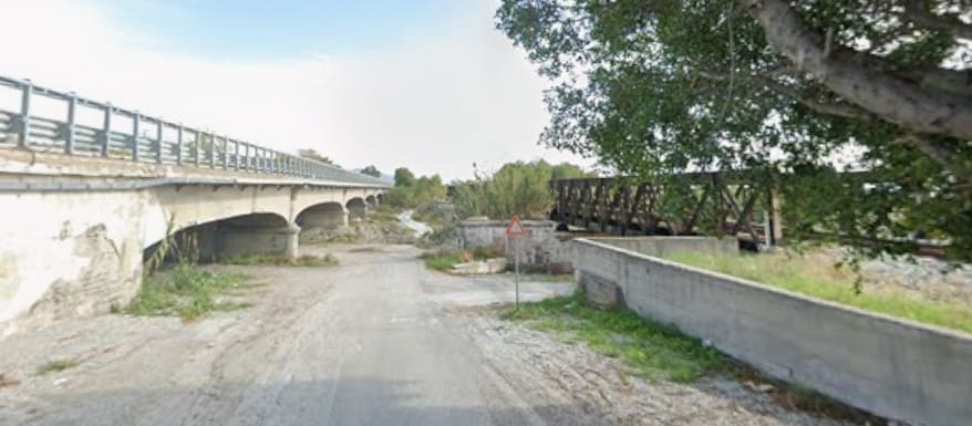
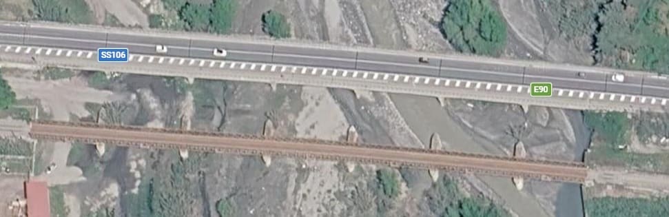
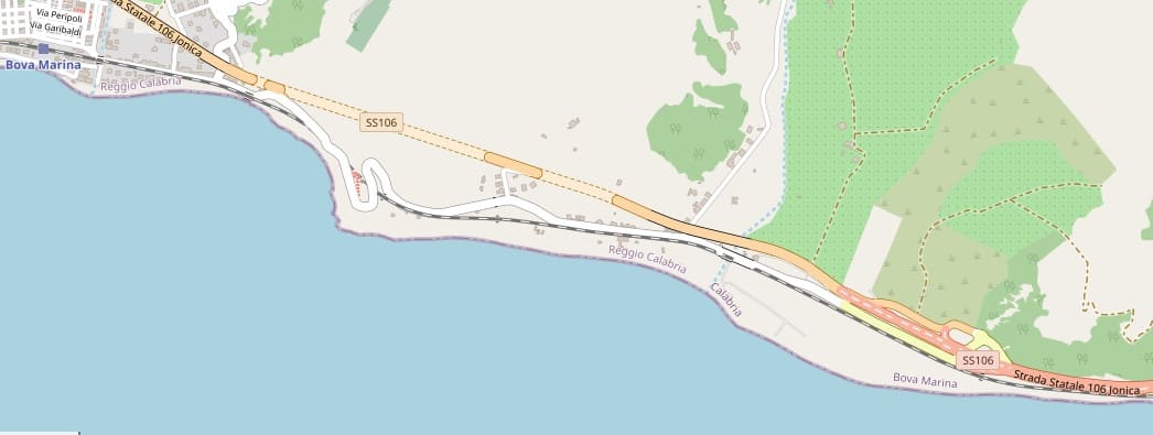
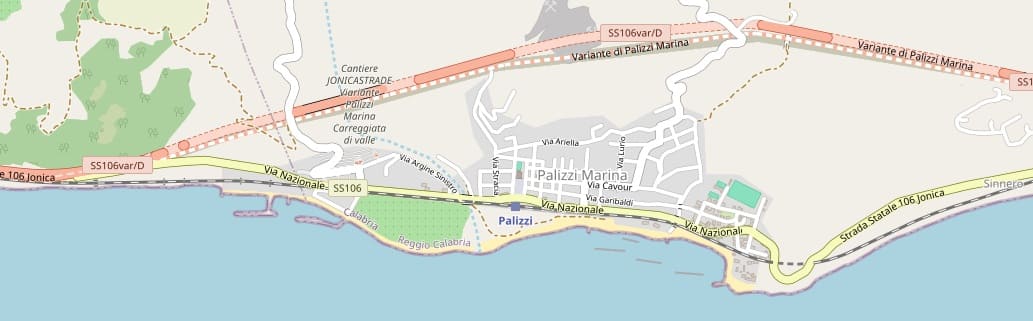
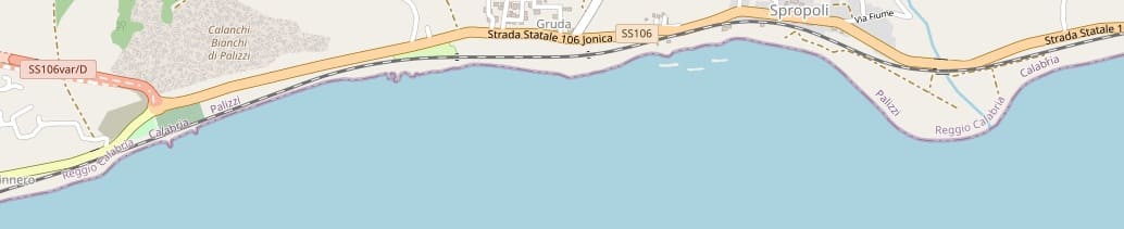
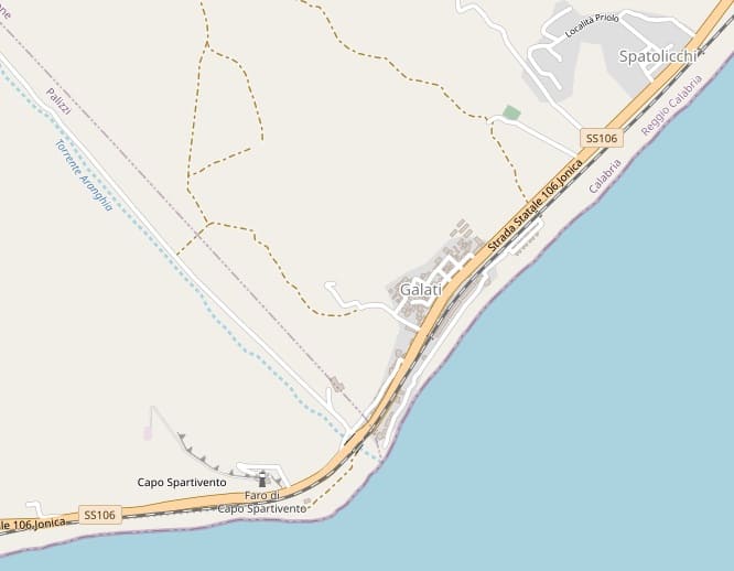
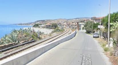
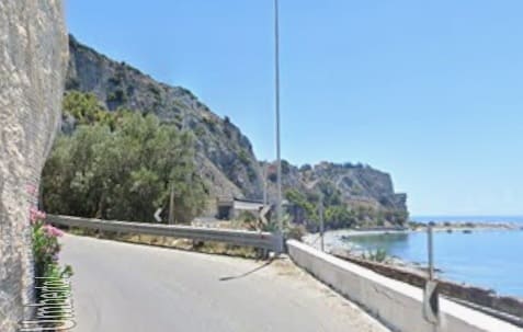
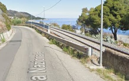
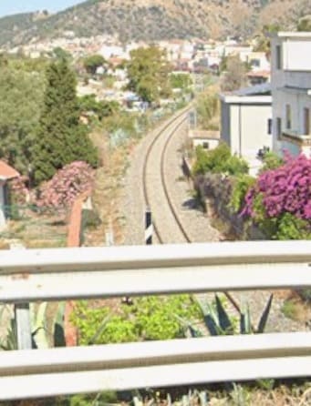
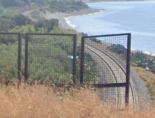
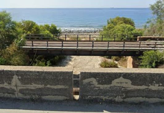
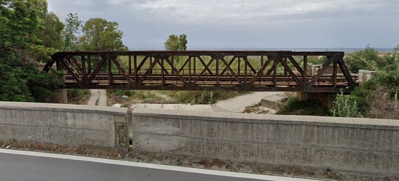

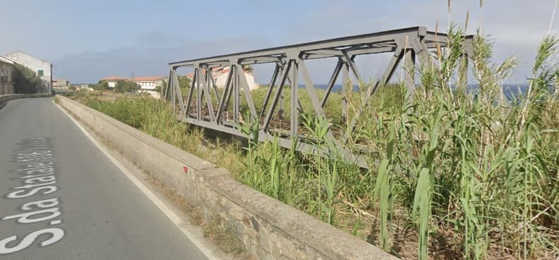
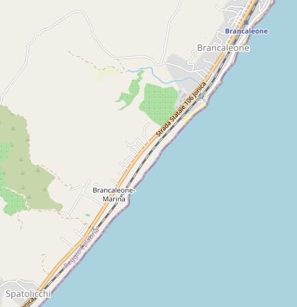
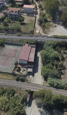
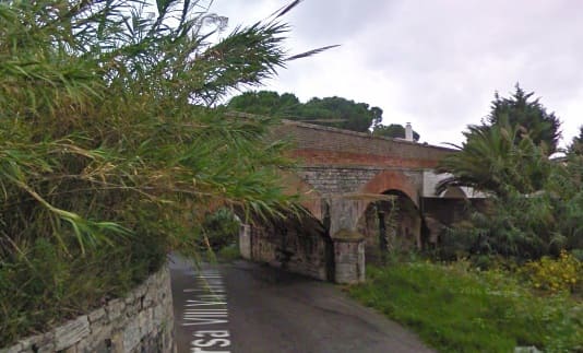
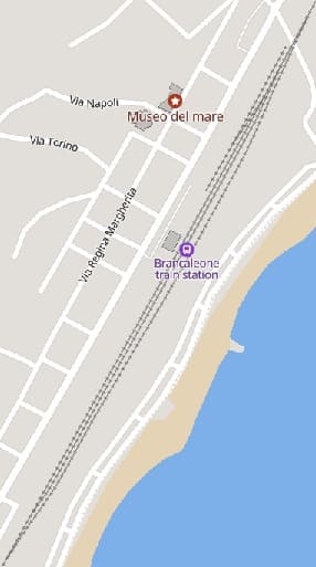
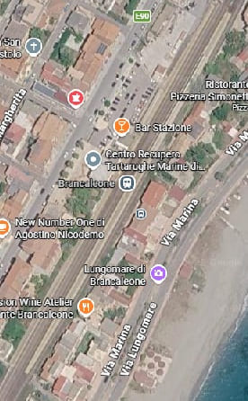
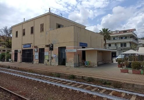
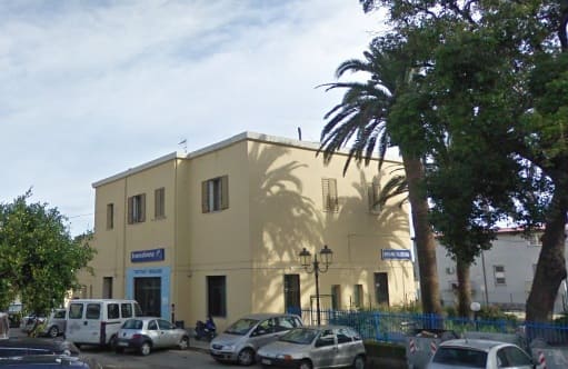
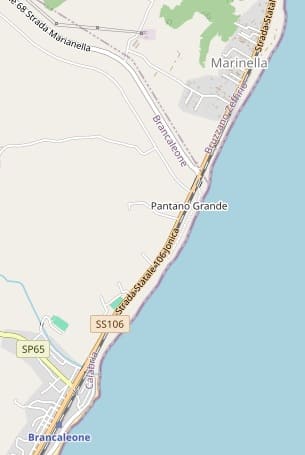
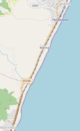
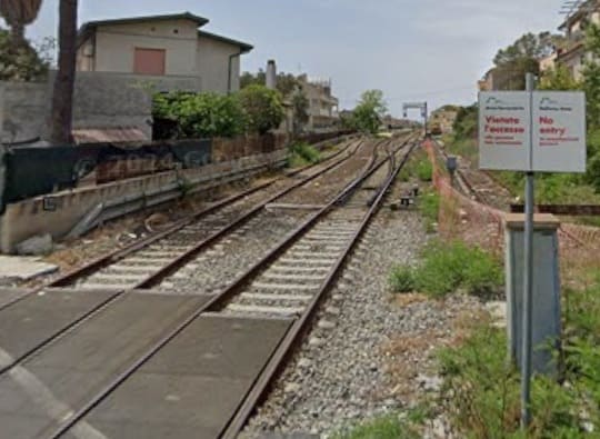
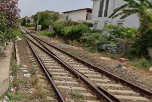
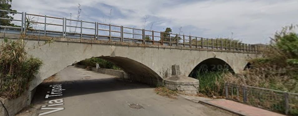
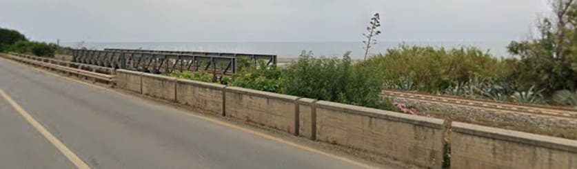
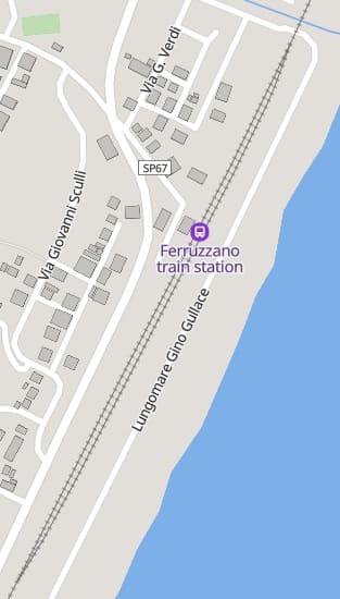
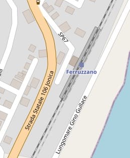
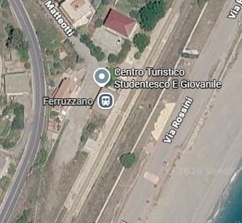
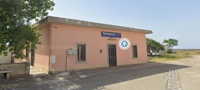
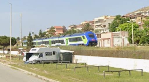
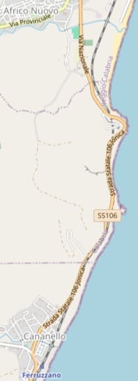
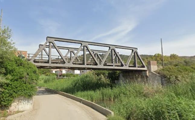
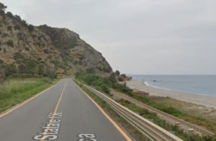
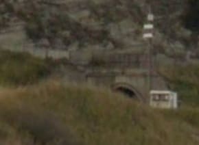
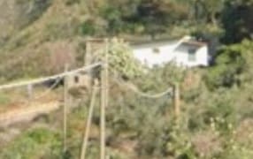
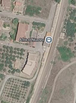
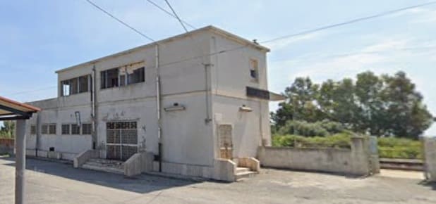
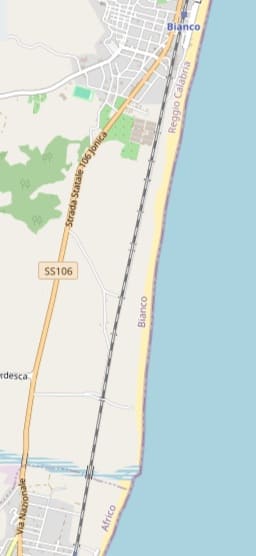
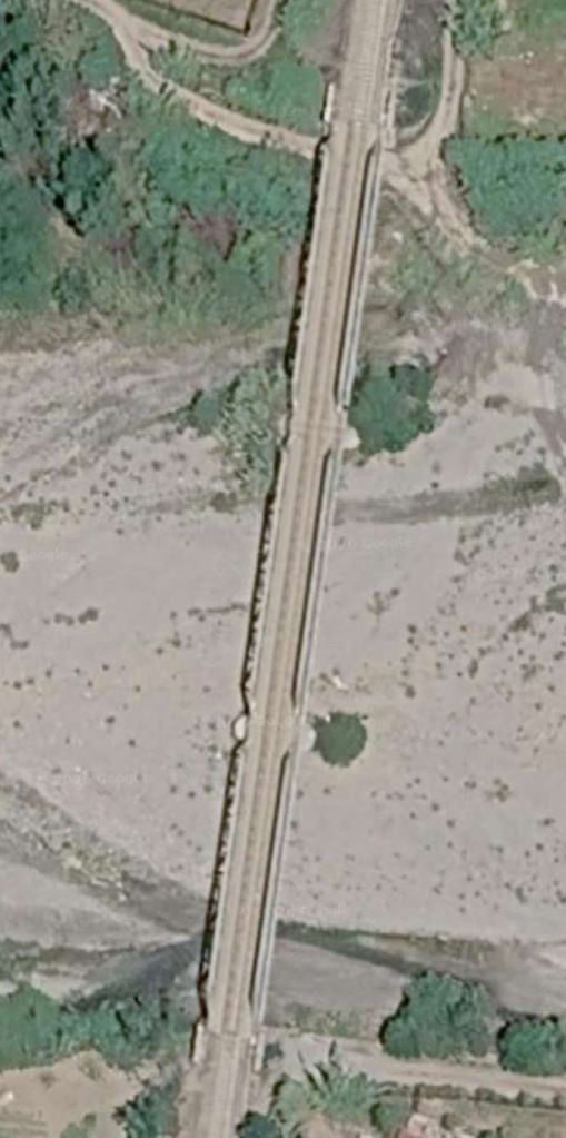
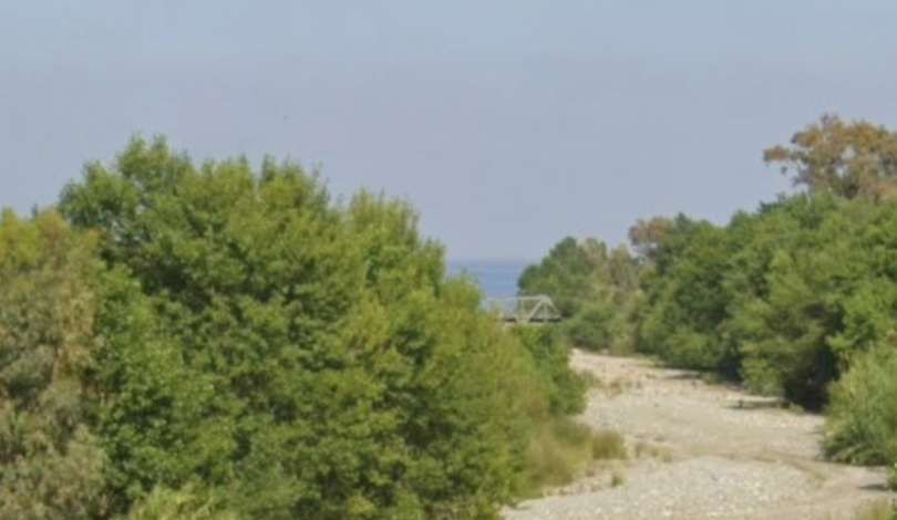
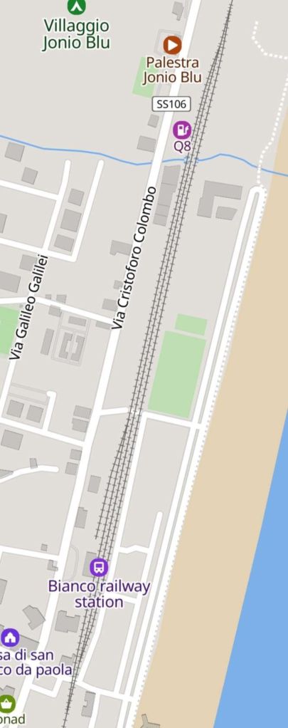
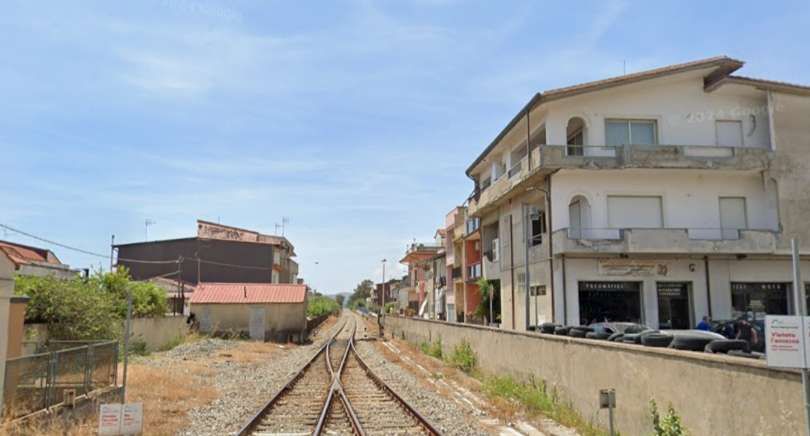
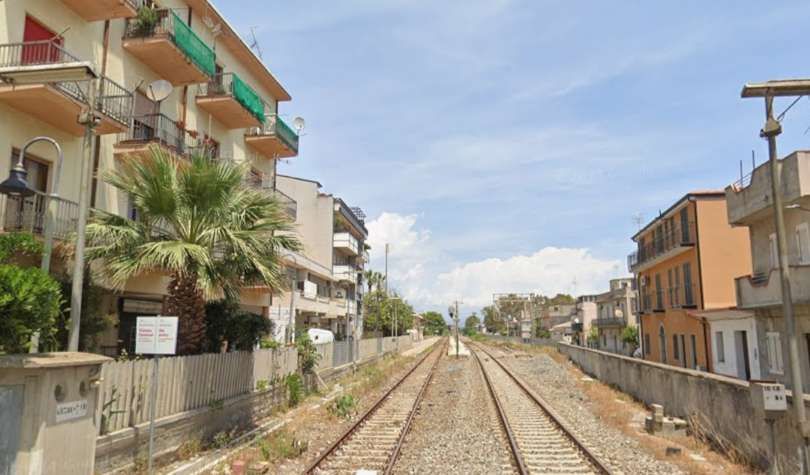
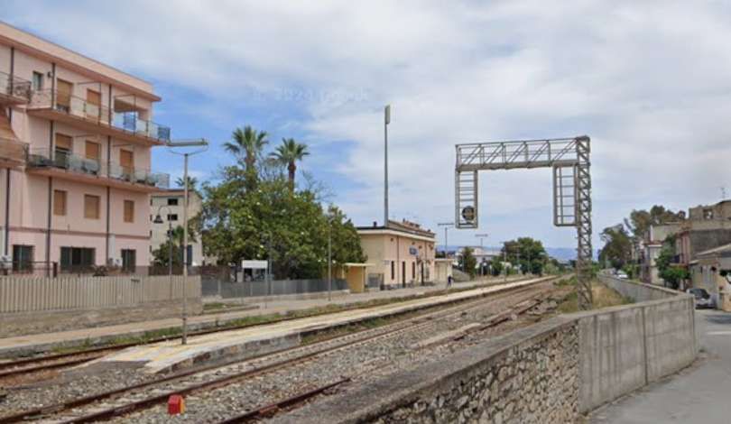
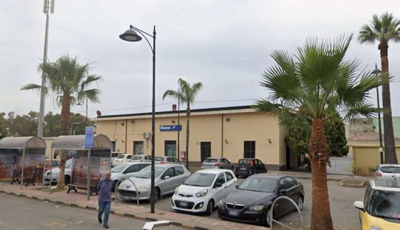
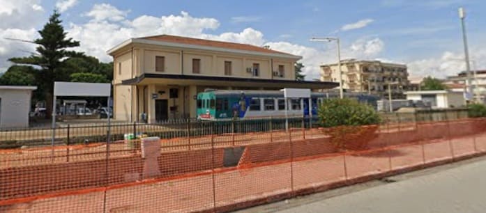
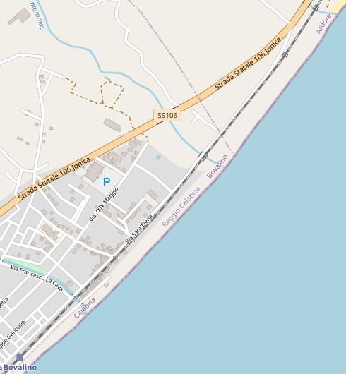
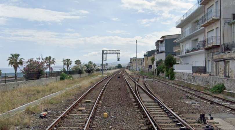
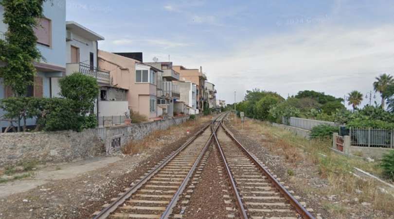
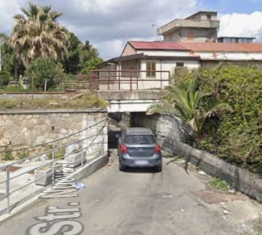
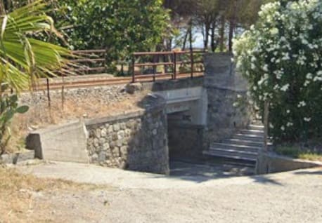
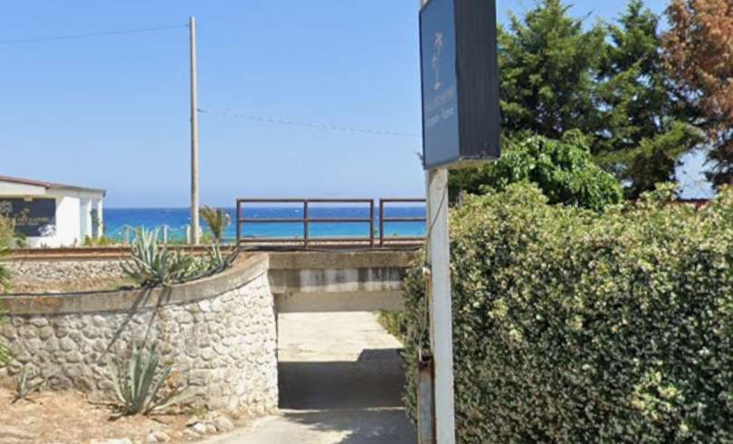
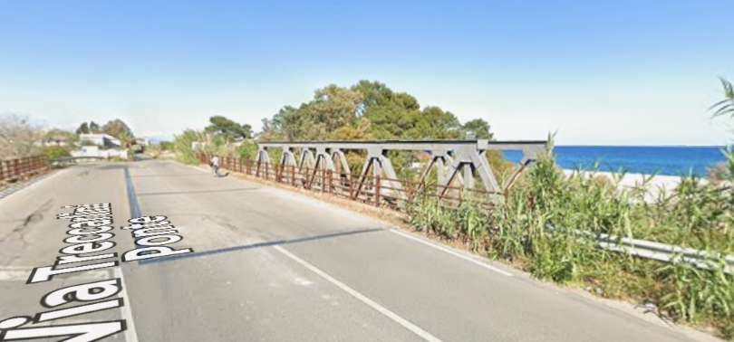
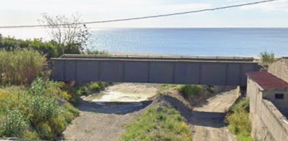
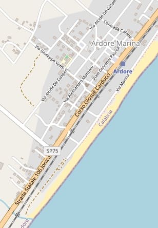
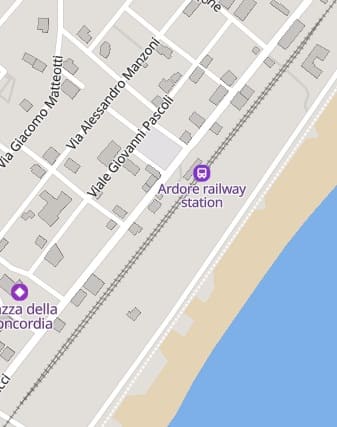
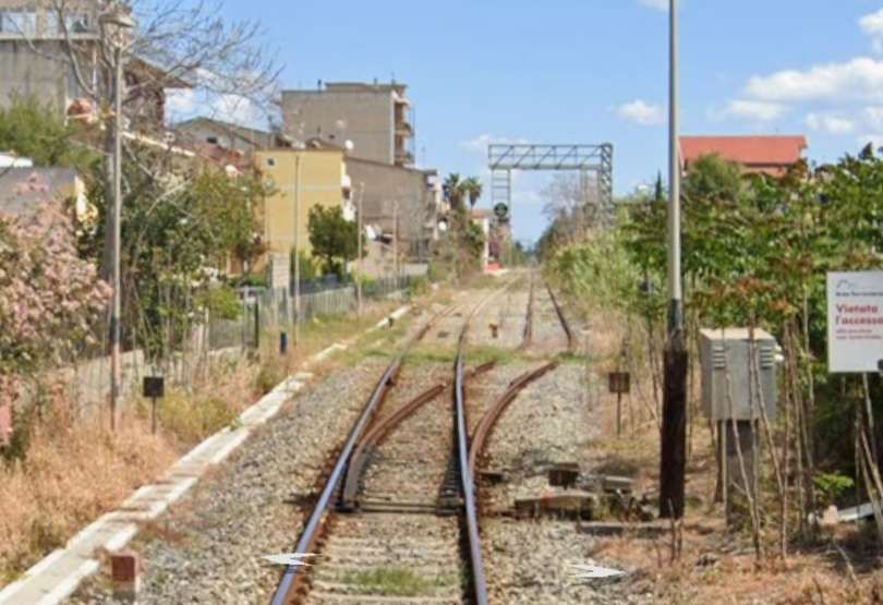
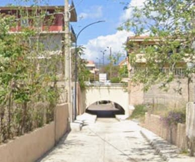
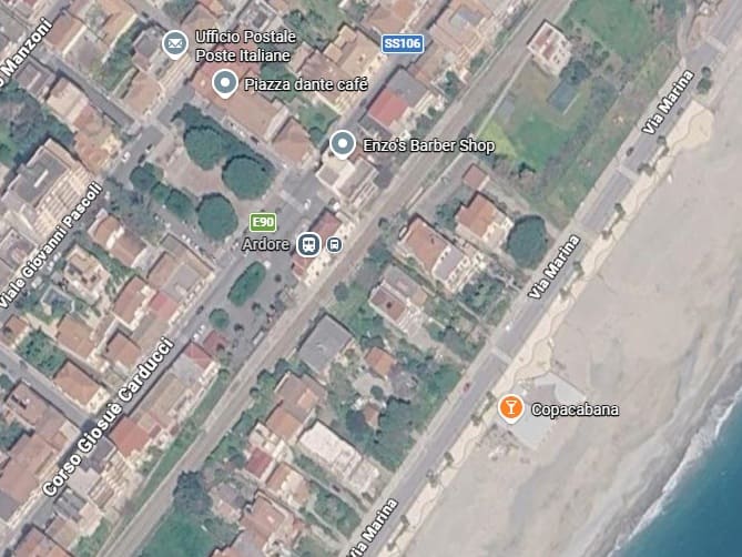
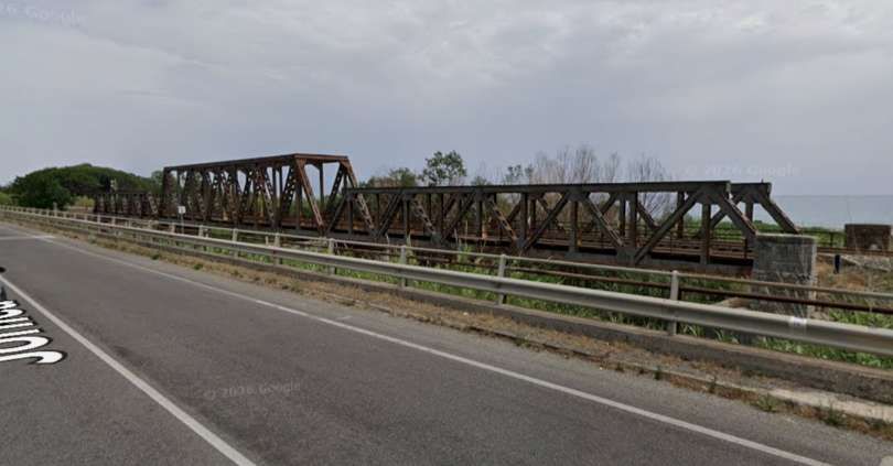
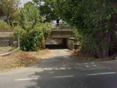
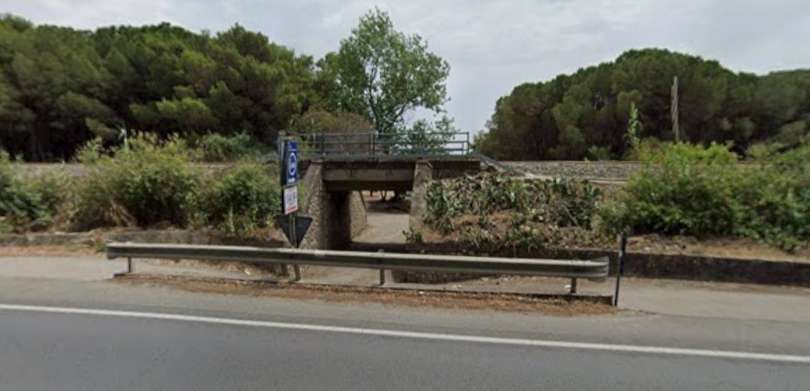
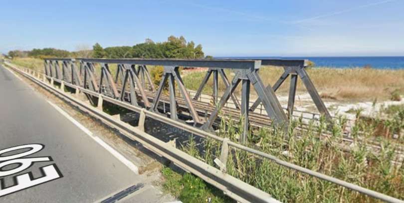
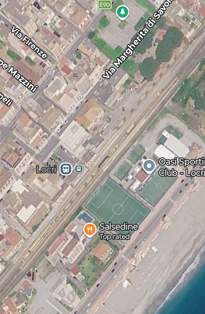
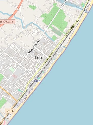
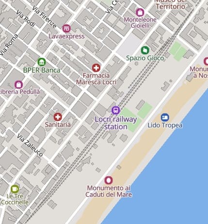
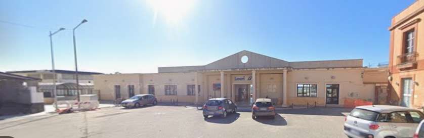
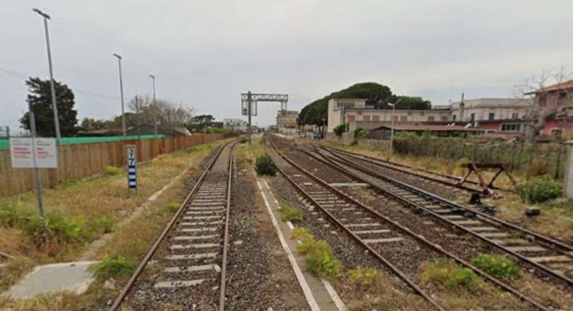
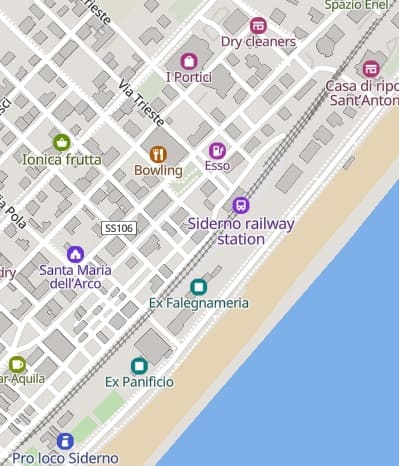
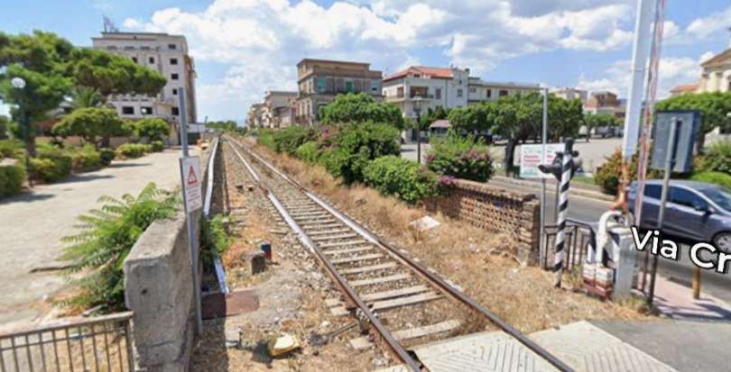
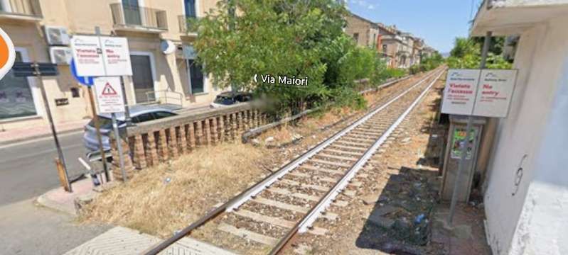
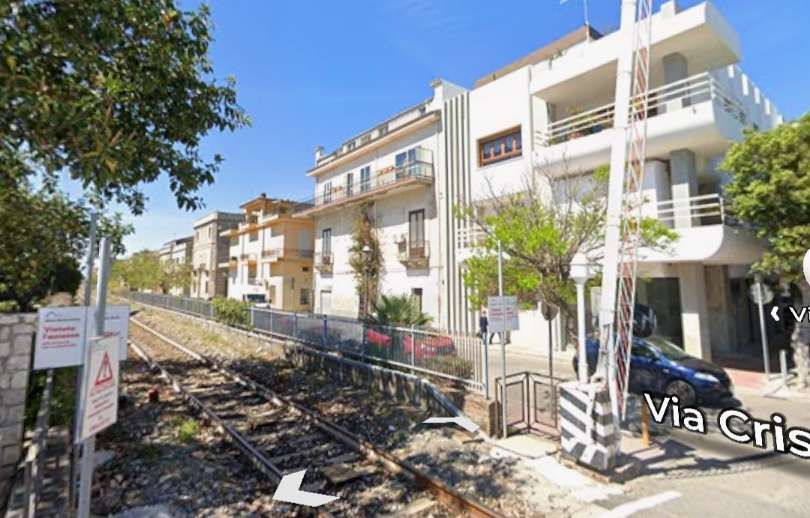
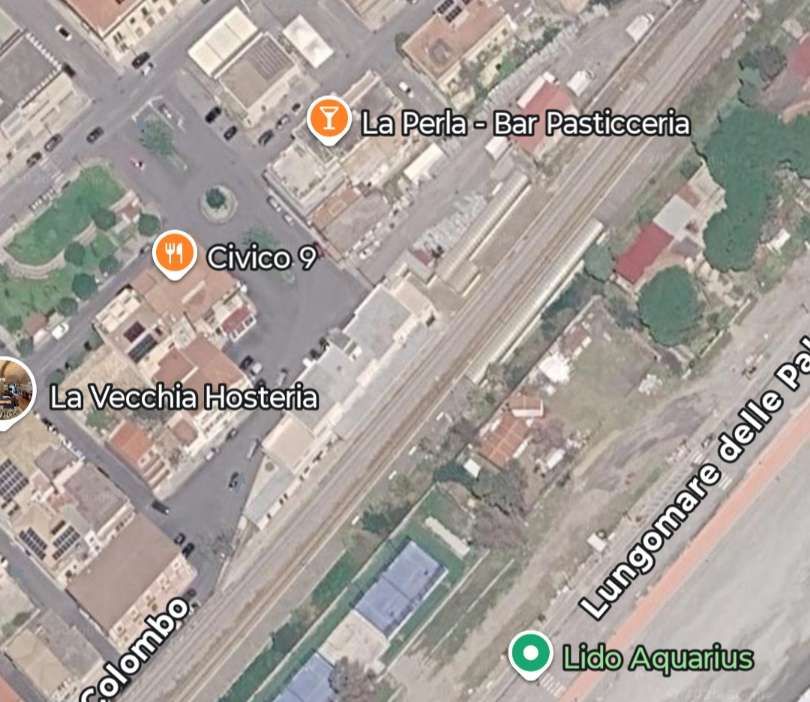
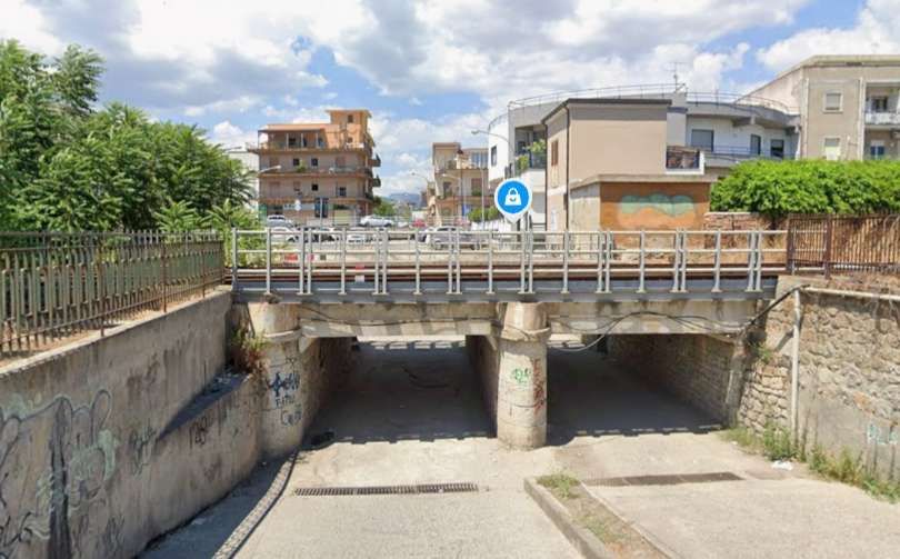
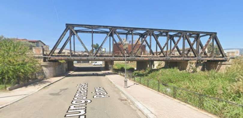
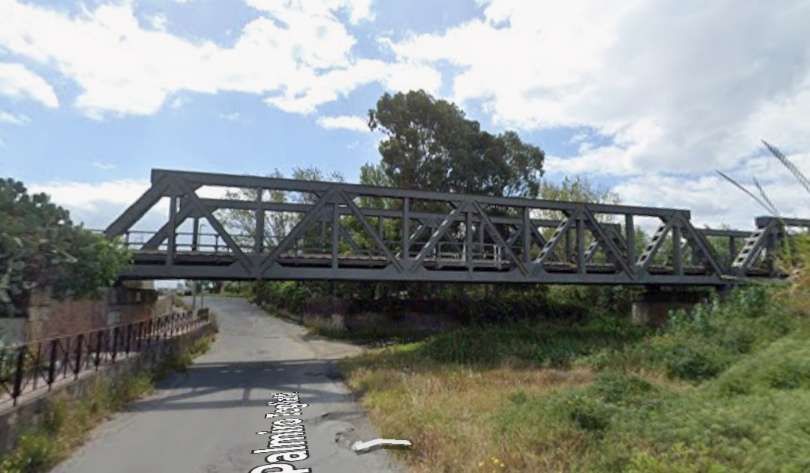
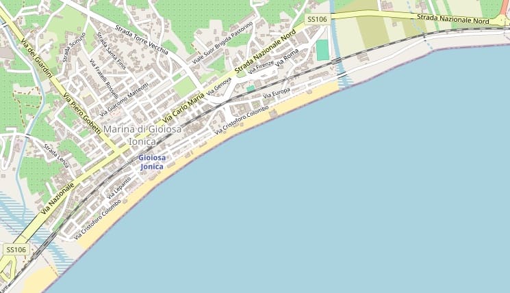
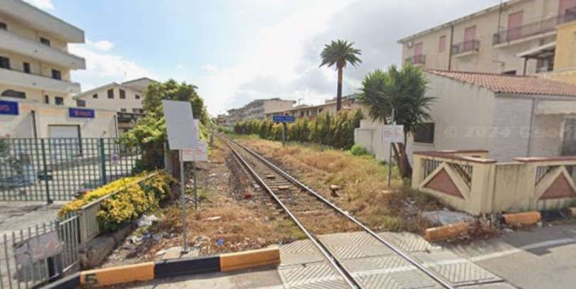
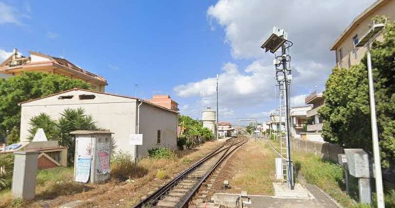
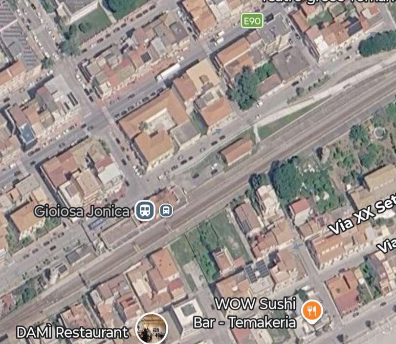
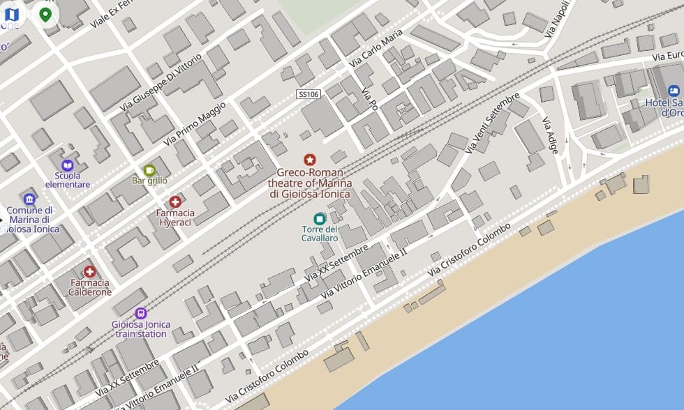
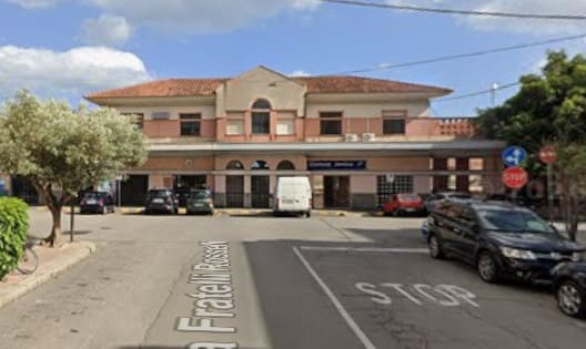
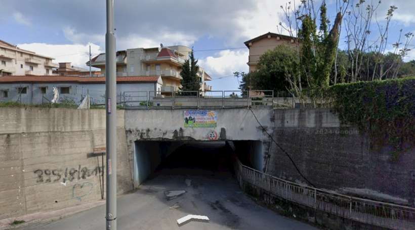
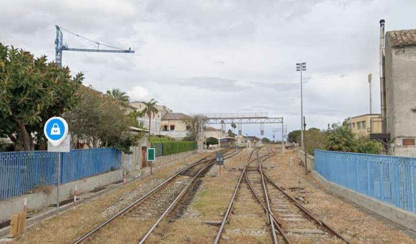
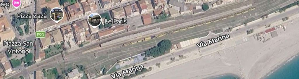
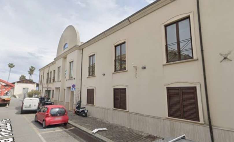
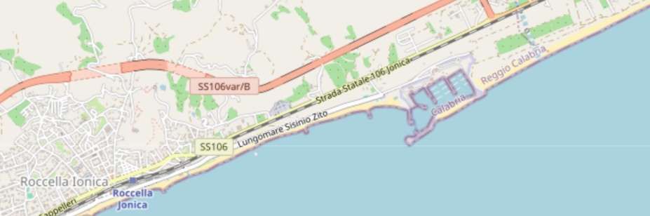
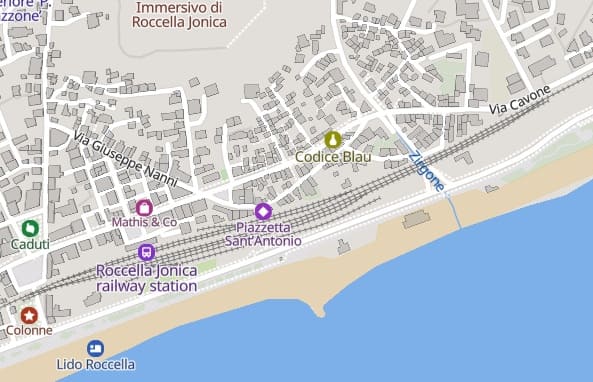
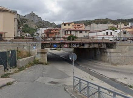
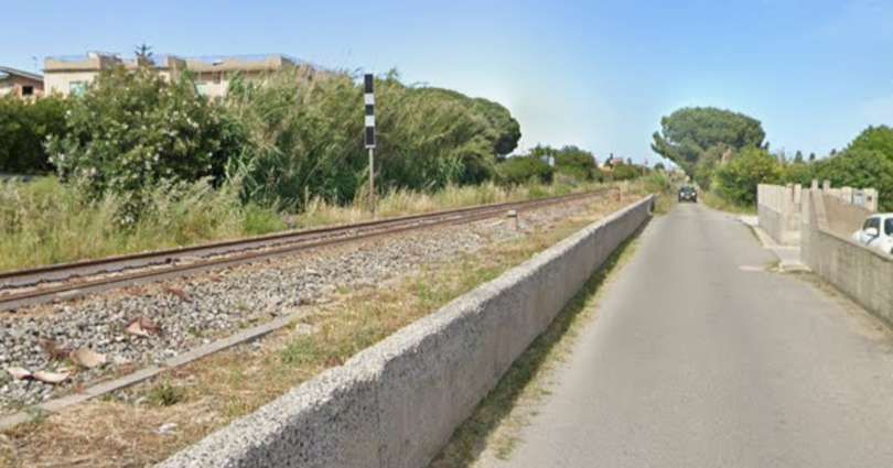
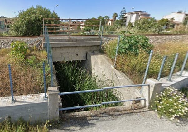
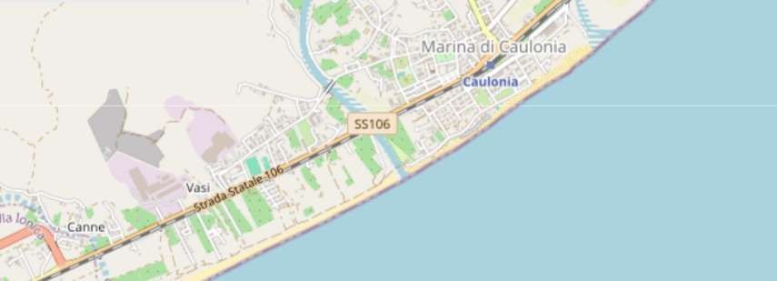
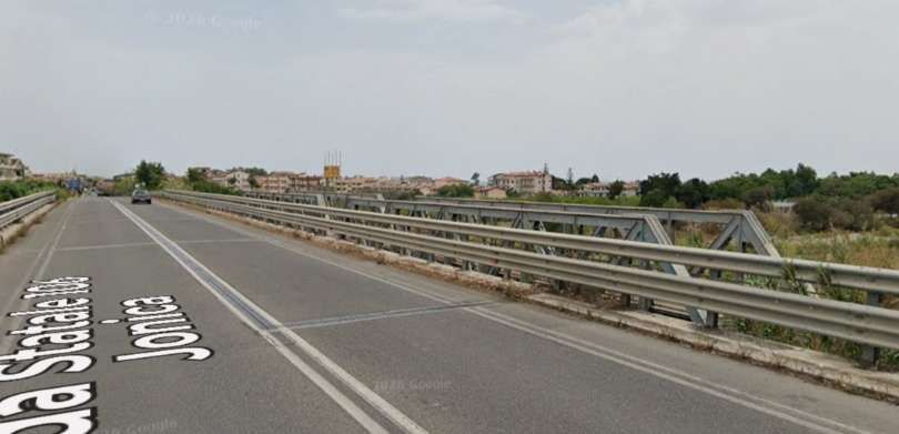
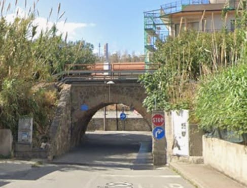
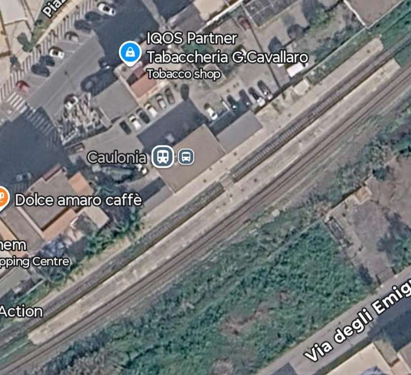
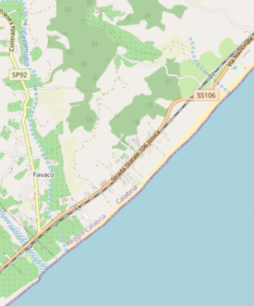
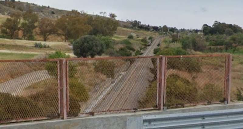
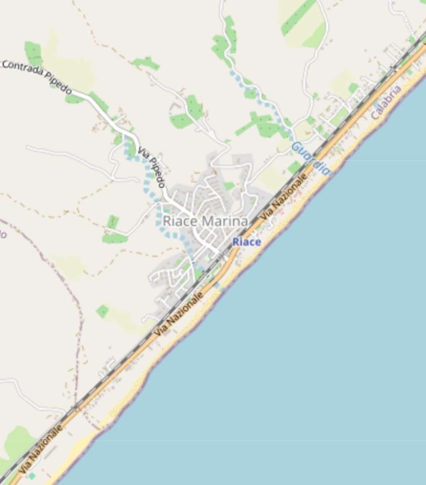
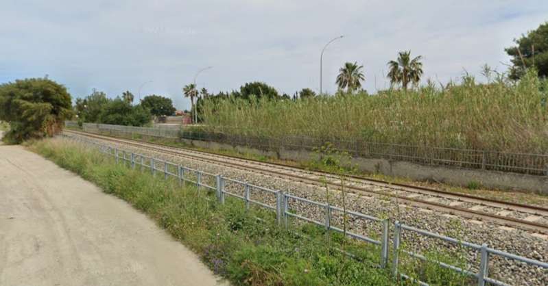
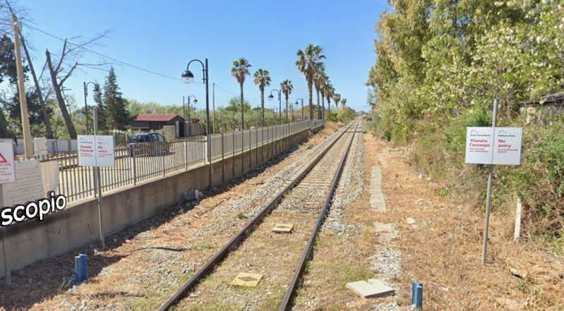
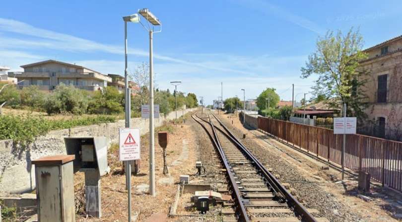
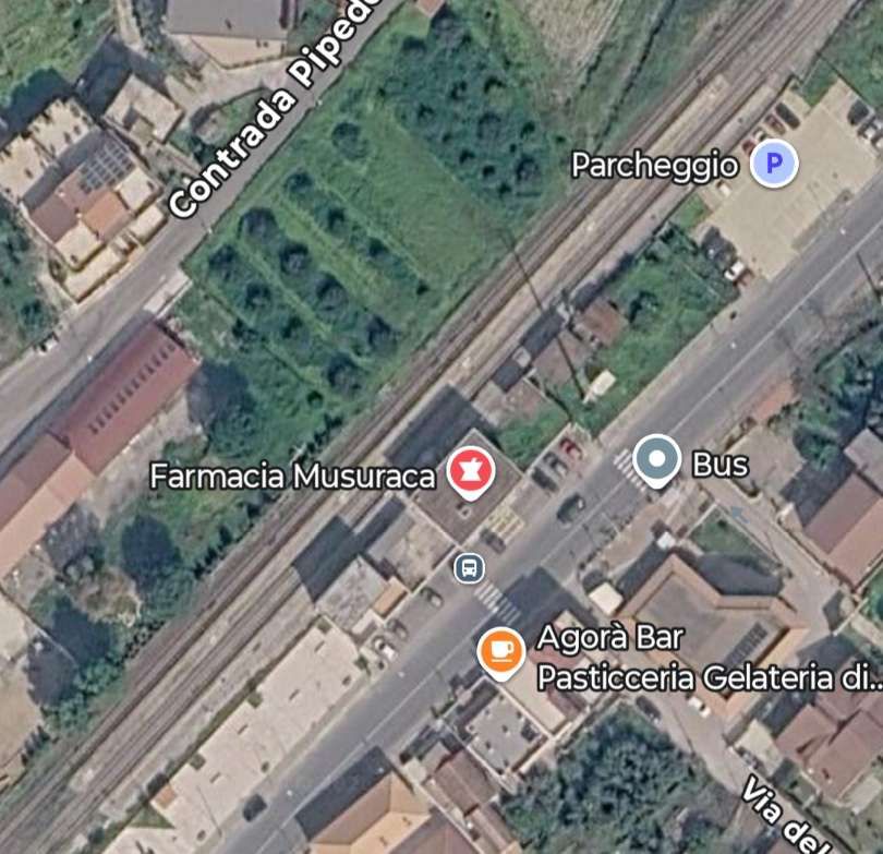
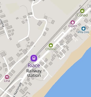
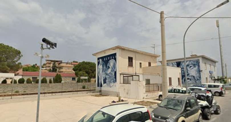
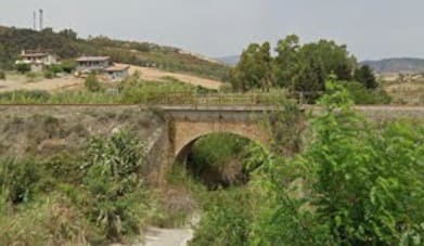
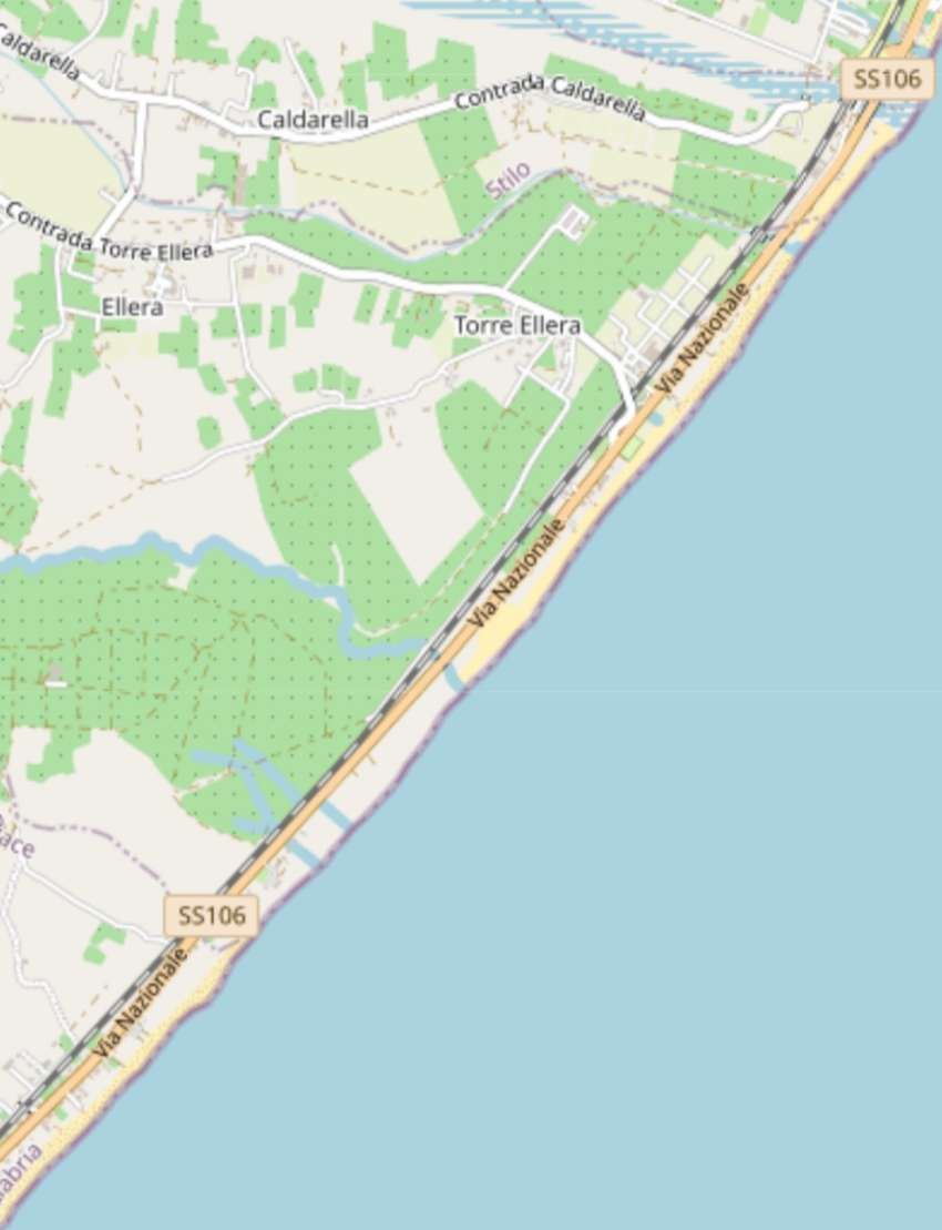
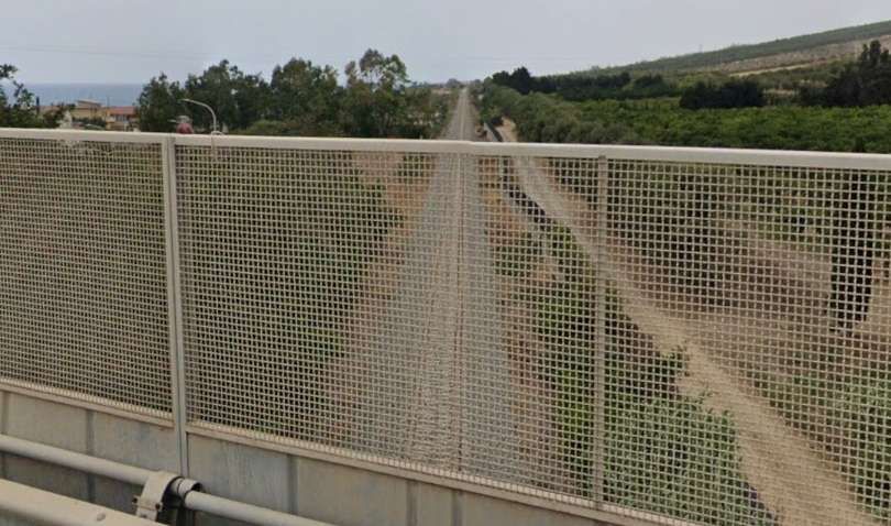
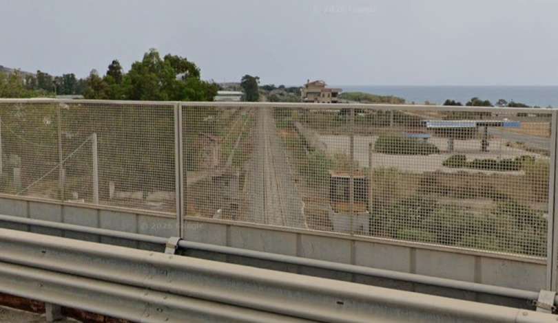
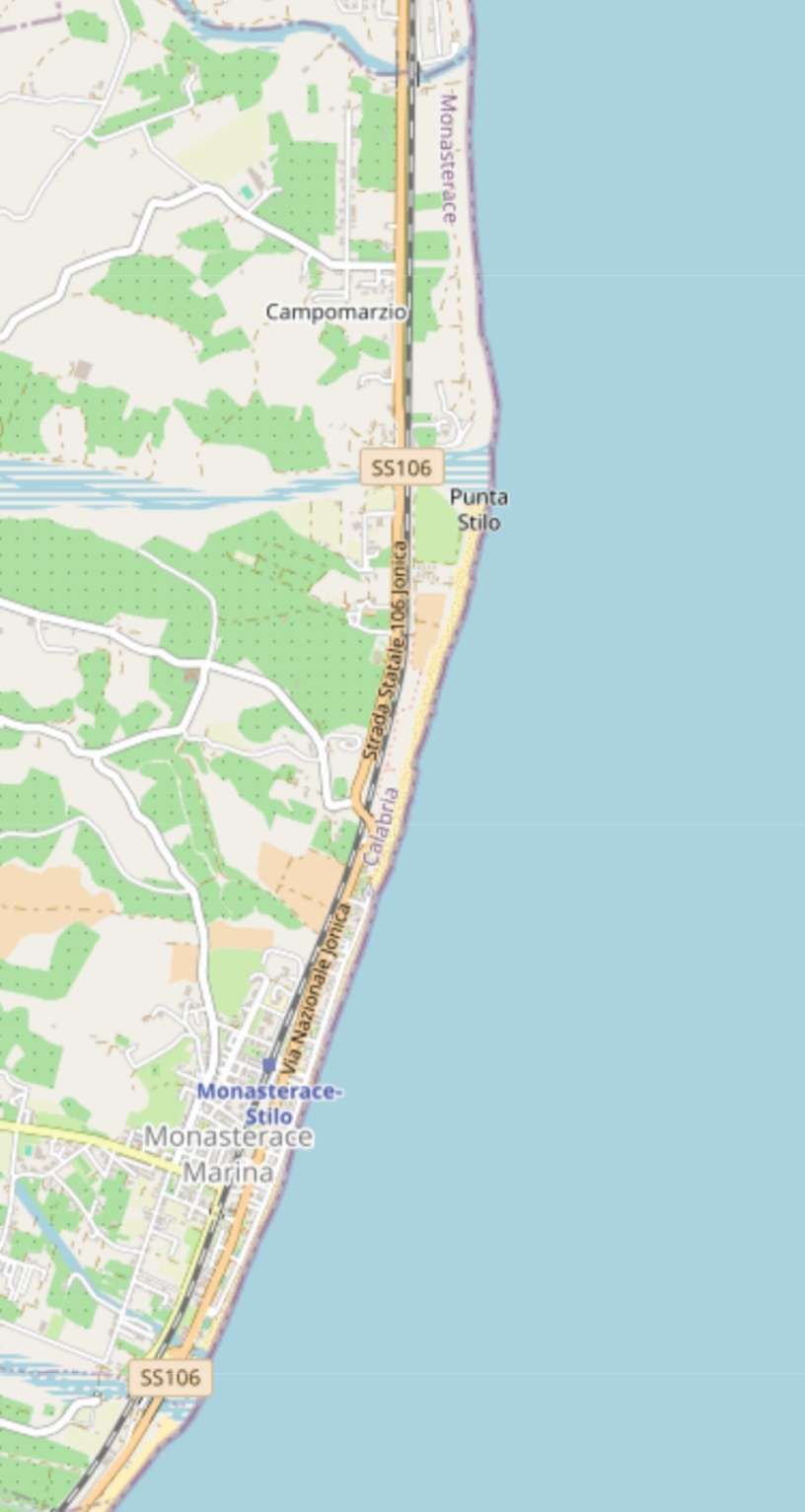
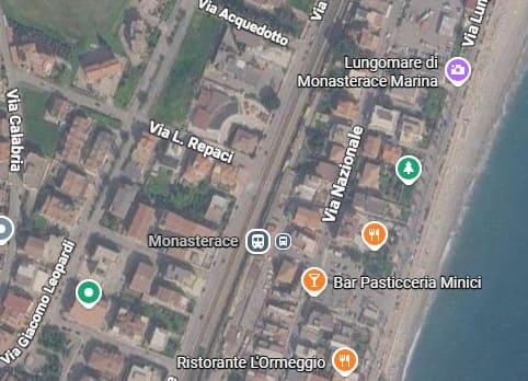
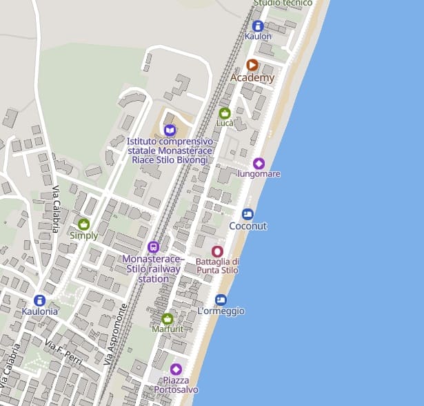
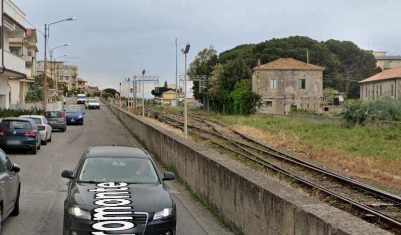
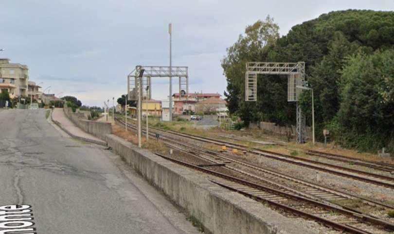
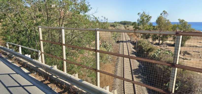
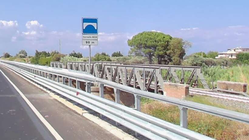
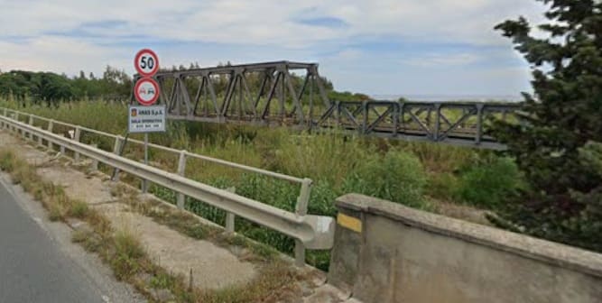
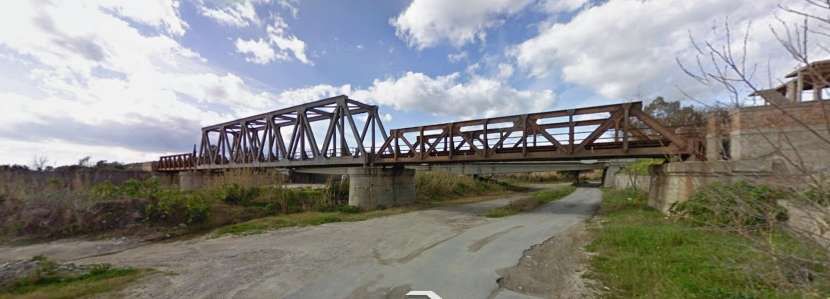
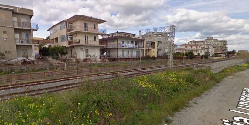
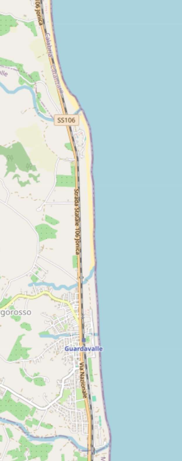
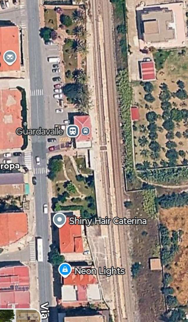
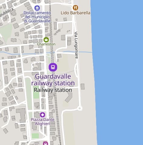
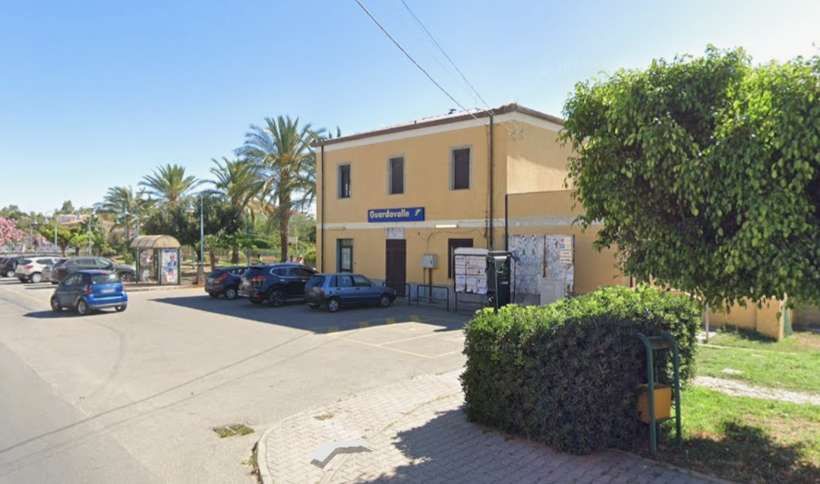
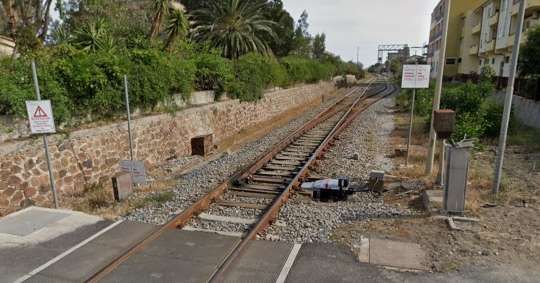
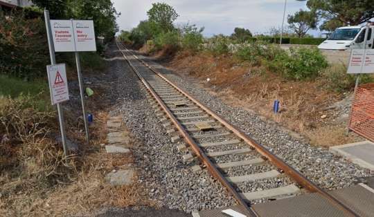
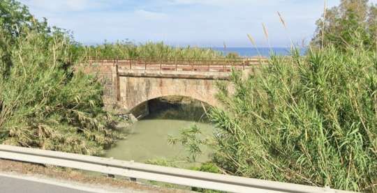
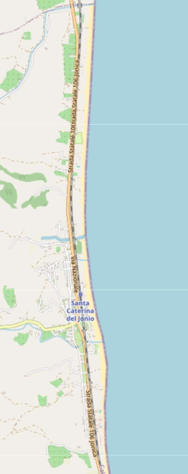
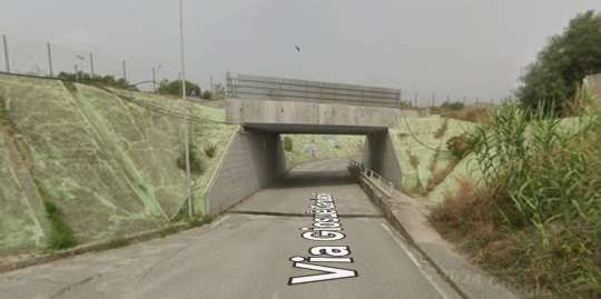
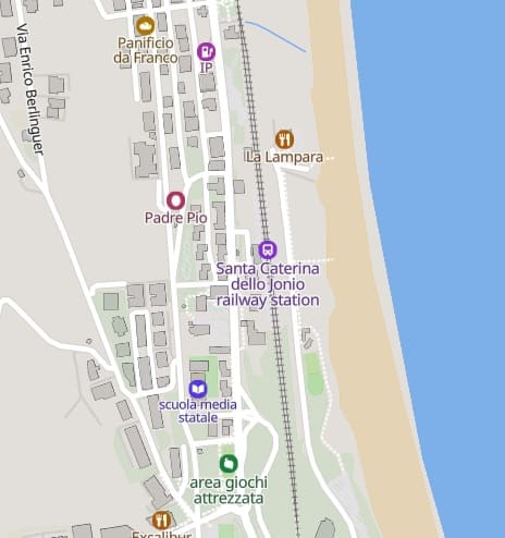
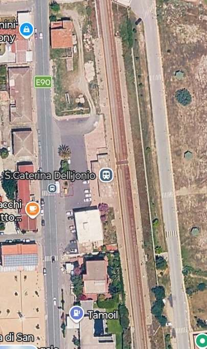
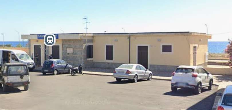
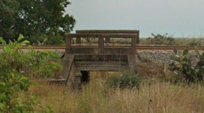
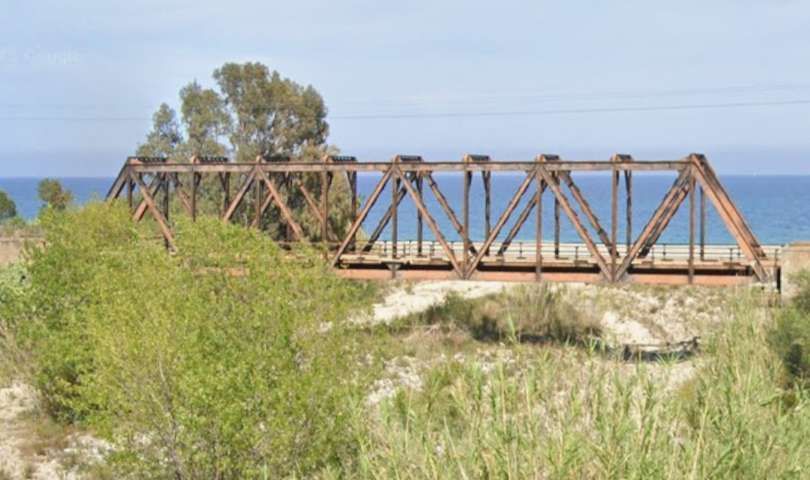
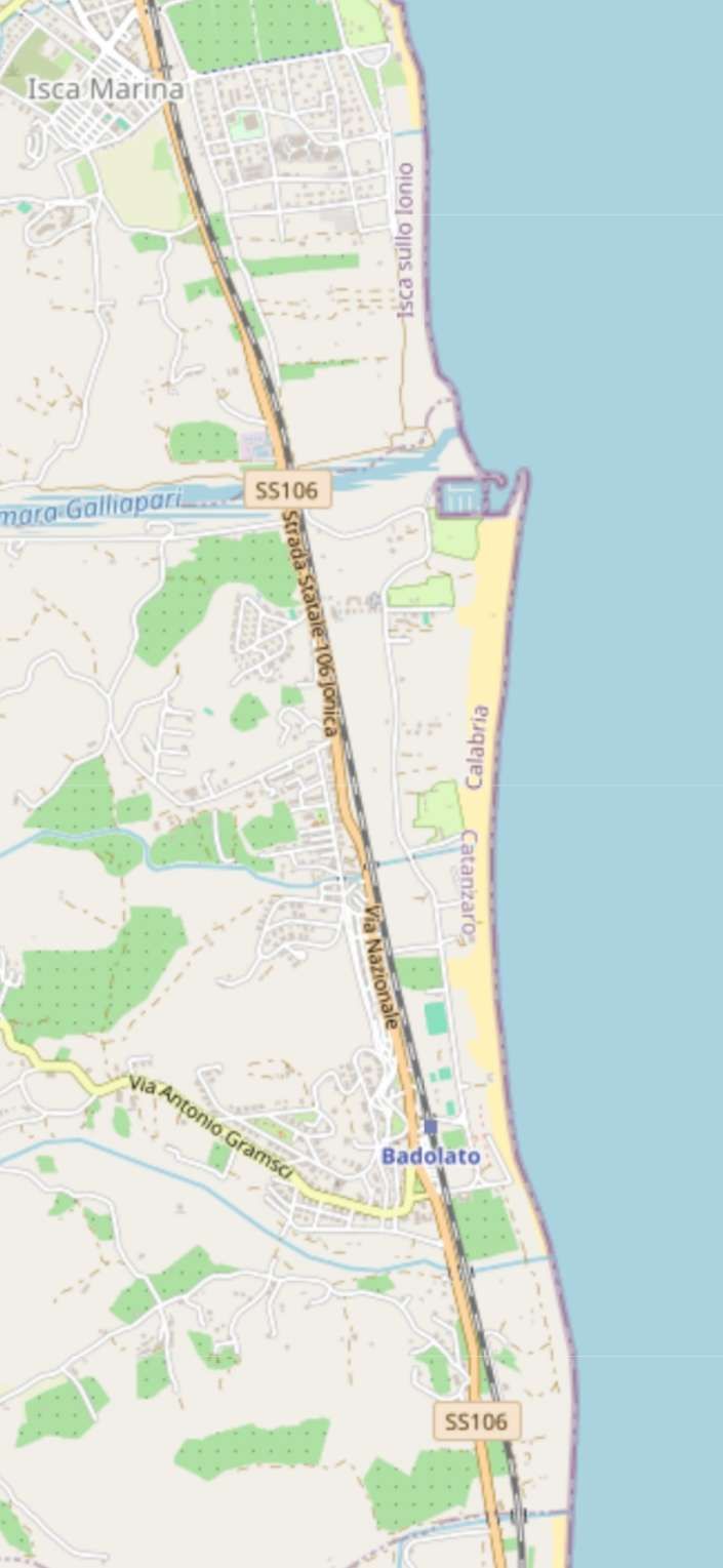
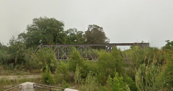
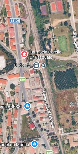
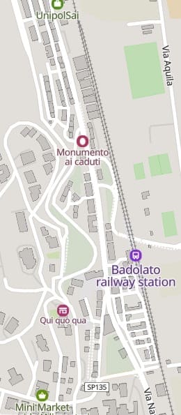
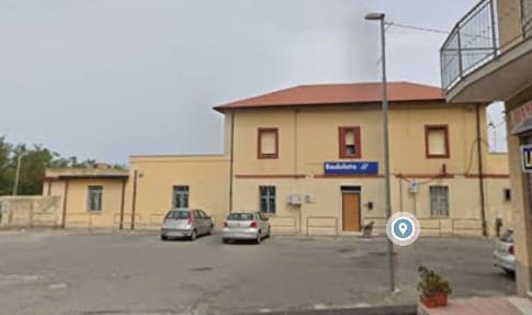
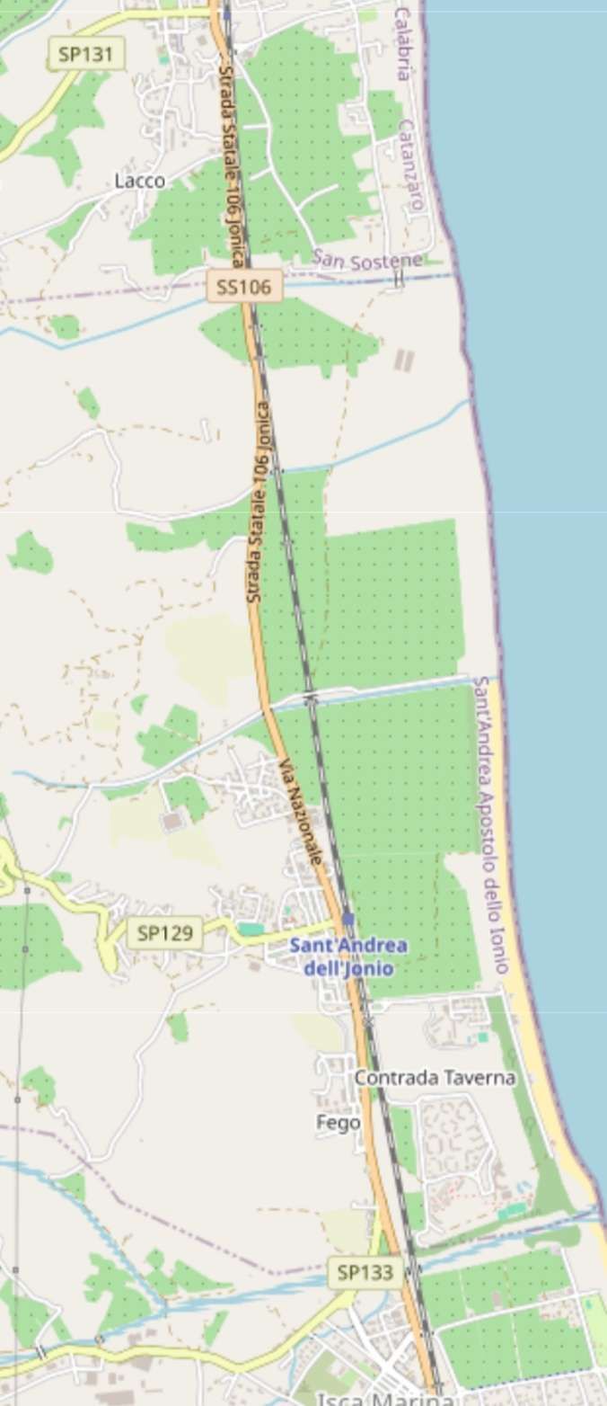
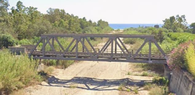
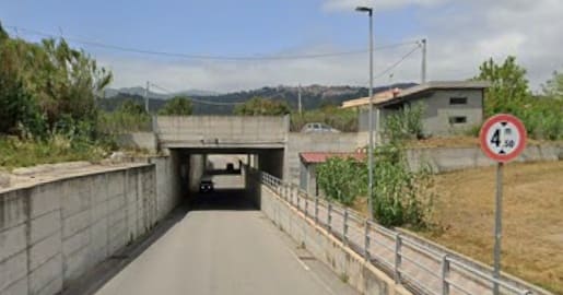
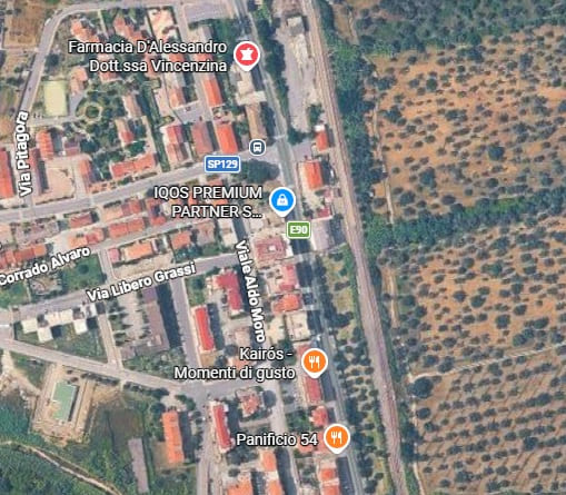
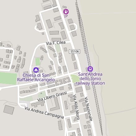

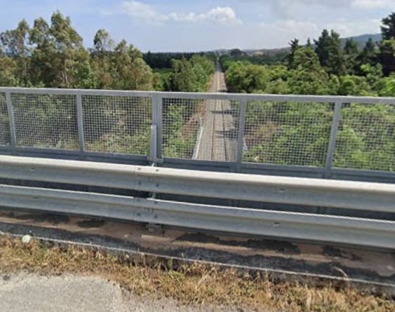
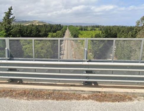
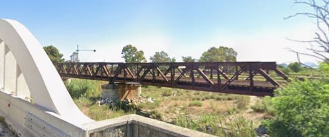
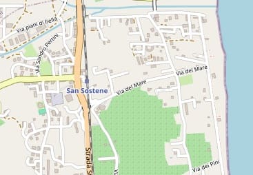
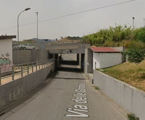
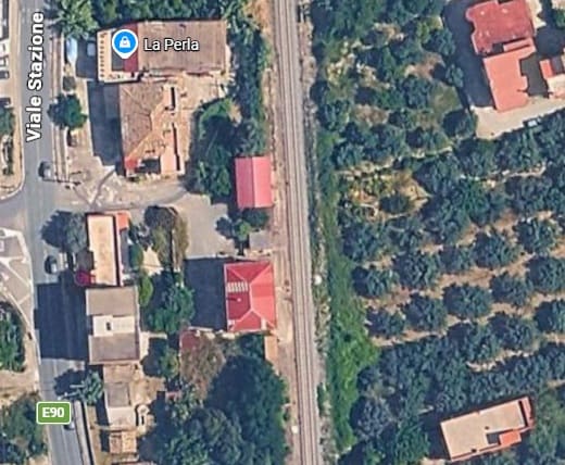
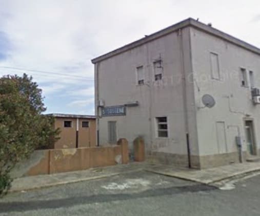
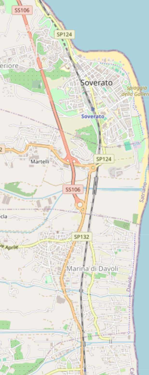
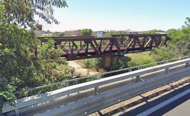
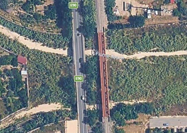
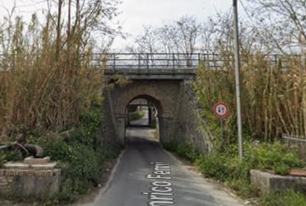
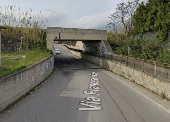
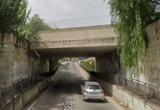
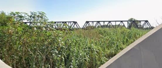
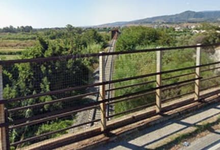
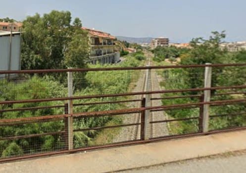
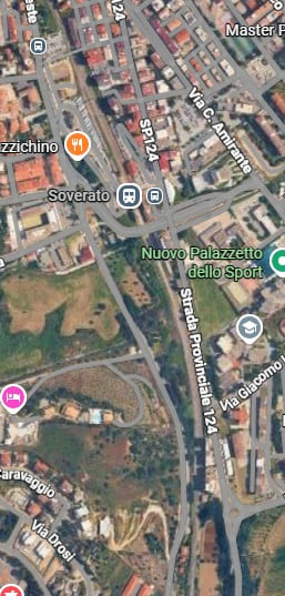
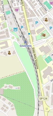
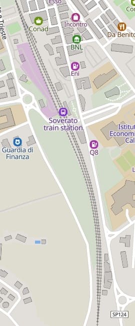
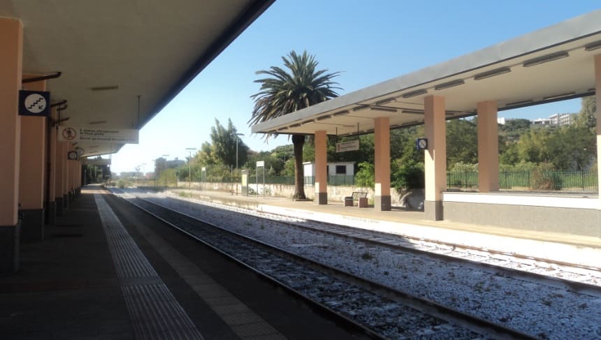
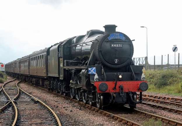
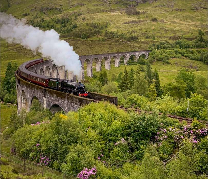
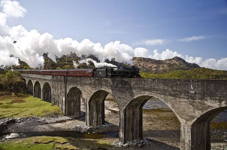
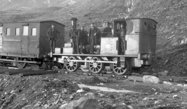
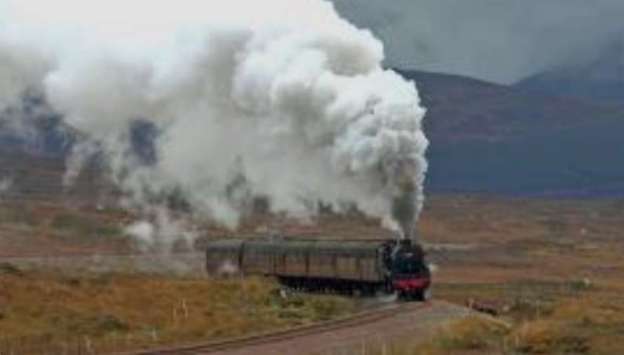
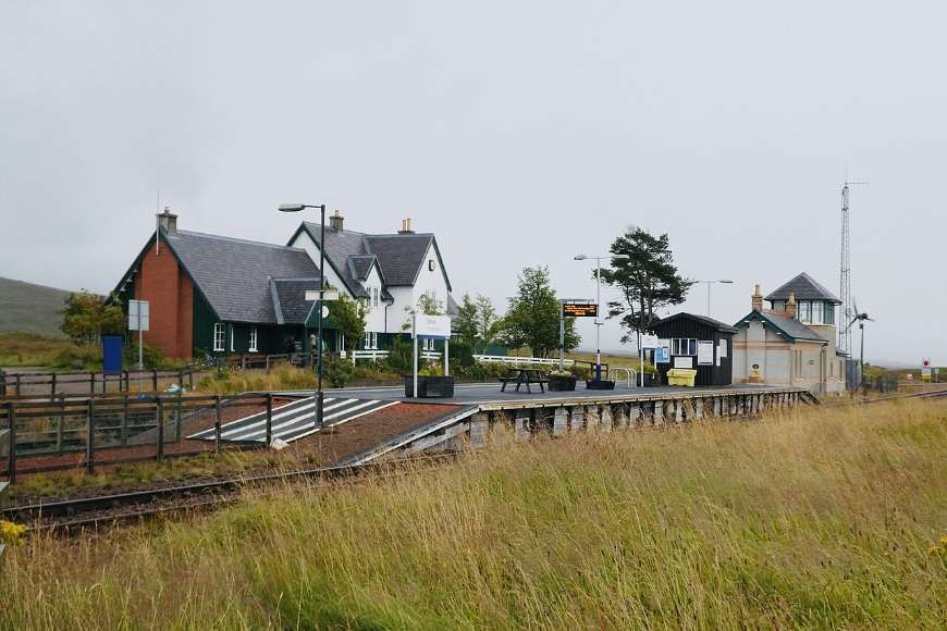
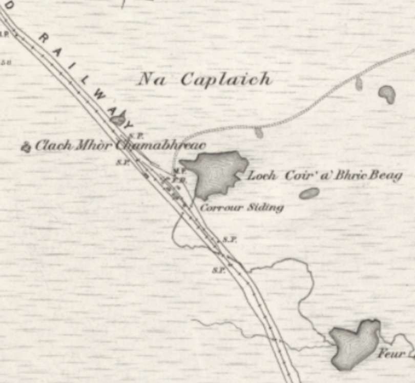
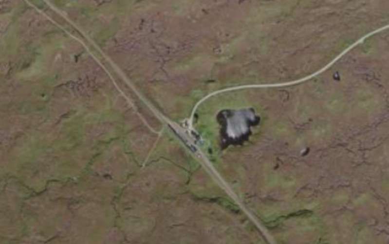
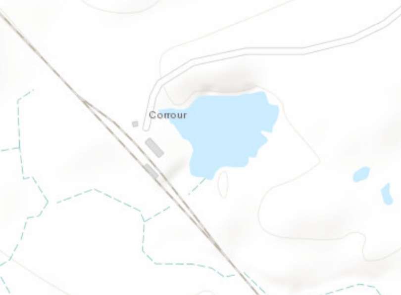
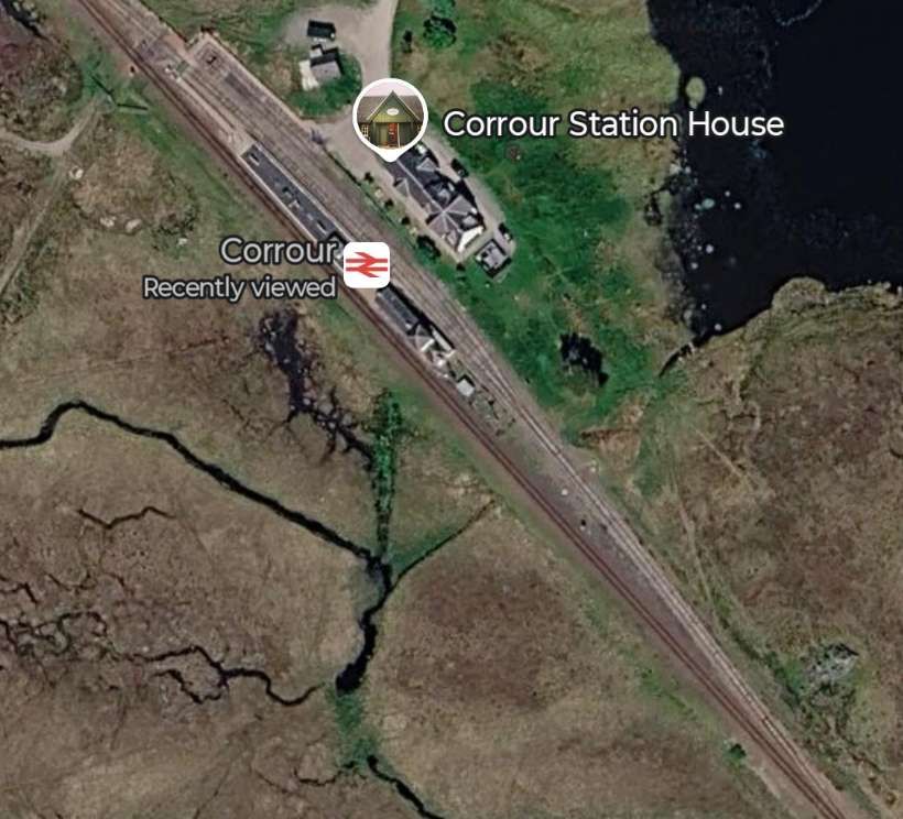
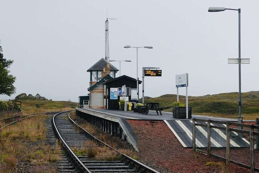
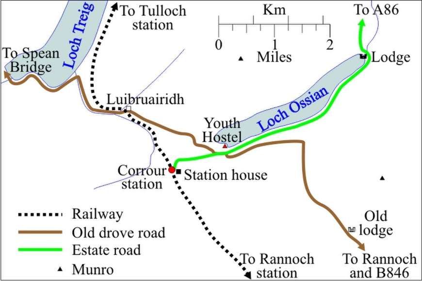
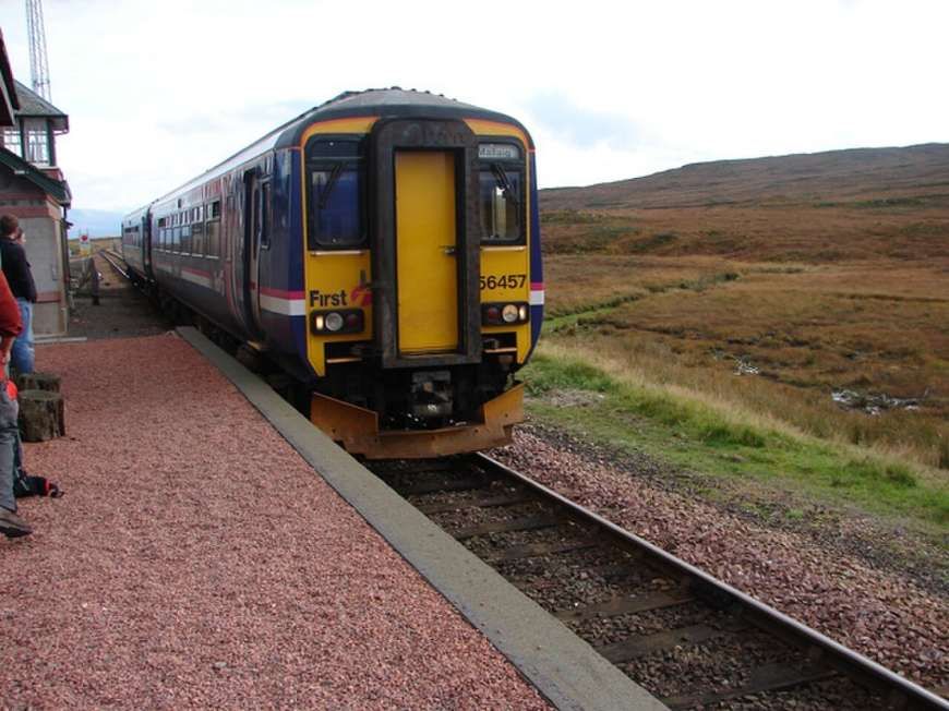
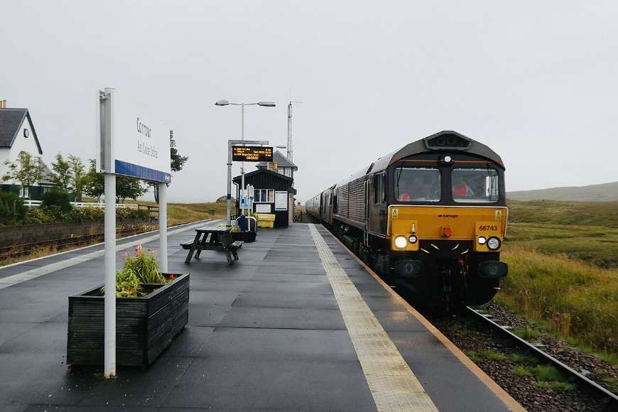

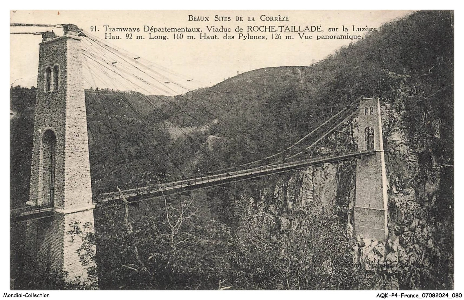
.jpg)
#/media/File:The_Jacobite_Arriving_at_Mallaig_-_geograph.org.uk_-_3119099.jpg)
.jpg)