In the early 1950s, Price tells us, “A considerable stir was caused in railway circles by the news that the Russian and Czech railways had introduced a service of through sleeping-cars between Prague and Moscow, overcoming the break of gauge at the Russian frontier. It appeared that the cars could be lifted on jacks, complete with their passengers, while the standard-gauge bogies were run out and replaced by others of the wider Russian gauge. This method was later extended to other routes, and the accompanying photograph, taken in 1957, shows the cars of the Moscow-Berlin Express raised up on electric jacks in the gauge-conversion yard at Brest-Litovsk, on the frontier of Russia and Poland. … Unknown to the Ministry of Communications of the U.S.S.R., something very similar has been going on quite unobtrusively here in these islands, not just in the last decade, but ever since 1933. The place is Laxey, Isle of Man, and the cause is the six-inch difference in gauge between the Manx Electric Railway’s Douglas-Ramsey line and the Snaefell Mountain Railway. The coastal tramway was constructed to the usual Manx gauge of 3 ft. 0 in., but on the Snaefell line this would not have left sufficient room for the centre rail and the gripper wheels and brake-gear, with the result that the mountain line uses a gauge of 3 ft. 6 in. instead.” [1: p19]
Both the MER and the Snaefell lines “have always been under a common management, and in past years, repainting of Snaefell cars was carried out at the mountain line’s car shed by staff who travelled up each day from Derby Castle. Since Snaefell car shed at Laxey is narrow and rather dark, the work was mostly done out of doors, the car being run in and out of the shed each time it rained. After the 1933 fire at the other Laxey car shed had created a float of spare plate-frame bogies, the management decided to use a pair of these to bring Snaefell cars due for overhaul down to the principal Manx Electric workshops at Derby Castle, Douglas. Controller overhauls and motor repairs were already carried out at Douglas, and since 1933 work at Laxey has therefore been confined to routine maintenance, running repairs and truck overhauls.” [1: p19]
The result of this decision was that every now and again (once or twice a year) a Snaefell car had to be lifted off its 3 ft. 6 in. gauge trucks and mounted on 3 ft. gauge bogies to be towed down to Douglas, returning by the same means when its overhaul was completed. This operation was rarely seen by visitors to the Isle of Man as it took place out-of-season.
“The Snaefell 1963 operating season ended on Friday 13th September, and the moving operation started soon after eight o’clock next morning, when Snaefell car No. 4 was brought down from the car shed and run on to the dual-gauge siding. With it came a set of traversing-jacks, various tools, and the necessary wooden packing, kept in the Snaefell car-shed for this twice-yearly operation and any other less foreseeable. eventualities. Four … men then set to work … following a sequence which, like many other Manx Electric operations, is handed down from one generation to the next without ever having found its way into print.” [1: p22]
J.H. Price continues:
“First, the brake-gear and bogie-chains are disconnected, and the bow-collectors roped to the trolley-wire so that the pins can safely be removed, after which the collectors are untied again and lowered to the ground. Once this is done, no part of the car’s circuit can become ‘live’, and next the motor and field connections are broken at their terminals in the junction-boxes, which are housed under the seats and above the motor positions. The body is now merely resting on its two bogies, with no connection between them.
The next stage is to lift the car and exchange the 3 ft. 6 in. gauge bogies for others of 3 ft. 0 in. gauge. In the case of the Russian sleeping-cars mentioned earlier, the two gauges are concentric and the car. bodies need only a straight lift and lowering, but Laxey siding has three rails (not four), and the car body therefore has to be traversed laterally by three inches from the centre-line of the 3 ft. 6 in. gauge to the centre-line of the 3 ft. 0 in. To do this, the staff use a pair of special traversing-jacks with a screw-thread in the base that enables the load to be moved sideways; similar jacks are used by the Royal Engineers to re-rail locomotives, and were also used by them to place Newcastle tram No. 102 on rails at Beaulieu in March, 1959.
Considerations of safety make it preferable to keep one end of the car resting on a chocked bogie, so the Manx Electric use only one pair of jacks, tackling first one end of the car and then the other. First the Snaefell end of the car is lifted, and the 3 ft. 6 in. gauge bogie is pushed out; in this case, it was then towed up to the car shed by Snaefell car No. 1. Meanwhile, two men fetch a 3 ft-gauge plate-frame trailer bogie from Laxey Car Shed and push it by hand along the northbound running line to Laxey station, where it is shunted on to the three-rail siding and run in under the Snae- fell car. The body is then lowered to the horizontal, traversed to suit the centre of the 3 ft. gauge bogie, and landed on the bogie baseplate. A king-pin is then inserted, the loose retaining-chains are secured, and the jacks taken out and re- erected at the other end of the car.
Now comes the turn of the Laxey end (the two ends of the mountain cars are referred to as Laxey end and Snaefell end, not as No. 1 and No. 2, or uphill and down). The car body is raised again on the jacks, and the other Snaefell bogie pushed to the end of the siding. A second plate-frame trailer bogie is then brought up to a nearby position on the northbound Douglas-Ramsey road, derailed with pinch-bars, and manhandled across the tarmac on to the three-rail siding. Once re-railed, the bogie is then run in under the car end, which is lowered, traversed and secured in the same way as before. The Snaefell car is now ready for its trip to Douglas, and as soon as it has been towed away, another Snaefell car collects the remaining 3 ft. 6 in. gauge bogie and takes it up to the Snaefell car-shed, together with the ladder, tools, packing and jacks. [1: p22]
At the suggestion of ‘Modern Tramway’ a member of staff of the MER agreed to make a photographic record of the whole process. The images were then reproduced in ‘Modern Tramway’. The sequence of images appears below, starting with the Snaefell car No.4 being run into the three-rail siding.
Photograph 1: Snaefell No. 4 “is run on to the three-rail siding at Laxey Station; linesmen tie each bow collector to the trolley wire to take the strain off the mountings, then remove the pins from the spring bases, untie the bow and lower it to the ground.” [1: p20]
Photograph 2: “The car body is disconnected from the trucks (electrically and mechanically) and raised on jacks, and the first 3 ft. 6 in. gauge motor bogie pushed out and towed by another car to the Snaefell depot.” [1: p20]
Photograph 3: “A 3 ft. gauge plateframe trailer bogie is brought up by hand from Laxey Car Shed, ready to be placed beneath the mountain end of No. 4.” [1: p20]
Photograph 4: “The trailer bogie is run in under the car, and the body lowered and traversed sideways on to the bogie centre-plate, then secured by a king-pin and side chains.” [1: p20]
Photograph 5: The traversing jacks are re-erected at the other end of the car, the body lifted off the second motor bogie which is then pushed on to the end of the three-rail siding.
Photograph 6: A second plate-frame trailer bogie brought up on to the running line, derailed with crow-bars, and pushed across the tarmac to the three-rail siding.
Photograph 7: The bogie is run in under the Laxey end of No. 4, and the body lowered, tra- versed and secured. The conversion from 3 ft. 6 in. gauge to 3 ft. gauge is now complete.
Photograph 8: MER. saloon No. 22 enters the transfer siding by the rarely-used 3 ft. gauge crossover and is coupled by bar and chain to Snaefell No.4, ready for the trip to Douglas.
With this work taking place on a Friday, Snaefell car No. 4 was taken to Laxey car shed and then moved on Monday 16th September to Douglas.
Snaefell Car No. 4 was built in 1895 as the fourth of a batch of 6 cars and arrived at Laxey in the spring of 1895. MER’s website tells us that, “Power for the Car was by Bow Collectors with Mather and Platt electrical equipment, trucks and controllers, and Braking using the Fell Rail system. As new, the cars were delivered without glazed windows and clerestories. Both were fitted in Spring 1896 (following complaints of wind, as the original canvas roller blinds did not offer much protection).” [2]
“Car No.4 was one of two Snaefell Cars (Car No.2 the other) to carry the Nationalised Green livery, applied from 1958. No.4 became the last car/trailer in the MER/SMR fleets to carry the scheme, it being moved to Derby Castle Car Sheds for repaint and overhaul during September 1963.” [2]
Car No. 4’s last trip on the MER for overhaul was during Winter 1993, moving back by Spring 1995. After this all maintenance on Car No. 4 was undertaken at Laxey. Laxey was significantly remodelled in 2014. The dual-gauge siding is no longer used and in the remodelling a token 3-raol length was included for effect.
References
J.H. Price; The Secret of Laxey Siding; in the Modern Tramway and Light Railway Review, Volume 27, No. 313; Light Railway Transport League and Ian Allan, Hampton Court Surrey, January 1964, p19-23.
The Modern Tramway and Light Railway Review of November 1963 carried an article by C.S. Dunbar about the Kingsway Tram Subway. It seemed an opportune moment to focus on the Subway as the southernmost portion of the tunnel was about to open to motor traffic as the Strand Underpass.
An image in my blog in an article about the last few years of London’s tram network prompted some response. [2] So, having read his article, I thought that reproducing most of C.S. Dunbar’s article here might be of interest to others. …
The former tramway subway ran beneath Aldwych and Kingsway. “When the London County Council, as the tramway authority for the Metropolis, decided that it would itself operate the services as the various leases fell in, the question of joining up the separate company systems became very important, particularly with a view to giving communication between the north and south sides of the river. The decision to clear an insanitary area in Holborn, and to construct Aldwych and Kingsway, led to discussion in 1898 on the possibility of using the new streets for a tramway to connect the northern and southern systems. It was then suggested that instead of running the trams on the streets, a sub-surface line should be constructed as an integral part of the improvement. Something similar had already been done in New York and Boston, and a deputation … was, therefore sent to those places.” [1: p385]
On the strength of their report, an application was made in the 1902 session of parliament for powers “to construct a subway for single-deck tramcars at an estimated cost of £282,000 from Theobalds Road to the Embankment at Waterloo Bridge, from which point a surface line would continue to and over Westminster Bridge. By the LC.C (Subway and Tramways) Act, 1902, the subway itself was approved for the whole proposed length, but the tramway was not authorised beyond the north side of the Strand. The proposed Embankment line was rejected and in fact it took the Council four years to secure powers. Many ridiculous arguments were advanced against the line, the most absurd, probably, being that the trams would interfere with members crossing the road to reach St. Stephen’s Club. Six Bills introduced by the Council between 1892 and 1905 to enable it to carry the tramways across Westminster and other bridges and along the Victoria Embankment were thrown out by one or other House of Parliament, and not until 1906 was the battle resolved in the Council’s favour.” [1: p385-386]
As events were to prove, “a great mistake was made in deciding that the subway should only provide for the passage of single-deck cars, but this decision was reached for three main reasons:
(1) to avoid a large sewer under Holborn would, it was thought, necessitate too steep a descent to be safe for double-deck cars – as it was there was a gradient of 1 in 10 from Theobalds Road;
(2) the position of the District Railway in relation to Waterloo Bridge and the gradient from the Strand presented difficulties in the way of making a satisfactory southern exit;
(3) there was a feeling that it might be found that London traffic could be handled more expeditiously with coupled single-deck cars than with double-deckers.” [1: p386]
“Construction was undertaken at the same time as the new streets were laid out and as well as making provision for the trams, a pipe subway for gas and water mains 10 ft. high and 74 ft. wide was built on each side. The approach from Theobalds Road was by an open cutting 170 ft. long in the middle of the road. The tracks then passed into two cast-iron tubes, 14 ft. 5 in. in diameter and 255 ft. long, which took the tracks under the Holborn branch of the Fleet sewer. The rails were 31 ft. below the road surface when passing under Holborn, rising again at 1 in 10 to Holborn Station. Raised side-walks were provided in the single tunnels. From here to Aldwych the tunnel was 20 ft. wide with a roof of steel troughing just below the street. The running rails were laid on longitudinal wooden sleepers embedded in concrete, and since the conduit would not have to bear the weight of road traffic a special lighter design was used in which the normal slot rails were replaced by plates which could be lifted for maintenance. As usual with L.C.C. tramway figures it is difficult to ascertain the actual cost of the work, but it seems likely that the construction of the subway itself accounted for £133.500 for the 2,920 ft. from Theobalds Road to Aldwych, with a further £112.500 for permanent way and electrical equipment.
At the time the subway was opened it was not connected with any other electrified route, so it was decided to terminate the public service at Aldwych Station (situated at the junction of Aldwych and Kingsway) and to use the tracks which extended southwards from there towards the Strand as a depôt. Inspection pits were therefore constructed under this length and some repair equipment installed. An intermediate station was built at Great Queen Street (subsequently renamed Holborn). Pending the opening of Greenwich power station, current was obtained from the County of London Electric Supply Company at a cost of 1d per unit.
Single Deck Cars
Sixteen Class F tramcars (numbered 552 to 567) were ordered from the United Electric Car Company, Limited, Preston at £750 each. The Board of Trade, then the Government Department concerned with tramways, was very focussed on the risk of fire in the tunnels and the new cars had to be as non-flammable as possible. “The underframes were therefore made of steel angle and channel sections, and the body panels were of sheet steel. The slatted longitudinal seats were of non-flammable Pantasote on angle steel supports; the seating capacity of the cars was 36. Even the adjustable spring roller-blinds, with which the windows were fitted, were supposed to be non-flammable. The inside finish was entirely in aluminium. The cars were 33 ft. 6 in. long over the fenders and 24 ft. 10 in. over the body pillars. The trucks were centre bearing maximum traction bogies by Mountain and Gibson with a 4 ft. 6 in. wheelbase and 311 in diameter driving wheels. The distance between the centre of the driving axles was 14 ft. 6 in. The controllers were by Dick Kerr and included provision for using the electro-magnetic brake for service stops.” [1: p387]
Service 31 had more vicissitudes than the other two. Consequent upon the conversion of part of the Wandsworth service to trolleybuses on 12th September, 1937, it was cut back to Prince’s Head, Battersea. The conversion of the Shoreditch area caused its diversion on 10th December, 1939, to terminate at the lay-by at Islington Green (outside the Agricultural Hall) which had been put in in 1906 but never used for regular services, except possibly for a few weeks in 1909. Destination indicators, however, showed ‘Angel, Islington.’ There was a further curtailment on 6th February, 1943, when the service began working between Bloomsbury and Prince’s Head in peak hours and between Westminster Station and Prince’s Head at other times. This arrangement was unsatisfactory owing to the turning points being on through routes and the cars and crews being based at Holloway, and it was hoped as from January, 1947, to run between Islington Green and Wandsworth High Street. It was not, however, possible to introduce this improvement until 12th November, 1947.
In addition to the 100 E/3 type cars previously mentioned, 160 other cars were built to the fireproof specifications laid down for the Subway (HR/2 class 1854- 1903 and 101-159, E/3 class 160 to 210), and in later years some of these worked regularly on the subway services, particularly after war losses. After Hackney depôt closed, the cars for the subway were provided by Holloway depôt for all three services and also by Wandsworth (for 31), Norwood (33) and Camberwell (35). At one time in 1941, Holloway depôt was cut off for several days by an unexploded bomb and could only operate a shuttle service of two cars between Holloway and Highgate, during which period wooden E/1 cars from South London depôts were perforce used on the subway routes, turning back at Highbury Station. The famous L.C.C. car No. 1 of 1932 was intended for the subway services, with air-operated doors and folding steps for use at the subway stations, and worked from Holloway depôt on these services from 1932 to 1937. This car was sold in 1951 to Leeds and is now preserved at Clapham.
In 1937, the rebuilding of Waterloo Bridge necessitated the diversion of the subway exit to a position centrally beneath the new bridge, at a cost of £70,000 including a new crossing of the District Railway; after the changeover took place, on 21st November, 1937, the curved section of tunnel leading to the former exit in the bridge abutment was walled off and still exists. For the next three years, the trams entered the subway through the bare steelwork, as the new bridge took shape above their heads. In anticipation of a general conversion of the London tramways to trolleybus working, an experimental trolleybus (No. 1379) placed in service on 12th June, 1939, was so designed as to permit passengers to board and alight from the offside at Aldwych and Holborn Stations. Not until some years later did London Transport admit officially that this experiment had been a failure. The war brought a reprieve to the remaining London tramways, and was followed by a decision that the routes still working would be replaced by motor buses and the subway closed.
Owing to a need to replace worn-out buses, tramway replacement did not commence until 1950, when on 1st October, tram service No. 31 (Wandsworth High Street- Islington Green) was replaced by bus service 170 (Wandsworth High Street – Hackney L.T. Garage), running via Norfolk Street northbound and Arundel Street southbound, and taking about eight minutes from Savoy Street to Bloomsbury as against four minutes by tram. From 7th October, 1951, Camberwell depôt was closed for reconstruction and its share of service 35 taken over by New Cross. Finally, on Saturday, 5th April, 1952, trams ran through the Subway for the last time; tram service 35 (Forest Hill – Highgate) was replaced next day by bus service 172, and tram service 33 (West Norwood – Manor House) was replaced by bus service 171, West Norwood – Tottenham (Bruce Grove). The last car to carry passengers through the subway in service was E/3 No. 185, some time after midnight, and in the early hours of the following morning the remaining cars from Holloway depôt were driven south through the Subway to new homes or the scrapyard.
“A clerestory roof was fitted with a trolley plate on top, although the cars never actually carried a trolley-pole but were built solely for conduit operation. The height from the ground to the trolley plate was 11 ft. The internal height to the top of the clerestory was 7 ft. 94 in. and the width was 6 ft. 6 in. over the solebars, 6 ft. 8 in. over the pillars and 6 ft. 10 in. over the roof. There were five windows on each side. The first of the class, No. 552, was built with bulkhead doors of the twin sliding type and had side doors to the unvestibuled platforms, which interworked with the folding steps. These doors were removed before the car entered service, and the remainder of the class had the normal single door in each bulkhead and a simple sheathed chain across the platform sides.
Each bulkhead was fitted with an oil lamp above the nearside bulkhead panel, which showed either a white or red aspect externally and also threw a light into the interior of the car. These were replaced by electric lamps at an early date. Hanging from each canopy was a box for the colour- light headcode, and above the canopy was a destination indicator. Projecting from the roof at both ends was an iron bar; this struck against other bars hanging from signal lamps at the beginning of the descent from Theobalds Road travelling south and that from Holborn Station travelling north, so putting the aspect to red. Corresponding contacts were made on leaving the section in both directions to put the signals back to green, the object, of course, being to prevent more than one car in each direction being on the 1 in 10 gradient at one time.
To provide a northern connection with the subway, it was decided to electrify the line in Theobalds Road (by arrangement with the North Metropolitan Tramways Company, which then held the lease) and to construct a new line in Rosebery Avenue and St. John’s Street to the Angel, Islington. The estimate for this was £40,500, but owing to great difficulties with sub-surface mains and other obstructions the cost eventually reached £47,000. Part of the reconstructed roadway was carried on a concealed iron viaduct. Work was started on the reconstruction on 17th September, 1905. The Board of Trade inspected the Subway and the new line to the Angel on 29th December, 1905, and motormen then, began to be trained.” [1: p387]
A public service from Angel to Aldwych began on 24th February 1906, the delay was down to the Board of Trade’s worries over the non-flammable character of the tramcars. The ceremonial opening included “the first car, painted blue and gold, taking 12 minutes northbound and 10 south. This was good running, remembering that horse cars were working in Theobalds Road. Smoking was not permitted in the cars and this led one councillor to suggest the provision of open cars especially for smokers. Fares were fixed at 1d. from the Angel to Holborn Hall and from Holborn Hall to Aldwych and d. for the full journey. The novelty attracted a considerable number of passen- gers from the start and the takings for the first three days with a two-minute service averaged [just over 2s. 2d.] per mile as against 1s. per mile for the double-deckers in South London.” [1: p387]
Class G Tramcar No. 584 leaving the Subway for Westminster in 1923. The L.C.C. flaman can be seen to the right of the photograph. [1: p389]
“Meanwhile in July, 1905, the Council’s attention had been drawn to the fact that its compulsory powers for the acquisition of land and easements for the construction of the subway from Aldwych to the Embankment would expire in August. It therefore voted £50,000 for the necessary acquisition in the hope that powers for the Embankment tramway would eventually be secured. Actually £9,400 was paid to the Duchy of Lancaster and £15,250 to C. Richards and Company for the extinction of their interests in the arches under Wellington Street. In the Parliamentary session of 1905 powers were secured for an additional station south of the Strand under Wellington Street.
In November, 1905, the Council ordered a further 34 cars of a similar type to the first batch, but this time with Brush bodies, glazed bulkheads and Westinghouse equipment (Nos. 568-601, class G). It had not been possible to build steel bodies as cheaply as timber ones and the cost of these cars came out at £27,761, or nearly £817 each. On the delivery of these cars, there were sufficient to extend the route to Highbury Station on 16th November 1906, after High Street and Upper Street, Islington, had been reconstructed in the short time of 12 weeks. In fact the cars started running before the borough council had completed the wood paving at the sides of the carriageway.
When the Embankment tramway was eventually opened and powers had been obtained for the subway link, work was pushed ahead on the remaining section. This fell on a gradient of 1 in 20 from Kingsway to the Strand, 1 in 108.3 under the Strand, and was then level; it was far more costly to construct than the original length, mainly owing to difficulties in crossing the District Railway. The final 620 ft, in fact, cost £96,000 exclusive of permanent way and equipment. The cost would have been £20,000 more had the proposed station at Wellington Street been built, but in March, 1907, the Council decided that the proposal should be aban- doned, as the site was only 200 yards from the Embankment and the platform would be 32 ft. below ground. This decision enabled the extension to be opened nine months earlier than would have been the case otherwise. The Council undertook the whole of the work by direct labour and completed it in about twelve months. South of Aldwych Station, the tracks curved sharply to the south-west in twin tunnels and continued beneath Aldwych as a single tunnel with brick-arch roof, separating again at the Strand into twin cast-iron tubes which continued to about a third of the way under Lancaster Place. The exit on to the Embankment was through the western wing wall of Waterloo Bridge and here a triangular junction was constructed. The eastern side of the junction, leading towards Blackfriars, was never used and was removed during the 1930 re-construction referred to later.
Through services were inaugurated on 10th April, 1908, from Highbury Station to Tower Bridge and from Highbury Station to Kennington Gate. Fares ranged from 0.5d. to 3d, (the maximum on both routes). Special workmen’s fares of 1d. single and 2d, return were given from any terminus to Waterloo Bridge. The journey times varied from 47 to 50 minutes on the Tower Bridge route and 41 to 44 on the other. A six minute service was given on each route with early morning extras between Highbury and Aldwych. The cars were stabled at Holloway and New Cross depôts.
The Kennington service did not pay and in looking for another route on which to use the single-deck cars, the management thought of Queen’s Road, Battersea, on which it was impossible to run double- deckers owing to a low railway bridge. The Kennington service was therefore diverted on 25th January, 1909, to work between St. Paul’s Road and Lavender Hill via Battersea Park Road, giving a service to the Lavender Hill area while the Wandsworth Road line was being electrified. As Essex Road was being reconstructed at this time, it is possible that cars actually turned at the Angel or at Agricultural Hall for some weeks. The through fare was 4d. and the journey time 52 minutes. Transfer fares to Kennington were given. In May, 1910, the Angel definitely became the northern terminus, with a short service working between St. Paul’s Road and Southampton Row. In the following year, the southern portion was cut back to Vauxhall, the crossover in Wandsworth Road by the gas works being used. Transfers were issued to Battersea On 17th June, 1912, the service was again extended but this time to Clapham Junction via Battersea Park Road and the Sunday afternoon service began to work from Southgate Road. In the summer of 1911 (probably on 22nd June) the Tower Bridge service was extended to Tooley Street (Bermondsey Street), the through fare remaining at 3d. and the journey time being 52 minutes, but a year or so later Tower Bridge again became the terminus. The junction westward into Tooley Street was replaced in 1923 by one in the opposite direction.
Until 1912, the cars carried colour-light headcodes, the original through services displaying red-green-red for Highbury Station – Tower Bridge and blank-green-blank for Highbury Station – Kennington Gate. When L.C.C. routes began to be numbered in September, 1912, the Tower Bridge service became 33 and that to Clapham Junction 35, the number being hung from the canopy. This arrangement, used on double-deck cars only until upper deck stencils were fitted, was retained on the subway cars until 1930. On 28th October, 1913, 35 was altered to run between Highbury and Belvedere Road only, the southern part of the service being taken over by 86 from Embankment to Clapham Junction. At this time cars on 35 turned at a lay-by in St. Paul’s Road at one end of the route and in Lambeth Palace Road at the other. A year or so later, Westminster Station became the southern terminus. Service 33 was withdrawn altogether, but reappeared after the 1914-18 war as a weekday service between Highbury and County Hall, while 35 then became Highgate – County Hall. After the withdrawal of 33, Tower Bridge Road was covered by 68 from Waterloo Station. In July, 1924, both 33 and 35 were extended to the Elephant and Castle via St. Georges Road, obtaining at last a terminus at which the cars could stand without obstructing other through services. The author believes that the subway services were the only ones which ever regularly used the southbound track in St. Georges Road. When cheap mid-day tickets were instituted, Savoy Street was taken as the ‘City terminus’ on southbound cars and Bloomsbury on northbound. [1: p387-389]
Decision to Enlarge
As years went by, the L.C.C. increasingly became aware that single-deck cars could not be made profitable. The use of double-deck rolling stock would allow many useful connections and the movement of rolling-stock across the Thames would be facilitated. The, then current, route for double-deck trams to cross the Thames was via North Finchley, Putney and Wandsworth.
In 1929, the L.C.C. decided to increase the headroom to 16 ft. 6 in. They sought to raise the roof at the northern end and deepen the tunnel at other places. The decision resulted in observations that the subway might well be “enlarged to take motor traffic as well as trams, but the Metropolitan Police Commissioner pointed out that congestion would arise at each end of the tunnel, that a serious traffic block would quickly develop if a vehicle broke down inside, and that there was a danger of exhaust fumes and even fire. The London Traffic Advisory Committee recommended that the tunnel could serve no useful purpose as a motor-way, and the L.C.C. would have nothing to do with the idea. Nevertheless, on the day the subway was reopened, The Times returned to the theme and hoped that the tunnel would be available for omnibuses and other vehicles ‘when tramways have had their day.'” [1: p390]
Dunbar continues:
“The contract was awarded to John Cochrane and Sons, Limited, who started work on the street level on 11th September, 1929, this necessitating the temporary diversion via Hart Street and Theobalds Road of bus services 7 and 184. North of Holborn the roadway was opened up and the twin tunnels replaced (after sewer diversions) by one wide passage with a steel girder roof, while elsewhere the additional headroom was obtained by under-pinning the side walls with concrete and lowering the track by approximately 5 ft. The estimated cost was £326,000 including £76,000 for the reconstruction of the 50 single-deck cars. On and from 16th January, 1930, only one tram service (numbered 33) ran through the subway from Highgate to the Elephant, while 35 worked Highgate – Bloomsbury. The single-deck cars carried passengers through the subway for the last time on Monday morning, 3rd February, 1930, after which the subway was closed altogether, a connection being maintained by temporary L.G.O.C. bus service 175 (Islington – Charing Cross Embankment via Kingsway and Northumberland Avenue, returning via Norfolk Street, Strand and Aldwych). On 14th May another bus service – 161 – was put on between Islington and Waterloo on weekdays only. The two tramway stations were rebuilt and modernised, that at Holborn being finished in travertine, a cream marble used in ancient Rome. Standard trackwork with yokes and slot-rails set in concrete was used in place of the special type evolved for the original construction.
It had been hoped that the subway would be reopened by the Prince of Wales on 17th December, 1930, and in anticipation of this car No. 1930 was painted blue and gold. Actually, however, it was not possible to start experimental runs before 5th January 1931. The formal reopening was performed on Wednesday, 14th January, 1931, by the Chairman of the Council, Major Tasker, car No. 1931 painted white with blue lining being employed, followed by two other cars. These ran from the Embankment to Theobalds Road and back to Holborn Station, where one of the platform seats served as a rostrum for the speeches. Public service commenced at 5 o’clock next morning, with a one-minute headway and a total of 5,000 cars per week. The L.C.C. issued a special booklet describing the subway’s history and reconstruction and listing the new services and transfer facilities, together with the running times. [1: p390]
“The subway service was worked by the new E/3 class cars (Nos. 1904-2003) which had been ordered in June, 1929, from Hurst, Nelson & Co., of Motherwell, and had been working on various South London services until the subway was ready. In the subway, it became necessary to use the drivers’ platforms and the front stairways for boarding and alighting at the island platforms of Holborn and Aldwych stations. The former bar-operated signals at Holborn and Bloomsbury were replaced by others worked by the passage of the plough in the conduit slot. The single-deck cars were withdrawn and the trucks and Westinghouse equipments used under new English Electric composite bodies, but still bearing the original numbers (552-601). The single- deck car bodies were offered for sale in 1930, to be collected at Holloway or Charlton. In earlier years, some of these cars were stabled, first at Jew’s Row and later at Clapham for the Queens Road service, while in 1911 some were sent to Hampstead for the experiment with coupled cars which took place between January and August of that year on the Hampstead – Euston route.
Public service through the subway began again on 15th January, 1931, with three services: 31, Hackney Station – Wandsworth High Street via Shoreditch and Battersea Park Road (73 minutes, weekdays), Hackney – Tooting Junction (Saturday evenings) and Leyton Station L.M.S. – Westminster Station (54 minutes, Sundays); 33, Highbury Station – Water Lane, Brixton (42 minutes, weekday peak hours), with occasional workings to Norbury; 35, Highgate, Archway Tavern-New Cross Gate via Kennington (59 minutes, daily). It was originally intended to work 31 through to Wimbledon via Haydon’s Road, but this was never done. From 19th April to 4th October, 1931, the Sunday working of this service was from Leyton, Baker’s Arms, to Tooting Junction (17 miles). A similar arrangement prevailed in subsequent summers, but for the rest of the year the Sunday workings were between Baker’s Arms and Wandsworth.
Service 33 was altered twice during 1931 and began operating in off-peak hours, being diverted first to Norwood on 14th May, and then at the other end to Manor House on 8th October, after which it remained unchanged. Also on 14th May, 1931, 35 was extended to Forest Hill (Cranston Road) via Brockley, the indicators actually showing Brockley Rise. A Saturday evening and Sunday working was instituted between Highgate and Downham via Brockley – 16 miles the longest tram service ever operated entirely inside the County of London. The dates of this service are uncertain, but it was definitely working on 8th October, 1931. It possibly ceased after 5th March, 1932, on which date the southern terminus of 35 became the lay-by at Forest Hill Station. On 30th June, 1932, the route was diverted via Walworth Road instead of via Kennington and thereafter remained unchanged. On 1st June, 1933, short workings were introduced between Highbury and Elephant and Castle via St. Georges Road. These were numbered 35A.” [1: p390-392]
Route 31 saw a series of different changes over its life. Dunbar tells us that “consequent upon the conversion of part of the Wandsworth service to Trolleybuses on 12th September 1937, it was cut back to Prince’s Head, Battersea. The conversion of the Shoreditch area caused its diversion on 10th December 1939, to terminate at the lay-by at Islington Green (outside the Agricultural Hall) which had been put in in 1906 but never used for regular services, except possibly for a few weeks in 1909. Destination indicators, however, showed ‘Angel, Islington’. There was a further curtailment on 6th February 1943, when the service began working between Bloomsbury and Prince’s Head in peak hours and between Westminster Station and Prince’s Head at other times. This arrangement was unsatisfactory owing to the turning points being on through routes and the cars and crews being based at Holloway, and it was hoped as from January 1947, to run between Islington Green and Wandsworth High Street. It was not, however possible to introduce this improvement until 12th November 1947.”[1: p392-394]
“In addition to the 100 E/3 type cars previously mentioned, 160 other cars were built to the fireproof specifications laid down for the Subway (HR/2 class 1854 to 1903 and 101-159, E/3 class 160 to 210). and in later years some of these worked regularly on the subway services, particularly after war losses. After Hackney depôt closed, the cars for the subway were provided by Holloway depôt for all three services and also by Wandsworth (for 31), Norwood (33) and Camberwell (35). At one time in 1941, Holloway depôt was cut off for several days by an unexploded bomb and could only operate a shuttle service of two cars between Holloway and Highgate, during which period wooden E/ cars from South London depôts were per- force used on the subway routes, turning back at Highbury Station. The famous L.C.C. car No. 1 of 1932 was intended for the subway services, with air-operated doors and folding steps for use at the subway stations, and worked from Holloway depôt on these services from 1932 to 1937. The car was sold in 1951 to Leeds and is preserved at Clapham. [1963]
In 1937, the rebuilding of Waterloo Bridge necessitated the diversion of subway exit to a position centrally beneath the new bridge, at a cost of £70,000 including a new crossing of the District Railway; after the changeover took place, on 21st November, 1937, the curved section of tunnel leading to the former exit in the bridge abutment was walled off and still exists. For the next three years, the trams entered the subway through the bare steelwork, as the new bridge took shape above their heads. In anticipation of a general con- version of the London tramways to trolley- bus working, an experimental trolleybus (No. 1379) placed in service on 12th June 1939, was so designed as to permit passengers to board and alight from the offside at Aldwych and Holborn Stations. Not until some years later did London Transport admit officially that this experiment had been a failure.” [1: p394]
The Second World War meant a reprieve for the remaining tramways in London. Trolleybuses were no longer seen as the future, the decision was taken to replace the trams with motor buses. The decision was taken to close the Subway. In practice tramway closures did not happen quickly. Already worn out buses were replaced first, so tramway replacement did not start until 1950. We have looked at the twilight years of London’s tramways in an earlier post in this series. [4]
On Saturday 5th April 1952, “trams ran through the Subway for the last time. … The last car to carry passengers through the Subway in service was E/3 No. 185, some time after midnight, and in the early hours of the following morning the remaining cars from Holloway depôt were driven South through the Subway to new homes or the scrapyard.” [1: p394]
“The tracks remained unaltered, though disused, until the final abandonment of London’s tramways on 5th July, 1952, after which the street tracks were lifted in stages and those in the subway, cut at the approaches, were left as the longest section remaining in London. A technical committee was set up by the Minister of Transport to report on the possible use of the subway for motor vehicles, and tests with road vehicles were carried out both before and after closure, but the committee concluded that a satisfactory scheme would cost £1,200,000 and the Minister decided that the money could be better used in other ways. An alternative scheme to convert the subway to a car park was rejected because the cost (£175,000) was out of proportion to the benefit. In 1953, London Transport used the subway to store 120 retired buses and coaches in case they were needed for the Coronation, and in 1955 it was used to represent a railway tunnel in the film Bhowani Junction. A film company offered to take over the whole subway as a film studio, but this was rejected on account of the fire risk. Repeated questions in Parliament kept the issue alive, but in 1955 London Transport invited applications for the use of the tunnel as a store for non-flammable goods, and finally leased it in October, 1957, to S. G. Young & Co. of Blackfriars as a store for machine parts. The new tenants introduced fluorescent lighting colour-washed walls, and filled in part of the floor so as to use fork-lift trucks and pallets. After the trolleybus power supply ceased in 1959, the DC automatic pumps beneath the Strand at the lowest point of the subway were re-motored to work from the public supply.
Meanwhile, in June, 1958, the London County Council expressed interest in taking over the subway and creating an underpass for light traffic beneath the Strand and Aldwych to deal with the traffic jams which often extend right across Waterloo Bridge. This plan involved about half the subway, from Lancaster Place to Kemble Street, and received official backing, though not until April 1962, did the Minister of Transport decide to make a grant of 75 per cent towards the estimated total cost of £1,306,512. The consulting engineers were Frederick Snow & Partners, and the contract for the reconstruction, totalling £1,025,233, was awarded in July, 1962, to John Mowlem & Co, who moved in on 1st September, 1962, and promptly began their 15-month task.” [1: p395]
The new underpass opened on 21 January 1964. “It is only 17 feet (5.2 m) wide and, as a result, it is normally one-way northbound because of the side clearances required. The headroom is only 12.5 feet (3.8 m) due to the tunnel having to pass beneath [a] bridge abutment by a 1:12 gradient. An electronic ‘eye’ alerts drivers of tall vehicles and diverts them to an ‘escape route’ to the left of the entrance. However, high vehicles do still try to pass through and so get stuck occasionally.” [5]
“The underpass is a concrete box within the former tram subway, with the road surface at the original track level. At the northern end of the underpass the road rises to the surface on a new carriageway supported by metal pillars. This passes through the site of the former Aldwych tramway station; because of the greater width requirement, 27 trees and some pavement sections were removed for it to be constructed.” [5]
“The tunnel was used by the 521 bus route northbound until it was withdrawn in April 2023. In 2012, the direction of traffic in the tunnel was temporarily reversed, so that it was in use by southbound traffic. This was to facilitate easier traffic flow during the 2012 Summer Olympics.” [5]
References
C.S. Dunbar; London’s Tramway Subway; in Modern Tramway and Light Railway Review, Volume 26 No. 311, November 1963, p385-395.
Jose Banaudo published a two volume set of books about the historic trams of Nice, “Nice au fil du Tram.” Articles based around the first of these two volumes can be found on the following links:
This new post is the first of a series of articles based on the second volume. [1] The books were published as French language texts, quotations directly from the books have been translated with the assistance of ‘Google Lens’ and ‘Google Translate’.
Jose Banaudo tells us that, after a time served only by horse-powered trams, Nice granted concessions to the Tramways de Nice et du Littoral (TNL). Those concessions were granted, line by line, by the city of Nice, by the State, by the Principality of Monaco, by the Port of Nice and by the Departmente des Alpes-Maritimes on the understanding that electrically powered trams would be used. The individually granted concessions meant that the TNL had to work hard to ensure that the differences between these concessions did not significantly affect the service it provided to the public. In fact, it achieved “a remarkable technical unification of its operations.” [1: p6]
Rather than looking at the detail of the statutes, Jose Banaudo has grouped his work into three main categories: the urban lines of Nice; those of the coast (including the urban networks of Monaco and Menton); and those of the hinterland.
Held in Nice Archive Library, this is a map of the tram network (cartes du reseau des tramways), in the early 20th century. Archives Nice Côte d’Azur, 2 O 3. [3]
The urban network in Nice was built in just a short time between 1900 and 1902. “Subsequently, the mileage was increased in 1903 by the Parc-Impérial line, in 1907 by the extension of the Gendarmerie to St. Pons line, then in 1908 by the line to La Madeleine and the extension from St. Pons to St. André.” [1: p6] Banaudo tells us that, “Other lines planned for the residential areas of the city centre and on the edge of the Old Town were not built, following disagreements with the municipality.” [1: p6]
In the first chapter of his book, [1] Jose Banaudo covers the nine original urban lines, and the modifications made to that network. This article covers four of those lines.
He notes that until the end of 1922, the lines were designated by a number which did not appear on the vehicles. On 1st January 1923 visible numbering was introduced which was then altered on 8th October 1934. This later renumbering took account of the removal of the north-south axis route and most of the interurban lines ….
For each of the lines covered below, Banaudo provides a route map. The route maps used comes from a series produced in 1934.
La Ligne de Cimiez
The first tramway on this route was a 600mm track gauge tramway created in 1895. The new tramway was double track for most of its route, it began at the corner of Rue de l’Hôtel-des-Postes and Avenue de la Gare, where it connected with the tracks going up the avenue from Place Masséna.
This, and subsequent route maps, show each route as it was in 1934. They are sourced from the collection of Richard Panizzi. [1: p7]L’Hotel des Postes with a tram running on Rue de l’Hotel des Postes. [2]L’Hotel des Postes looking North from Rue Foncet in October 2022. [Google Streetview, October 2022]
After passing Place de la Liberté (now Wilson) in front of the main post office (built in 1888 and which gave its name to the street), it reached the crossroads at Rue Tonduti-de-L’Escarène where it was crossed at right angles by the route between Nice’s Port and the Railway Station. (That route was used both for passengers and for goods.
The line crossed Place Defly (today Marshall) where it passed in front of the main entrance of the l’hopital St. Roch. It then passed the end of the Rue de l’Hôtel-des-Postes (initially named Scaliéro at that point) close to the southern slopes of the hill of Cimiez. Here the tramway veered left onto Boulevard Carabacel, while on the right a short walk of 140 m made it possible to reach the depot of Ste. Agathe via the Barla bridge.
Around here were elite villas and a few luxurious hotels, such as the Hermitage and the Grand-Palais, which had their own private funicular. At the end of Boulevard Carabacel, the Avenue Désambrois heralded the start of the Boulevard de Cimiez and its long climb to Les Arenes.
Le Boulevard de Cimiez. [4]Le Boulevard de Cimiez in March 2023. [Google Streetview, March 2023]Another view of Le Boulevard de Cimiez. This image was shared on the Comte de Nice et son Histoire Facebook Group on 8th July 2019 by Roland Ciccoli. [5]Le Boulevard de Cimiez in March 2023 again. [Google Streetview, March 2023]
Le Boulevard de Cimiez climbed to a junction beneath the substantial Régina Hotel where the statue of Queen Victoria marks the frequent stays of the British sovereign in the Cimiez district in the latter years of the 19th century.
The older tramway turned to the left to pass in front of the hotel. The TNL route turned to the right with a brief steep climb to reach Les Arenes (the Arena) directly.
The tram route bears to the right in front of the Regina Palace Hotel. The older horse -drawn tramway turned left at this location. This image was shared on the Comte de Nice et son Histoire Facebook Group on 15th March 2019 by Jean-Paul Bascoul. [5]The same location in 2023. [Google Streetview, April 2023]
Les Arenes, the remains of the ancient Roman city of Cemenelum, was very popular with the people of Nice with its park of olive trees and the nearby Franciscan monastery. Many walkers used this tram service to access this area on Sundays and during the annual festivals of Des Mais and Des Cougourdons. Here, the line became single track to go up Avenue Cap-de-Croix (today Flirey). The only passing loop was near the Octroi-de-Brancolar on the Place des Quatre-Chemins (now Commandant-Gérôme), shortly before reaching the Cimiez terminus. This was located on a single track and steep slope in front of the entrance to the Zoological Gardens.
The terminus of ‘La Ligne de Cimiez’ at the Zoological Gardens. This image was shared on the Comte de Nice et son Histoire Facebook Group on 27th June 2015 by Jean-Paul Bascoul. [7]
The Jardin Zoologique was founded in the last years of the 19th century and closed in 1906.
La Ligne de Carras, La California, St. Augustin et St. Laurent-du-Var
A route map from 1934 held in the collection of Richard Panizzi [1: p10]
This line ran West from Place Massena to St. Laurent-du-Var, initially following an East-West route along Rue Masséna, Place Magenta, Rue de France and the Place de la Croix-de-Marbre.
That length of this route was shared with the interurban lines to Cagnes and Antibes, and with other urban routes: the one towards the Passage-à-Niveau branched off onto Boulevard Gambetta, while the line from La Madeleine branched off at Pont-Magnan.
Pont Magnon. The tram tracks can be seen in the road surface. The branch to La Madeleine turns away at the right of this image which was shared on the Comte de Nice et son Histoire Facebook Group on 14th January 2020 by Roland Coccoli. [10]The location of Pont Magnan. Boulevard de la Madeleine runs away to the right at this junction. [Google Streetview, October 2022]
Beyond the bridge over the Magnan valley, the tramway followed the Avenue de la Californie to serve the Lenval children’s hospital; the suburb of Ste. Hélène and its church; continuing then to Carras where several services terminated.
TNL tram No. 124 alongside the church rooms if Ste. Hélène on Avenue de la Californie. This image was shared on the Comte de Nice et son Histoire Facebook Group on 11th June 2020 by Jean-Paul Bascoul. [9]The same location on Avenue de la Californie, l’Eglise de Ste. Helene. [Google Streetview, April 2023]
The line then continued on through the district of La Californie, where the electricity substation provided power and where a short branch line, opened in 1910 to serve the airfield for the great air show in Nice.
Banaudo notes that the creation of a branch for an air show which lasted only two weeks aroused criticism. “The local press pointed out that in this same district, the TNL company had always refused to establish a line serving the Caucade cemetery, which would have been more useful for the people of Nice. Families going to the cemetery had to leave the tramway at Carras and walk up Avenue Ste. Marguerite. … This large cemetery in the west of Nice was first served by public transport by the Santa-Azur bus company which opened a bus-route in 1922, to which the TNL reacted, opening their own tram service in 1925.” [1: p9]
Trams then stopped near the St. Augustin bridge to serve the station called ‘Le Var’ (today ‘Nice-St. Augustin’). At this point the line became single-track and ran alongside the railway embankment to the left (East) bank of the river. A branch serving the Hippodrome du Var was opened in 1901. The branch was about 800 metres long and was used on horse racing days. The River Var was initially crossed on a 355 m long mixed rail/road bridge, carrying the PLM railway, the tramway and the highway. In 1923, a new railway bridge was built upstream of the original. On the right (West) bank, the tramcars providing urban services terminated at the level crossing of St. Laurent-du-Var, while those towards Cagnes and Antibes continued heading West.
A tram on the bridge over the River Var. This image was shared on the Comte de Nice et son Histoire Facebook Group on 17th March 2016 by Roland Ciccoli. [8]A view in 2022 of the same bridge, vegetation close to the bridge makes it impossible to show a direct modern comparison with the picture above. [Google Streetview, October 2022]
La Ligne de St. Maurice et St. Sylvestre
Originally this line had its terminus at Place Masséna, although services on the route were quickly extended to the Port.
From the Port, trams followed Rue Cassini to Place Garibaldi where they turned left along Rue des Italiens towards Place Masséna.
A route map of this line from 1934 held in the collection of Richard Panizzi [1: p13]Place Massena looking North along Avenue de la Gare, which in 2023 is known as Avenue Jean Medecin. This image was shared on the Comte de Nice et son Histoire Facebook Group on 22nd December 2015 by Roland Coccoli. [12]A similar view from Place Massena looking towards Avenue Jean Medecin. [Google Streetview, 2013]
Banaudo notes that North of Place Masséna there was a connection to Rue de l’Hôtel des Postes and the line to Cimiez.
At the junction between Avenue de la Gare (now Avenue Jean Medecin) and Rue de l’Hotel des Postes with Café de la Regence on the corner. Avenue de la Gare runs away on the left side of the image. The connection to the line to Cimiez can be seen on the right. Note the central conduit used for power in the centre of Nice. [16]The same junction in the 21st century. The Café de la Regence has been replaced by the Societe Generale building. Modern tram tracks can be seen in the surface of Avenue Jean Medecin. [Google Streetview,
The line then followed Avenue de la Gare (later renamed Avenue de la Victoire then today Avenue Jean-Médecin). “On this route,” Banaudo says, “shaded by majestic plane trees was concentrated a great urban activity with the first big stores of the city, the banks, the hotels, the brasseries and cafes, of which some were frequented heavily by those on winter vacations.” [1: p12]
Banaudo continues: “After passing in front of the neo-Gothic style Notre-Dame church, inaugurated in 1868, the tramway crossed the tracks arriving from the Port by Rue Assalit which continued towards the PLM station by Avenue Thiers. It then passed under the bridge of the Nice-Ventimiglia line, beyond which the supply by aerial wire replaced the underground conduit which was used between Place Masséna and the railway station.” [1: p12]
In this South-facing view, a tram passes Notre Dame church on what was Avenue de la Gare, Avenue Jean-Médecin (Public Domain). [13]The same location looking South on Avenue Jean Medecin (previously Avenue de la Gare) with the Basilique Notre Dame de l’Assomption on the right. [Google Streetview, May 2018]Avenue Jean Medecin passes under the SNCF (formerly PLM) railway lines. Boulevard Raimbaldi runs away from the camera alongside the railway. This photograph was shared on the Comte de Nice et son Histoire Facebook Group by Laure Bermond on 22nd July 2023. [14]The railway bridge now sits beneath the Voi Pierre Mathis. [Google Streetview, May 2018]Trams on Avenue Malaussena. The conduit used for power collection is visible again. The trams are stopped here to allow the pickup assembly (plough) to be lifted from the conduit and for the pole to be raised to make contact with the overhead power line. [17]
North of the railway lines, the route continued along Avenue Malaussena, through Place Béatrix (later Place Gambetta of the Liberation and today Place General De Gaulle) where stood the imposing facade of the Gare du Sud, terminus of the Chemins de Fer du Sud de la France lines which served Digne-les-Bains, Grasse, Draguignan and Meyrargues. Those lines can be followed in other posts on this blog. [11]
Avenue Borriglione in 1900. The trams share the carriageway with horse drawn carts. In the 21st century the route is reserved for the use of trams and pedestrians. [18]The same length of Avenue Borriglione seen from the corner of Rue Parmentier in the 21st century. The trams have the road carriageway dedicated to their use. [Google Streetview, October 2022]
At Place Beatrix, the line towards the Passage-à-Niveau Gambetta turned away to the left along Boulevard Joseph-Garnier, while the route we are following “continued its route along Avenue Borriglione, a narrower street than those previously taken. Place de St. Maurice (today Place de Alexandre-Médecin) marked the end of the double track and served as a terminus for every other service on this route. Beyond this, the tram continued its route along Avenue du Ray through what were then still rural suburbs. There were four crossing loops along this length. The terminus was established on the Place deSt. Sylvestre (today Place de General-Goiran), at the outlet of the Vallon-Obscur where inns, guinguettes and boules pitches were popular Sunday excursion destinations.” [1: p12]
A stop on the run towards the terminus in St. Sylvestre. This image was shared on the Comte de Nice et son Histoire Facebook Group by Jose Barbe D’acier on 20th February 2023. [15]The tram terminus at St. Sylvestre. This image was also shared on the Comte de Nice et son Histoire Facebook Group by Jose Barbe D’acier on 20th February 2023. [15]This image shows the approximate location of the old tramway terminus on Avenue de St. Sylvestre. [Google Streetview, October 2022]
La Ligne des Abattoirs et de la Trinite (Gare PLM – Abattoirs)
This line shared most of its route with other lines and when the restructuring occurred in 1934 the city centre section between Avenue Thiers and Place Garibaldi, was removed as the service was covered effectively by other lines.
Originally, the line started in front of the PLM station in Nice-Ville, from where the tramway went along Avenue Thiers to turn South on Avenue de la Gare, which it followed to Place Masséna. At the southern end of Place Masséna, the double-track turned into the Boulevards Mac-Mahon and du Pont-Vieux (today Jean-Jaurès).
The old route of the tramway turned left into Boulevard Mac-Mahon. This view shows the street in 1866 before the River Paillon was culverted. [21]The old route of the tramway turned left into Boulevard Mac-Mahon. [19]A similar view in the 21st century, looking along Boulevard Jean-Jaurès. [Google Streetview, October 2022]
Passing along the left (East) bank of the River Paillon. Banaudo notes that the river was, “often reduced to a meager trickle of water flowing over stretches of pebbles where the ‘bugadiera’ (washerwomen) came to wash and spread their laundry on either side of the Pont-Vieux.” [1: p17]
‘Bugadiera’ in the river channel of the Paillon. [23]
There was a fruit and vegetable market here in summer at the edge of the Old Town that the people of Nice affectionately nicknamed the ‘Babazouk’.
This route map for the line shows its route after the changes to the network in 1934. The map comes from the collection of Richard Panizzi. Place Garibaldi can be seen bottom-centre of the image. To the left of this the route shown dies not match that described by Jose Banaudo. The changes to the network in 1934 resulted in the trams beginning this journey by travelling along Boulevard Gambetta from their new terminus at Place Gambetta. They turned left onto Rue de France and then ran along Rue H. Sauvan and across the North end of Place Masséna onto Rue Gioffredo before turning right onto Rue Defley and approaching Place Garibaldi from the North. [1: p20]A tram on Rue Gioffredo after the Second World War. [20]
“When it reached Place Garibaldi, the … tramway crossed the Monte-Carlo and Port lines, before joining the Contes line, which had its terminus at a corner of the square. The double tracks ran up Rue de la République in its entirety, crossing at the intersection of Rue Barla the Gare PLM-Place Saluzzo line. Then at the intersection of Boulevard Ste. Agathe it passed the junction to the depot and the Riquier district. Arriving at Place Risso, it took the road to Turin and passed under the bridge of the PLM Nice-Ventimiglia line.” [1: p17]
The next section of the line passed Nice’s gas works and coking plant where a series of branches allowed for goods traffic to and from the works/plant and military military maintenance warehouses. There was also a branch into the St. Roch station.
After Place de La Brigue, the tramway passed under the bridge of the PLM Nice-Coni line and crossed an industrial district, with slaughterhouses and the cattle market on its left, and to the right, refrigerated warehouses and meat traders and the access to St. Roch station. A terminus for urban services was located a little beyond the footbridge of the Abattoirs, at the point where the Route de Turin joins the bank of the River Paillon.
The double track ended, and just beyond this point, the line included sidings at the Hauteur de la Cité PLM and at the Octroi de Turin, the urban terminus and a stabling point for freight trains waiting to enter the city. Banaudo, writing in 2005, comments that “the provisional terminus of the new Nice tramway will be established here, at the end of the ‘Pont Michel’ named after a former metallurgical workshop in the St. Roch district. This end of the Chemin de Roquebillière is now called Boulevard Pierre Sémard.” [1: p17]
The single track tramway was now laid in the shoulder if the road and provided connections to a marble merchant and to the military fodder yard, an establishment which gave its name to a tram stop with a passing loop. Here, “the valley narrowed between the heights of Mont Gros, surmounted by the dome of the Observatory on the left bank, and the hills of Cimiez and St. Pons on the right bank where the line to Levens ran.” [1: p17]
After passing “the Notre-Dame de Bon-Voyage chapel, where travelers in the past invoked divine protection before undertaking their journey towards the Col de Tende and Piedmont, the line passed under the … PLM Nice-Coni line and l’Evitement des Carrières where some other urban services terminated. Opposite the then rural district of L’Ariane, the tramway tracks crossed those of the railway which served the Gerland warehouse, and then the Vallon de l’Oli and Boccadore sidings.” [1: p17]
“At the entrance to the town of La Trinité-Victor, trams encountered the bridge over the Laghet valley, … then the branch to the Ariane flour mill which turned left to cross the PLM railway and the Paillon. The track rejoined the roadway in the centre of La Trinité-Victor, where the terminus was established.” [1: p17] Trams providing rural services continued beyond this point. The line actually continued on to Contes, Bendéjun and La Grave-de-Peille.
The line continues on from the urban terminus at La Trinite-Victor toward Contes. [22]
References
Jose Banaudo; Nice au fil du Tram, Volume No. 2: Les Hommes, Les Techniques; Les Editions de Cabri, Breil-sur-Roya, France, 2005. This is a french language text.
The lines to Digne-les-Bains and Meyrargues were metre-gauge secondary railway lines. The original terminus no longer serves the railways and is a cultural and food centre with a more modern, but much less impressive, terminus sited to the West.
Modern Tramway Journal included a short article in October 1963 about developments in 1899 on the Isle of Man, and particularly about the use of ‘Bonner Wagons’ by the Isle of Man Tramways and Electric Power Company Limited. [1]
An item about ‘Bonner Wagons’ in the “American technical Press attracted the attention of Mr. Alexander Bruce, Chairman of the Isle of Man Tramways and Electric Power Company Limited, the predecessors of the Manx Electric Railway. Mr. Bruce was engaged in promoting and constructing a 10-mile extension of the coastal tramway from Laxey to Ramsey, and this line was intended to enter Ramsey along the seafront and possibly terminate at the pier, where freight could have been transhipped direct to and from cargo steamers without the expensive carriage necessary at Douglas. The new line also involved a rail-side steam power station at Ballaglass remote from road access. But the Ramsey Town Commissioners would not allow the sea-front route, and Mr. Bruce was forced to adopt instead the inland route and terminus which we know today. This line was opened to Ballure on 5th August, 1898, and into Ramsey on 24th July, 1899.” [1: p350-351]
Included in the tramway promotion was a granite quarry at the Dhoon, “purchased in 1895 and staffed partly by skilled Scottish sett-makers brought over from Dalbeattie, the centre of the Scottish granite industry. Setts from Dhoon Quarry were used for paving the Upper Douglas Cable Tramway, and setts and roadstone were produced both for the island’s roads and for export to the mainland. The export trade would provide an excellently balanced freight traffic on the electric line, the rail wagons taking the setts to Ramsey harbour and returning laden with coal for the power station at Ballaglass.” [1: p351]
After the Town Commissioners had prevented the extension of the tramway to Ramsey harbour, Mr. Bruce ordered several 3 ft. gauge ‘Bonner Wagons’ from the USA, which would “travel over the tramway to the outskirts of Ramsey, and could then be transferred to road by a removable ramp at one of the several level crossings. These wagons also came in very handy to counter a demand from the Ramsey Commissioners early in 1899 for 5 per cent of the gross receipts earned on the portion of the line in their area; Mr. Bruce threatened to turn the cars back at the town limits, and pointed out that by using the Bonner Wagons in the town the Company could carry on their freight traffic as they pleased. The Ramsey Commissioners soon gave way, and in return were treated on 9th June, 1899, to a special trip from Ballure to Snaefell Summit and back.” [1: p351-352]
Increasingly after the Second World War, the practice of hauling laden road trailers and semi-trailers on flat rail carsdeveloped in North America. “In this way, the railways of North America are attracting to that share of the long-distance freight that would normally move by road, quoting long-haul charges sufficiently low to represent to the haulier a clear saving over sending the load by road throughout, with its own tractive unit and crew.” [1: p350]
In the early years of railway travel “private carriages (with or without their occupants) were often conveyed on railway-wagons in the early years of railways, and in the days when motor-cars were less reliable than they are now they would quite often cover long distances in motor car vans attached to the train in which their owner travelled a forecast of today’s car-carrier trains. This method was also used for freight vehicles such as the pantechnicons of furniture-removal firms and (of course) by the circus, but the more usual method was for freight consignment to be bulked in railway wagons or vans, the railway company providing carriage services in the towns served, with transhipment in its own terminal warehouses.” [1: p350]
In competition with the mainline railways there were interurban services which predominantly carried passenger traffic but additionally sought freight traffic if it could be handled efficiently. Often such movement attracted significant transshipment costs. “In an effort to reduce these handling costs and quote competitive rates for collection-and-delivery traffic, a few American interurbans adopted a device known (after its inventor) as the Bonner Railwagon. The Bonner Wagon was in fact two separate vehicles which could be combined in one for the rail journey. The main portion was a substantial spring-axle high-sided cart of about four tons capacity, mounted on four spoked road wheels and designed to be drawn by horses when running on the streets; the second, smaller portion was a small axle-carrying truck on four flanged solid disc type wheels, on which the cart would ride for the rail journey, and which supported the cart’s axles at a height sufficient to bring the road wheels well clear of the tracks and pointwork.” [1: p350]
The first demonstration of the Bonner Railwagon system using horse-drawn wagons in Toledo in 1898. [4]
The mechanism was similar to the practice espoused by some European narrow-gauge railways where standard-gauge wagons could be carried over narrow-gauge lines. A typical example would be the practice as used on the Brünig Railway in Switzerland or on the Hartsfeldbahn in Bavaria which made use of Rollbocken in the mid-20th century.
The Rollbocke was an invention by Director Langbein of the Saronno branch of Maschinenfabrik Esslingen, which supplied many European narrow-gauge railways with it. The Härtsfeldbahn had up to 28 units, but then in connection with the expansion of the Rollbocke traffic to the Aalen-Ebnat section in 1950, 16 rental vehicles from the WEG-Bahn Amstetten-Laichingen were added. In 1960 another 16 units followed from the DB route Nagold-Altensteig. [2]
A typical Rollbocke (or dollie). [2]A standard-gauge freight wagon on ‘dollies’ (rollbocken) at the ramp in Neresheim, around 1970. (Photo: Kurt Seidel Collection)[2]
The use of these Rollbocken was somewhat different in nature to the use of Bonner wagons as separate units were used for each axle of a larger-gauge wagon. Pits were provided to allow the Rollbocken to pass under the larger-gauge wagons.
Rollbock pit in Gbf Aalen in 1967. (Photo: Winkler / Härtsfeld Museumsbahn archive). [2]
The transfer of a Bonner Wagon between road and rail was done by means of a ramp at each side of the rails. In the USA, “the interurban car would shunt the wagon towards this ramp, the sides of which would offer support to the road wheels and as the move proceeded would cause the road wagon to rise clear of the rail vehicle; the latter would then be drawn out from underneath, after releasing appropriate locking devices, leaving the road wagon to be hauled by horses to its destination in the town.” [1: p350]
The transfer taking place in North America. Typically, Bonner wagons had wide-spaced wheels and no cross axles, and were parked astride the railway tracks on small ramps. A specially designed rail car was then run underneath them. Pneumatic jacks lifted the trailer wheels off the ramps slightly and clamped them securely in place. The transfer from road to rail could be accomplished in as little as four minutes. The system promised great efficiency and cost savings as high as 50% by eliminating the re-handling of freight between trucks and rail cars. Nor would cars have to sit idle waiting to be loaded or unloaded. [3]
Although the use of Bonner Wagons “was not widespread, even in America, the method sur- vived long enough to be used in the late 1920s in conjunction with motor tractors by the Lake Shore Electric Railway, with transfer ramps in the outskirts of Cleveland and Toledo at either end of an 85-mile main-line run. Bonner Wagons could be run in trains of any reasonable length, bar couplings being provided between the projecting ends of the rail units.” [1: p350]
An advert in North America from the Electric Railways Freight Company who were freight agents for the Lake Shore Electric Railway Company (1931). [3]
Returning to the Isle of Man, “when the line to Ramsey was fully operative, the Bonner Wagons settled down to a regular routine; granite setts from the Dhoon to Ramsey harbour, coal to Balla- glass power station, empty to Dhoon, and so on. The loading ramp was a removable installation, apparently used at Queens Drive crossing and not at the Ramsey Palace terminus, though even out at Queens Drive local residents often complained of the nocturnal noises caused by the shunting and transfers. It seems from this that the ramp could only be installed and used after the last passenger car had gone past at night, to be removed again before the first car in the morning. … Another ramp was installed at Derby Castle (Douglas) to perform the same rites as at Ramsey for journeys to and from Douglas harbour, and also for general freight traffic in the town.” [1: p352]
Transferring a Bonner Wagon from rail to road on the ‘Bonner siding’ at Derby Castle, Douglas, showing the ramps which supported the road wheels while the rail carrier was being moved. [1: p351]A train of Bonner wagons hauled by a Manx Electric cross-bench car of the 14-18 series, at Laxey Station in 1899. The building on the right was later lost to fire. [1: p351]
So far as we know, the three Bonner Wagons on the Manx Electric Railway, survived for about 20 years. They were probably the only example of ‘Piggy-back’ vehicles on any British tramway or electric railway. Pearson & Price commented in 1963 that, at that time, the Bonner Wagon name “live[d] on … in an unexpected way, for the Derby Castle layout include[d] one siding that [ran] all alone behind the car shed nearest to the sea-front, and … that piece of track [was] known to the staff as the ‘Bonner siding’. The Dhoon granite quarry finally closed down in 1961, having belonged to the Highways Board for many years.” [1: p352]
References
F.K. Pearson & J.H. Price; ‘Piggy-Back’ in 1899; in Modern Tramway and Light Railway Review, Volume 26 No. 2, Light Railway Transport League and Ian Allan, Hampton Court, Surrey, October 1963, p350-352.
In the previous article in this series, we looked at the Humber Arm, the tramway which ran from Lubstree Wharf on the Arm to Old Lodge Furnaces and the later mineral railway which operated from 1870 which ran from Lubstree Wharf via the Midland Ironworks (Walkers) to Muxton Bridge Colliery. That article can be found on this link:
Bob Yate has written an excellent book about the railways and locomotives of the Lilleshall Company. [2] In that book, he provides a sketch map of the Lilleshall Company’s private railways, an extract from that sketch map is shown below. We covered the most northerly elements of these railways in the article above.
This article focuses on the immediate area of Old Lodge Furnaces and the later Granville Colliery. It shows a length of the Donnington Wood Canal alongside the tramways and mineral railways in the area. Other articles will follow the Lilleshall Company’s railway network further to the South.
Bob Yate provides a sketch of the whole of the Lilleshall Company’s network of railways. This extract from the sketch map shows the length of their railways covered in this and the previous article. The locations shown are those from Yate’s sketch map and its key. Those on this extract are: 3. Old Lodge Furnaces; 8. The Humber Arm Railway; 9. Lubstree Wharf; 10. The Donnington (LNWR) exchange sidings and the Midland Ironworks; 13. Lodge Trip; 19. Granville Colliery; 20. Barn Pits Colliery; 21. Waxhill Barracks Colliery; 22. Muxton Bridge Colliery; 23. Freehold Colliery; and 24. Shepherd Slag Crushing Plant. Yaye does not record Meadow Colliery which was close to the Donnington Wood Canal to the Southwest of Muxton Bridge Colliery and apparently tramway served until its closure. [2: p38]
First a general history of the Lilleshall Company before we then look at the two main industrial sites:
The Lilleshall Company
The Levenson-Gower family made their fortune serving the wool trade in Wolverhampton in the 15th and 16th centuries and purchased the Lilleshall estates from Henry VIII in 1539. These estates were once owned by Lilleshall Abbey. Yate tells us that:
“The 1st Baron Gower (1675-1709) and his son, the 1st Earl Gower (1694-1754), enlarged their properties through acquisition and marriage. Granville Leveson-Gower, the 2nd Earl Gower (1721-1803), continued this tradition in 1748 by marrying Lady Louisa Egerton, the daughter of the Duke of Bridgwater.
The 2nd Earl Gower was an astute businessman, always looking to make the best use of his considerable properties. Looking at the various new industries prospering nearby, it was a logical step to join these and to similarly profit by them. However, lacking the necessary technical knowledge and industrial experience, he wisely formed a partnership on 8th September 1764 with two brothers, John Gilbert and Thomas Gilbert, to develop the minerals on the Earl’s estate. John Gilbert had initially been apprenticed to Matthew Boulton before joining his father’s metalworking firm in Birmingham. However, he moved on to become agent to the Duke of Bridgwater and thus gained valuable knowledge of canal construction and operation. His brother Thomas had been educated more formally and qualified as a barrister. This partnership, trading as Earl Gower and Company … [and later] as Marquis of Stafford and Company, until 1802. During this 38 year period, the coal, iron and limestone deposits were developed, and canals built. … One of the earliest examples was the Donnington Wood Canal. …” [2: p7]
Yate goes on to relate how the 2nd Earl Gower passed the mantle to his eldest son who, eventually, became the Duke of Sutherland by marriage. Although it was actually his second son who became active in the business. He dissolved the original partnership and on 24th June 1802 formed the Lilleshall Company. A series of new partners joined the Company bringing with them their capital in the form of existing local mines and ironworks at Snedshill, Wrokwardine Wood and Donnington Wood. A further expansion in 1807 brought further Snedshill businesses into the Company and it soon became necessary to broaden the Company’s land rights to permit further mining and manufacturing work.
Yate continues to relate how the chairmanship of the Company passed down from the second son, (incidentally called Granville Leveson-Gower after his father) who became the 1st Earl Granville in 1833, to his son of the same name who became the 2nd Earl Granville in 1846 and to the 3rd Earl Granville in 1891. Yate gives some details of the various establishments associated with the Lilleshall Company: [2: p11-18]
Wrokwardine Wood Brickworks and Donnington Wood Brickworks: two early brickworks which were probably both out of use by 1850s when a new Donnington Wood Brickworks was opened.
Snedshill Brickworks: it is not clear when this opened but it certainly was active by 1850. It was the last of the Lilleshall brickworks to continue in production, closing in 1977.
Donnington Wood Brickworks: the new works opened in 1850 and closed in 1971.
Wrokwardine Wood Furnaces: Active from 1801 to 1824.
Donnington Wood Furnaces: three blast furnaces, two dated from 1783 and one from 1802. Two were blown out in 1843 and one in 1859.
Lodge Bank Coke Ovens: were opened at the Lodge Furnaces site in 1842 with 42 beehive ovens. 10 ovens were added in 1901. Coal came from Freehold, Muxton Bridge, Meadow and Cockshutts mines. Screening and washing was undertaken at the coke ovens site. The Coke ovens survived the closure of the Old Lodge Furnaces, closing themselves in 1908, although screening and washing of coal continued until 1910.
Old Yard (Donnington Wood): a general engineering works that built boats for canals. It closed in 1861.
Sndeshill Furnaces, Priorslee Furnaces, Priorslee Steelworks, New Yard Engineering Work (Phoenix Foundry) Snedshill Concrete Works, Priorslee Distillation Plant, and Priorslee Asphalt Plant are covered later in this series of articles.
Yate also covers the collieries that we have already encountered in this and the previous article: [2: p15-18]
Waxhill Barracks Colliery: Sinking of the shaft was begun in 1818 and eventually exceeded a depth of 300 yards, but the pit did not open until 1828, and was named after the nearby company housing scheme. In 1896, there were 40 underground and 25 surface workers. The pit closed in 1900, although pumping continued until 1930. [2: p16]
Freehold Colliery: Opened around 1840, there were two 7.5ft diameter shafts initially of 147 yards depth, that eventually reached 245 yards. In 1896 there were 29 underground and 11 surface workers. However, by 1905 this had increased to a total of 205 men, which by 1927 had further increased to 314 at which it remained steady until closure in 1928. [2: p16]
Meadow Colliery: Opened prior to 1840, the horse tramway system connected this pit to the Lodge Furnaces and to the Donnington Wood Canal. It was closed in 1894. [2: p16]
Muxton Bridge Colliery: The exact date of opening is not known, but it was in operation by 1837 and closed in 1912. In 1896, there were 68 underground and 30 surface workers. The remains of the former engine house (built in 1844), which once contained a horizontal steam winding engine, are extant in the Granville Country Park which now covers this site. [2: p16]
Granville Colliery: see the notes later in this article.
Other collieries covered by Yate will be addressed when they are encountered as we continue to follow the Lilleshall Company’s tramways and railways in later articles in this series.
A comprehensive account of the rise and consolidation of the Lilleshall Company was written by W.K.V Gale & C.R. Nicholls in 1979. [7]
Old Lodge Furnaces and their vicinity
An artist’s impression of what the Old Lodge Furnaces site would have looked like in its heyday. The view is from the Northeast. The canal arm which served the furnaces can be seen entering the sketch from the bottom-right (the North). The image is a little misleading as it shows narrow-boats on the canal when in fact tub-boats would have been used. The tub-boats would have been drawn by horses. The rails shown as a schematic representation of the rails on the site throughout its history and show an engine shed on the North end of the fun of furnaces. [My photograph, 27th July 2023]This map extract is taken from the 25″ Ordnance Survey of 1881/1882. The canal arm enters from the top of the extract and railways/tramways are shown in preponderance, with the furnaces themselves in a row running North-South just above the centre of the extract. The line leaving the extract on the left ran towards Lubstree Wharf. [1]This extract from RailMapOnline.com’s satellite imagery shows the area of the furnaces in the 21st century, a little more of the area immediately to the North than appears on the OS map extract above and less on the East-West axis. The turquoise lines are symbolic representations of the tramway network which preceded the mineral railway which is represented by the purple lines. The two tramway routes leading North out of this and the map extract served, from the left: Meadow Colliery (which appears in the first map extract below); Barn Colliery; Waxhill Barracks and Barracks Colliery; and Muxton Bridge Colliery. (That line, from Muxton Bridge Colliery to the site of Old Lodge Furnaces is illustrated on the map extracts which follow the one covering Meadow Colliery). [3]This extract from the 1881/1882 25″ Ordnance Survey shows Meadow Colliery on the North side of the Donnington Wood Arm of the Shropshire Canal. The tramway from Old Furnaces was still in use at the time of the survey and bridged the canal as shown. It appears that by the time of this Ordnance Survey the canal arm running South from the Donnington Wood Arm of the canal is separated off from the main canal and no longer in use. [4]A similar area to that shown on the map extract above, the line of the Donnington Wood Canal and that of the tramway are still visible in the landscape. [10]Muxton Bridge Colliery and sidings with the Donnington Wood Canal shown passing under Muxton Bridge. The colliery sidings functioned as a revering point for traffic to and from Lubstree Wharf and the exchange sidings near to the Midland Ironworks. [4]Modern satellite imagery shows roughly the same area as in the OS map extract immediately above. The site of Muxtonbridge Colliery is now a reasonably dense deciduous woodland. The trees extend across the line of the old canal. The curve of the Southeastern edge of the woodland approximates to the Southeast side of the old canal. [11]This extract covers the length of the two mineral railway lines to the Southwest of Muxton Bridge Colliery. The canal is seen running immediately adjacent to the East of the railways. [4]A similar area, once agian, to the OS Map extract directly above, the routes of the Canal and railway lines are now covered by deciduous trees. [12]Waxhill Barracks Colliery and Methodist Chapel with the Donnington Wood Canal Arm and the Mineral Railway running in between. The Mineral Railway from Lubstree Wharf curves in and out of the top of this extract. The Mineral Railway/tramway running North from Old Lodge Furnaces crossed the canal at the location shown at the top of this extract. [4]In the 2st century, the area covered by the map extract above is, again, heavily wooded. The alignment of each of the two railway lines is relatively easy to place. Curving away at the top of this extract from the ESRI satellite imagery provided by the National Library of Scotland the line heading for the exchange sidings at Donnington ran just inside the treeline adjacent to the modern housing estate. The line running South towards the location of the Old Lodge Furnaces is also under tree-cover but at the right side of this image. The line of the canal is much more difficult to envisage on the modern landscape. [13]Waxhill Barracks with Donnington Wood Canal Arm immediately alongside and the Mineral Railway of 1870 running to its East. [4]Again, a similar area to that covered by the map extract above. the line of the old canal runs between ‘A’ and ‘B’ along what appears to be a slight break in the tree cover. The Mineral Railway runs through the trees to the right of the satellite image between ‘C’ and ‘D’. [14]Barn Colliery as shown on the 25″ Ordnance Survey of 1881/1882. [4]A similar area to that covered by the map extract above, extending a little further to the West so that the line of the old canal can be shown easily (between ‘B’ and ‘E’). The railway and the sidings associated with Barn Colliery were between ‘D’ and ‘F’. Interestingly, the incline up onto Barn Colliery spoil heap is still clearly identified to the East of the Mineral Railway line. [15]These two extracts from the 1881/1882 25″ Ordnance Survey are, together, an enlargement of the plan of the Old Lodge Furnaces towards the top of this article. Together, they give an enhanced view of the mapping of the area around the furnaces. In the lower of the two extracts the line running off the extract to the East heads towards Granville Colliery. The line running off the extract to the South runs to Dawes Bower and Grange Colliery. Of the lines exiting the extract to the West, one, running Northwest (at the top corner of the lower image) is the old tramway link to Lubstree Wharf. There are also two lines leaving the bottom-left corner of the lower image, the lower line runs towards collieries/shafts local to the furnaces and is probably a tramway at a higher level than the upper of the two lines which is in cutting and is the connection from Old Lodge Furnaces into the wider Mineral Railway network belonging to the Lilleshall Company. [1] A view of Old Lodge Furnaces from the East. [4] (This image was first produced in the ‘London Trade Exchange’ of 2nd January 1875. Some of the tramways are visible, as are the coke ovens in the distance, and the engine house on the right, although the engraver has omitted the chimney beside the engine house.) [2: p11]
The Friends of Granville Country Park’s website provides a general introduction to the history of the Old Lodge Furnaces: … [6]
In 1824 the [Lilleshall] Company brought into blast two new furnaces near the site of the Old Lodge. They were named the Old Lodge furnaces because of their proximity to the site of an old hunting lodge which was demolished in 1820. In March 1825 the Lilleshall Company paid the Coalbrookdale Company £2392 for (presumably) a Blast Engine. George Roden, a stonemason from the Nabb, was paid £425 in 1825 and £777 and 5 shillings in 1826 for erecting loading ramps and the retaining walls. In 1830 the Donnington Wood and the Old Lodge ironworks together produced 15,110 tons. A third furnace was added in 1846 and two more in 1859.
New blast beam engines, manufactured by the Lilleshall Company, were installed in 1862 and the height of the furnaces was increased from 50 to 71 feet at about the same time. Limestone came, via the canal, from the Lilleshall quarries and the coal (coke) and iron stone from the local pits via an extensive system of tramways, some of which, were later converted to standard gauge railways. The 1882 map show this series of transport plateways to transport the materials to the top of the furnace, and remove pig iron the furnace bottom.
The Old Lodge Furnaces produced cold-blast pig iron of the finest quality, but eventually it could not compete with cheaper iron made elsewhere and in 1888 the last of the Old Lodge furnaces was blown out 1888. The furnaces were demolished in 1905 by Thomas Molineaux Jnr, including a tall chimney 140 feet high by 13 feet diameter, known locally as “The Lodge Stack”. In 1956 the stone was reused for St Mathew’s Church. Thereafter the company concentrated all its iron and steel making at Priorslee. [6]
As we have already noted, the Lilleshall Company was formed in 1802. [7: p21] The world was catching up with the Company by the 1960s and 1970s. The Company’s railways were closed in 1959 and the Company itself was showing some signs of strain in the 1960s. [8] However, in 1979, it still seemed, to those involved with the Company, to be ‘soundly based’, “aware and proud of its distinguished past; … living and prospering in the present; … planning with confidence for the future.” [7: p118]
The closure of the Lilleshall Company in Shropshire occurred in the 1980s. The company still exists at a much smaller scale today in Newbury, manufacturing plastic building components. [9]
The Friends of Granville Country Park continue: “All that remains of the furnace after extensive dismantling and site restoration involving raising of the ground levels are parts of the brickwork of the first three furnaces. … The high walls behind the furnaces are the remains of the furnace loading ramps. On the right of the ramp walls hidden in the trees is a retaining wall in front which was the blowing house. Behind the loading ramps were calcining kilns which were added in 1870 to improve the quality of the iron ore.” [6]
Dr. Mike Nevill now works with the Ironbridge Gorge Museum Trust, he also writes a blog about Industrial Archaeology. One of his relatively recent articles is entitled ‘Seasonal Archaeology: the Old Lodge Ironworks in the Snow‘ [16] and, in it, he highlights the remains of the Old Lodge Furnaces. They are a superb example of the way in which old industrial sites can become considerably more visible when the leaves are not on the trees. He writes:
“The large stone and brick ruins, in place 10m high, were the remains of the Old Lodge Furnaces on the north-eastern outskirts of modern Telford in Shropshire. These furnaces were built by the Lilleshall Company in 1825-8 and form part of a wider 18th and 19th century industrial landscape encompassing two collieries and accessed via a late 18th century canal. The complex now sits within Granville Country Park and is managed by the Shropshire Wildlife Trust. The park itself was designed as one of the green open spaces for the new town of Telford in the mid- to late 20th century. Now, this industrial landscape has reverted to semi-natural woodland and parkland, the industrial archaeology of the area appearing suddenly out of the overgrowth.” [16]
Nevill wrote this article on 19th December 2022. He goes on to say:
“In the 21st century, the circular brick bases of three of the five furnaces run in front of the high stone walls, this stone terracing, which formed the furnace loading ramps, framing these features. Standing within the ruins of a once hot and noisy furnace complex on one of the coldest mornings of the year had a certain irony. Instead of the sound of men working the furnaces and tapping the pig iron, sweating in the heat, there was only the chirp of robins defending their woodland territory and the crunch of frozen snow under foot.” [16]
Yate tells us that the sinking of the main shaft started in 1860, to a depth of 409 yards. By 1950, this had reached 444 yards. It was linked to Grange Colliery underground in 1952 and finally closed in 1979. He continues: “The most prolific of the collieries, [Granville Colliery] supplied the LNWR, GWR and Cambrian Railways with locomotive coal, and latterly also to Ironbridge ‘B’ Power Station. In 1896, there were 177 underground and 67 surface workers. Later the pit had a fairly consistent workforce of around 300 men, but after the closure of the nearby Kemberton colliery in 1967, this grew to 900 men, but shrank again to around 600 in the early 1970s. Meanwhile, the annual output had grown from around 300-350,000 tons to 600,000 tons in the late 1960s.” [2: p16]
This extract from the 25″ Ordnance Survey of 1881/1882 shows the full length of the Mineral Railway branch from the East side of the map extracts above which show Old Lodge Furnaces. It is worth noting the loop which allowed locomotives to run round their trains just to the West of the Colliery site. [1]An extract from the ERSI satellite imagery provided by the National Library of Scotland. The two lanes which appear on the map extract above can easily be seen on this satellite image. The line of the old Mineral Railway is also easy to make out. Nothing remains of the old colliery building. [17]This much enlarged extract shows the immediate vicinity of the Granville Colliery in 1881/1882. [1]A similar extract from the 25″ Ordnance Survey of 1901/1902. In 20 years some changes have occurred. The more southerly of the two colliery buildings has been enlarged and the new tramway/tramroad has been provided onto the spoil heap North of the standard-gauge mineral railway terminus, [18]This map extract comes from the 1925/1927 edition of the 25″ Ordnance Survey. [19]The Colliery site on the 1:10,000 Ordnance Survey published in 1954. [20]The colliery site on the 1:10,000 Ordnance Survey published in 1967. [21]This extract from the same Ordnance Survey sheet of 1967 shows the wider area close to Granville Colliery and the rationalisation which had by then taken place. The line North off this extract heads for the site of Muxtonbridge Colliery where trains to the Donnington Sidings would reverse. The line leaving the extract to the West runs on to the rest of the Lilleshall Company’s network. [21]By 1970, this was the layout of the lines between the mainline at Donnington and the Colliery. This hand-drawn image appears in Bob Yate’s book. [2: p119]
Having looked at maps showing the Granville Colliery site at different points in its history, some photographs will help us better to envisage the site.
The colliery had its own narrow-gauge railway/tramway system under ground and close to the main shafts. Some pictures of this system. The first four are above ground.
Under the head gear at Granville Colliery. Coal was lifted up the shaft and run off to left to what appears to be a tippler. Form there the coal went down to the screens. This image was shared on the Granville Colliery Facebook Group on 1st March 2014 by Marcus Keane. [37]The same lines seen form the opposite direction and from above. This image was shared on the Granville Colliery Facebook Group on 1st March 2014 by Marcus Keane. [38]The Tippleris featured in this image which was shared by John Wood on the Granville Colliery Facebook Group on 30th January 2015. [41]Two of the tubs/wagons used underground are seen in this image which was shared by John Wood on the Granville Colliery Facebook Group on 30th January 2015. [40]
Underground, there was an extensive network of lines which were initially served by horse power but which were later to see a number of dedicated locomotives in use.
Cliff Hewitt shared this image on the Granville Colliery Facebook Page on 11th September 2015. He comments: “Old loco road, loco on the full run, looking inbye.” [45]The underground workshop/garage at Granville Colliery in 1958. Granville had three English Electric battery locos and the garage had battery charging benches on either side of the rails. This image was shared by Cliff Hewitt on 22nd November 2015 on the Granville Colliery Facebook Group. [46]Granville Colliery had English Electric battery locos, picture is of the loco garage with the 3.3kv battery chargers to the left of frame switchgear to the right & a loco in the background ready for a battery change. This image was shared by Cliff Hewitt as a comment under a post by Ray Pascal, dated 18th November 2015, on the Granville Colliery Facebook Group. [47]A loco battery changeout. This image was shared on the Granville Colliery Facebook Group on 18th November 2015 by Cliff Hewitt. [48]
The next article in this series will continue West from the area of Granville Colliery, taking in Grange Colliery and the area around Oakengates.
B & R Video Productions produce a series of DVDs which have primarily been created by converting cine-film. One part of their library is the Jim Clemens Collection. These stills from the video are shared here with permission from Michael Clemens who holds the copyright on his father’s work. Michael is an author in his own right and maintains a website: https://www.michaelclemensrailways.co.uk. On that website there are details of all of the books he as published together with quite a bit of downloadable material including working timetables. His most relevant publication to this current article is: Michael Clemens; The Last Years of Steam in Shropshire and the Severn Valley; Fonthill Media Ltd, Stroud, Gloucestershire, 2017. That book contains two photographs which are similar to two of the images shown above (p67).
The July 1962 issue of ‘Modern Tramway’ included a short article about the Carstairs House Tramway, written by Christopher T. Harvie. [1]
Wikipedia states that the Carstairs House Tramway operated between Carstairs railway station and Carstairs House between 1888 and 1895. [2] Railscot has slightly different information. It indicates that the tramway opened in 1889 as an electric tramway but reverted to being horse-powered by 1896. It continued operating in this way until 1925. [3]
Carstairs Junction Station as it appears on the 6″ Ordnance Survey of 1896/1898. The tramway can be seen on the left of the map extract running from close to the Hotel. [4]The full length of the tramway appears on this smaller scale extract from the OS mapping. Carstairs House appears bottom-left. [5]
The two RailMapOnline extract below show the full length of the line superimposed on Google Maps satellite imagery. [7]
The route of the tramway is shown by the pink line on these extracts. [7]Looking Southwest along St. Charles Avenue in Carstairs. The drive to Monteith House is directly ahead. The tramway route ran under the modern properties on the right. [Google Streetview, October 2010]
Carstairs House is now known as Monteith House. It overlooks the River Clyde and sits “about one mile from the main Glasgow-London line of the Caledonian Railway at Carstairs West Station, and in 1886 the owner decided to build a tramway from the railway station to carry passengers to the house, agricultural implements and supplies to the Home Farm, and the great amount of coal then needed for heating the mansion. Accordingly plans were made for a line of 2 ft. 6 in. gauge, electrified at 250 volts, the current being generated by a turbine driven by a waterfall on the Clyde. … The positive and negative conductors were wires running alongside the tracks, supported by insulated posts about a foot high. On the car there was a double shoe to pick up current.” [1: p226]
At Carstairs House there were a few short branches serving a carriage shed and stores/outhouses. Between the House and the railway station was Carstairs Mains Home Farm where there were two further branch lines, one into the yard and the other to a sawmill. The sawmill provided the Caledonian Railway “with a considerable traffic in timber, the area being well forested. Leaving the Farm, the line cut across wooded country to rejoin the road and run alongside it to the main gates of the Estate where, at a lodge immediately opposite the railway, the terminal for passengers was situated. Shortly before it reached the lodge a branch diverged to the left, to run to a transfer siding with the Caledonian Railway.” [1: p226]
This extract from the 25″ Ordnance Survey of 1896/1897 shows the terminus of the line at the roadside opposite the Caledonian Railway station and the siding which ran Northwest alongside the Caledonian Railway to a transfer platform. [6]
There were three electric cars used for passenger services, “the first was a saloon four-wheeler built at the House in 1886. The other two were probably obtained second-hand from the electric railway demonstrated at the 1886 Edinburgh Exhibition and may have been built by the North Metropolitan Tramway Company of London.” [1: p227]
The small six-seat 2ft 6in gauge tram constructed locally for the Carstairs House tramway can be seen below. Different sources give different information about the year in which electric operation ceased. Most probably electric operation ceased in 1905 but the tramway itself survived for a further 30 years in order to ship coal and other freight from Carstairs station to the house and to export sawmill products from the estate, through the use of horse-drawn wagons. The tram, which was powered through electricity generated by a hydro-electric plant, drew its current from raised conductor rails, as clearly visible in the photograph below.
One of the Carstairs electric trams in action on the Tramway. The conductor rails can clearly be seen in this photograph. This image was shared on the I Belong to Carstairs Facebook Group on 21st July 2020 by Mark Allison. [8]
A further image showing one of these trams can be found in a book by Peter Waller, Lost Tramways of Scotland: Scotland West. [9]
In 1905, apparently, the owner was electrocuted by falling on the live electrical contacts. The result was that the electrical equipment was removed, the electric cars were placed in storage in their dedicated shed. They remained there until the final closure of the line.
Harvie tells us that:
“After the removal of the electrical equipment, horses took over the working of the line and its history continued uneventfully until the first world war, when it saw a period of intense activity as a transporter of spagnum moss, or bog-cotton, which was used as a substitute for American cotton during the period of unrestricted submarine warfare.
The line continued in use until around 1935, when the Montieth family left Carstairs House. Apparently the electric cars were then scrapped, after over thirty years of disuse. As the coming of the motor-car had ended its passenger services the agricultural tractor and motor-lorry meant the end of its usefulness as a freight carrier.
Shortly after the opening of the line there was put forward a plan for the construction of a network of local electric railways to serve the towns of Motherwell, Hamilton and Wishaw, after the same pattern as the Carstairs House Tramway, with power generated by the Falls of Clyde, near Lanark. Although this scheme remained a proposal, both parts of it were later carried out independently, a conventional electric tramway of 4 ft. 7 in. gauge being built to link these towns with Glasgow in 1903 and a generating station being built on the Falls of Clyde by the Clyde Valley Power Company.” [1: p227]
Christopher T. Harvie; The Carstairs House Tramway; in Modern Tramway and Light Railway Review, Volume 25 No. 295, Light Railway Transport League and Ian Allan Hampton Court, Surrey, p226-227.
In June 1962, the ‘Modern Tramway’ carried a report by J. W. Higgins and Ralph Forty entitled ‘A New Electric Interurban in Japan’. [1]
The Izu Express was at that time Japan’s newest railway. It had opened on 10th December 1961.
In the 21st century, the line is known as ‘The Izu Kyūkō Line’. It is a privately owned railway line of the Izukyū Corporation in Shizuoka Prefecture, Japan. [2]
The line approximately parallels the eastern coast of the Izu Peninsula, a tourist district noted for its numerous hot spring resorts, and golf courses, between Itō Station in Itō and Izukyū Shimoda Station in Shimoda. [2]
The Izu Peninsula showing the route of the Izu Express as produced for the ‘Modern Tramway’ journal. [1: p206]The Izu Peninsula as it appears on Google Maps in 2023. [Google Maps, 8th August 2023]
The line extended “southwards from the National Railways railhead at Ito, 76 miles south-west of Tokyo, to Shimoda on the south coast of the Izu peninsula, serving Kawana, Atagawa and several other resort towns en-route.” [1: p206]
Higgins and Forty continue:
“The mountainous topography of the peninsula has kept Shimoda relatively isolated in recent years, despite the resort development. Shimoda’s place in history stems from this isolation, for the town was chosen as the site for the first American Consulate in 1853 by a Japanese government trying to minimise the impact of foreign influence. The Izu Express Railway, or IKK, electrified at 1500 volts, d.c., has overcome the mountains by long tunnels and many bridges, and the line took almost two years to build; during this period, 34 workers were killed by cave-ins, landslides and other accidents. Completion of the line was a major engineering feat, and required 31 tunnels and 66 bridges of various sizes. These included an elevated structure on concrete pillars between Ito and Minami-Ito, and the Yazu tunnel, some 2,796 metres long, between Kawaza and Inazusa. A new depôt was constructed at Izu Kogen, equipped with car washers and a repair pit.
Shiny blue cars of the line’s small fleet provide local service between Ito and Shimoda at intervals of 25 to 55 minutes, the journey taking about 70 minutes. Three of the workings operate through between Shimoda and Atami, where the JNR 10.5-mile branch to Ito connects with the main Tokaido line, and have two classes of accommodation. The remaining 24 (25 on Sundays) workings make connections at Ito with Ito-Tokyo or Ito-Atami trains, and generally have second-class cars only. The JNR runs through expresses on the new line, using ‘Shonan’-type multiple-unit railcar trains which take 2 hours 50 minutes for the through run from Tokyo. Of three such workings, one operates only at weekends and one appears to be worked by Izu Express cars between Shimoda and Ito or Alami. There are only eleven intermediate stops between Ito and Shimoda; all are passing places, and the separation is unusually wide for a Japanese interurban.
The Tokyu Car Company supplied the 22 passenger cars, which have end doors and transverse seating in keeping with the resort-area nature of the traffic. Car design is up to the best of modern Japanese design, though not as luxurious as the new panorama cars of the Nagoya Railway. Fares are high by Japanese standards, at 230 yen (4s. 7d.) for the run from Ito to Shimoda, compared with 130 yen for the same distance on JNR. However, the express buses which the line replaced charged 260 yen plus 50 yen for a seat reservation, and took two to three hours for the journey.
Inatori station has an additional track for freight and express workings, and Shimoda station has a building which could be used for freight when completed, but on 16th December there was no freight service in operation. There is, however, a package-express service using a car borrowed from the Tokyo Express Electric Railway (TKK). The TKK … controls the Izu Express Railway as well as several other railways and bus routes in Japanese tourist centres, and also the Tokyu Car Company.” [1: p206-207]
“With the 1964 Olympic Games drawing near, development of the Shimoda area into a tourist centre is going ahead rapidly. A Luftseilbahn has been opened from Shimoda to Mt. Nesugata, and hotels are under active construction in readiness for the expected influx of business. So, as over a hundred years ago when Admiral Perry arrived in Shimoda with his black ships and opened Japan to foreign commerce, the IKK has also arrived. Now when the yearly ‘Black Ship Festival’ is held, the tourists will arrive, not by bumpy bus ride, but by a fast smooth, efficient electric interurban ride through the hills and along the beautiful Izu peninsula.” [1: p207-208]
All the cars provided at the opening of the line are 20 metres long and 2.8 metres wide. They were:
Class Kumoha 100: Nos. 101-104 each with 68 seats. Their capacity was set at 150 people which means that when full nearly 100 passengers would have to stand. They were double-ended motor cars.
Class Kumoha 110: Nos. 111-120 each with 74 seats. Their capacity was set at 160 people which means that when full nearly 90 passengers would have to stand. They were single-ended motor cars.
Class Kuha 150: Nos. 151-156 each with 74 seats. Their capacity was set at 160 people which means that when full nearly 90 passengers would have to stand. They were single-ended control trailers.
Class Saroha 180: Nos. 181-182 each with 30 first-class seats and 41 second-class seats. Their capacity was set at 116 people which means that when full 45 passengers would have to stand in second-class. They were two-class trailers.
TKK 3608: a passenger car used for package express workings.
The normal train formation consisted of two sets for Atami-Ito-Shimoda workings, made up: 110+180+110+150+110; for Ito-Shimods workings, there were four sets made up: 150+110 or 150+110+100. TKK3608 ran independently, not as part of a passenger consist.
Wikipedia records 21st century stock as:
“Izukyu 2100 series, Izukyu 8000 series, E257-2000/2500 series. Future Izukyu 3000 series (Former 209-2000/2100 series). Former 185 series.” [2] This listing does not include the cars first used on the line and shown in monochrome above. It was completed before the Izukyu 3000 series entered service in 2022.
J. W. Higgins and Ralph Forty; A New Electric Interurban in Japan; in Modern Tramway and Light Railway Review, Light Railway Transport League and Ian Allan Hampton Court Surrey, Volume 25 No. 294, June 1962, p206-208.
The June and July 1962 issues of ‘Modern Tramway’ included a 2-part review of the first five years of operation and maintenance of the Manx Electric Railway (MER) after nationalisation on 1st June 1957.
June 1962 marked the end of the first term of office of the MER Board. … ‘Modern Tramway’ Journal, in its June 1962 edition, begins:
“We should first explain something of how the Isle of Man Government sets about its work; day-to-day administration is in the hands of Boards of Tynwald, consisting partly of elected members of the House of Keys (the Manx House of Commons) and partly of non-Tynwald members appointed by the Governor. These Boards occupy much the same position as Ministries in the British Government, except that they serve in a part-time capacity. The M.E.R. Board, set up in 1957, has three Tynwald members and two others.
The first Manx Electric Railway Board was appointed in May, 1957. Its Chairman was Sir Ralph Stevenson, G.C.M.G., M.L.C., with Mr. R. C. Stephen, M.H.K. (a journalist), Mr. A. H. Simcocks, M.H.K. (a lawyer), Mr. T. W. Kneale, M.Eng. (a former Indian Railways civil engineer, with an expert knowledge of permanent-way) and Mr T. W. Billington (an accountant) as it’s members. … They were entrusted with the task of running the railway and reconstructing much of the permanent way, and an annual estimate of the money required was to be presented to Tynwald by 31st March of each year. No changes were made in the railway’s staff, the full-time management, as under the Company, remaining in the capable hands of Mr. J. Rowe (Secretary and Joint Manager) and Mr. J. F. Watson, M.I.E.E. (Chief Engineer and Joint Manager), who occupy the same posts today.
The new Board took over from the Company with due ceremony on 1st June, 1957, but found during their first year of office that, owing to rapidly rising costs, far more money than anticipated would be needed to reconstruct the railway at the rate intended, and to keep it running. Instead of a grant of £25,000 per year (the figure agreed upon by Tynwald), they would require £45,000, and after Tynwald had rejected both this request and their alternative proposed economies (cutting out early and late cars, and closing down in winter) the entire Board, with the exception of Mr. Kneale, resigned. A new Board then came into being, the Chairman being Mr. H. H. Radcliffe, J.P., M.H.K., with the following gentlemen as Mr. Kneale’s new colleagues: Mr. W. E. Quayle, J.P., M.H.K.. (Vice-Chairman), Lieut.-Commander J. L. Quine, M.H.K., and Mr. R. Dean, J.P. The new Board undertook to do their best to run the railway within the originally- planned subsidy of £25,000 per year, and reaffirmed that they would continue the work of reconstruction, but at a rate such as to lie within the original budget, the effect being of course that the rate of reconstruction has been somewhat slowed down and the method of financing has varied from that originally planned. The original. intention was to finance the relaying of the Douglas-Laxey section by an outright. annual grant, so that the track would enjoy. many years of debt-free life, but after the 1958 re-appraisal Tynwald reverted to the proposal of the second Advisory Committee to finance this work by a loan repayable over the 20-year life of the new track.” [1: p201-203]
A map of the MER and other rail routes. I find the hand drawn maps, which appear in the post-war to 1960s period magazines, of greater interest than the computer-aided mapping/drawings of layer years. This image should assist in placing elements of the MER referred to in the text. [1: p202]Roughly the same area as shown on the hand-drawn map above. The light blue line is the MER. The red lines are the Isle of Man Railway. The pink line is the Groudle Glen Railway. The Green line is the Douglas Bay Horse Tramway. The Dark Blue line is the Snaefell Mountain Railway. Manx Northern Railway is shown in Yellow. []
Modern Tramway continues:
“In July, 1958, the Board was granted borrowing powers up to a maximum of £110,000, and of this the sum of £20,000 has been borrowed at 5 per cent, the usual interest and sinking funds being set up to provide for repayment. The money was used to relay 200 tons of rails, including labour, rail fastenings, sleepers and ballast. In January, 1960, however, Tynwald made a special grant of £9,000 for the next stage of the track relaying, with another grant a year later, while the traffic results from the 1960 and 1961 seasons were so good that in these two years a sizeable part of the £25,000 operating subsidy remained in hand and was able to be spent on relaying; 4,000 sleepers were bought out of the annual grant in 1961, and 100 tons of rails and 4,000 sleepers by the same means early in 1962. …
Since June, 1957, despite the overall financial stringency, quite a lot has therefore been done. Five hundred tons of new rail have been laid, and to date the Board has completely renewed about seven single-track miles of line between Douglas and Laxey. Concurrently, more than half of the 24,000 sleepers on this section have been renewed. To date, new 60 lb. per yard flat-bottom rails have been laid on the following sections: both tracks from Douglas Bay Hotel to Onchan, the northbound track from Far End to Groudle, both tracks from Groudle to Baldrine, the northbound track from Baldrine to Garwick, the southbound track from Ballagaune to Ballabeg, the north- bound one from Ballabeg towards Fairy Cottage, and the southbound track from Fairy Cottage to South Cape, plus new crossovers at Onchan Head and Groudle. Many of the new sleepers were produced on the island by the Forestry Board, but the more recent ones have been imported from Scotland since no more are available locally at present. The old ones, apart from a few sold to the Groudle Glen railway, are sent to Douglas prison and cut up there for firewood.
Since the M.E.R. Company had been living a hand-to-mouth existence for several years prior to the nationalisation, the management had lost touch with manufacturers, and had to make fresh contacts. This has had the incidental advantage of allowing them to benefit from the very latest improvements in track components, and much of the recent relaying has been done with elastic rail spikes, while to the north of Ballagaune is an experimental 200-yard length of track laid with rubber pads, giving a superb and almost noiseless ride. Modern techniques have also been adopted when relaying some of the sharp curves, with careful prior calculations to determine the correct transition and super-elevation for each, instead of the rule-of-thumb methods used in earlier days.
The permanent way renewal carried out to date represents about half the total trackage between Douglas and Laxey, including all the heavily-worn sections which in 1956 were overdue for renewal. At the time the Government took over, it was hoped to relay the entire line to Laxey within seven years, followed by the Snaefell line in the ensuing three. …
Corresponding renewals have also been made to the overhead line, using round-section trolley wire and phosphor-bronze overhead parts supplied by British Insulated Callenders’ Cables Ltd., who have undertaken to continue the manufacture of whatever components the MER. may require. With gradual change to grooved wire at Blackpool, the Manx Electric will probably be the last British user of tradi- tional round trolley wire, with its big trolley wheels and “live” trolley poles reminiscent of American interurban practice. The gradual corrosion of the overhead standards in the coastal atmosphere … has been very largely arrested by a very thorough repainting.” [1: p204-205]
Further support from the Manx Government was forthcoming during the first-year period after nationalisation under a scheme designed to offset the seasonal nature of the island’s biggest industry, tourism. £7,000/year was allocated dependent on the level of employment achieved. This funding could not be for planned major work as it covered the provision of work for those employed in the summer tourism period. It was “used for marginal rather than essential work, and the Board prepare[d] estimates of such work that could usefully be done and submit them to Tynwald for eventual adoption later on. Under these schemes, Laxey and Ramsey stations [were] resurfaced in tarmac, and the whole of the Douglas-Ramsey line and most of the Snaefell line [were] completely weeded and the fences and drainage works trimmed and cleaned, which when related to the real mileage (all double track) is a considerable achievement. … The Board, … in addition, treated the whole right-of-way with a selective weed-killer. … The chemical [was] applied by a special 6-ton wagon rebuilt as a weed-killer tank wagon, with a small petrol engine providing pressure spraying at 5 m.p.h. This unit [was] based at Laxey depot.” [1: p205]
Track maintenance formed the largest element of the Board’s expenditure. Little, other than routine maintenance, was done to rolling stock during this period. Physical deterioration to stock was reduced as a result of track improvements. As the images above show, some stock received cosmetic treatment, what might be called rebranding in the 21st century world.
Modern Tramway continues:
“The passenger stock remains at 24 cars and 24 trailers (excluding trailer 52, which is now a flat car). … With the increased amount of track work, car No. 2 has been converted each winter to a works car, with work-benches and equipment in place of its longitudinal seats, but like No. 1 it can be restored to passenger service in mid-summer if need be. Certain freight wagons not required for engineering purposes, including those lying derelict at Dhoon, have been dismantled in the general clearing-up. The average age of the present 48 cars and trailers is now 61 years, but most of them are only used in the summer and should be good for many years yet.” [1: p205]
This begs the question about the stock remained on the MER in the 21st century. …
In 2023, Wikipedia tells us that, “The Manx Electric Railway … is unique insofar as the railway still operates with its original tramcars and trailers, all of which are over one hundred years old, the latest dating from 1906. Save for a fire in 1930 in which several cars and trailers were lost, all of the line’s original rolling stock remains extant, though many items have been out of use for a number of years, largely due to the decrease in tourism on the island over the last thirty years. Despite this, members of each class are still represented on site today, though not all are in original form or in regular use.” [2]
The following list details what has happened to the full fleet of motorised trams:
No. 1: built in 1893 by G.F. Milnes & Co., Ltd is an Unvestibuled saloon and painted Red, White and Teak. It has 34 seats and is painted in the MER 1930s house style. It remains available for use.
No. 2: built in 1893 by G.F. Milnes & Co., Ltd is an Unvestibuled saloon and painted Red, White and Teak. It has 34 seats and is painted in the MER 1930s house style. It remains available for use.
No. 5: built in 1894 by G.F. Milnes & Co., Ltd is a Vestibuled saloon and painted Red, White and Teak. It has 32 seats and is painted in the MER 1930s house style. It remains available for use.
No. 6: built in 1894 by G.F. Milnes & Co., Ltd is a Vestibuled saloon and painted Maroon, White and Teak. It has 36 seats and is painted in the MER late Edwardian livery. It remains available for use.
No. 7: built in 1894 by G.F. Milnes & Co., Ltd is a Vestibuled saloon and painted Blue, Ivory and Teak. It has 36 seats and is painted in the original MER livery. It was rebuilt between 2008 and 2011 and remains available for use.
No. 8: lost in 1930 in a shed fire.
No. 9: built in 1894 by G.F. Milnes & Co., Ltd is a Vestibuled saloon and painted Red, White and Teak. It has 36 seats and is painted in the standard MER livery. It is illuminated and remains available for use.
No. 10: built in 1895 by G.F. Milnes & Co., Ltd is a Vestibuled saloon, painted Grey and has no seats. It was rebuilt as a freight car and is currently stored.
No. 11: was scrapped in 1926.
No. 12: was scrapped in 1927
No. 13: was scrapped in 1957.
No. 14: was built in 1898 by G.F. Milnes & Co., Ltd is a roofed ‘toastrack’ and painted Maroon. It has 56 seats and was rebuilt/restored to original condition between 2015 and 2018 and remains available for use.
No. 15: was withdrawn from service in 1973, it is currently stored. It was originally built by G.F. Milnes & Co., Ltd in 1898 and is a roofed ‘toastrack’. It is painted Red & White and has 56 seats.
No. 16: was built in 1898 by G.F. Milnes & Co., Ltd is a roofed ‘toastrack’ and painted Red & White. It has 56 seats . The livery is described as ‘House Style’. It remains available for use.
No. 17: was built in 1898 by G.F. Milnes & Co., Ltd is a roofed ‘toastrack’ and painted Red &White. It was withdrawn in 1973. It has 56 seats and is currently stored.
No. 18: was built in 1898 by G.F. Milnes & Co., Ltd is a roofed ‘toastrack’ and painted Red &White. It has 56 seats and was withdrawn to storage in 2000.
No. 19: was built in 1899 by G.F. Milnes & Co., Ltd is a winter saloon and is painted Maroon, Cream & Teak. It has 48 seats and is in its original livery. It remains available for service.
No. 20: was built in 1899 by G.F. Milnes & Co., Ltd. It is a winter saloon and painted Red, White & Teak. It has 48 seats and is in 1970s style. It remains available for service.
No. 21: was built in 1899 by G.F. Milnes & Co., Ltd. It is a winter saloon and painted Green & White. It has 48 seats and is in nationalisation livery. It remains available for service.
No. 22: was built in 1899 by G.F. Milnes & Co., Ltd. It is a winter saloon and painted Red, White & Teak. It has 48 seats and is in standard livery. It remains available for service.
No. 23: was built in 1900 by the Isle of Man T. & E.P. Co., Ltd. It is a Green & Grey Locomotive. It was withdrawn to storage in 1994.
No. 24: was lost in a shed fire in 1930.
No. 25: was built in 1898 by G.F. Milnes & Co., Ltd was a roofed ‘toastrack’ and painted Red &White. It had 56 seats and was withdrawn in 1996.
No. 26: was built in 1898 by G.F. Milnes & Co., Ltd was a roofed ‘toastrack’ and painted Red &White. It had 56 seats and was withdrawn in 2009.
No. 27: was built in 1898 by G.F. Milnes & Co., Ltd was a roofed ‘toastrack’ and painted Yellow, Red &White. It had no seats and was withdrawn in 2003.
No. 28: was built in 1898 by the Electric Railway and Tramway CarriageCo., Ltd. It was a roofed ‘toastrack’ and painted Red &White. It had 56 seats and was withdrawn in 2000.
No. 29: was built in 1904 by the Electric Railway and Tramway Carriage Co., Ltd. It is a roofed ‘toastrack’ and painted Red &White. It has 56 seats and was rebuilt between 2019 and 2021.
No. 30: was built in 1904 by the Electric Railway and Tramway Carriage Co., Ltd. It was a roofed ‘toastrack’ and painted Red &White. It had 56 seats and was withdrawn in 1971.
No. 31: was built in 1906 by the Electric Railway and Tramway Carriage Co., Ltd. It was a roofed ‘toastrack’ and painted Red &White. It had 56 seats and was withdrawn in 2002.
No. 32: was built in 1906 by the United Electric Car Co., Ltd. It is a roofed ‘toastrack’ and painted Green &White (Nationalisation livery). It has 56 seats and is still available for service.
No. 33: was built in 1906 by the United Electric Car Co., Ltd. It is a roofed ‘toastrack’ and painted Red &White (Nationalisation livery). It has 56 seats and is still available for service.
No. 34: was built in 1995 by Isle of Man Transport. It is a diesel locomotive, painted Yellow & Black.
As an aside, G.F. Milnes & Co., Ltd was initially based in Birkenhead but before the turn of the 20th century had purchased a site in Hadley, Shropshire, now part of Telford. “Production commenced at Hadley in June 1900, and the works in Birkenhead closed in 1902. There were around 700 employees and 701 tramcars were built in 1901. The business benefitted from the rush of orders when horse and steam tramway systems were converted to electric traction, but the market had begun to contract by the beginning of 1903. The Company went into receivership in September and, after some complex manoeuvering, became part of the United Electric Car Company Ltd. in June 1905.” [3]
Hadley is only a few miles away from our home in Malinslee, Telford. The Works are still referred to as the Castle Car Works.
Other rolling stock on the MER included four roofed ‘toastrack’ trailers which were lost in the 1930 fire (Nos. 34, 35, 38, & 39); two ‘toastrack’ trailers in storage (No. 50, withdrawn in 1978; and No. 55, withdrawn in 1997); two ‘toastrack’ trailers being rebuilt in 2020 (Nos. 36 & 53); nineteen available for passenger service in 2020 (Nos. 37, 40-44, 46-49, 51, 54, 56-62); and two flatbed trailers (Nos. 45 & 52). [2]
In addition to ‘home-based’ stock the MER has welcomed a number of visiting vehicles over the years details of which can be found on Wikipedia. [2]
Returning to the ‘Modern Tramway’ articles: the Journal reported that, “Maintaining this picturesque but veteran fleet has brought its usual quota of problems, and in view of the age of much of the equipment the Company has installed an ultrasonic flaw-detector at Derby Castle works, which is being used very successfully to detect cracks in axles, and has also been used to test axles bought from British Railways before turning them down to size for use in trailers. This method of flaw-detection is markedly superior to the earlier method with magnetic fluid, since the latter could not reveal faults that were hidden by the wheel boss or the gear seating. The car motors are being rewound with glass fibre insulation, which is expected to cure burn-outs caused by the moisture that tends to accumulate while the cars are idle in winter, and should therefore bring longer motor life. Cars 7 and 9 have been fitted experimentally with hydraulic shock-absorbers on the bogie bolster springs to counteract excessive sideways motion, and the Brush type D bogies of car No. 2 have had their axlebox leaf-springs replaced with a system of brackets and coil-springs, allow- ing more movement in the hornways and. giving a smoother ride. The Management hope that these two modifications when combined will give a vastly superior ride on the ten cars with this type of bogie.” [1: p205]
In the second of the two articles, [4] the Journal continued to note that in 1960 further modern compressor sets were purchased from Sheffield Corporation which were fitted to cars Nos.1, 5, 6, 7, 9, 16, 25, 26, 27, 32 & 33.
For a short while after nationalisation a green and white colour scheme was employed to mark the change. It was quickly realised that the vehicles looked their best when painted and trimmed in accordance with their builders intentions. So, in 1962, the Journal noted that, “The more recent repainting of M.E.R. cars has therefore seen a reversion to varnished teak and Post Office red with white and light brown secondary colourings, and with full lining, crests and detail in pre-war style, and many visitors have expressed their pleasure at this reversion. For the open cars, the equivalent livery is red and white, in each case with the full title instead of the initials M.E.R. During the winter of 1960, saloon trailer No. 57 was splendidly re- upholstered in blue moquette, replacing the original cane rattan which dated quite unchanged from 1904, and No. 58 has undergone the same transformation during the past winter; the concurrent refurbishing of the interior woodwork is a joy to behold. The red used on these two cars is somewhat deeper than that mentioned above.” [2: p221-222]
Planned addition provision of four new saloon cars had by 1962 been deferred indefinitely. Grants being only sufficient to address trackwork concerns. And, since inflation had seen the cost of new cars rise significantly, it was likely that in future the Board would “probably be forced back on the alternatives of reconstructing existing cars or buying others second-hand, if any can be found. Unfortunately, the engineering restrictions imposed by the 3ft. gauge and the 90ft. radius curves and reduced clearances are such that none of the available second-hand cars from Continental narrow-gauge systems is acceptable, and although quotations were obtained for relatively modern cars from the Vicinal and the E.L.R.T., the Vicinal cars were too wide and the cost of the others including modifications was prohibitive. In the whole of Continental Europe, the 3ft. gauge (exact or approximate) is found on electric lines only in Majorca, Linz and Lisbon, and although Lisbon has some two-motor Brill 27G trucks that would be ideal for the MER, the Lisbon tramway staff think the world of them and have no intention of selling.” [2: p222]
The Journal also observed that “the problem of the two main-road crossings between Douglas and Laxey, … still remains unsolved, and although a quotation was obtained for installing powerful flashing lights, the Highways Board whose responsibility this is has not yet been willing to find the money. This is a pity, for 1962 will see the introduction of a car-ferry steamer from the mainland and the arrival of many motorist visitors unfamiliar with such Manx phenomena as rural electric railways. Despite the vigilance of MER drivers, accidents are likely to continue at these points until something drastic is done; in the meantime, some prominent warning boards and white letters on the road surface would be better than nothing.” [2: p222]
A quick look at Google Maps/Streetview shows that by 2023 that problem had been resolved.
The road crossing closest to Douglas is at the top-right of this extract from RailMapOnline. [5]The view North-northeast along the A2 at the above crossing. [Google Streetview, October 2010]The road crossing closer to Laxey. [5]The view North along the A2 at the crossing above. [Google Streetview, October 2010]
By 2010, both crossing points were protected by standard crossing lights.
During the 5 years from 1957 to 1962 traffic, as predicted, fluctuated with the weather. It was “doubly unfortunate that the first two summers (1957 and 1958) were rather poor ones. However, the splendid weather in the summer of 1959 revitalised the railway, and the new Board was happily surprised to find that the returning popularity of the railway was sustained in 1960 and even more evident in 1961.” [2: p222]
The Journal provided a comparison of passenger numbers on a number of heritage lines on the Isle of Man and in Wales. Their table is reproduced below.
‘Modern Tramway’ cautions against making too much from the figures in this table as season are not comparable. It is clear however that the MER was performing acceptably when it’s performance was judged against its peers. [2: p222]
Throughout 1957 to 1962, the MER operated with the limits imposed by Tynwald (operating revenues plus an annual grant of £25,000, supplemented by monies allocated under employment relief schemes). A wage increase threatened to upset this equilibrium, but Tynwald responded by increasing the annual grant by £3,000 in 1961. Performance improvements meant that the sum was not actually drawn down.
References
Manx Electric 1957-1962; in Modern Tramway, Volume 25, No. 294, June 1962; Light Railway Transport League and Ian Allan, Hampton Court, Surrey, p201-205
Manx Electric 1957-1962; in Modern Tramway, Volume 25, No. 295, July 1962; Light Railway Transport League and Ian Allan, Hampton Court, Surrey, p221-225.
Modern Tramway and Light Railway Review, June 1962 carried an article based on notes by H.J. Bertschmann, G.A. Meier and M. Frei about then new articulated trams in these two Swiss cities. [1]
Both the Basler Verkehrs-Betriebe and the Verkehrsbetriebe der Stadt Zürich had taken delivery, in the months prior to the article being written, of the first prototypes of a new design of articulated tramcar. The design was a new departure, a double-articulated tram on three trucks. Earlier models of articulated cars had two sections on two or three trucks, or three sections on two or four trucks, but never before three sections on three trucks.
“Wages costs represent a very high pro- portion of the total costs in the operation of public transport, and in both Basel and Zürich reach[ed] 80 per cent of the total expenditure. Economy in staff [was] therefore the only way in which undertakings [could] remain solvent, and the rapid increase in traffic oblige[d] transport undertakings to use high-capacity vehicles in order to minimise utilisation of the road surface. The development of bogie cars was the first step in this direction, and the delivery of the first articulated cars carries this a stage further.” [1: p19]
The very different technical requirements of the Swiss urban transport undertakings had often hindered the development of a Swiss standard tramcar, one of the difficulties was caused by differences in the topography of the towns.
“This … led to a unified effort by the Basel and Zürich undertakings, the two largest tram- ways in Switzerland, to design an articulated car whose basic design was suitable for both undertakings. Whilst a classical (by German standards) two-section single-articulated six-axle car was built for Zürich by SWS (Schlieren), the co-operation between the two systems to find the most advantageous design resulted in an order for three articulated cars, two for the BVB (Basel) and one for the VBZ (Zurich), being placed with SIG (Neuhausen). SIG conceived a new style of construction, departing from the customary articulation over the central bogie (known as a Jacobs bogie) in favour of a short middle section on a two-axle non-rigid truck with an articulation at each end.
There [we]re so many common features in the design for both BVB and VBZ that practically the only differences [we]re in the number of motors and their electrical connections. Basel cars [had] four motors totalling 264 kW, whilst Zürich cars [had] six motors rated at a total of 396 kW. Motor bogie wheels ha[d] a diameter of 720 mm against the 660 mm of the Basel middle bogie wheels. Whilst the Basel cars [would] normally each haul a bogie trailer and the Zürich prototype car will also do this, the production batch of Zürich cars [would] run in multiple-unit pairs, and … (like Basel) have only two power trucks. Zürich has still to decide whether the two leading trucks will be motored, as distinct from the end trucks as at Basel. By confining the differences to these features (apart from minor differences in interior styling), the cars [could] achieve the maximum economy whilst ensuring the best use of the adhesion weight. By means of special mechanisms, it was possible to arrange the axle loadings so that the load on the driving axles was the same in both the four-motor and six-motor cars. Variations in the axle-load on the middle truck induce[d] horizontal forces in the upper part of the articulations; these induce[d] turning movements in the vertical plane, with consequent transfer of load between the outer and inner trucks. As a result of this design, the car [was] better able to start from rest on hills. [1: p19-21]
The advantages of the new design were:
The middle truck is not under the articulation mechanisms – so maintenance is much easier.
Rotation over each of the two mechanisms is half of that for one mechanism.
The body did not obstruct the drivers view of the exit doors which are in the middle section of the tram.
Double articulation permits wider front and end designs which allows doors to be built in the parallel sides of the tram.
A minimising of internal obstructions for passengers was achieved by the lesser amount of articulation required.
Trams travelled at a maximum speed of 60km/h and had a capacity of 42 seated and 123 standing. The empty car weighed 28.3 tonnes. The significant dimensions of the tramcars were:
Overall length between couplings: 20.45m
Length of body: 19.7m
Height of roof over rails: 3.385m
Width: 2.2m
Distances between king-pins: 7.0m
Overhangs: 2.85m
Wheelbase of motorised truck: 1.86m
Wheelbase of non-motorised truck: 1.7m
The article describes the trucks, braking systems and control systems as follows:
“The motor trucks are swing-link trucks with outside frames and torsion-bar springing. The springing of the torsion bar and the swing-links is combined into a single springing system, and this contributes considerably to noise reduction, in conjunction with the resilient wheels. The longitudinally-mounted motors are held by a three-point suspension to the truck frames, using rubber inserts.
The braking system: … The service brake is rheostatic, augmented with an air-operated disc-brake. A Charmilles brake handle is fitted under the controller wheel (a Volkswagen steering-wheel), … the air brake automatically supplements the electrical brake as the regenerative current dies out, and excessive braking through combined electric and air braking applications is eliminated. In an emergency, the braking effort can be supplemented with magnetic brakes. The parking brake is a hydro-mechanical hand brake. An Electro-pneumatic valve proportions the application of air to the trailer and (on the Basel cars) to the un-motored truck.
The control system has 22 running notches, of which the last three are field-weakening notches; there are 23 notches for rheostatic braking and a 24th emergency notch for magnetic braking in addition. The motors are connected in series pairs, each motor operating at half-voltage, and every effort has been made to keep the number of power cables crossing an articulation to a minimum.” [1: p190-191]
The Modern Tramway Journal also reported on a number of other features:
“The exit doors incorporate a device similar to that on the Stuttgart articulated cars. They are operated by the passengers through a push-button, and the opening of a light inner door by the passenger in order to gain access to the step holds the main doors open. The other function of the inner door is to prevent the entry of passengers at the exit doors. In Zürich, passengers would press the push-button to signal to the conductor to open the doors, whilst Basel had intended that passengers should open the doors themselves. However, as Basel experienced some confusion with this arrangement, they changed over to the Zürich system.
Particularly interesting features of the new cars include a “Hesomat” indicator blind, driven by an electric motor. The driver merely presses a “tens” button and a “second digit” button for the code number of the desired destination, and this is automatically set-up. Another innovation is the point-changing button enabling the driver to simulate a “power” signal whilst coasting past the detector. To prevent the current taken by auxiliaries causing a false “power” signal, a push-button in the centre of the controller wheel can cut off all auxiliary power as the detector is passed.
The Zürich undertaking needs new cars urgently and it is hoped that the number of articulated cars will ultimately rise to 200; they are intended to be the basic unit for the planned Tiefbahn (subway) services. The Basel plans are less ambitious for the present, but they hope to operate route 6 entirely by these cars at some date in the future. This route, from Allschwil to the German border at Riehen, is one of the fastest urban routes in Switzerland, and these cars should be particularly suitable.” [1:p191]
Ultimately, tram No. 1801 was a success as a prototype in Zurich. A series of these vehicles were purchased later in the 1960s and were called ‘Mirages’. [4] An online acquaintance tells me that a number of these trams were later sold to the city of Vinnytsia in Ukraine. Details can be found here, [6] and in the YouTube video below. [7]
Ukraine passes trams to Vinnytsia. [7]
Tram No. 601 and its partner were less of a success in Basel. As a result, the two trams ordered by Basel were not followed by a larger order. They remained the only Basel trams of their specific type. [5] Basel did purchase further articulated trams but from different a different source.
References
H.J. Bertschmann, G.A. Meier & M. Frei; New Articulated Tramcars for Basel and Zurich; in Modern Tramway, Light Railway Transport League and Ian Allan, Hampton Court, Surrey, June 2022, p187-191.
The Humber Arm Railway linked an earlier canal branch (which ran from the Newport Branch of the Shropshire Union Canal at Kynnersley to a wharf at Lubstree close to The Humbers, a small hamlet North of the old LNWR mainline through Donnington and on the North side of Venning Barracks, the base of the 11th Signal Brigade and Headquarters West Midlands, part of the British Army’s 3rd UK Division.) with the Lilleshall Company’s private rail network. [1]
The Canal was opened to traffic in May 1844 and was initially served by a tramway which ran from Lubstree Wharf to Lodge Furnaces. Between the Canal and the tramway the distance from the Shropshire Union Canal to Lodge Furnaces was about 4 miles (1 mile of canal and 3 miles of tramway).
The canal arm was authorised by an Act of parliament in 1827. If built at that time it would have been part of the Birmingham and Liverpool Junction Canal. Its successor was the Shropshire Union Canal. It seems that the Duke of Sutherland landowner and influential partner in the Lilleshall Company built both the canal arm and the associated tramway. [2: p41]
Charles Hadfield notes that two branches were authorized from canal serving Newport, “one to Edgmond that was never built, and one, to be a cut with 7 locks or a tramroad, to Lilleshall. This, on a different line and without locks, became the Humber Arm, … leading to the Marquess of Stafford’s Lubstree wharf, which opened for business in 1844.” [29: p185]
The six map extracts immediately below are mostly taken from the 25 inch Ordnance Survey of 1881/1882 and they show the full length of the canal. Traffic on the Humber Arm ended in 1922, when the fifth Duke of Sutherland closed the wharf and the railway line to Lilleshall. [3]
The junction of the Shropshire Union Canal Newport Branch and the Humber Arm which was just a few tens of metres to the South of the aqueduct shown above. The junction was to the East of Kynnersley. The Humber Arm heads Southeast from the Newport Branch. very little changed at this location from the opening to the closing of the Humber Arm. This map comes from the 1901 25″ Ordnance Survey. The following three images are extracts from the next sheet from the Ordnance Survey of 1881.[4]Three successive map extracts cover the length of the Humber Branch (Humber Arm of the Shropshire Union Canal) which appears to the bottom left of the relevant 1881 Ordnance Survey sheet. [5]The remainder of the Canal Arm is on the next 25″ Ordnance Survey sheet to the South which was published in 1882. This length brings the canal to the North end of Lubstree Wharf. [6]The Canal Wharf at Lubstree. 25″ Ordnance Survey of 1882. [6]Approximately the same area as shown on the last map extract above as it appears on the RailMapOnline.com satellite imagery. The purple lines are the approximate line of the Mineral Railway that replaced the tramway we will following first. Satellite imagery shows nothing of the Canal Arm to the North of this image. Heading to the North from here, the line if the canal traverses open fields and then Aqueduct plantation. The trees in the plantation obscure any direct evidence of the old canal arm from above and, similarly, the location of its junction with the Shropshire Union Canal Newport Branch. [10]
While it is true that direct evidence of canal remains cannot be seen, tree growth differs along the line of the two old canals as this next satellite image from Google Maps shows.
Tree growth patterns highlight both the line of the Humber Arm and the Shropshire Union Canal Newport Branch. [Google Maps, July 2023]
Derelict structures once sat adjacent to the remaining length of canal at Lubstree Wharf.
The West elevation of the Engine Shed. [13]The Engine Shed at the top end of the remaining length of canal close to the bridge which used to span the Humber Arm but which now forms a scenic break with no canal beyond. [18]The view South from the ‘bridge’ alongside the Engine Shed in the mid 20th century. The remaining length of the canal alongside Lubstree Wharf was not always full of water. [19]The view South from alongside the Engine Shed down the line of the tramway/railway which served the Wharf. [13]The transhipment shed at Lubstree Wharf in the 20th century before major deterioration set in and the roof was lost. [16]The transhipment shed early in the 21st century before reconstruction started. [17]Looking North-northwest from Humber Lane the remaining length of the canal can be seen to the right of the centre if this image. The Goods Shed which appears on the map extract and satellite image above can be seen to the left of the young tree close to the camera. It appears to be being refurbished. [Google Streetview, June 2022]
The site was advertised for sale online by Barbers Rural Estate Agents with planning permission, granted on 31st January 2019. [13] At the time the above image was taken (June 2022) the old Goods Shed/transfer facility was being refurbished as a dwelling. The three images below come from the Estate Agent’s site and show what the architect planned for the Goods Shed and the Engine Shed.
The proposed dwelling built out of the remains of the Goods Shed. [13]The computer-aided 3-D design drawings look very realistic. This image shows the planned refurbishment of the Goods Shed, the remaining length of the canal, and in the distance a refurbished Engine Shed! [13]The proposed refurbishment of the Engine Shed adjacent to the bridge which once spanned the Canal, but which now forms a ‘scenic-break’. The is no canal to the North of the bridge. [13]
The tramway was replaced by a standard-gauge railway as part of the Lilleshall Company’s network of private railways in 1870.
The Tramway
I have not been able to find earlier maps than the 1881/1882 Ordnance Survey that would show the tramway. It is, however, reasonable to assume that, at least as far as the tunnel under the LNWR mainline, the railway was built on the formation of the old tramway. The last map extract above shows the terminus of the railway (which would have also been the tramway terminus) alongside the canal wharf, the next series of map extracts show the railway (and so also the route of the tramway), running South to pass under the LNWR railway line.
The Humbers hamlet at the end of Lubstree Wharf. The end of the canal can be seen in the top-left of the extract. The tramway/railway crossed the lane through the hamlet at the end of the canal. The Humber Brook runs to the South side of the tramway/railway. [6]These two extracts from RailMapOnline’s satellite imagery cover the same length of the tramway/railway as the map extract above. [10]A wide-angle view looking West-southwest along Humber Lane. The tramway/railway crossed the lane closer to the camera than the bridge which carried Humber Lane across Humber Brook. [Google Streetview, June 2022]The camera is just to the East of the bridge over Humber Brook and is looking Southeast. The brickwork to the right edge of the picture is the end of the parapet of the bridge carrying the lane across the brook. The tramway/railway used to run along the modern driveway, heading Southeast. [Google Streetview, June 2022]This photograph is taken from a point further to the East along Humber Lane. The old tramway/railway ran just beyond the vegetation on the left of the image and behind the properties visible in the right of the picture. [Google Streetview, June 2022]The old tramway/railway continued in a South-southeast direction. [6]Again, this RailMapOnline satellite image shows roughly the same length of line as the map extract above. [10]The old tramway/railway continued following the East bank if the Humber Brook. [6]This satellite image shows the same length of line as the map extract above. [10]This map extract shows the old tramway/railway turning towards the Southeast. The Humber Brook turns away to the West. An open drain crosses under the railway and runs parallel to the old tramway/railway as it heads Southeast. [6]A similar area to that shown on the top-left of the map extract above. The purple line indicating the route of the old tramway/railway is crossed by other purple lines which mark later rails serving MOD Donnington. [10]This RailMapOnline covers approximately the same length of line as the bottom-right quadrant of the last map extract and the top-left quadrant of the map extract below. [10]The old tramway/railway turns once again to the South-southeast and is shadowed by one arm of the open drain. [6]This satellite image extends just a little further to the South than the map extract above. [10]Two map extracts showing the South-southeast trajectory of the line as it came closer to the LNWR mainline. The next map extract takes the tramway/railway on to another 25″ map sheet. [6]The approach to the point where the LNWR line crossed the route of the tramway/railway. [7]A series of three extracts from RailMapOnline’s satellite imagery which bring the purple line to approximately the position as the bottom of the last map extract above. The gate into MOD Donnington can be picked out under the purple line adjacent to the Babcock building. [10]Looking North through the gates to MOD Donnington the road running North-northwest (directly ahead of the camera) from the gate follows the line of the old tramway/railway. [Google Streetview, June 2022]Looking South-southeast from a very similar location. The bridge ahead carries the A518 over the access road to MOD Donnington. It is at the same location as the bridge which carried the old LNWR mainline over the old tramway/railway. [Google Streetview, June 2022]This extract from the 1882 25″ Ordnance Survey shows the point at which the LNWR bridged the Lilleshall Company’s tramway/railway. It also shows the old tramway route continuing to the South-southeast and the later standard-gauge mineral curving round to the Northeast to run parallel to the LNWR main line. [7]This final RailMapOnline satellite image shows the features noted on map extract above and shows the dramatic changes which have occurred in the immediate vicinity of the old tramway. The tramway route is not followed by RailMapOnline South-southeast of Wellington Road. [10]Looking North-northwest towards the bridge carrying the A518 across the entrance road to MOD Donnington. As we have already noted, the bridge is at the same location as that which carried the LNWR line over the old tramway/railway. The road leading under the bridge to the site gates of MOD Donnington follows the line of the old tramway/railway. The camera is at the approximate location where the old tramway route separated from the newer mineral railway. The mineral railway curved away to the right of this image after passing under the old bridge. [Google Streetview, June 2022]
The last map extract above shows the route of the old tramway extending South-southeast from the LNWR mainline with the more modern standard-gauge mineral railway curving round after passing under the mainline and climbing on a gradient of about 1 in 77 to run alongside the LNWR line.
This image is a further extract from the 25″ 1881/1882 Ordnance Survey. It shows the route of the old tramway crossing what became Wellington Road and continuing along what became Wrekin Drive. [7]
South of this point the old tramway continued in a South-southeasterly direction. It crossed what became Wellington Road as can be seen below on the next extract from the 1881/1882 25″ Ordnance Survey. As can also be seen on the map extract, South of the road the old tramway formation was by 1882 being used as a road/track. Which ultimately became Wrekin Drive.
The next two satellite images are taken from the ESRI images provided by the National Library of Scotland. They show the long straight length of the tramway route which is followed by modern roads.
This satellite image is taken from the ESRI image set supplied by the National Library of Scotland. The road shown running North-northwest to South-southeast across the centre of the image follows the formation of the old tramway/railway. In the bottom right of the image a bridge carries the modern A518 over the road just mentioned. That bridge and the A518 are on the line of the old LNWR mainline through Donnington. The bridge is at the same location as the bridge carrying the LNWR line over the tramway/mineral railway. [8]At the same scale as the satellite image above, this ESRI image shows the road with continues to follow the route of the old tramway. The later mineral railway turned away to the East in the top left of this image, rising to run alongside the old LNWR mainline. The smaller of the two roundabouts was built over the line of the old tramway. The road running South-southeast from the roundabout is Wrekin Drive which was also built over the line of the old tramway. [9]Looking South-southeast across the smaller of the two roundabouts mentioned above. Wrekin Drive is the road directly ahead of the camera and it follows the line of the old tramway. [Google Streetview, June 2022]
The on-going tramway route is followed on the 25″ Map extracts below but as a smaller scale than the images above. It passed Donnington Wood Farm and crossed Queens Road and then following the route of what became St.George’s Road it crossed the Donnington Wood Canal. At this point the map extract shows that the tramway tracks remained in place to serve an old ironstone mine/shaft.
It was then only a short distance further south that the tramway met the wider network of tramways in the Donnington area.
A first smaller-scale extract from the 25″ Ordnance Survey of 1882. [7]Following Wrekin Drive to the South on Google Streetview, the road entering the image from the left is Turreff Avenue. [Google Streetview, June 2022]Wrekin Drive heading towards its junction with Queen Road/Oakengates Road, still on the line of the old tramway. [Google Streetview, June 2022]This 25″ map extract from the 1882 Ordnance Survey shows (centre-top) the point at which the old tramway route crossed what is now the junction between Wrekin Drive and Queens Road/Oakengates Road. From this point on the road name changes to St. George’s Road. In the bottom-left the crossing point over the Donnington Wood Canal can be seen with tramway rails still in place to serve the Ironstone shaft which appears centre-bottom of the extract. [7]This extract from Google Maps covers the length of the old tramway route from the North edge of the extract above to the South edge of the next map extract below. [Google Maps, July 2023]This extract from the RailMapOnline satellite imagery shows the old tramway in turquoise overlaid on St. George’s Road and Lodge Road. [10]The view South from Wrekin Drive onto St. George’s Road at the crossroads with Queen’s Road and Oakengates Road. [Google Streetview, June 2022]The view South across the point where the old tramway crossed the Donnington Wood Canal. The road on the right is High Mount which follows the old canal towpath. The canal itself is long-gone. [Google Streetview, June 2022]Further to the South, the connection is made between the tramway crossing the Canal and the wider tramway network. The road entering the bottom the extract and running Northeast toward the tramway is now St. George’s Road. Its extension to the East of the tramway is Bradley Road. The tramway curves round from what is now the South-southeast bound St. George’s Road onto what is now Lodge Road. [7]As St. George’s Road veers to the right to meet the roundabout ahead the old tramway alignment runs through the bus stop and trees parallel to the footpath on the left of the image. [Google Streetview, June 2022]The old tramway crossed what is now Bradley road and then turned to the left along what is now Lodge Road, joining the wider tramway network. [Google Streetview, June 2022]The view Southeast from the roundabout along Lodge Road. The old tramway ran on the South side of the road. [Google Streetview, June 2022]The tramway followed the South side of what became Lodge Road. [7]The tramway and Lodge Road only just touched the top-right corner of this 25″ OS sheet published in 1882. [14]This RailMapOnline image shows the approximate route of the tramway from the modern roundabout and across Donnington Wood Way heading towards Old Lodge Furnaces in what is now Glanville Country Park. Its Eastern edge is in approximately the same location as the Eastern edge of the OS map extract immediately above. The turquoise line running left to right across the image is the approximate line of the tramway. The 1882 OS map extracts show the line running within the carriageway, but on the South side, of Lodge Road. [10] Lodge Road looking East. The track on the left is an arm of Lodge Road. Ahead the road is gated and now-a-days narrows to a tarmacked footpath leading towards Donnington Wood Way. [Google Streetview, July 2018]Looking West along Lodge Road footpath from a point 30 metres or so beyond the gate. [My photograph, 27th July 2023]Looking East along Lodge Road towards Donnington Wood Way. [My photograph, 27th July 2023]Looking back West along Lodge Road from the pelican crossing on Donnington Wood Way. [My photograph, 27th July 2023]Looking East across Donnington Wood Way from the same location. The bollards on the opposite side of the road mark the continuing line of Lodge Road and the old tramway. [My photograph, 27th July 2023]Travelling further to the East and on the next OS sheet, the tramway continues East-southeast along Lodge Road which is shown as a relatively wide track. [15]This image from RailMapOnline covers a similar length of the tramway as does the OS map extract above. [10]Looking Southeast from Donnington Wood Way along the route of the tramway. In the past Lodge Road was a wider track, the tramway continued to run just inside the South verge of the track. [Google Streetview, June 2022]Looking back along the line of the old tramway towards the modern Donnington Wood Way. [My photograph, 27th July 2023]Turning through 180°, this is the view Southeast along the line of the tramway. [My photograph, 27th July 2023]Around 100metres further to the Southeast, this is the view back towards Donnington Wood Way. [My photograph, 27th July 2023]And again, Turning through 180°, this is the view Southeast towards Old Lodge Furnaces. [My photograph, 27th July 2023]At the bottom-right of the satellite image above, and at the top-left of the satellite image below, this is the view along the line of the old tramway where it crosses Granville Road. The line ran through the trees ahead curving round a little towards the South but still generally on a Southeast bearing. [My photograph, 27th July 2023]This next map extract from the 25″Ordnance Survey published in 1882 shows the line curving round to the Southeast and passing a series of spoil heaps before arriving at the site of Old Lodge Furnaces. [15]This RailMapOnline image is approximately the same width as the map extract above. The tramway route we have been following enters top-left and runs diagonally across to the right edge of the image. Modern industry now occupied the Western part of the Old Lodge Furnaces site. [10] The site of Old Lodge Furnaces as it appears on the 25″Ordnance Survey of 1882. The tramway enters the site at the bottom-left of this map extract. [15]Covering approximately the same area as the map extract above, this image, from the RailMapOnline satellite imagery shows the area of Old Lodge Furnaces as it appears in the 21st century. The turquoise lines are tramways, the purple lines are the later standard-gauge Mineral Railways of the Lilleshall Company. [10]This is a close-up of part of an information board in Glanville Country Park. It shows Old Lodge Furnaces as they would have appeared when the tramways provided for their transport needs. The view is from the Northeast. [My photograph, 27th July 2023]
This is as far as we follow the old tramway which served the Humber Arm, as the tramways near Old Lodge Furnaces will be covered in greater detail elsewhere. It is worth noting that a significant investment was made in the transport facilities at the site which depended, while open, on a series of tramway branches to supply the furnaces and to take away the iron that they produced.
Old Lodge Furnaces. [21]
The Friends of Granville Country Park’s website provides a general introduction to the history of the Old Lodge Furnaces: … [22]
In 1824 the company brought into blast two new furnaces near the site of the Old Lodge. They were named the Old Lodge furnaces because of their proximity to the site of an old hunting lodge which was demolished in 1820. In March 1825 the Lilleshall Company paid the Coalbrookdale Company £2392 for (presumably) a Blast Engine. George Roden, a stonemason from the Nabb, was paid £425 in 1825 and £777 and 5 shillings in 1826 for erecting loading ramps and the retaining walls. In 1830 the Donnington Wood and the Old Lodge ironworks together produced 15,110 tons. A third furnace was added in 1846 and two more in 1859.
New blast beam engines, manufactured by the Lilleshall Company, were installed in 1862 and the height of the furnaces was increased from 50 to 71 feet at about the same time. Limestone came, via the canal, from the Lilleshall quarries and the coal (coke) and iron stone from the local pits via an extensive system of tramways, some of which, were later converted to standard gauge railways. The 1882 map show this series of transport plateways to transport the materials to the top of the furnace, and remove pig iron the furnace bottom.
The Old Lodge Furnaces produced cold-blast pig iron of the finest quality, but eventually it could not compete with cheaper iron made elsewhere and in 1888 the last of the Old Lodge furnaces was blown out 1888. The furnaces were demolished in 1905 by Thomas Molineaux Jnr, including a tall chimney 140 feet high by 13 feet diameter, known locally as “The Lodge Stack”. In 1956 the stone was reused for St Mathew’s Church. Thereafter the company concentrated all its iron and steel making at Priorslee. [22]
The Mineral Railway
We return now the the overbridge which carried the LNWR over the tramway and the later mineral railway which curved round to the East after passing under the bridge. The length from Lubstree Wharf to the LNWR overbridge is covered above. Charles Hadfield explains that in 1870, anxious to save money on the Trench Incline, the Canal company “agreed to lease Lubstree wharf on the Humber Arm of the Newport branch from the Duke of Sutherland and pay a wharfage rate of 0.5d/ton, so that the coal and other traffic from Lilleshall could be shipped there. To carry it, 30 boats were taken from the company’s fleet, and others ordered to replace them. New accommodation was provided, and a railway line built from Lubstree to the Lilleshall Company’s works.” [29: p239]
However, by 1880, “the Humber Arm was only carrying fluxing stone, though two years before the iron ore toll from Ellesmere Port had been specially reduced for the Lilleshall Co. Negotiations for its better use followed, and the [canal] company agreed to take 300-400 tons a week of limestone and 100-150 tons of ore at agreed rates. The Shropshire Union also hoped for a coal trade outwards, and pig-iron to be carried for transhipment to the L.N.W.R. Business seems to have remained brisk for some time after that, for in 1891, when the wharf lease was renewed, another siding was built. In 1905 it was renewed for another fourteen years.” [29: p242]
David Clarke the photographer of the image above is also the author of a book about the Railways in the Telford Area published by the Crowood Press. You can find a review of the book on this link.
The canal route can be followed on the Captain Ahab’s Watery Tales blog, so there is no need to repeat it here. [27] The remaining length of the mineral railway to Muxton Bridge Colliery is covered below.
This sequence of 9 extracts from RailMapOnline.com show the same length of the mineral railway as covered by the Ordnance Survey extract above the sequence. [10]Looking Southeast along Cookson Close from a point close to the roundabout on Donnington Wood Way. The old tramway ran through the trees to the right of the fence visible in this image. It ran at a higher level. [Google Streetview, June 2022]Further Southeast, this view looks East along Cookson Close. The old tramway was at a higher level. Its route runs beyond the fence and trees at the right of this image. [Google Streetview, June 2022]Cookson Close curves round towards the Northeast before reaching a modern development boundary. A short footpath takes us to Jarrett Walk. This photograph is taken at the point where we join Jarrett Walk and looks Northeast. The old tramway route ran at a higher level beyond the fence and trees to the right of this image. [Google Streetview, June 2022]As we reach the far boundary of this development, Jarrett Walk turns away to the Northwest. The old tramway route continues ahead parallel to but beyond the fence to the right and at a higher level. [Google Streetview This next extract from the 1881 25″ Ordnance Survey shows Muxtonbridge Colliery, which was served by the mineral railway, Muxtonbridge Farm and the Donnington Wood Canal arm meandering its way Northeast towards Lilleshall Grove Lilyshall Abbey and Lilyhurst Road. [26]These last two extracts from RailMapOnline.com show the last length of the mineral railway that served Muxtonbridge Colliery. [10]
Both Waxhill Barracks Collery and Muxtonbridge Colliery closed at around the same time at the turn of the 20th century. [22] Muxtonbridge Colliery was active from 1890 to 1905. Waxhill Barracks Colliery had a longer life, 1818 to 1900.
The remains of Muxton Bridge Colliery pumping engine house is a listed ancient monument. [28]
We have now looked beyond the immediate length of the Humber Arm of the Newport Branch of the Shropshire Union Canal and the Lilleshall Company’s tramways and mineral railways in the immediate area of the canal arm. We have covered the old tramway between the Canal and Old Lodge Furnaces and a significant length of the later Mineral Railway, so as to get an impression of the area that the Lubstree Wharf served when it was active.

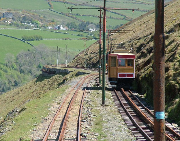
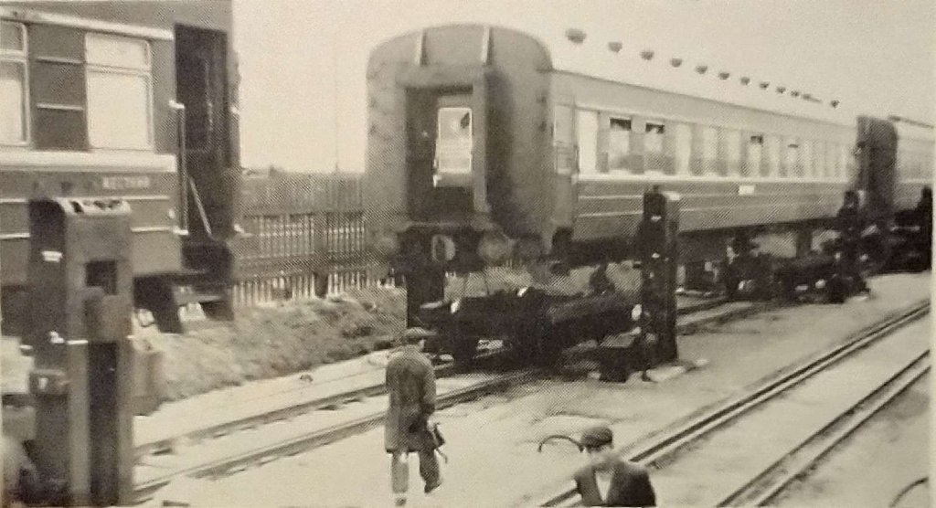
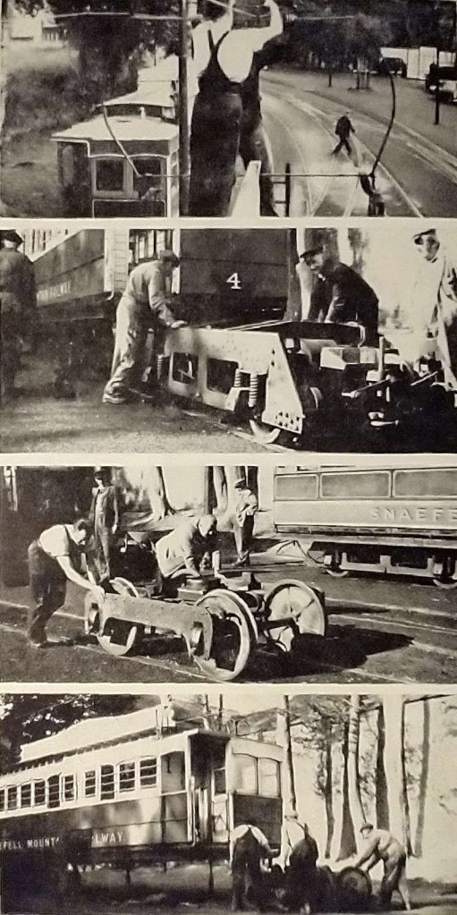
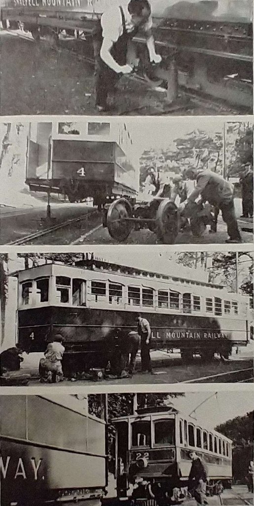
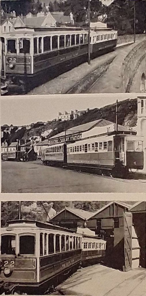
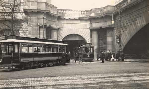
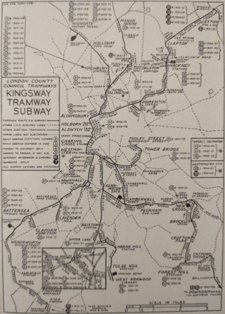
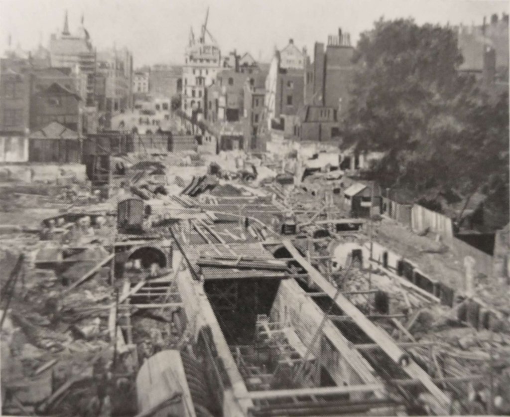
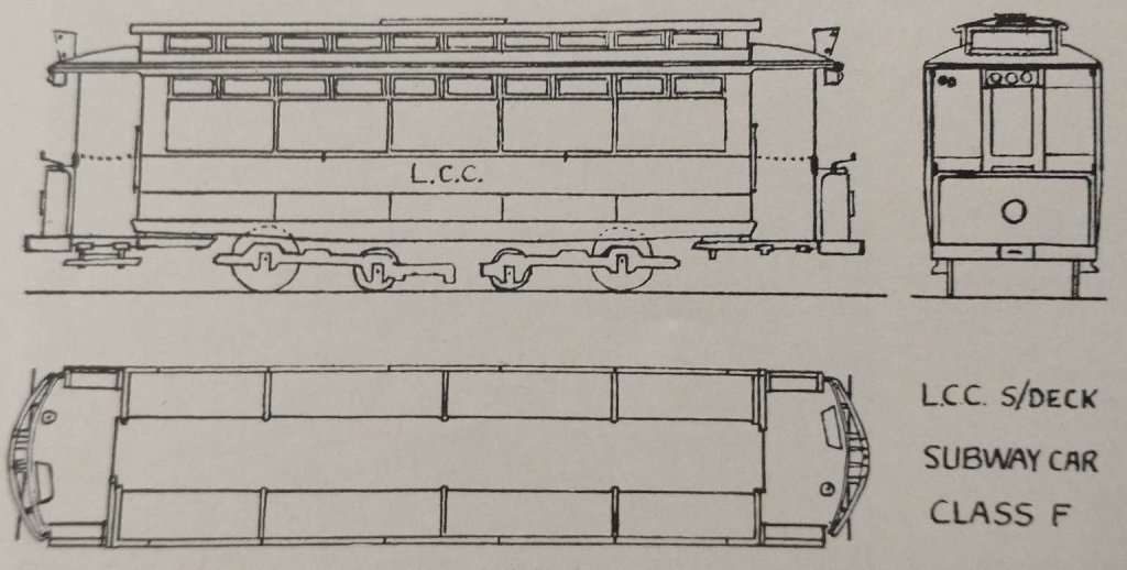
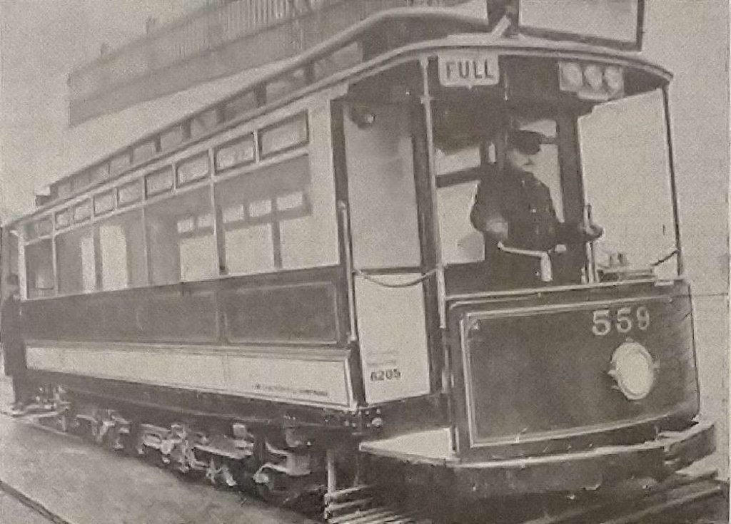

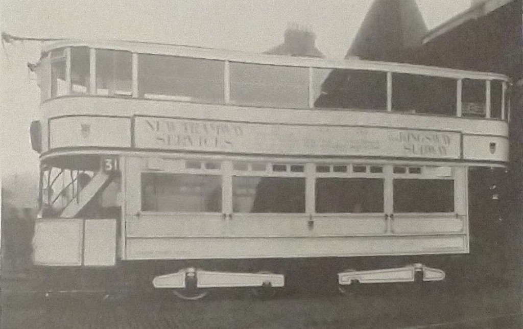
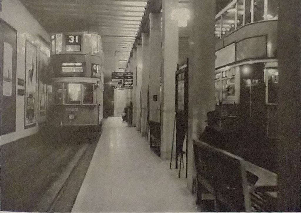
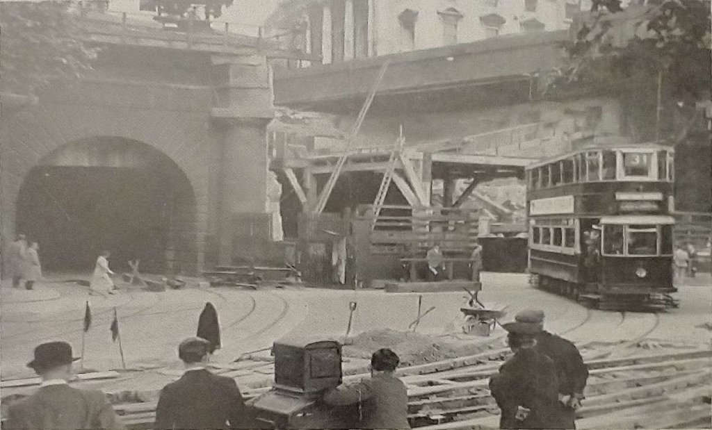
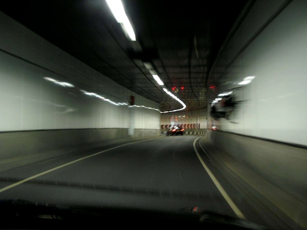
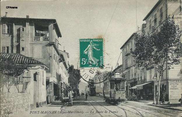
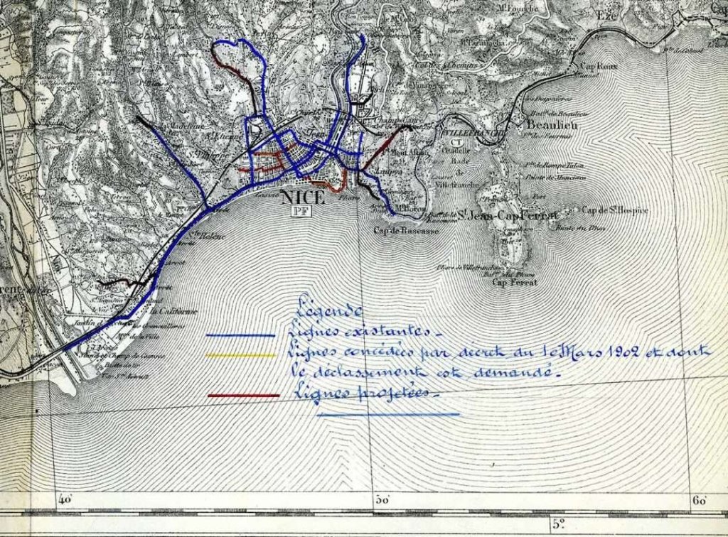
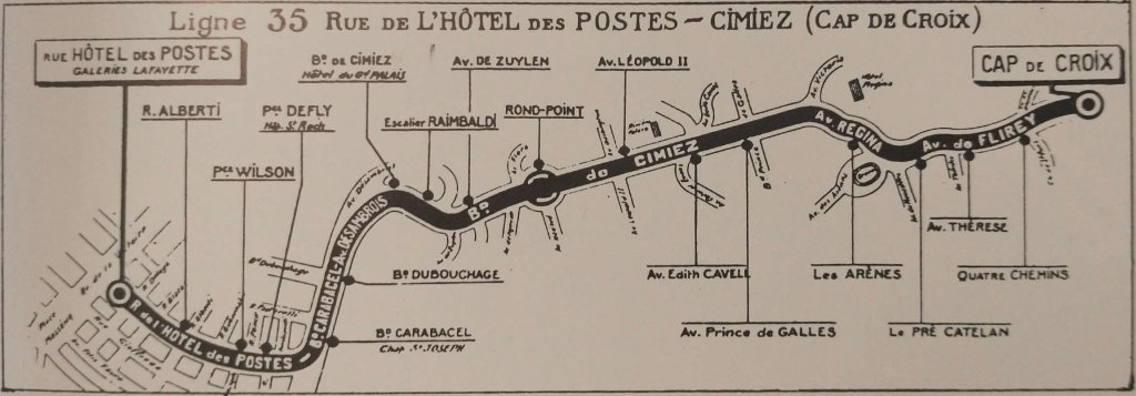
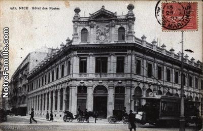
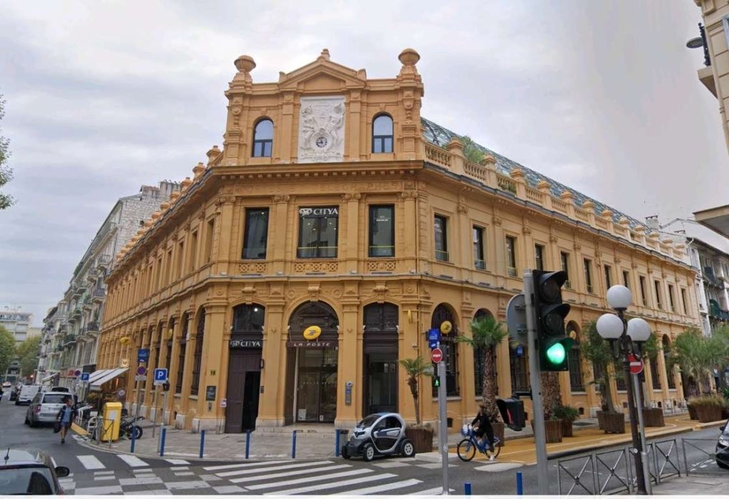
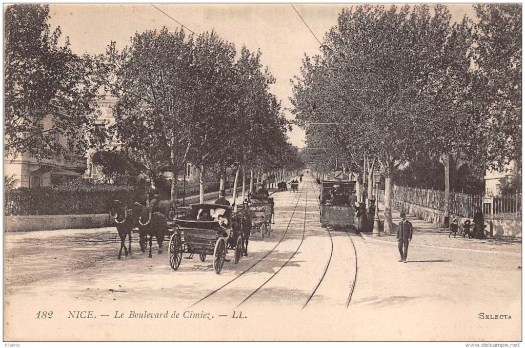
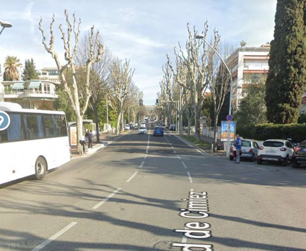
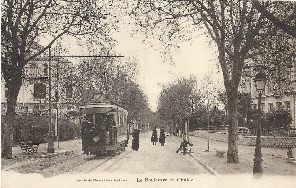
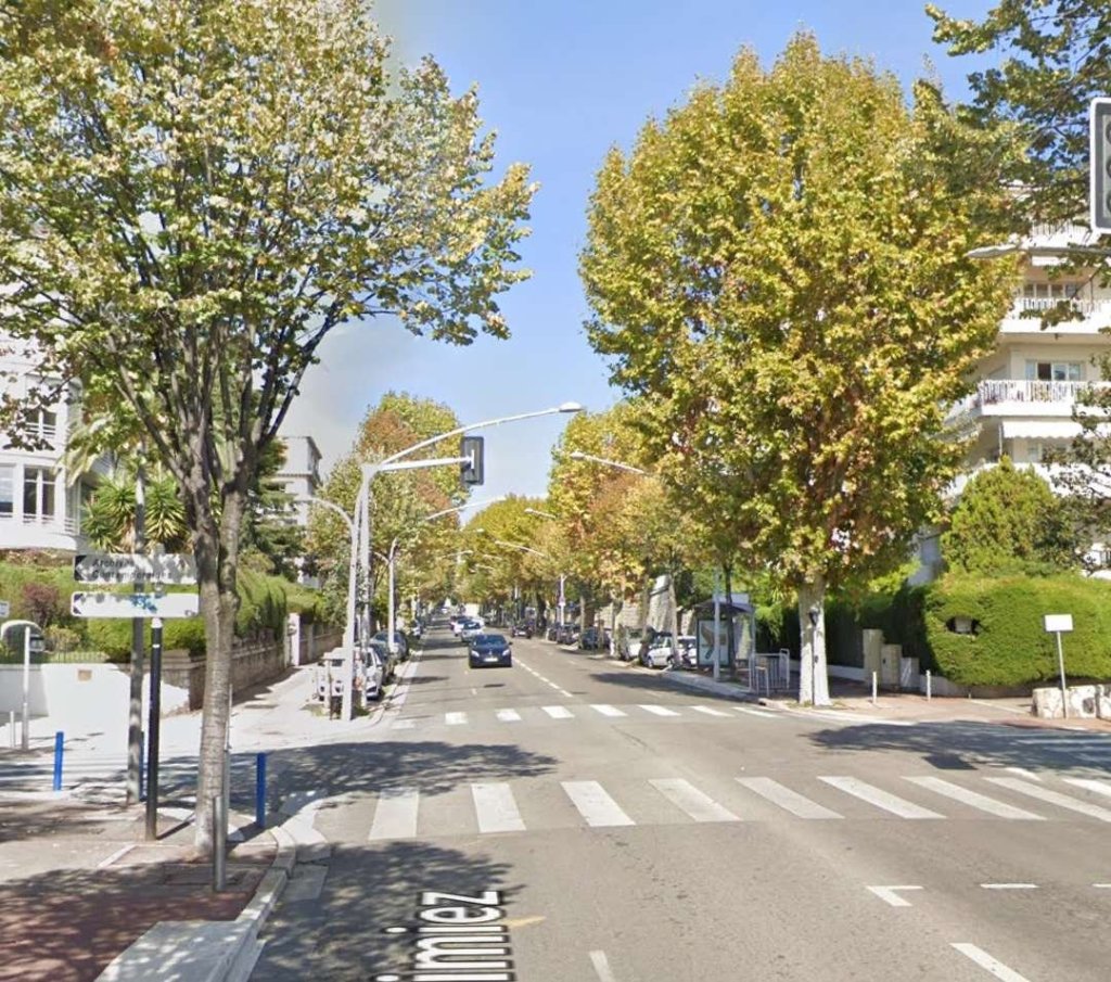
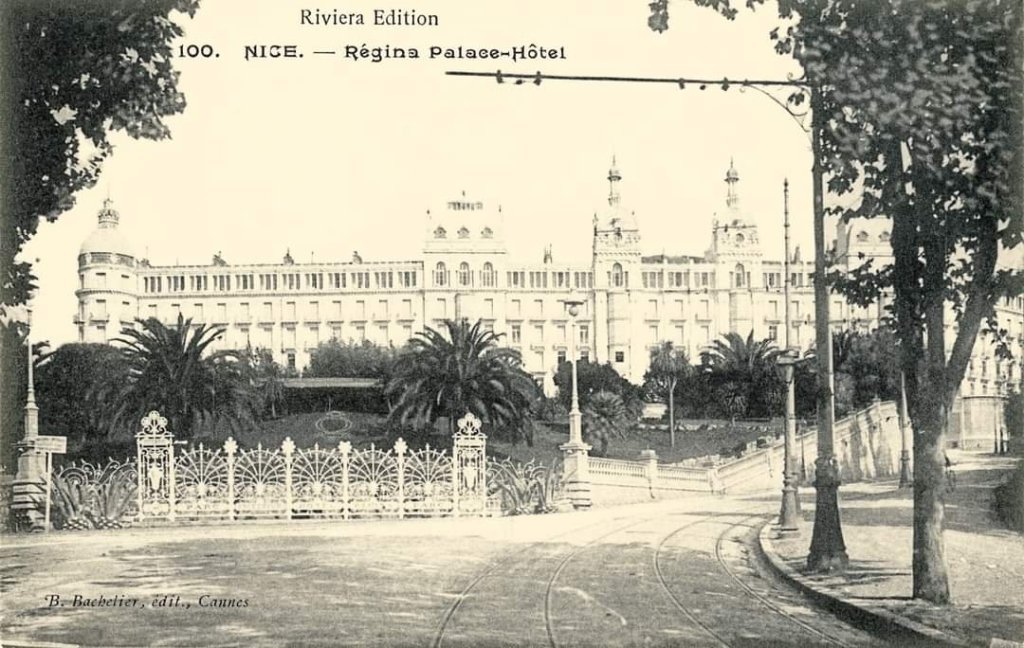
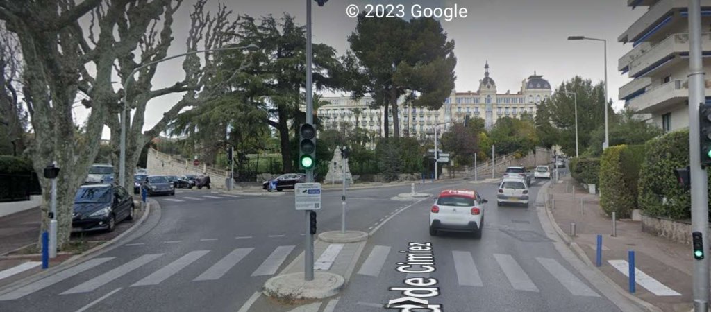
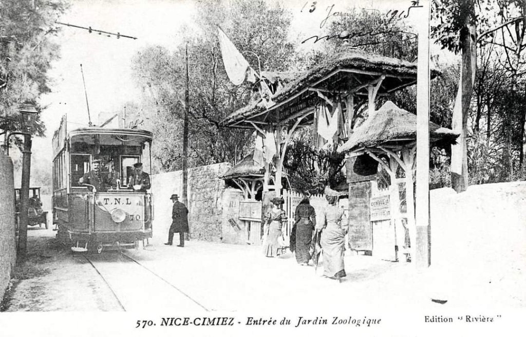
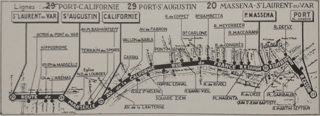
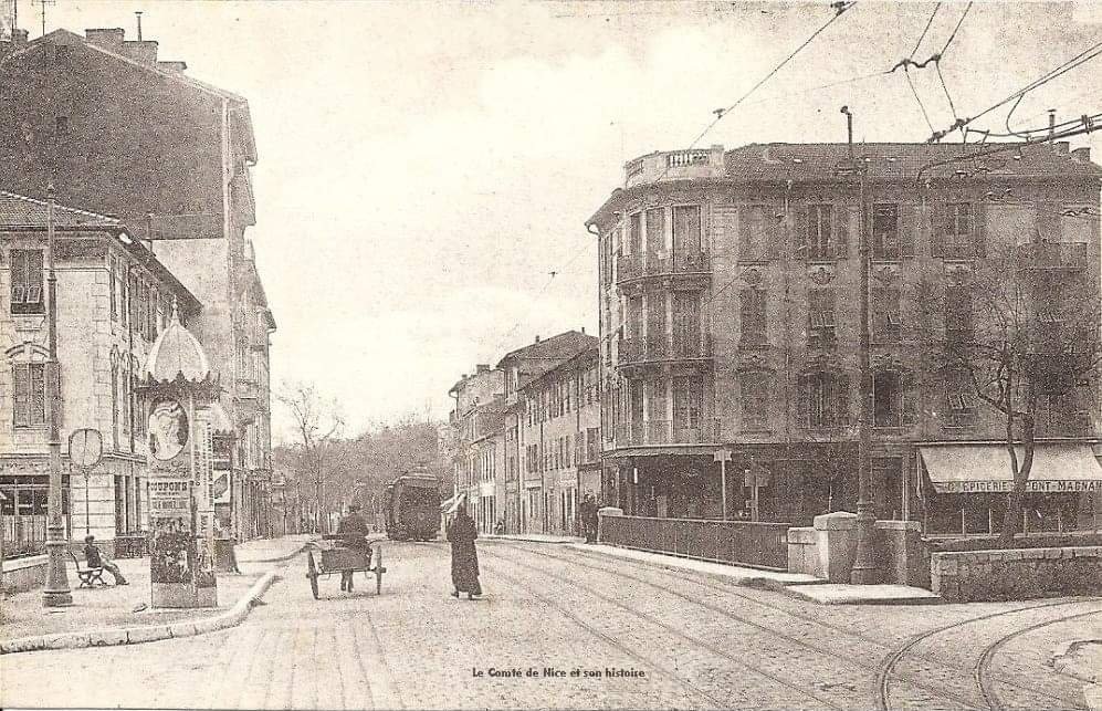
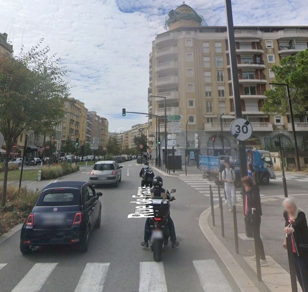
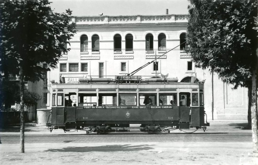
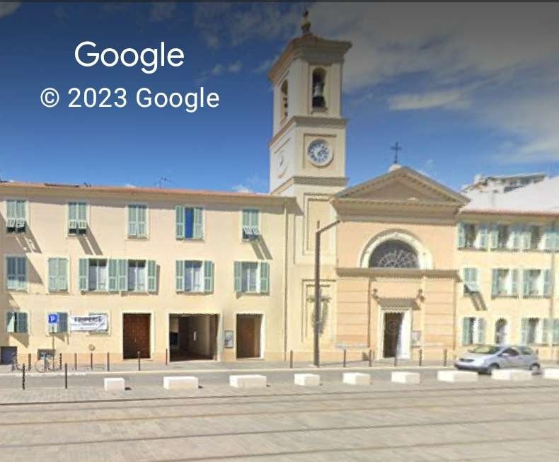
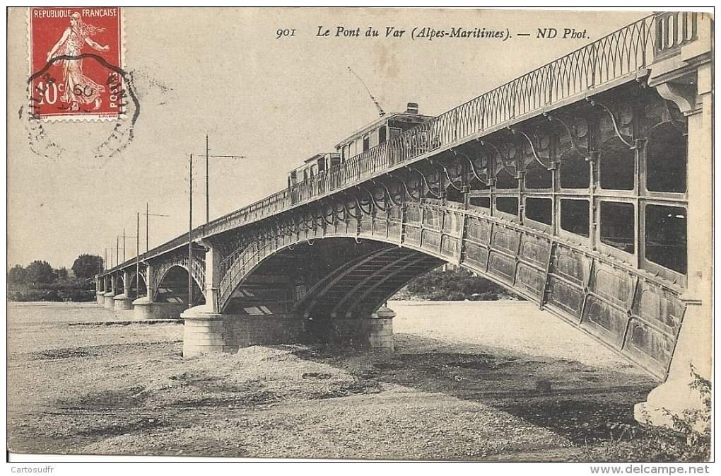
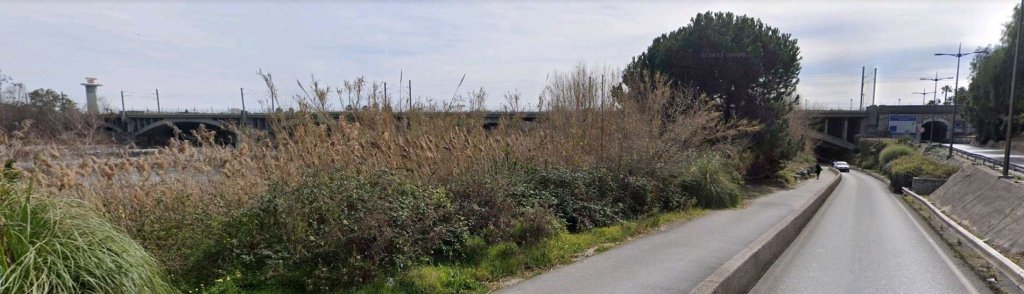
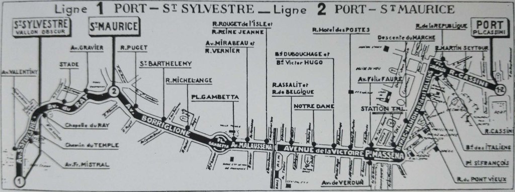
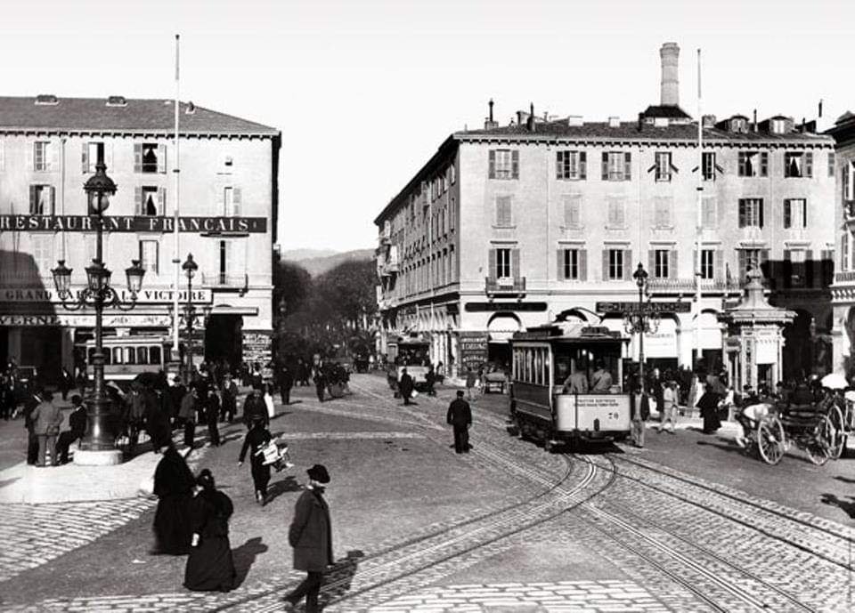
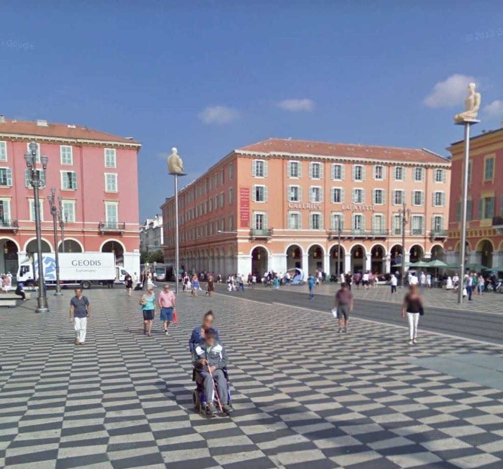
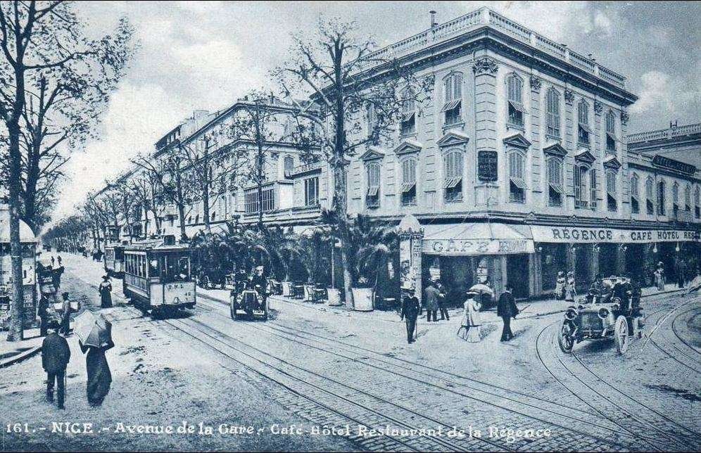
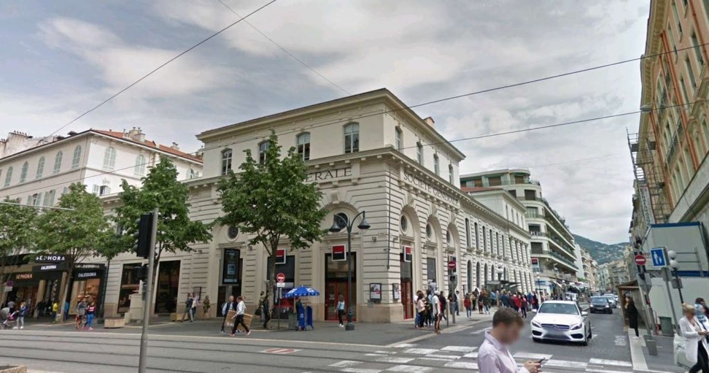
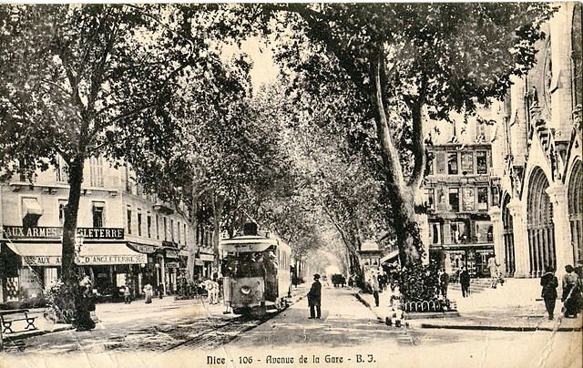
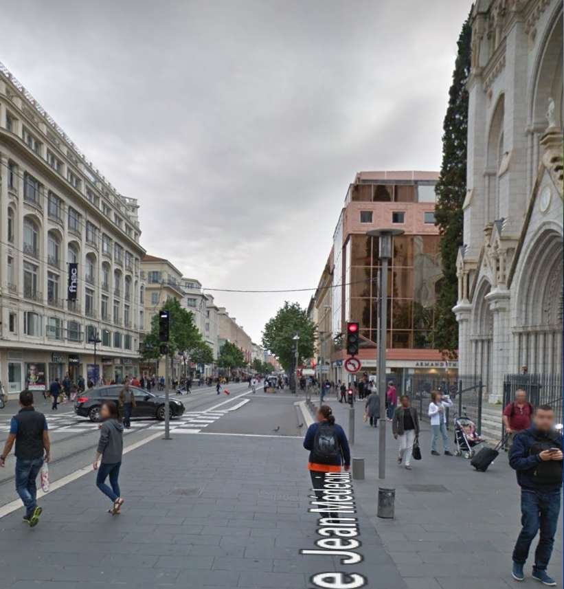
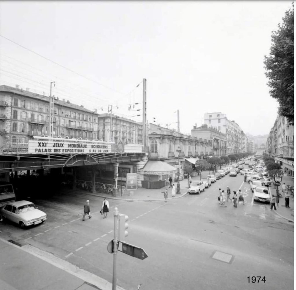
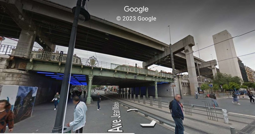
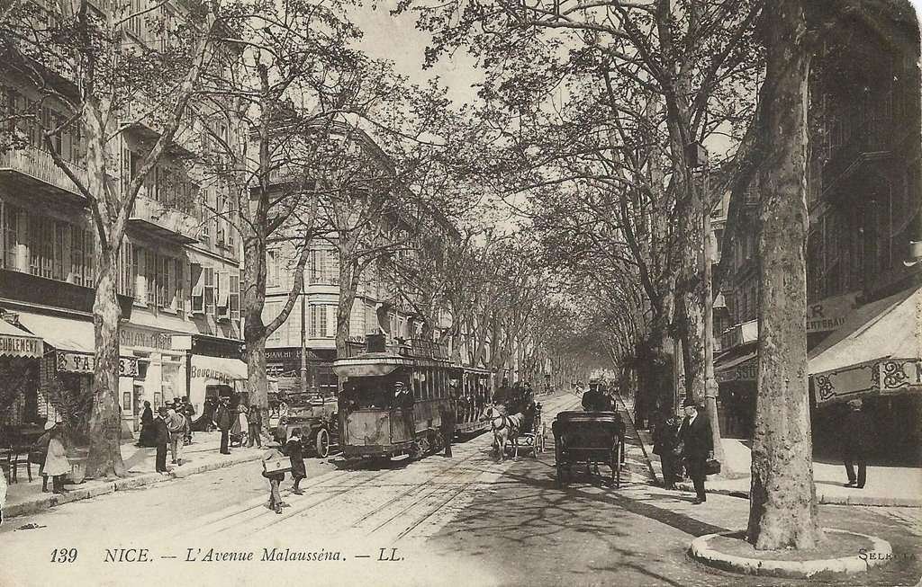
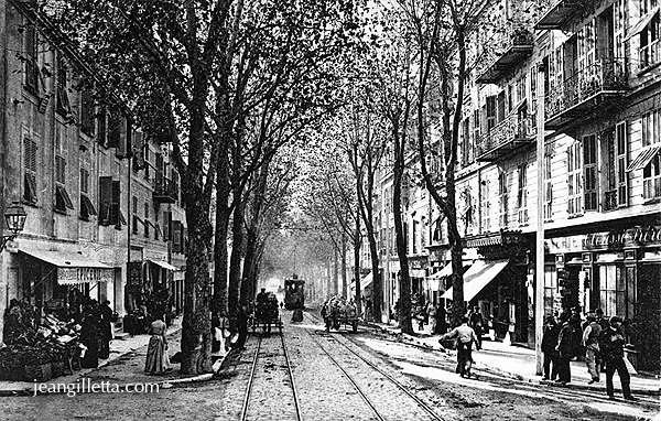
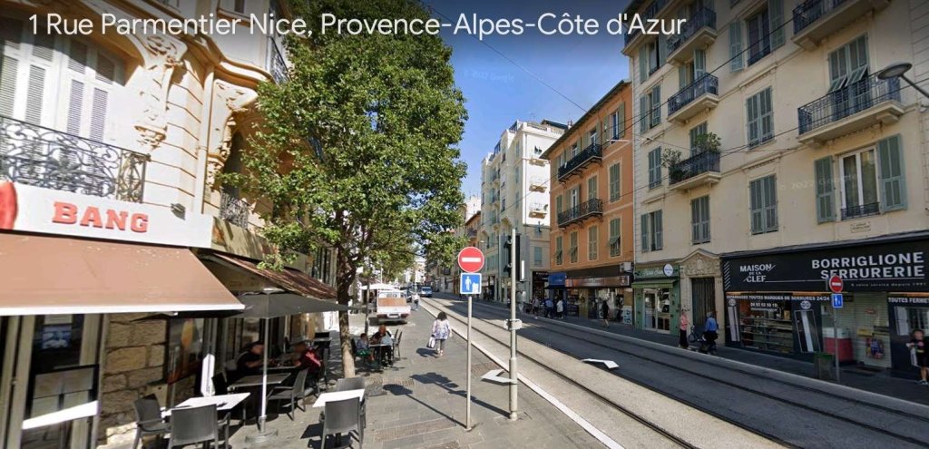
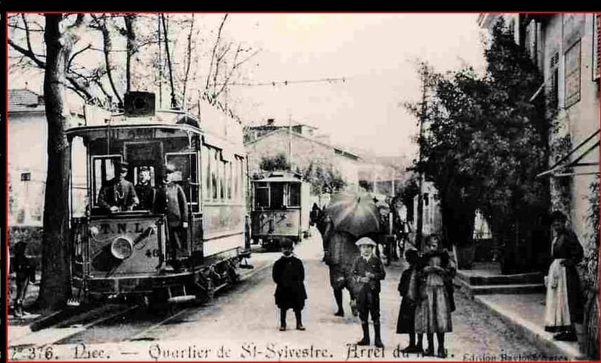
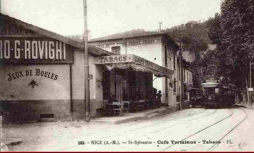
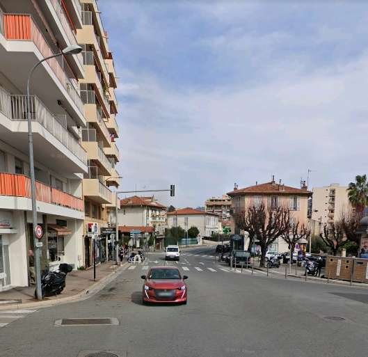
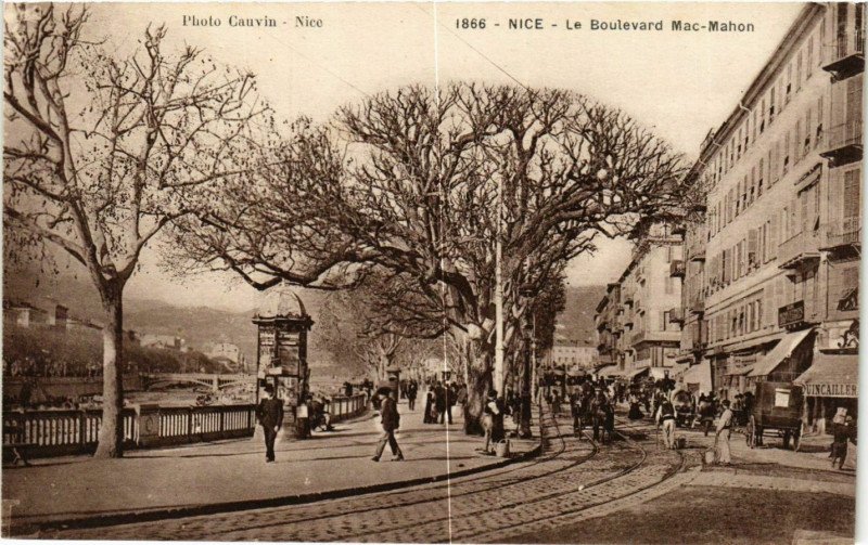
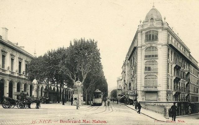
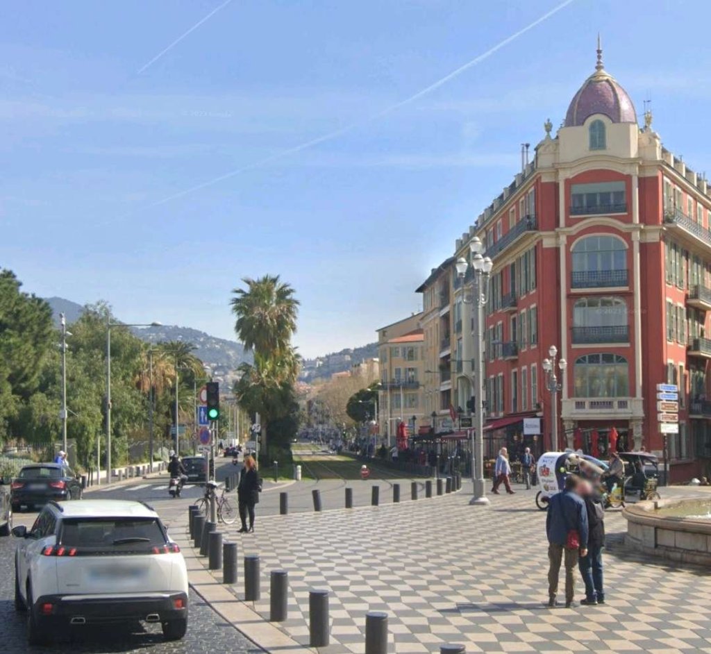
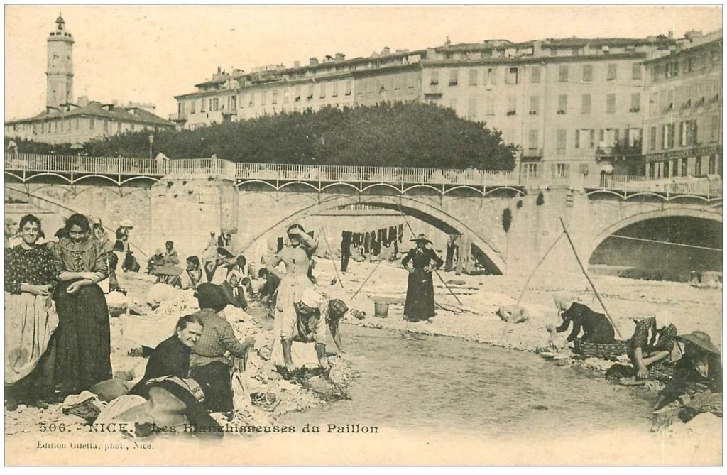
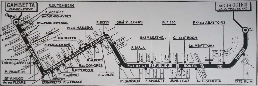
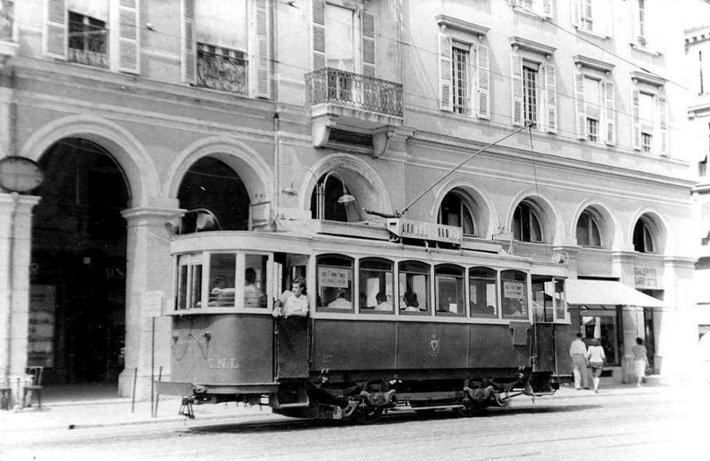
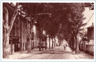
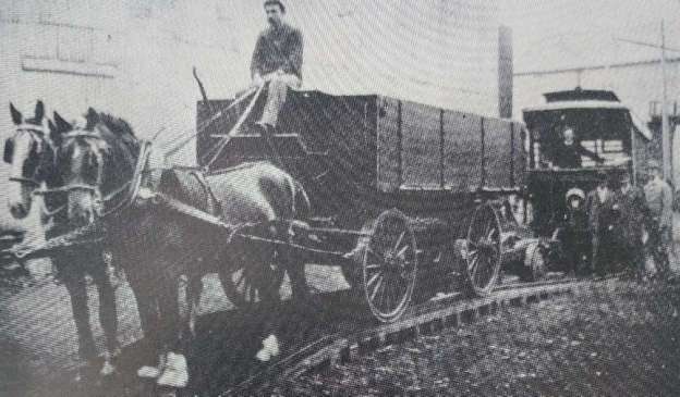
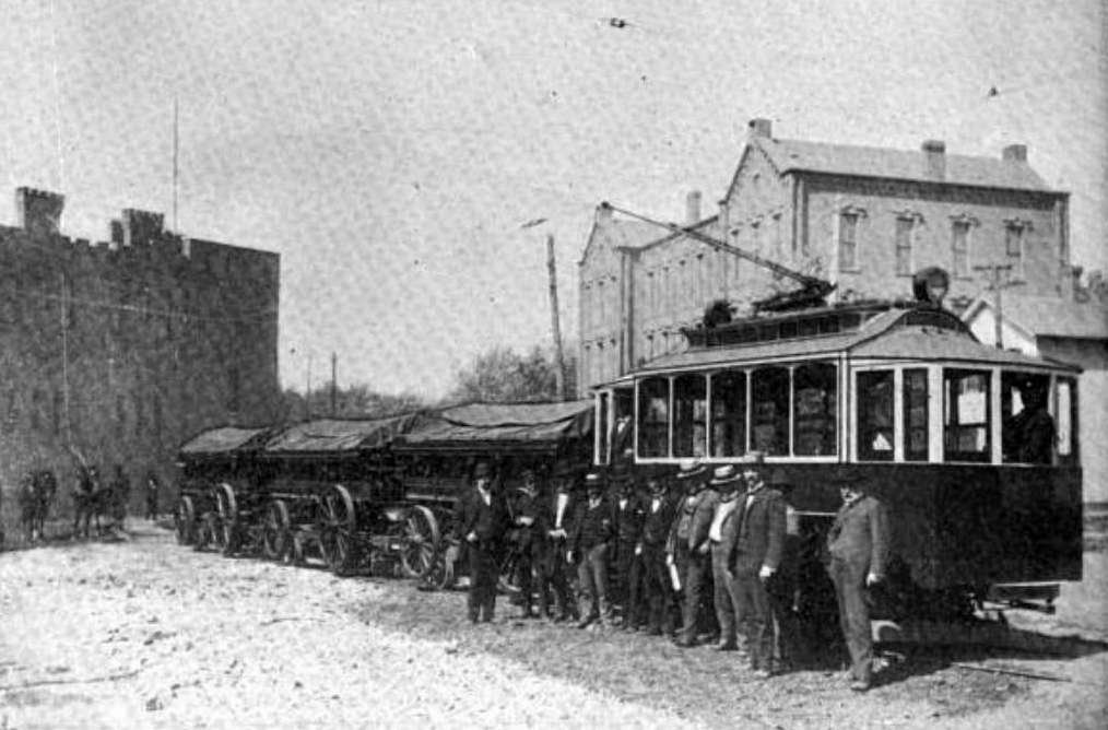
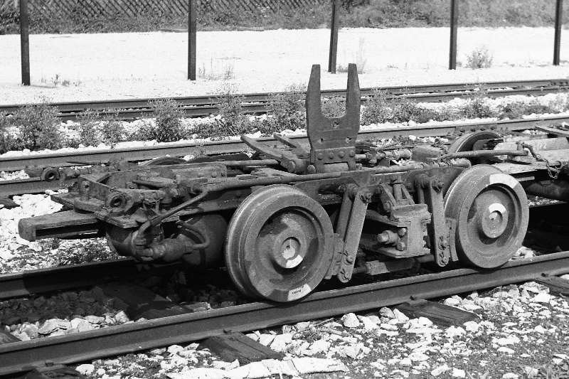
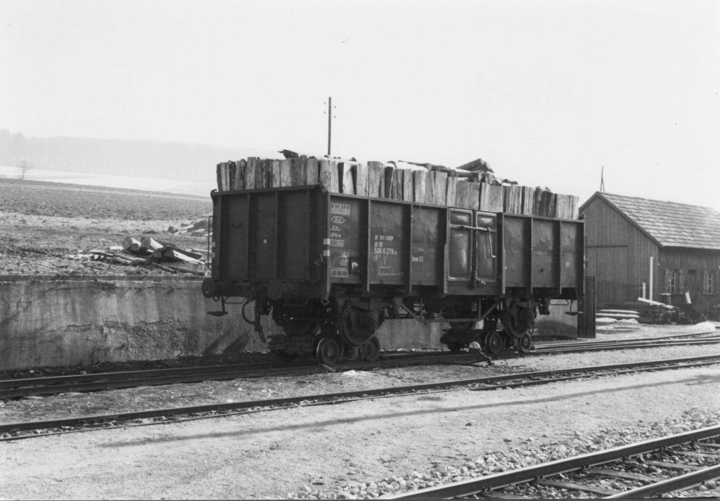
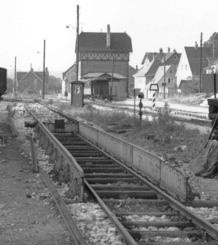
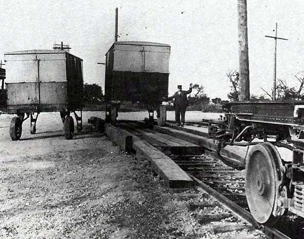
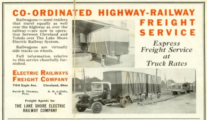
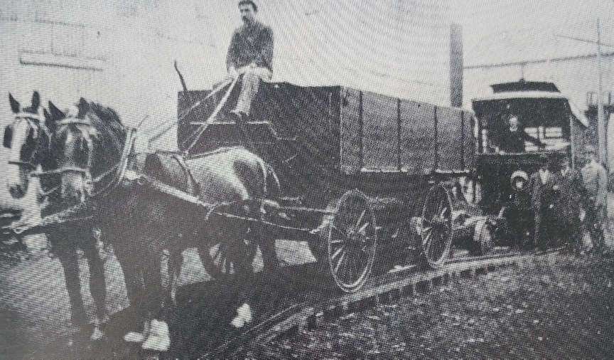
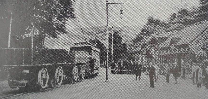
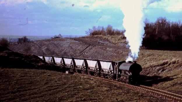
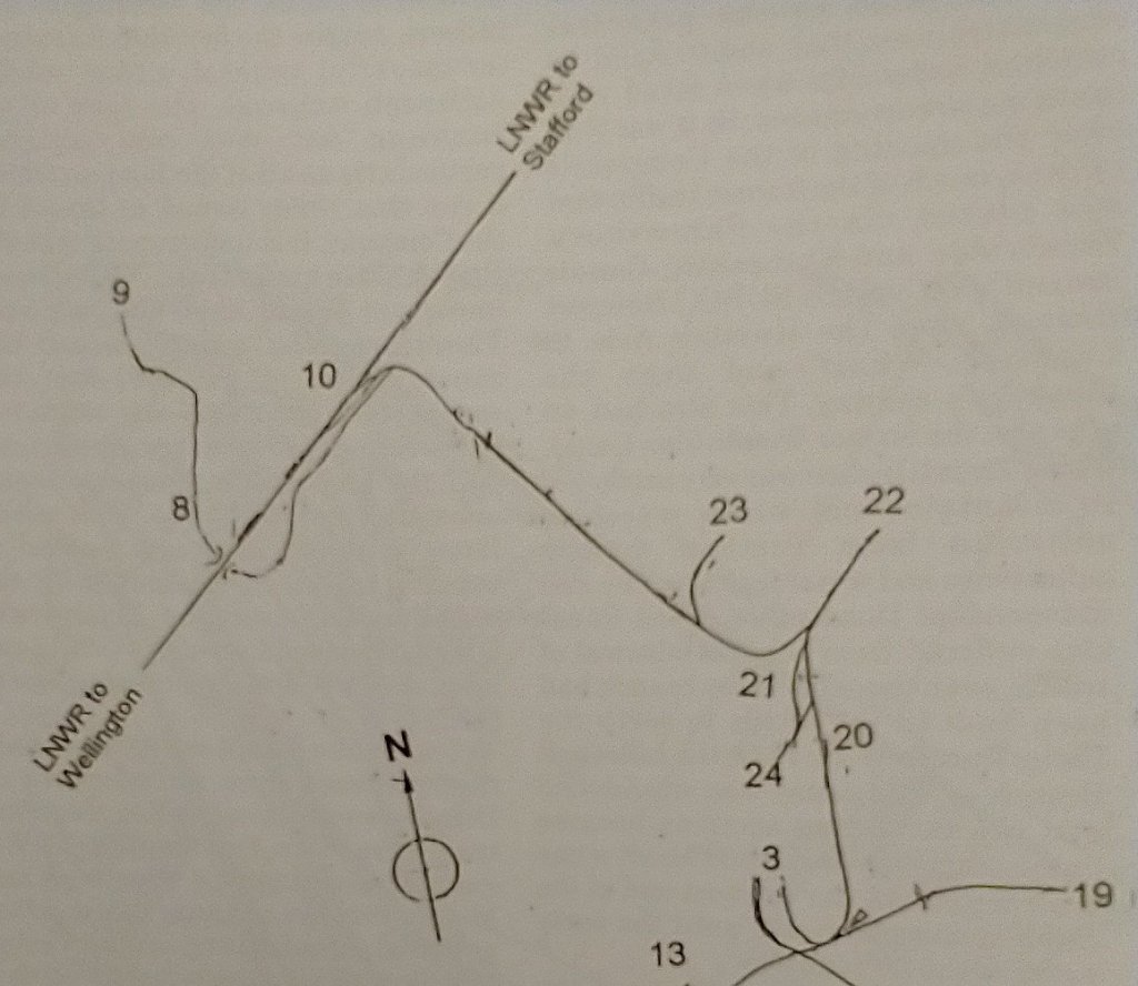
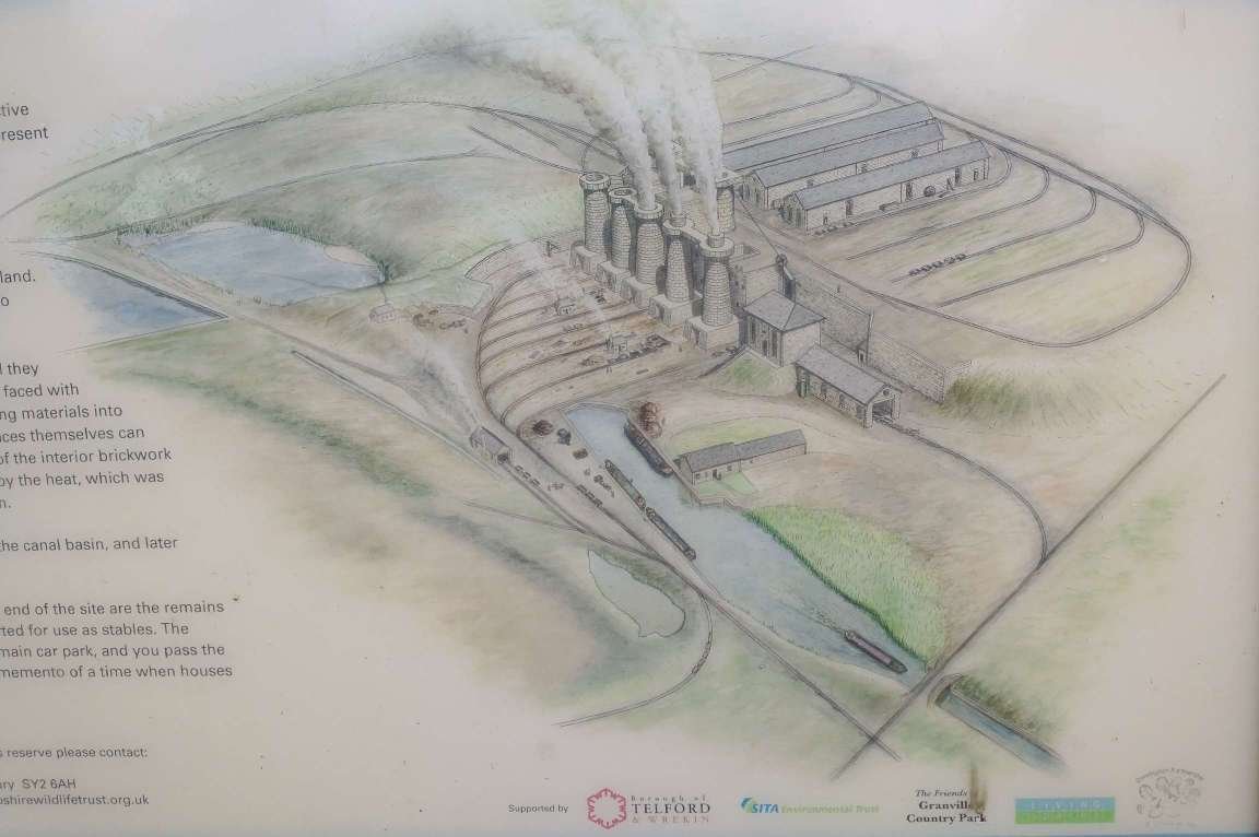


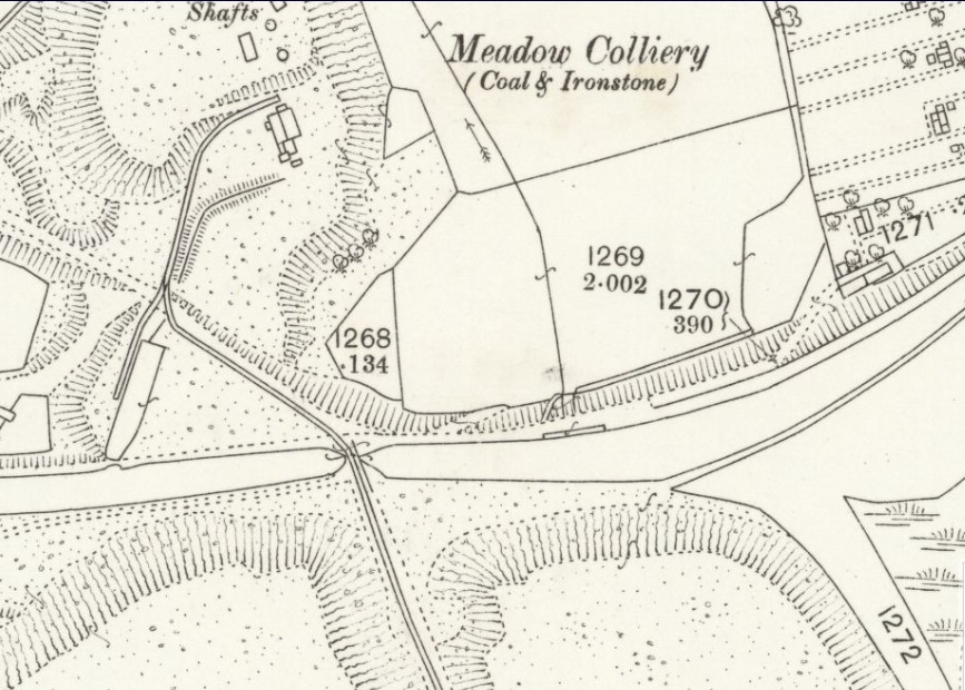


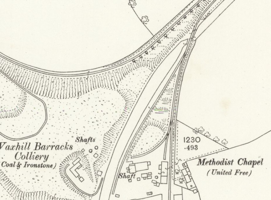
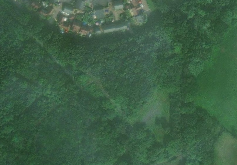
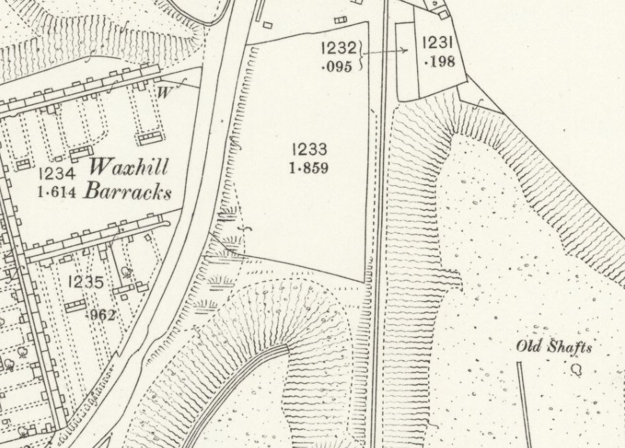
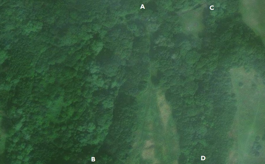
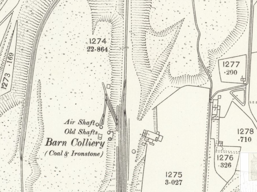

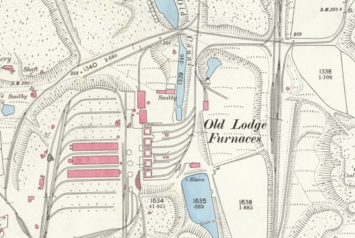
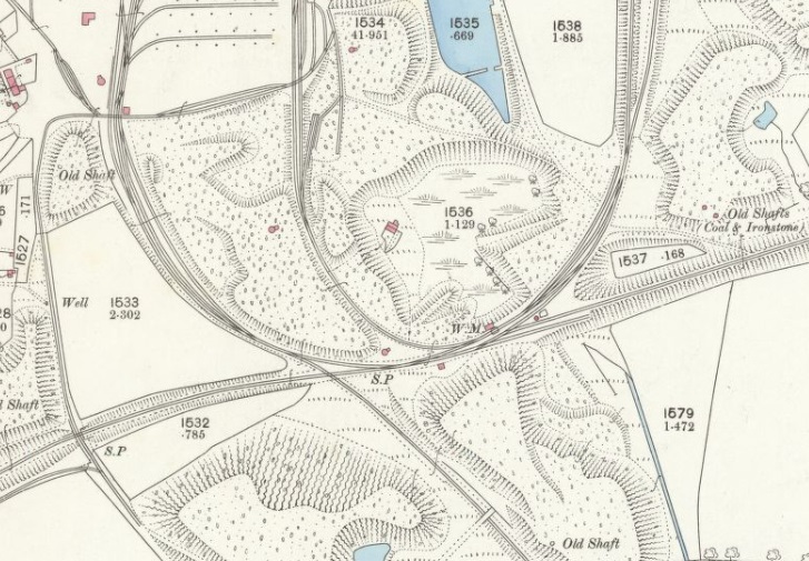

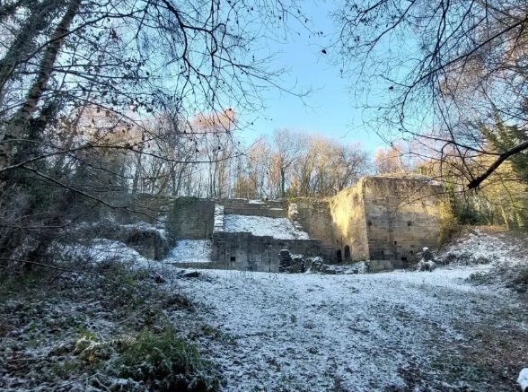
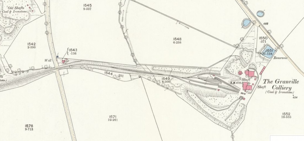

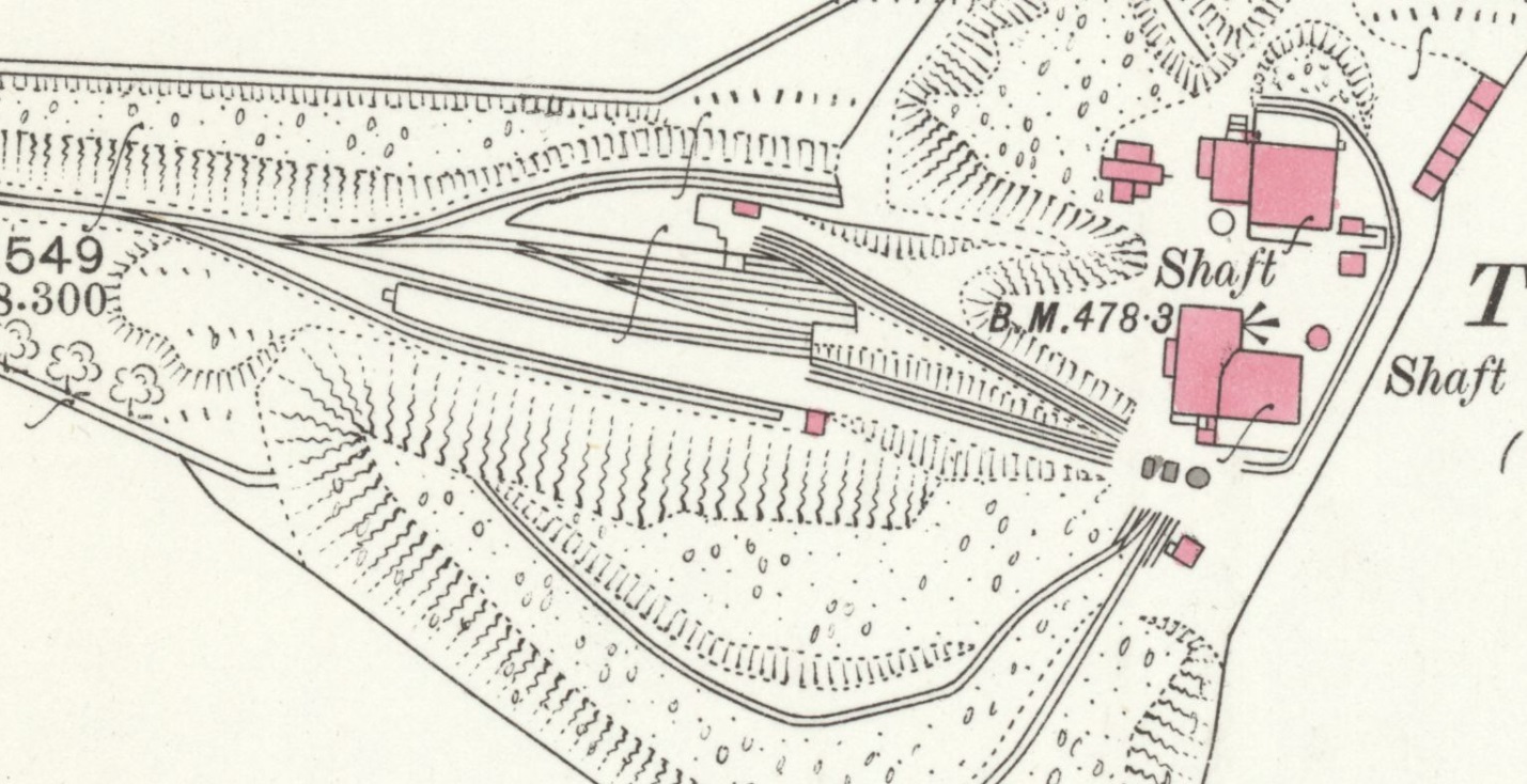
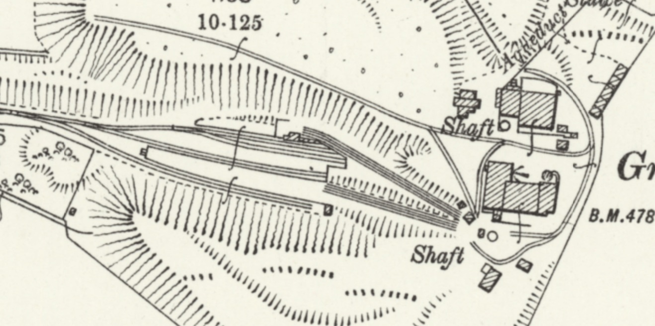
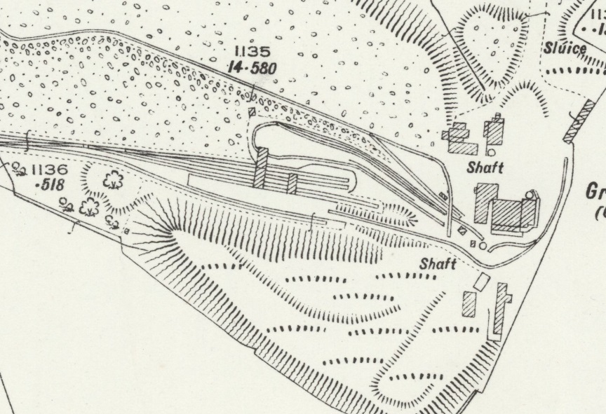
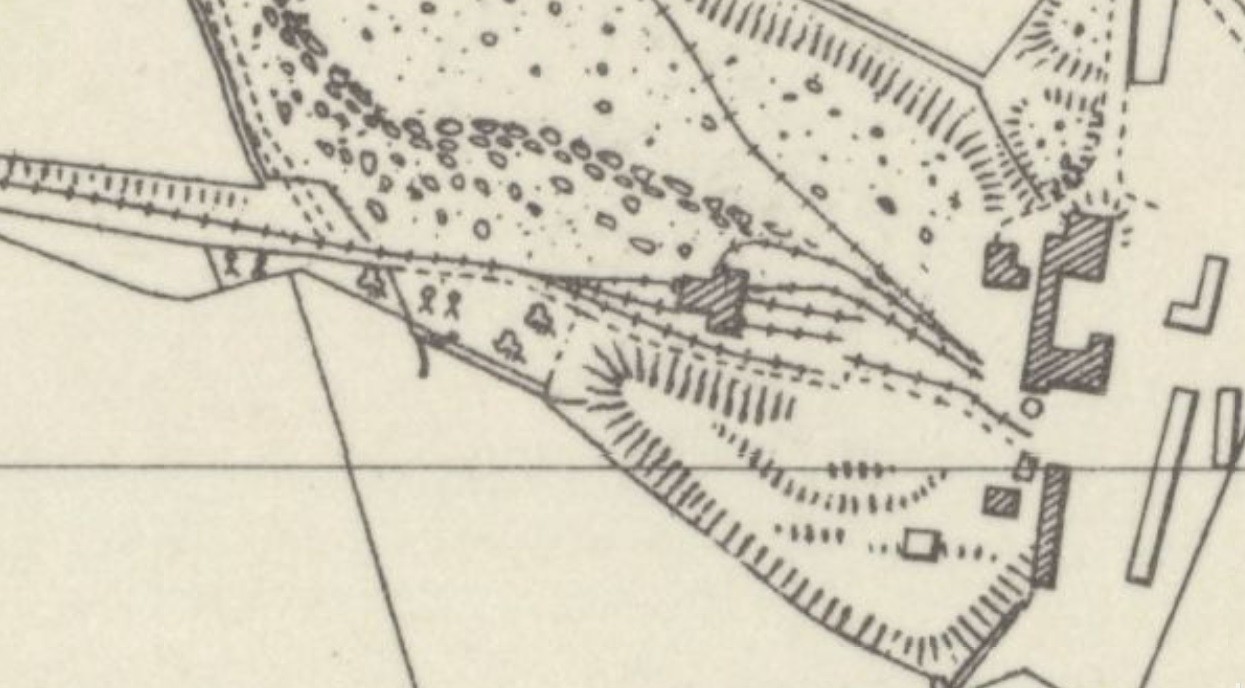
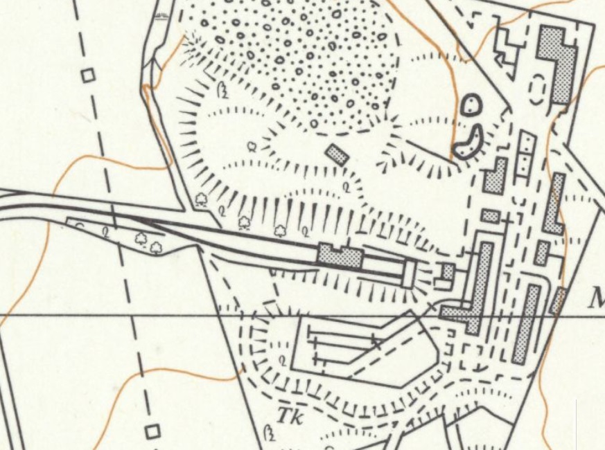


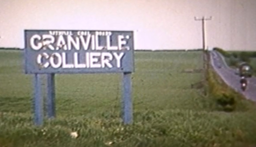
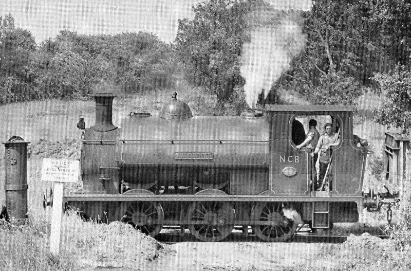
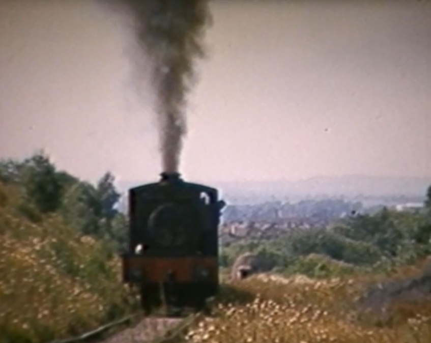

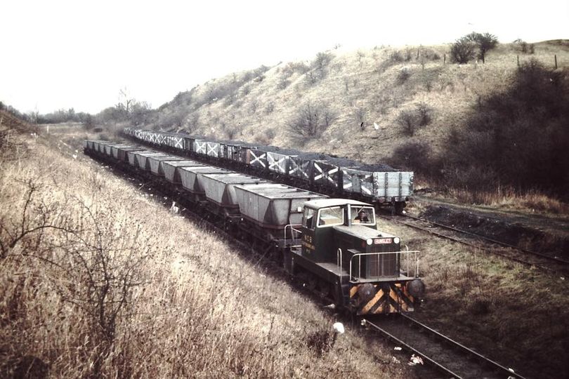
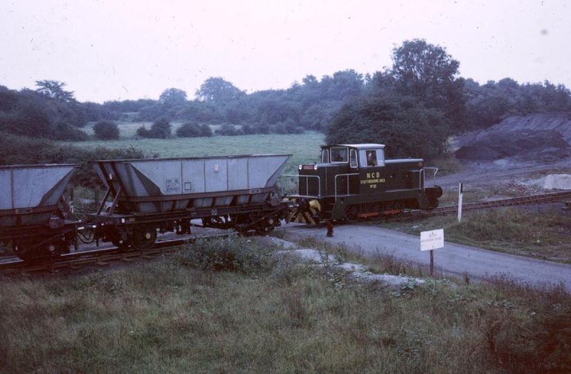
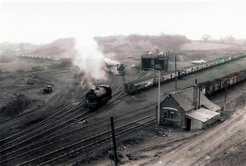


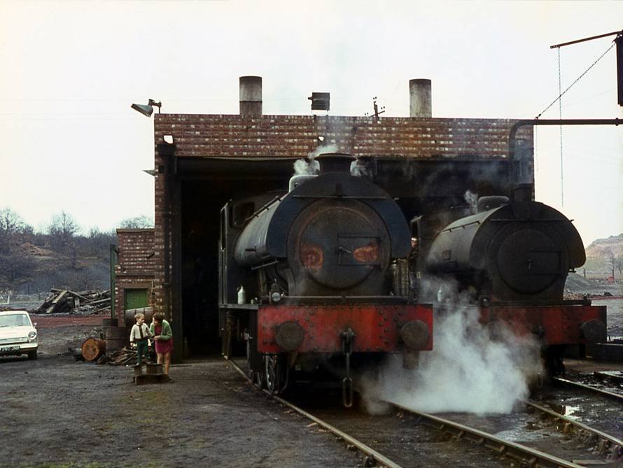

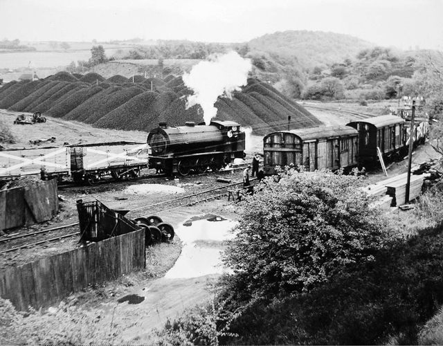
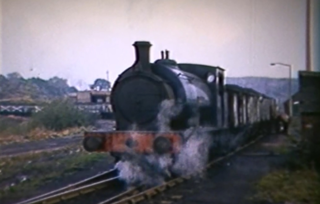

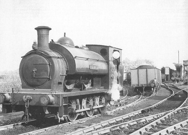

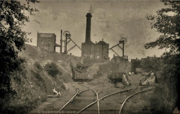
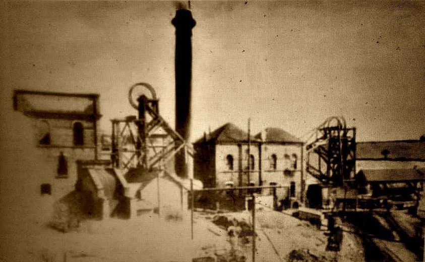
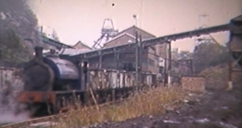
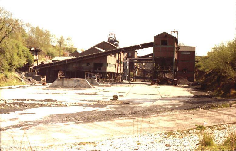
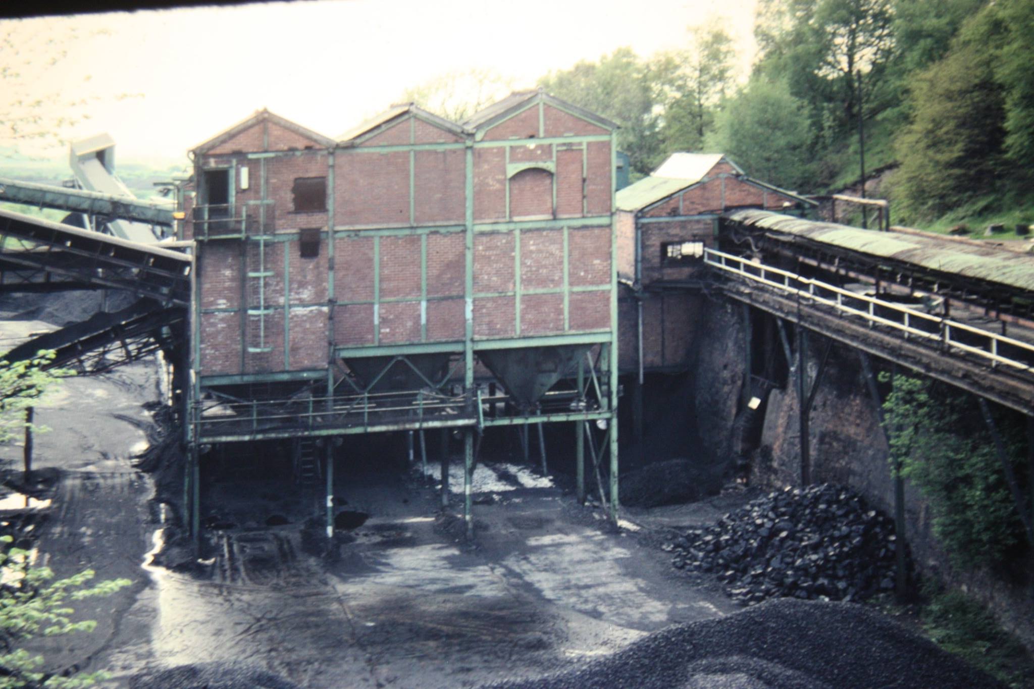
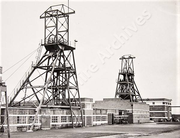


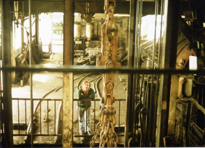

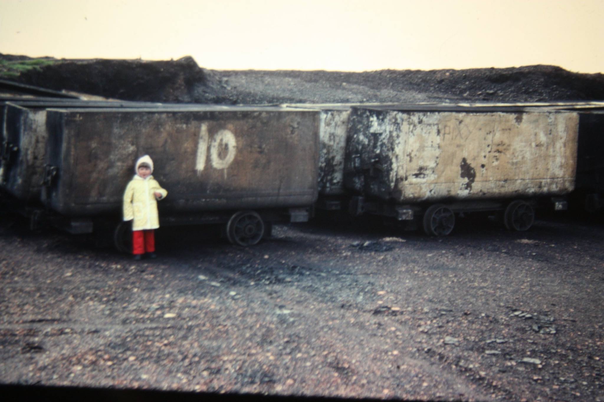
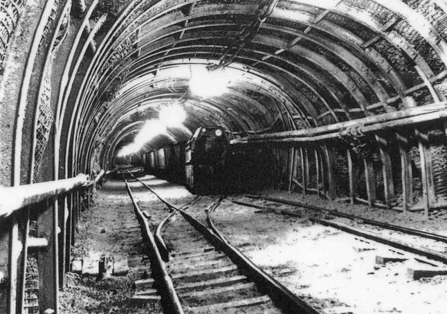
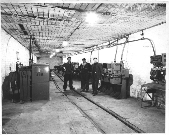
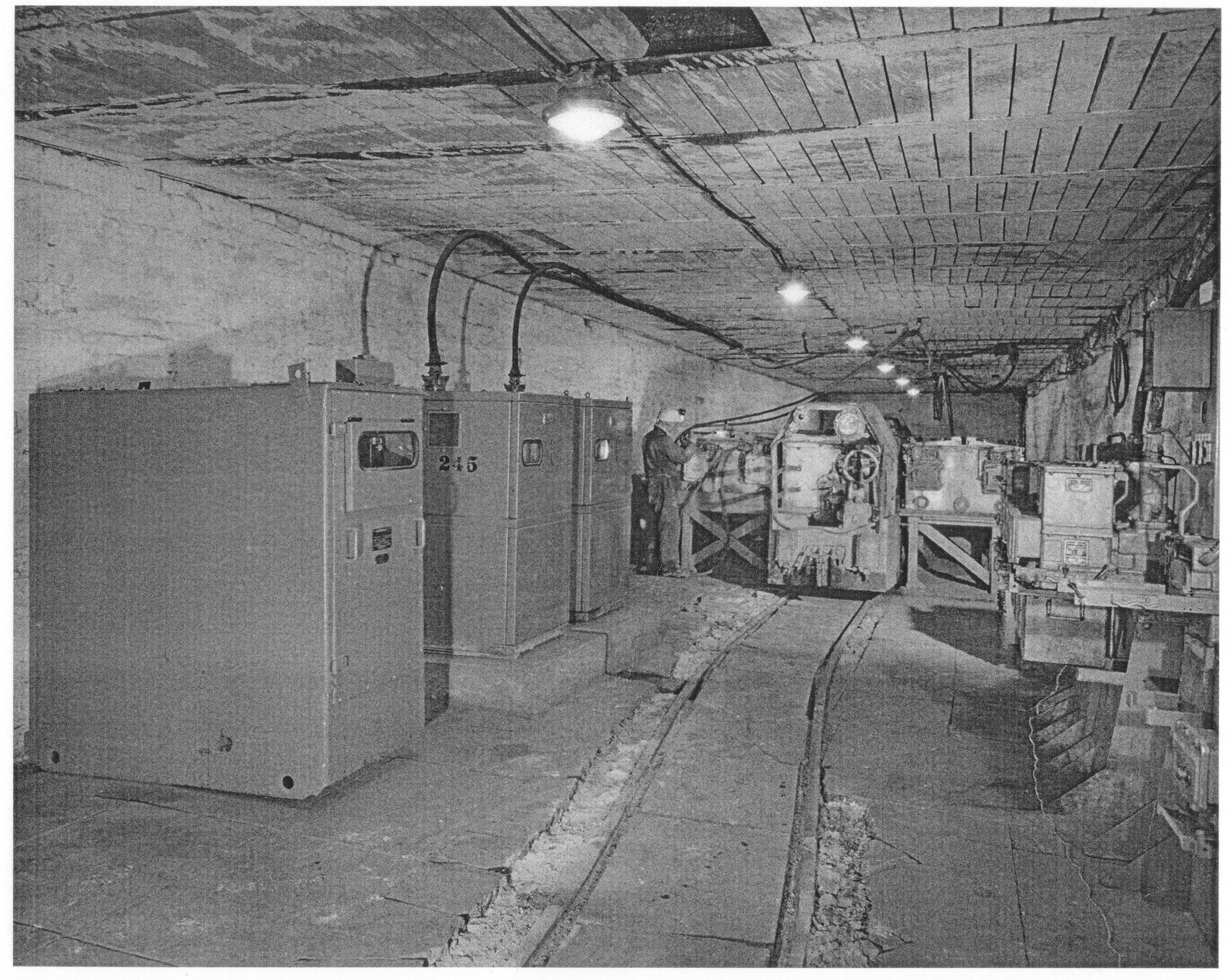

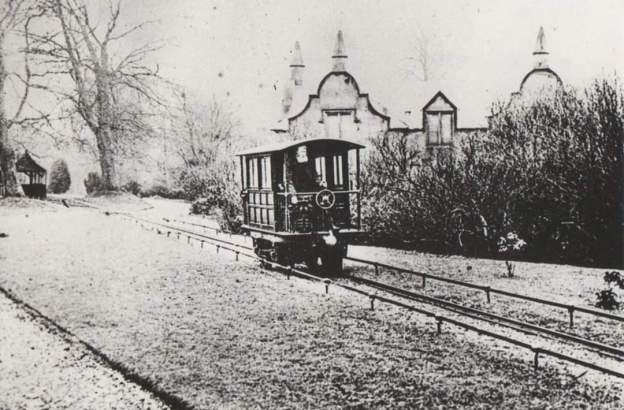
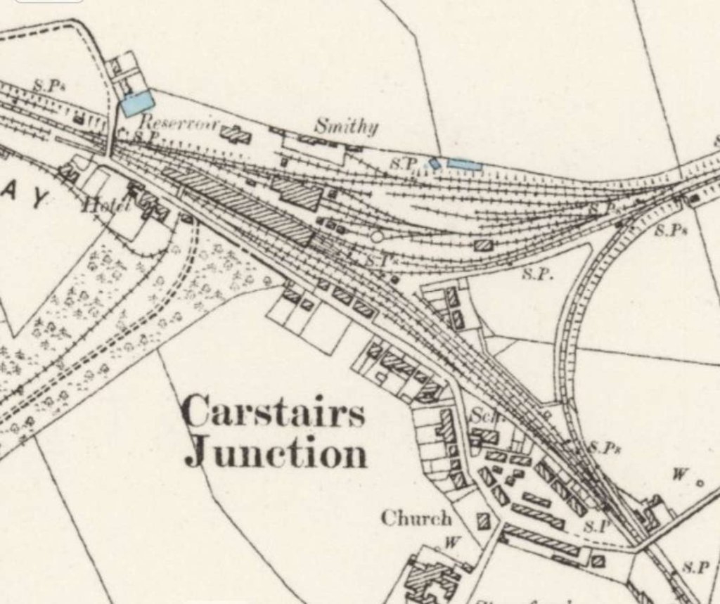
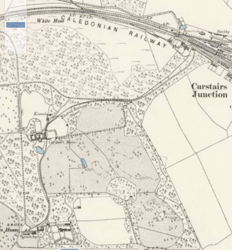
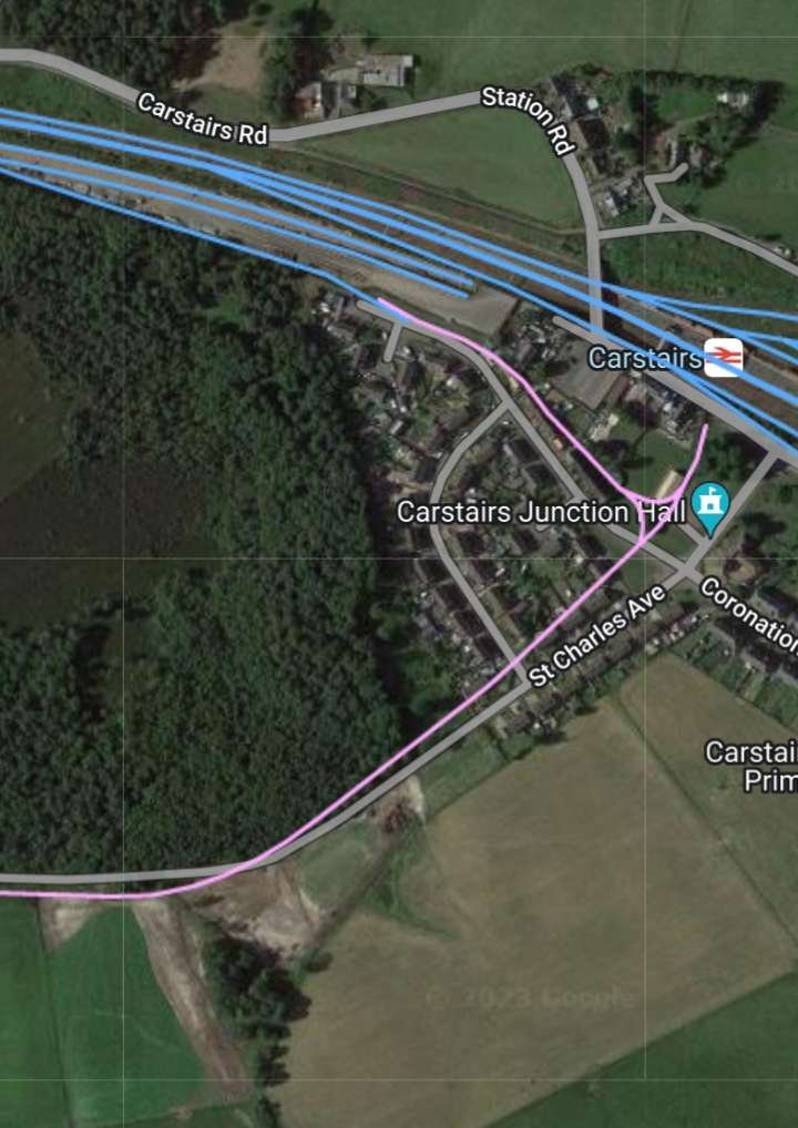
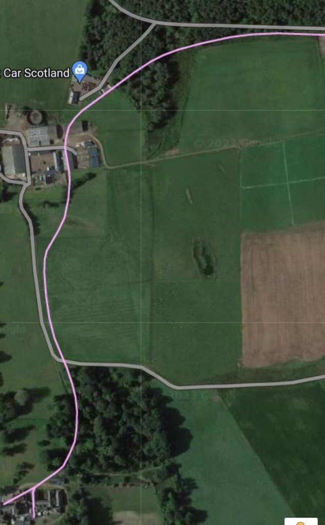
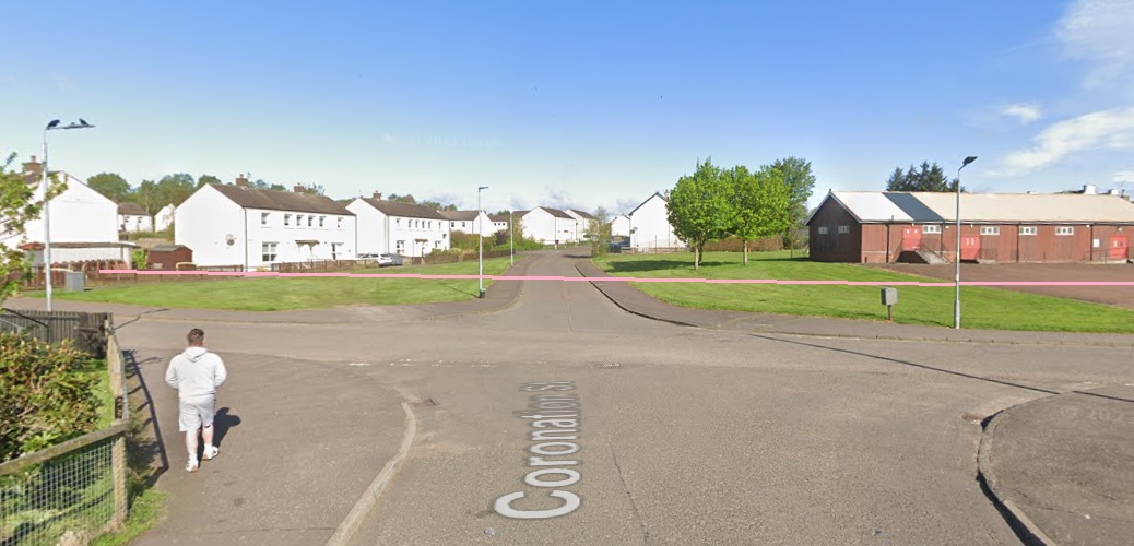
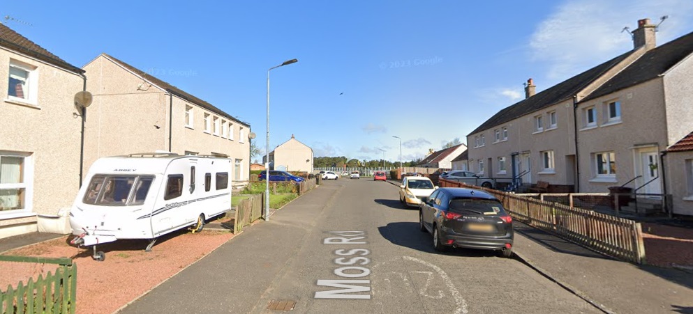
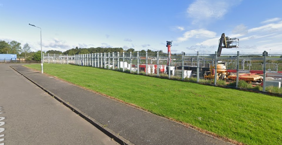
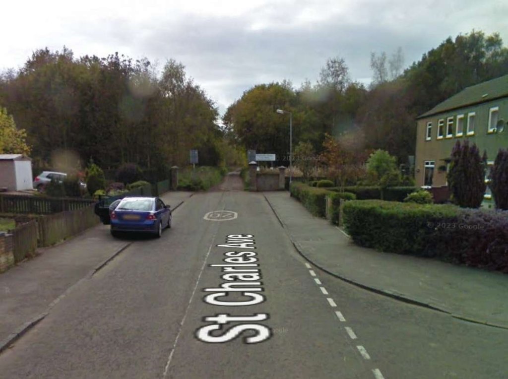
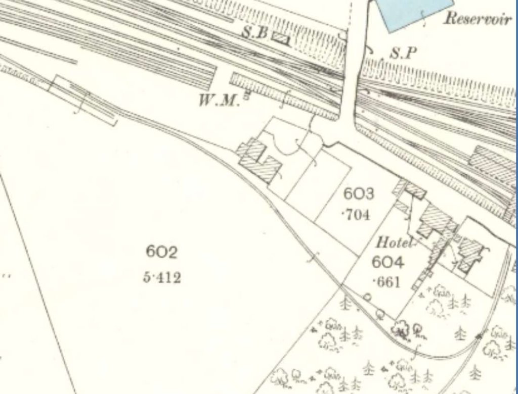
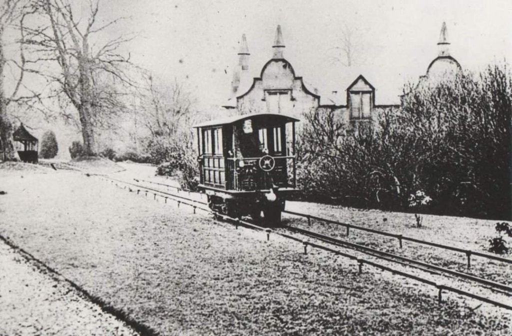
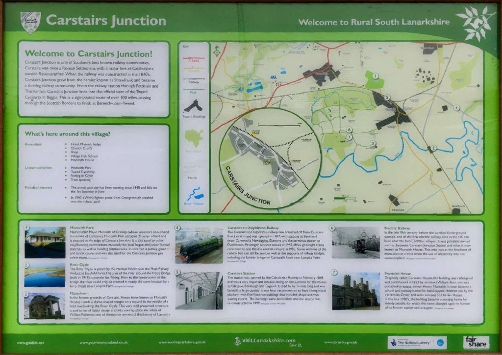
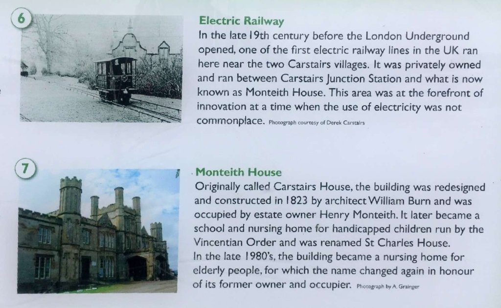
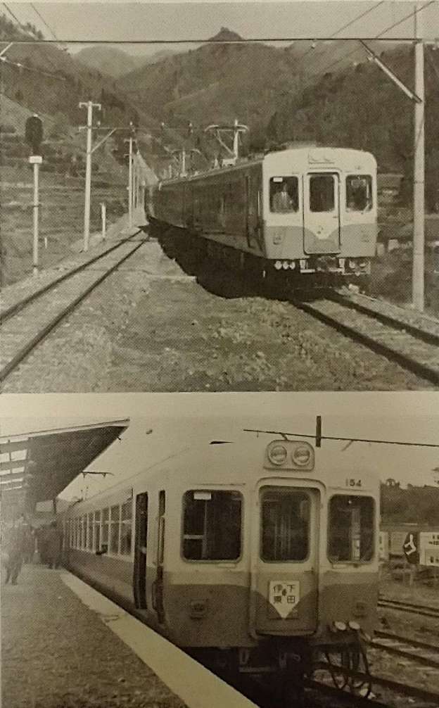
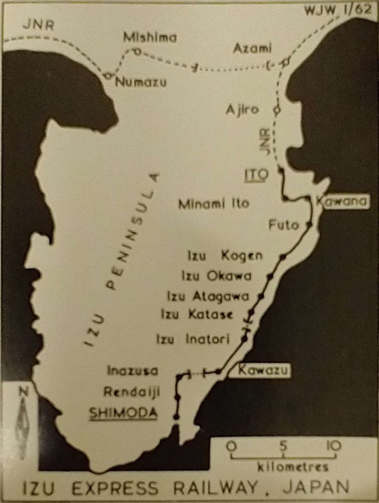
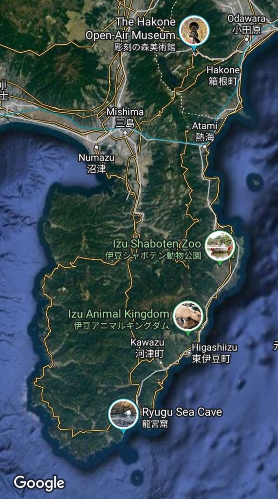

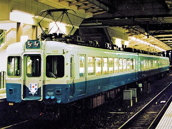
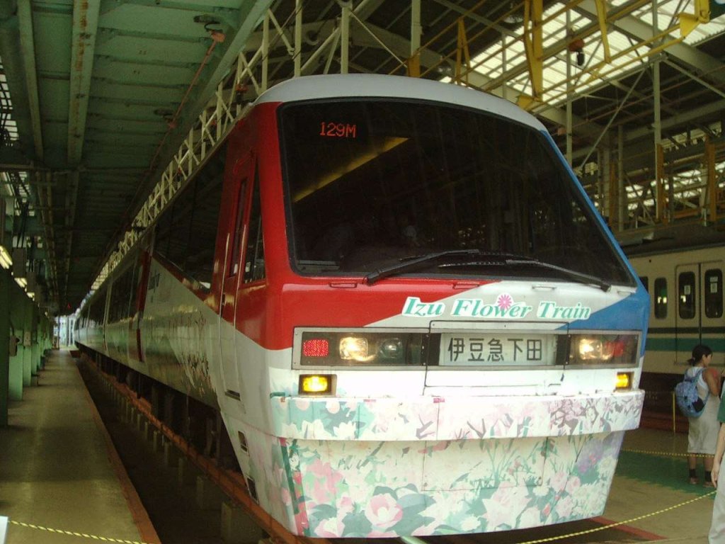
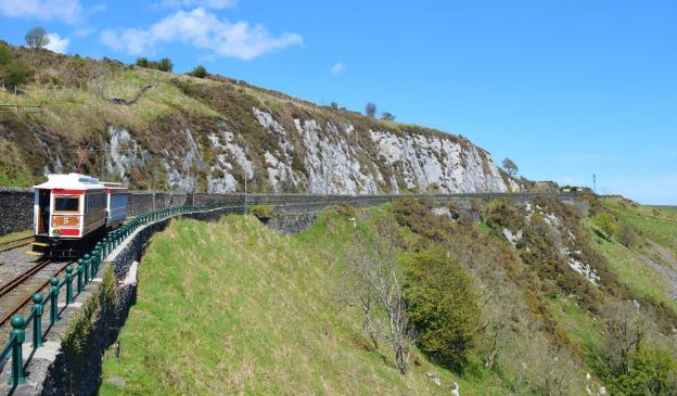
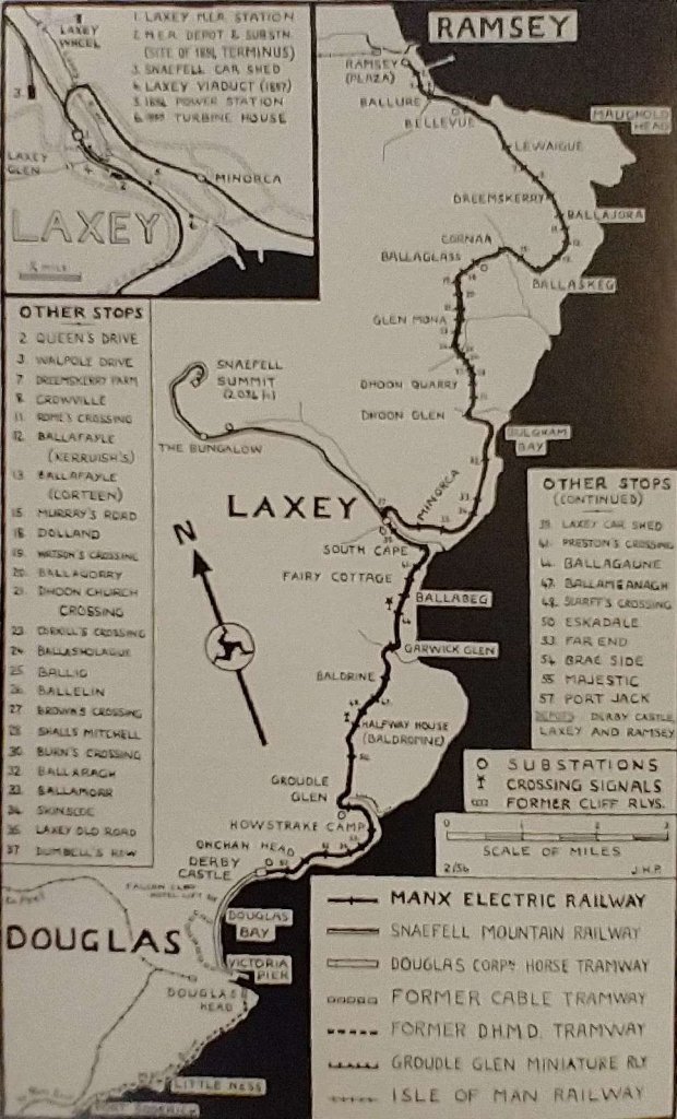
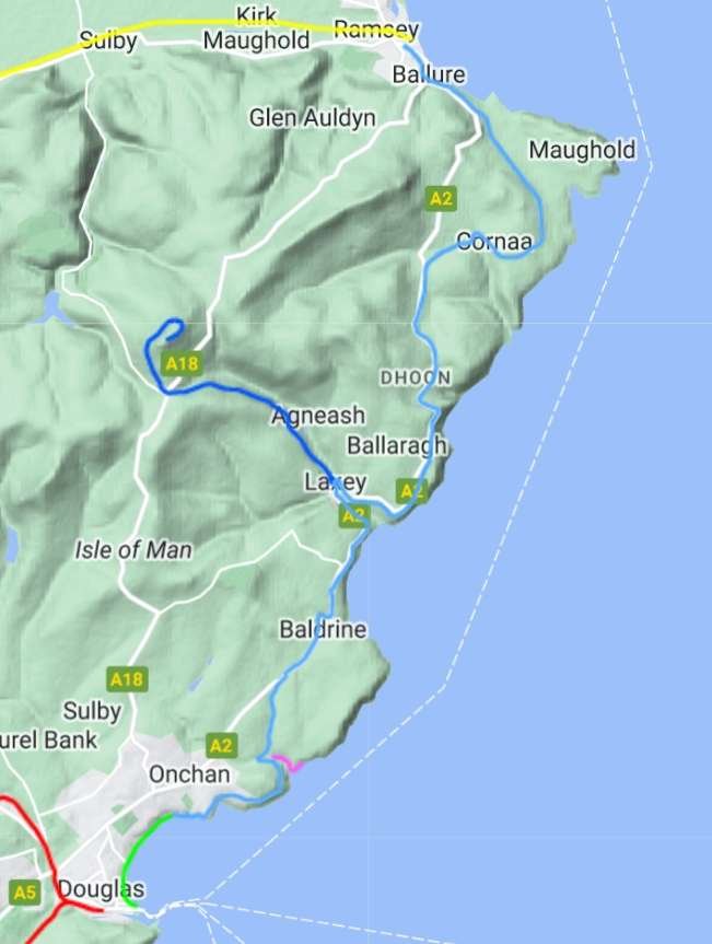


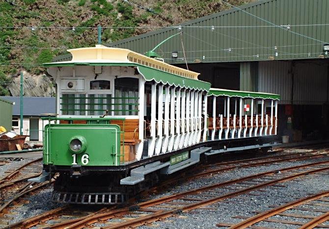

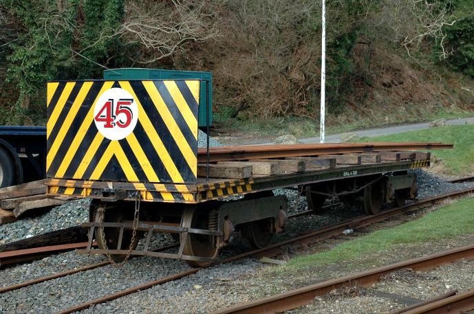


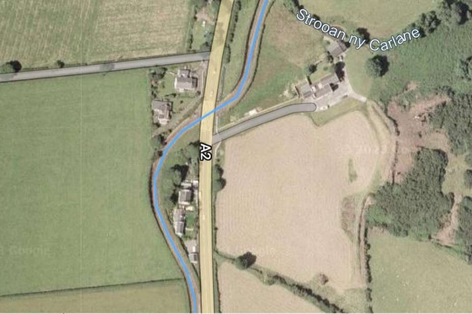
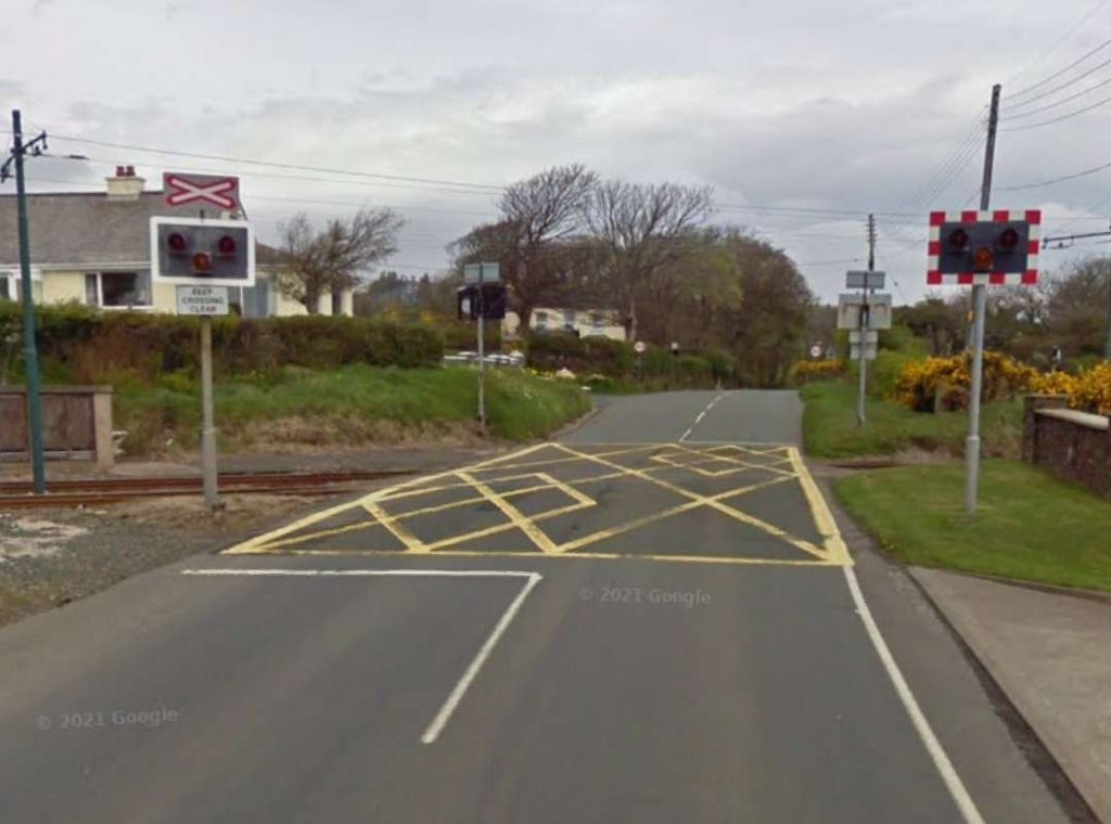
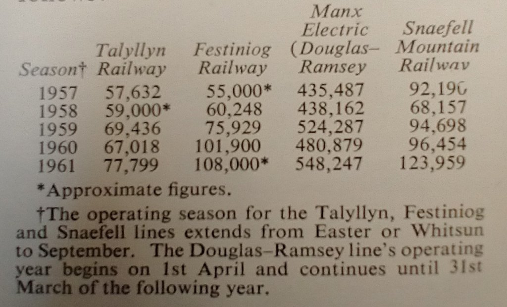
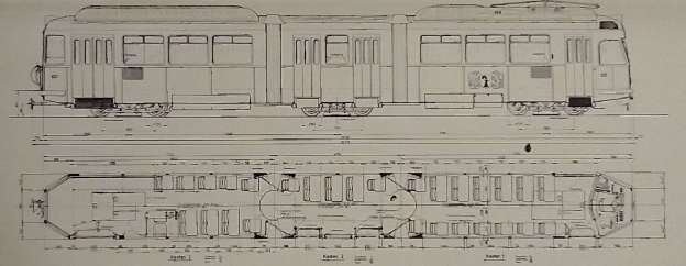
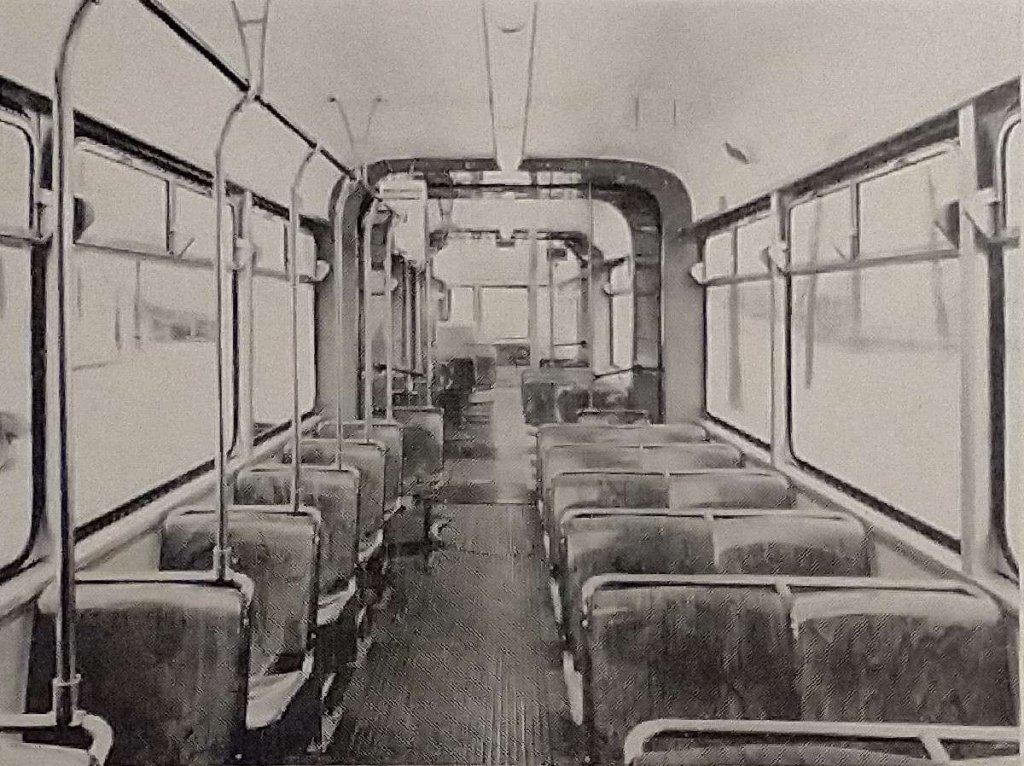
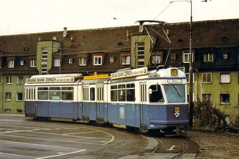
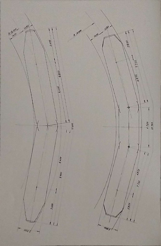
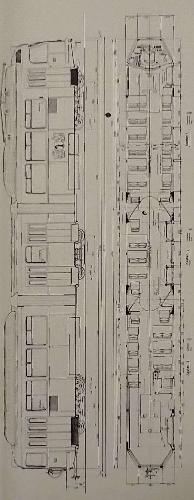
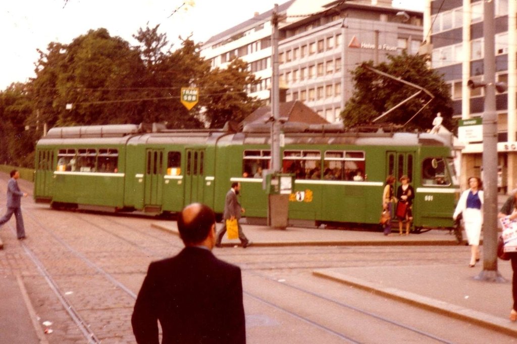
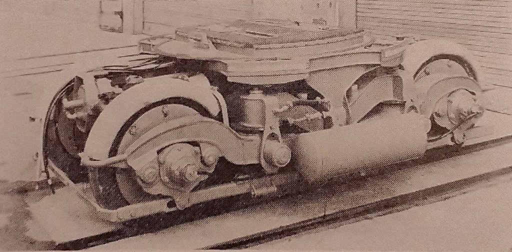
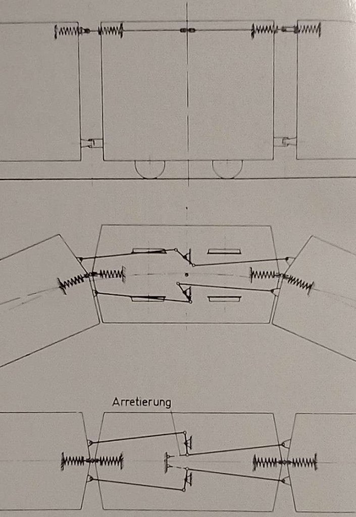
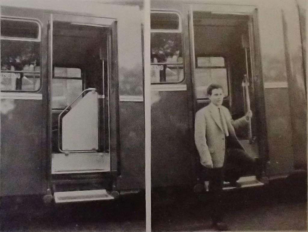
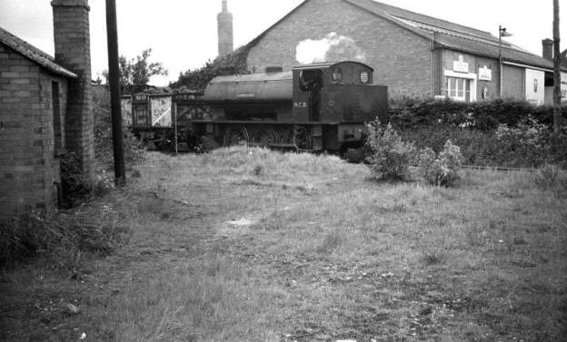
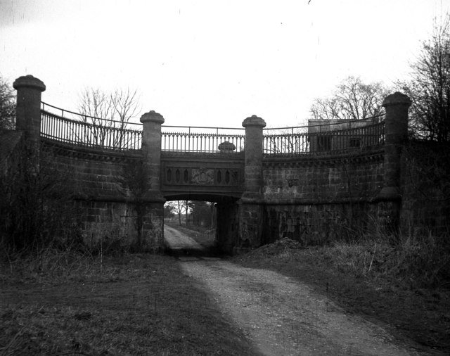
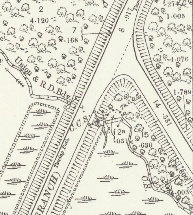
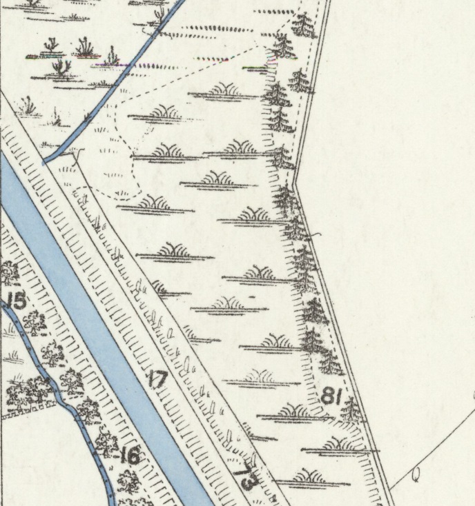
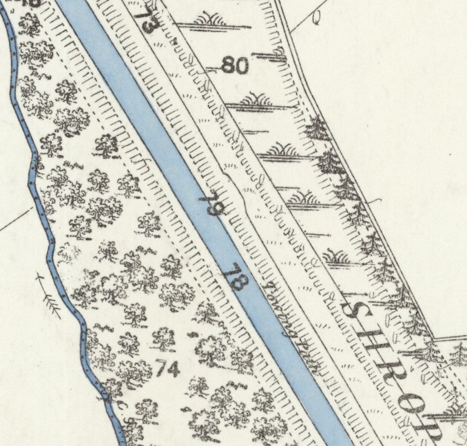
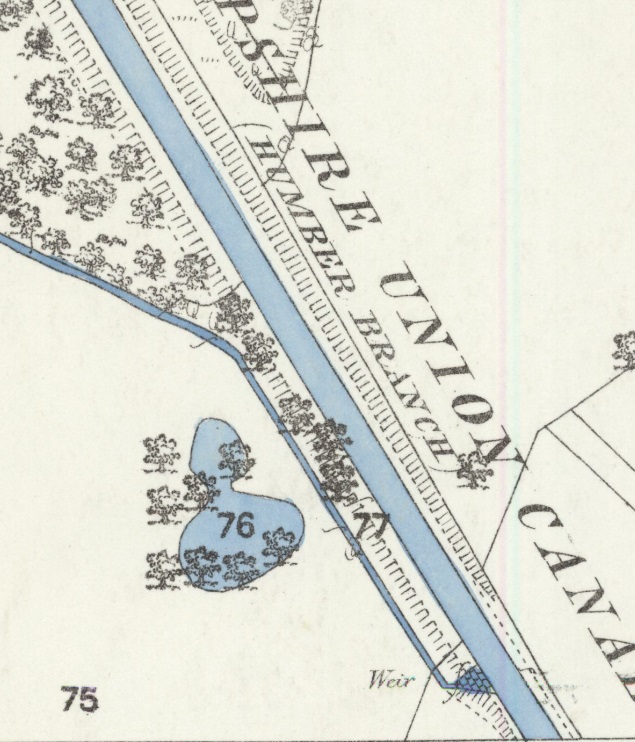
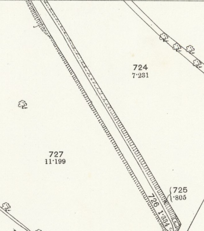
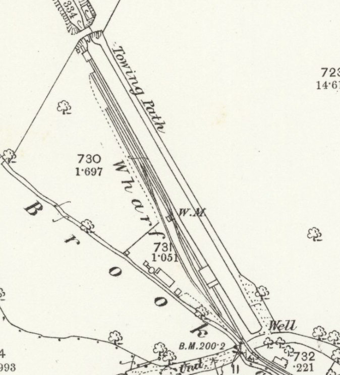
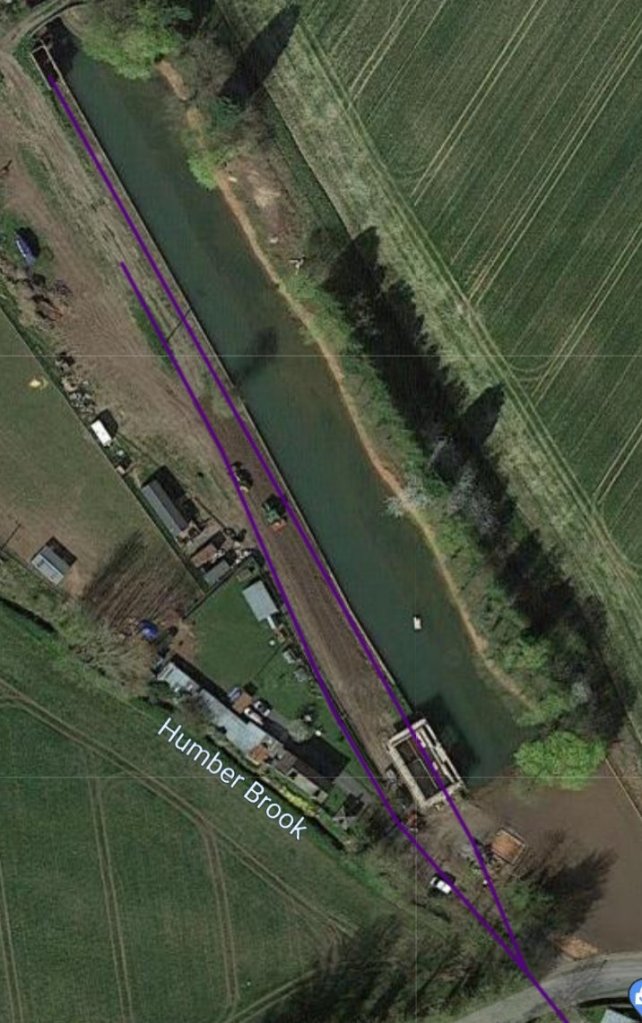
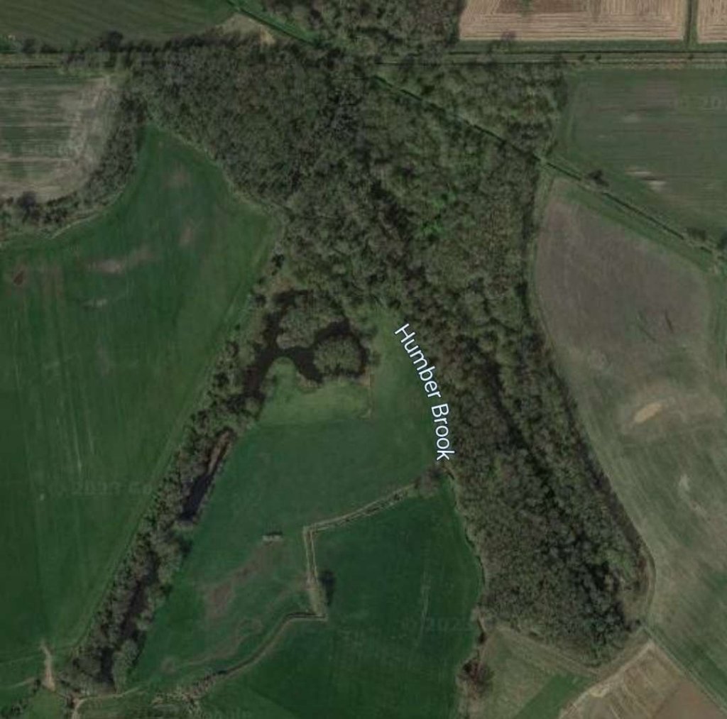
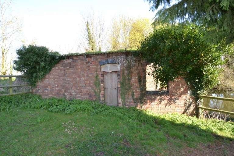
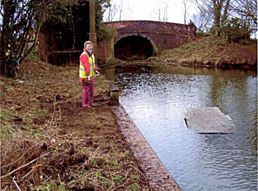

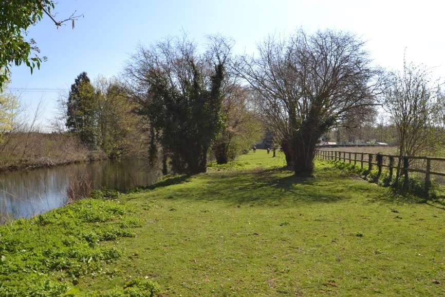
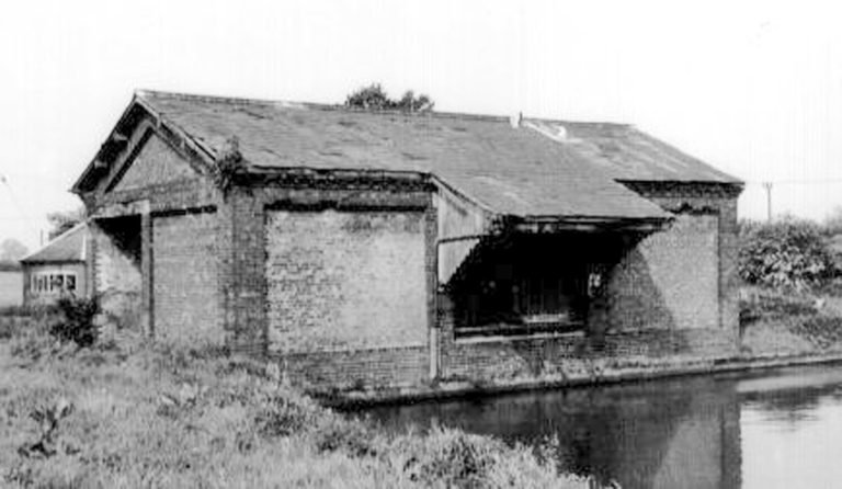
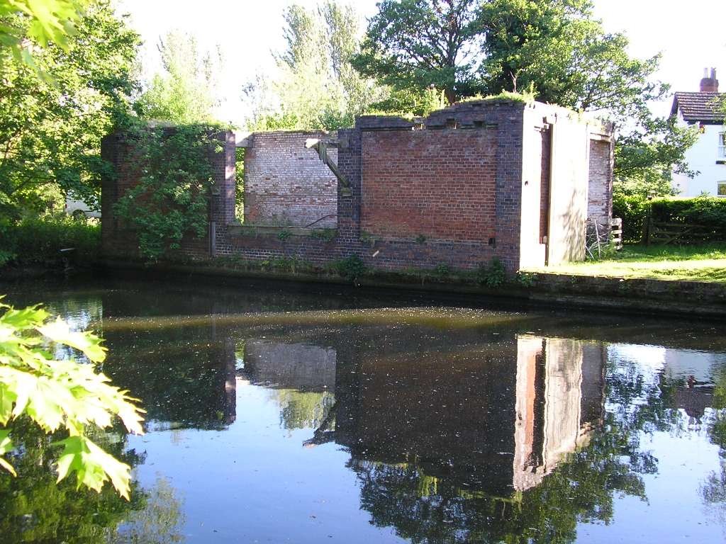
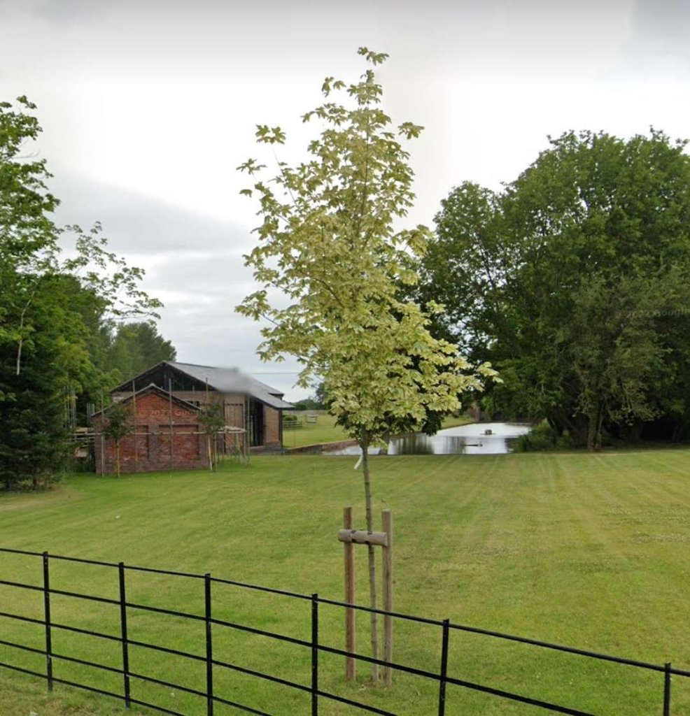
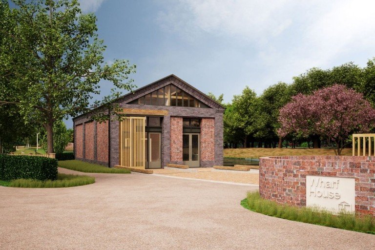
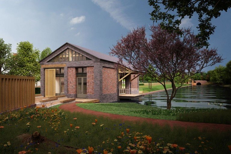

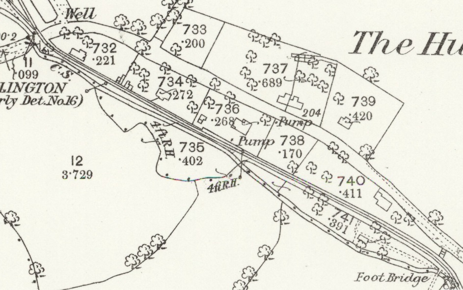
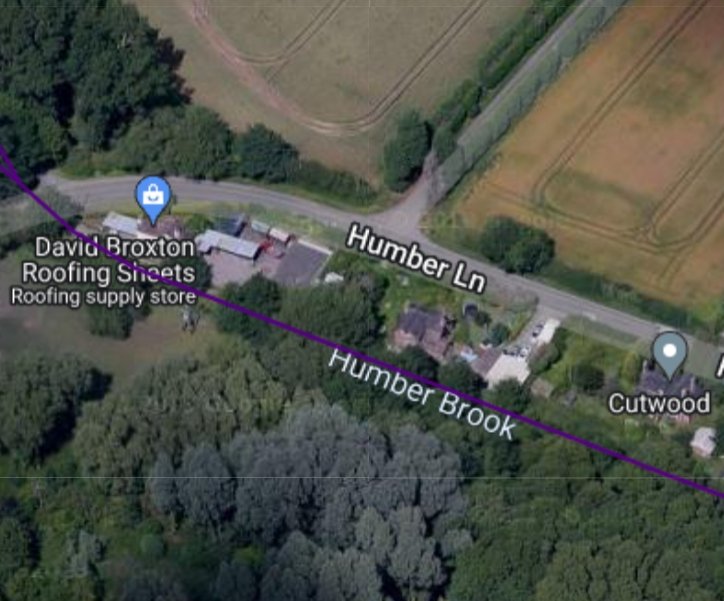
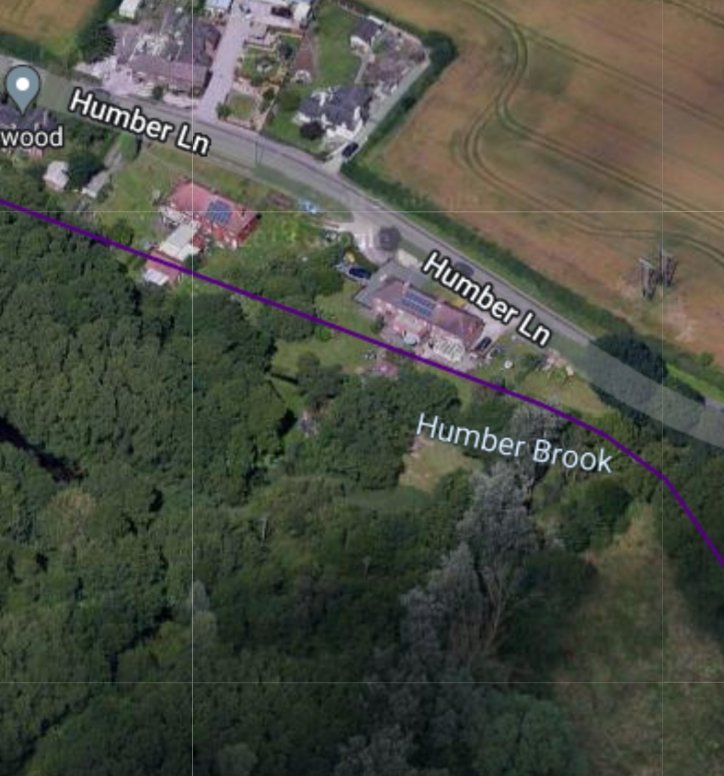
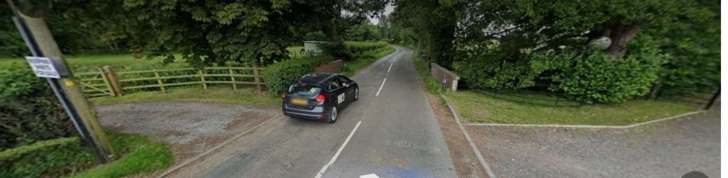
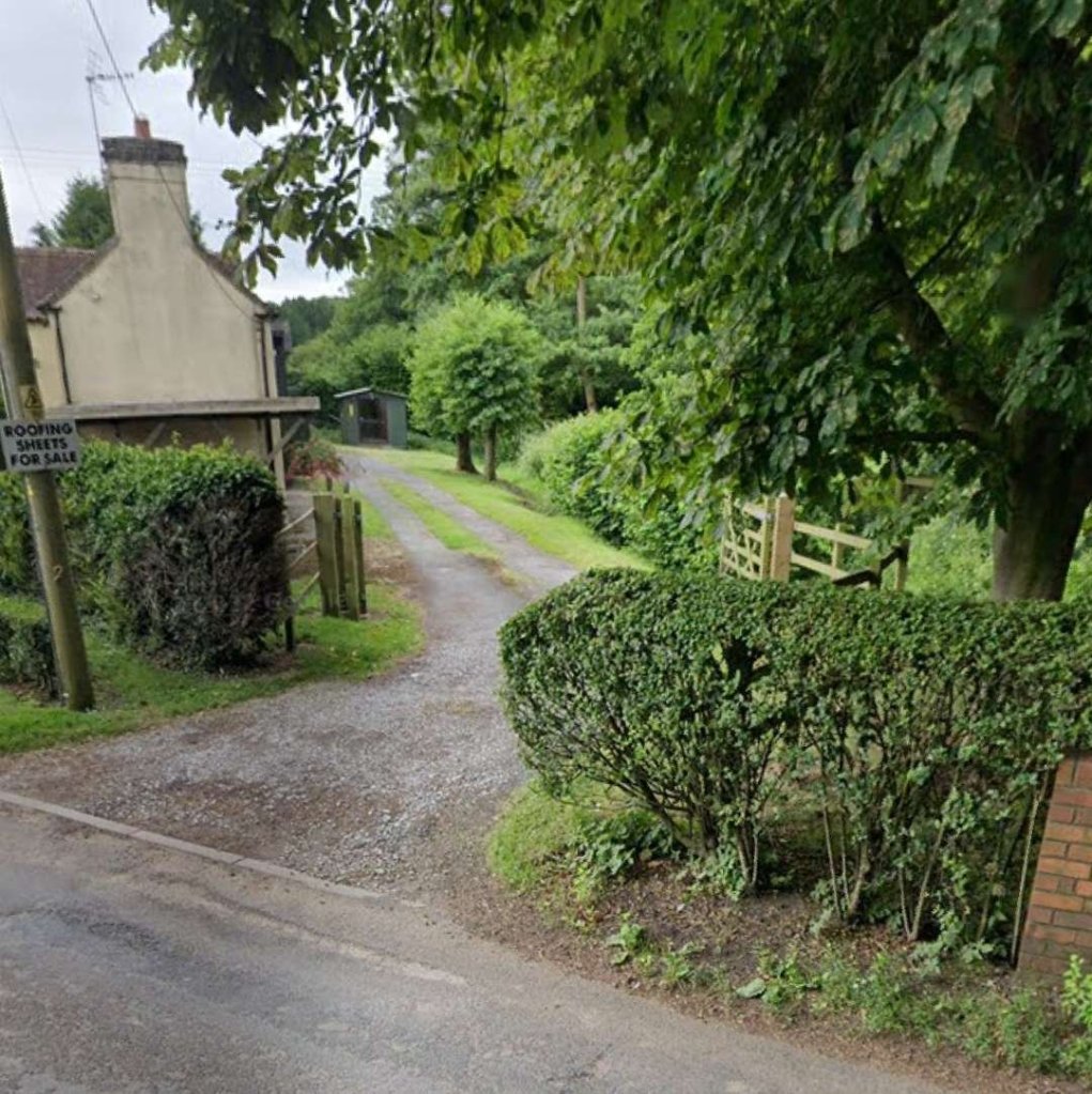
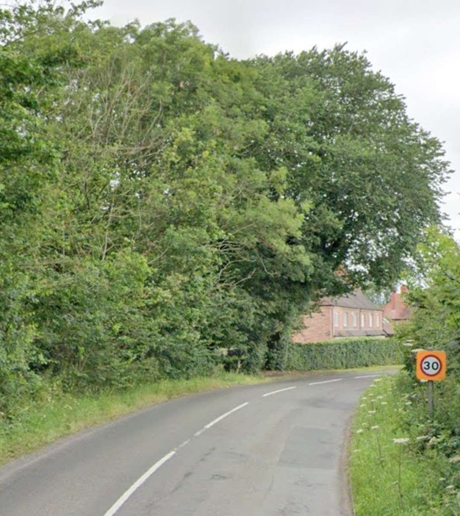
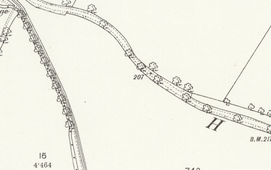
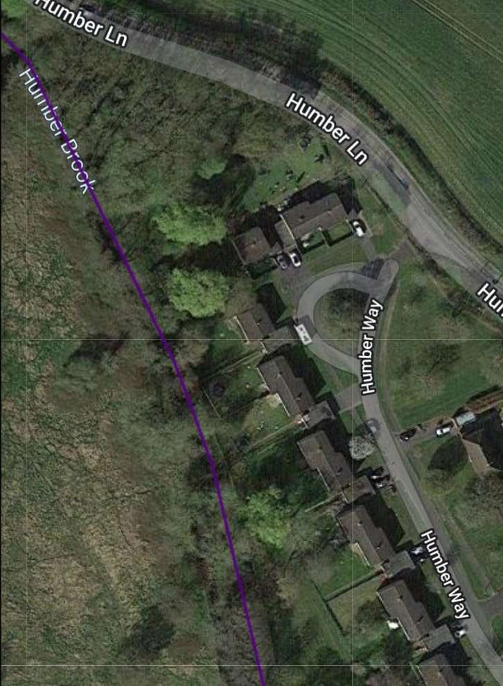
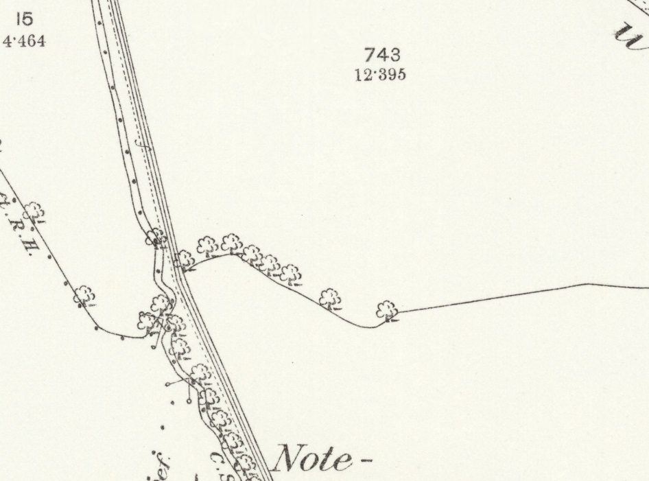
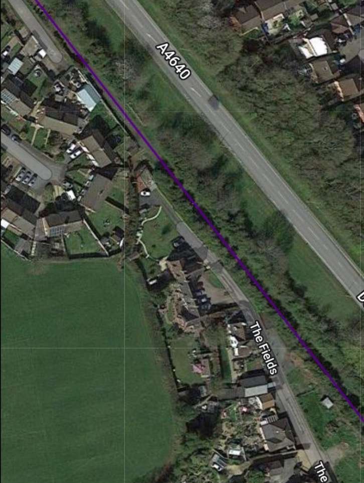
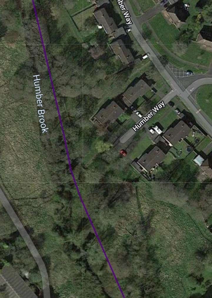
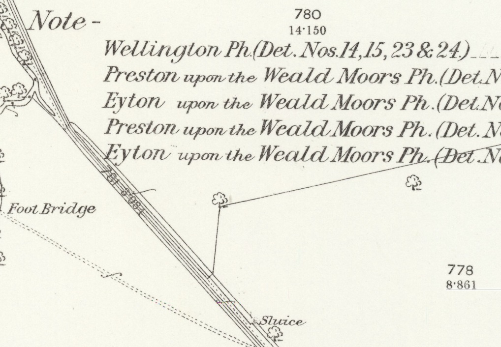
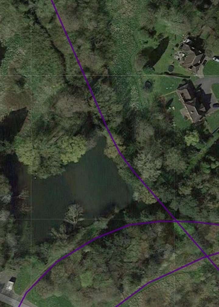
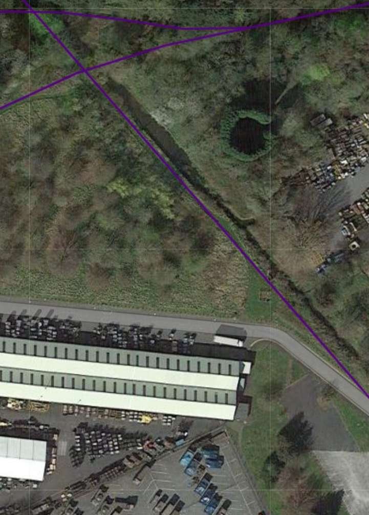
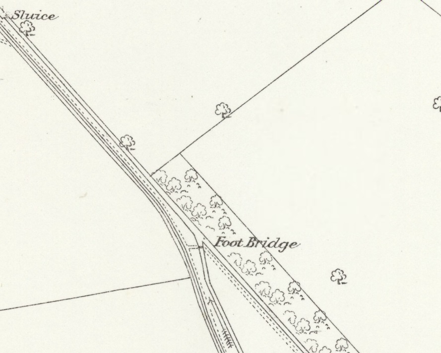
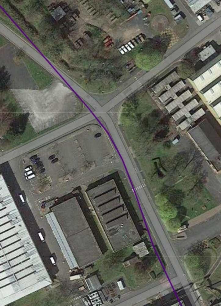
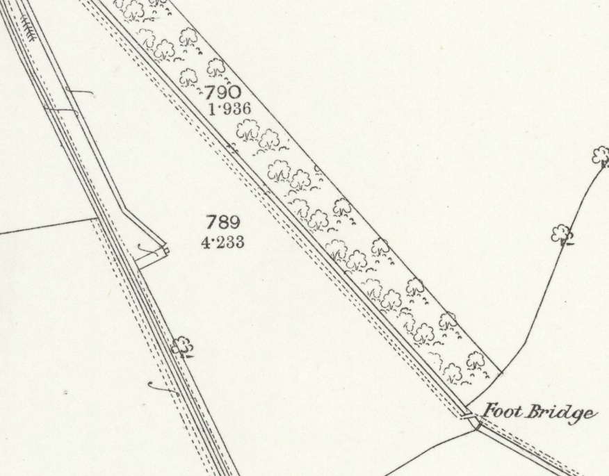
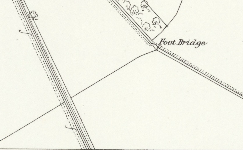
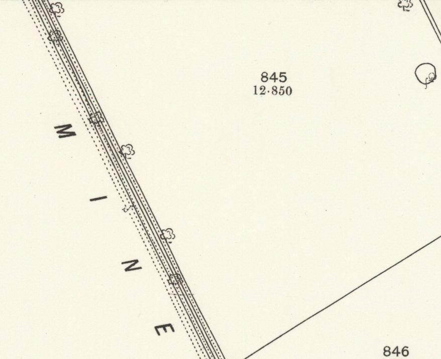
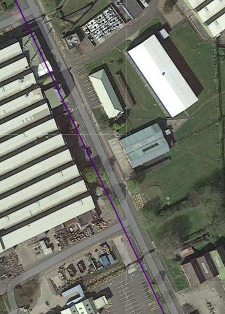
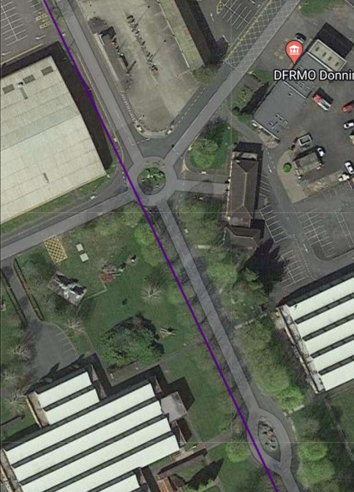
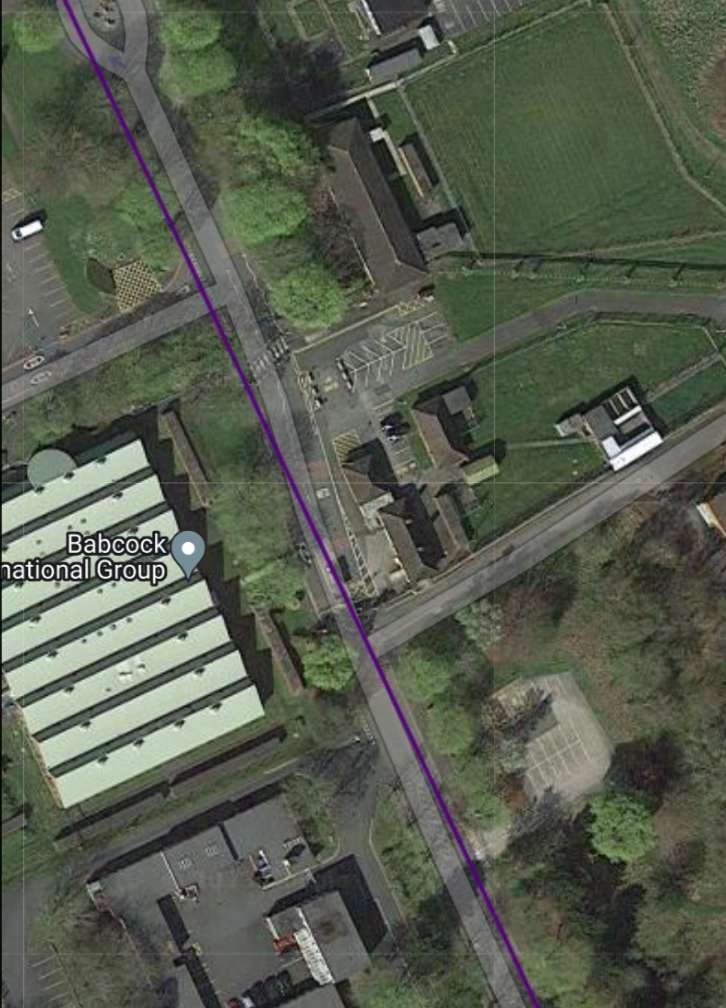
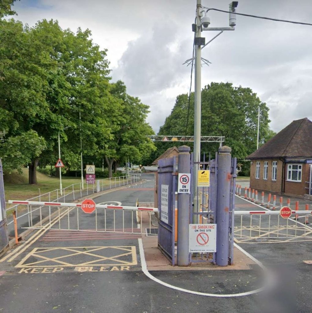
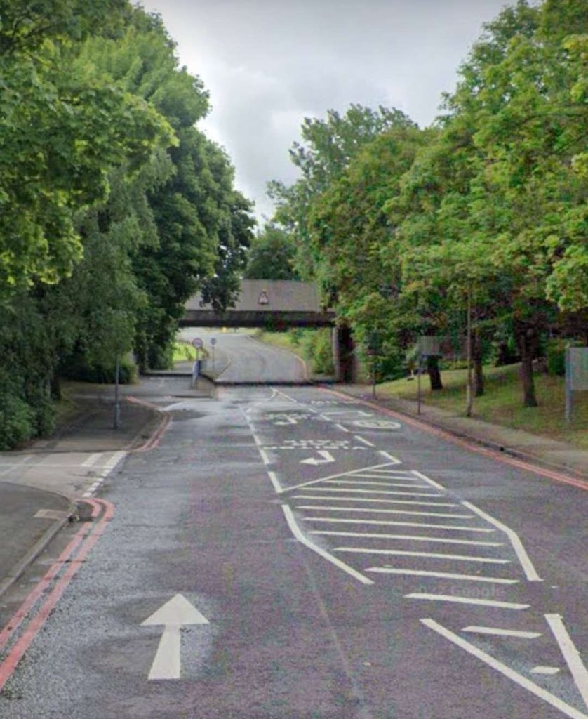

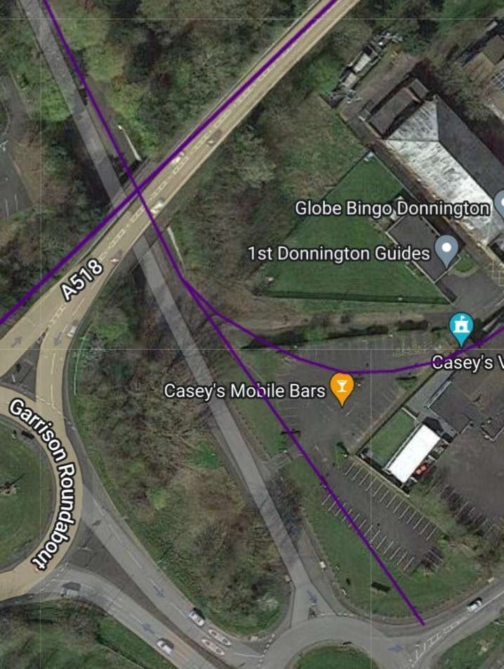
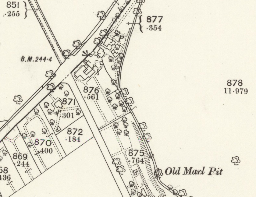
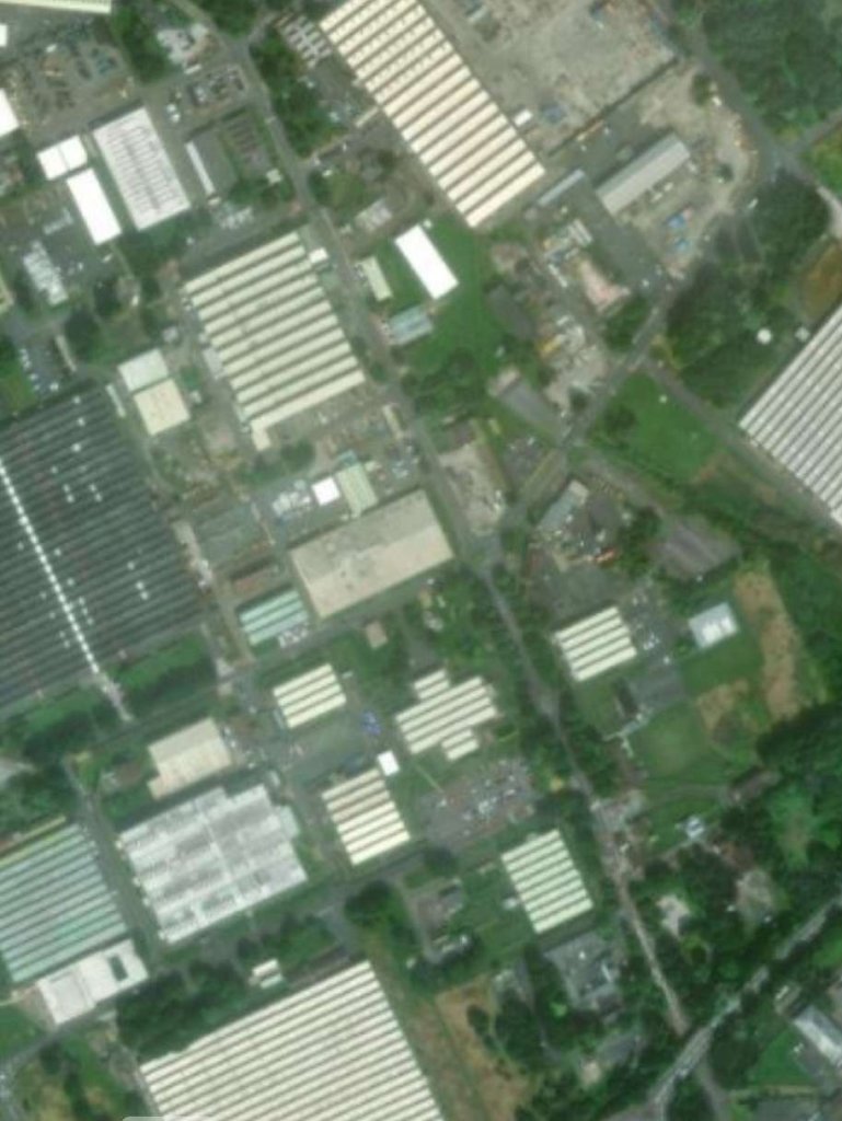
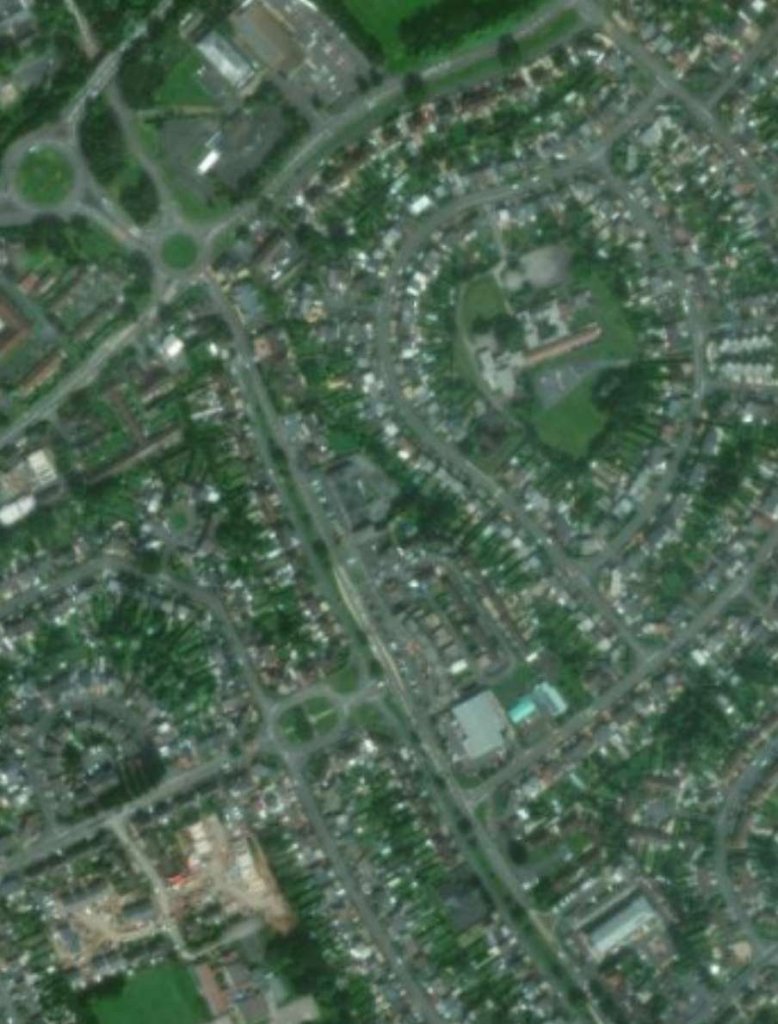
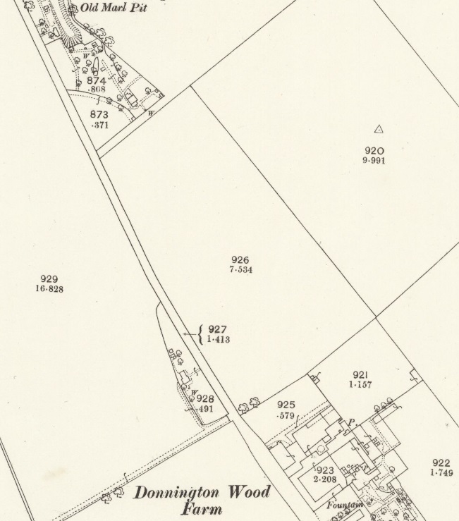
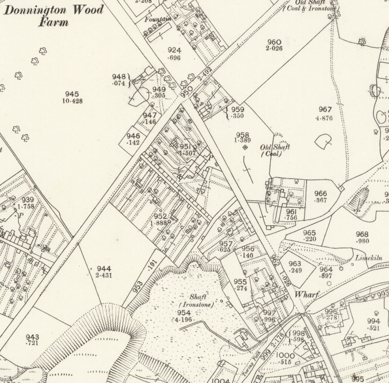
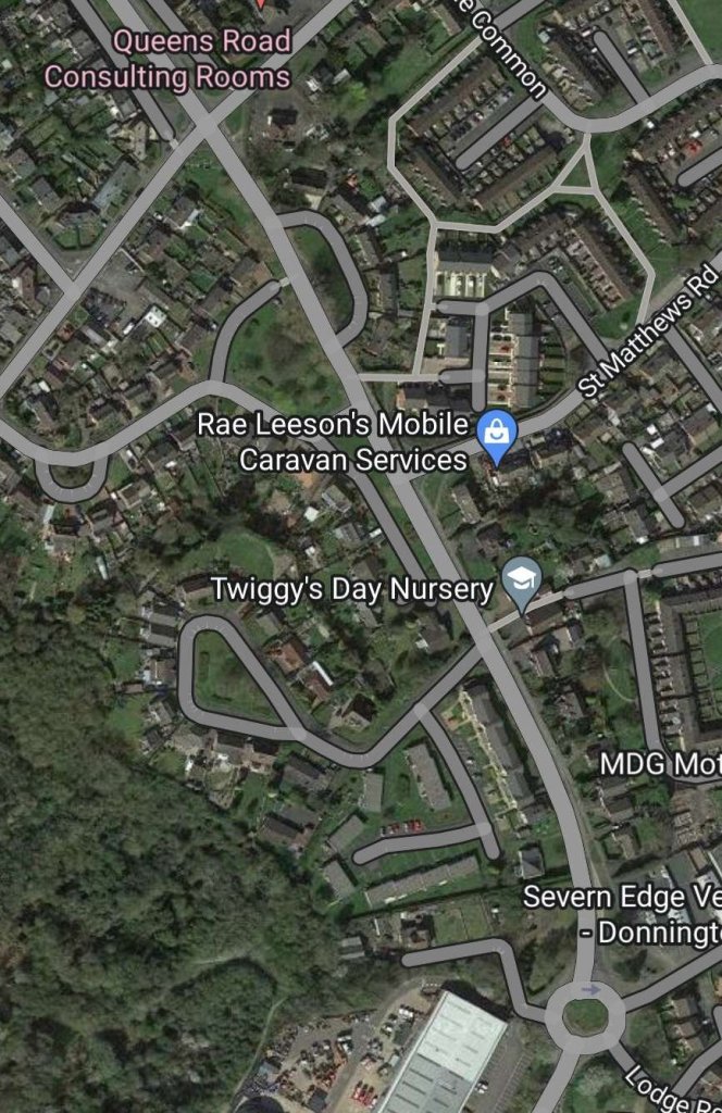
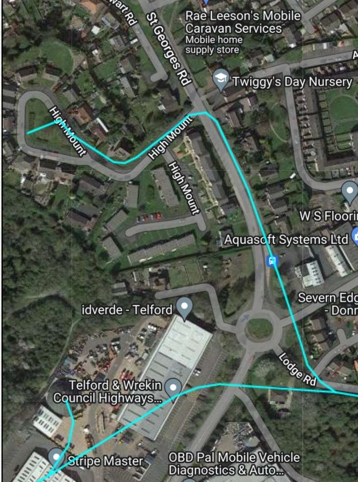
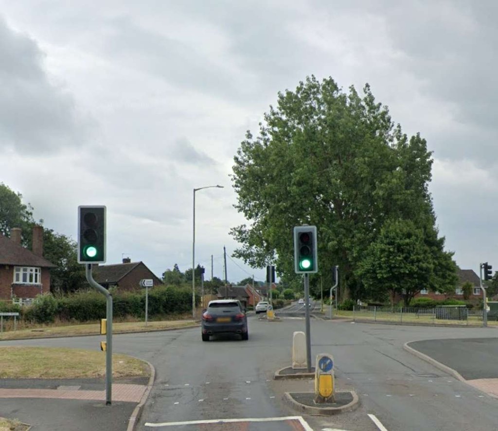
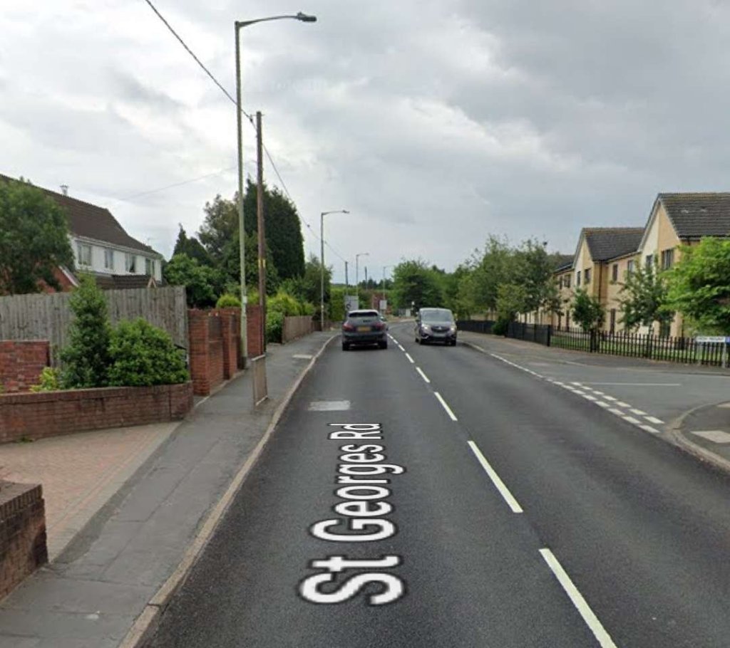
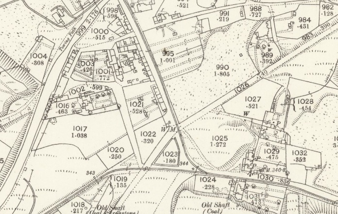
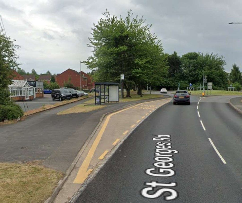
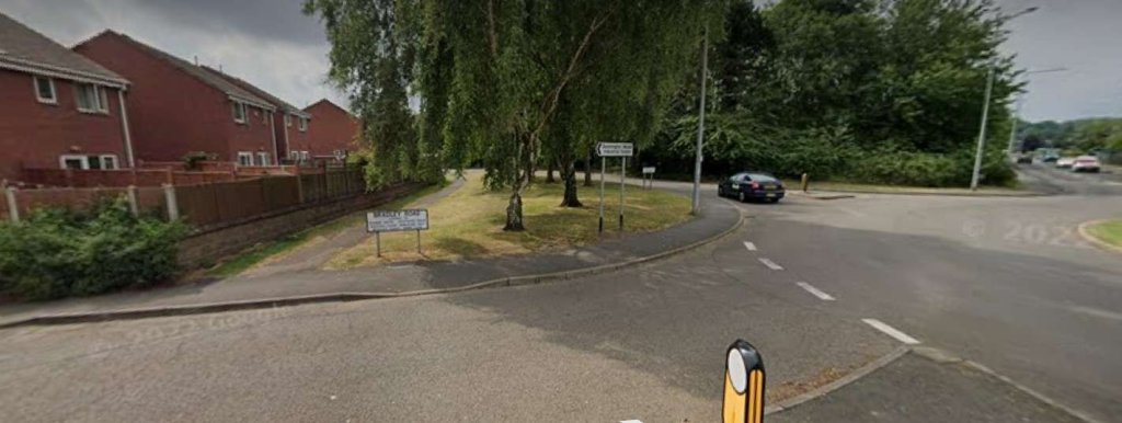
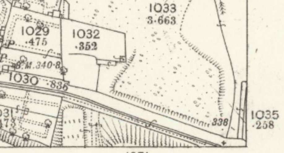

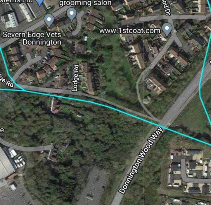
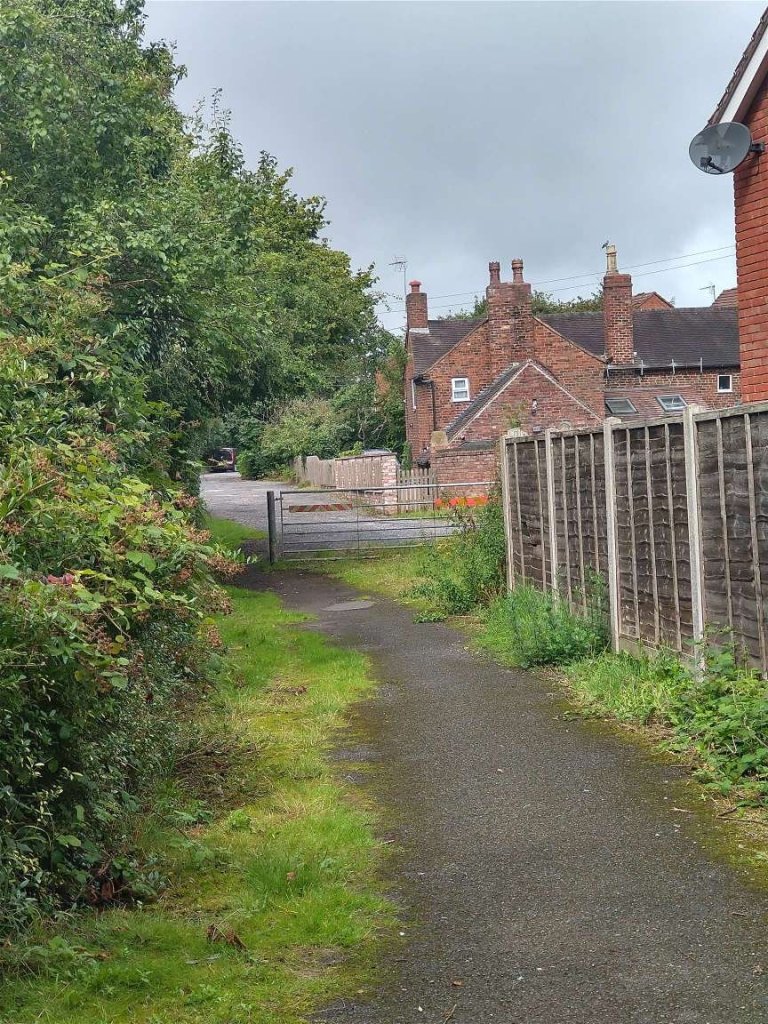
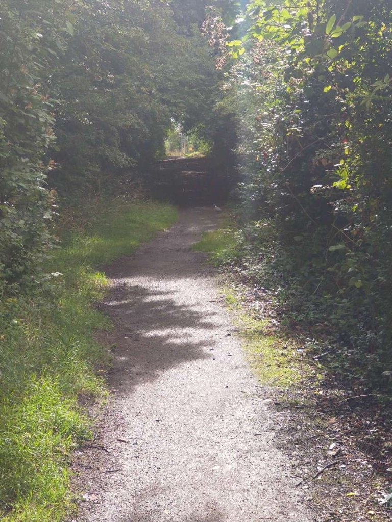
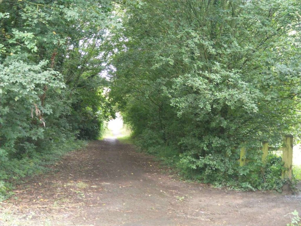
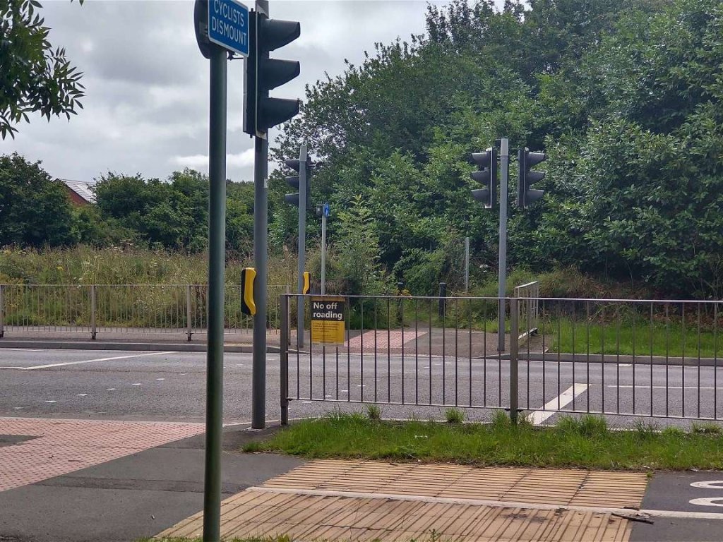
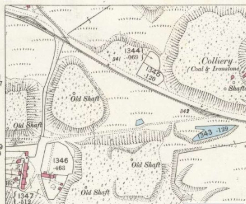
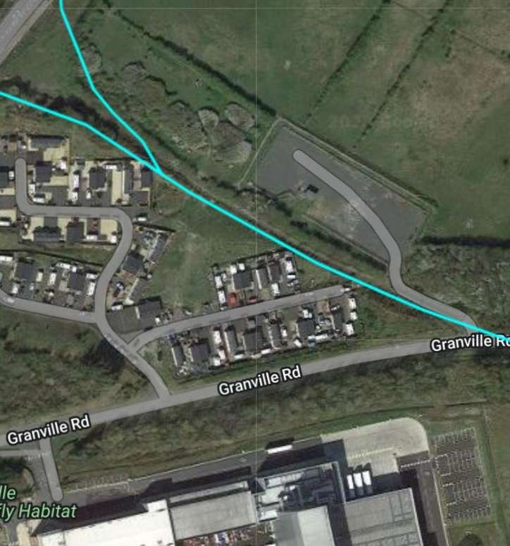
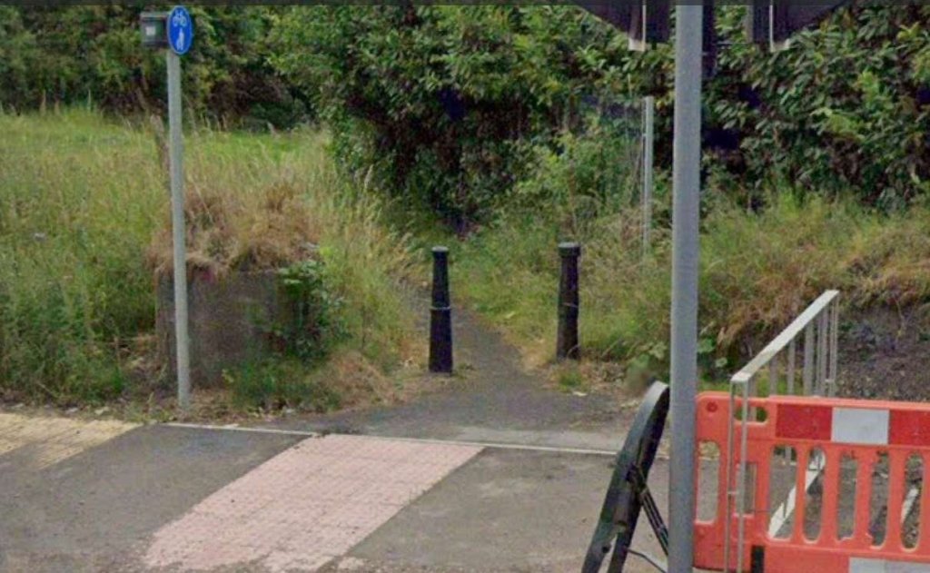
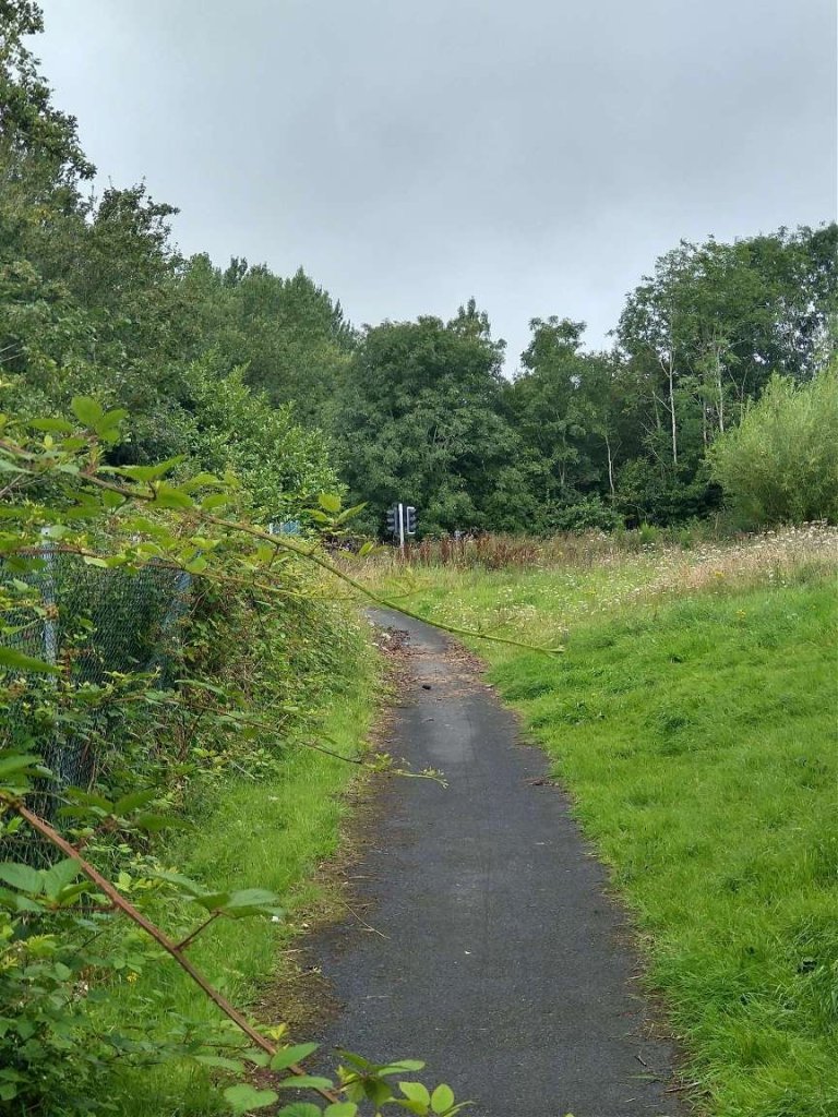
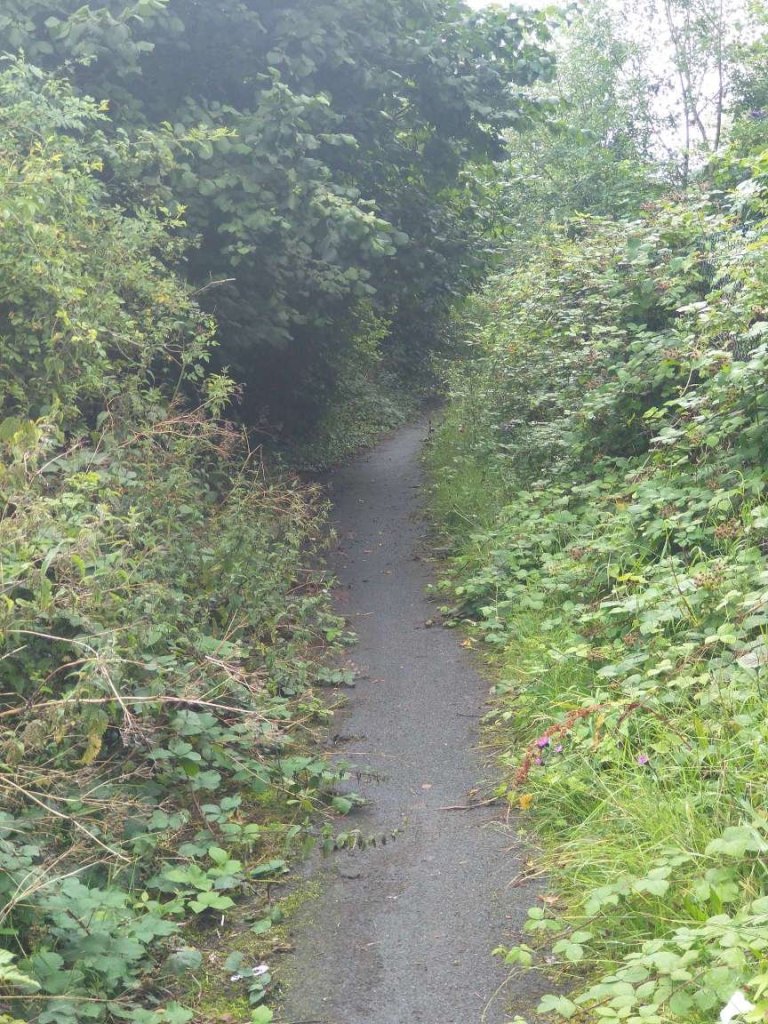
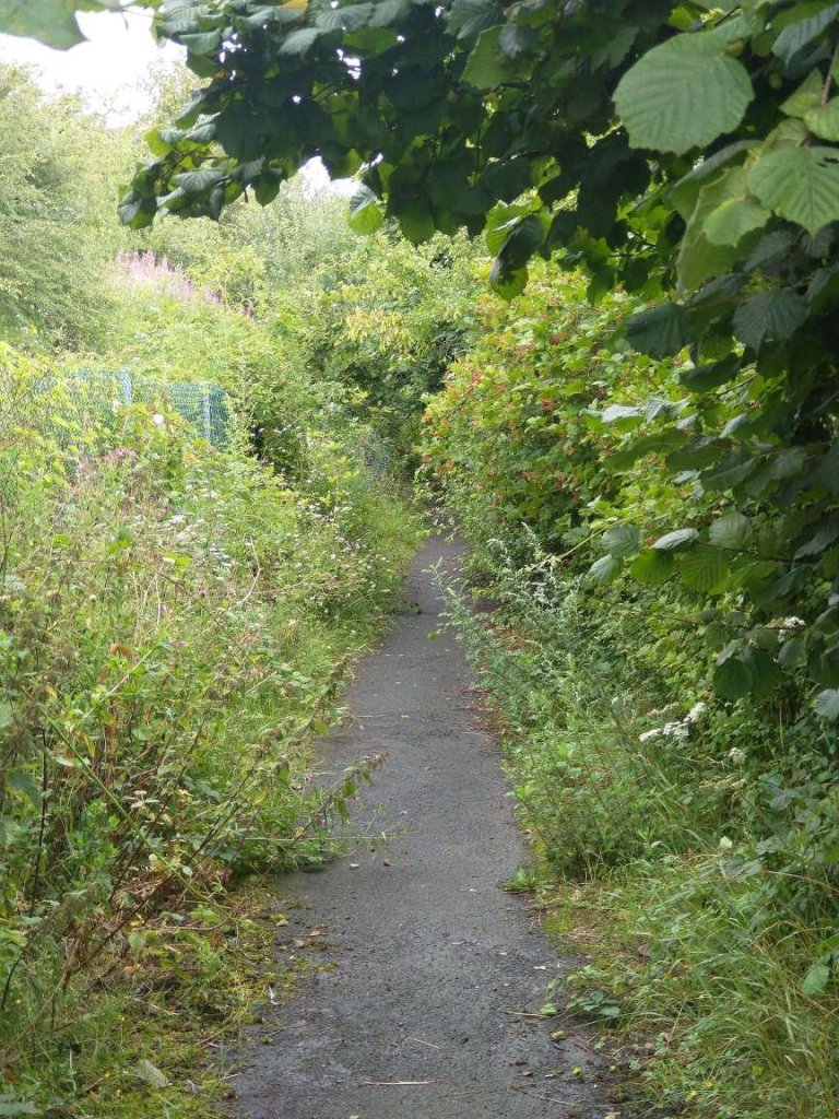
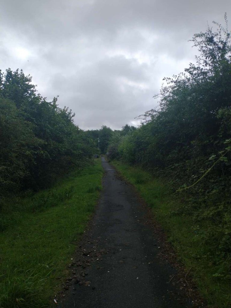
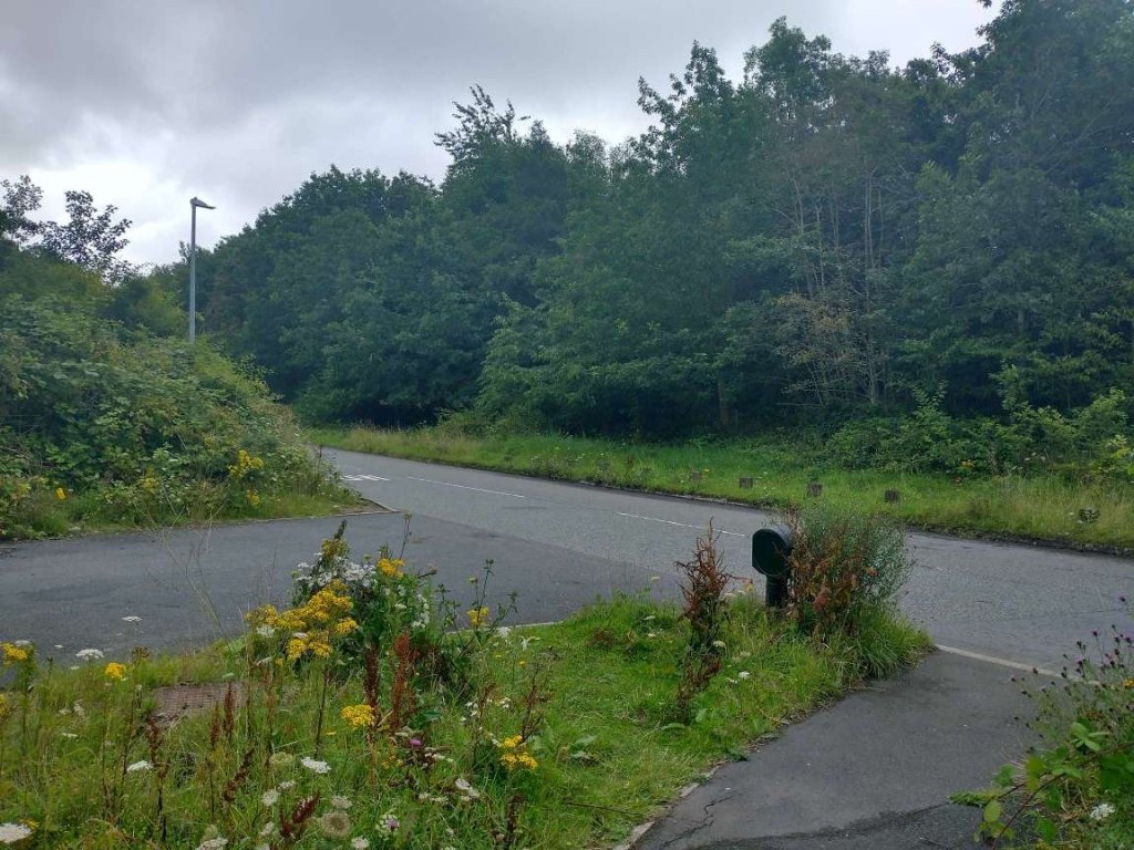
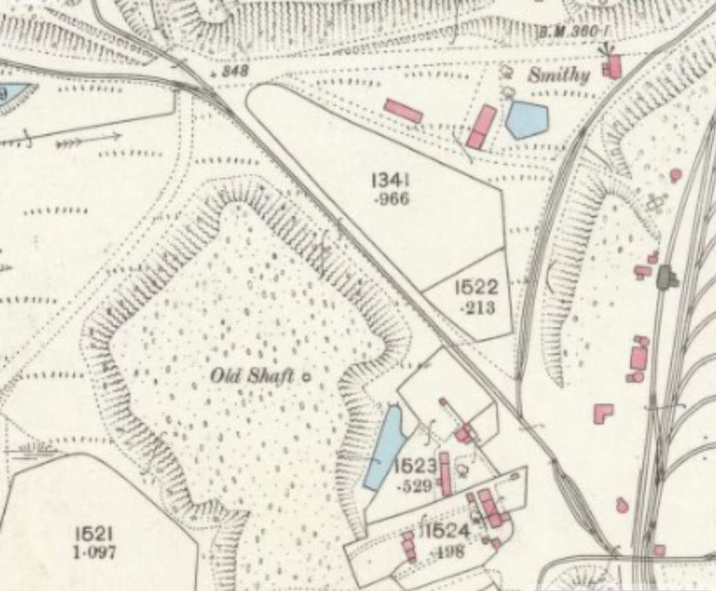
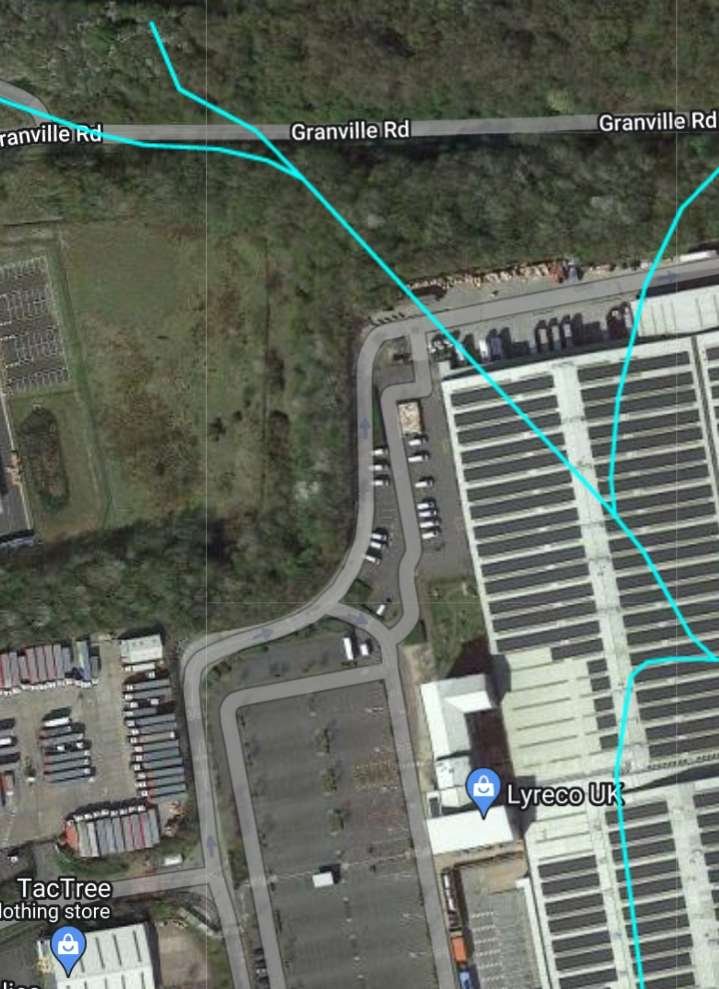
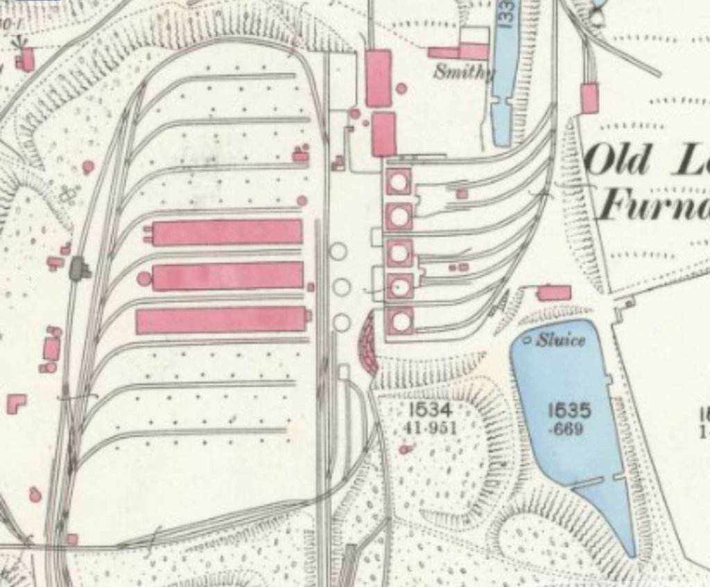
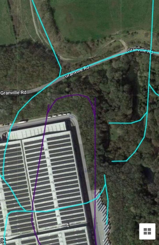
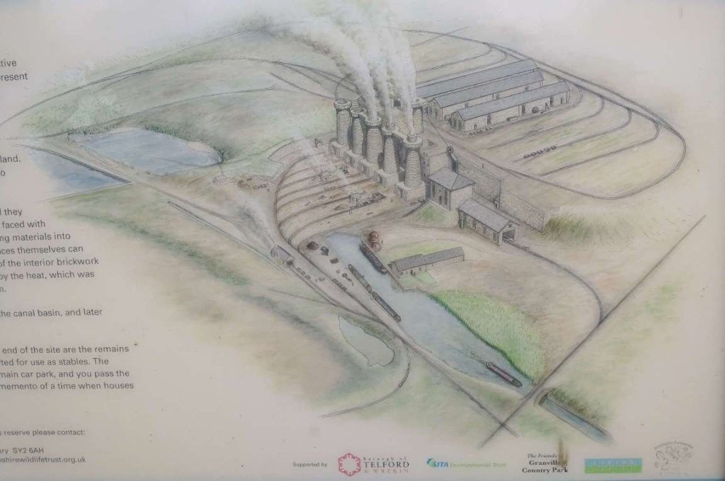

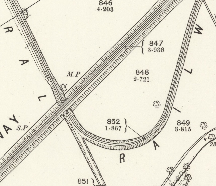
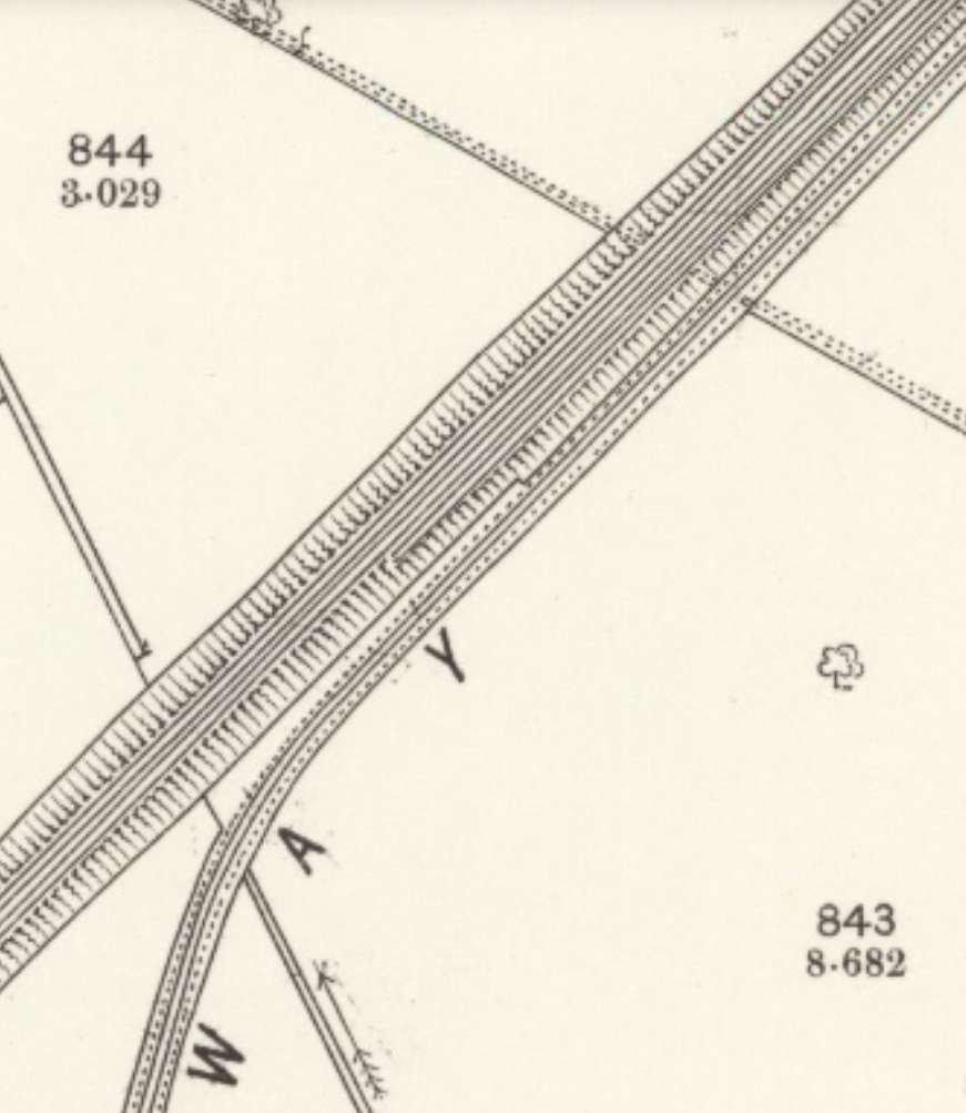
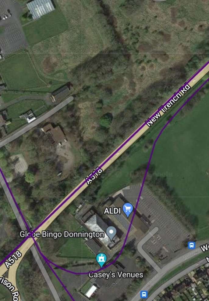
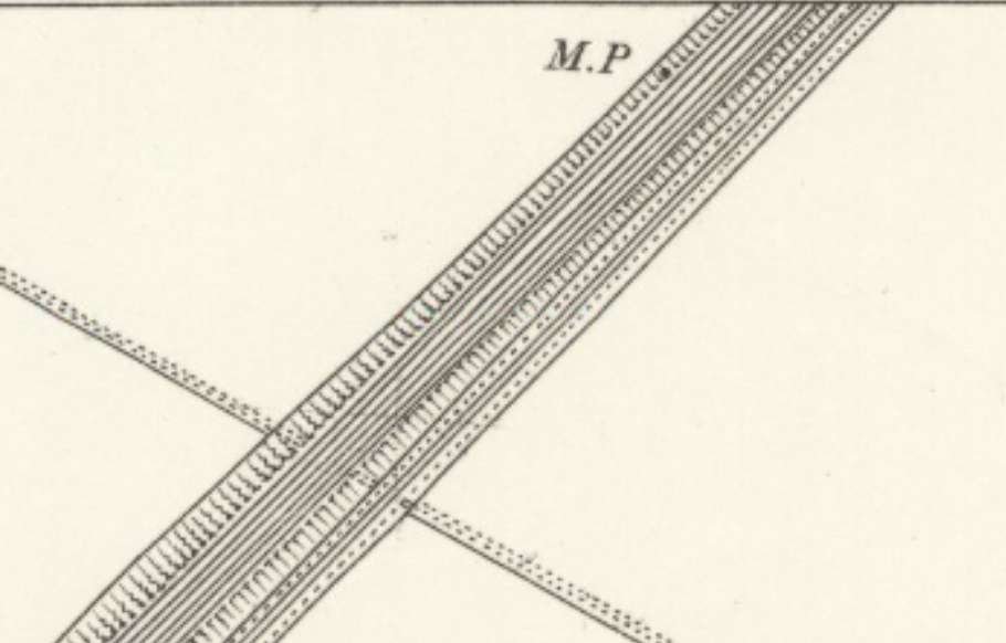
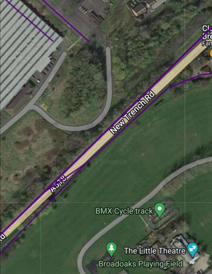
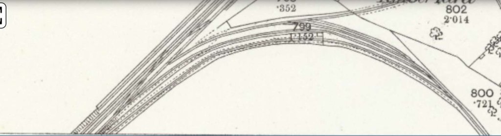


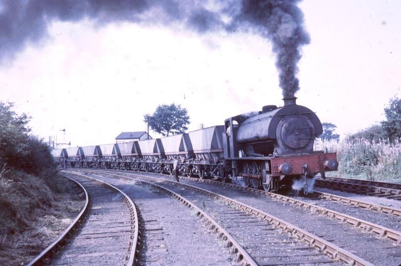
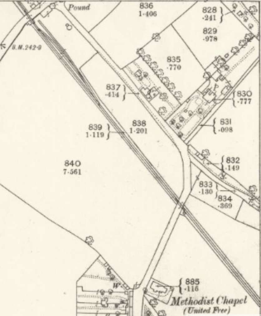
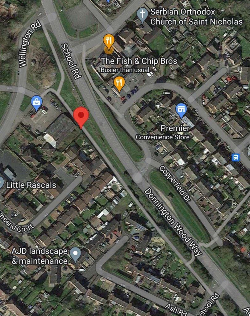
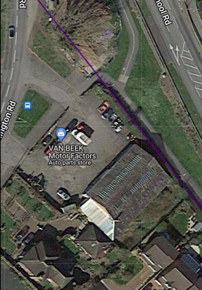
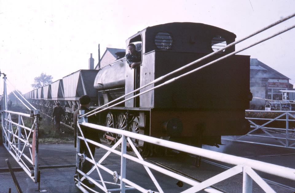
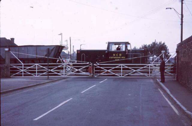


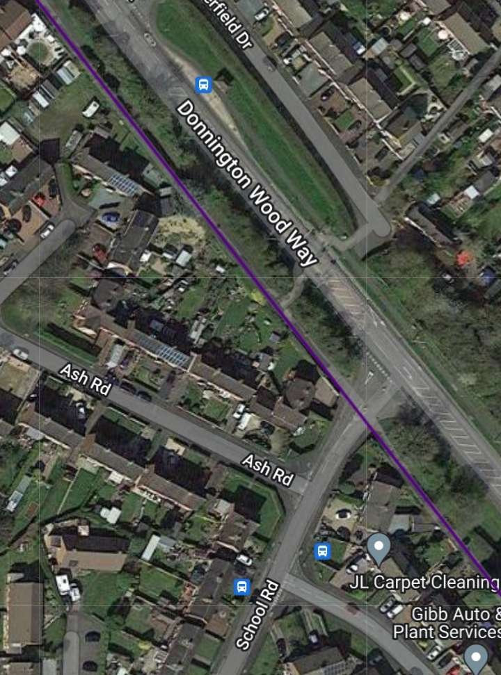
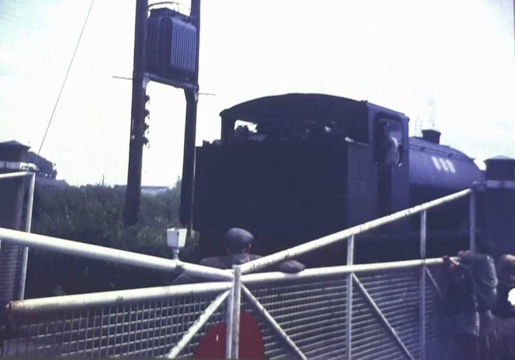
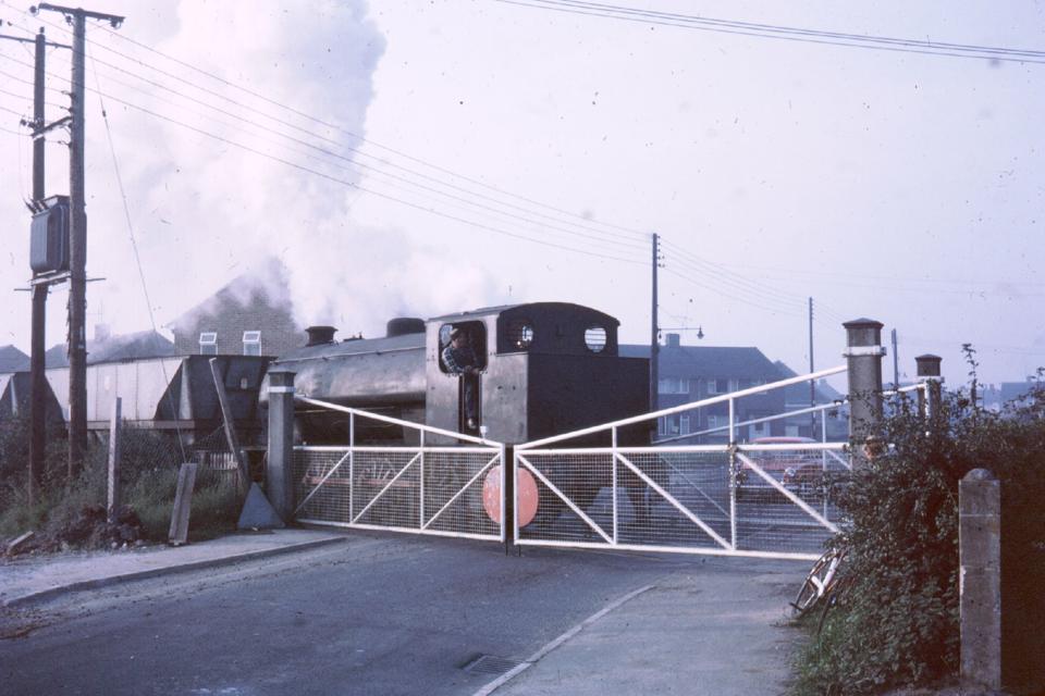
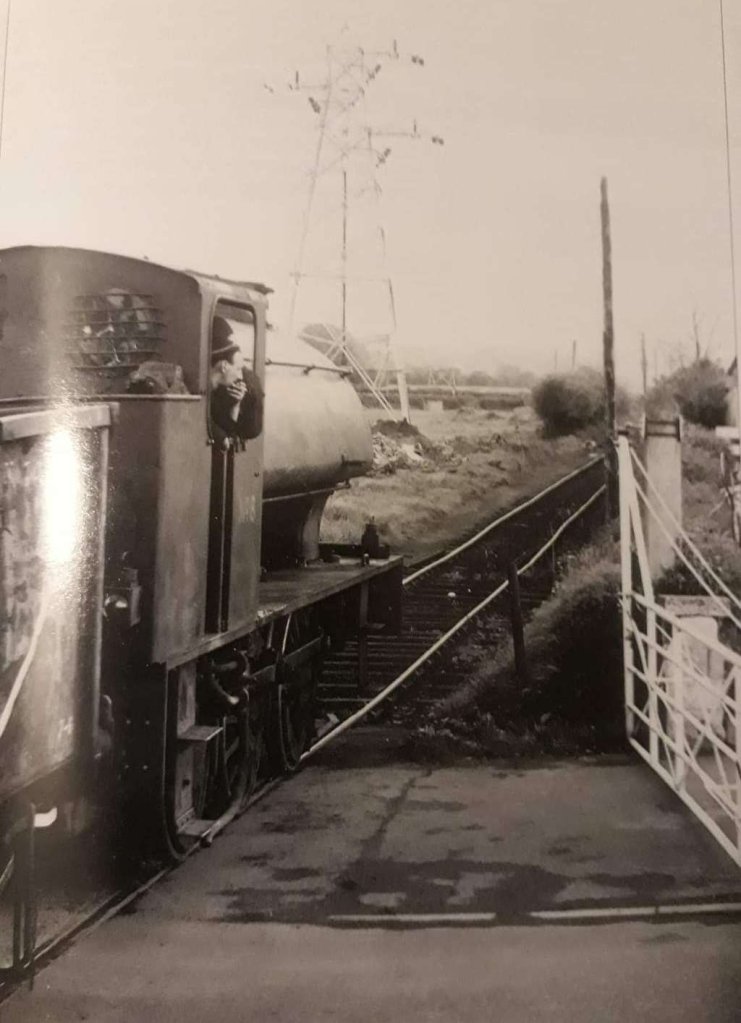
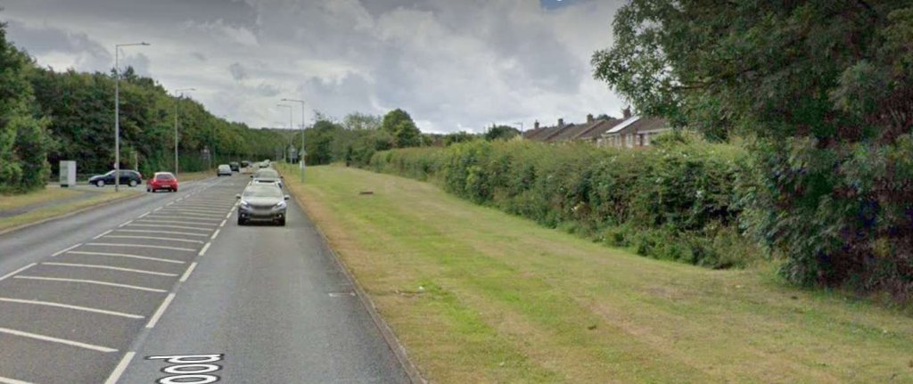
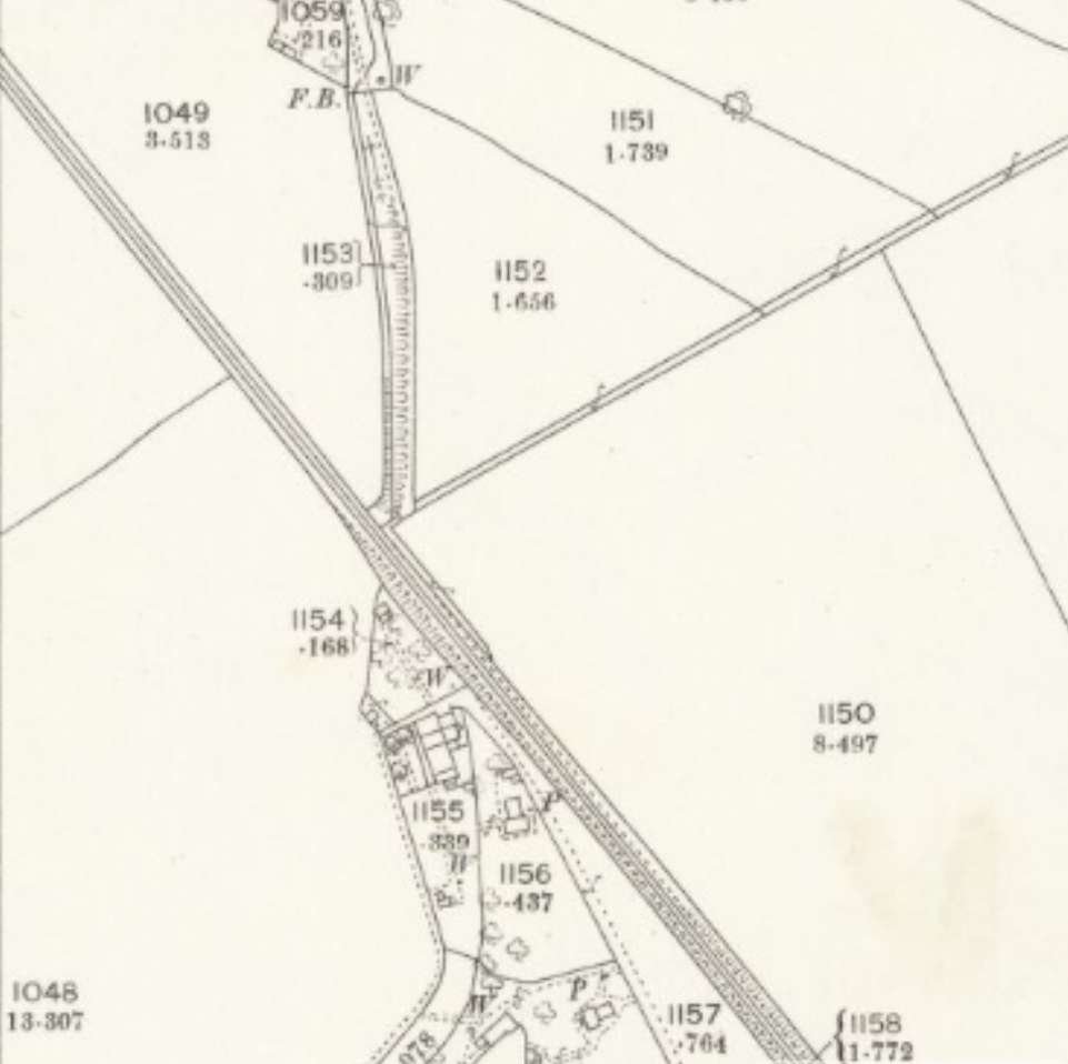
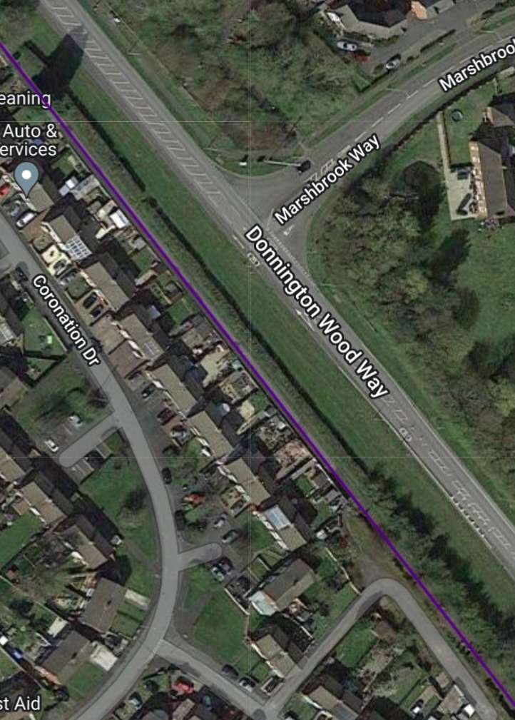
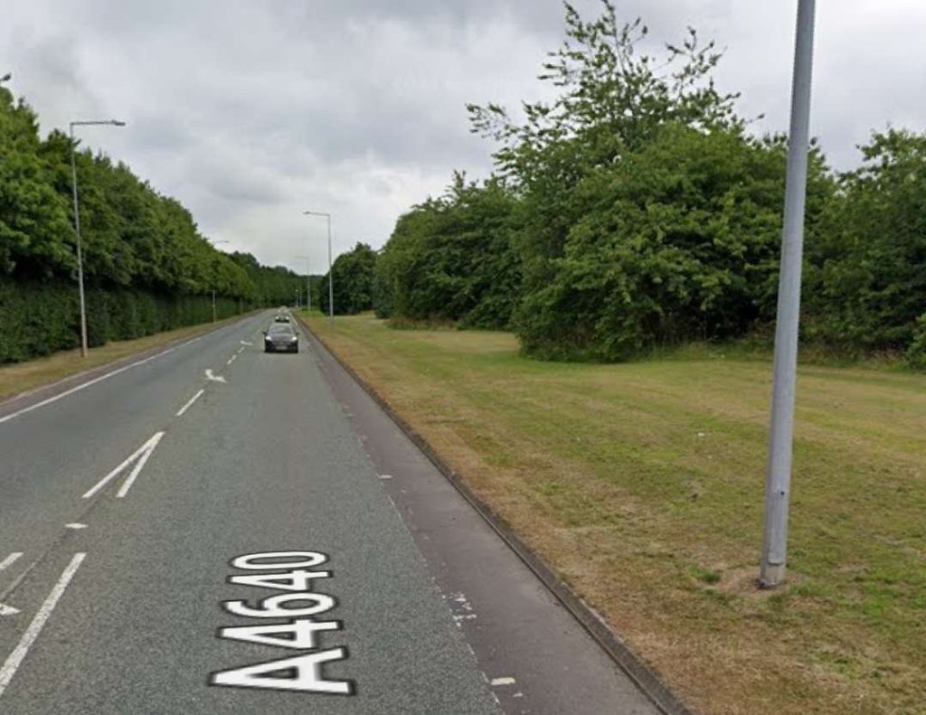

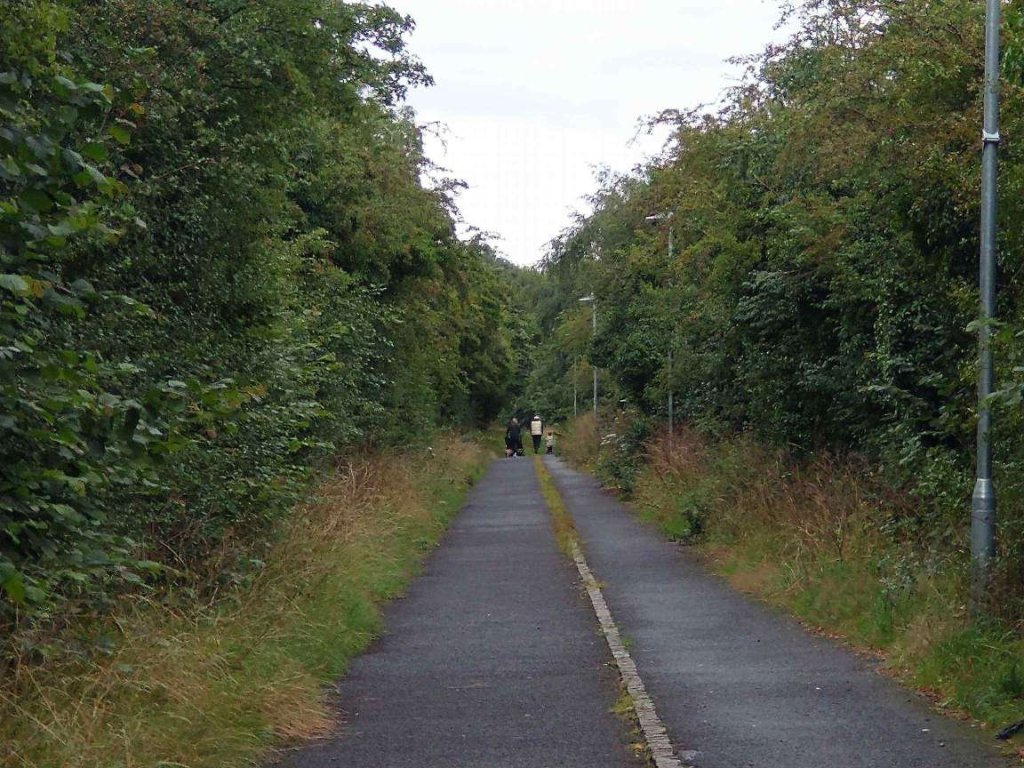
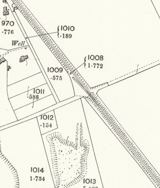
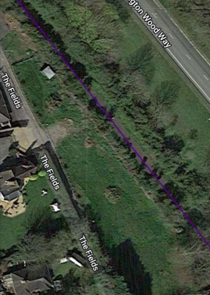

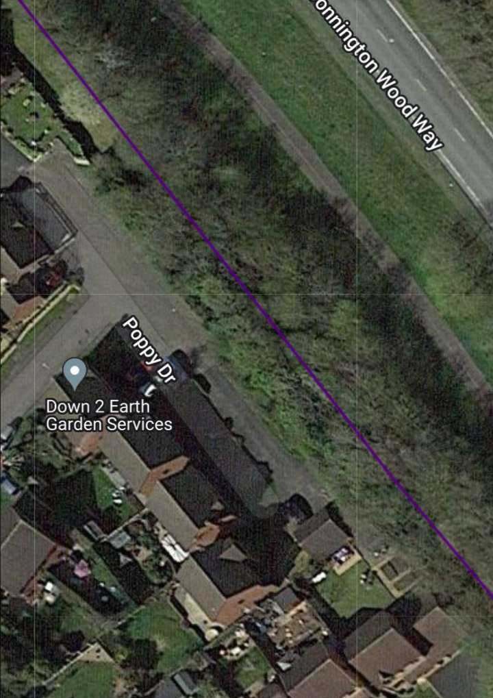
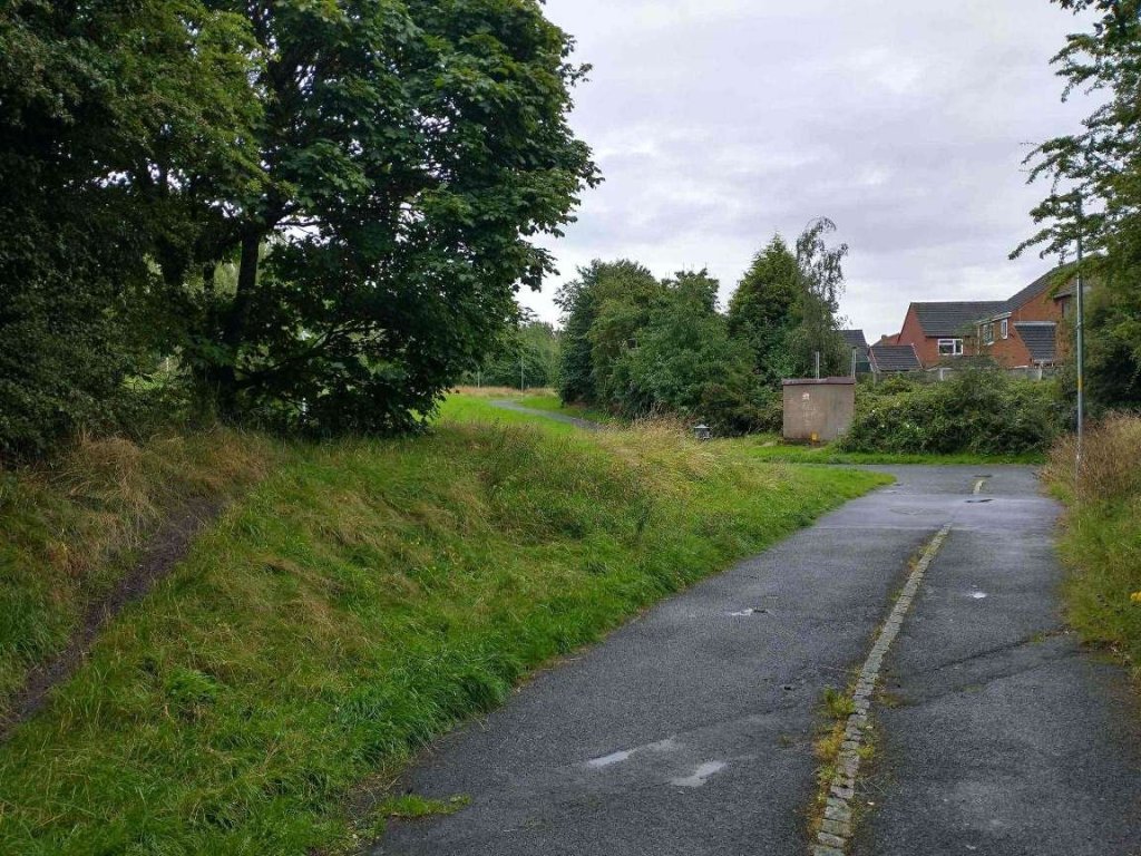
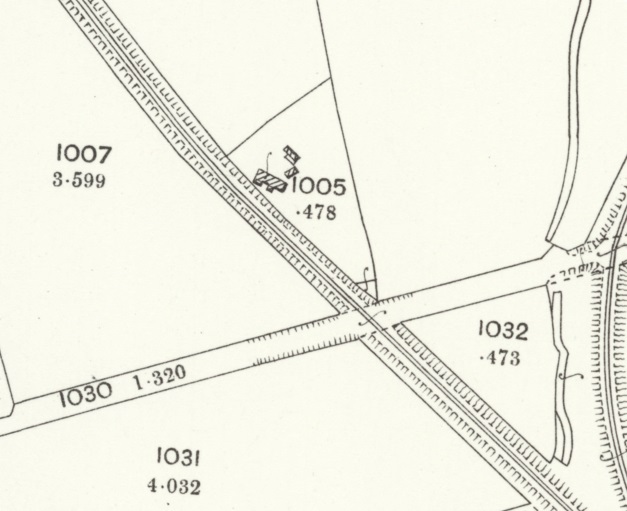
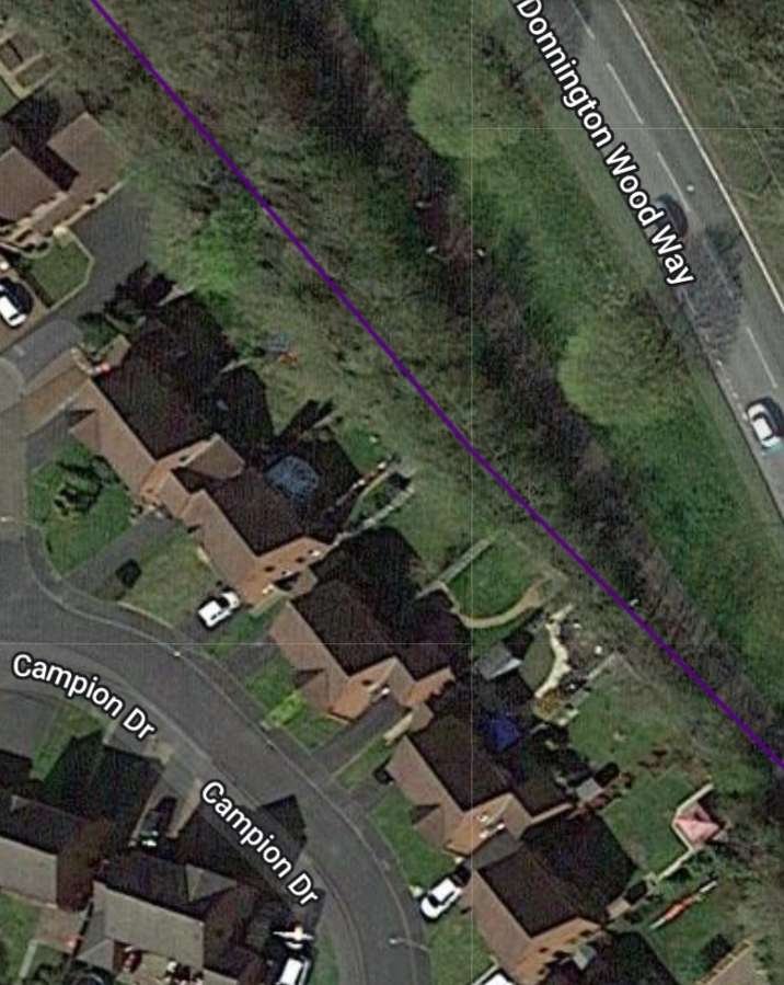
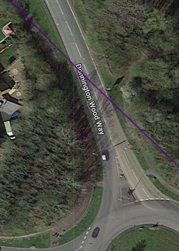
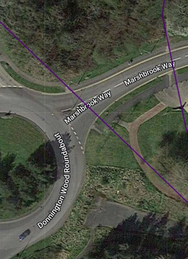
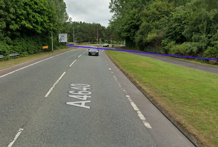
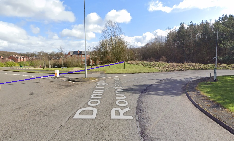

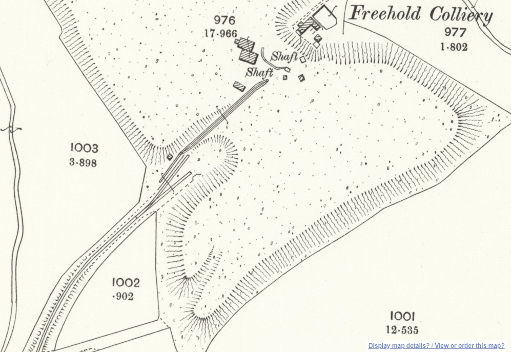


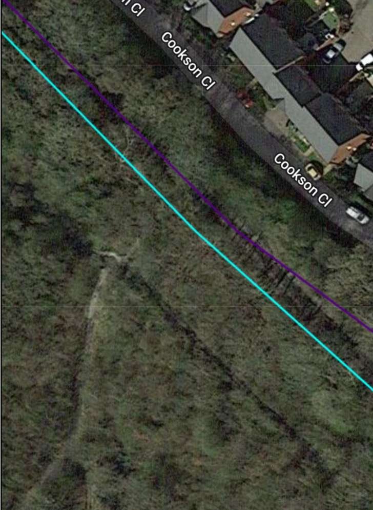
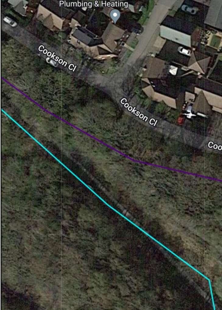
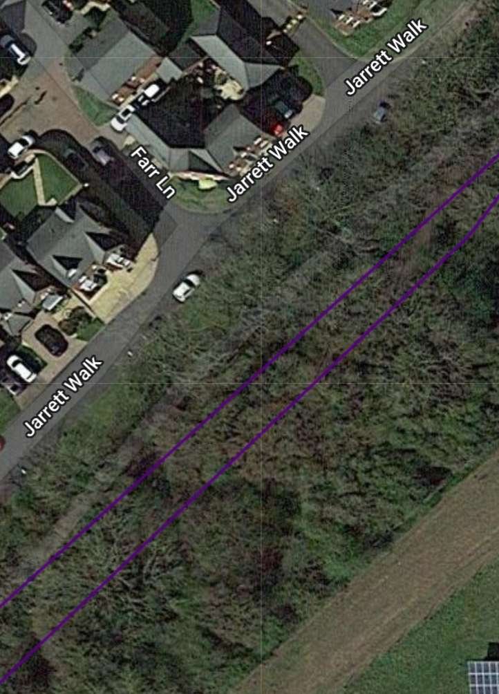
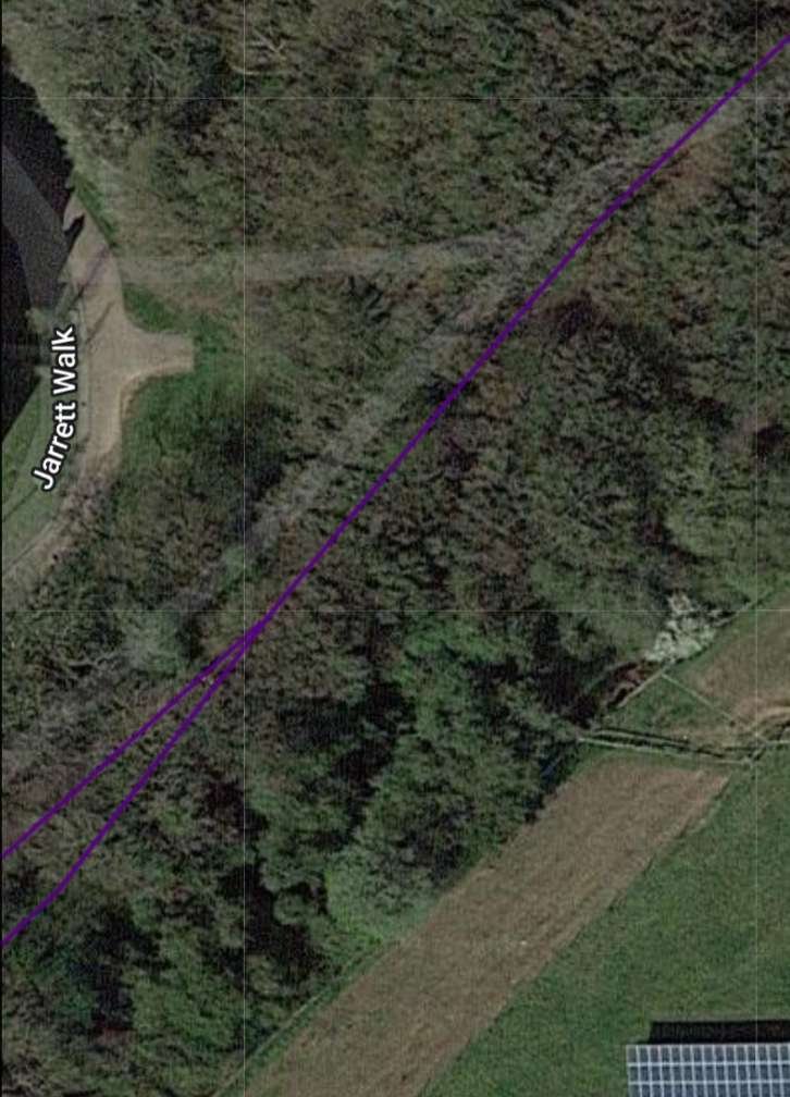
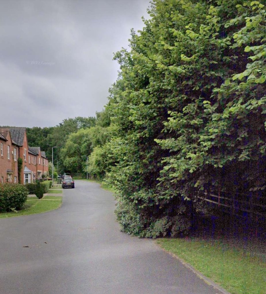

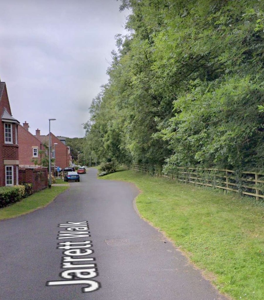
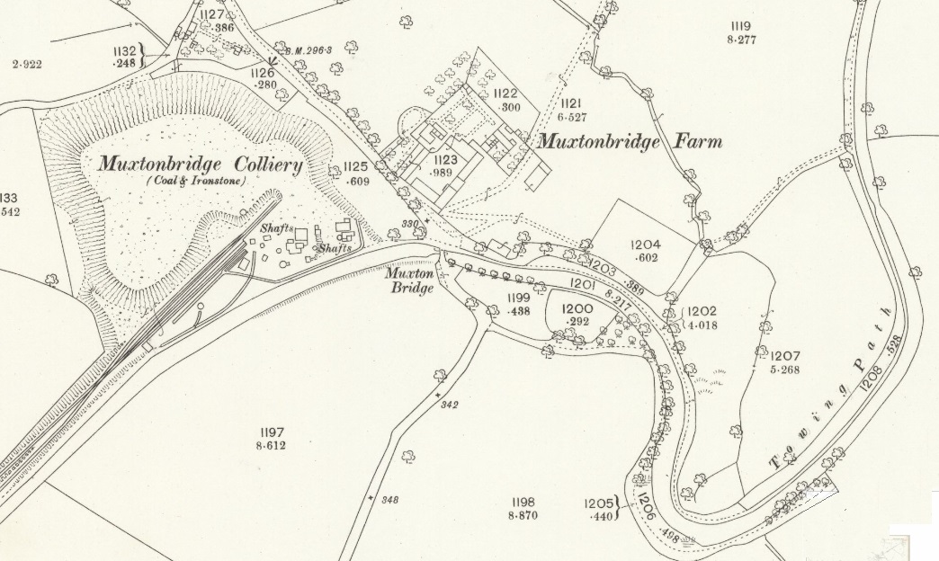
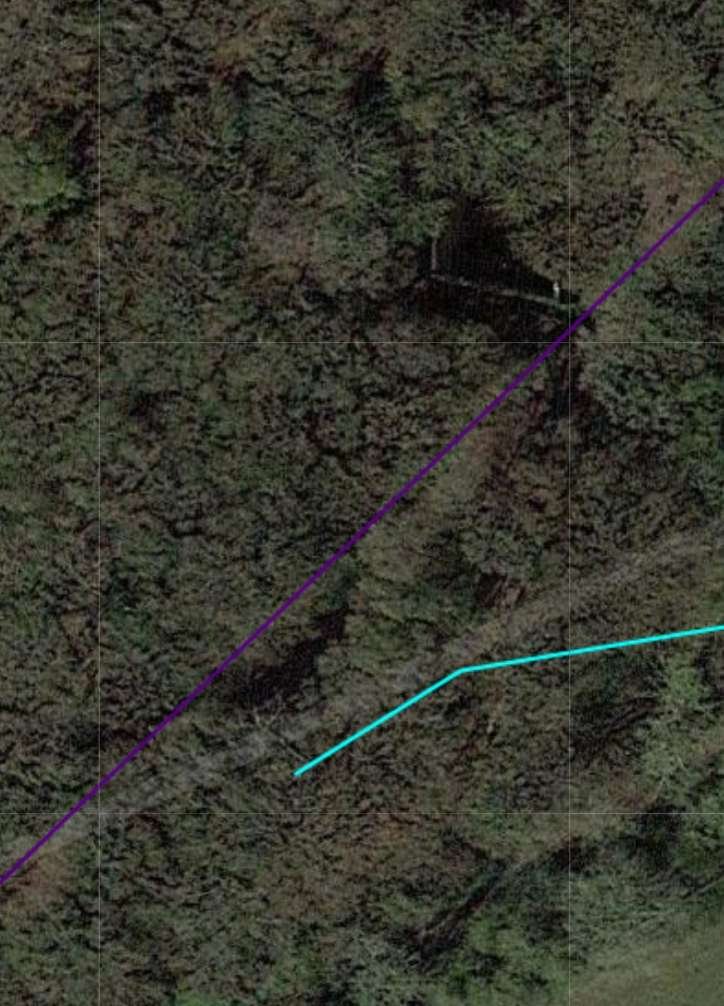
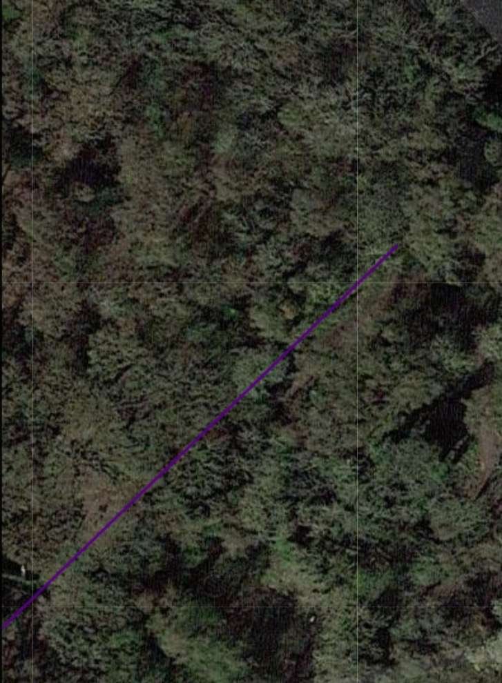
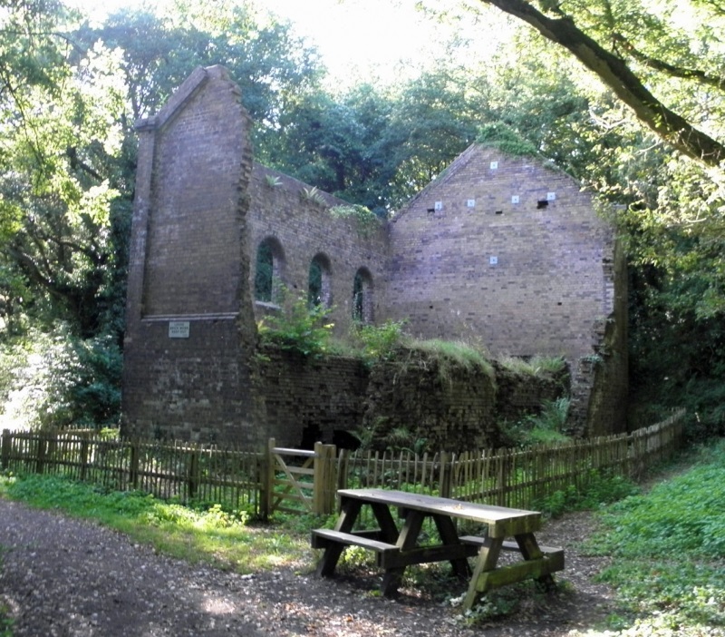

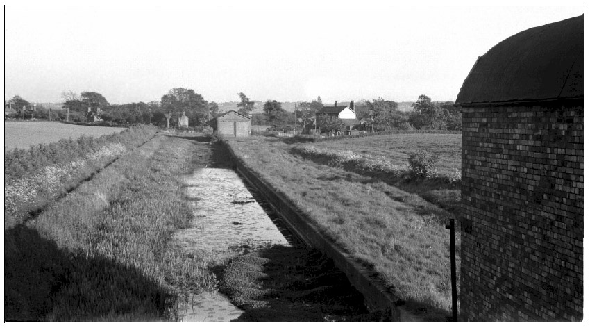