In January 2026, I was reading an early copy of The Railway Magazine and wrote an article about the Edaville Railroad which can be found here. [1]
In January 2026, I had not really cottoned-on to the significance of the Edaville Railroad as a pioneer in the field of preservation.
We all recognise the Talyllyn Railway as the first railway in the world to be preserved. But the Edaville Railroad predates the date in 1951 when volunteers began running the Talyllyn.
The Edaville Railroad opened in 1947. It was not a ‘preserved’ railway, but it still has a claim to being the first heritage railway. It was a 2ft-gauge railway, built by an enthusiast on a green field site to run historic stock.
Definitely not the same thing as a ‘preserved Railway’ but still of paramount significance in the early development of the international preservation movement.
Jones retells the story of the line, starting with its 2ft-gauge antecedents in Massachusetts and Maine:
The Billerica and Bedford Railroad opened near Boston, Massachusetts in the 19th century. It was not the success that George Mansfield, its owner, had hoped.It was unable to compete effectively with the well-established standard-gauge lines around Boston. It closed. Mansfield saw a better location for his railroad. [8]
The Sandy River Railroad(or the Sandy River & Rangeley Lakes Railroad) was the result of Mansfield’s careful consideration. His 2ft-gauge railway was much more suited to the mountainous terrain. Smaller and lighter locomotives were much more able to handle the tight curves and steep inclines needed to negotiate the mountain valleys. It was the first of five 2ft-gauge railways in Maine. [7] The others were:
The Kennebec CentralRailroad between Randolph and Togus. The railroad was built to offer transportation for American Civil War veterans living at Togus to the nearby City of Gardiner, although only reaching Radolph on the opposite side of the Kennebec River. [3]
The Wiscasset, Waterville & Farmington Railway is a restored 2-foot narrow-gauge heritage railroad in Alna, Maine. 3.5 miles (5.6 km) of the track has been rebuilt and is operated by the non-profit Wiscasset, Waterville and Farmington Railway Museum as a heritage railroad. The original line hauled freight and passengers from 1895 to 1933. It was famous for its ‘big dreams and little wheels’. The line was operated from 1895 until 1933 between Wiscasset, Albion, and Winslow, it never made it to Waterville and Farmington. It was abandoned by 1936. [4]
The Monson Railroad operated between Monson Junction on the Bangor and Aroostook Railroad and Monson, Maine. The primary purpose of this railroad was to serve several slate mines and finishing houses in Monson. It operated from 1883 to 1943. [5]
The Bridgton & Saco River Railroad (the Bridgton & Harrison Railway) was established in 1882 to connect the towns of Cumberland County with the national rail network at the Saco River. The route was extended in 1898 to reach Harrison. It was purchased by the Maine Central Railroad in 1912, but faced severe financial struggles in the 1920s. In 1927, it was reorganized as the Bridgton & Harrison Railway to keep the line alive. The Harrison extension was shut down in 1930. The remainder of the line ceased regular operations in 1941. [6] Jones says that the line stayed open until 1944 for excursion rides. [2: p93]
Jones says that one of those enthusiasts “was Ellis D. Atwood a cranberry farmer from South Carver. He thoroughly enjoyed his experiences on the Bridgton & Harrison, and when that railroad finally decided to close, he bought most of the remaining equipment and five miles of rail.” [2: p93]
The series of dykes and canals around Atwood’s plantation, in particular the dykes, provided the ideal place to lay the 2ft-gauge track. “The first rails were laid in late 1945, heading out in a clockwise direction from the screen (processing) house into the bogs. The trains were sent out with supplies and workers until they reached the end of the line, at which time they were unloaded and reversed direction, backing up all the way to the screen house to reload. … A mild winter and some intelligent planning … enabled work to continue right through the winter of 1947. … Ellis also employed several of his farmhands as railroad track gangs … keeping them working during the normally quiet winter season.” [2: p93]
By April 1947, nearly 5.5 miles of track formed a complete loop of track. An acquaintance stubbled across two locomotives from the Monson Railroad. Although these were in a poor state of repair, Atwood bought both. He now had four locomotives, Nos. 3 and 4 from the Monson Railroad and Nos. 7 and 8 from the Bridgton & Harrison Railway.
Atwood also purchased some surviving rolling stock from the Sandy River & Rangeley Lakes Railroad.
Jones goes on to explain that:
“Atwood had originally planned to use the passenger cars to carry his workers from one location to another, but fairly soon after completion of the trackwork, enthusiasts started showing up and asking for rides. Atwood’s neighbours were enchanted by the diminutive railroad and, little by little, word spread about these tiny trains. Soon, enthusiasts were arriving daily hoping to get a ride. Ellis loved to show off his trains and, in the beginning, gave people rides out of the kindness of his heart. It became evident that there was money to be made from paying passengers.
“He charged a nickel a ride and soon there was so much demand for rides that the tourist trains became more important than the railroad’s role as a working part of the plantation.
“Atwood built a station near the screen house and started selling tickets to his little railroad empire. It was an immediate success.
“He was delighted by the Christmas season. He had decorated his nearby home for many years, and people would come from all over to see the bright lights and displays. Once the decision was made to turn Edaville into an excursion railroad, he soon realised he had a wonderful location to expand on the Christmas decorations he loved, and thus the Holiday Festival of Lights was born, pre-empting, surely, today’s Santa specials on heritage railways. The lights would soon become Edaville’s most successful venture, bringing crowds of nearly 10,000 people each day in later years. Soon after Edaville had established itself as a thriving excursion railroad, in November 1950, Atwood was killed in a boiler explosion while trying to fix a malfunctioning heater in the screen house. He was 61.” [2: p94]
After telling the early tale of the line, Jones goes on to tell the story of the next few years under Norman Blounts ownership and the ensuing unstable years when operation was spasmodic. He rehearses the story of the removal of much of Atwood’s original collection back to Maine in September 1993 to become a significant part of the collection of the newly opened Maine Narrow Gauge Railroad and Museum. Jones also writes of Edaville’s life as the home of Thomas Land from 2015 onwards.
Jones concludes by drawing contrasts and comparisons between the Edaville Railroad and the Talyllyn. …
“There are many close similarities between the two operations, but also many differences both stark and subtle.
“Firstly, both lines were built for the conveyance of freight: the Talyllyn was planned to take slate from the Bryn Eglwys mines opened by John Pughe in the shadow of Cader Idris in 1847 and received Parliamentary sanction in 1865, while the Edaville Railroad was laid after the Second World War by a man who was obviously a steam enthusiast, but at the outset only wanted his trains to carry cranberries on the first leg of their long journey from the bogs in which they grew on his South Carver farm to the Christmas table and elsewhere.
“Both heritage concerns relied on traction imported from closed lines elsewhere: the original Edaville stock had been made redundant by closures in Maine while the Talyllyn revivalists were fortunate enough to be able to obtain two 2ft 3in gauge locomotives from the sister Corris Railway which had just closed.
“Again, the Edaville concern differs from the Talyllyn in that it was not in itself an original railway, as it was built on a green field site and became a heritage line purely by chance rather than deliberation: the closures of the 1940s which had ravaged other narrow gauge railroads led to enthusiasts converging on the diminishing numbers of steam sites in greater numbers to the point where Ellis D Atwood was staring a gift horse in the mouth.
“It was hardly a volunteer-led affair: some of his full-time farmhands were ordered to forget the fabled red fruits and build and operate the railway around his estate and the heritage trains were later run, successfully from the start, on a commercial basis.” [2: p97]
Robin Jones; The First Heritage Railway; in Great British Railway Firsts: How Britain Led the World in Rail Technology; Mortons Media, Horncastle Lincs., 2019, p92-97.
I saw the featured image in a photo book compiled by Alton Douglas for Beacon Radio in 1987, ‘Memories of the Wrekin and Beyond’. It shows Lilleshall Estate’s 2ft-gauge railway in actionin 1933. [1: p47]
The Lilleshall Estate in Shropshire featured a historic 2-foot gauge miniature railway that operated from 1928 until the onset of World War II. Built to entertain tourists, the line used unique petrol-powered, steam-outline locomotives manufactured by E.E. Baguley Ltd.
Opened in 1928 and closed in 1939.
In 1917 the Duke of Sutherland sold the Hall and and Gardens. Eventually these were acquired by Herbert Ford who developed the site into a tourist attraction.
A map of the Lilleshall Hall and its grounds which shows the route of the railway. [3]
“The guide book was titled ‘Lovely Lilleshall’, adding ‘see Lilleshall and know the thrill of living’. On offer to visitors were: lunches & teas in the Hall, tennis courts, putting greens, archery, bowling greens, children’s playground, formal gardens, abbey ruins and a 2ft gauge railway. Opened on Easter Saturday, 7th April 1928, the line was a balloon loop of 1 mile, giving a full ride of 1¼ miles. Stations were provided at ‘Lilleshall Hall’ (the terminus) and ‘Abbey’ on the return loop in the woods. Apparently, internal combustion motive power was chosen to protect valuable plants alongside the line from damage by a steam locomotive. The line was presumably a success as a second steam outline locomotive was ordered from Baguley, arriving in May 1929. The Hall and railway were closed at the outbreak of the Second World War on 3rd September 1939.” [2]
Baguley 1695 (1928): The first locomotive delivered to Lilleshall, it is fully preserved and operates at the Apedale Valley Light Railway in Staffordshire.
Baguley 1769 “Altonia” (1929): A larger locomotive purchased to boost capacity was later moved to Alton Towers, and is now preserved at the Old Kiln Light Railway in Surrey.
References
Alton Douglas; Memories of the Wrekin and Beyond; Beacon Broadcasting, Wolverhampton, 1987.
I have just been given a small pamphlet style paperback book compiled and published in June 1920 by W.G. Tilling.
The featured image for this article comes from the frontispiece of Tilling’s book. It is a picture of the Class L 4-6-4T superheated large tank locomotive ‘Charles C. Macrae’. [1]
Tilling’s forward to the book states:
“For many years particulars of the locomotives running on our railway lines were difficult to obtain, but the Great Western Railway Company a year or two back broke through the usual official reticence by publishing a list of all their named engines. This was doubtless done to interest the general public in that railway, and I believe has proved a successful advertisement.
“Unofficial lists have also been published of the engines of the London and North Western Railway and a few of the smaller lines. Following these examples, I am prompted to deal with the locomotives of the London Brighton and South Coast Railway. This Company’s engines have probably had a larger circle of admirers than those of any other railway of similar size. The influence on locomotive design of the genius of the late William Stroudley (locomotive superintendent from 1871 until 1889) has appealed to the technical mind; whilst many, unconnected with railways, first attracted in their boyhood to this Company’s locomotives by their bright yellow livery and the fact that nearly all bore distinctive names, continue to take a keen interest in them long after their school days; and even now, when the engines are painted in less attractive colours, and the Stroudley classes are passing to the scrapheap, I feel sure there is a sufficiently large number interested to warrant the publication of this little book, and moreover, I am sanguine enough to hope that it may be of some use to many in the Company’s service.” [1: p3]
There were six hundred and six locomotives on the company’s roster in 25 different classes at the time that Tilling was writing these were:
The locomotives of the London, Brighton & South Coast Railway in 1920. [1: p4]
There were 172 tender engines and 434 tank engines (all of the side tank variety). In addition, Tilling writes, there were four tank engines attached to the Locomotive Department for shunting in the Locomotive Works and the three principal steam sheds.
Class B1 0-4-2 Express Passenger Locomotive. [1: facing p4]
Tilling continues:
“All engines are fitted with the Westinghouse brake, whilst a few running in conjunction with ‘foreign’ lines have the automatic vacuum brake in addition. These latter engines proved extremely useful during the war in dealing with the large amount of other Companies’ rolling stock that passed over the Brighton system.
“The passenger engines are painted umber colour lined out with two yellow lines with the Company’s arms in colours on the splashers and gold lettering, whilst the goods engines are painted black with red lining and gold lettering.” [1: p5]
There were seventeen Locomotive Depots on the system. …
Locomotive Depots of the LB&SCR. [1: p5]Class B4 4-4-0 Express Passenger Locomotive. [1: facing p5]Class A1x 0-6-0T Rail Motor Engine. [1: facing p9]
Tilling describes the various classes of locomotive:
“CLASS A: are small six-coupled side tanks with 4-ft. wheels, usually known as ‘Terriers’. They were designed [in 1872] years ago for working passenger trains on the South London and East London lines. Fifty engines were built in all, originally Nos. 35-84; several have been sold to other Companies, others scrapped, whilst the remainder are now used on rail motor work, excepting Nos. 642 and 682, which are yard engines at Battersea shed and Brighton works respectively.
“During the war several were taken over by the Government for working on light military lines in England and Scotland, for which their light weight only 27 tons 10 cwt. in working order made them very suitable. Although the oldest class now running on the line they are still very useful little engines, and several have recently been rebuilt with new boilers, etc., and are now classed A1x.
“CLASS B: include Stroudley’s and R. J. Billinton’s four-coupled passenger express engines, subdivided into B1 (‘Gladstones’), B2 (‘Grasshoppers’), B3 (one engine only-213 ‘Bessemer’) and B4 (‘Scotchmen’). The B2 and B3 engines are now all rebuilt with larger boilers of the C3 type and classed B2x.
The Bl’s are front-coupled non-bogie engines, and they for many years worked the bulk of the express traffic between London and Brighton until superseded by the B4’s in 1901. The majority of the survivors are now employed on work usually done by tank engines, and several are now stationed at Tunbridge Wells shed. ‘Gladstone’ itself, after thirty-seven years, is still in evidence working slow trains between Brighton and the Metropolis. No. 172 is the only one of the class not fitted with Stroudley’s pumps and arrangement for utilising part of the exhaust steam to heat the water in the tender.
“The B2’s were the first express engines with a leading bogie to run on the LBS&CR. They were built to supersede the old single wheelers on the London-Portsmouth road with its many curves, and the first batch, Nos. 314-324, were all sent to Fratton shed, except No. 323, which worked from St. Leonards.
“No. 206 was badly damaged in the Wivelsfield accident of December, 1899, and also has the distinction of having worked the first sixty-minute Pullman train from Victoria to Brighton on 2nd October 1898.
“Several of the B2x’s have had wells fitted to their tenders to increase their water capacity, whilst Nos. 204, 206-209, 211, 212, 314, 323 and 324 now have the large tenders formerly on the C3 goods engines.
“The B4’s were nearly all built in Glasgow at the time of the Boer War, and many carried names reminiscent of that campaign, until Mr. Marsh, with a few exceptions, abandoned the naming of engines.
“The B4’s have been used for a number of trials at one time and another. No. 45 ran from 1902 till 1911 with a Drummond water-tube fire-box. No. 48 worked for some time early in 1905 fitted with templates over the boiler to test the clearance of the newly designed ‘Atlantics’. When Mr. Marsh decided to do away with the old yellow livery in 1905, he painted experimentally two of this class (Nos. 50 and 52) dark green. No. 52 also ran for some time in 1902/3 fitted with Holden’s oil fuel apparatus (as did also some of the B1, B2 and E5 classes). No. 53 ran for several years fitted with the Hotchkiss water circulator, whilst No. 59 worked with a ‘Phoenix’ superheater from 1912 to 1915.
“No. 54 formerly bore the name ‘Empress’, and was at one time used for all Royal specials. She carried the name ‘La France’ for a week in August, 1905, when working special trains in connection with the visit of the French fleet to Portsmouth.
“Several of this class have now been fitted with extended smokeboxes.” [1: p6-8]
A Class B2x 4-4-0 Express Passenger Locomotive. [1: facing p12]A Class C3 0-6-0 Main Line Goods Locomotive No. 301. [1: p46]Class D1 0-4-2T Passenger Locomotive. [1: facing p8]
Tilling next focused on Class C locomotives:
“Class C: are the tender goods engines, of which there are four varieties.
“The C1 class, when built, were amongst the largest goods engines in the country. Only two survive, No. 428 stationed at Fratton and No. 430 at Brighton. They have both recently had the Stroudley patent brake gear removed and the standard arrangement substituted, in order to cope with heavier goods trains. No. 430 in the early days of the war worked a troop special through to Doncaster.
“The C2’s were all built by the Vulcan Foundry Co. They are now being reconstructed as C2x’s, having the larger C3 boiler. Like the B4’s they have makers’ plates on the back of the tenders, but as the tenders have been interchanged at various times, the works numbers on the plates do not necessarily apply to the engines to which the tenders are now attached. Two of the C2x’s, Nos. 524 and 546, are at present (June 1920) on loan to the Great Western Railway; they are stationed at Old Oak Common depot and regularly work through onto the Brighton line.
“The C3’s are nearly all at present attached to the Horsham depot; they were an advance on the C2 class in boiler power, but the first five only had 174-inch cylinders, though the remaining five have 18 inch cylinders. They originally had 3112 gallon tenders, but latterly these large tenders have been transferred to engines of the B2x class and the C3’s now have the smaller ones formerly on the B2x engines.” [1: p8-9]
Tilling continues:
CLASS D: “The D1 class is Stroudley’s well-known front-coupled tank engine. Mr. Stroudley built no fewer than 125 of these engines, distributed over practically the whole period of his rule at Brighton. Whilst designed for the London suburban traffic they have been used on every class of work, and some of them are to be found at every shed on the system. Perhaps Fratton has seen the least of them, but Nos. 254 and 356 are there at present for working the Portsmouth-Chichester rail motor. No. 248 has side tanks with rounded ends as in the Marsh engines.
“No. 625 of this class was the first engine on this railway to be fitted with the Westinghouse brake; and 233 is noteworthy as having been for many years stationed at East Grinstead, being, in fact, the only engine ever stationed there.
“The D3 class is Mr. R. J. Billinton’s four-coupled bogie tank. Having a greater coal and water capacity than the D1’s, they are used on the longer routes. The valve gear and cylinders of this class are interchangeable with those of the C2 goods engines. Two of the D3’s (Nos. 396 and 397) have been rebuilt with the larger boiler of the I2 class.” [1: p9-10]
He continues:
Class E: “The ‘E’ CLASSES are the six-coupled side tanks, the oldest being Stroudley’s E1’s. The first of these appeared in 1874, and the last were turned out in 1891 by Mr. R. J. Billinton, who fitted his own design of boiler which added slightly to the weight. No. 689 has been entirely rebuilt, having new tanks, cab and boiler.
“No. 157 differs from all the other engines of its class. It was built for, and has worked all its life on the difficult Eastbourne-Tunbridge Wells line. It has side tanks and bunker slightly larger than the other E1’s, cylinders 18.25in × 26in, motion as Classes B1 and C1, and weighs 46 tons 18 cwt. in working order.
“Several of the E1’s were condemned for scrap in 1912, and Mr. L. B. Billinton designed an entirely new class to take their place. These are the E2’s. There are ten of this series, the second five having longer side tanks than the others. For a short time, when new, Nos. 103 and 104 worked in the centre of six coaches as a rail motor between London Bridge and Crystal Palace via Forest Hill.
“When Mr. Stroudley died in December 1889, an experimental six-coupled radial tank was in hand. This engine – No. 158 – did not commence work until just two years after his death, and while it had Stroud let’s standard 18.25in × 26in cylinders, it was essentially ‘Billinton’ in appearance. This engine weighed 52 tons 14 cwt. When Mr R. J. Billinton subsequently built sixteen others, they had his standard 18in x 26in cylinders. They are Class E3.
A Class E2 0-6-0T Goods Tank Locomotive, No. 100. [1: facing p36]A Class E5 0-6-2T Mixed Traffic Tank Locomotive, No. 587. [1: facing p37]
Tilling continues:
“The E4’s and E5’s are similar to the E3’s but with larger driving wheels for mixed traffic and passenger work respectively, the capacity of the tanks is, however, larger. Twelve of the E4 class served on active service in France. They were Nos. 470, 481, 498, 504, 506, 516, 518, 562-565 and 580, and were chiefly employed banking trains on the St. Pol-Amiens line. They have all now been returned, and having been overhauled are back in service, painted black and unlined. They still bear the small plate inside the cab with which they were supplied before going overseas, to the effect that they are the property of the LB&SCR. of England. They were the only Brighton engines that were sent overseas during hostilities.
“Four engines of Class E4 have been rebuilt with the larger 12 class boiler and are now classed E4x, whilst four of the E5’s and two of the E6’s have been fitted with the larger C3 boiler and are now class E5x and E6x respectively.
No. 591, one of the E5’s, for some years regularly worked the 8.00 p.m. Grande Vitesse train from London Bridge to Newhaven; this engine is also noteworthy in having retained its name ‘Tillington’ and its yellow livery until 1917, over four years after all other ‘yellow’ engines had disappeared. Several of the E3’s and E4’s have been fitted with circular smokeboxes supported on a saddle, but when they retain the original sized boiler they are not classed E3x or E4x.” [1: p11]
Again, Tilling continues
Class H: This class “consist of the ‘Atlantics’, eleven in number. Mr. Marsh came to Brighton from Doncaster, and the first engine he designed for this railway was based on the familiar G.N. standard express type. Five were at first built by Messrs. Kitson of Leeds (Class H1). The H2’s were built at Brighton some years later; they have super-heaters which allow larger cylinders and lower boiler pressure to be used. Ten of them are stationed at Brighton and one at Eastbourne, and in conjunction with the ‘J’ and ‘L’ tanks they work all the heaviest expresses between London, Brighton and Eastbourne. No. 39 is frequently used for Royal specials, and bears the name ‘La France’. [1: p11-12]
A Class H2 Superheated 4-4-2 Express Passenger Locomotive No. 421. [1: facing p13]
The next class of locomotives that Tilling covers are:
Class I: “The ‘I’ class consist of the ten-wheeled tanks. The I1’s suffer from having too small boilers, but the later I3’s built for express work are very successful engines.
“No. 21 differs from the others in having 6 ft. 9 in. drivers, and the same cylinders and motion as the B4’s; it was fitted with a superheater during 1919. Twenty others of the I3’s are fitted with superheaters but have 21 in. x 26 in. cylinders.
“The I1’s are used on various local services; the I2’s and I4’s (which are the same as the I2’s, but with 20 in. cylinders and superheated) on such services as the London-Tunbridge Wells trains; whilst the I3’s work chiefly between London and the Coast on fast trains.
“No. 23 worked regularly for some weeks during 1909 in conjunction with the LNWR engine No. 7, ‘Titan’, on the ‘Sunny South Special’, running from Brighton through to Rugby one day and returning the next.” [1: p12]
A Class I1 4-4-2T Passenger Tank Locomotive No. 597. [1: facing p20]A Class I3 Superheated 4-4-2T Express Tank Locomotive No. 22. [1: facing p21]
Class J: “The ‘J’ Class consist of two experimental tank engines built by Mr. D. Earle Marsh for the express service between London and the Coast. They are of the ‘Pacific’ or 4-6-2 type with 21 in. × 26 in. cylinders, driving wheels 6 ft. 7 in. diameter, and superheated. No. 325 is fitted with Stephenson’s valve gear, whilst No. 326 was the first engine on this line to be fitted with the Walschaert pattern valve gear.
A Class J Superheated 4-6-2T Express Tank Locomotive – N0.326 ‘Besborough’. [1: facing p28]
Tilling continues:
Class K: “The ‘K’ Class are the latest heavy goods engines designed by Mr. L. B. Billinton for the traffic between London and Newhaven. They are tender engines of the ‘Mogul’ or 2-6-0 type, superheated. The first of these was put into service in September, 1913. To meet the greatly increased goods service to Newhaven, due to the war, another five were built in 1916; they are fitted with top feed to the boilers and have Belpaire fireboxes, and having proved so successful in service others with an improved top feed system are now under construction at Brighton. No. 339, one of the earlier engines, was fitted with this new arrangement in April, 1920, and is illustrated in these pages.” [1: p13]
A Class K Superheated 2-6-0 Fast Goods Locomotive No. 337. [1: facing p29]
He also notes that in 1920 there were:
“Seven engines of the K class … under construction at Brighton, they will be numbered 347 to 353. The engines at present numbered 347 to 353 will in due course be re-numbered 214 to 220; and engines at present numbered 214, 217 and 219 will be re-numbered 618, 619 and 620.” [1: p46]
Another Class K Superheated 2-6-0 Fast Goods Locomotive, No. 339, which was fitted with the, then, latest arrangement of Top Feed (April 2020). [1: p45]
Class L: “The ‘L’ Class consist of two tank engines of the ‘Baltic’ or 4-6-4 type. These are the largest express tank engines in Britain, and were built by Mr. L. B. Billinton to work the fast non-stop service between London and the coast towns at an approximately uniform speed, and so save racing on the down grades. These engines have cylinders of 22 in. diameter and 28 in. stroke, and the boiler which is of ample capacity is fitted with a superheater. The driving wheels are 6 ft. 9 in. diameter, and sufficient water and coal is carried for the longest non-stop run between London and Portsmouth.” [1: p13]
In the years prior to 1920, the LB&SCR had locomotives not recorded by Tilling, these include:
LB&SCR Richmond class: This class was a series of 0-4-2 express passenger locomotives, designed by William Stroudley in 1877. They were a larger version of his “Lyons” class (D2) which were in turn developed from his successful ‘D-tank’ class of 1873. [2]
The six locomotives in this class were built at Brighton railway works and appeared in traffic between October 1878 and March 1880, intended to replace earlier classes designed by John Chester Craven on the heaviest express trains between London and Brighton. They performed well on these duties for a decade but were eventually replaced by Stroudley’s larger “Gladstone” class (B1). They were then transferred to Eastbourne and St Leonards to work on expresses from those towns. During the winter of 1900/01 members of the class were transferred to the duplicate list. Withdrawal commenced in April 1901 and was completed by November 1904. No examples were preserved. [2]
They were originally classified as “B class” together with the members of the larger “Gladstone class”. As all six locomotives had been withdrawn before D.E. Marsh introduced his letter/number classification scheme, they were never officially allocated a new class designation. They were, however, described as ‘D3 class’. [2]
Diagram of a Richmond class 0-4-2, (c) F. Burtt and Public Domain. [2]
Locomotives designed by and built during the tenure of John Chester Craven between his appointment in 1847 and his retirement in January 1870. A full list of these locomotives can be found here. [3]
The ‘Jenny Lind’: The ‘Jenny Lind’ was built in 1847 after a relatively complicated gestation by E. B. Wilson and Company. [4] But it proved to be so successful that the design was used by Wilson & Co. as their standard design and more than seventy examples were built for various railways, including twenty-four for the Midland Railway. It could be said to be the first to be mass-produced to a consistent pattern. Indeed, the manufacturers charged a hefty premium for variations, although in response to pressure, they later built a number of “large jennies”. [4]
Other manufacturers and railways also adopted the type. John Chester Craven, Kirtley’s successor at Brighton, built a class of five similar “Jenny Lind singles” from 1853 to 1854. [4] An enlarged type was also built by Beyer, Peacock and Company in 1860 for the Portuguese South Western Railway. [4]
The original Jenny Lind, (c) Public Domain. [4]
Class G: A prototype single locomotive, No. 151 Grosvenor, was designed by Stroudley and produced by Brighton railway works in December 1874. This was extensively tested before a second, scaled down locomotive No. 325 Abergavenny, was ordered in June 1876 and completed in January 1877. Both locomotives performed adequately, but Abergavenny was significantly less powerful than Grosvenor. A modified design was developed and twelve further locomotives were built between December 1880 and November 1881. The members of this class worked express trains between London and South Coast towns such as Portsmouth, Brighton and Eastbourne, and covered large mileages. The introduction of the Billinton B2 class made the singles redundant on the Portsmouth line and so several were transferred to Tunbridge Wells. … Withdrawals began in May 1907, and the last locomotive survived until May 1914. No examples have been preserved, but there is a model of No. 331 Fairlight in the museum at Sheffield Park on the Bluebell Railway. [5]
London Brighton and South Coast Railway Class G 2-2-2 Locomotive. 26 locomotives were produced in this class. ‘Grosvenor’ was the first, ‘Abergavenny’ was the second (with alterations) and subsequently 24 more were produced, (c) Public Domain. [5]
Very Early Locomotives of the LB&SCR: Wikipedia also provides a list of all the locomotives owned by the LB&SCR from its inception (1846) until 1849. [6] That list includes a significant number of locomotives built by a series of specialist locomotive builders including: Sharp, Roberts & Co.; Jones, Turner and Evans; G and J Rennie; Edward Bury & Co.; William Fairbairn; George Forrester & Co.; Sharp Brothers; R and W Hawthorn Ltd.; Jones & Potts; John George Bodmer; Timothy Hackworth; and Stothert & Slaughter. Many of these were built for companies which formed the LB&SCR in 1846 and were built as early as 1838.
The majority of the locomotives acquired were owned or ordered by one of the three constituent railways, but some had been ordered by the Joint Committee. After the Joint Committee’s dissolution, some locomotives were ordered by John Gray, the new locomotive superintendent, from Timothy Hackworth and delivered during 1847 and 1848. Others were purchased from Stothert & Slaughter between 1847 and 1849. After this date the railway’s new locomotives were designed and built by John Chester Craven, usually at Brighton railway works. [6]
A List of Locomotive of the LB&SCR in 1920: Tilling provides a detailed list, locomotive by locomotive, of locomotives in use by the LB&SCR in 1920 to complete his book. These tables can be found here.
References
W.G. Tilling; The Locomotives of the London, Brighton & South Coast Railway; Tilling, London, 1920.
The travel section of the Saturday Guardian Magazine on 23rd May 2023 included a few pages about train journeys in Europe (pages 72 to 77). This is the fifth part of a look at those pages. …
The two pages of Nicky Gardner’s article. [1: p76-77]
Nicky Gardner, lead co-author of the guidebook ‘Europe by Rail’, has championed slow travel across the continent’s most scenic routes. Her writings highlight sea-hugging railways where travellers can take in spectacular coastal panoramas, deep fjords, and dramatic cliffs right from the carriage window. The short Guardian article featuring a few such routes was written by her and is directly quoted here.
5. Europe’s Best Coastal Train Lines
A. Scotland: Coast to Coast
The first line Nicky Gardner chooses to highlight is operated by ScotRail. Travelling the Inverness to Kyle of Lochalsh line will set you back £32 for a single ticket The journey is 83 miles and takes 2hrs 40mins. There are 4 trains a day (only two on Sundays). Sit on the right side first and then switch to the left. …
Nicky Gardner writes:
“There is only one rail route in Britain offering views of both the west and east coasts from a regular local train, and that’s the line from Inverness to Kyle of Lochalsh. For the east coast, look out for Cromarty Firth away to the right as the train approaches Dingwall, about half an hour after leaving Inverness. Later, you have good views of west coast sea lochs as the train runs down to the Atlantic coast at Kyle. And in between you’ll find alliterative desolation aplenty as it pauses at Achnashellach, Achnasheen, Achanalt and Attadale.
“The last 20 minutes down to Kyle bring a magic panorama of coast, headlands and islands. The sun sparkles on Loch Carron with glorious views north to the wild Applecross peninsula. Seals shuffle for safety as we approach Duncraig and all too soon we are pulling into Kyle of Lochalsh.” [1: p76]
“The Kyle of Lochalsh line is a primarily single-track railway line in the Scottish Highlands, from Dingwall to Kyle of Lochalsh. Many of the passengers are tourists, but there are also locals visiting Inverness for shopping, and commuters. All services are provided by ScotRail and run beyond Dingwall to Inverness. In the past there were some through services to and from Glasgow, Edinburgh or Aberdeen. None of the 63-mile (101 km) line is electrified, and all trains on the line are diesel-powered, as are all other trains in the Scottish Highlands.” [2]
When the first section of the Dingwall & Skye Railway opened on 19th August 1870 the area around Strathpeffer area became much better connected. However, because of the resistance of a local landowner, the Dingwall & Skye railway was pushed further North and had to run up a steep gradient (1 in 50) to a much higher line on the valley side. The new line had a station named ‘Strathpeffer’ but it was 2 miles from the spa on a relatively steep road. It would have been so much better had the line been able to follow the valley floor. With Strathpeffer’s rise in popularity it became necessary to build a branch line into the village.
The former station at Achterneed. [Google Maps, June 2026]Looking back towards Dingwall from the road-crossing at Achterneed. [Google Streetview, September 2025]Looking ahead along the line towards Kyle of Lochalsh from the road-crossing at Achterneed. [Google Streetview, September 2025]
The railway bridge over the Black Water at the East end of Loch Garve. The line runs along the South shore of the loch before turning Northwest and running into Garve Railway Station. [Google Maps, June 2026]
Garve Railway Station. [Google Maps, June 2026]
Two Class 158 Diesel Multiple Units (158701 and 158704) operated by Abellio ScotRail pass each other at Garve station’s passing loop, with services bound for Inverness and Kyle of Lochalsh respectively, (c) Sexy Simon and licensed for reuse under a Creative Commons licence, (CC BY-SA 4.0). [3]Looking back into Garve Railway Station from the A835 level-crossing. [Google Streetview, September 2025]
Looking ahead along the line towards Kyle of Lochalsh from the level-crossing on the A835 at Garve. [Google Streetview, September 2025]
The line runs alongside the A835 and then the A832. Alongside the A832, it crosses this forestry access road. A short distance to the West of this crossing the A832 turns away to the Northwest. [Google Streetview, September 2025]
The line then turns to the Southwest to meet the North shore of Loch Luichart and runs West along the North shore before crossing the outfall from Mossford Hydroelectric Power Station. The line can be seen in the bottom-right of this satellite image. [Google Maps, June 2026]
Loch Luichart Railway Station seen from the approach road looking Southwest towards the station. The station sits above the North shore of the Loch at its western end. [Google Streetview, December 2021]
The original station at Lochluichart (called Lochluichart High) was opened by the Dingwall and Skye Railway in August 1871. It sat at a lower level than the present station.
Soon thereafter the line crosses the River Bran. In the 1950s the Conon Valley hydro-electric scheme raised the water level of Loch Luichart which required the railway line to be diverted onto higher ground and a new station to be erected. [Google Maps, June 2026]
The new line was known as the Lochluichart Diversion. It required a replacement bridge over the river. This image shows construction work on the bridge in the 1950s, (c) Am Bailie. [4]
The line ran on the South shore of Loch a’ Chuilinn before turning Northwest to cross the channel of the River Bran at its western end.A satellite image is below. [Google Maps, June 2026] The adjacent image is a drone’s eye view of the same bridge, (c) Brian McInally (August 2021). [Google Maps, June 2026]
Now on the North bank of the River Bran, the line runs West passing Loch Achanalt and through then request stop of the same name.
Achanalt Request stop and the A832. The River Bran runs just below the bottom of this image and just intrudes into it at the bottom-left. From this point on for a reasonable distance the line runs on the South side of the A832, with the River Bran to the South of the line. [Google Maps, June 2026]The next railway station is at Achnasheen just before the next bridge over the River Bran. [Google Maps, June 2026]
Achnasheen Railway Bridge spans the River Bran at the Southwest end of Achnasheen Railway Station. It is a single lattice-girder span of unusually light construction, with masonry abutments. [5]
Then, parallel to the A890, the line runs down the East side of Loch Gowan and continues to follow the River Bran upstream, crossing the River once again on a much smaller structure.
After the line bridges a tributary of the River Bran, this next bridge over the River Bran itself encounters a much smaller river! [Google Maps, June 2026]
The A890 runs to the North of Loch Scaven, the railway on the South side of the Loch. Both continue West-southwest across moorland and woodland.
The former Glencarron Railway Station is surrounded by woodland. The station was known as Glencarron Platform. [6]
Glencarron Platform was opened in 1873 on the Highland Railway’s line from Dingwall to Kyle of Lochalsh, this remote station closed in 1964. It had originally been for the sole use of the landowner but was later opened to all travellers. [7]
Southwest of Glencarron Platform the railway followed the A890 down the valley of the River Carron. The Road was Northwest of the line, the river was to the Southeast of the line.
Further Southwest, a forest access road crossed the line at a level-crossing. [Google Maps, June 2026]The level-crossing seen from the A890. [Google Streetview, September 2025]River, road and railway continue West from the crossing. [Google Maps, June 2026]Further West again, the A890 passes under the railway. [Google Maps, June 2026]This view looks South through the underbridge which was designed only for a single line of traffic. [Google Streetview, September 2025]This view looks North through the same bridge. [Google Streetview, September 2025]
The valley of the River Carron is heavily wooded and the line disappears at times under the canopy. Even Achnashellach Railway Station is difficult to make out from above!
The A890 and the railway run to the Northwest of Loch Dugaill at the Southwest end of the loch the railway crosses the A890 again.
The road crossing to the Southwest of Loch Dugaill. [Google Maps, June 2026]Looking Northeast along the Carron valley towards Dingwall. [Google Streetview, September 2025]Looking Southwest along the Carron valley towards Kyle of Lochalsh. [Google Streetview, September 2025]
The road and the railway run in close proximity for quite a distance.
Both road and rail are close once again at Attadale Railway Station which served/served the Attadale Estate and Attadale Gardens. [Google Maps, June 2026]
Attadale Railway Station. [Google Streetview, September 2025]
The road and railway remain close together for a distance to the South of Attadale Station, passing through Stromeferry Tunnel.
The Strathcarron Tunnel was designed to provide protection for both the railway and the A890. Current arrangements mean that the road is close and traffic diverted to run through the rail tunnel under strictly controlled traffic arrangements. [Google Streetview, September 2025]
The tunnel is a concrete structure which covers both the railway and A890, it protects the railway and road from the cliff above. The tunnel was built in the 1970s. When the Stromeferry Bypass road opened, it met the older road from Strathcarron and in doing so resulted in the closure of the Strome Ferry crossing from Stromeferry to North Strome Pier. [10]
The cutting back of the cliff face for the road resulted in instability and the surface was netted to prevent rockfalls. [11]
Work became necessary on the cliff face, the space for doing this needed the road traffic to be diverted onto the line of the railway. Matting was placed on the railway to allow this and an arrangement that interlocked the railway signalling with the road traffic lights. [11][12]
Looking Northeast through Strathcarron Tunnel during traffic restriction in place in 2018. In this photograph we see that vehicles are running over the line of the railway and controlled by interlocked traffic lights and railway signals. [12]
Since 2012, the Highland Council have been consulting with local people and drawing up a number of plans to alleviate the rockfall problem in the future. “Widening the existing route is now seen as a complete non-starter, although netting on the cliff faces, and regular monitoring of their condition, have kept the road open. The two main proposals remaining are … to redirect the road around the back of the hills from Attadale to Glen Udalain, or to build a bridge at Strome. This second option would also see the pretty lochside village of Lochcarron bypassed, with a new road around the back on the hillside, although doubtless this could be put back as a long term aspiration, with the bridge still built. In both of these options the present road below the cliff would then be converted to a rock trap to protect the railway, with the two ends remaining open for local access.” [13]
Southwest of the Strathcarron Tunnel road and rail run close together along the shore of the loch. [Google Streetview, September 2025]
The close alignment continues for some distance further to the Southwest. [Google Streetview, September 2025]
With the A890 now a little further inland the railway approaches Stromeferry. This view looks back along the line to the Northeast. [Google Streetview, May 2010]Looking ahead towards Stromeferry Railway Station at the same location. [Google Streetview, May 2010]Stromeferry Railway Station. [Google Maps, June 2026]Stromeferry Railway Station seen from the West. [Google Streetview, April 2009]A little further down the coast an approach road to the shore passes under the line by means of a low arch bridge. [Google Streetview, September 2025]The line bridges the mouth of Abhainn Srath Ascaig. [Google Maps, June 2026]It also crosses the mouth of a small lagoon. [Google Maps. May 2026]And then it enters Duncraig Railway Station and across the mouth of another lagoon. [Google Maps, June 2026]Duncraig Railway Station seen from the access road bridge. [Google Streetview, June 2025]The arch bridge over the mouth of the lagoon to the Southwest of Duncraig Station. [Google Streetview, June 2025]Another bridge (smaller this time) over the mouth of another lagoon formed by an embankment carrying the line. [Google Maps, June 2026]The next significant location along the line is Plockton Railway Station. [Google Maps, June 2026]Looking back East along the line from the road bridge over the railway station. [Google Streetview, September 2025]Plockton Railway Station as seen from the road bridge over the Northeast end of the station site. [Google Streetview, September 2025]The Station building seen from the Northeast on Station Road. [Google Streetview, November 2021]The line then crosses another stream as it flows into the loch. [Google Maps, June 2026]The embankment at this location is relatively significant in height, the steam passes under the line via a stone-arched culvert. [Google Streetview, September 2025]At Duirnish Railway Station the line crosses a minor road serving a few properties on the loch shore. [Google Maps, June 2026]Looking Northeast from the road-crossing. [Google Streetview, September 2025]Duirnish Railway Station seen from the Northeast. [Google Streetview, September 2025]Shortly after passing through Duirnish Railway Station the line is bridged by another minor road. [Google Maps, June 2026]Another embankment takes the line across an inlet from the loch. [Google Maps, June 2026]A more substantial structure, this time a steel girder bridge spans the channel through this embankment. [Google Streetview, May 2026]
Looking North from Main Street Bridge. [Google Streetview, September 2025]Looking South from Main Street Bridge. [Google Streetview, September 2025]Two images looking North from The bridge carrying Station Road across the two arms of the railway entering Kyle Station. [Google Streetview, September 2025]
Looking South at the lines to the West of Kyle of Lochalsh Railway Station’s island platform. [Google Streetview, September 2025]A view of the West side of the station in 1939. The ferry to Kyleakin is off scene to the right. A train is leaving for Dingwall and Inverness, with an ex-Highland 4-6-0, (c) Walter Dendy and licensed of reuse under a Creative Commons licence (CC BY-SA 2.0). [14]Looking South at the lines to the East of Kyle of Lochalsh Railway Station’s island platform. [Google Streetview, September 2025]
Sheep ready to be loaded onto a train in the years between WWI and WWII. This is one of a number of images of the Kyle line held by the Museum in Kyle of Lochalsh station building. [15]
B. Ireland: Dublin to Wicklow
Irish Rail operates the Dublin Connolly to Arklow line. The 50 mile journey takes 1hr 45mins and costs only €8.85. There are 6 trains each day with 3 on Saturday and Sunday. Make sure to sit on the left.
Nicky Gardner writes:
“Londoners may be surprised to read that Dublin had commuter trains earlier than the UK capital. Ireland’s first railway ran from Westland Row to Kingstown (now Dún Laoghaire), a stretch of track that is now the prelude to a fine route that extends right down to Wexford and Rosslare in the south-east corner of Ireland. The spectacular coastal section just south of Dún Laoghaire is a remarkable piece of engineering as the railway cuts under Bray Head. It was designed by none other than Isambard Kingdom Brunel, and in many ways resembles his celebrated coastal railway at Dawlish in Devon.
“South of Bray Head, the railway hugs the coast, with fine views of the Wicklow Hills well off to the west and the Murrough Wetlands closer to hand. Coastal purists may opt to stop at Wicklow, but I recommend staying on board to enjoy a short foray through the hills and down the Vale of Avoca, with its lush woodland. Alight in Arklow where the railway regains the coast again.” [1: p76]
The line to Dún Laoghaire (and beyond) is part of the Dublin DART network. It is a fast, frequent, and electrified commuter rail system. Originally it ran only along the coast of the Irish Sea, connecting Malahide and Howth in north County Dublin through the city centre down to Greystones in County Wicklow. The DART servesd32 stations and consisted of 53 route kilometres of electrified railway (46 km (29 mi) double track, 7 km (4.3 mi) single), and carried to up 23 million passengers per year. [16] That original network ahs been expanded.
The adjacent image shows the expanded DART network with the original line shown in green. The route that Nicky Gardner highlights is the line shown Magenta and Green to the South of the centre of Dublin with its terminus at Greystones in Co. Wicklow. [16][17]
Leaving the centre of Dublin, the Southbound DART follows the coast closely all the way to Greystones. Each of the stations on the route South from Connolly Street Railway Station is shown on the extract from Dublin’s schematic transport map above. [17]
Connelly Street Railway Station – the DART platforms serving the line to the South are those at the top-right of the image, with the DART leaving the image on the lower left. The DART runs on a viaduct above the city streets. [Google Maps, June 2026]
Leaving Connolly Street Station heading South, trains on the DART cross the River Liffey at high level The Bridge is known as the Cumann na mBan Bridge, this utilitarian steel-truss viaduct connects Connolly Station on the northside to Pearse Station on the southside. Designed by John Chaloner Smith (engineer to the Dublin, Wicklow and Wexford Railway), the bridge was built between 1889 and 1891. It consists of wrought iron lattice girders on a double row of piers with five spans. The viaduct is approximately six metres above street level and supports two railway tracks. [18]
The bridge carrying the DART over the River Liffey (c) YvonneM and licensed for reuse under a Creative Commons Licence (CC BY-SA 3.0). [20]
A closer photograph of the bridge taken in 2008, (c) KGGucwa (Public Domain) [19] and (below) a satellite image showing the bridge. [Google Maps, June 2026]
After crossing the River Liffey, the DART runs through Tara Station (top-left) and Pearce Station towards the bottom of the image at the centre. [Google Maps, June 2026]
The line continues heading Southeast through Grand Canal Dock Station and Lansdowne Road Station. Just to the South East of Lansdowne Road Station the DART crosses the River Dodder (just off the image to the bottom-right). [Google Maps, June 2026]
The next two stations are Sandymount (top-left) and Sydney Parade (bottom-right). [Google Maps, June 2026]
Nicky Gardner’s focus is on the length of the line to the South of Dún Laoghaire. Immediately to the Southeast of the Station the line passes in tunnel under the central sea front area of the town.
This OpenStreetMap extract shows the tunnel more clearly than some mapping. [21]
Leaving the tunnel to the South East of Dún Laoghaire, the line first head South and passes through Sandycove & Glasthule Station. [Google Maps, June 2026]
Sandy Cove and Glasthule Station facing South, (c) Autarch and licensed for reuse under a Creative Commons licence (CC BY-SA 3.0). [23]Turning Southeast the line continues through Glenageary Station. [Google Maps, June 2026]
Glenageary Railway Station looking Southeast, (c) Doug Lee and licensed for reuse under a Creative Commons licence (CC BY-SA 2.0). [24]
The line continues Southeast through Dalkey Railway Station. [Google Maps, June 2026]
Dalkey Railway Station seen from the Southwest, (c) Andrewrabbott and placed in the Public Domain. [25]
South of Dalkey the line turns through South to South West and follows the coast towards Killiney, shown below. [Google Maps, June 2026]
Killiney Station facing South, (c) William Murhy and licensed under a Creative Commons licence. (CC BY-SA 2.0). [26]
Further to the South the line passes through Shankill Railway Station heading South. [Google Maps, June 2026]
The line continues South from Shankill Railway Station through Woodbrook Railway Station and then Bray Daly Railway Station.
Woodbrook Station is at the top of the first of these images, Bray Daly in the top half of the second. [Google Maps, June 2026]
Woodbrook Railway Station looking South with a Northbound service sitting at the platform. [27]
Bray Daly Railway Station looking South with an IE 29000 Class DMU heading South across the level-crossing at the North end of the Railway Station. [28]
South of Bray Daly Railway Station trains run through storage sidings which hold trains during off-peak hours to provide a peak hour service North through Dublin. As the line heads South through these sidings the line become a single track and heads East at first to run alongside the sea and then curving around Bray Head. The single-track line clings to steep cliffs, offering dramatic views of the Irish Sea as it weaves through historic tunnels. A series of photographs of this next length of the line can be found here. [29]
“The route around the headland was surveyed and engineered by … Isambard Kingdom Brunel, who at the time was engaged with the construction of the Dublin & Wicklow Railway’s line from Bray to the county town of Wicklow further south. The section of line around the headland from Bray to Greystones was first opened in 1855. The line featured several engineering structures, including tunnels and several wooden trestle built viaducts. High maintenance costs and constant damage from the sea resulted in several deviations from the original 1855 route, the first of which involved the construction of new tunnel (No.1) in 1876, however a section of the 1855 alignment was retained as ‘Worthington Siding’ until 1882. The second occurred in 1879 between No.2 and 3 Tunnels, and the final deviation was implemented as late as 1917, which involved the construction of the longest tunnel (No.4) at 1,042 yards long at the southern end of the headland.” [29]
“All of the deviations eliminated the Brunel’s viaducts and cliff sections, the line now taking on the name Brunel’s Folly due to the route’s reconstructions. Today there are four tunnels in total, including some smaller nameless ones. A well maintained pathway between Bray and Greystones overlooks the majority of the railway line.” [29]
Bray Head: the railway ran close to the sea around the headland. [Google Maps, June 2026][30]
The railway around Bray Head, (c) Stuart Fisher (2008) and licensed for reuse under a Creative Commons licence (CC BY_SA 2.0). [31]
The railway is somewhat less dramatically sited as it heads further South, through Greystones and on to Wicklow. [Google Maps, June 2026]
Perhaps it is worth noting that this journey only costs €8.85 single or €17.70 return!
C. Germany: Over the Sea to Sylt
Nicky Gardner suggests that it is best to sit on the left of the train as it leaves Husum to travel to Keitum. A 44 mile journey will cost €21.60 single and take an hour to complete. Trains on the Marschbahn line run hourly and are operated by Deutsche Bahn (DB). [32]
She writes:
“One cannot fail to be impressed by the determination of the Weimar Republic’s engineers and planners who needed to build a railway to Sylt. This sandy outpost of German territory is the largest of the North Frisian Islands. The traditional route to Sylt relied on a ferry from a mainland port on territory which was ceded to Denmark after the first world war. So a causeway was constructed across the Wadden Sea to reach Sylt. It opened in 1927, and a century later the Hindenburg causeway is still car-free – and since mid-April this year it is for the very first time possible to ride a posh ICE train over the sea to Sylt.
“Leaving Husum, a coastal town shaped by the herring trade, we sweep over the town’s harbour on a high bridge. There’s a cluster of fishing boats at the quayside below. Then we glide north over marshlands and meadows, all protected by high dykes to prevent the area from being inundated.
“From the train, you get a real feel for these landscapes with their distant horizons. But the sea seems far away, held at bay by dykes. That changes after Klanxbüll, where the railway turns west and crosses salty mudflats to reach the open sea. Check tide tables and make this journey at high tide – ideally on a stormy day. In such conditions, this is an unforgettable experience. Alight at Keitum, to my mind the nicest village on Sylt. From the station, it is an easy stroll into the village with several cosy cafes and a feast of fine Frisian thatch and gables.” [1: p76-77]
The line to Sylt runs North out of Hamburg. As the train glides gently through the flat expanse of Schleswig-Holstein, picturesque views of green meadows and the Kiel Canal open up. Shortly before arrival, the route offers an unforgettable panorama: the Wadden Sea stretches out before you with its characteristic tidal creeks. [32]
Husum (Nordsee) Railway Station. [Google Maps, June 2026]Husum Railway Station Building is a substantial structure, (c) Mef.ellingen and licensed for reuse under a Creative Commons licence (CC BY-SA 4.0). [34]Hattstedt Railway Station. [Google maps, June 2026]Hattstedt Station seen from the level-crossing at the West end of the station site. [Google Streetview, August 2022]
The next station on the line is in Struckum – although, as can be seen below it appears no longer to be in use as a station. [Google Maps, June 2026]
Looking South through the site of the station from Brückenstraße which bridges the line just off the top of the satellite image of the site. [Google Streetview, May 2022]Looking North from the bridge on Brückenstraße. [Google Streetview, May 2022]
The next station is only a short distance further North in Bredstedt. [Google Maps, June 2026]
Bredstedt Railway Station building seen from the West [Google Streetview, September 2023]
Theis view looks back towards Bredstedt from the bridge carrying Margarethenberg over the line. [Google Streetview, September 2023]Turning through 180°, this view shows the line heading North towards Langenhorn. [Google Streetview, September 2023]Looking back South towards Bredstedt from the level-crossing at Beekensweg. [Google Streetview, May 2022]The line ahead to the North from the same level-crossing. [Google Streetview, May 2022]
The next station is at Langenhorn. [Google Maps, June 2026]
Langenhorn Railway Station seen from the level-crossing at its South end. [Google Streetview, September 2023]
The line continues on a straight alignment just to the West of North. The next image shows the view North along the line at the Dorpstraat level-crossing in Bargum.
Looking North at the Dorpstraat Level-Crossing in Bargum. [Google Streetview, September 2023]
The view North from the railway-crossing on Dorfstraße at Stedesand. [Google Streetview, June 2022]
Looking Southeast from the level-crossing on Dorfstraße in Risum-Lindholm. [Google Streetview, September 2023]
Looking Northwest at the same level-crossing. [Google Streetview, September 2023]
Further Northwest, this is the view along Legerade with the railway alongside. [Google Streetview, September 2023]
The next railway station at Niebüll is in two parts. There is the normal passenger facility towards the top of the adjacent satellite image. To the South of this station is the loading point for the SyltShuttle at Niebüll – Niebüll Autoverladung. It is the point that vehicles travelling to Sylt are loaded onto the shuttle trains – ‘Blue’ or ‘Red’ [Google Maps, June 2026]
Niebull Railway Station building seen from the West. [Google Streetview, May 2022]Looing East across the level-crossing on Gather Landstraße at the North end of the Railway Station site. [Google Streetview, September 2023]Looking Southinto the Station site from the crossing at Gather Landstraße [Google Streetview, September 2023]
North of the Railway Station in Niebull a junction divides the single line heading North from the line serving Sylt which head Northwest. [Google Maps, June 2026]
The line to Sult heads to the left (Northwest) after crossing Gather Landstraße [Google Streetview, September 2023]
Looking Northwest from the level-crossing at Süderende. [Google Streetview, September 2023]The w ide-open, expansive and flat countryside is once again emphasised by this view North from the level-crossing at Süderdeich. [Google Streetview, September 2023]
Klanxbüll, Schleswig-Holstein is the final station on the mainland before the embankment/causeway that takes the railway across the Wadden Sea. [Google Maps, June 2026]
Klanxbüll, Schleswig-Holstein as seen from the level-crossing at the Southeast end of the station site. [Google Streetview, September 2023]
Wide open flat lands on the approach to the Wadden Sea. [Google Streetview, September 2023]
A drone’s eye view of the shuttle service operated by DB (the Red Train) which crosses the embankment leading to Sylt. [35]
The Blue Train covers the same route – it is operated by RDC Deutschland (Railroad Development Corporation). [36]
A drone’s eye view of the shuttle service operated by DB which crosses the embankment leading to Sylt. [35]The first railway station on Sylt is Morsum. [Google Maps, June 2026]Morsum Railway Station seen from the level-crossing at the West end of the station site. [Google Streetview, March 2022]Keitum Railway Station. [Google Maps, June 2026]Train sitting at Keitum Railway Station enroute to Westerland Railway Station. [Google Streetview, August 2025]
Westerland Railway Station on Sylt. Car trains unload and load here. [Google Maps, June 2026][Google Streetview, March 2022]
Westerland is the end of the line and the last kilometre or two from Keitum to Westerland are not particularly scenic. It seems as though Nicky Gardner is happy to get off the train at Keitum. The flat landscape and the significant crossing of the Wadden Sea by train are positive attributes of a line, that to me at least, seems to be less than Nicky Garner promises it will be.
The next article in this series will be the last. It focuses on a line in Northern Spain and a line in Southern Italy.
References
Nicky Gardner; Over Land & Sea: Magical Views and Sea-Hugging Routes on Europe’s Best Coastal Train Lines; in Saturday(the Guardian Magazine), 23rd May 2026, p76-77.
The featured image for this article is a photograph of East African Railways (EAR) Class 30 steam locomotive No. 3019 ‘Nyamwezi’ at Tabora depot on the Central Line, Tanzania in 1968. Class 30 locomotives were oil-burning 2-8-4 steam locomotives. Built in the 1950s by the North British Locomotive Company in Glasgow, the 26 engines in the Class were named after indigenous tribes across Kenya, Uganda, and Tanganyika (now Tanzania). They were known as the ‘Tribal Class’ of locomotives, (c) Basil Roberts and licensed for reuse under a Creative Commons licence (CC BY-SA 4.0). [44]
The line from Dar-es-Salaam to Kigoma. was known during the German Protectorate as the Mittelland Bahn. “In the March of 1895 the Colonial Department of the German Foreign Office, the Deutsch Ost Afrikanische Gesellschaft and the Deutsche Bank formed a committee to consider plans for a central railway from the coast to Lakes Tanganyika and Victoria. In the June of 1896 the committee submitted a report to the Chancellor, which recommended the immediate construction of a 75-cm-gauge railway from Dar-es-Salaam and Bagamoyo to Morogoro, as the first section of a line to the Lakes. The committee suggested that the construction be entrusted to a reliable firm and that the Reich should offer such aid and subsidies as would induce German high finance to support the development of German East Africa. The report stated that the country which the railway would open up offered ‘all the foundations for marvellous … economic development’.” [1: p84]
So, initial plans were for a 750mm-gauge railway heading inland from Dar-es-Salaam. “In 1894 and 1896 an army engineer, von Schlobach, had found a good crossing of the Ruvu at Mafisi and studied alternative routes from there to Morogoro and Kisaki-north and south of the Uluguru Mountains and the possibilities of navigation on the lower Ruvu. Von Schlobach’s report referred to the Mackinnon Road which had been started in 1876 by Sir William Mackinnon and Sir Thomas Fowell Buxton and ran seventy miles west from Dar-es-Salaam. At the same time as von Schlobach’s survey, a reconnaissance was undertaken of the second section of the railway from Morogoro to Tabora.” [1: p84]
“By the September of 1896, the formation of a company to undertake the building of the railway was almost completed when events took a sudden and unfavourable turn. Herr Kayser, the director of the Colonial Department of the Foreign Office, who had been a strong supporter of the building of the Central Line, suddenly retired. His successor thought differently and urged that the Usambara Bahn be built first. The troubles, financial and otherwise, which beset that railway caused the Central Line project to be pigeon-holed for three years. In the October of 1899, the Kolonial Rath (Colonial Council) resolved that the Central Line be built and urged that an adequate sum for its survey be included in the Budget for 1900. In November 1901, this resolution was confirmed. The Kolonial Rath advocated ‘a railway policy fully conscious of its aim to counter the competition of neighbouring colonies’, and the enactment by the Reichstag of the necessary legislation to enable an early start on the building of the railway.” [1: p84-85]
Hill continues:
“In 1903 the Deutsche Bank formed a syndicate which financed another survey of the alignment between Dar es Salaam and Morogoro. In 1904 the Kolonialwirtschaftliche Komite a group representative of agricultural, commercial and industrial interests in the German colonies – submitted to the Reichstag a memorandum on the importance of building the Central line as a fillip to the increased production of cotton. The argument was won and the Reichstag passed the legislation enabling the building of the railway. On 29th June 1904, the Ost Afrikanische Eisenbahn Gesellschaft was founded in Berlin with a capital of 21 million marks. On the following day the Imperial Government granted the Company the rights of a corporation and a concession to build and run a metre-gauge railway from Dar-es-Salaam to Morogoro. The Reich guaranteed the payment of 3 per cent. interest on the Company’s capital. The concession also entitled the Company to select from a zone, 100 kilometres wide on either side of the railway, 20 square kilometres of land for each kilometre of the railway, and to a free grant of the land selected. The Company also received sole prospecting and mining rights over an area of 1,150 square kilometres, in not more than three blocks, within the 200-kilometre zone. A subsidiary company, the Ost Afrikanische Land Gesellschaft, was formed to administer the Railway Company’s land. Until 1912, the Land Gesellschaft was also concerned with a company which sought to attract tourists by building hotels at Dar-es-Salaam, Tabora and Kigoma; and from 1907 onwards, the railway’s workshops in Dar es Salaam supplied the town with electric light and power.
The Railway Company gave the contract for the construction of the first section of the line to Phillip Holzmann & Co., of Frankfurt-am-Main, a firm of international repute which had recently built the first section of the Baghdad Railway in Asia Minor. Many of the staff of Holzmann & Co. and several of the sub-contractors who had worked in Asia Minor were transferred to German East Africa. Construction started on 9th February 1905, and serious difficulties were soon encountered during the rainy season. The ranges of hills, inland from the coast, composed of clays and marly sandstones, proved to be treacherous, and the crossing of the plain on either side of the Ruvu, which flooded every rainy season, required a greater number of girder bridges on deep foundations than had been expected. There was also a shortage of labour, caused by the outbreak of the Maji-Maji rebellion. Arrangements were made to import indentured Chinese labour, but the difficulty was more sensibly overcome by recruiting large numbers of African labourers, mainly Wanyamwezi. By the standards of the day they were well paid and well fed, their rations including a generous measure of Bombay rice. The Wanyamwezi, cheerful and sturdy, were the mainstay of the labour force and their output of work was a major factor in the progress of the line. At first the rate of construction was by no means spectacular, for the 80 kilometres to Ruvu were built at a mean annual progress of 32 kilometres – at least a great improvement on the Tanga line. Thereafter the advance was far more rapid. Morogoro station was opened to traffic on 16th December 1907, nearly seven months sooner than the date stipulated by the contract. The 200 kilometres of the railway from Dar-es-Salaam to Morogoro were built at the rate of 67 kilometres a year.” [1: p85-86]
There was, in 1905 and 1906, a large rebelliion against German rule . The Maji-Maji rebellion broke out in the Matumbi Hills, near Kilwa in July 1905 and spread throughout the southern part of German East Africa. A hut-tax had been imposed in 1897 with the primary aim of forcing natives to work for planters so as to raise the money to pay the tax. The Reichstag seems to have accepted that the primary cause of the revolt was a reckless increase in the hut-tax and the enforced labour of those who failed to pay it. This was exacerbated by the poor treatment of workers on the plantations and often the ruthless cruelty of the planters. Hill highlights a number of features of the rebellion:
“First was the alliance between several tribes who had not previously been known to co-operate on any basis. Whereas the Germans had always recognised the risk of revolt by a single tribe and were prepared for it, they regarded a concerted conspiracy by several tribes as too improbable to be seriously considered.
“Secondly, the tribes which took part in the rebellion had previously been regarded as peaceable and as most unlikely to cause trouble. It was fortunate that the more war-like tribes – mindful maybe of the experience of the Chagga, the Wagogo and the Wahehe kept aloof from the rebellion.
“Thirdly, the preparations for the rebellion, started more than a year before the out-break at Kilwa, were conducted with such secrecy that no German administrator, soldier, missionary or planter heard a whisper of what was brewing and the Government was taken completely by surprise. The first conspirators were the chiefs and medicine men of two of the smaller tribes, who drew their relations, blood-brothers and fellow clansmen into the conspiracy, and the meetings at which their plans were discussed were held under oath of secrecy.
“The fourth, and the most remarkable feature, gave the revolt the name of the Maji-Maji rebellion. [‘Maji’ is the Swahili word for water] Throughout the disaffected area the natives were convinced that anyone armed with a certain medicine became invulnerable to bullets because the medicine turned them to water. This belief created the dangerous delusion that the Germans could easily be defeated, as the fire power of their weapons would be of no avail. It is not clear whether the story was invented by the original conspirators to spur the tribes into rebellion or whether they themselves were misled by the medicine’s fame.
In any case, the natives were convinced that in the Rufin river there lived a great medicine man in the form of a water monster, and that he dispensed medicine which gave protection against famine, disease and every sort of evil. The original medicine was a mixture of ground maize, sorghum seed and water. Some drank it, some sprinkled it on their bodies, others carried it about in a small tube of bamboo. Before the outbreak at Kilwa the fame of the medicine was widespread and thousands of natives walked far to obtain it from medicine men. The Germans were well aware of this, but it was done so openly that they never suspected that the natives regarded the medicine as more than a protection against the calamities of African life. They never guessed that the natives were also convinced that rifles fired against those protected by the medicine would only spout water, or that the bullets, if fired, would trickle like water from their bodies. The medicine was regarded as far superior to German arms and it was also believed to make women invisible so that they could avoid capture.
“With cries of ‘Maji-Maji’ or ‘Hongo, hongo’ (medicine man), the rebels flung themselves on the German troops. Those whose courage failed were sprinkled with the medicine which soon restored it. In the extreme south-west the natives were also told that if they looked back the medicine would lose its power. How belief in the medicine survived the many and drastic proofs that it was useless against the Germans’ bullets is a mystery. The natives were completely under the influence of the medicine men who, during the early months of the rebellion, concocted one new medicine after another and also asserted that those who seemed to be dead were merely sleeping and would soon arise again with greater strength and courage. … Apart from the underlying causes there is some similarity between the Maji-Maji rebellion and the Mau Mau revolt which broke out in Kenya in 1952. … [However,] by the spring of 1906 the Germans had suppressed the revolt in most of the affected area, but around Songea the task of liquidating the last of the rebel gangs was not com-pleted until the January of 1907. Realising that the extermination of the gangs did little to damp the fire of revolt among the tribesmen, the Germans adopted a ruthless policy designed to make the people realise the consequences of rebellion. They employed a form of total warfare which devastated a vast area of the country. Villages and crops were burnt in order to create widespread famine which became the most potent weapon of the Germans’ armoury. The loss of life in battle, and by the hangman’s rope and bullet in executions, was severe, but it was small in comparison with the death roll caused by famine. It was estimated that about 120,000 natives died as a result of the Maji-Maji rebellion. For many years afterwards an empty and devastated countryside bore witness to the German way of suppressing a revolt in Africa. At least it was effective in subduing the population, for after 1907 there was rarely need for German troops to provide aid in support of the civil power.” [1: p91-93]
Wikipedia tells us that the “Estimates of the numbers who died in the Maji-Maji rebellion vary between 75,000 and 300,000, overwhelmingly from famine. [3: p495] The end of the war was followed by a period of famine, known as the Great Hunger (ukame), caused in large part by the scorched-earth policies used by governor Gustav Adolf von Götzen to suppress the rebellion. These tactics have been described by scholars as genocidal. [4: p310][5: p243] The name may have been the origin of the term for the ‘Mau Mau rebellion’ in Kenya five decades later.” [2]
Returning to the construction of the Mittelbahn, Hill comments that the building of railways through undeveloped country almost invariably provokes controversy and the Central line was no exception:
“Between Dar es Salaam and Morogoro the railway followed a route well to the north of that originally proposed and it was argued that the change was made solely to suit the convenience of construction and without regard to the prospect of development in the country through which the railway passed. There was also criticism of the alignment between Dar es Salaam and Morogoro and of the standard of construction. This criticism was largely justified by [events], for in 1912 extensive realignments on this section were financed by savings from the estimated cost of the line between Tabora and Kigoma. The original light rails – 40-32 lb[/yard] – were then replaced by rails weighing 43-141 lb[/yard], but the job was not finished by the outbreak of the First World War. A section of the track between Dar es Salaam and Morogoro was re-laid with a heavier rail weighing 56-14 lb[/yard].” [1: p86]
Hill illustrates the tendancy to criticise by quoting and article from the Koelnische Volkszeitung of 13th March, 1907:
“This line has been for a long time the stepchild of railway planning in Africa. Obstacles of many kinds have been placed in its way. The construction of this line was justified at the time by declaring that it would open up a part of the colony where existed large acreages of fertile land, cultivated by natives who lived in numerous prosperous villages. Those who sponsored the building of the line stated that it would not cross wild or unpopulated areas, but districts which were already showing an exceptional degree of development. Colonel Gerding, the traveller, described this country, its fertility and the villages in the most glowing colours. Shortly before the Reichstag granted the required funds, in the spring of 1904, it became known, purely by chance, that the Colonial Administration had allowed the Construction Company to follow an entirely different route from the one which had originally been adopted. Concerning the suitability of this new route no information was available and the situation gave rise to certain suspicions. Later the Administration admitted the facts and reassured the Reichstag by the statement that the change of route would in a similar degree permit the exploitation of an area equally fertile and advanced as the one recommended by Colonel Gerding. This explanation, however, was not universally accepted. In fact, some people were of the opinion that the Construction Company would make an additional profit of two or three million marks, as the new alignment would be considerably shorter. On the other hand, they said, the railway could not possibly be of the maximum usefulness, as almost half of the planned alignment would traverse the wholly infertile Makassa steppe.
“Our correspondent, who travelled extensively in the area, confirms the above opinion. He also mentions various misgivings which he had when observing the actual construction work. He writes:
“‘When I travelled from Morogoro to Dar es Salaam in 1906 I had ample opportunity to study the construction work in progress. I was surprised to learn that the northern alignment, which traverses a totally unsuitable and desert-like area, had been given preference over the originally planned southern alignment which would have served fertile and well-populated country. For example: between Morogoro, Km. 224. and Pugu, Km. 22, I found fresh water in three places only-Ngerengere, Ruvu and Pugu. Apart from these localities the line will run through uncultivable and waterless desert. During the rainy season the steppe becomes waterlogged, the waterline reaching the crest of the embankment. Marching through the region of the southern alignment I came across fresh water every 15 or 20 kilometres. All that country was under cultivation. It is quite correct to say that the adopted alignment will be shorter than the original one, but this will be the only advantage resulting from the change.
“I noticed that the Europeans employed by the Construction Company, mainly Greeks, appeared to be without any previous experience of railway construction. The execution of the work suffers accordingly. To give an example: trees, which were an obstacle to the progress of the construction, were felled in a most amateurish fashion and, or so it seemed, easiest to the natives. Many of the trees had been amputated by their crowns; trunks and roots had not been dealt with and were left standing on the embankment. These trees will, of course, go on growing and prove a danger to the earthworks. Also a great deal of dead timber was still lying on the embankment and has only superficially been covered with earth. Due to the heavy rains this will, without a doubt, lead after a while to a breaking away and a sinking in of the earthworks. In my opinion the actual embankment has been constructed at far too steep an angle, and in any case it consists mainly of dry and loose mud which will be washed away. The culverts are not at all adequate; they will soon be blocked and consequently endanger the earthworks. The tunnel constructed at Km. 27 has collapsed three times already and cost several lives. At Km. 18, I noticed that the walls of a 15-metre-high bridge consisted of unmortared stonework not built to resist the pressure of the surrounding ground. In fact this bridge threatened to collapse at several points. Coral rock, which was used as ballast, from Km. 1 to Km. 22, is totally unsuitable for this purpose, as it pulverises rapidly. Suitable ballast could have been transported from the interior but this was not done. The site of the projected station at Morogoro has still not been fixed, which makes it difficult to allocate land to private buyers’.
“So much for our correspondent’s report. He is by no means hostile to colonial railway projects and he has a great deal of experience of local conditions. We hope that Herr Demburg, the Secretary for the Colonies, will soon go out to East Africa, as it is understood he will do, so that he can gain first-hand experience of conditions there, We would give expression to our hope that he will also study there matters connected with the railway project.” [1: p86-88]
Hill assesses the comments made by the unnamed correspondent above, as overstated. Although he accepts that the tunnel (actually from Km. 25.5 – 25.6) had caused a great deal of trouble. He goes on to say that:
“In 1906, the Secretary for the Colonies wrote to the Governor and asked for a full report. As no tunnel of such a length had previously been built in the German colonies, the Secretary thought that full use should be made of the experience gained. Plans and drawings of the tunnel were sent to Berlin. It is difficult to believe that the earthworks were quite as bad as the correspondent alleged, although the Greek sub-contractors on the line were constantly criticised in the Press and by their few German competitors. In 1906, the Railway Company requested the Governor to instruct the District Commissioner at Bagamoyo to arrest and remove a Greek contractor who was said to be at large in the Ngerengere area. He and a partner had contracted to build the earthworks from Km. 140 to Km. 150, but they proved incapable of doing the job satisfactorily. In consequence the contract was cancelled. One of the partners accepted the decision, but the other refused to leave the site and stirred up the native labourers to the extent that several knife fights had occurred. The Railway stated that so far only natives had been involved, but it was feared that worse would happen if the contractor were not removed. Whatever were their failings, there is no doubt that the Greek sub-contractors got on well with the natives and that they were largely responsible for maintaining the large labour force employed on construction which, at peak periods, varied between 15,000 and 20,000 men. The Press and the few German sub-contractors were prejudiced against the Greeks, but the impartial judgement must be that without them the Central Line could not have been so quickly or so cheaply built.” [1: p88]
Hill also points out that the German authorities found dealing with an indigenous labour force complicated after the Maji-Maji rebellion. He provides, as an example, an official report of October 1907 which deals with the suitability of various tribes for employment:
“The Wasagara, who live in the country between Morogoro and Kidete, are inter-bred with immigrants from the coast, and they should on the whole be willing to take on railway employment, but the number of suitable workers from this tribe will never be great.
“The Wagogo in habit the country between Kidete and Kilimatinde. They were thought to be cunning and thieving rascals, but the experience of the writer of this report, when he travelled unarmed and alone through their country, was that they were a peaceable and well-mannered people. The men are tall and strongly built and still wear only skins. Treated well, they should make very good workers.
“The Wanyamwesi and the Wasukuma had taken a liking to construction work and if treated decently these tribes will provide a good source of labour supply.” [1: p88-89]
Hill then indicates that the report goes on to point out that the Government had the duty to introduce an extensive programme of protection for workmen and to ensure that natives were treated in accordance with it. The main points of such an enlightened programme should be:
“Labour should only be signed on by reliable recruiting agents licensed by the Government.
“Labour should be formed into fairly large gangs, led by a picked and intelligent African.
“In order to ensure compliance with labour regulations, both employers and workmen should appear in person before a District Commissioner when being signed on and discharged. Written records should be kept of the terms of contracts. If a native wishes to prolong the period of his contract he should appear before a District Commissioner to whom he should make known his intention. District Commissioners should approve all contracts and regulations concerning wages.
“Doctors, medical orderlies and hospitals should be available to deal with sick workmen. There should be a scheme of workmen’s compensation. In camps, good food and drinking water should be available, as natives prefer a full belly at the end of a working day to a higher wage at the end of a contract.
“If workmen were properly protected and handled, District Commissioners could encourage their people to sign on as workers with an easy conscience and in the knowledge that their districts would not be depopulated. They would be able, in good faith, to tell their people, through the headmen, that it was in the interests of all to build a railway and that the natives themselves would benefit.” [1: p89]
Hill notes also that the report was clear that no force should be employed when recruiting indigenous labour. However he also notes a strongly paternalistic attitude towards the local population:
Natives “should be treated carefully and like children. [They] are not yet great friends of work. They should be told that even in Germany people have to shoulder a certain burden when a new railway is constructed, i.e. their land may be confiscated. The African contribution should be to offer their muscles to help construct the permanent way which is mainly built for their benefit, while the taxpayer at home will have to carry for many years to come the far heavier burden of paying for its construction in hard cash.” [1: p89-90]
Whilst the comments immediately above are somewhat disingenuous and perhaps misleading, there had seemingly been a significant change in attitudes after the Maji-Maji rebellion. Reforms had been introduced and German administrators were becoming more conscious of the need/duty to concern themselves with the rights and interests of native people. Action was taken against Colonial officers that failed to understand the necessity of change.
After the rebellion, the colonial leadership was changed to reflect a more enlightened even if still paternalistic attitude to the governance of the protectorate. The control of the colonial administration in Berlin was moved from the Imperial Chancellor and handed to a new Colonial Office which was placed in the hands of a Dr Dernberg, a banker and economist who immediate after his appointment, travelled to Africa and, to broaden his experience travelled on the Uganda Railway from Mombasa to Kisumu. On arriving in German East Africa, he announced his intention to extend the Mittelland Bahn from Morogoro to Lake Tanganyika. His plans were approved by the Reichstag on 18th May 1908. on 12th July 1908 an agreement was signed between the Railway Company and the Colonial Government. The Company retained all its concessions and was awarded a loan of 80 million marks which was the estimated cost of the extension of the line to Lake Tanganyika.
Hill tells us that:
“As security, the Dar-es-Salaam – Morogoro section of the railway was mortgaged to the Colonial Government. As each section of the extension was completed it was also mortgaged, and 95 per cent. of the Company’s original sharecapital was purchased by the Colonial Government. In consequence the Mittelland Bahn virtually became a state railway operated by the Ost Afrikanische Eisenbah Gesellschaft as a public utility company. This point became of great importance in the settlement, arising from the Treaty of Versailles, after the First World War.
“Dr. Dernburg’s financial plan ensured that funds for the construction of the railway were available when required, and so the delays which had held up the progress of the Tanga line were avoided. The definite decision that the railway be extended to Lake more satisfactory manner than previously, and contractors were assured of work for several years ahead, all of which led to a radical improvement of the rate of progress and of the standards of alignment and construction. From Morogoro to Kigoma heavier rails – 56.12 lb. per linear yard – and sleepers of excellent design were used.
“The Railway Company, in anticipation of the agreement, had arranged for the survey beyond Morogoro in 1906 and 1907. Between Morogoro and Tabora the railway closely followed the old Arab slave route. The only diversion of any importance was the climb up the double step of the “Rift Wall” at Saranda on the ruling grade of one in fifty. The Railway Company also anticipated the signing of the contract for the building of the line, for whereas construction started from Morogoro on 16th June 1908, the contract was not signed until the following month. On 8th July, the Railway Company complained to the Governor that they had received no news of the signing of the contract and that a Railway Commissioner had not been appointed although the Governor had suggested Herr Allmaras. The Company pointed out that unless these matters were quickly settled the construction of the line would be delayed and 2,000 labourers would be idle. The response was a cable from the Colonial Office stating that the contract had been signed in Berlin and authorising the Governor to appoint a Commissioner to represent the interests of both the Government and the Railway Company. On 13th July 1908, the Company agreed to the Governor’s nomination of Allmaras, and he was appointed Eisenbahn Kommissar, a title later changed to Eisenbahn Referent. Railhead was at Tabora on 24th February 1912, and the station was opened to public traffic on 1st July 1912, more than two years ahead of contract time.
“On 12th December 1911, the Reichstag had formally approved the extension from Tabora to Lake Tanganyika. There was considerable doubt about the most suitable terminus on the Lake and alternative surveys aimed for Kigoma, Karema and Bismarckburg, at the southern end of Lake Tanganyika. After the surveyors had found a comparatively cheap and technically admirable way of descent from the central plateau to the Luiche delta, it was obvious that Kigoma, with its well-protected harbour, was the right choice. The Mittelland Bahn reached Kigoma on 1st February 1914, fourteen months ahead of contract time. The rate of progress was greatly aided by the introduction of a mechanical method of plate-laying. Over the 1,048 kilometres from Morogoro to Kigoma, the mean annual progress was 190 kilometres, while the section from Tabora to Kigoma was built at the rate of 266 kilometres a year. The port installations were not finished by the outbreak of the First World War, but they were sufficiently advanced to permit the use of Kigoma as a naval base. By an agreement with the Colonial Government dated 1st April 1913, the Railway Company became responsible for operating the Dar-es-Salaam dockyard, the fleet of coastal steamers and the marine services on Lakes Tanganyika and Nyasa. One of the two steamers ordered by the Railway Company, the Graf von Goetzen was commissioned in time to play a small part in naval operations on Lake Tanganyika. This ship of 1,575 tons was originally built in sections in Germany and assembled at Kigoma. She had an adventurous youth, which ended by scuttling off the mouth of the Malagarasi river. At the end of the war the Belgians salvaged the Graf von Goetzen and towed her back to Kigoma. There she sank at her moorings and lay at the bottom of the lake until she was again salvaged by British engineers. Re-named Liemba the original name of Lake Tanganyika-she was re-conditioned at a cost of £30,000 and [then] played a notable part in the traffic across and around the Lake.” [1: p93-95]
The first train to arrive at Kigoma. [1: facing p94]
Hill notes that construction of the Mittelland Bahn provided nowhere near the same difficulty as was faced by the engineers working on the Uganda Railway. For much of its length, it crossed relatively flat land, generally at around 4,000ft above sea level. Difficulties were encountered crossing the plain either side of the River Ruvu, crossing the Mkata plain, and the Nyahua and Malagarasi rivers. These were all drainage arteries, flooded during the rains, and the heavy black clays made matters more awkward. The building of the bridge over the River Malagarasi was the most notable engineering feat. The 50-metrecentral truss-girder was assembled on pontoons at low water and floated into position on rising flood waters.
One of the spans of the bridge over the River Malagarasi being floated into position. [1: facing p94]
The key problems which were encountered by, or which beset, the Mittelland Bahn were very similar to those encountered by the engineers building and running the Uganda Railway, these included:
Sparsity of population over much of the route: “two thirds of Tanganyika [then German East Africa and now Tanzania] is entirely uninhabited and … two-thirds of the population is concentrated on one tenth of its surface. Along the way of the Central Line there is a fairly high density of population around Dar es Salaam, south of Morogoro and around Dodoma. There is a comparatively small pocket of population at Tabora, and another concentration of people around Kigoma, mainly to the north-east. From Manyoni to Tabora and thence to within a few miles of Kigoma the population is very small and widely scattered. In those circumstances, the maintenance of an adequate labour force was a constant cause of anxiety. It was exceedingly difficult to keep the labour force supplied with food and water and to avoid heavy wastage from sickness in a countryside where tsetse-fly and mosquitoes were dangerous and unrelenting enemies.” [1: p96]
Water was also a problem: There was “either ‘water, water everywhere or not a drop to drink’ or to use, as flood and drought chased each other down the seasons of the year. In the dry lands between Dodoma and Kigoma the transport of food and water to the construction camps was largely undertaken by Sikh and Punjabi contractors, who bought large numbers of native donkeys from Unyaturu, Usandawe and Masailand and, despite the menace of tsetse-fly, made good use of them as pack animals. It was not just a matter of supplying the gangs with drinking-water. In order to maintain a reasonable rate of progress it was essential that bridges and culverts be built well ahead of the plate-layers. That meant the transport of many thousands of tons of cement and water for the masonry.” [1: p96]
Hill tells us that:
“The total cost of the Mittelland Bahn was approximately 111 million marks, involving an interest burden of 4.4 million marks/year at the rate of 4% guaranteed by the Reich. The balance sheets of the Railway Company showed a surplus of revenue over expenditure, exclusive of interest charges, which increased from 94,000 marks in 1908 to 1,778,000 marks in 1913. This surplus was decreased by payments to a Renewals Fund, which rose from nothing in 1908 to 816,000 marks in 1913. During the three years 1911, 1912 and 1913, nearly half of the railway’s revenue was derived from the carriage of construction material, so the prospect of the Mittelland Bahn paying its way after railhead had reached Kigoma was remote. The Railway Company was never able to make more than a small contribution to the interest charges of 4.4 million marks a year which had to be met by the Colonial Government with the aid of the Reich’s guarantee. Early in 1914, the rolling-stock of the Mittelland Bahn consisted of 63 engines, 44 of which were tank engines, 30 passenger coaches, 319 goods wagons, 29 water-trucks, 4 cranes, 39 derricks and 98 trollies. The station accommodation was of a very high standard, Undoubtedly the Mittelland Bahn contributed to the development of the country, but in German times the economic advantage derived from it was considerably less than from the Nordbahn.” [1: p96]
Hill goes on to report on a febrile atmosphere which affected the German authorities as they looked further to the West. The planned Cape to Cairo line and the growing number of British immigrants to the country to the West of Lake Tangayika led to fears that major work would be undertaken by the British to connect much of the area beyond the Lake to the Kisumu to Mombasa line. Concerns were expressed by the German Consul that without further significant rail investment between Lake Tanganyika and Lake Kivu it would be unlikely that the British would be dissuaded from taking the Cape to Cairo line through the areas of Belgian influence and particularly through Stanleyville (modern Kisangani).
The German Consul’s assessment was quoted by Hill:
“”There remains the problem of a link with the Cape to Cairo route. As far as the goods traffic on the Mittelland Bahn is concerned, one has to consider the present economic situation in the area to the north-west of Lake Tanganyika and to the west and north-west of Lake Kivu. A projected extension from Tabora to Ujiji would greatly benefit from any economic development in that area, especially if supported by a feeder line Usumbura to Ishangi and a steamer connection, Ishangi-Kissenji-Bobandana. It is impossible to connect Lake Tanganyika and Lake Kivu by steamer traffic via the River Russusi but only by railway. Such a railway would probably persuade the British to build a link with their own north-south system. Germany has a great interest in such a link, and to ensure that the Cape to Cairo route shall not go through Stanleyville or anywhere else in Belgian territory. If the Cape to Cairo route were eventually to cross Belgian territory, this would only strengthen the British influence in Katanga and the Province Orientale. The construction of a railway from Usumbura to Ishangi and steamer traffic on Lakes Kivu and Tanganyika could make Germany master of the central part of the Cape to Cairo route and also capture for Germany the traffic from the eastern parts of Province Orientale to the south of the Equator. Traffic would go via Ujiji and Dar es Salaam in preference to the more expensive route via Cairo. Germany will, however, be unable to prevent part of the traffic in the Walikali area from making use of the Lake Victoria – Mt. Sabino line and thence to the Mombasa line. By constructing the Usumbura – Ishangi line Germany would be able to capture whatever remains of this traffic. This would also prevent Britain from constructing an extension of their railway from Mt. Sabino via Lake Kivu to Lake Tanganyika.
“For Germany the most favourable solution of these problems would be to divert the British altogether from Lake Kivu and persuade them to use for their Cape to Cairo route the connection via Ujiji and Tabora and a railway to be constructed by Germany from Tabora to Mwanza. However, there appears to be little hope for this solution any longer.” [1: p98-99]
Apparently the Belgian authorities were also alarmed by the increasing number of British settlers in the Katanga region. They were seeking to encourage settlement by Belgian subjects and were hoping to link Katanga with central Congo by rail so as to ensure the transport of minerals to Antwerp on traffic routes solely under Belgian control. They appeared to have accepted that a mistake had been made when they favoured the construction of a rail link between Katanga and Rhodesia.
The German authorities were clearly not willing to be content with the building of the Mittelland Bahn. “The influx of capital had given a false sense of prosperity and imports had risen from £559,403 in 1903 to £1,697,085 in 1909. They continued to rise, and reached £2,515,000 in 1912. A large part of the imports was directly or indirectly concerned with the construction of the railway. There had also been a remarkable increase of exports, which rose from £214,802 in 1900 to £655,904 in 1909 and to £1,570,000 in 1912, but most of them came from around Tanga and along the coastal belt and did not provide a commensurate increase of revenue to the railways.” [1: 99-100]
Hill continues:
“On Rufita Hill at Tabora was the headquarters of a large and efficient organisation for the building of railways. There was a strong feeling that the services of these should not be lost to German East Africa. The tendency to over-estimate the economic potentialities of the country and the urge to develop ‘dormant wealth’ were stronger than ever. There seemed to no difficulty in obtaining the necessary capital from Germany, and so the only question was not whether to build railways but where to build them.
“The north-west corner of Deutsch Ost Afrika, the mountain lands of Ruanda and Urundi, was the most attractive prospect for a railway. There lived nearly half the population of German East Africa in country barely touched by the German economy. In the three Residencies of Ruanda, Urundi and Bukoba, the people were ruled by their chiefs or Sultans, under the light supervision of the German Residents, and they paid virtually no taxes. A line from Tabora to the eastern border of Ruanda-Urundi would be about 500 kilometres long and two-thirds of it would cross easy country. Once the elbow of the Kagera river was reached, there was the great attraction of several hundred kilometres of navigable waterway. Towards the end of 1912, the Governor, Dr. von Schnee, who had just succeeded von Rechenburg, set off with Allmaras, the Railway Commissioner, to examine the prospect for himself. He was followed by a reconnaissance party of surveyors and engineers. During the dry season of 1913, a party of sixteen engineers employed by the contractors prepared detailed plans and estimates. These were submitted to the Colonial Office early in 1914, together with a memorandum which pointed out that the taxes which could be collected from the natives of Ruanda and Urundi would provide an adequate and legitimate financial return on the capital investment. The memorandum also noted that technical and economic reasons, including the avoidance of competition with the Uganda Railway, made it desirable to reach Ruanda direct by railway rather than by crossing the Lake from Mwanza. The scheme was quickly approved and 17 million marks were provided by the 1914 budget. Construction from Tabora started forthwith and the work proceeded after the outbreak of war and during 1915. The earthworks and bridges of the first 120 kilometres were completed and 40 kilometres of rails, which arrived in the last ship to reach Dar-es-Salaam, were laid. In 1917, the Belgians removed 29 kilometres of these rails to continue their Katanga railway to the Lualaba. The sleepers were stacked at Tabora. There remained a short branch of 11 kilometres into a fuel area north of Tabora.” [1: p100]
Later in his book, Hill notes some population figures:
“In the March of 1913, the native population of German East Africa was estimated as 7,641,800, of which 3-5 millions lived in Ruanda-Urundi. The white population was 5,336, of which 4,107 were of German nationality and 90 were British – the British investment in German East Africa was about £1.5 millions. In 1912, the white population also included 268 so-called ‘Colonial English’, mainly from South Africa. The Asian population was nearly 15,000. In 1914, the white population included some 3.500 adult males. Of these about 450 were Government officials, 260 were officers and NCOs of the Defence Force, 450 were missionaries, 300 were engineers and 809 were planters. [1: p109]
Returning to Hill’s account of the railways in German East Africa, Hill says:
“Towards the end of 1913, the proposal to continue the Tanga line to Lake Victoria was finally abandoned. In 1912, the Director of the Railway Company had written: “It seems advisable to leave to the Uganda Railway the further development of the German regions along Lake Victoria. …. More important and mainly for strategic reasons would be the construction of a railway to Lake Nyasa.” In the following year, the Governor wrote: “The valuable districts along Lake Victoria are already opened by the Uganda Railwa. … Vast areas of the Protectorate are still awaiting development. For this reason the good British communications on the Lake must be utilised and rail-ways should be built in other directions.” When war came, the situation changed, and in 1915 German engineers surveyed a line from Isaka, on the route of the Ruanda Railway, to Mwanza.” [1: p100-101]
Hill also notes that, “In 1915, there was a reconnaissance survey for a railway joining the Mittelland Bahn with the Nordbahn. The routes examined lay between Mikese and Kilosa on the Central Line and between Korogwe and Mombo on the Northern Line.” [1: p101]
After many reversals in the first two years of war a British offensive commenced in March 1916 under the leadership of Lieut-General J. C. Smuts. The campaign was reported by Hill as being successful but only “at a terrible cost in human life and suffering.” [1: p146]
British troops entraining for a journey to the front line from a military siding in Nairobi. [1: facing p148]
The Mittelland Bahn was an essential supply line for German forces resisting a British advance from the North and rather then engaging in direct fighting the German command engaged in a series of strategic manoeuvres which were effectively a manage retreat. Destruction of important structures on the Northern line meant British endeavours had to focus on rebuilding damaged infrastructure which slowed any advance. This is not the place for a retelling of the story of the war. Hill devotes many pages to this and refers readers to other works such as the second volume of The History of the Royal Army Service Corps. [1: p157][7]
By the end of 1916, Hill reports:
“The railways, the ports and the principal settled areas of German East Africa had been occupied. Nearly two-thirds of the country was in Allied hands. Nevertheless, Lieut.-General Smuts had not gained any decisive military success against von Lettow-Vorbeck. The summary of the campaign-in The Official History of the Great War, ‘Military Operations, East Africa,’ expresses these views:
“Faced by a wary and able opponent, he [Lieut.-General Smuts] had judged shrewdly and planned skilfully. But in effect his operations, while they had finally wrested from German possession a vast tract of territory, had amounted virtually to a succession of turning movements, resolutely carried through in the face of constant hardship and privation, effectively manœuvring the Germans into continual retreat at little cost in British battle casualties, but falling short, despite all efforts, of the ultimate aim of defeating the enemy.
“Throughout, the Commander-in-Chief had been hampered by the continuously increasing difficulties involved in moving and maintaining his troops on a scale un-precedented, in point of time, numbers and distance, in any previous military operation conducted in similar conditions of climate and terrain.” [1: p164]
The British reached the Mittelland Bahn in July 1916 and discovered that although bridges and rolling stock had been destroyed by the retreating German forces, the permanent way was largely intact. We have noted elsewhere the way in which the narrow-gauge trolley line from Mombo to Handeni was very successfully made operational by using converted road vehicles. [8]
“The South African Pioneers and Motor Transport Companies resorted to a [similar] device. … As the first step towards opening the line, the bridges were only repaired sufficiently to carry motor vehicles. Napier lorries, weighing five to six tons loaded, were used as tractors to pull trailers and open trucks, carrying ten tons of supplies. The 2nd Division was thus able to use the railway almost at once and the rail tractors made it possible to supply the division along the 120 miles of line between Dodoma and Kilosa. It was not for several months that the bridges were restored to a fit state to carry heavy steam locomotives.
With the arrival of the main force at Morogoro and the capture of Dar es Salaam, the same device was used to get the railway going between the two places. The Motor Transport workshops at Mombo and Nairobi converted lorries into rail tractors as fast as possible and eventually 35 of them were shipped to Dar es Salaam from Tanga and Mombasa. The four railway units of Sappers and Miners – the 25th, 26th, 27th and 28th Companies, which formed the Railway Battalion, commanded by Lieut.-Colonel C. W. Wilkinson of the Royal Engineers – tackled the repair of the bridges and the permanent way. The report of the Director of Railways, Sir William Johns, stated:
“On the establishment of through communications for tractors between the Army and the base at Dar es Salaam, the second step was to strengthen the repairs up to heavy engine standard. This duplication and even triplication of repair work delayed the advent of the locomotive to some extent, but the proper feeding of the Army was the first consideration and the rail tractors were successful in dealing with that. In spite of the delays at the port, the first engine and train reached Ruvu on October 4th. Simultaneously the first tractors reached Dar es Salaam from the west and supplies began to go forward from the base. After a few days, the tractors began working from Ruvu westwards, locomotives filling the dump from Dar es Salaam. On the 21st [October], the locomotives began forming a dump some 30 miles beyond Ruvu. On the 27th the Ngerengere river was crossed and a new dump formed on the west bank…. The section of line from Ngerengere to Morogoro (53 miles) was an exceptionally heavy one, with numerous deep nullah crossed by high bridges, all of which had been seriously damaged by the enemy. It was not, therefore, till the 24th of the following month (November) that the train reached Morogoro. Meanwhile the tractors had done their work and the Army was being well fed. The gradual advance of the locomotive had enabled military operations to be resumed in the Dodoma area, tractors released from the lower section being available for transport of supplies farther westward.”
“On the general subject of railway construction in the field, Sir William Johns pointed out the great advantage of the metre gauge standard in East Africa. It was capable of carrying its own constructional material simultaneously with supplies for a large army. ‘The experience of the campaign,’ he wrote, ‘showed that in easy country – and much of the alignment is easy – a metre-gauge line can be laid at the rate of a mile a day and feed an army of 30,000 men.'” [1: p167-168]
Hill concludes his chapter on the war with these comments:
“The magnificent achievement of the technical troops employed on the repair of the Central line is best illustrated by the fact that in little more than three months they restored over 300 miles of vital railway to a state capable of carrying the supplies of Lieut.-General Smuts’ forces advancing south of the line.” [1: p169]
As a result of the Treaty of Peace with Germany, signed on 28th June 1919, Germany renounced all her rights over German East Africa. The Allied powers agreed a mandate which permitted the British to administer the territory which was named the ‘Tanganyika Territory’. Only the small territory of Ruanda-Urundi was placed under Belgian administration.
Hill explains that:
“When the civil administration assumed responsibility for the Tanganyika Railways on 1st April 1919, an immense task of repair and reorganisation had to be tackled and the prospect of the railway system paying its way was dubious and remote. The Northern line (351.7 kms.), henceforth known as the Tanga Railway, had been severely damaged by the Germans. All ten of the major bridges, with aggregate spans of 260 metres, and 23 minor bridges, with aggregate spans of 160 metres, were blown up: most of the water tanks and pumps were destroyed; 30 miles of track were picked up and thrown into the bush, and 60 sets of points and crossings were damaged.
“The Voi-Kahe line (149 kms.) lay mainly within Kenya. It was essentially a military railway built for purposes very different from the working of open-line traffic on a commercial basis.
“On the Central line (1,244 kms.) most of the damage was between Dar es Salaam and Dodoma. The retreating Germans blew up 92 major bridges with aggregate spans of 2,200 metres and 14 minor bridges; more than 100 sets of points and crossings were destroyed, and most of the watering stations were damaged. As already related, temporary repairs were soon effected. The Tanga line was opened for through traffic in the August of 1916 and the Central line was again being worked in the February of 1917. … Nevertheless, the physical damage done to the lines was by no means made good while they were under military control. All efforts were naturally concentrated on military objects and the railway service was regulated accordingly. The maintenance of the permanent way and of buildings was only undertaken in so far as it was necessary. The civil administration, therefore, had to repair the deterioration and destruction of the war, … sort out the consequent confusion and … build up an organisation suitable for peace conditions. The task was not aided by the failure to appoint a substantive General Manager until late in 1920, … nor by the fact that the section of the Central Railway from Tabora to Kigoma was not handed over by the Belgians until the April of 1921. …
“During the last two phases of the East African campaign three lines were built to carry supplies to the forces. From the Central line a branch, 25 kilometres long, was built from Dodoma towards the Great Ruaha, but the rails were soon picked up as they were needed elsewhere. A short tramline in-land from Kilwa was also soon picked up. The Lindi line originally ran from Mingoyo to Mtua. It was later extended for about 44 miles down the creek towards Lindi and then from Mtua through Ndanda to Masasi, giving a total length of about 90 miles. The rails varied in weight from 12 lb. to 20 lb. to the lineal yard, and the steepest grade was 1 in so up from the coast and 1 in 33 down to the coast.” [1; p179-180]
Our focus here is on the Central line. Repairs commenced on the line in 1919. Permanent repairs to the line were completed by the end of 1922, with the exception of a few structures. A great deal of bush clearance had to be undertaken. Repairs to station buildings and staff quarters were required but funding constraints meant that only the most urgent repairs were undertaken.
Towards the end of April 1919, a very serious flood “occurred west of Kidete station on the Central Railway. Nearly four kilometres of the line were under water and for six weeks not a single vehicle was able to travel over this section of the line. That capricious old lady, Mother Africa, then went from one extreme to another, from flood to drought. Another factor which adversely affected traffic on the Central line during 1919 was a famine which afflicted a large part of central Tanganyika. The removal of foodstuffs from the famine-stricken area, which stretched for about 340 kilometres along the railway, was prohibited for the greater part of the year. The loss of down traffic was largely compensated for by the up traffic of foodstuffs dispatched from Dar es Salaam for the relief of the famine. These factors made it very difficult for the Railway Administration to estimate the probable traffic in a more normal year. An official report stated:
“Traffic on the Central line is confined to a few stations, the majority not even paying the wages of the staff, and the country for the most part appearing unproductive. As many stations as possible have been closed and only those kept open which are necessary to avoid excessive runs and to provide crossing places. There are 36 stations open and 18 closed.” [1: p181-182]
Rolling stock on the Central Line
Hill tells us that:
“On the Central line the Tanganyika Railways inherited from the Germans, 20 German goods engines (2-8-0 type) of which six were derelict; 22 German tank engines (2-8-0 type) of which six were derelict; two German tank engines (0-8-2 type); seven German Mallet engines (0-4-4-0 type), of which two were derelict and five were laid up, and six German shunting tank engines (0-4-0 type). In addition there were nine engines of British manufacture which had been brought over from India during the war. Four of them were G-class (Indian) ABR engines (4-8-0 type); one was an F-class (Indian) (0-6-0 type) and four were G-class (Indian) Nizam engines (4-8-0 type). In 1922 the four G-class ABR engines and the F-class engine were packed for return to India. The German goods engines, with bogie tenders, were capable of pulling a maximum load of 16 four-wheeled vehicles over all sections of the line. The German tank engines had less tractive effort and less boiler capacity, and they were only suitable for use on the plateau to the east and west of Tabora. It was estimated that the locomotive stock was sufficient to work one train each way per day between Dar es Salaam and Tabora. By the end of 1921 one passenger train and one goods train ran once a week in each direction between Dar es Salaam and Kigoma, and a mixed train ran once a week in each direction between Dar es Salaam and Tabora. In addition a water train ran once a week along the length of the line. It was also estimated, with unwarranted optimism, that the German goods engines would last for another twelve years, the tank engines for ten years, and that new engines would not be required until and unless the traffic increased to more than a train a day between Dar es Salaam and Tabora, in addition to fuel and construction trains.” [1: p182]
Hill tells us that a significant amount of money was spent on reconditioning the German engines. None were satisfactory and all were scrapped as soon as money was available to buy new British engines.
Other rolling stock was also in poor condition across the three maintenance depots in Tanganyika, 30 wagons had to be completely rebuilt, 400 underwent heavy repairs and 190 light repairs.
Hill says that the German passenger stock was not divided into compartments. The seating was sometimes arranged with a centre gangway and sometimes with a side corridor. Lighting was generally by acetylene or oil-burning lamps. These coaches were renovated, divided into compartments and fitted with electric lighting.
In 1923, the first 38 miles of the Central Line out from Dar-es-Salaam were re-laid with 55-lb British standard track. Also in 1923, six new 4-8-0 tender superheated DL Class locomotives were imported and set to work on the Central Line along with 21 bogie wagons of 25 tons. The workshops were completing new brake vans and passenger coaches.
The DL Class 4-8-0 locomotives were the first British locomotives to be built for the Tanganyika Railways They went into service in 1923. The DL class locos were later known as the EAR 23 class. Their design was derived from the Nigerian Railways Emir class. The six members of the class were built by Beyer, Peacock & Co. in Gorton, Manchester. (c) EAR&H. [1:p297][9]
In 1926, eleven new Mikado engines (2-8-2) were imported from the UK. Two shunting engines were imported in 1927 and seven more in 1929.
An MK Class 2-8-2 Locomotive. These ‘Mikado’ locos went into service in circa 1926. The eleven members of the class were built by Vulcan Foundry, in Newton-le-Willows, Lancashire, (c) EAR&H. [1: p299][10]
Much of the history of the Central Line during the British mandate, until the start of World War II, is covered here. [11] Another article covers the years of World War II and its aftermath, this can be found here. [12]
The Mittelland Bahn (The Central Railway) from Dar-es-Salaam to …………
Very early proposals for a railway running out of Dar-es-Salaam can be seen on the plan immediately below. The year is 1891, some considerable time before the substantive MGR was built.
In the 21st century, the metre-gauge railway (MGR) terminus in Dar-es-Salaam is at the Kamata Karaikoo Station, located in the Gerezani area of the Ilala Municipal Council. This temporary MGR station sits about 1.2 kilometres short of the original, closed Central Railway Station. It is one of three different terminus stations in Dar-es-Salaam.
The other two stations are:
The modern Standard-Gauge Railway Terminus which sits adjacent to the old Metre-Gauge Railway Terminus – Central Railway Station.
The Tazara Railway Terminus in Dar-es-Salaam is located in the Vingunguti area of the Ilala Municipal Council, along Julius Nyerere Road near the Mfugale Flyover and the TAZARA Authority Houses.
The original MGR Central Station was a substantial building which opened in 1906.
This relatively modern map extract predates the coming of the SGR and highlights the two main arms of the MGR. This extract comes from a paper published in June 2024. [17]This is the MGR network at the port of Dar-es-Salaam as it appears on MapCarta’s mapping. Top-left of this map extract the old MGR Central Railway Station has been replaced by the SGR facilities. There are also interchange facilities with the Tazara railway in the Main Quay area of the docks. One Tazara siding runs North-South on the East side of Kilwa Road bottom-centre of this image. The other arm of the Tazara network enters bottom-right, to the East of Nelson Mandela Road and then runs parallel to the MGR siding along Main Quay. Bothe the SGR and the Tazara railways will be the subject of future article in the series about Tanzania’s railways. [20]This map of Dar-es-Salaam shows the line of the MGR (and SGR) as it leaves the city centre and heads Southwest. This is an extract from a map based on ‘A Survey of Dar es Salaam’ by J. A. K. Leslie, published in 1963. [21]
We will follow the line in some detail below, but before we do so, here are two extracts from a map compiled, drawn, and printed by the E. A. Survey Group of the British Army in February 1942 which show the Central line heading West from Dar-es-Salaam through Ruvu to a little to the West of Ngerengere. These two map extracts will be used as a reference against which the remainder of this article can be checked.
Two extracts from a single map sheet (SB375) compiled, drawn and printed by the E. A. Survey Group of the British Army in February 1942. These were partially revised and reprinted by 157(E.A & S.R.) Base Survey Coy E. А. E. May 44 Revised and reprinted by N°1 (EA) Reproduction Sec. E.A.E. June 1946. [22]The SGR now sits on what were the running lines of the MGR. The various MGR workshops and sidings remain on the North side of the SGR. a single metre-gauge line heads West from these facilities on the North side of the SGR. The SGR is at high level and just to the west of this extract from Google’s Satellite imagery, the MGR passes under the modern line. [Google Maps, June 2026]
Leaving the City Centre, the MGR (and now also the SGR) crossed what are now Nkrumah Street and Msimbazi Street and then entered Kamata Railway Station as shown on the Google Maps extract below: …
The MGR (and now also the SGR) cross what are now Nkrumah Street and Msimbazi Street and then enter Kamata Railway Station. [Google Maps, June 2026]A closer view of the two railway lines and the two road crossings. The MGR line from the workshops passes under the SGR at the extreme right of this extract from Google’s satellite imagery. It runs next to the MGR line from Malindi Wharf and Main Quay and heads West on the South side of the SGR. The SGR crosses both roads at high level whereas the MGR has a level-crossing at each road. [Google Maps, June 2026]This is the road-crossing at Nkrumah Street. The line from the workshops is more distinct than that serving the port, presumably it currently sees significantly more traffic. [Google Maps, June 2026]
This next image shows the road-crossing at Msimbazi Street. The SGR is at the top of the image, the MGR road-level crossing has the two lines referred to above. The line from the port runs across the bottom of the image. That from the workshops, to the North of the line serving the port. [Google Maps, June 2026]
Kamata railway station is now the terminus for passenger services on the MGR. It sits in the shadow of the high-level SGR line. In this image an MGR locomotive is shunting MGR stock at the station. [Google Streetview, June 2026]Looking into the site of Kamata Railway Station from Msimbazi Street. Pedestrians are crossing the two MGR lines and the SGR passes overhead, (c) Herbert Moshi (2022). [Google Maps, June 2026]
Looking East at Kamata Railway Station. Commuter coaches sit on one of the two lines through in the station, (c) Isaya Thomasi, 2020. [Google Maps, June 2026]
Looking West at Kamata Railway Station with commuters waiting in the evening sun for their train home, (c) Herbert Moshi (2020). [Google Maps, June 2026]
Another evening photograph, this was taken in January 2025. It shows a train on the SGR, a commuter train on the MGR and some stock set aside in a metre-gauge siding, (c) Assistmaster26. [Google Streetview, June 2026]
The Kamata Railway Station site as it is shown on Mapcarta’s mapping. Two line on the North side of the station (at high level) constitute the SGR. The rest of the station and the sidings to the West are part of the MGR. Kamata Railway Station is the terminus for all MGR passenger services running on the Central Line. [23]The yard and workshops at Kamata Railway Station. [Google Maps, June 2026]
The Shauri Moyo Street Level-Crossing. [Google Maps, June 2026]
The Kigogo Road Level-Crossing. [Google Maps, June 2026]
The MGR marshalling yard at Kamata is full in this satellite image. Careful inspection will see abandoned wagons in the top-right of the image. [Google Maps, June 2026]
Abandoned rolling stock adjacent to the MGR at Kamata. [Google Maps, June 2026]
The high-level SGR and the MGR run immediately adjacent to each other on their way out of Dar-es-Salaam. The MGR runs through Bungoni Railway station. …
Bungoni Railway Station is the first halt on the MGR line leaving Dar-es-Salaam. This satellite image appears to have picked up a commuter train heading into Dar-es-Salaam on the MGR. At this point the MGR is flanked on both sides by SGR lines. The lower of the two SGR lines was still under construction when this satellite image was taken. it leads down towards Main Quay. [Google Maps, June 2026]
Just to the West of Bungoni Railway Station the SGR port branch bridges the MGR and joins the line from the SGR Central Railway Station. [Google Maps, June 2026]
The Nelson Mandela Road MGR Level-Crossing in Bungoni. [Google Maps, June 2026]
Immediately to the West of Nelson Mandela Road is Buguruni Railway Station, (c) Kaiza Bananga (2018). [Google Maps, June 2026]
To the West of Buguruni Railway Station, the MGR passes under the high-level SGR. The is a branch line heading North away from the MGR main line at that point.
After passing under the SGR, a branch line leaves the MGR to the North and serves three stations – Relini, Mabibo and Ubungo Maziwa. [Google Maps, June 2026]
The next few images take us on a diversion along the commuter line in the above satellite image. …
The full length of the branch line to Relini, Mabibo and Ubungo Maziwa is shown on this extract from the MapCarta mapping of Dar-es-Salaam. [20]
The three stations on this short branch are: Relini, Mabibo and Ubungo Maziwa which are shown below: …
Relini Railway Station – Note the trailing stub siding which serves the adjacent container terminal including Africa Global Logistics Tanzania’s base. [Google Maps, June 2026]
A commuter train at Relini Railway Station, (c) JoJane (2018). [Google Maps, June 2026]
Mabibo Railway Station. [Google Maps, June 2026]
A commuter train at Mabibo Railway Station (c) Innocent Samuel Majule (2022). [Google Maps, June 2026.
Ubungo Maziwa Railway Station. [Google Maps, June 2026]
Two photographs of Ubongo Maziwa Railway Station, (c) Hussein Iddy (2021). [Google Maps, June 2026]
We return now to the MGR Central line heading West away from Buguruni Railway Station.
The main access road into Vingunguti from Julius K Nyerere Road bridges bothe the MGR and the SGR. [Google Maps, June 2026]
Beyond the flyover, the SGR and MGR continue in parallel on a West-Southwest bearing towards Karakata Railway Station.
Another commuter train has been picked up on Google’s satellite imagery just to the East of the construction site for the Nija Panda Road bridge. Karakata Railway Station sits just to the West of the bridge. [Google Maps, June 2026]
Karakata Railway Station is the Airport Station on the MGR The Airport sits to the South of Julius K. Nyerere Road which itself is just off this satellite image to the South. [Google Maps, June 2026]
Another flyover carries a road over the two railways in Kipwa. [Google maps, June 2026]
Through Ukonga, the SGR continues to run in a West-Southwest direction without deviation. The MGR, however deviates to the North for a short distance following the contours of the ground.
The MGR deviates to the North to follow the contours. [Google Maps, June 2026]
This extract from the MapCarta mapping highlights the deviation to the North by the MGR that is shown on the satellite image above. It is only for a short distance following the contours of the ground. The SGR goes into cutting along this length. [20]
A view from a MGR commuter train somewhere to the East of Pugu. [27]
Gongo la Mboto Railway Station is little more than a halt. The MGR is still on the North side of the SGR. [20][Google Maps, June 2026]
Another view from a passenger train somewhere on the MGR Central Line, probably also a commuter train to the East of Pugu. [27]
A short distance further to the Southwest the SGR enters Pugu Railway Station. There is a significant length of line with multiple tracks approaching Pugu Station and for a short distance beyond. The MGR follows a more sinuous route tracking the contours into a much smaller MGR Pugu Railway Station.
Both of the flags for the railway stations in Pugu are towards the left of this extract from MapCarta. The MGR station is in the top-left of this image. [20]This satellite image focusses in on the location of the two railway stations in Pugu. The MGR station is top-left and the SGR station buildings are bottom-right. [Google Maps, June 2026]this is the first of a few images which focus-in on parts of the above satellite image. Here we have the road crossing on the MGR which is at the top-right of the satellite image above. Note the abandoned rail vehicles which sit in the top-left quadrant of this image. Both to the Southeast to the Northwest of the road crossing a series on sidings branch away from the running lines. Most of these sidings appear to be overgrown and disused. [Google Maps, June 2026]That series of sidings mentioned above lead to predominantly overgrown sidings with what appears to be a range of abandoned goods vehicles. One set of industrial premises (on the left of this image) may well still be in use. In the bottom-left, the footbridge for the SGR Railway Station can be seen. [Google Maps, June 2022]A closer view of these buildings on the left of the last image shows a number of locomotives which my be in storage, suggesting that these buildings are probably railway workshops. The Business Insider reported in March 2026 that “Tanzania Railways Corporation (TRC) [had] taken a significant step toward building domestic industrial capacity in the railway sector after beginning assembling Metre Gauge Railway (MGR) locomotives locally. This move … positions the country among the few in Africa undertaking such technical work. The project, currently underway at the Pugu Railway Workshop in Dar es Salaam, marks the first time locomotives for the MGR network are being assembled within Tanzania. Officials say the initiative could reduce reliance on imports while strengthening local technical expertise in the rail industry.” [24]The full length of Pugu’s MGR railway station site.An extract from MapCarta shows the site of the station. [20]
Pugu Metre-Gauge Railway Station in 1910. This image was shared by Jack Mutahanamilwa on the Tumetoka Mbali (Tukumbuke Facebook Group on 23rd July 2024. [25]
West of Pugu, the two railways (MGR and SGR) follow the same corridor with the MGR’s route being dictated by the contours of the land and the maximum gradients that steam engines on metre-gauge track could accommodate. The SGR alignment take a more sinuous form. [26]
Just to the West of Pugu MGR station the metre-gauge line turns North and crosses a murram road. [Google Maps, June 2026]
The MGR crosses the Msimbazi River on a steel two-span bridge. A substantial structure is necessitated by high flows during rainy seasons. [Google Maps, June 2026]
Further West the MGR crosses from the Dar-es-Salaam Region to the Pwani region, crossing a bridge over one of the tributaries of the Msimbazi River. [Google Maps, June 2026]
A short distance further West the MGR crosses the SGR service road at level and passes under the SGR. The substantial bridge seems to allow either for and additional metre-gauge line, or for possible flash flooding. [Google Maps, June 2026]
After passing under the SGR, the MGR heads away to the South following the valley of the Msimbazi River, and so for a while follows a significantly different path to the SGR.
In the Kisarawe area and still following the Msimbazi River, the line is crossed by a relatively minor road which heads North to pass under the SGR. [Google Maps, June 2026]
This next extract takes us as far West as Mpiji. The MGR [passes under the SGR at the right side of this extract from MapCarta. The MGR’s path remains dictated by the contours of the land, the SGR is able to smooth out what were once very significant factors in the building of the metre-gauge line. [26]
Still traveling West following the Msimbazi River which is now much decreased in volume, the MGR passes under the SGR again. [Google Maps, June 2026]
Now in the Kiluvya area and North of the SGR, the MGR crosses another murram road. [Google Maps, June 2026]
There is a passing loop at Mpiji which on this extract from Google’s satellite imagery, appears to be occupied by a train of bogie wagons. [Google Maps, June 2026]The same area as it appears on MapCarta. [26]From Mpiji to Soga the MGR and SGR take closer order. [26]
A series of culverts/bridges are provided along the length of both the MGR and SGR to allow for flash flooding in wet seasons. This pair are a little beyond Mpiji where the two lines are much closer together again. [Google Maps, June 2026]
More flood relief culverts/bridges on the MGR and SGR. These last two satellite images and the passing loop at Mpiji age in the vicinity of Bokomnemela. This location is just to the South of a semipermanent lake which overtops in the wet season. [Google Maps, June 2026]
Still in Bokomnemela but further West, another pair of culverts The MGR still runs to the North of the SGR along this section of the route. [Google Maps, June 2026]
Now in the Soga area, another flood relief channel is crossed by a culvert (MGR) and a more substantial structure (SGR). Again, these structures are just to the South of a lake which will overtop in the wet season.[Google Maps, Juna 2026]
Soga is the location of the next stations on both the MGR and the SGR. The long passing loop at the MGR station has a significant amount of bogie goods wagons in storage. [Google Maps, June 2026]
The same location as it appears on the MapCarta mapping. [26]
The MGR station buildings at Soga.[Google Maps, June 2026]
The SGR station building at Soga. [Google Maps, June 2026]
To the West of Soga a bridge has been built over both lines between two murram roads. [Google Maps, June 2026]
Further to the West, a murram road crosses the MGR but not the SGR. [Google Maps, June 2026]
Approximately halfway between Soga and Ngeta, a dry riverbed is crossed by both lines. A relatively small culvert carries the MGR, a larger structure carries the SGR. [Google Maps, June 2026]
The latest Google Maps satellite image covering the Station at Ngeta on the MGR shows construction work underway on the SGR. Note the murram road crossing the MGR just to the West of the station site. [Google Maps, June 2026]MapCarta shows the SGR at this location as being complete. There is no SGR station at Ngeta but there is a passing loop of significant length on the MGR. [26]From Makotopola/Ngeta to Ruvu. [26]
This extract from Google’s satellite imagery shows the murram road at the top-left of the satellite image above. It appears here and in the wider image above that a train has just passed through Ngeta Railway Station on the MGR heading West. [Google Maps, June 2026]
MapCarta shows another road a short distance further Northwest which crosses both railways. [26]
OpenStreetMap shows two separate bridges over the lines at the same location. [28]
Bing’s older satellite imagery only shows the line of the SGR marked but not built. It too shows a road crossing the two lines as above.All these extracts suggest that the road carried over the two lines by bridges built as part of the construction work on the SGR is a new road alignment, rather than a pre-exiting road. [29]
At Kikongo, the MGR passes to the North of the town, the SGR to the South. There is a branch line heading North from the MGR which can just be made out on the satellite imagery. [Google Maps, June 2026]
This MapCarta extract shows the two lines (MGR and SGR) more clearly and it is easy to see the branch line head North. Neither line appears to have a station at Kikongo. [26]
The branch line noted above extends only about 3.5 km North of the MGR main line, to Hua Fu Steel Company Ltd. [30]
Continuing West from Kikongo both the MGR and the SGR reach Ruvu in a relatively short distance, the MGR following a more circumspect route to keep gradients within tolerable limits. Both lines cross a tributary of the Ruvu River.
This two span girder bridge carries the MGR over the tributary.Southwest of the bridge it appears that the MGR runs on a causeway/embankment with relatively marshy land on either side and with a number of culverts to provide relief in the wet season. [Google Maps, June 2026]
On the approach to Ruvu, the MGR and SGR return to running relatively close to each other. In this satellite image, the MGR runs across the top-left corner, The SGR runs from top-right to middle bottom. It has a significant number of long sidings parallel to the runnign lines at this location. [Google Maps, June 2026]
If you were to wander back along the SGR from Ruvu Station to the limits of the station site where lines begin to diverge heading West. This would be the view you would see, (c) Patrick joseph (January 2026). [Google Maps, June 2026]
Ruvu SGR railway station sits to the East of the town. The MGR is running parallel to the SGR a mater of a few 10s of metres to the North. [Google Maps, June 2026]
To the West of the station platforms of the SGR Station a significant culvert permits wet season water flow from the North. At the top-right of this image, the much smaller aperture structure supporting the MGR can be seen. [Google Maps, June 2026]
If you were to wander forward towards the town of Ruvu, along the SGR line beyond the platform limits, at the point where the various tracks come together, this is the view you would see, (c) Patrick joseph (January 2026). [Google Maps, June 2026]
A short distance to the West of the SGR station, trains on the MGR enter the Ruvu MGR Station limits and a series of loops alongside the main line allow for passing traffic and for storage of goods vehicles.
The full length of the Ruvu MGR Railway Station. [Google Maps, June 2026]Ruvu MGR Railway Station as it appears on MapCarta’s mapping. [26]
A closer aerial view of the old station buildings at Ruvu MGR Railway Station. [Google Maps, June 2026]
This satellite image shows the proximity of the town of Ruvu to its MGR station. [Google Maps, June 2026]
The access road into Ruvu from the South is bridged by the SGR and forms a level-crossing with the MGR. [Google Maps, June 2026]
This is the next length of the Central Line – running West from Ruvu to Kwala. Close to Ruvu the MGR and the SGR cross the Ruvu River. Close to the centre-top of this map, the line which heads North to meet the Tanga Line can be seen leaving the MGR. Both the SGR and the MGR run through Kwala but only the MGR has a railway station in the town. [31]Just to the West of the town of Ruvu, the main channel of the Ruvu River is bridged by both the MGR and the SGR. Both railways have had to make their own provision for accommodating wet season river flows. This satellite image shows the river in dry season. but West of the main channel a series of culverts/bridges are provided to accommodate wet season flows. [Google Maps, June 2026]This extract from the OpenStreetMap shows the main river channel and bridges in the bottom-right. Across the full length of this image a series of structures can be seen on both the MGR and the SGR to allow for peak water flows. [32]This extract from Google’s satellite imagery shows the area during the wet season. As is very clear the provision of so many channels to permit the river’s wet season flow to pass Southwest to Northeast under the two railways is essential! [Google Maps, April 2026]
This extract from OpenStreetMap shows the length of the MGR running through the junction with the link to the North. [32]
Approximately the same area in the wet season! Again illustrating the need for so may structures in the flood plain of the river! This extract from the satellite imagery provided by Google shows one of the SGR‘s significant structures, bottom-right. [Google Maps, April 2026]
The metre-gauge branch railway between Ruvu and the Tanga line in the North of Tanzania is covered in a separate article in this series. It can be found here. [33]
As this satellite image indicates, the junction between the Central Line and the later-built link line was once a triangular junction which allowed for train movements in all directions. [Google Maps, June 2026]
Further West the MGR reaches Kwala Railway Station. …
MapCarta shows a passing loop and sidings are present at the MGR Railway Station at Kwala. [31]
But the location bears closer inspection in the light of the development of the Ruvu ICD to the West of Kwala. MapCarta fails to pick up the existence of a branch line which leaves the MGR to the East of the Kwala Railway Station, and, as the image immediately below shows, gradually diverges from the MGR.
Kwala Railway Station was, until recently, not much more than a rural backwater, but in the 21st century it has become an important location on the MGR. In this satellite image a line can be seen leaving the MGR to the North of the main running line. [Google Maps, June 2026]That line can be seen here to the North of the MGR running line. [Google Maps, June 2026]And, as the MHR turns away to the Southwest, the branch line continues West. [Google Maps, June 2026]The line runs into the Ruvu ICD! Details of the site appear below. [Google Maps, June 2026]This image shows the Northeast of the Ruvu ICD site with the line we have just been following entering the site from the East. [Google Maps, June 2026]Ruvu ICD is not noted on MapCarta, but sits just to the West of Kwala. [37]
West of Kwala, both the MGR and the SGR approach the Southwest corner of Ruvu ICD (Ruvu Inland Container Depot). A tarmac road crosses both lines. It bridges the SGR and crosses the MGR at level. [Google Maps, June 2026]
The Ruvu ICD is a major 500-hectare dry port project located approximately 60 km from the Dar es Salaam port. Developed in partnership with SUMA JKT and the Tanzania Ports Authority (TPA), it is designed to relieve congestion at Dar es Salaam. It acts as a specialized holding and processing area for shipping containers, easing the operational burden on coastal port facilities. [34][35][36]
The tarmac access road crosses the MGR at a level crossing. [Google Maps, June 2023]
A murram road crosses the MGR to the Southeast of the Ruvu ICD. [Google Maps, June 2026]
This is another dry water channel which is some distance to the West of the Ruvu ICD. The relatively small bridge structure carrying the MGR is dwarfed by the civil engineering for the culvert under the SGR. [Google Maps, June 2026]
The MGR and the SGR continue to follow the same transport corridor as they head West. This extract from Google’s satellite imagery shows a train heading East on the SGR. [Google Maps June 2026] A closer view of the Marshalling Yard which sits to the West of the Ruvu ICD. MapCarta has yet to show the point-work. [37]Google Maps satellite imagery does not show detail over much of the length of the marshalling yard. A satellite pass with greater definition in the future will improve this. A the right side of this image a short head-shunt is visible on the South side of the SGR running line. The MGR remains on the North side of the MGR and is separated from the SGR marshalling yard by a thin line of vegetation. [Google Maps, June 2026]
To the West of the marshalling yard there is a significant length of the MGR before the next stations at Kidugalo, Ngerengere, and then at Mikese. Both the SGR and the MGR appear on the extract from MapCarta below.
The SGR and the MGR continue to follow the same corridor with the MGR being more beholden to the profile of the land. [38]
The grainy image showing the marshalling yard is typical of what Google Maps offers over the next kilometre or so. Further West Google’s satellite imagery has not been refreshed since the SGR construction commenced. Over the next few kilometres, the satellite images only show the much older MGR Central Line. The detail is less distinct than seen on the satellite images above.
Typically the line follows the contours across relatively open ground and its route is punctured by a series of culverts designed to manage water flows in the wet season. This image shows one of these. [Google Maps, June 2026]
This changes once again as the line closes in on the village of Magindu.
The point at which the satellite imagery improves and is more up-to-date. in these next satellite images the SGR appears to still be under construction, so a new satellite pass will be needed to bring details of the line(s) fully up-to-date. [Google Maps, June 2026]
Both the MGR and the SGR curve to the North to avoid the centre of the village of Magindu. [38]
The village of Magindu and the SGR and MGR. [Google Maps, June 2o26]
A few kilometres West of Magindu, the two lines leave Pwani Region and enter Morogoro Region. The lines pass through Kidugalo. The station at Kidugalo sits on the Northeastern edge of a Sisal plantation.
Kidugalo was a junction station, a branch curved away from the Northwest end of the station site and headed South to serve the Sisal Plantation. Only a short sub of the branch remains as its line is crossed by the SGR. [39]Google Maps is of little help in envisioning what Kidugalo Station site is like, as at the time the satellite images were taken, cloud covered the station site. The route of the old branch line can be seen to the left of this photograph as it turns away to the Southwest and leaves the image towards the bottom-left. [Google Maps, June 2026]This extract from the Bing satellite imagery shows the station site. The old branch line can be see turning away from the MGR main line in the top left of this image. [40]
The Sisal Plantation was served by its own narrow-gauge lines. It was built and operated by the Karimjee Jivanjee family, it utilized small locomotives to transport raw sisal from the fields to estate decortication factories. The estate was bought by the family in June 1920. It was a plantation of both Sisal and Rubber of 292 hectares in size which was purchased for £6,250 sterling. [41]
“By 1924, the firm had acquired six sisal estates and eventually became the third largest sisal producer in the world. The extensive nature of Karimjee Jivanjee Estates’ plantation work can be gauged from the fact that it employed a large army of labourers, numbering between 12,000 and 15,000. It also employed forty European managers, assistants, and engineers comprising English, Germans, Greeks, Italian, Dutch, Swiss, Indian, and Sri Lankan internationals.” [41] Along with the expected industrial buildings, the family provided a hospital with a European nurse in charge. [41]
The narrow gauge lines on the estate were probably of 2ft-gauge. Like many narrow-gauge sisal lines established during the colonial era, use of the Kidugalo railway declined in the latter half of the 20th century. The introduction of synthetic fibres caused the global sisal market to crash, forcing estates to cut costs, neglect track maintenance, and eventually transition their transport needs entirely to road vehicles.
There is little detail available on line about this specific plantation and its railway. However, careful inspection of Google satellite imagery shows that many of the roads on the plantation follow the alignment of the historic railway.
More information about narrow gauge line used on plantations in Tanzania can be found here [43] and here. [42]
Returning to the MGR main line to the West of Kidugalo, the MGR and the SGR run across the North edge of the Sisal plantation before the SGR crosses the Ngerengere River, with the MGR remaining on the North bank of the river and running across the North side of the town of Ngerengere.
The town of Ngerengere with the MGR running round its northern flank on the North side of the Ngerengere River. The MGR bridges the river towards the left side of this satellite image. [Google Maps, June 2026]
The main road North out of Ngerengere crosses the MGR at a level-crossing, just to the East of the Ngerengere River. [Google Maps, June 2026]
The Ngerengere River bridge on the MGR is a truss girder bridge. [Google Maps, June 2026]
The Ngerengere River bridge on the MGR, (c) Joseph Gibson (October 2021). [Google Maps, June 20226]
Another road-crossing on the MGR, this time to the West of the river and on the Northwest side of the town. [Google Maps, June 2026]
To the West of Ngerengere, the two railways come very close together for a short distance. One of the SGR construction camps was placed at this location.
The Yapi Merkezi SGR Construction Camp and both the MGR and the SGR railways. [Google Maps, June 2026]
The Ngererngere River or a tributary of it continues to flow along side the MGR over some distance, on the North side of the line until the MGR bridges it again.
Two MGR bridges over the river. [Google Maps, June 2026]
Another MGR bridge over the river. [Google Maps, June 2026]
Further West, the next crossing of a river sees the MGR cross a tributary by means of the culvert. [Google Maps, June 2026]
Still the same river, and another bridge carrying the MGR. Throughout this last sequence of bridges the SGR line has remained on the South side of the river. [Google Maps, June 2026]
Another more modern structure. [Google Maps, June 2026]
Another culvert over a stream bed which clearly allows for west season water flows. [Google Maps, June 2026]
A further culvert on the MGR’s approach to Mikese Railway Station. [Google Maps, June 2026]
The town of Mikese sat some distance North of the MGR and over time a significant community grew up around the Railway Station, Kalungwana Mills and the Hospital. That community can be seen on this satellite image, the town was off to the North of this image. Both the two railways appear on this image. The MGR is at the top of the image, the SGR at the bottom of the image. The MGR station building can be be made out centre-top of this image. [Google Maps, June, 2026]The MGR Station at Mikese had a passing loop . This is how it appears on MapCarta. [44]Mikese MGR Station. [Google Maps, June 2026]A much closer view of the MGR station buildings at Mikese. [Google Maps, June 2026]
References
M.F. Hill; Permanent Way Volume II: The Story of the Tanganyika Railways; East African Railways and Habours, Nairobi, Kenya; Watson & Viney, Aylesbury & Slough, 1957.
John Iliffe; The Organization of the Maji Maji Rebellion; in The Journal of African History, Volume 8 No. 3, 1967, p495–512.
Dominik J. Schaller; From Conquest to Genocide; in A. Dirk Moses (ed.); From Conquest to Genocide: Colonial Rule in German Southwest Africa and German East Africa. Empire, Colony, Genocide: Conquest, Occupation, and Subaltern Resistance in World History. War and Genocide. Volume 12 (1st ed.); Berghahn Books, New York City, 2010, p310. …. “It is doubtlessly appropriate—probably even important—to understand the German suppression of the Maji-Maji Revolt as genocidal.”
Klaus Bachmann & Gerhard Kemp, Gerhard; Was Quashing the Maji-Maji Uprising Genocide? An Evaluation of Germany’s Conduct through the Lens of International Criminal Law; in Holocaust and Genocide Studies Volume 35 No. 2, July 2021, p243. …… “If the German command’s strategy was to destroy entire settlements (crops, harvests, and food), kill civilians along with combatants, coerce the surrender of entire groups through deliberate starvation, and to intentionally deprive ethnic groups of the leadership that was crucial to their survival — then Germany’s conduct in East Africa deserves the label of genocide.”
Stanleyville is the former name of Kisangani, the capital of Tshopo Province in the Democratic Republic of the Congo (DRC). Established as a trading post in 1883 and named after Sir Henry Morton Stanley, it remains the largest city in the tropical Congo Basin woodlands.
John Fortescue; The Royal Army Service Corps. A History of Transport and Supply in the British Army. Volumes I and II; University Press, Cambridge, 1930-1931.
Hua Fu Steel Company Limited, is an importer and exporter of steel. Between Mar 2025 and Feb 2026, the company recorded an import turnover of $4.09M and export turnover of $517.89K. During that period, the company sourced 93 import shipments and supplied 21 export shipments. Imports were primarily sourced from China and Zambia, while exports were distributed to Mozambique.https://www.marketinsidedata.com/en/company/hua-fu-steel/2cab40ef326069fc9f97572ca0222c47, accessed on 3rd June 2026.
This is the second in a series of articles about the railways of West Cumberland. The first can be found here. [3]
This article is based around the potted history of West Cumberland’s railways written by C. A. Knight and included in his article in The Railway Magazine of November 1954. [1]
Knight explains that the growing importance of Carlisle as a railway centre, sitting as it did on the natural route between England and Scotland and already the terminus of existing and proposed railways meant that it was:
“the obvious route for the improvement of communications between West Cumberland and the rest of the country, in comparison with the alternative route to the south involving the crossing of several estuaries. The Maryport & Carlisle Railway was incorporated in 1837, and was constructed in stages between 1840 and 1845, to provide communication between the points named and also to develop the coalfield between Maryport and Aspatria by facilitating the shipment of coal through Maryport Docks and the transport of coal to other parts of the country through Carlisle. The company enjoyed prosperity from the beginning, and was one of the few early railways to retain its individuality until the Railways Act of 1921. The original single-platform station at Maryport is still in use as part of the [coastal] through route from Carlisle to Carnforth.” [1: p757]
“The extension of railway communication to Workington and Whitehaven was the logical development to connect these two towns with Carlisle. This railway, known as the Whitehaven Junction, and incorporated in 1844, was the result of the enterprise of the second Earl of Lonsdale. It cut across several existing tramways from collieries to the sea, and the rights of passage were protected under the Act of Incorporation. Leaving Maryport in a southerly direction, the line traversed the level sea-shore to cross the River Derwent at Workington, crossing a colliery tramway on the level immediately after leaving Maryport. The mining village of Flimby was the only intermediate station between Maryport and Workington, the station at Siddick Junction was not built until the construction of the Cleator & Workington Junction Railway.”[1: p757 & p759]
“From Workington to Whitehaven, the line, although continuing level, followed the natural line of the coast, involving heavy engineering work in maintaining a formation at the foot of the high ground which runs to the sea. The terminus at Whitehaven was at Bransty, at the north end of the town, and the original station [was, at the time of Knight’s article, used] for carriage cleaning, with the exception of one platform, which [had] been extended to form one side of what is in effect an island platform, and [was] still used for trains to and from the North starting or terminating at Whitehaven.” [1: p759]
“Crossing the line immediately north of Bransty Station, from William Pit on the east to Whitehaven Harbour on the west side, is the sole surviving, [in 1954,] colliery tramway, which [was] still in daily use. In 1848, the railway was extended along the west side of Bransty Station to serve Whitehaven Harbour, and in 1858, a branch was constructed from a junction immediately north of Workington Station to serve Workington Harbour, now known as Merchants’ Quay. Maryport Docks were originally connected to the Maryport & Carlisle Railway, but the Whitehaven Junction constructed its own line to the docks in 1865, thus giving access from the south, and, following an era of amalgamation by the large railway companies, the whole line was absorbed by the London & North Western Railway in 1866.” [1: p759]
“By 1845, the only important place in West Cumberland without railway communication was Cockermouth, a pleasant town serving an agricultural community. The opening of the Cockermouth & Workington Railway in 1847 extended the network of railways which was taking shape. Leaving the Whitehaven Junction Railway [to the] North of the bridge over the River Derwent, this line followed the natural route eastwards along the valley, with many crossings of the winding river. but no other substantial engineering work. The line opened up the coalfield in the Camerton area, and used Workington Station jointly with the Whitehaven Junction. The terminus at Cockermouth was at the east end of the town and [was, in 1954,] the site of the goods station. The extension of the railway in an easterly direction was delayed by reason of the difficult country beyond Cockermouth, but the importance of the line was increased in 1861 by the construction of the Cockermouth, Keswick & Penrith Railway, when it became part of the direct route between the Durham coalfield and West Cumberland.” [1: p759]
“In 1863, the Cockermouth & Workington Railway was extended to the new Workington dock system on the North side of the River Derwent by means of a level crossing at Derwent Junction over the Whitehaven Junction line, and connection was also given by a private line running on the east side of the Whitehaven Junction, from St. Helens Colliery, Siddick, to Workington Dock. The railway was the first in West Cumberland to come into the hands of the London & North Western Railway, in 1866, and with the absorption of the Whitehaven Junction in the following year, the LNWR controlled the whole of the existing West Cumberland lines, although they were isolated from the rest of [their] system and reached by running powers.” [1: p759]
“The extension of railway facilities in a southerly direction from Whitehaven was again largely the result of the enterprise of the second Earl of Lonsdale, who held large interests in a number of collieries in Whitehaven and district, and was anxious to open up communication with other parts of the country. The Whitehaven & Furness Junction Railway. incorporated in 1845, originally was proposed to run from a terminus at Preston Street, Whitehaven, [the goods station in 1954] to a junction with the Furness Railway near Askam, but the scheme was modified in favour of a junction at Broughton, some six miles north of Askam. The railway was completed to Broughton in 1850, but for some years was in financial difficulties. It ran through sparsely populated agricultural country, and the remunerative iron ore traffic from the Cleator and Frizington district, which became such an important factor in the future prosperity of the line, was still undeveloped. In 1852, the single-line tunnel between Corkickle and Bransty Stations, Whitehaven, was opened, and Bransty Station was extended to cope with the influx of traffic from the south. There already existed a physical link between the Whitehaven & Furness Junction and the Whitehaven Junction by a line from Preston Street terminus along the streets of the town to Whitehaven Harbour, thence by the Harbour Commissioners’ lines to the junction with the Whitehaven Junction at Bransty, but this was never used for through traffic.” [1: p759-760]
“With the completion of the encirclement of West Cumberland by coast lines, the possibility of developing the rich iron ore deposits a short distance to the east of Whitehaven, particularly at Egremont and Cleator Moor, came under review. These deposits had been known for many years, but transport difficulties and inadequate mining facilities had restricted their output to the small quantity of ore which could be carted to Whitehaven for shipment. In 1857, the Whitehaven, Cleator & Egremont Railway was opened from Mirehouse Junction, a mile south of Corkickle, on the Whitehaven & Furness Junction Railway, to Moor Row, and thence … to Frizington to the north-east, and Egremont to the south. The result was an immediate improvement in the fortunes of the Whitehaven & Furness Junction Railway, which hauled the traffic from Mirehouse Junction, although it is probable that much of the traffic was short-hauled to Whitehaven Harbour for shipment, thus repeating the history of the coal industry by retaining the same port of shipment but extending the area of operations. The Whitehaven, Cleator & Egremont Railway surmounted the high-lying country by a series of easy curves to Moor Row on a final gradient of 1 in 52.” [1: p760]
“The continued prosperity of the iron ore industry made possible the extension in 1864 of the Whitehaven, Cleator & Egremont Railway from Frizington to Lamplugh. This is even more difficult country, and the improvement in the tractive effort of locomotives would no doubt have had some influence in endeavouring to overcome the gradients from Frizington, where the rise steepens to 1 in 44. Fortunately, the main flow of traffic was downhill, but with the locomotives available there must have been some struggles up the winding approach to Yeathouse, through a wooded cutting. The circle was completed in 1866 by an extension from Lamplugh to Marron Junction, between Brigham and Workington, where the Whitehaven, Cleator & Egremont Railway joined the Cockermouth & Workington Railway, which had been taken over by the L.N.W.R. in the previous year.” [1: p760]
“Development of the iron ore deposits in the Beckermet area, south of Egremont, followed the extension of the line from Egremont to Sellafield in 1869, to form a junction with the Furness Railway. That company was still anxious to carry a greater share of the remunerative iron ore traffic over its own lines, and strongly opposed this extension because it had previously sought powers to extend its own line to Egremont. This last major extension of the Whitehaven, Cleator & Egremont Railway was a fortunate one, as the mines at Ullcoats and Beckermet have been very productive, and now remain as the only iron ore mines still in operation in the area. Its success emboldened the company to seek a further extension from Ullock, between Rowrah and Marron Junction, to Distington, subsequently extended to form a junction with the L.N.W.R. at Parton. The development of the iron ore field in the Lamplugh area had been disappointing, no doubt partly as the result of the circuitous haul to the furnaces, and the new route reduced the distance considerably. A small colliery was opened at Wythmoor, West of Ullock Junction, but the only intermediate station between Ullock Junction and Parton was Distington, where an ironworks was established.” [1: p760]
The Whitehaven, Cleator & Egremont Railway was confident in its own success, rebuffing takeover approaches from the LNWR until the arrival of the Cleator & Workington Junction Railway in 1876.
Knight continues:
“For some time there had been growing concern in the area in view of the virtual monopoly of transport for the heavy industries which was in the hands of the London & North Western and the Whitehaven, Cleator & Egremont Railways. Both served different parts of the district, so that no effective competition between them was possible, and an increase in rates in 1873 brought forward several proposals for competitive lines, notably one from Cleator Moor to Workington. These developments were received with composure by the existing companies, as all the apparently obvious routes were already occupied. There is little doubt that the strongly individualistic traders in the area did not relish the remote control exercised from Euston, and much preferred to deal with locally controlled railways, whose directorate was often identical with their own, possibly to some extent to their mutual advantage.” [1: p761]
“The prospect of a competitive route caused considerable alarm to the directors of the Whitehaven, Cleator & Egremont Railway and in the following year amalgamation with the LNWR was accepted. The Furness Railway, still unable to get a substantial foothold in the area, objected strongly, and in 1878 both sides were more or less satisfied by joint acquisition of the Whitehaven, Cleator & Egremont by the Furness and the London & North Western Railways.” [1: p761]
The Cleator & Workington Junction Railway was essentially built to provide competition to effective monopoly companies in the area.
Knight continues:
“With the exception of two collieries, at Walkmill, between Cleator Moor and Moresby Parks, and later at Oatlands, between Rowrah and Distington the line did not open up any new industrial territory, and was almost entirely, and for obvious reasons, financed from local business sources.
“Construction commenced immediately and the line ran from a junction with the deviated Whitehaven, Cleator & Egremont Railway at Cleator Moor, to a junction with the LNWR at Siddick, north of Workington. It is probable that the promoters would have liked to avoid the LNWR altogether, and make a junction with the Maryport & Carlisle Railway, but even they were daunted by the formidable country to be traversed north of the Derwent valley. As this railway was the last in the field, it was left with little choice in the matter of route, with the result that it was constructed through scarcely populated country involving 11½ miles of line almost entirely on a gradient of 1 in 70. Its purpose was to provide a competitive route from the many small furnaces which were in existence at that time, but the difficult country through which it ran necessitated the main line running past even these, and the works were served by small branches. The headquarters and principal station at Workington were centrally situated, but long-distance passengers were more adequately catered for by the LNWR, which had a more direct route north and south, and the passenger business was principally local.” [1: p761-762]
Workington Central Railway Station which closed to passenger traffic on 13th April 1931 and closed completely to freight traffic in May 1964. The station site included two platforms and a bay platform, serving the Cleator and Workington Junction Railway. It was situated approximately half a mile closer to the town centre than the alternative Workington railway station. The site is now a car park, although the bridge remains.. [1: p762]
Immediately north of Workington Central, a short connection was made from Cloffocks Junction across the River Derwent to the LNWR at Workington Bridge, on the Cockermouth and Workington line, and a little further north, at Dock Junction, a branch diverged in westerly direction, crossing the LNWR and describing an almost complete circle to reach Workington Docks and the Oldside Works.
Knight continues:
“Pursuing its aggressive policy, the Cleator & Workington Junction Railway next turned attention to the limestone so necessary in the production of iron, of which large deposits existed at Rowrah, the summit of the Whitehaven, Cleator & Egremont Railway between Moor Row and Marron Junction. The construction of the Oatlands branch in 1877 gave a much more direct route to Workington, and it was built from a junction at a point just south of Distington, to Rowrah, a distance of some 6½ miles.
“The branch diverges to the west of the main line, but immediately crosses it by an overbridge, and commences to climb in a southerly direction on a gradient of 1 in 44 for two miles. At Oatlands there was a station and the small colliery previously referred to, and the gradient continues for another mile at 1 in 52, when the first summit is reached. A mile and a half falling at 1 in 60 follows, succeeded by another climb just short of a mile at 1 in 46 to reach Arlecdon, the last station on the branch. A little further on the line crosses the Whitehaven, Cleator & Egremont Railway by an overbridge, and turns northwards parallel with it, thus effectively cutting off that line from the quarries at Rowrah Hall and Rowrah Head, and finally making an end-on junction with the little-known Rowrah & Kelton Fell Railway, a private undertaking owned by quarry interests, and serving iron ore mines and limestone quarries to the east of Rowrah.” [1: p763]
“The enterprising spirit of the Cleator & Workington Junction still chafed at the necessity for handing over traffic to the LNWR at the north end of the line, and in 1883, the company reverted to the original proposal to give traffic direct to the Maryport & Carlisle. Proposals were put forward for a line from Workington to Brayton, to exchange traffic at that point with the Solway Junction Railway. This proposal was later modified, no doubt as a result of opposition by the other railway companies, and construction of a line was commenced from Calva Junction, between Workington and Siddick Junction, to a junction with the Maryport & Carlisle at Linefoot, on the branch between Bullgill and Brigham. This had the same effect, except that the Cleator & Workington Junction haulage was slightly shorter, and a small proportion was left to the Maryport & Carlisle.
“The route also was influenced by the prospect of developing the southern fringe of the Maryport – Aspatria coalfield, and collieries were served at Camerton and Buckhill, between Seaton and Great Broughton, and at Alice Pit, near Linefoot Junction. Intermediate stations were at Seaton, now practically a suburb of Workington, and Great Broughton, and the line ran almost parallel with but northward of the LNWR from Workington to Brigham, but at a much higher level. Once again, the Cleator & Workington Junction was faced with the occupation of the obvious route, and heavy gradients and sharp curvature were involved in crossing the area north-east of Workington.” [1: p763-764]
Knight goes on to describe the decline of the local rail network:
“The heyday of the West Cumberland railways was the latter part of the nineteenth century, when the iron ore mines and the small iron works supplied by them were literally in ‘full blast’. In spite of temporary trade recessions from time to time, this situation continued with little diminution during the first two decades of the 1900s. Practically all the lines had passenger services, and even those which had no advertised timetable had workmen’s trains to serve the various works. The services on the interior lines certainly look sparse compared with the present bus timetable, but conditions were vastly different in those days. With the exception of workmen’s travel, which was regular, and the extent of which was known in advance, there was little demand for casual or pleasure travel, and the agricultural workers and the iron-ore miners in the pits, remote from the civilisation of the coast towns, preferred to rely on local relaxation.
“It is not surprising, therefore, that the lines which were built followed the pattern of small railways in other parts of the country. Commencing as a series of local lines to give facilities for the conveyance of traffic to ports for shipment, most of them ultimately became part of larger systems, and lost their highly individual existence. Passengers were usually a secondary consideration, and the lines followed the coastwise routes and the few intersecting river valleys to obtain the easiest formation compatible with the development of the natural resources of the area, sometimes apparently without much regard to the situation of the villages on the route, with the result that some of the stations were a considerable distance from the communities which they served, and this became obvious with the development of passenger road services.
“At the time when the railways were built, the iron industry was spread over a large number of small furnaces, most of which had been sited with a view to the proximity of local ore, but the increased use of imported ore, and improved methods of production in large furnaces, led to the gradual absorption of the small furnaces through their inability to compete, resulting in their closing down and eventual demolition. The industry is now, [in 1954,] centralised at Workington, which is largely supplied with imported ore. The importance of these interior lines has, therefore, largely decreased, and many of the areas served by them became distressed because no alternative employment was available to those whose work had come to an abrupt conclusion.
“The amalgamation of the railways in West Cumberland following the passage of the Railways Act of 1921 was the cause of far-reaching changes. Local management disappeared, and while some local tradition went with it, the railways were enabled to operate as a whole, rather than for the benefit of the constituent companies. Amalgamation, with the consequent cessation of inter-company competition, meant, however, [a new] monopoly against which local industrialists previously fought so strongly, and the prospect of which was, to a large extent, the justification for the construction of the Cleator & Workington Junction, and there is little doubt that the outlook was viewed with somewhat mixed feelings.” [1: p764-765]
“The gradual centralisation of the iron industry was economically sound, but its disadvantages were accentuated by the trade depression of the early 1930s. The smaller furnaces which had survived were closed one by one, and the inhabitants of the locality found their livelihood completely gone, and were without any prospect of employment. Places like Frizington and Egremont, almost entirely dependent upon the iron industry, were particularly hard hit.
“The interior railway lines, immediately affected by any recession in the iron ore industry, became redundant, and the small amount of passenger traffic was quite inadequate to keep them remuneratively employed, with the result that passenger services were withdrawn from all except the coast line north and south and the branch from Workington to Cockermouth. The last-named was retained to serve Cockermouth and Keswick, and to connect these two towns with the main line at Penrith. The steeply-graded Rowrah-Distington branch of the Cleator & Workington Junction was completely removed, as the colliery at Oatlands had been closed, and it was found possible to make a connection between the limestone quarry at Rowrah Hall and the Whitehaven, Cleator & Egremont Joint line, with a consequent increase in the train loading because of the easier gradients. The same connection allowed part of the Cleator & Workington Junction branch from Harrington Junction to Derwent Works, Workington, to be removed, as the heavy limestone traffic was worked through the LNWR connection.
“Apart from the closing of some of the smaller stations for passenger traffic, the situation since the withdrawal of the passenger services on the interior lines has ,[in 1954] remained unchanged, except for the institution of workmen’s services on the Moor Row – Egremont – Sellafield line. The area is now served by the Cumberland Motor Services buses, which provide for local traffic. Great changes have taken place, however, in the economic position of the district. After the depression of the 1930s, strenuous efforts were made to attract light industries, and the success may be measured by the number of firms which have commenced business in many kinds of industry.
“Generally, it may be taken that coal was the driving force, in both an economic and a literal sense, behind the railways of West Cumberland, and although this industry retains an economic importance, the use of coal for locomotives is diminishing. It is, therefore, appropriate that the first use to be made of main-line diesel units in the north-west should be in West Cumberland, where lightweight diesels are to operate between Carlisle, Workington and Penrith. In many ways the district is a microcosm of railway developments in other parts of the country, present or future, for it was first served by small independent local lines, afterwards amalgamated into a larger system, and finally became part of an area suitable for the operation of diesel units, with their facilities for rapid acceleration and quick turn-round at terminals.” [1: p765]
A mix of legacy, pre-grouping, LMS, and early BR standard locomotives worked the region in the 1950s:
Mixed Traffic & Freight Locomotives: LMS Stanier Class 5 ‘Black 5’ 4-6-0s were the undisputed backbone of both passenger excursions and heavy freight along the Cumbrian Coast. LMS ‘Jubilee’ Class 4-6-0s handled principal passenger and express services. WD ‘Austerity’ 2-8-0s & 2-10-0s were deployed for the transport of coal and iron ore from local pits. LMS Ivatt Class 4 2-6-0s & Class 2 2-6-0s were regularly used for lighter passenger duties and banking on steep gradients. [8]
Mineral & Branch Line Engines: LMS Fowler 3F ‘Jinty’ 0-6-0Ts were used for shunting and short-haul mineral trains in the heavy industrial zones of Workington and Whitehaven. LNWR Super D’ Class 0-8-0s were a frequent sight on slow-moving freight trains in the early BR era. [8]
Early BR Region Innovations: BR Standard Class 3 2-6-2Ts were introduced in the early 1950s as modern mixed-traffic branch line tanks. They were utilized across the region’s secondary and cross-country routes. [8] Derby Lightweight DMUs were introduced in the mid-1950s to reduce operating costs and increase passenger numbers on quiet branch lines. [7]
The development of British Rail’s Derby Lightweight diesel multiple units (DMUs) were a significant milestone in UK railway history. They were introduced to West Cumberland in late 1954 as part of the London Midland Region’s modernization scheme. They were the first diesel multiple units built en-masse for British Railways. “Thirteen power trailer sets were built specifically for the West Cumberland area … to operate on three lines: Carlisle to Silloth; … the Carlisle – Maryport – Workington – Whitehaven line; … and the Workington, Cockermouth, Keswick & Penrith line. All would be delivered to Carlisle Upperby depot, some would move to Workington. They would be joined by more sets moved from other LMR schemes. By the time of their replacement by Class 108s in 1969 around 75% of all LMR Derby Lightweight (79xxx series) power cars would have spent time allocated to Carlisle, some of the original routes had closed and their use would spread to other routes from the city.” [7]
Further details of the history of the Derby lightweight DMUs in West Cumberland can be found here. [7]
The sleek, wide-windowed design was highly popular with tourists, and the introduction of these DMUs led to an 80% growth in passenger ticket receipts on some Cumbrian routes. [9]
The travel section of the Saturday Guardian Magazine on 23rd May 2023 included a few pages about train journeys in Europe (pages 72 to 77). This is the fourth part of a look at those pages and includes more reader’s recommendations of journeys by train. It includes a few more uploaded by the Guardian online.
Further Guardian reader’s recommendations for rail journeys can be found here. [2]
4. Readers’ Favourite Railway Journeys– Part B
F. Vintage Locomotives in Tuscany
“We took the Treno Natura from Siena last May for a whole day out in the beautiful Tuscan countryside. It’s a real steam engine with classic coaches. Most passengers were friendly locals: we only encountered two other foreign tourists, a Swiss couple. A band came aboard to entertain us, and an optional walk through vineyards was also available. Fabulous value at only €42 each.” [3][Reader: Nigel Gould]
The Treno Natura (Nature Train) is a restored historic steam train from the 1930s that takes passengers on scenic, slow-paced journeys through the Tuscan countryside, departing from Siena’s main station.
The Treno Natura (Nature Train). [20]
The Treno Natura has a mixed schedule from March through October, to combine a scenic ride with special events like festivals, markets, sagras and food and wine tastings. Departing from Siena, the train alternates routes, taking you to the gorgeous Val d’Orcia, to Asciano, Montalcino and other historic towns, where you can enjoy special food markets, antique markets, festivals or other events. You can also combine your ride with a walk through Italy’s postcard-perfect landscapes, and dine in authentic Tuscan trattorias. [20]
G. Alpine beauty on the Montreux to Interlaken line
“From Montreux station I took the MOB railway to Interlaken. Weaving up through vineyards, Lac Léman shimmers below as the panorama broadens. Suddenly, you’re in pine forests and glimpsing jagged mountain crests. Bridges straddle rushing white water. The clanging and hooting warnings for road crossings. A long tunnel. Then burst into alpine pastures peppered with chalets. Le Pays d’Enhaut. Valleys filled with crisp air, summer cowbells, flowers and crickets – perfect for long walks. Or winter-snow-muffled land, all skis and fondues. Arriving in Château-d’Œx feels like discovering a new world.” [3][Reader: Christian Vassie]
The Montreux to Interlaken line, operated by the GoldenPass Express (GPX), is a 3-hour and 15-minute scenic journey through Switzerland. Thanks to pioneering variable-gauge technology, the train seamlessly connects Lake Geneva to the Bernese Alps without requiring a change of trains at Zweisimmen.
Montreux, Zweisimmen and Interlaken. [21]
As the train winds up the hillside above Lac Léman’s north shore, leaving Montreux behind, the bustle of the ‘Swiss Riviera’ gives way to the tranquil farming country of the Pays d’Enhaut, followed by the upmarket resort of Gstaad, before a gentle descent to Interlaken, between the twin lakes of Thun and Brienz in the Bernese Oberland.
One of our earliest family holidays abroad was a two week stay in Château-d’Œx. I was probably 14 years old at the time. The memories of the alpine pastures and the train at that time are vague. Much later in my 40s we travelled the line again after a night in Montreux and before staying on a caravan site close to Interlaken. A change of train was necessary at Zweisimmen.
This 70-mile route, crosses the röstigraben (the French-Swiss German language border) and links some of Switzerland’s most famous tourist centres.
Caroline Bishop tells us that since the early 2020s there has no longer been a need to change trains at Zweisimmen. The result of something that counts as a technological first. The Montreux Oberland Bernois railway (MOB) and BLS (the two train companies operating the line) were determined to develop a bespoke bogie which could narrow or widen to fit the different widths of the two railways, as well as adjust to their different platform heights. [21]
At Zweisimmen, The train crosses a special gauge-adapting ramp in Zweisimmen at a low speed of up to 15 km/hr. The train’s weight is momentarily relieved, allowing the variable-gauge bogies to slide the wheels closer together or further apart. The carriage is automatically raised or lowered from 35 cm to 55 cm, to align the doors with the different platform heights. Because the railway networks use different electrical voltages 900 V DC and 15 kV AC, a locomotive is attached or detached during the process. It takes just 8 minutes in all with the physical gauge and height changes happening in just a few seconds. [24]
The video below shows the process: [25]
Incidentally, the Golden Pass Line is not the only line to leave the lake shore at Montreux. The line to Rochers de Naye also claims away from the lakeside town. Rochers de Naye is a 2,042-metre-high mountain in the Swiss Alps, towering over Lake Geneva (Lac Léman) and the town of Montreux. It boasts panoramic views of the Alps (including Mont Blanc and the Eiger), it is easily accessible all-year-round by a historic 50-minute cogwheel train from Montreux.
The journey up Rochers de Naye departs from Montreux Station, climbing over 1,600 metres through forests, alpine meadows, and steep rocky ridges. The Montreux–Rochers-de-Naye railway line is an electrically operated rack railway of 800 mm track gauge of 800 mm. The line operates via the village of Glion, on the mountainside above Montreux, where it connects with the Territet–Glion funicular. [22]
Please see here for more about the Rochers de Naye railway. [23]
H. Slow travel at its best: Belgrade to Bar
” The train trip from Belgrade to Bar must be one of the slowest in Europe, taking 11 hours to cover 296 miles. At €23, it was probably the best-value travel money I’ve ever spent. In fact, the train trip was about the only time in my life when I longed for a journey to go slower rather than faster. It took me through some of the most dramatic scenery I’ve ever seen. Passing through deep gorges, canyons and mountain peaks, the train crossed more than 400 bridges and seemed to stop at every village. The Mala Rijeka viaduct was a highlight. The route took in spectacular dams, ancient monasteries and stone houses where old black-clad women waved at us from open kitchen windows. At one point, the passengers got out to feed a herd of goats and once we were overtaken by a mountain cowboy on a galloping horse. For the last part, you can see swimmers and sunbathers on Adriatic beaches.” [3][Reader: Peter]
The railway journey from Belgrade (Serbia) to Bar (Montenegro) is 476-kilometres (296-miles) in length. It features 254 tunnels and 435 bridges, including the Mala Rijeka Viaduct and it descends from the mountains to the Adriatic coast. There are two direct trains, one during the day and one at night. The Daytime Train (‘Tara’): Runs during the summer season. It departs around 09:00/09:45 and arrives in Bar around 21:00. In 2026, a standard second class single ticket costs €24. The best views can be seen when sitting on the right side of the train travelling from Belgrade to Bar.
Belgrade to Bar a multi-national scenic journey. [26]
Camilla Bell-Davies describes the route like this:
“After leaving a sun-drenched Belgrade behind, it’s not long before we’re gazing out at the rolling hills of the verdant Valjevo and Užice wine regions. The scenery becomes more dramatic as the line reaches the Zlatibor mountain range. We’re tempted to get off and explore Tara national park, which has excellent hiking trails and wild camping spots. But we press on, gathering speed past well tended fields and roaming goats.
“We pass through a slice of Bosnia-Herzegovina and back into Serbia again. In 1976, there were no border checks between these Yugoslav republics. Today, stern border guards rap on the carriage door at each crossing and hawkers board the train and sell beer, burek (pastries) and cigarettes.
“After our third border crossing, the pastoral hills swell into Montenegro’s Black Mountains, which dodge in and out of view between the tunnels and bridges. At Kolašin, a town near Durmitor national park, we stop to stretch our legs and peer up at monasteries atop impossible summits. How fun it would be to climb them. Next time, we think, as the long hoot of the train’s whistle signals our departure.
“Within an hour we reach the dizzying Mala Rijeka viaduct. Our train briefly resembles the Hogwarts Express soaring over the Scotland’s Glenfinnan viaduct in the Harry Potter films. After that, the mountains taper to the brutalist blocks of Montenegro’s capital Podgorica – named Titograd from 1946 until 1992. There’s little to recommend it, so we keep going to Virpazar on Lake Skadar, where we stop and spend a day pottering in a boat.” [26]
“Half of the lake falls within Albania’s borders, and the Accursed mountains double up in the reflection of the water. These days the main division is a culinary one: Albania prepares the lake’s carp in a sizzling prune and tomato sauce called tavaë krapi, and Montenegro eats the freshwater fish salted and pickled, which is best tasted right by the water at the Restaurant Silistria.
“The next afternoon, we’re back on the train for the last stretch. At sunset, the Adriatic hoves into view. The sea opens to one side, the oranges and pinks in the sky melting into the water. For the final hour we swing past craggy headlands and sand-swept bays, arriving in Bar as darkness falls.” [26]
The Belgrade to Bar railway was completed in 1976. It was built by the Yugoslav State Railways (JŽ) and was 25 years in the making.
Sections of the railway were completed as follows:
Resnik – Vreoci in 1958
Podgorica – Bar in 1959
Vreoci – Valjevo in 1968
Valjevo – Užice in 1972
Užice – Podgorica in 1976
It is now operated by JŽ’s successor companies, Železnice Srbije (ŽS), Željeznice Republike Srpske (ŽRS) and Željeznička Infrastruktura Crne Gore (ŽICG). [29]
During the 1990s, the line had a chequered history:
In February 1993, the short Bosnian section of the railway was the site of the Štrpci massacre.
Maintenance of the Belgrade–Bar railway suffered from chronic underfunding during the 1990s, which has resulted in the railway deteriorating and becoming unsafe. This culminated in the Bioče derailment, when a passenger train derailed, causing the deaths of 47 passengers. As a result, efforts are being made to thoroughly reconstruct the railway.
The Serbian part of the railway was targeted several times by NATO during its bombing campaign in 1999, seriously damaging portions of the railway.
The small section that passes through Bosnia and Herzegovina was blown up by SFOR ground forces in the late 1990s. [29]
Repair work on the line is progressing gradually. In 2016, Serbia started a thorough reconstruction of its portion of the line in order to restore its original maximum speed of 120 kilometres per hour (75 mph). The first section, between Belgrade and Valjevo (27% of the Serbian part of the line) was completed in 2017. [29]
Since 2017, the Belgrade to Bar railway has undergone targeted, phased overhauls rather than a total route modernization, with hundreds of kilometers of track still awaiting upgrades. Progress has been split between Serbian and Montenegrin territories, heavily backed by the European Union and international loans.
In Serbia:
Resnik–Valjevo Section: Completed in 2017/2018, this USD $80 million upgrade by Russian Railways International rehabilitated a 77.6 km stretch of the railway. It restored maximum passenger speeds to 120 km/hr on this length of the line.
Valjevo to the Montenegrin Border: Engineering and technical documentation for the reconstruction of the remaining 210 km down to the border was initiated. However, construction has remained in the planning phase, with Serbian authorities estimating the total required investment for their remaining sections at €1.5 to €2 billion. [30]
In Montenegro:
Vrbnica–Bar Line Rehabilitation (2016–2020): Technical assistance with – and structural work on – the main Montenegrin corridor were completed with European Investment Bank (EIB) support.
Bar–Golubovci Upgrade: The European Union and the EIB committed a €175.6 million financial package to modernize a key 39 km stretch, improving reliability, safety, and increasing network capacity.
Kos–Trebešica Section: Targeted rehabilitation actions on this highly vulnerable section were launched to prevent bottlenecks and secure the combined maritime-railway transport with the Port of Bar.
Future Upgrades: Montenegro still requires major structural repairs across an estimated 160 km of its portion of the line. [30]
I. Through Italy’s Apennines to Rome from the Adriatic
“The cross-country east-west train trip from Pescara on the Adriatic to Rome is magnificent. It traverses the spine of Italy, single track all the way across the Apennines, stopping at towns such as Sulmona and Avezzano. The scenery changes as the route traverses mountain passes and ridiculous gradients before descending to plains over a period of 3 to 4 hours.” [3][Reader: Stephen]
The railway between Pescara and Rome is a 240-kilometre (150-mile) long railway line, that connects Rome with Tivoli, Avezzano, Sulmona and Pescara. The route operates through the regions of Lazio and Abruzzo. It was built in stages between 1873 and 1888. [9]
The line between Pescara and Popoli opened on 1st March 1873. That between Popoli and Sulmona opened on 1st November 1873. Tivoli to Mandela opened on 10th December1884. Mandela to Cineto Romano opened on 25th November 1885. Rome to Tivoli opened on 1st August 1887. The line between Sulmona and Avezzano opened on 28th/30th July 1888. [10]
A 15 minute introduction to the journey and the trains used on the line. [7]
It seems possible that the great experience that Stephen had on this line is not likely to be available for too much longer. …
Major upgrading of the route has been ongoing throughout the 2020s and was scheduled for completion by 2026. [4] Once all work has been completed, the number of trains covering the route will double and the journey time will drop from 3 hours 20 minutes (at best) to around 2 hours. But it is not at all clear how soon that might be.
The project has faced problems along the way. It was put on hold in October 2023, when Italy missed out on 1.5 billion euros from the EU Recovery and Resilience Fund. Although it seems that “the Italian government is now ready to partly refinance the initiative with 951 million euros. Around 720 million euros were unlocked by the Interministerial Committee for Economic Planning and Sustainable Development (CIPESS) via the EU Cohesion Fund. The remaining 231 million euros are coming from the funds for non-deferrable works.” [6]
On 6th March 2024, RailFreight.com reported that the funding made available by the Italian Government related primarily to the length of the line which is within the Abruzzo region. That scheme is separated into two lots, the first (Lot 1) envisioned the doubling of the line connecting the Interporto d’Abruzzo terminal to Manoppello. Lot 2 entailed laying a second track between Manoppello and Scafa. In total, these lines amount to roughly 13 kilometres of the roughly 240 making up the whole Rome-Pescara line. This is a very small portion of the whole line.
There are two further “lots that still need to be addressed: the Sulmona – Pratola Peligna and [the] Tagliacozzo – Avezzano sections, for which there does not [yet] seem to be any plan.” [6] Original intentions were also to improve the line from the Airport “terminal to Pescara via Chieti. No new decisions have been made for this section either as of yet.” [6]
Railfreight.com note that even after the present schemes are completed much of the route will still be single-track, old and with steep sections and tunnels that do not meet current European standards.
It transpires, even so, that progress has not been without problems. As of May 2026, work on the first two lots mentioned above is underway but the likely completion date is now in 2028.
The low-resolution video below gives an idea of progress made by early 2026: [8]
Work should be completed by 2028 on the two lots which are under contract: Interporto d’Abruzzo – Manoppello and Manoppello – Scafa. [8]
So, perhaps the deduction to be made is that it still might be worth taking a journey along the line for some time to come!
Incidentally, on a journey through Sulmona one should also note the existence of another line which runs from Sulmona to Isernia. It is named ‘Ferrovia dei Parchi’. [11]
Ferrovia dei Parchi
The line is given this name on account of the special nature of the places it passes through. Its spectacular route passes through the Maiella National Park and the Abruzzo, Lazio and Molise National Park. [11]
Opened on 18th September 1897, the Sulmona-Isernia was destroyed by the Germans during World War II. It was rebuilt and relaunched in 1955 as far as Castel di Sangro, and reached Carpinone in 1960. The line, which has never been electrified, has always been linked to steam locomotives. In the 1980s, was allowed to quietly deteriorate with no significant maintenance undertaken. In 1995, ticket offices were closed and several stations were downgraded to mere halts, until eventually, the line’s connection to the line from Pescara to Rome was severed in the early years after the millennium. [11]
Nowadays, the line has been given a new lease of life as a tourist railway. It was superbly engineered when it was built. Despite the mountainous territory through which it runs the Ferrovia dei Parchi climbs gently up the mountainsides using viaducts, curves and tunnels, never exceeding gradients of more than 28%. It is over 128 km in length, 25 km of which are in 58 tunnels. Those tunnels are among more than one hundred engineering works carrying the line including bridges and viaducts. In addition, there are more than 300 aqueducts, bridges, avalanche barriers and overpasses, as well as 21 different stations. [11]
The tourist train runs in the summer months – June to September – booking in advance is advised and packages are available with accommodation in Sulmona included. [12][13]
“The service uses vintage carriages consisting of wagons dating back to the 1930s, such as Corbellini and Centoporte carriages , generally hauled by an FS D.445 diesel locomotive.” [15]
Two photographs of Locomotive D445 ‘Bombardone’ and the early 20th century, wooden-bodied coaching stock. [11]
J. Best way to See the Pyrenees? On a Little Yellow Train!
“Le Train Jaune runs between Villefranche-de-Conflent and Latour-de-Carol in France. ‘Le Canari’, as it’s known locally, climbs to 1,595 metres at Bolquère-Eyne during its spectacular 40-mile (63km) route. Fresh mountain air, breathtaking views and valley-crossing suspension bridges can all be experienced either from the train’s bright yellow open-air wagons or from within the cosy comfort of its carriages. It is the best way to discover the wonders of the Pyrenees. My wife and I went for our honeymoon and fell in love with the little yellow train. [3][Reader: Joe Brownen]
Le Petit Train Jaune. [31]
Highlights on the journey include crossing the UNESCO-listed Gisclard Suspension Bridge, the Séjourné Viaduct, and rolling through the Cerdagne plateau.
The train takes 3 hours for a one-way trip from Villefranche-de-Conflent to Latour de Carol/Enveitg and the cost is €22.50 (or €5 if you got a special summer offer from the “Region Occitanie”). A return trip takes 6 hours minimum (there is a stop of a few hours at the terminus) for €45 full price. (Prices correctly in May 2026.) [16]
The Ligne de Cerdagne, usually referred to as Le Train Jaune is a 1,000 mm (3 ft 3 3⁄8 in) gauge railway. The line serves 22 stations, fourteen of which are ‘request stops’. There are 19 tunnels, the longest of which is the Tunnel du Pla de Llaurar with a length of 380 metres.
Amongst the various structures along the line are the two viaducts over the River Têt which are mentioned above. They are classified as Historic Monuments because of their architectural and technical importance:
The Pont Séjourné, a 236.70 metre-long masonry viaduct in the town of Fontpédrouse. [19]
The line is single-track with passing loops. Trains are powered by electricity at 850 volts DC, supplied by a third rail. The power is supplied by hydro-electric generators on the River Têt. The maximum speed of the train is 55 km/h (34 mph). Modern two-car multiple units are used, as well as older powered cars with trailer carriages. Line maintenance vehicles are stored at Villefranche-de-Conflent. [17]
Construction started in 1903 and the section from Villefranche-de-Conflent to Mont-Louis was completed in 1910, followed by the extension to Latour-de-Carol in 1927. [17]
The website for le Petit Train Jaune can be found here. [32]
References
Readers’Travel Tips: Favourite Train Trips; in Saturday (the Guardian Magazine), 23rd May 2026, p75.
The travel section of the Saturday Guardian Magazine on 23rd May 2023 included a few pages about train journeys in Europe (pages 72 to 77). This is the third part of a look at those pages and focuses on some reader’s recommendations of journeys by train. It includes a few more uploaded by the Guardian online.
“I love the surprise of urban rail. Porto’s metro D line heading south emerges from mundane darkness underground to suddenly skim rooftops and then rattle across the fantastic Eiffel-inspired Dom Luís I bridge. Choosing to walk back across the metal deck is a completely different experience.” [1: p75][12][Reader: Amy]
A map of the Metro in Porto. The yellow line is line D. It runs from Hospital Sãn João to Santo Ovidio. It is the one Metro line that crosses the Rio Douro. [2]
The Porto Metro (Portuguese: Metro do Porto) is the light rail network in Porto. It runs underground in central Porto and above ground into the city’s suburbs. The first parts of the system have been in operation since 2002. The network uses low-floor tram vehicles. [3]
“The Socimi Eurotram (later sold as the Bombardier Flexity Outlook (E)) is an electric tramcar originally designed for the tram system of Compagnie de Transports Strasbourgeois (CTS). Initially produced by Socimi, after the company became bankrupt Eurotrams were manufactured first by ABB Group’s transportation division, then by Adtranz and finally by Bombardier Transportation, who marketed the tram as part of their Flexity Outlook range.” [4]
The bridge was designed by Theophile Seyrig and opened at the end of October 1886. In the 21st century, “the bridge’s upper level is used by pedestrians and by line D of the Porto Metro, whilst the lower level is used by buses, taxis, cyclists and pedestrians. The lower level links to the Porto waterfront, including the Praça da Ribeira and the lower station of the Guindais Funicular, at its northern end, and to Gaia waterfront, with its Port wine lodges, at its southern end. The upper level connects to Porto city centre and São Bento station at its northern end, and adjoins the Serra do Pilar Monastery and the upper station of the Gaia Cable Car at its southern end.” [6]
“In 1879, Gustave Eiffel presented a project to construct a new bridge over the Douro, with a high single deck in order to facilitate ship navigation. This project was rejected due to dramatic growth of the urban population, which required a re-thinking of the limits of a single-deck platform. … A competition was initiated in November 1880, in order to construct a double-deck metal bridge, which included projects by Compagnie de Fives-Lille, Cail & C., Schneider & Co., Gustave Eiffel, Lecoq & Co., Société de Braine-le-Comte, Société des Batignolles (which submitted two ideas), Andrew Handyside & Co., Société de Construction de Willebroek (also two projects) and John Dixon. It was in January of the following year that deliberations by the committee supported the project of Société de Willebroek, a design that cost 369,000 réis and provided better carrying capacity. On 21st November 1881, the public work was awarded to the Belgian Société de Willebroek, from Brussels, for 402 contos. It was to be administered by Théophile Seyrig, the former partner of Gustave Eiffel and author of the project. Seyrig had also designed the Maria Pia bridge that was constructed by Eiffel & cie, hence the resemblance of his new bridge to the Maria Pia bridge. Construction began on the Luis I bridge alongside the towers of an earlier suspension bridge, the Ponte Pênsil, which was disassembled.” [6]
“By 26th May 1886, the first weight experiments began, with the transport of a 2,000 kilograms (4,400 lb) per metre. On 30th October construction of the main arch and upper deck were concluded, resulting in its inauguration the very next day. On 1st November, a toll system began to operate under the administration of the winning company, that was equal to 4 reís per person. The following year the lower deck was inaugurated, completing the project. During its ceremonies, the bridge was blessed by Bishop D. Américo.” [6]
Line D (yellow line) opened on 17th September 2005 between Câmara de Gaia in Vila Nova de Gaia and Pólo Universitário in the North. At the northern end, the São João Hospital and IPO stations, were not brought into service until March 2006 due to safety concerns. At the southern end, the line was expanded until D. João II in May 2008 and then to Santo Ovídio in October 2011. In June 2024, the line was extended southwards by 3.15 km with three new stations added, Manuel Leão, Hospital Santos Silva and Vila d’Este. [3]
The Guardian reader (Amy) speaks of the tram emerging from the darkness of the tunnel before crossing the bridge. The tunnel mouth can be seen in the satellite image immediately below.
This satellite image shows the location mentioned above. Trams emerge from underground on the North side of the Rio Douro and are soon high above city streets such as Escardas do Codecal and Av. Gustavo Eiffel and then crossing the river. [Google Maps, May 2026]
On the South side of the river trams fly over R. da Cabo Simeo and Calcada da Serra before meeting and crossing R. Rocha Leao at level.
Metro line D runs North to South, crossing R. Rocha Leao at level. [Google Maps, May 2026]Looking North towards the Rio Douro from R. Rocha Leao. [Google Streetview, June 2025]Turning through 180°, this is the view South along Metro Line D from R. Rocha Leao. [Google Streetview, June 2025]
The Guardian reader talked of crossing the bridge on the Metro and then walking back over it afterwards!
B. Fjords and Waterfalls in Norway
“I travelled across Norway by rail on the spectacular Bergensbanen, running between Oslo and Bergen, and the unforgettable Flåmsbana branch line. The Bergensbanen crosses the high mountain plateau of Hardangervidda, passing lakes, forests and snow‑covered peaks before descending toward the fjords of western Norway. At Myrdal, I transferred on to the steep Flåmsbana, which drops dramatically to Flåm on the Aurlandsfjord, with waterfalls and sheer-sided valleys at every turn.” [1: p75][12][Reader: Daniel]
The Bergensbanen is a spectacular 496-kilometre railway connecting Oslo and Bergen in Norway. Taking approximately 7 hours, it is Northern Europe’s highest mainline railway, reaching 1,237 metres above sea level. The line runs 4 to 6 times daily, offering stunning views of Hardangervidda mountain plateau and deep fjords.
Trains on the Bergensbanen are operated by Vy. [7] Highlights along the way include Finse (the highest station), Myrdal (transfer to the Flåm Railway), and Voss (a major skiing hub).
The Bergensbanen is actually a 371-kilometre (231 mile) long scenic standard-gauge railway line between Bergen and Hønefoss, Norway. However, the name is often applied to the entire route from Bergen to Oslo, including the Randsfjord and Drammen lines between Hønefoss and Oslo, covering a total distance of 496 kilometres (308 miles). [8]
An article about the Flam railway can be found here. [11]
C. An Electric Gem in Germany
“I took the RB26 train from Berlin-Lichtenberg to Müncheberg and changed for the Buckower Kleinbahn historic narrow gauge railway. Opened in 1930 as an early electric railway, it closed its regular service in the late 1990s. It is now volunteers who run the line that takes you through the rolling hills of Märkische Schweiz in Brandenburg to the pretty spa town of Buckow. Here, I visited the residence of Bertolt Brecht and Helene Weigel on the peaceful reedy shores of Lake Schermützel, before returning refreshed to the Berlin bustle.” [1: p75][12][Reader: Rachael]
The Buckower Kleinbahn railway runs from Buckow to/from Müncheberg a round journey of close to 10km.
The blue line approxi.ates to the route of the preservation railway line. [14]
“The little railway museum in Buckow’s train station building illustrates the history of Buckow’s narrow-gauge railway, as well as of other private and secondary railways, such as the Müncheberg narrow-gauge railway, the Oderbruch train and the ‘Royal Prussian Eastern Line’ (now the RB 26). There are also many exhibits of all sizes and ages, relating to general railroading in Germany.” [13]
“A range of diesel and electricity-powered vehicles from the time between 1920 and 1986 are presented in the outdoor area of the Buckow train station. In addition to this, the old rectifier facility of Buckow’s narrow-gauge railway is home to an exhibition about railway power technology, as well as railway signalling and safety.” [13]
“Buckow’s narrow-gauge railway (Buckower Kleinbhan) with historic vehicles operates on weekends from April to October, and it is inseparably linked to the railway museum. Visitors coming from Berlin can board the museum train at Müncheberg station and are taken to Buckow via Waldsieversdorf with very friendly assistance. Children of all ages get to look over the train driver’s shoulder and interested adults can take part in a training course and obtain a certificate as an honorary train driver of the Buckow narrow-gauge railway.” [13]
“When time is not important, a little-known French railway line allows you to enter Switzerland through the valley of the watchmakers. The line from Besançon in France drifts through the beautiful Jura foothills to Le Locle, a Swiss watchmaking town. No one got on or off at L’Hôpital-du-Grosbois, a byway station en route named after a leprosy hospital. A line that Dr Beeching would probably have closed still delivers you into Switzerland on time. [1: p75][12][Reader: Martin]
The “Watchmakers’ Line” (La Ligne des Horlogers) is a historic cross-border railway connecting Besançon, France, to La Chaux-de-Fonds/Le Locle, Switzerland. Named in honour of the region’s rich horological heritage, it spans the Jura mountains
Winding through the rugged terrain of the French Pays Horloger (Watchmaking Country) and the Swiss canton of Neuchâtel, the line is a marvel of 19th-century railway engineering. It features numerous tunnels and viaducts built to conquer the steep alpine inclines. The route is actively served by TER (Transport Express Régional) trains on the French side and connects seamlessly with the Swiss rail network.
The TER (regional) train takes approximately 1 hour and 15 minutes to cover the 48-kilometre distance. There are around 9 direct trains per day in both directions.
A standard train on the route between Besançon, France and La Chaux-de-Fonds/Le Locle, Switzerland. [16]
From 1st March to 31st October 2021, SNCF Réseau carried out major modernization work on the Horlogers line, a century-old mountain line, which connects Besançon (25) to La Chaux-de-Fonds in Switzerland for a budget of €55.5 million. These works reinforced structures (bridges, tunnels, walls, and trenches), renewed 35 km of track for €49 million (€19.4 million from the French State, €19.4 million from the Bourgogne-Franche-Comté Region, €6 million from INTERREG, and €4.2 million from SNCF Réseau), made the Morteau and Valdahon stations accessible to all for €1.5 million (€0.75 million from the French State and €0.75 million from the Bourgogne-Franche-Comté Region), and modernized the signaling system to allow TER regional trains in the Bourgogne-Franche-Comté Region to continue operating in Switzerland for €5 million (€2.5 million from the French State and €2.5 million from the Bourgogne-Franche-Comté Region). After a complete eight-month service interruption on the line, traffic between Besançon and Morteau resumed on 31st October, and between Morteau and La Chaux-de-Fonds on 23rd December 2021. [15]
The site of La Chaux-de-Fonds/Le Locle consists of two towns situated close to one another in a remote environment in the Swiss Jura mountains, on land not particularly suited to farming. Planned in the early 19th century, after extensive fires, the towns owed their existence to the watchmaking industry. Their layout along an open-ended scheme of parallel strips on which residential housing and workshops are intermingled reflects the needs of the local watchmaking culture that dates to the 17th century and is still alive today.
E. Charmed by the Vienna to Zagreb train
“The journey from Vienna to Zagreb saw mountainous central Europe relax into Balkan charm. Stunning Alpine scenery melted into forest, settling down into rolling hills as we passed through Graz and reached the Slovene border, stopping for an hour’s changeover at the tiny Zidani Most station, where we enjoyed afternoon beers gazing over lush Slovenian countryside. The connection to Zagreb boasted dramatic lake scenery that gave way to farm land, golden in evening light, as we passed into Croatia, soon rattling into its underrated capital. We booked this through Omio, which came in relatively cheaply at £41.” [12][Reader: Matt]
It is possible to get a direct train. According to thetrainline.com, the journey takes about 6 to 6.5 hours, covering roughly 370 km. Tickets can start around €25 to €35. There are normally 11 trains per day travelling from Vienna to Zagreb and tickets for this journey start from £25.89 when you book in advance. [17] The raileurope.com website quotes a lowest fare at under £22.00. [18]
The train journey from Vienna to Zagreb transitions from spectacular Alpine peaks to lush river valleys and rolling Balkan countryside. The journey takes you through southeastern Austria and northern Slovenia before arriving in Croatia. To catch the best views, sit on the left side of the train when departing Vienna to look down into the Semmering valleys. When traveling through Slovenia, sit on the right side to enjoy the best riverside views.
Shortly after leaving Vienna (Wiener Neustadt), the train climbs the Semmering Pass. This is a UNESCO World Heritage site, famous for winding viaducts, tunnels, and panoramic views of steep mountain valleys and dark pine forests.
As you descend from the mountains, you’ll pass through the rolling, green agricultural landscapes and vineyards surrounding the city of Graz.
Crossing the border, the scenery becomes dramatic. The train tracks hug the winding Savinja and Sava rivers, passing through deep gorges and canyons flanked by dense forests and rural villages.
The rugged terrain flattens out into the golden farmlands and charming countryside of northern Croatia before pulling into Zagreb’s main station, Zagreb Glavni Kolodvor.
Further suggestions for rail journeys from Guardian readers can be found in the fourth of this series of articles based around the Guardian Saturday Magazine of 23rd May 2026.
References
Readers’Travel Tips: Favourite Train Trips; in Saturday (the Guardian Magazine), 23rd May 2026, p75.
The travel section of the Saturday Guardian Magazine on 23rd May 2023 included a few pages about train journeys in Europe (pages 72 to 77). This is the second part of a look at those pages. …
My wife and I stay regularly in Nice or in Les Alpes Maritime and have often travelled on the line between Nice, Tende and Cuneo – Le Train des Merveilles. A particular favourite location to stay has been the perched village of Saorge which overlooks a section of the line.
In recent years, the valley of La Roya has experienced devastating flooding. In October 2023, Storm Alex hit the valleys of the Royal and the Vesubie causing catastrophic damage.
The Institut Géographique National published excellent interactive maps showing the Roya and Vésubie valleys before and after Alex. These can be found here. [2]
If it is of interest you can read about the history of the railway line in a series of articles, here, [3] here, [4] here, [5], here, [6] here, [7] here, [8] here, [9] here, [10] and here. [11]
In 2026, the railway line running up the valley of La Roya is open once again. Annabelle Thorpe writes about a journey up the line and about other surrounding areas visited. [1]
It was good to read about the area in the article in the Guardian Saturday magazine. [1]
The two pages of the article in the Guardian’s Saturday magazine on 23rd May 2026. [1]
Annabelle Thorpe travelled the line after it reopened. She writes:
“Back on track last December after a programme of major works closed the line for a year, it’s one of the most spectacular train routes in Europe, a two-hour journey that climbs 1,000 metres in 100km, linking Nice with the medieval town of Tende, surrounded by the soaring peaks of the Mercantour national park.
“It’s barely 10 minutes before the suburbs of Nice begin to melt into low hills, scattered with auburn-roofed villas and copses of chestnut trees. Once the ascent begins, it’s easy to see why maintaining the line, begun in 1883, is a serious task. More than 100 bridges and viaducts – and almost as many tunnels and retaining walls – stitch the track together, along with ingenious helical loop tunnels, which gain altitude by following a series of bends inside the mountain itself.
“It’s a breathtaking ride, the hills gaining height and heft, until a great mountainscape begins to unfold before us; jagged peaks that make the valley road below seem little more than a thin sliver of ribbon.
“Many passengers ride straight up to Tende and set off to hike the mountain trails that lead off from the town. But we want to see a little more, and disembark first at Sospel, a medieval town where the 13th-century Pont-Vieux straddles the Bévéra River. It’s market day and, even in such a small town, there are flower and vegetable stalls, great wheels of cheese and delicious looking breads. We stroll the quiet streets, past crumbling baroque churches and gothic-style houses. It’s amazing to think we are barely an hour from Nice – it feels like we’ve been transported to an entirely different region of France.
The higher we go, the more the feeling of stepping back in time grows. At La Brigue, the gateway to the Mercantour national park, the tangle of medieval streets feel barely raised from their winter sleep; the town only really comes alive in summer, when the hikers arrive. La Brigue’s claim to fame is the Chapel of our Lady of Fountains, a couple of miles outside the town. Named for the seven springs that trickle through the rocks nearby, parts of the church date back to the 13th century, when, legend has it, villagers built it as a sign of gratitude to the Virgin Mary after prayers for a new water source for La Brigue were answered. While the facade is unassuming, the interior is truly extraordinary; its walls and ceiling are covered in 15th-century frescoes by Giovanni Canavesio that are so vivid the church is sometimes called the Sistine Chapel of the Southern Alps.
By the time we arrive in Tende, where the houses cling to the mountainside, we are 800 metres above sea level and there is nothing but wooded slopes leading to high peaks and a crisp, clear silence. We follow the modern main street through the clustered, medieval houses of the old town up to the ruins of Chateau Lascaris, where the views stretch to the distant peaks of the Marguareis massif, the last mountains before Italy. It’s quite a pull, and afterwards we reward ourselves with mammoth croque monsieurs at Stella Alpina – part outdoor equipment shop, part rustic eaterie. Around us, hearty looking chaps in Lycra cycling tops are tucking into pints of lager and platters of local cheese and cured meats.
Much restored, we dip into the Musee de Merveilles, where we learn (through our fractured French) that the area is home to one of Europe’s largest Neolithic and Bronze Age rock-engraving sites. The town’s more recent (relatively speaking) history is tied to the Salt Road, a mule train route between the Piedmontese Alps and the Ligurian coast, used from the middle ages until the 18th century. Built as the last French stop-off along the trade route, it partly explains why a town of such a size was located in such an isolated, mountainous location.” [1: p74-75]
Annette Thorpe’s article goes on to talk of visits to Antibes, Beaulieu-sur-Mer and the city of Nice. Places that feature strongly in our own experience of Nice and its environs and which sit alongside places like Saorge and Menton in our own reminiscences!
The railway from Nice through Tende to Cuneo is as spectacular as Annette Thorpe says. It is an excellent experience which I can highly recommend.
Annette Thorpe concludes:
“That’s the beauty of Nice. It’s both a destination itself and a gateway to very different worlds, all of them just a train ride away. The Train des Merveilles is unarguably the highlight; those extraordinary twists and turns, the grandiose scenery, wild and untouched, so different from the busy streets of Nice. But to pack all of it into one short trip is to make the very most of this diversely beautiful region; a trip des merveilles indeed. [1: p75]
Our visits to the city of Nice have always been in the late Autumn when Mediterranean weather is considerably more mild than in high summer. The added benefit of travel in the late Autumn, is that traffic density on the coast roads is much lower than in the height of the tourist season.
Any visit to Nice should also include a trip on the metre-gauge Chemins de Fer de Provence and, of course, visits to the villages along its route.
References
Annabelle Thorpe; France’s Wonder Train; in Saturday (the Guardian Magazine), 23rd May 2026, p74-75.
The first of the articles, written by Sophia Seymour picks up on a new film about the region around Naples which “reveals rarely visited villas, seismic landscapes and a ‘civilisation buried mid-sentence’ – all accessible by train.” [1: p72]
The article by Sophia Seymour describes a journey made on the ‘Circumvesuviana’ a narrow gauge line around the Bay of Naples. A journey that she chose to make after watching a Gianfranco Rosi film ‘Pompei: Below the Clouds. [1: p72-73][2]
The film had its world premiere in the main competition of the 82nd Venice International Film Festival on 30th August 2025, where it won the Special Jury Prize. It was theatrically released in Italy by 01 Distribution on 18th September 2025. [2][3]
Peter Bradshaw of The Guardian rated the film five stars out of five, calling it “utterly distinctive” and “a ghostly yet luminous cinematic mosaic.” [2]
Sophia Seymour chose to experience the Naples portrayed by Gianfranco Rosi by travelling on the ‘Circumvesuviana’ a narrow gauge line around the Bay of Naples, a train which Rosi says, is “my time machine“.
Rosi chooses to travel on the ‘Circumvesuviana’ beyond the tourist route to Pompei and Herculaneum. “He stays on the train, camera in hand and traverses this seismic landscape – from the Sorrentine peninsula, crowned by Vesuvius in the east, to the lesser-known crates of the Phlegraean Fields in the West.” [1: p72]
The Bay of Naples, Naples, Pompei Herculaneum, Sorrento and Vesuvius. [1: p72]
Sophia Seymour writes:
“Before the Circumvesuviana reaches the archaeological site of Pompei, it skirts the Gulf of Naples, passing through a number of overlooked towns characterised by a stratification of history visible in the architecture. Drawing into the station of Torre Annunziata, Rosi holds the camera on the visible layers of the town’s history: diamond-patterned Roman brickwork cut from nearby volcanic quarries, Doric columns from an excavated Roman villa, and the still-lived-in mid-century housing blocks rising above them. That Roman villa is worth stopping for. Believed to have been built for Poppaea Sabina, the second wife of Emperor Nero, Villa Oplontis feels like a secret discovery. Its frescoes are almost untouched, its colonnade pristine, and on this day, as always, there was scarcely another soul in sight.
Back on the Circumvesuviana, I head east to Somma Vesuviana. A team from the University of Tokyo has been excavating here for decades, slowly uncovering the Villa Augustea, the imperial estate where the Emperor Augustus is believed to have died in AD 14. It was not the great eruption of AD 79 that buried the villa, but a later one in AD 472. The archaeological treasures still buried across the region are so numerous that tomb raiders have long burrowed into the soft volcanic stone looking for loot to sell on.
A second train line, the Cumana, runs in the opposite direction. It departs from Montesanto station in central Naples and heads west, reaching Pozzuoli in 25 minutes. At the end of the line lies a working port city of 75,000 people living in the basin of one of the world’s most geologically active calderas (volcanic craters). The lore surrounding Vesuvius has long overshadowed the dangers posed by the Phlegraean Fields, which rumble daily beneath the city’s foundations.
Stepping off the train at Pozzuoli, I was hit by the pungent sulphuric smoke drifting over the port. I had timed my arrival for a simple lunch at Abbascio ù Mare (a local favourite serving fish landed from the boats that morning) before visiting the Macellum of Pozzuoli, a 2nd-century Roman market near the harbour. Here, I found the clearest record of what is known as bradyseism, the movement of magmatic fluid and gas beneath the surface of the Earth that lifts and lowers the land, sinking entire towns and raising them again centuries later.
Halfway up the ancient columns, I spotted bands of small holes in the stone. These were bored by molluscs when the columns once stood metres below the bay. Rosi’s camera follows the phenomenon underwater, descending into the submerged ruins of nearby Baia, where robed marble figures stand upright on the seabed as shoals of fish drift over mosaics and between their feet.
Between east and west, at the intersection of the Circumvesuviana and the Cumana, lies Naples – known to the Greco-Romans as Neapolis (the new town) because it was new compared with Pompei and Baia. In the centre of the city, at the Museo Archeologico Nazionale di Napoli, Rosi films Maria, the museum’s archaeologist, deep in the storage vaults. This is what he calls the casaforte (the safe of memory) – shelf upon shelf of fragmented marble torsos, legs and busts, the overflow of 2,000 years of excavation.” [1: p72-73]
The Circumvesuviana and the Cumana are two essential, distinct commuter rail networks operated by the Ente Autonomo Volturno (EAV) in the Naples metropolitan area. They serve completely different regions and purposes for both commuters and travelers.
The Circumvesuviana is a 950 mm gauge railway network radiating east and south of Naples, circling Mount Vesuvius. It operates 142 km (88 mi) of route on six lines. It is entirely separate from other national and regional railway lines. It has 96 stations with an average inter-station distance of 1.5 km. [4]
It is the primary way for tourists to reach major archaeological sites like Pompei (Pompei Scavi station) and Herculaneum (Ercolano Scavi station). It also runs to Sorrento, making very busy during the tourist season.
Main departures are from Napoli Porta Nolana, though trains stop at Napoli Garibaldi (underneath the main Centrale station).
Because regular Circumvesuviana trains are heavily used by locals, frequently crowded, and lack air-conditioning, EAV operates the Campania Express during the peak tourist season. This premium service guarantees seating, is air-conditioned, and makes far fewer stops between Naples and Sorrento.
The Cumana is a standard-gauge commuter railway that heads west from central Naples, traveling through the Phlegrean Fields (Campi Flegrei) along the coast to Torregaveta. [6]
It runs through the western districts of Naples (Fuorigrotta and Bagnoli) out to Pozzuoli, Baia, and Fusaro. It is popular for accessing coastal views, the port for ferries to the islands, and local archaeological spots like the Flavian Amphitheater.
The main city centre station is Napoli Montesanto. The Cumana is typically more modern, less crowded, and used more by local commuters than the chaotic, tourist-heavy Circumvesuviana.
Sophia Seymour; Time Travel on the Naples Line; in Saturday (the Guardian Magazine), 23rd May 2026, p72-73.
Peter Bradshaw; Pompei: Below the Clouds review – a ghostly yet luminous cinematic mosaic of Naples crowns a superb trio; in Saturday (the Guardian Magazine), 30th August 2025.

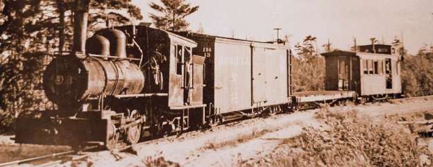
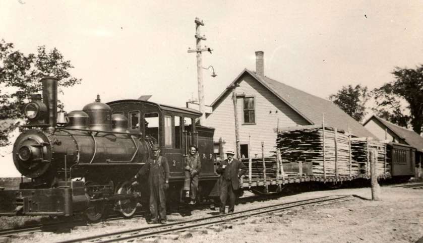
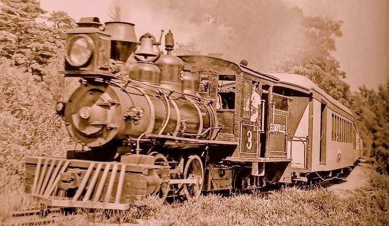

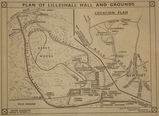
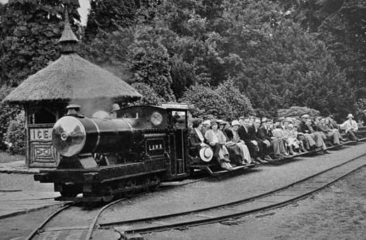
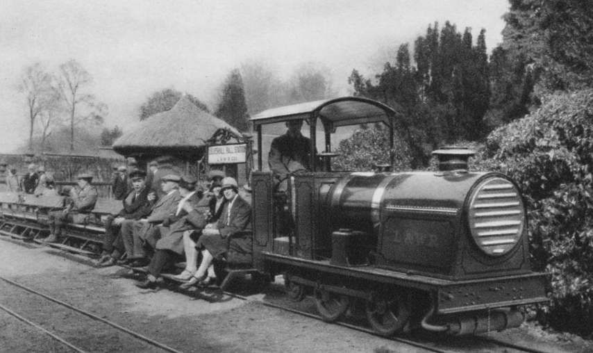
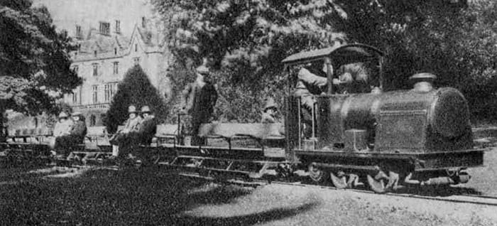
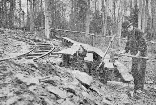
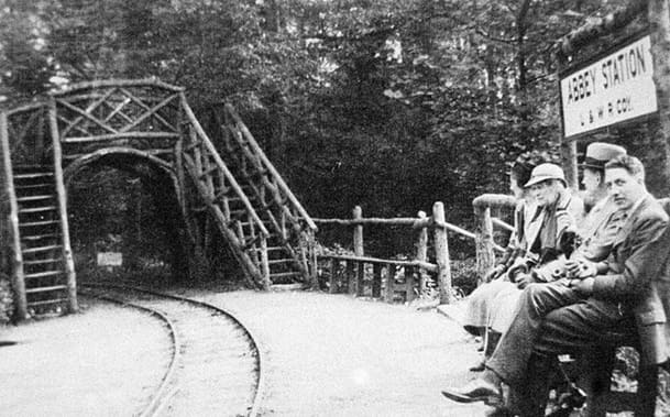
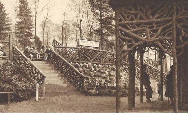
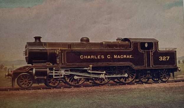
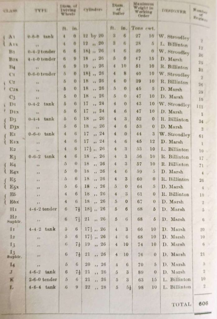
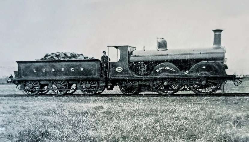
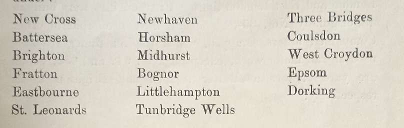
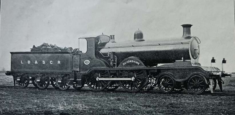
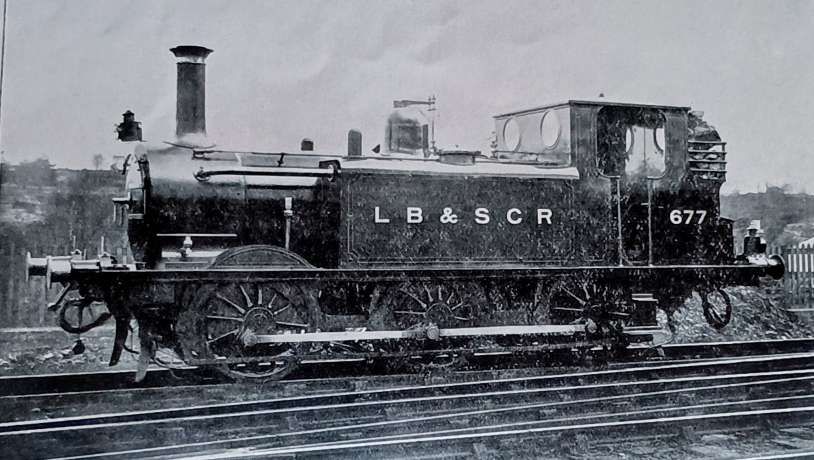
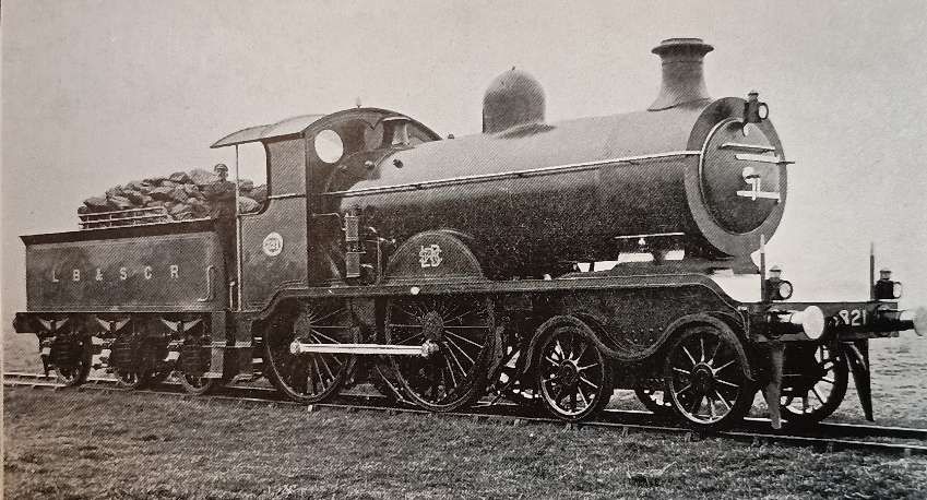
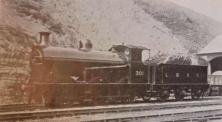
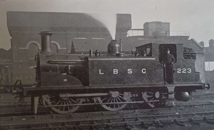
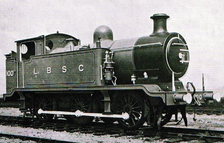
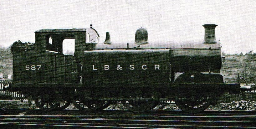
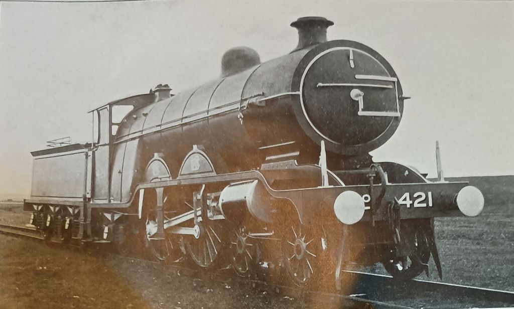
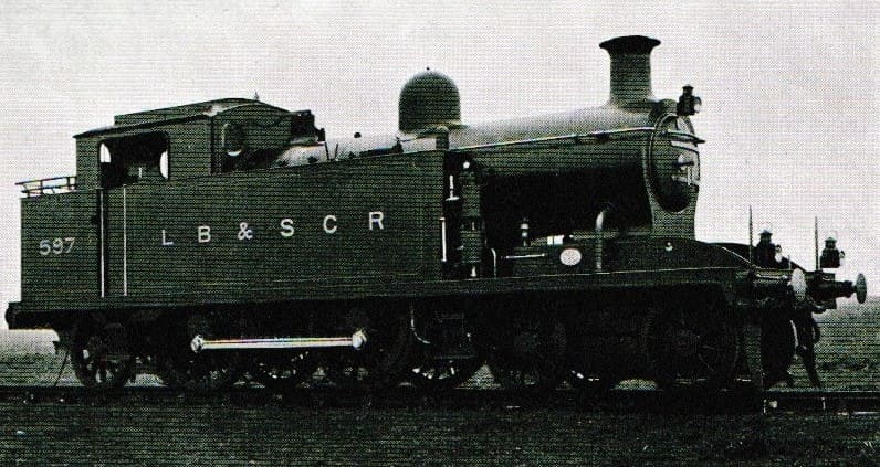
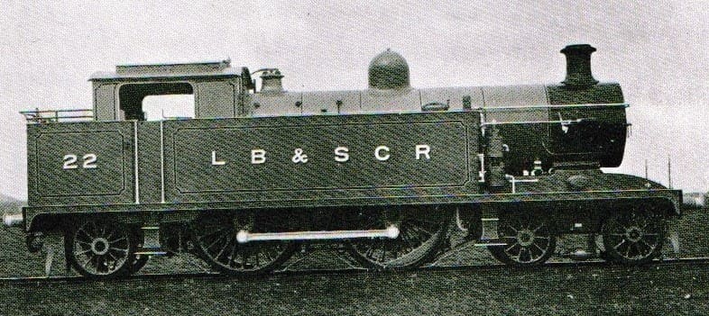
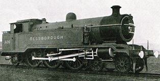
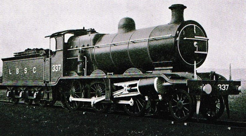
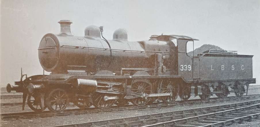
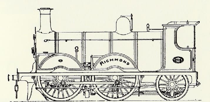
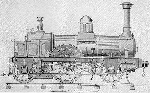
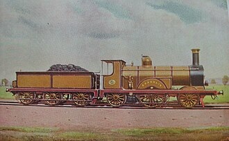
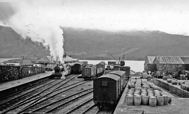
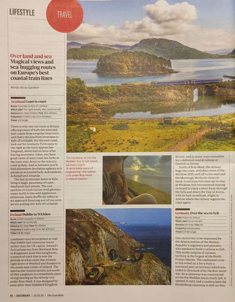
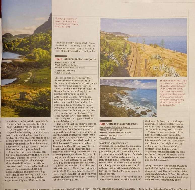
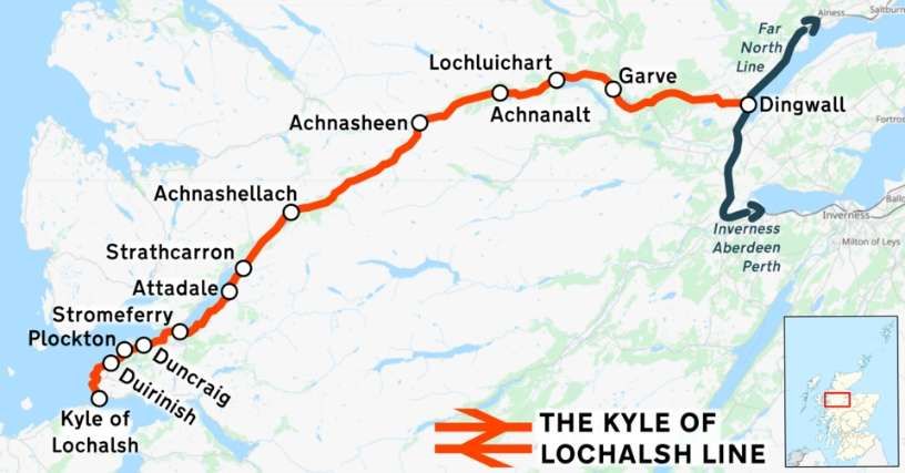
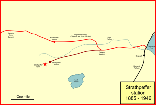
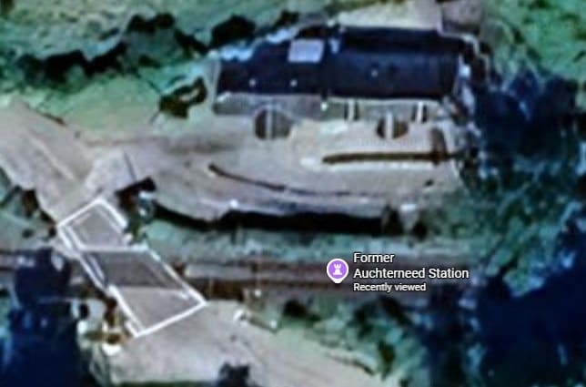
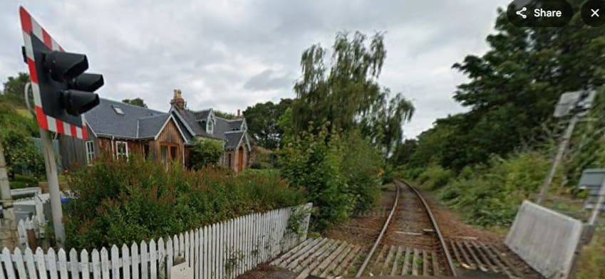
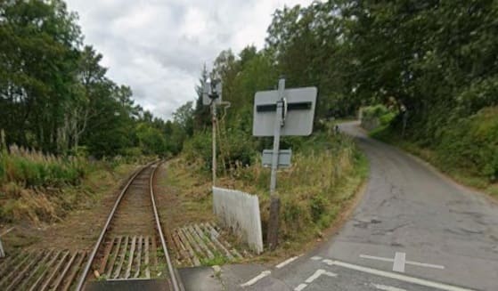
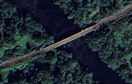
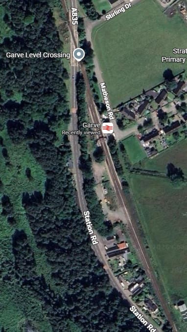
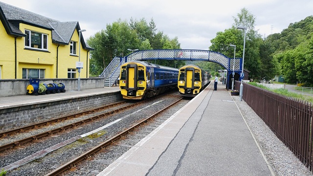
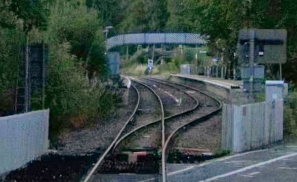
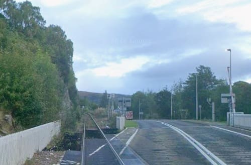
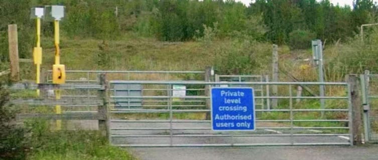
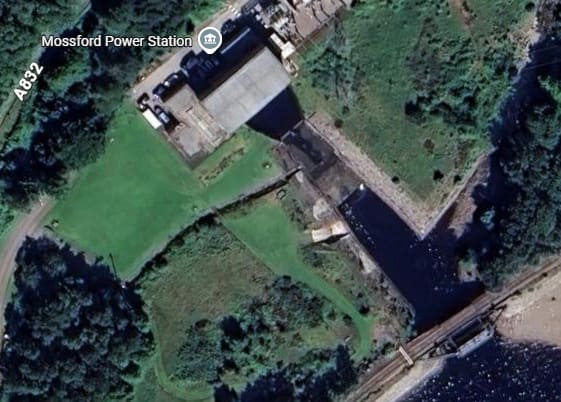
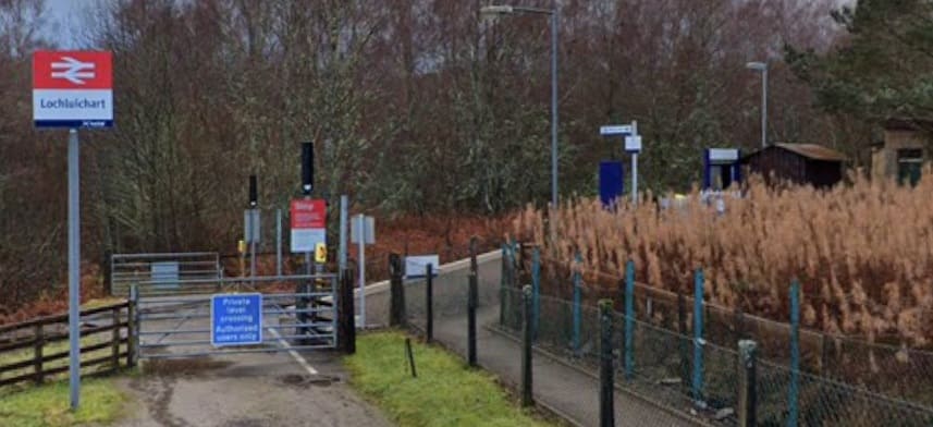
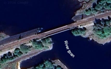
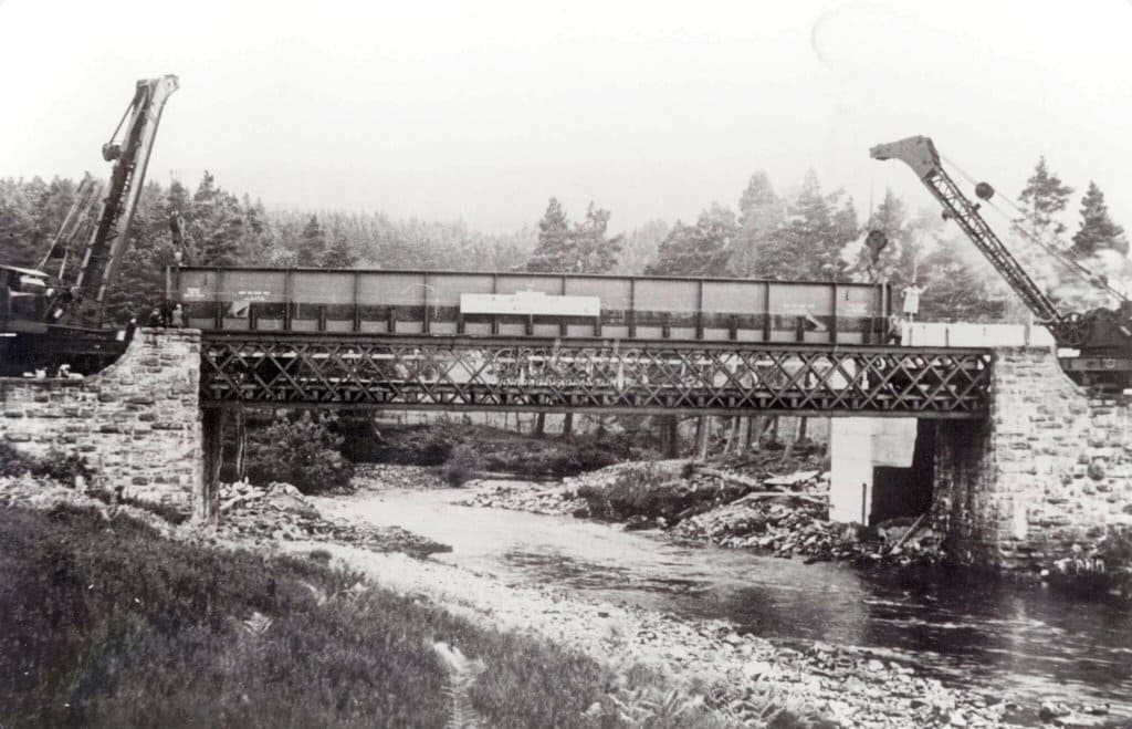
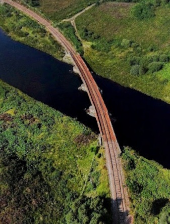
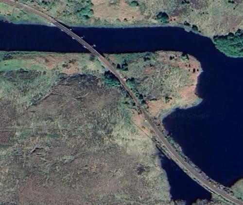
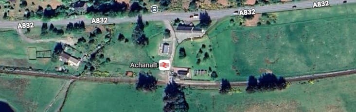
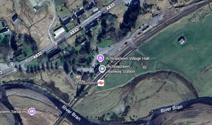
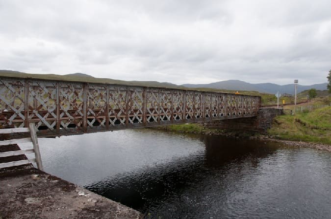
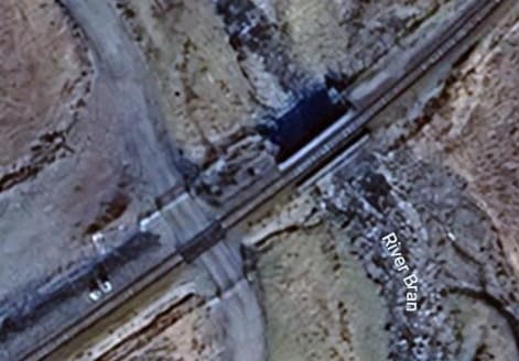
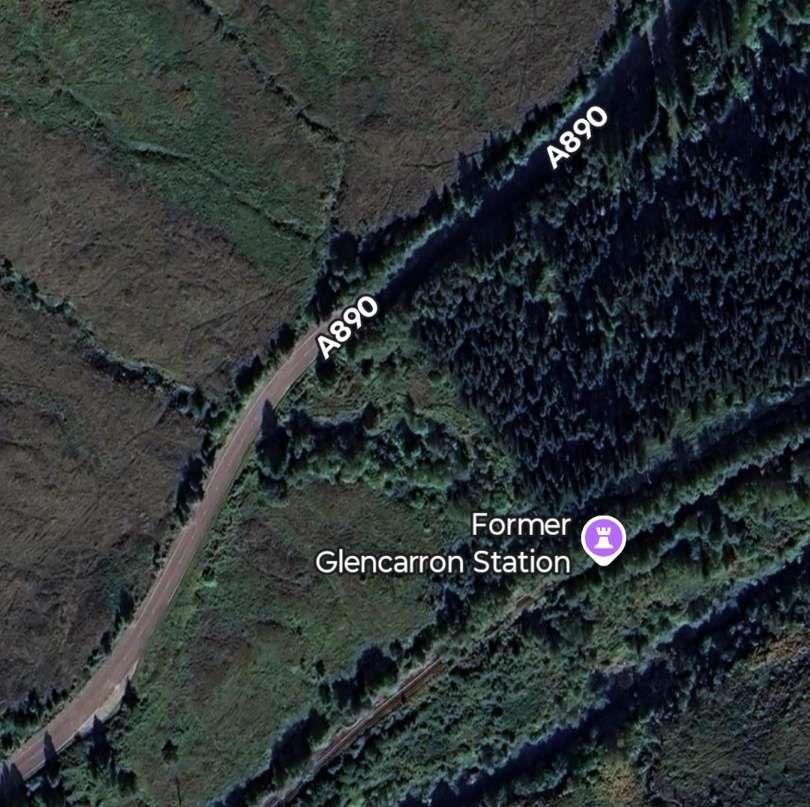
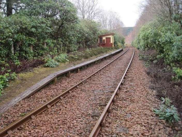
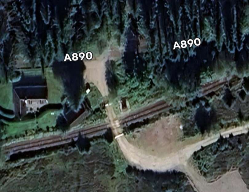
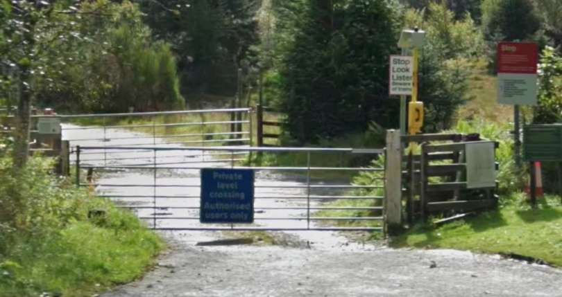
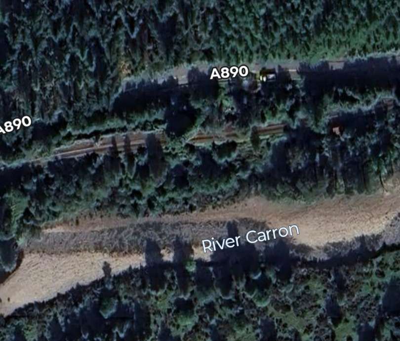
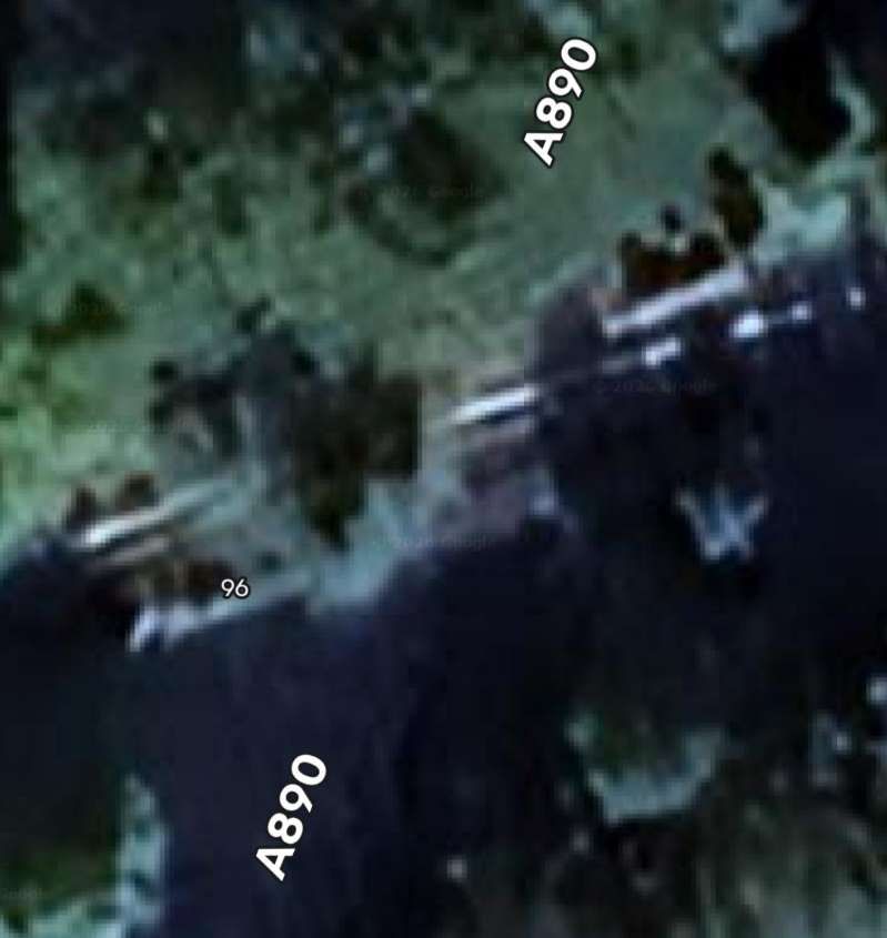
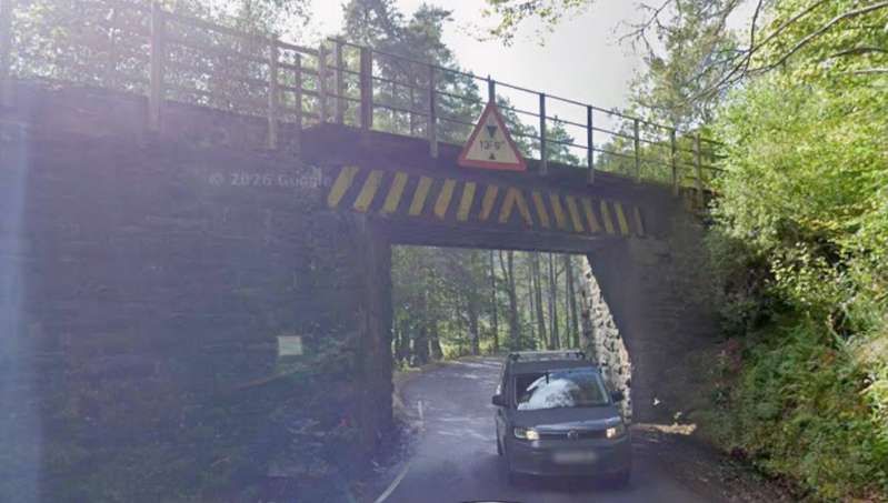
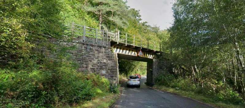
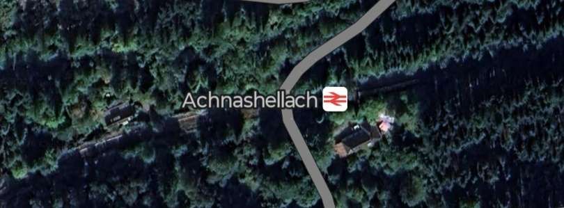
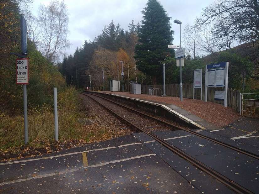
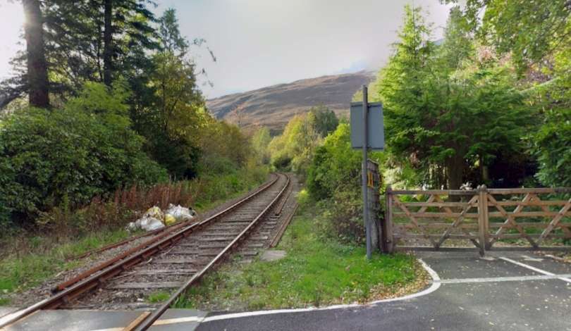
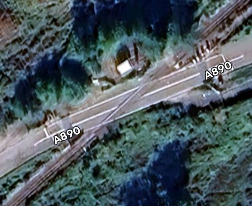
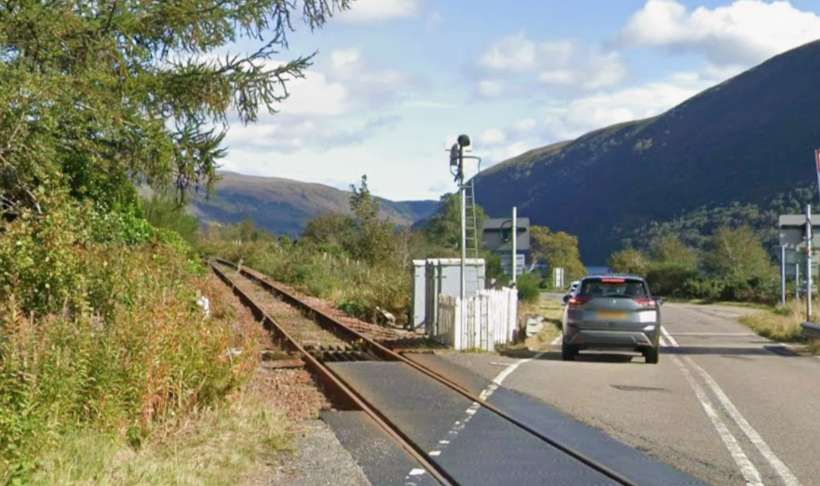
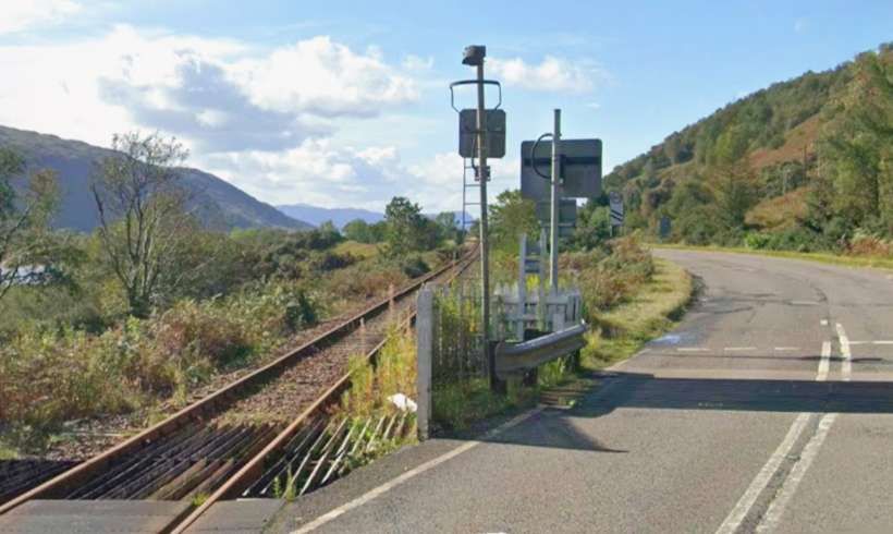
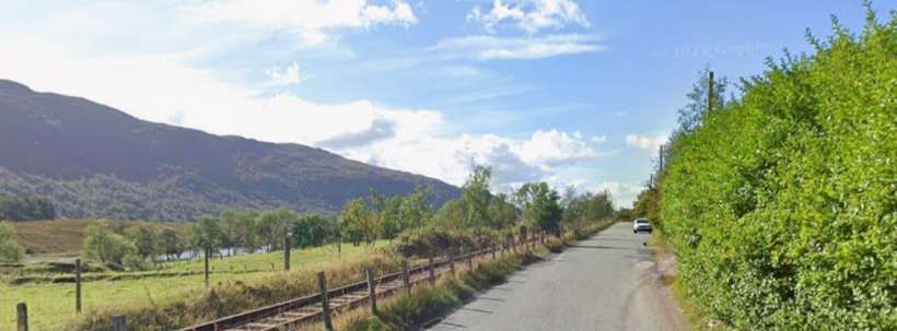
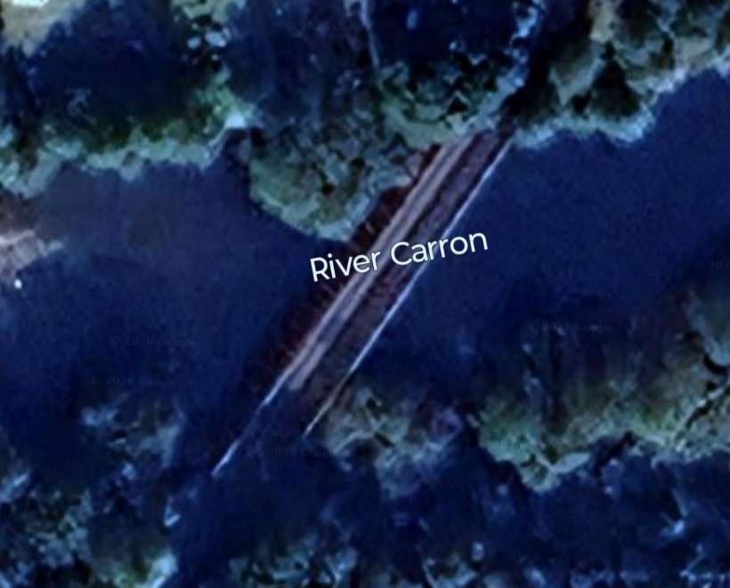
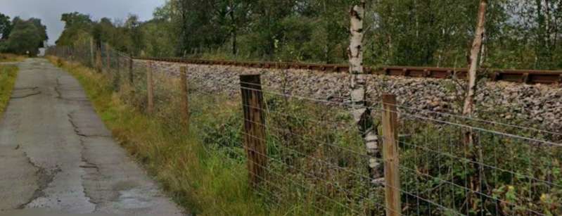
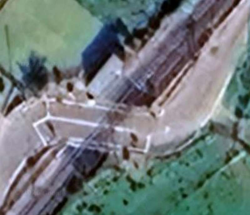
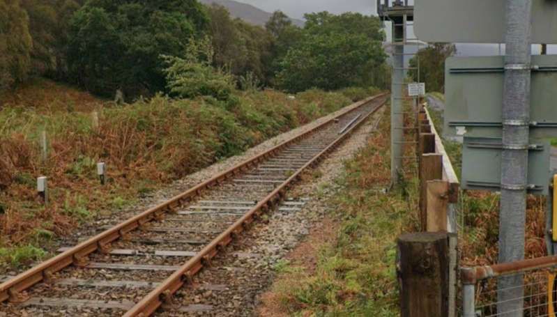
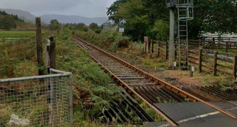
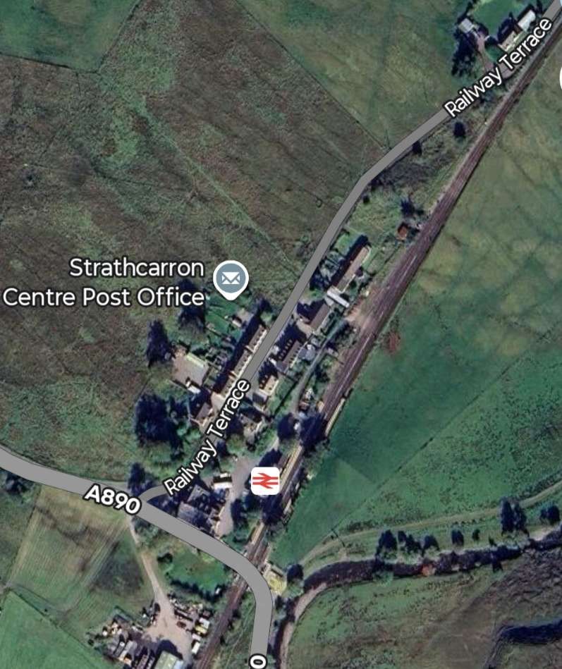
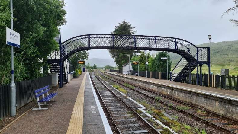
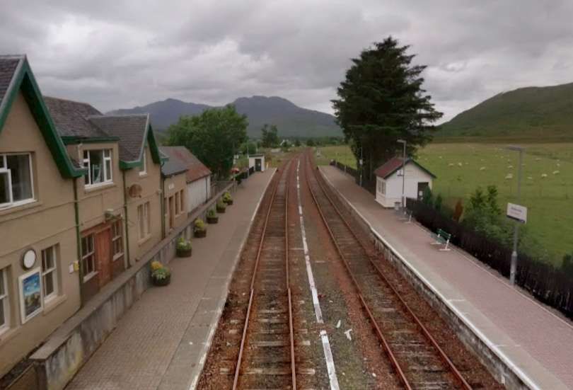
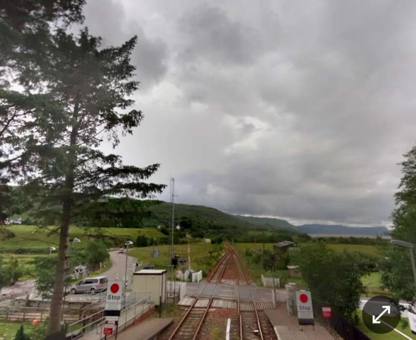
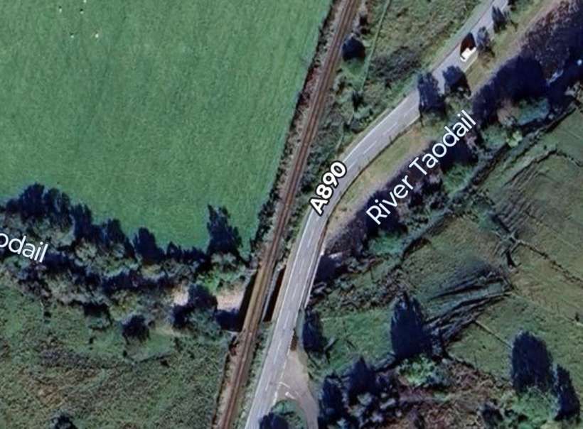
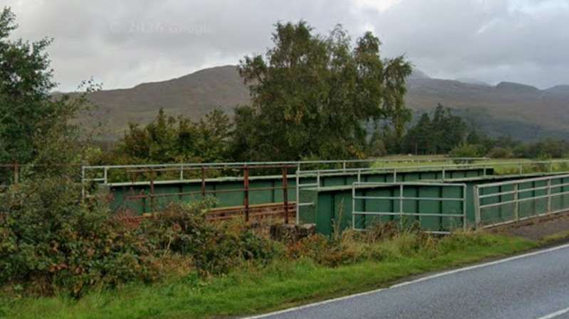
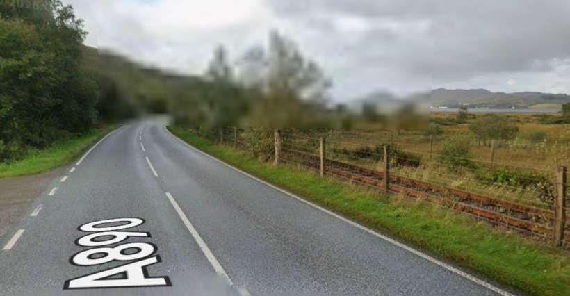
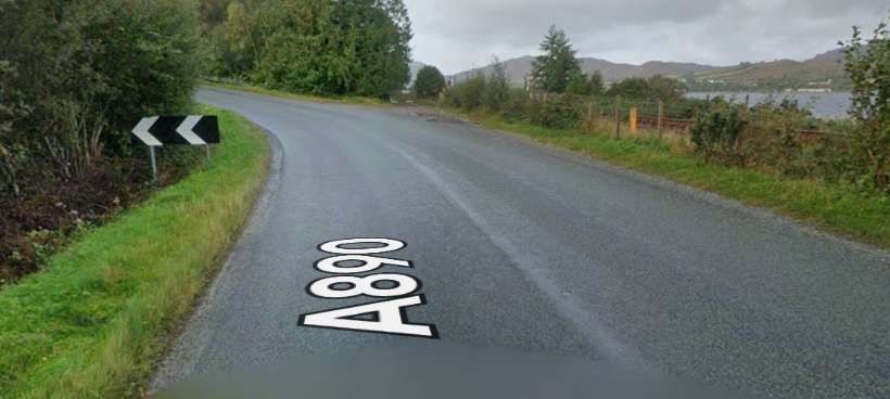
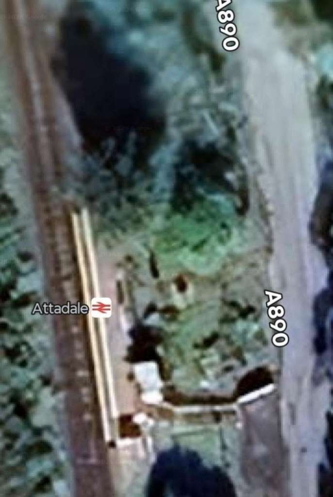
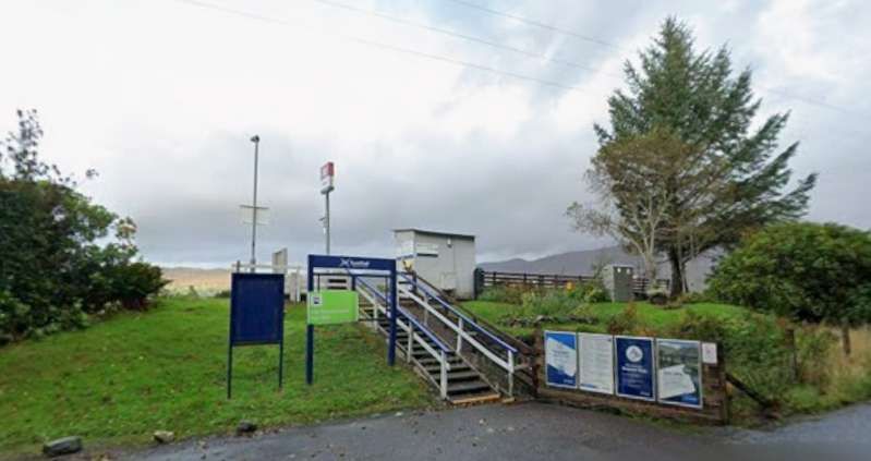
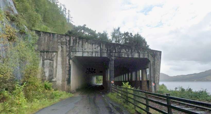
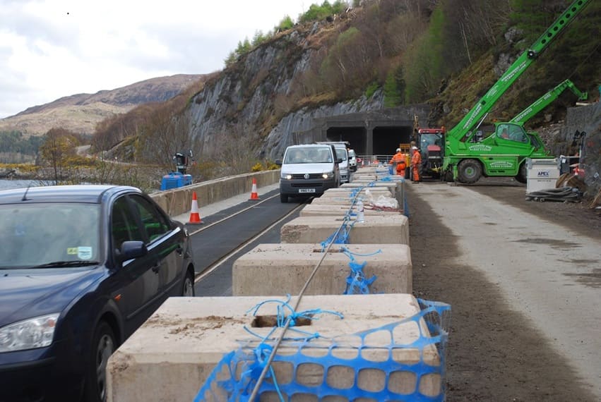
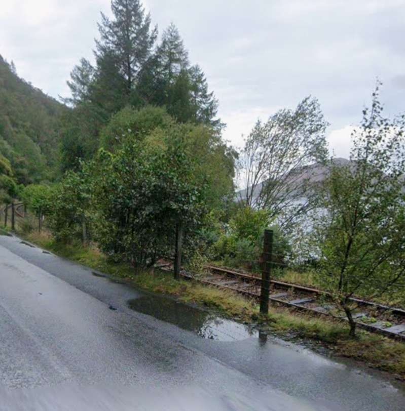
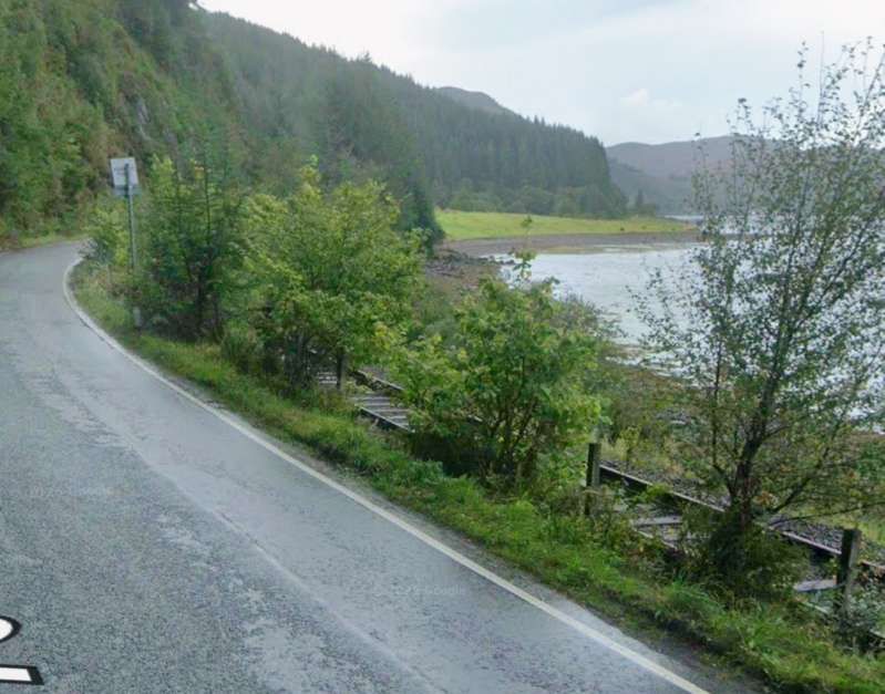
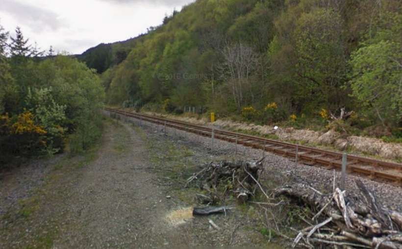

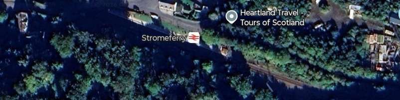
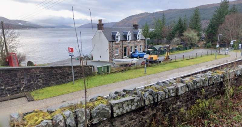
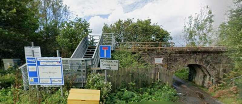
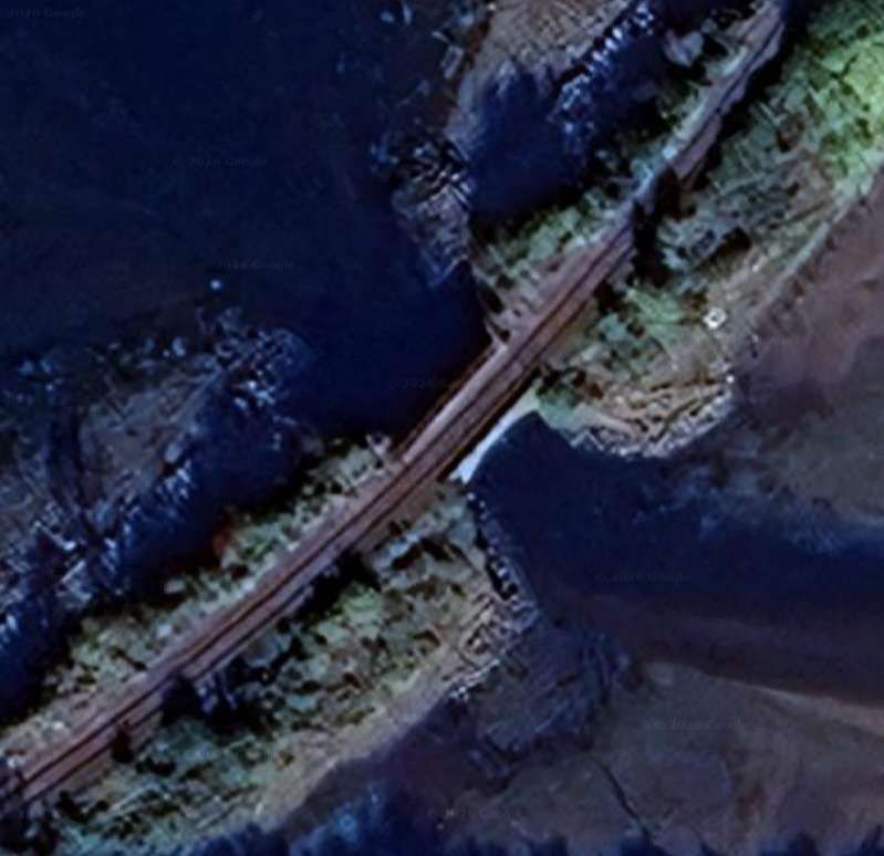
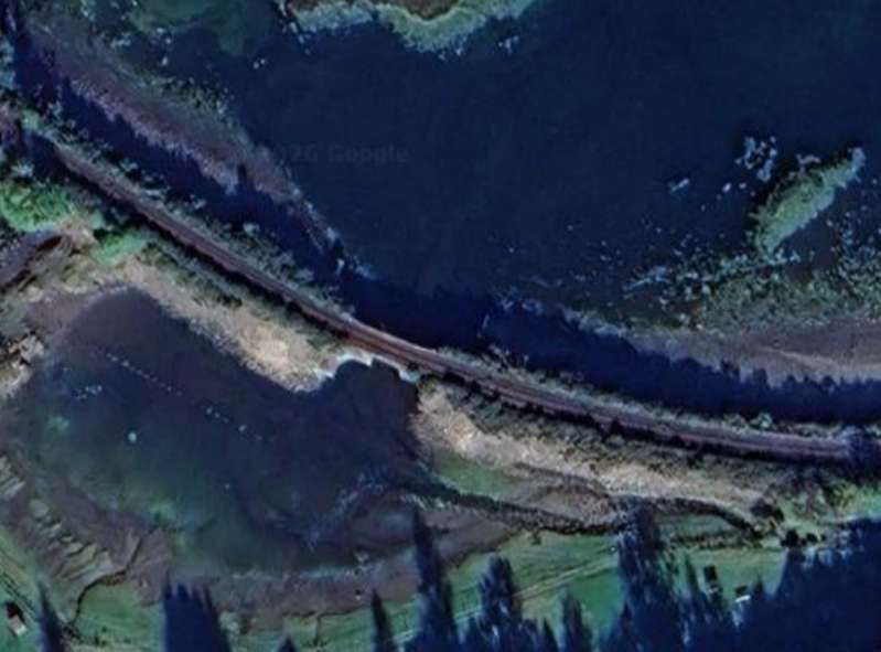
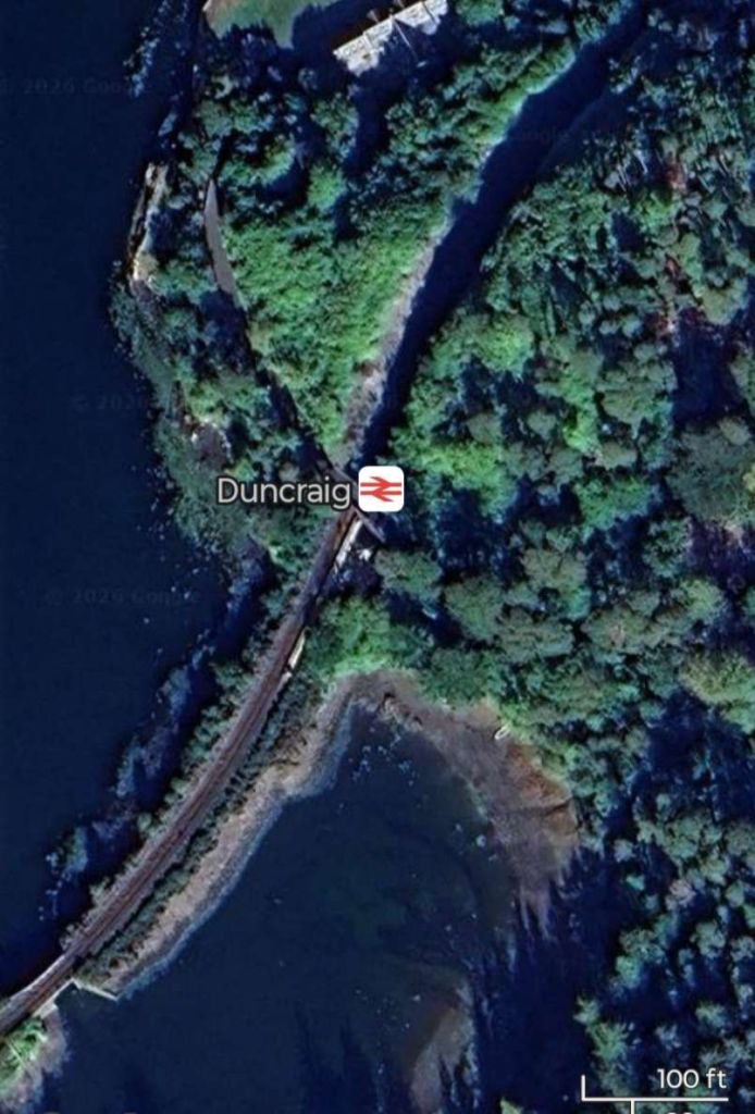
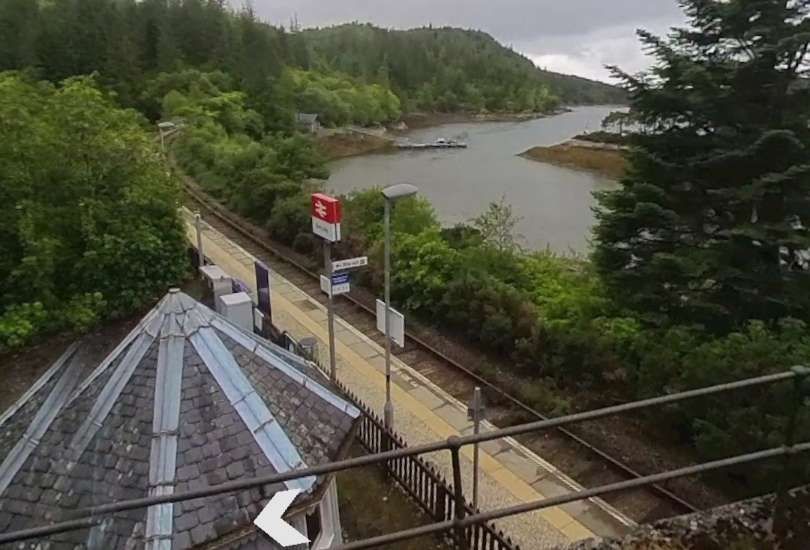
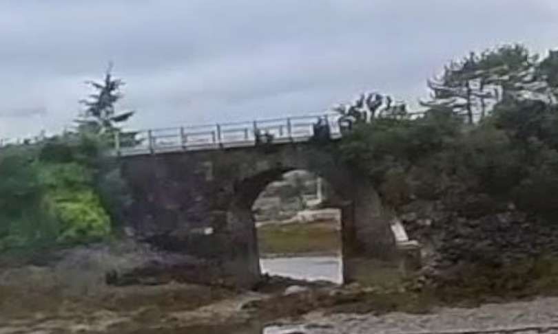
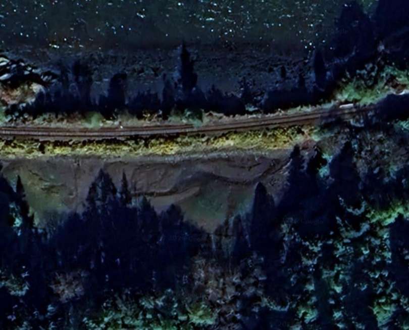
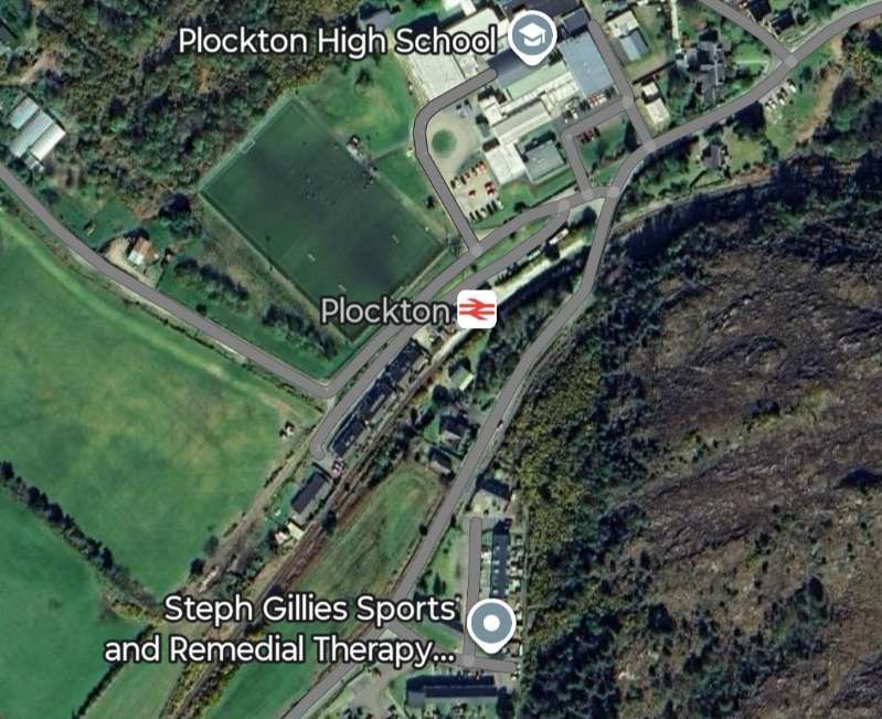
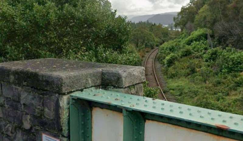
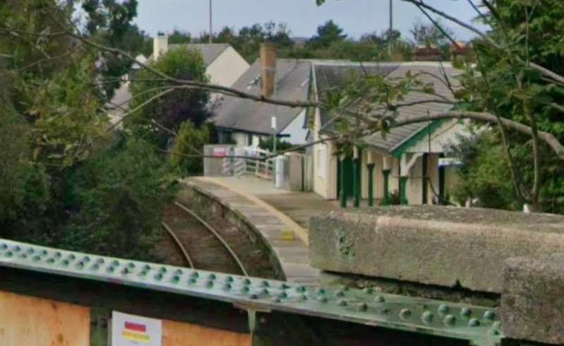
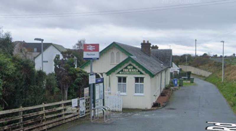
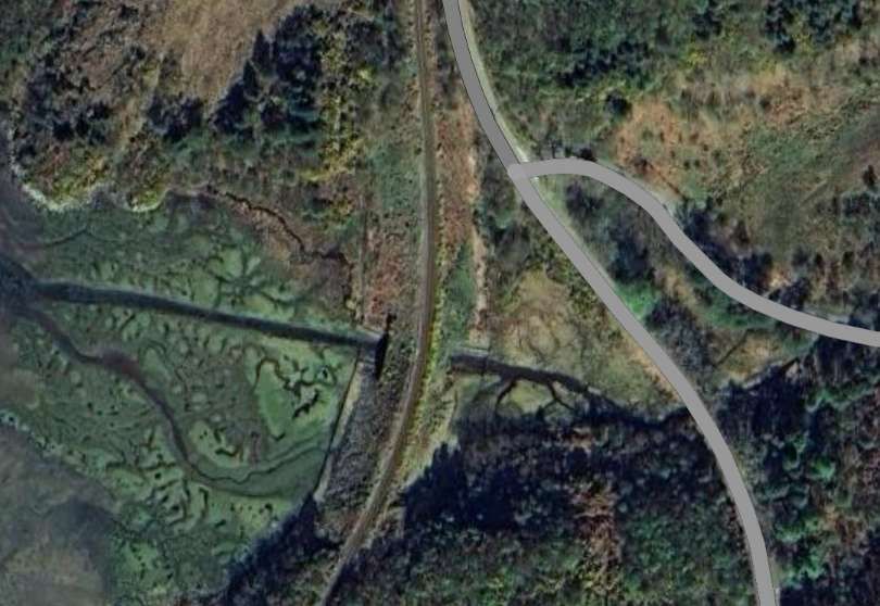
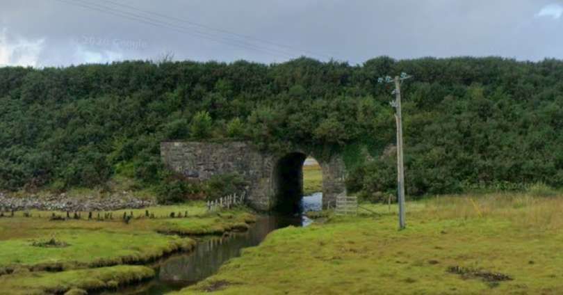
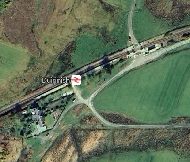
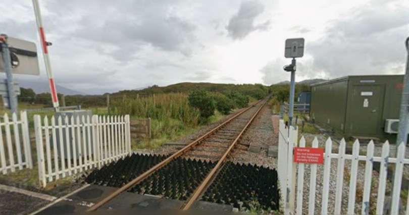
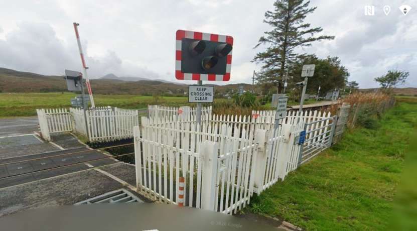
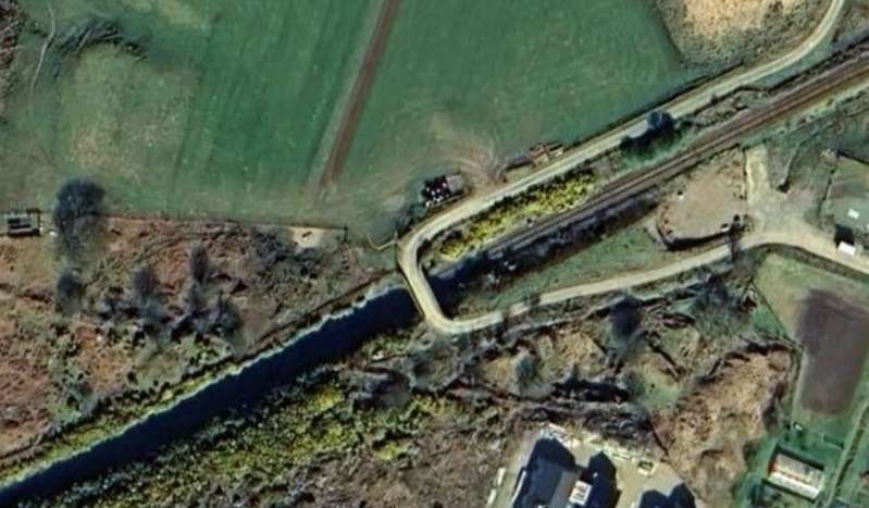
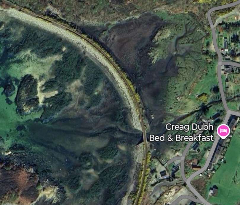
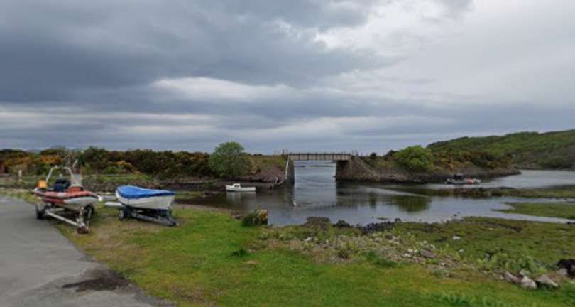
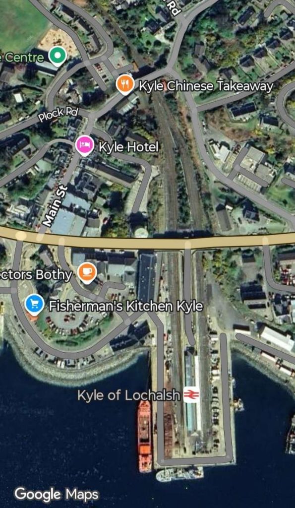
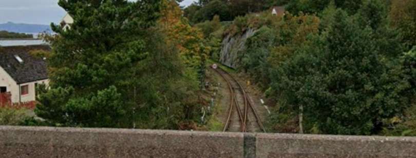
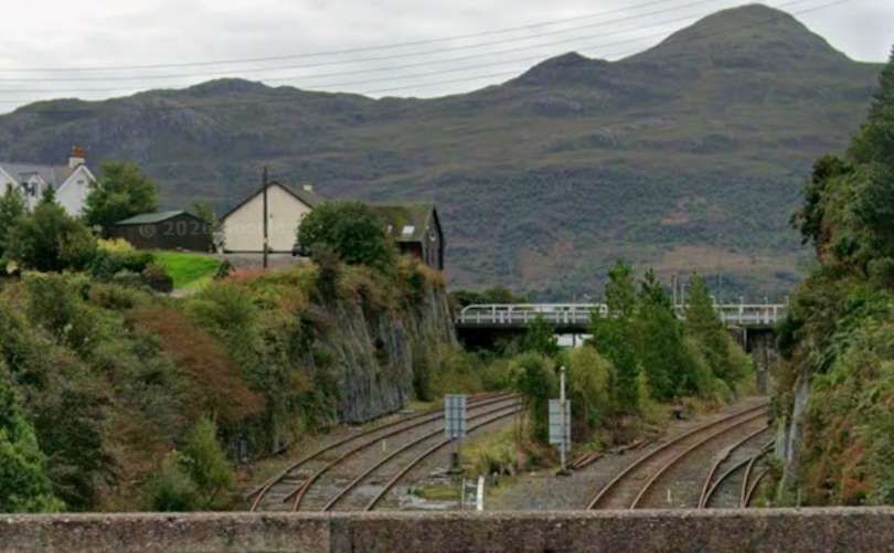
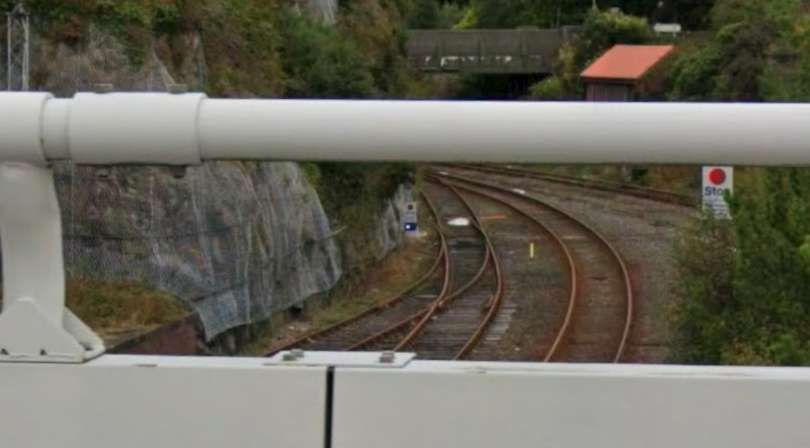
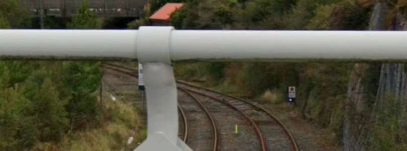
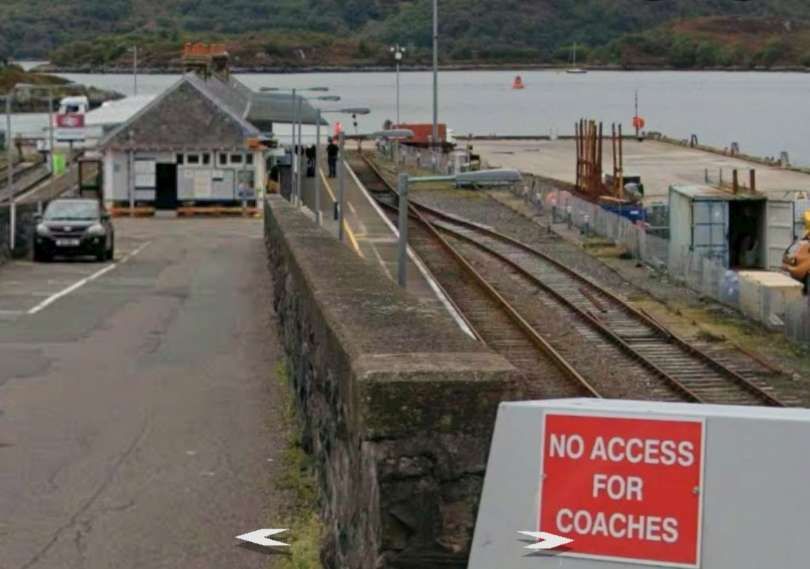

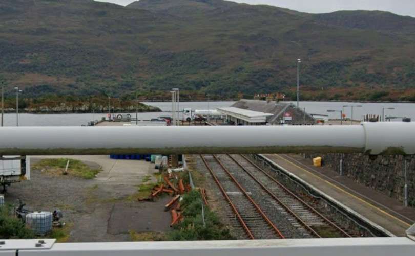
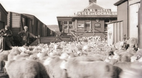
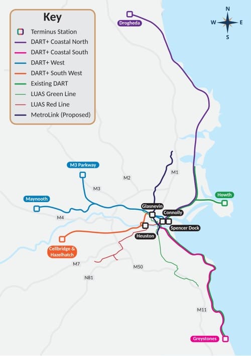
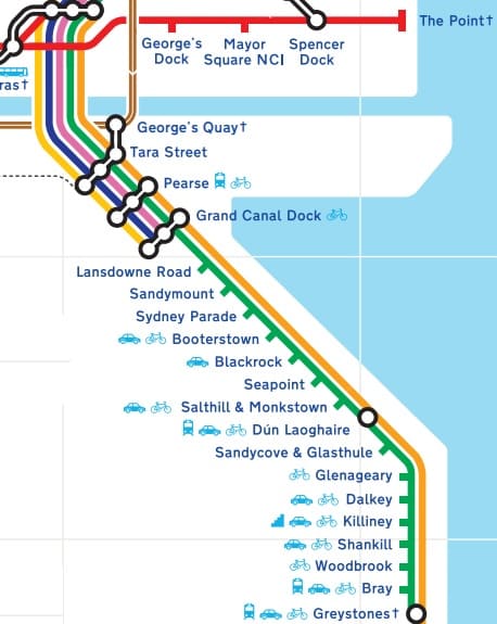
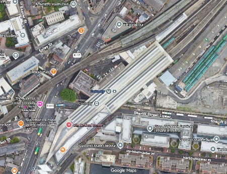
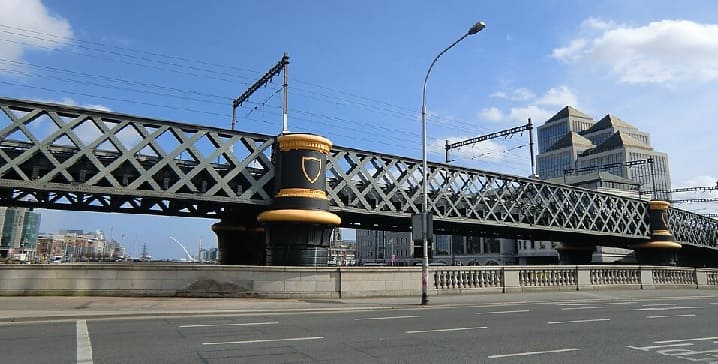
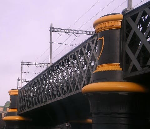
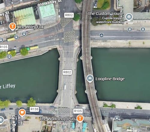
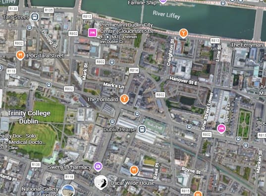
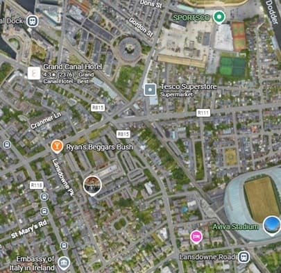
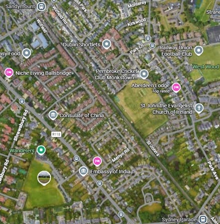
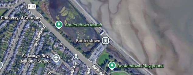
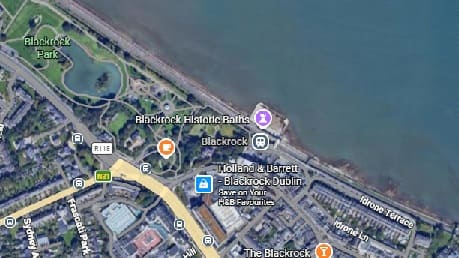
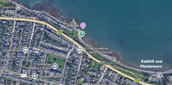
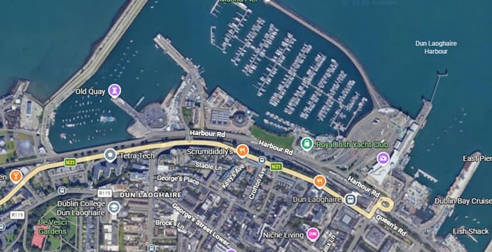
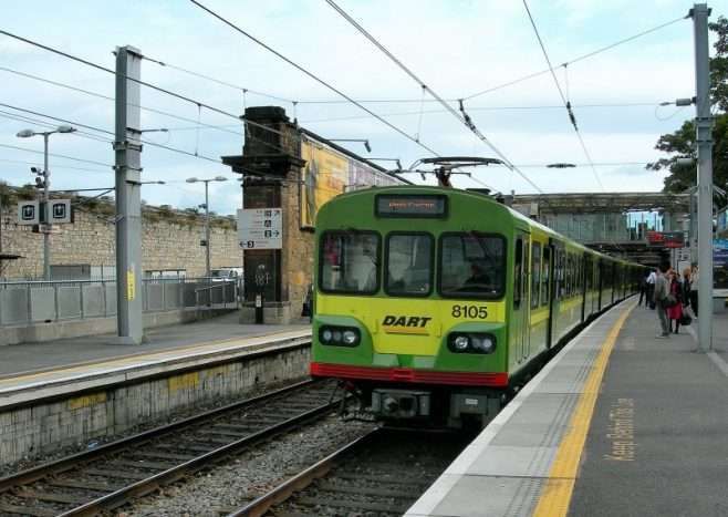
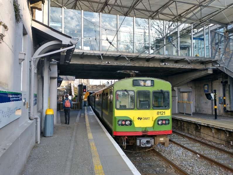
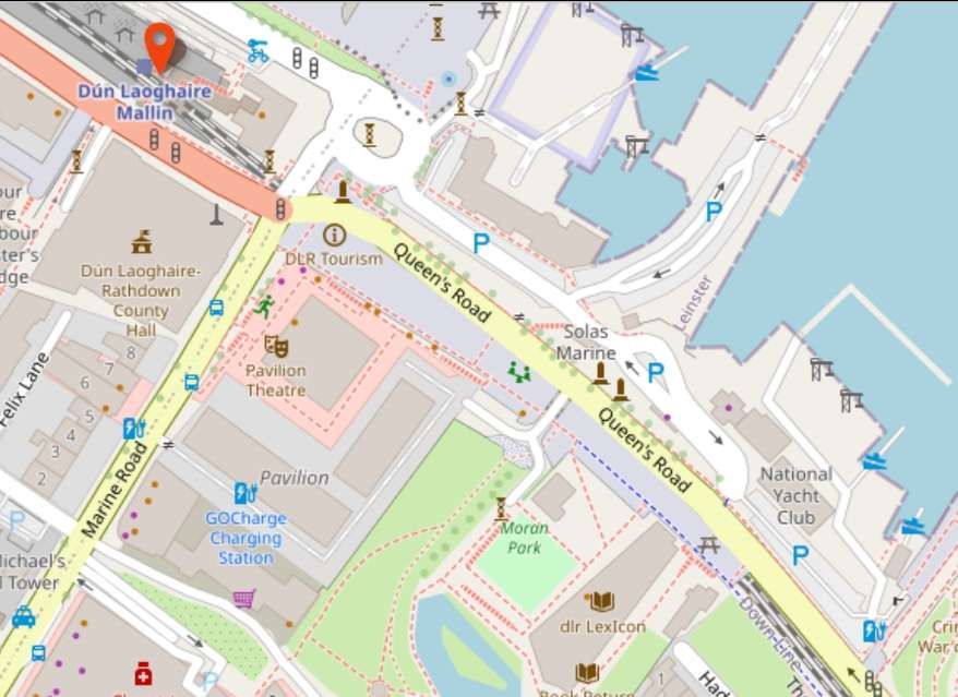
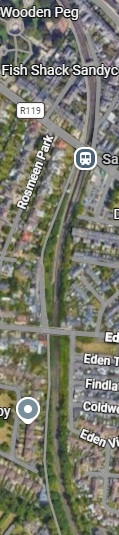
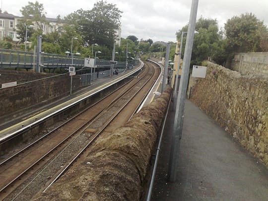
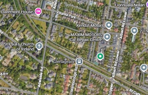
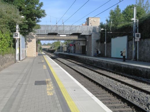
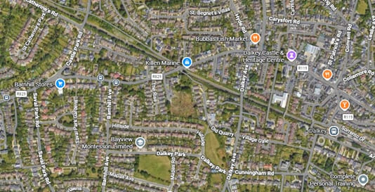
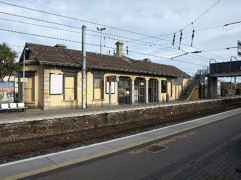
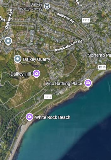
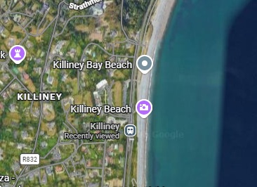
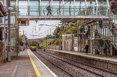
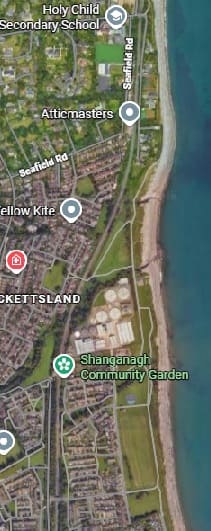
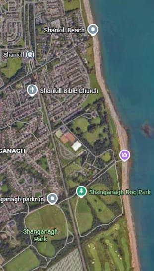
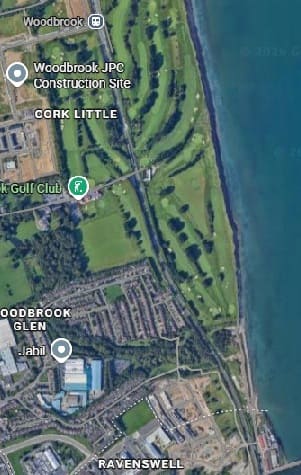
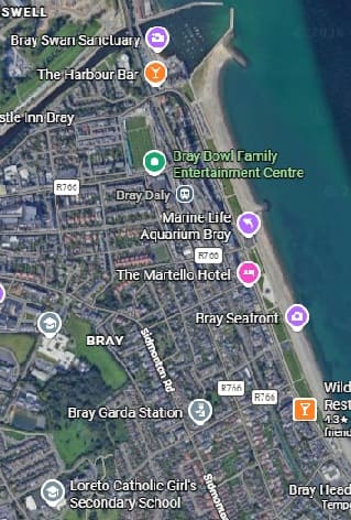
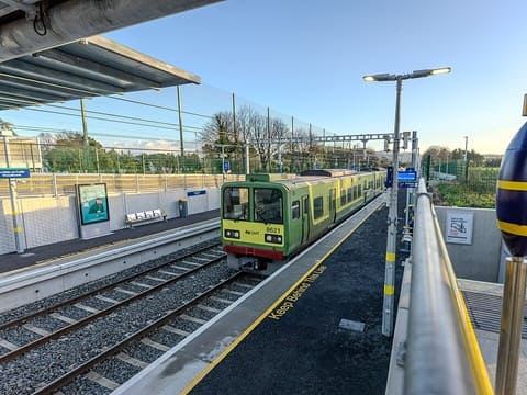
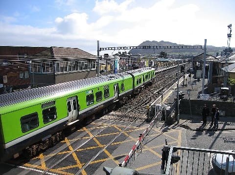
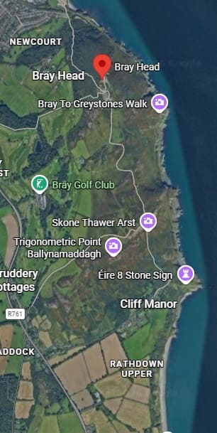
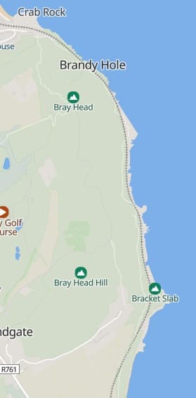
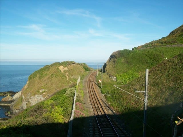
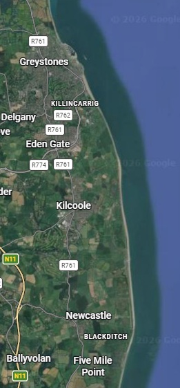
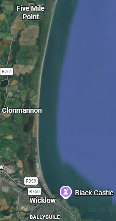
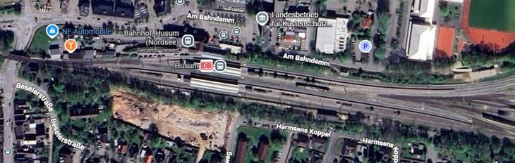
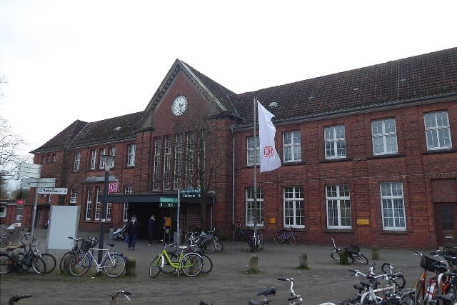
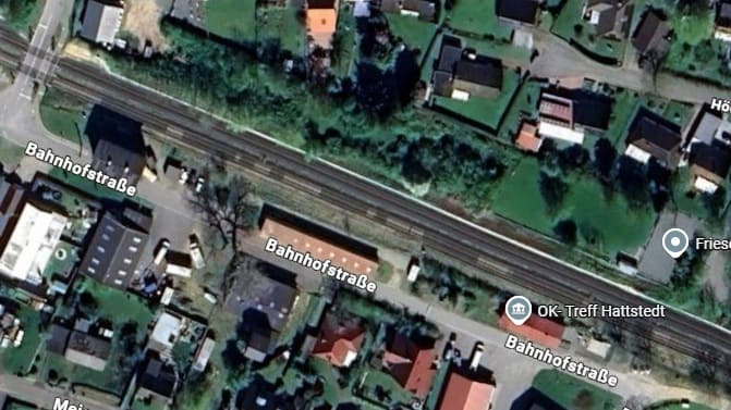
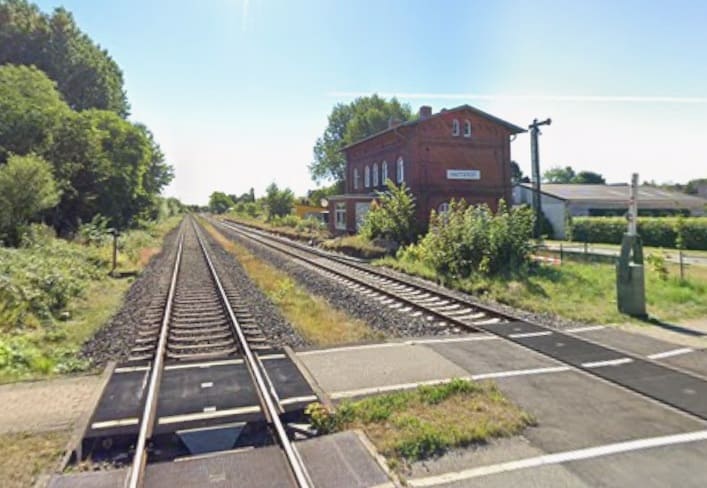
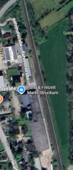
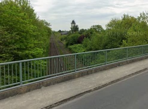
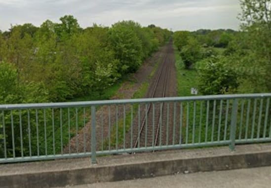
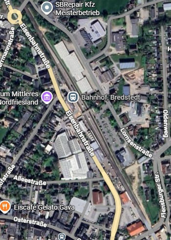
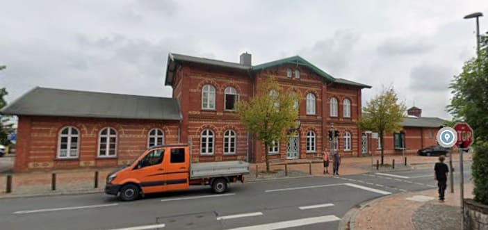
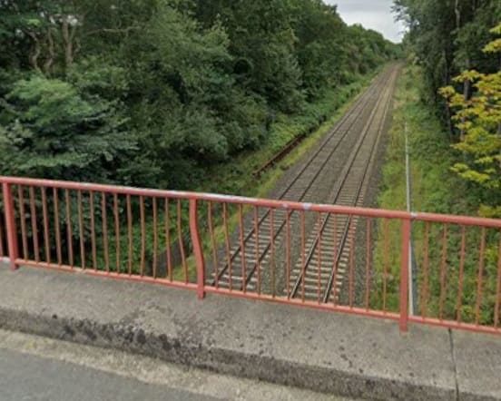
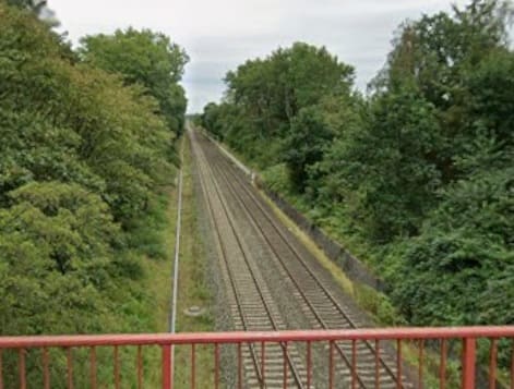
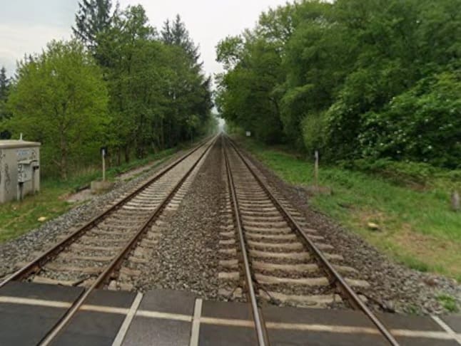
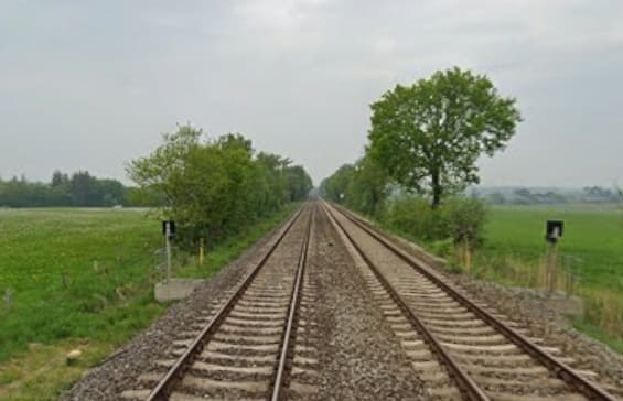
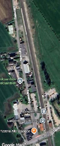
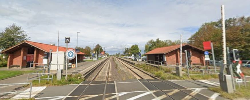
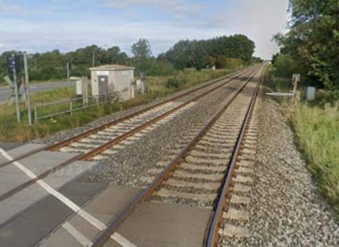
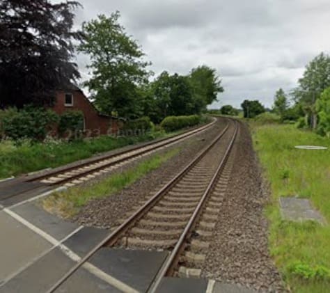
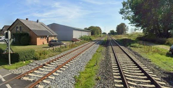
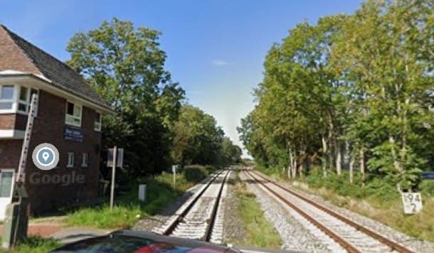
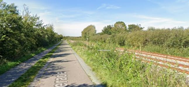
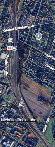
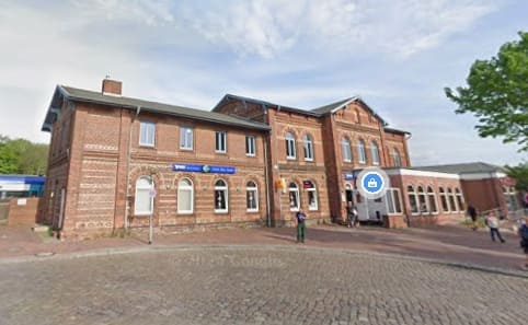
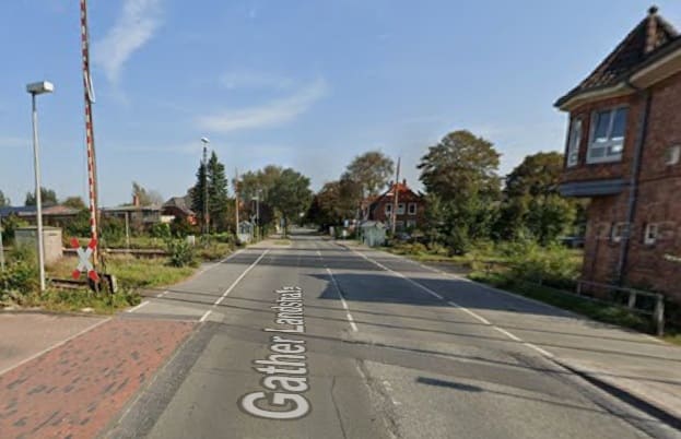
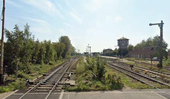
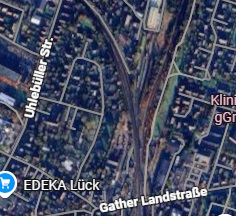
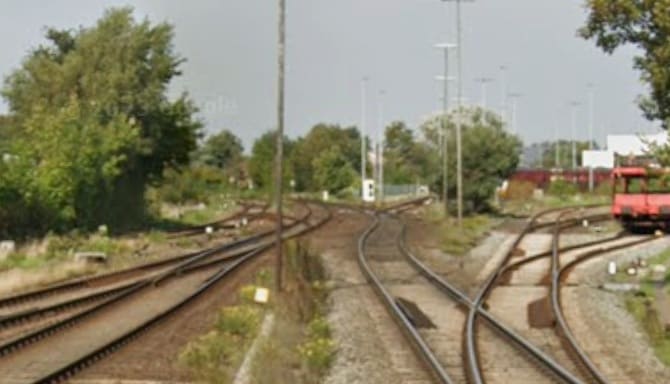
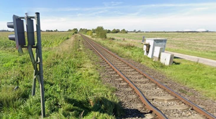
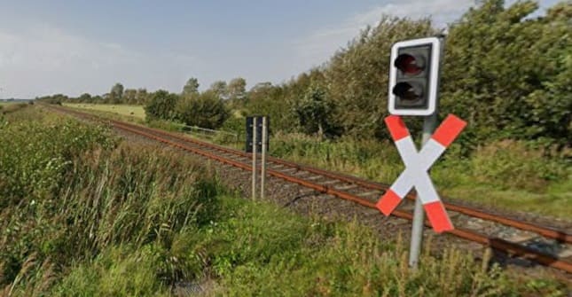
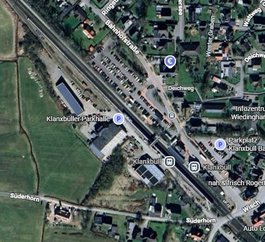
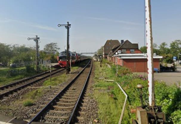
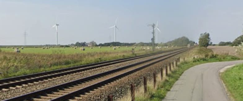
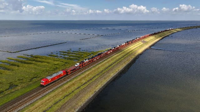
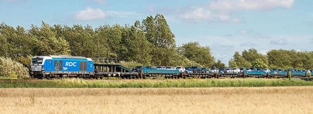
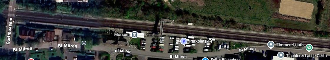
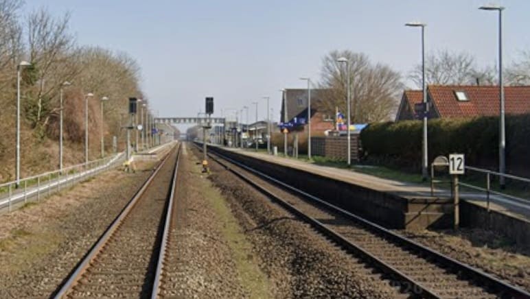
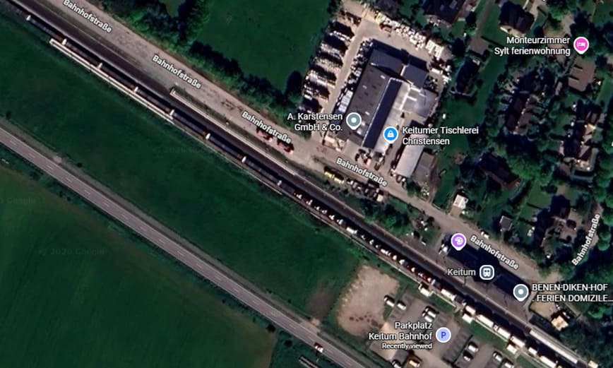
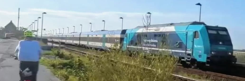
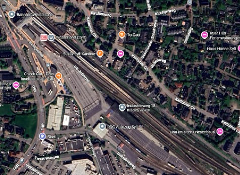
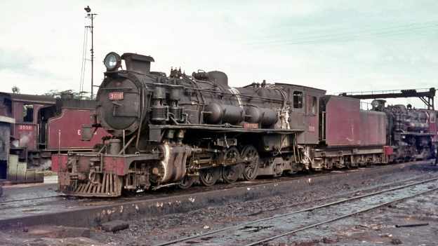

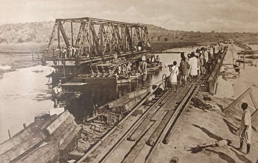
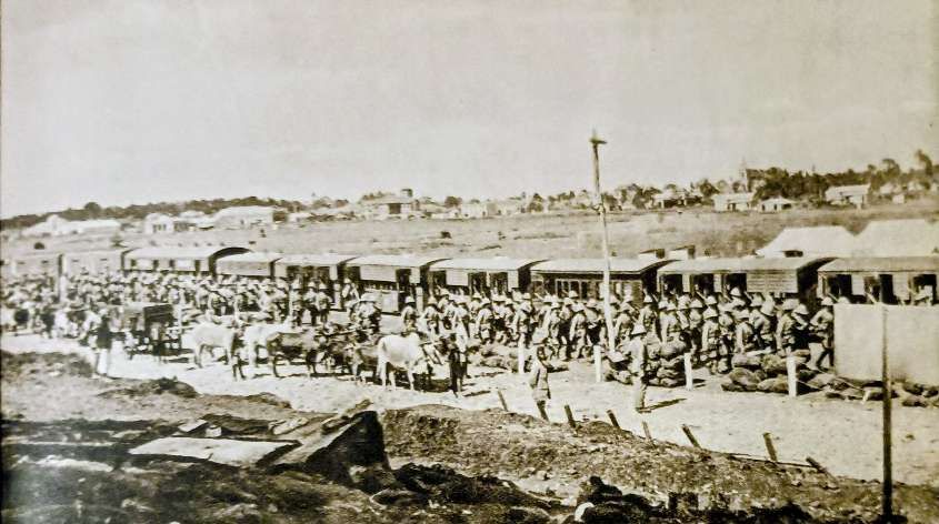
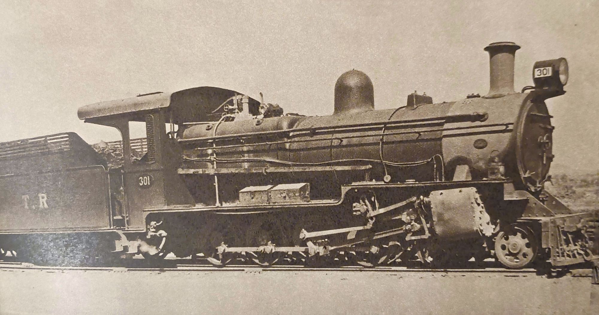
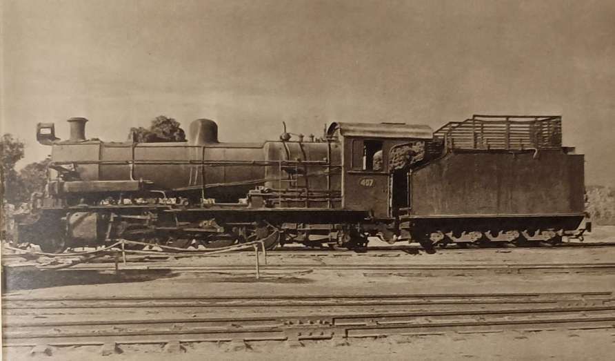
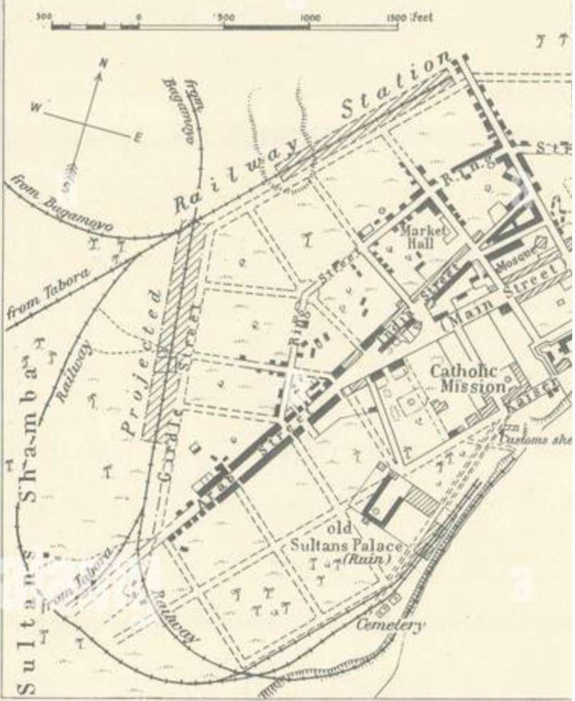
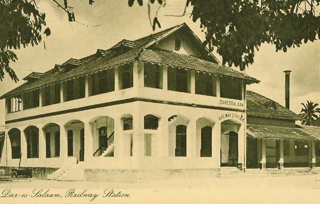
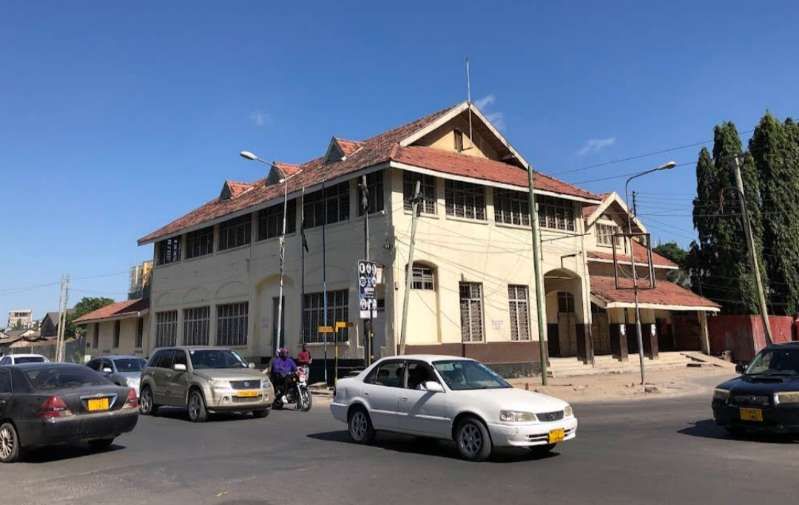

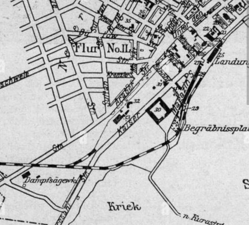
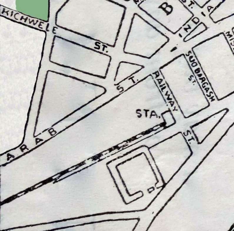
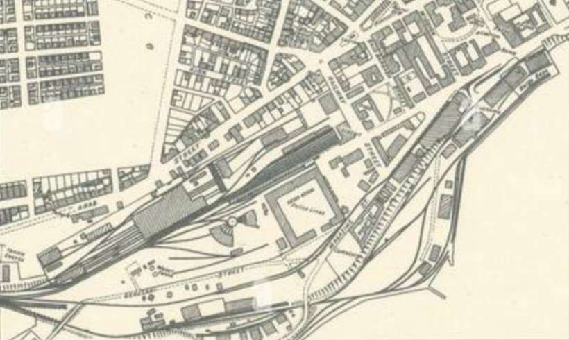

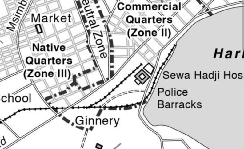
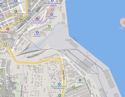
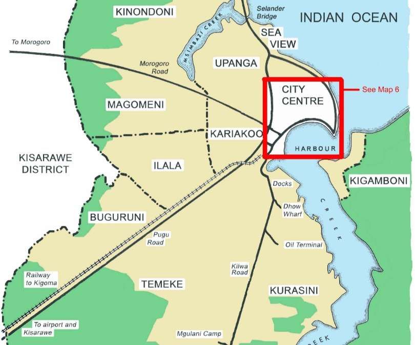
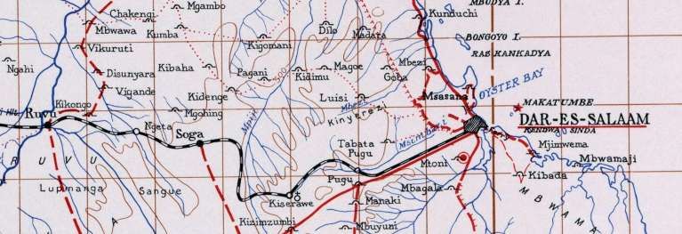
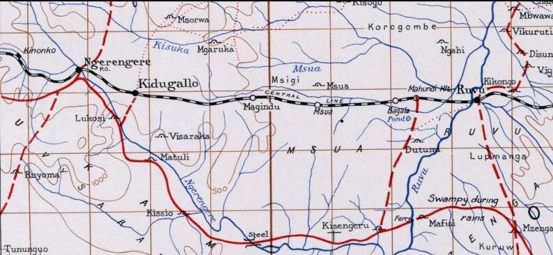
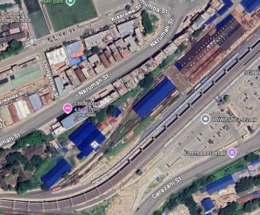
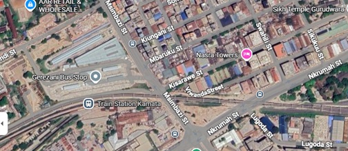
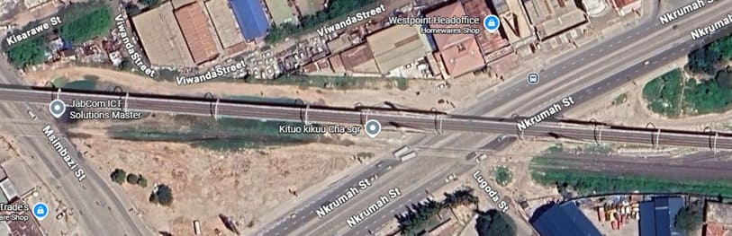
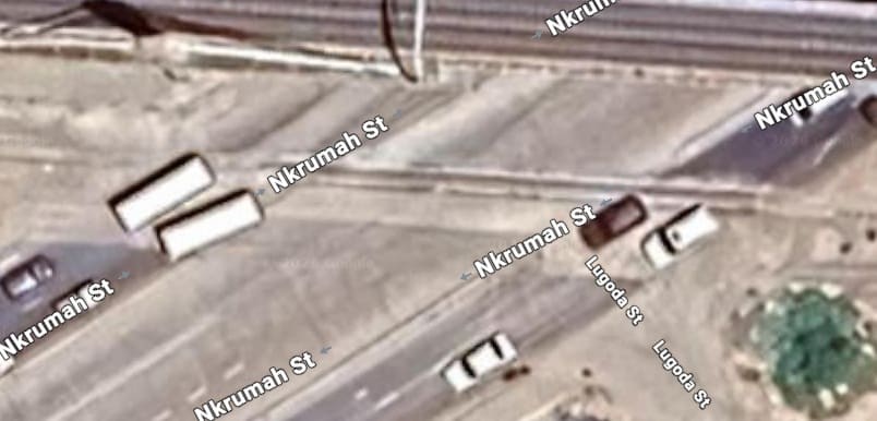
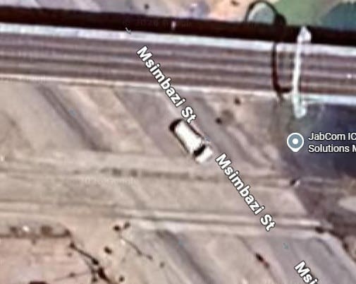
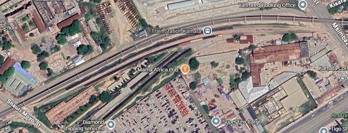
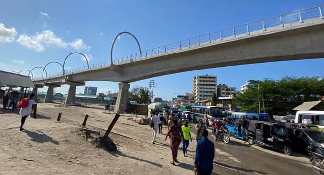
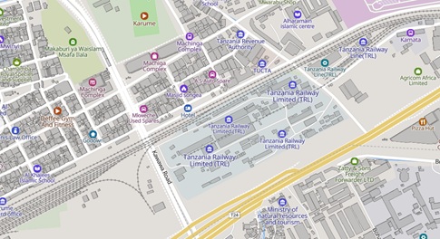
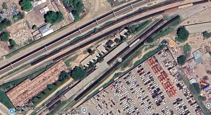
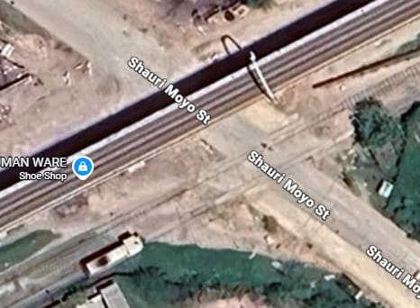
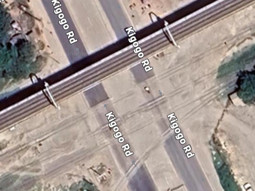
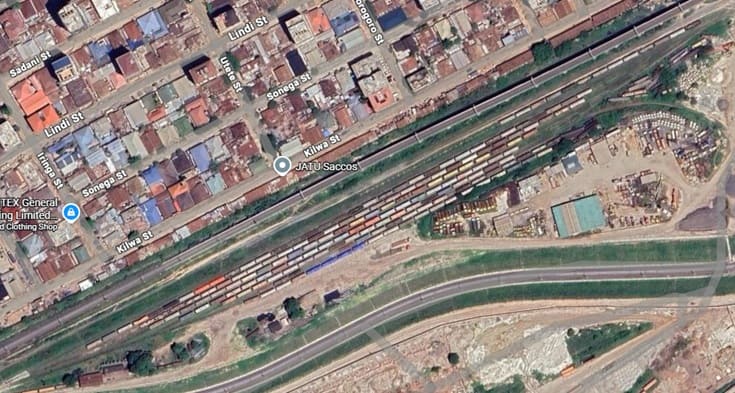
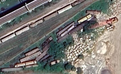
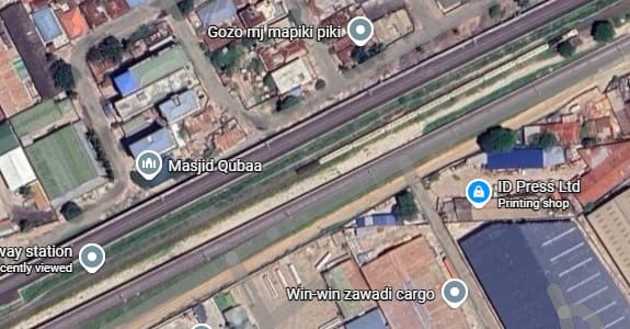
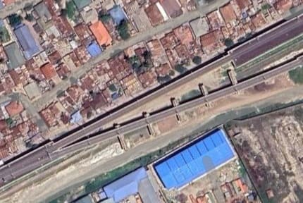
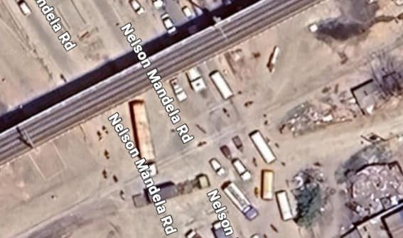
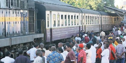
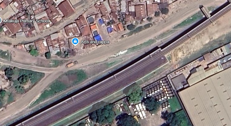
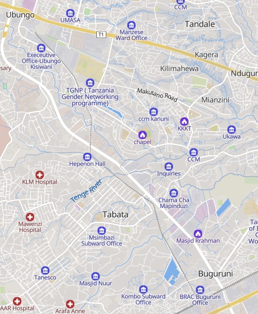
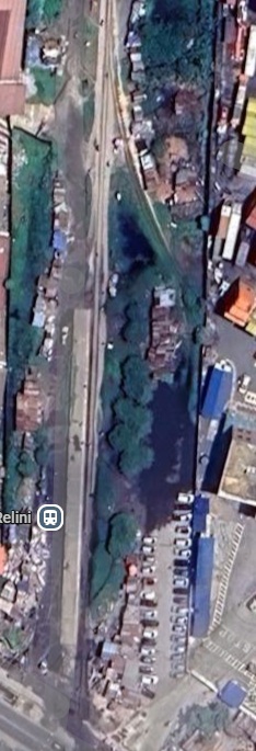
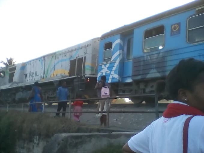
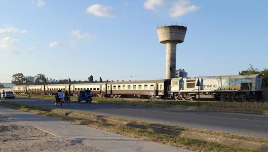
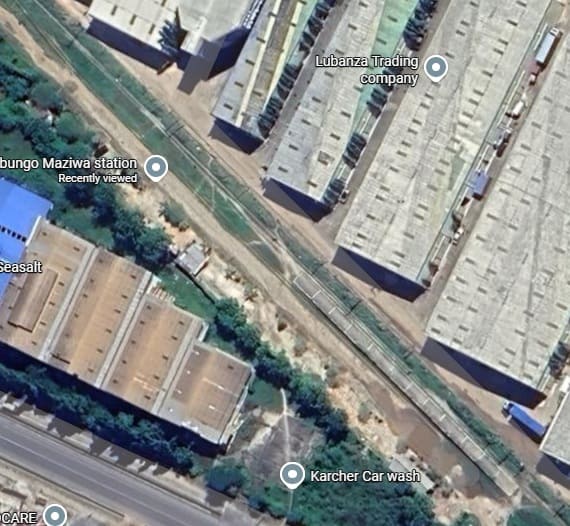
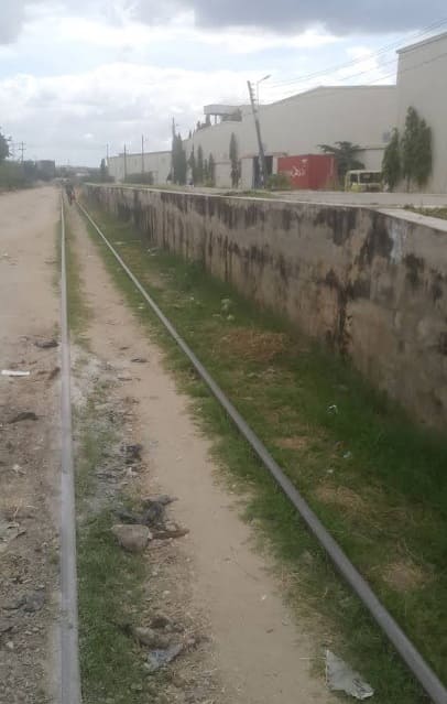
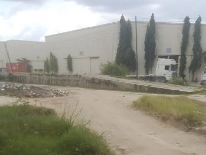
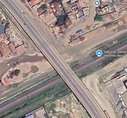
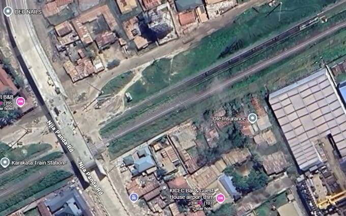
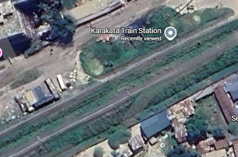
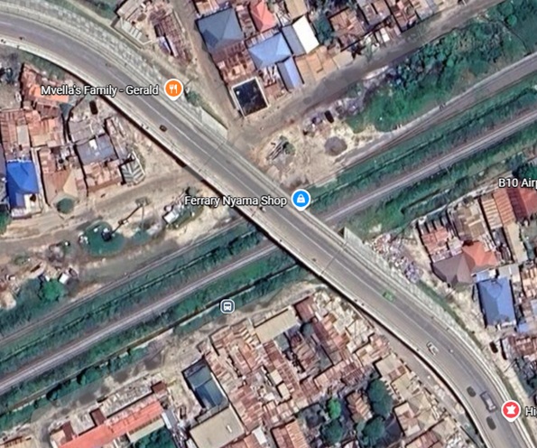
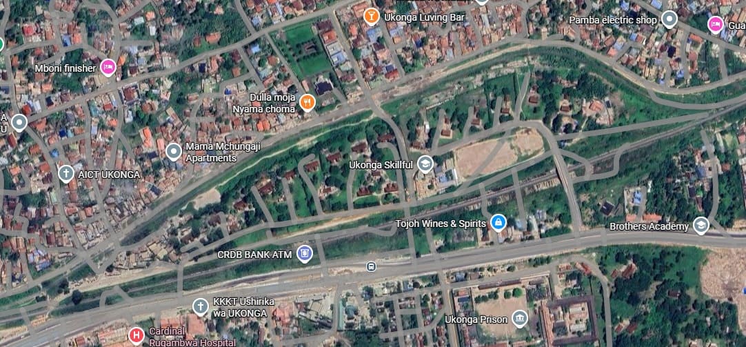
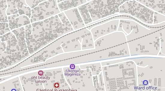
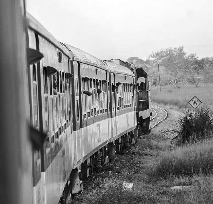
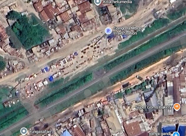
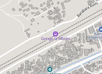
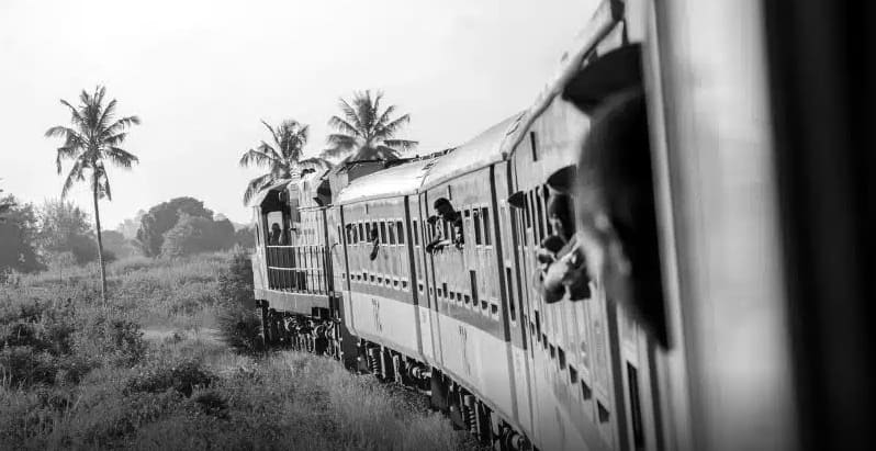
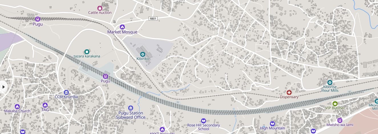
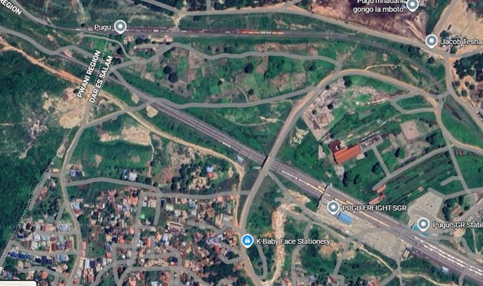
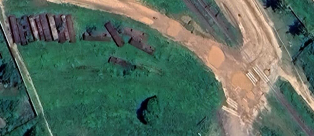
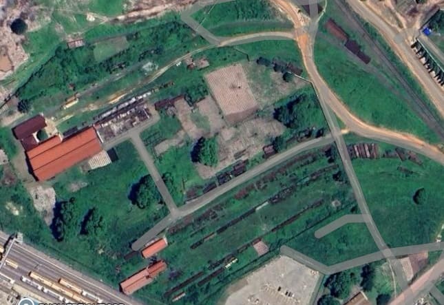
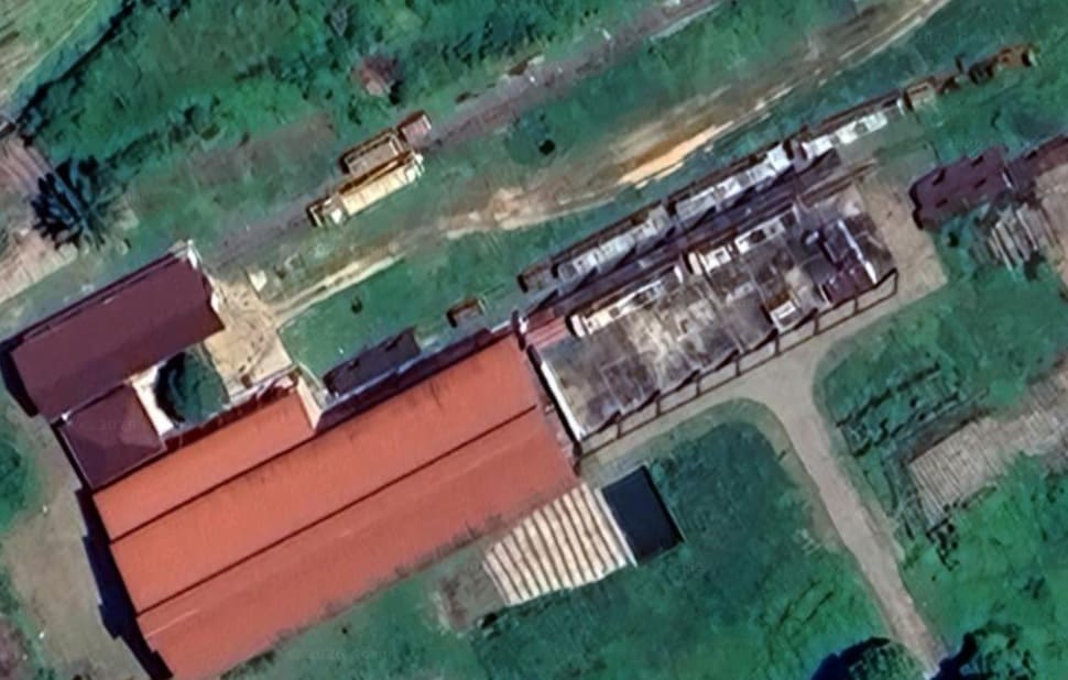
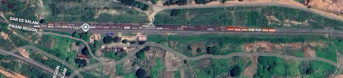
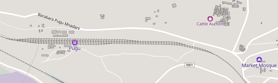

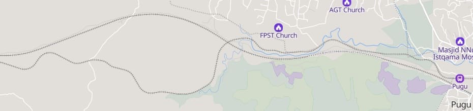
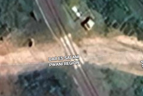
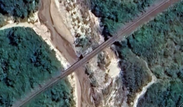
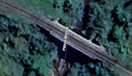
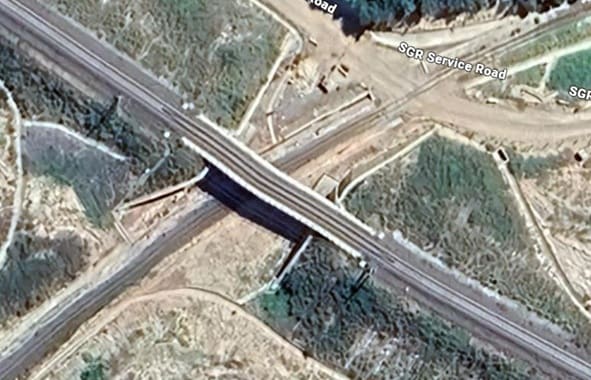
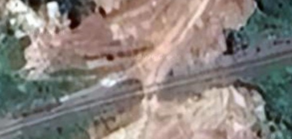
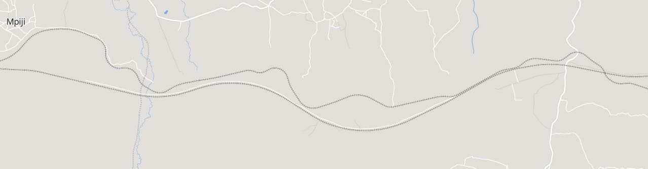
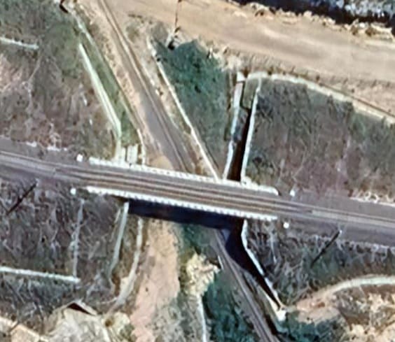
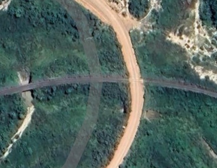
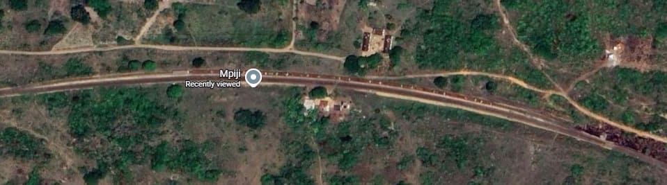
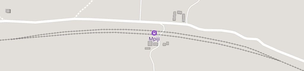
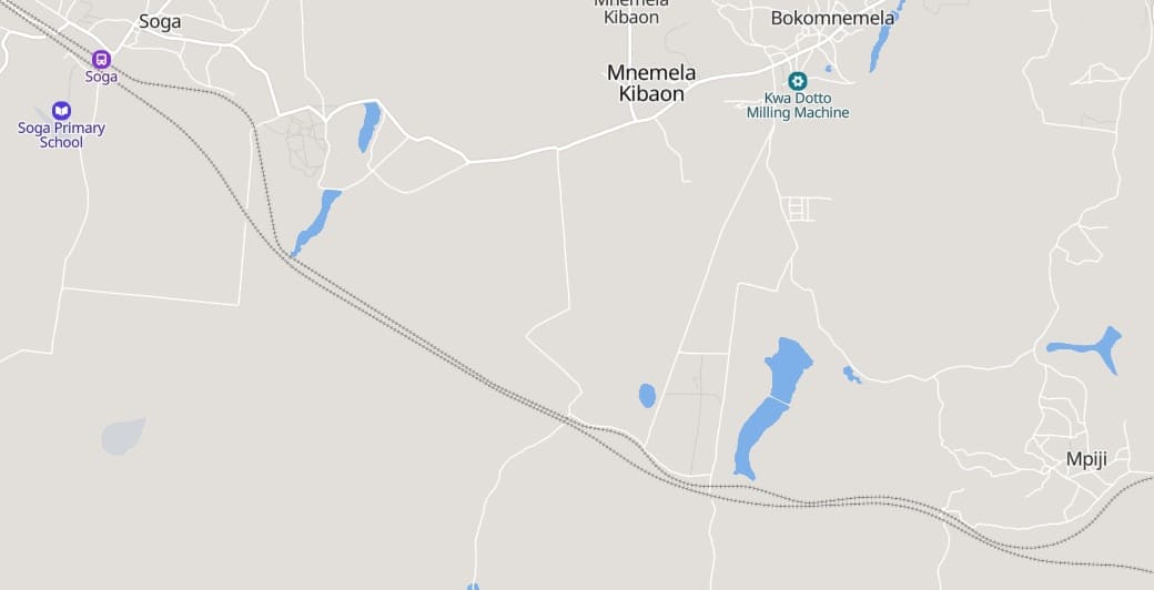
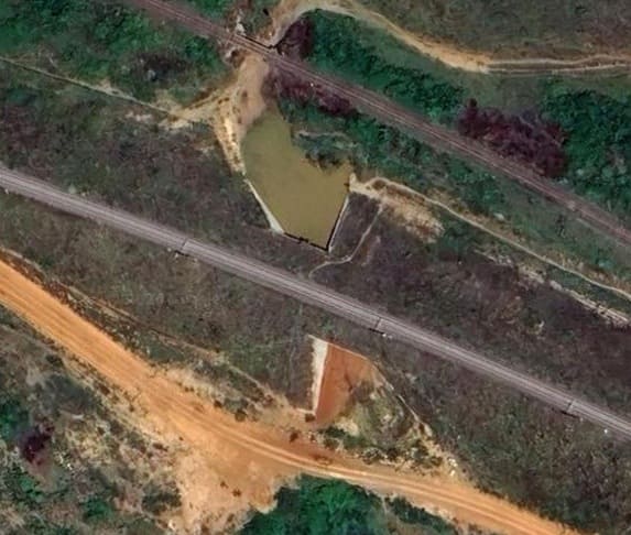
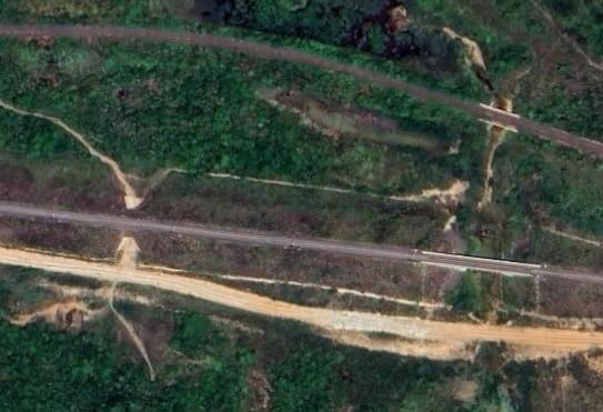
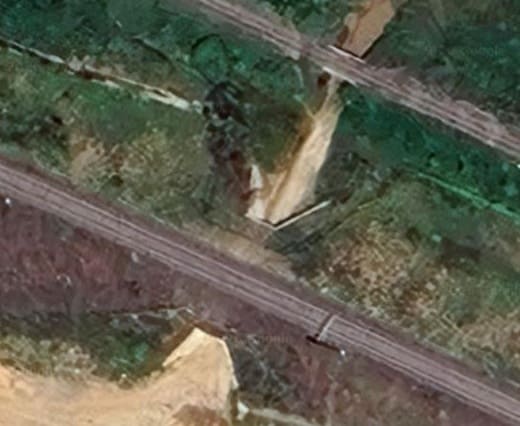
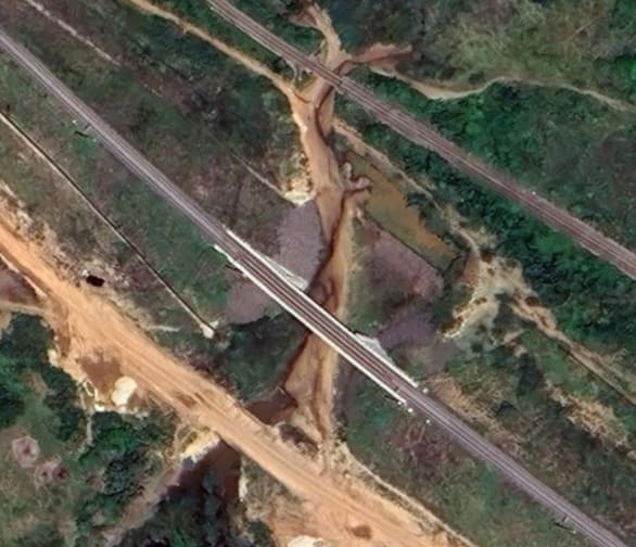
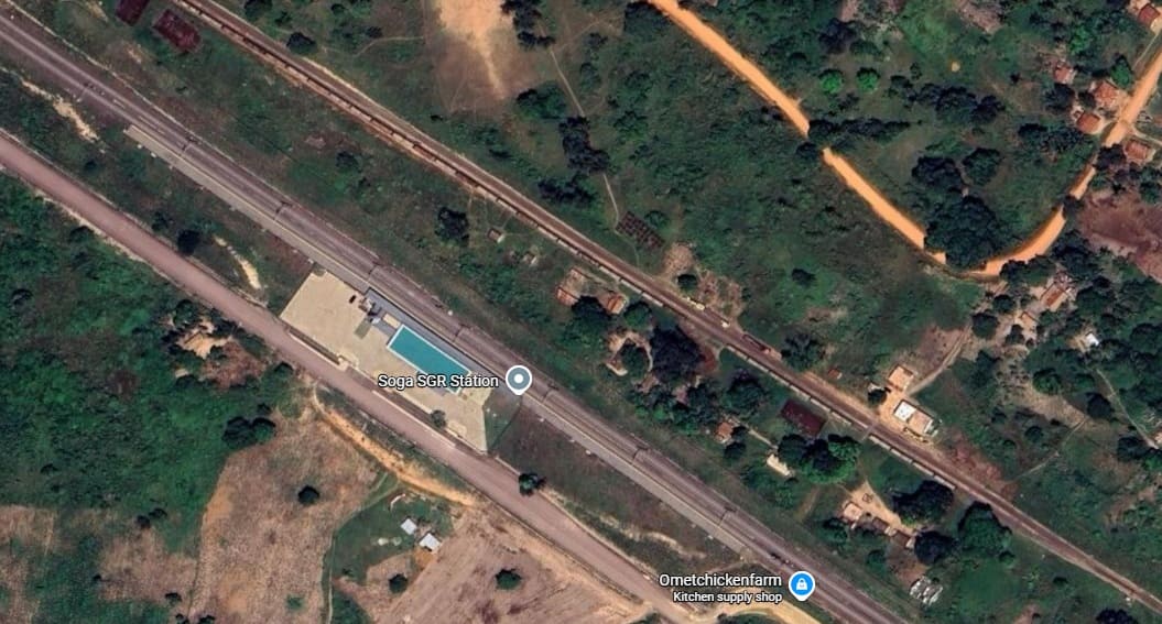
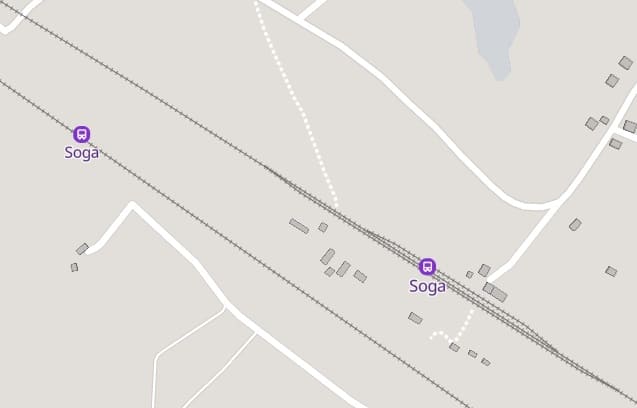
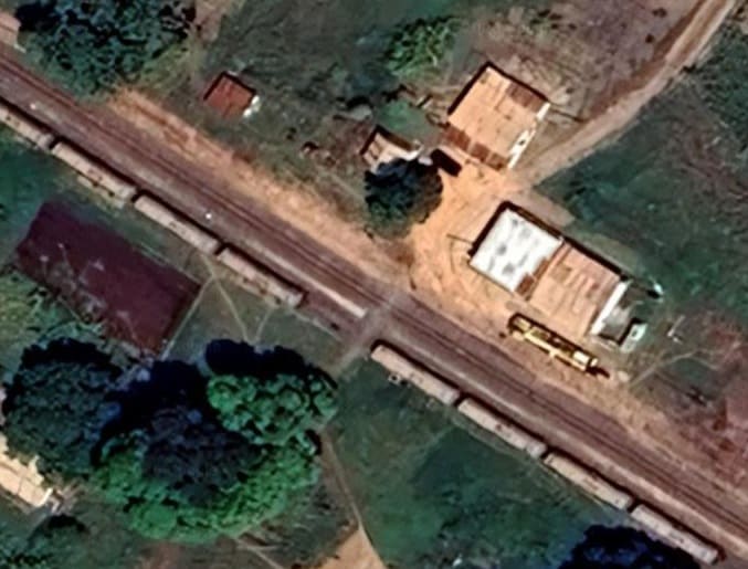
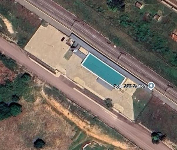
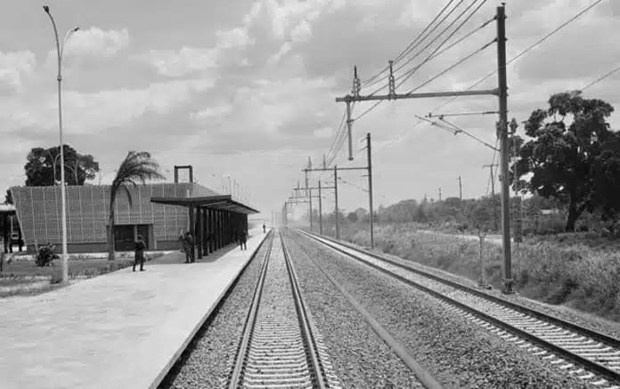
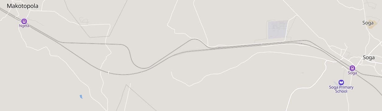
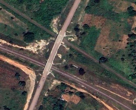
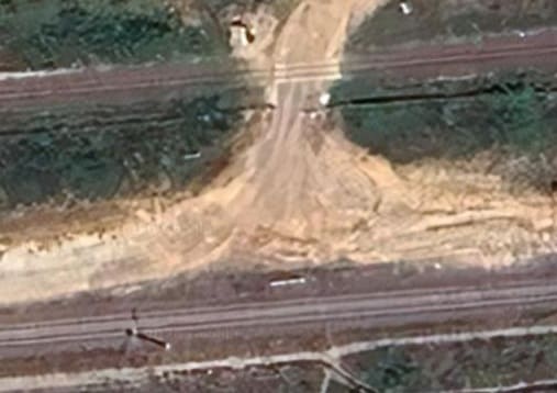
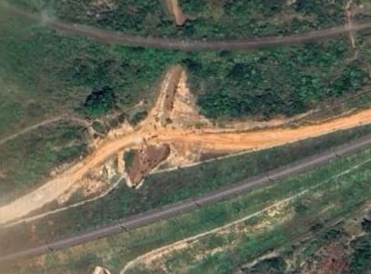
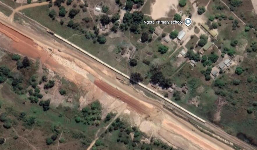
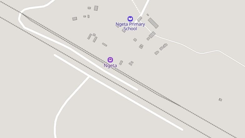
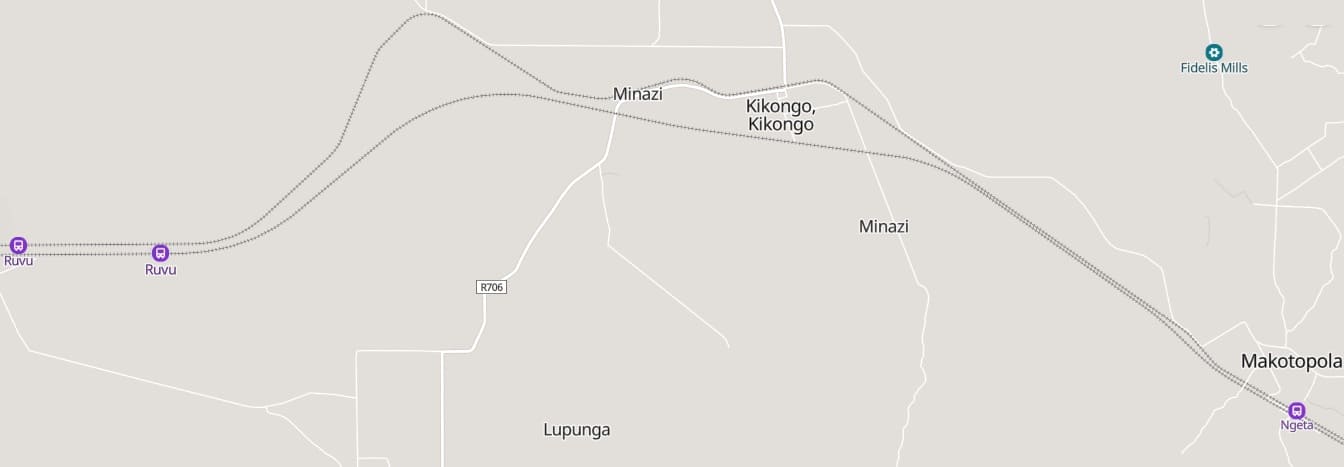
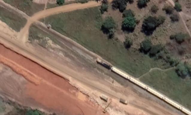
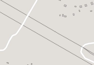
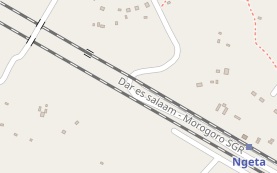
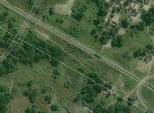
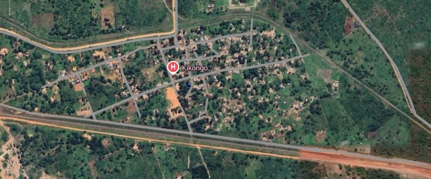
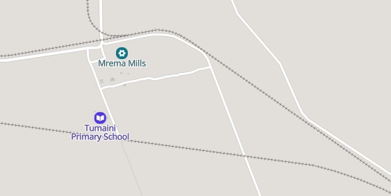
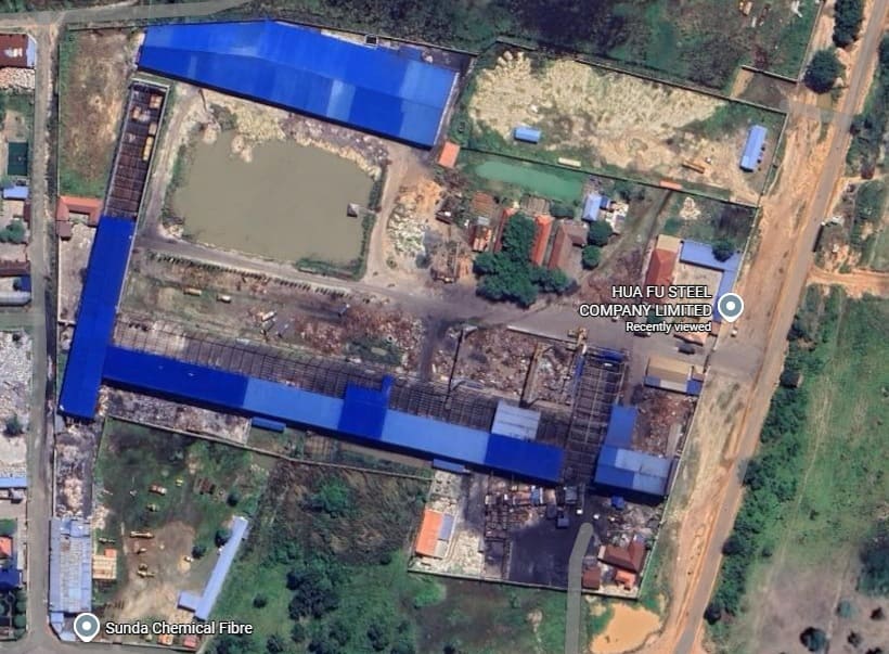
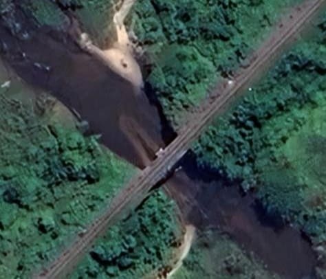
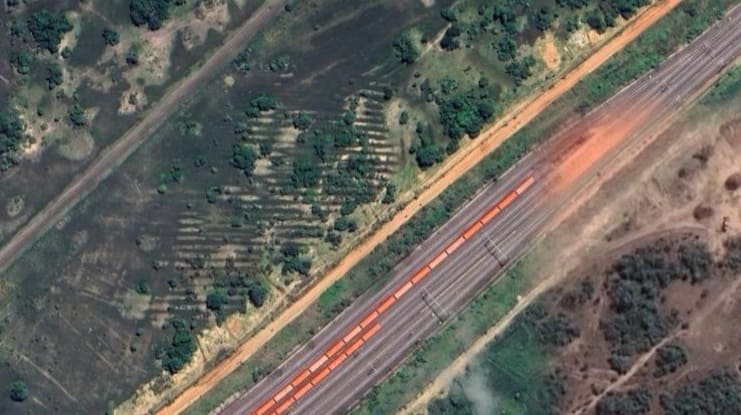
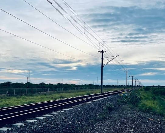
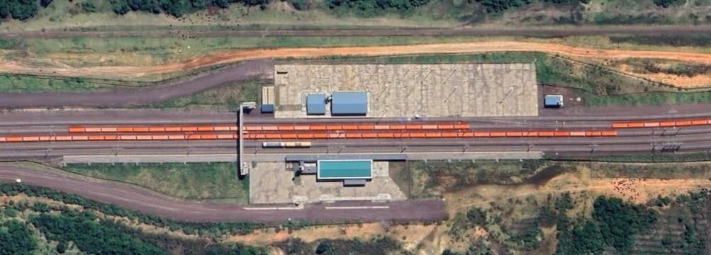
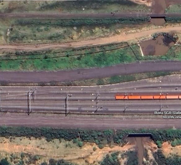
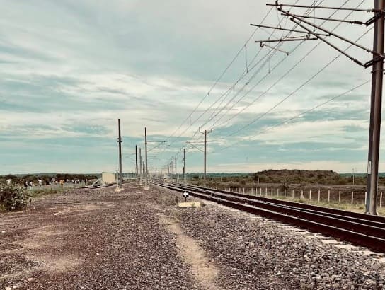
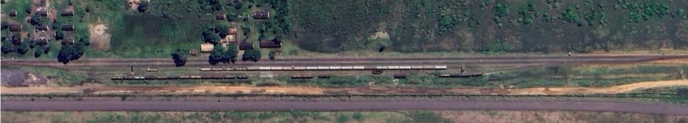
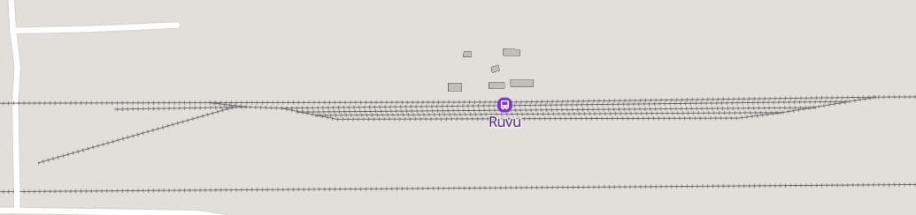
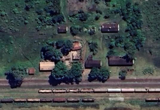
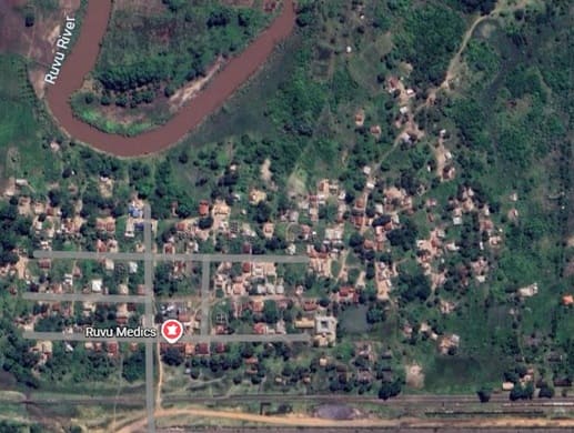
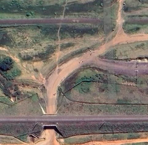
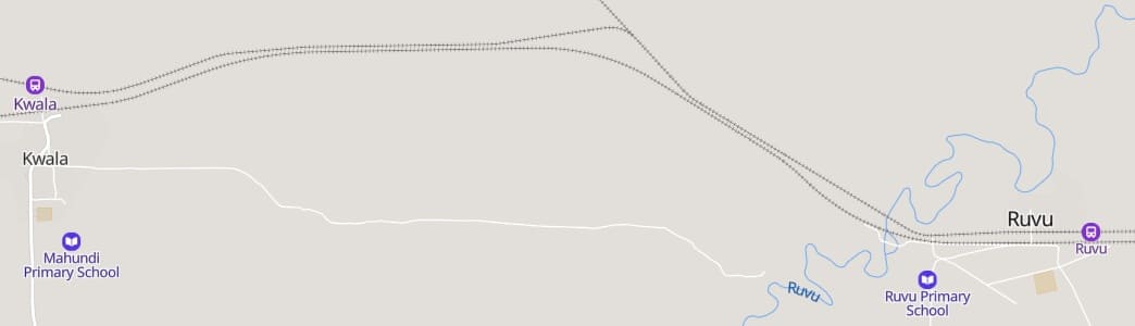
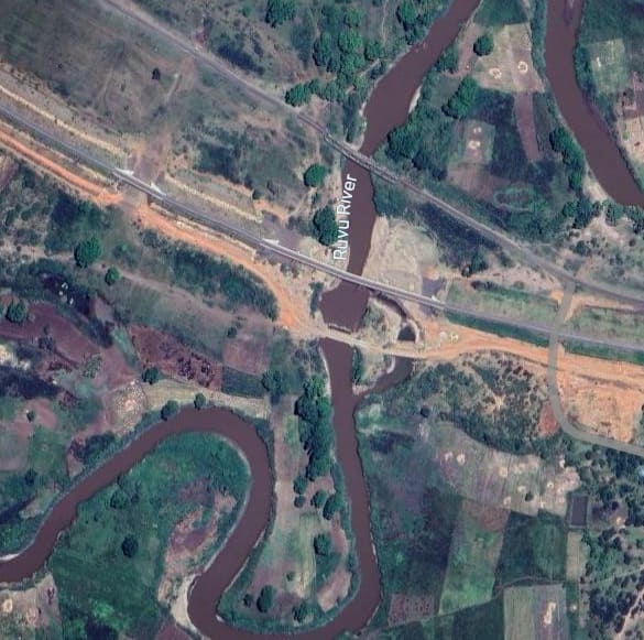
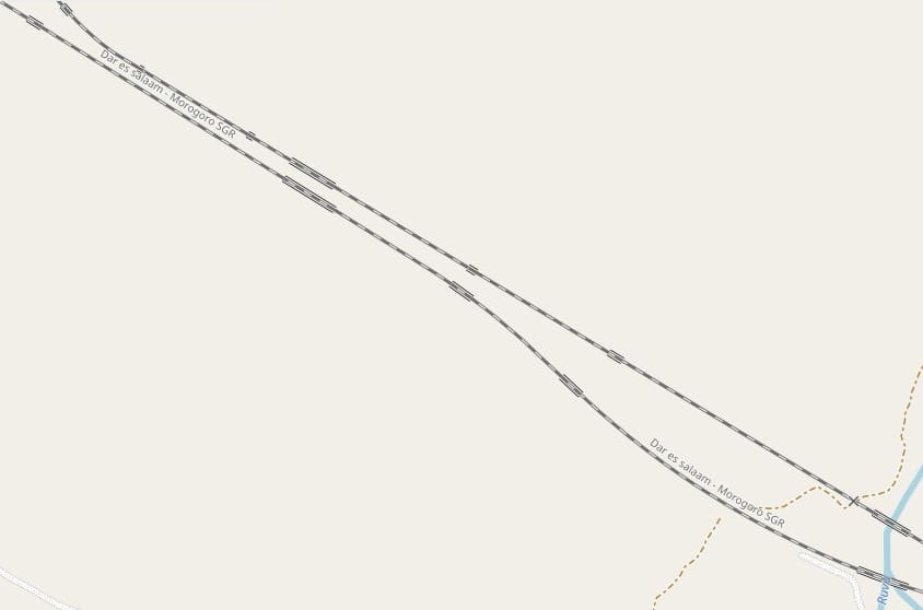
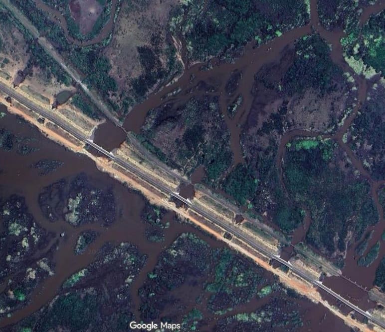
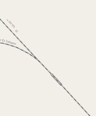
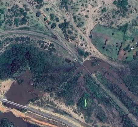
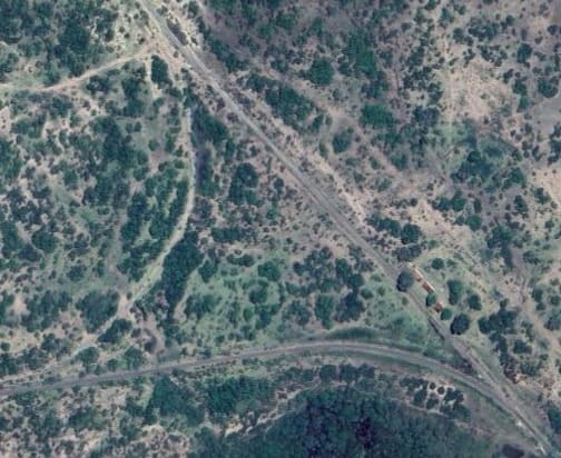
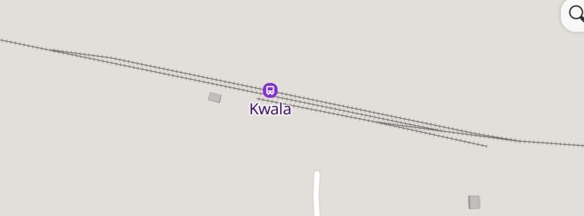
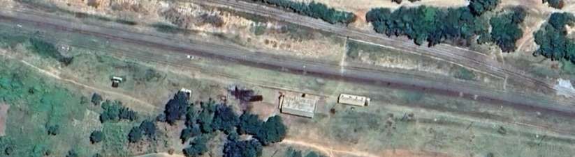
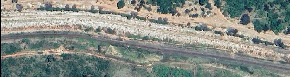
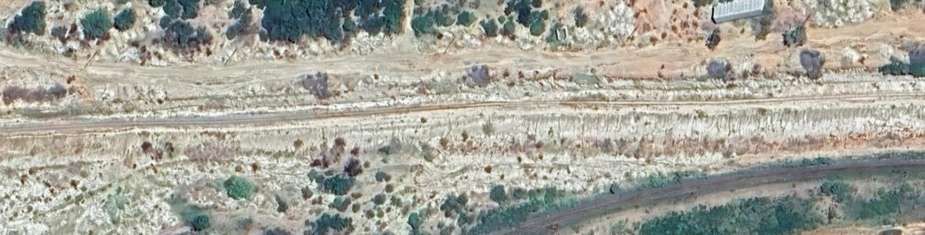
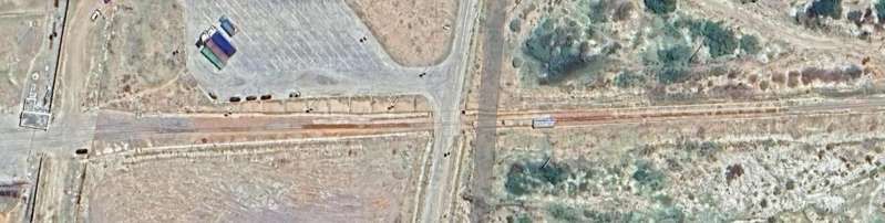
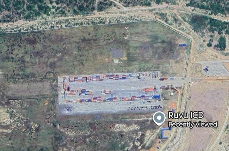
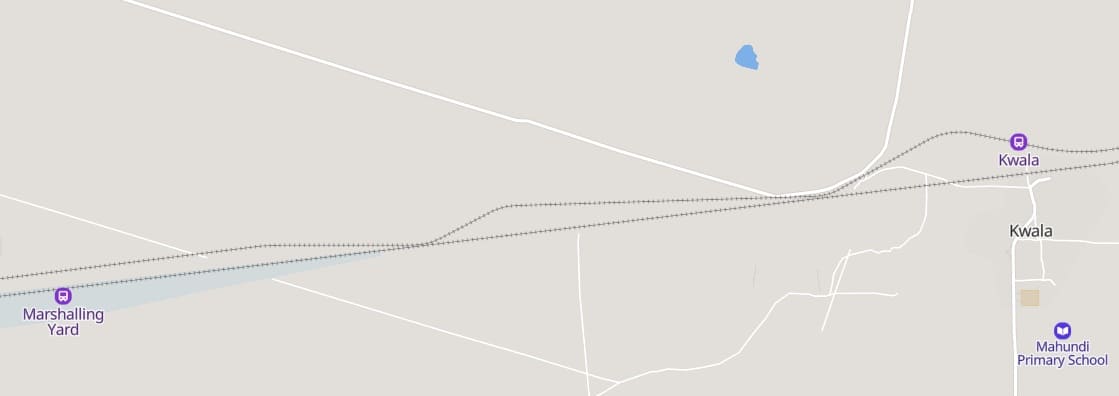
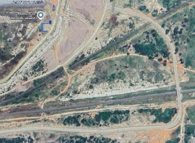
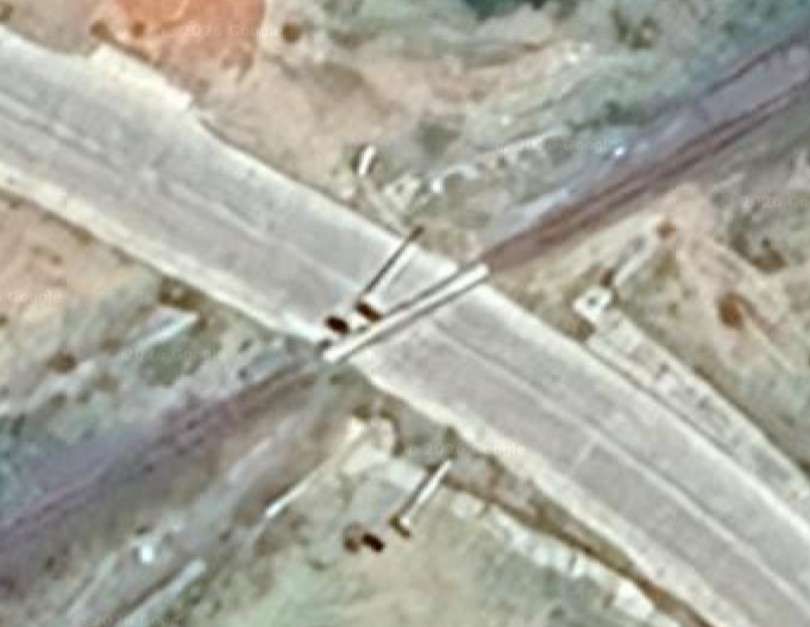
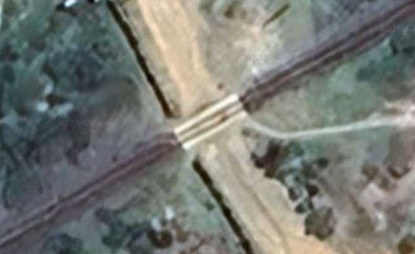
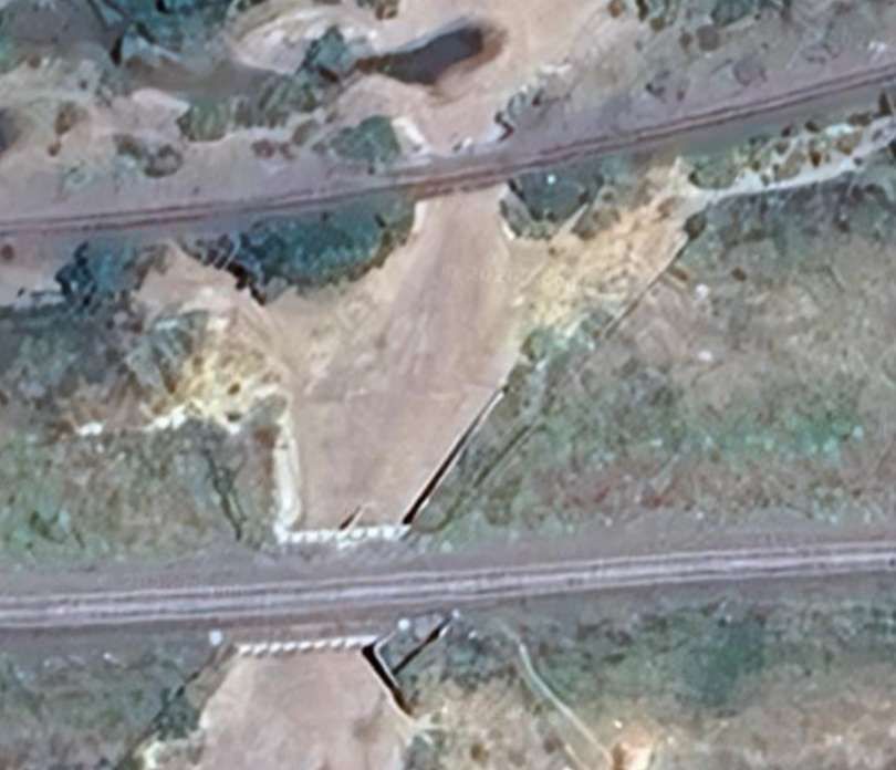
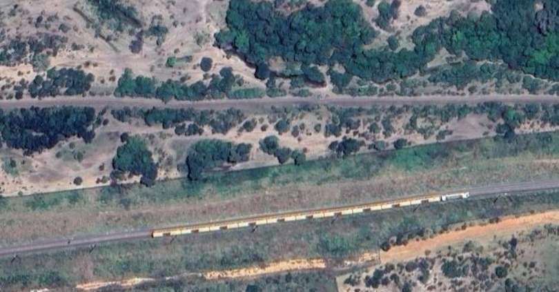
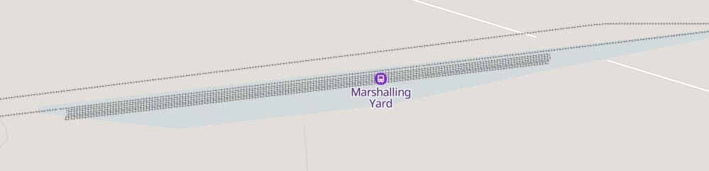
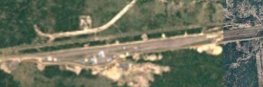
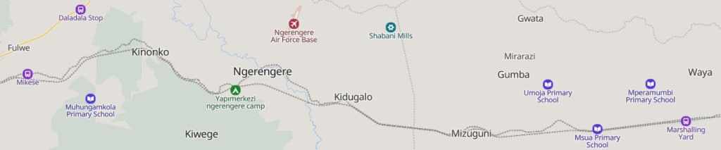
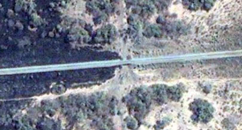
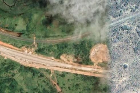
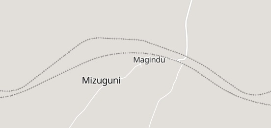
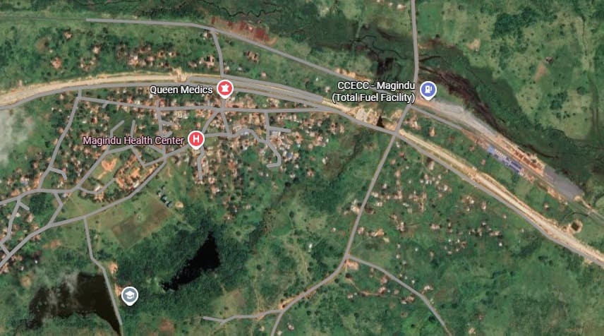
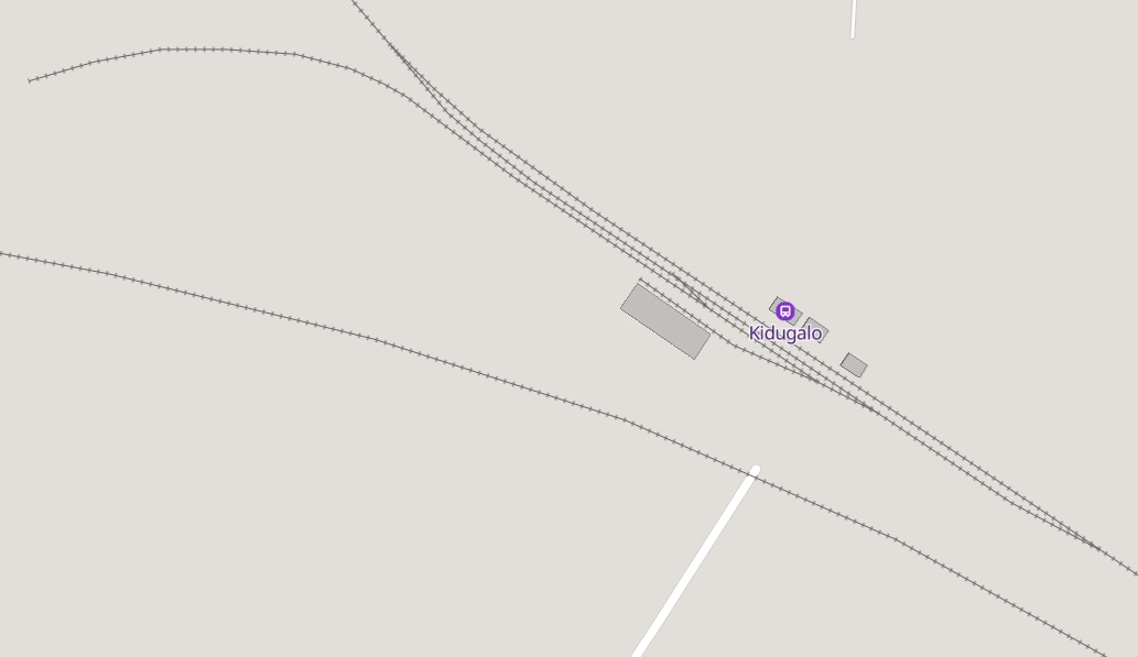
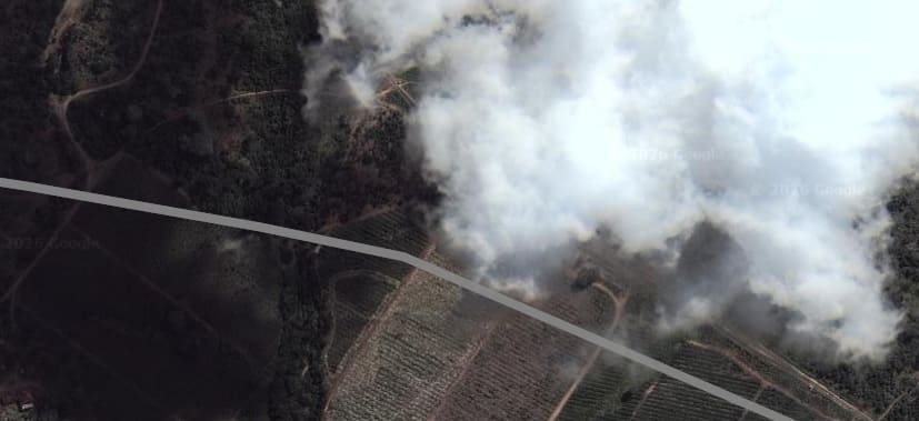
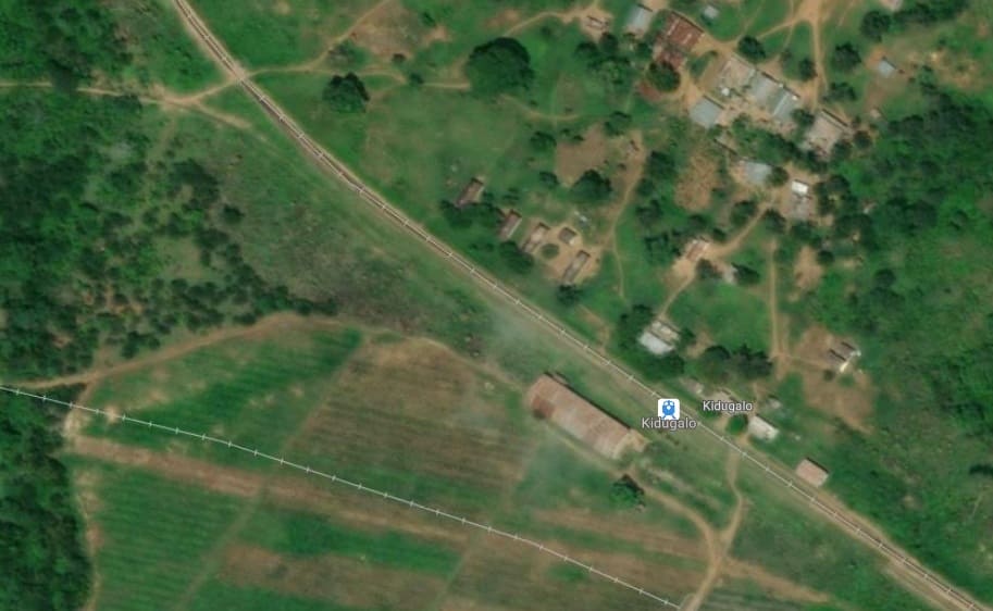
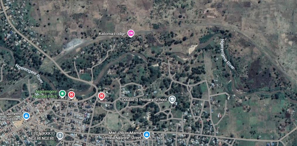
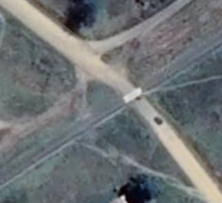
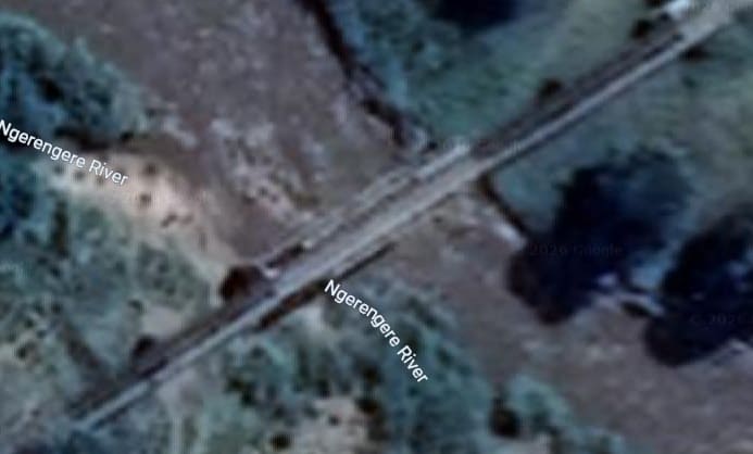
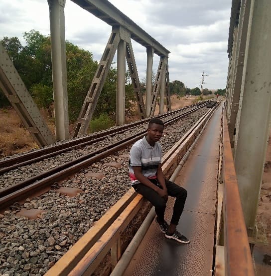
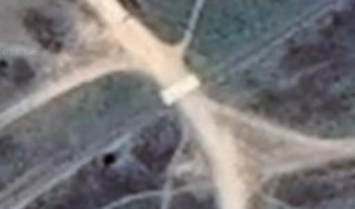
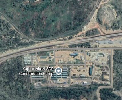
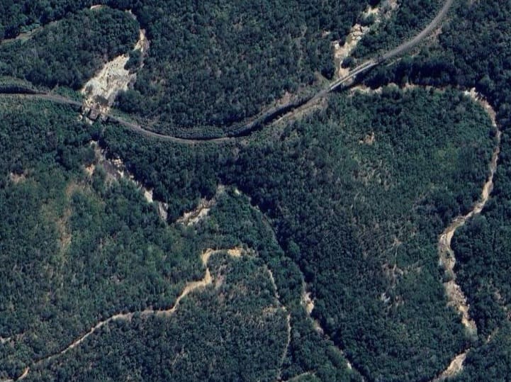
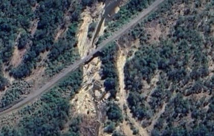
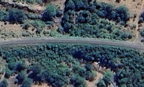
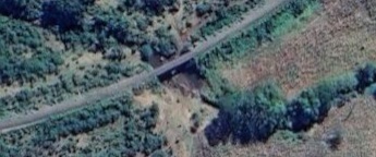
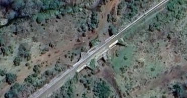
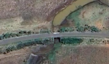
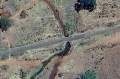
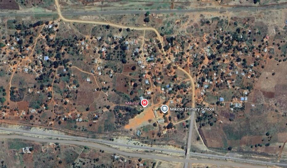
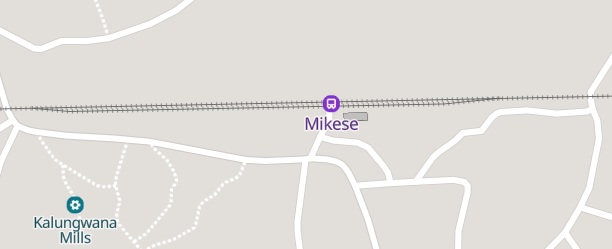
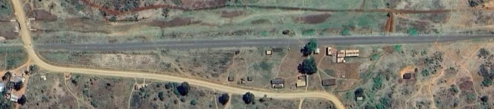
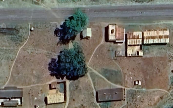
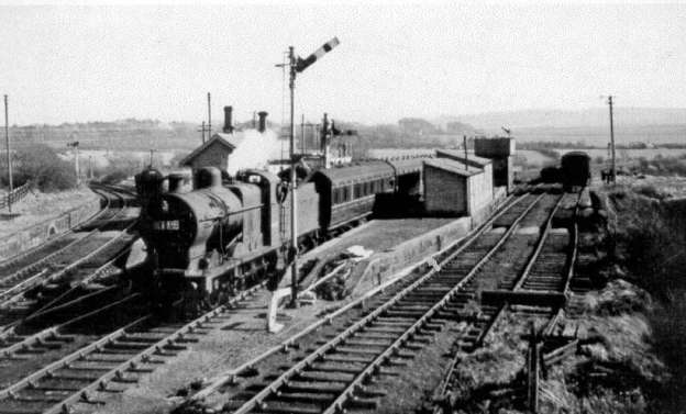
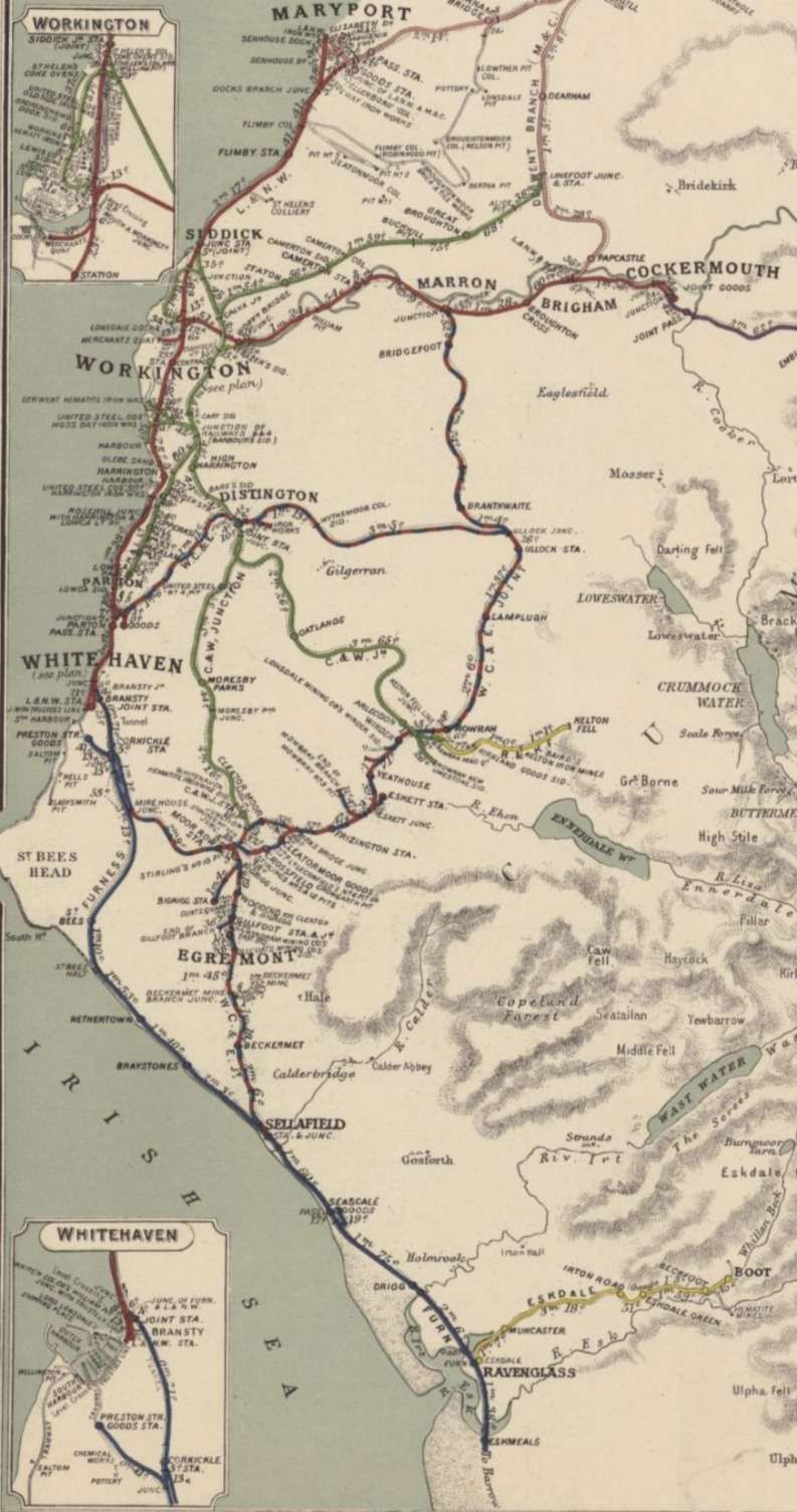
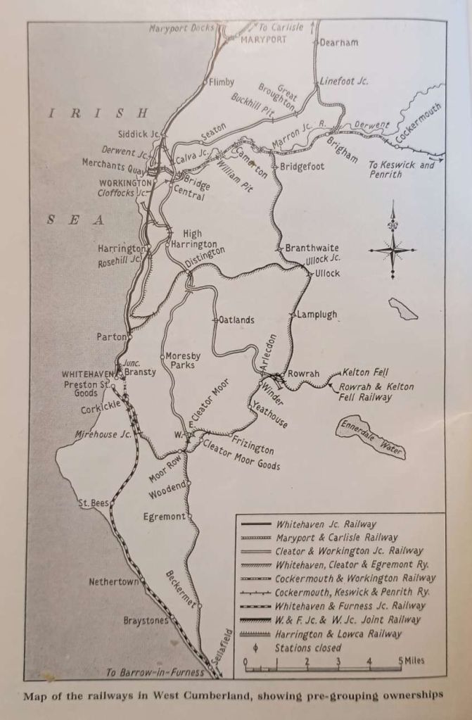
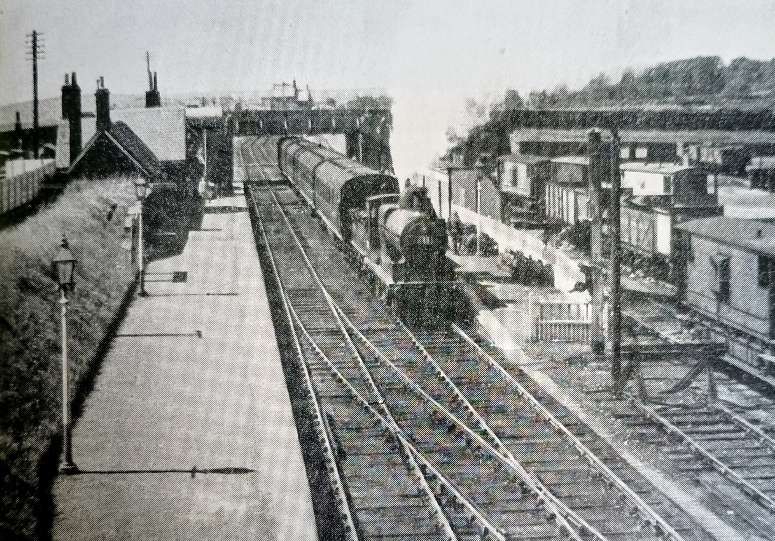
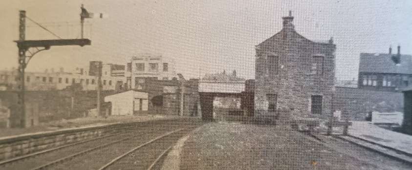

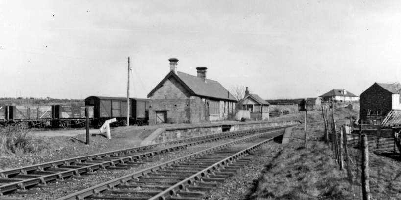
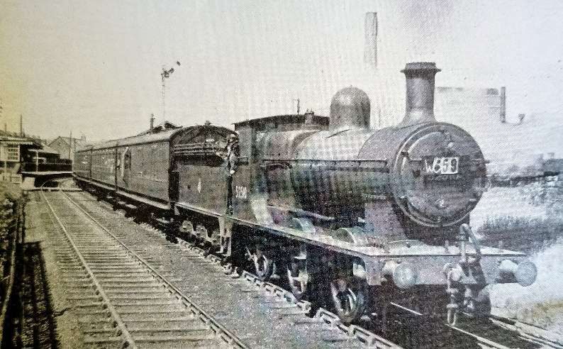
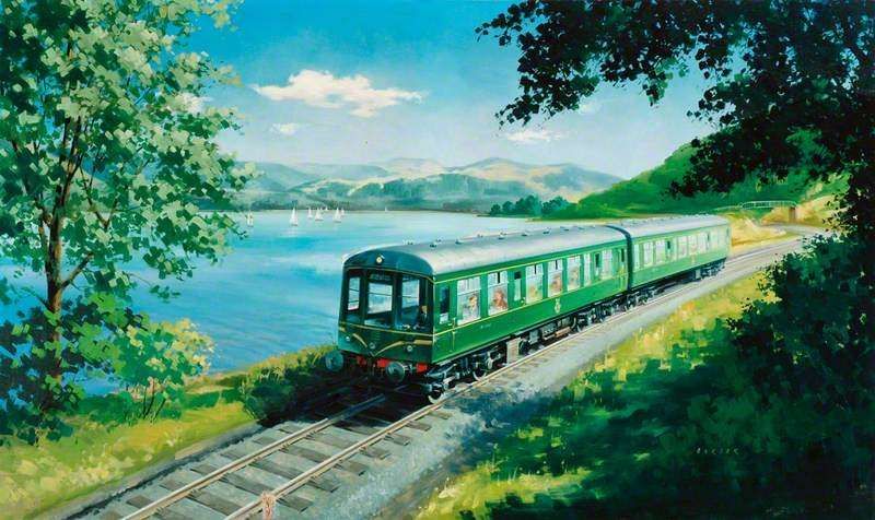
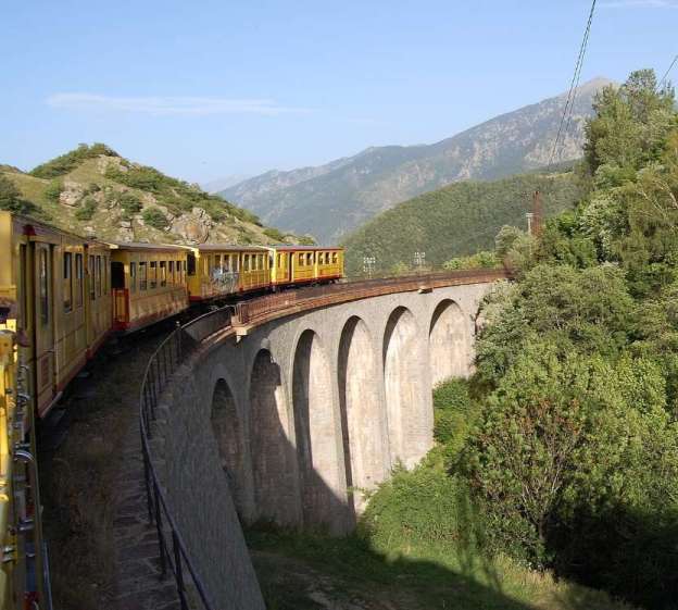
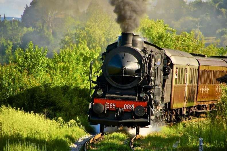
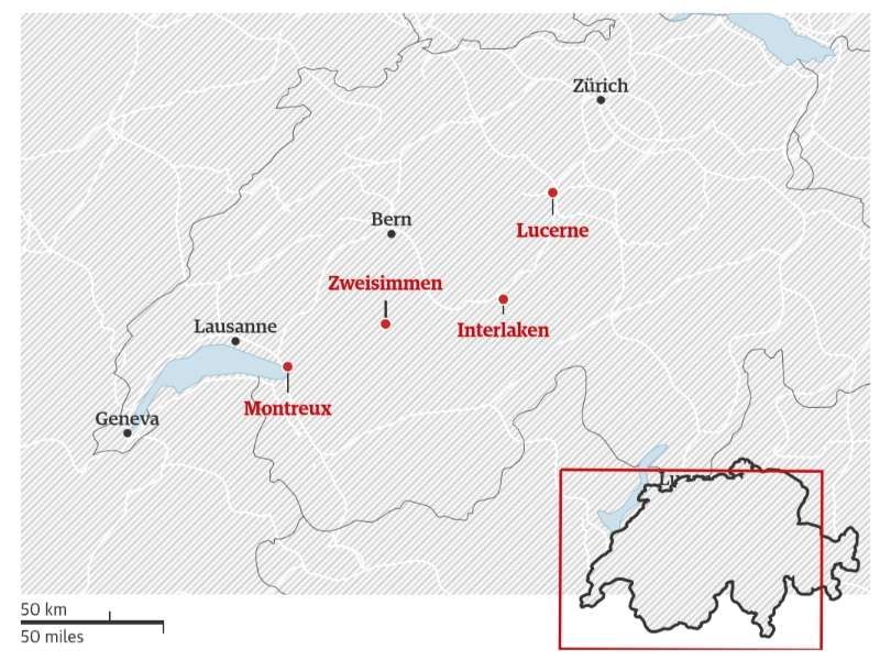
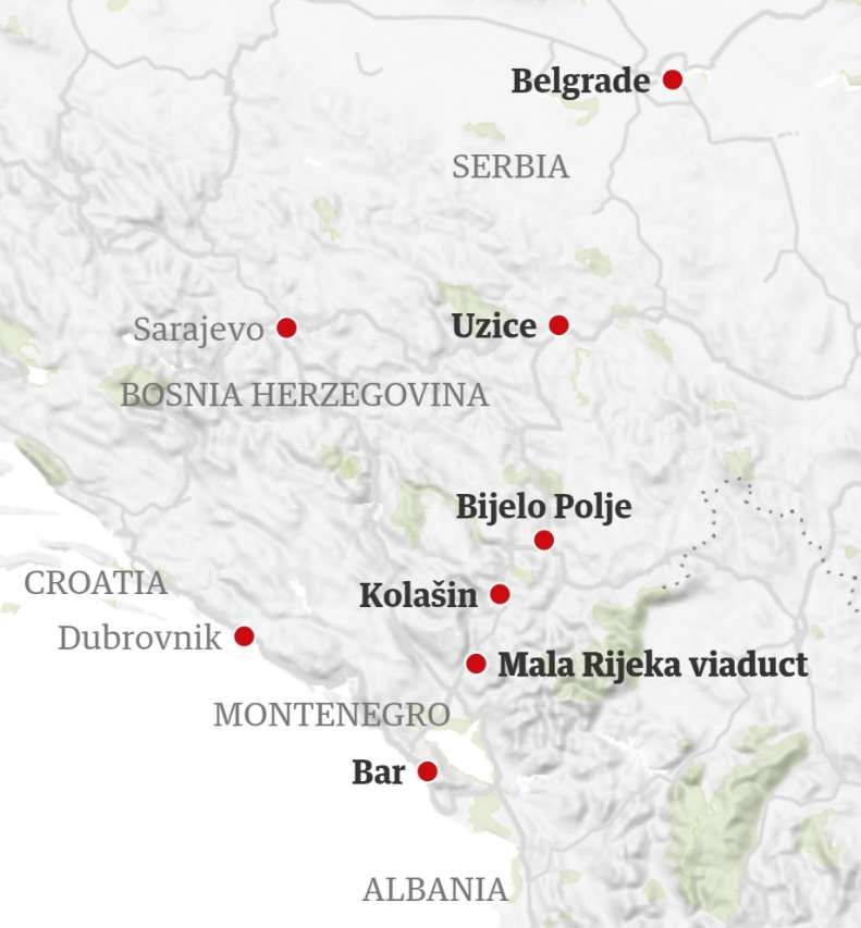
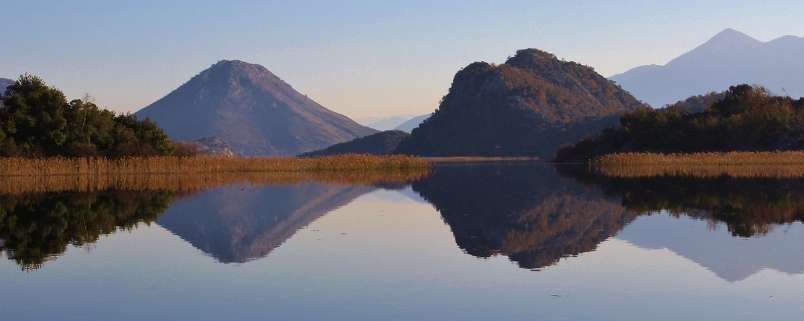
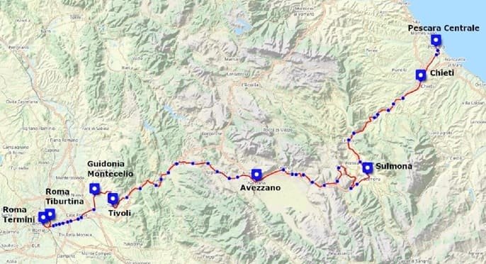
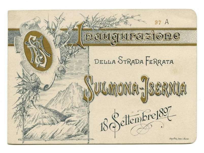
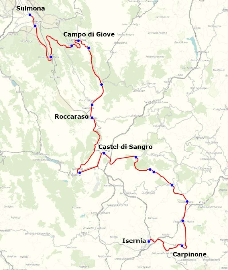
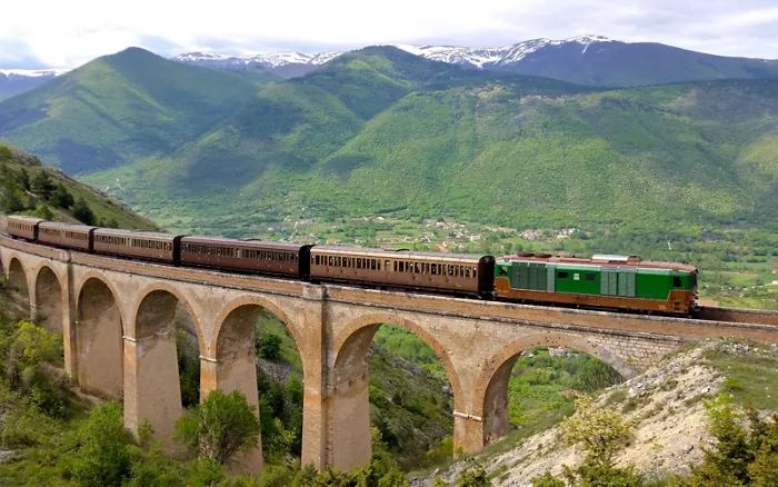
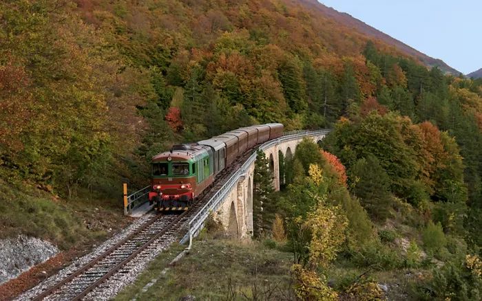
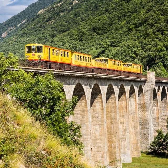
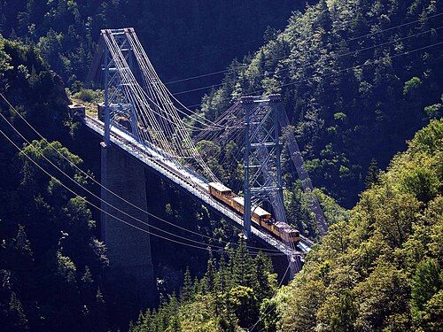
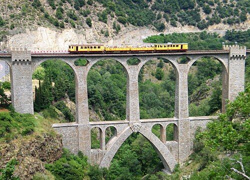

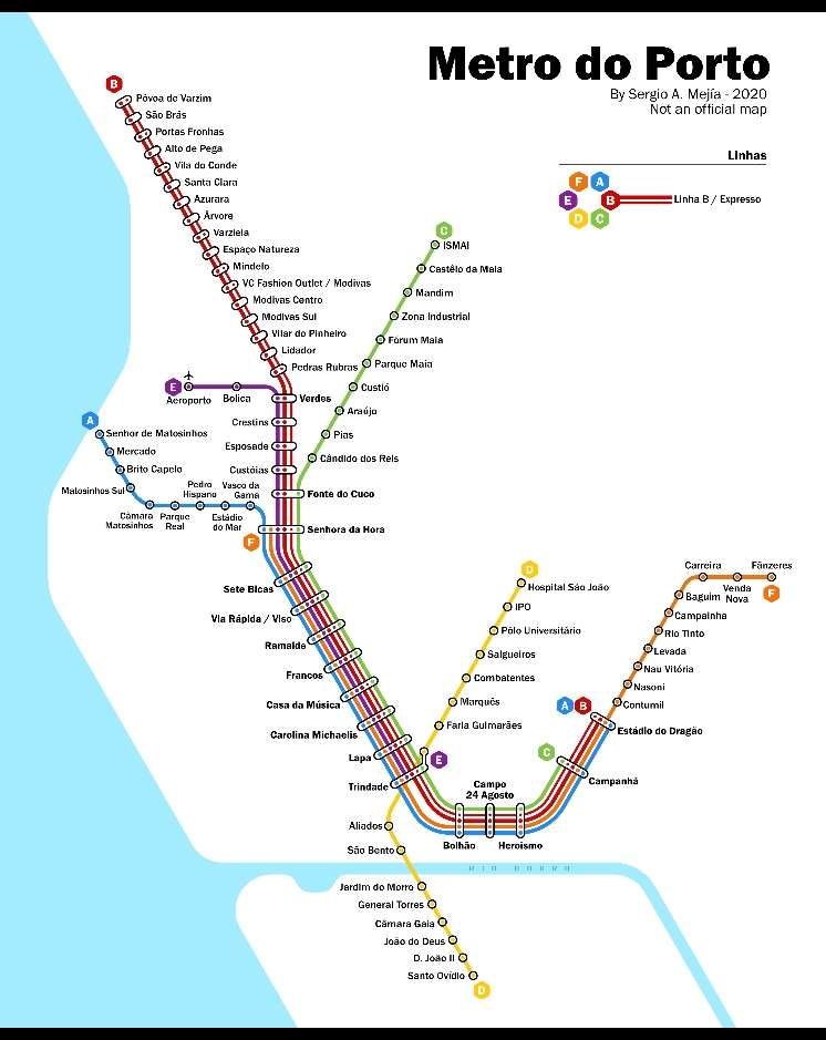
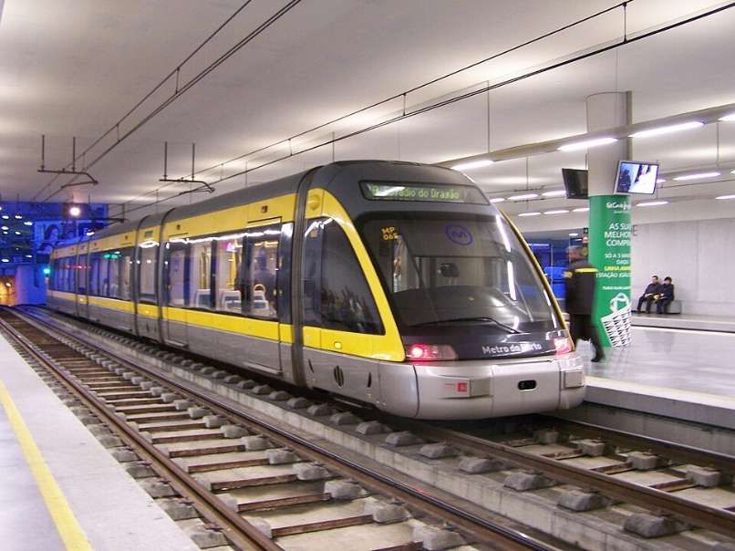
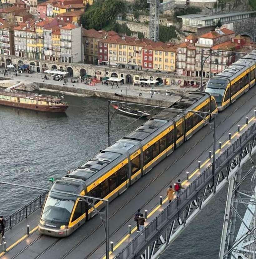
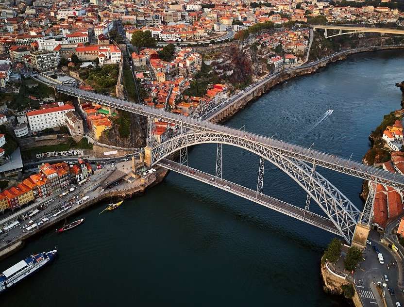
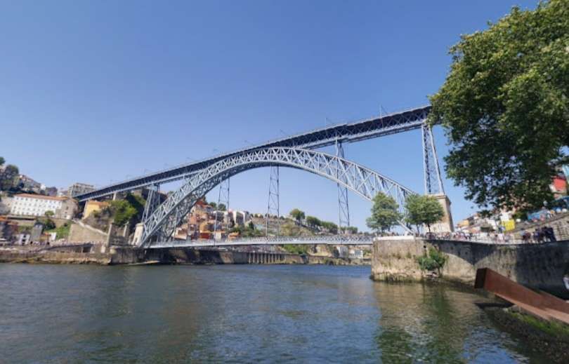
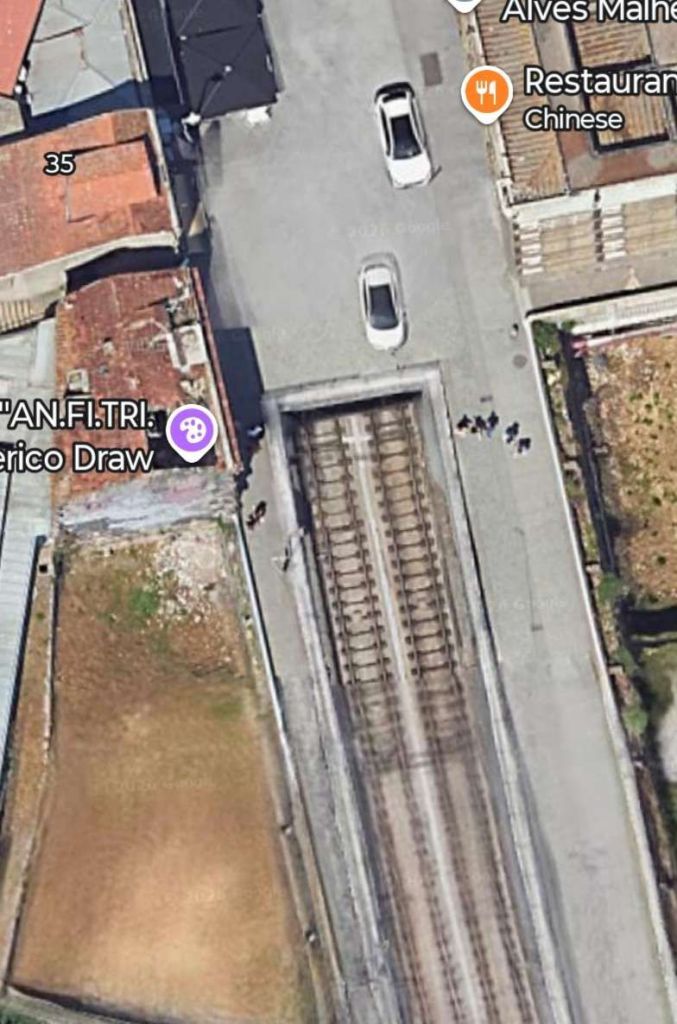
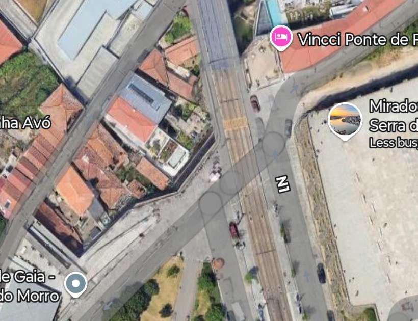
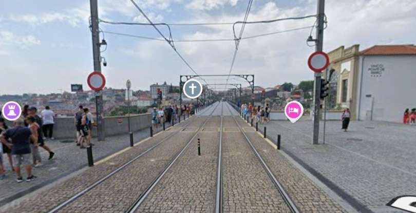
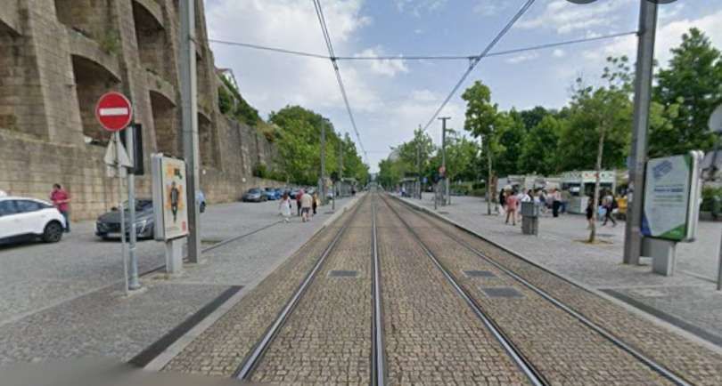
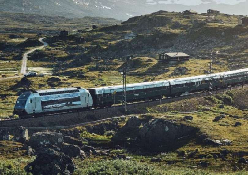
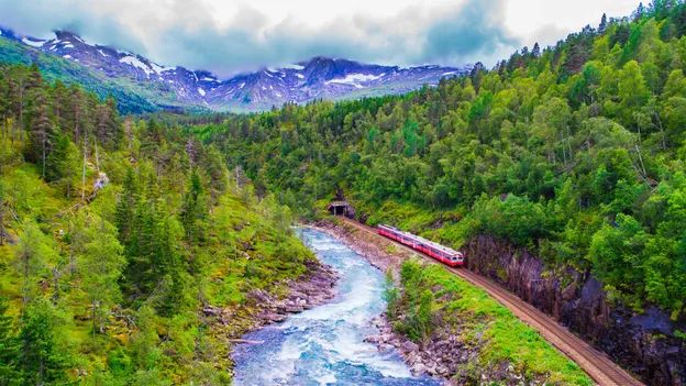
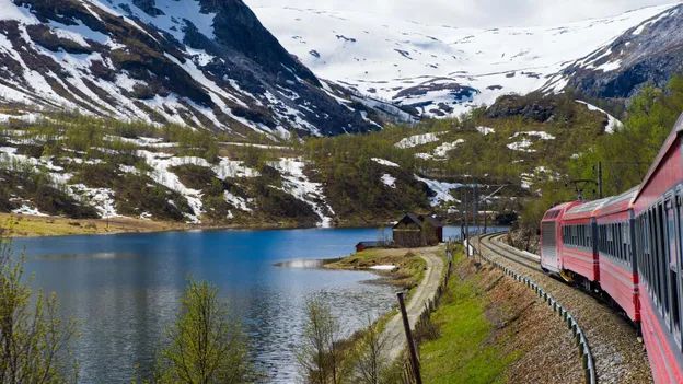
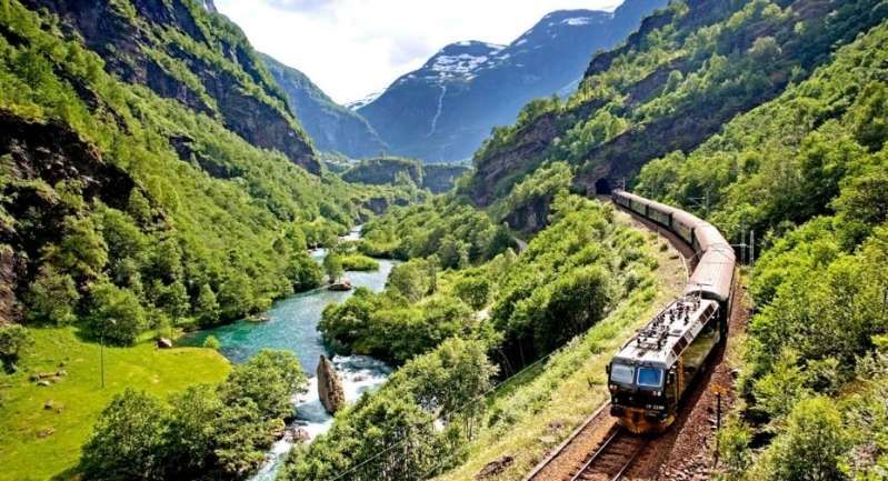
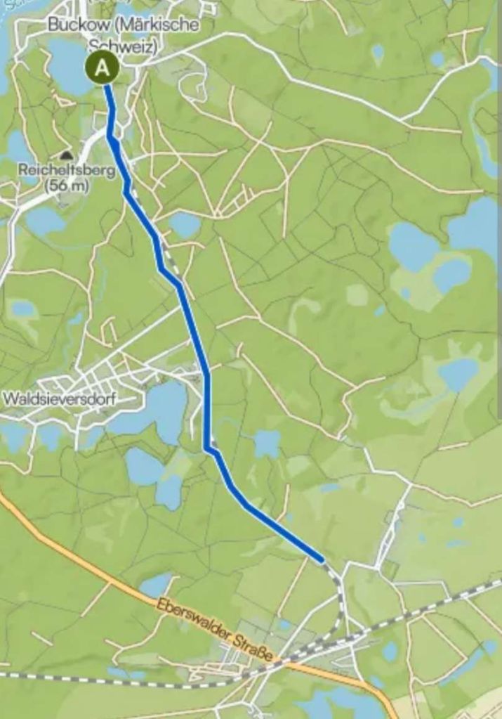
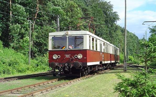
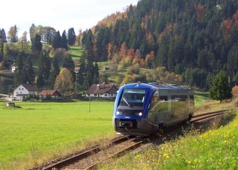
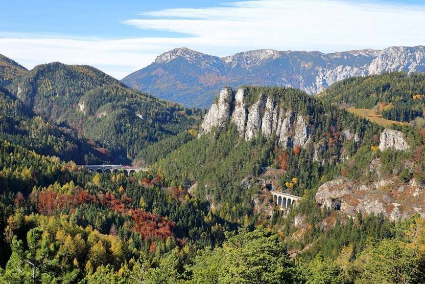
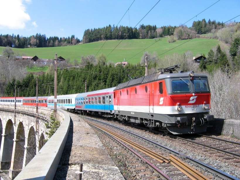
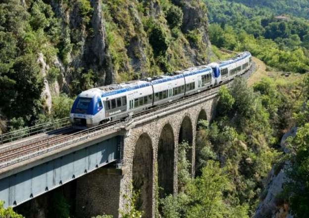
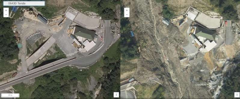
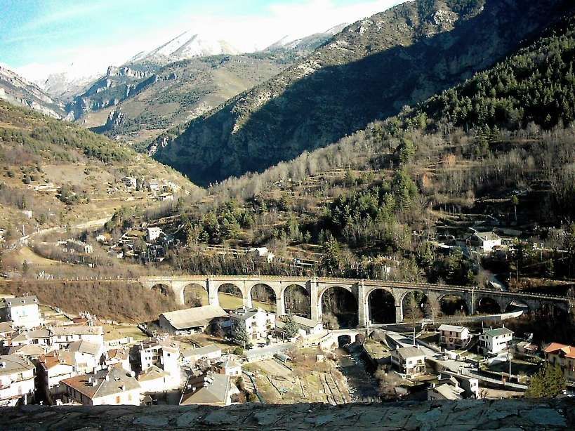
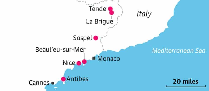
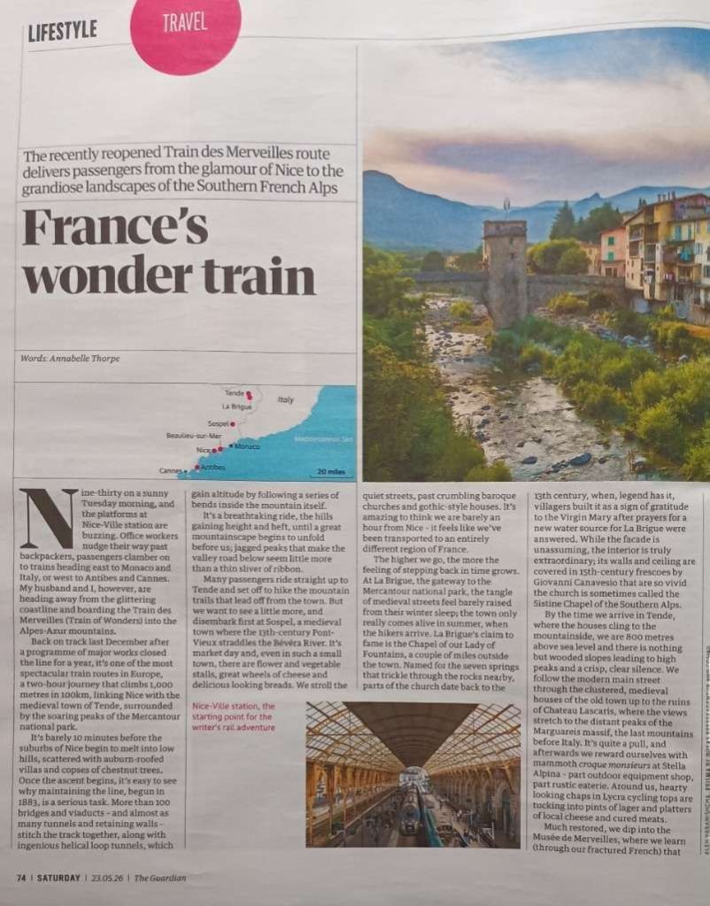
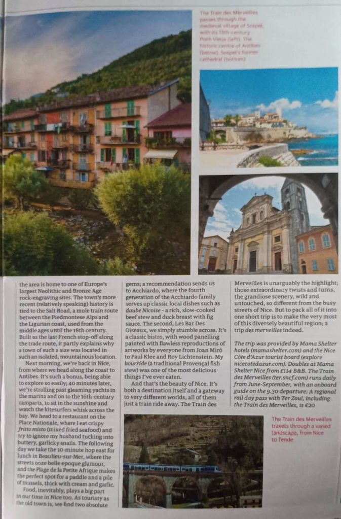
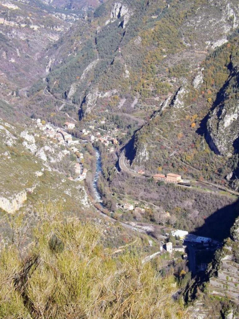
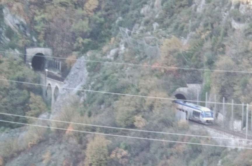
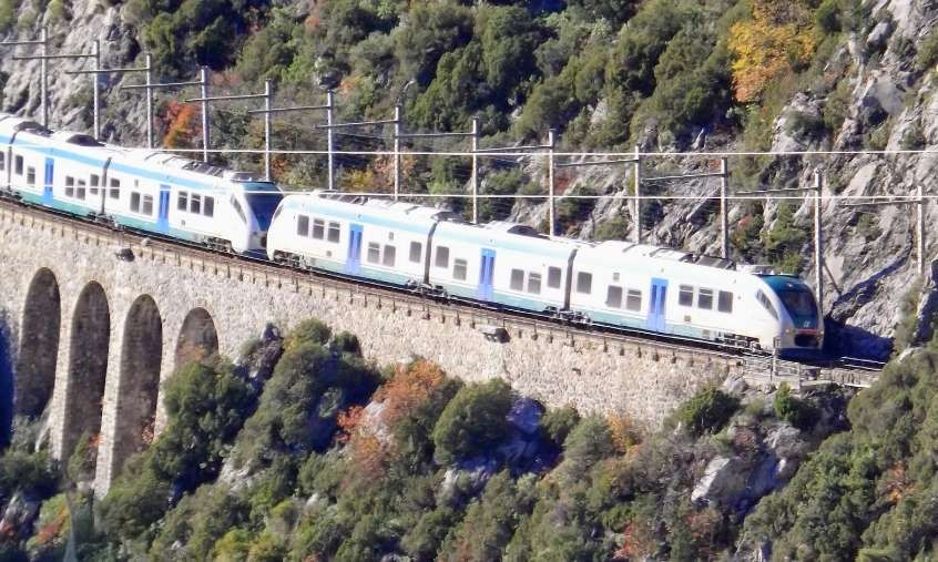
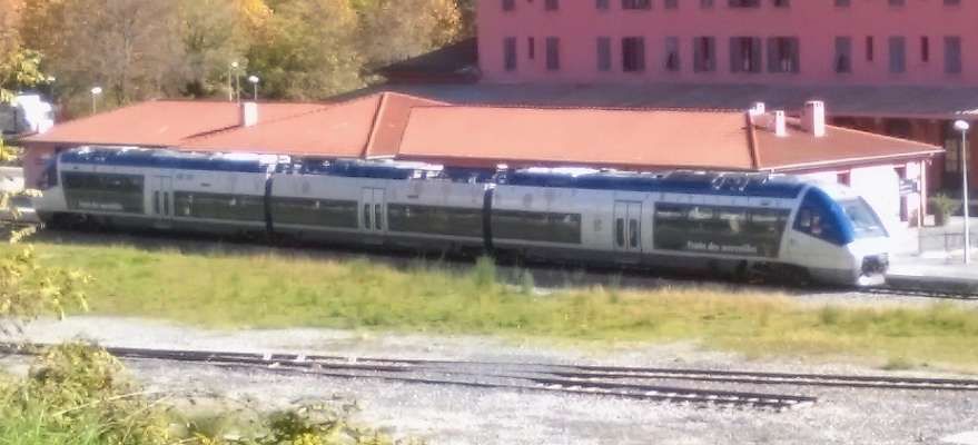
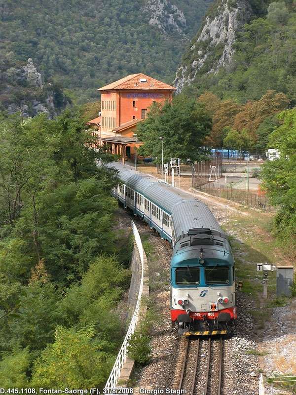
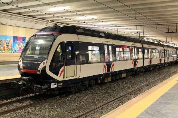
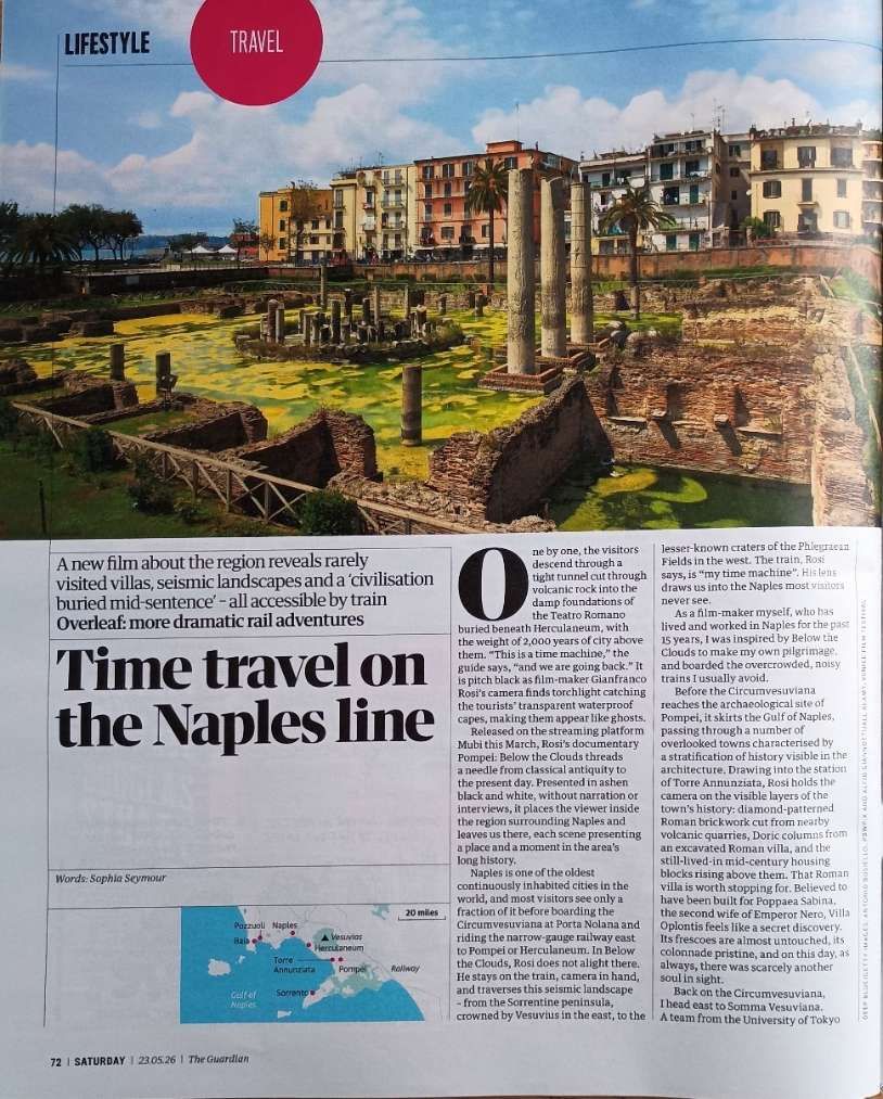
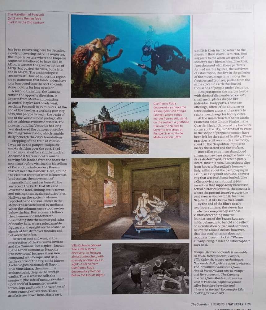
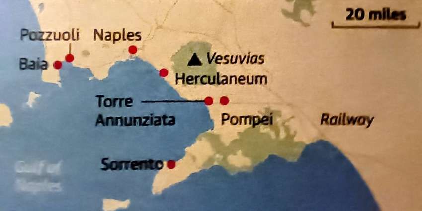
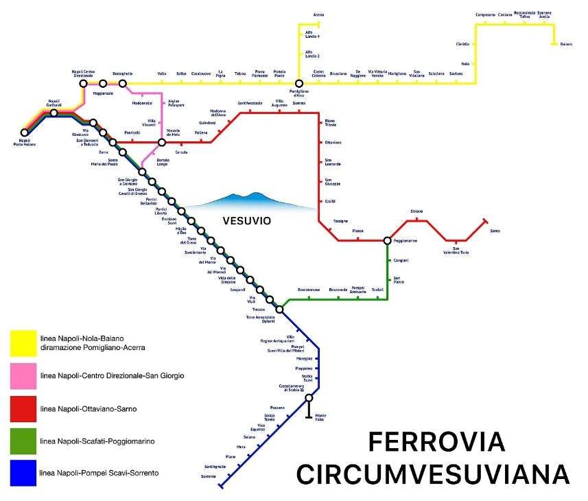
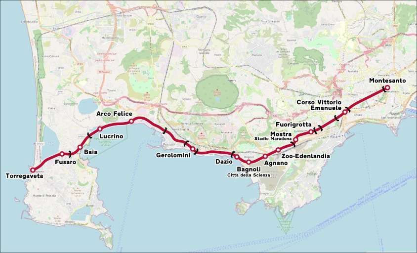

.jpg)
#/media/File:P1020943_Bahnhof_Husum_2019.jpg)
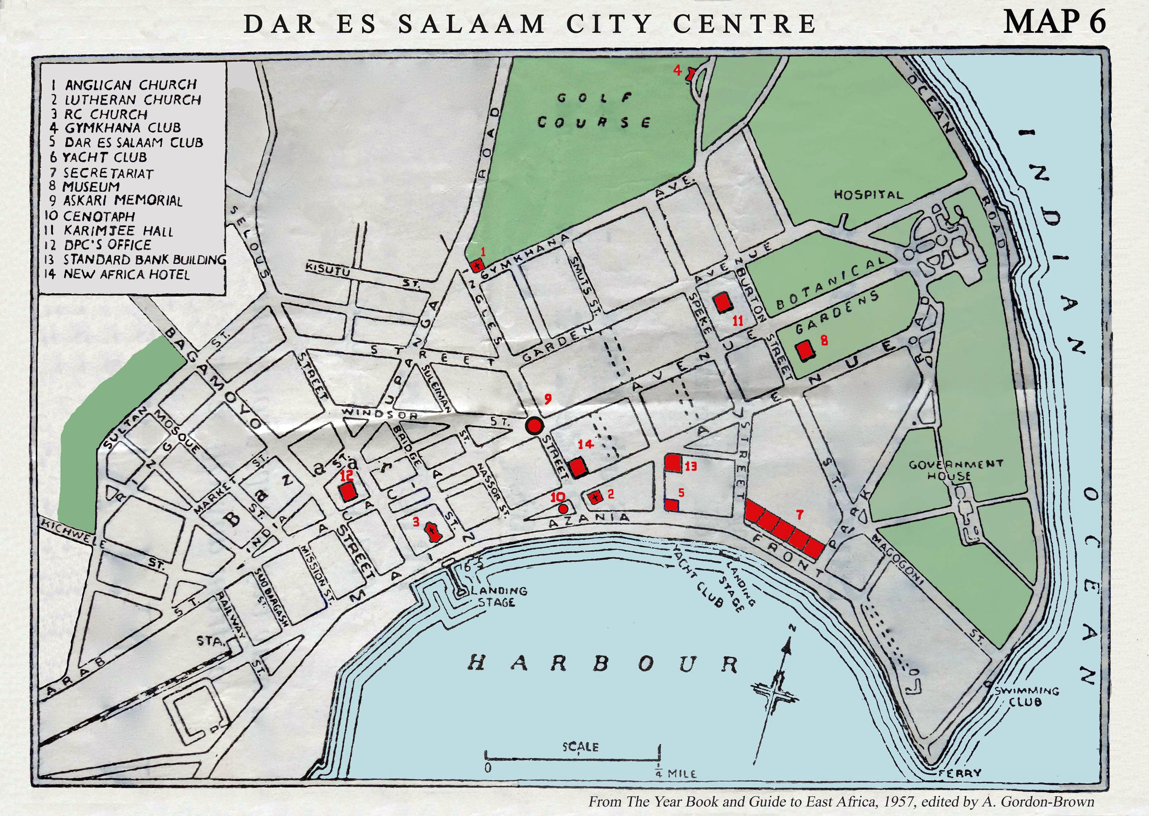
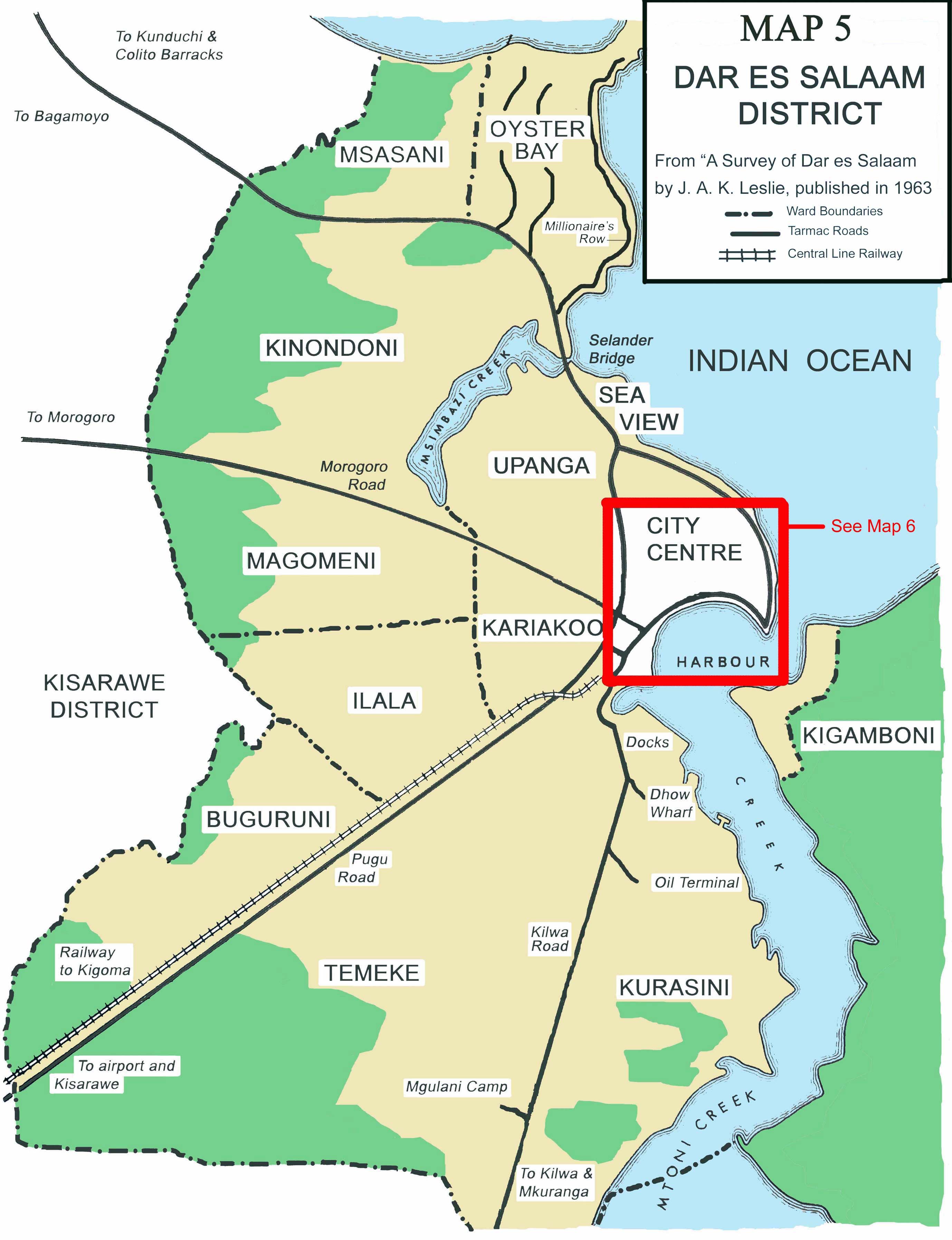
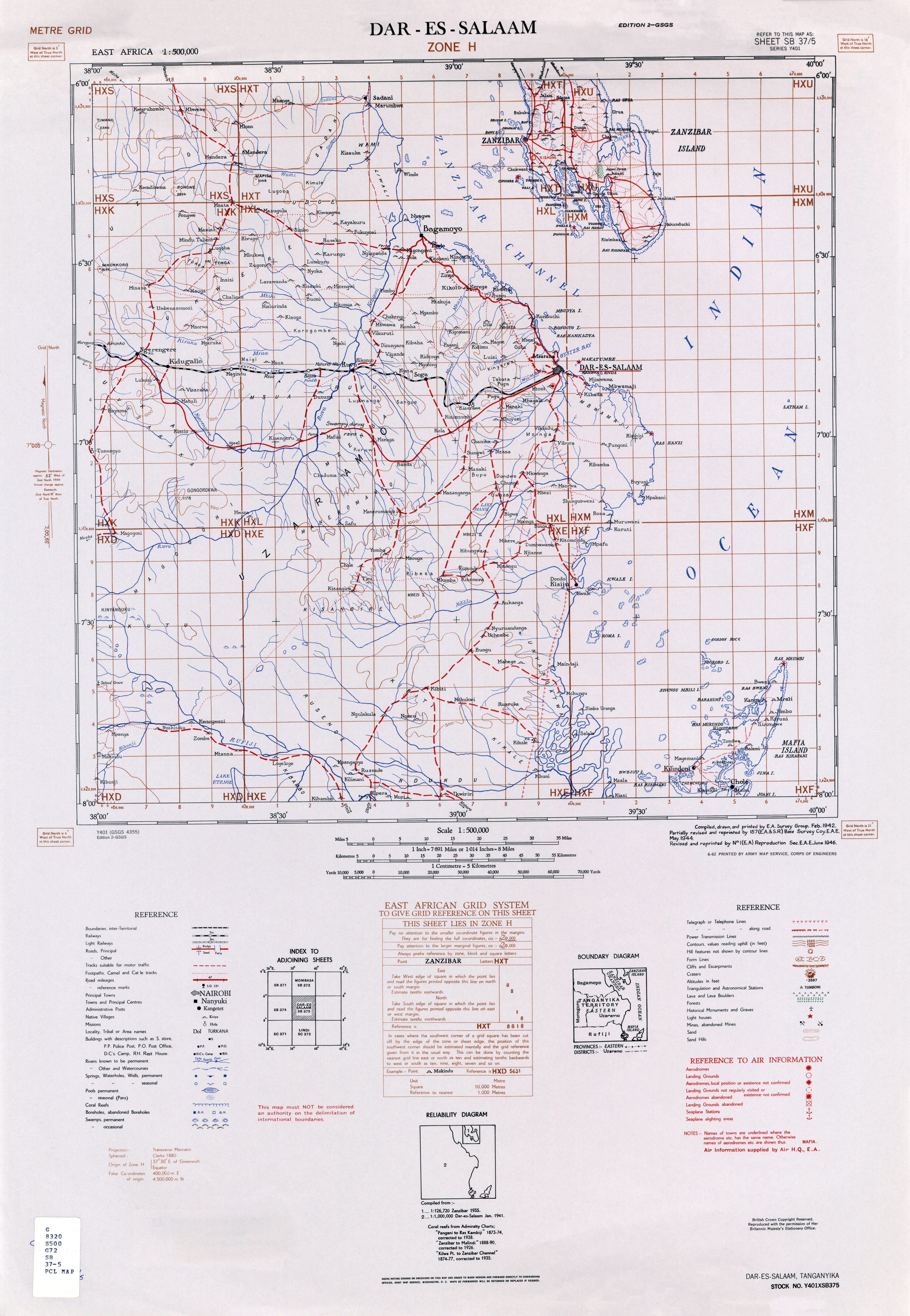
.jpg)
.jpg)
.jpg)
#/media/Dosiero%3AFontan-Saorge_staz_ferr_D.445.jpg)