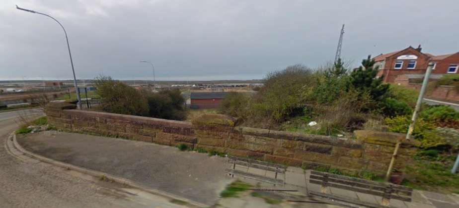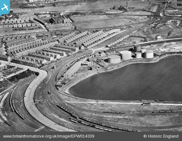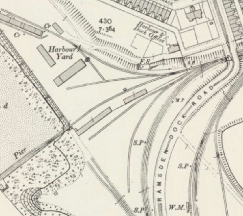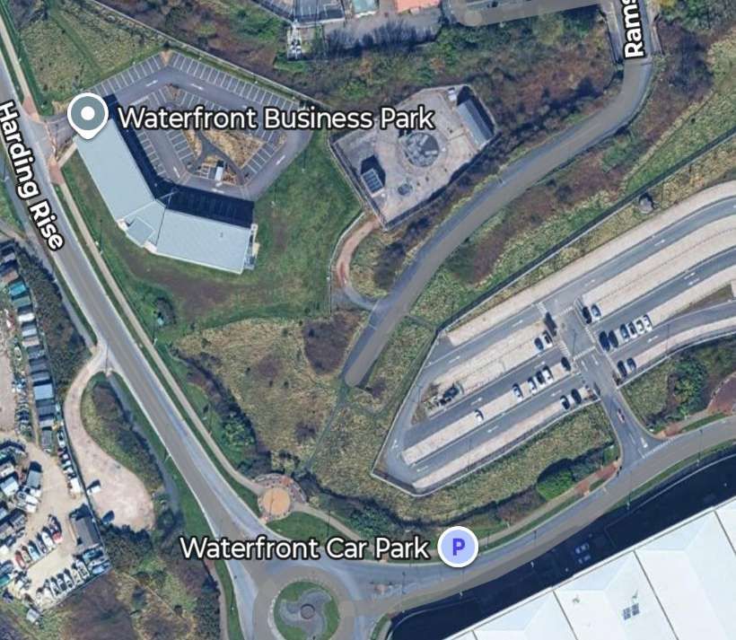
Tag Archives: railways

The Crumbles Branch, Eastbourne

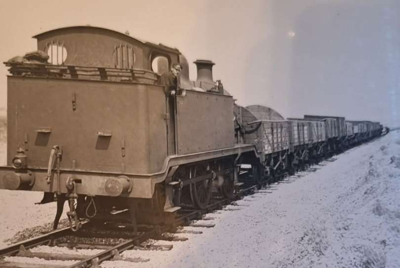
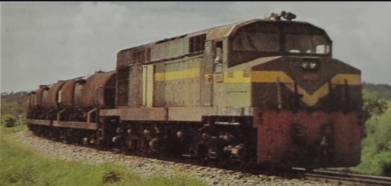
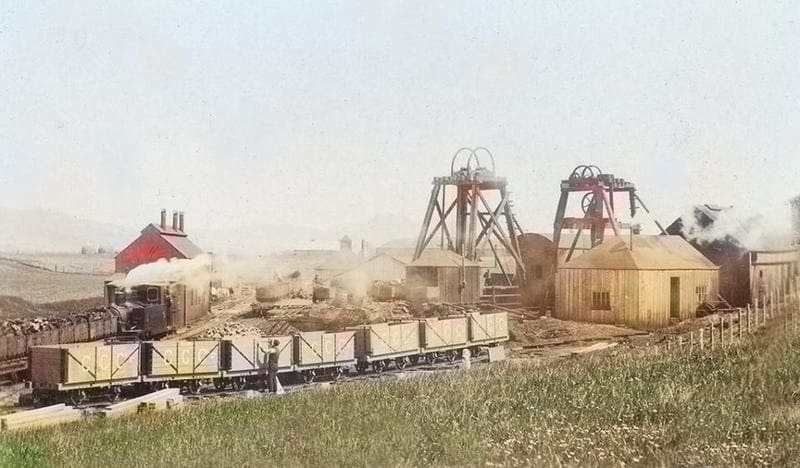
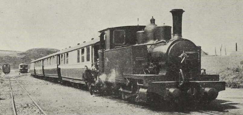
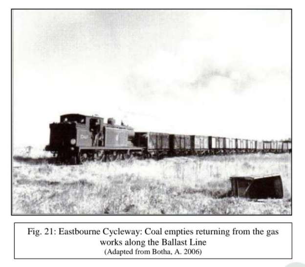
The featured image for this article shows a typical branch train heading towards Eastbourne. It comprises a number of mineral wagons running empty after delivering coal to the Eastbourne Gas Works, © Public Domain. [38]

The Crumbles Branch (also known as the Ballast Line or Crumbles Railway) was a 3.5-mile standard-gauge industrial branch line constructed in 1862 that ran east from Eastbourne’s railway area out onto the remote shingle beach known as The Crumbles. [5][6][7][8]
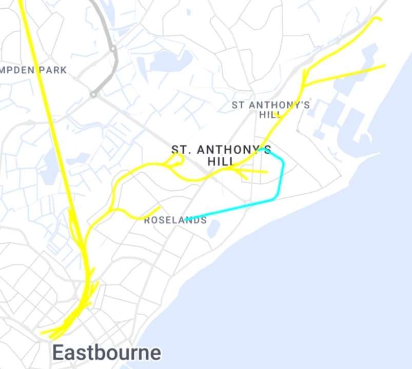
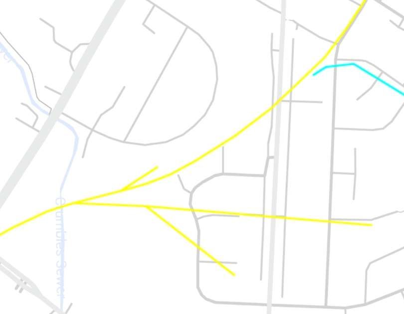
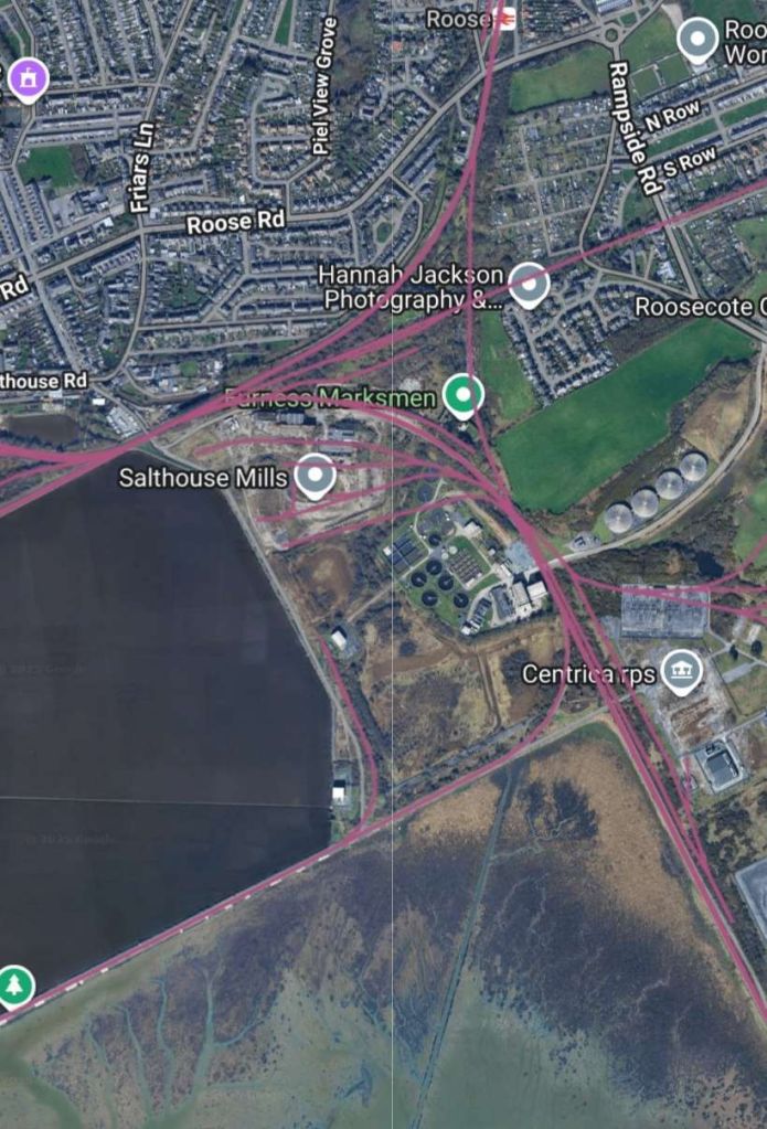
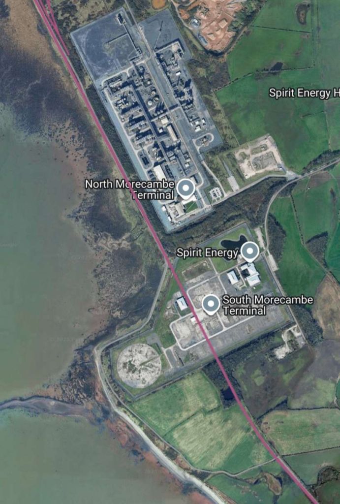
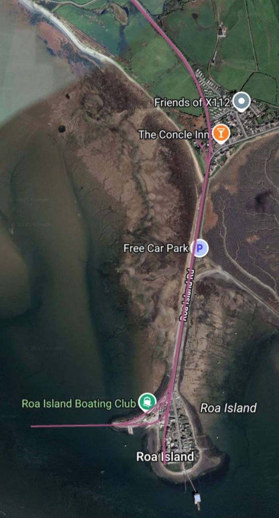
The Crumbles Branch ran from Eastbourne Railway Station Northeast roughly parallel to the coast. It is shown in yellow as it was part of the wider network near Eastbourne. A short branch can be seen near Roselands which served the Destructor Works. The Gas Works with its associated sidings, is directly North of the ‘LA’ of Roselands. The Turquoise line runs through, what were until the 1960s, rifle ranges to the Northeast of Eastbourne. It appears on the Ordnance Survey undertaken at the end of the 19th century but not on later surveys, so should not be confused with an electric tramway which was a tourist attraction in the mid-20th century. It may be associated with the Hall & Co. Narrow-Gauge (2ft) Tramway. [24][31]
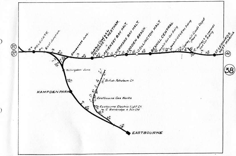
This image is a scan of the relevant page of a BR SR Route Mileage folder which gives some details of the Crumbles line at Eastbourne. The branch features at the centre of the image. This image was shared on the Disused Railways of Sussex Facebook Group by John Atkinson on 28th January 2021. [36]

The shingle bank/beach was 3⁄4-mile-wide (1.2 km) – shingle collected here was used as ballast for railway lines across the LB&SCR and the wider UK network. [2: plate 27]
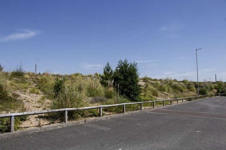
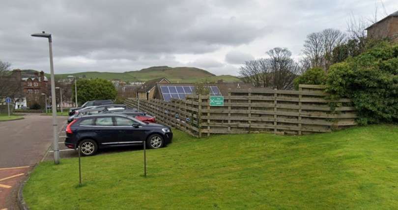
This photograph was taken by Andrew Diack at the beginning of July 2025. Looking north-northeast from the Waterfront car park at Sovereign Harbour, the photo shows a fenced-off fragment of land in the form of a bank that is approximately 3⁄4-mile-wide (1.2 km) and is known as the Crumbles, © Andrew Diack and licensed for reuse under a Creative Commons licence (CC BY-SA 2.0). [6]

Andrew Diack tells us that, “This distinctive area of coastal deposition lying adjacent to the sea underlies modern Sovereign Park and Princes Park and continues towards Sea Houses, near Eastbourne Pier. The irregular surface of ridges and hollows once contained pools of water in places, and a “Cromble Pond” of irregular form is shown on early maps, including John Speed’s map of Sussex of 1611 and Robert Marden’s map of Sussex of 1693, while the Ordnance Survey map of 1813 also shows “Crumble Pond”. In 1845, the Crumbles were partitioned between Lord Burlington, later the 7th Duke of Devonshire, and the Gilbert family; both families had a long association with the town as major landowners, benefactors and developers. The Gilberts and the Cavendish family, who as the Dukes of Devonshire were, in fact, connected by marriage through the Compton family, who were also landowners in Eastbourne and whose estate was managed from their residence at Compton Place, previously Bourne Place. The partition of the Crumbles was said to have been beneficial toward the development of the Seaside suburb to the east of Eastbourne. The railway came to Eastbourne in 1849, and with the expansion of railways so grew the demand for railway ballast and the need for gravel quarries to supply the stone. In 1857-62 the London Brighton & South Coast Railway (LB&SCR) negotiated the purchase of not less than 48,000 cubic yards of shingle from the Duke of Devonshire at 1 penny per cubic yard, to be extracted from the Crumbles.” [6]

Andrew Diack writes: “Due to the buoyant demand for ballast, this was a period of expansion for the gravel pits that produced the product, but it was equally a time when the natural landscape of vegetated shingle ridges suffered greatly by being transformed into a scarred landscape where industrial machines created holes and gashes in the surface of the land. Over a period of a hundred years shingle was removed at the rate of around 250,000 tons per year for railway ballast and building material, and that resulted in the height of the land being reduced by 4 metres within 100 metres of the shore.” [6]

Additional branches were added to the line, including a siding built in 1870 for the Eastbourne Gas Company, which straddled the railway. The gasworks received coal via the rail connection and in return, produced coke, which was taken away. [2: plate 32][3]

“In 1926, a line was laid for the Eastbourne Corporation Electric Works, which transported coal and supplied fuel to the bus garage, as well as taking scrap metal from the refuse destructor works.” [2: plate 29][3][5]

In fact, “as Eastbourne expanded, the branch evolved into an industrial corridor. It served the town’s gasworks (delivering large volumes of coal), brickworks, timber yards, and destructor works.” [6]

Ballast trains ran until 1932, when the LB&SCR’s successor, the Southern Railway, switched to using granite.

Andrew Diack continues: “Although the gravel had a variety of uses, when railways changed to the use of granite chippings in 1930, the business went into terminal decline. (Broken granite chips interlock better than rounded pieces of flint, and they also provide good shock absorption and easier maintenance.) Shingle extraction gradually diminished, and by 1932, the railway was no longer used to transport shingle, though it continued to serve [some] other industrial sidings in addition to the gasworks.” [6]

“The branch ceased steam working in April 1960, after which diesel shunting locomotives took over [2: plate 28] until the line was closed in … 1967.” [2: plate 29][3][5]

Andrew Diack says that “The Crumbles railway continued to serve the gasworks until …  1967, but with gas production ceasing in June 1967, the track fell into disuse, and in the late 1980s it was removed at the time of the Eastbourne re-signalling project.” [6]

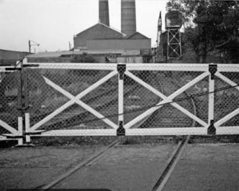
A short series of photographs follow below, all taken circa. 1962 by Dick Gilbert.
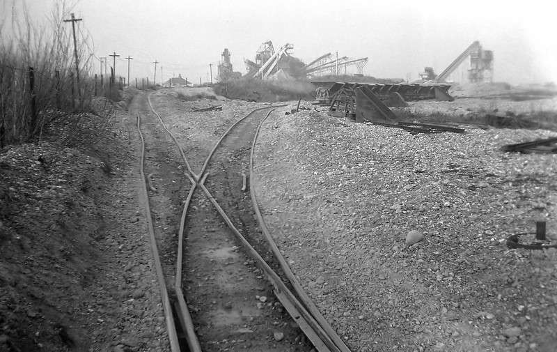
The line to the Crumbles remained in place until the early 1960s when these pictures were taken.
There is no trace of anything shown in these pictures in the 21st century (Dick Gilbert, around 1962), (CC BY 2.0). [4]
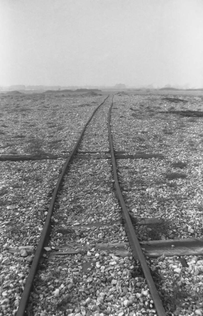
The line across the Crumbles (Dick Gilbert, around 1962), (CC BY 2.0). [4]
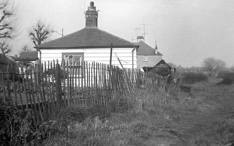
The location of this wooden building is what is now the eastern side of the roundabout where the A259 coast road meets Lottbridge Drove (A2290). It is no longer there, but was probably a house for the crossing gates controller as the line crossed the A259 here – the houses on the left are on that road and some are still recognisable. The trackbed out to the Crumbles is on the right (Dick Gilbert, around 1962), (CC BY 2.0). [4]
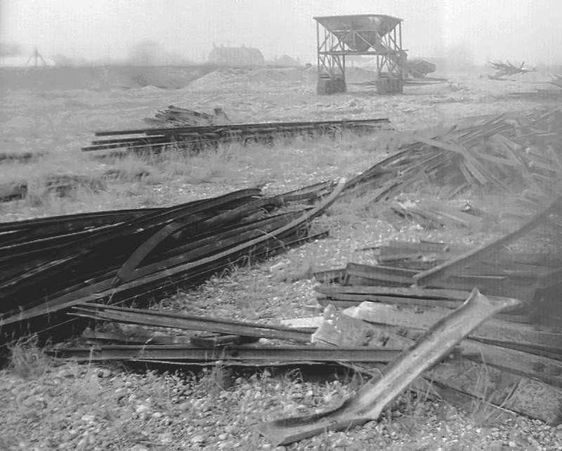
The redundant rails and sleepers removed from the branch line (Dick Gilbert, around 1962), (CC BY 2.0). [4]
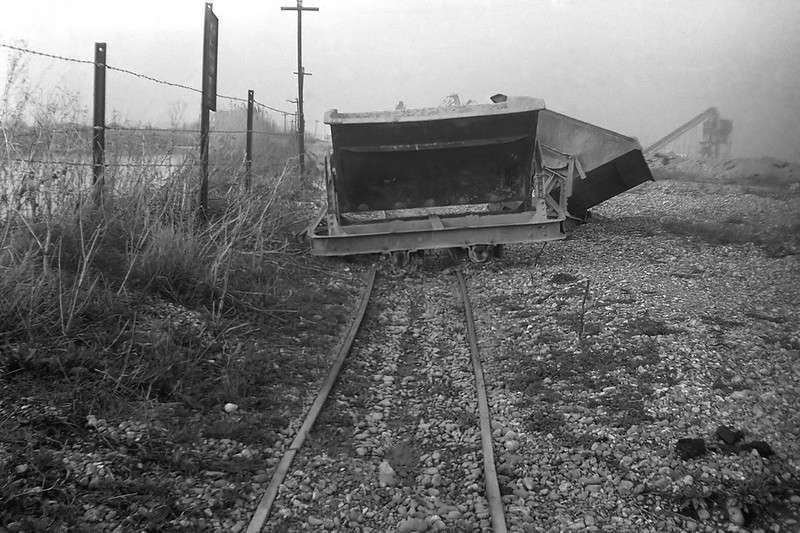
Disused/redundant skip wagons (Dick Gilbert, around 1962), (CC BY 2.0). [4]

The remote shingle beach area of The Crumbles where the line terminated has since been redeveloped and is now home to Sovereign Harbour and retail developments. 

An exploration of this line can be found here on YouTube. [7]

Following the Line

A separate line ran alongside the main line out beyond the location of the Engine House. …
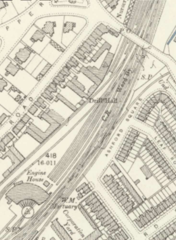
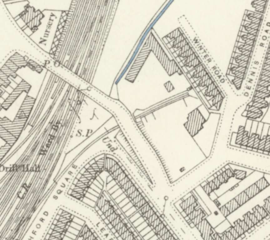
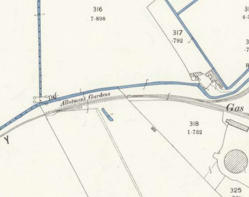
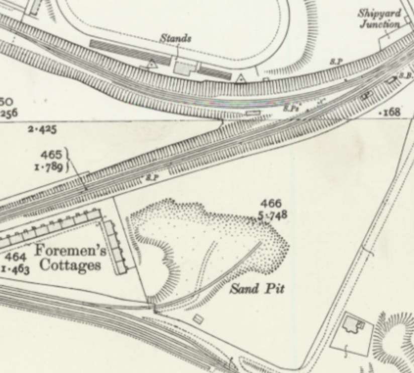
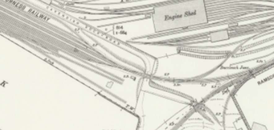
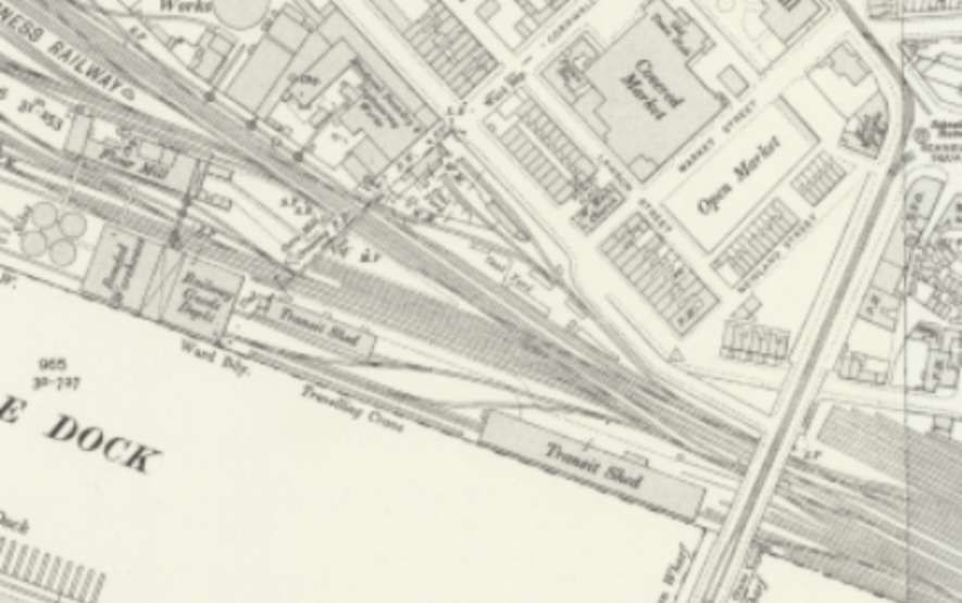
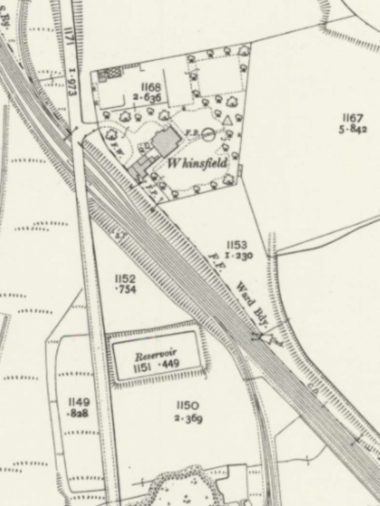
The Crumbles Branch ran beside and to the East of the main line a short stub line turned away to the East from the branch to serve a small yard. The branch continued under the bridge which provided a link between Upper Avenue and Cavendish Place. The 25″ Ordnance Survey of 1898, published in 1899. [8]
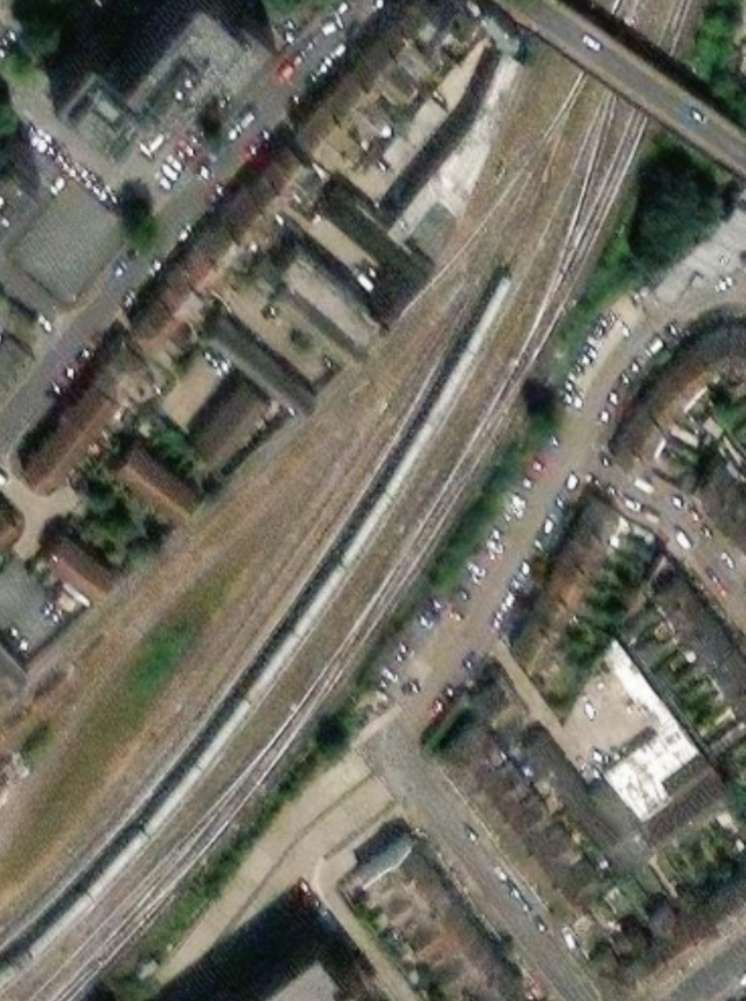
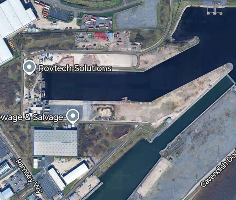
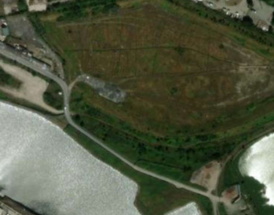
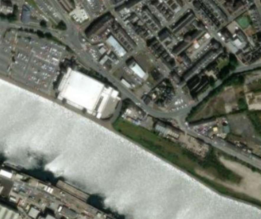
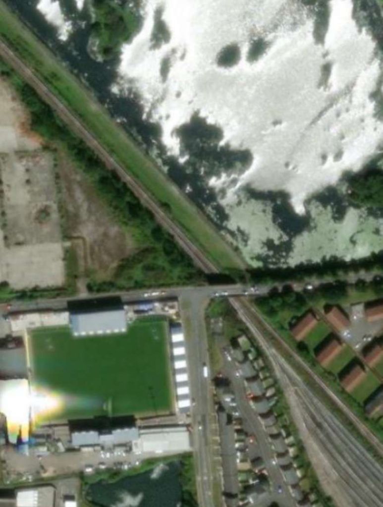
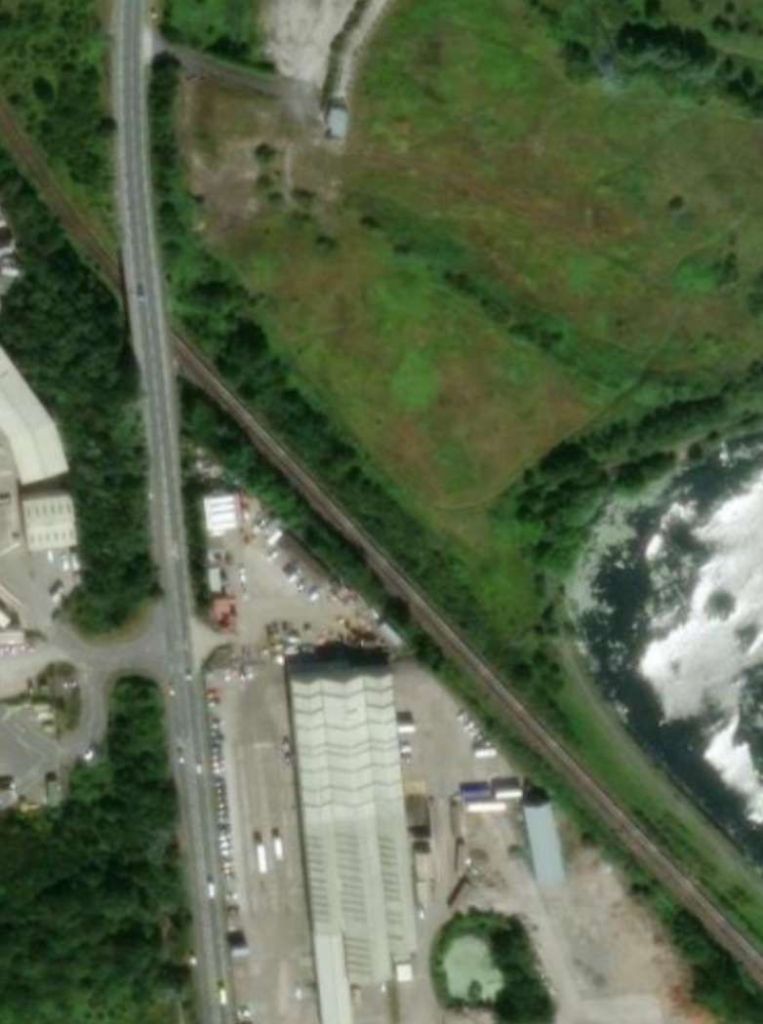
The same area as it appears on the modern ESRI satellite imagery provided by the National Library of Scotland. The bridge noted on the map extract above can be seen in the top-right of this image. The road is now named Upper Avenue. [9]
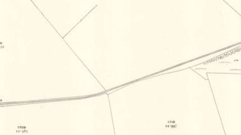
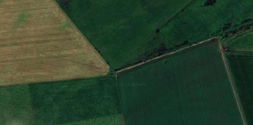
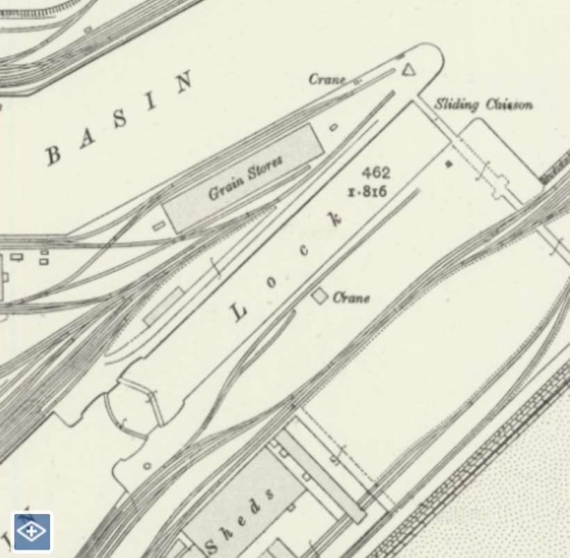
The short stub siding mentioned above is shown here on another extract from the same OS sheet. It passes under the link road and most probably already in place before that road was conceived. The site served by the sliding is marked ‘Smithy’ on a later Ordnance Survey map. [8]
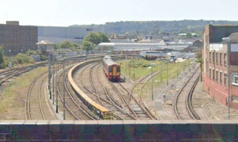
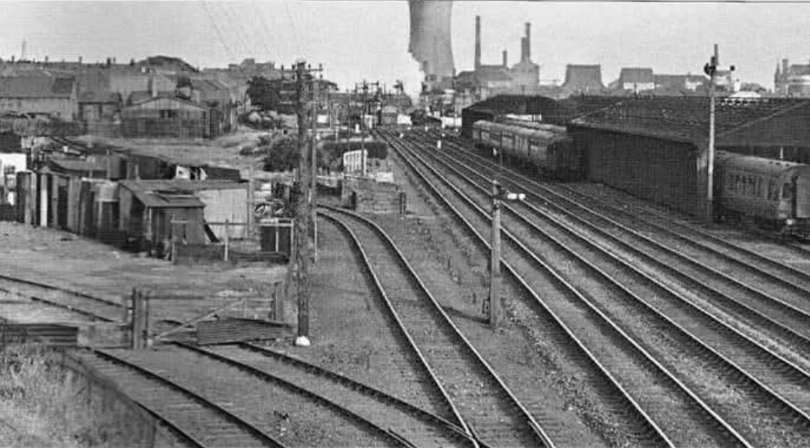
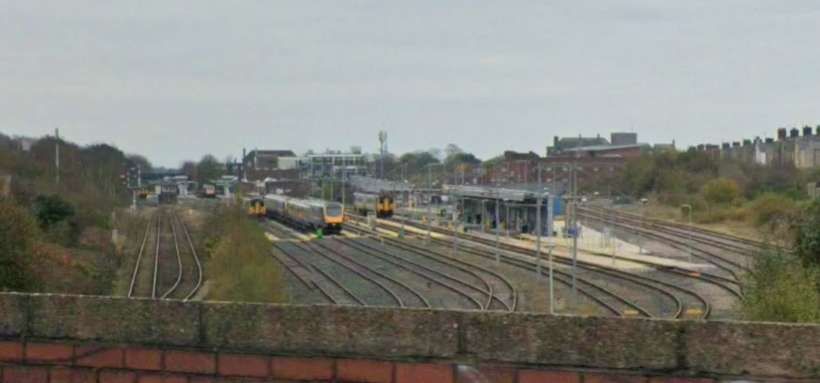
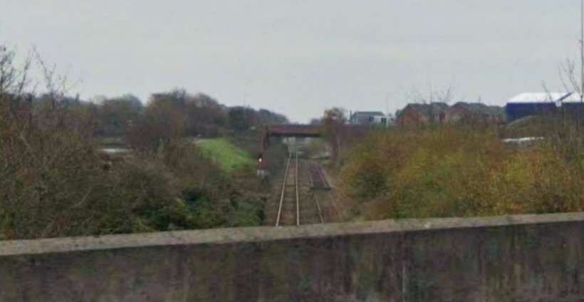
The view South from Upper Avenue bridge towards Eastbourne Station. [Google Streetview, August 2024]
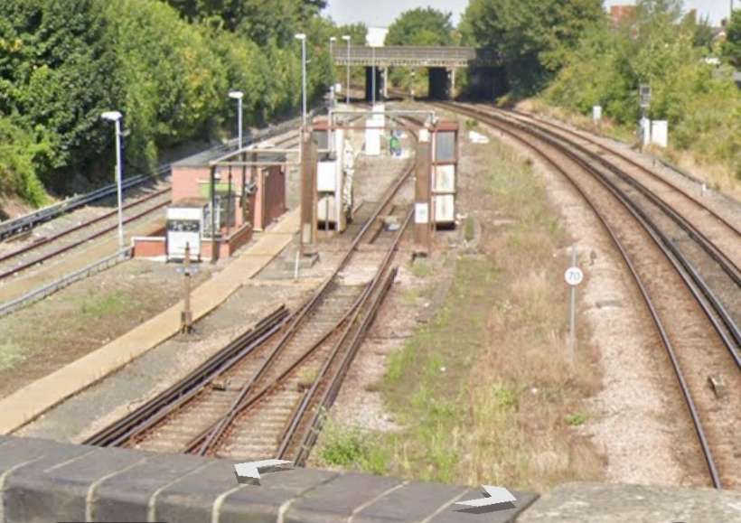
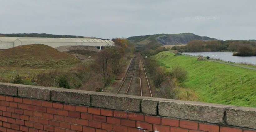
Looking North from Upper Avenue bridge towards Whitley Road bridge. [Google Streetview, August 2026]
The next length of the line which covers the length between Upper Avenue bridge and that carrying Whitley Road. The 25″ Ordnance Survey of 1898, published in 1899. [10]
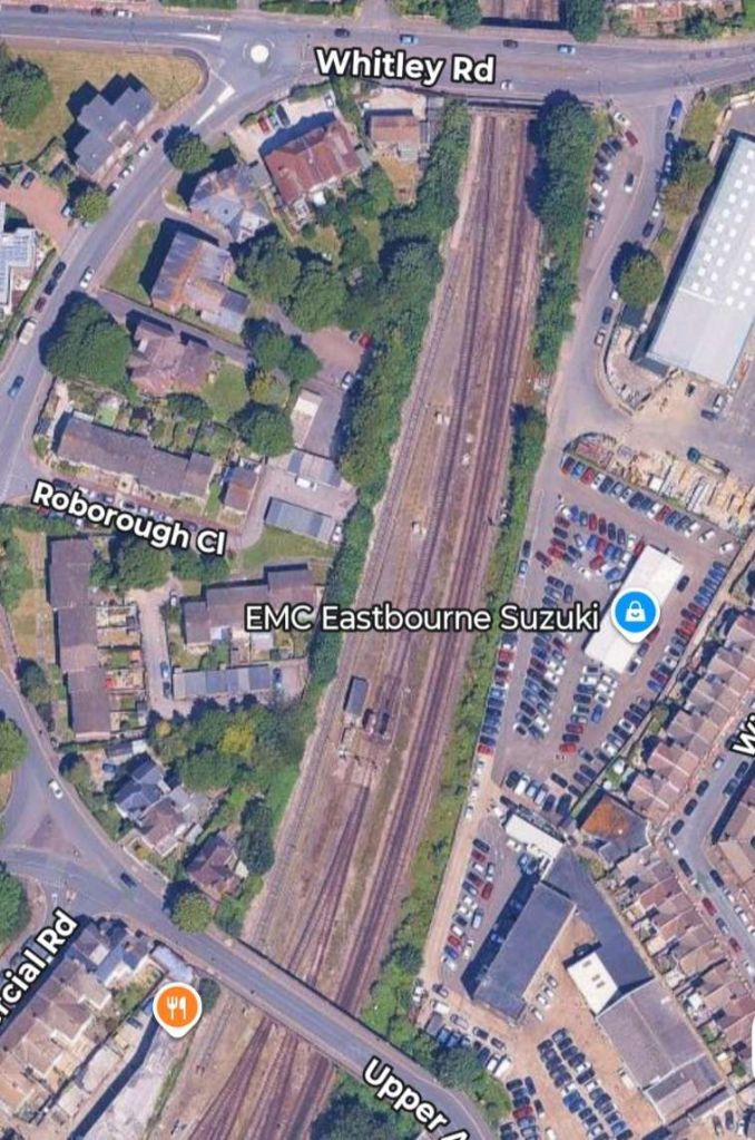
While Upper Avenue appears to be much the same width as on the map extracts, Whitley Road bridge has been significantly widened. [Google Maps, August 2026]
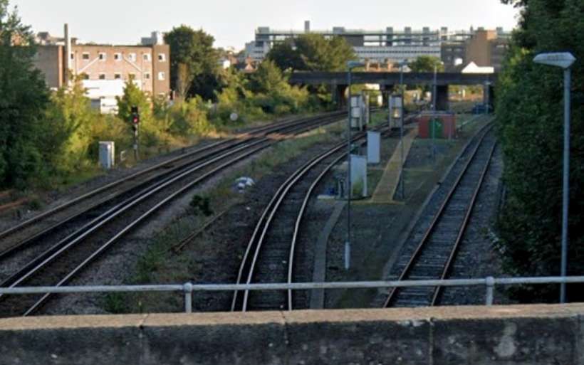
Looking South from Whitley Road bridge towards Upper Avenue bridge. [Google Streetview, August 2026]
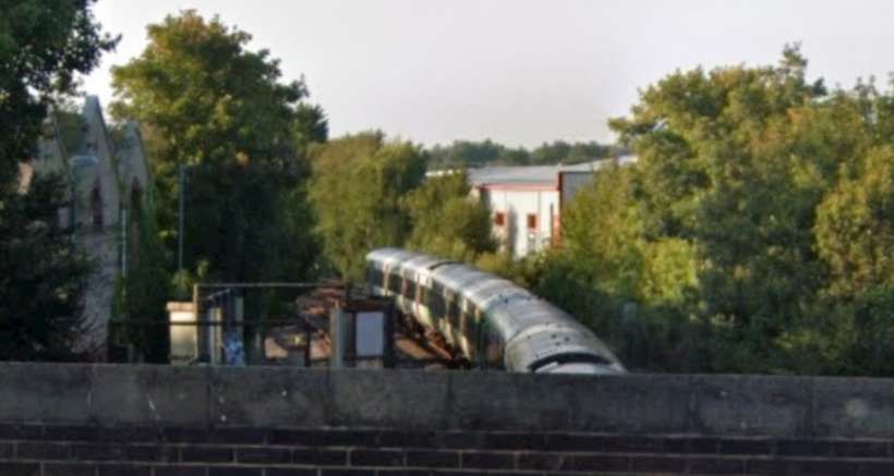
Looking North from Whitley Road bridge. [Google Streetview, August 2026]
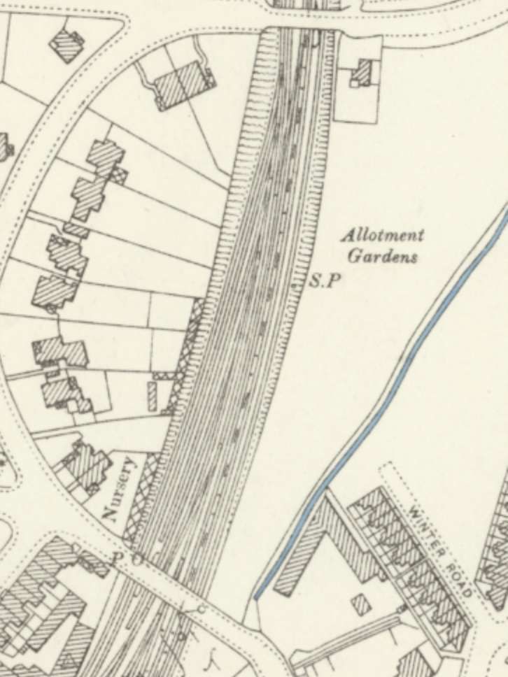
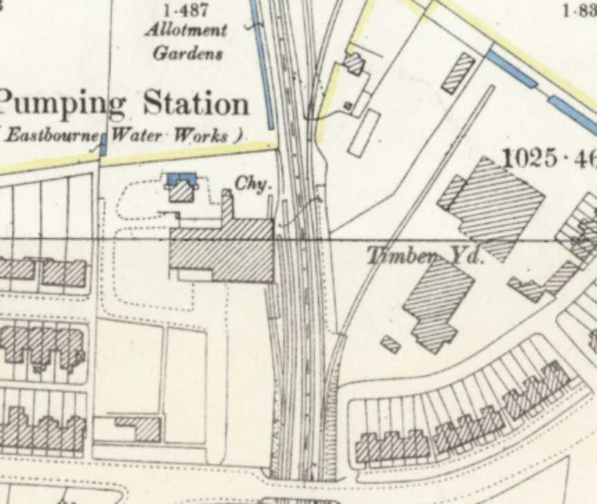
The line to the North of Whitley Road bridge. Another short branch from the Crumbles Branch serves as a private siding for a Timber Yard. The Crumbles Branch can be seen separating from the main line close to the Pumping Station. Another short siding can also be seen leaving the branch closed to the top of this map extract. This 25″ OS map extract of 1898, published 1899, spans two OS sheets. [10][11]
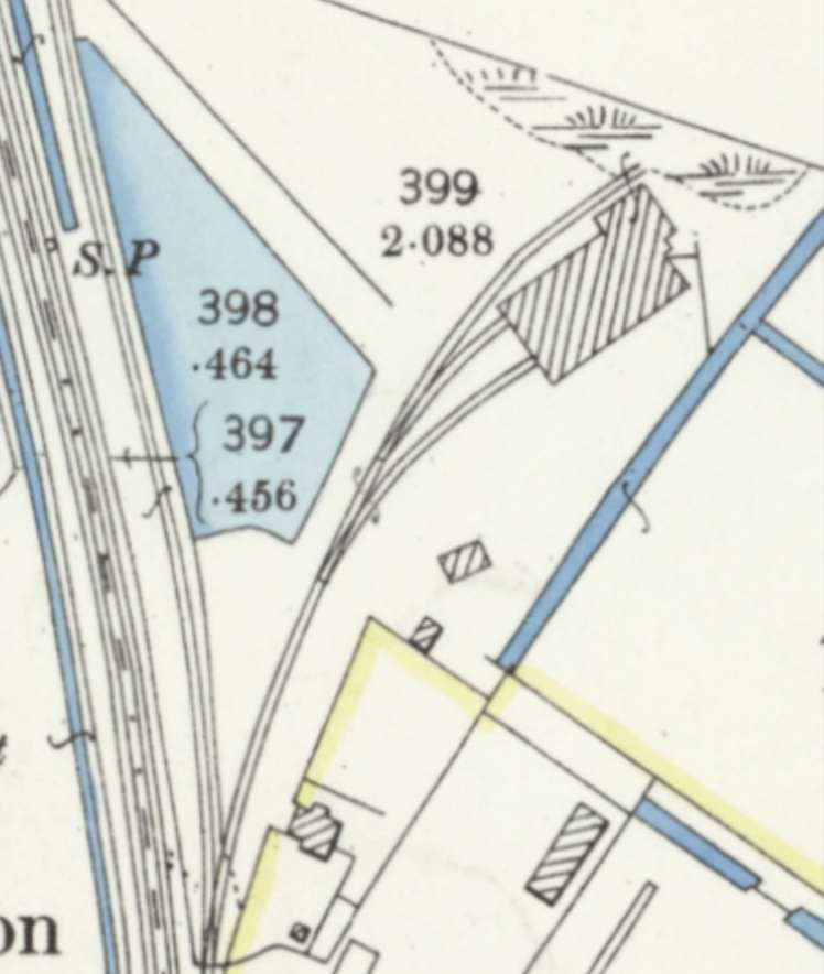
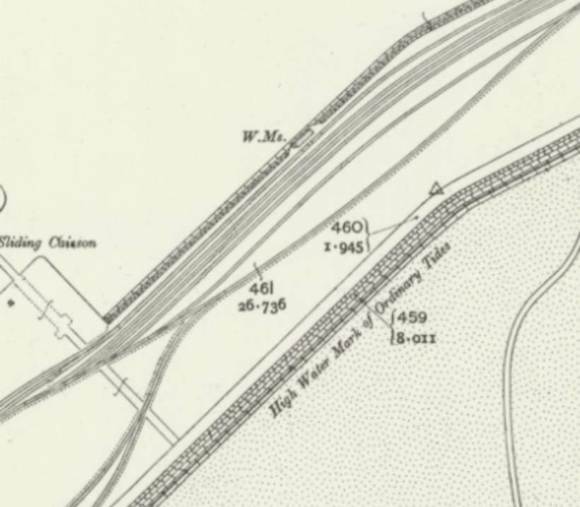
This extract from the 25″ OS map extract of 1898, published 1899 shows the sliding which appeared at the very top of the last map extract. It is not clear what the site was used for at the turn of 20th century. [11]

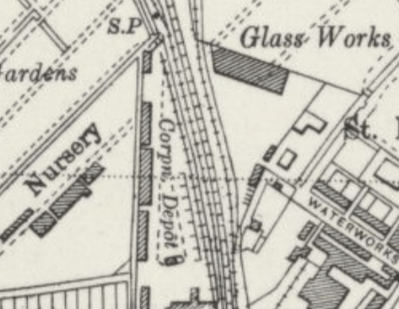
This small extract from the 6″ Ordnance Survey of 1938, published in 1947, shows a new building on the site, no rail connection, and the site is designated a Glass Works. Careful examination of the map extract shows that, although the sidings within the site and the building they served are now gone, the point on the Crumbles Branch remains. [12]
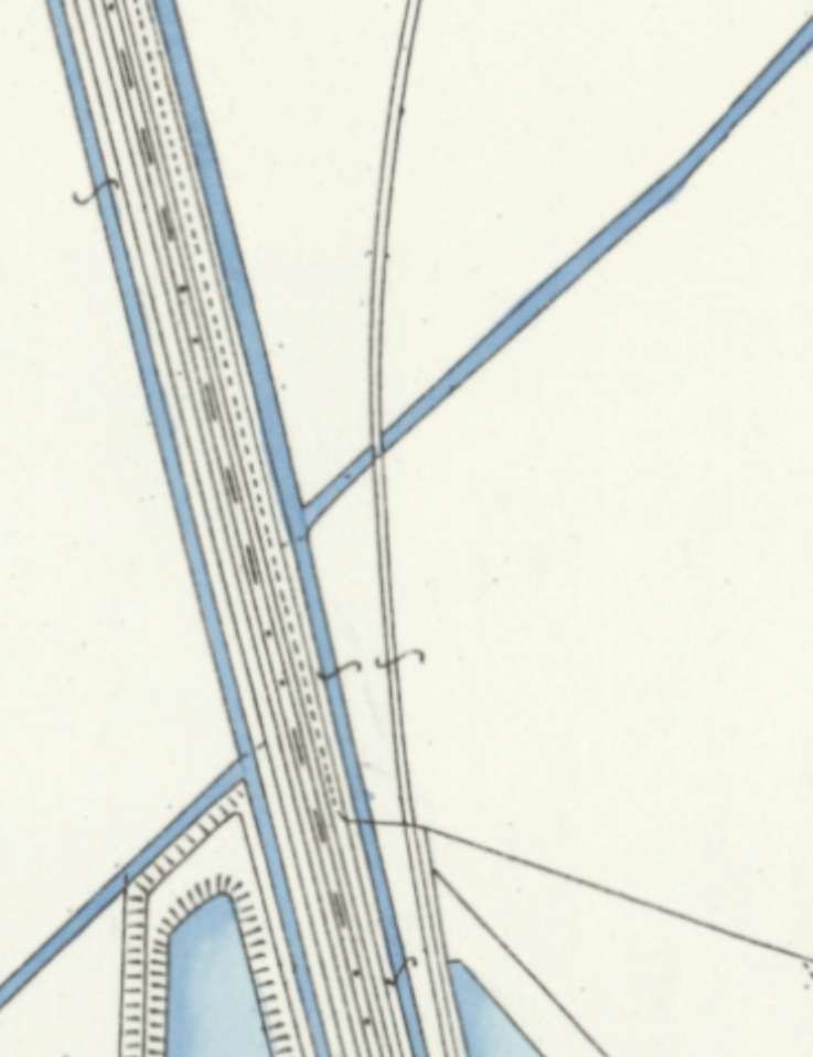
The Crumbles Branch diverged from the main line. 25″ OS map extract of 1898, published 1899. [11]
The line continued to turn northeastwards. [11]
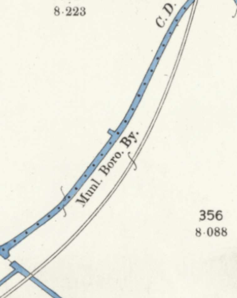
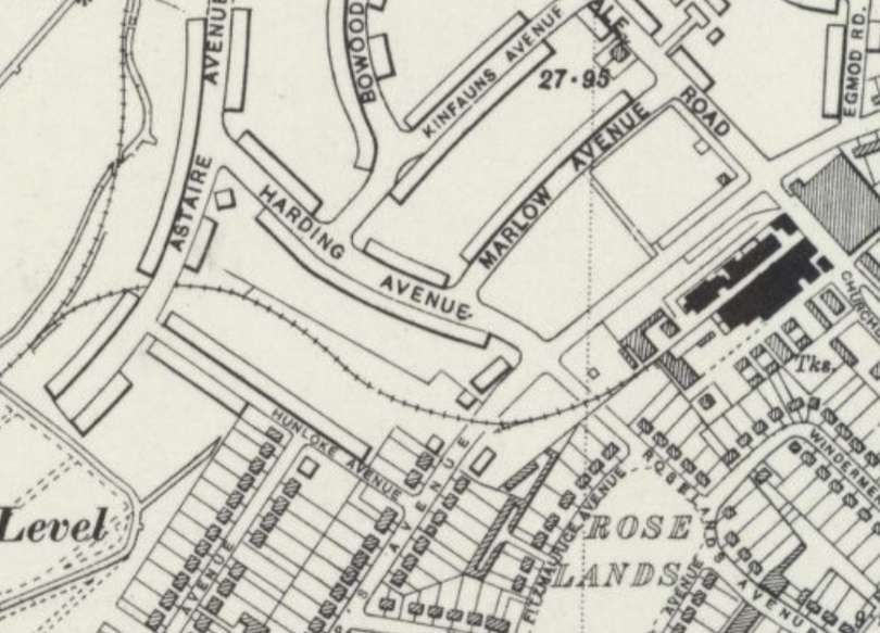
Now heading Northeast, just at the top-right of this map extract a branch led away to the East. It served the Eastbourne Destructor Works and was in place for a period in the early- to mid-20th century. [11]
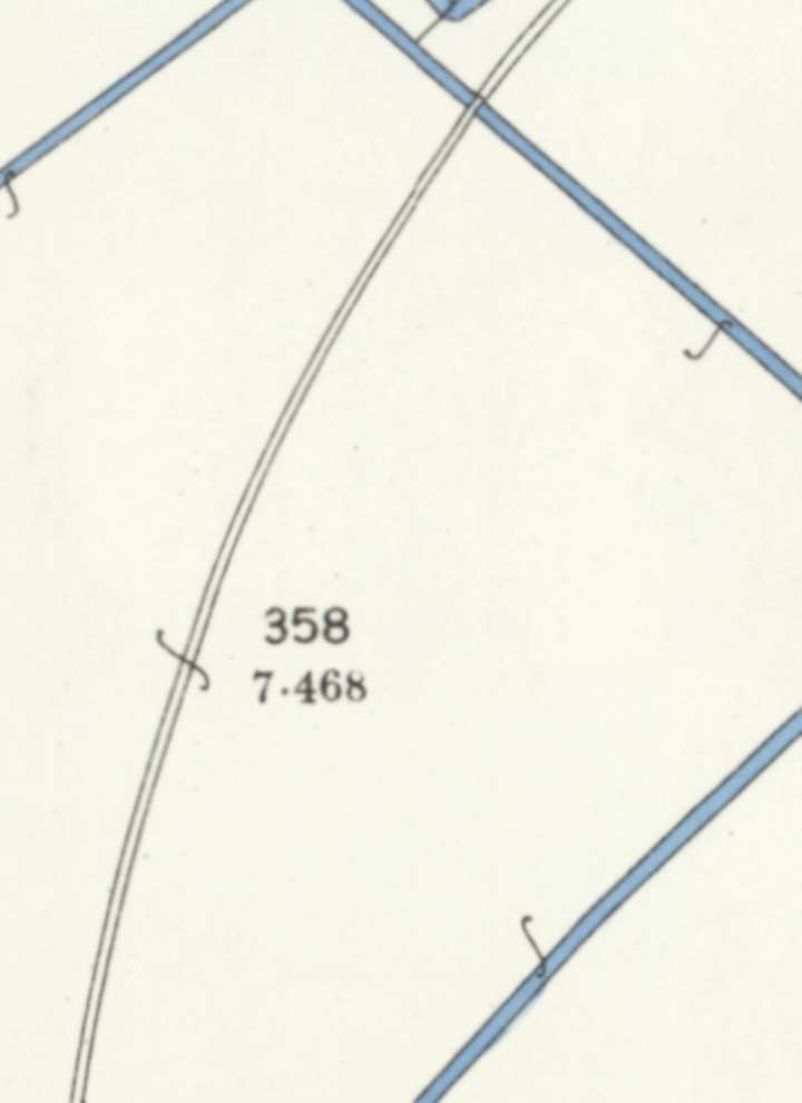
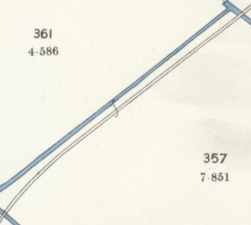
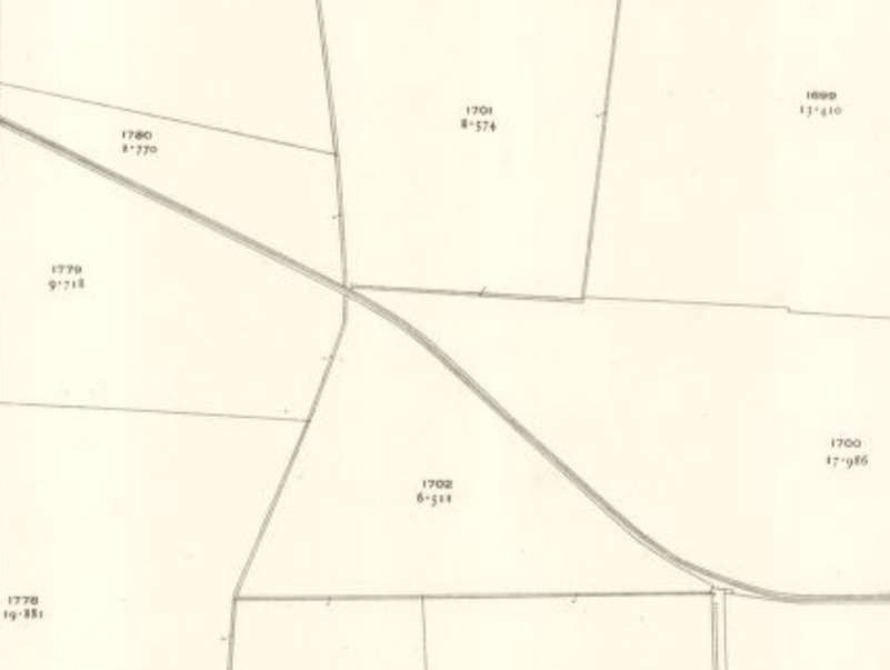
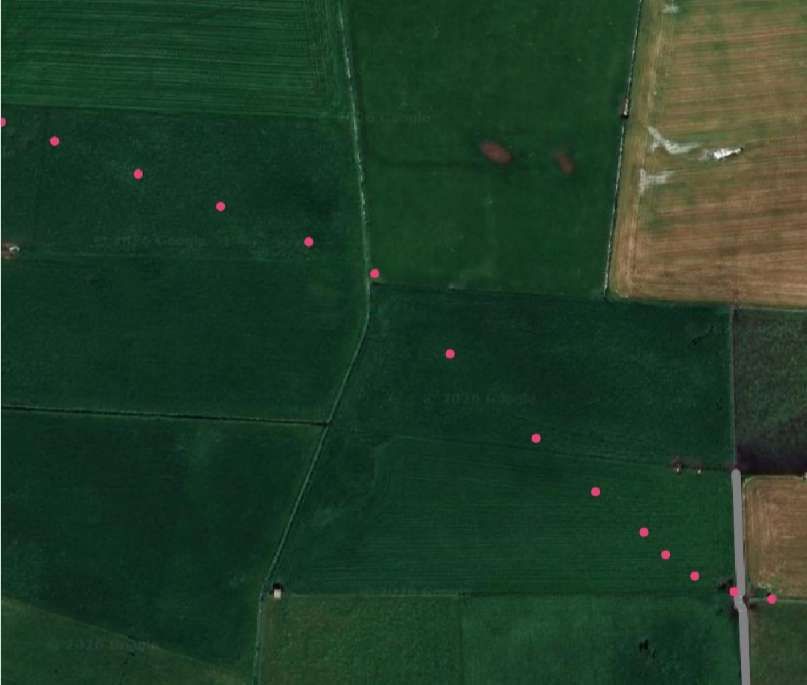
The Crumbles Branch begins to turn North, the branch to the Destructor Works does not appear on this next 25″map extract from 1898/99, nor does it appear on later 25″ surveys provided by the NLS. [11]
The 6″ Ordnance Survey of 1938, published in 1947 shows both the short siding/branch and the Destructor Works themselves which were sited to the Southeast of St. Philips Avenue. [12]

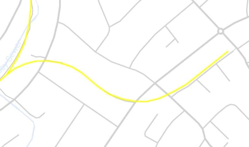
The branch serving the Destructor Works. [24]

A short aside is worthwhile here, to provide some information about the Destructor Works. …

The Eastbourne Destructor Works was a late 19th-century municipal waste incinerator and early energy-from-waste facility, producing electricity which was used locally in Eastbourne. Plants like this were built as towns grew and traditional waste disposal became difficult, the site burned household refuse in high-temperature furnaces to reduce volume, produce clinker, and generate steam for electricity. Coal was often required alongside the rubbish to keep the furnaces hot enough. [7][13][14]

By the 1950s and 1960s, shifting environmental standards, modern waste management approaches, led to the closure and demolition of the complex and the lifting of its rail link. [7][14]

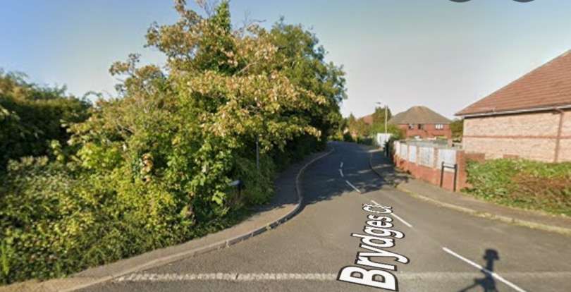
The wider industrial footprint stretched across the area of modern-day St Philips Avenue and Bridges Close. The refuse handling section stood roughly where the current recycling site is on St Philips Avenue, while the core furnace operations and rail sidings were nearby towards Bridges Close. Only the recycling centre remains as a hint to the past use of the industrial site. The rest of the land has been redeveloped into housing estates and roads.

Simon Meader shared two photographs (photographer not known) which were taken before the nationalisation of the railways, both focus on the location of the level-crossing on St. Philip’s Avenue.
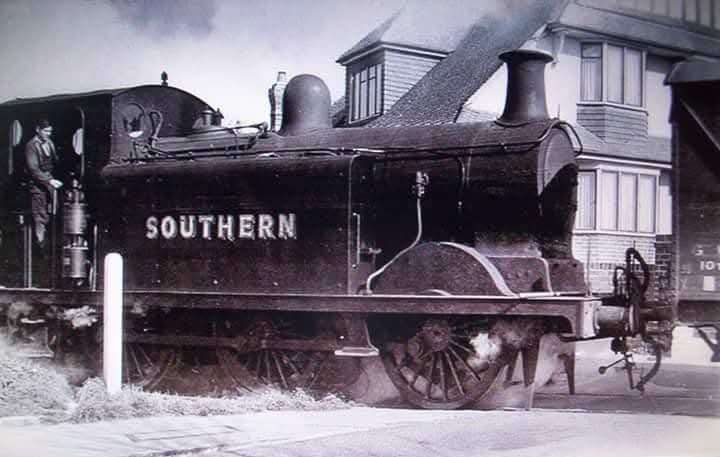
The level-crossing on St. Philip’s Avenue in the inter-war years of the 20th century. This image was shared on the Disused Railways of Sussex Facebook Group by Simon Meader in comments in 2024, © Public Domain. [15]
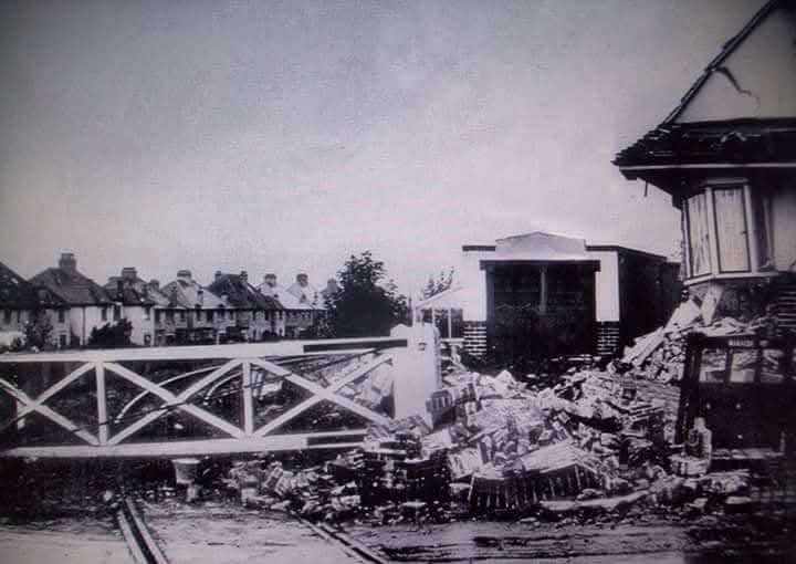
The level-crossing on St. Philip’s Avenue after bomb damage to the adjacent property in WW2. This image was shared on the Disused Railways of Sussex Facebook Group by Simon Meader in comments in 2024, © Public Domain. [15]
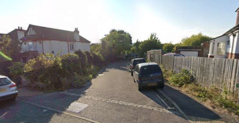
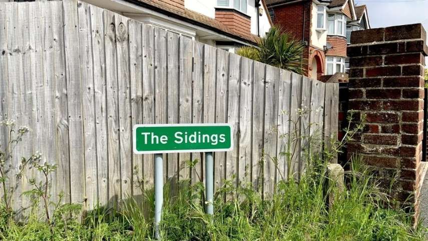
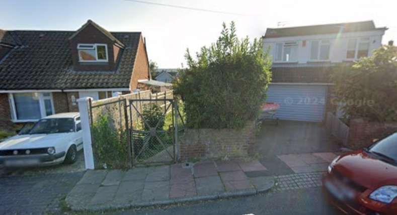
Looking West-northwest along the line of the old rail link, a short cul-de-sac called ‘The Sidings’ is seen here from St. Philip’s Avenue in August 2024. The waste amenity site is behind the camera to the right. [Google Maps, August 2024]

The Sidings runs West-southwest from St. Philip’s Avenue along the line of the old rail link.
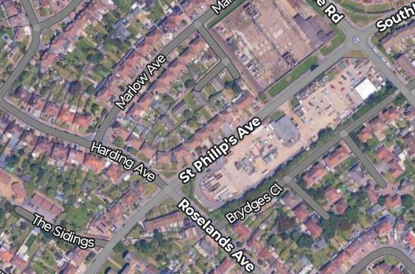
The Sidings is bottom-left in this image, the civic amenity site is centre-right. [Google Maps, August 2026]
Looking along the rail link into the site of the Destructor Works from Roseland Avenue level-crossing. This image was shared by  Matthew Cox on the History of Sussex Facebook Group on 14th November 2025, © Public Domain. [17]
Approximately the same view from Roseland Avenue in the 21st century. [Google Streetview, August 2024]
Turning through 180° from the view above, this image looks back along the line of the old railway towards St. Philip’s Avenue. The pedestrian gate is on the approximate line of the railway. [Google Streetview, August 2024]

More about the Destructor Works can be seen on Matthew Cox’s video below:
A video providing details of Eastbourne’s Destructor Works and associated rail link. [14]
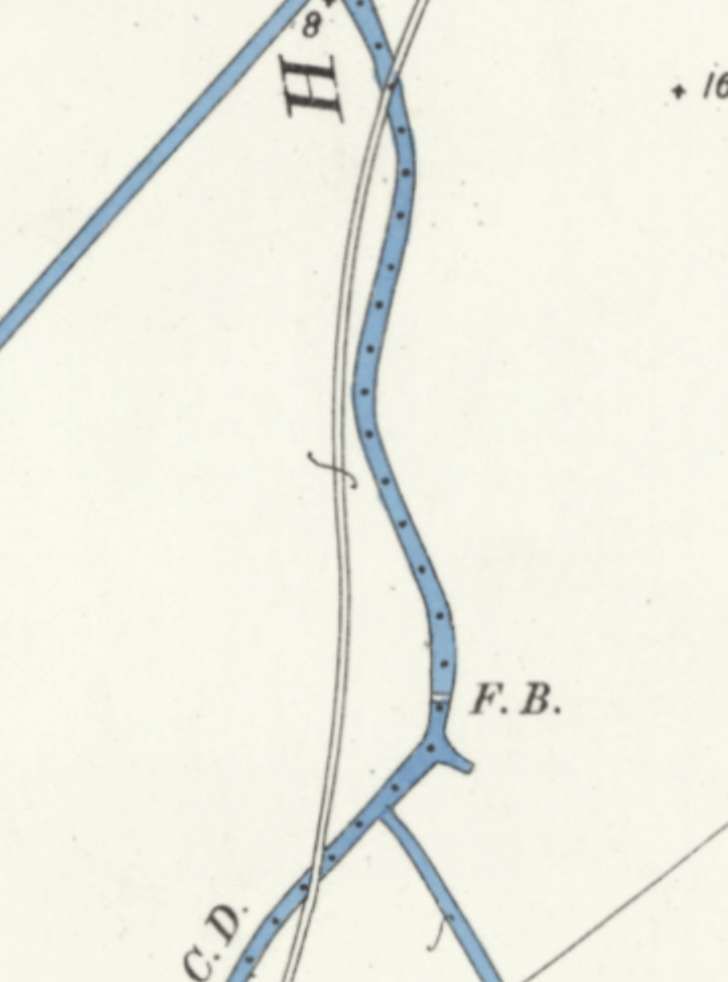
The Crumbles Branch continues on towards Eastbourne Gas Works. The watercourse that it bridges twice on this extract is Horsey Sewer [11]
At a reduced scale this extract shows the line continuing Northeast. [11]
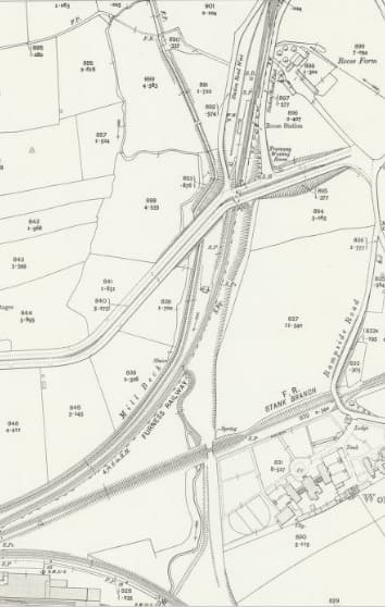
Now turning East the branch approached the gas works which straddled the line. [11]
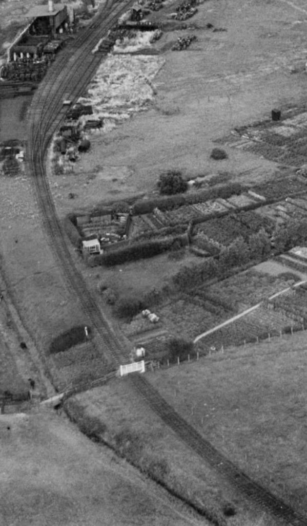
The Crumbles Branch approaching the Gas Works, seen from the West in 1932, © Historic England (EPW039402). [22]
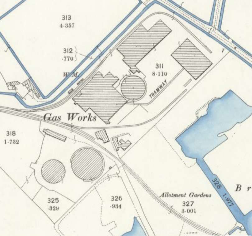
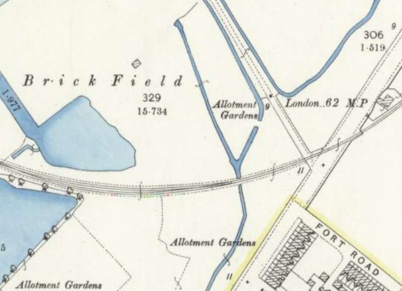
Eastbourne Gas Works as shown by the 25″ Ordnance Survey of 1898, published in 1899. [11]

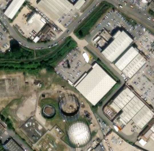
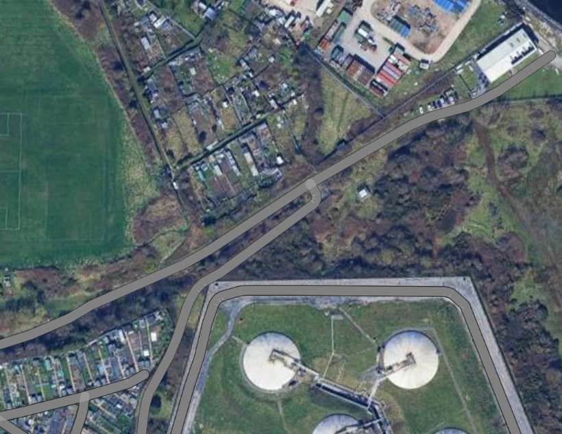
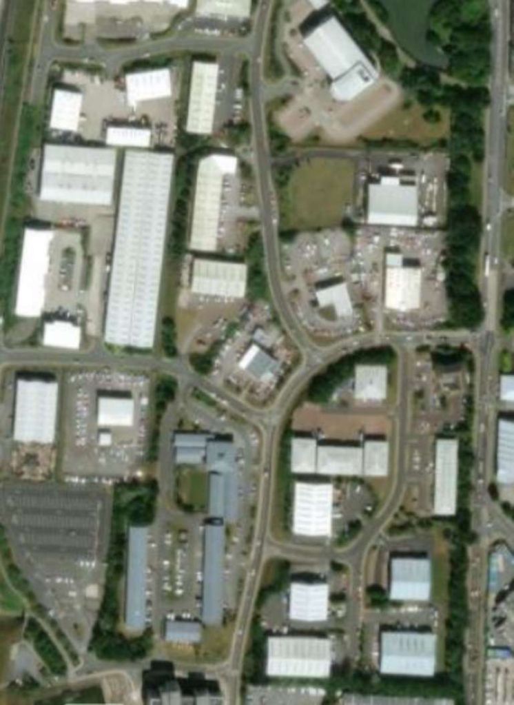
The same area in the 21st century, the locations of the two gasometers can still be seen alongside a later additional gasometer. [19]
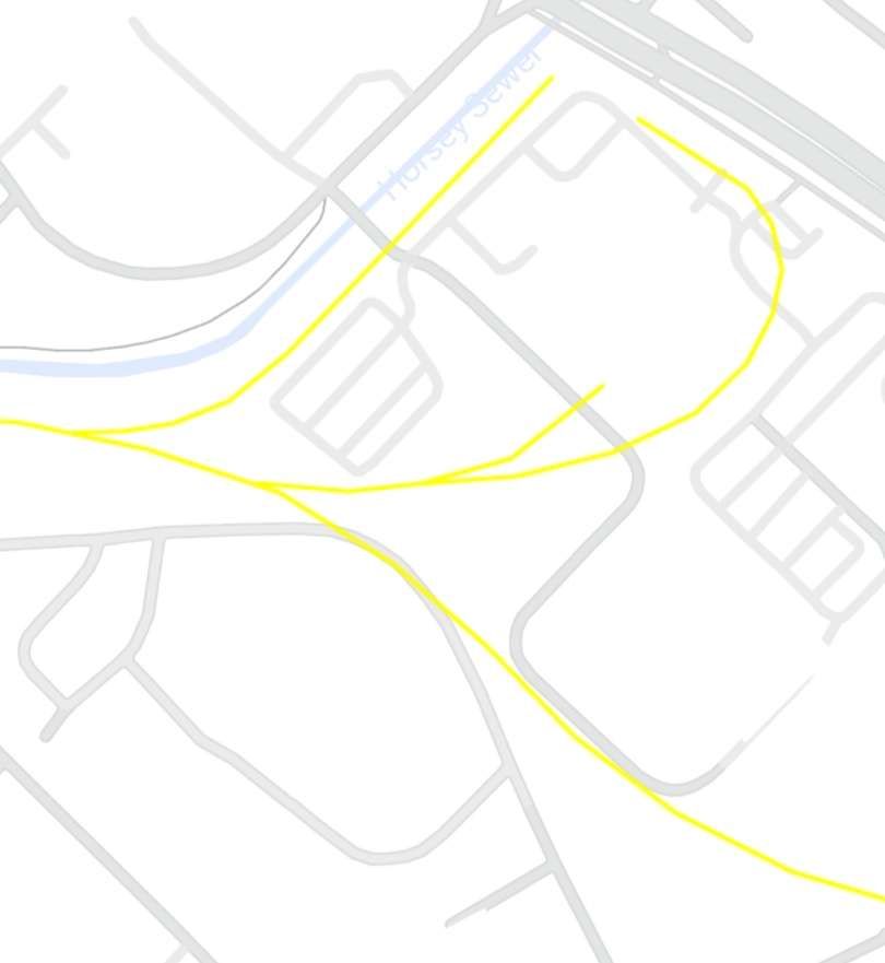
The lines serving the Gas Works. [24]
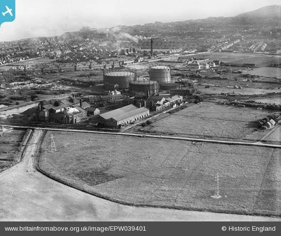
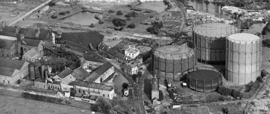
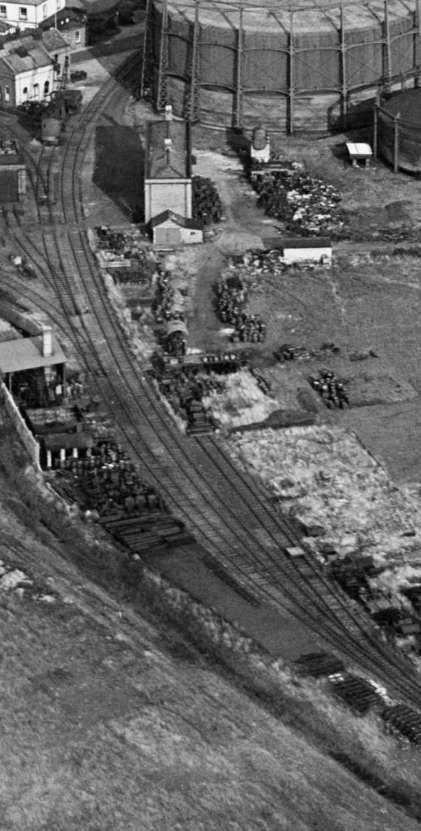
Eastbourne Gas Works were rail-served by the Crumbles Branch. The three gasometers can be seen in this aerial view of the Works, © Historic England (EPW039401). [16]
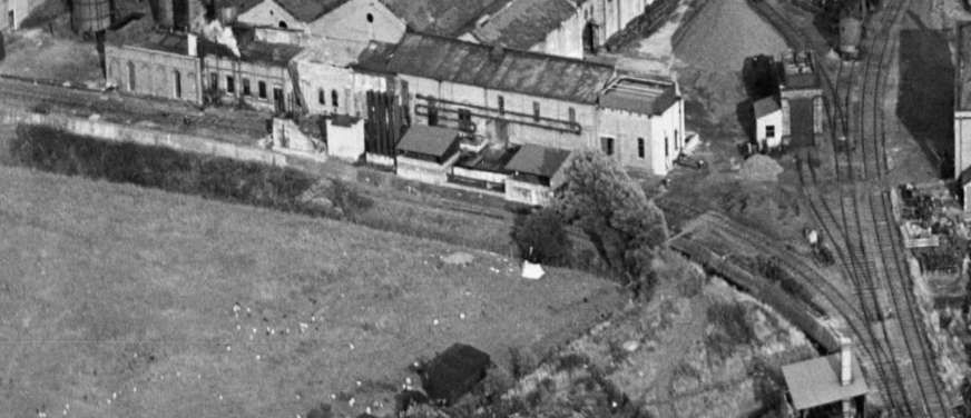
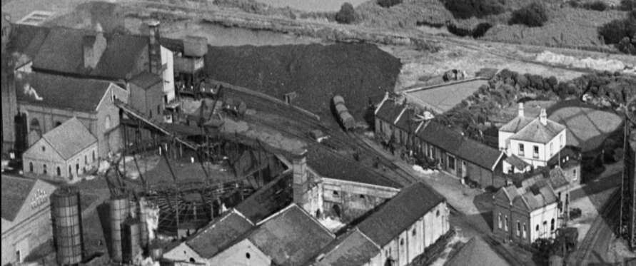
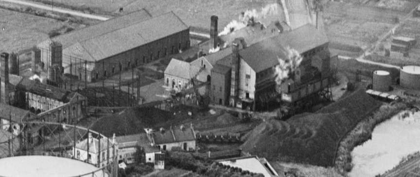
A closer view of the gasworks, seen from the West in 1932, © Historic England (EPW039397). [20]
An even closer view of the gasworks, seen from the West in 1932, showing the Crumbles Branch running through the Works, © Historic England (EPW039397). [20]
The sidings on the West side of the Works, seen from the West in 1932, © Historic England (EPW039397). [20]
The sidings on the East side of the Works with a number of Southern Railway coal wagons in evidence, seen from the West in 1932, © Historic England (EPW039397). [20]
The Gas Works, seen from the South in 1932, © Historic England (EPW039398). [21]

The National Archive record for the Works states: “The Eastbourne Gas Company was formed by Deed of Settlement in 1857. The original area of supply was the town and parish of Eastbourne and the parish of Willingdon. The company was dissolved and reincorporated by Act of Parliament in 1868. A new works was built in Willingdon and the original one closed.”

Over the next eighty or so years The area served by the plant grew. At each stage of development an Act of Parliament either extended the area of supply or permitted the company to purchase other gas companies and their areas of supply until nationalisation took place in 1949 when the undertaking became part of the Sussex Divison of South Eastern Gas Board.
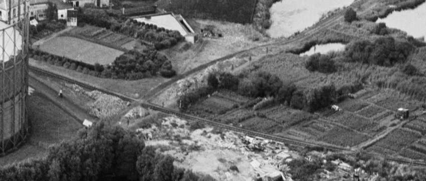
The Crumbles Branch left the Gas Works heading Southeast, (one of the Gasometers is on the left of this image), seen from the South in 1932, © Historic England (EPW039398). [21]
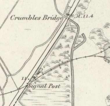
A passing loop was provided on the line, to the East of the Gas Works, after bridging a drainage channel the line crossed…. to the Southwest of Crumbles Bridge. [11]
Crumbles Bridge can be seen at the top-centre of this next map extract. The line continues in a generally East-northeast direction, crossing another drainage channel. [11]

The early gravel extraction/ballast workings were to be found at this location and this was for a time the end of the branch as shown on the 6″ Ordnance Survey below: …
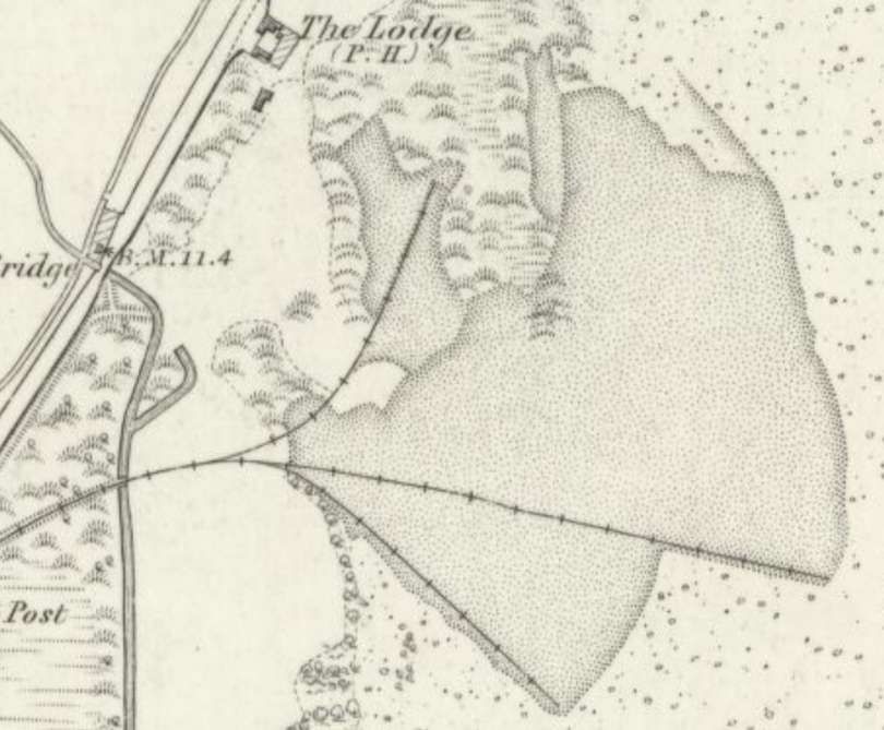
In 1875/76 this 6″ Ordnance Survey, published in 1879 shows the gravel pits which were the end of the line at that time. Crumbles Bridge can be seen just to the North of centre-left of the extract. [25]

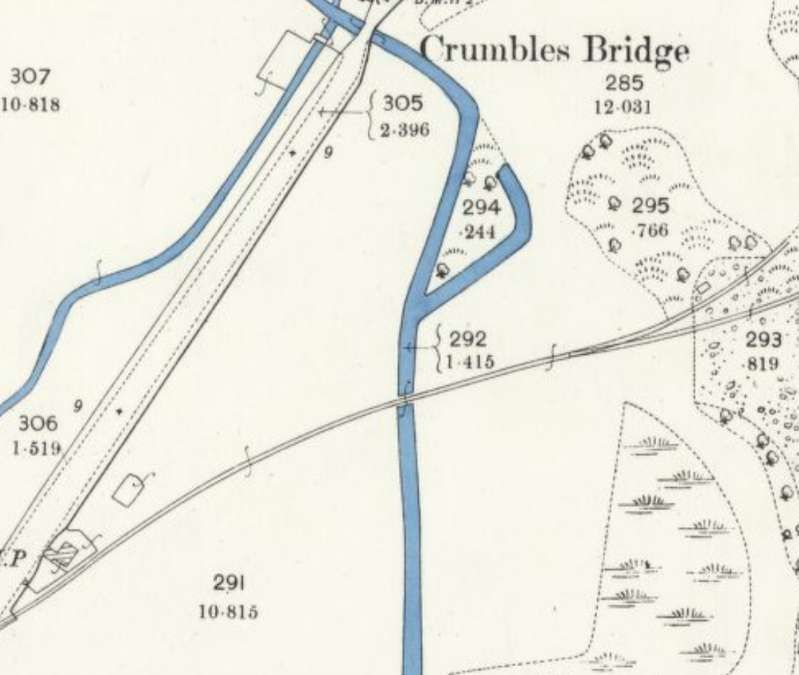
The level crossing and Crumbles Bridge. [25]

Crumbles Bridge was built between 1823 and 1827 to serve the local turnpike road network connecting Eastbourne and Hailsham. It crossed a low-lying drainage channel.  The bridge was reconstructed in 1969 as the local road infrastructure changed. The surrounding shingle and marsh landscape has since been heavily redeveloped into residential areas and the Sovereign Harbour marina.
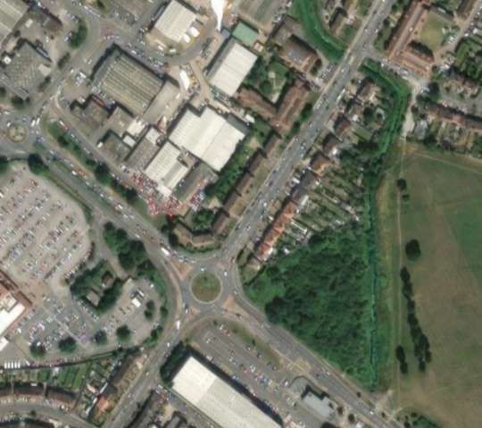
The same area as shown on the map extract immediately above. The location of the level crossing is just to the Southwest of the roundabout. The drainage channel continues to follow its original course with the more modern bridge sitting at the same location as the old Crumbles Bridge. [37]
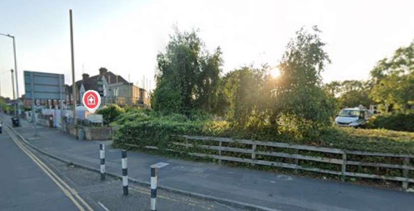
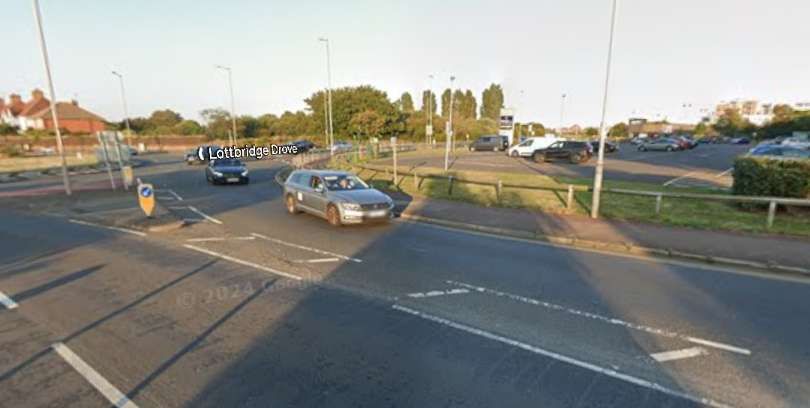
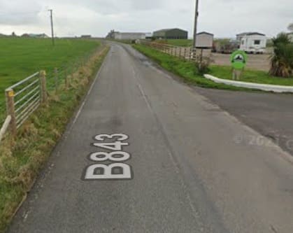
Looking Southwest along the line of the Crumbles Branch from the location of the old level-crossing on Seaside. [Google Streetview, August 2024]
Looking Northeast along the line of the Crumbles Branch from the location of the old level-crossing on Seaside. The line ran towards the poplar trees on the horizon. [Google Streetview, August 2024]
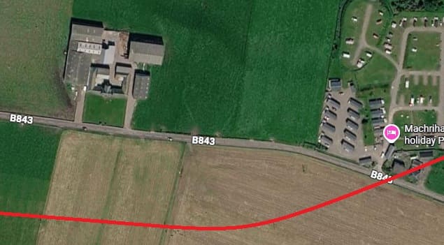
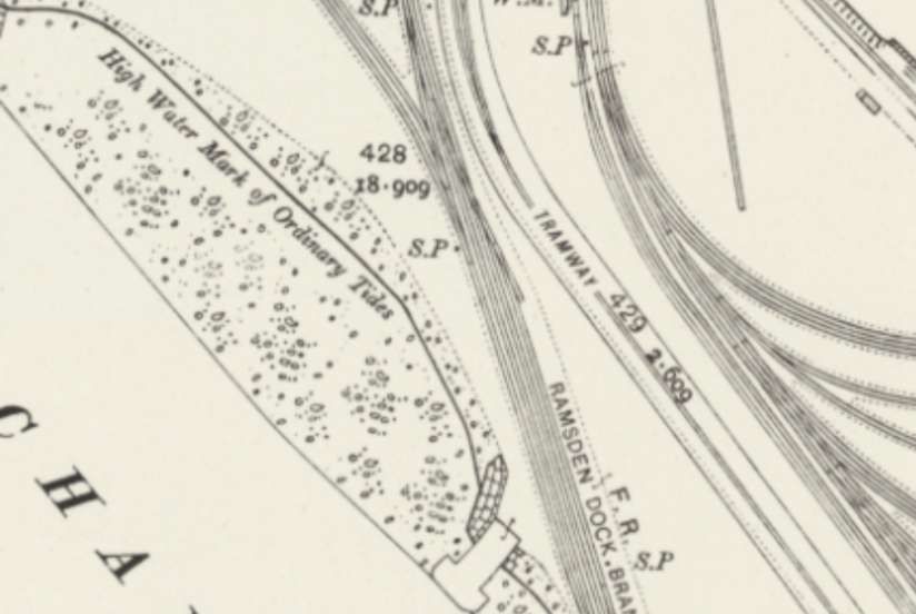
The same location as on the extract from the 1875/76 6″ Ordnance Survey as it appears on railmaponline.com. [24] The turquoise line which appears here may represent a part of a 2ft-gauge network of tramways owned by Hall & Co. Hall & Co. tramways were transient, moving with the area being worked for shingle. [31]

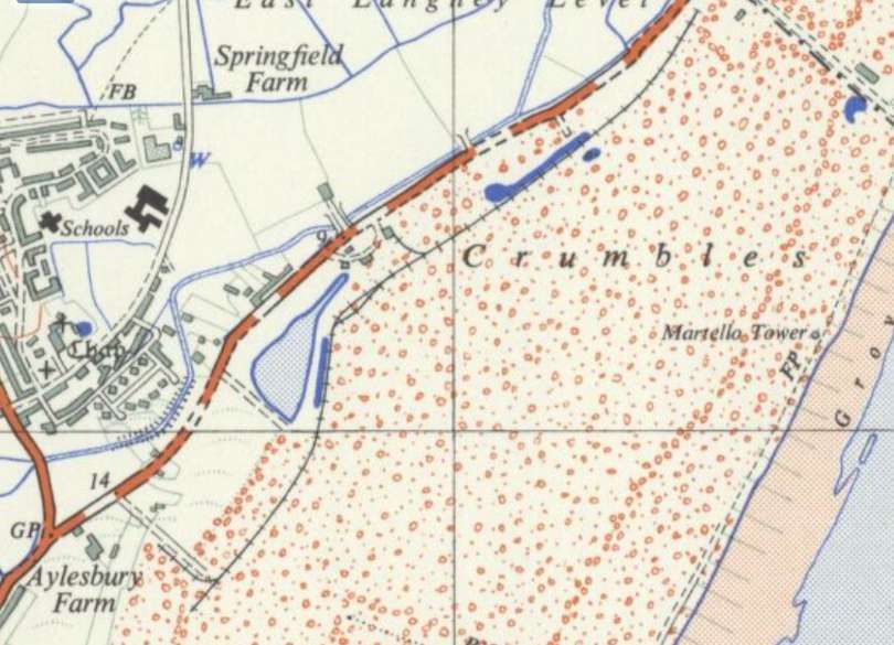
Hall & Co. 2ft-gauge tramway as it was in 1959, this extract is taken from the 1:25,000 Ordnance Survey. [32]

The Crumbles Branch line was extended beyond that shown on the 1875/76 6″ Ordnance Survey above, to access further gravel reserves to the Northeast.
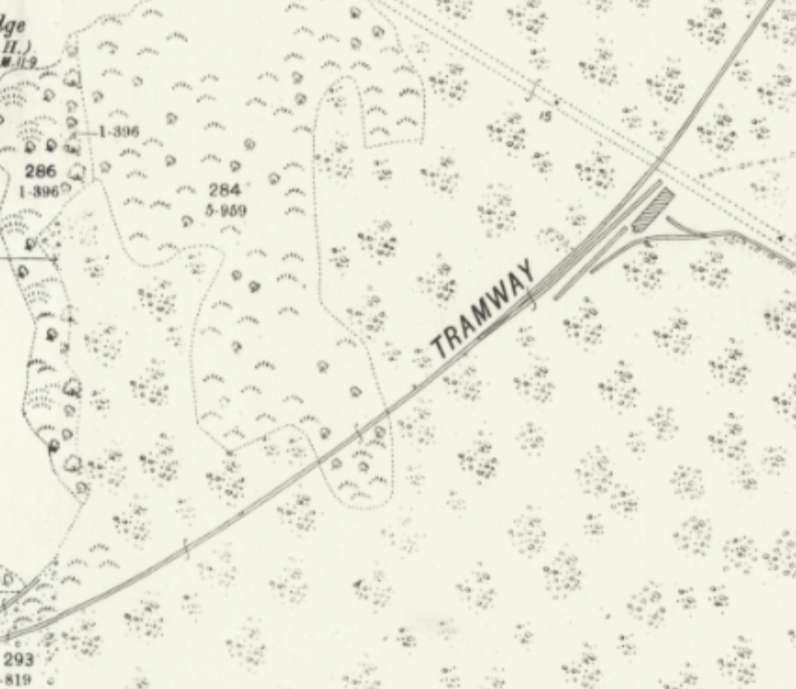
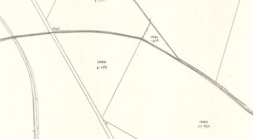
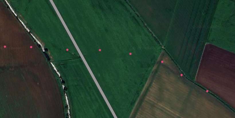
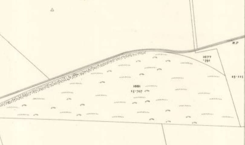
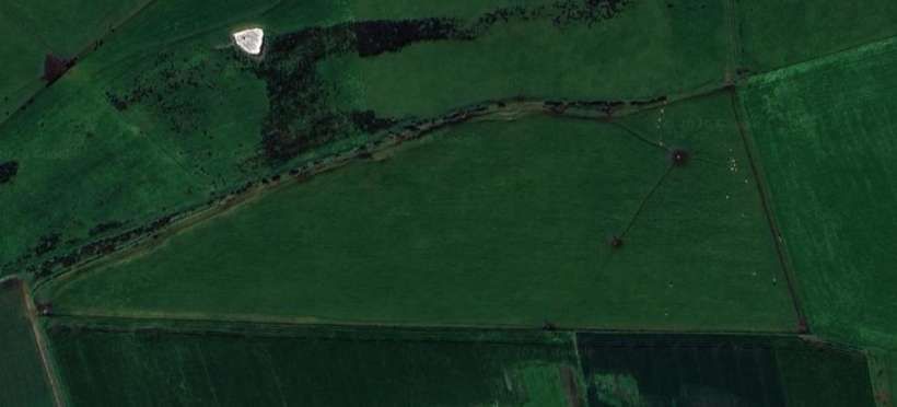
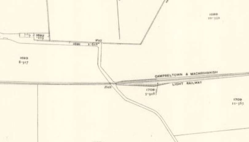
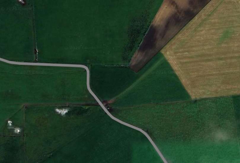
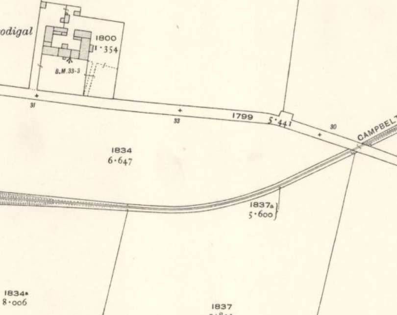
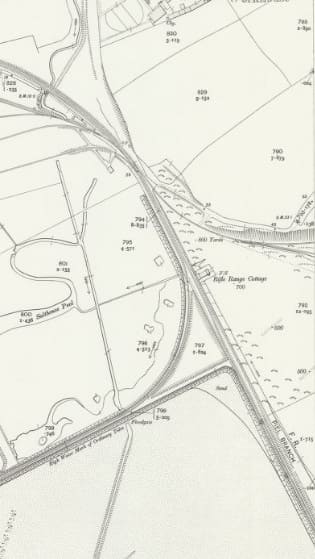
The line curve towards the Northeast and passed the end of a tramway which ran through the rifle ranges. [26]

The military association with the Crumbles began in the early 19th century with the construction of defensive Martello Towers to ward off Napoleonic invasion. By the late 1800s and early 1900s, this desolate, wide-open shingle plain was deemed the perfect location for a military live-firing range.

The main range featured firing points stretching up to 600 yards. Marksmen and local cadet groups (such as the Eastbourne College Cadet Corps) would lie on the dirt to fire live ammunition from .303 Lee-Enfield rifles at large targets. The targets were managed by soldiers or cadets stationed “in the butts”—a protected, sunken trench directly beneath the targets. Their dangerous job was to pull the massive frames up and down via ropes, patch up the bullet holes, and signal the scores back to the firing line.

A red warning flag was flown whenever firing was live, and any stray bullets flew harmlessly out over the English Channel. The ranges remained active through both World Wars for troop training and continued operating well into the 1960s. The range finally closed in the late 1960s, and the area was later completely reshaped to build the Sovereign Harbour marina complex.

The electric tramway of the mid-20th century is covered in a separate article which can be found here. [30]
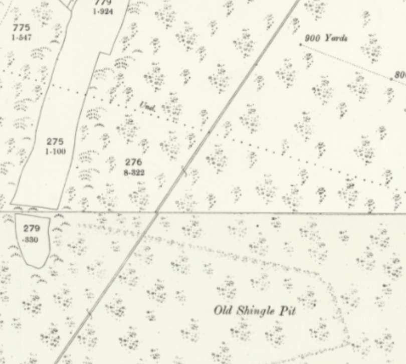
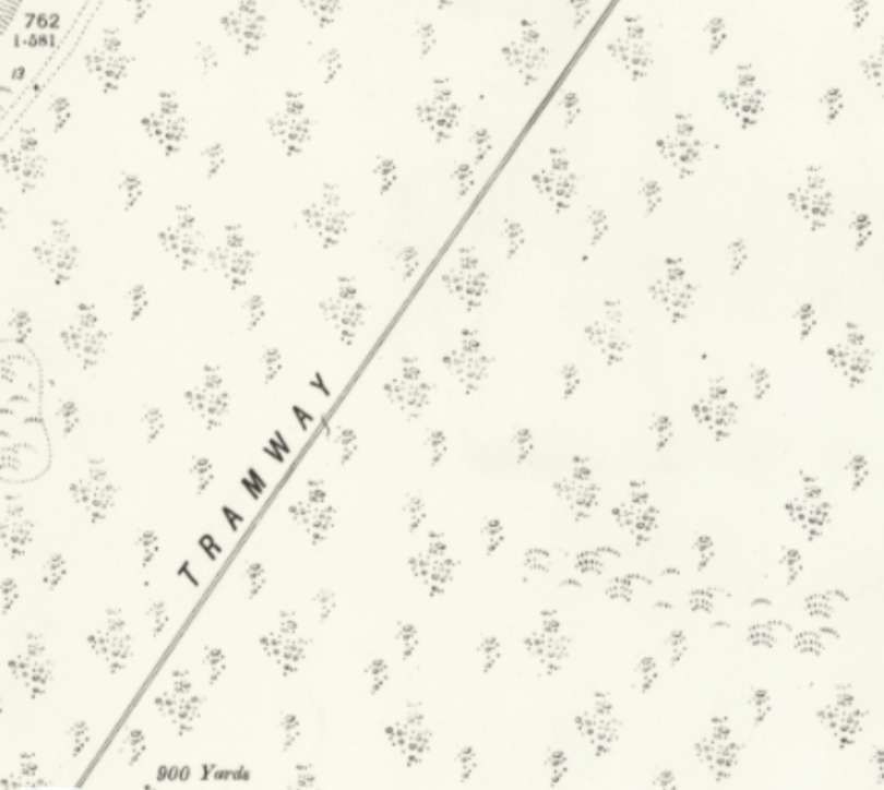
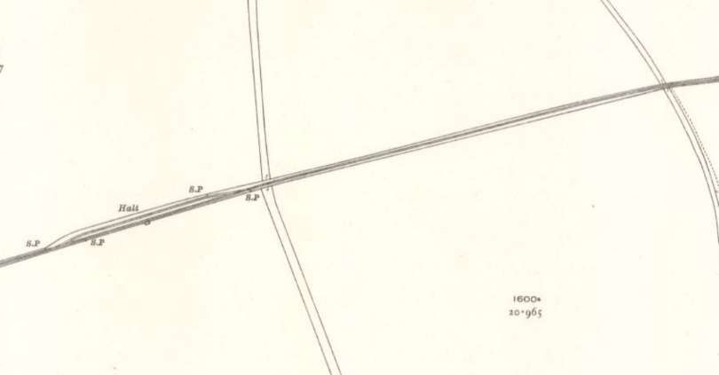
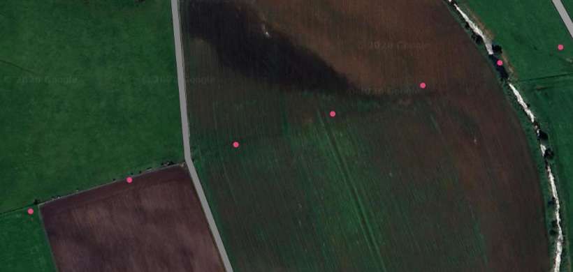
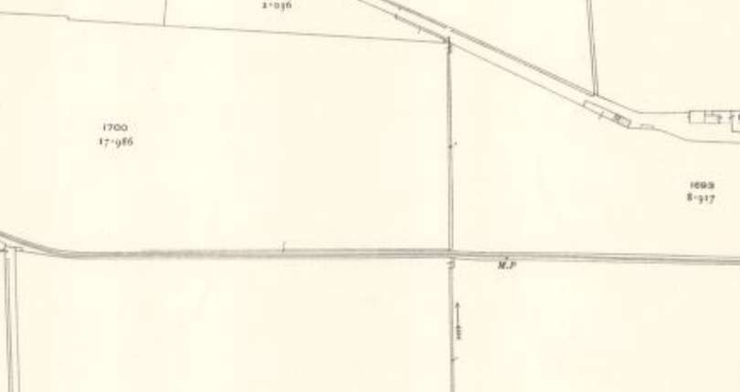
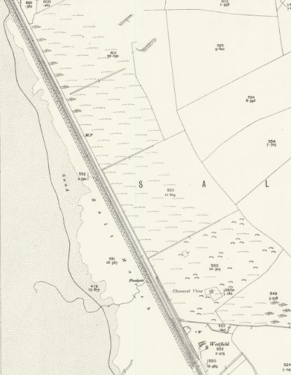
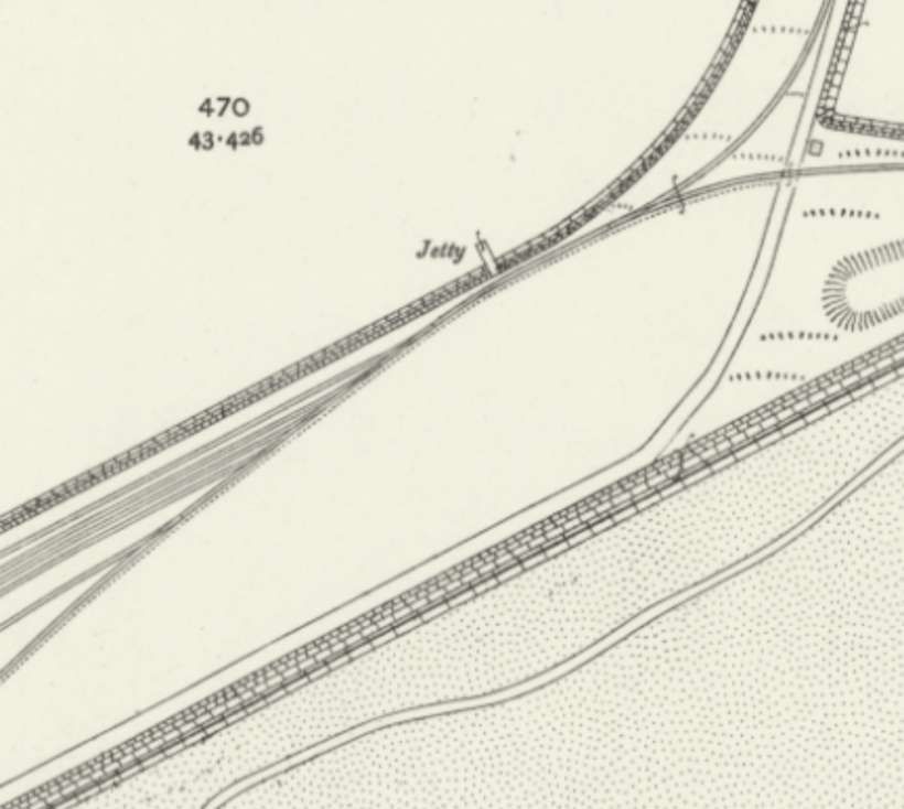
The line continued out across the shingle bank. [26][27]
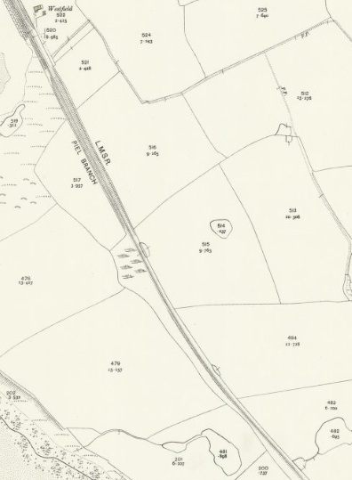
The line continued further Northeast. [27]

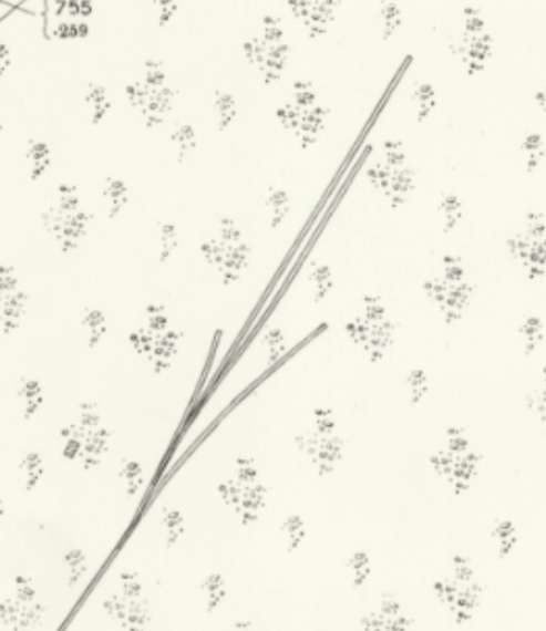
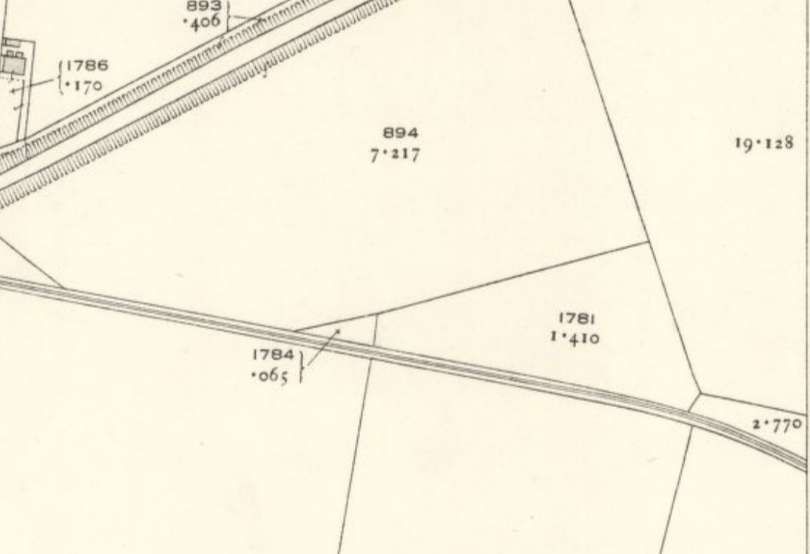
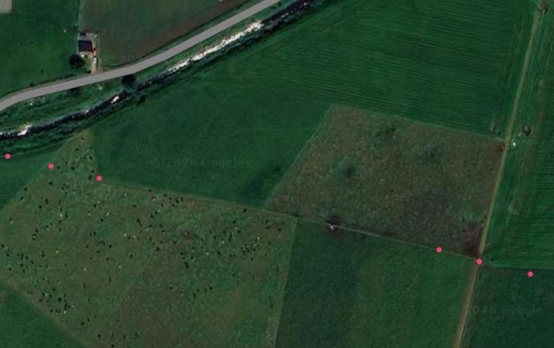
The end of the line in 1898/99. [27]
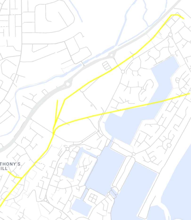
Railmaponline.com shows a somewhat greater extent of the various lines which served the shingle quarries/workings at this location. These extensions supported the workings until their closure in the 1930s. [24]
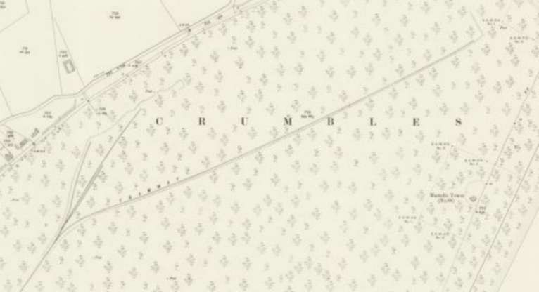
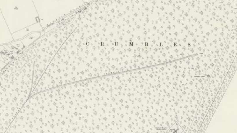
This is the extent of the line as it appears on the 25″Ordnance Survey of 1908, published in 1909. [28]
This is the extent of the line as it appears on the 25″Ordnance Survey of 1925. [29]
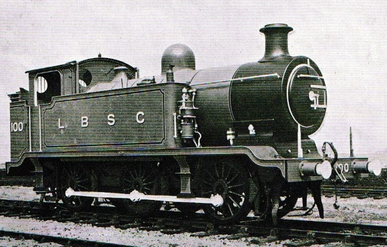
E2 Tank No. 100 at the Ballast Pit in the 1920s. This image was shared by Robert Ian on the Disused Railways of Sussex Facebook Group on 15th January 2025. [35]

We have noted in the narrative above the 2ft-gauge Hall & Co. Tramway which was horse and cable-worked. [31][32][34] There were other transient tramways laid on the Crumbles, these were associated with the local brickworks. Just inland of the open shingle beach (approaching St. Anthony’s Hill and the Langney boundary), the 1898 OS maps catch the footprint of Eastbourne’s late-Victorian building boom. Local clay pits and brickfields (such as those that eventually became the South Eastern Brick and Terra Cotta Works) utilized small, lightweight clay tramways to transfer raw materials from excavation pits to the kilns. [33]

References

  1. Vic Mitchell & Keith Smith; Brighton to Eastbourne; Middleton Press, 1985.
  2. Vic Mitchell & Keith Smith; Eastbourne to Hastings; Middleton Press, 1986.
  3. https://en.wikipedia.org/wiki/East_Coastway_line, accessed on 29th August 2026.
  4. https://www.flickr.com/photos/harryclaggers/43482880200/in/photostream, accessed on 29th August 2026.
  5. https://uktransport.fandom.com/wiki/East_Coastway_Line, accessed on 29th August 2026.
  6. https://www.geograph.org.uk/photo/8115913, accessed on 29th August 2026.
  7. https://youtu.be/HSSFptGzpPc?is=TGSPLGusqjEehdRd, accessed on 29th August 2026.
  8. https://maps.nls.uk/geo/explore/#zoom=17.6&lat=50.77259&lon=0.28579&layers=168&b=ESRIWorld&o=100, accessed on 29th August 2026.
  9. https://maps.nls.uk/geo/explore/#zoom=17.6&lat=50.77259&lon=0.28579&layers=168&b=ESRIWorld&o=0, accessed on 29th August 2026.
  10. https://maps.nls.uk/view/103675453, accessed on 29th August 2026.
  11. https://maps.nls.uk/view/103675420, accessed on 28th August 2026.
  12. https://maps.nls.uk/view/101436231, accessed on 30th August 2026.
  13. https://www.bbc.co.uk/history/ww2peopleswar/stories/20/a3187820.shtml, accessed on 30th August 2026.
  14. https://youtu.be/9X0YFtsGYzM?is=yWKt8iiJQbE-rt-x, accessed on 30th August 2026.
  15. https://www.facebook.com/share/p/18ZS5t6UBz, accessed on 30th August 2026.
  16. https://www.britainfromabove.org.uk/en/image/epw039401, accessed on 30th August 2026.
  17. https://m.facebook.com/groups/sussexhistory/permalink/25602800352636948, accessed on 30th August 2026.
  18. https://www.heritageopendays.org.uk/submission-event/eastbourne-industry-and-commerce.html, accessed on 30th August 2026.
  19. https://maps.nls.uk/geo/explore/#zoom=17.0&lat=50.78783&lon=0.30057&layers=168&b=ESRIWorld&o=0, accessed on 30th August 2026.
  20. https://www.britainfromabove.org.uk/en/image/EPW039397, accessed on 31st August 2026.
  21. https://www.britainfromabove.org.uk/en/image/EPW039398, accessed on 31st August 2026.
  22. https://www.britainfromabove.org.uk/en/image/EPW039402, accessed on 31st August 2026.
  23. https://discovery.nationalarchives.gov.uk/details/r/e9fbbd39-8529-47dc-b58f-045c4d7fd34d, accessed on 31st August 2026.
  24. https://railmaponline.com, accessed on 31st August 2026.
  25. https://maps.nls.uk/view/102347779, accessed on 31st August 2026.
  26. https://maps.nls.uk/view/103675429, accessed on 31st August 2026.
  27. https://maps.nls.uk/view/103675393, accessed on 31st August 2026.
  28. https://maps.nls.uk/view/103675390, accessed on 31st August 2026.
  29. https://maps.nls.uk/view/103675387, accessed on 31st August 2026.
  30. The Hall & Co. Narrow-Gauge Tramway was, unlike the main LB&SCR railway branch that took deep shingle out for mainline railway ballast, a localized system dedicated to commercial shingle and gravel extraction. Track was moved dynamically over the years across the Crumbles to reach active digging pits. It was cable-worked and horse-drawn in its earliest iterations. It fed local concrete product works and smaller commercial loading docks rather than servicing the LB&SCR’s need for ballast. See also the OS Map @ reference [32]
  31. https://maps.nls.uk/view/95750294#zoom=4.6&lat=2718&lon=3174&layers=BT, accessed on 31st August 2026.
  32. https://plandocs.tandridge.gov.uk/my-requests/document-viewer?DocNo=25469297, accessed on 31st August 2026.
  33. https://deangoods.co.uk/eastsxng.html, accessed on 31st August 2026.
  34. https://www.facebook.com/share/p/1GfNXWhYgx, accessed on 31st August 2026.
  35. https://www.facebook.com/share/p/1GSkYoS75y, accessed on 31st August 2026.
  36. https://maps.nls.uk/geo/explore/#zoom=16.6&lat=50.78750&lon=0.30722&layers=168&b=ESRIWorld&o=0, accessed on 1st September 2026.
  37. This image is taken from a report written by C. Butler & C Russell; Desk-based Assessment for the Sovereign Harbour Cycle Network Phases 2 and 3, (Ringwood Road to St Anthony’s Hill Roundabout) Eastbourne, East Sussex (updated from the original Desk-based Assessment for Phase 2A); Chris Butler MIfA, Archaeological Services Ltd., 2012; via: https://archaeologydataservice.ac.uk/archiveDS/archiveDownload?t=arch-969-1/dissemination/pdf/chrisbut1-398965_1.pdf, accessed on 1st September 2026.

Appendices

Appendix 1

Chris Butler and Dr Caroline Russell

Desk-based Assessment for the Sovereign Harbour Cycle Network Phases 2 and 3, (Ringwood Road to St Anthony’s Hill Roundabout) Eastbourne, East Sussex (updated from the original Desk-based Assessment for Phase 2A)

Chris Butler MIfA, Archaeological Services Ltd – Project No. CBAS0176 – October 2012

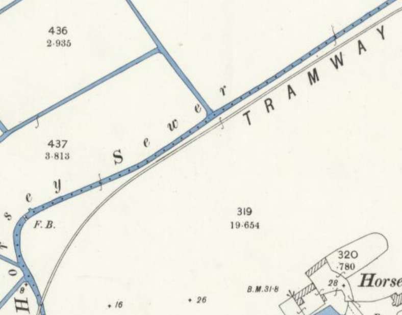
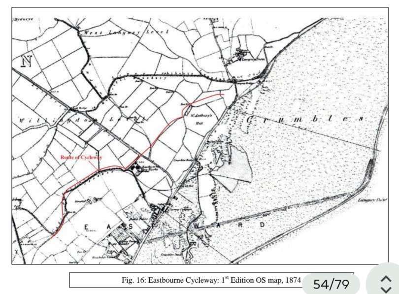
4.9.11 …The 1st Edition OS map of 1874 (Fig. 16) shows significant changes to have taken place to the landscape surrounding the Phase 2 cycleway route. Although the Horsey Sewer is shown within a field system that broadly reflects that seen on the early maps, a tramway now runs along its length. It crosses the sewer at three places, to run past the Eastbourne Gas Works and on to the Crumbles, with a single track branching off into the gasworks. To the immediate southeast is Horsey Farm, and then further southeast are ‘Rose Lands’ and a brickfields. [p15]

4.9.12 … The tramway served the beach gravel extraction on the Crumbles, and can be seen on the broader OS map to extend onto the beach before dividing into three separate branches; the gravel pits on the beach are recorded as MES7969-MES7971. In 1857-1862, the London Brighton and South East Railway negotiated with the Duke of Devonshire to purchase not less than 48,000 cubic yards of shingle from the Crumbles, at 1 penny per cubic yard. [48] They constructed a railway close to Eastbourne railway station, which ran through open countryside and along the Horsey Sewer, to turn south to cross the turnpike road (Seaside) near the junction with Lottbridge Drove. The railway was 6.4m wide and ran for 5.6km. It was known as the Ballast Line or the Crumbles Railway, and served the gasworks from 1870 onwards. In 1874, the Crumbles were also used for firing practice (firing ranges MES7961 and MES7962).

4.9.13 The Eastbourne Gas Company was formed in 1852, [49] and was incorporated by an Act of Parliament in 1868, [50] whilst the brickworks was in existence by 1866, and was operated by James Peerless, who leased the land from the Devonshire Estate in 1860. [51]

It continued to operate there until 1899. A smaller brickworks was located at Rose Lands, and was operated from 1860 to the 1880’s by the Eastbourne Brick Co. Ltd. [52]

4.9.14 In contrast, little change had taken place by 1875-1880 along the Phase 3 cycleway route (see Fig. 16 for the 1st Edition OS map). A footpath led through the short droveway, having come through the fields to the northwest. Further northeast along the Phase 3 route, two causeways, each in a different field, gave entry to the same field to the southeast. A drainage channel had been excavated beside the Crumble Sewer, to define a small rectangular plot, possibly a holding pen, directly outside the site boundary. At the north end of this new plot, a footbridge now provided access across the sewer and into the field to the northeast. From here, an adjacent causeway, rather than the previous central causeway, led southeast into the narrow field north of St. Anthony’s Hill. The only building nearby was ‘The Lodge’, a public house on the coast road, south of the hill.

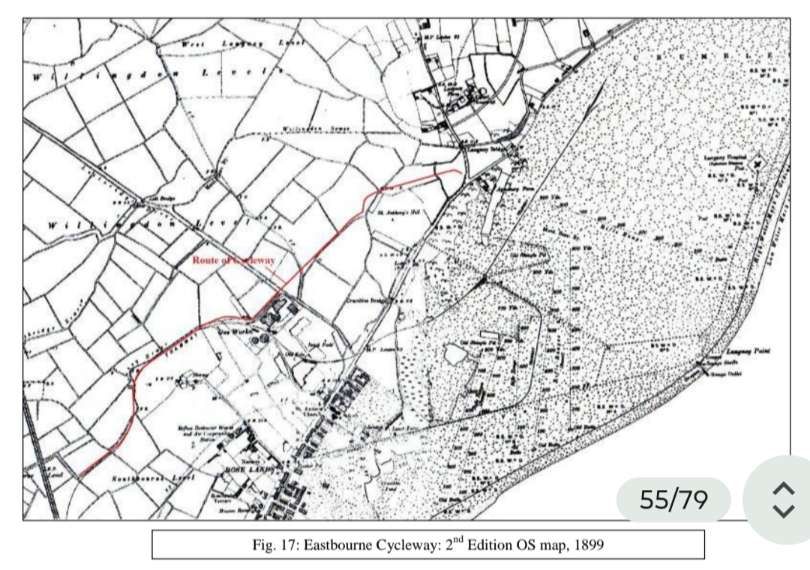
4.9.15 The gasworks had expanded eastwards by the 2nd Edition OS map of 1899 (Fig. 17); ESRO holds a plan of the land intended to be acquired for this expansion, which was drawn in 1879 by H.E. Jones, the Engineer for Eastbourne Gas. [53] The main brickworks had migrated northeast, with allotment gardens having been established along the northern edge of the earlier workings. Rose Lands was a nursery by this time, with a refuse destructor works and air compressing station located on its north side. [p16]

4.9.16 The tramway now had additional sidings serving the gasworks. It continued onto the Crumbles, where it ran to the east, while a branch turned southwest before returning westwards to Seaside on an existing earthwork (MES7968) shown on the 1st Edition OS map. Housing development had expanded northeast along the southeast side of Seaside. The tramway also later served the refuse destructor works and air compressing station, the brickworks and a timber yard.

4.9.17 The Phase 3 cycleway route remained unaltered between 1875-1880 and 1899 (see Fig. 17 for the 2nd Edition OS map). The footbridge had gone. The possible animal pen on St Anthony’s Hill now looks to have been defined by a fence line rather than by ditches, and a second larger such enclosure had been erected in the same former field, on the south side of the hill.

4.9.18 The Martello Towers (MES512 and MES513 / MES7994) on this stretch of coastline all disappeared in the late 19th or early 20th century. Tower 71 was demolished after having been used as target practice for the testing of the new rifled Armstrong Guns in 1860. [54]

Tower 72 had been washed away by the sea sometime prior to 1872, [55] as had West Langney Fort. Tower 70 had likewise been undermined by the sea and was abandoned in 1872 along with Tower 69. Tower 67 was demolished in 1922, whilst Tower 68 was knocked down in c.1925 to make way for residential development (however, see para. 4.9.28).

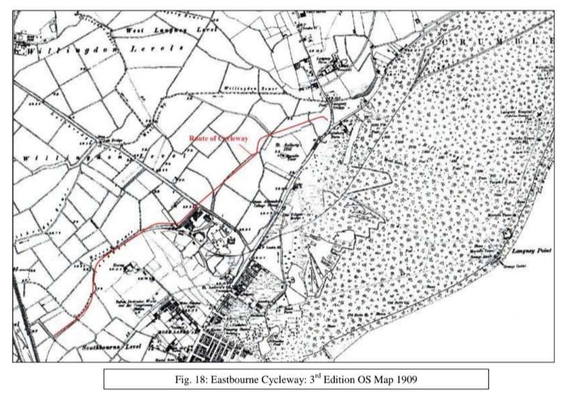
4.9.19 The 3rd Edition OS map of 1909 (Fig. 18) shows little change to the immediate area around the Phase 2 site, although there had been further housing development along Seaside. A long narrow plot of land was now fenced off along one side of a field, to form a passageway presumably for the movement of livestock between two fields, including the narrow field to the east in which the cycleway runs through. The Martello Tower on St. Anthony’s Hill (MES513 / MES7994) is marked on the map, along with its moat and footbridge; its absence from the 1st or 2nd Edition OS map is somewhat odd, although military installations were often omitted from OS maps for security purposes.

4.9.20 During the First World War, a temporary tented camp was set up at Horsey Bank, in the area of the junction of Churchdale Road and Astaire Avenue. [56] The allotment gardens shown on the 2nd and 3rd Edition OS maps (Figs. 17 and 18) were put to good use during these years, although it is recorded that the Eastbourne Gas Company refused a request to plough up land for allotments, but a compulsion order overturned this. [57] [p17]

4.9.21 From December 1911, Eastbourne Aviation Company Ltd had their manufacturing aerodrome (MES7491) at a site directly to the north of Lottbridge Drove. [58]

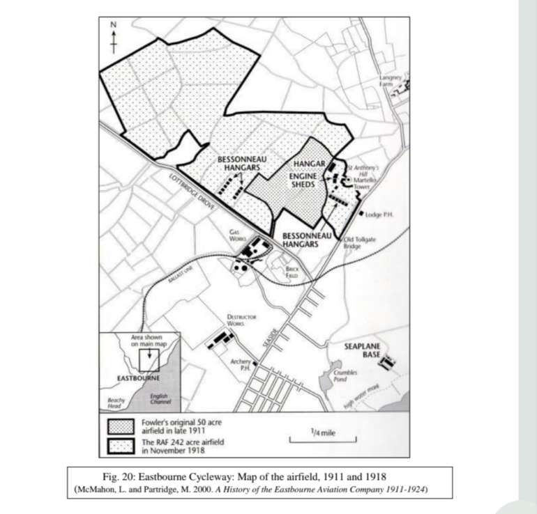
From about this time, this site also became the school aerodrome for the Eastbourne Aviation School and the Fowler Flying School. A map of the airfield [59] (Fig. 20) shows the middle stretch of the Phase 3 cycleway route to have been located within Fowler’s original 50 acre airfield.

4.9.22 In August 1914, the hangars and buildings of the aerodrome were taken over by the Royal Navy Air Service. [60] The aerodrome at St. Anthony’s was a RNAS flying school from April 1915 to April 1918, when it became a training depot station for the RAF until 1919. In November 1918, the RAF airfield comprised 242 acres, having predominantly expanded northwest across the Levels (Fig. 20). Almost the full route of the Phase 3 cycleway now stood within the airfield, except for the last stretch through the two fields at the northeast end. With the exception of one area, the buildings, which included a large hangar (MES7990) and the engine sheds, were built around the Martello Tower (MES513 / MES7994) and therefore outside the site boundary. The 15 Bessoneaux hangars were erected in three rows, with two rows having stood opposite each other to the northwest of what is now Birch Road, and the third row having stood along the south side of what is now Leeds Avenue, directly south of St. Anthony’s Hill. During the Phase 2A watching brief an identity disc was found. It is engraved R.N.A.S. / TURNER / ERNEST / EDWARD / A M / F364/ CCE. Ernest Edward Turner is recorded as having been born in 1894 in Bangalore, India, and entered the RNAS in 1914; [61] it is presumed that he served at St Anthony’s.

4.9.23 The aerodrome was licensed for civilian use again in April 1920 [62] and finally closed in 1925. The only remaining structure of the aerodrome is a guardroom (MES7991) from the RNAS phase of use, which is now a bungalow on Leeds Avenue. The large hangar (MES7990) stood extant nearby until the storm in 1987; its foundations are still visible today.

4.9.24 A site on the Crumbles, in the region of the present day Sovereign Centre, was used by the Eastbourne Aviation Company as a seaplane factory, and also for the refuelling and servicing of patrolling seaplanes. [63] The hangars on the Crumbles were converted to an aircraft factory, and during the war the Eastbourne Aviation Company built a total of 252 aircraft. [p18]

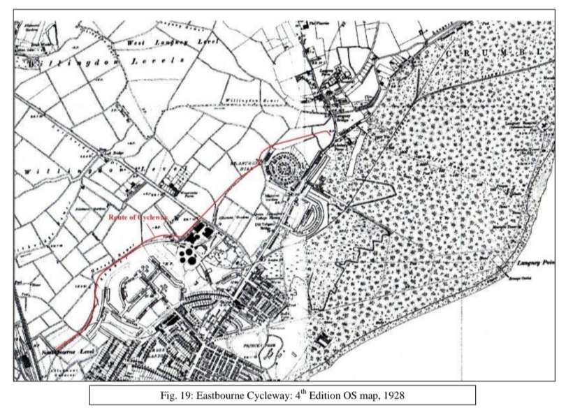
4.9.25 By the 4th Edition OS map of 1928 (Fig. 19), the tramway has developed to include a branch line to the refuse destructor works and air compressing station, and additional sidings at the gasworks. The return route of the tramway to Seaside from the Crumbles had been dismantled by this time. Some ‘tanks’ are shown adjacent to the Horsey Sewer, north of the gasworks and alongside a footbridge. Major housing development had taken place to the southeast of the Phase 2 cycleway route, along the northwest side of Seaside. Eastbourne Corporation had a licence to place a footbridge over the Horsey Sewer in 1926, [64] and had an agreement for works in the Horsey Sewer in 1937. [65]

4.9.26 The decline of the tramway began in 1920 when the ballast used on the railways changed to granite chippings and there was no further requirement for the shingle. 

Shingle continued to be taken to the Duke of Devonshire’s depots at Eastbourne Station to be used for building purposes until 1931. [66] The shingle beds at the Crumbles were leased to Hall and Co. [67] who then began to use lorries to move the shingle, stopping rail movements completely in 1932. The tramway continued to serve the gasworks and other industrial sidings, taking thousands of tons of coal to the gasworks (Fig. 21). [68]

4.9.27 The land around the Phase 3 cycleway route looked little different in 1925-1930 from what it had done in 1910 (see Fig. 20 and the 4th Edition OS map of Fig. 19 for a comparison), revealing how easily the land had reverted to pasture after its use as an airfield. A number of buildings from the aerodrome still stood, including the engine sheds as well as the guardroom (MES7991) and large hangar (MES7990). A sluice is shown across the Crumble Sewer, south of the former hangar. A crossing across the sewer was now sited where the footbridge once was; it is the location of a bridge today, although it was not identified as such on this OS map. The crossing led into a small enclosure, once part of a larger enclosure, which linked up with the field to the east.

4.9.28 Residential housing had been built on the east side of St. Anthony’s Hill, and below it along Seaside. Both the inner and outer circular roads of The Circus and Rotunda Road had been laid out around the hill, although neither was specifically named as such at this time. The Circus was built around the in-filled moat of Tower 68, [69] whilst Rotunda Road may have traced the boundary of land first purchased by the government in 1795. The single building at the centre of the housing development, within The Circus, may incorporate the base of the Martello Tower (MES513 / MES7994) in its cellar. [70] Allotment gardens had been planted directly south of St. Anthony’s Hill and beside the Phase 3 cycleway route on Lottbridge Drove. [p19]

4.9.29 During the Second World War the coastline was put into a state of defence with anti-tank cubes, walls and ditches (e.g. MES7997), minefields (e.g. MES8007) andscaffolding located on the beach, and other defences such as pillboxes positioned to the rear (e.g. MES7999, MES8017 and MES8018). [71] Unexploded bombs fell in allotments near Lottbridge Drove on 14th September 1940, while the gasworks was attacked on the 19th October, setting alight the Number Three gasholder. [72] On 12th March 1941, eight bombs were dropped to the south of the Phase 2 site around Churchdale and Southbourne Roads, and on the following night bombs were dropped to the north of the gasworks. On the 26th August 1942, a German FW190 fighter-bomber was shot down and crashed into a ditch beside Lottbridge Drove. Further bombs were dropped on open ground near the gasworks as well as on the Crumbles on 6th June 1943. On considering its location in the Levels, further out of town, no bombs are known to have fallen in the area of the Phase 3 cycleway route. [73]

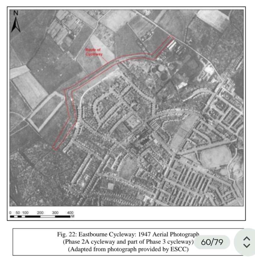
4.9.30 A 1947 aerial photograph (Fig. 22) shows residential development to have extended almost as far north as the Horsey Sewer. By the early 1960’s (modern OS maps are not reproduced), the housing developments had reached the southern edge of the sewer, and the tramway is still shown. In the locality of the Phase 3 cycleway route, further residential development had occurred on and around St. Anthony’s Hill, and hadexpanded out onto the Crumbles along Wallis Road and around the adjacent crescent.

Between 1947 and 1961, the Horsey Sewer was straightened to the north of the gasworks, cutting off the former droveway onto Lottbridge Drove. Three new causeways had been constructed along the course of the Phase 3 cycleway.

4.9.31 The tramway had gone by the time of the 1975 OS map, as it had finally closed in 1966. [74] The 1975 map also shows the commercial developments at the southeast end of Lottbridge Drove. One or two buildings appear to have stood at the northeast end of the Phase 3 cycleway route, facing onto the road north of the roundabout, which had been built by then; these buildings were demolished by 1992. The commercial developments had extended beyond the Horsey Sewer, along both sides of Lottbridge Drove by the 1981 OS map. This map also shows new housing developments along the north side of the Horsey Sewer. [p20]

Relevant References

48. Botha, A. 2006. The Crumbles Story. Eastbourne: ALB Books

49. Wright, J.C. 1902. Bygone Eastbourne. Spottiswood and Co. Ltd.

50. ESRO amsh/AMS5616/2/70

51. Beswick, M. 2001. Brickmaking in Sussex. Middleton Press.

52. Ibid.

53. ESRO QDP/448

54. http://sussexhistoryforum.co.uk/index.php?topic=1669.0;prev_next=next#new

55. http://www.martello-towers.co.uk/south-coast/towers

56. Elliston, R.A. 1999. Eastbourne’s Great War 1914-1918. Seaford: S.B. Publications.

57. Ibid.

58. CCI Gazetteer of Flying Sites

59. McMahon, L. And Partridge, M. 2000. A History of the Eastbourne Aviation Company 1911-1924. Eastbourne Local History Society.

60. CCI Gazetteer of Flying Sites

61. National Archives ADM 188/1175

62. Ibid.

63. McMahon, L. And Partridge, M. 2000. A History of the Eastbourne Aviation Company 1911-1924. Eastbourne Local History Society.

64. ESRO SRA7/15/33

65. ESRO SRA4/6/16

66. Botha, A. 2006. The Crumbles Story. Eastbourne: ALB Books.

67. http://www.cambrianmodels.co.uk/eastsxng.html (Gazetteer of Narrow Gauge Railways in East Sussex)

68. Botha, A. 2006. The Crumbles Story. Eastbourne: ALB Books.

69. Butler, C. 2007. East Sussex Under Attack. Stroud: Tempus Publishing.

70. Ibid.

71. Butler, C. 2007. East Sussex Under Attack. Stroud: Tempus Publishing.

72. Humphrey, G. 1998. Eastbourne at War. Seaford: S.B. Publications.

73. Ibid.

74. Botha, A. 2006. The Crumbles Story. Eastbourne: ALB Books.

Relevant Images (p50 – 56)
Didcot Railway Station Through the Years.

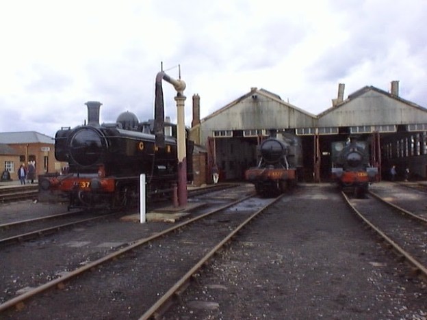
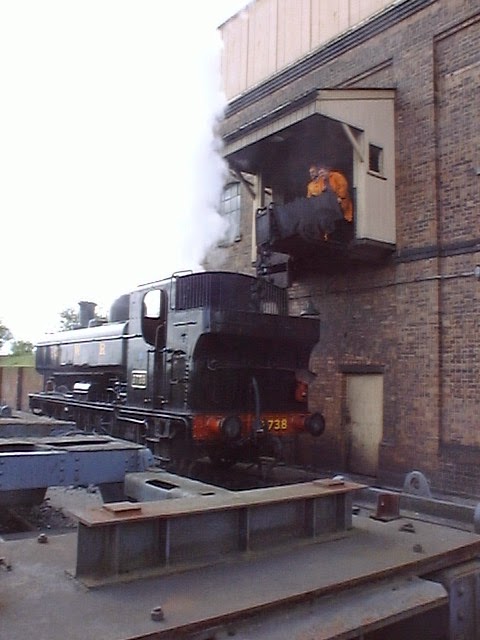
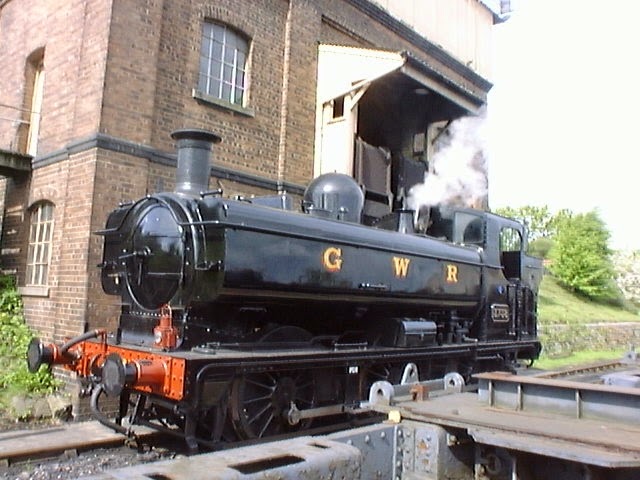
The featured image for this article is a photograph of the engine shed at Didcot Railway Centre taken in 2003. [My photograph, May 2003]

We start this article with a couple of photographs from the late 1920s/early 1930s showing express services from Paddington to Didcot.

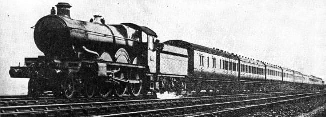
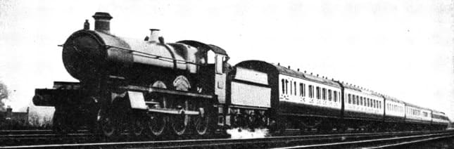
A Paddington to Didcot train in the capable hands of 4-6-0 locomotive ‘Star’ Class No. 4016, ‘Knight of the Golden Fleece’, in 1928. This image was carried in the Great Western Railway Magazine, Volume XL No. 6 of June 1928, p231. The photograph was taken by M. W. Earley, © Public Domain. [4]
Another Paddington to Didcot train in behind 4-6-0 locomotive ‘Saint Martin’ of their 2900 ‘Saint’ Class, in 1928. This image was carried in the Great Western Railway Magazine, Volume XL No. 11 of November 1928, p429. The photograph was taken by M. W. Earley, © Public Domain. [5]
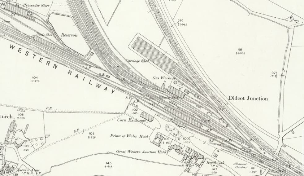
Didcot Railway Station in 1898, as it appears on the 25″ Ordnance Survey published in 1899. Note the small number of buildings opposite the station across Station Road. Didcot itself, just intrudes into the bottom-left of this map extract. [12]
Embed from Getty Images
Didcot Junction, Oxfordshire, 1904. View looking from the east at a signal box towards the junction station, with an engine approaching and a line of carriages to the left. The Branch Junction to Oxford and the erection of Isambard Kingdom Brunel’s covered station was completed in 1844, Artist Henry Taunt. (Photo from English Heritage/Heritage Images/Getty Images), Public Domain. [2]

Didcot Railway Station sat at the point where the line to Oxford diverged from the London-Bristol main line. It was an important interchange. The railway reached Didcot in 1839 and the station opened in 1844. It was rebuilt after fire in 1855. The timber island platforms in this view date from that rebuilding. The two-storey brick booking office in the image below was a later addition, dating from the early years of the 20th century. The booking office was rebuilt in the 1980s when the station was renamed Didcot Parkway. Only in the latter half of the 20th century has the town itself grown to match the importance of its railway station.

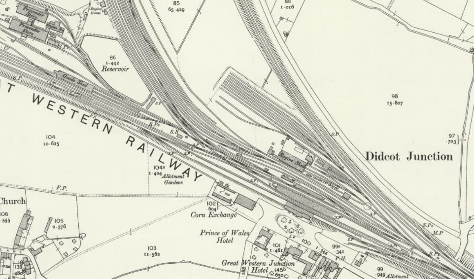
Didcot Railway Station as shown on the 25″ Ordnance Survey of 1910, published in 1912. The carriage shed appears to have been removed although the sidings are still present. The provender store top-right has become a complex of three significant buildings. [13]
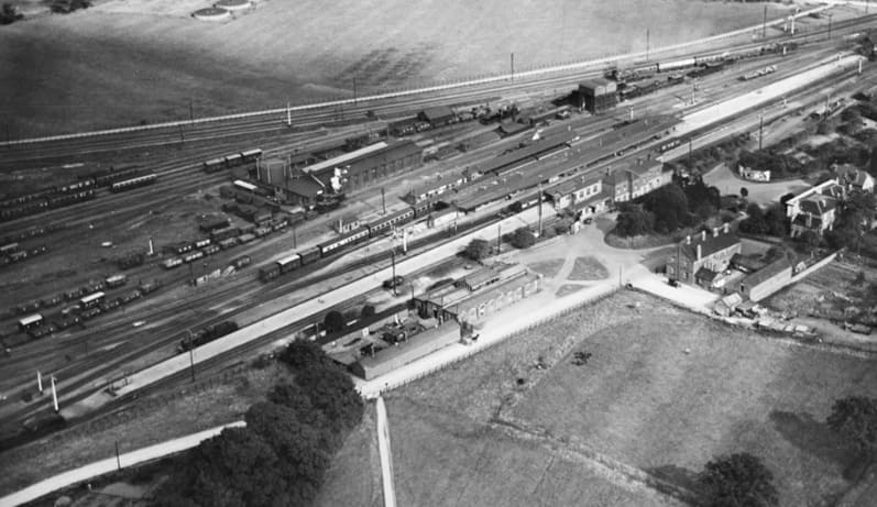
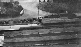
Didcot Railway Station, seen from the air in 1928. This is an excellent study of the station. The original locomotive depot which is seen beyond the station has changed significantly. It underwent a complete rebuild just a few years after this photograph was taken, in 1932. It was closed in 1965 and eventually it was sold to the Great Western Society to be redeveloped as their Didcot Railway Centre. The London-Bristol line runs right to left across the photograph – top-right to bottom-left. The East to North avoiding line is in the background beyond the depot. Trains from London to Oxford can pass through the station and then sweep round to the North immediately beyond the station of they can take the avoiding line. Trains from the Swindon direction can turn North at Foxhall Junction before reaching the station, but if scheduled to call at Didcot they would need to reverse to gain the Oxford line. Various 0-6-0s, 2-6-0s and 4-4-0s can be seen in the image. One 4-4-0 has left several coaches in the down platform and is running round its train, (c) Historic England (1928) EPW024646. [1]

This extract from another aerial image, this time facing South and looking across the site of Didcot Railway Station. The station buildings are in the top-right quadrant of the image (c) Historic England (1928) EPW024648. [8]

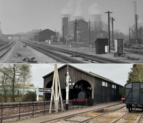
The first of these two images is a view looking west from the west end of Didcot Station around 1970 The down main line is furthest left. The bridge in the distance is Foxhall Road. The building in the middle distance on the right side of the main line is the old broad gauge/standard gauge goods transfer shed. In the heyday of Brunel’s broad gauge goods to and from the GWR system had to be laboriously transferred between GWR wagons and those of the standard-gauge. That building was preserved by relocating it on the Great Western Society’s Didcot Railway Centre site, where it has been recreated (apparently in a shortened form) as Burlescombe Shed (second photo), complete with mixed gauge track. The view in the first photo has changed in almost every way possible since I took it: transfer shed relocated, provender store (right of transfer shed) demolished, power station closed and demolished, main lines overhead electrified, bridge rebuilt. It all seemed so permanent at the time! These two photographs were shared by Vaughan Snook on the 19th Century Railway Enthusiasts’ Facebook Group in March 2026 © Vaughan  Snook. [3]
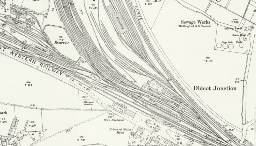
This extract comes from the 25″ Ordnance Survey of 1932, published in 1933. The new engine shed is in place. The number of sidings has increased again. The old engine shed has not yet been removed and the coaling stage has yet to be built. [14]

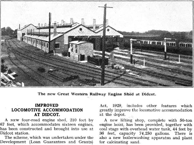
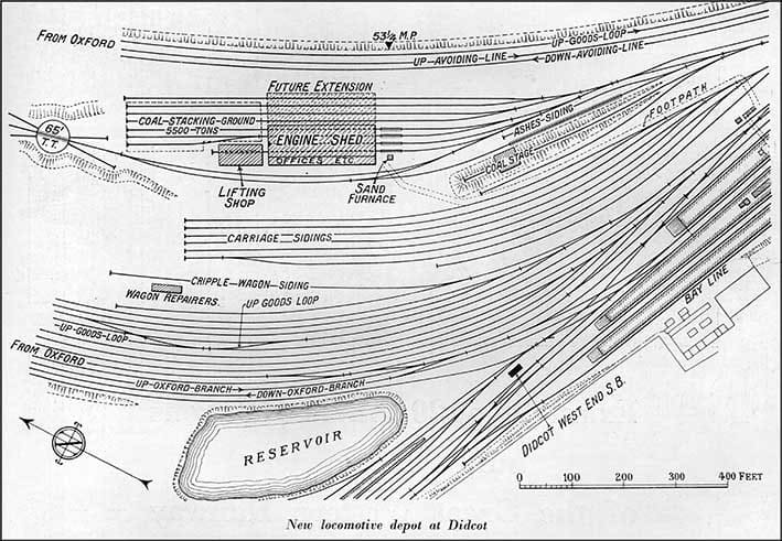
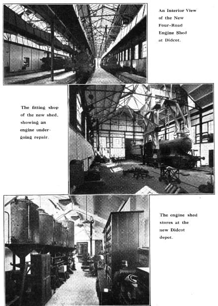
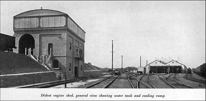
In 1932, a large four-road engine shed (210ft x 67ft) was built which could accommodate sixteen to twenty-four locomotives. In addition to the shed, a new lifting shop, with 50-ton hoist, has been provided, together with a large coaling stage with an overhead 74,250-gallon water-tank (44ft x 36ft). There was also new boiler-washing apparatus and plant for calcinating sand.

Following on the standardisation of locomotives, The GWR also sought to streamline and improve its maintenance facilities. It provided a number of new locomotive depots incorporating arrangements for enabling repairs and maintenance to be efficiently carried out. One of these was at Didcot, where the old locomotive depot was swept away and an entirely new depot provided on the triangle between the western main line and the line to Oxford and the North.

932: The New Engine Shed at Didcot. This unattributed image was carried in the Great Western Railway Magazine, Volume XL IV No. 10 of October 1932, p371. © Public Domain. [5]
A plan of the engine shed, coaling stage and carriage sidings at Didcot in 1933. Great Western Railway Development Works – Supplement to THE RAILWAY GAZETTE – 8th December 1933. [10]
1932: three images showing the interior of the New Engine Shed and Stores at Didcot. These unattributed images were carried in the Great Western Railway Magazine, Volume XL IV No. 10 of October 1932, p370. © Public Domain. [6]
A general view of the locomotive facilities at Didcot, featuring the new coaling stage on the left of the image. [10]

The 1932-built locomotive shed also included offices, stores and enginemen’s rooms, arranged along the south-west side of the building. They are commodious, well-lighted and warmed, and washing facilities are provided for enginemen, chargemen, fitters, mechanics, cleaners and shedmen. All the enginemen’s notices, instructions and roster sheets are contained in glass cases by which means they are kept flat, clean and easily discernible, and are posted up in a lobby between the stores and the offices. [10]

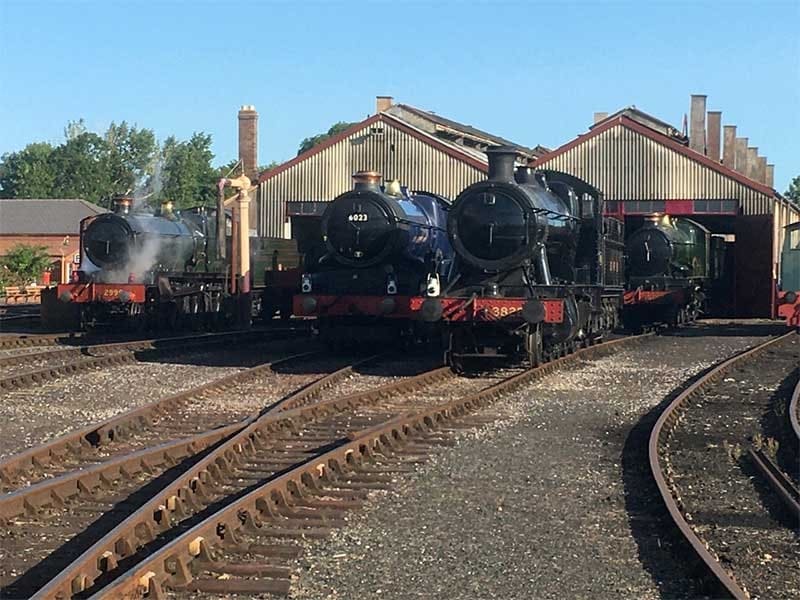
Various locomotive on shed in the 21st century. More can be found here. [11]

Photographs of the Coaling Stage at Didcot in May 2003. [My photographs, May 2003]

1932-1985

Little changed at Didcot in the years after WW2. The whole site remained virtually unchanged during the nationalised ownership of British Railways, but for the engine shed taking on the new code of 81E. The standard allocation of locomotives remained much the same as before nationalisation, with Halls, Dukedogs and Panniers making up the bulk of the depot’s fleet.

The gradual replacement of steam by diesel traction resulted in the closure of the locomotive facilities in June 1965.

In 1967, the Great Western Society took over the 1932 engine shed and surrounding infrastructure to establish a living railway museum – Didcot Railway Centre.

Didcot Parkway

Didcot Railway Station was renamed ‘Didcot Parkway’ in 1985. “A new main building for the station was built along with a new 600-space car park on the site of the former provender store to the west of the station for Park and Ride use. These were opened on 29th July 1985 by David Mitchell MP, Parliamentary Under Secretary of State for Transport, and on that date the station was renamed Didcot Parkway.” [9]

More recently, in 2018, a multi-storey car park was opened, costing £20 million and increasing the number of spaces by 65% to 1800. The car park also has a sheltered footbridge. In 2021, a new cycle storage hub was constructed, providing 600 covered spaces, LED lighting, CCTV cameras and a bike repair station. The project cost £1m, and was completed by a partnership of GWR, DfT and Network Rail. The station was served by some ‘Cross Country’ services until 2003, when Virgin ‘Cross Country’ ceased to call at the station, with all services using the Didcot East curve to and from the Oxford line. As at December 2018, one late night ‘Cross Country’ service from Reading to Birmingham New Street passed through Didcot Parkway to allow drivers to retain route knowledge. Passenger services on the West Curve ceased for a time after Thames Trains’ Oxford to Bristol Temple Meads service was withdrawn in 2003 but was reinstated on Saturdays in 2024. [9]

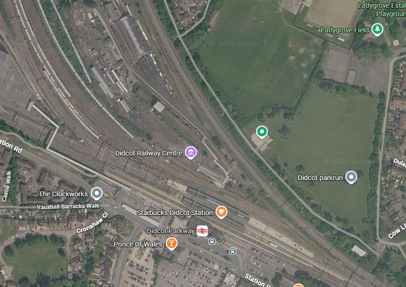
A 21st century satellite image showing the modern station at Didcot – Didcot Parkway and the Southern end of the Didcot Railway Centre. The avoiding line can be seen running from the bottom-right to the top-middle. The carriages sit on sidings alongside the line for Oxford which leaves the main line to the West of the station. [Google Maps, September 2026]
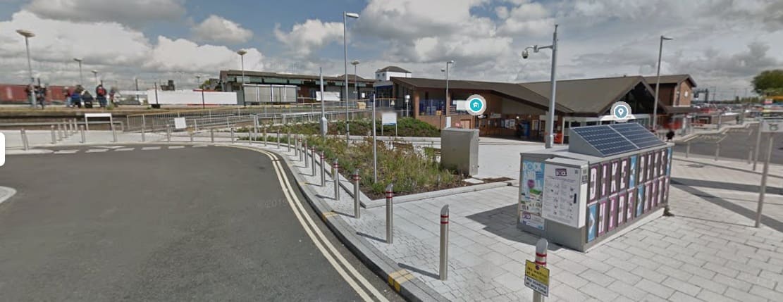
Didcot Parkway Railway Station, seen from the Southwest. [Google Streetview, April 2015]

References

  1. https://www.britainfromabove.org.uk/en/image/EPW024646, 9th September 2026.
  2. https://www.gettyimages.com/detail/961476136, accessed on 11th September 2026
  3. https://www.facebook.com/groups/1614960195255335/posts/26251905641134115, accessed on 11th September 2026.
  4. https://www.greatwesterntrust.org.uk/PDFViewer/web/viewer.html?file=%2fFilename.ashx%3ftableName%3dta_journals%26columnName%3dfilename%26recordId%3d469%26page%3d12%26end%3d13, accessed on 11th September 2026.
  5. https://www.greatwesterntrust.org.uk/PDFViewer/web/viewer.html?file=%2fFilename.ashx%3ftableName%3dta_journals%26columnName%3dfilename%26recordId%3d474%26page%3d12%26end%3d12, accessed on 11th September 2026.
  6. https://www.greatwesterntrust.org.uk/PDFViewer/web/viewer.html?file=%2fFilename.ashx%3ftableName%3dta_journals%26columnName%3dfilename%26recordId%3d547%26page%3d8%26end%3d8, accessed on 11th September 2026.
  7. https://www.greatwesterntrust.org.uk/PDFViewer/web/viewer.html?file=%2fFilename.ashx%3ftableName%3dta_journals%26columnName%3dfilename%26recordId%3d547%26page%3d7%26end%3d7, accessed on 11th September 2026.
  8. https://www.britainfromabove.org.uk/image/epw024648, accessed on 11th September 2026.
  9. https://en.wikipedia.org/wiki/Didcot_Parkway_railway_station, accessed on 11th September 2026.
  10. https://didcotrailwaycentre.org.uk/article.php/310/the-1932-engine-shed-when-new, accessed on 11th September 2026.
  11. https://didcotrailwaycentre.org.uk/article.php/17/1932-engine-shed, accessed on 11th September 2026.
  12. https://maps.nls.uk/view/104196166, accessed on 11th September 2026.
  13. https://maps.nls.uk/view/104196163, accessed on 11th September 2026.
  14. https://maps.nls.uk/view/104196160, accessed on 11th September 2026.

Railways of Tanzania – Part 16 – Locomotives in use in Tanganyika/Tanzania during the tenure of the EAR&H (EAR)

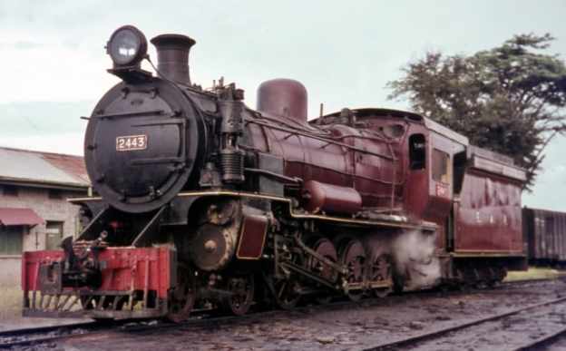
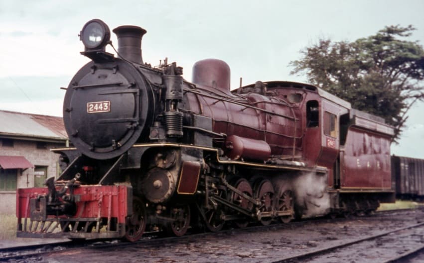
The featured image for this article shows an East African Railways (EAR) Class 24 4-8-0 locomotive No. 2443. The engine was manufactured by Vulcan Foundry and Nasmyth, Wilson and Company between 1923 and 1930. The photo shows the locomotive at Tabora depot in Tanzania during 1968, © Basil Roberts and licensed for reuse under a Creative Commons licence (CC BY-SA 4.0). [26]

East African Railways and Harbours was formed in 1949 through the amalgamation of Kenya and Uganda Railways and Harbours and Tanganyika Railways and Ports. Some locomotives which were ordered by Tanganyika Railways were delivered after the amalgamation. One of the EAR’s first actions was to develop a new numbering system which was applicable across East Africa. “Under the new system, tank engines were allotted Class number 10-19, tender engines 20-49 and Garratts 50 upwards. Diesels, then still only on order, were to become 80 upwards. Similar locomotives in service on both systems were taken together in one class, as was the case with the ED1 (KUR) and St (TR) classes, both becoming Class 11, Nos. 1105-1131 and 1101-1104 respectively.” [1: p70]

After initial experiments with the Giesl ejector from 1957 a large-scale programme was initiated in the early 1960s to fit all post-war main-line engines with this equipment.

Early EAR locomotives:

EAR 10 Class (formerly KUR EE Class) 2-6-4T Locomotives

These locomotives were retained on the lines of the old KUR.

EAR 11 Class (formerly TR ST Class and KUR ED1 Class) 2-6-2T Locomotives

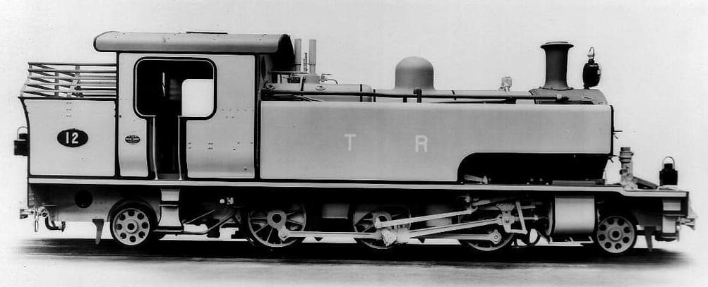
In 1930, the TR received four 2-6-2T shunters (the same type as the KUR ED1 Class). These were designated as the ST Class. They initially had running numbers TR Nos. 11-14, later TR Nos. 103-106. The locomotives were supplied by Vulcan. Under EAR control the locomotives were numbered EAR Nos. 1101-1104. [1: p60]

TR No. 12 was later designated TR No. 104 and later still, EAR No. 1101. This is an ex-Works photograph taken at the Vulcan Works in the UK, (c) Public Domain. [31]

Many of the EAR Class 11 locomotives were adapted to burn oil fuel rather than wood or coal and were still in use in 1972. [1: p60]

EAR 12 Class (formerly TR SS Class) 2-6-2T Locomotives

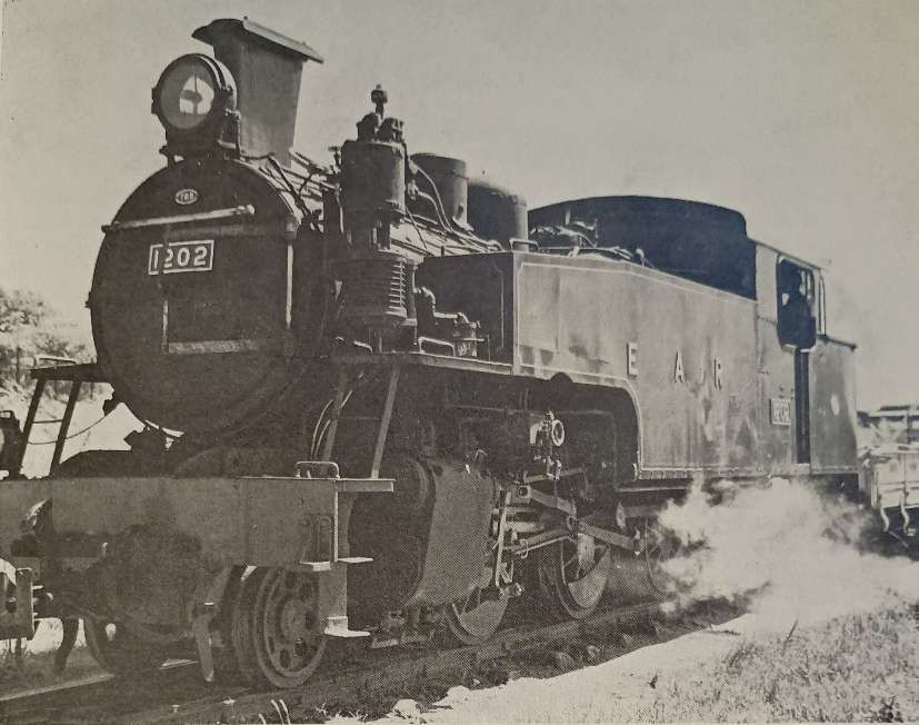
These two locomotives were ordered by Tanganyika Railways but not delivered until 1950. They were the first superheated piston-valve shunters in East Africa and were a generally updated and modernised version of the EAR 11 Class. [1: p70]

A TR SS Class 2-6-2T locomotive delivered in 1950 became one of the EAR Class 12 locomotives. – No. 1202. It is seen here in its altered form with Giesl ejector shunting at Tabora, (c) Public Domain. [1: p69]

The two engines in this Class were “put to work in the harbour area in Dar es Salaam, from where they were transferred to Morogoro in the mid 1950s and eventually to Tabora in the early 1960s, where they are still in service. The 12 class are the only shunters with Giesl ejectors.” [1: p70]

EAR 21 Class (formerly TR RV Class) 4-8-2 Locomotives

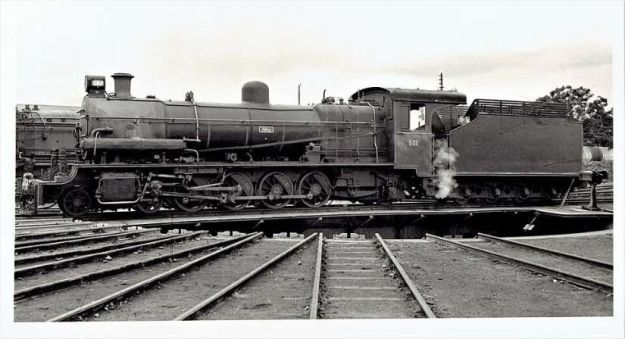
This is a Tanganyika Railway (TR) oil-fuelled RV (River) class 4-8-2 locomotive, later classified as the East African Railways (EAR) 21 class. It was first numbered TR252, then No. TR502 and later EAR2103. The locomotive was built by the Vulcan Foundry in Lancashire, between 1928 and 1930, © Public Domain. [27][9: p303]

For more details of this class of steam locomotive please click here. [28]

EAR 22 Class (formerly TR G Class) 4-8-0 Locomotives

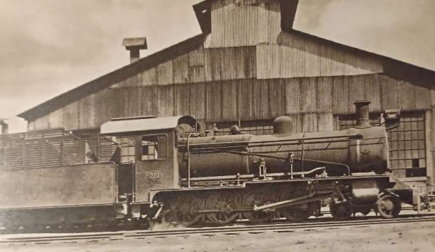
TR Class G 4-8-0 Locomotive No. 210 (later 22 Class) – these locomotives entered service in1928. Hill tells us that these locomotives were obtained to work two specific lengths of railway – the Tanga Line and the Mwanza branch off the Central Line, (c) Public Domain. [9: p299]

For more details of this class of steam locomotive please click here. [28]

EAR 22 Class (formerly TR NZ Class) 4-8-0 Locomotives

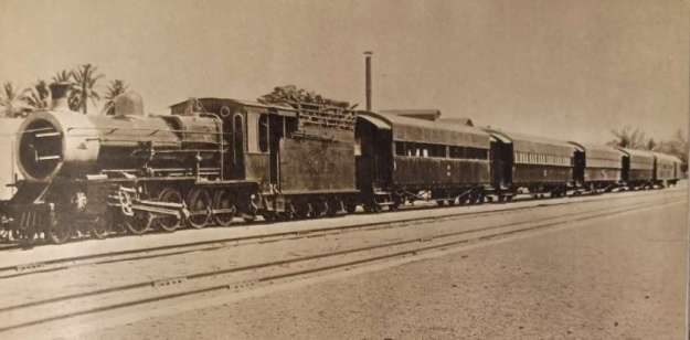
TR NZ Class No. 1098 leaving Dar-es-Salaam with the mail train in 1922. These locomotives were originally ordered by the Nizam’s Guaranteed State Railway for use on its network in the Dominion of Nizam, better known as the Hyderabad State, in India, but served their entire working lives in Tanganyika, East Africa. Class 22 locomotives were 4-8-0 locomotives built in 1915 by Nasmyth, Wilson and Company. These locomotives were numbered TR1095–TR1098, later TR200–TR203, and later still, EAR2201–EAR2204, © Public Domain. [9: facing p182][1: p55]

For more details of this class of steam locomotive please click here. [28]

EAR 24 Class (formerly UR GD Class) 4-8-0 Locomotives

East African Railways (EAR) Class 24 4-8-0 locomotive No. 2443.The engine was manufactured by Vulcan Foundry and Nasmyth, Wilson and Company between 1923 and 1930. The photo shows the locomotive at Tabora depot in Tanzania during 1968, © Basil Roberts and licensed for reuse under a Creative Commons licence (CC BY-SA 4.0). [26]

The 24 Class were a larger and modified version of the experimental UR GC Class. [26]

EAR 25 Class (formerly TR MK Class) 2-8-2 Locomotives

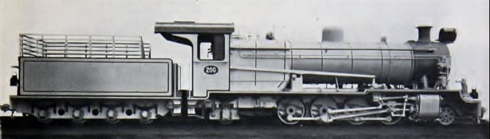
The TR Mk Class was renumbered by the EAR to become the EAR 25 class, the eleven members of the class were built by Vulcan Foundry, in Newton-le-Willows, Lancashire, for the Tanganyika Railway (TR). They entered service on the TR in 1925–1927. [10] All of them were transferred to the EAR.

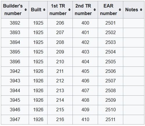
The eleven members of the Class were:

The eleven members of the original TR MK Class. [2]
Vulcan Foundry ex-Works photo of TR MK 206. [2]

This class was a great success and the Class were still in use at the time Ramaer wrote his book, although he notes that they were now on borrowed time. “One problem with the design of the MK was the fact that the leading pony truck provided insufficient guidance on the sharp curves on the Dar-es-Salaam-Morogoro and the Malagarasi-Kigoma sections.” [1: p57]

EAR 26 Class (formerly TR ML Class) 2-8-2 Locomotives

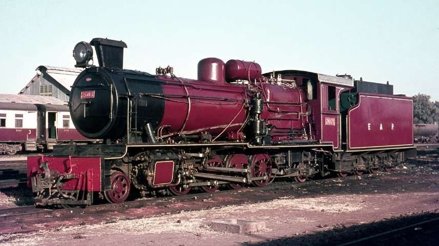
East African Railways (EAR) 26 class (ex-TR ML class) 2-8-2 steam locomotive no. 2603 at Tabora depot, Tanzania in 1968, © Basil Roberts and licensed for reuse under a Creative Commons licence (CC BY-SA 4.0). [7]

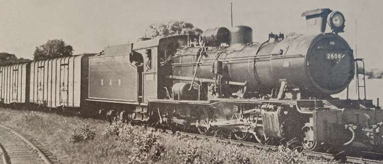
The six members of the ML class (an improved MK design) were built in 1947 by W. G. Bagnall, in Stafford, England, and delivered to the TR. They were later operated by the TR’s successor, the East African Railways (EAR), as its 26 class. In 1952, six further members of the 26 class were delivered to the EAR. They had been built by Vulcan Foundry, of Newton-le-Willows and Robert Stephenson & Hawthorns of North East England and were numbered EAR Nos 2607-2612. [7]

The new locomotives were intended for use on the flatter sections of the Central Line between Dodoma and Tabora. According to Ramaer, these locomotives were still in use in 1972, provided with larger tenders than the MK/25 Class. However, they were “relegated to secondary duties, but their service record proved less favourable than that of the older 25s. They [were] definitely heavier on maintenance and their active life would probably end shortly, together with the 25 class, when both were replaced by new diesel locomotives.” [1: p70]

Former TR ML Class 2-8-2 No. 2608 with Giesel ejector and air brakes, one of the last designs of the TR, is seen heading a goods train out of Tabora, (c) Public Domain. [1: p71]

EAR 27 Class (formerly TR MR Class) 2-8-2 Locomotives

These locomotives were American-built. Many of these engines were built by various American manufacturers, including: Alco; Baldwin; and Davenport. These locomotives were known as ‘MacArthurs’. Those which ended up working on the Tanganyika Railways were manufactured in 1944. [1: p70] and arrived from Malaya in 1949. There were eight locomotives bought in this way which became the MR Class, running numbers 800-807. They were built by three different manufacturers and as a result had minor differences: Alco Nos. 800-802; Baldwin Nos. 803-805; Davenport Nos. 806-807. [1: p70]

TR 2-8-2 No. 802 of the MacArthur austerity class at Tabora in the early 1950s before its conversion to oil fuel. [1: p68]

Ramaer tells us that, “At first there were problems, and modifications were needed to water tanks and reversing gear, which was undertaken at Nairobi works because of the limited capacity of the shops at Dar-es-Salaam. An additional difficulty was posed by the fact that the engines had not been designed to burn wood fuel. Grates were rather small and no rocking or dropping equipment was available. This circumstance gave rise to criticism because of the high ash residue of the wood fuel and only after the locomotives were converted to burn oil was the problem satisfactorily solved. After conversion the MacArthurs by then classified EAR 2701-8, did reasonably well.” [1; p69] The class was expanded in 1950 under EAR control when eight more were purchased from Malaya and one in parts from Nigeria. The last of these locomotives in service was based at Tabora and had been kept running by cannibalising other members of the class.

Early Beyer-Garratt locomotives:

EAR 4-8-2+2-8-4 Garratt 53 Class (formerly TR GA Class)

Built in 1931 by Beyer, Peacock & Co., these 4-8-2+2-8-4 locomotives were the first Garratts on the Tanganyika Railway. Two of this Class continued in service during EAR years. In EAR days the two 53 Class locomotives “went to the northern part of the now united system, to be replaced on the Central Line by the newer 60 Class, but later they returned to Tanzania for transfer work in Dar-es-Salaam, where they were scrapped in the late 1960s.” [1: p61]

East African Railways publicity photograph of no. 5302 Iringa, c. 1953, (c) Public Domain. [3]

EAR 4-8-2+2-8-4 Garratt 55 Class (formerly TR GB and KUR EC1 Class) Locomotives

The Tanganyika Railway (TR) GB class were 4-8-2+2-8-4 Beyer-Garratt steam locomotives were originally ordered by the British War Department for service in Brazil, although not built. Later the design was used for locomotives for India and Burma. Four were acquired by the TR in 1946 from Burma. They later became members of the East African Railways (EAR) 55 class. [13][1: p64]

GB Class Garratt locomotive No. 753 entered service in 1948 immediately prior to the amalgamation of the TR and the KUR. [9: p307]

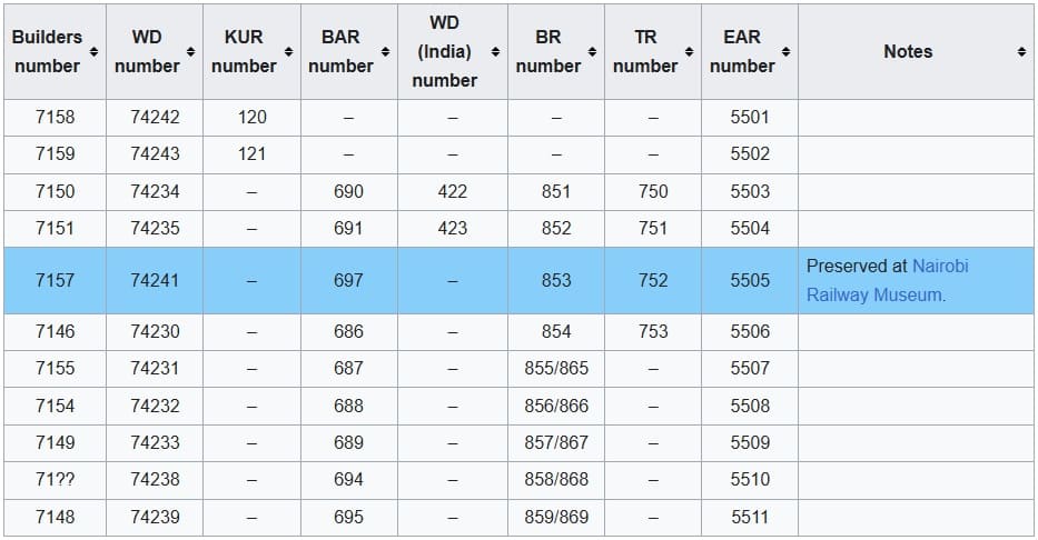
The Garratt locomotives that eventually made up the full 55 Class list were in use on the KUR and the TR. The full list is shown below:

The full EAR 55 Class list: as can be seen 4 of the Class served in Tanganyika, one of which (EAR No. 5505, ex-TR No. 752) is preserved at Nairobi Railway Museum. When serving in Tanganyika before the amalgamation of the two networks, these locomotives were numbered TR 750 – TR 753. [4]

EAR Designed/Purchased Steam Locomotives:

Despite having access to a broad spectrum of different locomotives from the two networks, the EAR was clearly in need of locomotives. It had available Class 54, 57 and 58 Locomotives but these were unsuitable as a base for further development [1: p71] Fuel was also a problem, wood was still in extentives use and coal supplies during WW2 were of relatively poor quality. The EAR decided that it should focus on oil-burning locomotives. Ramaer says that conversions started almost immediately, all EAR engines “were gradually converted to burn oil, a job which was completed by 1955.” [1: p72]

EAR made an initial decision to focus on steam-power for the immediate future.

EAR 13 Class 4-8-2T/4-8-4T Locomotives

These locomotives were probably not used to any great extent of the historic TR network within the EAR.

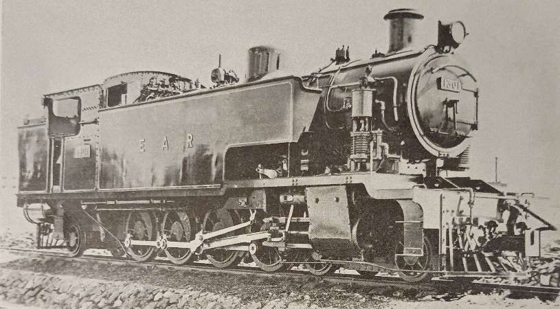
EAR 13 Class 4-8-2T Locomotive No.1301 as supplied in 1953. [1: p78]

Eighteen of these tank locomotives were built by North British and entered service in 1953. All of these locomotives were initially 4-8-2T locomotives but their performance was poor. They were prone to frequent derailments in sidings. The decision was taken to adapt them to be 4-8-4T locomotives.

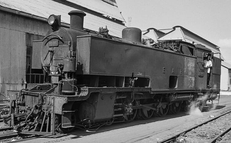
The trailing ponies were changed to bogies recovered from old 50 Class Garratts from the KUR which were being withdrawn from that network. At the same time the side tanks were extended and lined up with the smokebox door. This required the repositioning of the compressor and the opportunity was also taken to enlarge the rear fuel tank slightly. [1: p78]

A superb study of a 13 Class 4-8-4T modified locomotive, (c) ETH-Bibliothek Zürich, Bildarchiv / Fotograf: Schmid, Walter / Com_L25-0840-0013-0008 and licensed for reuse under a Creative Commons licence (CC BY-SA 4.0). [6]

After Class 13, plans were in place for a further Class of shunting locomotive – the 14 Class but none were built in the end as a result of research into Diesel Shunters which could produce a greater tractive effort with a lower fuel consumption.

EAR 29 Class 2-8-2 Locomotives

Along with 30 Class and 31 Class locomotives and the 59 and 60 Class Garratts these were the last steam locomotives built for the EAR.

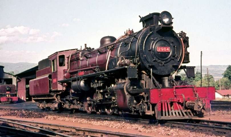
EAR 29 Class 2-8-2 Locomotive No. 2904 is an oil-burning locomotive built by the North British Locomotive Company in Glasgow. This photo was taken at the Moshi depot in Tanzania in 1968, (c) Basil Roberts and licensed for reuse under a Creative Commons licence (CC BY-SA 4.0). [7]

The 29 Class were derived from the Nigerian ‘River’ Class 2-8-2 Locomotives which were built to operate with low grade coal. The EAR version was oil-burning. Crews at times called these locomotives ‘Nigerians’. Two arrived with the EAR in 1951 and a further eighteen in 1952. These were reliable and effective locos with an axle load of thirteen tons and designed to be freight locomotives on the main line. Their performance gave rise to another order for eleven further 29 Class locomotives from North British in 1955. Ramaer tells us that, “These newer locomotives differ[ed] from the earlier ones in that they ha[d] spring-loaded intermediate buffing gear, later standardised on the 31 class 2-8-4s, and larger injectors than the first twenty engines. Externally, they [were] easily distinguishable for a larger smokebox door has been fitted than on the earlier engines. To reduce the weight on the trailing pony truck, already heavily stressed by the big Belpaire firebox, the compressors were repositioned to be in line with the smoke-box door, and in consequence some minor changes had to be introduced to the leading pony truck.” [1: p80-81]

One of the later 29 Class locomotives Ear No. 29 which shows the larger smokebox door, (c) Alexander Leisser and licensed for reuse under a Creative Commons licence (CC BY-SA 4.0). [8]

Ramaer says that “A point of some concern in the design of the 29 class was the relatively high axle load on the trailing pony, which caused the engines to lean back with heavy trains, with consequent loss of adhesive weight. To remedy this shortcoming, the EAR went in following designs to a wheel arrangement with a bogie under the fire-box, considered by many engineers to be the best possible solution for locomotives with a big and heavy firebox, as it improves riding and, indirectly, eases maintenance. The 2-8-4s thus evolved belong to two classes, 30 and 31, introduced in 1955-6 and built by North British and Vulcan, respectively.” [1: p81]

The 29 Class was ubiquitous across different sheds throughout the EAR territory. [1: p81-81]

EAR 30 Class 2-8-4 Locomotives

The 30 class is heavier than the 31 Class and is directly derived from the 29 Class. It has the same boiler, although adhesive weight is slightly lower than the 29 Class “as a result of the introduction of the bogie under the firebox. The bogie has American-inspired cast steel outside frames and was introduced following the example of the Canadian Pacific type 59 to improve riding. For the same reason, compensated spring gear on the coupled axles was reintroduced following the example of the pre-war 28 Class Mikados. These changes certainly resulted in better riding qualities.” [1: 81]

EAR 30 Class 2-8-4 Oil-burning Locomotive No. 3019 ‘Nyamwezi’ sitting at Tabora depot. The 26 members of the Class served their entire careers in Tanganyika/Tanzania. [9: p83] The Class was built in 1955 by the North British Locomotive Company in Glasgow, These locomotives primarily served on the Central Line in Tanganyika, now Tanzania, (c) Basil Roberts and licensed for reuse under a Creative Commons licence (CC BY-SA 4.0). [10]

The 30 class design included a large cast steel tender, running on six-wheel bogies, having a capacity of 1,950 gallons of fuel oil and 7,000 gallons of water. This, with Timken roller bearings [11][12] throughout has resulted in an engine capable of running long distances over the Central Line of Tanzania, on sections with unreliable water supplies, like Morogoro-Tabora. The 30 Class spent their full working life in Tanganyika/Tanzania. [1: p81-82]

EAR 31 Class 2-8-4 Locomotives

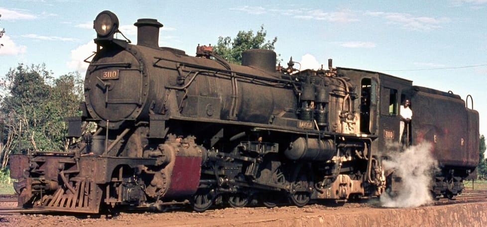
The EAR 31 class was a class of oil-burning 2-8-4 steam locomotives. The 46 members of the class were built in 1955 by Vulcan Foundry, in Newton-le-Willows, Lancashire, for the EAR. They were a lighter, branch-line version of the EAR 30 class, and worked from various sheds throughout the EAR system.[1: p80-82][9: p83][13]

EAR 31 Class 2-8-4 Oil-burning Locomotive No. 3110 ‘Bakiga’ at Nairobi in 1968. The 46 members of the Class served on branch lines across the full EAR network. The Class was built in 1955 and 1956 by the Vulcan Foundry in Newton-le Willows, Lancashire, (c) Basil Roberts and licensed for reuse under a Creative Commons licence (CC BY-SA 4.0). [13]

The Vulcan Works Magazine carried this ex-Works image of a 31 Class locomotive. The locomotives were Vulcan Foundry Works Nos. 2576, 2578-81 and 2583 & 84. [14]

The Vulcan Foundry magazine notes that these engines were designed for the lightest tracks on the EAR network: “The locomotives are required for universal use throughout East Africa, but in the first place are to be placed for duty in Kenya and Uganda. All are oil fired and forty-one have Westinghouse brakes, the other five being dual fitted with Westinghouse and Vacuum Brake Equipment, so that they will be available for service in Tanganyika when required. The locomotives will negotiate with ease, curves of 330ft radius, with 0.5in gauge widening and also I in 7.5 turnouts (equivalent to a curve of 350ft radius without gauge widening) and are suitable for operating on 3% gradients. … As on all recent East African orders, the locomotives are so arranged that they can be converted to 36in gauge in accordance with requirements for the future standardisation of the East African Railways. For the same reason the dragboxes [15][16] have been made to suit both the MCA Coupler (as fitted) and the Knuckle type Coupler. Wherever possible, detail parts have been made interchangeable with the “29” and “30” classes, but a smaller boiler and slightly smaller cylinders have been provided.” [14]

Later Beyer Garratt Locomotives:

EAR 57 and 58 Class

These locomotives were not used in Tangayika/Tanzania. For more detail, please click here. [17]

EAR 59 Class

The axle loads of these locomotives were too high for the relatively light rail used in Tanganyika/Tanzania. They were used, as intended, on the old KUR network. For more detail, please click here. [17]

EAR 60 Class

Introduced in 1953, these 4-8-2+2-8-4 locomotives were used extensively on the Central Line between Dar -es-Salaam and Morogoro

Class 60 Garratt 4-8-2+2-8-4 locomotive No. 6019 at Tabora depot, Tanzania, in 1968. [5]

The EAR 60 class, also known as the Governor class, was built for the EAR as a development of the EAR’s earlier 56 class. The 29 members of the 60 class were ordered by the EAR from Beyer, Peacock & Co. The first 12 of them were built by sub-contractors Société Franco-Belge in Raismes (Valenciennes), France, and the rest were built by Beyer, Peacock in Gorton, Manchester. The class entered service in 1953-54. Initially, all members of the class carried the name of a Governor (or equivalent) of Kenya, Tanganyika or Uganda, but later all of the Governor nameplates were removed. [5]

Initially, the first locomotives were ordered as an extension to the 56 Class – 5607 – 5618. Compared with the 56 Class, the Franco-Belge locomotives had more water and less oil capacity. It was only just before delivery that it was decided to classify them separately. As we have noted, the remainder of the Class was built in the UK by Beyer-Peacock. Raemer reports:

“With an axle load of only eleven tons, the 60 class is, with the 55 and 56 classes, the standard light Garratt on the system, taking all the lighter mixed traffic. It was on one of these engines, No 6029, that the first test with the Giesl ejector was made, No 5805 following suit. Today, all 60s have this equipment. Originally the 60 class carried the names of the Governors of Kenya, Tanganyika and Uganda, but later the nameplates were removed. At present, [1972] only No. 6001 still carries a name Umoja (Unity). They are straightforward engines, with the well-tried Belpaire firebox, a working pressure of 200lb/sq in and 16×24in cylinders, developing a tractive effort of 43,520lb. They, too, have roller bearings on all axles, but somewhat surprisingly plate frames of wartime origin were retained, like the 55 and 56 classes. Although the 60s are quite good engines, they never came came up to the level of the 56s, especially where the free steaming quality of the boilers is concerned.” [1: p78]

EAR Diesel Locomotives used in Tanganyika/Tanzania

I have written extensively on the various Diesel locomotives used on the EAR network, for more detail, please click here. [18] The EAR operated a progressive fleet of diesel locomotives in Tanganyika (now Tanzania) starting in the 1950s, featuring key classes such as the 83, 84 & 85 Class hydraulic shunters and later mainline diesel-electrics.

There were a significant number of different diesel locomotive classes on the EAR , but records that I have come across do not specify which of these locos were stabled at which depots. It is difficult in many cases, to be sure which classes of loco were used on the lines in Tanganyika/Tanzania. The fleet included:

32 Class (previously 80 Class): please see notes below about the 80 Class locos.

33 Class (previously 81 Class): please see notes below about the 81 Class locos.

34 Class (previously 82 Class): please see notes below about the 82 Class locos.

35 Class: Andrew Barclay 0-6-0 locomotives.

61 Class: These locomotives were supplied by the German manufacturer Henschel & Son.

71 Class (previously 91 Class) Diesel-Electric Locomotives: supplied by English Electric.

72 Class (previously 92 Class) Diesel-Electric Locomotives: supplied by English Electric.

79 Class Locomotive: only one of these locomotives was built.

80 Class (later 32 Class):

81 Class (Later 33 Class): Supplied by the Drewry Car Co., these versatile internal combustion locomotives handled secondary and transfer tasks during the early phase of internal combustion transition.

82 Class (Later 34 Class):

83, 84, 85 & 86 Classes (Later 43, 44, 45 & 46 Classes): Introduced from 1955 onwards, these light and medium diesel-hydraulic locomotives (built by manufacturers like Hunslet, Andrew Barclay, and North British Locomotive Company) took over shunting and lighter duties on the Tanganyika Central Line.

86 Class (later 46 Class):

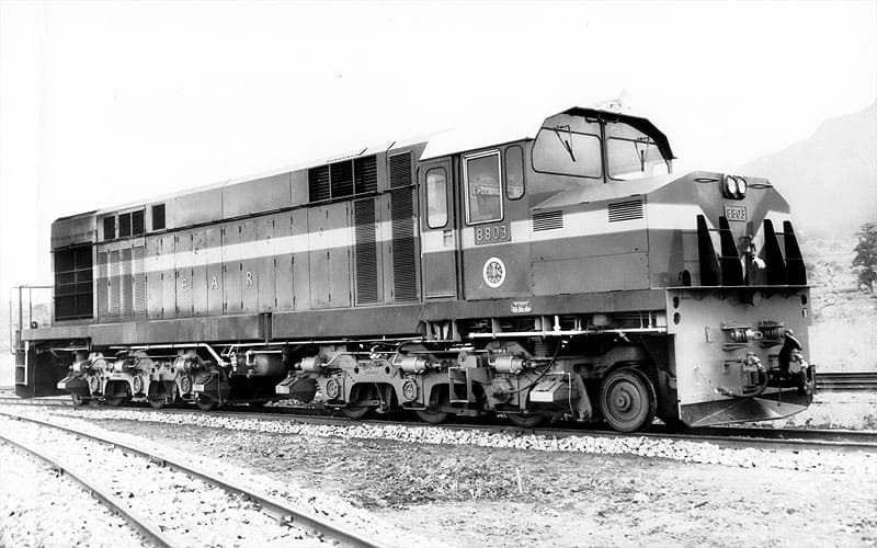
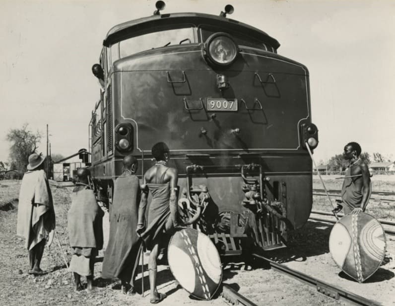
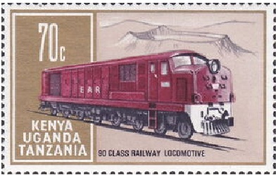
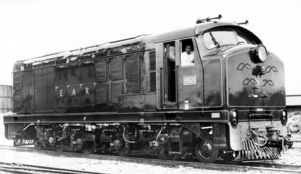
90 Class (later 87 Class) English Electric types: from around 1960, powerful diesel-electric units gradually supplemented and replaced heavy steam power (like the 30 and 60 classes) on main trunk routes connecting Dar-es-Salaam, Tabora, and Kigoma. Dieselization in Tanganyika in the late 1950s and 1960s dealt a blow to the continued use of steam-power as they were more effective on handling steep gradients and overcame water scarcity issues inherent to steam operations across the territory.

91 Class (later 71 Class) Diesel-Electric Locomotives: supplied by English Electric

88 & 92 Class Canadian supplied Diesel Electric locomotives, of which there were 20 No. 88 Class and 15 No. 92 Class locomotives.

More about each Class of Diesel Locomotive

A little more information about each of these classes of diesel locomotive can be found in the paragraphs below. For more information and more images than are included in this article please click here. [18]

EAR 35 Class Locomotives

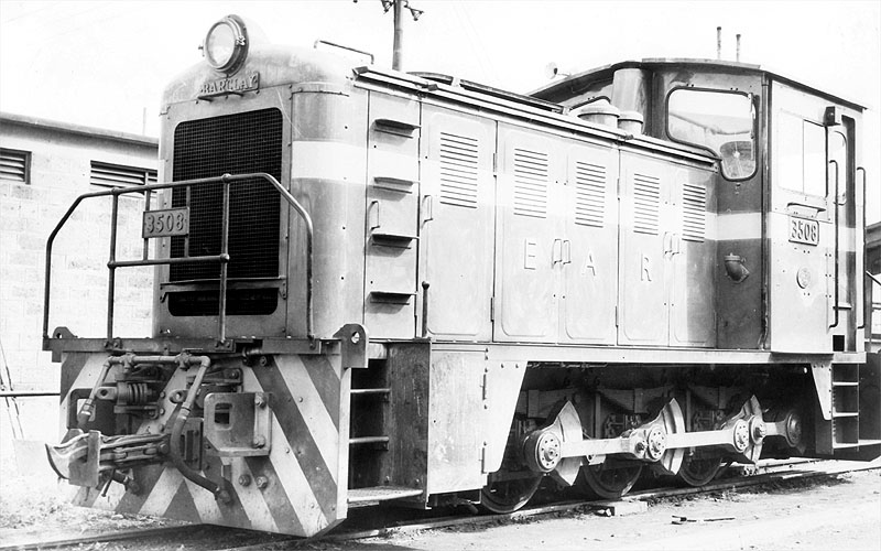
These were Andrew Barclay 0-6-0 diesel shunters.

The EAR 35 Class of 0-6-0 shunters had a cast list of at least eight. This is EAR No. 3508. The photographer is not known. [18]

EAR 43 Class (originally 83 Class) Locomotives

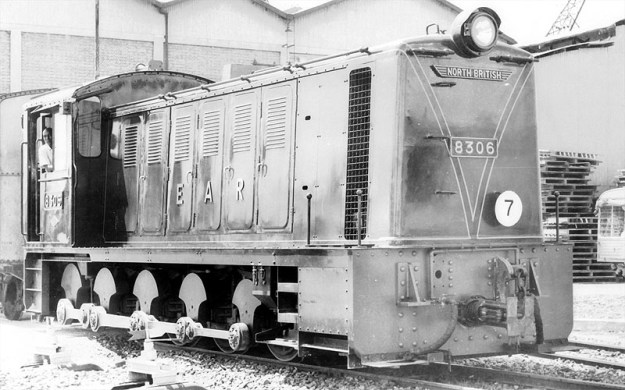
These locos were built by the North British Locomotive Company.

EAR 83 Class 0-8-0 Locomotive, EAR No. 8306. The photographer is not known. [18]

EAR 44 Class (originally 84 Class) Locomotives

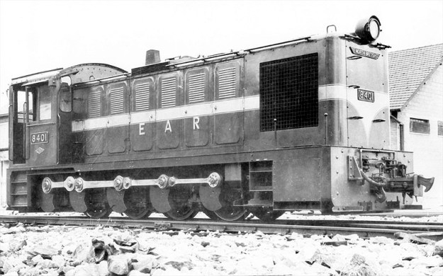
This 0-8-0 class was also built by the North British Locomotive Company.

EAR 84 Class 0-8-0 Locomotive, EAR No. 8401. The photographer is not known. [18]

EAR 45 Class (originally 85 Class) Locomotives

Still another North British 0-8-0 class of loco.

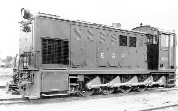
EAR 85 Class 0-8-0 Locomotive, EAR No. 8504. The photographer is not known. [18]

EAR 46 Class (originally 86 Class) Locomotives

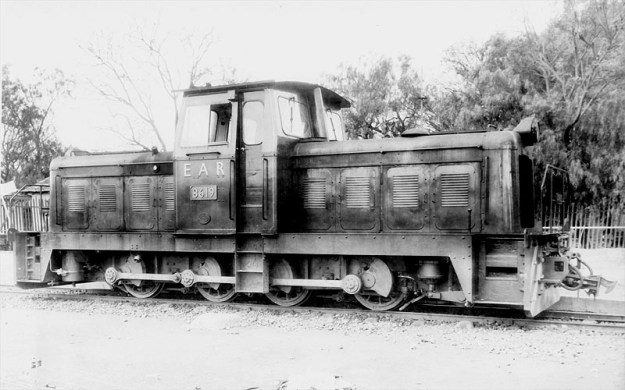
The 46 Class (originally 86 Class) 0-8-0 central cab locos were built for the EAR by Andrew Barclay Sons & Co.

EAR 86 Class 0-8-0 Locomotive, EAR No. 8619. The photographer is not known. [18]

EAR 61 Class Locomotives

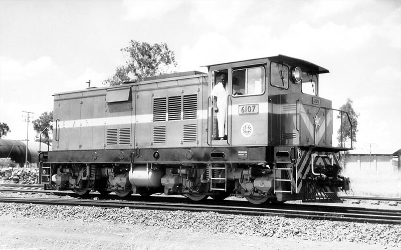
Once the decision had been taken not to build a new class of Beyer Garratt locomotives which would have been 61 Class locomotives. The Class number was used for a series of Henschel-built Bo-Bo shunters.

61 Class Henschel-built Bo-Bo shunting locomotive, EAR No. 6107, photographer not known. [18]

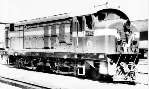
EAR 71 Class (previously 91 Class) Locomotives

See the 91 Class below.

EAR 72 Class (previously 92 Class) Locomotives

The East African Railways (EAR) 72 Class consists of 10 diesel-electric locomotives built by English Electric at the Vulcan Works in Newton-le-Willows in 1971 and 1972. They featured a 1-Bo-Bo-1 wheel arrangement and a 1,240 horsepower rating tailored for lightweight tracks across the whole EAR network. For more details about this locomotive please click here. [24]

EAR 72 Class (previous 92 Class) Locomotive No. 7209, photographer not known. [18]

79 Class Locomotive

Only one of these Co-Co locomotives was built. No. 7901 was supplied as an experimental type by AEI Lister-Blackmore. Looking at the export market in the late 1950s British Tomson-Houston (BTH), with Clayton and Lister-Blackstone commissioned the Explorer CM-gauge prototype, which was ready in 1959. This featured a Lister-Blackstone engine, BTH electrical equipment and mechanical parts by established partner Clayton. [25]

EAR 79 Class Locomotive No. 7901, photographer not known. [18]

80 Class (later 32 Class)

The Class 80/32 0-6-0 locos were built for the EAR by John Fowler & Co Engineers of Leathley Road, Hunslet, Leeds, West Yorkshire.

[18]

81 Class (Later 33 Class)

Supplied by the Drewry Car Co., these versatile internal combustion locomotives handled secondary and transfer tasks during the early phase of internal combustion transition.

[18]

82 Class (Later 34 Class)

[18]

83, 84 & 85 Classes (Later 43, 44 & 45 Classes)

Introduced from 1955 onwards, these light and medium diesel-hydraulic locomotives (built by manufacturers like Hunslet, Andrew Barclay, and North British Locomotive Company) took over shunting and lighter duties on the Tanganyika Central Line. Please see 43, 44 and 45 Classes above.

86 Class (later 46 Class)

Please see the 46 Class above.

EAR 88 Class Locomotives

There were 20 diesel-electric locomotives built by the Montreal Locomotive Works (MLW) in this Class. These were lighter weight versions of the 92 Class. These locomotives had a 1-Co-Co-1 wheel arrangement and were designed to handle intense tractive effort demands across the challenging terrain of Kenya, Uganda, and Tanzania.

EAR 88 Class Locomotive built by Montreal Locomotive Works (MLW). These locomotives worked across the whole EAR network, photographer not known. [18]

EAR 90 Class (later Class 87) Locomotives

There were 44 of this Class built by English Electric by the end of the 1960s. They worked across the whole EAR network.

Masai tribesmen inspect an English Electric-AEI Class 90 diesel electric loco, East African Railways No. 9007, 1960. This image was shared on the Commonwealth Heritage Forum on Facebook on 6th October 2023. [19]

Some notes about English Electric Twelve cylinder diesels and the EAR 90 class written by Steve Palermo: [20]

“EE generally designed locomotives to meet individual railway requirements, using standard components. Nevertheless, established designs were often adapted for other customers, and this is apparent in the 12-cylinder sequence, which accordingly could be described as being a series of quasi-standard locomotives. A greater degree of standardization is apparent in EE’s sequence of 6-cylinder models, though.

“The list of EE 12-cylinder models, in chronological order of first appearance, is:

1. Queensland Railways (QR) 1200 class, 10 built.
2. New Zealand Railways (NZR) Df class, 10 built
3. Malayan Railways (KTM) 20 class, 26 built
4. QR 1250 class, the first EE Australia variant, 17 built
5. Sudan Railways 1000 class, 65 built
6. East African Railways 90 (later 87) class, 44 built
7. British Railways (BR) 37 class, 309 built
8. Western Australian Government Railways (WAGR) C class, 3 built
9. Rhodesian Railways DE3 class, 16 built
10. QR 1270 class, 30 built
11. WAGR K class, also Goldsworthy Mining A class, 17 built
12. QR 1300 class, 45 built
13. WAGR R and RA classes, 18 built
14. AIS D34 class, 1 built
15. Ghana Railways & Harbours 1851 class, 16 built
16. Tasmanian Government Railways (TGR) Z class, 4 built
17. QE 2350 class, 16 built
18. TGR ZA class, 6 built

“The total number of EE 12-cylinder locomotives built was thus 653, of which 496 were of UK origin, and 157 came from Australia. …

“BR, with 309 of its 37 class, was the biggest user of EE 12-cylinder models. Next came QR, with a total of 118 spread over 5 basic models, although there were subvariants. QR was also the first
operator to buy 12-cylinder EE locomotives, so are more detailed study of the group logically starts with the QR 1200 class, which then conveniently links to both the later UK and the Australian models. At least basic information on most classes is reasonably available, and of course the BR 37 has been the subject of many treatments in the literature.

“The EAR 90 class was the second English Electric 12CSVT-engined model to be delivered, but the first to be ordered. The initial order, for 8 units was announced in October 1958, and an increase to 10 units was announced in March 1959. This was EARH’s first order for line-service diesel locomotives. A 13.5 ton maximum axle loading was imposed, to enable the locomotives to work northwest of Nairobi to Nakuru and Kampala [and elsewhere on the EAR network], as well as between Mombasa and Nairobi, which section alone would have allowed a higher axle loading. This axle loading constraint required a multi-axle design, as it is unlikely that EE could have built a compliant 12-cylinder Co-Co model. Unsurprisingly, EE used a 1-Co-Co-1 wheel arrangement. The resulting locomotive was largely a new design, although it included features drawn from the QR 1250 class (body style and general layout) and the Rhodesian Railways (RR) 16-cylinder DE2 class (running gear and in-frame fuel tank). What it was not, though, was simply a 1-Co-Co-1 variant of the QR 1250 with 12CSVT in place of 12SVT engine.

“Nevertheless, the QR 1250 makes a useful yardstick for comparison purposes. The EARH 90, at 51’0″ over headstocks, was a little longer than the QR 1250, at 49’6”. This extra length was most likely required to accommodate the more complex running gear, although it probably also gave a bit more space to accommodate the dynamic braking unit and a higher capacity cooling group. The total wheelbase was 41’6″, as compared with 40’0″ for the QR 1250. The equipment layout for the most part followed established EE practice. The nose compartment housed the leading bogie traction motor blower, which was motor-driven. The T-shaped main equipment cubicle was immediately behind the cab; then came the dynamic braking unit, which was mounted high & just below the cantrail – with a crosswise orientation, fan-shaft horizontal. Then came the generators, the engine, followed by the radiator compartment with mechanically-driven vertical-shaft fan, and finally the rear-compartment, housing the air compressor, mechanically-driven from the radiator fan gearbox, and the trailing bogie traction motor blower.

“The running gear was based upon that of the RR DE2, which had proved successful in service. Thus, the bogie frames were one-piece castings by Henricot. Because the EARH 90 was shorter, the axle spacings were all reduced by 6 inches. Each bogie had an overall wheelbase of 17’6″, with a rigid wheelbase of 12’0″ equally distributed, and the two inner bogie axles were separated by 6’6″. The pivot centres, placed between the pilot and outer driving axles, were 37’10” apart. Consistent with EE’s thinking about maximizing the advantages obtainable from the 1-Co-Co-1 wheel arrangement where it was necessary to use same, the axle spacings were chosen to obtain maximum bending moment relief, so reducing vertical railhead forces. As this required relatively close coupling of the bogies, a conventional suspended fuel tank was precluded, hence the use of an in-frame fuel tank, an EE feature that went back at least as far as the New Zealand Railways De class. The main bogies were interconnected by a lateral spring control mechanism that helped ensure optimum wheel flange angles in curves, so reducing lateral railhead forces. One way of looking at this is that the coupling allowed the leading bogie to pilot the trailing bogie into curves,
the leading bogie itself being guided by its own pilot truck. Wheel diameters were the same as on the DE2, namely 28½” pilot and 37½” driving. The main bogies had three-point load transfer from the mainframe, with a resiliently mounted pivot between the pilot axle and the outer driving axle, and a pair of coil spring bearers between the centre and inner driving axles. Equalization for each bogie was continuous from pilot truck axle to inner driving axle. This was a change from the DE2 bogie, which was equalized in two groups, although the casting did make provision for full equalization should it have been required. As with the DE2, the driving axle springs were of the leaf type interconnected by equalizing bars, but at the fixed attachment points, rubber bushes were used in place of the auxiliary coil springs used on the DE2. All three traction motors on each bogie faced outwards, consistent with high-adhesion bogie practice. EE claimed that this bogie design virtually eliminated intra-bogie weight transfer, whilst the wide pivot spacing minimized
inter-bogie weight transfer. I have never seen the benefit quantified in the same way that EE Australia did for its high-adhesion Co bogie first used on the Western Australia Government Railways R class, but taking the latter as indicative, EE’s view could well have been that a 1-Co-Co-1 locomotive with 81 tons adhesive weight would for practical purposes match a similarly-powered 90 ton Co-Co with more-or-less conventional bogies, whilst offering lower dynamic railhead forces as well as (fairly obviously) lower static railhead forces. EE certainly made much of the capabilities of it own-design 1-Co-Co-1 running gear (here one needs to be careful to exclude the non-EE design bogie that it was forced to use, against its better judgement, for the British Rail 40 class) and noted that its good performance had been verified by the railway administrations using it.

“The 12CSVT Mk II engine had three manually adjustable governor power settings that allowed optimization for altitude, bearing in mind that the route embraced the range from sea level to 9136 ft elevation. 1840 hp (gross) was available up to 5500 ft, 1800 hp up to 7800 ft, and 1775 hp up to 9136 ft. One assumes that the settings were chosen according to which part of the EARH system the locomotives were assigned. The main generator was the EE822 model, and the six traction motors were the new EE537 4-pole model, connected in permanent series-parallel (2S3P) with two stages of field weakening. I have not been able to verify the gear ratio, but most probable was 72:15, fairly standard for the EE537 motor. The 45 mile/h maximum service speed would not have required faster gearing. The overhung auxiliary generator, model number unknown, was of 48 kW capacity.

“The EARH 90 was fitted with the by-now standard EE air-throttle control system, with the EE governor and the new hydraulically operated load regulator. The two driving stations were fitted with EE’s then-standard two-lever control stands. The throttle lever also operated the dynamic brake according to the standard EE 3-notch protocol. The main driving station was on the right hand side. There was a second driving station on the left-hand side, but this was not diagonally opposite and reversed as might have been expected. Rather it seems to have been arranged to allow bidirectional operation during shunting operations.

“The braking system was air for the locomotive and train, EARH being an air-braked road. However, the design made provision for the retrofitting of vacuum train brake equipment if required. At the time, it was evidently still thought possible that the EARH system would be converted from metre to Cape gauge to align with the rest of Southern Africa. The same conversion would also have required a (retrograde) change from air to vacuum brakes, the latter being the Southern African standard, with at least a period of dual-braking capability being required. One can wonder how vacuum brakes would have performed at 9000 ft altitude. Also, it is not immediately apparent as to where the vacuum exhausters would have been accommodated on the 90 class, bearing in mind that both the large compressor and the dynamic braking equipment would have been retained. Perhaps EE was thinking in terms of using a combined exhauster-compressor unit in place of the air compressor.

“I have not been able to find definitive information about the type of air braking system fitted to the EARH 90 class, other than that the initial batch had Westinghouse UK equipment. Had an American-type “schedule” system been fitted, most likely it would have been noted in the trade press descriptions. So more likely is that the braking system followed British precepts, with physically separate driver’s valves for independent and train brake control, and an electrically operated. independent-release-after-automatic-application function. Certainly EARH did not have a history of using schedule systems on its steam locomotives, late examples of which were fitted with Westinghouse No. 4 automatic brake valves and Gresham & Craven Mk IV locomotive steam brake valves. The layout diagrams show that the two driver’s brake valves are somewhat separated, with that for the automatic brake being to the driver’s right, and that for the independent brake a little to the left, ahead of the control stand. Clasp brakes were fitted to the driving wheels, withy one brake cylinder per wheel. The pony truck wheels were unbraked.

“Another unknown is the electrical capacity of the dynamic brake unit. For the second series, the peak braking effort is shown as 30 000 lbf at approximately 21 mile/h, which suggests around 1200 kW. The second series is said to have had a greater dynamic braking range than the first series, so it is possible the latter had a smaller capacity unit. As described, it is stated that the locomotive brake is interlocked with the dynamic brake so that both cannot be applied simultaneously. A literal interpretation suggests that the 90 was fitted with a conventional lockout system. But if so, it was a departure from established EE practice. In its previous diesel-electric locomotive dynamic braking installations, EE had used an anti-compounding system, in which the dynamic brake was released if locomotive brake cylinder pressure reached a predetermined level, typically 23 lbf/in².

“The EAR 90 was equipped for multiple unit operation. There was a central EE elbow-style jumper socket at each end on the front sheet, along with three “plug-in” hose connections arranged in a triangle. Most probably these were for respectively main reservoir, engine speed control and independent brake. The 90 was MU compatible with the later and smaller EE-built 91 (71) and 72 classes, but beyond that EAR did not seem to be concerned to establish a single common MU standard. Later diesel locomotives from other builders were equipped with control and MU systems that were more-or-less their respective builder’s standards.

Notwithstanding the 13.5 tons axle loading specification, the first series were built to a slightly lower 12.8 tons number, giving an adhesive weight of 76.8 tons. The total weight was 97.5 tons. The continuous tractive effort is consistently quoted as 44 500 lbf, although there is some variety in the corresponding minimum continuous speed, which is variously reported as 11.5, 11.7 and 12¼ mile/h. The top speed is usually reported as 45 mile/h, but this would have been a track limited speed, as the expected 72:15 gearing would have allowed 60 mile/h, and there is no reason why the running gear would not have accommodated this on suitable track.” [20]

EAR 90 Class Locomotive on an East African 70c Stamp, issued on 5th April 1971; size: 44 x 28 mm; designer: Rena Fennessy; printers: Harrison & Sons Ltd. [21]

EAR 91 Class (later 71 Class) Class Locomotives

Built in 1967/1968, these locomotives were powered by an 8CSVT MkII engine with 1350hp for traction and weighed 68 tons. 10 were built. two batches of 10. In 1971-72, another 10 similar, but slightly heavier, units arrived, and were denoted the 92 class (later known as the 72 class). All were used in branch line service. These had a 1-Bo-Bo-1 a drawing of the side elevation of these locomotives can be seen here. [23]

EAR 91 Class (later 71 Class) locomotive No. 9101, photographer not known. [18]

Original EAR 92 Class Locomotives

See 72 Class above.

EAR 92 Class Locomotives

There were 15 locomotives in the Class. They were Canadian-built 1-Co-Co-1 diesel-electric locomotives manufactured by Montreal Locomotive Works (MLW) – heavier versions of the 88 Class! They were not suitable for the lighter rails in Tanganyika/Tanzania.

EAR 92 Class: These locomotives were purchased specifically for work only on the line West from Mombasa.

In this image the locomotive is in charge of a rake of empty tanks heading for Mombasa. [22]

Other locomotives in Tanzania

The Tazara Line operated independently from the metre-gauge network in Tanzania. It will be covered in another article. Writing in 2026, I am aware of the progress being made in Tanzania to develop a standard-gauge railway network. This too will be the subject of a future article.

References

  1. R. Ramaer; Steam Locomotives of the East African Railways; David & Charles, Newton Abbot, 1974.
  2. https://en.wikipedia.org/wiki/TR_MK_class, accessed on 19th July 2026.
  3. https://en.wikipedia.org/wiki/TR_GA_class, accessed on 19th July 2026.
  4. https://en.wikipedia.org/wiki/KUR_EC5_class, accessed on 19th July 2026.
  5. https://en.wikipedia.org/wiki/EAR_60_class, accessed on 22nd July 2026.
  6. https://en.wikipedia.org/wiki/EAR_13_class, accessed on 22nd July 2026.
  7. https://en.wikipedia.org/wiki/EAR_29_class, accessed on 22nd July 2026.
  8. https://en.wikipedia.org/wiki/Nairobi_Railway_Museum, accessed on 22nd July 2026.
  9. A. E. Durrant, C. P. Lewis & A. A. Jorgensen; Steam in Africa; Hamlyn, London,1981′
  10. https://en.wikipedia.org/wiki/EAR_30_class, accessed on 23rd July 2026.
  11. The Timken Roller Bearing Company was one of the first to introduce roller bearings for railroad cars. Railroad cars owned and operated by the Atchison, Topeka and Santa Fe Railway were some of the first to use roller bearings rather than “oil waste journal” boxes. Henry Timken, a German immigrant, invented an improved bearing and founded the company in 1899. It was later renamed The Timken Company. The first locomotive to use roller bearings made by Timken was Timken 1111, a 4-8-4 built by Alco in 1930. The locomotive was used on 15 American railroads for demonstration runs, and was purchased by the Northern Pacific Railroad, the last railroad to try the specially-built locomotive, in 1933. It operated in regular service on the NP until retirement in 1957 and was subsequently scrapped. Some British steam locomotives also used roller bearings. The LMS Turbomotive was fitted with Timken roller bearings, and they were also retrofitted to some of the LMS Coronation class. [12]
  12. https://en.wikipedia.org/wiki/Timken_Roller_Bearing_Company, accessed on 23rd July 2026.
  13. https://en.wikipedia.org/wiki/EAR_31_class, accessed on 23rd July 2026.
  14. https://fsmr.co.uk/ear-tribal-31-class, accessed on 23rd July 2026.
  15. A dragbox is a substantial, often cast metal, part of a locomotive to which the coupling mechanism is attached to allow the locomotive to pull a train. [16]
  16. https://en.wikipedia.org/wiki/Dragbox, accessed on 23rd July 2026.
  17. https://rogerfarnworth.com/2018/06/26/uganda-railways-part-25-locomotives-and-rolling-stock-part-c-steam-1948-to-1977
  18. https://rogerfarnworth.com/2018/06/29/uganda-railways-part-26-locomotives-and-rolling-stock-part-d-diesel-1948-to-1977
  19. https://www.facebook.com/photo?fbid=624070156589901&set=a.394728832857369&locale=en_GB, accessed on 23rd July 2026.
  20. https://www.friendsoftherail.com/forum/viewtopic.php?t=10472, accessed on 23rd July 2026.
  21. https://colnect.com/en/stamps/stamp/454492-Class_90_diesel-electric_locomotive-East_African_Railways-British_East_Africa_Kenya_Uganda_and_Tanganyika, accessed on 23rd July 2026.
  22. https://www.instagram.com/p/DYLgArQtvHB, accessed on 23rd July 2026.
  23. https://www.flickr.com/photos/29903115@N06/8598321329/in/photostream, accessed on 23rd July 2026.
  24. https://rogerfarnworthsrailways.wordpress.com/wp-content/uploads/2026/07/1bo-bo1-diesel-electric-locomotive-for-east-africa.pdf, accessed on 23rd July 2026.
  25. https://www.derbysulzers.com/AEI.html, accessed on 29th June 2018.
  26. https://en.wikipedia.org/wiki/UR_GD_class, accessed on 27th July 2026.
  27. https://en.wikipedia.org/wiki/TR_RV_class, accessed on 17th July 2026.
  28. https://rogerfarnworth.com/2026/07/22/railways-of-tanzania-part-15-locomotives-from-the-first-railways-built-by-the-german-colonial-powers-through-to-the-amalgamation-which-formed-east-african-railways-and-harbours-in-1948

Railways and Religion

The featured image for this article is a stained glass window in Emneth Parish Church which is a memorial to Revd. Wilbert Vere Awdry who served as the incumbent of the parish from 1953 to 1965. [9]

In his book ‘The World the Railways Made’, in a chapter entitled ‘The Habits the Railways Changed’, and after a discussion of the dramatic effect the railways had on the consumption of different foodstuffs, Nicholas Faith talks of the food the railways carried not only being physical:

“It was also spiritual, enabling pilgrims to travel far more easily. But there were natural hesitations before God-fearing folk were prepared to use such an obviously secular phenomenon. The Russian bishops, for instance, were afraid that ‘pilgrims would come to the monastery [Sergiev Posad (now Zagorsk), site of the sacred Troitsk monastery] in railway cars, in which all sorts of tales can be heard, and often dirty stories, whereas now they come on foot and each step is a feat pleasing to God’. Despite this reluctance, the Metropolitan himself opened the line from Moscow to the holy spot, and by the time the Trans-Siberian was opened, the church was happy to commission a splendid ‘church car’ to minister to the congregations en route. [2]

“The pattern was repeated with different religions throughout the world. The first railway in what was then called Persia was a narrow-gauge line which ran six miles from Tehran to a shrine in the village of Shah Abdul Azim. [3] In Japan at least two railways served important shrines, at Ise and a special line from Oji to the temples at Nara. By the 1890s there was a convenient stop for pilgrims to pay their homage to Mount Fuji.

“Some of the promoters of the first railways in India had hoped to spread Christianity, others were afraid that pilgrims would not use them to travel to their sacred shrines. According to Herbert Spencer, Robert Stephenson referred the matter ‘to the Dhurma Subha of Calcutta, the great sanhedrin of orthodox Hindoos, who, after consulting the sacred texts and the learned pundits, delivered it as their opinion that the devotee might ride in a railway carriage to the various shrines without diminishing the merit of the pilgrimage.’ The result was an amazing growth in pilgrimages, to the mutual advantage of the ‘Hindoos’ and the railway companies. (Quarterly Review, 1868).

“Railways could also be used for secular worship. As late as 1968 the pious Chinese built a railway sixty miles from Hangsha, the capital of Hunan province, to Shao-sha, the birthplace of Mao-Tse-Tung. Over the next decade, before the cult of Mao’s personality waned, three million passengers took the leisurely four-hour journey every year.

“Railways were obviously most suitable for mass religious movements and so concentrated attention on a small number of famous shrines, leading to the neglect of older sites. The most obvious beneficiary was Lourdes, which can truthfully be described as ‘The Shrine the Railway Made’. [cf. 19]

“Bernadette Soubirous’ visions had started in the late 1850s, before the route of the line from Bayonne to Toulouse had been decided. So the town council seized with both hands the opportunity to ensure that the line passed by Lourdes.

In October 1862, the council agreed to compensate any land-owners who suffered, even from the railways’ surveys. In May 1863, councillors asked the railway to site its station as close as possible to the centre of town and complied with every one of the company’s requests. They admitted the navvies and railway workers to the local hospital and ignored their riotous behaviour.

“Their reward came in 1866 with the simultaneous opening of the grotto and the railway from Tarbes, which connected with trains to Bordeaux and far-off Paris. Between 1870 and 1878 a total of 958 pilgrimages to Bernadette’s shrine brought 661,000 pilgrims to Lourdes, 100,000 of them on a single day, 3rd July 1876, to rejoice in the newly-proclaimed doctrine of the Immaculate Conception and affirm the idea of la France Catholique.

“At much the same time similar ideas were being spread throughout France by another railway-based religious order, the Assumptionists, who exploited the railways to assemble mass rallies, largely of the most humble of folk. The Assumptionists were a strange, and in their time highly important, sect, founded by the scion of a rich land-owning family, who acquired considerable political influence through their ability to mount mass rallies.

“But the railway’s most dramatic influence was not on Christianity, but on Islam. Throughout the 19th century increasing numbers of pilgrims had made the difficult and dangerous journey to Mecca. In September 1900, Sultan Abdul Hamid proposed to build a railway to Mecca as a pious gesture on the twenty-fifth anniversary of his accession to the Ottoman throne. The idea was immediately greeted as an important affirmation of Muslim values.

“The Sultan naturally insisted on building a purely Muslim railway. He decreed that, ‘only Muslim workers and Muslim materials ought to be employed; timber from the vast forests of Anatolia and Macedonia; ballast from the country being crossed, rails and wagons from the Imperial workshops; engineering regiments would provide the workforce, the schools of Constantinople the engineers and the foremen.’ [4]

“In the event, much of the material had to be bought in Europe, together with some skilled labour, supervised by the German engineer who had built most of the railways in the Levant. The combination of ferocious piety, the Sultan’s will-power and German organising ability ensured that this railway, nearly a thousand miles in length, was built within eight years.

“Meissner Pasha, the German chief engineer, was simply given the two terminals, Damascus and Mecca, and told to connect them by rail as best he could. He was a genius. He had to handle a huge construction force composed of a dozen nationalities. The line was built across some of the bleakest, hottest, most implacable terrain in the world, without natural resources of any kind. His worst problem was with the Bedouin, furious at being deprived of the pilgrims who had been their prey, ruffians eventually hunted down by an implacably efficient Turkish general, Kaisim Pasha.

“Meissner was not allowed to complete his work. Neither he, nor any other infidel, was allowed to venture beyond Medina Saleh, the 587th mile-post on the line. Fortunately he had trained up a highly-accomplished Turkish engineer, Muktar Bey, who brought the line into Medina in August, 1908. But then the Bedouin took their revenge, wiping out a whole construction camp, and thus scotching any idea of building the railway the final 300 miles to Mecca itself. Unfortunately the line ran for a mere eight years, until T. E. Lawrence blew it up. Since then it has lain abandoned, the break-up of the Ottoman Empire signalling the end of any hope of cooperation between the peoples along the lines.

“In Anglo-Saxon countries deep religious faith produced, not railways, but strong hostility to the very idea of running them on the Sabbath, as a serious challenge to the fundamental Sabbatarianism which was as much a feature of the age as the railways themselves.

“The famous Versailles accident of 1842 was naturally exploited by the Sabbatarians as an awful lesson meted out to the Godless foreign travellers who had dared desecrate the day. After an equally appalling accident in Clayton tunnel just outside Brighton twenty years later ‘plenty of people rushed about proclaiming the accidents as a judgment of God.’ In between times the railways’ Sunday excursions were denounced as ‘trips to Hell at 7s 6d.’ [5]

“But it was not the excursionists (who included such devout souls as Thomas Cook) who forced the railway companies to break the Sabbath. According to Michael Robbins in The Railway Age, it was the absolute need for mail trains to run on a Sunday which broke the resistance of the Sabbatarians in both Scotland and Wales. They were never as powerful as was made out, and most clerics probably reacted like Dr Grantley in Trollope’s Barchester Towers: ‘If you can withdraw all the passengers the company I dare say will withdraw the trains. It is merely a question of dividends’.

“Nevertheless the argument rumbled on. In 1883 the inhabitants of a small Highland village managed to prevent a load of fish from leaving on the Sabbath and were greeted as heroes when they returned from serving the jail sentence to which they were sent-enced. Six years later ‘the anti-Sunday Travel Union’ had 58 branches with some 8,000 adherents. Partly owing to its activities, trains on suburban lines normally ceased running on Sundays during the hours of Divine service.

“Similar battles were fought in the United States. In Galesburg, the railroad was the blunt instrument which broke the power of the Sabbatarians. The first Sunday train was boarded by the impressive figure of President Blanchard of Knox College, who was told to go to Hell when he ordered the engineer to take the engine back to the roundhouse. And that, wrote Ernest Elmo Calkins, was the end of the powerof ‘the little group of pious men who had founded Galesburg to be a Christian town after their own ideal’. [6]

In South Africa, the Reverend Van Lingen managed to prevent any Sunday trains from desecrating the Sabbath at the settlement of Paarl. After denouncing the railway from the pulpit, he founded a Sunday stage coach service for passengers from Cape Town which successfully kept the railway at bay for half a century.

“There was, and remains, a strong counter-current, a positive railway-worship among clergymen of the Church of England. Bishop Eric Treacy and Canon Roger Lloyd were famous railway writers; Canon Reginald Fellows wrote a history of Bradshaw, founding father of railway timetables (which Archbishop William Temple was reputed to know by heart); and more recently the Reverend Wilbert Awdry made a fortune by recounting the adventures of Thomas the Tank Engine and his friends.” [1: p266-270]

The Rt. Revd. Eric Tracy, Bishop of Wakefield at Christ Church Halifax in 1971, after a wedding, © R. J. Stott and licensed for reuse under a Creative Commons licence (CC BY-SA 3.0). [25]

On 13th May 1978, Treacy died from a heart attack on Appleby Station on the Settle-Carlisle Railway whilst waiting for a railtour hauled by BR 92220 Evening Star. A slate plaque is displayed on the main station building in his memory, © RuthAS and licensed for reuse under a Creative Commons licence (CC BY 3.0). [25]

In 1979 LMS Stanier Class 5 4-6-0 number 45428 was named Eric Treacy. It is now preserved on the North Yorkshire Moors Railway. The Treacy Collection of 12,000 photographs forms part of the National Railway Museum’s archive of over 1.4 million images. [25]

In the 19th century, the rapid expansion of railways in the UK was met with both profound spiritual revival and fierce religious resistance. While some religious leaders initially condemned trains as ‘rank infidelity’ and decried Sunday travel, railways ultimately revolutionized religious life, opening up previously remote pilgrimage sites like Glastonbury to the masses.

The massive influx of migrant workers, known as ‘navvies’, who built the complex rail lines had squalid living conditions. In response, religious groups established dedicated missions. In the Western Dales, the construction of the Settle-Carlisle line and West Coast Mainline left behind a trail of small chapels, churches, and meeting houses dedicated to these workers. [11][12]

The Railway Mission, founded in 1881, continues to provide support and solace to everyone associated with the railways. [21]

The Railway Mission was founded in 1881. It was a Christian philanthropic organization designed to combat the ‘sinful behaviour’ of railway workers. It provided spiritual guidance, reading rooms, and temperance advocacy to railway employees. [13][14]

Spiritual Metaphors: The advent of steam engines gave birth to rich new religious vocabulary. Preachers and poets of the era often invoked railways as metaphors for salvation. In popular broadsides like ‘The Spiritual Railway’, repentance was the ‘station’, the Word of God was the ‘first engineer’, and Faith was the passenger train! [15]

Nikolaus Pevsner transcribed the following lines from a memorial in the cloister of Ely Cathedral to two victims of an accident on the Norwich to Ely railway line in 1845. Pevsner finds it “eminently characteristic of the earnestness with which this new triumph of human ingenuity was still regarded.” [9]

“The line to Heaven by Christ was made,
With heavenly truth the Rails are laid,
From Earth to Heaven the Line extends,
To Life Eternal where it ends.
Repentance is the Station then,
Where Passengers are taken in ;
No Fee for them is there to pay,
For Jesus is himself the way.
God’s Word is the first Engineer,
It points the way to Heaven so clear,
Through tunnels dark and dreary here.
It does the way to Glory steer.
God’s Love the fire, his Truth the Steam,
Which drives the Engine and the Train;
All you who would to Glory ride,
Must come to Christ, in him abide.
In First, and Second, and Third Class,
Repentance, Faith, and Holiness,
You must the way to Glory gain,
Or you with Christ will not remain.
Come then poor Sinners, now’s the time,
At any Station on the Line,
If you’ll repent, and turn from sin,
The Train will stop and take you in
.” [10]

Dedicated Chapels in entirely new settlements, such as Tebay in Cumbria, sprang up around major railway junctions. The influx of workers forced the Church of England and Nonconformists to erect new places of worship (like the 1885 Methodist chapel in Tebay) specifically to serve the growing railway community. [16]

Tebay Methodist Chapel built in 1885 to serve the railway community. [Google Streetview, September 2024]

Michael Ainsworth wrote an article in 2015 which reflected on Railways, Clergy, Religion and the Law. [17] In it he said:

“The coming of the railways in the 19th century excited deep passions among churchmen, as many novels of the time illustrate. The manner in which building was legally driven through, line-by-line, has been exhaustively documented. For some the speed, the smoke, the ‘blot on the landscape’, were unnatural and diabolical – particularly when Sunday trains broke the sabbath commandment. The vast church of St Bartholomew Brighton was built on a commanding site, and allegedly on the dimensions of Noah’s Ark, as a witness to those travelling down for ‘dirty weekends’. However, one of the most ‘proper’ films ever, Brief Encounter, takes place in a railway station … at Carnforth,” [17]

“Clergy joined with landowners in resisting encroachment. (They had limited success – note, for example, how the line curves round Sacred Trinity Church in Salford.) The perils of rail travel were brought home early by the first railway fatality, in 1830, of William Huskisson MP at the opening of the Liverpool to Manchester line: a memorial at the site, still clearly visible on the line over Chat Moss, was erected in 1913. The dangers were confirmed by the Tay Bridge disaster of 1879 which evoked what has been widely hailed as the worst poem in the English language (but curiously enjoyable) by William McGonagall.” [17]

“But others hailed railways as a godsend and a sign of divinely-blessed progress (despite blighting the urban landscape) … By the latter part of the century, they had certainly revolutionised episcopal ministry. The late 19th-century renewal of enthusiasm for confirmation would not have been possible without the railways. For example, of James Fraser, Bishop of Manchester 1870-85, it was written he spent the week travelling through his diocese, so that there were few days in which he was not somewhere on the railways.” [17]

James Fraser, Bishop of Manchester, 1870-1885, consecrated 99 new parish churches across Manchester Diocese.. He was a frequent railway passenger. [24]

Michael Ainsworth moved on to reflect on clergy interest in railways (model, real or fictional). He said:

“Among clergy who have been ‘keen on railways’, perhaps Eric Treacy, Bishop of Wakefield from 1968-76, significantly described in his Google entry as railway photographer and Anglican bishop, in that order, was pre-eminent. He died in 1978 on Appleby station awaiting a rail-tour arrival. One of the few lapses in Alan Bennett’s chronicling of northern life is in his … Bed Among the Lentils where ‘Mrs Vicar’, the alcoholic wife of a Leeds incumbent (in the diocese of Ripon, as it then was) entertains the bishop who leaves on the pretext of having to bless a steam engine in Keighley (then in another diocese: Bradford, as it then was). However both – plus Treacy’s diocese of Wakefield – are now within the diocese of West Yorkshire and the Dales, aka Leeds (whichever it has decided to call itself), so no harm is done. Appleby remains in Carlisle diocese.

“It has often been said that the reason why some clergy – probably male rather than female – and others, including church musicians, are keen on railways is because they are reassuringly ‘closed systems’, and Awdry’s setting of his railways on the Isle of Sodor confirms this. Lines and boundaries are set, detailed timetables can be pored over, structures are clear: a joy for those who run model railways in their attics for their own pleasure, or larger versions in their gardens to raise funds – both, according to various reports, threatened from time to time by health and safety regulations.

“This joy is less pronounced now that the real railways have been franchised and fragmented. Responsibility for trains, track, signalling, stations and all else is dispersed among many bodies – providing more benefit to lawyers than to passengers, or ‘customers’. Connections, where they exist at all, cannot be held because they will incur a fine for stopping too long in the station. Problems are always someone else’s fault.” [17]

In their book, ‘The Railway Station: A Social History‘, Jeffrey Richards & John M. McKenzie also make connections between Religion, the Clergy and the Railway (particularly the Railway Station):

“Many … have come to the conclusion that the role and atmosphere of the station large and small is essentially ecclesiastical. G. K. Chesterton, a self-confessed station saunterer, celebrated the station as a temple of tradition, a comforting source of continuity in a world increasingly dedicated to change:

“The only way of catching a train I have ever discovered is to miss the train before. Do this, and you will find in a railway station much of the quietude and consolation of a cathedral. It has many of the characteristics of a great ecclesiastical building; it has vast arches, void spaces, coloured lights, and above all, it has recurrence of ritual. It is dedicated to the celebration of water and fire, the two prime elements of all human ceremonial. Lastly, a station resembles the old religions rather than the new religions in this point, that people go to it. In connection with this it should also be remembered that all popular places, all sites actually used by the people, tend to retain the best routine of antiquity very much more than any localities or machines used by any privileged class. Things are not altered so quickly or coarsely by common people as they are by fashionable people. … If you wish to find the past preserved, follow the million feet of the crowd. At the worst the uneducated only wear down old things by sheer walking. But the educated kick them down out of sheer culture. I feel this profoundly as I wander about the empty railway station, where I have no business of any kind. I have extracted a vast number of chocolates from automatic machines; I have obtained cigarettes, toffee, scent, and other things that I dislike by the same machinery; I have weighed myself with sublime results; and this sense not only of the healthiness of popular things, but of their essential antiquity and permanence is still in possession of my mind.” [26: p11-12][27: p219-224]

Richards & Mackenzie note that a similar sense of ecclesiastical peace was detected by Karel Čapek in Czech country stations:

“There are little stations threaded on the lines like beads on a rosary; they stand in the solitude like places of pilgrimage, far from the profane noises of the world; they are the real chapels dedicated to the silent ceremony of Waiting. They are led to as a rule by a country lane with a straggling row of trees; the longer it is the more profound and lasting is the silence which embraces the pilgrim who comes to the station to wait. … We who are waiting, shuffle from one foot to the other and cough under our breath like worshippers in a chapel; we are dressed in clean clothes and depressed in a Sunday sort of way. … ‘Mummy!’ says the piping voice of a little girl. ‘Be quiet’, her mother reproves her in a whisper. ‘Mummy, when will the train come?’ Be quiet, little girl, we have to wait for the train to come. If you aren’t as good as if you were in church, the train won’t come, and we shan’t go away in it to the ends of the earth.” [28: p99-101]

Ricahrds & Mackenzie comment that it is appropriate that Canon Roger Lloyd spoke of the quietude of Marylebone Station:

“It is essentially peaceful and when some rather fussy penitent told his father confessor that he could find nowhere in London where he could meditate in quiet and peace, he was astonished to hear the caustic answer: ‘Have you tried Marylebone, my son?'” [29: p99]

Richards & Mackenzie argue that it is possible to extend the metaphor ad infinitum:

“For if the station is seen as cathedral or chapel, it can also be seen to possess in its heyday a Bible every bit as imposing and sometimes even as impenetrable as the Authorized Version (Bradshaw), incense (steam), and liturgical chanting (‘The train now standing at platform 3 is …’, ‘Close the doors and stand clear’, ‘All change’). In some countries nature imitates art and makes this fancy reality. In Tsarist Russia, icons were often placed in railway-station waiting-rooms and in Greece there were shrines at stations where the traveller could light candles to protect him on his journey. The ceiling of the Great Hall at the old Euston Station was deliberately modelled on that of the church of St. Peter extra muros in Rome.” [26: p12-13]

So, they go on to note that:

“Somehow sensing this connection, clerics have been drawn as if by a magnet to the rails. Bishop Eric Treacy of Wakefield, who had an engine named after him, was a tireless photographer of and writer about railways. Similarly prolific and passionate in their dedication were Canon Roger Lloyd, author of, among other works, The Fascination of Railways, Canon Reginald Fellows, researcher into the history of Bradshaw, Canon Victor Whitechurch, creator of the fictional railway detective Thorpe Hazell, and Revd Wilbert Awdrey, author of the much-loved children’s books about Thomas the Tank Engine and his friends. Archbishop William Temple when headmaster of Repton had a complete mental recall of Bradshaw and would set as an imposition for an errant boy the best way of travelling from Great Yarmouth to Exeter or Penrith to Ipswich without touching London, complete with changes and times. He would then correct it from memory. It was therefore entirely fitting that, in the celebrated Ealing comedy about the last age of steam, The Titfield Thunderbolt should be driven by the local vicar and fired by a visiting bishop.” [26: p13]

Richards & Mackenzie also talk of trainspotters taking up their hallowed places at the end of station platforms and holding well-thumbed copies of the Ian Allan Guide: “the Bible of their cult.” [26: p13]

They reflect too on the use of railways on pilgrimages, particularly in India:

“The religious metaphor is never very far from the pen of the writer on railways and stations. But railways have also had a powerful literal effect upon religious movements around the world. Stations everywhere took on the role of the Tabard Inn at Southwark, where Chaucer’s pilgrims assembled for their journey to Canterbury. Muslims flocked to the stations of Russian Central Asia, up-country India, Malaya, and North Africa to commence their long journeys to Mecca. The leaders of Eastern religions which had resisted the appearance of the railway, as in China and Japan, soon found that their co-religionists swiftly took to the rails to visit temples and shrines. The stations of the South African Boer Republics, themselves huge concessions to the modern world which the Boers would originally much rather have done without, took on some of the dour, flinty character of Dutch Reformed Calvinism.

“But it was in India that the railways produced their most dramatic religious effect. Hinduism is one of the most mobile of all religions and Hindus found in the railways a hitherto unimaginable opportunity to travel to shrines, pilgrim centres, and important ceremonies. The Murray’s Handbooks to India are punctuated with references to stations much used by pilgrims. In 1906, the Chief Superintendent of the East India Railway provided readers of the Railway Magazine with a graphic description of a pilgrimage to Allahabad. [26: p172-174][32: p326-328] Every twelve years, a ceremony known as the Kumbh mela took place at the confluence of the Jumna (Yamuna) and Ganges rivers just outside Allahabad. The ceremonies lasted for a month and millions attended, many coming only for a few days.

For the duration of the mela as many as twenty pilgrim trains a day, each carrying a thousand passengers, might be brought into Allahabad in addition to the normal traffic. It was necessary to use all the Allahabad stations, Naini, Kotaparcha, Kyogunge, Allengunge, as well as the Main and Fort stations to distribute the tremendous pressure of passengers. Temporary booking-offices, thatched and constructed of railway sleepers, were built near the site of the mela itself to sell tickets to returning pilgrims. At the station barriers, barricades and pens had to be constructed to separate ‘up’ from ‘down’ passengers and avoid crushing and injury. Most of the special pilgrim ‘rakes’ were made of goods wagons with a mat on the floor to sit on, and an oil lamp hung from the roof for illumination. Superintendent Huddleston assured his readers that pilgrims found this accommodation perfectly comfortable and never made any complaints. Pilgrims, he went on, were the most patient of passengers. But even they had been known to take direct action when driven to desperation. Some years earlier a train carrying pilgrims had been so seriously held up that its journey had taken twenty-four hours rather than seven or eight. Towards the end of the journey the pilgrims discovered that their train had been shunted into a siding at a station in order to give precedence to the mail train:

“They thought it time to take action on their own account. Several of them thereupon left their carriages and placed their heads on the rails vowing that, rather than allow another train to pass by they would sacrifice their lives. After this demonstration it is needless to say which train got away first, but, of course, there was an outcry because the Mail ran late!” [32: p328]

Sometimes the lack of co-ordination among the different Indian railway companies made things difficult for pilgrims. There were, for example, no through trains from the East India Railway to the Oudh and Rohilkan railway, and pilgrims together with other travellers had all to change trains at Moghalsarai junction, a mere ten miles from the great pilgrim city of Benares (now Varanasi). Huddleston described the scene:

“During pilgrim rushes, surging, struggling crowds filled the platforms and the waiting halls, and while the masses changed from one train to another the station was a Babel. The delays between connecting trains often being considerable, it is needless to remark that the position was one of intolerable discomfort, though it was accepted by both passengers and railway staff as part of the day’s work.” [32: p501-502]

Through trains were eventually provided, and ‘the convenience to pilgrims and relief to Moghalsarai station is immense’.

The complexities of the arrangements made for pilgrimages is borne out in a number of ways. The Government Health Department sent men to examine pilgrims alighting from trains. Their job was to watch out for cases of smallpox and cholera. The railway also had its own medical department, which attempted to take action when cases of plague, small-pox, or cholera were reported:

“During the mela a slight outbreak of cholera occurred at a small station called Manickpore on the Jubbulpore line. The company’s doctor was on the spot in no time, attended the patients, examined the sanitary arrangements, disinfected and closed the station well, and arranged for tanks of pure water to be conveyed from 62 miles away.” [32: p425-426]

The traffic arrangements for the Kumbh Mela in 1906 were entrusted to the same officer who had made all the arrangements for the Great Delhi Durbar organized by the Viceroy Curzon in 1904. He was provided with 450 employees to help. The earnings from the pilgrims, who travelled at very low fares, amounted to £53,500 in 27 days. Superintendent Huddleston noted with evident self-satisfaction that ‘everything worked without a hitch, and there was not a single accident of any kind’. [26: p172-174]

‘The Railway Age’, according to Richards & Mackenzie had many faults. But:

“But it was an age which saw the slow, sure, and steady progress of social improvement and it was an age of hope, of optimistic belief in the future, unashamed aspiration for better days and better conditions in the world. The great stations stand, if they do still stand, as towering monuments to that belief, public meeting-places where faith in the perfectibility of man by his own ingenuity and the blessing of a divine providence was daily affirmed. In this respect, the oft-quoted cathedral metaphor is not inapt. Stations were cathedrals of the new technology. They were also places of hope, faith, and inextinguishable humanity, embodiments of that spirit that Charles MacKay captured so well in his poem ‘Railways 1846’. [26: p17]

John MacKay’s poem reads:

‘Railways 1846’ by John MacKay. [30: p69]

For a more about Clergy and Railways, please click here. [7]

It is also worth listening to Railway Mania Podcast Episode 19 to gain an understanding of the way in which Christian non-conformists in the UK were so instrumental in the development of the railways in the UK. [8]

Railway Chaplains

As we have already noted, The Railway Mission is a British mission devoted to the rail industry. It was founded in 1881 based in mission halls, and now operates a chaplaincy service across the rail network in the UK.

In the early days of the Railway Mission there were a number of mission halls at railway stations throughout the country. These days Railway Chaplains cover hundreds of miles by train. Lorraine Worsley-Carter points to one of these chaplains – Revd. Mike Roberts: “Mike works under the auspices of the Railway Mission. He covers a vast area in the North West from Stafford to Carlisle, Blackpool to the Pennines. This includes 11 Passenger and Freight Operators; Network Rail; 11 depots; over a hundred stations and 50 signal boxes. He is also a chaplain to the British Transport Police.” [20]

The Railway Mission is committed to making a real difference to the lives of people in the “railway family.” [21] The Railway Mission says this about its work on the railways:

“Every day, rail colleagues keep passengers and freight moving safely. When something difficult happens a fatality, a serious incident, an assault, a sudden death in the team – it is people who carry it home. … Railway Mission chaplains are present across the network. We offer calm, confidential pastoral support in the moment, and we stay alongside staff and managers as they take the next steps. Sometimes that is a quiet conversation at a depot or station. Sometimes it helps a manager hold a team together after devastating news. … In 2025, our chaplains recorded 9,157 support interactions across the industry. 23.5% were requested by a manager or director, a sign that chaplaincy is valued not only for individual care, but also for coordinated, time-critical support after incidents. …

“Independent social value work using RSSB’s Rail Social Value Tool has estimated that for every £1 invested in Railway Mission chaplaincy, around £3.13 of social value is generated. That is why partner support matters. It keeps chaplains present where and when staff need them most.” [22]

Lorraine Worsley-Carter says: “The introduction of railway chaplains in the United Kingdom has been a significant development in the provision of spiritual and emotional support to both railway employees and passengers. These dedicated individuals serve a crucial role in an industry that operates around the clock, often under stressful and challenging conditions. … One of the primary attributes of railway chaplains is their ability to provide emotional support to railway employees. Working in the railway industry can be physically and mentally demanding, with long hours and often unpredictable schedules. Railway chaplains offer a listening ear and a supportive presence, helping employees cope with the stresses and challenges of their jobs. They provide a safe space for employees to discuss their concerns, anxieties, and personal issues, which can have a positive impact on mental health and job satisfaction.” [20]

What About Patron Saints?

Some are highlighted by John Bull (inspired by writer Anne Thériault). [18] Here they are!

  1. Saint Christopher – Patron Saint of Travellers – St Christopher’s sainthood is based on his, allegedly, having carried the baby Jesus across a river. As such he is the generic Patron Saint for travellers. He is also Saint Patron of Truck Drivers!
  2. Saint Montague – Patron Saint of Railways – Montague was the abbot of a monastery, but died when he was hit by a locomotive. This is likely another of the Catholic Church’s canonisations to keep up with new transport technologies.
  3. Saint Galthus – Patron Saint of Steam Engines – Saint Galthus is the patron of steam engines. Having run the Pope’s private rail line, he was martyred by a faulty boiler. His body was found to be incorruptible after death and he was duly canonized. Although, it is said his Pope just really loved trains.

4. Saint Catherine of Alexandria – Patron Saint of Railway Workers – Catherine was a 4th century martyr, was well educated, and is also the patron saint of philosophers and preachers. It is not clear why she was anointed Patron Saint of Railway Workers, although the social media posts of some railway workers do point to a degree of philosophising and preaching! [18]

Painting by Caravaggio (1598–99) in the Thyssen-Bornemisza Museum in Madrid. [31]

According to John Bull there are other patron saints who can be considered as being closely allied to railways. [18] Here are a few:

  • St Dominic de la Calzada – Patron Saint of Civil Engineers – worked on building bridges and paved causeways to help pilgrims in Spain – calzada means causeway in Spanish. [18]
  • St Bénézet – Patron Saint of Bridge Builders – Bénézet saw a vision during the eclipse of 1177 that propelled him to build a bridge over the River Rhône at Avignon. He built the bridge single-handedly, as church and civil authorities refused to help him, thus becoming an early advocate for community based transport planning. [18]
  • Saint Barbara – Patron Saint of Tunnellers (and Mining Engineers) – Saint Barbara, has often been invoked to protect diggers and mine engineers in such dangerous work, and so is also the patron saint of miners. And by extension the patron saint of railway tunnels and tunnellers. To this day, tunnels under construction often have a small alcove in which a small statue of her is placed, for her divine protection. The medieval miners also named digging equipment after women in her honour, and this tradition is still followed to the present – tunnel boring machines (TBMs) are still given female names! [18]

In addition to religious saints, John Bull also provides some suggestions for ‘Secular Saints’, including these. [18]

  • Thomas Rammell – Patron Saint of Pneumatic Railways – Engineer Thomas Rammell had a single-minded obsession with pneumatic railways, beginning with his London Pneumatic Despatch Railway … Although this seems more like a case for Saint Jude, the Patron Saint of Hopeless Causes.
  • Antonio Gaudí – Patron Saint of Trams – Architect Antonio Gaudí was struck & killed by a tram right next to his under-construction La Sagrada Familia Basílica. Unfortunately he looked quite dishevelled, so passersby thought he was a vaigrant and he didn’t get the medical help that could have saved his life.
  • Saint Harriet – Patron Saint of the Underground Railroad – some Anglicans consider Harriet Tubman a saint, as she was the conductor of the Underground Railroad in the US. Whilst not a physical railroad, but more a concept, Harriet deserves inclusion.

And finally … Having Faith in the Rail Industry (A Muslim Perspective)

CPMS-Egis Scheme Project Manager Farah Sajwani on the challenges to make the railways inclusive to all religions. As a Middle Eastern Muslim Farah Sajwani never thought she’d be working in the railway for a company in England. Farah’s journey into the industry began when she left Oman to pursue an undergraduate degree in chemical engineering in Australia. She then moved to Manchester, where she completed her postgraduate degree in engineering project management. It was from here that she moved to London and joined the graduate scheme at CPMS-Egis where she has been for nearly three years. [June 2021]

This is an article from RailDirector magazine: [23: p46-47]

“Landing a job in a railway-focused company was very exciting, yet overwhelming, as I came from a country that did not have a railway,” said Farah. “I was a little apprehensive at first as I was concerned about being credible and having a successful career there, not knowing much about rail, but everyone has been very welcoming and helpful and I’m really enjoying it. Another pleasant surprise was getting a graduate placement in a company that is understanding and inclusive of other cultures and religions. I’d often heard friends saying that the working environment can be tough and that people from a different ethnicity, religion, education and national origin can sometimes feel left out in the workplace, but I have been fortunate at CPMS-Egis. I have felt included from the outset of my placement and am now Scheme Project Manager. I am also actively involved in the company’s EDI and Community Kindness Groups.”

In February [2021], Farah was invited by Women in Rail (WR) to join the Equality Diversity and Inclusion (EDI) Charter Working Group created by Women in Rail (WR) and the Railway Industry Association (RIA) following its launch last November. “I’ve joined the Charter Working Group because I want to make a difference and help organisations understand better how to attract a more diverse workforce and be more inclusive,” she said. “I think every person, regardless of their ethnicity, religious beliefs and background should be able to contribute equally to the growth and wellbeing of the organisation they work for, thrive in their job and realise their full potential.”

The EDI Charter has already been signed by more than 160 organisations which demonstrate the industry’s commitment to the equality, diversity and inclusion agenda. The EDI Charter Working Group comprises young professionals in rail chosen by WR and RIA on the basis of their personal commitment and qualities and the fact that they represent a spectrum of the backgrounds, ages, genders and identities and various grades, roles and companies within the UK rail industry at this particular point in time.

“Being part of the working group is the opportunity to share my experiences and to help organisations understand better what may be holding them back from attracting a diverse workforce and being more inclusive,” she said. “It is also a way for me to be the voice of the people who share my background who may be facing challenges in the workplace but are not able or prepared to speak out. Each member of the group brings a different perspective on EDI and the challenges to inclusion so the group is not only about sharing my experiences, explaining how companies can be more inclusive of Muslim women, but also about learning about others, listening to their experiences, their challenges, and understanding how I can myself help foster better inclusion in the workplace and the railway.”

Farah is using her voice to inform the industry about what can be done to encourage more Muslims into the rail sector. Like nearly all industries in the UK, Muslims face universal barriers to employment, with prejudice believed to be a contributor as to why unemployment rates are more than double that of any other community. … “I am keen to use my voice to raise awareness to the need to create more flexibility around the working environment in the railways for people like me,” she said. “For instance, as a Muslim, I don’t celebrate Christmas and I don’t do anything special on Boxing Day, yet as an employee, it is automatically assumed that I will take those days off because it is a bank holiday. It would be good to be able to work those days and use that credit to take time off on the days I celebrate my religion such as Eid-al Fitr (Festival of Breaking the Fast) which follows Ramadan (a month of fasting).”

“Again, with Ramadan it would be good if organisations could make people more aware that they have colleagues fasting and ask them to be a little bit more understanding. I have found my colleagues at CPMS-Egis to be really supportive, but I am aware that it is not always the case for other Muslim people. … In the long term, it would be good to see employers make prayer space available for everyone. I pray five times a day so it would be nice to have a personal space to do this, but this space could also be used as a meditation room for individuals or just somewhere where anyone who needs to take a moment can decompress, … I am pregnant at the moment and flexibility is important to me, to go to hospital appointments for instance. As long as I am doing my job right and making up the working hours, that should be the main focus.”

It is these sorts of ideas that Farah hopes to promote and move forward as part of her role in the working group of the EDI Charter. “When I first joined the rail industry, I did feel a little awkward when I was taking time off to celebrate my faith and during Ramadan when I was fasting,” she said. “Organisations could look at offering more flexible hours for employees during these times, because for example I don’t take a lunch break when fasting. … A lot of it comes down to raising awareness, which is a priority for me with the EDI Charter Working Group. Inclusion is not a case of one size fits all and what works for one organisation. might not work for another. Employers need to connect with their employees, open the discussion and both need to work together to make it work for them.”

“Our role as the EDI Charter Working Group is about understanding our respective challenges and come up with ideas and suggestions as to how employers can address them so they can attract a more diverse workforce and create better inclusion. … I have really enjoyed my time in the rail industry so far and I really want to play my part in making sure I help everyone feel included, whilst at the same time encouraging others to join the industry. … Based on my overall experiences so far, I would recommend the rail industry to everyone and I would encourage everyone to speak up if they face challenges. … There are lots of opportunities to work in the railways. You just need to understand the industry and make sure the industry understands you.” [23: p46-47]

References

  1. Nicholas Faith; The World the Railways Made; Pimlico, London, 1990, 1994, p259-270.
  2. J. N. Westwood; A History of Russian Railways, George Allen and Unwin, London, 1964.
  3. https://rogerfarnworth.com/2020/03/23/railways-in-iran-part-1-tehran-to-rey-1888.
  4. Eleuthere Eléfteriades; Les Chemins de Fer en Syrie et au Liban; Beirut, 1944.
  5. Jack Simmons; The Railway in Town and Country 1839-1914; David & Charles, Newton Abbot, 1986.
  6. Earnest Elmo Calkins; They Broke the Prairie; UI Press, Illinois, 1989.
  7. https://rogerfarnworth.com/2020/11/14/clergy-and-railways.
  8. https://youtu.be/9VeRcXnPGCc?is=wYW6d7pU_9LPEOrw, accessed on 4th July 2026.
  9. https://lawandreligionuk.com/2016/04/18/thoughts-on-railways-clergy-religion-and-the-law, accessed on 8th July 2026.
  10. Nikolaus Pevsner; The Buildings of England: Cambridgeshire; Penguin, Harmondsworth, Middlesex, 1954, p365.
  11. https://www.methodistheritage.org.uk/visit/railways-and-religion-western-dales, accessed on 8th July 2026.
  12. https://cockermouthhistory.uk/religion/railways-and-religion, accessed on 8th July 2026.
  13. https://shura.shu.ac.uk/21510/1/Mallery_2018_PhD_CrossingTheLine.pdf, accessed on 8th July 2026.
  14. https://railwaymission.org/home/messages-of-hope, accessed on 8th July 2026.
  15. https://songsfromtheageofsteam.uk/fantasy-metaphor/religion-temperance/107-fantasy-metaphor/religion-temperance/2287-bar396, accessed on 8th July 2026.
  16. https://www.ctfc.org.uk/wp-content/uploads/2025/09/railways-and-religion.pdf, accessed on 8th July 2026.
  17. Michael Ainsworth; Thoughts on railways, clergy, religion and the law; in Law & Religion UK, 17th April 2015; via https://www.lawandreligionuk.com/2016/04/17, accessed on 8th July 2026.
  18. John Bull; Let’s Get Metaphysical – Patron Saints of Railways & other Transport Modes; 19th December 2024; via https://londonreconnections.com/lets-get-metaphysical-patron-saints-of-railways-other-transport-modes, accessed on 9th July 2026.
  19. John Eade; The Changing Role of Railways in the Life of a European Pilgrimage Shrine; via Researchgate; https://www.researchgate.net/publication/289637979_THE_CHANGING_ROLE_OF_RAILWAYS_IN_THE_LIFE_OF_A_EUROPEAN_PILGRIMAGE_SHRINE, accessed on 9th July 2026. This paper examines the changing role of the railway in the development of one of the most important Roman Catholic shrines – Lourdes in France. During the second half of the nineteenth and the first half of the twentieth century, trains were vital in establishing Lourdes’ position as a major national and international shrine. Although the expansion of car ownership and tourism after the Second World War have vastly increased, the numbers visiting the shrine, the importance of the railway has declined. This paper examines the changing role played by the railway in the shrine’s development, the declining importance of organised pilgrimage groups and the growth of individual choice and the flexibility provided by diverse modes of transport. It concludes with a consideration of the relevance of this case study to the study of pilgrimage and tourism in Europe and beyond.
  20. Lorraine Worsley-Carter; Finding the RIght Track with a Railway Chaplain; via https://quayslife.com/people/finding-the-right-track-with-a-railway-chaplain, accessed on 9th July 2026.
  21. https://railwaymission.org, accessed on 9th July 2026.
  22. https://railwaymission.org/onewebmedia/Railway_Mission_Chaplaincy_Support_Report_2025%20%28v18%29.pdf, accessed on 9th July 2026.
  23. https://issuu.com/raildirector/docs/001-080_rdjune2021/46?ff, accessed on 9th July 2026.
  24. https://en.wikipedia.org/wiki/James_Fraser_(bishop), accessed on 10th July 2026.
  25. https://en.wikipedia.org/wiki/Eric_Treacy, accessed on 10th July 2026.
  26. Jeffrey Richards & John M. Mackenzie; The Railway Station: A Social History; Oxford University Press, Oxford, 1986.
  27. G. K. Chesterton; Tremendous Trifles; Methuen, London, 1909.
  28. Karel Čapek; Intimate Things; George Allen & Unwin, London, 1935.
  29. Roger Lloyd; The Fascination of Railways; George Allen & Unwin, London, 1951.
  30. Samuel Carr (ed.); The Poetry of Railways; Batsford, London, 1978.
  31. https://en.wikipedia.org/wiki/Catherine_of_Alexandria, accessed on 11th July 2026.
  32. The Railway Magazine Volume 18, 1906, p326-328.

The Thinking About Light Railways before 1896 (and the 1896 Act of Parliament in the UK).

The featured image for this article shows a brand new standard-gauge locomotive – 0-6-4T Mersey Railway No. 1 ‘The Major’. It had not yet received its nameplates when it posed in ‘works grey’ at the Beyer, Peacock works at Manchester in 1885. The locomotive served on the Mersey Railway until that line decided on electrification. Four engines from the line, including ‘The Major’ found employment in Australia, on John Brown’s private light railway – the Richmond Vale Railway in New South Wales. The image comes from “Light Railways – Australia’s Magazine Industrial and Narrow Gauge Railways.” It is included here as an example of a standard gauge locomotive employed on an industrial line recognised as a light railway by ‘The Light Railway Research Society of Australia’. Not all ‘Light railways’ were narrow gauge, nor were their locomotives small 0-4-0T or 0-6-0T locomotives. [7]

W.J.K. Davies tells us that in the 1870s, it became apparent both in the UK and other countries that “many districts, while they would benefit immensely from the facilities afforded by a railway, just could not maintain a line built and operated to main line standards. And so, gradually, during the 1870’s and 1880’s, the concept of the light railway was formulated; a sub-standard means of bringing the advantages of rail transport into rural districts with the deliberate intention of opening them up and improving them. It must be made clear that this concept was different both from the idea of a standard gauge branch line which, although single track, was built and equipped in such things as signalling, stock and staffing to the same standards as the main lines, and from those narrow gauge lines already in existence which had been constructed in difficult country for a specialized purpose, normally the carriage of minerals; the best example of which was the Ffestiniog Railway, in Wales. These lines were not light railways in the true sense of the term.” [1: p24]

“The true light railway developed first beyond the confines of the UK, “while at home even the minor railways, both standard and narrow gauge, were still largely restricted by custom which demanded such things as raised station platforms, separate goods yards and elaborate signalling arrangements; and by Board of Trade regulations framed for more ambitious projects. Even abroad, ideas developed in various ways in different countries, usually by trial and error methods, and it was not until the 1890’s, when the International Railway Congress debated the situation at several of their annual conferences, that anything resembling a clear picture of what constituted a light railway emerged.” [1: p24-25]

“The term, as might be expected, proved difficult to define, for what was a light railway in one country, might be considered main line in another; it might be of standard or narrow gauge depending on the circumstances. In Britain, a light railway usually meant a light branch line of an average length of about ten miles, while on the other hand, in France, metre gauge lines substantially built with considerable engineering works and often fifty miles or more in length were also classed as light railways as indeed they were in comparison with the cost of building and maintaining a standard gauge line in the same circumstances. Perhaps the best definition is that a light railway is a line of railway constructed deliberately below the standard of a country’s main line railways for the sake of economy in construction and working and intended to open up a poor district, at the same time producing additional traffic for the main lines. It must, if it is to obtain all the advantages of being a light railway, be freed from many restrictions imposed on main lines for safety reasons, such as elaborate signalling, manning of level crossings, etc. It must be able to throw off sidings at convenient points and even perhaps have portable tracks laid right into the farms. In order to have these advantages, it will also have to put up with some restrictions the imposition of a low maximum speed, the need often for special light locomotives and rolling stock so as not to strain a light trackbed, a lower standard of comfort, and problems of interchange of goods with the main line.” [1: p25]

In the 1890s, a light railway was seen as having desirable and undesirable features. “It must be borne in mind that some of the theories have been disproved in practice over the years and also that subsequent developments in road-motor transport particularly have invalidated many of the points put forward as advantageous for instance, no minor line could now tolerate the somewhat slow and leisurely method of operation which some of the ideas presupposed – but, nevertheless, at the time all the arguments for light railways had validity and much construction was based on them. Even now in remote, hilly districts such as one finds in Austria, or under special conditions (e.g. concentrated agricultural traffic such as sugar beet) they may have relevance.” [1: p25]

“The basic tenet of all light railway theory was that the line must be suited to the traffic it was to carry initially and for a period of some years after the opening. Remember that, ipso facto, light railways were to open up poor districts – if the district was rich it could support a full-scale railway from the beginning – and so traffic would have to be generated by the railway. Thus, the argument ran, if a district was estimated to support a traffic of, say, 10,000 tons a year, then it was foolish initially to lay down a railway with a capacity of 50,000 tons a year. Track and equipment would be uneconomically used and, more important, the original capital outlay with its interest charges would be unnecessary and perhaps even fatally large, whereas if the line was constructed in a manner suited to the traffic available it stood a much better chance of paying its way and building up a strong reserve. Then, if and when the increase in traffic caused by its construction warranted the improvement of the railway to higher standards, perhaps even to main line standards, this could be undertaken with evidence of a solid backing, and a considerable amount of goodwill already gained; while if no development occurred, the capital loss was smaller.” [1: p25-26]

The question of suitability for the traffic expected, prompts a consideration of the type of railway required. “Once the traffic was estimated, the best and most economical way of handling it had to be considered, and immediately the problem of track gauge arose. Now this comes only third in the International Railway Congress’s [IRS] table of conditions influencing the cost of railways in easy country.” [1: p26] The conditions were:

  • the axle-load, on which the weight of rail depends;
  • the speed of trains;
  • the gauge;
  • the station accommodation. [1: p26] cf. [2]

“Nevertheless the gauge is a very important factor and in hilly or otherwise difficult country its importance becomes paramount. There were two schools of thought, the supporters of the standard gauge (of the country concerned, whether it was 5ft 3in, 4ft 8lin, or 3ft 6in) and those of the narrow gauge, the latter being somewhat divided among themselves by the multiplicity of gauges in use. The proponents of the standard gauge suggested that this was most convenient in all respects, particularly in ‘easy’ country where extensive earthworks were unnecessary. The railway, they said, could at first be laid with light rail and worked by specially designed light locomotives and stock until traffic had increased sufficiently for it to be brought up to ordinary branch line standard. To the objection that such stock would not remove the need for transhipment since light waggons could not be worked in with main line equipment, they suggested that the line could be made just strong enough so that the lighter types of main line stock, in particular goods waggons, could be worked over it, and then, when the time came for upgrading, the trackbed was already there. They pointed out that the narrow gauge had several major disadvantages. First there was the problem and expense of transhipment of goods; then there was the problem of maintaining enough rolling stock for peak periods without too much lying idly by at other times; and thirdly there was the need to maintain expensive separate workshops to service the line’s equipment.” [1: 26]

“The narrow gaugers retorted that there was a considerable difference in capital cost, which might often mean the difference between success and failure; that the transhipment bogey was greatly overrated; that, especially in agricultural country, the narrow gauge had the advantage of being able to use sharper curves and thus to run right into the very farms and warehouses it served, and down the streets of towns if necessary; and that with small railways extensive workshops were not required. Running repairs could be carried out by a competent fitter and the engine crews, and for all heavy repairs it would be more economical to send the stock away to a main line depot. They pointed out, moreover, that the standard gauge had an additional disadvantage that its users might demand an improvement in standards without the necessary traffic to justify these and public opinion might force the railway company to comply. This did in fact happen in several places such as South Australia, where feeder lines were constructed on the standard gauge of 5ft 3in with 40 lb rails, a maximum axle load of 7 tons, 20-ton locomotives and a maximum speed of 20 mph; a set of conditions eminently satisfactory for economical working. Unfortunately, public opinion forced successive increases in weight and speed until the railways were running 35-ton locomotives with a 9-ton axle-load at speeds of up to 35 mph on the original track, which was certainly not a satisfactory state of affairs! As the narrow gauge protagonists said, this was unlikely to happen on the narrow gauge where customers would cheerfully put up with conditions which, on a standard gauge line, would draw forth howls of wrath.” [1: p26-27]

No clear-cut conclusions were possible. The International Railway Congress concluded after meetings over several years, that, “while light railways on the standard gauge might very well serve for fairly short distances over easy ground, there was nothing to be lost from a break of gauge should circumstances require it and indeed in many cases it would be advantageous, through leading to a substantially lower capital cost with consequently lower interest charges and lower maintenance costs. The following Table drawn up by the Congress may be of interest.” [1: p27]

Table 1: Construction Costs per Mile (in £ sterling) in the 1890s. [1: p27]

The cost difference rises rapidly under certain conditions. This is particularly true as the length of line increases or the topography becomes more difficult. Davies notes that Mackay [2] quotes instances of construction costs from: the Indian Sub-continent (one, 17 miles in length) and Australia (one, 6 miles in length and one, 16 miles in length).

India:

  • Standard-Gauge (5ft 3in): £2,927 per mile
  • Metre-Gauge: £1,969 per mile
  • 2ft 6in-Gauge: £1,817 per mile

Queensland, Australia:

  • Standard-Gauge (4ft 8.5in): £46,000 per mile
  • 3ft 6in-Gauge: £15,000 per mile

Davies observes: “there is not a very great difference in the lndian figures, though the difference will become more important as the line lengthens, ln the case of the Queensland line, however, the adoption of a narrower gauge with its sharper curves and smaller road-bed allowed a tremendous reduction in initial cost which would, no doubt, be also reflected in the maintenance costs. If this is considered to be rather an extreme example, then the case of the Styrian Local Government railways in Austria may be of interest. Here the light railway on the standard gauge from Cilli to Woollan cost £9,000 per mile, while the cost of several narrow gauge lines constructed by the same concern in similar terrain averaged under £4,000 per mile and even the 750mm gauge railway from Kapfenberg to Seebach (still in service [in 1964] for goods) which ran through very difficult country cost only £4,265 per mile, including the provision of stock.” [1: p28]

The figures quoted “could of course only be realized if the narrow gauge line was planned to take full advantage of economies in route layout and construction. The IRC pointed out that not too much notice need be taken of laying out the track for easy conversion to a standard gauge railway for, if the expected traffic materialized, then capital could be found to make any modifications to the route that were found necessary; thus if a district would only support a narrow gauge line, it would be folly to make the substructure similar to that of a standard gauge one.” [1: p28]

“The IRC also pointed out, and its opinion was endorsed by many authorities, that even the lightest standard gauge line would often be of too great capacity for the needs of a district and that by adopting a gauge in accordance with the estimated capacity required, all interests would be better served. The Indian railway system, then being extensively developed, is a good example of the sound reasoning behind this theory. In India, the main arteries were built to a gauge of 5ft 6in. Larger areas which were poorly developed but which had a definite potential, were served by metre gauge lines substantially laid and worked to high standards but with a considerable saving in costs these were secondary systems rather than true light railways. Poor or isolated districts, or those in which difficult country made a broader gauge financially impossible, were served either by sub-standard metre gauge lines or by what were termed ‘special gauge’ railways, normally on the military 2ft 6in gauge but occasionally, if conditions warranted it, on the 2ft gauge. It is interesting to note that, except where military expediency decided the gauge (not always 2ft 6in) the gauges chosen seemed well proportioned to their work. A survey in 1895-96 showed that in practice traffic and costs decreased proportionally with each narrowing of gauge, as long as each railway worked within its calculated capacity, and most of the railways are still in use at the present time; [1964] many indeed having been extended and otherwise improved.” [1: p28-29]

The IRC did, however, disapprove of the wide variety of narrow gauges being put into operation. It was considered that: “in order to encourage the development of light lines, the greatest possible liberty should be left them to choose the width of their gauge. … But, it is also advantageous to keep to certain recognised patterns which practice has already approved. … The four ordinary standards, 4ft 8.5in; metre;2ft 6in; and 2ft are only ones which ought to be recommended.” [1: p30]

Davies points out that “It was considered that this would help to increase standardization in the event of lines connecting or the authorities concerned wishing to re-use material. This latter possibly requires a little explanation. One of the points put forward in support of building the smallest possible line to start with was that, if traffic developed to the extent where the railway had to be rebuilt, the original material could be taken away and used again to open up a new district; this of course presupposed some kind of central or local authority control over the construction and working of light railways.” [1: p30]

Davies notes that, “in common with many engineers of the time, members of the International Railway Congress considered that the 2ft gauge was really too narrow, leading to unnecessary slowness and problems of stability. (Those who cited the Festiniog in reply were told quite truly that this was not really a good example; it merely proved that the gauge could, if the need arose, bear a heavy traffic but that no one would suppose it to be ideal for a heavily engineered line carrying some 150,000 tons a year.) The gauge had its champions, however, particularly the Decauville Company in France, who advocated it as very suitable for light roadside tramways, in particular in agricultural areas where sharp curves and many side lines were desirable. This company later built up several quite extensive systems. … It was also used further afield, a typical example being the Darjeeling-Himalaya line in India. The South African Railways especially have shown that the 2ft gauge is by no means a toy [cf. 3] if properly handled.” [1: p30]

Davies says that a narrower gauge was advocated by some for specialized purposes such as estate railways or agricultural lines. Decauville produced the 500mm gauge (about 16in) and in England Sir A. P. Heywood’s pioneering work with the 15in gauge is noted by Davies. Smaller gauges did not, however, catch on and 2ft/600mm remained the smallest gauge in general use. [1: p30]

Whatever the width of the narrow gauge, there was one thing which exercised the minds of all light railway theorists in the 1880s and into the 1890s – “that of transhipment of goods between main line and light railway. It was, of course, a major argument for those who advocated light standard gauge lines but, after considerable study, the experts, both amateurs like Sir Arthur Heywood and professionals like the members of the International Railway Congress came to the conclusion that the problem was not nearly so serious as it seemed. They pointed out that transhipment was taken as a matter of course in other circumstances, that goods were freely transferred from waggons to railway trucks and vice versa without any complaints. A survey of methods in various countries showed that at that time (mid-1890’s) it could be economically done for between 1 1/2 d and 3d a ton; where rates were higher than this, they considered that the procedure should be overhauled and greater co-operation secured between the companies concerned. Co-operation, in fact, was rightly considered the most important factor in transhipment. It was emphasized that the main line concern should encourage the light railways in every possible way since it was to their own advantage to stimulate as much traffic as possible. Several continental countries, such as Austria and Hungary, wrote into their light railway Acts clauses which compelled the main line concerns to give their smaller neighbours every facility and encouraged the initiation of partnership arrangements.” [1: p31]

As to the actual arrangements for transhipping goods, the IRC considered that: “Several special cases may justify the erection of special transhipment fittings but apart from these exceptional cases, as a general rule the most ordinary and most simple methods of transhipment from waggon to waggon, on roads at the same level, should be recommended.” [1: p31]

Davies says that, “A transhipment shed with the lines so arranged that waggon floors were on the same level with a platform between them, or even with the light railway on a slightly higher level so that the interchange platform sloped gently down to the standard gauge, was thought to be the most sensible arrangement and was widely adopted. Considering the basic idea behind a light railway, that it was intended for a comparatively light, general traffic in both directions and including much agricultural produce which would be difficult to tranship in bulk anyway, this was undoubtedly a sound idea, since the capital cost of gantry cranes, tipplers, etc., would only be justified if there was a fairly large, one-way flow of bulky traffic. This did apply in many cases, particularly overseas and when mineral traffic was an important feature of the railway’s economy. Our own Glyn Valley Tramway, for example, although very much a rural steam-worked light railway as far as general traffic was concerned, had a big outgoing granite and slate traffic which justified the installation of fairly elaborate loading banks and two waggon tipplers.” [1: p31]

The considerations around this subject were very different depending on ‘light railway’ practice in any particular country. French metre-gauge light railways could be many kilometres in length and were at least equivalent to a busy shorter branch line in the UK. Traffic generated could be significant. Davies notes: “Here the cost of transhipment became a more important factor than the theorists of the 1890’s realized, especially as road transport with its ‘door-to-door’ capabilities became more competitive. They had advocated the container system as the most suitable but somehow this idea was never widely adopted, while the transporter waggon which allowed standard gauge trucks to be ferried over narrow gauge lines and which had been thought uneconomical because of the time a standard gauge waggon was out of traffic, saw a great development in the [1920s and 1930s]. ” [1: p32-33]

“Success appears to depend largely on the relationship between the gauges involved; 2ft is too narrow to take a 4ft 8 in gauge waggon safely, but with 2ft 6in and metre gauge the system is quite satisfactory and has been extensively used in Belgium, Germany, Austria and other continental countries. Provided the main line is well equipped with rolling stock, the ‘time-out-of-traffic’ problem has not proved important. Its main drawback is that the narrow gauge railway must have sufficient clearances to enable standard gauge stock to pass over it, and this means that many earthworks and all bridges, tunnels, etc., must be to the main line loading-gauge or even slightly larger. In practice this has restricted the use of transporters to lines passing through fairly easy country where such obstructions are at a minimum and the extra cost involved is therefore low. In hilly districts even such considerable systems as the French Vivarais system must keep to the traditional methods with straightforward interchange sidings.” [1: p33]

“The gauge to be used and its associated problems were, however, only one of the factors that had to be taken into account. There were many other considerations, particularly with regard to where economies could safely be practised; and most of these were greatly influenced by the second basic tenet of light railway theory which was that the line should serve the district it ran through otherwise its potentialities would be largely wasted. This axiom may appear self-obvious but it was often neglected with dire results, especially in this country. If it was heeded, it largely determined the theoretical course of a railway, for such a line might well not be able to follow the most direct course or the easiest one from the engineering point of view. For example, a line might be projected to join A and B, some 50 miles apart by the most direct route. Then the promoters would have to consider whether a deviation to serve C, involving about 4 miles extra track mileage would be justified from the point of view of the additional traffic it would create, or the benefit it would give to the district. If it was being sponsored by a local authority specifically to open up a district the line would probably go the long way round but if it was being privately financed this was a major problem, for mileage was inevitably an important factor in determining the cost of the line. The IRC needless to say had very definite views on the subject. A light railway, in its opinion, should provide transport virtually from door to door, or at least from farm to market, and should be laid out to facilitate this in every possible way.” [1: p33]

“But if this was to be done, other problems immediately arose. Laying out a line on the route best calculated to serve the countryside inevitably meant that obstacles that could otherwise have been avoided had to be surmounted. Steep gradients, river and road crossings, sharp curves, particularly where the railway followed a road, were all likely to occur more frequently. Here, incidentally, the narrow gauge scored on all counts; it could take sharper curves, it took up less space on a roadside verge, the proportion of dead to live weight hauled was lower than on a standard gauge line, so that better payloads could be hauled up the gradients, and it was easier to run off both permanent and temporary sidings. Whatever gauge was to be used, however, the problems remained. Was it better to have a shortish, steep gradient or to make a deviation round the rise? Should the railway run along a public road or on its own right of way? Opinions differed, but obviously the need for economy often dictated the final decision. Quite elaborate Tables were calculated to show the effect of varying gradients on working and one is given below.” [1: p33-34]

Estimates provided by Davies of the effect of various gradients: Davies says that “No real account need be taken of gradients of less severity than 1 in 200 but that the stiffer the gradients that were encountered, the more economical it would be to avoid them, particularly as the carrying potential of a train would be determined to some extent by the stiffest gradient of any length found on the railway.” [1: p34]

“Thus one or two fairly steep gradients could be tolerated providing, first, that they were short enough to be rushed, and second that the ruling gradient was sufficiently gentle so as not to exhaust the steaming powers of the locomotives. A ruling gradient of not more than 1 in 80 was recommended but 1 in 50 was, it appears, more often accepted as the maximum in practice.” [1: p34]

This table shows the sharpness with which load hauling powers drop off as the gradient increases. Taken from a thesis of the period, it assumes locomotives with a tractive force of about 321 Ib per ton weight (then thought to be the optimum for light railway engines) working at a maximum speed of 7 mph on gradients of any reasonable length. It will be seen how quickly, proportionately, the tonnage which can be hauled drops away once the ruling grade exceeds about 1 in 80. [1: p35]

Roadside running “was recommended wherever possible, especially for the smaller lines, both because it was economical in first cost, the land involved already being in most cases the property of the local authority, and because it was the route most likely to serve the community.” [1: p34]

Davies goes on to say that, “On one thing … all were agreed whatever was done about the route, economies should not be practised on the track itself. The initial cost of a well-built trackbed, with an adequate weight of rail, would pay for itself many times over in reduced maintenance costs and smoother running; and an interesting sidelight – many authorities, from Decauville to Sir A. P. Heywood, recommended steel sleepers rather than the usual wooden ones, as being stronger and longer lasting. This last suggestion was not widely adopted, although it proved its worth on light lines but the consequences of neglecting the earlier warning soon became all too plain. Minimum recommended rail-weights per yard for the various gauges were:” [1: p34-35]

  • 2ft gauge: 25 lb
  • 2ft 6in gauge: 30 lb
  • Metre gauge: 50 lb [1: p34-35]

“These proved satisfactory in practice providing that adequate sleeper spacing and ballasting was provided, since these two factors have a considerable influence on the axle-load a given weight of rail will safely bear. The troubles of many light railways in their later years sprang from a parsimonious outlook when they were built, which compelled their constructors to use too few sleepers and very inferior ballast, often containing a high proportion of earth. … The main economies which it was felt could be effected came under three headings: accommodation, working arrangements, and manning, the first one of these being the most controversial, especially in this country. Collectively they make up the third tenet of light railway theory as propounded in the 1890s, which might well be summed up in Henry Ford’s famous slogan ‘Simplify and add Lightness’. All unnecessary frills were to be omitted. Complex signalling, interlocking of points and signals, gated level crossings, fencing, even the normal staff and token system used on single line railways, virtually all the safety measures so dear to the administrators, should be ignored and, indeed, were forgotten in most countries where the light railway idea took firm root. A system of train orders and, later, telephone communication, proved perfectly satisfactory for the slow and infrequent trains of such lines and could well have functioned over here, as was proved by the Glyn Valley Tramway which was a roadside light railway of continental type but which profited by its official classification to run its operations in a very free and easy manner without any serious mishap. As for gated level crossings, when these theories were being worked out, there was, of course, very little traffic on the roads and many lines were roadside anyway; even now [1964] the majority of continental lines do without gates. They have the occasional accident but rarely one sufficient to disturb anyone’s equanimity for long.” [1: p35-36]

“This urge for economy extended, too, to the lineside buildings which, it was stressed, should be of the simplest and of a limited number of standard patterns. … Such things as raised platforms were considered unnecessary and, indeed, an encumbrance as, in order to increase the economy of working at wayside stations, goods and parcels sheds were often combined with the station house and the very sensible plan adopted of having a siding or loop directly in front of these for goods waggons, the main running line being a short distance away.” [1: p36]

The diagrams below illustrate the difference between UK practice and that on the continent.

Typical layouts of stations on light railways in the UK (A and B) and on the Continent (C and D). A and C represent typical intermediate stations, B and D represent passing/crossing places. Davies suggests that it is important to note the differing arrangements of goods facilities and the usual practice on continental railways of providing toilets at stations, something that was unusual for lines in the UK. [1: p41]

“Places of little importance were to have halts only, which, on the Continent at least, were and are often just a nameboard at a level crossing, with the possible addition of a small shelter.” [1: p36]

There was also the question of staffing. The IRC claimed that, in effect, railwaymen should be able to put their hands to almost everything. Among other things they suggested:

  • The possibility of giving up the fireman, or, at all events, being enabled to make him assist in other work apart from the engine, and engaging him as a simple fireman apprentice.
  • The use of carriages with a central gangway which allows of their being looked after by a single guard to examine tickets even in trains of as many as eight carriages.
  • Allowing the train staff (brakesmen of goods trains and firemen) to share in working points, handling baggage, etc., at the stopping places and intermediate stations.
  • People other than railway employces being engaged to look after stopping places of small importance.
  • Station-houses could be inhabited by men employed at various jobs on the railway, the stations being looked after by their wives, and it was even proposed that the wives should issue and collect tickets on trains. (In practice many light railways employed far too large a staff, although in later years, as competition grew, and conditions worsened, the staff numbers were of necessity reduced. Davies says that “Regrettably, it was often in the essential posts such as gangers that economies were made rather than in the more expendable administrative personnel.”) [1: p37]
  • In respect of the trains, “economies could, it was considered, be obtained by such devices as composite carriages for the lesser used classes, reduction of the number of classes, waggons of similar capacity to those on the main line if this was practicable, and particularly by careful study of the maximum axle-load and the maximum speed required, both of which, if kept to a reasonably low figure, would ease maintenance all round. A prominent supporter of this view was E. R. Calthrop, who advocated a uniform axle-load for all vehicles on a railway, adopting in practice a maximum load of 5 tons for a 2ft 6in gauge line laid with 30 lb rail, with a relatively low maximum speed of 15 mph; that his theory was sound is indicated by its success on the Barsi Light Railway in India; and by the Leek & Manifold Valley Light Railway in Staffordshire, the track of which needed no replacement at all during the thirty years life of the line.” [1: p37

However, that the track of many light railways lasted as long as it did was due not so much to careful planning as to infrequency of traffic. “Generally speaking it was considered that two trains a day would meet the requirements of most districts. ‘Transport‘ commented in 1894: ‘Almost all the places where light lines are asked for have at present only two connections by public vehicle each way daily, one in the morning and one in the evening. It would therefore be reasonable for poor lines to have only two trains each way daily’.” [1: p37]

Davies goes on to note that “it is of interest … that the same Journal also advocated the introduction of ‘motor trains’ or, as the French call them, ‘trains legères’ if circumstances justified additional services over busy parts of the line. These in practice, in the early years, usually consisted of an engine hauling one or two coaches but later on, of course, railcars were used. When one considers cases like that of the all-stations mixed train on the ‘Le Blanc-Argent’ line in Touraine, which took 14 hours to cover its 191 kilometres and was indicated on the public timetables as three separate trains, one realizes why such trains legères were considered desirable. Admittedly the [Le Blanc-Argent] train had to struggle through no less than four standard gauge junctions with their attendant complications but it was by no means alone in its tardiness. Even in the 1890s, however, the disadvantages of mixed trains had been recognized and the IRC recommended that, as soon as traffic on a line justified it, they should be abolished.” [1: p37-38]

Davies concludes that the theorists’ arguments of the 1890s, before the Light Railway Act of 1896 were that a line should be:

  • suitable for the traffic expected;
  • of service to the community; and
  • simple in construction and operation.

The theorists thought “of light railways as sub-standard lines designed to open up a district and to contribute traffic to the main line railways; they were to be constructed on the simplest pattern compatible with operating efficiency. This … entailed a number of restrictions in carrying power, train size and speed, but did not mean that the railway should be a ramshackle concern. If it was properly suited to its traffic there should be sufficient capital to build it substantially in comparison with that traffic it was to carry. Economies were to be realized mainly through throwing overboard all the elaborate trappings and working practices of the main lines and, depending on its circumstances, a line classed as a light railway might range from a 2ft gauge steam tramway only a few miles long to a fully equipped metre or 3ft 6in gauge line up to or even exceeding 100 miles in length. Standard gauge lines rarely came within this category unless they were of feeble length and laid with very light rails and equipment, since narrow gauge lines offered economies in capital cost which out-weighed their disadvantages.” [1: p38]

In practice, the UK was a relatively late adopter of light railway schemes. “A fair amount of legislation for, and, indeed, construction of local railways had already taken place by the end of the 1880s in various countries. But development was very patchy and the lines that had been built tended to adhere to the physical conditions governing the main line railways in their own country, more from lack of fresh thoughts on the subject than for any other reason. Thus, in Britain, for example, minor lines had high platforms, and goods sheds detached some distance from the main station buildings, neither of which practices, as we have seen, was considered necessary by the theorists. Indeed as late as 1902 there was so little clearly formulated planning on the subject in Britain that an eminent practising engineer found it necessary to write a manual to inform his colleagues of the practical principles involved in laying a light railway.” [1: p39][3]

There was “a surprising amount of agreement among existing continental light railway builders as to the basic requirements of a light railway except, of course, in the always invidious matter of gauge; and it was on the basis of existing practice that the theorists of the 1890’s were able to formulate their ideas. Nor was the considerable body of light railway theory so built up entirely the work of amateurs. The professional ‘International Railway Congress Association’,† an official body set up by most European and some other countries, maintained a standing committee to consider the subject of light railways and to sift out the best elements of existing practice.” [1: p39]

The recommendations relating to light railways by the 19th century theorists were followed to a significant extent. A good example is the case of railway gauges, always a thorny problem. Before the 1890’s there was a multitude of gauges in use, but very few light railways built after about 1895 did not conform roughly to one of the IRC’s four recommended gauge groups. There was general agreement over fencing, signalling and standardisation, although the rigour with which standardisation was persued depended on the country concerned. Davies highlights a problem experienced in France during WW1. … “France, merely laid down general rules and left individual companies to produce their own detailed specifications. The disadvantages of this were not apparent while vehicles remained on their home lines, but became plain when they had to run on other railways, as the French found out when the 1914-18 War forced them to strengthen their north-eastern light railways with stock from lines all over the country. The variations in coupling and braking systems in particular were numerous and severely taxed the ingenuity of the operating staff; while the Austrians, who had standardized with just this eventuality in mind, were able to reinforce their military railways with no trouble at all. The disadvantages also showed in peace-time when railways started to close down and other lines wished to buy their equipment.” [1: p40]

Steam Locomotive on the Tramway de Royan at the turn of the 20th century, (c) Public Domain. [5]

Davies highlights a few interesting matters:

A. Rather hazy distinctions between ‘light railways’ and ‘tramways’ – Tramways were usually lines of only local interest and running for the most part alongside public roads, these were typically exempt from state railway laws. Promotion and control were usually left in the hands of local authorities. “Yet these lines might not be ‘tramways’ in the generally accepted sense of the term today, but true light railways which just happened to run by the roadside. Indeed some considerable systems of what were officially classed as tramways arose, a typical example being the Tramways de la Sarthe in France, operating 20 connected lines of metre-gauge track, with a total length of 406.1 kilometres. Such lines usually had … wayside stations, … steam traction, and carried goods as an integral part of their traffic.” [1: p40,42] Ultimately, the only distinction between such tramways and a ‘light railway’ would be the likelihood that the light railway probably mainly kept to its own right-of-way.

B. The use of ‘concessions’ in most countries in Europe for their light railways – this practice was unusual in the UK in respect of light railways. It was, however, relatively commonplace in respect of tramways built in local roads in the UK. These were granted a fixed length of operation by a contractor with a first refusal for the local authority when the term came to an end.

In Europe, almost every country used some form of ‘concession’ system, “whereby companies did not simply go out and buy land with the right to build a railway on it and use it in perpetuity after an initial authorization, but were simply given powers to build a railway and run it for a fixed period as contractors, after which the position would be reviewed. Alternatively they might operate a railway already constructed by the state or by some other organization; and often the state reserved to itself the right to purchase the line at a specific time after construction. These concessions were of two main types which may conveniently be referred to by their French titles of ‘concessionaire’ and ‘fermier’.” [1: p42]

Davies tells us that “The ‘concessionaire’ company normally undertook to work a railway or railways ‘at their own risks and perils’. In other words. it had to pay its way or close. This was not quite so bleak a prospect as it might seem since the operation of the railway was often subsidized by a state or local authority and guaranteed interest might even be paid on the capital of the railway company concerned. Such companies often built their railway(s) in the first place and provided their own rolling stock.” [1: p42]

“The ‘compagnie fermière’ on the other hand, was solely an operating company and worked a railway on behalf of an owning organization, usually a local or municipal authority. It worked either as a completely controlled subsidiary to the authority, in which case profit did not come into the matter, or else contracted to operate the line for a fixed percentage of the gross receipts. This type of concession was used frequently in later years when the railway concerned was almost certain to make a loss but was considered of sufficient benefit to the community for its continued operation to be worth while.” [1: p42]

Davies continues: “It was in the granting of these concessions and in the various ways by which the concessionary companies were helped, that the attitudes of different countries showed themselves; and it was the terms under which such concessions were granted that often determined whether the light railway network of a country was a success or a failure. Where the state organized its secondary rail system, either by judicious financing or by direct control, lines were built sensibly and with reasonable success; a fruitful co-operation grew up between the State and the concessionaries. But where the State was not quite sure what it wanted, or where local authorities were allowed to have the major say in authorizing and constructing systems of any importance, the results, generally speaking, were not so good. This was probably due mainly to over-enthusiasm and to the desire to meet the demands of poor districts which felt the need of a railway as much as their more prosperous neighbours. The result in both cases was that promoters tended to be offered unduly favourable terms, with insufficient security on their part in return. Hence many lines were built that were of very doubtful viability under any circumstances and certainly unlikely to be a paying proposition. The construction of these uneconomic lines was often justified by the explanation that they were not expected to pay their way, initially at any rate, but were designed to benefit a region by opening up new districts, the local authority being quite willing to pay a subsidy to achieve this end. This argument was possibly valid where the operating company did not make a considerable profit out of the situation but such lines inevitably had to be offered under guaranteed terms which cost the local authority dearly. Moreover, the lines concerned were naturally very vulnerable to any improvements in road transport.” [1: p42-43]

C. Other Factors – affecting the viability of ‘light railways included:

  • Prestige: “The local company usually had its pride, and this led to considerably more expenditure on lineside fittings than was strictly necessary. In particular, station buildings tended to be substantial, … often of brick and stone, and of two stories where a simple hutment would have sufficed. Too often, also, unnecessarily elaborate workshops were provided for each small company although big private concerns, to give them their due, often had a central workshop where all heavy repairs were done.” [1: p43]
  • An operational problem: often ignored by early theorists. For “minor railways which formed dead-end branches, the obvious place for the operational headquarters and running sheds was at or near the junction with a main line railway. Yet traffic flow usually required the first train out in the morning to be from the far terminus to the junction. Hence a sub-shed, capable of storing one or two locomotives, and equipped with fuelling facilities, and even at times living accommodation, had to be provided at the far terminus. On a system with several branches this could well be a considerable expense.” [1: p43]
  • Staffing: was often on a more lavish scale than the theorists or IRC would have liked. Dvvies, in 1964 writes: “It was far more lavish in many cases than was strictly necessary, as has been shown by a number of French minor lines in recent years. Such lines as the CFD du Vivarais, or the late-lamented CFD du Tarn have, since the war, cut their personnel by almost half; and for a 55 miles system like the Tarn this meant a decrease of some forty men. It is being wise after the event, but it is plain that the fortunes of some minor concerns would not have been so bad, had they controlled their staffing ratios more realistically in the first place.” [1: p43]
  • Dual Effects of Traditional Ideas of Railway Building: Davies sees these as a ‘standard gauge mentality’ and a failure to appreciate the results of improvements in road transport. Both, he says, led to stagnation of ideas: “The standard gauge mentality was, as the name implies, a fixed idea among officials involved in planning light railways, to avoid the, as they saw them, disruptive effects of a multiplicity of gauges and standards. It implied a large degree of conformity with main line standards in signalling and other matters as much as conformity in the actual gauge. It was by no means always destructive but in many cases a railway built on these principles meant one far too large and elaborately equipped, hopelessly uneconomic for the traffic it was to carry and for the revenue which could be expected. In extreme cases it simply meant that no railway was built at all.” [1: p44] … Davies goes on to say that on the Continent and in Britain from about 1910, the “light railway builders of the period often stuck too closely to the mass of theoretical dicta which had appeared about the turn of the century. In France especially, but also in other countries they went on planning tortuous roadside lines, designed for slow and infrequent trains, without realizing that road competition was becoming even then a very real factor. The theorists had not visualized motor transport; the builders of the 1910’s seem to have ignored its presence to a surprising degree. The result was the construction and operation of such systems as the Tramways de la Corréze in central France. This was an extensive system of no less than five separate lines on the metre gauge, totalling 179.5 km and opened as late as 1913-14. Yet it was for the most part roadside, serving small communities, laid with light rail and equipped with 4-wheel stock of a pattern already outdated. Even the locomotives were small 0-6-0T’s designed for the haulage of light trains at slow speed. Even after the 1914-18 War some of the light railways that were promoted then followed much the same pattern and it is all the odder that, while sticking religiously to what were becoming, in the circumstances, outmoded concepts, the builders of such lines were not afraid of constructing considerable engineering works if the need arose. The TC [Tramways de la Corréze] mentioned above had, for example, the viaduct of La Roche Taillade, a huge suspension bridge noted throughout France for its superb design, … while the Côtes du Nord system, which was building such lines as late as 1925, was also a pioneer in the use of pre-stressed concrete structures and used the material extensively for viaduct work.” [1: p44]
Viaduc de Roche-Taillade sur la Luzege 92 metres high, 160 metres long with piers/stanchions of 126 metres in height. [4]

Conclusions

The success of a light railway was likely to vary in practice with the conditions it encountered rather than its adherence to a particular set of ideas. Davies concludes that “in virgin territory overseas, the light railways had ideal conditions for survival; long hauls; great potential for traffic development; and a fair chance of expansion provided the ‘standard gauge mentality’ of colonial administrators could be overcome. On the Continent and at home, on the other hand, they were more hidebound by traditional ideas, problems of prestige, etc., and were far more subject to competition which developed from other forms of transport. ” [1: p45]

A short article picks up on a short piece in The Railway Magazine of August 1905 which reflected on the early years of Light Railways after the 1896 Act. This can be found here. [6]

References

  1. W. J. K. Davies; Light Railways: their rise and decline; Ian Allan, London, 1964.
  2. J. C. Mackay; Light Railways for the United Kingdom, India and the Colonies; Institution of Civil Engineers (facsimile ed.), London, 2011.
  3. R. M. Parkinson; Light Railway Construction; Longmans, Green & Co., London and New York, 1902; via https://archive.org/details/lightrailwaycon00parkgoog/page/n3/mode/2up, accessed on 4th July 2026.
  4. https://i.ebayimg.com/images/g/EV8AAOSwsRpneCcF/s-l1600.webp, accessed on 6th July 2026.
  5. https://de.wikipedai.org/wiki/Datei:Locomotive_vapeur_de_Tramway_de_Royan.jpg, accessed on 6th July 2026.
  6. https://rogerfarnworth.com/2024/09/17/light-railways-in-the-uk-the-early-years-after-the-1896-act-the-railway-magazine-august-1905
  7. https://media.lrrsa.org.au/irok230/Light_Railways_230.pdf, accessed on 6th July 2026.

The Campbeltown and Machrihanish Light Railway. …

The featured image for this article shows ‘Argyll’ (a Barclay built 0-6-2T) taking its train Southeast out of Campbeltown before turning Southwest to run round the South side of the town. This image was shared on the Machrihanish Online Facebook Page on 26th July 2023. (c) Public Domain. [22]

The Campbeltown and Machrihanish Light Railway was a 6-mile, 2 ft 3 in (686 mm) narrow-gauge railway in Kintyre, Scotland, operating between 1906 and 1934. It ran from Campbeltown’s New Quay to Machrihanish, primarily serving coal traffic while also transporting tourists and locals across the peninsula.

It replaced an earlier industrial tramway which was built in 1876 and used by the Argyll Coal and Canal Company, which before this had replaced a canal.

In 1876, the line followed the line of the old canal that used to be used to transport coal.

In 1905/6 the curves were improved and the steeper gradients eased.

Most of the output from the colliery was used locally – by residents and the 34 distilleries. The coal business was largely seasonal and the owners looked for a use during the summer months and in 1905/6 a light railway (2’3″ gauge/686mm)was built to replace the tramway and at the same time it was extended to Machrihanish and along the front in Campbeltown.

Opened in 1906, the Campbeltown and Machrihanish Light Railway was Scotland’s only passenger-carrying narrow-gauge railway and operated as an isolated line with no connection to the national rail system.

Ultimately, the railway suffered from increased road competition from bus services, financial problems, and reduced coal quality in the early 1930s, closing in 1932 (officially 1933) and being dismantled in 1934.

Stenlake Publishing has recently published a new ‘Oakwood Press’ 3rd edition of a book first published by David & Charles in 1970. A second edition was published in 1993 by Plateway Press. The new edition has minor updates and some ‘new’ old photographs. The author, now in his 90s, visited Campbeltown in the early 1930s and again in 1941 thus sparking his interest in this operation. In the 1950s he decided to build a scale model and his new bride was only too happy to accompany him to Campbeltown on their honeymoon so he could take the necessary research photographs of what was left of this line built to move coal economically from pit to ship. The route was from the colliery near Machrihanish across the Kintyre Peninsula to the pierhead at Campbeltown. Coal strikes in the 1930s, competing services from buses, financial problems and the fact that Machrihanish coal wasn’t of especially high quality, all contributed to the inevitable demise in the mid 1930s, but traces of the line remain visible along the route today.

The Route of the Line – Campbeltown to Machrihanish

The route of the line is shown below on contemporary Ordnance Survey mapping which was revised in 1914/1915 and published in 1921. These map extracts are supported by Google Maps satellite imagery and Google Streetview images. Occasionally other images illustrate the particular section of the route. …

The Railway Harbour branch ran out onto New Quay and along Hall Street. Ordnance Survey mapping revised in 1915 and published in 1921. [4]
The same area in the 21st century. [Google Maps, May 2026]

The Harbour branch did not just see use by goods trains. Once steamer traffic began to bring tourists to Campbeltown, the train would take them across to Machrihanish, © Public Domain. [3]

A similar view in the 21st century: Hall Street is a dual carriageway with a central verge. The light railway occupied the centre of the carriageway where there is now a grass verge. [Google Streetview, November 2021]
Another postcard view: this is a closer view of the passenger train sitting in the centre of Hall Street. This image was shared on the Disused Stations Facebook Group by Gordon Thomson on 15th February 2023, © Public Domain. [8]
A single-coach train sits on Hall Street: both locomotive and coach seem to be in a pristine condition. This photograph  could have been taken as early as 1906, © Public Domain. [9]
The route of the Harbour branch followed the shore before crossing Kilkerran Road. [4]
‘Argyll’ (a Barclay built 0-6-2T) takes its train Southeast out of Campbeltown before turning Southwest to run round the South side of the town. This image was shared on the Machrihanish Online Facebook Page on 26th July 2023. (c) Public Domain. [22]
The same area in the 21st century. There is a footpath visible through the park between Kilkerran Road and the foreshore. The old railway route approximates to the line of the footpath.  [Google Maps, May 2026]
This view looks Southeast along the line of the old railway. [Google Streetview, November 2021]
A closer satellite view of the point where the old railway route crosses Kilkerran Road. [Google Maps, May 2026]
Looking back from the location of the level crossing, through the park towards the harbour at Campbeltown, the centre line of the old railway runs through the first tree at the centre of this image and then follows the path back towards Hall Street. [Google Streetview, November 2021]
Looking forward from the location of the road crossing along the route of the old railway. The path at the centre of this image follows the line of the old railway. Ahead among the trees was a length of relatively deep cutting. [Google Streetview, November 2021]
Looking back towards Kilkerran Road from the line of the old railway, © James Emmans and authorised for reuse under a Creative Commons licence (CC BY-SA 2.0). [11]
The Harbour branch ran in deep cutting towards the location of sidings on Stewart Street. These map extracts come from the Ordnance Survey mapping, revised in 1915 and published in 1921. The NLS provides these maps free and without copyright restrictions. [4]
The same area as it appears on Google’s satellite imagery in the 21st century. [Google Maps, May 2026]
The cutting mentioned and shown above. The photograph shows the footpath which now follows the line of the old railway, © Steve Partridge and licensed for reuse under a Creative Commons licence (CC BY-SA 2.0). [10]
The deep cutting on the right side of this colourised postcard image suggests that the train shown has just left the seashore to the Southeast of Campbeltown and is heading Southwest along the South side of Campbeltown. AT that location there is a significant stand of trees much matching that shown behind the train in this image, but I would have expected there to be some signs of the yard which can be seen on the OS map extract below. This picture was shared on the Machrihanish Online Facebook Page on 15th May 2019, (c) Public Domain. [25]
The sidings which sat behind the Gaelic Church, off Stewart Street. The Harbour line enters this map extract in the bottom-right. The line to Machrihanish leaves in the bottom-left corner of the image: the 25″ Ordnance Survey of 1914 published 1921. [4]
The same location on the 25″ Ordnance Survey revision of 1898, published in 1899. This shows the older ‘tramway’ which did not have access to the harbour and Hall Street, terminating instead at a ‘station’ with road access from Stewart Street. To the West of this location the old tramway formation became the light railway formation. [13]
A similar area on Google’s satellite imagery in the 21st century. The Gaelic Church sits approximately in the centre of this image. The area occupied by the old light railway which sat to the West of the church had now been redeveloped. The location of the triangular junction, coal depot and carriage shed remains undeveloped, with the exception of a helicopter landing pad for the hospital which sits on the old railway site. [Google Maps, May 2026]

The next few photographs show the site of the sidings as it is in the 21st century, beginning at the North end and wandering to the South. …

Looking South from Stewart Street, the buildings on the left straddle the top of the site. The ginnel behind the blank gates and the single-storey building to the right were present when the site was in use by the old light railway. [Google Streetview, December 2021]
Looking South through the site with the arch of the modern buildings behind the camera. [Google Streetview, October 2015]
Further South through the site, this view continues to look to the South. [Google Streetview, October 2015]
This view from the hospital access road looks North through the site of the old sidjngs towards Stewart Street. [Google Streetview, December 2021]
Turing through 180°, the view faces South from the same location as the image above. Hospital buildings sit directly over the old site. [Google Streetview, December 2021]
Further to the South, peering over the wall we can see the open grass area that was once the triangular railway junction in Campbeltown. [Google Streetview, December 2021]

The line to Machrihanish set off just to the South of West and immediately crossed what is now Ralston Road at an unmanned, ungated level crossing. ….

The road crossed by the railway is now known as Ralston Road. [4]
Approximately the same area as it appears on Google satellite imagery in the 21st century. The fence line on the right of this image on the North side of Limecraigs Road marks the approximate Centreline of the old railway. The line of the old railway now passes through the hosing estate on the West side of this image. [Google Maps, May 2026]
Looking East from Ralston Road, the fence line sits on the line of the old railway. [Google Streetview, November 2021]
Looking West from Ralston Road, the Centreline of the old light railway passed through the house at the centre of this image. [Google Streetview, November 2021]
The line continues West but on a West-southwest trajectory. [4]
A series of red dots give an approximation to the route of the old railway. A relatively modern housing estate sits over the old line. [Google Maps, May 2026]
The old line curved round to just North of West before crossing what is now Tomaig Road. [4]
Again, red dots show the approximate alignment of the old railway on this next extract from Google’s satellite imagery. The alignment becomes visible once the housing estate is left behind. [Google Maps, May 2026]
A closer view of the location of the level-crossing. The red dots indicate the line of the old railway. [Google Maps, May 2026]
Looking back along the line of the old railway towards Campbeltown. [Google Streetview, November 2021]
Looking West from the same crossing, along the route of the old railway, towards Machrihanish. [Google Streetview, November 2021]
The line ran on Northwest from the crossing at Tomaig Road. [4]
The same length of railway shown on the 21st century ESRI satellite imagery provided by the NLS. Its route is easy to see. [14]

This next map extract shows the line as far West as the edge of the Ordnance Survey map sheet. [4]

A similar length of the line as it appears on the ESRI satellite imagery provided by the NLS. The resolution on this image is not as good as that on the satellite imagery provided by Google but none-the-less, the route of the old light railway can easily be made out. [15]
The line continued Northwest to another level crossing (top-left) over what in the 21st century is the B843. [5]
A similar length of the line is shown in this satellite image. The route of the line can be picked out, running from the bottom-right towards the top left, where it crosses the B843. [Google Maps, May 2026]
A closer view of the location of the level-crossing. The red dots approximate to the line of the old light railway. [Google Maps, May 2026]
Looking back along the line of the old railway from the level-crossing at the B843, the fence line beyond the tree in the middle fairground marks the line of the railway. [Google Streetview, November 2021]
Turning through 180° at the same location, the tree in the centre foreground sits on the line of the old light railway. [Google Streetview, November 2021]
From the level-crossing, the line ran on to the West. [5]
The field boundary running West from the location of the level-crossing marks the line of the old light railway. [Google Maps, May 2026]
Two relatively tight curves on this next map extract saw the line turning to the Northwest. [5]
The field boundaries running across the centre of this satellite image mark the line of the old railway. [Google Maps, May 2026]
A wide sweeping curve took the line on to the West. [5]
The red dots show the approximate line of the old railway. The two most westerly of these dots are perhaps a little too far to the North to actually sit over the old line. [Google Maps, May 2026]
The line continued West-southwest. [5]
Again, the line of red dots approximate the route of the old railway. By the 21st century, much of the formation has been ploughed into the fields surrounding it. [Google Maps, May 2026]
This next map extract shows the old railway as it continued heading West-southwest. [6]
A similar length of line is again shown on the 21st century satellite imagery provided by Google. The line of the old light railway is a little easier to identify running West-southwest from the top-right of the image towards the lower-left side. [Google Maps, May 2026]
The line continues heading West-southwest before beginning to curve round to the West. [6]
The route of the old railway follows the field boundaries which run from top-right to a little below centre-left on this Google satellite image. [Google Maps, May 2026]
The line crosses this map extract from right to left at the centre of the extract. [6]
Approximately the same area as it appears on Google’s satellite imagery. The line of the old railway runs East to West a little below the centre of the image. [Google Maps, May 2026]
Only at the left hand side of this extract does the line turn a little towards the Northwest. [6]
The route of the old railway is a little harder to make out on the satellite image. The string of red dots show it’s approximate alignment. [Google Maps, May 2026]
The turn to the Northwest is much more evident on this next extract from the 25″ Ordnance Survey of 1914/15 published 1921. [6]
The line of red dots on this next extract from Google’s satellite imagery is the best that I can do to show the approximate line of the old railway. Much of this length of the line has been ploughed back into the landscape. [Google Maps, May 2026]
Now curving back towards the West, the line approaches the Machrihanish Water. [7]
The red dots on this image mark the approximate line of the old railway at each edge of the satellite image. The field boundary between marks the line of the railway. [Google Maps, May 2026]
Adjacent to West Machrihanish, Machrihanish Water ran alongside the railway. Just to the West of the access road to West Machrihanish the light railway branched to serve the colliery and the village of Machrihanish. The line to the colliery ran parallel to Machrihanish Water, that serving the village turned away to the Southwest. [7]

West Machrihanish farm in 2026, also showing the access road and Machrihanish Water. The line of the old railway turning away for Machrihanish village is marked in red. The line to the Colliery ran alongside Machrihanish Water. [Google Maps, June 2026]

The next map extract shows the site of Argyll Colliery which mined the Machrihanish Coalfield, the ‘Main Coal’ was the principal coal seam at this location and is some 3 to 4m thick. A further, higher seam known as the ‘Kilkivan Coal’ has also been worked by the colliery.

The site of Argyll Colliery. [7]

A similar area in the 21st century. The lines drawn are only approximate. [Google Maps, June 2026]

Mining was taking place at the site of the colliery “before the 16th century, largely in connection with a local sea-salt industry. Similar but very small scale activity also took place on the northeast coast of the nearby Isle of Arran. It continued at a low level through to the late 18th century when a new pit was sunk at the Argyll Colliery, ushering in the coalfield’s busiest period which lasted until the closure of the mine in 1929, following a fire in 1925. Much of the coal was used to fuel the area’s numerous distilleries. The coalfield was linked to Campbeltown by a canal from the late 18th century and by a tramway/narrow-gauge railway at the end of the 19th century.” [16]

After closure in 1929, plans were in the 1930s “to distil oil from Machrihanish coal, but they were never put into practice. The mine was reopened in 1946, … with two drift mines … serviced by modern machinery.” [17]  The mine, however, closed permanently in 1967.

A colourised postcard image of the pit head at the Argyll Colliery. This image was shared on the Machrihanish Online Facebook Page on 11th August 2019, (c) Public Domain. [2]

For more about Argyll Colliery, please click here, [18] here. [19]

We continue to follow the main line through to Machrihanish Station. …

Having turned to the Southwest away from the branch into the colliery the main line then crossed the road from Campbeltown to Machrihanish. The crossing can be seen at the right side of this map extract. [7]
Approximately the same area as shown on the map extract above. The red line gives the approximate route of the old railway. It is difficult to finally fix the location of the crossing as no historic features remain at the location and the caravan park post dates the line by some time. The exact location of the crossing may be as much as 50 metres to the West of the point that the red line crosses the road, perhaps not as much to the East. [Google Maps, June 2026]

Looking West along the B843 at the approximate location of the railway crossing. [Google Streetview, November 2021]

Looking East along the B843 at the approximate location of the railway crossing. [Google Streetview, November 2021]

About 50 metres to the South of the B843, the line ran parallel to the road. [7]
Approximately the same area as shown on the map extract above, as it appears in satellite imagery in the 21st century. [Google Maps, June 2026]
The line to the South of the relatively large homes which fronted onto the B843 in Machrihanish. [7]
Roughly the same area in the 21st century. The line ran behind the properties which still face out onto the B843. [Google Maps June 2026]
A coluorised postcard image showing ‘Argyll’ arriving at Mchrihanish Railway Station sometime in the 1920s. This image was share on the Machrihanish Online Facebook Page on 26th July 2019, (c) Public Domain. [25]
Machrihanish Railway Station sat behind (to the South of) the village. It was a simple two road station with passing loop. [7]
Again, approximately the same area as covered by the map extract above. The red lines approximate to the railway – with a simple passing loop in the old station. As can be seen a modern estate has been built over the site of the old railway station. [Google Maps, June 2026]
Machrihanish: the railway sat behind the buildings shown here, (c) Public Domain. This old postcard image was shared on the Machrihanish Online Facebook Page on 8th September 2019. [

The backs of the buildings at Machrihanish in 1905, before the railway arrived in the village, (c) Public Domain. [20]

A view of Machrihanish village from the Northeast soon after the turn of the 20th century (c) Public Domain. [21]

Machrihanish railway station with ‘Argyll’ a Barclay built 0-6-2T which can be seen more easily in the image below. (c) Public Domain. [1]
‘Argyll’, Andrew Barclay & Sons 0-6-2T Works No. 1049 of 1906, is in charge of a rake of what appears to be 4 of the 6 coaches owned by the Campbeltown and Machrihanish Light Railway. The six coaches built for the line all came from R. Y. Pickering. The location is probably Machrihanish Railway Station. This image was included in The Railway Magazine of February 1920, © E. A Gurney-Smith, Public Domain. This image can be found in various places online, it was shared by Dan Quine on the Narrow Gauge Enthusiasts Facebook Group on 5th April 2021. [12]

A superb painting of ‘Argyll’ by Jonathan Clay can be found here. [23]

Looking South along the short station approach road, now named ‘Bayview’. [My photograph, May 2026]
Looking North on the same length of road. [My photograph, May 2026]
At the same location as the last image but facing South. [My photograph, May 2026]
Turning to face East into what was once the site of the Railway Station and is now ‘Bay View’. [My photograph, May 2026]
Looking East along what was the line of the old railway from the location of Machrihanish Railway Station. [Google Streetview, November 2021]
‘Argyll’ or ‘Atlantic’ awaiting a next duty on the line. This image was shared on the Disused Stations Facebook Group by Gordon Thomson on 15th February 2023, © Public Domain. [8]

The railway owned two large tank engines built by Barclays of Kilmarnock named the “Argyll” and “Atlantic” together with three smaller engines inherited from the colliery. Its six unique large coaches handled the passenger business and there were 150 colliery owned coal wagons.

Links to other sites, blogs, articles

References

  1. https://www.facebook.com/groups/169965873834335/posts/1720525862111654, accessed on 30th June 2026.
  2. https://www.facebook.com/photo.php?fbid=2350515415035270&set=pb.100063155654203.-2207520000&type=3, accessed on 1st July 2026.
  3. https://www.airbnb.co.uk/rooms/1333351742651568177?_set_bev_on_new_domain=1779435972_EANDk3YzNmMTIyZG&set_everest_cookie_on_new_domain=1779435972.EAOTg3NDhlNmVkMDlkOW.nzC8ycC2pcO-Eo_DbSM_xowJUhqVWkKW93L_Y-WO6NI&source_impression_id=p3_1779435973_P3gs1P0wiIMMOgVk&modal=PHOTO_TOUR_SCROLLABLE&modalItem=2067524742, accessed on 22nd May 2026.
  4. https://maps.nls.uk/view/82866012, accessed on 13th May 2026.
  5. https://maps.nls.uk/view/82866006, accessed on 13th May 2026.
  6. https://maps.nls.uk/view/82866000, accessed on 13th May 2026.
  7. https://maps.nls.uk/view/82865994, accessed on 21st May 2026.
  8. https://www.facebook.com/share/p/1H6s5J2QDR, accessed on 22nd May 2026.
  9. https://commons.wikimedia.org/wiki/File:Campbeltown_and_Machrihanish_Light_Railway_-_Argyll_-_0-6-2T_built_1906_by_Andrew_Barclay_-_2ft_3inch_light_railway_built_in_1905_and_closed_in_1933.png, accessed on 22nd May 2026.
  10. https://www.geograph.org.uk/photo/618505, accessed on 22nd May 2026.
  11. https://www.geograph.org.uk/photo/5154005, accessed on 22nd May 2026.
  12. https://www.facebook.com/share/p/17YGPh2uQz, accessed on 22nd May 2026.
  13. https://maps.nls.uk/geo/explore/#zoom=16.8&lat=55.42136&lon=-5.60560&layers=168&b=ESRIWorld&o=100, accessed on 23rd May 2026.
  14. https://maps.nls.uk/geo/explore/#zoom=16.7&lat=55.41981&lon=-5.62128&layers=168&b=ESRIWorld&o=0, accessed on 23rd May 2026.
  15. https://maps.nls.uk/geo/explore/#zoom=16.7&lat=55.42049&lon=-5.62441&layers=168&b=ESRIWorld&o=0, accessed on 23rd May 2026.
  16. https://en.wikipedia.org/wiki/Machrihanish_Coalfield, accessed on 9th June 2026.
  17. https://www.machrihanish.net/mining-at-machrihanish/nggallery/slideshow, accessed on 9th June 2026.
  18. https://theroadtodrumleman.wordpress.com/2017/02/08/argyll-colliery-the-pit-baths, accessed on 30th June 2026.
  19. https://www.facebook.com/groups/411524423288996/posts/1531038634670897, accessed on 30th June 2026.
  20. https://www.ebay.co.uk/itm/358620977945, accessed on 30th June 2026.
  21. https://www.ebay.co.uk/itm/396540988984, accessed on 30th June 2026.
  22. https://www.facebook.com/photo.php?fbid=618175316964318&set=pb.100063155654203.-2207520000&type=3&locale=en_GB, accessed on 1st July 2026.
  23. https://www.facebook.com/photo.php?fbid=3840078236082171&set=p.3840078236082171&type=3, accessed on 1st July 2026.
  24. https://www.facebook.com/photo.php?fbid=2399835046769973&set=pb.100063155654203.-2207520000&type=3, accessed on 1st July 2026.
  25. https://www.facebook.com/photo.php?fbid=2323275297759282&set=pb.100063155654203.-2207520000&type=3, accessed on 1st July 2026.

Locomotives of the London, Brighton & South Coast Railway (LB&SCR) – 1920.

I have just been given a small pamphlet style paperback book compiled and published in June 1920 by W.G. Tilling.

The featured image for this article comes from the frontispiece of Tilling’s book. It is a picture of the Class L 4-6-4T superheated large tank locomotive ‘Charles C. Macrae’. [1]

Tilling’s forward to the book states:

“For many years particulars of the locomotives running on our railway lines were difficult to obtain, but the Great Western Railway Company a year or two back broke through the usual official reticence by publishing a list of all their named engines. This was doubtless done to interest the general public in that railway, and I believe has proved a successful advertisement.

“Unofficial lists have also been published of the engines of the London and North Western Railway and a few of the smaller lines. Following these examples, I am prompted to deal with the locomotives of the London Brighton and South Coast Railway. This Company’s engines have probably had a larger circle of admirers than those of any other railway of similar size. The influence on locomotive design of the genius of the late William Stroudley (locomotive superintendent from 1871 until 1889) has appealed to the technical mind; whilst many, unconnected with railways, first attracted in their boyhood to this Company’s locomotives by their bright yellow livery and the fact that nearly all bore distinctive names, continue to take a keen interest in them long after their school days; and even now, when the engines are painted in less attractive colours, and the Stroudley classes are passing to the scrapheap, I feel sure there is a sufficiently large number interested to warrant the publication of this little book, and moreover, I am sanguine enough to hope that it may be of some use to many in the Company’s service.” [1: p3]

There were six hundred and six locomotives on the company’s roster in 25 different classes at the time that Tilling was writing these were:

The locomotives of the London, Brighton & South Coast Railway in 1920. [1: p4]

There were 172 tender engines and 434 tank engines (all of the side tank variety). In addition, Tilling writes, there were four tank engines attached to the Locomotive Department for shunting in the Locomotive Works and the three principal steam sheds.

Class B1 0-4-2 Express Passenger Locomotive. [1: facing p4]

Tilling continues:

“All engines are fitted with the Westinghouse brake, whilst a few running in conjunction with ‘foreign’ lines have the automatic vacuum brake in addition. These latter engines proved extremely useful during the war in dealing with the large amount of other Companies’ rolling stock that passed over the Brighton system.

“The passenger engines are painted umber colour lined out with two yellow lines with the Company’s arms in colours on the splashers and gold lettering, whilst the goods engines are painted black with red lining and gold lettering.” [1: p5]

There were seventeen Locomotive Depots on the system. …

Locomotive Depots of the LB&SCR. [1: p5]
Class B4 4-4-0 Express Passenger Locomotive. [1: facing p5]
Class A1x 0-6-0T Rail Motor Engine. [1: facing p9]

Tilling describes the various classes of locomotive:

“CLASS A: are small six-coupled side tanks with 4-ft. wheels, usually known as ‘Terriers’. They were designed [in 1872] years ago for working passenger trains on the South London and East London lines. Fifty engines were built in all, originally Nos. 35-84; several have been sold to other Companies, others scrapped, whilst the remainder are now used on rail motor work, excepting Nos. 642 and 682, which are yard engines at Battersea shed and Brighton works respectively.

“During the war several were taken over by the Government for working on light military lines in England and Scotland, for which their light weight only 27 tons 10 cwt. in working order made them very suitable. Although the oldest class now running on the line they are still very useful little engines, and several have recently been rebuilt with new boilers, etc., and are now classed A1x.

“CLASS B: include Stroudley’s and R. J. Billinton’s four-coupled passenger express engines, subdivided into B1 (‘Gladstones’), B2 (‘Grasshoppers’), B3 (one engine only-213 ‘Bessemer’) and B4 (‘Scotchmen’). The B2 and B3 engines are now all rebuilt with larger boilers of the C3 type and classed B2x.

The Bl’s are front-coupled non-bogie engines, and they for many years worked the bulk of the express traffic between London and Brighton until superseded by the B4’s in 1901. The majority of the survivors are now employed on work usually done by tank engines, and several are now stationed at Tunbridge Wells shed. ‘Gladstone’ itself, after thirty-seven years, is still in evidence working slow trains between Brighton and the Metropolis. No. 172 is the only one of the class not fitted with Stroudley’s pumps and arrangement for utilising part of the exhaust steam to heat the water in the tender.

“The B2’s were the first express engines with a leading bogie to run on the LBS&CR. They were built to supersede the old single wheelers on the London-Portsmouth road with its many curves, and the first batch, Nos. 314-324, were all sent to Fratton shed, except No. 323, which worked from St. Leonards.

“No. 206 was badly damaged in the Wivelsfield accident of December, 1899, and also has the distinction of having worked the first sixty-minute Pullman train from Victoria to Brighton on 2nd October 1898.

“Several of the B2x’s have had wells fitted to their tenders to increase their water capacity, whilst Nos. 204, 206-209, 211, 212, 314, 323 and 324 now have the large tenders formerly on the C3 goods engines.

“The B4’s were nearly all built in Glasgow at the time of the Boer War, and many carried names reminiscent of that campaign, until Mr. Marsh, with a few exceptions, abandoned the naming of engines.

“The B4’s have been used for a number of trials at one time and another. No. 45 ran from 1902 till 1911 with a Drummond water-tube fire-box. No. 48 worked for some time early in 1905 fitted with templates over the boiler to test the clearance of the newly designed ‘Atlantics’. When Mr. Marsh decided to do away with the old yellow livery in 1905, he painted experimentally two of this class (Nos. 50 and 52) dark green. No. 52 also ran for some time in 1902/3 fitted with Holden’s oil fuel apparatus (as did also some of the B1, B2 and E5 classes). No. 53 ran for several years fitted with the Hotchkiss water circulator, whilst No. 59 worked with a ‘Phoenix’ superheater from 1912 to 1915.

“No. 54 formerly bore the name ‘Empress’, and was at one time used for all Royal specials. She carried the name ‘La France’ for a week in August, 1905, when working special trains in connection with the visit of the French fleet to Portsmouth.

“Several of this class have now been fitted with extended smokeboxes.” [1: p6-8]

A Class B2x 4-4-0 Express Passenger Locomotive. [1: facing p12]
A Class C3 0-6-0 Main Line Goods Locomotive No. 301. [1: p46]
Class D1 0-4-2T Passenger Locomotive. [1: facing p8]

Tilling next focused on Class C locomotives:

“Class C: are the tender goods engines, of which there are four varieties.

“The C1 class, when built, were amongst the largest goods engines in the country. Only two survive, No. 428 stationed at Fratton and No. 430 at Brighton. They have both recently had the Stroudley patent brake gear removed and the standard arrangement substituted, in order to cope with heavier goods trains. No. 430 in the early days of the war worked a troop special through to Doncaster.

“The C2’s were all built by the Vulcan Foundry Co. They are now being reconstructed as C2x’s, having the larger C3 boiler. Like the B4’s they have makers’ plates on the back of the tenders, but as the tenders have been interchanged at various times, the works numbers on the plates do not necessarily apply to the engines to which the tenders are now attached. Two of the C2x’s, Nos. 524 and 546, are at present (June 1920) on loan to the Great Western Railway; they are stationed at Old Oak Common depot and regularly work through onto the Brighton line.

“The C3’s are nearly all at present attached to the Horsham depot; they were an advance on the C2 class in boiler power, but the first five only had 174-inch cylinders, though the remaining five have 18 inch cylinders. They originally had 3112 gallon tenders, but latterly these large tenders have been transferred to engines of the B2x class and the C3’s now have the smaller ones formerly on the B2x engines.” [1: p8-9]

Tilling continues:

CLASS D: “The D1 class is Stroudley’s well-known front-coupled tank engine. Mr. Stroudley built no fewer than 125 of these engines, distributed over practically the whole period of his rule at Brighton. Whilst designed for the London suburban traffic they have been used on every class of work, and some of them are to be found at every shed on the system. Perhaps Fratton has seen the least of them, but Nos. 254 and 356 are there at present for working the Portsmouth-Chichester rail motor. No. 248 has side tanks with rounded ends as in the Marsh engines.

“No. 625 of this class was the first engine on this railway to be fitted with the Westinghouse brake; and 233 is noteworthy as having been for many years stationed at East Grinstead, being, in fact, the only engine ever stationed there.

“The D3 class is Mr. R. J. Billinton’s four-coupled bogie tank. Having a greater coal and water capacity than the D1’s, they are used on the longer routes. The valve gear and cylinders of this class are interchangeable with those of the C2 goods engines. Two of the D3’s (Nos. 396 and 397) have been rebuilt with the larger boiler of the I2 class.” [1: p9-10]

He continues:

Class E: “The ‘E’ CLASSES are the six-coupled side tanks, the oldest being Stroudley’s E1’s. The first of these appeared in 1874, and the last were turned out in 1891 by Mr. R. J. Billinton, who fitted his own design of boiler which added slightly to the weight. No. 689 has been entirely rebuilt, having new tanks, cab and boiler.

“No. 157 differs from all the other engines of its class. It was built for, and has worked all its life on the difficult Eastbourne-Tunbridge Wells line. It has side tanks and bunker slightly larger than the other E1’s, cylinders 18.25in × 26in, motion as Classes B1 and C1, and weighs 46 tons 18 cwt. in working order.

“Several of the E1’s were condemned for scrap in 1912, and Mr. L. B. Billinton designed an entirely new class to take their place. These are the E2’s. There are ten of this series, the second five having longer side tanks than the others. For a short time, when new, Nos. 103 and 104 worked in the centre of six coaches as a rail motor between London Bridge and Crystal Palace via Forest Hill.

“When Mr. Stroudley died in December 1889, an experimental six-coupled radial tank was in hand. This engine – No. 158 – did not commence work until just two years after his death, and while it had Stroud let’s standard 18.25in × 26in cylinders, it was essentially ‘Billinton’ in appearance. This engine weighed 52 tons 14 cwt. When Mr R. J. Billinton subsequently built sixteen others, they had his standard 18in x 26in cylinders. They are Class E3.

A Class E2 0-6-0T Goods Tank Locomotive, No. 100. [1: facing p36]
A Class E5 0-6-2T Mixed Traffic Tank Locomotive, No. 587. [1: facing p37]

Tilling continues:

“The E4’s and E5’s are similar to the E3’s but with larger driving wheels for mixed traffic and passenger work respectively, the capacity of the tanks is, however, larger. Twelve of the E4 class served on active service in France. They were Nos. 470, 481, 498, 504, 506, 516, 518, 562-565 and 580, and were chiefly employed banking trains on the St. Pol-Amiens line. They have all now been returned, and having been overhauled are back in service, painted black and unlined. They still bear the small plate inside the cab with which they were supplied before going overseas, to the effect that they are the property of the LB&SCR. of England. They were the only Brighton engines that were sent overseas during hostilities.

“Four engines of Class E4 have been rebuilt with the larger 12 class boiler and are now classed E4x, whilst four of the E5’s and two of the E6’s have been fitted with the larger C3 boiler and are now class E5x and E6x respectively.

No. 591, one of the E5’s, for some years regularly worked the 8.00 p.m. Grande Vitesse train from London Bridge to Newhaven; this engine is also noteworthy in having retained its name ‘Tillington’ and its yellow livery until 1917, over four years after all other ‘yellow’ engines had disappeared. Several of the E3’s and E4’s have been fitted with circular smokeboxes supported on a saddle, but when they retain the original sized boiler they are not classed E3x or E4x.” [1: p11]

Again, Tilling continues

Class H: This class “consist of the ‘Atlantics’, eleven in number. Mr. Marsh came to Brighton from Doncaster, and the first engine he designed for this railway was based on the familiar G.N. standard express type. Five were at first built by Messrs. Kitson of Leeds (Class H1). The H2’s were built at Brighton some years later; they have super-heaters which allow larger cylinders and lower boiler pressure to be used. Ten of them are stationed at Brighton and one at Eastbourne, and in conjunction with the ‘J’ and ‘L’ tanks they work all the heaviest expresses between London, Brighton and Eastbourne. No. 39 is frequently used for Royal specials, and bears the name ‘La France’. [1: p11-12]

A Class H2 Superheated 4-4-2 Express Passenger Locomotive No. 421. [1: facing p13]

The next class of locomotives that Tilling covers are:

Class I: “The ‘I’ class consist of the ten-wheeled tanks. The I1’s suffer from having too small boilers, but the later I3’s built for express work are very successful engines.

“No. 21 differs from the others in having 6 ft. 9 in. drivers, and the same cylinders and motion as the B4’s; it was fitted with a superheater during 1919. Twenty others of the I3’s are fitted with superheaters but have 21 in. x 26 in. cylinders.

“The I1’s are used on various local services; the I2’s and I4’s (which are the same as the I2’s, but with 20 in. cylinders and superheated) on such services as the London-Tunbridge Wells trains; whilst the I3’s work chiefly between London and the Coast on fast trains.

“No. 23 worked regularly for some weeks during 1909 in conjunction with the LNWR engine No. 7, ‘Titan’, on the ‘Sunny South Special’, running from Brighton through to Rugby one day and returning the next.” [1: p12]

A Class I1 4-4-2T Passenger Tank Locomotive No. 597. [1: facing p20]
A Class I3 Superheated 4-4-2T Express Tank Locomotive No. 22. [1: facing p21]

Class J: “The ‘J’ Class consist of two experimental tank engines built by Mr. D. Earle Marsh for the express service between London and the Coast. They are of the ‘Pacific’ or 4-6-2 type with 21 in. × 26 in. cylinders, driving wheels 6 ft. 7 in. diameter, and superheated. No. 325 is fitted with Stephenson’s valve gear, whilst No. 326 was the first engine on this line to be fitted with the Walschaert pattern valve gear.

A Class J Superheated 4-6-2T Express Tank Locomotive – N0.326 ‘Besborough’. [1: facing p28]

Tilling continues:

Class K: “The ‘K’ Class are the latest heavy goods engines designed by Mr. L. B. Billinton for the traffic between London and Newhaven. They are tender engines of the ‘Mogul’ or 2-6-0 type, superheated. The first of these was put into service in September, 1913. To meet the greatly increased goods service to Newhaven, due to the war, another five were built in 1916; they are fitted with top feed to the boilers and have Belpaire fireboxes, and having proved so successful in service others with an improved top feed system are now under construction at Brighton. No. 339, one of the earlier engines, was fitted with this new arrangement in April, 1920, and is illustrated in these pages.” [1: p13]

A Class K Superheated 2-6-0 Fast Goods Locomotive No. 337. [1: facing p29]

He also notes that in 1920 there were:

“Seven engines of the K class … under construction at Brighton, they will be numbered 347 to 353. The engines at present numbered 347 to 353 will in due course be re-numbered 214 to 220; and engines at present numbered 214, 217 and 219 will be re-numbered 618, 619 and 620.” [1: p46]

Another Class K Superheated 2-6-0 Fast Goods Locomotive, No. 339, which was fitted with the, then, latest arrangement of Top Feed (April 2020). [1: p45]

Class L: “The ‘L’ Class consist of two tank engines of the ‘Baltic’ or 4-6-4 type. These are the largest express tank engines in Britain, and were built by Mr. L. B. Billinton to work the fast non-stop service between London and the coast towns at an approximately uniform speed, and so save racing on the down grades. These engines have cylinders of 22 in. diameter and 28 in. stroke, and the boiler which is of ample capacity is fitted with a superheater. The driving wheels are 6 ft. 9 in. diameter, and sufficient water and coal is carried for the longest non-stop run between London and Portsmouth.” [1: p13]

In the years prior to 1920, the LB&SCR had locomotives not recorded by Tilling, these include:

LB&SCR Richmond class: This class was a series of 0-4-2 express passenger locomotives, designed by William Stroudley in 1877. They were a larger version of his “Lyons” class (D2) which were in turn developed from his successful ‘D-tank’ class of 1873. [2]

The six locomotives in this class were built at Brighton railway works and appeared in traffic between October 1878 and March 1880, intended to replace earlier classes designed by John Chester Craven on the heaviest express trains between London and Brighton. They performed well on these duties for a decade but were eventually replaced by Stroudley’s larger “Gladstone” class (B1). They were then transferred to Eastbourne and St Leonards to work on expresses from those towns. During the winter of 1900/01 members of the class were transferred to the duplicate list. Withdrawal commenced in April 1901 and was completed by November 1904. No examples were preserved. [2]

They were originally classified as “B class” together with the members of the larger “Gladstone class”. As all six locomotives had been withdrawn before D.E. Marsh introduced his letter/number classification scheme, they were never officially allocated a new class designation. They were, however, described as ‘D3 class’. [2]

Diagram of a Richmond class 0-4-2, (c) F. Burtt and Public Domain. [2]

Locomotives designed by and built during the tenure of John Chester Craven between his appointment in 1847 and his retirement in January 1870. A full list of these locomotives can be found here. [3]

The ‘Jenny Lind’: The ‘Jenny Lind’ was built in 1847 after a relatively complicated gestation by E. B. Wilson and Company. [4] But it proved to be so successful that the design was used by Wilson & Co. as their standard design and more than seventy examples were built for various railways, including twenty-four for the Midland Railway. It could be said to be the first to be mass-produced to a consistent pattern. Indeed, the manufacturers charged a hefty premium for variations, although in response to pressure, they later built a number of “large jennies”. [4]

Other manufacturers and railways also adopted the type. John Chester Craven, Kirtley’s successor at Brighton, built a class of five similar “Jenny Lind singles” from 1853 to 1854. [4] An enlarged type was also built by Beyer, Peacock and Company in 1860 for the Portuguese South Western Railway. [4]

The original Jenny Lind, (c) Public Domain. [4]

Class G: A prototype single locomotive, No. 151 Grosvenor, was designed by Stroudley and produced by Brighton railway works in December 1874. This was extensively tested before a second, scaled down locomotive No. 325 Abergavenny, was ordered in June 1876 and completed in January 1877. Both locomotives performed adequately, but Abergavenny was significantly less powerful than Grosvenor. A modified design was developed and twelve further locomotives were built between December 1880 and November 1881. The members of this class worked express trains between London and South Coast towns such as Portsmouth, Brighton and Eastbourne, and covered large mileages. The introduction of the Billinton B2 class made the singles redundant on the Portsmouth line and so several were transferred to Tunbridge Wells. … Withdrawals began in May 1907, and the last locomotive survived until May 1914. No examples have been preserved, but there is a model of No. 331 Fairlight in the museum at Sheffield Park on the Bluebell Railway. [5]

London Brighton and South Coast Railway Class G 2-2-2 Locomotive. 26 locomotives were produced in this class. ‘Grosvenor’ was the first, ‘Abergavenny’ was the second (with alterations) and subsequently 24 more were produced, (c) Public Domain. [5]

Very Early Locomotives of the LB&SCR: Wikipedia also provides a list of all the locomotives owned by the LB&SCR from its inception (1846) until 1849. [6] That list includes a significant number of locomotives built by a series of specialist locomotive builders including: Sharp, Roberts & Co.; Jones, Turner and Evans; G and J Rennie; Edward Bury & Co.; William Fairbairn; George Forrester & Co.; Sharp Brothers; R and W Hawthorn Ltd.; Jones & Potts; John George Bodmer; Timothy Hackworth; and Stothert & Slaughter. Many of these were built for companies which formed the LB&SCR in 1846 and were built as early as 1838.
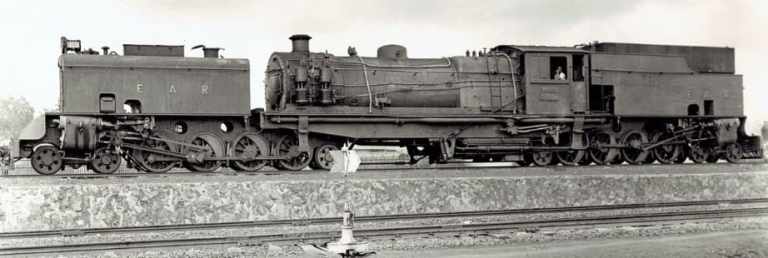
The majority of the locomotives acquired were owned or ordered by one of the three constituent railways, but some had been ordered by the Joint Committee. After the Joint Committee’s dissolution, some locomotives were ordered by John Gray, the new locomotive superintendent, from Timothy Hackworth and delivered during 1847 and 1848. Others were purchased from Stothert & Slaughter between 1847 and 1849. After this date the railway’s new locomotives were designed and built by John Chester Craven, usually at Brighton railway works. [6]

A List of Locomotive of the LB&SCR in 1920: Tilling provides a detailed list, locomotive by locomotive, of locomotives in use by the LB&SCR in 1920 to complete his book. These tables can be found here.

References

  1. W.G. Tilling; The Locomotives of the London, Brighton & South Coast Railway; Tilling, London, 1920.
  2. https://en.wikipedia.org/wiki/LB%26SCR_Richmond_class, accessed on 13th June 2026.
  3. https://en.wikipedia.org/wiki/List_of_Craven_locomotives, accessed on 13th June 2026.
  4. https://en.wikipedia.org/wiki/Jenny_Lind_locomotive, accessed on 13th June 2026.
  5. https://en.wikipedia.org/wiki/LB%26SCR_G_class, accessed on 14th June 2026.
  6. https://en.wikipedia.org/wiki/List_of_early_locomotives_of_the_London_Brighton_and_South_Coast_Railway, accessed on 14th June 2026.
  7. https://rogerfarnworthsrailways.wordpress.com/wp-content/uploads/2026/06/lbscr-locos-1920.pdf

The Railways of West Cumberland – Part 1 – An Introduction

The November 1954 issue of The Railway Magazine included an article by C. A. Knight about the railways between Sellafield and Maryport and inland as far as Cockermouth and Kelton Fell.

The featured image at the head of this article (and the article by C. A. Knight) shows an early 1950s image of Workington Station with a train to Euston ready to depart behind a ‘Royal Scot’ loco. [1: p757]
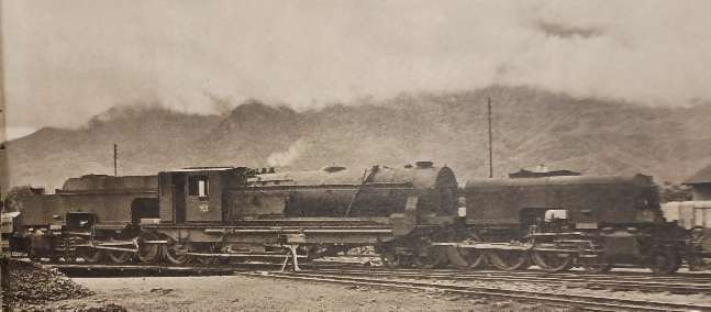
Reading Knight’s article encouraged me to begin a review of the different railways and tramways of the area. This article is the first of a series. …

Knight says: “Travellers to Keswick by the ‘Lakes Express’ during the summer [of 1954] may have speculated on the country to the west of that delectable town which is served by the train in the final stages of its journey. Some may venture as far as Cockermouth, but few will follow the train to its terminus at Workington, that product of Victorian enterprise in industry, as there is little in the area to attract the tourist from the delights of the Lake District. To the student of railway history, however, its tangle of intersecting railways holds promise of interest.” [1: p757]

The 10.50 am train to Euston at Workington, headed by ‘Royal Scot’ class 4-6-0 locomotive No. 46161, ‘Kings Own’, © W. Dendy. [1: p756]
A Map of West Cumberland’s Railway Network. [2]
Aap of the railways in West Cumberland, showing pre-grouping ownerships. [1: p758]

Knight tells us that, “The early evolution of the railways of West Cumberland was not marked by the contentious episodes which frequently characterised railway development in the mid-nineteenth century; rather [it could] be described as a process of peaceful penetration. … The narrow belt of agricultural land on the western edge of Cumberland was for many years practically isolated by the difficulties of travel through the mountains of the Lake District. The discovery of rich seams of coal, and the improvement of mining technique which enabled coal to be won from under the sea-bed, led to development of shipping facilities, and the economic factor became the distance from the port of shipment. Tramways in various forms were installed to enable coal to be brought from more distant pits, and on these, horse-drawn vehicles were no doubt used.” [1: p757]

The Early Tramways of West Cumberland

Early tramways in West Cumberland were primarily focused on moving industrial goods—specifically coal and iron ore—rather than passengers. Online references to Industrial Waggonways and Tramways in the 19th Century include:

  • Woodagreen Pit to Whitehaven Harbour: a crude wooden waggonway built at the Ginns as early as 1683. [9]
  • Seaton Tramroad: A 3 mile wooden waggonway built from Seaton pit to Workington, in the early 1730s. [6]
  • Harrington Harbour/Bain’s Tramway (c. 1760/1840s): A wagonway was established at Harrington Harbour as early as 1760. Later, it became known as “Bain’s Tramway,” which is shown on an 1864 OS map connecting Harrington Harbour with mines at John Pit and Hodgson Pit, passing through Rose Hill.
  • Whitehaven Harbour: A horse-drawn tramway was completed in 1854, authorized by the Whitehaven and Furness Junction Railway Amendment Act 1853. It allowed goods wagons to travel from Preston Street to the south end of the harbour.
  • Mr. Curwen’s Waggonway: A significant waggonway owned by Henry Curwen of Workington, which necessitated a bridge for the Whitehaven Junction Railway to pass over it in 1844.
  • Colliery Lines: These include: Waggonways from Lonsdale Collieries on Broughton Moor; Howgill Colliery Waggonway; and Whingill Colliery Waggonway.
  • Whitehaven Mineral Lines: The rapid development of haematite deposits in the Cleator Moor and Egremont districts in the 1840s led to numerous industrial lines and tramroads, later absorbed by the Whitehaven, Cleator & Egremont Railway (opened in parts from 1857).
  • The First Howgill Incline: constructed by 1813 in Whitehaven. [22]
  • Rowrah & Kelton Fell Mineral Railway: A significant line developed to serve the limestone quarries and iron ore mines near Rowrah, with development occurring through the 1860s and 1870s.
  • Jane Pit to Quayside (Workington): saw horses towing basic coal trucks from the pit down and over the railway, along to Chapel Bank and on to the Quayside. [8]
  • Cleator & Workington Junction Railway (1879): While technically a later railway, it was built to connect the existing iron and coal mining infrastructure (early pits and associated wagonways) with the coast to break existing transport monopolies.
  • Harrington and Lowca Light Railway: (commonly known as the Lowca Light Railway or LLR)
  • Lowca: An early locomotive works was established at Lowca, lasting until 1926, its business was fatally undermined by a disastrous fire in which the wooden patterns used during manufacture were burned. [5]
  • Corkickle Brake: A standard-gauge rope-worked incline survived as late as 1986, which was a remnant of early industrial transport methods, handling 500,000 tons of traffic at its peak.

These early, often private, waggonways generally used iron rails (replacing wooden ones) to connect pits to collieries or directly to the rapidly developing ports of Workington, Harrington, and Whitehaven.

Main Line and Branch Line Railways

There were a surprising number of standard-gauge railway companies operating in West Cumberland, as the maps above show.

The Whitehaven Junction Railway

The Whitehaven Junction Railway (WJR) was a historic English railway company sanctioned in 1844 to connect the town of Whitehaven with the Maryport and Carlisle Railway, facilitating industrial growth in West Cumberland. It played a crucial role in linking local coal mines and ironworks to broader transport networks. [10]

The Whitehaven & Furness Junction Railway

The Whitehaven & Furness Junction Railway (W&FJR) was established to connect the town of Whitehaven with the Furness Railway at Broughton-in-Furness. [11]

The Whitehaven, Cleator & Egremont Railway

The Whitehaven, Cleator and Egremont Railway (WC&ER) was built to open up the hematite orefield to the south-east of Whitehaven. It opened for goods traffic in 1855 and for passenger traffic in 1857. [12]

The Maryport & Carlisle Railway

The Maryport and Carlisle Railway (M&CR) was incorporated in 1837 to connect the two towns of Carlisle and Maryport. George Stephenson was the engineer of the line, which opened fully on 10th February 1845. [13]

The Cleator & Workington Junction Railway

The Cleator and Workington Junction Railway (C&WJR) served the towns of Cleator Moor and Workington and intermediate villages. It was mainly used for coal, limestone and iron ore traffic for the local industries. [14]

The Cockermouth & Workington Railway

The Cockermouth and Workington Railway (C&WR) was established by act of Parliament in 1845. The railway opened for service in 1847, and ran from the Whitehaven Junction Railway station at Workington to a station at Cockermouth near the bridge over the Derwent. [15]

The Cockermouth, Keswick & Penrith Railway

The Cockermouth, Keswick and Penrith Railway (CK&PR) was incorporated by Act of Parliament on 1st August 1861, to build a line connecting the town of Cockermouth with the London and North Western Railway (LNWR) West Coast Main Line at Penrith. [16]

The Whitehaven & Furness Junction & Whitehaven Junction Joint Railway

While they were separate companies, the W&FJR and the WJR worked together, particularly around Whitehaven. By 1852, a connecting line (including the Bransty tunnel) linked the W&FJR from the south with the WJR from the north. From the mid-1850s, the two companies merged their efforts to focus passenger traffic at Whitehaven Bransty Station (jointly managed) and goods traffic at Preston Street. [17]

The Harrington & Lowca Light Railway

The Harrington and Lowca Light Railway (commonly known as the Lowca Light Railway or LLR) was a short railway close to the coast on the South side of Harrington. Rosehill Junction was the junction between Bain’s Tramway (later known as the Harrington and Lowca Light Railway) and the Cleator and Workington Junction Railway’s Harrington Branch (later known as the Rosehill Branch). [18][19

Tramways

A Proposed Electric Tramway for West Cumberland – 1901

At the turn of the 20th century, the Cleator Moor Electric Tramway was planned and Acts of Parliament were sought for its construction. [3] Sadly, this standard-gauge tramway was not built, even though three different enabling Acts of Parliament were sought and passed (1901, 1903 and 1905). [3]

The tramway was to be operated by the ‘West Cumberland Power & Tramway Company Limited’ [4]

Later Industrial Railways

These railways include:

  • The CORUS Works Tramroad: a 3 ft-gauge works railway. [7]
  • Whitehaven Harbour: by the late 19th century, almost all of the harbour had a rail network. Locomotives were first introduced in 1848, the last locomotive being disposed of in 1986. [20]
  • Various Inclines and Other Lines: in addition to the Corkickle Break mentioned above (which lasted until 1986) there was a second Howgill Incline built by 1923 and of which remains can be found adjacent to Wellington Lodge. The Howgill Incline(s) have been out of use since 1972. [23][24]
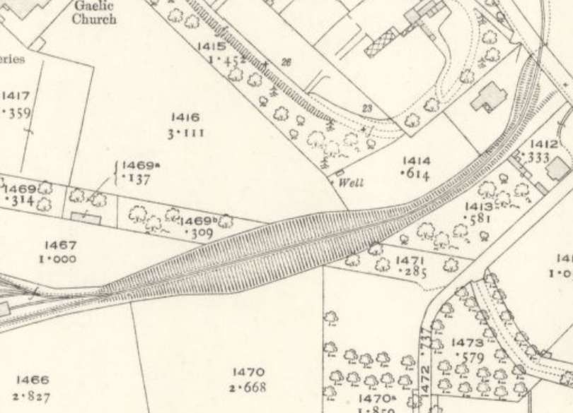
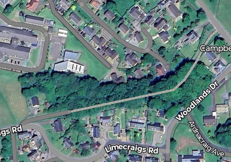
References

  1. C. A. Knight; Railways of West Cumberland; in The Railway Magazine, November 1954; Tothill Press, London, 1954, p757-765.
  2. The Railway Clearing House, London, 1921; via, https://maps.nls.uk/view/245959305, accessed on 3rd April 2026.
  3. https://www.littleireland.co.uk/2019/10/cleator-moor-electric-tramway.html?m=1, accessed on 3rd April 2026.
  4. Emile Garcke (Ed.); The Manual of Electrical Undertakings, 11th Edition; Electrical Press, London, 1907, p997; via,  https://www.lakesguides.co.uk/html/maps/GRK1.htm, accessed on 3rd April 2026.
  5. https://www.lococarriage.org.uk/cumbria_rail.html, accessed on 3rd April 2026.
  6. https://www.lakesguides.co.uk/html/lgaz/LK39356.htm, accessed on 3rd April 2026.
  7. https://www.lakesguides.co.uk/html/lgaz/LK02667.htm, accessed on 3rd April 2026.
  8. https://www.facebook.com/share/p/18HqJFu9h8, accessed on 3rd April 2026.
  9. https://www.whitehavennews.co.uk/news/17161961.a-fascinating-delve-into-towns-rail-history, quoting from Howard Quayle; Whitehaven: The Railways and Waggonways of a Unique Cumberland Port; Cumbrian Railways Association, Pinner, Middlesex, 2007.
  10. https://wp.me/p3J9rW-11F, accessed on 6th April 2026.
  11. https://transportsofdelight.smugmug.com/RAILWAYS/LOCOMOTIVES-OF-THE-LMS-CONSTITUENT-COMPANIES/LOCOMOTIVES-OF-THE-FURNESS-RAILWAY/i-Ls4ZZF3%23, accessed on 6th April 2026.
  12. https://en.wikipedia.org/wiki/Whitehaven,_Cleator_and_Egremont_Railway, accessed on 6th April 2026.
  13. https://www.gracesguide.co.uk/Maryport_and_Carlisle_Railway, accessed on 6th April 2026.
  14. https://en.wikipedia.org/wiki/Cleator_and_Workington_Junction_Railway, accessed on 6th April 2026.
  15. https://en.wikipedia.org/wiki/Cockermouth_and_Workington_Railway, accessed on 6th April 2026.
  16. https://en.wikipedia.org/wiki/Cockermouth,_Keswick_and_Penrith_Railway, accessed on 6th April 2026.
  17. https://en.wikipedia.org/wiki/Preston_Street_railway_station, accessed on 6th April 2026.
  18. https://en.wikipedia.org/wiki/Harrington_and_Lowca_Light_Railway, accessed on 6th April 2026.
  19. https://www.railscot.co.uk/companies/H/Harrington_and_Lowca_Light_Railway, accessed on 6th April 2026.
  20. https://www.whitehavenhc.org.uk/about-the-harbour, accessed on 6th April 2026.
  21. https://railwaymatters.wordpress.com/fell-type-mountain-railways, accessed on 2nd May 2026.
  22. https://www.facebook.com/share/p/1E7do6dbMy, accessed on 2nd May 2026.
  23. https://www.facebook.com/share/p/18tB4qhxPW, accessed on 2nd May 2026.
  24. https://www.facebook.com/share/p/1BugADHZGo, accessed on 2nd May 2026.

Parliament and the Railways in 1858.

N. Caplan reviewed parliamentary activity relating to railways in 1858 in The Railway Magazine of December 1958. His aim was to encourage research into railway history through the various Acts of Parliament relating to railways.

The Railway Magazine, December 1858, page 833. [1: p833]

“By 1858, the Railway Mania was well in the past, hostility to the railways had largely died away, and Parliament evidently felt that the railways might reasonably be left to consolidate their position by more prudent management, subject to the continuing close scrutiny of railway Bills by Parliamentary Committees. Some 8,000 miles of railway had been constructed, and the main trunk routes had mostly taken shape by 1858. After the financial disasters of the collapse of the railway boom, money was not readily forthcoming.

Most of the railway schemes before Parliament in 1858 were relatively modest. But there was plenty of fresh legislation with over seventy railway Acts receiving the Royal Assent in that year. These were, almost without exception, ‘Local & Personal Acts’ relating to particular railway companies, there were only two ‘Public General Acts’, and one of these applied only to railways in Ireland, the other amended the famous Act of 1844.” [1: p833]

Prior to reading Caplan’s article I was unaware of the distinction made in Parliament between ‘Local & Personal Acts’ and ‘Public General Acts’,

It appears that UK Acts of Parliament Acts of Parliament can be divided into two types: public acts and private acts. …

“Public acts are legislation of universal application and change the general law. Private acts (also known as local and personal acts) affect the powers of individual groups, such as companies or local authorities. Prior to 1798, all acts, both public and private, were published together with private acts listed as ‘local and personal acts declared private’. Since 1798, printed acts have been divided into two series: ‘public general acts’ and ‘local and personal acts’.” [2: p2]

The picture after 1798 is relatively complex:

According to the House of Commons information Office, [2: p3-4] Private Acts are listed as:

(a) Private Acts (until 1802);
(b) Local and Personal Acts, not printed (1802-1814); Private Acts (1815-date) (titled Personal Acts from 1948).

All private acts have been printed since 1922.

Local and Personal Acts include:

(c) Public Local and Personal Acts (1798-1802);

(d) Local and Personal Acts to be judicially noticed (1803-1814); Local and Personal Acts declared public and to be judicially noticed (1815-1867);

(e) Provisional Order Confirmation Acts (regarded as public acts of a local
character) (1867-1963);

(f) Local and Personal Acts (1868);

(g) Local and Private Acts (1869);

(h) Local Acts (1870 onwards).

The House of Commons Information Office comments: “The differences between all these series can often be set aside, except in searching out the actual texts from library shelves. However, it is normal to cite acts in a standard way, despite what may appear on the document itself.” [2: p4]

“It is now usual to cite public acts of all periods with arabic figures and post-1797 non-public acts with roman numerals. Personal Acts have italic arabic figures, and it is a service to the reader to supply the information (Not Printed) after the citation of any such act known never to have been printed. The [Chronological Table of the Statutes](CTS) is a useful guide for citing public acts of whatever age.” [2: p4-5]

The House of Commons Information Office goes on to provide specific details of how citations should be structured and then gives examples of how this should be done, note that ‘cap’ is short for ‘chapter’:

For Public Acts examples are: [2: p5]

Disorderly Houses Act 1751 (25 Geo 2 cap 36)
Debtors Act 1869 (32 & 33 Vict cap 62)
County Courts (Penalties for Contempt) Act 1983 (cap 45)

For Local Acts, examples are: [2: p5]

Aberbrothwick Harbour Act 1839 (2 & 3 Vict cap xvii)
Epping Forest Act 1878 (41 & 42 Vict cap ccxiii)
British Railways (Liverpool Street Station) Act 1983 (cap iv)

For Personal and Private Acts, examples are: [2: p5]

Marquess of Abergavenny’s Estates Act 1946 (9 & 10 Geo 6 cap 1)
Hugh Small and Norma Small (Marriage Enabling) Act 1982 (cap 2)

Returning to Caplan’s article: he speaks of just two Public Acts relating to railways in 1858, it appears that these are:

  • An Act to continue “The Railways Act (Ireland), 1851.” UK Public General Acts 1858 cap. 34 (Regnal. 21_and_22_Vict). [3]
  • The Cheap Trains and Canal Carriers Act 1858 (21 & 22 Vict. cap. 75), which amended earlier regulations regarding passenger duty and company liabilities. [4]

Caplan has more to say about the second of these two Acts. His comments can be found later in this article. …….

There is a summary, available online, of the clauses in the railways Acts of the 1858 session of Parliament giving powers to the Board of Trade. [7] That Summary may well be of interest here and is reproduced as Appendix 1 to this article (after the References below).

In his article, Caplan goes on to look at a number of specific ‘Local and Personal Acts’, he says: “Some of the Local & Personal Acts of 1858 exemplified the continuing problems of railway development, while others reflected the emergence of new problems, and it is interesting to look at a selection of these Acts.” [1: p833] Those he looked at included:

  • The Knighton Railway Act – one of the few in 1858 relating to an entirely new railway company. This Act, dated 21st May 1958, incorporated the Knighton Railway Company to construct a 9-mile line from Craven Arms to Bucknell, later extending to Knighton. It was a key component of the Central Wales line development, aiming to connect the industrial Midlands with Welsh border towns, eventually being absorbed by the LNWR. [5][6] The Act stated that:

“a Railway from the Craven Arms Station of the Shrewsbury & Hereford Railway, in the County of Salop, to the Borough of Knighton, in the County of Radnor, would be of great public and local advantage. The cost of construction was modestly estimated at £66,000 to be raised by a capital of 6,600 shares of £10. The Knighton Railway was intended to be be worked in conjunction with the Shrewsbury & Hereford Company, and the Act provided for the latter to work the Knighton line. No doubt largely as a matter of form the Act gave similar sanction for the Knighton Company to work the Shrewsbury & Hereford line.” [1: p833]

Knighton Railway Station: serves the border market town of Knighton in Powys. The station itself is located in Shropshire, (the border is immediately adjacent to the south side of the station and runs through the car park). It lies 32 1⁄2 miles (52.3 km) south west of Shrewsbury (by railway line) on the Heart of Wales Line, © Fabian Musto, licenced for reuse under a Creative Commons licence (CC BY-SA 2.0). [14]

It is worth noting the powers reserved to the Board of Trade in respect of this railway which appears in Appendix 1 to this article below. [7][Appendix 1]

Caplan points out that the Knighton Act was full of interesting facets of Parliament’s ideas about the control of railways, such as: the detailed control of maximum passenger and freight charges; and the maximum charge of fivepence per ton per mile “for fish, feathers, canes, cochineal, house-hold furniture, hats, shoes, toys and all other articles, matters, and things.” [1: p833]

Caplan also highlights the delays in completing new lines such as the Salisbury & Yeovil Railway and the need to authorise the sale of that line to the London & South Western Railway:

  • The Salisbury & Yeovil Railway Act

The Salisbury & Yeovil had a struggle to build its line because of shortage of money. The Salisbury & Yeovil Company was incorporated by an Act of 1854, and was authorised to make a railway from the terminus of the Basingstoke and Salisbury line of the London & South Western Railway at Salisbury to Yeovil, together with a branch to join the Wilts, Somerset & Weymouth Railway near Yeovil. The 1854 Act had laid down that these lines were to be completed in four years, and failure to comply might have involved a penalty of (30,000. The Salisbury & Yeovil had to go back to Parliament in 1855 and again in 1857 for authority for deviations from the original route, and was still desperately short of funds. The company was compelled to turn to the London & South Western for help, and amalgamation was the only real solution of its difficulties.

Dinton Railway Station on what was the Salisbury & Yeovil Railway Line, © Public Domain, photographer not known.This image was shared by Brian Prevett on the Disused Stations Facebook Group on 3rd November 2024. [15]

The Salisbury & Yeovil Act of 28th June 1858, gave the company further time to complete the revised route – two years from the passing of the Act and power to transfer the undertaking of the company to the L.S.W.R. Under the “South-Western Railway (Works and Capital) Act, 1858,” of 12th July 1858, the L.S.W.R. received power to lease or purchase the Salisbury & Yeovil Company and the way was cleared for the L.S.W.R.’s through main line from London to Exeter. [1: p833-834]

  • Railway Construction Costs

Caplan notes that railway construction costs almost inevitably exceeded estimates made by companies and thus the provision made for financing the construction and operation of a line by Parliament. Troubles arose:

“because of unforeseen engineering problems, … [and/or] the high costs of acquiring land and fighting rival promoters. … It is worth recalling that the costs of railway construction in Britain were strikingly high; it was stated in Parliament in 1858 that the average cost had been ₤33,000 a mile, compared with only £9,000 a mile in the United States, where land was so cheap and built-up areas so few. [1: p834]

Many of the 1858 Acts were designed to deal with money matters. This was true of:

  • The Cromford & High Peak Railway Act, 1858
The Cromford & High Peak Railway – Sheep Pasture Incline in 1904: Class 1P LNWR 2-4-0T ‘Chopper’ locomotive is ascending on the winding rope. The locomotive is using power to assist the stationary engine at the top of the plane. The catchpit between the tracks is a safety device to catch runaway waggons in the event of the rope snapping. Note the Pointsman’s cabin on the right at the convergence of the tracks, © Public Domain. [16]

This Act authorised:

“the Cromford & High Peak Railway Company to raise further Sums of Money; and for other Purposes. This unique railway was incorporated in 1826, and the company was given power in 1855 to raise more money, and to re-organise its capital structure. The 1858 Act referred to the ‘improvement of their railway, and they have laid out considerable sums of money upon that portion of the line which is situate between the junction of the Stockport, Disley & Whaley Bridge Railway and the station near the town of Buxton, and such expenditure has been beneficial to the company and the public and a considerable increase of traffic has arisen upon the railway’. The 1858 Act authorised the Cromford & High Peak to raise another £60,000 capital in the form of 3,000 more 6% preference shares of £20, and to raise £20,000 by mortgage.” [1: p834]

Interestingly, Caplan states, “All of the Acts dealing with financial powers of railway companies contained a clause of great … importance in relation to the Railway Mania of the 1840s, and the chequered career of George Hudson, the ‘Railway King’.“[1: p834] This clause stated:

“It shall not be lawful for the company, out of any money by this Act authorised to be raised by calls in respect of shares or by the exercise of any power of borrowing, to pay to any shareholder interest or dividends on the amount of the calls made in respect of the shares held by him in the capital by this Act authorised.” [1: p834]

Caplan explains that “The Hudson Empire had been built up only at the expense of the integrity of the various companies’ capital, and there had been cases of dividends being paid out of capital instead of out of genuine net earnings. It was these irregular dividend payments which helped to stimulate the public demand for railway shares, and thus led to the fantastic boom of 1845-46 in which railway promoters were offering the public the prospect of even 14 or 15 per cent. interest. The collapse of the boom, and the investigation of company accounts, led Parliament to insist on this standard clause to prohibit dividend payments out of capital.” [1: p834]

George Hudson controlled a significant part of the railway network in the 1840s. He had the title “The Railway King” conferred on him by Sydney Smith in 1844, © Public Domain. [17]

George Hudson controlled a significant part of the railway network in the 1840s. He had the title “The Railway King” conferred on him by Sydney Smith in 1844. He played a major role in linking London to Edinburgh by rail. He also formed the first significant merger of railway companies, creating the Midland Railway, and developed his home city of York into a major railway junction. He represented Sunderland in the House of Commons. However, his “success was built on dubious financial practices and he frequently paid shareholders out of capital rather than money the company had earned.” [8]

There were a series of railway mergers over the 1850s. Caplan say that “the process of railway amalgamation continued in 1858, as some of the smaller and financially-weaker companies found it impossible to carry on, and a number of Acts provided for amalgamation by outright purchase or for such close financial and working arrangements that the companies concerned lost all effective independence.” [1: p834] Caplan mentions one in particular:

  • The Inverury & Old Meldrum Junction Railway

On 11th June 1858, this railway was authorised “to be leased in perpetuity to the Great North of Scotland Railway for a rental of £650 per year, payable half-yearly. … A very modest sum for the lease of a railway but the Inverury & Old Meldrum Junction was a very small railway.” [1: p834]

The route of the Inverury & Old Meldrum Junction Railway. [9]

The authorising Act for the Inverury and Old Meldrum Junction Railway received the Royal Assent on 15th June 1855, a necessary capital of £22,000 was authorised. The line was “5 miles 1194 yards in length, from a junction at Inverurie. The station at that time was some distance south of the present one; the Old Meldrum branch line ran alongside the main line for nearly a mile before diverging. The engineer was John Willet. There were few engineering complications in constructing the line, the biggest work being a 50-foot girder bridge over the River Ury.” [9][10: p7-9][11][12]

The capital was raised mainly locally, and construction was completed quickly and cheaply, being ready by June 1856 at a low cost of about £5,000 per mile. The opening to passengers took place on Thursday 26th June 1856. [9][10: p7-9][13]

In 1866 the Great North of Scotland Railway (GNoSR) set about incorporating several branch line leases into the parent company; the Oldmeldrum company was one of them. The £650 annual lease rental was converted to £13,810 of new GNoSR Old Meldrum preference stock. Parliament authorised the change on 1 August 1866. Ordinary shareholders got £3 of GNoSR stock for their £10 shares. [9][10: p7-9][13]

In 1930 passenger receipts had totalled £243, which represented a loss in working of £718. It was hardly sustainable to continue such an operation, and the LNER closed the passenger service from 2 November 1931. [9][10: p58][18: p315]

The basic goods service to Oldmeldrum continued, but it too became unsupportable in the 1960s, and it was closed on 3 January 1966.[18: p315] It was later used for a while for wagon storage.[9][10: p65]

  • The Manchester South Junction & Altrincham Railway

This railway was authorised by Parliament in 1845 and was jointly owned by the London & North Western and the Manchester, Sheffield and Lincolnshire railways.

Caplan says that:

“It is not surprising that the railway companies concerned in the operation of joint lines did not always see eye to eye, and one Act of 1858 brings clearly above the surface some of the difficulties which arose. This was the ‘Act to improve the management of the Manchester South Junction & Altrincham Railway’. …. The M.S.J.A.R. …. was managed by a board of six directors, three nominated by each company, and two chairmen, each company appointing one. The chairmen were to preside alternately at board meetings and the presiding chairman had a casting vote in the event of a tie.

“Such an arrangement was bound to cause trouble at times and as the preamble to the 1858 Act said ‘it has been found that in cases where the interests of the London & North Western and the Manchester, Sheffield & Lincolnshire Railway Companies differ the said provisions with respect to the chairman of the board of directors produce great inconvenience and delay, and that resolutions passed by the said board under one chairman are often rescinded by a subsequent board under another chairman.” The preamble went on to refer to the competition between the parent companies: inasmuch as the two companies work over and are competitors for much of the traffic which is or may be conveyed over the South Junction Railway, and the questions therefore between them are likely to be multiplied, it is essential to the public convenience and to the proper use of the South Junction Railway…

“The Act provided that in future the chairman presiding over any board meeting should not have a casting vote. Instead, the parent companies were to appoint each December an arbitrator and, in the event of failure to agree on an arbitrator, the Board of Trade was to make this appointment. The arbitrator’s term of office was fixed at one year, though he could be re-appointed. The arbitrator was given the power to decide disputed matters in cases where there was a tie in voting at the board of the South Junction Railway. [1: p834-835]

The route map of the Manchester, South Junction and Altrincham Railway as at December 1931, © Ian Threlfall and licenced for reuse under a Creative Commons licence (CC BY-SA 2.5). [19]
  • A Station near Victoria Street, Pimlico and a Railway to Connect it with the West End of London & Crystal Palace Railway at Battersea

Caplan says that the continued growth of towns and passenger traffic required big changes in station arrangements, and a particularly interesting Act of 1858 concerned London. This was:

“‘An Act to authorise the construction of a station near Victoria Street, Pimlico, in the County of Middle-sex, and of a railway to connect the same with the West End of London & Crystal Palace Railway at Battersea in the County of Surrey, in order to afford improved communication between certain of the railways south of the Thames and the western districts of the Metro-polis; and for other purposes’.

This was indeed a major scheme of passenger traffic improvement – the authorised capital was £675,000. The existing terminus of the West End of London & Crystal Palace Railway was South of the Thames at Battersea – it was, however, called ‘Pimlico’ – and this was not at all convenient for the West End. Pimlico Station was opened in March, 1858, and the new Victoria Station authorised by the 1858 Act was opened in October, 1860, so that the ‘West End Terminus’ south of the River had the shortest of lives.” [1: p835][20]

The Victoria Station and Pimlico Railway (VS&PR) was by the Victoria Station and Pimlico Railway Act 1858 on 23 July 1858. to build Victoria Station, Grosvenor Bridge over the River Thames, and a length of line to Connect with the London & Crystal Palace Railway. The company later leased its lines and stations to the LB&SCR and the London Chatham and Dover Railway (LC&DR) but continued in existence until December 1922 when it was very briefly amalgamated with the South Eastern Railway before becoming part of the Southern Railway as a result of the Railways Act 1921, which created the Big Four on 1 January 1923.

Victoria Railway Station in the 21st century, © AvidWriter123 and licenced for reuse under a Creative Commons Licence (CC BY-SA 4.0).  [21]
  • The Act to Amend the Law Relating to Cheap Trains

In 1844, ‘Gladstone’s Act’ was passed ‘to attach certain Conditions to the Construction of future Railways’. Although about the general regulation of the railways, Gladstone’s Act was known as the charter of third class passengers who suffered a miserable time travelling on those railways that thought it worthwhile recognising their existence!

Caplan says that:

” Parliament’s aim in Clause VI of the 1844 Act was to ‘secure to the poorer class of travellers the means of travelling by railway at moderate fares, and in carriages in which they may be protected from the weather’ and at least one train a day in each direction on all main, junction and branch lines was to provide such facilities. Parliament specified the fare to be charged: ‘The fare or charge for each third class passenger by such train shall not exceed one penny for each mile travelled’.

“However, there was room here for disagreement about the proper basis of charging for fractions of a mile travelled. Hardened as we are by the course of inflation, we may be tempted to smile at the thought of Parliament moving in all its majesty in 1858 to lay down that fractions of a mile must be charged for at a specific rate, but farthings and halfpennies were real money a hundred years ago. The Victorians-individuals and railway companies were unlikely to dismiss farthings and halfpennies as insignificant quite apart from the question of the principle of the thing.

“So it was that Clause 1 of the Cheap Trains Act, 1858, prescribed the method of charging for fractions of a mile on journeys by the ‘Parliamentary Trains’: ‘When the distance travelled by any third class passenger by any train run in accordance with the provisions [of the 1844 Act] is a portion of a mile, and does not exceed one mile, the fare for such portion of a mile may be one penny, or when such distance amounts to one mile, or two or more miles, and a portion of another mile, the fare or charge for each such portion of a mile, if the same amounts to or exceeds one half mile, may be one halfpenny’.” [1: p835, p860]

The first page of the Act referred to as the ‘Cheap Trains Act’. It is worth noting that the Act sought not only to amend the law relating to Cheap Trains but also to restrain the Exercise of certain powers by Canal Companies being also Railway Companies. [22]

The ‘Cheap Trains Act’ was actually also intended to curb railway companies from monopolizing transport by abusing their control over acquired canal networks. It regulated the leasing of canals by railway companies, ensuring they couldn’t stifle competition, while also addressing railway pricing.

The Act specifically addressed concerns that railway companies, having bought up canals, would allow them to fall into disrepair or charge prohibitive tolls to force traffic onto the rails.

It also restricted any ‘Canal or Navigation Company, being also a Railway Company’ from leasing other canals or railways without parliamentary authority, preventing the massive consolidation of transport networks by a few rail companies.

It sought to maintain the viability of independent canal carriers against ‘Railway and Canal Companies’.

It also sought to strengthen the provisions of the Railway and Canal Traffic Act 1854 which forced canal and rail companies to provide ‘reasonable facilities’ for transport.

The 1858 Act was later made perpetual by the Cheap Trains Act 1860. It acted as a protection mechanism for the waning canal industry against aggressive railway competition during the expansion of the UK’s rail network.

However, the 1860 Act was not Parliament’s last word on the subject of Cheap Trains. A further Act was passed in 1883. It was known as the ‘Cheap Trains Act’. The 1883 spurred the expansion of affordable ‘workmen’s trains’. It abolished or reduced passenger duty (duty not fares) for companies charging less than a penny a mile, requiring them to provide sufficient services for working-class commuters, particularly in urban areas. [23] It obliged the railway companies to operate a larger number of cheap trains. [24]

That 1883 Act also consolidated the Law relating to the conveyance of the Queen’s Forces by Railway. [23]

“Some railways in London were already operating workmen’s trains although they were often overcrowded and inconveniently timed. Although the act was opposed by some railway officers, notably Sir Edward Watkin of the Manchester, Sheffield and Lincolnshire Railway, the number of cheap suburban services increased greatly. During the 20th century, the appearance of competing road services meant that the railways were forced to reduce their fares. So few services eventually attracted duty that the act was abolished in the Finance Act 1929.” [24]

Further Acts of Parliament relating to railways were not considered worth noting by Caplan, some of these are covered in Appendix 2.

Returning to Caplan’s article, he concludes by saying that, “No railway enthusiast should be deterred from the thought of looking into Acts of Parliament by the mistaken impression that they are dry as dust. Many of them bring the ‘Railway Age’ before us in the most vivid way.” [1: p860]

Hopefully this review of his article has further emphasised the value of reading through relevant Acts of Parliament to gain a better understanding of railway history.

References

  1. N. Caplan; Parliament and Railways in 1858; in The Railway Magazine, December 1958; Tothill Press, London, 1958, p833-835 & p860.
  2. https://www.parliament.uk/globalassets/documents/commons-information-office/l12.pdf, accessed on 11th April 2026.
  3. https://www.legislation.gov.uk/ukpga/Vict/21-22/34/enacted, accessed on 11th April 2026.
  4. https://www.legislation.gov.uk/ukpga/Vict/21-22/75/enacted, accessed on 11th April 2026.
  5. https://powysenc.weebly.com/railways-central—lnwr.html, accessed on 11th April 2026.
  6. https://en.wikipedia.org/wiki/Knighton,_Powys#:~:text=Otherwise%2C%20Knighton%20was%20remote%20from,Alexis%20Korner%2C%20who%20also%20performed, accessed on 11th April 2026.
  7. https://www.ekeving.se/ext/uk/Report_1858/62-65.pdf, accessed on 18th April 2026.
  8. https://en.wikipedia.org/wiki/George_Hudson, accessed on 30th April 2026.
  9. https://en.wikipedia.org/wiki/Inverury_and_Old_Meldrum_Junction_Railway, accessed on 30th April 2026.
  10. Duncan McLeish; Rails to Banff, Macduff and Oldmeldrum: Three Great North of Scotland Railway Branch Lines; Great North of Scotland Railway Association, 2014, p7-9.
  11. Donald J Grant; Directory of the Railway Companies of Great Britain; Matador, Kibworth Beauchamp, 2017, p278.
  12. H A Vallance; The Great North of Scotland Railway; David and Charles, Dawlish, 1965, p59-60.
  13. David Ross; The Great North of Scotland Railway: A New History; Stenlake Publishing, p40, 83, 222 & 223.
  14. https://www.geograph.org.uk/photo/5915861, accessed on 1st May 2026.
  15. https://www.facebook.com/share/p/15jqh5tCYcw, accessed on 1st May 2026.
  16. http://www.pittdixon.go-plus.net/c+hpr/c+hpr.htm, accessed on 1st May 2026.
  17. https://www.jorvik.co.uk/george-hudson, accessed on 1st May 2026.
  18. John Thomas & David Turnock; A Regional History of the Railways of Great Britain: Volume 15, North of Scotland; David and Charles, Newton Abbot, 1989.
  19. https://commons.wikimedia.org/wiki/File:MSJAR_map.jpg, accessed on 1st May 2026.
  20. These developments were described in The Railway Magazine in October 1956 and March 1958.
  21. https://commons.wikimedia.org/wiki/File:Victoria_Bus_and_Railway_Station.jpg, accessed on 1st May 2026.
  22. https://www.legislation.gov.uk/ukpga/Vict/21-22/75/enacted, accessed on 2nd May 2026.
  23. https://vlex.co.uk/vid/cheap-trains-act-1883-808185373, accessed on 2nd May 2026.
  24. https://en.wikipedia.org/wiki/Cheap_Trains_Act_1883, accessed on 2nd May 2026.

Appendix 1

Committee of Privy Council for Trade &c. p62-65.

The Clauses in the Railways Acts of the 1858 Session of Parliament giving Powers to the Board of Trade are to the following effect:

Construction of Works

Alyth Railway Act, 1858, c. 43. s. 28., &c. —Provides that the junction with the Scottish North-Eastern Railway, in case of differ­ence, is to be made according to a plan approved of by an engineer appointed by the Board of Trade previously to the commencement of such work; and any difference as to the nature or necessity of the signals and other works at the junction, the same to be referred to arbitration or the decision of an engineer, to be appointed by the Board of Trade, at the option of the Scottish North-Eastern Company.

Andover and Redbridge Railway Act, 1858, c. 82. s. 22., &c. — Provides that the Company are not to proceed with any works affecting the Bishopstoke and Salisbury Railway, or any of the works of the London and South-Western Railway Company, until they shall have delivered to that Company a plan, &c. of the pro­posed works, and obtained the approval thereof of the principal engineer; but if he shall not certify his approval within one calendar month of the delivery of such plan, &c., and shall fail to furnish within such period a plan of executing the works satisfactory to that Company, the Andover Company may submit a plan, &c., to the Board of Trade, and on the same being certified, proceed to the execution of the works, &c.

The Company shall also so make and maintain the Branch Railway as to enable the London and South-Western Company to make a convenient junction between it and the Southampton and Dorchester Railway; and any difference with reference thereto is to be settled by the arbitrator of the Board of Trade, and the Company are not to open the railway between Romsey and Red­bridge, or any part thereof, for public traffic, unless they simul­taneously open for traffic the branch railway.

Banbridge, Lisburn, and Belfast Railway Act, 1858, c. 46. s. 32. — Provides that in case of difference with respect to any works for effecting the communication with the Ulster Railway and the Banbridge Junction Railway, the same is to be determined by an engineer, to be appointed by the Board of Trade.

Caledonian Railway (Branch to Port Carlisle Railway) Act, 1858, c. 66. s. 5. — Provides that all communications between the Branch
Railway authorized by this Act and the Port Carlisle Railway, in case of difference, are to be effected by means of connexion rails, and points of such construction, and laid in such manner as shall he determined by an engineer to be appointed by the Board of Trade.

Devon Valley Railway Act,, 1858, c. 122. s. 26., &c. — Provides that in case of difference, the junctions of the railway with the Tillicoultry Branch of the Stirling and Dunfermline Railway, and with the Fife and Kinross Railway, are to be made according to a plan to be approved of by an engineer to be appointed by the Board of Trade; and any difference as to the nature or necessity of the works to be constructed at such junctions shall be referred to arbitration, or the decision of an engineer to be appointed by the Board of Trade, at the option of the Stirling Company or the Fife and Kinross Company respectively. A certain road in the parish of Dollar is to be carried over the railway by a stone bridge, to the satisfaction of the engineers of the Company and the landowners named in the Act, or in case of difference, of an engineer to be appointed by the Board of Trade.

Dublin and Meath Railway Act, 1858, c. 119. — Provides that communications between the railways authorized by the Act and the railway of any other Company, shall be made to the satisfac­tion of the engineer of the Company with whose line such com­munication is to be made: and if such Company shall have no engineer, or the engineers shall differ, then such communications shall be made in the manner directed by an engineer to be appointed by the Board of Trade.

East Kent Railway ( Western Extension) Act, 1858, c. 107. s. 7., &c. — Provides that all communications between the railway and the Mid-Kent Railway (Bromley to St. Mary Cray), in case of dispute, shall be made in such manner as shall be directed by an engineer to be appointed by the Board of Trade. Before the Company open the railway for public traffic, they are to make a station at Sole Street at which all trains are to stop (except on Sundays), for the purpose of taking up and setting down passengers, goods &c., special or express, or mail trains, only excepted.

East Suffolk Railway (Branch and Capital) Act, 1858, c. 47. s. 10. — Provides that in case of difference as to the mode of making the communications with the Lowestoft Railway, or as to the works necessary or convenient for effecting the same, the matter is to be settled by the Board of Trade, or its arbitrator.

Eden Valley Railway Act, 1858, c. 14. s. 28. — Provides that in case of disputes as to the nature or necessity of the works at the junctions of the railway authorized by this Act with the Lancaster and Carlisle Railway, or the South Durham and Lancashire Union Railway, the matter shall be referred to arbitration, or to the decision of an engineer to be appointed by the Board of Trade, on the application of either of the Companies.

Exeter and Exmouth Railway Act, 1858, c. 56. s. 46. — Provides that if any carriageway be made across the railway on the level for the benefit or convenience of any person interested in the shore or river bank adjoining the railway, the mode of making and watching such crossing shall be subject to the approval of the Board of Trade.

Fife and Kinross and Kinross-shire Railways Junction and Joint Station Aci, 1858, c. 65. s. 5. &c. — Provides that the junction between the railways of the two Companies and the joint station at Kinross, and the bridge for carrying the Great North Road, &c. over the Kinross-shire Railway and the levels of the two railways, are to be made to the satisfaction of the engineers for the time being of the Companies, and in case of difference, of an engineer to be appointed by the Board of Trade, on the appli­cation of either Company.

Either of the Companies, on giving three months’ notice, may construct the joint station at Kinross, and will be entitled to recover from the other Company one moiety of the expense, as the same shall be certified by the engineers, or in case of differ­ence, by an engineer to be appointed by the Board of Trade.

Formartine and Buchan Railway Act, 1858, c. 108. s. 45., &c. — Provides that the Branch Railway to Ellon is to be constructed simultaneously with the main line from Dyce to Old Deer, and no part of the main line is to be opened to the public until the branch has been opened, and no part of the railway is to be opened until a double line of rails shall have been laid down upon the Great North of Scotland Railway between the point of junction at Dyce and Kittybrewster. Any difference as to the mode of effecting the communication with the Great North of Scotland Railway is to be determined by a referee, to be appointed by the Board of Trade.

Knighton Railway Act, 1858, c. 19. s. 22. — Provides that any difference as to the mode of effecting the communications with the Shrewsbury and Hereford Railway is to be determined by a referee, to be appointed by the Board of Trade.

Midland Great Western Railway o f Ireland (Clare Deviation) Act, 1858, r. 94. s. 9. —Provides that in case of difference with reference to any works for effecting the communication between the railway authorized by the Act and the Great Southern and Western Railway, the same is to be determined by an engineer, to be appointed by the Board of Trade.

Newport, Abergavenny, and Hereford Railway Act, 1858, r. 126. s. 7., &c. — Provides that a deviation is to be made in the Aberdare Canal, at the expense of the Company, and to be maintained and repaired by them during a period of five years; and if any dis­pute shall arise between them and the Canal Company touching the said matters, the same is to be determined by an engineer, to be appointed by the Board of Trade.

North British Railway Consolidation Act, 1858, c. 109. s. 49. — Provides that this Act repeals the prohibition against the use of locomotive engines on the Old Leith Branch Railway, and em­powers the Company to stop up such of the roads or accesses across the railway in the parish of South Leith as they may think fit, and to make provision for the crossing of the railway, at two or more points, by means of occupation or other roads, and to execute such works as may be necessary for adapting the railway to the use of locomotive engines, and to run the same thereon.

Portsmouth Railway Amendment Act, 1858, c. 101. s, 7., &c. — Provides that if any difference shall arise respecting the com­munication between the Portsmouth Railway and the railways belonging either jointly or separately to the Brighton and South- Western Companies, or as to the erection of signals at, and other matters connected with such junctions, the same is to be deter­mined by arbitration, in the manner provided by the Railways Clauses Consolidation Act, 1845, section 21. The Company are prohibited from appropriating any part of a certain road, called Blackfriars Road, belonging to the Landport and Southsea Commissioners; but they may and shall, for the purpose of forming a communication between their railway and the line of the Brighton and South-Western Companies at Landport, make sidings, with two lines of rails, within the limit of deviation, across and on the level of the said road, subject to the usual pro­visions in reference to crossing roads on the level, and to such other reasonable regulations as may be agreed on between them and the surveyor, or, in case of dispute, as shall be settled by an officer to be appointed by the Board of Trade.

Redditch Railway Act, 1858, c. 137. s. 36. — Provides that the bridge for carrying the railway over the Worcester and Birming­ham Canal is to be constructed, as to its position, form, and dimensions, to the satisfaction of the engineer of the Railway and Canal Companies, and, in the event of disagreement, to the satis­faction of an engineer to be approved by the Board of Trade.

Symington, Biggar, and Broughton Railway Act, 1858, c. 15. s. c25., &c. —Provides that in case of difference as to the mode of effecting the junction with the Caledonian Railway, the same is to be made according to a plan approved of by an engineer, to be appointed by the Board of Trade previously to the commencement of the works; and any question as to the nature or necessity of works at the junction, in case of dispute, is to be referred to arbi­tration, or to the decision of the Board of Trade, at the option of the Caledonian Company.

Whitehaven Junction Railway (New Branches) Act, 1858, c. 127. s. 27. — Provides that if the Company shall be required by the Lords of the Admiralty, under the provisions of this Act, to make any carriageway across the railway on the level, for the purpose of affording access to the seashore, then the manner of making and watching such level crossing shall be subject to the approval of the Board of Trade, and the Company shall not be liable for the expenses of watching such level crossing.

Additional Rails

East Suffolk Railway (Branch and Capital) Act, 1858, c. 47. s. 27. — Provides that the main line from the Leiston Junction to Halesworth, and the part from Halesworth to Haddiscoe, are to be completed, so that two lines of railway may be laid down when and as the Company think proper; and if the Company shall not lay down two such lines of rails, then when it shall appear to the Board of Trade that another line of rails, in addition to the single line of rails on such portions, is required for the public accommo­dation.

Portsmouth Railway Amendment Act, 1858, c. 101. — Provides that if the gross annual proceeds of the traffic on the line between Godalming and Havant for three consecutive years shall average £45,000, the Company, on request of the Board of Trade, shall lay down an additional line of rails, raising such an amount of additional capital as may be necessary for that purpose.

Lease, Sale or Amalgamation

East Suffolk Railway Companies Amalgamation Act, 1858, c. 111. s. 3. and s. 43., &c. — Provides that from the passing of the Act the undertakings of the East Suffolk Company, the Yarmouth and Haddiscoe Company, and the Lowestoft and Beccles Com­pany were united and consolidated into one undertaking.

The Company may grant a lease of their undertaking to Sir M. Peto for any term not exceeding 21 years, determinable on 12 months’ notice, after a resolution by the Company that such lease shall be determined, provided that if within three months after such notice the lessee shall apply to the Board of Trade and object to the determination of such lease, then the resolution and notice shall have no force or effect, unless the Board of Trade shall be of opinion that the lease is injurious to the public in­terests, and shall confirm such resolution. Any shareholder, voting against such resolution, within three months may require the Company to purchase the shares, in respect of which he voted, at par.

South Devon and Tavistock Railway Act, 1858, c. 102. s. 3. — Provides that lease to the South Devon Company, with consent of Shareholders of both Companies, the Company still remaining liable to the provisions of the 30th section, 17 & 18 Vict. c. 189, as to laying down additional rails on the narrow gauge, if required so to do by the Board of Trade: the terms and conditions of using the same by any Company, in case of dispute, are to be settled and adjusted by the Board of Trade.

Staines, Wokingham, and Woking Railway Act, 1858, c. 58. s. 19., &c. — Provides that the Company may lease all or any part of their undertaking to the South-Western Company, with consent of shareholders of both Companies. The lease, at the expiration of every ten years, to be subject to such modification as the Board of Trade may consider necessary to protect the public interests.

Ulverstone and Lancaster Railway Act, 1858, c. 98. s. 42., &c. — Provides for lease or sale to the Furness Company of all or any part of the undertaking; the terms to be approved of by the Board of Trade.

Vale of Towy Railway (Leasing) Act, 1858, c. 147. s. 3. — Provides that the Company may lease for a period of 10 years their undertaking to the Llanelly Railway and Dock Company, such lease to be approved of by the Board of Trade.


Use of Railway Station, &c.

Fife and Kinross and Kinrosshire Railways Junction and Joint Station Act, 1858, c. 65. s. 17., &c. — Declares that the manage­ment and maintenance of the joint station are in the Companies; but in the event of any difference thereon, or on any other ques­tions relating to the use and working of such station, or as to the expense thereof, the same is to be settled by an arbitrator, to be appointed by the Board of Trade. The Companies may agree with the Edinburgh, Perth, and Dundee Company with respect to the use and working of the railways authorized by this Act on the terms of the Fife and Kinross Railway Act, 1855, and the Kinrosshire Railway Act, 1857.

London, Brighton, and South Coast Railway (New Lines) Act, 1858, c. 84. s. 27., Sec. — Provides that the Company and all per­sons lawfully using their railway, may likewise use the Mid-Sussex Railway Stations, &c.; and in case of dispute as to the time, conditions, and regulations respecting the use thereof, the same shall be determined by the Board of Trade, or its arbitrator.

London and North-Western Railway (Additional Works) Act, 1858, c. 131. s. 12. — Provides that the Company, and the Great Western Company may, if they shall think fit, instead of proceeding with the arbitration under the provisions of 17 & 18 Vict. c. 200., for the separation and allotment of the joint station at Wolverhampton, known as the High Level Station, or in addition thereto, so far as the same shall not extend, make and carry into effect agreements for the appropriation and allotment to and between, or to either of them, of the whole or any part of such station ; and upon such appropriation and allotment being completed and approved of by the Board of Trade, the several portions shall vest in the Stour Valley and Great Western Com­ panies accordingly. The portion which may be assigned to the Stour Valley Company shall be deemed to be included in the lease to the London and North-Western Company.

Portsmouth Railway Amendment Act, 1858, c. 101. s. 25. — Provides that the Company, and all other companies lawfully using the Portsmouth Railway, may pass over and use so much of the railway of the Brighton Company as will be situated be­tween the point of junction with that railway, in the parish of Havant, and the Portsmouth Railway, and the point at or near Hilsea Redoubt, where the Brighton Railway unites with the line to Portsmouth belonging to the Brighton and South-Western Companies, and also of their line to Portsmouth between the said point at Hilsea Redoubt and the terminus of the said railway at the Landport road, in the parish of Portsea, and also so much of the line of the South-Western Company as will be situate between the point of junction therewith of the intended railway firstly de­scribed in this Act, and the before-mentioned point at Hilsea Redoubt. The terms and conditions of such user are to be settled, failing agreement between the Companies, by their principal engineers, or their umpire, or, failing such appointment, by some person to be appointed by the Board of Trade. The right of user of the joint station at Landport is limited to traffic conveyed on the public service, but the Companies may agree for the use thereof for the general traffic.

The Portsmouth Company, in working or using the railway of the Brighton and South-Western Companies, is to observe the regulations and bye-laws of the Companies in force on the rail­ways so used, as far as the same shall be applicable to the Portsmouth Company; and in case of dispute respecting such regulations or bye-laws, or the mode in which the powers or privileges given by the Act shall be exercised, or the regulations to be adopted exclusively for the convenience or accommodation to be afforded to the traffic of the Portsmouth Company, the same shall be settled as before-mentioned, provided that neither such regulations and bye-laws, so far as they affect the Ports­mouth Company, nor the award thereon of the engineers, or their umpire, shall have any force unless the same shall have been confirmed by the Board of Trade. Any award of an umpire may be reconsidered by order of the Board of Trade.

Traffic Arrangements.

Alyth Railway Act, 1858, c. 48. s. 47., &c. —Provides that a traffic agreement may be made with the Scottish North-Eastern, and Edinburgh and Perth, and Dundee Companies, or either of them. Agreement limited to ten years, and to be assented to by the shareholders of the several Companies in special meeting, and to be approved of by the Board of Trade.

Athenry and Tuam Railway Act, 1858, c. 112. s. 44., &c. — Provides that a traffic agreement may be made with the Midland Railway of Ireland Company. Agreement limited to ten years, and to be assented to by the shareholders of the Companies in general meeting, and to be approved of by the Board of Trade.

Banbridge, Lisburn, and Belfast Railway Act, 1858, c. 46. s. 44, &c. —Provides that a traffic agreement may be made with the Ulster, the Dublin and Belfast Junction, and the Banbridge Junction Companies, or either of them. Agreement limited to ten years, to be assented to by the shareholders of the Companies parties thereto, and approved of by the Board of Trade.

Caledonian Railway (Branch to Port Carlisle Railway) Act, 1858, r. 66. s. 16., &c. — Provides that a traffic agreement may be made with the Port Carlisle Company and the Carlisle and Silloth Bay Company, or either of them. Agreement limited to ten years, to be assented to by the shareholders of each Company, and to be approved of by the Board of Trade.

Cleveland Railway Act, 1858, c. 114. s. 40. —Provides that a traffic agreement may be made with the West Hartlepool Com­pany. Agreement to be assented to by the shareholders of the Companies, and approved of by the Board of Trade. On the expiration of ten years from the commencement of any agreement, the Board of Trade may cause the same to be revised, and the Board is empowered to declare that, if any modification required by it be not agreed to by the Companies, then, at the expiration of twelve months after notice given to the Companies of such modification being required, the said agreement shall determine.

East Kent Railway (Western Extension) Act, 1858, c. 107. s. 17., &c. — Provides for the due transmission of traffic to or from any part of the railways belonging to the South-Eastern Company, to or from any part of the railways belonging to the East Kent Railway Company, and empowers the Board of Trade, in case of dispute as to the nature and extent of the accommo­dation to be afforded by the latter Company, and the rates of charge at which the several services required of it shall be per­formed, to settle the terms and conditions. The Company and the West London and Crystal Palace Company may enter into traffic arrangements. Agreement limited to ten years, to be assented to by the shareholders of both Companies, and approved of by the Board of Trade. Any question or difference which
may arise between the Companies with reference to the construc­tion of any such agreement, is to be settled by the Board of Trade, or its arbitrator.

East Suffolk Railway Companies Amalgamation Act, 1858, c. 111. s. 50. &c. — Provides that a traffic agreement may be en­tered into with the Eastern Counties Company, the Norfolk Company, and the Eastern Union Company. Agreement to be assented to by the shareholders of the several Companies, and approved of by the Board of Trade, and to be liable to revision by that Board at the expiration of every ten years. If the revision proposed by the Board of Trade be not agreed to, the Board may declare that the agreement, at the expiration of twelve months, shall determine.

Eden Valley Railway Act, 1858, c. 14. s. 39., &c. — Provides that a traffic agreement may be made with the Stockton and Darling­ton Company, the Lancaster and Carlisle Company, and the South Durham and Lancashire Union Company, or either of them. Agreement to be assented to by the shareholders of the several Companies, and approved of by the Board of Trade, and to be liable to revision by that Board on the expiration of every ten years. If the revision proposed by the Board of Trade be not agreed to, the Board may declare that the agreement, at the ex­piration of twelve months, shall determine. The South Durham Company are required by the Act to afford all proper facilities for the due transmission of the traffic.

Exeter and Exmonth Railway Act, 1858, c. 56. s. 63., &c. — Provides that a traffic agreement may be made with the South- Western Company. Agreement to be assented to by the share­ holders of both Companies, and approved of by the Board of Trade. At the expiration of ten years after the date of any such agreement, if the Board of Trade is of opinion that the agreement is adverse to the public interests, it may require the Companies to modify the terms and conditions thereof.

Formartine and Buchan Railway Act, 1858, c. 108. s. 52., &c. — Provides that a traffic agreement may be made with the Great North of Scotland Company. Agreement limited to ten years, to be assented to by the shareholders of both Companies, and approved of by the Board of Trade.

Great Northern and Manchester, Sheffield and Lincolnshire Rail­way Companies Act, 1858, c. 113. s. 1., &c. — Provides that the Companies from time to time during 50 years, with assent of share­ holders, and approval of the Board of Trade, may enter into agree­ment with respect to the conduct of the traffic. The Manchester Company is to afford to the London and North-Western, or any other Company on demand, all reasonable facilities for the for­warding of traffic between Liverpool and the port of Great Grimsby, and between any other station of the London and North-Western Railway and the same port, or between any sta­tion of such other Company and the port of Great Grimsby; and any difference as to the facilities to be afforded, or as to the amount of the rates, is to be settled from time to time by an arbitrator, to be appointed by the Board of Trade. It is not incumbent on the Manchester Company to afford any such facilities, unless the Company applying shall afford to them similar facilities between the same places.

Great Northern and Western (of Ireland) Railway Act, c. 96. s. 21., &c. — Provides that agreements which the Companies may enter into under the 20 & 21 Vict. c. 84., may be for such periods as the Companies think fit. Any such agreement, at the expira­tion of ten years from the date or revision thereof, is liable to the revision of the Board of Trade, if the Board shall be of opinion that the public interests are injuriously affected by it.

Knighton Railway Act, 1858, c. 19. s. 43., &c. —Provides that a traffic agreement may be made with the Shrewsbury and Here­ford Company. Agreement limited to ten years, to be assented to by the shareholders of both Companies, and approved of by the Board of Trade.

Liskeard and Looe Railway Act, 1858, c. 1 1 . s. 33., &c. — Provides that a traffic agreement may be made with the Liskeard and Caradon Company. Agreement limited to ten years, to be assented to by the shareholders of both Companies, and approved of by the Board of Trade.

South-Western Railway (Works and Capital) Act, 1858, c. 89. .v. 33., &c. — Provides that a traffic agreement may be made with the Wimbledon and Dorking Company and the Exeter and Exmouth Company, with consent of shareholders, and approval of the Board of Trade, which Board, at the end of every ten years, may call on the Companies to modify the terms and conditions of the agreements if the Board shall be of opinion that the public interests are thereby injuriously affected.

North Yorkshire and Cleveland Railway Act, 1858, c. 134. s. 25., &c. — Provides that a traffic agreement may be made with the North-Eastern Company. Agreement limited to ten years, to be assented to by shareholders of both Companies, and approved of by the Board of Trade.

Redditch Railway Act, 1858, c. 137. s. 26., &c. — Provides that a traffic agreement may be made with the Midland Company. Agreement limited to ten years, to be assented to by the share­ holders of both Companies, and approved of by the Board of Trade.

Stokes Bay Railway and Pier Act, 1858, c. 50. s. 10., &c — Provides that a traffic agreement may be made with the London and South-Western Company. Agreement limited to 10 years; to be assented to by the shareholders of both Companies, and approved of by the Board of Trade.

Symington, Biggar and Broughton Railway Act, 1858, c. 15. s. 46., &c. — The Act confirms an agreement for ten years, already entered into by the Company with the Caledonian Com­pany, and provides that during the present or any future agree­ment, the tolls and charges shall be those contained in the Caledonian Railway Act 1845. The agreement may be renewed with assent of shareholders and approval of the Board of Trade.

Ulverstone and Lancaster Bailway Act, 1858, c. 98. s. 42., &c. — Provides that a traffic agreement may be made with the Fur­ness Company. Agreement to be assented to by the shareholders of both Companies, and to be approved of by the Board of Trade, and to be subject, at the end of every ten years, to be modified in such manner as the Board may consider necessary for the public interests.

Victoria Station and Pimlico Railway, Act 1858, c. 118. — Pro­vides that a traffic agreement may be made with the Brighton Company, the Crystal Palace Railway Company, and the East Kent Company, or any one or more of them. Agreement to be assented to by the shareholders, and approved of by the Board of Trade, and to be subject, at the end of every ten years, to such revision as the Board of Trade may consider neces­sary. In the schedule to the Act is set out an agreement between the Company and the East Kent Company. The Act defines the west end traffic of the East Kent Company therein referred to to be traffic for which the Company’s intended station will, as regards its situation, afford convenient accommodation for the western parts of the Metropolis, and the words “West End of the Metropolis,” in the said agreement, to be that portion of the Metropolis which may be conveniently accommodated by the said station. Any dispute with reference to the matters contained in the above provision is to be determined by the Board of Trade, or its arbitrator, or as to the rate of payment per passenger to be made by the East Kent Company being unreasonable, is to be determined by the Board of Trade, or its arbitrator, if the same be not settled by the Companies themselves.

Miscellaneous.

North British Railway Consolidation Act, 1858. — Provides that certain portions of the authorized railway belonging to the Com­pany are to be abandoned, and the Company are to make com­pensation to the owners of certain private roads, and to the trustees or surveyors of public roads, for the maintenance of bridges or tunnels erected by the Company under or over those roads, except when such bridges or tunnels shall, with the per­mission of the Board of Trade, be removed by the Company, and the roads restored to the satisfaction of the Board; sect. 48.

Appointment of Arbitrator.

Dublin and Meath Railway Act, 1858. — The Act appoints (section 25) an arbitrator in the case of certain lands required by the Company, and provides in a certain event that the Board of Trade shall appoint an arbitrator in the matter.

Manchester, South Junction, and Altrincham Railway Act, No. 2. — This is an Act to improve the management of the Manchester, South Junction, and Altrincham Railway. It enacts that the chairman of the Company shall not, in the case of an equality of votes at any meeting of the Board, have, in addition to his original vote, a casting vote; and that the London and North-Western Company and the Sheffield Company shall, in the month of December in every year, appoint an arbitrator, whose duty it will be to attend any meeting of the South Junction Board, if required so to do, and to decide upon any matter affecting the undertaking of the South Junction Company, on which there shall be an equality of votes, and which may be referred to him under the provisions of the Act. In case the Companies do not concur in the appointment of the arbitrator, upon the requisition in writing of either of them, the Board of Trade shall appoint the arbitrator.

Appendix 2

Several railway-related acts were passed in 1858 in the UK, focusing on specific company incorporations, extensions, and operational regulations.

Key examples, not referred to by Caplan, include the East Suffolk Railway Act and acts incorporating lines like the Symington, Biggar and Broughton Railway. These acts enabled the expansion of the UK rail network and facilitated improvements in infrastructure.

Numerous other local and private acts were passed, such as the Edinburgh and Glasgow and Stirling and Dunfermline Railways Act 1858 and the Staines, Wokingham and Woking Railway Act 1858.

The East Suffolk Railway Act 1858 provided regulations for connecting with other lines (such as the Lowestoft Railway) and required matters of dispute to be settled by the Board of Trade.

The Severn Valley Railway Extension Act extended the time allowed for completion of the railway.

There were some Indian Railway Acts as well. For example: the Great Southern of India Railway Company was formally established in 1858 to facilitate railway development in India. The Government of India Act 1858, while not exclusively a railway Act, transferred control of Indian territories (and their developing railway systems) from the East India Company to the British Crown.

The Railways of Barrow-in-Furness

Barrow-in-Furness Railway Station is shown in the featured image above and repeated in the first image below. It featured a large, distinct covered roof over the platforms, as seen in this vintage postcard view from the south. The prominent locomotive is one of the Furness Railway K2 Class locomotive, often referred to as “Larger Seagulls”. [4]

Barrow was featured in The Railway Magazine in March 1959. [1] The rebuilding of the old Central Station at Barrow-in-Furness which was virtually destroyed (please see the images below) in the air-raids of 1941 was completed in the late 1950s. The replacement buildings marked another link broken with Barrow’s past. Originally known as Barrow Central Station and the headquarters of the Furness Railway, it was, by the end of the rebuilding renamed Barrow-in-Furness. Early in the 20th century, the borough boasted ten stations. It had grown from a hamlet of a few farms with a population of around 100 to “a seething steel-town of 60,000 in under forty years.” [1: p149]

Barrow Central Station with its distinctive overall roof, circa 1910, seen from the South end of the station site, © Public Domain. [1: p 149][4]
Barrow Central Station Forecourt and the original station building, as it appeared between 1882 and 1941, © Public Domain. [5]
A similar view after the bombing in May 1941, © Public Domain. [6]
Another view of the station buildings in the aftermath of the May 1941 bombing, © Public Domain. [5]
The rebuilt station as seen in 1966, © Ben Brooksbank and made available for reuse under a Creative Commons licence (CC BY-SA 2.0). [5]

The most significant factor in the dramatic increase in population was apparently “the progress in railway development in the 1830s. The two dukes had toyed with the possibility of a mineral line for some years, but it was not until George Stephenson’s plan for the Caledonian, West Cumberland & Furness Railway was made known in 1837 that serious attention was given to the idea. Though this scheme for crossing the Duddon Estuary and Morecambe Bay came to nothing, a survey for embanking and reclaiming land and for a mineral line in Furness was carried out in 1841 by James Walker at the request of the Earl of Burlington (later seventh Duke of Devonshire).” [1: p149]

The coming of the railway made the exploitation of vast iron ore deposits feasible. Large ironworks, steelmaking, and shipbuilding industries developed, attracting thousands of workers and causing rapid population growth, urbanization, and infrastructural development. Barrow village had been shipping iron ore for many years and was chosen as a suitable port for iron ore from Lindal-in-Furness and slate quarries at Kirkby-in-Furness.

Google Maps satellite imagery shows the relative location of Kirkby-, Lindal-, and Barrow-in-Furness. [Google Maps, 21st December 2025]

The person directly responsible for the organisation of the Bill and for the affairs of the new Furness Railway Company was Benjamin Currey, Clerk of the House of Lords and Agent of the Devonshire Estates. He visited Furness frequently at this period and was able to influence the local population in favour of the railway. [1: p149-151]

It appears that a strong influence on the development of railways in the area was the purchase of Roa Island by J. A. Smith, who, in conjunction with the Preston & Wyre Railway at Fleetwood, planned to build a pier to accommodate a ferry service between Furness and Fleetwood.

Roa Island lies just over half a mile (1 km) south of the village of Rampside at the southernmost point of the Furness Peninsula in Cumbria. [2]

Roa Island in the 21st Century. This view looks North towards the village of Rampside. [3]
Roa Island sits to the South of the Furness Peninsula and North of Piel Island and Piel Castle. [Google Maps, December 2025]

Smith’s plans meant that the Furness Railway Company needed to provide a connecting line to the pier. Two trips between Fleetwood and Roa Island were made daily from 24th August 1846.

A superb diagrammatic map of the railway system around Barrow-in-Furness giving details of the network in 1959 with dates on railways previously proposed but not built and others which had already been removed. The present main line from Ulverston enters the sketch map in the top right. The line to Whitehaven leaves the map centre-top. [1: p150]
The wider Furness Railway network and its connections to other companies’ railways in the pre-grouping era. [1: p151]

Initially the Furness Railway Company built a single line North from the pier on Roa Island. The competing needs of mineral and passenger traffic could not be accommodated. The solution was the doubling of the track running North-South between Millwood Junction and Roose Junction. Timetables were published in Bradshaw but Smith’s ferry was not ready in time for the new season. Unsurprisingly, relationships between Smith and the Furness Railway Company were strained!

Indeed, the relationship continued to be difficult, seemingly with Smith seeking to persuade the Furness Railway to purchase his interest in the pier. Eventually, after significant damage occurred to the pier in a storm on 27th December 1852. The Furness Railway saw an opportunity to deal with the problem and bought out Smith’s interests in the pier and in any of Smith’s schemes to access mineral reserves in Furness. Apparently the buy out cost £15,000. However Smith’s pier continued in use until the opening of Ramsden Dock Station in 1881. The pier “was rebuilt in 1867-8 to accommodate the Midland Railway boat trains (which began in 1867) and survived until 1891, when it was finally demolished.” [1: p152]

A train at Piel Station on Roa Island, circa 1900. This building replaced the original Piel Pier Station which closed in 1882. It survived until 1936, © Public Domain. [1: p153][7] As we have noted, steamer services transferred to Ramsden Dock from 1881, but local trains continued from Platform 3 at Barrow Central, running via the 1873 curve at Salthouse Junction until closure of Piel Station in July 1936. [1: p156][7]

Andrews continues: “During the early years Barrow grew slowly, as railway workshops were built and its pier gradually enlarged, and it was not until 1859 that the stage was set for the boom that hit this village in the 1860s. In 1846 a young man named James Ramsden, from Wolverton Works, had been appointed Locomotive Superintendent of the Furness, and from the outset had shown considerable promise as an administrator. He was appointed Secretary and Superintendent of the Line in 1850.” [1: p152]

Continuing developments saw the line to Kirkby-in-Furness extended in 1848 to Broughton and the Whitehaven & Furness Junction Railway opened to Whitehaven in 1850. The line to Dalton was continued to Ulverston by 1854 and the Ulverston & Lancaster Railway opened through to Carnforth by 1857. In Barrow, the first blast furnaces opened in 1859.

“With the local production of iron and the establishment of through rail communication, Ramsden was able to put into operation his plan for a new Barrow – a model industrial town and port. The first stage was the construction of a dock between Barrow Island and the mainland, when it would be possible to build up passenger and freight steamer services with Belfast and the Isle of Man. Stage two was the development of an industrial estate on Barrow Island and on the mainland shore, with a residential area inland.” [1: p152]

1863 saw an Act obtained for the construction of the Devonshire and Buccleuch Docks. The Devonshire Dock was opened in September 1867. During that year: Barrow became a County Borough; a ferry service from Piel Pier to the Isle of Man commenced; the Belfast ferry service opened (in the Autumn); and the population of Barrow exceeded 11,000; and the Barrow Haematite Iron & Steel Company paid a 30% divided to shareholders.

“Negotiations with the Midland Railway led to the Furness & Midland Joint line scheme of 1863 which included the moving of the Midland steamer services from Morecambe to Piel Pier.” [1: p153]

It seems that the “Midland Railway was anxious that a communication should be provided for affording better access to the Lakes in connection with the Yorkshire districts.” [8]

Andrews tells us that,  “During the 1860s, the Furness Railway … absorbed its neighbours one by one. The Ulverston & Lancaster, which had been heavily subsidised by the Furness during its construction, was bought in 1862 and … the Whitehaven & Furness Junction Railway was taken over in 1866.” [1: p154]

There were plans for the construction of a viaduct to span the Duddon Estuary which would have been part of a new line running North along the coast from a point near to the Iron Works and Steel Works at Hindpool. The scheme failed to gain parliamentary approval because it constricted access to the small port at Borwick Rails.

After a depression in the late 1860s, a return to prosperity in 1870 brought with it a fresh wave of development plans. These included:

  • Moving the ferry/steamer service from Piel Pier to a new Dock Station.
  • Two loop lines intended to relieve congestion on the mainline, one the Gleaston loop between Lindal and Salt-house, and the other the Barrow loop from Salthouse to Ormsgill. Later the Gleaston scheme was abbreviated to a single line branch to Stank Mines (opened in 1873. The Barrow loop was slowed by the depression of the late 1870s and was not opened until 1882;
  • Completion of the docks, which ultimately proved to be somewhat over scale. However the deep water berth at Ramsden Dock was a great improvement over Piel Pier.

High capital expenditure in the 1870s meant that resources for railway development were limited in the 1880s. In the 1890s, exhaustion of local iron ore stocks and the lower cost of imported iron ore saw local freight traffic decline rapidly. In 1893, the Midland Railway gave three years’ notice to the Furness Railway as it had developed its own harbour at Heysham. Some services remained at Barrow until the first world war. Services declined further after the railway grouping, iron ore traffic dwindled away, leaving only that between Hodbarrow and the iron works/docks.

A century of gradual decline brought changes to the rail network. The original line entered Barrow “at Millwood Junction, where the Kirkby and Dalton branches joined, and then ran down the narrow valley to the ruins of Furness Abbey, where a station and hotel were completed in 1847. This became an important interchange station when the lines through to Carnforth and Whitehaven were open, and although a curve was opened between the two branches on 1st August 1858, most trains continued to reverse at Furness Abbey until 1873 when Dalton took over the exchange traffic; the now-unused bays at Dalton were for the Barrow branch trains. Furness Abbey was still used for dividing boat trains into portions for the dock and Barrow until 1904, and the down loop used for this existed until the 1930s. An up bay at Furness Abbey was used in the 1880s for a service from and to Coniston, but this was discontinued in 1891. The first part of the original Kirkby branch from Millwood to Park Junction (renamed Goldmire in 1882) fell rapidly into disuse after this as Whitehaven-Barrow traffic used the Park loop after 1882. Millwood Junction was finally removed in 1898.” [1: p155]

A postcard image of Furness Abbey Railway Station which was shared on the Disused Stations Facebook Group by Brian Prevett on 31st December 2024. © Public Domain. [9]

The next station down the line from Furness Abbey was Roose.

Roose Railway Station as it appeared on 25″ OS mapping of 1889, published in 1890. Note the road bridge spamming the railway to the South of the Station and the tramway crossing that bridge. [11]
Roose Railway Station in the 21st century, as shown on satellite imagery provided by Railmaponline.com. [10]
Looking North through Roose Station in 2022 © NTL PWM Survey. [Google Streetview, March 2022]

In 1959, Roose had “a reasonable passenger traffic from the surrounding housing estates. The main road originally crossed the line on the level and it was at these gates that trains first stopped by signal in the 1850s. The old junction with the Piel line was where the bridge carrying the main road now stands (which was completed with the [station present in 1959] in 1875).” [1: p156]

Looking South from Roose Station in 2022, this photograph  shows the bridge referred to above, © NTL PWM Survey. [Google Streetview, March 2022]

“The Piel line curved away to the left, following the shore for about a mile before entering a cutting to reach Rampside Station.” [1: p156]

The three map extracts below show the line as it appeared  on 25″ OS mapping of 1889, published in 1890. The chord running South towards Rampside Station had, by this time, already been removed. …

The line to Rampside Station curved away to the South from the line between Roose Station and Barrow Central Station, © Ordnance Survey and provided by the NLS. These first two, somewhat fuzzy, extracts come form the 1911 Ordnance Survey, published in 1913.  [11]
These two map extracts from the same OS Sheet show the line to Rampside Station running along the shore, © Ordnance Survey and provided by the NLS. [12]
These two map extracts show that line then curved to the South running through Rampside Station before continuing on across a causeway to Roa Island and Piel Pier, © Ordnance Survey and provided by the NLS. [13]

The next sequence of satellite images shows the line to Rampside Station and Roa Island superimposed on modern satellite imagery. The main line can be seen curving away to the West after passing South through Roose Railway Station. …

This sequence of three satellite image extracts from Railmaponline.com show the line serving Piel Pier. Rampside Station was closed to the Concle Inn at the top of the third of the images. [10]

The two map extracts below show Rampside Station and Roa Island as they appear on the 25″ OS mapping of 1889, published in 1890.

Rampside Railway Station in 1889. [13]
Rampside Railway Station closed in 1936. There was a period in the early 1800s when Rampside was a larger community than Barrow! In 1800, the population of Barrow was 65, that of Rampside was 94, © Public Domain. [16]

Rampside Railway Station was a single platform station opened on 24th August 1846 as Concle Station, [14: p37] it was renamed Rampside in 1869. The station remained operational until 1936 when it closed along with the line and the following station at Piel, which had been reachable via the Roa Island Causeway. The station building and entire branch line had been demolished by the 1980s. [15]

Roa Island in 1889. The Pier Hotel has the benchmark on its West side.  [13]
This view faces South on Roa Island, the Pier Hotel is now a private dwelling, Piel Station was to its West side (on the right of the Hotel in this image). [Google Streetview, October 2024]

Returning to the main line: South and West of Roose Railway Station the main line curves round towards what was Salthouse Junction.

Salthouse Junction: the line from Roose Station curved into the map extract in the top-right corner on the North side of the Paper Works which just intruded into the right of the image, the line to Barrow Central Station curves away from the Junction and leaves this map extract on the left. The lines running from the top-right to the bottom left are local lines serving the docks and industry in the area, © Ordnance Survey and provided by the NLS. [11]
A slightly wider area centred on the OS map extract immediately above. This is from Railmaponline.com’s satellite imagery which superimposed historic lines over the modern image. The large area of water at the bottom of this image is known as Cavendish Dock. [10]

Only the main line remains to the East of Salthouse Junction. To the West, a single line leaves the main line at Salthouse Junction on the South side of the main line, heading West alongside Cavendish Dock.

Andrews tells us that a significant embankment was built from Salthouse Junction to Barrow Island. A line was laid along this which separated the Ramsden and Buccleuch Docks, running to the South of what was the old line to Strand Station. After the building of the embankment, land to its North was reclaimed and the old Strand Station was closed together with the line which approached it on a rather tortuous/sinuous route. Parts of the embankment for this old line were still visible in the late 1950s.

A triangular junction sat to the West, of which Salthouse Junction formed one apex. St. Luke’s junction formed the northern apex, close to which the original railway embankment appears on this map extract. A chord, the Loop Line curved down the West side of the triangle providing access from the North to the line to Barrow Island – named the Ramsden Dock branch.  [11]
The same area on the satellite imagery provided by Railmaponline.com. [10]
The original Strand Station, seen in the 1950s, from the South end – its entrance arches bricked up. This photograph was taken by M.J. Andrews, © Public Domain. [1: p154]

Andrews tells us that “The original Barrow Station, a wooden structure with one platform, rapidly became inadequate to deal with the expanding traffic of the town and was converted into an engine shed in 1862.” [1: p156] Apparently, in the late 1950s, it was still in use “as a carpenters’ shed and offices, although the lines leading to it were closed in January 1871. … The main line was taken round the outside of the works [shown below] to reach the newer Strand Station in 1862. This, [in the late 1950s,] the Railway Institute, had to be enlarged again in 1873 and the old carriage shed … converted into an arrival station. However, hardly had these alterations been completed in the Strand, than the intention to build a large new station in the centre of the new town.” [1: p156]

This extract from the 1911 Ordnance Survey shows the railway works and sidings. [11]
This image is an extract from Railmaponline.com’s satellite imagery showing the same area as the map extract above. So much railway infrastructure has been lost. [10]

The line from St. Luke’s Junction through Barrow Central Station was not opened until 1882. Andrews continues: “by which time it had been put on a through route to the North by the completion of the Park loop line. A curve between Oaklea and Goldmire Junctions allowed the station to be approached from Carnforth in both directions. This curve [shown dashed in the adjacent image] was closed in 1904.” [1: p156]

An early view of Strand Station which emphasises its location adjacent to the docks, © Public Domain. [18]
Strand Station building seen from the East, now in private hands as the premises of a scaffolding company. [Google Streetview, November 2024]
Strand Station building, seen from the North in 2013. The station opened in 1846 and closed in 1882 when it was replaced by the current through station. While in use, this was the headquarters of the Furness Railway, © Nigel Thompson and licensed for reuse under a Creative Commons Licence (CC BY-SA 2.0). [17]

Andrew’s describes Central Station as having “a large, all-over roof covering Platforms 1 and 2. No. 3, the other side of the island platform, was uncovered and was used by the local service to Piel which ran from 1881 to 1936. These trains approached the Piel line by a curve from Salthouse Junction built in 1873; the line from Roose Junction to Parrock Hall was closed in 1881, after the boat trains were diverted to Ramsden Dock.” [1: p156]

Central Station appears top-centre on the extract from the sketch map of Barrow’s railways below. We will return to look at this later in this article

Andrews continued: “From 1881, the boat trains left the main line at Salthouse Junction and proceeded down the embankment to Loco Junction, where the curve from St. Lukes Junction, on the Central line, came in on the up side, and where the line to the Barrow goods yard and old Strand Station curved away. The passageway between the Ramsden and Buccleuch Docks was crossed by a swing bridge, replaced by the present lift bridge in 1907.” [1: p156-157]

And again: “Shipyard Junction was reached in a cutting and the line to the Naval construction works curved off to the right. A station, Island Road, was built in 1899 for workmen’s trains and these have used the platforms ever since. The line is now used for out-of-gauge loads to Vickers Works, near Island Road Station, and normal freight traffic is worked over Devonshire Bridge from the goods yard.” [1: p157]

Andrews continued: “Reaching the shore, the line to the docks branched off at Dockyard Junction and the passenger line curved away to the left to reach Ramsden Dock Station, which consisted of a long covered platform and a short bay. A goods shed separated the platform from the quayside and at low tide passengers embarked through a tunnel under the lines. The station was completed in 1885. Regular steamboat traffic to the Isle of Man, Belfast and Fleetwood ceased at the outbreak of the first world war, but excursion boats were run from the station, mainly to Blackpool, until 1936. The station was pulled down in 1938.” [1: p157]

Although the docks, seen on satellite imagery, seem substantially as shown on the drawing in Andrews’ article, closer inspection will reveal substantial changes. [Google Maps, February 2026]

Before looking at the rail infrastructure of the 21st century it is right to at least try to show what existed in around 1910 and which has since been substantially lost.

It is difficult to give an effective account of the complexity of the railway infrastructure around the docks at the turn of the 20th century, although the sketch map from 1959 is particularly helpful for understanding the mid-20th century situation. The following extracts from the 25″ Ordnance Survey from around 1910 may do more to obfuscate than to illustrate!

The Buccleuch Bridge of 1907 is shown in this extract. [20]

The New Buccleuch Bridge across the Buccleuch Dock in Barrow in around 1910, © Public Domain. [24] More photographs of the bridge can be found here. [25]

The location of the 1907 lift bridge as it appears in the 21st century. [Google Maps, February 2026]

As we have noted, the lift bridge mentioned by Andrews in 1959, is long gone, as is all of the network to the West of the bridge. That network was substantial. … A line ran from the bridge Southwest before curving round to the Southeast to head into Ramsden Dock Station.

That line can be seen here running from top-right to bottom-left through Shipyard Junction. [20]
Approximately the same area in the 21st century! [Google Maps, February 2026]
Shipyard Junction is top-right in this extract. The line ran Southwest passing a series of workers cottages. [20]
Approximately the same area in the 21st century! [Google Maps, February 2026]
Looking East along the line of the old railway from the South end of Andrew Street. [Google Streetview, May 2022]
Looking West along the line of the old railway from the South end of Andrew Street. [Google Streetview, May 2022]
Dockyard Junction is at the centre-top of this extract close to terraced housing. The line then passed under Ramsden Dock Road before curving round to the South as shown below. [20]
Approximately the same area in the 21st century! [Google Maps, February 2026]
Looking East along the line of the old railway from the bridge carrying Ramsden Dock Road. [Google Streetview, April 2009]
Looking West along the line of the old railway from the bridge carrying Ramsden Dock Road. [Google Streetview, April 2009]
This aerial image from the Britain From Above website (Image No. EPW014339), was taken facing Northeast. It shows the railway running under and alongside Ramsden Dock Road. The most westerly of the lines, served Ramsden Dock Station which was off the bottom right of the image, © Historic England. [27]
The road and the railway curved together to the South. It is worth noting the tramway which ran down the centre line of Ramsden Dock Road. [20]
Approximately the same area in the 21st century! Note that Ramsden Dock Road has been severed to accommodate a road scheme. [Google Maps, February 2026]
Further South the line ran closer to the sea shore. [20]
Approximately the same area in the 21st century! [Google Maps, February 2026]
Looking South from the roundabout shown in the satellite image above, approximately along the line of the railway which served Ramsden Dock Station. [Google Streetview, May 2022]
Ramsden Dock Station and Pier. Note that the lines continued beyond the Station curving round to the Northeast. [20]
Approximately the same area in the 21st century! There is nothing to indicate that a railway station was ever on the site. [Google Maps, February 2026]

Ramsden Dock railway station (also known as Barrow Island and officially as Barrow Ramsden Dock) was the terminus of the Furness Railway’s Ramsden Dock Branch. [26]

The station operated between 1881 and 1915. Located at the southern tip of Barrow Island alongside Ramsden Dock it primarily served the adjacent Walney Channel passenger ferry terminal. It was accessible by Ramsden Dock Road and the Barrow-in-Furness Tramway. [26]

The station building was demolished in the 1940s, while the rail line leading to it was completely removed in the 1990s. No evidence of either remain and a windfarm operations centre has been built on the site. [26]

The lines from Ramsden Dock Station curved round into the dock railway network. [20]
Approximately the same area in the 21st century! [Google Maps, February 2026]
Barrow Port, looking towards the Cumbrian Hills. [30]
A Britain From Above aerial image looking Northeast across the Dock Basin EPW004066 in 1920 © Historic England. [31]

Running parallel to the line through Ramsden Dock Station were lines which served the various sidings in the docks. These lines can be seen in the extract above entering at the third-point along the top from the left of the image, and appear on the extract below, running diagonally across the image from the top-left corner.

A tree of sidings curved off the feeder line and ran East-West. The lines leaving the bottom of the extract at the third-point from the right enter the last extract from the quarter-point from the left. [20]
Anchor Basin and the Anchor Line Sheds circa 1910. [20]
South of the extract above, the extract shows the Dock Basin which had a lock gate to open water at its Southwest end with Cattle Sheds to its Southeast. [20]
A grain store sat to the Southeast of Anchor Basin and a lock linked it with the Dock Basin in the last extract. The Northeast end of the Cattle Sheds can be seen at the bottom of this extract. [20]
Approximately the same area as covered by the four map extracts above, as it appears in the 21st century! [Google Maps, February 2026]
Lines ran between the Southeast dock wall of Ramsden Dock and the shore. [20]
At the Southeast corner of Ramsden Dock, one line remained close to the shore with another turning North to run between Ramsden Dock and Cavendish Dock. The line along the Southeast side of Cavendish Dock and close to the shore led across to the Piel Branch curving round to the North to make a junction with the Branch. [20]
The line heading North linked back to the line that ran along the Northwest edge of Cavendish  Dock and crossed the Buccleuch Bridge. [20]
This length of line is part of the remnants of what was on an extensive rail system. [20]
Approximately the same area as covered by the four map extracts above in the 21st century! [Google Maps, February 2026]

Much more has changed since 1959. The significant network of dock railways has been replaced by a single line running down the East side of Ramsden Dock.

Railmaponline.com shows a single line entering Barrow along the original main line from the Northeast on this satellite image. The triangular junction is gone, although the ghost of the original curve from St. Luke’s Junction to Loco Junction can still be made out. A line curves to the Northwest towards Barrow Railway Station.The line to the docks heads Southwest from Salthouse Junction [10]
This satellite image provided by railmaponline.com shows the single line on the East side of Ramsden Dock curving round to the Southwest to serve ABP’s Port. [10]
This photograph was taken in August 2005. Cavendish Dock is on the right of this North-facing image. The disused Barrow Paper Mills are in the background. The building with the tall chimney at the right of the photo is the gas fired Electricity Power Station, © David Jackson and licenced for reuse under a Creative Commons licence (CC BY-SA 2.0). [28]
The line curving round to the North side of Cavendish Dock from Cavendish Dock Road © habiloid and licensed for reuse under a Creative Commons Licence (CC BY-SA 2.0). [29]

Associated British Ports’ “Port of Barrow plays a key role in serving the offshore energy industry in the region described as Britain’s “energy coast”. The port has 15ha of secure open storage and is the site of BAE Systems’ submarine design and manufacturing facility. … The Port of Barrow … handles over 100,000 tonnes of cargo each year, comprising an array of different products including limestone, sand, aggregates, granite and woodpulp. Heavy lift projects are also routinely and efficiently carried out to support the offshore energy sector.” [19]

To the Northwest of the dock lines we have been looking at, were the Naval Engineering Works and Shipbuilding Yard. These were served from the Southeast by a line heading West-northwest from Shipyard Junction which ran round the Southern side of the stadium and then in the surface of Island Road.

To the West of Shipyard Junction the lines thinned down to a single line which took its place in the road surface. [22]
The same area in the 21st century. [22]
The railway in Island Road. [22]
The same area in the 21st century. [22]
Looking East-Southeast along Island Road and the line of the railway. [Google Streetview, May 2022]
Looking West-Northwest along Island Road and the line of the railway. [Google Streetview, May 2022]
The Naval Construction and Engineering Works and the Shipbuilding Yard. Devonshire Dock sits to the North of the Works and railway lines curved round the Northwest end of the Dock to meet those running along its Northeast side. [22]
The structures on the site seem very similar in the 21st century. [22]
In this aerial image looking North-northeast from 1920 the high-level bridge can be seen top-right, Michaelson Road runs bottom-left to top-right, Island Road/Bridge Road runs a Ross the bottom half of the image. The Naval Works dominate the centre and centre-left of the image, © Historic England. [
Further West along Island Road looking West-northwest into the Naval Works. [Google Streetview, May 2022]
Looking West-northwest through the naval Works. [Google Streetview, May 2022]
Further West, looking Northwest along Bridge Road. [Google Streetview, May 2022]
This photograph is taken approximately at the location of the old Devonshire Bridge. It looks North along North Road. [Google Streetview, May 2022]
Buccleuch Junction at the left of this map extract was the point at which the line South between Ramsden and Cavendish Docks, the line across Buccleuch Bridge and the line along the Northeast side of Buccleuch Dock separated. There were a series of sidings which ran along the Northeast side of Buccleuch and Devonshire Docks. [22]
Only the line curving to the South remains in the 21st century. [22]
Note not only the significant rail infrastructure but also the tramways which served Barrow. [22]
Both the railway and the trams no longer feature on this 21st century satellite image. [22]
A high level bridge took Michaelson Road and its tramway over both the railway lines and the Docks. [22]
The same area in the 21st century. [22]
The high-level bridge features at the centre of this extract from an aerial image provided by Britain From Above. It is included here for the railway sidings on the far dock wall, © Historic England. [32]
A rail line from the South of the Devonshire Dock curved around its Northwest end, crossing Devonshire Bridge and linking up with the lines on the Northeast of the Dock. [22]
The same area in the 21st century. The Dock’s length has been curtailed and North Road now curves round on the approximate line of the old railway and bridge. [22]
We have already seen this photograph which is taken approximately at the location of the old Devonshire Bridge. It looks North along North Road. [Google Streetview, May 2022]
A series of tracks curved away to the North to serve the Iron & Steelworks site. [23]
The same area in the 21st century! [23]

The road layout in the area of the Steelworks and to their immediate South has changed significantly. The image immediately below looks North-northwest along the line of the old and new Ironworks Road which now accommodates Northbound traffic on the A590.

Looking North-northwest along the modern Ironworks Road which accommodates the Northbound A590 traffic. This location is on the approximate line of the old Ironworks Road. [Google Streetview, May 2022]
The tightly packed Ironworks and Steelworks site with its myriad of rail lines. [23]
In the 21st century, the site remains an industrial site but with much lighter industrial processes! [23]
The Steelworks seen from the Southeast in an extract from Britain from Above aerial image, Image No. EPW004060. Ironworks Road can be seen on the left of the image, © Historic England. [33]
This next extract from the early 20th century Ordnance Survey shows the multiple rail lines of the Steelworks site gradually condensing down to a few lines going North. [23]
No sign of rails infrastructure in the 21st century! So much has changed! [23]
Further North again, the lines travelling North from the Steelworks meet those which have passed through Barrow Central Station which can be seen below. The Hawcoat Beach served Hawcoat Quarry. [23]
In the 21st century, a double-track line runs out from Barrow to the North. The A590 curves bottom to top across this extract from the ESRI satellite imagery provided by the National Library of Scotland. The alignment of the old road can just be picked out to the East of the railway line, running Northwest away from the A590, then dog-legging back towards the modern road alignment. [23]

Looking at the lines further to the North, Andrews said in 1959 that, “The economy drive which closed the Piel branch in 1936 also abolished the junction into the goods lines at Ormsgill north of the Central Station, and now trains from the north of the iron works have to work round through Loco Junction and Barrow yard.” [1: p157]

Ormsgill Junction is at the bottom-left of this sketch map. Lines to Hawcoat Quarry and Roanhead Iron Mines were similarly closed by the late-1950s. [1: p150]

But to complete our look at the central area of Barrow, we follow the line up through Barrow Central Station to the North.

Barrow Central Station after the turn of the 29th century. [21]
The site of the station as it appears on the ESRI satellite imagery supplied by the National Library of Scotland. [21]
Barrow Central Station seen from the South on the Station Approach in the 21st century. [Google Streetview, August 2018]
Barrow Central Station seen from Abbey Road Bridge looking Northwest. [Google Streetview, May 2022]

Andrews said in 1959: “The buildings at the new Barrow in Furness Station have been constructed on the site of the old, and are mainly steel framed. A considerable amount of glass has been introduced in the infilling panels forming windows to both the road and platform elevations. Multi-coloured rustic bricks have been used, with slate window sills and fascia over the high-level windows of the front entrance. The platform awnings are of light steel decking, with continuous roof glazing in line with the face of the external wall adjacent to No. 1 platform. The flooring of the booking hall and cafeteria-waiting rooms is laid in precast tiles, and polished hardwood has been used extensively as a decorative wall lining in the cafeterias, and for the framing to the ticket windows and internal window frames. The walls of the booking hall are finished in glazed tiles to the top of door height, with a glossy finish above, and re-erected on the south wall is the Furness Railway 1914-18 war memorial, Loudspeakers have been installed through out the station, and the open platform lighting is fluorescent, incorporating the station name within the light fitting.” [1: p200]

Looking North from the end of the station platform towards what was the location of the carriage sheds. [Google Streetview & Vextrix Surveys, November 2021]
Carriage Sheds to the Northwest of Barrow Central Station in the early 20th century. Note the single industrial siding serving British Griffin Chilled Iron Works. [21]

A similar area in the 21st century! [21]
By the early 1930s, the provision for local industry close to the carriage sidings had increased significantly! This extract comes from the 25″ Ordnance Survey of 1931, published in 1933. [35]
The lines passed under Devonshire Road. [23]
The same location in the 21st century. [23]
This photograph was taken in the late 1950s from a point somewhere Southeast of Devonshire Road. The carriage sheds are on the right of the photograph. There are two tracks on the left of the main line which served industrial premises. The Ordnance Survey shows the first of these sidings serving British Griffin Chilled Ironworks. This image was shared by Ralph Sheppard on the Barrow-in-Furness in Old Photos Facebook Group on 29th December 2019. [34]
Looking Southeast from Devonshire Road towards the maintenance facilities and the station beyond. [Google Streetview,  November 2024]
Looking Northwest from Devonshire Road. [Google Streetview, November 2024]
Continuing Northwest, the lines passed under Walney Road. [23]
The same location in the 21st century. [23]
Looking Southeast from the A590, Walney Road, along the line of the railway towards Barrow Railway Station. [Google Streetview, November 2024]

We finish our survey of Barrow’s Railways at this northern point. Towards the end of his 1959 article, Andrews commented about the first half of the 20th century: “The last fifty years have shown a steady decline in Barrow’s railway system, the inevitable result of the failure of James Ramsden’s vision to become reality. Although the iron ore brought a temporary and easy prosperity, the geographical situation was a permanent setback to the port. The industrial centres of Lancashire and Yorkshire were just too far away and the Furness main line was not built for real speed. Moreover, the Furness Railway Company just failed to establish sufficient variety of local industry to keep the port busy with local trade and the town came in the end to rely almost entirely on the shipbuilding industry. Since the last war, however, there have been signs of a reversal in this downward trend; sidings are being laid in to serve new factories at Salthouse and Sandscale, and Barrow is to become a divisional centre in the L.M.R. de-centralisation scheme. It is hoped that some of the prosperity of the old days is on the way back.” [1: p157]

From 1959 to 2026, Barrow-in-Furness transitioned from a traditional heavy industrial town into a specialized hub for nuclear submarine construction and offshore energy. While iron and steel industries closed by 1988, the BAE Systems shipyard became the town’s primary economic driver, cementing its role in national defense. 

British Cellophane (1959) and Kimberly Clark (1967) established manufacturing plants in Barrow and the 1980s saw the development of gas terminals for the Morecambe Bay gas field.

The vast majority of the industrial railway heritage has disappeared. The town is left with its mainline service which serves the Cumbrian Coast and connects the town to the wider UK, and a branch line which runs down to the ABP port facilities.

References

  1. M. J. Andrews; The Railways of Barrow; in The Railway Magazine, Tothill Press, London, March 1959, p149-157 & 200.
  2. https://en.wikipedia.org/wiki/Roa_Island, accessed on 22nd December 2025.
  3. https://visitbarrow.org.uk/roa-island, accessed on 22nd December 2025.
  4. https://en.wikipedia.org/wiki/File:Barrow_Central_railway_station.jpg, accessed on 22nd December 2025.
  5. https://en.wikipedia.org/wiki/Barrow-in-Furness_railway_station, accessed on 22nd December 2025.
  6. https://signalfilmandmedia.com/blitz-stories-images/barrow-central-station, accessed on 22nd December 2025.
  7. https://en.wikipedia.org/wiki/Piel_railway_station, accessed on 23rd December 2025.
  8. Andrews quotes from a newspaper report of a Furness shareholders’ meeting in 1869. [1: p153]
  9. https://www.facebook.com/share/p/1AxvAoRHBg, accessed on 23rd December 2025.
  10. https://www.railmaponline.com/UKIEMap.php, accessed on 24th December 2025.
  11. https://maps.nls.uk/view/126514796, accessed on 24th December 2025.
  12. https://maps.nls.uk/view/126514871, accessed on 24th December 2025.
  13. https://maps.nls.uk/view/126515072, accessed on 24th December 2025.
  14. Peter W. Robinson; Cumbria’s Lost Railways; Stenlake Publishing, Catrine, 2002.
  15. https://en.wikipedia.org/wiki/Rampside_railway_station, accessed on 24th December 2025.
  16. https://www.nwemail.co.uk/features/nostalgia/16445714.rampside-was-a-haven-for-19th-century-sea-bathers, accessed on 24th December 2025.
  17. https://www.geograph.org.uk/photo/3562688, accessed on 27th December 2025.
  18. https://encrypted-tbn0.gstatic.com/images?q=tbn:ANd9GcRGdfLogUZSAQZgRDfqBb-aHVR2IlOZsU-5chvmZR0aNy_pS1j6lQIS_1c&s=10, accessed on 28th December 2025.
  19. https://www.abports.co.uk/locations/barrow, accessed on 12th February 2026.
  20. Individual extracts can be found by enlarging the mapping provided by the National Library of Scotland on this link: https://maps.nls.uk/geo/explore/#zoom=13.6&lat=54.10820&lon=-3.21096&layers=168&b=ESRIWorld&o=100, accessed on 12th February 2026.
  21. https://maps.nls.uk/geo/explore/#zoom=16.9&lat=54.11966&lon=-3.22651&layers=168&b=ESRIWorld&o=100, accessed on 13th February 2026.
  22. Individual extracts can be found by enlarging the mapping provided by the National Library of Scotland on this link: https://maps.nls.uk/geo/explore/#zoom=15.0&lat=54.10776&lon=-3.23089&layers=168&b=ESRIWorld&o=100, accessed on 13th February 2026.
  23. Individual extracts can be found by enlarging the mapping provided by the National Library of Scotland on this link: https://maps.nls.uk/geo/explore/#zoom=14.3&lat=54.12347&lon=-3.24052&layers=168&b=ESRIWorld&o=100, accessed o. 13th February 2026.
  24. https://commons.wikimedia.org/wiki/File:The_New_Bridge_at_Buccleuch_Dock,_Barrow_in_Furness,_circa_1910.jpg, accessed on 14th February 2026.
  25. https://www.sankeyphotoarchive.uk/collection/view/?id=2152, accessed on 14th February 2026.
  26. https://en.wikipedia.org/wiki/Ramsden_Dock_railway_station, accessed on 14th February 2026.
  27. https://britainfromabove.org.uk/image/EPW014339, accessed on 14th February 2026.
  28. https://www.geograph.org.uk/photo/34423, accessed on 14th February 2026.
  29. https://www.geograph.org.uk/photo/7514496, accessed on 14th February 2026.
  30. https://www.abports.co.uk/media/ohpjrxsw/port-charges-barrow-2025-v2.pdf, accessed on 14th February 2026.
  31. https://www.britainfromabove.org.uk/en/image/EPW004066, accessed on 14th February 2026.
  32. https://www.britainfromabove.org.uk/en/image/EPW004065, accessed on 15th February 2026.
  33. https://www.britainfromabove.org.uk/en/image/EPW004060, accessed on 15th February 2026.
  34. https://m.facebook.com/groups/Barrowinoldphotos/permalink/3301006416594574, accessed on 15th February 2026.
  35. https://maps.nls.uk/view/126514772, accessed on 15th February 2026.