Tag Archives: railway

Egyptian Rail News – Summer 2026

Egyptian National Railways is the national railway network of Egypt. Founded in 1854, it is the oldest railway system in Africa and the Middle East. [7] A separate article provides more detail about the history of the railways of Egypt which can be found here. [9] Other articles are under preparation in July 2026.

This article focuses on relatively recent news about the railways of Egypt. …

A. Cairo Monorail Project: The 56.5km East Nile line began operations in March 2026, serving 22 stations with driverless technology, reducing Cairo congestion. A second line, bringing the total network to over 100km, is under development.

B. High-Speed Network: Siemens Mobility is constructing a 2,000 km network, featuring Velaro and Desiro HC trains traveling up to 250 km/h, covering 60 cities.

C. Modernisation: of Egypt’s 10,000 kilometre rail network. ……

A. Cairo Monorail Network

Recent articles about various railways in Egypt include the news that Egypt has just opened a new monorail, 56 kilometres in length.

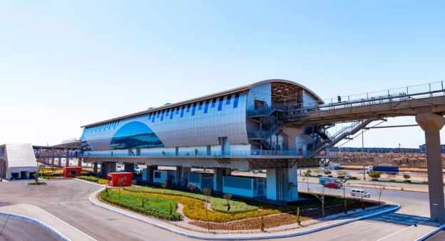
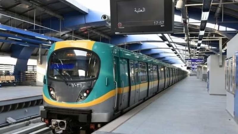
The featured image shows one of the twenty-two station s on the route. [1][2]

Solomon Ekanem reports that Egypt has officially launched the 56.5-kilometre East Nile monorail – Africa’s longest – marking a major milestone in the country’s push to modernise urban transport and expand green mobility infrastructure.

The East Nile monorail, connects Cairo’s Nasr City to the New Administrative Capital. It is a driverless monorail which calls at 22 stations. It is intended to ease congestion and improve urban connectivity. It is Africa’s longest single monorail line and part of the continent’s largest monorail network when combined with a second line. The eco-friendly, automated system reduces energy consumption by 30% compared to conventional electric rail.

President Abdel Fattah al-Sisi inaugurated the driverless system on Friday 20th March 2026 and then travelled alongside families of fallen Egyptian soldiers on the monorail from the Al-Fattah Al-Alim Mosque station to the Financial District, passing through key residential zones.

Transport Minister Kamel al-Wazir described the project as a “civilizational leap,” noting that it aligns with government efforts to deploy eco-friendly transport systems that reduce fuel consumption and road congestion. The rubber-tyred, fully automated system operates on elevated tracks, minimizing disruption to existing road networks.

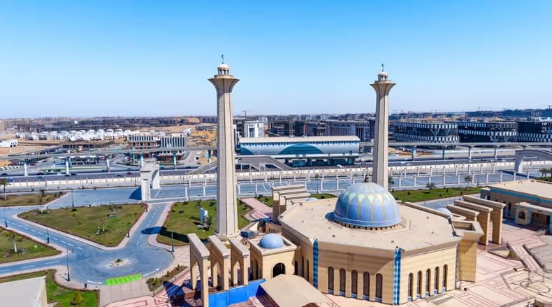
El-Mosheer Tantawy Mosque sits close to the monorail, one station of the monorail can be seen beyond the mosque in this image. [1][2]

The East Nile monorail … is part of a broader network — the “Cairo Monorail” system — which includes a second line linking 6th of October City. When both lines are combined, the network stretches to about 96 km, making it Africa’s largest monorail system overall. In simple terms, the East Nile route holds the record for a single line, while the full Cairo network holds the continental record for total system size. Built by a consortium including Alstom, Orascom Construction, and Arab Contractors, the project features 40 trains capable of reaching speeds of up to 80 km/h, with intervals as short as 90 seconds. The system integrates with Cairo’s Metro Line 3 and the Light Rail Transit (LRT), with future links planned to Metro Lines 4 and 6.” [1]

Equipped with platform screen doors, LED displays, and accessibility features, the monorail is expected to play a central role in reshaping Cairo’s urban mobility and supporting the shift toward sustainable transport.” [1]

Ekanem’s report is echoed by a report in Egypt Today. [2]

Cairo Monorail was first conceptualized in the late 2010s to combat the rise of traffic in the Greater Cairo area, and to provide a rapid transportation option for suburban residents. The Monorail was also thought of as a rail link between Cairo and Egypt’s New Administrative Capital. “Funding for the project was secured and obtained through a mix of local and international investments. This included a substantial loan facilitation agreement between the National Authority for Tunnels and JP Morgan Europe Limited, as well as contributions from other financial institutions such as the European Bank for Reconstruction and Development (EBRD) and the European Investment Bank (EIB). The total funding amounted to approximately 4.5 billion Euros.” [4]

It was reported in August 2019, that French rolling stock manufacturer, Alstom, would lead a consortium which includes The Arab Contractors: Osman Ahmed Osman & Co and Orascom. The consortium would sign a 2.7 billion Euros contract to design, construct, operate, and maintain the two monorail lines. Upon completion of construction, the consortium will operate and maintain the network for 30 years. [4]

Hill International highlighted their involvement with the project in a post on LinkedIn four years ago. They were providing project management, design review, and implementation supervision services for the New Administrative Capital City and 6th of October City (East and West) Lines. [3]

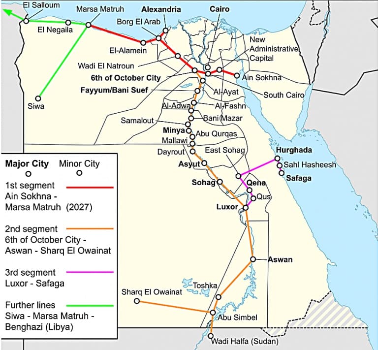
B. High-Speed Network: This network is a planned 2,000 km network which Siemens Mobility is constructing. It will feature Velaro and Desiro HC trains traveling up to 250 km/h, covering 60 cities. The network will include three lines:

Line 1 (Green Line): Connects Ain Sokhna to Marsa Matrouh via Cairo.
Line 2: Connects Cairo to Abu Simbel.
Line 3: Connects Qena with Hurghada and Safaga.

Egypt’s planned High Speed Network © Abs616 and licensed for reuse under a Creative Commons licence (CC BY-SA 4.0). [6]

The project includes 15-year maintenance by Deutsche Bahn and involves upgrading 7 key rail stations via Thales, focusing on increasing freight capacity to 13 million tonnes annually.

Egypt has a bold vision to build one of the world’s largest high-speed rail networks. Siemens Mobility is committed to delivering fully integrated, sustainable transportation solutions tailored to Egypt’s unique environment. The High Speed rail project “will span over 2,000 kilometres. It will ultimately connect all the major cities and reach nearly 90% of the population. Once complete, Egypt will have the sixth-largest high-speed network in the world. It will significantly reducing travel times, cutting CO₂ emissions, and boosting sustainable local economic development.” [6]

Siemens Mobility’s 15-year maintenance commitment covers the entire fleet for Egypt’s new high-speed rail network ensuring long-term operational excellence. This network will cut travel times by up to 50%. It will offer millions of passengers safer, more reliable, and more comfortable journeys. [6]

Currently completed to over 65%, the first phase of Egypt’s Ain Sokhna to Marsa Matrouh high-speed train is set to begin operations in 2027. The 670-kilometre line will include 21 stations! [6]

C. Modernization: In addition to new lines, Egypt is modernizing its existing 10,000 km network with new trainsets from Talgo, locomotives from Progress Rail, and new traffic control systems to improve efficiency.

The Railway Gazette International reported in September 2025 that Hitachi Rail has deployed a centralised traffic control system to manage 19 stations on the 200 km Cairo to Alexandria line. [5]

The initial contract for the programme was signed in 2013, and has since been extended to encompass more than €100m of investment. The mechanical and electrical signalling has been replaced with a modern electronic system, including digital interlockings, new signals and motorised drives. A fixed and mobile telecommunications system has been installed, with drivers able to communicate with the operations manager in case of emergency or failure. Level crossings have been modernised, and technical buildings constructed.” [5]

The modernisation project will enable Egyptian National Railways to increase the maximum speed of trains by 40 km/h to 160 km/h, reducing the journey time between the two cities to 2½ h. The route’s throughput is also set to grow by 40% to a maximum of 286 trains/day. A progressive increase in the number of freight trains is planned, allowing the line to carry 15 per day in 2030 and 50 per day by 2060.” [5]

In November 2025, TravelMole.com reported that Egypt had showcased a new high-speed train. [6]

On 10th November 2025, German technology giant Siemens unveiled the Velaro high-speed train in Cairo, which had been specifically adapted to withstand the harsh climate conditions of Egypt. The official presentation occurred during TransMEA 2025, the region’s leading exhibition for transportation and logistics in the Middle East and Africa. The Siemens Mobility Velaro high-speed train is specially adapted for Egypt’s desert conditions. It can reach a speed of up to 250 km/h and offers seating for 489 passengers. The company will deliver 41 Velaro trains to the Egyptian rail network.” [6]

On the same day, “the Desiro HC regional train successfully completed its first train run on newly constructed tracks near the 6th of October Depot, West of Cairo. The Desiro High-Capacity regional train is a key element of Egypt’s new high-speed rail network, with 94 trains set to provide efficient and comfortable regional transport. Specially adapted for Egypt’s climate, each train offers up to 849 passenger spaces and advanced features such as air conditioning,” [6]

With a top speed of 160 km/h, the Desiro HC fleet will play a vital role in connecting cities along the Green Line. This line consists of a 660 km network connecting Cairo to Ain Sokhna, Alexandria, and Marsa Matrouh. The Green Line is already referred to as the ‘Suez Canal on Rails’.” [6]

Freight – in June 2026, reports the Railway Gazette, Egyptian National Railways signed four freight corridor upgrade contracts.

An Alstom-led consortium has signed four contracts worth €690m with Egyptian National Railways for the modernisation of two strategic freight rail corridors. Together with Rowad Modern Engineering and Concrete Plus, Alstom will upgrade the 6th October City – Alexandria and Belbes – 10th Ramadan City lines. The upgrades aim to reduce transit times by up to 80 minutes and improve connections between Egypt’s logistics hubs and seaports. [8]

In addition to these ‘Heavy Rail’ commitments, Egypt is also seeking to modernise its tram networks and Cairo’s Metro.

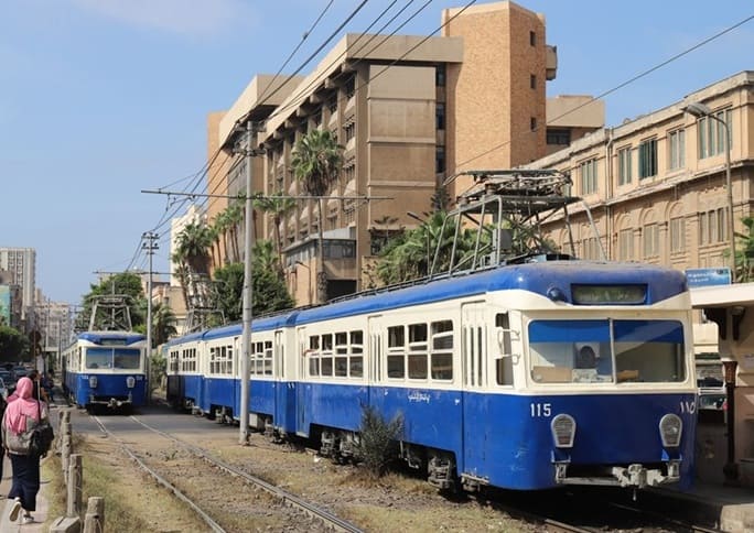
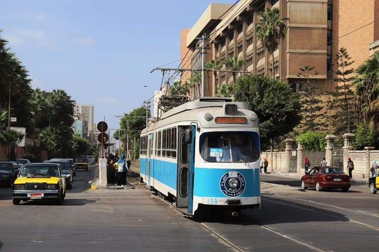
Alexandria’s Trams:

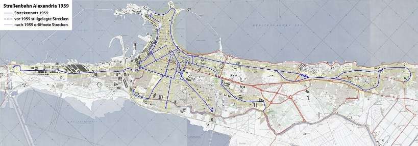
Alexandria’s Tram network in 1959 © Maximilian Dörrbecker (Chumwa) and licensed for reuse under a Creative Commons licence (CC BY-SA 3.0). [13]
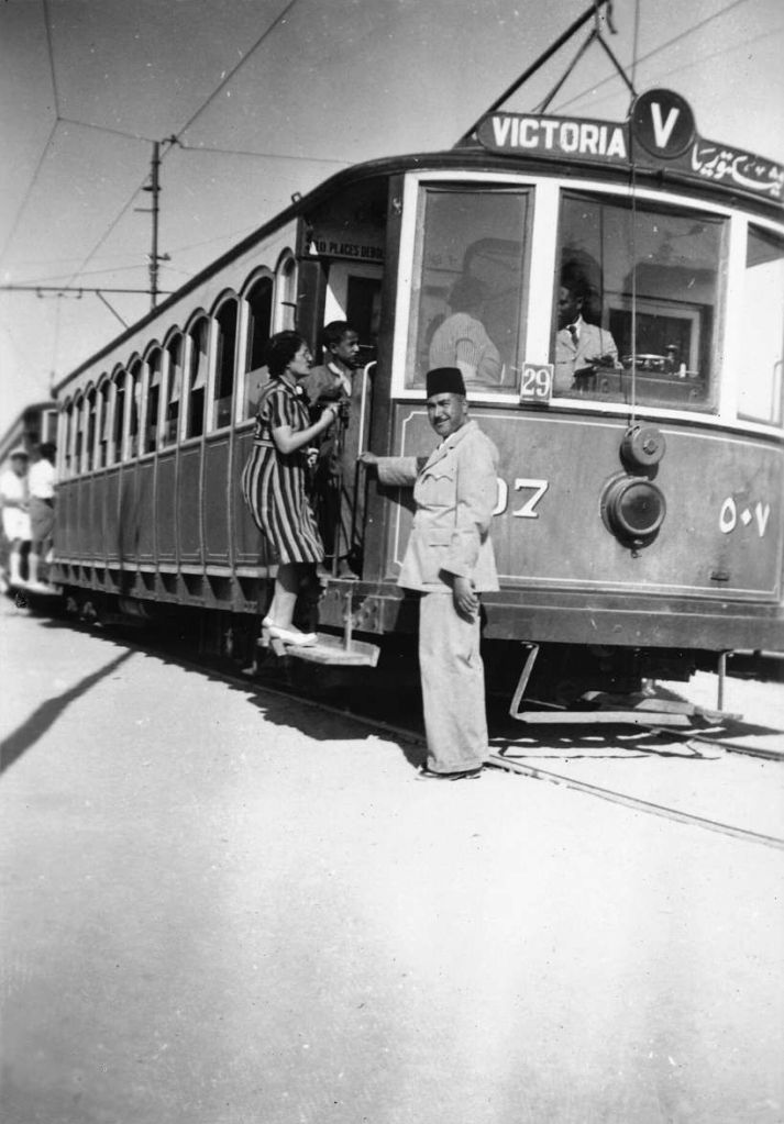
Alexandria Tram in the 1940s © foundin_a_attic and licensed for reuse under a Creative Commons licence (CC BY 2.0). [13]
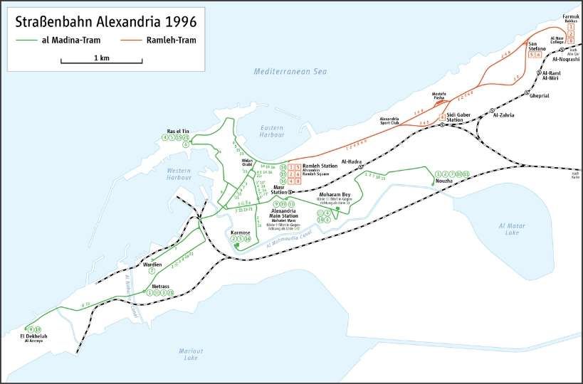
Alexandria tramway routes in 1996, © Maximilian Dörrbecker (Chumwa) and licensed for reuse under a Creative Commons licence (CC BY-SA 3.0). [13]

Egypt’s major tram modernization focuses on the historic Al Raml tramway in Alexandria, which suspended operations on 1st April 2026. Managed by the National Authority for Tunnels (NAT), the €236 million overhaul converts the 14.1 km heritage line into a fast, digitally controlled light rail system slated to finish by late 2028. [10]

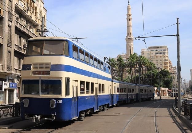
Until its closure, Alexandria — alongside Hong Kong and Blackpool — was one of the last tram systems worldwide to operate double-decker trams in regular service. This chapter has now come to an end, © UTM. [11]
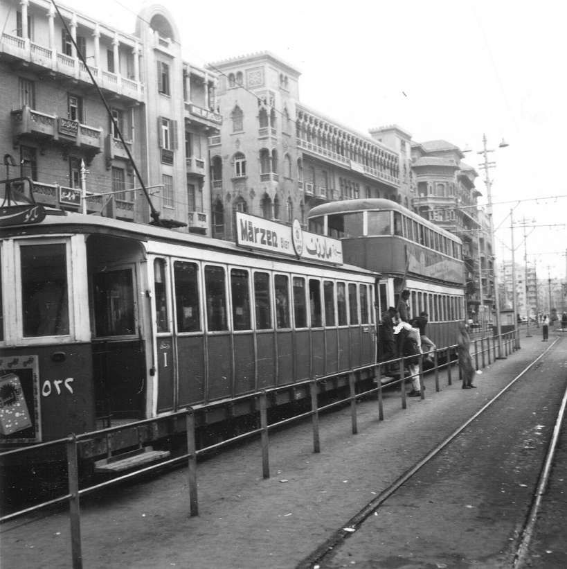
Alexandria’s Trams in 1969: a double-decker tram is part of the consist shown here, © FOTO:FORTEPAN/Gyöngyi and licensed for reuse under a Creative Commons licence (CC BY-SA 3.0). [13]
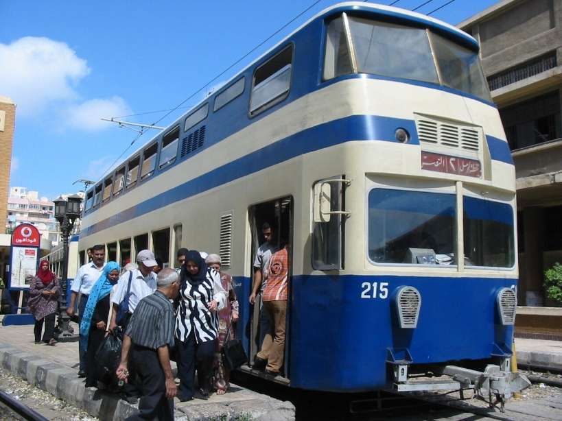
One of the small number of double-deck cars (from Kinki Sharyo) in Alexandria’s fleet. All six are non-motorised control trailers, photo taken in 2008, © Wrightbus and licensed for reuse under a Creative Commons (CC BY 3.0). [13]

Hitachi Rail has secured a contract to deliver the rail systems and digital technologies that will modernise and upgrade the Alexandria Raml Tram – the first modern tramway project of its kind in Egypt. The contract was awarded by the Hassan Allam Construction and Arab Contractors joint venture and will significantly improve speed, capacity and reliability on one of the world’s oldest continuously operating tram systems. [10]

The Alexandria El Raml Tram is the oldest tramline in the Middle East and Africa, dating back to 1863. Despite its age and limited modernisation since the 1960s, it remains one of the few tramways globally to operate double-deck vehicles in regular service. The new contract marks a major step in the line’s transformation. [10]

Under the agreement, Hitachi Rail will supply advanced signalling and communications systems, a modern Operational Control Centre, SCADA, CCTV and access control, passenger information systems, and on-board equipment. Together, these systems will help deliver a faster, safer and more efficient public transport service aligned with Egypt’s Vision 2030 goals for sustainable mobility. [10]

The modernisation programme includes the reconstruction of 24 stations and 13.2 km of track. Once completed, the new system will:

  • reduce travel time from 60 to 35 minutes
  • double operational speed from 11 km/h to 21 km/h
  • cut headways from 9 minutes to 3 minutes
  • increase capacity from 4,700 to 13,800 passengers per hour per direction

This capacity boost will ease congestion, support modal shift and reduce CO₂ emissions while improving daily mobility across Alexandria. [10]

The El Raml Tram upgrade represents a significant milestone for Hitachi Rail’s growing presence in Egypt’s rail and metro sector. The company is already involved in key national programmes, including the Greater Cairo metro network, the LRT and monorail systems, and AFC modernisation initiatives. [10]

Hitachi Rail continues to expand its local footprint through engineering, financial, legal and operational teams established in Egypt. The company has increased localisation of IVVQ activities for CBTC systems and developed automated fare collection (AFC) projects that promote high-tech employment and diversity. These align with Egypt’s industrial and economic development priorities.[10]

Digital passenger information and multimodal payment systems are becoming central to Hitachi Rail’s offering in the region. For example, the upcoming Abu Qir Metro in Alexandria will integrate TRANSCITY™ AFC, enabling payments via QR codes, contactless cards, EMV bank cards and NFC mobile devices. [10]

The contract will see us modernize and upgrade the oldest electric tram system in Africa, transforming it into a reliable, efficient, and digitally enhanced transportation system. The project underlines the capabilities of Hitachi Rail technologies in the rehabilitation and modernization of tramway systems,” Carlo Piacenza, SRS MEA Regional Director, Hitachi Rail, said. [10]

Urban Transport Magazine reported in April 2026 that, “with the closure of the long-established Ramleh tramway, Alexandria is currently undergoing one of the most radical system transformations in urban rail transport in North Africa. The project exemplifies a global trend: replacing historically evolved tramway systems with higher-capacity light rail infrastructure — and the associated trade-offs.” [11]

Alexandria’s tramway network is among the oldest in the world: opened as early as 1863 and electrified from 1902, the Ramleh line in particular developed into one of the city’s most important east–west corridors. With around 80,000 passengers per day and a route length of approximately 32 km, it was a central component of the urban transport system. [11]

At the same time, the system suffered from decades of underinvestment. Low average speeds of around 11 km/h, ageing infrastructure and limited reliability significantly constrained its performance. Against the backdrop of increasing congestion and ongoing urbanisation, comprehensive modernisation gradually moved to the forefront of transport policy. [11]

Until its closure, operations on the Ramleh tramway were characterised by a remarkably heterogeneous and ageing fleet. The core of the services was provided by modernised vehicles from Kinki Sharyo, complemented by locally Tatra Yug units. In addition, a number of second-hand high-floor trams originally built by Düwag in the 1960s and acquired from Copenhagen remained in service. This mix of vehicles from different generations and technical standards reflected both the long operational history of the line and the prolonged lack of fleet renewal, resulting in increasing maintenance complexity and declining reliability in the final years of operation. [11]

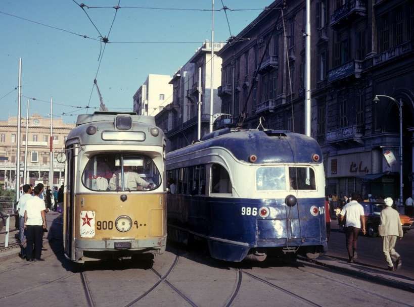
Alexandria Trams in 1974: An ex-Copenhagen tram on the left passing an ex-Toronto PCC tram. Car 900, on the left, is a Düwag GT6, ex-Københavns Sporveje number 900, © Kurt Rasmussen (Public Domain). [13]
Two Kinki Sharyo tramsets, largely identical to those formerly used on the now-closed Heliopolis tramway in Cairo, operating on a segregated right-of-way, © UTM. [11]
The Ramleh tram already operated largely on a segregated right-of-way, which is now set to be partially replaced by viaducts — a proposal that has raised eyebrows among transport experts, © UTM. [11]

The transition to the new system began in early 2026 with a phased shutdown. Following initial restrictions in February, operations were completely suspended on 1 April 2026. Since then, the existing infrastructure — including tracks, power supply and stops — has been undergoing comprehensive dismantling. The complete interruption of services represents a deliberate break with historical continuity, in contrast to many European modernisation projects, where upgrades are often carried out while operations continue. [11]

In place of the conventional tramway, a modern light rail system with significantly altered parameters is being developed. Approximately 13 km of the route will be fundamentally upgraded and partially realigned. [11]

Key elements include:

  • Increase in average speed from 11 to around 21 km/h
  • Reduced stop density (approximately 500 m spacing)
  • Modern signalling and control systems
  • Introduction of 30 high-capacity vehicles (Hyundai Rotem)

The project is thus clearly aimed at increasing capacity and efficiency, and conceptually aligns more closely with light rail or metro systems than with traditional tramways. [11]

Since early 2026, operations on the Ramleh tramway have been gradually wound down: following initial test closures in February, partial suspension began on 11th February, before services were fully discontinued on 1st April 2026. [11]

In the weeks leading up to this, the network saw something of a series of “farewell runs”, before the final trams ceased operation in early April. In parallel with the closure, comprehensive dismantling of the infrastructure began, including tracks, overhead lines and, in some cases, adjacent urban spaces. [11]

The transformation has met with considerable criticism in Alexandria and is the subject of intense public debate. While the government presents the project as a necessary step towards modernisation to increase capacity and speed, many residents view it as a profound intervention in the city’s historic urban fabric. [11]

A central point of criticism is the planned elevation of the route. More than half of the future line, which will be around 13 km long, is to run on viaducts. Critics fear that the existing tree-lined right-of-way will be replaced by “concrete stilts”, leading to a loss of the city’s characteristic urban landscape. [11]

Furthermore, it is argued that the shift towards a faster system, more strongly segregated from general traffic, may bring operational advantages but could come at the expense of urban integration. Urban planners warn that the new infrastructure is geared more towards throughput and speed, and less towards public realm quality and local accessibility. [11]

Transport impacts have also been viewed critically: even during the construction phase, the suspension of services has exacerbated traffic problems, as replacement services have only been able to compensate for demand to a limited extent. Some observers see this as an indication that, in the short term, the transformation could even lead to increased reliance on private motorised transport. [11]

Finally, the loss of cultural heritage plays a central role in the public debate. For many residents, the tramway is not merely a mode of transport, but an integral part of the city’s identity. Critics therefore speak of a tension between modernisation and “cultural dislocation”. [11]

Reopening is scheduled for the end of 2027. Whether the new system will meet expectations in terms of performance and attractiveness will depend largely on how successfully operational efficiency can be balanced with urban integration. [11]

Cairo’s Metro:

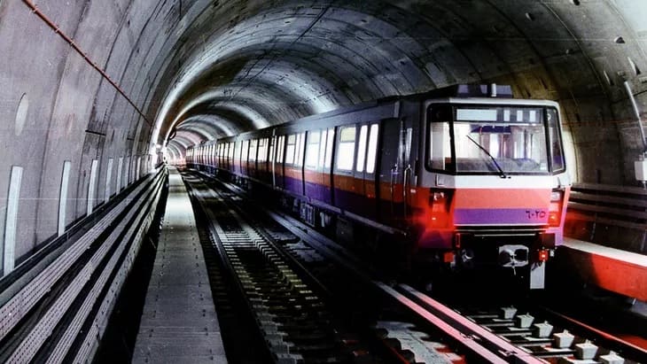
As of 2024, Cairo’s Metro has 84 stations of which 5 are transfer stations, with a total length of 106.8 kilometres (66.4 mi). The system consists of three operational lines numbered 1 to 3. It is part of an integrated transport network.

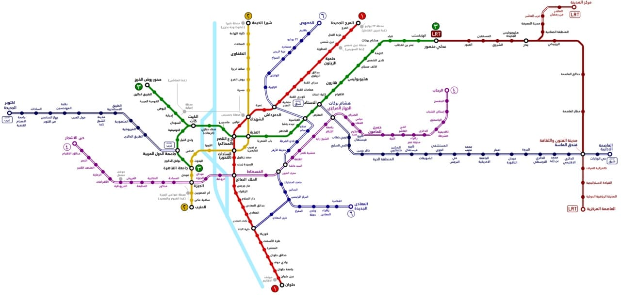
Map of Cairo Metro, LRT, and Monorail lines. Thick lines indicate lines in operation and hollow lines indicate lines under construction or in planning, (c) BasilLeaf and licensed for reuse under a Creative Commons licence, (CC BY-SA 4.0). [12]

As the biggest and most densely populated megacity in Africa and the Middle East, Greater Cairo had a strong case for a metro. In 1987 that population stood at 10 million residents, not counting the two million or so commuters who came into Cairo every day to work. The capacity of Cairo’s public transport infrastructure was around 20,000 passengers/hour, which increased to 60,000 after the construction of the metro. [13]

In the 2020s, “Cairo has more than 20 million people in its metropolitan area, and the chaos on the surface can be disorientating for anyone arriving for the first time: gridlock that stretches for kilometres, constant horns, intersections that follow no obvious logic. But beneath all that noise there is a system that organises the movement of millions of people every day. The Cairo Metro — officially the Cairo Metro or مترو القاهرة — is the backbone of public transport in this megalopolis, the first metro ever built in Africa, and the first in the entire Arab world.” [14]

In 2023, Cairo Metro carried 1,460 million passengers, which works out to around 5 million journeys a day — a figure that puts it among the most heavily used metro systems in Africa and the Arab world. For most of its passengers, the metro is not an alternative to other options; it is the only realistic way to cross the city in a reasonable amount of time. [14]

What makes this system distinctive is not only its history but its composition. Line 1 was born from the conversion of existing suburban railway corridors, combining surface sections with a few kilometres of tunnel through the historic heart of the city. Line 2 was a first for the continent: it crosses the Nile through a tunnel, the first railway tunnel under that river anywhere in Africa, a genuinely complex engineering achievement. Line 3, the most modern, was under construction in phases for over a decade and represents the biggest technological step forward in the system, with better stations and newer trains. It was completed in 2024. [14]

For travellers arriving in Cairo, the Metro is an indispensable tool for connecting the historic centre with modern districts, Ramses train station and the main residential areas. At present, the Cairo Metro does not reach the Pyramids of Giza. [14]

The density of Greater Cairo makes any underground construction extraordinarily complicated. Several sections were built directly beneath narrow alleyways, centuries-old markets, multi-storey buildings and layers of pre-existing infrastructure. Expropriations in historic districts such as Khan El Khalili, or in densely populated residential neighbourhoods, required lengthy and costly negotiations. In some stretches engineers opted for cut-and-cover construction with minimal disruption; in the historic centre, tunnel-boring machines were the only viable approach. [14]

The system at present operates trains from different generations depending on the line.

Line 1 still runs sets from the original era — nine-car trains with capacity for over 2,000 passengers, revised and upgraded over the decades. Some were refurbished by Hyundai in the early 2010s. [19] Others are being refurbished by Mitsubishi at present. [14][17]

Line 2 has more modern stock acquired in the 1990s and early 2000s. [18] The National Authority for Tunnels has awarded CAF three contracts totalling more than €450m for the modernisation and maintenance of trainsets on Cairo Metro Line 2 and the maintenance of trainsets on Line 1. [14][20]

Line 3 works with the newest trains, some of them from contracts signed with Alstom in 2020/2021 for the supply of new Metropolis units. [14][21]

Line 4 connecting to Giza is under construction. The line is ultimaely intended to be 42 kilometres in length. [15] A first phase of 18-19 kilometres and between 15 and 17 stations planned, it will connect the El-Malek El-Saleh area with north-west Giza, bringing the Metro significantly closer to the Pyramids zone for the first time. The project includes lifts for passengers with disabilities and modern access management systems built into the original design. Opening is estimated at being in the first half of 2028. [14][16]

Phase 1 runs largely underground, serving 17 stations, from the boundary between Cairo and 6th of October City to Grand Egyptian Museum, Remaya Square, Haram Street, Giza Station, El-Malek El-Saleh and Fustat. Gewaily says that Line 4 will carry approximately 2 million passengers a day when completed. [16]

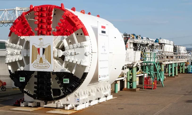
Four high-performance Herrenknecht tunnel boring machines were deployed for tunnel construction. They commenced excavation at the end of 2023 and the beginning of 2024, ensuring efficient and precise tunnelling under challenging geological conditions. [15]

Mitsubishi is supplying 23 trains for the line, the first of was scheduled for delivery In May 2026, construction of depot facilities and the installation of electromechanical systems. Civil works are being undertaken by domestic firms Arab Contractors, Orascom, Concord, Petrojet, and Hassan Allam Construction. [16]

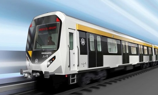
A Mitsubishi Kinki Sharyo train manufactured for the Cairo Metro Line 4. Phase 1 of Line 4 is scheduled to open in the first half of 2028.The contract includes supplying 184 metro cars to be delivered between 2026 and 2028.The trainsets are being shipped from Kobe, Japan, to Alexandria, Egypt. [16]

The government is currently considering three further phases for Line 4:

Phase 2: Fustat – New Cairo
Phase 3: Hadaeq El Ashgar – Hosary Square, and
Phase 4: New Cairo – the Capital Airport. [16]

The extended line will provide interchange with the planned metro Line 6, the Light Rail Transit (LRT) network and both the East of Nile and West of Nile monorail lines. [16]

Also planned is an extension to Line 3 to reach Cairo International Airport. It will add roughly 7 kilometres and 5 new stations from the Heliopolis area to the airport terminal. As of mid-2026 there is no confirmed opening date: the project has been announced on several occasions, but financing and timescales are not yet settled. [16]

Line 5 and Line 6 and the long-term network. The Greater Cairo master plan envisages a network of up to six metro lines plus complementary systems including the monorail, long-distance high-speed rail and extensions to the new satellite cities. Line 6 is planned to connect Shubra with Maadi, providing a new north-south axis that takes pressure off Line 1. All of these projects extend beyond 2030. [16]

References

  1. Solomon Ekanem; Africa’s longest monorail line begins operations as Egypt opens 56.5km Cairo route; in Business Insider Africa, 21st March 2026; via https://africa.businessinsider.com/local/lifestyle/africas-longest-monorail-line-begins-operations-as-egypt-opens-565km-cairo-route/n64xvkw, accessed on 22nd March 2026.
  2. https://www.egypttoday.com/Article/1/145804/East-Nile-monorail-begins-operations-linking-Cairo-to-New-Capital, accessed on 22nd March 2026.
  3. https://www.linkedin.com/feed/update/urn:li:activity:6881253143993204736, accessed on 22nd March 2026.
  4. https://en.wikipedia.org/wiki/Cairo_Monorail, accessed on 22nd March 2026.
  5. https://www.railwaygazette.com/infrastructure/cairo-to-alexandria-railway-modernised-to-increase-speed-and-capacity/69588.article, accessed on 22nd March 2026.
  6. https://www.travelmole.com/news/egypt-showcases-its-new-high-speed-train, accessed on 22nd March 2026.
  7. https://en.wikipedia.org/wiki/Egyptian_National_Railways, accessed on 22nd March 2026.
  8. https://www.railwaygazette.com/category/egypt, accessed on 19th July 2026.
  9. https://rogerfarnworth.com/2026/04/01/egyptian-railway-history-a-short-version/
  10. https://www.railwaypro.com/wp/hitachi-rail-to-modernise-egypts-historic-alexandria-tram, accessed on 28th July 2026.
  11. https://www.urban-transport-magazine.com/en/alexandria-system-transition-of-the-ramleh-tram-between-modernisation-and-the-loss-of-urban-identity, accessed on 28th July 2026.
  12. https://upload.wikimedia.org/wikipedia/commons/6/6e/Cairo_Rapid_Transit_map.png, accessed on 28th July 2026.
  13. https://en.wikipedia.org/wiki/Cairo_Metro, accessed on 28th July 2026.
  14. https://mapa-metro.com/en/egypt/cairo/cairo-metro-map.htm, accessed on 29th July 2026.
  15. https://www.herrenknecht.com/en/references/referencesdetail/cairo-metro-line-4, accessed on 29th July 2026.
  16. https://www.railjournal.com/passenger/metros/cairo-metro-line-4-opening-announced, accessed on 29th July 2026.
  17. https://www.railwaypro.com/wp/caf-to-refurbish-cairo-metro-trains, accessed on 29th July 2026.
  18. https://www.herrenknecht.com/en/references/referencesdetail/cairo-metro-line-2, accessed on 29th July 2026.
  19. https://rollingstockworld.com/lrv/hyundai-rotem-finalized-a-contract-for-the-supply-of-40-metro-trains-for-cairo, accessed on 29th July 2026.
  20. https://www.railwaygazette.com/urban/2025/09/25/cairo-metro-train-modernisation-and-maintenance-contracts-awarded, accessed on 29th July 2026.
  21. https://www.railway-technology.com/news/cairo-metro-egypt-phase-4b-extension-of-line-3, accessed on 29th July 2026.

Railways of Tanzania – Part 16 – Locomotives in use in Tanganyika/Tanzania during the tenure of the EAR&H (EAR)

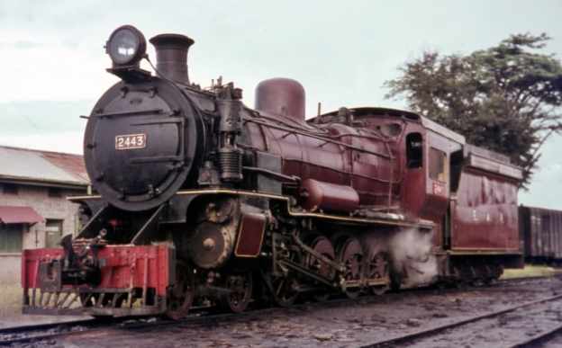
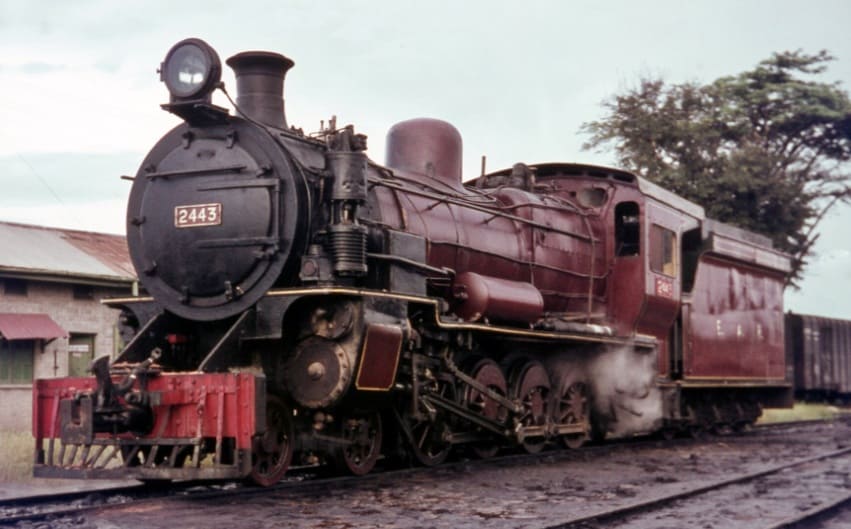
The featured image for this article shows an East African Railways (EAR) Class 24 4-8-0 locomotive No. 2443. The engine was manufactured by Vulcan Foundry and Nasmyth, Wilson and Company between 1923 and 1930. The photo shows the locomotive at Tabora depot in Tanzania during 1968, © Basil Roberts and licensed for reuse under a Creative Commons licence (CC BY-SA 4.0). [26]

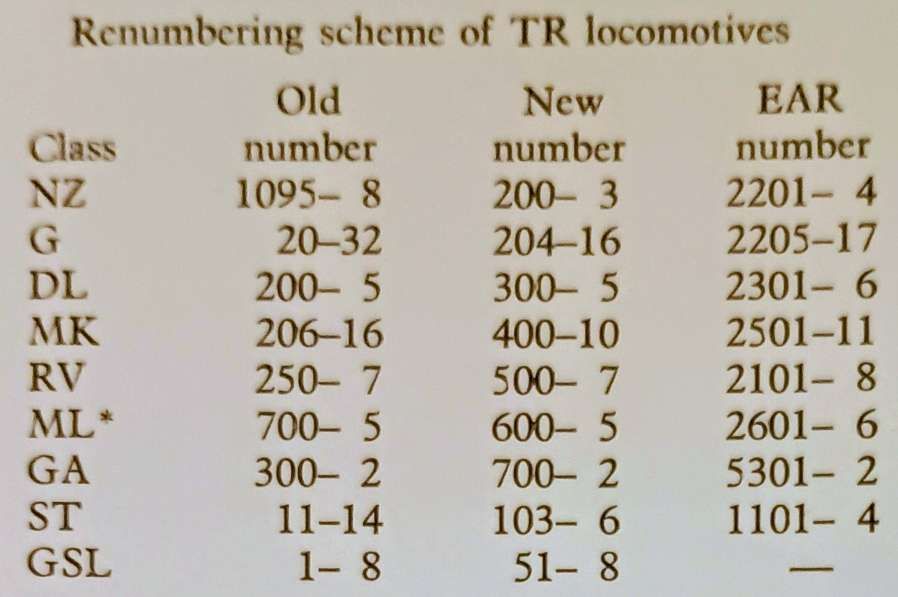
East African Railways and Harbours was formed in 1949 through the amalgamation of Kenya and Uganda Railways and Harbours and Tanganyika Railways and Ports. Some locomotives which were ordered by Tanganyika Railways were delivered after the amalgamation. One of the EAR’s first actions was to develop a new numbering system which was applicable across East Africa. “Under the new system, tank engines were allotted Class number 10-19, tender engines 20-49 and Garratts 50 upwards. Diesels, then still only on order, were to become 80 upwards. Similar locomotives in service on both systems were taken together in one class, as was the case with the ED1 (KUR) and St (TR) classes, both becoming Class 11, Nos. 1105-1131 and 1101-1104 respectively.” [1: p70]

After initial experiments with the Giesl ejector from 1957 a large-scale programme was initiated in the early 1960s to fit all post-war main-line engines with this equipment.

Early EAR locomotives:

EAR 10 Class (formerly KUR EE Class) 2-6-4T Locomotives

These locomotives were retained on the lines of the old KUR.

EAR 11 Class (formerly TR ST Class and KUR ED1 Class) 2-6-2T Locomotives

In 1930, the TR received four 2-6-2T shunters (the same type as the KUR ED1 Class). These were designated as the ST Class. They initially had running numbers TR Nos. 11-14, later TR Nos. 103-106. The locomotives were supplied by Vulcan. Under EAR control the locomotives were numbered EAR Nos. 1101-1104. [1: p60]

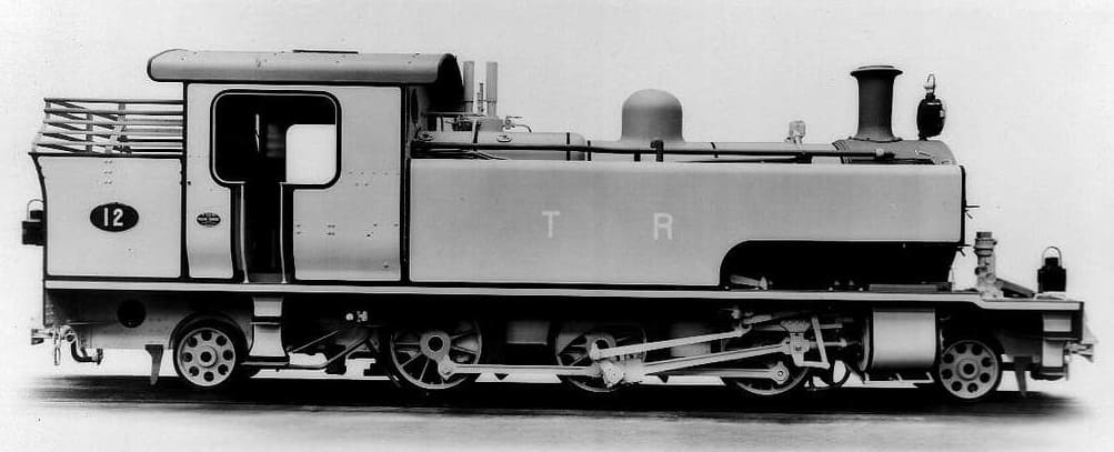
TR No. 12 was later designated TR No. 104 and later still, EAR No. 1101. This is an ex-Works photograph taken at the Vulcan Works in the UK, (c) Public Domain. [31]

Many of the EAR Class 11 locomotives were adapted to burn oil fuel rather than wood or coal and were still in use in 1972. [1: p60]

EAR 12 Class (formerly TR SS Class) 2-6-2T Locomotives

These two locomotives were ordered by Tanganyika Railways but not delivered until 1950. They were the first superheated piston-valve shunters in East Africa and were a generally updated and modernised version of the EAR 11 Class. [1: p70]

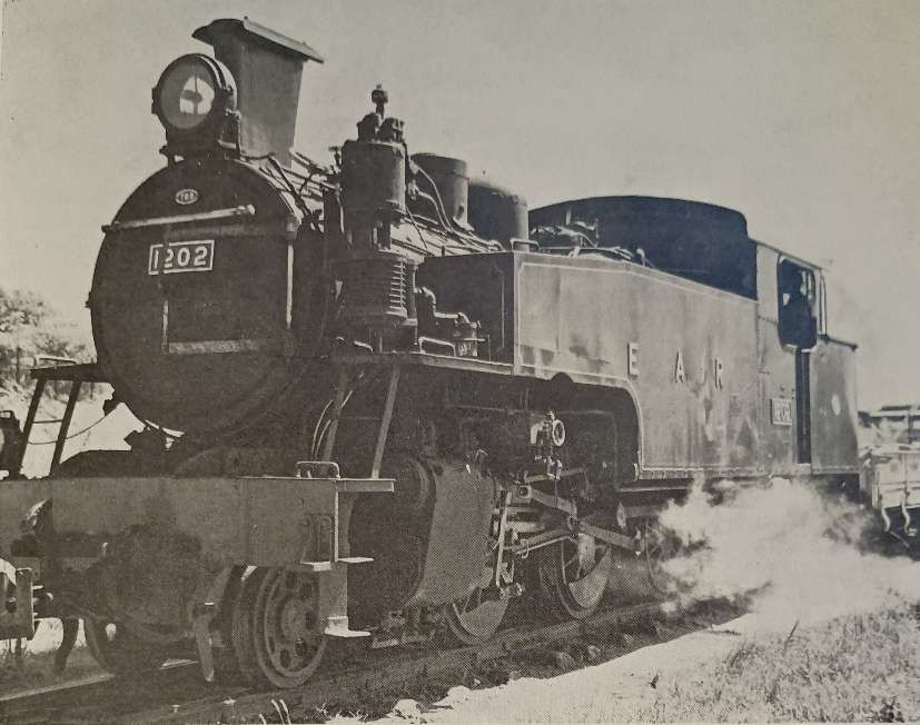
A TR SS Class 2-6-2T locomotive delivered in 1950 became one of the EAR Class 12 locomotives. – No. 1202. It is seen here in its altered form with Giesl ejector shunting at Tabora, (c) Public Domain. [1: p69]

The two engines in this Class were “put to work in the harbour area in Dar es Salaam, from where they were transferred to Morogoro in the mid 1950s and eventually to Tabora in the early 1960s, where they are still in service. The 12 class are the only shunters with Giesl ejectors.” [1: p70]

EAR 21 Class (formerly TR RV Class) 4-8-2 Locomotives

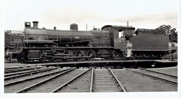
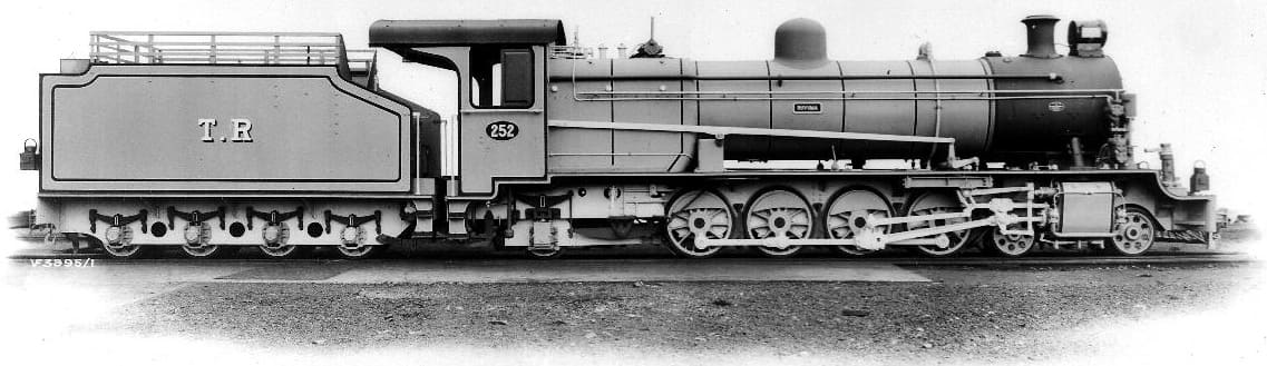
This is a Tanganyika Railway (TR) oil-fuelled RV (River) class 4-8-2 locomotive, later classified as the East African Railways (EAR) 21 class. It was first numbered TR252, then No. TR502 and later EAR2103. The locomotive was built by the Vulcan Foundry in Lancashire, between 1928 and 1930, © Public Domain. [27][9: p303]

For more details of this class of steam locomotive please click here. [28]

EAR 22 Class (formerly TR G Class) 4-8-0 Locomotives

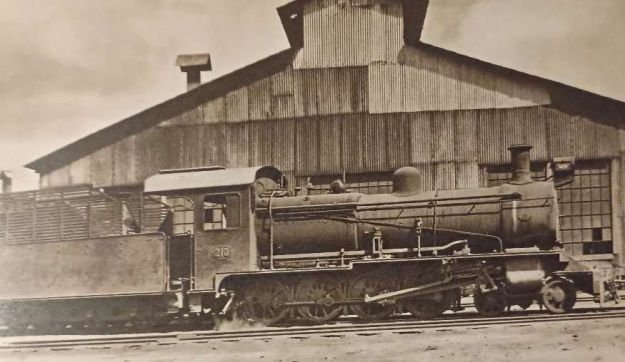
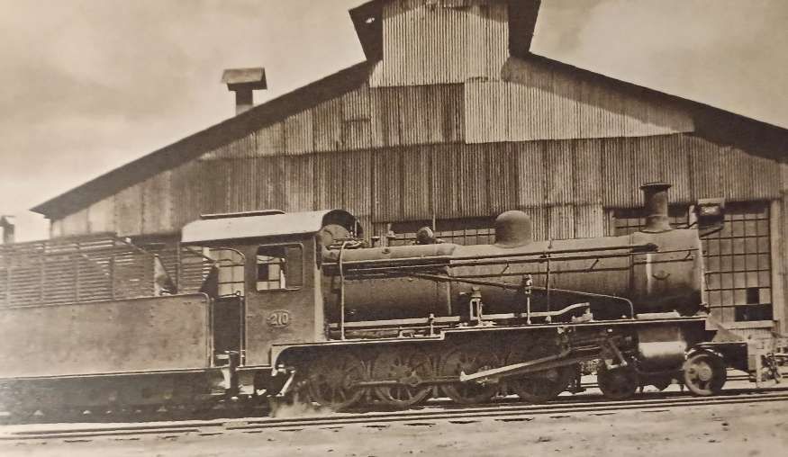
TR Class G 4-8-0 Locomotive No. 210 (later 22 Class) – these locomotives entered service in1928. Hill tells us that these locomotives were obtained to work two specific lengths of railway – the Tanga Line and the Mwanza branch off the Central Line, (c) Public Domain. [9: p299]

For more details of this class of steam locomotive please click here. [28]

EAR 22 Class (formerly TR NZ Class) 4-8-0 Locomotives

TR NZ Class No. 1098 leaving Dar-es-Salaam with the mail train in 1922. These locomotives were originally ordered by the Nizam’s Guaranteed State Railway for use on its network in the Dominion of Nizam, better known as the Hyderabad State, in India, but served their entire working lives in Tanganyika, East Africa. Class 22 locomotives were 4-8-0 locomotives built in 1915 by Nasmyth, Wilson and Company. These locomotives were numbered TR1095–TR1098, later TR200–TR203, and later still, EAR2201–EAR2204, © Public Domain. [9: facing p182][1: p55]

For more details of this class of steam locomotive please click here. [28]

EAR 24 Class (formerly UR GD Class) 4-8-0 Locomotives

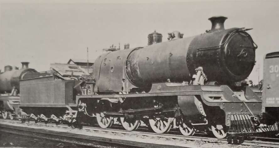
East African Railways (EAR) Class 24 4-8-0 locomotive No. 2443.The engine was manufactured by Vulcan Foundry and Nasmyth, Wilson and Company between 1923 and 1930. The photo shows the locomotive at Tabora depot in Tanzania during 1968, © Basil Roberts and licensed for reuse under a Creative Commons licence (CC BY-SA 4.0). [26]

The 24 Class were a larger and modified version of the experimental UR GC Class. [26]

EAR 25 Class (formerly TR MK Class) 2-8-2 Locomotives

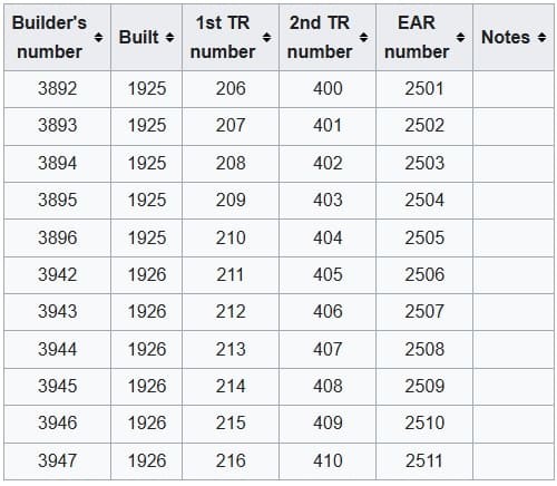
The TR Mk Class was renumbered by the EAR to become the EAR 25 class, the eleven members of the class were built by Vulcan Foundry, in Newton-le-Willows, Lancashire, for the Tanganyika Railway (TR). They entered service on the TR in 1925–1927. [10] All of them were transferred to the EAR.

The eleven members of the Class were:

The eleven members of the original TR MK Class. [2]
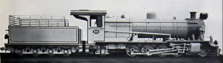
Vulcan Foundry ex-Works photo of TR MK 206. [2]

This class was a great success and the Class were still in use at the time Ramaer wrote his book, although he notes that they were now on borrowed time. “One problem with the design of the MK was the fact that the leading pony truck provided insufficient guidance on the sharp curves on the Dar-es-Salaam-Morogoro and the Malagarasi-Kigoma sections.” [1: p57]

EAR 26 Class (formerly TR ML Class) 2-8-2 Locomotives

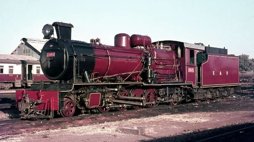
East African Railways (EAR) 26 class (ex-TR ML class) 2-8-2 steam locomotive no. 2603 at Tabora depot, Tanzania in 1968, © Basil Roberts and licensed for reuse under a Creative Commons licence (CC BY-SA 4.0). [7]

The six members of the ML class (an improved MK design) were built in 1947 by W. G. Bagnall, in Stafford, England, and delivered to the TR. They were later operated by the TR’s successor, the East African Railways (EAR), as its 26 class. In 1952, six further members of the 26 class were delivered to the EAR. They had been built by Vulcan Foundry, of Newton-le-Willows and Robert Stephenson & Hawthorns of North East England and were numbered EAR Nos 2607-2612. [7]

The new locomotives were intended for use on the flatter sections of the Central Line between Dodoma and Tabora. According to Ramaer, these locomotives were still in use in 1972, provided with larger tenders than the MK/25 Class. However, they were “relegated to secondary duties, but their service record proved less favourable than that of the older 25s. They [were] definitely heavier on maintenance and their active life would probably end shortly, together with the 25 class, when both were replaced by new diesel locomotives.” [1: p70]

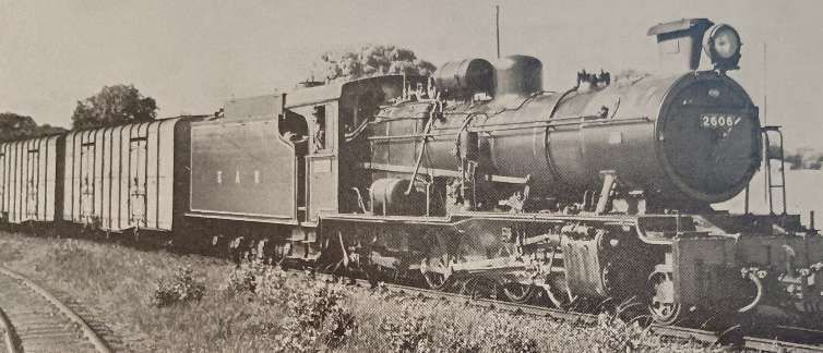
Former TR ML Class 2-8-2 No. 2608 with Giesel ejector and air brakes, one of the last designs of the TR, is seen heading a goods train out of Tabora, (c) Public Domain. [1: p71]

EAR 27 Class (formerly TR MR Class) 2-8-2 Locomotives

These locomotives were American-built. Many of these engines were built by various American manufacturers, including: Alco; Baldwin; and Davenport. These locomotives were known as ‘MacArthurs’. Those which ended up working on the Tanganyika Railways were manufactured in 1944. [1: p70] and arrived from Malaya in 1949. There were eight locomotives bought in this way which became the MR Class, running numbers 800-807. They were built by three different manufacturers and as a result had minor differences: Alco Nos. 800-802; Baldwin Nos. 803-805; Davenport Nos. 806-807. [1: p70]

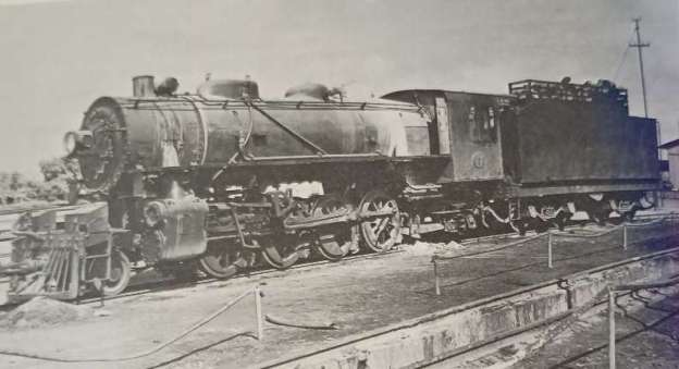
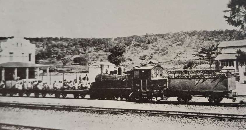
TR 2-8-2 No. 802 of the MacArthur austerity class at Tabora in the early 1950s before its conversion to oil fuel. [1: p68]

Ramaer tells us that, “At first there were problems, and modifications were needed to water tanks and reversing gear, which was undertaken at Nairobi works because of the limited capacity of the shops at Dar-es-Salaam. An additional difficulty was posed by the fact that the engines had not been designed to burn wood fuel. Grates were rather small and no rocking or dropping equipment was available. This circumstance gave rise to criticism because of the high ash residue of the wood fuel and only after the locomotives were converted to burn oil was the problem satisfactorily solved. After conversion the MacArthurs by then classified EAR 2701-8, did reasonably well.” [1; p69] The class was expanded in 1950 under EAR control when eight more were purchased from Malaya and one in parts from Nigeria. The last of these locomotives in service was based at Tabora and had been kept running by cannibalising other members of the class.

Early Beyer-Garratt locomotives:

EAR 4-8-2+2-8-4 Garratt 53 Class (formerly TR GA Class)

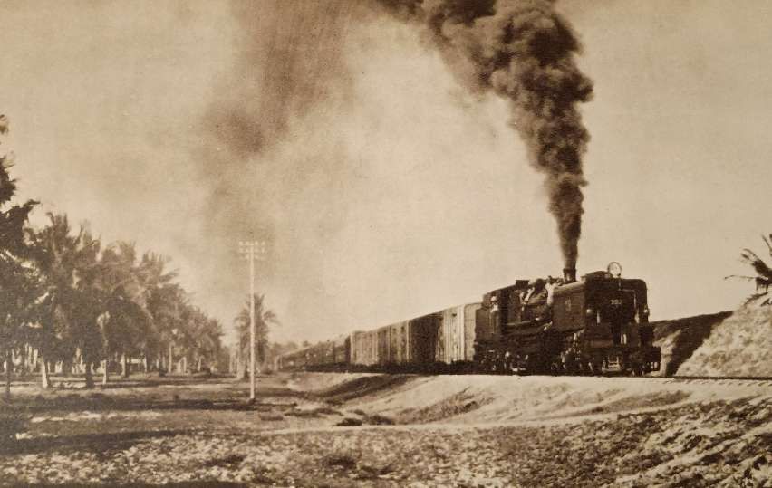
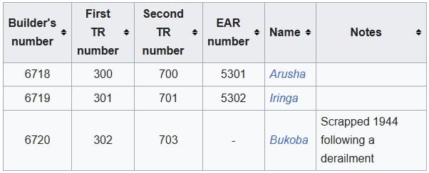
Built in 1931 by Beyer, Peacock & Co., these 4-8-2+2-8-4 locomotives were the first Garratts on the Tanganyika Railway. Two of this Class continued in service during EAR years. In EAR days the two 53 Class locomotives “went to the northern part of the now united system, to be replaced on the Central Line by the newer 60 Class, but later they returned to Tanzania for transfer work in Dar-es-Salaam, where they were scrapped in the late 1960s.” [1: p61]

East African Railways publicity photograph of no. 5302 Iringa, c. 1953, (c) Public Domain. [3]

EAR 4-8-2+2-8-4 Garratt 55 Class (formerly TR GB and KUR EC1 Class) Locomotives

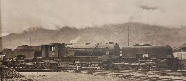
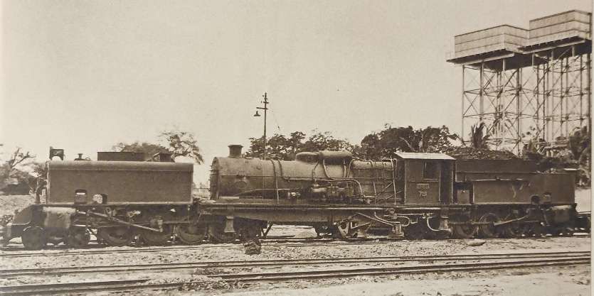
The Tanganyika Railway (TR) GB class were 4-8-2+2-8-4 Beyer-Garratt steam locomotives were originally ordered by the British War Department for service in Brazil, although not built. Later the design was used for locomotives for India and Burma. Four were acquired by the TR in 1946 from Burma. They later became members of the East African Railways (EAR) 55 class. [13][1: p64]

GB Class Garratt locomotive No. 753 entered service in 1948 immediately prior to the amalgamation of the TR and the KUR. [9: p307]

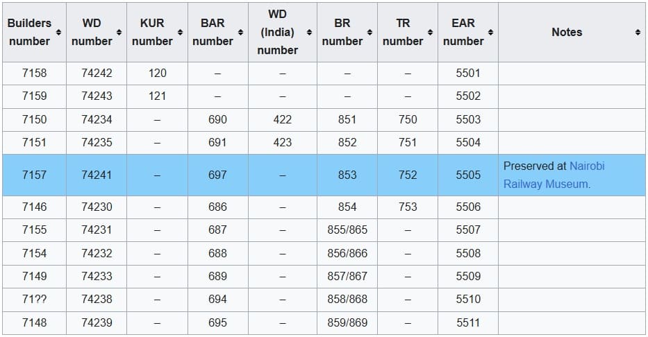
The Garratt locomotives that eventually made up the full 55 Class list were in use on the KUR and the TR. The full list is shown below:

The full EAR 55 Class list: as can be seen 4 of the Class served in Tanganyika, one of which (EAR No. 5505, ex-TR No. 752) is preserved at Nairobi Railway Museum. When serving in Tanganyika before the amalgamation of the two networks, these locomotives were numbered TR 750 – TR 753. [4]

EAR Designed/Purchased Steam Locomotives:

Despite having access to a broad spectrum of different locomotives from the two networks, the EAR was clearly in need of locomotives. It had available Class 54, 57 and 58 Locomotives but these were unsuitable as a base for further development [1: p71] Fuel was also a problem, wood was still in extentives use and coal supplies during WW2 were of relatively poor quality. The EAR decided that it should focus on oil-burning locomotives. Ramaer says that conversions started almost immediately, all EAR engines “were gradually converted to burn oil, a job which was completed by 1955.” [1: p72]

EAR made an initial decision to focus on steam-power for the immediate future.

EAR 13 Class 4-8-2T/4-8-4T Locomotives

These locomotives were probably not used to any great extent of the historic TR network within the EAR.

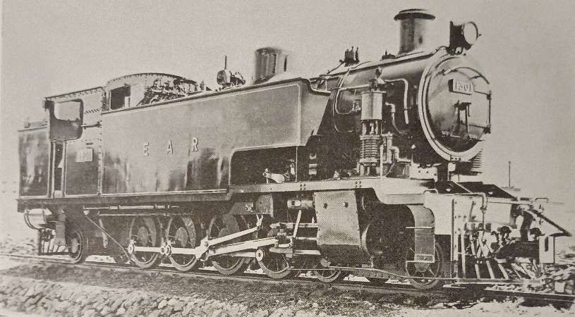
EAR 13 Class 4-8-2T Locomotive No.1301 as supplied in 1953. [1: p78]

Eighteen of these tank locomotives were built by North British and entered service in 1953. All of these locomotives were initially 4-8-2T locomotives but their performance was poor. They were prone to frequent derailments in sidings. The decision was taken to adapt them to be 4-8-4T locomotives.

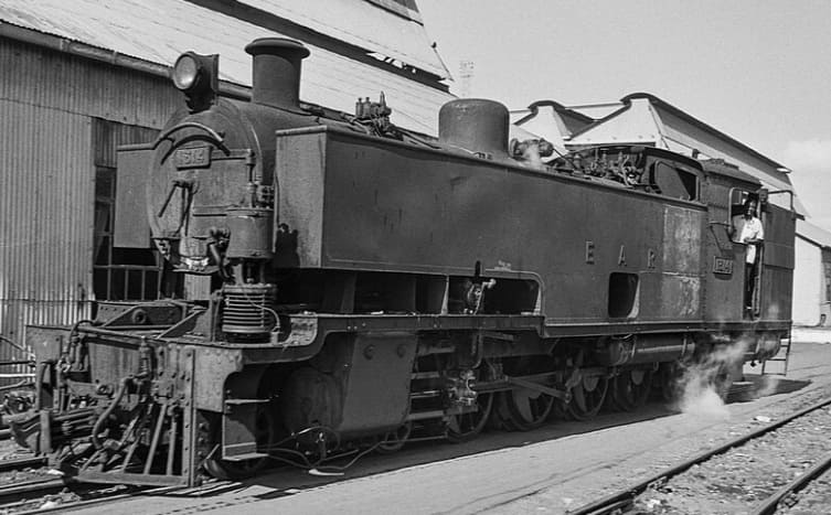
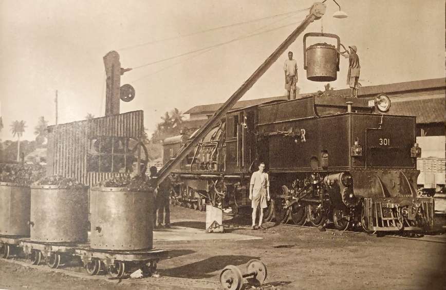
The trailing ponies were changed to bogies recovered from old 50 Class Garratts from the KUR which were being withdrawn from that network. At the same time the side tanks were extended and lined up with the smokebox door. This required the repositioning of the compressor and the opportunity was also taken to enlarge the rear fuel tank slightly. [1: p78]

A superb study of a 13 Class 4-8-4T modified locomotive, (c) ETH-Bibliothek Zürich, Bildarchiv / Fotograf: Schmid, Walter / Com_L25-0840-0013-0008 and licensed for reuse under a Creative Commons licence (CC BY-SA 4.0). [6]

After Class 13, plans were in place for a further Class of shunting locomotive – the 14 Class but none were built in the end as a result of research into Diesel Shunters which could produce a greater tractive effort with a lower fuel consumption.

EAR 29 Class 2-8-2 Locomotives

Along with 30 Class and 31 Class locomotives and the 59 and 60 Class Garratts these were the last steam locomotives built for the EAR.

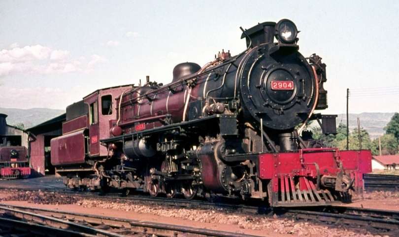
EAR 29 Class 2-8-2 Locomotive No. 2904 is an oil-burning locomotive built by the North British Locomotive Company in Glasgow. This photo was taken at the Moshi depot in Tanzania in 1968, (c) Basil Roberts and licensed for reuse under a Creative Commons licence (CC BY-SA 4.0). [7]

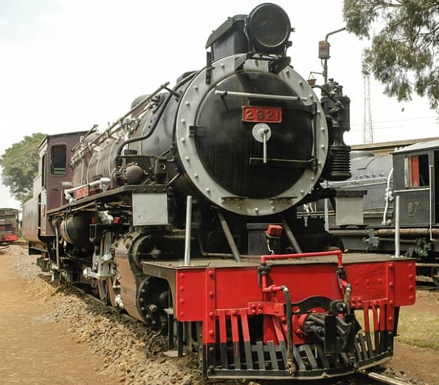
The 29 Class were derived from the Nigerian ‘River’ Class 2-8-2 Locomotives which were built to operate with low grade coal. The EAR version was oil-burning. Crews at times called these locomotives ‘Nigerians’. Two arrived with the EAR in 1951 and a further eighteen in 1952. These were reliable and effective locos with an axle load of thirteen tons and designed to be freight locomotives on the main line. Their performance gave rise to another order for eleven further 29 Class locomotives from North British in 1955. Ramaer tells us that, “These newer locomotives differ[ed] from the earlier ones in that they ha[d] spring-loaded intermediate buffing gear, later standardised on the 31 class 2-8-4s, and larger injectors than the first twenty engines. Externally, they [were] easily distinguishable for a larger smokebox door has been fitted than on the earlier engines. To reduce the weight on the trailing pony truck, already heavily stressed by the big Belpaire firebox, the compressors were repositioned to be in line with the smoke-box door, and in consequence some minor changes had to be introduced to the leading pony truck.” [1: p80-81]

One of the later 29 Class locomotives Ear No. 29 which shows the larger smokebox door, (c) Alexander Leisser and licensed for reuse under a Creative Commons licence (CC BY-SA 4.0). [8]

Ramaer says that “A point of some concern in the design of the 29 class was the relatively high axle load on the trailing pony, which caused the engines to lean back with heavy trains, with consequent loss of adhesive weight. To remedy this shortcoming, the EAR went in following designs to a wheel arrangement with a bogie under the fire-box, considered by many engineers to be the best possible solution for locomotives with a big and heavy firebox, as it improves riding and, indirectly, eases maintenance. The 2-8-4s thus evolved belong to two classes, 30 and 31, introduced in 1955-6 and built by North British and Vulcan, respectively.” [1: p81]

The 29 Class was ubiquitous across different sheds throughout the EAR territory. [1: p81-81]

EAR 30 Class 2-8-4 Locomotives

The 30 class is heavier than the 31 Class and is directly derived from the 29 Class. It has the same boiler, although adhesive weight is slightly lower than the 29 Class “as a result of the introduction of the bogie under the firebox. The bogie has American-inspired cast steel outside frames and was introduced following the example of the Canadian Pacific type 59 to improve riding. For the same reason, compensated spring gear on the coupled axles was reintroduced following the example of the pre-war 28 Class Mikados. These changes certainly resulted in better riding qualities.” [1: 81]

EAR 30 Class 2-8-4 Oil-burning Locomotive No. 3019 ‘Nyamwezi’ sitting at Tabora depot. The 26 members of the Class served their entire careers in Tanganyika/Tanzania. [9: p83] The Class was built in 1955 by the North British Locomotive Company in Glasgow, These locomotives primarily served on the Central Line in Tanganyika, now Tanzania, (c) Basil Roberts and licensed for reuse under a Creative Commons licence (CC BY-SA 4.0). [10]

The 30 class design included a large cast steel tender, running on six-wheel bogies, having a capacity of 1,950 gallons of fuel oil and 7,000 gallons of water. This, with Timken roller bearings [11][12] throughout has resulted in an engine capable of running long distances over the Central Line of Tanzania, on sections with unreliable water supplies, like Morogoro-Tabora. The 30 Class spent their full working life in Tanganyika/Tanzania. [1: p81-82]

EAR 31 Class 2-8-4 Locomotives

The EAR 31 class was a class of oil-burning 2-8-4 steam locomotives. The 46 members of the class were built in 1955 by Vulcan Foundry, in Newton-le-Willows, Lancashire, for the EAR. They were a lighter, branch-line version of the EAR 30 class, and worked from various sheds throughout the EAR system.[1: p80-82][9: p83][13]

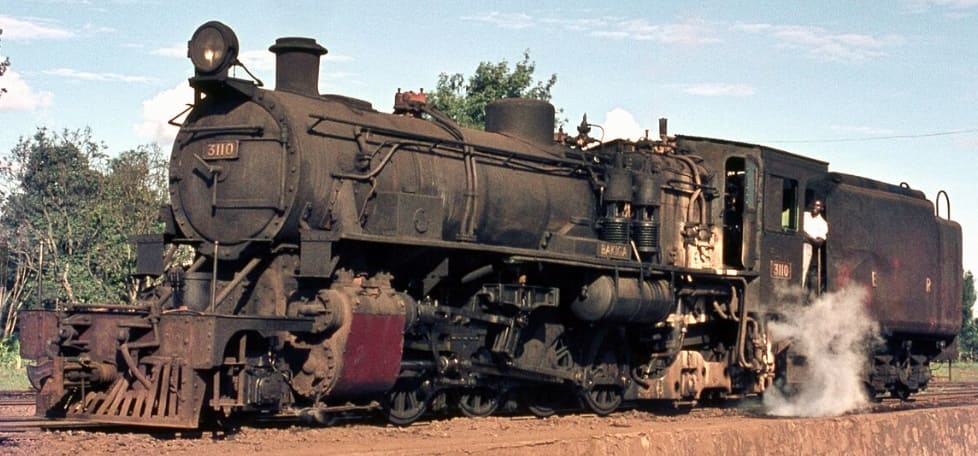
EAR 31 Class 2-8-4 Oil-burning Locomotive No. 3110 ‘Bakiga’ at Nairobi in 1968. The 46 members of the Class served on branch lines across the full EAR network. The Class was built in 1955 and 1956 by the Vulcan Foundry in Newton-le Willows, Lancashire, (c) Basil Roberts and licensed for reuse under a Creative Commons licence (CC BY-SA 4.0). [13]

The Vulcan Works Magazine carried this ex-Works image of a 31 Class locomotive. The locomotives were Vulcan Foundry Works Nos. 2576, 2578-81 and 2583 & 84. [14]

The Vulcan Foundry magazine notes that these engines were designed for the lightest tracks on the EAR network: “The locomotives are required for universal use throughout East Africa, but in the first place are to be placed for duty in Kenya and Uganda. All are oil fired and forty-one have Westinghouse brakes, the other five being dual fitted with Westinghouse and Vacuum Brake Equipment, so that they will be available for service in Tanganyika when required. The locomotives will negotiate with ease, curves of 330ft radius, with 0.5in gauge widening and also I in 7.5 turnouts (equivalent to a curve of 350ft radius without gauge widening) and are suitable for operating on 3% gradients. … As on all recent East African orders, the locomotives are so arranged that they can be converted to 36in gauge in accordance with requirements for the future standardisation of the East African Railways. For the same reason the dragboxes [15][16] have been made to suit both the MCA Coupler (as fitted) and the Knuckle type Coupler. Wherever possible, detail parts have been made interchangeable with the “29” and “30” classes, but a smaller boiler and slightly smaller cylinders have been provided.” [14]

Later Beyer Garratt Locomotives:

EAR 57 and 58 Class

These locomotives were not used in Tangayika/Tanzania. For more detail, please click here. [17]

EAR 59 Class

The axle loads of these locomotives were too high for the relatively light rail used in Tanganyika/Tanzania. They were used, as intended, on the old KUR network. For more detail, please click here. [17]

EAR 60 Class

Introduced in 1953, these 4-8-2+2-8-4 locomotives were used extensively on the Central Line between Dar -es-Salaam and Morogoro

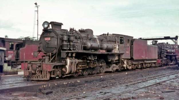
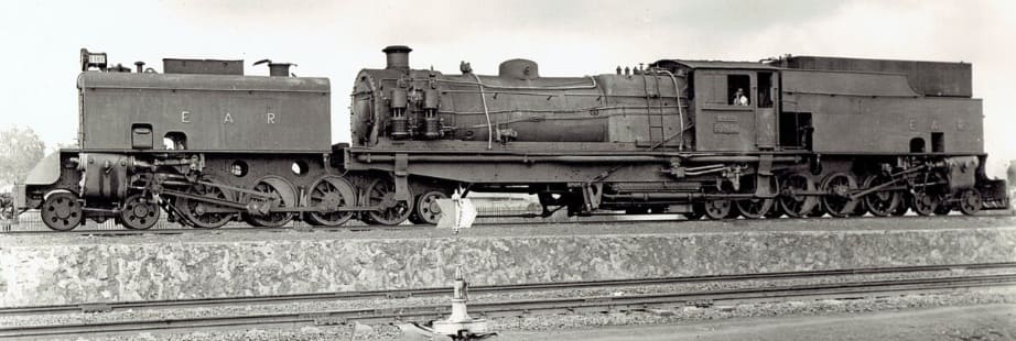
Class 60 Garratt 4-8-2+2-8-4 locomotive No. 6019 at Tabora depot, Tanzania, in 1968. [5]

The EAR 60 class, also known as the Governor class, was built for the EAR as a development of the EAR’s earlier 56 class. The 29 members of the 60 class were ordered by the EAR from Beyer, Peacock & Co. The first 12 of them were built by sub-contractors Société Franco-Belge in Raismes (Valenciennes), France, and the rest were built by Beyer, Peacock in Gorton, Manchester. The class entered service in 1953-54. Initially, all members of the class carried the name of a Governor (or equivalent) of Kenya, Tanganyika or Uganda, but later all of the Governor nameplates were removed. [5]

Initially, the first locomotives were ordered as an extension to the 56 Class – 5607 – 5618. Compared with the 56 Class, the Franco-Belge locomotives had more water and less oil capacity. It was only just before delivery that it was decided to classify them separately. As we have noted, the remainder of the Class was built in the UK by Beyer-Peacock. Raemer reports:

“With an axle load of only eleven tons, the 60 class is, with the 55 and 56 classes, the standard light Garratt on the system, taking all the lighter mixed traffic. It was on one of these engines, No 6029, that the first test with the Giesl ejector was made, No 5805 following suit. Today, all 60s have this equipment. Originally the 60 class carried the names of the Governors of Kenya, Tanganyika and Uganda, but later the nameplates were removed. At present, [1972] only No. 6001 still carries a name Umoja (Unity). They are straightforward engines, with the well-tried Belpaire firebox, a working pressure of 200lb/sq in and 16×24in cylinders, developing a tractive effort of 43,520lb. They, too, have roller bearings on all axles, but somewhat surprisingly plate frames of wartime origin were retained, like the 55 and 56 classes. Although the 60s are quite good engines, they never came came up to the level of the 56s, especially where the free steaming quality of the boilers is concerned.” [1: p78]

EAR Diesel Locomotives used in Tanganyika/Tanzania

I have written extensively on the various Diesel locomotives used on the EAR network, for more detail, please click here. [18] The EAR operated a progressive fleet of diesel locomotives in Tanganyika (now Tanzania) starting in the 1950s, featuring key classes such as the 83, 84 & 85 Class hydraulic shunters and later mainline diesel-electrics.

There were a significant number of different diesel locomotive classes on the EAR , but records that I have come across do not specify which of these locos were stabled at which depots. It is difficult in many cases, to be sure which classes of loco were used on the lines in Tanganyika/Tanzania. The fleet included:

32 Class (previously 80 Class): please see notes below about the 80 Class locos.

33 Class (previously 81 Class): please see notes below about the 81 Class locos.

34 Class (previously 82 Class): please see notes below about the 82 Class locos.

35 Class: Andrew Barclay 0-6-0 locomotives.

61 Class: These locomotives were supplied by the German manufacturer Henschel & Son.

71 Class (previously 91 Class) Diesel-Electric Locomotives: supplied by English Electric.

72 Class (previously 92 Class) Diesel-Electric Locomotives: supplied by English Electric.

79 Class Locomotive: only one of these locomotives was built.

80 Class (later 32 Class):

81 Class (Later 33 Class): Supplied by the Drewry Car Co., these versatile internal combustion locomotives handled secondary and transfer tasks during the early phase of internal combustion transition.

82 Class (Later 34 Class):

83, 84, 85 & 86 Classes (Later 43, 44, 45 & 46 Classes): Introduced from 1955 onwards, these light and medium diesel-hydraulic locomotives (built by manufacturers like Hunslet, Andrew Barclay, and North British Locomotive Company) took over shunting and lighter duties on the Tanganyika Central Line.

86 Class (later 46 Class):

90 Class (later 87 Class) English Electric types: from around 1960, powerful diesel-electric units gradually supplemented and replaced heavy steam power (like the 30 and 60 classes) on main trunk routes connecting Dar-es-Salaam, Tabora, and Kigoma. Dieselization in Tanganyika in the late 1950s and 1960s dealt a blow to the continued use of steam-power as they were more effective on handling steep gradients and overcame water scarcity issues inherent to steam operations across the territory.

91 Class (later 71 Class) Diesel-Electric Locomotives: supplied by English Electric

88 & 92 Class Canadian supplied Diesel Electric locomotives, of which there were 20 No. 88 Class and 15 No. 92 Class locomotives.

More about each Class of Diesel Locomotive

A little more information about each of these classes of diesel locomotive can be found in the paragraphs below. For more information and more images than are included in this article please click here. [18]

EAR 35 Class Locomotives

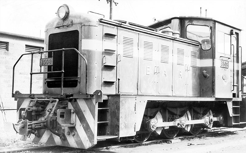
These were Andrew Barclay 0-6-0 diesel shunters.

The EAR 35 Class of 0-6-0 shunters had a cast list of at least eight. This is EAR No. 3508. The photographer is not known. [18]

EAR 43 Class (originally 83 Class) Locomotives

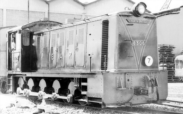
These locos were built by the North British Locomotive Company.

EAR 83 Class 0-8-0 Locomotive, EAR No. 8306. The photographer is not known. [18]

EAR 44 Class (originally 84 Class) Locomotives

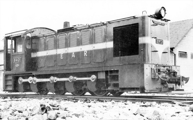
This 0-8-0 class was also built by the North British Locomotive Company.

EAR 84 Class 0-8-0 Locomotive, EAR No. 8401. The photographer is not known. [18]

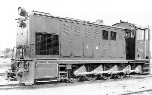
EAR 45 Class (originally 85 Class) Locomotives

Still another North British 0-8-0 class of loco.

EAR 85 Class 0-8-0 Locomotive, EAR No. 8504. The photographer is not known. [18]

EAR 46 Class (originally 86 Class) Locomotives

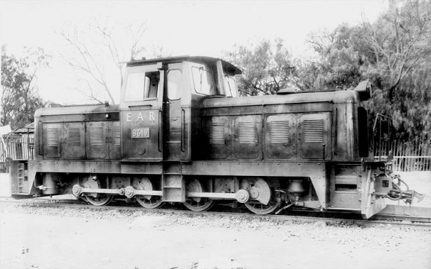
The 46 Class (originally 86 Class) 0-8-0 central cab locos were built for the EAR by Andrew Barclay Sons & Co.

EAR 86 Class 0-8-0 Locomotive, EAR No. 8619. The photographer is not known. [18]

EAR 61 Class Locomotives

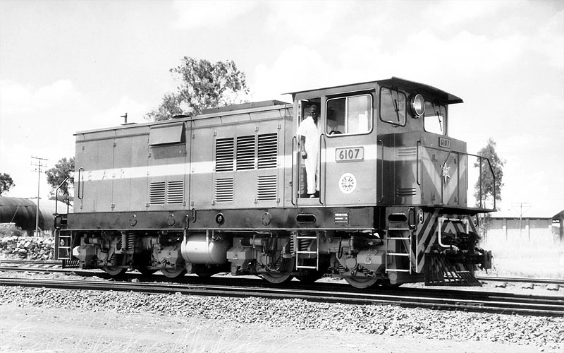
Once the decision had been taken not to build a new class of Beyer Garratt locomotives which would have been 61 Class locomotives. The Class number was used for a series of Henschel-built Bo-Bo shunters.

61 Class Henschel-built Bo-Bo shunting locomotive, EAR No. 6107, photographer not known. [18]

EAR 71 Class (previously 91 Class) Locomotives

See the 91 Class below.

EAR 72 Class (previously 92 Class) Locomotives

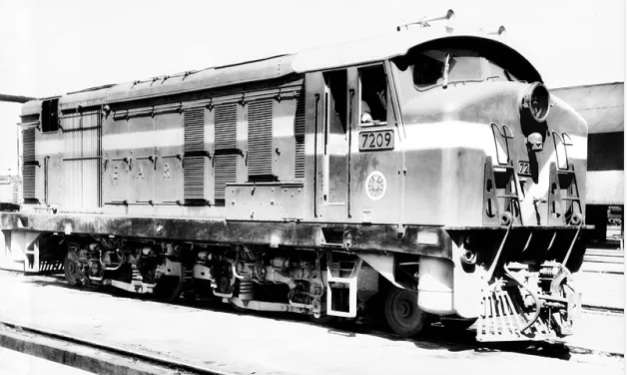
The East African Railways (EAR) 72 Class consists of 10 diesel-electric locomotives built by English Electric at the Vulcan Works in Newton-le-Willows in 1971 and 1972. They featured a 1-Bo-Bo-1 wheel arrangement and a 1,240 horsepower rating tailored for lightweight tracks across the whole EAR network. For more details about this locomotive please click here. [24]

EAR 72 Class (previous 92 Class) Locomotive No. 7209, photographer not known. [18]

79 Class Locomotive

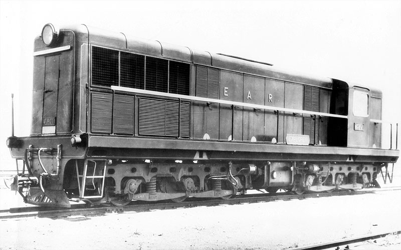
Only one of these Co-Co locomotives was built. No. 7901 was supplied as an experimental type by AEI Lister-Blackmore. Looking at the export market in the late 1950s British Tomson-Houston (BTH), with Clayton and Lister-Blackstone commissioned the Explorer CM-gauge prototype, which was ready in 1959. This featured a Lister-Blackstone engine, BTH electrical equipment and mechanical parts by established partner Clayton. [25]

EAR 79 Class Locomotive No. 7901, photographer not known. [18]

80 Class (later 32 Class)

The Class 80/32 0-6-0 locos were built for the EAR by John Fowler & Co Engineers of Leathley Road, Hunslet, Leeds, West Yorkshire.

[18]

81 Class (Later 33 Class)

Supplied by the Drewry Car Co., these versatile internal combustion locomotives handled secondary and transfer tasks during the early phase of internal combustion transition.

[18]

82 Class (Later 34 Class)

[18]

83, 84 & 85 Classes (Later 43, 44 & 45 Classes)

Introduced from 1955 onwards, these light and medium diesel-hydraulic locomotives (built by manufacturers like Hunslet, Andrew Barclay, and North British Locomotive Company) took over shunting and lighter duties on the Tanganyika Central Line. Please see 43, 44 and 45 Classes above.

86 Class (later 46 Class)

Please see the 46 Class above.

EAR 88 Class Locomotives

There were 20 diesel-electric locomotives built by the Montreal Locomotive Works (MLW) in this Class. These were lighter weight versions of the 92 Class. These locomotives had a 1-Co-Co-1 wheel arrangement and were designed to handle intense tractive effort demands across the challenging terrain of Kenya, Uganda, and Tanzania.

EAR 88 Class Locomotive built by Montreal Locomotive Works (MLW). These locomotives worked across the whole EAR network, photographer not known. [18]

EAR 90 Class (later Class 87) Locomotives

There were 44 of this Class built by English Electric by the end of the 1960s. They worked across the whole EAR network.

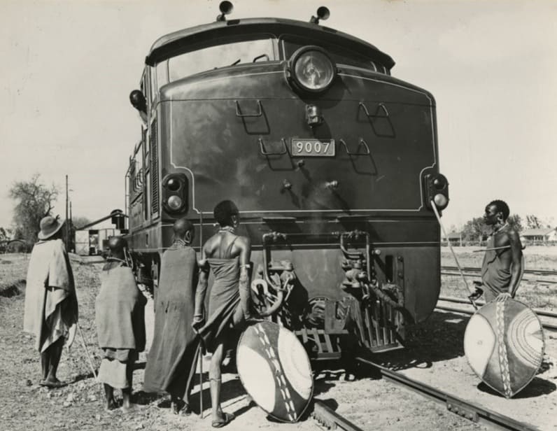
Masai tribesmen inspect an English Electric-AEI Class 90 diesel electric loco, East African Railways No. 9007, 1960. This image was shared on the Commonwealth Heritage Forum on Facebook on 6th October 2023. [19]

Some notes about English Electric Twelve cylinder diesels and the EAR 90 class written by Steve Palermo: [20]

“EE generally designed locomotives to meet individual railway requirements, using standard components. Nevertheless, established designs were often adapted for other customers, and this is apparent in the 12-cylinder sequence, which accordingly could be described as being a series of quasi-standard locomotives. A greater degree of standardization is apparent in EE’s sequence of 6-cylinder models, though.

“The list of EE 12-cylinder models, in chronological order of first appearance, is:

1. Queensland Railways (QR) 1200 class, 10 built.
2. New Zealand Railways (NZR) Df class, 10 built
3. Malayan Railways (KTM) 20 class, 26 built
4. QR 1250 class, the first EE Australia variant, 17 built
5. Sudan Railways 1000 class, 65 built
6. East African Railways 90 (later 87) class, 44 built
7. British Railways (BR) 37 class, 309 built
8. Western Australian Government Railways (WAGR) C class, 3 built
9. Rhodesian Railways DE3 class, 16 built
10. QR 1270 class, 30 built
11. WAGR K class, also Goldsworthy Mining A class, 17 built
12. QR 1300 class, 45 built
13. WAGR R and RA classes, 18 built
14. AIS D34 class, 1 built
15. Ghana Railways & Harbours 1851 class, 16 built
16. Tasmanian Government Railways (TGR) Z class, 4 built
17. QE 2350 class, 16 built
18. TGR ZA class, 6 built

“The total number of EE 12-cylinder locomotives built was thus 653, of which 496 were of UK origin, and 157 came from Australia. …

“BR, with 309 of its 37 class, was the biggest user of EE 12-cylinder models. Next came QR, with a total of 118 spread over 5 basic models, although there were subvariants. QR was also the first
operator to buy 12-cylinder EE locomotives, so are more detailed study of the group logically starts with the QR 1200 class, which then conveniently links to both the later UK and the Australian models. At least basic information on most classes is reasonably available, and of course the BR 37 has been the subject of many treatments in the literature.

“The EAR 90 class was the second English Electric 12CSVT-engined model to be delivered, but the first to be ordered. The initial order, for 8 units was announced in October 1958, and an increase to 10 units was announced in March 1959. This was EARH’s first order for line-service diesel locomotives. A 13.5 ton maximum axle loading was imposed, to enable the locomotives to work northwest of Nairobi to Nakuru and Kampala [and elsewhere on the EAR network], as well as between Mombasa and Nairobi, which section alone would have allowed a higher axle loading. This axle loading constraint required a multi-axle design, as it is unlikely that EE could have built a compliant 12-cylinder Co-Co model. Unsurprisingly, EE used a 1-Co-Co-1 wheel arrangement. The resulting locomotive was largely a new design, although it included features drawn from the QR 1250 class (body style and general layout) and the Rhodesian Railways (RR) 16-cylinder DE2 class (running gear and in-frame fuel tank). What it was not, though, was simply a 1-Co-Co-1 variant of the QR 1250 with 12CSVT in place of 12SVT engine.

“Nevertheless, the QR 1250 makes a useful yardstick for comparison purposes. The EARH 90, at 51’0″ over headstocks, was a little longer than the QR 1250, at 49’6”. This extra length was most likely required to accommodate the more complex running gear, although it probably also gave a bit more space to accommodate the dynamic braking unit and a higher capacity cooling group. The total wheelbase was 41’6″, as compared with 40’0″ for the QR 1250. The equipment layout for the most part followed established EE practice. The nose compartment housed the leading bogie traction motor blower, which was motor-driven. The T-shaped main equipment cubicle was immediately behind the cab; then came the dynamic braking unit, which was mounted high & just below the cantrail – with a crosswise orientation, fan-shaft horizontal. Then came the generators, the engine, followed by the radiator compartment with mechanically-driven vertical-shaft fan, and finally the rear-compartment, housing the air compressor, mechanically-driven from the radiator fan gearbox, and the trailing bogie traction motor blower.

“The running gear was based upon that of the RR DE2, which had proved successful in service. Thus, the bogie frames were one-piece castings by Henricot. Because the EARH 90 was shorter, the axle spacings were all reduced by 6 inches. Each bogie had an overall wheelbase of 17’6″, with a rigid wheelbase of 12’0″ equally distributed, and the two inner bogie axles were separated by 6’6″. The pivot centres, placed between the pilot and outer driving axles, were 37’10” apart. Consistent with EE’s thinking about maximizing the advantages obtainable from the 1-Co-Co-1 wheel arrangement where it was necessary to use same, the axle spacings were chosen to obtain maximum bending moment relief, so reducing vertical railhead forces. As this required relatively close coupling of the bogies, a conventional suspended fuel tank was precluded, hence the use of an in-frame fuel tank, an EE feature that went back at least as far as the New Zealand Railways De class. The main bogies were interconnected by a lateral spring control mechanism that helped ensure optimum wheel flange angles in curves, so reducing lateral railhead forces. One way of looking at this is that the coupling allowed the leading bogie to pilot the trailing bogie into curves,
the leading bogie itself being guided by its own pilot truck. Wheel diameters were the same as on the DE2, namely 28½” pilot and 37½” driving. The main bogies had three-point load transfer from the mainframe, with a resiliently mounted pivot between the pilot axle and the outer driving axle, and a pair of coil spring bearers between the centre and inner driving axles. Equalization for each bogie was continuous from pilot truck axle to inner driving axle. This was a change from the DE2 bogie, which was equalized in two groups, although the casting did make provision for full equalization should it have been required. As with the DE2, the driving axle springs were of the leaf type interconnected by equalizing bars, but at the fixed attachment points, rubber bushes were used in place of the auxiliary coil springs used on the DE2. All three traction motors on each bogie faced outwards, consistent with high-adhesion bogie practice. EE claimed that this bogie design virtually eliminated intra-bogie weight transfer, whilst the wide pivot spacing minimized
inter-bogie weight transfer. I have never seen the benefit quantified in the same way that EE Australia did for its high-adhesion Co bogie first used on the Western Australia Government Railways R class, but taking the latter as indicative, EE’s view could well have been that a 1-Co-Co-1 locomotive with 81 tons adhesive weight would for practical purposes match a similarly-powered 90 ton Co-Co with more-or-less conventional bogies, whilst offering lower dynamic railhead forces as well as (fairly obviously) lower static railhead forces. EE certainly made much of the capabilities of it own-design 1-Co-Co-1 running gear (here one needs to be careful to exclude the non-EE design bogie that it was forced to use, against its better judgement, for the British Rail 40 class) and noted that its good performance had been verified by the railway administrations using it.

“The 12CSVT Mk II engine had three manually adjustable governor power settings that allowed optimization for altitude, bearing in mind that the route embraced the range from sea level to 9136 ft elevation. 1840 hp (gross) was available up to 5500 ft, 1800 hp up to 7800 ft, and 1775 hp up to 9136 ft. One assumes that the settings were chosen according to which part of the EARH system the locomotives were assigned. The main generator was the EE822 model, and the six traction motors were the new EE537 4-pole model, connected in permanent series-parallel (2S3P) with two stages of field weakening. I have not been able to verify the gear ratio, but most probable was 72:15, fairly standard for the EE537 motor. The 45 mile/h maximum service speed would not have required faster gearing. The overhung auxiliary generator, model number unknown, was of 48 kW capacity.

“The EARH 90 was fitted with the by-now standard EE air-throttle control system, with the EE governor and the new hydraulically operated load regulator. The two driving stations were fitted with EE’s then-standard two-lever control stands. The throttle lever also operated the dynamic brake according to the standard EE 3-notch protocol. The main driving station was on the right hand side. There was a second driving station on the left-hand side, but this was not diagonally opposite and reversed as might have been expected. Rather it seems to have been arranged to allow bidirectional operation during shunting operations.

“The braking system was air for the locomotive and train, EARH being an air-braked road. However, the design made provision for the retrofitting of vacuum train brake equipment if required. At the time, it was evidently still thought possible that the EARH system would be converted from metre to Cape gauge to align with the rest of Southern Africa. The same conversion would also have required a (retrograde) change from air to vacuum brakes, the latter being the Southern African standard, with at least a period of dual-braking capability being required. One can wonder how vacuum brakes would have performed at 9000 ft altitude. Also, it is not immediately apparent as to where the vacuum exhausters would have been accommodated on the 90 class, bearing in mind that both the large compressor and the dynamic braking equipment would have been retained. Perhaps EE was thinking in terms of using a combined exhauster-compressor unit in place of the air compressor.

“I have not been able to find definitive information about the type of air braking system fitted to the EARH 90 class, other than that the initial batch had Westinghouse UK equipment. Had an American-type “schedule” system been fitted, most likely it would have been noted in the trade press descriptions. So more likely is that the braking system followed British precepts, with physically separate driver’s valves for independent and train brake control, and an electrically operated. independent-release-after-automatic-application function. Certainly EARH did not have a history of using schedule systems on its steam locomotives, late examples of which were fitted with Westinghouse No. 4 automatic brake valves and Gresham & Craven Mk IV locomotive steam brake valves. The layout diagrams show that the two driver’s brake valves are somewhat separated, with that for the automatic brake being to the driver’s right, and that for the independent brake a little to the left, ahead of the control stand. Clasp brakes were fitted to the driving wheels, withy one brake cylinder per wheel. The pony truck wheels were unbraked.

“Another unknown is the electrical capacity of the dynamic brake unit. For the second series, the peak braking effort is shown as 30 000 lbf at approximately 21 mile/h, which suggests around 1200 kW. The second series is said to have had a greater dynamic braking range than the first series, so it is possible the latter had a smaller capacity unit. As described, it is stated that the locomotive brake is interlocked with the dynamic brake so that both cannot be applied simultaneously. A literal interpretation suggests that the 90 was fitted with a conventional lockout system. But if so, it was a departure from established EE practice. In its previous diesel-electric locomotive dynamic braking installations, EE had used an anti-compounding system, in which the dynamic brake was released if locomotive brake cylinder pressure reached a predetermined level, typically 23 lbf/in².

“The EAR 90 was equipped for multiple unit operation. There was a central EE elbow-style jumper socket at each end on the front sheet, along with three “plug-in” hose connections arranged in a triangle. Most probably these were for respectively main reservoir, engine speed control and independent brake. The 90 was MU compatible with the later and smaller EE-built 91 (71) and 72 classes, but beyond that EAR did not seem to be concerned to establish a single common MU standard. Later diesel locomotives from other builders were equipped with control and MU systems that were more-or-less their respective builder’s standards.

Notwithstanding the 13.5 tons axle loading specification, the first series were built to a slightly lower 12.8 tons number, giving an adhesive weight of 76.8 tons. The total weight was 97.5 tons. The continuous tractive effort is consistently quoted as 44 500 lbf, although there is some variety in the corresponding minimum continuous speed, which is variously reported as 11.5, 11.7 and 12¼ mile/h. The top speed is usually reported as 45 mile/h, but this would have been a track limited speed, as the expected 72:15 gearing would have allowed 60 mile/h, and there is no reason why the running gear would not have accommodated this on suitable track.” [20]

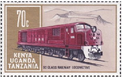
EAR 90 Class Locomotive on an East African 70c Stamp, issued on 5th April 1971; size: 44 x 28 mm; designer: Rena Fennessy; printers: Harrison & Sons Ltd. [21]

EAR 91 Class (later 71 Class) Class Locomotives

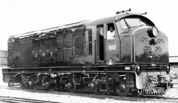
Built in 1967/1968, these locomotives were powered by an 8CSVT MkII engine with 1350hp for traction and weighed 68 tons. 10 were built. two batches of 10. In 1971-72, another 10 similar, but slightly heavier, units arrived, and were denoted the 92 class (later known as the 72 class). All were used in branch line service. These had a 1-Bo-Bo-1 a drawing of the side elevation of these locomotives can be seen here. [23]

EAR 91 Class (later 71 Class) locomotive No. 9101, photographer not known. [18]

Original EAR 92 Class Locomotives

See 72 Class above.

EAR 92 Class Locomotives

There were 15 locomotives in the Class. They were Canadian-built 1-Co-Co-1 diesel-electric locomotives manufactured by Montreal Locomotive Works (MLW) – heavier versions of the 88 Class! They were not suitable for the lighter rails in Tanganyika/Tanzania.

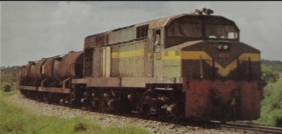
EAR 92 Class: These locomotives were purchased specifically for work only on the line West from Mombasa.

In this image the locomotive is in charge of a rake of empty tanks heading for Mombasa. [22]

Other locomotives in Tanzania

The Tazara Line operated independently from the metre-gauge network in Tanzania. It will be covered in another article. Writing in 2026, I am aware of the progress being made in Tanzania to develop a standard-gauge railway network. This too will be the subject of a future article.

References

  1. R. Ramaer; Steam Locomotives of the East African Railways; David & Charles, Newton Abbot, 1974.
  2. https://en.wikipedia.org/wiki/TR_MK_class, accessed on 19th July 2026.
  3. https://en.wikipedia.org/wiki/TR_GA_class, accessed on 19th July 2026.
  4. https://en.wikipedia.org/wiki/KUR_EC5_class, accessed on 19th July 2026.
  5. https://en.wikipedia.org/wiki/EAR_60_class, accessed on 22nd July 2026.
  6. https://en.wikipedia.org/wiki/EAR_13_class, accessed on 22nd July 2026.
  7. https://en.wikipedia.org/wiki/EAR_29_class, accessed on 22nd July 2026.
  8. https://en.wikipedia.org/wiki/Nairobi_Railway_Museum, accessed on 22nd July 2026.
  9. A. E. Durrant, C. P. Lewis & A. A. Jorgensen; Steam in Africa; Hamlyn, London,1981′
  10. https://en.wikipedia.org/wiki/EAR_30_class, accessed on 23rd July 2026.
  11. The Timken Roller Bearing Company was one of the first to introduce roller bearings for railroad cars. Railroad cars owned and operated by the Atchison, Topeka and Santa Fe Railway were some of the first to use roller bearings rather than “oil waste journal” boxes. Henry Timken, a German immigrant, invented an improved bearing and founded the company in 1899. It was later renamed The Timken Company. The first locomotive to use roller bearings made by Timken was Timken 1111, a 4-8-4 built by Alco in 1930. The locomotive was used on 15 American railroads for demonstration runs, and was purchased by the Northern Pacific Railroad, the last railroad to try the specially-built locomotive, in 1933. It operated in regular service on the NP until retirement in 1957 and was subsequently scrapped. Some British steam locomotives also used roller bearings. The LMS Turbomotive was fitted with Timken roller bearings, and they were also retrofitted to some of the LMS Coronation class. [12]
  12. https://en.wikipedia.org/wiki/Timken_Roller_Bearing_Company, accessed on 23rd July 2026.
  13. https://en.wikipedia.org/wiki/EAR_31_class, accessed on 23rd July 2026.
  14. https://fsmr.co.uk/ear-tribal-31-class, accessed on 23rd July 2026.
  15. A dragbox is a substantial, often cast metal, part of a locomotive to which the coupling mechanism is attached to allow the locomotive to pull a train. [16]
  16. https://en.wikipedia.org/wiki/Dragbox, accessed on 23rd July 2026.
  17. https://rogerfarnworth.com/2018/06/26/uganda-railways-part-25-locomotives-and-rolling-stock-part-c-steam-1948-to-1977
  18. https://rogerfarnworth.com/2018/06/29/uganda-railways-part-26-locomotives-and-rolling-stock-part-d-diesel-1948-to-1977
  19. https://www.facebook.com/photo?fbid=624070156589901&set=a.394728832857369&locale=en_GB, accessed on 23rd July 2026.
  20. https://www.friendsoftherail.com/forum/viewtopic.php?t=10472, accessed on 23rd July 2026.
  21. https://colnect.com/en/stamps/stamp/454492-Class_90_diesel-electric_locomotive-East_African_Railways-British_East_Africa_Kenya_Uganda_and_Tanganyika, accessed on 23rd July 2026.
  22. https://www.instagram.com/p/DYLgArQtvHB, accessed on 23rd July 2026.
  23. https://www.flickr.com/photos/29903115@N06/8598321329/in/photostream, accessed on 23rd July 2026.
  24. https://rogerfarnworthsrailways.wordpress.com/wp-content/uploads/2026/07/1bo-bo1-diesel-electric-locomotive-for-east-africa.pdf, accessed on 23rd July 2026.
  25. https://www.derbysulzers.com/AEI.html, accessed on 29th June 2018.
  26. https://en.wikipedia.org/wiki/UR_GD_class, accessed on 27th July 2026.
  27. https://en.wikipedia.org/wiki/TR_RV_class, accessed on 17th July 2026.
  28. https://rogerfarnworth.com/2026/07/22/railways-of-tanzania-part-15-locomotives-from-the-first-railways-built-by-the-german-colonial-powers-through-to-the-amalgamation-which-formed-east-african-railways-and-harbours-in-1948

Railways of Tanzania – Part 15 – Locomotives from the first railways built by the German colonial powers through to the amalgamation which formed East African Railways and Harbours in 1948.

Locomotives used during the EAR years from 1948 onwards will be covered in Part 16 of this series of articles.

The featured image for this article is Tanganyika Railways 2-8-2 No. 802 of the MacArthur austerity class at Tabora in the early 1950s before its conversion to oil fuel. [1: p68]

This is an overall view of Tanga Railway Station in 1908 during the the years of German East Africa. The station served as the coastal terminus of the Usambara Railway (Usambarabahn or Usambara Eisenbahn (UE)), which was constructed starting in 1893.The photograph was taken by German photographer Carl Vincenti it shows a train, headed by an unidentified early German steam locomotives, preparing to set off inland, (c) Deutsches Historisches Museum, (Inv. No. BA 90/5791)/Carl Vincenti and licensed for reuse under a Creative Commons licence (CC-BY-SA 3.0). [15]

Locomotives in the Years of German East Africa:

UE Class 0-4-2T Locomotives

The Tanga Line (or Usambarabahn) was constructed over a relatively long period, starting in 1893, reached Korogwe in 1905 and Moshi in 1912. Initially the line was operated by five 0-4-2 tank locomotives. Ramear tells us that these five locomotives were built in 1893 by Vulcan (Vulkan) of Stettin. They were built to a standard design which Vulcan had standardised for use in Germany. [1: p19]

UE Engine No. 1 with an early passenger train ready for departure at Tanga Railway Station. This locomotive is the first in a class of 5 0-4-2T locomotives used on the Usambarabahn (c) Public Domain. [16][1: p19]
UE No. 2, one of a class of five 0-4-2T locomotives built by Vulcan of Stetting in 1893, (c) Public Domain. [1: p18]

UE Nos. 6-10 Mallet Class of 0-4-4-0T Locomotives

A vintage postcard view of an Usambara Eisenbahn 0-4-4-0T mallet type steam locomotive, one of five built by Arnold Jung (No. 414-418) in 1900 and in charge of a mixed train. These locomotives were UE Nos. 6-10, later Nos. 601-605. [17]
Another view of an Usambara Eisenbahn 0-4-4-0T Mallet type steam locomotive in charge of a passenger train which is waiting to depart at Tanga Railway Station. [18]
Another view of a Mallet type steam locomotive in charge of a mixed train which is waiting to depart at Njussi Railway Station. [22]
UE Mallet 0-4-4-0T No. 8 with a passenger train at Mombo, (c) Public Domain. [1: p20]

UE Nos 11-14 Class 2-8-0T Locomotives

After the line was improved with curves being increased to 200m radius, 8-coupled locomotives became feasible. Ramaer tells us that “Four tank locomotives with a 2-8-0T wheel arrangement were built for the UE by Messrs Orenstein & Koppel in 1908 to a standardised tank engine design used on all German colonial railways in Africa. … They were a distinct improvement over the Mallets. Although they were designed to burn coal, the high price of imported coal meant that they remained on wood fuel, which must have given problems with fireboxes and ashpans.” [1: p19-20] Sadly these locomotives seem not to appear on the Wikipedia list of Orenstein & Koppel locomotives. [23]

For an illustration of this type of locomotive please see the OAEG 2-8-0T below.

UE Nos. 15-16 & Nos. 17-18 Class 2-8-0 Locomotives

An Orenstein & Koppel (O&K) 2-8-0 locomotive which was one of a class built between 1908 and 1910 for the Usambarabahn. This specific locomotive is UE No. 15. [19]

These 2-8-0 tender locomotives were a significant improvement over the tank engines with a same wheel arrangement – with the side tanks removed and water carried in the tender the boiler size and weight could be increased. These were the last locomotives to eb supplied to the Usambarabahn and it operated with these locomotives well into the years of World War 1. [1: p20]

OAEG 0-4-0T Locomotives

Henschel of Kassel supplied 4 of these locomotives intended for the work of building the line. A further 4 of these locomotives were supplied, to the same design by, Henschel in 1909. [1: p21] In between these two batches of locomotive (in 1907) another 0-4-0T locomotive was put into service, the origins of this locomotive are obscure and it did not match the Henschel-built locomotives. Ramaer presumes that this locomotive was taken over from the contractor, Holzmann & Co. It was built by Markmaschinen (Works No. 26) in 1893. [1: p21, p27]
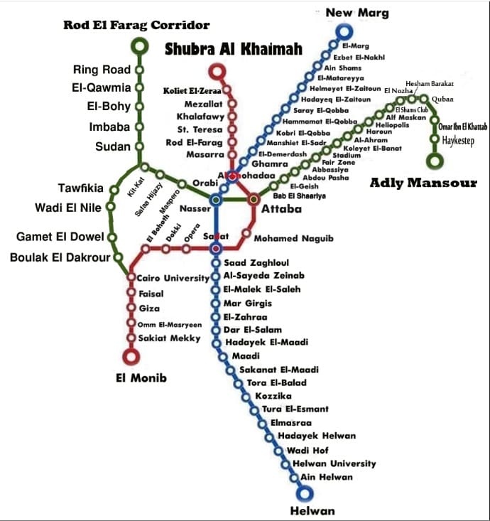
Ramaer notes that the Henschel engines “could be used as both coal and oil burners, and … had a bunker capacity of ton of coal besides 300 litres (66 gallons) of fuel oil. Their water capacity was 2 m³ (440 gallons). These little engines had a comparatively long life, surviving the war and the subsequent change to British management, and the last did not go out of service before the early 1930s.” [1: p23]
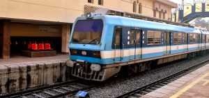
OAEG 0-4-0T Locomotive No. 2 with a line building train at Ugaga (later known as Malagarasi), (c) Public Domain. [1: p21]

OAEG Henschel Mallet Class 0-4-4-0T Locomotives

Just as the Usambarabahn needed to invest in more powerful Mallet types of locomotive which could also accommodate the tight curves on the line, so the OAEG to ordered five comparable Mallet 0-4-4-0Ts, four of which were supplied by Henschel in 1905 and put in service during the first half of 1906 with the fifth following in 1907; like the 0-4-0s they were built for either coal or oil fuel. The OAEG found these Mallets not to be as effective as had been hoped and decided to order Mallets from Henschel with a different wheel arrangement. [1: p23]

OAEG Henschel Mallet Class 2-4-4-0T Locomotives

Henschel supplied a second batch of four locomotives in 1908 as 2-4-4-0Ts with larger boilers and cylinders. They also had a higher working pressure of 14 atmospheres (at) (200lb/sq in) in comparison to 12 at (170lb/sq in) for the earlier engines. While the bunker capacity had been increased from 1.2 to 2.2 tonnes of coal, oil fuel had been discarded. [1: p23]

Mallets proved to be expensive to run and the OAEG realised that if it were to be able to use suitably powered locomotives for the train loads envisaged, it would need to improve the alignment of the later sections of the Mittellandbahn and upgrade to trackwork. This allowed the OEAG to consider using rigid-bodied 8-coupled locomotives.

OAEG 2-4-4-0T No. 27, in the last Mallet class to be built for German East Africa. This locomotive appears in the Wikipedia list of Henschel steam locomotives. [24] It also appears in R. Ramaer’s book (although possibly a slightly different image) [9: p23] and A.E. Durrant’s book about Mallets. [25: p66]

On the whole, the Mallets were not as successful as had been hoped, so it was something of a relief for the OAEG that it was able to use much larger radius curves once the more difficult topography close to the coast gave way to much flatter country. The OAEG was able to look at rigid-framed locomotives. With the invention of the Gölsdorf system [26][27] which allowed spring-controlled side-play in coupled axles at the end of the 19th century. Eight-coupled engines became more feasible. The OAEG took advantage of this innovation and began to introduce eight-coupled locomotives. Ramaer tells us that “The first solution tried was the 0-8-2 tank, built with the pony truck under the fuel bunker to make adhesion independent of diminishing supplies to the maximum possible extent, besides making riding somewhat more comfortable for the crew. High prices for imported coal from Europe had made the railway look for a cheaper alternative and these engines were the first to be built for wood fuel. Henschel supplied them in 1909 as works numbers 9301-2, running numbers 47-8.

OAEG 0-8-2T Locomotives Nos. 47 and 48

One of two OAEG 0-8-2T locomotives supplied to the OAEG by Henchel. This is No. 48, (c) Public Domain. [1: p24]
This is the same locomotive but with elements easier to see as the image has a darker hue, (c) Public Domain. [28]

Ramaer tells us that “The first solution tried [by the OAEG] was the 0-8-2 tank, built with the pony truck under the fuel bunker to make adhesion independent of diminishing supplies to the maximum possible extent, besides making riding somewhat more comfortable for the crew. High prices for imported coal from Europe had made the railway look for a cheaper alternative and these engines were the first to be built for wood fuel. Henschel supplied them in 1909 as works numbers 9301-2, running numbers 47-8.” [1: p23]

OAEG 2-8-0T Locomotives Nos 41-44 (also UE 11-14)

A Borsig-built 2-8-0T. These locomotives served on the OAEG Mittellandbahn, Ramaer tells us that there were 20 of these locomotives in use in East Africa. [1: p24 & 25]

Ramaer tells us that “Simultaneously, Borsig and Orenstein & Koppel introduced an alternative [to the 0-8-2T] and more logical solution in the shape of six 2-8-0T engines, also built for wood fuel. Both types, with only 5½ and 5 cubic metres water capacity respectively, normally carried auxiliary tenders for both water and firewood, besides hoses on the engine to allow for taking water en-route. … From this class and a comparable, but compound engine, supplied, also by Orenstein & Koppel, to South West Africa and Togo, a standardised 2-8-0T locomotive was developed, which was supplied to all German colonial lines in Africa. … Besides serving on other railways, it worked on the Usambarabahn, as described above, and was built for the OAEG by Borsig, O & K, Hanomag (or Georg Egestorff, as this firm was originally known) and Maffei to a total of eighteen engines in 1909-10. Including the engines of the first batches by O & K and Borsig of six locomotives, the total of the Einheitstenderlok (standard tank locomotive) classes amounted to twenty-four engines by the end of German rule.” [1: p25]

These locomotives were far better than the 0-8-2T locos, particularly in respect of their performance at speed. This was of some importance when maximum speeds were raised to 45km/h, and planning envisaged 60km/h (36mph) for the Dar es Salaam-Kigoma mail trains. “The standard tanks were a good, straightforward design and were kept in service for a fairly long period under British management; the last ones … being withdrawn in 1951.” [1: p25]

The series was made up of Orenstein & Koppel locomotives (Works Nos.3223-3226) built in 1909, OAEG Nos. 41-44; Borsig locomotives (Works Nos. 7143-7144) built in 1909, OAEG Nos. 45-46; Henschel locomotives (Works Nos. 9301-9302) built in 1909, OAEG Nos. 47-48; Borsig locomotives (Works Nos. 7153-7155) built in 1909, OAEG Nos. 49-51; Orenstein & Koppel locomotives (Works Nos.3312-3314) built in 1909, OAEG Nos. 52-54; Borsig locomotives (Works Nos. 7552-7555) built in 1910, OAEG Nos. 55-58; Hanomag locomotives (Works Nos. 5845-5948) built in 1910, OAEG Nos. 59-64; Maffei locomotives (Works Nos. 3628-3631) built in 1910,OAEG Nos. 63-66. [1: p27]
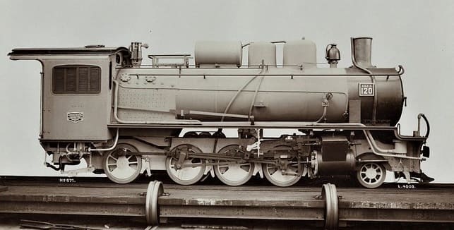
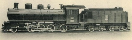
OAEG 2-8-0 Locomotives Nos 101-120

An ex-Works photograph of one of a series of Hannoversche Maschinenbau Hanomag’s 2-8-0 locomotives built for the Ostafrikanische Eisenbahngesellschaft (East African Railway Company). No. 120 was Works No. 6666 of 1913 and was intended for use on the Mittellandbahn running West from Dar-es-Salaam. This locomotive was provided with a tender built by Borsig of Berlin. The locomotive was in use from 1923 to 1937. [20]

Numbered 101-120 these locomotives were built in three batches, 101-110 (6080-89) in 1911, 111-115 (6597-6601) in 1912 and 116-120 (6662-66) in 1913. The class was intended to include a total of 22 locomotives, but only 20 were built. The locomotives were primarily intended to support the construction and operation of the Central Line (Mittellandbahn or Tanganjikabahn) running from Dar es Salaam to Kigoma. Following World War I and the transition of the region to British administration, the engines entered service with the Tanganyika Railway Company, remaining in use into the late 1920s and 1930s. One of the Class is shown below with its Borsig tender.

An Hanomag 2-8-0 Locomotive with Borsig tender, (c) Public Domain. [21]

These were the largest and most powerful OAEG locomotives. They were put into service only after the eastern sections of the Mittellandbahn had been relaid with 55lb rail which would accommodate a ten ton axle load. Ramaer says that these locomotives were 46.2 tonnes (45.5 tons) in weight: “On level lines, these engines handled 500-ton trains, and on 1 in 55 gradients 250 tons at 10 1 km/h. Three carried feedwater purifiers/pre-heaters on top of the boiler. In their day, for the narrow gauge, they were advanced locomotives, and in the early post-war years, enginemen commented favourably upon those that survived. Nevertheless, the fact that they were not in line with British engineering practices presumably was the reason that all were scrapped in the period between the wars. The first ones went in the early 1920s, but the last survived until 1937, where it was in use on the Mwanza line. Without doubt the bulk of the class disappeared much earlier than would have been the case if the line had continued under German management.” [1: p25]

OAEG 2-8-0 Locomotive No. 107, one of the first batch of locomotives supplied by Hannoversche Maschinenbau Hanomag. When built these were the heaviest locomotives in East Africa. [1: p25]

One significant problem on the Mittellandbahn was the availability of water for the locomotives

Locomotives under British Management:

Under British administration the Tanganyika Railway started operation on 1st April 1919. It gained a series of different locomotives of German origin and some which the British forces had brought into Tanganyika during the first world war. Much of the German network had been destroyed by the retreating German forces. Ramaer says that around 4 miles was shaved off the journey between Dar-es-Salaam and Kigoma as the opportunity was taken to realign sections of the line to smooth out the worst curves.

Ramaer says that “Of the German locomotives, four classes were initially put into service on the Central Line, 14 of the Hanomag-built 2-8-0 tender locomotives of the former class 101-20 and now classified GG for German Goods, 22 2-8-0Ts, the German Einheits-vlok, now called class GT, for German Tank, 2 0-8-2 tanks and 6 0-4-0T pugs, dating back to the earliest years of the line, when the DKEBBG had used them for line building purposes. Later on, a total of seven 0-4-4-0T and 2-4-4-0T Mallets were also reconditioned.” [1: p53-54]

Only 5 German locos were salvageable on the Tanga Line: “three of the Orenstein & Koppel-built 2-8-0 tender locomotives of the German series 15-18 and two of the standard 2-8-0 tanks. Many of the Hanomag engines on the Central Line needed new cylinder castings, as the Germans had destroyed them in an attempt to prevent subsequent use of the engines. The new castings were made at the Parel works in Bombay of the former Great Indian Peninsula Railway and mostly fitted at Tabora, where the Germans had installed the main workshops for the Central Line. Thus 14 engines could be reconditioned, Nos 102-3, 105-6, 108, 111-17, 119-20.” [1: p54]

The two 2-8-0 tender classes disappeared after a fairly short life in comparison to other, British-built locomotives on the system. The first engines went in the early 1920s, when money was made available to buy new engines from Britain. The remaining Hanomag locomotives were laid up in about 1932, after the arrival of the new class GA Garratts. One, however, was temporarily brought back into service in 1937, equipped with an electric headlamp, to work the engineering train on the lightly laid Mwanza line, which was very susceptible to washaways, and was always troublesome to operate from the locomotive point of view. All the Mallet tanks were derelict at Tabora works in 1930-31 and were subsequently sold as scrap to Japan.” [1: p54]

TR GT 2-8-0T Class Locomotives

It seems that, of the German fleet, only the 2-8-0T locos had a significant life under British control. Numbered 101 and 102 they were finally scrapped at Nairobi works in 1951.

TR GT Class 2-8-0T in use as a shunter at Tanga. This and its sister locomotive were Orenstein & Koppel locomotives and were the last two German locomotives to be in use on the network in Tanganyika, (c) Public Domain. [1: p53]

TR NZ Class 4-8-0 Locomotives

TR NZ Class No. 1098 leaving Dar-es-Salaam with the mail train in 1922. These locomotives were originally ordered by the Nizam’s Guaranteed State Railway for use on its network in the Dominion of Nizam, better known as the Hyderabad State, in India, but served their entire working lives in Tanganyika, East Africa. Class 22 locomotives were 4-8-0 locomotives built in 1915 by Nasmyth, Wilson and Company. These locomotives were numbered TR1095–TR1098, later TR200–TR203, and later still, EAR2201–EAR2204, © Public Domain. [1: p55][9: facing p182]

In March 1916, while the four members of the class were on their way to India, they were commandeered to assist in the British invasion of German East Africa, where they entered service with the Tanganyika Railway (TR), still carrying their NGSR lettering and numbers 1095–1098. In the early 1930s, they were officially classified as the TR’s NZ class (the NZ being a reference to “Nizam”), and renumbered as 200–203. [4]

The class was later operated by the TR’s successor, the East African Railways (EAR), as its 22 class, numbers 2201–2204. In the late 1940s, two of them were transferred to the Southern Province Railway, [5] the isolated network developed to support the ultimately unsuccessful Tanganyika Groundnuts Scheme. Nos 2202 and 2204 were scrapped in 1952, and 2201 and 2203 in 1956. [4]

TR DL Class 4-8-0 Locomotives

The abbreviation ‘DL’ stands for ‘Development Loan’. The locomotives first carried running numbers 200-205 and later 300-305. They had piston valves and superheater rather than the slide valves and saturated steam of the Nizams.Ramaer says that, “They were derived from the lighter engines of the Nigerian Railways’ Emir Class. Like them, they had narrow fireboxes which were found to be less suitable for wood burning, so that the DLs were used mainly on the section between Dar-es-Salaam and Morogoro, where coal was available.” [1: p56]

TR No. 301 was a TR DL Class 4-8-0 locomotive. It was originally numbered ‘TR No. 201. This Class were the first British locomotives to be built for the TR. They entered service in 1923, (c) Public Domain. [9: p297]
The TR DL class, later known as the EAR 23 class, was a class of 4-8-0 steam locomotives derived from the Nigerian Railways Emir class. The six members of the class were built by Beyer, Peacock & Co. in Gorton, Manchester for the Tanganyika Railway (TR). They entered service on the TR in 1923, and were later operated by the TR’s successor, the East African Railways (EAR). No. 2302 was originally numbered TR No. 202 and later TR No. 302, (c) Basil Roberts and licensed for reuse under a Creative Commons licence, (CC BY-SA 4.0). [8]

The DLs were survivors. Ramaer records that they were still is use in 1972 as EAR Class 2301-2306, although it was expected that they would be set aside in 1973. [1: p56]

TR MK 2-8-2 Class Locomotives

To resolve the problem of the DLs’ narrow fireboxes, a new locomotive design was ordered with a 2-8-2 wheel arrangement. The MK Class had a larger boiler and wider firebox. ‘MK’ was short for ‘Mikado’ which was the standard name across the world for 2-8-2 locomotives.

MK Class 2-8-2 Locomotive No. 407. This class of locomotive entered service in 1925-1927. [9: p299]

Later known as the EAR 25 class, the eleven members of the class were built by Vulcan Foundry, in Newton-le-Willows, Lancashire, for the Tanganyika Railway (TR). They entered service on the TR in 1925–1927. [10]

The eleven members of the Class were:

The eleven members of the original TR MK Class. [10]
Vulcan Foundry ex-Works photo of TR MK 206. [10]

This class was a great success and the Class were still in use at the time Ramaer wrote his book, although he notes that they were now on borrowed time. “One problem with the design of the MK was the fact that the leading pony truck provided insufficient guidance on the sharp curves on the Dar-es-Salaam-Morogoro and the Malagarasi-Kigoma sections, and the design of the Bissel truck [29] left something to be desired.” [1: p57] The solution was a redesign for the next class of locomotive – the RV.

TR RV Class 4-8-2 Locomotives

The RV Class were a redesign of the MK Class – the only significant changes were the extending of the frames by 2 ft 9 in., to accommodate the leading bogie of the 4-8-2 wheel arrangement. Ramaer says that, “As a result of this change it was found necessary to extend the smokebox to keep the cylinders at least roughly in line with the blastpipe and chimney.” [1: p57] The design creted problems – “the greater length of the smokebox created vacuum problems, resulting in insufficient boiler draught. In consequence the RVs were poor steamers and this manifested itself clearly in their early days when they worked the mail trains on the Central Line. They were particularly bad on the Dar-es-Salaam-Morogoro and Kigoma-Kazuramimba sections with ruling gradients of two percent and more, although the below-average quality of firewood on the western section also had something to do with these poor performances.” [1: p57-58] They were nor popular with the train-crews.

This is a Tanganyika Railway (TR) oil-fuelled RV (River) class 4-8-2 locomotive, later classified as the East African Railways (EAR) 21 class. It was first numbered TR252, then No. TR502 and later EAR2103. The locomotive was built by the Vulcan Foundry in Lancashire, between 1928 and 1930, © Public Domain. [2][9: p303]
TR Rv Class Locomotives – class list. [2]
The ex-Works photograph of RV Class No. 252, © Public Domain. [3]

At the time of writing of Ramaer’s book (1972?), these locomotives were working out their lives on lighter duties from Morogoro shed and were unlikely to continue in use beyond 1973. [1: p58]

TR G Class 4-8-0 Locomotives (including 4 No. NW Class 4-8-0 Locos)

TR Class G 4-8-0 Locomotive No. 210 (later 22 Class) – these locomotives entered service in1928. Hill tells us that these locomotives were obtained to work two specific lengths of railway – the Tanga Line and the Mwanza branch off the Central Line, (c) Public Domain. [9: p299]

These locomotives were a redesign of the NZ Class. Ramear says: “The four Nizam 4-8-0s obtained in 1916 served as the prototype for the TR’s own G class, a very similar unsuperheated, slide-valve engine, thirteen of which were supplied by Stephenson and Nasmyth Wilson and put in service in 1928-31. They were again closely similar to the original BESA-designed 4-8-0s for India and thus provide, as the last 4-8-0s built for the TR, a direct link with the first engines of this wheel arrangement to see service in this part of the world. The first eight were supplied to the Tanga Line in 1928 and released F class engines 96 and 720, which had become very expensive to maintain. One of the new Gs, unassisted, could handle the mail trains, a marked improvement over the old and obsolete six-coupled engines. The G had an axle load of only 8-8½ tons, a necessity on the light track of the Tanga Line. The reason for their obsolete concept is not quite clear, however, if we remember that these engines were built at the same time as the KUR EA class Mikados. Their original running numbers 20-32 were later changed to 204-16, as the locomotives were considered to be direct descendants of the NZ class locomotives 200-3. After the amalgamation in 1948 the G class engines were renumbered 2205-17 and gradually taken out of service.” [1: p58]

This is a later publicity photograph of an East African Railways (EAR) Class 22 steam locomotive, numbered 2217. These locomotives were very similar to the earlier batch of NZ Class locomotives but these four locomotives were initially given the Class name NW. Built by Nasmyth, Wilson and Co. in 1930, they had Works numbers 1588-1591. They later became EAR2214-EAR2217, © Public Domain. [4]

The EAR grouped a number of locomotives into the 22 Class in the late 1940s or early 1950s. This manoeuvre grouped ex-Tanganyika engines alongside a slightly newer batch of 1930 Nasmyth Wilson locomotives (Works Numbers 1588–1591) which also operated as Class 22s. [6]

Another publicity photograph taken in the early 1950s which shows EAR2216, another of the same group of 1930-built, Nasmyth engines, EAR 2214-EAR2217, © Public Domain. [6]

The Tanganyika Railways Class G included four locomotives from a group initially known as NW Class 4-8-0s but others as well. We have noted above that the NZ Class of locomotives became EAR2201-EAR2204 (not Class G) and that the NW Class (included in Class G) later became EAR2214-EAR2217, two of which are pictured above. Others in Class G were to become: EAR2205 – EAR2209 Stephenson built locomotives (1927) Works Nos. 3959 -3963; EAR2210 – EAR2213 Stephenson built locomotives (1929) Works Nos. 3990-3991 & 4011-4012. [6]

All of the Class 22 locomotives were scrapped between 1956 and 1970. [6]

Renumbering

This table shows the revised numbering in use by the TR in the 1930s and the later EAR numbering scheme.

The TR changed all running numbers in the early 1930s to a much more logical and consistent system. … Each class started at a round figure in series blocks of hundreds.” [1: p59]

TR ST Class 2-6-2T Locomotives

In 1930, the TR received four 2-6-2T shunters (the same type as the KUR ED1 Class). These were designated as the ST Class. They initially had running numbers TR Nos. 11-14, later TR Nos. 103-106. The locomotives were supplied by Vulcan. Under EAR control the locomotives were numbered EAR Nos. 1101-1104. [1: p60]

TR No. 12 was later designated TR No. 104 and later still, EAR No. 1101. This is an ex-Works photograph taken at the Vulcan Works in the UK, (c) Public Domain. [31]

Many of the EAR Class 11 locomotives were adapted to burn oil fuel rather than wood or coal and were still in use in 1972. [1: p60]

TR Sentinel GSL 50 Class Shunters

The TR GSL class locomotives were 0-4-0T geared steam locomotives designed for shunting and light duties. Built by Sentinel Waggon Works in Shrewsbury between 1929 and 1931, these locomotives were primarily used for shunting in yards and short-haul operations. A total of eight locomotives were built. They feature a side-tank design with geared drive, providing better traction on tight curves and low-speed manoeuvres, while the 0-4-0T Whyte notation reflects a rigid wheelbase for stability in confined spaces. [14]

A GSL Class Sentinel Shunter. Hill tells us that 8 of these small locomotives were purchased in 1930. They served in various roles until they were scrapped by the EAR in the early 1950s, (c) Public Domain. [9: p301]

Procurement of the GSL class occurred in the late 1920s amid broader post-war modernization initiatives across East African railways, with the Tanganyika Railway ordering eight units (which it numbered 50-57) to bolster yard operations as traffic volumes rose. Economic considerations favoured geared designs for their lower maintenance costs and suitability to tropical conditions, where conventional engines often suffered from corrosion and overheating. [14]

Ramaer tells us that, “Among their duties in the [1930s and 1940s] they were used as shed pilots, particularly for hauling out larger engines from the German-pattern roundhouse sheds to the turn-table, an arrangement frequently used at Central Line depots. After the war, they began showing signs of age and as newly built steam shunters were not readily available, they were replaced by diesels, the first on the TR. The last Sentinels, although outmoded, served at Tabora until the middle 1950s before being scrapped.” [1: p60]

TR GA 4-8-2+2-8-4 Garratt Class Locomotives

GA Class 4-8-2+2-8-4 Garratt No. 302 at the head of the Dar-es-Salaam -Kigoma mail train. [1: p60][9: facing p230]

The TR GA class, later known as the EAR 53 class, was a class of 4-8-2+2-8-4 Garratt-type articulated steam locomotives. The three members of the class were built in 1930 by Beyer, Peacock & Co. in Manchester for the Tanganyika Railway (TR). They entered service in 1931, and, with one exception, were later operated by the TR’s successor, the East African Railways (EAR). The class list is shown below. [11]

The GA Class numbered only three locomotives. [11]

The design of the GA class locomotives was based upon that of the Kenya-Uganda Railways (KUR) EC2 class, which was built at about the same time by the North British Locomotive Company for the (KUR). The main design difference was that the GAs had higher, narrower front tanks than the EC2s. With their reduced water capacity, the GAs also had a lower axle loading, which made them suitable for operation over the World War I-damaged bridges on the Central Line in Tanganyika. [11]

GA Class 4-8-2+2-8-4 Garratt No. 700 which was brought into service between Dar-es-Salaam and Morogoro in 1931. [9: p303]

Upon entry into service in 1931, the GA class locomotives were allocated numbers 300–302. Each of them was also given a name: the first two carried the names Arusha and Iringa, respectively, after the locations of the TR’s big road depots, and no. 302 was named Bukoba. Later, the GAs were renumbered 700–702. [1: p61]

GA Class 4-8-2+2-8-4 Garratt No. TR 301 was coal-fired and can be seen here being refuelled at Tanga. [9: facing p198]

It was the TR’s general policy to allocate tender locomotives to standard duties, and use its Garratts only for the most demanding tasks. The GA class therefore normally worked between Dar-es-Salaam and Morogoro, the heaviest part of the Central Line. [12: p184]

The GA class’s operating costs were markedly lower than those of their predecessors. Even during the Great Depression, when traffic volumes greatly declined, they were of great operational benefit. Following the outbreak of World War II, they became indispensable. [1: p60]

Unfortunately one member of the class, TR No 702 Bukoba, was derailed by a washaway near Mikese during a night of bad weather in 1944. The crew was saved, but the locomotive was almost completely submerged and had to be scrapped. [1: p60]

In 1949, the TR and the KUR were merged to form the EAR, which took over the two survivors, classified them as its 53 class, and renumbered them 5301–5302. [1: p61]

The EAR also equipped the two survivors with a French-style ACFI feedwater heater, one of which had already been fitted to the last member of the KUR EC1 class, no 66. However, the feedwater heaters were later removed, partly because they achieved only limited improvement in thermal efficiency, and also as they had caused similar maintenance problems to those experienced by the KUR. [1: p61]

In the 1950s, the EAR 53 class locomotives were replaced on the Central Line by the new EAR 60 class locomotives, and therefore transferred to the northern part of the EAR system. Later, they returned to what had become Tanzania, to carry out transfer work in Dar-es-Salaam. They were withdrawn and scrapped there in the late 1960s. [1: p61][12: p184]

East African Railways publicity photograph of no. 5302 Iringa, c. 1953, (c) Public Domain. [11]

TR GB 4-8-2+2-8-4 Garratt Class Locomotives

The Tanganyika Railway (TR) GB class were 4-8-2+2-8-4 Beyer-Garratt steam locomotives were originally ordered by the British War Department for service in Brazil, although not built. Later the design was used for locomotives for India and Burma. Four were acquired by the TR in 1946 from Burma. They later became members of the East African Railways (EAR) 55 class. [13][1: p64]

GB Class Garratt locomotive No. 753 entered service in 1948 immediately prior to the amalgamation of the TR and the KUR. [9: p307]

The Garratt locomotives that eventually made up the full 55 Class list were in use on the KUR and the TR. The full list is shown below:

The full EAR 55 Class list: as can be seen 4 of the Class served in Tanganyika, one of which (EAR No. 5505, ex-TR No. 752) is preserved at Nairobi Railway Museum. When serving in Tanganyika before the amalgamation of the two networks, these locomotives were numbered TR 750 – TR 753. [13]

TR ML 2-8-2 Class Locomotives

East African Railways (EAR) 26 class (ex-TR ML class) 2-8-2 steam locomotive no. 2603 at Tabora depot, Tanzania in 1968, © Basil Roberts and licensed for reuse under a Creative Commons licence (CC BY-SA 4.0). [7]

The six members of the ML class (an improved MK design) were built in 1947 by W. G. Bagnall, in Stafford, England, and delivered to the TR. They were later operated by the TR’s successor, the East African Railways (EAR), as its 26 class. In 1952, six further members of the 26 class were delivered to the EAR. They had been built by Vulcan Foundry, of Newton-le-Willows and Robert Stephenson & Hawthorns of North East England. [7]

TR BB Class Locomotives

Four 4-6-0 tender locomotives were found at El Shatt, at the southern end of the Suez Canal opposite Suez. These engines were originally built in 1926 at Ajmer works in India for the Bombay, Baroda and Central India Railway (BB&CI Railway) and “during the war nine were taken to Egypt to serve on the metre gauge Qena-Port Safaga railway from the upper Nile to the Red Sea. The 4-6-0s were found lying idle at El Shatt in 1945 and four were initially taken over by the TR in 1947-8.” [1:p67]

Ramaetr tells us that, “They were not successful in Tanganyika, in fact they were considered poor engines; the round-top fireboxes gave trouble and non-standard parts had been used in their construction. Hence, the five remaining engines were not taken over, while the four that had come to the TR as class BB (for BB&CI), Nos 270-3 later EAR 2001-4, were used mainly for shunting and occasional banking duties. They led a somewhat shadowy existence and even a good photograph of them does not seem to exist, the only one known showing No 272 with its old TR number being cut up at Dar es Salaam about 1957-8.” [1: p67]

Engines of the TR 2-6-0 BB Class being dismantled at Dar-es-Salaam in 1958. [1: p68]

TR MR Class 2-8-2 Locomotives

These locomotives were American-built. Many of these engines were built by various American manufacturers, including: Alco; Baldwin; and Davenport. These locomotives were known as ‘MacArthurs’. Those which ended up working on the Tanganyika Railways were manufactured in 1944. [1: p70] and arrived from Malaya in 1949. There were eight locomotives bought in this way which became the MR Class, running numbers 800-807. They were built by three different manufacturers and as a result had minor differences: Alco Nos. 800-802; Baldwin Nos. 803-805; Davenport Nos. 806-807. [1: p70]

TR 2-8-2 No. 802 of the MacArthur austerity class at Tabora in the early 1950s before its conversion to oil fuel. [1: p68]

Ramaer tells us that, “At first there were problems, and modifications were needed to water tanks and reversing gear, which was undertaken at Nairobi works because of the limited capacity of the shops at Dar-es-Salaam. An additional difficulty was posed by the fact that the engines had not been designed to burn wood fuel. Grates were rather small and no rocking or dropping equipment was available. This circumstance gave rise to criticism because of the high ash residue of the wood fuel and only after the locomotives were converted to burn oil was the problem satisfactorily solved. After conversion the MacArthurs by then classified EAR 2701-8, did reasonably well.” [1; p69] The class was expanded in 1950 under EAR control when eight more were purchased from Malaya and one in parts from Nigeria. The last of these locomotives in service was based at Tabora and had been kept running by cannibalising other members of the class.

TR Sentinel Railcars

[9: facing p198]

In 1929, two Sentinel rail cars were put into service between Moshi and Arusha in the North of Tanganyika. Although they were appreciated by the travelling public, they failed to attract sufficient traffic to make them an economic proposition on this section of the line.” [9: p199]

These railcars were manufactured by the Sentinel Waggon Works in Shrewsbury, in partnership with Cammell Laird. They were innovative geared steam-powered cars which were intended to increase service frequency and passenger convenience.

References

  1. R. Ramaer; Steam Locomotives of the East African Railways; David & Charles, Newton Abbot, 1974.
  2. https://en.wikipedia.org/wiki/TR_RV_class, accessed on 17th July 2026
  3. https://en.wikipedia.org/wiki/TR_RV_class#/media/File:TR_RV_252_works_photo.jpg, accessed on 17th July 2026.
  4. https://en.wikipedia.org/wiki/TR_NZ_class, accessed on 17th July 2026.
  5. https://rogerfarnworth.com/2026/03/04/narrow-gauge-industrial-lines-in-tanganyika-tanzania/
  6. https://www.flickr.com/photos/124446949@N06/35821749336, accessed on 17th July 2026.
  7. https://en.wikipedia.org/wiki/TR_ML_class, accessed on 18th July 2026.
  8. https://en.wikipedia.org/wiki/TR_DL_class#, accessed on 18th July 2026.
  9. M. F. Hill; Permanent Way Volume II: The Story of the Tanganyika Railways; East African Railways and Habours, Nairobi, Kenya; Watson & Viney, Aylesbury & Slough, 1957.
  10. https://en.wikipedia.org/wiki/TR_MK_class, accessed on 19th July 2026.
  11. https://en.wikipedia.org/wiki/TR_GA_class, accessed on 19th July 2026.
  12. A. E. Durrant; Garratt Locomotives of the World (rev. and enl. ed.). David & Charles, Newton Abbot, 1981.
  13. https://en.wikipedia.org/wiki/KUR_EC5_class, accessed on 19th July 2026.
  14. https://grokipedia.com/page/tr_gsl_class, accessed on 20th July 2026.
  15. https://commons.wikimedia.org/wiki/File:Carl_Vincenti_Bahnhof_von_Tanga.jpg, accessed on 20th July 2026.
  16. https://www.facebook.com/share/p/1ALffLxhDg, accessed on 18th March 2026.
  17. https://www.facebook.com/GermanColonialEmpire/posts/next-in-our-series-on-the-railways-and-steam-locomotives-of-german-east-africage/1345234614304324, accessed on 20th July 2026.
  18. https://gweaa.com/wp-content/uploads/2012/02/The-Indian-Railway-Corps-East-African-Expeditionary-Force_1.pdf, accessed on 20th March 2026.
  19. https://www.drehscheibe-online.de/foren/read.php?108,9540359, accessed on 20th July 2026.
  20. https://eisenbahn.de/lok-magazin/schienen-im-schutzgebiet-wie-das-deutsche-kaiserreich-seine-kolonien-mit-eisenbahnen-erschloss_27156, accessed on 20th July 2026.
  21. I cannot identify the source of this image, given the age of the locomotive and the likely date of the image it will be in the Public Domain.
  22. https://www.facebook.com/GermanColonialEmpire/photos/njussi-station-of-the-usambara-railway-in-the-german-colony-of-east-africa-from-/1339164168244702, accessed on 20th July 2026.
  23. https://en.wikipedia.org/wiki/List_of_Orenstein_%26_Koppel_steam_locomotives, accessed on 20th July 2026.
  24. https://de.m.wikipedia.org/wiki/Liste_schmalspuriger_Lokomotiven_von_Henschel, accessed on 24th March 2024.
  25. A.E. Durrant; The Mallet Locomotive; David & Charles, Newton Abbot, Devon, 1974.
  26. The Gölsdorf axle system is used to achieve quiet running and low wear-and-tear when negotiating curves. The axle system comprises a combination of fixed axles and axles that can slide transversely, all within a single, rigid locomotive frame. The system was invented by a young Austrian locomotive builder, Karl Gölsdorf, around the end of the 19th century. The first locomotive to use this principle entered service in 1897. [27]
  27. https://en.wikipedia.org/wiki/G%C3%B6lsdorf_axle, accessed on 21st July 2026.
  28. https://www.ebay.co.uk/itm/402962028832, accessed on 21st July 2026.
  29. The Bissell truck (or Bissel truck) is a swiveling bogie or pony truck assembly fitted on steam locomotives. Patented by American engineer Levi Bissell in 1857, its genius lies in placing the pivot pin behind the truck and just ahead of the front driving wheels, shortening the rigid wheelbase and allowing the wheels to smoothly navigate uneven curves. [30]
  30. https://www.gutenberg.org/files/25454/25454-h/25454-h.htm, accessed on 22nd July 2026.
  31. https://picryl.com/media/tr-st-12-works-photo-c12c48?zoom=true, accessed on 22nd July 2026.

Latest Railway News/Reports from East Africa

The featured image for this article shows a Tata Chemicals locomotive at work on the metre-gauge line near Magadi. [9][cf. 6]

A. Railways Africa recently reported:

East African Governments Ramp Up Rail Investment in 2026/27 Budgets

East Africa’s latest budget allocations show rail moving higher up the public investment agenda, with governments linking railway development to logistics efficiency, urban mobility and regional trade competitiveness. Kenya, Uganda and Tanzania are each approaching the sector from different starting points, but the common direction is clear: rail is being positioned as a strategic infrastructure tool, not only a transport asset.

Africa Star Railway Operation Company (Afristar) is the company that runs the SGR in Kenya, it is a subsidiary of the China Road and Bridge Corporation (CRBC). It has been the operator of Kenya’s Standard Gauge Railway (SGR) since its launch. However, the Kenya Railways Corporation (KRC) has been gradually taking over these operations, with full control expected in 2027. [10][11]

The figures also point to a wider corridor logic across the region. Uganda’s Malaba–Kampala SGR, Tanzania’s continued SGR construction and rehabilitation programme, and Kenya’s rail allocations all sit within the broader ambition of improving inland connectivity, reducing logistics costs and strengthening access between ports, production centres and landlocked markets.

East African governments are significantly increasing investment in railway infrastructure in their 2026/27 national budgets, with Kenya, Uganda and Tanzania allocating billions of shillings to expand rail networks, modernise transport systems and improve regional trade connectivity.

In Kenya, Cabinet Secretary for the National Treasury, John Mbadi Ng’ongo, announced a proposed allocation of KSh38.4 billion for railway projects as part of the government’s transport infrastructure programme.

From Naivasha to Malaba, construction of the SGR expansion was due to start in July 2026. [12] The project will reshape logistics, lower transport costs and boost connectivity across counties. This project stands as a symbol of progress and long-term economic planning in motion.

The allocation forms part of a broader effort to improve public transport and logistics infrastructure.

To improve urban mobility, the government has also proposed KSh582 million for the Nairobi Bus Rapid Transit (BRT) Project, aimed at reducing traffic congestion in the capital.

Meanwhile, Uganda has continued prioritising railway development through substantial infrastructure spending.

Finance, Planning and Economic Development Minister Henry Musasizi announced the commencement of the construction of the 273-kilometre Standard Gauge Railway (SGR) linking Malaba and Kampala.

Once completed, the railway is expected to reduce the cost of transporting containers from Mombasa to Kampala from approximately US$3,500 to US$1,600, while cutting transit times from five days to one day.

Musasizi revealed that the rehabilitation of the Tororo–Gulu Metre Gauge Railway has reached 66% completion, while works on the Kampala–Mukono section have been completed.

Uganda has allocated Shs8.79 trillion for transport infrastructure development in the next financial year, with priority given to the construction of the Malaba–Kampala Standard Gauge Railway and completion of the metre gauge railway rehabilitation programme.

In Tanzania, the government has allocated 1.27 trillion Tanzanian shillings for the construction and rehabilitation of railway infrastructure, including 1.12 trillion shillings dedicated to the Standard Gauge Railway programme.

The government said construction of the Dar es Salaam–Dodoma SGR sections, covering Lots 1 and 2, has been completed and is now operational.

According to Finance Minister Ambassador Khamis Mussa Omar, the government views the Standard Gauge Railway as a key component of its broader economic transformation strategy.

The railway, together with Msalato International Airport, will support the development of Dodoma into a modern administrative capital, a regional transport and logistics hub and a centre for sustainable urban development.

Tanzania also plans to continue implementing the TAZARA Railway Revitalisation Project and advance construction of the Standard Gauge Railway from Dodoma to Mwanza and Isaka to Kigoma.

According to the government, these projects are expected to stimulate economic activity across multiple regions by improving transport efficiency, strengthening regional trade corridors and leveraging Tanzania’s strategic geographic position.” [1]

In 2009, the East African Community produced the East African Railway Master Plan, [3] a proposal for upgrading the railways serving Tanzania, Kenya, and Uganda, and building new railways to serve Rwanda and Burundi. Evidence of progress in development of SGR routes is manifest, but the pace of development has been relatively slow.

B. On Sunday 28th June 2026, The East African reported:

Uganda locks funds for joint SGR as Kenya plan stalls

President William Ruto and his Ugandan counterpart Yoweri Museveni during the official launch of the Kisumu-Malaba Standard Gauge Railway at Kibos in Kisumu County on 21st March 2026, (c) Alex Odhiambo, Nation Media Group. [2]

Uganda expects to conclude financing arrangements for its €2.7 billion ($3 billion) standard gauge railway (SGR) project within the next few months after securing a major funding commitment from the Islamic Development Bank (IsDB), bringing the long-delayed infrastructure initiative closer to financial close than at any point in the past decade.” [2]

But Kenya, with which Kampala is building the cross-border project, is struggling to raise about $4 billion for the extension of its line from Naivasha in the Central Rift to Malaba on the border, with the Treasury confirming the project will not proceed under public private partnership as earlier advised.” [2]

C. Magadi Soda Works and Branch line

Thanks to ‘Class442’ on RailUKForums [4] for pointing this out.

Tata-Owned Locomotive Catches Fire

A locomotive operated by Tata Chemicals Magadi Ltd, which transports soda ash from Lake Magadi to Mombasa, caught fire on 1st July 2026, at or near Simba station in Kajiado County. The branch line between Magadi and Konza where it encounters the Nairobj-Mombasa metre-gauge line is managed as a private line by Magadi Ltd. It was a company locomotive that caught fire while travelling on the main line near Simba.

This MapCarta extract shows the town of Simba at the left side of the image, with both the metre-gauge line (MGR) and the more modern standard-gauge line (SGR). The MGR railway station is in the town. The SGR station is about 4 kilometres East of the town of Simba. [5]

Online (Instagram Video) can be found on these links:

https://www.instagram.com/reels/DaSSNIBMpXB (PLUG TV)

https://www.instagram.com/reels/DaQYQGBt8XR (TV 47)

First responders were local people. They took a number of photographs of which this is one. Flames engulfed the train as emergency responders and members of the public worked to contain the fire. [6]

Kenya Digest reports:

“A cargo train fire at Simba Station has prompted investigations as authorities work to determine what caused the incident and assess the extent of the damage. The train, operated by Tata Chemicals Magadi Ltd, caught fire on June 1, 2026, leading to an emergency response along the Magadi rail corridor.

Kenya Railways confirmed the incident in a statement issued late Wednesday night, saying the cargo train burst into flames while carrying out its normal operations.

Emergency teams were quickly sent to the scene to contain the fire, support recovery efforts, and begin assessing what may have led to the incident.

According to preliminary findings released by Kenya Railways, the fire is believed to have started after mechanical damage affected the locomotive’s fuel tank.

Officials suspect the damage caused fuel to leak before it ignited, resulting in the blaze. However, the corporation stressed that these are only early findings and that investigations are still underway to establish the exact cause of the fire and the sequence of events.

Kenya Railways said investigators are examining all available evidence before reaching a final conclusion. The corporation noted that more details will be made public once the investigation has been completed.

The railway operator also confirmed that it is working closely with Tata Chemicals Magadi Ltd, the owners of the cargo train, as both parties seek to understand what happened. Management teams from both organisations are coordinating recovery operations while technical experts continue inspecting the affected locomotive.

The cargo train operates along the Magadi rail corridor, an important industrial railway that has served the region for many years.

The line plays a key role in transporting soda ash and other industrial cargo from Magadi to different parts of the country, supporting manufacturing and other economic activities.

By the time the incident was reported, no casualties had been officially confirmed. The absence of reported injuries was welcomed, although the fire has raised fresh questions about the condition of industrial locomotives and the importance of regular maintenance to reduce the risk of similar incidents.

The latest fire also comes at a time when the government is continuing efforts to revive and modernise Kenya’s metre-gauge railway network. The rehabilitation programme is intended to improve transport options for businesses and passengers while making greater use of existing railway infrastructure across the country.

Kenya Railways has assured the public that it remains committed to establishing the facts surrounding the incident.

Officials have urged patience as technical assessments continue, saying a comprehensive report will provide a clearer picture of what caused the fire and whether any additional safety measures will be required to help prevent similar incidents in the future.” [6]

‘Class442’ points out that this is not the first incident associated with Magadi Ltd. Two years ago on 9th July 2026, there was an accident on the Magadi-Konza line.

Kenya Railways noted that the train in the accident that claimed one life, was operated privately by Tata Chemicals Magadi Limited. [7]

Maria Silantoi of  Swala Nyeti reported in July 2024: “According to witnesses and police, on 9th July 2024, the train carrying 59 passengers was heading towards Kajiado town from Magadi when it rolled backwards along a steep section of the track. Local residents believe the accident was caused by a combination of factors, including rampant vandalism of the railway line and poor visibility due to recent heavy rains. Concerns have been raised about the increasing frequency of such vandalism by scrap metal dealers, who reportedly evade capture by patrolling officers. … The ill-fated train service provided a vital and affordable public transport option for residents in remote villages of Kajiado West Sub-county, offering a Sh70 fare for a journey of approximately 135 kilometres. This service was established specifically to address the transportation challenges faced by these local communities. Previously, reaching Kajiado through the Kiserian-Isinya route could cost up to Sh700 and take as long as four hours. … The tragedy highlights the urgent need for improved railway infrastructure security and maintenance in the region. This incident serves as a stark reminder of the importance of prioritizing safety measures to prevent such devastating accidents on crucial public transport routes.” [8]

D. Biza Kenya reports on 2nd July 2026

Construction of the Malaba Extension Begins

The 475-kilometre Naivasha-Kisumu-Malaba SGR project forms a vital section of the Northern Corridor transport network, which is expected to boost trade with East African countries and cement Kenya’s role as the region’s logistics hub. [12][13]

Kenya Railways has officially commenced construction on the 475-kilometre Naivasha-Kisumu-Malaba Standard Gauge Railway, with the Sh700 billion project now underway in Narok County, which hosts approximately 100 kilometres of the corridor.

The project is divided into Phase 2B (Naivasha-Kisumu), covering 264 kilometres with an 8.69-kilometre branch line to Kisumu Port, and Phase 2C (Kisumu-Malaba), covering 107 kilometres through Siaya, Vihiga, Kakamega and Busia counties.

The entire Naivasha-Malaba extension is targeted for completion by June or August 2027. Land acquisition is ongoing, with compensation planned for over 3,500 landowners. [12]

References

  1. Chamwe Kaira; East African Governments Ramp Up Rail Investment in 2026/27 Budgets; Railways Africa;  https://www.railwaysafrica.com/news/east-african-governments-ramp-up-rail-investment-in-2026-27-budgets, accessed on 29th June 2026.
  2. Julius Barigaba, Vincent Owino & James Anyanzwa; Uganda locks funds for joint SGR as Kenya plan stalls; The East African, 28th June 2026; via https://www.theeastafrican.co.ke/tea/business-tech/uganda-locks-funds-for-joint-sgr-as-kenya-plan-stalls-5511520, accessed on 29th June 2026.
  3. https://acrobat.adobe.com/id/urn:aaid:sc:EU:a8806fa2-3669-444d-8624-47320503d3be, accessed on 30th June 2026.
  4. https://www.railforums.co.uk/threads/kenya-and-uganda-news-february-2026.300641/#post-7853475, accessed on 8th July 2026.
  5. https://mapcarta.com/W1198959229/Map, accessed on 8th July 2026.
  6. https://kenyadigest.com/kenya-railways-reveals-early-findings-after-cargo-train-blaze-at-simba-station/amp, accessed on 8th July 2026.
  7. https://k24.digital/411/kenya-railways-on-magadi-train-accident, accessed on 8th July 2026.
  8. https://swalanyeti.co.ke/news/article/8929/1-dead-scores-injured-in-magadi-konza-commuter-train-morning-accident, accessed on 8th July 2026.
  9. https://businesstoday.co.ke/tata-chemicals-magadi-wins-company-year-award, accessed on 11th July 2026.
  10. https://newsaf.cgtn.com/news/2021-05-31/Kenya-to-mark-4th-anniversary-since-launch-of-SGR-operations-10He0J9sBdS/index.html, accessed on 11th July 2026.
  11. https://en.wikipedia.org/wiki/Mombasa%E2%80%93Nairobi_Standard_Gauge_Railway, accessed on 11th July 2026.
  12. https://www.facebook.com/share/p/18yjTai4wd, accessed on 11th July 2026.
  13. https://gaa.go.ke/construction-sh700b-sgr-extension-malaba-begins, accessed on 11th July 2026.

Parliament and the Railways in 1858.

N. Caplan reviewed parliamentary activity relating to railways in 1858 in The Railway Magazine of December 1958. His aim was to encourage research into railway history through the various Acts of Parliament relating to railways.

The Railway Magazine, December 1858, page 833. [1: p833]

“By 1858, the Railway Mania was well in the past, hostility to the railways had largely died away, and Parliament evidently felt that the railways might reasonably be left to consolidate their position by more prudent management, subject to the continuing close scrutiny of railway Bills by Parliamentary Committees. Some 8,000 miles of railway had been constructed, and the main trunk routes had mostly taken shape by 1858. After the financial disasters of the collapse of the railway boom, money was not readily forthcoming.

Most of the railway schemes before Parliament in 1858 were relatively modest. But there was plenty of fresh legislation with over seventy railway Acts receiving the Royal Assent in that year. These were, almost without exception, ‘Local & Personal Acts’ relating to particular railway companies, there were only two ‘Public General Acts’, and one of these applied only to railways in Ireland, the other amended the famous Act of 1844.” [1: p833]

Prior to reading Caplan’s article I was unaware of the distinction made in Parliament between ‘Local & Personal Acts’ and ‘Public General Acts’,

It appears that UK Acts of Parliament Acts of Parliament can be divided into two types: public acts and private acts. …

Public acts are legislation of universal application and change the general law. Private acts (also known as local and personal acts) affect the powers of individual groups, such as companies or local authorities. Prior to 1798, all acts, both public and private, were published together with private acts listed as ‘local and personal acts declared private’. Since 1798, printed acts have been divided into two series: ‘public general acts’ and ‘local and personal acts’.” [2: p2]

The picture after 1798 is relatively complex:

According to the House of Commons information Office, [2: p3-4] Private Acts are listed as:

(a) Private Acts (until 1802);
(b) Local and Personal Acts, not printed (1802-1814); Private Acts (1815-date) (titled Personal Acts from 1948).

All private acts have been printed since 1922.

Local and Personal Acts include:

(c) Public Local and Personal Acts (1798-1802);

(d) Local and Personal Acts to be judicially noticed (1803-1814); Local and Personal Acts declared public and to be judicially noticed (1815-1867);

(e) Provisional Order Confirmation Acts (regarded as public acts of a local
character) (1867-1963);

(f) Local and Personal Acts (1868);

(g) Local and Private Acts (1869);

(h) Local Acts (1870 onwards).

The House of Commons Information Office comments: “The differences between all these series can often be set aside, except in searching out the actual texts from library shelves. However, it is normal to cite acts in a standard way, despite what may appear on the document itself.” [2: p4]

It is now usual to cite public acts of all periods with arabic figures and post-1797 non-public acts with roman numerals. Personal Acts have italic arabic figures, and it is a service to the reader to supply the information (Not Printed) after the citation of any such act known never to have been printed. The [Chronological Table of the Statutes](CTS) is a useful guide for citing public acts of whatever age.” [2: p4-5]

The House of Commons Information Office goes on to provide specific details of how citations should be structured and then gives examples of how this should be done, note that ‘cap’ is short for ‘chapter’:

For Public Acts examples are: [2: p5]

Disorderly Houses Act 1751 (25 Geo 2 cap 36)
Debtors Act 1869 (32 & 33 Vict cap 62)
County Courts (Penalties for Contempt) Act 1983 (cap 45)

For Local Acts, examples are: [2: p5]

Aberbrothwick Harbour Act 1839 (2 & 3 Vict cap xvii)
Epping Forest Act 1878 (41 & 42 Vict cap ccxiii)
British Railways (Liverpool Street Station) Act 1983 (cap iv)

For Personal and Private Acts, examples are: [2: p5]

Marquess of Abergavenny’s Estates Act 1946 (9 & 10 Geo 6 cap 1)
Hugh Small and Norma Small (Marriage Enabling) Act 1982 (cap 2)

Returning to Caplan’s article: he speaks of just two Public Acts relating to railways in 1858, it appears that these are:

  • An Act to continue “The Railways Act (Ireland), 1851.” UK Public General Acts 1858 cap. 34 (Regnal. 21_and_22_Vict). [3]
  • The Cheap Trains and Canal Carriers Act 1858 (21 & 22 Vict. cap. 75), which amended earlier regulations regarding passenger duty and company liabilities. [4]

Caplan has more to say about the second of these two Acts. His comments can be found later in this article. …….

There is a summary, available online, of the clauses in the railways Acts of the 1858 session of Parliament giving powers to the Board of Trade. [7] That Summary may well be of interest here and is reproduced as Appendix 1 to this article (after the References below).

In his article, Caplan goes on to look at a number of specific ‘Local and Personal Acts’, he says: “Some of the Local & Personal Acts of 1858 exemplified the continuing problems of railway development, while others reflected the emergence of new problems, and it is interesting to look at a selection of these Acts.” [1: p833] Those he looked at included:

  • The Knighton Railway Act – one of the few in 1858 relating to an entirely new railway company. This Act, dated 21st May 1958, incorporated the Knighton Railway Company to construct a 9-mile line from Craven Arms to Bucknell, later extending to Knighton. It was a key component of the Central Wales line development, aiming to connect the industrial Midlands with Welsh border towns, eventually being absorbed by the LNWR. [5][6] The Act stated that:

“a Railway from the Craven Arms Station of the Shrewsbury & Hereford Railway, in the County of Salop, to the Borough of Knighton, in the County of Radnor, would be of great public and local advantage. The cost of construction was modestly estimated at £66,000 to be raised by a capital of 6,600 shares of £10. The Knighton Railway was intended to be be worked in conjunction with the Shrewsbury & Hereford Company, and the Act provided for the latter to work the Knighton line. No doubt largely as a matter of form the Act gave similar sanction for the Knighton Company to work the Shrewsbury & Hereford line.” [1: p833]

Knighton Railway Station: serves the border market town of Knighton in Powys. The station itself is located in Shropshire, (the border is immediately adjacent to the south side of the station and runs through the car park). It lies 32 1⁄2 miles (52.3 km) south west of Shrewsbury (by railway line) on the Heart of Wales Line, © Fabian Musto, licenced for reuse under a Creative Commons licence (CC BY-SA 2.0). [14]

It is worth noting the powers reserved to the Board of Trade in respect of this railway which appears in Appendix 1 to this article below. [7][Appendix 1]

Caplan points out that the Knighton Act was full of interesting facets of Parliament’s ideas about the control of railways, such as: the detailed control of maximum passenger and freight charges; and the maximum charge of fivepence per ton per mile “for fish, feathers, canes, cochineal, house-hold furniture, hats, shoes, toys and all other articles, matters, and things.” [1: p833]

Caplan also highlights the delays in completing new lines such as the Salisbury & Yeovil Railway and the need to authorise the sale of that line to the London & South Western Railway:

  • The Salisbury & Yeovil Railway Act

The Salisbury & Yeovil had a struggle to build its line because of shortage of money. The Salisbury & Yeovil Company was incorporated by an Act of 1854, and was authorised to make a railway from the terminus of the Basingstoke and Salisbury line of the London & South Western Railway at Salisbury to Yeovil, together with a branch to join the Wilts, Somerset & Weymouth Railway near Yeovil. The 1854 Act had laid down that these lines were to be completed in four years, and failure to comply might have involved a penalty of (30,000. The Salisbury & Yeovil had to go back to Parliament in 1855 and again in 1857 for authority for deviations from the original route, and was still desperately short of funds. The company was compelled to turn to the London & South Western for help, and amalgamation was the only real solution of its difficulties.

Dinton Railway Station on what was the Salisbury & Yeovil Railway Line, © Public Domain, photographer not known.This image was shared by Brian Prevett on the Disused Stations Facebook Group on 3rd November 2024. [15]

The Salisbury & Yeovil Act of 28th June 1858, gave the company further time to complete the revised route – two years from the passing of the Act and power to transfer the undertaking of the company to the L.S.W.R. Under the “South-Western Railway (Works and Capital) Act, 1858,” of 12th July 1858, the L.S.W.R. received power to lease or purchase the Salisbury & Yeovil Company and the way was cleared for the L.S.W.R.’s through main line from London to Exeter. [1: p833-834]

  • Railway Construction Costs

Caplan notes that railway construction costs almost inevitably exceeded estimates made by companies and thus the provision made for financing the construction and operation of a line by Parliament. Troubles arose:

“because of unforeseen engineering problems, … [and/or] the high costs of acquiring land and fighting rival promoters. … It is worth recalling that the costs of railway construction in Britain were strikingly high; it was stated in Parliament in 1858 that the average cost had been ₤33,000 a mile, compared with only £9,000 a mile in the United States, where land was so cheap and built-up areas so few. [1: p834]

Many of the 1858 Acts were designed to deal with money matters. This was true of:

  • The Cromford & High Peak Railway Act, 1858
The Cromford & High Peak Railway – Sheep Pasture Incline in 1904: Class 1P LNWR 2-4-0T ‘Chopper’ locomotive is ascending on the winding rope. The locomotive is using power to assist the stationary engine at the top of the plane. The catchpit between the tracks is a safety device to catch runaway waggons in the event of the rope snapping. Note the Pointsman’s cabin on the right at the convergence of the tracks, © Public Domain. [16]

This Act authorised:

“the Cromford & High Peak Railway Company to raise further Sums of Money; and for other Purposes. This unique railway was incorporated in 1826, and the company was given power in 1855 to raise more money, and to re-organise its capital structure. The 1858 Act referred to the ‘improvement of their railway, and they have laid out considerable sums of money upon that portion of the line which is situate between the junction of the Stockport, Disley & Whaley Bridge Railway and the station near the town of Buxton, and such expenditure has been beneficial to the company and the public and a considerable increase of traffic has arisen upon the railway’. The 1858 Act authorised the Cromford & High Peak to raise another £60,000 capital in the form of 3,000 more 6% preference shares of £20, and to raise £20,000 by mortgage.” [1: p834]

Interestingly, Caplan states, “All of the Acts dealing with financial powers of railway companies contained a clause of great … importance in relation to the Railway Mania of the 1840s, and the chequered career of George Hudson, the ‘Railway King’.“[1: p834] This clause stated:

“It shall not be lawful for the company, out of any money by this Act authorised to be raised by calls in respect of shares or by the exercise of any power of borrowing, to pay to any shareholder interest or dividends on the amount of the calls made in respect of the shares held by him in the capital by this Act authorised.” [1: p834]

Caplan explains that “The Hudson Empire had been built up only at the expense of the integrity of the various companies’ capital, and there had been cases of dividends being paid out of capital instead of out of genuine net earnings. It was these irregular dividend payments which helped to stimulate the public demand for railway shares, and thus led to the fantastic boom of 1845-46 in which railway promoters were offering the public the prospect of even 14 or 15 per cent. interest. The collapse of the boom, and the investigation of company accounts, led Parliament to insist on this standard clause to prohibit dividend payments out of capital.” [1: p834]

George Hudson controlled a significant part of the railway network in the 1840s. He had the title “The Railway King” conferred on him by Sydney Smith in 1844, © Public Domain. [17]

George Hudson controlled a significant part of the railway network in the 1840s. He had the title “The Railway King” conferred on him by Sydney Smith in 1844. He played a major role in linking London to Edinburgh by rail. He also formed the first significant merger of railway companies, creating the Midland Railway, and developed his home city of York into a major railway junction. He represented Sunderland in the House of Commons. However, his “success was built on dubious financial practices and he frequently paid shareholders out of capital rather than money the company had earned.” [8]

There were a series of railway mergers over the 1850s. Caplan say that “the process of railway amalgamation continued in 1858, as some of the smaller and financially-weaker companies found it impossible to carry on, and a number of Acts provided for amalgamation by outright purchase or for such close financial and working arrangements that the companies concerned lost all effective independence.” [1: p834] Caplan mentions one in particular:

  • The Inverury & Old Meldrum Junction Railway

On 11th June 1858, this railway was authorised “to be leased in perpetuity to the Great North of Scotland Railway for a rental of £650 per year, payable half-yearly. … A very modest sum for the lease of a railway but the Inverury & Old Meldrum Junction was a very small railway.” [1: p834]

The route of the Inverury & Old Meldrum Junction Railway. [9]

The authorising Act for the Inverury and Old Meldrum Junction Railway received the Royal Assent on 15th June 1855, a necessary capital of £22,000 was authorised. The line was “5 miles 1194 yards in length, from a junction at Inverurie. The station at that time was some distance south of the present one; the Old Meldrum branch line ran alongside the main line for nearly a mile before diverging. The engineer was John Willet. There were few engineering complications in constructing the line, the biggest work being a 50-foot girder bridge over the River Ury.” [9][10: p7-9][11][12]

The capital was raised mainly locally, and construction was completed quickly and cheaply, being ready by June 1856 at a low cost of about £5,000 per mile. The opening to passengers took place on Thursday 26th June 1856. [9][10: p7-9][13]

In 1866 the Great North of Scotland Railway (GNoSR) set about incorporating several branch line leases into the parent company; the Oldmeldrum company was one of them. The £650 annual lease rental was converted to £13,810 of new GNoSR Old Meldrum preference stock. Parliament authorised the change on 1 August 1866. Ordinary shareholders got £3 of GNoSR stock for their £10 shares. [9][10: p7-9][13]

In 1930 passenger receipts had totalled £243, which represented a loss in working of £718. It was hardly sustainable to continue such an operation, and the LNER closed the passenger service from 2 November 1931. [9][10: p58][18: p315]

The basic goods service to Oldmeldrum continued, but it too became unsupportable in the 1960s, and it was closed on 3 January 1966.[18: p315] It was later used for a while for wagon storage.[9][10: p65]

  • The Manchester South Junction & Altrincham Railway

This railway was authorised by Parliament in 1845 and was jointly owned by the London & North Western and the Manchester, Sheffield and Lincolnshire railways.

Caplan says that:

“It is not surprising that the railway companies concerned in the operation of joint lines did not always see eye to eye, and one Act of 1858 brings clearly above the surface some of the difficulties which arose. This was the ‘Act to improve the management of the Manchester South Junction & Altrincham Railway’. …. The M.S.J.A.R. …. was managed by a board of six directors, three nominated by each company, and two chairmen, each company appointing one. The chairmen were to preside alternately at board meetings and the presiding chairman had a casting vote in the event of a tie.

“Such an arrangement was bound to cause trouble at times and as the preamble to the 1858 Act said ‘it has been found that in cases where the interests of the London & North Western and the Manchester, Sheffield & Lincolnshire Railway Companies differ the said provisions with respect to the chairman of the board of directors produce great inconvenience and delay, and that resolutions passed by the said board under one chairman are often rescinded by a subsequent board under another chairman.” The preamble went on to refer to the competition between the parent companies: inasmuch as the two companies work over and are competitors for much of the traffic which is or may be conveyed over the South Junction Railway, and the questions therefore between them are likely to be multiplied, it is essential to the public convenience and to the proper use of the South Junction Railway…

“The Act provided that in future the chairman presiding over any board meeting should not have a casting vote. Instead, the parent companies were to appoint each December an arbitrator and, in the event of failure to agree on an arbitrator, the Board of Trade was to make this appointment. The arbitrator’s term of office was fixed at one year, though he could be re-appointed. The arbitrator was given the power to decide disputed matters in cases where there was a tie in voting at the board of the South Junction Railway. [1: p834-835]

The route map of the Manchester, South Junction and Altrincham Railway as at December 1931, © Ian Threlfall and licenced for reuse under a Creative Commons licence (CC BY-SA 2.5). [19]
  • A Station near Victoria Street, Pimlico and a Railway to Connect it with the West End of London & Crystal Palace Railway at Battersea

Caplan says that the continued growth of towns and passenger traffic required big changes in station arrangements, and a particularly interesting Act of 1858 concerned London. This was:

“‘An Act to authorise the construction of a station near Victoria Street, Pimlico, in the County of Middle-sex, and of a railway to connect the same with the West End of London & Crystal Palace Railway at Battersea in the County of Surrey, in order to afford improved communication between certain of the railways south of the Thames and the western districts of the Metro-polis; and for other purposes’.

This was indeed a major scheme of passenger traffic improvement – the authorised capital was £675,000. The existing terminus of the West End of London & Crystal Palace Railway was South of the Thames at Battersea – it was, however, called ‘Pimlico’ – and this was not at all convenient for the West End. Pimlico Station was opened in March, 1858, and the new Victoria Station authorised by the 1858 Act was opened in October, 1860, so that the ‘West End Terminus’ south of the River had the shortest of lives.” [1: p835][20]

The Victoria Station and Pimlico Railway (VS&PR) was by the Victoria Station and Pimlico Railway Act 1858 on 23 July 1858. to build Victoria Station, Grosvenor Bridge over the River Thames, and a length of line to Connect with the London & Crystal Palace Railway. The company later leased its lines and stations to the LB&SCR and the London Chatham and Dover Railway (LC&DR) but continued in existence until December 1922 when it was very briefly amalgamated with the South Eastern Railway before becoming part of the Southern Railway as a result of the Railways Act 1921, which created the Big Four on 1 January 1923.

Victoria Railway Station in the 21st century, © AvidWriter123 and licenced for reuse under a Creative Commons Licence (CC BY-SA 4.0).  [21]
  • The Act to Amend the Law Relating to Cheap Trains

In 1844, ‘Gladstone’s Act’ was passed ‘to attach certain Conditions to the Construction of future Railways’. Although about the general regulation of the railways, Gladstone’s Act was known as the charter of third class passengers who suffered a miserable time travelling on those railways that thought it worthwhile recognising their existence!

Caplan says that:

” Parliament’s aim in Clause VI of the 1844 Act was to ‘secure to the poorer class of travellers the means of travelling by railway at moderate fares, and in carriages in which they may be protected from the weather’ and at least one train a day in each direction on all main, junction and branch lines was to provide such facilities. Parliament specified the fare to be charged: ‘The fare or charge for each third class passenger by such train shall not exceed one penny for each mile travelled’.

“However, there was room here for disagreement about the proper basis of charging for fractions of a mile travelled. Hardened as we are by the course of inflation, we may be tempted to smile at the thought of Parliament moving in all its majesty in 1858 to lay down that fractions of a mile must be charged for at a specific rate, but farthings and halfpennies were real money a hundred years ago. The Victorians-individuals and railway companies were unlikely to dismiss farthings and halfpennies as insignificant quite apart from the question of the principle of the thing.

“So it was that Clause 1 of the Cheap Trains Act, 1858, prescribed the method of charging for fractions of a mile on journeys by the ‘Parliamentary Trains’: ‘When the distance travelled by any third class passenger by any train run in accordance with the provisions [of the 1844 Act] is a portion of a mile, and does not exceed one mile, the fare for such portion of a mile may be one penny, or when such distance amounts to one mile, or two or more miles, and a portion of another mile, the fare or charge for each such portion of a mile, if the same amounts to or exceeds one half mile, may be one halfpenny’.” [1: p835, p860]

The first page of the Act referred to as the ‘Cheap Trains Act’. It is worth noting that the Act sought not only to amend the law relating to Cheap Trains but also to restrain the Exercise of certain powers by Canal Companies being also Railway Companies. [22]

The ‘Cheap Trains Act’ was actually also intended to curb railway companies from monopolizing transport by abusing their control over acquired canal networks. It regulated the leasing of canals by railway companies, ensuring they couldn’t stifle competition, while also addressing railway pricing.

The Act specifically addressed concerns that railway companies, having bought up canals, would allow them to fall into disrepair or charge prohibitive tolls to force traffic onto the rails.

It also restricted any ‘Canal or Navigation Company, being also a Railway Company’ from leasing other canals or railways without parliamentary authority, preventing the massive consolidation of transport networks by a few rail companies.

It sought to maintain the viability of independent canal carriers against ‘Railway and Canal Companies’.

It also sought to strengthen the provisions of the Railway and Canal Traffic Act 1854 which forced canal and rail companies to provide ‘reasonable facilities’ for transport.

The 1858 Act was later made perpetual by the Cheap Trains Act 1860. It acted as a protection mechanism for the waning canal industry against aggressive railway competition during the expansion of the UK’s rail network.

However, the 1860 Act was not Parliament’s last word on the subject of Cheap Trains. A further Act was passed in 1883. It was known as the ‘Cheap Trains Act’. The 1883 spurred the expansion of affordable ‘workmen’s trains’. It abolished or reduced passenger duty (duty not fares) for companies charging less than a penny a mile, requiring them to provide sufficient services for working-class commuters, particularly in urban areas. [23] It obliged the railway companies to operate a larger number of cheap trains. [24]

That 1883 Act also consolidated the Law relating to the conveyance of the Queen’s Forces by Railway. [23]

Some railways in London were already operating workmen’s trains although they were often overcrowded and inconveniently timed. Although the act was opposed by some railway officers, notably Sir Edward Watkin of the Manchester, Sheffield and Lincolnshire Railway, the number of cheap suburban services increased greatly. During the 20th century, the appearance of competing road services meant that the railways were forced to reduce their fares. So few services eventually attracted duty that the act was abolished in the Finance Act 1929.” [24]

Further Acts of Parliament relating to railways were not considered worth noting by Caplan, some of these are covered in Appendix 2.

Returning to Caplan’s article, he concludes by saying that, “No railway enthusiast should be deterred from the thought of looking into Acts of Parliament by the mistaken impression that they are dry as dust. Many of them bring the ‘Railway Age’ before us in the most vivid way.” [1: p860]

Hopefully this review of his article has further emphasised the value of reading through relevant Acts of Parliament to gain a better understanding of railway history.

References

  1. N. Caplan; Parliament and Railways in 1858; in The Railway Magazine, December 1958; Tothill Press, London, 1958, p833-835 & p860.
  2. https://www.parliament.uk/globalassets/documents/commons-information-office/l12.pdf, accessed on 11th April 2026.
  3. https://www.legislation.gov.uk/ukpga/Vict/21-22/34/enacted, accessed on 11th April 2026.
  4. https://www.legislation.gov.uk/ukpga/Vict/21-22/75/enacted, accessed on 11th April 2026.
  5. https://powysenc.weebly.com/railways-central—lnwr.html, accessed on 11th April 2026.
  6. https://en.wikipedia.org/wiki/Knighton,_Powys#:~:text=Otherwise%2C%20Knighton%20was%20remote%20from,Alexis%20Korner%2C%20who%20also%20performed, accessed on 11th April 2026.
  7. https://www.ekeving.se/ext/uk/Report_1858/62-65.pdf, accessed on 18th April 2026.
  8. https://en.wikipedia.org/wiki/George_Hudson, accessed on 30th April 2026.
  9. https://en.wikipedia.org/wiki/Inverury_and_Old_Meldrum_Junction_Railway, accessed on 30th April 2026.
  10. Duncan McLeish; Rails to Banff, Macduff and Oldmeldrum: Three Great North of Scotland Railway Branch Lines; Great North of Scotland Railway Association, 2014, p7-9.
  11. Donald J Grant; Directory of the Railway Companies of Great Britain; Matador, Kibworth Beauchamp, 2017, p278.
  12. H A Vallance; The Great North of Scotland Railway; David and Charles, Dawlish, 1965, p59-60.
  13. David Ross; The Great North of Scotland Railway: A New History; Stenlake Publishing, p40, 83, 222 & 223.
  14. https://www.geograph.org.uk/photo/5915861, accessed on 1st May 2026.
  15. https://www.facebook.com/share/p/15jqh5tCYcw, accessed on 1st May 2026.
  16. http://www.pittdixon.go-plus.net/c+hpr/c+hpr.htm, accessed on 1st May 2026.
  17. https://www.jorvik.co.uk/george-hudson, accessed on 1st May 2026.
  18. John Thomas & David Turnock; A Regional History of the Railways of Great Britain: Volume 15, North of Scotland; David and Charles, Newton Abbot, 1989.
  19. https://commons.wikimedia.org/wiki/File:MSJAR_map.jpg, accessed on 1st May 2026.
  20. These developments were described in The Railway Magazine in October 1956 and March 1958.
  21. https://commons.wikimedia.org/wiki/File:Victoria_Bus_and_Railway_Station.jpg, accessed on 1st May 2026.
  22. https://www.legislation.gov.uk/ukpga/Vict/21-22/75/enacted, accessed on 2nd May 2026.
  23. https://vlex.co.uk/vid/cheap-trains-act-1883-808185373, accessed on 2nd May 2026.
  24. https://en.wikipedia.org/wiki/Cheap_Trains_Act_1883, accessed on 2nd May 2026.

Appendix 1

Committee of Privy Council for Trade &c. p62-65.

The Clauses in the Railways Acts of the 1858 Session of Parliament giving Powers to the Board of Trade are to the following effect:

Construction of Works

Alyth Railway Act, 1858, c. 43. s. 28., &c. —Provides that the junction with the Scottish North-Eastern Railway, in case of differ­ence, is to be made according to a plan approved of by an engineer appointed by the Board of Trade previously to the commencement of such work; and any difference as to the nature or necessity of the signals and other works at the junction, the same to be referred to arbitration or the decision of an engineer, to be appointed by the Board of Trade, at the option of the Scottish North-Eastern Company.

Andover and Redbridge Railway Act, 1858, c. 82. s. 22., &c. — Provides that the Company are not to proceed with any works affecting the Bishopstoke and Salisbury Railway, or any of the works of the London and South-Western Railway Company, until they shall have delivered to that Company a plan, &c. of the pro­posed works, and obtained the approval thereof of the principal engineer; but if he shall not certify his approval within one calendar month of the delivery of such plan, &c., and shall fail to furnish within such period a plan of executing the works satisfactory to that Company, the Andover Company may submit a plan, &c., to the Board of Trade, and on the same being certified, proceed to the execution of the works, &c.

The Company shall also so make and maintain the Branch Railway as to enable the London and South-Western Company to make a convenient junction between it and the Southampton and Dorchester Railway; and any difference with reference thereto is to be settled by the arbitrator of the Board of Trade, and the Company are not to open the railway between Romsey and Red­bridge, or any part thereof, for public traffic, unless they simul­taneously open for traffic the branch railway.

Banbridge, Lisburn, and Belfast Railway Act, 1858, c. 46. s. 32. — Provides that in case of difference with respect to any works for effecting the communication with the Ulster Railway and the Banbridge Junction Railway, the same is to be determined by an engineer, to be appointed by the Board of Trade.

Caledonian Railway (Branch to Port Carlisle Railway) Act, 1858, c. 66. s. 5. — Provides that all communications between the Branch
Railway authorized by this Act and the Port Carlisle Railway, in case of difference, are to be effected by means of connexion rails, and points of such construction, and laid in such manner as shall he determined by an engineer to be appointed by the Board of Trade.

Devon Valley Railway Act,, 1858, c. 122. s. 26., &c. — Provides that in case of difference, the junctions of the railway with the Tillicoultry Branch of the Stirling and Dunfermline Railway, and with the Fife and Kinross Railway, are to be made according to a plan to be approved of by an engineer to be appointed by the Board of Trade; and any difference as to the nature or necessity of the works to be constructed at such junctions shall be referred to arbitration, or the decision of an engineer to be appointed by the Board of Trade, at the option of the Stirling Company or the Fife and Kinross Company respectively. A certain road in the parish of Dollar is to be carried over the railway by a stone bridge, to the satisfaction of the engineers of the Company and the landowners named in the Act, or in case of difference, of an engineer to be appointed by the Board of Trade.

Dublin and Meath Railway Act, 1858, c. 119. — Provides that communications between the railways authorized by the Act and the railway of any other Company, shall be made to the satisfac­tion of the engineer of the Company with whose line such com­munication is to be made: and if such Company shall have no engineer, or the engineers shall differ, then such communications shall be made in the manner directed by an engineer to be appointed by the Board of Trade.

East Kent Railway ( Western Extension) Act, 1858, c. 107. s. 7., &c. — Provides that all communications between the railway and the Mid-Kent Railway (Bromley to St. Mary Cray), in case of dispute, shall be made in such manner as shall be directed by an engineer to be appointed by the Board of Trade. Before the Company open the railway for public traffic, they are to make a station at Sole Street at which all trains are to stop (except on Sundays), for the purpose of taking up and setting down passengers, goods &c., special or express, or mail trains, only excepted.

East Suffolk Railway (Branch and Capital) Act, 1858, c. 47. s. 10. — Provides that in case of difference as to the mode of making the communications with the Lowestoft Railway, or as to the works necessary or convenient for effecting the same, the matter is to be settled by the Board of Trade, or its arbitrator.

Eden Valley Railway Act, 1858, c. 14. s. 28. — Provides that in case of disputes as to the nature or necessity of the works at the junctions of the railway authorized by this Act with the Lancaster and Carlisle Railway, or the South Durham and Lancashire Union Railway, the matter shall be referred to arbitration, or to the decision of an engineer to be appointed by the Board of Trade, on the application of either of the Companies.

Exeter and Exmouth Railway Act, 1858, c. 56. s. 46. — Provides that if any carriageway be made across the railway on the level for the benefit or convenience of any person interested in the shore or river bank adjoining the railway, the mode of making and watching such crossing shall be subject to the approval of the Board of Trade.

Fife and Kinross and Kinross-shire Railways Junction and Joint Station Aci, 1858, c. 65. s. 5. &c. — Provides that the junction between the railways of the two Companies and the joint station at Kinross, and the bridge for carrying the Great North Road, &c. over the Kinross-shire Railway and the levels of the two railways, are to be made to the satisfaction of the engineers for the time being of the Companies, and in case of difference, of an engineer to be appointed by the Board of Trade, on the appli­cation of either Company.

Either of the Companies, on giving three months’ notice, may construct the joint station at Kinross, and will be entitled to recover from the other Company one moiety of the expense, as the same shall be certified by the engineers, or in case of differ­ence, by an engineer to be appointed by the Board of Trade.

Formartine and Buchan Railway Act, 1858, c. 108. s. 45., &c. — Provides that the Branch Railway to Ellon is to be constructed simultaneously with the main line from Dyce to Old Deer, and no part of the main line is to be opened to the public until the branch has been opened, and no part of the railway is to be opened until a double line of rails shall have been laid down upon the Great North of Scotland Railway between the point of junction at Dyce and Kittybrewster. Any difference as to the mode of effecting the communication with the Great North of Scotland Railway is to be determined by a referee, to be appointed by the Board of Trade.

Knighton Railway Act, 1858, c. 19. s. 22. — Provides that any difference as to the mode of effecting the communications with the Shrewsbury and Hereford Railway is to be determined by a referee, to be appointed by the Board of Trade.

Midland Great Western Railway o f Ireland (Clare Deviation) Act, 1858, r. 94. s. 9. —Provides that in case of difference with reference to any works for effecting the communication between the railway authorized by the Act and the Great Southern and Western Railway, the same is to be determined by an engineer, to be appointed by the Board of Trade.

Newport, Abergavenny, and Hereford Railway Act, 1858, r. 126. s. 7., &c. — Provides that a deviation is to be made in the Aberdare Canal, at the expense of the Company, and to be maintained and repaired by them during a period of five years; and if any dis­pute shall arise between them and the Canal Company touching the said matters, the same is to be determined by an engineer, to be appointed by the Board of Trade.

North British Railway Consolidation Act, 1858, c. 109. s. 49. — Provides that this Act repeals the prohibition against the use of locomotive engines on the Old Leith Branch Railway, and em­powers the Company to stop up such of the roads or accesses across the railway in the parish of South Leith as they may think fit, and to make provision for the crossing of the railway, at two or more points, by means of occupation or other roads, and to execute such works as may be necessary for adapting the railway to the use of locomotive engines, and to run the same thereon.

Portsmouth Railway Amendment Act, 1858, c. 101. s, 7., &c. — Provides that if any difference shall arise respecting the com­munication between the Portsmouth Railway and the railways belonging either jointly or separately to the Brighton and South- Western Companies, or as to the erection of signals at, and other matters connected with such junctions, the same is to be deter­mined by arbitration, in the manner provided by the Railways Clauses Consolidation Act, 1845, section 21. The Company are prohibited from appropriating any part of a certain road, called Blackfriars Road, belonging to the Landport and Southsea Commissioners; but they may and shall, for the purpose of forming a communication between their railway and the line of the Brighton and South-Western Companies at Landport, make sidings, with two lines of rails, within the limit of deviation, across and on the level of the said road, subject to the usual pro­visions in reference to crossing roads on the level, and to such other reasonable regulations as may be agreed on between them and the surveyor, or, in case of dispute, as shall be settled by an officer to be appointed by the Board of Trade.

Redditch Railway Act, 1858, c. 137. s. 36. — Provides that the bridge for carrying the railway over the Worcester and Birming­ham Canal is to be constructed, as to its position, form, and dimensions, to the satisfaction of the engineer of the Railway and Canal Companies, and, in the event of disagreement, to the satis­faction of an engineer to be approved by the Board of Trade.

Symington, Biggar, and Broughton Railway Act, 1858, c. 15. s. c25., &c. —Provides that in case of difference as to the mode of effecting the junction with the Caledonian Railway, the same is to be made according to a plan approved of by an engineer, to be appointed by the Board of Trade previously to the commencement of the works; and any question as to the nature or necessity of works at the junction, in case of dispute, is to be referred to arbi­tration, or to the decision of the Board of Trade, at the option of the Caledonian Company.

Whitehaven Junction Railway (New Branches) Act, 1858, c. 127. s. 27. — Provides that if the Company shall be required by the Lords of the Admiralty, under the provisions of this Act, to make any carriageway across the railway on the level, for the purpose of affording access to the seashore, then the manner of making and watching such level crossing shall be subject to the approval of the Board of Trade, and the Company shall not be liable for the expenses of watching such level crossing.

Additional Rails

East Suffolk Railway (Branch and Capital) Act, 1858, c. 47. s. 27. — Provides that the main line from the Leiston Junction to Halesworth, and the part from Halesworth to Haddiscoe, are to be completed, so that two lines of railway may be laid down when and as the Company think proper; and if the Company shall not lay down two such lines of rails, then when it shall appear to the Board of Trade that another line of rails, in addition to the single line of rails on such portions, is required for the public accommo­dation.

Portsmouth Railway Amendment Act, 1858, c. 101. — Provides that if the gross annual proceeds of the traffic on the line between Godalming and Havant for three consecutive years shall average £45,000, the Company, on request of the Board of Trade, shall lay down an additional line of rails, raising such an amount of additional capital as may be necessary for that purpose.

Lease, Sale or Amalgamation

East Suffolk Railway Companies Amalgamation Act, 1858, c. 111. s. 3. and s. 43., &c. — Provides that from the passing of the Act the undertakings of the East Suffolk Company, the Yarmouth and Haddiscoe Company, and the Lowestoft and Beccles Com­pany were united and consolidated into one undertaking.

The Company may grant a lease of their undertaking to Sir M. Peto for any term not exceeding 21 years, determinable on 12 months’ notice, after a resolution by the Company that such lease shall be determined, provided that if within three months after such notice the lessee shall apply to the Board of Trade and object to the determination of such lease, then the resolution and notice shall have no force or effect, unless the Board of Trade shall be of opinion that the lease is injurious to the public in­terests, and shall confirm such resolution. Any shareholder, voting against such resolution, within three months may require the Company to purchase the shares, in respect of which he voted, at par.

South Devon and Tavistock Railway Act, 1858, c. 102. s. 3. — Provides that lease to the South Devon Company, with consent of Shareholders of both Companies, the Company still remaining liable to the provisions of the 30th section, 17 & 18 Vict. c. 189, as to laying down additional rails on the narrow gauge, if required so to do by the Board of Trade: the terms and conditions of using the same by any Company, in case of dispute, are to be settled and adjusted by the Board of Trade.

Staines, Wokingham, and Woking Railway Act, 1858, c. 58. s. 19., &c. — Provides that the Company may lease all or any part of their undertaking to the South-Western Company, with consent of shareholders of both Companies. The lease, at the expiration of every ten years, to be subject to such modification as the Board of Trade may consider necessary to protect the public interests.

Ulverstone and Lancaster Railway Act, 1858, c. 98. s. 42., &c. — Provides for lease or sale to the Furness Company of all or any part of the undertaking; the terms to be approved of by the Board of Trade.

Vale of Towy Railway (Leasing) Act, 1858, c. 147. s. 3. — Provides that the Company may lease for a period of 10 years their undertaking to the Llanelly Railway and Dock Company, such lease to be approved of by the Board of Trade.


Use of Railway Station, &c.

Fife and Kinross and Kinrosshire Railways Junction and Joint Station Act, 1858, c. 65. s. 17., &c. — Declares that the manage­ment and maintenance of the joint station are in the Companies; but in the event of any difference thereon, or on any other ques­tions relating to the use and working of such station, or as to the expense thereof, the same is to be settled by an arbitrator, to be appointed by the Board of Trade. The Companies may agree with the Edinburgh, Perth, and Dundee Company with respect to the use and working of the railways authorized by this Act on the terms of the Fife and Kinross Railway Act, 1855, and the Kinrosshire Railway Act, 1857.

London, Brighton, and South Coast Railway (New Lines) Act, 1858, c. 84. s. 27., Sec. — Provides that the Company and all per­sons lawfully using their railway, may likewise use the Mid-Sussex Railway Stations, &c.; and in case of dispute as to the time, conditions, and regulations respecting the use thereof, the same shall be determined by the Board of Trade, or its arbitrator.

London and North-Western Railway (Additional Works) Act, 1858, c. 131. s. 12. — Provides that the Company, and the Great Western Company may, if they shall think fit, instead of proceeding with the arbitration under the provisions of 17 & 18 Vict. c. 200., for the separation and allotment of the joint station at Wolverhampton, known as the High Level Station, or in addition thereto, so far as the same shall not extend, make and carry into effect agreements for the appropriation and allotment to and between, or to either of them, of the whole or any part of such station ; and upon such appropriation and allotment being completed and approved of by the Board of Trade, the several portions shall vest in the Stour Valley and Great Western Com­ panies accordingly. The portion which may be assigned to the Stour Valley Company shall be deemed to be included in the lease to the London and North-Western Company.

Portsmouth Railway Amendment Act, 1858, c. 101. s. 25. — Provides that the Company, and all other companies lawfully using the Portsmouth Railway, may pass over and use so much of the railway of the Brighton Company as will be situated be­tween the point of junction with that railway, in the parish of Havant, and the Portsmouth Railway, and the point at or near Hilsea Redoubt, where the Brighton Railway unites with the line to Portsmouth belonging to the Brighton and South-Western Companies, and also of their line to Portsmouth between the said point at Hilsea Redoubt and the terminus of the said railway at the Landport road, in the parish of Portsea, and also so much of the line of the South-Western Company as will be situate between the point of junction therewith of the intended railway firstly de­scribed in this Act, and the before-mentioned point at Hilsea Redoubt. The terms and conditions of such user are to be settled, failing agreement between the Companies, by their principal engineers, or their umpire, or, failing such appointment, by some person to be appointed by the Board of Trade. The right of user of the joint station at Landport is limited to traffic conveyed on the public service, but the Companies may agree for the use thereof for the general traffic.

The Portsmouth Company, in working or using the railway of the Brighton and South-Western Companies, is to observe the regulations and bye-laws of the Companies in force on the rail­ways so used, as far as the same shall be applicable to the Portsmouth Company; and in case of dispute respecting such regulations or bye-laws, or the mode in which the powers or privileges given by the Act shall be exercised, or the regulations to be adopted exclusively for the convenience or accommodation to be afforded to the traffic of the Portsmouth Company, the same shall be settled as before-mentioned, provided that neither such regulations and bye-laws, so far as they affect the Ports­mouth Company, nor the award thereon of the engineers, or their umpire, shall have any force unless the same shall have been confirmed by the Board of Trade. Any award of an umpire may be reconsidered by order of the Board of Trade.

Traffic Arrangements.

Alyth Railway Act, 1858, c. 48. s. 47., &c. —Provides that a traffic agreement may be made with the Scottish North-Eastern, and Edinburgh and Perth, and Dundee Companies, or either of them. Agreement limited to ten years, and to be assented to by the shareholders of the several Companies in special meeting, and to be approved of by the Board of Trade.

Athenry and Tuam Railway Act, 1858, c. 112. s. 44., &c. — Provides that a traffic agreement may be made with the Midland Railway of Ireland Company. Agreement limited to ten years, and to be assented to by the shareholders of the Companies in general meeting, and to be approved of by the Board of Trade.

Banbridge, Lisburn, and Belfast Railway Act, 1858, c. 46. s. 44, &c. —Provides that a traffic agreement may be made with the Ulster, the Dublin and Belfast Junction, and the Banbridge Junction Companies, or either of them. Agreement limited to ten years, to be assented to by the shareholders of the Companies parties thereto, and approved of by the Board of Trade.

Caledonian Railway (Branch to Port Carlisle Railway) Act, 1858, r. 66. s. 16., &c. — Provides that a traffic agreement may be made with the Port Carlisle Company and the Carlisle and Silloth Bay Company, or either of them. Agreement limited to ten years, to be assented to by the shareholders of each Company, and to be approved of by the Board of Trade.

Cleveland Railway Act, 1858, c. 114. s. 40. —Provides that a traffic agreement may be made with the West Hartlepool Com­pany. Agreement to be assented to by the shareholders of the Companies, and approved of by the Board of Trade. On the expiration of ten years from the commencement of any agreement, the Board of Trade may cause the same to be revised, and the Board is empowered to declare that, if any modification required by it be not agreed to by the Companies, then, at the expiration of twelve months after notice given to the Companies of such modification being required, the said agreement shall determine.

East Kent Railway (Western Extension) Act, 1858, c. 107. s. 17., &c. — Provides for the due transmission of traffic to or from any part of the railways belonging to the South-Eastern Company, to or from any part of the railways belonging to the East Kent Railway Company, and empowers the Board of Trade, in case of dispute as to the nature and extent of the accommo­dation to be afforded by the latter Company, and the rates of charge at which the several services required of it shall be per­formed, to settle the terms and conditions. The Company and the West London and Crystal Palace Company may enter into traffic arrangements. Agreement limited to ten years, to be assented to by the shareholders of both Companies, and approved of by the Board of Trade. Any question or difference which
may arise between the Companies with reference to the construc­tion of any such agreement, is to be settled by the Board of Trade, or its arbitrator.

East Suffolk Railway Companies Amalgamation Act, 1858, c. 111. s. 50. &c. — Provides that a traffic agreement may be en­tered into with the Eastern Counties Company, the Norfolk Company, and the Eastern Union Company. Agreement to be assented to by the shareholders of the several Companies, and approved of by the Board of Trade, and to be liable to revision by that Board at the expiration of every ten years. If the revision proposed by the Board of Trade be not agreed to, the Board may declare that the agreement, at the expiration of twelve months, shall determine.

Eden Valley Railway Act, 1858, c. 14. s. 39., &c. — Provides that a traffic agreement may be made with the Stockton and Darling­ton Company, the Lancaster and Carlisle Company, and the South Durham and Lancashire Union Company, or either of them. Agreement to be assented to by the shareholders of the several Companies, and approved of by the Board of Trade, and to be liable to revision by that Board on the expiration of every ten years. If the revision proposed by the Board of Trade be not agreed to, the Board may declare that the agreement, at the ex­piration of twelve months, shall determine. The South Durham Company are required by the Act to afford all proper facilities for the due transmission of the traffic.

Exeter and Exmonth Railway Act, 1858, c. 56. s. 63., &c. — Provides that a traffic agreement may be made with the South- Western Company. Agreement to be assented to by the share­ holders of both Companies, and approved of by the Board of Trade. At the expiration of ten years after the date of any such agreement, if the Board of Trade is of opinion that the agreement is adverse to the public interests, it may require the Companies to modify the terms and conditions thereof.

Formartine and Buchan Railway Act, 1858, c. 108. s. 52., &c. — Provides that a traffic agreement may be made with the Great North of Scotland Company. Agreement limited to ten years, to be assented to by the shareholders of both Companies, and approved of by the Board of Trade.

Great Northern and Manchester, Sheffield and Lincolnshire Rail­way Companies Act, 1858, c. 113. s. 1., &c. — Provides that the Companies from time to time during 50 years, with assent of share­ holders, and approval of the Board of Trade, may enter into agree­ment with respect to the conduct of the traffic. The Manchester Company is to afford to the London and North-Western, or any other Company on demand, all reasonable facilities for the for­warding of traffic between Liverpool and the port of Great Grimsby, and between any other station of the London and North-Western Railway and the same port, or between any sta­tion of such other Company and the port of Great Grimsby; and any difference as to the facilities to be afforded, or as to the amount of the rates, is to be settled from time to time by an arbitrator, to be appointed by the Board of Trade. It is not incumbent on the Manchester Company to afford any such facilities, unless the Company applying shall afford to them similar facilities between the same places.

Great Northern and Western (of Ireland) Railway Act, c. 96. s. 21., &c. — Provides that agreements which the Companies may enter into under the 20 & 21 Vict. c. 84., may be for such periods as the Companies think fit. Any such agreement, at the expira­tion of ten years from the date or revision thereof, is liable to the revision of the Board of Trade, if the Board shall be of opinion that the public interests are injuriously affected by it.

Knighton Railway Act, 1858, c. 19. s. 43., &c. —Provides that a traffic agreement may be made with the Shrewsbury and Here­ford Company. Agreement limited to ten years, to be assented to by the shareholders of both Companies, and approved of by the Board of Trade.

Liskeard and Looe Railway Act, 1858, c. 1 1 . s. 33., &c. — Provides that a traffic agreement may be made with the Liskeard and Caradon Company. Agreement limited to ten years, to be assented to by the shareholders of both Companies, and approved of by the Board of Trade.

South-Western Railway (Works and Capital) Act, 1858, c. 89. .v. 33., &c. — Provides that a traffic agreement may be made with the Wimbledon and Dorking Company and the Exeter and Exmouth Company, with consent of shareholders, and approval of the Board of Trade, which Board, at the end of every ten years, may call on the Companies to modify the terms and conditions of the agreements if the Board shall be of opinion that the public interests are thereby injuriously affected.

North Yorkshire and Cleveland Railway Act, 1858, c. 134. s. 25., &c. — Provides that a traffic agreement may be made with the North-Eastern Company. Agreement limited to ten years, to be assented to by shareholders of both Companies, and approved of by the Board of Trade.

Redditch Railway Act, 1858, c. 137. s. 26., &c. — Provides that a traffic agreement may be made with the Midland Company. Agreement limited to ten years, to be assented to by the share­ holders of both Companies, and approved of by the Board of Trade.

Stokes Bay Railway and Pier Act, 1858, c. 50. s. 10., &c — Provides that a traffic agreement may be made with the London and South-Western Company. Agreement limited to 10 years; to be assented to by the shareholders of both Companies, and approved of by the Board of Trade.

Symington, Biggar and Broughton Railway Act, 1858, c. 15. s. 46., &c. — The Act confirms an agreement for ten years, already entered into by the Company with the Caledonian Com­pany, and provides that during the present or any future agree­ment, the tolls and charges shall be those contained in the Caledonian Railway Act 1845. The agreement may be renewed with assent of shareholders and approval of the Board of Trade.

Ulverstone and Lancaster Bailway Act, 1858, c. 98. s. 42., &c. — Provides that a traffic agreement may be made with the Fur­ness Company. Agreement to be assented to by the shareholders of both Companies, and to be approved of by the Board of Trade, and to be subject, at the end of every ten years, to be modified in such manner as the Board may consider necessary for the public interests.

Victoria Station and Pimlico Railway, Act 1858, c. 118. — Pro­vides that a traffic agreement may be made with the Brighton Company, the Crystal Palace Railway Company, and the East Kent Company, or any one or more of them. Agreement to be assented to by the shareholders, and approved of by the Board of Trade, and to be subject, at the end of every ten years, to such revision as the Board of Trade may consider neces­sary. In the schedule to the Act is set out an agreement between the Company and the East Kent Company. The Act defines the west end traffic of the East Kent Company therein referred to to be traffic for which the Company’s intended station will, as regards its situation, afford convenient accommodation for the western parts of the Metropolis, and the words “West End of the Metropolis,” in the said agreement, to be that portion of the Metropolis which may be conveniently accommodated by the said station. Any dispute with reference to the matters contained in the above provision is to be determined by the Board of Trade, or its arbitrator, or as to the rate of payment per passenger to be made by the East Kent Company being unreasonable, is to be determined by the Board of Trade, or its arbitrator, if the same be not settled by the Companies themselves.

Miscellaneous.

North British Railway Consolidation Act, 1858. — Provides that certain portions of the authorized railway belonging to the Com­pany are to be abandoned, and the Company are to make com­pensation to the owners of certain private roads, and to the trustees or surveyors of public roads, for the maintenance of bridges or tunnels erected by the Company under or over those roads, except when such bridges or tunnels shall, with the per­mission of the Board of Trade, be removed by the Company, and the roads restored to the satisfaction of the Board; sect. 48.

Appointment of Arbitrator.

Dublin and Meath Railway Act, 1858. — The Act appoints (section 25) an arbitrator in the case of certain lands required by the Company, and provides in a certain event that the Board of Trade shall appoint an arbitrator in the matter.

Manchester, South Junction, and Altrincham Railway Act, No. 2. — This is an Act to improve the management of the Manchester, South Junction, and Altrincham Railway. It enacts that the chairman of the Company shall not, in the case of an equality of votes at any meeting of the Board, have, in addition to his original vote, a casting vote; and that the London and North-Western Company and the Sheffield Company shall, in the month of December in every year, appoint an arbitrator, whose duty it will be to attend any meeting of the South Junction Board, if required so to do, and to decide upon any matter affecting the undertaking of the South Junction Company, on which there shall be an equality of votes, and which may be referred to him under the provisions of the Act. In case the Companies do not concur in the appointment of the arbitrator, upon the requisition in writing of either of them, the Board of Trade shall appoint the arbitrator.

Appendix 2

Several railway-related acts were passed in 1858 in the UK, focusing on specific company incorporations, extensions, and operational regulations.

Key examples, not referred to by Caplan, include the East Suffolk Railway Act and acts incorporating lines like the Symington, Biggar and Broughton Railway. These acts enabled the expansion of the UK rail network and facilitated improvements in infrastructure.

Numerous other local and private acts were passed, such as the Edinburgh and Glasgow and Stirling and Dunfermline Railways Act 1858 and the Staines, Wokingham and Woking Railway Act 1858.

The East Suffolk Railway Act 1858 provided regulations for connecting with other lines (such as the Lowestoft Railway) and required matters of dispute to be settled by the Board of Trade.

The Severn Valley Railway Extension Act extended the time allowed for completion of the railway.

There were some Indian Railway Acts as well. For example: the Great Southern of India Railway Company was formally established in 1858 to facilitate railway development in India. The Government of India Act 1858, while not exclusively a railway Act, transferred control of Indian territories (and their developing railway systems) from the East India Company to the British Crown.

Developments in Freight Transport – The Railway Magazine – January 1959

A, then, recent exhibition at Battersea Wharf Goods Depot of British Railways and British Road Services freight vehicles and handling equipment prompted a review in The Railway Magazine of January 1959, [1] of developments in the handling of freight. The emphasis of the exhibition was on the improvement of door-to-door services. It was part of the broader Modernisation and Re-Equipment of the British Railways plan launched in 1954, which sought to modernize and improve freight services in the late 1950s and early 1960s.

The location of Battersea Wharf Goods Depot as it appears on the 1913 25″ Ordnance Survey which was published in 1916. [17]

The Freight Transport Exhibition at Battersea Wharf Goods Depot in London was held from 28th–30th October 1958. It was a major showcase organized by the British Transport Commission.

The exhibition highlighted initiatives to streamline freight transport, including the increased use of containers, modern cranes for lifting heavy containers, and the transition from traditional to motorized handling. A major goal of the exhibition was to demonstrate to traders and manufacturers the efficiency of using both rail and road services to move goods directly from factory to destination, aiming to recapture traffic lost to road transport.

Battersea Wharf Goods Depot, near Chelsea Bridge, was an area with significant railway goods activity in the 1950s.

Displays included mobile cranes lifting heavy containers, emphasizing the faster, safer, and more reliable methods for moving freight. The exhibition also featured, among other things: bulk cement wagons with compressed air unloading; the ‘Penman‘ ramp; numerous types of pallets and containers; and automatic coupling of wagons.

Wikipedia tells us that the Modernisation Plan failed to successfully redefine “what the purpose of the railways was. British Railways remained bound by the Railway and Canal Traffic Acts that obligated it to provide carriage for virtually any type of goods, regardless of quantity (large or small) between any two stations on the network, at set and published rates. This legislation dated back to the 19th century to prevent the railways abusing their monopoly as the sole practical long-distance transport provider for much of the country, but the growth of road transport had left the railways locked into a highly disadvantageous position. Road freight operators had no legal restrictions and could turn down work that was uneconomic, which BR could not, and could easily undercut BR’s carriage rates which the railway could not alter without legal consent.” [2]

The Railway and Canal Traffic Acts also saddled BR with the necessity to maintain thousands of goods yards and other facilities, plus rolling stock and staff to service them, even when there was ever-decreasing demand for those services and such traffic as did exist was rarely profitable. This issue had been identified during the Great Depression, and the Big Four had campaigned for repeal of the Railway and Canal Traffic Acts as a ‘Fair Deal’ during the 1930s. However, this did not happen until the Transport Act 1962 gave BR freedom of contract, and until then the Modernisation Plan had to commission locomotives, rolling stock and facilities to manage the ever-declining but legally required wagonload freight traffic.” [2]

The timing of the Modernisation Plan was also unfortunate, as just months after its publication the train drivers’ trade union, ASLEF, called a strike that lasted for 17 days, causing major disruption to the network. Many of BR’s long-standing freight customers – especially smaller business and industrial users which provided much of the remaining wagonload and less than carload freight traffic – were forced by necessity to start using road transport and never returned to the railways, which hastened the decline in railway freight traffic and rapidly undermined the logic and business case for the Plan’s renewal and expansion of large marshalling yards.” [2]

The exhibition in 1958 was an attempt to recover some of the freight movements lost road transport.

The Railway Magazine reported that in recent years “considerable progress [had] been made in extending and improving the service offered by British Railways to the trader and industrialist for the movement of freight of all kinds. Many of the major developments concerned with freight in the modernisation plan [were] of a long-term character: though they [were] being pushed forward with vigour, their full benefits [would] not be realised for some time. In many directions, however, other lesser but nevertheless important projects which [had] been completed [were] producing results … and [were] enabling the railways to provide freight services of growing reliability and speed.” [1: p47]

Main policy developments [lay] in the direction of speedier movement of bulk supplies over long distances on trunk routes; extending door-to-door services; more economical handling of small loads; more detailed planning to meet customers’ requirements and the introduction of new vehicles, rolling stock and other equipment to meet changing conditions.” [1: p47]

The relationship between rail and road [was] being thought of more and more in terms of co-operative arrangements designed to combine the best features of each in the common interest of the customer and the transport undertaking.” [1: p47]

The ‘Penman’ Ramp

The Penman Ramp was an intriguing device designed to enhance the transfer of containers  by which the motion of the rail or road vehicle lifts the container from one on to the other. The Penman ramp was being used experimentally by British Railways.

The Railway Magazine reported that the Penman Ramp, “consists of two raised rails with inclined sections at either end which are positioned one at each side of a siding. The containers have pull-out metal skids near each corner and, as the vehicle moves between the raised rails, the skids engage with the inclined sections at the rail ends, and the container is raised from the vehicle. When the rail or road vehicle to which it is being transferred is moved into position between the raised rails, a hinged flap under the container engages with a batten on the vehicle floor and the container is pushed along the rails and down the inclined sections, to settle gently on the lorry or wagon. With this system, there are few costs; the equipment is robust and the mechanics are simple.” [1: p47,49]

Online archive material from the Commercial Motor magazine similarly reports that:

“The Penman ramp is being experimentally used. This simple device is designed to ease the task of transferring containers between rail and road vehicles in the railway siding. It consists of two raised rails with inclined end sections which are set up on each side of the railway line. The containers are provided with pull-out skids at each corner and these engage with the guide rails as the vehicle moves between them.

“Thus, a railway conflat wagon can he driven between the guide rails, the skids are rolled up the incline and the container is left in the elevated position while the wagon is removed and replaced by the lorry. In the reverse motion, a hingedt flap under the container engages with a batten on the floor of the vehicle, the motion of which draws the container gently downwards on to the platform.

“Perhaps the greatest factor in reducing handling costs is the use of the unit load, either in a container or on a pallet. Containers are available in a large number of types and sizes, for both rail and road use. They are, howeVer, expensive consignments when travelling empty. An effective solution of this problem lies in the collapsible container, an example of which has been developed for the railways by T.I. (Group Services), Ltd.” [3]

The ‘Penman’ transhipment ramp, showing containers being lifted onto the ramp by dismounting tubes as the railway wagons are shunted in by a tractor. [1: p48]
Drawing off a container onto a road trailer: a hinged flap beneath the container is engaged by a batten on the floor of the road vehicles. [1: p48]

The ‘Freightlifter’ Fork-lift Truck

The Railway Magazine reported that a heavy duty fork-lift truck had been developed which could lift over 8 tons as a fork-lift and which could act as a mobile crane capable of lifting 6.75 tons, and which, with a lifting frame could handle containers of up to 7.25 tons in weight. The report continued: “It can also be converted into a searcher crane for removing articles weighing up to a ton from the corners of covered wagons. It has alternative driving positions, and can be driven on the road.” [1: p49] By the beginning of 1959, some fifty Freightlifters were in use in British Transport facilities.

A ‘Freightlifter’ truck raising a prototype light&alloy container, with a 7.5 ton crane in the background. [1: p49]

A model produced by Oxford Diecast of a Shelvoke & Drewry Freightlifter operated by British Railways. This is an N Scale model of a 1957 Shelvoke and Drewry Dualdrive Model 100 Freightlifter Forklift from Oxford Diecast featuring a metal body, window glazing and realistic decoration. [4]

The Freightlifters purchased by British Railways were of the ‘Dualdrive’ version. They could “be driven like a normal truck between sites at 22 m.p.h. and then controlled from a separate cabin. It was developed after the magistrates, at Slough, convicted British Railways for using a vehicle on the road in which the driver’s vision was obscured by a ‘jungle of steel’. This example could lift 18,000 lbs and carried special container lifting equipment.” [5]

Shelvoke & Drewry were based in Letchworth in Hertfordshire. Shelvoke & Drewry Ltd was formed in October 1922 by Harry Shelvoke (1878 – 1962) and James Drewry (1883 – 1952) who were employed by the Lacre Company that moved to Letchworth Garden City in 1910.

Mr. Shelvoke was General Manager, and Mr. Drewry was Chief Engineer.

Initially, they produced a low loadbed, smaller vehicle called the ‘Freighter’. “Early customers included the L.M.S. Railway, Carter Paterson, Express Dairy and J. Lyons. But the municipal potential was soon realised and by the end of 1924, when the hundredth vehicle had been built, there were 35 freighters in municipal service. The first order being from Deptford in September 1923.” [5]

The company became known for a range of refuse disposal vehicles and also, after a request from the London Brick Company, for the Freightlifter range of forklift trucks (which first came off their production line in 1952). The Company fulfilled 170 orders from London Brick where some of the vehicles were in service for 21 years. The Company built forklift trucks until 1974. [5][6] The ‘Dualdrive’ version was produced from 1957.

The ‘Dualdrive’ forklift known as a ‘Freightlifter’ [7]

Freightliners

The Railway Magazine also reported on British Railways plans for Freightliner trains. Two wagons with containers were on display at the show. The Railway Magazine noted that British Railways were “shortly to run in an entirely new experimental service [which] consists of flat-top wagons permanently kept together. The rake [would] run to a regular timetable between main centres at high speeds. Freightlifters or cranes [would] remove or load containers at stopping places.” [1: p49]

The Railway Magazine noted that in January 1959 there were “over 44,000 containers in service on British Railways alone, and many more [were] being produced. They [varied] from what [was] virtually an open box, adaptable for the conveyance of a wide variety of goods, to specialised highly-insulated types for ice-cream and quick-frozen foods. Sizes [ranged] from the large B.R.S. container, 24 ft. long, to a British Railways small wheel container that can be pushed by hand. Experimental collapsible containers, and ones made of light alloy, [were]being tested.” [1: p49]

In March 1959, British Railways introduced the Condor service, a pioneering overnight container train operating between London and Glasgow. Known as a precursor to the modern ‘Freightliner’ concept, it offered door-to-door container service using roller-bearing flat wagons and was often hauled by Metro-Vic Co-Bo diesel locomotives.” [8]

In the end the ‘Feightliner’ service did not commence until November 1965. “Initially, the new Freightliner service was intended for the domestic movement of freight in containers between points in Great Britain, with 16 terminals in operation in 1968, and Southampton and Tilbury under construction. However, in 1968 a London to Paris working was started which relied upon the Dover to Dunquerke train ferry, and by 1969, the service was linked into ports with a short-sea and a deep-sea service to other countries. By the end of the 1960s, liner trains (united transport) were carrying 12,900,000 tonnes (14,200,000 tons) per year. By the end of 1978, this average was 39,300,000 tonnes (43,300,000 tons). In 1969, British Rail transferred ownership of Freightliner to the National Freight Corporation, but with BR supplying the wagons and locomotives. It was returned to BR in 1978.” [9]

By 1981, Freightliner was operating to 43 terminals, 25 of their own and 18 privately used locations. In 1982, the Port of Felixstowe was despatching three daily freight trains with containers on. In 1983, a second terminal opened (Felixstowe North), and between the two terminals, the amount of containers transhipped to and from rail was about 80,000 per year. … When a third terminal was opened in 2013 (named Felixstowe North, with the previous one being renamed Felixstowe Central), over 40 million TEUs (twenty-foot equivalent units) with 36 daily departures carrying containers were being handled. In 1986 and 1987, several terminals were closed, including four in Scotland (Aberdeen, Clydeport [Greenock], Dundee and Edinburgh) despite the potential for long-distance services from these terminals. British Rail deemed it more efficient to load containers at Coatbridge in Glasgow, and use electric traction south on the West Coast Main Line. Before the closures, Freightliner operated 35 terminals, including ports, compared with 19 under privatisation.” [9]

More on the history of freightliner intermodal services can be found here. [9]

Pallet Vans (Palvans, Diagram 1/211)

First procured in 1952, by January 1959 “nearly 1,500 specially-built railway pallet vans [were] in service and many more [were] on order for the exclusive conveyance of palletised loads. The typical example shown at Battersea [had] extra wide doors for easy access by mechanical handling equipment. It was built to accommodate the most common sizes of pallets, but [could] be adapted for any size by removable partitions and shields which also prevent movement during the journey. There [were] also over 1,200 pallet brick wagons used for the conveyance of refractory bricks.” [1: p49-50]

Ultimately, “BR built a total of 2388 Palvans with heavy doors at diagonal corners using two distinctive brake riggings. Although all had auxiliary suspension they rode poorly causing accidents so most were withdrawn by the mid 1960s, with a few surviving with UIC suspension. Note that some, in internal use with plain bearings, may have been built with roller bearings which were swapped out before allocation as internal user.” [10]

Two typical pallet vans are shown immediately below. …

Palvan No. B778771 at Ruddington Fields Station, Great Central railway Nottingham, 2010. [11]
Palvan No. WGB 4023 alsoat Ruddington Fields Station in 2010. [11]

Transformer Wagons

Also exhibited at Battersea Good Depot was a specially designed “British Railways transformer wagon. … It [had] 24 wheels, [was] 92 ft. long, and [could] carry electric transformers weighing up to 135 tons. The wagon [was] equipped with traversing mechanism which enables an exceptionally wide load to be slewed sideways to avoid obstructions. The side girders [were] removed to load the vehicle.” [1: p50]

These Transformer wagons were enormous. The date and location of this image is not known. Most such loads in Britain now travel by road, for all or part of the journey, on gigantic low-loaders which proceed at little more than walking speed. In contrast, over in Europe and elsewhere in the world a number of huge and impressive railway transformer wagons can still be seen. Their continued existence is due in no small part to the more generous loading gauges found abroad and the generally more pro-rail attitude found outside Britain. This image is a British Transport Commission photo © National Railway Museum & SSPL reproduced under creative commons licence. [12]

The Variety and Number of Wagons

One object of the exhibition at Battersea Goods Depot was to show that the bulk-carrying capacity of British Railways and British Road Services was being continuously expanded. In a, then, “recent year British Railways produced over 33,000 all-steel 16-ton mineral wagons, 4,500 hopper wagons of 21-tons capacity, 1,300 25½-ton iron-ore hopper wagons, and 530 of 33-ton capacity. The 16-ton mineral wagon [was] the general wagon for bulk cargoes, but a great volume of coal and other minerals [was] carried daily in 21-ton hopper wagons of which there are now 36,000. There [were] also some 10,000 21-ton flat-bottomed mineral wagons, many of which [ran] in block trains direct from the collieries to merchants in main industrial and residential centres. The largest hopper wagon in service [was] the 56-ton bogie ore vehicle. A train of nine of these vehicles [could] carry 500 tons and the unloading time, through power-operated doors, [was] less than 60 sec. for the complete train.” [1: p50]

Wagons Requiring Specialised Equipment

Of wagons for commodities which require specialised equipment, a cement wagon was shown. This special 20-ton all-steel enclosed wagon, which [could] be pressurised with air for pneumatic discharge through a flexible pipe to a road vehicle, or to a storage silo, overcame many difficulties. It [was] also suitable for alumina, salt, fuller’s-earth, powdered lime, pulverised fuel, and slate dust.” [1: p50]

The pipe discharge of cement from a British Railways bulk-carrying wagon, into which compressed air was fed through a valve below the side frame. Loading was by gravity through roof doors. [1: p47]

Bulk Liquid Carriers

The exhibition also included a selection of rail and road vehicles designed for carrying liquids in bulk. There were tanks which [were] fixed to a railway chassis and [could] carry 10,000 gal. at a time; others which are demountable and can be placed on a road vehicle; and some road trailers designed to be carried ‘piggy-back‘.” [1: p50]

Bulk liquid transport on British Railways featured a transition from the end of the 1950s from traditional four-wheelers to larger, high-capacity bogie tankers. Key vehicles included Class A and B tankers for oil/petrol, TTA two-axle tank wagons for various liquids, and specialized containers for milk, chemicals (like chlorine), and beer. TTA Wagons were used extensively for industrial hot tar, agricultural cold milk, and high-octane aviation fuel.

Interfrigo and Transfesa Wagons

Among wagons shown at Battersea, which are used in international traffic to and from the Continent by the train ferry services, was the ‘Interfrigo’, fitted with electrical ventilation, and the ‘Transfesa’, a large-capacity wagon some 40 ft. long, used for transporting citrus fruit and other perishables from Spain, returning with export machinery. The axles of the latter vehicle can be changed to enable it to travel on both the wide-gauge Spanish railways and standard-gauge lines in Europe.” [1: p51]

Intercontainer was established, originally, as a not for profit cooperative partnership between principal European rail companies, in 1967. In 1993 the business acquired and operations were pushed together with those of another not for profit cooperative partnership called Interfrigo which had been founded in 1949 and specialised in timely refrigerated rail transport of high volume goods, notably bananas carried from the port of Rotterdam to principal European markets such as Germany and Switzerland. The resulting combination now became known as Intercontainer-Interfrigo. In 2003 the company was converted into an ‘Aktiengesellschaft’ (a form of Joint-stock company) as defined under Belgian law.” [13]

On 26th November 2010 the owners placed the business in liquidation with the stated intention of minimizing disruption to customers by transferring operation of the company’s 145 or so weekly trains to the rail companies themselves.” [13]

Interfrigo was an international organisation owned by a consortium of European railways and set up to provide specialist refrigerated wagons.  This example was built to fit the British loading gauge. [15]

Transfesa was founded in 1943, early operations were centered around the domestic transport of livestock. During 1952, it received its first freight wagons to be constructed with interchangeable axles, permitting freight movements between Spain and the rest of Europe without the need from transhipment, thus accelerating service speeds and lowering costs. Throughout the 1950s and 1960s, international traffic grew based around the carriage of fruit exports to western Europe using company’s own ventilated wagons.” [14]

During the 1960s and 1970s, Transfesa opened numerous branches across Europe, such as in Germany and Switzerland.[2] In 1972, it expanded into the British market as well.[3] During the 1970s and 1980s, the company found new business in the automotive sector, transporting complete cars by rail to dealerships throughout the continent, as well as parts between manufacturing sites. In the 1990s, Transfesa branched out into ancillary activities such as rolling stock maintenance and terminal management services.” [14]

More can be discovered about Transfesa here. [14]

A modern Transfesa wagon, © Nuno Morão Portugal. This image is licenced for reuse under a Creative Commons licence (CC BY-SA 2.0). [14]

An experimental automatic coupler manufactured by Dowty Hydraulic Units Limited also was demonstrated. It incorporate[d] the vacuum brake pipe, and [would] engage and lock in a wide range of track curvature and gradient conditions; uncoupling is achieved simply by operating a lever mounted on either side of each wagon. When coupling wagons not fitted with automatic couplers, the unit can be swung through 90 deg. to present a standard draw hook. It is interchangeable with conventional draft gear without modifications having to be made to the wagon.” [1: p51]

The Dowty experimental automatic goods wagon coupler. The horns are about to engage, during trials on sharply-curved track. An uncoupling lever is provided on each side of every wagon. [1: p50]

This final image shows the Dowty Coupler not in active use or, as in the image title, in swung aside position. [16]

References

  1. Developments in Freight Transport; in The Railway Magazine January 1959; Tothill Press, London, 1959, p47-51.
  2. https://en.wikipedia.org/wiki/History_of_rail_transport_in_Great_Britain_1948, accessed on 20th March 2026.
  3. https://archive-uat.commercialmotor.com/article/7th-november-1958/92/btc-ain, accessed on 20th March 2026.
  4. https://www.themodelcentre.com/nsdf001-oxford-diecast-n-gauge-shelvoke-drewry-freightlifter-british-rail-western, accessed on 20th March 2026.
  5. https://shelvoke-drewry.co.uk, accessed on 20th March 2026.
  6. https://www.gracesguide.co.uk/Shelvoke_and_Drewry, accessed on 20th March 2026.
  7. https://shelvoke-drewry.co.uk/assets/files/Issue20.pdfhttps://shelvoke-drewry.co.uk/assets/files/Issue20.pdf, accessed on 20th March 2026.
  8. https://en.wikipedia.org/wiki/Condor_(train), accessed on 20th March 2026.
  9. https://en.wikipedia.org/wiki/Intermodal_railfreight_in_Great_Britain, accessed on 20th March 2026.
  10. https://paulbartlett.zenfolio.com/brpalvan, accessed on 20th March 2026.
  11. http://ukrailways1970tilltoday.me.uk/wagons_GCR_Nottigham_covered_Wagons.html, accessed on 20th March 2026.
  12. http://disused-stations.org.uk/features/marchwood_military_railway/index.shtml, accessed on 20th March 2026.
  13. https://en.wikipedia.org/wiki/Intercontainer-Interfrigo, accessed on 20th March 2026.
  14. https://en.wikipedia.org/wiki/Transfesa, accessed on 20th March 2026.
  15. http://www.railalbum.co.uk/railway-wagons/ferry/italy-interfrigo-van-1.htm, accessed on 20th March 2026.
  16. https://www.dowtyheritage.org.uk/content/dowty-group/dowty-hydraulics/british-railways-dowty-automatic-couplers, accessed on 20th March 2026.
  17. https://maps.nls.uk/view/103313384, accessed on 20th March 2026.

The Halton Light Railway

This short line originated from a proposal made by the stationmaster at Wendover. [1: p97]

The featured image for this short article is a photograph of a OO-Gauge model of Wendover Railway Station built by David Dan Givens and covered in the September 2018 edition of Hornby Magazine. The image shows the Northwest approach to Wendover Station. The branch line to RAF Halton leaves the main line just off camera to the left. [17]

The Halton Light Railway grew out of proposals made by the stationmaster at Wendover Station (bottom-left on this map extract). The line was less than 2 miles in length. It had a short 2ft-gauge extension across the Icknield Way into the beech woods on the slopes of the Chilterns. [1: p97]
A very similar area, on modern satellite imagery. [Google Maps, March 2026]

Wendover Railway Station serves the town of Wendover in Buckinghamshire, England, and villages including Ellesborough and Wendover Dean. It was opened by the Metropolitan Railway in 1892 and is on the London Marylebone to Aylesbury line and, in the 21st century, is served by Chiltern Railways trains. It sits between Great Missenden and Stoke Mandeville stations. [4]

The main line Northwest of Wendover in 1930, © Transport for London. [13]
The main line Southeast of Wendover in 1930, © Transport for London. [13]
Wendover Railway Station seen from the Southeast in 1944. The northbound platform is on the left and the southbound on the right. Both platforms have brick buildings and gabled canopies; the roofs of the canopies are part-glazed. A covered footbridge stands at the end of the buildings. A signal cabin [16] is located at the end of the northbound platform, with a goods shed on the opposite side of the tracks; wagons are stored on a track by the shed. Note the station name roundel on the southbound platform, with its accompanying oil lamp, © Transport for London. [11]
Wendover Station in the 21st century, also seen from the Southeast, © Mertbiol. This file is made available under the Creative Commons CC0 1.0 Universal Public Domain Dedication. [12]
Wendover Station seen from the railway bridge to the Southeast of the Station © H. Landon. This image was shared by Rod Bacon on the Wendover Memories Facebook Group on 19th December 2022. [20]
This postcard image of Wendover Station was shared by Rod Bacon on the Wendover Memories Facebook Group on 8th December 2020, © Public Domain. [20]

The Halton Light Railway was a spur line from Wendover Station to RAF Halton used to transport coal and other goods to and from RAF Halton.

Wendover Railway Station and the branch to Halton. The branch can be seen leaving the main line Northwest of the Station, close to the top of this extract from Britain from Above Image No. EPW036323 which is taken from the Southeast, © Historic England. [10]
The hedge line running left to right across this extract from Britain from Above Image No. EPW036323, marks the line of the branch, © Historic England. [10]

A narrow gauge railway link to Wendover station, which had been used to transport timber from beech woods on the Halton Estate in support of the [First World] war effort, was replaced in 1917 with a standard gauge branch line, to bring in coal and building materials to the RFC workshops. Timber from Halton Woods was used as trench props on the Western Front. [7]

Opened in 1917 after an eight-week construction period, the line ran for 1.75 miles (2.82 km) and was constructed by German prisoners of war during World War I. The railway was originally built, earlier in WW1 to carry timber from local beech woods to Wendover Station and building materials into the site of RAF Halton for construction of the workshops and other units. It also forwarded coal to the boilers on the camp. [7]

Wikipedia says that the line was originally built as a narrow gauge line and “was later converted from a narrow gauge of 1 ft 11 1⁄2 in (597 mm) to 4 ft 8 1⁄2 in (1,435 mm) standard gauge and was used to bring timber out of Halton woods.” [2]

The Railway has a Monument Record and appears on Buckinghamshire County Council’s Heritage Portal. It is Monument Record No. 0951006000. [7]

The Historic Monument Record says that the Railway is shown on historic mapping NG 6″ Provisional Edition 1955-62 and NG 10k Edition 1972-90. Labelled as ‘dismantled railway’ on 25k digital raster map. It appears to be disused even by 1955-62 edition. [7]

A railway dating from the 20th century is visible on historic aerial photographs and remote sensing data as extant structures, earthworks and levelled earthworks and was mapped as part of the Aylesbury Vale Aerial Investigation and Mapping project (EBC18604). Located on the north side of the town of Wendover and centred at SP 86991 08905. The railway line, originally built as a narrow-gauge line, was constructed to extract timber from the woods at Halton, felled by Canadian lumberjacks, for use in the trenches in World War I. [8: p81] Aerial photographs from 1961 appear to show the railway still present but it does not show on those from 1967. Images of the railway and the station at West Camp are on the ukairfields website for Halton. [7]

The conversion of boilers on the RAF station from coal fired to oil fired, allowed road-tankers to take over the inward flow of fuel and accelerated the demise of the railway and the last train ran on 29th March 1963 with closure following two days afterwards.[7]

The majority of the track has since been removed, including the original bridge over the Grand Union Canal which was replaced by a modern footbridge, however much of the line is designated a permissive footpath (rail trail).

The two images below are embedded in this article from ukairfields.org.uk and are © Richard E. Flagg. The first shows a remaining length of what appears to be 2ft-gauge track. The second shows what was the RAF Halton Railway Station.

A video covering this line can be found here. [5] This is one of a series of videos under the overall title of “Henry’s Adventures.”

The Route of the Line

Leaving Wendover heading Northwest, trains serving the Halton RAF Station ran alongside the main line before turning away to the Northeast.

The line crossed Aylesbury road at a level -crossing. …

Looking Northwest along Aylesbury Road, the crossing sat adjacent to Castle Park. This image was shared by Rod Bacon on the Wendover Memories Facebook Group on 28th March 2025. [18]
The crossing gates on the Southeast side of Aylesbury Road. This image was shared by Rod Bacon on the Wendover Memories Facebook Group on 4th April 2025. [19]
The line of the Light Railway is marked in this and later satellite images by a brown line superimposed on the image by RailMapOnline.com. [14]
Looking Southwest from Aylesbury Road. The hedge immediately in from of the camera masks the line of the old railway. [Google Streetview, September 2025]
Looking Northeast from Aylesbury Road, the track ahead of the camera and the hedge line to its left are on the line of the old railway. [Google Streetview, September 2025]

Further East the line crossed the Wendover Arm of the Grand Union Canal. …

The location of the railway bridge over the Wendover Arm of the Grand Union Canal. The rail line followed the field boundaries, running from the bottom-left corner of this image to the top-right. [Google Maps, March 2026]

The Footbridge (Oliver’s Bridge) replacing the original railway bridge over the Canal. As is obvious, the footbridge is narrow-gauge, unsuitable for access for all, © Chris Reynolds and licenced for reuse in under a Creative Commons licence (CC BY-SA 2.0). [15]

Beyond the Canal, the line turned Northeast before reaching RAF Halton where a station building and platform received and despatched trains. A fan of sidings sat to the right of the line.

The approach to RAF Halton showing the power house and workshop, © Public Domain. This image was shared by Rod Bacon on the Wendover Memories Facebook Group on 2nd October 2025. [22]

A short length of 2ft-gauge line remained in use until it was closed in 1941. It sat to the Northeast of the sidings and crossed Icknield Way before coming to its terminus.

RailMapOnlne.com records the railway lines in the immediate vicinity of RAF Halton in brown and orange, as shown here. The standard-gauge line (brown) is much as shown on the first plan/map above. The 2ft-gauge line is different to that shown on the map/plan near the head of this article. If we make the assumption that there would be a need to tranship timber from the 2ft line to the standard-gauge line, then the layout shown here is the more likely. The two maps have the crossing point over the Icknield Way (B4009) at approximately the same location. [14]
The crossing over the Icknield Way was at the approximate location shown by the orange line superimposed on the satellite imagery from RailMapOnline.com. [14]
Looking West from Icknield Way along the line of the old 2ft-gauge line. [Google Streetview, March 2025]
Looking East from Icknield Way along the line of the old 2ft-gauge line. [Google Streetview, March 2025]

Locomotives

I have not been able to establish a locomotive roster for the RAF lines at Halton. One locomotive in particular was identified by Frank Jones in the 1960s. ….

Manning Wardle 0−4−0 saddle tank R.A.F. No.2 was photographed by Frank Jones, presumably after the closure of the branch line and after she had been through the hands of John F. Wake’s Geneva Engineering Works in Darlington. Frank Jones submitted a photograph of No. 2 to the Industrial Railway Record in October 1968. It can be seen here. [6]

Modelling

Hornby Magazine covered an OO-Gauge Model of Wendover Railway Station which included the first few metres of the branch line. The layout featured in the September 2018 edition of the magazine. [17]

The RAF Halton Branch is represented by the line at the centre of this image which has a very short train heading away along the branch. [17]

This image shows the branch locomotive which was a Manning Wardle 0-4-0ST heading for RAF Halton. [17]

Wendover’s Goods Shed and Signal Box (shown here) sat immediately Southeast of the junction. [17]

References

  1. Clive Foxell; The Story of the Met & GC Joint Line; Clive Foxell, Chesham, Buckinghamshire, 2000.
  2. https://en.wikipedia.org/wiki/Halton_Railwayhttps://en.wikipedia.org/wiki/Halton_Railway, accessed on 13th March 2026.
  3. https://www.raf.mod.uk/our-organisation/stations/raf-halton, accessed on 13th March 2026.
  4. https://en.wikipedia.org/wiki/Wendover_railway_station, accessed on 13th March 2026.
  5. https://share.google/53r8ODIIX65bYAGnx, accessed on 13th March 2026.
  6. https://www.irsociety.co.uk/Archives/21/PP_21.htm, accessed on 13th March 2026.
  7. https://heritageportal.buckinghamshire.gov.uk/Monument/MBC24945, accessed on 13th March 2026.
  8. Andrew E. Adam; Beechwoods and Bayonets: The Book of Halton; Barracuda Books, 1983.
  9. http://www.ukairfields.org.uk/halton.html, accessed on 13th March 2026.
  10. https://www.britainfromabove.org.uk/en/image/EPW036323, accessed on 13th March 2026.
  11. https://www.ltmuseum.co.uk/collections/collections-online/photographs/item/1998-66276, accessed on 13th March 2026.
  12. https://commons.wikimedia.org/wiki/File:Wendover_railway_station_and_A413_road,_Wendover,_Buckinghamshire.jpg, accessed on 13th March 2026.
  13. https://www.ltmuseum.co.uk/collections/my-collections/simon-eccles/wendover-rail-collection, accessed on 13th March 2026.
  14. https://www.railmaponline.com/UKIEMap.php, accessed on 13th March 2026.
  15. https://www.geograph.org.uk/photo/1235766, accessed on 13th March 2026.
  16. https://signalbox.org/branch-lines/lets-wend-over-to-wendover, accessed on 14th March 2026.
  17. David Dan Givens; Wendover; Hornby Magazine, September 2018, via https://www.keymodelworld.com/article/wendover-oo-gauge-1930-lner-layout, accessed on 14th March 2026.
  18. https://www.facebook.com/share/p/1DXAafLM4i, accessed on 15th March 2026.
  19. https://www.facebook.com/share/p/1CAPnmd3ng, accessed on 15th March 2026.
  20. https://www.facebook.com/share/p/1DozKwvnab, accessed on 15th March 2026.
  21. https://www.facebook.com/share/p/18Ldav8tSn, accessed on 15th March 2026.
  22. https://www.facebook.com/share/p/1a586d1661, accessed on 15th March 2026.

Shoeburyness History, Standard-Gauge Military Tramway, and other Narrow-Gauge Tramways

Shoeburyness was once a fortified place guarding the Northern flank of the Thames Estuary. It appears in the Anglo-Saxon Chronicle of 894 CE, and it was assumed for many years to have been built as a  ‘Danish Camp’ by the Viking leader Haesten as those chronicles say that while King Alfred headed West towards Exeter, Danish marauding parties, “gathered at Shobury in Essex, and there built a fortress.” [1][2: p60]

However, in 1998, archeological excavations unearthed classic Iron Age interior features and just a year later found evidence of a Middle/Late Bronze Age pottery associated with the visible remains of the ramparts. [1] These excavations took place after the closure of Shoeburyness Barracks while the site was being prepared for redevelopment. Subsequently Southend Borough Council sought to create a Conservation Area centred on the site. [3]

Speaking of this site, Historic England (List Entry 1017206) says: “The defended prehistoric settlement at Shoeburyness has been denuded by the development of the 19th century military complex, although the southern half of the enclosure has been shown to survive extremely well and to retain significant and valuable archaeological information. The original appearance of the rampart is reflected in the two standing sections, and the associated length of the perimeter ditch will remain preserved beneath layers of accumulated and dumped soil. Numerous buried features related to periods of occupation survive in the interior, and these (together will the earlier fills of the surrounding ditch) contain artefactual evidence illustrating the date of the hillfort’s construction as well as the duration and character of its use. In particular, the recent investigations have revealed a range of artefacts and environmental evidence which illustrate human presence in the Middle and Late Bronze Age and a variety of domestic activities in the Middle Iron Age, including an assemblage of pottery vessels which demonstrate extensive trading links with southern central England. Environmental evidence has also shown something of the appearance and utilisation of the landscape in which the monument was set, further indications of which will remain sealed within deposits in the enclosure and on the original ground surface buried beneath the surviving sections of bank. Evidence of later use, or reuse, of the enclosure in the Late Iron Age and Roman periods is of particular interest for the study of the impact of the Roman invasion and subsequent provincial government on the native population; the brief reoccupation of the site in the Anglo-Saxon period, although currently unsupported by archaeological evidence, also remains a possibility.” [4]

Despite the extensive destruction wrought by the occupation of the site by the Board of Ordnance in 1849 (and successors), much more of the original survives than might be expected.

Historic England’s listing continues: “The settlement, which many 19th century antiquarians associated with historical references to a Danish Camp, lay in a rural setting until 1849 when Shoebury Ness was adopted as a range finding station by the Board of Ordnance and later developed into a complex of barracks and weapon ranges. The visible remains of the Iron Age settlement were probably reduced at this time leaving only two sections of the perimeter bank, or rampart, standing. This bank is thought to have originally continued north and east, following a line to East Gate and Rampart Street, and enclosed a sub-rectangular area of coastal land measuring some 450m in length. The width of the enclosure cannot be ascertained as the south eastern arm (if any existed) is presumed lost to coastal erosion. The surviving section of the north west bank, parallel to the shore line and flanking Warrior Square Road, now lies some 150m-200m inland. It measures approximately 80m in length with an average height of 2m and width of 11m. The second upstanding section, part of the southern arm of the enclosure, lies some 150m to the south alongside Beach Road… [Trial excavations within the enclosure during 1998] revealed a dense pattern of well preserved Iron Age features, including evidence of four round houses (identifiable from characteristic drainage gullies), two post- built structures, several boundary ditches and numerous post holes and pits. Fragments from a range of local and imported pottery vessels date the main phase of occupation to the Middle Iron Age (around the period 400-200 BC).” [4]

Our primary interest in this article is in the later development of the site from 1849 onwards and the construction and extension of a military tramway and railways associated with the Ordnance depot and other military sites along the coast close to Shoeburyness.

The land was first purchased here for Experimental artillery ranges in 1849. “Shoeburyness was chosen because of its position close to the Maplin Sands, Where a huge expanse left dry at low tide could be used in conjunction with the sparsely inhabited coast of Essex adjacent. In 1856, Lord Panmure, Secretary of State for War, submitted a recommendation that the work of proof experimentation should be severed from that of instruction. The outcome was the creation of a separate school of gunnery, which was opened on 1st April 1859.” [5: p239]

Throughout the immediate vicinity of Shoeburyness there are a lot of older buildings associated with the Military Depot.  A number of these buildings can be found here. [31]

The Standard-Gauge Military Tramway

Shoeburyness changed rapidly from a hamlet to a bustling military establishment. And by 1873, and the completion of the construction of the site, “the original portion of the Shoeburyness Military Tramway had been built as an integral part of it. The line was linked to three piers to facilitate unloading and transport by river from Woolwich and elsewhere, of stores, equipment and guns, brought and destined for various parts of the garrison.” [5: p239]

The use, officially, of the word ‘tramway’ for what is in fact a ‘railway’ was derived from the term’s use in respect of colliery tramways and “is rooted in the legislation under which it was extended and worked. … Had the original line impinged on any highway, the Tramways Act of 1870 would have been applied to it, but having been laid on land already held from which the public were rigorously excluded, the Act was not invoked. By the time the first extension was required. the Military Tramways Act of 1887 had been passed, a measure designed to strengthen rather than to supersede the Act of 1870, which was intended primarily for street tramways.” [5: p239]

The main Shoeburyness military tramway was standard-gauge, but the military site also featured separate narrow-gauge sections of both 2 ft- and 2 ft 6 in-gauge. The standard-gauge line was constructed by the army to connect various installations within the experimental range and was later connected to the main railway network in 1884. The site used standard gauge lines extensively to serve its numerous buildings.

The separate narrow-gauge lines were often used in high-risk areas, such as shell filling huts, where steam locomotives were considered a fire hazard. These lines typically used hand-pushed or sometimes horse-hauled trolleys.

When the tramway was extended to New Ranges in 1890, the whole line was brought within the provisions of the Act of 1887. (But thirty years later, it appears that the extension to Havengore Island did not conform with the Act). “The Shoeburyness Military Tramways Order of 1893 authorised, retrospectively, an extension north-eastward for a distance of 1 mile 20 chains. from a junction with the original tramway, 21 chains South of Campfield Road, to where new artillery ranges had been brought into use on 5th April 1890.” [5: p239-240]

By permission given in April 1889, the tramway passed through the London, Tilbury & Southend Railway station yard alongside its southern boundary: and an Agreement dated 8th July 1891 anticipated a rail connection there, for which £1000 had been voted in accordance with the Army Estimates for 1886/1887 This having been accomplished, fresh terms were embodied in a second Agreement dated 4th July 1895. Administrative buildings and the railway centre were placed in and around a seventeenth century property known as Suttons,” [5: p240] or Sutton Manor.

The now Grade II listed Sutton Manor was “built in 1681 of red brick and is surrounded by a red brick wall and gate.  The interior has wooden panelling. An oak staircase with a dining room, servant quarters and around 9 bedrooms.
The land was owned by Daniel Finch (2nd Earl of Nottingham) but the House itself was most likely built by Francis Maidstone (a dealer in woollen textiles). He may have demolished a previous house standing on site.” [6] Suttons is a Category A structure on the Historic England Heritage at Risk Register. [7]

In 1906, the line was further extended 1 mile 52.22 chains from New Ranges to Havengore Point. The War Department completed the acquisition of New England and Foulness islands in 1914/1915. In August 1915, a contract was placed with Findlay & Co Ltd. For the supply and erection of a Scherzer Rolling Lift Bridge over Havengore Creek. Scherzer was an American Company from Chicago. The contract for the viaduct to run either side of the bridge was placed with Braithwaite Thirsk in February 1917 and piling started in June. There were a number of problems with the piling and completion of the viaduct stretched out to 1919 when the lift bridge was erected.

The bridge had a split counterweight and was originally hand operated carrying a road and a military tramway which enabled the tramway to be taken to a terminus on Havengore Island by 1925. [11]

The bridge was shown on the 25″ Ordnance Survey of 1920/1921, published in 1923. However it was not connected to the standard-gauge military tramway network at this time. [23]

In 1959, this was still the terminus of the line. … The road across the bridge ran to Churchend and Fisherman’s Head was completed in 1922-23. [11]

Back to the Southwest, in 1957, work commenced on a new line, 1,300 yards long moving the line from the South side of Suttons to the North. By the beginning of 1958, track was laid along the length within the perimeter of New Ranges and earthworks were completed over the remainder of the realigned route. [5: p240]

The line was designed to relieve congestion Southwest of Suttons. It eliminated two sharp curves on the original line and opened in November 1958, after which the older line was removed.

At the time of the writing of The Railway Magazine article, the School of Gunnery had just closed. With that closure the primary purpose of the tramway became the support of the “requirements of the Ministry of Supply which [had] controlled the Proof and Experimental Establishment since 1939. Although the War Department still own[ed] the tramway and the land on which it [was] built, the right to its use and control … passed to the Ministry. For convenience, the War Department operated[d] the tramway because, [as of that date], railway operation and maintenance [was] a branch of army training.” [5: p241]

The greatest length of the tramway [was] 5 miles, and its total track mileage [was] 24. Havengore Bridge, the only engineering feature of note, [was] a cantilever structure of 55 ft. span for road and rail.” [5: p241] The steepest gradient on the line was 1 in 52 on the eastern approach to Havengore Bridge. “Conveyance of increasingly heavy pieces of ordnance … necessitated the use of rail weighing 98 lb. per yd. The track [was] variously ballasted with slag, clinker, Thames ballast or granite. Weed-killing on the main line [was] by motor-driven spray on a diesel-hauled wagon, and on sidings by hand-spray on a plate-layers’ trolley. Points are hand-operated, sixty percent of them by MacNee tumbler lever boxes [9] and the rest by Williams two-way spring levers. [10] Facing points [had to be held down by the fireman (the word ‘Stoker’ – foreign to railway terminology – [was] used officially), although responsibility for the train’s safe passage rest[ed] with the driver. The radius for curves and turnouts varie[d] between 600 and 320 ft.” [5: p241]

Freight train at Suttons hauled by a 110-h.p. diesel locomotive built by the English Electric Co. Ltd. in 1926. [5: p241]

At one time, signals were installed to protect road crossings and these were operated by gate-keepers. In practice, they were not needed. Even so, they were only gradually removed – the last survived until the mid-1950s.

A census of locomotives and rolling stock on site in June 1957 showed that the Ministry of Supply owned “6 railcars, 99 open wagons, 71 flat-top wagons, 45 assorted vans and 28 cranes (18 steam and 10 electric). The biggest crane weigh[d] 200 tons, and ha[d] a lifting capacity of 60 tons.” [5: p241] Also on site, but owned by the War Department, were “17 locomotives (11 steam, 5 diesel and one diesel-electric) and 12 passenger coaches.” [5: p241]

One passenger vehicle, used as a drawing office, was a celebrity! It carried a plaque inscribed: ‘This coach did service on the Suakin-Berber Railway. It is reputed to have been the saloon coach used by Lord Kitchener’.

In December, 1899, at the close of his campaign in the Sudan, Lord Kitchener left Khartoum for South Africa, whereas Suakin and Berber were not linked by rail until 1905. The reference intended probably is to Kitchener’s famous military railway built across the Nubian Desert in 1897, and completed to Berber and the Atbara River in 1898. The letters T.V.R. are moulded into the ornamental brackets supporting the lug gage racks. Built by the Metropolitan Carriage & Wagon Company of Saltney, the coach is one of a pair of 32-ft. clerestory carriages which, in common with other passenger stock, has been saved from the scrap heap by acquisition for service on the Shoeburyness Military Tramway – the so-called Kitchener coach in 1898, the other in 1900.” [5: p243]

The ‘Kitchener Coach’ built in 1898 and in use, in the late 1950s as a drawing office at Shoeburyness. [5: p242]

Locomotives, etc.

Sequestrator reports that the motive power on the tramway network fell into three categories, “steam locomotives, diesel locomotives and railcars. The maximum weight permissible on the … bridge being 20 tons, steam engines [were by 1958] confined to the west of Havengore Island. To overcome this limitation, electric battery locomotives were introduced, and diesel engines [then] superseded them. The railcars [were] for the transport of gangs with tools and light equipment or for use as inspection cars.” [5: p243]

Taken at Camp Field terminus, a WD 0-6-0ST Iain charge of a two coach train. The locomotive was delivered in 1945, the two corridor- coaches were built at Derby for the Midland Railway in 1906/7. [5: p239]

Of the steam locomotives, “ten [were] of one ubiquitous type, having been built to standard specification by various firms in 1943-45: five by the Hunslet Engine Co. Ltd., two by W. G. Bagnall Limited, and one each by Robert Stephenson & Hawthorns Limited, Andrew Barclay Sons & Company, and the Vulcan Foundry Limited. All [were] 0-6-0 saddle-tank engines with 4 ft. 5in. wheels, and inside cylinders using saturated steam at 170 lb pressure. The water capacity [was] 1,200 gal. and the weight empty 371 tons. The eleventh steam locomotive, built by Hudswell, Clarke & Company in 1923, [was] smaller and lighter, but [was] a favourite with the men for efficiency and ease of working.” [5: p243]

The Tramway’s oldest locomotive (as of the late 1950s) a Hudswell, Clarke & Co. 0-6-0ST of 1923. [5: p242]

The lined-out brown livery in use prior to WW2 had, by the late 1950s, given way to plain light apple-green for all steam locomotives. Locomotives and rolling stock were kept in excellent condition. Each engine carried three numbers. That displayed most prominently was the local number by which locomotives were distinguished for rota purposes. “Every engine owned by the War Department [had] a W.D. number, irrespective of the particular railway on which it [was] in service. There [was] also a makers’ number.” [5: p243]

“Most of the traffic [was] internal, and at times as many as twelve motive-power units [could] be at work simultaneously. Transfers to and from British Railways [took] place on an exchange siding – a single line just over 100 yd. long – on the extreme south of the station yard at Shoeburyness.” [5: p243] By the late 1950s, river-borne consignments were rare, and the piers were little used.

Military Standing Orders and Bye-laws

Military standing orders for train working, which correspond to the rule book in normal railway practice, incorporate the original bye-laws dated 11th August 1896, which were framed in compliance with the Act of 1887. Government Records [8] hold a copy of the bye-laws in place on the line. These bye-laws were promulgated by the War Department with the approval of the of Trade, under the provisions of the Military Tramways Act, 1887. Additional bye-laws were made in April 1915. The bye-laws are included immediately below. [8]

Bye-laws, page 1. [8]
Bye- laws, page 2. [8]
Bye-laws, page 3. [8]
Bye-laws page 4. [8]

It may also be of interest to read the bye-laws covering the military ranges on the MOD site. These can be read here. [39]

Sequestrator comments that in general the bye-laws “enforce the use of the train staff on the one-engine-in-steam principle, regulate the closure of crossing gates, prohibit regular traffic after dark, and forbid anyone but the magazine attendant to ‘travel in or on the Powder Wagon’. A general speed limit of 12.5 m.p.h. is imposed. At one time the tramway system itself played a part in providing flying target practice, and a special supplementary bye-law. signed by Lord Kitchener on April 2 1915, permitted a speed of up to 35 m.p.h. by an engine and vehicle over a specified stretch near Wakering Stairs. The train staff is carried only west of Suttons, where, in passing through a semi-built-up area, the line [had] several sharp curves, some of them blind. Eastward, however, the railway crosse[d] flat, open land, where branch-lines and sidings [led] to firing platforms and testing sites, and where a collision at 12.5 m.p.h. would be inexcusable.” [5: p243]

Administration [was] delegated to army officers of the Royal Engineers, whose responsibility [was] divided between motive power, civil engineering, track maintenance and traffic control. The staff [were] wholly civilian; their working day begins at 6.45 am, and ends at 6 p.m. Engine-drivers work[ed] on a daily rota system, which [was] set out on a ‘detail board’. Steam locomotives [were] sent to the makers for overhaul every five years, but normal repairs and maintenance [were] done in War Department’s own workshops at Suttons.” [5: p243-244]

The full extent of the Shoeburyness Military Tramway as shown in The Railway Magazine article of April 1959. [5: p239]

A Journey Along the Line

We start our journey at the Southwest end of the network.

These first two extracts from the 1st Edition of the 25″ Ordnance Survey which was amended in 1895 show the piers at Shoeburyness and the Artillery Barracks. [14 & 15]
The line ran North-northeast on the West side of the Cricket Ground. [16]
The same area as covered by the three 25″ OS map extracts above, as it appears on railmaponline.som’s satellite imagery. The lines of the Shoeburyness Military Tramway are shown in Orange and the Green line rep[resents a narrow-gauge line which ran West from a Powder Magazine, along Magazine Road to a point adjacent to the standard-gauge tramway. Arms of this narrow-gauge line also served the Gravel Pit on the East side of the standard-gauge line and on the South side of the narrow-gauge line. The original line served the piers which are shown on the map extracts above. A later line served the new, larger, pier which can be seen at the bottom left of this image. At the top of this image the chapel visible on the third of the OS map extracts above can be seen at the East end of New Garrison Road. [17]
The more modern pier at Shoeburyness which appears in the bottom left of the satellite image immediately above, (c) Prashant Kumar (March 2017) and shared on Google Streetview. [18]
Turning to look North-northeast, the orange lines superimposed on this image mark the alignment of the two tramway lines approaching the piers from the Northeast, (c) Prashant Kumar (March 2017) and shared on Google Streetview. [18]
North-northeast on New Barge Pier Road, this view looks South-southwest from the road along the line of the two arms of the old tramway, that to the right is the newer line which led to the more modern pier. [Google Streetview, June 2024]
The tramway main line heads Northeast away from the modern New Barge Pier Road, a short branch ran Southeast from the mainline at this point into the area immediately behind the tree in the right foreground. A narrow-gauge tramway ran along Magazine Road – to the right of this image further back from the tree. The narrow gauge line is represented by the green line in this image. It split with a longer length following Magazine Road and as shorter length serving a Gravel Pit which has been infilled and serves as a children’s play area. [Google Streetview, June 2024]
Looking East along the modern Magazine Road. The green lines illustrate the approximate route of the narrow-gauge lines. The gravel pit was to the right (South).of the road [Google Streetview, June 2024]
Travelling North-northeast, the line crossed two roads on the level. The modern road layout is shown on the satellite image below. [19]
This modern satellite image is an extract from the satellite imagery from railmaponline.com and it covers the area shown on the OS map extract above. Campfield Road is the more northerly of the two roads shown on the map extract. Extending Chapel Road to the West to meet Campfield Road, gives the line of the other road. A new road now serves the area around St. George’s Church – New Garrison Road. [17]
Looking North-northeast along the line of the old railway from New Garrison Road. The Pier Insurance building is built over the line of the old railway. The tree in the foreground sits approximately on the centre line of the railway. [Google Streetview, June 2024]
Looking back Southwest along the line of the old railway from Campfield Road. The distant tree at the centre of the image is approximately on the line of the railway. [Google Streetview, June 2024]
Looking Head along the line from Campfield Road. The line curves round to the East from this location. [Google Streetview, June 2024]
Just to the North of Campfield Road, rail access was provided to a gravel pit. This is an extract from the 25″ Ordnance Survey of 1920/21, published in 1923. [20]
The line swung through East to Southeast and met the access siding from the national rail system adjacent to Shoeburyness Railway Station. [20]
The route of the line crosses Rosewood Lane. [17]
Looking North on Rosewood Lane, the old railway would have run just ahead of the camera. [Google Streetview, June 2024]
It then runs through the carpark at the end of Rosewood Lane. [17]
The line once ran through where the vehicles are parked directly ahead of the camera. [Google Streetview, June 2024]
The turquoise-blue line marks the connection siding which remains in place in the 21st century. The junction with the military line is at the right side of this extract from railmaponline.com’s satellite imagery. The rail tracks can be seen beneath the superimposed turquoise and red lines. [17]
The access siding from Shoeburyness Station remains in place and from the junction on to the East and North the next length of railway remains in an operable condition with gated crossings to public roads. This map extract highlights the presence of other off-road tramways of which there were a significant number in the area. [20]
This extract from the satellite imagery from railmaponline.com illustrates the preponderance of different rail systems in this immediate area. Historic tramways are shown in green, the standard-gauge military railway is shown in red and the national rail network in turquoise-blue. [17]
The line crosses High Street. [Google Maps, February 2026]
The line heading back towards Shoeburyness Station. [Google Streetview, June 2024]
The line ahead. [Google Streetview, June 2024]
A similar view but from beyond the crossing gates, © Nigel Cox and licenced for reuse under a Creative Commons licence (CC BY-SA 2.0). [29]

The line heads Northwest, alongside Gunners Road in the 21st century. …

Gunners Road runs along the West side of the line. [Google Maps, February 2026]
The view northwest along Gunners Road. [Google Streetview, June 2024]
A little further Northwest. [Google Streetview, June 2024]
Further Northwest the line runs alongside Tingdene Parks Road. [Google Maps, February 2026]
Looking Northwest towards Blackgate Road. [Google Streetview, June 2023]
The Blackgate Road Crossing. [Google Maps, February 2026]
Looking back along the line towards High Street from Blackgate Road. [Google Streetview, April 2012]
Turning through 180°, this is the view ahead along the line. [Google Streetview, April 2012]
Within the military site. [Google Maps, February 2026]
Further North, two lines diverge. [Google Maps, February 2026]
Taken looking North-northeast at the location above and showing stored underground stock and main line railway stock in 2005, © Glyn Baker and licenced for reuse under a Creative Commons licence (CC BY-SA 2.0). [30]
The 25″ 1920/1921 Ordnance Survey shows only a single line North of the junction shown in the image above. That line curved round to the East and entered a passing loop. [21]
The main line then curved away from the coast before heading North-northeast and then Northeast. A complex series of sidings sat alongside the coast. [21]
This later map extract shows the more complex arrangements in place at the start of WW2. This 25″ Ordnance Survey extract comes from the 1939 revision which was published in 1947. It is clear, however from later mapping that the network on the site has changed dramatically. [22]

The next two satellite images cover approximately the same area as the three map extracts above. RailmapOnline.com seeks to show all the different track layouts which once graced the MOD site. It appears to be a ‘cats’ cradle’ of different lines! …

This image shows the area of the MOD depot immediately to the North of the rail junction shown in the street level photographs above. [17]

These next two satellite images show the lines at the Western edge of the site and the buildings that they serve. …

The two buildings at the western edge of the MOD site and the lines that serve them. [Google Maps, February 2026]

Attempting to show all the lines on the site on satellite images at a larger scale bill be more confusing than helpful, so contemporary Ordnance Survey maps, and the diagrams of track layout from RailMapOnline.com will suffice, together with 21st century OpenStreetMap mapping.

In these two images, the same area as covered in the three map extracts above is shown. A myriad of different lines criss-crossed the site. [17]
Access from the sidings met the main line again as shown on the right of this map extract. The double-junction in the bottom-right of this image appears at the centre-top of the satellite image immediately above. [21]
The same location appears bottom-left in this satellite image. [17]
Of the two lines seen on this map extract, that on the left of the image ran Northeast. In 1925, it was extended to Havengore Bridge. That running diagonally across the extract served the various coastal ranges. Both appear in the next satellite image below. [32]
The road running diagonally across the bottom-left of this image appears towards the top of the last RailMapOnline.com satellite image above. [17]
By 1925, the line to Havengore Bridge left the line at the left of this extract and headed North-northeast. [33]
This extract from RailMapOnline.com’s satellite imagery continues to follow both lines, with the line heading to Havengore Bridge leaving the top of this image. [17]
The bottom half of this TailMapOnline.com shows two lines converging to a junction off the right of the image. The line leaving the top of the image runs towards Havengore Bridge. [17]
The line in the above extract ran West to join the line serving the coastal ranges. [33]
The same area as it appears on modern satellite imagery. [17]
The end of the coastal line was close to Haven Point (Havengore Point?). [34]
This satellite image covers the remaining length of the line which served the coastal ranges. [17]
The other line ran North-northeast to cross Havengore Bridge. [23]
Havengore Bridge in the 21st century. The original bridge was shared by both road and rail. [17]
The extension of the military tramway across Havengore Bridge was not completed until 1925. [5: p239]

The remaining extracts from the satellite imagery provided by RailMapOnline.com show the route of the line to its terminus at the eastern extremity of Havengore Island. …

Three images extracted from the satellite imagery from RailMapOnline.com’s satellite imagery take us to the full extent of the line on Havengore Island. [16]

The series of extracts from OpenStreetMap.org below shows the railway layout within the military site North of the junction on the last Google Maps satellite image some distance above (near the crossing at Brodie Road). The layout is considerably different to that in place in the 1920s and at the beginning of WW2. These extracts purport to show what remains of the rail network in the 21st century…

The biggest changes in the network appear in these first two extracts from OpenStreetMap.org. [26]

Further Northeast on the site the railway layout is much reduced from that shown on earlier series of images. …

The line that once ran across Havengore e terminated towards the top of this map extract
The coastal line still terminated close to Havengore Point.

In the 21st century, the site is managed by QinetiQ and consists of a range covering a land area of 7,500 acres (3,000 ha) with 35,000 acres (14,000 ha) of tidal sands and 21 operational firing areas. MOD Shoeburyness is also a centre of excellence for environmental testing of ordnance, munitions and explosives. The Environmental Test Centre on site also simulates extreme environmental conditions to evaluate military vehicles and equipment. [24]

Several buildings and structures on the site are listed, including the cart and wagon shed, which is used as a heritage and community centre; together they are described by Historic England as constituting “a complete mid-19th century barracks”. [25] As of 2016 many of these have been refurbished for sale as private houses, and additional housing is being built in the vicinity. A tower was planned to stand in the Shoeburyness Garrison housing development. The tower was to be 18 storeys high and designed to mark the start of the Thames Gateway development. [24]

The history of the site, in pictures, can be found here. [27]

Buildings on the site include the Air Blast Tunnel below:

The Air Blast Tunnel (ABT), © Simon Clubley, 2013, and licensed for reuse under a Creative Commons licence (CC BY-SA 4.0). [28]

Understandably full details of buildings on the site and their military uses are difficult to obtain!

Passengers

The passenger service on the line was limited to use by Government employees. The service began when the line was extended to New Ranges. By 1959, Old Ranges Station had been demolished, and the old station at Camp Field partly so. Chapel Road Station and Magazine Station were disused. Platforms in use in 1959, “were built long enough to accommodate six-coach trains, in anticipation of a large influx of troops which did not materialise; but Magazine could take only one coach, and the rest four coaches, which, until three or four years [before] was the normal complement.” [5: p244]

All intermediate stations except Village Crossing were conditional stopping-places and Magazine and Camp Field (old station) were untimed. The bye-laws of 1893 oblige[d] trains to stop before crossing the road, and state that ‘a man with a danger flag shall warn the Public of the approach of trains’. For this reason Village Crossing ha[d] two platforms, both on the south side of the single line, but one on each side of the crossing, thus enabling passengers to alight while the train [was] waiting for the gates to open.” [5: p244]

Sequestrator tells us that average passenger numbers were: 166/day in the year to 31st March 1895; 276/day in the year to 31st March 1896; just below 140 passengers/day in January 1957. “In 1894-5 it was calculated that the cost of conveyance per mile per passenger was 0.065d. In this computation no allowance was made for depreciation, maintenance or interest on capital.” [5: p244]

Passenger train times were provided as an appendix to standing orders, and up to 1929, with each major change, the new times were printed in a pocket folder for distribution to those entitled to use the service. “The timetable for 1910 shows eight up and nine down trains on ordinary weekdays, each with a journey time of ten minutes. The first [left] the southern terminal station (then named Engine Shed) for New Ranges at 8.20am, the departure of the last, also a down train, [was] at 4.50 p.m. There [were] two additional trains each way on Saturdays during the summer, and one in winter. The schedule for 1913 [was] similar but mark[ed] the withdrawal of all Saturday afternoon trains.” [5: p244]

March, 1922, saw the service in a transitional stage, “with six trains each way between New Ranges and Old Ranges (renamed). Two more start[ed] from, and terminate[d] at, Camp Field, the latter, as well as Magazine, being names which appear for the first time. With the issue of the last printed timetable, in June 1929, … the passenger service between Camp Field and Old Ranges [was] withdrawn, and six trains each way (five in winter) beg[an] and end[ed] their journeys at a terminal station, built in 1924, on a spur at the site of an old quarry north of Campfield Road. For the benefit of employees with children attending school, one down and two up ‘children’s trains’ (untimed) [we]re introduced.” [5: p245]

A passenger service managed by a WD Austerity 0-6-0ST crossing the road at ‘ Village Crossing’, approaching the eastern platform of the station, in the later days of the passenger service. [5: p244]

Passenger trains were withdrawn on 1st September 1958. There were at that time three trains each way daily except on Saturdays and Sundays, leaving New Ranges at 7.50 a.m. and 12.40 and 1 p.m., and returning at 8.50 a.m. and 12.50 and 1.50 p.m. The actual time for the journey of just over one mile was six minutes, compared with an allowance of eight minutes in 1929. In orders and official notices the army’s own 24-hour system of time recording was incorporated. … The two coaches, once resplendent in Midland livery with coats of arms, [we]re painted over a dull brown. Inside, though first and third class compartments [we]re still distinguishable, the plush upholstered seats [we]re covered with hessian. Above them [was] a glass-framed gallery of faded pictures redolent of the England of Edwardian days – Neidpath Castle, Rowsley Bridge, Ambleside, Sulgrave Manor, Chatsworth House with here and there a black-out notice, and the once-familiar poster depicting the individual with long furry ears erect listening to the careless talk of fellow-citizens which might cost lives. They [we]re ladies of quality, these coaches, 24 to 28 tons apiece, … fallen on hard times but still well cared for and comfortable to ride in. [In use,] they screech[ed] querulously on cruel curves; and no wonder, for the driver sa[I’d] he ha[d] to keep a good head of steam to pull them round.” [5: p245]

Havengore Bridge Replacement

The Replacement Havengore Bridge was completed in 1988. It spans Havengore Creek and provides the only vehicle crossing point to Foulness Island. No provision for a tramway was made in the design of the bridge. [12] The bridge is a single leaf, counter-weighted bascule bridge raised by a pair of double acting hydraulic cylinders. [13]

Following many years of service, it was identified that the second bridge’s lifting mechanism and associated control system were in need of refurbishment and upgrading and Fairfield Control Systems were appointed to conduct the work. This included: [13]

  • Comprehensive survey and inspection of the hydraulic systems, mechanical components and control systems
  • Refurbishment and upgrade of hydraulic control, including redesign and replacement of cylinder manifold blocks and HPU control manifold
  • Replacement of the two 4m main lifting cylinders
  • Repair of tail-locking bolts and fixings
  • Installation of upgraded lifting control, control desk, safety and diagnostic systems
  • Replacement wigwag warning lights and barrier repairs
  • Refurbishment of ancillary steelworks

Work was undertaken in 2019 & 2020. [13]

As the island is used for the testing of new munitions and the destruction of old ones. When these tests are in progress, the bridge cannot be used. However, the bridge is staffed for two hours either side of high water (during which time the creek is navigable) during daylight hours only, 365 days of the year.

Narrow-Gauge Tramways

In addition to the standard-gauge military tramway, the area was criss-crossed by a series of narrow gauge tramways which were primarily industrial, serving the area’s extensive brickworks, coastal gun ranges, and military depots between the late 19th century and WWII.

A former tramway at East Beach, Shoeburyness. The grassy picnic area just to the West of East Beach was once a brickworks – hence the remains of the narrow-gauge tramway seen here. The marquees in the distance are for the Ganesh Visarjan Hindu Festival in 2012, © David Kemp, and licenced for reuse under a Creative Commons Licence (CC BY-SA 2.0). [35]

Brickfields Lines

There was a 2ft-gauge line connecting East Beach brickfields to Elm Road and wartime, ammunition storage tracks on the New Ranges, with some remnants remaining visible at East Beach, as can be seen above. This and other lines predated the arrival of the London, Tilbury & Southend Railway. The coming of the railway saw the growth of the town and its expansion into what were the sites of brickworks.

A significant 2ft-gauge tramway network connected East Beach with the area in and around Elm Road. [17]
Tramways serving the brickworks in the area between Elm Road and the Railway Station in 1896. This map extract comes from the 25″ Ordnance Survey of 1896, published in 1897. Some of these tramways remained in use as late as the 1920s. [36]

This next series of map extracts come from the 6″ Ordnance Survey of 1873, published in 1880 and they show an earlier incarnation of the tramways in the area to the North of the railway station (which had yet to be built).

A first length of tramway ran from East Beach across the North side of the old settlement. [37]
The line ran North with a short branch off it to the North-northwest. [37]
The end of the short branch line appears on the extract, the main line heads North and another branch heads East. [37]
The line continued to the North. [37]
The end of the line was a short distance to the Northwest. [37]
The branch line heading East towards the coast. [37]

The different incarnations of tramway ran to the coast at East Beach where there were further brickworks and where bricks were loaded into barges on piers. The tramway crossed the standard-gauge military tramway on the level. [38]

Military Lines

The Ministry of Defence (MoD) and War Department (WD) operated narrow-gauge lines within their firing range area. These included, 2ft-gauge lines, with evidence of a 2ft-gauge Ruston diesel locomotives operating there.

East Beach Remains:

A tramway system existed near East Beach, which may be that pictured above. It was re-purposed or re-installed by the WD in 1943 for ammunition storage, connecting to the, New Ranges.

Maplin Sands Line

A separate, small-gauge, tramway existed on Maplin Sands in connection with the gun ranges.

Largely independent of the main standard-gauge line that ran into the Shoeburyness station, these systems were crucial to the town’s early industrial and military, infrastructure.

References

  1. https://www.themodernantiquarian.com/site/20159/danish-camp-shoeburyness, accessed on 5th December 2025.
  2. J. A. Giles (trans); The Anglo-Saxon Chronicle; G. Bell & Sons, London, 1914; via http://www.public-library.uk/dailyebook/The%20Anglo-Saxon%20chronicle%20%20(1914).pdf, accessed on 5th December 2025.
  3. https://democracy.southend.gov.uk/documents/s48578/Appendix%205%20Southend%20CAA%20Shoebury%20Garrison.pdf, accessed on 5th December 2025.
  4. https://historicengland.org.uk/listing/the-list/list-entry/1017206?section=official-list-entry, accessed on 5th December 2025.
  5. Sequestrator; Shoeburyness Military Tramway; in The Railway Magazine, Tothill Press Limited, London, April 1959, p239-245.
  6. https://fortheloveofhistory.home.blog/2021/04/19/the-almost-forgotten-manor-suttons, accessed on 7th December 2025.
  7. https://historicengland.org.uk/listing/heritage-at-risk/search-register/list-entry/48360, accessed on 7th December 2025.
  8. https://assets.publishing.service.gov.uk/media/5b2a2c0ae5274a18f134fe02/Shoeburyness_Mil_Tramway_1923.pdf, accessed on 12th December 2025.
  9. The Macnee patent was for a hand-operated point lever (or “lever box” as they were known in the trade). Although holding the patent, Macnee sold his manufacturing plant to Anderson Foundry, a significant supplier of rail chairs. Victorian patent, business relationships and tendering processes were fairly murky, but it is probable Daniel Macnee would have received his commision per unit (he was still working as a London based agent for Andersons) till his death in 1893 and afterwards to his heirs. He had business connexions with Dugald Drummond and Sons, the Caledonian Railway and the L&SWR. The levers could be positioned on either side as safety dictated, and the lever position would sit towards the V for the “main” line and pulled “back” for the diverging road. … These notes have been extracted from a post on the Caledonian Railway Association Forum (https://www.crassoc.org.uk/forum/viewtopic.php?t=38), accessed on 13th December 2025.
  10. Williams two-way spring point levers were patented in May 1916 in the US. Drawings can be seen at the bottom of these references (https://85a.uk/templot/club/index.php?resources/wynn-williams-patent-ground-lever-boxes.16, accessed on 13th December 2025).
  11. http://www.barlingwakeringvillages.co.uk/heritage/havengore_bridge.html, accessed on 13th December 2025.
  12. https://www.qinetiq.com/en/shoeburyness/public-access/havengore-bridge, accessed on 13th December 2025.
  13. https://www.fairfields.co.uk/fes/sectors/bridges/havengore-lifting-bridge-upgrade, accessed on 13th December 2025.
  14. https://maps.nls.uk/geo/explore/#zoom=17.0&lat=51.52278&lon=0.78849&layers=168&b=ESRIWorld&o=100, accessed on 16th December 2025.
  15. https://maps.nls.uk/geo/explore/#zoom=17.0&lat=51.52543&lon=0.78974&layers=168&b=ESRIWorld&o=100, accessed on 16th December 2025.
  16. https://maps.nls.uk/geo/explore/#zoom=17.0&lat=51.52817&lon=0.79082&layers=168&b=ESRIWorld&o=100, accessed on 16th December 2025.
  17. https://railmaponline.com/UKIEMap.php, accessed on 16th December 2025.
  18. https://www.google.com/maps/place/Shoeburyness,+Southend-on-Sea/@51.5215111,0.7824944,3a,75y,268.59h,88.17t/data=!3m8!1e1!3m6!1sCIHM0ogKEICAgICE1cfElwE!2e10!3e11!6shttps:%2F%2Flh3.googleusercontent.com%2Fgpms-cs-s%2FAPRy3c-ooyjPUlo1M8G75dkeC5x8yVIKNQhwzD86BATQ8d6mAIcwTK3kjj_RxSaMLxx22wsxueC1L4kXfKGuoaMZHEYSRLqu1-TxPakoFRpZi-qQ7l2GgVvrOPDs4iyg0AYdPZLVLx7L%3Dw900-h600-k-no-pi1.826277195659742-ya357.58743373399966-ro0-fo100!7i7680!8i2166!4m6!3m5!1s0x47d8d83fa5f72033:0x8e098255675351c0!8m2!3d51.5354901!4d0.7905701!16zL20vMDFjdzA4?entry=ttu&g_ep=EgoyMDI1MTIwOS4wIKXMDSoKLDEwMDc5MjA2N0gBUAM%3D, accessed on 16th December 2025.
  19. https://maps.nls.uk/view/104191016, accessed on 17th February 2026.
  20. https://maps.nls.uk/view/104195166, accessed on 17th February 2026.
  21. https://maps.nls.uk/view/104195145, accessed on 17th February 2026.
  22. https://maps.nls.uk/view/104195142, accessed on 17th February 2026.
  23. https://maps.nls.uk/view/104194773, accessed on 17th February 2026.
  24. https://en.wikipedia.org/wiki/MOD_Shoeburyness, accessed on 18th February 2026.
  25. Historic England: “Blocks K-M, Shoebury Garrison (1112690)”National Heritage List for England. Accessed on 18th February 2026.
  26. This series of map extracts can be found by following this link and then moving around the page reached, https://www.openstreetmap.org/#map=16/51.55235/0.84549, accessed on 17th February 2026.
  27. https://www.qinetiq.com/en/shoeburyness/about/mod-shoeburyness-timeline-and-history, accessed on 18th February 2026.
  28. https://www.researchgate.net/figure/Air-blast-tunnel-ABT-at-MoD-Shoeburyness-8_fig1_328060297, accessed on 18th February 2026.
  29. https://www.geograph.org.uk/photo/924400, accessed on 18th February 2026.
  30. https://www.geograph.org.uk/photo/66789, accessed on 18th February 2026.
  31. https://aroundus.com/p/165471749-shoeburyness-boom, accessed on 18th February 2026.
  32. https://maps.nls.uk/view/104195172, accessed on 18th February 2026.
  33. https://maps.nls.uk/view/104194773, accessed on 18th February 2026.
  34. https://maps.nls.uk/view/104194776, accessed on 18th February 2026.
  35. https://www.geograph.org.uk/photo/3140647, accessed on 18th February 2026.
  36. https://maps.nls.uk/view/104191010, accessed on 19th February 2026.
  37. https://maps.nls.uk/view/102342029, accessed on 19th February 2026.
  38. Richard Kirton; Sandpit Cottages Shoebury; Barling and Wakering Villages Plus Website; accessed on 19th February 2026.
  39. https://assets.publishing.service.gov.uk/media/5a79d33e40f0b670a8025b2d/shoeburyness_artillery_ranges.pdf, accessed on 19th February 2026.
Williams Point Levers – see reference 10 above.

The Strathspey Line – Part 1 – Keith to Dufftown

The featured image for this article is the last of the Great North of Scotland 4-4-0s was No.62277 ‘Gordon Highlander’, nick named ‘The Soldier’.  Before being retired for preservation and resorted to its original green livery, No.62277 spent its remaining days in regular service working the goods between Keith and Elgin, and over the Speyside branch, © W.J.V.Anderson. [48]

The January issue of The Railway Magazine usually focussed on Scotland. The January 1959 edition was no exception. [1] Included in the Magazine were articles by:

  • H.A. Vallance about The Strathspey Line.
  • J.W. Grant about Scottish 0-4-4 Tank Engines.
  • G.H. Robin about The Lanarkshire & Dunbartonshire Railway.
  • M.D. Grenville about Scottish Railways in 1859.

This article picks up on the article by H.A. Vallance, and begins a journey along the Strathspey line which ran down the valley of the River Spey from Keith towards Abernethy. Initially the line ran Southwest along Strathisla before crossing the watershed to Strathspey.

At much the same time (November 1860) as the Highland Railway promoted its scheme from Forrest to Grantown-on-Spey and on across the Grampians by the Druimuachdar Pass into Strathtay, the Great North of Scotland Railway subscribed £100,000 to a nominally independent scheme was promoted by the Keith & Dufftown Railway. In addition to its subscription, the Great North of Scotland Railway undertook to work the railway.

Vallance tells us that from Dufftown, “the Strathspey Railway was to run north-westwards for nearly four miles to Craigellachie, and thence in a south-westerly direction, through Strathspey, for some 28 miles to Abernethy. Connection with the Inverness & Perth Junction Railway (IPJR) was to be provided by a short branch south of Grantown. The railway was authorised on 17th May 1861 (five days before the IPJR), and the construction of the main line went ahead with all possible speed, but the works on the branch at Grantown were not undertaken.” [1: p4]

The railway between Dufftown and Abernethy opened on 1st July 1863. Two months later, on 9th September, the last section of the IPJR was opened. The lack of a physical link between the two lines meant that the Strathspey line suffered financially. Vallance says that powers for the link were obtained on 5th July 1865, “when the Strathspey Company was authorised to extend its railway from Abernethy to a junction with the line to Perth some two miles north of Boat of Garten. Earlier in the year, the IPJR and its associated companies had been amalgamated, and in June had assumed the title of the Highland Railway.” [1: p5]

The Strathspey trains were extended from Abernethy to Boat of Garten on 1st August 1866, but a dispute with the Highland Railway soon arose with the Highland Railway over costs associated with the junction signal box meant a temporary closure of the link until the dispute could be settled. The link reopened 1st June 1868 on the basis that a separate track would provided for the Strathspey, from the original junction as far as the Station at Boat of Gareth where a physical connection would occur.

The Strathspey line also formed a junction at Craigellachie with the Morayshire Railway which gave a cess Loosiemouth via Elgin. The short connection between the Morayshire Railway and the Strathspey line was opened on 1st July 1863. Vallance notes that once the working agreement with the Great North came into force, “the Morayshire Railway virtually lost its separate identity. The Great North thus secured complete control of a route from Keith to Elgin, but many years were to elapse before through trains between Aberdeen and Inverness ran via Craigellachie.” [1: p5]

An extract from a drawing in H.A. Vallance’s article which shows the length of the Strathspey line from Keith through Dufftown and Craigellachie to Boat of Garten. Great North of Scotland lines are shown solid black, those of the Highland Railway are shown dashed. [1: p4]

On 30th July 1866, “the Great North obtained powers to absorb the Keith & Dufftown and the Strathspey Railways, and the fusion became effective two days later. At the same time, the Morayshire Company was authorised to amalgamate with the Great North as soon as mutually acceptable terms had been agreed; but so involved were its finances that it was not possible to reach an agreement until 1880.” [1: p5]

Keith to Dufftown

This length of the line has become the preservation line, the Keith and Dufftown Railway. Their website is on this link. [41]

Keith Station as it appears on the 25″ OS mapping of 1903, published in 1905. [3]
Keith Railway Station on 21st century satellite imagery. [Google Maps, January 2026]
Keith Railway Station in April 2008, © Anne Burgess and licenced for reuse under a Creative Commons licence (CC BY-SA 2.0). [4]
Keith Railway Station in April 2008, looking towards Inverness, © Anne Burgess and licenced for reuse under a Creative Commons licence (CC BY-SA 2.0). [5]

In the 21st century, “only a single platform remains in full-time use at Keith Railway Station, though the Dufftown branch platform (numbered 1) is available if required for turning back trains from the Aberdeen direction. … The bays have been filled in, having been abandoned and tracks lifted in the early 1970s after the closure of the Moray Coast Line (for which the station was a terminus). A signal box (which retains the name Keith Junction) remains at the eastern end to control a passing loop on the single track main line beyond the station, the now little-used goods yard (formerly used by trains accessing the nearby Chivas Regal whisky plant) and the stub of the Dufftown branch.” [6]

Further information about Keith Railway Station can be found here. [7]

Vallance describes a journey along the line in 1959. Starting from Keith Station (Junction), “the Craigellachie line ascends Strath Isla for some eight miles, past the single-platform station of Keith Town, Auchindachy, and Drummuir.” [1: p5]

Keith Town Station as it appears on the 25″ OS mapping of 1903, published in 1905. [8]
Keith Town Railway Station as shown on the satellite imagery from RailMapOnline.com. [9]
Keith Town Station seen from the A96 to the West – looking East. [Google Streetview, August 2025]
Keith Town Railway Station seen from the Northeast in August 2025. The Keith Town Railway Station serves the Keith–Dufftown heritage railway line, also known as “The Whisky Line”. The photograph shows one of the line’s two trains, known as the “Spirit of Banffshire”, © Lucas Kendall and licenced for reuse under a Creative Commons licence (CC BY-SA 2.0). [10]
Keith Town: the railway station is visible to the top left of this map extract which shows the town as laid out by the Earl of Findlater in 1750. [11][14]
The same area of Keith as shown on the map extract above, as it appears in the 21st century. The railway station is just visible to the top left of this satellite image. [Google Maps, January 2026]

The line continues from Keith Town Station, Southwest towards Auchindachy.

Just to the Southwest of Keith Town Station the line passed under two bridges. The first carries Bridge Street which became the A96. The second  [11]
Approximately the same area in the 21st century as seen on Railmaponline.com’s satellite imagery. [9]
The bridge carrying the A96 over the line as seen from the next bridge down the line. [Google Streetview, October 2014]
The bridge carrying Old Town over the line to the Southwest of the A96, seen from the South on Old Town. [Google Streetview, October 2014]

Strathisla Mill sat on the banks of the Isla.

Strathisla Mill on the banks of the River Isla was passed just before the line bridged the river. [12]
The same location in the 21st century. The older mill buildings are now part of the Strathisla Distillery complex. [Google Maps, January 2026]
The bridge over the River Isla to the South of the mill buildings. [12]
The same bridge over the River Isla, in the 21st century. [Google Maps, January 2026]
The next bridge along the line. [13]
The same location in the 21st century. [Google Maps, January 2026]
The same bridge seen from the Southeast. [Google Streetview, October 2014]
The same bridge seen from the North. [Google Streetview, October 2014]

Further Southwest another overbridge links the Douglasbrae Lime Kilns to the road network. The main road here is now the B9014.

The next overbridge carried the access road to Douglasbrae Lime Kilns over the River and the railway. [13]
The same location in the 21st century. I am not quite sure what I think about the two different names given to the site of what we’re on e the Douglasbrae Lime Kilns – Strathisla Pet Crematorium sounds so much better than Douglasbrae Knackery! [Google Maps, January 2026]
Looking back to the Northeast from the bridge carrying the access road. [Google Streetview, October 2014]
The bridge carrying the access road, seen from the Southwest on the B9104. [Google Streetview, June 2023]
The view Southwest along the line from the access road bridge. [Google Streetview, October 2014]

The line continues Southwest towards Bridge of Maisley.

At Bridge of Maisley the line passed under what is now the B9104, close to a junction with a minor road which first served Maisley Lime Works, before running West on the North side of the River Isla. The railway then bridges the river, crossing from the North bank to the South bank. [13]
The same location in the 21st century, the three bridges are still evident. [Google Maps, January, 2026.
The bridge which carries the B9014 across the railway, seen from the road to the Northeast of the line. [Google Streetview, June 2023]
The view back to the Northeast along the railway. [Google Streetview, June 2023]
The view ahead to the Southwest along the line. [Google Streetview, June 2023]
The railway bridge over the Isla is hidden by vegetation from the B9014. This is the view from the North on the minor road mentioned above. [Google Streetview, March 2022]
The railway remains on the South side of the river for a very short distance before crossing back to the other bank, travelling in a southerly direction. [13]
The same location in the 21st century. [Google Maps, January 2026]

A short distance to the South, the line approaches Auchindachy Station.

Auchindachy Station as shown on the 1868 25″ Ordnance Survey, published in 1869. [15]
The location of Auchindachy Station as shown on the ESRI satellite imagery provided by the National Library of Scotland (NLS). [16]

Auchindachy Railway Station had two platforms set on a gentle curve. Photographs of the station can be found here. [17]

Auchindachy Railway Station in the 20th century. It closed with the line to passengers in 1968.  The line survived for freight and eventually  became the Keith and Dufftown Heritage Railway. The station building is now in private ownership and fenced off along the platform. This image comes from September 1974. © Graham Johnston and shared on the Disused Stations Facebook Group on 9th July 2021. [18]
The same location in 1997, seen from a little further to the Southeast, © Ben Brooksbank and licenced for reuse under a Creative Commons licence (CC BY-SA 2.0). [19]
Immediately to the South of the station the railway passed the Mill of Towie. Here, the road crossed the line again. [15]
The B9014 crosses the line once again. [Google Maps, January 2026]
Looking North from the bridge we can see both the railway and the road approaching the bridge. [Google Streetview, May 2022]
Looking South from the bridge we can see the railway heading South and the B9014 to the right with a minor road approaching the bridge on the left. [Google Streetview, May 2022]
The next significant structure is at Bridge of Howdoup as shown on the 1st edition of the 25″ Ordnance Survey. [15]
The same location in the 21st century. [Google Maps, January 2026]
The bridge over the railway at Bridge of Howdoup as seen from the B9014. [Google Streetview, March 2022]
The view back to the North along the line from the bridge over the railway at Bridge of Howdoup. [Google Streetview, March 2022]
The view South along the line from the bridge over the railway at Bridge of Howdoup. [Google Streetview, March 2022]
Just to the South East of Lower Towie Bridge was Limekilns Siding. This extract is from the 1st Edition 25″ Ordnance Survey of 1868 which was published in 1869. [20]
The same location as it appears on the 2nd Edition 25″Ordnance Survey of 1903, published in 1904. The site is in use as Towiemore distillery. [21]
The same location in the 21st century. The site is now occupied by L.H. Stainless Ltd. The company’s main activities include process engineering, vessel manufacture and design services for the distilling, brewing and offshore industries. [Google Maps, January 2026][22]
A short distance to the Southwest the line passes under the B9014, down here on the 1st Edition 25″ Ordnance Survey [20]
The realigned road overbridge as it appears in the 21st century. The railway can be seen, but the bridge also spans the River which is shrouded in vegetation. [Google Maps, January 2026]
Looking back Northeast along the line. The view is almost completely obscured by vegetation. [Google Streetview March 2022]

Turning to look to the Southwest.  In 2022, the view along the line was completely obscure by tree growth. The photograph below was taken earlier in the 21st century.

Looking Southwest along the line from the bridge carrying the B9014 over the line. [Google Streetview, August 2011]
A short distance further Southwest the railway bridges the River Isla again. [20]
The same location in the 21st century. [Google Streetview, January 2026]

In short shift trains heading South entered Drummuir Railway Station. …

Drummuir Railway Station at around the turn of the 20th century. [23]
The same location in the 21st century. [Google Streetview, January 2026]

Drummuir station was first opened in 1862 by the Keith and Dufftown Railway. The station was closed to passengers by British Railways in May 1968, but the line remained open for freight and special excursions for some time. It was reopened as a preserved station in 2003 by the Keith and Dufftown Railway Association.

Drummuir Railway Station in 1977, © Ben Brooksbank and licenced for reuse under a Creative Commons licence (CC BY-SA 2.0)[24]
Drummuir Railway Station in preservation, © Lucas Kendall and licensed for reuse under a Creative Commons licence (CC BY-SA 2.0). [25]

Further pictures of Drummuir Railway Station can be found here. [26]

Immediately Southwest of the site of Drummuir Station the line passes under a road bridge and crosses the Burn of Drumhendry.  This is the location at the turn of the 20th century. [27]
The same location in the 21st century. [Google Maps, January 2026]
Looking back to the Northeast through Drummuir Railway Station. [Google Streetview, September 2011]
Looking Southwest from the road bridge, the view ahead is obstructed by foliage but it is possible to seethe Burn of Drumhendry after it has passed under the railway. [Google Streetview, September 2011]
The bridge over the Burn of Drumhendry seen from a point to the Northwest of the bridge over the railway. [Google Streetview, September 2011]
The next structure along the line, again at the turn of the 20th century. [27]
The same location in the 21st century. The railway can just be made out but the route of the road is less easy to pick out so its centre-line is highlighted by the blue line. [Google Maps, January 2026]
At the same location, the bridge parapet and the view back along the line towards Drummuir. [Google Streetview, May 2022]
At the same location, the other bridge parapet and the view ahead along the line. [Google Streetview, May 2022]

About a mile beyond Drummuir is Loch Park, a narrow sheet of water lying in a wooded gorge. The railway skirts its southern shore on a narrow ledge at the foot of the precipitous hillside.” [1: p5]

Just before passing the dam at the East end of the Loch the line passes under the road which runs across the West end of Loch Park.

Just before the line passes Loch Park it is bridged once again. [27]
The same structure in the 21st century. [Google Maps, January 2026]
The tidy looking structure seen from the road to the East. [Google Streetview, May 2022]
Looking East back along the line from the bridge. [Google Streetview, May 2022]
Looking West along the line from the bridge towards Loch Park. Note the well-kept permanent way but between the railway and the road. [Google Streetview, May 2022]
A view from the West looking past the platelayer’s hut towards the road bridge. [Google Streetview, May 2022]
This modern satellite image shows the railway running alongside Loch Park. Its route appears as a dark line in the trees immediately adjacent to the Southeast shore of the Loch. [Google Maps, January 2026]
A very similar area as it appears on the 25″ 2nd Edition OS Map from the turn of the 20th century. [28]

From the summit at the western end of Loch Park, the line descends at 1 in 60 into the valley of the River Fiddich, which is crossed on a masonry bridge shortly before Dufftown is reached. ” [1: p5]

The next structure to the Southwest appears on the map extract below. …..

The line passes under what will be the B9014. [29]
The same location with the B9104 crossing the line in the 21st century. [Google Maps, January 2026]
The bridge seen from the Northeast. [Google Streetview, May 2022]
Looking Northeast along the line from the B9014 bridge. [Google Streetview, May 2022]
Looking Southwest from the same bridge. [Google Streetview, May 2022]

The next map extract shows the junction close to the Parkmore Distillery, where a branch serving Parkmore Lime Works and Glendullan and Mortlach distilleries left the main line. …

The line to Dufftown continued to the West on the South side of the Parkmore Distillery, while the short branch ran south to serve local industry. At the turn of the 20th century, the Parkmore Limekilns had their own short siding. [30]
Approximately the same area in the 21st century. [Google Maps, January 2026]
The railway bridge over the B9104, seen from the North. [Google Streetview, May 2022]
A view from the South on the B9104. The railway bridge carrying the line over the B9104 is on the left. The access road from rail level down to the road network is on the right. The branch line ran through the area which, in the 21st century, is wooded at the right side of the image. [Google Streetview, March 2022]
Glendullan Distillery had its own short siding with the line running towards Mortlach Distillery. [31]
Glendullan Distillery is owned by Diageo in the 21st century. The alignment of the old railway siding and branch are shown by the orange lines superimposed on the Google Maps satellite imagery. [9]
The line curves round the East side of Dufftown. [32]
The route of the line as it appears on the railmaponline.com satellite imagery. [9]
The bridge carrying the A941 over the route of the old branch to Mortlach Distillery and over Dullan Water – the Bridge of Crachie. [Google Streetview, June 2023]
A closer view of the bridge over rail and river. [32]

The branch only ran a short distance beyond the Bridge of Crachie to serve Mortlach Distillery

The short branch terminated at Mortlach Distillery. [33]
A similar area in the 21st century with the railway route superimposed again. [9]

Returning to the main line we see it bridging the River Fiddich. …

The main line bridges the River Fiddich and begins to curve round to the Northwest. [34]
The route of the line is again superimposed on the modern satellite imagery. [9]
The view looking East from Castle Road (B975) towards the bridge over the River Fiddich. [Google Streetview, September 2025]
As the line approached Dufftown Station it passed Glenfiddich Distillery. [35]
The Glenfiddich Distillery in the 21st century with the original railways shown as orange lines superimposed on the satellite imagery from railmaponline.com. [9]
Looking North alongside Glenfiddich Distillery from Castle Road (B975), the line can be seen in a shallow cutting on its approach to Dufftown Railway Station. A DMU can be made out in the middle left of the photograph. [Google Streetview, September 2025]

A remarkable number of distillery buildings survive in the 21st century in the immediate vicinity of Dufftown. The most famous of these is the Glenfiddich Distillery which continues to produce a significant volume of Whisky. [37]

Parkmore Distillery buildings are no longer used for producing Whisky. They were operational from 1894 but mostly silent from 1931, closing officially in 1988; its well-preserved buildings are now used by Edrington Group for whisky warehousing, with its rare existing whisky valued by collectors and its grounds sometimes hosting whisky experiences. [38]

Glendullan Distillery is a significant but often behind-the-scenes producer of single malt Scotch whisky, primarily for Diageo’s blends like Johnnie Walker, though it also contributes to The Singleton range. Founded in 1897, it operates a larger, modern facility built next to the original, which now serves as storage and workshops after its closure in 1985. [39]

And Mortlach also remains active. It was founded in 1823 and is now owned by Diageo. Its Whisky is a key component in several Johnnie Walker bottlings,and Diageo also markets four Mortlach single malts. [40]

Balvenie Distillery, owned by William Grant & Sons Ltd., sits to the Northeast of the Glenfiddich Distillery on the East side of Dufftown Station. Grant left his employment at Mortlach Distillery to set up his own company in 1886 when the foundations of the new distillery were laid. The distillery remains active. “David Stewart MBE, Balvenie’s Malt Master, is one of the industry’s most experienced experts and began working with William Grant & Sons in 1962. He was the first to create the process that would later be known as wood finishing, whereby whiskies are matured in one type of cask, such as ex-Bourbon barrels, then transferred into a second cask type (such as ex Sherry, Port or Rum), resulting in a greater depth and complexity of the final flavour of the whisky. He received his MBE from Queen Elizabeth II on the 5th of July, 2016, for his services to the Scotch Whisky Industry.” [42]

Kininvie Distillery is a Speyside single malt Scotch whisky distillery in Dufftown, owned by William Grant & Sons, built in 1990 primarily to supply their popular blends like Grant’s and Monkey Shoulder, though it now releases its own single malts, often using shared facilities (mash/fermentation) with its sister distillery, The Balvenie. [43]

Dufftoen Railway Station at the turn of the 20th century. [36]
Dufftown Railway Station in the 21st century. It is now the terminus of the preservation line. [9]

Dufftown Railway Station “first opened on 21st February 1862 by the Keith and Dufftown Railway. There was a goods yard to the southwest, which is used for stock storage nowadays. The station closed on 6th May 1968 to passengers. The line for westbound trains was lifted shortly after. Goods traffic ceased around 1991. In 2003, the Keith and Dufftown Association reopened the station and the line as a preserved railway and set up their headquarters at the station.” [44]

Some images of Dufftown Station can be found here [45] and here. [47]

Dufftown Railway Station, looking along the line towards Keith, © Rosser1954 and authorised for reuse under a Creative Commons licence (CC BY-SA 4.0). [46]

We complete this leg of the journey standing on the platform of the preservation railway at Dufftown Railway Station. The next leg of the journey will take us over the watershed into Strathspey.

References

  1. The Railway Magazine Volume 105 No. 693, Tothill Press, London, January 1959.
  2. H.A. Vallance; The Strathspey Line; in The Railway Magazine Volume 105 No. 693, Tothill Press, London, January 1959, p3-9.
  3. https://maps.nls.uk/view/82870398, accessed on 1st January 2026.
  4. https://www.geograph.org.uk/photo/768496, accessed on 1st January 2026.
  5. https://www.geograph.org.uk/photo/768488, accessed on 1st January 2026.
  6. https://en.wikipedia.org/wiki/Keith_railway_station, accessed on 1st January 2026.
  7. http://gnsra.org.uk/keith%20junction%20station.htm, accessed on 1st January 2026.
  8. https://maps.nls.uk/view/82870410, accessed on 1st January 2026.
  9. https://www.railmaponline.com/UKIEMap.php, accessed on 1st January 2026.
  10. https://www.geograph.org.uk/photo/8138394, accessed on 1st January 2026.
  11. https://maps.nls.uk/view/75067059, accessed on 9th January 2026.
  12. https://maps.nls.uk/view/74478209, accessed on 9th January 2026.
  13. https://maps.nls.uk/view/75067071, accessed on 9th January 2026
  14. https://en.wikipedia.org/wiki/Earl_of_Seafield, accessed on 10th January 2026.
  15. https://maps.nls.uk/view/75066297, accessed on 10th January 2026.
  16. https://maps.nls.uk/geo/explore/#zoom=17.0&lat=57.51478&lon=-2.99243&layers=168&b=ESRIWorld&o=0, accessed on 10th January 2026.
  17. http://gnsra.org.uk/auchindachy%20station.htm, accessed on 13th January 2026.
  18. https://www.facebook.com/share/p/14RsbKRXphH, accessed on 13th January 2021.
  19. https://www.geograph.org.uk/photo/3242712, accessed on 13th January 2026.
  20. https://maps.nls.uk/view/75066285, accessed on 13th January 2026.
  21. https://maps.nls.uk/geo/explore/#zoom=16.9&lat=57.49776&lon=-3.01043&layers=168&b=ESRIWorld&o=100, accessed on 9th January 2026.
  22. https://www.l-h-s.co.uk, accessed on 13th January 2026.
  23. https://maps.nls.uk/geo/explore/#zoom=16.6&lat=57.48534&lon=-3.03882&layers=168&b=ESRIWorld&o=100, accessed on 13th January 2026.
  24. https://www.geograph.org.uk/photo/3421048, accessed on 13th January 2026.
  25. https://www.geograph.org.uk/photo/8019306, accessed on 13th January 2026.
  26. http://gnsra.org.uk/drummuir%20station.htm, accessed on 13th January 2026.
  27. https://maps.nls.uk/view/75066291, accessed on 13th January 2026.
  28. https://maps.nls.uk/geo/explore/#zoom=15.4&lat=57.47659&lon=-3.07211&layers=168&b=ESRIWorld&o=100, accessed on 14th January 2026.
  29. https://maps.nls.uk/geo/explore/#zoom=16.8&lat=57.46006&lon=-3.11040&layers=168&b=ESRIWorld&o=100, accessed on 14th January 2026.
  30. https://maps.nls.uk/geo/explore/#zoom=15.0&lat=57.45459&lon=-3.12168&layers=168&b=ESRIWorld&o=100, accessed on 14th January 2026.
  31. https://maps.nls.uk/geo/explore/#zoom=16.0&lat=57.45140&lon=-3.12073&layers=168&b=ESRIWorld&o=100, accessed on 14th January 2026.
  32. https://maps.nls.uk/geo/explore/#zoom=17.0&lat=57.44511&lon=-3.11855&layers=168&b=ESRIWorld&o=100, accessed on 14th January 2026.
  33. https://maps.nls.uk/geo/explore/#zoom=17.0&lat=57.44304&lon=-3.12240&layers=168&b=ESRIWorld&o=100, accessed on 14th January 2026.
  34. https://maps.nls.uk/geo/explore/#zoom=17.0&lat=57.45404&lon=-3.12257&layers=168&b=ESRIWorld&o=100, accessed on 14th January 2026.
  35. https://maps.nls.uk/geo/explore/#zoom=17.0&lat=57.45498&lon=-3.12743&layers=168&b=ESRIWorld&o=100, accessed on 14th January 2026.
  36. https://maps.nls.uk/geo/explore/#zoom=17.0&lat=57.45825&lon=-3.13089&layers=168&b=ESRIWorld&o=100, accessed on 14th January 2026.
  37. https://www.glenfiddich.com/en-gb, accessed on 14th January 2026.
  38. https://en.wikipedia.org/wiki/Parkmore_distillery, accessed on 14th January 2026.
  39. https://en.wikipedia.org/wiki/Glendullan_distillery, accessed on 14th January 2026.
  40. https://en.wikipedia.org/wiki/Mortlach_distillery, accessed on 14th January 2026.
  41. https://keith-dufftown-railway.co.uk, accessed on 15th January 2026.
  42. https://en.wikipedia.org/wiki/Balvenie_distillery, accessed on 15th January 2026.
  43. https://en.wikipedia.org/wiki/Kininvie_distillery, accessed on 15th January 2026.
  44. https://en.wikipedia.org/wiki/Dufftown_railway_station, accessed on 15th January 2026.
  45. http://gnsra.org.uk/dufftown%20station.htm, accessed on 15th January 2026.
  46. https://commons.wikimedia.org/wiki/File:Dufftown_railway_station_and_sidings._View_towards_Keith.jpg, accessed on 15th January 2026.
  47. http://theatreorgans.com/hammond/keng/kenhtml/KeithTownToDufftownSep2008/Keith%20&%20Dufftown%20Railway%20Sept%202008%20Page%204.htm, accessed on 15th January 2026.
  48. https://chasewaterstuff.wordpress.com/tag/great-north-of-scotland-railway, accessed on 16th January 2026.

East Africa Railway News – November/December 2025

A. Uganda to begin construction of its Standard Gauge railway network in April 2026.

In August 2025, Rogers Atukunda wrote of the construction of Uganda’s Standard Gauge railway network commencing in April 2026. His article can be found here. [1]

B. Uganda is to use electric traction for the Kampala to Malaba Standard Gauge Railway Line.

Uganda has recently confirmed that its Standard Gauge line from Malaba/Tororo to Kampala will operate with electric traction to European standards rather than diesel traction to Chinese standards.

The planned regional standard-gauge network includes two lines separating inside the Eastern border of Uganda at Tororo. These then diverge further in the West (at Bihanga) and in the North (at Gulu). The total route length will be 1,724 kilometres subject to change due to design modifications and additional sidings and/or branch lines. [3]

Kabona Esiara of ‘The East African‘ explained in November 2025 that this required detailed negotiations between the railway authorities in Kenya and Uganda. These negotiations commenced in mid-November 2025. [2]

Uganda and Kenya were working on a raft of technical and policy measures to facilitate a seamless SGR system between the two countries as they work in the next few years on parallel finishing of their SGR lines.

Kenya says it will start constructing the Naivasha-Kisumu-Malaba line early in 2026 while construction of Uganda’s Kampala-Malaba should commence in the second quarter of 2026.

Further details can be found here. [2]

C. A series of mis-steps in the development of railways in Kenya and Uganda.

Mary Serumaga, in 2018, said that “the building of standard gauge (SGR) railways in both Uganda and Kenya and the predictable sagas that have ensued are reminiscent of the controversies surrounding the building of the Uganda and Rhodesian Railways in the late 19th and early 20th centuries. Both present a framework within which it is possible finally to understand the limited achievements in development in all sectors (and frankly, underdevelopment in many) and regression in Uganda’s primary education, copper mining and agricultural sectors. Both SGR projects are tainted with suspicion of shady procurement which, if taken together with the track records of the implementers, points to corruption. It would be irresponsible to say otherwise.” [4]

The route, design, level of service and all other decisions of the Uganda Railway of 1990 were dictated by potential profits for foreign investors (both public and private) and their local agents, and not by notions of public service and the common good of those who would bear the ultimate cost. Return on investment is not a bad thing but the Imperial government also claimed to be acting in the interests of the indigenous populations. … The difference now is that there is no pretence about whether the railways are serving the interests of the general population. The different financial implications presented by the procurement process itself, the selection of routes and the relative cost of engineering in the different terrains, plus the cost of compensating displaced landowners, provide scope for long-running, energy-depleting corruption scandals. From the outset, there has been a lack of confidence that procurement processes for the necessary services would prioritise the interests of the public over the interests of the contractor and would actively exclude the personal interests of the public servants commissioning the works. This is what is triggering the anxiety surrounding the SGRs.” [4]

Moreover, the choice over whether to upgrade the old railway or to start afresh was not adequately debated publicly. Ditto the options on financing. For the Kenyan SGR, the most costly of the potential routes were reportedly selectively chosen. Several cheaper routes on land allegedly already in possession of the government are said to have been rejected. … There are also questions surrounding passenger service. Do the railways only serve trade or are passengers entitled to this alternative to dangerous road transport?” [4]

Uganda owns one half of the old East African Railway. Together with the Kenyan leg, it was put under a 25-year management contract. The new owners renamed their new toy Rift Valley Railways (RVR). In 2017, after only twelve years, the governments cancelled the contracts in a move the RVR called an illegal takeover. On the Ugandan end, there were allegations of asset-stripping by previous European concessionaires as well as unpaid concession fees and massive salary arrears caused by RVR. If RVR were to successfully sue the government for cancellation of the contract, their compensation would be the first budget overrun. … The government of Uganda then signed a Memorandum of Understanding in 2014 with the China Civil Engineering Construction Corporation (CCECC), which had submitted a study. It abandoned those negotiations in favour of a second Chinese entity, the China Harbour Engineering Company. In justifying its action, the government questioned the quality of the CCECC’s study, which it said was cut and pasted from pre-existing feasibility studies (something that could have been avoided by following proper procurement procedures). CCECC insists it was a pre-feasibility study requiring less detail than a full-blown feasibility study. Whatever the case, if CCECC had followed through with its suit for US$8 million in compensation, which would have been another massive blow to the budget at inception. Whatever compensation they have agreed to has not been made public but as matters stand, the budget for the eastern leg of the SGR has gone up from CCECC’s proposed US$4.2 billion to CHEC’s US$6.7 billion.” [4]

The remainder of Mary Serumaga’s article which looks back at colonial construction work and draws parallels with 21st century procurement and construction in East Africa can be found here. [4]

D. President Yoweri Museveni’s State of the Nation Address in June 2025.

In June 2025, President Museveni highlighted significant rail developments, advancing the Standard Gauge Railway (SGR) project to link with Kenya and the region, aiming to cut costs and boost trade, while discussing financing for the $2.8 billion Kampala-Malaba SGR and emphasizing participation in the development of the new rail infrastructure. In essence, the 2025 address signalled a push for comprehensive road and railway modernization and expansion, leveraging oil revenues and debt financing to build a robust network for economic transformation. [5] Museveni said, “we are soon finalizing the construction of the 1,443km East African Crude Oil Pipeline (EACOP) from Buliisa to Tanga in Tanzania. The construction of the SGR, which I launched last year, is soon starting,” [5] and “the NRM Government has prioritized infrastructure development especially roads, railways and electricity.” [5] In addition, the government will be focusing on revitalizing metre-gauge lines (like Tororo-Gulu, Kampala-Malaba).

E. Kenya – Additional Madaraka Express Trains for the Christmas period.

Kenya Railways announces additional Madaraka Express trains from 8th December 2025, to 5th January 2026, to meet increased festive season demand. The Nairobi-Mombasa train departs Nairobi at 9:40 AM, arriving in Mombasa at 3:35 PM, while the Mombasa-Nairobi train leaves at 4:30 PM, reaching Nairobi at 10:55 pm. [6]

The railway operator said the move comes in response to increased demand during the holiday period, when thousands of Kenyans and tourists journey along the scenic Nairobi-Mombasa route. … ‘We are committed to providing a safe and convenient travel experience, and the additional services will help ease congestion while maintaining punctuality’ reads the notice dated 2nd December.” [7]

References

  1. Rogers Atukunda; Uganda to Begin Construction of Standard Gauge Railway in April 2026; in SoftPower News, https://softpower.ug/uganda-to-begin-construction-of-standard-gauge-railway-in-april-2026, accessed on 24th November 2025
  2. Kabona Esiara; Uganda prefers European standard for SGR, throwing off Kenya; in The East African, 25th November 2025; via https://www.zawya.com/en/world/africa/uganda-prefers-european-standard-for-sgr-throwing-off-kenya-j9zxxa2r, accessed on 24th November 2025.
  3. https://www.sgr.go.ug, accessed on 24th November 2025.
  4. Mary Serumaga; The New Lunatic Express: Lessons not learned from the East African Railway; in The Elephant – African Analysis, Opinion, and Investigation; https://www.theelephant.info/analysis/2018/06/16/the-new-lunatic-express-lessons-not-learned-from-the-east-african-railway; accessed on 7th December 2025.
  5. https://parliamentwatch.ug/wp-content/uploads/2025/06/STATE-OF-THE-NATION-ADDRESS-HE-VERY-FINAL-2025_250605_160027.pdf, accessed on 7th December 2025.
  6. The Kenya Times; https://www.facebook.com/groups/thekenyatimes/posts/1532674321328248, accessed on 8th December 2025.
  7. https://www.the-star.co.ke/news/2025-12-02-kenya-railways-adds-extra-madaraka-express-train, accessed on 8th December 2025.