This is the second book written by Heather Hurley which focuses on railway history. The first concentrated or the early tramways/tramroads of the Wye valley. [2] A short review of that earlier book can be found here. [3]
In this latest publication, Heather Hurley provides a social history of the lines which served the area between Ludlow in the North and Chepstow in the South – the area shown in the map below.
The area covered by the book. [1: pvii]
Given the essentially rural nature of the Southern Marches, it is sometimes easy to forget the industries which existed in the area and the manifest need, in the 19th century, for the railway connections which developed over time.
This book is an obvious successor to Hurley’s earlier study of the Tramways in the Wye valley. It is “written by a local historian, not a railway enthusiast, who has delved through the archives of 18 railway companies: two were abandoned from the start, four remained open, with another partly restored as a heritage line. Apart from the documentary research, a great deal of fieldwork was undertaken [by Hurley] in the counties of Herefordshire, Gloucestershire, Monmouthshire, Brecknockshire and Radnorshire, in order to provide important visual information.” [1: pix]
Hurley’s account, “follows the challenges, disappointments, financial gains and losses throughout a period of railway mania and beyond. The account has been thoroughly researched, drawing on Acts of Parliament and tables of tolls, company minutes and accounts, plans and maps, newspapers, journals and books, with contemporary and modern photographs to illustrate the railways, trains and people involved, the enormous task of construction, opening celebrations, and the history of each line until its fate was decided.” [1: pix]
The different individual railways have been well recorded in many publications, but this is the first book to give an overview of the relatively haphazard development of the railway network in the southern marches. It highlights the incredible social significance of the developing rail network during the 19th century and chronicles their impact on the industries, local economies and growing population during the nineteenth century.
Hurley does not claim to be a railway historian, but she has collated, “A richly detailed and illustrated account of the railways formed between 1845 and 1900 across Herefordshire, Gloucestershire, Monmouthshire, Brecknockshire and Radnorshire. Unpicking an often haphazard network, the book traces the lines and infrastructure, the stations, bridges and tunnels, the investors, engineers and navvies, and the charismatic steam locomotives that criss-crossed the region up until the 1960s.” [1: back cover]
Preliminary chapters look at:
the history of the Welsh Marches, their industries and communications. The earlier tramways in the area are dealt with in Hurley’s earlier book. [2] Although reference is made in this book to both the Leominster Canal of 1791 and the earlier long-distance tramways.
the arrival of steam powered railways, including: locomotives, wagons and coaching stock; and the work and life of the navvies that built the lines.
Succinct chapters deal with the development, acts of parliament and incorporation, construction, life, eventual demise of most of the railway companies and lines covered, and present day remains (mainly buildings, bridges and sections of the line):
The South Wales Railway and The Monmouth & Hereford Railway.
The Newport, Abergavenny & Hereford Railway.
The Shrewsbury & Hereford Railway.
The Hereford, Ross & Gloucester Railway.
The Worcester & Hereford Railway.
The Coleford, Monmouth, Usk & Pontypool Railway and The Coleford Railway.
The Leominster & Kingston Railway and The Kingston & Eardisley Railway.
The Hereford, Hay & Brecon Railway.
The Ross & Monmouth Railway.
The Wye Valley Railway.
The Mitcheldean Road & Forest of Dean Junction Railway.
The Newent Railway and the Ross & Ledbury Railway.
The Golden Valley Railway.
The Severn & Wye Railway.
Clearly there is insufficient space in a volume of this nature for detailed descriptions and historical investigations, nonetheless this book is an excellent introduction to the railways of the Southern Marches and a good starting point for any reader wanting to study any of these railways.
It is a well-written and well illustrated social history of the railways of the Southern Marches.
I noticed only a couple of minor points worth questioning in the whole volume:
The Worcester Mile is mentioned [1: p53] as providing a direct route from South to North from Barrs Court Station. I believe that the Worcester Mile ran South to North from Barton Station. [4]
Colonel Rich [1: p156] is noted as ‘the chief Great Western Railway engineer’. In fact, Colonel Frederick Henry Rich (8th March 1824 – 22nd August 1904) was a British soldier, who served with the Royal Engineers and was initially seconded to the Board of Trade as an Inspector of Railways in 1861. He continued in this role after his retirement from the Royal Engineers, serving as Chief Inspecting Officer of the Railway Inspectorate between 1885 and 1889. It was normal for the Board of Trade to inspect newly constructed railways prior to their opening for public use. [5]
References
Heather Hurley; The Railways of Herefordshire and the Southern Marches; Logaston Press, Eardisley, 2026.
Heather Hurley; Horse-drawn Tramways of the Wye Valley; Logaston Press, Eardisley, 2022.
Egyptian National Railways is the national railway network of Egypt. Founded in 1854, it is the oldest railway system in Africa and the Middle East. [7] A separate article provides more detail about the history of the railways of Egypt which can be found here. [9]Other articles are under preparation in July 2026.
This article focuses on relatively recent news about the railways of Egypt. …
A. Cairo Monorail Project: The 56.5km East Nile line began operations in March 2026, serving 22 stations with driverless technology, reducing Cairo congestion. A second line, bringing the total network to over 100km, is under development.
B. High-Speed Network: Siemens Mobility is constructing a 2,000 km network, featuring Velaro and Desiro HC trains traveling up to 250 km/h, covering 60 cities.
C. Modernisation: of Egypt’s 10,000 kilometre rail network. ……
A.Cairo Monorail Network
Recent articles about various railways in Egypt include the news that Egypt has just opened a new monorail, 56 kilometres in length.
The featured image shows one of the twenty-two station s on the route. [1][2]
Solomon Ekanem reports that Egypt has officially launched the 56.5-kilometre East Nile monorail – Africa’s longest – marking a major milestone in the country’s push to modernise urban transport and expand green mobility infrastructure.
The East Nile monorail, connects Cairo’s Nasr City to the New Administrative Capital. It is a driverless monorail which calls at 22 stations. It is intended to ease congestion and improve urban connectivity. It is Africa’s longest single monorail line and part of the continent’s largest monorail network when combined with a second line. The eco-friendly, automated system reduces energy consumption by 30% compared to conventional electric rail.
President Abdel Fattah al-Sisi inaugurated the driverless system on Friday 20th March 2026 and then travelled alongside families of fallen Egyptian soldiers on the monorail from the Al-Fattah Al-Alim Mosque station to the Financial District, passing through key residential zones.
Transport Minister Kamel al-Wazir described the project as a “civilizational leap,” noting that it aligns with government efforts to deploy eco-friendly transport systems that reduce fuel consumption and road congestion. The rubber-tyred, fully automated system operates on elevated tracks, minimizing disruption to existing road networks.
El-Mosheer Tantawy Mosque sits close to the monorail, one station of the monorail can be seen beyond the mosque in this image. [1][2]
“The East Nile monorail … is part of a broader network — the “Cairo Monorail” system — which includes a second line linking 6th of October City. When both lines are combined, the network stretches to about 96 km, making it Africa’s largest monorail system overall. In simple terms, the East Nile route holds the record for a single line, while the full Cairo network holds the continental record for total system size. Built by a consortium including Alstom, Orascom Construction, and Arab Contractors, the project features 40 trains capable of reaching speeds of up to 80 km/h, with intervals as short as 90 seconds. The system integrates with Cairo’s Metro Line 3 and the Light Rail Transit (LRT), with future links planned to Metro Lines 4 and 6.” [1]
“Equipped with platform screen doors, LED displays, and accessibility features, the monorail is expected to play a central role in reshaping Cairo’s urban mobility and supporting the shift toward sustainable transport.” [1]
Ekanem’s report is echoed by a report in Egypt Today. [2]
Cairo Monorail was first conceptualized in the late 2010s to combat the rise of traffic in the Greater Cairo area, and to provide a rapid transportation option for suburban residents. The Monorail was also thought of as a rail link between Cairo and Egypt’s New Administrative Capital. “Funding for the project was secured and obtained through a mix of local and international investments. This included a substantial loan facilitation agreement between the National Authority for Tunnels and JP Morgan Europe Limited, as well as contributions from other financial institutions such as the European Bank for Reconstruction and Development (EBRD) and the European Investment Bank (EIB). The total funding amounted to approximately 4.5 billion Euros.” [4]
It was reported in August 2019, that French rolling stock manufacturer, Alstom, would lead a consortium which includes The Arab Contractors: Osman Ahmed Osman & Co and Orascom. The consortium would sign a 2.7 billion Euros contract to design, construct, operate, and maintain the two monorail lines. Upon completion of construction, the consortium will operate and maintain the network for 30 years. [4]
Hill International highlighted their involvement with the project in a post on LinkedIn four years ago. They were providing project management, design review, and implementation supervision services for the New Administrative Capital City and 6th of October City (East and West) Lines. [3]
B. High-Speed Network: This network is a planned 2,000 km network which Siemens Mobility is constructing. It will feature Velaro and Desiro HC trains traveling up to 250 km/h, covering 60 cities. The network will include three lines:
Line 1 (Green Line): Connects Ain Sokhna to Marsa Matrouh via Cairo. Line 2: Connects Cairo to Abu Simbel. Line 3: Connects Qena with Hurghada and Safaga.
The project includes 15-year maintenance by Deutsche Bahn and involves upgrading 7 key rail stations via Thales, focusing on increasing freight capacity to 13 million tonnes annually.
Egypt has a bold vision to build one of the world’s largest high-speed rail networks. Siemens Mobility is committed to delivering fully integrated, sustainable transportation solutions tailored to Egypt’s unique environment. The High Speed rail project “will span over 2,000 kilometres. It will ultimately connect all the major cities and reach nearly 90% of the population. Once complete, Egypt will have the sixth-largest high-speed network in the world. It will significantly reducing travel times, cutting CO₂ emissions, and boosting sustainable local economic development.” [6]
Siemens Mobility’s 15-year maintenance commitment covers the entire fleet for Egypt’s new high-speed rail network ensuring long-term operational excellence. This network will cut travel times by up to 50%. It will offer millions of passengers safer, more reliable, and more comfortable journeys. [6]
Currently completed to over 65%, the first phase of Egypt’s Ain Sokhna to Marsa Matrouh high-speed train is set to begin operations in 2027. The 670-kilometre line will include 21 stations! [6]
C. Modernization: In addition to new lines, Egypt is modernizing its existing 10,000 km network with new trainsets from Talgo, locomotives from Progress Rail, and new traffic control systems to improve efficiency.
The Railway Gazette International reported in September 2025 that Hitachi Rail has deployed a centralised traffic control system to manage 19 stations on the 200 km Cairo to Alexandria line. [5]
“The initial contract for the programme was signed in 2013, and has since been extended to encompass more than €100m of investment. The mechanical and electrical signalling has been replaced with a modern electronic system, including digital interlockings, new signals and motorised drives. A fixed and mobile telecommunications system has been installed, with drivers able to communicate with the operations manager in case of emergency or failure. Level crossings have been modernised, and technical buildings constructed.” [5]
“The modernisation project will enable Egyptian National Railways to increase the maximum speed of trains by 40 km/h to 160 km/h, reducing the journey time between the two cities to 2½ h. The route’s throughput is also set to grow by 40% to a maximum of 286 trains/day. A progressive increase in the number of freight trains is planned, allowing the line to carry 15 per day in 2030 and 50 per day by 2060.” [5]
In November 2025, TravelMole.com reported that Egypt had showcased a new high-speed train. [6]
“On 10th November 2025, German technology giant Siemens unveiled the Velaro high-speed train in Cairo, which had been specifically adapted to withstand the harsh climate conditions of Egypt. The official presentation occurred during TransMEA 2025, the region’s leading exhibition for transportation and logistics in the Middle East and Africa. The Siemens Mobility Velaro high-speed train is specially adapted for Egypt’s desert conditions. It can reach a speed of up to 250 km/h and offers seating for 489 passengers. The company will deliver 41 Velaro trains to the Egyptian rail network.” [6]
On the same day, “the Desiro HC regional train successfully completed its first train run on newly constructed tracks near the 6th of October Depot, West of Cairo. The Desiro High-Capacity regional train is a key element of Egypt’s new high-speed rail network, with 94 trains set to provide efficient and comfortable regional transport. Specially adapted for Egypt’s climate, each train offers up to 849 passenger spaces and advanced features such as air conditioning,” [6]
“With a top speed of 160 km/h, the Desiro HC fleet will play a vital role in connecting cities along the Green Line. This line consists of a 660 km network connecting Cairo to Ain Sokhna, Alexandria, and Marsa Matrouh. The Green Line is already referred to as the ‘Suez Canal on Rails’.” [6]
Freight – in June 2026, reports the Railway Gazette, Egyptian National Railways signed four freight corridor upgrade contracts.
An Alstom-led consortium has signed four contracts worth €690m with Egyptian National Railways for the modernisation of two strategic freight rail corridors. Together with Rowad Modern Engineering and Concrete Plus, Alstom will upgrade the 6th October City – Alexandria and Belbes – 10th Ramadan City lines. The upgrades aim to reduce transit times by up to 80 minutes and improve connections between Egypt’s logistics hubs and seaports. [8]
In addition to these ‘Heavy Rail’ commitments, Egypt is also seeking to modernise its tram networks and Cairo’s Metro.
Egypt’s major tram modernization focuses on the historic Al Raml tramway in Alexandria, which suspended operations on 1st April 2026. Managed by the National Authority for Tunnels (NAT), the €236 million overhaul converts the 14.1 km heritage line into a fast, digitally controlled light rail system slated to finish by late 2028. [10]
Hitachi Rail has secured a contract to deliver the rail systems and digital technologies that will modernise and upgrade the Alexandria Raml Tram – the first modern tramway project of its kind in Egypt. The contract was awarded by the Hassan Allam Construction and Arab Contractors joint venture and will significantly improve speed, capacity and reliability on one of the world’s oldest continuously operating tram systems. [10]
The Alexandria El Raml Tram is the oldest tramline in the Middle East and Africa, dating back to 1863. Despite its age and limited modernisation since the 1960s, it remains one of the few tramways globally to operate double-deck vehicles in regular service. The new contract marks a major step in the line’s transformation. [10]
Under the agreement, Hitachi Rail will supply advanced signalling and communications systems, a modern Operational Control Centre, SCADA, CCTV and access control, passenger information systems, and on-board equipment. Together, these systems will help deliver a faster, safer and more efficient public transport service aligned with Egypt’s Vision 2030 goals for sustainable mobility. [10]
The modernisation programme includes the reconstruction of 24 stations and 13.2 km of track. Once completed, the new system will:
reduce travel time from 60 to 35 minutes
double operational speed from 11 km/h to 21 km/h
cut headways from 9 minutes to 3 minutes
increase capacity from 4,700 to 13,800 passengers per hour per direction
This capacity boost will ease congestion, support modal shift and reduce CO₂ emissions while improving daily mobility across Alexandria. [10]
The El Raml Tram upgrade represents a significant milestone for Hitachi Rail’s growing presence in Egypt’s rail and metro sector. The company is already involved in key national programmes, including the Greater Cairo metro network, the LRT and monorail systems, and AFC modernisation initiatives. [10]
Hitachi Rail continues to expand its local footprint through engineering, financial, legal and operational teams established in Egypt. The company has increased localisation of IVVQ activities for CBTC systems and developed automated fare collection (AFC) projects that promote high-tech employment and diversity. These align with Egypt’s industrial and economic development priorities.[10]
Digital passenger information and multimodal payment systems are becoming central to Hitachi Rail’s offering in the region. For example, the upcoming Abu Qir Metro in Alexandria will integrate TRANSCITY™ AFC, enabling payments via QR codes, contactless cards, EMV bank cards and NFC mobile devices. [10]
“The contract will see us modernize and upgrade the oldest electric tram system in Africa, transforming it into a reliable, efficient, and digitally enhanced transportation system. The project underlines the capabilities of Hitachi Rail technologies in the rehabilitation and modernization of tramway systems,” Carlo Piacenza, SRS MEA Regional Director, Hitachi Rail, said. [10]
Urban Transport Magazine reported in April 2026 that, “with the closure of the long-established Ramleh tramway, Alexandria is currently undergoing one of the most radical system transformations in urban rail transport in North Africa. The project exemplifies a global trend: replacing historically evolved tramway systems with higher-capacity light rail infrastructure — and the associated trade-offs.” [11]
Alexandria’s tramway network is among the oldest in the world: opened as early as 1863 and electrified from 1902, the Ramleh line in particular developed into one of the city’s most important east–west corridors. With around 80,000 passengers per day and a route length of approximately 32 km, it was a central component of the urban transport system. [11]
At the same time, the system suffered from decades of underinvestment. Low average speeds of around 11 km/h, ageing infrastructure and limited reliability significantly constrained its performance. Against the backdrop of increasing congestion and ongoing urbanisation, comprehensive modernisation gradually moved to the forefront of transport policy. [11]
Until its closure, operations on the Ramleh tramway were characterised by a remarkably heterogeneous and ageing fleet. The core of the services was provided by modernised vehicles from Kinki Sharyo, complemented by locally Tatra Yug units. In addition, a number of second-hand high-floor trams originally built by Düwag in the 1960s and acquired from Copenhagen remained in service. This mix of vehicles from different generations and technical standards reflected both the long operational history of the line and the prolonged lack of fleet renewal, resulting in increasing maintenance complexity and declining reliability in the final years of operation. [11]
The transition to the new system began in early 2026 with a phased shutdown. Following initial restrictions in February, operations were completely suspended on 1 April 2026. Since then, the existing infrastructure — including tracks, power supply and stops — has been undergoing comprehensive dismantling. The complete interruption of services represents a deliberate break with historical continuity, in contrast to many European modernisation projects, where upgrades are often carried out while operations continue. [11]
In place of the conventional tramway, a modern light rail system with significantly altered parameters is being developed. Approximately 13 km of the route will be fundamentally upgraded and partially realigned. [11]
Key elements include:
Increase in average speed from 11 to around 21 km/h
Reduced stop density (approximately 500 m spacing)
Modern signalling and control systems
Introduction of 30 high-capacity vehicles (Hyundai Rotem)
The project is thus clearly aimed at increasing capacity and efficiency, and conceptually aligns more closely with light rail or metro systems than with traditional tramways. [11]
Since early 2026, operations on the Ramleh tramway have been gradually wound down: following initial test closures in February, partial suspension began on 11th February, before services were fully discontinued on 1st April 2026. [11]
In the weeks leading up to this, the network saw something of a series of “farewell runs”, before the final trams ceased operation in early April. In parallel with the closure, comprehensive dismantling of the infrastructure began, including tracks, overhead lines and, in some cases, adjacent urban spaces. [11]
The transformation has met with considerable criticism in Alexandria and is the subject of intense public debate. While the government presents the project as a necessary step towards modernisation to increase capacity and speed, many residents view it as a profound intervention in the city’s historic urban fabric. [11]
A central point of criticism is the planned elevation of the route. More than half of the future line, which will be around 13 km long, is to run on viaducts. Critics fear that the existing tree-lined right-of-way will be replaced by “concrete stilts”, leading to a loss of the city’s characteristic urban landscape. [11]
Furthermore, it is argued that the shift towards a faster system, more strongly segregated from general traffic, may bring operational advantages but could come at the expense of urban integration. Urban planners warn that the new infrastructure is geared more towards throughput and speed, and less towards public realm quality and local accessibility. [11]
Transport impacts have also been viewed critically: even during the construction phase, the suspension of services has exacerbated traffic problems, as replacement services have only been able to compensate for demand to a limited extent. Some observers see this as an indication that, in the short term, the transformation could even lead to increased reliance on private motorised transport. [11]
Finally, the loss of cultural heritage plays a central role in the public debate. For many residents, the tramway is not merely a mode of transport, but an integral part of the city’s identity. Critics therefore speak of a tension between modernisation and “cultural dislocation”. [11]
Reopening is scheduled for the end of 2027. Whether the new system will meet expectations in terms of performance and attractiveness will depend largely on how successfully operational efficiency can be balanced with urban integration. [11]
Cairo’s Metro:–
As of 2024, Cairo’s Metro has 84 stations of which 5 are transfer stations, with a total length of 106.8 kilometres (66.4 mi). The system consists of three operational lines numbered 1 to 3. It is part of an integrated transport network.
Map of Cairo Metro, LRT, and Monorail lines. Thick lines indicate lines in operation and hollow lines indicate lines under construction or in planning, (c) BasilLeaf and licensed for reuse under a Creative Commons licence, (CC BY-SA 4.0). [12]
As the biggest and most densely populated megacity in Africa and the Middle East, Greater Cairo had a strong case for a metro. In 1987 that population stood at 10 million residents, not counting the two million or so commuters who came into Cairo every day to work. The capacity of Cairo’s public transport infrastructure was around 20,000 passengers/hour, which increased to 60,000 after the construction of the metro. [13]
In the 2020s, “Cairo has more than 20 million people in its metropolitan area, and the chaos on the surface can be disorientating for anyone arriving for the first time: gridlock that stretches for kilometres, constant horns, intersections that follow no obvious logic. But beneath all that noise there is a system that organises the movement of millions of people every day. The Cairo Metro — officially the Cairo Metro or مترو القاهرة — is the backbone of public transport in this megalopolis, the first metro ever built in Africa, and the first in the entire Arab world.” [14]
In 2023, Cairo Metro carried 1,460 million passengers, which works out to around 5 million journeys a day — a figure that puts it among the most heavily used metro systems in Africa and the Arab world. For most of its passengers, the metro is not an alternative to other options; it is the only realistic way to cross the city in a reasonable amount of time. [14]
What makes this system distinctive is not only its history but its composition. Line 1 was born from the conversion of existing suburban railway corridors, combining surface sections with a few kilometres of tunnel through the historic heart of the city. Line 2 was a first for the continent: it crosses the Nile through a tunnel, the first railway tunnel under that river anywhere in Africa, a genuinely complex engineering achievement. Line 3, the most modern, was under construction in phases for over a decade and represents the biggest technological step forward in the system, with better stations and newer trains. It was completed in 2024. [14]
For travellers arriving in Cairo, the Metro is an indispensable tool for connecting the historic centre with modern districts, Ramses train station and the main residential areas. At present, the Cairo Metro does not reach the Pyramids of Giza. [14]
The density of Greater Cairo makes any underground construction extraordinarily complicated. Several sections were built directly beneath narrow alleyways, centuries-old markets, multi-storey buildings and layers of pre-existing infrastructure. Expropriations in historic districts such as Khan El Khalili, or in densely populated residential neighbourhoods, required lengthy and costly negotiations. In some stretches engineers opted for cut-and-cover construction with minimal disruption; in the historic centre, tunnel-boring machines were the only viable approach. [14]
The system at present operates trains from different generations depending on the line.
Line 1 still runs sets from the original era — nine-car trains with capacity for over 2,000 passengers, revised and upgraded over the decades. Some were refurbished by Hyundai in the early 2010s. [19] Others are being refurbished by Mitsubishi at present. [14][17]
Line 2 has more modern stock acquired in the 1990s and early 2000s. [18] The National Authority for Tunnels has awarded CAF three contracts totalling more than €450m for the modernisation and maintenance of trainsets on Cairo Metro Line 2 and the maintenance of trainsets on Line 1. [14][20]
Line 3 works with the newest trains, some of them from contracts signed with Alstom in 2020/2021 for the supply of new Metropolis units. [14][21]
Line 4 connecting to Giza is under construction. The line is ultimaely intended to be 42 kilometres in length. [15] A first phase of 18-19 kilometres and between 15 and 17 stations planned, it will connect the El-Malek El-Saleh area with north-west Giza, bringing the Metro significantly closer to the Pyramids zone for the first time. The project includes lifts for passengers with disabilities and modern access management systems built into the original design. Opening is estimated at being in the first half of 2028. [14][16]
Phase 1 runs largely underground, serving 17 stations, from the boundary between Cairo and 6th of October City to Grand Egyptian Museum, Remaya Square, Haram Street, Giza Station, El-Malek El-Saleh and Fustat. Gewaily says that Line 4 will carry approximately 2 million passengers a day when completed. [16]
Four high-performance Herrenknecht tunnel boring machines were deployed for tunnel construction. They commenced excavation at the end of 2023 and the beginning of 2024, ensuring efficient and precise tunnelling under challenging geological conditions. [15]
Mitsubishi is supplying 23 trains for the line, the first of was scheduled for delivery In May 2026, construction of depot facilities and the installation of electromechanical systems. Civil works are being undertaken by domestic firms Arab Contractors, Orascom, Concord, Petrojet, and Hassan Allam Construction. [16]
A Mitsubishi Kinki Sharyo train manufactured for the Cairo Metro Line 4. Phase 1 of Line 4 is scheduled to open in the first half of 2028.The contract includes supplying 184 metro cars to be delivered between 2026 and 2028.The trainsets are being shipped from Kobe, Japan, to Alexandria, Egypt. [16]
The government is currently considering three further phases for Line 4:
Phase 2: Fustat – New Cairo Phase 3: Hadaeq El Ashgar – Hosary Square, and Phase 4: New Cairo – the Capital Airport. [16]
The extended line will provide interchange with the planned metro Line 6, the Light Rail Transit (LRT) network and both the East of Nile and West of Nile monorail lines. [16]
Also planned is an extension to Line 3 to reach Cairo International Airport. It will add roughly 7 kilometres and 5 new stations from the Heliopolis area to the airport terminal. As of mid-2026 there is no confirmed opening date: the project has been announced on several occasions, but financing and timescales are not yet settled. [16]
Line 5 and Line 6 and the long-term network. The Greater Cairo master plan envisages a network of up to six metro lines plus complementary systems including the monorail, long-distance high-speed rail and extensions to the new satellite cities. Line 6 is planned to connect Shubra with Maadi, providing a new north-south axis that takes pressure off Line 1. All of these projects extend beyond 2030. [16]
The featured image for this article shows a Tata Chemicals locomotive at work on the metre-gauge line near Magadi. [9][cf. 6]
A. Railways Africa recently reported:
East African Governments Ramp Up Rail Investment in 2026/27 Budgets
“East Africa’s latest budget allocations show rail moving higher up the public investment agenda, with governments linking railway development to logistics efficiency, urban mobility and regional trade competitiveness. Kenya, Uganda and Tanzania are each approaching the sector from different starting points, but the common direction is clear: rail is being positioned as a strategic infrastructure tool, not only a transport asset.
Africa Star Railway Operation Company (Afristar) is the company that runs the SGR in Kenya, it is a subsidiary of the China Road and Bridge Corporation (CRBC). It has been the operator of Kenya’s Standard Gauge Railway (SGR) since its launch. However, the Kenya Railways Corporation (KRC) has been gradually taking over these operations, with full control expected in 2027. [10][11]
“The figures also point to a wider corridor logic across the region. Uganda’s Malaba–Kampala SGR, Tanzania’s continued SGR construction and rehabilitation programme, and Kenya’s rail allocations all sit within the broader ambition of improving inland connectivity, reducing logistics costs and strengthening access between ports, production centres and landlocked markets.
“East African governments are significantly increasing investment in railway infrastructure in their 2026/27 national budgets, with Kenya, Uganda and Tanzania allocating billions of shillings to expand rail networks, modernise transport systems and improve regional trade connectivity.
“In Kenya, Cabinet Secretary for the National Treasury, John Mbadi Ng’ongo, announced a proposed allocation of KSh38.4 billion for railway projects as part of the government’s transport infrastructure programme.
From Naivasha to Malaba, construction of the SGR expansion was due to start in July 2026. [12] The project will reshape logistics, lower transport costs and boost connectivity across counties. This project stands as a symbol of progress and long-term economic planning in motion.
“The allocation forms part of a broader effort to improve public transport and logistics infrastructure.
“To improve urban mobility, the government has also proposed KSh582 million for the Nairobi Bus Rapid Transit (BRT) Project, aimed at reducing traffic congestion in the capital.
“Meanwhile, Uganda has continued prioritising railway development through substantial infrastructure spending.
“Finance, Planning and Economic Development Minister Henry Musasizi announced the commencement of the construction of the 273-kilometre Standard Gauge Railway (SGR) linking Malaba and Kampala.
“Once completed, the railway is expected to reduce the cost of transporting containers from Mombasa to Kampala from approximately US$3,500 to US$1,600, while cutting transit times from five days to one day.
“Musasizi revealed that the rehabilitation of the Tororo–Gulu Metre Gauge Railway has reached 66% completion, while works on the Kampala–Mukono section have been completed.
“Uganda has allocated Shs8.79 trillion for transport infrastructure development in the next financial year, with priority given to the construction of the Malaba–Kampala Standard Gauge Railway and completion of the metre gauge railway rehabilitation programme.
“In Tanzania, the government has allocated 1.27 trillion Tanzanian shillings for the construction and rehabilitation of railway infrastructure, including 1.12 trillion shillings dedicated to the Standard Gauge Railway programme.
“The government said construction of the Dar es Salaam–Dodoma SGR sections, covering Lots 1 and 2, has been completed and is now operational.
“According to Finance Minister Ambassador Khamis Mussa Omar, the government views the Standard Gauge Railway as a key component of its broader economic transformation strategy.
“The railway, together with Msalato International Airport, will support the development of Dodoma into a modern administrative capital, a regional transport and logistics hub and a centre for sustainable urban development.
“Tanzania also plans to continue implementing the TAZARA Railway Revitalisation Project and advance construction of the Standard Gauge Railway from Dodoma to Mwanza and Isaka to Kigoma.
“According to the government, these projects are expected to stimulate economic activity across multiple regions by improving transport efficiency, strengthening regional trade corridors and leveraging Tanzania’s strategic geographic position.” [1]
In 2009, the East African Community produced the East African Railway Master Plan, [3] a proposal for upgrading the railways serving Tanzania, Kenya, and Uganda, and building new railways to serve Rwanda and Burundi. Evidence of progress in development of SGR routes is manifest, but the pace of development has been relatively slow.
B. On Sunday 28th June 2026, The East African reported:
Uganda locks funds for joint SGR as Kenya plan stalls
President William Ruto and his Ugandan counterpart Yoweri Museveni during the official launch of the Kisumu-Malaba Standard Gauge Railway at Kibos in Kisumu County on 21st March 2026, (c) Alex Odhiambo, Nation Media Group. [2]
“Uganda expects to conclude financing arrangements for its €2.7 billion ($3 billion) standard gauge railway (SGR) project within the next few months after securing a major funding commitment from the Islamic Development Bank (IsDB), bringing the long-delayed infrastructure initiative closer to financial close than at any point in the past decade.” [2]
“But Kenya, with which Kampala is building the cross-border project, is struggling to raise about $4 billion for the extension of its line from Naivasha in the Central Rift to Malaba on the border, with the Treasury confirming the project will not proceed under public private partnership as earlier advised.” [2]
C. Magadi Soda Works and Branch line
Thanks to ‘Class442’ on RailUKForums [4] for pointing this out.
Tata-Owned Locomotive Catches Fire
A locomotive operated by Tata Chemicals Magadi Ltd, which transports soda ash from Lake Magadi to Mombasa, caught fire on 1st July 2026, at or near Simba station in Kajiado County. The branch line between Magadi and Konza where it encounters the Nairobj-Mombasa metre-gauge line is managed as a private line by Magadi Ltd. It was a company locomotive that caught fire while travelling on the main line near Simba.
This MapCarta extract shows the town of Simba at the left side of the image, with both the metre-gauge line (MGR) and the more modern standard-gauge line (SGR). The MGR railway station is in the town. The SGR station is about 4 kilometres East of the town of Simba. [5]
Online (Instagram Video) can be found on these links:
First responders were local people. They took a number of photographs of which this is one. Flames engulfed the train as emergency responders and members of the public worked to contain the fire. [6]
Kenya Digest reports:
“A cargo train fire at Simba Station has prompted investigations as authorities work to determine what caused the incident and assess the extent of the damage. The train, operated by Tata Chemicals Magadi Ltd, caught fire on June 1, 2026, leading to an emergency response along the Magadi rail corridor.
Kenya Railways confirmed the incident in a statement issued late Wednesday night, saying the cargo train burst into flames while carrying out its normal operations.
Emergency teams were quickly sent to the scene to contain the fire, support recovery efforts, and begin assessing what may have led to the incident.
According to preliminary findings released by Kenya Railways, the fire is believed to have started after mechanical damage affected the locomotive’s fuel tank.
Officials suspect the damage caused fuel to leak before it ignited, resulting in the blaze. However, the corporation stressed that these are only early findings and that investigations are still underway to establish the exact cause of the fire and the sequence of events.
Kenya Railways said investigators are examining all available evidence before reaching a final conclusion. The corporation noted that more details will be made public once the investigation has been completed.
The railway operator also confirmed that it is working closely with Tata Chemicals Magadi Ltd, the owners of the cargo train, as both parties seek to understand what happened. Management teams from both organisations are coordinating recovery operations while technical experts continue inspecting the affected locomotive.
The cargo train operates along the Magadi rail corridor, an important industrial railway that has served the region for many years.
The line plays a key role in transporting soda ash and other industrial cargo from Magadi to different parts of the country, supporting manufacturing and other economic activities.
By the time the incident was reported, no casualties had been officially confirmed. The absence of reported injuries was welcomed, although the fire has raised fresh questions about the condition of industrial locomotives and the importance of regular maintenance to reduce the risk of similar incidents.
The latest fire also comes at a time when the government is continuing efforts to revive and modernise Kenya’s metre-gauge railway network. The rehabilitation programme is intended to improve transport options for businesses and passengers while making greater use of existing railway infrastructure across the country.
Kenya Railways has assured the public that it remains committed to establishing the facts surrounding the incident.
Officials have urged patience as technical assessments continue, saying a comprehensive report will provide a clearer picture of what caused the fire and whether any additional safety measures will be required to help prevent similar incidents in the future.” [6]
‘Class442’ points out that this is not the first incident associated with Magadi Ltd. Two years ago on 9th July 2026, there was an accident on the Magadi-Konza line.
Kenya Railways noted that the train in the accident that claimed one life, was operated privately by Tata Chemicals Magadi Limited. [7]
Maria Silantoi of Swala Nyeti reported in July 2024: “According to witnesses and police, on 9th July 2024, the train carrying 59 passengers was heading towards Kajiado town from Magadi when it rolled backwards along a steep section of the track. Local residents believe the accident was caused by a combination of factors, including rampant vandalism of the railway line and poor visibility due to recent heavy rains. Concerns have been raised about the increasing frequency of such vandalism by scrap metal dealers, who reportedly evade capture by patrolling officers. … The ill-fated train service provided a vital and affordable public transport option for residents in remote villages of Kajiado West Sub-county, offering a Sh70 fare for a journey of approximately 135 kilometres. This service was established specifically to address the transportation challenges faced by these local communities. Previously, reaching Kajiado through the Kiserian-Isinya route could cost up to Sh700 and take as long as four hours. … The tragedy highlights the urgent need for improved railway infrastructure security and maintenance in the region. This incident serves as a stark reminder of the importance of prioritizing safety measures to prevent such devastating accidents on crucial public transport routes.” [8]
D. Biza Kenya reportson 2nd July 2026
Construction of the Malaba Extension Begins
The 475-kilometre Naivasha-Kisumu-Malaba SGR project forms a vital section of the Northern Corridor transport network, which is expected to boost trade with East African countries and cement Kenya’s role as the region’s logistics hub. [12][13]
Kenya Railways has officially commenced construction on the 475-kilometre Naivasha-Kisumu-Malaba Standard Gauge Railway, with the Sh700 billion project now underway in Narok County, which hosts approximately 100 kilometres of the corridor.
The project is divided into Phase 2B (Naivasha-Kisumu), covering 264 kilometres with an 8.69-kilometre branch line to Kisumu Port, and Phase 2C (Kisumu-Malaba), covering 107 kilometres through Siaya, Vihiga, Kakamega and Busia counties.
The entire Naivasha-Malaba extension is targeted for completion by June or August 2027. Land acquisition is ongoing, with compensation planned for over 3,500 landowners. [12]
I have just been given a small pamphlet style paperback book compiled and published in June 1920 by W.G. Tilling.
The featured image for this article comes from the frontispiece of Tilling’s book. It is a picture of the Class L 4-6-4T superheated large tank locomotive ‘Charles C. Macrae’. [1]
Tilling’s forward to the book states:
“For many years particulars of the locomotives running on our railway lines were difficult to obtain, but the Great Western Railway Company a year or two back broke through the usual official reticence by publishing a list of all their named engines. This was doubtless done to interest the general public in that railway, and I believe has proved a successful advertisement.
“Unofficial lists have also been published of the engines of the London and North Western Railway and a few of the smaller lines. Following these examples, I am prompted to deal with the locomotives of the London Brighton and South Coast Railway. This Company’s engines have probably had a larger circle of admirers than those of any other railway of similar size. The influence on locomotive design of the genius of the late William Stroudley (locomotive superintendent from 1871 until 1889) has appealed to the technical mind; whilst many, unconnected with railways, first attracted in their boyhood to this Company’s locomotives by their bright yellow livery and the fact that nearly all bore distinctive names, continue to take a keen interest in them long after their school days; and even now, when the engines are painted in less attractive colours, and the Stroudley classes are passing to the scrapheap, I feel sure there is a sufficiently large number interested to warrant the publication of this little book, and moreover, I am sanguine enough to hope that it may be of some use to many in the Company’s service.” [1: p3]
There were six hundred and six locomotives on the company’s roster in 25 different classes at the time that Tilling was writing these were:
The locomotives of the London, Brighton & South Coast Railway in 1920. [1: p4]
There were 172 tender engines and 434 tank engines (all of the side tank variety). In addition, Tilling writes, there were four tank engines attached to the Locomotive Department for shunting in the Locomotive Works and the three principal steam sheds.
Class B1 0-4-2 Express Passenger Locomotive. [1: facing p4]
Tilling continues:
“All engines are fitted with the Westinghouse brake, whilst a few running in conjunction with ‘foreign’ lines have the automatic vacuum brake in addition. These latter engines proved extremely useful during the war in dealing with the large amount of other Companies’ rolling stock that passed over the Brighton system.
“The passenger engines are painted umber colour lined out with two yellow lines with the Company’s arms in colours on the splashers and gold lettering, whilst the goods engines are painted black with red lining and gold lettering.” [1: p5]
There were seventeen Locomotive Depots on the system. …
Locomotive Depots of the LB&SCR. [1: p5]Class B4 4-4-0 Express Passenger Locomotive. [1: facing p5]Class A1x 0-6-0T Rail Motor Engine. [1: facing p9]
Tilling describes the various classes of locomotive:
“CLASS A: are small six-coupled side tanks with 4-ft. wheels, usually known as ‘Terriers’. They were designed [in 1872] years ago for working passenger trains on the South London and East London lines. Fifty engines were built in all, originally Nos. 35-84; several have been sold to other Companies, others scrapped, whilst the remainder are now used on rail motor work, excepting Nos. 642 and 682, which are yard engines at Battersea shed and Brighton works respectively.
“During the war several were taken over by the Government for working on light military lines in England and Scotland, for which their light weight only 27 tons 10 cwt. in working order made them very suitable. Although the oldest class now running on the line they are still very useful little engines, and several have recently been rebuilt with new boilers, etc., and are now classed A1x.
“CLASS B: include Stroudley’s and R. J. Billinton’s four-coupled passenger express engines, subdivided into B1 (‘Gladstones’), B2 (‘Grasshoppers’), B3 (one engine only-213 ‘Bessemer’) and B4 (‘Scotchmen’). The B2 and B3 engines are now all rebuilt with larger boilers of the C3 type and classed B2x.
The Bl’s are front-coupled non-bogie engines, and they for many years worked the bulk of the express traffic between London and Brighton until superseded by the B4’s in 1901. The majority of the survivors are now employed on work usually done by tank engines, and several are now stationed at Tunbridge Wells shed. ‘Gladstone’ itself, after thirty-seven years, is still in evidence working slow trains between Brighton and the Metropolis. No. 172 is the only one of the class not fitted with Stroudley’s pumps and arrangement for utilising part of the exhaust steam to heat the water in the tender.
“The B2’s were the first express engines with a leading bogie to run on the LBS&CR. They were built to supersede the old single wheelers on the London-Portsmouth road with its many curves, and the first batch, Nos. 314-324, were all sent to Fratton shed, except No. 323, which worked from St. Leonards.
“No. 206 was badly damaged in the Wivelsfield accident of December, 1899, and also has the distinction of having worked the first sixty-minute Pullman train from Victoria to Brighton on 2nd October 1898.
“Several of the B2x’s have had wells fitted to their tenders to increase their water capacity, whilst Nos. 204, 206-209, 211, 212, 314, 323 and 324 now have the large tenders formerly on the C3 goods engines.
“The B4’s were nearly all built in Glasgow at the time of the Boer War, and many carried names reminiscent of that campaign, until Mr. Marsh, with a few exceptions, abandoned the naming of engines.
“The B4’s have been used for a number of trials at one time and another. No. 45 ran from 1902 till 1911 with a Drummond water-tube fire-box. No. 48 worked for some time early in 1905 fitted with templates over the boiler to test the clearance of the newly designed ‘Atlantics’. When Mr. Marsh decided to do away with the old yellow livery in 1905, he painted experimentally two of this class (Nos. 50 and 52) dark green. No. 52 also ran for some time in 1902/3 fitted with Holden’s oil fuel apparatus (as did also some of the B1, B2 and E5 classes). No. 53 ran for several years fitted with the Hotchkiss water circulator, whilst No. 59 worked with a ‘Phoenix’ superheater from 1912 to 1915.
“No. 54 formerly bore the name ‘Empress’, and was at one time used for all Royal specials. She carried the name ‘La France’ for a week in August, 1905, when working special trains in connection with the visit of the French fleet to Portsmouth.
“Several of this class have now been fitted with extended smokeboxes.” [1: p6-8]
A Class B2x 4-4-0 Express Passenger Locomotive. [1: facing p12]A Class C3 0-6-0 Main Line Goods Locomotive No. 301. [1: p46]Class D1 0-4-2T Passenger Locomotive. [1: facing p8]
Tilling next focused on Class C locomotives:
“Class C: are the tender goods engines, of which there are four varieties.
“The C1 class, when built, were amongst the largest goods engines in the country. Only two survive, No. 428 stationed at Fratton and No. 430 at Brighton. They have both recently had the Stroudley patent brake gear removed and the standard arrangement substituted, in order to cope with heavier goods trains. No. 430 in the early days of the war worked a troop special through to Doncaster.
“The C2’s were all built by the Vulcan Foundry Co. They are now being reconstructed as C2x’s, having the larger C3 boiler. Like the B4’s they have makers’ plates on the back of the tenders, but as the tenders have been interchanged at various times, the works numbers on the plates do not necessarily apply to the engines to which the tenders are now attached. Two of the C2x’s, Nos. 524 and 546, are at present (June 1920) on loan to the Great Western Railway; they are stationed at Old Oak Common depot and regularly work through onto the Brighton line.
“The C3’s are nearly all at present attached to the Horsham depot; they were an advance on the C2 class in boiler power, but the first five only had 174-inch cylinders, though the remaining five have 18 inch cylinders. They originally had 3112 gallon tenders, but latterly these large tenders have been transferred to engines of the B2x class and the C3’s now have the smaller ones formerly on the B2x engines.” [1: p8-9]
Tilling continues:
CLASS D: “The D1 class is Stroudley’s well-known front-coupled tank engine. Mr. Stroudley built no fewer than 125 of these engines, distributed over practically the whole period of his rule at Brighton. Whilst designed for the London suburban traffic they have been used on every class of work, and some of them are to be found at every shed on the system. Perhaps Fratton has seen the least of them, but Nos. 254 and 356 are there at present for working the Portsmouth-Chichester rail motor. No. 248 has side tanks with rounded ends as in the Marsh engines.
“No. 625 of this class was the first engine on this railway to be fitted with the Westinghouse brake; and 233 is noteworthy as having been for many years stationed at East Grinstead, being, in fact, the only engine ever stationed there.
“The D3 class is Mr. R. J. Billinton’s four-coupled bogie tank. Having a greater coal and water capacity than the D1’s, they are used on the longer routes. The valve gear and cylinders of this class are interchangeable with those of the C2 goods engines. Two of the D3’s (Nos. 396 and 397) have been rebuilt with the larger boiler of the I2 class.” [1: p9-10]
He continues:
Class E: “The ‘E’ CLASSES are the six-coupled side tanks, the oldest being Stroudley’s E1’s. The first of these appeared in 1874, and the last were turned out in 1891 by Mr. R. J. Billinton, who fitted his own design of boiler which added slightly to the weight. No. 689 has been entirely rebuilt, having new tanks, cab and boiler.
“No. 157 differs from all the other engines of its class. It was built for, and has worked all its life on the difficult Eastbourne-Tunbridge Wells line. It has side tanks and bunker slightly larger than the other E1’s, cylinders 18.25in × 26in, motion as Classes B1 and C1, and weighs 46 tons 18 cwt. in working order.
“Several of the E1’s were condemned for scrap in 1912, and Mr. L. B. Billinton designed an entirely new class to take their place. These are the E2’s. There are ten of this series, the second five having longer side tanks than the others. For a short time, when new, Nos. 103 and 104 worked in the centre of six coaches as a rail motor between London Bridge and Crystal Palace via Forest Hill.
“When Mr. Stroudley died in December 1889, an experimental six-coupled radial tank was in hand. This engine – No. 158 – did not commence work until just two years after his death, and while it had Stroud let’s standard 18.25in × 26in cylinders, it was essentially ‘Billinton’ in appearance. This engine weighed 52 tons 14 cwt. When Mr R. J. Billinton subsequently built sixteen others, they had his standard 18in x 26in cylinders. They are Class E3.
A Class E2 0-6-0T Goods Tank Locomotive, No. 100. [1: facing p36]A Class E5 0-6-2T Mixed Traffic Tank Locomotive, No. 587. [1: facing p37]
Tilling continues:
“The E4’s and E5’s are similar to the E3’s but with larger driving wheels for mixed traffic and passenger work respectively, the capacity of the tanks is, however, larger. Twelve of the E4 class served on active service in France. They were Nos. 470, 481, 498, 504, 506, 516, 518, 562-565 and 580, and were chiefly employed banking trains on the St. Pol-Amiens line. They have all now been returned, and having been overhauled are back in service, painted black and unlined. They still bear the small plate inside the cab with which they were supplied before going overseas, to the effect that they are the property of the LB&SCR. of England. They were the only Brighton engines that were sent overseas during hostilities.
“Four engines of Class E4 have been rebuilt with the larger 12 class boiler and are now classed E4x, whilst four of the E5’s and two of the E6’s have been fitted with the larger C3 boiler and are now class E5x and E6x respectively.
No. 591, one of the E5’s, for some years regularly worked the 8.00 p.m. Grande Vitesse train from London Bridge to Newhaven; this engine is also noteworthy in having retained its name ‘Tillington’ and its yellow livery until 1917, over four years after all other ‘yellow’ engines had disappeared. Several of the E3’s and E4’s have been fitted with circular smokeboxes supported on a saddle, but when they retain the original sized boiler they are not classed E3x or E4x.” [1: p11]
Again, Tilling continues
Class H: This class “consist of the ‘Atlantics’, eleven in number. Mr. Marsh came to Brighton from Doncaster, and the first engine he designed for this railway was based on the familiar G.N. standard express type. Five were at first built by Messrs. Kitson of Leeds (Class H1). The H2’s were built at Brighton some years later; they have super-heaters which allow larger cylinders and lower boiler pressure to be used. Ten of them are stationed at Brighton and one at Eastbourne, and in conjunction with the ‘J’ and ‘L’ tanks they work all the heaviest expresses between London, Brighton and Eastbourne. No. 39 is frequently used for Royal specials, and bears the name ‘La France’. [1: p11-12]
A Class H2 Superheated 4-4-2 Express Passenger Locomotive No. 421. [1: facing p13]
The next class of locomotives that Tilling covers are:
Class I: “The ‘I’ class consist of the ten-wheeled tanks. The I1’s suffer from having too small boilers, but the later I3’s built for express work are very successful engines.
“No. 21 differs from the others in having 6 ft. 9 in. drivers, and the same cylinders and motion as the B4’s; it was fitted with a superheater during 1919. Twenty others of the I3’s are fitted with superheaters but have 21 in. x 26 in. cylinders.
“The I1’s are used on various local services; the I2’s and I4’s (which are the same as the I2’s, but with 20 in. cylinders and superheated) on such services as the London-Tunbridge Wells trains; whilst the I3’s work chiefly between London and the Coast on fast trains.
“No. 23 worked regularly for some weeks during 1909 in conjunction with the LNWR engine No. 7, ‘Titan’, on the ‘Sunny South Special’, running from Brighton through to Rugby one day and returning the next.” [1: p12]
A Class I1 4-4-2T Passenger Tank Locomotive No. 597. [1: facing p20]A Class I3 Superheated 4-4-2T Express Tank Locomotive No. 22. [1: facing p21]
Class J: “The ‘J’ Class consist of two experimental tank engines built by Mr. D. Earle Marsh for the express service between London and the Coast. They are of the ‘Pacific’ or 4-6-2 type with 21 in. × 26 in. cylinders, driving wheels 6 ft. 7 in. diameter, and superheated. No. 325 is fitted with Stephenson’s valve gear, whilst No. 326 was the first engine on this line to be fitted with the Walschaert pattern valve gear.
A Class J Superheated 4-6-2T Express Tank Locomotive – N0.326 ‘Besborough’. [1: facing p28]
Tilling continues:
Class K: “The ‘K’ Class are the latest heavy goods engines designed by Mr. L. B. Billinton for the traffic between London and Newhaven. They are tender engines of the ‘Mogul’ or 2-6-0 type, superheated. The first of these was put into service in September, 1913. To meet the greatly increased goods service to Newhaven, due to the war, another five were built in 1916; they are fitted with top feed to the boilers and have Belpaire fireboxes, and having proved so successful in service others with an improved top feed system are now under construction at Brighton. No. 339, one of the earlier engines, was fitted with this new arrangement in April, 1920, and is illustrated in these pages.” [1: p13]
A Class K Superheated 2-6-0 Fast Goods Locomotive No. 337. [1: facing p29]
He also notes that in 1920 there were:
“Seven engines of the K class … under construction at Brighton, they will be numbered 347 to 353. The engines at present numbered 347 to 353 will in due course be re-numbered 214 to 220; and engines at present numbered 214, 217 and 219 will be re-numbered 618, 619 and 620.” [1: p46]
Another Class K Superheated 2-6-0 Fast Goods Locomotive, No. 339, which was fitted with the, then, latest arrangement of Top Feed (April 2020). [1: p45]
Class L: “The ‘L’ Class consist of two tank engines of the ‘Baltic’ or 4-6-4 type. These are the largest express tank engines in Britain, and were built by Mr. L. B. Billinton to work the fast non-stop service between London and the coast towns at an approximately uniform speed, and so save racing on the down grades. These engines have cylinders of 22 in. diameter and 28 in. stroke, and the boiler which is of ample capacity is fitted with a superheater. The driving wheels are 6 ft. 9 in. diameter, and sufficient water and coal is carried for the longest non-stop run between London and Portsmouth.” [1: p13]
In the years prior to 1920, the LB&SCR had locomotives not recorded by Tilling, these include:
LB&SCR Richmond class: This class was a series of 0-4-2 express passenger locomotives, designed by William Stroudley in 1877. They were a larger version of his “Lyons” class (D2) which were in turn developed from his successful ‘D-tank’ class of 1873. [2]
The six locomotives in this class were built at Brighton railway works and appeared in traffic between October 1878 and March 1880, intended to replace earlier classes designed by John Chester Craven on the heaviest express trains between London and Brighton. They performed well on these duties for a decade but were eventually replaced by Stroudley’s larger “Gladstone” class (B1). They were then transferred to Eastbourne and St Leonards to work on expresses from those towns. During the winter of 1900/01 members of the class were transferred to the duplicate list. Withdrawal commenced in April 1901 and was completed by November 1904. No examples were preserved. [2]
They were originally classified as “B class” together with the members of the larger “Gladstone class”. As all six locomotives had been withdrawn before D.E. Marsh introduced his letter/number classification scheme, they were never officially allocated a new class designation. They were, however, described as ‘D3 class’. [2]
Diagram of a Richmond class 0-4-2, (c) F. Burtt and Public Domain. [2]
Locomotives designed by and built during the tenure of John Chester Craven between his appointment in 1847 and his retirement in January 1870. A full list of these locomotives can be found here. [3]
The ‘Jenny Lind’: The ‘Jenny Lind’ was built in 1847 after a relatively complicated gestation by E. B. Wilson and Company. [4] But it proved to be so successful that the design was used by Wilson & Co. as their standard design and more than seventy examples were built for various railways, including twenty-four for the Midland Railway. It could be said to be the first to be mass-produced to a consistent pattern. Indeed, the manufacturers charged a hefty premium for variations, although in response to pressure, they later built a number of “large jennies”. [4]
Other manufacturers and railways also adopted the type. John Chester Craven, Kirtley’s successor at Brighton, built a class of five similar “Jenny Lind singles” from 1853 to 1854. [4] An enlarged type was also built by Beyer, Peacock and Company in 1860 for the Portuguese South Western Railway. [4]
The original Jenny Lind, (c) Public Domain. [4]
Class G: A prototype single locomotive, No. 151 Grosvenor, was designed by Stroudley and produced by Brighton railway works in December 1874. This was extensively tested before a second, scaled down locomotive No. 325 Abergavenny, was ordered in June 1876 and completed in January 1877. Both locomotives performed adequately, but Abergavenny was significantly less powerful than Grosvenor. A modified design was developed and twelve further locomotives were built between December 1880 and November 1881. The members of this class worked express trains between London and South Coast towns such as Portsmouth, Brighton and Eastbourne, and covered large mileages. The introduction of the Billinton B2 class made the singles redundant on the Portsmouth line and so several were transferred to Tunbridge Wells. … Withdrawals began in May 1907, and the last locomotive survived until May 1914. No examples have been preserved, but there is a model of No. 331 Fairlight in the museum at Sheffield Park on the Bluebell Railway. [5]
London Brighton and South Coast Railway Class G 2-2-2 Locomotive. 26 locomotives were produced in this class. ‘Grosvenor’ was the first, ‘Abergavenny’ was the second (with alterations) and subsequently 24 more were produced, (c) Public Domain. [5]
Very Early Locomotives of the LB&SCR: Wikipedia also provides a list of all the locomotives owned by the LB&SCR from its inception (1846) until 1849. [6] That list includes a significant number of locomotives built by a series of specialist locomotive builders including: Sharp, Roberts & Co.; Jones, Turner and Evans; G and J Rennie; Edward Bury & Co.; William Fairbairn; George Forrester & Co.; Sharp Brothers; R and W Hawthorn Ltd.; Jones & Potts; John George Bodmer; Timothy Hackworth; and Stothert & Slaughter. Many of these were built for companies which formed the LB&SCR in 1846 and were built as early as 1838.
The majority of the locomotives acquired were owned or ordered by one of the three constituent railways, but some had been ordered by the Joint Committee. After the Joint Committee’s dissolution, some locomotives were ordered by John Gray, the new locomotive superintendent, from Timothy Hackworth and delivered during 1847 and 1848. Others were purchased from Stothert & Slaughter between 1847 and 1849. After this date the railway’s new locomotives were designed and built by John Chester Craven, usually at Brighton railway works. [6]
A List of Locomotive of the LB&SCR in 1920: Tilling provides a detailed list, locomotive by locomotive, of locomotives in use by the LB&SCR in 1920 to complete his book. These tables can be found here.
References
W.G. Tilling; The Locomotives of the London, Brighton & South Coast Railway; Tilling, London, 1920.
The first of the articles, written by Sophia Seymour picks up on a new film about the region around Naples which “reveals rarely visited villas, seismic landscapes and a ‘civilisation buried mid-sentence’ – all accessible by train.” [1: p72]
The article by Sophia Seymour describes a journey made on the ‘Circumvesuviana’ a narrow gauge line around the Bay of Naples. A journey that she chose to make after watching a Gianfranco Rosi film ‘Pompei: Below the Clouds. [1: p72-73][2]
The film had its world premiere in the main competition of the 82nd Venice International Film Festival on 30th August 2025, where it won the Special Jury Prize. It was theatrically released in Italy by 01 Distribution on 18th September 2025. [2][3]
Peter Bradshaw of The Guardian rated the film five stars out of five, calling it “utterly distinctive” and “a ghostly yet luminous cinematic mosaic.” [2]
Sophia Seymour chose to experience the Naples portrayed by Gianfranco Rosi by travelling on the ‘Circumvesuviana’ a narrow gauge line around the Bay of Naples, a train which Rosi says, is “my time machine“.
Rosi chooses to travel on the ‘Circumvesuviana’ beyond the tourist route to Pompei and Herculaneum. “He stays on the train, camera in hand and traverses this seismic landscape – from the Sorrentine peninsula, crowned by Vesuvius in the east, to the lesser-known crates of the Phlegraean Fields in the West.” [1: p72]
The Bay of Naples, Naples, Pompei Herculaneum, Sorrento and Vesuvius. [1: p72]
Sophia Seymour writes:
“Before the Circumvesuviana reaches the archaeological site of Pompei, it skirts the Gulf of Naples, passing through a number of overlooked towns characterised by a stratification of history visible in the architecture. Drawing into the station of Torre Annunziata, Rosi holds the camera on the visible layers of the town’s history: diamond-patterned Roman brickwork cut from nearby volcanic quarries, Doric columns from an excavated Roman villa, and the still-lived-in mid-century housing blocks rising above them. That Roman villa is worth stopping for. Believed to have been built for Poppaea Sabina, the second wife of Emperor Nero, Villa Oplontis feels like a secret discovery. Its frescoes are almost untouched, its colonnade pristine, and on this day, as always, there was scarcely another soul in sight.
Back on the Circumvesuviana, I head east to Somma Vesuviana. A team from the University of Tokyo has been excavating here for decades, slowly uncovering the Villa Augustea, the imperial estate where the Emperor Augustus is believed to have died in AD 14. It was not the great eruption of AD 79 that buried the villa, but a later one in AD 472. The archaeological treasures still buried across the region are so numerous that tomb raiders have long burrowed into the soft volcanic stone looking for loot to sell on.
A second train line, the Cumana, runs in the opposite direction. It departs from Montesanto station in central Naples and heads west, reaching Pozzuoli in 25 minutes. At the end of the line lies a working port city of 75,000 people living in the basin of one of the world’s most geologically active calderas (volcanic craters). The lore surrounding Vesuvius has long overshadowed the dangers posed by the Phlegraean Fields, which rumble daily beneath the city’s foundations.
Stepping off the train at Pozzuoli, I was hit by the pungent sulphuric smoke drifting over the port. I had timed my arrival for a simple lunch at Abbascio ù Mare (a local favourite serving fish landed from the boats that morning) before visiting the Macellum of Pozzuoli, a 2nd-century Roman market near the harbour. Here, I found the clearest record of what is known as bradyseism, the movement of magmatic fluid and gas beneath the surface of the Earth that lifts and lowers the land, sinking entire towns and raising them again centuries later.
Halfway up the ancient columns, I spotted bands of small holes in the stone. These were bored by molluscs when the columns once stood metres below the bay. Rosi’s camera follows the phenomenon underwater, descending into the submerged ruins of nearby Baia, where robed marble figures stand upright on the seabed as shoals of fish drift over mosaics and between their feet.
Between east and west, at the intersection of the Circumvesuviana and the Cumana, lies Naples – known to the Greco-Romans as Neapolis (the new town) because it was new compared with Pompei and Baia. In the centre of the city, at the Museo Archeologico Nazionale di Napoli, Rosi films Maria, the museum’s archaeologist, deep in the storage vaults. This is what he calls the casaforte (the safe of memory) – shelf upon shelf of fragmented marble torsos, legs and busts, the overflow of 2,000 years of excavation.” [1: p72-73]
The Circumvesuviana and the Cumana are two essential, distinct commuter rail networks operated by the Ente Autonomo Volturno (EAV) in the Naples metropolitan area. They serve completely different regions and purposes for both commuters and travelers.
The Circumvesuviana is a 950 mm gauge railway network radiating east and south of Naples, circling Mount Vesuvius. It operates 142 km (88 mi) of route on six lines. It is entirely separate from other national and regional railway lines. It has 96 stations with an average inter-station distance of 1.5 km. [4]
It is the primary way for tourists to reach major archaeological sites like Pompei (Pompei Scavi station) and Herculaneum (Ercolano Scavi station). It also runs to Sorrento, making very busy during the tourist season.
Main departures are from Napoli Porta Nolana, though trains stop at Napoli Garibaldi (underneath the main Centrale station).
Because regular Circumvesuviana trains are heavily used by locals, frequently crowded, and lack air-conditioning, EAV operates the Campania Express during the peak tourist season. This premium service guarantees seating, is air-conditioned, and makes far fewer stops between Naples and Sorrento.
The Cumana is a standard-gauge commuter railway that heads west from central Naples, traveling through the Phlegrean Fields (Campi Flegrei) along the coast to Torregaveta. [6]
It runs through the western districts of Naples (Fuorigrotta and Bagnoli) out to Pozzuoli, Baia, and Fusaro. It is popular for accessing coastal views, the port for ferries to the islands, and local archaeological spots like the Flavian Amphitheater.
The main city centre station is Napoli Montesanto. The Cumana is typically more modern, less crowded, and used more by local commuters than the chaotic, tourist-heavy Circumvesuviana.
Sophia Seymour; Time Travel on the Naples Line; in Saturday (the Guardian Magazine), 23rd May 2026, p72-73.
Peter Bradshaw; Pompei: Below the Clouds review – a ghostly yet luminous cinematic mosaic of Naples crowns a superb trio; in Saturday (the Guardian Magazine), 30th August 2025.
The featured image for this article is Brno Tramways No. 131 with Trailer No. 310, which early in 1951 was newly delivered to Brno. [1: p21]
Gerald Deuce reported in February 1951 on a series of new tramcars being delivered to Brno in what is now the Czech Republic. [1: p25-26]
He writes that these tramcars:
“are uni-directional single truck motor-cars with trailers of similar design and are intended for PAYE [Pay As You Enter] operation with the entrance at the rear. All the doors except the leading set of the motor-car, are under the control of the respective conductor.
“The cars are heated by electric radiators fitted under the transverse seats, and lighted by a fluorescent tube strip along the ceiling.
“Brno is the capital of Moravia and has a population of just over 273,000. It is situated about 130 miles south-east of Prague, and is the centre of the Czechoslovak textile industry and an important tourist centre.” [1: p25]
Their ‘vital statistics’ were: ….
In this table, the first column of figures relates to the motorcar the second column of figures relates to the trailer. [1: p25]As far as I can tell the trams introduced in 1950/51 in Brno were KPS Brno 4MT trams and the trailer is a vv4 trailer car. Deuce does not give full details. [1: p25]
In 1950, the Královopolská strojírna plant in Brno manufactured new tram cars, including the KPS Brno 4MT2 motor tram and a vv4 trailer, which served the city. This period focused on modernizing existing infrastructure, with four-axle T-series trams and K-series cars introduced during the 1950s/60s. The KPS Brno 4MT2 tram, manufactured in 1950, was later used in the 1970s by the Technical Museum. [9]
Deuce continues:
“The tramway system is of standard gauge, the lines all rising from the railway station, near the centre of the town, with a total route mileage of about 23. The main depot and workshops are at Pisarky, approached by a long sleeper-track section. This line also serves the exhibition grounds, where there is a special four-track layout. There is an interurban line to Lisen, 5.2 miles long and nearly all on private right-of-way; most of this line is single-track with passing loops, with automatic colour-light signals.
“The higher number indicated against the first three services refers to a short working over the central portion of the route. Services 5 and 9 run together for most of the distance. Frequent services with trailers are operated on all routes. The through trains on the Lisen line usually consist of a motor-car and two trailers, and run at intervals varying between 15 and 40 minutes; there are additional short workings.
“The Brno tramway network (Czech: Tramvajová doprava v Brně, simply Tramvaje v Brně) was the first network of its kind to be put into operation in what is now known as the Czech Republic with its horse tram lines dating back to 1869. [In the 21st century], Brno is the second largest city in the Czech Republic, after Prague, and its tram network is also the second largest in the country.” [5]
At different times, three different modes of propulsion were used on the network: from 1869, horse-power was in use; from 1884, steam-power was in use; and from 1900 electric trams were introduced. [5]
Brno hosts a tram parade in June each year. The three images below come from that parade: ….
These next paragraphs come from a webpage written in 1998/99 by Richard Bilek from the Czech Republic, who died in 2001 (R.I.P.). Translated from Czech, that have in places been paraphrased to read more easily. They are a ‘snapshot’ of the tramway network in Brno in 1998/1999 and a potted history of developments from the 1950s to the late 1990s. [2]
“In 1951, Brno had 62 km of network. In 1948, the last two-axle tramcars from Zbrojovka Zidenice were delivered. In the 50s, the city renewed their tramcars with new progressive tramcars of class T2. 94 tramcars of this type were delivered till 1961. No T1 type tramcars were purchased by the city.
“In 1963 new tramcars of T3 arrived. The city wanted tramcars with bigger capacity. Tatra Works developed articulated tramways of type K2 in the mid of 60s. First prototypes were tested here in 1965, and between 1966 and 1977, the City purchased 132 tramcars of this type, so they operated the largest fleet of K2 tramcars in the Czech Republic. These tramcars were still most typical for Brno at the end of the 20th century.
“All Czech cities except Brno at the end of 60s shortened their network at the end of the 1960s. Brno was the only city with uninterruptable expansion of track after WW2 through until the turn of the 21st century. New housing estates in Brno also were connected with the tramway and later, with trolleybuses. The last major expansion, a new line, was opened in 1989, a further short connection line was opened in 1994. An additional 2.2 km was under construction in 1998/1999. The city purchased new KT8D5 tramcars at the turn of the 21st century, 28 cars entered service. Further renewals were also planned – T6B5 type. and low-floor tramways of RT6N1 type.
“The city was operating the following tramcars just prior to the turn of the 21st century:
1470+1462 Last units of T2 tramcars of T2 type. These two vehicles were due to be scrapped in 1998. 1495..1668 Tramcars of T3 or T3SUCS. Mostly in service 1001..1132 Articulated tramways of K2. 126 still in service 1701..1728 KT8D5 Tramcars. One withdrawn after an accident 1201..1220 New T6B5 tramcars, delivered 1995 and 1996 1729..1735 KT8 tramcars with low-floor mid section 1801-1804 RT6 low floor tramcars
“The city also sought to renew these old tramcars:
“Tramcar T3 no.1615 was rebuilt in 1993-1994 to new type T3MB with new body, renewed electricity, etc. There was a hope to rebuild approx. 70 tramcars to this state, but only 11 had been renewed by the end of 1997.
“Also, K2 tramcars were intended for renewal in this way. First prototype was rebuilt in Pars DMN Sumperk works (small city approx. 120 km norhtern from Brno) and was placed in service in Brno. An additional batch of 6 similar tramcars was renewed later.
“There were plans to order new KT8 tramcars (for a new line to Lisen). They were due to be delivered with a low-floor middle section in 1998/1999.” [2]
The Modern Tram Network
As we have already noted, Brno is the second largest city in the Czech Republic, after Prague, and its tram network is also the second largest in the country.
Scribble Map of Brno’s 21st century tram network on OpenStreetMap.com base map. Follow this link to the interactive map. [3]
The urbanrail.net webpage has a more detailed map and plenty of images of trams in service on the network. [4]
The Brno tram system comprises 12 lines, with a total operational track length of 139 kilometres (86 miles) and a total route length of 70.4 kilometres (43.7 miles). The lines not only serve the urban area, but also lead to the neighboring town of Modřice located south of Brno. Before construction began on the final leg of the extension in 2008, the entire network was made up of 69.7 km of track. [5][9]
Further details of the modern network and the trams in service in the mid-21st century can be found here. [5]
References
Gerald Deuce; New Cars for the Brno Tramways; in The Modern Tramway, Volume 14, No. 158; The Light Railway Transport League, February 1951, p25-26.
The featured image for this article is a picture of Swedish State Railways (Swedish: Statens Järnvägar) Locomotive No. 907 at Arvidsjaur Railway Station. The image is dated May 1935, (c) Public Domain. [60]
Known as Sweden’s Inland Railway, the Inlandsbanan “extends from Gällivare, in Lapland, to Kristinehamn, on Lake Väner, in Värmland, a distance of 800 miles, through scenery that ranges from the tundra of the Arctic to the forest lands of Central Sweden.” [1: p826]
The line is known for its leisurely pace, allowing for wildlife spotting (reindeer, elk) and spontaneous stops, with onboard hosts providing commentary. Trains operate with daily departures during the 3 months of high summer, often with packages that include hotels. It also operates for 4 months in the winter.
It was built between 1908 and 1937, and was designed to connect inland northern Sweden, avoiding the coast for security reasons and to foster regional development.
The Railway Magazine.of December 1958 carried an article about the line written by M. D. Greville & H. A. Vallance. [1]
The northern length of the Inlandsbanen from Ostersund to Gällivare. Ostersund features in the OpenStreetMap images below and appears at the South end of the portion of the line shown in the first of two maps of the line. [1: p827]
Vallance and Greville wrote: “The inland route was first projected at the end of the nineteenth century as a private enterprise, to carry iron ore from Lapland and timber from Central Sweden to a new port on the west coast, north of Gothenburg. No progress was made with this scheme, and in 1907 the Swedish Government decided to begin the construction of the northern part of the railway from Östersund, on the main line from Bräcke to Storlien, on the Norwegian frontier, completed in 1882.” [1: p826]
Östersund in May 2021, (c) Hult and licenced for reuse under a Creative Commons licence (CC BY-SA 4.0). [13]
Östersund is the capital of Jämtland. It is located at the shores of Sweden’s fifth-largest lake, Storsjön, opposite the island Frösön. With a total population of 50,960 (2017) Östersund is the 22nd most populous city in Sweden. [14]
Östersund appears on this second map of the route which shows the Southern length of the line which extends to Kristinehamn. [1: p827]
The completed line runs from Gällivare, in the North, to Kristinehamn in the South, passing through Östersund which is the most significant location along the line.
Stops along the line recorded by Greville and Vallance include: Kasajakk, Kuosakabba, Jutsajaure, Luspebryggan, Porjus, Harspranget, Liggavagen, Jokkmokk, Piatis, Maitum, Kerkejaure, Kabdalis, Iggejaur, Moskosei, Tjappsaive, Uttertrask, Arvidsjaur (a junction station serving the line to Jorn), Juitrask, Avaviken, Gullon, Slagnas, Buresjon, Sorsele (which was the Northern terminus of the line from 1929 until the line was completed), Blattnicksele, Gubberget, Sarttrask, Storuman (which was the junction for the line to Hallnas), Vinlidsberg, Norrheden, Fiandberg, Vojman, Volgsele, Vilhelmina (the northern terminus of the line from 1918 to 1929), Vlogsjorfors, Meselefors, Granberget, Dorotea, Hoting (the junction station for the line to Forsmo), Lovberga, Ulriksfors (which became a junction station when the line to the North opened in 1912, with the original line to Stromsund becoming a short branch line), Tannviken, Gisselas, Sikas (whuch was a junction station for the short line to Hammerdal), Bjorvallen, Munkflohogen, Norderasen, Haggenas, Litsnaset and Östersund. [1: p827]
South of Östersund, Greville and Vallance record the following stations: Brunflo (the Junction station on the line to Bräcke), Hackas, Svenstavik, Asarna, Kvarnsjo, Rojan, Sortjarn, Overhoodal, Jamnvallen, Alvros, Sveg, Bodarsjon, Sidertjarn, Lillhamra, Alvho, Gratback, Emadalen, Orsa (which is the junction station for the line to Bollnas), Mora (the junction station for the lines to Alvdalen, Falun and Borlange), Vika, Vimo, Van, Vansbro (the junction station for the lines to Sarna and Ludvika), Vakern, Sagen, Neva, Oforsen, Lesjobruk, Langban, Persberg, Nyhyttan (the junction for the line to Filipstad and beyond), Herrhult (the junction station for the lines to Gothenburg and Galve), Slabraten, Sjoandan and Kristuinehamn. [1: p827]
The city of Östersund sits on the East shore of Lake Storsjön. The railway line between Bräcke and Storlien, on the Norwegian frontier, hugs the lakeshore. It enters the map extract near the bottom-right corner and leaves close to the E14 near the top-left. The Inland line (Inlandsbanan) leaves the Bräcke to Storlien line North of Östersund and leaves this map extract towards the top-right. [8]
Östersund Railway Station, the line to Bräcke leaves this map extract in the bottom-right corner. The roundhouse at Östersund is also at the bottom left of this image. [8]
The junction: the line to Storlien hugs the shore of Lake Storsjon, the Inlandsbanan heads away to the North. [8]
The 74 miles North from Östersund to Strömsund were opened in 1912. Strömsund was the terminus of the line until the line was opened further to the North. [1: p826]
What became the main line to the North can be seen in the bottom-right of this map extract. Strömsund was served from that time on (1918) by a short branch line. The junction was at Ulriksfors which is just off the bottom right of this image. [10]
Strömsund Railway Station is now its bus station. [10]
Strömsund Station seen from the Northwest. The tracks ran along the right side of the building which is now the town’s bus station. [Google Streetview, July 2024]The line from Strömsund to Ulriksfors is shown by the red line running from the left side of this satellite image to meet the Inlandsbanen in the bottom-right of the image. [Google Maps, April 2026]
Ulriksfors Railway Station sits just to the North of the railway bridge over the Faxälven River. (Google gives the river the name ‘Fängsjön’.) [11]
The railway bridge over the river, seen from the East from the road bridge over the river. [Google Streetview, July 2024]Ulriksfors Railway Station seen from the Southwest. [Google Streetview, September 2023]
“The line was then continued northward from Ulriksfors to develop wide and very sparsely-inhabited areas in Lapland. The 80 miles from Ulriksfors to Vilhelmina were brought into use in 1918 and, after an interval of 11 years, the 87 miles thence to Sorsele were opened in 1929.” [1: p826]
Vilhelmina and Sorsele are shown below. …
Vilhelmina Railway Station was on the West side of the town between it and Lake Vojmän. The railway was opened through to the town from the South in 1918. [12]
Vilhelmina had 3,657 inhabitants in 2010. [15]
The town centre, (c) Konky2000 and licenced for reuse under a Creative Commons Licence (CC BY-SA 3.0) [15]
A closer view on OpenStreetMap of Vilhelmina Railway Station. [12]
The same area as it appears on Google’s satellite imagery. [Google Maps, April 2026]
The building closest to the camera is the bus station at Vilmelmina. [Google Streetview, September 2025]
The next two photographs show a steam locomotive which used to work on the Inlandsbanan which has been stabled in a short spur to the North of the bus station building. …
Sorsele was the next terminus location as the line was gradually built to the North. It was the northern terminus of the line from 1929 until the connection to the line being built South from Gällivare was made. [16][Google Maps, April 2026]
Sorsele Railway Station in 2014, (c) Reinhard Dietrich and licenced for reuse under a Creative Commons licence (CC0 1.0 Universal). [17]
While the line was progressing gradually North from Östersund to Sorsele, construction started from a junction with the line to Narvik (in Norway) at Gällivare. [2][3]
Greville & Vallance tell us that, “A temporary track, to carry materials for the construction of a big hydro-electric power station, had been laid for 33 miles to Porjus in 1911, and this section was opened for goods traffic in 1916, and for passengers in 1925. The 29 miles from Porjus to Jokkmokk were brought into use in 1927. The intervening gap of 163 miles from Jokkmokk to Sorsele was bridged in two sections, from Sorsele to Arvidsjaur (55 miles) in 1933, and from Arvidsjaur to Jokkmokk (108 miles) in 1937. Between 1924 and 1930, cross-country lines were opened from Hoting to Forsmo, and from Storuman to Hallnas, to connect the new inland route with the older main line from Stockholm to Lapland.” [1: p826]
We will pick up details of these different locations as we travel along the line from Gällivare to Kristinehamn in this and future articles.
“Historically, the southern half of the route, from Östersund to Kristinehamn, falls into two parts. The Kristinehamn-Sjöandan Railway, seven miles long, was constructed between those places as early as 1850, as part of a system of narrow-gauge railways and canals connecting the local iron foundries with Lake Vaner and, via the Gota Canal, with the sea. It was at first worked by horses, but became steam-operated in 1858, and in 1859 started to carry passengers. In 1873, this line was acquired by the Ostra Varmlands Railway, converted to standard gauge, and extended for 29 miles to Persberg in 1875, part of another narrow-gauge line, the Kroppa Railway, being incorporated.” [1: p826]
Greville and Vallance continue: “Between 1889 and 1891, the Östra Värmlands Railway opened the 102 miles from Persberg, through Vansbro, to Mora, where a connection was made with the Falun-Rättvik-Mora Railway, which was extended for eight miles from Mora to Orsa in 1892. The 77 miles from Orsa to Sveg were built by the Orsa-Härjedalens Railway, and opened in 1909 The whole line from Kristinehamn to Sveg passed into the hands of the Swedish State Railways between 1917 and 1919. … The remainder of the route was built by the State, in a southerly direction from a junction with the Bräcke-Östersund line at Brunflo, nine miles from Östersund. The 42 miles from Brunflo to Åsarna were brought into use in sections between 1916 and 1918, and the 63-mile link between Åsarna and Sveg was completed in 1922.” [1: p829]
Following the Route of the Railway – Gällivare to Arvidsjaur
Gällivare is at the northern end of the Inlandsbanan. We start our journey along the line from here. …
Gällivare. [Google Maps, April 2026]
Gällivare Station sits alongside the Vassara River on the Southwest side of the town. The line to Narvik heads away to the West, North of the top of this map extract. The Inlandsbanan also leaves heading West from the triangle. The line heading Southeast across the Vassara River heads for Luleå and thence to Stockholm via the coastal line. [Google Maps, April 2026]
The next two images are taken from OpenStreetMap’s mapping and, between them, show the length of the station site at Gällivare. …
The North end of Gällivare Railway Station site. The triangular junction is worth noting at the top of this extract. [7]
The South end of Gällivare Railway Station site. The significant roundhouse should be noted at the top of this image. [7]
Two closer views of Gällivare’s roundhouse: one cartographic, [7] the other satellite. [Google Maps, April 2026]
Trains travelling South on the Inlandsbanan set off from Gällivare Railway Station in a northerly direction. North of the Roundhouse they bear round to the West.
Greville and Vallance talk of the line in 1958: “The line is single track throughout, with passing loops at most stations. Unlike the railway to Narvik, it is not electrified. Apart from the bridges over the numerous rivers, heavy engineering works have been avoided, and the gradients are undulating, and frequently quite steep. For many miles, the railway passes through forests and tundra, almost devoid of habitation. The country is rather flat, but is relieved by several lakes, and there are distant views, towards the west, of the Lapland mountains, including Kelneksise (8,900 ft.) the highest mountain in Sweden. Herds of wandering reindeer are frequently seen, and may even hold up the train while they cross the unfenced line to reach their feeding grounds. Laspebryggan, 28 miles from Gällivare, is the starting point for the popular journey by boat along a chain of lakes to Stora Sjöfallet, the finest waterfall in Sweden, and considered by many to be the most magnificent in Europe.” [1: p829]
Heading West the Inlandsbanan bridges the Sikträskbäcken River which feeds into Lake Vassaraträsket close to which Gällivare sits.
The truss girder bridge over the Sikträskbäcken. [Google Maps, April 2026]
The bridge as it appears on OpenStreetMap’s mapping. [18]
The line continues in a westerly direction for some considerable distance. …
Kasajokk (Kasajakk) Station. [19]
There was a passing loop at this location. [Google Maps, April 2026]
The bridge over the Gassajahka River. [20]
The Gassajahka River bridge. [Google Maps, April 2026]
Ödemarksvagen forest road and railway station. [21]
Ödemarksvagen Railway Station. [Google Maps, April 2026]
After passing through Ödemarksvagen, the line begins to turn to the Southwest, eventually passing through Avvakajjo station.
Avvakajjo Railway Station can be seen on OpenStreetMap. Bottom-left, there was once a track for storage of a track maintenance vehicle at this location. [22]
There is no easily identifiable location on Google Maps.
After Avvakajjo the line begins to turn to a South-southwest bearing and then bridges the Vuosmajákka River.
The bridge over the Vuosmajákka River. [Google Maps, April 2026][23]
Jutsajaure Halt. [24][Google Maps, April 2026]
Jutsajakka River. [25][Google Maps, April 2026]
The line continues Southwest crossing the BD827 road and entering Luspebryggan Halt. [26][Google Maps, April 2026]
Looking Northwest along the Inlandsbanen from the BD 827. [Google Streetview, May 2024]Looking Southeast along the Inlandsbanen from the BD 827. The halt of Luspebryggan is just ahead. [Google Streetview, May 2024]
Beyond Luspebryggan, the line turn towards the South, running along the lakeshore (Store Lulwvatten) to Porjus.
The small town of Porjus. [27]
Porjus Railway Station. [Google Maps, April 2026] [27]
Porjus Railway Station, seen from the Northeast. This photograph was taken on the E45 approaching Porjus. [Google Streetview, May 2024]Looking North along the lakeside, with the railway curving round to the North as it sets off for Gällivare. [Google Streetview, May 2024]Porjus Railway Station building which is also a B&B, offering opportunities for glamping! [Google Streetview, May 2024]
A short distance further along the line it is crossed by a short access road from the E45 to the lakeshore. [Google Maps, April 2026]
Looking Northwest along the lakeshore towards Porjus Station from that level-crossing to the lake shore. [Google Streetview, May 2026]Looking Southwest along the line. [Google Streetview, May 2024]
A short distance along the line a little further than the point where the line leaves the lakeside it is crossed by the BD819. [Google Maps, April 2026]
Looking back towards Porjus from the level-crossing on the BD819. [Google Streetview, May 2024]Turning through 180°, this is the view Southwest along the line. [Google Streetview, May 2024]
Porjus is the site of a significant hydroelectric power station which was built below ground in the early 1900s, the purpose was to provide electricity for the Malmbanan Railway, which was used to transport iron ore. The new hydroelectric power plant and electrification contributed to a strong growth in Sweden’s mining industry. [45]
“Construction of the Porjus power plant began in 1910. In 1915, Gustaf V inaugurated the Porjus power plant by telephone, as his advisors did not consider it safe to make such a long journey in the middle of the war. Porjus quickly became a hub in an industrial Sweden that was consuming increasingly more energy. When the power plant was inaugurated, there were already 20 hydroelectric power plants around the country, but Porjus received a lot of attention because of its geographical location and because the construction technology was very advanced for its time.” [45]
“The power plant is located underground, blasted into the rock. The number of turbines in the old power plant increased between 1920 and 1960 to nine units. The turbines are still operational but are not used in normal operation. Two of the old units have been converted into research units and are used to test new technology and equipment.” [45]
“A new power plant with two new units was built in 1971–1975. All new transformers were built underground, and therefore no new building was needed. … The old dam has been replaced by a rockfill dam with a dense core of moraine. It has been built immediately downstream of the old dam, and has two new spillways that are closed by segmental gates.” [45]
Greville and Vallance comment that “A run of some thirty miles through mountainous and well-wooded country brings the train to the girder bridge over the rapid Lilla Lule Alv (Little Lale River) and to Jokkmokk (800 ft. above sea level), formerly a Lapp village and market centre, but now a thriving modern town.” [1: p829]
We continue our journey South from Porjus.
Just beyond the level-crossing at the BD819 there was another Halt – Porjusfallen Halt, after which the line curved round to the South. [27]
A further level-crossing took the railway over Lillselebacken, the BD826 road. [Google Maps, April 2026]
Looking back North towards Porjus from the level-crossing on Lillselebacken, the BD826 road. [Google Streetview, May 2024]Looking South at the same location. [Google Streetview, May 2024]
Beyond Porjus the Inlandsbanan followed the banks of the Lulealven River/Lake in a southeasterly direction, for about 3 miles before turning West to bridge the river.
The bridge over the Lulealven River – named ‘Långselebron’. [Google Maps, April 2026]
Beyond the bridge, the line turns South and runs along the West bank of the river/lake. The next Halt is at Harspranget adjacent to the dam.
Harsprånget (the Hare’s Leap), was formerly one of the finest falls in Sweden, but by 1958, the water had been diverted to a new power station. [1: p829]
Harspranget Halt sat at the West end of the reservoir. dam. The E45 ran alongside the lake/river on the opposite bank. Google records the body of water held by the dam as ‘Harsprangsselet’. [28]
This view looks South from the E45 at a point about 1 km North of the dam. The road drops to the level of the foot of the dam over the that 1 km. [Google Streetview, May 2024]
The railway follows the West, bank of the river for another kilometre or so before turning relatively sharply to the Northwest to follow the contours round the valley of the Bahkkojahka River. [28]
The line follows the West bank of the Lulealven River which is dammed once again a little further down stream. The E45 crosses the river at this point running at the top of the dam, before bridging the railway. [29]
Looking Northwest along the Inlandsbanan towards Porjus. [Google Streetview, May 2024]Looking Southeast along the railway from the level-crossing on the E45 (the same level-crossing). [Google Streetview, May 2024]Travelling South the railway and the E45 run parallel to each other in close proximity. [Google Streetview, May 2024]
Road and rail pass close to Vajkigaur and just a short distance further South the line crosses the BD 818 close to its junction with the E45. [30]
Looking North along the Inlandsbanan from its level-crossing with the BD 818. [Google Streetview, May 2024]
Looking South along the Inlandsbanan from the same level- crossing. [Google Streetview, May 2024]
A short distance further South at Haraudden both road and rail cross the Lulealven River to the South of another dam. [31][Google Maps, April 2026]
The view of the rail bridge over the Lulealven River from the bridge carrying the E45 across the river at the base of the dam which is visible in the images above. [Google Streetview, May 2024]
Greville and Vallance tell us that “A granite pillar at the station commemorates the opening of the inland line in 1937 by the Crown Prince of Sweden (now King Gustaf VI Adolf) The inscription includes a facsimile of the Crown Prince’s signature.” [1: p829]
The level-crossing at Kyrkogaten. [Google Maps, April 2026]Looking back towards Jokkmokk Station from the level-crossing at Kyrkogaten. [Google Streetview, May 2024]Looking Southeast from the level-crossing at Kyrkogaten. [Google Streetview, May 2024]The Line to the South of Jokkmokk. [36]
“Some three miles south of Jokkmokk, the train crosses the Arctic Circle, marked by white boards and stones, and heralded by a long blast on the whistle.” [1: p829]
An Inlandsbanan train stopped at the Arctic Circle, (c) Chihiro Tanaka, 2016. [Google Maps, April 2026]
An Inlandsbanan train heading for Gällivare, sitting at the Arctic Circle Station, (c) Martin Divis, 2010. [Google Maps, April 2026]The next length of the line brings it back close to the E45. [38]
There is a Halt at Piatis which is accessed by a short path from the maintenance road which runs alongside the railway. [38]
There is a further halt shown on the OpenStreetMap at Vaimats. [38]
The line bridges the Appokalven River. [38][Google Maps, April 2026]
The next length of the line follows the same route as the E45 road (Klockarvägen). it crosses the road at Tarrajaur a small settlement at the head of a lake which bears the same name. [39]
A closer view of Tarrajaur. [39]Looking back towards Jokkmokk. [Google Streetview, May 2024]Looking ahead along the line. The railway is bridged by a footbridge close to the road before it turns away to the South. [Google Streetview, May 2024]
A diesel railcar at Tarrajaur. This was a conditional stop where the disc signal was used to indicate that passengers were waiting to be picked up, (c) H. A. Vallance, 1958. [1: p832]
The line then runs Southeast alongside the E45 road on the West side of the road.
The next Halt is named Maitum. [39]
The building at the centre of this satellite image is at Maitum Halt. [Google Maps, April 2026]
The building which appears at the centre of the map and satellite image above, seen from the E45. [Google Streetview, May 2024]
The line continues running Southeast. [40]
And again, the line continues running Southeast. [41]
Kerkejaure Halt sits to the North of Lill Kurken, the small lake at the top right of the image. A much closer view shows both a platform and building
This much closer view shows both a platform, a building and a road crossing at Kerkejaure. [41]Kerkejaure on satellite imagery. [Google Maps, April 2026]
When the line next runs alongside the E45, it has turned closer to the South. [42]
Kittajaur is a small settlement with its own station. [42]
The Polar Station at Kittajaur. The line runs on the far side of the building and the railway platform is to the left of the building. [Google Streetview, May 2024]Looking back North towards the station from the E45 level-crossing. [Google Streetview, May 2026]Looking South from the same road crossing. [Google Streetview, May 2024]Continuing South, the road and the railway are at times seen close together. This is a typical location looking Southeast from the E45, the railway can be seen close by but at a higher level. [Google Streetview, May 2023]This next length of the line takes us as far as Kabdalis. [43]The line is seen here alongside the E45 with lake Gurtek beyond. The photograph looks East from the road.[Google Streetview, May 2023]
On the approach to Kabdalis, the line crosses an access road to an electrical substation/industrial site. [Google Maps, April 2026]
Looking Northwest from the level-crossing. [Google Streetbview, May 2023]Looking Southeast from the same level-crossing towards the station at Kabdalis. [Google Streetview, May 2023]
Kabdalis Railway Station: a passing loop is provided to the Southeast of the station platform. [43]
Kabdalis Railway Station seen from the approach road. The platform is beyond the building and extends to the left of it as well. [Google Streetview, May 2023]Kabdalis Railway Station. [Google Maps, April 2026]
The line to the South of Kabdalis. [44]
The railway crosses the E45 again just to the South of Kabdalis. [Google Maps, April 2026]
Looking back North from the level-crossing on the E45 towards Kabdalis Railway Station. [Google Streetview, May 2023]Looking South from the level-crossing on the E45 towards Kabdalis R. [Google Streetview, May 2023]
After the road crossing the road and railway take significantly different paths South. …
A few hundred meters along the line after passing Lake Satermjaure, the line bridges the Vitbacken River. [44][Google Maps, April 2026]
After crossing a forest track and a few kilometres along the line, it bridges the Arpatsbacken River. [44][Google Maps, April 2026]
After another forest track is crossed the line crosses the Tunokvagen forest road at a Level Crossing. [44][Google Maps, April 2026]
A few kilometres beyond the Tunokwagen, the railway crosses the Sikan River by means of a high embankment and culvert. [44][Google Maps, April 2026]
A very short distance South of the river crossing was Kvanberget Halt. [44][Google Maps, April 2026] There was a passing loop at this Halt as can be seen in the monochrome image below from The Railway Magazine article below. The small station building does not feature on OpenStreetMap nor Google’s satellite imagery.
A short distance to the West of of the Halt at Tellejåkk the line bridges the Telebacken River alongside the road. [46][Google Maps, April 2026]
The rail bridge over the Telebacken seen from the BD638. [Google Streetview, May 2023]Although travelling predominantly in a westerly direction the line does not follow a straight path. Here it can be seen diverting to the South and running beside Lake Guvrejavrre where there was another Halt on the line. [47]
Lake Guvrejavrre and the Halt at Kuri. [47]{Google Maps, April 2026]
The railway crosses the BD638 at a level-crossing just to the south of the Halt. [47][Google Maps, April 2026]
Looking North from the level crossing at the BD638. [Google Streetview, May 2023]Looking South from the level crossing at the BD638. [Google Streetview, May 2023]
Road and rail, heading West, are at times very close together. The Varjisan River is towards the bottom of the map extract. [47][Google Maps, April 2026]
Looking West along the BD638 at the location shown above. [Google Streetview, May 2023]
Lake Frostselet is a widening of the Varjisan River. At times the road and railway sit close to its banks. [47][Google Maps, April 2026]
Looking South from the BD638 in the early spring. Both railway and lake are visible. Later as leaf growth continues, neither will be easily seen from the road. [Google Streetview, May 2023]Road, railway and river continue heading West. [48]
A side road from the BD638, the Frostselwagen, crosses the railway on the level. [48]
Looking south from the BD638 the level-crossing is visible from the main road! [Google Maps, April 2026]
The level-crossing at Frostselwagen. [Google Streetview, May 2023]
The next station on the line – Varjistrask – sits on the North side of (the Lake) Stor- Varjistrasket. [48][Google Maps, April 2026]
Varjisträsk Station building seen from the train with snow still on the ground. It is not possible to see the station building from the BD638, (c) Karlsson, June 2017. {Google Maps, April 2026]West of Varjistrask, the line turns to the Southwest. [49]
It bridges the Varjisan River just to the West of Stor-Varjistrasket and adjacent to the BD638. [49][Google Maps, April 2026]
Looking Southeast from the bridge carrying the BD638 over the Varjisan River, the bridge carrying the railway over the river can be seen easily. [Google Streetview, May 2023]
Almost immediately to the Southwest of the river bridge the BD638 crosses the railway on the level. [49][Google Maps, April 2026]
Looking Northeast from the level-crossing over the BD638 towards the location of the bridge over the Varjisan. [Google Streetview, May 2023]Looking Southwest from the level-crossing. [Google Streetview, May 2023]Continuing Southwest the line passes through Iggejaur, bridges the Pitealven River at Pitealvsbron and then turns to the South. [50]
The Halt at Iggejaur. [50][Google Maps, April 2026]
The combined road/rail bridge (Piteälvsbron) over the Pitealven River. [50][Google Maps, April 2026]
The small Halt at Pitealvsbron and the bridge seen from close to the Halt. [Google Streetview, September 2009]
Looking South over the bridge, which is a shared road and rail bridge. [Google Streetview, September 2009] And a of the bridge from the East, (c) Gustavo Azevedo, 2025, [Google Maps, April 2026]
This location South of Pitealvsbron has a passing place but is not named either on Google Maps or OpenStreetMap. [50][Google Maps, April 2026]
As can be seen from the satellite image an access road runs from the BD638 to the location which, together with passing loop would suggest the existence of a Halt in the past.
This extract from OpenStreetMap’s mapping shows the line running South-southeast into Moskosei. [51]
On its way towards Moskosel, the line runs between the BD638 and the Abmoalven River, a tributary of the Pitealven River. [51]
As can be seen in the image immediately above, the railway can be seen from the BD638, looking Northeast. [Google Streetview, May 2023]
Road, rail and river run practically adjacent to each other as we continue South-southeast towards Moskosel. [51]
The view West from the BD638 across the railway to the Abmoalven River. [Google Streetview, May 2023]
Another bridge – this one crosses the Abmoalven. [51][Google Maps, April 2026]
On the approach to Moskosel the line crosses the BD629 (Abmorvagen) at a level crossing. [51]
The crossing at Abmorwagen (BD629). [Google Maps, April 2026]
Looking Northwest from the level-crossing on Abmorwagen. [Google Streetview, May 2023]Looking Southeast towards the station at Moskosel. [Google Streetview, May 2023]
Moskosel Railway Station site. [Google Maps, April 2026][51]
Moskosel Railway Station had a long siding to the North of the station platform and two loops off the main running line to the South of the station platform. These can be seen in the extracts from OpenStreetMap’s mapping immediately above.
The Railway Station building at Moskosel is, in the 21st century, a small railway museum which It focuses on the history of the “rallare” (railway construction workers) who built the Inland Railway. [Google Streetview, April 2021]Looking North, this view shows the station platform at Moskosel. [Google Streetview, April 2021]
Seen from the East across the single line through the station, this is the platform side view of the station building, (c) dirk-steffen, 2025. [Google Maps, April 2026]
The station is quite a distance Northwest of Moskosel town centre. [51]
South of Moskosel, the line first finds its own way to the Southwest. ….
The line to the Southwest of Moskosel: it passes to the West of Lake Linkosjon and heads Southwest, passing to the South of Lake Sierbra before turning South once again. [52]
Tjappsaive Halt is at the end of a long side road off the E45 road. [52][Google Maps, April 2026]
The line continues South from Tjappsaive Halt, crossing the E45 again on the way. [53]
Before reaching the level-crossing, the line bridged the Grantraskan which flowed between Lake Levas and Lake Auktsjaursjon. [53][Google Maps, April 2026]
The level-crossing at Auktsjaur and the Halt which is just to the South of the crossing. [53]
The E45 level-crossing. [Google Maps, April 2026]Looking North from the crossing. [Google Streetview, July 2025]Looking South. [Google Streetview, July 2025]
Auktsjaur Railway Station is a halt without a passing loop. The village it serves sits to the Northeast of the station straddling the E45. [Google Maps, April 2026]
Auktsjaur Railway Station seen from Uttertrask road. the railway line runs behind the building. [Google Streetview, September 2021]A little way South of the station Uttertrask crosses the line. [Google Maps, April 2026]
Looking back North towards Auktsjaur Station from the road-crossing with Uttertrask. [Google Streetview, September 2021]Looking South down the line from the same road-crossing. [Google Streetview, September 2021]
Road and rail cross again at the hamlet of Uttertrask alongside Lake Uttertrasket. [53][Google Maps, April 2026]
Looking North towards Auktsjaur from the road crossing above. [Google Streetview, September 2021]Looking South from the same crossing. [Google Streetview, September 2021]On this next map extract, Uttertrask appears top right, the line turns to travel West, running to the South of two lakes Vastra Sarvasjaure and Ostra Sarvasjaure. It then crosses the BD643. [54]
The road-crossing at the BD643. [54][Google Maps, April 2026]
Still travelling ina predominantly westward direction the line crosses this next map extract and takes up closer order with the E45 again near the small village of Akkavare. [55]
Akkavare Village and Halt. [55][Google Maps, April 2026]
This last OpenStreetMap wide area extract covers the run in to Arvidsjaur. [56]
The E45 and the Inlandsbanan bridge the channel linking Lake Vastra Kikkejaure and Lake Arvidsjaurjon. Both are on causeways which are breached by short bridges. [56][Google Maps, April 2026]
This photograph shows the Inlandsbanan bridge as it is seen from The E45. This image faces Southeast. [Google Streetview, August 2025]
The E45 and the Inlandsbanan cross the channel linking Lake Stentrasket with Lake Arvidsjaurjon. [56][Google Maps, April 2026.
An early morning view of the Inladsbanan bridge seen, looking East, from the E45 bridge. [Google Streetview, August 2025
A little further South road and rail bridge the Svardalven River, Google has this as the Byske. [56][Google Maps, April 2025]
Looking Northeast from the E45 along the Byske/Svardalven. [Google Streetview, August 2025]
We are now on the approach to Arvidsjaur and its Railway Station. As the line enters the outskirts of the town, close to the Prasttjarnen Lake it crosses Norrwagen. [56]
The line crosses Norrvagen. [Google Maps, April 2026]
Looking Northwest along the line. [Google Streetview, August 2025]Looking Southeast towards the Railway Station. [Google Streetview, August 2025]
Arvidsjaur Railway Station used to be a junction station. with two arms of the inlandsbanan entering the station from the Northwest and a line to Jörn leaving to the Southeast. The line to Jörn has been lifted. The 75-km Jörn–Arvidsjaur railway line (opened 1928, closed 1990) connects Arvidsjaur with the main line at Jörn. While disused, there are potential plans to reopen it for defence purposes. This map extract shows the two arms of the Inlandsbanan meeting to the Northwest of the railway station. Note also the two sidings on the North side of the running lines. [56][57]The same area as it appears on Google’s satellite imagery. Note the rolling stock in the sidings on the North side of the running lines. [Google Maps, April 2026]Looking Northwest in mid-winter from the level-crossing at Skillnadsgatan.The line from the North is at the centre of the image, the line for the South is shown to the left and the sidings mentioned above are on the right side of this photograph. [Google Stretview, January 2021]Similarly in the grip of winter this view looks from the same road-crossing towards Arvidsjaur Railway Station. The Inlandsbanan line from the North is at the centre of the image, that for the South is on the right side of the picture. The sidings are on the left of the image. [Google Streetview, January 2021]This map extracts focuses on the Railway Station at Arvidsjaur with the two arms of the inlandsbanan entering from the Northwest and the sub of the line to Jörn running only a very short distance to the Southeast, acting as no more than a head shunt for the station. At the top-left of the image the locomotive depot can be seen on the South side of the running lines. [56]A similar area as it appears on Google’s satellite imagery. There is a lot of rollingstock visible in the sidings at the station. There also appear to be some single car and two-car DMUs in the locomotive depot at the top-left of the image. The ‘head shunt’ can be picked out crossing Västlundavägen and heading for the bottom-right of the image. [Google Maps, April 2026]
The old locomotive shed/depot now acts as a stabling point for railbuses that are used on the Inlandsbanen. [56][Google Maps, April 2026]
The locomotive depot at Arvidsjaur is used for the stabling of railcars, (c) dirk-steffen, 2025. [Google Maps, April 2026]A winter view of the station buildings at Arvidsjaur, seen from Tallgatan (South of the station). [Google Streetview, January 2021]A view in early spring (March) of the station buildings at Arvidsjaur, from the station approach. [Google Streetview,March 2021]
The station building seen from the North, (c) dirk-steffen, 2025. [Google Maps, April 2026]
The station building seen from the East, (c) gesla 26.11, 2024. [Google Maps, April 2026]
Steam at Arvidsjaur on 20th May 1935, Locomotive No. 907, no known copyright restrictions. [60]
More photographs of the site of the railway station and some rolling stock can be seen here. [58]
Looking Northwest from the road-crossing at Västlundavägen into the site of the railway station. [Google Streetview, July 2025]Looking Southeast along what was the line to Jörn which now acts as a head-shunt for the railway station. [Google Streetview, July 2025]
Arvidsjaur had a population of 4,635 in 2010. During the winter months, major car-manufacturers perform arctic trials in the Arvidsjaur area. The town also fosters tourism by offering snowmobile tours, trekking, skiing, fishing and dogsled rides. Arvidsjaur is a Swedish adaptation of the Ume Sámi word árviesjávrrie, derived from árvies (“generous” or “one who gives abundantly”) and jávrrie (“lake”), referring to the fishing in the nearby lake of the same name. Aruens järff by was the Swedishized name of the Sámi village where the Arvidsjaur Church was built in 1607. [59]
It is at Arvidsjaur that we take a break on our journey South down the Inlandsbanan.
References
M. D. Grenville & H. A. Vallance; Sweden’s Inland Railway; in The Railway Magazine, December 1958; Tothill Press, London, 1958, p826-832 & p870.
Gällivare is 744 miles (1,198 km) from Stockholm. It a quaint mining town and the gateway to the mountains, forest and glaciers of Laponia. This small town of around 8,500 people is an ideal base from which to venture into the surrounding wilderness. (The Laponia World Heritage Site includes the spectacular national parks of Sarek, Stora Sjöfallet and Muddus) Gällivare’s museum allows one to learn about the lives of the town’s early settlers as well as the culture of the region’s indigenous Sami communities. A guided tour of the Aitik Copper Mine, one of the largest mines in Europe, is available. Expedia suggests visits to the town’s historic churches including: the tiny Old Church (Gällivare Gamla Kyrka), which dates back to the 18th century; and the white New Church (Gällivare Nya Kyrka) which was designed by architect Emil Langlet. A visit to Malmberget would give a further glimpse into this region’s industrial past. Malmberget is home to a branch of the LKAB Iron-Ore Mine which offers daily tours. A visit to Kåkstan, a historical “shanty town” museum village, dating back to the 1888 iron-ore rush should be included in any itinerary. [3]
Jokkmokk is a locality and the seat of Jokkmokk Municipality in Norrbotten County, province of Lapland, Sweden, with 2,786 inhabitants in 2010. The Lule Sámi name of the place (composed of the individual words jåhkå and måhkke) means “River’s Curve,” due to the meandering river that runs through it. As in other towns in Lapland, the Swedish language is dominant, accessed on 23rd April 2026. at an official level in Jokkmokk in modern times. The settlement is just north of the Arctic Circle. [33]
Limestone had been shipped from Carnlough for some time, but the trade was small, and declining. It was for this purpose that Gibbons [7] built a pier. Jimmy Irvine tells us that, at Carnlough, “There had been a ‘hurry’, or gravitational inclined plane at the quarry to assist in bringing down stone to the head of the Croft or Gortin Road as it was then called. From there it came on to the pier by cart. Of the pier, Lieut. John Chaytor wrote in 1832, ‘There is a quay at the north east end of the town which has been for some yeans in a state of dilapidation. Small craft from 15 to 20 tons can come in here,’ and he added, ‘Some are in the habit of shipping limestone to Scotland where they barter it for coal . . . but not to such an extent as in the town and neighbourhood of Glenarm. [8] Vessels calling at Glenarm, however, had to stand out in the bay and be loaded by lighter. The new projected Carnlough Harbour would allow ships to enter a basin which would not only offer them protection in times of storm, but would permit their being loaded direct from trucks, thereby ensuring a speedy turnaround.” [9]
A mineral railway and enlarged harbour were constructed in 1853/1854 with a first significant cargo of limestone leaving the Carnlough harbour for Scotland in mid-August 1854.
Jimmy Irvine continues: “Exactly nine months after the work first began Wilson [10] wrote, ‘I have this day loaded a vessel of Limestone from the end of the new quay. I had the stone brought down from the quarries by carts, but it will not pay to do so.’ (8.8.1854). The shipping of this load brought an immediate order from the recipients. Messrs. Tennent of Glasgow for 10,000 tons of stone.” [9]
Wilson encountered serious problems in constructing the harbour. A significant band of harder rock was encountered at what was to be the harbour entrance. It was some years before larger shops were able to enter the harbour. During that time only smaller ships could be loaded efficiently at the harbour walls. The larger ships had to be served by lighters taking limestone out to deeper water.
Carnlough Harbour as it appears on the 6″ Ordnance Survey of 1903, published in 1906. Two bridges carried the railway over Harbour Road and High Street. [13]The harbour in 2026. [Google Maps, April 2026]An aerial view of the route of the railway into the harbour area, looking Southwest over the harbour. From the bridge over Harbour Road, the line curves round to run at high level adjacent to the harbour wall where ‘drops’ were operated to load shipping with limestone, (c) Gareth Rowan, 2020. [Google Maps, April 2026]A view of the high level ‘plateau’ which house rail sidings, ‘drops and later, tippers. This photograph looks Southeast across the harbour from Harbour Road. [Google Maps, April 2026]Carnlough Harbour seen from the Northeast in the early 20th century, (c) Public Domain. [14]
The story of the harbour is a litany of different problems: [9]
The band of rock already noted;
A 2 year period to get the limestone ‘drops’ working effectively;
A sand bar developing which further restricted access to the harbour;
15 months wait for a dredger;
“In February 1860, part of the South Pier carrying the railway and one of the shoots, collapsed into the water. There was a difference of some 30 feet between the top of the pier and the floor of the basin, where the foundations had given way. Watson took charge of the repairs and by October, With the help of divers, he had rebuilt the fallen masonry and cleared the basin of debris.” [9]
In April 1862, Wilson that “the harbour has filled up nearly two feet since the dredger was at work and we are now obliged to have resource to the old system of shipping outside in lighters.” [9]
Another long wait occurred until a dredger could be permanently allocated to the harbour.
Problems were also encountered with the rail inclines. Only on the upper part of the railway could the loaded trucks pull up the empties, so that horse-drawing was still necessary on the lower. Robert Watson, an engineer from Seaham was brought in to see what he could do. He arrived in March 1856, and two months later Wilson wrote, “I am happy to say Watson has succeeded admirably in making it self acting, superseding the use of Horse work in drawing up the empty wagons.” (9.5.1856). [9]
Wilson sought to diversify to increase income. He began to burn lime in the small kiln (17.12.1855). By keeping careful accounts he soon found that he could sell at a profit. Armed with this knowledge, he urged the building of lime kilns as part of the development scheme. These were authorised at a cost of £600 and the railway to them at another £577. “Watson thought of a plan whereby trucks would be hoisted up to feed the kiln instead of running on an incline, thus saving almost £300.” [9]
McGuigan wrote that, “kilns for burning the limestone, and a mill for manufacturing whiting, were erected.” [1: p792] In fact, the project was so successful that once lime burning began in August, 1857, in a short time a further two kilns had to be built, making five in all. [9]
McGuigan tells us that the kilns “flourished until the second decade of the [20th] century, when the general industrial depression, coupled with the decrease in the use of lime mortar for building and the decline of the iron smelting industry on the west coast of Great Britain, caused the demand for limestone and burnt lime to drop. The kilns ceased operating, but fortunately there arose a demand for crushed lime for agricultural purposes and this kept the undertaking going during the lean years.” [1: p792] In 1954, that product still formed the major portion of the works output, and McGuigan reported that recently the demand for raw limestone had increased. …
The lines running over these bridges were dual gauge, accommodating both narrow-gauge and standard-gauge traffic. The narrow-gauge line to Tullyoughter Quarry is dealt with later in this article.
The line to Gortin Quarry and Creggan Quarry
J. H. McGuigan tells us that “The original railway was of single track, about a mile in length, running inland on a gradient of 1 in 25 from the harbour to Gortin Quarry. This line [was] still in use [in 1954], except for the final 150 yd. or so, which was abandoned when the quarry became worked out [in around 1929/1939].” [1: p782]
The original railway extended from the harbour, through the site of Whiting Mill and on to Gortin Quarry. This is an extract from the 6″ Ordnance Survey of 1903, published in 1906. [13]The line continues Northwest and up a steep incline towards Gortin Quarry. [13]The line continued uphill and to the Northwest. [13]Very close now to Gortin Quarry, the track arrangements at the top of the incline are evident in the top-right corner of this image. The line to Creggan Quarry leaves at 90° to the line from Carnlough and exits this map extract at the top. [13]This map extract shows the arrangement of the track work at the entrance to Gortin Quarry. [13]
“In the meantime, quarrying had extended northwards, and a second line, about half a mile in length, was constructed on a 1 in 7 gradient at a right angle to, and as an extension of, the original line. This also continue[d] in use [in 1954], giving a total of about one-and-a-half miles [then] working. The gauge [was] 4 ft. 8.5 in., rather unusual in Ireland.” [1: p782]
The line was originally operated by gravity and horse power but this was later replaced by cables with a winding house over at least part of the route. [2]
The line to Creggan Quarry left the lower incline at 90°, running Northeast. [13]Gortin Quarry was served by a short internal railway. [13]
McGuigan noted, in 1954, that the first section of about 750 yards, “from the harbour to a point about 500 yd. above the mill, [was] worked by a single cable and winding engine, the loaded trucks descending to the harbour by gravity but
attached to the haulage cable and therefore under the control of the engine driver. Empty trucks at the harbour [were] then coupled to the cable in place of the loaded ones and hauled up by the winder. Until the middle of 1952, the winding engine was steam-operated, and strongly resembled a ship’s winch. It had two cylinders, each 6 in. dia. by 11 in. stroke; the drum was 34 in. dia., with a brake drum 48 in. dia. on the same shaft, and was manufactured by Alexander Chapman & Company of Glasgow. Steam was supplied by a vertical cross-tube boiler 10 ft. high and 4 ft. dia. In 1952, the unit was electrified by the s
imple expedient of removing both connecting-rods, fitting a vee-belt pulley in place of one crank, and installing a 35-h.p. three-phase electric motor with vee-belt drive.” [1: p792-793]
Trucks on the standard-gauge track attached to the cable from the winding engine. The cable passed overhead to an idling drum before returning to ground level. [1: p794]
Above the powered rope-worked incline another 650 yard self-acting rope-worked incline operated with the weight of descending wagons lifting empties. That incline was “single track with a passing loop at the middle. The haulage cable passe[d] round a drum 8 ft. 6 in. dia. in a pit at the top of the incline. The drum rotate[d] about a roughly vertical axle and [was] provided with a hand-operated band-brake by which the speed of the trucks [was] controlled. To avoid the two portions of the cable becoming crossed, the ascending rake of trucks [had] to travel on the same side of the passing loop as that used by the previous descending rake, and this entail[ed] throwing the points at each end of the loop after every run. A man [travelled] on the rear truck of each rake, and as these approach[ed] the passing loop the brakeman reduce[d] speed. Each man then dismount[ed] as his rake enter[ed] the loop, [threw] the points when the last truck of the entering rake [had] passed, and board[ed] the last vehicle of the emerging rake on which he return[ed] to his base.” [1: p793]
At the top of the incline, the next section, left at an angle of about 90°, the connection was made by means of a turntable, a square crossing and a cut-off line. McGuigan said in 1954: “Loaded trucks from the upper incline travel via the cut-off line to a dead end, from which they reverse on to the lower incline. Empty trucks from the lower line are turned on the turntable and enter the upper incline over the square crossing with the track used by loaded vehicles.” [1: p793]
McGuigan continued his narrative: “From this point to the terminus (approximately half a mile) the line is worked as two consecutive gravity inclines, similar to that just described, a siding and a turntable adjacent to the brake-drum of the lower incline giving access to the working face of the neighbouring Creggan Quarry via a fan of tracks along which the trucks are manhandled.” [1: p793]
“Some 100 yd. above this point, the second incline enter[ed] a cutting about 100 ft. deep in which [was] the passing loop, and then passe[d] through a concrete-lined tunnel about 100 yd. long from which it emerge[d] to the upper quarry.” [1: p795]
McGuigan continued, in his article, to talk through the signalling arrangements in use on the line. One of the disc signals mentioned can be seen in the monochrome image above. “Disc signals, each consisting of a board about 3 ft. 6 in. square, painted black with a white disc on one side, and mounted on a wooden post arranged to turn about a vertical axis, [were] provided at the top and bottom of each incline. The heights of the posts [varied] from about 4 ft. to 25 ft., according to position. The normal aspect of the signal [was] with the board parallel to the track, that is with the disc invisible to a person on the track. When a rake of trucks, usually six vehicles, [was] ready to depart from one end of an incline the operator there turn[ed] his signal to exhibit its disc to the operator at the other end. When the latter [had] ascertained that the rake at his end [was] ready, he turn[ed] his signal and exhibit[ed] its disc in acknowledgment. The brakeman or engine man, as the case may be, then release[d] the brake and allow[ed] the run to take place.” [1: p795]
Whiting Mill and its Rails
Whiting Mill as shown on the 6″ Ordnance Survey of 1903, published in 1906. Notice the array of tracks close to the mill, the line heading West-northwest ran to the base of the first incline. The line running South-southwest is the 3ft 6in-gauge line to the quarry at Tullyoughter which is discussed below. It is worth comparing this map extract with the one immediately below. [13]Whiting Mill as shown on the 6″ Ordnance Survey of 1931, published in 1933. Notice that the buildings have been enlarged, that the track layout in the yard is more simple and that the line which used to serve the quarry at Tullyoughter has gone. [12]
The Narrow-gauge line to Tullyoughter Quarry
McGuigan continued: “About 1890, presumably because of a boom in the limestone business, a quarry was opened at Tullyaughter, about two miles south of Whiting Mill, and a 3 ft. 6 in. gauge, single-track railway was laid thence. The addition of a third rail to the existing line allowed trucks of limestone to pass directly from the quarry to the harbour. The new line crossed the Carnlough River on a timber trestle bridge, and then, about half a mile further on, crossed the Ballymena-Carnlough road on the level. Gates to close the ends of the railway when trains were not passing were provided there, and a man was employed to operate them and exhibit a red flag to road traffic when a train was approaching.” [1: p795]
The first length of the 3ft 6in-gauge line from Whiting Mill to the quarry at Tullyoughter bridged the Carnlough River and ran down the West side of Harphall House. [13]
The route of the line is shown on the satellite image on the right above as a red line. this applies along the route of this 3ft 6in line and to the satellite images below. [Google Maps, April 2026]
The next length of the line ran behind the properties which face out onto the A2, [13]
The line continues South at the rear of what were single properties facing the A2 but now replaced by small estates. [13]
The railway ran along the West bank of the Glencloy River. It passed to the West of Bay Cottage, [13]
The next extract from the NLS 6″ OS mapping takes us to the bottom of the OS sheet. … [13]
The line to the edge of the OS sheet. [13]
The next three sections of the line are shown on the next OS sheet. … [15]
The next length of the railway is on the next Ordnance Survey sheet. [15]
A very similar length of the line as shown on the adjacent OS mapping. [Google Maps, April 2026]
The length from the Level-Crossing to Tullyoughter. [15]
The next images show the last length of the line and its terminus in Tulluoughter Quarry. … [16]
The line terminates at Tullyoughter Quarry, [15]
McGuigan says: “The line from the mill to the quarry was on a rising gradient of about 1 in 50, and was worked by gravity and horses until a steam locomotive was acquired in 1898. This was a 0-4-0 side tank engine, named Otter, built in 1896 by Andrew Barclay, Sons & Company, of Kilmarnock, and had 7 in. by 14 in. outside cylinders, 2 ft. 1 in. wheels, and a wheelbase of 3 ft. 9 in. The heating surface was 145 sq. ft., the grate area 3.5 sq. ft., and the working pressure, 140 lb. per sq. in. The engine was provided with a cab, and the fuel bunker was in part of the right-hand tank. Otter hauled loads of about 20 trucks. Work at Tullyaughter Quarry ceased about 1922, and the line between it and the mill was lifted about 1924. Otter continued to work in the mill yard and at the harbour till about 1930, after which it lay derelict until it was sold for scrap and cut up in July, 1951.” [1: p795]
Writing in 1954, McGuigan goes on to talk about rolling stock on the line: “Rolling stock at present consists of about 80 trucks for the 4 ft. 8 in. gauge. and 13 for the 3 ft. 6 in. gauge. The former have timber frames and steel bodies 7 ft. 8 in. long, 4 ft. wide, and 2 ft. 10 in. deep. The wheelbase is 3 it. 5 in., and wheel diameter in some cases 2 ft. 6 in., and in others 2 ft. The narrow-gauge vehicles consist of seven trucks with bodies and six flats, and are of all-wooden construction, except for wheels and fittings. Both broad-and narrow-gauge trucks are designed for end tipping, and have one end arranged to swing outwards on a hinge just above the top edge. The narrow-gauge stock is used exclusively for the transport of finely ground products from the mill to the harbour, the flats are used for bagged material. An agricultural tractor acts as locomotive between the harbour and the mill, and does shunting work. The track layout at the harbour is triangular, and includes sidings of each gauge, three-rail mixed-gauge sidings, and one four-rail mixed-gauge track leading to four turntables which serve the chutes down which the limestone is delivered into the holds of the steamers.” [1: p795]
McGuigan then talks of planned modernisation of the railway with new sidings serving a new crushing plant, “the provision of an electrically operated wagon-tippler, and the electrification of the winding-engine all indicat[ing] that, unlike some public railways in Ireland which are in decline, the Carnlough Railway [was] entering its second century in a spirit of rejuvenation.” [1: p795]
An Aerial Ropeway for the The Sulphate of Ammonia Co. Ltd. (Carnlough)
Perhaps of additional interest is another industrial concern in the vicinity. In the early 1900s an American and a German, Messrs. H.C. Woltrick and G.W. Mottram, who had arrived in England in 1899 “to demonstrate the process for the production of white lead by electrolysis, … had ventured to [Co. Antrim] where they discovered … that the mountain behind Carnlough, in the townland of Harphall, was particularly rich in the type of peat from which ammonia could be extracted. Thus the venture began and a limited syndicate was formed to carry on the work.” [11]
“Early in 1904 the business was taken over by the Chemical Proprietory Co. Ltd. with a capital of £100,000. Woltrick and Mottram remained directors and it was not long before this new company … ran into difficulties. It was reconstructed as Chemicals Ltd. in late 1904.” [11]
The Company needed to transport peat, in an efficient manner, down the side of the mountain. Their chosen solution was an aerial ropeway. They negotiated an agreement with the local landowner and “early in 1905 a dining-room and huts for sleeping were erected [on] the mountain; and an office, staff house and retorts were built at the foot of the mountain at … the ‘Low Station’. The aerial ropeway, supported by 24 trestles in a straight line down the mountain side and over the Cranny River to the Low Station was also built.” [11]
“The aerial ropeway was to carry numerous buckets which were to circulate continuously in a clockwise direction up and down the mountain side. They would be loaded with peat at the top of the mountain and carry it down to the Low Station to be unloaded and burned in the large retorts. Tools such as stone hammers and peat knives were purchased to aid the workers cut the peat. Some 200 people were employed.” [11]
“Railway lines 7 feet wide resting on 12 foot sleepers were laid [across the bog on the mountain]. Side lines were laid in conjunction with the main line. The peats were stacked beside the lines and then loaded onto wagons on the main line which were drawn by an engine called ‘Moor Hen’ to the head of the aerial ropeway. Here they were transferred into buckets and taken by cable to the Low Station at Drumahoe … where they were emptied into the large retorts lined with lead and burned using sulphuric acid. From here the produce was loaded in granule form into trucks and sent down to the harbour for export.” [11]
After a few months, “Chemicals Ltd. went into liquidation for lack of capital. It was reconstructed as the Sulphate of Ammonia Company with a capital of £125,000 and for the next two years things went well without any hitches.” [11]
Early in 1908 production was almost at a standstill due to the decreasing ammonia content of the peat and the lack of further capital. The company ceased trading and “the aerial ropeway… was purchased by a Cumberland coal mining company. Under the direction of Hugh and Thomas Wilson it was re-erected at St. Bee’s Head.” [11]
References
J. H. McGuigan; Carnlough Limestone Railway and Harbour; in The Railway Magazine, Tothill Press, London, November 1954, p792-795.
Phillip Gibbons was master of a smack from Westport, Co.Sligo. Late in the eighteenth century he pulled in at Glenarm where, foresaking the sea, he married Anne, daughter of Nicholas Stewart, the Earl of Antrim’s agent. Through his marriage he became possessed of, amongst other properties, the townland of Carnlough North, where they resided. He was a sort of farmer-contractor, prepared to undertake any work for the betterment of the district. He died about 1815.
The Ordnance Survey Memoirs for the Parish of Ardclinis: see “The Glynns” Vol I, page 31.
Following on from a couple of articles about the Tanat Valley Light Railway written some years back, I was reading some older rather tatty magazines and found an article entitled “Rails up the Tanat Valley” in an issue of the Ian Allan publication ‘Railway World‘ – the June 1990 edition. [1]
The Tanat Valley Railway and associated lines. [1: p365]
In his article, Colin Ganley recounted the rise and decline of the minor lines running west from Oswestry, the last remnant of which by 1990 had been ‘mothballed’.
Colin Ganley wrote: “In October 1988, the last train ran between Gobowen and Biodwell Quarry in Shropshire. For some years the line had carried only stone trains, bringing out ballast to the requirements of the Area Engineer. The trains, normally Class 31-hauled, traversed the remains of five different branch lines, which in their heyday provided Oswestry and the eastern end of the Tanat Valley with a fascinating and complicated array of lines to serve local industry. With the decision to cease using ballast from Blodwell, traffic on the line came to an end, marking the final cessation of all rail services connected with the delightful one-time Tanat Valley Light Railway.” [1: p364]
He continued: “For the present, this surviving section is in suspended animation. As there is a possibility that the stone traffic may restart in the future, the railway is being left in place. Traffic will resume if BR returns to this source of ballast. If not, eventually a decision will be made to lift the track and dispose of the land: unless the Cambrian Railways Society, based at Oswestry, is in a position to take an active interest in its future.” [1: p364]
Parts of the derelict line at Nant Mawr which were once the western end of the Old Potts Railway are now owned by ‘The Tanat Valley Light Railway’ which is a modern charity that aims to preserve and restore this line.
“The original Tanat Valley Light Railway was the first cross border light railway crossing from England into Wales, meandering up the fantastic Tanat Valley from Llynclys Junction to Llangynog and providing links to Llanymynech and Llanfyllin via its other branches.” [2] It was opened in 1904, mainly as a direct result of the 1896 Light Railways Act, but, says Ganley, “before taking up its story it would be useful to look at its associated lines and also earlier schemes to provide the picturesque village of Llangynog with railway transport. At the height of railway mania in 1845, the Shrewsbury, Oswestry and Chester Junction Railway obtained powers to build a line from Shrewsbury to Chester with a branch from Gobowen to Llanymynech. All that was built of the branch was the 2.25 miles from Gobowen to Oswestry, which opened on 23rd December 1848. In 1854 this line became part of the Great Western Railway.” [1: p364]
He continues: “The second portion of line to be constructed was the Oswestry & Newtown Railway, which was incorporated in 1855. to link these two towns. The section between Oswestry and Pool Quay opened on 1st May 1860 with the remainder to Newtown opening on 14th August. … The company, which was to be the foundation of the later Cambrian Railways, opened a 1.25-mile freight-only branch from Llynclys Junction, some 3.5 miles south of Oswestry, to Porthywaen. This branch served important quarries, some of which are still operating today, and became the railhead for the industries of the Upper Tanat Valley, Shortly after the Porthywaen branch was opened, a mineral line was built from it to serve some collieries at Trefonen. These collieries however were not very successful and this line was abandoned as early as 1881.” [1: p364]
“In the meantime there had been several proposals to build a line up the Tanat Valley. One such proposal envisaged a great trunk line from Worcester to Porth Dinllaen, near Nefyn on the Caenarvonshire coast, with the object of providing an alternative route for Irish Mail traffic. In 1860, a similar proposal was put forward as the West Midlands, Shrewsbury & Coast of Wales Railway which planned a railway from Shrewsbury to Portmadoc via Llanymynech, Llangynog and Bala. This route would have included a 1.5-mile tunnel under the Berwyn Mountains between Llangynog and Bala.” [1: p364]
“However, the project had trouble raising support and money. … Proposals for a similar route were resurrected in 1862 as the Shrewsbury & North Wales Railway. Powers were obtained by 1865 to build a line from Abbey Foregate, Shrewsbury, to Llanymynech but before this section was completed the company had merged with another scheme to provide a railway from Stoke-on-Trent to Shrewsbury. The combined efforts brought forth the grand title of the Potteries, Shrewsbury & North Wales Railway (or POTTS for short) and extended the original plans to include an extension from Llanymynech to Nantmawr over which passenger trains were to run as far as Llanyblodwell (later renamed Blodwell Junction). The financial troubles of the POTTS and its rebirth as the renowned Shropshire & Montgomeryshire Light Railway [3] are outside the scope of this article, but the result was the working of the Llanymynech to Nant Mawr section by the Cambrian Railways from 1881. At this time goods traffic only was operated, the passenger service between and Llanymynech and Lianyblodwell having ceased in 1880.” [1: p364-365]
“The Light Railways Act of 1896 made possible the construction of railways to remote agricultural areas that hitherto had had difficulties in raising capital and several places along the Welsh border benefited from such schemes, one being the Tanat Valley. The Act saw the birth of two schemes to provide, at last, rail transport to the Upper Tanat Valley and the industries of Llangynog. The unsuccessful proposal was for a 2ft 6in gauge railway from the Llanfyllin terminus of the Cambrian branch from Llanymynech.” [1: p365]
“This plan, the Llanfyllin & Llangynog Light Railway, was to cross sparsely populated country between Llanfyllin and Penybontfawr and would not have benefited the lower part of the Tanat Valley. It nevertheless could have been a fascinating line had it been constructed, though the change of gauge at Llanfyllin would have proved a disadvantage.” [1: p365]
“The scheme that was selected by the Light Railway Commissioners was for a standard gauge line from the Cambrian’s Porthywaen mineral branch straight up the valley Liangynog. The plan also envisaged using a short section of the Nantmawr branch. The Tanat Valley Light Railway received its Light Railway Order in 1898 and was constructed by J. Strachan of Cardiff who employed about 125 men on the work. The total cost of the line proved to be about £92,000 which was around £20,000 more than the company had hoped for. This shortfall, not helped by a delay in construction, meant that the Tanat Valley Co was impoverished from the outset and had to approach the Treasury for more grant aid. During construction in 1903 some directors found that the contractor was giving a ‘free’ train service over the partially finished railway but as the contractor was allowed to finish the job it can be assumed that any quarrel was rectified.” [1: p365] For the earlier articles about this line, please follow these two links:
Colin Ganley continues: the Tanat Valley Light Railway “opened on 5th January 1904 to both passengers and freight and was worked by the Cambrian from the start. It became wholly part of the Cambrian in 1921, passing to the Great Western Railway and then to the Western Region of British Rail. The length of the linc from Llynclys Junction to Llangynog was some 15 miles 71 chains and included 11 stations or halts, one of which was former POTTS station of Llanyblodwell which was renamed Blodwell Junction. The stations were of typical light railway pattern with rather mean corrugated iron clad buildings and, except for Liangedwyn and Llanrhaiadr Mochnant, had only one platform. Original plans for some stations did consider refreshment rooms in effort to build up tourism but the company’s lack of capital put an end to such plans.” [1: p365-366]
“With the opening of the Tanat Valley line, passenger services were restored between Llanymynech and Blodwel Junction as this had been a condition of securing support from potential opponents during the planning stages. The opening of the Tanat Valley line also restimulated the slate quarries at Llangynog which had all but closed by 1900. Slate quarrying continued intermittently until 1939 but lead mining, which had effectively ceased in 1877, was never to resume on any commercial scale. The railway also assured the development of granite quarrying at Llangynog, the Berwyn Granite Co. providing much traffic until World War 2. The quarry survived into the mid 1950s but at the end offered virtually no traffic to the railway.” [1: p366] Berwyn Granite Quarries Ltd. remains an active company with headquarters in Wellington, Shropshire. [4]
Colin Ganley continues: “Initially the passenger service consisted of four trains each weekday with an extra trip on Wednesdays. Many trains were mixed and the journey to Oswestry took no less than 75min on some trains. Two trains a day carried a through coach to Llanymynech, detached at Blodwell Junction, but this practice ceased in 1915 and was replaced by a connecting service. The Blodwell Junction to Llanymynech service ceased completely as from 1st January 1917, having been hardly ever used and only operated to fulfil an agreement. Freight traffic over this section ceased in 1925, the Nantmawr traffic then being worked via Porthywaen, and most of it was lifted between 1936 and 1938.” [1: p366]
By 1923, “the number of passengers being carried was half the level of 1913 and continued to decline during the GWR years. By 1925 services, which normally consisted of two four-wheeled carriages, were reduced to three trains each way, though certain extras ran on Wednesdays and Saturdays. In 1929, the GWR introduced a rival bus service which was taken over by Crosville in 1933. The bus served the centres of villages far better than the train as certain stations. Llanrhajadr Mochnant in particular, were badly situated. This, coupled with the elongated journey times caused by the adherence to light railway practices, reduced traffic even further.” [1: p366-367]
“During World War 2 the passenger service was reduced to two trains each way, by now composed of a single Cambrian brake third. After the war, despite petrol rationing, few people were making the delightful trip up the Tanat Valley by rail. Goods traffic was also on the wane and on 15th January 1951 passenger services ceased because of a grave coal shortage, never to return. Official closure took place on 1st July 1952 and at the same time freight traffic was also withdrawn between Llanrhaiadr Mochnant and Llangynog. The track on this section remained in situ for several years, not being lifted until 1958. Freight traffic to Llanrhaiadr Mochnant ceased abruptly on 5th December 1960 after the river bridge near Pentrefelin was badly damaged by flooding,” [1: p367]
“Services on neighbouring lines were savaged in the mid-1960s. All passenger traffic between Welshpool and Whitchurch and also over the Llanfyllin branch were withdrawn on 18th January 1965, leaving Oswestry with the Gobowen diesel shuttle service, which ceased in November the following year. By 1967, just the single track South of Oswestry to Porthywaen and Nantmawr was left, along with the line from Gobowen. Reduction in traffic over the ensuing years left just the Blodwell Quarry service. All the sidings at Oswestry and Porthywaen disappeared. The section west of Blodwell Junction had been lifted by 1965 and though the Nantmawr branch has not seen a train for 20 years the track is still in-situ, although with sturdy trees growing between the sleepers.” [1: p367]
“No account of the Tanat Valley would be complete without a brief mention of its quaint motive power. From the outset, the Cambrian normally provided three Sharp Stewart 2-4-0Ts, Nos 57, 58 & 59 of 1866 vintage. They became GWR Nos. 1192, 1196 and 1197 respectively, and although No 1192 was withdrawn in 1929 after being sent to Devon, Nos 1196 & 1197, both in a rebuilt state, survived at Oswestry until 1948.” [1: p367]
Sharp, Stewart and Co. “was a steam locomotive manufacturer, originally based in Manchester, England. The company was established in 1843 following the dissolution of Sharp, Roberts & Co.. In 1888, it relocated to Glasgow, Scotland, where it later amalgamated with two other Glasgow-based locomotive manufacturers to form the North British Locomotive Company.” [5]
Ganley tells us that the two surviving Sharp Stewart locomotives were “assisted by No. 1308 Lady Margaret, an Andrew Barclay 2-4-0T built in 1902 for the Liskeard and Looe Railway and taken over by the GWR in 1909. This locomotive also did yeoman service in the Tanat Valley until it too was withdrawn in 1948.” [1: p367]
“Other locomotives were seen up the Tanat Valley at various times, including old Cambrian Sharp Stewart 0-6-0s dating from 1875 and the odd Dean Goods. In the latter years passenger traffic was the preserve of ‘5800’ class 0-4-2 tanks, numbers 5808 & 5812 being particular regulars. Goods traffic that remained was normally entrusted by the early 1950s to the Ivatt Class 2 2-6-0s.” [1: p367]
“Various types of diesels handled the surviving quarry services, including Classes 25, 31 and 37. A Class 31 had the privilege to be the last railway locomotive to operate a commercial train (so far) in this region of complex and fascinating railway history. It remains to be seen whether the Cambrian Railways Society will be able to continue the railway traditions of the area if they can successfully launch a private steam service from their Oswestry base.” [1: p367]
Ganley was writing in 1990, things have moved on over the past 36 years. Cambrian Heritage Railways, in the 2020s, operate a service on selected days from their Oswestry Station to Weston Wharf, featuring steam, vintage diesel and diesel multiple units. The 1.75-mile scenic route leads to Weston Wharf with its period station with a café, picnic area, and railway artifact displays. Cambrian Heritage Railways also operate the ‘Llynclys Railway Centre’ which is open on select dates – at Llynlcys South Station. [6][7]
References
Colin Ganley; Rails up the Tanat Valley; in Railway World; Ian Allan, June 1990, p364-367.
This short line originated from a proposal made by the stationmaster at Wendover. [1: p97]
The featured image for this short article is a photograph of a OO-Gauge model of Wendover Railway Station built by David Dan Givens and covered in the September 2018 edition of Hornby Magazine. The image shows the Northwest approach to Wendover Station. The branch line to RAF Halton leaves the main line just off camera to the left. [17]
The Halton Light Railway grew out of proposals made by the stationmaster at Wendover Station (bottom-left on this map extract). The line was less than 2 miles in length. It had a short 2ft-gauge extension across the Icknield Way into the beech woods on the slopes of the Chilterns. [1: p97]A very similar area, on modern satellite imagery. [Google Maps, March 2026]
Wendover Railway Station serves the town of Wendover in Buckinghamshire, England, and villages including Ellesborough and Wendover Dean. It was opened by the Metropolitan Railway in 1892 and is on the London Marylebone to Aylesbury line and, in the 21st century, is served by Chiltern Railways trains. It sits between Great Missenden and Stoke Mandeville stations. [4]
A narrow gauge railway link to Wendover station, which had been used to transport timber from beech woods on the Halton Estate in support of the [First World] war effort, was replaced in 1917 with a standard gauge branch line, to bring in coal and building materials to the RFC workshops. Timber from Halton Woods was used as trench props on the Western Front. [7]
Opened in 1917 after an eight-week construction period, the line ran for 1.75 miles (2.82 km) and was constructed by German prisoners of war during World War I. The railway was originally built, earlier in WW1 to carry timber from local beech woods to Wendover Station and building materials into the site of RAF Halton for construction of the workshops and other units. It also forwarded coal to the boilers on the camp. [7]
Wikipedia says that the line was originally built as a narrow gauge line and “was later converted from a narrow gauge of 1 ft 11 1⁄2 in (597 mm) to 4 ft 8 1⁄2 in (1,435 mm) standard gauge and was used to bring timber out of Halton woods.” [2]
The Railway has a Monument Record and appears on Buckinghamshire County Council’s Heritage Portal. It is Monument Record No. 0951006000. [7]
The Historic Monument Record says that the Railway is shown on historic mapping NG 6″ Provisional Edition 1955-62 and NG 10k Edition 1972-90. Labelled as ‘dismantled railway’ on 25k digital raster map. It appears to be disused even by 1955-62 edition. [7]
A railway dating from the 20th century is visible on historic aerial photographs and remote sensing data as extant structures, earthworks and levelled earthworks and was mapped as part of the Aylesbury Vale Aerial Investigation and Mapping project (EBC18604). Located on the north side of the town of Wendover and centred at SP 86991 08905. The railway line, originally built as a narrow-gauge line, was constructed to extract timber from the woods at Halton, felled by Canadian lumberjacks, for use in the trenches in World War I. [8: p81] Aerial photographs from 1961 appear to show the railway still present but it does not show on those from 1967. Images of the railway and the station at West Camp are on the ukairfields website for Halton. [7]
The conversion of boilers on the RAF station from coal fired to oil fired, allowed road-tankers to take over the inward flow of fuel and accelerated the demise of the railway and the last train ran on 29th March 1963 with closure following two days afterwards.[7]
The majority of the track has since been removed, including the original bridge over the Grand Union Canal which was replaced by a modern footbridge, however much of the line is designated a permissive footpath (rail trail).
A video covering this line can be found here. [5] This is one of a series of videos under the overall title of “Henry’s Adventures.”
The Route of the Line
Leaving Wendover heading Northwest, trains serving the Halton RAF Station ran alongside the main line before turning away to the Northeast.
The line crossed Aylesbury road at a level -crossing. …
Looking Northwest along Aylesbury Road, the crossing sat adjacent to Castle Park. This image was shared by Rod Bacon on the Wendover Memories Facebook Group on 28th March 2025. [18]The crossing gates on the Southeast side of Aylesbury Road. This image was shared by Rod Bacon on the Wendover Memories Facebook Group on 4th April 2025. [19]The line of the Light Railway is marked in this and later satellite images by a brown line superimposed on the image by RailMapOnline.com. [14]Looking Southwest from Aylesbury Road. The hedge immediately in from of the camera masks the line of the old railway. [Google Streetview, September 2025]Looking Northeast from Aylesbury Road, the track ahead of the camera and the hedge line to its left are on the line of the old railway. [Google Streetview, September 2025]
Further East the line crossed the Wendover Arm of the Grand Union Canal. …
The location of the railway bridge over the Wendover Arm of the Grand Union Canal. The rail line followed the field boundaries, running from the bottom-left corner of this image to the top-right. [Google Maps, March 2026]
Beyond the Canal, the line turned Northeast before reaching RAF Halton where a station building and platform received and despatched trains. A fan of sidings sat to the right of the line.
A short length of 2ft-gauge line remained in use until it was closed in 1941. It sat to the Northeast of the sidings and crossed Icknield Way before coming to its terminus.
RailMapOnlne.com records the railway lines in the immediate vicinity of RAF Halton in brown and orange, as shown here. The standard-gauge line (brown) is much as shown on the first plan/map above. The 2ft-gauge line is different to that shown on the map/plan near the head of this article. If we make the assumption that there would be a need to tranship timber from the 2ft line to the standard-gauge line, then the layout shown here is the more likely. The two maps have the crossing point over the Icknield Way (B4009) at approximately the same location. [14]The crossing over the Icknield Way was at the approximate location shown by the orange line superimposed on the satellite imagery from RailMapOnline.com. [14]Looking West from Icknield Way along the line of the old 2ft-gauge line. [Google Streetview, March 2025]Looking East from Icknield Way along the line of the old 2ft-gauge line. [Google Streetview, March 2025]
Locomotives
I have not been able to establish a locomotive roster for the RAF lines at Halton. One locomotive in particular was identified by Frank Jones in the 1960s. ….
Manning Wardle 0−4−0 saddle tank R.A.F. No.2 was photographed by Frank Jones, presumably after the closure of the branch line and after she had been through the hands of John F. Wake’s Geneva Engineering Works in Darlington. Frank Jones submitted a photograph of No. 2 to the Industrial Railway Record in October 1968. It can be seen here. [6]
Modelling
Hornby Magazine covered an OO-Gauge Model of Wendover Railway Station which included the first few metres of the branch line. The layout featured in the September 2018 edition of the magazine. [17]
The RAF Halton Branch is represented by the line at the centre of this image which has a very short train heading away along the branch. [17]
This image shows the branch locomotive which was a Manning Wardle 0-4-0ST heading for RAF Halton. [17]
Wendover’s Goods Shed and Signal Box (shown here) sat immediately Southeast of the junction. [17]
References
Clive Foxell; The Story of the Met & GC Joint Line; Clive Foxell, Chesham, Buckinghamshire, 2000.

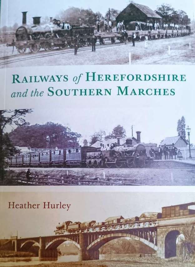
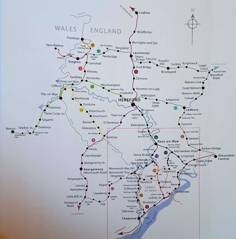
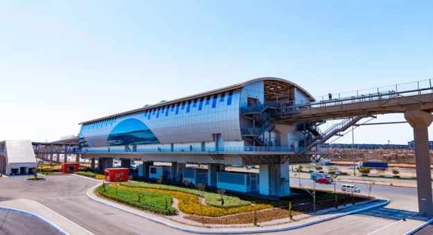
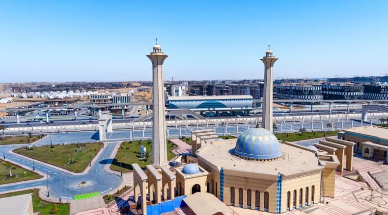
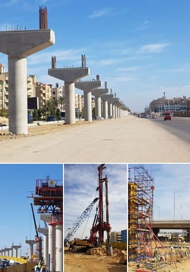
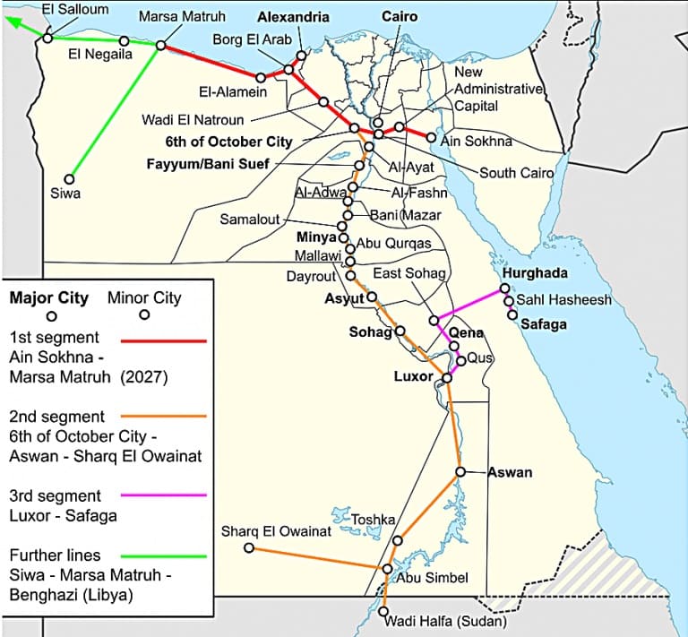
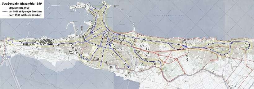
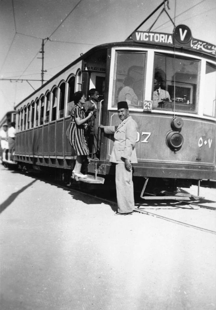
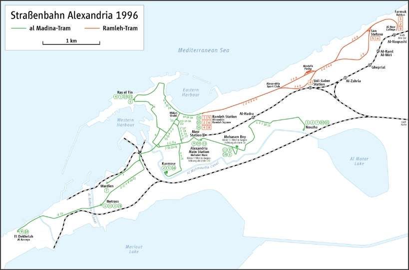
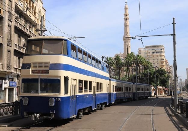
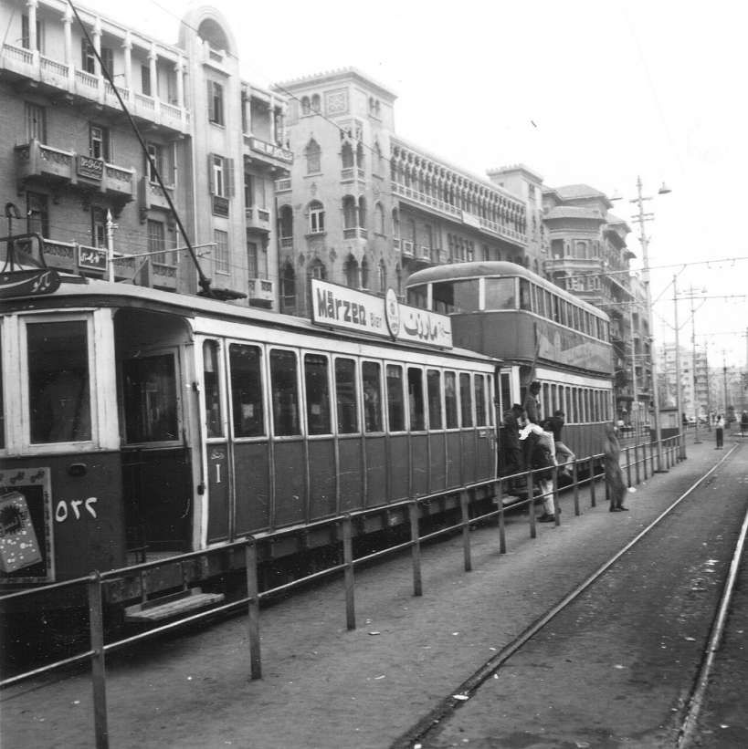
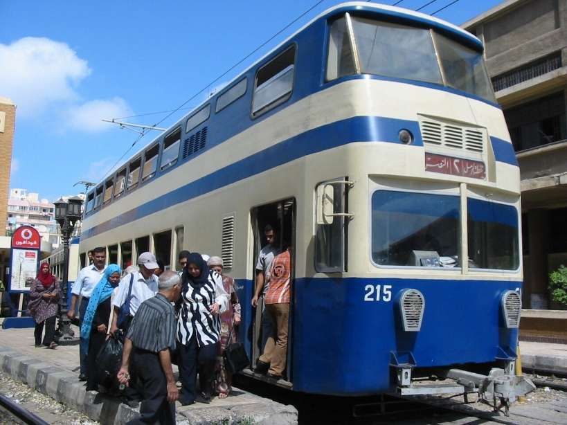
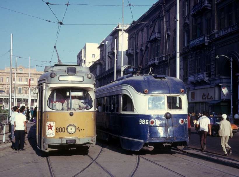
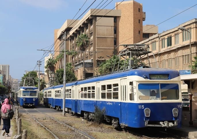
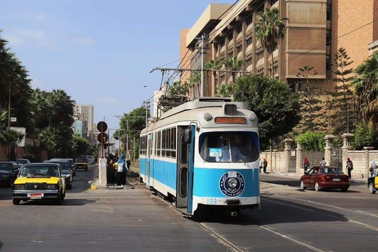
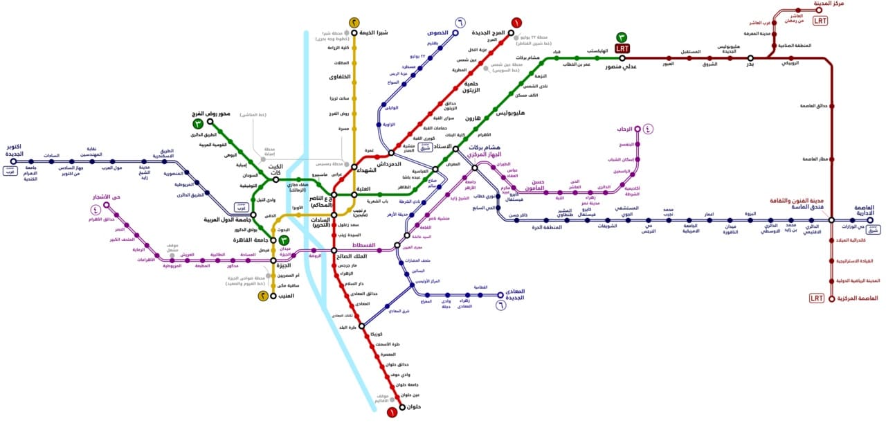
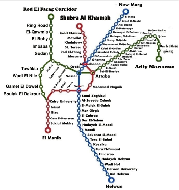
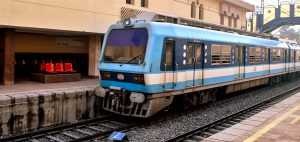
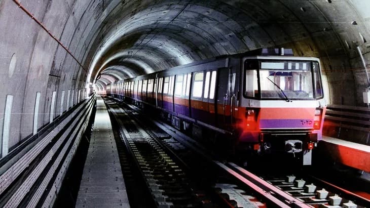
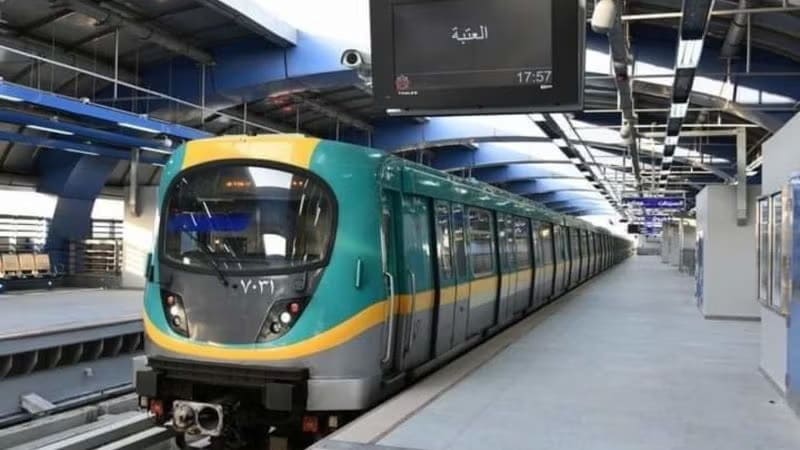
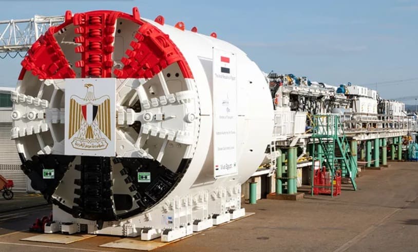
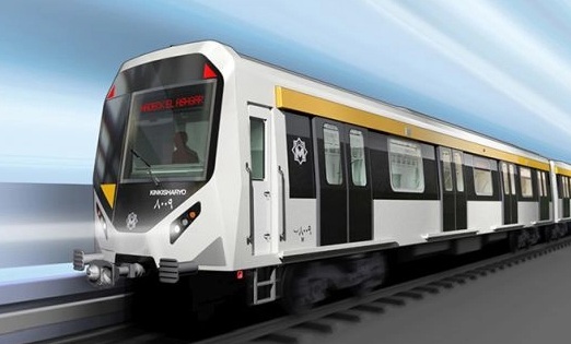


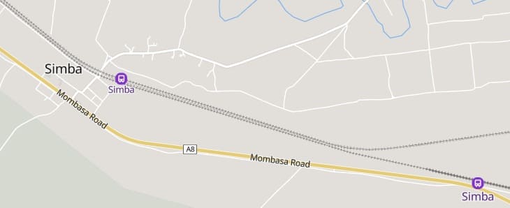


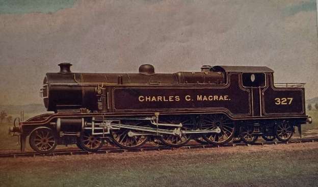
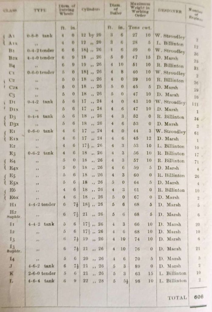
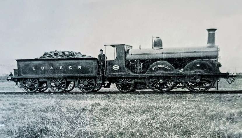
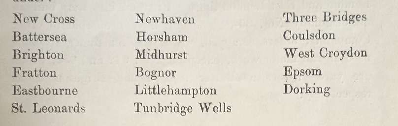
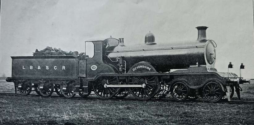
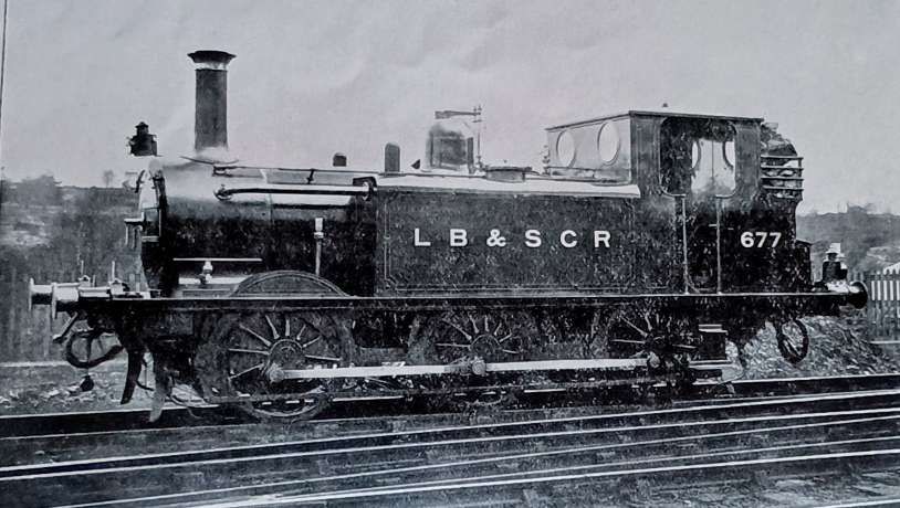
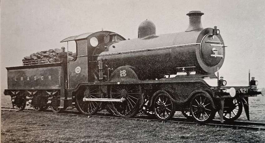
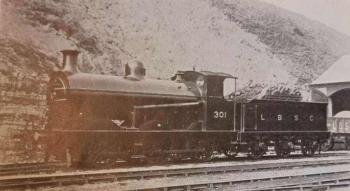
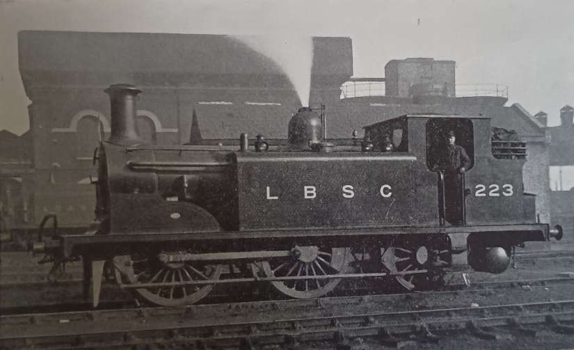
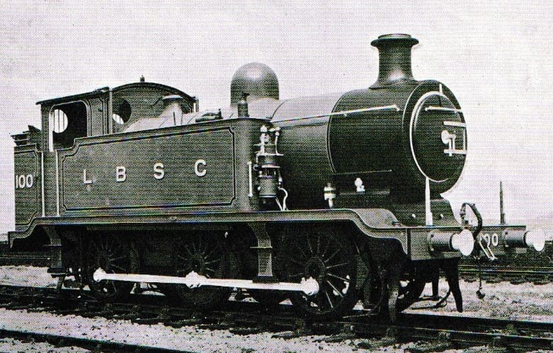
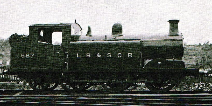
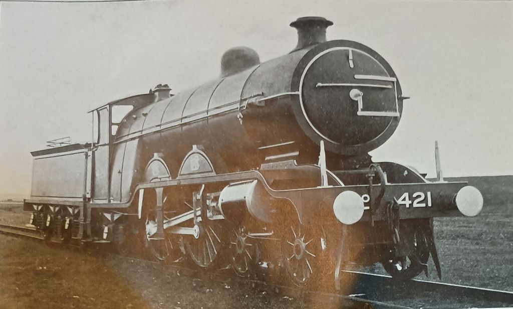
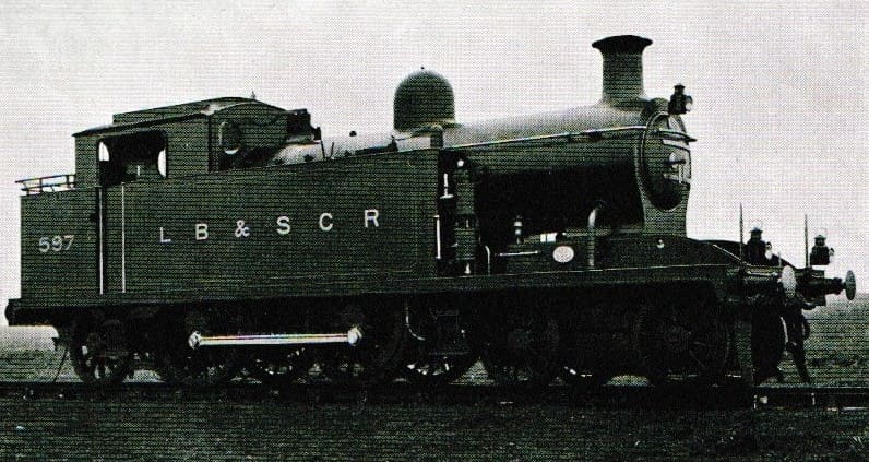
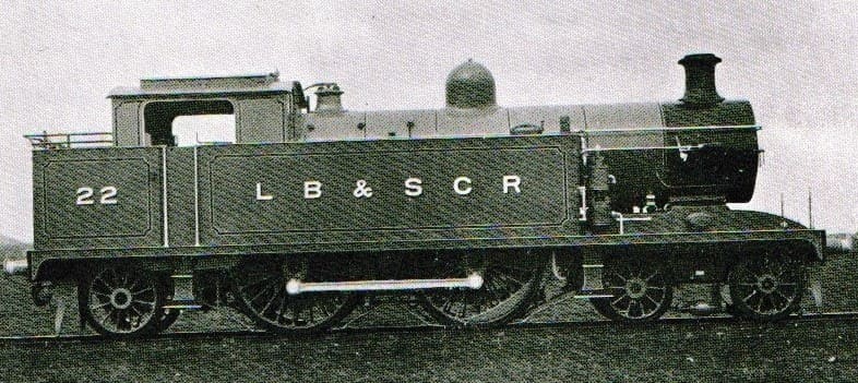
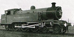
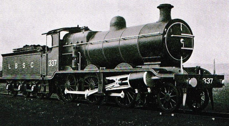
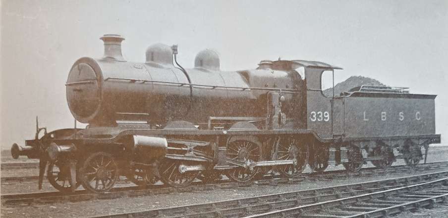
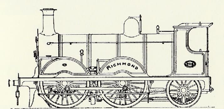
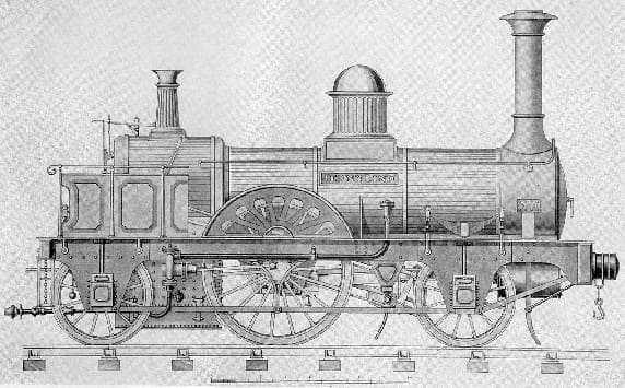
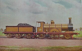
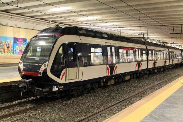
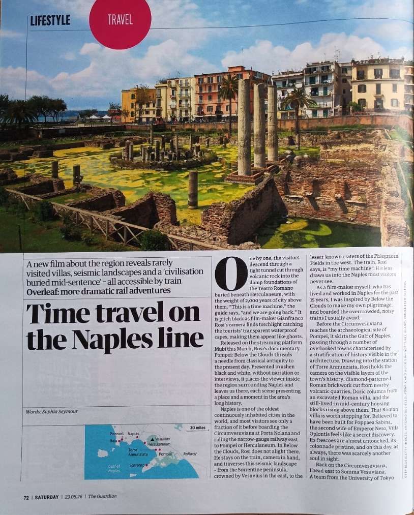
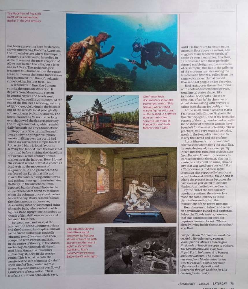
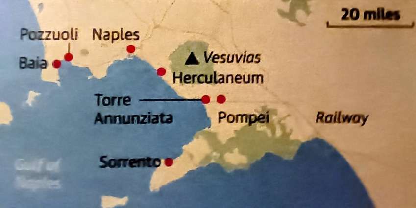
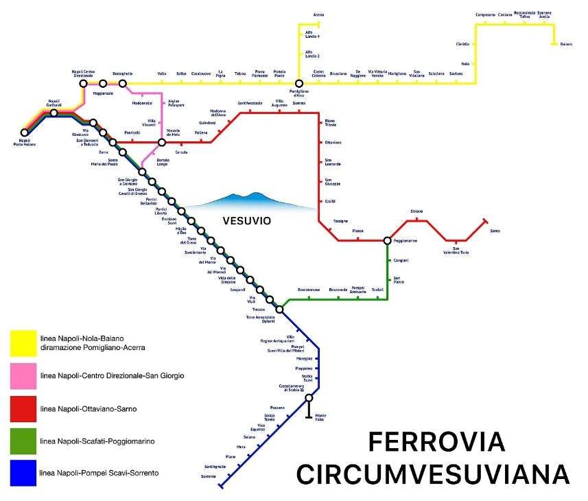
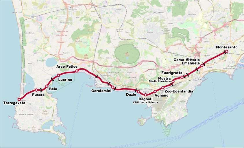
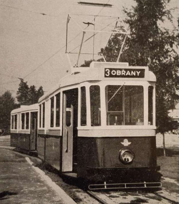
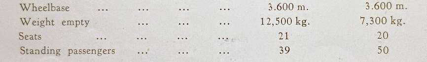
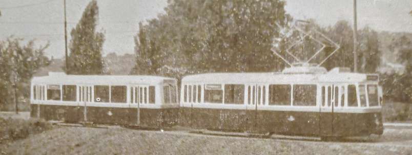
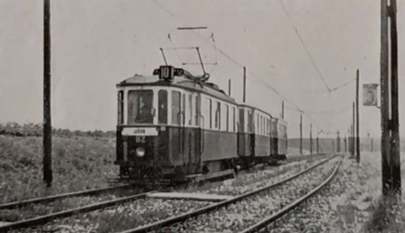
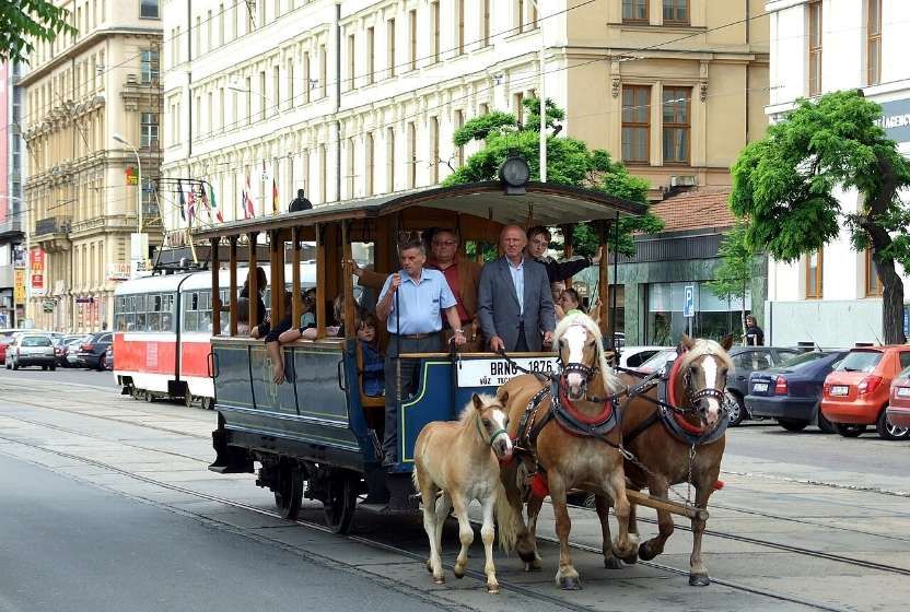
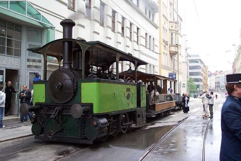
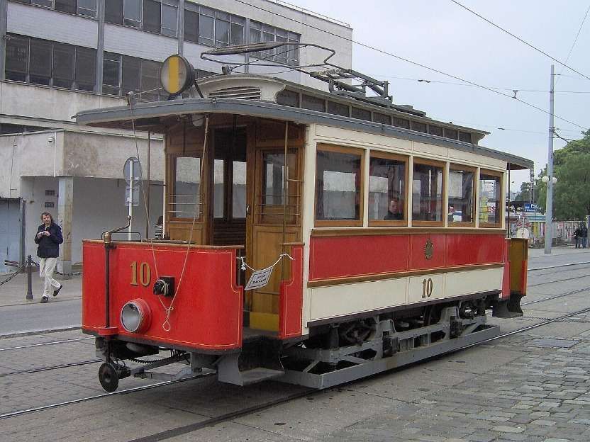
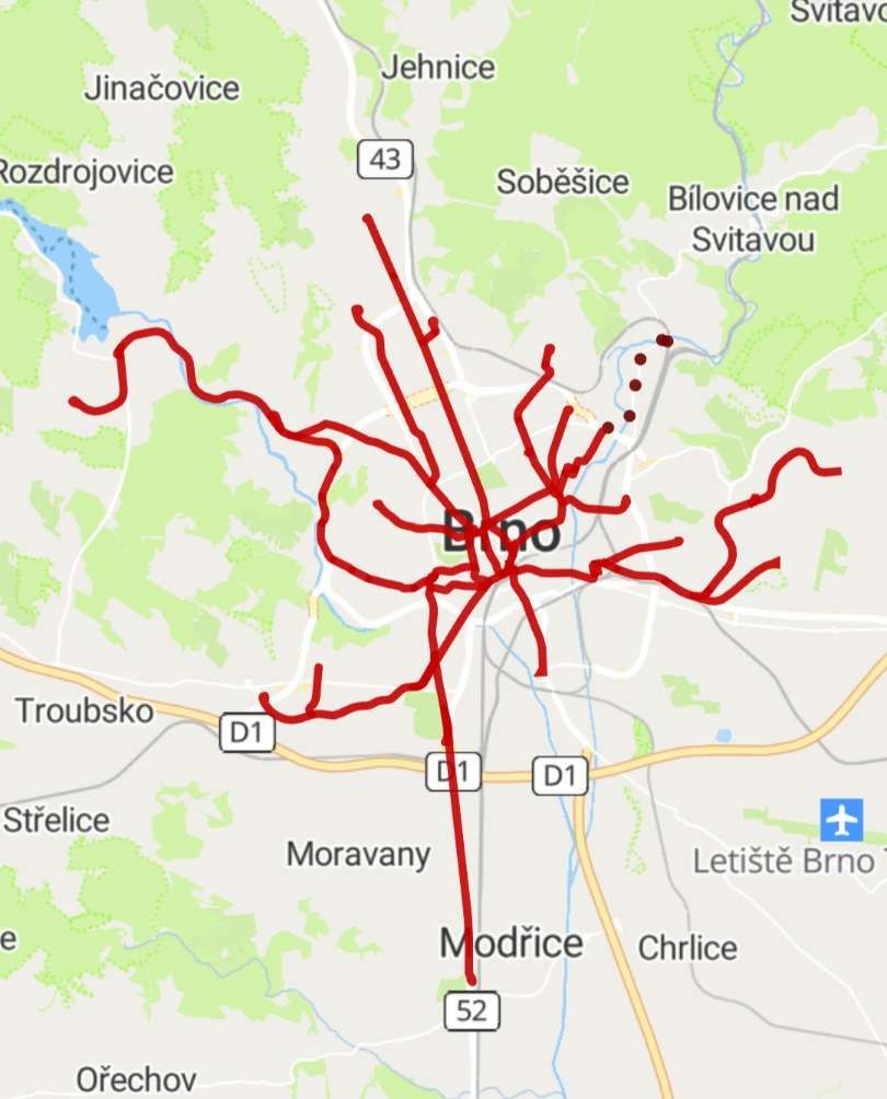
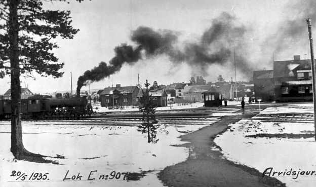
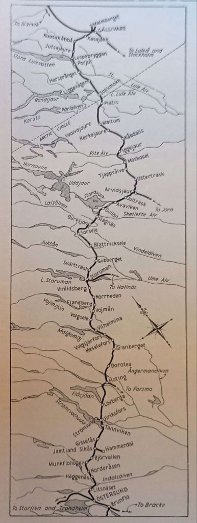
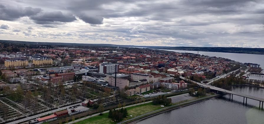
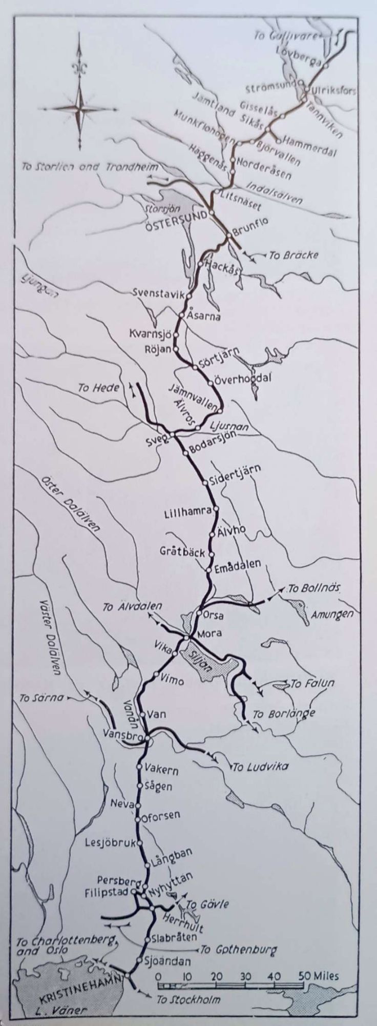
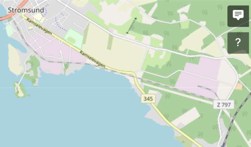
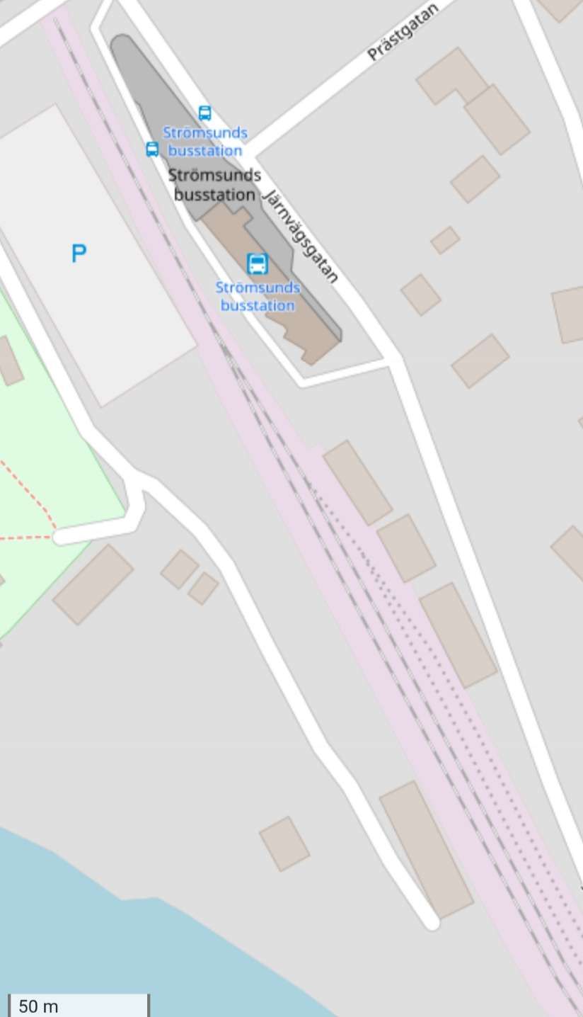
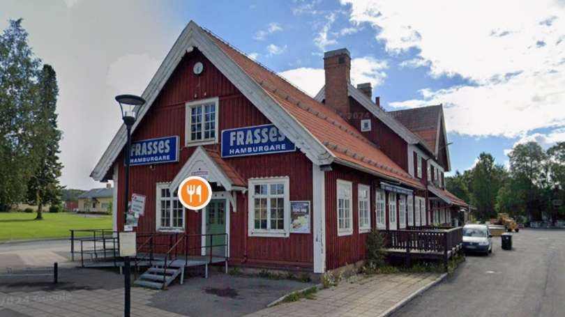
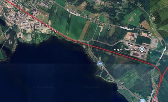
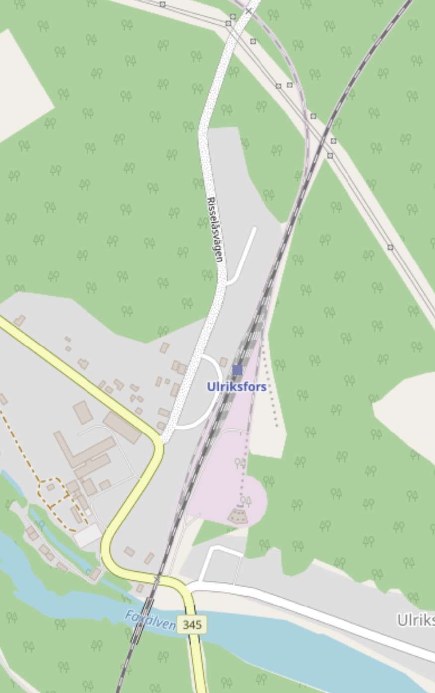
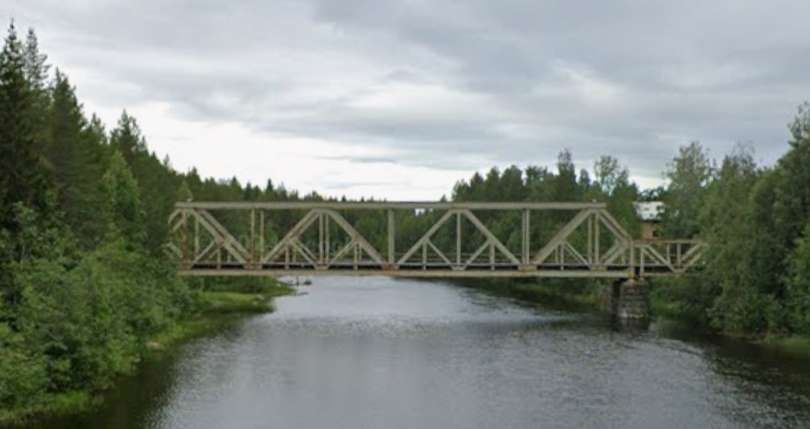
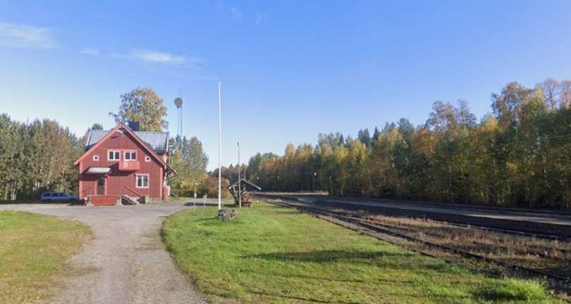
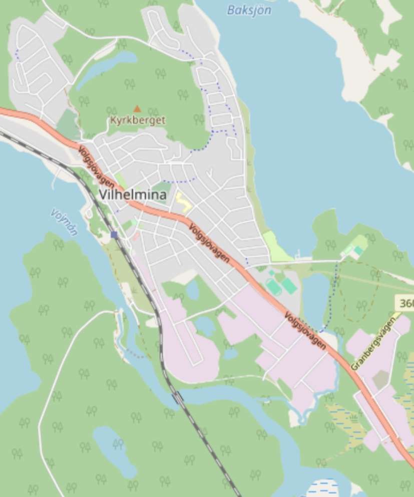
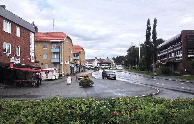
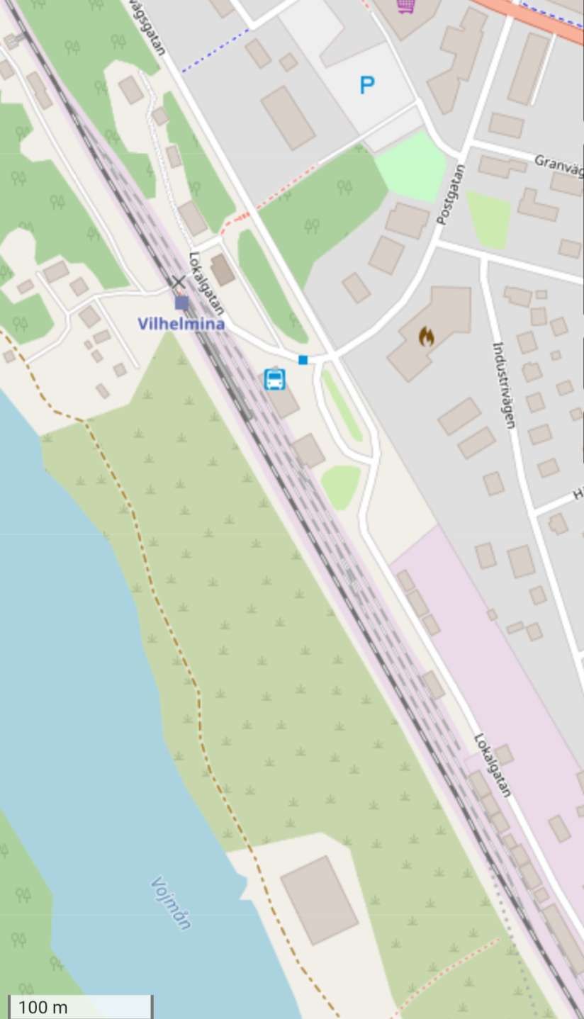
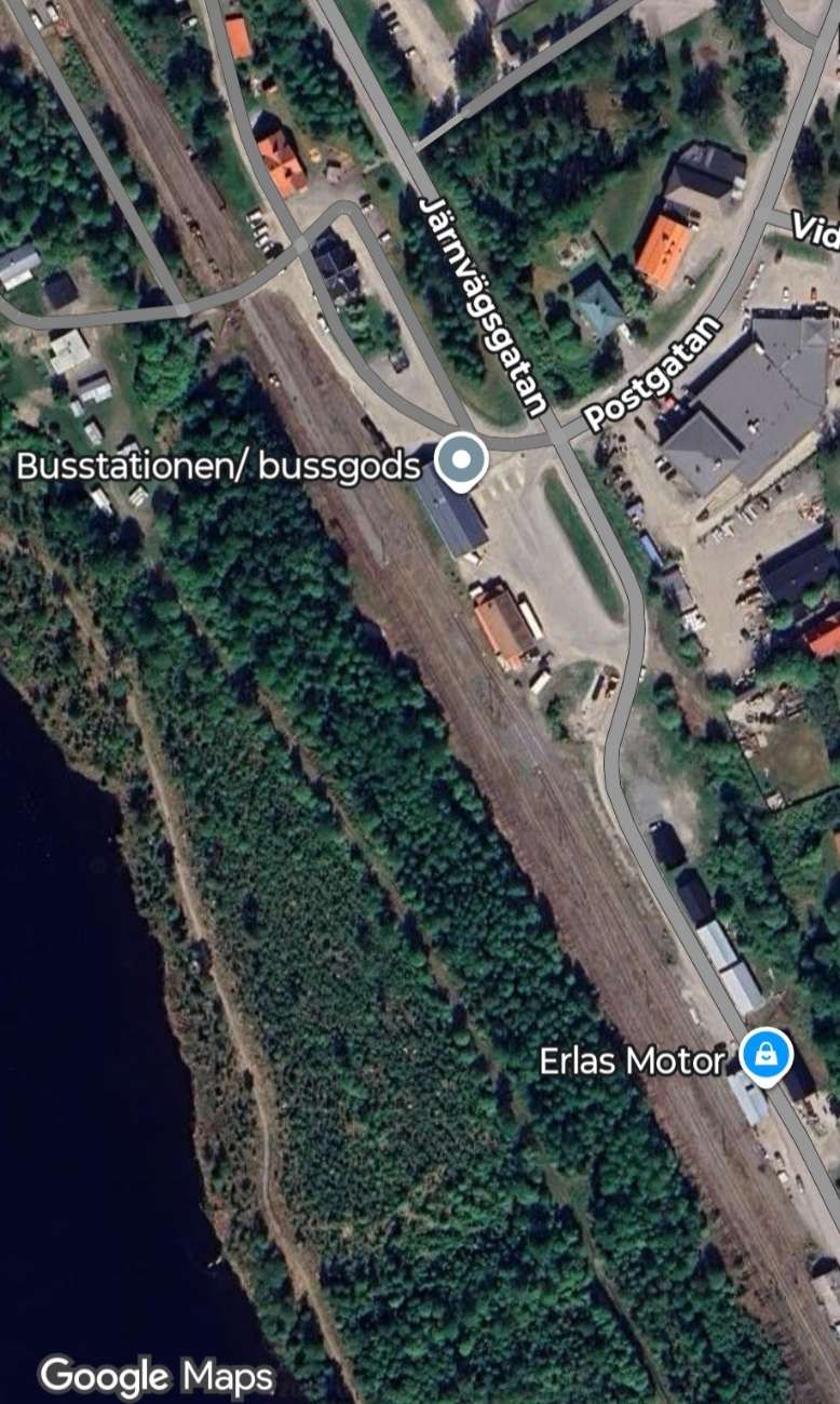
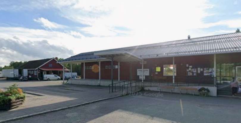
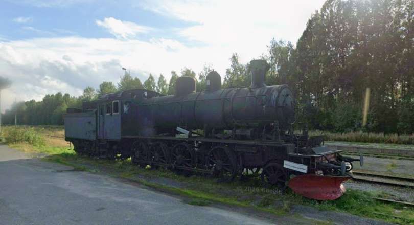
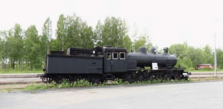
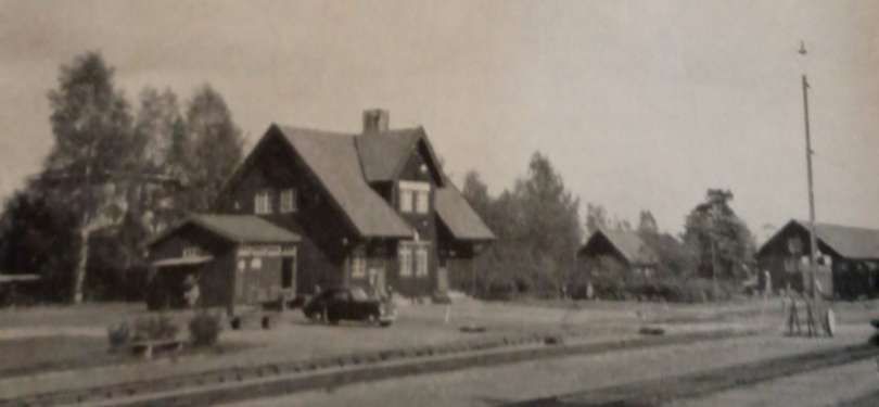
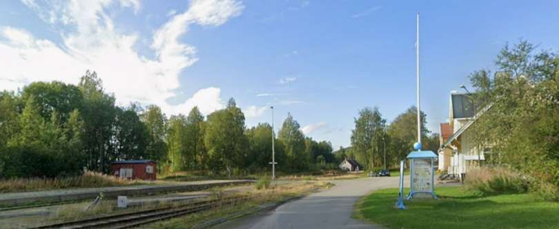
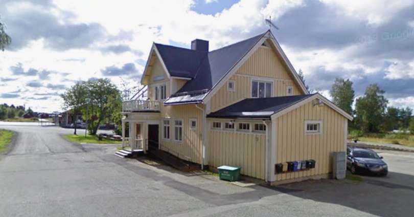
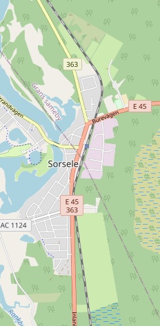
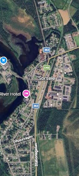
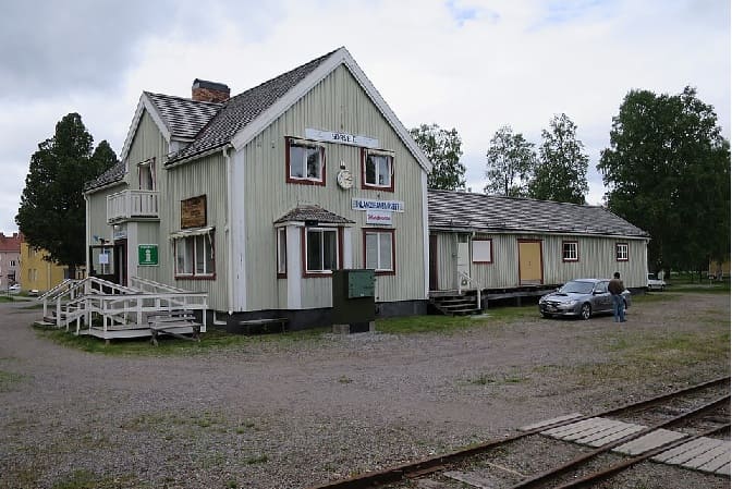
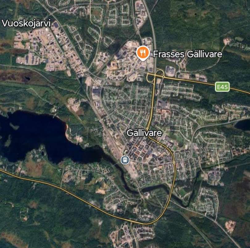
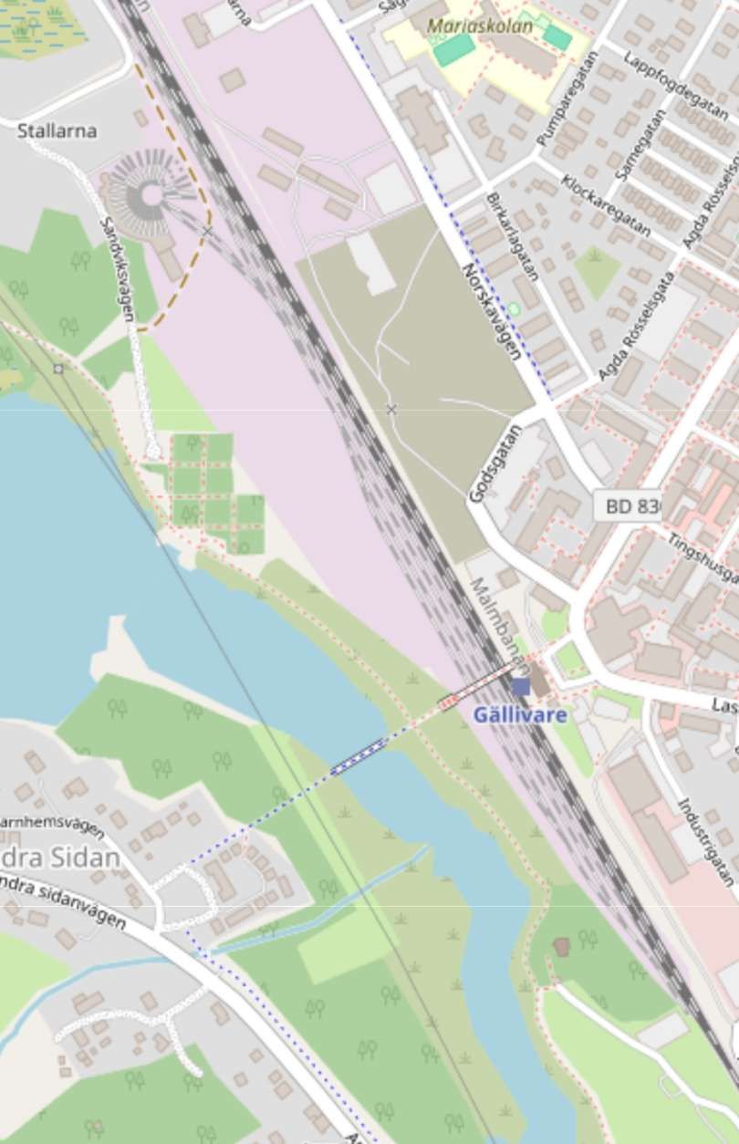
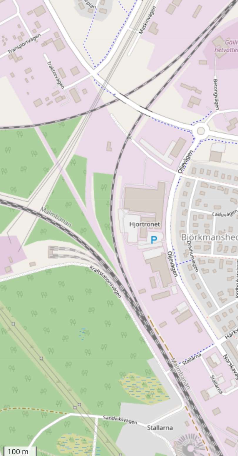
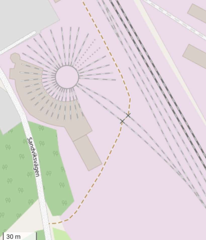
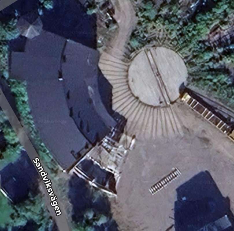
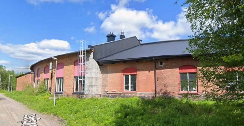
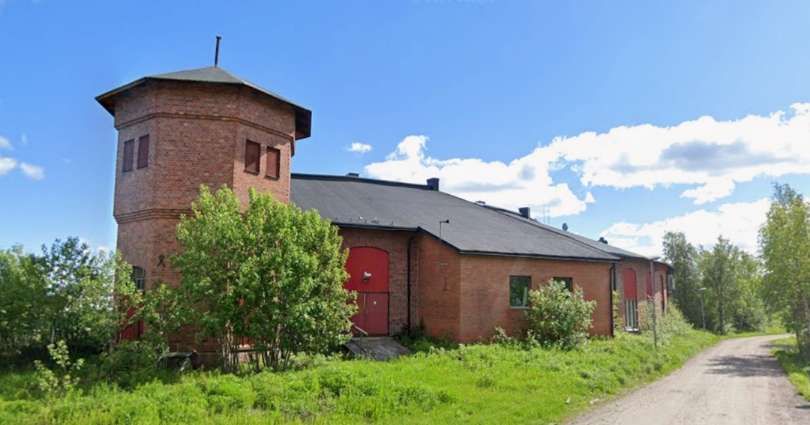
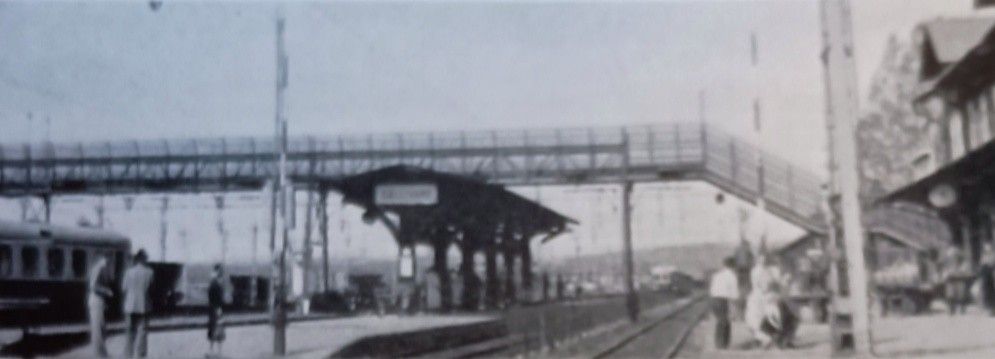
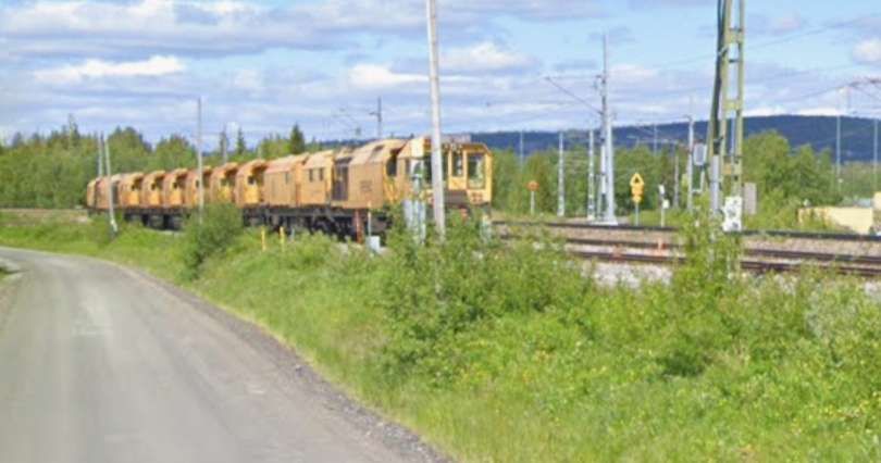
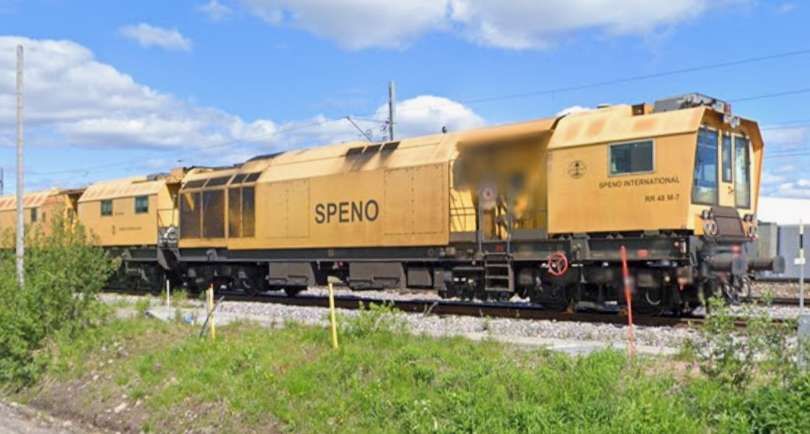
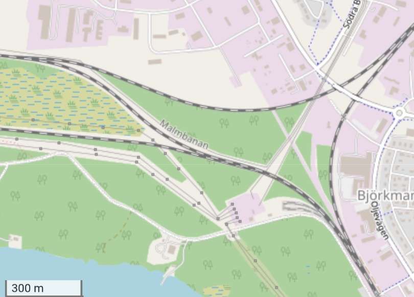
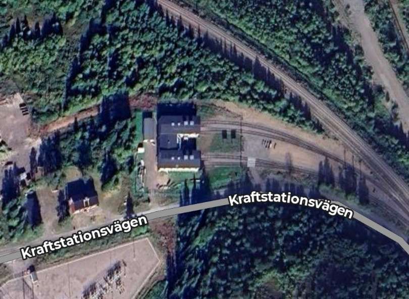
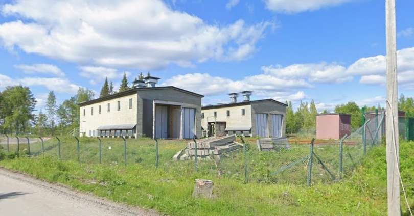
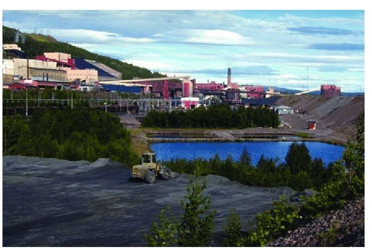
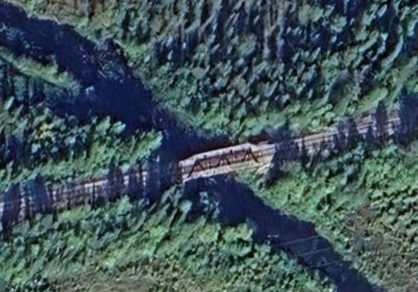
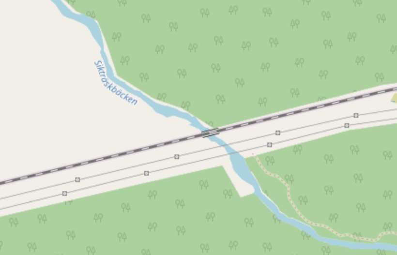
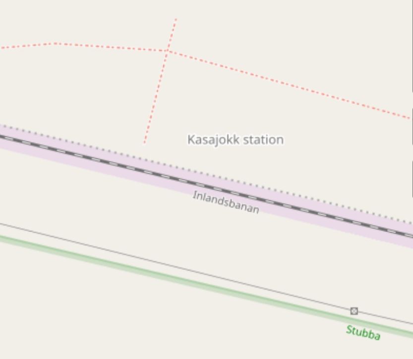
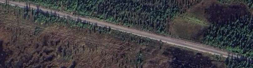
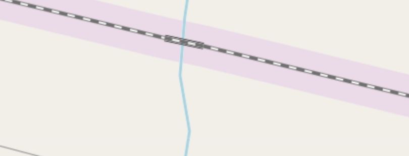
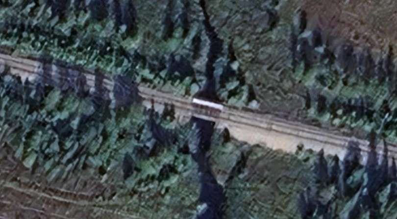
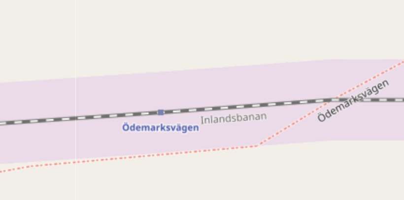
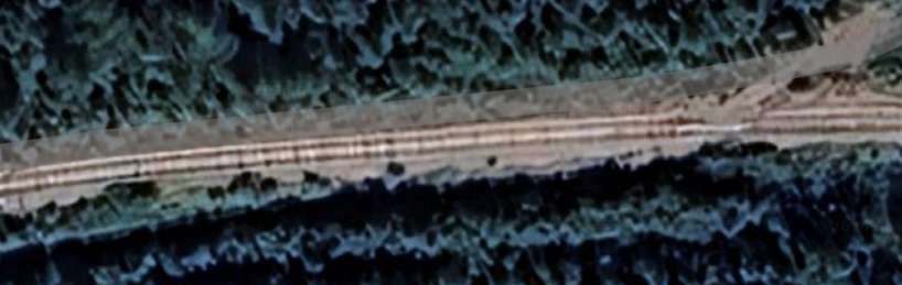
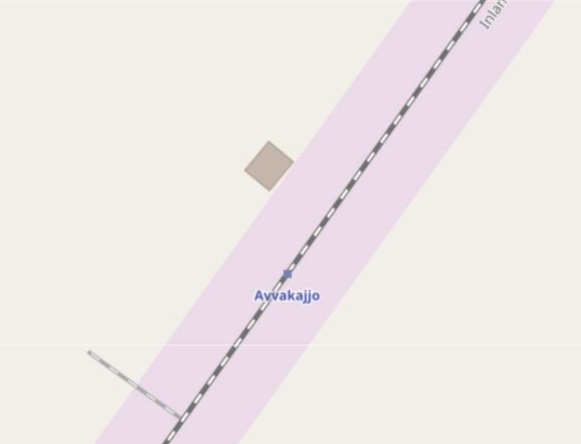
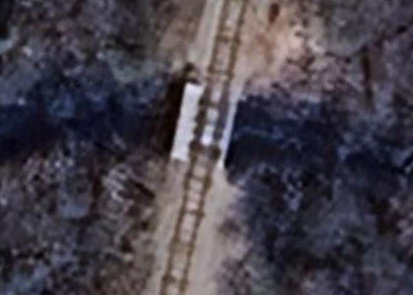
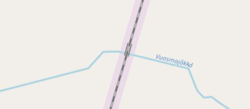
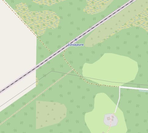
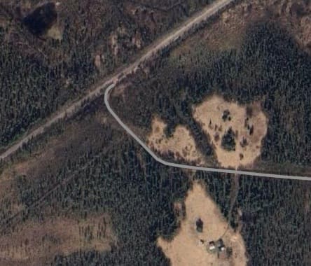
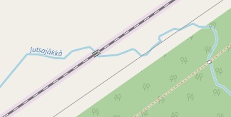
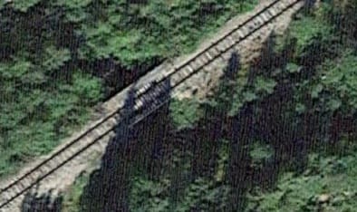
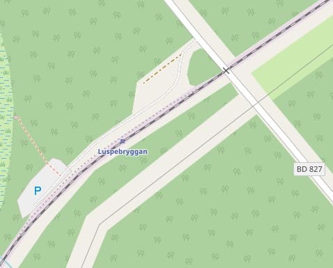
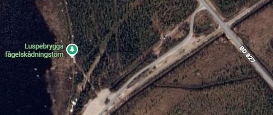
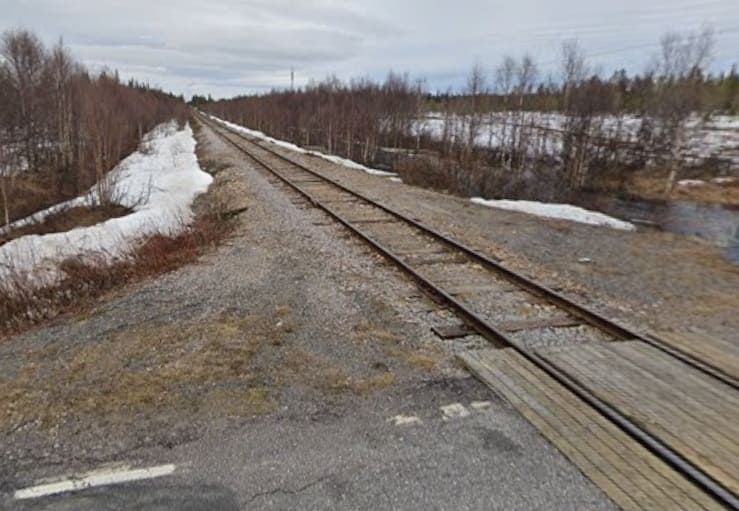
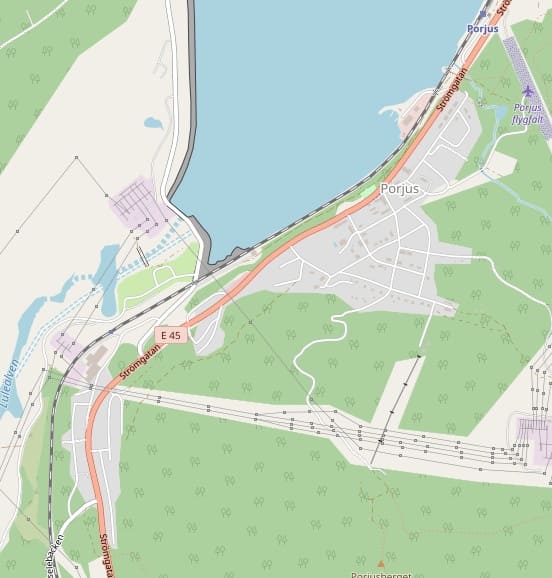
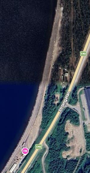
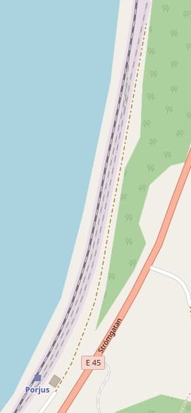
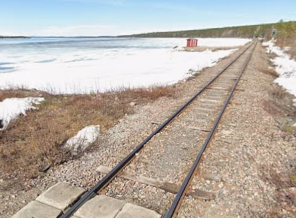
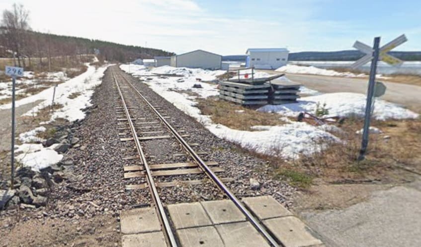
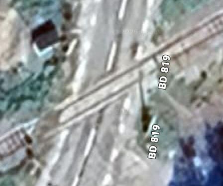
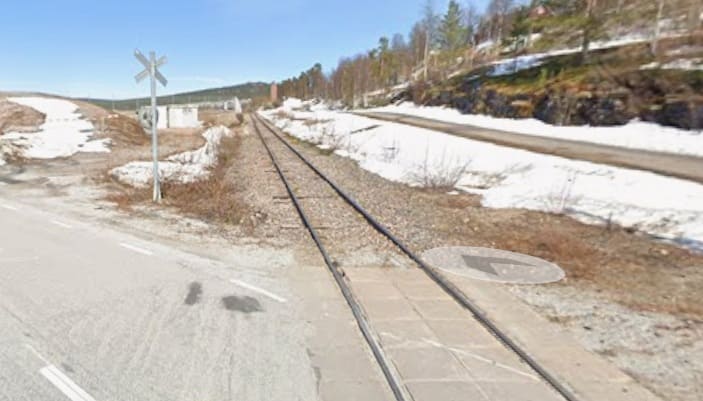
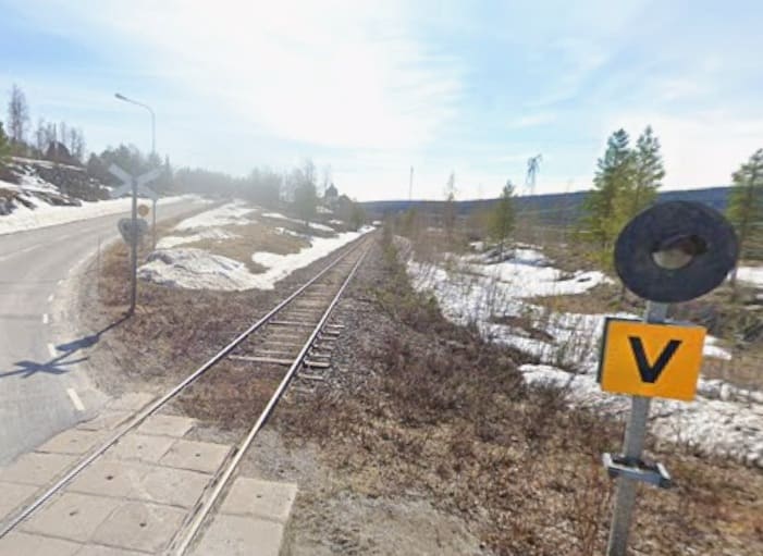
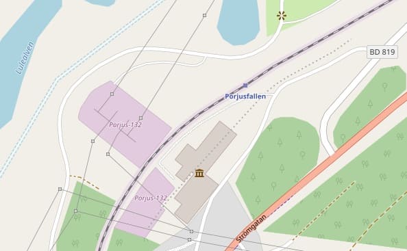
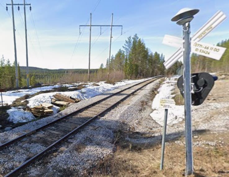
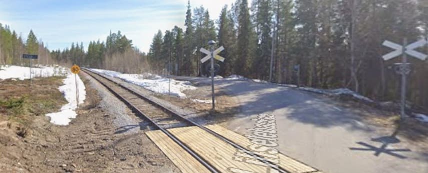
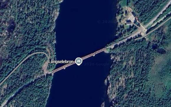
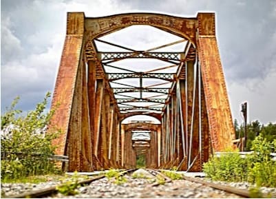
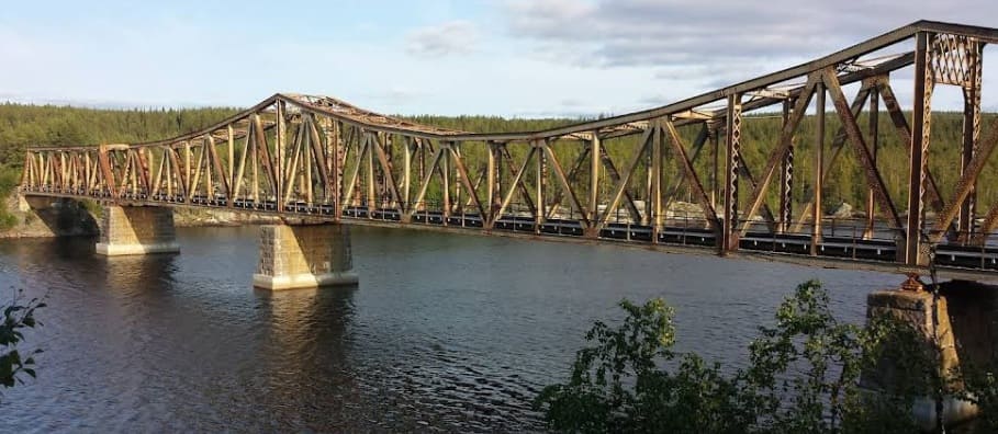
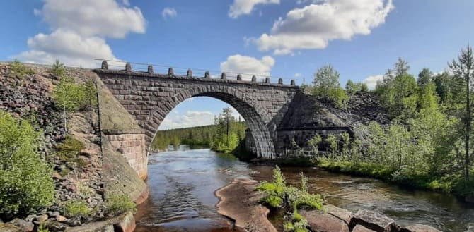
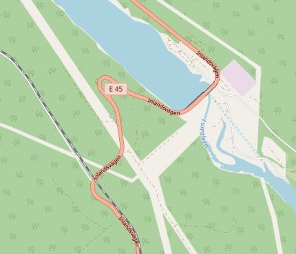
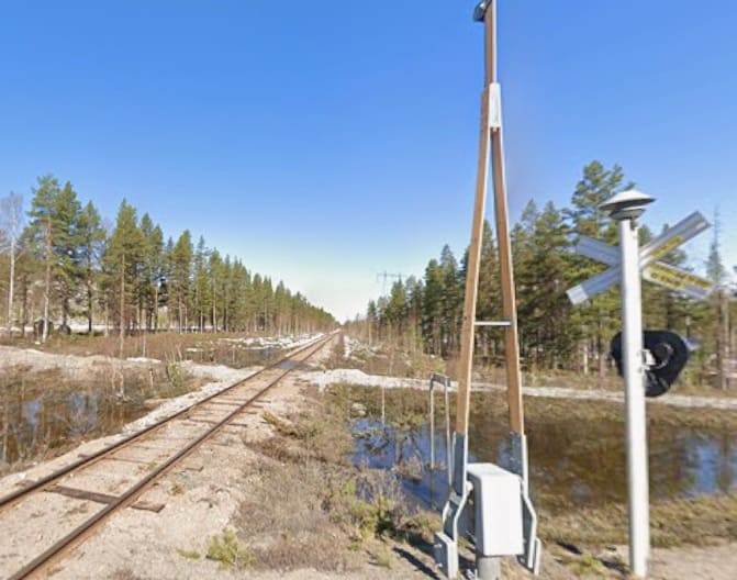
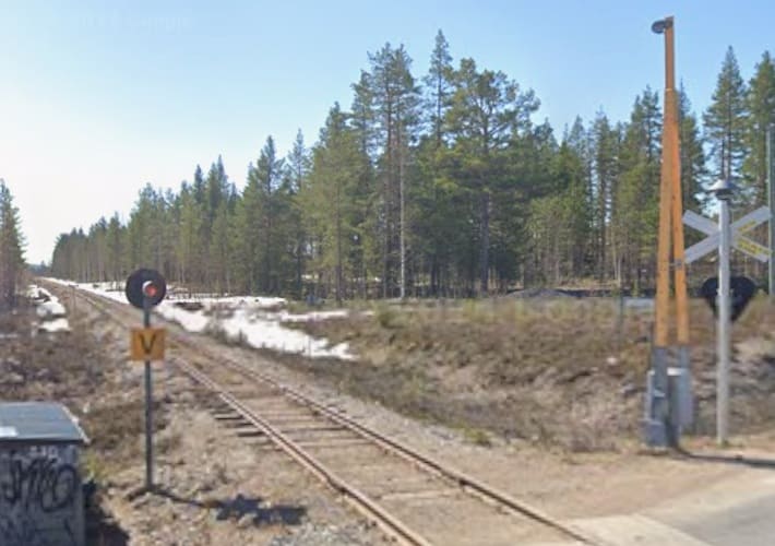
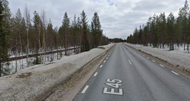
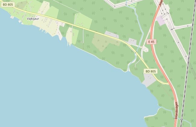
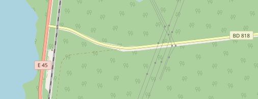
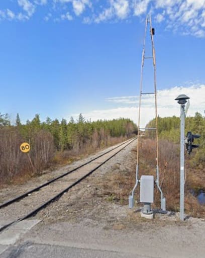
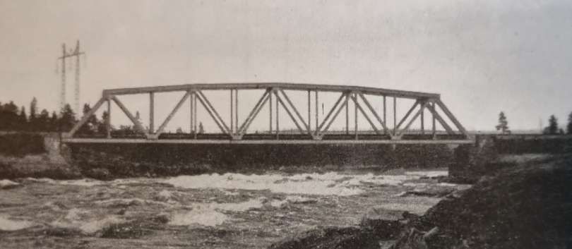
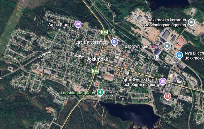
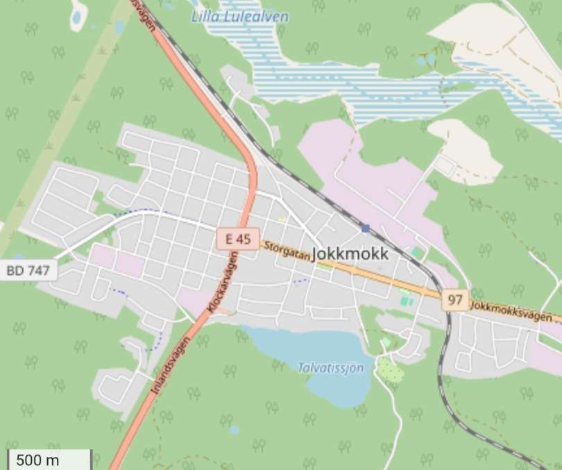
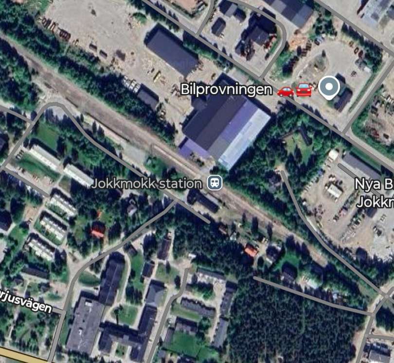
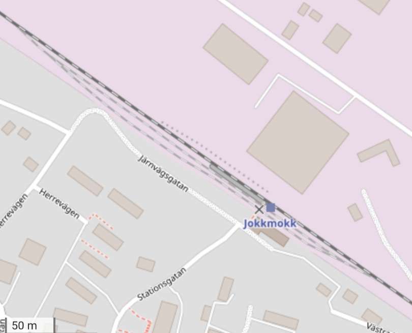
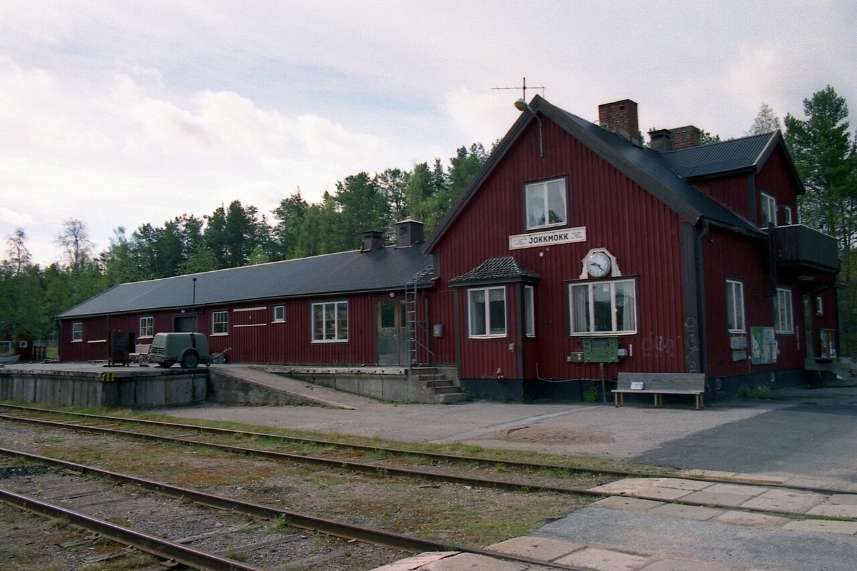
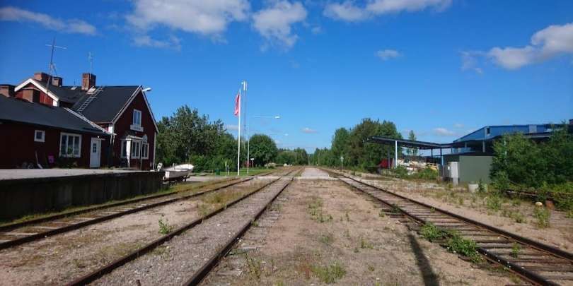
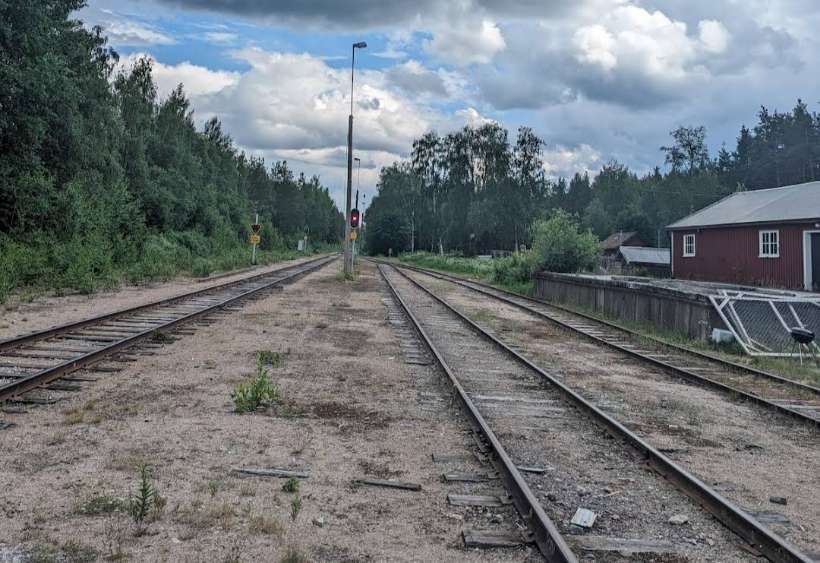
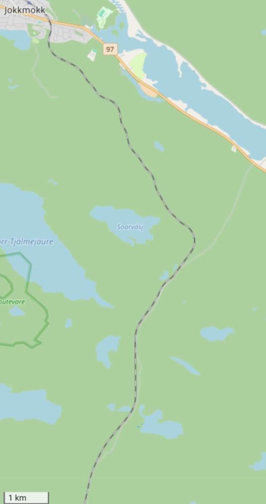
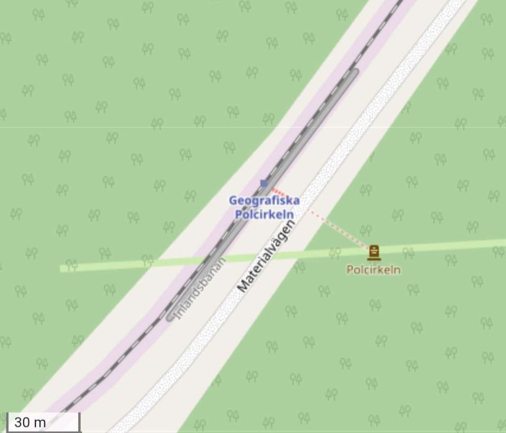
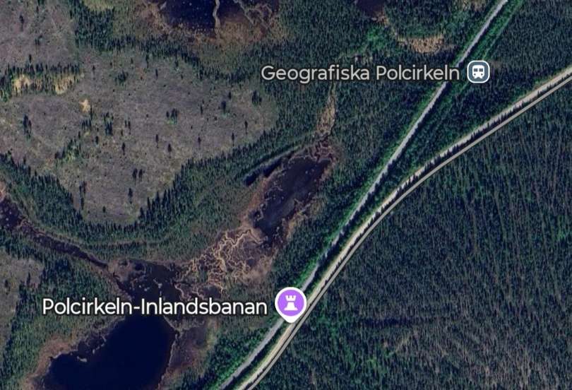
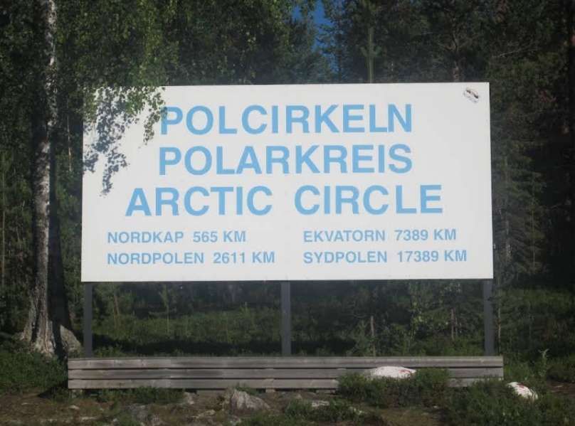
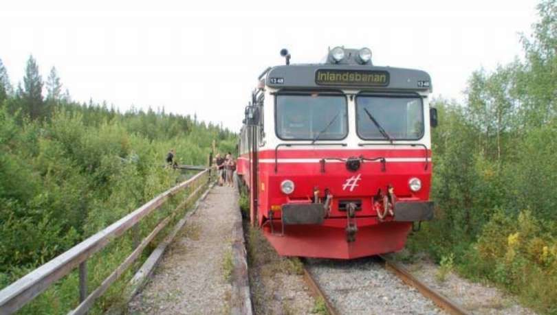
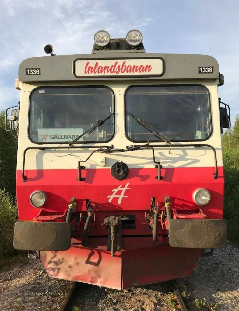
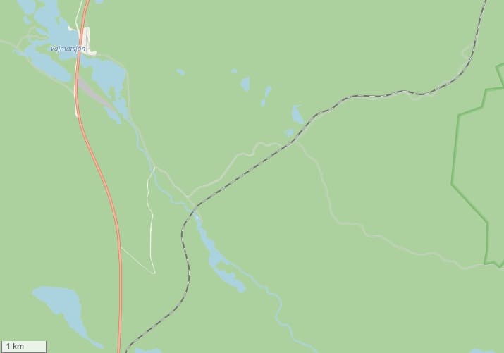
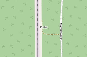
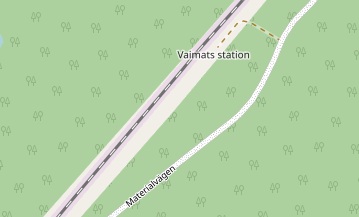
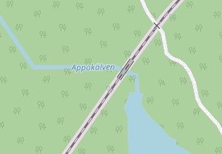
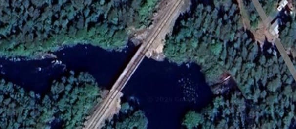
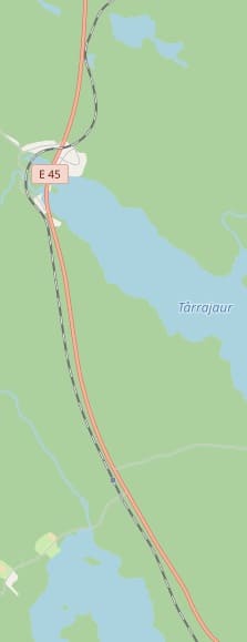
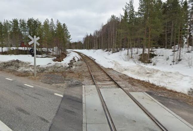
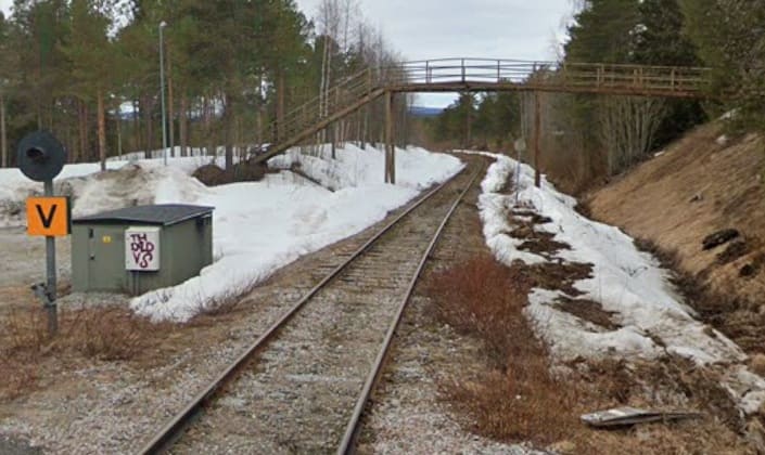
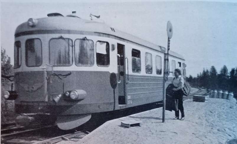
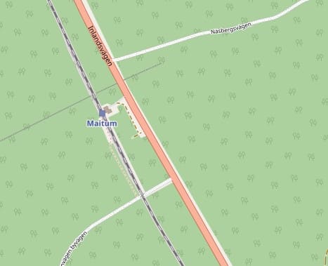
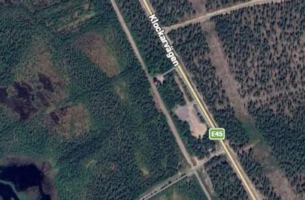
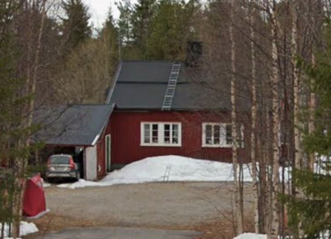
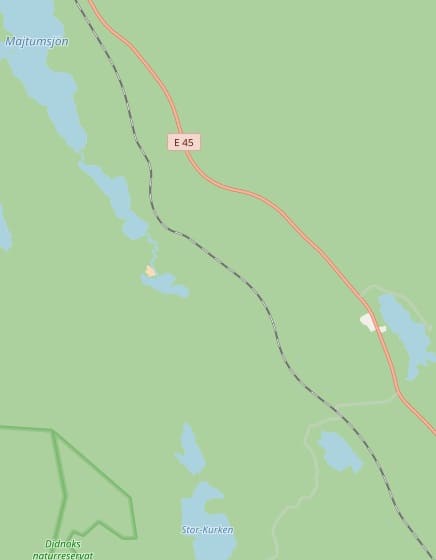
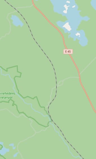
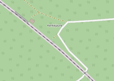
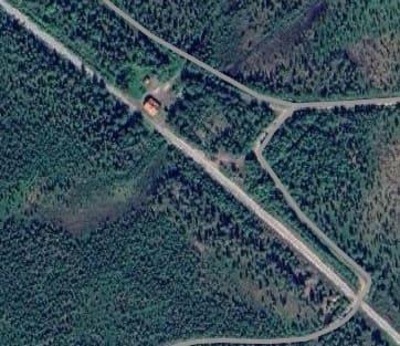
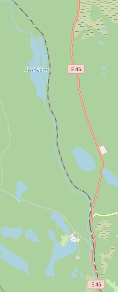
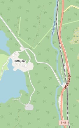
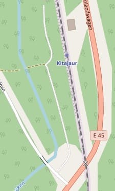
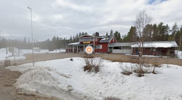
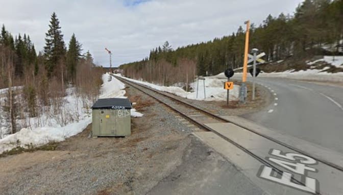
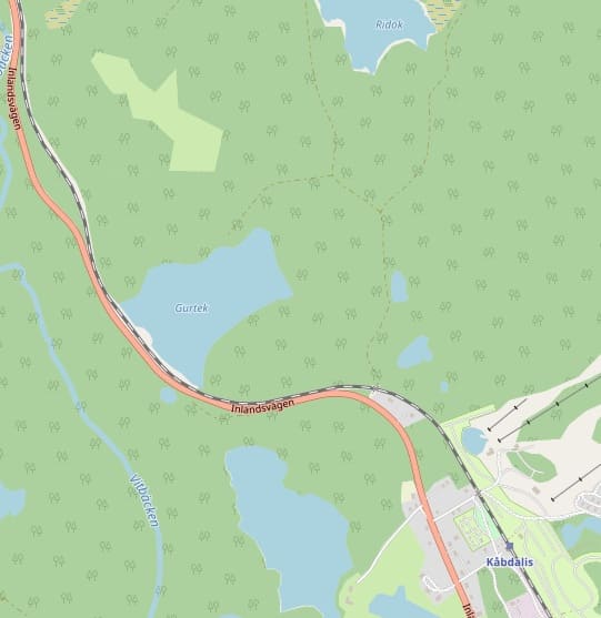
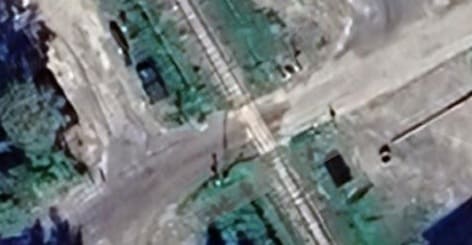
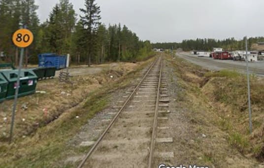
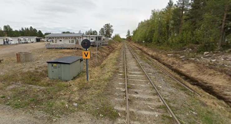
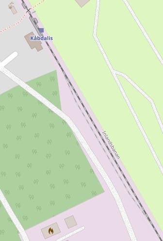
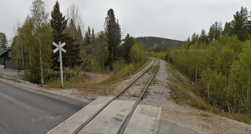
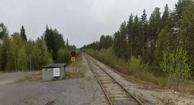
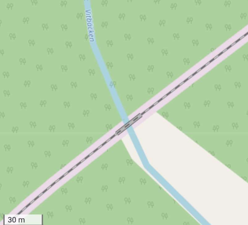
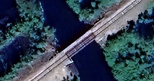
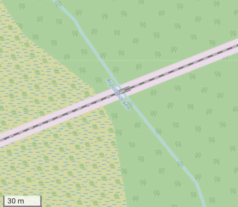
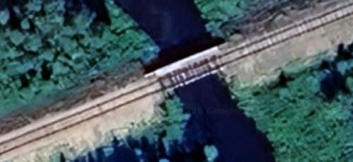
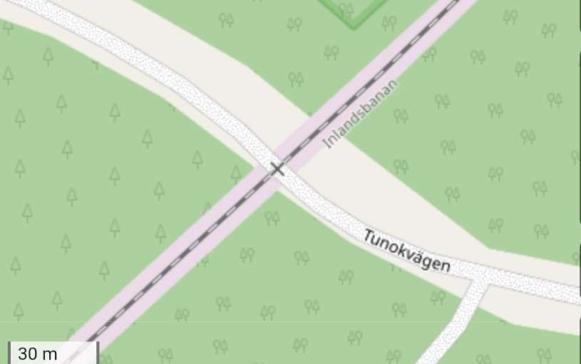
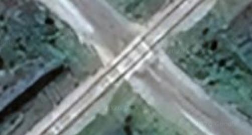
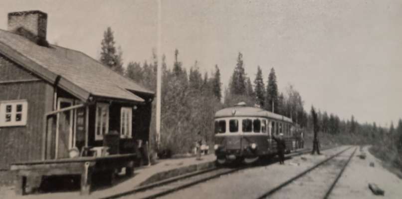
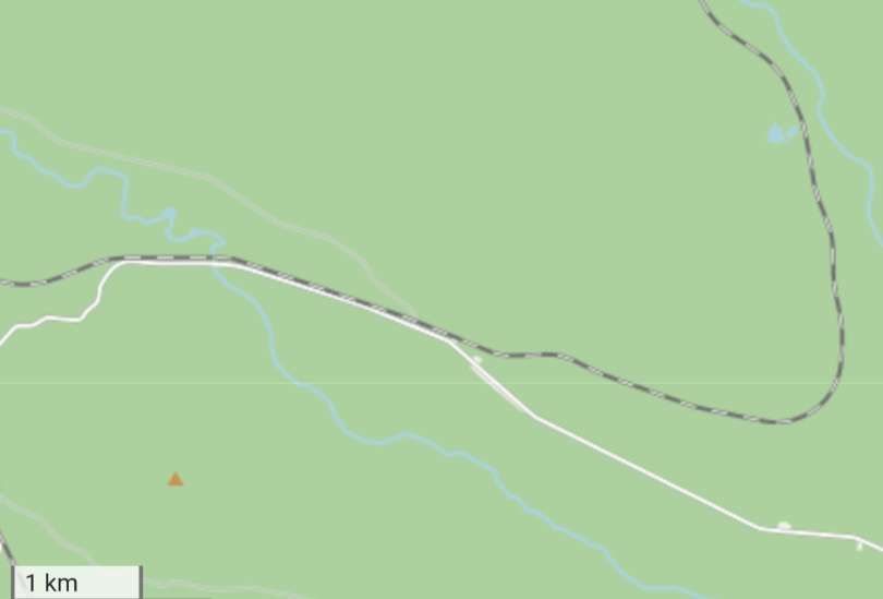
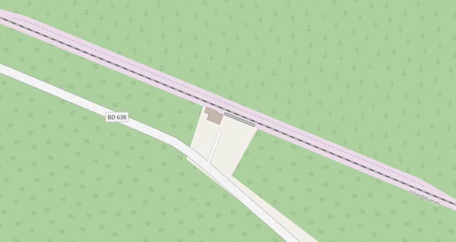
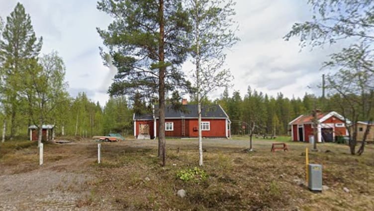
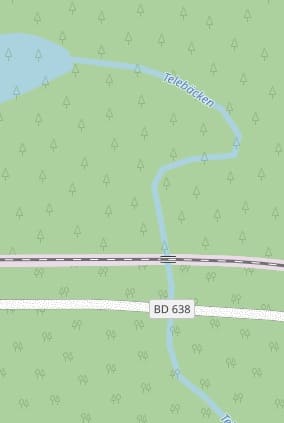
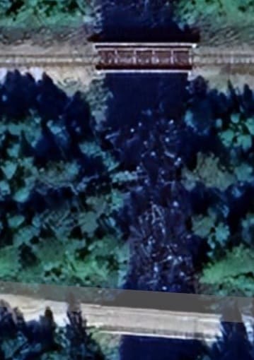
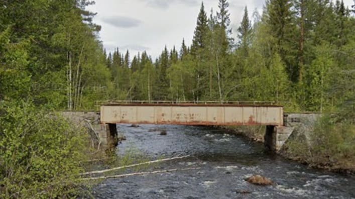
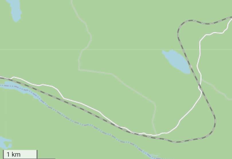
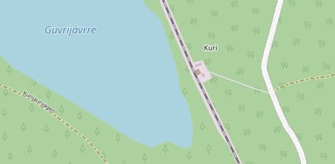
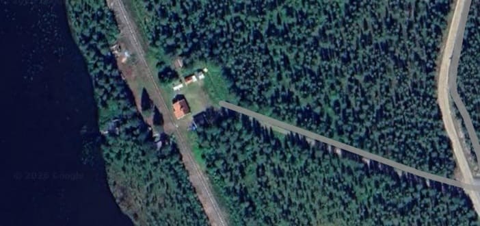
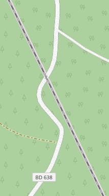
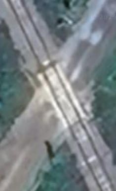
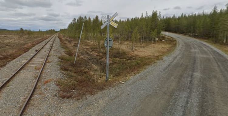
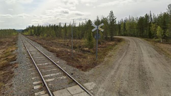
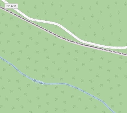
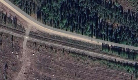
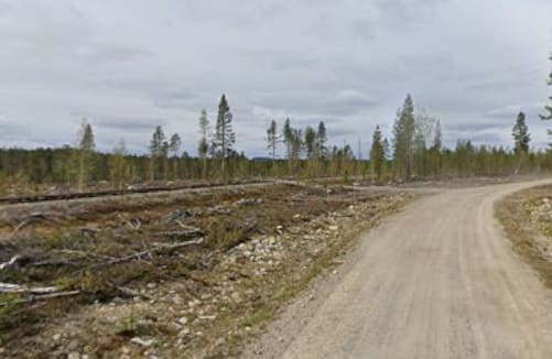
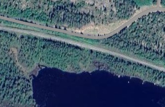
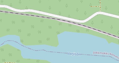
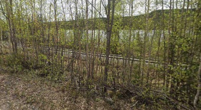
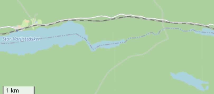
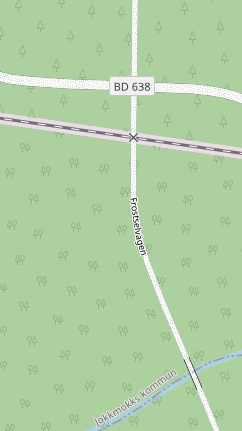
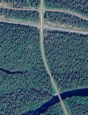
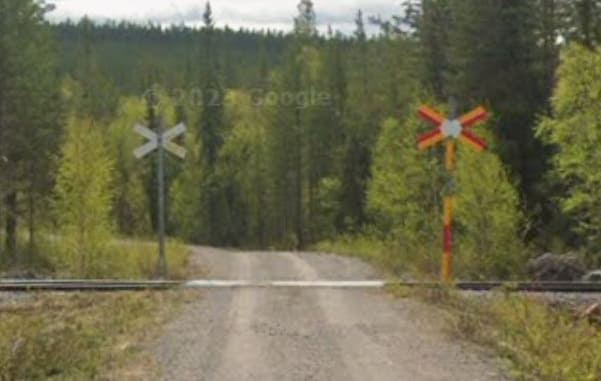
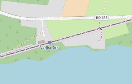
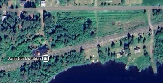
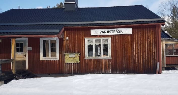
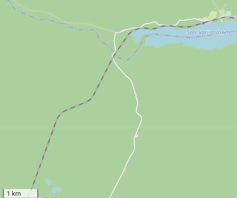
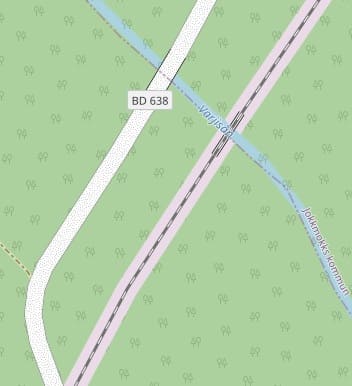
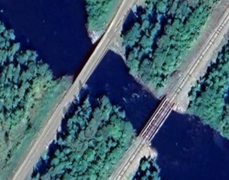
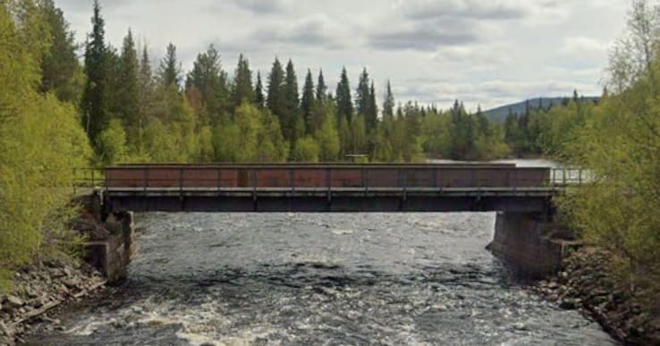
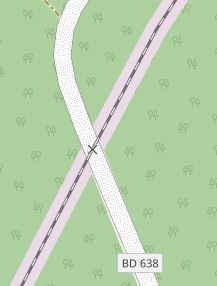
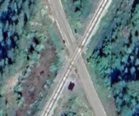
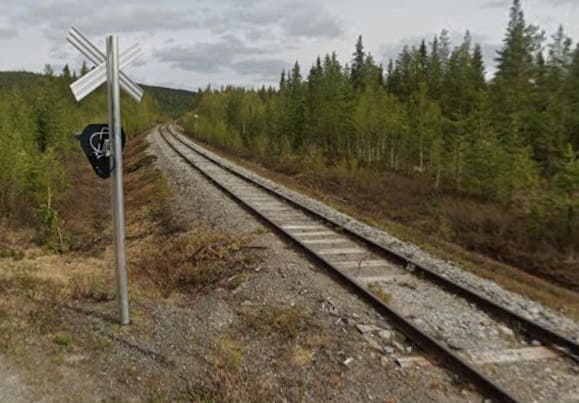
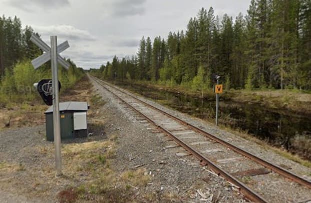
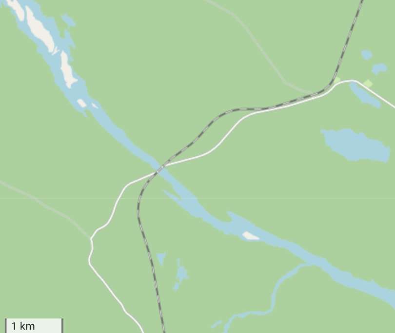
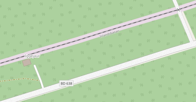
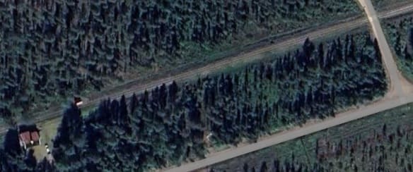
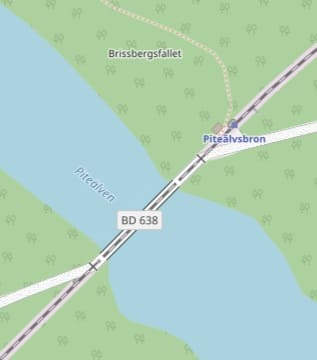
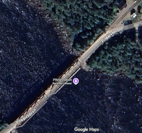
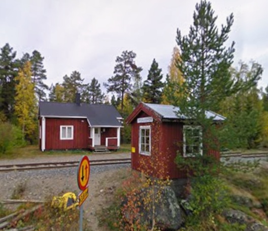
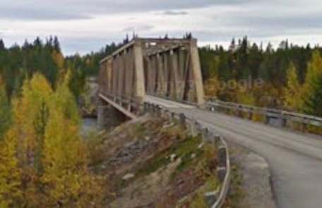
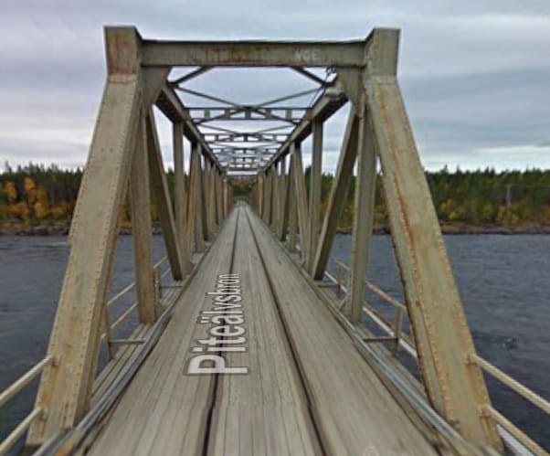

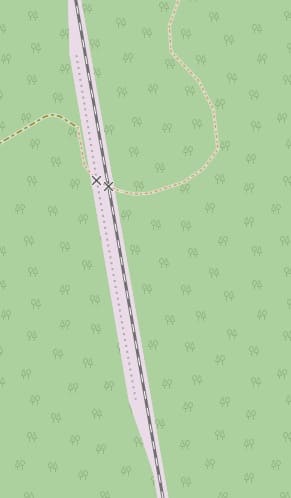
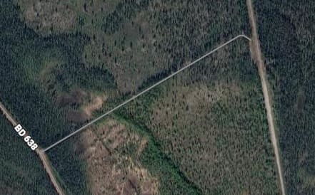
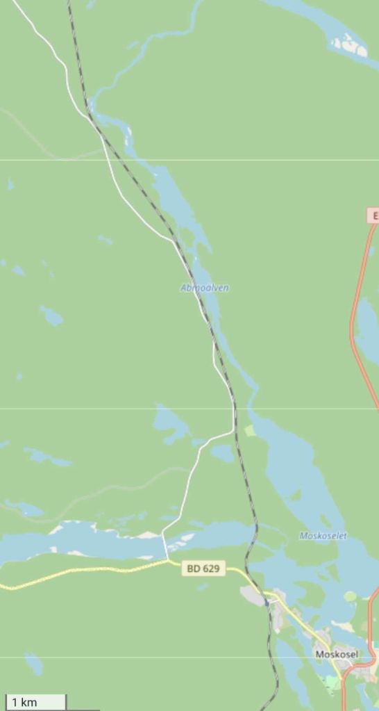
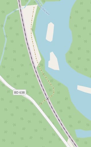
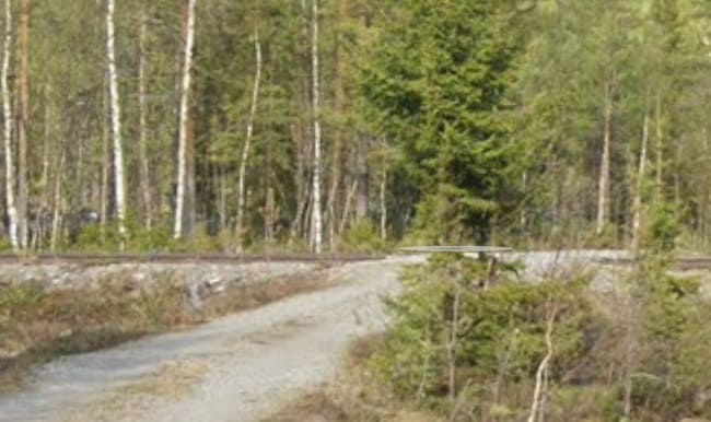
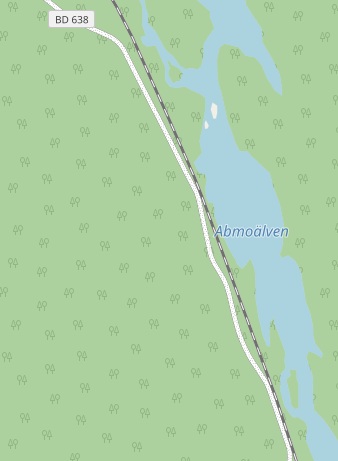
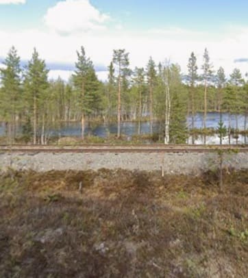
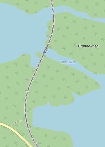
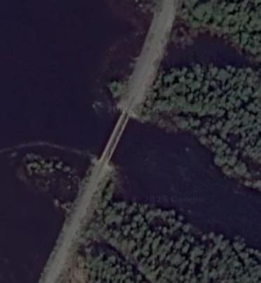
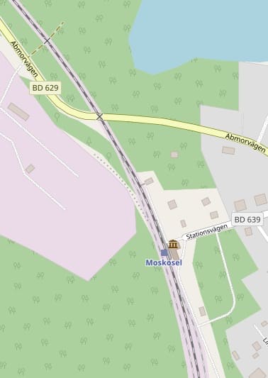
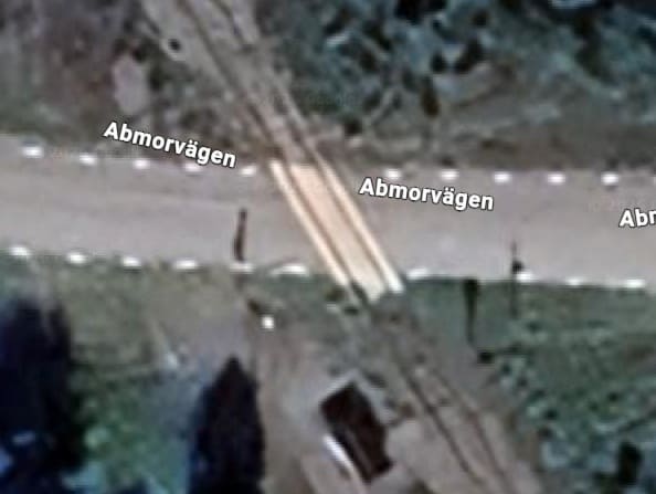
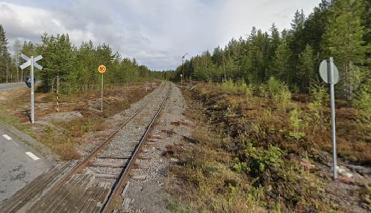
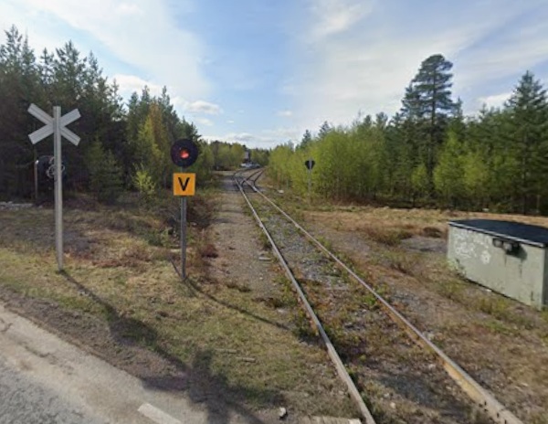
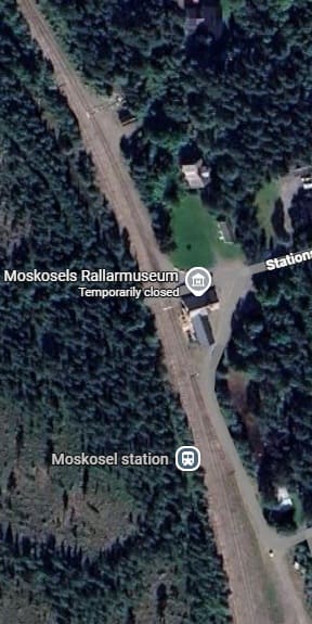
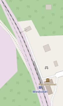
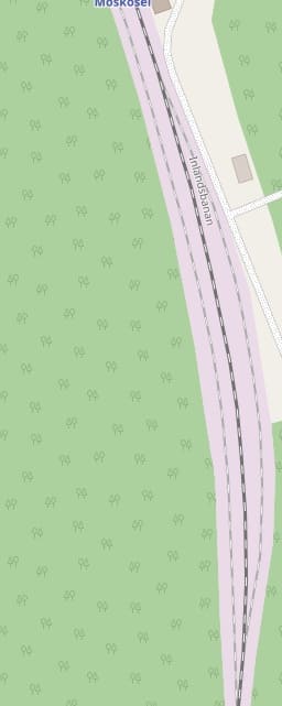
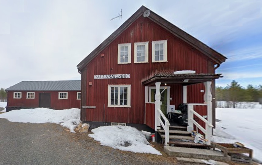
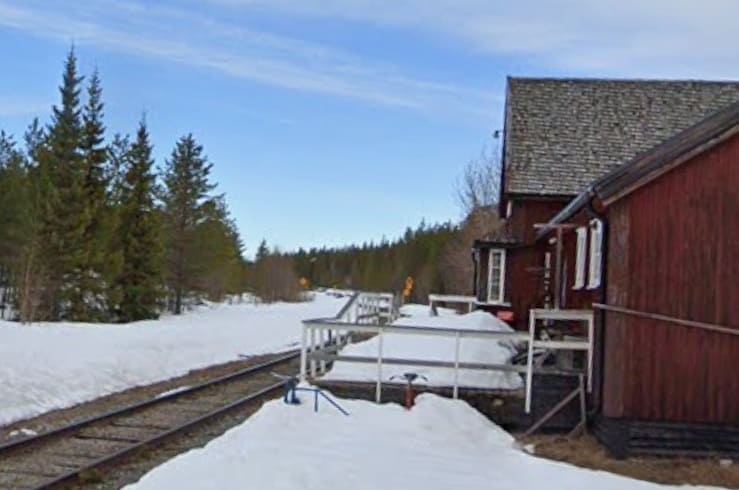
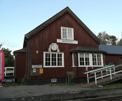
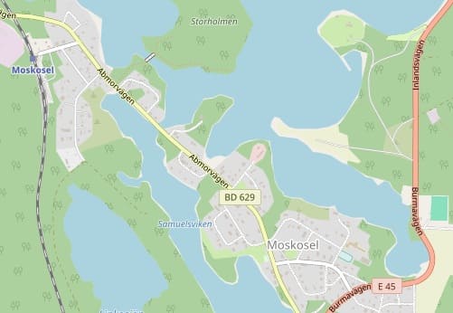
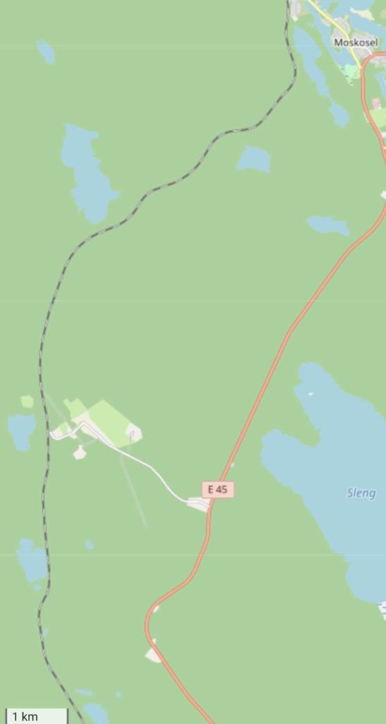
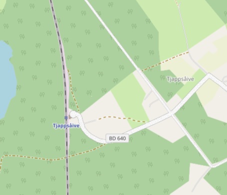
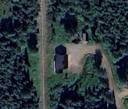
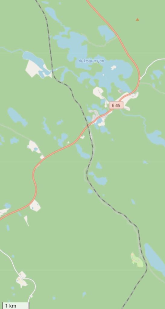
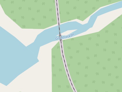
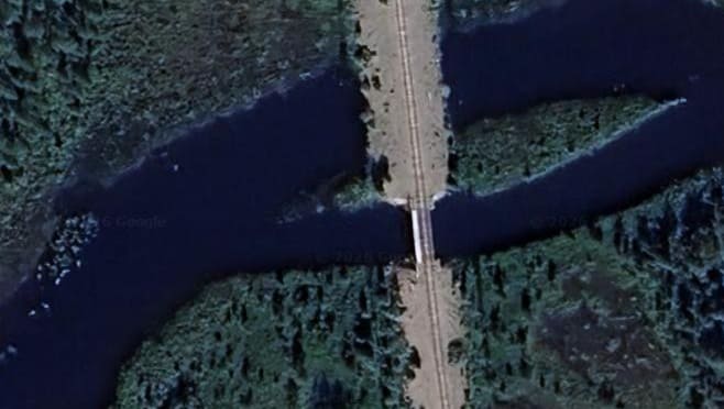
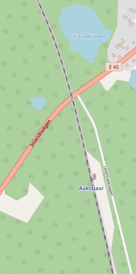
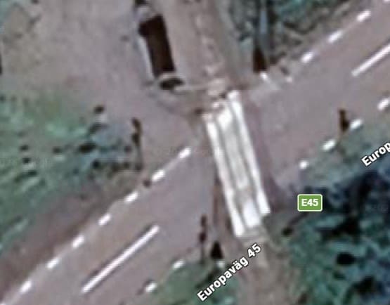
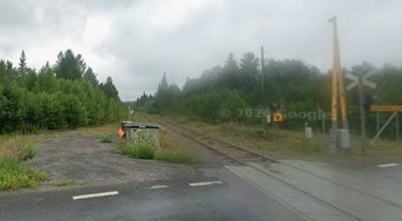
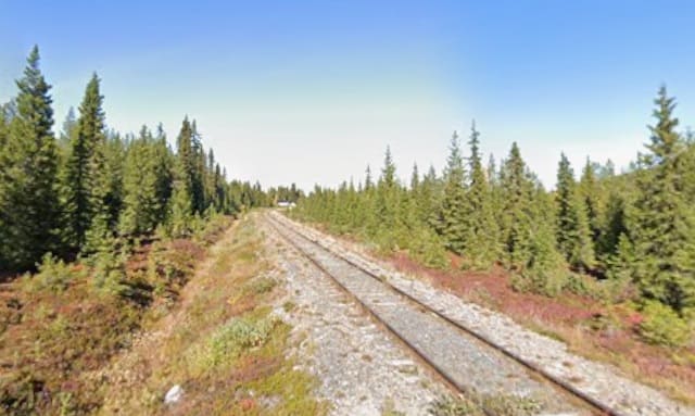
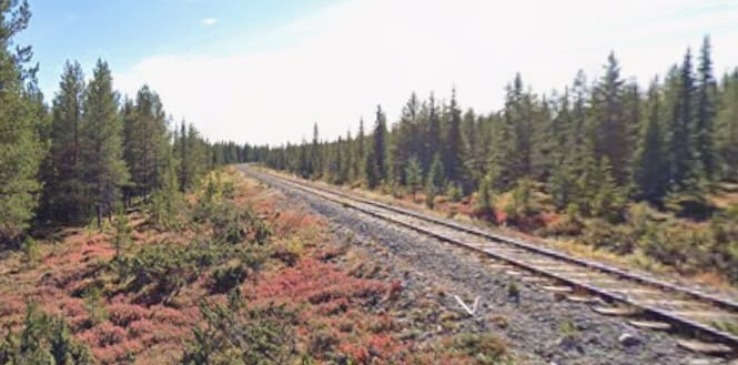
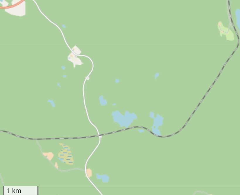
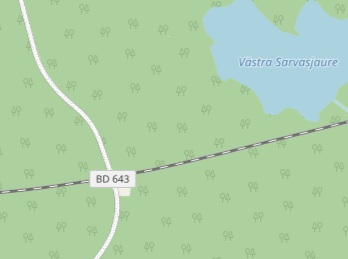
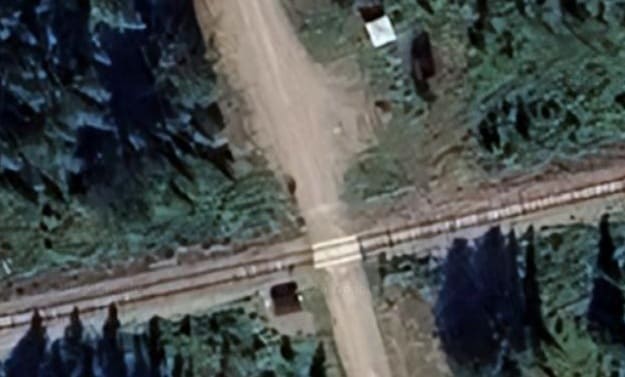
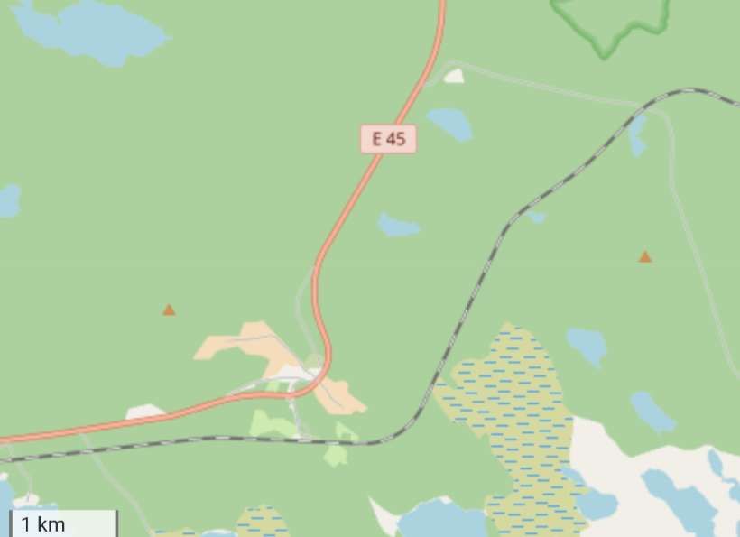
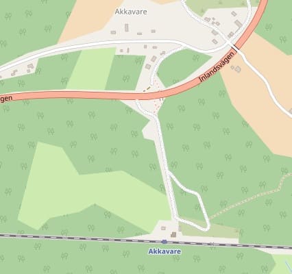
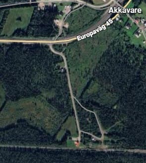
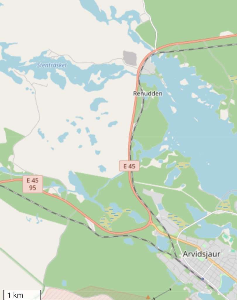
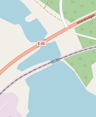
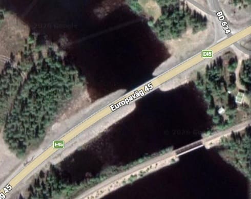
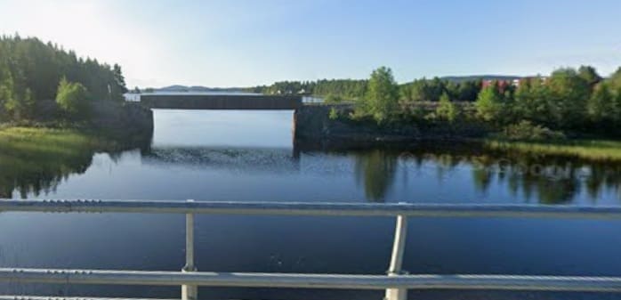
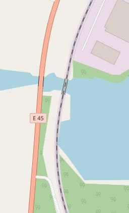
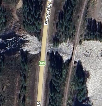
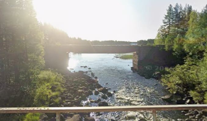
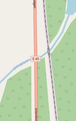
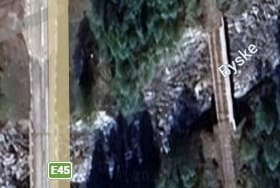
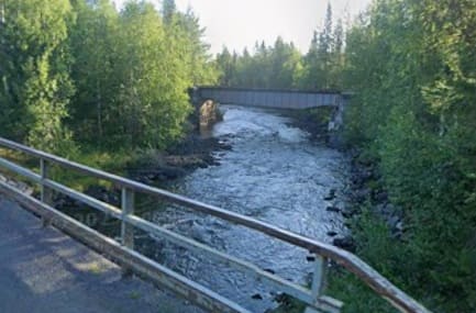
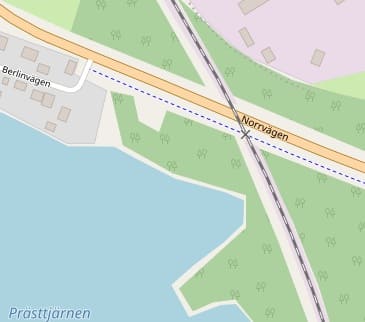
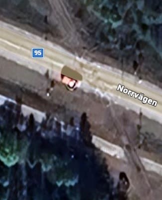
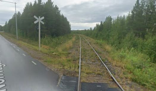
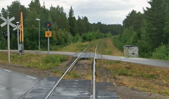
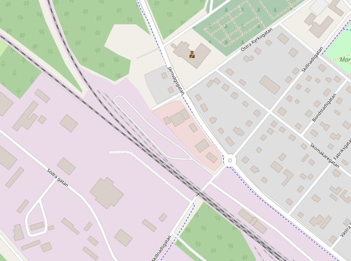
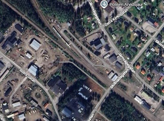
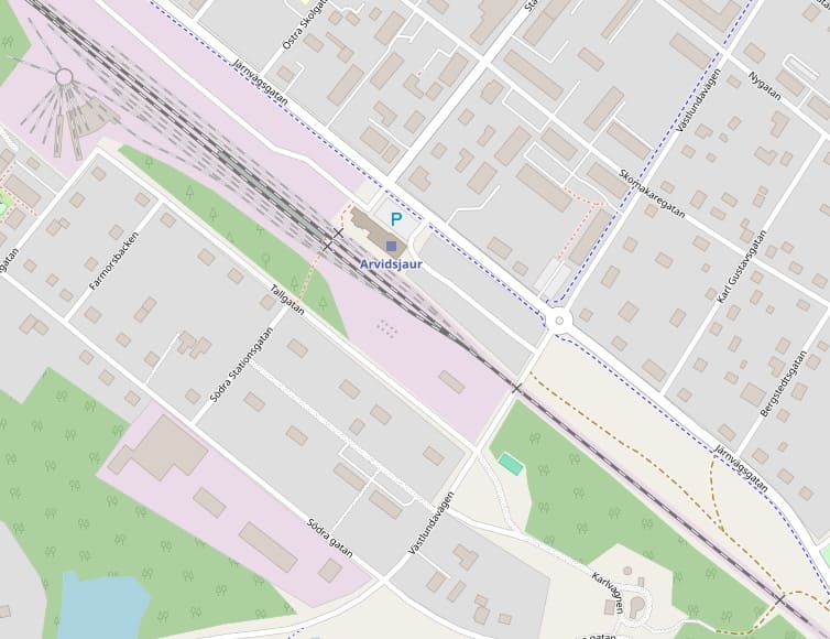
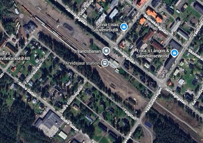

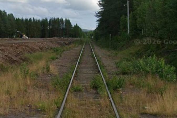
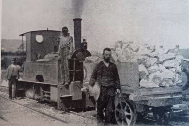
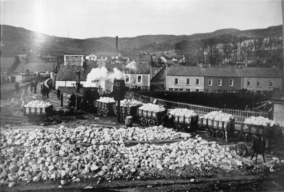
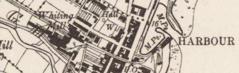
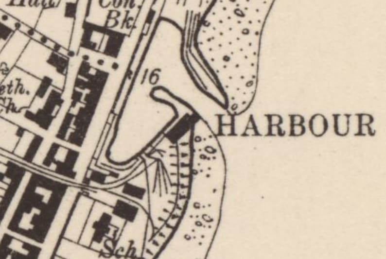
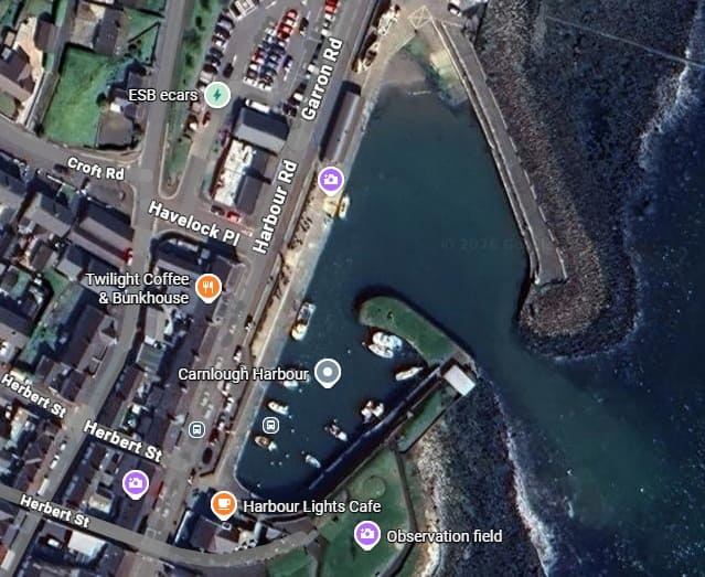
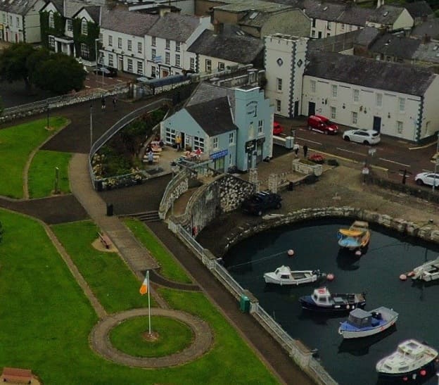
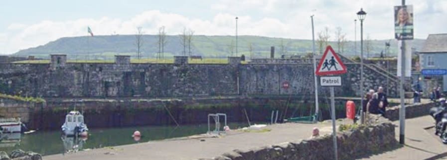
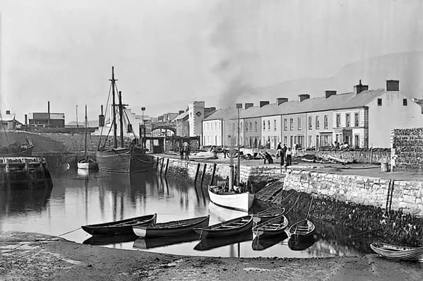
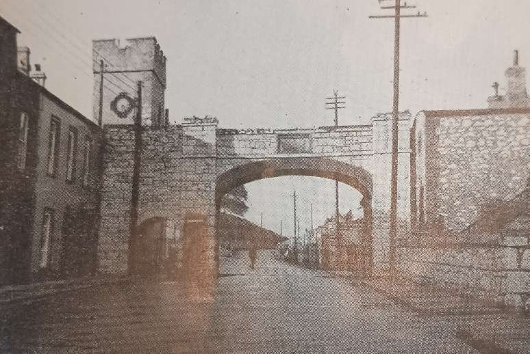
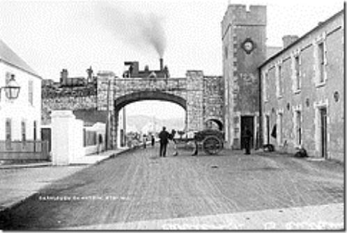
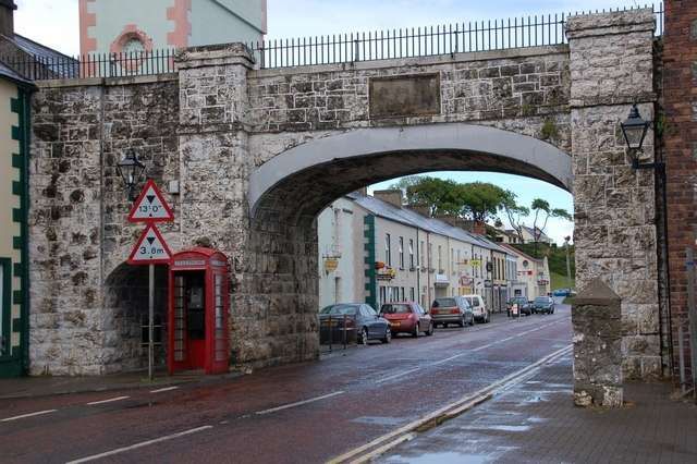
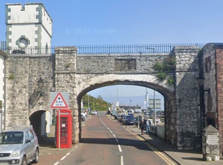
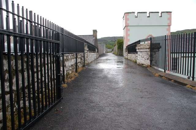
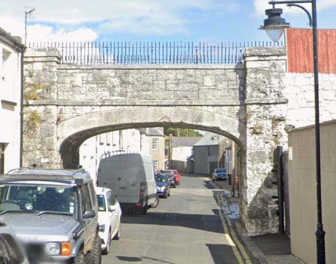
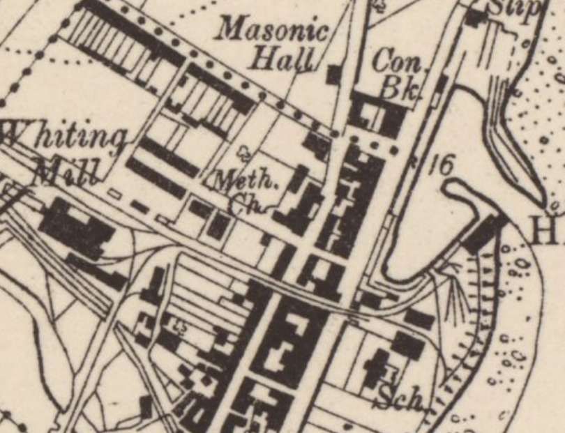
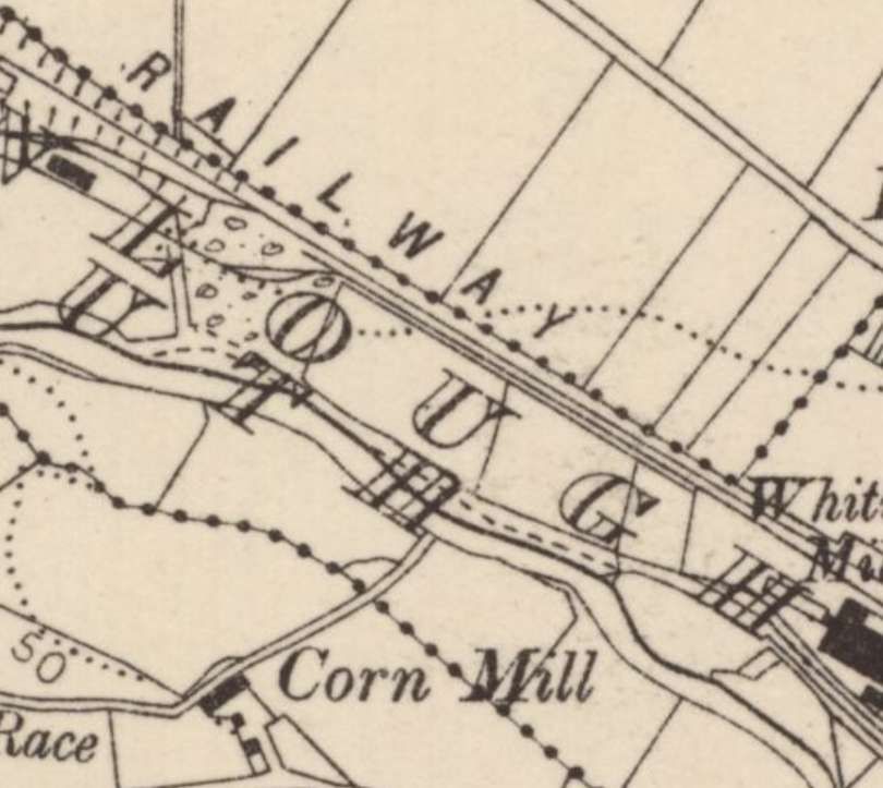
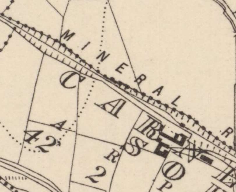
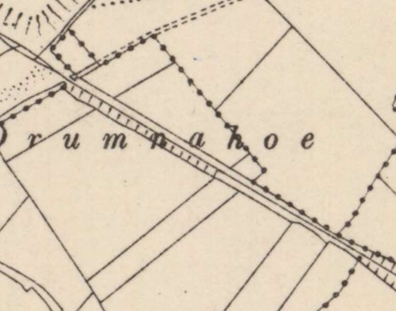
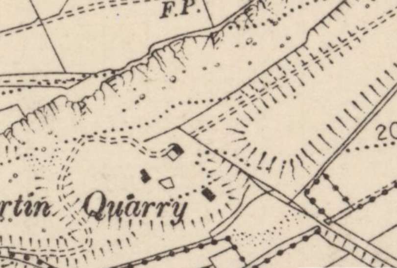
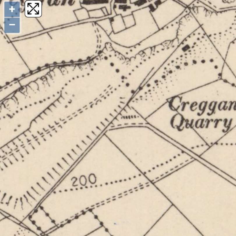
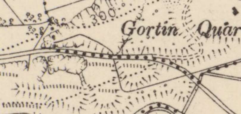
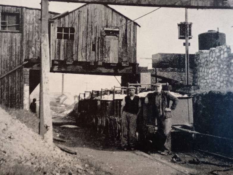
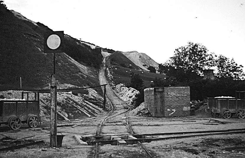
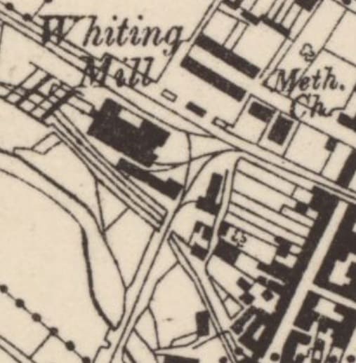
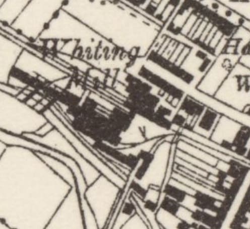
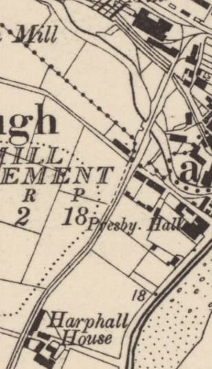
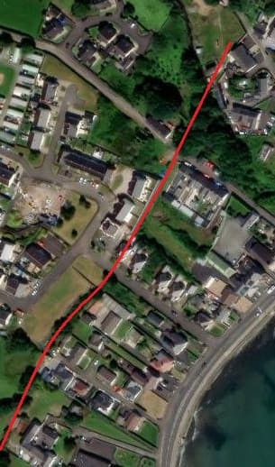
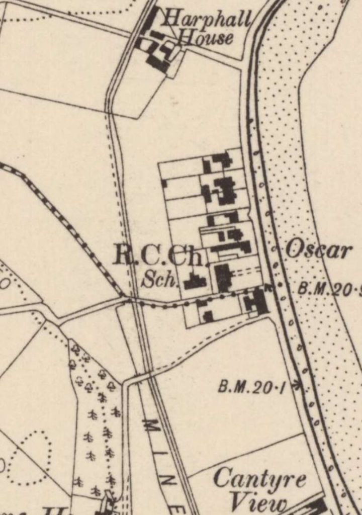
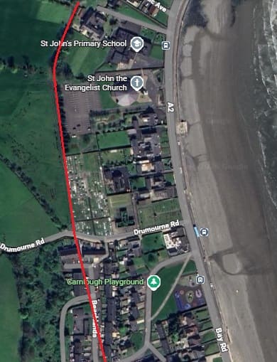
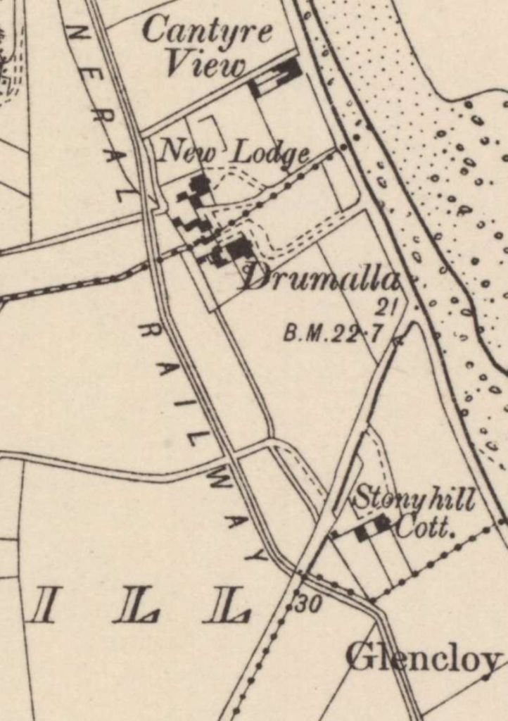
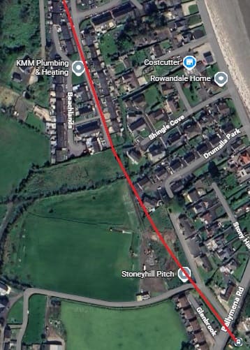
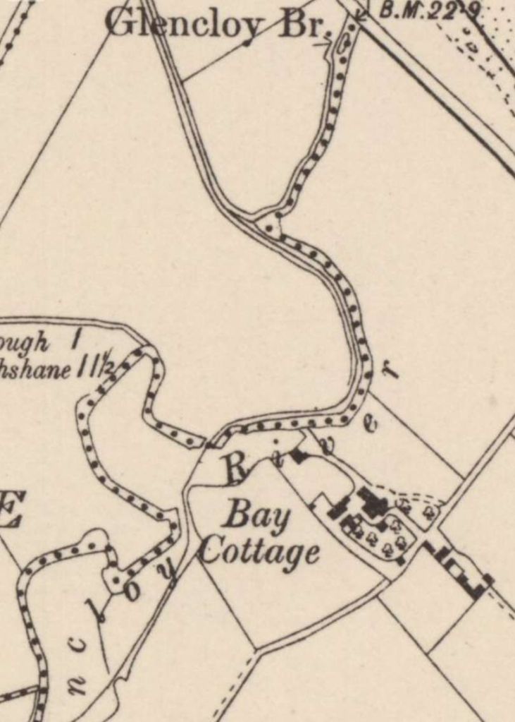
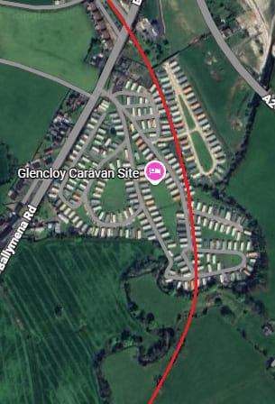
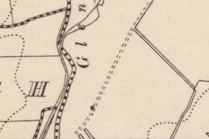
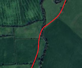
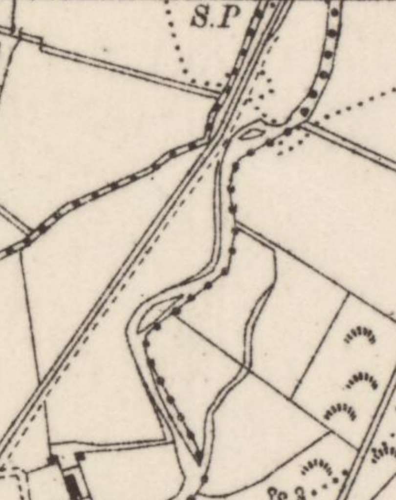
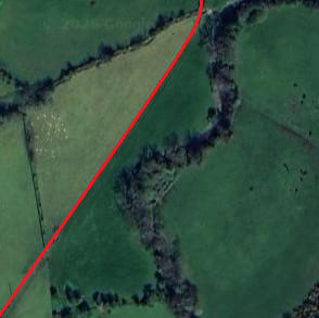
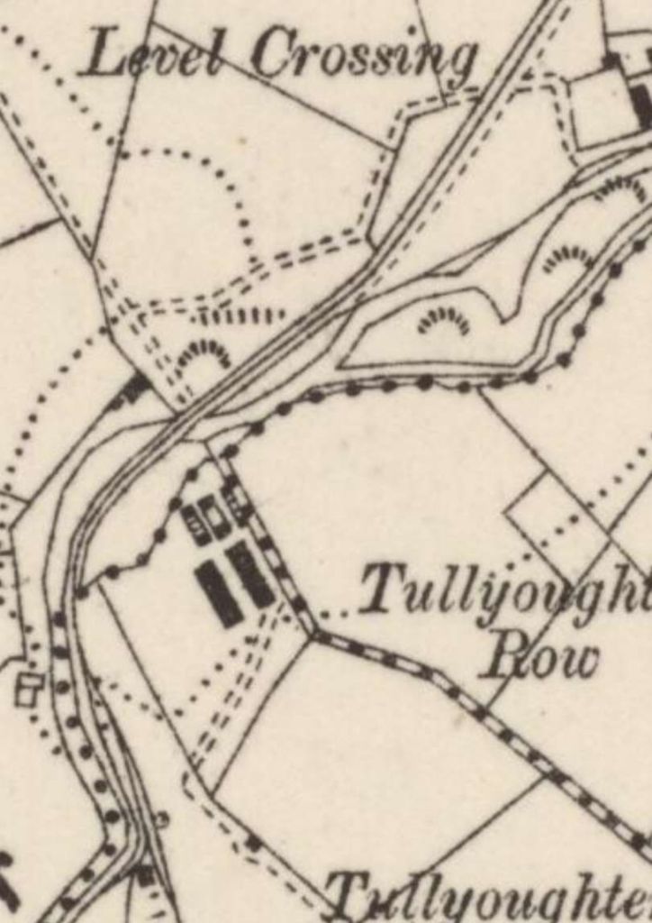
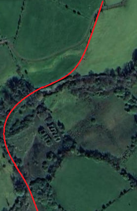
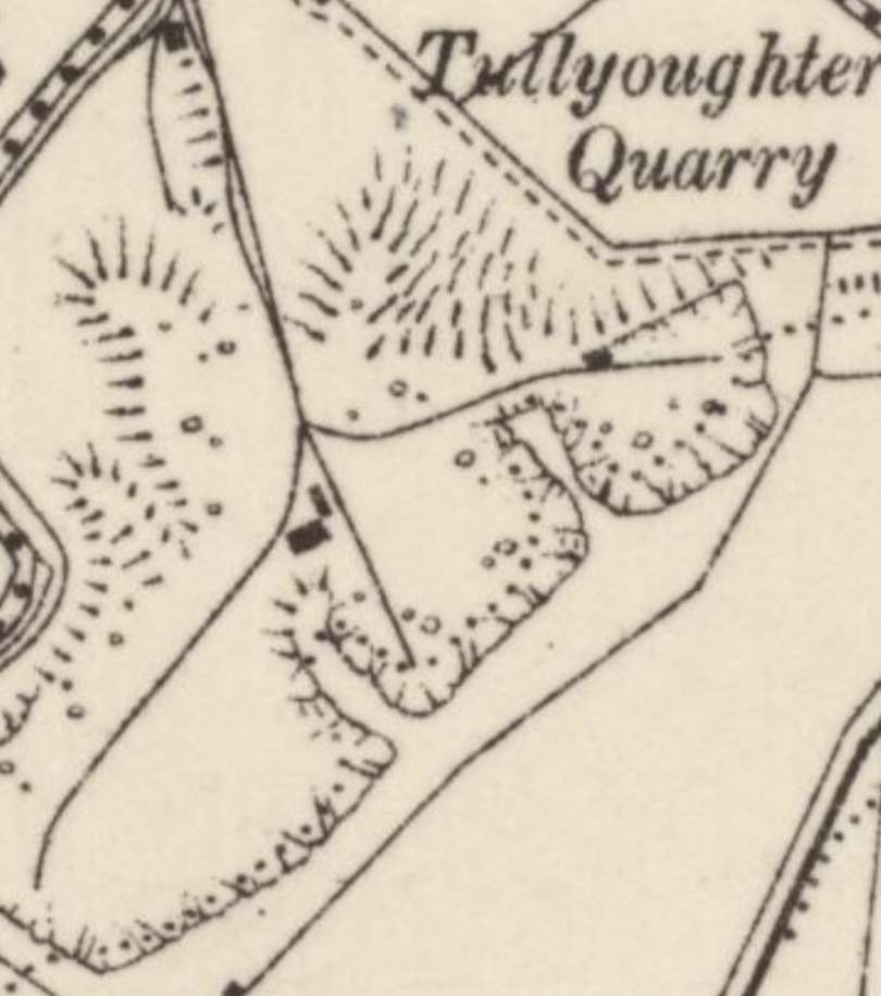
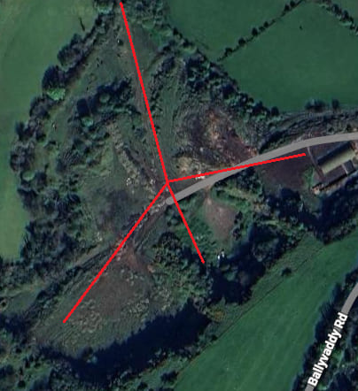
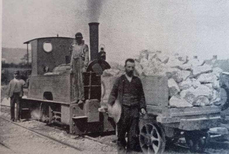
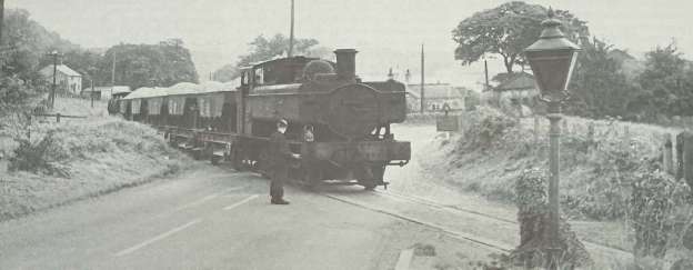
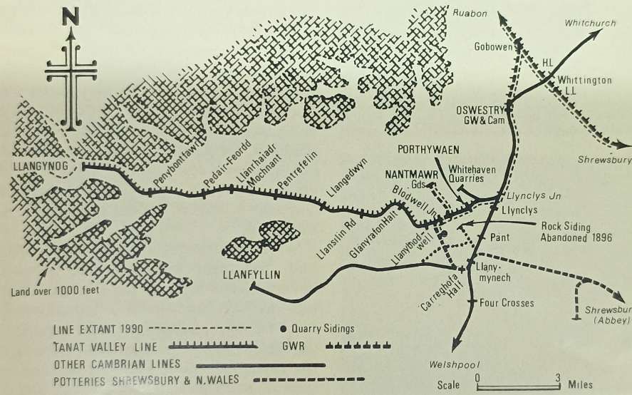
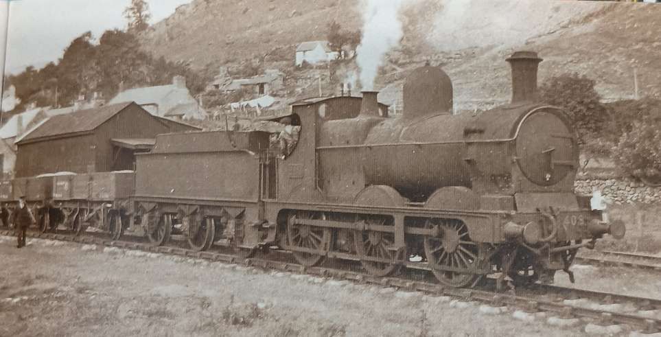
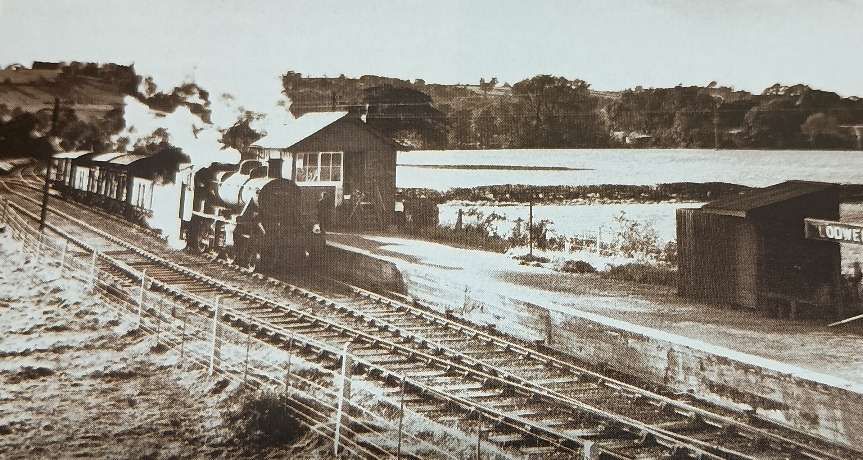
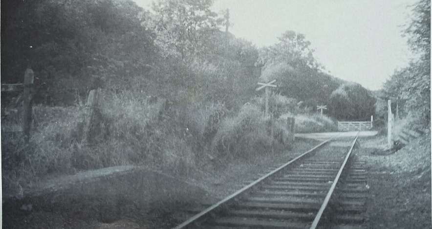
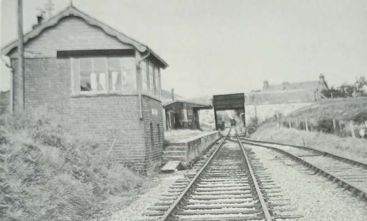
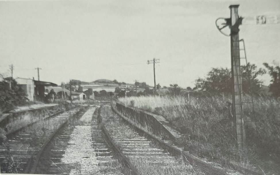
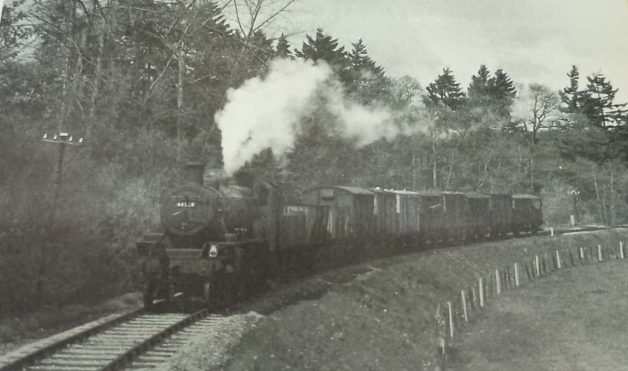
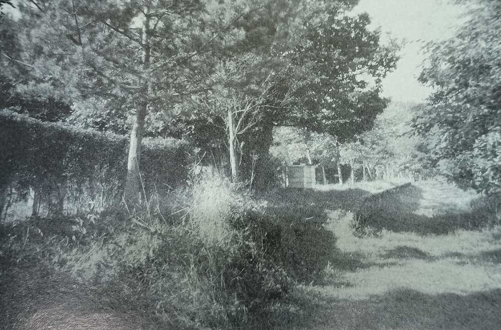
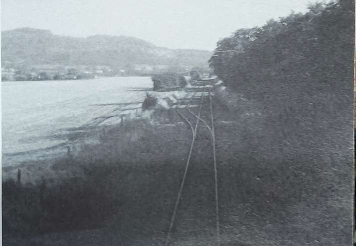
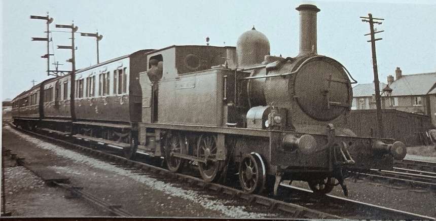
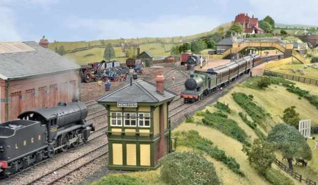
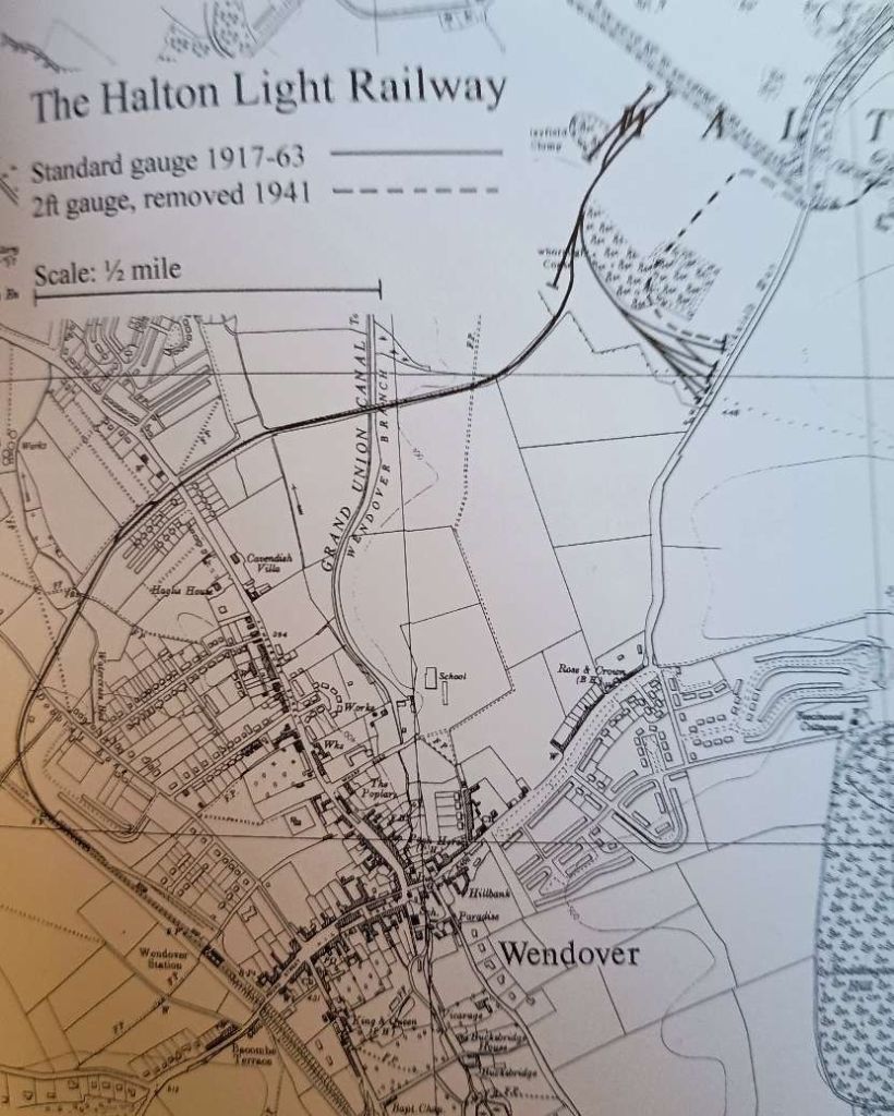
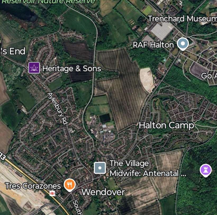
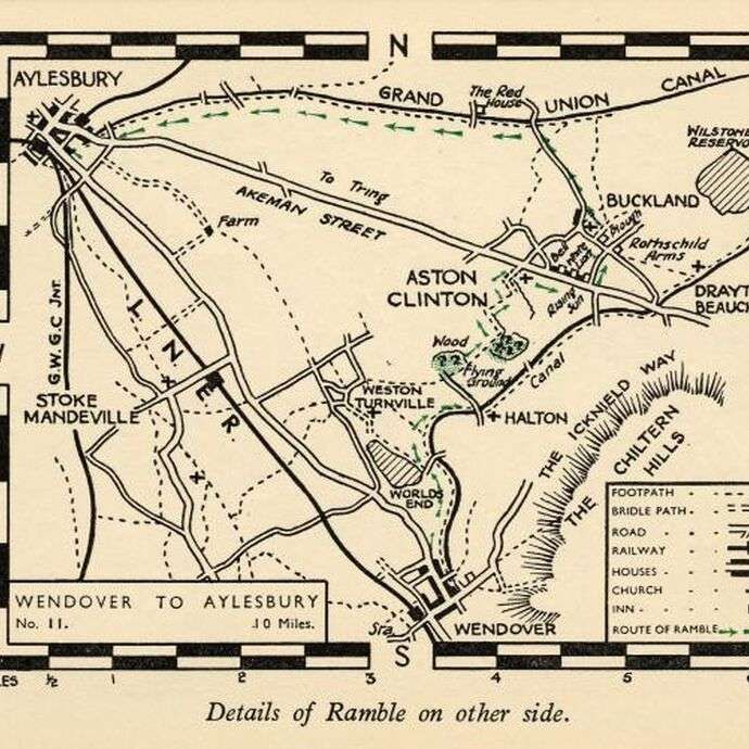
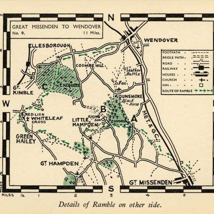
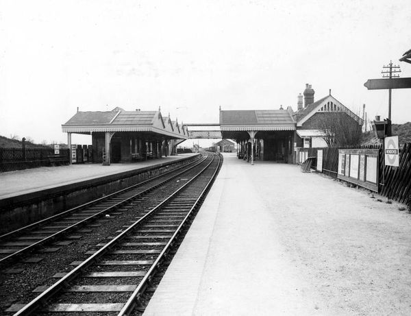
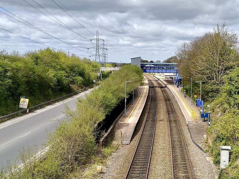
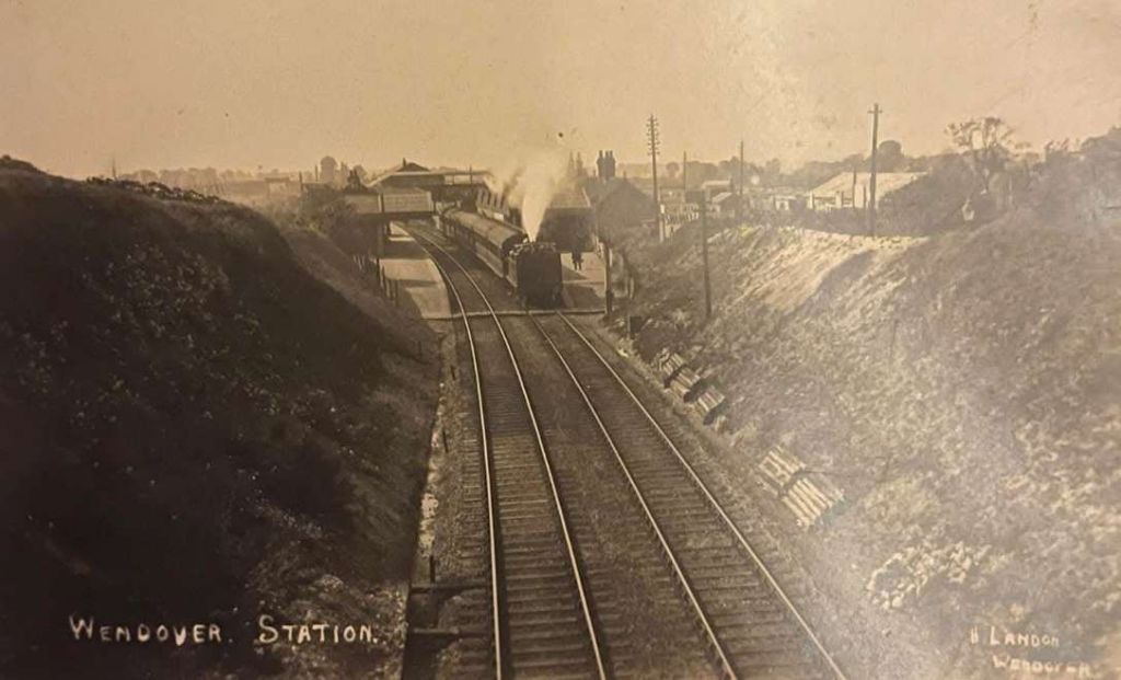
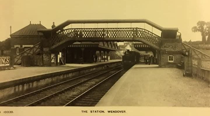
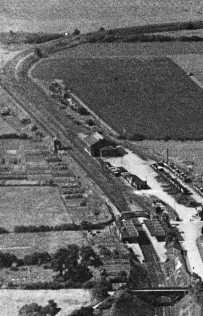
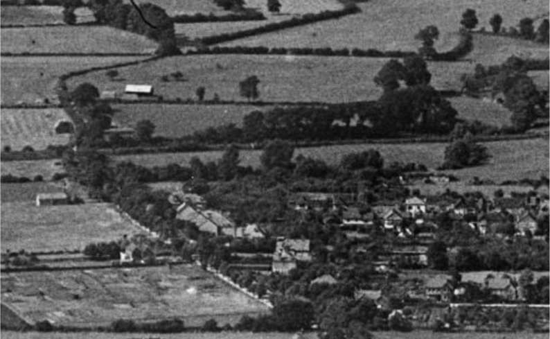
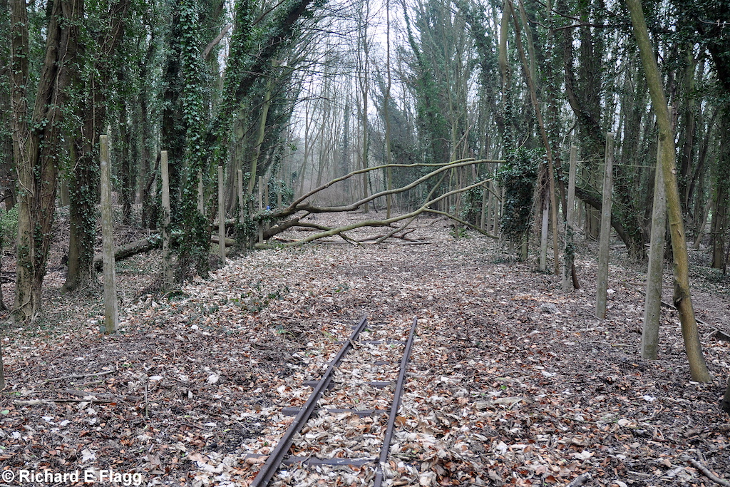

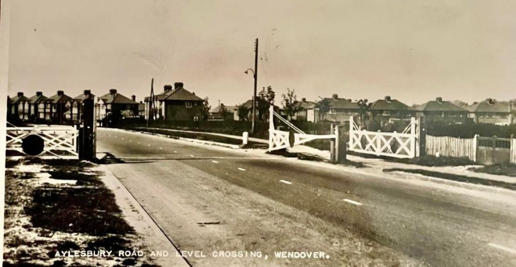
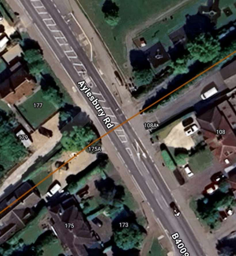
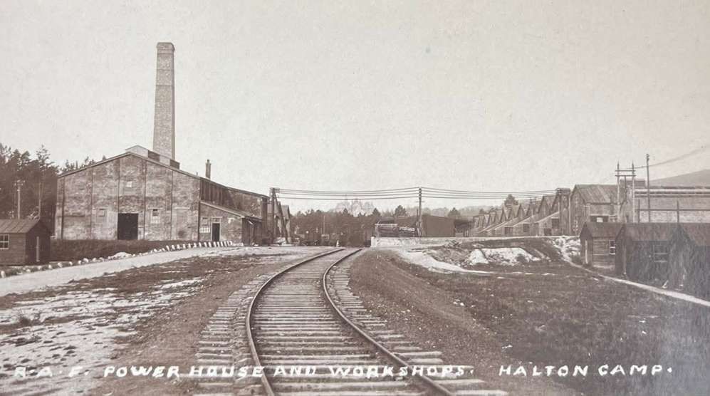
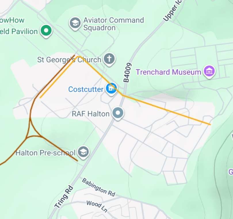
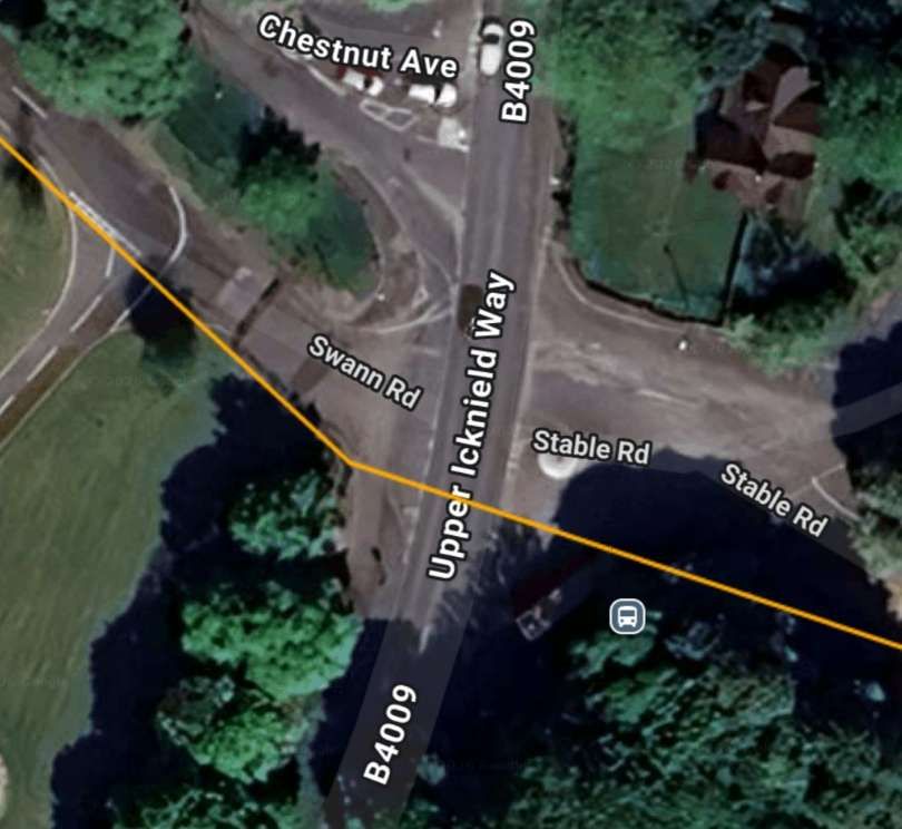
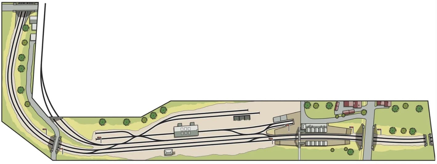
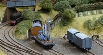
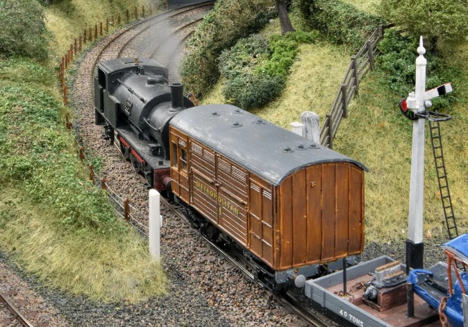
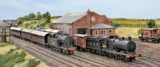

,_N%C3%A1dra%C5%BEn%C3%AD,_10.jpg)
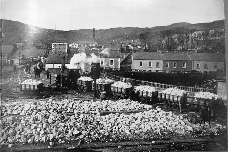