
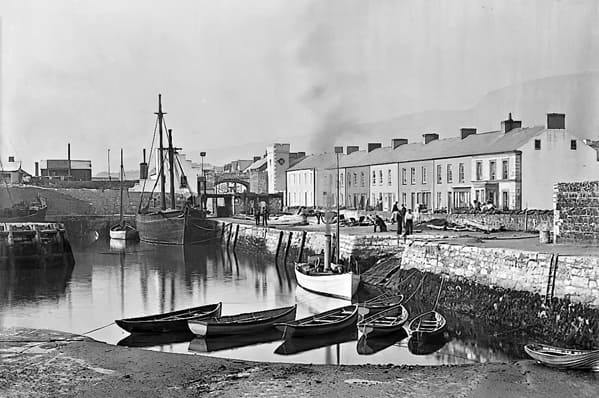
Limestone had been shipped from Carnlough for some time, but the trade was small, and declining. It was for this purpose that Gibbons [7] built a pier. Jimmy Irvine tells us that, at Carnlough, “There had been a ‘hurry’, or gravitational inclined plane at the quarry to assist in bringing down stone to the head of the Croft or Gortin Road as it was then called. From there it came on to the pier by cart. Of the pier, Lieut. John Chaytor wrote in 1832, ‘There is a quay at the north east end of the town which has been for some yeans in a state of dilapidation. Small craft from 15 to 20 tons can come in here,’ and he added, ‘Some are in the habit of shipping limestone to Scotland where they barter it for coal . . . but not to such an extent as in the town and neighbourhood of Glenarm. [8] Vessels calling at Glenarm, however, had to stand out in the bay and be loaded by lighter. The new projected Carnlough Harbour would allow ships to enter a basin which would not only offer them protection in times of storm, but would permit their being loaded direct from trucks, thereby ensuring a speedy turnaround.” [9]
A mineral railway and enlarged harbour were constructed in 1853/1854 with a first significant cargo of limestone leaving the Carnlough harbour for Scotland in mid-August 1854.
Jimmy Irvine continues: “Exactly nine months after the work first began Wilson [10] wrote, ‘I have this day loaded a vessel of Limestone from the end of the new quay. I had the stone brought down from the quarries by carts, but it will not pay to do so.’ (8.8.1854). The shipping of this load brought an immediate order from the recipients. Messrs. Tennent of Glasgow for 10,000 tons of stone.” [9]
Wilson encountered serious problems in constructing the harbour. A significant band of harder rock was encountered at what was to be the harbour entrance. It was some years before larger shops were able to enter the harbour. During that time only smaller ships could be loaded efficiently at the harbour walls. The larger ships had to be served by lighters taking limestone out to deeper water.
The story of the harbour is a litany of different problems: [9]
- The band of rock already noted;
- A 2 year period to get the limestone ‘drops’ working effectively;
- A sand bar developing which further restricted access to the harbour;
- 15 months wait for a dredger;
- “In February 1860, part of the South Pier carrying the railway and one of the shoots, collapsed into the water. There was a difference of some 30 feet between the top of the pier and the floor of the basin, where the foundations had given way. Watson took charge of the repairs and by October, With the help of divers, he had rebuilt the fallen masonry and cleared the basin of debris.” [9]
- In April 1862, Wilson that “the harbour has filled up nearly two feet since the dredger was at work and we are now obliged to have resource to the old system of shipping outside in lighters.” [9]
- Another long wait occurred until a dredger could be permanently allocated to the harbour.
Problems were also encountered with the rail inclines. Only on the upper part of the railway could the loaded trucks pull up the empties, so that horse-drawing was still necessary on the lower. Robert Watson, an engineer from Seaham was brought in to see what he could do. He arrived in March 1856, and two months later Wilson wrote, “I am happy to say Watson has succeeded admirably in making it self acting, superseding the use of Horse work in drawing up the empty wagons.” (9.5.1856). [9]
Wilson sought to diversify to increase income. He began to burn lime in the small kiln (17.12.1855). By keeping careful accounts he soon found that he could sell at a profit. Armed with this knowledge, he urged the building of lime kilns as part of the development scheme. These were authorised at a cost of £600 and the railway to them at another £577. “Watson thought of a plan whereby trucks would be hoisted up to feed the kiln instead of running on an incline, thus saving almost £300.” [9]
McGuigan wrote that, “kilns for burning the limestone, and a mill for manufacturing whiting, were erected.” [1: p792] In fact, the project was so successful that once lime burning began in August, 1857, in a short time a further two kilns had to be built, making five in all. [9]
McGuigan tells us that the kilns “flourished until the second decade of the [20th] century, when the general industrial depression, coupled with the decrease in the use of lime mortar for building and the decline of the iron smelting industry on the west coast of Great Britain, caused the demand for limestone and burnt lime to drop. The kilns ceased operating, but fortunately there arose a demand for crushed lime for agricultural purposes and this kept the undertaking going during the lean years.” [1: p792] In 1954, that product still formed the major portion of the works output, and McGuigan reported that recently the demand for raw limestone had increased. …
The lines running over these bridges were dual gauge, accommodating both narrow-gauge and standard-gauge traffic. The narrow-gauge line to Tullyoughter Quarry is dealt with later in this article.
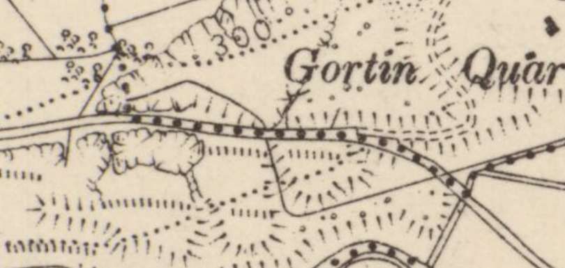
The line to Gortin Quarry and Creggan Quarry
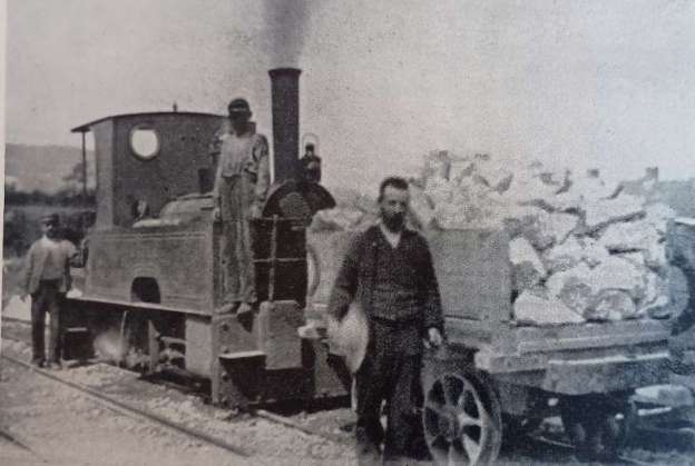
J. H. McGuigan tells us that “The original railway was of single track, about a mile in length, running inland on a gradient of 1 in 25 from the harbour to Gortin Quarry. This line [was] still in use [in 1954], except for the final 150 yd. or so, which was abandoned when the quarry became worked out [in around 1929/1939].” [1: p782]
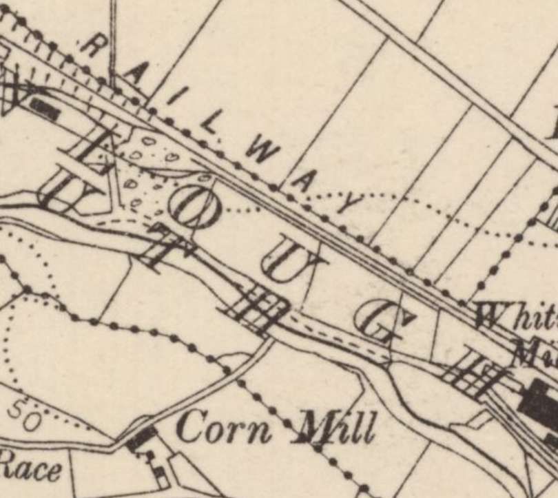
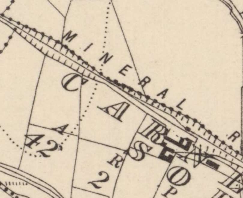
“In the meantime, quarrying had extended northwards, and a second line, about half a mile in length, was constructed on a 1 in 7 gradient at a right angle to, and as an extension of, the original line. This also continue[d] in use [in 1954], giving a total of about one-and-a-half miles [then] working. The gauge [was] 4 ft. 8.5 in., rather unusual in Ireland.” [1: p782]
The line was originally operated by gravity and horse power but this was later replaced by cables with a winding house over at least part of the route. [2]
McGuigan noted, in 1954, that the first section of about 750 yards, “from the harbour to a point about 500 yd. above the mill, [was] worked by a single cable and winding engine, the loaded trucks descending to the harbour by gravity but
attached to the haulage cable and therefore under the control of the engine driver. Empty trucks at the harbour [were] then coupled to the cable in place of the loaded ones and hauled up by the winder. Until the middle of 1952, the winding engine was steam-operated, and strongly resembled a ship’s winch. It had two cylinders, each 6 in. dia. by 11 in. stroke; the drum was 34 in. dia., with a brake drum 48 in. dia. on the same shaft, and was manufactured by Alexander Chapman & Company of Glasgow. Steam was supplied by a vertical cross-tube boiler 10 ft. high and 4 ft. dia. In 1952, the unit was electrified by the s
imple expedient of removing both connecting-rods, fitting a vee-belt pulley in place of one crank, and installing a 35-h.p. three-phase electric motor with vee-belt drive.” [1: p792-793]
Above the powered rope-worked incline another 650 yard self-acting rope-worked incline operated with the weight of descending wagons lifting empties. That incline was “single track with a passing loop at the middle. The haulage cable passe[d] round a drum 8 ft. 6 in. dia. in a pit at the top of the incline. The drum rotate[d] about a roughly vertical axle and [was] provided with a hand-operated band-brake by which the speed of the trucks [was] controlled. To avoid the two portions of the cable becoming crossed, the ascending rake of trucks [had] to travel on the same side of the passing loop as that used by the previous descending rake, and this entail[ed] throwing the points at each end of the loop after every run. A man [travelled] on the rear truck of each rake, and as these approach[ed] the passing loop the brakeman reduce[d] speed. Each man then dismount[ed] as his rake enter[ed] the loop, [threw] the points when the last truck of the entering rake [had] passed, and board[ed] the last vehicle of the emerging rake on which he return[ed] to his base.” [1: p793]
At the top of the incline, the next section, left at an angle of about 90°, the connection was made by means of a turntable, a square crossing and a cut-off line. McGuigan said in 1954: “Loaded trucks from the upper incline travel via the cut-off line to a dead end, from which they reverse on to the lower incline. Empty trucks from the lower line are turned on the turntable and enter the upper incline over the square crossing with the track used by loaded vehicles.” [1: p793]
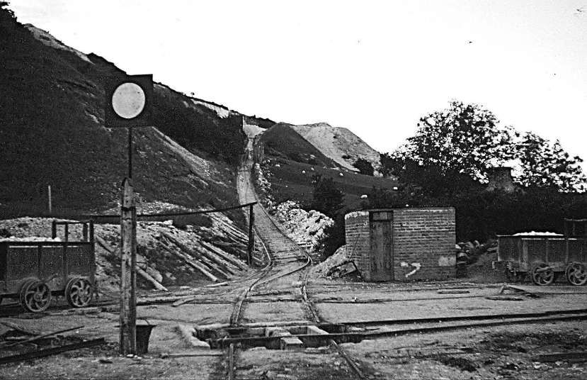
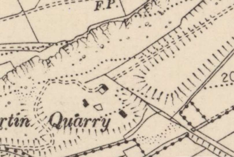
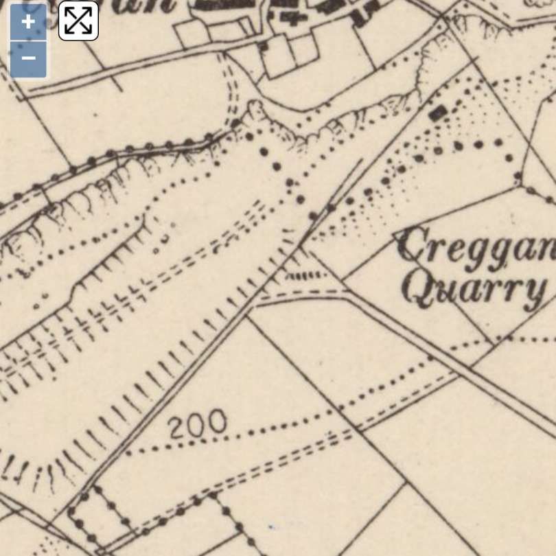
McGuigan continued his narrative: “From this point to the terminus (approximately half a mile) the line is worked as two consecutive gravity inclines, similar to that just described, a siding and a turntable adjacent to the brake-drum of the lower incline giving access to the working face of the neighbouring Creggan Quarry via a fan of tracks along which the trucks are manhandled.” [1: p793]
“Some 100 yd. above this point, the second incline enter[ed] a cutting about 100 ft. deep in which [was] the passing loop, and then passe[d] through a concrete-lined tunnel about 100 yd. long from which it emerge[d] to the upper quarry.” [1: p795]
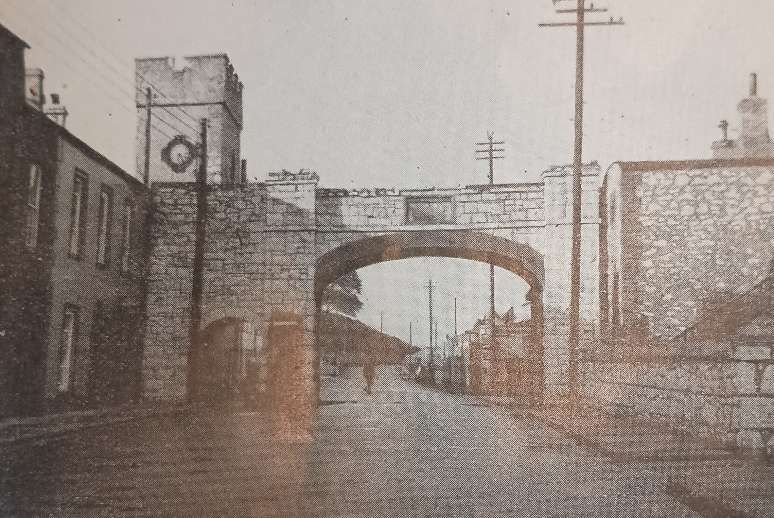
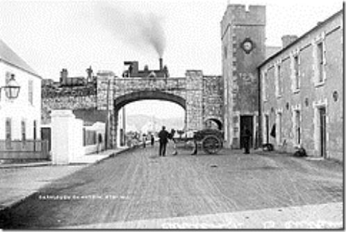
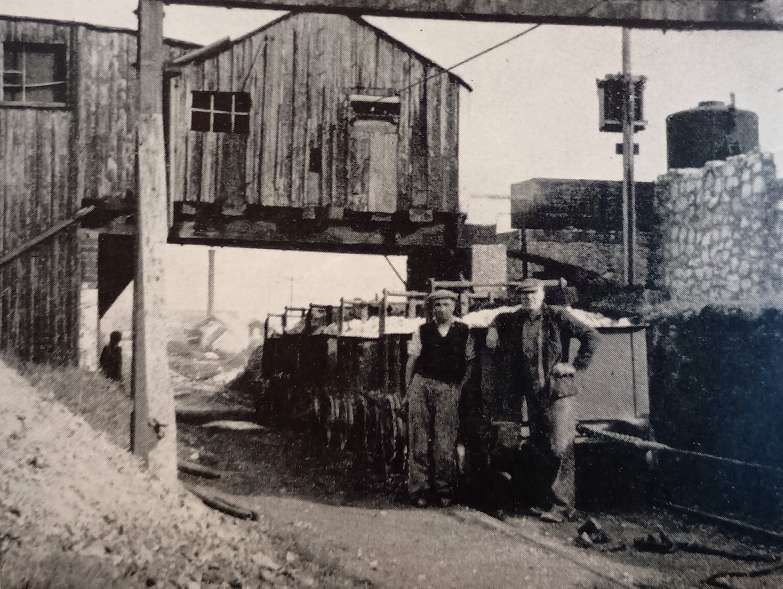
McGuigan continued, in his article, to talk through the signalling arrangements in use on the line. One of the disc signals mentioned can be seen in the monochrome image above. “Disc signals, each consisting of a board about 3 ft. 6 in. square, painted black with a white disc on one side, and mounted on a wooden post arranged to turn about a vertical axis, [were] provided at the top and bottom of each incline. The heights of the posts [varied] from about 4 ft. to 25 ft., according to position. The normal aspect of the signal [was] with the board parallel to the track, that is with the disc invisible to a person on the track. When a rake of trucks, usually six vehicles, [was] ready to depart from one end of an incline the operator there turn[ed] his signal to exhibit its disc to the operator at the other end. When the latter [had] ascertained that the rake at his end [was] ready, he turn[ed] his signal and exhibit[ed] its disc in acknowledgment. The brakeman or engine man, as the case may be, then release[d] the brake and allow[ed] the run to take place.” [1: p795]
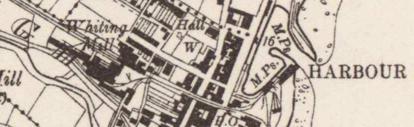
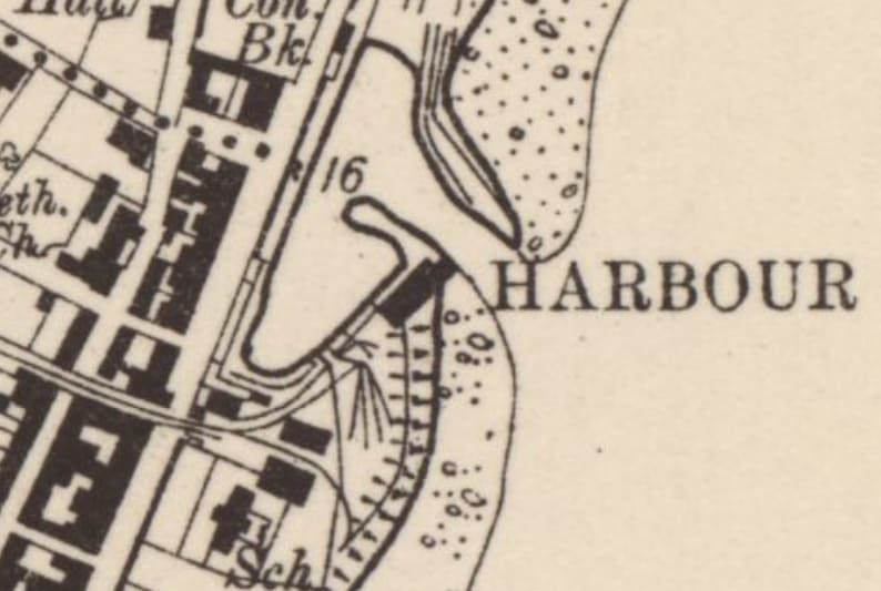
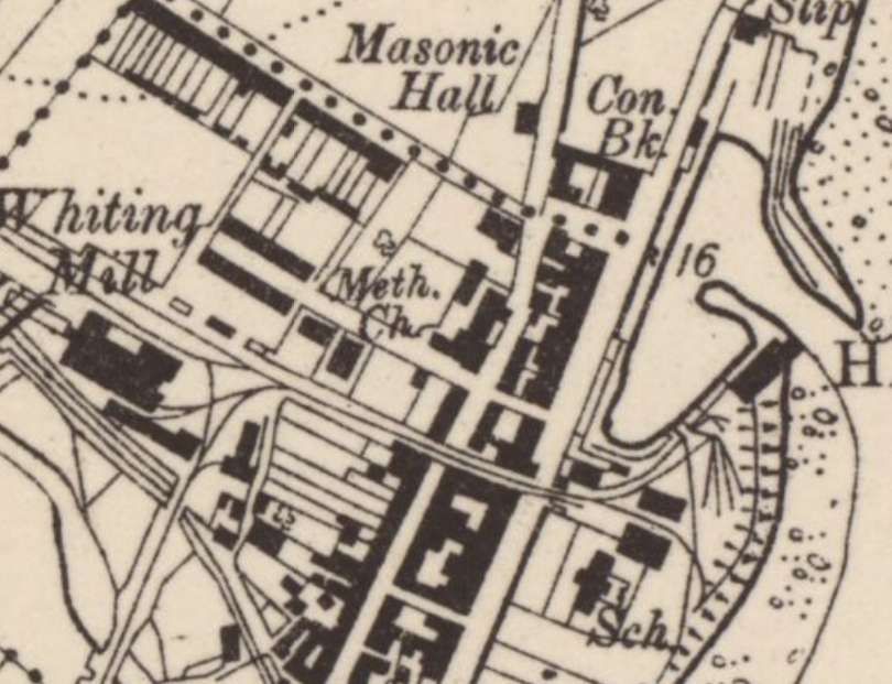
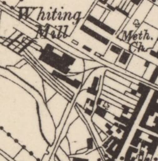
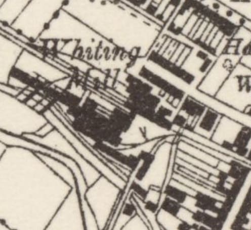
Whiting Mill and its Rails
The Narrow-gauge line to Tullyoughter Quarry
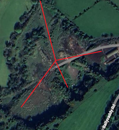
McGuigan continued: “About 1890, presumably because of a boom in the limestone business, a quarry was opened at Tullyaughter, about two miles south of Whiting Mill, and a 3 ft. 6 in. gauge, single-track railway was laid thence. The addition of a third rail to the existing line allowed trucks of limestone to pass directly from the quarry to the harbour. The new line crossed the Carnlough River on a timber trestle bridge, and then, about half a mile further on, crossed the Ballymena-Carnlough road on the level. Gates to close the ends of the railway when trains were not passing were provided there, and a man was employed to operate them and exhibit a red flag to road traffic when a train was approaching.” [1: p795]
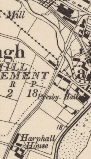
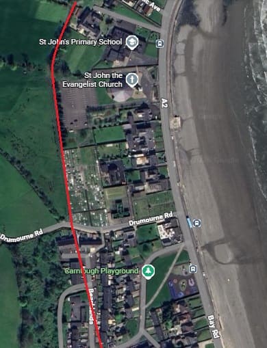
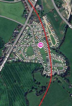
The first length of the 3ft 6in-gauge line from Whiting Mill to the quarry at Tullyoughter bridged the Carnlough River and ran down the West side of Harphall House. [13]
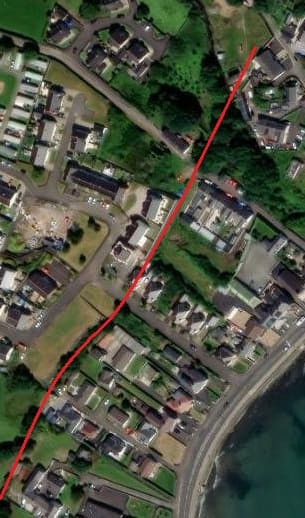
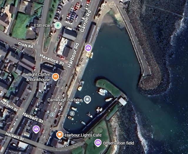
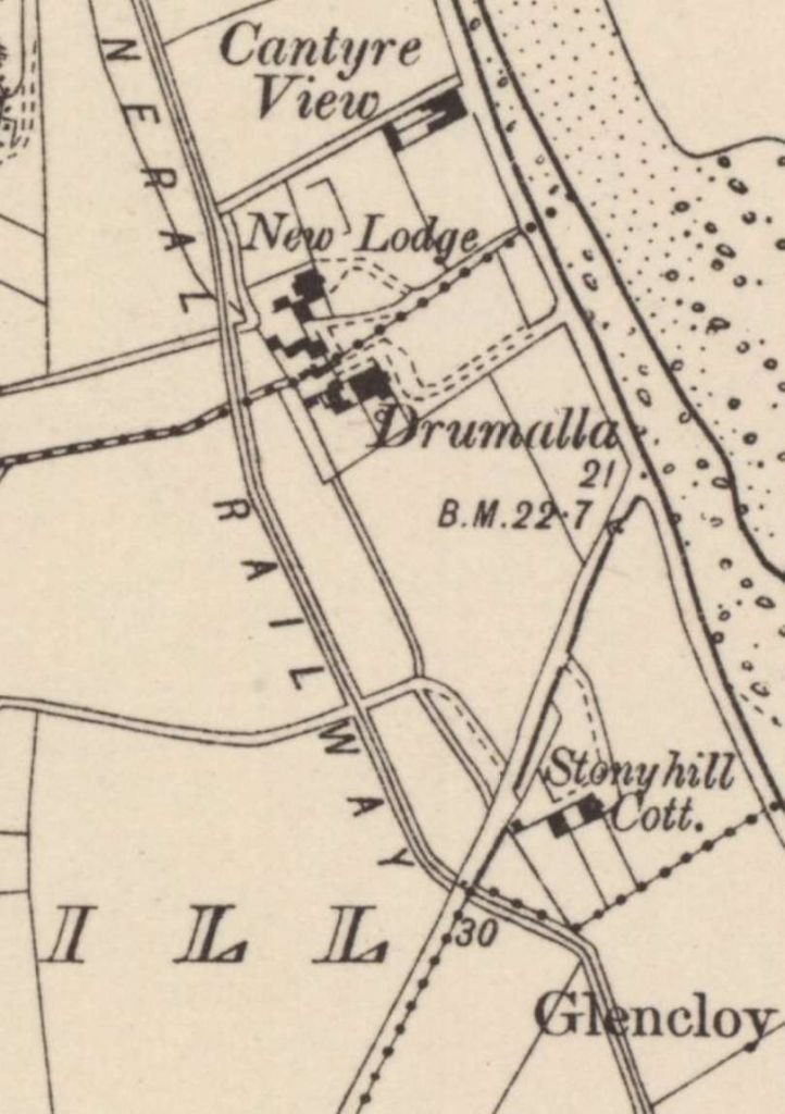
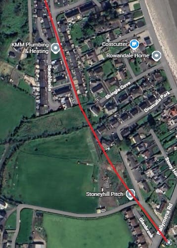
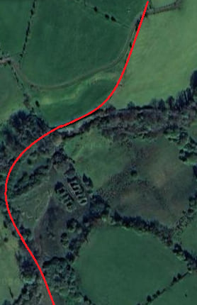
The route of the line is shown on the satellite image on the right above as a red line. this applies along the route of this 3ft 6in line and to the satellite images below. [Google Maps, April 2026]
The next length of the line ran behind the properties which face out onto the A2, [13]
The line continues South at the rear of what were single properties facing the A2 but now replaced by small estates. [13]
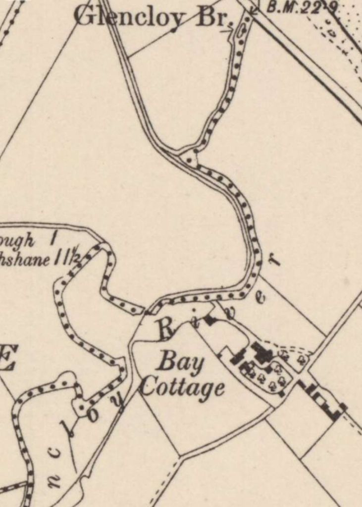
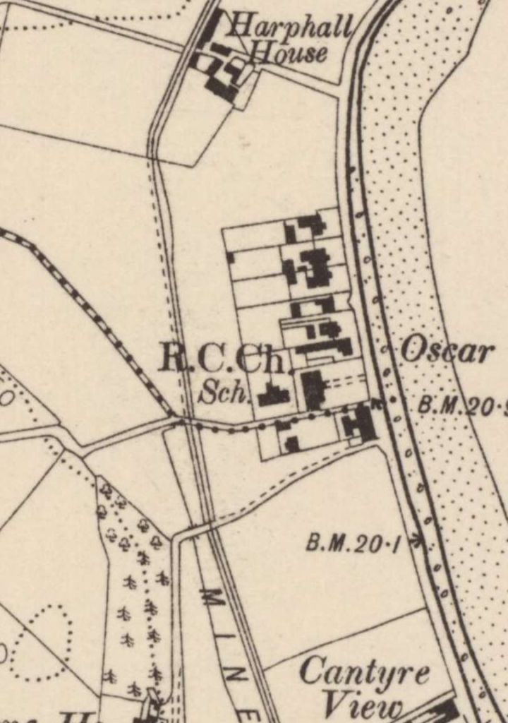
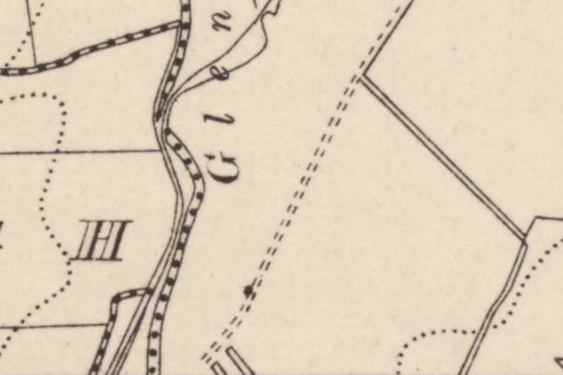
The railway ran along the West bank of the Glencloy River. It passed to the West of Bay Cottage, [13]
The next extract from the NLS 6″ OS mapping takes us to the bottom of the OS sheet. … [13]
The line to the edge of the OS sheet. [13]
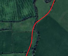
The next three sections of the line are shown on the next OS sheet. … [15]
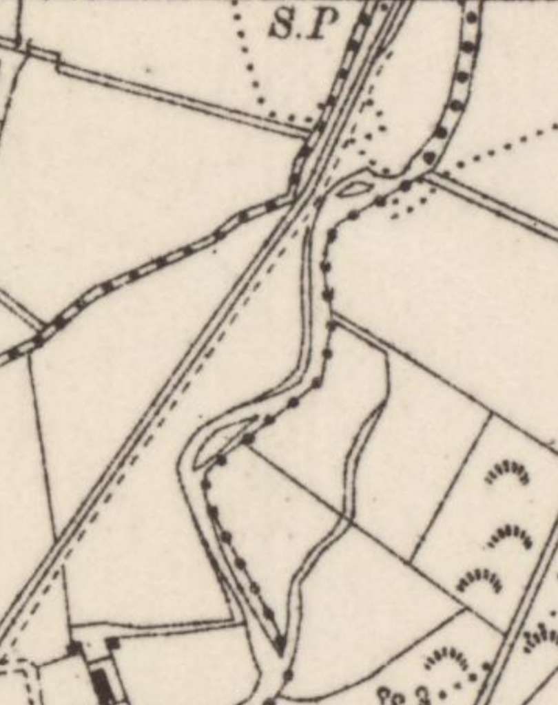
The next length of the railway is on the next Ordnance Survey sheet. [15]
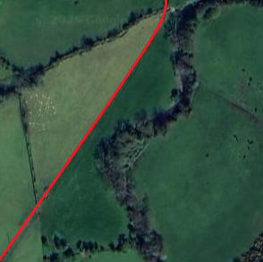
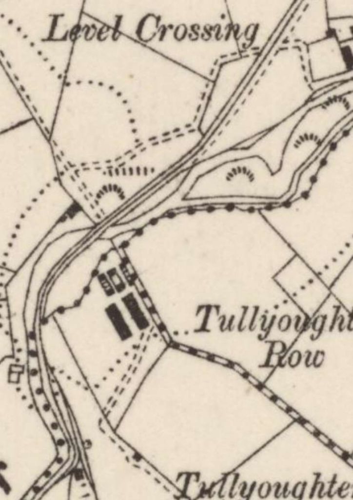
The length from the Level-Crossing to Tullyoughter. [15]
The next images show the last length of the line and its terminus in Tulluoughter Quarry. … [16]
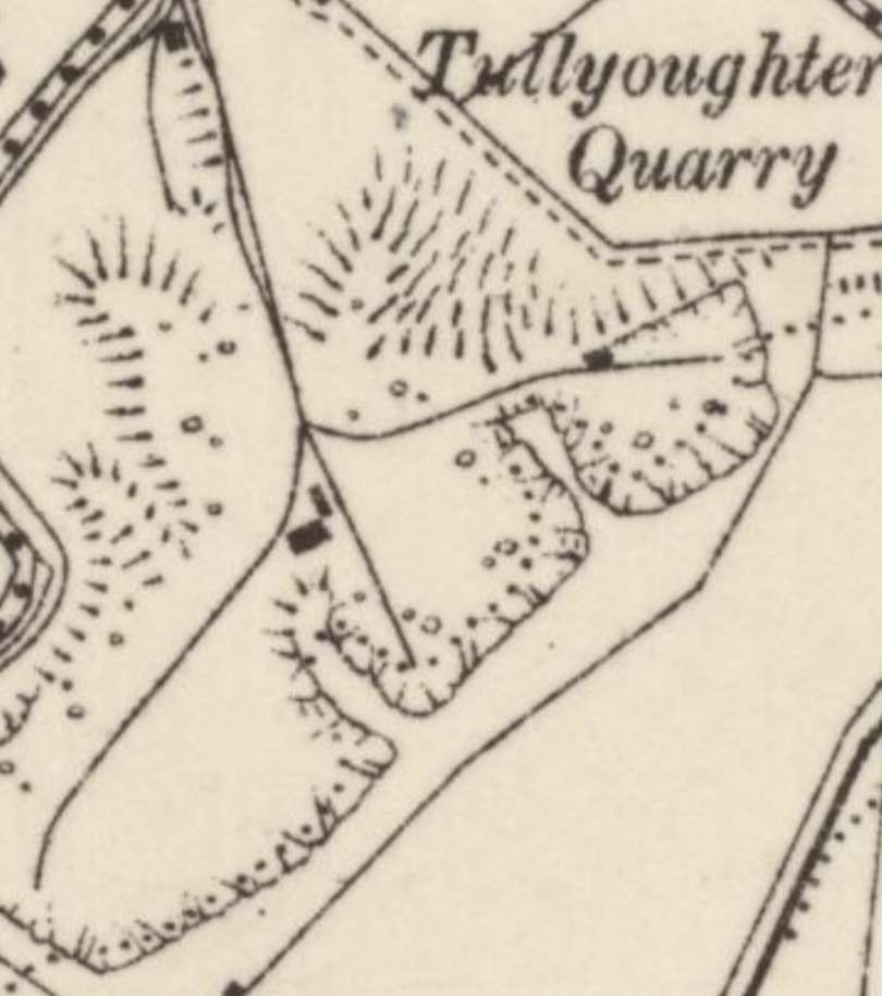
The line terminates at Tullyoughter Quarry, [15]
McGuigan says: “The line from the mill to the quarry was on a rising gradient of about 1 in 50, and was worked by gravity and horses until a steam locomotive was acquired in 1898. This was a 0-4-0 side tank engine, named Otter, built in 1896 by Andrew Barclay, Sons & Company, of Kilmarnock, and had 7 in. by 14 in. outside cylinders, 2 ft. 1 in. wheels, and a wheelbase of 3 ft. 9 in. The heating surface was 145 sq. ft., the grate area 3.5 sq. ft., and the working pressure, 140 lb. per sq. in. The engine was provided with a cab, and the fuel bunker was in part of the right-hand tank. Otter hauled loads of about 20 trucks. Work at Tullyaughter Quarry ceased about 1922, and the line between it and the mill was lifted about 1924. Otter continued to work in the mill yard and at the harbour till about 1930, after which it lay derelict until it was sold for scrap and cut up in July, 1951.” [1: p795]
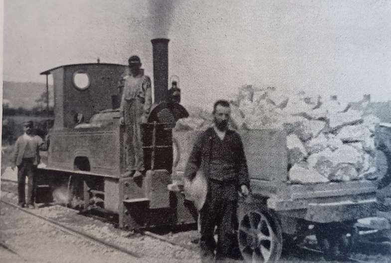
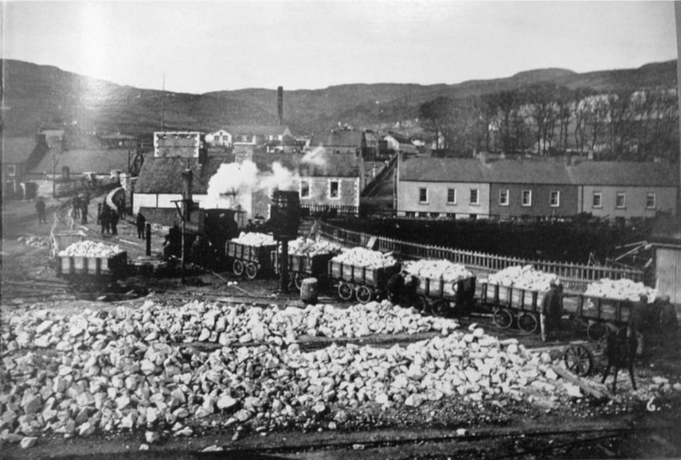
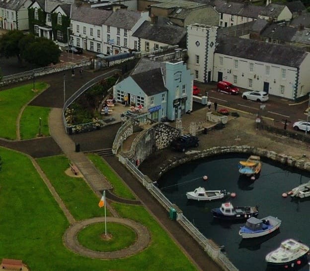
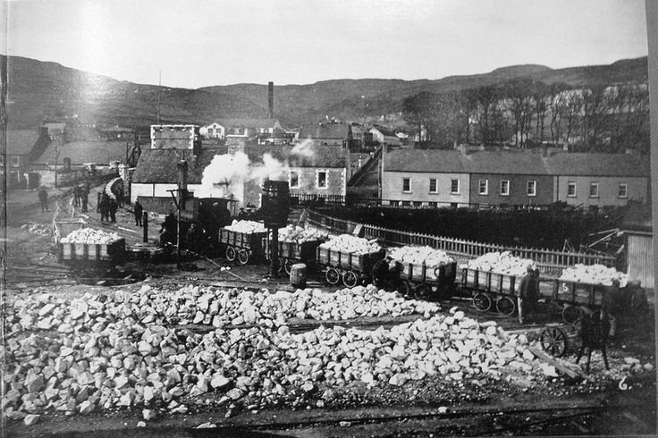
Writing in 1954, McGuigan goes on to talk about rolling stock on the line: “Rolling stock at present consists of about 80 trucks for the 4 ft. 8 in. gauge. and 13 for the 3 ft. 6 in. gauge. The former have timber frames and steel bodies 7 ft. 8 in. long, 4 ft. wide, and 2 ft. 10 in. deep. The wheelbase is 3 it. 5 in., and wheel diameter in some cases 2 ft. 6 in., and in others 2 ft. The narrow-gauge vehicles consist of seven trucks with bodies and six flats, and are of all-wooden construction, except for wheels and fittings. Both broad-and narrow-gauge trucks are designed for end tipping, and have one end arranged to swing outwards on a hinge just above the top edge. The narrow-gauge stock is used exclusively for the transport of finely ground products from the mill to the harbour, the flats are used for bagged material. An agricultural tractor acts as locomotive between the harbour and the mill, and does shunting work. The track layout at the harbour is triangular, and includes sidings of each gauge, three-rail mixed-gauge sidings, and one four-rail mixed-gauge track leading to four turntables which serve the chutes down which the limestone is delivered into the holds of the steamers.” [1: p795]
McGuigan then talks of planned modernisation of the railway with new sidings serving a new crushing plant, “the provision of an electrically operated wagon-tippler, and the electrification of the winding-engine all indicat[ing] that, unlike some public railways in Ireland which are in decline, the Carnlough Railway [was] entering its second century in a spirit of rejuvenation.” [1: p795]
An Aerial Ropeway for the The Sulphate of Ammonia Co. Ltd. (Carnlough)
Perhaps of additional interest is another industrial concern in the vicinity. In the early 1900s an American and a German, Messrs. H.C. Woltrick and G.W. Mottram, who had arrived in England in 1899 “to demonstrate the process for the production of white lead by electrolysis, … had ventured to [Co. Antrim] where they discovered … that the mountain behind Carnlough, in the townland of Harphall, was particularly rich in the type of peat from which ammonia could be extracted. Thus the venture began and a limited syndicate was formed to carry on the work.” [11]
“Early in 1904 the business was taken over by the Chemical Proprietory Co. Ltd. with a capital of £100,000. Woltrick and Mottram remained directors and it was not long before this new company … ran into difficulties. It was reconstructed as Chemicals Ltd. in late 1904.” [11]
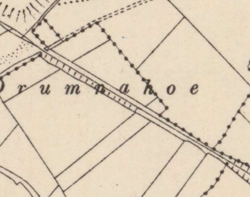
The Company needed to transport peat, in an efficient manner, down the side of the mountain. Their chosen solution was an aerial ropeway. They negotiated an agreement with the local landowner and “early in 1905 a dining-room and huts for sleeping were erected [on] the mountain; and an office, staff house and retorts were built at the foot of the mountain at … the ‘Low Station’. The aerial ropeway, supported by 24 trestles in a straight line down the mountain side and over the Cranny River to the Low Station was also built.” [11]
“The aerial ropeway was to carry numerous buckets which were to circulate continuously in a clockwise direction up and down the mountain side. They would be loaded with peat at the top of the mountain and carry it down to the Low Station to be unloaded and burned in the large retorts. Tools such as stone hammers and peat knives were purchased to aid the workers cut the peat. Some 200 people were employed.” [11]
“Railway lines 7 feet wide resting on 12 foot sleepers were laid [across the bog on the mountain]. Side lines were laid in conjunction with the main line. The peats were stacked beside the lines and then loaded onto wagons on the main line which were drawn by an engine called ‘Moor Hen’ to the head of the aerial ropeway. Here they were transferred into buckets and taken by cable to the Low Station at Drumahoe … where they were emptied into the large retorts lined with lead and burned using sulphuric acid. From here the produce was loaded in granule form into trucks and sent down to the harbour for export.” [11]
After a few months, “Chemicals Ltd. went into liquidation for lack of capital. It was reconstructed as the Sulphate of Ammonia Company with a capital of £125,000 and for the next two years things went well without any hitches.” [11]
Early in 1908 production was almost at a standstill due to the decreasing ammonia content of the peat and the lack of further capital. The company ceased trading and “the aerial ropeway… was purchased by a Cumberland coal mining company. Under the direction of Hugh and Thomas Wilson it was re-erected at St. Bee’s Head.” [11]
References
- J. H. McGuigan; Carnlough Limestone Railway and Harbour; in The Railway Magazine, Tothill Press, London, November 1954, p792-795.
- https://www.causewaycoastalroute.com/carnlough-history, accessed on 3rd April 2026.
- https://www.facebook.com/share/p/1Gq2XF7S82, accessed on 3rd April 2026.
- https://www.geograph.org.uk/photo/435591, accessed on 4th April 2026.
- https://www.geograph.org.uk/photo/435596, accessed on 4th April 2026.
- https://irishrailwaymodeller.com/uploads/monthly_2021_09/930E0570-F053-4DC1-8936-C891361563D2.jpeg.ec550e3399411be053d9c70e7653cc60.jpeg, accessed on 4th April 2026.
- Phillip Gibbons was master of a smack from Westport, Co.Sligo. Late in the eighteenth century he pulled in at Glenarm where, foresaking the sea, he married Anne, daughter of Nicholas Stewart, the Earl of Antrim’s agent. Through his marriage he became possessed of, amongst other properties, the townland of Carnlough North, where they resided. He was a sort of farmer-contractor, prepared to undertake any work for the betterment of the district. He died about 1815.
- The Ordnance Survey Memoirs for the Parish of Ardclinis: see “The Glynns” Vol I, page 31.
- A much fuller story of the construction of the harbour can be found on the Glens Of Antrim Historical Society website: https://antrimhistory.net/carnlough-harbour-development-scheme-18541864-by-jimmy-irvine, accessed on 4th April 2026.
- The land agent in charge of the works was Richard Wilson. [9]
- https://antrimhistory.net/the-sulphate-of-ammonia-co-ltd-carnlough-by-linda-mcneill, accessed on 4th April 2026.
- https://maps.nls.uk/view/247678190, accessed on 4th April 2026.
- https://maps.nls.uk/view/247665827, accessed on 4th April 2026.
- https://www.oneirishrover.com/carnlough-bay, accessed on 4th April 2026.
- https://maps.nls.uk/view/247665839, accessed on 5th April 2026.
