

The travel section of the Saturday Guardian Magazine on 23rd May 2023 included a few pages about train journeys in Europe (pages 72 to 77). This is the third part of a look at those pages and focuses on some reader’s recommendations of journeys by train. It includes a few more uploaded by the Guardian online.
The featured image for this article is a Flexity Outlook Eurotram at Trindade station in Porto, Portugal, © Cornelius Kibelka and licensed for reuse under a Creative Commons licence (CC BY-SA 2.0). [3]
3. Readers’ Favourite Railway Journeys
A. A Dramatic Metro Line in Porto
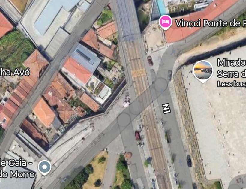
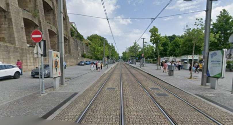
“I love the surprise of urban rail. Porto’s metro D line heading south emerges from mundane darkness underground to suddenly skim rooftops and then rattle across the fantastic Eiffel-inspired Dom Luís I bridge. Choosing to walk back across the metal deck is a completely different experience.” [1: p75][12][Reader: Amy]
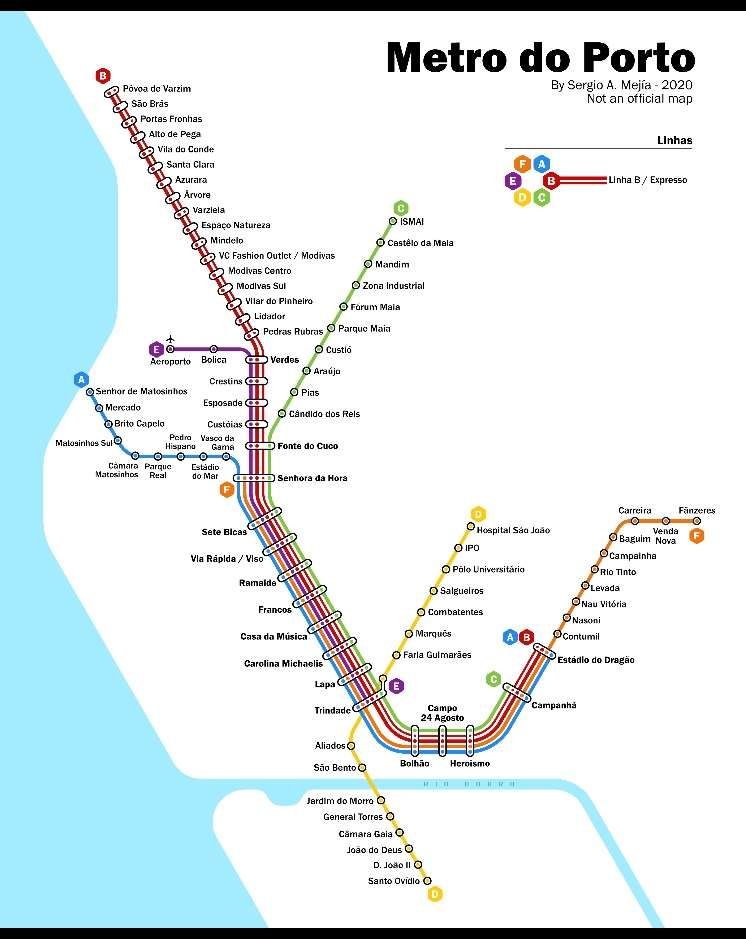
The Porto Metro (Portuguese: Metro do Porto) is the light rail network in Porto. It runs underground in central Porto and above ground into the city’s suburbs. The first parts of the system have been in operation since 2002. The network uses low-floor tram vehicles. [3]
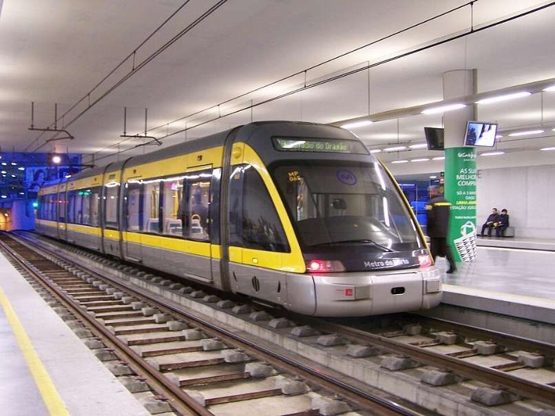
“The Socimi Eurotram (later sold as the Bombardier Flexity Outlook (E)) is an electric tramcar originally designed for the tram system of Compagnie de Transports Strasbourgeois (CTS). Initially produced by Socimi, after the company became bankrupt Eurotrams were manufactured first by ABB Group’s transportation division, then by Adtranz and finally by Bombardier Transportation, who marketed the tram as part of their Flexity Outlook range.” [4]
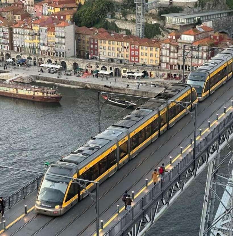
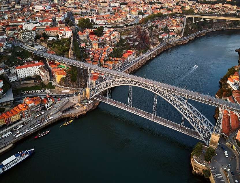
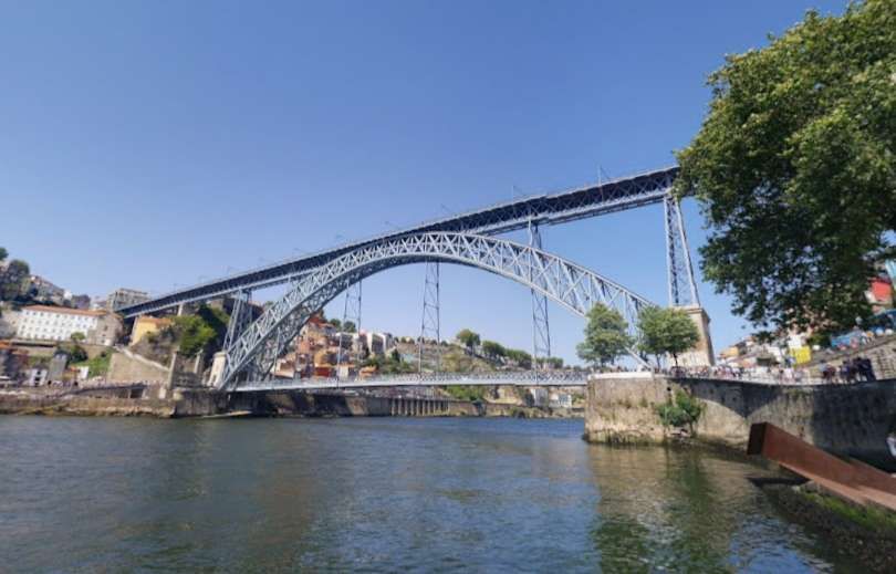
The bridge was designed by Theophile Seyrig and opened at the end of October 1886. In the 21st century, “the bridge’s upper level is used by pedestrians and by line D of the Porto Metro, whilst the lower level is used by buses, taxis, cyclists and pedestrians. The lower level links to the Porto waterfront, including the Praça da Ribeira and the lower station of the Guindais Funicular, at its northern end, and to Gaia waterfront, with its Port wine lodges, at its southern end. The upper level connects to Porto city centre and São Bento station at its northern end, and adjoins the Serra do Pilar Monastery and the upper station of the Gaia Cable Car at its southern end.” [6]
“In 1879, Gustave Eiffel presented a project to construct a new bridge over the Douro, with a high single deck in order to facilitate ship navigation. This project was rejected due to dramatic growth of the urban population, which required a re-thinking of the limits of a single-deck platform. … A competition was initiated in November 1880, in order to construct a double-deck metal bridge, which included projects by Compagnie de Fives-Lille, Cail & C., Schneider & Co., Gustave Eiffel, Lecoq & Co., Société de Braine-le-Comte, Société des Batignolles (which submitted two ideas), Andrew Handyside & Co., Société de Construction de Willebroek (also two projects) and John Dixon. It was in January of the following year that deliberations by the committee supported the project of Société de Willebroek, a design that cost 369,000 réis and provided better carrying capacity. On 21st November 1881, the public work was awarded to the Belgian Société de Willebroek, from Brussels, for 402 contos. It was to be administered by Théophile Seyrig, the former partner of Gustave Eiffel and author of the project. Seyrig had also designed the Maria Pia bridge that was constructed by Eiffel & cie, hence the resemblance of his new bridge to the Maria Pia bridge. Construction began on the Luis I bridge alongside the towers of an earlier suspension bridge, the Ponte Pênsil, which was disassembled.” [6]
“By 26th May 1886, the first weight experiments began, with the transport of a 2,000 kilograms (4,400 lb) per metre. On 30th October construction of the main arch and upper deck were concluded, resulting in its inauguration the very next day. On 1st November, a toll system began to operate under the administration of the winning company, that was equal to 4 reís per person. The following year the lower deck was inaugurated, completing the project. During its ceremonies, the bridge was blessed by Bishop D. Américo.” [6]
Line D (yellow line) opened on 17th September 2005 between Câmara de Gaia in Vila Nova de Gaia and Pólo Universitário in the North. At the northern end, the São João Hospital and IPO stations, were not brought into service until March 2006 due to safety concerns. At the southern end, the line was expanded until D. João II in May 2008 and then to Santo Ovídio in October 2011. In June 2024, the line was extended southwards by 3.15 km with three new stations added, Manuel Leão, Hospital Santos Silva and Vila d’Este. [3]
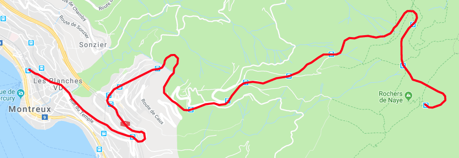
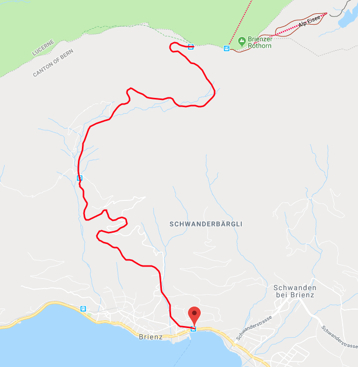
The Guardian reader (Amy) speaks of the tram emerging from the darkness of the tunnel before crossing the bridge. The tunnel mouth can be seen in the satellite image immediately below.
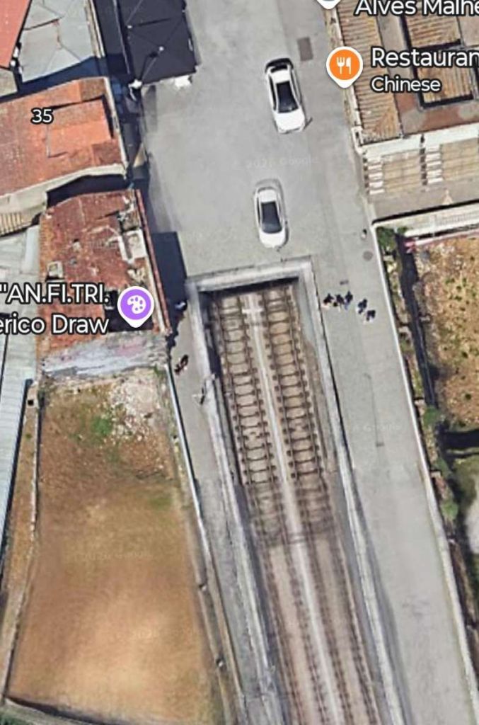
On the South side of the river trams fly over R. da Cabo Simeo and Calcada da Serra before meeting and crossing R. Rocha Leao at level.
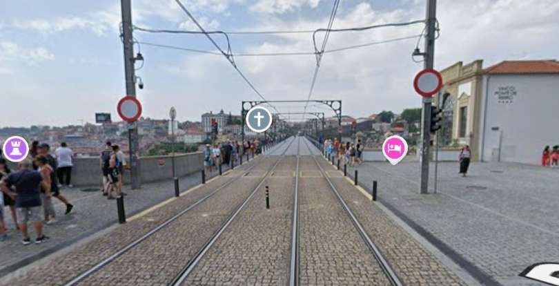
The Guardian reader talked of crossing the bridge on the Metro and then walking back over it afterwards!
B. Fjords and Waterfalls in Norway
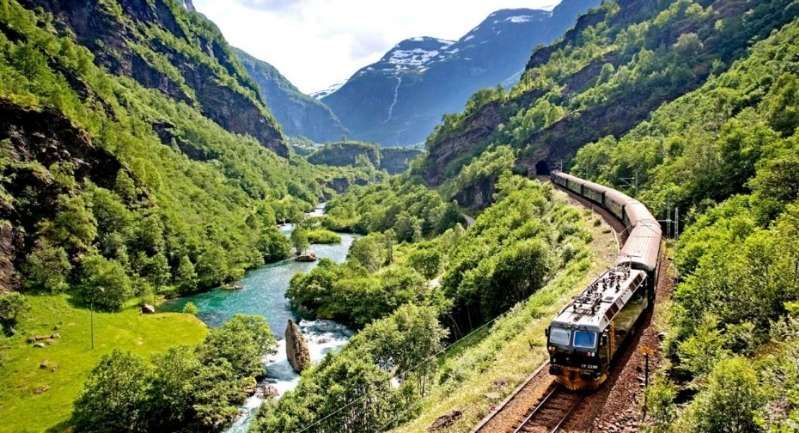
“I travelled across Norway by rail on the spectacular Bergensbanen, running between Oslo and Bergen, and the unforgettable Flåmsbana branch line. The Bergensbanen crosses the high mountain plateau of Hardangervidda, passing lakes, forests and snow‑covered peaks before descending toward the fjords of western Norway. At Myrdal, I transferred on to the steep Flåmsbana, which drops dramatically to Flåm on the Aurlandsfjord, with waterfalls and sheer-sided valleys at every turn.” [1: p75][12][Reader: Daniel]
The Bergensbanen is a spectacular 496-kilometre railway connecting Oslo and Bergen in Norway. Taking approximately 7 hours, it is Northern Europe’s highest mainline railway, reaching 1,237 metres above sea level. The line runs 4 to 6 times daily, offering stunning views of Hardangervidda mountain plateau and deep fjords.
Trains on the Bergensbanen are operated by Vy. [7] Highlights along the way include Finse (the highest station), Myrdal (transfer to the Flåm Railway), and Voss (a major skiing hub).
The Bergensbanen is actually a 371-kilometre (231 mile) long scenic standard-gauge railway line between Bergen and Hønefoss, Norway. However, the name is often applied to the entire route from Bergen to Oslo, including the Randsfjord and Drammen lines between Hønefoss and Oslo, covering a total distance of 496 kilometres (308 miles). [8]
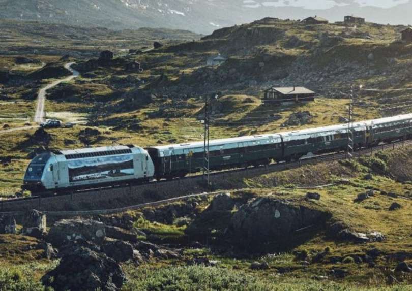
Between Oslo and Bergen by train, © Vy/Øivind Haug. [9]
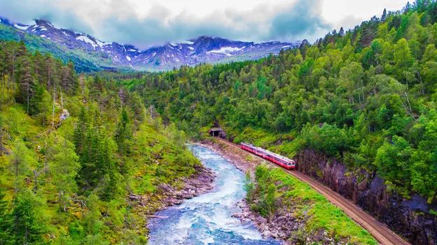
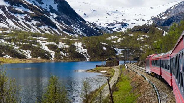
The Flåmsbana is one of the most beautiful train rides in the world and it takes you past mountains and waterfalls you will not forget.
An article about the Flam railway can be found here. [11]
C. An Electric Gem in Germany
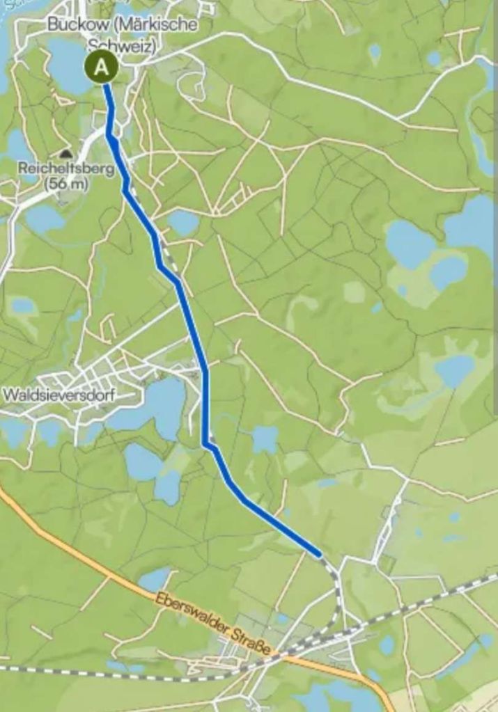
“I took the RB26 train from Berlin-Lichtenberg to Müncheberg and changed for the Buckower Kleinbahn historic narrow gauge railway. Opened in 1930 as an early electric railway, it closed its regular service in the late 1990s. It is now volunteers who run the line that takes you through the rolling hills of Märkische Schweiz in Brandenburg to the pretty spa town of Buckow. Here, I visited the residence of Bertolt Brecht and Helene Weigel on the peaceful reedy shores of Lake Schermützel, before returning refreshed to the Berlin bustle.” [1: p75][12][Reader: Rachael]
The Buckower Kleinbahn railway runs from Buckow to/from Müncheberg a round journey of close to 10km.
“The little railway museum in Buckow’s train station building illustrates the history of Buckow’s narrow-gauge railway, as well as of other private and secondary railways, such as the Müncheberg narrow-gauge railway, the Oderbruch train and the ‘Royal Prussian Eastern Line’ (now the RB 26). There are also many exhibits of all sizes and ages, relating to general railroading in Germany.” [13]
“A range of diesel and electricity-powered vehicles from the time between 1920 and 1986 are presented in the outdoor area of the Buckow train station. In addition to this, the old rectifier facility of Buckow’s narrow-gauge railway is home to an exhibition about railway power technology, as well as railway signalling and safety.” [13]
“Buckow’s narrow-gauge railway (Buckower Kleinbhan) with historic vehicles operates on weekends from April to October, and it is inseparably linked to the railway museum. Visitors coming from Berlin can board the museum train at Müncheberg station and are taken to Buckow via Waldsieversdorf with very friendly assistance. Children of all ages get to look over the train driver’s shoulder and interested adults can take part in a training course and obtain a certificate as an honorary train driver of the Buckow narrow-gauge railway.” [13]
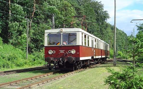
This historic electric railcar is one of a number of such vehicles, Class 279 or ET188 types, with some refurbished in the early 1980s, which run on the Buckower Kleinbahn railway, © Museumsbahn Buckower Kleinbahn e.V. [13]
D. The Swiss Watchmakers’ Line
“When time is not important, a little-known French railway line allows you to enter Switzerland through the valley of the watchmakers. The line from Besançon in France drifts through the beautiful Jura foothills to Le Locle, a Swiss watchmaking town. No one got on or off at L’Hôpital-du-Grosbois, a byway station en route named after a leprosy hospital. A line that Dr Beeching would probably have closed still delivers you into Switzerland on time. [1: p75][12][Reader: Martin]
The “Watchmakers’ Line” (La Ligne des Horlogers) is a historic cross-border railway connecting Besançon, France, to La Chaux-de-Fonds/Le Locle, Switzerland. Named in honour of the region’s rich horological heritage, it spans the Jura mountains
Winding through the rugged terrain of the French Pays Horloger (Watchmaking Country) and the Swiss canton of Neuchâtel, the line is a marvel of 19th-century railway engineering. It features numerous tunnels and viaducts built to conquer the steep alpine inclines. The route is actively served by TER (Transport Express Régional) trains on the French side and connects seamlessly with the Swiss rail network.
The TER (regional) train takes approximately 1 hour and 15 minutes to cover the 48-kilometre distance. There are around 9 direct trains per day in both directions.
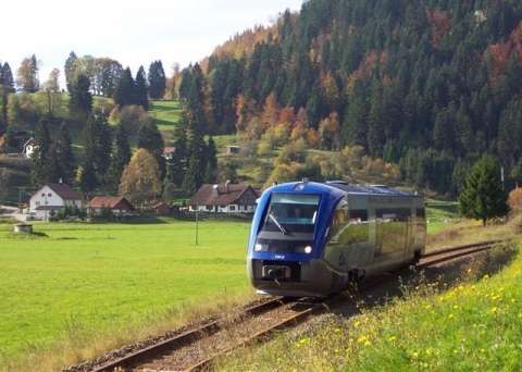
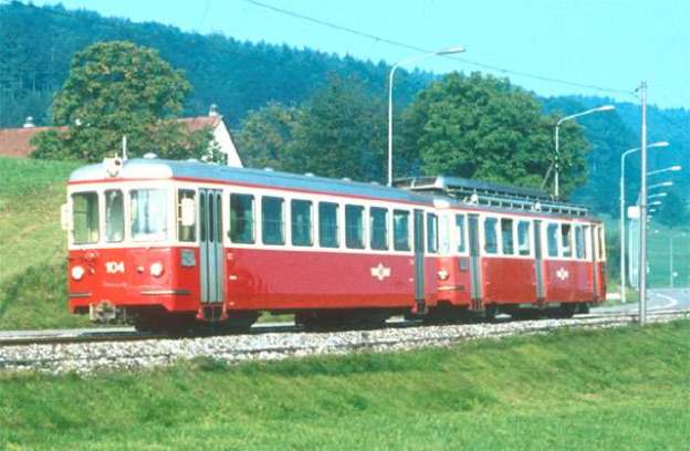
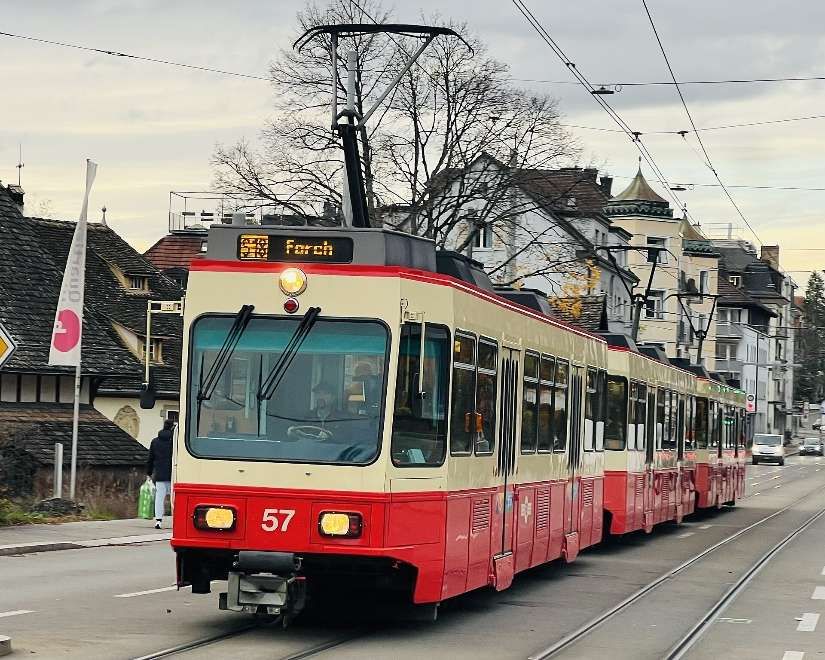
A standard train on the route between Besançon, France and La Chaux-de-Fonds/Le Locle, Switzerland. [16]
From 1st March to 31st October 2021, SNCF Réseau carried out major modernization work on the Horlogers line, a century-old mountain line, which connects Besançon (25) to La Chaux-de-Fonds in Switzerland for a budget of €55.5 million. These works reinforced structures (bridges, tunnels, walls, and trenches), renewed 35 km of track for €49 million (€19.4 million from the French State, €19.4 million from the Bourgogne-Franche-Comté Region, €6 million from INTERREG, and €4.2 million from SNCF Réseau), made the Morteau and Valdahon stations accessible to all for €1.5 million (€0.75 million from the French State and €0.75 million from the Bourgogne-Franche-Comté Region), and modernized the signaling system to allow TER regional trains in the Bourgogne-Franche-Comté Region to continue operating in Switzerland for €5 million (€2.5 million from the French State and €2.5 million from the Bourgogne-Franche-Comté Region). After a complete eight-month service interruption on the line, traffic between Besançon and Morteau resumed on 31st October, and between Morteau and La Chaux-de-Fonds on 23rd December 2021. [15]
The site of La Chaux-de-Fonds/Le Locle consists of two towns situated close to one another in a remote environment in the Swiss Jura mountains, on land not particularly suited to farming. Planned in the early 19th century, after extensive fires, the towns owed their existence to the watchmaking industry. Their layout along an open-ended scheme of parallel strips on which residential housing and workshops are intermingled reflects the needs of the local watchmaking culture that dates to the 17th century and is still alive today.
E. Charmed by the Vienna to Zagreb train
“The journey from Vienna to Zagreb saw mountainous central Europe relax into Balkan charm. Stunning Alpine scenery melted into forest, settling down into rolling hills as we passed through Graz and reached the Slovene border, stopping for an hour’s changeover at the tiny Zidani Most station, where we enjoyed afternoon beers gazing over lush Slovenian countryside. The connection to Zagreb boasted dramatic lake scenery that gave way to farm land, golden in evening light, as we passed into Croatia, soon rattling into its underrated capital. We booked this through Omio, which came in relatively cheaply at £41.” [12][Reader: Matt]
It is possible to get a direct train. According to thetrainline.com, the journey takes about 6 to 6.5 hours, covering roughly 370 km. Tickets can start around €25 to €35. There are normally 11 trains per day travelling from Vienna to Zagreb and tickets for this journey start from £25.89 when you book in advance. [17] The raileurope.com website quotes a lowest fare at under £22.00. [18]
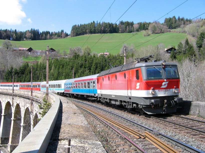
The train journey from Vienna to Zagreb transitions from spectacular Alpine peaks to lush river valleys and rolling Balkan countryside. The journey takes you through southeastern Austria and northern Slovenia before arriving in Croatia. To catch the best views, sit on the left side of the train when departing Vienna to look down into the Semmering valleys. When traveling through Slovenia, sit on the right side to enjoy the best riverside views.
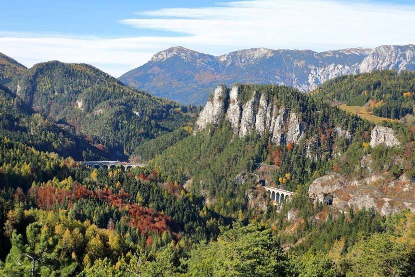
Shortly after leaving Vienna (Wiener Neustadt), the train climbs the Semmering Pass. This is a UNESCO World Heritage site, famous for winding viaducts, tunnels, and panoramic views of steep mountain valleys and dark pine forests.
As you descend from the mountains, you’ll pass through the rolling, green agricultural landscapes and vineyards surrounding the city of Graz.
Crossing the border, the scenery becomes dramatic. The train tracks hug the winding Savinja and Sava rivers, passing through deep gorges and canyons flanked by dense forests and rural villages.
The rugged terrain flattens out into the golden farmlands and charming countryside of northern Croatia before pulling into Zagreb’s main station, Zagreb Glavni Kolodvor.
Further suggestions for rail journeys from Guardian readers can be found in the fourth of this series of articles based around the Guardian Saturday Magazine of 23rd May 2026.
References
- Readers’Travel Tips: Favourite Train Trips; in Saturday (the Guardian Magazine), 23rd May 2026, p75.
- https://www.reddit.com/r/TransitDiagrams/comments/gidbxm/ocdiagram_metro_do_porto_portugal, accessed on 25th May 2026.
- https://en.wikipedia.org/wiki/Porto_Metro, accessed on 25th May 2026.
- https://en.wikipedia.org/wiki/Socimi_Eurotram, accessed on 25th May 2026.
- https://commons.wikimedia.org/wiki/File:Vila_Nova_de_Gaia_(52734250241).jpg, accessed on 25th May 2026.
- https://en.wikipedia.org/wiki/Dom_Lu%C3%ADs_I_Bridge#/media/File%3ADom_Lu%C3%ADs_I_Bridge_(36961760686).jpg, accessed on 25th May 2026.
- https://www.vy.no/en/train/routes/the-bergen-line, accessed on 25th May 2026.
- https://en.wikipedia.org/wiki/Bergen_Line, accessed on 25th May 2026.
- https://en.visitbergen.com/visitor-information/travel-information/getting-here/bergensbanen-oslo-to-bergen-by-train, accessed on 25th May 2026.
- https://www.bbc.co.uk/travel/article/20230130-the-highest-rail-route-in-northern-europe, accessed on 25th May 2026.
- https://rogerfarnworth.com/2019/01/01/the-flam-railway-in-1950
- https://www.theguardian.com/travel/2026/may/22/readers-favourite-scenic-european-railway-journeys-trains, accessed on 25th May 2026.
- https://www.brandenburg-tourism.com/poi/seenland-oder-spree/industrial-culture/eisenbahnmuseum-and-buckower-kleinbahn-train-museum, accessed on 25th May 2026.
- https://www.komoot.com/smarttour/3623001, accessed on 25th May 2026.
- https://www.sncf-reseau.com/fr/cp/bourgogne-franche-comte/ligne-horlogers-modernisee-entre-besancon-et-morteau, accessed on 25th May 2026.
- https://www.railwaypro.com/wp/colas-consortium-to-modernise-ligne-des-horlogers, accessed on 25th May 2026.
- https://www.thetrainline.com/en/train-times/vienna-to-zagreb, accessed on 25th May 2026.
- https://www.raileurope.com/en-gb/destinations/vienna-zagreb-train, accessed on 25th May 2026.
- https://en.wikipedia.org/wiki/Semmering_railway, accessed on 25th May 2026.


.jpg)
.jpg)