Tag Archives: Modern Tramway

The Modern Tramway – July 1951 – The Tramways of Clermont-Ferrand

The Modern Tramway of July 1951 included an article by Peter J. Jacques about the tramways of Clermont-Ferrand. [1]

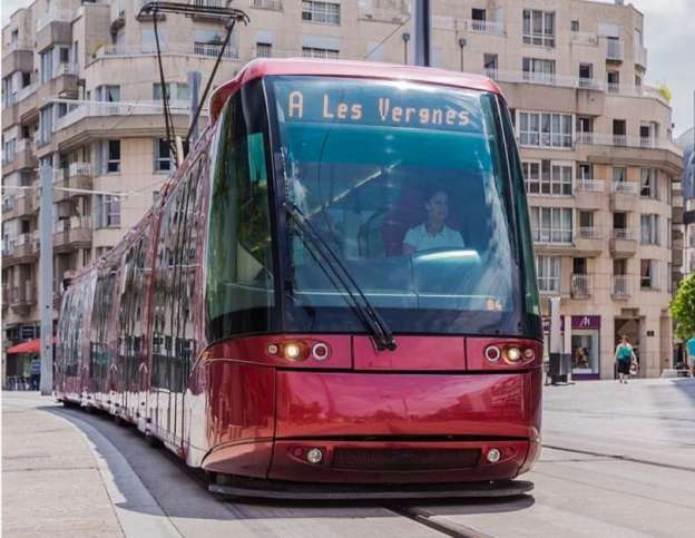
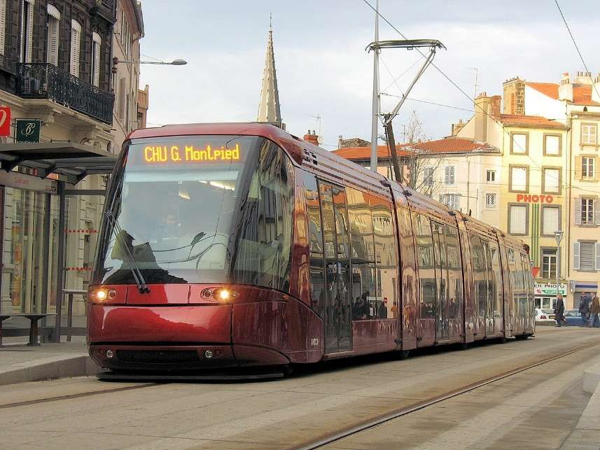
The featured image for this article is a photograph of one of Clermont-Ferrand’s modern trams. The initial fleet was 26 trains, but in September 2019, the fleet was expanded to 30 trains. Every STE 4 model consists of 4 cars, for a length of 32 metres (105 ft), © William Crochot and licenced for reuse under a Creative Commons licence (CC BY-SA 4.0). [2]

Jacques wrote:

“The French city of Clermont-Ferrand has a population of approximately 100,000 and is situated in the mountainous Departement of Puy de Dome. Most of the local transport is provided by the Compagne des Tramways de Clermont-Ferrand et du Puy de Dome, which operates tram services over four routes and several bus services. The tramcar fleet comprises 66 single-deck cars, including 33 trailers. The system is interesting, not merely because of its present day policy of retention and modernisation, but also on account of its importance in the history of French Tramways.” [1: p156]
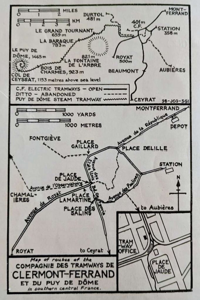
A map of the Clermont-Ferrand tram network in the 1950s. [1: p156]
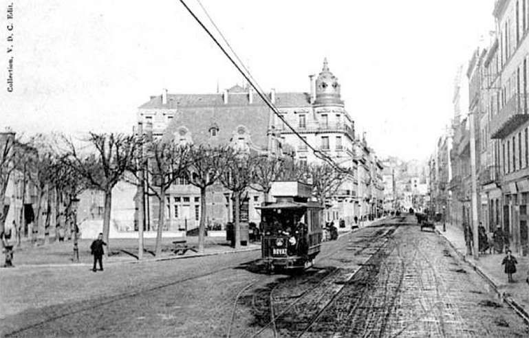
An early postcard image, © Public Domain. [10]

“It was at Clermont-Ferrand that the first French electric tramway was installed in 1888; the line ran from Montferrand to Royat and was built by M. Claret, the father of the present [in 1951] Director.vthere was a branch line to the station and a depot at Montferrand. Current was collected, by means of a shoe which the car towed at the end of a wire, from a rectangular tube suspended 6 metres above the track. ‘Marsillon’ type rails [3] were used, laid on wooden sleepers and held in position by cast-iron chairs. The cars were 4-wheel single-deckers fitted with ‘Thury’ type motors.” [1: p156-157]

Marsillon Type Rails: two pictures of this rail type are shown below. Antoine-Léon Marsillon (1824-1892) was responsible for the design.
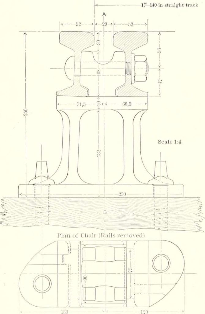
This image comes from page 369 of ‘The Street Railway Journal’ of 1884. [3]

Thury Type Motors: were pioneering direct-current (DC) traction motors and high-voltage DC (HVDC) power systems developed by the Swiss-French engineer René Thury in the late 19th and early 20th centuries. Thury’s innovative designs were heavily utilized across early European tramways and electrified mountain railways. Clermont-Ferrand used Thury 25-horsepower motors. A single motor drove one axle via a gear train, and the second axle was driven by connection rods coupled to the first. [4]
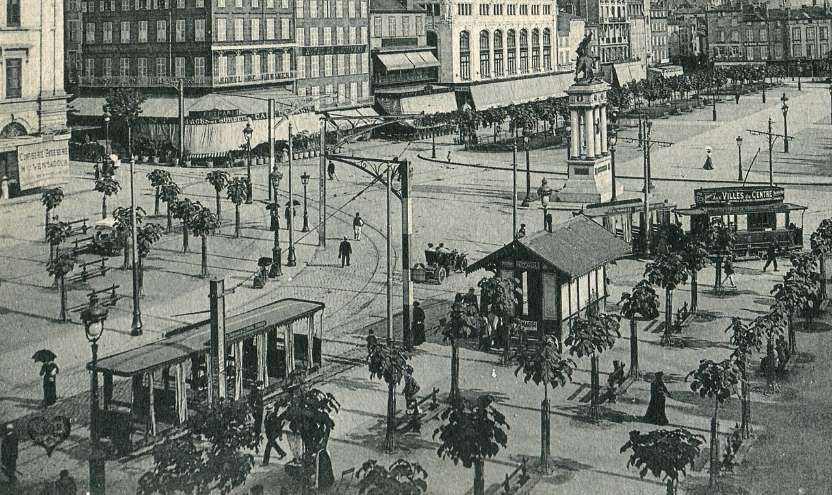
An early postcard image showing trams in the Place de Jaude just after the statue of Vercingetorix was erected, © Public Domain. [11]

Jacques continued:

“Two years later, an experiment was made with surface-contact current collection on a stretch of track 219 yards long, using the Claret Vuilleumier system, although it was never adopted in Clermont-Ferrand, the success of the trial in that city led M. Claret to construct a tramway on this system in Paris, from the Place de la République to Romainville. (The latter tramway was the first electric route in the French capital and was opened in 1896).

“In 1903, another route was added to the Clermont-Ferrand tramways; it followed a winding course from the Place Delille to the Place de Jaude. In 1906, a light railway was constructed from the Place Lamartine to the summit of the Puy de Dôme mountain, to the west of the city. This line was worked by steam tank locomotives hauling three or four 4-wheeled carriages. The depot was at Durtol.

“In the course of the next few years, normal overhead wires were installed in place of the overhead “tubes,” and the cars were fitted with trolley poles; at the same time the track was entirely relaid with ‘Broca’ rails.

“New trailer cars were built in 1912 and these open-sided bogie vehicles are still [in 1951] used during the summer months. The following year saw the construction of new lines to Fontgiève and to the station via the Place des Salins. The line to Vallières and Beaumont was opened in 1914, and several new trailers with partly-open bodywork were built in that year. The route from the Place Delille to the Place de Jaude was closed in 1915.” [1: p157]

The Claret Vuilleumier System of Current Collection: The Claret-Vuilleumier system was an early, now obsolete surface-contact method for powering electric trams without overhead wires. Developed in the late 19th century, it used electromagnetic, road-level studs that only became energized as a tram passed over them, delivering power to the vehicle through an under-carriage skate. It was most notably implemented on tram lines in Paris (such as the République-Romainville line), the system was engineered to eliminate the visual “wire pollution” of overhead catenaries in city centres. It solved the shock hazard problem of exposed surface studs through an ingenious, albeit troublesome, mechanical setup. [5]

Small iron contact studs were spaced about 2.5 metres apart and protruded roughly 5 mm above the cobblestone surface. The studs were not permanently live. Instead, they were connected to a series of underground switches controlled by a master mechanism. As the tram rolled over the track, magnets on the vehicle triggered the underground switch. The stud directly beneath the tram became energized with 500–600 volts to power the tram’s motors, while the studs ahead and behind remained safely dead. [5]

Broca Rail: (often called a grooved or girder rail) is a specialized steel track invented in the late 19th century. It is primarily used for streetcars and trams, featuring a built-in groove that allows trains to sit flush with paved city streets without disrupting car traffic or pedestrian walking paths. [6]
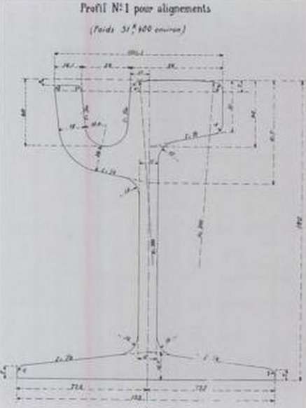
Broca’ rail was designed by Georges Broca, © Public domain. [7]

Jacques continued:

“In 1918, the Company built 5 new motor trams fitted with two Westinghouse H 100 35 h.p. motors and these were followed by 6 more of the same type between 1919 and 1922. During the latter year, the Beaumont line was extended to Ceyrat, a distance of over 4 miles from the city centre.

“The Puy de Dôme railway was closed in 1926 and a road was built on the right-of-way. The line as far as Durtol was retained for a time as an electric tramway but was shortly replaced by a bus route. In 1928, the Aubière line was opened and in the following year, the short Fontgiève line was closed. The replacing bus service also served other outlying districts not yet sufficiently developed to require tramway service.” [1: p158]
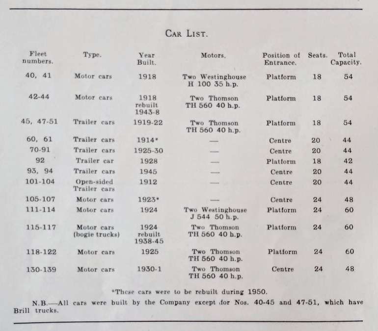
Jacques provided a list of tramcars used on the Clermont-Ferrand network in the very early 1950s. [1: p158]

Jacques narrative continued:

“Between 1923 and 1930, 12 new motor trams and 23 trailers were added to the fleet. Of these, four motor cars (Nos. 111-14) were fitted with two Westinghouse J544 50 h.p. motors, while the remaining 8, Nos. 115-22, were of improved design with independent suspension, fitted with two Thomson TH 560 40 h.p. motors. In 1930, a new tramcar was built at the Company’s workshops. Of modern design with centre entrances and independent suspension, it had two Thomson TH 560 40 h.p. motors and had seats for 24 passengers in two saloons with room for 24 standing passengers on its large central platform. The success of this car led to the construction of nine others, all of which were in service by the end of 1931. This type are numbered 130-139. In 1938, work began on the reconstruction of Nos. 115-117, the only bogie motor trams in the fleet. In 1943, three more cars, Nos. 42-44 were rebuilt and given Thomson TH 560 40 h.p. motors. Two new trailers were built in 1945 (Nos. 93-4).” [2: p158]

The Westinghouse J544 50 h.p. Motor: was an early-20th-century direct current (DC) traction motor rated at 50 horsepower. Widely used on streetcars and interurban railways in North America, these motors provided the high starting torque and reliability necessary to modernize urban public transit.

The Thomson TH 560 40 h.p. Motor (or GE-560): was  an early 40-horsepower electric railway motor. It as manufactured at the turn of the 20th century by the British Thomson-Houston (BTH) company (and its American parent, General Electric).

Jacques continued:

“At the end of the Second World War, the future of the tramways was discussed and it was decided to retain trams on all routes except that serving Aubière; this route was closed in December, 1949. The overhaul and repainting of all cars was begun and a new livery of bright red and cream was chosen to replace the former maroon and cream. Many cars have now been repainted and five trailers which do not conform to the standard pattern (60, 61, 105-7) are being rebuilt with central double doors. All work is carried out in the Company’s own workshops at Montferrand.

“At present, four routes are worked, the cars carrying a coloured destination board, as follows:

– Yellow: Station – Place des Salins – Place de Jaude – Place Delille – Station.

– Red: Station – Place Delille – Place de Jaude –  Place des Salins – Station.

– Blue: Royat Chamalières – Place de Jaude –  Place Delille – Montferrand.

– White: Place de Jaude – Vallières – Beaumont – Ceyrat.

“The headway on the Station and Montferrand Royat routes is usually six minutes. The Ceyrat route has short workings to Vallières and Beaumont. Ceyrat cars maintain a headway of 40 minutes which is shortened to 20 minutes as required. Cars run to Beaumont and Vallières every 20 and 10 minutes respectively. One car is sufficient to operate the Vallières short working and it is usually one of the 118-122 type.

“An interesting feature of the system is the provision of curbside or island loading facilities at the termini and main stops. All termini have sheltered waiting rooms and there are small enquiry offices at the station and the Place de Jaude.

“As Clermont-Ferrand is an important tourist centre, heavy demands are placed on the tramways during the summer months. Royat is a celebrated spa and its population increases from 3,500 to 10,000 between June and September. Ceyrat lies in the heart of beautiful hilly countryside and is much visited. The trams have no difficulty in handling the crowds and the ordinary service to Royat is capable of carrying nearly a thousand passengers an hour (ten trains an hour with an average capacity of 98). Seats in the open-sided trailers are eagerly sought when these cars are in service.

It is encouraging to note that there is no bias in favour of any one form of transport; whilst the Company have abandoned certain lines unsuitable for tramway operation, they are retaining tramcars on the more heavily-burdened routes. In addition to the reconditioning of cars already mentioned, the Company is opening a new sub-station (with three mercury vapour rectifiers) and ultra-modern passenger shelters have been built at Montferrand, Royat and the Place de Jaude. Trolleybuses are to replace motor buses on the Durtol route and if the area develops any further, the trams may yet run again to that district.” [1: p159 & 161]
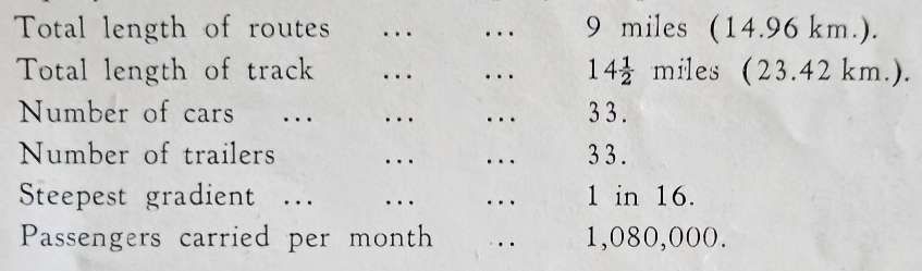
Jacques provided these statistics for the Clermont-Ferrand tramway network. [1: p161]
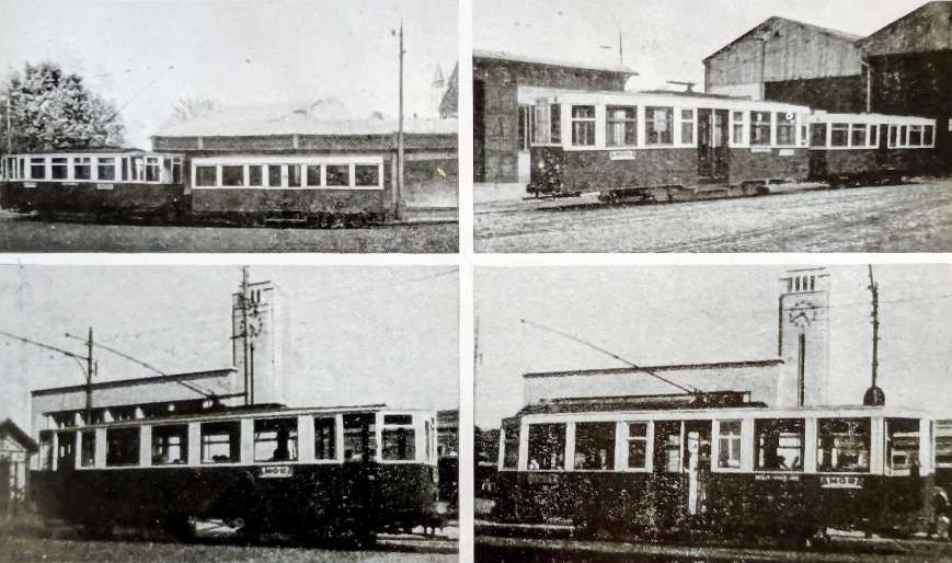
Four photographs taken by M.S. Hill and P.J. Jacques accompanied the article. Top-left: Motor -car No. 114 and trailer No. 84 at the Royat terminus. Top-right: Motor-car No. 139 and trailer No. 76 at the Montferrand depot. Bottom-left: Bogie-car No. 116 at Station. Bottom-right: Centre-entrance car No 139 at Station, © M.S. Hill & P. J. Jacques, Public Domain. [1: p161]

Just 5 years after Jacques article, the tram network in Clermont-Ferrand was closed in favour of buses. “The last tram in Clermont-Ferrand ran on 17th March 1956. After this, public transportation in the city was solely by bus. In many places, the rails were paved over to make way for cars.” [8]

Clermont-Ferrand’s Modern Tramway

In the 1970s, concern over the consequences of automobile use increased. In the 1983 Elections, a tramway was proposed by Socialist mayor Roger Quilliot in his re-election campaign. … However, the tram project was only seriously considered … in 1990. The development of the system was given to SOFRETU (now Systra), which proposed the building of two tramlines: one north–south line (which would eventually become Line A), and an east–west line. In 1996, bids were solicited for the rolling stock for the tramway. Alstom proposed that Alstom Citadis trams be used for the system, and Alstom Citadis trams were bought for Line A on 14th October 1996. Thus, the first tramway followed SOFRETU’s proposal, which corresponded to the present day Line A. However, due to pressure from the Chamber of Commerce and industries in Clermont-Ferrand (mostly Michelin), this initial tramway project was halted.” [8]

A revised project was proposed in 2000 and bids were sought in 2002. The contract was won by Lohr Industrie. A first section was opened in November 2006 with the remainder of the originally proposed network opening in 2007. The line had to be closed for seven weeks in 2013 to renovate many station platforms due to their deterioration. [8]

In 2011, an extension of Line A to Vergnes was initiated. Work began in December 2011 and took almost 2 years.” [8]

On 14th December 2013, the 2-kilometre (1.2 mile) extension of Line A from Champratel to Vergnes opened to the public.  This extension was part of the ‘Reorganization of Les Verges Region’ program, mainly to ease access to the Stade Gabriel Montpied.” [8]
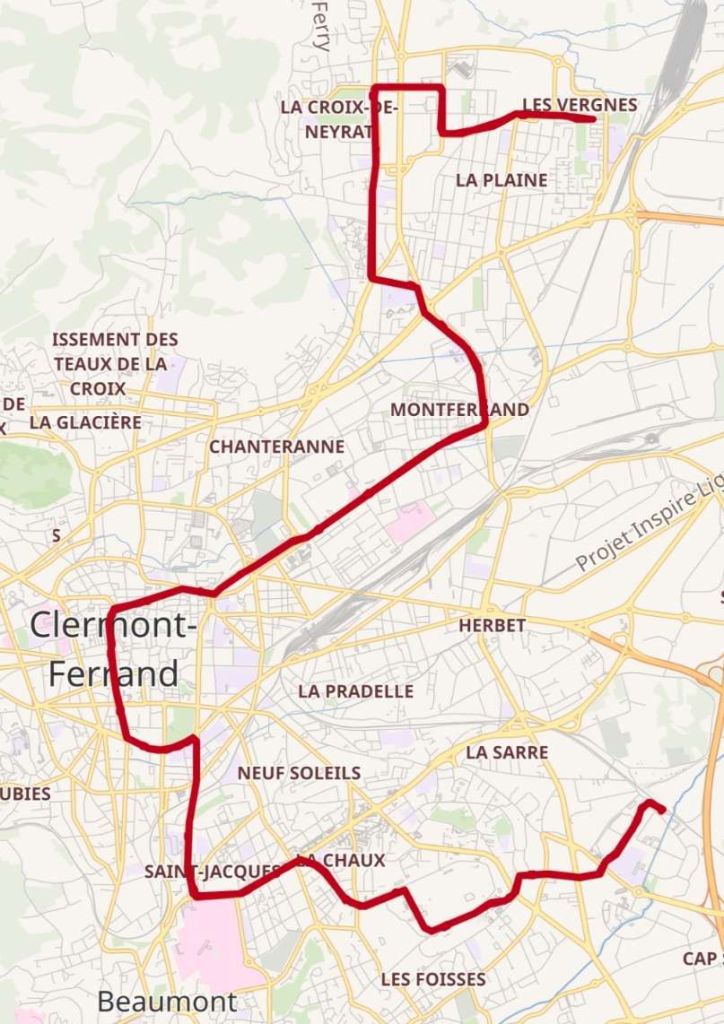
The modern Clermont-Ferrand tram network. [9]
A modern Clermont-Ferrand tram on Avenue des Etats Unis, © Fabien1309 and licenced for reuse under a Creative Commons licence (CC BY-SA 2.0). [12]

The tramway of Clermont-Ferrand uses Translohr technology. The initial fleet was 26 trains, but in September 2019, the fleet was expanded to 30 trains. Every STE 4 model consists of 4 cars, for a length of 32 metres (105 ft). … Every train has a maximum capacity of 238 people with around 40 sitting. Six trains were priced at approximately 14 million euros.” [8]

References

  1. P. J. Jacques; The Tramways of Clermont-Ferrand; in The Modern Tramway Volume 14 No. 163, July 1951, p156-159 & p161.
  2. https://en.wikipedia.org/wiki/Clermont-Ferrand_tramway#/media/File%3ATranslohr_STE4_-_143.jpg, accessed on 18th May 2026.
  3. https://commons.wikimedia.org/wiki/Category:Marsillon_rail, accessed on 18th May 2026.
  4. https://en.wikipedia.org/wiki/History_of_electric_power_transmission, accessed on 18th May 2026.
  5. https://www.citytransport.info/Trams02.htm, accessed on 18th May 2026.
  6. https://www.glorycrane.com/grooved-rails., accessed on 18th May 2026.
  7. https://commons.wikimedia.org/wiki/Category:Broca_rail#/media/File%3AProfil_du_Rail_Broca%2C_en_forme_du_champignon._Profil_N%C2%B01_pour_alignements_(Doc._Archives_de_Paris).jpg, accessed on 18th May 2026.
  8. https://en.wikipedia.org/wiki/Clermont-Ferrand_dtramway, accessed on 18th May 2026.
  9. https://en.wikipedia.org/wiki/Clermont-Ferrand_tramway#/map/0, accessed on 18th May 2026.
  10. https://en.wikipedia.org/wiki/Clermont-Ferrand_tramway_(1890%E2%80%931956)#/media/File%3ATramway-electrique-Clermont-Ferrand-cp.jpg, accessed on 18th May 2026.
  11. https://en.wikipedia.org/wiki/Clermont-Ferrand_tramway_(1890%E2%80%931956)#/media/File%3AELD_3497_-_CLERMONT-FD_-_Place_de_Jaude_-_Vue_prise_de_l’Hotel_de_la_Poste_(D%C3%A9tail).JPG, accessed on 18th May 2026.
  12. https://en.wikipedia.org/wiki/Clermont-Ferrand_tramway#/media/File%3ATramway-clermont-ferrand-2.jpg, accessed on 18th May 2026.
The Modern Tramway – February 1951 – Traction Motor Trends in 1951 – and beyond

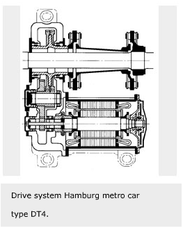
The featured image for this article is a line drawing of a drive system from a Hamburg Metro Car, an SKF DT4. [5] … AC traction motors (commonly induction motors) are the standard for modern trams, replacing older DC motors to provide higher efficiency, better reliability, and reduced maintenance. These motors, often running at 60–200 kW, power the bogies and enable regenerative braking to feed energy back into the overhead line. They are controlled by variable-frequency inverters for smooth acceleration.

The Modern Tramway of February 1951 carried an article by ‘Eltee’ entitled ‘Traction Motor Trends’ about the recent changes in electric motors in trams. [1: p33-34]

“The present trend towards the use of lightweight high-speed electric motors for traction purposes, a trend exemplified at its best by the motors used in in the P.C.C. cars in America, and those of similar design now being introduced at Blackpool and and Glasgow and on the Continent, justifiably prompts the query as to why motors were not, in the past, built as they are today. There are actually several reasons for this, some highly technical, but one of the more important is that the need for efficient ventilation of motors was not sufficiently appreciated in the early days.

“When a motor is running and current is passing through its conductors these conductors are heated by the passage of current, just as are the conductors of an electric stove though much less so. The power represented by this heat is lost to the motor, and called the ‘copper loss’. Another source of loss is the rotation of the armature in the motor magnetic field; the alternating magnetism through the armature caused by its rotation brings about power losses in armature iron, which also appear as heat. In running, then, the motor gets heated, and if there were no means of dissipating this heat the motor would get hotter and hotter until something melted.

“In practice this does not happen, as the motor casing is in contact with the air around it, and when the casing is hot it loses heat to this air, doing so all the more readily when the car it is driving is moving and there is a certain amount of draught. Many years ago this was the only way of cooling the tramway motor, hence a large motor had to be used simply to ensure that there was enough casing area to dissipate the heat generated. Some additional armature cooling was given by the provision of axial ducts in the armature, aided by a few radial ducts. In this way some slight fanning action was given by the moving armature, swirling the air in the motor casing and conveying the heat from the armature more readily to the outside casing for dissipation into the atmosphere.

“A later development introduced what is now known as ‘series ventilation’, the self-ventilated motor being introduced about 1910. In such a motor a fan is mounted on the non-commutator end of the armature, and two sets of openings are made in the same end of the motor casing. The fan draws air through the armature axial ducts when the motor is running and expels it through one of the casing openings; this assists to keep the armature cool. This air, in the first place, is drawn in through the other set of openings and over the field coils before turning round and entering the armature ducts; in this way the field also is kept cool, but the ventilation of the armature suffers because the air is already somewhat warmed by its passage over the field coils.

“A further development, common from about 1920 onwards, is known as ‘parallel ventilation’, in which there are two parallel air streams through the motor. A twin fan is fitted to the non-commutator end of the armature, and openings made in both ends of the motor casing. The fan draws a stream of cool air over the commutator, round the armature surface and over the field coils before expelling it. The other half of the fan draws an air stream under the commutator and through the armature axial ducts, thus keeping the interior of the armature cool and dissipating most of the iron losses effectively.

“With a motor as efficiently ventilated as this it is possible to ‘force’ the motor more without its getting too hot; that is, in more technical language, a motor can have a higher rated power. Consideration of the above method of ventilation readily shows that if the motor armature rotates more quickly the attached fan will draw more air through it, ventilate it even more thoroughly, and permit even more ‘forcing’ by the passage of greater currents. This, in essence, explains the present trend towards motors of high rotational speed; the efficient ventilation possible on such motors permits more power to be passed through them than through motors of similar size with less effective ventilation.

“The above being understood, two further points are worthy of emphasis. One is that the greatest losses occur in a motor when it is starting and running slowly; the best ventilation occurs when it is running quickly. Cars on a town route will thus need bigger motors than similar cars on an interurban route on which there is a lot of free running, providing their maximum speeds are equal. The second point is that, if motors have been used on a service on which their capabilities are being fully employed the gear ratio must not be altered, because, although the speed of the cars can thereby be improved, such a measure will not only increase the currents passed through the motor (for more power will be required from the motor) but will also decrease the average speed of rotation of the motor. resulting increased “losses” and impaired ventilation will both tend to raise the operating temperature of the motor. and so reduce its life, unless it was known that hitherto it had been used well below its capacity and was operating at relatively low temperatures.” [1: p33-34]

Since ‘Eltee’ was writing at the beginning of the 1950s, much has changed!

Improvements in the ventilation of tramcar electric motors since 1950 have centred on a move away from traditional forced-air cooling in direct current (DC) motors to advanced, sealed, and integrated systems used with modern AC traction, enhancing reliability and reducing maintenance. [2][3]

Modern three-phase AC motors allow for lighter, more compact, and more powerful motors. These motors are often less sensitive to heat and easier to cool than older designs. [2][3]

Modern tram design integrates motors directly into the bogies, with ventilation systems designed as part of the overall low-floor, compact carriage architecture, ensuring better cooling airflow in restricted spaces. [3]

Many modern motors are now completely enclosed, utilizing improved heat sinking and specialized cooling fan designs rather than drawing in outside air, reducing the impact of dust and water on electrical components. [2][3]

The use of GTO-inverters and modern power electronics reduces motor heat generation compared to older resistor-controlled DC motors, reducing the load on ventilation systems. [2][3]

Improved insulation materials allow motors to operate safely at higher temperatures, reducing the strain on the cooling systems and improving longevity. [2][3]

Modern electric trams utilize motors to generate electricity during braking, returning power to the grid or charging on-board batteries/supercapacitors. The use of battery-power and on-board storage can allow trams to pass through city centres or other sensitive areas without overhead wires. [3][4]

Electric motors are ideal for rapid urban transport because their higher torque at low speeds allows speedy departures from stops on a network. It also allows tramcars to handle hilly terrain better than internal combustion engines.

Electric motors are roughly 90% efficient at converting energy into motion. In contrast, diesel engines lose about 60-70% of fuel energy as heat. [4]

Additionally, unlike internal combustion engined vehicles that consume fuel while stopped, electric trams use virtually no power when stationary. [4]

AC motors have been shown to improve reliability and decrease downtime compared to traditional DC motors. But they have significantly lower maintenance needs than internal combustion engines, having far fewer moving parts and not needing oil changes, spark plugs, filters, and complex exhaust systems. The high torque of electric motors at low speeds eliminates the need for heavy, expensive multi-stage gearboxes common in internal combustion engined vehicles. [4]

Trams typically have a service life of about 30 years, roughly double that of diesel-powered buses. They typically produce no local pollutants like nitrogen oxides or particulates, which is critical for city air quality and meeting climate targets. Electric propulsion is significantly quieter than internal combustion engines, reducing noise pollution in densely populated areas. In addition, electricity can be generated from various sources, including renewable energy (wind, solar, hydro), making the system future-proof as the power grid decarbonizes. [4]

Increasingly in an urban environment public transport is heading underground. Because they emit no exhaust fumes, electric trams can safely operate in tunnels and underground stations where diesel engines cannot.

Internal flexibility is increased as the need for bulky and heavy engines and fuel tanks is eliminated. The net gain is a more friendly user experience, faster loading and unloading at stops and increased passenger capacity. [4]

It is not surprising that many cities around the UK, and across the world, are seeking to reintroduce trams and to increase the size of their networks.

References

  1. ‘Eltee’; Traction Motor Trends; in The Modern Tramway Volume 14 No. 158; The Tramway and Light Railway League, February 1951, p33-34.
  2. https://en.wikipedia.org/wiki/Electric_locomotive, accessed on 12th May 2026.
  3. https://en.wikipedia.org/wiki/History_of_trams, accessed on 12th May 2026.
  4. https://medium.com/@blaisekelly/why-trams-are-cheaper-than-buses-6d929192624a, accessed on 12th May 2026.
  5. https://evolution.skf.com/new-drive-systems-for-mass-transit, accessed on 12th May 2026.

Modern Tramway – January 1951 – Birmingham Bustigestion!

I have a few older copies of Modern Tramway which I had not yet read. The first of these is the January 1951 issue.

The editorial for this issue of Modern Tramway was a long update on Birmingham’s tram-scrapping programme. An update that railed against the dominance of the bus! It was clearly written by someone who knew the centre of Birmingham at the start of the 1950s very well.

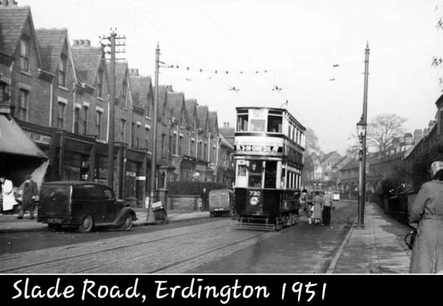
The featured image for this article shows a tram service on Slade Road, Erdington in 1951, the photograph was shared on the Birmingham Area History Facebook Group by Jan Ross on 23rd November 2023, © Public Domain. [4]

Birmingham Corporation Tramways operated a network of tramways in Birmingham from 1904 until 1953. It was the largest narrow-gauge tramway network in the UK, and was built to a gauge of 3 ft 6 in (1,067 mm). It was the fourth largest tramway network in the UK behind London, Glasgow and Manchester.” [2]

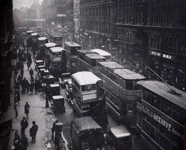
Congestion in the Birmingham city centre was a major problem as this photograph of trams and buses on Corporation Street in 1931 illustrates so well, © Public Domain. [3]

“As Birmingham’s tram-scrapping programme continues it becomes increasingly clear how great a part has hitherto been played by the tramways in keeping city centre congestion within bounds. Birmingham has an awkward arrangement of  central streets, and for many years now a large number of bus services, some of them cross-city, have followed a loop route through the central streets (Victoria Square, New Street, Corporation Street, Bull Street and Colmore Row). This is an admittedly convenient arrangement for cross-city passengers, but the very large number of buses traversing these streets adds considerably to the congestion; it could just be done, however, with the existing number of bus services and aided by the desperate expedient of the world’s most complicated one-way scheme, formulated in 1933.

In 1933, however, most of the traffic to the city was catered for by tramways terminating on the fringe of the central loop area; their terminal arrangements were far from ideal in many cases, but the quick turn-round possible with trams at such places as Hill Street and Steelhouse Lane did materially aid matters, as did the arrangement by which the Martineau Street trams (services 3, 3X, 6, 8 and 10) followed the one-way routing by a single track in Corporation Street from Martineau Street, then passing through a central island at the Corporation Street – Bull Street corner (where other traffic turned left and right) and across what may be described as a ‘one-way watershed’ alongside Lewis’s building, to rejoin the Corporation Street traffic where two-way traffic commences at Old Square. This arrangement was severely criticised on the ground that it involved the running of trams against the one-way traffic for one block alongside Lewis’s, but this feature could very easily have been rectified by extending the already rather complicated island at Bull Street corner up to Old Square, so as to keep the tramway traffic on a reservation throughout the very short stretch where it conflicted in direction. with the road traffic. This would not have caused any additional congestion, for traffic along Corporation Street from Old Square towards Bull Street has in any case to be split into two streams (right and left) at the Lewis’s island, and to do this in advance of the corner would probably have assisted traffic flow rather than otherwise, while the single track is no wider than other islands in Corporation Street erected as traffic aids, including a long one opposite Cherry and Union Streets which directly continues the line of the track.

There need therefore have been no difficulty in running trams along Corporation Street, whilst doing so did have the immense advantage of directing the traffic from Martineau Street terminus into a path which short-circuited the very congested détour via Bull Street and Steelhouse Lane which was the only alternative.

The tramway abandonments which have occurred since 1933, however, have in most cases had the effect of upsetting these arrangements and causing further invasions of the already congested central ‘loop’. Thus the Ladywood changeover brought an additional bus service into Victoria Square and Paradise Street, and the Moseley Road changeover two more, owing to the lack of flexibility of buses, whereby they must have central streets to loop round, instead of simple reversal as was possible with the trams in Hill Street. The Transport Department was evidently anxious to keep the additional buses to a minimum, for the former Cannon Hill service was eliminated altogether, and many thickly populated streets in the Balsall Heath area left for the first time in fifty years without service, in a desperate attempt to eliminate one service at all costs and thus limit the mischief. As it is, Paradise Street is now a solid mass of bus loading stations (incidentally without weather protection, which the tram termini had), and scenes at rush hours beggar description.

The next step was the abandonment of the Witton and Perry Barr routes operating from Martineau Street. As the replacing buses could not, of course, use the ‘watershed’ at Lewis’s, these two services (33a and 39) were compelled to go via the Bull Street and Steelhouse Lane detour, bringing additional buses to this very congested area; a recent traffic census showed this part of Bull Street to carry the heaviest volume of traffic in Birmingham.

Then, in October last, the remaining Martineau Street tram routes were scrapped. It had evidently been decided on this occasion that no further traffic could possibly be added to upper Bull Street, for some very awkward expedients were adopted to avoid this. The buses (55b) replacing the service 8 trams were brought into the city by the former outward route and terminated by reversal in Old Square (short of Bull Street); this, besides depositing passengers some distance short of the former central terminus, has meant additional vehicles turning right out of Corporation Street into Old Square, causing considerably more obstruction than the former tramway arrangement at this point, for the trams merely separated the two streams of traffic, while the buses intersect them. The Washwood Heath service (56) replacing tram 10 has been routed still more awkwardly; it comes into Martineau Street by the former route, and turns into Corporation Street, but at the Lewis’s island turns right down lower Bull Street, and rejoins the outward route at an extremely awkward narrow hairpin bend at the foot of Bull Street, where a double line of buses has to be squeezed between the blind corner and a central lavatory island. The change from one-way to two-way traffic, in fact, occurs at the narrowest peak (STET) of the whole loop! Local tramway students prophesied trouble at this point as soon as the plans were known; a single traffic bollard was planted in this narrow ‘throat’ to separate the two lines of traffic, but a Belisha Beacon on the corner became a casualty on the first day of operation, and a day or two afterwards an elevated kerb and guard rails were very hastily erected to protect the blind corner. Notwithstanding these precautions a skidding bus tore through the guard rails and caused a fatal accident on the morning of 10th November, less than six weeks after the changeover. At the inquest on the victim of this accident, the jury added a rider saying: (a) that the wood block paving was dangerous and (b) that they did not agree with the route followed by bus service 56 (round the Bull Street Dale End hairpin bend). When asked if they would be satisfied if a non-skid surface were laid, they replied in the negative and said they still thought the route was wrong. A non-skid surface has since been laid very hastily, but the route of the 56 bus remains unchanged.

On Wednesday, 1st November [1950], the Chairman of the Traffic Advisory Com mittee stated that ‘removal of trams in Corporation Street had greatly eased the stress there and in Lancaster Place’. Statements to this effect are regularly made in Birmingham, but few now believe them, and unfortunately for the Chairman, the very worst traffic jam ever experienced in Birmingham occurred on the afternoon following his self-congratulatory speech, and had Lancaster Place for its centre! The subsequent highly-embarrassed official explanations blamed everything which could be thought of (including a collision near Five Ways, over two miles away on the other side of the city!) but there is little doubt that the trouble was directly caused by the new bus arrangements, for any hitch at the foot of Bull Street quickly dams traffic back along the short length of lower Bull Street to Lewis’s corner, and this in turn blocks Corporation Street both ways, with inevitable trouble at Lancaster Place.

There was a much better case for anticipating an improvement at Perry Barr terminus after the changeover, for the tram terminus at Perry Barr was admittedly in an awkward place, and with the replacing 33A buses extended to Boar’s Head, no vehicles of any sort now terminate at Perry Barr. Nevertheless, queues of traffic extending nearly a mile from Perry Barr to Heathfield Road can be seen any evening and it is the considered opinion of many that the chaos there is much worse than before.

Such are the results of tram-scrapping so far in Birmingham. It may be said that besides the points already mentioned, there are many other traffic plague-spots, all tramless, such as the notorious instance of Digbeth and Deritend. Remaining to be ‘converted’ are the two groups of services following the Bristol and Lichfield Roads (36, 70, 71; 2, 78, 79), which at present are among the busiest, though least congested, thoroughfares in Birmingham. Abandonment of the Bristol Road tramway will involve removing an exceptionally heavy traffic load (including Austin Motor Works industrial, and Lickey Hills holiday traffic) from the present reservations, and the consequent invasion of the adjoining carriageways by hundreds of additional vehicles, with results which may be imagined (or seen, at Kingsway, Manchester). Abandonment of the Lichfield Road services will mean the loss of a good deal more reservation (especially in Tyburn Road) and perhaps more important in this particular case, will involve finding turning circles and loading places in the city for three extremely heavily-trafficked routes. It is difficult to see, in fact, how this can possibly be done. Looping via Corporation Street, Bull Street and Steelhouse Lane would put an intolerable extra burden on the busiest section of Bull Street and add more turning traffic to the Snow Hill corner; there is certainly no more room in the Old Square, and though Martineau Street is not now fully utilised, any more buses there mean Bull Street again, either to the left (already chock-a-block) or to the right (where the recent fatality occurred). The authorities have so far kept very quiet as to what is proposed for these routes, and one suspects that they are to be quietly cut back to Lancaster Place, with a nice half-mile walk to the city centre for all passengers. But as these are scheduled as the last routes to go, it will then be too late for anyone to protest!” [1: p2-3 & 5]

There is no doubting that these are the partisan words of a lobbying group opposed to the removal of Birmingham’s trams. But the increased congestion which would inevitably occur with the introduction of a significant number of additional buses should have been foreseen and have been better planned.

In more modern times the retention and refurbishment of the tram network would perhaps have been seen as the better option along with the pedestrianisation of much of the central area of the city.

But the early 1950s were not the 2020s. The internal combustion engine was seen as the future for transport and the electric trams were seen as leftovers from another era.

References

  1. Birmingham’s Bustigestion; in Modern Tramway Volume 14 No. 157; The Light Railway Transport League, London, January 1951.
  2. https://en.wikipedia.org/wiki/Birmingham_Corporation_Tramways, accessed on 19th May 2026.
  3. https://en.wikipedia.org/wiki/Birmingham_Corporation_Tramways#/media/File%3ACorporation_Street_Bham.jpg, accessed on 10th May 2026.
  4. https://www.facebook.com/share/p/1EJ5qJBtuX, accessed on 10th May 2026.

A Lickey Light Railway – Modern Tramway Vol. 13 No. 146

The mention of ‘Lickey’ in the railway press usually conjures up thoughts of the Lickey Incline and the bankers needed to enable steam-powered trains to make the climb.

In an article written in 1949 (Modern Tramway’s Prize Article of 1949) and published in February 1950, B.J. Pridmore prophetically proposed a Light Rail solution to anticipated traffic issues on the transport corridor centred on the Bristol Road.

Would cities in the UK which already had some reserved tram tracks have benefitted from forward thinking that sustained the use of trams through the latter years of the 20th century on tracks and routes which would be suitable for the current wave of Light Rapid Transit/Modern Tramway provision?

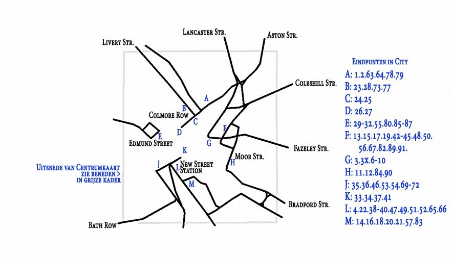
A schematic representation of the tramways in the centre of Birmingham in 1930, © Voogd075 and licenced for use here under a Creative Commons Licence (CC BY-SA 3.0).  [4]
The line from Birmingham to Rednal and Rubery, © Voogd075 and licenced for use here under a Creative Commons Licence (CC BY-SA 3.0). [4]

Here is Pridmore’s article in full (illustrations are from a variety of referenced sources):

Summary

There are few cities with a passenger transport route so convenient for conversion to a rapid-transit light railway as is the Birmingham route to the Lickey Hills. In this article is submitted a scheme for such a conversion, describing the route, the alterations required to the track and vehicles, the attractive services which could be operated, and the possibility, in the future, of the possession by Birmingham of a true rapid-transit installation giving a public passenger transport system freed from the delays due to street congestion.

Introduction

The Lickey route of the Birmingham tramways extends about eight miles Southwest of the city, connecting it to the suburb of Edgbaston (2 miles) and the almost separate entities of Selly Oak (4 miles), Northfields (6 miles) and Longbridge (7 miles and location of the Austin Works), bifurcation at this point giving two termini at the dormitory villages of Rednal and Rubery on the edge of the Lickey Hills.

The traffic on this route is partly of a business character, with a morning peak to the city, two small mid-day peaks, outward and inward, from the city to Selly Oak, and the evening peak of outward-bound traffic. Superimposed upon this are the industrial peaks, of a general nature to and from the city, and of a concentrated nature in the opposite directions to and from the Austin Works at Longbridge. Further traffic is of an interurban nature: between each of the shopping centres of Northfields and Selly Oak as well as from each of these to Birmingham there is appreciable miscellaneous traffic. There is also considerable holiday traffic to the Lickey Hills on non-working days.

Services are operated from the city to Rubery and Rednal, with many short workings to Selly Oak, and extra mid-day journeys from Longbridge to Northfields and Selly Oak, whilst services on the inner (and suburban) section of the route are amplified by the superposition of those to and from Pershore Road (Cotteridge). which share the Bristol Road with the Lickey routes for the first two miles or so to the junction at Pebble Mill Road.

This trunk route with large and varied traffic and high load factor has already about three-quarters of its length constructed as reserved track. Much of this has recently been relaid “solid” on a concrete foundation, instead of on the ballasted sleepers as originally.

It has only two short gradients of any magnitude, and would thus seem ideal for gradual conversion towards an interurban light railway giving ample capacity on the route and removing public transport from the road proper, hence also reducing congestion in the bigger Birmingham of tomorrow for it is along this route that Birmingham seems ripe for the next phase of expansion.

In the remainder of this article it is suggested how, ultimately, this route should be converted to a light railway as a contribution towards ideal transport in the greater Birmingham of the future.

The Track and the Route

The present Navigation Street terminus loop should be improved to give loading islands outside two parallel tracks at the terminal loading point; the track layout should include crossovers to enable Pershore Road cars to be separated from Lickey cars, and Selly Oak and other short working cars to be separated from through cars (as will be needed for peak-hour services, q.v.). The one-way streets forming the loop are amply wide enough to permit the tram tracks to be relocated at the sides and be totally reserved; public transport would thus be segregated from the rest in this most congested section of the route.

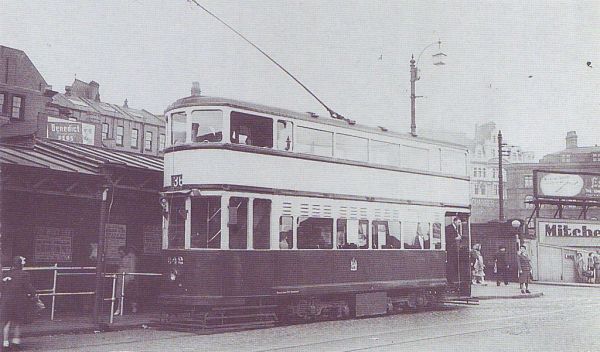
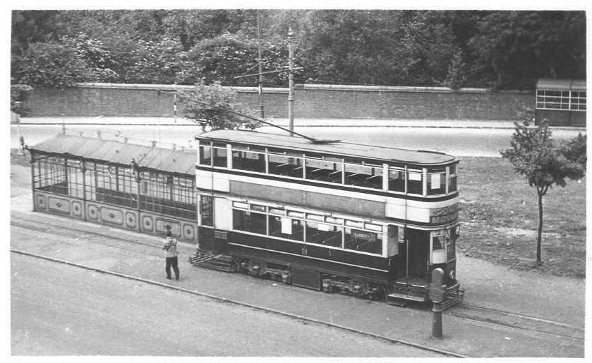
Tram No. 842 sits at the Navigation Street terminus of the route from Birmingham to Rednal and Rubery. [3]
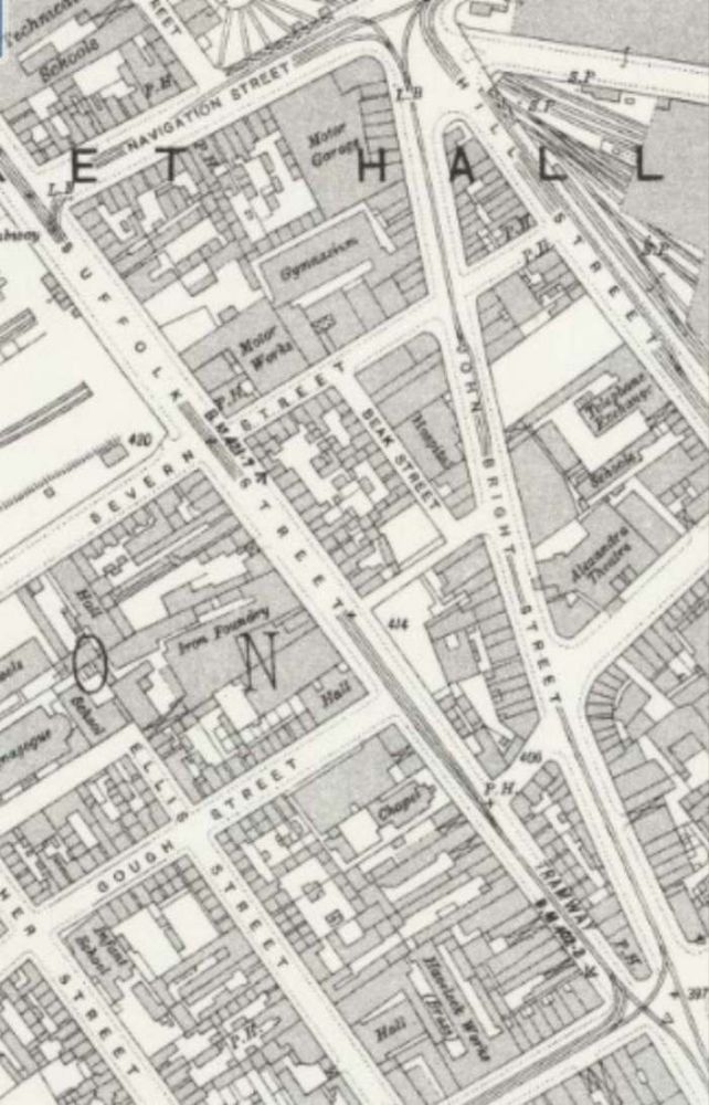
The Navigation Street terminus of the tram service to and from the Lickey Hills. Tram services No. 70 and No. 71 circulated round the loop shown on this extract from the 25″ Ordnance Survey of 1913 (published in 1918). [6]

The Bristol Road as far as Pebble Mill Road will ultimately have to be widened if traffic increases much more; but taking in part of the footways and front gardens would in general give room for the central eighteen feet of reservation which would suffice for the tramway. Alternatively, the reservation could be at the side and a three-lane road be left for the remainder of the traffic. As an interim measure local road-widening and the provision of loading islands with queue barriers, the former combined with pedestrian crossings, at the few important stops, should be undertaken.

The narrow road through Selly Oak and under the railway bridge presents the greatest obstacle; track reservation should be made when this is widened, while the provision of loading islands would seem the only present practicable measure.

The roads through Northfields and Longbridge are amply wide enough for a narrow track reservation (lacking the wide grass borders of the present reservations) and conversion of these sections to dual carriageway with central reservation for the tramway should be done as soon as the conversion scheme is commenced.

The tracks at present reserved can remain as now except that it would be wise to convert the remainder of the sleeper track to ‘solid’ track before high-speed running is commenced.

The Cars

Pending the acquisition of new cars (possibly like those at Llandudno, which show what can be done on 3ft. 6in. gauge if the spirit is willing), conversion of about 20 cars of the ‘800’ class for the base service and its reserves, and rehabilitation of another forty air-braked cars, would enable the Department to put the scheme into operation with the minimum of delay.

The cars to be converted should have their roofs and ends removed and the body sides made straight (instead of waisted). The roofs and ends should be renewed and the cars at the same time lengthened about two feet each end. The new ends and roofs should be on the lines of those of the post war Glasgow cars: platform doors should be added and the stairhead doors and bulkheads omitted. Large destination and route number blinds should be fitted below the top-deck windows. Interior decoration should be as modern and attractive as in any other vehicle of early 1950s – brown ceilings are out of place to-day.

To reduce noise the short coil springs on the bogies might be replaced by rubber pads. The long coil springs should be shortened and stiffened (to reduce noise) and have rubber pads above them, again to reduce noise. The motor gear ratio should be decreased by about 10 per cent and helical gears fitted. Automatic but optional field shunting, giving 66 per cent of normal field, should be added. This should give free-running speed of up to 35 m.p.h., yet, by reason of the large amount of free-running possible on such a route, should not unduly stress the motors thermally. The present controllers would suffice for the more arduous duty if a lineswitch contactor were added to perform circuit breaking; the cost and complexity of contactor control would not, in such a conversion, be justified. The present brake installation could be retained if rubber bushed joints were used in the rigging to reduce noise.

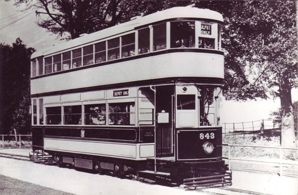
The cars to be rehabilitated should be given straight sides, new roofs, rubber rods in the springing, automatic optional weak field, and lineswitch circuit breakers. These alterations would render them comparable in appearance and performance with No. 843, which in good condition, is still an advertisement for 3ft. 6in. gauge possibilities.” [1: p37-38]

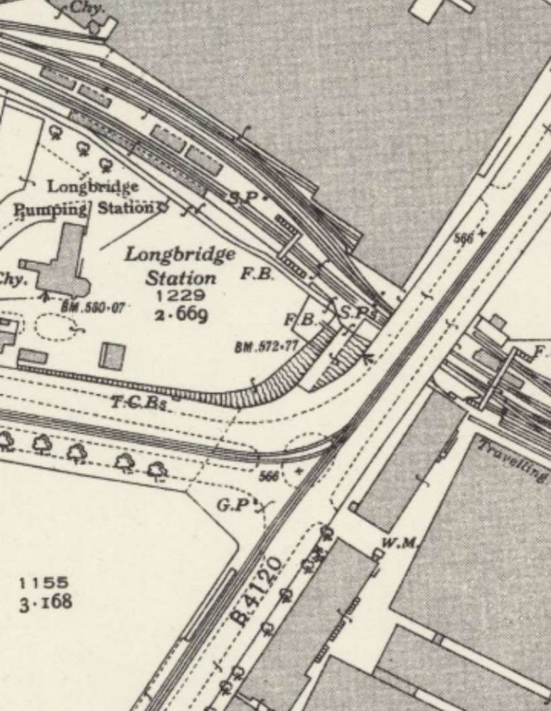
Close to Longbridge Railway Station and Longbridge Works the two tram services down Bristol Road (No. 70 & No. 71) separated. One turning to the West along the A38 (to Rubery), the other continuing along the B4120 to Rednal. [8]
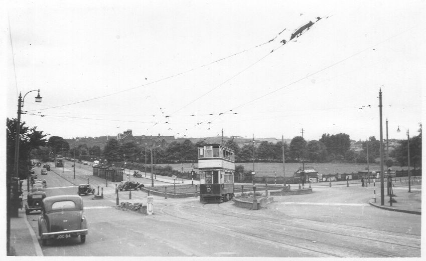
The tram is turning left to follow the A38 into Birmingham having travelled from Rubery along the A38. The road ahead on the left side of this photograph is Lickey Road which heads towards Rednal, © D.J. Norton and used with the kind permission of his son (donation made to Asthma UK). [5]
The Rubery tram terminus was closed to the Rubery Mental Hospital which sat just to the North of the A38. The central reservation of the Bristol Road widened to give space for the terminus. [8]
Tram No. 759 at the Rubery terminus in 1952, © D.J. Norton and used with the  kind permission of his son (donation made to Asthma UK). [5]
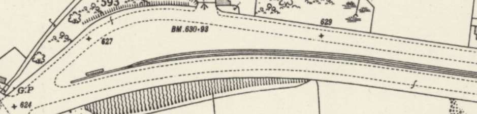
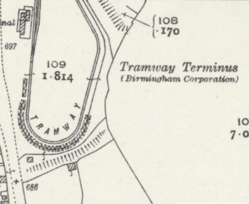
The Rednal tramway terminus is a loop which straddles the join between two 25″ Ordnance Survey map sheets, that which cover the Longbridge Works and the sheet to the South. This is the element of the terminus which sits at the top of the more southerly OS map sheet. [9]
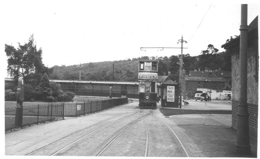
Tram No. 777 at the Rednal terminus in 1952, © D.J. Norton and used with the  kind permission of his son (donation made to Asthma UK). [5]
Tram No. 843 sitting at the Rednal terminus, © Public Domain. [2]

Pridmore continues:

“The Stops

These should be spaced as widely as possible, on the theory of ‘greatest good for greatest number’, even if the short-distance passenger suffers during peak hours. It is more important that the many living in Selly Oak and beyond should have a fast journey home than that an Edgbaston passenger should be set down at the end of his turning. There should be three stops only between Navigation Street and Pebble Mill Road, located where they will be of most use to peak-hour passengers. These stops should have loading islands and queue barriers as described earlier. Other stops, convenient for short distance passengers, clearly labelled ‘not used in peak hours’,  should be provided to attract the extra revenue, so useful to any undertaking, which accrues from the casual off peak travel which is a consequence of an attractive service being available.

Beyond Pebble Mill Road, peak-hour stops at each outskirts and the centre of Selly Oak, Northfields, and Longbridge, should be the main points for loading and unloading; there should be some additional stops between these centres at places where the need is obviously great. None of these additional stops should be separated by less than a quarter of a mile, however, but additional stops ‘not used in peak hours’ should also be provided where considered appropriate.” [1: p38-39]

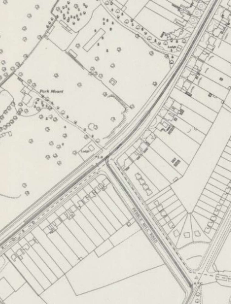
The junction of Pebble Mill Road and Bristol Road, Birmingham as shown on the 25″ Ordnance Survey  of 1939 which was published in 1945. [7]
Looking Southwest along Bristol Road through its junction with Pebble Mill Road. The trams for The Lickey Hills stopped just beyond the junction. Pebble Mill Road central reservation was at times used to store trams and particularly after the closure of the network before there was room for them at the Depot. [Google Streetview, June 2024]

Pridmore continues:

Services

A base frequency of 12 cars per hour from Navigation Street, half of which would run to Selly Oak only, would probably suffice. Pershore Road should be symmetrically superimposed. The equal service to

During peak hours, however, a different technique would facilitate traffic flow and give quick travel to long-distance passengers; it is suggested that 12 packets of departures per hour be arranged. The first of each packet would be a fast to Rednal or Rubery, running non-stop to Pebble Mill Road. The second would be a duplicate of the first, but routed to the alternative terminus, stopping only at the peak hour stops to Pebble Mill Road to pick up only. Thence both these cars, would continue, using peak hour stops only (as is presumed in all peak hour services), to their respective termini. The third car would be the triplicate, running as the duplicate but probably to Selly Oak, Northfields or Longbridge only, as the traffic for the extremities of route dictates. Fourth would be the Pershore Road car, stopping also to set down at intermediate points to Pebble Mill Road, and fifth would be its duplicate performing similar duties as necessary.

If a less or more frequent service should prove necessary its pattern should be similar to that indicated above, as the suggested total frequency of 60 cars per hour is well within the capacity of a single line of tramway, whilst the use of packet departures will facilitate the through-running of the long-distance cars.

Inwards peak hour working, when with the load, would be arranged so that cars from Bristol Road would stop only to set down between Pebble Mill Road and Navigation Street, and that such cars should be given priority at the Pebble Mill Road junction.”

The necessity for large destination blinds on the cars, a point mentioned earlier, is now appreciated; the indication of “limited stop” must be given, as well as the destination, and regular users will wish clearly to be aware of both whilst a car approaches their stop.” [1: p39-40]

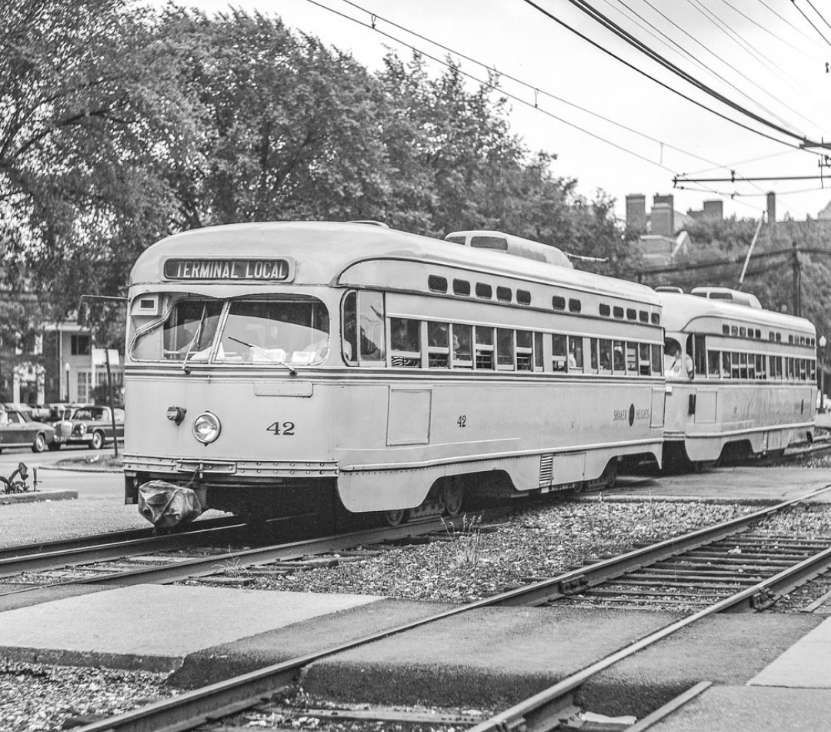
A P.C.C. tram at work in Cleveland, Ohio. Pridmore suggests trams of this type as being suitable in the longer term for his proposed Lickey (Bristol Road) Light Railway. The picture shows Tram No. 42 of the Shaker Heights Rapid Transit in Cleveland at Shaker Square in the 1960s. No. 42 is running in multiple unit (MU) mode with another Shaker Heights Rapid Transit P.C.C., © Robert Farkas. [10]

Again, Pridmore continues:

Future Development

The success of a scheme such as that described above would commend its application to the similar but not quite so heavily trafficked routes to Pype Hayes and Erdington on the east of Birmingham.

When the full conversion to reserved track had been completed in the less near future, consideration should be given to the provision of a third track to Pebble Mill Road to permit the regular operation of peak hour expresses both ways, and for the ultimate operation of two or three-car trains of single deck high-speed vehicles much as the P.C.C. cars on metre gauge lines in the U.S.A. and elsewhere.

The use of such trains would then render possible the economic construction of cross-town subways in further effort to remove passenger transport from the sorely congested central streets of Birmingham.

The transport problem of Birmingham, as of many large cities, is becoming increasingly severe. The author is of the opinion that such problems can only be solved by the provision of an urban transport installation, and not by the use of supposedly flexible vehicles on the existing network of roads; it is the attempt to solve the problem by this latter means that is responsible for the congestion in the centre of Birmingham at the present time. An embryo specialised installation exists in Birmingham to-day; it is recommended that it be developed as far as possible for its specialist purpose while there is still time and before the traffic of the future swamps the Bristol Road completely, as it will do if numberless small vehicles are expected to cope with it in competition with the many others who regard themselves as having equal claim to the surface of a public road.” [1: p40]

References

  1. B. I. Pridmore; A Lickey Light Railway; in Modern Tramway Vol. 13 No. 146, London, p37-40.
  2. https://www.birminghamforum.co.uk/index.php?topic=710.9, accessed on 10th January 2025.
  3. https://www.birminghamforum.co.uk/index.php?topic=710.99, accessed on 10th January 2025.
  4. https://en.m.wikipedia.org/wiki/Birmingham_Corporation_Tramways#/media/File%3ABirmingham-1930.png, accessed on 10th January 2025.
  5. http://www.photobydjnorton.com/TramsBristolRoad.html, accessed on 10th January 2025.
  6. https://maps.nls.uk/view/115633314, accessed on 10th January 2025.
  7. https://maps.nls.uk/view/115633266, accessed on 10th January 2025.
  8. https://maps.nls.uk/view/120223278, accessed on 10th January 2025.
  9. https://maps.nls.uk/view/120899500, accessed on 10th January 2025.
  10. https://akronrrclub.wordpress.com/tag/shaker-heights-rapid-transit-lines, accessed on 2nd January 2025.