
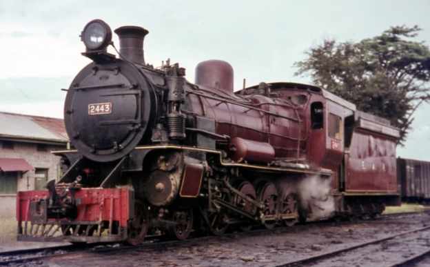
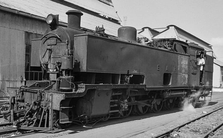
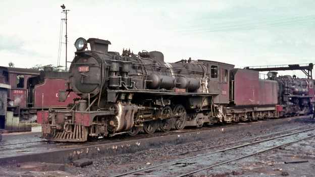
The featured image for this article shows an East African Railways (EAR) Class 24 4-8-0 locomotive No. 2443. The engine was manufactured by Vulcan Foundry and Nasmyth, Wilson and Company between 1923 and 1930. The photo shows the locomotive at Tabora depot in Tanzania during 1968, © Basil Roberts and licensed for reuse under a Creative Commons licence (CC BY-SA 4.0). [26]
East African Railways and Harbours was formed in 1949 through the amalgamation of Kenya and Uganda Railways and Harbours and Tanganyika Railways and Ports. Some locomotives which were ordered by Tanganyika Railways were delivered after the amalgamation. One of the EAR’s first actions was to develop a new numbering system which was applicable across East Africa. “Under the new system, tank engines were allotted Class number 10-19, tender engines 20-49 and Garratts 50 upwards. Diesels, then still only on order, were to become 80 upwards. Similar locomotives in service on both systems were taken together in one class, as was the case with the ED1 (KUR) and St (TR) classes, both becoming Class 11, Nos. 1105-1131 and 1101-1104 respectively.” [1: p70]
After initial experiments with the Giesl ejector from 1957 a large-scale programme was initiated in the early 1960s to fit all post-war main-line engines with this equipment.
Early EAR locomotives:
EAR 10 Class (formerly KUR EE Class) 2-6-4T Locomotives
These locomotives were retained on the lines of the old KUR.
EAR 11 Class (formerly TR ST Class and KUR ED1 Class) 2-6-2T Locomotives
In 1930, the TR received four 2-6-2T shunters (the same type as the KUR ED1 Class). These were designated as the ST Class. They initially had running numbers TR Nos. 11-14, later TR Nos. 103-106. The locomotives were supplied by Vulcan. Under EAR control the locomotives were numbered EAR Nos. 1101-1104. [1: p60]
Many of the EAR Class 11 locomotives were adapted to burn oil fuel rather than wood or coal and were still in use in 1972. [1: p60]
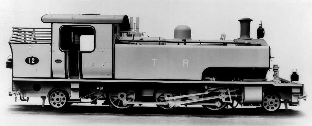
EAR 12 Class (formerly TR SS Class) 2-6-2T Locomotives
These two locomotives were ordered by Tanganyika Railways but not delivered until 1950. They were the first superheated piston-valve shunters in East Africa and were a generally updated and modernised version of the EAR 11 Class. [1: p70]
The two engines in this Class were “put to work in the harbour area in Dar es Salaam, from where they were transferred to Morogoro in the mid 1950s and eventually to Tabora in the early 1960s, where they are still in service. The 12 class are the only shunters with Giesl ejectors.” [1: p70]
EAR 21 Class (formerly TR RV Class) 4-8-2 Locomotives
For more details of this class of steam locomotive please click here. [28]
EAR 22 Class (formerly TR G Class) 4-8-0 Locomotives
For more details of this class of steam locomotive please click here. [28]
EAR 22 Class (formerly TR NZ Class) 4-8-0 Locomotives
For more details of this class of steam locomotive please click here. [28]
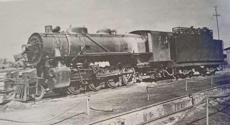
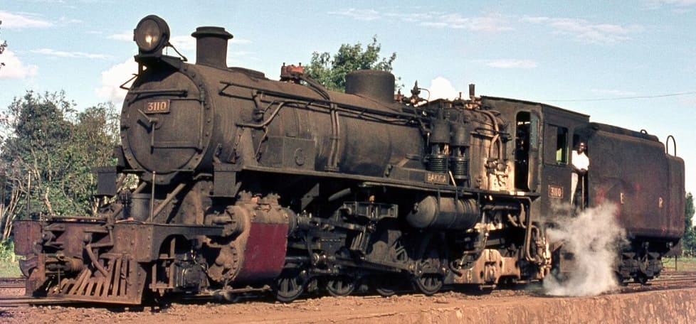
EAR 24 Class (formerly UR GD Class) 4-8-0 Locomotives
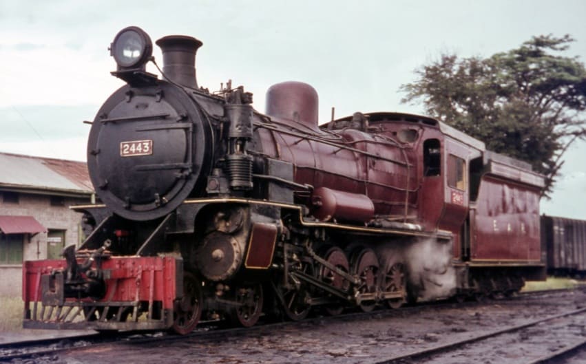
The 24 Class were a larger and modified version of the experimental UR GC Class. [26]
EAR 25 Class (formerly TR MK Class) 2-8-2 Locomotives
The TR Mk Class was renumbered by the EAR to become the EAR 25 class, the eleven members of the class were built by Vulcan Foundry, in Newton-le-Willows, Lancashire, for the Tanganyika Railway (TR). They entered service on the TR in 1925–1927. [10] All of them were transferred to the EAR.
The eleven members of the Class were:
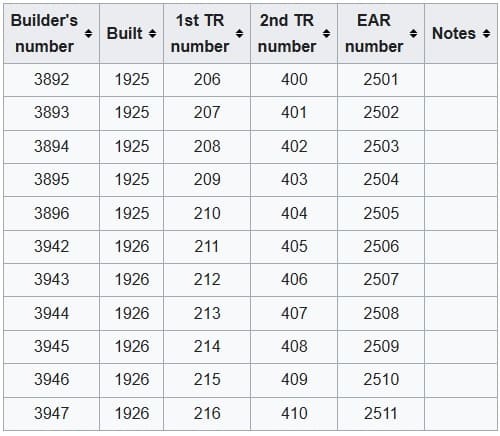
This class was a great success and the Class were still in use at the time Ramaer wrote his book, although he notes that they were now on borrowed time. “One problem with the design of the MK was the fact that the leading pony truck provided insufficient guidance on the sharp curves on the Dar-es-Salaam-Morogoro and the Malagarasi-Kigoma sections.” [1: p57]
EAR 26 Class (formerly TR ML Class) 2-8-2 Locomotives
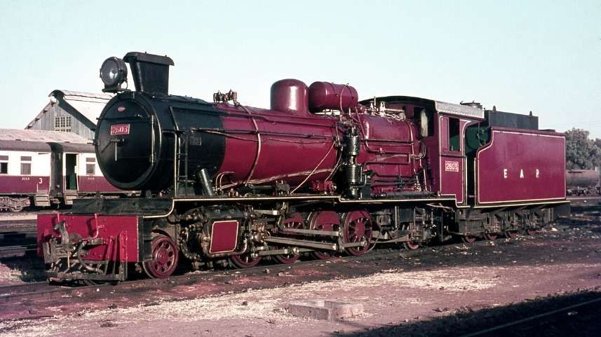
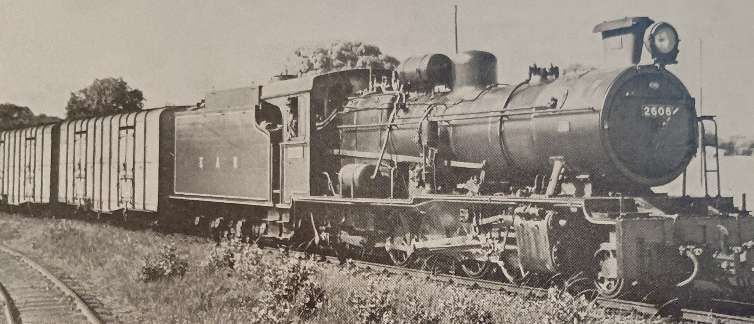
The six members of the ML class (an improved MK design) were built in 1947 by W. G. Bagnall, in Stafford, England, and delivered to the TR. They were later operated by the TR’s successor, the East African Railways (EAR), as its 26 class. In 1952, six further members of the 26 class were delivered to the EAR. They had been built by Vulcan Foundry, of Newton-le-Willows and Robert Stephenson & Hawthorns of North East England and were numbered EAR Nos 2607-2612. [7]
The new locomotives were intended for use on the flatter sections of the Central Line between Dodoma and Tabora. According to Ramaer, these locomotives were still in use in 1972, provided with larger tenders than the MK/25 Class. However, they were “relegated to secondary duties, but their service record proved less favourable than that of the older 25s. They [were] definitely heavier on maintenance and their active life would probably end shortly, together with the 25 class, when both were replaced by new diesel locomotives.” [1: p70]
EAR 27 Class (formerly TR MR Class) 2-8-2 Locomotives
These locomotives were American-built. Many of these engines were built by various American manufacturers, including: Alco; Baldwin; and Davenport. These locomotives were known as ‘MacArthurs’. Those which ended up working on the Tanganyika Railways were manufactured in 1944. [1: p70] and arrived from Malaya in 1949. There were eight locomotives bought in this way which became the MR Class, running numbers 800-807. They were built by three different manufacturers and as a result had minor differences: Alco Nos. 800-802; Baldwin Nos. 803-805; Davenport Nos. 806-807. [1: p70]
Ramaer tells us that, “At first there were problems, and modifications were needed to water tanks and reversing gear, which was undertaken at Nairobi works because of the limited capacity of the shops at Dar-es-Salaam. An additional difficulty was posed by the fact that the engines had not been designed to burn wood fuel. Grates were rather small and no rocking or dropping equipment was available. This circumstance gave rise to criticism because of the high ash residue of the wood fuel and only after the locomotives were converted to burn oil was the problem satisfactorily solved. After conversion the MacArthurs by then classified EAR 2701-8, did reasonably well.” [1; p69] The class was expanded in 1950 under EAR control when eight more were purchased from Malaya and one in parts from Nigeria. The last of these locomotives in service was based at Tabora and had been kept running by cannibalising other members of the class.
Early Beyer-Garratt locomotives:
EAR 4-8-2+2-8-4 Garratt 53 Class (formerly TR GA Class)
Built in 1931 by Beyer, Peacock & Co., these 4-8-2+2-8-4 locomotives were the first Garratts on the Tanganyika Railway. Two of this Class continued in service during EAR years. In EAR days the two 53 Class locomotives “went to the northern part of the now united system, to be replaced on the Central Line by the newer 60 Class, but later they returned to Tanzania for transfer work in Dar-es-Salaam, where they were scrapped in the late 1960s.” [1: p61]
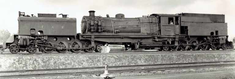
EAR 4-8-2+2-8-4 Garratt 55 Class (formerly TR GB and KUR EC1 Class) Locomotives
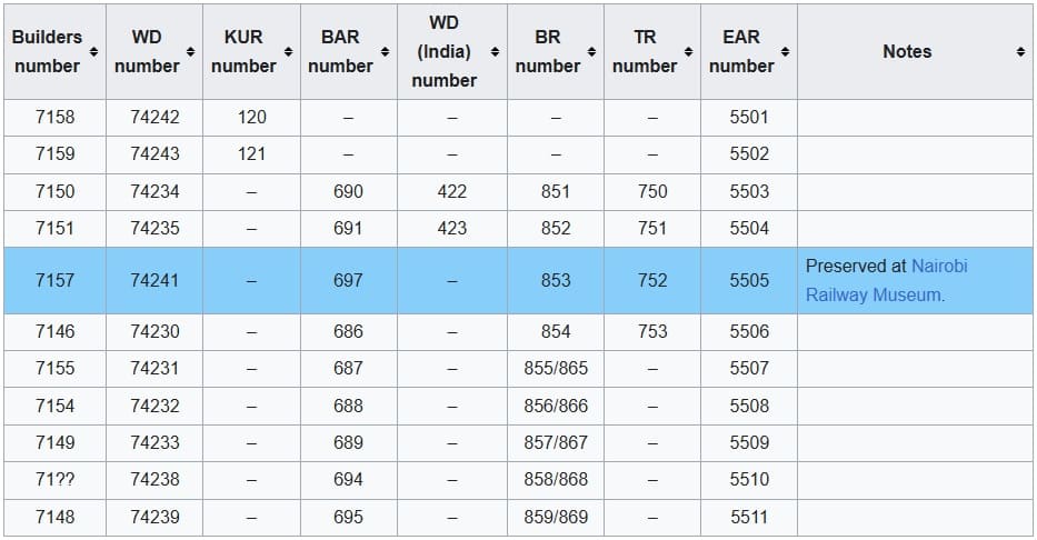
The Tanganyika Railway (TR) GB class were 4-8-2+2-8-4 Beyer-Garratt steam locomotives were originally ordered by the British War Department for service in Brazil, although not built. Later the design was used for locomotives for India and Burma. Four were acquired by the TR in 1946 from Burma. They later became members of the East African Railways (EAR) 55 class. [13][1: p64]
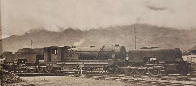
The Garratt locomotives that eventually made up the full 55 Class list were in use on the KUR and the TR. The full list is shown below:
EAR Designed/Purchased Steam Locomotives:
Despite having access to a broad spectrum of different locomotives from the two networks, the EAR was clearly in need of locomotives. It had available Class 54, 57 and 58 Locomotives but these were unsuitable as a base for further development [1: p71] Fuel was also a problem, wood was still in extentives use and coal supplies during WW2 were of relatively poor quality. The EAR decided that it should focus on oil-burning locomotives. Ramaer says that conversions started almost immediately, all EAR engines “were gradually converted to burn oil, a job which was completed by 1955.” [1: p72]
EAR made an initial decision to focus on steam-power for the immediate future.
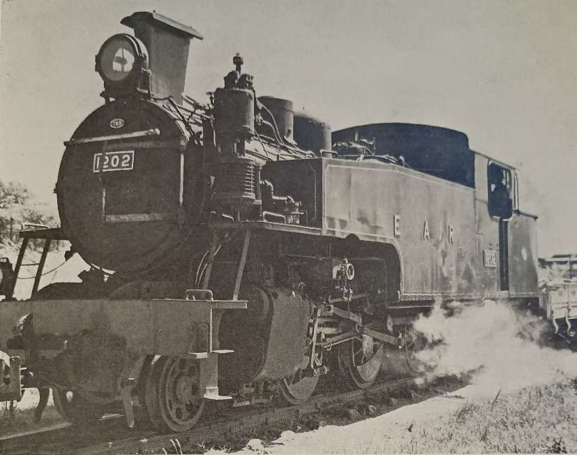
EAR 13 Class 4-8-2T/4-8-4T Locomotives
These locomotives were probably not used to any great extent of the historic TR network within the EAR.
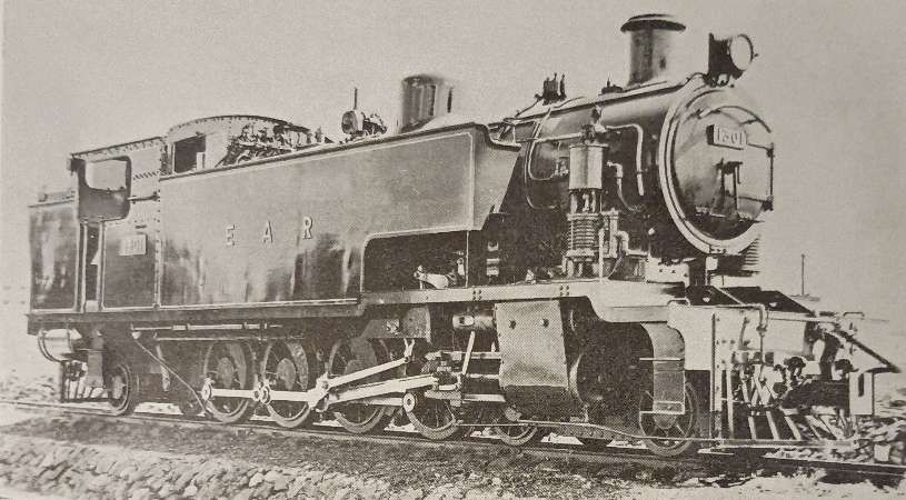
Eighteen of these tank locomotives were built by North British and entered service in 1953. All of these locomotives were initially 4-8-2T locomotives but their performance was poor. They were prone to frequent derailments in sidings. The decision was taken to adapt them to be 4-8-4T locomotives.
The trailing ponies were changed to bogies recovered from old 50 Class Garratts from the KUR which were being withdrawn from that network. At the same time the side tanks were extended and lined up with the smokebox door. This required the repositioning of the compressor and the opportunity was also taken to enlarge the rear fuel tank slightly. [1: p78]
After Class 13, plans were in place for a further Class of shunting locomotive – the 14 Class but none were built in the end as a result of research into Diesel Shunters which could produce a greater tractive effort with a lower fuel consumption.
EAR 29 Class 2-8-2 Locomotives
Along with 30 Class and 31 Class locomotives and the 59 and 60 Class Garratts these were the last steam locomotives built for the EAR.
The 29 Class were derived from the Nigerian ‘River’ Class 2-8-2 Locomotives which were built to operate with low grade coal. The EAR version was oil-burning. Crews at times called these locomotives ‘Nigerians’. Two arrived with the EAR in 1951 and a further eighteen in 1952. These were reliable and effective locos with an axle load of thirteen tons and designed to be freight locomotives on the main line. Their performance gave rise to another order for eleven further 29 Class locomotives from North British in 1955. Ramaer tells us that, “These newer locomotives differ[ed] from the earlier ones in that they ha[d] spring-loaded intermediate buffing gear, later standardised on the 31 class 2-8-4s, and larger injectors than the first twenty engines. Externally, they [were] easily distinguishable for a larger smokebox door has been fitted than on the earlier engines. To reduce the weight on the trailing pony truck, already heavily stressed by the big Belpaire firebox, the compressors were repositioned to be in line with the smoke-box door, and in consequence some minor changes had to be introduced to the leading pony truck.” [1: p80-81]
Ramaer says that “A point of some concern in the design of the 29 class was the relatively high axle load on the trailing pony, which caused the engines to lean back with heavy trains, with consequent loss of adhesive weight. To remedy this shortcoming, the EAR went in following designs to a wheel arrangement with a bogie under the fire-box, considered by many engineers to be the best possible solution for locomotives with a big and heavy firebox, as it improves riding and, indirectly, eases maintenance. The 2-8-4s thus evolved belong to two classes, 30 and 31, introduced in 1955-6 and built by North British and Vulcan, respectively.” [1: p81]
The 29 Class was ubiquitous across different sheds throughout the EAR territory. [1: p81-81]
EAR 30 Class 2-8-4 Locomotives
The 30 class is heavier than the 31 Class and is directly derived from the 29 Class. It has the same boiler, although adhesive weight is slightly lower than the 29 Class “as a result of the introduction of the bogie under the firebox. The bogie has American-inspired cast steel outside frames and was introduced following the example of the Canadian Pacific type 59 to improve riding. For the same reason, compensated spring gear on the coupled axles was reintroduced following the example of the pre-war 28 Class Mikados. These changes certainly resulted in better riding qualities.” [1: 81]
The 30 class design included a large cast steel tender, running on six-wheel bogies, having a capacity of 1,950 gallons of fuel oil and 7,000 gallons of water. This, with Timken roller bearings [11][12] throughout has resulted in an engine capable of running long distances over the Central Line of Tanzania, on sections with unreliable water supplies, like Morogoro-Tabora. The 30 Class spent their full working life in Tanganyika/Tanzania. [1: p81-82]
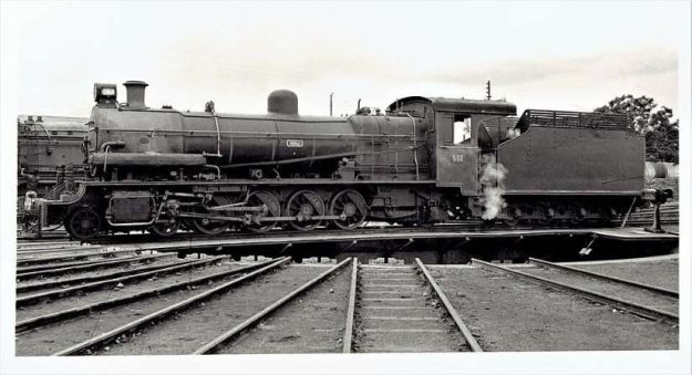
EAR 31 Class 2-8-4 Locomotives
The EAR 31 class was a class of oil-burning 2-8-4 steam locomotives. The 46 members of the class were built in 1955 by Vulcan Foundry, in Newton-le-Willows, Lancashire, for the EAR. They were a lighter, branch-line version of the EAR 30 class, and worked from various sheds throughout the EAR system.[1: p80-82][9: p83][13]
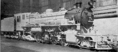
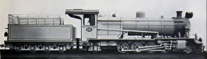
The Vulcan Works Magazine carried this ex-Works image of a 31 Class locomotive. The locomotives were Vulcan Foundry Works Nos. 2576, 2578-81 and 2583 & 84. [14]
The Vulcan Foundry magazine notes that these engines were designed for the lightest tracks on the EAR network: “The locomotives are required for universal use throughout East Africa, but in the first place are to be placed for duty in Kenya and Uganda. All are oil fired and forty-one have Westinghouse brakes, the other five being dual fitted with Westinghouse and Vacuum Brake Equipment, so that they will be available for service in Tanganyika when required. The locomotives will negotiate with ease, curves of 330ft radius, with 0.5in gauge widening and also I in 7.5 turnouts (equivalent to a curve of 350ft radius without gauge widening) and are suitable for operating on 3% gradients. … As on all recent East African orders, the locomotives are so arranged that they can be converted to 36in gauge in accordance with requirements for the future standardisation of the East African Railways. For the same reason the dragboxes [15][16] have been made to suit both the MCA Coupler (as fitted) and the Knuckle type Coupler. Wherever possible, detail parts have been made interchangeable with the “29” and “30” classes, but a smaller boiler and slightly smaller cylinders have been provided.” [14]
Later Beyer Garratt Locomotives:
EAR 57 and 58 Class
These locomotives were not used in Tangayika/Tanzania. For more detail, please click here. [17]
EAR 59 Class
The axle loads of these locomotives were too high for the relatively light rail used in Tanganyika/Tanzania. They were used, as intended, on the old KUR network. For more detail, please click here. [17]
EAR 60 Class
Introduced in 1953, these 4-8-2+2-8-4 locomotives were used extensively on the Central Line between Dar -es-Salaam and Morogoro

The EAR 60 class, also known as the Governor class, was built for the EAR as a development of the EAR’s earlier 56 class. The 29 members of the 60 class were ordered by the EAR from Beyer, Peacock & Co. The first 12 of them were built by sub-contractors Société Franco-Belge in Raismes (Valenciennes), France, and the rest were built by Beyer, Peacock in Gorton, Manchester. The class entered service in 1953-54. Initially, all members of the class carried the name of a Governor (or equivalent) of Kenya, Tanganyika or Uganda, but later all of the Governor nameplates were removed. [5]
Initially, the first locomotives were ordered as an extension to the 56 Class – 5607 – 5618. Compared with the 56 Class, the Franco-Belge locomotives had more water and less oil capacity. It was only just before delivery that it was decided to classify them separately. As we have noted, the remainder of the Class was built in the UK by Beyer-Peacock. Raemer reports:
“With an axle load of only eleven tons, the 60 class is, with the 55 and 56 classes, the standard light Garratt on the system, taking all the lighter mixed traffic. It was on one of these engines, No 6029, that the first test with the Giesl ejector was made, No 5805 following suit. Today, all 60s have this equipment. Originally the 60 class carried the names of the Governors of Kenya, Tanganyika and Uganda, but later the nameplates were removed. At present, [1972] only No. 6001 still carries a name Umoja (Unity). They are straightforward engines, with the well-tried Belpaire firebox, a working pressure of 200lb/sq in and 16×24in cylinders, developing a tractive effort of 43,520lb. They, too, have roller bearings on all axles, but somewhat surprisingly plate frames of wartime origin were retained, like the 55 and 56 classes. Although the 60s are quite good engines, they never came came up to the level of the 56s, especially where the free steaming quality of the boilers is concerned.” [1: p78]
EAR Diesel Locomotives used in Tanganyika/Tanzania
I have written extensively on the various Diesel locomotives used on the EAR network, for more detail, please click here. [18] The EAR operated a progressive fleet of diesel locomotives in Tanganyika (now Tanzania) starting in the 1950s, featuring key classes such as the 83, 84 & 85 Class hydraulic shunters and later mainline diesel-electrics.
There were a significant number of different diesel locomotive classes on the EAR , but records that I have come across do not specify which of these locos were stabled at which depots. It is difficult in many cases, to be sure which classes of loco were used on the lines in Tanganyika/Tanzania. The fleet included:
32 Class (previously 80 Class): please see notes below about the 80 Class locos.
33 Class (previously 81 Class): please see notes below about the 81 Class locos.
34 Class (previously 82 Class): please see notes below about the 82 Class locos.
35 Class: Andrew Barclay 0-6-0 locomotives.
61 Class: These locomotives were supplied by the German manufacturer Henschel & Son.
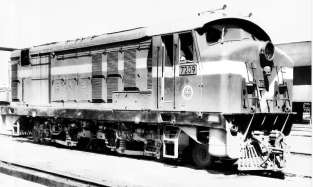
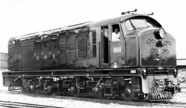
71 Class (previously 91 Class) Diesel-Electric Locomotives: supplied by English Electric.
72 Class (previously 92 Class) Diesel-Electric Locomotives: supplied by English Electric.
79 Class Locomotive: only one of these locomotives was built.
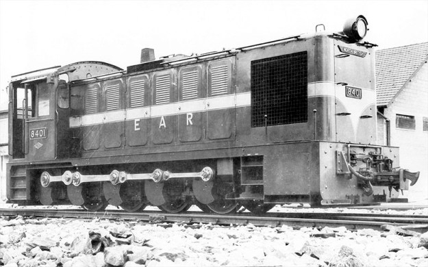
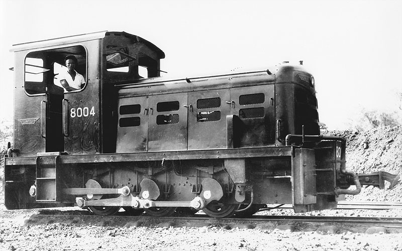
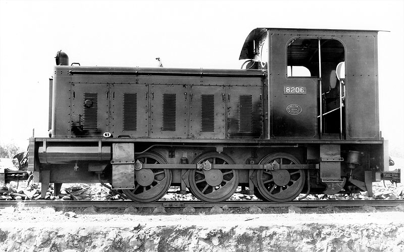
80 Class (later 32 Class):
81 Class (Later 33 Class): Supplied by the Drewry Car Co., these versatile internal combustion locomotives handled secondary and transfer tasks during the early phase of internal combustion transition.
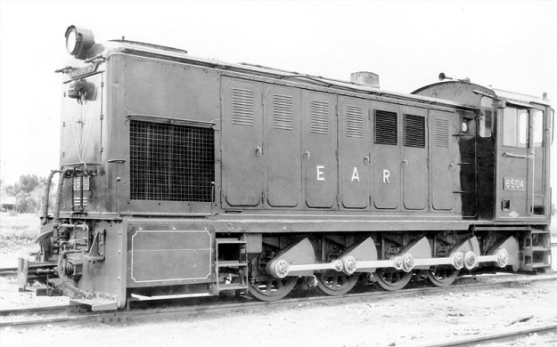
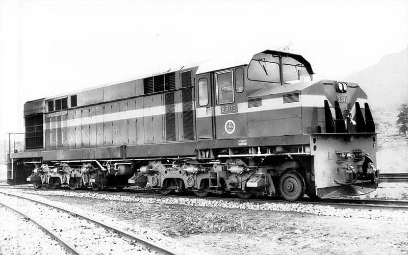
82 Class (Later 34 Class):
83, 84, 85 & 86 Classes (Later 43, 44, 45 & 46 Classes): Introduced from 1955 onwards, these light and medium diesel-hydraulic locomotives (built by manufacturers like Hunslet, Andrew Barclay, and North British Locomotive Company) took over shunting and lighter duties on the Tanganyika Central Line.
86 Class (later 46 Class):
90 Class (later 87 Class) English Electric types: from around 1960, powerful diesel-electric units gradually supplemented and replaced heavy steam power (like the 30 and 60 classes) on main trunk routes connecting Dar-es-Salaam, Tabora, and Kigoma. Dieselization in Tanganyika in the late 1950s and 1960s dealt a blow to the continued use of steam-power as they were more effective on handling steep gradients and overcame water scarcity issues inherent to steam operations across the territory.
91 Class (later 71 Class) Diesel-Electric Locomotives: supplied by English Electric
88 & 92 Class Canadian supplied Diesel Electric locomotives, of which there were 20 No. 88 Class and 15 No. 92 Class locomotives.
More about each Class of Diesel Locomotive
A little more information about each of these classes of diesel locomotive can be found in the paragraphs below. For more information and more images than are included in this article please click here. [18]
EAR 35 Class Locomotives
These were Andrew Barclay 0-6-0 diesel shunters.
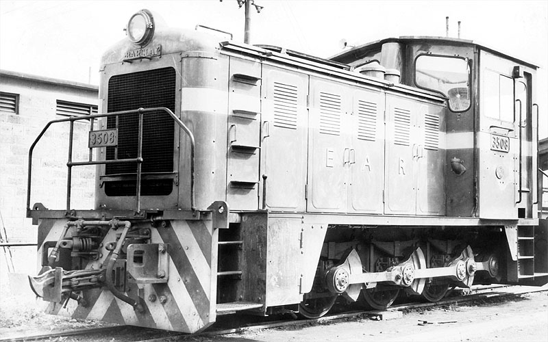
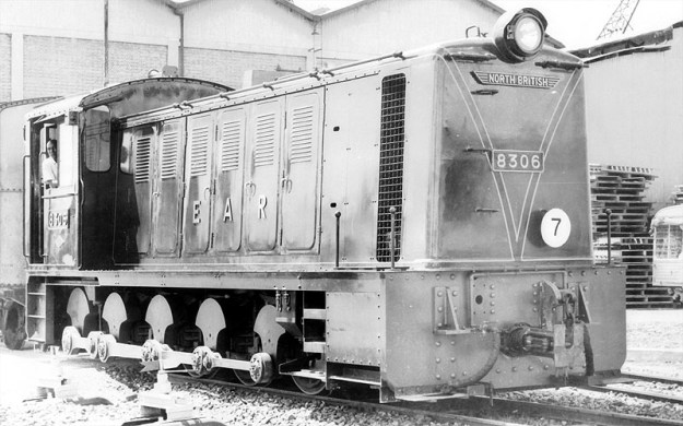
EAR 43 Class (originally 83 Class) Locomotives
These locos were built by the North British Locomotive Company.
EAR 44 Class (originally 84 Class) Locomotives
This 0-8-0 class was also built by the North British Locomotive Company.
EAR 45 Class (originally 85 Class) Locomotives
Still another North British 0-8-0 class of loco.
EAR 46 Class (originally 86 Class) Locomotives
The 46 Class (originally 86 Class) 0-8-0 central cab locos were built for the EAR by Andrew Barclay Sons & Co.
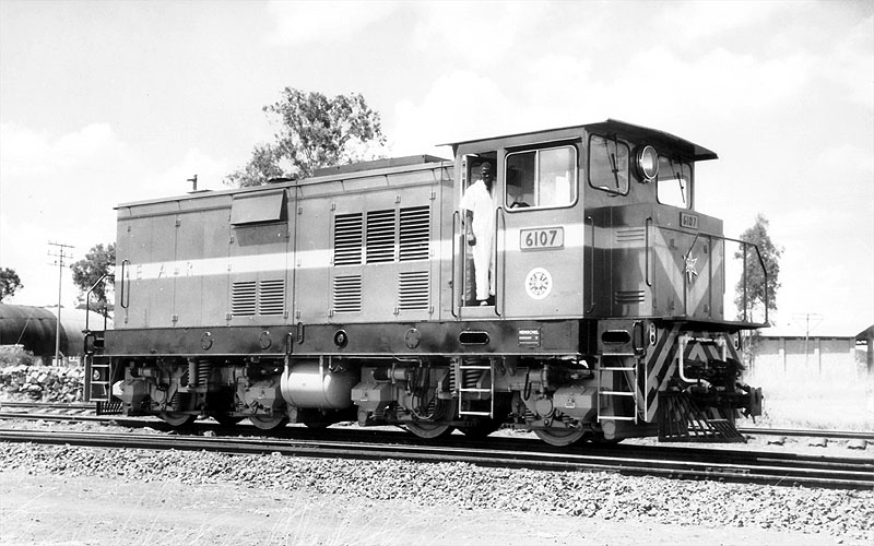
EAR 61 Class Locomotives
Once the decision had been taken not to build a new class of Beyer Garratt locomotives which would have been 61 Class locomotives. The Class number was used for a series of Henschel-built Bo-Bo shunters.
EAR 71 Class (previously 91 Class) Locomotives
See the 91 Class below.
EAR 72 Class (previously 92 Class) Locomotives
The East African Railways (EAR) 72 Class consists of 10 diesel-electric locomotives built by English Electric at the Vulcan Works in Newton-le-Willows in 1971 and 1972. They featured a 1-Bo-Bo-1 wheel arrangement and a 1,240 horsepower rating tailored for lightweight tracks across the whole EAR network. For more details about this locomotive please click here. [24]
79 Class Locomotive
Only one of these Co-Co locomotives was built. No. 7901 was supplied as an experimental type by AEI Lister-Blackmore. Looking at the export market in the late 1950s British Tomson-Houston (BTH), with Clayton and Lister-Blackstone commissioned the Explorer CM-gauge prototype, which was ready in 1959. This featured a Lister-Blackstone engine, BTH electrical equipment and mechanical parts by established partner Clayton. [25]
80 Class (later 32 Class)
The Class 80/32 0-6-0 locos were built for the EAR by John Fowler & Co Engineers of Leathley Road, Hunslet, Leeds, West Yorkshire.
81 Class (Later 33 Class)
Supplied by the Drewry Car Co., these versatile internal combustion locomotives handled secondary and transfer tasks during the early phase of internal combustion transition.
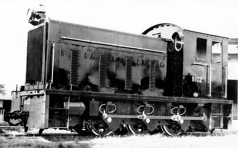
82 Class (Later 34 Class)
83, 84 & 85 Classes (Later 43, 44 & 45 Classes)
Introduced from 1955 onwards, these light and medium diesel-hydraulic locomotives (built by manufacturers like Hunslet, Andrew Barclay, and North British Locomotive Company) took over shunting and lighter duties on the Tanganyika Central Line. Please see 43, 44 and 45 Classes above.
86 Class (later 46 Class)
Please see the 46 Class above.
EAR 88 Class Locomotives
There were 20 diesel-electric locomotives built by the Montreal Locomotive Works (MLW) in this Class. These were lighter weight versions of the 92 Class. These locomotives had a 1-Co-Co-1 wheel arrangement and were designed to handle intense tractive effort demands across the challenging terrain of Kenya, Uganda, and Tanzania.
EAR 90 Class (later Class 87) Locomotives
There were 44 of this Class built by English Electric by the end of the 1960s. They worked across the whole EAR network.
Some notes about English Electric Twelve cylinder diesels and the EAR 90 class written by Steve Palermo: [20]
“EE generally designed locomotives to meet individual railway requirements, using standard components. Nevertheless, established designs were often adapted for other customers, and this is apparent in the 12-cylinder sequence, which accordingly could be described as being a series of quasi-standard locomotives. A greater degree of standardization is apparent in EE’s sequence of 6-cylinder models, though.
“The list of EE 12-cylinder models, in chronological order of first appearance, is:
1. Queensland Railways (QR) 1200 class, 10 built.
2. New Zealand Railways (NZR) Df class, 10 built
3. Malayan Railways (KTM) 20 class, 26 built
4. QR 1250 class, the first EE Australia variant, 17 built
5. Sudan Railways 1000 class, 65 built
6. East African Railways 90 (later 87) class, 44 built
7. British Railways (BR) 37 class, 309 built
8. Western Australian Government Railways (WAGR) C class, 3 built
9. Rhodesian Railways DE3 class, 16 built
10. QR 1270 class, 30 built
11. WAGR K class, also Goldsworthy Mining A class, 17 built
12. QR 1300 class, 45 built
13. WAGR R and RA classes, 18 built
14. AIS D34 class, 1 built
15. Ghana Railways & Harbours 1851 class, 16 built
16. Tasmanian Government Railways (TGR) Z class, 4 built
17. QE 2350 class, 16 built
18. TGR ZA class, 6 built“The total number of EE 12-cylinder locomotives built was thus 653, of which 496 were of UK origin, and 157 came from Australia. …
“BR, with 309 of its 37 class, was the biggest user of EE 12-cylinder models. Next came QR, with a total of 118 spread over 5 basic models, although there were subvariants. QR was also the first
operator to buy 12-cylinder EE locomotives, so are more detailed study of the group logically starts with the QR 1200 class, which then conveniently links to both the later UK and the Australian models. At least basic information on most classes is reasonably available, and of course the BR 37 has been the subject of many treatments in the literature.“The EAR 90 class was the second English Electric 12CSVT-engined model to be delivered, but the first to be ordered. The initial order, for 8 units was announced in October 1958, and an increase to 10 units was announced in March 1959. This was EARH’s first order for line-service diesel locomotives. A 13.5 ton maximum axle loading was imposed, to enable the locomotives to work northwest of Nairobi to Nakuru and Kampala [and elsewhere on the EAR network], as well as between Mombasa and Nairobi, which section alone would have allowed a higher axle loading. This axle loading constraint required a multi-axle design, as it is unlikely that EE could have built a compliant 12-cylinder Co-Co model. Unsurprisingly, EE used a 1-Co-Co-1 wheel arrangement. The resulting locomotive was largely a new design, although it included features drawn from the QR 1250 class (body style and general layout) and the Rhodesian Railways (RR) 16-cylinder DE2 class (running gear and in-frame fuel tank). What it was not, though, was simply a 1-Co-Co-1 variant of the QR 1250 with 12CSVT in place of 12SVT engine.
“Nevertheless, the QR 1250 makes a useful yardstick for comparison purposes. The EARH 90, at 51’0″ over headstocks, was a little longer than the QR 1250, at 49’6”. This extra length was most likely required to accommodate the more complex running gear, although it probably also gave a bit more space to accommodate the dynamic braking unit and a higher capacity cooling group. The total wheelbase was 41’6″, as compared with 40’0″ for the QR 1250. The equipment layout for the most part followed established EE practice. The nose compartment housed the leading bogie traction motor blower, which was motor-driven. The T-shaped main equipment cubicle was immediately behind the cab; then came the dynamic braking unit, which was mounted high & just below the cantrail – with a crosswise orientation, fan-shaft horizontal. Then came the generators, the engine, followed by the radiator compartment with mechanically-driven vertical-shaft fan, and finally the rear-compartment, housing the air compressor, mechanically-driven from the radiator fan gearbox, and the trailing bogie traction motor blower.
“The running gear was based upon that of the RR DE2, which had proved successful in service. Thus, the bogie frames were one-piece castings by Henricot. Because the EARH 90 was shorter, the axle spacings were all reduced by 6 inches. Each bogie had an overall wheelbase of 17’6″, with a rigid wheelbase of 12’0″ equally distributed, and the two inner bogie axles were separated by 6’6″. The pivot centres, placed between the pilot and outer driving axles, were 37’10” apart. Consistent with EE’s thinking about maximizing the advantages obtainable from the 1-Co-Co-1 wheel arrangement where it was necessary to use same, the axle spacings were chosen to obtain maximum bending moment relief, so reducing vertical railhead forces. As this required relatively close coupling of the bogies, a conventional suspended fuel tank was precluded, hence the use of an in-frame fuel tank, an EE feature that went back at least as far as the New Zealand Railways De class. The main bogies were interconnected by a lateral spring control mechanism that helped ensure optimum wheel flange angles in curves, so reducing lateral railhead forces. One way of looking at this is that the coupling allowed the leading bogie to pilot the trailing bogie into curves,
the leading bogie itself being guided by its own pilot truck. Wheel diameters were the same as on the DE2, namely 28½” pilot and 37½” driving. The main bogies had three-point load transfer from the mainframe, with a resiliently mounted pivot between the pilot axle and the outer driving axle, and a pair of coil spring bearers between the centre and inner driving axles. Equalization for each bogie was continuous from pilot truck axle to inner driving axle. This was a change from the DE2 bogie, which was equalized in two groups, although the casting did make provision for full equalization should it have been required. As with the DE2, the driving axle springs were of the leaf type interconnected by equalizing bars, but at the fixed attachment points, rubber bushes were used in place of the auxiliary coil springs used on the DE2. All three traction motors on each bogie faced outwards, consistent with high-adhesion bogie practice. EE claimed that this bogie design virtually eliminated intra-bogie weight transfer, whilst the wide pivot spacing minimized
inter-bogie weight transfer. I have never seen the benefit quantified in the same way that EE Australia did for its high-adhesion Co bogie first used on the Western Australia Government Railways R class, but taking the latter as indicative, EE’s view could well have been that a 1-Co-Co-1 locomotive with 81 tons adhesive weight would for practical purposes match a similarly-powered 90 ton Co-Co with more-or-less conventional bogies, whilst offering lower dynamic railhead forces as well as (fairly obviously) lower static railhead forces. EE certainly made much of the capabilities of it own-design 1-Co-Co-1 running gear (here one needs to be careful to exclude the non-EE design bogie that it was forced to use, against its better judgement, for the British Rail 40 class) and noted that its good performance had been verified by the railway administrations using it.“The 12CSVT Mk II engine had three manually adjustable governor power settings that allowed optimization for altitude, bearing in mind that the route embraced the range from sea level to 9136 ft elevation. 1840 hp (gross) was available up to 5500 ft, 1800 hp up to 7800 ft, and 1775 hp up to 9136 ft. One assumes that the settings were chosen according to which part of the EARH system the locomotives were assigned. The main generator was the EE822 model, and the six traction motors were the new EE537 4-pole model, connected in permanent series-parallel (2S3P) with two stages of field weakening. I have not been able to verify the gear ratio, but most probable was 72:15, fairly standard for the EE537 motor. The 45 mile/h maximum service speed would not have required faster gearing. The overhung auxiliary generator, model number unknown, was of 48 kW capacity.
“The EARH 90 was fitted with the by-now standard EE air-throttle control system, with the EE governor and the new hydraulically operated load regulator. The two driving stations were fitted with EE’s then-standard two-lever control stands. The throttle lever also operated the dynamic brake according to the standard EE 3-notch protocol. The main driving station was on the right hand side. There was a second driving station on the left-hand side, but this was not diagonally opposite and reversed as might have been expected. Rather it seems to have been arranged to allow bidirectional operation during shunting operations.
“The braking system was air for the locomotive and train, EARH being an air-braked road. However, the design made provision for the retrofitting of vacuum train brake equipment if required. At the time, it was evidently still thought possible that the EARH system would be converted from metre to Cape gauge to align with the rest of Southern Africa. The same conversion would also have required a (retrograde) change from air to vacuum brakes, the latter being the Southern African standard, with at least a period of dual-braking capability being required. One can wonder how vacuum brakes would have performed at 9000 ft altitude. Also, it is not immediately apparent as to where the vacuum exhausters would have been accommodated on the 90 class, bearing in mind that both the large compressor and the dynamic braking equipment would have been retained. Perhaps EE was thinking in terms of using a combined exhauster-compressor unit in place of the air compressor.
“I have not been able to find definitive information about the type of air braking system fitted to the EARH 90 class, other than that the initial batch had Westinghouse UK equipment. Had an American-type “schedule” system been fitted, most likely it would have been noted in the trade press descriptions. So more likely is that the braking system followed British precepts, with physically separate driver’s valves for independent and train brake control, and an electrically operated. independent-release-after-automatic-application function. Certainly EARH did not have a history of using schedule systems on its steam locomotives, late examples of which were fitted with Westinghouse No. 4 automatic brake valves and Gresham & Craven Mk IV locomotive steam brake valves. The layout diagrams show that the two driver’s brake valves are somewhat separated, with that for the automatic brake being to the driver’s right, and that for the independent brake a little to the left, ahead of the control stand. Clasp brakes were fitted to the driving wheels, withy one brake cylinder per wheel. The pony truck wheels were unbraked.
“Another unknown is the electrical capacity of the dynamic brake unit. For the second series, the peak braking effort is shown as 30 000 lbf at approximately 21 mile/h, which suggests around 1200 kW. The second series is said to have had a greater dynamic braking range than the first series, so it is possible the latter had a smaller capacity unit. As described, it is stated that the locomotive brake is interlocked with the dynamic brake so that both cannot be applied simultaneously. A literal interpretation suggests that the 90 was fitted with a conventional lockout system. But if so, it was a departure from established EE practice. In its previous diesel-electric locomotive dynamic braking installations, EE had used an anti-compounding system, in which the dynamic brake was released if locomotive brake cylinder pressure reached a predetermined level, typically 23 lbf/in².
“The EAR 90 was equipped for multiple unit operation. There was a central EE elbow-style jumper socket at each end on the front sheet, along with three “plug-in” hose connections arranged in a triangle. Most probably these were for respectively main reservoir, engine speed control and independent brake. The 90 was MU compatible with the later and smaller EE-built 91 (71) and 72 classes, but beyond that EAR did not seem to be concerned to establish a single common MU standard. Later diesel locomotives from other builders were equipped with control and MU systems that were more-or-less their respective builder’s standards.
Notwithstanding the 13.5 tons axle loading specification, the first series were built to a slightly lower 12.8 tons number, giving an adhesive weight of 76.8 tons. The total weight was 97.5 tons. The continuous tractive effort is consistently quoted as 44 500 lbf, although there is some variety in the corresponding minimum continuous speed, which is variously reported as 11.5, 11.7 and 12¼ mile/h. The top speed is usually reported as 45 mile/h, but this would have been a track limited speed, as the expected 72:15 gearing would have allowed 60 mile/h, and there is no reason why the running gear would not have accommodated this on suitable track.” [20]
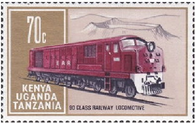
EAR 90 Class Locomotive on an East African 70c Stamp, issued on 5th April 1971; size: 44 x 28 mm; designer: Rena Fennessy; printers: Harrison & Sons Ltd. [21]
EAR 91 Class (later 71 Class) Class Locomotives
Built in 1967/1968, these locomotives were powered by an 8CSVT MkII engine with 1350hp for traction and weighed 68 tons. 10 were built. two batches of 10. In 1971-72, another 10 similar, but slightly heavier, units arrived, and were denoted the 92 class (later known as the 72 class). All were used in branch line service. These had a 1-Bo-Bo-1 a drawing of the side elevation of these locomotives can be seen here. [23]
Original EAR 92 Class Locomotives
See 72 Class above.
EAR 92 Class Locomotives
There were 15 locomotives in the Class. They were Canadian-built 1-Co-Co-1 diesel-electric locomotives manufactured by Montreal Locomotive Works (MLW) – heavier versions of the 88 Class! They were not suitable for the lighter rails in Tanganyika/Tanzania.
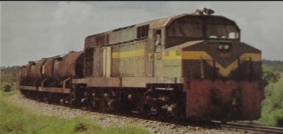
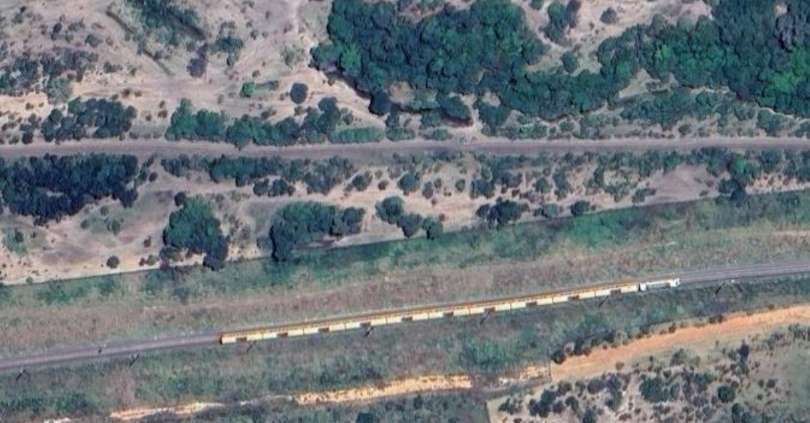
EAR 92 Class: These locomotives were purchased specifically for work only on the line West from Mombasa.
In this image the locomotive is in charge of a rake of empty tanks heading for Mombasa. [22]
Other locomotives in Tanzania
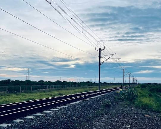
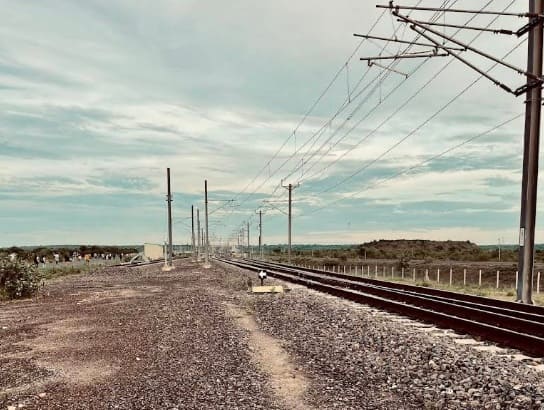
The Tazara Line operated independently from the metre-gauge network in Tanzania. It will be covered in another article. Writing in 2026, I am aware of the progress being made in Tanzania to develop a standard-gauge railway network. This too will be the subject of a future article.
References
- R. Ramaer; Steam Locomotives of the East African Railways; David & Charles, Newton Abbot, 1974.
- https://en.wikipedia.org/wiki/TR_MK_class, accessed on 19th July 2026.
- https://en.wikipedia.org/wiki/TR_GA_class, accessed on 19th July 2026.
- https://en.wikipedia.org/wiki/KUR_EC5_class, accessed on 19th July 2026.
- https://en.wikipedia.org/wiki/EAR_60_class, accessed on 22nd July 2026.
- https://en.wikipedia.org/wiki/EAR_13_class, accessed on 22nd July 2026.
- https://en.wikipedia.org/wiki/EAR_29_class, accessed on 22nd July 2026.
- https://en.wikipedia.org/wiki/Nairobi_Railway_Museum, accessed on 22nd July 2026.
- A. E. Durrant, C. P. Lewis & A. A. Jorgensen; Steam in Africa; Hamlyn, London,1981′
- https://en.wikipedia.org/wiki/EAR_30_class, accessed on 23rd July 2026.
- The Timken Roller Bearing Company was one of the first to introduce roller bearings for railroad cars. Railroad cars owned and operated by the Atchison, Topeka and Santa Fe Railway were some of the first to use roller bearings rather than “oil waste journal” boxes. Henry Timken, a German immigrant, invented an improved bearing and founded the company in 1899. It was later renamed The Timken Company. The first locomotive to use roller bearings made by Timken was Timken 1111, a 4-8-4 built by Alco in 1930. The locomotive was used on 15 American railroads for demonstration runs, and was purchased by the Northern Pacific Railroad, the last railroad to try the specially-built locomotive, in 1933. It operated in regular service on the NP until retirement in 1957 and was subsequently scrapped. Some British steam locomotives also used roller bearings. The LMS Turbomotive was fitted with Timken roller bearings, and they were also retrofitted to some of the LMS Coronation class. [12]
- https://en.wikipedia.org/wiki/Timken_Roller_Bearing_Company, accessed on 23rd July 2026.
- https://en.wikipedia.org/wiki/EAR_31_class, accessed on 23rd July 2026.
- https://fsmr.co.uk/ear-tribal-31-class, accessed on 23rd July 2026.
- A dragbox is a substantial, often cast metal, part of a locomotive to which the coupling mechanism is attached to allow the locomotive to pull a train. [16]
- https://en.wikipedia.org/wiki/Dragbox, accessed on 23rd July 2026.
- https://rogerfarnworth.com/2018/06/26/uganda-railways-part-25-locomotives-and-rolling-stock-part-c-steam-1948-to-1977
- https://rogerfarnworth.com/2018/06/29/uganda-railways-part-26-locomotives-and-rolling-stock-part-d-diesel-1948-to-1977
- https://www.facebook.com/photo?fbid=624070156589901&set=a.394728832857369&locale=en_GB, accessed on 23rd July 2026.
- https://www.friendsoftherail.com/forum/viewtopic.php?t=10472, accessed on 23rd July 2026.
- https://colnect.com/en/stamps/stamp/454492-Class_90_diesel-electric_locomotive-East_African_Railways-British_East_Africa_Kenya_Uganda_and_Tanganyika, accessed on 23rd July 2026.
- https://www.instagram.com/p/DYLgArQtvHB, accessed on 23rd July 2026.
- https://www.flickr.com/photos/29903115@N06/8598321329/in/photostream, accessed on 23rd July 2026.
- https://rogerfarnworthsrailways.wordpress.com/wp-content/uploads/2026/07/1bo-bo1-diesel-electric-locomotive-for-east-africa.pdf, accessed on 23rd July 2026.
- https://www.derbysulzers.com/AEI.html, accessed on 29th June 2018.
- https://en.wikipedia.org/wiki/UR_GD_class, accessed on 27th July 2026.
- https://en.wikipedia.org/wiki/TR_RV_class, accessed on 17th July 2026.
- https://rogerfarnworth.com/2026/07/22/railways-of-tanzania-part-15-locomotives-from-the-first-railways-built-by-the-german-colonial-powers-through-to-the-amalgamation-which-formed-east-african-railways-and-harbours-in-1948


.jpg)