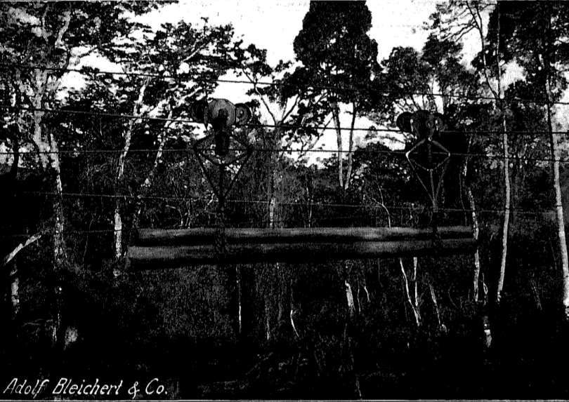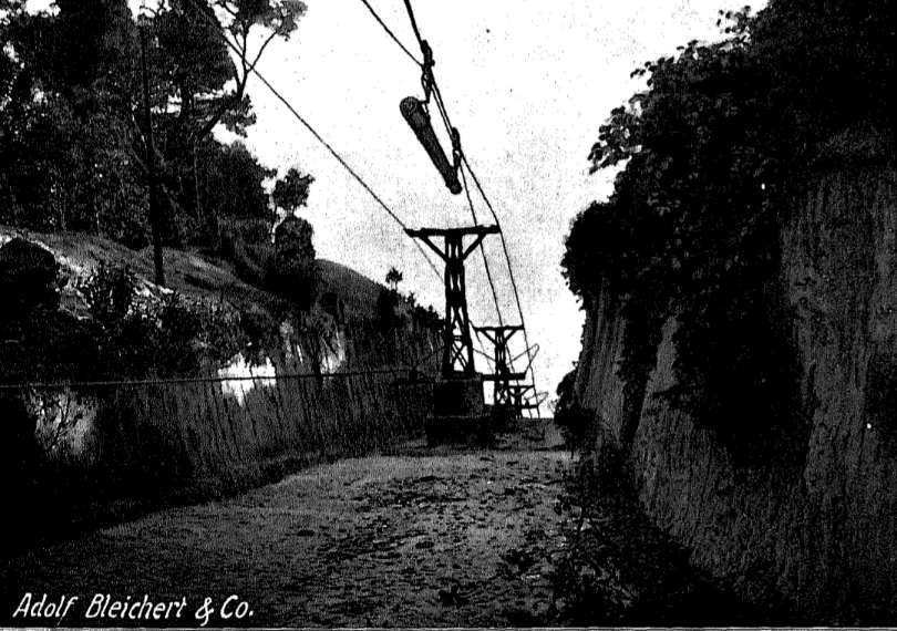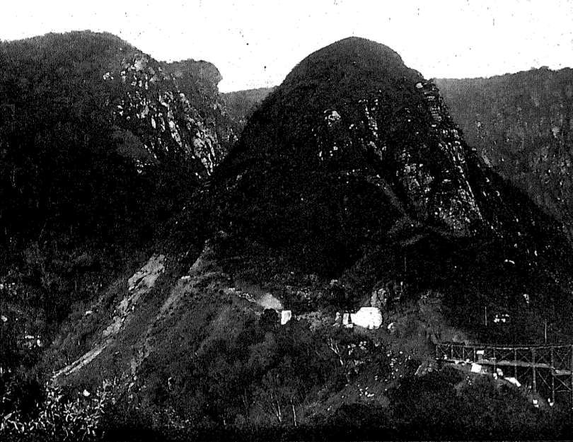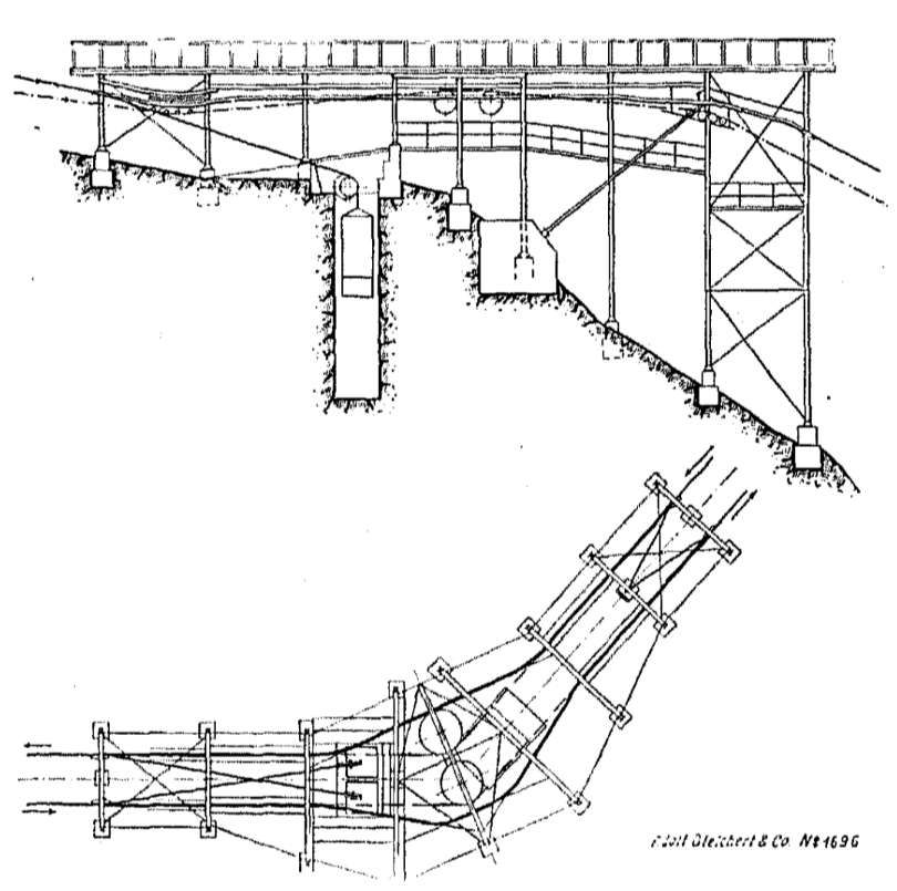
Tag Archives: German East Africa

Railways of Tanzania – Part 15 – Locomotives from the first railways built by the German colonial powers through to the amalgamation which formed East African Railways and Harbours in 1948.

Locomotives used during the EAR years from 1948 onwards will be covered in Part 16 of this series of articles.

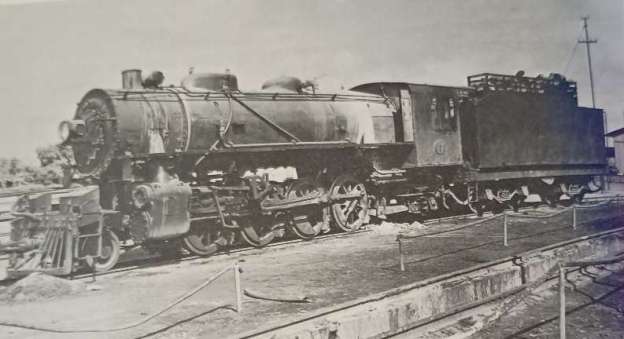
The featured image for this article is Tanganyika Railways 2-8-2 No. 802 of the MacArthur austerity class at Tabora in the early 1950s before its conversion to oil fuel. [1: p68]
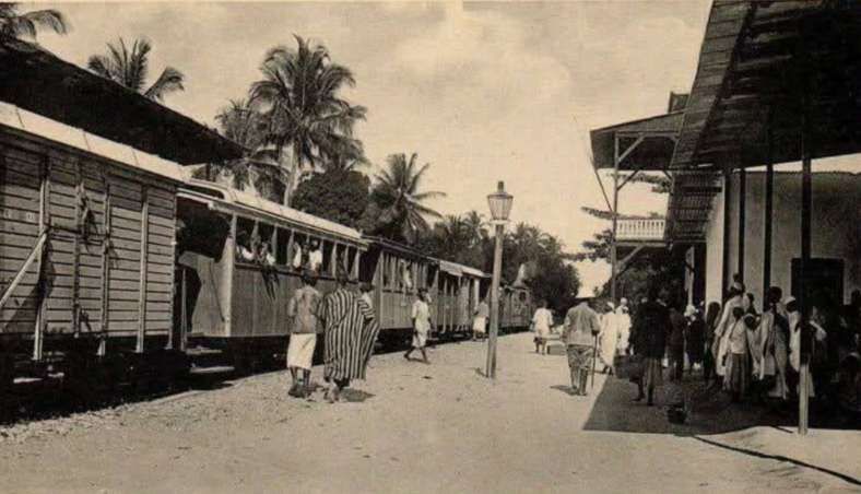
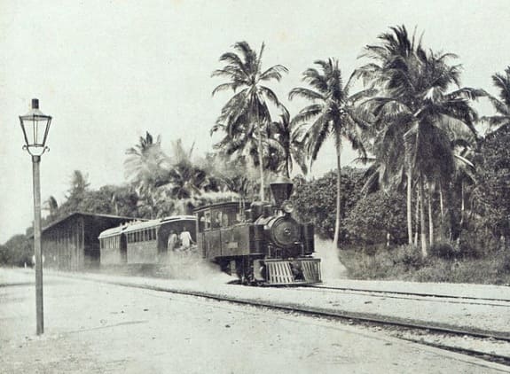
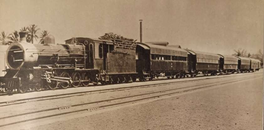
This is an overall view of Tanga Railway Station in 1908 during the the years of German East Africa. The station served as the coastal terminus of the Usambara Railway (Usambarabahn or Usambara Eisenbahn (UE)), which was constructed starting in 1893.The photograph was taken by German photographer Carl Vincenti it shows a train, headed by an unidentified early German steam locomotives, preparing to set off inland, (c) Deutsches Historisches Museum, (Inv. No. BA 90/5791)/Carl Vincenti and licensed for reuse under a Creative Commons licence (CC-BY-SA 3.0). [15]

Locomotives in the Years of German East Africa:

UE Class 0-4-2T Locomotives

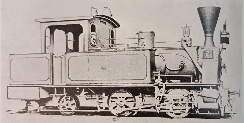
The Tanga Line (or Usambarabahn) was constructed over a relatively long period, starting in 1893, reached Korogwe in 1905 and Moshi in 1912. Initially the line was operated by five 0-4-2 tank locomotives. Ramear tells us that these five locomotives were built in 1893 by Vulcan (Vulkan) of Stettin. They were built to a standard design which Vulcan had standardised for use in Germany. [1: p19]
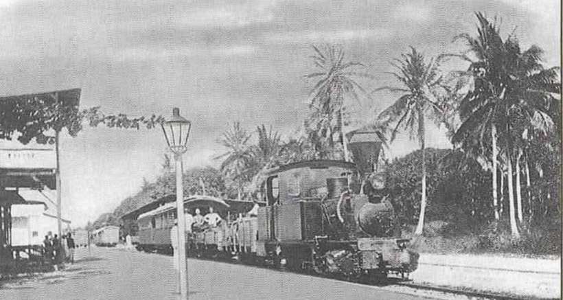
UE Engine No. 1 with an early passenger train ready for departure at Tanga Railway Station. This locomotive is the first in a class of 5 0-4-2T locomotives used on the Usambarabahn (c) Public Domain. [16][1: p19]
UE No. 2, one of a class of five 0-4-2T locomotives built by Vulcan of Stetting in 1893, (c) Public Domain. [1: p18]

UE Nos. 6-10 Mallet Class of 0-4-4-0T Locomotives
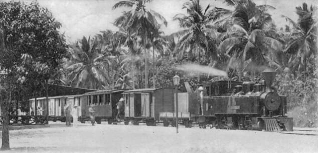
A vintage postcard view of an Usambara Eisenbahn 0-4-4-0T mallet type steam locomotive, one of five built by Arnold Jung (No. 414-418) in 1900 and in charge of a mixed train. These locomotives were UE Nos. 6-10, later Nos. 601-605. [17]
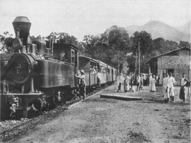
Another view of an Usambara Eisenbahn 0-4-4-0T Mallet type steam locomotive in charge of a passenger train which is waiting to depart at Tanga Railway Station. [18]
Another view of a Mallet type steam locomotive in charge of a mixed train which is waiting to depart at Njussi Railway Station. [22]
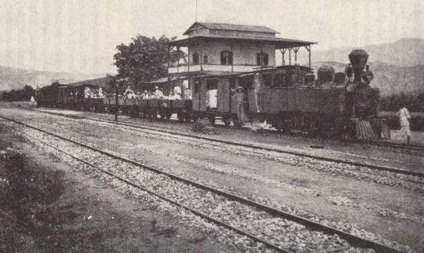
UE Mallet 0-4-4-0T No. 8 with a passenger train at Mombo, (c) Public Domain. [1: p20]

UE Nos 11-14 Class 2-8-0T Locomotives

After the line was improved with curves being increased to 200m radius, 8-coupled locomotives became feasible. Ramaer tells us that “Four tank locomotives with a 2-8-0T wheel arrangement were built for the UE by Messrs Orenstein & Koppel in 1908 to a standardised tank engine design used on all German colonial railways in Africa. … They were a distinct improvement over the Mallets. Although they were designed to burn coal, the high price of imported coal meant that they remained on wood fuel, which must have given problems with fireboxes and ashpans.” [1: p19-20] Sadly these locomotives seem not to appear on the Wikipedia list of Orenstein & Koppel locomotives. [23]

For an illustration of this type of locomotive please see the OAEG 2-8-0T below.

UE Nos. 15-16 & Nos. 17-18 Class 2-8-0 Locomotives
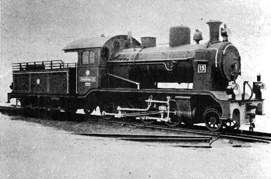
An Orenstein & Koppel (O&K) 2-8-0 locomotive which was one of a class built between 1908 and 1910 for the Usambarabahn. This specific locomotive is UE No. 15. [19]

These 2-8-0 tender locomotives were a significant improvement over the tank engines with a same wheel arrangement – with the side tanks removed and water carried in the tender the boiler size and weight could be increased. These were the last locomotives to eb supplied to the Usambarabahn and it operated with these locomotives well into the years of World War 1. [1: p20]

OAEG 0-4-0T Locomotives

Henschel of Kassel supplied 4 of these locomotives intended for the work of building the line. A further 4 of these locomotives were supplied, to the same design by, Henschel in 1909. [1: p21] In between these two batches of locomotive (in 1907) another 0-4-0T locomotive was put into service, the origins of this locomotive are obscure and it did not match the Henschel-built locomotives. Ramaer presumes that this locomotive was taken over from the contractor, Holzmann & Co. It was built by Markmaschinen (Works No. 26) in 1893. [1: p21, p27]

Ramaer notes that the Henschel engines “could be used as both coal and oil burners, and … had a bunker capacity of ton of coal besides 300 litres (66 gallons) of fuel oil. Their water capacity was 2 m³ (440 gallons). These little engines had a comparatively long life, surviving the war and the subsequent change to British management, and the last did not go out of service before the early 1930s.” [1: p23]
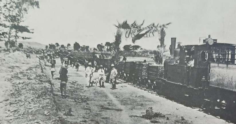
OAEG 0-4-0T Locomotive No. 2 with a line building train at Ugaga (later known as Malagarasi), (c) Public Domain. [1: p21]

OAEG Henschel Mallet Class 0-4-4-0T Locomotives
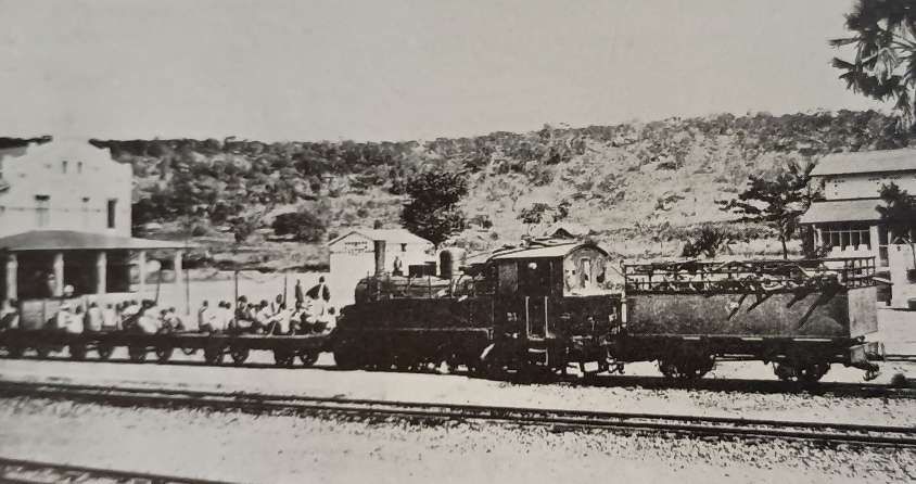
Just as the Usambarabahn needed to invest in more powerful Mallet types of locomotive which could also accommodate the tight curves on the line, so the OAEG to ordered five comparable Mallet 0-4-4-0Ts, four of which were supplied by Henschel in 1905 and put in service during the first half of 1906 with the fifth following in 1907; like the 0-4-0s they were built for either coal or oil fuel. The OAEG found these Mallets not to be as effective as had been hoped and decided to order Mallets from Henschel with a different wheel arrangement. [1: p23]

OAEG Henschel Mallet Class 2-4-4-0T Locomotives

Henschel supplied a second batch of four locomotives in 1908 as 2-4-4-0Ts with larger boilers and cylinders. They also had a higher working pressure of 14 atmospheres (at) (200lb/sq in) in comparison to 12 at (170lb/sq in) for the earlier engines. While the bunker capacity had been increased from 1.2 to 2.2 tonnes of coal, oil fuel had been discarded. [1: p23]

Mallets proved to be expensive to run and the OAEG realised that if it were to be able to use suitably powered locomotives for the train loads envisaged, it would need to improve the alignment of the later sections of the Mittellandbahn and upgrade to trackwork. This allowed the OEAG to consider using rigid-bodied 8-coupled locomotives.
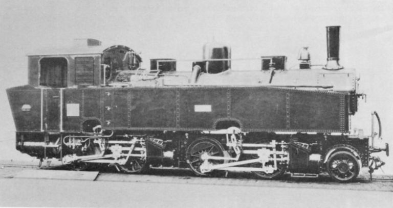
OAEG 2-4-4-0T No. 27, in the last Mallet class to be built for German East Africa. This locomotive appears in the Wikipedia list of Henschel steam locomotives. [24] It also appears in R. Ramaer’s book (although possibly a slightly different image) [9: p23] and A.E. Durrant’s book about Mallets. [25: p66]

On the whole, the Mallets were not as successful as had been hoped, so it was something of a relief for the OAEG that it was able to use much larger radius curves once the more difficult topography close to the coast gave way to much flatter country. The OAEG was able to look at rigid-framed locomotives. With the invention of the Gölsdorf system [26][27] which allowed spring-controlled side-play in coupled axles at the end of the 19th century. Eight-coupled engines became more feasible. The OAEG took advantage of this innovation and began to introduce eight-coupled locomotives. Ramaer tells us that “The first solution tried was the 0-8-2 tank, built with the pony truck under the fuel bunker to make adhesion independent of diminishing supplies to the maximum possible extent, besides making riding somewhat more comfortable for the crew. High prices for imported coal from Europe had made the railway look for a cheaper alternative and these engines were the first to be built for wood fuel. Henschel supplied them in 1909 as works numbers 9301-2, running numbers 47-8.

OAEG 0-8-2T Locomotives Nos. 47 and 48
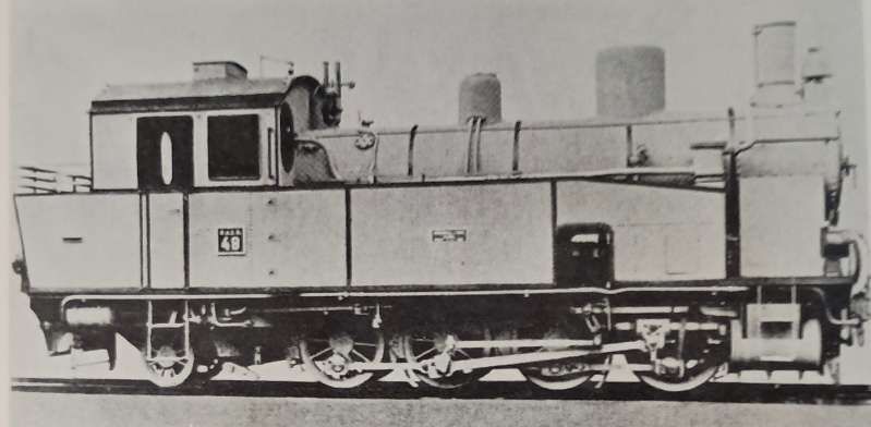
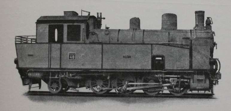
One of two OAEG 0-8-2T locomotives supplied to the OAEG by Henchel. This is No. 48, (c) Public Domain. [1: p24]
This is the same locomotive but with elements easier to see as the image has a darker hue, (c) Public Domain. [28]

Ramaer tells us that “The first solution tried [by the OAEG] was the 0-8-2 tank, built with the pony truck under the fuel bunker to make adhesion independent of diminishing supplies to the maximum possible extent, besides making riding somewhat more comfortable for the crew. High prices for imported coal from Europe had made the railway look for a cheaper alternative and these engines were the first to be built for wood fuel. Henschel supplied them in 1909 as works numbers 9301-2, running numbers 47-8.” [1: p23]

OAEG 2-8-0T Locomotives Nos 41-44 (also UE 11-14)
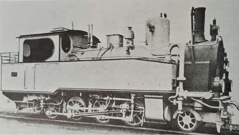
A Borsig-built 2-8-0T. These locomotives served on the OAEG Mittellandbahn, Ramaer tells us that there were 20 of these locomotives in use in East Africa. [1: p24 & 25]

Ramaer tells us that “Simultaneously, Borsig and Orenstein & Koppel introduced an alternative [to the 0-8-2T] and more logical solution in the shape of six 2-8-0T engines, also built for wood fuel. Both types, with only 5½ and 5 cubic metres water capacity respectively, normally carried auxiliary tenders for both water and firewood, besides hoses on the engine to allow for taking water en-route. … From this class and a comparable, but compound engine, supplied, also by Orenstein & Koppel, to South West Africa and Togo, a standardised 2-8-0T locomotive was developed, which was supplied to all German colonial lines in Africa. … Besides serving on other railways, it worked on the Usambarabahn, as described above, and was built for the OAEG by Borsig, O & K, Hanomag (or Georg Egestorff, as this firm was originally known) and Maffei to a total of eighteen engines in 1909-10. Including the engines of the first batches by O & K and Borsig of six locomotives, the total of the Einheitstenderlok (standard tank locomotive) classes amounted to twenty-four engines by the end of German rule.” [1: p25]

These locomotives were far better than the 0-8-2T locos, particularly in respect of their performance at speed. This was of some importance when maximum speeds were raised to 45km/h, and planning envisaged 60km/h (36mph) for the Dar es Salaam-Kigoma mail trains. “The standard tanks were a good, straightforward design and were kept in service for a fairly long period under British management; the last ones … being withdrawn in 1951.” [1: p25]

The series was made up of Orenstein & Koppel locomotives (Works Nos.3223-3226) built in 1909, OAEG Nos. 41-44; Borsig locomotives (Works Nos. 7143-7144) built in 1909, OAEG Nos. 45-46; Henschel locomotives (Works Nos. 9301-9302) built in 1909, OAEG Nos. 47-48; Borsig locomotives (Works Nos. 7153-7155) built in 1909, OAEG Nos. 49-51; Orenstein & Koppel locomotives (Works Nos.3312-3314) built in 1909, OAEG Nos. 52-54; Borsig locomotives (Works Nos. 7552-7555) built in 1910, OAEG Nos. 55-58; Hanomag locomotives (Works Nos. 5845-5948) built in 1910, OAEG Nos. 59-64; Maffei locomotives (Works Nos. 3628-3631) built in 1910,OAEG Nos. 63-66. [1: p27]

OAEG 2-8-0 Locomotives Nos 101-120
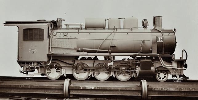
An ex-Works photograph of one of a series of Hannoversche Maschinenbau Hanomag’s 2-8-0 locomotives built for the Ostafrikanische Eisenbahngesellschaft (East African Railway Company). No. 120 was Works No. 6666 of 1913 and was intended for use on the Mittellandbahn running West from Dar-es-Salaam. This locomotive was provided with a tender built by Borsig of Berlin. The locomotive was in use from 1923 to 1937. [20]

Numbered 101-120 these locomotives were built in three batches, 101-110 (6080-89) in 1911, 111-115 (6597-6601) in 1912 and 116-120 (6662-66) in 1913. The class was intended to include a total of 22 locomotives, but only 20 were built. The locomotives were primarily intended to support the construction and operation of the Central Line (Mittellandbahn or Tanganjikabahn) running from Dar es Salaam to Kigoma. Following World War I and the transition of the region to British administration, the engines entered service with the Tanganyika Railway Company, remaining in use into the late 1920s and 1930s. One of the Class is shown below with its Borsig tender.
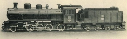
An Hanomag 2-8-0 Locomotive with Borsig tender, (c) Public Domain. [21]

These were the largest and most powerful OAEG locomotives. They were put into service only after the eastern sections of the Mittellandbahn had been relaid with 55lb rail which would accommodate a ten ton axle load. Ramaer says that these locomotives were 46.2 tonnes (45.5 tons) in weight: “On level lines, these engines handled 500-ton trains, and on 1 in 55 gradients 250 tons at 10 1 km/h. Three carried feedwater purifiers/pre-heaters on top of the boiler. In their day, for the narrow gauge, they were advanced locomotives, and in the early post-war years, enginemen commented favourably upon those that survived. Nevertheless, the fact that they were not in line with British engineering practices presumably was the reason that all were scrapped in the period between the wars. The first ones went in the early 1920s, but the last survived until 1937, where it was in use on the Mwanza line. Without doubt the bulk of the class disappeared much earlier than would have been the case if the line had continued under German management.” [1: p25]
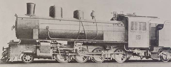
OAEG 2-8-0 Locomotive No. 107, one of the first batch of locomotives supplied by Hannoversche Maschinenbau Hanomag. When built these were the heaviest locomotives in East Africa. [1: p25]

One significant problem on the Mittellandbahn was the availability of water for the locomotives

Locomotives under British Management:

Under British administration the Tanganyika Railway started operation on 1st April 1919. It gained a series of different locomotives of German origin and some which the British forces had brought into Tanganyika during the first world war. Much of the German network had been destroyed by the retreating German forces. Ramaer says that around 4 miles was shaved off the journey between Dar-es-Salaam and Kigoma as the opportunity was taken to realign sections of the line to smooth out the worst curves.

Ramaer says that “Of the German locomotives, four classes were initially put into service on the Central Line, 14 of the Hanomag-built 2-8-0 tender locomotives of the former class 101-20 and now classified GG for German Goods, 22 2-8-0Ts, the German Einheits-vlok, now called class GT, for German Tank, 2 0-8-2 tanks and 6 0-4-0T pugs, dating back to the earliest years of the line, when the DKEBBG had used them for line building purposes. Later on, a total of seven 0-4-4-0T and 2-4-4-0T Mallets were also reconditioned.” [1: p53-54]

Only 5 German locos were salvageable on the Tanga Line: “three of the Orenstein & Koppel-built 2-8-0 tender locomotives of the German series 15-18 and two of the standard 2-8-0 tanks. Many of the Hanomag engines on the Central Line needed new cylinder castings, as the Germans had destroyed them in an attempt to prevent subsequent use of the engines. The new castings were made at the Parel works in Bombay of the former Great Indian Peninsula Railway and mostly fitted at Tabora, where the Germans had installed the main workshops for the Central Line. Thus 14 engines could be reconditioned, Nos 102-3, 105-6, 108, 111-17, 119-20.” [1: p54]

The two 2-8-0 tender classes disappeared after a fairly short life in comparison to other, British-built locomotives on the system. The first engines went in the early 1920s, when money was made available to buy new engines from Britain. The remaining Hanomag locomotives were laid up in about 1932, after the arrival of the new class GA Garratts. One, however, was temporarily brought back into service in 1937, equipped with an electric headlamp, to work the engineering train on the lightly laid Mwanza line, which was very susceptible to washaways, and was always troublesome to operate from the locomotive point of view. All the Mallet tanks were derelict at Tabora works in 1930-31 and were subsequently sold as scrap to Japan.” [1: p54]

TR GT 2-8-0T Class Locomotives

It seems that, of the German fleet, only the 2-8-0T locos had a significant life under British control. Numbered 101 and 102 they were finally scrapped at Nairobi works in 1951.
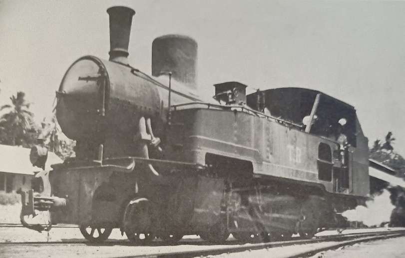
TR GT Class 2-8-0T in use as a shunter at Tanga. This and its sister locomotive were Orenstein & Koppel locomotives and were the last two German locomotives to be in use on the network in Tanganyika, (c) Public Domain. [1: p53]

TR NZ Class 4-8-0 Locomotives

TR NZ Class No. 1098 leaving Dar-es-Salaam with the mail train in 1922. These locomotives were originally ordered by the Nizam’s Guaranteed State Railway for use on its network in the Dominion of Nizam, better known as the Hyderabad State, in India, but served their entire working lives in Tanganyika, East Africa. Class 22 locomotives were 4-8-0 locomotives built in 1915 by Nasmyth, Wilson and Company. These locomotives were numbered TR1095–TR1098, later TR200–TR203, and later still, EAR2201–EAR2204, © Public Domain. [1: p55][9: facing p182]

In March 1916, while the four members of the class were on their way to India, they were commandeered to assist in the British invasion of German East Africa, where they entered service with the Tanganyika Railway (TR), still carrying their NGSR lettering and numbers 1095–1098. In the early 1930s, they were officially classified as the TR’s NZ class (the NZ being a reference to “Nizam”), and renumbered as 200–203. [4]

The class was later operated by the TR’s successor, the East African Railways (EAR), as its 22 class, numbers 2201–2204. In the late 1940s, two of them were transferred to the Southern Province Railway, [5] the isolated network developed to support the ultimately unsuccessful Tanganyika Groundnuts Scheme. Nos 2202 and 2204 were scrapped in 1952, and 2201 and 2203 in 1956. [4]

TR DL Class 4-8-0 Locomotives

The abbreviation ‘DL’ stands for ‘Development Loan’. The locomotives first carried running numbers 200-205 and later 300-305. They had piston valves and superheater rather than the slide valves and saturated steam of the Nizams.Ramaer says that, “They were derived from the lighter engines of the Nigerian Railways’ Emir Class. Like them, they had narrow fireboxes which were found to be less suitable for wood burning, so that the DLs were used mainly on the section between Dar-es-Salaam and Morogoro, where coal was available.” [1: p56]

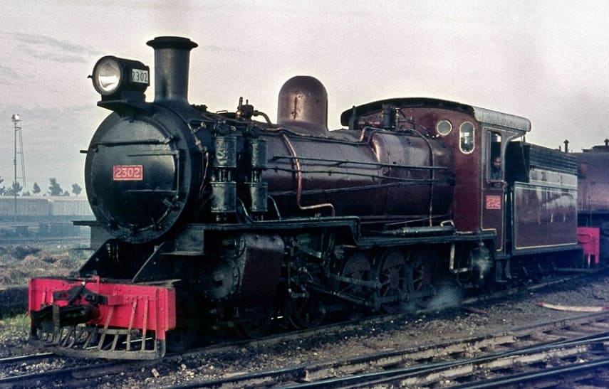
TR No. 301 was a TR DL Class 4-8-0 locomotive. It was originally numbered ‘TR No. 201. This Class were the first British locomotives to be built for the TR. They entered service in 1923, (c) Public Domain. [9: p297]
The TR DL class, later known as the EAR 23 class, was a class of 4-8-0 steam locomotives derived from the Nigerian Railways Emir class. The six members of the class were built by Beyer, Peacock & Co. in Gorton, Manchester for the Tanganyika Railway (TR). They entered service on the TR in 1923, and were later operated by the TR’s successor, the East African Railways (EAR). No. 2302 was originally numbered TR No. 202 and later TR No. 302, (c) Basil Roberts and licensed for reuse under a Creative Commons licence, (CC BY-SA 4.0). [8]

The DLs were survivors. Ramaer records that they were still is use in 1972 as EAR Class 2301-2306, although it was expected that they would be set aside in 1973. [1: p56]

TR MK 2-8-2 Class Locomotives

To resolve the problem of the DLs’ narrow fireboxes, a new locomotive design was ordered with a 2-8-2 wheel arrangement. The MK Class had a larger boiler and wider firebox. ‘MK’ was short for ‘Mikado’ which was the standard name across the world for 2-8-2 locomotives.
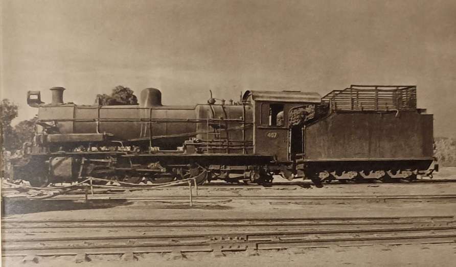
MK Class 2-8-2 Locomotive No. 407. This class of locomotive entered service in 1925-1927. [9: p299]

Later known as the EAR 25 class, the eleven members of the class were built by Vulcan Foundry, in Newton-le-Willows, Lancashire, for the Tanganyika Railway (TR). They entered service on the TR in 1925–1927. [10]

The eleven members of the Class were:
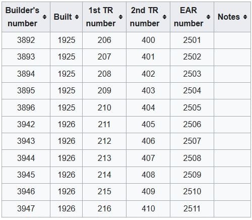
The eleven members of the original TR MK Class. [10]
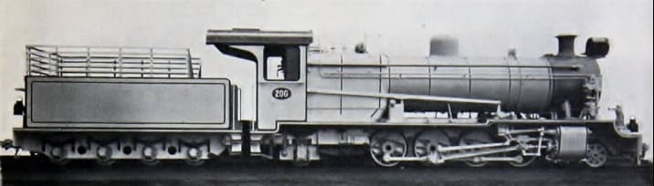
Vulcan Foundry ex-Works photo of TR MK 206. [10]

This class was a great success and the Class were still in use at the time Ramaer wrote his book, although he notes that they were now on borrowed time. “One problem with the design of the MK was the fact that the leading pony truck provided insufficient guidance on the sharp curves on the Dar-es-Salaam-Morogoro and the Malagarasi-Kigoma sections, and the design of the Bissel truck [29] left something to be desired.” [1: p57] The solution was a redesign for the next class of locomotive – the RV.

TR RV Class 4-8-2 Locomotives

The RV Class were a redesign of the MK Class – the only significant changes were the extending of the frames by 2 ft 9 in., to accommodate the leading bogie of the 4-8-2 wheel arrangement. Ramaer says that, “As a result of this change it was found necessary to extend the smokebox to keep the cylinders at least roughly in line with the blastpipe and chimney.” [1: p57] The design creted problems – “the greater length of the smokebox created vacuum problems, resulting in insufficient boiler draught. In consequence the RVs were poor steamers and this manifested itself clearly in their early days when they worked the mail trains on the Central Line. They were particularly bad on the Dar-es-Salaam-Morogoro and Kigoma-Kazuramimba sections with ruling gradients of two percent and more, although the below-average quality of firewood on the western section also had something to do with these poor performances.” [1: p57-58] They were nor popular with the train-crews.
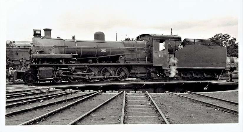
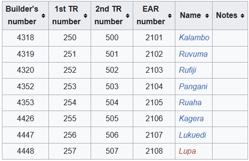
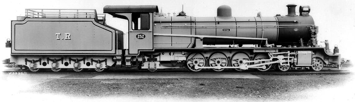
This is a Tanganyika Railway (TR) oil-fuelled RV (River) class 4-8-2 locomotive, later classified as the East African Railways (EAR) 21 class. It was first numbered TR252, then No. TR502 and later EAR2103. The locomotive was built by the Vulcan Foundry in Lancashire, between 1928 and 1930, © Public Domain. [2][9: p303]
TR Rv Class Locomotives – class list. [2]
The ex-Works photograph of RV Class No. 252, © Public Domain. [3]

At the time of writing of Ramaer’s book (1972?), these locomotives were working out their lives on lighter duties from Morogoro shed and were unlikely to continue in use beyond 1973. [1: p58]

TR G Class 4-8-0 Locomotives (including 4 No. NW Class 4-8-0 Locos)
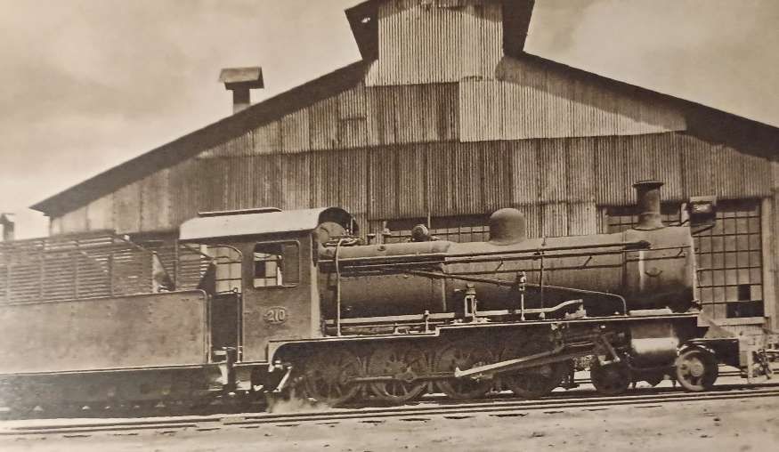
TR Class G 4-8-0 Locomotive No. 210 (later 22 Class) – these locomotives entered service in1928. Hill tells us that these locomotives were obtained to work two specific lengths of railway – the Tanga Line and the Mwanza branch off the Central Line, (c) Public Domain. [9: p299]

These locomotives were a redesign of the NZ Class. Ramear says: “The four Nizam 4-8-0s obtained in 1916 served as the prototype for the TR’s own G class, a very similar unsuperheated, slide-valve engine, thirteen of which were supplied by Stephenson and Nasmyth Wilson and put in service in 1928-31. They were again closely similar to the original BESA-designed 4-8-0s for India and thus provide, as the last 4-8-0s built for the TR, a direct link with the first engines of this wheel arrangement to see service in this part of the world. The first eight were supplied to the Tanga Line in 1928 and released F class engines 96 and 720, which had become very expensive to maintain. One of the new Gs, unassisted, could handle the mail trains, a marked improvement over the old and obsolete six-coupled engines. The G had an axle load of only 8-8½ tons, a necessity on the light track of the Tanga Line. The reason for their obsolete concept is not quite clear, however, if we remember that these engines were built at the same time as the KUR EA class Mikados. Their original running numbers 20-32 were later changed to 204-16, as the locomotives were considered to be direct descendants of the NZ class locomotives 200-3. After the amalgamation in 1948 the G class engines were renumbered 2205-17 and gradually taken out of service.” [1: p58]
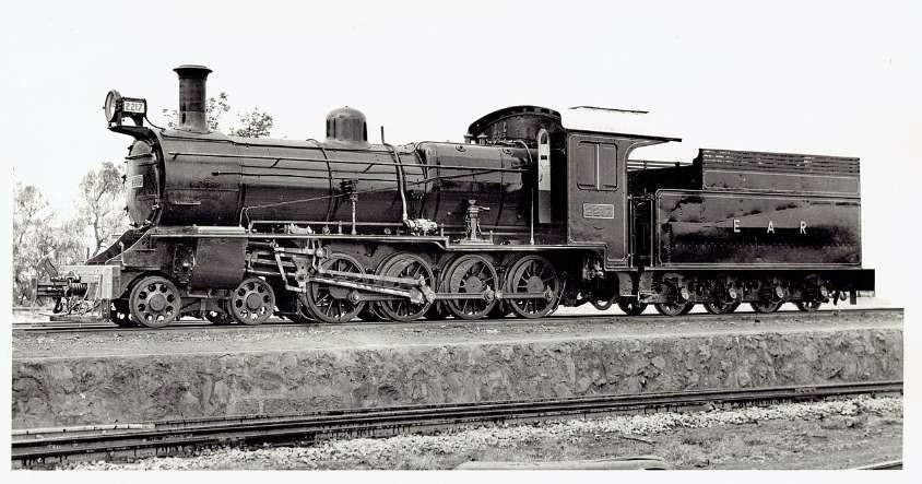
This is a later publicity photograph of an East African Railways (EAR) Class 22 steam locomotive, numbered 2217. These locomotives were very similar to the earlier batch of NZ Class locomotives but these four locomotives were initially given the Class name NW. Built by Nasmyth, Wilson and Co. in 1930, they had Works numbers 1588-1591. They later became EAR2214-EAR2217, © Public Domain. [4]

The EAR grouped a number of locomotives into the 22 Class in the late 1940s or early 1950s. This manoeuvre grouped ex-Tanganyika engines alongside a slightly newer batch of 1930 Nasmyth Wilson locomotives (Works Numbers 1588–1591) which also operated as Class 22s. [6]
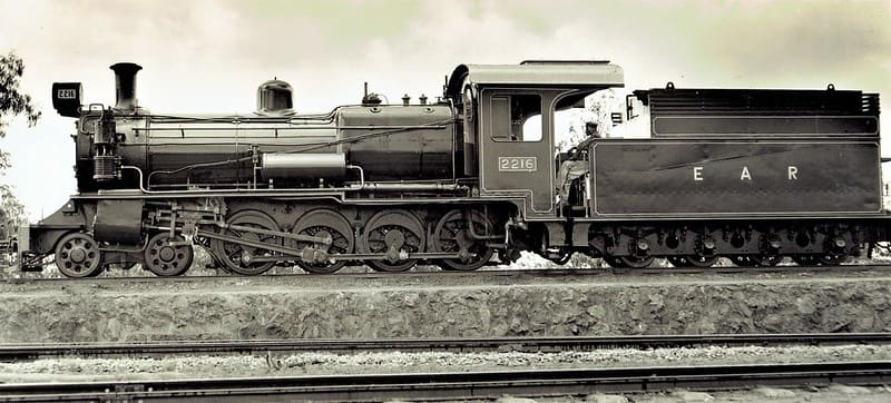
Another publicity photograph taken in the early 1950s which shows EAR2216, another of the same group of 1930-built, Nasmyth engines, EAR 2214-EAR2217, © Public Domain. [6]

The Tanganyika Railways Class G included four locomotives from a group initially known as NW Class 4-8-0s but others as well. We have noted above that the NZ Class of locomotives became EAR2201-EAR2204 (not Class G) and that the NW Class (included in Class G) later became EAR2214-EAR2217, two of which are pictured above. Others in Class G were to become: EAR2205 – EAR2209 Stephenson built locomotives (1927) Works Nos. 3959 -3963; EAR2210 – EAR2213 Stephenson built locomotives (1929) Works Nos. 3990-3991 & 4011-4012. [6]

All of the Class 22 locomotives were scrapped between 1956 and 1970. [6]

Renumbering
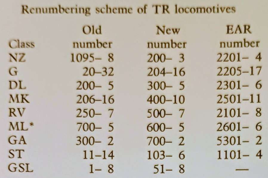
This table shows the revised numbering in use by the TR in the 1930s and the later EAR numbering scheme.

The TR changed all running numbers in the early 1930s to a much more logical and consistent system. … Each class started at a round figure in series blocks of hundreds.” [1: p59]

TR ST Class 2-6-2T Locomotives

In 1930, the TR received four 2-6-2T shunters (the same type as the KUR ED1 Class). These were designated as the ST Class. They initially had running numbers TR Nos. 11-14, later TR Nos. 103-106. The locomotives were supplied by Vulcan. Under EAR control the locomotives were numbered EAR Nos. 1101-1104. [1: p60]
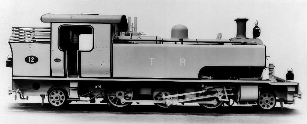
TR No. 12 was later designated TR No. 104 and later still, EAR No. 1101. This is an ex-Works photograph taken at the Vulcan Works in the UK, (c) Public Domain. [31]

Many of the EAR Class 11 locomotives were adapted to burn oil fuel rather than wood or coal and were still in use in 1972. [1: p60]

TR Sentinel GSL 50 Class Shunters

The TR GSL class locomotives were 0-4-0T geared steam locomotives designed for shunting and light duties. Built by Sentinel Waggon Works in Shrewsbury between 1929 and 1931, these locomotives were primarily used for shunting in yards and short-haul operations. A total of eight locomotives were built. They feature a side-tank design with geared drive, providing better traction on tight curves and low-speed manoeuvres, while the 0-4-0T Whyte notation reflects a rigid wheelbase for stability in confined spaces. [14]
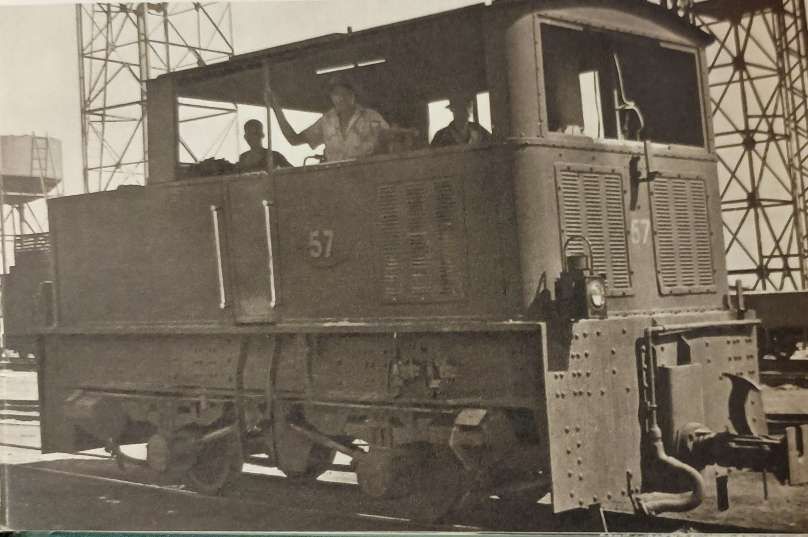
A GSL Class Sentinel Shunter. Hill tells us that 8 of these small locomotives were purchased in 1930. They served in various roles until they were scrapped by the EAR in the early 1950s, (c) Public Domain. [9: p301]

Procurement of the GSL class occurred in the late 1920s amid broader post-war modernization initiatives across East African railways, with the Tanganyika Railway ordering eight units (which it numbered 50-57) to bolster yard operations as traffic volumes rose. Economic considerations favoured geared designs for their lower maintenance costs and suitability to tropical conditions, where conventional engines often suffered from corrosion and overheating. [14]

Ramaer tells us that, “Among their duties in the [1930s and 1940s] they were used as shed pilots, particularly for hauling out larger engines from the German-pattern roundhouse sheds to the turn-table, an arrangement frequently used at Central Line depots. After the war, they began showing signs of age and as newly built steam shunters were not readily available, they were replaced by diesels, the first on the TR. The last Sentinels, although outmoded, served at Tabora until the middle 1950s before being scrapped.” [1: p60]

TR GA 4-8-2+2-8-4 Garratt Class Locomotives
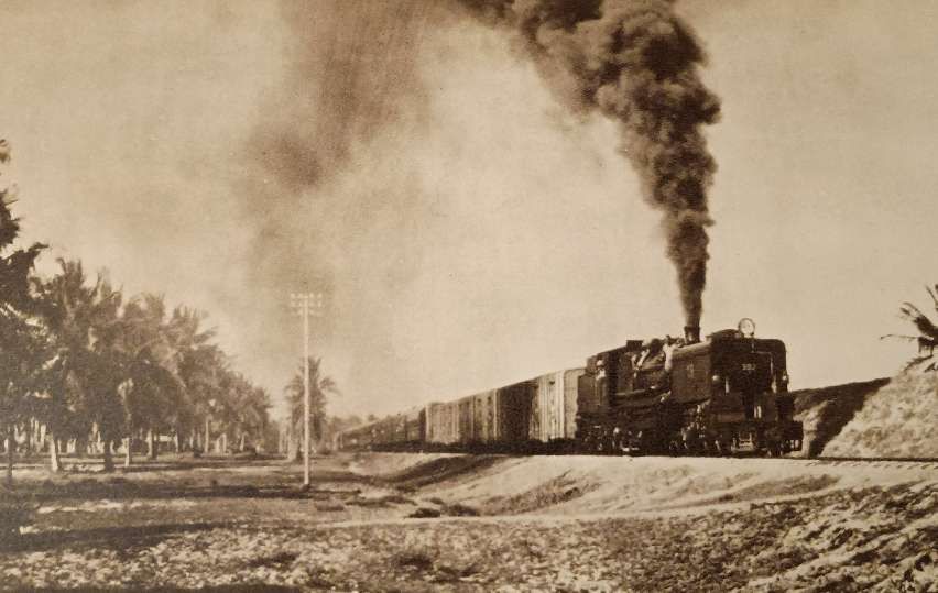
GA Class 4-8-2+2-8-4 Garratt No. 302 at the head of the Dar-es-Salaam -Kigoma mail train. [1: p60][9: facing p230]

The TR GA class, later known as the EAR 53 class, was a class of 4-8-2+2-8-4 Garratt-type articulated steam locomotives. The three members of the class were built in 1930 by Beyer, Peacock & Co. in Manchester for the Tanganyika Railway (TR). They entered service in 1931, and, with one exception, were later operated by the TR’s successor, the East African Railways (EAR). The class list is shown below. [11]
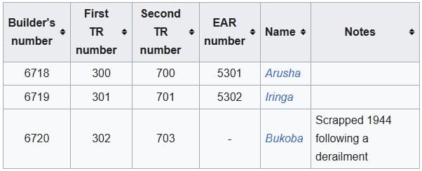
The GA Class numbered only three locomotives. [11]

The design of the GA class locomotives was based upon that of the Kenya-Uganda Railways (KUR) EC2 class, which was built at about the same time by the North British Locomotive Company for the (KUR). The main design difference was that the GAs had higher, narrower front tanks than the EC2s. With their reduced water capacity, the GAs also had a lower axle loading, which made them suitable for operation over the World War I-damaged bridges on the Central Line in Tanganyika. [11]
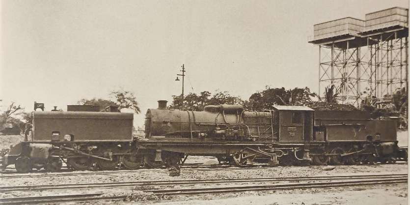
GA Class 4-8-2+2-8-4 Garratt No. 700 which was brought into service between Dar-es-Salaam and Morogoro in 1931. [9: p303]

Upon entry into service in 1931, the GA class locomotives were allocated numbers 300–302. Each of them was also given a name: the first two carried the names Arusha and Iringa, respectively, after the locations of the TR’s big road depots, and no. 302 was named Bukoba. Later, the GAs were renumbered 700–702. [1: p61]
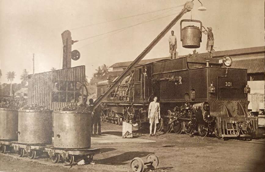
GA Class 4-8-2+2-8-4 Garratt No. TR 301 was coal-fired and can be seen here being refuelled at Tanga. [9: facing p198]

It was the TR’s general policy to allocate tender locomotives to standard duties, and use its Garratts only for the most demanding tasks. The GA class therefore normally worked between Dar-es-Salaam and Morogoro, the heaviest part of the Central Line. [12: p184]

The GA class’s operating costs were markedly lower than those of their predecessors. Even during the Great Depression, when traffic volumes greatly declined, they were of great operational benefit. Following the outbreak of World War II, they became indispensable. [1: p60]

Unfortunately one member of the class, TR No 702 Bukoba, was derailed by a washaway near Mikese during a night of bad weather in 1944. The crew was saved, but the locomotive was almost completely submerged and had to be scrapped. [1: p60]

In 1949, the TR and the KUR were merged to form the EAR, which took over the two survivors, classified them as its 53 class, and renumbered them 5301–5302. [1: p61]

The EAR also equipped the two survivors with a French-style ACFI feedwater heater, one of which had already been fitted to the last member of the KUR EC1 class, no 66. However, the feedwater heaters were later removed, partly because they achieved only limited improvement in thermal efficiency, and also as they had caused similar maintenance problems to those experienced by the KUR. [1: p61]

In the 1950s, the EAR 53 class locomotives were replaced on the Central Line by the new EAR 60 class locomotives, and therefore transferred to the northern part of the EAR system. Later, they returned to what had become Tanzania, to carry out transfer work in Dar-es-Salaam. They were withdrawn and scrapped there in the late 1960s. [1: p61][12: p184]
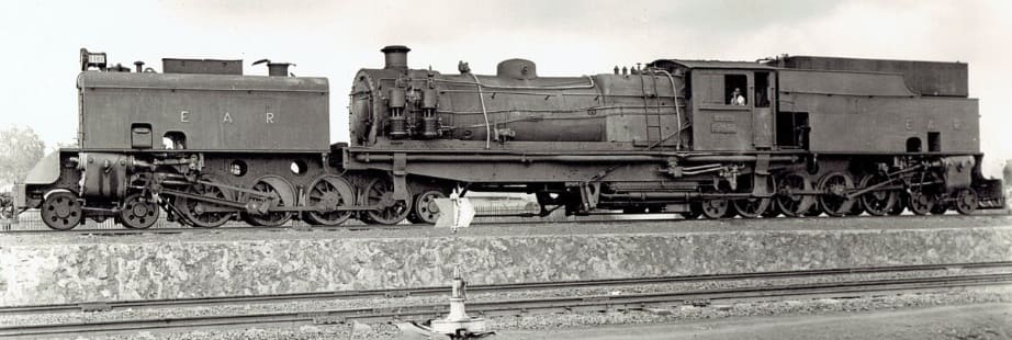
East African Railways publicity photograph of no. 5302 Iringa, c. 1953, (c) Public Domain. [11]

TR GB 4-8-2+2-8-4 Garratt Class Locomotives

The Tanganyika Railway (TR) GB class were 4-8-2+2-8-4 Beyer-Garratt steam locomotives were originally ordered by the British War Department for service in Brazil, although not built. Later the design was used for locomotives for India and Burma. Four were acquired by the TR in 1946 from Burma. They later became members of the East African Railways (EAR) 55 class. [13][1: p64]
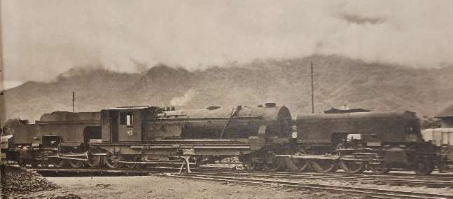
GB Class Garratt locomotive No. 753 entered service in 1948 immediately prior to the amalgamation of the TR and the KUR. [9: p307]

The Garratt locomotives that eventually made up the full 55 Class list were in use on the KUR and the TR. The full list is shown below:
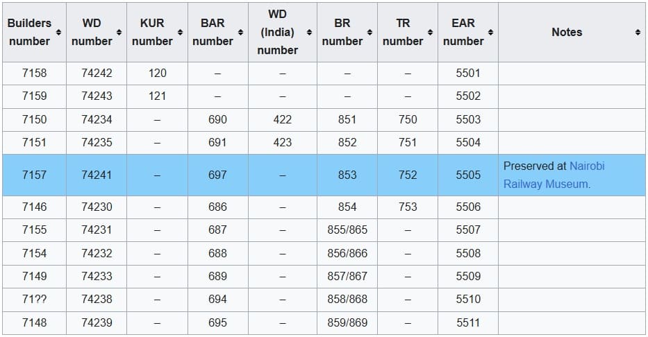
The full EAR 55 Class list: as can be seen 4 of the Class served in Tanganyika, one of which (EAR No. 5505, ex-TR No. 752) is preserved at Nairobi Railway Museum. When serving in Tanganyika before the amalgamation of the two networks, these locomotives were numbered TR 750 – TR 753. [13]

TR ML 2-8-2 Class Locomotives

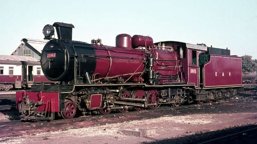
East African Railways (EAR) 26 class (ex-TR ML class) 2-8-2 steam locomotive no. 2603 at Tabora depot, Tanzania in 1968, © Basil Roberts and licensed for reuse under a Creative Commons licence (CC BY-SA 4.0). [7]

The six members of the ML class (an improved MK design) were built in 1947 by W. G. Bagnall, in Stafford, England, and delivered to the TR. They were later operated by the TR’s successor, the East African Railways (EAR), as its 26 class. In 1952, six further members of the 26 class were delivered to the EAR. They had been built by Vulcan Foundry, of Newton-le-Willows and Robert Stephenson & Hawthorns of North East England. [7]

TR BB Class Locomotives

Four 4-6-0 tender locomotives were found at El Shatt, at the southern end of the Suez Canal opposite Suez. These engines were originally built in 1926 at Ajmer works in India for the Bombay, Baroda and Central India Railway (BB&CI Railway) and “during the war nine were taken to Egypt to serve on the metre gauge Qena-Port Safaga railway from the upper Nile to the Red Sea. The 4-6-0s were found lying idle at El Shatt in 1945 and four were initially taken over by the TR in 1947-8.” [1:p67]

Ramaetr tells us that, “They were not successful in Tanganyika, in fact they were considered poor engines; the round-top fireboxes gave trouble and non-standard parts had been used in their construction. Hence, the five remaining engines were not taken over, while the four that had come to the TR as class BB (for BB&CI), Nos 270-3 later EAR 2001-4, were used mainly for shunting and occasional banking duties. They led a somewhat shadowy existence and even a good photograph of them does not seem to exist, the only one known showing No 272 with its old TR number being cut up at Dar es Salaam about 1957-8.” [1: p67]
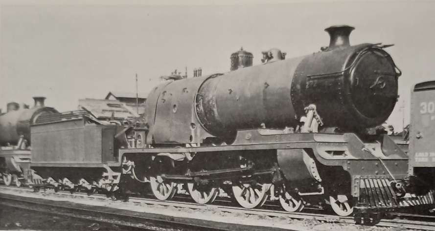
Engines of the TR 2-6-0 BB Class being dismantled at Dar-es-Salaam in 1958. [1: p68]

TR MR Class 2-8-2 Locomotives

These locomotives were American-built. Many of these engines were built by various American manufacturers, including: Alco; Baldwin; and Davenport. These locomotives were known as ‘MacArthurs’. Those which ended up working on the Tanganyika Railways were manufactured in 1944. [1: p70] and arrived from Malaya in 1949. There were eight locomotives bought in this way which became the MR Class, running numbers 800-807. They were built by three different manufacturers and as a result had minor differences: Alco Nos. 800-802; Baldwin Nos. 803-805; Davenport Nos. 806-807. [1: p70]
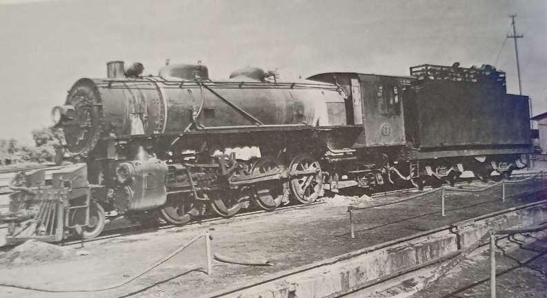
TR 2-8-2 No. 802 of the MacArthur austerity class at Tabora in the early 1950s before its conversion to oil fuel. [1: p68]

Ramaer tells us that, “At first there were problems, and modifications were needed to water tanks and reversing gear, which was undertaken at Nairobi works because of the limited capacity of the shops at Dar-es-Salaam. An additional difficulty was posed by the fact that the engines had not been designed to burn wood fuel. Grates were rather small and no rocking or dropping equipment was available. This circumstance gave rise to criticism because of the high ash residue of the wood fuel and only after the locomotives were converted to burn oil was the problem satisfactorily solved. After conversion the MacArthurs by then classified EAR 2701-8, did reasonably well.” [1; p69] The class was expanded in 1950 under EAR control when eight more were purchased from Malaya and one in parts from Nigeria. The last of these locomotives in service was based at Tabora and had been kept running by cannibalising other members of the class.

TR Sentinel Railcars
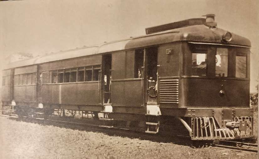
[9: facing p198]

In 1929, two Sentinel rail cars were put into service between Moshi and Arusha in the North of Tanganyika. Although they were appreciated by the travelling public, they failed to attract sufficient traffic to make them an economic proposition on this section of the line.” [9: p199]

These railcars were manufactured by the Sentinel Waggon Works in Shrewsbury, in partnership with Cammell Laird. They were innovative geared steam-powered cars which were intended to increase service frequency and passenger convenience.

References

  1. R. Ramaer; Steam Locomotives of the East African Railways; David & Charles, Newton Abbot, 1974.
  2. https://en.wikipedia.org/wiki/TR_RV_class, accessed on 17th July 2026
  3. https://en.wikipedia.org/wiki/TR_RV_class#/media/File:TR_RV_252_works_photo.jpg, accessed on 17th July 2026.
  4. https://en.wikipedia.org/wiki/TR_NZ_class, accessed on 17th July 2026.
  5. https://rogerfarnworth.com/2026/03/04/narrow-gauge-industrial-lines-in-tanganyika-tanzania/
  6. https://www.flickr.com/photos/124446949@N06/35821749336, accessed on 17th July 2026.
  7. https://en.wikipedia.org/wiki/TR_ML_class, accessed on 18th July 2026.
  8. https://en.wikipedia.org/wiki/TR_DL_class#, accessed on 18th July 2026.
  9. M. F. Hill; Permanent Way Volume II: The Story of the Tanganyika Railways; East African Railways and Habours, Nairobi, Kenya; Watson & Viney, Aylesbury & Slough, 1957.
  10. https://en.wikipedia.org/wiki/TR_MK_class, accessed on 19th July 2026.
  11. https://en.wikipedia.org/wiki/TR_GA_class, accessed on 19th July 2026.
  12. A. E. Durrant; Garratt Locomotives of the World (rev. and enl. ed.). David & Charles, Newton Abbot, 1981.
  13. https://en.wikipedia.org/wiki/KUR_EC5_class, accessed on 19th July 2026.
  14. https://grokipedia.com/page/tr_gsl_class, accessed on 20th July 2026.
  15. https://commons.wikimedia.org/wiki/File:Carl_Vincenti_Bahnhof_von_Tanga.jpg, accessed on 20th July 2026.
  16. https://www.facebook.com/share/p/1ALffLxhDg, accessed on 18th March 2026.
  17. https://www.facebook.com/GermanColonialEmpire/posts/next-in-our-series-on-the-railways-and-steam-locomotives-of-german-east-africage/1345234614304324, accessed on 20th July 2026.
  18. https://gweaa.com/wp-content/uploads/2012/02/The-Indian-Railway-Corps-East-African-Expeditionary-Force_1.pdf, accessed on 20th March 2026.
  19. https://www.drehscheibe-online.de/foren/read.php?108,9540359, accessed on 20th July 2026.
  20. https://eisenbahn.de/lok-magazin/schienen-im-schutzgebiet-wie-das-deutsche-kaiserreich-seine-kolonien-mit-eisenbahnen-erschloss_27156, accessed on 20th July 2026.
  21. I cannot identify the source of this image, given the age of the locomotive and the likely date of the image it will be in the Public Domain.
  22. https://www.facebook.com/GermanColonialEmpire/photos/njussi-station-of-the-usambara-railway-in-the-german-colony-of-east-africa-from-/1339164168244702, accessed on 20th July 2026.
  23. https://en.wikipedia.org/wiki/List_of_Orenstein_%26_Koppel_steam_locomotives, accessed on 20th July 2026.
  24. https://de.m.wikipedia.org/wiki/Liste_schmalspuriger_Lokomotiven_von_Henschel, accessed on 24th March 2024.
  25. A.E. Durrant; The Mallet Locomotive; David & Charles, Newton Abbot, Devon, 1974.
  26. The Gölsdorf axle system is used to achieve quiet running and low wear-and-tear when negotiating curves. The axle system comprises a combination of fixed axles and axles that can slide transversely, all within a single, rigid locomotive frame. The system was invented by a young Austrian locomotive builder, Karl Gölsdorf, around the end of the 19th century. The first locomotive to use this principle entered service in 1897. [27]
  27. https://en.wikipedia.org/wiki/G%C3%B6lsdorf_axle, accessed on 21st July 2026.
  28. https://www.ebay.co.uk/itm/402962028832, accessed on 21st July 2026.
  29. The Bissell truck (or Bissel truck) is a swiveling bogie or pony truck assembly fitted on steam locomotives. Patented by American engineer Levi Bissell in 1857, its genius lies in placing the pivot pin behind the truck and just ahead of the front driving wheels, shortening the rigid wheelbase and allowing the wheels to smoothly navigate uneven curves. [30]
  30. https://www.gutenberg.org/files/25454/25454-h/25454-h.htm, accessed on 22nd July 2026.
  31. https://picryl.com/media/tr-st-12-works-photo-c12c48?zoom=true, accessed on 22nd July 2026.
600 mm Narrow Gauge Lines used during World War 1 in East Africa – Predominantly in what is now Tanzania

600 mm gauge trolley lines (often known as Feldbahnen or “field railways”) played a crucial role in the East African Campaign of the First World War, particularly in German East Africa (GEA) where they were used for both industrial and military logistics. These narrow-gauge systems were used to connect coastal areas, plantations, and interior supply depots to the main standard-gauge (1,000 mm) railways, or directly to the frontline.

Numerous privately owned 600 mm gauge Sisal Plantation Railways operated throughout the coastal and Tanga regions of German East Africa. These lines linked the plantations to factories and ultimately to the port at Tanga. During the first world war these were adapted for military use and transported troops, supplies and weapons.

In 1917, the Lukuledi Valley Line, a 600 mm trolley line in the Lukuledi Valley was extensively used to supply the German forces in the south of GEA and to evacuate their casualties to Lindi.

These light railways allowed the German Schutztruppe, led by Lieutenant Colonel von Lettow, to move heavy loads (such as artillery pieces from the sunken cruiser Königsberg) across difficult terrain without relying on limited road infrastructure. The lines often used prefabricated track segments. Trolleys were frequently moved by hand-pushing by local porters or workers, though sometimes small locomotives or tractors were used.

As British forces moved South into German East Africa from early 1916 onwards they were able to make extensive use of these 600mm lines, and built their own 600 mm light railways particularly in the later stages of the campaign as they pushed deeper inland where transport infrastructure was non-existent. The British made use of some small locomotives which had been in use on Sisal plantations before the war but also tractors designed for use on these lines.

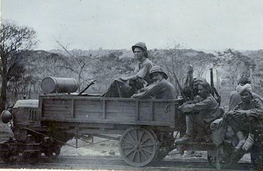
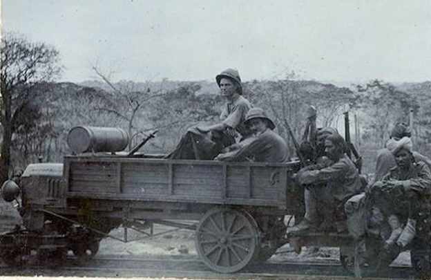
A typical tractor in use on one of the 600 mm railways/trolley line. This one was in use on the line serving Handeni. [1: p9]

A number of these 600 mm lines are referred to by Harry Fecitt in an article entitled “The Indian Railway Corps East African Expeditionary Force, 1914-1919” the majority of which is is reproduced in Appendix A below.

Fecitt describes the work of the Indian Railway Corps as part of the advance Southwards into German East Africa by British forces. He notes that from Mombo station as far as Handeni the Germans had built a hand-powered field railway (trolley line) of 600 mm gauge to “Handeni, 65 kilometres to the south. The 25th Railway Company assisted the Royal Engineers in restoring this line as it had been partially destroyed, and on completion this trolley line was very useful for moving supplies in support of General Smuts’ advance to Morogoro.” [1: p8]

He notes also that a similar 600 mm gauge line had been constructed by the Germans from “Korogwe … towards Handeni. The materials for this line came from abandoned German farms and plantations and the locomotion came from adapted Ford cars used as tractors and operated by the East Africa Motor Transport Corps.” [1: p9]

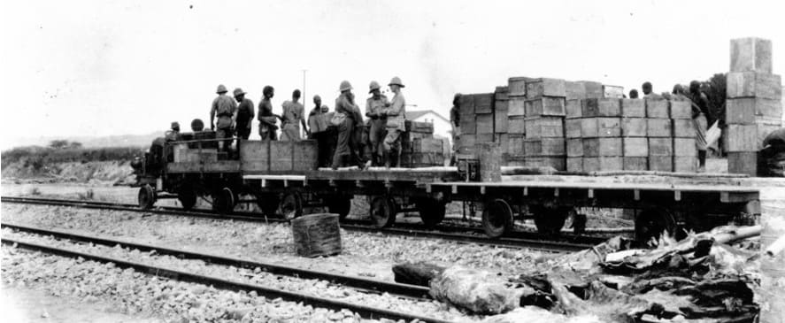
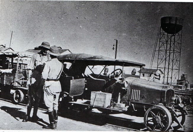
A typical ‘train’ on a trolley line in what was once German East Africa but which by this time was terrritory occupied by the British. [21: p13]

In British hands, these lines were very short-lived. Fecitt talks of the construction by the British of another 600 mm line as they moved South through German East Africa. The British “developed Kilwa Kisinjane as a port where men and supplies could be landed. Commencing in November 1916 a 600 mm tramway was built by the Corps from the ocean to Kilwa Kivinje, a distance of 26 kilometres, and then onwards for a further 24 kilometres. The construction material was produced by stripping the trolley lines previously built from Mombo and Korogwe. Motor tractors were again used and a driver company and a supporting maintenance company were formed from mechanical transport personnel; these companies became sub-units in the Railway Corps.” [1: p13]

Apparently, “the driving of tractors on railway lines, especially around curves, was not as easy as many potential drivers thought and de-railings with consequent damage were frequent. Sixty more tractors were ordered from India and 50 more from South Africa; these were all converted Ford cars with bogie trucks in place of the front axle and with heavier back axles and box bodies. The first 16 kilometres of track was duplicated but in broader gauge and steam trains ran along it, allowing swifter movement of men from the port to the first camp site where water was available. In July 1917 further construction was authorised at Kilwa and the 600 mm line was extended to Lungo, Mile 84, by November. On this line, which had a slight gradient, each box-body tractor pulled two trailers with a total load of up to 2.72 metric tonnes (3 tons).” [1: p13-14]

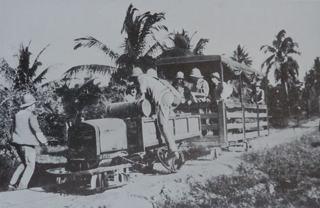
A typical Ford tractor in use on one of the trolley lines. [1: p15]

Further to the South, and inland from the port at Lindi which was 110 km South of Kilwa, there was an existing trolley line running from a jetty on the Lukuledi River which ran into Lindi Harbour, to former German plantations. The line had also been used by the German military. It was estimated that 30 kilometres of track could be recovered from the German line. A British line was then constructed heading inland from Lindi, using recovered materials where possible, by the 25th Railway Company. “On 27th August the line was open to Mtua and proved to be very useful in quickly evacuating wounded men as well as in carrying forward supplies. In this month, the 27th Railway Company arrived at Lindi, and support was provided by the South African Pioneers and the 61st (King George’s Own) Pioneers. Unskilled labour was badly needed and this problem had to be solved by moving down large labour gangs from the Usumbara and Central Railways. A few small steam engines were found on various plantations and put to use on the line. When the tractors from India arrived it was found that their axles had been made from inferior steel and they broke at the rate of two or three a day. This problem was compounded by severe rates of sickness that affected most of the Corps. At the beginning of November only 9 tractors out of 36 were working and only two mechanics were manning the workshops.” [1: p15]

Later in the month the Kilwa line was closed down and personnel were redeployed to Lindi where the Corps base was relocated, however the movement of badly needed materials and plant was delayed by shipping shortages. Railhead reached Ndanda, Mile 62, on 27th February 1918 and the decision was made to stop the line there.” [1: p15]

In November 1917, the Lindi line was still in use, with Army Service Corps men driving supplies from railhead into Portugese East Africa (PEA).

Much further North in Nairobi, a 13 km line was constructed from the town to the vast King’s African Rifles (KAR) Depot Camp at Mbagathi; the running of this line was handed over to the KAR.

In September 1918, “as the Germans in PEA were observed to be moving northwards, the Lindi line was ordered to be extended 30 kilometres to Massasi. The 28th Railway Company which was stood-by to sail for India quickly returned to Ndanda and started the work. Concurrently permission was obtained to raise an African Pioneer Company to replace the 28th Company. Suitable men were recruited from maintenance gangs on the Central Railway and from labour that had worked on the Mbagathi trolley line. The Lindi line reached Massasi in mid-November just as General von Lettow … still undefeated and then in Northern Rhodesia, now Zambia, accepted the Armistice terms decided in Europe and agreed to surrender. The 28th Railway Company sailed for India.” [1: p16]

References

  1. Harry Fecitt; The Indian Railway Corps East African Expeditionary Force, 1914-1919; via https://gweaa.com/wp-content/uploads/2012/02/The-Indian-Railway-Corps-East-African-Expeditionary-Force_1.pdf, 16th March 2026.

Appendix A – The Indian Railway Corps East African Expeditionary Force, 1914-1919

Introduction

In early August 1914 India was tasked with providing Indian Expeditionary Forces (IEFs) ‘B’ and ‘C’ for service in East Africa, and the provision of a Railway Corps was included in the organisation of IEF ‘B’ that was destined for German East Africa (GEA). The 25th and 26th Railway Companies, Sappers & Miners, under Majors C.F. Anderson and C.W. Wilkinson, both Royal Engineers, along with the Traffic and Locomotive Reserve of the two companies were mobilised at Sialkot and Quetta. Each company was around 300 men strong; an accompanying Coolie Corps of 300 men was raised mostly from the relatives of the company personnel. The officers were nearly all civilian railway officers of the Indian State Railways or Royal Engineer officers employed under the Indian Railway Board. The skills included survey, construction and operation. Major Anderson was medically repatriated soon after arrival and Lieutenant H.L. Woodhouse, Royal Engineers, then commanded the 25th Railway Company. Sir William Johns CIE was appointed Director of Railways.

The Indian Railway Board provided equipment sufficient for the repair and running of a section of the German East Africa railway. This equipment included 10 miles (16 kilometres) of 50-pound track, a large surplus of sleepers, 15 locomotives, nearly 200 trucks, a large number of pine baulks, a number of 20-foot and 40-foot bridge spans, cranes, pile drivers, machine tools, hand tools of all sorts, survey instruments, tents and office necessities. The companies brought out their own telegraph equipment but this was later handed over to the Indian Telegraph unit that carried out all the telegraph work of the railways and tramways.

Initial Employment in British East Africa

The Railway Corps arrived in two ships at Tanga in GEA where IEF ‘B’ was scheduled to land. Tanga was the Indian Ocean terminal of the German Usambara Railway that ran to Moshi near Mount Kilimanjaro; the British later named this line The Northern Railway. IEF ‘B’ failed to defeat the German force at Tanga and re-embarked; the Railway Corps stayed on its ships throughout the Tanga fight. IEF ‘B’ then steamed up to Kilindini, the port at Mombasa in British East Africa (BEA). Mombasa was the ocean terminal for the British Uganda Railway that ran up to Lake Victoria. IEF ‘B’ disembarked at Kilindini on 9th November 1914 and merged with IEF ‘C’ that had arrived in BEA in September.

A Railway Corps survey party commenced delineating a route for a military railway from Voi on the Uganda Railway westwards towards Moshi in GEA. The Railway Companies took over the defence of the Uganda Railway, sections of which were under threat from enemy raiding parties from GEA. Once all the stores had been landed it was decided to return most of the locomotive and traffic staff and the civilian officers to India, from where they could be easily recalled. In late December the two companies were moved from railway defence to construction work on the Kajiado to Longido road; better use was now made of their technical expertise and qualifications in the construction of roads, fortified posts and water supplies. The 25th Company went to Namanga and Longido and the 26th Company was based at Bissel.

Railway Construction

In February 1915 the decision was made to construct the first 40 miles (65 kilometres) of the one metre-guage military line from Voi towards Moshi in order to connect the military posts at Bura and Maktau. Twenty five miles of track were sent from India, 5 Miles were borrowed from the Uganda Railway, and the Corps already possessed 10 miles. The Railway Board in India continued its excellent support to the Corps by delivering to site the 25 miles of track only seven weeks after receiving the indent in India. The specialists were recalled from India and the companies were moved to Voi; material was moved up from Kilindini.

The construction method used was that one company laid track whilst the other worked ahead building the next bridge. Local labour for bush-cutting and earthworks was recruited from the Wataita tribe with the help of the District Commissioner and a missionary of the Church Missionary Society. The Wataita proved to be intelligent men who were quick learners. The 61st (King George’s Own) Pioneers had also landed with IEF ‘B’ and it had recently been employed in prolonging the Coonoor Railway to Ootacamund; when not tasked elsewhere the Pioneers provided useful support to the Corps. As the railhead advanced the Coolie Corps took over the maintenance of the track.

The Voi River was crossed and the first station opened at Mile 6.5 on 16th April. Heavy monsoon rains set in during May delaying the movement forward of supplies as the line needed constant repair and maintenance. On 31st May the bridge and station at Bura were opened at Mile 22. From now on the railway had to carry troops, supplies and water between Voi and Bura as well as construction material. The first section of the line was completed to Maktau on 23rd June. Whilst the railhead was advancing a big effort had been put into making Voi a suitable terminus for the military line. A workshop had been constructed, engines and rolling stock were brought up from Kilindini, a large store yard was established and an armoured train was built.

An unescorted Wataita earthwork gang was fired on by a German patrol and four men were wounded on 9th June; the Wataita were undeterred and asked if they could bring their bows and arrows to the worksite in future. The military line was blown up for the first time five days later, and after that the Germans blew the line every week, usually at around 2000 hours. This suited the repair gangs as they could make overnight repairs before the first morning train was run. The German demolitions were never very effective. On one occasion a train carrying the 130th (King George’s Own) Baluchis (Jacob’s Rifles) was pushing a truck loaded with sepoys’ kits ahead of it when an enemy mine detonated under the truck. A gap 0.75 metres in length was blown out of one of the rails but the complete train successfully passed over the gap and proceeded, with passenger and cargo damage being confined to some of the sepoys’ kits. The Germans had more success when attacking the Uganda Railway as that line often ran through desolate country and could be approached more easily.

A British attack at Mbuyuni, west of Maktau, failed on 14th July and that failure halted extension of the line. During this halt the companies constructed field works and defences and put in crossing stations and sidings on the Uganda Railway. A regular train service was introduced between Voi and Maktau and a Train Control System was installed. A second indent for 30 miles of track was sent to India and it arrived two months later. On November 13th 1915 the Director of Railways was placed in control of the Uganda Railway. This was done in order to ensure intimate cooperation between the Uganda Railway and the military line during the planned British offensive in early 1916. Officers and men of the Railway Corps were posted to the Uganda Railway whose operations were effectively militarised.

Platelaying began again in January 1916 and Mbuyuni, Mile 53.25, was reached on the 25th of that month, the Germans having withdrawn from the location two days earlier without fighting. Thousands of South African, British, Rhodesian, Indian and African troops were now being housed in camps along the military line and the supply of water in railway travelling tanks to these camps was a vital task for the Corps. Some relief was obtained when the engineers ran a pipeline from Bura, where the water was sourced, to Maktau. The British attacked Salaita Hill, west of Mbuyuni, on 12th February but the attack failed, the enemy counter-attacking to the railhead at Lanjoro, Mile 60.

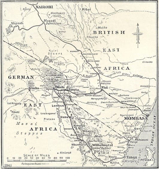
This map illustrates the area of early operations in German East Africa. [21: p5]

Moving into German East Africa

The Germans withdrew from Salaita Hill and moved to defend the Latema-Reata hills just west of Taveta on the GEA and BEA border. The Corps pushed the military line westwards through dense bush, following up the advancing British troops. From drafts arriving from India and from within the existing Railway Companies the 27th Railway Company, Sappers & Miners, was formed; the Company Commander was Captain R.E. Gordon, Royal Engineers. This allowed the Corps to continue platelaying in dangerous territory whilst providing its own security. The Lumi River was crossed and Taveta reached, Mile 75, on 23rd March. After a tough fight the Germans had withdrawn from the Latema-Reata position on 12th March, allowing the Corps to lay track over a saddle between the two hills.

The enemy was demolishing the Usambara Railway line as he withdrew down it and once Moshi was in British hands a half-company of the Corps repaired the track from Moshi to the Ruvu River. Meanwhile the railhead was advanced over what was the toughest stretch on the entire military line. The monsoon rains again fell heavily but three rivers were crossed and a dense forest penetrated; the soil was black-cotton and quickly became marsh resulting in platelaying being achieved under water. A junction with the Usambara line was made 20 kilometres below Moshi and 40 kilometres from Taveta on 25th April. This was just in time for the British troops in Moshi who had lost their road from Taveta to the monsoon rains and floods, and who now relied upon supplies arriving by train.

The South African General J.L. Van Deventer was tasked by the British theatre commander, General J.C. Smuts, to advance south-westwards through Arusha and Kondoa Irangi to the German Central Railway line that ran from Dar Es Salaam on the Indian Ocean coast to Lake Tanganyika in the interior. To assist the supply columns supporting the South Africans in getting across a large number of bad drifts on the initial stage of the road the Railway Corps was tasked with pushing a line westwards from Moshi over the Garanga River to Sanja, Mile 21 on this new short line. Sanja was reached by the end of June. At this time the 28th Railway Company, Sappers & Miners, arrived from India commanded by Captain. E. St.G. Kirke, Royal Engineers, raising the establishment of the Railway Companies to that of a battalion. Lieutenant Colonel C.W. Wilkinson, Royal Engineers, was appointed Commandant of the Railway Battalion which became a unit in the Railway Corps.

Reconstructing the Usambara Railway

On 14th May reconstruction of the Usambara Railway south of Ruvu commenced; the Germans had demolished the Ruvu bridge but the Corps 7 erected an 18-metre girder bridge on 20th May. From then onwards on the 320 kilometres of track leading to Tanga every bridge had been destroyed. However the demolitions had been hasty and planned ineffectively and the Corps could quickly make track diversions or re-build bridges. In many places the track had been torn up and the fastenings thrown into the bush, in other places the fastenings only had been removed, and elsewhere each alternate rail joint had been blown up. The track was repaired through Lembeni, Same, Makania, Hedaru and ‘German Bridge’ stations, the latter being reached on 20th June. ‘German Bridge’ was the last suitable crossing point over the Pangani River until Maurui is reached 80 kilometres further on. The Germans had started building a bridge here and the British completed the construction.

Just beyond ‘German Bridge’ is Buiko, 180 kilometres from Tanga and the mid-point in the line. Mombo station, Mile 75, was opened on 29th June; from here the Germans had built a hand-powered field railway (trolley line) of 60 centimetres gauge to Handeni, 65 kilometres to the south. 25th Railway Company assisted the Royal Engineers in restoring this line as it also had been partially destroyed, and on completion this trolley line was very useful for moving supplies in support of General Smuts’ advance to Morogoro.

Fighting in the Infantry Role

On 4th July, railhead reached the Pangani River near Maurui and by the end of the month had reached Korogwe. However the German theatre commander, Colonel Paul von Lettow, had early in July tasked 500 or more of his troops as a ‘stay behind’ group to harass the British lines of communication in the area between Tanga, Maurui and Handeni. This enemy group successfully made a nuisance of itself by attacking convoys, mining roads, cutting telegraph and telephone lines and sniping from the bush. An attack by 170 German troops with a light gun had been repulsed at Zugunatto Bridge by the Jind Infantry on 13th July; the soldiers from the Princely State of Jind were amongst the best of the British troops. General Smuts ordered his Inspector General of Communications Brigadier General W.F.S. Edwards, a former BEA policeman, to resolve this problem. As Edwards had no spare infantry he decided to use the 25th and 26th Railway Companies, Indian Sappers and Miners, along with a few infantrymen, and reported this to General Smuts who made no comment. But Edwards did not confer with the Director of Railways who badly needed those two companies to stay on the job of railway restoration in order to alleviate supply problems. After dark on 13th July the two companies with 100 Jind Infantry, 50 British other ranks and 100 sepoys, moved out from Korogwe tasked with attacking Segera Hill and Mfumbile. Captain E. St.G. Kirke, Royal Engineers, commanded the companies and Lieutenant Colonel Wilkinson commanded the force.

The Railway Companies did well on Segera Hill, getting up to a machine gun, killing the German NCO in charge and capturing the gun in a bayonet assault. The German force withdrew hurriedly but counterattacked next day. The companies were up to their new task and broke the enemy assault. Lt Col Wilkinson now moved across country to deal with an enemy force at Hale, found that it had withdrawn to Kwa Mugwe, moved there and drove the enemy rear-guard away and then repelled another German counter-attack on 19th July. In these operations the machine guns of the accompanying Jind Infantry gave the Railway Companies the supporting firepower that they needed. The companies then returned to their railway duties, having taken a few casualties but doubtless with many war stories to tell. On 18th August Tanga was reached and the port and railway came into use for moving supplies from Kilindini to Korogwe where another 60-centimetre trolley line was constructed towards Handeni. The materials for this line came from abandoned German farms and plantations and the locomotion came from adapted Ford cars used as tractors and operated by the East Africa Motor Transport Corps.

The 600 mm trolley line serving Handeni. [21: p9]
Railway workshops in Nairobi converted many vehicles, including this Vauxhall, to carry supplies on the hastily rep lines in German East Africa. In three months over 300 miles of railway were repaired, enabling locomotives to take once more. [21: p10]

Incidents on the Central Railway

The Royal Navy along with infantry units advancing from Bagamoyo seized Dar Es Salaam, the GEA capital, on 4th September. A reconnaissance of the Central Railway between Morogoro and Dar Es Salaam showed that all bridges were down. Two Railway Companies were shipped to Dar Es Salaam to start repairing the track from that end and the other two were shipped to Bagamoyo; from Bagamoyo they moved overland to the dropped bridges over the Ruwu River which urgently needed reconstruction. The line was repaired for light use to Morogoro and mechanical transport units converted a selection of lorries to rail tractors, allowing the South African Pioneers to run a supply service westwards to Dodoma, 240 kilometres from Morogoro. Each tractor could pull 15 tons of trucks and freight. Further work was needed before the heavier steam trains could use the line but Dodoma was being supplied from Dar Es Salaam by steam trains on 1st January 1917. The South African Water Supply Corps gave constant support to the Railway Corps whenever a water supply point or a pumping station needed to be established, and large numbers of labourers from the South African Native Labour Corps were supplied to support the Corps; unfortunately many of these Africans succumbed to tropical diseases.

The Germans had destroyed many engines and trucks on the line but again their demolition work was unsatisfactory and did not greatly hinder the Corps. Troops from the Belgian Congo, now the Democratic Republic of the Congo, had crossed Lake Tanganyika and fought their way to Tabora, where 40 engines and 200 trucks were found basically undamaged. These were shared with the Belgians. The Railway Corps moved its base from BEA to Dar Es Salaam but immediately had to support the engineers restoring the docks there; Corps cranes were used to unload ships and the companies constructed jetties and slipways. In January 1917 Major L.N. Malan, Royal Engineers, took over command of the Railway Battalion from Colonel Wilkinson who became Deputy Director of the Railway Corps.

In April 1917 a branch line was constructed from Dodoma on the Central Railway southwards towards the Ruaha River. 26th, 27th and 28th Railway Companies were involved in the work which lasted until August, when railhead reached Matikira, Mile 28. The country was very difficult to cross and the lack of shipping to bring down sleepers from Kilindini caused delay. As soon as this short line was no longer needed the rails were recovered and used elsewhere.

A bad accident occurred on the Central Railway on 5th May when a re-built bridge at Mkata collapsed at night in heavy rain, due to an original German pier proving to have insufficient foundations. Sixteen gunners from 24th (Hazara) Mountain Battery (Frontier Force) and four Askari from the King’s African Rifles were drowned when their cattle trucks fell into the swollen river. Many other men were badly injured when they were flung against weapons and stores in the trucks. 26th Railway Company was deployed to restore the damaged line.

On 29th August 1917 the station at Kahe, where the military line from Voi joined the Usambara Railway from Moshi, was unexpectedly attacked by enemy troops, causing consternation amongst rear-echelon elements in Nairobi. An enemy raiding party had broken away from the German forces in southern GEA and had advanced northwards across the Central Railway, attacking British and Belgian locations; former German Askari enthusiastically joined the raiders. Elements of the party got up to Lake Victoria and one small group attacked Kahe. Two trains were captured as they approached the station, then looted and burned. Three British officers were taken prisoner, the Station Master was mortally wounded and a number of porters and labourers were killed. Before withdrawing the Germans started one of the two trains and let it run towards Taveta, but an Indian engine driver who had escaped into the bush jumped into one of the two engines on the train and brought it under control. When the train was at a safe distance from Kahe the driver disconnected the carriages and drove the engines to Taveta, where he was given a prompt military award.

A Trolley Line in the Kilwa Area

Moving south the British now developed Kilwa Kisinjane as a port where men and supplies could be landed. Commencing in November 1916 a 60centimetre tramway was built by the Corps from the ocean to Kilwa Kivinje, a distance of 26 kilometres, and then onwards for a further 24 kilometres. The construction material was produced by stripping the trolley lines previously built from Mombo and Korogwe. Motor tractors were again used and a driver company and a supporting maintenance company were formed from mechanical transport personnel; these companies became sub-units in the Railway Corps.

However tropical diseases and ailments such as malignant malaria were now affecting the Corps badly and often far more men of all trades were sick than were at work. Also the driving of tractors on railway lines, especially around curves, was not as easy as many potential drivers thought and de-railings with consequent damage were frequent. Sixty more tractors were ordered from India and 50 more from South Africa; these were all converted Ford cars with bogie trucks in place of the front axle and with heavier back axles and box bodies. The first 16 kilometres of track was duplicated but in broader guage and steam trains ran along it, allowing swifter movement of men from the port to the first camp site where water was available. In July 1917 further construction was authorised at Kilwa and the 60-centimetre line was extended to Lungo, Mile 84, by November. On this line, which had a slight gradient, each box-body tractor pulled two trailers with a total load of up to 2.72 metric tonnes (3 tons).

A typical ‘train’ on a trolley line in what was once German East Africa but which by this time was terrritory occupied by the British. [21: p13]
A typical Ford light railway tractor in use in the occupied German East Africa. [21: p15]

Construction activities at Lindi

A hundred and ten kilometres south of Kilwa more port facilities were developed at Lindi, which had a fine natural harbour. A British force was moving into the interior and needed a railway to follow it. Steam trains were ruled out because shipping was not available to move the necessary materials and rolling stock from Dar Es Salaam and Kilindini, so another 60-centimetre tractor line was started. This was helped by the fact that an existing trolley line led from several former German plantations to a jetty on the river running into Lindi Harbour; it was estimated that 30 kilometres of track could be recovered from the German line.

The 25th Railway Company deployed to Lindi in June and commenced work, following the British advance. Survey work on both the Lindi and Kilwa lines was sometimes interrupted the appearance of both lions, rhinoceros and elephants, and occasionally by the approach of enemy patrols who were engaged and driven off. On 27th August the line was open to Mtua and proved to be very useful in quickly evacuating wounded men as well as in carrying forward supplies. In this month the 27th Railway Company arrived at Lindi, and support was provided by the South African Pioneers and the 61st (King George’s Own) Pioneers. Unskilled labour was badly needed and this problem had to be solved by moving down large labour gangs from the Usumbara and Central Railways. A few small steam engines were found on various plantations and put to use on the line. When the tractors from India arrived it was found that their axles had been made from inferior steel and they broke at the rate of two or three a day. This problem was compounded by severe rates of sickness that affected most of the Corps. At the beginning of November only 9 tractors out of 36 were working and only two mechanics were manning the workshops.

Later in the month the Kilwa line was closed down and personnel were redeployed to Lindi where the Corps base was relocated, however the movement of badly needed materials and plant was delayed by shipping shortages. Railhead reached Ndanda, Mile 62, on 27th February 1918 and the decision was made to stop the line there. By then General, as he now was, von Lettow … and his slimmed-down German army were moving deeper into Portuguese East Africa (PEA), now Mozambique.

The Run-down of the Indian Railway Corps in East Africa

By November 1917 the 25th Railway Company was medically unfit for work with its strength at less than 40 fit men, and it was returned to India in March 1918. The 26th and 27th Railway Companies were in a similar condition and in May they also returned to India. 28th Railway Company remained in the field and all recent arrivals and returnees from leave were posted into that company. The Lindi line continued to be used and Army Service Corps men drove supplies from railhead into PEA; sadly many of these European drivers succumbed to tropical diseases and are buried in East Africa. As the East African Force was slimmed down Directorates were abolished and in March Sir William Johns left the theatre after handing over the Railway Corps to Colonel Wilkinson.

Up in Nairobi a tramway 13 kilometres long was constructed from the town to the vast King’s African Rifles (KAR) Depot Camp at Mbagathi; the running of this line was handed over to the KAR. The line from Voi to Tanga was practically on a peace footing and the Central Railway was being converted to commercial use. The arrival of 100 new tractors from South Africa, the increased use of steam traction, and a big improvement in the health of the personnel meant that soon the Lindi line was running very efficiently.

In September, as the Germans in PEA were observed to be moving northwards, the Lindi line was ordered to be extended 30 kilometres to Massasi. The 28th Railway Company which was stood-by to sail for India quickly returned to Ndanda and started the work. Concurrently permission was obtained to raise an African Pioneer Company to replace the 28th Company. Suitable men were recruited from maintenance gangs on the Central Railway and from labour that had worked on the Mbagathi trolley line. The Lindi line reached Massasi in mid-November just as General von Lettow-Vorbeck, still undefeated and then in Northern Rhodesia, now Zambia, accepted the Armistice terms decided in Europe and agreed to surrender. The 28th Railway Company sailed for India.

The Indian Railway Corps retained responsibility for railways in East Africa until January 1919, when civilian direction and personnel replaced it. The Corps had done an excellent job, tackling the diverse and serious challenges that East Africa presented in a most professional manner. Credit for the performance of the Corps must be attributed to the support provided by the Indian Railways Board and the Corps of Royal Engineers, but above all else to the skill, adaptability and perseverance of the men of the Railway Companies, Sappers & Miners. Shabash!

Tanzania Railways – Part 10 – The Mkumbara to Neu Hornow Cableway/Ropeway, Usambara Hills, German East Africa/Tanganyika.

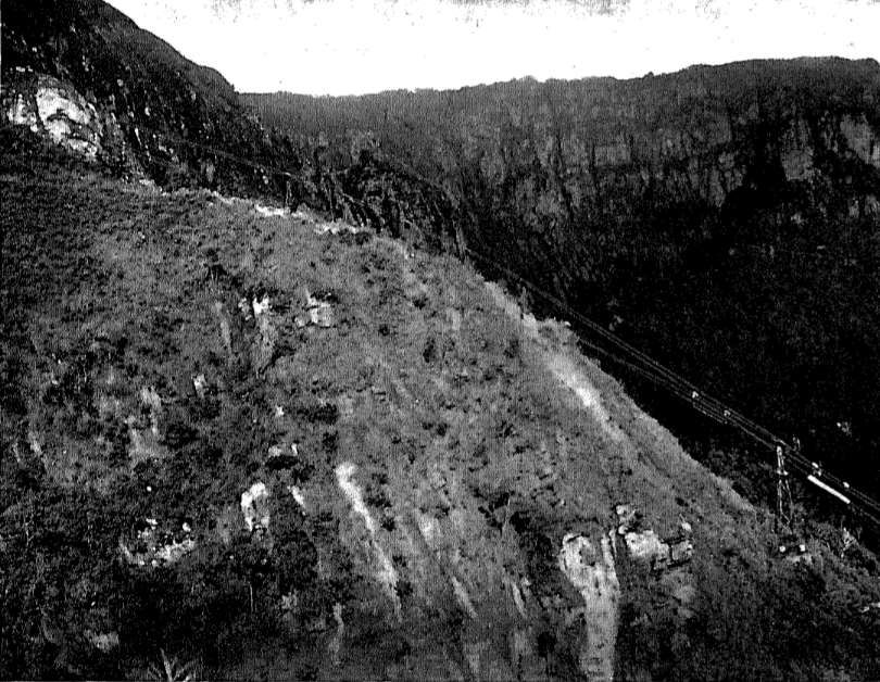
The western Usambara Hills were characterised by precipitous cliffs and deep gorges. The provision of a rail link between Mkumbara and Neu Hornow was not considered practical.

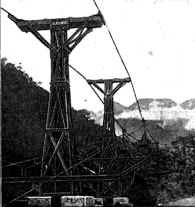
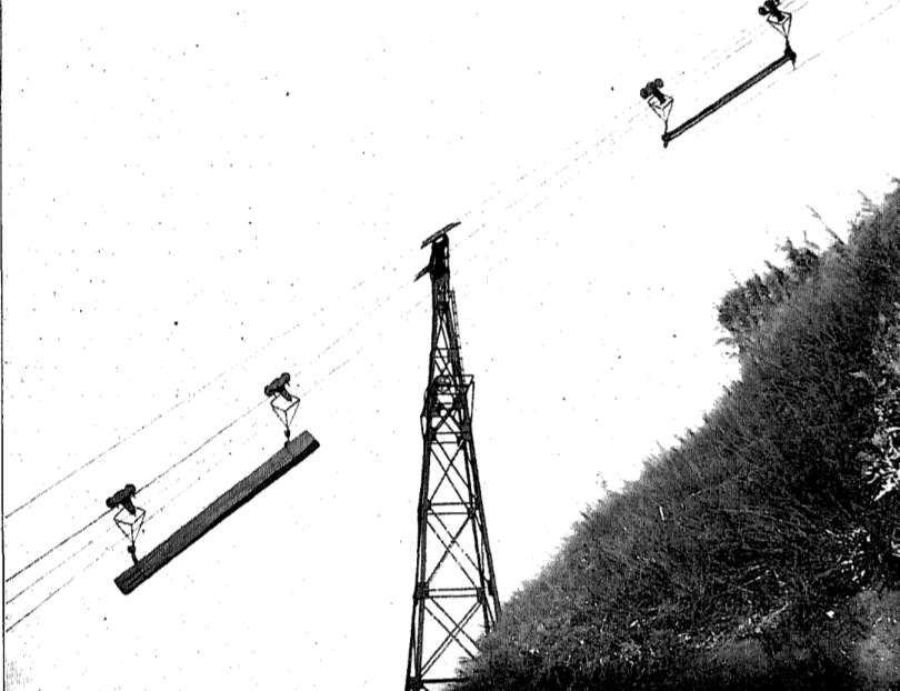
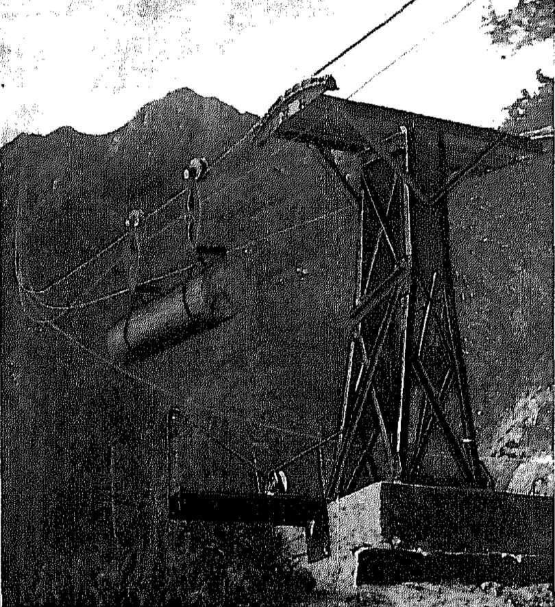
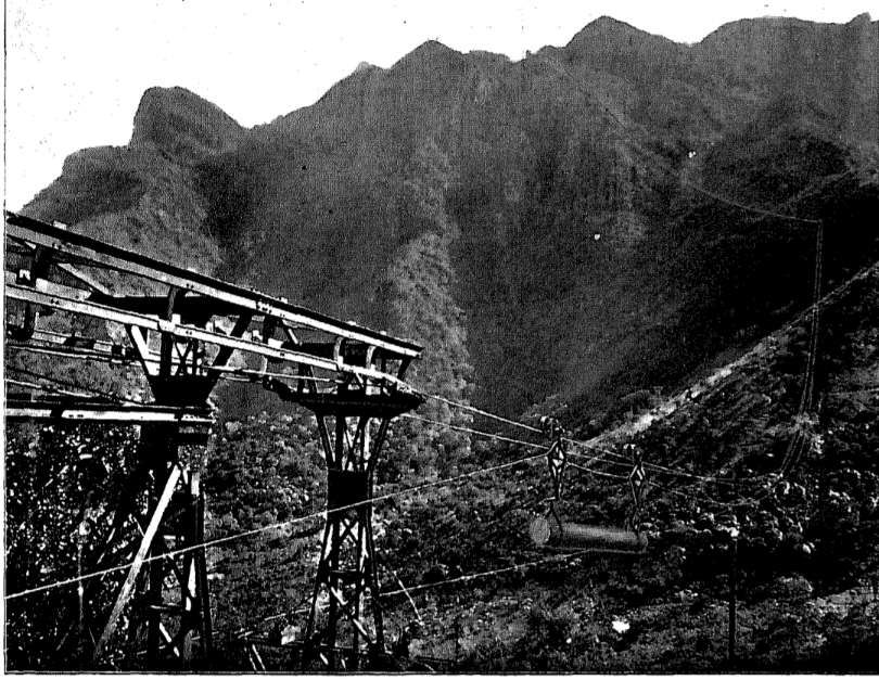
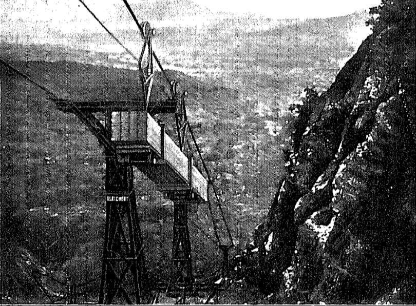
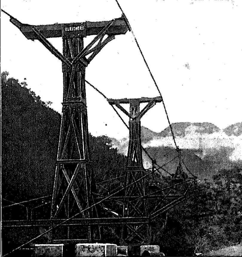
A 9 km long ropeway was constructed, under the ownership of “the firm of Wilkens and Wiese, and designed to carry cedar from the Shume plateau to the railway, an enterprise that was never an economic success. The longest span of the ropeway, 907 metres, was said to be the longest in the world when it was built in the years 1910-1911.” [1: p75] Wood was transported via the Goatal/Ngoha Valley in the Schumewald/Shume Forest. [2]

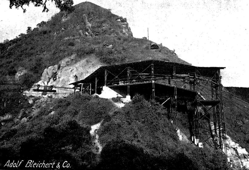
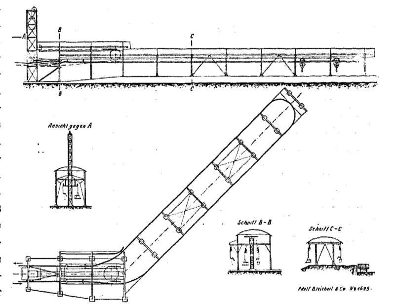
The ropeway was constructed by Adolf Bleichert & Co. a German company primarily active in  cableway construction . It was founded in 1876 by Adolf Bleichert and was headquartered in Leipzig – Gohlis from 1881. [2] More information about Adolf Bleichert & Co. can be found here. [3]

What follows here is a translation of a German language text with the associated images. [4]

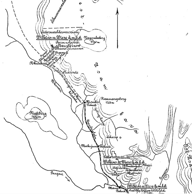
Wilkens & Wiese were aware, when negotiating with the German authorities for a concession to harvest timber saplings in the western Usambara hills and particularly the Schumewald forest, of the difficulty of connecting the steep high plateau with the railway in the plain. A railway or road would have been completely out of the question due to the sharp, steep, and heavily forested slopes of the hills. The only option available to them was a cableway to connect the high plateau with the then-planned station of Mkumbara on the Usambara Railway. In anticipation of the expected difficulties, the cableway was ordered from Adolf Bleichert & Co. in Leipzig-Gohlis andwork commenced in the spring of 1910. The location of the cable car and the timber concession of Wilkins & Wiese are shown below: [4: p17]

Site plan of the enterprises of the plantation company Wilkins and Wiese in Vestusambara. [4: p17]

The undertaking faced enormous difficulties due to the steep mountain slope. Furthermore, the rock was crumbly and easily weathered, so landslides often disrupted the work. A shortage of workers, the construction of new roads to transport building materials, and last but not least, Sandfly and Mosquitoes tormented workers and hindered completion throughout. Only through sheer energy and great sacrifice was it possible to complete the work. [4: p17-18]

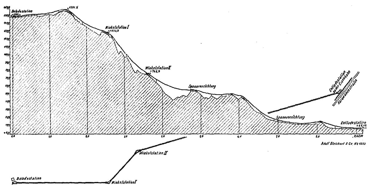
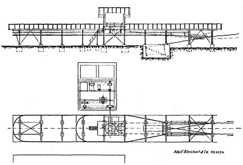
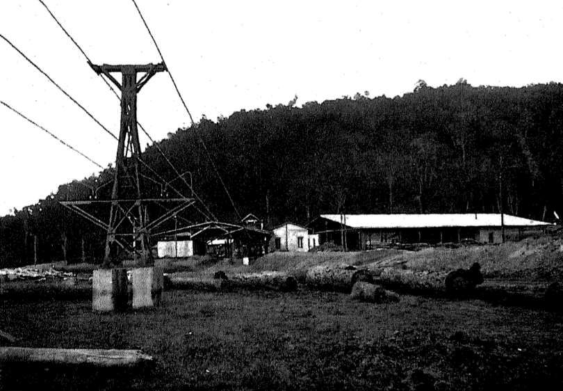
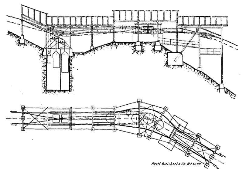
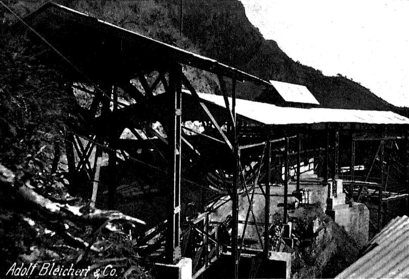
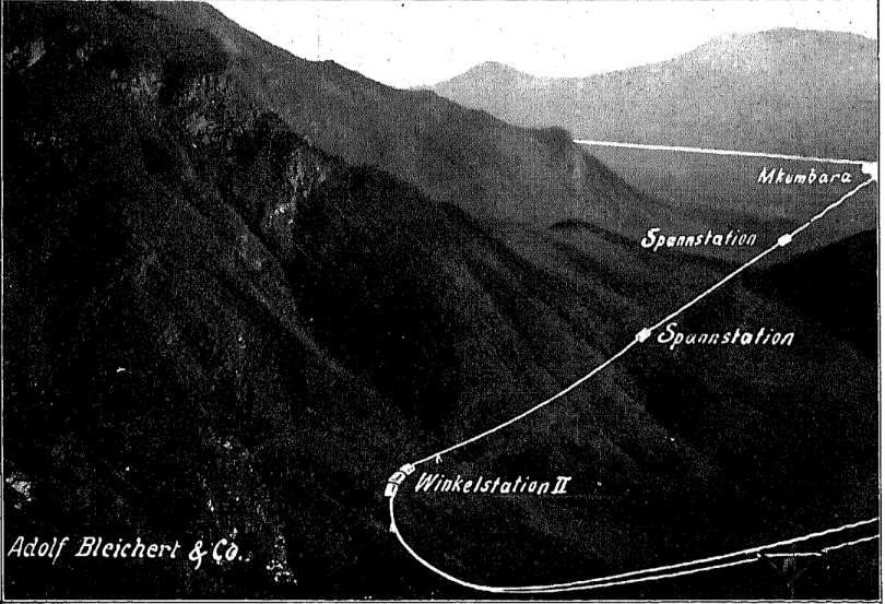
By 1911, the system shown below was fully operational and transported sawn timber, beams, and logs from the sawmill located on the high plateau at 2000 m above sea level to the Mkumbara railway station on a regular schedule. Its horizontal length is 9.0 km, with a height difference of 1435m between the terminal stations. The greatest difference in elevation of the cableway is 1523 m, as shown in the longitudinal profile below. Due to the extremely unfavourable conditions, the line had to be divided into three sections, the uppermost of which first has to overcome a climb of about 90 metres. Therefore, a traction system had to be provided for all eventualities, which would assist if the gradient became too heavily congested with wagons. The cableway’s capacity was designed for ten tons per hour downhill and one tonne per hour uphill. [4: p18]

A longitudinal profile of the Mkumbara tto Neu Horow Cableway. [4: p18]

The line began at the loading station near the Neu-Hornow Sawmill at an altitude of approximately 2000 m above sea level. At about 1.2 km from the sawmill, it crosses the edge of the plateau. It then descends quite steeply to an altitude of 1290 m, where it turned through a 45° angle. From here, the cableway had to be routed to a breakpoint, where it turned once again seeking suitable locations for the support towers. The line then continued with two spans of more than 300 metres each to another breakpoint, the junction station at an altitude of 770 metres. Then the cableway heads for Mkumbara, crossing the uniquely beautiful Ngoha Valley with a free span of 100 metres. Prior to reaching the bottom station at an altitude of 68 metres, the railway has a tensioning and anchoring station at 660 metres and a double tensioning station at 170 metres. The journey of a load takes about one hour.

The Neu-Hornow sawmill has several standard frame saws on which logs can be cut into beams and processed into lumber. The loading station, shown below, is equipped with fixed hanging rails. In addition to the necessary guide rails for operation, it also has a storage area for empty hangers.

The cableway loading station at the sawmill. [4: p19]


The points at which hangers attach and detach from the cable/rope are visible on the right of the drawing. These points allow the incoming cars to detach automatically from the haul rope, while the outgoing cars automatically reconnect to the haul rope. Patented Bleichert apparatus is used as the attaching device. [4: p19]

The end guide pulley was equipped with two hand brakes, each with a disc diameter of approximately 2 metres, capable of braking 50 horsepower, with one serving as a safety brake. The brakes were only applied when the train was stationary. During operation, an automatic brake regulator controlled the train speed. This regulator (a hydraulic brake), along with the cableway’s drive system, was housed in a separate engine room next to the loading station. There was a 1.6 m³ reservoir on the roof of the loading station and two concrete tanks in front of the engine house, in which water supplies for the summer were collected. [4: p19]

The cableway needed both effective braking and a good quality drive system. Sometimes heavy loads had to climb the first length from the loading station without sufficient weight on the longer descent to balance the load. A higher capacity engine was required so that the cableway would also be used to generate electricity to power the sawmill. so a 50 PS electric motor was installed and performed well. [4: p19-20]

The hydraulic regulator consisted mainly of a capsule structure with a relieved throttle valve, which was driven by a belt from the cableway countershaft. The mechanism drew water from a reservoir and pushed it back into the box through slots of the regulating slide. The regulating slide is fully actuated by a centrifugal force governor, which may also be driven by the drive shaft of the track via a belt. As soon as the revolutions per minute of the countershaft begin to increase, the centrifugal force governor moves the regulating slide into action. [4: p20]

A General view of the Neu-Hornow sawmill. On the left in the foreground is the first support pillar of the cableway; in the middle is the loading station with the building for the drive and brake regulator. To the right of that is the sawmill with a grey timber drying shed. [4: p20]

The frame saw is driven by a Lanz Lokomobile/traction engine. (A Lokomobile was a portable, self-propelled, or towable steam-powered (or sometimes internal combustion) engine used historically to provide power to machinery like threshing machines or sawmills. Mounted on wheels or skids, these versatile, mobile power units were commonly used in agriculture and industry, frequently featuring a steam boiler and a single-cylinder engine.) [5]

Given the extremely difficult road conditions on the mountain, the firm Wilkins & Wiese undoubtedly acted uneconomically in choosing a locomobile as the drive system, because it was foreseeable that it would cause enormous difficulties to transport this large and heavy 10 hp machine up the mountain, and that the profit from saving on assembly costs compared to a stationary engine and boiler system to be transported disassembled would be far outweighed by the extraordinarily high transport costs of the fully assembled locomobile. [4: p21]

The locomobile/traction engine had to be transported 60 km from Mombo, the then terminus of the Usambara Railway, via Wilhelmsthal to Neu-Hornow. Two to three Europeans and 100 labourers worked continuously on the transportation of the traction engine for about seven months. The boiler was mounted on a railway wagon frame, which was then moved forward on a track. The track was then removed behind the wagon and reattached at the front. Depending on the difficulty of the route, distances of 100 to 1000 metres were covered daily.

This image shows the lengths that Wilkins & Weise had to go to, in order to get the locomobile/traction engine into position at Neu Hornow. [4: p21]

This required building roads and bridges, widening and reinforcing existing paths, and blasting rocks. Often the machine hovered over the abyss, in danger of plunging down and destroying months of expensive work. Using animals for transport was impossible because the tsetse fly was native to this area. Since the traction engine also had to provide the power for the initial commissioning of the cableway, the transport of the locomobile to Neu Hornow was a major contributor to delays in commissioning the cableway. [4: p21]

A glimpse into the loading station of the cableway at Neu Hornow. The station, except for the roof, was constructed entirely of iron to protect it from termites. The coupling points for Bleichert’s automatic clamping device, the “Automat,” are clearly visible at the front. This device was operated by the weight of the sling and the load. At the coupling points, the weights were supported during entry and exit by laterally arranged auxiliary rails, on which they ran with small rollers. Depending on whether the coupling rails rise or fall, the weight of the vehicles was raised or lowered, thus opening or closing the clamp. The haul rope was guided in such a way that it was gripped by the smooth coupling mechanism with a sling swivel. The process of coupling and uncoupling is therefore relatively simple: incoming cars require no operation at all, outgoing cars were pushed out of the station by hand and coupled themselves automatically to the haul rope. The coupling and uncoupling process was absolutely safe, and lifting the car’s weight by the auxiliary rails posed no risk of derailment, as the coupling rollers were only lifted by a very small amount and were also guided laterally, while the running gear did not lift off the track. [4: p22]

From the loading station, the track gradually ascended to its highest point. The log wagons, illustrated in the image below, which transported logs up to 14 m long and weighing up to 1000 kg, consisted of two carriages connected by the haulage rope. To increase the clamping force of the lead-weighted coupling mechanism on these steep inclines, stops were provided to the right and left of the suspension of the carriage, against which the suspension bracket was applied to inclines. Under the influence of a load, it acts like a lever on the pull piece of the clamp, thereby achieving a correspondingly increased clamping force, which ceases immediately when the incline decreases, so that the positive characteristics of the automatic coupling device reappear. Among these, the great protection afforded to the haul rope is particularly noteworthy, as the clamping force was not greater than absolutely necessary. The slings were designed with a lightweight construction, yet possessed the required stability during idling and when entering stations due to the use of a counterweight. [4: p22-23]

Timber-wagons on the cableway. [4: p23]

Platform wagons were used for transporting sawn timber down the valley and for transporting various goods up the mountain. These wagons were also used for passenger transport. [4: p23]

The highest point of the line was at 2011 m above sea level, 1591.2 m above the survey base, was reached 1.2 km from Neu-Hornow, 1523 m above the unloading station. To obtain the most favorable line alignment, a simple cut had to be made at the crossing over the edge of the plateau (shown in the image below). This presented no difficulties due to the firm clay layer, but in light of the heavy tropical downpours, special safety measures for the support foundations were required. For this purpose, the line was laid at an angle and equipped with a lateral drainage ditch. Sloping ditches were also dug in front of the supports to divert the water.  The slope of the ground followed the profile of the cableway and accordingly had a gradient of 1:2. [4: p24]

The summit of the line seen approaching from the loading station at Neu Hornow. [4: p24]

Ahead down the line was a gorge-like valley which the cableway panned on its way to the first ‘angle-station’, making use of a 30 metre high support stanchion.

The first angle-station (winkelstation) son the side of a promontory of rock above the gorge mentioned in the last paragraph. In order to accommodate the ‘winkelstation’, excavation was necessary at the top of the promontory. This cause difficulties as the ground proved friable and the easily crumbling and weathering rock fractured in two directions. Repeated collapses significantly delayed the completion of the cableway. Stability was finally achieved by building a significant retaining wall and by concreting the rock fissures. [4: p24-25]

This photograph was taken during construction of the first ‘winkelstation’. the cableway flanked the side of the promontory. ‘The ‘winkelstation’ is under construction to the right of this image. [4: p25]

The ‘winkelstation’ sat immediately above/behind the retaining wall and required some excavation of the rock to create a plateau. A sketch diagram appears below:

Winkelststaion No. 1. The cables of the first length line were tensioned by weights: the fully loaded cable, with 1 ton, the slack cable with 13 tons. The tension weights consisted of iron frames filled with concrete cubes. The cables of second length of the cableway were anchored in the winkelstation. The haul rope of the first line passed over the second line and was guided by deflection and guide rollers in the station. The station does not operate automatically. Automatic operation was omitted to keep costs as low as possible. Accordingly, each rope section had a coupling and attachment cleat, these operated in the same manner as at the loading station. A photograph pf this winkelstation appears below. [4: p26]
A photograph of Winkelstation No. 1. [4: p27]

Beyond Winkelstation No. 1, the railway crosses a short rocky ridge, then continues supported in the middle of two spans of approximately 300 metres each, across several hundred metres of steep gullies to the Willkelstation No. 2, located on the side of another rocky ridge and accessible only via difficult paths. Given the exceptionally unfavorable terrain, the central support between winkelstations I and II had to be maintained at a height of approximately 33 metres.

The section between the two Winkelstations is of particular interest because at the time of construction it was the steepest continuously operating cableway in the world. The location is shown in the image immediately below. Here, the gradient was 41° = 1 in 1.15 or 86 %). However, such inclined lifts with shuttle operation are not uncommon. The Bleichert company stated that this gradient was only surpassed by a few cable cars in the canton of Salzburg and the Wetterhorn lift near Grindelwald. The steepest gradient at the Wetterhorn lift, reaching up to 200%, corresponding to approximately 87°!

The steepest section of the cableway, shortly below Willkelstation No. 1 [4: p28]

Even funicular railways lag behind the Neu-Hornow cableway. The maximum gradient on a funicular railway is 70% on the Virgelbahn near Bolzano, which operates with a reciprocal carriage system.  The photograph below shows just how steep this section of the cableway is.

Over the longer spans, the haul rope had to be guided as far away as possible from the track rope to prevent entanglement in the track rope. Based on these considerations, a support design generally emerged that deviated from the normal design due to the large distance between the haul rope guide and the support shoe.

The steepest section of the cableway: 8 metre-long cedar beams are being transported down the gradient. Despite the gradient, the Bleichert coupling mechanism “Automat” holds the haul rope securely. Therefore, no safety or  multi-coupling devices are required. [4: p29]
The abnormal stanchion at the bottom of the steepest section of the cableway. [4: p30]

In Winkelstation No. 2 (shown diagrammatically below), the track cables of the second section are tensioned by counterweights. To gain the necessary space for the counterweights, a pit had to be blasted. The haul rope from Neu-Hornow terminates at this station. However, it is inextricably linked to the haul rope for the final section to Mkumbara, so that the speed of both ropes is the same.

Winkelstation No. 2. [4: p30]

Handbrake operation for the further descent did not seem reliable enough. It was much more practical to also apply the brake regulator installed in Neu-Hornow to the last section of the cableway. Furthermore, for this last section, with its relatively gentle gradient compared to the higher sections, there was a risk that the haul rope would stop if there was a large uphill load and a poorly occupied downhill section. Therefore, at Winkelstation No. 2, the traction cable of the upper two sections is guided around a pulley on the end guide shaft of the lower traction cable run, thus achieving the necessary positive connection. The traction cable of the upper section then passes over an end guide pulley mounted in a tensioning frame and is tensioned by tightening the tensioning lever due to weight distribution. In this station as well, the wagons are manually guided onto the following sections for the reason already mentioned. Winkelstation No. 2 is shown in the photograph immediately below. The coupling points are visible at the entry and exit points. To find space and support points for the installation, costly blasting and foundation work was also necessary here. [4: p28-29]

Winkelstation No. 2 [4: p31]
This photograph shows, dramatically, the length between Winkelstation No. 2 and Winkelstation No. 1 in the far distance. The longest span between support stanchions on the cableway was 900 metres which was the length closest to Winkelstation No. 2. It appears to good effect in this image! [4: p32]

As far as the terrain allowed, naturally existing support points were utilized. For example, just below Willkelstation No. 2, a support could be erected just before the drop into the Ngoha valley; however, beyond this point, no support was possible before the opposite valley edge, which was 210 m lower and 100 m away.

This photograph looks down the line of the cableway to Mkumbara in the valley bottom. In the foreground, the first and second 300-meter spans between suspension stations I and II are visible. On the left side of the image, the Winkel station II with its white roofs can be seen. From here, the large span across the Ngoha Valley begins, behind which the first tensioning and anchoring station for section III is located. The line then descends further to the plain, intersecting the banks of the hills in front of the Usambara massif twice more, between which the second suspension station, Pangalliebeno, is located on the northern slope. [4: p33]

The railway descends from the first suspension station shown in the above photograph at a gradient of 1 in 3. Cuts had to be made in the affected ridges, the first of which, at support No. 59 (shown below), was particularly troublesome. Supports had to be spaced 10 m apart, and an allowance had to be made for very unstable ground where the substrata was highly fissured and where rockfalls were frequent. Due to the continued disruption, more than 6000 cubic metres of rock had to be moved,

Planed timber planks being carried past the site of the landslide shortly before dropping down the cableway onto the plain. This image gives a good idea of the terrain that the cableway travelled over/through. [4: p34]
The supports/stanchions, as the pictures show, are largely identical. This gave the advantage for the cableway that the individual elements could be interchanged as required. [4: p34]

About 100 metres before the lower terminal station there was a double tensioning station where the suspension cables leading to the lower station were tensioned because the lower terminal station did not offer enough space for the weights.  It was necessary to create pits for the tensioning weights. [4:p31]

From the tensioning station the cableway crossed level ground to reach the terminus in Mkumbara. [4: p32]

The terminal station (shown in plan and section below) was angled, due to the direction of the connecting track to the Usambara railway. The ground below the station was piled shaped to create a loading ramp from which the logs could be easily rolled into the railway wagons on the metre-gauge siding. The unloading of the cableway was carried out in the same way as the loading, using a mobile ‘table’ that was moved under the arriving logs and raised by a simple winch. The sling chains were then released. The table was then tilted towards the ramp, whereupon the logs rolled off in the desired direction. Sawn timber was unloaded by hand. To prevent any delays in railway operations, a siding was provided alongside the main line. [4: p32-33]

The lower terminal station of the cableway at Mkumbara. [4: p35]

Perhaps of interest is the fact that permission to operate the railway telephone was granted only after great difficulties and subject to revocation, because telephone lines longer than 500 m, even if they ran entirely on the owner’s land, were within the protected area of the Tanganyika postal monopoly. [4: p33]

All the railway structures were made of iron to protect against termites, and the telephone poles were made of Mannesmann tubing. [6] This increased the construction costs. Freight costs for shipping and rail transport were within the normal limits appropriate to the size of the project. [4: p33]

In contrast, the costs of transporting the components to the construction site from the then-terminus of the Usambara Railway at Mombo, the execution of the foundation work, and the procurement of cement, water, etc., required considerable expenditure, especially since, neither the cattle-herding Maasai from the surrounding areas were available to work, nor could draft or pack animals be kept due to the tsetse fly. Roads also had to be built almost everywhere for transporting the materials, along which the supports, station components, and building materials were hauled individually by porters, during which many a sack of cement and many a barrel of water leaked quite by accident along the way, thus becoming lighter. The wages were relatively low, amounting to 45 heller or 60 pfennigs per day with free board including rice. The workers’ housing was also inexpensive to build.  They consisted of reed sheds or reed huts, which, at best, were covered with clay. [4: p33-34]

Taking into account all the factors that delayed and complicated construction, it is understandable, despite the low wages paid to the workers, that the total construction costs exceeded those of the actual delivery of mechanical parts for the cableway many times over, and it does not seem implausible that the construction as a whole cost between 1.75 and 2 million marks according to one account, and between 2 and 2.5 million marks according to another. [34]

Writing in the early 20th century, Hand Wettich said, “The question must now be raised whether these considerable costs for a private branch line of 9 km in length will also achieve the desired success, but it can be stated that the system is already well on its way to doing so. In 1909/10, as already mentioned, 1240 cubic metres of cedar wood were exported from Neu-Hornow, and exports are constantly increasing.” [4: p34]

The influence of the timber transport cableway on plantation farming.

The company (Wilkens & Worse), which, like so many others, was only brought into being by the construction of the Usambara Railway, developed in a direction that was hardly expected beforehand. …. For logging, the construction of roads, field railways, and houses, the company Wilkens & Wiese needed to keep a large number of native workers and hauling the timber required the keeping of cattle. As an alternative, earlier in the 20th century, two stallions and ten Norman mares were purchased in Marseille and transported to Africa. Despite the contaminated coastal areas, they arrived safely in the mountains at that time. Initially, some animals died, but the majority began to acclimatize, as evidenced by a number of foals. The success of the stud farm was limited, although the animals were at least protected from the tsetse fly on the heights of western Usambara and otherwise found favourable conditions. The number of horses was insufficient for the needs of the sawmill. Therefore, oxen, the humped cattle of the country, were also raised. [4: p35]

Keeping people and animals forced the plantation society to engage in agriculture on the Usambara plateau. On the protected clearings, maize, turnips, and oats were cultivated. Barley, in particular, yielded exceptionally good harvests, albeit in a small area. Barley was preferable to oats as it was  less susceptible to damage from the numerous buffalo and wild boar of the Schummewald forest, which caused considerable damage to the oat fields. Potatoes yielded up to 100 hundredweight per acre, but the potato harvests were threatened by severe night frosts, which at the time of writing of Wettich’s article had destroyed almost the entire year’s crop. [4: p35-36]

These developments, which came about almost accidentally, provided the possibility that both arable and livestock farming on the plateau could meet needs across German East Africa. In addition, non-food crops might be able to be cultivated – hemp, rubber, tannins, coffee, quinine , cotton, etc. – all these could be transported to the plains via the cableway. Neu Hornow and its cableway seemed to have a very bright future.

The scale that Wilkens & Wiese’s plantation business had reached was demonstrated by the company’s development, which began 13 years before with two Europeans and 100 native-born workers and by 1907 employed 10 to 12 Europeans and about 2,500 native-born workers. The company was started with a maximum capital of 500,000 marks, which gradually grew to 3,500,000 marks (as of 1907). [4: p36]

Just as the firm Wilkens & Wiese secured its business by expanding from timber harvesting, so too other timber companies established or acquired plantations for the same reason. For example, Elie Deutsche Holz-Gesellschaft für Ostafrika (Elie German Timber Company for East Africa) took over the rubber plantation of 3,000 Manihot Glaziovii trees [7] established directly at Sigi by the former Sigi Export Company. The three- to four-year-old trunks were tapped for the first time in 1910. Wettich was unable to comment on the quality of the rubber harvest because it was only at the time en route to Hamburg; however, the company was convinced of a good future for its plantation. [4: p36]

References

  1. M.F. Hill; Permanent Way Volume II: The Story of the Tanganyika Railways; East African Railways and Harbours, Nairobi, Kenya; Watson & Viney, Aylesbury & Slough, 1957.
  2. https://de.wikipedia.org/wiki/Adolf_Bleichert_%26_Co, accessed on 5th March 2025.
  3. https://web.archive.org/web/20081008211723/http://petervb.com/pdf/Clips_-_WireRopeNews.pdf, accessed on 5th March 2026.
  4. Hans Wettich; The development of Usambara under the influence of the East African Northern Railway and its private branch lines, with special consideration of the Mkumbara-Neu-Hornow cable car; Simion, Berlin 1911. Reprint from: Proceedings of the Association for the Promotion of Industry 90 (1911), Issue 6; via https://publikationen.ub.uni-frankfurt.de/frontdoor/index/index/docId/11924, accessed on 24th February 2026.
  5. https://commons.wikimedia.org/wiki/File:Lokomobile.jpg, accessed on 6th March 2026.
  6. Mannesmann tubing refers to high-quality, specialized steel tubes produced by Mannesmann Precision Tubes GmbH and Mannesmann Line Pipe GmbH, which are subsidiaries of the Salzgitter Group. The brand is known for pioneering the “Mannesmann process” for creating seamless steel tubes. Products are characterized by high dimensional accuracy, tight wall thickness tolerances, and minimal eccentricity. For more information see: https://en.wikipedia.org/wiki/Mannesmann and https://www.mannesmann-precision-tubes.com, accessed on 8th March 2026.
  7. Manihot Glaziovii is also known as Tree Cassava or Ceara Rubber Tree. It is a species of deciduous flowering plant in the spurge family, Euphorbiaceae, that is native to eastern Brazil. The tree cassava was used as a source of rubber, instead of Hevea brasiliensis throughout the world. The plant is introduced largely in the world, but now it is classified as one of the most highly invasive plants in the world. See: https://en.wikipedia.org/wiki/Manihot_carthaginensis_subsp._glaziovii, accessed on 8th March 2026.