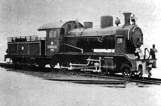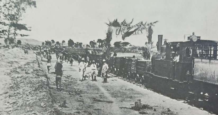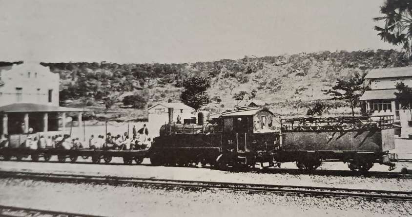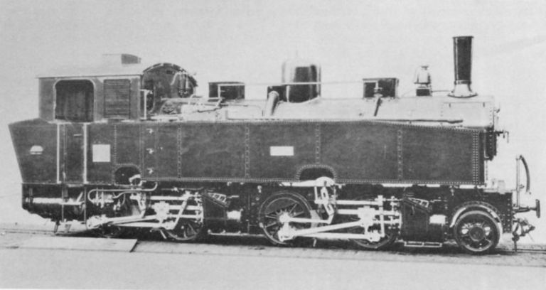
Tag Archives: steam Engine

Swanscombe Cement Works, Kent

The featured image for this article is Aveling & Porter 0-4-0WTG Reliance seen at Swanscombe in 1921. Only one end of the axles was geared. This is the non-geared side of the locomotive. Swanscombe Works employed a range of unusual industrial locomotives! (Locomotive Publishing Co.), © Public Domain. [30: p48]

Possibly as early as 1825, an extensive horse-drawn tramway network served the works.

The tramway was laid to 3ft 5.5in. “The gauge was measured to the outside of the railheads as the wheels had flanges outside of the rails. … They were the earliest railways in the area. … It is said that outside flanges were used so that the space between the rails could be built up into a firm level path for the horses. Fallen lumps of chalk could then be easily kicked clear of the rails.” [1: p4]

The works lay to the north of the London Road and the tramway ran due north for 1000 yards to Bell Wharf. There was a whiting works to the west of the main works with a tramway to the pits near the cricket ground. The main pits were between the London Road and the South Eastern Railway. Some time before 1898 the tramway burrowed under the South Eastern Railway in a tunnel at Craylands and pits were opened south of the railway later extending for a considerable distance. There was a transhipment siding on the South Eastern Railway at Craylands during the time of the narrow gauge.” [30: p38,42]

“Steam locomotives were introduced in 1875, built by a variety of builders. “There were engines by Lewin of Poole, HE Taylor of Chester, Kilmarnock Engineering Co. and … Aveling and Porter of Rochester. By 1927, these charming workhorses were becoming increasingly difficult to maintain and so, with the need to increase production, the railway was re-laid to standard gauge and new locomotives purchased.” [1: p4]

Initially the industry was made up of a series of independent companies. These companies joined in 1900 to form ‘The Associated Portland Cement Manufacturers’ (APCM), often referred to within the industry as ‘The Combine’. After 1900 the various works continued to be known by their original names.

The modernisation of the railways at Swanscombe Works was completed by 1929. … The Works shifted to a busy, efficient standard-gauge system connecting the chalk pits, main plant, river Thames jetty, and British Rail interchange.

When the standard gauge line was built a single track ran down from the exchange sidings on a steep and curving route to the works. The standard gauge ‘main line’ ran through the tunnel under Craylands, then turned more westerly than the old line, and passed under a footbridge across old workings, through a tunnel under a lane, then another tunnel under Alkerden Lane, and into a very large pit running almost down to Watling Street, a distance of 14 miles from the Works.” [30: p42]

The Works were among the most important cement production facilities in the country. Extensive railway infrastructure was required to handle raw materials and finished cement, resulting in a complex network of sidings, exchange lines, and industrial locomotives. Rail traffic included limestone and chalk movements, internal works shunting, and outward cement trains connecting with the wider British Rail network. By the late 1960s and early 1970s, the site reflected wider changes across the UK rail system. [11]

A sketch of the area around Swanscombe Works. The pier on the Thames, the Works and the quarries were on a North-South axis. This sketch is an extract from a broader sketch of the various Cement Works on the South side of the River Thames. [30: p10]

The series of map extracts and photographs below illustrate the development of the Works over the years.

Map of Works in 1864

The First Edition OS 1:2500 County Series Kent X.1 map surveyed 1864 (British Library), modified to National grid format. The plant in 1864 was in course of rapid expansion, still using the wet process static kilns originated by Frost. Chalk quarrying, initially north of the road, had spread to the area between the road and the railway, connected by a 4 m wide tunnel under the road – the first of five eventually dug. [

Map of Works in 1895

This pair of Ordnance Survey Map extracts are taken from the 25″ Ordnance Survey of 1895, published in 1897. [7]

Map of Works in 1915/1916

These two map extracts are intended to be read together. They show the extent of the Swanscombe Cement Works and the pier on the River Thames as they appear on the 6″ Ordnance Survey of 1915/1916, although not published until 1923. [3]
Swanscombe Works from the Southwest in April 1927, © Historic England – NMR Aerofilms Collection. Britain from Above reference number EPW017658. [28]

Map of Works in 1934

These two map extracts are also intended to be read together. They show the extent of the Swanscombe Cement Works and the pier on the River Thames as they appear on the 6″ Ordnance Survey of 1931/1932, published in 1934. [4]
The Works seen from the West in February 1939, © Historic England – NMR Aerofilms Collection. Britain from Above reference number EPW060599. [29]

Map of Works 1938-1940

These three 6″ Ordnance Survey map extracts of 1938-1940 and published in 1950-1951 belong together. The top two overlap marginally North to South. [5] The third extract sits alongside the second – to its left. It comes from a different OS Sheet and shows the Works line extending to Chalk Pits near Knockhall and Alkerden Manor Farm. [6]

Swanscombe Cement Works began operations in 1825, when James Frost commenced making his “British Cement” using wet process bottle kilns. The plant was acquired by Francis and White in 1833 and made the same product. The partnership was dissolved in 1836 and John Bazley White and Sons commenced as a business in 1837, making both Roman and Frost’s cements at the Swanscombe site. [8]

Map of the Railway Network in 1965

Note that the Northpoint for this plan is turned through about 120 degrees. The Thames jetty is off the left of the plan. The chalk Pit Workings are off to the bottom-right. [12]

In 1965, the Works had seven 0−4−0STs to work the considerable traffic – six built by Hawthorn Leslie (four in 1928, one in 1929 and one in 1935) and the last by Robert Stephenson & Hawthorns in 1948. All seven were painted green with the running number on each side of the tank. There were no diesels. One was tried but it could not manage the poor track and was continually “sitting down”. There is no prospect of having any until money can be spared for relaying several miles of track. [12] A number of other locomotives were used at different times after 1929.

The five identical Hawthorn Leslie 0-4-0ST engines were delivered in 1928, followed by a sixth in 1935. They weighed 25 tons, featured 16in x 24in outside cylinders, and had a tractive effort of 21,425 lbf. [13]

The works can be divided into three areas. The first two are old chalkpits, dug each side of the main road, while the third contains the line to the workings. The first area is bisected by a private road with the cement works proper on one side. On the other side is the single road engine shed and works, and also an awning over one track where engines stand when not in use. A single line runs past the works, and across the marshy countryside to the jetty on the river Thames. [12]

Another line runs across the road and winds its way around the main works until entering a tunnel under the main road. This brings it to the second old pit, where are situated two unloading tips for arriving trains. As can be seen from the map, a connection to British Railways struggles up and round the side of the pit. (Sand all over the rails shows the severity of the climb.) On the opposite side of the pit, another single line dips downwards into a tunnel under BR, a road and the connecting line, and emerges into a long, deep and wide cutting. There are two passing loops on the way to the workings, of which one has watering facilities, and another tunnel, and a high footbridge.” [12]

Chris Down, writing in 1965, continues:

“At the middle pit, an arriving train runs above one of the two tips, and backs down on to the tip. When the end wagon is on the tip, the wagons are braked, and the locomotive is uncoupled so that it can go up to the end of the line to obtain coal and water.

“The tips are similar to mechanical coaling plants on B.R. and deal with one wagon at a time. As each wagon is unloaded, it runs along the siding by gravity, until the train is reformed at the other end of the loop. The locomotive then comes back and couples onto the same end as before. The next train brings the single line tablet which is hung on a hook on a post. The first train collects the tablet and then goes down to the workings, the locomotive propelling the wagons.

“I spent some time around the footbridge, photographing the trains which passed at frequent intervals. The maximum speed was about 20m.p.h., but trains lurched terribly, due to the poor track. When the track deteriorates so much as to necessitate its replacement, diesels will doubtless be purchased. From the opinion of many of the men to whom I spoke, however, steam should retain its supremacy for some time to come.” [12]

Satellite Image the Area of the Works of 2026

Swanscombe cement works operated for nearly 165 years, one of the longest-lived cement works in the world and, for many decades, … one of the largest. For a hundred years from about 1826 until 1929 it employed a unique narrow gauge railway using outside-flanged wheels, with over thirty steam locomotives, many also unique. When modernised in the 1927-29 period, its new standard gauge railway was one of the busiest and most efficient in the industry.” [9]

Details of locomotives employed at the Works can be found below.

Production at Swanscombe Works measured in tonnes per year. [8]

Comparing 1915/1916 to the 21st century

A few images follow which compare locations on the Swanscombe Works network with modern satellite imagery. The plans and satellite images are supplemented, where available, with photographs from close to ground level.

Bell Wharf at the North end of the company’s rail network, as it appears on the 6″ Ordnance Survey of 1915/1916 published in 1923. [33]

The Wharf as it appears on the ESRI satellite imagery provided by the national Library of Scotland (NLS) [34]

The approach to the Jetty along the line of the old railway. This view looks North towards the jetty. [Google Streetview, August 2025]

The jetty seen from the South. [Google Streetview, August 2025]

Looking South across the marshes from the jetty towards the location of Swanscombe Works. [Google Streetview, August 2025]

The Cement Works in 1915/1916. A road can bee seen leaving London Road at the bottom-left of this map extract and running towards Manor Way Farm through the centre of the site. [33]

In the 21st century, the outline of the Cement Works site is still visible. A variety of primarily transport related companies use the site. Manor Way now runs from the bottom-right across the centre of the old cement works site and the area is known as Manor Way Business Park. [34]

This aerial view looks across the cement works from the Southeast. The junction between Manor Way and London Road is flagged in the top-left. This photograph was taken in 1939, Image No. EPW060594 © Historic England. [35]

Looking Northeast along Manor Way in the 21st century. The majority of buildings which were present when the Cement Works was in operation have been removed. [Google Streetview, October 2024]

Narrow Gauge Locomotives before 1929

Although records are sketchy, Stoyel and Kidner give details of nearly 30 narrow-gauge locomotives which served at Swanscombe, all of which had wheels with outside flanges. These included:

Aveling & Porter supplied a total of eight 3ft 5.5in, outside-gauge, geared tramway engines to Swanscombe Works. These were all scrapped by 1929 after the standard-gauge works lines were built.

A blueprint for the Aveling & Porter locomotives, note, bottom-left, the outside-flanged wheels, © Public Domain. [1: p7]

The Aveling & Porter locomotives, according to Stoyel & Kidner, were built between 1896 and 1909 – all were 0-4-0WTG locomotives;

Goliath, Works No. 3680, a single-cylinder (8″ x 12″)

Jubilee, Works No. 3978, compound cylinders (9″ x 14.5″ x 14″), 3ft diameter wheels.

Samson, Works No. 4176, compound cylinders (9″ x 14.5″ x 14″), 3ft 6in diameter wheels.

Galley Hill, Works No. 4469, compound cylinders (9″ x 14.5″ x 14″), 3ft 6in diameter wheels.

Barnfield, Works No. 4501, compound cylinders (9″ x 14.5″ x 14″), 3ft 6in diameter wheels.

Progress, Works No. 6040, compound cylinders (9″ x 14.5″ x 14″), 3ft 6in diameter wheels.

Enterprise, Works No.6419, compound cylinders (9″ x 14.5″ x 14″), 3ft 6in diameter wheels.

Reliance, Works No. 6828, compound cylinders (9″ x 14.5″ x 14″), 3ft 6in diameter wheels.

Progress photographed at Swanscombe in 1921. The geared wheels can easily be seen. Note the long front overhang (Locomotive Publishing Co.), © Public Domain. [30: p48]
Reliance seen at Swanscombe on the same occasion. Only one side of the four-coupled axles was geared. This is the non-geared side of the locomotive, (Locomotive Publishing Co.), © Public Domain. [30: p48]

S. Lewin of Poole – Only a small number of locomotives were built by this company, including: an 0-4-0 locomotive of 1875, for the 1 ft 10 in (559 mm) gauge Cornish Hush Mine, Howden Burn; 0-4-0 Ant and Bee, for the 20 in (508 mm) gauge Great Laxey Mine Railway, Isle of Man; an 0-4-0ST for Seaham Harbour, County Durham; an 0-4-0 steam tram engine for Guernsey Railway; an 0-4-0 with rear tank, 3 ft 5 1⁄2 in (1,055 mm) gauge, outside flanged, (photographed below at) Swanscombe Cement Works; and an 0-4-0 Tiny, a 3 ft 9 in (1,143 mm) gauge loco for the Fayle’s Tramway on the Isle of Purbeck. [23][24]
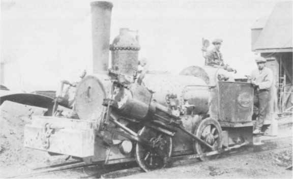
0-4-0WT ‘Erith’ at Swanscombe Works. This shows the outside-flange wheels and the circular section connecting rod quite clearly. The name ERITH is in the centre of the cabside plate above the date 1875 (although the latter is a little indistinct): in the outer band SWANSCOMBE WORKS appears at the top, with REBUILT off centre at the bottom; one would have expected the year of rebuilding to follow, but a powerful glass reveals no raised lettering. ERITH is said to have been rebuilt in 1920 and it seems a distinct possibility that this date may have been stamped on the plate. This image is embedded here directly from the Industrial Railway Society webpage, but it is also shown in Stoyel and Kidner’s book, © Public Domain. [21][22][30: p38]

S. Lewin only made a few locomotives. Erithhad the eccentrics on the front axle and the valves were on top of the steeply-inclined cylinders, the spindles being actuated by Stephenson link motion. Erith was rebuilt at Swanscombe Works in 1920 with the help of fitters from the Dorset Iron Foundry.” [30: p45]

De Winton supplied one vertical-bolier 0-4-0WT locomotive, Revolution, it had two 6″ x 10″ cylinders and 1ft 7in diameter wheels.

De Winton vertical-bolier 0-4-0WT locomotive, Revolution, built in 1881, seen at Swanscombe in 1921, (Locomotive Publishing Co.), © Public Domain. [30: p47]

It is possible that Revolution “came second-hand in about 1890 and possibly from the Bute Works Supply Co. Cardiff, who were advertising a similar locomotive for sale in 1893.” [30: p45]

H. E. Taylor of Chester supplied six 0-4-0 side tank locomotives to Swanscombe Works between 1877 and 1882.

Stoyel & Kidner provide details of these locomotives:

Swanscombe, 0-4-0ST, 1879, outside cylinders other details not known.

Iron Horse, 0-4-0ST, 1882, outside cylinders (9.5″ x 18″), 2ft 6in wheels.

Dead Horse, 0-4-0ST, 1882, outside cylinders other details not known.

Millbank, 0-4-0ST, 1879, outside cylinders other details not known.

Liverpool, 0-4-0ST, 1879, outside cylinders other details not known.

Chester, 0-4-0ST, 1877, outside cylinders other details not known.

Iron Horse, one of the H. E. Taylor-built 0-4-0ST as work at Swanscombe (Locomotive Publishing Co.), © Public Domain. [30: p40]
This image, dating from May 1910, shows the locomotive ‘Millbank’ of 1879 standing at the Works. The outside flanges to the wheels can be seen easily. Apparently, narrow-gauge engines  at Swanscombe were not usually fitted with cabs, © Public Domain. [1: p5]

William Wilkinson & Co. built around sixty locomotives. Wilkinson’s also contracted out the manufacture of tram locomotives to Beyer, Peacock and Co, Black, Hawthorn and Co and Thomas Green and Son. Altogether 207 engines were built to Wilkinson’s patent. The Plymouth & Devonport Tramways steam locomotives were assembled at Wilkinson’s works in Wigan, the vertical boiler in each of these locomotives was made by the Steel Company of Scotland. Small bore cylinders acted upon a crankshaft that was in turn connected to the four, coupled wheels by means of cog-wheel gears. The axles, wheels and nearly all the working parts of the engine were made of Sieman-Martin’s best quality steel and all the brass workings were of phosphor bronze. The exhaust steam was superheated in the firebox before escaping to the atmosphere through the chimney. The fuel was coke and the emission of smoke was described as ‘scarcely perceptible’. The Plymouth locomotives were apparently from Wilkinson’s own works. They cost between £600 each for the non-condensing version and £1,100 for those fitted with the condensing apparatus. [26]

A number of the Wilkinson steam trams purchased by the Plymouth & Devonport Tramways for their abortive experiment with steam trams were bought by the Swanscombe Works in the late 1880s/early 1890s. [25]

A typical Wilkinson’s Steam Tram – this one was used on the Wigan network close to Wilkinson’s Works. It was built in 1886. These engines must have been an unusual sight working on an industrial railway! [27]

Wilkinson also supplied a single vertical-boiler locomotive to Swanscombe Works. It was built in 1884.

Wilkinson-built 0-4-0WT locomotive, Devonport, of 1884, seen here at Swanscombe in 1921, (Locomotive Publishing Co.), © Public Domain. [30: p47]

Kilmarnock Engineering Co. supplied five 0-4-0ST 3ft 5.5in outside-gauge locomotives to Swanscombe Works in 1920 and 1925. Kilmarnock Engineering Co. were not prolific engine builders. These five were some of a very few locomotives built by the Company.

These sturdy 0-4-0ST locomotives undertook most of the chalk haulage for Swanscombe Works in the 1920s. When the railway was modernised and the gauge changed the locomotives were scrapped. [1: p6]
‘Hustler’ was one of this batch of locomotives from Kilmarnock Engineering Co., (c) Public Domain. (Kenn Nunn Collection/LCGB). [25: photo No. 26]

J. B. White & Bros, owners of the Swanscombe works, appear to have constructed at least one locomotive in use on their own site, Gravesend, another 0-4-0WT. It is also possible that a number of other locomotives used on the site were rebuilt there at various times. [30: p45]

Bagnall – one locomotive, Rede, an 0-4-0ST built in 1894, was built by Bagnall (Works No. 1413) and came second-hand in 1921. [30: p45]

Hudswell Clarke – one locomotive, Spry, another 0-4-0ST, was built by Hudswell Clarke and arrived at Swanscombe in 1923. [30: p45]

Stoyel & Kidner tell us that “on a visit to the works in December 1929, 12 narrow gauge locomotives were seen on a length of track awaiting scrapping. The old 3-road engine shed was rebuilt as a two-road standard gauge shed. … On the modernisation of the railway system in 1929 all the remaining narrow gauge locomotives were scrapped that year or in 1930, and it is thought that very few of them had been scrapped at an earlier date, although Plymouth and Devonport are said to have been broken up in 1922, and Swanscombe by 1920. The second-hand engines would have had their gauge altered on arrival.” [30: p45]

The narrow gauge wooden tipper wagons, “were shunted in 1929 into the passing loops half way down the tramway to the river, and remained there for many years. There were also a few left in an old pit south of Ingress Gardens.” [30: p45]

Standard Gauge Locomotives after 1929

When preparations were made in 1928 for replacing the narrow gauge system by one laid to the 4ft 8½ in. gauge, an order was placed for a series of powerful new locomotives for the purpose. Pending their delivery three old locomotives were transferred from other works but they were usually employed two at a time in removing the overburden prior to quarrying, on track which had no physical connection with the remainder of the system.” [30: p45]

Those early standard-gauge arrivals were from two manufacturers:

Falcon – Henry Hughes and Company was based at Falcon Works. The firm experienced financial difficulties in the late 1870s/early 1880s. It was restructured as the Falcon Railway Plant Works in 1883 under the control of Norman Scott Russell. [31]

The factory remained busy with both railway and tramway locomotives and rolling stock. Among these were tank locomotives for Ireland, Spain and the Azores. Some were subcontracts from other firms, such as Kerr, Stuart and Co, at that time in Glasgow. [32]

The two Falcon locomotives came to Swanscombe second-hand, they were Works Nos 120 and 150 and were named Wolf and Delta. Delta was one of a number originally supplied to Gibbs Works, Essex. It had a dropped cab for passage through low tunnels. [30: p43, 45]

Delta sits steaming gently between duties at Swanscombe (G. Alliez), © Public Domain. [30: p43]

Falcon also provided a later second-hand arrival,  Lion, (Works No. 205?) which was transferred from Stone Court in 1946. [30: p41, 45]

Manning WardleGuernsey, a 0-4-0ST, Works No. 1241 of 1892 came second-hand to Swanscombe at the end of the 1920s.

Hawthorn Leslie supplied five identical standard-gauge 0-4-0ST locomotives to Swanscombe Works in 1928. [1: p6] These locomotives were constructed with two outside cylinders of 16in x 24in, 3ft 3in diameter driving wheels and a weight of 25 tons and a tractive effort of 21.425 lbf. [13] A single further engine (No. 6) was supplied in 1935.

  • No. 1 was Hawthorn Leslie Works No. 3715. [13]
  • No. 2 was Hawthorn Leslie Works No. 3716. [16]
  • No. 3 was Hawthorn Leslie Works No. 3717. [15]
  • No. 4 was Hawthorn Leslie Works No. 3718. [14]
  • No. 5 was Hawthorn Leslie Works No. 3719. [17][25]
  • No. 6 was Hawthorn Leslie Works No. 3860. [18]
No. 5 was one of the fleet of standard-gauge Hawthorn Leslie Locomotives. It is seen here working the exchange sidings at Swanscombe, (c) Public Domain, (Andrew Neale Collection). [25: photo No. 27]
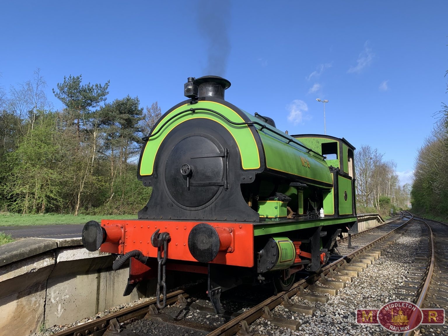
This image is embedded here directly from the Middleton Railway Website, it shows Hawthorn-Leslie No. 3860 Swanscombe ‘No.6’ which was gifted to the Middleton Railway in 1971 once the APCM turned away from steam- to diesel-power. [19]

Chapman & FurneauxKappa, another 0-4-0ST, built by Chapman & Furneaux (successors to Black, Hawthorn & Co) Works No. 1164 (of 1898) arrived at Swanscombe in the 1930s. [30: p45]

Robert Stephenson & Hawthorns supplied one slightly larger standard-gauge locomotive to Swanscombe Works – 0-4-0ST No. 7, RSH No. 7405 of 1948. [1: p6]

Robert Stephenson & Hawthorns No, 7405, Swanscombe Works No. 7, 0-4-0ST of 1948. Seen here close to the tunnel mouth at the Swanscombe works in 1968, © copyright Alan Murray-Rust and licensed for reuse under a Creative Commons licence (CC BY-SA 2.0). [20]

Miscellaneous

Some historic footage of the Swanscombe Works and quarries can be found here. [2]

References

  1. A & G Hatherill; Narrow Gauge & Industrial Album; RCL Publications, Gaendolbenmaen, Gwynedd, 2004.
  2. https://www.facebook.com/share/v/18Lm6U8N5w, accessed on 9th August 2026.
  3. https://maps.nls.uk/view/102342323, accessed on 10th August 2026.
  4. https://maps.nls.uk/view/101428125, accessed on 10th August 2026.
  5. https://maps.nls.uk/view/101428119, accessed on 10th August 2026
  6. https://maps.nls.uk/view/101428077, accessed on 10th August 2026.
  7. https://maps.nls.uk/view/103676144, accessed on 10th August 2026.
  8. https://www.cementkilns.co.uk/cement_kiln_swanscombe.html, accessed on 10th August 2026.
  9. https://irsshop.co.uk/swanscombe, accessed on 10th August 2026.
  10. C. Down; Swanscombe Cement Works and its Railways; Industrial Locomotive Society, Whitchurch, Shropshire, 2022.
  11. https://www.gres.org.uk/members-layouts-apcm-swanscombe-works, accessed on 10th August 2026.
  12. C. Down; Christmas at Swanscombe; Industrial Railway Society, 1965; via https://shop.irsociety.co.uk/Archives/12/christmas_at_swanscombe.htm, accessed on 10th August 2026.
  13. https://preservedbritishsteamlocomotives.com/hawthorn-leslie-works-no-3715-associated-portland-cement-at-swanscombe-no-1-0-4-0st, accessed on 10th August 2026.
  14. https://www.railwaymagazine.co.uk/4710/new-face-at-quainton-as-it-bags-ex-swanscombe-hawthorn-no-4, accessed on 11th August 2026.
  15. https://preservedbritishsteamlocomotives.com/hawthorn-leslie-works-no-3717-associated-portland-cement-at-swanscombe-no-3-0-4-0st, accessed on 11th August 2026.
  16. https://www.gwra.co.uk/auctions/worksplate-r-w-hawthorn-leslie-co-ltd-engineers-ne-2023jul-0296.html, accessed on 11th August 2026.
  17. Swanscombe No. 5 did not survive into preservation.
  18. https://preservedbritishsteamlocomotives.com/hawthorn-leslie-works-no-3860-associated-portland-cement-at-swanscombe-no-6-0-4-0st, accessed on 11th August 2026.
  19. https://middletonrailway.org.uk/wp-content/uploads/2024/04/3860-1536×1152.jpg, accessed on 11th August 2026.
  20. https://www.facebook.com/photo/?fbid=10224531389586054&set=gm.5187090374725107&idorvanity=163976490369879, accessed on 11th August 2026.
  21. https://shop.irsociety.co.uk/Archives/36/Lewin.jpg, accessed on 11th August 2026.
  22. https://shop.irsociety.co.uk/Archives/36/Letters_36.htm, accessed on 11th August 2026.
  23. https://en.wikipedia.org/wiki/Stephen_Lewin, accessed on 11th August 2026.
  24. The industrial Locomotive Society; Steam on the Narrow Gauge. A Collection; David Charles, 1965.
  25. Andrew Neale/Chalk Pits Museum; Industrial Railways of the South-East; Middleton Press, 1984.
  26. Brian Moseley; When Plymouth had Steam Trams; Old Plymouth Society, December 2012; via https://oldplymouthsociety.net/when-plymouth-had-steam-trams, accessed on 13th August 2026.
  27. https://www.gracesguide.co.uk/File:Im1955EnV199-p834.jpg, accessed on 13th August 2026.
  28. http://www.britainfromabove.org.uk/image/EPW017658, accessed on 13th August 2026.
  29. http://www.britainfromabove.org.uk/image/EPW060599, accessed on 13th August 2026.
  30. B. D. Stoyel & R. W. Kinder; The Cement Railways of Kent; Oakwood Press, Headington, Oxford, 1973, 1990.
  31. https://collection.sciencemuseumgroup.org.uk/people/cp20744/henry-hughes-and-company, accessed on 15th August 2026.
  32. https://www.gracesguide.co.uk/Falcon_Engine_and_Car_Works, accessed on 15th August 2026.
  33. https://maps.nls.uk/geo/explore/#zoom=16.0&lat=51.46122&lon=0.30214&layers=6&b=ESRIWorld&o=100, accessed on 16th August 2026.
  34. https://maps.nls.uk/geo/explore/#zoom=16.0&lat=51.46122&lon=0.30214&layers=6&b=ESRIWorld&o=0, accessed on 16th August 2026.
  35. https://www.britainfromabove.org.uk/en/image/EPW060594, accessed on 16th August 2026.
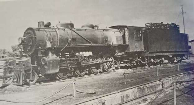
Railways of Tanzania – Part 15 – Locomotives from the first railways built by the German colonial powers through to the amalgamation which formed East African Railways and Harbours in 1948.

Locomotives used during the EAR years from 1948 onwards will be covered in Part 16 of this series of articles.

The featured image for this article is Tanganyika Railways 2-8-2 No. 802 of the MacArthur austerity class at Tabora in the early 1950s before its conversion to oil fuel. [1: p68]

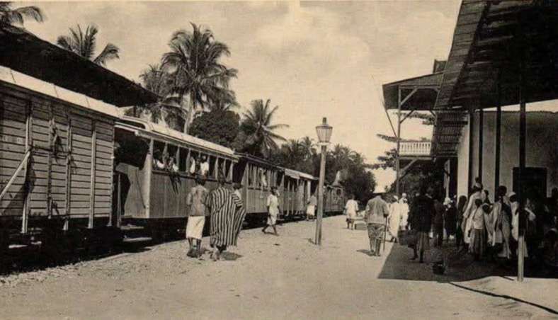
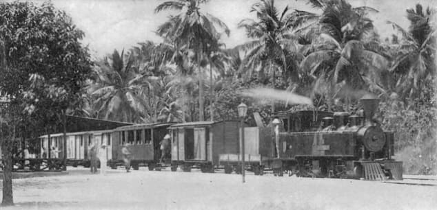
This is an overall view of Tanga Railway Station in 1908 during the the years of German East Africa. The station served as the coastal terminus of the Usambara Railway (Usambarabahn or Usambara Eisenbahn (UE)), which was constructed starting in 1893.The photograph was taken by German photographer Carl Vincenti it shows a train, headed by an unidentified early German steam locomotives, preparing to set off inland, (c) Deutsches Historisches Museum, (Inv. No. BA 90/5791)/Carl Vincenti and licensed for reuse under a Creative Commons licence (CC-BY-SA 3.0). [15]

Locomotives in the Years of German East Africa:

UE Class 0-4-2T Locomotives

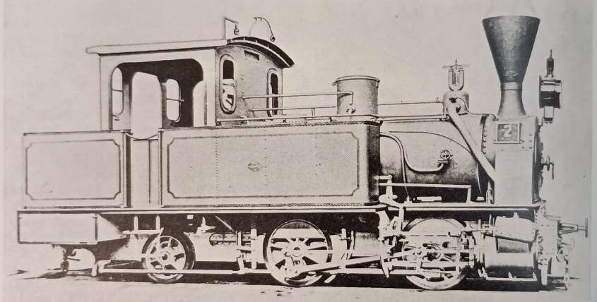
The Tanga Line (or Usambarabahn) was constructed over a relatively long period, starting in 1893, reached Korogwe in 1905 and Moshi in 1912. Initially the line was operated by five 0-4-2 tank locomotives. Ramear tells us that these five locomotives were built in 1893 by Vulcan (Vulkan) of Stettin. They were built to a standard design which Vulcan had standardised for use in Germany. [1: p19]

UE Engine No. 1 with an early passenger train ready for departure at Tanga Railway Station. This locomotive is the first in a class of 5 0-4-2T locomotives used on the Usambarabahn (c) Public Domain. [16][1: p19]
UE No. 2, one of a class of five 0-4-2T locomotives built by Vulcan of Stetting in 1893, (c) Public Domain. [1: p18]

UE Nos. 6-10 Mallet Class of 0-4-4-0T Locomotives

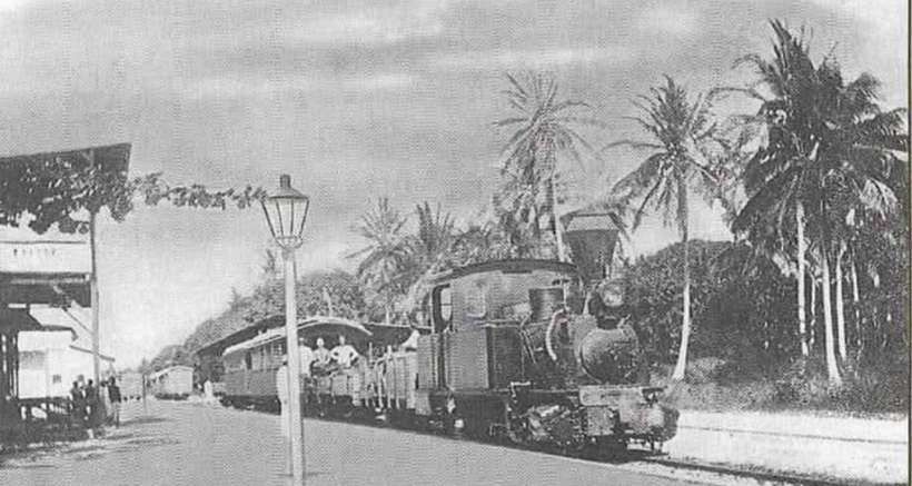
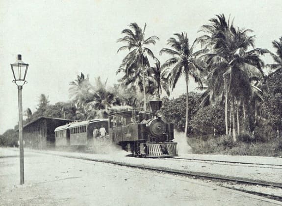
A vintage postcard view of an Usambara Eisenbahn 0-4-4-0T mallet type steam locomotive, one of five built by Arnold Jung (No. 414-418) in 1900 and in charge of a mixed train. These locomotives were UE Nos. 6-10, later Nos. 601-605. [17]
Another view of an Usambara Eisenbahn 0-4-4-0T Mallet type steam locomotive in charge of a passenger train which is waiting to depart at Tanga Railway Station. [18]
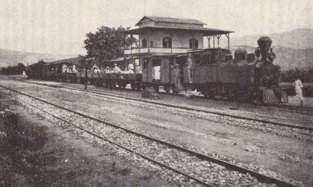
Another view of a Mallet type steam locomotive in charge of a mixed train which is waiting to depart at Njussi Railway Station. [22]
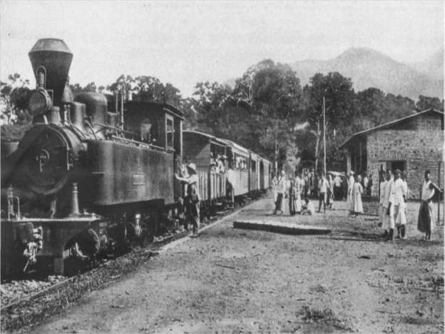
UE Mallet 0-4-4-0T No. 8 with a passenger train at Mombo, (c) Public Domain. [1: p20]

UE Nos 11-14 Class 2-8-0T Locomotives

After the line was improved with curves being increased to 200m radius, 8-coupled locomotives became feasible. Ramaer tells us that “Four tank locomotives with a 2-8-0T wheel arrangement were built for the UE by Messrs Orenstein & Koppel in 1908 to a standardised tank engine design used on all German colonial railways in Africa. … They were a distinct improvement over the Mallets. Although they were designed to burn coal, the high price of imported coal meant that they remained on wood fuel, which must have given problems with fireboxes and ashpans.” [1: p19-20] Sadly these locomotives seem not to appear on the Wikipedia list of Orenstein & Koppel locomotives. [23]

For an illustration of this type of locomotive please see the OAEG 2-8-0T below.

UE Nos. 15-16 & Nos. 17-18 Class 2-8-0 Locomotives

An Orenstein & Koppel (O&K) 2-8-0 locomotive which was one of a class built between 1908 and 1910 for the Usambarabahn. This specific locomotive is UE No. 15. [19]

These 2-8-0 tender locomotives were a significant improvement over the tank engines with a same wheel arrangement – with the side tanks removed and water carried in the tender the boiler size and weight could be increased. These were the last locomotives to eb supplied to the Usambarabahn and it operated with these locomotives well into the years of World War 1. [1: p20]

OAEG 0-4-0T Locomotives

Henschel of Kassel supplied 4 of these locomotives intended for the work of building the line. A further 4 of these locomotives were supplied, to the same design by, Henschel in 1909. [1: p21] In between these two batches of locomotive (in 1907) another 0-4-0T locomotive was put into service, the origins of this locomotive are obscure and it did not match the Henschel-built locomotives. Ramaer presumes that this locomotive was taken over from the contractor, Holzmann & Co. It was built by Markmaschinen (Works No. 26) in 1893. [1: p21, p27]

Ramaer notes that the Henschel engines “could be used as both coal and oil burners, and … had a bunker capacity of ton of coal besides 300 litres (66 gallons) of fuel oil. Their water capacity was 2 m³ (440 gallons). These little engines had a comparatively long life, surviving the war and the subsequent change to British management, and the last did not go out of service before the early 1930s.” [1: p23]

OAEG 0-4-0T Locomotive No. 2 with a line building train at Ugaga (later known as Malagarasi), (c) Public Domain. [1: p21]

OAEG Henschel Mallet Class 0-4-4-0T Locomotives

Just as the Usambarabahn needed to invest in more powerful Mallet types of locomotive which could also accommodate the tight curves on the line, so the OAEG to ordered five comparable Mallet 0-4-4-0Ts, four of which were supplied by Henschel in 1905 and put in service during the first half of 1906 with the fifth following in 1907; like the 0-4-0s they were built for either coal or oil fuel. The OAEG found these Mallets not to be as effective as had been hoped and decided to order Mallets from Henschel with a different wheel arrangement. [1: p23]

OAEG Henschel Mallet Class 2-4-4-0T Locomotives

Henschel supplied a second batch of four locomotives in 1908 as 2-4-4-0Ts with larger boilers and cylinders. They also had a higher working pressure of 14 atmospheres (at) (200lb/sq in) in comparison to 12 at (170lb/sq in) for the earlier engines. While the bunker capacity had been increased from 1.2 to 2.2 tonnes of coal, oil fuel had been discarded. [1: p23]

Mallets proved to be expensive to run and the OAEG realised that if it were to be able to use suitably powered locomotives for the train loads envisaged, it would need to improve the alignment of the later sections of the Mittellandbahn and upgrade to trackwork. This allowed the OEAG to consider using rigid-bodied 8-coupled locomotives.

OAEG 2-4-4-0T No. 27, in the last Mallet class to be built for German East Africa. This locomotive appears in the Wikipedia list of Henschel steam locomotives. [24] It also appears in R. Ramaer’s book (although possibly a slightly different image) [9: p23] and A.E. Durrant’s book about Mallets. [25: p66]

On the whole, the Mallets were not as successful as had been hoped, so it was something of a relief for the OAEG that it was able to use much larger radius curves once the more difficult topography close to the coast gave way to much flatter country. The OAEG was able to look at rigid-framed locomotives. With the invention of the Gölsdorf system [26][27] which allowed spring-controlled side-play in coupled axles at the end of the 19th century. Eight-coupled engines became more feasible. The OAEG took advantage of this innovation and began to introduce eight-coupled locomotives. Ramaer tells us that “The first solution tried was the 0-8-2 tank, built with the pony truck under the fuel bunker to make adhesion independent of diminishing supplies to the maximum possible extent, besides making riding somewhat more comfortable for the crew. High prices for imported coal from Europe had made the railway look for a cheaper alternative and these engines were the first to be built for wood fuel. Henschel supplied them in 1909 as works numbers 9301-2, running numbers 47-8.

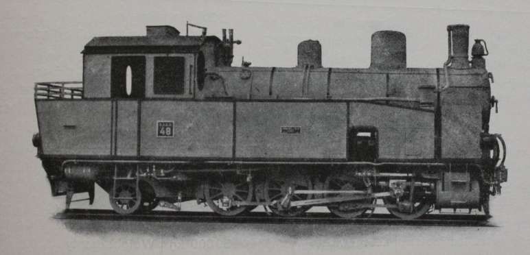
OAEG 0-8-2T Locomotives Nos. 47 and 48

One of two OAEG 0-8-2T locomotives supplied to the OAEG by Henchel. This is No. 48, (c) Public Domain. [1: p24]
This is the same locomotive but with elements easier to see as the image has a darker hue, (c) Public Domain. [28]

Ramaer tells us that “The first solution tried [by the OAEG] was the 0-8-2 tank, built with the pony truck under the fuel bunker to make adhesion independent of diminishing supplies to the maximum possible extent, besides making riding somewhat more comfortable for the crew. High prices for imported coal from Europe had made the railway look for a cheaper alternative and these engines were the first to be built for wood fuel. Henschel supplied them in 1909 as works numbers 9301-2, running numbers 47-8.” [1: p23]

OAEG 2-8-0T Locomotives Nos 41-44 (also UE 11-14)

A Borsig-built 2-8-0T. These locomotives served on the OAEG Mittellandbahn, Ramaer tells us that there were 20 of these locomotives in use in East Africa. [1: p24 & 25]

Ramaer tells us that “Simultaneously, Borsig and Orenstein & Koppel introduced an alternative [to the 0-8-2T] and more logical solution in the shape of six 2-8-0T engines, also built for wood fuel. Both types, with only 5½ and 5 cubic metres water capacity respectively, normally carried auxiliary tenders for both water and firewood, besides hoses on the engine to allow for taking water en-route. … From this class and a comparable, but compound engine, supplied, also by Orenstein & Koppel, to South West Africa and Togo, a standardised 2-8-0T locomotive was developed, which was supplied to all German colonial lines in Africa. … Besides serving on other railways, it worked on the Usambarabahn, as described above, and was built for the OAEG by Borsig, O & K, Hanomag (or Georg Egestorff, as this firm was originally known) and Maffei to a total of eighteen engines in 1909-10. Including the engines of the first batches by O & K and Borsig of six locomotives, the total of the Einheitstenderlok (standard tank locomotive) classes amounted to twenty-four engines by the end of German rule.” [1: p25]

These locomotives were far better than the 0-8-2T locos, particularly in respect of their performance at speed. This was of some importance when maximum speeds were raised to 45km/h, and planning envisaged 60km/h (36mph) for the Dar es Salaam-Kigoma mail trains. “The standard tanks were a good, straightforward design and were kept in service for a fairly long period under British management; the last ones … being withdrawn in 1951.” [1: p25]

The series was made up of Orenstein & Koppel locomotives (Works Nos.3223-3226) built in 1909, OAEG Nos. 41-44; Borsig locomotives (Works Nos. 7143-7144) built in 1909, OAEG Nos. 45-46; Henschel locomotives (Works Nos. 9301-9302) built in 1909, OAEG Nos. 47-48; Borsig locomotives (Works Nos. 7153-7155) built in 1909, OAEG Nos. 49-51; Orenstein & Koppel locomotives (Works Nos.3312-3314) built in 1909, OAEG Nos. 52-54; Borsig locomotives (Works Nos. 7552-7555) built in 1910, OAEG Nos. 55-58; Hanomag locomotives (Works Nos. 5845-5948) built in 1910, OAEG Nos. 59-64; Maffei locomotives (Works Nos. 3628-3631) built in 1910,OAEG Nos. 63-66. [1: p27]

OAEG 2-8-0 Locomotives Nos 101-120

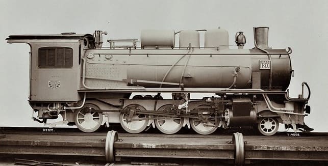
An ex-Works photograph of one of a series of Hannoversche Maschinenbau Hanomag’s 2-8-0 locomotives built for the Ostafrikanische Eisenbahngesellschaft (East African Railway Company). No. 120 was Works No. 6666 of 1913 and was intended for use on the Mittellandbahn running West from Dar-es-Salaam. This locomotive was provided with a tender built by Borsig of Berlin. The locomotive was in use from 1923 to 1937. [20]

Numbered 101-120 these locomotives were built in three batches, 101-110 (6080-89) in 1911, 111-115 (6597-6601) in 1912 and 116-120 (6662-66) in 1913. The class was intended to include a total of 22 locomotives, but only 20 were built. The locomotives were primarily intended to support the construction and operation of the Central Line (Mittellandbahn or Tanganjikabahn) running from Dar es Salaam to Kigoma. Following World War I and the transition of the region to British administration, the engines entered service with the Tanganyika Railway Company, remaining in use into the late 1920s and 1930s. One of the Class is shown below with its Borsig tender.

An Hanomag 2-8-0 Locomotive with Borsig tender, (c) Public Domain. [21]

These were the largest and most powerful OAEG locomotives. They were put into service only after the eastern sections of the Mittellandbahn had been relaid with 55lb rail which would accommodate a ten ton axle load. Ramaer says that these locomotives were 46.2 tonnes (45.5 tons) in weight: “On level lines, these engines handled 500-ton trains, and on 1 in 55 gradients 250 tons at 10 1 km/h. Three carried feedwater purifiers/pre-heaters on top of the boiler. In their day, for the narrow gauge, they were advanced locomotives, and in the early post-war years, enginemen commented favourably upon those that survived. Nevertheless, the fact that they were not in line with British engineering practices presumably was the reason that all were scrapped in the period between the wars. The first ones went in the early 1920s, but the last survived until 1937, where it was in use on the Mwanza line. Without doubt the bulk of the class disappeared much earlier than would have been the case if the line had continued under German management.” [1: p25]

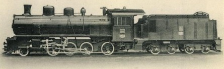
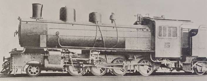
OAEG 2-8-0 Locomotive No. 107, one of the first batch of locomotives supplied by Hannoversche Maschinenbau Hanomag. When built these were the heaviest locomotives in East Africa. [1: p25]

One significant problem on the Mittellandbahn was the availability of water for the locomotives

Locomotives under British Management:

Under British administration the Tanganyika Railway started operation on 1st April 1919. It gained a series of different locomotives of German origin and some which the British forces had brought into Tanganyika during the first world war. Much of the German network had been destroyed by the retreating German forces. Ramaer says that around 4 miles was shaved off the journey between Dar-es-Salaam and Kigoma as the opportunity was taken to realign sections of the line to smooth out the worst curves.

Ramaer says that “Of the German locomotives, four classes were initially put into service on the Central Line, 14 of the Hanomag-built 2-8-0 tender locomotives of the former class 101-20 and now classified GG for German Goods, 22 2-8-0Ts, the German Einheits-vlok, now called class GT, for German Tank, 2 0-8-2 tanks and 6 0-4-0T pugs, dating back to the earliest years of the line, when the DKEBBG had used them for line building purposes. Later on, a total of seven 0-4-4-0T and 2-4-4-0T Mallets were also reconditioned.” [1: p53-54]

Only 5 German locos were salvageable on the Tanga Line: “three of the Orenstein & Koppel-built 2-8-0 tender locomotives of the German series 15-18 and two of the standard 2-8-0 tanks. Many of the Hanomag engines on the Central Line needed new cylinder castings, as the Germans had destroyed them in an attempt to prevent subsequent use of the engines. The new castings were made at the Parel works in Bombay of the former Great Indian Peninsula Railway and mostly fitted at Tabora, where the Germans had installed the main workshops for the Central Line. Thus 14 engines could be reconditioned, Nos 102-3, 105-6, 108, 111-17, 119-20.” [1: p54]

The two 2-8-0 tender classes disappeared after a fairly short life in comparison to other, British-built locomotives on the system. The first engines went in the early 1920s, when money was made available to buy new engines from Britain. The remaining Hanomag locomotives were laid up in about 1932, after the arrival of the new class GA Garratts. One, however, was temporarily brought back into service in 1937, equipped with an electric headlamp, to work the engineering train on the lightly laid Mwanza line, which was very susceptible to washaways, and was always troublesome to operate from the locomotive point of view. All the Mallet tanks were derelict at Tabora works in 1930-31 and were subsequently sold as scrap to Japan.” [1: p54]

TR GT 2-8-0T Class Locomotives

It seems that, of the German fleet, only the 2-8-0T locos had a significant life under British control. Numbered 101 and 102 they were finally scrapped at Nairobi works in 1951.

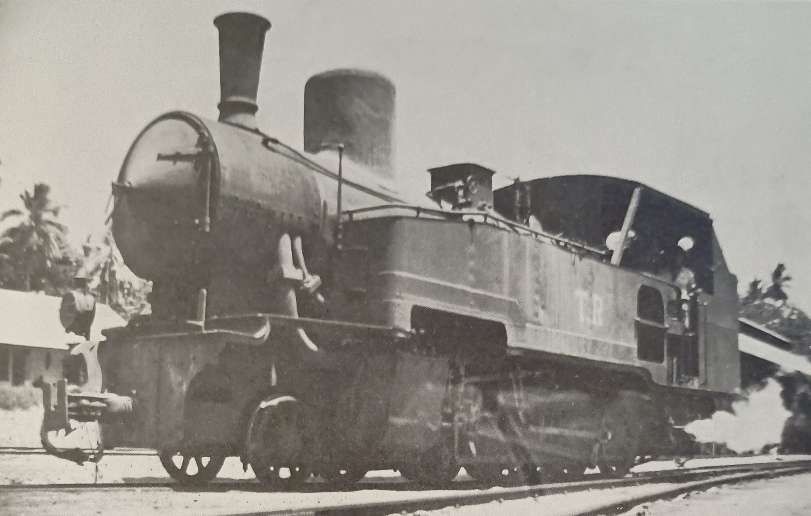
TR GT Class 2-8-0T in use as a shunter at Tanga. This and its sister locomotive were Orenstein & Koppel locomotives and were the last two German locomotives to be in use on the network in Tanganyika, (c) Public Domain. [1: p53]

TR NZ Class 4-8-0 Locomotives

TR NZ Class No. 1098 leaving Dar-es-Salaam with the mail train in 1922. These locomotives were originally ordered by the Nizam’s Guaranteed State Railway for use on its network in the Dominion of Nizam, better known as the Hyderabad State, in India, but served their entire working lives in Tanganyika, East Africa. Class 22 locomotives were 4-8-0 locomotives built in 1915 by Nasmyth, Wilson and Company. These locomotives were numbered TR1095–TR1098, later TR200–TR203, and later still, EAR2201–EAR2204, © Public Domain. [1: p55][9: facing p182]

In March 1916, while the four members of the class were on their way to India, they were commandeered to assist in the British invasion of German East Africa, where they entered service with the Tanganyika Railway (TR), still carrying their NGSR lettering and numbers 1095–1098. In the early 1930s, they were officially classified as the TR’s NZ class (the NZ being a reference to “Nizam”), and renumbered as 200–203. [4]

The class was later operated by the TR’s successor, the East African Railways (EAR), as its 22 class, numbers 2201–2204. In the late 1940s, two of them were transferred to the Southern Province Railway, [5] the isolated network developed to support the ultimately unsuccessful Tanganyika Groundnuts Scheme. Nos 2202 and 2204 were scrapped in 1952, and 2201 and 2203 in 1956. [4]

TR DL Class 4-8-0 Locomotives

The abbreviation ‘DL’ stands for ‘Development Loan’. The locomotives first carried running numbers 200-205 and later 300-305. They had piston valves and superheater rather than the slide valves and saturated steam of the Nizams.Ramaer says that, “They were derived from the lighter engines of the Nigerian Railways’ Emir Class. Like them, they had narrow fireboxes which were found to be less suitable for wood burning, so that the DLs were used mainly on the section between Dar-es-Salaam and Morogoro, where coal was available.” [1: p56]

TR No. 301 was a TR DL Class 4-8-0 locomotive. It was originally numbered ‘TR No. 201. This Class were the first British locomotives to be built for the TR. They entered service in 1923, (c) Public Domain. [9: p297]
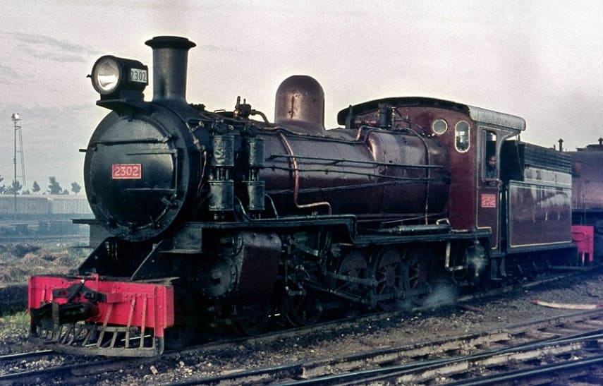
The TR DL class, later known as the EAR 23 class, was a class of 4-8-0 steam locomotives derived from the Nigerian Railways Emir class. The six members of the class were built by Beyer, Peacock & Co. in Gorton, Manchester for the Tanganyika Railway (TR). They entered service on the TR in 1923, and were later operated by the TR’s successor, the East African Railways (EAR). No. 2302 was originally numbered TR No. 202 and later TR No. 302, (c) Basil Roberts and licensed for reuse under a Creative Commons licence, (CC BY-SA 4.0). [8]

The DLs were survivors. Ramaer records that they were still is use in 1972 as EAR Class 2301-2306, although it was expected that they would be set aside in 1973. [1: p56]

TR MK 2-8-2 Class Locomotives

To resolve the problem of the DLs’ narrow fireboxes, a new locomotive design was ordered with a 2-8-2 wheel arrangement. The MK Class had a larger boiler and wider firebox. ‘MK’ was short for ‘Mikado’ which was the standard name across the world for 2-8-2 locomotives.

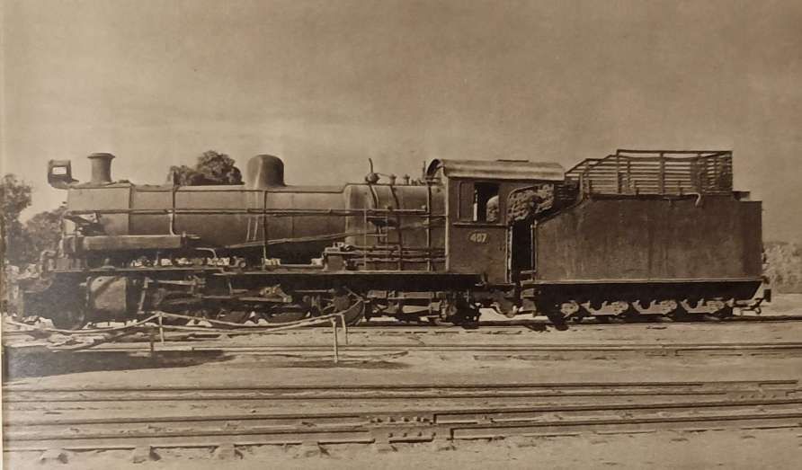
MK Class 2-8-2 Locomotive No. 407. This class of locomotive entered service in 1925-1927. [9: p299]

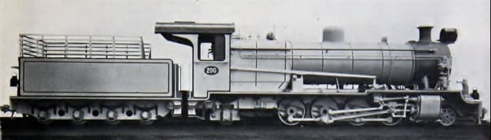
Later known as the EAR 25 class, the eleven members of the class were built by Vulcan Foundry, in Newton-le-Willows, Lancashire, for the Tanganyika Railway (TR). They entered service on the TR in 1925–1927. [10]

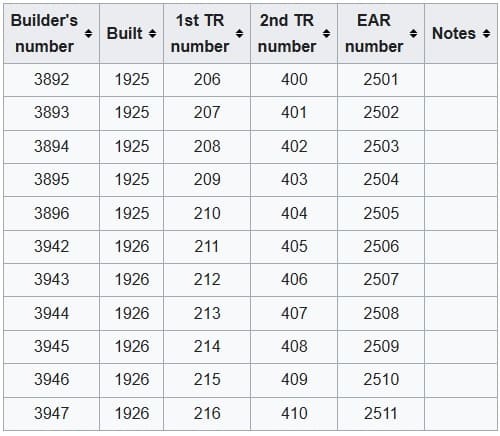
The eleven members of the Class were:

The eleven members of the original TR MK Class. [10]
Vulcan Foundry ex-Works photo of TR MK 206. [10]

This class was a great success and the Class were still in use at the time Ramaer wrote his book, although he notes that they were now on borrowed time. “One problem with the design of the MK was the fact that the leading pony truck provided insufficient guidance on the sharp curves on the Dar-es-Salaam-Morogoro and the Malagarasi-Kigoma sections, and the design of the Bissel truck [29] left something to be desired.” [1: p57] The solution was a redesign for the next class of locomotive – the RV.

TR RV Class 4-8-2 Locomotives

The RV Class were a redesign of the MK Class – the only significant changes were the extending of the frames by 2 ft 9 in., to accommodate the leading bogie of the 4-8-2 wheel arrangement. Ramaer says that, “As a result of this change it was found necessary to extend the smokebox to keep the cylinders at least roughly in line with the blastpipe and chimney.” [1: p57] The design creted problems – “the greater length of the smokebox created vacuum problems, resulting in insufficient boiler draught. In consequence the RVs were poor steamers and this manifested itself clearly in their early days when they worked the mail trains on the Central Line. They were particularly bad on the Dar-es-Salaam-Morogoro and Kigoma-Kazuramimba sections with ruling gradients of two percent and more, although the below-average quality of firewood on the western section also had something to do with these poor performances.” [1: p57-58] They were nor popular with the train-crews.

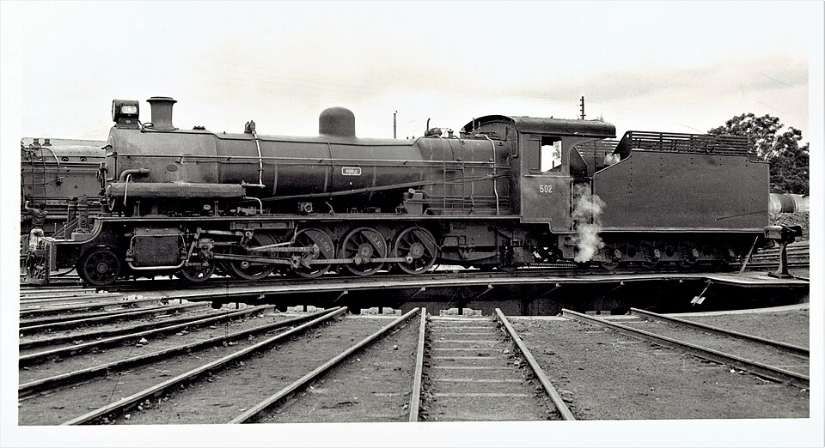
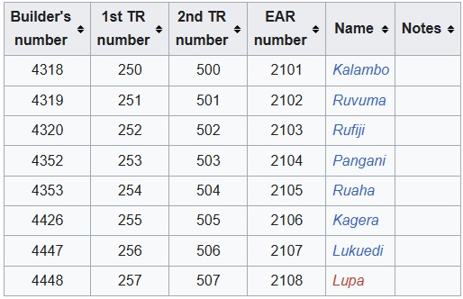
This is a Tanganyika Railway (TR) oil-fuelled RV (River) class 4-8-2 locomotive, later classified as the East African Railways (EAR) 21 class. It was first numbered TR252, then No. TR502 and later EAR2103. The locomotive was built by the Vulcan Foundry in Lancashire, between 1928 and 1930, © Public Domain. [2][9: p303]
TR Rv Class Locomotives – class list. [2]
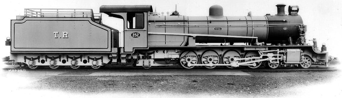
The ex-Works photograph of RV Class No. 252, © Public Domain. [3]

At the time of writing of Ramaer’s book (1972?), these locomotives were working out their lives on lighter duties from Morogoro shed and were unlikely to continue in use beyond 1973. [1: p58]

TR G Class 4-8-0 Locomotives (including 4 No. NW Class 4-8-0 Locos)

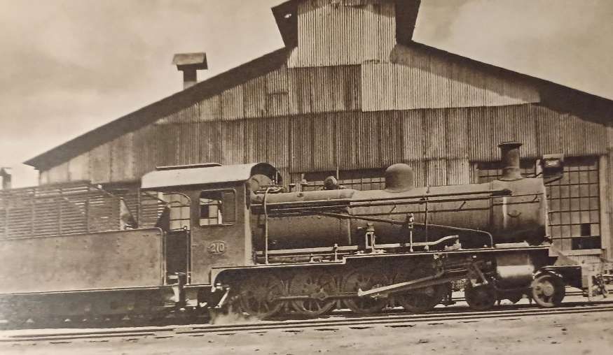
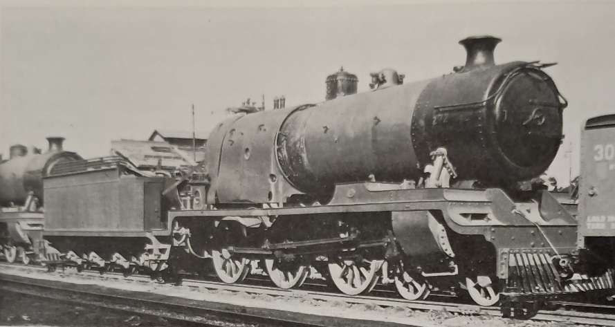
TR Class G 4-8-0 Locomotive No. 210 (later 22 Class) – these locomotives entered service in1928. Hill tells us that these locomotives were obtained to work two specific lengths of railway – the Tanga Line and the Mwanza branch off the Central Line, (c) Public Domain. [9: p299]

These locomotives were a redesign of the NZ Class. Ramear says: “The four Nizam 4-8-0s obtained in 1916 served as the prototype for the TR’s own G class, a very similar unsuperheated, slide-valve engine, thirteen of which were supplied by Stephenson and Nasmyth Wilson and put in service in 1928-31. They were again closely similar to the original BESA-designed 4-8-0s for India and thus provide, as the last 4-8-0s built for the TR, a direct link with the first engines of this wheel arrangement to see service in this part of the world. The first eight were supplied to the Tanga Line in 1928 and released F class engines 96 and 720, which had become very expensive to maintain. One of the new Gs, unassisted, could handle the mail trains, a marked improvement over the old and obsolete six-coupled engines. The G had an axle load of only 8-8½ tons, a necessity on the light track of the Tanga Line. The reason for their obsolete concept is not quite clear, however, if we remember that these engines were built at the same time as the KUR EA class Mikados. Their original running numbers 20-32 were later changed to 204-16, as the locomotives were considered to be direct descendants of the NZ class locomotives 200-3. After the amalgamation in 1948 the G class engines were renumbered 2205-17 and gradually taken out of service.” [1: p58]

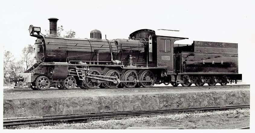
This is a later publicity photograph of an East African Railways (EAR) Class 22 steam locomotive, numbered 2217. These locomotives were very similar to the earlier batch of NZ Class locomotives but these four locomotives were initially given the Class name NW. Built by Nasmyth, Wilson and Co. in 1930, they had Works numbers 1588-1591. They later became EAR2214-EAR2217, © Public Domain. [4]

The EAR grouped a number of locomotives into the 22 Class in the late 1940s or early 1950s. This manoeuvre grouped ex-Tanganyika engines alongside a slightly newer batch of 1930 Nasmyth Wilson locomotives (Works Numbers 1588–1591) which also operated as Class 22s. [6]

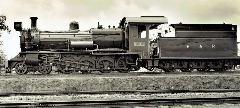
Another publicity photograph taken in the early 1950s which shows EAR2216, another of the same group of 1930-built, Nasmyth engines, EAR 2214-EAR2217, © Public Domain. [6]

The Tanganyika Railways Class G included four locomotives from a group initially known as NW Class 4-8-0s but others as well. We have noted above that the NZ Class of locomotives became EAR2201-EAR2204 (not Class G) and that the NW Class (included in Class G) later became EAR2214-EAR2217, two of which are pictured above. Others in Class G were to become: EAR2205 – EAR2209 Stephenson built locomotives (1927) Works Nos. 3959 -3963; EAR2210 – EAR2213 Stephenson built locomotives (1929) Works Nos. 3990-3991 & 4011-4012. [6]

All of the Class 22 locomotives were scrapped between 1956 and 1970. [6]

Renumbering

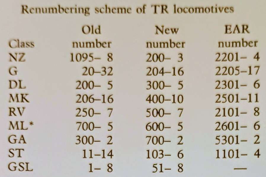
This table shows the revised numbering in use by the TR in the 1930s and the later EAR numbering scheme.

The TR changed all running numbers in the early 1930s to a much more logical and consistent system. … Each class started at a round figure in series blocks of hundreds.” [1: p59]

TR ST Class 2-6-2T Locomotives

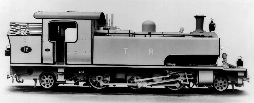
In 1930, the TR received four 2-6-2T shunters (the same type as the KUR ED1 Class). These were designated as the ST Class. They initially had running numbers TR Nos. 11-14, later TR Nos. 103-106. The locomotives were supplied by Vulcan. Under EAR control the locomotives were numbered EAR Nos. 1101-1104. [1: p60]

TR No. 12 was later designated TR No. 104 and later still, EAR No. 1101. This is an ex-Works photograph taken at the Vulcan Works in the UK, (c) Public Domain. [31]

Many of the EAR Class 11 locomotives were adapted to burn oil fuel rather than wood or coal and were still in use in 1972. [1: p60]

TR Sentinel GSL 50 Class Shunters

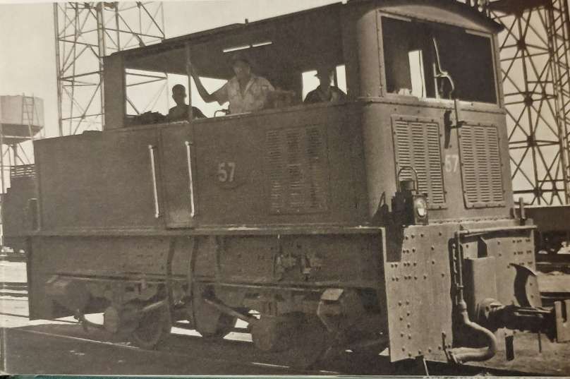
The TR GSL class locomotives were 0-4-0T geared steam locomotives designed for shunting and light duties. Built by Sentinel Waggon Works in Shrewsbury between 1929 and 1931, these locomotives were primarily used for shunting in yards and short-haul operations. A total of eight locomotives were built. They feature a side-tank design with geared drive, providing better traction on tight curves and low-speed manoeuvres, while the 0-4-0T Whyte notation reflects a rigid wheelbase for stability in confined spaces. [14]

A GSL Class Sentinel Shunter. Hill tells us that 8 of these small locomotives were purchased in 1930. They served in various roles until they were scrapped by the EAR in the early 1950s, (c) Public Domain. [9: p301]

Procurement of the GSL class occurred in the late 1920s amid broader post-war modernization initiatives across East African railways, with the Tanganyika Railway ordering eight units (which it numbered 50-57) to bolster yard operations as traffic volumes rose. Economic considerations favoured geared designs for their lower maintenance costs and suitability to tropical conditions, where conventional engines often suffered from corrosion and overheating. [14]

Ramaer tells us that, “Among their duties in the [1930s and 1940s] they were used as shed pilots, particularly for hauling out larger engines from the German-pattern roundhouse sheds to the turn-table, an arrangement frequently used at Central Line depots. After the war, they began showing signs of age and as newly built steam shunters were not readily available, they were replaced by diesels, the first on the TR. The last Sentinels, although outmoded, served at Tabora until the middle 1950s before being scrapped.” [1: p60]

TR GA 4-8-2+2-8-4 Garratt Class Locomotives

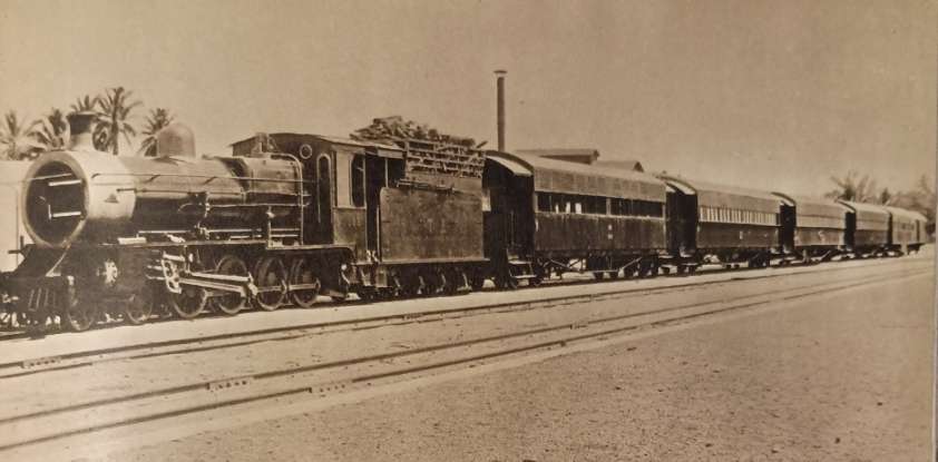
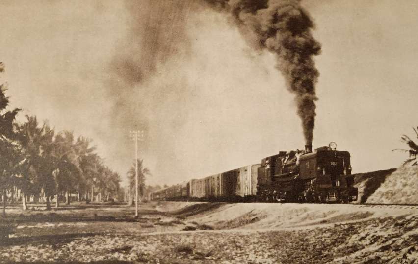
GA Class 4-8-2+2-8-4 Garratt No. 302 at the head of the Dar-es-Salaam -Kigoma mail train. [1: p60][9: facing p230]

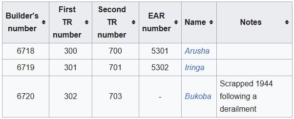
The TR GA class, later known as the EAR 53 class, was a class of 4-8-2+2-8-4 Garratt-type articulated steam locomotives. The three members of the class were built in 1930 by Beyer, Peacock & Co. in Manchester for the Tanganyika Railway (TR). They entered service in 1931, and, with one exception, were later operated by the TR’s successor, the East African Railways (EAR). The class list is shown below. [11]

The GA Class numbered only three locomotives. [11]

The design of the GA class locomotives was based upon that of the Kenya-Uganda Railways (KUR) EC2 class, which was built at about the same time by the North British Locomotive Company for the (KUR). The main design difference was that the GAs had higher, narrower front tanks than the EC2s. With their reduced water capacity, the GAs also had a lower axle loading, which made them suitable for operation over the World War I-damaged bridges on the Central Line in Tanganyika. [11]

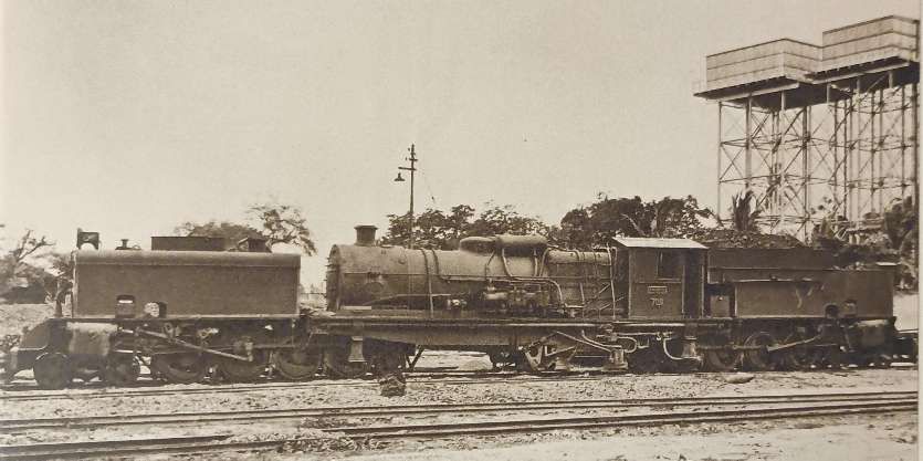
GA Class 4-8-2+2-8-4 Garratt No. 700 which was brought into service between Dar-es-Salaam and Morogoro in 1931. [9: p303]

Upon entry into service in 1931, the GA class locomotives were allocated numbers 300–302. Each of them was also given a name: the first two carried the names Arusha and Iringa, respectively, after the locations of the TR’s big road depots, and no. 302 was named Bukoba. Later, the GAs were renumbered 700–702. [1: p61]

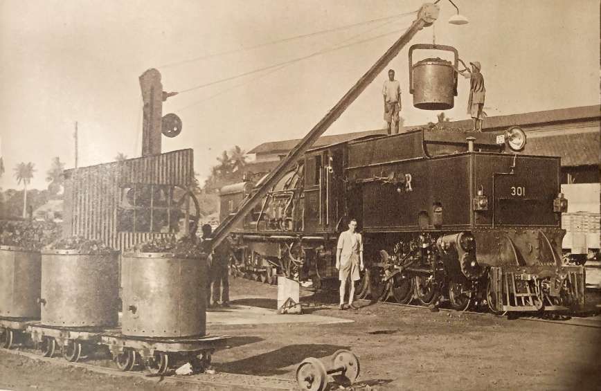
GA Class 4-8-2+2-8-4 Garratt No. TR 301 was coal-fired and can be seen here being refuelled at Tanga. [9: facing p198]

It was the TR’s general policy to allocate tender locomotives to standard duties, and use its Garratts only for the most demanding tasks. The GA class therefore normally worked between Dar-es-Salaam and Morogoro, the heaviest part of the Central Line. [12: p184]

The GA class’s operating costs were markedly lower than those of their predecessors. Even during the Great Depression, when traffic volumes greatly declined, they were of great operational benefit. Following the outbreak of World War II, they became indispensable. [1: p60]

Unfortunately one member of the class, TR No 702 Bukoba, was derailed by a washaway near Mikese during a night of bad weather in 1944. The crew was saved, but the locomotive was almost completely submerged and had to be scrapped. [1: p60]

In 1949, the TR and the KUR were merged to form the EAR, which took over the two survivors, classified them as its 53 class, and renumbered them 5301–5302. [1: p61]

The EAR also equipped the two survivors with a French-style ACFI feedwater heater, one of which had already been fitted to the last member of the KUR EC1 class, no 66. However, the feedwater heaters were later removed, partly because they achieved only limited improvement in thermal efficiency, and also as they had caused similar maintenance problems to those experienced by the KUR. [1: p61]

In the 1950s, the EAR 53 class locomotives were replaced on the Central Line by the new EAR 60 class locomotives, and therefore transferred to the northern part of the EAR system. Later, they returned to what had become Tanzania, to carry out transfer work in Dar-es-Salaam. They were withdrawn and scrapped there in the late 1960s. [1: p61][12: p184]

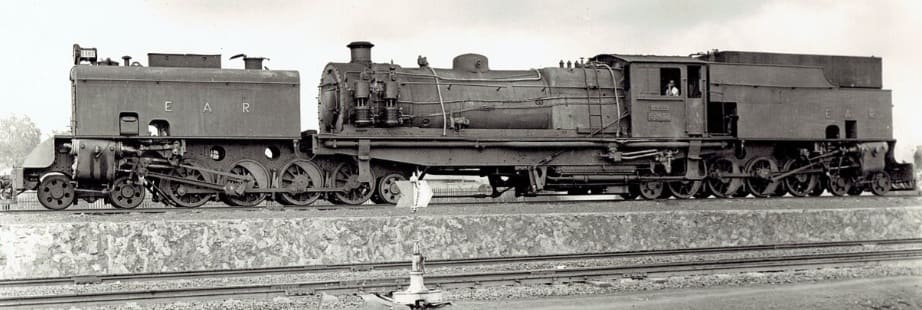
East African Railways publicity photograph of no. 5302 Iringa, c. 1953, (c) Public Domain. [11]

TR GB 4-8-2+2-8-4 Garratt Class Locomotives

The Tanganyika Railway (TR) GB class were 4-8-2+2-8-4 Beyer-Garratt steam locomotives were originally ordered by the British War Department for service in Brazil, although not built. Later the design was used for locomotives for India and Burma. Four were acquired by the TR in 1946 from Burma. They later became members of the East African Railways (EAR) 55 class. [13][1: p64]

GB Class Garratt locomotive No. 753 entered service in 1948 immediately prior to the amalgamation of the TR and the KUR. [9: p307]

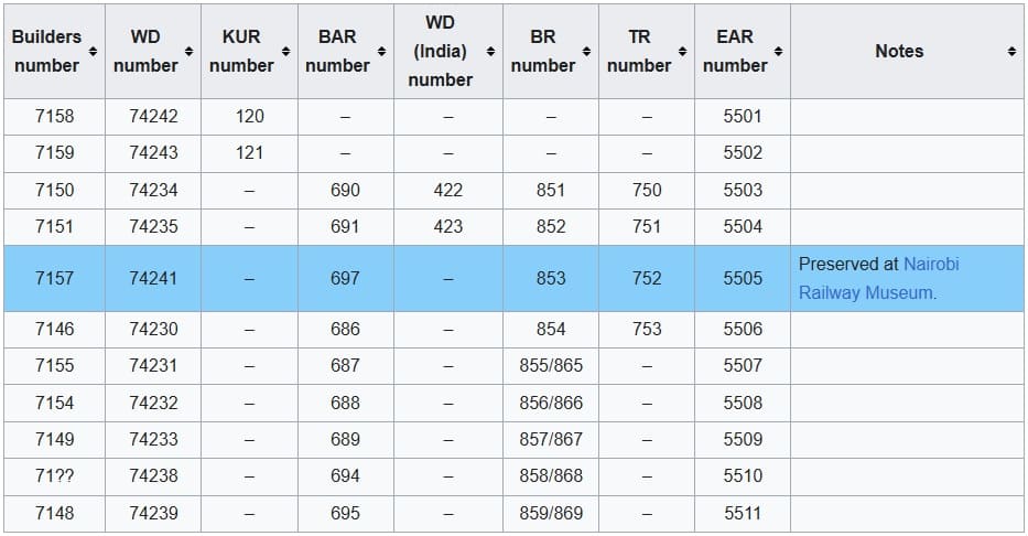
The Garratt locomotives that eventually made up the full 55 Class list were in use on the KUR and the TR. The full list is shown below:

The full EAR 55 Class list: as can be seen 4 of the Class served in Tanganyika, one of which (EAR No. 5505, ex-TR No. 752) is preserved at Nairobi Railway Museum. When serving in Tanganyika before the amalgamation of the two networks, these locomotives were numbered TR 750 – TR 753. [13]

TR ML 2-8-2 Class Locomotives

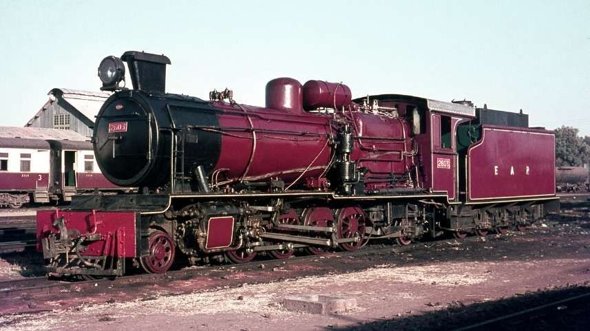
East African Railways (EAR) 26 class (ex-TR ML class) 2-8-2 steam locomotive no. 2603 at Tabora depot, Tanzania in 1968, © Basil Roberts and licensed for reuse under a Creative Commons licence (CC BY-SA 4.0). [7]

The six members of the ML class (an improved MK design) were built in 1947 by W. G. Bagnall, in Stafford, England, and delivered to the TR. They were later operated by the TR’s successor, the East African Railways (EAR), as its 26 class. In 1952, six further members of the 26 class were delivered to the EAR. They had been built by Vulcan Foundry, of Newton-le-Willows and Robert Stephenson & Hawthorns of North East England. [7]

TR BB Class Locomotives

Four 4-6-0 tender locomotives were found at El Shatt, at the southern end of the Suez Canal opposite Suez. These engines were originally built in 1926 at Ajmer works in India for the Bombay, Baroda and Central India Railway (BB&CI Railway) and “during the war nine were taken to Egypt to serve on the metre gauge Qena-Port Safaga railway from the upper Nile to the Red Sea. The 4-6-0s were found lying idle at El Shatt in 1945 and four were initially taken over by the TR in 1947-8.” [1:p67]

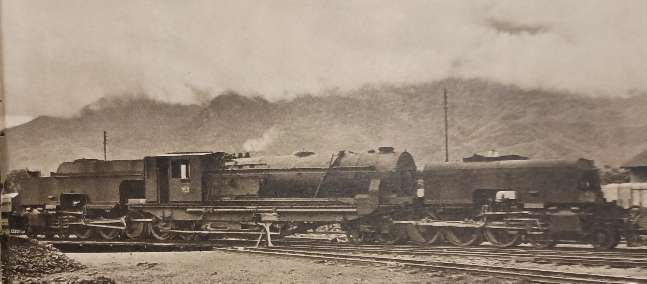
Ramaetr tells us that, “They were not successful in Tanganyika, in fact they were considered poor engines; the round-top fireboxes gave trouble and non-standard parts had been used in their construction. Hence, the five remaining engines were not taken over, while the four that had come to the TR as class BB (for BB&CI), Nos 270-3 later EAR 2001-4, were used mainly for shunting and occasional banking duties. They led a somewhat shadowy existence and even a good photograph of them does not seem to exist, the only one known showing No 272 with its old TR number being cut up at Dar es Salaam about 1957-8.” [1: p67]

Engines of the TR 2-6-0 BB Class being dismantled at Dar-es-Salaam in 1958. [1: p68]

TR MR Class 2-8-2 Locomotives

These locomotives were American-built. Many of these engines were built by various American manufacturers, including: Alco; Baldwin; and Davenport. These locomotives were known as ‘MacArthurs’. Those which ended up working on the Tanganyika Railways were manufactured in 1944. [1: p70] and arrived from Malaya in 1949. There were eight locomotives bought in this way which became the MR Class, running numbers 800-807. They were built by three different manufacturers and as a result had minor differences: Alco Nos. 800-802; Baldwin Nos. 803-805; Davenport Nos. 806-807. [1: p70]

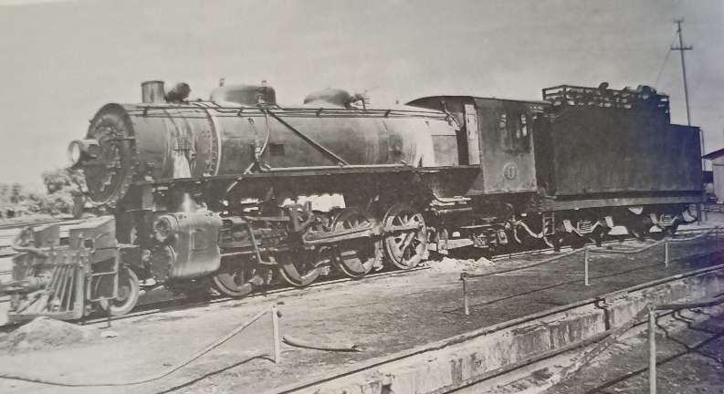
TR 2-8-2 No. 802 of the MacArthur austerity class at Tabora in the early 1950s before its conversion to oil fuel. [1: p68]

Ramaer tells us that, “At first there were problems, and modifications were needed to water tanks and reversing gear, which was undertaken at Nairobi works because of the limited capacity of the shops at Dar-es-Salaam. An additional difficulty was posed by the fact that the engines had not been designed to burn wood fuel. Grates were rather small and no rocking or dropping equipment was available. This circumstance gave rise to criticism because of the high ash residue of the wood fuel and only after the locomotives were converted to burn oil was the problem satisfactorily solved. After conversion the MacArthurs by then classified EAR 2701-8, did reasonably well.” [1; p69] The class was expanded in 1950 under EAR control when eight more were purchased from Malaya and one in parts from Nigeria. The last of these locomotives in service was based at Tabora and had been kept running by cannibalising other members of the class.

TR Sentinel Railcars

[9: facing p198]

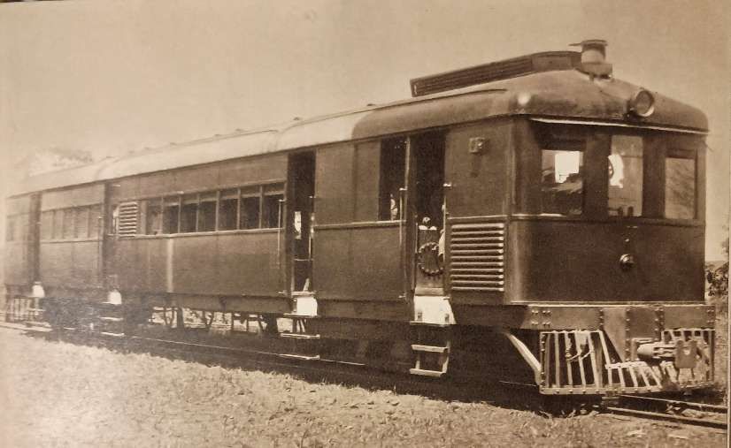
In 1929, two Sentinel rail cars were put into service between Moshi and Arusha in the North of Tanganyika. Although they were appreciated by the travelling public, they failed to attract sufficient traffic to make them an economic proposition on this section of the line.” [9: p199]

These railcars were manufactured by the Sentinel Waggon Works in Shrewsbury, in partnership with Cammell Laird. They were innovative geared steam-powered cars which were intended to increase service frequency and passenger convenience.

References

  1. R. Ramaer; Steam Locomotives of the East African Railways; David & Charles, Newton Abbot, 1974.
  2. https://en.wikipedia.org/wiki/TR_RV_class, accessed on 17th July 2026
  3. https://en.wikipedia.org/wiki/TR_RV_class#/media/File:TR_RV_252_works_photo.jpg, accessed on 17th July 2026.
  4. https://en.wikipedia.org/wiki/TR_NZ_class, accessed on 17th July 2026.
  5. https://rogerfarnworth.com/2026/03/04/narrow-gauge-industrial-lines-in-tanganyika-tanzania/
  6. https://www.flickr.com/photos/124446949@N06/35821749336, accessed on 17th July 2026.
  7. https://en.wikipedia.org/wiki/TR_ML_class, accessed on 18th July 2026.
  8. https://en.wikipedia.org/wiki/TR_DL_class#, accessed on 18th July 2026.
  9. M. F. Hill; Permanent Way Volume II: The Story of the Tanganyika Railways; East African Railways and Habours, Nairobi, Kenya; Watson & Viney, Aylesbury & Slough, 1957.
  10. https://en.wikipedia.org/wiki/TR_MK_class, accessed on 19th July 2026.
  11. https://en.wikipedia.org/wiki/TR_GA_class, accessed on 19th July 2026.
  12. A. E. Durrant; Garratt Locomotives of the World (rev. and enl. ed.). David & Charles, Newton Abbot, 1981.
  13. https://en.wikipedia.org/wiki/KUR_EC5_class, accessed on 19th July 2026.
  14. https://grokipedia.com/page/tr_gsl_class, accessed on 20th July 2026.
  15. https://commons.wikimedia.org/wiki/File:Carl_Vincenti_Bahnhof_von_Tanga.jpg, accessed on 20th July 2026.
  16. https://www.facebook.com/share/p/1ALffLxhDg, accessed on 18th March 2026.
  17. https://www.facebook.com/GermanColonialEmpire/posts/next-in-our-series-on-the-railways-and-steam-locomotives-of-german-east-africage/1345234614304324, accessed on 20th July 2026.
  18. https://gweaa.com/wp-content/uploads/2012/02/The-Indian-Railway-Corps-East-African-Expeditionary-Force_1.pdf, accessed on 20th March 2026.
  19. https://www.drehscheibe-online.de/foren/read.php?108,9540359, accessed on 20th July 2026.
  20. https://eisenbahn.de/lok-magazin/schienen-im-schutzgebiet-wie-das-deutsche-kaiserreich-seine-kolonien-mit-eisenbahnen-erschloss_27156, accessed on 20th July 2026.
  21. I cannot identify the source of this image, given the age of the locomotive and the likely date of the image it will be in the Public Domain.
  22. https://www.facebook.com/GermanColonialEmpire/photos/njussi-station-of-the-usambara-railway-in-the-german-colony-of-east-africa-from-/1339164168244702, accessed on 20th July 2026.
  23. https://en.wikipedia.org/wiki/List_of_Orenstein_%26_Koppel_steam_locomotives, accessed on 20th July 2026.
  24. https://de.m.wikipedia.org/wiki/Liste_schmalspuriger_Lokomotiven_von_Henschel, accessed on 24th March 2024.
  25. A.E. Durrant; The Mallet Locomotive; David & Charles, Newton Abbot, Devon, 1974.
  26. The Gölsdorf axle system is used to achieve quiet running and low wear-and-tear when negotiating curves. The axle system comprises a combination of fixed axles and axles that can slide transversely, all within a single, rigid locomotive frame. The system was invented by a young Austrian locomotive builder, Karl Gölsdorf, around the end of the 19th century. The first locomotive to use this principle entered service in 1897. [27]
  27. https://en.wikipedia.org/wiki/G%C3%B6lsdorf_axle, accessed on 21st July 2026.
  28. https://www.ebay.co.uk/itm/402962028832, accessed on 21st July 2026.
  29. The Bissell truck (or Bissel truck) is a swiveling bogie or pony truck assembly fitted on steam locomotives. Patented by American engineer Levi Bissell in 1857, its genius lies in placing the pivot pin behind the truck and just ahead of the front driving wheels, shortening the rigid wheelbase and allowing the wheels to smoothly navigate uneven curves. [30]
  30. https://www.gutenberg.org/files/25454/25454-h/25454-h.htm, accessed on 22nd July 2026.
  31. https://picryl.com/media/tr-st-12-works-photo-c12c48?zoom=true, accessed on 22nd July 2026.

Locomotives of the London, Brighton & South Coast Railway (LB&SCR) – 1920.

I have just been given a small pamphlet style paperback book compiled and published in June 1920 by W.G. Tilling.

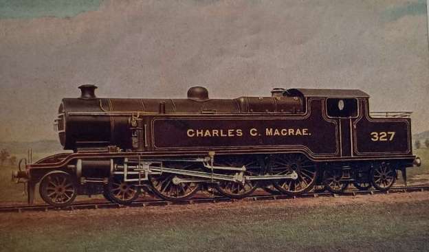
The featured image for this article comes from the frontispiece of Tilling’s book. It is a picture of the Class L 4-6-4T superheated large tank locomotive ‘Charles C. Macrae’. [1]

Tilling’s forward to the book states:

“For many years particulars of the locomotives running on our railway lines were difficult to obtain, but the Great Western Railway Company a year or two back broke through the usual official reticence by publishing a list of all their named engines. This was doubtless done to interest the general public in that railway, and I believe has proved a successful advertisement.

“Unofficial lists have also been published of the engines of the London and North Western Railway and a few of the smaller lines. Following these examples, I am prompted to deal with the locomotives of the London Brighton and South Coast Railway. This Company’s engines have probably had a larger circle of admirers than those of any other railway of similar size. The influence on locomotive design of the genius of the late William Stroudley (locomotive superintendent from 1871 until 1889) has appealed to the technical mind; whilst many, unconnected with railways, first attracted in their boyhood to this Company’s locomotives by their bright yellow livery and the fact that nearly all bore distinctive names, continue to take a keen interest in them long after their school days; and even now, when the engines are painted in less attractive colours, and the Stroudley classes are passing to the scrapheap, I feel sure there is a sufficiently large number interested to warrant the publication of this little book, and moreover, I am sanguine enough to hope that it may be of some use to many in the Company’s service.” [1: p3]

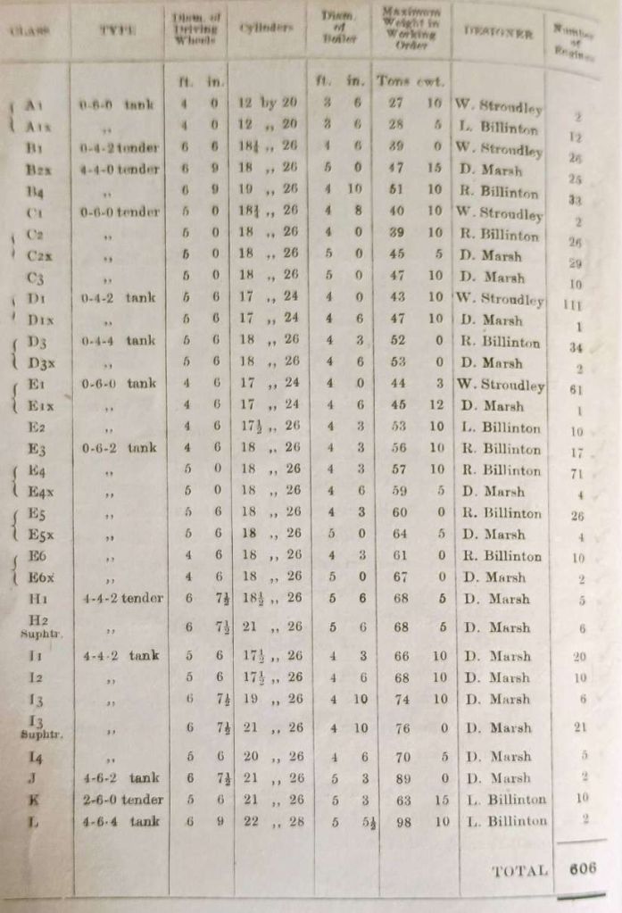
There were six hundred and six locomotives on the company’s roster in 25 different classes at the time that Tilling was writing these were:

The locomotives of the London, Brighton & South Coast Railway in 1920. [1: p4]

There were 172 tender engines and 434 tank engines (all of the side tank variety). In addition, Tilling writes, there were four tank engines attached to the Locomotive Department for shunting in the Locomotive Works and the three principal steam sheds.

Class B1 0-4-2 Express Passenger Locomotive. [1: facing p4]

Tilling continues:

“All engines are fitted with the Westinghouse brake, whilst a few running in conjunction with ‘foreign’ lines have the automatic vacuum brake in addition. These latter engines proved extremely useful during the war in dealing with the large amount of other Companies’ rolling stock that passed over the Brighton system.

“The passenger engines are painted umber colour lined out with two yellow lines with the Company’s arms in colours on the splashers and gold lettering, whilst the goods engines are painted black with red lining and gold lettering.” [1: p5]

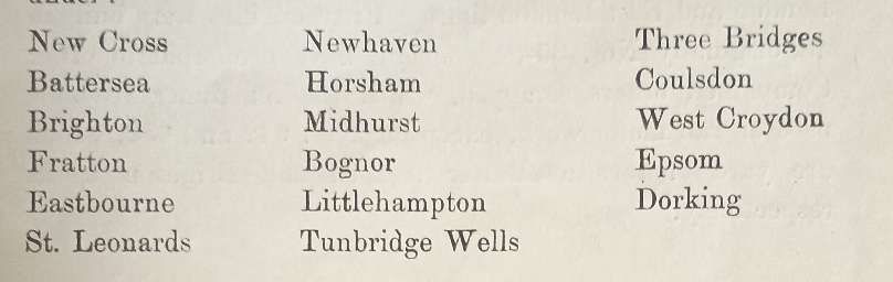
There were seventeen Locomotive Depots on the system. …

Locomotive Depots of the LB&SCR. [1: p5]
Class B4 4-4-0 Express Passenger Locomotive. [1: facing p5]
Class A1x 0-6-0T Rail Motor Engine. [1: facing p9]

Tilling describes the various classes of locomotive:

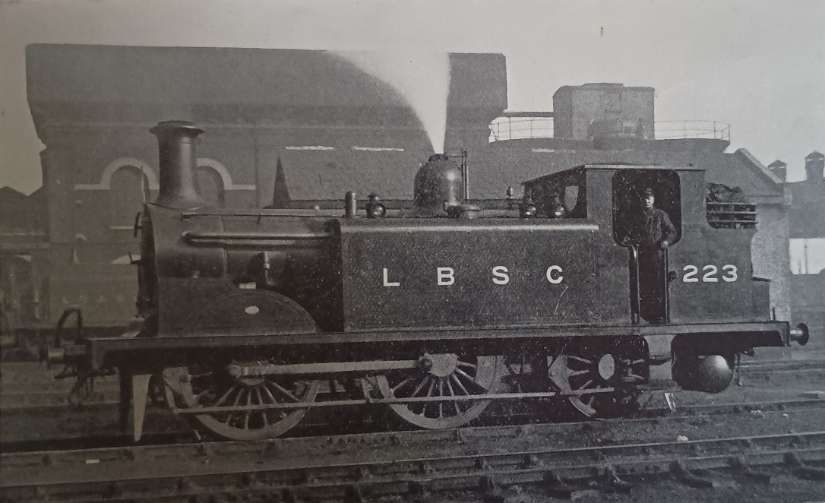
CLASS A: are small six-coupled side tanks with 4-ft. wheels, usually known as ‘Terriers’. They were designed [in 1872] years ago for working passenger trains on the South London and East London lines. Fifty engines were built in all, originally Nos. 35-84; several have been sold to other Companies, others scrapped, whilst the remainder are now used on rail motor work, excepting Nos. 642 and 682, which are yard engines at Battersea shed and Brighton works respectively.

“During the war several were taken over by the Government for working on light military lines in England and Scotland, for which their light weight only 27 tons 10 cwt. in working order made them very suitable. Although the oldest class now running on the line they are still very useful little engines, and several have recently been rebuilt with new boilers, etc., and are now classed A1x.

CLASS B: include Stroudley’s and R. J. Billinton’s four-coupled passenger express engines, subdivided into B1 (‘Gladstones’), B2 (‘Grasshoppers’), B3 (one engine only-213 ‘Bessemer’) and B4 (‘Scotchmen’). The B2 and B3 engines are now all rebuilt with larger boilers of the C3 type and classed B2x.

The Bl’s are front-coupled non-bogie engines, and they for many years worked the bulk of the express traffic between London and Brighton until superseded by the B4’s in 1901. The majority of the survivors are now employed on work usually done by tank engines, and several are now stationed at Tunbridge Wells shed. ‘Gladstone’ itself, after thirty-seven years, is still in evidence working slow trains between Brighton and the Metropolis. No. 172 is the only one of the class not fitted with Stroudley’s pumps and arrangement for utilising part of the exhaust steam to heat the water in the tender.

“The B2’s were the first express engines with a leading bogie to run on the LBS&CR. They were built to supersede the old single wheelers on the London-Portsmouth road with its many curves, and the first batch, Nos. 314-324, were all sent to Fratton shed, except No. 323, which worked from St. Leonards.

“No. 206 was badly damaged in the Wivelsfield accident of December, 1899, and also has the distinction of having worked the first sixty-minute Pullman train from Victoria to Brighton on 2nd October 1898.

“Several of the B2x’s have had wells fitted to their tenders to increase their water capacity, whilst Nos. 204, 206-209, 211, 212, 314, 323 and 324 now have the large tenders formerly on the C3 goods engines.

“The B4’s were nearly all built in Glasgow at the time of the Boer War, and many carried names reminiscent of that campaign, until Mr. Marsh, with a few exceptions, abandoned the naming of engines.

“The B4’s have been used for a number of trials at one time and another. No. 45 ran from 1902 till 1911 with a Drummond water-tube fire-box. No. 48 worked for some time early in 1905 fitted with templates over the boiler to test the clearance of the newly designed ‘Atlantics’. When Mr. Marsh decided to do away with the old yellow livery in 1905, he painted experimentally two of this class (Nos. 50 and 52) dark green. No. 52 also ran for some time in 1902/3 fitted with Holden’s oil fuel apparatus (as did also some of the B1, B2 and E5 classes). No. 53 ran for several years fitted with the Hotchkiss water circulator, whilst No. 59 worked with a ‘Phoenix’ superheater from 1912 to 1915.

“No. 54 formerly bore the name ‘Empress’, and was at one time used for all Royal specials. She carried the name ‘La France’ for a week in August, 1905, when working special trains in connection with the visit of the French fleet to Portsmouth.

“Several of this class have now been fitted with extended smokeboxes.” [1: p6-8]

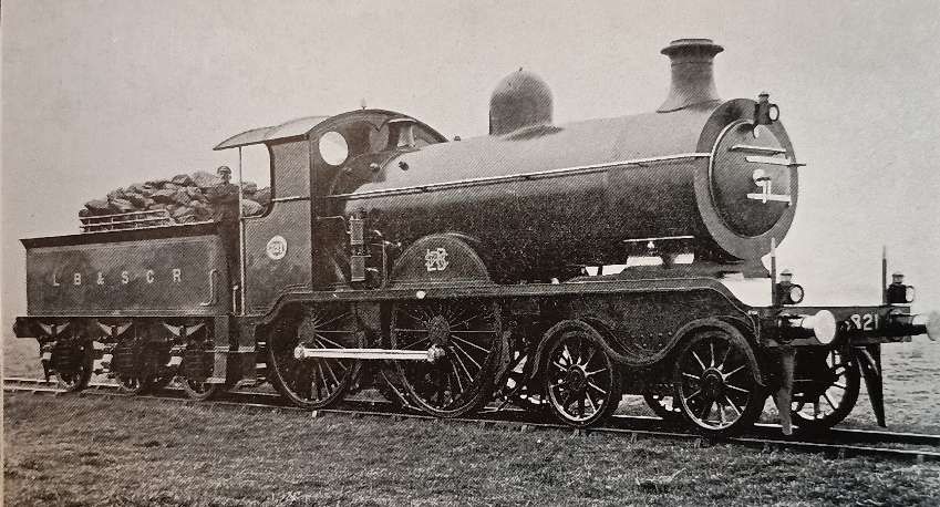
A Class B2x 4-4-0 Express Passenger Locomotive. [1: facing p12]
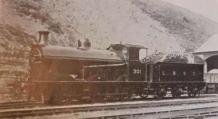
A Class C3 0-6-0 Main Line Goods Locomotive No. 301. [1: p46]
Class D1 0-4-2T Passenger Locomotive. [1: facing p8]

Tilling next focused on Class C locomotives:

Class C: are the tender goods engines, of which there are four varieties.

“The C1 class, when built, were amongst the largest goods engines in the country. Only two survive, No. 428 stationed at Fratton and No. 430 at Brighton. They have both recently had the Stroudley patent brake gear removed and the standard arrangement substituted, in order to cope with heavier goods trains. No. 430 in the early days of the war worked a troop special through to Doncaster.

“The C2’s were all built by the Vulcan Foundry Co. They are now being reconstructed as C2x’s, having the larger C3 boiler. Like the B4’s they have makers’ plates on the back of the tenders, but as the tenders have been interchanged at various times, the works numbers on the plates do not necessarily apply to the engines to which the tenders are now attached. Two of the C2x’s, Nos. 524 and 546, are at present (June 1920) on loan to the Great Western Railway; they are stationed at Old Oak Common depot and regularly work through onto the Brighton line.

“The C3’s are nearly all at present attached to the Horsham depot; they were an advance on the C2 class in boiler power, but the first five only had 174-inch cylinders, though the remaining five have 18 inch cylinders. They originally had 3112 gallon tenders, but latterly these large tenders have been transferred to engines of the B2x class and the C3’s now have the smaller ones formerly on the B2x engines.” [1: p8-9]

Tilling continues:

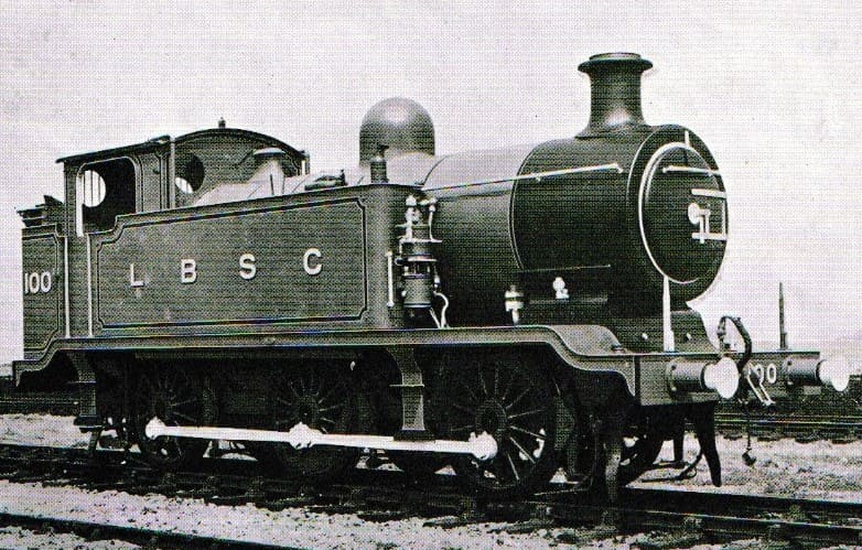
CLASS D: “The D1 class is Stroudley’s well-known front-coupled tank engine. Mr. Stroudley built no fewer than 125 of these engines, distributed over practically the whole period of his rule at Brighton. Whilst designed for the London suburban traffic they have been used on every class of work, and some of them are to be found at every shed on the system. Perhaps Fratton has seen the least of them, but Nos. 254 and 356 are there at present for working the Portsmouth-Chichester rail motor. No. 248 has side tanks with rounded ends as in the Marsh engines.

“No. 625 of this class was the first engine on this railway to be fitted with the Westinghouse brake; and 233 is noteworthy as having been for many years stationed at East Grinstead, being, in fact, the only engine ever stationed there.

“The D3 class is Mr. R. J. Billinton’s four-coupled bogie tank. Having a greater coal and water capacity than the D1’s, they are used on the longer routes. The valve gear and cylinders of this class are interchangeable with those of the C2 goods engines. Two of the D3’s (Nos. 396 and 397) have been rebuilt with the larger boiler of the I2 class.” [1: p9-10]

He continues:

Class E: “The ‘E’ CLASSES are the six-coupled side tanks, the oldest being Stroudley’s E1’s. The first of these appeared in 1874, and the last were turned out in 1891 by Mr. R. J. Billinton, who fitted his own design of boiler which added slightly to the weight. No. 689 has been entirely rebuilt, having new tanks, cab and boiler.

“No. 157 differs from all the other engines of its class. It was built for, and has worked all its life on the difficult Eastbourne-Tunbridge Wells line. It has side tanks and bunker slightly larger than the other E1’s, cylinders 18.25in × 26in, motion as Classes B1 and C1, and weighs 46 tons 18 cwt. in working order.

“Several of the E1’s were condemned for scrap in 1912, and Mr. L. B. Billinton designed an entirely new class to take their place. These are the E2’s. There are ten of this series, the second five having longer side tanks than the others. For a short time, when new, Nos. 103 and 104 worked in the centre of six coaches as a rail motor between London Bridge and Crystal Palace via Forest Hill.

“When Mr. Stroudley died in December 1889, an experimental six-coupled radial tank was in hand. This engine – No. 158 – did not commence work until just two years after his death, and while it had Stroud let’s standard 18.25in × 26in cylinders, it was essentially ‘Billinton’ in appearance. This engine weighed 52 tons 14 cwt. When Mr R. J. Billinton subsequently built sixteen others, they had his standard 18in x 26in cylinders. They are Class E3.

A Class E2 0-6-0T Goods Tank Locomotive, No. 100. [1: facing p36]
A Class E5 0-6-2T Mixed Traffic Tank Locomotive, No. 587. [1: facing p37]

Tilling continues:

“The E4’s and E5’s are similar to the E3’s but with larger driving wheels for mixed traffic and passenger work respectively, the capacity of the tanks is, however, larger. Twelve of the E4 class served on active service in France. They were Nos. 470, 481, 498, 504, 506, 516, 518, 562-565 and 580, and were chiefly employed banking trains on the St. Pol-Amiens line. They have all now been returned, and having been overhauled are back in service, painted black and unlined. They still bear the small plate inside the cab with which they were supplied before going overseas, to the effect that they are the property of the LB&SCR. of England. They were the only Brighton engines that were sent overseas during hostilities.

“Four engines of Class E4 have been rebuilt with the larger 12 class boiler and are now classed E4x, whilst four of the E5’s and two of the E6’s have been fitted with the larger C3 boiler and are now class E5x and E6x respectively.

No. 591, one of the E5’s, for some years regularly worked the 8.00 p.m. Grande Vitesse train from London Bridge to Newhaven; this engine is also noteworthy in having retained its name ‘Tillington’ and its yellow livery until 1917, over four years after all other ‘yellow’ engines had disappeared. Several of the E3’s and E4’s have been fitted with circular smokeboxes supported on a saddle, but when they retain the original sized boiler they are not classed E3x or E4x.” [1: p11]

Again, Tilling continues

Class H: This class “consist of the ‘Atlantics’, eleven in number. Mr. Marsh came to Brighton from Doncaster, and the first engine he designed for this railway was based on the familiar G.N. standard express type. Five were at first built by Messrs. Kitson of Leeds (Class H1). The H2’s were built at Brighton some years later; they have super-heaters which allow larger cylinders and lower boiler pressure to be used. Ten of them are stationed at Brighton and one at Eastbourne, and in conjunction with the ‘J’ and ‘L’ tanks they work all the heaviest expresses between London, Brighton and Eastbourne. No. 39 is frequently used for Royal specials, and bears the name ‘La France’. [1: p11-12]

A Class H2 Superheated 4-4-2 Express Passenger Locomotive No. 421. [1: facing p13]

The next class of locomotives that Tilling covers are:

Class I: “The ‘I’ class consist of the ten-wheeled tanks. The I1’s suffer from having too small boilers, but the later I3’s built for express work are very successful engines.

“No. 21 differs from the others in having 6 ft. 9 in. drivers, and the same cylinders and motion as the B4’s; it was fitted with a superheater during 1919. Twenty others of the I3’s are fitted with superheaters but have 21 in. x 26 in. cylinders.

“The I1’s are used on various local services; the I2’s and I4’s (which are the same as the I2’s, but with 20 in. cylinders and superheated) on such services as the London-Tunbridge Wells trains; whilst the I3’s work chiefly between London and the Coast on fast trains.

“No. 23 worked regularly for some weeks during 1909 in conjunction with the LNWR engine No. 7, ‘Titan’, on the ‘Sunny South Special’, running from Brighton through to Rugby one day and returning the next.” [1: p12]

A Class I1 4-4-2T Passenger Tank Locomotive No. 597. [1: facing p20]
A Class I3 Superheated 4-4-2T Express Tank Locomotive No. 22. [1: facing p21]

Class J: “The ‘J’ Class consist of two experimental tank engines built by Mr. D. Earle Marsh for the express service between London and the Coast. They are of the ‘Pacific’ or 4-6-2 type with 21 in. × 26 in. cylinders, driving wheels 6 ft. 7 in. diameter, and superheated. No. 325 is fitted with Stephenson’s valve gear, whilst No. 326 was the first engine on this line to be fitted with the Walschaert pattern valve gear.

A Class J Superheated 4-6-2T Express Tank Locomotive – N0.326 ‘Besborough’. [1: facing p28]

Tilling continues:

Class K: “The ‘K’ Class are the latest heavy goods engines designed by Mr. L. B. Billinton for the traffic between London and Newhaven. They are tender engines of the ‘Mogul’ or 2-6-0 type, superheated. The first of these was put into service in September, 1913. To meet the greatly increased goods service to Newhaven, due to the war, another five were built in 1916; they are fitted with top feed to the boilers and have Belpaire fireboxes, and having proved so successful in service others with an improved top feed system are now under construction at Brighton. No. 339, one of the earlier engines, was fitted with this new arrangement in April, 1920, and is illustrated in these pages.” [1: p13]

A Class K Superheated 2-6-0 Fast Goods Locomotive No. 337. [1: facing p29]

He also notes that in 1920 there were:

“Seven engines of the K class … under construction at Brighton, they will be numbered 347 to 353. The engines at present numbered 347 to 353 will in due course be re-numbered 214 to 220; and engines at present numbered 214, 217 and 219 will be re-numbered 618, 619 and 620.” [1: p46]

Another Class K Superheated 2-6-0 Fast Goods Locomotive, No. 339, which was fitted with the, then, latest arrangement of Top Feed (April 2020). [1: p45]

Class L: “The ‘L’ Class consist of two tank engines of the ‘Baltic’ or 4-6-4 type. These are the largest express tank engines in Britain, and were built by Mr. L. B. Billinton to work the fast non-stop service between London and the coast towns at an approximately uniform speed, and so save racing on the down grades. These engines have cylinders of 22 in. diameter and 28 in. stroke, and the boiler which is of ample capacity is fitted with a superheater. The driving wheels are 6 ft. 9 in. diameter, and sufficient water and coal is carried for the longest non-stop run between London and Portsmouth.” [1: p13]

In the years prior to 1920, the LB&SCR had locomotives not recorded by Tilling, these include:

LB&SCR Richmond class: This class was a series of 0-4-2 express passenger locomotives, designed by William Stroudley in 1877. They were a larger version of his “Lyons” class (D2) which were in turn developed from his successful ‘D-tank’ class of 1873. [2]

The six locomotives in this class were built at Brighton railway works and appeared in traffic between October 1878 and March 1880, intended to replace earlier classes designed by John Chester Craven on the heaviest express trains between London and Brighton. They performed well on these duties for a decade but were eventually replaced by Stroudley’s larger “Gladstone” class (B1). They were then transferred to Eastbourne and St Leonards to work on expresses from those towns. During the winter of 1900/01 members of the class were transferred to the duplicate list. Withdrawal commenced in April 1901 and was completed by November 1904. No examples were preserved. [2]

They were originally classified as “B class” together with the members of the larger “Gladstone class”. As all six locomotives had been withdrawn before D.E. Marsh introduced his letter/number classification scheme, they were never officially allocated a new class designation. They were, however, described as ‘D3 class’. [2]

Diagram of a Richmond class 0-4-2, (c) F. Burtt and Public Domain. [2]

Locomotives designed by and built during the tenure of John Chester Craven between his appointment in 1847 and his retirement in January 1870. A full list of these locomotives can be found here. [3]

The ‘Jenny Lind’: The ‘Jenny Lind’ was built in 1847 after a relatively complicated gestation by E. B. Wilson and Company. [4] But it proved to be so successful that the design was used by Wilson & Co. as their standard design and more than seventy examples were built for various railways, including twenty-four for the Midland Railway. It could be said to be the first to be mass-produced to a consistent pattern. Indeed, the manufacturers charged a hefty premium for variations, although in response to pressure, they later built a number of “large jennies”. [4]

Other manufacturers and railways also adopted the type. John Chester Craven, Kirtley’s successor at Brighton, built a class of five similar “Jenny Lind singles” from 1853 to 1854. [4] An enlarged type was also built by Beyer, Peacock and Company in 1860 for the Portuguese South Western Railway. [4]

The original Jenny Lind, (c) Public Domain. [4]

Class G: A prototype single locomotive, No. 151 Grosvenor, was designed by Stroudley and produced by Brighton railway works in December 1874. This was extensively tested before a second, scaled down locomotive No. 325 Abergavenny, was ordered in June 1876 and completed in January 1877. Both locomotives performed adequately, but Abergavenny was significantly less powerful than Grosvenor. A modified design was developed and twelve further locomotives were built between December 1880 and November 1881. The members of this class worked express trains between London and South Coast towns such as Portsmouth, Brighton and Eastbourne, and covered large mileages. The introduction of the Billinton B2 class made the singles redundant on the Portsmouth line and so several were transferred to Tunbridge Wells. … Withdrawals began in May 1907, and the last locomotive survived until May 1914. No examples have been preserved, but there is a model of No. 331 Fairlight in the museum at Sheffield Park on the Bluebell Railway. [5]

London Brighton and South Coast Railway Class G 2-2-2 Locomotive. 26 locomotives were produced in this class. ‘Grosvenor’ was the first, ‘Abergavenny’ was the second (with alterations) and subsequently 24 more were produced, (c) Public Domain. [5]

Very Early Locomotives of the LB&SCR: Wikipedia also provides a list of all the locomotives owned by the LB&SCR from its inception (1846) until 1849. [6] That list includes a significant number of locomotives built by a series of specialist locomotive builders including: Sharp, Roberts & Co.; Jones, Turner and Evans; G and J Rennie; Edward Bury & Co.; William Fairbairn; George Forrester & Co.; Sharp Brothers; R and W Hawthorn Ltd.; Jones & Potts; John George Bodmer; Timothy Hackworth; and Stothert & Slaughter. Many of these were built for companies which formed the LB&SCR in 1846 and were built as early as 1838.

The majority of the locomotives acquired were owned or ordered by one of the three constituent railways, but some had been ordered by the Joint Committee. After the Joint Committee’s dissolution, some locomotives were ordered by John Gray, the new locomotive superintendent, from Timothy Hackworth and delivered during 1847 and 1848. Others were purchased from Stothert & Slaughter between 1847 and 1849. After this date the railway’s new locomotives were designed and built by John Chester Craven, usually at Brighton railway works. [6]

A List of Locomotive of the LB&SCR in 1920: Tilling provides a detailed list, locomotive by locomotive, of locomotives in use by the LB&SCR in 1920 to complete his book. These tables can be found here.

References

  1. W.G. Tilling; The Locomotives of the London, Brighton & South Coast Railway; Tilling, London, 1920.
  2. https://en.wikipedia.org/wiki/LB%26SCR_Richmond_class, accessed on 13th June 2026.
  3. https://en.wikipedia.org/wiki/List_of_Craven_locomotives, accessed on 13th June 2026.
  4. https://en.wikipedia.org/wiki/Jenny_Lind_locomotive, accessed on 13th June 2026.
  5. https://en.wikipedia.org/wiki/LB%26SCR_G_class, accessed on 14th June 2026.
  6. https://en.wikipedia.org/wiki/List_of_early_locomotives_of_the_London_Brighton_and_South_Coast_Railway, accessed on 14th June 2026.
  7. https://rogerfarnworthsrailways.wordpress.com/wp-content/uploads/2026/06/lbscr-locos-1920.pdf

The Mother of All Inventions. …

Why were railways created?

What were the circumstances which brought about their existence?

History does not make it easy to take out one example from a steady continuum of change. …

David Wilson writes: “There have been track or plateways since Roman times. You might say that these could be brought within the term railway and therefore the Romans invented the railway.” [1: p61]

Except there were railways of a sort, at least as far back at 600 BCE, possibly going back even further, maybe as far back as 1000 BCE. The clearest example being the Diolkos Trackway. [2] This was a paved trackway near Corinth in Ancient Greece which enabled boats to be moved overland across the Isthmus of Corinth.

David Wilson continues: “For most people, however, the railways began with the Stockton and Darlington (S&D), though I’m sure many people already appreciate that history is not always what it seems.” [1: p61]

David Wilson tells us that if one wished to take the view that the first ever railway was the first to have been authorised by Parliament, then the first railway was built in Leeds – The Middleton Railway. “The Middleton Railway was given Parliamentary Assent in 1758 and began using steam traction in 1812, two years before the advent of Mr Stephenson’s first locomotive, ‘Blucher’, and 13 years before the opening of the S&D.” [1: p61]

But there is more to consider. … The Lake Lock Rail Road opened in 1798 (arguably the world’s first public railway). It carried coal from the Outwood area to the Aire and Calder navigation canal at Lake Lock near Wakefield. [3][4] The Surrey Iron Railway was the first railway to be authorised by the UK Parliament (21st May 1801).  It was a horse-drawn railway which ran between Wandsworth and Croydon. [5][6][7][8][9] It was followed by The Carmarthenshire Railway or Tramroad (authorised by Act pf Parliament on 3rd June 1802). It was a horse-drawn goods line, located in Southwest Wales, the first public railway first authorised by Act of Parliament in Wales.[3][10][11][12]

The Low Moor Furnace Waggonway was constructed in 1802. It connected Barnby Furnace Colliery to Barnby Basin on the Barnsley Canal. It was replaced in 1809 by The Silkstone Waggonway which operated until 1870. [19][20] The Merthyr Tramroad, between Merthyr Tydfil and Abercynon, also opened in 1802. [5][13][14][15][16][17][18] The Lancaster Canal Tramroad (also known as the Walton Summit Tramway or the Old Tram Road), was completed in 1803. It linked the north and south ends of the Lancaster Canal across the Ribble valley. [21][22]

The first steam locomotive to pull a commercial load on rails was Penydarren (or Pen-y-Darren) was built by Richard Trevithick. It was used to haul iron from Merthyr Tydfil to Abercynon, Wales. The first train carried a load of 10 tons of iron. On one occasion it successfully hauled 25 tons. However, as the weight of the locomotive was about 5 tons the locomotive’s weight broke many of the cast iron plate rails. [5][13][14][15][16][17]

We could go on to mention:

  • The Croydon, Merstham & Godstone Goods Railway opened in 1805; [23]
  • The Sirhowy Tramroad opened in 1805; [24]
  • The Ruabon Brook Tramway (also known as Jessop’s Tramway or the Shropshire Union Tramway) also opened in 1805; [25][26][27][28]
  • The Middlebere Plateway (or Middlebere Tramway) opened on the Isle of Purbeck in 1806; [29][30][31][32]
  • The Monmouthshire Canal Tramway, open by 1806; [33][34]
  • The Oystermouth Railway, opened in 1806; [35][36] and
  • The Doctor’s Tramroad, Treforest which opened in 1809. [37][38][39]
  • The Monmouth Railway authorised by the UK Parliament in 1811. [5][72][73]
  • The Kilmarnock & Troon Railway which opened in 1812. [5][74][75][76][77]
  • The Killingworth Waggonway of which a first stretch opened in 1762 and which was extended in 1802, 1808 and 1820. [78][79][80][81][82][83]
  • The Haytor Granite Railway of 1820 which not only transported granite from Dartmoor as freight but ran on granite rails. [84]

The drawing of the locomotive Blücher (below) was done by Clement E. Stretton, © Public Domain. Blücher was built by George Stephenson for the Killingworth Waggonway. It was the first of a series of locomotives which established his reputation as an engine designer and eventually “Father of the Railways”.

We could list other railways opening before the S&D in 1825. The use of steam power at The Merthyr Tramroad and The Middleton Railway preceded its use on the S&D. A very strong claim to be the most significant development in the early 1800s could be made on behalf of The Middleton Railway. But it is the Stockton & Darlington (S&D) Railway which has caught the imagination and it is the 200th anniversary of the S&D which is being celebrated in 2025 as the beginning of the railway age.

Why is this?

It is clear that the claim to fame of the Stockton and Darlington (S&D) is lessened, at least, by the prior claim of the Middleton Railway both as first to be sanctioned by Parliament and first to make commercial use of steam power. The claims associated with other railways which preceded the S&D also must be significant. However, there is one important and fundamental difference between it and them. David Wilson says that, unlike the Middleton Railway, “the S&D was constructed with a view to carrying other companies’ goods and, to a lesser extent, to carry people.” [1: p61]

In addition, he says, “Bear in mind the distinction between the carriage of goods and people, and between carrying one’s own goods and those of others. In many ways this type of division is what distinguishes the modern concept of the railway as a system for the transport of goods and passengers on a hire and reward basis from the early plateways and railways such as the Middleton, which were not essentially built to carry anything other than goods, typically coal, for their owners.” [1: p61]

Perhaps, though, there are more grounds for the place taken in history by the S&D. Rather than just running between a pithead and a coal wharf on a canal, river or road and serving specific industrial concerns, the S&D also was built by public subscription and linked one town to another.

David Wilson continues: “To arrive at a description of what constitutes a railway we have to enlarge our definition to include not only Parliamentary Sanction, the use of rails or tracks, and the carriage of goods, but also the carriage of the public, the carriage of public goods and that one settlement be joined to another by the laying of a line paid for through the issue of shares. Thus … a railway is a set of tracks laid between two centres of habitation, which carries goods or people for commercial reward and has been authorised by Act of Parliament. It will have been built through the raising of public funds, either through the sale of shares in it or via government spending from the public purse.” [1: p61]

Let’s return to the era before the existence of the steam locomotive, the era of that list of lines highlighted above (and many more).

David Wilson comments: “The growth of the coal mining industry in the later part of the 17th and early 18th century had led to a growth in the plateway systems used to move the coal from the pit head to [a road], canal or river for shipment to the growing cities and the newly built mills. By as early as 1645 there were wagonways taking coal from the Durham coalfields down to the Tyne. By 1800 there were more than 100 miles of these plateways in the Tyneside area alone.” [1: p61]

Similar developments were taking place elsewhere in the UK:

  • The first overground railway line in England may have been a wooden-railed, horse-drawn tramroad which was built at Prescot, near Liverpool, around 1600 and possibly as early as 1594. Owned by Philip Layton, the line carried coal from a pit near Prescot Hall to a terminus about half a mile away. [40]
  • The Wollaton Waggonway in Nottinghamshire was in use by 1604. [5]
  • In East Shropshire and around the Severn Gorge; [41][42] A railway was made at Broseley in Shropshire some time before 1605 to carry coal for James Clifford from his mines down to the River Severn to be loaded onto barges and carried to riverside towns. It is possible that Clifford’s ‘railway’ was in use as early as 1570 and a similar line may well have been constructed by William Brooke near Madeley, again down to the River Severn. [43: p21] By 1775, there were a number of both short and long tramroads in the area around the Severn Gorge.
  • The Tranent to Cockenzie Waggonway was built by the York Buildings Company of London, to transport coal from the Tranent pits to the salt pans at Cockenzie and the Harbour at Port Seton, in Haddingtonshire, now East Lothian. [5][44]
  • The Alloa Wagon Way was constructed in 1768 by the Erskines of Mar in Alloa, to carry coal from the Clackmannanshire coalfields of central Scotland to the Port of Alloa. [45]
  • The Halbeath Railway opened in 1783, from the colliery at Halbeath to the harbour at Inverkeithing. [46][47]
  • The Charnwood Forest Canal, sometimes known as the ‘Forest Line of the Leicester Navigation’ was, under the guidance of William Jessop, using railways to supplement the canal between Nanpantan and Loughborough wharf, Leicestershire by 1789. [5][48]
  • The Butterley Gangroad (or Crich Rail-way) was built by Benjamin Outram in 1793. [49][50][51][52][53][54][55][56][57]
  • The Earl of Carlisle’s Waggonway opened in 1799 from coal pits owned by George Howard, 6th Earl of Carlisle around Lambley to Brampton, Cumbria. [51][58] There is some confusion over dates. The earliest opening date quoted is 1774, the latest 1799. [59] Dendy Marshall says that it was built in 1775. [60] C.E. Lee says it was constructed in 1798. [59][61]

It is perhaps easy to loose sight of the scale of these industrial undertakings. The rapid expansion of mining, plateways and railways “led to an increase in the numbers of horses in use … and a growth in the amount of horse feed needed. By 1727 The Tanfield Waggonway, in Co. Durham, carried 830 wagon loads of coal daily that’s a lot of horses.” [1: p61][5][62][63] “In 1804, the Middleton Colliery line was carrying 194 loads per day. Each wagon held about 2.5 tons and required the use of one horse and driver.” [1: p61]

A crisis in the use of horses and wagons occurred early in the 19th century with the advent of the Napoleonic Wars. The conflict became a significant drain on both horse and horse feed availability. The resulting inflation in the price of horses and feed lowered the profitability of each wagon load of coal. David Wilson says that, “The more visionary (or greedy, depending on your point of view) pit owners started to search for alternatives to the horse to move their goods to market. They provided their pit engineers with money and materials to experiment with steam power to replace horse power.” [1: p61]

Of course, steam power wasn’t new. Knowledge of the power of steam had been around since before the Common Era in Greek society [64][65][66] and the pits themselves had steam engines for pumping out the water and for lifting coal to the surface, or as winding engines on rope-worked inclines. [66][67] Newcomen’s first engine was installed for pumping in a mine in 1712 at Dudley Castle in Staffordshire. [66][68] What was new was first, the expiry of Boulton & Watt’s patent for a high-pressure steam engine, [5][69] and second, the idea of making the steam engine mobile, thus creating the steam locomotive. What eventually became even more revolutionary was the idea of creating a network of railways to serve the whole country. [1: p61]

We sometimes talk of a ‘perfect storm’ (a particularly violent storm arising from a rare combination of adverse meteorological factors), when we are talking about a series of adverse conditions occurring at the same time – a situation caused by a combination of unfavourable circumstances. The opposite of a ‘perfect storm’ is usually assumed to be a period of calm. However, the true opposite of a perfect storm is the occurrence (co-occurence) of a series of positive factors which combine to produce something significantly valuable. Wilson says that “as with almost anything man-made, there must be certain ingredients present. To bake a cake you need eggs, flour, milk etc. and in creating a railway you need, metalworking skills, engineering expertise, labour, capital and an incentive.” [1: 61]

The early years of the 19th century saw a timely co-incidence of these and other factors:

  • growing shortages of horse and feed coupled to the rising prices of both;
  • poor road conditions;
  • a rapidly developing understanding of engineering – Wilson suggests that this was “as a consequence of the more theoretical works of philosophers such as Newton, Descartes and Leibniz. … Such men have a reputation as creators or exponents of the mechanistic world view. Prior to the works of these men many had thought, and indeed some still do think, that the earth was a living entity. However, the views espoused by Newton, Descartes and Leibniz came to be accepted, the world was made up of dead, lifeless and inert matter, here to benefit mankind;” [1: p62]
  • the availability of skilled and unskilled labour – particularly the ‘navigators’ who were skilled in the techniques of earthworks, tunneling and bridge building – the men who had earlier built the canals. (“These men were to become the skilled labour of the railway construction industry and in turn they passed on their skills to the former farm labourers who were recruited to railway works as the lines progressed along their routes“); [1: p62]
  • developing metalworking skills – “the Darby family, who set up the … Coalbrookdale foundry. had acquired new skills in metalworking from tinkers, in what is now the Netherlands;” [1: p62] After constructing Ironbridge, “the Coalbrookdale ironmasters began to widen their horizons. One of their number, John “Iron Mad” Wilkinson, constructed what was reputedly the first iron barge and, more importantly, … the smiths of Coalbrookdale collaborated with Richard Trevithick in the construction of his locomotive – they cast the cylinder block and the plates for the construction of the boiler;” [1: p62]
  • the increasing availability of financial capital;
  • the increasing birth rate and the better health of the work-force which provided the necessary labour while engineering work was still labour-intensive.

The Availability of Capital

Among the physical factors listed above is an interesting financial factor which will bear some scrutiny. Wilson tells us that “the capital to build the world’s first public railway came, not from the Government, but from the Society of Friends, the Quakers.” [1: p62] He notes too that the Darby family whose Coalbrookdale plant had such a formative influence in the early days of the industrial revolution, were also Quakers. Wilson explains that Quakers were isolated from much of society and public life because of a refusal to sign up to the articles of faith of the established church. However, the same religious views made them sympathetic to works performed for the public good. Various Quaker families began to take an interest in the developing railway sphere. The website quakersintheword.org [70] tells the story of the significant role played in financing railways played by the Quakers.

In 1818 a small group of Quaker businessmen, including Edward Pease and his son Joseph from Darlington, Benjamin Flounders and the banker Jonathan Backhouse, met to discuss the possibility of building a railway from Darlington, passing several collieries, to the port of Stockton.” [70] 

The Act of Parliament required for the work to take place faced significant delays in the parliamentary process. “The delay proved very significant, as in April 1821 Edward met George Stephenson and recruited him as an engineer for the railway. The original intention had been that the coaches would be horse drawn, just like all the others now in existence. However, George convinced Edward that steam engines were the future for railways, and that he could build them. The Pease family then put up much of the capital that enabled Stephenson to establish a company in Newcastle, where he built the locomotives.” [70]

After the opening of the Stockton & Darlington Railway, “the railway network grew under the guidance of Edward’s son Joseph, who opened the Stockton & Middlesbrough branch in 1828. … In 1833 Joseph became the first Quaker to enter Parliament and the railway interests passed to his brother Henry. In 1838, Henry opened the Bishop Auckland & Weardale line, followed by the Middlesbrough and Redcar line in 1846. Henry wanted to traverse the Pennines and in 1854 he started the Darlington & Barnard Castle line, which opened in 1856.” [70]

Quakers were often involved in railway developments in the 19th century, for instance, “in 1824, a group of merchants, including Quaker philanthropist and anti-slavery campaigner James Cropper, went to see the Stockton and Darlington railway.  They soon began building the Liverpool and Manchester railway, which opened in 1830.” [70]

Incidentally, Quakers “were also responsible for two innovations that improved the way these new passenger railways worked – timetables and tickets. James Cropper produced a 12-page timetable for the Liverpool and Manchester railway, probably the first railway timetable ever.  It was the forerunner of Quaker George Bradshaw’s Railway Companion, published in 1839. Bradshaw’s became a household name for anyone using the railways. … The second innovation was the railway ticket. In 1839 Thomas Edmundson, another Quaker, was appointed station master at Milton, on the Newcastle and Carlisle line.  He was unhappy that customers paid their fares directly to him without receiving a receipt.  Consequently he introduced the railway ticket, which came into general use with the creation of the Railway Clearing House in 1842.” [70]

The Birth Rate and Increasing Health of the UK Population

Wilson points us to one more significant factor in the development of railways in the early 19th century. “Seemingly disconnected and irrelevant factors were playing their part. During the period from the end of the civil war (1649) onwards there was a growing awareness of the value of the human being as resource, and a concerted effort was made to increase the birth rate and to cut the death rate. … This did not stem from any rise in humanitarianism but from a recognition that people were worth money. After all, in the 1640s and on into the 19th century, slavery was still common throughout the so-called civilised world, including Britain. Improvements in diet and sanitation increased life exресtancy. It is no coincidence that the first workhouses began to appear around the middle of the 17th century – a reasonably fit and healthy population produced more than a sickly and unfit one.” [1: p62]

By the beginning of the 19th century, the conditions were in place for a major economic expansion. A growing empire and military strength ensured the supply of raw materials and provided a growing market place for the products made from them. An expanding population provided the physical means by which the empire might be held together. Technology provided the ability to carry out the grand design. The workhouses and other reforms had created a disciplined workforce.” [1: p62-63]

By 1850, a quarter of a million workers – a force bigger than the Army and Navy combined – had laid down 3,000 miles of railway line across Britain, connecting people like never before. [71]

And Finally …

Wilson suggests one other, less definable, reason for the dramatic welcome given to steam technology in particular. He suggests that there was a more visceral connection to steam power which predisposed humanity to embrace the technology.

No doubt, the S&D was at the forefront of engineering developments it was “the white heat of technology, the frontier of science.” [1: p63] Wilson asks us to consider that there was (and still is) a connection between “a piece of primitive industrial technology, the steam locomotive and its enduring popularity, and an ancient, and some might say mystical, view of the world.” [1: p63]

Wilson says: “Prior to the advent of the mechanistic world view in which cause and effect, hard science and hard facts are the order of the day, people held to a more animistic philosophy. Miners would pray to the earth before digging it up. … In this more mystic view of the world things were not made of chemicals and atoms, molecules and the force of gravity. They were composed of the four elements – earth, air, fire and water.” [1: p63] He asks us to consider whether “the reason so many people took to the steam engine and the railway when it began was that the steam locomotive has a unique blend of the four elements not only in its construction but in the very forces and requirements necessary for its movement. … [It] is made from the ores of the earth, heated by fire which needs air to burn. The metals from the forge are then tempered by water whilst being shaped on the anvil. In order to make the steam locomotive work, coal, or part of the earth, is consumed along with air in a fire which turns water into steam which in turn brings the locomotive to life.” [1: p63]

We all know that all men, are just little boys at heart. Increasingly women are involved in the preservation movement. There seems to be a deep emotional connection for many of us between the steam beasts of earth, wind, fire and water that reigned over the railway networks for the world for more than a century and a half and our own psyche, something deeply ‘elemental’!

Whatever the cause, the early 19th century saw humanity embrace steam-power and the benefits it brought with open arms and wallets.

References

  1. David Wilson; Mother of Inventions; in the Evening Mail Supplement, 1st June 1993, p61-63.
  2. https://en.m.wikipedia.org/wiki/Diolkos, accessed on 2nd March 2025.
  3. https://en.wikipedia.org/wiki/1790s_in_rail_transport, accessed on 20th February 2025.
  4. https://web.archive.org/web/20100604080339/http://www.stanleyhistoryonline.com/Lake-Lock-Rail-Road.html, accessed on 8th January 2025.
  5. https://en.wikipedia.org/wiki/Timeline_of_railway_history, accessed on 7th January 2025.
  6. https://web.archive.org/web/20070523122428/http://www.stephensonloco.fsbusiness.co.uk/surreyiron.htm, accessed on 9th January 2025.
  7.  Dorian Gerhold; The Rise and Fall of the Surrey Iron Railway, 1802–46 (PDF); in Surrey Archaeological Collections, Vol. 95, 2010, p193–210; via https://archaeologydataservice.ac.uk/archiveDS/archiveDownload?t=arch-379-1/dissemination/pdf/vol_95/surreyac095_193-210_gerhold.pdf, accessed on 6th February 2025.
  8. https://en.wikipedia.org/wiki/1801_in_rail_transport, accessed on 20th February 2025.
  9. https://en.wikipedia.org/wiki/Surrey_Iron_Railway, accessed on 20th February 2025.
  10. https://coflein.gov.uk/en/site/275707, accessed on 8th January 2025.
  11.  https://en.wikipedia.org/wiki/1802_in_rail_transport, accessed on 20th February 2025.
  12.  M.R. Connop Price; The Llanelly & Mynydd Mawr Railway; Oakwood Press, Oxford, 1992.
  13. https://rogerfarnworth.com/2019/02/02/the-penydarren-tramroad-south-wales-part-1
  14. https://rogerfarnworth.com/2019/02/06/the-penydarren-tramroad-south-wales-part-2
  15. https://coflein.gov.uk/en/site/91513, accessed on 8th January 2025.
  16. https://www.irsociety.co.uk/Archives/59/Penydarren.htm, accessed on 8th January 2025.
  17. https://coflein.gov.uk/en/site/91513, accessed on 8th January 2025.
  18. https://en.wikipedia.org/wiki/Merthyr_Tramroad, accessed on 20th February 2025.
  19. https://en.wikipedia.org/wiki/Low_Moor_Ironworks, accessed on 20th February 2025.
  20. Silkstone Waggonway, South Yorkshire: Survey Report (PDF). Vol. 1; Yorkshire Archaeological Trust,  August 2012; via https://web.archive.org/web/20160311113301/http://iadb.co.uk/epip/Silkstone%20Waggonway%20Vol%201%20text%20plates%20figures.pdf, accessed on 20th February 2025.
  21. https://en.wikipedia.org/wiki/Lancaster_Canal_Tramroad, accessed on 20th February 2025.
  22. S. Barritt; The Old Tramroad – Walton Summit to Preston Basin; Carnegie Publishing, Lancaster, 2000.
  23. Paul W. Sowan; The Croyden, Mertsham & Godstone Iron Railway: A Short Chapter in a Long Story; The Bourne Society (LHR45), Croydon, London, 2006, LHR45, p53-69; via https://bournesoc.org.uk/bslivewp/wp-content/uploads/CMG-Iron-Railway-SECURE.pdf, accessed on 9th January 2025.
  24. https://en.wikipedia.org/wiki/Sirhowy_Railway#Sirhowy_Tramroad, accessed on 20th February 2025.
  25. Alan Jowett; Jowett’s Railway Atlas; Patrick Stephens Limited, 1989, p57, 59.
  26. https://en.wikipedia.org/wiki/Ruabon_Brook_Tramway, accessed on 20th February 2025.
  27. Trefynant – Opening of Branch Railway at Trefynant Works; in Wrexham Advertiser, 6th January 1866, p8.
  28. Meeting of the Wrexham District Highways’ Board; in Wrexham Advertiser. 26th January 1867, p5.
  29. https://en.wikipedia.org/wiki/Middlebere_Plateway, accessed on 20th February 2025.
  30. R.W. Kidner; The Railways of Purbeck (Third ed.); Oakwood Press, 2000.
  31. Purbeck’s clay railways; in Dorset Life Magazine, January 2007; via https://web.archive.org/web/20070927150728/http://www.dorsetlife.co.uk/articles/ArticlesDetail.asp?ID=599, accessed on 20th February 2025.
  32. Middlebere Plateway; The Purbeck Mineral & Mining Museum; via https://web.archive.org/web/20070928063415/http://www.pmmmg.org/Middlebere.htm, accessed on 20th February 2025.
  33. https://en.wikipedia.org/wiki/Monmouthshire_and_Brecon_Canal#Monmouthshire_Canal_Tramway, accessed on 20th February 2025.
  34. https://coflein.gov.uk/en/site/308291, accessed on 20th February 2025.
  35. https://en.wikipedia.org/wiki/1807_in_rail_transport, accessed on 20th February 2025.
  36. https://en.wikipedia.org/wiki/Swansea_and_Mumbles_Railway, accessed on 9th January 2025.
  37. https://cof, lein.gov.uk/en/site/407018/?ref=goodoil.news, accessed on 20th February 2025.
  38. https://coflein.gov.uk/en/site/96185, accessed on 20th February 2025.
  39. https://britishlistedbuildings.co.uk/300024912-machine-bridge-also-known-as-pont-y-doctor-pontypridd/photos/147433, accessed on 20th February 2025.
  40. Mark Jones; Lancashire Railways – The History of Steam; Countryside Books, Newbury, 2012 p. 5.
  41. https://rogerfarnworth.com/2022/04/25/ancient-tramroads-near-telford-part-1-tramroads
  42. https://rogerfarnworth.com/2022/04/26/ancient-tramroads-near-telford-part-2-the-coalbrookdale-company-tramroads-shown-on-the-1882-83-6-os-maps-published-in-1887-and-later-surveys
  43. Peter King, The First Shropshire Railways in G. Boyes (ed.), in Early Railways 4: Papers from the 4th International Early Railways Conference 2008, Six Martlets, Sudbury, 2010, p70–84.
  44. https://en.wikipedia.org/wiki/Tranent_to_Cockenzie_Waggonway, accessed on 25th February 2025.
  45. An oblique aerial photograph taken facing north shows a general view in 1928 of Alloa, its Town Hall, Marshill and Church Street. The wagon road which was used to transport coal from the Holton area of Sauchie to Alloa harbour. Although the tracks are gone the road still exists from Station Hotel down to South School. https://www.britainfromabove.org.uk/image/SPW020247, accessed on 7th January 2025.
  46. https://en.wikipedia.org/wiki/1780s_in_rail_transport, accessed on 25th February 2025.
  47. Mark Poustie; Halbeath Railway; via https://www.railscot.co.uk/articles/Halbeath_Railway/#google_vignette, accessed on 25th February 2025.
  48. https://waterways.org.uk/waterways/discover-the-waterways/charnwood-forest-canal, accessed on 8th January 2025.
  49. Early Years; https://web.archive.org/web/20180120205818/http://www.butterleygangroad.co.uk/bgearlyyears.html, accessed on 8th January 2025.
  50. https://heritagecalling.com/2015/03/17/heritage-highlights-where-is-one-of-the-worlds-oldest-surviving-railway-tunnels, accessed on 8th January 2025.
  51. https://en.wikipedia.org/wiki/1790s_in_rail_transport, accessed on 20th February 2025.
  52. https://en.wikipedia.org/wiki/Butterley_Gangroad, accessed on 22nd February 2025.
  53.  https://historicengland.org.uk/listing/the-list/list-entry/1422984?section=official-list-entry, accessed on 22nd February 2025.
  54.  https://www.bbc.co.uk/news/uk-england-derbyshire-31951751, accessed on 22nd February 2025.
  55.  P. Riden; Outram, Benjamin (bap. 1764, d. 1805); in the Oxford Dictionary of National Biography; Oxford University Press, Oxford, 2004; via, https://www.oxforddnb.com/display/10.1093/ref:odnb/9780198614128.001.0001/odnb-9780198614128-e-20959, accessed on 22nd February 2025.
  56. https://historicengland.org.uk/listing/the-list/list-entry/1109195?section=official-list-entry, accessed on 22nd February 2025.
  57. https://en.wikipedia.org/wiki/Steam_Horse_locomotive, accessed on 22nd February 2025.
  58. Brian Webb & David A. Gordon; Lord Carlisle’s Railways; Railway Correspondence & Travel Society, 1978.
  59. https://en.wikipedia.org/wiki/Brampton_Railway, accessed on 25th February 2025.
  60. C.F. Dendy Marshall; A History of British Railways Down to the Year 1830; Oxford University Press, London. 1938, 1971.
  61. C.E. Lee; The Brampton Railway; in The Railway Magazine, May and June 1942.
  62. https://en.wikipedia.org/wiki/Tanfield_Railway, accessed on 25th February 2025.
  63. Tanfield Railway; Wear – BBC Home; via https://www.bbc.co.uk/wear/content/articles/2008/05/20/tanfield_main_feature.shtml, accessed on 25th February 2025.
  64. Hero (Heron) of Alexandria, described in detail what is thought to be the first working steam engine. He called it an aeolipile (“wind ball”). His design was a sealed caldron of water was placed over a heat source. As the water boiled, steam rose into the pipes and into the hollow sphere. The steam escaped from two bent outlet tubes on the ball, resulting in rotation of the ball. The principle he used in his design is similar to that of today’s jet propulsion. Hero (Heron) did not consider this invention being useful for everyday applications: he considered his aeolipile invention as a novelty, a remarkable toy. https://www.smith.edu/hsc/museum/ancient_inventions/steamengine2.html, accessed on 3rd March 2025. The same device was also mentioned by Vitruvius in De Architectura about 100 years earlier. [66]
  65. https://blogs.bl.uk/digitisedmanuscripts/2020/12/ancient-steam-engines.html, accessed on 3rd March 2025.
  66. https://en.wikipedia.org/wiki/History_of_the_steam_engine, accessed on 3rd March 2025.
  67. In 1712, Thomas Newcomen’s atmospheric engine became the first commercially successful engine using the principle of the piston and cylinder, which was the fundamental type of steam engine used until the early 20th century. The steam engine was used to pump water out of coal mines. [66]
  68. Steven Johnson; The Invention of Air: A story of Science, Faith, Revolution and the Birth of America; Riverhood Books, New York, 2008.
  69. https://mises.org/mises-daily/james-watt-monopolist, accessed on 8th January 2025.
  70. https://www.quakersintheworld.org/quakers-in-action/286/Railways-in-Britain, accessed on 3rd March 2025.
  71. https://www.railwaymuseum.org.uk/objects-and-stories/navvies-workers-who-built-railways, accessed on 3rd March 2025.
  72. https://co-curate.ncl.ac.uk/wylam-wagonway, accessed on 15th January 2025.
  73. https://www.twsitelines.info/smr/1032, accessed on 15th January 2025.
  74. https://en.wikipedia.org/wiki/Kilmarnock_and_Troon_Railway, accessed on 20th February 2025.
  75. Campbell Highet; The Glasgow and South Western Railway; Oakwood Press, Lingfield, 1965.
  76. https://en.wikipedia.org/wiki/1812_in_rail_transport, accessed on 20th February 2025.
  77. C.J.A. Robertson; The Origins of the Scottish Railway System 1722–1844; John Donald Publishers, Edinburgh, 1983.
  78. https://my.northtyneside.gov.uk/sites/default/files/web-page-related-files/Killingworth%20Moor%20Archaeological%20Assessment.pdf, accessed on 3rd March 2025.
  79. https://co-curate.ncl.ac.uk/blucher, accessed on 15th January 2025.
  80. https://en.wikipedia.org/wiki/Killingworth_locomotives
  81. Clement E. Stretton; The Railway World, Volume VI; 1897.
  82. https://co-curate.ncl.ac.uk/killingworth-waggonway, accessed on 15th January 2025.
  83. https://www.northeastheritagelibrary.co.uk/coalsarchive/ww07/killingworth-waggonway, accessed on 15th January 2025.
  84. https://en.wikipedia.org/wiki/Haytor_Granite_Tramway, accessed on 27th April 2025