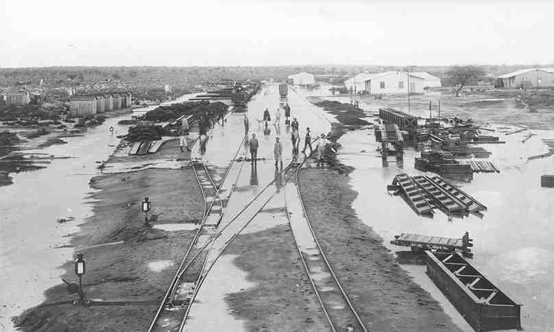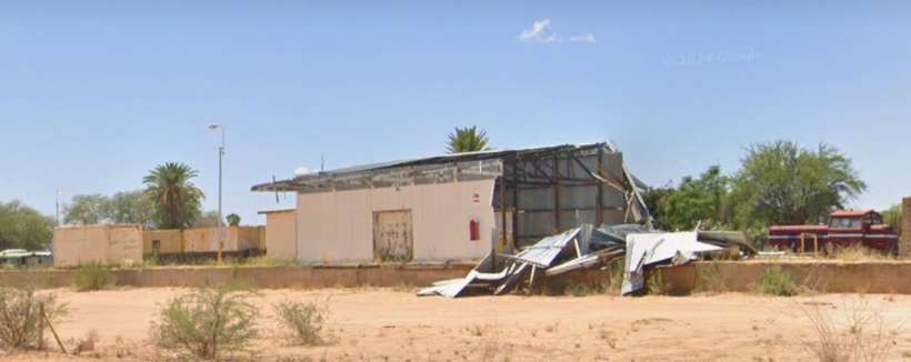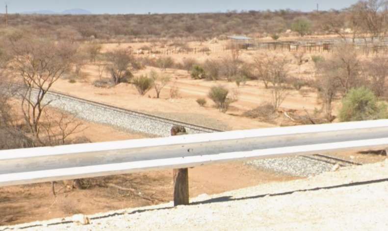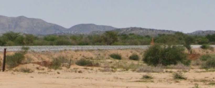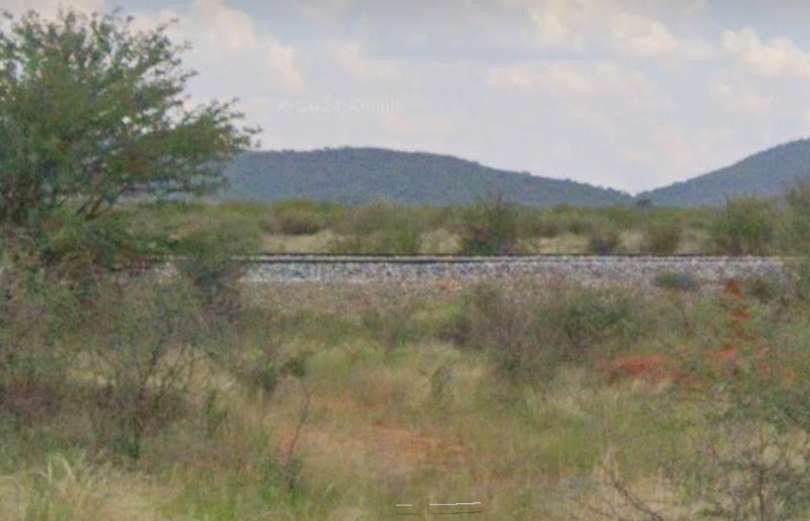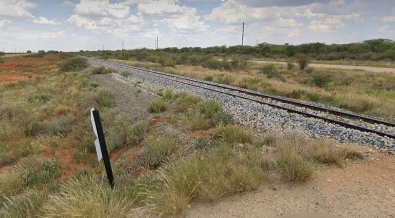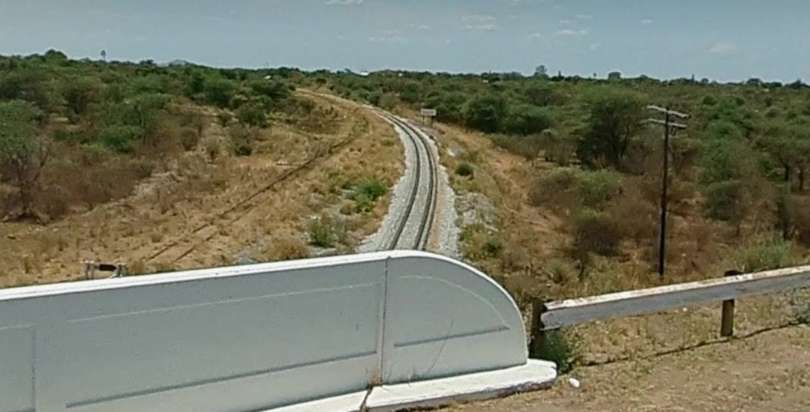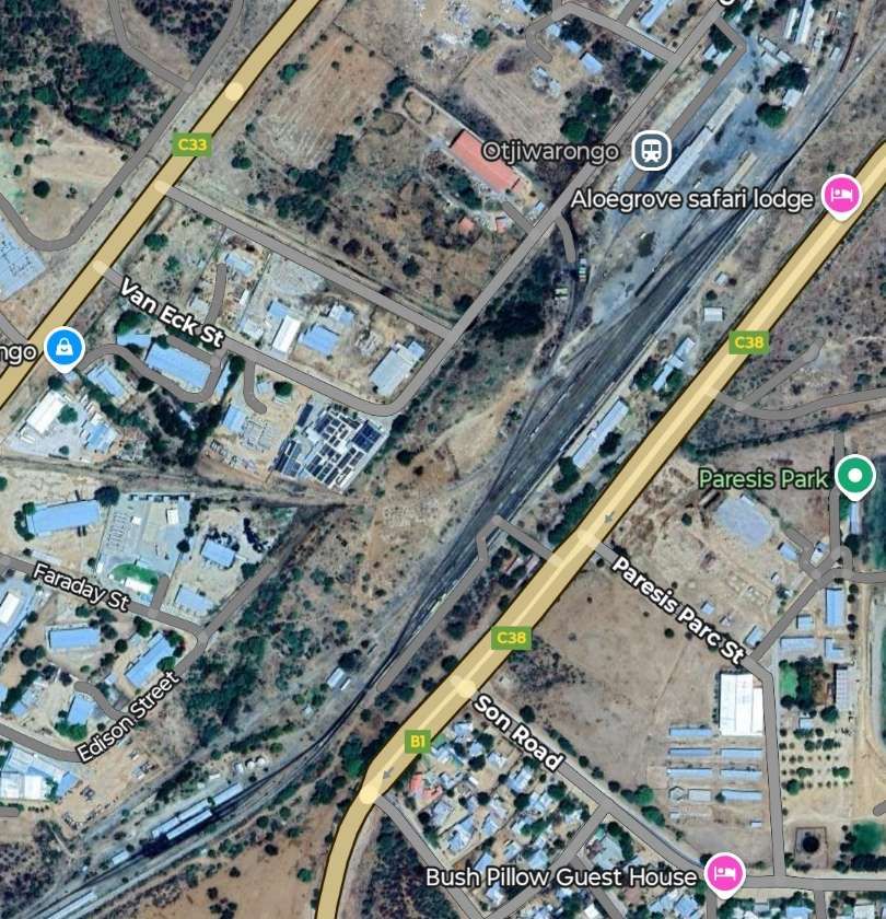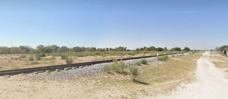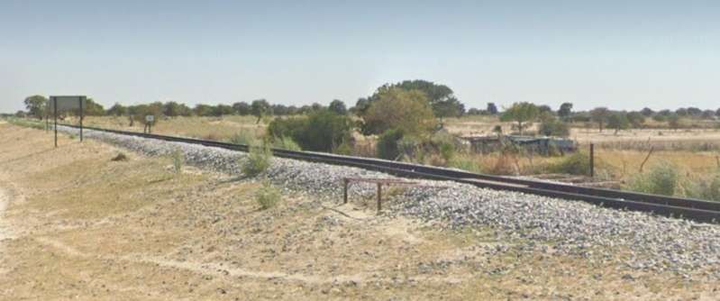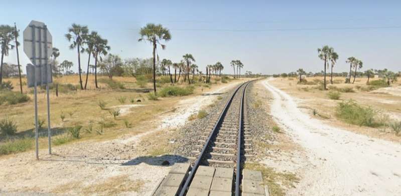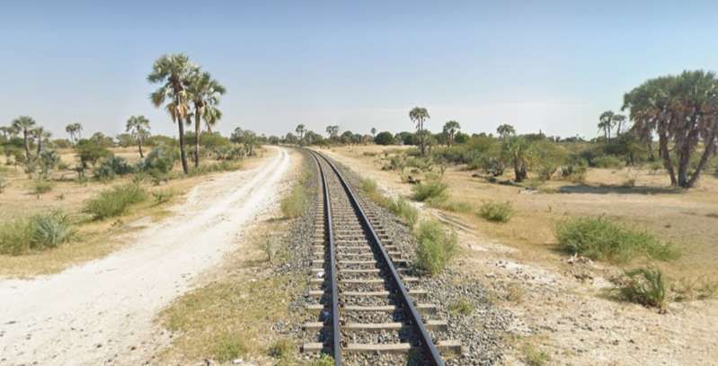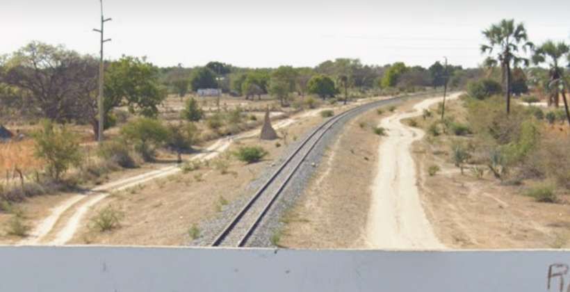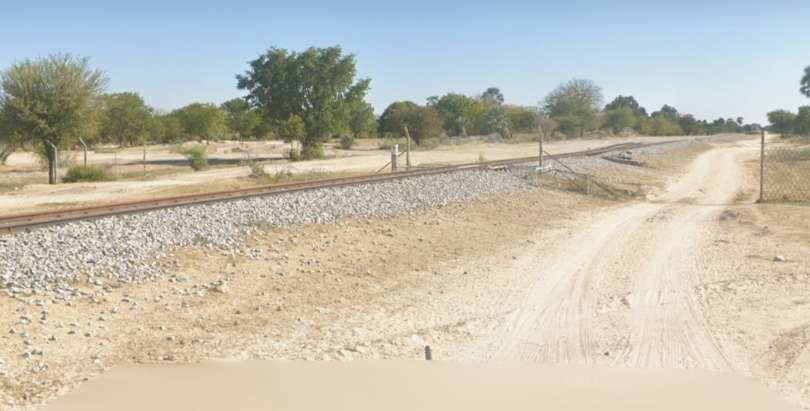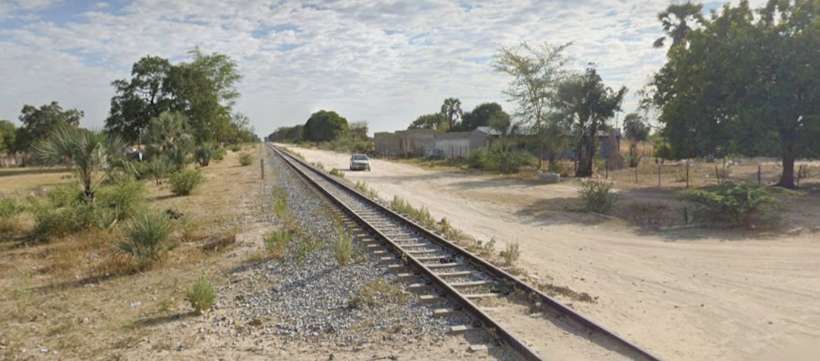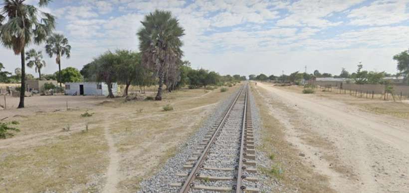
Tag Archives: travel

The Railways of Namibia (the former South West Africa) – Part 1 – Windhoek and the Northern Lines

The Railway Magazine of February 1952 carried an article by Charles E. Lee about railways in what was German South West Africa. This encouraged me to have a look at the history of Namibia’s railways and their condition and extent in the 21st century. The 1952 article also caught my attention because Manchester Diocese (I was a priest in Manchester Diocese before retirement) is linked with the Diocese of Namibia.

The territory was formally colonized by Germany between 1884-1890. It covered an area of 835,100 sq. km. It was a settler colony and had attracted around 3,000 German settlers by 1903, who primarily settled in the central high grounds. [2]

German South West Africa, now known as Namibia, was a German colony from 1884 to 1915. It was not a province within the German Empire but a separate colonial territory. From 1891, the capital was Windhoek, which also serves as the capital of modern-day Namibia. [2]

The arrival of German settlers disrupted the existing socioeconomic balance and led to conflicts, particularly with the Herero and Nama people.

In 1883 Franz Adolf Lüderitz, a merchant from Bremen, Germany, established a trading post in southwest Africa at Angra Pequena, which he renamed Lüderitzbucht. He also acquired the adjacent coastal area, which he named Lüderitzland. These areas were constituted the first German colony under German protection on April 24, 1884. The German occupation subsequently extended inland. By the latter 1880s the German Colonial Company for the South realized that it was incapable of administering the territory, and the German government immediately took over the colony’s administration. As a result of the Zanzibar Treaty (1890) between Germany and Great Britain, German South West Africa acquired the Caprivi Strip (named after the German chancellor Graf Leo von Caprivi), a tract of land 280 miles (450 km) long in the extreme northeast of the territory; the colony thus gained access to the Zambezi River.” [3]

German colonial rule was harsh, leading to insurrections and resistance. “Major Theodor Leutwein, governor of the colony in 1894–1904, suppressed insurrections of the Khoekhoe (1894) and of the Hereros (1896). In 1904, however, the Hereros fomented a far more dangerous rebellion. The German force, at first only 750 strong and supported only by one artillery battery, had to face an army of some 8,000 men equipped with modern weapons. Reinforcements increased the German force, ultimately under the command of General Lothar von Trotha, and resulted in a decisive German victory on the Waterberg River. Further Khoekhoe rebellions were put down in 1904–07.” [3]

German South West Africa was occupied by the South African Union Defence Force in 1915 during World War I, and Germany formally ceded the territory under the Treaty of Versailles in 1919. Its administration was taken over by the Union of South Africa (part of the British Empire) and the territory was administered as South West Africa under a League of Nations mandate. It became independent as Namibia on 21st March 1990. [2]

The Railways

The railways in German South West Africa played a crucial role in the colonial administration and the First World War campaign. The German colonial authorities built a railway network between 1897 and 1914 to enable colonial territorialization and facilitate the extraction of resources. [4]

Charles E. Lee tells that “under the German regime, the first railway in South West Africa was the Northern State Railway (NSR), as it was then called, built to a gauge of 60 cm. (1 ft. 11 in.) between Swakopmund and Windhoek, via Jackalswater and Karibib, a distance of 238 miles. This line was begun in 1897 and was built by a German Military Brigade from Europe. It was first intended to be worked by animal power – Argentine mules or Cape donkeys – but steam traction was soon adopted. The first section (15 miles) was opened to traffic from Swakopmund in January 1898. By the end of that year 68 miles were ballasted and 54 open. In July 1900, the line was opened to Karibib, 121 miles, and the whole railway completed to Windhoek, a further 117 miles, in June, 1902. The curves and gradients were very severe, the gradient out of the Khan River gorge, for instance, being 1 in 19 with curves of 180 ft. radius. The rails weighed about 19 lb. a yard and were laid on iron sleepers. There were iron girder bridges at Khan River, Dorst River, and Kubas. The only good and plentiful water supplies were at Swakopmund and Karibib.” [1: p121]

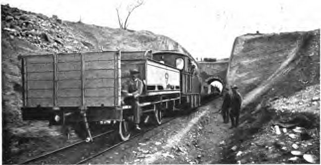
Wikipedia tells us that there was actually an earlier line than the one Lee talks about. It was a small mining rail line at Cape Cross in 1895. [5] “Soon afterwards, the ox-cart transport system totally collapsed, in the wake of a rinderpest epidemic in 1897. As it was necessary to react quickly to the now extremely precarious transport situation, decisions were made: to build a railway line from the German port of Swakopmund to Windhoek (the Staatsbahn); to use existing, 600 mm (1 ft 11 5⁄8 in) gauge military Feldbahn material; and to entrust a railway brigade with the construction work, which began in September 1897.” [5]

Wikipedia continues: “Construction of the railways connecting with the Staatsbahn was aimed partly at military strategic objectives following the uprising of the Herero and Nama, and partly at economic requirements. … By World War I, the following lines had been developed (listed by the first year of full operation):” [5]

  • 1902: Swakopmund–Windhoek line, 600 mm (1 ft 11 5⁄8 in) gauge, Karibib–Windhoek section re-gauged in 1911 to 3 ft 6 in (1,067 mm) gauge. [5]
  • 1906: Otavibahn, 600 mm gauge. [5]
  • 1905: Onguati–Karibib branch. [5]
  • 1908: Otavi–Grootfontein branch. [5]
  • 1907: Lüderitzbahn, 3 ft 6 in (1,067 mm). [5]
  • 1909: Seeheim–Kalkfontein branch. [5]
  • ca 1911: Kolmannskuppe–Elisabethbucht–Bogenfels, industrial railway of the diamond fields. This 600mm gauge railway was electrified from 1911 (the only electric railway in Namibia’s history).  Diamond mining in the region gradually moved south. The northern part of the line as far as Pomona was abandoned in 1931, and some of its materials were used for the extension of the railway towards Oranjemund. The southern section was operated with diesel traction. This line no longer exists. [5]
  • 1912: Windhoek–Keetmanshoop railway, 3 ft 6 in (1,067 mm) gauge. [5]
  • 1912: Rehoboth shuttle, 600 mm (1 ft 11 5⁄8 in) gauge (questionable). [6][7][2][5]
  • 1914: Otjiwarongo–Outjo–Okahakana, 600 mm gauge (project started, but not completed due to the war). [5]
The Windhoek–Keetmanshoop railway, circa 1916, © Franz Baltzer, Public Domain. [5]

Lee talks of the formation, by the Otavi Mining & Railway Company, an Anglo-German syndicate owning the copper mines at Otavi and Tsumeb, of a railway: “This company was formed in Berlin in 1900, in accordance with an arrangement between the South-West Afrika Company, the Disconto-Gesellschaft of Berlin, and the Exploration Company. The first intention was to build a 3 ft. 6 in. gauge railway from Port Alexander in Portuguese West Africa to run in a south-easterly direction up the Muende River Valley and via Etosha Pan to the Tsumeb Copper Mines, and later to extend this line to Rhodesia to form a trans-African railway. Eventually it was decided to form a 60 cm. gauge line entirely in German territory connecting Swakopmund with Tsumeb, a distance of 351 miles. Construction was undertaken by Arthur Koppel & Co. and was begun in November 1903, but was delayed by the Herero War, and the work completed on 25th August 1906. This undertaking, called the Otavi Railway, had the distinction of being the longest narrow-gauge railway in the world. Branches were laid subsequently from Otavi to Grootfontein (56 miles) and from Onguati to Karibib on the State Railway (9 miles). The cost is stated to have been about £2,400 a mile, or roundly £1,000,000 in total. The railway was bought by the German Imperial Government in 1910 for £1,250,000, but the management was left in the hands of the company under a 30-year lease, terminable after 10 years.” [1: p121]

This line was well constructed, and well ballasted. It had a ruling gradient of 1 in 66 and minimum curvature of 150 metres. The permanent way consisted of steel rails in 30-ft. lengths, 30 lb. a yard, laid on steel sleepers weighing about 26 lb. each. “From Swakopmund, for a distance of 68 miles, the line rises steadily on a grade of 1 in 66 to Ebony Station, where it reaches an altitude of 3,500 ft. (On the down journey, the last 40 miles into Swakop-mund can be run by gravity.) From Ebony there is a regular fall to Usakos, which is 2,640 ft. above sea level. From Usakos it climbs 690 ft. in 13 miles to Onguati, and continues to rise until it attains its greatest elevation near Kalk-feld, where the summit is 5,200 ft.” [1: p121]

The Otavi Railway, like the State Railway, was built to the 2 ft-gauge, though a difference of 1 centimetre in the wheel gauges is stated to have prevented the free interchange of rolling-stock. The widening to 3 ft. 6 in. of the gauge between Swakopmund and Omaruru had been voted by the German Railway Board, but the work had not been put in hand by the outbreak of the 1914 war. A new branch projected at the same period was the Ovamboland Line, the first aim of which was to provide Ovambo labour for the South. The Landesrat in November 1913, approved a line of 2 ft-gauge, but on earthworks and bridges wide enough for a 3ft. 6in. gauge track, to run from Otjiwarongo (on the Otavi Railways) to Outjo and Okahakana.” [1: p121]

Railways in South West Africa from Swakopmund, mainly German- built, included the 361 miles to Tsumeb, opened in 1906, and the longest narrow-gauge railway in the world. The gauge at the Southern end was widened in 1915. [1: p122]

A sum of £450,000 was allowed for the line from Otjiwarongo to Outjo and Okahakana “in the German Loan Estimates for 1914-15. The first section, including the 55 miles from Otjiwarongo to Amiab Poort, was to cost £250,000. Construction was begun, and the line was laid for 22 miles before the outbreak of hostilities in the first world war.” [1: p123]

Railway developments south of Windhoek, on the 3 ft. 6 in. gauge, made it desirable to convert the earlier 2ft. lines. During 1911, the section from Karibib to Windhoek was converted to 3 ft. 6 in. gauge at a cost of £550,000, with the Bechstein-Koppel Gesellschaft as contractor. The ruling gradient [was] 1 in 66 with a minimum curvature of 656 ft. This work was completed during 1913. The Swakop River at Okahandja [was] spanned by a bridge 350 ft. long, and there [was] a smaller bridge at Otjihavera. About the same time, the coastward section from Karibib to Swakopmund was practically abandoned in favour of the alternative route provided by the Otavi Railway. In fact, the settlers in the Swakop Valley, who asked for a short railway to link them with Swakopmund, were promised in November 1913, that the material from the disused 92 miles of the State line between Swakopmund and Kubas would be used for this purpose, but it was not done.” [1: p123]

An image showing an armoured train in South West Africa during World War I, 1914-1918, can be found here [29] The South African army invaded the German colony of South West Africa in March 1915 overrunning the much smaller German forces.

Wikipedia tells us that, “With the outbreak of World War I, the German Schutztruppe military unit retreated from the coast, and withdrew into the inland. In the process, the Schutztruppe destroyed the Otavibahn, and the old Staatsbahn towards Karibib, as far as Rössing.” [5]

The Staatsbahn was abandoned but this was not the case with the Otavibahn. In 1914, “British troops … moved forward from the British enclave of Walvis Bay, and by the end of 1914 they had built a 37 km (23 mi) long 3 ft 6 in (1,067 mm) railway to Swakopmund. The Otavibahn was also reconstructed in 3 ft 6 in (1,067 mm) as far as Usakos, and the section between Usakos and Karibib was realigned. The network north of Usakos remained in 600 mm (1 ft 11 5⁄8 in) gauge; the workshop for both gauges was consolidated in Usakos, and the one in Karibib was closed.” [5]

Lee tells us that by 1917 the Staatsbahn line from Karibib to the coast had ceased to exist. “the line between Karibib and Rossing (95 miles), the 10-mile branch from Jakalswater (built to carry water from the Swakop River at Riet), and the Kubas military line (4.5 miles), were lifted and removed to provide material for Tanganyika and the Union of South Africa.” [1: p123]

Lee goes on to confirm that the Union forces, in the course of their invasion of German South West Africa, “laid a 3 ft. 6 in. line for 100 miles inland from Swakopmund to Kranzberg along the original track of the Otavi line, which the Germans had wrecked in their retreat. This was completed in August, 1915. The construction of a new 12.5-mile section, of the same gauge, from Kranzberg to Karibib, was completed in July 1915, and again connected the Otavi Railway with the [NSR]. Thus, in August 1915, there was continuous communication of uniform gauge for the first time from Swakopmund to points south of Windhoek. As strategic railways had meanwhile linked the Union Railways with those of South-West Africa on 25th June 1915, a through railway of 1,635 miles was provided between Walvis Bay and Cape Town.” [1: p123]

Also during the first world war, a new railway from South Africa was constructed – “as an extension of the De Aar-Prieska Railway – to achieve a secure supply route for … South African troops. In 1916, the line was connected to the German network at Kalkfontein (now Karasburg).” [5]

With the linking of the Kranzberg-Tsumeb 2ft-gauge line to the workshops at Usakos by means of a third rail between Usakos and Kranzberg on the 3-ft. 6-in. gauge track of improved location, the 9-mile section from Karibib to Onguati was no longer of value, and it was uplifted in 1924.” [1: p123]

The former Otavi Railway system [was] therefore represented [in 1952] by about 100 miles of 3 ft. 6 in. line on the coastward section, part of the main railway system of South-West Africa, and 307 miles of 2ft-gauge farther inland. [In 1952, there were] also various private branch lines (some disused) connected with the 2ft section. [In 1952], the present main line of this gauge [was] from Kranzberg to Tsumeb, some 251 miles, on which one train in each direction [was] run two days a week.” [1: p123]

Wikipedia continues: Under South African/British occupation, the following lines were established (listed by first year of full operation): [5][10]

  • 1914: Walvis Bay–Swakopmund in 3 ft 6 in (1,067 mm). [5]
  • 1915: Swakopmund–Karibib: Reconstruction in 3 ft 6 in (1,067 mm). [5]
  • 1915/1916: (De Aar)–Nakop (border)–Kalkfontein in 3 ft 6 in (1,067 mm). [5]
  • 1921: Otjiwaronge–Outjo 600mm gauge (based on German preparations). [5]
  • 1929: Windhoek–Gobabis railway in 3 ft 6 in (1,067 mm). [5]
  • From 1958: the Otavibahn north of Usakos was gradually regauged to 3 ft 6 in (1,067 mm), with the new line being laid parallel to the existing line, but largely on new foundations; the new line was in operation from 1961. [5]

From August 1915 the Namibian railway network was operated de facto by South African Railways, and this arrangement became official in 1922. … From 1959, steam locomotives were gradually replaced by diesel locomotives, for which an engine-house was built in Windhoek. This made operations very much easier, because water is in short supply in Namibia, and the coal needed to heat the water in the steam locomotives also had to be procured from the Transvaal.” [5]

The Namibian Network in the 21st century

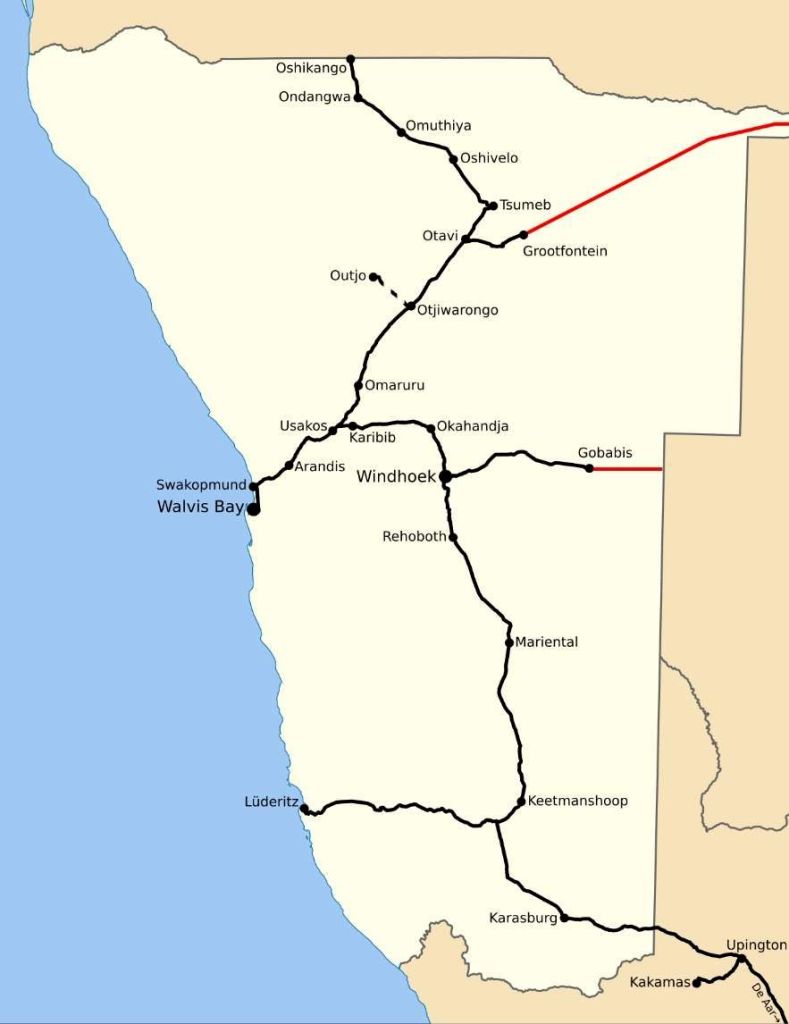
In the 21st century, the rail network of Namibia is operated by TransNamib. As of 2017, the Namibian rail network consisted of 2,687 km of tracks. [11]

The Namibian Rail Network, © Htonl and authorised for reuse under a Creative Commons Licence (CC BY-SA 2.0). [11]
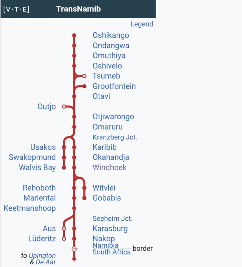
A schematic representation of the Nambian network. [11]

Windhoek-Kranzberg

The railway line from Windhoek to Kranzberg is 210 kilometres (130 miles) long and was completed in 1902. [10]

  • Windhoek (capital – junction)
  • Okahandja
  • Karibib (proposed cement works)
  • Kranzberg (junction Tsumeb v Windhoek)

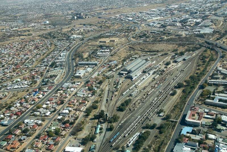
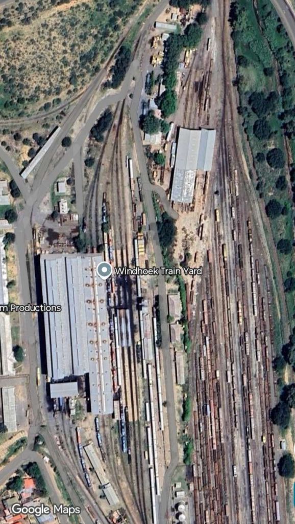
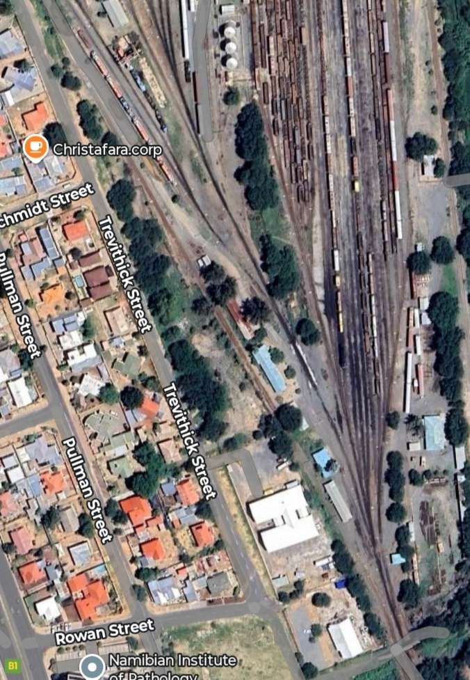
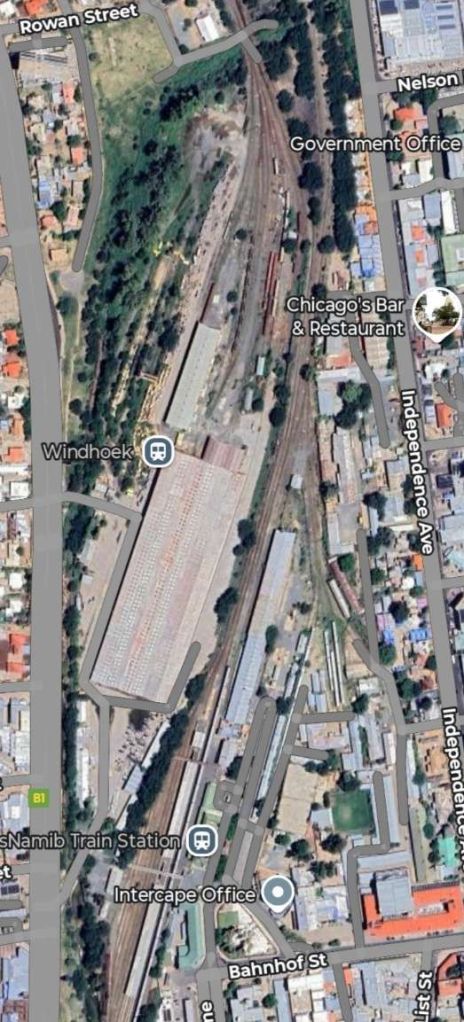
After the aerial image immediately below, the next three images form a kind of ‘tryptic’ which shows the TransNamib train yard and station at Windhoek. Taken together they show the full site. …

An aerial image showing Windhoek train yard, © Hp Baumeler and authorised for reuse under a Creative Commons Licence (CC BY-SA 4.0). [28]
These three images taken together cover the full Windhoek train yard and station. [Google Maps, June 2025]

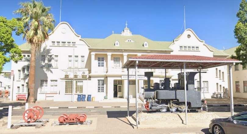
The main station building and the TransNamib Museum are located at the Southeast corner of the whole site.

Windhoek Railway Station building with a static locomotive display sitting outside its front entrance. The locomotive was known as ‘Poor Ole Joe’. [Google Streetview, 2024]
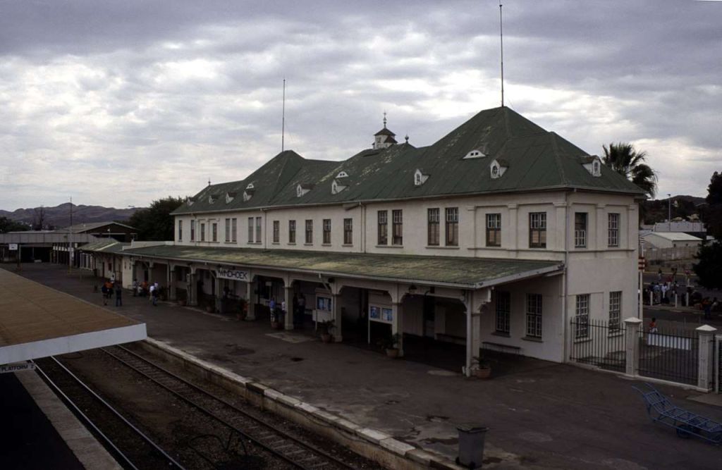
Windhoek Railway Station building seen from the South, © Bernhard Dunst and authorised for reuse under a Creative Commons Licence (CC BY-SA 4.0). [40]

Wikipedia tells us that “the station was built in a Cape Dutch-style and is located on Bahnhof Street. An additional northern wing was constructed by South African Railways in 1929 to match the existing style of the building. … The station also houses the small Trans-Namib Railroad Museum which outlines Namibian transport history, particularly that of the railway. Opened on 1st July 1993, the exhibition consists of a wide range of railway equipment, maps and related items which date back to German colonial times. Another part of the exhibition is dedicated to Namibian Airways history and Namibian Maritime history. …  Across from the entrance [to the station] stands the German locomotive ‘Poor Ole Joe’, one half of a South West African Zwillinge, No 154A, the sole surviving specimen of this type of steam locomotive. It was originally shipped to Swakopmund in 1899 and reassembled for the run to Windhoek” [23][24]

0-6-0T locomotive ‘Poor Ole Joe’ sits outside Windhoek Railway Station, © Catatine and made available for reuse under a GNU Free Documentation Licence (GNU FDL). [26]

Namibia Scientific Society posted the following on Facebook on 9th June 2020: Poor Ole Joe is a 600mm-gauge steam locomotive “and was manufactured in 1900 by Henschel & Sohn GmbH, Kassel, Germany, under the serial number 5376. It was put into operation in 1904 and operated on the Swakopmund – Windhoek route. The steam locomotive was taken out of service in 1939 after traveling approximately 371,000 miles.” [25]

There is some uncertainty over the date of fabrication of the locomotive. Perhaps the two years mentioned relate to a date when the locomotive was shipped from the factory and the date of completion of the reassembly in Swakopmund?

Looking North from Robert Mugabe Avenue which crosses the line at the North end of the train yard, the main running line is that on the right. [Google Streetview, 2024]
The line continues North through the northern industrial corridor. In this image the line crosses an unwanted crossing with Bavaria Road to the right. [Google Streetview, 2024]
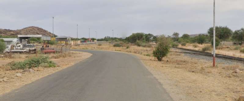
Continuing northwards, the line runs parallel to the access road to the TransNamib Container terminal. On the right of this picture the siding accessing the terminal can be seen leaving the main running line. [Google Streetview, 2024]
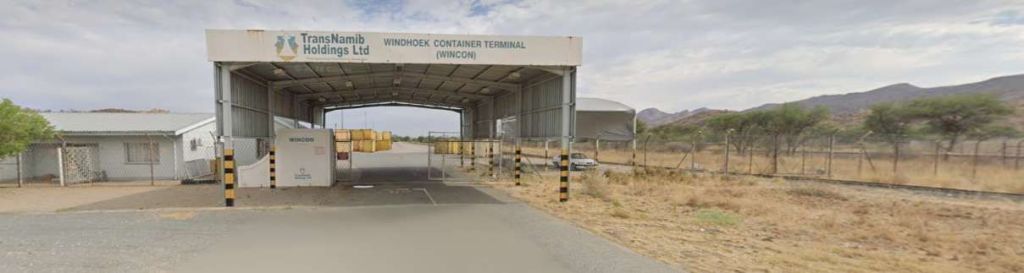
The entrance to the TransNamib Holdings Ltd. Windhoek Container Terminal sits adjacent to the line to Okahandja and beyond. [Google Streetview, 2024]
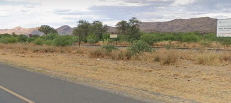
As the line runs out of Windhoek to the North it runs alongside the A1, from where this picture is taken. [Google Streetview, 2024]
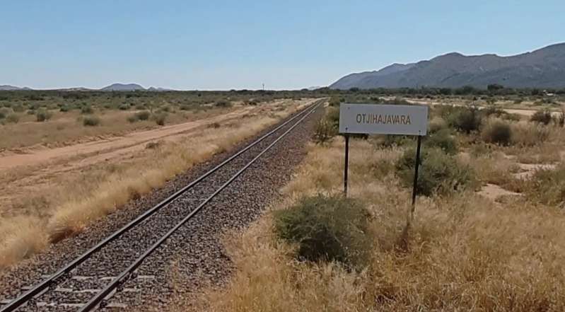
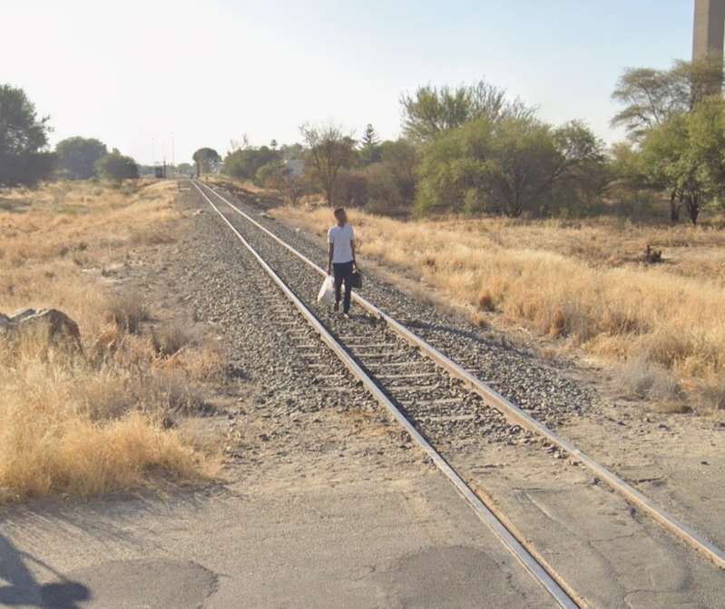
Much of the route North is through scrubland with low growing vegetation. Google Streetview, 2024]
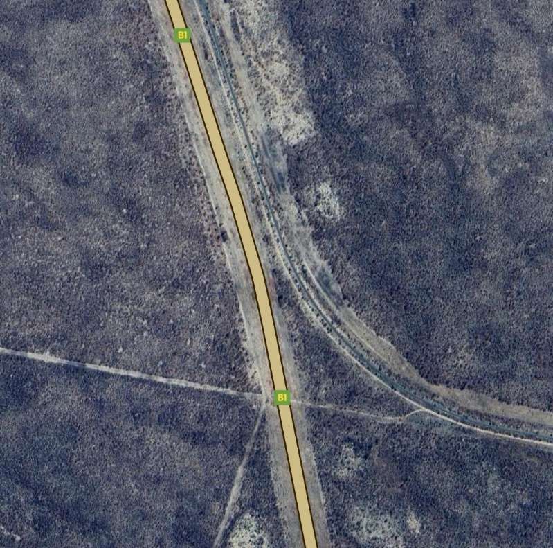
Some miles still from Okahandja the line is seen passing under the B1.  [Google Streetview, 2022]
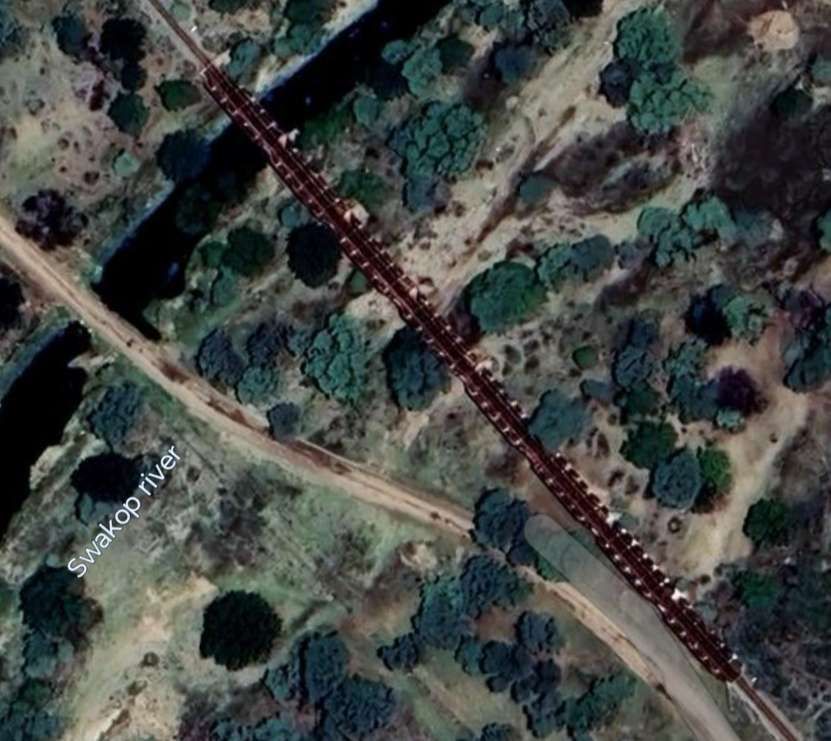
It then crosses the Swakopmund River.. [Google Maps, June 2025]
And crosses the Swakopmund River channel again! [Google Maps, June 2025]
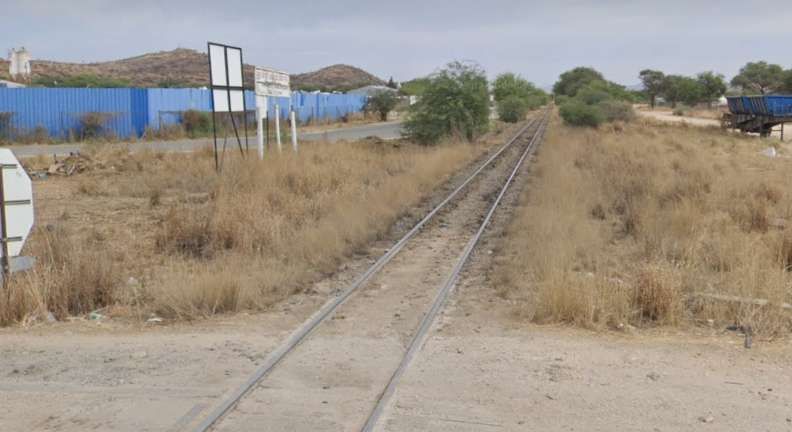
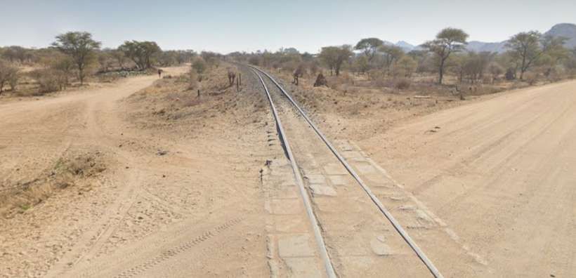
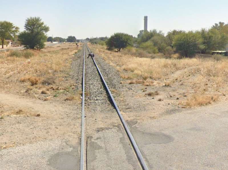
It crosses another, unnamed, road by means of an ungated crossing adjacent to a large abattoir. [Google Streetview, 2024]
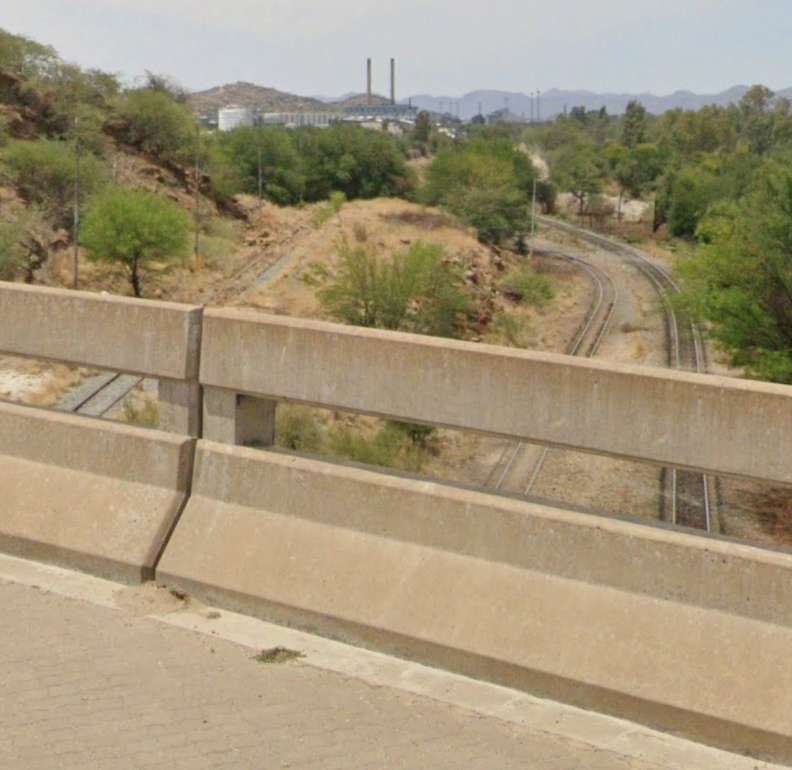
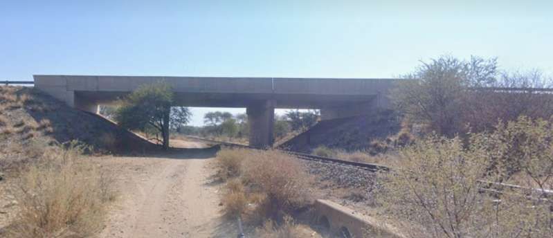
Then under the B1 which is carried by this concrete bridge. [Google Streetview, July 2024]
Across Willhem Sanders Street [Google Streetview, 2024]
And across a side street of Kahimemua Avenue before arriving at Okahandja Railway Station. [Google Streetview, 2024]
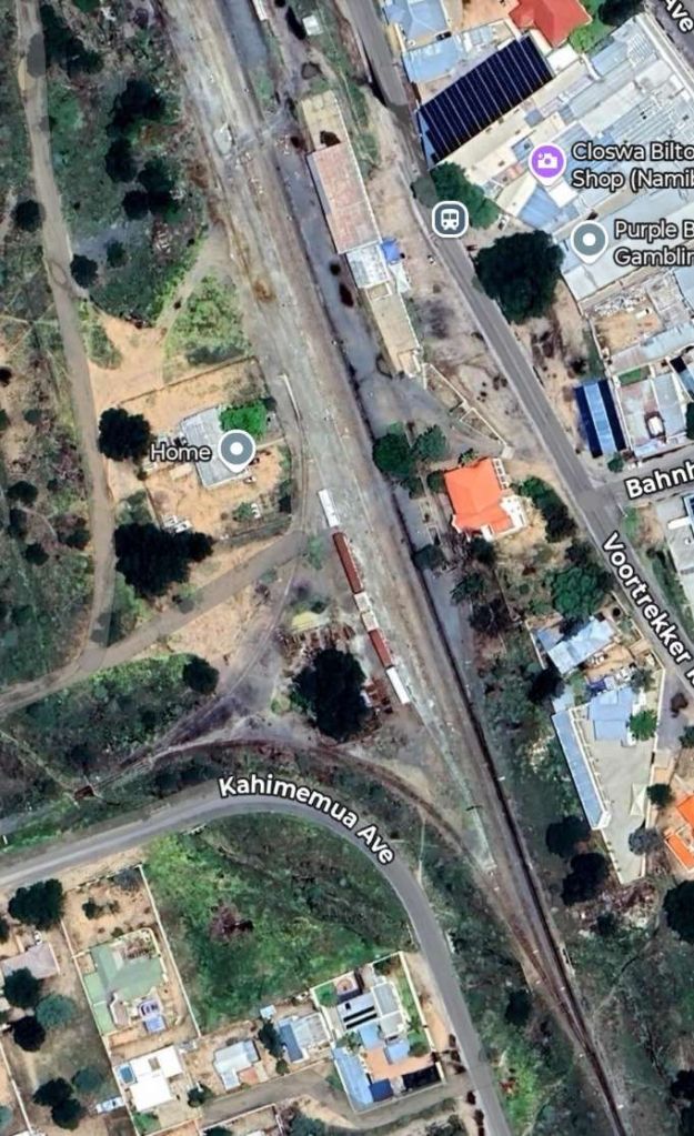
Okahandja Railway Station and turning triangle. Google Maps, June 2025]
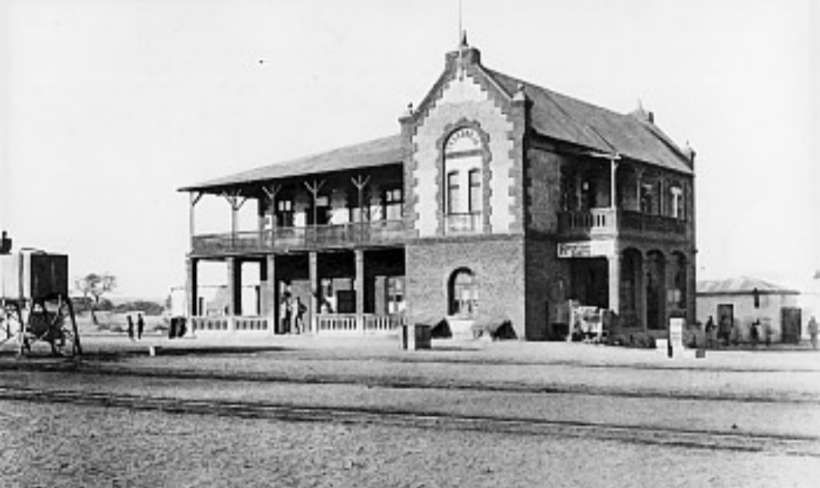
Okahandja Railway Station building in 1903, © Public Domain. [27]
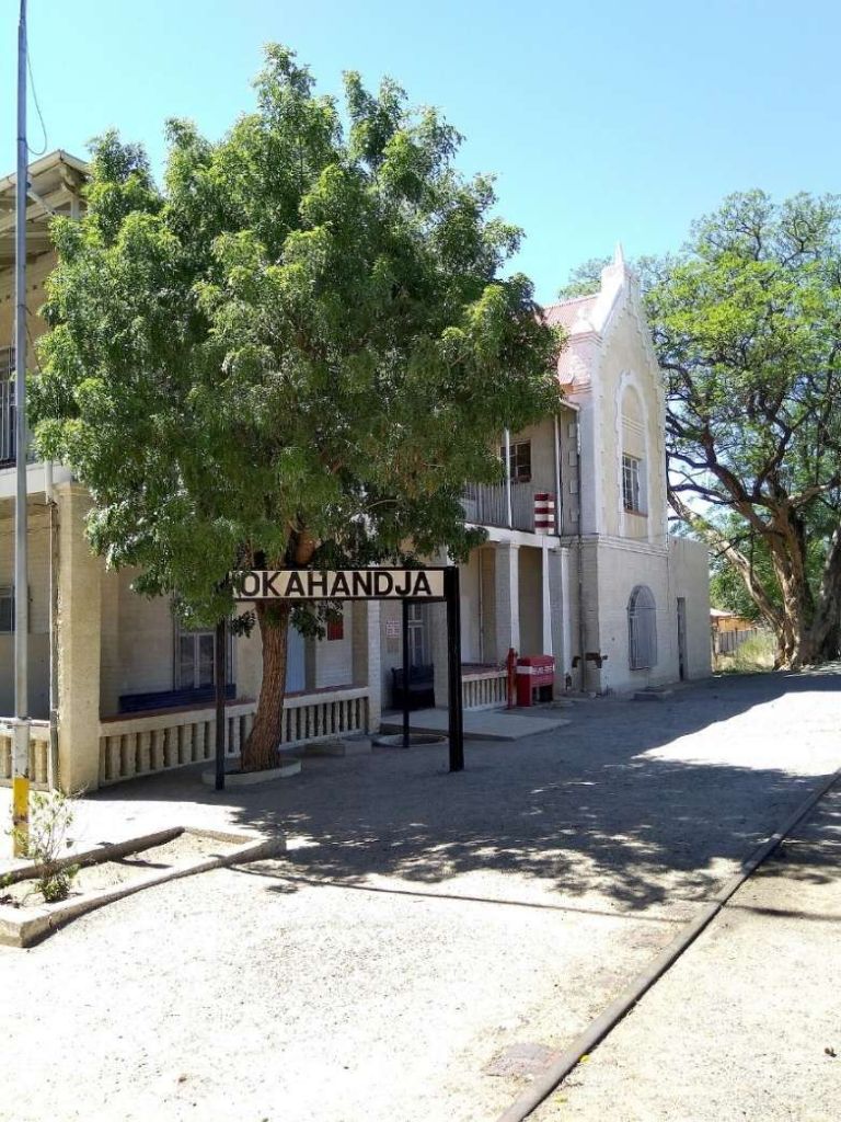
Okahandja Railway Station building in the 21st century, © Louise Kapp and licenced for reuse under a Creative Commons Licence (CC BY-SA 4.0). [27]
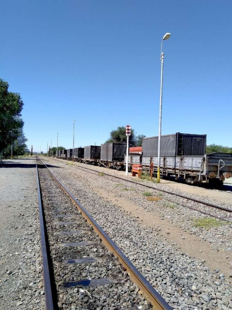
Okahandja Railway Station, showing goods wagons opposite the station building in the 21st century, © Louise Kapp and licenced for reuse under a Creative Commons Licence (CC BY-SA 4.0). [27]
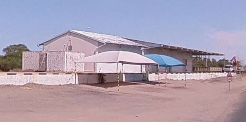
Okahandja Goods Shed seen looking West from Voortrekker Road. [Google Streetview, 2022]
Looking towards Karibib from the B1 bridge over the line. [Google Streetview, 2024]
A typical view along the line heading West. [Google Streetview, 2024]
A view Southwest from a dirt road which crosses the line just to the Northeast of a passing loop at Wilheimstal. [Google Streetview, July 2024]
A bridge over a dry riverbed close to Wilheimstal, seen from the North. [Google Streetview, July 2024]
Looking West along the line towards Karibib from the C36. [Google Streetview, October 2024]
Looking ahead along the railway towards Karibib from a minor road. [Google Streetview, 2024]
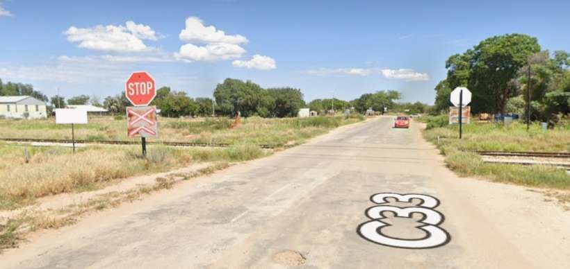
Looking ahead towards Karibib from the C33. [Google Streetview, October 2924]
Looking back from Kapapu Road, Karibib, along the railway towards Okahandja and Windhoek. [Google Streetview, July 2024]
Looking Southwest into the site of Karibib Railway Station from Kapapu Road. [Google Streetview, July 2024]
An aerial view of Karibib  in 2017, showing the railway and station on the left © Hp Baumeler and authorised for reuse under a Creative Commons Licence (CC BY-SA 4.0). [31]
Karibib Railway Station in the 1920s, © Unknown , Public Domain. [5]
Karibib Railway Station building. [Google Streetview, July 2024]
Looking back towards Karibib from Kalk Street in its Southwest suburbs. [Google Streetview, 2024]
Looking Southwest towards Kransberg from  Kalk Street. [Google Streetview, 2024]
Looking back towards Karibib from an unnamed street further to the Southwest. [Google Streetview, 2024
Looking ahead along the line towards Kransberg and Swakopmund. [Google Streetview, 2024]
The line heading on towards Kransberg. A significant length of the B2 runs on the South side of the railway. [Google Streetview, 2004]
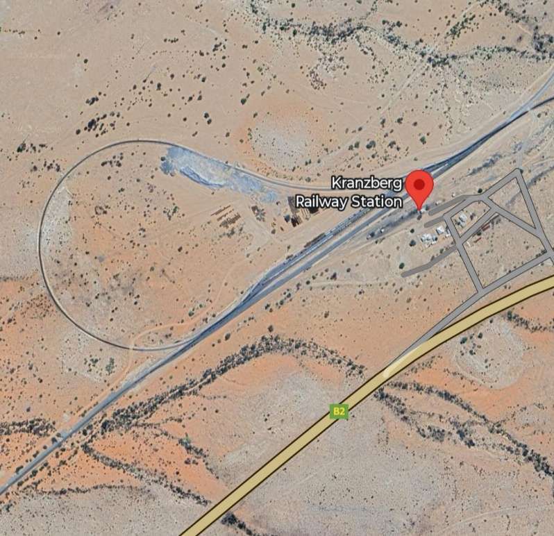
Kranzberg Railway Station and turning loop. This is a junction station, the two lines can be seen diverging on the top-right of the image. The more northerly of the two is the line to Tsumeb. The more southerly heads towards Windhoek. [Google Maps, June 2025]
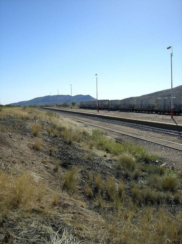
Kranzburg Railway Station, © Pgallert and licenced for reuse under a Creative Commons Licence (CC BY-SA 3.0). [32]

Kranzberg-Walvis Bay

The railway line from Kranzberg to Walvis Bay is 201 kilometres (125 miles) long. The section between Kranzberg and Swakopmund was completed in 1902. In 1914, an extension to Walvis Bay was commissioned; the rails were laid close to the shore of the Atlantic Ocean. In 1980, this extension was replaced by an alternative route behind the dunes that allowed for higher axle load. [10]

  • Kranzberg (junction Tsumeb v Windhoek)
  • Usakos
  • Arandis (crossing loop)
  • Swakopmund
  • Walvis Bay (port)
Looking back Northeast towards Kranzberg Railway Station from the B2. [Google Streetview, 2024]
Looking Southwest along the railway towards Usakos’, Arandis and Swakopmund. [Google Streetview, 2024]

Key locations along the line to Swakopmund are illustrated below: …

Close to Usakos and looking back East along the line towards Kranzberg. The line turns through 90° with Usakos’ station off the right side of this photograph. A short distance to the East of this location a locomotive turning triangle has been maintained. [Google Streetview, 2024]
Usakos railway station and associated infrastructure. [Google Maps, June 2025]
Usakos in the early 20th century. The line was originally 2ft-gauge. This image was shared on the 2ft Gauge Railways in Colonial Namibia Facebook Group by Pierre de Wet on 22nd January 2024, © Public Domain. [33]
Usakos in the early 20th century. The 2ft-gauge is more clearly evident in this image which was shared on the 2ft Gauge Railways in Colonial Namibia Facebook Group by Pierre de Wet on 22nd January 2024, © Public Domain. [34]
A plinthed steam engine with Usakos’ railway station beyond [Google Streetview, 2024]
Locomotive No. SW40 at Usakos Railway Station. This is a 2’0” gauge Class Hd/NG5 2-8-2 (Henschel works number 10720) built in 1912. The building behind, is the old railway station building which has, since the picture was taken, been demolished. Loco. No.. SW40 had 2 sisters numbered 41 & 42 – together they made up class Hd. These locos retained their numbers under SAR administration, and were withdrawn in 1960 when the narrow gauge was converted to standard Cape gauge. Sister locomotive #41 is plinthed at Otjiwarongo station further to the north. Like many other SWA locos they had dust covers to protect the motion. The carrying wheels were arranged as radial axles. As there were no separate bogie truck, the axle boxes were guided in such a way that the wheels could move radially with respect to the frame. [21][22]
Usakos’ historic railway sheds. [Google Streetview, 2024]
Usakos’ historic water towers. [Google Streetview, 2024]
Looking Northwest a short distance to the South of Usakos’ railway station. The line heading for Swakopmund sits on embankment and turns to the West after leaving the station.A modern concrete bridge carries the railway over the D1914 road. [Google Streetview, 2024]
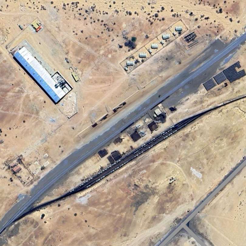
Arandis: the marshalling yard is the darker of the two rail routes in this image and shows a number of wagons at rest in the yard. The main line is the lighter strip running from bottom-left to top-right. The line from Usakos and Kranzberg enters top-right, that from Swakopmund enters bottom-left. The line with the darker ballast is a branch line which serves Rossing Uranium Mine, one of the world’s largest open cast Uranium mines. [20][Google Maps, June 2025]

Before having a look at the Rossing Uranium Mine, it is worth a quick diversion Northwest of the station and marshalling yard shown above. The Namibia Institute of Mining & Technology is host to a plinthed display of a locomotive and carriages from the old 2ft-gauge railways of Namibia.

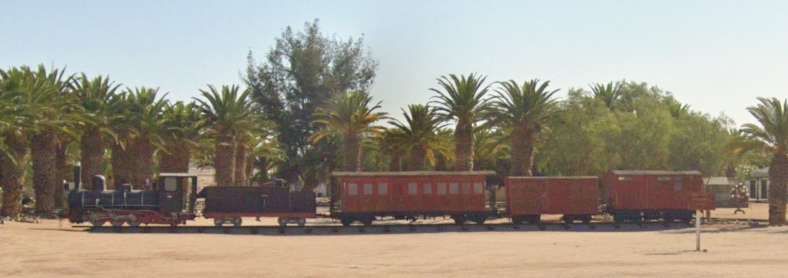
This image shows a complete (but short) 2ft-gauge train at the Namibia Institute of Mining and Technology. [Google Streetview, 2024],

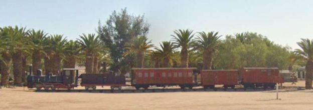
This train was once on display in Windhoek. It was moved to the Namibia Institute of Mining Technology (NIMT) outside Arandis. and restored with the help of Wesbank Transport and AWH Engineering, Rigging and Rentals. The locomotive, is a Henschel Hb 56. The locomotive and its wagons were in use between Usakos and Tsumeb between 1906 and 1959. The South African Railways then donated it to the National Museum in Windhoek and in 1964 it was placed in front of the Alte Feste, but it was too close to the Reiterdenkmal and was moved in 1974 to the southern side. The train consists of the locomotive, a coal wagon, a closed goods wagon, a passenger coach for first and second class and a wagon in which the conductor travelled with the mailbags, milk and cream cans that were picked up along the route. The passenger coach could transport 16 passengers. The first-class passengers could sit on upholstered seats while the second-class passengers sat on plain wooden benches. The two classes were divided by a small washroom. The conductor’s wagon was destroyed in 2007 when it was set alight by a homeless person who slept in the train and made a fire. The boilermaker and carpentry students at NIMT renovated the train. [35]

The locomotive is from the class Hb 0-6-2T. Of the 15 locomotives built by Henschel for the Otavi line between 1905 and 1908, six were absorbed into the SAR. The engines had Allan valve gear and often ran with an auxiliary tender attached which contained both coal and water.” [36]

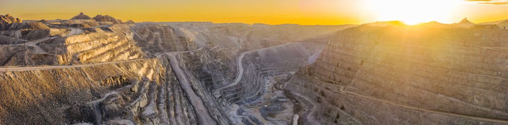
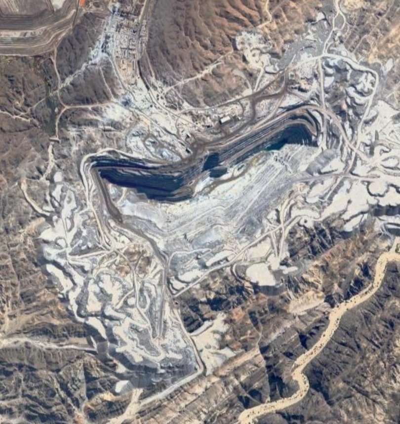
Rossing Opencast Uranium Mine. [20]
Rossing Opencast Uranium Mine. [Google Maps, June 2025]
The view Northeast towards the passing loop and marshalling yards at Arandis. The Uranium Mine is a few miles off to the right of the picture. Swakopmund is still me miles away behaving Nd the camera. [Google Streetview, 2024]
Looking ahead towards Swakopmund. [Google Streetview, 2024]
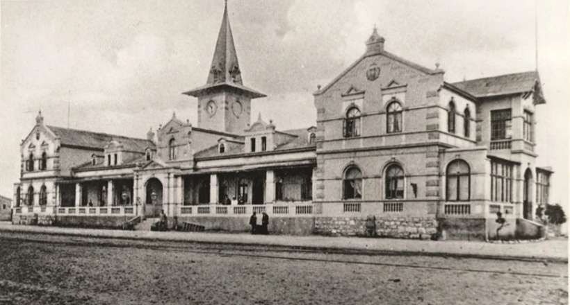
The Swakopmund Railway Station as it appeared in the early 20th century. [37]
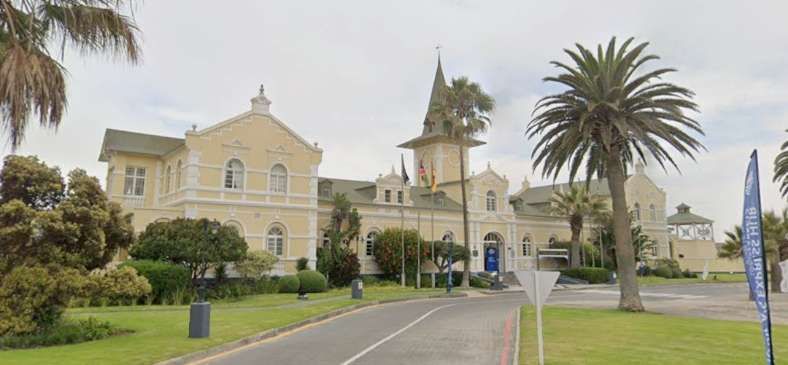
The original Swakopmund Railway Station is now a hotel and casino with the modern railway station a short distance to the East. [Google Streetview, 2024]
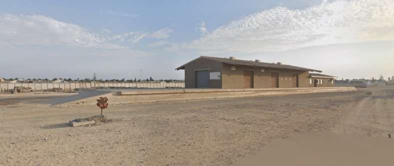
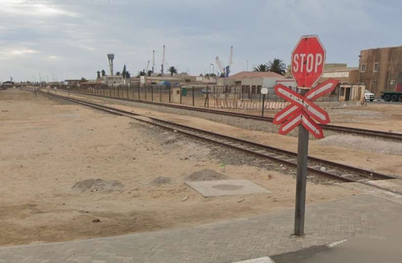
Swakopmund Railway Station in the 21st century as flagged on Google Maps. It is difficult to make out any railway tracks at this location. The Desert Express was the only passenger service serving Swakopmund and that service was suspended indefinitely in 2020. Freight trains still run into Swakopmund. [Google Streetview, 2024][19]
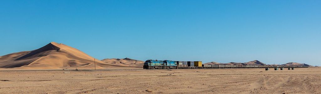
A train on the Swakopmund-Walvis Bay route, © Diego Delso and approved for reuse under a Creative Commons Licence (CC BY-SA 4.0). [11]
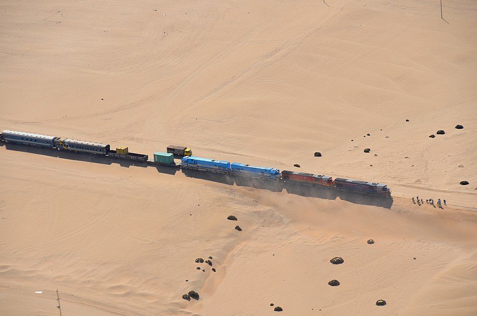
Track from Swakopmund to Walvis Bay covered by sand
(22°47′17″S 014°35′20″E), © Olga Ernst & Hp.Baumeler and Iicenced for reuse under a Creative Commons Licence, (CC BY-SA 4.0). [11]
Looking Southeast towards the railway station from Railway Street, Walvis Bay. [Google Streetview, 2024]
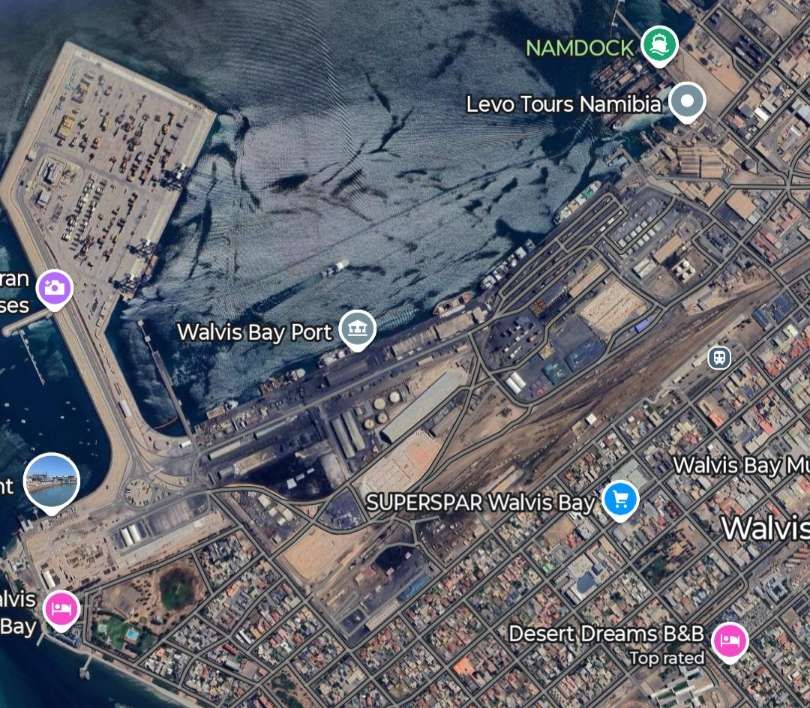
Walvis Bay Port and Railway Station: rail lines extend out onto the container port area to the left of this satellite image; run along the quay in the centre of the image (flagged ‘Walvis Bay Port); through the area where ships are berthed. A large marshalling yard sits on the Northwest side of the station which is flagged on the right side of this image. [Google Maps, June 2025]
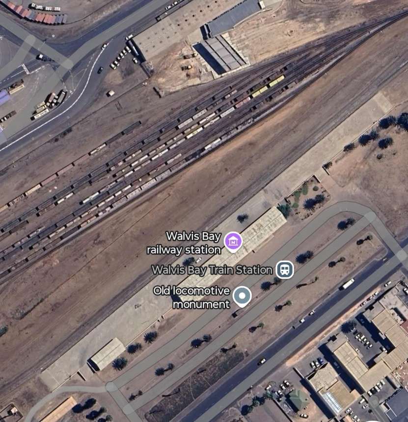
A closer view of Walvis Bay Passenger Station and the nearby freight marshalling area. [Google Maps, June 2025]
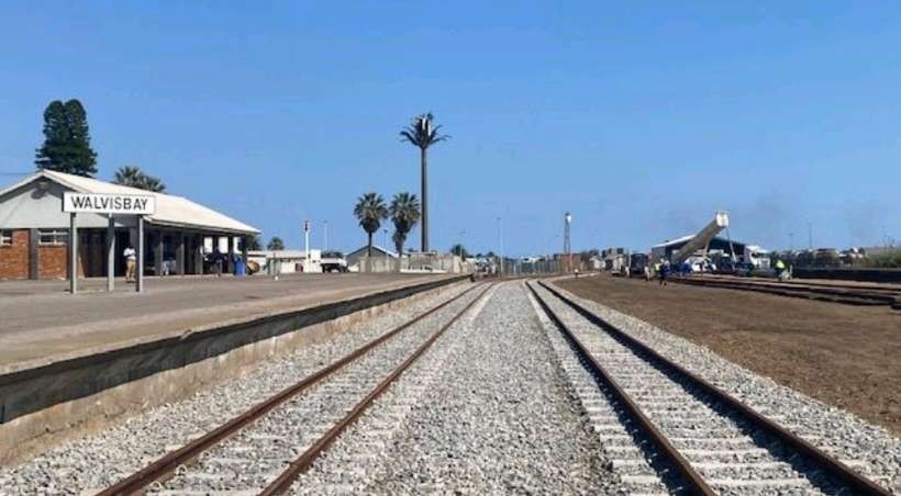
Walvis Bay Railway Station: track side. This image was shared on LinkedIn by Johan Stewart Laubscher in 2022. [38]
Walvis Bay Railway Station: station approach. [Google Streetview, 2024]
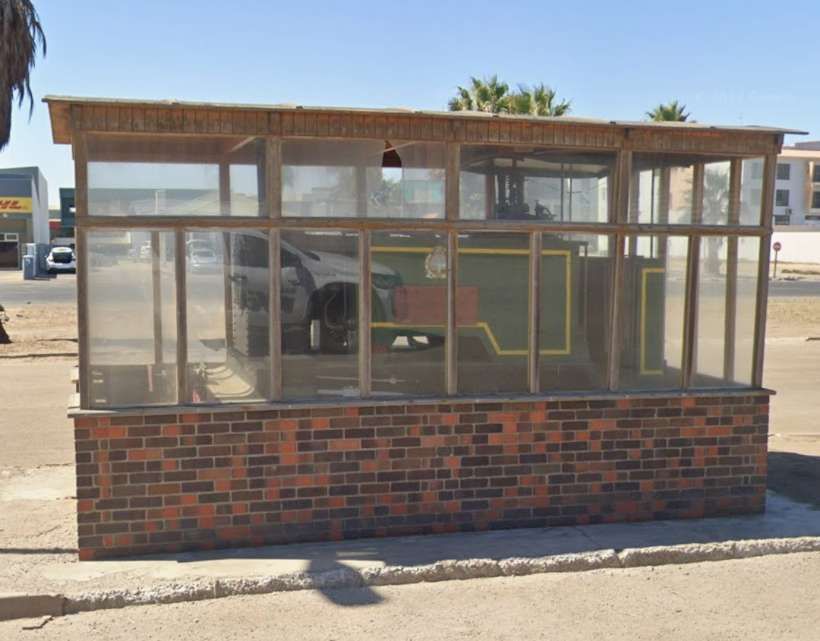
The static enclosed display of an old steam locomotive on the forecourt of Walvis Bay Railway Station. This locomotive is ‘Hope’, a Kerr Stuart locomotive which was built at their works in Stoke on Trent and entered service in what is now Namibia in 1899. [Google Streetview, 2024]

Walvis Bay was a British enclave in German South West Africa. The first narrow gauge railway in the British ruled Cape Colony was in Walvis Bay. Initially projected merely to connect the jetty with the town, the Walvis Bay Railway was opened in 1899 and ran for twelve miles up north to the German border at Plum. [17]

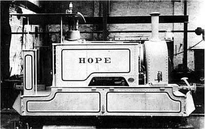
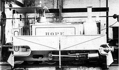
On 6th March 1899 the Agent General for the Cape of Good Hope ordered a “Sirdar” class locomotive named ‘Hope’ which was almost as long in transit to Walvis Bay – where it arrived on 22nd August 1899 on board the British barque Primera – as it had been in the building. Because of the extremely light nature of the track (12 lb. rail with sleepers spaced three feet apart) HOPE was provided with an additional pair of carrying wheels at both ends. Thus the standard 0-4-0T type was converted to a 2-4-2T type. Even so the maximum axle load of ‘Hope’ in working order would be about 1¾ tons, which is considerably more than today’s suggested figure for this category of track of 1 ton 4 cwt. Within six years the railway was virtually moribund and by 1915, ‘Hope’ had been laid aside and forgotten. That was because the Germans preferred to use their own harbour in Swakopmund.” [17][18]

Two works photographs of ‘Hope’: in the one with the valance (wheel cover) raised, one of the smaller carrying wheels can just be made out on the left of the picture. [17][18]

Kranzberg-Otavi

The railway line from Kranzberg to Otavi is 328 kilometres (204 miles) long and was completed in 1906. [10]

  • Kranzberg (junction Tsumeb v Windhoek)
  • Omaruru
  • Kalkfeld (short siding)
  • Otjiwarongo (junction for Outjo)
  • Otavi

Kranzberg Railway Station has already been featured above. The next images show the line from there to Otavi. …

Kranzberg Railway Station. [Google Streetview, June 2025]

The loop allows trains from Windhoek to access the route to Otavi without reversing. That line running towards Otavi sets off from Kranzberg in a Northeasterly direction crossing a series of dry watercourses and gradually taking a more northerly course before encountering the D2315 (a dirt road).

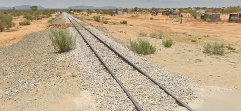
Looking North from the ungated crossing on the D2315. [Google Streetview, 2024]
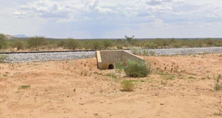
Less than 100 metres North of the D2315, this is a typical drainage culvert on the line. [Google Streetview, 2024]
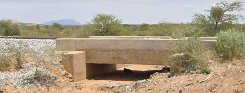
Just a little further North is an example of a culvert provided at a dry river/stream bed [Google Streetview, 2024]
And another culverted dry watercourse. Google Streetview, 2024]
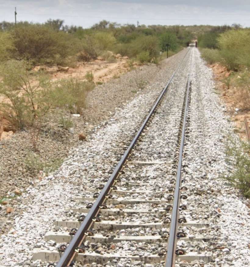
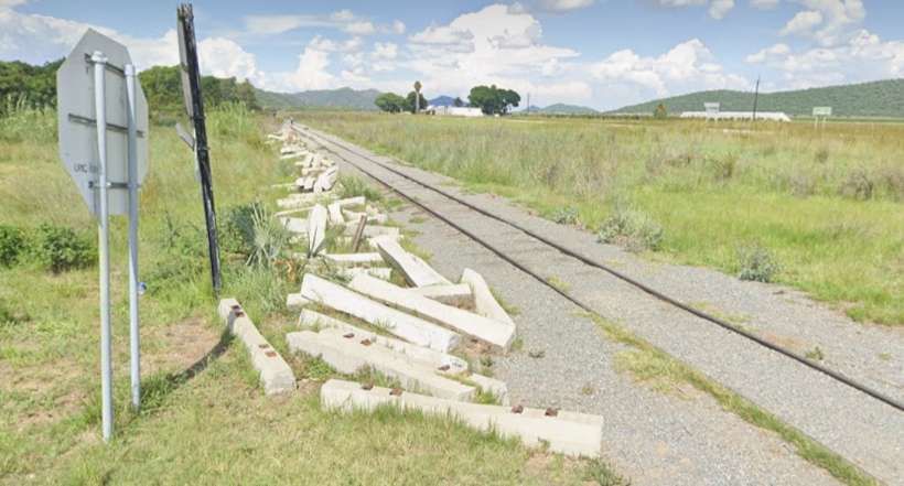
A typical length of the permanent way seen looking North from an ungated crossing. [Google Streetview, 2024]
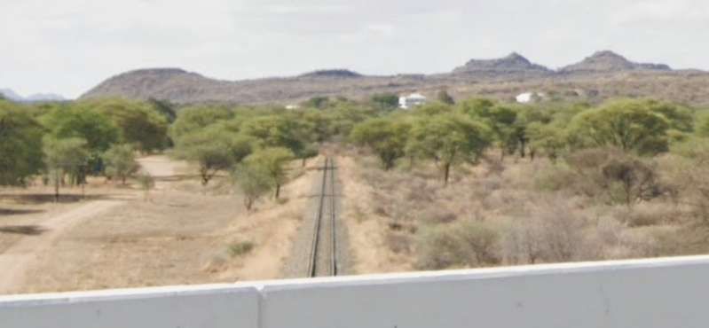
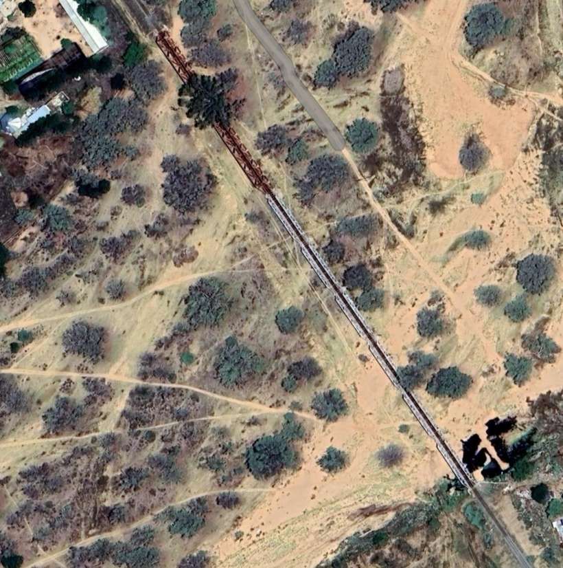
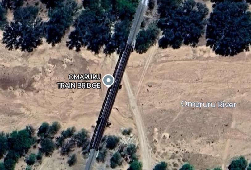
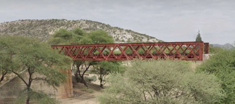
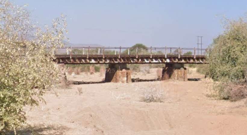
The line crosses the dry river bed of the Omaruru River by means of a multi-span truss girder bridge. [Google Maps, June 2025]
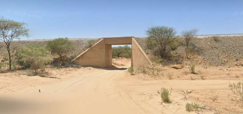
On the approach to Omaruru, a dirt road is bridged by the railway. [Google Streetview, 2024]
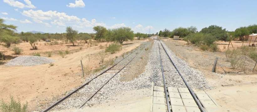
At Aloe Street ungated crossing, two lines are now visible heading Northeast towards Omaruru Railway Station. The line on the left is a headshunt or storage siding. [Google Streetview, 2024]
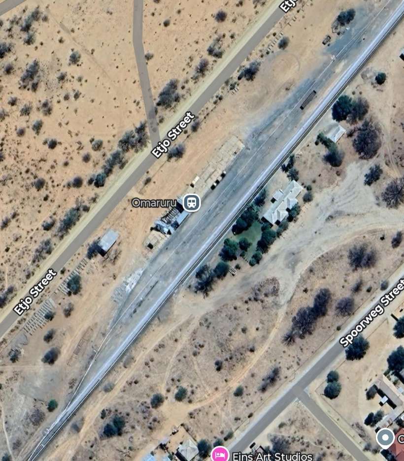
This satellite image is centred on the building at Omaruro Railway Station. [Google Maps, June 2025]
Omaruru Railway Station in its earliest incarnation in 1906. At this time the line to Otavi was 2ft-gauge. The site appears to be littered with railway construction materials, © Public Domain. [30]
The station building has seen better days! This view looks East from Etjo Street. [Google Streetview, 2024]
Leaving Omaruru, the line passes under the C36. [Google Streetview, 2024]
It runs alongside the C33 all the way to Kalkfeld. This view is taken looking North-northwest from the road. [Google Streetview, 2024]
Crossing dry river beds on the journey North. [Google Streetview, 2024]
The line passes under the C33 once on the way to Kalkfeld. [Google Streetview, 2024]
Closing in on Kalkfeld there is a passing loop. [Google Maps, June 2025]
Another view of the line from the C33. [Google Streetview, 2024]
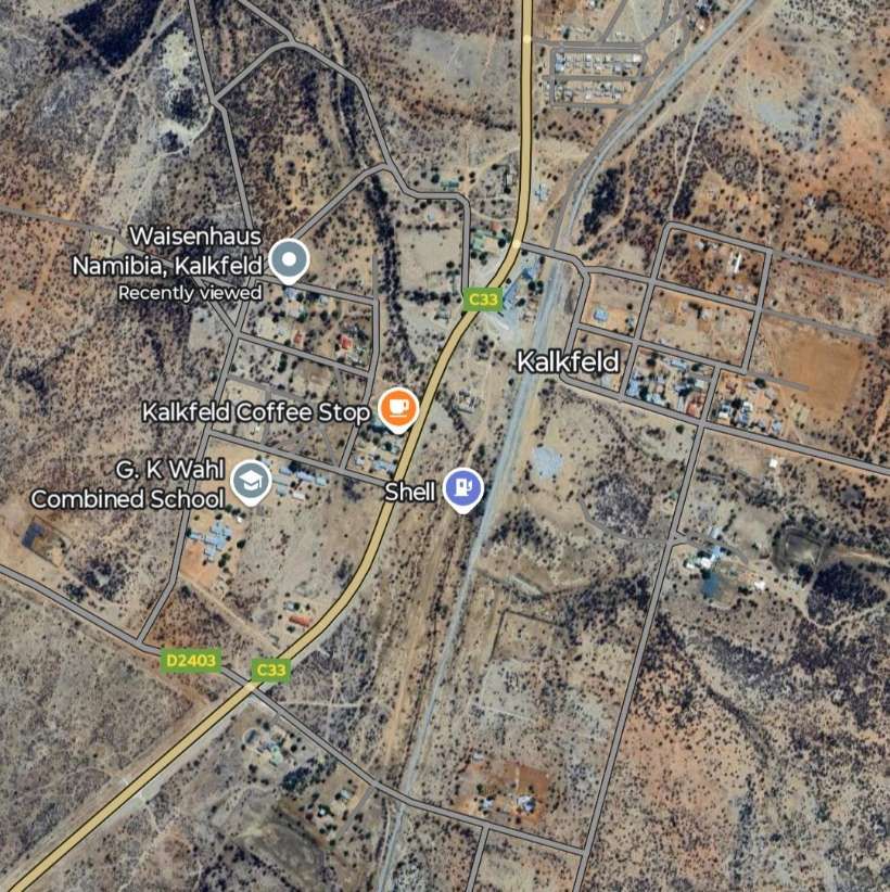
Kalkfeld: the C33 and the railway pass North-northeast through the town. There is no passenger station here. [Google Maps, June 2025]
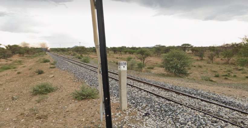
In Kalkfeld two roads cross the line. Here we look North along the line from the first of these ungated crossings, a minor dirt road. [Google Streetview, 2024]
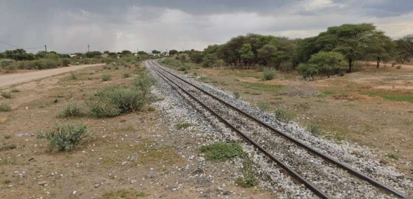
The second ungated crossing takes the D2414 across the line, again we are looking North. [Google Streetview, 2024]

From Kalkfeld the line heads in a generally Northeasterly direction towards Otjiwarongo.

As on the earlier length of the line, we see it crossing a number of dry river beds. [Google Maps , June 2025]

The next five images are a sequence which shows a long passing loop, perhaps halfway towards Otjiwarongo.

A sequence of five images shows a passing loop. The sequence has the Northeast end of the loop in the first of the five images and the Southwest end of the loop in the fifth image, immediately above. [Google Maps, June 2025]

The next five images show a sequence of structures over dry river beds

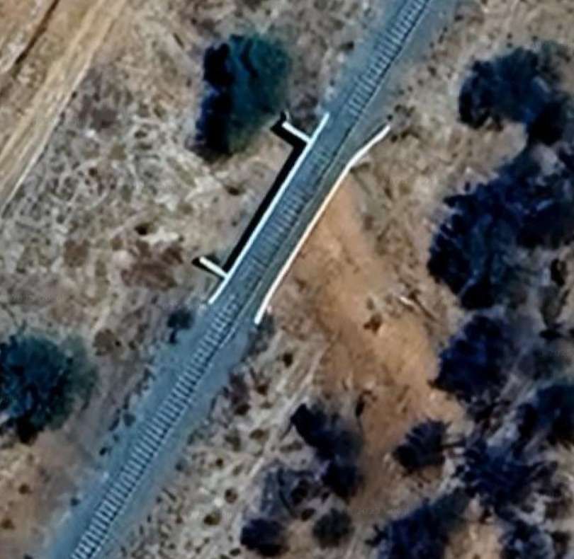
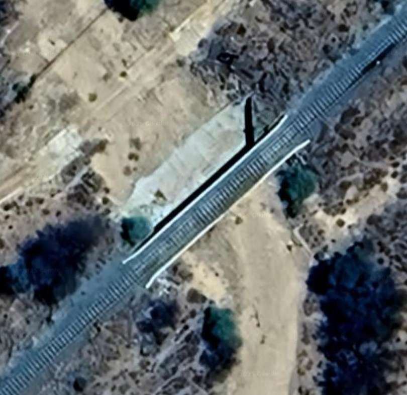
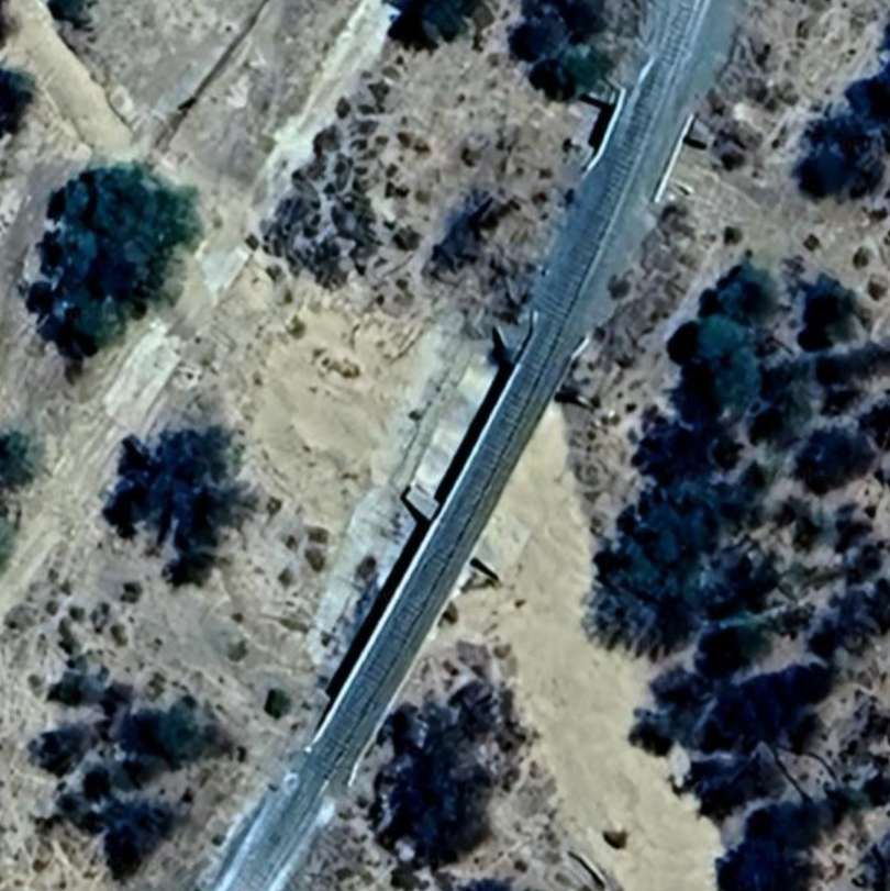
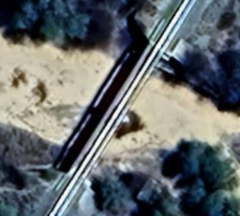
Five bridges spanning dry watercourses. [Google Maps, June 2025]
This photograph is taken from the C33 which has followed the railway Northeast towards Otjiwarongo. [Google Streetview, 2024]
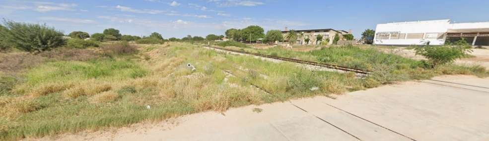
Approaching Otjiwarongo, this photograph faces East-northeast from alongside an ungated crossing around 50 metres Southeast of the C33. [Google Streetview, 2024]
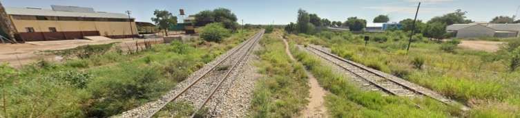
This photograph faces East-northeast along the approach to Otjiwarongo Railway Station. The road from which it is taken is the C38. [Google Streetview, 2024]
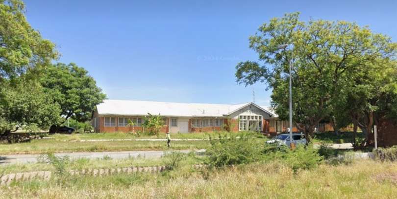
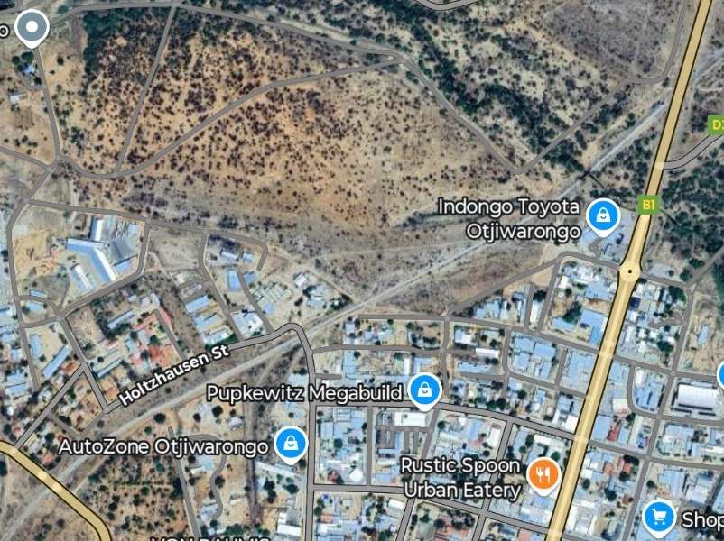
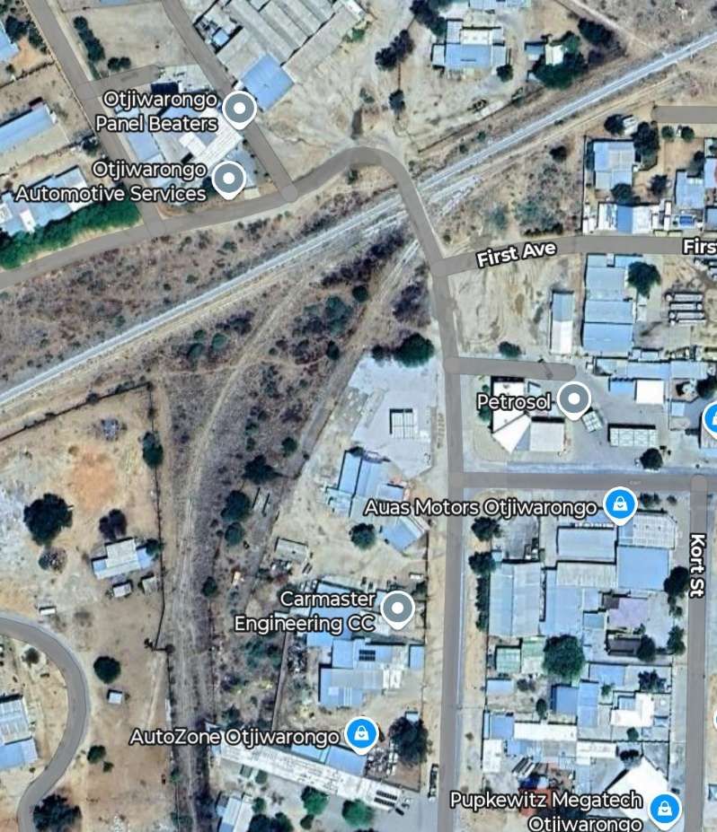
Otjiwarongo Railway Station is a junction station with line onward to Otavi and Outjo. [Google Maps, June 2025]
Otjiwarongo Railway Station building. [Google Streetview, 2024]
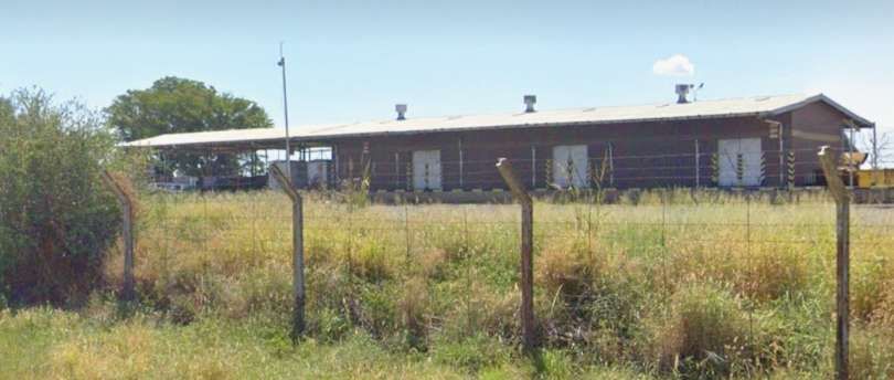
Otjiwarongo Goods Shed. [Google Streetview, 2024]
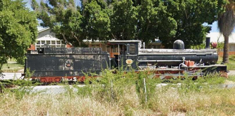
In 1912, Henschel built three 2-8-2 tender engines No. 40, No. 41 and No. 42 for the Otavi line for use on the Swakopmund-Karabib section. No. 41 is plinthed outside Otjiwarongo Railway Station. Like many other SWA locos they had dust covers to protect the motion. The carrying wheels were arranged as radial axles. As there were no separate bogie truck, the axle boxes were guided in such a way that the wheels could move radially with respect to the frame. At that time the railway was a 2ft-gauge line [Google Streetview, 2024] More information can be found here. [39]

The line to Otavi continues heading Northeast. …

The line to the Northeast of Otjiwarongo Railway Station. [Google Maps, June 2025]
At the bottom-left of the image above the line crosses the C33 at an ungated crossing. [Google Streetview, 2024]
A closer satellite view of the length of the line to the Northeast of the C33. A few sidings serve industries to the South of the line. The road at the centre of the image running North-South is Industria Street. [Google Maps, June 2024]
Looking West from Industria Street. [Google Streetview, 2024]
Looking Northeast from Industria Street. [Google Streetview, 2024]
The B1 to the Northeast of Otjiwarongo bridges the line. This view looks Southwest towards the railway station. [Google Str
Looking Northeast towards Otavi from the B1. [Google Streetview, 2024]
The line runs parallel to the B1 heading Northeast. [Google Streetview, July 2024]
Looking Northeast along the line from an ungated crossing at the D2430. The B1 can just be seen on the left of this image. [Google Streetview, July 2024]
A little further Northeast this photograph, taken from the B1, shows a minor road crossing the railway at an ungated crossing. [Google Streetview, July 2024]
As we travel Northeast, the landscape becomes greener. This another view looking East from the B1 and shows another ungated crossing of a minor road. [Google Streetview, July 2024]
The line passing under the B1. The landscape has changed. The line is running through dense shrubs and small trees. [Google Streetview, 2024]
In Otavi, this is Phyllis Street. It crosses the line at the Southwest end of the station site. [Google Streetview, 2024]
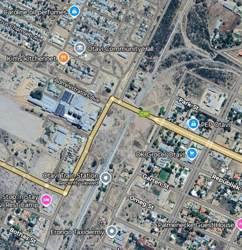
Otavi Railway Station and turning triangle. [Google Maps, June 2025]
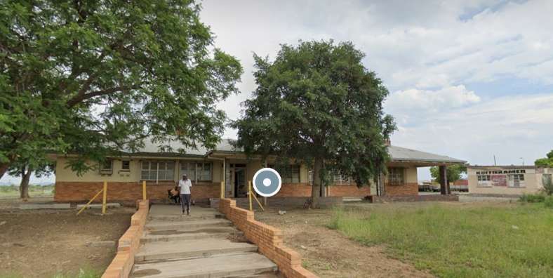
Otavi Railway Station building. [Google Streetview, 2024]

It is worth noting here that the original gauge of the line from the coast to Otavi and Tsumeb was originally built to 2ft-gauge. Later it was converted to 3ft 6in gauge. The line was built for the Otavi Mining and Railway Company (Otavi Minen- und Eisenbahn-Gesellschaft or OMEG). The company was founded was a railway and mining company in German Son 6th April 1900 in Berlin with the Disconto-Gesellschaft and the South West Africa Company as major shareholders. [41]

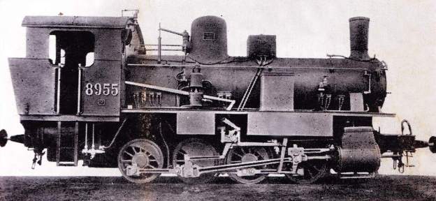
The first locomotives designed for regular service were fifteen 22-tonne 0-6-2T locos built by Arn. Jung. [41][42: p45] Henschel & Sohn built twelve locomotives similar to the Jung design and three 0-6-0T locos. [41][42: p45] Twenty 8-wheel auxiliary tenders carrying 8 cubic metres of water and 3.5 tonnes of coal were built to enable these tank locomotives to complete longer runs. [41][42: p45][43: p65] Henschel & Sohn built three HD class 2-8-2 in 1912 with separate 8-wheel tenders for long-distance running. [42: p47] These locomotives weighed 59 tonnes (including the 26-tonne tender) and remained in service for 50 years as the 2-8-2 type became standard for the railway. [41]

By 1913, train service included 4 express trains, 14 mixed trains, and 29 freight trains each week. [42: p39] Express and mixed trains included a baggage car, a car for African passengers, and a coach for first and second class passengers. [42: p39] The passenger coaches carried concrete ballast in a depressed center section to minimize the possibility of wind tipping a lightly loaded car off the rails. [43] Express trains stopped only at designated stations, but other trains would stop at intermediate points when transport was required. [42: p39] Equipment included: 96 low-side ore gondolas; 55 high-side gondolas; 20 limestone gondolas; 20 boxcars; 12 tank cars; 4 stock cars; 3 passenger coaches; and an executive business car with a kitchen, a bathroom, and an office convertible to a bedroom at night. [41][42: p42][43: p65]

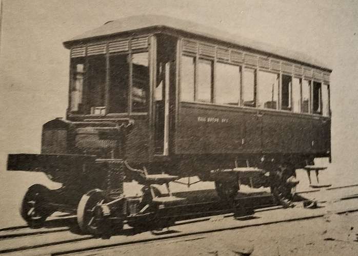
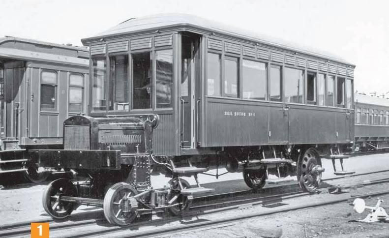
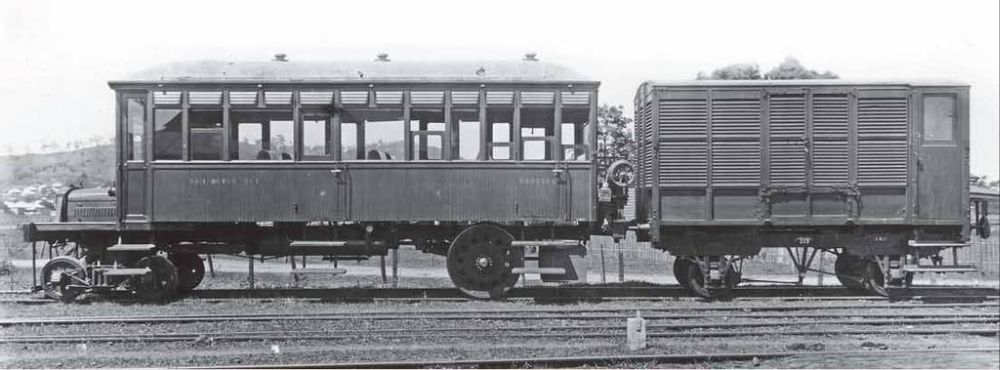
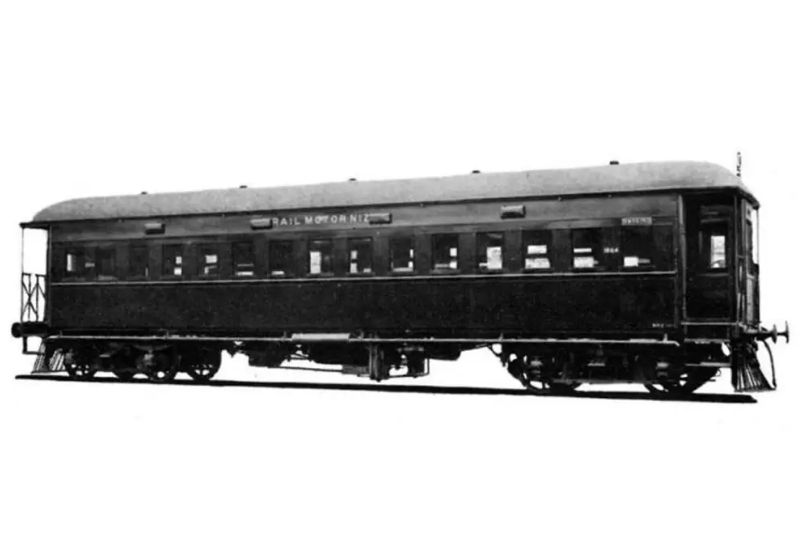
There were also some self-powered steam rail cars with a coal bunker, a mail compartment, 2 compartments for Europeans, and 4 for Africans. [41][42: p36]

Otavi-Grootfontein

The railway line from Otavi to Grootfontein is 91 kilometres (57 miles) long and was completed in 1908. [10]

  • Otavi (junction for Grootfontein)
  • Grootfontein (branch terminus)
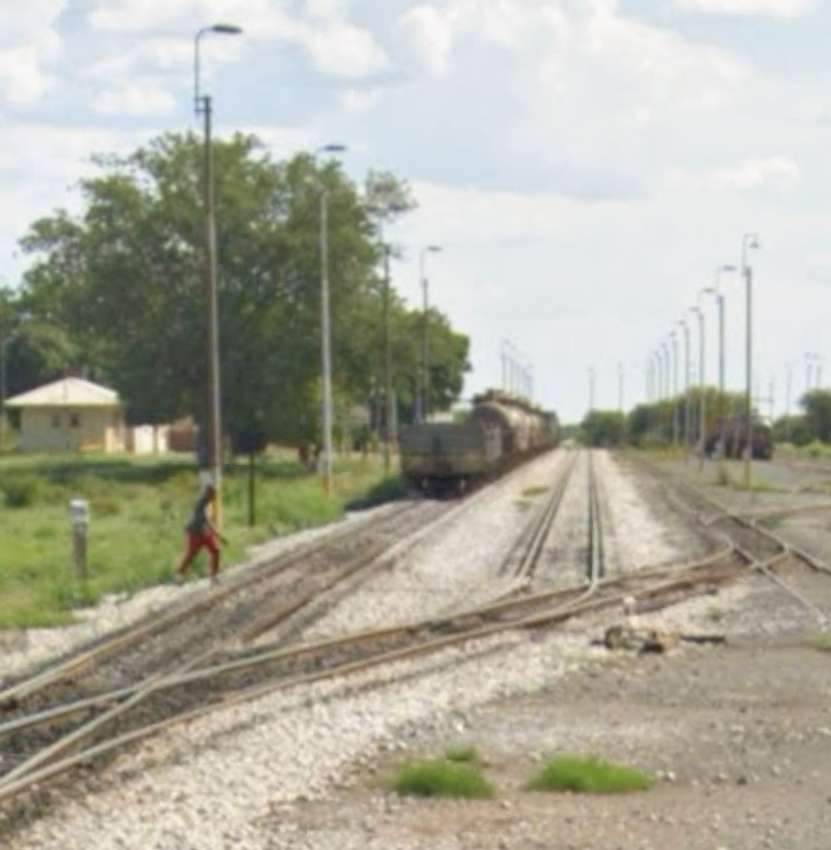
Otavi Railway Station, seen from the C39 at the Northeast end of the station site. [Google Streetview, 2024]
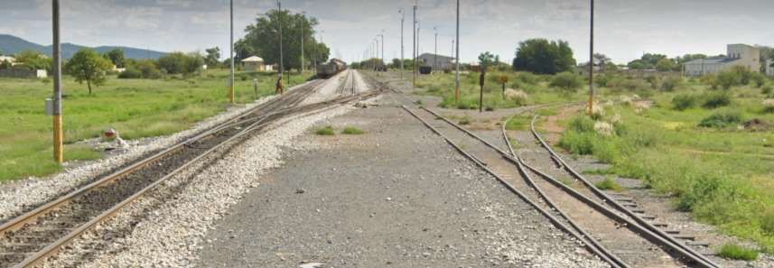
From the same location on the C39 a wider view shows the sidings at Otavi Railway Station [Google Streetview, 2024]
Turning through approximately 180° and looking Northeast, the line to Tsumeb runs towards the hills at the left of the image. The line to Grootfontein curves away to the right. [Google Streetview, 2024]
Looking back towards Otavi Railway Station from the ungated crossing on Josef Buchholz Avenue. [Google Streetview, 2024]
Turning through 180°, this is the view Sputheast from Josef Buchholz Avenue towards Grootfontein. [Google Streetview, 2024]
Heading Southeast out of Otavi the line to Grootfontein passes under the B1. This is the view along the line from the road and bridge. [Google Streetview, 2024]
Out of Otavi, the line soon starts to accompany the B8 in its journey East. This photograph is taken from the B8 and shows an ungated crossing on a minor road. [Google Streetview, 2024]
An ungated crossing provides access from the B8 into Kombat. The road is the D2863. This is the view East at the crossing. [Google Streetview, 2024]

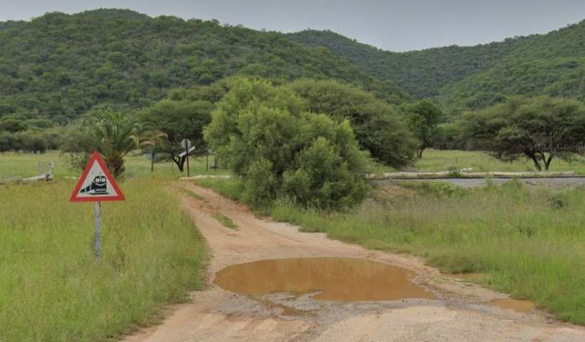
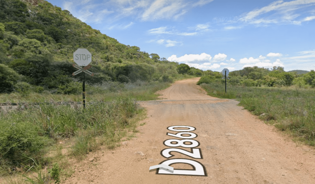
The line turns away from the B8, to the North. As it does so it crosses the D2860 at an ungated crossing.

The line to Grootfontein crosses the D2860 at an ungated crossing. [Google Streetview, 2024]

The line follows the D2860 and then the D2905 before passing under the B8, as it heads for Grootfontein.

An ungated crossing to the South of the D2905. [Google Streetview, 2024]
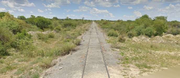
The view ahead along the line towards Grootfontein from the B8. [Google Streetview, 2024]
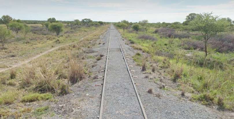
The view towards Grootfontein from a minor road ungated crossing. [Google Streetview, 2024]
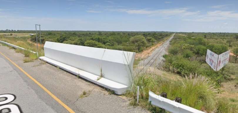
Much closer to Grootfontein, another view East along the railway. [Google Streetview, 2024]
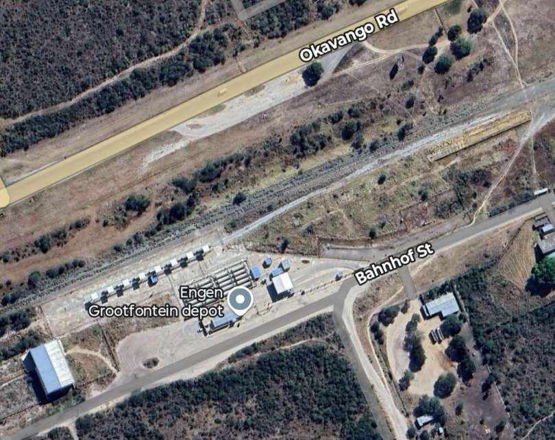
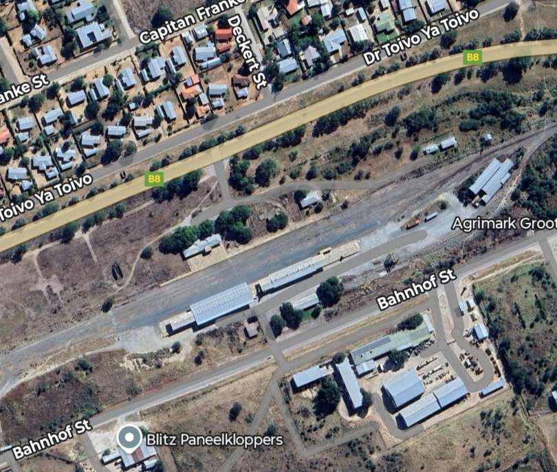
The fuel depot at Grootfontein. [Google Maps, June 2025]
Grootfontein Railway Station. [Google Maps, June 2025]
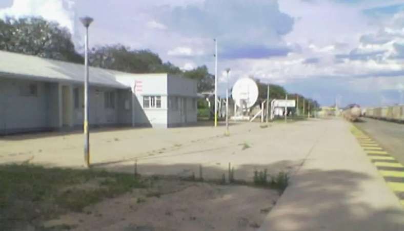
Grootfontein Railway Station in 2007. This image was shared on the African Railway Station Stopping Places Facebook Page In 2012. [46]
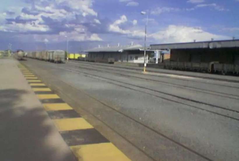
Grootfontein Railway Station goods depot in 2007. This image was shared on the African Railway Station Stopping Places Facebook Page In 2012. [47]

Grootfontein railway station is being converted into a logistics hub for business with the DRC and Zambia.

At the moment, trucks from the DRC, Zambia or Namibia travel about 2,500 kilometres from Walvis Bay harbour to Lubumbashi. With the introduction of the Grootfontein hub, these trucks will travel a distance of about 1,400 kilometres. TransNamib is prepared to dedicate four trains a week for this business idea. [44] 

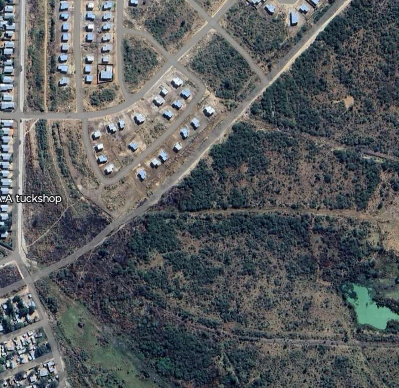
Immediately to the East of the railway station the line turns to the South and is clearly not well used and significantly overgrown in places. [Google Maps, June 2025]
After a few hundred metres the line turns to the East. It can clearly be made out towards the bottom of this satellite image. [Google Maps, June 2025]
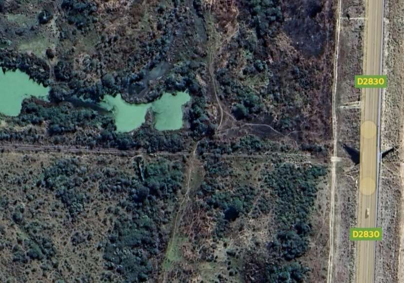
The line continues East and passes under the D2830. [Google Maps, June 2025]
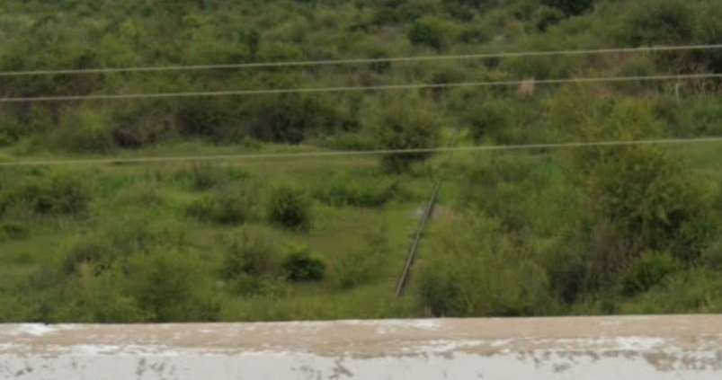
Looking West from the D2830, a short length of the line can be seen just to the right of the centre of this image. [Google Streetview, 2024]
To the East of the D2380 a series of sidings still exist. [Google Maps, June 2025]
It is harder to make out the sidings in this view. The photograph looks East from the D2380. [Google Streetview, 2024]
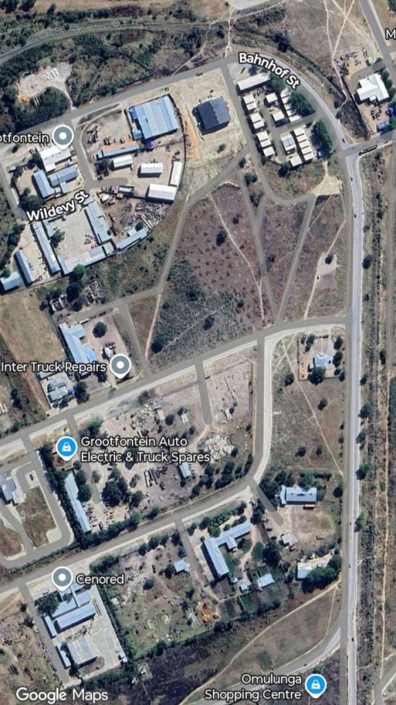
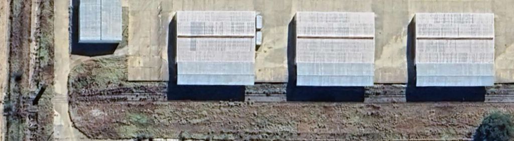
These last two satellite images show the extent of the tracks in the industrial area to the East of the D2380. [Google Maps, June 2025]

Otjiwarongo-Outjo

  • Otjiwarongo (junction for Outjo)
  • Outjo (railhead)

Otjiwarongo Railway Station is illustrated above. The railway line from Otjiwarongo to Outjo is 69 kilometres (43 mi) long. The first 26 kilometres (16 mi) were completed under the German colonial administration in 1914/1915; the railway line was named Amboland Railway in reference to the territory of the Ovambo people. The link to Outjo was completed in 1921 under South African rule. [10]

The branch line to Outjo can be seen turning away North from the line to Otavi. [Google Maps, June 2025]
The branch line crossed the C33 at an ungated crossing. This photograph looks South from the C33 towards Otjiwarongo Railway Station. [Google Streetview, 2024]
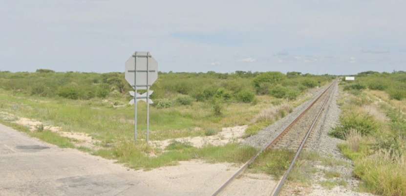
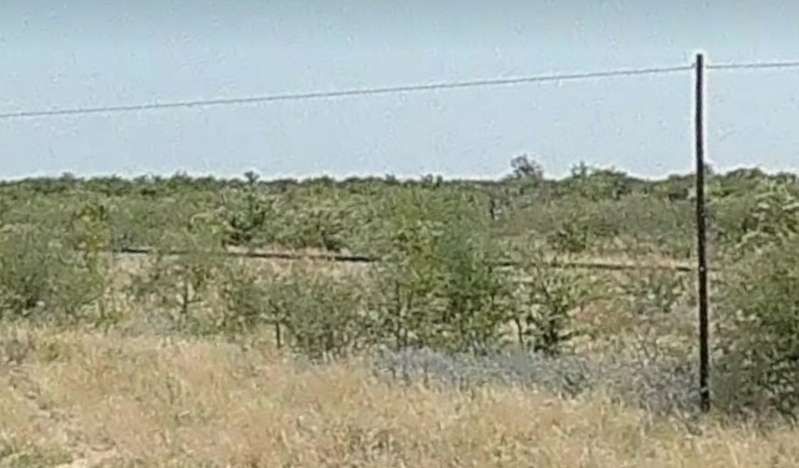
Turning through 120°, or perhaps more, standing on the C33, the rails of the line to Outjo disappear into the vegetation. The line has clearly not been used for some time. However, we will see that much of the line to Outjo remains in place and perhaps could be renovated should the need arise. [Google Streetview, 2024]
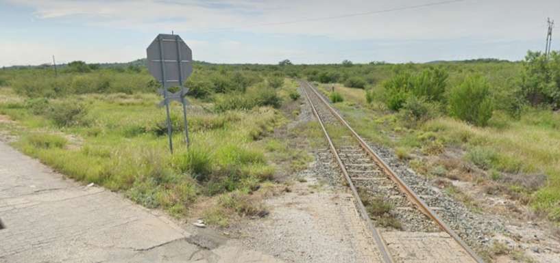
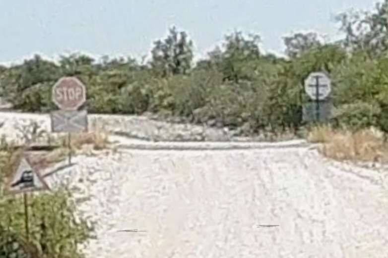
The line curves round towards the West. On the way it appears often out of the undergrowth. Here, this minor road crosses the old railway and the signs still stand proudly either side of the line, either side of the railway. [Google Streetview, 2924]
The road shown above appears bottom-right of this image. [Google Maps, June 2025]
The line then heads Southwest for a while before gradually turning through the West to the Northwest. [Google Maps, June 2025]
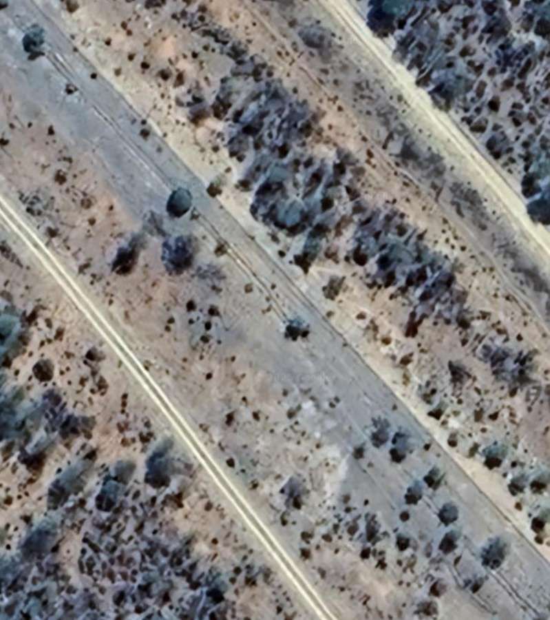
The line appears out of the brush quite often and sometimes for significant distances, as these two. [Google Maps, June 2025]
These two images are typical of what can be seen on satellite imagery. The line appears out of the brush quite often and sometimes for significant distances. [Google Maps, June 2025]
The line turns through West to Northwest. [Google Maps, June 2025]
It continues, Northwest. [Google Maps, June 2025]
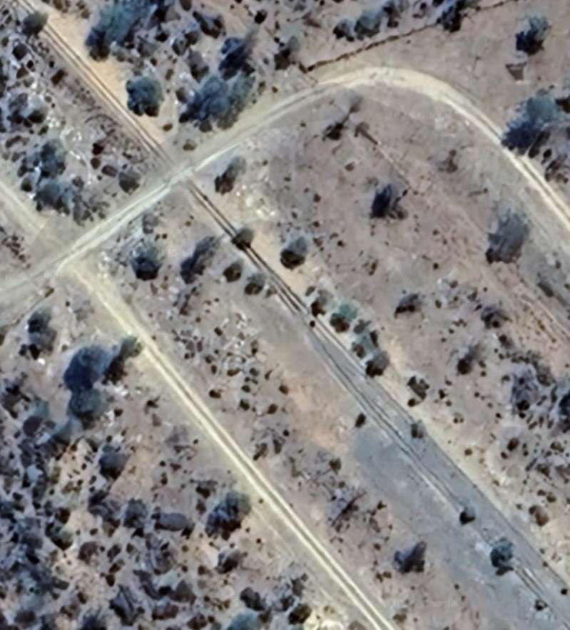
One passing loop appears out of the undergrowth. [Google Maps, June 2025]
Here it can be seen crossing another minor road. [Google Maps, June 2025]
And then a tarmac road. All crossings are ungated. [Google Maps, June 2025]

The next series of six photographs show sidings parallel to the running line. This location is more than just a passing loop but I have not been able to establish whether a specific local industry was the reason for the sidings. The photographs run in sequence Southeast to Northwest. …

The last of six photographs of sidings adjacent to the line to Outjo. [Google Maps, June 2025]

The next sequence of four photographs shows a passing loop on the line. In sequence, these photographs run from the Southeast to the Northwest. …

The last of a series of four satellite images showing a passing loop on the Otjiwarongo to Outjo Railway. [Google Maps, June 2025]
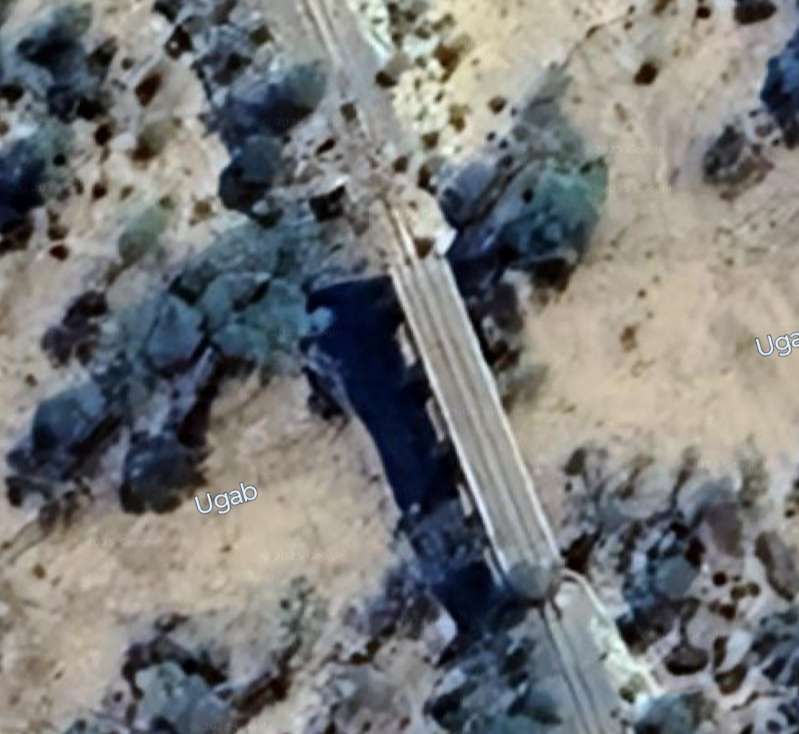
Further to the Northwest the line crosses the Ugab River. [Google Maps, June 2025]
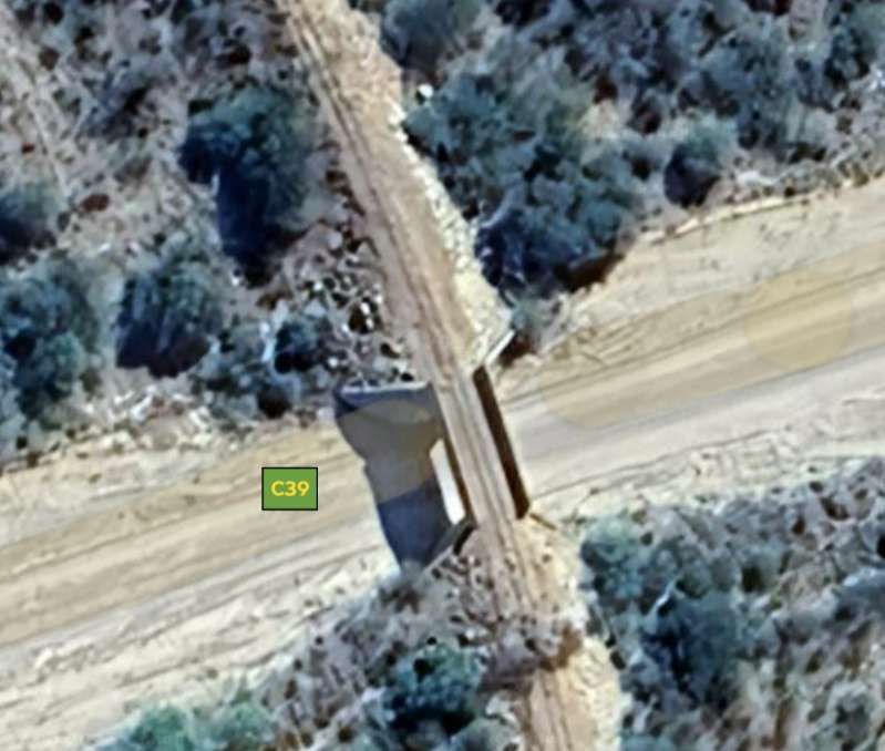
And then the C39 road, after which the line turns to the West and runs into Outjo. [Google Maps, June 2025]
Looking North from the C39 entering Outjo. A series of rail sidings sit to the North of the running line. [Google Streetview, 2024]
The last photograph looks North from the C39 at the left side of this satellite image. [Google Maps, June 2025]
Outjo Railway Station. [Google Maps, June 2025]
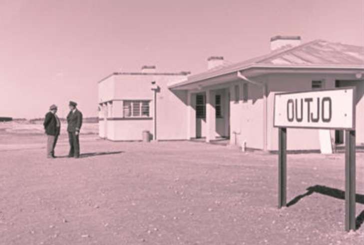
Outjo Railway Station in 1961, © SAR Publicity & Travel Department. [45]
Outjo Railway Station. [Google Streetview, 2024]
The turning triangle at the end of the line performed the

Otavi-Oshikango

In 2005, a new 89 km section of Northern Railway from Tsumeb to Oshivelo was opened by President Sam Nujoma, as part of the “Northern Extension” of the railway link from Kranzberg to Otavi. Construction on the project’s second phase, a 59 km stretch from Ondangwa to Oshikango on the Angolan border at a cost of about N$329m, was scheduled to be completed by December 2007. Ondangwa Station opened in 2006 for freight.

In phase 3, a 58 km branch from Ondangwa to Oshakati was constructed at an estimated cost of N$220m, for completion in December 2008. For the future a connection from Oshikango to a point near Cassinga is planned on Angola’s southern railway system. [11][13][14]

The Ondangwa-Oshikango line was officially opened by President Hifikepunye Pohamba in July 2012. In order to keep the system operational and safe, provincial governor Usko Nghaamwa implored local residents to stop stealing railroad ties and sections of the wire fence. [11][15]

  • Otavi (junction for Grootfontein)
  • Tsumeb
  • Ondangwa (junction)
  • Oniipa (road bridge)
  • Onjdiva [11][14]
  • Namacunde [11][16]
  • Oshakati
  • Oshikango (Angolan border)
The C39 crossed the railway immediately to the North of Otavi Railway Station. as we have already noted, this view from the ungated crossing shows the branch to Grootfontein heading away to the right and the line North-northeast to Tsumeb heading for the distant hills. [Google Streetview, 2024]

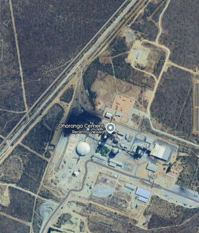
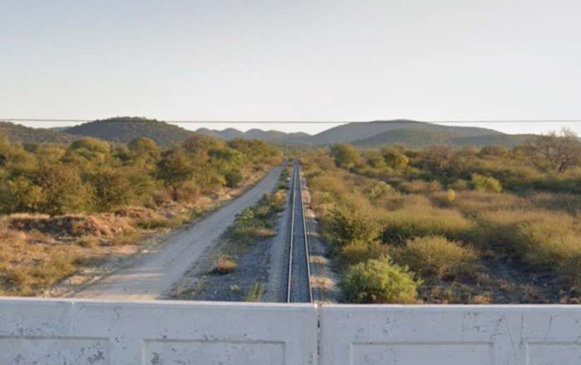
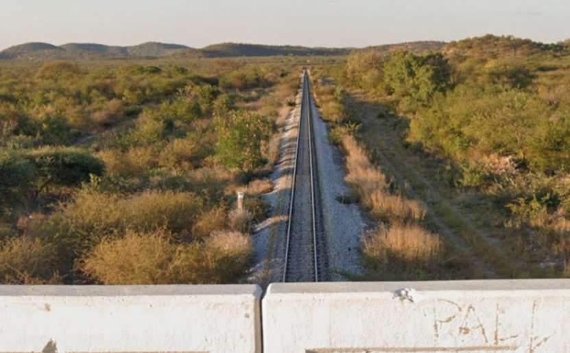
The journey towards Tsumeb runs uneventfully over flat ground surrounded by shrub and small trees, heading North-northeast, until it reaches Ohorongo Cement Works.

An aerial view of the works can be found here. [48] That view looks North across the Works and shows the railway and a dedicated branch to the Works in the background.

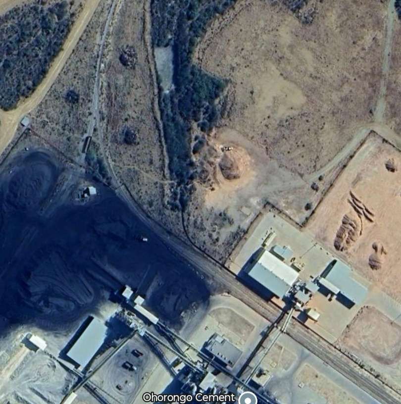
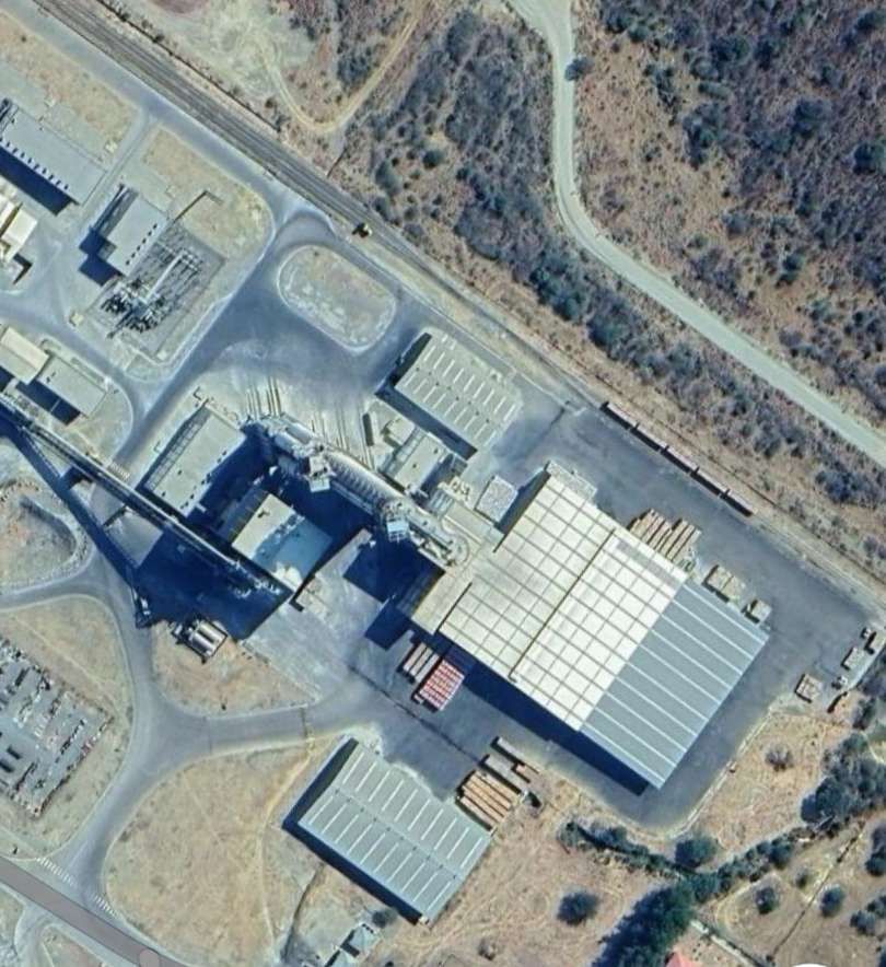
Ohorongo Cement Works. [Google Maps, June 2025]
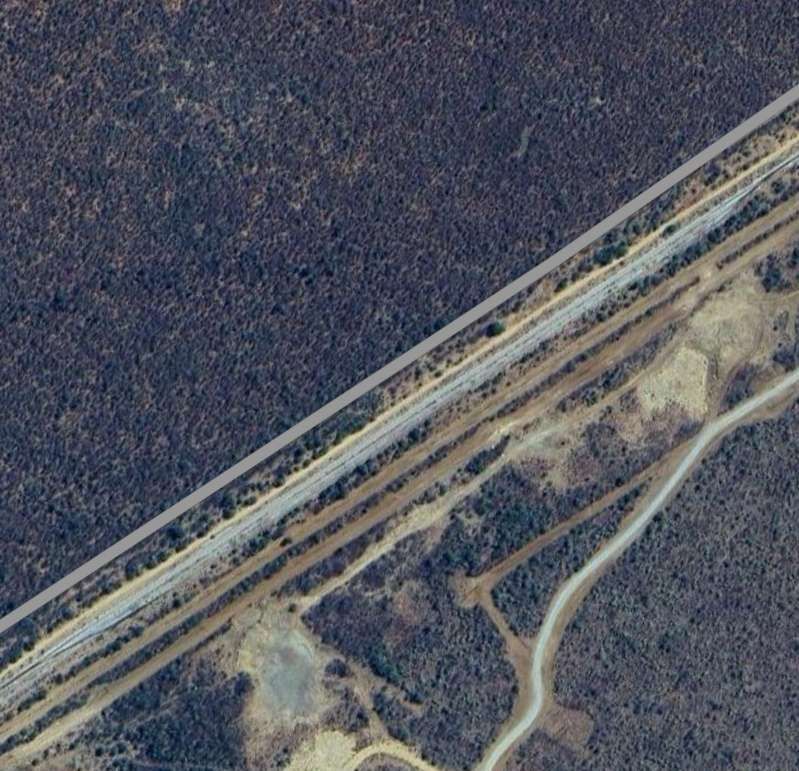
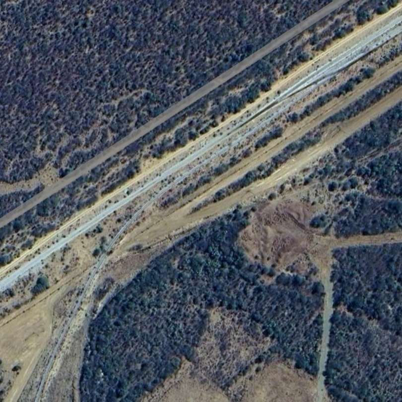
The passing loop and access to the cement works’ private sidings. [Google Maps, June 2025]
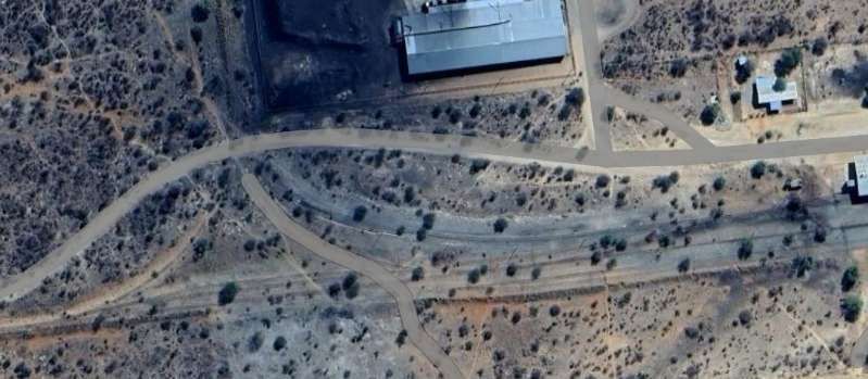
The dedicated siding can be seen leaving the main line at the Southwest end of the passing loop. [Google Maps, June 2025]
The siding curves round along the Northeast side of the Works. [Google Maps, June 2025]
The siding ends towards the Northeast corner of thecsite

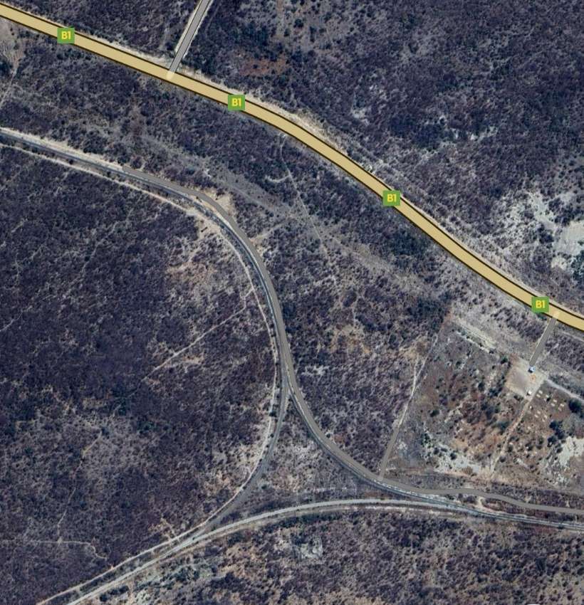
The railway continues Northeast over largely unremarkable flat terrain, before turning East, encountering one arm of the B1 and then a triangular junction.

Looking back West from the B1 towards Otavi. [Google Streetview, May 2024]
The view East from the B1 towards Tsumeb. [Google Streetview, May 2024]
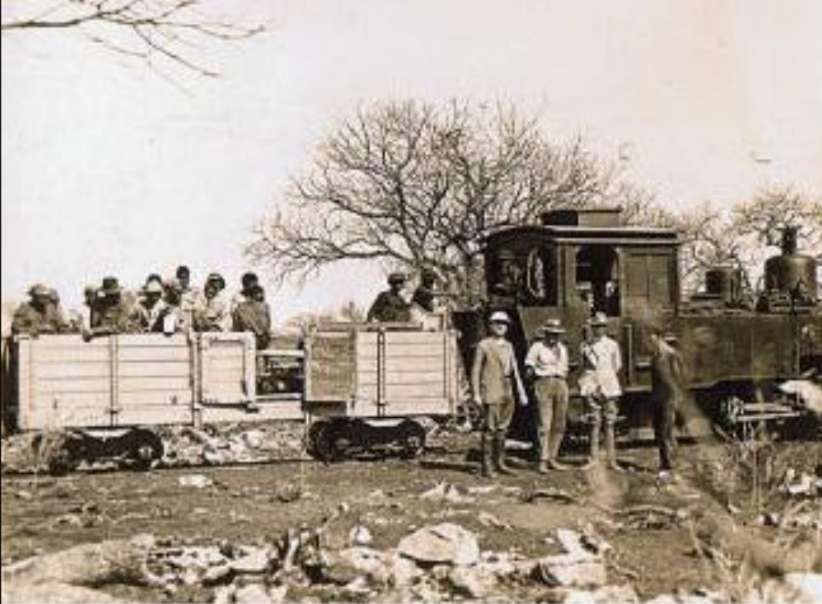
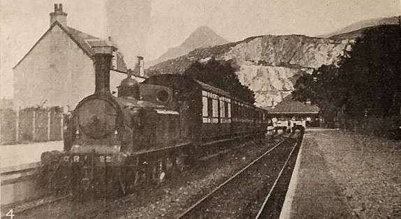
An early photograph of a 2ft-gauge train close to Tsumeb, © Not supplied, but made available under a Creative Commons Licence (CC BY-SA 3.0). [49]
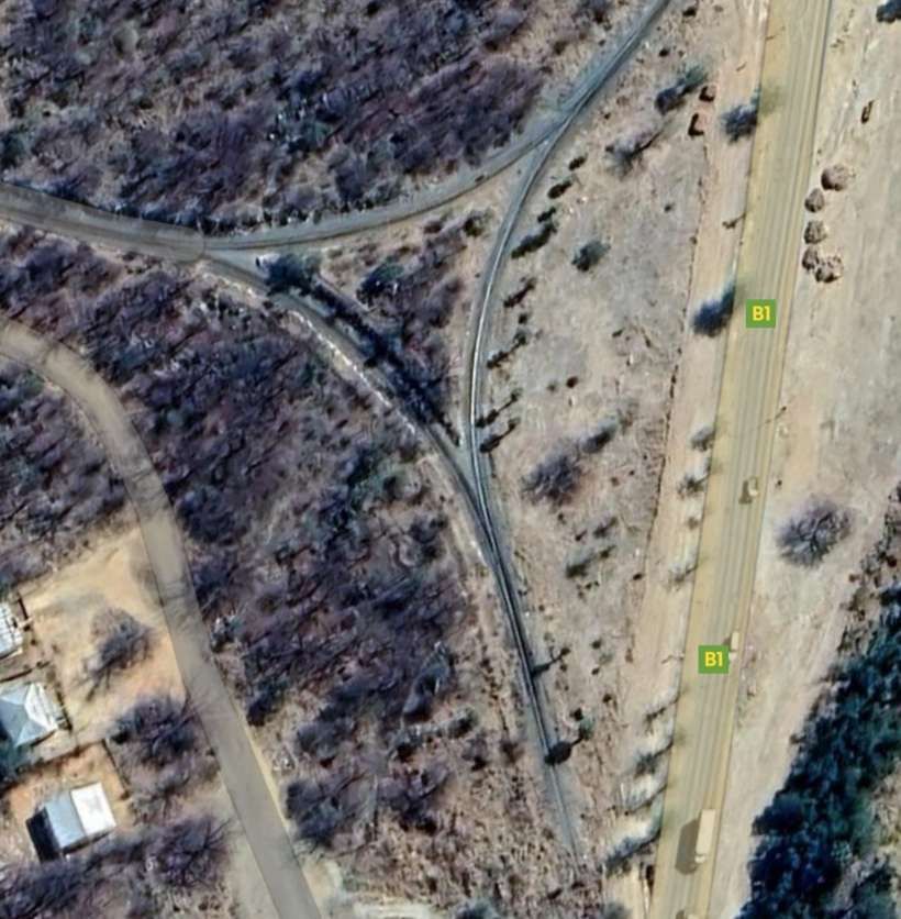
The triangular junction to the West of Tsumeb. The northern arm heads for Oshivelo, Omuthiya, Ondangwa, Oniipa, Onjdiva, Namacunde, Oshakati and Oshikango. The eastern arm to Tsumeb and beyond. [Google Maps, June 2025]
Tsumeb Railway Station. [Google Maps, June 2025]
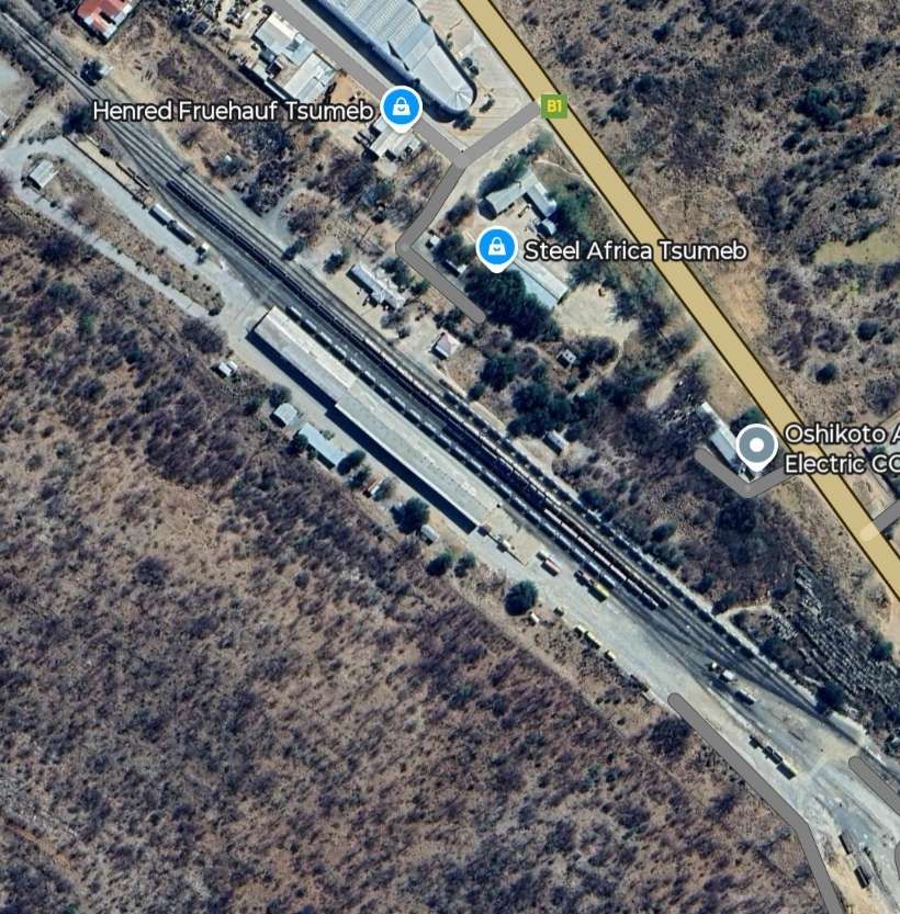
Tsumeb freight depot, with the line serving Tsumeb’s large mine passing under the B1. [Google Maps, June 2024]
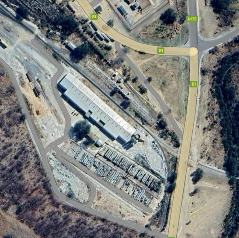
The turning triangle at Tsumeb sits immediately alongside the B1 to the South of the fright depot. [Google Maps, June 2025]
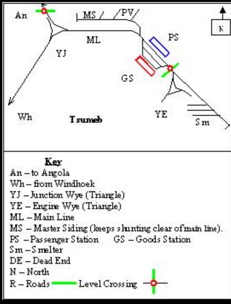
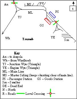
A diagrammatic representation of the rail network around Tsumeb, © Tabletop and licenced for reuse under a GNU Free Documentation Licence. [52]
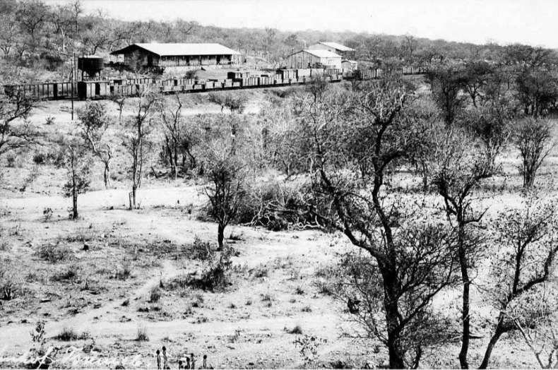
Tsumeb Railway Station in 1908 in 2ft-gauge days! © Public Domain. [55]

Encyclopedia Britannica tells us that “In 1851 Sir Francis Galton, a British explorer, made note of copper ore deposits in the vicinity of what later became the town of Tsumeb. An Anglo-German company acquired mining rights for the Tsumeb area in 1903. Southwest of Tsumeb is the site of the final German troop surrender to South African forces in World War I. The town remained a small copper-mining centre until the Tsumeb mine was purchased in 1947 by a largely U.S.-based corporation. It has since been developed as a planned company town (although ownership of the mine has changed hands several times), exploiting mineral deposits that include significant amounts of lead and copper as well as zinc, cadmium, silver, and germanium (a metalloid element used as a semiconductor). An integrated copper and lead smelter treats concentrates from Tsumeb and other mines. Owambo labourers are the chief contract workers.” [50]

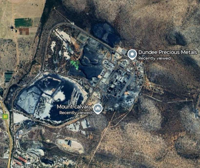
The mine, owned by Dundee Precious Metals sits to the East of the B1.

Tsumeb’s Mine is owned (in 2025) by Dundee Precious Metals, [51], a Canadian-based international gold mining company with operations and projects located in Bulgaria, Ecuador, Namibiaand Serbia. . [Google Maps, June 2025]
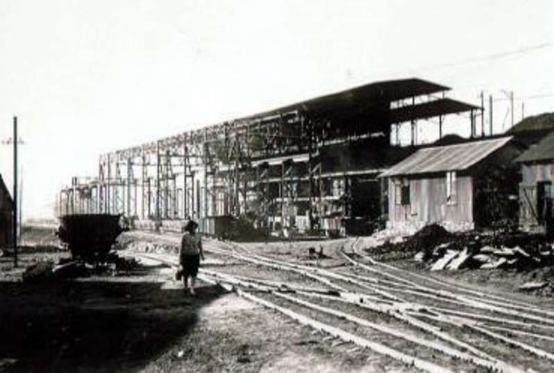
Rails and building under construction at Tsumeb Mine, © Not supplied, but made available under a Creative Commons Licence (CC BY-SA 3.0). [53]
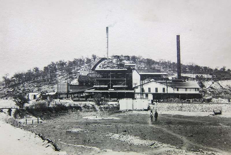
The old smelter at Tsumeb in 1910, © Public Domain and shared by jbdodane on Flickr on 9th April 2014. [54]

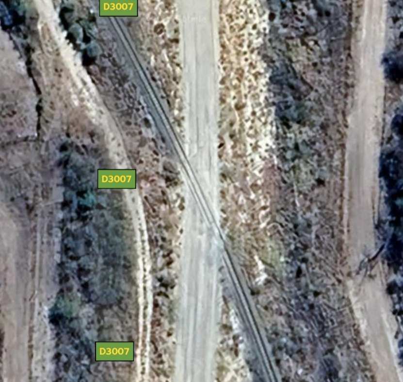
The line to the North of Tsumeb left the triangular junction to the West of the town heading first to the West and then to the Northwest and then directly North alongside the D3007, before turning West-northwest again.

Looking Southeast from the B1 towards Tsumeb. [Google Streetview, 2022]
Looking Northwest from the B1 along the line towards Omuthiya. [Google Streetview, 2022]
The ungated crossing at the D3007. [Google Maps, June 2025]

After a few kilometres on a West-northwest heading, the line then turns to the North-northwest and runs parallel to the B1 for some considerable distance.

The B1 and the railway converge and head North-northwest. [Google Maps, June 2025]
The line seen from the B1. [Google Streetview, 2022]
The ungated crossing on the D3004. [Google Streetview, 2022]
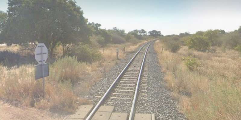
The view North-northwest along the line from the ungated crossing on the D3001. [Google Streetview, 2022]
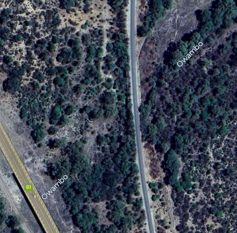
The line diverges from the B1 just to the South of the River Owambo. Both the railway and the road cross the river in this satellite image. [Google Maps, June 2025]
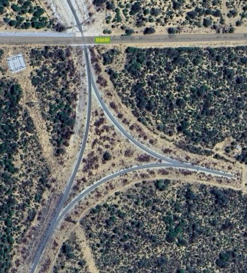
Triangle on the South side of the D3610 at Oshivelo. [Google Maps, June 2025]
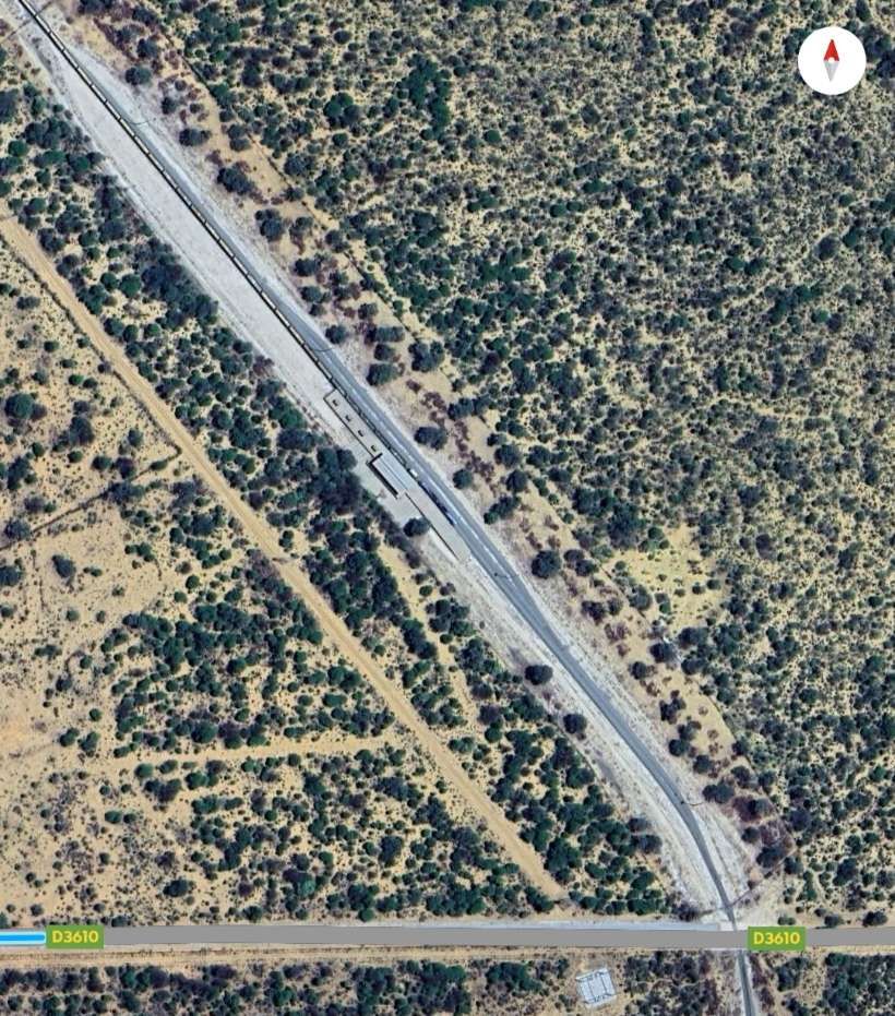
Oshivelo Railway Station on the North side of the D3610. [Google Maps, June 2025]
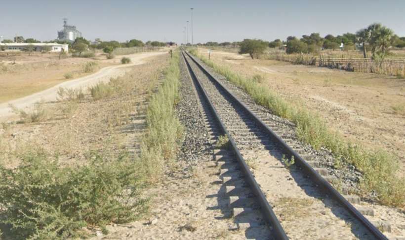
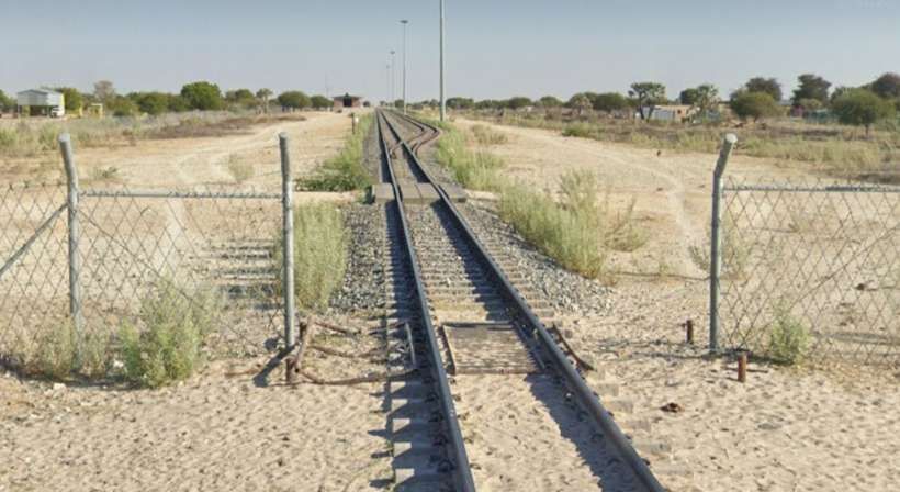
Looking South East from an ungated crossing just to the Southeast of Omuthiya Railway Station. [Google Streetview, 2022]
Looking Northwest from the same ungated crossing into the site of Omuthiya Railway Station. [Google Streetview, 2022]
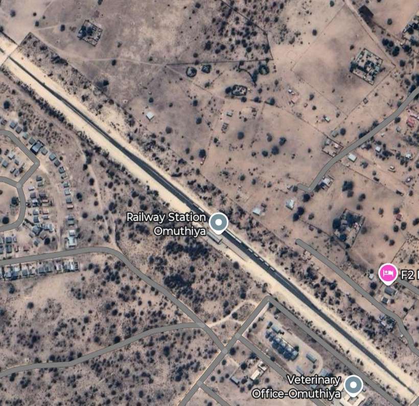
Omuthiya Railway Station. [Google Maps, June 2025]
The line to the Northwest of the station, seen from the South. [Google Streetview, 2024]
A short distance further up the line looking back towards Omuthiya. [Google Streetview, 2024]
A little further Northwest again, this time looking North towards Ondangwa. [Google Streetview, 2024]
Looking back towards Omuthiya from the ungated crossing on the D3603. [Google Streetview, 2024]
At the same ungated crossing, this photograph is taken looking forward towards Ondangwa. [Google Streetview, 2024]
Two culverts then take the line over the dry channel of the River Gwashigam. [Google Maps, June 2025]
Looking back Southeast from the bridge carrying the D3622 over the line on the approach to 0ndangwa. [Google Streetview, 2024]
Looking Northwest from the same bridge towards Ondangwa. [Google Streetview, June 2025]
Looking South-southeast from an ungated minor dirt road crossing closer to Ondangwa Railway Station. [Google Streetview, 2024]
Looking West-northwest towards Ondangwa. [Google Streetview, 2024]
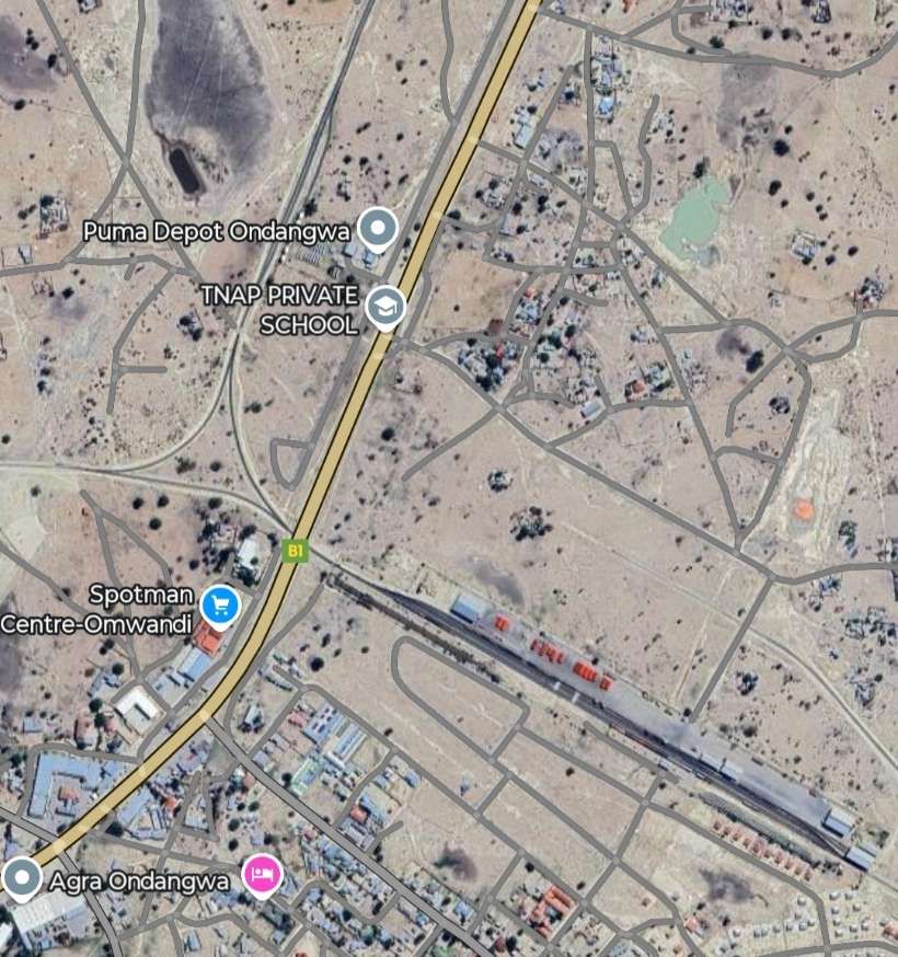
Ondangwa Railway Station and turning triangle. [Google Maps, June 2025]
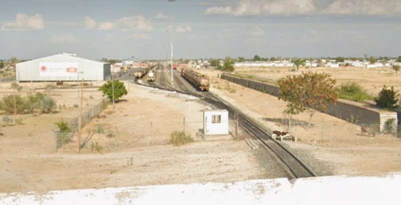
Looking South East from the B1 overbridge into the site of Ondangwa Railway Station. [Google Streetview, 2024]
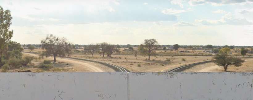
The view West from the same bridge across the turning triangle, the arm on the right leads to the line heading North towards the Angolan border. [Google Maps, June 2025]
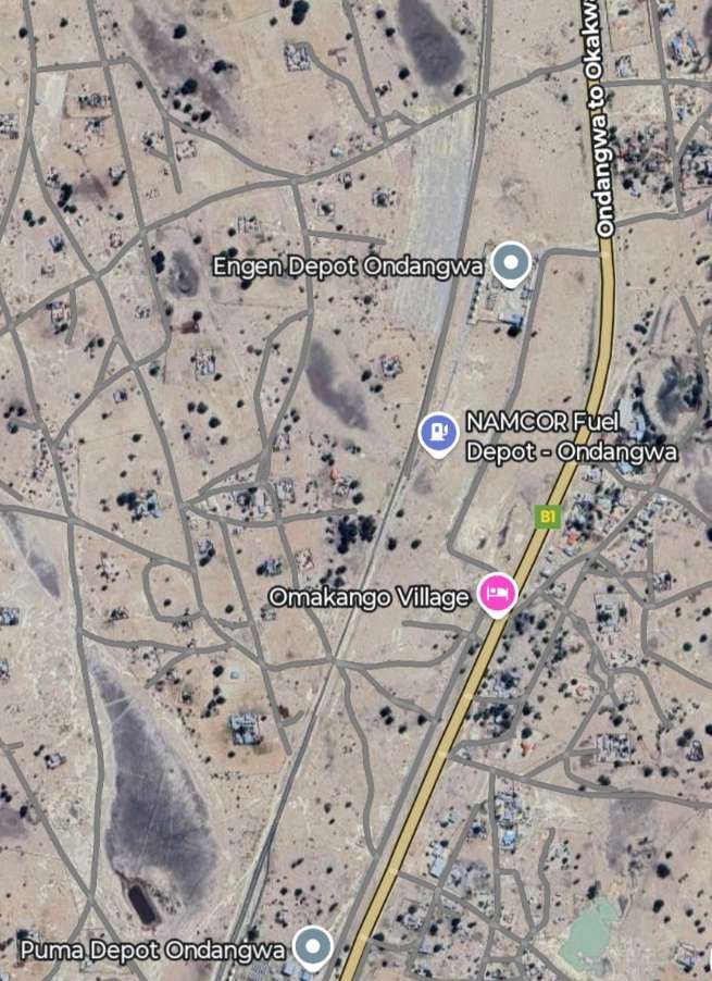
Fuel depots sit alongside the line as it heads North. [Google Maps, June 2025]
Looking North from the bridge carrying the C45 over the railway which is now closing in on the railhead on the Angolan border. [Google Streetview, 2024]

The next three images are a sequence of North-facing photogra

The last photograph on the northern line is a satellite image showing the railhead

The railhead in Oshikango at the Namibia/Angola border. [Google Maps, June 2025]

References

  1. Charles E. Lee; The Longest Narrow-Gauge Railway; in The Railway Magazine, February 1952, Tothill Press, Westminster, London, p121-123.
  2. https://en.m.wikipedia.org/wiki/German_South_West_Africa, accessed on 7th June 2025.
  3. https://www.britannica.com/place/German-South-West-Africa, accessed on 7th June 2025.
  4. https://en.m.wikipedia.org/wiki/South_West_African_Jung, accessed on 7th June 2025.
  5. https://en.m.wikipedia.org/wiki/History_of_rail_transport_in_Namibia, accessed on 8th June 2025.
  6. Helmut Schroeter; Die Eisenbahnen der ehemaligen deutschen Schutzgebiete Afrikas und ihre Fahrzeuge = Die Fahrzeuge der deutschen Eisenbahnen 7 [The Railways of the former German Protectorates in Africa and their Rolling Stock = the Rolling Stock of the German Railways 7]. (in German); Verkehrswissenschaftliche Lehrmittelgesellschaft, Frankfurt am Main, 1961.
  7. Helmut Schroeter and Roel Ramaer; Die Eisenbahnen in den einst deutschen Schutzgebieten: Ostafrika, Südwestafrika, Kamerun, Togo und die Schantung-Eisenbahn: damals und heute [German colonial railways: East Africa, Southwest Africa, Cameroon, Togo and the Shantung Railway: then and now] (in German and in English); Röhr-Verlag, Krefeld, 1993.
  8. Brenda Bravenboer and Walter Rusch; The First 100 Years of State Railways in Namibia; TransNamib Museum, Windhoek, 1997.
  9. According to Schroeter; Bravenboer does not mention this line.
  10. Klaus Dierks; The South African Period 1915–1989: The Development of the Namibia Railway Network!; via http://www.klausdierks.com/Namibia_Rail/2.htm, accessed on 8th June 2025.
  11. https://en.m.wikipedia.org/wiki/Rail_transport_in_Namibia, accessed on 8th June 2025.
  12. Not used.
  13. Ministry of Trade & Industry; Northern Railway Extension; via http://www.mti.gov.na/subpage.php?linkNo=72, this link is broken.
  14. Angola- Namibia Link; railwaysafrica.com; via https://web.archive.org/web/20141023100300/http://www.railwaysafrica.com/blog/2014/10/21/angola-namibia-link-3, accessed on 8th June 2025.
  15. Namibia: Community Vandalizes New Railway Line (9th July 2012); New Era; via http://allafrica.com/stories/201207090857.html, accessed on 8th June 2025.
  16. RailwaysAfrica No. 5, 2014, p11, via https://en.m.wikipedia.org/wiki/Railways_Africa, accessed on 8th June 2025.
  17. https://steam-locomotives-south-africa.blogspot.com/2008/07/walvis-bay-hope-steam-locomotive.html?m=1, accessed on 8th June 2025.
  18. The Industrial Railway Record Issue No. 37, June 1971, p78-85.
  19. https://www.expertafrica.com/namibia/windhoek/desert-express, accessed on 8th June 2025.
  20. https://www.rossing.com, accessed on 8th June 2025.
  21. https://en.m.wikipedia.org/wiki/Usakos_railway_station, accessed on 9th June 2025.
  22. https://steam-locomotives-south-africa.blogspot.com/2007/11/plinthed-class-hd-at-usakos-in-namibia.html?m=1, accessed on 9th June 2025.
  23. Leith Paxton & David Bourne; Locomotives of the South African Railways (1st ed.); Struik, Cape Town, 1985, p117 & 121.
  24. https://en.m.wikipedia.org/wiki/Windhoek_railway_station, accessed on 9th June 2025.
  25. https://www.facebook.com/share/p/1De1p8q5Mj/l, accessed on 9th June 2025.
  26. https://commons.m.wikimedia.org/wiki/File:LocomZwillinge_Windhoek1.JPG, accessed on 9th June 2025.
  27. https://en.m.wikipedia.org/wiki/Okahandja_railway_station, accessed on 10th June 2025.
  28. https://commons.m.wikimedia.org/wiki/File:Train_station_Windhoek_(2018).jpg, accessed on 10th June 2025.
  29. https://www.gettyimages.co.uk/detail/news-photo/trainload-of-armoured-cars-south-west-africa-world-war-i-news-photo/463970465, accessed on 10th June 2025.
  30. https://m.wikidata.org/wiki/Q7089896#/media/File%3AEisenbahnstation_Omaruru_1906.jpg, a cessed on 10th June 2025.
  31. https://commons.m.wikimedia.org/wiki/File:Karibib_aerial_view.jpg, accessed on 10th June 2025.
  32. https://commons.m.wikimedia.org/wiki/File:Kranzberg_Station.jpg, accessed on 20th June 2025.
  33. https://www.facebook.com/groups/namib2footers/permalink/6730769210360985, accessed on 10th June 2025.
  34. https://www.facebook.com/groups/namib2footers/permalink/6730826530355253, accessed on 10th June 2025.
  35. https://www.namibian.com.na/historic-train-preserved-for-posterity, accessed on 10th June 2025.
  36. https://steam-locomotives-south-africa.blogspot.com/2007/?m=1, accessed on 10th June 2025.
  37. https://www.news24.com/life/travel/go/then-now-swakopmund-railway-station-20240927, accessed on 10th June 2025.
  38. https://www.linkedin.com/posts/johan-stewart-laubscher-53342658_namibia-railinfrastructure-makinghistory-activity-6815601290438037504-swBC?utm_source=share&utm_medium=member_android&rcm=ACoAAFKPlCQBKyM6SVcRIYzuUN4W9XocTSJS0sY, accessed
  39. https://steam-locomotives-south-africa.blogspot.com/2007/11/narrow-gauge-locomotive-plinthed-at.html?m=1, accessed on 11th June 2025.
  40. https://en.m.wikipedia.org/wiki/Windhoek_railway_station, accessed on 11th June 2025.
  41. https://en.m.wikipedia.org/wiki/Otavi_Mining_and_Railway_Company, accessed on 12th June 2025.
  42. Frederic J. Shaw; Little Railways of the World; Howell-North, Berkeley, California, 1958.
  43. Dick Andrews; Extra Narrow Gauge Junction: Otavi Ry., State Northern Ry. in South Africa [sic]; in Narrow Gauge and Short Line Gazette, Volume 16 No. 1, 1991, p63–66.
  44. https://www.namport.com.na/news/428/grootfontein-train-station-new-logistics-hub-for-drc-zambia, accessed on 12th June 2025.
  45. http://atom.drisa.co.za/collections/N_Collection_lo-res/N70462.jpg, accessed on 12th June 2025.
  46. https://www.facebook.com/share/p/1CBLYcCydW, accessed on 12th June 2025.
  47. https://www.facebook.com/share/p/15abDSmZ7m, accessed on 12th June 2025.
  48. https://maps.app.goo.gl/Ta8Pcutiq8dYKQ1c8?g_st=ac, accessed on 13th June 2025.
  49. https://commons.m.wikimedia.org/wiki/File:Tsumeb_Railway.JPG, accessed on 13th June 2025.
  50. https://www.britannica.com/place/Tsumeb, accessed on 13th June 2025.
  51. https://dundeeprecious.com/about-us/overview, accessed on 13th June 2025.
  52. https://upload.wikimedia.org/wikipedia/commons/e/e6/Diagram_Tsumeb_railway_station_2007.jpg, accessed on 13th June 2025.
  53. https://commons.m.wikimedia.org/wiki/File:Tsumeb_2.JPG, accessed on 13th June 2025.
  54. https://www.flickr.com/photos/jbdodane/13848969294, accessed on 13th June 2025.
  55. https://picryl.com/media/1908-bahnhof-tsumeb-b561a6, accessed on 13th June 2025.

The Highland Railway – Part 5 – The Fortrose (or Black Isle) Branch

Stanley Jenkins tells us that “The opening of the Inverness & Rossshire Railway between Inverness and Dingwall on 11th June 1862 brought the benefits of rail transport to a prosperous farming area in Ross & Cromarty. The line was completed throughout to Invergordon on 25th March 1863, while a series of subsequent extensions eventually resulted in the creation of the Highland Railway’s ‘Far North’ line between Inverness and Wick. Inevitably the 161½ mile ‘Far North’ line omitted large numbers of places that would have benefited from direct rail links, and for this reason several branch-line schemes were put into effect during the latter part of the 19th century.” [1: p48]

The Black Isle peninsula, between the Beauly and Cromarty Firths, became the focal point for two such schemes, only one of which was successful.” [1: p48]

Wikipedia tells us that “The Highland Railway was surprised when in 1889 the Great North of Scotland Railway (GNoSR) proposed the construction of a railway to Fortrose, … The GNoSR operated a network from Aberdeen and the nearest place to Inverness served by it was at Elgin, some distance away. The branch would have been detached from the owning railway, but running through the Black Isle it would have made a junction with the Highland Railway at Muir of Ord. A ferry operation from Fortrose to Ardersier, on the south side of the Moray, was included in the plans. Ardersier was then known as Campbelltown, and a railway branch to it was included. Two other schemes striking into Highland territory were proposed at the same time, elevating Highland Railway discomfort about its competitive position.” [2][3]

The two companies had been adversaries for some time, and in 1883 and the following years there had been a state of continual warfare over junctions, frontiers and running powers. … The Highland saw at once that if this branch were built, it would be easy for the GNoSR to demand running powers into Inverness to reach its branch, and in that way the rival company would have gained access to the Highland’s stronghold.” [2]

After considerable ‘argument’ between the two companies, the GNoSR and the Highland Railway each submitted Bills to the UK Parliament for a line to Fortrose.

It was the Highland Railway’s scheme which received Parliamentary consent on 4th July 1890. Jenkins tells us that it was for a “16 mile branch line between Muir of Ord, on the ‘Far North’ line, and the fishing port of Rosemarkie. The gentle topography of the Black Isle ensured that the proposed line could be built with relative ease, and on 1st February 1894 a single line was opened as far as Fortrose a distance of 13 miles 45 chains. The final section between Fortrose and Rosemarkie was never built, the terminal station at Fortrose being deemed a suitable railhead for the surrounding district.” [1: p48]

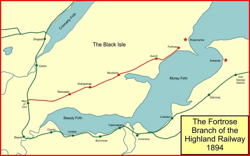
The Fortrose Branch is shown as a red line on the image running from Muir of Ord to Fortrose, © Afterbrunel and licenced for reuse under a Creative Commons Licence (CC BY-SA 4.0) [4]

The Fortrose branch provided useful transport facilities … on the South side of the Black Isle, but it was felt that better facilities were needed on the North side of the peninsula. The 1896 Light Railways Act offered a solution to this local transport problem, and on 1st August 1902 a Light Railway Order was obtained for construction of a 19 mile line between Conon, on the ‘Far North’ line, and Cromarty. Work began at the Cromarty end, but subsequent progress was painfully slow, and extensions of Time Orders were obtained in 1907, and again in 1910. … About six miles of track was actually laid between Cromarty and Newhall, but all work was suspended in 1914 on the outbreak of World War I. At that time, construction work was in hand on a further two miles of line, but little had been done on the remaining eleven miles of line to Conon. The track was lifted around 1915 for use in the war effort, leaving the earthworks and other engineering features of the unfinished light railway in a derelict condition.” [1: p49]

If the Cromarty & Dingwall Light Railway had been completed it would have had stations at Alcaig Ferry, Culbokie, Drumcudden, and Newhall. Other halts may have been opened once the line was in operation, while there were also suggestions that the route might be extended south-westwards from Cromarty to Rosemarkie and Fortrose, thereby creating a scenic ‘coastal’ route around the Black Isle that would have had considerable potential as a tourist attraction. Unfortunately the changed economic conditions after World War I meant that schemes of this kind were no longer viable, and the Fortrose branch was therefore left in splendid isolation as the only completed railway in the Black Isle area.” [1: p49]

The Fortrose route was worked as a feeder branch for the ‘Far North’ line, and as such it was moderately-successful. Like other Highland Railway branch lines it was normally worked by small tank locomotives such as the Dübs 4-4-0Ts. Other engines seen on the line were Drummond’s well-known 0-4-4 branch-line tanks.” [1: p49]

The Route from Muir of Ord to Fortrose

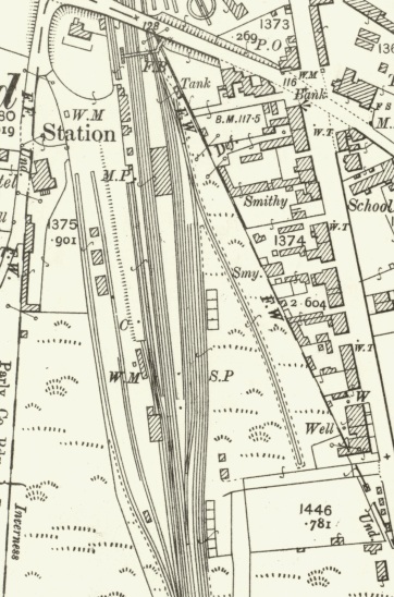
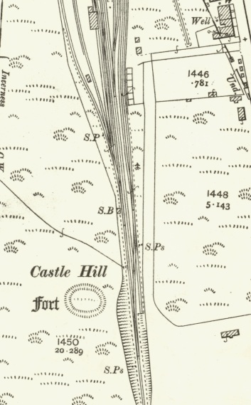
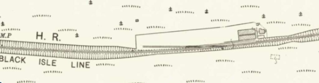
The extracts below from the 25″ Ordnance Survey of 1904, published in 1906 cover the site of Muir of Ord Railway Station. [6] Jenkins tells us that “Muir of Ord – the junction station for branch services to Fortrose – was opened on 11th June 1862 when the initial section of the Highland ‘Far North’ line was brought into use between Inverness and Dingwall.” [1: p49]

The station was orientated from North to South, with its main station building on the down, or northbound side. The track layout was relatively complex, with sidings on both sides of the running line and a lengthy crossing loop. The main goods yard, with accommodation for coal, livestock, furniture, machinery, and general-merchandise traffic, was situated to the south of the platforms on the down side. One of the yard sidings passed through a goods shed, while others were used mainly for coal or other forms of wagon-load traffic. Further sidings were available on the up side, and one of these gave access to a 50ft diameter locomotive turntable.” [1: p49]

Wikipedia tells us that “The station is 13 miles 4 chains (13.05 mi; 21.0 km) from Inverness, between Beauly and Conon Bridge, and is the location of the sole remaining passing loop on the single line between Dingwall and Inverness.” [5]

The station building and platform canopy were erected in 1894, [5][7] 32 years after the station itself opened. [8] Passenger services on the branch ceased on 1 October 1951, but the branch remained open for freight until 13 June 1960. Muir of Ord station was closed on 13 June 1960 but reopened in 1976, on 4 October.” [5][8]

After the railway bridge across the River Ness washed away in February 1989, isolating the entire network north of Inverness, Muir of Ord was chosen as the location for a temporary depot, from which the stranded rolling stock could operate the service to the highland communities which depended on the line.” [5][9]

In November 2015, work commenced on a new A862 road bridge at the northern end of the station.” [5][10]

The project cost £3.7 million and was completed in the Summer of 2017. [11]

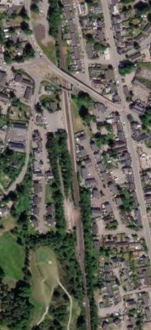
This ESRI satellite image supplied by the NLS shows the station site after the reconstruction of the raod bridge. [6]

Wikipedia tells us that “in the 21st century, both station platforms have modern waiting shelters and benches, with step-free access. There is a car park and bike racks adjacent to platform 1, along with a help point near to the entrance from the car park.” [5]

As there are no facilities to purchase tickets, passengers must buy one in advance, or from the guard on the train.” [5]

The station has a passing loop 32 chains (700 yd; 640 m) long, flanked by two platforms which can each accommodate a ten-coach train.” [5][12]

On 11th June 1862 the Inverness and Ross-shire Railway opened their line between Inverness and Dingwall. It included a station at the village of Tarradale but the company decided to name it after the nearby cattle tryst (market), Muir of Ord. Eventually the name Muir of Ord was applied to the surrounding area.” [14]

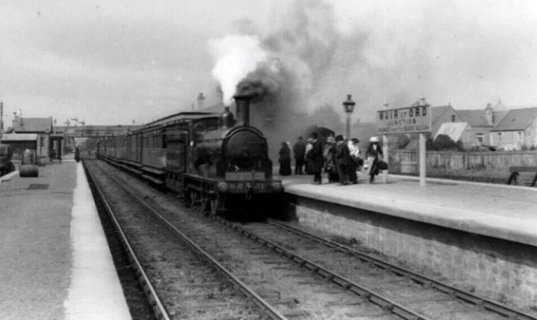
Looking North at platform level, Highland Railway No. 21can be seen in 1913 in charge of a southbound passenger service. The locomotive was one of Highland Railway’s 12-strong ‘Barney’ class of 0-6-0 locomotive. They were designed by Peter Drummond to pull goods traffic but they frequently found themselves on passenger service duty, as seen here. HR 21 was built by Dübs & Co of Glasgow and was delivered in August 1902, © Public Domain. [13] This image appears to have been sourced from the http://www.ambaile.org.uk/Highland Railway Society website. [14]
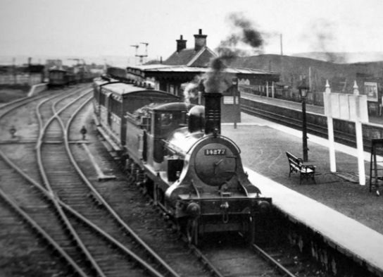
Looking South from the footbridge at the North end of the station site sometime in the 1920s. The ‘Strath’ class of 4-4-0 passenger locomotives were built for the Highland Railway by Neilson Reid & Co. of Glasgow in 1892. They were built to the design of David Jones, the company’s locomotive superintendent, and were similar in design to his other locomotives, with the exception of having larger boilers. The twelve locomotives were numbered 89 to 100 and six of them passed into LMS ownership in 1923. This photograph shows LMS 14272 ‘Strathdearn’ heading North at Muir of Ord. On completion for the Highland Railway it carried the number 92 and was renumbered on five occasions: to 92A in June 1918; to 92 in August 1918; to 92A again in April 1919; to 92 in September 1919 and 92A in July 1921. It was one of the class to pass into LMS ownership and was numbered 14272 by the new company. It was withdrawn from service in February 1930, © Public Domain. These two images were found on a youTube video but the source will be Am Baile and they probably come from the Highland Railway Society Collection, © Public Domain. [13]
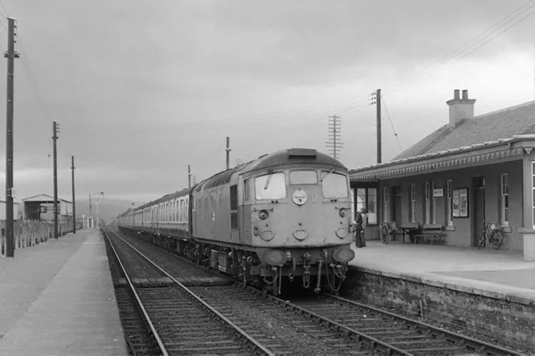
Looking South at platform level in 1978, a train from Inverness to Wick and Thurso pauses to collect passengers at Muir of Ord station. © The Carlisle Kid and licensed for reuse under a Creative Commons Licence, (CC BY-SA 2.0). [15]

As can be seen in the image below, all of the station buildings have been removed and replaced with waiting shelters with little or no character.

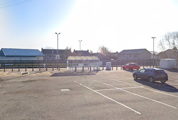
The modern facilities at Muir of Ord Railway Station are quite primitive. The phot was taken from the West in 2023. [Google Streetview, March 2023]
Looking Southeast across the original bridge at the North end of Muir of Ord Station site. [10]
The replacement structure at the North end of the Station site as it appeared from the air in 2017. [11]
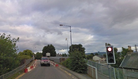
Looking South from the road bridge in the 21st century. [Google Streetview, March 2023]
Looking Southeast across the road bridge in 2023. [Google Streetview, March 2023]
Looking Northwest across the road bridge. [Google Streetview, March 2023]
Looking North from the road bridge towards the location of the Fortrose branch line junction. [Google Streetview, March 2023]
Looking North from a trackside location just to the North side of the road bridge at Muir of Ord, a train from Kyle of Lochalsh heads South into the station, © The Carlisle Kid and licensed for reuse under a Creative Commons Licence, (CC BY-SA 2.0). [16]

On leaving Muir of Ord, branch trains diverged eastwards, and having, executed a full 90 degree turn the route maintained its easterly heading for about two miles.” [1: p49]

A further extract from the 25″ Ordnance Survey of 1904, published in 1906. This extract shows the brach leaving the main line just North of the Station and heading East. [17]
The same area as shown on ESRI satellite imagery provided by the NLS, in the 21st century. [17]
As the line curved to the East it was crossed at level by a track. [17]

Additional sidings on the north side of the station provided locomotive facilities for the branch engine. The main engine siding gave access to a 50ft turntable, while a ‘kick-back’ spur ran into a single-road engine shed; another siding served as a coaling road. The station building was a typical Highland Railway timber-framed structure which was similar to its counterparts at Hopeman and Burghead, albeit with a second cross-wing at the left-hand end (when viewed from the platform). The resulting building was thus an ‘H-plan’ structure with a central block flanked by two cross-wings.” [1: p51]

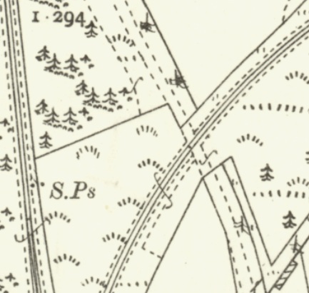
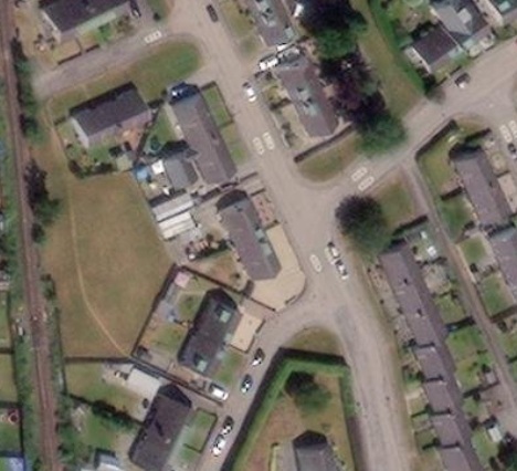
In the 21st century, the track has been replaced by a modern estate road – Highfield Circle. The road entering bottom-centre is Fairmuir Road, that leaving top-right is part of Highfiels Curcle. These two roads approximately follow the line of the old railway. [17]
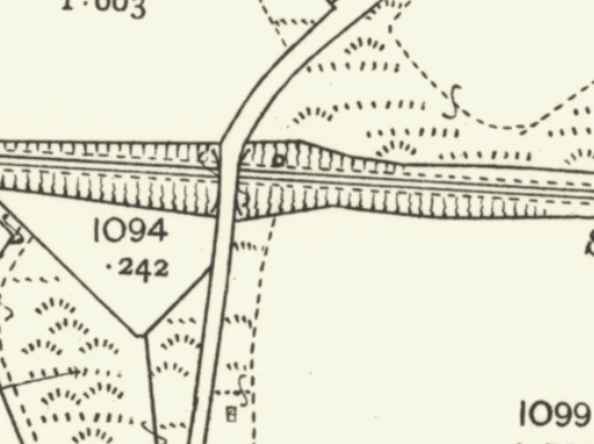
A short distance to the East the line was in cutting and bridged by a minor road. [17]
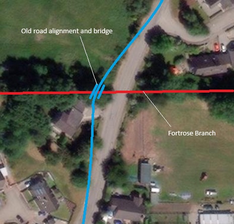
ESRI satellite imagery from the NLS shows the realigned road in the 21st century. The approximate line of the old road (blue) and railway (red) have been superimposed on the image. The modern road is named ‘Balvaird Road’. [17]
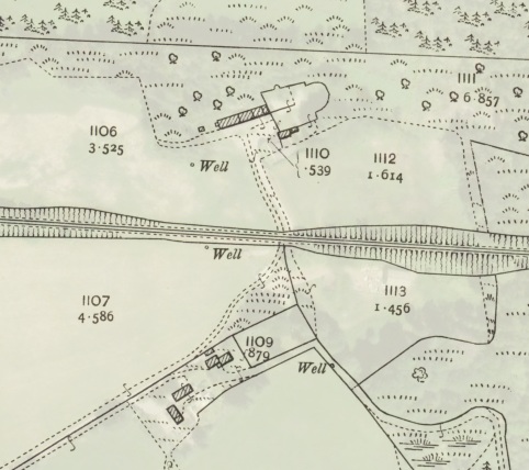
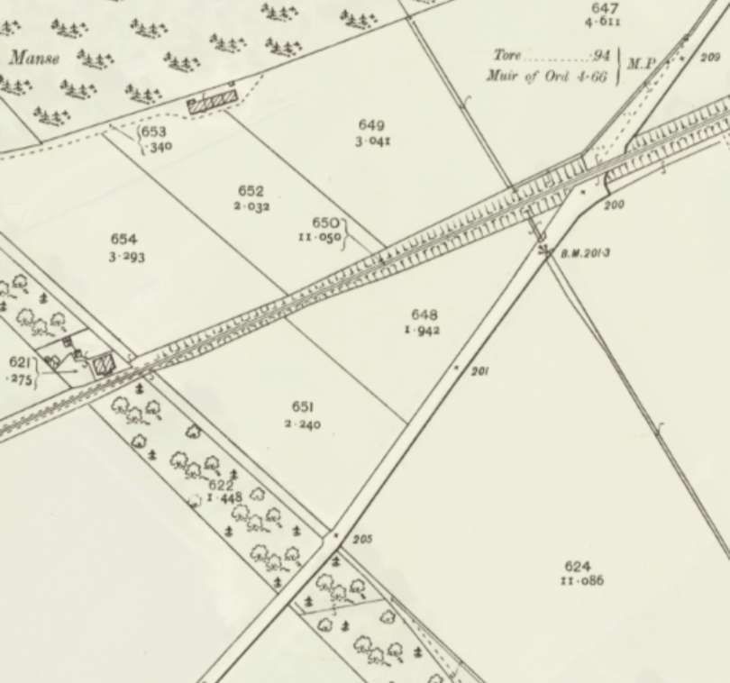
A short distance further East the line was crossed by a farm access raod at a level-crossing. [18]
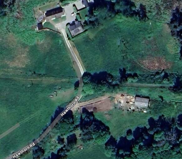
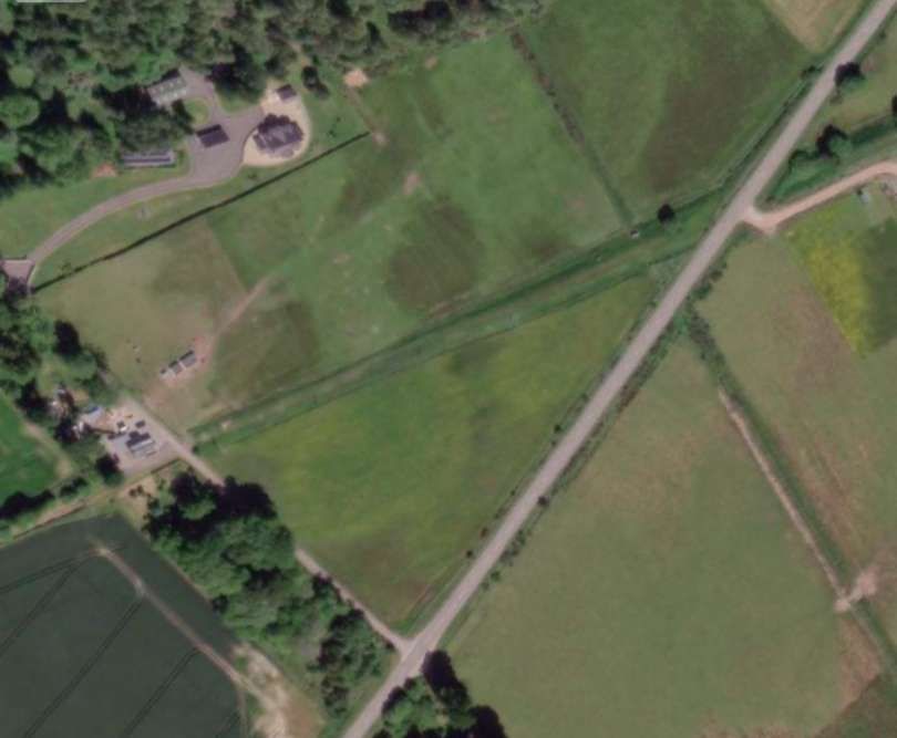
The same location in the 21st century as shown on Google Maps satellite imagery. The lane is now named ‘Hawthorne Road’. [Google Maps, March 2025]
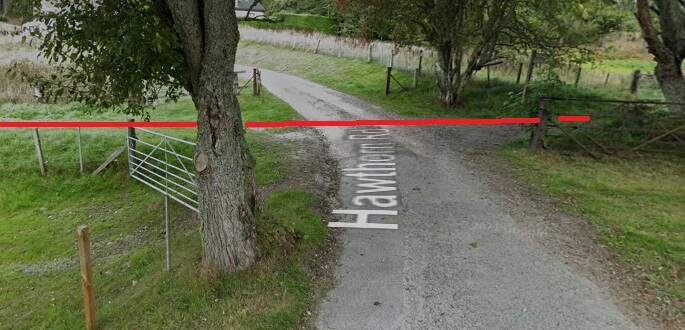
Looking North along Hawthorne Road, across the line of the old railway (marked approximately by the red line). Google Streetview, September 2021]
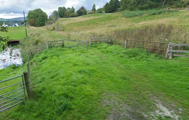
Looking West from Hawthorne Road along the line of the old railway towards Muir of Ord. The line of the railway is gated by the single-bar gate and it ran from there towars the distant trees. [Google Streetview, September 2021]
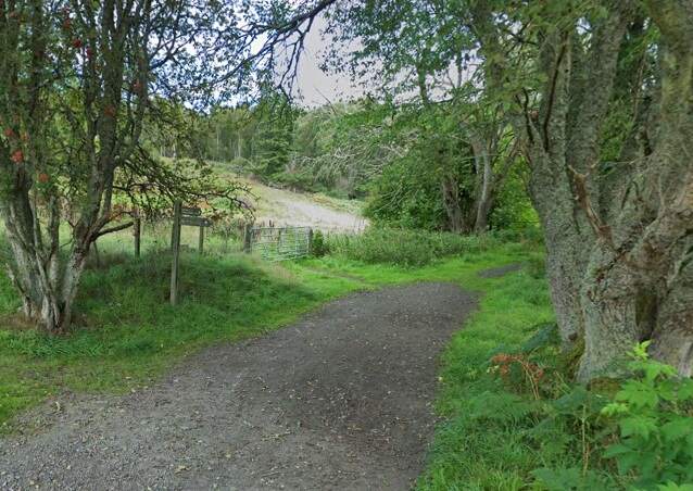
A footpath follows the line of the old railway to the East of Hawthorne Road. [Google Streetview, September 2021]

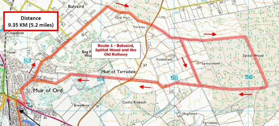
From Hawthorne Road eastwards a public footpath follows the line of the old railway. There is a leaflet of walks for the area around Muir of Ord. One of the four walks included in the leaflet includes a length of the old railway. [19]

The walk follows the Balvaird Road from Muir of Ord crossing the railway at the location we noted above. It crosses open fields to get to Spital Wood before dropping down to the line of the olfd railway, following that West to Hawthorne Road and from there back to Muir of Ord. The return leg of the walk runs East-West and almost entirely follows the line of the railway. [19]
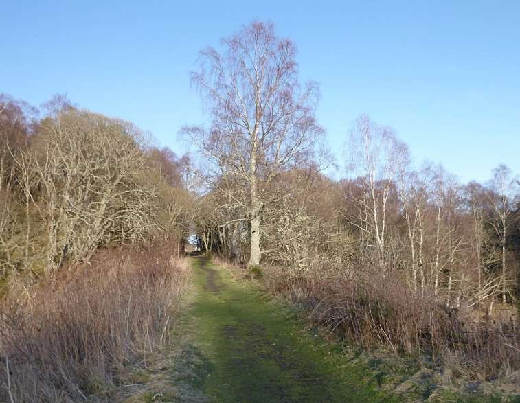
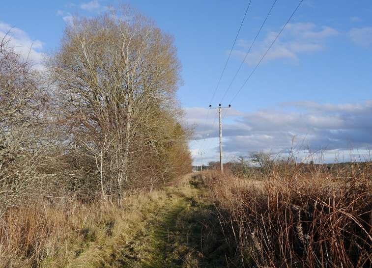
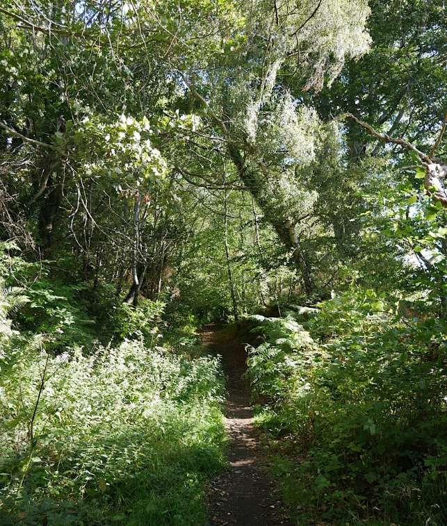
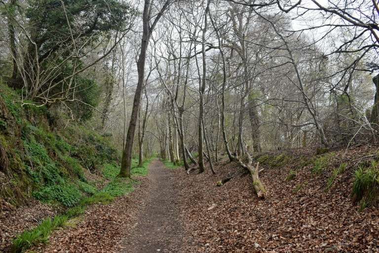
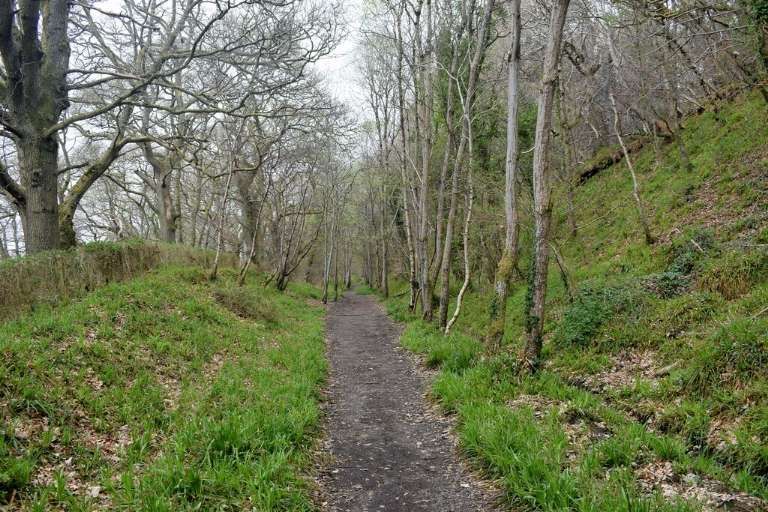
The footpath along the old railway, to the East of Hawthorne Road. This view faces East, © Craig Wallace and licensed for reuse under a Creative Commons Licence (CC BY-SA 2.0). [39]
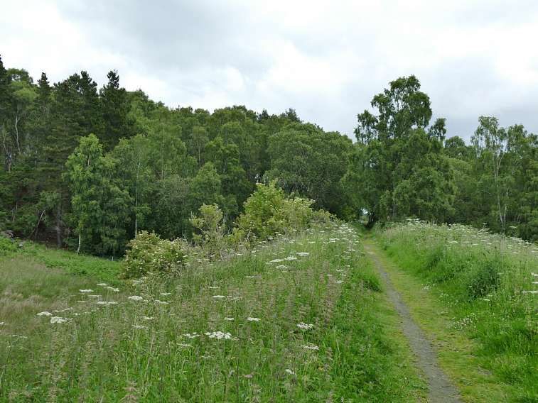
A summertime view looking East at the same location, © Stephen Craven and licensed for reuse under a Creative Commons Licence, (CC BY-SA 2.0). [40]

Our journey runs West to East along a straight section of the old line as far as the B9169.

The road running from the top to the bottom of this map extract was to become the B9169. The coming of the railway meant that the original road location at this point had to be altered to accommodate a railway bridge over the road. After closure of the railway the bridge was removed and the road reverted to its original course. [20]
The ESRI satellite imagery shows the same location in the 21st century. [20]
Looking East from the B9169 in the 21st century. [Google Streetview, March 2022]
Looking West from the B9169, the railway embankment is more visible. [Google Streetview, March 2022]
Looking East along a minor road which now follows the remaining rail embankment. The embankment can be seen on the left. [September 2021]
An old railway bridge to the East of the B9169. It appears on the left of the map extract below. It carried the Fortrose Branch presumably over a farm track under the railway, now rather overgrown, © Craig Wallace and licensed for reuse under a Creative Commons Licence (CC BY-SA 2.0). [43]
With the line continuing East on embankment it first crossed a cattle creep and then a lane, as shown here in this extract from the 1904 25″ OS survey. [21]
The same length of the line in the 21st century on the NLS provided ESRI satellite imagery. [21]
Looking Northwest from the minor road at the point on the right side of the satellite image where the road turns to the Southeast. This photo shows the rail embankment running above and beyond the road across the image. [Google Streetview, September 2021]

For a short length the old railway formation has been ploughed back into farmland. The next image looks back along the line of the old railway from a point further to the East.

This image looks East from the point where the modern farm track comes back to run parallel to the old railway route. [Google Streetview, 2012]
Just a short distance further to the East the track turns up onto the old railway formation. This is the view back East from that point. [Google Streetview, 2012]
Further East again, a track crossed the old line by means of a stone bridge. [23]
The same location in the 21st century – the track entering from the left of this extract from the NLS ESRI satellite imagery occupies the old railway formation before slipping off to the North side of the line as the old line runs in cutting to pass under the accommodation bridge which sits just to the right of the centre of the image. To the West of the track, the line disappears in cutting into Spital Wood. [23]
The view East along the old railway alignment from a point close to the Eastern edge of the satellite image above. [Google Streetview, 2012]
Here, looking East, the modern farm track leaves the railway alignment which runs ahead into a. Cutting and then under an accommodation bridge. [Google Streetview, 2012]
A little further East along the old railway formation. The dead tree which is prominent in this image can be seen in the image immediately above. The parapets of the bridge seem here appear on the next two photographs, © Craig Wallace and licenced for reuse under a Creative Commons Licence (CC BY-SA 2.0). [37]
The accommodation bridge parapets, seen from the South. [Google Streetview, 2012]
The same bridge parapets seen from the North. [Google Streetview, 2012]
Looking West towards Muir of Ord from the bridge in the images above, © Julian Paren and licensed for reuse under a Creative Commons Licence, (CC BY-SA 2.0). [71]

After passing under the accommodation bridge, the old line ran east in cutting through what is now Spital Wood. Then, ” curving east-north-eastwards,” Jenkins tells us, “the railway continued to Redcastle (3 miles 58 chains), where the single-platform station was equipped with a full range of accommodation for goods, passengers, and livestock traffic.” [1: p49]

After a few hundred metres in cutting, the line had a short length close to the surrounding ground levels where a siding was provided. I have not been able to establish what function this short siding and its adjacent buildings performed. [24]
A closer view of the same facility, trains heading towards Fortrose would need to lay bay into the siding to release wagons. [24]
The same location as seen on modern satellite imagery, now surrounded by Spiral Wood. [24]
Old railway bridge, in Spittal Wood – a small bridge under the old railway line close to the siding above, now fenced off, and a bit overgrown with bushes, © Craig Wallace and licensed for reuse under a Creative Commons Licence (CC BY-SA 2.0). [41]
A second underbridge, just a short distance to the East of the bridge above, it is a small bridge under the old railway line, this was probably a cattle creep. The bridge is now fenced off with a ditch running underneath, and partly blocked by trees, ©  Craig Wallace and licensed for reuse under a Creative Commons Licence (CC BY-SA 2.0). [42]

A typical old fence post alongside the line of the old railway in Spittal Wood, © Craig Wallace and licenced for reuse under a Creative Commons Licence (CC BY-SA 2.0). [36]
At the East end of Spiral Woods looking East along the old railway, © Valenta and licenced for reuse under a Creative Commons Licence (CC BY-SA 2.0). [35]
A little to the East of Spittal Wood, this view North across the fields by Blairdhu shows a cattle creep which passed under the line at this point, © Craig Wallace and licenced for reuse under a Creative Commons Licence (CC BY-SA 2.0). [45]
The next significant structure was a bridge carrying the line over an access track. [25]
The same location in the 21st century. [25]
An access over bridge provided when the line was built. [26]
The same location in the 21st century. [26]
Just to the Southwest of Redcastle Station a minor road bridged the line. [27]

Pictures of the station soon after closure can be seen on the Canmore website, here [46] and here. [47]

The same location. In the 21st century. [27]
Redcastle Railway Station seen from across the adjacent field. This is the only remaining station building on the Fortrose Branch (Black Isle Railway). When this photograph was taken in 2014 it was the offices of Nansen Highland, a charity providing training for young people. It continues to serve in this way, © Craig Wallace and licenced for reuse under a Creative Commons Licence (CC BY-SA 2.0). [38]
Redcastle Station building seen from the approach road. [Google Streetview, September 2021]
This extract shows the full length of the Redcastle Station site. [27]
And this image shows the site in the 21st century. [27]
The route of the old railway line, heading from Redcastle Station towards Linnie. This was the site of a goods yard, with several sidings just to the left here. Some parts of the platforms remain, now hidden amongst the trees, © Craig Wallace and licensed for reuse under a Creative Commons Licence (CC BY-SA 2.0). [44]

Beyond [Redcastle], trains climbed towards the 250ft contour, the line’s modest summit of around 260ft above mean sea level being sited near the next station at Allangrange. Situated some 5 miles 39 chains from the junction, Allangrange was another fully-equipped station with provision for a range of goods traffic.” [1: p49]

The line continued in an East-northeast direction towards Allangrange Railway Station. [28]
The same area as shown on the 21st century NLS ESRI satellite imagery. [28]
Looking Southwest along the old railway towards Redcastle Station from the minor road towards the left of the satellite image above. [Google Streetview, April 2011]
Looking Northeast along the old railway towards Fort from the minor road towards the left of the satellite image above. [Google Streetview, April 2011]
Looking Southwest along the line of the old railway from the A832. [Google Streetview, March 2023]
Looking Northeast along the line of the old railway from the A832. [Google Streetview, July 2008]
Again, still heading East-northeast, trains drew closer to Allangrange Railway Station. [29]
The same area in the 21st century. [29]

The line curved round from an East-northeast direction to and easterly alignment before entering Allangrange Railway Station.

From the point at which the old line crossed another lane, this is the view back towards Redcastle Station. The tree at the centre of the image on the horizon stand immediately adjacent to the line of the railway. [
Little can be seen looking towards Allangrange Railway Station from the minor road as the rail alignment close to the road is overwhelmed by vegetation. [Google Streetview, September 2021]
The line curved round to run in an easterly direction through Allangrange Railway Station which had a reasonable sized goods yard to the West of the passenger facilities. [30]

The same location in the 21st century. The major road at the West end of the old station site is the modern A9 dual carriageway. [30]
This is the view East along the line of the old railway from the A9 dual carriageway. [Google Streetview, March 2023]
Noe looking East from the A9 through the trees and through the site of Allangrange Railway Station. [Google Streetview, March 2023]
Looking West from the old A9 into Allangrange Station site. [Google Streetview, March 2023]
Looking East from the old A9 towards Fortrose. [Google Streetview, March 2023]

Beyond Allangrange Station, and heading east-north-eastwards again, “the single-line railway descended towards Munlochy (8 miles 2 chains) which, like the other intermediate stations on the Fortrose branch, was fully-equipped for all forms of goods traffic.” [1: p49]

Another overbridge to the East-northeast of Allangrange Railway Station. [31]
The same location in the 21st century. [31]
A little further East-northeast, an accommodation overbridge was provided over the old railway. [32]
The same location in the 21st century. [32]
A farm track runs parallel to the dismantled railway line which ran to the left of this image, © Julian Paren and licensed for reuse under this Creative Commons Licence, (CC BY-SA 2.0). [52]
The line ran through the village of Munlochy and onto  Munlochy Railway Station. [33]
Munlochy in the 21st century. [33]
Bridge over the long-disused railway line approaching Munlochy, © Juliian Paren and licensed for reuse under s Creative Commons Licence (CC BY-SA 2.0). [50]
Close to Munlochy, this view looks Southwest from Littleburn along the line of the old railway. [Google Streetview, September 2021]
Looking Northwest on Littleburn. The old railway ran across this image behind the building featured. [Google Streetview,July 2011]
Looking Southwest approximately along the line of the old railway from Station Brae towards what was a bridge over Littleburn. [Google Streetview, March 2023]
Looking Northeast along Station Road, Munlochy. The railway ran on the Northwest side of the road. [Google Streetview, March 2023]
Munlochy Railway Station on the 25″ Ordnance Survey of 1904. [34]
The same area in the 21st century, housing now occupies the site of the old railway station. [34]
Further Northeast, another view along Station Road. The passenger station building was on the left here and the station site ran through the location of the houses which are prominent in this image. [Google Streetview, September 2021]

Three images of Munlochy Railway Station can be seen online at http://www.ambaile.co.uk here, [53] here [54] and here. [55] Kind permission has been given to reproduce two of these images in this article.

Munlochy Railway Station looking Northeast. [53]
Munlochy Railway Station, looking Southwest along the platform. [54]
Looking Northeast through the station site from Cameron Crescent. [Google Streetview, September 2021]
Again, looking NorthEast through the station site along Station Court. [Google Streetview, September 2021]
Looking back Southwest from Millbank Road (B9161) through the station site. [Google Streetview, March 2023]
Looking Northeast along the line of the old railway from Millbank Road (B9161) towards Fortrose. The A842 is just to the left. [Google Streetview, March 2023]

From Munlochy the route passed over a small underline bridge, and with the A833 (later A832) road maintaining a parallel course to the left, Fortrose trains reached Avoch Station (11 miles 25 chains).” [1: p49]

To the East of Munlochy the line sat on an embankment above the surrounding fields, it crossed two cattle creeps before the structure shown a few images below. That structure appears on the left of this OS map extract. The track shown on the right of this extract crossed over the line to serve Easter Gateside. The track remains but the buildings are long go ne. The cutting shown here has been infilled. [56]
The same length of the old railway as it appears in the 21st century. [56]
This embankment was built to carry the old railway. The A832 runs immediately alongside the old railway formation. The tree-topped Ord Hill is prominent on the right, © Richard Dorrell and licensed for reuse under a Creative Commons Licence (CC BY-SA 2.0). [48]
The line of the railway between Munlochy and Avoch.in the summer months, © Julian Paren and licensed for reuse under a Creative Commons Licence (CC BY-SA 2.0). [49]
The railway underbridge just to the West of Ord Hill, © Dave Thompson and licensed for reuse under a Creative Commons Licence (CC BY-SA 2.0). [51]
In this view from the A832, the slight mound visible close tot the telegraph pole and against the backdrop of Ord Hill is the location of the bridge which carried the track to Easter Gateside over the old railway. [Google Streetview, March 2023]
Further Northeast the line ran through Corrachie Crossing – 25″ Ordance Survey of 1904 (published 1906). [57]
Corrachie Crossing as it appears on the NLS ESRI satellite imagery. [57]
A mile further Northeast the road which would become the A832 crossed above the old railway as shown at the left of this exctract from the 1904 (published 1906) 25″ Ordnance Survey. Immediately beyond the road over rail bridge trains entered Avoch Railway Station. [58]
The same area in the 21st century, the station site has been devloped as a small housing estate. [58]
Looking East through the site of the old railway station at Avoch from the turning head on the estate Road. [Google Streetview, September 2021]
The view East towards the East end of the station site in 2015, © Nigel Thompson and licenced for reuse under a Creative Commons Licence (CC BY-SA 2.0). [59]
Immediatel;y to the East of Avoch Railway Station, the old line crossed Avoch Burn, passed under a road bridge and then over another minor road. [60]
The same area in the 21st century. Another housing estate occupies the route of the old railway. [60]
The old railway bridge over Avoch Burn, Valenta and licensed for reuse under a Creative Commons Licence (CC BY-SA 2.0). [61]

From Avoch, the line continued north-eastwards for a further … three miles to its terminus at Fortrose where, some 13 miles 45 chains from Muir of Ord, journeys came to an end in a surprisingly large station.” [1: p49-51]

To the East of the railway station the line curved first Southeast and then round to the Northeast. [62]
The same area on the ESRI satellite imagery from the NLS. [62]
The line ran Northeast through Craig Wood towards Fortrose Railway Station. [63]
The same location alongside the Moray Firth. [63]
A short distance beyond Avoch, looking back to the Southwest, © Bill Harrison and licensed for reuse under a Creative Commons Licence (CC BY-SA 2.0). [67]
Lol oking Southwest along the old railway line in Craig Wood, © Bill Harrison and licensed for reuse under a Creative Commons Licence (CC BY-SA 2.0). [66]
Looking Northeast along the path along the old railway in Craig Wood between Avoch and Fortrose, © Craig Wallace and licenced for reuse under a Creative Commons Licence (CC BY-SA 2.0). [65]
Getting closer to Fortrose, this view looks along the old railway to the Northeast towards Fortrose, © Bill Harrison and licensed for reuse under a Creative Commons Licence (CC BY-SA 2.0). [69]
Close to Fortrose looking back Southwest along the old railway through Craig Wood, © Bill Harrison and licensed for reuse under a Creative Commons Licence (CC BY-SA 2.0). [68]
This extract from the 1904 25′ Ordnance Survey shows Fortrose Railway Station. [64]
The same location in the 21st century. [64]
Fortrose Railway Station site: the view north across the old station forecourt towards the end of the platform and the buffers, with the station building having been to the extreme left. The former weighbridge in the foreground appears to be the only visible evidence of what was here before, © Copyright Nigel Thompson and licensed for reuse under this Creative Commons Licence (CC BY-SA 2.0). [70]

Fortrose had just one platform on the up side, with a run-round loop to the north and a four-siding goods yard to the south. One of the goods sidings passed through a goods shed, while another served a loading bank; a spur at the west end of the goods yard formed a short headshunt.” [1: p51]

Fortrose Railway passenger station building had “the booking hall and general waiting-room … in the centre part of the building, while the booking office and toilets were housed in the ends. The timber structure was clad in American-style vertical matchboarding, with thin cover strips affixed at each join to produce a ‘ribbed’ effect.” [1: p52] The centre block was recessed between the cross-wings to create a roofed waiting area at the front of the station.

Fortrose Railway Station building and platform on the last day of steam, © Unknown. [72]
Looking Northeast along the platform at Fortrose Railway Station. The local pickup goods has yet to pick up any wagons, © Unknown. [72]
Engine No 14399 ‘Ben Wyvis’ sits at Fortrose Station waiting to depart with its train for Muir of Ord on 4th August 1948, © Unknown. [72]

Additional photographs of the Station can be found on the www.ambaile.co.uk website here, [73] here [74] and here. [75] Kind permission has been given to reproduce these photographs here.

Fortrose Railway Station from the end of the platform in 1912, showing the station building. A branch train is in the platform and a locomotive is on the turntable in the background. [73]
Fortrose Railway Station seen from the Northeast (adjacent to the buffers). Llocomotive No. 57594 is described in the notes for the next image. Here it is about to be turned to take its train back to Muir of Ord. [74]
Locomotive No. 57594 has just been turned and is being readied to haul the last train from Fortrose.
The locomotive is an ex-Caledonian ‘812’ Class 0-6-0, built in August 1900 as CR No. 856, becoming LMS No. 17594 and finally BR No. 57594. It was withdrawn in December 1962. [75]

Decline and Closure

The Fortrose branch was relatively successful. Its passenger services were maintained throughout the LMS era. But the line “became increasingly vulnerable to road competition after World War II, and for this reason its passenger services were withdrawn with effect from 1st October 1951. Goods traffic lingered on for a few more years, but the end came in 1960, with the line being closed to all traffic from 13th June of that year.” [1: p52]

References

  1. Stanley Jenkins; Highland Railway Minor Lines: 2; in Rex Kennedy (ed.); Steam Days; Red Gauntlet Publications, Bournemouth, Dorset, January 2002; p48-57.
  2. https://en.m.wikipedia.org/wiki/Fortrose_Branch, accessed on 7th March 2025.
  3. H.A. Vallance, C.R. Clinker and Anthony J. Lambert; The Highland Railway; David & Charles, Newton Abbot, 1985.
  4. https://commons.m.wikimedia.org/wiki/File:Fortrose_rly.png, accessed on 7th March 2025.
  5. https://en.wikipedia.org/wiki/Muir_of_Ord_railway_station, accessed on 24th March 2025.
  6. https://maps.nls.uk/geo/explore/#zoom=16.0&lat=57.51748&lon=-4.46140&layers=168&b=ESRIWorld&o=100, accessed on 24th March 2025.
  7. John Gifford; The Buildings of Scotland, Highland and Islands; Yale University Press, 1992.
  8. Michael Quick; Railway Passenger Stations in Great Britain: A Chronology (PDF) (5th ed.); Railway and Canal Historical Society, London, 2022.
  9. Peter Caton; Remote Stations; Matador, Leicestershire, 2018, p242.
  10. Richard Rooney; Work to start next month on vital Highland bridge replacement; Press and Journal, 14th October 2015; via https://www.pressandjournal.co.uk/fp/news/inverness/722267/work-to-start-next-month-on-vital-bridge-replacement, accessed on 24th March 2025.
  11. https://www.georgeleslie.co.uk/projects/muir-ord-railway-bridge-replacement, accessed on 24th March 2025.
  12. Martyn Brailsford; Railway Track Diagrams 1: Scotland & Isle of Man (6th ed.); Trackmaps, Frome, December 2017 (1st edition was 1987), Map 18C.
  13. https://www.youtube.com/watch?v=9to-7k8BYsw, accessed on 24th March 2025.
  14. https://www.ambaile.org.uk/asset/27761, accessed on 24th March 2025.
  15. https://www.geograph.org.uk/photo/2485366, accessed on 24th March 2025.
  16. https://www.geograph.org.uk/photo/2485360, accessed on 24th March 2025.
  17. https://maps.nls.uk/geo/explore/#zoom=16.2&lat=57.52018&lon=-4.45449&layers=168&b=ESRIWorld&o=100, accessed on 24th March 2025.
  18. https://maps.nls.uk/geo/explore/#zoom=17.0&lat=57.52138&lon=-4.44706&layers=168&b=ESRIWorld&o=83, accessed on 24th March 2025.
  19. https://themuirhub.org/walks-around-the-muir, accessed on 24th March 2025.
  20. https://maps.nls.uk/geo/explore/#zoom=17.0&lat=57.52118&lon=-4.43217&layers=168&b=ESRIWorld&o=100, accessed on 24th March 2025.
  21. https://maps.nls.uk/geo/explore/#zoom=17.0&lat=57.52121&lon=-4.42751&layers=168&b=ESRIWorld&o=0, accessed on 26th March 2025.
  22. https://maps.nls.uk/geo/explore/#zoom=16.9&lat=57.52093&lon=-4.41841&layers=168&b=ESRIWorld&o=91, accessed on 26th March 2025.
  23. https://maps.nls.uk/geo/explore/#zoom=16.9&lat=57.52082&lon=-4.41692&layers=168&b=ESRIWorld&o=100, accessed on 27th March 2025.
  24. https://maps.nls.uk/geo/explore/#zoom=16.7&lat=57.52054&lon=-4.40763&layers=168&b=ESRIWorld&o=100, accessed on 27th March 2025.
  25. https://maps.nls.uk/geo/explore/#zoom=16.7&lat=57.52308&lon=-4.39050&layers=168&b=ESRIWorld&o=100, accessed on 27th March 2025.
  26. https://maps.nls.uk/geo/explore/#zoom=16.7&lat=57.52588&lon=-4.37867&layers=168&b=ESRIWorld&o=100, accessed on 27th March 2025.
  27. https://maps.nls.uk/geo/explore/#zoom=16.4&lat=57.52846&lon=-4.36778&layers=168&b=ESRIWorld&o=100, accessed on 27th March 2025.
  28. https://maps.nls.uk/geo/explore/#zoom=16.3&lat=57.53157&lon=-4.35467&layers=168&b=ESRIWorld&o=100, accessed on 27th March 2025.
  29. https://maps.nls.uk/geo/explore/#zoom=16.3&lat=57.53479&lon=-4.34343&layers=168&b=ESRIWorld&o=100, accessed on 27th March 2025.
  30. https://maps.nls.uk/geo/explore/#zoom=16.3&lat=57.53615&lon=-4.32768&layers=168&b=ESRIWorld&o=100, accessed on 27th March 2025.
  31. https://maps.nls.uk/geo/explore/#zoom=16.3&lat=57.54145&lon=-4.30038&layers=168&b=ESRIWorld&o=100, accessed on 27th March 2025.
  32. https://maps.nls.uk/geo/explore/#zoom=16.3&lat=57.54524&lon=-4.28371&layers=168&b=ESRIWorld&o=100, accessed on 27th March 2025.
  33. https://maps.nls.uk/geo/explore/#zoom=16.3&lat=57.54982&lon=-4.26387&layers=168&b=ESRIWorld&o=100, accessed on 27th March 2025.
  34. https://maps.nls.uk/geo/explore/#zoom=16.3&lat=57.55170&lon=-4.26085&layers=168&b=ESRIWorld&o=100, accessed on 27th March 2025.
  35. https://www.geograph.org.uk/photo/5872795, accessed on 27th March 2025.
  36. https://www.geograph.org.uk/photo/3847775, accessed on 27th March 2025.
  37. https://www.geograph.org.uk/photo/3552936, accessed on 27th March 2025.
  38. https://www.geograph.org.uk/photo/3840210, accessed on 27th March 2025.
  39. https://www.geograph.org.uk/photo/3420066, accessed on 27th March 2025.
  40. https://www.geograph.org.uk/photo/6777852, accessed on 27th March 2025.
  41. https://www.geograph.org.uk/photo/3840181, accessed on 27th March 2025.
  42. https://www.geograph.org.uk/photo/3843627, accessed on 27th March 2025.
  43. https://www.geograph.org.uk/photo/2660345, accessed on 27th March 2025.
  44. https://www.geograph.org.uk/photo/3840241, accessed on 27th March 2025.
  45. https://www.geograph.org.uk/photo/3840264, accessed on 27th March 2025.
  46. https://canmore.org.uk/collection/435134, accessed on 27th March 2025.
  47. https://canmore.org.uk/collection/435135, accessed on 27th March 2025.
  48. https://www.geograph.org.uk/photo/3796578, accessed on 29th March 2025.
  49. https://www.geograph.org.uk/photo/6893634, accessed on 29th March 2025.
  50. https://www.geograph.org.uk/photo/3389352, accessed on 29th March 2025.
  51. https://www.geograph.org.uk/photo/7755584, accessed on 29th March 2025.
  52. https://www.geograph.org.uk/photo/6833474, accessed on 29th March 2025.
  53. https://www.ambaile.org.uk/cdn/highlife/previews/93/de6b4a84015a3dc994419527853a0730/5/17b67afcae996d41df5ce9c0c0f85799/27778.jpg, accessed on 29th March 2025.
  54. https://www.ambaile.org.uk/cdn/highlife/previews/93/8714e03bf00f9f3da55ddabcc2a96a2b/5/37a6facb1be1e10521780c5190e0b68a/27775.jpg, accessed the on 29th March 2025.
  55. https://www.facebook.com/share/p/15KnbQPdre, accessed on 29th March 2025.
  56. https://maps.nls.uk/geo/explore/#zoom=16.5&lat=57.55560&lon=-4.23886&layers=168&b=ESRIWorld&o=91, accessed on 29th March 2025.
  57. https://maps.nls.uk/geo/explore/#zoom=17.0&lat=57.56245&lon=-4.21449&layers=168&b=ESRIWorld&o=100, accessed on 31st March 2025.
  58. https://maps.nls.uk/geo/explore/#zoom=17.0&lat=57.56910&lon=-4.18718&layers=168&b=ESRIWorld&o=100, accessed on 31st March 2025.
  59. https://www.geograph.org.uk/photo/4413772, accessed on 31st March 2025.
  60. https://maps.nls.uk/geo/explore/#zoom=17.0&lat=57.56931&lon=-4.17724&layers=168&b=ESRIWorld&o=100, accessed on 31st March 2025.
  61. https://www.geograph.org.uk/photo/5570187, accessed on 31st March 2025.
  62. https://maps.nls.uk/geo/explore/#zoom=16.2&lat=57.56924&lon=-4.16934&layers=168&b=ESRIWorld&o=100, accessed on 31st March 2025.
  63. https://maps.nls.uk/geo/explore/#zoom=16.0&lat=57.57417&lon=-4.15474&layers=168&b=ESRIWorld&o=100, accessed on 31st March 2025.
  64. https://maps.nls.uk/geo/explore/#zoom=16.0&lat=57.58180&lon=-4.13470&layers=168&b=ESRIWorld&o=100, accessed on 31st March 2025.
  65. https://www.geograph.org.uk/photo/7596643, accessed on 31st March 2025.
  66. https://www.geograph.org.uk/photo/7166928, accessed on 31st March 2025.
  67. https://www.geograph.org.uk/photo/7169674, accessed on 31st March 2025.
  68. https://www.geograph.org.uk/photo/7166914, accessed on 31st March 2025.
  69. https://www.geograph.org.uk/photo/7169691, accessed on 31st March 2025.
  70. https://www.geograph.org.uk/photo/4413804, accessed on 31st March 2025.
  71. https://www.geograph.org.uk/photo/3883075, accessed on 1st April 2025.
  72. http://www.fortroseandrosemarkiearchive.org/groups.asp?id=, accessed on 1st April 2025
  73. https://www.ambaile.org.uk/asset/27308, accessed on 1st April 2025.
  74. https://www.ambaile.org.uk/asset/27303/1/EN27303-fortrose-station-from-the-east-end.htm, accessed on 1st April 2025.
  75. https://www.ambaile.org.uk/asset/27302, accessed on 1st April 2025.

The Mother of All Inventions. …

Why were railways created?

What were the circumstances which brought about their existence?

History does not make it easy to take out one example from a steady continuum of change. …

David Wilson writes: “There have been track or plateways since Roman times. You might say that these could be brought within the term railway and therefore the Romans invented the railway.” [1: p61]

Except there were railways of a sort, at least as far back at 600 BCE, possibly going back even further, maybe as far back as 1000 BCE. The clearest example being the Diolkos Trackway. [2] This was a paved trackway near Corinth in Ancient Greece which enabled boats to be moved overland across the Isthmus of Corinth.

David Wilson continues: “For most people, however, the railways began with the Stockton and Darlington (S&D), though I’m sure many people already appreciate that history is not always what it seems.” [1: p61]

David Wilson tells us that if one wished to take the view that the first ever railway was the first to have been authorised by Parliament, then the first railway was built in Leeds – The Middleton Railway. “The Middleton Railway was given Parliamentary Assent in 1758 and began using steam traction in 1812, two years before the advent of Mr Stephenson’s first locomotive, ‘Blucher’, and 13 years before the opening of the S&D.” [1: p61]

But there is more to consider. … The Lake Lock Rail Road opened in 1798 (arguably the world’s first public railway). It carried coal from the Outwood area to the Aire and Calder navigation canal at Lake Lock near Wakefield. [3][4] The Surrey Iron Railway was the first railway to be authorised by the UK Parliament (21st May 1801).  It was a horse-drawn railway which ran between Wandsworth and Croydon. [5][6][7][8][9] It was followed by The Carmarthenshire Railway or Tramroad (authorised by Act pf Parliament on 3rd June 1802). It was a horse-drawn goods line, located in Southwest Wales, the first public railway first authorised by Act of Parliament in Wales.[3][10][11][12]

The Low Moor Furnace Waggonway was constructed in 1802. It connected Barnby Furnace Colliery to Barnby Basin on the Barnsley Canal. It was replaced in 1809 by The Silkstone Waggonway which operated until 1870. [19][20] The Merthyr Tramroad, between Merthyr Tydfil and Abercynon, also opened in 1802. [5][13][14][15][16][17][18] The Lancaster Canal Tramroad (also known as the Walton Summit Tramway or the Old Tram Road), was completed in 1803. It linked the north and south ends of the Lancaster Canal across the Ribble valley. [21][22]

The first steam locomotive to pull a commercial load on rails was Penydarren (or Pen-y-Darren) was built by Richard Trevithick. It was used to haul iron from Merthyr Tydfil to Abercynon, Wales. The first train carried a load of 10 tons of iron. On one occasion it successfully hauled 25 tons. However, as the weight of the locomotive was about 5 tons the locomotive’s weight broke many of the cast iron plate rails. [5][13][14][15][16][17]

We could go on to mention:

  • The Croydon, Merstham & Godstone Goods Railway opened in 1805; [23]
  • The Sirhowy Tramroad opened in 1805; [24]
  • The Ruabon Brook Tramway (also known as Jessop’s Tramway or the Shropshire Union Tramway) also opened in 1805; [25][26][27][28]
  • The Middlebere Plateway (or Middlebere Tramway) opened on the Isle of Purbeck in 1806; [29][30][31][32]
  • The Monmouthshire Canal Tramway, open by 1806; [33][34]
  • The Oystermouth Railway, opened in 1806; [35][36] and
  • The Doctor’s Tramroad, Treforest which opened in 1809. [37][38][39]
  • The Monmouth Railway authorised by the UK Parliament in 1811. [5][72][73]
  • The Kilmarnock & Troon Railway which opened in 1812. [5][74][75][76][77]
  • The Killingworth Waggonway of which a first stretch opened in 1762 and which was extended in 1802, 1808 and 1820. [78][79][80][81][82][83]
  • The Haytor Granite Railway of 1820 which not only transported granite from Dartmoor as freight but ran on granite rails. [84]

The drawing of the locomotive Blücher (below) was done by Clement E. Stretton, © Public Domain. Blücher was built by George Stephenson for the Killingworth Waggonway. It was the first of a series of locomotives which established his reputation as an engine designer and eventually “Father of the Railways”.

We could list other railways opening before the S&D in 1825. The use of steam power at The Merthyr Tramroad and The Middleton Railway preceded its use on the S&D. A very strong claim to be the most significant development in the early 1800s could be made on behalf of The Middleton Railway. But it is the Stockton & Darlington (S&D) Railway which has caught the imagination and it is the 200th anniversary of the S&D which is being celebrated in 2025 as the beginning of the railway age.

Why is this?

It is clear that the claim to fame of the Stockton and Darlington (S&D) is lessened, at least, by the prior claim of the Middleton Railway both as first to be sanctioned by Parliament and first to make commercial use of steam power. The claims associated with other railways which preceded the S&D also must be significant. However, there is one important and fundamental difference between it and them. David Wilson says that, unlike the Middleton Railway, “the S&D was constructed with a view to carrying other companies’ goods and, to a lesser extent, to carry people.” [1: p61]

In addition, he says, “Bear in mind the distinction between the carriage of goods and people, and between carrying one’s own goods and those of others. In many ways this type of division is what distinguishes the modern concept of the railway as a system for the transport of goods and passengers on a hire and reward basis from the early plateways and railways such as the Middleton, which were not essentially built to carry anything other than goods, typically coal, for their owners.” [1: p61]

Perhaps, though, there are more grounds for the place taken in history by the S&D. Rather than just running between a pithead and a coal wharf on a canal, river or road and serving specific industrial concerns, the S&D also was built by public subscription and linked one town to another.

David Wilson continues: “To arrive at a description of what constitutes a railway we have to enlarge our definition to include not only Parliamentary Sanction, the use of rails or tracks, and the carriage of goods, but also the carriage of the public, the carriage of public goods and that one settlement be joined to another by the laying of a line paid for through the issue of shares. Thus … a railway is a set of tracks laid between two centres of habitation, which carries goods or people for commercial reward and has been authorised by Act of Parliament. It will have been built through the raising of public funds, either through the sale of shares in it or via government spending from the public purse.” [1: p61]

Let’s return to the era before the existence of the steam locomotive, the era of that list of lines highlighted above (and many more).

David Wilson comments: “The growth of the coal mining industry in the later part of the 17th and early 18th century had led to a growth in the plateway systems used to move the coal from the pit head to [a road], canal or river for shipment to the growing cities and the newly built mills. By as early as 1645 there were wagonways taking coal from the Durham coalfields down to the Tyne. By 1800 there were more than 100 miles of these plateways in the Tyneside area alone.” [1: p61]

Similar developments were taking place elsewhere in the UK:

  • The first overground railway line in England may have been a wooden-railed, horse-drawn tramroad which was built at Prescot, near Liverpool, around 1600 and possibly as early as 1594. Owned by Philip Layton, the line carried coal from a pit near Prescot Hall to a terminus about half a mile away. [40]
  • The Wollaton Waggonway in Nottinghamshire was in use by 1604. [5]
  • In East Shropshire and around the Severn Gorge; [41][42] A railway was made at Broseley in Shropshire some time before 1605 to carry coal for James Clifford from his mines down to the River Severn to be loaded onto barges and carried to riverside towns. It is possible that Clifford’s ‘railway’ was in use as early as 1570 and a similar line may well have been constructed by William Brooke near Madeley, again down to the River Severn. [43: p21] By 1775, there were a number of both short and long tramroads in the area around the Severn Gorge.
  • The Tranent to Cockenzie Waggonway was built by the York Buildings Company of London, to transport coal from the Tranent pits to the salt pans at Cockenzie and the Harbour at Port Seton, in Haddingtonshire, now East Lothian. [5][44]
  • The Alloa Wagon Way was constructed in 1768 by the Erskines of Mar in Alloa, to carry coal from the Clackmannanshire coalfields of central Scotland to the Port of Alloa. [45]
  • The Halbeath Railway opened in 1783, from the colliery at Halbeath to the harbour at Inverkeithing. [46][47]
  • The Charnwood Forest Canal, sometimes known as the ‘Forest Line of the Leicester Navigation’ was, under the guidance of William Jessop, using railways to supplement the canal between Nanpantan and Loughborough wharf, Leicestershire by 1789. [5][48]
  • The Butterley Gangroad (or Crich Rail-way) was built by Benjamin Outram in 1793. [49][50][51][52][53][54][55][56][57]
  • The Earl of Carlisle’s Waggonway opened in 1799 from coal pits owned by George Howard, 6th Earl of Carlisle around Lambley to Brampton, Cumbria. [51][58] There is some confusion over dates. The earliest opening date quoted is 1774, the latest 1799. [59] Dendy Marshall says that it was built in 1775. [60] C.E. Lee says it was constructed in 1798. [59][61]

It is perhaps easy to loose sight of the scale of these industrial undertakings. The rapid expansion of mining, plateways and railways “led to an increase in the numbers of horses in use … and a growth in the amount of horse feed needed. By 1727 The Tanfield Waggonway, in Co. Durham, carried 830 wagon loads of coal daily that’s a lot of horses.” [1: p61][5][62][63] “In 1804, the Middleton Colliery line was carrying 194 loads per day. Each wagon held about 2.5 tons and required the use of one horse and driver.” [1: p61]

A crisis in the use of horses and wagons occurred early in the 19th century with the advent of the Napoleonic Wars. The conflict became a significant drain on both horse and horse feed availability. The resulting inflation in the price of horses and feed lowered the profitability of each wagon load of coal. David Wilson says that, “The more visionary (or greedy, depending on your point of view) pit owners started to search for alternatives to the horse to move their goods to market. They provided their pit engineers with money and materials to experiment with steam power to replace horse power.” [1: p61]

Of course, steam power wasn’t new. Knowledge of the power of steam had been around since before the Common Era in Greek society [64][65][66] and the pits themselves had steam engines for pumping out the water and for lifting coal to the surface, or as winding engines on rope-worked inclines. [66][67] Newcomen’s first engine was installed for pumping in a mine in 1712 at Dudley Castle in Staffordshire. [66][68] What was new was first, the expiry of Boulton & Watt’s patent for a high-pressure steam engine, [5][69] and second, the idea of making the steam engine mobile, thus creating the steam locomotive. What eventually became even more revolutionary was the idea of creating a network of railways to serve the whole country. [1: p61]

We sometimes talk of a ‘perfect storm’ (a particularly violent storm arising from a rare combination of adverse meteorological factors), when we are talking about a series of adverse conditions occurring at the same time – a situation caused by a combination of unfavourable circumstances. The opposite of a ‘perfect storm’ is usually assumed to be a period of calm. However, the true opposite of a perfect storm is the occurrence (co-occurence) of a series of positive factors which combine to produce something significantly valuable. Wilson says that “as with almost anything man-made, there must be certain ingredients present. To bake a cake you need eggs, flour, milk etc. and in creating a railway you need, metalworking skills, engineering expertise, labour, capital and an incentive.” [1: 61]

The early years of the 19th century saw a timely co-incidence of these and other factors:

  • growing shortages of horse and feed coupled to the rising prices of both;
  • poor road conditions;
  • a rapidly developing understanding of engineering – Wilson suggests that this was “as a consequence of the more theoretical works of philosophers such as Newton, Descartes and Leibniz. … Such men have a reputation as creators or exponents of the mechanistic world view. Prior to the works of these men many had thought, and indeed some still do think, that the earth was a living entity. However, the views espoused by Newton, Descartes and Leibniz came to be accepted, the world was made up of dead, lifeless and inert matter, here to benefit mankind;” [1: p62]
  • the availability of skilled and unskilled labour – particularly the ‘navigators’ who were skilled in the techniques of earthworks, tunneling and bridge building – the men who had earlier built the canals. (“These men were to become the skilled labour of the railway construction industry and in turn they passed on their skills to the former farm labourers who were recruited to railway works as the lines progressed along their routes“); [1: p62]
  • developing metalworking skills – “the Darby family, who set up the … Coalbrookdale foundry. had acquired new skills in metalworking from tinkers, in what is now the Netherlands;” [1: p62] After constructing Ironbridge, “the Coalbrookdale ironmasters began to widen their horizons. One of their number, John “Iron Mad” Wilkinson, constructed what was reputedly the first iron barge and, more importantly, … the smiths of Coalbrookdale collaborated with Richard Trevithick in the construction of his locomotive – they cast the cylinder block and the plates for the construction of the boiler;” [1: p62]
  • the increasing availability of financial capital;
  • the increasing birth rate and the better health of the work-force which provided the necessary labour while engineering work was still labour-intensive.

The Availability of Capital

Among the physical factors listed above is an interesting financial factor which will bear some scrutiny. Wilson tells us that “the capital to build the world’s first public railway came, not from the Government, but from the Society of Friends, the Quakers.” [1: p62] He notes too that the Darby family whose Coalbrookdale plant had such a formative influence in the early days of the industrial revolution, were also Quakers. Wilson explains that Quakers were isolated from much of society and public life because of a refusal to sign up to the articles of faith of the established church. However, the same religious views made them sympathetic to works performed for the public good. Various Quaker families began to take an interest in the developing railway sphere. The website quakersintheword.org [70] tells the story of the significant role played in financing railways played by the Quakers.

In 1818 a small group of Quaker businessmen, including Edward Pease and his son Joseph from Darlington, Benjamin Flounders and the banker Jonathan Backhouse, met to discuss the possibility of building a railway from Darlington, passing several collieries, to the port of Stockton.” [70] 

The Act of Parliament required for the work to take place faced significant delays in the parliamentary process. “The delay proved very significant, as in April 1821 Edward met George Stephenson and recruited him as an engineer for the railway. The original intention had been that the coaches would be horse drawn, just like all the others now in existence. However, George convinced Edward that steam engines were the future for railways, and that he could build them. The Pease family then put up much of the capital that enabled Stephenson to establish a company in Newcastle, where he built the locomotives.” [70]

After the opening of the Stockton & Darlington Railway, “the railway network grew under the guidance of Edward’s son Joseph, who opened the Stockton & Middlesbrough branch in 1828. … In 1833 Joseph became the first Quaker to enter Parliament and the railway interests passed to his brother Henry. In 1838, Henry opened the Bishop Auckland & Weardale line, followed by the Middlesbrough and Redcar line in 1846. Henry wanted to traverse the Pennines and in 1854 he started the Darlington & Barnard Castle line, which opened in 1856.” [70]

Quakers were often involved in railway developments in the 19th century, for instance, “in 1824, a group of merchants, including Quaker philanthropist and anti-slavery campaigner James Cropper, went to see the Stockton and Darlington railway.  They soon began building the Liverpool and Manchester railway, which opened in 1830.” [70]

Incidentally, Quakers “were also responsible for two innovations that improved the way these new passenger railways worked – timetables and tickets. James Cropper produced a 12-page timetable for the Liverpool and Manchester railway, probably the first railway timetable ever.  It was the forerunner of Quaker George Bradshaw’s Railway Companion, published in 1839. Bradshaw’s became a household name for anyone using the railways. … The second innovation was the railway ticket. In 1839 Thomas Edmundson, another Quaker, was appointed station master at Milton, on the Newcastle and Carlisle line.  He was unhappy that customers paid their fares directly to him without receiving a receipt.  Consequently he introduced the railway ticket, which came into general use with the creation of the Railway Clearing House in 1842.” [70]

The Birth Rate and Increasing Health of the UK Population

Wilson points us to one more significant factor in the development of railways in the early 19th century. “Seemingly disconnected and irrelevant factors were playing their part. During the period from the end of the civil war (1649) onwards there was a growing awareness of the value of the human being as resource, and a concerted effort was made to increase the birth rate and to cut the death rate. … This did not stem from any rise in humanitarianism but from a recognition that people were worth money. After all, in the 1640s and on into the 19th century, slavery was still common throughout the so-called civilised world, including Britain. Improvements in diet and sanitation increased life exресtancy. It is no coincidence that the first workhouses began to appear around the middle of the 17th century – a reasonably fit and healthy population produced more than a sickly and unfit one.” [1: p62]

By the beginning of the 19th century, the conditions were in place for a major economic expansion. A growing empire and military strength ensured the supply of raw materials and provided a growing market place for the products made from them. An expanding population provided the physical means by which the empire might be held together. Technology provided the ability to carry out the grand design. The workhouses and other reforms had created a disciplined workforce.” [1: p62-63]

By 1850, a quarter of a million workers – a force bigger than the Army and Navy combined – had laid down 3,000 miles of railway line across Britain, connecting people like never before. [71]

And Finally …

Wilson suggests one other, less definable, reason for the dramatic welcome given to steam technology in particular. He suggests that there was a more visceral connection to steam power which predisposed humanity to embrace the technology.

No doubt, the S&D was at the forefront of engineering developments it was “the white heat of technology, the frontier of science.” [1: p63] Wilson asks us to consider that there was (and still is) a connection between “a piece of primitive industrial technology, the steam locomotive and its enduring popularity, and an ancient, and some might say mystical, view of the world.” [1: p63]

Wilson says: “Prior to the advent of the mechanistic world view in which cause and effect, hard science and hard facts are the order of the day, people held to a more animistic philosophy. Miners would pray to the earth before digging it up. … In this more mystic view of the world things were not made of chemicals and atoms, molecules and the force of gravity. They were composed of the four elements – earth, air, fire and water.” [1: p63] He asks us to consider whether “the reason so many people took to the steam engine and the railway when it began was that the steam locomotive has a unique blend of the four elements not only in its construction but in the very forces and requirements necessary for its movement. … [It] is made from the ores of the earth, heated by fire which needs air to burn. The metals from the forge are then tempered by water whilst being shaped on the anvil. In order to make the steam locomotive work, coal, or part of the earth, is consumed along with air in a fire which turns water into steam which in turn brings the locomotive to life.” [1: p63]

We all know that all men, are just little boys at heart. Increasingly women are involved in the preservation movement. There seems to be a deep emotional connection for many of us between the steam beasts of earth, wind, fire and water that reigned over the railway networks for the world for more than a century and a half and our own psyche, something deeply ‘elemental’!

Whatever the cause, the early 19th century saw humanity embrace steam-power and the benefits it brought with open arms and wallets.

References

  1. David Wilson; Mother of Inventions; in the Evening Mail Supplement, 1st June 1993, p61-63.
  2. https://en.m.wikipedia.org/wiki/Diolkos, accessed on 2nd March 2025.
  3. https://en.wikipedia.org/wiki/1790s_in_rail_transport, accessed on 20th February 2025.
  4. https://web.archive.org/web/20100604080339/http://www.stanleyhistoryonline.com/Lake-Lock-Rail-Road.html, accessed on 8th January 2025.
  5. https://en.wikipedia.org/wiki/Timeline_of_railway_history, accessed on 7th January 2025.
  6. https://web.archive.org/web/20070523122428/http://www.stephensonloco.fsbusiness.co.uk/surreyiron.htm, accessed on 9th January 2025.
  7.  Dorian Gerhold; The Rise and Fall of the Surrey Iron Railway, 1802–46 (PDF); in Surrey Archaeological Collections, Vol. 95, 2010, p193–210; via https://archaeologydataservice.ac.uk/archiveDS/archiveDownload?t=arch-379-1/dissemination/pdf/vol_95/surreyac095_193-210_gerhold.pdf, accessed on 6th February 2025.
  8. https://en.wikipedia.org/wiki/1801_in_rail_transport, accessed on 20th February 2025.
  9. https://en.wikipedia.org/wiki/Surrey_Iron_Railway, accessed on 20th February 2025.
  10. https://coflein.gov.uk/en/site/275707, accessed on 8th January 2025.
  11.  https://en.wikipedia.org/wiki/1802_in_rail_transport, accessed on 20th February 2025.
  12.  M.R. Connop Price; The Llanelly & Mynydd Mawr Railway; Oakwood Press, Oxford, 1992.
  13. https://rogerfarnworth.com/2019/02/02/the-penydarren-tramroad-south-wales-part-1
  14. https://rogerfarnworth.com/2019/02/06/the-penydarren-tramroad-south-wales-part-2
  15. https://coflein.gov.uk/en/site/91513, accessed on 8th January 2025.
  16. https://www.irsociety.co.uk/Archives/59/Penydarren.htm, accessed on 8th January 2025.
  17. https://coflein.gov.uk/en/site/91513, accessed on 8th January 2025.
  18. https://en.wikipedia.org/wiki/Merthyr_Tramroad, accessed on 20th February 2025.
  19. https://en.wikipedia.org/wiki/Low_Moor_Ironworks, accessed on 20th February 2025.
  20. Silkstone Waggonway, South Yorkshire: Survey Report (PDF). Vol. 1; Yorkshire Archaeological Trust,  August 2012; via https://web.archive.org/web/20160311113301/http://iadb.co.uk/epip/Silkstone%20Waggonway%20Vol%201%20text%20plates%20figures.pdf, accessed on 20th February 2025.
  21. https://en.wikipedia.org/wiki/Lancaster_Canal_Tramroad, accessed on 20th February 2025.
  22. S. Barritt; The Old Tramroad – Walton Summit to Preston Basin; Carnegie Publishing, Lancaster, 2000.
  23. Paul W. Sowan; The Croyden, Mertsham & Godstone Iron Railway: A Short Chapter in a Long Story; The Bourne Society (LHR45), Croydon, London, 2006, LHR45, p53-69; via https://bournesoc.org.uk/bslivewp/wp-content/uploads/CMG-Iron-Railway-SECURE.pdf, accessed on 9th January 2025.
  24. https://en.wikipedia.org/wiki/Sirhowy_Railway#Sirhowy_Tramroad, accessed on 20th February 2025.
  25. Alan Jowett; Jowett’s Railway Atlas; Patrick Stephens Limited, 1989, p57, 59.
  26. https://en.wikipedia.org/wiki/Ruabon_Brook_Tramway, accessed on 20th February 2025.
  27. Trefynant – Opening of Branch Railway at Trefynant Works; in Wrexham Advertiser, 6th January 1866, p8.
  28. Meeting of the Wrexham District Highways’ Board; in Wrexham Advertiser. 26th January 1867, p5.
  29. https://en.wikipedia.org/wiki/Middlebere_Plateway, accessed on 20th February 2025.
  30. R.W. Kidner; The Railways of Purbeck (Third ed.); Oakwood Press, 2000.
  31. Purbeck’s clay railways; in Dorset Life Magazine, January 2007; via https://web.archive.org/web/20070927150728/http://www.dorsetlife.co.uk/articles/ArticlesDetail.asp?ID=599, accessed on 20th February 2025.
  32. Middlebere Plateway; The Purbeck Mineral & Mining Museum; via https://web.archive.org/web/20070928063415/http://www.pmmmg.org/Middlebere.htm, accessed on 20th February 2025.
  33. https://en.wikipedia.org/wiki/Monmouthshire_and_Brecon_Canal#Monmouthshire_Canal_Tramway, accessed on 20th February 2025.
  34. https://coflein.gov.uk/en/site/308291, accessed on 20th February 2025.
  35. https://en.wikipedia.org/wiki/1807_in_rail_transport, accessed on 20th February 2025.
  36. https://en.wikipedia.org/wiki/Swansea_and_Mumbles_Railway, accessed on 9th January 2025.
  37. https://cof, lein.gov.uk/en/site/407018/?ref=goodoil.news, accessed on 20th February 2025.
  38. https://coflein.gov.uk/en/site/96185, accessed on 20th February 2025.
  39. https://britishlistedbuildings.co.uk/300024912-machine-bridge-also-known-as-pont-y-doctor-pontypridd/photos/147433, accessed on 20th February 2025.
  40. Mark Jones; Lancashire Railways – The History of Steam; Countryside Books, Newbury, 2012 p. 5.
  41. https://rogerfarnworth.com/2022/04/25/ancient-tramroads-near-telford-part-1-tramroads
  42. https://rogerfarnworth.com/2022/04/26/ancient-tramroads-near-telford-part-2-the-coalbrookdale-company-tramroads-shown-on-the-1882-83-6-os-maps-published-in-1887-and-later-surveys
  43. Peter King, The First Shropshire Railways in G. Boyes (ed.), in Early Railways 4: Papers from the 4th International Early Railways Conference 2008, Six Martlets, Sudbury, 2010, p70–84.
  44. https://en.wikipedia.org/wiki/Tranent_to_Cockenzie_Waggonway, accessed on 25th February 2025.
  45. An oblique aerial photograph taken facing north shows a general view in 1928 of Alloa, its Town Hall, Marshill and Church Street. The wagon road which was used to transport coal from the Holton area of Sauchie to Alloa harbour. Although the tracks are gone the road still exists from Station Hotel down to South School. https://www.britainfromabove.org.uk/image/SPW020247, accessed on 7th January 2025.
  46. https://en.wikipedia.org/wiki/1780s_in_rail_transport, accessed on 25th February 2025.
  47. Mark Poustie; Halbeath Railway; via https://www.railscot.co.uk/articles/Halbeath_Railway/#google_vignette, accessed on 25th February 2025.
  48. https://waterways.org.uk/waterways/discover-the-waterways/charnwood-forest-canal, accessed on 8th January 2025.
  49. Early Years; https://web.archive.org/web/20180120205818/http://www.butterleygangroad.co.uk/bgearlyyears.html, accessed on 8th January 2025.
  50. https://heritagecalling.com/2015/03/17/heritage-highlights-where-is-one-of-the-worlds-oldest-surviving-railway-tunnels, accessed on 8th January 2025.
  51. https://en.wikipedia.org/wiki/1790s_in_rail_transport, accessed on 20th February 2025.
  52. https://en.wikipedia.org/wiki/Butterley_Gangroad, accessed on 22nd February 2025.
  53.  https://historicengland.org.uk/listing/the-list/list-entry/1422984?section=official-list-entry, accessed on 22nd February 2025.
  54.  https://www.bbc.co.uk/news/uk-england-derbyshire-31951751, accessed on 22nd February 2025.
  55.  P. Riden; Outram, Benjamin (bap. 1764, d. 1805); in the Oxford Dictionary of National Biography; Oxford University Press, Oxford, 2004; via, https://www.oxforddnb.com/display/10.1093/ref:odnb/9780198614128.001.0001/odnb-9780198614128-e-20959, accessed on 22nd February 2025.
  56. https://historicengland.org.uk/listing/the-list/list-entry/1109195?section=official-list-entry, accessed on 22nd February 2025.
  57. https://en.wikipedia.org/wiki/Steam_Horse_locomotive, accessed on 22nd February 2025.
  58. Brian Webb & David A. Gordon; Lord Carlisle’s Railways; Railway Correspondence & Travel Society, 1978.
  59. https://en.wikipedia.org/wiki/Brampton_Railway, accessed on 25th February 2025.
  60. C.F. Dendy Marshall; A History of British Railways Down to the Year 1830; Oxford University Press, London. 1938, 1971.
  61. C.E. Lee; The Brampton Railway; in The Railway Magazine, May and June 1942.
  62. https://en.wikipedia.org/wiki/Tanfield_Railway, accessed on 25th February 2025.
  63. Tanfield Railway; Wear – BBC Home; via https://www.bbc.co.uk/wear/content/articles/2008/05/20/tanfield_main_feature.shtml, accessed on 25th February 2025.
  64. Hero (Heron) of Alexandria, described in detail what is thought to be the first working steam engine. He called it an aeolipile (“wind ball”). His design was a sealed caldron of water was placed over a heat source. As the water boiled, steam rose into the pipes and into the hollow sphere. The steam escaped from two bent outlet tubes on the ball, resulting in rotation of the ball. The principle he used in his design is similar to that of today’s jet propulsion. Hero (Heron) did not consider this invention being useful for everyday applications: he considered his aeolipile invention as a novelty, a remarkable toy. https://www.smith.edu/hsc/museum/ancient_inventions/steamengine2.html, accessed on 3rd March 2025. The same device was also mentioned by Vitruvius in De Architectura about 100 years earlier. [66]
  65. https://blogs.bl.uk/digitisedmanuscripts/2020/12/ancient-steam-engines.html, accessed on 3rd March 2025.
  66. https://en.wikipedia.org/wiki/History_of_the_steam_engine, accessed on 3rd March 2025.
  67. In 1712, Thomas Newcomen’s atmospheric engine became the first commercially successful engine using the principle of the piston and cylinder, which was the fundamental type of steam engine used until the early 20th century. The steam engine was used to pump water out of coal mines. [66]
  68. Steven Johnson; The Invention of Air: A story of Science, Faith, Revolution and the Birth of America; Riverhood Books, New York, 2008.
  69. https://mises.org/mises-daily/james-watt-monopolist, accessed on 8th January 2025.
  70. https://www.quakersintheworld.org/quakers-in-action/286/Railways-in-Britain, accessed on 3rd March 2025.
  71. https://www.railwaymuseum.org.uk/objects-and-stories/navvies-workers-who-built-railways, accessed on 3rd March 2025.
  72. https://co-curate.ncl.ac.uk/wylam-wagonway, accessed on 15th January 2025.
  73. https://www.twsitelines.info/smr/1032, accessed on 15th January 2025.
  74. https://en.wikipedia.org/wiki/Kilmarnock_and_Troon_Railway, accessed on 20th February 2025.
  75. Campbell Highet; The Glasgow and South Western Railway; Oakwood Press, Lingfield, 1965.
  76. https://en.wikipedia.org/wiki/1812_in_rail_transport, accessed on 20th February 2025.
  77. C.J.A. Robertson; The Origins of the Scottish Railway System 1722–1844; John Donald Publishers, Edinburgh, 1983.
  78. https://my.northtyneside.gov.uk/sites/default/files/web-page-related-files/Killingworth%20Moor%20Archaeological%20Assessment.pdf, accessed on 3rd March 2025.
  79. https://co-curate.ncl.ac.uk/blucher, accessed on 15th January 2025.
  80. https://en.wikipedia.org/wiki/Killingworth_locomotives
  81. Clement E. Stretton; The Railway World, Volume VI; 1897.
  82. https://co-curate.ncl.ac.uk/killingworth-waggonway, accessed on 15th January 2025.
  83. https://www.northeastheritagelibrary.co.uk/coalsarchive/ww07/killingworth-waggonway, accessed on 15th January 2025.
  84. https://en.wikipedia.org/wiki/Haytor_Granite_Tramway, accessed on 27th April 2025

Henry Robinson Palmer and Early British Monorails

Henry Robinson Palmer (1793-1844) was a British engineer who designed the first monorail system and also invented corrugated iron!

Born in 1793 in Hackney, he was the son of the Revd Samuel Palmer, a nonconformist minister, and his wife, Elizabeth, née Walker. [1] He was baptised in Tooting [2] and was educated at the academy run by his father and between 1811 and 1816 was an apprentice at 1811-16 Apprenticed to Bryan Donkin and Co.

When he finished his apprenticeship, Palmer was taken on by Thomas Telford, working for him for 10 years and involved with a variety of road/canal surveys and associated designs. In 1818, Palmer was one of three young engineers key to the founding of the Institution of Civil Engineers and on 23rd May 1820, he formally became a member of the Institution. [3]

Elijah Golloway recorded Palmer’s ideas for a Suspension Railway in the image above which is dated 1822. It seems as though Galloway’s book, History of the Steam Engine, From Its First Invention to the Present Time: Illustrated by Numerous Engravings From Original Drawings, Made Expressly for This Work, was not published until 1828 by B. Steill. [4][5]

On 22nd November 1821, Palmer patented his proposed monorail system. [6][19: p57]

In 1823, Palmer wrote his short book, Description of a Railway on a new Principle, (J. Taylor, 1823) about his monorail ideas. [7]

The illustrations immediately below come from a copy of that book which is held by the Science Museum. [7]

Palmer was unaware of the experimental work being undertaken in Russia at around the same time. The work of Ivan Kirillovich Elmanov is covered here. [26]

These images are taken from H.R. Palmer; ‘Description of a Railway on a New Principle’
and are released by the Science Museum under a Creative Commons Licence (CC BY-NC-SA 4.0) [7]

In his book, Palmer refers to examples of railways already constructed. It is clear that he is talking of railways which operate on more traditional principles. He tabulates those to which he is referring in a table which is reproduced below: the Llanelly Tramroad; the Surrey Tramroad; the Penrhyn Slate Quarries, edge rail road; the Cheltenham Tram Road; a branch of the Cheltenham Tram Road; Edge Rail Roads near Newcastle-upon-Tyne. These he compares with his own proposed railway which was built in Deptford Dockyard in London in 1824. [6]

Table showing the resistance form the rails of various railways in use in the early 19th century. [8: p29]

History only seems to record two of Palmer’s monorails in the UK. The first was constructed at Deptford as we have already noted. The second was built at Cheshunt and opened about 3 months prior to the Stockton & Darlington Railway (in June 1825) and was described, that month, in The Times newspaper. [9] Although his ideas were attempted in at least one other place. The railway built in what is now Hungary in 1827 (15th August). It was a fleeting experiment about which more details can be found here. [10]

Palmer is recorded as having given evidence, in 1825, in favour of navigation interest and against the Liverpool and Manchester Railway. [4] He was appointed resident engineer to the London Docks in 1826, where, for 9 years, he designed and executed the Eastern Dock, with the associated warehousing, entrance locks, bridges, and other works. While undertaking this role, in 1828, he inventedthe “Corrugation and Galvanisation” of sheet iron. [11]

Regarding Palmer’s invention of corrugated iron, Dr. Pedro Guedes wrote that “Palmer exploited the unique properties of metal, creating a lightweight, rigid cladding material, capable of spanning considerable distances without any other supports, helping to make lightweight iron buildings and roofs possible. Palmer’s invention completely broke with precedent and tapped into another level of thinking. The sinusoidal corrugations that Palmer imagined as the means to impart strength to his sheets of wrought iron have continued virtually unchanged for close on two centuries.” [11]

In 1831, he was elected as a Fellow of the Royal Society, publishing two papers on the movement of shingle in Philosophical Transactions, 1831 and 1834. In 1833, he took out patents for improvements in the construction of arches and roofs. [12] In 1835, he moved to Westminster and worked as a consulting engineer and was involved in numerous surveys for projected railways, and the design and construction of several docks and harbours, including those at Port Talbot, Ipswich, Penzance, and Neath. He carried out the original surveys for the South Eastern Railway, assisted by P. W. Barlow, and would have executed the scheme but ill health intervened. His original surveys for a Kentish railway dated from the time he was associated with Telford.

He died on 12th September 1844. [13]

C. von Oeynhaussen & H. von Dechen inspected both of Palmer’s monorails during their visit to the UK in 1826 and 1827 and comment on both. First they describe the principles involved: “To facilitate laying out a railway with reduced friction, and to make it independent of the small unevennesses of the ground, Mr Palmer has proposed and built a kind of railway which consists of a single bar, and the wagons have only one wheel on each axle. The track is erected on posts or columns at a suitable height above the ground, and the load hangs so far below the wheels that the wagon frame cannot overturn. [16] This railway has the disadvantage that its construction is not solid, or it becomes very expensive; that it can compensate only for very small unevenness of the ground; that the motive power can operate only with an inclined pull; and that special precautions must be taken for unloading and loading the wagons. Therefore, the scheme has not come into general use. Excepting the two now to be mentioned, no railways of this kind appear to have been built in England.” [14: p75-76]

Palmer’s Deptford Railway

C. von Oeynhaussen & H. von Dechen describe this railway: “This railway leads from the Thames across the yard of the Victualling Office up to the warehouse, and serves to transport provisions out of the warehouse to the ships, or the reverse. The railway consists of cast-iron columns which project from 3 to 5 ft out of the ground; these are provided with fork-shaped seats at the top and are spaced 10 ft apart. Planks 9 in. high and 3 in. thick rest in the forks on double wooden wedges, so that they can be set at the correct level very easily. On the upper edge of these planks, wrought-iron bars are spiked, which are 3½ in. wide, somewhat convex, and in. thick in the middle. The ends of these bars are not square, but cut in a broken line, and rest, not directly on the plank, but on a small iron plate let into the wood.” [14: p76]

The line is nearly horizontal, and has a fall of only about 20 minutes of angle to the river. … The wagons which run on this line have three wheels of 18 in. diameter, one behind the other; they have two flanges and the groove is shaped to fit the rail. These wheels are fixed to a wrought-iron frame which consists of three stirrups going over the wheels with connecting pieces below. The stirrups reach 2 or 3 ft below the railway, and are provided on both sides with an inclined platform, on which are placed the casks to be conveyed. For loading the wagons, there are two sloping frames at the same height as the wagon platforms, and between which the wagon has just room to pass. A wagon is loaded with 10 casks which weigh about 4½ cwt each, therefore totalling 45 cwt. The wagon can be taken at 5 cwt, so that the whole weight comes to 50 cwt, which can be moved up the line easily by four men.” [14: p76]

The Cheshunt Railway – The first passenger carrying monorail

Cheshunt had a railway three months before the Stockton and Darlington line was opened. It was a horse-drawn monorail, built by Henry Robinson Palmer, who had previously built one in Deptford Dockyard, the first in the UK. The Cheshunt Railway, his second venture, was opened on 26th June 1825, running from Mr Gibbs’ Brick Pit (to the west of Gews Corner), to a wharf on the River Lea, not far from the site of the current Cheshunt Station. Its original purpose was to haul bricks, but it was also utilised for carrying passengers. For such a short distance, it must have been principally a novelty; regardless of this, it was the first passenger monorail in the world. [15]

The design was an overhead track from which carriages were suspended, drawn by a single horse. The line crossed the main road by a section hinged like a gate, enabling it to be moved off the road. No sign of the monorail has survived, but its legacy gives Cheshunt a vital, if little-known, position in the history of railways. [15]

C. von Oeynhaussen & H. von Dechen describe the railway: “From the lime and brick kilns at Cheshunt, in Hertfordshire, about 20 miles north of London, which lie on a main road, a Palmer railway leads to the Lee Canal in the flat and level Lee valley. The railway has a fall of 5 to 10 minutes of angle towards the canal; it is mile Engl. (580 fathoms Pruss.) long and serves to transport lime and bricks. The line rests on wooden posts which project on average 34 ft out of the ground; towards the limekiln, however, the bottom of the line is in a cutting in the ground, so that the posts stand in a kind of dry trench, the base of which is 9 ft wide. The wooden posts stand 10 ft apart, are 4 in. thick, and 7 in. wide; the top is fork-shaped 3 in. wide and cut 16 in. deep. In the bottom of this fork lies a block 12 to 15 in. long, in different heights, which is supported by a pair of inserted angle-pieces 14 in. high and 2 in. thick. Two wedges 2 ft long rest on this block with their inclined faces lying against one another, so that a horizontal support is always afforded to the plank which lies thereon. The planks are 101 in. high and 3 in. thick; they are 30 ft long and always meet in the middle of a post. Iron bolts with screws go through the post to hold together its fork-shaped end. There are oblong holes in the planks through which these bolts pass, so that the underlying wedges can be adjusted when necessary. On top of the planks a wrought-iron convex rail is laid, 4 in. wide, 1 in. thick at the edges, and in. thick in the middle. [14: p76]

C. von Oeynhaussen & H. von Dechen continue: “The rails are 20 ft long with their ends cut obliquely, and they are fixed by no more than two or three spikes of in. diameter with their heads countersunk in the rails. The rails have some spare holes which are used when one or other of the spikes breaks. Some posts are made of three parts fixed together. The pieces are 6 in. wide; the middle piece is 3 in. thick, the side pieces are 21 in. thick, and they are bound together by three screw-bolts; the wedges lie upon screwed-in blocks which are 1 ft long at the top. Although these planks are very thick, they have become bent at some places because of the great distance between the posts and are propped up by pillars set under them subsequently.” [14: p77]

There is a siding on the railway in the vicinity of the canal. Here the line is made double for a length of about 30 ft, and between the double piece and the single track there is a strong door 10 ft wide which is hinged to the single rail and may be fastened to either of the two tracks. The railway lies on the upper edge of the door. Directly over the hinge is a small turning piece of rail by which the severe angle which the door makes with the main railway is reduced. This railway passes over an ordinary road by a similar door.” [14: p77]

The wagons on this railway have only two cast-iron wheels, 26 in. diameter, with two flanges; they are 51 in. wide including the flanges, which are in. thick and project 11 in. They have six spokes and a nave 6 in. long and 2 in. wide. The wheel turns with a hollow cast-iron axle 2 in. thick and 12 in. long, which lies in round brass bushes at both ends; these have an inside diameter of 11 in., an outside diameter of 2 in., and are 3 in. long inside. They are fitted to seats on the wrought-iron stirrups which form the main frame of the wagon. Through the hollow cast-iron axle and the brass bushes is a wrought-iron axial bar 26 in. long, and 1 in. thick, the ends of which are fastened to the stirrup. This makes a firmer connection with the wagon frame. The two wheel centres are 46 in. apart. The platforms on which the wagon bodies are placed are 40 in. below the axle centres and are 17 in. apart. There is one wagon body on each side of the wagon, and each holds 20 cu. ft. One such body is laden with 20 cwt of lime or bricks, and therefore a wagon takes 40 cwt. One horse draws two such wagons or 80 cwt, exclusive of the bodies and the wagon.” [14: p77]

On a disused standing wagon, there is a special arrangement for reducing the friction of the wheels on the axles, which is neither properly devised according to theory nor well carried out practically. The brass bushes wherein the cast-iron axle turns have a circular-segment-shaped slot, in. wide, cut in the upper part, and in this notch rests a 4 in. high iron friction wheel, on which the whole load of the wagon bears, while the brass bush is not entirely held fast in the wagon frame.” [14: p77]

The Cheshunt Railway is also featured in the Register of Arts and Sciences No. 47, 2nd July, 1825, [17] where the illustration below appears, along with a detailed description of the opening of the railway.

The Cheshunt Railway. [17: p353]

The article is reproduced in full below at Appendix A.

C.F. Dendy Marshall also refers to Palmer (and his monorails) in his history of railways to 1830. He notes that “Palmer was prominent in connexion with the London and Brighton schemes, and was [a] principal founder of the Institution of Civil Engineers. He wrote a paper in the Journal of the Franklin Institute in 1828, advocating the use of sails on railways. An illustration is given [below] of his railway with that method of propulsion, from Hebert’s Practical Treatise on Rail Roads (1837). [19] Two short lines were made on Palmer’s principle, on which horses were used: one at the Victualling Yard, Deptford; and one from some lime-kilns and tile-works near Cheshunt to the Lea Canal. The best account of these lines is given by von Oeynhausen and von Dechen, in ‘Ueber Schienen Wage in England, 1826-27.” [18: p171]

Marshall was writing in 1935, over 30 years before the Newcomen translation of von Oeynhausen and von Dechen’s German text was published, so he took the trouble to provide his own translation of their words in full. [18: p171-173] He also points his readers to an article in the Mechanics Magazine of 6th August 1825 which concluded: “One carriage, which has been constructed for the purpose of trying the application of the plan to the conveyance of passengers, differs from the others. Its boxes partake partly of the shape of a gig, and partly that of a balloon-car; in each are two cushioned seats vis-à-vis, with a little dickey behind, the whole carriage being covered with an awning.” [18: p173-174]

Palmer’s Idea for sail propulsion on his patented monorail. [18: p171][19: p62] At times we may feel a sense of ridicule at proposals which were coming to the fore in the early days of railways, but we need to remember that railways were the most up-to-date, advanced technology of the day and that progress would not have been made if a whole range of ideas were being put forward and tried.

Hebert discusses Palmer’s ideas in his book, Practical Treatise on Rail Roads (1837): “Mr. Palmer’s railway consists of only one, which is elevated upon pillars, and carried in a straight line across the country, however undulating and rugged, over hills, valleys, brooks, and rivers, the pillars being longer or shorter, to suit the height of the rail above the surface of the ground, so as to preserve the line of the rail always straight, whether the plane be horizontal or inclined. The waggons, or receptacles for the goods, travel in pairs, one of a pair being suspended on one side of the rail, and the other on the opposite side, like panniers from the back of a horse. By this arrangement only two wheels are employed, instead of eight, to convey a pair of waggons; these two wheels are placed one before the other on the rail, and the axle-trees upon which they revolve are made of sufficient length and strength to form extended arms of support, to which are suspended the waggons.” [19:p57]

Hebert provides an illustration of the line in use. And the principles by which various obstacles were overcome. In the image below, “on the left is seen a jointed rail, or gate, that crosses the road over which the carriages have just passed, and the gate swung back, to leave the road open; the horse and man having just forded, the train of carriages is proceeding in its course, and following another train, part of which is seen on the right, crossing a rail bridge, simply constructed for that purpose.” [19:p59]

An Illustration of Palmer’s Suspension Railway. [19: p59]

Provision is made for trains of carriages that are proceeding in opposite directions, by means of ‘sidings’ or passing places. With respect to loading, if both receptacles be not loaded at the same time, that which is loaded first must be supported until the second is full. Where there is a permanent loading place, the carriage is brought over a step or block; but when it is loaded promiscuously, it is provided with a support connected to it, which is turned up when not in use. From the small height of the carriage, the loading of those articles usually done by hand becomes less laborious. The unloading may be done in various ways, according to the substance to be discharged, the receptacles being made to open either at the bottom, the ends, or the sides. In some cases, it may be desirable to suspend them by their ends, when, turning on their own centres, they are easily discharged sideways.” [19:p59]

Among the advantages contemplated by the patentee of this railway, may be mentioned that of enabling the engineer, in most cases, to construct a railway on that plane which is most effectual, and where the shape of the country would occasion too great an expenditure on former plans – that of being maintained a perfectly straight line, and in the facility with which it may always be adjusted; in being unencumbered with extraneous substances lying upon it; in receiving no interruption from snow, as the little that may lodge on the rail is cleared off by merely fixing a brush before the first carriage in the train; in the facility with which the loads may be transferred from the railway on to the carriages, by merely unhooking the receptacles, without displacing the goods, or from other carriages to the railway, by the reverse operation; in the preservation of the articles conveyed from being fractured, owing to the more uniform gliding motion of the carriages; in occupying less land than any other railway; in requiring no levelling or road-making; in adapting itself to all situations, as it may be constructed on the side of any public road, on the waste and irregular margins, on the beach or shingles of the sea-shore, indeed, where no other road can be made; in the original cost being much less, and the impediments and great expense occasioned by repairs in the ordinary mode, being by this method almost avoided.” [19: p59-60]

Hebert goes on to talk of the line built in Cheshunt in 1825. In that case, “The posts which support the rails are about ten feet apart, and vary in their height from two to five feet, according to the undulations of the surface, and so as to preserve a continuous horizontal line to the rail. The posts were made of sound pieces of old oak, ship timber, and in a, the slot or cleft at the upper ends of the posts, are fixed deal planks twelve inches by three, set in edgeways, and covering with a thin bar of iron, about four inches wide, flat on its under side, and very slightly rounded on its upper side; the true plane of the rail being regulated or preserved by the action of counter-wedges between the bottom of the mortices, and that of the planks. By this rail, on the level, one horse seemed to be capable of drawing at the usual pace about fourteen tons, including the carriages.” [19: p60]

Hebert quotes Tredgold, who commented: “We expect that this single railroad will be found far superior to any other for the conveyance of the mails and those light carriages of which speed is the principal object; because we are satisfied that a road for such carriages must be raised so as to be free from interruptions and crossings of an ordinary railway.” [19: p60][20]

Hebert notes a particular problem with Palmer’s design: “It has generally been considered a defect in Mr Palmer’s arrangement, that in order to make turns in the road, it is necessary that a portion of the rail should be made to turn with the carriages upon it. This defect, Mr. T. Chapman, of Royal Row, Lambeth, proposed to remedy, by so constructing the carriage, as to enable it to turn itself upon a fixed suspension rail, whether curved or straight, or from one angle to another. Fig. 1 … exhibits an end view of the carriage, and Fig. 2 a side view of the same, partly in section. … aa is the rail, bb two wheels on the rail; these carry the turning plates cc, each having four friction-rollers: ee, upper plates; ff, the vertical axis of the wheel-frames or turn-plates cc; they pass through the plates d and e, from which the boxes gg are suspended, by the lateral arms hh and ii. Now as the wheels and frames b c can turn freely on their axis ff, they each require four guiding rollers jjjj to keep them in a right line with the rail, and to cause them to turn as the rail turns. These carriages should not be further asunder than is absolutely necessary for the required curve of the rail. The bottom of the carriage has a joint at one third of its length, and is held up at this by the hooks kk; by removing these, the contents may be let out: the fixed portion of the bottom is made sloping, so that it may be readily emptied.” [19: p60-61]

Hebert now turns to consideration of the force of the wind: “About thirteen years ago it occurred to [him], that the force of the wind might be beneficially employed as an auxiliary power for propulsion on railways; and considering that the suspension principle, which had just then been promulgated by Mr. Palmer, was better adapted to that object than any other, he wrote a short paper on the subject, which was inserted in the eighth number of the Register of Arts, for January, 1824, under the signature of “L. H.” The plan also embraced a proposition for enabling boats from the sea, a river, or canal, to pass out of the water, at once upon the rail, and thereon be propelled precisely in the same manner as the receptacles provided by the inventor are, and from which they scarcely need to differ in shape. Both of these propositions have been treated with abundance of ridicule, by persons who were either incapable or indisposed to reason. But one of them having, according to the newspapers, been recently carried into actual practice at Sunderland, and under less favourable circumstances, (i.e. on the common ground rail) the writer need not dilate upon its feasibility. And as respects the other propositions, he will only observe, that believing it to contain the germ of something that may hereafter prove of public benefit, he hesitates not to place it before the judgment of the reader. The following are extracts from the paper alluded to. ‘The inhabitants of small islands, and of the sea-coast gene-rally, subsist chiefly upon fish; and as they are remarkable for robust constitutions, it follows that their food must be strengthening and wholesome. I propose, therefore, a railway, on Palmer’s principle, from London to the nearest seaport town or fishing-place, that shall give to the inhabitants of this city the advantages of a plentiful supply of the cheap and wholesome food enjoyed by those in maritime situations. In the drawing which accompanies this [see the sail propulsion drawing above], the scene sketched is entirely imaginary, and intended, first to represent a railway leading to a sea-port, with the carriages being propelled, according to the modes projected by Mr. Palmer; the first train of carriages being drawn along the rail by a locomotive steam-engine, the second, more in the perspective, is supposed to be drawn by a horse. Brighton is perhaps the most eligible situation for such an undertaking. By a railroad from that place, the London market might be supplied with a prodigious quantity of fish within three or four hours after their being taken from the sea, at the mart trifling expense of carriage; and if the wind were to be employed as an auxiliary propelling force, which I propose, the rapidity with which the fish might generally be brought lo our markets would give us all the advantage of a sea-port town in the purchase of it If the Hollanders have found it practicable (as is well known) to sail over land in four-wheeled carriages, how much more practicable and advantageous would it be to bring into use the admirable facilities furnished by Mr. Palmer in his new suspension railway, in which the resistance to the motion of the carriages is reduced to one-twentieth part; or in other words, wherein the facilities are twenty times greater. As objections will of course he raised, on the score of the variableness of the wind, I must repeat, that I only propose it. as an auxiliary power. It would rarely happen that the wind would not he favourable in going or returning; and it is well known that S.W. winds prevail more than any other in our quarter, which would be favourable for the principal traffic; that is to London. In the absence of a steam-engine, a horse should always be in attendance; so that when employed in drawing a train of carriages, if a favourable breeze should spring up, the sails might be spread, and the horse be-put into one of the receptacles, where, over his bag of corn, he might regale and invigorate himself for fresh exertions, should the wind fall off.” [19; p61-62]

Hebert goes on, even more fancifully in my view, to explain how Palmer’s design can be adapted to one of Hebert’s own ideas of overcoming the need for transshipment between canals and railways, and perhaps to overcome the need for locks altogether as lengths of canal could be linked by Palmer’s monorail, provided the canal vessels were designed to suit. So, Hebert says: “The railway I propose Is to be constructed as usual, elevated upon pillars, and not to terminate on arrival at the look gates B, but to pass over it, and terminate at the other end, just within the second gates A, and be supported upon pillars from the floor of the lock, the same as on dry ground. In [drawing](which is a plan) the double train of vessels are supposed to have all entered the lock, half on one side of the rail, and half on the other, and they are hooked on to the axle-trees of the wheels which are already upon the rail for that purpose. The gates next to the river or canal are then closed, and all being fast, the water is let out of the lock by a sluice at D. till it falls below the bottom of the outer gates; at which time the vessels are all suspended on their axles in the air. The gates being next opened, and the wind fair, they sail across the valley or are propelled by other means provided by the patentee.” [19: p62-63]

Hebert’s proposed transfer lock – canal to Palmer’s monorail. [19: p63]

Further Immediate Developments

As early as 1826, the German railway pioneer Friedrich Harkort had a demonstration line of Palmer’s system built at his steel factory in Elberfeld (today part of Wuppertal), but objections prevented the construction of a public railway. [22]

Soon after, the first Hungarian railway line was completed on 15th August 1827, and led from Pest to Kőbánya. It was a monorail built on the principles outlined by Palmer. [23][24]

That Hungarian scheme is described here. [25]

References

  1. Non-Conformist and Non-Parochial Records.
  2. Parish records.
  3. https://www.gracesguide.co.uk/1820_Institution_of_Civil_Engineers:_New_Members, accessed on 18th February 2025.
  4. https://www.gracesguide.co.uk/Henry_Robinson_Palmer, accessed on 18th February 2025.
  5. https://books.google.co.uk/books/about/History_of_the_Steam_Engine_from_Its_Ear.html?id=5yOk_AeOFTMC&redir_esc=y, accessed on 18th February 2025.
  6. https://www.urban-transport-magazine.com/en/monorails-on-the-rise, accessed on 18th February 2025.
  7. https://collection.sciencemuseumgroup.org.uk/objects/co474278/description-of-a-railway-on-a-new-principle, accessed on 18th February 2025.
  8. H.R. Palmer; Description of a Railway on a New Principle: With Observations on Those Hitherto Constructed and a Table Shewing the Comparative Amount of Resistance on Several Now in Use; J. Taylor, London, 1823. [NB: a second edition was published by J. Taylor in 1824]
  9. The Times; Monday 27th June 1825.
  10. https://rogerfarnworth.com/2025/02/07/a-first-short-lived-horse-powered-railway-in-hungary.
  11. https://espace.library.uq.edu.au/data/UQ_225741/n01_Thesis_text_Guedes.pdf?Expires=1739979301&Key-Pair-Id=APKAJKNBJ4MJBJNC6NLQ&Signature=Mta6J-AfDmIox2Cyn9W0thOJLfTU~R9QiqLT8VT89xVPRJgExbS1S4QfcUKrb6UlMbRmQMlQia08caTuBVwGTTKWPfuHEw6uOtvyS4iXAAasj4oOU-UnDKHCJaFRy7vXuI~GVvFmYSTbsUlZYjZTJ0aNnXX9GMN91PPH54y3dqOwpOEQwMxrYNiqlUvLIzSs40wveXwq3Hwlr~Cc7JSz1dvO6B8Xp~H4JM2PCvroy8IvgFCZqxjuwHnYEUXj7fY-INLhfV-Jqf6jTiGa48vSr-VHKQPy9xaupA0dsyXbFU711pyxy76s0kSvdXD9gW8oFX19LtveL9ohve2r3YAJSQ__, accessed on 18th February 2025.
  12. The Leicester Chronicle, or Commercial and Agricultural Advertiser; Saturday, 15th February 1834.
  13. The Ipswich Journal, Saturday, 14th September 1844.
  14. C. von Oeynhaussen & H. von Dechen; Railways in England 1826 and 1827; translated by E.A. Forward and edited by C. E. Lee & K. R. Gilbert; Heffer &b Sons Ltd, Cambridge, for the Newcomen Society, 1971.
  15. Nicholas Blatchley; Cheshunt Railway, 1825; via https://www.hertsmemories.org.uk/content/herts-history/topics/transport/railways/cheshunt_railway_1825, accessed on 18th February 2025.
  16. This refers to a device patented by Henry Robinson Palmer (1795-1844) on 22nd November 1821 (Patent No. 4618). The line in the Royal Victualling Yard, Deptford, appears to have been brought into use in the latter part of 1824. The Cheshunt line was opened with considerable ceremony on 25th June 1825.
  17. Register of Arts and Sciences No. 47, 2nd July 1825; via https://commons.wikimedia.org/wiki/File:Register_of_the_arts_and_sciences._Volume_2,_1825._(IA_s1id13655130).pdf, accessed on 18th February 2025.
  18. C.F. Dendy Marshall; A History of British Railways Down to the Year 1830; Oxford, 1938.
  19. Luke Hebert; Practical Treatise on Rail Roads and Locomotive Engines; Thomas Kelly, London, 1837.
  20. Thomas Tredgold; A Practical Treatise on Rail-roads and Carriages; J. Taylor, London, 1825.
  21. The Railway Magazine; H. R. Palmer, A Forgotten Railway Pioneer; Volume 99 March 1953, p658ff.
  22. https://www.urban-transport-magazine.com/en/monorails-on-the-rise, accessed on 19th February 2025.
  23. https://pestbuda.hu/en/cikk/20220812_the_first_hungarian_railway_was_built_195_years_ago_the_special_structure_delivered_construction_materials_from_kobanya, accessed on 6th February 2025.
  24. https://pestbuda.hu/en/cikk/20230322_the_downfall_of_the_first_hungarian_railway, accessed on 6th February 2025.
  25. https://rogerfarnworth.com/2025/02/07/a-first-short-lived-horse-powered-railway-in-hungary.
  26. https://rogerfarnworth.com/2025/02/19/early-monorail-proposals-in-russia.

Appendix A – The Opening of the Patent Suspension Railway at Cheshunt, Herts

The Register of Arts and Sciences No. 47, 2nd July, 1825

We had the gratification on Saturday last of witnessing a practical demonstration of the advantages of Mr. Palmer’s new Suspension Railway, the nature and construction of which having been fully described in the 7th and 8th numbers of this Work, to those articles we refer our readers, as connected with our present account.

A line of railway on these beautiful principles having been erected at Cheshunt, in Hertfordshire, by Mr. Gibbs of that place, the same was opened for public inspection on the above-mentioned day, when a numerous and highly-respectable company of persons attended by invitation to witness the operation of the carriages, and partake of a rural entertainment provided for the occasion. The weather proved fine during the forenoon, but the rain which after-wards occasionally descended in showers, would have been felt very inconveniently by the numerous fair visitors, had they not been provided with large booths, in which were erected ranges of elevated seats, commanding a view of the entire piece of rail-road, besides affording a fine prospect of the surrounding country, which is beautifully picturesque. Near to these was stationed a band of music, which played a variety of national airs; and the flags of England, France, America, and other nations, waving their colours in different parts of the beautiful meadows, gave a delightful effect to the scene, independently of the highly interesting business of the day.

The chief object of the proprietor of this undertaking is the conveyance of bricks across the Marsh to the River Lea for shipment, and the carriages have consequently receptacles adapted to that peculiar purpose. But on the present occasion each receptacle was fitted up with temporary seats, for the conveyance of the persons in the manner represented in the engraving; each receptacle being likewise loaded with a quantity of bricks as ballast, which were stowed away under the seats, making, perhaps, a total weight to each receptacle of one ton; and there being two receptacles to a carriage (one suspended on each side of the rail) will make the whole weight about fourteen tons. The first carriage shewn in the train * had the receptacles expressly made for passengers, and were elegantly constructed in the barouche style, the passengers sitting opposite to each other. The whole of this immense train was drawn by a single horse by means of a towing rope attached to the first carriage, and with so little exertion apparently, that it was evident the strength of a good average horse would be sufficient to draw double the weight operated upon. The rail was proved to be upon a level plane by the animal drawing the load with equal facility, in either direction. The posts which support the rail are about ten feet apart, and vary in their height from two to five feet according to the undulations of the ground, so as to preserve the horizontal line of the rail. Under the rail, and between a cleft of each of the posts are placed reverse wedges, which admits of a facile and almost instantaneous adjustment of the plane, in the nicest manner. [a] The posts are made of that almost ever-lasting stuff, sound old ship timber, and securely fixed in the ground in a peculiar manner; the rail is constructed with 3-inch planks, 12 inches wide, which are placed edgeways between the clefts of the pillars. The upper surface of the rail is covered with a bar of iron four inches wide and about a quarter of an inch thick, and a little con-vexed on the upper side, to suit the occasionally inclined position of the wheels, and to prevent (as we suppose) a too extended contact of their surfaces.

Our object in giving another sketch of this truly excellent invention has been, chiefly to shew its admirable application for the conveyance of persons as well as goods. The vehicles glide so smoothly over the surface of the country, as to be compared only to the floating of boats in the stream of a river; and it is evident that no mode of travelling can possibly be less free from danger.

The simplicity and effectiveness of this new railway was the subject of general admiration; among the spectators we noticed several engineers of eminence, who, very honourably to themselves, awarded their meed of praise, so justly due to the inventor, for the erection of (unquestionably) the best rail-way hitherto constructed. [b] The uses and advantages are indeed so obvious to every observer, that it is impossible not to believe that it will become of general adoption in all situations suited to a work of the kind.

Notes

  1. This simple method of adjustment is one of very considerable importance in every point of view. In the common railroads, when the surface has become irregular by the sinking of particular parts, the rails must be taken up of necessity, and a complete re-bedding of their foundations made, which is of course attended with considerable expense and inconvenience. By Mr. Palmer’s plan a tap or two with a hammer sets the whole straight.
  2. Even Mr. Vallance, who may be regarded as unfriendly to railways generally, very candidly says in his pamphlet on the subject, “By the effects produced on different railroads, it is proved, that a power which will raise one pound perpendicularly, will move above 100 lbs. horizontally at the same rate; and on a railway of Mr. H. R. Palmer’s invention, it may at any time be seen, that the same power will produce the same effect on above 300 lbs!”

Stockport Corporation Tramways – Part 2 (Modern Tramway Vol. 12 No. 138, June 1949)

P.W. Gentry wrote about Stockport’s trams in the July 1949 issue of Modern Tramway.

He says: “Besides possessing several interesting features of its own, the Stockport system today commands added attention as the last last surviving member of that once network of standard gauge undertakings encircling Manchester. It is an unusually pleasing system by virtue of its compact and simple arrangement, its focal point being Mersey Square.” [1: p123]

The article in Modern Tramway caught my attention because for about 9 years I worked in Stockport as a highway engineer.

This is a second article looking at Stockport Corporations Tramways. The first article which looked at the history of the network and followed one axis of that network can be found here. [2]

Mersey Square was the main hub of Stockport’s tramway network and appeared as a schematic plan in Gentry’s article in The Modern Tramway. …

Mersey Square was the hub of the Stockport Corporation tramways. Mersey Square Depot and Heaton Lane Depot are shown clearly on this sketch plan drawn in 1949. The modern A6 runs left-right across the lower half of the plan. © P.W. Gentry, Public Domain. [1: p123]
An extract from Map: Lancashire CXII.9; Ordnance Survey, 25 inch to 1 mile; revised: 1934; published: 1936, showing Mersey Square as it was in 1934. The tram depot had, by this time, been enlarged and the additional depot on Heaton Lane constructed. Heaton lane Depot is accessed via the branch West off Wellington Road. [8]

Stockport Corporation’s Trams

Before looking at the remaining tram routes operated by Stockport Corporation it is worth noting the trams which Stockport Corporation used to operate the network. P.W. Gentry listed these as follows:

This table is taken from Gentry’s article. [1: p126]

Gentry provided basic details in his article, more details can be found here. [8] The same website provides a history of the network [9] and a Trolleybus/Bus Fleet List 1913-1969. [10]

Stockport’s Tram Routes

The Stockport Corporation Tramway Network (1901-1951), © Rcsprinter123 and licenced for reuse under a Creative Commons Licence (CC BY 3.0) [3]

Edgeley to Mersey Square and Mersey Square to Reddish and Gorton

This first axis of the network was covered in my first article about Stockport Corporation Trams, here. [2] Two further axes are worth our attention: the first, below, that between Gatley and Bredbury; the second that between Manchester and Hazel Grove.

Gatley to Mersey Square and Mersey Square towards Bredbury

We start with the tram terminus in Gatley.

Gatley Green and the terminus of the Stockport Corporation Tramway as shown on the 25′ Ordnance Survey of 1907, published in 1935. [11]
The same location in the 21st century. [Google Streetview, January 2025]
The Gatley tram terminus was outside the Horse and Farrier Pub. This view looks East from Gatley Bridge, © Public Domain. [5]
A similar view along the A560 in the 21st century, with the Horse and Farrier Pub on the left. [Google Streetview, August 2024]
A tram at the same location viewed from another angle, this time from the South, © Public Domain. [6]
A similar view from Church Road in the 21st century. [Google Streetview, August 2024]
To the East, the tramway passed under Gatley Road Railway Bridge. 25′ Ordnance Survey of 1907, published in 1935 the railway as being under construction but with the bridge in place. [11]
Gatley Road Railway Bridge seen from the West, looking East along the A560. [Google Streetview, August 2024]
This satellite image shows the length of the A560 from just West of Gatley Railway Bridge to just East of Greenhall Bridge. The dominant feature at the centre of the image is the A34, Kingsway, one of the main arterial routes on the South side of Manchsterer.  [Google Maps, January 2025]
Looking West towards Gatley Road Railway bridge in the 1910s with a tram heading for Stockport, © Public Domain. [16]
A similar location on Gatley Road in the 21st century. [Google Streetview, August 2024]
This extract from the 25′ Ordnance Survey of 1907, published in 1935, shows a location further to the East – Greenhall Bridge carried the road and tramway over Micker Brook. On this map the political boundary has taken precedence over the tramway. The tramway ran along the road from left to right. [11]
Looking East Long the A560 towards Cheadle. The bridge over Micker Brook was one which we needed to replace during the 1990s when I was responsible for the maintenance of highway bridges for Stockport MBC. [Google Streetview, August 2024]
It is somewhat easier to appreciate the layout of the bridge with 3D image. This bridge was rebuilt during my time at Stockport Council in the 1990s. [Google Earth (3D), January 2025]

Gatley Road ran through to the junction at the West end of the Cheadle High Street.

The tramway ran through from Gatley Road onto High Street, Cheadle as the 25′ Ordnance Survey of 1907, published in 1935, shows. [11]
The same junction in the 21st century. [Google Maps, January 2025]
Looking West along Gatley Road, Cheadle in 1908, from the West end of Cheadle High Street, © Public Domain. [7]
A very similar view looking West from Cheadle High Street in the 21st century. [Google Streetview, August 2024]
The tramway ran West to East along Cheadle High Street and on to Stockport Road. This extract is taken, again, from the 25″ Ordnance Survey, this sheet was surveyed in 1916 and published in 1922. [12]
Looking West along Cheadle High Street, © Public Domain. [15]
The same view in the 21st century. [Google Streetview, August 2024]
The junction of Cheadle High Street with Stockport Road and Manchester Road, looking West. The passing loop at the junction can be seen in this image, © Public Domain. [13]
A view of the same road junctionfrom Stockport Road in the 21st century. [Google Streetview, August 2024]
an early image looking East from the junction. The tram is heading for Stock port on Stockport Road, Cheadle Green is behind the tram, © Public Domain. [14]
A similar view in the 2020s. [Google Streetview, August 2024]
Further East on the same OS map sheet, the tramway can be seen continuing East on Stockport Road. [12]
The last section of Stockport Road on this particular OS map sheet shows the tramway and road running Northeast and approaching the railway bridge. [12]
The next 25″ Ordnance Survey sheet ( surveyed in 1916 and published in 1922) shows Stockport Road and the tramway heading Northeast under the railway bridge into Cheadle Heath. Top-right in this map extract is Cheadle Heath Railway Station. The junction with Edgeley Road is just above the centre of the image. [17]
Looking Southwest along Stockport Road Cheadle Heath with the railway bridge on the right side of the image. This image comes from Stockport Image Archive, © Public Domain. [20]
A similar view in the 2020s looking across the motorway slop road roundabout and under the railway bridge, West towards Cheadle. [Google Streetview, August 2024]
Laying the tram tracks at the junction of Stockport Road and Edgeley Road, Cheadle Heath in 1903. This image comes from the Stockport Image Archive and faces towards Stockport, © Public Domain. [21]
The same location in the 1940s, again facing towards Stockport. This is another image from the Stockport Image Archive, © Public Domain. [22]
The view along Stockport Road towards Stockport in the 2020s. [Google Streetview, August 2024]
Continuing Northeast, the road and tramway began the descent into the River Mersey valley. The road took the name Brinksway. [17]
The tramway followed Brinksway as it ran East on the South side of the River Mersey. One of Stockport’s road bridges over the river, Brinksway Bridge, can be seen towards the right of this map extract. [17]
Looking down Brinksway towards Stockport town centre. This image is held in the Stockport Image Archive, © Public Domain. [23]
A similar view in the 2020s. [Google Streetview, August 2024]
Looking up Brinksway to the location of the photograph above. The houses on the distance in this view are those on the left of the last image. This image is held in the Stockport Image Archive, © Public Domain. [24]
Approximately the same location on Brinksway, facing the same direction. [Google Streetview, August 2024]
Further East down Brinksway this view shows one of the significant rock outcrops. This view is held in the Stockport Image Archive, © Public Domain. [25]
A very similar location on Brinksway, facing in the same direction. [Google Streetview, August 2024]
An extract from Britain from Above image EPW036823, Brinksway and Brinksway Bridge in 1931, © Historic England. [26]
Trams on Brinksway.in 1931. This view looks towards Stockport town centre, © Public Domain. [26]
A similar location in n Brinksway, looking towards the town centre. [Google Streetview, August 2024]
Continuing East Brinksway became Chestergate as trams approached the centre of Stockport, passing under Stockport’s iconic viaduct which can be seen in the extreme top-right of the map extract. [17]
Just a very short length of Chestergate (and the tramway) intrudes into the next map sheet to the North (25″ Ordnance Survey of 1916, published in 2922). [18]
Trams then passed under the A6, Wellington Road South into Mersey Square (an extract from the 25″ Ordnance Survey of 1917, published in 1922). [19]
Looking East towards Mersey Square, a tram heads West towards Gatley/Cheadle, Public Domain. [4: p94]
Looking West-southwest under Wellington Road along Chestergate with the Beckwith Steps to the right. This image was shared on the Memories of Stockport Facebook Group by Dave Moran on 23rd April 2024 [28]
A tram turns out of Mersey Square onto Chestergate, heading for Cheadle/Gatley, while another, older trams heads towards St. Peter’s Square, © Public Domain. [31]

Tram services entered Mersey Square and crossed the Mersey. Services to the West of the town commenced here and ran along Princes Street to Bridge Street. That length of the network is covered in an earlier article which can be found here. [2]

We resume this article at the Northeast end of Princes Street and its junction with Bridge Street and then follow the route to Hyde.

A tram at the junction of Tiviot Dale, Princes Street and Bridge Street. Bridge Street runs off the picture to the right. This image was shared on the Memories of Stockport Facebook Group by Dave Moran on 24th August 2023, © Public Domain. [27]
A similar view from the end of Princes Street. [Google Streetview, August 2024]
The views above look Northeast from Princes Street, the two immediately below face Northwest from Bridge Street and the two further below face Southeast along Bridge Street. [35]
Looking back from Bridge Street to its junction with Princes Street ,(on the left) and Tiviot Dale (on the right). A tram is pictured on the corner of Tiviot Dale and Princes Street. Several shot fronts are pictured in the background including the Co-operative Insurance, Leonard Aaron, opthalmic opticians as well as shops selling musical instruments and a chemist. This image was shared by Dave Moran on the Memories of Stockport Facebook Group on 23rd April 2024, © Public Domain. [32]
The same location in the 2020s. [Google Streetview, August 2024]
Looking Southeast from the junction of Tiviot Dale, Princes Street and Bridge Street, a tram heads along Bridge Street towards the junction. The tram has just turned right onto Bridge Street from Warren Street. [33]
An earlier monochrome image from Stockport Image Archive which shows Tram No. 28 turning from Warren Street onto Bridge Street before crossing Lancashire Bridge. This image was shared by Marilyn Ann Cronshaw on the Memories of Stockport Facebook Group on 14th August 2015, © Public Domain. [44]
A similar view in the 21st century. [Google Streetview, August 2024]
An overhead view looking East across Lancashire Bridge and Warren Street This is an extract from image No. EPW013110, © Historic England. [36]
Warren Street cut across a peninsula of land between the River Goyt and the River Mersey with the confluence between the River Goyt and the River Tame to the North. [35]
An accident in the 1930s on Warren Street between a tram and a lorry, © Public Domain. [34]
Park Bridge is bottom left on this extract from the 25″ Ordnance Survey of 1917, published 1922. [35]
A shorter stretch of Great Portwood Street in the 21st century. [Google Maps, January 2025]
A tram passes the Queen’s Public House on Great Portwood Street on its way East. This image was shared on the Memories of Stockport Facebook Group by Julian Ryan on 20th November 2022, © Public Domain. [38]
The same location in the 2020s. [Google Streetview, August 2024]
Further Northeast along Great Portwood Street on the same OS Map sheet as the extract above. [35]
A similar length of Great Portwood Street. It now has one of the major M60 junctions.on the North side. [Google Streetview, January  2025]
The tramway turns Southeast onto Carrington Road and runs down to the River Goyt at Carrington Bridge before continuing West on Stockport Road West. [35]
A similar length of the road/tramway as appears on the map extract above. St. Paul’s School and Church at the junction of Great Portwood Street and Carrington Road are long gone and Carrington Road has been diverted to meet the large motorway roundabout. [Google Maps, January 2025]
St. Paul’s Church, Great Portwood Street, seen from the Southwest on Great Portwood Street. The junction with. Arrington Road is behind the tram. This image was shared on the Stockport Memories Facebook Group by Niall Dorsett on 24th November 2024, © Public Domain. [49]
This view looking West from Portwood Roundabout is from approximately the same location. Everything in the monochrome image above has gone. [Google Streetview, September 2023]
Carrington Road, Portwood, looking Northwest close to it junction with Great Portwood Street which is just at the far end of the St. Paul’s School site. The school is to the left of the tram. The churchyard is on the right with the church building just off the picture to the right, © Public Domain. [37]
Looking Northwest along what was Carrington Road. The wall beyond the lamp post is what was the churchyard boundary wall. The line of the road ran through the planted beds with the location of the Scholl to the left of the planting. [Google Streetview, September 2023]
This next extract from the 25″ Ordnance Survey takes the tramway to the West edge of the OS Sheet, over New Bridge, along Stockport Road West. [35]
The same length of Stockport Road West on modern satellite imagery. Notice the shortening of the loop in the River Goyt which was required to allow construction of the M60. [Google Maps, January 2025]
Stockport Road West as it appears on the 25″ Ordnance Survey of 1917, published in 1922. [39]
A very similar length of Stockport Road West which, rather than running through a rural landscape, now runs through a residential area. [Google Maps, January 2025]
Stockport Road East through Bredbury as it appeared on the 1917 Ordnance Survey. [39]
A short molar length of Stockport Road East in the 21st century. [Google Maps, February 2025]
An interesting arrangement of under and over bridges appears in the bottom-left of this next extract from the 25″ Ordnance Survey of 1917. Trams passed over the Cheshire Lines Committee (Great Central and Midland Joint Railway) from Bredbury Junction, and then under the same company’s lines through Bredbury Railway Station. Woodley village can be seen top-right and on the next map extract. [40]
St. Mark’s Woodley appears bottom-left in between Stockport Road East and Redhouse Lane. [40]
This image shows a similar length of the A560 as it appears towards the end of the first quarter of the 21st century. [Google Maps, February 2025]
Hyde Road Woodley looking Northeast from St. Mark’s Church. This image was shared on the Stockport Memories Facebook Group by Ian Scottson on 8th October 2024, © Public Domain. [50]
Looking Northeast along the A560 from adjacent to St. Mark’s Churchyard. Redhouse Lane joins the A560 from the right. [Google Streetview, April 2015]
Stockport Tram No.10 outside the Lowes Arms in Woodley in 1947, heading for Hyde. This image was shared on the Stockport Memories Facebook Group by Dave Eccles on 10th June 2024, © Public Domain. [48]
A similar view looking North from the A560 at the location of the Lowes Arms in Woodley. [Google Streetview, June 2023]
Woodley village continues Northeast along Hyde Road. [40]
Woodley Railway Station is in the upper-right quadrant of this extract from the 25″Ordnance Survey. Hyde Road runs bottom-left to top-right. [40]
A similar length of the A560/A627 as in the map extracts immediately above. Woodley Railway Station is at the top-right of the image. [Google Maps, February 2025]
An early 20th century photograph looking Northeast along Stockport Road, Woodley. The railway station is on the right with the railway passing under the road ahead. As can be seen here and on the map extract above, there was a passing loop which allowed trams to pass each other immediately outside Woodley Railway Station. This image was shared on the Stockport Memories Facebook Group by Ian Scottson on 5th October 2024, © Public Domain. [47]
Now the A627, Hyde Road runs past Woodley Railway Station. This view is from a similar location to the monochrome image above. [Google Streetview, June 2023]
Stockport Road/Hyde Road continues Northeast from Woodley towards Gee Cross. [41]
The same length of Hyde Road/Stockport Road in the 21st century
This view Southwest along Stockport Road shows a tram heading for Woodley along Pole Bank (Stockport Road, A560 in the 21st century), © Public Domain. [46]
The same view in the 21st century. [Google Streetview, June 2025]
The 25″ Ordnance Survey shows that trams turned East along Stockport Road towards Gee Cross. [41]
Dowson Road runs North and Stockport Road heads East at the junction on the left side of this satellite image. Trams turned East along Stockport Road. [Google Maps, February 2025.
Looking Northeast from the Gerrards, close to the left edge of the map extract and satellite image above, along Stockport Road towards Dawson Road in Gee Cross. In the middle distance trams heading for Hyde turned right on Stockport Road, © Public Domain. [30]
A view Northeast from a camera location closed to the location of the tram in the monochrome image above. [Google Streetview, June 2023]
In Gee Cross, the main road on which the trams were travelling (Stockport Road) gave way to Mottram Old Road – both now lengths of the A560. Trams branched off what is now the A560 along another length of Stockport Road. Today, this is the B6468.  [42]
A similar length of Stockport Road, Gee Cross. [Google Earth, February 2025]
This image shows a tram travelling along Stockport Road, Gee Cross at the very bottom of the map extract above, © Public Domain. [29]
A similar location in the 21st century looking Northeast. [Google Streetview, June 2023]
Probably dating from the 1920s, This photograph shows the tramlines running along Stockport Road towards Hyde. Mottram Old Road is on the right side of the image. There was a passing loop at the junction. The old sign post remains at the junction but has lost an arm. The lamp on the top of the pole remains. The houses behind it have gone leaving a grassy embankment. © Public Domain. [45]
A view Northeast from a similar location in the 2020s. The lamppost can easily be made out beyond the car turning onto the A560. [Google Streetview, June 2023]
This next extract from the 25″ Ordnance Survey shows the tram tracks running North along Stockport Road (B6468), bridging the Cheshire Lines Committee railway and then Northwest into Hyde along Market Street. [42]
A similar length of Stockport Road and Market Street in Hyde. The old railway in cutting is now a footpath/cycleway. A roundabout now marks the bend from Stockport Road into Market Street and a housing estate now sits on the site of the Slack Cotton Mills. [Google Maps, February 2025]
Trams from Stockport continued Northwest along Market Street, Hyde. Terminating close to the Market ground, seen here in the top-left of the extract from the 25″ Ordnance Survey of 1917, published 1922. [42]
The final length of the route covered by Stockport’s trams which reached as far as the Market ground which can be seen in the top-left of this satellite image [Google Earth, February 2025]
Market Street, Hyde in around 1930. A tram on the Stockport Edgeley service waits at the Town Hall terminus as a bus departs for Romiley from the Market. This image was shared on the Hyde Past and Present Facebook Group by Lee E. Brown 8th November 2024. © Public Domain. [51]
A tram on Market Street, Hyde, © Public Domain. [52]
A view Northwest along Market Street in the 21st century. [Google Streetview, June 2023]
A photograph from around 1930 of the tram terminus on Market Street outside the Town Hall. The leading tram is a Manchester Corporation car on the No 19 service to Manchester Exchange. In the centre is an SHMD car and at the far end is a Stockport car and going off the position of the poles, they are both on the Edgeley run. Across the market there is a rare glimpse of the Norfolk Hotel. The photographer was standing on the corner of Greenfield Street, looking across to the market ground. Market Street goes away behind the trams. The top of the Midland Bank is visible above the trams. This length of tramway may be unique in the UK being served by four different tram companies/services, SHMD, Ashton, Manchester and Stockport trams. This image was shared on the Hyde Past and Present Facebook Group by Lee E. Brown on 23rd November 2019. [53]
A view from a similar location in the 21st century. [Google Streetview, June 2023]

This completes the length of the tramway from Stockport to Hyde. The next article in this short series will cover the line from Manchester to Hazel Gri

References

  1. P.W. Gentry; Stockport Corporation Tramway; Modern Tramway, Vol. 12 No. 138, June 1949, p123-126.
  2. https://rogerfarnworth.com/2025/01/15/stockport-corporation-tramways-modern-tramway-vol-12-no-138-june-1949-part-1
  3. https://en.m.wikipedia.org/wiki/Stockport_Corporation_Tramways, accessed on 3rd January 2025.
  4. Harry Postlethwaite, John Senior & Bob Rowe; Super Prestige No. 14, Stockport Corporation; Venture Publications, Glossop, Derbyshire, 2008. This document is made freely available by MDS Books as a .pdf: https://www.mdsbooks.co.uk/media/wysiwyg/Stockport_Download_1.pdf, accessed on 14th January 2025.
  5. https://www.ebay.co.uk/itm/361890923297?mkcid=16&mkevt=1&mkrid=711-127632-2357-0&ssspo=ibGa9k_VTo6&sssrc=4429486&ssuid=&var=&widget_ver=artemis&media=COPY, accessed on 15th January 2025.
  6. https://www.ebay.co.uk/itm/361906909095?mkcid=16&mkevt=1&mkrid=711-127632-2357-0&ssspo=ibGa9k_VTo6&sssrc=4429486&ssuid=&var=&widget_ver=artemis&media=COPY, accessed on 15th January 2025.
  7. https://fr.m.wikipedia.org/wiki/Fichier:Gatley_Road,_Cheadle_1908.png, accessed on 15th January 2025.
  8. https://localtransporthistory.co.uk/fleetlists/stockport2, accessed on 16th January 2025.
  9. https://localtransporthistory.co.uk/fleetlists/stockport1, accessed on 16th January 2025.
  10. https://localtransporthistory.co.uk/fleetlists/stockport3, accessed on 16th January 2025.
  11. https://maps.nls.uk/view/114581923, accessed on 16th January 2025.
  12. https://maps.nls.uk/view/126523838, accessed on 19th January 2025.
  13. https://www.facebook.com/photo/?fbid=521382444623405&set=a.454578394637144&locale=eu_ES, accessed on 20th January 2025.
  14. https://www.facebook.com/photo/?fbid=521383347956648&set=a.454578394637144&locale=eu_ES, accessed on 20th January 2025.
  15. https://www.cheadlephotos.net/contents/en-uk/d2_1900s.html, accessed on 20th January 2025.
  16. https://www.cheadlephotos.net/contents/en-uk/d8_1910s.html, accessed on 20th January 2025.
  17. https://maps.nls.uk/view/126523844, accessed on 20th January 2025.
  18. https://maps.nls.uk/view/126523814, accessed on 20th January 2025.
  19. https://maps.nls.uk/view/126523904, accessed on 20th January 2025.
  20. https://imagearchive.stockport.gov.uk/Home/Photograph?accessionno=34735&searchString=Tram&searchOption=Title&searchArea=All&first=False&last=False, accessed on 20th January 2025.
  21. https://imagearchive.stockport.gov.uk/Home/Photograph?accessionno=10854&searchString=Tram&searchOption=Title&searchArea=All&first=False&last=False, accessed on 20th January 2025.
  22. https://imagearchive.stockport.gov.uk/Home/Photograph?accessionno=25483&searchString=stockport%20road&searchOption=Title&searchArea=9&first=False&last=False, accessed on 20th January 2025.
  23. https://imagearchive.stockport.gov.uk/Home/Photograph?accessionno=35263&searchString=Brinksway&searchOption=Title&searchArea=All&first=False&last=False, accessed on 20th January 2025.
  24. https://imagearchive.stockport.gov.uk/Home/Photograph?accessionno=42132&searchString=Brinksway&searchOption=Title&searchArea=All&first=False&last=False, accessed on 20th January 2025.
  25. https://imagearchive.stockport.gov.uk/Home/Photograph?accessionno=2201&searchString=Brinksway&searchOption=Title&searchArea=All&first=False&last=False, accessed on 20th January 2025.
  26. https://www.britainfromabove.org.uk/en/image/epw036823, accessed on 20th January 2025.
  27. https://www.facebook.com/share/p/14edX1aoxB, accessed on 20th January 2025.
  28. https://www.facebook.com/share/p/18R2xVHgGe, accessed on 20th January 2025.
  29. https://www.ebay.co.uk/itm/163654326560?mkcid=16&mkevt=1&mkrid=711-127632-2357-0&ssspo=7o9wvntyQeW&sssrc=4429486&ssuid=afQhrar7TGK&var=&widget_ver=artemis&media=COPY, accessed on 21st January 2025.
  30. https://images.app.goo.gl/PgmXAz92FPtaD7Qa9, accessed on 21st January 2025.
  31. https://stockportheritagetrust.co.uk/gallery, accessed on 21st January 2025.
  32. https://www.facebook.com/share/p/1GiD3aC5Ku, accessed on 21st January 2025.
  33. https://www.reddit.com/r/stockport/comments/1896toe/bridge_st_1900s/#lightbo, accessed on 21st January 2025.
  34. https://imagearchive.stockport.gov.uk/Home/Photograph?accessionno=35206&searchString=Tram&searchOption=Title&searchArea=All&classSearch=False, accessed on 21st January 2025.
  35. https://maps.nls.uk/view/126523904, accessed on 21st January 2025.
  36. https://www.britainfromabove.org.uk/image/EPW013110, accessed on 21st January 2025
  37. https://www.facebook.com/share/p/158MXnGX2o, accessed on 21st January 2025.
  38. https://www.facebook.com/share/p/1YU8yCcRz2, accessed on 21st January 2025.
  39. https://maps.nls.uk/view/114581242, accessed on 22nd January 2025.
  40. https://maps.nls.uk/view/126523886, accessed on 22nd January 2025.
  41. https://maps.nls.uk/view/126523892, accessed on 22nd January 2025.
  42. https://maps.nls.uk/view/126523865, accessed on 23rd January 2025.
  43. Not used.
  44. https://www.facebook.com/share/p/15sGQpHa5e, accessed on 23rd January 2025.
  45. https://oldhyde.blogspot.com/2008/01/tramlines-at-gee-cross.html?m=1, accessed on 31st January 2025.
  46. https://www.ebay.co.uk/itm/126400306855?mkcid=16&mkevt=1&mkrid=711-127632-2357-0&ssspo=IfOvO8v2Tu-&sssrc=4429486&ssuid=afQhrar7TGK&var=&widget_ver=artemis&media=COPY, accessed on 31st January 2025.
  47. https://www.facebook.com/share/p/19wVpLgfFs, accessed on 31st January 2025.
  48. https://www.facebook.com/share/p/15J8AoAWM5, accessed on 1st February 2025.
  49. https://www.facebook.com/share/p/19NgP1hLD7, accessed on 1st February 2025.
  50. https://www.facebook.com/share/p/18ABuv2goR, accessed on 2nd February 2025.
  51. https://www.facebook.com/share/p/19kyFJiqkS, accessed on 5th February 2025.
  52. https://www.ebay.co.uk/itm/394065476691?mkcid=16&mkevt=1&mkrid=711-127632-2357-0&ssspo=VG76xMQ6St6&sssrc=4429486&ssuid=afQhrar7TGK&var=&widget_ver=artemis&media=COPY, accessed on 5th February 2025.
  53. https://www.facebook.com/share/p/1E8S164umA, accessed on 5th February 2025.

Stockport Corporation Tramways – Modern Tramway Vol. 12 No. 138, June 1949 – Part 1

P.W. Gentry wrote about Stockport’s trams in the July 1949 issue of Modern Tramway.

He says: “Besides possessing several interesting features of its own, the Stockport system today commands added attention as the last last surviving member of that once network of standard gauge undertakings encircling Manchester. It is an unusually pleasing system by virtue of its compact and simple arrangement, its focal point being Mersey Square.” [1: p123]

This article in Modern Tramway caught my attention because for about 9 years I worked in Stockport as a highway engineer.

We know that tramways arrived in Stockport in the 1880’s from the Manchester direction when “the Manchester Tramways and Carriage Co, Ltd., [opened] a horse-car service into Mersey Square via Levenshulme.” [1: p123]

In 1889, the Stockport and Hazel Grove Carriage and Tramway Co. Ltd. was formed and “instituted horse car services southwards to Hazel Grove and Edgeley at Easter 1890.” [1: p123]

Stockport tramcar No. 5, dating from 1901, is preserved at the Heaton Park Tramway. The lower saloon of tramcar No. 5 was recovered from a field, where it had been used as a hen house, in 1971. It was restored by the ‘Stockport 5 Tramway Trust’. It now runs on the Heaton Park Tramway, a tramway museum in Heaton Park, Manchester. [2]

Stockport Corporation began tramway operations when, in 1890, “an Order under the Tramways Act was obtained for the construction and operation of electric tramways. Work commenced in Sandy Lane on 12th February 1901 and the three routes projected were opened in stages.” [1: p123]

Woodley Route: to Woodley Station by 26th August 1901; and Pole Bank by 30th May 1902.

Reddish Route: to Sandy Lane by 3rd September 1901; to Holdsworth Square by 30th May 1902; and to the Bull’s Head in Reddish by 25th November 1903.

Cheadle Route: to the Robin Hood on Brinksway by 23rd January 1902; to Cheadle Heath Bridge by 25th July 1903; to Cheadle Green by 5th May 1904; and to the Horse & Farrier, Gatley Green by 24th May 1904.

In parallel, negotiations secured the purchase of the horse tramways. First, the Levenshulme line (which was electrified by Manchester Corporation by 1903 and maintained by them). The Stockport & Hazel Grove undertaking was purchased in 1994 for £14,000 and electrified by 5th July 1905.

Tram service No. 35 was by then running from Manchester to Hazel Grove.

Mersey Square was the main hub of Stockport’s tramway network. …

Mersey Square was the hub of the Stockport Corporation tramways. Mersey Square Depot and Heaton Lane Depot are shown clearly on this sketch plan drawn in 1949. The modern A6 runs left-right across the lower half of the plan. © P.W. Gentry, Public Domain. [1: p123]

The National Library of Scotland retains three digital versions of the OS 25″ mapping:

An extract from Map: Cheshire X.15; Ordnance Survey, 25 inch to 1 mile; revised: 1907; published: 1932 which shows Mersey Square as it was in 1907. It seems as though publication of this map was delayed for 25 years! [6]
An extract from Map: Lancashire CXII.9; Ordnance Survey, 25 inch to 1 mile; revised: 1917; published: 1922, which shows Mersey Square as it was in 1917. [7]
An extract from Map: Lancashire CXII.9; Ordnance Survey, 25 inch to 1 mile; revised: 1934; published: 1936, showing Mersey Square as it was in 1934. The tram depot has been enlarged and the additional depot on Heaton Lane constructed. Heaton lane Depot is accessed via the branch West off Wellington Road. [8]

The sequence of extracts from the Ordnance Survey’s 25″ series of maps shows the development from 1907 to 1934. The most significant changes in that period were: the dualling of the trackwork on the A6 South of the Square; and the development of the Tram Depot. As can be seen from the map extracts, the main depot building was widened to reach the river bank and then extended Southwest towards Mersey Square. A surprising change appears in the latest extract – the conversion of the dual track work on Chestergate where it passes under the A6, Wellington Road to a stretch of single track.

Mersey Square in 1932, seen from the West. This image was shared on the Memories of Stockport Facebook Group on 19th January 2021 by Chris Paul. [13]

The 1930s to the 1970s saw major changes to the centre of Stockport. The River Mersey was culverted from Mersey Square, Northeast to Bridge Street and a dual carriageway road was created along the line of the River Mersey. This new road was not used by trams but it altered traffic arrangements at Mersey Square while it was in use.

The construction of Merseyway in the 1930s is nearing completion in this photograph which was shared on the Memories of Stockport Facebook Group on 18th October 2020 by Dave Moran. [12]
The view Southwest from Bridge Street, showing the dual carriageway over the River Mersey in the mid-20th century. This image was shared on the Memories of Stockport Facebook Group on 26th June 2020 by Julian Ryan. [9]
Merseyway was built on a series of reinforced concrete portal frames spanning the river. Given the positioning of the vehicles on the structure, this image probably comes from while the road was closed. The image was shared on the Memories of Stockport Facebook Group on 26th September 2018 by Marilyn Ann Cronshaw. [11]
Merseyway is seen from the Southwest, looking Northeast in the mid-20th century. The tram depot is on the left. This image was shared on the Memories of Stockport Facebook Group on 10th August 2020 by Keith Povey. [10]
A final view of Merseyway as a road across the roundabout at its Southwest end in Mersey Square. The photograph was taken from Wellington Road and it was shared on the Memories of Stockport Facebook Group on 6th October 2020 by Mark Lloyd. [14]
Mersey Square seen from the Southeast in 1948. The oddly shaped roundabout at the end of Merseyway is on the right with the old fire station above it. This image was shared on the Memories of Stockport Facebook Group on 28th August 2023 by Michael  Sidebottom. [15]
Traffic emerging from Mersey Square onto Wellington Road (A6). Manchester is away to the right, Hazel Grove to the left. Heaton Lane Tram Depot is beyond Wellington Road on the right of the image. This photograph was shared by Marilyn Ann Cronshaw on 24th June 2015. [16]
Mersey Square, Stockport in the 21st century. [Google Maps, January 2025]

By July 1905, the network was “in its final shape, with a total route mileage of 19.46. Of this, however 2.51 route miles (Vernon Park Pole Bank) was the property of Bradbury and Romiley Urban District Council, 1.64 miles (Cheadle Heath Bridge Gatley Green) belonged to Cheadle and Gatley U.D.C. and 0.88 miles to Hazel Grove and Bramhall U.D.C., all these sections being leased to Stockport Corporation for operating purposes. The total length of track over the system as a whole was 34.03 miles, and the cost of track construction averaged the modest figure of £7,227 per route mile.” [1: p124]

In addition to joint working with Manchester Corporation, a similar arrangement was made with “The Stalybridge, Hyde, Mossley and Dukinfield Transport and Electricity Board, Pole Bank being the point of connection between the two systems. Stockport cars were operated through to Hyde Town Hall from 1st January, 1903, when the Pole Bank Hyde line was the property of the Oldham, Ashton and Hyde Electric Tramways, Ltd., a B.E.T. subsidiary, but it was not until 1923, when this undertaking sold out to local authorities and the Hyde – Pole Bank section was taken over by the Joint Board, that mutual through running could be started. A joint S.H.M.D.-S.C.T. service was introduced in March 1925, between Hyde and Edgeley via Mersey Square and continued until the Joint Board ceased to operate trams on 26th May, 1945. Thereafter, Stockport maintained the service unaided until 2nd March, 1947, when buses took over and the trams were cut back to Vernon Park.” [1: p124]

The withdrawal of the through services into Manchester occurred in the late 1940s but, Gently says, “luckily, only one section of the purely local system [had] suffered likewise, that being the Cheadle-Gatley section, on which buses were substituted on 21st September 1931. An early trolleybus route to Offerton was given up as impracticable many years [earlier].” [1: p124]

Wikipedia tells us that the fleet of tramcars steadily increased, with the Corporation owning a total of 87 double-deck electric tramcars through the life of the system, [3] although the highest number at any one time was 85 [4] and numbers  settled down at 82, “all of which [were] of the single-truck top-covered vestibuled type with an average seating capacity of 60. Only 26 cars [had] open balconies, and these [were] used only at peak periods; ten of them [had] reversed staircases. The 56 totally enclosed cars [included] 30 which [were] fully upholstered on both decks, the seats being particularly deep and comfortable. The car [equipment comprised] Westinghouse, DK.30 or DK.35 motors and Dick, Kerr DB.1 (form K3) controllers, and hand-operated track brakes [were] fitted on account of the steep gradients. In 1944, the fleet numbering was re-arranged with the primary object of grouping together between 1 and 29 all those cars which, on account of a low bridge near Bredbury, had low-built top-covers, these being identified by a large H (denoting “Hyde,” the route concerned) on either side of the headlamp.” [1: p124] This was needed until abandonment of the lines beyond Vernon Park rendered this unnecessary. [5]

Three photographs of Stockport Corporation Trams. The first photograph shows Tram No. 35 at Cheadle Heath. The second, Tram No. 54 at Hazel Grove. The third shows Trams Nos. 59 and 60 at Cheadle Heath, © V. E. Burrows but very probably in the Public Domain. [1: p125]

Most of the network survived the Second World War but was progressively closed in 1950 and 1951, only surviving for a short while after the Modern Tramway article of 1949. … “The Crossley Road to Hazel Grove route was the first to go, on 14th January 1950, followed by the Edgeley to Vernon Park route on 3rd March 1951, the Cheadle route on 10th April 1951 and finally the Reddish line on 25th August 1951.” [3]

Wikipedia also explains that: “The Corporation also ran a small trolleybus line, using three vehicles which collected current from the overhead lines using the German Lloyd-Kohler system, the only use of this system in Britain. The route opened in 1913, but the onset of the First World War made obtaining spare parts from Germany impossible, and it ran intermittently, due to maintenance problems. It was replaced by motor buses in 1920.” [3]

It is interesting to note that the deals made with adjacent networks “allowed long journeys to be made by tram, with the route from Hazel Grove to Seaforth Sands near Liverpool being 51.5 miles (82.9 km). One lady is known to have travelled between Liverpool and Stockport for pleasure on several occasions, although it took almost a whole day to reach her destination.” [3]

Gentry noted that Stockport’s track was “double throughout on the Levenshulme, Cheadle Heath, Edgeley and Hazel Grove routes and mostly so on Reddish except between the top of Lancashire Hill and Clare Road; this latter section, together with Princes Street and most of the Vernon Park route [was] single-and-loop. The rail used [weighed] 101 lbs. per yard. The chief depot [was] located in Mersey Square, with a subsidiary depot nearby in Heaton Lane.” [1: p124]

Stockport’s Tram Routes

The Stockport Corporation Tramway Network (1901-1951), © Rcsprinter123 and licenced for reuse under a Creative Commons Licence (CC BY 3.0) [3]

Edgeley to Mersey Square and Mersey Square to Reddish and Gorton

The first axis that we will look at is tram movements from Edgeley through Mersey Square and then North from Mersey Square to Reddish and beyond.

The tram terminus in Edgeley was on Castle Street just East of Dale Street and opposite a small Mission Church and Institute. It is shown here on an extract from the 25″ Ordnance Survey of 1916 (published 1922). This length of Castle Street is part of the B5465. [19]
A tram at the terminus on Castle Street, Edgeley, Stockport. This image faces West and was shared on the Memories of Stockport Facebook Group on 26th March 2020 by Jim Rooney, © Public Domain. [18]
The same location on Castle Street in Edgeley (B5465). Looking West, as above, Dale Street is on the left, on the near side of the half-timbered building. [Google Streetview, August 2023]
Looking East from Castle Street’s junction with Caroline Street. The Wesleyan Chapel, seen on the left, has been demolished and the road pedestrianised. This image was shared by Marilyn Ann Cronshaw on the Memories of Stockport Facebook Group on 14th April 2018, © Public Domain. [22]
A similar view East along Castle Street in the 21st century. [Google Streetview, January 2021]
Castle Street, Greek Street and Shaw Heath junction with dual tram tracks running along Castle Street and Greek Street. This is an extract from the 25″ Ordnance Survey of 1934 (published in 1936). [20]
A tram running towards Edgeley leaves Greek Street and crosses Shaw Heath before running along Castle Street, Edgeley. This image was shared on the Memories of Stockport Facebook Group by Marilyn Ann Cronshaw on 25th May 2016, © Public Domain. [23]
The Castle Street, Greek Street and Shaw Heath junction is now a roundabout. The armoury building still stands. This view shows the location in the monochrome image above as it appears in the 21st century. [Google Streetview, January 2021]
The line from Edgeley met that from Hazel Grove at the junction between the A6 and Greek Street1907 (published 1932). [21]
Looking North from the junction of Greek Street and Wellington Road South. This image was shared by Barry Tasker on the Memories of Stockport Facebook Group on 11th January 2019, © Public Domain. [26]
The same view in the 21st century. [Google Streetview, September 2023]
Now further North, looking South along Wellington Road South from its junction with St. Petersgate. This image was shared on the Memories of Stockport Facebook Group by Barry Tasker on 14th May 2021. It is held in Stockport Image Archive, © Public Domain. [24]
Looking South on Wellington Road South from a similar location in the 21st century. [Google Streetview, September 2023]
Trams ran North up Wellington Road South, turned right into St. Petersgate, then right into St. Peter’s Square and down the ramp into Mersey Square. [21]
Wellington Road South (A6), St. Petersgate, St. Peter’s Square and Mersey Square in the centre of Stockport in the 21st century. The large disturbed area either side of the A6 is the construction site for the new transport interchange. [Google Earth, January 2025]
The view North down Wellington Road South from a point South of St. Petersgate. A then brand new Brush-built tramcar No. 38 purchased in 1905 for the new Edgeley and Hazel Grove routes is standing in Wellington Road South and facing towards Mersey Square. In the left hand middle distance the shape of the gasometer which would be demolished to make way for the Heaton Lane complex can just be discerned.  This car would be top covered two years later. [38: p21]
Looking Northeast along St. Petersgate with the Public Baths on the left. This image was shared on the Memories of Stockport Facebook Group by Marilyn Ann Cronshaw on 20th February 2019. [28]
A similar view Northeast on St. Petersgate in the 21st century. [Google Streetview, January 2021]
St. Peter’s Square looking Southwest along St. Petersgate towards Wellington Road South. Trams from Hazel Grove and Edgeley turned of Wellington Road South at St. Petersgate. Those travelling towards Hazel Grove and Edgeley turned left into Duke Street/Lord Street and then right into Wellington Street to find their way to Wellington Road South. This image was shared on the Memories of Stockport Facebook Group by Marilyn Ann Cronshaw on 31st May 2016, © Public Domain. [30]
A similar, ground-level view in the 21st century. [Google Streetview, July 2021]
Two trams pass at the junction of St. Petersgate and St. Peter’s Square. This image was shared on the Memories of Stockport Facebook Group by Keith Povey on 8th July 2020, © Public Domain. [29]
A very similar camera position shows an earlier view with a new Manchester electric tram passes a Hazel Grove-bound horse tram in St Peter’s Square. This photograph was taken in 1902 soon after Manchester’s electric cars reached the town, but it would be another 20 or so years before Stockport’s cars could reach Manchester due to the complicated boundaries and various leasing agreements pertaining at the time. [38: p13]
A similar view in the 21st century. [Google Streetview, July 2018]
The Theatre Royal on St. Petersgate with a tram about to turn North into St. Peter’s Square. The image was shared in the Memories of Stockport Facebook Group by David Henthorne on 25th June 2024, © Public Domain. [27]
One of the buildings at the centre of the monochrome image above, that on the left, has been replaced.  That on the right survives. [Google Streetview, July 2024]

Trams ran through St. Peter’s Square and down the ramp into Mersey Square. The tram stop was in the centre of the paved area with both the Tram Depot and the Fire Station close by.

Tram No. 63 on the service from Edgeley to Reddish is about to leave Mersey Square. The tram depot is behind on the right, the fire station behind on the left. The tram will leave the tram stop, turn right onto Wellington Road and immediately right again into Princes Street. This image was shared on the Memories of Stockport Facebook Group on 26th July 2023 by Dave Moran.  [17]
The location is vastly different today. The Tram Depot and fire station now replaced by Merseyway Shopping Centre. [Google Streetview, 2018]
The main entrance to the Tram Depot. This image was shared on the Memories of Stockport Facebook Group by Marilyn Ann Cronshaw on 22nd May 2016. [32]
The interior of Stockport Tram Depot, © Public Domain. [31]
An extract from an image earlier in this article. It shows the tram route out of Mersey Square onto Wellington Road and the route then taken by trams from Reddish and East of the town centre up Princes Street. We noted earlier that the image shows Mersey Square in 1932. The fire station and the main Tram Depot are at the top of the extract. The building which just transgresses on the image in the bottom left is Heaton Lane Tram Depot, © Public Domain. [13]
An early view South from Wellington Road North showing trams leaving/entering Mersey Square. The tram at the centre of the image is turning left into Princes Street. Mersey Square was enlarged by removing the buildings on the left of this image. [38: p18]
Also looking South along Wellington Road South from Wellington Road North. The entrance to Mersey Square is on the left. The town hall is in the far distance, © Public Domain. [25]
The same view in the 21st century. The Town Hall is just visible in the distance. [Google Streetview, September 2023]
Princes Street in the early 20th century, seen from Mersey Square/Wellington Road. This image was shared on the Memories of Stockport Facebook Group by Barry Tasker on 9th October 2024. [33]

The Northeast end of Princes Street. The 25″ Ordnance Survey of 1934 (published in 1936). [34]
The Northeast end of Princes Street. Bridge Street is to the right, Tiviot Dale to the left. Trams for Brinksway and the East side of Stockport turned right at the junction, those for Reddish and beyond turned up Tiviot Dale. This image was shared on the Memories of Stockport Facebook Group by Dave Moran on 14th April 2024, © Public Domain. [35]
The same view in the 21st century. [Google Streetview, January 2021]
Beyond Tiviot Dale trams ran up Lancashire Hill and then along Sandy Lane. This is the junction of Lancashire Hill and Sandy Lane as shown on the 25″Ordnance Survey of 1934. [34]
After running along Sandy Lane, trams headed Northeast on Reddish Road. The 25″ Ordnance Survey of 1934. [34]

Reddish Road then turns to the North and later to the Northwest.

Another extract from the 25″ Ordnance Survey of 1934 (this sheet published in 1935). The tram tracks turned with Reddish Road as the road ahead led to Reddish Station forecourt. [36]
As this next extract from the 25″ Ordnance Survey of 1934 shows, trams followed Reddish Road over the railway via Reddish Bridge and on to Holdsworth Square. [36]
North of Holdsworth Square trams ran North along Gorton Road crossing the LMS & LNER Joint Railway between Manchester and Hayfield adjacent to that line’s Reddish Station. The location is shown on this extract from the 1934 25″ Ordnance Survey. [37]

The next map extract and photograph show the terminus of the route we have been following from Mersey Square to Gorton. …

The tramway from Stockport enters this map extract from the South along Reddish Lane. The terminus was in Reddish Lane close to the junction with Hyde Road. [39]
The tram terminus on Reddish Lane, Gorton, © Public Domain. [40]

This first article has looked at the history of Stockport Corporation’s Tramways and has highlighted two of the tramway routes operated by Stockport Corporation. The line from Edgeley to Mersey Square and the line from Mersey Square to Gorton. Subsequent articles will look at other routes operated by the Corporation.

References

  1. P.W. Gentry; Stockport Corporation Tramway; Modern Tramway, Vol. 12 No. 138, June 1949, p123-126.
  2. https://en.m.wikipedia.org/wiki/Stockport_Corporation_Tramways#/media/File%3AStockport_Number_5%2C_Heaton_Park_Tramway_Museum_(Geograph-4167219-by-David-Dixon).jpg, accessed on 3rd January 2025.
  3. https://en.m.wikipedia.org/wiki/Stockport_Corporation_Tramways, accessed on 3rd January 2025.
  4. Modern Tramway, June 1943.
  5. Modern Tramway, June 1944.
  6. https://maps.nls.uk/view/114581263, accessed on 5th January 2025.
  7. https://maps.nls.uk/view/126523904, accessed on 5th January 2025.
  8. https://maps.nls.uk/view/126523907, accessed on 5th January 2025.
  9. https://www.facebook.com/share/p/15pVSz4uTy, accessed on 5th January 2025.
  10. https://www.facebook.com/share/p/18ZGQQZQZZ, accessed on 5th January 2025.
  11. https://www.facebook.com/share/p/1AfqEejxmr, accessed on 5th January 2025.
  12. https://www.facebook.com/share/p/1AfB1qbnNG, accessed on 5th January 2025.
  13. https://www.facebook.com/share/p/1B5P32GLvD, accessed on 5th January 2025.
  14. https://www.facebook.com/share/p/1H1x6AYNkX, accessed on 5th January 2025.
  15. https://www.facebook.com/share/p/1DUQnYgBCr, accessed on 5th January 2025.
  16. https://www.facebook.com/share/p/15jXGS5iBm, accessed on 5th January 2025.
  17. https://www.facebook.com/share/p/1UnsoASBSk, accessed on 5th January 2025.
  18. https://www.facebook.com/share/p/15BPGZntyH, accessed on 5th January 2025.
  19. https://maps.nls.uk/geo/explore/#zoom=17.7&lat=53.40069&lon=-2.17069&layers=168&b=ESRIWorld&o=100, accessed on 5th January 2025.
  20. https://maps.nls.uk/view/126523934, accessed on 6th January 2025.
  21. https://maps.nls.uk/view/114581263, accessed on 6th January 2025.
  22. https://www.facebook.com/share/p/1HC6JcC1R1, accessed on 6th January 2025.
  23. https://www.facebook.com/share/p/1Qt37wW3hZ, accessed on 7th January 2025.
  24. https://www.facebook.com/share/p/1ApajVt82q, accessed on 7th January 2025.
  25. https://www.prints-online.com/framed-prints/new-images-july-2023/stockport-wellington-road-probably-1930s-32362390.html, acceessed on 7th January 2025.
  26. https://www.facebook.com/share/p/12DgqRHQ9dt, accessed on 7th January 2025.
  27. https://www.facebook.com/share/p/1G5sDeVFFy, accessed on 8th January 2025.
  28. https://www.facebook.com/share/p/19e1r8C26L, accessed on 8th January 2025.
  29. https://www.facebook.com/share/p/18W4BiYa6P, accessed on 8th January 2025.
  30. https://www.facebook.com/share/p/1TwNeXjxWq, accessed on 9th January 2025.
  31. https://www.facebook.com/share/p/165N1bS3t4, accessed on 9th January 2025.
  32. https://www.facebook.com/share/p/1CqDfJmzea, accessed on 9th January 2025.
  33. https://www.facebook.com/share/p/15koactRA9, accessed on 9th January 2025.
  34. https://maps.nls.uk/view/126523907, accessed on 9th January 2025.
  35. https://www.facebook.com/share/p/15qvo1w4d6, accessed on 9th January 2025
  36. https://maps.nls.uk/view/126523880, accessed on 9th January 2025.
  37. https://maps.nls.uk/view/126523853, accessed on 9th January 2025.
  38. Harry Postlethwaite, John Senior & Bob Rowe; Super Prestige No. 14, Stockport Corporation; Venture Publications, Glossop, Derbyshire, 2008. This document is made freely available by MDS Books as a .pdf: https://www.mdsbooks.co.uk/media/wysiwyg/Stockport_Download_1.pdf, accessed on 14th January 2025.
  39. https://maps.nls.uk/view/126522992, accessed on 14th January 2025.
  40. https://www.ebay.co.uk/itm/186869629144?mkcid=16&mkevt=1&mkrid=711-127632-2357-0&ssspo=FqgD3SOfROO&sssrc=4429486&ssuid=&var=&widget_ver=artemis&media=COPY, accessed on 14th January 2025.

Shaker Heights Rapid Transit Lines – Modern Tramway Vol. 12 No. 137, May 1949

Modern Tramway talks, in 1949, of the Shaker Heights Rapid Transit (SHRT) Lines as “A high speed electric light railway entirely on reserved track, connecting a beautiful high class residential district with the centre of a large city. affording such speedy and efficient service that the car-owning suburban residents prefer to use it and park their cars on land provided by the line; a system which makes a handsome profit and has recently taken delivery of 25 of the most modern type of electric rail units in the world [which] are only some of the outstanding facts about Shaker Heights Rapid Transit.” [1: p101]

Two images from Modern Tramway which show: first , a station in Shaker Heights which shows the central reservation and a car of standard type; second, a PCC car equipped for multiple-unit operation, one of a fleet of 25 delivered in 1948. [1: p112]

The network was created by the Van Sweringen brothers and purchased after their bankruptcy, and a period of 9 years in receivership, by Cleveland City Council in 1944. [2]

The official ownership details down the years are:

1913–1920: Cleveland & Youngstown Railroad
1920–1930: Cleveland Interurban Railroad
1930–1935: Metropolitan Utilities
1935–1944: Union Properties (47%), Guardian Savings and Trust (33%) and Cleveland Trust (20%)
1944–1975: City of Shaker Heights
1975–present: Greater Cleveland Regional Transit Authority.” [4]

The SHRT connected the city of Cleveland, Ohio, with the largest residential area known as Shaker Heights, six miles East.

The Van Sweringen brothers planned the line “in the early 1900’s as part of a land development scheme, … to serve the district that would grow up on the Heights and beyond, and the charter was obtained in 1907. The land development was planned around the line, and the engineers allowed for a railway area 90 feet wide through the property with 50 feet of open space each side of the tracks (room for four tracks and a grass verge on each side). Building was delayed by the First World War and the line was not opened until 11th April, 1920.” [1: p101]

In this 1919 map of Shaker Heights prepared for the Van Sweringens by the F. A. Pease Engineering Co., the relationship between the construction of the two lines of the new Shaker Rapid Transit and the proposed expansion of residential development in the Shaker Lakes Park area is clearly observable. Shaker Square is at the left of this map, © Shaker Historical Society, Public Domain. [11]
Construction work on the Shaker Heights Tramway with steam-powered construction trains, circa. 1919/1920. Steam construction trains on the east side of Cleveland, just west of Shaker Square, © Public Domain. [7]
Another view of steam locomotives at work on the construction of the line, circa. 1919/1920. [7]
The newly built tramway West of Shaker Square (Moreland Circle), at time of construction, circ. 1920. [7]
Original rolling-stock on the Shaker Heights Rapid Transit Line. [7]
Later general view of the mainline, east of Shaker Square. [7]

Tower City Station to Shaker Square

On 20th July 1930, Shaker Rapid Transit cars began using the Cleveland Union Terminal (CUT), after the Terminal Tower opened. [12]

Before this, on 17th December 1913, trams began operating on the first 1.6-mile segment in the median of what would become Shaker Boulevard, from Coventry Road east to Fontenay Road. [12] The line was grandly named ‘The Cleveland & Youngstown Railway’.

In 1915, the tram service was extended to Courtland Boulevard. In 1920 it became apparent that the plan to link Cleveland to Youngstown would not succeed and the line was renamed as ‘The Cleveland Interurban Railway’ (CIRR). In April of that year, the Van Sweringen brothers opened a segregated (trams separate from other rail and road traffic) line from East 34th Street to Shaker Heights with their trams using the urban tram (streetcar) network to reach the city centre. [12]

In 1923, the Standard Oil Company built the Coventry Road Station for $17,500. … In 1924, the Shaker trains were referred to as ‘the private right-of-way rapid transit line’, but calling it ‘the rapid’ probably dates back further than that.” [12]

The historic station at Tower City (1927 onwards) was the early terminus of the Shaker Heights Rapid Transit Lines which were extended along the Cleveland Waterfront.

The modern Tower City Station is the central station of the Cleveland, Ohio RTA Rapid Transit system, served by all lines: Blue, Green, Red and Waterfront. The station is located directly beneath Prospect Avenue in the middle of the Avenue shopping mall. The station is only accessible through the Tower City Center shopping complex. [13]

Shaker Rapid Transit Tracks on Cleveland city streets, East Side, prior to opening of sub-grade tracks into Terminal Tower project, 1927, © Public Domain. [7]
View showing tracks & reinforced concrete tunnel north of Shaker Rapid Transit car yards, Kingsbury Run, Cleveland, © Public Domain. [7]
The depot for the tramway network – the RTA Central Depot. [Google Earth, January 2025]
Looking North on East 75th Street through the bridge carrying the tramway. [Google Streetview, October 2022]
On the way East out of Cleveland the tramway was elevated passing over this truss bridge and reinforced concrete viaduct at East 80th Street in Cleveland, © Public Domain. [7]
The same bridge from above. [Google Earth, January 2025]
And a 3-D image of the same bridge. [Google Earth, January 2025]
Woodhill Station in the 21st century. [Google Maps, January 2025]
The line East towards Shaker Square from the junction of Buckeye Road and Woodhill Road. Woodhill Station is behind the camera. [Google Streetview, September 2022]
A little further to the East is East 116th Street Station. East 116th Street crosses the line at the right of this picture. [Google Maps, January 2025]
The view East towards Shaker Square from East 116th Street. [Google Streetview, September 2022]
An aerial view of Shaker Square in 1951, © Unknown. [14]

A few photographs between Shaker Square and Green Road. ….

Tram No. 91 at Shaker Square in 1965. This view looks West towards the city centre, © Unknown. [10]
Tram No. 42 at Shaker Square in the late 1960s. No. 42 is running in multiple unit (MU) mode with another Shaker Heights Rapid Transit PCC, © Robert Farkas. [9]
Shaker Square in the 21st century. The tram station is on the left of the image. The junction to the right of Shaker Square is the junction between the lines to Green Road and Moreland. [Google Maps, January 2025]
Two views of Shaker Square Station from the East in the 21st century. [Google Streetview, July 2022]
Green Road Station seen from the flyover on South Green Road. [Google Streetview, April 2023]
The end of the line at Green Road. The turnabout at Shaker Blvd. In the distance can be seen graded right-of-way, with poles, for 1937 expansion that was never constructed, © Public Domain. [7]
The same loop seen looking East from South Green Road in 2023. [Google Streetview, April 2023]
South Green Road is in the centre of this extract from Google Maps. The Station is to the left, the return loop to the right. [Google Maps, January 2025]

A few photographs taken along the Moreland Line. …..

Van Aken Boulevard Line/Moreland Line at Drexmore Road, Shaker Rapid Transit, 1956, © Public Domain. [7]
A ground-level view of Drexmore East Station and the junction between Drexmore Road and Van Aken Boulevard in the 21st century. [Google Streetview, September 2022]
General view of Lynnfield Station, Van Oken Line/Moreland Line, Shaker Heights Rapid Transit; now an antique store, © Public Domain. [7]
An artist’s sketch of the same station. [8]
The same building in the 21st century, now an antiques store. [Google Streetview, October 2021]
Warrensville Center Road Loop, Shaker Boulevard Line of Rapid Transit, 1936, © Public Domain. [7]
An overview of Warrensville Station. [Google Maps, January 2025]
The Warrensville terminus of the More look and Line. [Google Streetview, April 2023]
The end of the line as seen from Tuttle Road in the 21st century. The loop seen in the monochrome image above has been removed. [Google Streetview, April 2023]

The first cars were ordinary tramcars from the Cleveland City system, specially refitted for fast service. “In July, 1930, the SHRT (which had formerly entered the city over street tracks) was brought into the main line railway terminus over existing railway tracks. By this time the line extended for 9.5 miles from the Union Terminal Building in Cleveland to Green Road, at the far end of Shaker Heights; in addition, there was a branch line to Moreland.” [1: p101]

The two lines in the suburbs were extended. The Moreland line in 1929, eastward from Lynnfield (its original terminus) to Warrensville Center Rd. The Shaker line, in 1937, was extended from Warrensville Center Rd. to a new loop at Green Rd. [2]

Under the main floor of the Union Terminal Building, the SHRT tracks are adjacent to the main line railway platforms. The six miles out to Shaker Square are on an ascending grade along the valley of the Cuyahoga river, and are entirely on private right-of-way; from Shaker Square onwards, the line runs through a grass reservation in the centre of Shaker Boulevard as far as Green Road Terminal.” [1: p101]

The branch to Moreland, a suburb of smaller type property, diverges about 500 feet east of Shaker Square station, running in a south-easterly direction; at this terminus are storage yards with car parking facilities inside a U track formation.” [1: p101]

The overhead is compound catenary out to East 55th Street, Cleveland, and normal trolley-wire elsewhere; the line is signalled throughout and road crossings are well spaced.” [1: p101]

The journey from Green Road outer terminus to the Union Terminal Building in downtown Cleveland “is covered in 22 minutes including 16 stops en route. The six miles from Shaker Square down into Cleveland (which include four curves with speed restriction) are covered in 8-9 minutes by non-stop cars. The up-grade increases the express timing on the outward journey to Shaker Square to 12 minutes.” [1:p101]

When the City Council bought the line in 1944, the Director of Transportation, Mr. Paul K. Jones, began to modernise the existing fleet and to look around for new cars. He chose PCC cars with multiple unit equipment, and after trial runs in 1946 with a PCC-MU car ordered for Boston’s tramways, he ordered 25, to be modified to suit the SHRT’s demands and these were delivered towards the end of [1948]. They have Sprague Multiple Unit Control and are equipped for MU operation in trains of up to six cars. Other details are: Seating capacity. 62; overall length, 52ft. 7in.; overall height, 10ft. 4in.; width, 9ft.; truck wheel base, 6ft. 10in.; livery, canary yellow.” [1: p101]

A new $60,000 sub-station was built by 1949 in Shaker Heights which ensured adequate power for the PCC cars. Other improvements undertaken were “the doubling of car parking space at stations and an increase in service frequency.” [1: p101]

Extensions of the SHRT were, in 1949, considered likely; at that time, the line had been graded beyond Green Road as far as Gates Mills and steel poles had been erected part of the way. (This extension never occurred even though the preparatory work had been undertaken.) [7]

The Moreland Branch had been graded south to the Thistledown Race Track beyond Warrensville and there was little doubt, at that time that this extension would be completed. It turns out that this extension also never came to fruition.

In Cleveland itself, the City Council … asked for 31 million dollars for the purpose of financing extensions of its city lines east and west of the city. The East Side line was laid out and partly graded by the original builders of the SHRT; it left the Heights line at East 60th Street and needed, at the time of writing of the article in Modern Tramway, only a few months’ work to complete.” [1: p101]

Snow [had] no effect on the operation of the SHRT and the line [carried] on when local bus and trolley bus lines [had] ceased … in the severe winter of 1947-8; and all the year round, as mentioned before, the owners of the $75,000 homes of Shaker Heights [left] their cars behind and [travelled] into town by the faster and more reliable means so amply provided.” [1: p102]

In 1955 the Cleveland Transit System (which was formed in 1942 when the City of Cleveland took over the Cleveland Railway Company) opened the first section of the city’s new rapid transit line, now known as the Red Line. It used much of the right-of-way and some of the catenary poles from the Van Sweringen’s planned east-west interurban line adjacent to the NYC&StL tracks. The first section of the CTS rapid transit east from Cleveland Union Terminal included 2.6 miles (4.2 km) and two stations shared with the Shaker Heights Rapid Transit line, necessitating split platforms with low-level sections (for Shaker Heights rapid transit cars) and high-level sections (for CTS rapid transit cars).” [4]

In the 21st century, the Red Line (formerly and internally known as Route 66, also known as the Airport–Windermere Line) is now “a rapid transit line of the RTA Rapid Transit system in Cleveland, Ohio, running from Cleveland Hopkins International Airport northeast to Tower City in downtown Cleveland, then east and northeast to Windermere. 2.6 miles (4.2 km) of track, including two stations (Tri-C–Campus District and East 55th), are shared with the light rail Blue and Green Lines; the stations have high platforms for the Red Line and low platforms for the Blue and Green Lines. The whole Red Line is built next to former freight railroads. It follows former intercity passenger rail as well, using the pre-1930 right-of-way of the New York Central from Brookpark to West 117th, the Nickel Plate from West 98th to West 65th, and the post-1930 NYC right-of-way from West 25th to Windermere.” [5]

The Red Line is shown on the four extracts from OpenStreetMap below. [5]

These four map extracts show the full length of the Red Line from the airport in the West to East Cleveland. [5]

In the 21st century the two original Shaker Heights routes form the Blue Line and the Green Line as part of Cleveland, Ohio’s Rapid Transit System.

The Blue Line (formerly known as the Moreland Line and the Van Aken Line, and internally as Route 67) is a light rail line of the RTA Rapid Transit system in Cleveland and Shaker Heights, Ohio, running from Tower City Center downtown, then east and southeast to Warrensville Center Blvd near Chagrin Blvd. 2.6 miles (4.2 km) of track, including two stations (Tri-C–Campus District and East 55th), are shared with the rapid transit Red Line, the stations have low platforms for the Blue Line and high platforms for the Red Line. The Blue Line shares the right-of-way with the Green Line in Cleveland, and splits off after passing through Shaker Square.” [3]

The Blue Line from Cleveland to Shaker Heights shown on OpenStreetMap. [3]

The Green Line (formerly known as the Shaker Line) is a light rail line of the RTA Rapid Transit system in Cleveland and Shaker Heights, Ohio, running from Tower City Center downtown, then east to Green Road near Beachwood. 2.6 miles (4.2 km) of track, including two stations (Tri-C–Campus District and East 55th), are shared with the rapid transit Red Line; the stations have low platforms for the Green Line and high platforms for the Red Line. The Green Line shares the right-of-way with the Blue Line in Cleveland, and splits off after passing through Shaker Square.” [4]

This map shows the extent of the three lines – red, blue and green, © Public Domain. [6]

Tram Cars

Tram cars used on the Shaker Heights lines since 1920 include: the 1100-series and 1200-series centre-entrance fleet; the colourful PCC cars; and the current fleet of Breda LRVs which have operated the line since 1982. [15]

Cleveland’s 1100-series and 1200-series center-door cars were built in the mid-1910s.  “Not only were these cars distinctive and immediately identifiable as Cleveland cars, but many of them outlasted the Cleveland street railway itself.  This was because the suburban streetcar route to Shaker Heights, barely on the drawing board when the center-door cars were built, bought a handful of 1200-series cars to hold down service when it was new.  For years these cars were the backbone of service to Shaker Heights until the last of them were finally retired in favor of PCC cars in 1960.” [16]

A three-car train of 1200-series centre-door cars waits at what was then the Lynnfield Road terminus of the South Moreland Boulevard line around 1923 during the early years of the Shaker Heights operation.  The line was extended to Warrensville Center Road in 1930 and in 1950 South Moreland Boulevard was renamed Van Aken Boulevard. This photograph  is held in  Shaker Historical Museum photograph collection. © Public Domain. [16]

Cleveland’s PCC Trams began arriving in the late 1940s, as we have already noted. PCC (Presidents’ Conference Committee) trams were streetcars of a design that was first “built in the United States in the 1930s. The design proved successful domestically, and after World War II it was licensed for use elsewhere in the world where PCC based cars were made. The PCC car has proved to be a long-lasting icon of streetcar design, and many remain in service around the world.” [17]

The Shaker Heights Rapid Transit network purchased 25 new PCC cars and 43 second-hand cars. A total of 68: the original 25 Pullman cars were extra-wide and had left-side doors. The second-hand cars were: 20 cars purchased from Twin Cities Rapid Transit in 1953; 10 cars purchased from St. Louis in 1959; 2 former Illinois Terminal cars leased from museums in 1975; 2 cars purchased from NJ Transit in 1977; 9 ex-Cleveland cars purchased from Toronto in 1978. PCCs were used until 1981. [17]

The Cleveland Transit System had 50 PCCs purchased new and 25 second-hand. The second-hand cars purchased from Louisville in 1946. All  Cleveland’s cars were sold to Toronto in 1952. Of these, nine cars were (noted above) sent to Shaker Heights in 1978. [17]

Pullman Standard PCCs “were initially built in the United States by the St Louis Car Company (SLCCo) and Pullman Standard. … The last PCC streetcars built for any North American system were a batch of 25 for the San Francisco Municipal Railway, manufactured by St. Louis and delivered in 1951–2. … A total of 4,586 PCC cars were purchased by United States transit companies: 1,057 by Pullman Standard and 3,534 by St. Louis. Most transit companies purchased one type, but Chicago, Baltimore, Cleveland, and Shaker Heights ordered from both. The Baltimore Transit Co. (BTC) considered the Pullman cars of superior construction and easier to work on. The St. Louis cars had a more aesthetically pleasing design with a more rounded front and rear, compound-curved skirt cut-outs, and other design frills.” [17]

Both the Cities of Cleveland & Shaker Heights purchased PCC trolleys after WWII.  Cleveland operated theirs from 1946 to 1953 before they sold them to the City of Toronto.  Shaker Heights operated their PCCs for a much longer period – i.e. from 1947 up until the early 1980s.” [18]

A PCC Streetcar approaching Shaker Square Station, © David Wilson and licensed for reuse under a Creative Commons Licence (CC BY 2.0). [4]

Cleveland’s Breda LRVs are a fleet of 34 vehicles operating on the Blue, Green and Waterfront lines. One is shown below on the Blue Line and one on the Green Line. [19]

Two Breda LRVs on duty on the Blue Line and the Green Line towards the end of the 20th century, © Michael Barera and licenced for reuse under a Creative Commons Licence (CC BY-SA 4.0). [19]

The LRVs were purchased from the Italian firm, Breda Costruzioni Ferroviarie, to replace the aging PCC cars. They were dedicated on 30th October 1981. [3]

The cars consist of two half bodies joined by an articulation section with three bogies. The two end bogies are powered, and the central bogie under the articulation section is unpowered. “The car is slightly more than 24 m (79 ft 10 in) long, is rated AW2 (84 seated passengers and 40 standing), and can travel at a maximum speed of 90 km/hr (55 mph). This speed can be reached in less than 35 sec from a standing start.” [20]

Overall length: 79ft 11in.

Width: 9ft 3in

Tare weight: 84,000lb

Acceleration: 3mph/sec.

Service braking: 4mph/sec.

Emergency braking: 6mph/sec.

Each LRV “is bidirectional with an operator’s cab at either end and three doors per side. The passenger door near the operator’s cab is arranged to allow the operator to control fare collection. The 84 seats are arranged in compliance with the specification requirements. Half the seats face one direction and half the other. Each end of the car is equipped with … an automatic coupler with mechanical, electrical, and pneumatic functions so that the cars can operate in trains of up to four vehicles.” [20]

In 2024, the Greater Cleveland Regional Transit Authority board approved “the selection of Siemens Mobility for a contract to replace the Breda light rail vehicle fleet. … The planned framework contract with Siemens Mobility would cover up to 60 Type S200 LRVs, with a firm order for an initial 24. … The high-floor LRVs will be similar to cars currently used by Calgary Transit, with doors at two heights for high and low level platforms, an infotainment system, ice cutter pantographs, 52 seats, four wheelchair areas and two bicycle racks. … The fleet replacement programme currently has a budget of $393m, including rolling stock, infrastructure modifications, testing, training, field support, spare parts and tools. This is being funded by the Federal Transportation Administration, Ohio Department of Transportation, Northeast Ohio Areawide Co-ordinating Agency and Greater Cleveland RTA.” [21]

References

  1. Shaker Heights Rapid Transit Lines; in Modern Tramway Vol. 12, No 137, May, 1949, p101,102,112.
  2. https://case.edu/ech/articles/s/shaker-heights-rapid-transit, accessed on 1st January 2025.
  3. https://en.m.wikipedia.org/wiki/Blue_Line_(RTA_Rapid_Transit), accessed on 1st January 2025.
  4. https://en.m.wikipedia.org/wiki/Green_Line_(RTA_Rapid_Transit), accessed on 1st January 2025.
  5. https://en.m.wikipedia.org/wiki/Red_Line_(RTA_Rapid_Transit), accessed on 1st January 2025.
  6. https://commons.m.wikimedia.org/wiki/File:Cleveland_Rapid_map.svg, accessed on 1st January 2025.
  7. https://www.loc.gov/resource/hhh.oh0092.photos/?st=brief, accessed on 1st January 2025.
  8. https://www.etsy.com/uk/listing/1213398530/shaker-rapid-shaker-heights-oh-cleveland, accessed on 2nd January 2025.
  9. https://akronrrclub.wordpress.com/tag/shaker-heights-rapid-transit-lines, accessed on 2nd January 2025.
  10. https://www.ebay.co.uk/itm/276745885984?mkcid=16&mkevt=1&mkrid=711-127632-2357-0&ssspo=bTaNd6pwTTu&sssrc=4429486&ssuid=afQhrar7TGK&var=&widget_ver=artemis&media=COPY, accessed on 2nd January 2025.
  11. https://clevelandhistorical.org/items/show/418, accessed on 2nd January 2025.
  12. https://www.riderta.com/dec-17-1913-first-light-rail-service-operates-shaker-heights, accessed on 2nd January 2025.
  13. https://en.m.wikipedia.org/wiki/Tower_City_station, accessed on 2nd January 2025.
  14. https://www.shakersquare.net/history, accessed on 2nd January 2025.
  15. https://clevelandlandmarkspress.com/book_details.php?bid=5#&panel1-5, accessed on 2nd January 2025.
  16. https://hickscarworks.blogspot.com/2013/10/h1218.html?m=1, accessed on 2nd January 2025.
  17. https://en.m.wikipedia.org/wiki/PCC_streetcar, accessed on 3rd January 2025.
  18. https://cs.trains.com/mrr/f/13/t/290183.aspx, accessed on 3rd January 2025.
  19. https://commons.m.wikimedia.org/wiki/Category:Breda_trams/LRVs_in_Cleveland, accessed on 3rd January 2025.
  20. https://www.google.com/url?sa=t&source=web&rct=j&opi=89978449&url=https://onlinepubs.trb.org/Onlinepubs/state-of-the-art/2/2-031.pdf&ved=2ahUKEwinxYDwr9qKAxX0U0EAHWvkKooQFnoECBEQAQ&usg=AOvVaw2t9tHFDwPvUHB1juJqbqWe, accessed on 3rd January 2025.
  21. https://www.railwaygazette.com/light-rail-and-tram/cleveland-light-rail-vehicle-fleet-renewal-approved/64031.article, accessed on 3rd January 2025.

Two Experimental New South Wales Railmotors in the Early 20th Century

In April 1920, a couple of paragraphs in The Railway Magazine focussed on a new experimental Railmotor constructed by New South Wales Railways. [1]

Railmotor No. 1

In April 1920, The Railway Magazine reported that New South Wales’ Railway Commissioners introduced a railmotor service on the Lismore line, an isolated section on the North Coast. The railmotor car was provided by converting and lengthening to 8 ft. 6 in. the chassis of a five-ton Moreland motor lorry. The front pair of wheels were also replaced by a four-wheeled bogie. The railmotor provided seating accommodation for 33 passengers, and was designed and constructed at the carriage and wagon shops of the system at Eveleigh, Sydney. [1]

Before being placed in service, a severe trial run was made, and proved in every way to be most successful; a I in 40 grade being taken at a speed of 18 m.p.h. The time-table was arranged for speeds up to 25 mph. The Railway Magazine  noted that if found satisfactory in continued service similar rail-motor services would be introduced on other branch lines. [1]

NSW Railmotor No. 1, © Public Domain. [1]

NSW Railmotor No. 1 was powered by a 42 hp 4-cylinder American Waukesha petrol engine. This engine was later replaced by a 40 hp British Thornycroft 4-cylinder petrol engine. This vehicle proved a success on the line between Lismore and Grafton. [3]

Railmotor No. 1 again, © Public Domain. [2]
Railmotor No. 1 with a single wagon load, No. LC 219, which was designed for it. This vehicle was a four-wheel trailer of a wooden frame construction and was capable of carrying 72 cans of cream or 3 tons of goods and had a separate Guard’s compartment. Goods were loaded through double doors provided in the centre of the vehicle. Access to the Guard’s compartment was through a small door located on each side at one end. The guard’s compartment was fitted with glazed lookouts. Each end of the trailer was fitted with small buffers and adjustable screw drawgear. A handbrake, acting on all wheels, was operated from the guard’s compartment. This unit was withdrawn from service in November 1925, at the same time as Railmotor No. 1. On withdrawal, the vehicle was transferred to The Rock for use as a fitter’s repair van where the body was removed from the underframe. © Public Domain. [2][3]

The wooden body … was finished in narrow tongue and groove boards. It was divided into three separate sections, accommodating 33 passengers and 2 crew. The first section was the cab, which accommodated the train crew (the driver and the guard). The second section (the forward compartment) accommodated 23 passengers and the third section (the rear compartment) was a smoking area and accommodated 10 passengers. The two passenger compartments were fitted with transverse seats and drop type windows, and each compartment had two doors, which opened outwards. There was no interconnection between the three compartments. Steps were fitted under each of the doors to allow passengers to alight from the vehicle to ground level.” [3]

The Railmotor was designed to run in one direction only and draw-gear was fitted to the trailing end so that a trailer could be attached for hauling light goods and parcels. A collapsible tricycle (trike) was also carried for the train crew’s use in case of an emergency or breakdown in the section. This was carried on the back of the Railmotor.” [3]

In November 1925, after six years of reliable service, [this vehicle] was withdrawn from passenger traffic and it took on a new role as the Signal Engineer’s inspection car. It subsequently lost its title of Railmotor No.1 as this was re-allocated to one the newly designed 42-foot Railmotors in November 1926.” [3]

No. 1 was finally withdrawn from railway service in 1930. The body was sold and it began a new life as a house in the Coffs Harbour region, while the chassis was scrapped.” [3]

As we have already noted, one drawback with Railmotor No.1 was that it was only single ended and needed to be turned at the terminus for the return journey. Therefore double-ended operation was to be provided in the next prototype vehicle, Railmotor No.2, built in 1921. [3] Both trial vehicles were sufficiently successful to mean that the railway company went on to use a number of Railmotors.

Railmotor No. 2

Railmotor No. 2 (Kathleen)! “An end-platform suburban type carriage, FA 1864, was chosen for this experimental vehicle. Eveleigh Carriage Works converted this carriage to a Railmotor while its mechanical parts and the petrol engine were designed and built in Eveleigh Locomotive Works.” [3]

Configured as a railmotor, Kathleen (never its official name) “was divided into 4 sections, accommodating 53 passengers and 2 crew. [A] driving [cab was] positioned at each end. The First Class section accommodated 16 passengers, while the Second Class section accommodated 37 passengers. … Driving cabs were mounted in the centre of the end platforms at each end of the vehicle. Entry to the cab was gained through a back door that opened into the passenger compartment. The driving controls were arranged to allow the vehicle to be driven from either end and this meant the vehicle did not have to be turned for the return journey.” [3]

The first class section of the Railmotor “occupied one third of the vehicle’s length and the second class area occupied the remaining two thirds. Access to either area was gained through a door contained in a wall separating the two compartments. The engine protruded through the floor of the second class area and was covered by a padded fixture providing seating for an additional 5 passengers. This fixture measured 10′ 6″ x 3′ 6″. Battery boxes were also located in this central area and these to were covered with padded seats providing seating for 12 passengers.” [3]

Railmotor No. 2 was powered by a 6-cylinder 100 hp (@1,000 rpm) petrol engine manufactured in the Eveleigh Railway Workshops. This engine was regarded as a fine piece of engineering, as it was reversible. That is, it could be turned in either direction and it contained features such as coil ignition, seven bearing crankshaft, together with overhead valves and camshaft. To make the engine turn in the opposite direction a camshaft containing two sets of cams was slid into position by means of compressed air. This engine weighed 22 cwt. A three-speed gearbox was coupled by cardan-shaft to both axles on one bogie. The vehicle was geared to give a road speed of 40 mph (@1,425 rpm) in top gear. Total weight of the vehicle of 26 tons 7 cwt 2 qtr.” [4]

As the Railmotor could run in either direction, buffers, cowcatchers and standard screw drawgear were mounted on headstocks at either end and electric headlights were mounted above each of the driver’s windscreens. Electric lighting was used for the cab and compartment areas.” [4]

Railmotor No.2 ran trials between Tamworth and Barraba on the 29th April, 1921. On the 15th October, 1922, the public timetable officially showed the railmotor, which provided a faster daily service (except Sundays) in place of the three times weekly mixed train service.” [4]

No.2 failed to complete about two thirds of its allotted mileage during the first twelve months of operation and this poor performance was put down to undulating grades on the Barraba branch. The unit was eventually withdrawn from this working in November 1924. The unit proved a little more successful when it was trialled on the easier graded Burren Junction to Pokataroo branch during 1925.” [4]

It was withdrawn from service “in November 1925 and reverted to its original role as a suburban carriage number FA 1864. The engine that powered No.2 found a new life driving a water pump at Armidale and later at Valley Heights. … A proposal to construct another five cars similar to Kathleen but with an increased seating capacity lapsed. New designs proceeded and the standard 42-foot railmotor emerged.” [4]

References

  1. Petrol Railmotor Car: New South Wales Government Railways; in The Railway Magazine, April 1920, p230.
  2. https://www.everand.com/article/499571523/Modelling-Early-Nsw-Railmotors, accessed on 26th December 2024. accessed on 26th December 2024.
  3. https://trms.org.au/class-index, accessed on 26th December 2024.
  4. https://trms.org.au/rail-motor-no-2, accessed on 26th December 2024.

The Callander and Oban Railway

In July 1923, The Railway Magazine carried an article about the Callander & Oban Railway (C&O) written by G.F. Gairns. [1]

Gairns commented that the C&O constituted the third of the three great mountain lines: the Perth-Inverness line of the Highland Railway; the West Highland Line of the North British Railway; and the Callander & Oban Railway (including the Ballachulish Extension).

The Callander & Oban Railway. [1: p11]

A short series of four articles about the Ballachulish line can be found here, [2] here, [3] here, [4] and here. [5]

The C&O had previously been written about in the Railway Magazine, specifically in the issues of September 1903, August 1904, and August and September 1912. Gairns leaves the detailed history to those previous articles, apart from a brief introduction, and focusses in 1923 on a journey along the line from Stirling to Oban and to Ballachulish.

An excellent presentation of the various scenes which preceded the Callander & Oban Railway can be found in the early pages of John Thomas’, ‘The Callander & Oban Railway‘. [62: p1-26]

Ultimately, an agreement was signed between the Scottish Central Railway (SCR) and the Callander & Oban (C&O) was signed on 17th December 1864 which affirmed that the SCR would subscribe £200,000 to the scheme. “The C&O was to have nine directors, five appointed by the Scottish Central and four by the promoters. The line was to be ‘made, constructed and completed in a good, substantial sufficient and workmanlike manner, and without the adoption of timber bridges and culverts’. … The rails were to weigh 75 lb per yard and were to be laid in 24 ft lengths on larch sleepers placed at an average distance of 3 ft.” [62: p26-27]

As part of the agreement, once at least 20 miles of line directly connected to the Dunblane, Doune & Callander Railway had been constructed and passed by the Board of Trade, the Scottish Central Railway undertook work it in perpetuity, on the basis that it would receive half of the gross revenue.

The Callander & Oban Railway bill was drawn up and presented in Parliament in January 1865. … The bill sought:

First, a Railway commencing about Five Furlongs South-westwards from the Schoolhouse in the Town of Oban called the Oban Industrial School, and terminating by a Junction with the Dunblane, Doune and Callander Railway, about One and a Half Furlongs Eastward from the Booking Office of the Callander Station of the Railway.

Secondly, a Tramway commencing by a Junction with the Railway above described about One Furlong South-westwards from the said Schoolhouse, and terminating on the Pier on the East Side of the Harbour of Oban about Two Chains Eastward from the South-western end of the said Pier.” [62: p27]

148 railway bills were passed in a two-day session of Parliament on January 1865. These included the C&O and the Dingwall & Skye Railway.  Both these schemes had a similar primary purpose – to reach ports on the West Coast of Scotland to give the fishing trade access to markets in the rest of Scotland and further South.

Thomas comments: “The Callander & Oban Railway Act was passed on 8th July 1865. The  first sod was not cut for over fourteen months. Five years were to pass before a revenue-earning wheel was to turn on the line (and on only 17½ miles at that), and it would be fifteen years before a train entered Oban. … But even before the Act was passed sweeping changes had transformed the railway political scene. Ten days earlier, on 29th June, the Scottish Central had won permission to take over the Dunblane, Doune & Callander as from 31st July 1865; and the Central had enjoyed its new-found gains for one day. On 1st August 1865 the Central itself had been absorbed by the Caledonian, which acquired all its assets and liabilities including the obligation to finance and operate the Callander & Oban. At the outset the C & O directors found themselves with formidable new masters.” [62: p28]

As much as the Callander & Oban had looked attractive to the Scottish Central. “It was not at all attractive to the Caledonian, whose shareholders, had no stomach for squandering cash among the Perthshire hills. … The 1861 census had shown that Oban and Callander between them possessed fewer than 3,000 inhabitants, and the scattered hamlets between the two could produce barely a thousand more. The certain dividends lying in the coal and iron traffic of the Clyde Valley were infinitely preferable to the nebulous rewards from the fish and sheep of the West Highlands.” [62: p29]

From the beginning there was a faction on that Caledonian board which wished to drop expansion towards Oban at the earliest opportunity, “but the terms of the SCR-Caledonian amalgamation agreement forbade such a course. And there was another reason, if a negative one, why the Caledonian should use caution. The amalgamations of 1865 had given the Edinburgh & Glasgow to the North British, which as the result had now penetrated deep into traditional Caledonian territory – Glasgow and the Clyde coast; and the North British already possessed and exercised running powers into Callander. If the Caledonian abandoned its awkward foster-child on the Callander doorstep, it was reasonable to suppose that the North British would attempt to pick it up.” [62: p29]

The Callander & Oban directors had undertaken to find £400,000 along the route of the railway. This proved to be a monumental task. Their first attempts brought in 201 individual shareholders who subscribed for a total of £56,360 worth of shares! The C&O may well have been stillborn had it not been for the appointment of John Anderson as the Secretary to the C&O.

Given palpable hostility between the directors, Anderson “was left to conduct the line’s affairs single-handed.” [62: p32] Thomas goes on to describe in some detail the different methods he used to achieve progress. The machinations involved need not, however, detain us here

Gairns writes:

The Callander and Oban Railway Company was constituted in 1865. The Dunblane, Doune and Callander Railway was already in existence, having been opened in 1858. The Callander and Oban line was opened: Callander to Killin Junction, 1870; Killin Junction to Tyndrum, August, 1873; thence to Dalmally, May, 1877; and to Oban, July, 1880. At Balquhidder, at first known as Lochearnhead, the line from Crieff makes connection. This route, with connecting lines, was opened, Perth to Methven, 1838; Methven Junction to Crieff, 1866; Gleneagles (previously Crieff Junction, 1856; Crieff to Comrie, 1893; Comrie to St. Fillans, 1901; St. Fillans to Balquhidder (Lochearnhead), 1905. The Callander and Oban line has always been worked by the Caledonian Company, and is now [1923] included in the London Midland and Scottish Railway.

Dunblane is the ordinary junction for the Callander and Oban line, but trains which are not through to or from Glasgow use Stirling as their southern terminus. In some instances, ordinary Caledonian main line engines work the trains to and from Callander, the special C. and O, engines being attached or detached there, though this is mainly a traffic arrangement, convenient in the case of certain trains. At Dunblane there is an island platform on the down side, thus enabling branch trains to wait on the outer side to make connections. To Doune is double track, and the country mainly pastoral. Thence to Callander is single line, controlled by electric train tablet, as is the whole of the Callander and Oban line. The scenery continues to be of lowland character, though picturesque, but signs of the mountain country beyond show themselves. Between Doune and Callander is an intermediate crossing place – Drumvaich Crossing – to break up the long section of nearly 7 miles between stations. The original line diverged into what is now the goods station at Callander, the present station having been built when the Oban line was made. Callander station is distinctly picturesque, an ornamental clock tower surmounting the footbridge, and the station buildings being neat and attractive, while the platforms are decorated florally. It also has refreshment rooms on the platforms. On the up and down sides there are short bay lines from which locals can start as required. For down trains there is also a ticket platform, half a mile or so short of the station, but this is now used only by a few trains.” [1: p10]

The original location of Callander Railway Station as shown on the 6″ Ordnance Survey of 1862, published in 1866.  [6]
The original location of Callander Railway Station as shown on the 6″ Ordnance Survey of 1899, published in 1901. By this time the site had become Callander’s Goods Station. [7]
The location of Callander’s first Railway Station in the 21st century, as it appears on the ESRI satellite imagery provided by the National Library of Scotland (NLS). [6]
Callander Railway Station as shown on the 6″ Ordnance Survey of 1899, published in 1901. [9]
Callander Railway Station as shown on the 25″ Ordnance Survey of 1899, published in 1901. [13]
The location of Callander Railway Station in the 21st century as shown on the ESRI satellite imagery provided by the NLS. [9]
Coaches awaiting the arrival of the train, about 1895, © Public Domain. [62: p48]
A busy morning in 1959. A diesel excursion, No. 45153 on 9.18 am Oban -Glasgow, and No. 45213 on an up freight, © Public Domain. [62: p48]

Wikipedia tells us that “closure [for Callander Station] came on 1st November 1965, when the service between Callander and Dunblane ended as part of the Beeching Axe. The section between Callander and Crianlarich (lower) was closed on 27th September that year following a landslide at Glen Ogle.” [8]

Callander Station from the roadbridge Mar'73.
This is an embedded link to a Flickr image of Callander Railway Station (seen from the road bridge at the East end of the Station) in 1973, (c) David Christie. [10]
A very similar view in the 21st century. [Google Streetview, October 2016]
The road bridge at the East end of Callander Raiway Station in 1967 (Ancaster Road Bridge). (c) J.R. Hume, Public Domain [11]
Callander Railway Station forecourt in the 1940s, seen from the East. This image was shared on the Callander Heritage Society Facebook Page on 18th December 2023, (c) Public Domain. [12]
A similar view in the 21st century. [Google Streetview, October 2016]
Lookin West from Callendar Railway Station after the lifting of the rails. The tall signal box allowed for visibility beyond Leny Road Bridge which is just off the scene to the left. This image was shared on the Callendar Heritage Facebook Page on 27th September 2023. [14]

The old railway passed under Leny Road, Callander at the western end of the station site. The first image below shows the alignment of the railway looking Northeast from Leny Road. The pelican crossing marks the location of the old bridge. The second image shows the public footpath which follows the old railway to the South side of Leny Road.

The first length of the railway to the West of Callander is shown on the RailMapOnline.com image below.

The route of the Callander & Oban Railway to the West of Callander as shown on the satellite imagery provided by RailMapOnline.com. Loch Lubnaig is at the top-left of this image. [15]
This embedded image from the Canmore National Record of the Historic Environment looks Northeast along the Callander & Oban railway towards Callander Railway station. The Bowstring Girder Bridge in the foreground is mentioned by Gairns below. The stone-arch bridge in the distance is the bridge that carried Leny Road over the old railway, (c) J.R. Hume. [16]

Gairns mentions the Pass of Leny and the Falls of Leny, below. The falls are shown on the map extract immediately below. The Falls can be seen in the right half of the extract.

The Falls of Leny and the Callander & Oban Railway. Note that the river – Garbh Uisge – is crossed twice by the railway. These bridges were bowstring Girder bridges like that seen above. [17]
Pair of BRCW Type 2's.River Leny bridge. 7th August 1965.
This image is embedded from Flickr and shows one of the two girder bridges shown on the map extract above. The photograph was taken shortly before the closure of the line. (c) locoman1966. [18]

Gairns continues:

“Crossing the River Leny [Garbh Uisge] by a bowstring girder bridge, mountain country is entered in the Pass of Leny, and Ben Ledi and Ben Vane on the one side (the former skirted by the line), Ben Each, and, in the distance, Ben Vorlich, on the other, give evidence of the nature of the country traversed. The Falls of Leny can be seen on the right providing the intervening foliage is not too full. St. Bride’s Crossing, at the head of the Pass of Leny, is now only used as a crossing place at periods of special pressure. For nearly two miles the line then proceeds along the western shore, and almost at the water’s edge  of Loch Lubnaig ‘the crooked lake’. A short distance beyond St. Bride’s Crossing is Craignacailleach Platform, used by children of railway servants going to school in Callander the 5.40 a.m. from Oban and the 6.45 pm from Callander, daily except Saturdays. At the picturesque little station of Strathyre, both platforms are adorned by ornamental shrubs, and on the up side there is a fountain, rockeries, rustic gate ways, etc.. lending further interest to this pretty station among its beautiful natural surroundings.

Before reaching Strathyre station the River Balvag is crossed. It keeps close company with the railway until near Kingshouse Platform, where a glimpse is had of the hills encircling Loch Val.  Kingshouse Platform is used as a halt, trains calling as required, for the convenience of visitors to the Braes o’ Balquhidder.” [1: p10-11]

The adjacent RailMapOnline.com satellite image shows the railway running up the West side of Loch Lubnaig. Strathyre, mentioned by Gairns above, can be seen to the North of the Loch.

This portion of the old railway has been metalled to support its use as National Cycleway No. 7. South of the Loch, there is now a car park close to the upstream of the two bridges noted above.

The old railway formation is now the National Cycle Route No. 7. The blue line marks the route of the railway. The River Garbh Uisge is to the right of this North facing photograph. [Google Streetview, March 2009]
Another North facing view, this time alongside Loch Lubnaig. The tarmacked cycle route follows the line of the old railway. [Google Streetview, May 2022]

North of Loch Lubnaig, the old railway ran North through Strathyre, first crossing the river to the East bank and few hundred metres short of the Railway Station.

This extract from the 6″ Ordnance Survey of 1898, published in 1901 [19] shows the small village of Strathyre, its railway station and the bridge over the River Leny [Garbh Uisge].

Looking South from the main platform at Strathyre Railway Station towards Callander in September 1956, (c) T. Morgan and made available for use here under a Creative Commons Licence (CC BY-SA 2.0). [20]

North of Strathyre the line continued North-northeast towards Balquhidder.

RailMapOnline.com again – the satelitel image shows the route of the line North from Strathyre through Balquidder. [15]

King’s House Inn on the modern A84 had its own Halt – Kingshouse Platform. This was a request halt serving both King’s House Inn (just to the east of the line) and the road to Balquhidder Glen (to the west). The halt was built at the expense of the King’s House Inn. It was a single platform, on the east side of the line, with a waiting shelter. Both platform and building were built in timber. Traffic handled included passengers, children using the school train and milk churns. As can be seen below, the halt was located south of the road to the glen.

Kingshouse Platform (Halt) as shown on the 6″ Ordnance Survey of 1898, published in 1901. [21]

A short distance Northeast of Kingshouse Platform was Lochearnhead Railway Station sited some distance South of the community of the same name.

Lochearnhead Railway Station. [22]
Lochearnhead Railway Station as it appears on the 25″ Ordnance Survey of 1898, published 1901. [23]
The same location in the 21st century, as it appears on the ESRI satellite imagery provided by the NLS. The old railway ran from bottom-left to top-middle of this extract. [24]

The station was renamed Balquhidder Station on 1st July 1904, when the line to Crieff, Gleneagles and Perth was completed. The station then became the junction station. The branch came in from the North, paralleled by the Oban line for some distance, from the head of Loch Earn. Balquhidder station had an island platform on the up side to provide for connecting trains. A new station was built on the branch to serve Lochearnhead village. [25]

Balquhidder Railway Station looking Southwest towards Callander on 27th September 1961. The branch line was off to the left of this image, (c) Ben Brooksbank and authorised for reuse under a Creative Commons Licence (CC BY-SA 2.0). [26]

Gairns continues:

Leaving Balquhidder the Oban line climbs steeply along the hillside as it finds its way up Glen Ogle, overlooking, in the ascent, the Crieff line as it follows the shores of Loch Earn eastward, and giving views over the waters of the Loch, amidst their mountain setting, which are said to be the finest in the British Isles. … Nearly 8 miles separate Balquhidder and Killin Junction stations, though there is an intermediate crossing – Glenoglehead. This was the site of the original Killin station, before the opening of the Killin Branch Railway. The whole length of ‘gloomy’ Glen Ogle – a wild rocky valley, four miles in length, described as the Khyber Pass of Scotland – is traversed, with its rocky boulder-strewn slopes, the railway being carried in places on brick or masonry viaducts around the face of the rock where the cutting of a ledge was well-nigh impossible. For most of the ascent the view from the train is down almost precipitous slopes, continued upwards on the other side.” [1: p11]

The Oban line runs South to North on this extract from the RailMapOnline.com satellite imagery. The branch turns away to run East along the North side of Loch Earn which just peeps into this satellite image at the bottom-right. [15]
Four pictures of Glen Ogle Viaduct. The first was taken from the opposite side of the valley, (c) Euan Reid, Octobr 2024. [Google Maps, November 2024]
This next extract from RailMapOnline.com’s satellite imagery shows that to the North of Glen Ogle the old railway turned to the West. The line entering the extract from the top and meeting with the Callander & Oban Railway is the Killin Branch. [15]

Gairns continues:

“At the northern end of the Pass the line curves westward, overlooking the Loch Tay branch which runs from Killin Junction to the little town of Killin, with an extension of about a mile to a pier on Loch Tay to connect with the railway steamers which serve the whole length of the Loch, glimpses of which are had from the Oban train. The branch is on a lower level and its track can be seen for a long distance from the main line. The branch railway is one of very heavy gradients. At Killin Junction it makes connection with the main line which has descended from Glenoglehead to meet it. The station here has the usual island platform on the up side, to accommodate the branch trains clear of the main line.” [1: p11-12]

Looking South towards Lochearnhead, the A85 and the route of the old railway run immediately adjacent to each other alongside Locham Lairig Cheile which is just off the right side of this photograph. [Google Streetview, May 2022]
Looking North towards Glenoglehead Crossing at the smae location as the image above. Lochan Lairig Cheile ican be picked out on the left of the image. [Google Streetview, May 2022]

Glenoglehead Crossing permitted two trains on the line to pass each other.

A Google Maps satellite image extract showing the location of Glenoglehead Crossing in the 21st century. It was once known as Killian Railway Station (even though over 3 miles from Killin) and was at that time the northern terminus of the Callander & Oban Railway. [Google Maps, November 2024]

From Glenoglehead the line dropped down to Killin Junction. The two map extracts above come from the same 6″ Ordnance Survey sheet surveyed in 1899 and printed in 1901. [27]

The location of Glenoglehead Railway Station with the original station building in private hands. [Google Streetview, May 2022]
The route of the old railway descending from Glenoglehead. [Google Streetview, May 2022]
The line ran West on the Southern slopes of Glen Dochart. {Google Streetview, May 2022]
An enlarged extract from the 6″ Ordnance Survey of 1899 showing the location of Killin Junction. [27]
A similar length of the line on the RailMapOnline.com satellite imagery. [15]
Killin Junction Railway Station and Signal Box. This view looks Southwest through the station towards the Signal Box. This image is one of a number which scroll across the screen on [28]
Killin Junction Railway Station. This view looks Northeast. The image is one of a number which scroll across the screen on https://railwaycottagekillin.co.uk/history [28]

Just to the Southwest of Killin Junction the line was carried over the Ardchyle Burn on a stone viaduct – Glendhu Viaduct.

Glendu Viaduct carried the old railway over the Ardchyle Burn, (c) Richard Webb and made available for resue under a Creative Commons Licence (CC BY-SA 2.0), [29]

A short distance to the West of the viaduct, a farm acess track was carried over the railway on a stone arched bridge.

Farm access bridge over the old railway. This image was shared on the Re-Appreciate the Callander & Oban Line Facebook Group by John Gray on 6th October 2018. [32]

Along the length of the old railway between Killin Junction and Luib Railway Sation two more structures are worthy of note. First, Ledcharrie Viaduct at around the half-way point between Killin Junction and Luib spans the Ledcharrie Burn. [33] The second is Edravinoch Bridge which was a girder bridge which once spanned the Luib Burn. The aboutments remain but the girders were removed for scrap on closure of the line. [34] Bothe the pictures below were taken by John Gray and shared by him on the Re-Appreciate the Callander & Oban Line Facebook Group on 4th October 2018. John Gray’s photographs are reproduced here with his kind permission.

The next station on the old railway was Luib Railway Station in Glen Dochart.

River, road and railway in close proximity at Luib Railway Station. The 6″ Ordnance Survey of 1898, published in 1901. [30]
The site of Luib Railway station is, in the 21st century, Glen Dochart Holiday Park. [15]
This view looking West from Luib Railway Station is embedded from Ernie’s Railway Archive on Flickr, (c) J.M. Boyce. Note the signal box and the stone water tower base. [31]
The old road alignment and under bridge to the West of the Luib Railway Station site. [35]
Just to the West of Luib Railway Station the line crossed what became the A85. There is no clear indication on the groud of the location of the bridge as road improvements have swept away the vestiges of the old railway in the immediate vicinity. [Google Maps, November 2024]

Gairns continues:

“Westward past Luib to Crianlarich, Glen Dochart is traversed, with the River Dochart, until it merges into Loch Iubhair, succeeded in turn by Loch Dochart, and the public road, for company close alongside. Here splendid views are hard on both sides, bare mountain slopes being relieved by wooded areas, while rushing burns and streamlets add further interest. On both sides are peaks of considerable height, notably Ben Dheiceach (3,074 ft.) to the North, Ben More (3,843 ft.) immediately ahead, and Stobinian (3,821 ft.) to the South, with many others in the distance.

Crianlarich is important as it provides for interchange traffic with the West Highland line to Fort William and Mallaig, which here crosses. The stations are within a short distance, and there is siding connection for interchange goods traffic. The Callander and Oban station is a neat double-platformed station with rather attractive buildings on the down side, Just beyond the station the North British Railway crosses by an overbridge, and Crianlarich Junction is then reached, this controlling the connection with the West Highland line.” [1: p12-13]

Two different railways crossed at Crianlarich. The Callander & Oban Railway ran East-West. The West Highland Line ran North-South. The East-West line and station were opened on 1st August 1873 by the Callander and Oban Railway. This was the first railway station in Crianlarich. The station was originally laid out with two platforms, one on either side of a crossing loop. There were sidings on the south side of the station. After the West Highland Railway opened in 1894, Crianlarich could boast two railway stations. The West Highland Railway crossed over the Callander and Oban Railway by means of a viaduct located a short distance west of the Lower station. The West Highland Railway’s Crianlarich station was (and still is) located a short distance south of this viaduct. [36]
The two lines plotted on the modern satellite imagery provided by RailMapOnline.com. The blue line being the Callander and Oban Railway, the red line being the West Highland Line. The link line between the two stations/railways was put in by the West Highland Line and is shown in red. [15]

Crianlarich Junction was situated half a mile west of Crianlarich Lower station. Opened on 20th December 1897, the junction was located at one end of a short link line that ran to Crianlarich station on the West Highland Railway. There were two signal boxes: “Crianlarich Junction East” (32 levers) and “Crianlarich Junction West” (18 levers). Following closure of the line east from Crianlarich Lower, the line between there and Crianlarich Junction was retained as a siding, with the link line becoming the main line for trains to and from Oban. [37]

Crianlarich Lower Railway Station on the Callander and Oban Railway. The picture appears to have been taken in circa. the 1920s. Note that by this time the second platform and the loop had been removed. It is also [possible to see the high level viaduct which carried the West Highland line over the road (A85), the Callander and Oben Railway and the River Fillan. This image was shared by Brian Previtt on the Disused Stations Facebook Group on 25th October 2024, (c) photographer not known, Public Domain. [38]

The line to the West of Crianlarich Junction remains in use in the 21st century.

Gairns continues his description of the line:

Onwards through Strath Fillan magnificent views are had, and for some miles the West Highland line runs parallel, but on the opposite side of the valley, climbing up the hillside, after crossing the viaduct over the River Fillan until both lines are almost on the same level, with the valley between. Both lines have stations at Tyndrum (a favourite mountain resort), though these are some half-a-mile apart. The Callander and Oban station is a neat tree-shaded [location], with the goods yard at a lower level.” [1: p13]

The Callander & Oban Railway’s Tyndrum Railway Station sat to the South of the Hotel which the West Highland Line’s station to the North. [39]

Wikipedia tells us that Tyndrum Lower Station “opened on 1st August 1873 as a terminal station. This was the first railway station in the village of Tyndrum. Until 1877, it was the western extremity of the Callander and Oban Railway. In 1877, the Callander and Oban Railway was extended from Tyndrum to Dalmally. Concurrently, the station was relocated 301 yards (275 m) west, onto the new through alignment. The new station was on a higher level, as the line had to climb steeply to reach the summit about 0.6 miles (1 km) to the west. The old terminus then became the goods yard. The through station was originally laid out with two platforms, one on each side of a passing loop.” [40]

Tyndrum Lower and Upper Tyndrum Railway Stations can be seen on this extract from RailMapOnline.com’s satellite imagery. The image shows the route(also in blue) of a tramroad which served Tyndrum Lead Mines and Glengarry Lead Smelter (a little to the East of Tyndrum). After the closure of the smelter transfer to wagons of the Callander & Oban Railway took place at Tyndrum Lower Railway Station. [15]
Tyndrum Lower Railway Station in 2015 – a single platform Halt. The platform is on the North side of the line. This view looks East toward Crianlarich, (c) Alex17595 and made available under a Creative Commons Licence (CC BY-SA 4.0). [41]
Looking West along the line from the access road/carpark at Tyndrum Lower Railway Station. [Google Streetview, April 2011]

Gairns’ description of the line continues:

“Passing Tyndrum station a final view is had of the West Highland line [before] it turns its course northwards, while the Callander and Oban line makes a long sweep southwesterly through Glen Lochy, wild and bare. An intermediate crossing, Glenlochy breaks the 12-mile run from Tyndrum to Dalmally. Approaching the rather pretty station at the latter place, Glen Orchy is joined, fine views being had along it. Dalmally, at the foot of Glen Orchy, has been described as ‘the loveliest spot in all that lovely glen’. A short run of less than 3 miles crossing the Orchy and rounding a bay on Loch Awe, and incidentally giving beautiful views up the Loch, and Loch Awe station is reached, right on the water side, and with a pier alongside for the steamers which ply along the Loch. For four miles or so the line runs high on the base at Ben Cruachan and follows the shores of the Loch through the gloomy Pass of Brander in which the waters of the loch merge into the brawling River Awe most turbulent of Highland salmon streams, Three miles beyond Loch Awe station the Falls of Cruachan Platform is a convenience for visitors to the celebrated Falls, a glimpse of which is had from the train in passing. The crossing place is, however, Awe Crossing, a mile or so beyond. A further run of 41 miles and Taynuilt is reached, beyond which the shores of Loch Etive are followed to Connel Ferry, a run of 64 miles, with one intermediate station – Ach-na-Cloich – and providing lovely views over the loch and the hills and mountains. beyond.” [1: p13]

Glenlochy Crossing, which Gairns describes as “An intermediate crossing, Glenlochy breaks the 12-mile run from Tyndrum to Dalmally.” This image shows what is recorded on the 6″ Ordnance Survey of 1898, published in 1900. [41]
The same location as it appears in the 21st century on the ESRI satellite imagery provided by the NLS. The site of Glenlochy Crossing is in the trees close to the centre of this image. which runs diagonally down the centre portion of the imageof this image. The A85 runs to the West of the old railway’s route which runs diagonally down the centre portion of the image. The River Lochy passes immediately to the West of Glenlochy Crossing (left of centre). [41]

Glenlochy Crossing was a passing loop opened in 1882 to increase the capacity of the line. It broke the singl-track section between Tyndrum Lower and Dalmally. The building shown just to the East of the line was similar to that found at other crossings (such as Drumvaich Crossing and Awe Crossing0. It combined a railway cottage with a signal cabin. When first built the loop had two trailing sidings one at each end of the loop. We know that the loop was lifted in 1966 when the building was also demolished. There is still a footbridge across the River Lochy which gave access to the Crossing but that is now locked against public access. [42]

The Callander & Oban Railway closely followed the South bank Of the River Lochy, only turning away to the South to cross Eas a Ghaill (a tributary which approached the River Lochy from the South) by means of Succoth Viaduct.

Succoth Viaduct. This is an embedded link to an image on the GetLostMountaineering.co.uk webpage. The viaduct carries what was the Callander & Oban Railway over Eas a Ghaill. [43]

The line runs almost due West from Succoth Viaduct at a distance from the River Lochy until it reaches Dalmally Railway Station.

Dalmally Railway Station as it appears on the 6″ Ordnance Survey of 1897, published in 1900. [44]
Dalmally Railway Station as it appears on the satellite imagery provided by RailMapOnline.com. [15]
Looking West through Dalmally Railway Station, this mage was shared by Donald Taggart on Google Maps, (c) Donald Taggart (March 2020)
A similar view of the station buildings at Dalmally from Platform No. 2, (c) Anna-Mária Palinčárová. (June 2017), shared by her on Google Maps.

This photograph was taken from the Road overbridge at the West end of Dalmally Railway Station site, (c) inett (November 2017) and shared on Google Maps.

the road overbridge at the West end of Dalmally Station site seen from the ned of Platform No. 1, (c) Marian Kalina (November 2017) and shared on Google Maps.

West of Dalmally the line ran on towards a viaduct which crossed the River Lochy at Drishaig. However, we need to note that the road layout in this immediate area is considerably different to what was present at the turn of the 20th century.

The Southeast approach to the viaduct over the River Orchy as it appears on the 1897 Ordnance Survey, published in 1900. [46]
The smae area as it appears on the 21st century RailMapOnline.om satellite imagery with two roads appearing where non were evident at the turn of the 20th century. [15]

Just a short distance to the West, the line crossed the River Orchy at the East end of Loch Awe.

Further West of Dalmally, the line bridged the River Orchy at Drishaig. The mineral Railway which branched off the Callander & Oban Railway at Drishaig served the Ben Chruachan Quarry which was high on the East flank of Ben Chruachan. [45]
The same location as it appears in satellite imagery in the 21st century. [15]
An aerial image of Lochawe Railway Bridge with the A85 bridge behind. This aerial image was shared on Google Maps in September 2022, (c) Kevin Newton. [Google Maps, November 2024]
Lochawe Railway Bridge seen from ground level. This image was shared on Google Mpas in April 2021, (c) Wojciech Suszko. [Google Maps, November 2024]

The Ben Cruachan Quarry Branch was standard-gauge and ran North from Drishaig. It is shown here as it appears on the 6″ Ordnance Survey of 1897, published in 1900. The line North from Drishaig appears on the map extract on the left. [47]

Ben Cruachan Quarry itself, shown on the next 6″ OS Map Sheet. The quarry was on the eastern slopes of Ben Cruachan. The full extent of the quarry’s internal railways is not shown. [48].

Ben Cruachan Quarry was multi-levelled and was accessed by the railway which zig-zagged to gain height. The RailScot website rells us that”The ground frame for this short Ben Cruachan Quarries Branch (Callander and Oban Railway) was released by a tablet from Loch Awe station for the section to Dalmally. The quarry had its own pair of 0-4-0ST locomotives.” [49]

Just a short distance Southwest of Drishaig was the Lochawe Hotel which had its own railway station alongside the Loch.

Lochawe Railway Station and Hotel in 1897 as shown on the 6″ Ordnance Survey sheet of that year. [50]
The same location as shown on the satellite imagery of RailMapOnline.com. [15]
A postcard view of Lochawe Railway Station and Hotel, (c) Public Do9main. [52]
Lochawe Railway Station in 2015. The removed second platform can be seen easily, (c) Tom Parnell and licenced for reuse under a Creative Commons Licence (CC BY-SA 2.0). [51]

The line ran across the North shore of Loch Awe to a Halt named for the Falls of Cruachan – Falls of Churachan Platform.

The Falls of Cruachan Platform as shown on the 6″ Ordnance Survey of 1897. [50]
The same location in the 21st century. There is a significant hydro electric scheme at this location which has a visitor centre and its own Railway Station – Falls of Cruachan Railway Station. [15]

The line continues West/Northwest along the Northside of the River Awe. It crosses the river just North of The Bridge of Awe. Just prior to reaching the Viaduct the line bridged the minor road which served properties on the North side of the River Awe.

A matter of not much more than a couple of hundred metres to the West of the minor road, the line bridges the River Awe.

The Bridge of Awe with the Railway Viaduct just to the North, as they appear on the 6″ Ordnance Survey of 1897, published in 1900. [53]

The same location on RailMapOnline.com’s satellite imagery. [15]
An aerial image of the railway viaduct. [54]
The railway viaduct over the River Awe. Network Rail Undertook a £3.5m project to refurbish Awe viaduct in 2024/25. The viaduct is a three-span wrought iron viaduct, completed in 1879. During the 7-month project, engineers replaced the timber deck (which supports the track). They removed the old paint, carry out repairs to the metallic parts of the structure and repainted those parts of the structure to protect against rusting. [54]

Over the river, the line heads for Taynuilt.

The A85 runs directly alongside the line on the approach to Taynuilt. This photograph looks Northwest along the road/railway. [Google Streetview, May 2022]
Taynuilt village and Railway Station as they appear on the 6″ Ordnance Survey of 1897. [53]
The same length of the line as it is shown on the RailMapOnline.com satellite imagery. [15]

On the way into Taynuilt the line crosses a minor road which serves the East end of the village. That road can be seen at the righthand side of the satellite image and the map extract above.

The next bridge spans the railway adjacent to Taynuilt Railway Station it carries the B845.

The view East from Taynuilt Railway Station to the bridge carrying the B845 over the line, (c) Robert Hamilton (October 2017). [Google maps, November 2024]
Taynuilt Railwaty Station forecourt. [Google Streetview, November 2021]

A little further to the West the railway passes under the A85 again.

Looking West along the A85 showing the parapets of the bridge over the Callander & Oban Railway. {Google Streetview, November 2021]

The line now drops down to the shores of Loch Etive and in due course arrives at Auch-na-Cloich.

In 1897, the station at Auch-na-Cloich bore the name ‘Ach-na-Cloich, as the 6″ OS map extract shows. It bore that name right through to closure on 1st November 1965. [55][56]
The remaining buildings at Ach-na-Cloich, seen from the public road adjacent to Loch Etive. [Google Streetview, April 2011]

The line continues to hug the shore of Loch Etive passing over the A85 a couple of local roads on its way to Connel Ferry Railway Station.

The next bridge over the A85,seen from the Northwest. [Google Streetview, November 2021]

The next image comes form Gairns’ article in The Railway Magazine and shows a train approaching Connel Ferry from the East.

This photograph shows the Pullman viewing car in use on the line alongside Loch Etive with the iconic Connel Ferry Bridge as a backdrop. [1: p16]
Connel Ferry Village and Railway Station in 1897. [57]
The same location as shown by RailMapOnline.com on their modern satellite imagery. The single blue line heading Southeast from the West end of the station site represents extensive wartime sidings – Achaleven Sidings which were installed in 1940 and lifted in 1948. This group of railway sidings were identified from vertical air photographs taken in 1947 (CPE/Scot/UK 247, frames 4028-4029, flown 31 July 1947), running for about 484m SE from the S boundary of the station. Only two sidings with rails in situ are visible on the air photographs. [15][59][60]
An aerial view of Connel Ferry Railway Station and signal box looking Southeast from above Connel Ferry Bridge. This is an extract from No. SAW039391, (c) Historic Scotland. [61]
The substantial stone-arched bridge visible on the extract from the Aerial image above carried the railway over Lusragan Burn. [Google Streetview, November 2021]
Connel Ferry Railway Station, looking West towards Oban, © G.F. Gairns, Public Domain. [1: p14]
Connel Ferry Railway Station looking East in the 1950s. [58]

In its heyday when it served a branch to Ballachulish, Connel Ferry Railway Station had three platforms, a goods yard and a turntable. Later this was reduced to just the single platform, after the branch closed in 1966, [64] as it remains today. [63][65]

As we have already noted, the journey along the branch can be followed by reading articles elsewhere on this blog. We will continue our journey with Gairns along the main line to Oban. ….

Gairns continues

At Connel Ferry, junction for the Ballachulish line, there is a wide island platform serving the up and down main lines, and a single platform on the up side designed for branch trains, though generally these use the main platform to facilitate passenger and luggage transfer. The station has sidings and [a] goods yard. Its height above the village entails high viaducts both on the Oban line and on the approach to the famous Connel Ferry bridge, crossed by Ballachulish trains. Fine views are had of the bridge from the Oban line as it pursues its course high up on the hillside until it cuts inland to attain the summit of Glencruitten. This is at the top of the 3-mile incline at 1 in 50 by which the line zig-zags down to reach the shore at Oban, giving views now over Oban and the landward hills above it, and then, with final sweep round, over the Kerrera Sound and Kerrera Island, to the mountains of Mull and the Firth of Lorne.

Before reaching the terminus a stop is usually made at Oban ticket platform, adjacent to the goods yard and engine shed. Oban station has picturesque build ings surmounted by a clock tower, and the circulating area is adorned with hanging flower baskets. Refreshment and dining rooms are provided. The three main platforms are partly covered by a glazed all-over roof, though their outer curved portions are open. Alongside are two open arrival platforms permitting cabs, &c., to come directly alongside the trains, The station is immediately alongside the steamer pier and harbour premises, the location being peculiarly convenient to the principal hotels, the sea front, and the Corran Esplanade.

Oban – ‘a little bay’ – so widely favoured as a holiday resort, as a boating and yachting centre, and as headquarters for touring the Highlands and the Hebrides in all directions, has been described as the ‘Charing Cross of the Highlands’. Whether readers will agree with this as a happy choice or not, it certainly justifies it as a great steamer traffic and touring centre. Messrs. David MacBrayne, Ltd., operate steamers between Oban, the Sound of Mull and Tobermory to Castlebay and Lochboisdale (‘Inner Island Service’), Ardrishaig via the Crinan Canal, to Staffa and Iona, to Ballachulish, Kentallen and Fort William, and thence via the Caledonian Canal to Inverness, besides many local trips and excursions.” [1: p13-15]

Connel Ferry is the last station before Oban. The railway line runs behind (South of) Connel and then turns away from the coast and the A85.

The line Southwest of Connel Ferry Railway Station, as shown on railmaponline.com’s satellite imagery. [15]
This extract from the 6″ Ordnance Survey of 1897, published in 1900 shows the next bridge on the line where a local road passes under the railway. [66]
A similar area in the 21st century. [Google Maps, December 2024]
The bridge shown on the Ordnance Survey extract and on the modern satellite image from Googlee Maps.  This view looks Northwest along the lane under the bridge from the Southeast. [Google Streetview, November 2021]
Looking Southeast along the lane this time. Google Streetview, November 2021]
The next length of the line as shown on the 6″ Ordnance Survey of 1897, published in 1900. [66]

Trains encounter a number of accommodation bridges/underpasses which allow field access under the line of the railway. The one shown below, at the highest magnification possible from the public highway, is typical of one type of culvert.

Just a short distance Southwest is another underpass, this time of stone arch construction.

The next length of the line as shown on railmaponline.com’s satellite imagery. [15]

Another few hundred metres to the Southwest a further underpass is a girder bridge.

The next underpass is a stone arched structure.

These two locations appear on the 6″ Ordnance Survey of 1897. …

The next length of the railway as shown on the 6″ Ordnance Survey of 1897, published 1900. [67]
These two extracts (this and the one above) from the 6″ Ordnance Survey take us as far along the railway as the last railmaponline.com satellite image above. [68]
The next loength of the line as it appears on railmaponline.com’s satellite imagery. The outskirts of Oban can be seem on the left of the image. [15]
Two extracts from the 6″ Ordnance Survey take us almost as far at the length of line on the railmaponline.com satellite imagery above. [68]
This third extract from the 6″ Ordnance Survey completes the length covered by the railmaponline.com satellite image above and covers the length on the right on the satellite image below. [69]
The final length of the line into Oban as shown by railmaponline.com. [15]
This extract from the 6″ Ordnance Survey of 1898 covers the length of the line on the bottom half of the satellite image above. [69]
Looking South out of Oban along the A816, Soroba Road, The railway crosses the road on a simply supported girder bridge. [Google Streetview, May 2022]
This extract from the 6″ Ordnance Survey of 1898 shows the final length of the line and the two stations (passenger and goods) which existed at the turn of the 20th century. [69]
The same area as it appears on Google Maps in the 21st century. Glenshellach Terrace marks the north side of what was the Goods Station. [Google Maps, December 2024]

Running into Oban the line is crossed by three road bridges:

The first of these is a stone-arch bridge which carries Lochavullin Road. [Google Streetview, May 2022]
The second was the stone-arch bridge which carried Glenshellach Terrace on which the photographer is standing. The third is Albany Street bridge which can be seen in the middle distance in this photograph. [Google Streetview, May 2022]
Looking back South from Albany Street bridge towards Glenshallach Terrace bridge. [Google Streetview, May 2022]
The Station Throat, Oban, © G.F. Gairns, Public Domain. [1: p14]
The view from Albany Street bridge into Oban Station. The bridge sits over the station throat. [Google Streetview, May 2022]
Oban Railway Station Building. [1: p10]
Oban Railway Station passenger facilities in the mid-20th century (c) Public Domain. [70]
Oban Railway Station building in the21st century. [Google Streetview, April 2011]
Oban Railway Station showing the railside of the terminus and platforms, © G.F. Gairns, Public Domain. [1: p14]

For the sake of completeness, we note that Gairns’ narrative returns to Connel Ferry for commentary on the Ballachulish Branch.

Commencing at Connel Ferry station, the branch train reaches the famous bridge by a viaduct approach over the village of Connel Ferry. The Connel Ferry bridge, claimed to be the Forth Bridge’s ‘biggest British rival’, was opened for traffic on 21st August 1903. The bridge, which is of cantilever type (hence the analogy suggested with the Forth Bridge), has a length of 524 ft. between the two piers, the clear span being 500 ft., and the headway above high-water level, 50 ft. Extreme height from high water to the topmost point of the bridge is 125 ft., while the middle span, carried by the two cantilever spans, has a length of 232 ft. This bridge not only enabled a district hitherto most inconveniently situated in regard to rail traffic to be placed in communication with the Callander and Oban Railway at Connel Ferry, but provided a means of crossing Loch Etive, where previously a very lengthy detour had to be made to get from one side to the other, the only alternative being a very uncertain ferry service,

The difficulty having been solved from the railway point of view, there still remained the problem of providing for the transit of motor-cars and other road vehicles across the Loch, and for several years after the opening of the bridge the Caledonian Railway Company conveyed private motor-cars across the bridge by placing them on flat trucks and hauling them, passengers included, by road motor vehicles adapted to run on rails across the bridge.

This … was continued for a considerable time, but, several years ago, the Caledonian Railway Company adopted the alternative method of adapting the bridge also for the passage of motor vehicles, cycles, etc., under their own power. There is not, however, sufficient room for a roadway clear of the railway track, so that it is necessary to restrict the passage of road vehicles to periods when no train is signalled. At each end of the bridge, therefore gates under the control of the bridge keeper, are provided to close the bridge to road traffic when a train is due, and the tablet instruments are controlled by electric circuits in connection with the road gates, to ensure that unless the gates are properly closed, a tablet cannot be used. The roadway over the bridge comes close up to the rails, there being just sufficient room for a vehicle to pass between the rails and the side of bridge, and the bridgekeeper has to see that vehicles from both directions are not allowed on the bridge at the same time. These facilities apply only to private motor-cars and horse-drawn vehicles, and not trade vehicles, of either class. Cyclists and pedestrians also use the bridge. In each case the crossing of the bridge is subject to toll, the men in charge at the Connel Ferry and Benderloch ends acting as toll-keepers. … In August [1922], the bridge was used by 6,009 foot passengers, by 852 motor-cars, and by 290 cycles. [1: p15-16]

Gairns continues:

Passing North Connel halt, at the North end of the bridge, the line follows the shore to Benderloch station. At Barcaldine Crossing a platform is provided, where trains call as required. So far, the country traversed has been ‘comparatively’ flat and uninteresting, but as it crosses a peninsula to reach the shores of Loch Creran, mountain vistas again open up. Short of Creagan station the line crosses the Narrows to the Loch by a two-span girder bridge with approach viaducts, fine views being had on both sides.

Again crossing a peninsula. Appin is reached, and for the remainder of the journey the line follows closely the shores of Loch Linnhe. As it curves round after leaving Appin station, a good view is had of the ruins of Castle Stalker. Alongside the Loch splendid views are had, and Duror and Kentallen stations are sufficiently picturesque to harmonise with the general character of the scenery. At Ballachulish Ferry station tickets are collected, and the line then curves round to follow the shores of Loch Leven to the terminus at Ballachulish. This is a neat two-platformed station, with dining and refreshment rooms, and the district is impressively mountainous. A short distance from the station is a small harbour, whence a David MacBrayne steamer used to ply three times daily to and from the Kinlochleven wharf of the British Aluminium Company, for goods, passenger and mail traffic. This steamer service has now been withdrawn, a road having been built by German prisoners during the [First World War] and opened for traffic at the end of [1922].” [1: p16]

The Branch terminus at Ballachulish, © G.F. Gairns, Public Domain. [1: p14]

As noted close to the start of this article, the Ballachulish Branch has been covered extensively in an earlier series of articles which can be found here, [2] here, [3] here, [4] and here. [5]

Gairns goes on to reflect on the use of the Callander and Oban line. He says that its use is “complicated by the fact that its gradients are systematically so severe.” [1: p16] Indeed 1 in 50 gradients occurred:

several times for considerable distances, curves are numerous, and in several places reduced speed is necessary owing to the danger of tumbling rocks, notably alongside Loch Lubnaig in Glen Ogle and the Pass of Brander, and automatic alarm wires are erected on some stretches, a fall of rock encountering them causing warnings to be given in adjacent signal cabins and watchmen’s huts, and putting the special signals to danger. On the steep grades both goods and passenger trains are operated under special restrictions, stops being made at the summits and brakes tested, or, on goods trains, a proportion pinned down before descending. Mountain mists and fogs, occasional torrential rainstorms or cloudbursts and other ‘episodes’ peculiar to mountain lines, also complicate the working at times. But even in winter there is a steady traffic in meeting the transport needs of the wide areas rendered accessible by this line, of the various townships and villages (many are centres for other places within a considerable radius), country houses, castles and large estates, and in carrying mails, supplying coal and, in due season, conveying cattle and other live stock.

The winter train services are, naturally, much reduced as compared with those of the summer, but even the winter service provides four through trains each way daily, a local each way between Oban and Dalmally, and several additional trains between Callander and Glasgow. Sleeping cars and through carriages are provided between Euston and Oban in winter on Fridays only from London, returning on Mondays. The down vehicles are conveyed on the 8.25 a.m. from Stirling, due in Oban at 12.15 p.m. It is also possible to reach Oban at 4.45 p.m. from London by the 11 p.m. from Euston the night before, and by the 5 a.m. from Euston at 9.50 p.m., the same night, though not, of course, with through carriages.” [1: p16-17]

Gairns goes on to cover train movements on the line in some detail. While the copious detail he provided need not detain us here, it is worth noting the care with which connections to the various railway branches, steamer and motor-coach services associated with the main line were arranged. There were also a significant number of excursions and tours to suit passenger’s differing budgets.

Gairns’ final paragraph concentrated on the motive power in use on the line in the early 1920s and is worth recording here:

The locomotives generally employed are the well-known ‘Oban’ 4-6-0s, with 5-ft. coupled wheels, together with Mr. Pickersgill’s new ‘Oban’ class recently introduced, though odd trips are taken by 0-6-0 goods engines, which also render assistance on the steep grades. On the Killin branch and the Ballachulish extension 0-4-4 tank engines of the 4 ft. 6 in. class are used. Between Dunblane and Callander main line 4-4-0 locomotives from Glasgow or Stirling and 0-6-0 goods engines are used, as well as the Oban 4-6-0s on the through trains, a change being sometimes made at Callander. The Callander and Oban line and the Ballachulish extension are controlled by electric train tablet apparatus. Ordinary train staff is used on the Killin branch.” [1: p18]

References

  1. G.F. Gairns; The Callandar and Oban Railway; in The Railway Magazine, London, July 1923, p10-17
  2. https://rogerfarnworth.com/2019/01/01/the-ballachulish-railway-line-part-1
  3. https://rogerfarnworth.com/2019/01/02/the-ballachulish-railway-line-part-2
  4. https://rogerfarnworth.com/2019/01/05/the-ballachulish-railway-line-part-3
  5. https://rogerfarnworth.com/2024/07/16/the-caledonian-railway-rail-motor-car
  6. https://maps.nls.uk/geo/explore/#zoom=15.9&lat=56.24212&lon=-4.20521&layers=257&b=ESRIWorld&o=100, accessed on 2nd November 2024.
  7. https://maps.nls.uk/view/75656127, accessed on 2nd November 2024.
  8. https://en.m.wikipedia.org/wiki/Callander_railway_station, accessed on 2nd November 2024.
  9. https://maps.nls.uk/view/75656013, accessed on 3rd November 2024.
  10. https://www.flickr.com/photos/david_christie/5764782485, accessed on 3rd November 2023.
  11. https://canmore.org.uk/collection/682143, accessed on 3rd November 2024.
  12. https://www.facebook.com/callanderheritage/photos/callander-railway-station-looking-west-no-date-around-1940s/760225246144844, accessed on 3rd November 2024.
  13. https://maps.nls.uk/view/82899621, accessed on 3rd November 2024.
  14. https://www.facebook.com/reel/655973169967306, accessed on 4th November 2024.
  15. https://railmaponline.com/UKIEMap.php, accessed on 4th November 2024.
  16. https://i.rcahms.gov.uk/canmore/l/SC00682139.jpg, accessed on 4th November 2024.
  17. https://maps.nls.uk/view/75655998, accessed on 4th November 2024.
  18. https://www.flickr.com/photos/96915808@N03/53340427048, accessed on 4th November 2024.
  19. https://maps.nls.uk/view/75655856, accessed on 4th November 2024.
  20. https://www.geograph.org.uk/photo/6564414, accessed on 4th November 2024.
  21. https://maps.nls.uk/view/75655850, accessed on 4th November 2024.
  22. https://maps.nls.uk/view/75655673, accessed on 4th November 2024.
  23. https://maps.nls.uk/view/82899030, accessed on 4th November 2024.
  24. https://maps.nls.uk/geo/explore/#zoom=17.0&lat=56.36156&lon=-4.30648&layers=168&b=ESRIWorld&o=0, accessed on 4th November 2024.
  25. https://en.wikipedia.org/wiki/Balquhidder_railway_station, accessed on 4th November 2024.
  26. https://www.geograph.org.uk/photo/1749724, accessed on 4th November 2024.
  27. https://maps.nls.uk/view/75655499, accessed on 4th November 2024.
  28. https://railwaycottagekillin.co.uk/history, accessed on 4th November 2024.
  29. https://www.wikidata.org/wiki/Q116203468#/media/File:Glendhu_Viaduct.jpg, accessed on 6th November 2024.
  30. https://maps.nls.uk/view/75655490, accessed on 6th November 2024.
  31. https://www.flickr.com/photos/irishswissernie/36542360150, accessed on 6th November 2024.
  32. https://www.facebook.com/photo/?fbid=980038522183226&set=pcb.800198413666581, accessed on 6th November 2024.
  33. https://www.facebook.com/photo?fbid=978725508981194&set=pcb.799156517104104, accessed on 6th November 2024.
  34. https://www.facebook.com/photo?fbid=978725332314545&set=pcb.799156517104104, accessed on 6th November 2024.
  35. https://maps.nls.uk/view/75655487, accessed on 6th November 2024.
  36. https://maps.nls.uk/view/75655649, accessed on 6th November 2024.
  37. https://en.wikipedia.org/wiki/Crianlarich_Lower_railway_station, accessed on 6th November 2024.
  38. https://www.facebook.com/photo/?fbid=10160616125076909&set=gm.28307289845525004&idorvanity=1730959503584733, accessed on 6th November 2024.
  39. https://maps.nls.uk/view/75655466, accessed on 6th November 2024.
  40. https://en.wikipedia.org/wiki/Tyndrum_Lower_railway_station, accessed on 6th November 2024.
  41. https://maps.nls.uk/geo/explore/#zoom=17.0&lat=56.42498&lon=-4.83030&layers=6&b=ESRIWorld&o=100, accessed on 7th November 2024.
  42. https://www.railscot.co.uk/locations/G/Glenlochy_Crossing, accessed on 7th November 2024.
  43. https://getlostmountaineering.co.uk/walks.php?id=1253, accessed on 7th November 2024.
  44. https://maps.nls.uk/geo/explore/#zoom=17.6&lat=56.40080&lon=-4.98135&layers=6&b=ESRIWorld&o=100, accessed on 7th November 2024.
  45. https://maps.nls.uk/geo/explore/#zoom=16.6&lat=56.40862&lon=-5.02492&layers=6&b=ESRIWorld&o=100, accessed on 7th November 2024.
  46. https://maps.nls.uk/geo/explore/#zoom=16.6&lat=56.40455&lon=-5.01399&layers=6&b=ESRIWorld&o=100, accessed on 7th November 2024.
  47. https://maps.nls.uk/view/75483093, accessed on 7th November 2024.
  48. https://maps.nls.uk/view/75483090, accessed on 7th November 2024.
  49. https://www.railscot.co.uk/locations/B/Ben_Cruachan_Quarry, accessed on 7th November 2024.
  50. https://maps.nls.uk/view/75483096, accessed on 7th November 2024.
  51. https://commons.wikimedia.org/wiki/File:Loch_Awe_Railway_Station_(22837896929).jpg, accessed on 7th November 2024.
  52. https://www.forgottengreens.com/forgotten-greens/argyllshire-acharacle/loch-awe-dalmally, accessed on 7th November 2024.
  53. https://maps.nls.uk/view/75483078, accessed on 7th November 2024.
  54. https://www.networkrailmediacentre.co.uk/news/awe-inspiring-works-taking-place-to-restore-200-year-old-viaduct-in-the-highlands, accessed on 7th November 2024.
  55. https://maps.nls.uk/view/75482830, accessed on 7th November 2024.
  56. https://en.wikipedia.org/wiki/Ach-na-Cloich_railway_station, accessed on 7th November 2024.
  57. https://maps.nls.uk/view/75482821, accessed on 7th November 2024.
  58. https://www.ebay.co.uk/itm/204060151459, accessed on 7th November 2024.
  59. https://www.railscot.co.uk/locations/A/Achaleven_Sidings, accessed on 7th November 2024.
  60. https://canmore.org.uk/site/299480/connel-ferry-station-sidings, accessed on 7th November 2024.
  61. https://www.britainfromabove.org.uk/image/SAW039391, accessed on 7th November 2024.
  62. John Thomas; The Callander &Oban Railway: The History of the Railways of the Scottish Highlands – Vol. 4; David St. John Thomas Publisher, Nairn, Scotland, 1966, 1990 and 1991.
  63. https://en.m.wikipedia.org/wiki/Connel_Ferry_railway_station, accessed on 1st December 2024.
  64. https://www.undiscoveredscotland.co.uk/connel/connel/index.html, accessed on 1st December 2024.
  65. https://www.scottish-places.info/features/featurefirst91901.html, accessed on 1st December 2024.
  66. https://maps.nls.uk/view/75482821, accessed on 21st December 2024.
  67. https://maps.nls.uk/view/75483058, accessed on 22nd December 2024.
  68. https://maps.nls.uk/view/75483043, accessed on 22nd December 2024.
  69. https://maps.nls.uk/view/75483055, accessed on 22nd December 2024.
  70. https://thisisoban.com/24-incredible-images-of-the-old-oban-railway-station, accessed on 22nd December 2024.

Genoa’s Early Tram Network – Part 4 – World War 1 to World War 2

The first three articles in this series covered the network as it was established by the beginning of the First World War. These articles can be found here, [1] here [2] and here. [3]

This map shows the three companies’ networks, that managed the Genovese tram network immediately prior to the date of unification under UITE – December 1901. The Green lines were UITE (the former French Company). The Red lines were SFEF. The Blue lines were SATO, © Arbalete and authorised for reuse under a Creative Commons Licence (CC BY-SA 2.0). [19]

We have already noted that there were changes to the network above which occurred before WW1, particularly the second line to Piazza Sturla in the East, the additional line to Sampierdarena in the West and the Municipal line to Quezzi in the Northeast.

In this article we look at the network from World War 1 to the beginning of World War 2.

After WW1 and into early WW2

In 1923, driving on the right was imposed on roads throughout the country (until then, individual cities had discretion over the matter).  Genoa complied on 31st August 1924. The change did not cause major upheavals in the tram service as it had always been undertaken by bidirectional carriages with doors on both sides. [19][21: p56]

In the mid 20s the autonomous municipalities between Nervi and Voltri along the coast, up to Pontedecimo in Val Polcevera and up to Prato in Val Bisagno, were annexed to the capital and a ‘Greater Genoa’ was formed. The entire tram network fell within the new municipal area. [19]

During this time UITE remained as a private company but the City acquired a majority of shares. [19][20: p223] and began to direct the development of the company and the network. [19][21: p62]

In 1934, major reform of the network took place. Trams ceased to use Via Roma, Via XX Settembre, and Piazza de Ferrari. The piazza saw major change – the lifting of the ‘tramway ring’ allowed, first, the planting of a large flower bed, and later (in 1936) the construction of a large fountain  designed by Giuseppe Crosa di Vergagni. The trams were diverted through Piazza Dante and Galleria Colombo which was newly opened. [20: p224] At the same time new lines crossing the city were activated, with the aim of better distributing passengers in the central areas. [19][21: p62] The following year the trams also abandoned Corso Italia, in favour of a new route further inland which also included the new Galleria Mameli. [19][21: p125]

The modernization of the network included renewal of the fleet of trams. That renewal commenced in 1927 with the introduction of ‘Casteggini’ (trolley/bogie trams – named after the UITE engineer who designed them). These were followed in 1939 by modern ‘Genoa type’ trams, [20: p657] built first as single units and then, from 1942, in an articulated version. [19][20: p660]

In 1935, the large Littorio depot near Ponte Carrega (Val Bisagno) came into operation. In 1940, workshop facilities were opened at the depot. [20: p237-238]

Italian Wikipedia tells us that after the changes made in 1934, the following list covers the tram routes on the network: [19][21: p125]

1 Banco San Giorgio – Voltri
2 Banco San Giorgio – Pegli
3 Banco San Giorgio – Sestri
4 Banco San Giorgio – Sampierdarena
5 Banco San Giorgio – Sampierdarena – Rivarolo
6 Banco San Giorgio – Sampierdarena – Bolzaneto
7 Banco San Giorgio – Sampierdarena – Pontedecimo
8 Banco San Giorgio – Sampierdarena – Campasso
9 Banco San Giorgio – Galleria Certosa – Rivarolo
10 Banco San Giorgio – Galleria Certosa – Bolzaneto
11 Banco San Giorgio – Galleria Certosa – Pontedecimo
12 Banco San Giorgio – Galleria Certosa – Certosa – Sampierdarena – Banco San Giorgio
13 The reverse of Line 12
14 Banco San Giorgio – Cornigliano
15 Banco San Giorgio – Pra
16 Brignole – Corvetto – Pegli
18 Marassi – Bolzaneto
21 Dinegro – Manin – Staglieno
22 Manin – Corvetto – Piazza Santa Sabina
23 De Ferrari – Marassi – Quezzi
24 Corso Dogali – Manin – Corvetto – Principe – Corso Dogali (circulating clockwise through the hills)
25 The reverse of Line 24  (circulating anti-clockwise through the hills)
26 Dinegro – Principe – via Napoli
27 Corso Dogali – Manin – Corvetto – Tommaseo
28 Principe – Corvetto – Via Atto Vannucci – Banco San Giorgio
30 De Ferrari – Foce
31 Banco San Giorgio – Staglieno – Prato
32 Banco San Giorgio – Molassana – Giro del Fullo

33 De Ferrari – Piazza Verdi – Staglieno
34 Piazza della Vittoria – Staglieno – San Gottardo – Doria
35 Piazza della Vittoria – Staglieno
36 Piazza della Vittoria – Ponte Carrega
37 De Ferrari – Piazza Verdi – San Fruttuoso
38 De Ferrari – Via Barabino – Boccadasse
39 De Ferrari – Sturla – Nervi
40 Banco San Giorgio – De Ferrari – Albaro – Quinto
41 Piazza Cavour – Via Barabino – Corso Italia – Priaruggia
42 De Ferrari – San Francesco d’Albaro – Sturla
43 De Ferrari – San Francesco d’Albaro – Lido
44 Banco San Giorgio – De Ferrari – Borgoratti
45 De Ferrari – San Martino – Sturla
46 De Ferrari – Tommaseo – San Martino
47 De Ferrari – San Francesco d’Albaro – Villa Raggio
48 Piazza Cavour – Piazza della Vittoria – San Fruttuoso
49 De Ferrari – Tommaseo – ‘Ospedale San Martino
50 San Martino – Brignole – Corvetto – Sampierdarena – Campasso
51 Quezzi – Brignole – Principe – Galleria Certosa – Rivarolo
52 San Giuliano – Brignole – Principe – Dinegro
53 Tommaseo – Brignole – Principe – Sampierdarena – Campasso
54 Sturla – Albaro – De Ferrari – Banco San Giorgio – Dinegro
55 Foce – Brignole – Principe – Dinegro
56 Marassi – Brignole – Principe – Dinegro

The lines marked with a red ‘X’ are those which closed in the city centre with the reorganisation of 1934, (c) Paolo Gassani. [8]

After 1934, Piazza Banco di San Georgio became the centre of the altered network (it was referred to originally as Piazza Caricamento). This was facilitated by earlier alterations to the network which included:

Piazza Railbetta, Piazza di San Georgio, Via San Lorenzo and Piazza Umberto 1

These earlier alterations included a very short line, shown on the Baedecker 1916 map of Genova, connecting Piazza Banco di San Georgio and Piazza Raibetta. In addition, a line along Via San Lorenzo and Piazza Umberto 1 made a connection from that short line to Piazza Raffaele de Ferrari which at the time was at the heart of Genova’s tram network. This three-way length of connecting tramways opened up the possibility of the significant revisions to the network which occurred in 1934.  The 1916 Baedeker map is the first I have found which shows these links, early Baedeker maps available online do not show these lines. There is photographic evidence of these lines being in use by 1906.

This extract from the Baedeker map of Genoa of 1916 shows the short additions to the network which directly connected Piazza Caricamento, Piazza Raibetta (along Via ) and Piazza de Ferrari, (c) Public Domain and provided by the stagniweb.it website under a Creative Commons Licence (CC BY-SA 3.0). [4]
Via Frate Oliviero seen looking South from Piazza Banco de San Georgio (previously Piazza Caricamento) was the link between the two piazzas, Banco de San Georgio and Raibetta. This image comes from the 1950s and was shared on the Foto Genova Antica Facebook Group by Pietro Spanedda on 4th December 2022. [23]
Via San Lorenzo, looking East from close to its Western end, © Public Domain. [12]
A similar view looking East along the pedestrianised Via San Lorenzo in the 21st century. [Google Streetview, April 2019]
Via San Lorenzo looking East towards Piazza Raffeale de Ferrari, © Public Domain. [11]
A similar view, looking East on Via San Lorenzo in the 21st century. [Google Streetview, April 2019]

Ospidal Sant Andrea

An additional short line was provided from Piazza Galeazzo Alessi at the top of Via Corsica along Mura Sant Chiara, Mura del Prato, Viale Milazzzo and Via Alessandra Volta, as shown below.

A short length of additional tramway served the are immediately adjacent to Ospedal Sant Andrea above the old city walls, © Public Domain and provided by the stagniweb.it website under a Creative Commons Licence (CC BY-SA 3.0). [4]

Corso Italia

Corso Italia was built between 1909 and 1915 [6] and the tram line to Foce was extended along Corso Italia sometime in the early 1920s. The tram line can be seen (dotted) on the map extract below.

Via Corso Italia looking East, © Public Domain. [7]
A similar view from ground-level looking East along Corso Italia in the 21st century. [Google Streetview, August 2024]
A postcard image showing a tram running along Corso Italia while the service was in operation. The photograph looks West along the shore, (c) Public Domain. [5]
A similar view in the 21st century. [Google Streetview, August 2024]
A tram is just visible on the left of this image. To the right of the tram, closer to the centre of the image is Villa Chiossone, © Public Domain. [10]
Villa Chiossone from a similar angle in the 21st century. [My photograph, November 2024]
Further East on Corsa Italia, © Public Domain. [9]
A similar view in the 21st century. [Google Streetview, August 2024]

Other links were added such as a line between Piazza Brignole and Piazza Giuseppi Verdi (outside Brignole Station). With the culverting of the Bisagno River in 1930/31, a link along Via Tolemaide from Piazza Verdi to meet the existing tramway which ran Northeast/Southwest on Via Montevideo and continued East towards San Martino, became possible.

Piazza Raffeale de Ferrari, Piazza Dante and routes East

We have already noted that Piazza Raffaele de Ferrari ceased to be the main focus of the network in 1934 and that trams were removed from Via XX Settembre and Via Roma at the time. What remained in the vicinity of Piazza de Ferrari was a single loop line were 11 lines from the East and Valbisagno terminated. The terminus was on Via Petrarca with a return loop through Via Porta Soprana and Via Antonio Meucci to
Piazza Dante and then on to their destinations. The first image below shows the revised arrangements on the South corner of Piazza Raffaele de Ferrari.

Trams which originally entered Piazza Raffaele de Ferrari from the north along Via Roma were diverted from Piazza Corvetto along Via Serra toward Piazza Brignole. More about this further down this article.

After tram lines were removed from Piazza De Ferrari in 1934, the terminus for trams from the East was in Via Fransecso Petrarca. Trams arrived through Piazza Dante( bottom-right on this image) and along Via Dante, turning left into Via Petrarca before returning by Via Porta Soprana, Via Antonio Meucci and Via Dante to Piazza Dante. [Google Maps, December 2024]
This view Northwest across Piazza Dante shows Via Dante heading towards Piazza de Ferrari on the right. Porte Soprana (city gates) are on the left, © Public Domain. [13]

A 600 series tram in Via Meucci on the return loop. The tram is approaching Via Dante where it will turn right to head East out of the centre of Genova, (c) Public Domain. [13]

Trams travelled up and down Via Dante and through Galleria Cristoforo Colombo to serve the East of the city and the coast.

This satellite image shows the tramway running along Via Dante to Galleria Cristoforo Colombo and beyond. [Google Maps, December 2024]
Tram tracks being installed in Via Dante in 1934. This image face Northwest, © Public Domain. [14]
A very similar view in the 21st century. [Google Streetview, August 2024]
This monochrome image from the 1950s/1960s shows a similar view of Piazza Dante. It comes from the collection of Frederico Ferraboschi and was shared on the http://www.stagniweb.it website. It is authorised for reuse under a Creative Commons Licence (CC BY-SA 3.0). [15]
Galleria Cristiforo Colombo during construction in the 1930s, (c) Public Domain. [22]
The Southeast Portal of Galleria Chrisoforo Colombo opened out onto Piazza del Cavalletto and Via Giuseppe Macaggi, © Public Domain. [24]
The tram route we are following runs Southeast on Via Giuseppe Macaggi. Some trams turned North on Via Brigata Liguria and then Via Fiume to run through Piazza Giuseppe Verdi, and others continued East on Via Armardo Diaz. [Google Maps, December 2024]
Looking North along Via Brigata Liguria, © Public Domain. [25]
Looking South across Brignole Station in the 1930s.. Via Fiume and, beyond it, Via Brigata Liguria are on the right. Piazza Giuseppe Verdi is in front of the station. Trams from Via Fiume turned right to run across the face of the station building joining trams running from Piazza Brignole along a newly built link between Piazza Brignole and Piazza Verdi, © Public Domain. [26]

Via Edmondo de Amicis

When trams were diverted away from Piazza De Ferrari, those which used to travel down Via Roma were diverted along Via Serra and Piazza Brignole. A new length of tramway was built along Via Edmondo de Amicis to link Piazza Brignole with Piazza Verdi and Brignole Railway Station.

The revised route from Piazza Corvette to Piaza Verdi – a new length of tramway was built along Via Edmondo de Amicis to link Piazza Brignole with Piazza Verdi and Brignole Railway Station. [Google Maps, December 2024]
Piazza Giuseppe Verdi looking West. Hotel Verdi is in the centre of the image, with Via Edmondo de Amicis heading away from the camera on the right, © Public Domain. [27]
Avery similar view in the 21stcentury. Hotel Verdi dominates the photograph with Via Edmondo Amicis on the right and running away from the camera. [Google Streetview, July 2015]
A Genovese policeman directing traffic at the West end of Piazza Verdi as a tram approaches down Via Edmondo de Amicis, © Public Domain. [28]
A similar view (without the policeman) in the 21st century with a bus in place of a tram! [Google Streetview, August 2024]

Piazza Giuseppe Verdi

The station forecourt of Brignole Railway Station and the North side of Piazza Giuseppe Verdi became a significant hub within the new network  inaugurated in 1934.

Looking East across the face of Brignole Railway Station in the 1960s with the tram station in the centre of the view. This image was shared by Gianfranco Curatolo on the C’era Una Volta Genova Facebook group on 20th August 2016. [29]
Piazza Giuseppe Verdi and Brignole Railway Station in the 21st century. [Google Maps, December 2024]

East from Piazza Verdi (Via Tolemaide)

Major work was undertaken in the 1930s along the length of the River Bisagno from the railway to the sea shore. That full length of the river was converted and a broad boulevard was created.

The area around the station and the River Bisagno as shown on the Baedeker map of 1916, © Public Domain and provided by the stagniweb.it website under a Creative Commons Licence (CC BY-SA 3.0). [4]
The area East of Brignole Railway Station in 1943, the green lines on this map extract are tramways. Via Tolemaide now makes a direct connection to Piazza Verde but this map indicates that during WW2 the link along Via Tolemaide had not been installed, © Public Domain (US War Office, 1943) and licenced for reuse under a Creative Commons Licence (CC BY-SA 3.0). [30]
Looking East along Via Tolemaide in the 1950s, a tram heading East has just passed the camera. The tunnel under the railway at this location (Via Archimede) is still in use in the 21st century. The dramatic Signal Box has gone! This image was shared on the Foto Genova Antica Facebook Group on 3rd January 2024 by Silvia Brisigotti. [31]
Via Tolemaide looking East in the 21st century. The road is now classed as highway SS1. [Google Streetview, August 2024]
This view looks West along Via Tolemaide in 1957, the rails on Via Tolemaide are being lifted after services along the route were curtailed. This image was shared on the C’era Una Volta Genova Facebook Group on 8th February 2020 by Alessandro Megna. [32]
A similar location looking West on Via Tolemaide (SS1) in the 21st century. [Google Streetview, August 2024]

Piazza Verdi (Brignole Railway Station), Viale Brigata Partigiane/Viale Brigata Bisagno, Via Barabino, Galleria Mameli, Via Carlo e Nello Rosselli and further East

The construction of Galleria Principe di Piemonte (later Galleria Mameli) allowed a further route East from the city centre to be exploited.

This is a drawing carried by Genova Rivista Municipale No. 10, October 1936. It shows the South Portal of Galleria Mameli (then known as Galleria Principe di Piemonte). The tunnel was constructed in the 1930s. The image was shared on the C’era Una Volta Genova Facebook Group by Mario Forni on 5th October 2020. [33]
Construction of Galleria Mameli took place in the early 1930s, © Public Domain. [34]
The interior of Galleria Principe di Piemonte (later Galleria Mameli) in 1936, © Public Domain. [35]
East of Galleria Mameli trams followed Via Carloe Nello Rosselli, Via Piero Gobetti, Via Renso Righetti and Via Oreste de Gaspari. [Google Maps, December 2024]
Via Carlo e Nelle Rosselli, looking South in the 21st century. [Google Streetview, August 2024]
Via Piero Gobetti looking East in the 21st century. [Google Streetview, August 2024]
Via Renzo Righetti, looking East in the 21st century. [Google Streetview, August 2021]
Via Oreste de Gaspari, looking Southeast in the 21st century. [Google Streetview, August 2024]
After Via Oreste de Gaspari, the line turner North along Via Felice Cavallotti and then made a junction with the tramlines running West-East on Via Caprera and on the Piazza Sturla. [Google Maps, December 2024]
The junction between Via Oreste deGaspari and Via Felice Cavallotti, seen from Via Oreste de Gaspari in the 21st century. [Google Streetview, August 2024]
The Junction between Via Felice Cavallotti and Via Caprere, looking North from Via Felice Cavallotti in the 21st century. [Google Streetviw, August 2024]

This map shows the route we have just followed. In later years the route was used by Line No. 16, (c) Paolo Gassani. [8]

References

  1. https://rogerfarnworth.com/2024/12/03/genoas-early-tram-network-part-1-general-introduction-tunnels-the-years-before-world-war-one-and-the-early-western-network.
  2. https://rogerfarnworth.com/2024/12/08/genoas-early-tram-network-part-2-the-western-half-of-the-eastern-network
  3. https://rogerfarnworth.com/2024/12/14/genoas-early-tram-network-part-3-the-remainder-of-the-eastern-network-before-the-first-world-war
  4. https://www.stagniweb.it/mappe/GE1916.jpg, accessed on 16th December 2024.
  5. https://www.facebook.com/photo/?fbid=2049286151810128&set=gm.1668899133209243, accessed on 16th December 2024.
  6. https://it.wikipedia.org/wiki/Corso_Italia_(Genova), accessed on 16th December 2024.
  7. https://www.facebook.com/share/p/71MjBp5D22S7ibme, accessed on 16th December 2024.
  8. Paolo Gassani; Fotostoria del tramway a Genova; Nuova Editrice Genoves; accessed via https://www.marklinfan.com/f/topic.asp?TOPIC_ID=4530&whichpage=2, on 16th December 2024.
  9. https://www.facebook.com/share/p/53eQsSsDqVQihPtB, accessed on 16th December 2024.
  10. https://www.facebook.com/share/p/5HCMHKXdKRJQy5JG, accessed on 16th December 2024.
  11. https://www.facebook.com/share/p/aDJ5a49FpFsVZrT5, accessed on 16th December 2024.
  12. https://www.facebook.com/share/p/5b2Si6VYvDKM3CWT, accessed on 16th December 2024.
  13. https://www.marklinfan.com/f/topic.asp?TOPIC_ID=4530&whichpage=1, accessed on 17th December 2024.
  14. https://www.facebook.com/share/p/WEFm8bEAFcWph8Dk, accessed on 17th December 2024.
  15. https://www.stagniweb.it/foto6.asp?File=tram_ge&InizioI=1&RigheI=50&Col=5, accessed on 17th December 2024.
  16. https://en.m.wikipedia.org/wiki/AMT_Genova, accessed on 15th November 2024.
  17. Storia [History] (in Italian). AMT Genova; https://www.amt.genova.it/amt/amt-istituzionale/storia, accessed on 15th November 2024.
  18. http://www.uwrbancenter.comune.genova.it/sites/default/files/quaderno_arch_2011_03_21.pdf, accessed on 16th November 2024.
  19. Rete tranviaria di Genova; https://it.wikipedia.org/wiki/Rete_tranviaria_di_Genova, accessed on 26th November 2024.
  20. AMT (ed.); History of public transport in Genoa; Genoa, SAGEP Editrice, 1980.
  21. Paolo Gassani; Photo history of the tramway in Genoa , Genoa, Nuova Editrice Genovese, 1982.
  22. https://www.facebook.com/photo?fbid=10232797184498995&set=pcb.7130967057002396, accessed on 17th December 2024.
  23. https://www.facebook.com/share/p/JybARrWm7GmtDD9W, accessed on 17th December 2024.
  24. https://www.facebook.com/share/p/AayVX3X524jLgmi7, accessed on 17th December 2024.
  25. https://www.facebook.com/share/p/pJjBuUeF81f3LL3i, accessed on 17th December 2024.
  26. https://www.facebook.com/share/p/BsjLWDmoNQw4QjWb, accessed on 17th December 2024.
  27. https://www.facebook.com/share/p/fVjRbNsa8RPk2SE1, accessed on 17th December 2024.
  28. https://www.facebook.com/share/p/Crw7Lje3ZcHMr4KX accessed on 17th December 2024.
  29. https://www.facebook.com/share/p/4GTuSwY8RrCxGQJh, accessed on 18th December 2024.
  30. https://www.stagniweb.it/foto6.asp?File=mappe_ge&righe=1&inizio=5&InizioI=1&RigheI=50&Col=4, accessed on 18th December 2024.
  31. https://www.facebook.com/share/p/JmLna6oRqU8HmRbg, accessed on 18th December 2024.
  32. https://www.facebook.com/share/p/s3G2sL6e8hFGfeCX, accessed on 18th December 2024.
  33. https://www.facebook.com/share/p/dkNJ4yB1F1nkHLjD, accessed on 18th December 2024.
  34. https://www.facebook.com/share/p/GwXxfKHcemQQxj9T, accessed on 18th December 2024.
  35. https://www.facebook.com/share/p/Q34Q5GXXoamj1XhX, accessed on 18th December 2024.