A General Arrangement drawing of the Lartigue locomotives built by the Hunslet Engine Company of Leeds, England, in 1887, (c) Adrian Stapleton-Garner, 1968. [3]A Hunslet sales catalogue sheet from the late 19th century. [4: p289]
Andrew Neale wrote a short introduction to these unusual Hunslet Locomotives which was carried by the Narrow Gauge& Industrial Railway Modelling Review in July 2007. …
“The line’s first locomotive had been built by Tubize in Belgium and had previously been used briefly on a short demonstration line in London. It had twin vertical boilers but was primarily used on construction, the three new Hunslets working the regular traffic. These were makers numbers Hunslet 431 to 433, with the first two leaving the works on 10th October, 1887 and the third one seven days later. Each locomotive had twin boilers with two 7 ins x 12 ins cylinders driving three 24 inch diameter wheels on the engine portion giving a tractive effort of 3112 lbs. All wheels on both boiler and tender were double flanged and the horizontal guide wheels were of 12 inch diameter. The two boilers had Salter safety valves, and the main brake reservoirs were mounted under each boiler. The cab and tender were also divided and the latter was fitted with two auxiliary cylinders of 5 x 7 ins. driving the two carrying wheels by means of a jackshaft and side rods to add a further 926 lbs to the tractive effort.
“The locos were painted dark green with large circular brass number plates on the tender and a similar brass patent plate on each cab side.” [4: p288-289]
The locomotives proved, in service, to be under-powered. Insufficient steam was generated to be able to make use of both the standard and auxiliary cylinders noted in the sales catalogue sheet above. Neale tells us that the auxiliary cylinders were soon removed and that double-heading of trains became standard practice on the line. Neale suggests that Hunslet’s drawing office was aware that the auxiliary cylinders, although specified by the customer, might not be successful. The drawing office prepared plans for the powered tenders requested and for a ‘conventional, non-powered one.
Driving these locos was not easy, there was considerable noise from the track and the driver also had to fire one of the boilers. Nonetheless, the line settled down to a effective existence for 36 years! It was only the advent of road motor competition which forced closure in 1924.
“Many relics of the former line have been painstakingly salvaged and put on display. … A short replica of the line has been built in Listowel using a replica Loco and coaches from Alan Keef Ltd. although sadly this is diesel-powered. ” [4: p289]
Oakwood Press No. LP33 – Reprint
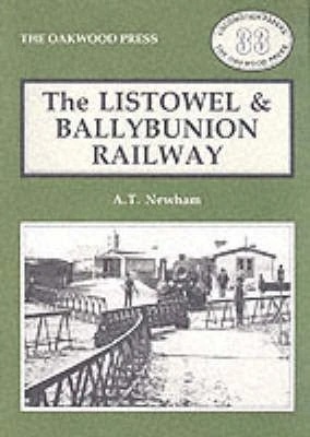
First published in 1967 as a slim Oakwood edition by A.T. Newham, going through two print runs. In 1989, Oakwood issued a new edition. This 2025 edition, was reprinted with a new cover design,
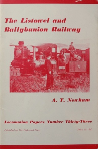
The book is softback, has 112 pages of text, around 100 illustrations including many black & white photos, route map, detail maps and drawings of carriages and locomotives. Covers of earlier editions are shown below. [5]
A Centenary Publication
Michael Guerin: A book was published about the railway by the Lartigue Centenary Committee in 1988. [6]
The Lartigue Centenary Committee was formed in Listowel, County Kerry, Ireland, in 1988 to mark the centenary of the unique Lartigue Listowel and Ballybunion Railway. The group published a foundational local history book and later evolved into restoration and twinning efforts.
The committee arranged for the construction of about 1000 m of demonstration track on which a full-scale diesel-powered replica of the original carriage can operate.
A museum was set up in ex-CIE (Irish State Railways) goods shed, which shows a film of the original line in operation and a large-scale model of the Lartigue station. The site of the original Listowel terminus is preserved in a nearby park and some track foundations remain along the remarkably straight road to Ballybunion. [7]
Egyptian National Railways is the national railway network of Egypt. Founded in 1854, it is the oldest railway system in Africa and the Middle East. [7] A separate article provides more detail about the history of the railways of Egypt which can be found here. [9]Other articles are under preparation in July 2026.
This article focuses on relatively recent news about the railways of Egypt. …
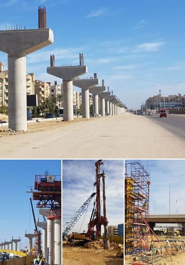
A. Cairo Monorail Project: The 56.5km East Nile line began operations in March 2026, serving 22 stations with driverless technology, reducing Cairo congestion. A second line, bringing the total network to over 100km, is under development.
B. High-Speed Network: Siemens Mobility is constructing a 2,000 km network, featuring Velaro and Desiro HC trains traveling up to 250 km/h, covering 60 cities.
C. Modernisation: of Egypt’s 10,000 kilometre rail network. ……
A.Cairo Monorail Network
Recent articles about various railways in Egypt include the news that Egypt has just opened a new monorail, 56 kilometres in length.
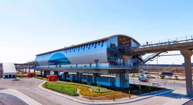
The featured image shows one of the twenty-two station s on the route. [1][2]
Solomon Ekanem reports that Egypt has officially launched the 56.5-kilometre East Nile monorail – Africa’s longest – marking a major milestone in the country’s push to modernise urban transport and expand green mobility infrastructure.
The East Nile monorail, connects Cairo’s Nasr City to the New Administrative Capital. It is a driverless monorail which calls at 22 stations. It is intended to ease congestion and improve urban connectivity. It is Africa’s longest single monorail line and part of the continent’s largest monorail network when combined with a second line. The eco-friendly, automated system reduces energy consumption by 30% compared to conventional electric rail.
President Abdel Fattah al-Sisi inaugurated the driverless system on Friday 20th March 2026 and then travelled alongside families of fallen Egyptian soldiers on the monorail from the Al-Fattah Al-Alim Mosque station to the Financial District, passing through key residential zones.
Transport Minister Kamel al-Wazir described the project as a “civilizational leap,” noting that it aligns with government efforts to deploy eco-friendly transport systems that reduce fuel consumption and road congestion. The rubber-tyred, fully automated system operates on elevated tracks, minimizing disruption to existing road networks.
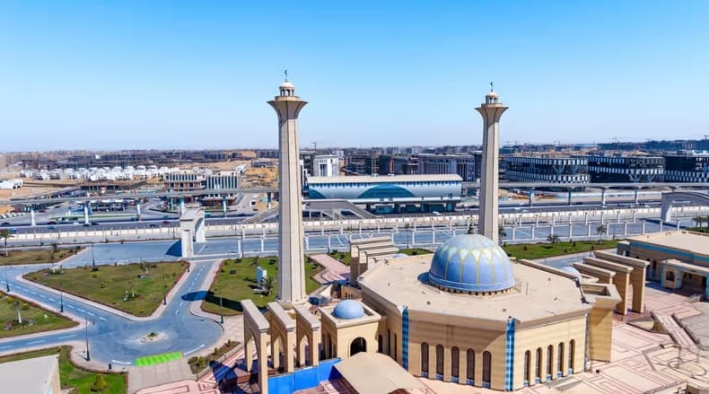
El-Mosheer Tantawy Mosque sits close to the monorail, one station of the monorail can be seen beyond the mosque in this image. [1][2]
“The East Nile monorail … is part of a broader network — the “Cairo Monorail” system — which includes a second line linking 6th of October City. When both lines are combined, the network stretches to about 96 km, making it Africa’s largest monorail system overall. In simple terms, the East Nile route holds the record for a single line, while the full Cairo network holds the continental record for total system size. Built by a consortium including Alstom, Orascom Construction, and Arab Contractors, the project features 40 trains capable of reaching speeds of up to 80 km/h, with intervals as short as 90 seconds. The system integrates with Cairo’s Metro Line 3 and the Light Rail Transit (LRT), with future links planned to Metro Lines 4 and 6.” [1]
“Equipped with platform screen doors, LED displays, and accessibility features, the monorail is expected to play a central role in reshaping Cairo’s urban mobility and supporting the shift toward sustainable transport.” [1]
Ekanem’s report is echoed by a report in Egypt Today. [2]
Cairo Monorail was first conceptualized in the late 2010s to combat the rise of traffic in the Greater Cairo area, and to provide a rapid transportation option for suburban residents. The Monorail was also thought of as a rail link between Cairo and Egypt’s New Administrative Capital. “Funding for the project was secured and obtained through a mix of local and international investments. This included a substantial loan facilitation agreement between the National Authority for Tunnels and JP Morgan Europe Limited, as well as contributions from other financial institutions such as the European Bank for Reconstruction and Development (EBRD) and the European Investment Bank (EIB). The total funding amounted to approximately 4.5 billion Euros.” [4]
It was reported in August 2019, that French rolling stock manufacturer, Alstom, would lead a consortium which includes The Arab Contractors: Osman Ahmed Osman & Co and Orascom. The consortium would sign a 2.7 billion Euros contract to design, construct, operate, and maintain the two monorail lines. Upon completion of construction, the consortium will operate and maintain the network for 30 years. [4]
Hill International highlighted their involvement with the project in a post on LinkedIn four years ago. They were providing project management, design review, and implementation supervision services for the New Administrative Capital City and 6th of October City (East and West) Lines. [3]
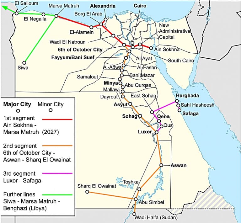
B. High-Speed Network: This network is a planned 2,000 km network which Siemens Mobility is constructing. It will feature Velaro and Desiro HC trains traveling up to 250 km/h, covering 60 cities. The network will include three lines:
Line 1 (Green Line): Connects Ain Sokhna to Marsa Matrouh via Cairo. Line 2: Connects Cairo to Abu Simbel. Line 3: Connects Qena with Hurghada and Safaga.
The project includes 15-year maintenance by Deutsche Bahn and involves upgrading 7 key rail stations via Thales, focusing on increasing freight capacity to 13 million tonnes annually.
Egypt has a bold vision to build one of the world’s largest high-speed rail networks. Siemens Mobility is committed to delivering fully integrated, sustainable transportation solutions tailored to Egypt’s unique environment. The High Speed rail project “will span over 2,000 kilometres. It will ultimately connect all the major cities and reach nearly 90% of the population. Once complete, Egypt will have the sixth-largest high-speed network in the world. It will significantly reducing travel times, cutting CO₂ emissions, and boosting sustainable local economic development.” [6]
Siemens Mobility’s 15-year maintenance commitment covers the entire fleet for Egypt’s new high-speed rail network ensuring long-term operational excellence. This network will cut travel times by up to 50%. It will offer millions of passengers safer, more reliable, and more comfortable journeys. [6]
Currently completed to over 65%, the first phase of Egypt’s Ain Sokhna to Marsa Matrouh high-speed train is set to begin operations in 2027. The 670-kilometre line will include 21 stations! [6]
C. Modernization: In addition to new lines, Egypt is modernizing its existing 10,000 km network with new trainsets from Talgo, locomotives from Progress Rail, and new traffic control systems to improve efficiency.
The Railway Gazette International reported in September 2025 that Hitachi Rail has deployed a centralised traffic control system to manage 19 stations on the 200 km Cairo to Alexandria line. [5]
“The initial contract for the programme was signed in 2013, and has since been extended to encompass more than €100m of investment. The mechanical and electrical signalling has been replaced with a modern electronic system, including digital interlockings, new signals and motorised drives. A fixed and mobile telecommunications system has been installed, with drivers able to communicate with the operations manager in case of emergency or failure. Level crossings have been modernised, and technical buildings constructed.” [5]
“The modernisation project will enable Egyptian National Railways to increase the maximum speed of trains by 40 km/h to 160 km/h, reducing the journey time between the two cities to 2½ h. The route’s throughput is also set to grow by 40% to a maximum of 286 trains/day. A progressive increase in the number of freight trains is planned, allowing the line to carry 15 per day in 2030 and 50 per day by 2060.” [5]
In November 2025, TravelMole.com reported that Egypt had showcased a new high-speed train. [6]
“On 10th November 2025, German technology giant Siemens unveiled the Velaro high-speed train in Cairo, which had been specifically adapted to withstand the harsh climate conditions of Egypt. The official presentation occurred during TransMEA 2025, the region’s leading exhibition for transportation and logistics in the Middle East and Africa. The Siemens Mobility Velaro high-speed train is specially adapted for Egypt’s desert conditions. It can reach a speed of up to 250 km/h and offers seating for 489 passengers. The company will deliver 41 Velaro trains to the Egyptian rail network.” [6]
On the same day, “the Desiro HC regional train successfully completed its first train run on newly constructed tracks near the 6th of October Depot, West of Cairo. The Desiro High-Capacity regional train is a key element of Egypt’s new high-speed rail network, with 94 trains set to provide efficient and comfortable regional transport. Specially adapted for Egypt’s climate, each train offers up to 849 passenger spaces and advanced features such as air conditioning,” [6]
“With a top speed of 160 km/h, the Desiro HC fleet will play a vital role in connecting cities along the Green Line. This line consists of a 660 km network connecting Cairo to Ain Sokhna, Alexandria, and Marsa Matrouh. The Green Line is already referred to as the ‘Suez Canal on Rails’.” [6]
Freight – in June 2026, reports the Railway Gazette, Egyptian National Railways signed four freight corridor upgrade contracts.
An Alstom-led consortium has signed four contracts worth €690m with Egyptian National Railways for the modernisation of two strategic freight rail corridors. Together with Rowad Modern Engineering and Concrete Plus, Alstom will upgrade the 6th October City – Alexandria and Belbes – 10th Ramadan City lines. The upgrades aim to reduce transit times by up to 80 minutes and improve connections between Egypt’s logistics hubs and seaports. [8]
In addition to these ‘Heavy Rail’ commitments, Egypt is also seeking to modernise its tram networks and Cairo’s Metro.
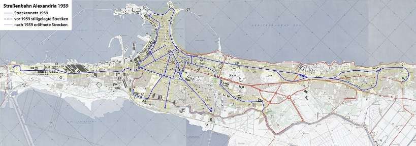
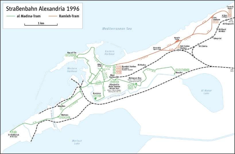
Egypt’s major tram modernization focuses on the historic Al Raml tramway in Alexandria, which suspended operations on 1st April 2026. Managed by the National Authority for Tunnels (NAT), the €236 million overhaul converts the 14.1 km heritage line into a fast, digitally controlled light rail system slated to finish by late 2028. [10]
Hitachi Rail has secured a contract to deliver the rail systems and digital technologies that will modernise and upgrade the Alexandria Raml Tram – the first modern tramway project of its kind in Egypt. The contract was awarded by the Hassan Allam Construction and Arab Contractors joint venture and will significantly improve speed, capacity and reliability on one of the world’s oldest continuously operating tram systems. [10]
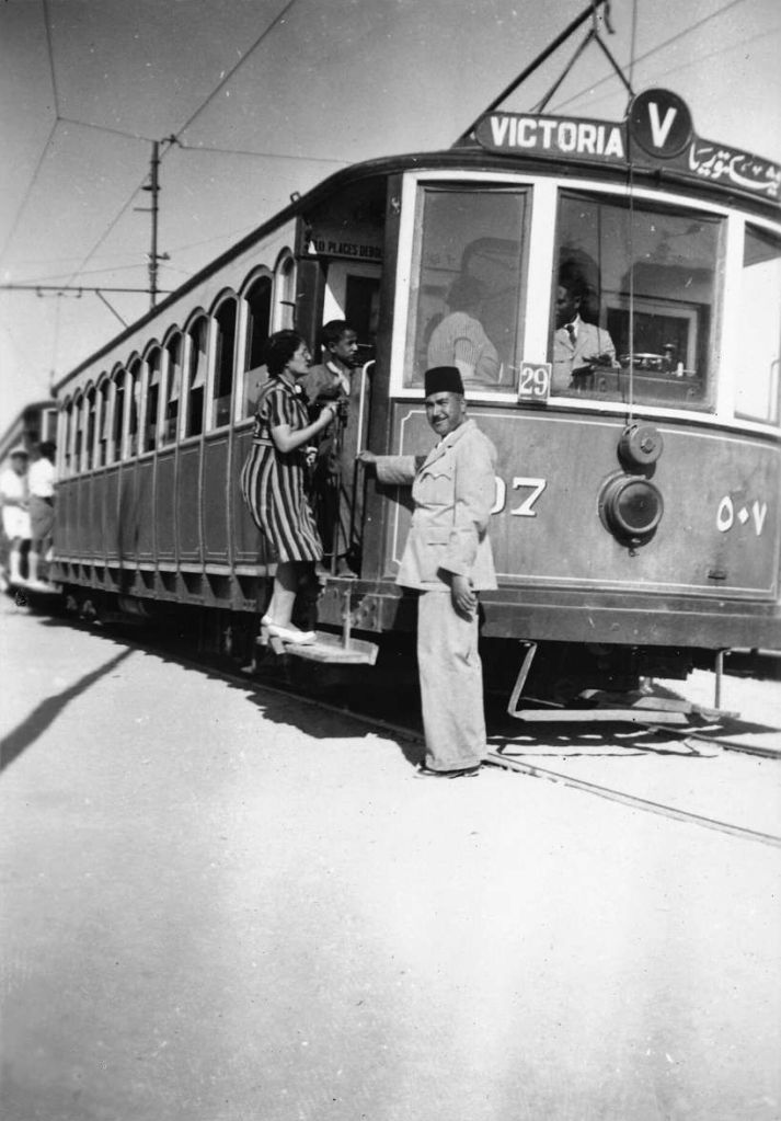
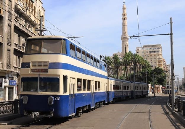
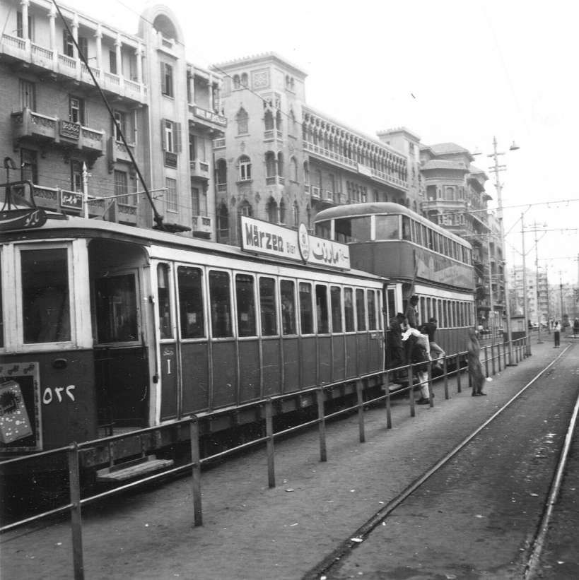
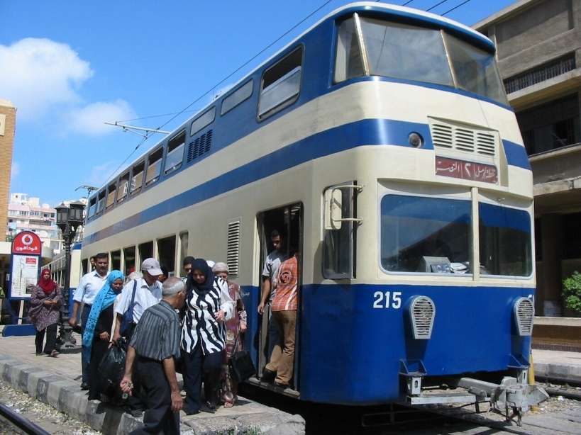
The Alexandria El Raml Tram is the oldest tramline in the Middle East and Africa, dating back to 1863. Despite its age and limited modernisation since the 1960s, it remains one of the few tramways globally to operate double-deck vehicles in regular service. The new contract marks a major step in the line’s transformation. [10]
Under the agreement, Hitachi Rail will supply advanced signalling and communications systems, a modern Operational Control Centre, SCADA, CCTV and access control, passenger information systems, and on-board equipment. Together, these systems will help deliver a faster, safer and more efficient public transport service aligned with Egypt’s Vision 2030 goals for sustainable mobility. [10]
The modernisation programme includes the reconstruction of 24 stations and 13.2 km of track. Once completed, the new system will:
reduce travel time from 60 to 35 minutes
double operational speed from 11 km/h to 21 km/h
cut headways from 9 minutes to 3 minutes
increase capacity from 4,700 to 13,800 passengers per hour per direction
This capacity boost will ease congestion, support modal shift and reduce CO₂ emissions while improving daily mobility across Alexandria. [10]
The El Raml Tram upgrade represents a significant milestone for Hitachi Rail’s growing presence in Egypt’s rail and metro sector. The company is already involved in key national programmes, including the Greater Cairo metro network, the LRT and monorail systems, and AFC modernisation initiatives. [10]
Hitachi Rail continues to expand its local footprint through engineering, financial, legal and operational teams established in Egypt. The company has increased localisation of IVVQ activities for CBTC systems and developed automated fare collection (AFC) projects that promote high-tech employment and diversity. These align with Egypt’s industrial and economic development priorities.[10]
Digital passenger information and multimodal payment systems are becoming central to Hitachi Rail’s offering in the region. For example, the upcoming Abu Qir Metro in Alexandria will integrate TRANSCITY™ AFC, enabling payments via QR codes, contactless cards, EMV bank cards and NFC mobile devices. [10]
“The contract will see us modernize and upgrade the oldest electric tram system in Africa, transforming it into a reliable, efficient, and digitally enhanced transportation system. The project underlines the capabilities of Hitachi Rail technologies in the rehabilitation and modernization of tramway systems,” Carlo Piacenza, SRS MEA Regional Director, Hitachi Rail, said. [10]
Urban Transport Magazine reported in April 2026 that, “with the closure of the long-established Ramleh tramway, Alexandria is currently undergoing one of the most radical system transformations in urban rail transport in North Africa. The project exemplifies a global trend: replacing historically evolved tramway systems with higher-capacity light rail infrastructure — and the associated trade-offs.” [11]
Alexandria’s tramway network is among the oldest in the world: opened as early as 1863 and electrified from 1902, the Ramleh line in particular developed into one of the city’s most important east–west corridors. With around 80,000 passengers per day and a route length of approximately 32 km, it was a central component of the urban transport system. [11]
At the same time, the system suffered from decades of underinvestment. Low average speeds of around 11 km/h, ageing infrastructure and limited reliability significantly constrained its performance. Against the backdrop of increasing congestion and ongoing urbanisation, comprehensive modernisation gradually moved to the forefront of transport policy. [11]
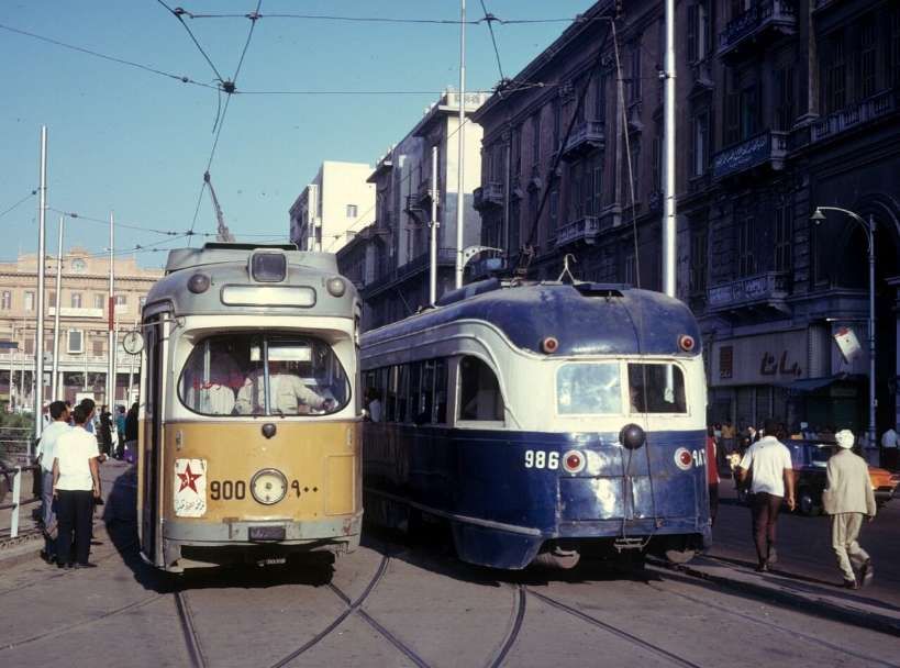
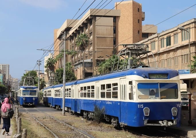
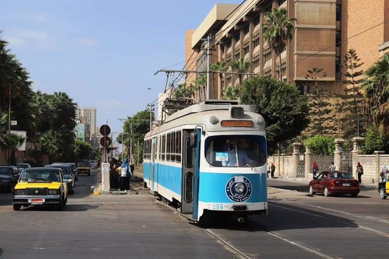
Until its closure, operations on the Ramleh tramway were characterised by a remarkably heterogeneous and ageing fleet. The core of the services was provided by modernised vehicles from Kinki Sharyo, complemented by locally Tatra Yug units. In addition, a number of second-hand high-floor trams originally built by Düwag in the 1960s and acquired from Copenhagen remained in service. This mix of vehicles from different generations and technical standards reflected both the long operational history of the line and the prolonged lack of fleet renewal, resulting in increasing maintenance complexity and declining reliability in the final years of operation. [11]
The transition to the new system began in early 2026 with a phased shutdown. Following initial restrictions in February, operations were completely suspended on 1 April 2026. Since then, the existing infrastructure — including tracks, power supply and stops — has been undergoing comprehensive dismantling. The complete interruption of services represents a deliberate break with historical continuity, in contrast to many European modernisation projects, where upgrades are often carried out while operations continue. [11]
In place of the conventional tramway, a modern light rail system with significantly altered parameters is being developed. Approximately 13 km of the route will be fundamentally upgraded and partially realigned. [11]
Key elements include:
Increase in average speed from 11 to around 21 km/h
Reduced stop density (approximately 500 m spacing)
Modern signalling and control systems
Introduction of 30 high-capacity vehicles (Hyundai Rotem)
The project is thus clearly aimed at increasing capacity and efficiency, and conceptually aligns more closely with light rail or metro systems than with traditional tramways. [11]
Since early 2026, operations on the Ramleh tramway have been gradually wound down: following initial test closures in February, partial suspension began on 11th February, before services were fully discontinued on 1st April 2026. [11]
In the weeks leading up to this, the network saw something of a series of “farewell runs”, before the final trams ceased operation in early April. In parallel with the closure, comprehensive dismantling of the infrastructure began, including tracks, overhead lines and, in some cases, adjacent urban spaces. [11]
The transformation has met with considerable criticism in Alexandria and is the subject of intense public debate. While the government presents the project as a necessary step towards modernisation to increase capacity and speed, many residents view it as a profound intervention in the city’s historic urban fabric. [11]
A central point of criticism is the planned elevation of the route. More than half of the future line, which will be around 13 km long, is to run on viaducts. Critics fear that the existing tree-lined right-of-way will be replaced by “concrete stilts”, leading to a loss of the city’s characteristic urban landscape. [11]
Furthermore, it is argued that the shift towards a faster system, more strongly segregated from general traffic, may bring operational advantages but could come at the expense of urban integration. Urban planners warn that the new infrastructure is geared more towards throughput and speed, and less towards public realm quality and local accessibility. [11]
Transport impacts have also been viewed critically: even during the construction phase, the suspension of services has exacerbated traffic problems, as replacement services have only been able to compensate for demand to a limited extent. Some observers see this as an indication that, in the short term, the transformation could even lead to increased reliance on private motorised transport. [11]
Finally, the loss of cultural heritage plays a central role in the public debate. For many residents, the tramway is not merely a mode of transport, but an integral part of the city’s identity. Critics therefore speak of a tension between modernisation and “cultural dislocation”. [11]
Reopening is scheduled for the end of 2027. Whether the new system will meet expectations in terms of performance and attractiveness will depend largely on how successfully operational efficiency can be balanced with urban integration. [11]
Cairo’s Metro:–
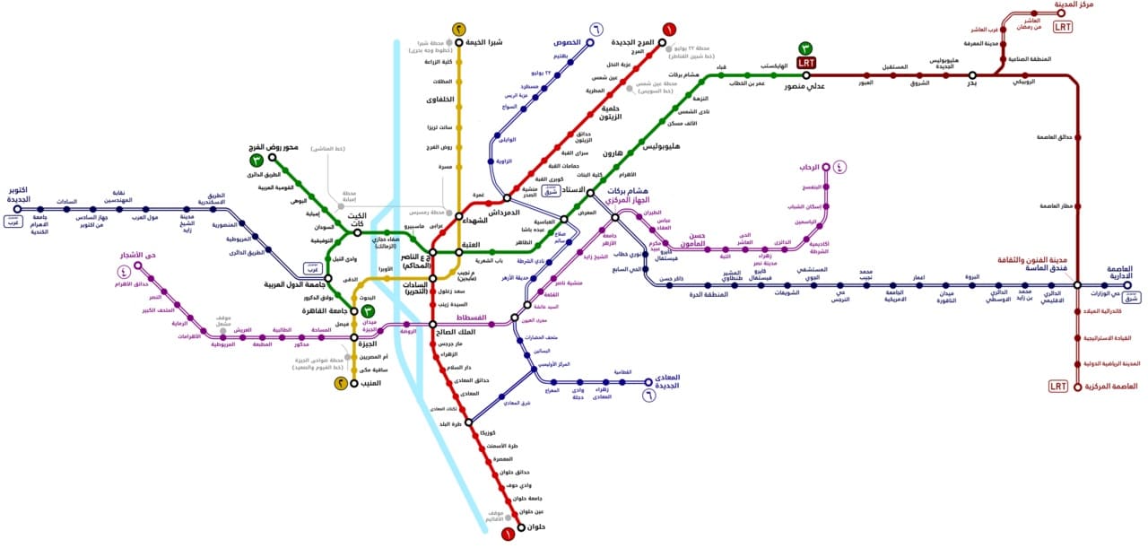
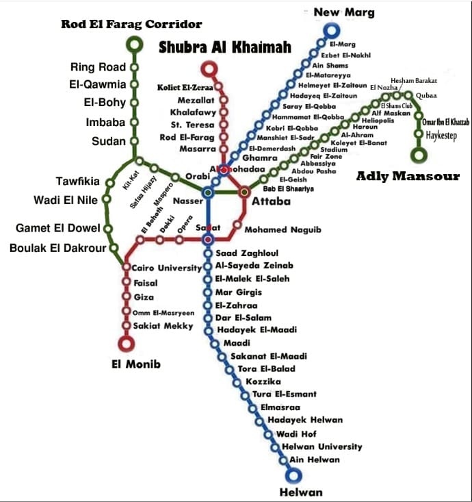
As of 2024, Cairo’s Metro has 84 stations of which 5 are transfer stations, with a total length of 106.8 kilometres (66.4 mi). The system consists of three operational lines numbered 1 to 3. It is part of an integrated transport network.
Map of Cairo Metro, LRT, and Monorail lines. Thick lines indicate lines in operation and hollow lines indicate lines under construction or in planning, (c) BasilLeaf and licensed for reuse under a Creative Commons licence, (CC BY-SA 4.0). [12]
As the biggest and most densely populated megacity in Africa and the Middle East, Greater Cairo had a strong case for a metro. In 1987 that population stood at 10 million residents, not counting the two million or so commuters who came into Cairo every day to work. The capacity of Cairo’s public transport infrastructure was around 20,000 passengers/hour, which increased to 60,000 after the construction of the metro. [13]
In the 2020s, “Cairo has more than 20 million people in its metropolitan area, and the chaos on the surface can be disorientating for anyone arriving for the first time: gridlock that stretches for kilometres, constant horns, intersections that follow no obvious logic. But beneath all that noise there is a system that organises the movement of millions of people every day. The Cairo Metro — officially the Cairo Metro or مترو القاهرة — is the backbone of public transport in this megalopolis, the first metro ever built in Africa, and the first in the entire Arab world.” [14]
In 2023, Cairo Metro carried 1,460 million passengers, which works out to around 5 million journeys a day — a figure that puts it among the most heavily used metro systems in Africa and the Arab world. For most of its passengers, the metro is not an alternative to other options; it is the only realistic way to cross the city in a reasonable amount of time. [14]
What makes this system distinctive is not only its history but its composition. Line 1 was born from the conversion of existing suburban railway corridors, combining surface sections with a few kilometres of tunnel through the historic heart of the city. Line 2 was a first for the continent: it crosses the Nile through a tunnel, the first railway tunnel under that river anywhere in Africa, a genuinely complex engineering achievement. Line 3, the most modern, was under construction in phases for over a decade and represents the biggest technological step forward in the system, with better stations and newer trains. It was completed in 2024. [14]
For travellers arriving in Cairo, the Metro is an indispensable tool for connecting the historic centre with modern districts, Ramses train station and the main residential areas. At present, the Cairo Metro does not reach the Pyramids of Giza. [14]
The density of Greater Cairo makes any underground construction extraordinarily complicated. Several sections were built directly beneath narrow alleyways, centuries-old markets, multi-storey buildings and layers of pre-existing infrastructure. Expropriations in historic districts such as Khan El Khalili, or in densely populated residential neighbourhoods, required lengthy and costly negotiations. In some stretches engineers opted for cut-and-cover construction with minimal disruption; in the historic centre, tunnel-boring machines were the only viable approach. [14]
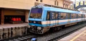
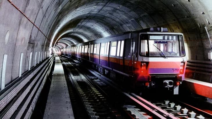
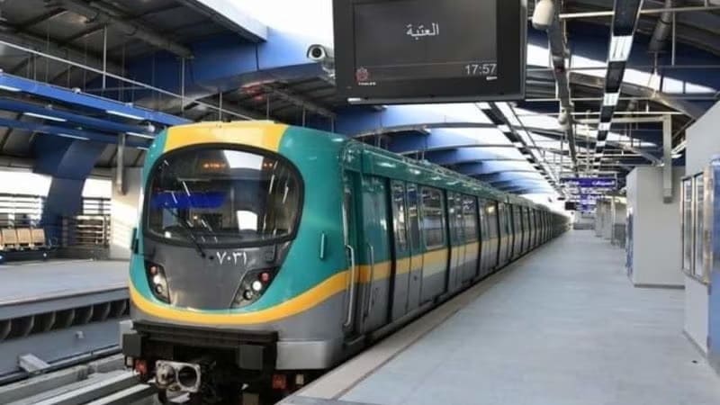
The system at present operates trains from different generations depending on the line.
Line 1 still runs sets from the original era — nine-car trains with capacity for over 2,000 passengers, revised and upgraded over the decades. Some were refurbished by Hyundai in the early 2010s. [19] Others are being refurbished by Mitsubishi at present. [14][17]
Line 2 has more modern stock acquired in the 1990s and early 2000s. [18] The National Authority for Tunnels has awarded CAF three contracts totalling more than €450m for the modernisation and maintenance of trainsets on Cairo Metro Line 2 and the maintenance of trainsets on Line 1. [14][20]
Line 3 works with the newest trains, some of them from contracts signed with Alstom in 2020/2021 for the supply of new Metropolis units. [14][21]
Line 4 connecting to Giza is under construction. The line is ultimaely intended to be 42 kilometres in length. [15] A first phase of 18-19 kilometres and between 15 and 17 stations planned, it will connect the El-Malek El-Saleh area with north-west Giza, bringing the Metro significantly closer to the Pyramids zone for the first time. The project includes lifts for passengers with disabilities and modern access management systems built into the original design. Opening is estimated at being in the first half of 2028. [14][16]
Phase 1 runs largely underground, serving 17 stations, from the boundary between Cairo and 6th of October City to Grand Egyptian Museum, Remaya Square, Haram Street, Giza Station, El-Malek El-Saleh and Fustat. Gewaily says that Line 4 will carry approximately 2 million passengers a day when completed. [16]
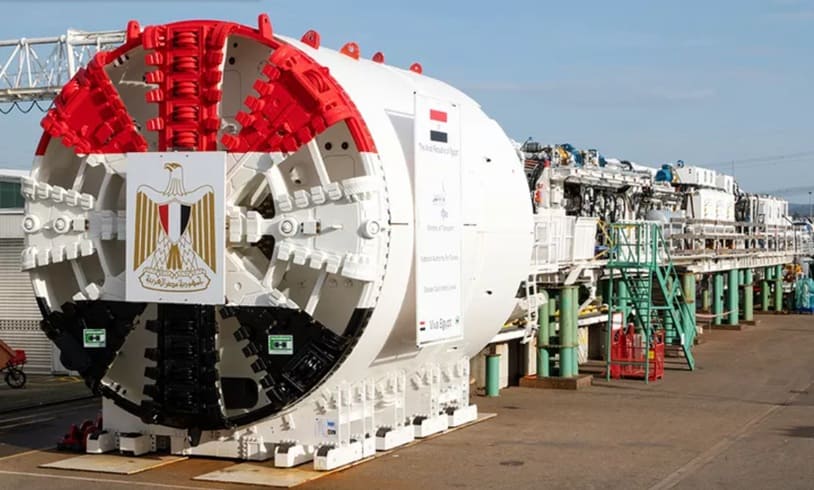
Four high-performance Herrenknecht tunnel boring machines were deployed for tunnel construction. They commenced excavation at the end of 2023 and the beginning of 2024, ensuring efficient and precise tunnelling under challenging geological conditions. [15]
Mitsubishi is supplying 23 trains for the line, the first of was scheduled for delivery In May 2026, construction of depot facilities and the installation of electromechanical systems. Civil works are being undertaken by domestic firms Arab Contractors, Orascom, Concord, Petrojet, and Hassan Allam Construction. [16]
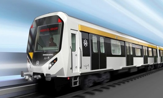
A Mitsubishi Kinki Sharyo train manufactured for the Cairo Metro Line 4. Phase 1 of Line 4 is scheduled to open in the first half of 2028.The contract includes supplying 184 metro cars to be delivered between 2026 and 2028.The trainsets are being shipped from Kobe, Japan, to Alexandria, Egypt. [16]
The government is currently considering three further phases for Line 4:
Phase 2: Fustat – New Cairo Phase 3: Hadaeq El Ashgar – Hosary Square, and Phase 4: New Cairo – the Capital Airport. [16]
The extended line will provide interchange with the planned metro Line 6, the Light Rail Transit (LRT) network and both the East of Nile and West of Nile monorail lines. [16]
Also planned is an extension to Line 3 to reach Cairo International Airport. It will add roughly 7 kilometres and 5 new stations from the Heliopolis area to the airport terminal. As of mid-2026 there is no confirmed opening date: the project has been announced on several occasions, but financing and timescales are not yet settled. [16]
Line 5 and Line 6 and the long-term network. The Greater Cairo master plan envisages a network of up to six metro lines plus complementary systems including the monorail, long-distance high-speed rail and extensions to the new satellite cities. Line 6 is planned to connect Shubra with Maadi, providing a new north-south axis that takes pressure off Line 1. All of these projects extend beyond 2030. [16]
Henry Robinson Palmer (1793-1844) was a British engineer who designed the first monorail system and also invented corrugated iron!
Born in 1793 in Hackney, he was the son of the Revd Samuel Palmer, a nonconformist minister, and his wife, Elizabeth, née Walker. [1] He was baptised in Tooting [2] and was educated at the academy run by his father and between 1811 and 1816 was an apprentice at 1811-16 Apprenticed to Bryan Donkin and Co.
When he finished his apprenticeship, Palmer was taken on by Thomas Telford, working for him for 10 years and involved with a variety of road/canal surveys and associated designs. In 1818, Palmer was one of three young engineers key to the founding of the Institution of Civil Engineers and on 23rd May 1820, he formally became a member of the Institution. [3]
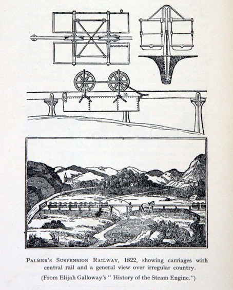
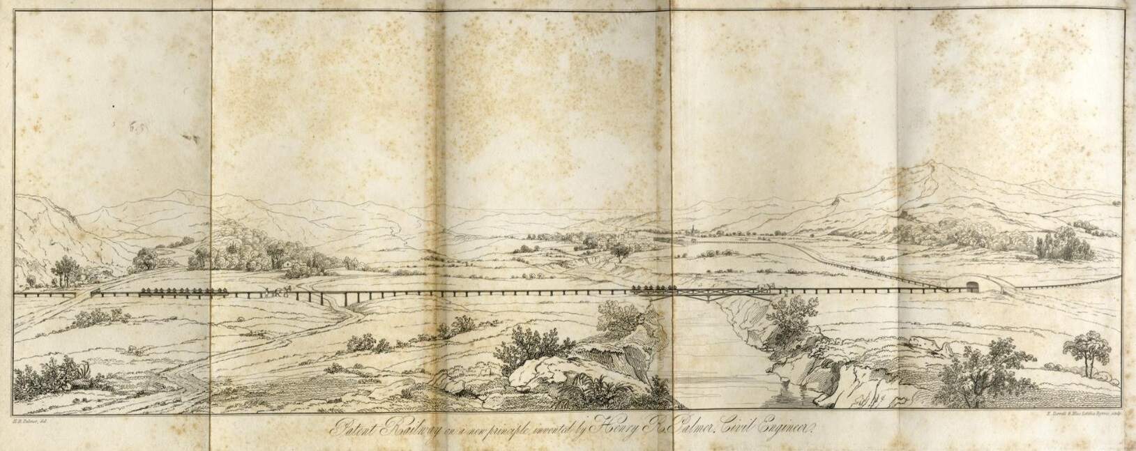
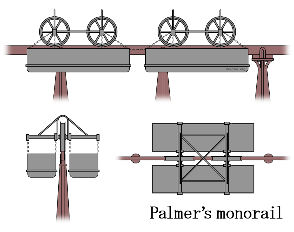
Elijah Golloway recorded Palmer’s ideas for a Suspension Railway in the image above which is dated 1822. It seems as though Galloway’s book, History of the Steam Engine, From Its First Invention to the Present Time: Illustrated by Numerous Engravings From Original Drawings, Made Expressly for This Work, was not published until 1828 by B. Steill. [4][5]
On 22nd November 1821, Palmer patented his proposed monorail system. [6][19: p57]
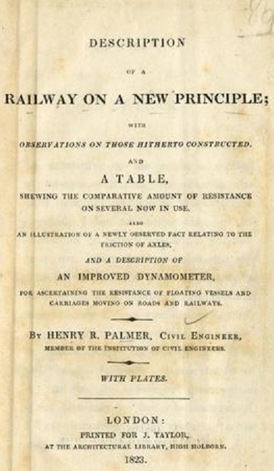
In 1823, Palmer wrote his short book, Description of a Railway on a new Principle, (J. Taylor, 1823) about his monorail ideas. [7]
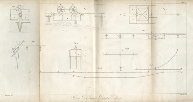
The illustrations immediately below come from a copy of that book which is held by the Science Museum. [7]
Palmer was unaware of the experimental work being undertaken in Russia at around the same time. The work of Ivan Kirillovich Elmanov is covered here. [26]
These images are taken from H.R. Palmer; ‘Description of a Railway on a New Principle’ and are released by the Science Museum under a Creative Commons Licence (CC BY-NC-SA 4.0) [7]
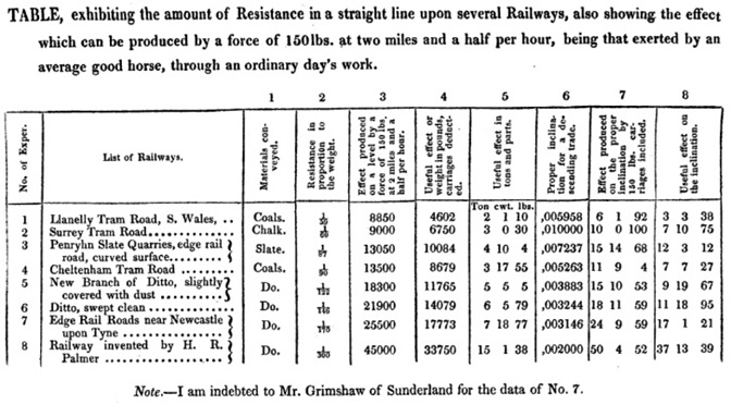
In his book, Palmer refers to examples of railways already constructed. It is clear that he is talking of railways which operate on more traditional principles. He tabulates those to which he is referring in a table which is reproduced below: the Llanelly Tramroad; the Surrey Tramroad; the Penrhyn Slate Quarries, edge rail road; the Cheltenham Tram Road; a branch of the Cheltenham Tram Road; Edge Rail Roads near Newcastle-upon-Tyne. These he compares with his own proposed railway which was built in Deptford Dockyard in London in 1824. [6]
Table showing the resistance form the rails of various railways in use in the early 19th century. [8: p29]
History only seems to record two of Palmer’s monorails in the UK. The first was constructed at Deptford as we have already noted. The second was built at Cheshunt and opened about 3 months prior to the Stockton & Darlington Railway (in June 1825) and was described, that month, in The Times newspaper. [9] Although his ideas were attempted in at least one other place. The railway built in what is now Hungary in 1827 (15th August). It was a fleeting experiment about which more details can be found here. [10]
Palmer is recorded as having given evidence, in 1825, in favour of navigation interest and against the Liverpool and Manchester Railway. [4] He was appointed resident engineer to the London Docks in 1826, where, for 9 years, he designed and executed the Eastern Dock, with the associated warehousing, entrance locks, bridges, and other works. While undertaking this role, in 1828, he inventedthe “Corrugation and Galvanisation” of sheet iron. [11]
Regarding Palmer’s invention of corrugated iron, Dr. Pedro Guedes wrote that “Palmer exploited the unique properties of metal, creating a lightweight, rigid cladding material, capable of spanning considerable distances without any other supports, helping to make lightweight iron buildings and roofs possible. Palmer’s invention completely broke with precedent and tapped into another level of thinking. The sinusoidal corrugations that Palmer imagined as the means to impart strength to his sheets of wrought iron have continued virtually unchanged for close on two centuries.” [11]
In 1831, he was elected as a Fellow of the Royal Society, publishing two papers on the movement of shingle in Philosophical Transactions, 1831 and 1834. In 1833, he took out patents for improvements in the construction of arches and roofs. [12] In 1835, he moved to Westminster and worked as a consulting engineer and was involved in numerous surveys for projected railways, and the design and construction of several docks and harbours, including those at Port Talbot, Ipswich, Penzance, and Neath. He carried out the original surveys for the South Eastern Railway, assisted by P. W. Barlow, and would have executed the scheme but ill health intervened. His original surveys for a Kentish railway dated from the time he was associated with Telford.
He died on 12th September 1844. [13]
C. von Oeynhaussen & H. von Dechen inspected both of Palmer’s monorails during their visit to the UK in 1826 and 1827 and comment on both. First they describe the principles involved: “To facilitate laying out a railway with reduced friction, and to make it independent of the small unevennesses of the ground, Mr Palmer has proposed and built a kind of railway which consists of a single bar, and the wagons have only one wheel on each axle. The track is erected on posts or columns at a suitable height above the ground, and the load hangs so far below the wheels that the wagon frame cannot overturn. [16] This railway has the disadvantage that its construction is not solid, or it becomes very expensive; that it can compensate only for very small unevenness of the ground; that the motive power can operate only with an inclined pull; and that special precautions must be taken for unloading and loading the wagons. Therefore, the scheme has not come into general use. Excepting the two now to be mentioned, no railways of this kind appear to have been built in England.” [14: p75-76]
Palmer’s Deptford Railway
C. von Oeynhaussen & H. von Dechen describe this railway: “This railway leads from the Thames across the yard of the Victualling Office up to the warehouse, and serves to transport provisions out of the warehouse to the ships, or the reverse. The railway consists of cast-iron columns which project from 3 to 5 ft out of the ground; these are provided with fork-shaped seats at the top and are spaced 10 ft apart. Planks 9 in. high and 3 in. thick rest in the forks on double wooden wedges, so that they can be set at the correct level very easily. On the upper edge of these planks, wrought-iron bars are spiked, which are 3½ in. wide, somewhat convex, and in. thick in the middle. The ends of these bars are not square, but cut in a broken line, and rest, not directly on the plank, but on a small iron plate let into the wood.” [14: p76]
“The line is nearly horizontal, and has a fall of only about 20 minutes of angle to the river. … The wagons which run on this line have three wheels of 18 in. diameter, one behind the other; they have two flanges and the groove is shaped to fit the rail. These wheels are fixed to a wrought-iron frame which consists of three stirrups going over the wheels with connecting pieces below. The stirrups reach 2 or 3 ft below the railway, and are provided on both sides with an inclined platform, on which are placed the casks to be conveyed. For loading the wagons, there are two sloping frames at the same height as the wagon platforms, and between which the wagon has just room to pass. A wagon is loaded with 10 casks which weigh about 4½ cwt each, therefore totalling 45 cwt. The wagon can be taken at 5 cwt, so that the whole weight comes to 50 cwt, which can be moved up the line easily by four men.” [14: p76]
The Cheshunt Railway – The first passenger carrying monorail
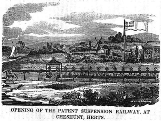
Cheshunt had a railway three months before the Stockton and Darlington line was opened. It was a horse-drawn monorail, built by Henry Robinson Palmer, who had previously built one in Deptford Dockyard, the first in the UK. The Cheshunt Railway, his second venture, was opened on 26th June 1825, running from Mr Gibbs’ Brick Pit (to the west of Gews Corner), to a wharf on the River Lea, not far from the site of the current Cheshunt Station. Its original purpose was to haul bricks, but it was also utilised for carrying passengers. For such a short distance, it must have been principally a novelty; regardless of this, it was the first passenger monorail in the world. [15]
The design was an overhead track from which carriages were suspended, drawn by a single horse. The line crossed the main road by a section hinged like a gate, enabling it to be moved off the road. No sign of the monorail has survived, but its legacy gives Cheshunt a vital, if little-known, position in the history of railways. [15]
C. von Oeynhaussen & H. von Dechen describe the railway: “From the lime and brick kilns at Cheshunt, in Hertfordshire, about 20 miles north of London, which lie on a main road, a Palmer railway leads to the Lee Canal in the flat and level Lee valley. The railway has a fall of 5 to 10 minutes of angle towards the canal; it is mile Engl. (580 fathoms Pruss.) long and serves to transport lime and bricks. The line rests on wooden posts which project on average 34 ft out of the ground; towards the limekiln, however, the bottom of the line is in a cutting in the ground, so that the posts stand in a kind of dry trench, the base of which is 9 ft wide. The wooden posts stand 10 ft apart, are 4 in. thick, and 7 in. wide; the top is fork-shaped 3 in. wide and cut 16 in. deep. In the bottom of this fork lies a block 12 to 15 in. long, in different heights, which is supported by a pair of inserted angle-pieces 14 in. high and 2 in. thick. Two wedges 2 ft long rest on this block with their inclined faces lying against one another, so that a horizontal support is always afforded to the plank which lies thereon. The planks are 101 in. high and 3 in. thick; they are 30 ft long and always meet in the middle of a post. Iron bolts with screws go through the post to hold together its fork-shaped end. There are oblong holes in the planks through which these bolts pass, so that the underlying wedges can be adjusted when necessary. On top of the planks a wrought-iron convex rail is laid, 4 in. wide, 1 in. thick at the edges, and in. thick in the middle. [14: p76]
C. von Oeynhaussen & H. von Dechen continue: “The rails are 20 ft long with their ends cut obliquely, and they are fixed by no more than two or three spikes of in. diameter with their heads countersunk in the rails. The rails have some spare holes which are used when one or other of the spikes breaks. Some posts are made of three parts fixed together. The pieces are 6 in. wide; the middle piece is 3 in. thick, the side pieces are 21 in. thick, and they are bound together by three screw-bolts; the wedges lie upon screwed-in blocks which are 1 ft long at the top. Although these planks are very thick, they have become bent at some places because of the great distance between the posts and are propped up by pillars set under them subsequently.” [14: p77]
“There is a siding on the railway in the vicinity of the canal. Here the line is made double for a length of about 30 ft, and between the double piece and the single track there is a strong door 10 ft wide which is hinged to the single rail and may be fastened to either of the two tracks. The railway lies on the upper edge of the door. Directly over the hinge is a small turning piece of rail by which the severe angle which the door makes with the main railway is reduced. This railway passes over an ordinary road by a similar door.” [14: p77]
“The wagons on this railway have only two cast-iron wheels, 26 in. diameter, with two flanges; they are 51 in. wide including the flanges, which are in. thick and project 11 in. They have six spokes and a nave 6 in. long and 2 in. wide. The wheel turns with a hollow cast-iron axle 2 in. thick and 12 in. long, which lies in round brass bushes at both ends; these have an inside diameter of 11 in., an outside diameter of 2 in., and are 3 in. long inside. They are fitted to seats on the wrought-iron stirrups which form the main frame of the wagon. Through the hollow cast-iron axle and the brass bushes is a wrought-iron axial bar 26 in. long, and 1 in. thick, the ends of which are fastened to the stirrup. This makes a firmer connection with the wagon frame. The two wheel centres are 46 in. apart. The platforms on which the wagon bodies are placed are 40 in. below the axle centres and are 17 in. apart. There is one wagon body on each side of the wagon, and each holds 20 cu. ft. One such body is laden with 20 cwt of lime or bricks, and therefore a wagon takes 40 cwt. One horse draws two such wagons or 80 cwt, exclusive of the bodies and the wagon.” [14: p77]
“On a disused standing wagon, there is a special arrangement for reducing the friction of the wheels on the axles, which is neither properly devised according to theory nor well carried out practically. The brass bushes wherein the cast-iron axle turns have a circular-segment-shaped slot, in. wide, cut in the upper part, and in this notch rests a 4 in. high iron friction wheel, on which the whole load of the wagon bears, while the brass bush is not entirely held fast in the wagon frame.” [14: p77]
The Cheshunt Railway is also featured in the Register of Arts and Sciences No. 47, 2nd July, 1825, [17] where the illustration below appears, along with a detailed description of the opening of the railway.
The Cheshunt Railway. [17: p353]
The article is reproduced in full below at Appendix A.
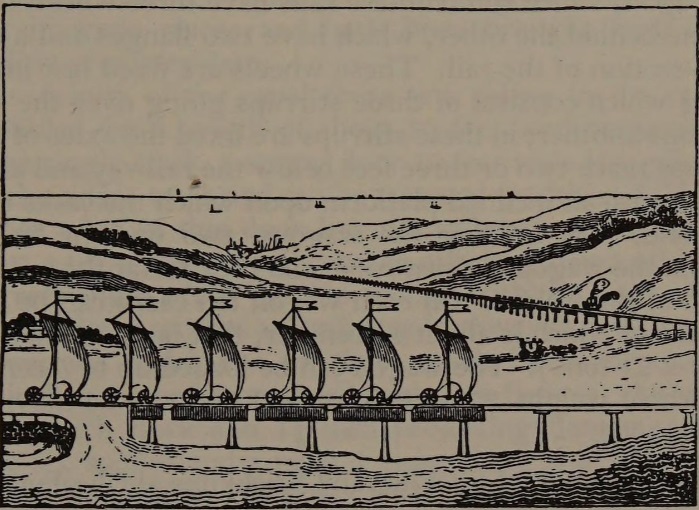
C.F. Dendy Marshall also refers to Palmer (and his monorails) in his history of railways to 1830. He notes that “Palmer was prominent in connexion with the London and Brighton schemes, and was [a] principal founder of the Institution of Civil Engineers. He wrote a paper in the Journal of the Franklin Institute in 1828, advocating the use of sails on railways. An illustration is given [below] of his railway with that method of propulsion, from Hebert’s Practical Treatise on Rail Roads (1837). [19] Two short lines were made on Palmer’s principle, on which horses were used: one at the Victualling Yard, Deptford; and one from some lime-kilns and tile-works near Cheshunt to the Lea Canal. The best account of these lines is given by von Oeynhausen and von Dechen, in ‘Ueber Schienen Wage in England, 1826-27.” [18: p171]
Marshall was writing in 1935, over 30 years before the Newcomen translation of von Oeynhausen and von Dechen’s German text was published, so he took the trouble to provide his own translation of their words in full. [18: p171-173] He also points his readers to an article in the Mechanics Magazine of 6th August 1825 which concluded: “One carriage, which has been constructed for the purpose of trying the application of the plan to the conveyance of passengers, differs from the others. Its boxes partake partly of the shape of a gig, and partly that of a balloon-car; in each are two cushioned seats vis-à-vis, with a little dickey behind, the whole carriage being covered with an awning.” [18: p173-174]
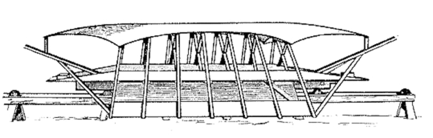
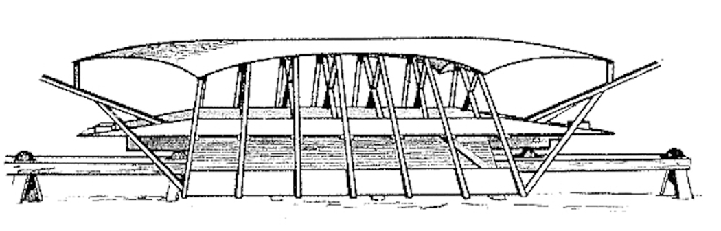
Palmer’s Idea for sail propulsion on his patented monorail. [18: p171][19: p62] At times we may feel a sense of ridicule at proposals which were coming to the fore in the early days of railways, but we need to remember that railways were the most up-to-date, advanced technology of the day and that progress would not have been made if a whole range of ideas were being put forward and tried.
Hebert discusses Palmer’s ideas in his book, Practical Treatise on Rail Roads (1837): “Mr. Palmer’s railway consists of only one, which is elevated upon pillars, and carried in a straight line across the country, however undulating and rugged, over hills, valleys, brooks, and rivers, the pillars being longer or shorter, to suit the height of the rail above the surface of the ground, so as to preserve the line of the rail always straight, whether the plane be horizontal or inclined. The waggons, or receptacles for the goods, travel in pairs, one of a pair being suspended on one side of the rail, and the other on the opposite side, like panniers from the back of a horse. By this arrangement only two wheels are employed, instead of eight, to convey a pair of waggons; these two wheels are placed one before the other on the rail, and the axle-trees upon which they revolve are made of sufficient length and strength to form extended arms of support, to which are suspended the waggons.” [19:p57]
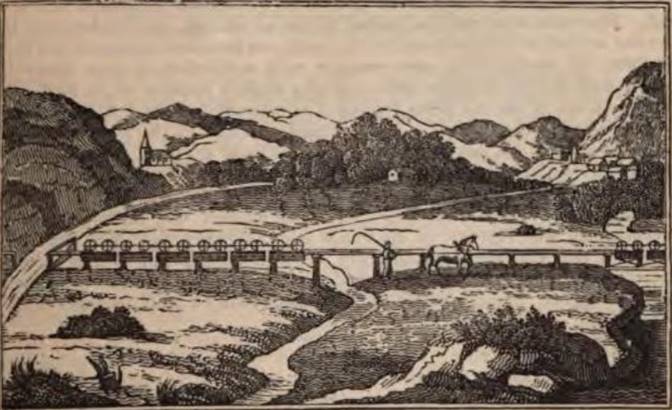
Hebert provides an illustration of the line in use. And the principles by which various obstacles were overcome. In the image below, “on the left is seen a jointed rail, or gate, that crosses the road over which the carriages have just passed, and the gate swung back, to leave the road open; the horse and man having just forded, the train of carriages is proceeding in its course, and following another train, part of which is seen on the right, crossing a rail bridge, simply constructed for that purpose.” [19:p59]
An Illustration of Palmer’s Suspension Railway. [19: p59]
“Provision is made for trains of carriages that are proceeding in opposite directions, by means of ‘sidings’ or passing places. With respect to loading, if both receptacles be not loaded at the same time, that which is loaded first must be supported until the second is full. Where there is a permanent loading place, the carriage is brought over a step or block; but when it is loaded promiscuously, it is provided with a support connected to it, which is turned up when not in use. From the small height of the carriage, the loading of those articles usually done by hand becomes less laborious. The unloading may be done in various ways, according to the substance to be discharged, the receptacles being made to open either at the bottom, the ends, or the sides. In some cases, it may be desirable to suspend them by their ends, when, turning on their own centres, they are easily discharged sideways.” [19:p59]
“Among the advantages contemplated by the patentee of this railway, may be mentioned that of enabling the engineer, in most cases, to construct a railway on that plane which is most effectual, and where the shape of the country would occasion too great an expenditure on former plans – that of being maintained a perfectly straight line, and in the facility with which it may always be adjusted; in being unencumbered with extraneous substances lying upon it; in receiving no interruption from snow, as the little that may lodge on the rail is cleared off by merely fixing a brush before the first carriage in the train; in the facility with which the loads may be transferred from the railway on to the carriages, by merely unhooking the receptacles, without displacing the goods, or from other carriages to the railway, by the reverse operation; in the preservation of the articles conveyed from being fractured, owing to the more uniform gliding motion of the carriages; in occupying less land than any other railway; in requiring no levelling or road-making; in adapting itself to all situations, as it may be constructed on the side of any public road, on the waste and irregular margins, on the beach or shingles of the sea-shore, indeed, where no other road can be made; in the original cost being much less, and the impediments and great expense occasioned by repairs in the ordinary mode, being by this method almost avoided.” [19: p59-60]
Hebert goes on to talk of the line built in Cheshunt in 1825. In that case, “The posts which support the rails are about ten feet apart, and vary in their height from two to five feet, according to the undulations of the surface, and so as to preserve a continuous horizontal line to the rail. The posts were made of sound pieces of old oak, ship timber, and in a, the slot or cleft at the upper ends of the posts, are fixed deal planks twelve inches by three, set in edgeways, and covering with a thin bar of iron, about four inches wide, flat on its under side, and very slightly rounded on its upper side; the true plane of the rail being regulated or preserved by the action of counter-wedges between the bottom of the mortices, and that of the planks. By this rail, on the level, one horse seemed to be capable of drawing at the usual pace about fourteen tons, including the carriages.” [19: p60]
Hebert quotes Tredgold, who commented: “We expect that this single railroad will be found far superior to any other for the conveyance of the mails and those light carriages of which speed is the principal object; because we are satisfied that a road for such carriages must be raised so as to be free from interruptions and crossings of an ordinary railway.” [19: p60][20]
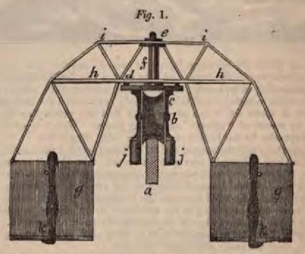
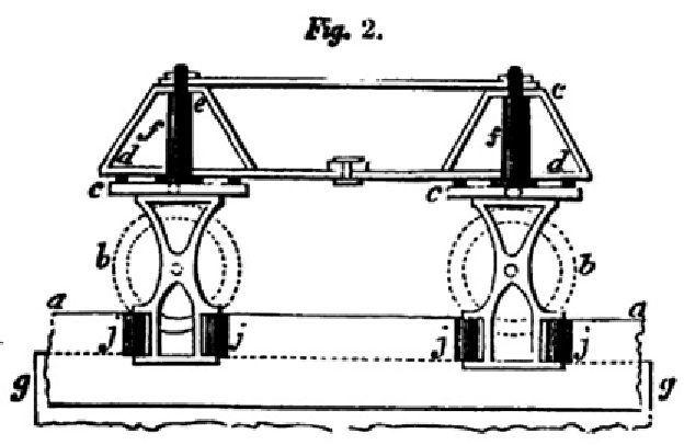
Hebert notes a particular problem with Palmer’s design: “It has generally been considered a defect in Mr Palmer’s arrangement, that in order to make turns in the road, it is necessary that a portion of the rail should be made to turn with the carriages upon it. This defect, Mr. T. Chapman, of Royal Row, Lambeth, proposed to remedy, by so constructing the carriage, as to enable it to turn itself upon a fixed suspension rail, whether curved or straight, or from one angle to another. Fig. 1 … exhibits an end view of the carriage, and Fig. 2 a side view of the same, partly in section. … aa is the rail, bb two wheels on the rail; these carry the turning plates cc, each having four friction-rollers: ee, upper plates; ff, the vertical axis of the wheel-frames or turn-plates cc; they pass through the plates d and e, from which the boxes gg are suspended, by the lateral arms hh and ii. Now as the wheels and frames b c can turn freely on their axis ff, they each require four guiding rollers jjjj to keep them in a right line with the rail, and to cause them to turn as the rail turns. These carriages should not be further asunder than is absolutely necessary for the required curve of the rail. The bottom of the carriage has a joint at one third of its length, and is held up at this by the hooks kk; by removing these, the contents may be let out: the fixed portion of the bottom is made sloping, so that it may be readily emptied.” [19: p60-61]
Hebert now turns to consideration of the force of the wind: “About thirteen years ago it occurred to [him], that the force of the wind might be beneficially employed as an auxiliary power for propulsion on railways; and considering that the suspension principle, which had just then been promulgated by Mr. Palmer, was better adapted to that object than any other, he wrote a short paper on the subject, which was inserted in the eighth number of the Register of Arts, for January, 1824, under the signature of “L. H.” The plan also embraced a proposition for enabling boats from the sea, a river, or canal, to pass out of the water, at once upon the rail, and thereon be propelled precisely in the same manner as the receptacles provided by the inventor are, and from which they scarcely need to differ in shape. Both of these propositions have been treated with abundance of ridicule, by persons who were either incapable or indisposed to reason. But one of them having, according to the newspapers, been recently carried into actual practice at Sunderland, and under less favourable circumstances, (i.e. on the common ground rail) the writer need not dilate upon its feasibility. And as respects the other propositions, he will only observe, that believing it to contain the germ of something that may hereafter prove of public benefit, he hesitates not to place it before the judgment of the reader. The following are extracts from the paper alluded to. ‘The inhabitants of small islands, and of the sea-coast gene-rally, subsist chiefly upon fish; and as they are remarkable for robust constitutions, it follows that their food must be strengthening and wholesome. I propose, therefore, a railway, on Palmer’s principle, from London to the nearest seaport town or fishing-place, that shall give to the inhabitants of this city the advantages of a plentiful supply of the cheap and wholesome food enjoyed by those in maritime situations. In the drawing which accompanies this [see the sail propulsion drawing above], the scene sketched is entirely imaginary, and intended, first to represent a railway leading to a sea-port, with the carriages being propelled, according to the modes projected by Mr. Palmer; the first train of carriages being drawn along the rail by a locomotive steam-engine, the second, more in the perspective, is supposed to be drawn by a horse. Brighton is perhaps the most eligible situation for such an undertaking. By a railroad from that place, the London market might be supplied with a prodigious quantity of fish within three or four hours after their being taken from the sea, at the mart trifling expense of carriage; and if the wind were to be employed as an auxiliary propelling force, which I propose, the rapidity with which the fish might generally be brought lo our markets would give us all the advantage of a sea-port town in the purchase of it If the Hollanders have found it practicable (as is well known) to sail over land in four-wheeled carriages, how much more practicable and advantageous would it be to bring into use the admirable facilities furnished by Mr. Palmer in his new suspension railway, in which the resistance to the motion of the carriages is reduced to one-twentieth part; or in other words, wherein the facilities are twenty times greater. As objections will of course he raised, on the score of the variableness of the wind, I must repeat, that I only propose it. as an auxiliary power. It would rarely happen that the wind would not he favourable in going or returning; and it is well known that S.W. winds prevail more than any other in our quarter, which would be favourable for the principal traffic; that is to London. In the absence of a steam-engine, a horse should always be in attendance; so that when employed in drawing a train of carriages, if a favourable breeze should spring up, the sails might be spread, and the horse be-put into one of the receptacles, where, over his bag of corn, he might regale and invigorate himself for fresh exertions, should the wind fall off.” [19; p61-62]
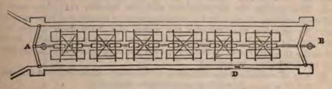
Hebert goes on, even more fancifully in my view, to explain how Palmer’s design can be adapted to one of Hebert’s own ideas of overcoming the need for transshipment between canals and railways, and perhaps to overcome the need for locks altogether as lengths of canal could be linked by Palmer’s monorail, provided the canal vessels were designed to suit. So, Hebert says: “The railway I propose Is to be constructed as usual, elevated upon pillars, and not to terminate on arrival at the look gates B, but to pass over it, and terminate at the other end, just within the second gates A, and be supported upon pillars from the floor of the lock, the same as on dry ground. In [drawing](which is a plan) the double train of vessels are supposed to have all entered the lock, half on one side of the rail, and half on the other, and they are hooked on to the axle-trees of the wheels which are already upon the rail for that purpose. The gates next to the river or canal are then closed, and all being fast, the water is let out of the lock by a sluice at D. till it falls below the bottom of the outer gates; at which time the vessels are all suspended on their axles in the air. The gates being next opened, and the wind fair, they sail across the valley or are propelled by other means provided by the patentee.” [19: p62-63]
Hebert’s proposed transfer lock – canal to Palmer’s monorail. [19: p63]
Further Immediate Developments
As early as 1826, the German railway pioneer Friedrich Harkort had a demonstration line of Palmer’s system built at his steel factory in Elberfeld (today part of Wuppertal), but objections prevented the construction of a public railway. [22]
Soon after, the first Hungarian railway line was completed on 15th August 1827, and led from Pest to Kőbánya. It was a monorail built on the principles outlined by Palmer. [23][24]
H.R. Palmer; Description of a Railway on a New Principle: With Observations on Those Hitherto Constructed and a Table Shewing the Comparative Amount of Resistance on Several Now in Use; J. Taylor, London, 1823. [NB: a second edition was published by J. Taylor in 1824]
The Leicester Chronicle, or Commercial and Agricultural Advertiser; Saturday, 15th February 1834.
The Ipswich Journal, Saturday, 14th September 1844.
C. von Oeynhaussen & H. von Dechen; Railways in England 1826 and 1827; translated by E.A. Forward and edited by C. E. Lee & K. R. Gilbert; Heffer &b Sons Ltd, Cambridge, for the Newcomen Society, 1971.
This refers to a device patented by Henry Robinson Palmer (1795-1844) on 22nd November 1821 (Patent No. 4618). The line in the Royal Victualling Yard, Deptford, appears to have been brought into use in the latter part of 1824. The Cheshunt line was opened with considerable ceremony on 25th June 1825.
Appendix A – The Opening of the Patent Suspension Railway at Cheshunt, Herts
The Register of Arts and Sciences No. 47, 2nd July, 1825
We had the gratification on Saturday last of witnessing a practical demonstration of the advantages of Mr. Palmer’s new Suspension Railway, the nature and construction of which having been fully described in the 7th and 8th numbers of this Work, to those articles we refer our readers, as connected with our present account.
A line of railway on these beautiful principles having been erected at Cheshunt, in Hertfordshire, by Mr. Gibbs of that place, the same was opened for public inspection on the above-mentioned day, when a numerous and highly-respectable company of persons attended by invitation to witness the operation of the carriages, and partake of a rural entertainment provided for the occasion. The weather proved fine during the forenoon, but the rain which after-wards occasionally descended in showers, would have been felt very inconveniently by the numerous fair visitors, had they not been provided with large booths, in which were erected ranges of elevated seats, commanding a view of the entire piece of rail-road, besides affording a fine prospect of the surrounding country, which is beautifully picturesque. Near to these was stationed a band of music, which played a variety of national airs; and the flags of England, France, America, and other nations, waving their colours in different parts of the beautiful meadows, gave a delightful effect to the scene, independently of the highly interesting business of the day.
The chief object of the proprietor of this undertaking is the conveyance of bricks across the Marsh to the River Lea for shipment, and the carriages have consequently receptacles adapted to that peculiar purpose. But on the present occasion each receptacle was fitted up with temporary seats, for the conveyance of the persons in the manner represented in the engraving; each receptacle being likewise loaded with a quantity of bricks as ballast, which were stowed away under the seats, making, perhaps, a total weight to each receptacle of one ton; and there being two receptacles to a carriage (one suspended on each side of the rail) will make the whole weight about fourteen tons. The first carriage shewn in the train * had the receptacles expressly made for passengers, and were elegantly constructed in the barouche style, the passengers sitting opposite to each other. The whole of this immense train was drawn by a single horse by means of a towing rope attached to the first carriage, and with so little exertion apparently, that it was evident the strength of a good average horse would be sufficient to draw double the weight operated upon. The rail was proved to be upon a level plane by the animal drawing the load with equal facility, in either direction. The posts which support the rail are about ten feet apart, and vary in their height from two to five feet according to the undulations of the ground, so as to preserve the horizontal line of the rail. Under the rail, and between a cleft of each of the posts are placed reverse wedges, which admits of a facile and almost instantaneous adjustment of the plane, in the nicest manner. [a] The posts are made of that almost ever-lasting stuff, sound old ship timber, and securely fixed in the ground in a peculiar manner; the rail is constructed with 3-inch planks, 12 inches wide, which are placed edgeways between the clefts of the pillars. The upper surface of the rail is covered with a bar of iron four inches wide and about a quarter of an inch thick, and a little con-vexed on the upper side, to suit the occasionally inclined position of the wheels, and to prevent (as we suppose) a too extended contact of their surfaces.
Our object in giving another sketch of this truly excellent invention has been, chiefly to shew its admirable application for the conveyance of persons as well as goods. The vehicles glide so smoothly over the surface of the country, as to be compared only to the floating of boats in the stream of a river; and it is evident that no mode of travelling can possibly be less free from danger.
The simplicity and effectiveness of this new railway was the subject of general admiration; among the spectators we noticed several engineers of eminence, who, very honourably to themselves, awarded their meed of praise, so justly due to the inventor, for the erection of (unquestionably) the best rail-way hitherto constructed. [b] The uses and advantages are indeed so obvious to every observer, that it is impossible not to believe that it will become of general adoption in all situations suited to a work of the kind.
Notes
This simple method of adjustment is one of very considerable importance in every point of view. In the common railroads, when the surface has become irregular by the sinking of particular parts, the rails must be taken up of necessity, and a complete re-bedding of their foundations made, which is of course attended with considerable expense and inconvenience. By Mr. Palmer’s plan a tap or two with a hammer sets the whole straight.
Even Mr. Vallance, who may be regarded as unfriendly to railways generally, very candidly says in his pamphlet on the subject, “By the effects produced on different railroads, it is proved, that a power which will raise one pound perpendicularly, will move above 100 lbs. horizontally at the same rate; and on a railway of Mr. H. R. Palmer’s invention, it may at any time be seen, that the same power will produce the same effect on above 300 lbs!”
Ivan Kirillovich Elmanov (Russian: Иван Кириллович Эльманов) was a Russian inventor. During 1820, in Myachkovo, near Moscow, he built a type of monorail described as a road on pillars. [3] The single rail was made of timber balks resting above the pillars. The wheels were set on this wooden rail, while the horse-drawn carriage had a sled on its top. [3] This construction is considered to be the first known monorail in the world. [5][6] The horse-drawn carriages travelled on an elevated track. One project envisaged using them to transport salt on Crimea. [9]
Russia was a pioneer in the design and construction of monorails, from early horse-drawn models to later electrical and magnetic levitation systems. [2] Sadly, Elmanov could not find investors to fund for his project and stopped working on the monorail. In 1821, Henry Palmer patented his own (similar) monorail design in the UK. [2][3]
On Elmanov’s monorail railway, the wagon rolled on a special rail on wheels mounted on a frame, so the vehicles had no wheels but virtually contained the rail. [9]
Later examples of early (pre-1900) Russian monorail proposals include:
In 1836, Prince Beloselsky-Belozersky [8] proposed another monorail design which contained two rows of wheels on mounted on a pillar structure; [2][3]
In 1872, a monorail designed by Lyarsky was shown at the Polytechnic Exhibition in Moscow; [2][9] (This was 4 years before the construction of a steam-powered monorail for the United States Centennial Exposition in the USA); [3]
In 1874, Alexei Khludov [10] constructed a monorail for transporting wood; [2][9]
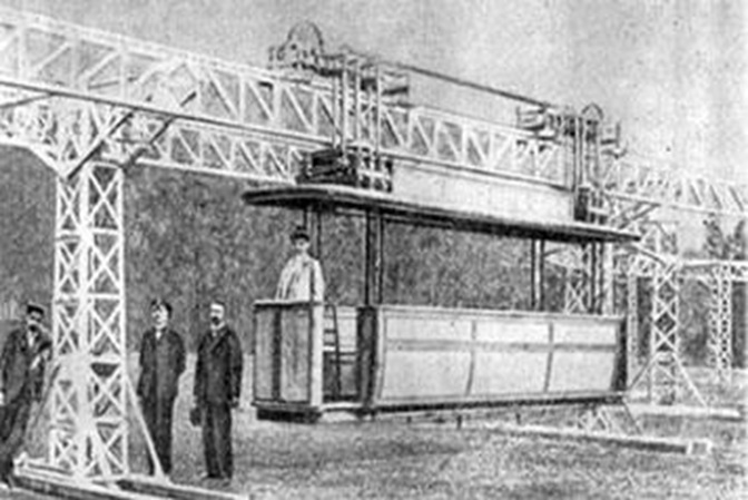
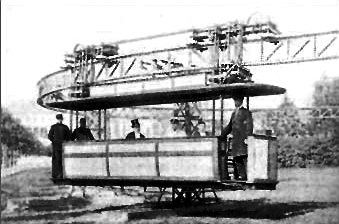
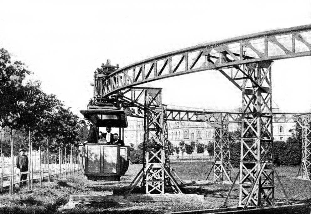
In late 1899, Russian engineer Ippolit Romanov built a prototype of an electric monorail in Odessa, modern-day Ukraine. “In 1897, he presented a functional model of his monorail at the meeting of Russian technological society. This idea was approved by the society, and an experimental electric monorail was built in 1899. In 1900, Empress Maria Fedorovna approved the building of an 0.2 kilometres (0.12 mi) long electric monorail in Gatchina. The monorail was tested on 25th June 1900. The monorail carriage … moved at a speed of 15 kilometres per hour (9.3 mph).” [2] “The cars weighing 1600 kg were made like the trams of that time and were suspended on a truss metal overpass at a height of at least 750 mm from the ground. Based on the published photographs, it can be assumed that the overpass was temporary and rested on long beams laid on the ground. … The car bogies were two-axle, with one running wheel with a diameter of 120 mm. Each bogie also had two pairs of horizontal guides and stabilizing wheels. Two motors with a capacity of 6 kW each operated on direct current with a voltage of 100 V. The electric drive control system provided for the possibility of regenerative braking. Power was supplied from a contact wire on the beam, the beam itself served as a second wire. … On 25th June 1900 (according to V. Nikolaev – 29th June), the monorail was tested. During the tests, the monorail moved with a load of up to 3200 kg (i.e. 2 times the tare weight of the carriage), with this load the speed was 15 km/h. It was noted that the carriage moved smoothly, without jerks and jolts. … According to the journal “Zheleznodorozhnoe Delo” No. 38,1900, the Romanov system … had advantages over foreign designs known at that time. The asymmetrical suspension scheme on an open beam, on the one hand, allowed this beam to be made fairly light and cheap, and on the other hand, allowed the bogies and drive to be made reliable and easy to maintain. … Romanov also put forward the idea of automatic driving of the monorail. In the magazine “Niva” No. 30, 1900 in an article about this monorail it was written: “Since the movement is produced by electrical energy transmitted along a copper wire along the entire route, then this same energy can be used to automatically divide the entire route into sections on which only one train can be at a time. Each train can approach the one in front no more than a certain distance, for example, about 1.5-2 miles. When the distance between trains decreases to this limit, then the train behind stops, although, of course, if necessary, a special device can bring the trains closer to each other to the desired distance. Acceleration or deceleration can be done automatically, so that the inattention or carelessness of the driver is corrected independently of him.” [3]
Oleg Izmerov; The Unknown Russian Monorail; via https://izmerov.narod.ru, accessed on 19th February 2025.
Oleg Izmerov; The death of sensations or strange episodes in domestic monorail history; via https://semafor.narod.ru/3_2001/monor.html, accessed on 19th February 2025. This article covers later developments in Monorail technology in Russia.
V. V. Chirkin, O. S. Petrenko, A. S. Mikhailov, Yu. M. Galonen; Passenger Monorails (in Russian); in Mashinostroenie (Mechanical Engineering), 1969, p240. [see [6] below]
“The source (book) provides basic information on the structure and operating features of monorails. It analyzes the most typical difficulties that arise when solving problems related to transport in modern large industrial centres, developing areas with unfavorable climatic conditions, and finding transport vehicles for direct communication between the centres of large cities, cities with airports, recreation areas, etc. It examines the selection of the main parameters and determination of the technical characteristics of the rolling stock and fixed devices of monorails. It analyzes the design features of the chassis, suspension systems, and stabilization of the rolling stock of existing and designed monorails. … A comparison is made of the technical and economic indicators of monorails and other types of transport, and recommendations are given for the selection of rational areas of application of monorail transport. … The book is intended for a wide range of engineering, technical and scientific workers in urban, industrial and other types of transport, as well as workers engaged in transport engineering.” (Translated from Russian) (https://www.logistics-gr.com/index.php?option=com_content&id=23626&c-72&Itemid=99)
The first Hungarian ‘railway line’ was completed nearly 20 years before the first steam-powered railway in Hungary (which was opened in 1846) on 15th August 1827, and ran from Pest to Kőbánya. [1]
It was one of the early horse-drawn ‘railways’ but was definitely atypical in form!!
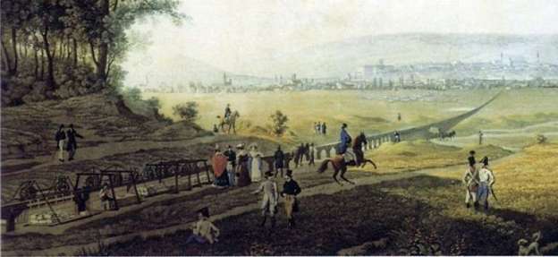
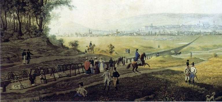
The track of the ‘floating railway’/’suspension Railway’ on an engraving by János Hofbauer. [1][2]
That railway “ran on a wooden structure running at an average height of one and a half to two metres above the ground, where the wooden beams were held by densely placed wooden posts. The wheels ran on very closely spaced rails on top of the beams, and the carriages hung down on either side of the entire structure, therefore floating, i.e. the design was very similar to a monorail.” [1]
“The strange, complicated structure was not a Hungarian invention, it was patented by an Englishman, namely Henry Palmer.” [1][4]
“Palmer made a patent application in 1821 for an elevated single rail supported on a series of pillars in an ordinary distance of ten feet, inserted into conical apertures in the ground, with carriages suspended on both sides, hanging on two wheels the one placed before the other. A horse is connected to the carriage with a towing rope, proceeding on one side of the rail on a towing path.” [4]
There was an earlier monorail in Russia, [5] of which Palmer was unaware. By 1823, George Smart had set up a trial version of Palmer’s monorail. [6]
Palmer wrote in the study presenting his system: “the charge of carrying the raw material to the manufacturing district, and the manufactured article to the market, forming no small proportion of its price to the consumer.[…] The leading problem in our present subject is, to convey any given quantity of weight between two points at the least possible expense.[…] In order to retain a perfectly smooth and hard surface, unencumbered with extraneous obstacles to which the rails near the ground are exposed, it appeared desirable to elevate the surface from the reach of those obstacles and at the same time be released from the impediments occasioned by snows in the winter season.” [7]
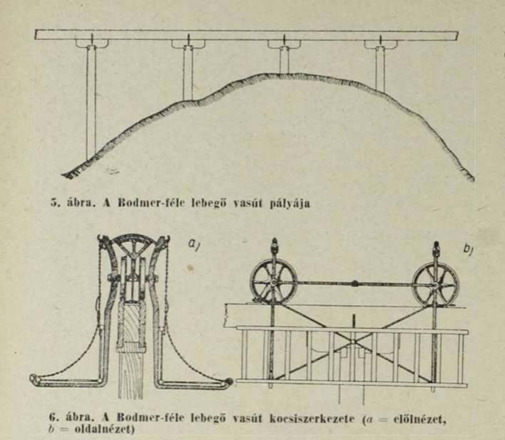
“In the 1820s, this system seemed to be very advantageous, since it was not necessary to raise embankments for its construction, the track could be created with relatively little earthwork, only a suitable amount of wood was needed. Such a railway was experimented with in several places in Europe, and Baden salt mine manager János Gáspár Bodmer jointly applied for a patent with the Austrian company Bollinger & Co. for the construction of a Hungarian network of more than 900 kilometers, which would have connected Pest with Debrecen and Fiume, for example. The costs were correspondingly high, the price of the entire network was set at two million forints.” [1]
Palatine Joseph liked the idea. “Archduke Joseph Anton of Austria … was the 103rd and penultimate Palatine of Hungary who served for over fifty years from 1796 to 1847, after a period as governor in 1795.” [3]
Before the entrepreneurs could get a license covering the entire country, the Palatine first wanted a test track that led from Pest to Kőbánya. “The Pest-Kőbánya route was ideal because the stones and bricks for the constructions in Pest were transported from Kőbánya, and by joining this stone transport business, the railway would have made a profit even on this short section of less than 7 and a half kilometres, according to the plans.” [2]
“Work on the 7.6 kilometre railway section began in May 1827. The company issued shares, a total of 513 shares were sold, among the shareholders were the palatine himself, György Sina, one of the richest men in the empire, as well as the banker Móric Ulmann and István Széchenyi. However, there was not enough money to use hardwood, so they built the course out of pine. The rapid work was hampered by the lack of manpower, so the palatine also ordered the military, but an additional problem was that one of the company partners and also the construction manager, János Bodmer, died unexpectedly in the early summer of 1827.” [1]
“The 1,372-pole line from Pest to Kőbánya was finally completed on 15th August 1827. Its main purpose was to supply Pest with building materials, so it branched off at Kőbánya, one end point was at the Kauser quarry, and the other branch was at the Lechner brick kiln. To facilitate stone transport, the line [was] slightly inclined towards Pest.” [1]
A drawing of the floating/suspension railway (Béla Czére: A pest-kőbányai próbavasút története [The history of the Pest-Kőbánya trial railway], Közlekedéstudományi Szemle, 1957. No. 7-8). [1]
The ceremonial opening took place on 20th August 1827, attended by the Palatine himself and his entire family, who travelled from Pest to Kőbánya on the new railway. The 25th August 1827 issue of Hazai’s Külföldi Tudósítások, commented:
“His High Duchy with his family, and the Deputation, led by Honourable Baron József Venkheim Főispán of Arad, at the city’s new Kőbánya, got on the carriages used for sitting, decorated with two flags with Hungarian colours flying in front of it, and all the way to the Kerepesi line, pulled by a horse, he arrived.” [2]
Palatine Joseph observed the return journey on which “a horse pulled 68 soldiers and a load of 148 Viennese quintal (that is, almost 8.3 tons), and later another train was started, and it was loaded with a total of 27 tons of stone, wool, and 40 barrels of wine. The journey time was approximately 1 hour.” [1]
The investors of the railway line leading from Pest, today’s Baross Square, to Kőbánya, naturally hoped for profit and the right to cover the entire country with their railway line later. Illés Aladár Edvi, in his study of Pest-Kőbánya Trial Railway (issue 7 of 1895 of the Magyar Mérnök és Építész-Egylet bulletin) cites the call made by János Bodmer, which he wrote to the hopeful shareholders:
“In Hungary, one of the most important points to be connected would be the one that would connect Pest, the centre of the country, with Szolnok by road, because goods coming from Poland and the Russian Empire could arrive here on Tisza or the newly built road in Ungvár county; the noble wines of Hegyalja, the linen of Upper Hungary, all of these can be transported to the world market quickly and cheaply from here.” [2]
“The business seemed to be successful, but problems soon appeared. On the one hand, there were not enough cars, i.e. not enough trains could run for the company to generate a profit. Of the existing 11 cars, usually only a maximum of 8 could be used at the same time, the rest had to be repaired, while three times as many, i.e. 24, were supposed to be running constantly, so the planned two trains per day could not always be started.” [1]
In addition, softwood rather than hardwood was used in the construction in order to save money. Hardwood was expensive and difficult to source at the time of construction. This led, however, to high maintenance costs and problems with deformation under load and natural drying of the timber meant that screws loosened and fell out. [1][2]
The wheels were above the cars. “The four wheels – 2 on each side – very close to each other rolled on the iron bands laid on the horizontal beams. Loads or passengers were accommodated in open structures hanging from the sides. The whole thing was drawn by horses, which of course walked on the ground. The idea was not completely unviable, according to reports from the time, a workhorse easily towed a 6-car, loaded assembly, which – converted to SI units – was nearly 14 tons including the weight of the cars.” [2]
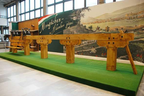
A part of the track and a 2/3 scale reconstruction of the cars at the 2010-2012 exhibition “A hídember gépei” [“The Bridgeman’s Machines”] of the Museum of Transport (Photo: Hungarian Museum of Science, Technology and Transport). [1][2]
The railway could not “run in strong winds, because the structure had a significant defect, which could actually have been easily rectified. Since there were only wheels at the top, four per car, which were located quite close to each other, the cars hanging over the sides were rocked by the wind. This could have been avoided if the carriages were equipped with horizontal wheels that roll on the sides of the beams supporting the track and thus prevent swaying, but neither the freight nor the passenger carriages had such wheels.” [1]
“As early as the spring of 1828, it became clear that the entire line should be rebuilt and replaced with hardwood, and new, horizontal wheels should be placed in the cars, which would reduce the swaying.” [2]
The venture also carried high finance costs. The project exceeded the 20,000 HUF budget, coming in at 31,000 HUF. New shares were issued, but not enough money came in. As a result, the Company owed nearly 5,000 HUF to master carpenter József Spiegel, the head of the construction, who took over the management of the construction after Bodmer’s unexpected death in 1827. [2]
No account appears to have been taken of the state of the market at the time. “The company would have been successful if it had continuously delivered building materials to Pest. However, it would have been necessary to successfully break into an already well-established … market, which would have been possible if the work was taken away from the competitors, who used to carry out the deliveries with carts, or … construction work in Pest … accelerated in such a way that … excess capacity” was required. [2]
The market did not grow and there was no need for additional capacity. The carriers who had been transporting building materials until then were not happy about the competition and formed a cartel to lower their prices, i.e. it was cheaper to transport by cart than by rail.
“At the shareholders’ meeting held on 20th March 1828, the situation was quite hopeless. The railway was already struggling with a debt amounting to 4,339 HUF 35 kreuzer, and it did not generate enough income to start making a profit. To hope for a profit, major improvements would have been necessary, for example, new cars would have had to be purchased. For the continued operation of the railway, and to have enough money for purchases, each shareholder should have had to pay an additional 15 HUF.” [2] This they were not willing to do. so the company ceased operations on 20th March 1828, i.e. after 7 months. The line was dismantled, the timber was sold for firewood, but there were beams that were used at the Chain Bridge. [1][2]
“From the point of view of Pest, the suspension railway was important for several reasons. On the one hand, this investment also confirmed what was stated in law 10 years later, that Pest and Buda are the country’s transport hub. The railway was based on the future hope that Pest [would face] development, not only in the field of construction but also in the field of industrial plants, which [would] require a large increase in land transport [capacity]. It is no coincidence that the railway was a trial section of a line extending to the Tisza and beyond to Debrecen – that is, from where it was not possible to transport by ship. … However, the railway was about 10 years ahead of its time. Only one public railway line operated in one place in the world, England.” [2]
https://en.m.wikipedia.org/wiki/Monorails_in_Russia, (the first Russian monorail was built by Ivan Elmanov in Myachkovo village, near Moscow in 1820. In this road on pillars”, horses pulled railroad carriages placed on a horizontal beam. The wheels were mounted on the beam, not on the carriages. Elmanov could not find investors to fund for his project, and stopped working on the monorail); accessed on 6th February 2025.
Anton Howes; Smart, George; in the Oxford Dictionary of National Biography. Oxford University Press, Oxford, 2004.
Henry R. Palmer, Palmer’s Observations on Railways / Description of a Railway on a New Principle; J. Taylor, London, 1823, p1, 2, 33, 34–35; via https://archive.org/details/bub_gb_HezfU0-Af4QC, accessed on 6th February 2025.
‘Telfer’ or ‘Telfere elettrico’, was a monorail railway line built in Genoa in 1914, the first of its kind built in Italy. The name was derived from the English term ‘telpher’. [1]
In this case, the ‘Telfer’ was a monorail. Examples of telphers in the UK include one at Manchester Victoria Railway Station which is described here. [6]
The term has more normally been used for the moving element of a beam crane used in warehouses or other industrial settings. [6]
Given the Telfer’s link to the English word ‘Telpher’ then strictly speaking ‘Telfer’ should be assumed to apply to the moving element of this short term transport solution in Genoa which could itself, perhaps, be considered to be a monorail.
The Telfer was installed for the Italian Colonial International Exhibition of Marine and Marine Hygiene which opened in May 1914 and closed in November of the same year. [7]
In an historical period when European powers were involved in colonial expansion. The stated aim of the Exhibition was to show the developments in the sectors of hygiene and maritime trade, but ultimately it was an opportunity for Italy to celebrate its colonial conquests! [7]
The Telfer connected Piazza di Francia (the south-eastern part of the current Piazza della Vittoria) to the Giano pier of the port, near the new Harbour Master’s Office. It was managed by UITE (Società Unione Italiana Tramways Elettrici).
The Telfer was originally intended for Milan, to connect Milan with the residential area of Milanino, approximately 8 km from the city. That project never came to fruition.
Instead, a shorter version was built in just 100 days for the Exhibition in Genoa. The Telfer entered service on 18th June 1914 and served throughout the time of the exhibition. It was later modified for the transport of goods, in particular coal, from the port to the factories located along the Bisagno. It continued to function throughout the period of the First World War but was dismantled in 1918.
Italian patents for the system were held by BBB (the Badoni Bellani Benazzoli Company of Milan). [4]
The Italian Wikipedia tells us that “the line was traversed by a single, symmetrical train, which ran on its own track formed by a beam raised from the ground, with a running rail at the top and two lateral ones for support and guidance. For the support piers, reinforced concrete was used. … The monorail beams were of an inverted T section, 85 cm wide at the base and 190 cm in height, over which Vignoles 36 kg/m rail was fixed on oak stringers. … Along the lower edges of the inverted T beams, two guides for the horizontal wheels were provided, made from L-shaped bars. … The items of rolling-stock sat astride the beam and were supported by hooded double-edged central wheels. They had lateral appendages extended downwards for the guide rollers.” [1]
“Seats were arranged in four longitudinal rows, two on each side, stacked in steps, with the backrests on the inside. Each ‘carriage’ had 38 seats and 12 standing places, or with the seats folded down a standing capacity of 80 passengers could be achieved. There were three access doors on each side. … The ‘locomotive’ had four 700 mm wheels, all powered, each connected to an AEG Thomson-Houston 40 hp 500 V engine regulated by controller as used for electric trams. The brake was compressed air with a double shoe for each wheel.” [1]
“As the driver’s position in the train was at the centre of the convoy (the locomotive was at the centre of the train), automatic safety devices were placed to stop the train at the station. The entire convoy when fully loaded carried about 350 people and weighed 80 tons. All the rolling stock was built by Carminati & Toselli of Milan.” [1]
The Route of the Telfer Monorail
A map from around 1914 (shown in full above) shows the route of the line. Segments of the line follow together with appropriate supporting images.
The Telfer’s Northeast terminus was in the southern corner of Piazza d’Armi above the River (Torrent) Bisagno, close to the Bezzecca Bridge which at the time was the first structure spanning the river North of its outfall into the Mediterranean. Piazza d’Armi became Piazza di Francia and later Piazza Della Vittoria.
Piazza Della Vittoria with its triumphal arch is at the top of this extract from Google’s satellite imagery. [Google Maps, November 2024]
The route crossed the Corso Aurelio Saffi by means of a 26 metre span skew bowstring concrete arch bridge and ran straight down the West side of the river channel on the road known as Via del Feritore at that time. The line hugged the base of the high retaining wall and, in doing so, curved round to the West.
The Telfer passed through the Stella Batterie by means of widened windows. [1][3: p103]
The line then ran straight to the landward end of Pier Giano, cutting across the stretch of water in front of the Cava baths like a viaduct. A curve as tight as 50 metre radius took the Telpher onto the pier and the line continued for some 370 metres. [1]
The entire route was just over 2.2 km in length, with an average height above ground of 4 m. Except for the short stretch on the Giano pier, which was made of wood, the route was fabricated in reinforced concrete and was supported on a total of 72 piers. A third of the piers sat directly in the sea. [1]
The route was travelled at a speed of 20-30 km/h and was completed in about seven minutes. [3] The train ran every half hour from 9:00 to 24:00, A single ticket cost 1.00 lire (about 3.70 euros today), a return ticket 1.50 lire (about 5.50 euros today), there were concessions for shareholders, military personnel, children and groups. [1][3: p99]
http://www.uwrbancenter.comune.genova.it/sites/default/files/quaderno_arch_2011_03_21.pdf, accessed on 16th November 2024, p17. …..”The first monorail in Europe: On 14th June 1914, the first monorail built in Europe was inaugurated in Genoa. It was built for the International Exhibition that occupied the area of the current Piazza della Vittoria and Via Diaze hosted numerous exhibitions set up inside pavilions designed largely by the architect Coppedè. The “Telfer elettrico” (or “suspended or aerial railway”) connected the “aerial” station, located inside the Exhibition, to the port, at Molo Giano, where the exhibition pavilion of the Consorzio Autonomo del Porto was located. The Telfer was 2227 m long and followed, approximately, the route of the current Viale Brigate Partigiane and part of the current Aldo Moro flyover: to cross the final part of Corso Aurelio Saffi a parabolic bridge with a span of 28 m was built, a true “work of art”. The Telfer consisted of a monorail suspended on wooden or concrete beams resting on triangular-shaped supports and an electric traction train that moved in both directions, placed astride the beam and composed of a central locomotive that drove two or four carriages. The carriages had a capacity of 46 seats or, alternatively, 80 standing places. The Telfer reached a maximum speed of between 20 and 30 km/h and took eight minutes to complete the entire journey. It was built in one hundred and fifty days of actual work and had seen the employment of more than six hundred workers. It could have been used, after the closing of the exhibition, for the transport of people or goods, but unfortunately the war events imposed the dismantling of the monorail and the partial reuse of the materials.”
Bibliography
Enrico Pieri, Il “Telfer” di Genova, in Strade Ferrate , n. 16, ottobre 1983, pp. 22-27.
Marco Marchisio, Il Telfer di Genova, in Tutto treno & storia, n. 14, novembre 2005, pp. 30-43.
Lorenzo Bortolin, TELFER, la monorotaia di Genova, in I Treni Oggi, n. 16, gennaio 1982, pp. 20–21.
Cornolò Ogliari, Si viaggia anche … così, Milano, Arcipelago edizioni, 2002, ISBN88-7695-228-4.
Stefano Percivale (da un progetto di), Genova com’era Genova com’è, Genova, Fratelli Frilli Editori, 2008.
Franco Rebagliati, Franco Dell’Amico, Giovanni Gallotti e Magno Di Murro, Il Telfer, in In tram da Savona a Vado 1912-1948, L. Editrice, 2012, pp. 68–71, ISBN 978-88-95955-73-5.
Massimo Minella, Il Telfer, una monorotaia sull’acqua, in 1914 – L’Esposizione Internazionale di Genova, De Ferrari, Genova, 2014, pp. 99–111. ISBN 978-88-6405-564-0.