The apostle Paul writes in I Corinthians 1:27 – “But God chose the foolish things of the world to shame the wise; God chose the weak things of the world to shame the strong.”
I want to invite you to travel with me in your imagination, back to another time and place. … If it is helpful, you might want to close your eyes. … It’s an unbelievable place. It has a sense of heavy quietness about it. You might know what I mean. I suppose, it’s like a cathedral. People are talking to each other in hushed tones. … Yet it still feels quiet.
Countless people from every nation under the sun are here. Some splendidly dressed in their finery, some carrying the tools of their trade – blacksmiths, … jewellers, … carpenters. Others, clearly with little money, have made every effort to look their best.
It is the 5th Century BC and as we scan the wide room we can see people of authority and power; Kings of Babylon, Media, Persia and Egypt stand erect and tall with their courtiers in attendance. Other kings and queens from unknown parts of the world are also here – Incas, Aztecs, Chinese, Indian and Ceylonese – everyone is here, with their monarchs standing proud in front of them.
This is no ordinary kind of cathedral, it’s too grand and large for that. The walls – too far away to see, the roof – higher and wider than anything we’ve ever seen. No columns hinder the view. The splendour of the room is beyond telling – it’s as though everything is covered in gold, silver, and precious jewels. … Yet despite all this beauty everything in the room seems to point to its centre.
On a raised platform is a magnificent throne. It’s like looking at the sun – seemingly all of the light in the room comes from that throne – … it is dazzlingly bright. It seems that wherever you are in the room the throne dominates your view.
Then, without any warning, everyone is suddenly aware of someone on that throne – the hushed conversation draws quiet. This is the moment we’re waiting for. … Our host stands up and as they move forward the brightness which had seemed to come from the throne moves too. No one needs to say anything – everyone around us just knows who this is. The whole room is first on its knees, and then flat on its face before God.
Our invitation to the heavenly court, said that God would be announcing his plans. Plans that mean declaring a chosen nation who will know God, and who’ll make God’s character known throughout the world. …
All of the kings and queens are ready – jealously wondering which of them God will choose. …………………. One word from God and everyone is standing once again; eagerly straining to see who it is. … Who has God chosen? …………..
From the back of the hall, somewhere behind the King of Babylon, a scruffy beggar stands and walks unsteadily forward to the throne. Some in the crowd look the other way as he passes, others try to stop him. It is only the voice of God which holds them still.
God welcomes the beggar at the centre of the throne-room and crowns him … ‘The Servant of the Lord‘. … It turns out that he is Israel, one of the small nations that have been conquered by Babylon. Insignificant, unimportant and of no consequence. What is God doing, choosing this non-entity, this tiny country, Israel? ……………..
As you think about that question, take a moment to adjust back to being here, wherever you are now, reading this blog …………….
I have tried to help you to understand the picture that chapters 40 to 55 of Isaiah want us to see.
Israel was a nation on its knees. Its people were in exile, depressed, defeated and angry; … God must have deserted them for ever – or so it seemed. A once proud nation, they were now snivelling with self-pity, full of shame and guilt. … Yet, in Isaiah 40 and 41 it is almost as though God whispers words of encouragement to this beggar Israel as he walks forward through the jealous and condemning ranks of the nations. Listen to his words:
Comfort, comfort my people, says your God. Speak tenderly to Jerusalem, and proclaim to her that her hard service has been completed, that her sin has been paid for.
My people, I took you from the ends of the earth, from its farthest corners I called you. I said, “You are my servant”; I have chosen you and have not rejected you.
So do not fear, for I am with you; do not be dismayed, for I am your God. I will strengthen you and help you; I will uphold you with my righteous right hand.
In Isaiah 42, God presents Israel to the nations as his servant. God confirms his love and protection of Israel and commissions Israel to serve him again.
With hindsight, we know that Israel never lived up to its calling.
As Christians we see these passages of Isaiah pointing forward to another Servant of the Lord, to Jesus. The one who through death and resurrection brings healing to the distressed, binds up the wounded and releases all sorts of captives from prison. In our Gospel reading Jesus receives the same kind of blessing from God:
“This is my Son, the Beloved, with whom I am well pleased.”
But even with Jesus this passage has not been fully fulfilled. Jesus once said: “As the Father sent me so I send you.” Jesus passes on to us both the privileges and responsibilities of being the Servant of the Lord. We are called to bring justice, to be a light to the nations. Ultimately, it is us that God is speaking to in the Isaiah passage. He wants us to hear his encouragement as he picks us up, dusts us down and sets us on our way again.
God knows that we so easily see ourselves as Israel saw itself – depressed and defeated – often struggling with self-pity, and full of shame and guilt. Or at times we see ourselves as right when others are wrong, we seek to build ourselves up at others expense, we cannot hear God’s love for us because we are so busy trying to establish our own reputation against that of others.
And we are no different to Israel. Weak, mis-understood, seemingly at the end of ourselves, seemingly without answers to the problems of our day and if we are not very careful, seeing everyone else as the problems rather than ourselves. Whether it be our lack of numbers, the suffering and injustice of our world or the disregard of spiritual things by so many people, we have no overwhelmingly obvious, argument settling answers to the difficulties that life brings. Yet God speaks to us in the same way as he spoke to Israel. “You are my servants,” he says. God speaks to us in the same way that he spoke to Jesus ….
“My son, my daughter, my Beloved, with whom I am well pleased.”
God wants us to hear his words of comfort, to hold onto them as our own. To listen to his challenge to bring justice, to bring his assurance and to shed his light into the lives of those outside of the church community. God wants us to be those who show love and compassion, who because we are loved by God give space for others to flourish, God wants us to be those who because we are loved do not need to compete for affection and status, a people who build others up rather than tear them down.
The truth is that it is our recognition of our own weakness that will mean that God can work through us to bring healing to our world.
I Corinthians 1:27 – But God chose the foolish things of the world to shame the wise; God chose the weak things of the world to shame the strong.
O God, by the leading of a star you manifested your only Son to the peoples of the earth: Lead us, who know you now by faith, to your presence, where we may see your glory face to face; through Jesus Christ our Lord, who lives and reigns with you and the Holy Spirit, one God, now and for ever. Amen.
Sermon
Today we celebrate the Epiphany. The visit of the Wise Men bringing gifts to the baby Jesus. I’d like us to think about two different aspects of the story this morning.
Firstly, we are told that the Wise Men who came to Jesus were guided by a star.
Second, The Epiphany and the arrival of the Wise Men is the moment when the wider Gentile, non-Jewish, world first engages with the story of Christmas. It is the point at which the birth becomes good news for the whole world, Good news to be shared.
We are told that the Wise Men who came to Jesus were guided by a star throughout their long journey. We use maps to guide us – or at least we used to. Many of us now use some form of satellite navigation to help us find our destination when we are in the car. Jo and I tend to use the directions provided by Google Maps. If you do not have a satnav or a hands-free mobile phone, then you will still rely on a map when you are driving. And a map of some sort is still useful to those of us who enjoy walking. When walking you might also follow a guided route for a country walk – either one on paper or one that has signs, way-markers along the route.
What matters most is that the guide we use is reliable. … We’ve all heard stories of lorries using satellite navigation getting stuck in country lanes or under bridges. … I’ve followed guided walks where either the written description is not good enough, or where someone has maliciously changed the waymarks and I have got lost. …
In life just as in driving or walking we need a reliable guide. A guide that we can trust. We have guides to follow in our Christian lives. The bibles that many of us own, are perhaps our clearest guide for the journey. How familiar are we with our bibles. Do we keep them on the bookshelf and only take them out sporadically? Some of us are overwhelmed by the amazing language of the King James’ Bible and celebrate it as a wonderful work of literature. However, this was not quite God’s intention, when he gave us his word. The beauty of the language, or the excellence of the binding, while of great value, are not what really matters. … It is no good having a map, or guidebook or satellite navigation system and then putting them in view on the mantelpiece or on the dashboard of the car and never using them, never switching them on. They are only valuable if they are used as they were intended to be.
The Wise Men saw the star and chose to follow it. We don’t really know what it was, perhaps a comet that moved gradually across the night sky, night by night. The wise men studied the heavens and when they saw this particular star they knew what it spoke of. But knowing what it was about was not enough. They had to follow where it led. Otherwise, the Star would have been of little value. … So it is, with all that God promises in his word. We need to hear what the bible has to say to us about who we are and how we should relate to others. We need to make God’s word and promises our own. God is with us, and will be with us in the year ahead.
The poem “The Gate of the Year” by Minnie Louise Haskins, was famously quoted by King George VI in his 1939 Christmas broadcast in the early months of World War II: “I said to the man who stood at the gate of the year. “Give me a light that I may tread safely into the unknown.” And he replied. “Go out into the darkness and put your hand into the hand of God. That shall be to you better than light and safer than a known way.” May that Almighty hand guide and uphold us all in uncertain times, enabling us to trust in divine guidance as 2026 unfolds.
So, the Epiphany speaks of God’s guidance.
But it is also so much more! It is the moment when the curtain is drawn aside and the whole world looks in on the birth of the Jewish Messiah. The Epiphany is the point when the Christmas story makes it clear that the Christ-child is not just the Jewish Messiah, but is Saviour of the World. What was once known only to the Holy Family and shepherds at Christmas is made known to a greater and a wider audience in the group of wisemen who visit sometime after Jesus’ birth.
In this season of Epiphany, Jesus is ‘revealed’ as Son of God to the Wise Men who come to worship and give their tribute. Jesus’ Epiphany as Son of God reaches out to all the nations on earth. … So today we celebrate Jesus as our Saviour. As well as him being the Jewish Messiah.
“Come and see,” say the shepherds and the wise men. “Come and follow.” But perhaps most importantly of all; “Go and tell.” ……..
The season of Epiphany is all about mission.
Epiphany is our special season of being sent out as God’s people, guided by the grace and love of God. This season of the Epiphany gives direction to our lives as God’s missionary people. The scriptures call us on to follow Christ, in the way we choose to relate to each other, in living the lives God calls us to, in witnessing to the love of God which conquers all adversity. Epiphany reminds us that people should be able to see in us the life and love of the Christ-child.
Epiphany reminds us that if we follow God’s guidance, in seeking to welcome all. If we endeavour to offer God’s inclusive welcome – welcoming the stranger, welcoming those different from us, welcoming those we find challenging, and those we fundamentally disagree with. If we truly are a welcoming and loving community, quietly and faithfully getting on with the business of being God’s welcoming people, we will become so attractive that we will draw others to faith in Christ.
Just a snap shot of the things appearing in the March 1959 issue of The Railway Magazine. [1]
1. There were adverts on the inside of the front cover – 5 of them. …. [1: pii]
Page ii of the March 1959 Railway Magazine.
The 34th Model Railway Club Model Railway Exhibition was due to take place in Easter Week. It would run from Tuesday March 31st to Saturday April 4th at Central Hall Westminster. On Tuesday provision appears to have been made for the final setting up of layouts, with the exhibition not opening until 12 noon, but the show was to be open until 9.00 pm each evening with an opening time of 10.30am for the remainder of the week.
I wonder what today’s exhibitors and exhibition managers would feel about a show that was 5 days long and a total of 52 hours of operating time? Much of the work setting up for the exhibition must have taken place on the Bank Holiday Monday and dismantling may well have taken place on the Sunday. There must have been quite a few people who gave up a full week’s leave for the sake of the show! Think too of the logistics of providing refreshments for a week-long show!
Getty Images hold a picture of two young boys enjoying a close interaction with some large scale model trams. The image can be found here. [2]
Three of the five adverts on page ii of the magazine related to books. One was for Foyles Bookshop and their newly opened travel bureau in London. Another was for the 5th Edition of ‘World Railways’ – 1,500 railways in 100 countries, 33 underground systems, 291 major manufacturers – published by Sampson Low, London. [3]
Just published in 1959 was O. S. Nock’s, ‘Historical Steam Locomotives’ – An illustrated history of British Locomotives down to the time of the grouping. [4]
And the remaining advert was for the Railway Correspondence & Travel Society’s ‘The Railway Observer’. The advert also highlighted the activities of the RCTS – branches throughout the country, a rail tours library, visits to depots and installations, affiliations to societies overseas and photographic & technical sections!
2. Metrovick Diesel-Electric Traction
Metropolitan Vickers Electrical Co. Ltd took out a full page advert for their new Co-Bo Diesel Electric Locomotive under a banner headline of “Chosen for Midland Region Modernisation.”
The Metrovick Co-Bo Locomotives were assembled at the Company’s Trafford Park works. The motors, generators and auxiliaries were made at their Sheffield works, the control gear at Trafford Park and mechanical parts at the Metropolitan-Vickers-Beyer-Peacock-Ltd., Stockton-on-Tees. [1: piv]
3. Editorial Notes highlight some of the concerns over the readership at the time and changes in the railway world. These included:
Open-Type Coaches on BR – In the correspondence columns of the January issue of the magazine there was a letter critical of the British Transport Commission decision to build no more corridor-compartment stock. The March editorial reflects the magazine’s post bag which asks BR to think again! [1: p147] Wikipedia suggests that the corridor stock was still being built until the mid-1960s, so perhaps campaigners were successful. It is also interesting to note that the Mk 1 corridor-compartment stock were in use on BR lines well into the 1980s and are still in use on heritage lines. … “The British Railways Mark 1 SK was the most numerous carriage design ever built in the United Kingdom. The original number series carried was 24000–26217. From 1983, those carriages in the 25xxx and 26xxx series were renumbered 18xxx and 19xxx. … There were two variants, those built for the Midland, Scottish, and Eastern / North Eastern regions had six seats per compartment, with fold-up arm-rests which folded into the seat-back, while those built for the Southern and Western regions, with their heavy commuter loadings into London, had eight seats in each compartment, and no arm-rests. Seating was of the interior sprung bench type.” [5]
Reservation of Sleeping Berths – apparently, by 1959, it had become common practice for passengers to reserve berths on a number of different sleeper services on British Railways, before finally deciding which service to use. Br brought in revised arrangements on 1st February 1959 which were designed to eliminate disappointment for those who were definitely planning to use a specific service. From February 1959, “Reservations [were] made only on payment of the full fees for the berths required, and three-quarters of this amount [would] be refunded to those who cancel before 4 p.m. on the day before that for which the berths have been booked. No refund [was] be made if cancellations [were] received after that time, except to those whose names [had] been placed on the waiting list, and from whom fees [had] been accepted subject to accommodation being available. Full repayment [was] made to those travellers if berths [did] not become vacant. … The new arrangements [ended] the selfish practice of making alternative reservations on different trains or days.” [1: p147]
London Midland Region Freight Traffic – “At the end of 1958, two-thirds of the business of the London Midland Region of British Railways [was] derived from freight. To attract new – and regain lost – traffic, a comprehensive short-term plan [was] evolved to streamline the whole of its freight transport. [It was planned that, before the mid-1960s, freight handling would] be speeded by [a] reduction in the number of marshalling yards, … from the [then] 111 to 46, and of depots for traffic from 170 to 48; many of those remaining [would] be extensively modernised. The value of the growing door-to-door service, with railhead collection and delivery by road vehicles, [would] be enhanced by the implementation of the plan. There already [were] about 600 regular overnight express freight trains in the Region, and movement [would] be further accelerated as more wagons [were] fitted with vacuum brakes, and diesel locomotives introduced. [It was thought that] if traders and manufacturers [could] be assured of new standards of service and reliability, the plan should show an early and satisfying financial return.” [1: p147] At a similar time, containerised freight was being developed. Wikipedia tells us that “the marshalling yard building programme was a failure, being based on a belief in the continued viability of wagon-load traffic in the face of increasingly effective road competition, and lacking effective forward planning or realistic assessments of future freight.” [6][7]
Handling of Mail/Parcels at Euston – in March 1959 structural alterations were underway which would love facilities for handling outward parcels traffic at Euston Station. By the end of 1959, passengers would be able to approach the booking offices and departure platforms without being delayed/impeded by long trains of barrows. Post Office lettermail , under new arrangements would be brought direct to the parcels office on No. 11 platform for loading into vans. The Railway Magazine reported that “A new building [was] to be provided above the station for the sorting and despatch of railway parcels, which [would] be sent by overhead lifts to the platforms for loading. An overhead conveyor, spanning the main departure lines, [would] take parcel post to the platforms from a new G.P.O. sorting depot.” [1: p148] One wonders whether the proposed arrangements would be similar to the ‘telpher‘ which for a time served Manchester Victoria Station. [8]
Diesels for Scotland – the editor also heralded and welcomed Diesel motive power on the East Coast Main Line North of Newcastle. The welcome was based on the likely acceleration of many services in the Scottish Region. “Between Edinburgh and Aberdeen, for example, almost every start from the principal intermediate stops has to be made up a sharply rising gradient, on which the high starting tractive effort of diesel locomotives would be most welcome. The maximum mileage for diesel power could be obtained by basing the locomotives on Edinburgh, and using them at night for the heavy traffic to and from Newcastle. By day they could work on the Newcastle and Aberdeen services, and perhaps between Edinburgh, Perth and Inverness. The last-named, with its long and steep gradients, is yet another route on which the high tractive effort of diesel locomotives could be used to advantage.” [1: p148]
Improvements to the Hertford North Line – work that could well have taken two or three years had been condensed into the first half of 1959, with a likely completion date in June 1959. Off-peak services between Wood Green and Hertford North had been replaced by buses. Work was phased so that the 6.5 miles from Wood Green to Crews Hill was undertaken in March, the next 8 miles to Hertford being worked on in April, May and June. All services on the branch would then be DMU.s or diesel-hauled “and maximum speeds of 70 mph … permitted. Improvement of the track is an essential preliminary to electrification.” [1: p148]
London Underground – apparently delays to some services had been caused by passengers refusing to move from one train to another when equipment failure has occurred or because a train was running far behind schedule. Lack of information was cited as the cause. London Underground was, in March 1959, installing new train information systems, a move welcomed by The Railway Magazine. [1: p148]
1910 – Rail versus Air – the editor also looked back to 1910 and specifically to the fist flight between London and Manchester. Which was a competitive exercise with a large prize of £10,000 offered by The Daily Mail. The two competitors, Louis Paulhan and Claude Grahame-White, chose to follow the LNWR main line. The company assisted by painting distinctive marks on sleepers to show where branch lines diverged (presumably to ensure the aeroplanes continued on the main line). Apparently, The Railway Gazette at the time said: “The flying machine may possibly become a serious competitor of the railway before very many years. … Both the aviators have been aided and abetted by the Premier Line in such ways as the provision of inspection cars in which to travel over the route beforehand, whilst a special train followed Mr. Paulhan all the way.” [1: p148][1: p167-168, 200]
The route of the London to Manchester flight – along the LNWR main line. [1: p167]
4. Railbuses on Western Region Branches
A short note appeared at the bottom of the pages proceeding the central photographic pages of the magazine. That note marked the introduction of diesel railbuses on the Kemble to Cirencester and Kemble to Tetbury branches of the Western Region on 2nd February 1959. These were the first sections of the Western Region to be served in this way. The railbuses accommodated “48 passengers with a small area for luggage. The services over both branches [had] been intensified. In addition, new halt facilities [were] afforded at Chesterton Lane on the Cirencester branch, and at Church’s Hill, Culkerton and Trouble House on the Tetbury branch.” [1: p172]
The Railway Magazine of March 1959 also included substantial articles:
The Railways of Barrow by Dr M.J. Andrews, [1: p149-157, p200];
Farewell to the ‘Leicesters’ by R.S.McNaught, [1: p158-160, p192];
The first part of Reminiscences of a Locomotive Engineer by George W. Mcard, [1: p161-165]; With 4 ft 7.25 in Wheels by K. Hoole, [1: p168-172];
British Locomotive Practice and Performance part of a long series by O.S. Nock, [1: p185-192];
The second part of Railway Development in Liverpool by M.D. Grenville & G.O. Holt, [1: p193-200];
New Railways in Quebec, [1: p201-203, p206]; and
A full list of British Railways Motive Power Depots. [1: p204-206]
6. Notes and News
Notes & News fill eight pages [1: p210-217] after three pages of letters. [1: p207-209] The Railway Magazine reported that:
Cheaper first class fares on Saturdays would be extended, after an experimental period on services between London and Manchester, to journeys between London and Liverpool, London and Glasgow and London and Edinburgh until the end of April. Return journeys could only be made on the next day or the following Saturday with no breaks in journeys permitted. [1: p210]
Little still remained, in 1959, of the Saundersfoot Railway other than tunnels and a few ruined buildings. Reference was made to an article in The Railway Magazine’s November-December 1946 issue. More can be found about this narrow gauge line in two articles, here [10] & here. [11] There is also a note about the Cambrian Hotel at Saundersfoot. The hotel’s sign bore a shield which contained a gold 2-2-0 tender loco with a wagon on a red background. [1: p210]
Construction work had just commenced on the new Oxford Road Station in Manchester [1: p210-211] and on major alterations to Dover Marine Station in Kent. [1: p211]
Some Western Region Train Services had seen timetable alterations as of January 1959. [1: p211]
More Diesel Services on the North Eastern Region – January 1959 saw the introduction of many additional diesel-powered workings on local services. The early 1959 introductions meant that the switch from steam to diesel on local services was almost complete. [1: p211]
From 2nd February, the 8.15 am up and the 4.45 pm down services between St. Pancras and Nottingham Midland Station were named the ‘Robin Hood‘. [1: p211]
2nd February saw five station closures on the Eastern Region: Offord & Buckden, near Huntingdon; Sturton, and Blyton, between Retford and Barnetby; and Haxey & Epworth, and Walkeringham, between Doncaster and Gainsborough. Greenock Princes Pier and Greenock Lynedoch Stations on the Scottish Region also closed on 2nd February. As did the Upper Port Glasgow goods depot. In the North Eastern Region, from 16th February, Gristhorpe Station, on the Hull-Scarborough line, was closed. On 28th February, the service from Acton Town to South Action was withdrawn and the Station at South Acton was closed to passengers. [1: p211, p212]
The South Wales Transport Bill permitting the closure of the Swansea & Mumbles Railway had its second reading in the House of Lords in February. [1: p212]
The 3 ft gauge Cavan and Leitrim Railway would close on 1st April. More about this line can be found here, [12] here, [13] here, [14] here, [15] here, [16] here, [17] here, [18] here, [19] here, [20] and here. [21] [1: p212]
The Bluebell Line – efforts were being made to establish a preservation society to reopen the Lewes to East Grinstead branch. Volunteers were being sought and an inaugural meeting arranged on 15th March in Haywards Heath. [1: p212] The Bluebell Line became the UK’s first preserved standard-gauge line in 1960, starting with the Sheffield Park to Horsted Keynes section, and later extended to East Grinstead. The first public service ran on 7th August 1960. [22]
Other items included details of: an educational tour by the Scottish Region’s Television Train, [1: p212]; new Electrically-Operated Train Departure Indicators at Shenfield [1: p212-213]; the LNWR Royal Saloon which had been on display at the Furniture Exhibition (January 28th to February 7th) at Earls Court, [1: p213]; the Golden Jubilee of the Stephenson Locomotive Society, [1: p213]; the AGM of the Festiniog (STET) Railway Society and the special trains being organised across the country to get delegates to and from the meeting, [1: p213]; Railway Enthusiasts’ Club Tours, [1: p213-214] news associated with Locomotives. [1: p214-217]
7. The Why and the Wherefore [1: p218-219] includes a series of replies to readers’ letters, particularly:
The North Sunderland Railway – which opened in August 1898 for goods and December 1898 for passengers, and closed on 27th October 1951. [1: p218] The branch ran from Chathill to Seahouses, with an intermediate station at North Sunderland. Chathill was on the main line of the North Eastern Railway between Morpeth and Berwick. The branch was four miles in length and standard-gauge single track. [23]
Water Troughs on the Southern Region – the former Southern Railway had no water Troughs as none of its non-stop runs were long enough to warrant replenishment of water levels. [1: p218-219]
Chalvey Halt (GWR) – was on the G.W.R. branch from Slough to Windsor. It had only a short life: opened on 6th May 1929, and closed on 7th July 1930.
Proposed New Branch to Looe – “a new seven-mile branch from St. Germans to Looe was projected by the Great Western Railway under the £30 million Government scheme of November, 1935, for the construction and improvement of railways, to alleviate unemployment. The branch was to leave the main line to Penzance about 13 miles west of St. Germans Station, and terminate at a station on the high ground at East Looe. The engineering works were heavy, and included a tunnel 2,288 yd. long, west of Downderry, two shorter tunnels, and long viaducts at Keveral and Mildendreath. The construction of the four miles from Looe to Keveral (which included both viaducts and the long tunnel) had been begun by the autumn of 1937, but this section was far from complete, and the remainder of the line had not been begun when the outbreak of war, in September, 1939, caused the works to be suspended.” [1: p219] Early in 1959, construction had not been resumed, and there appeared to be little prospect that the scheme would be revived. The new line was intended to replace the existing line from Liskeard to Looe. [24]
TheStirling & Dunfermline Railway – “was authorised on 16th July 1846, and was opened from Dunfermline to Alloa on 28th August 1850, and from Alloa to Stirling on 1st July 1852. Powers for branches from Alloa to Tillicoultry and to Alloa Harbour were included in the Act of Incorporation, and these lines were brought into use on 3rd June 1851, the former to a temporary terminus at Glenfoot, about half a mile short of Tillicoultry. The line probably was completed in December 1851, but a record of the exact date of opening to Tillicoultry Station does not appear to have survived. The Alloa Harbour branch had passenger services (to Alloa Ferry) only from its opening until the main line was completed to Stirling, some twelve months later. Provision was made in the Act of 1846 for the Stirling & Dunfermline Railway to be leased by the Edinburgh & Glasgow Railway … the lease came into effect on 5th December 1850. The Stirling & Dunfermline Railway was vested in the Edinburgh & Glasgow as from 4th June 1858, under powers obtained on the 28th of that month.” [1: p219] The line was completed throughout in 1952. “A predecessor line, the Alloa Waggonway, had been developed as a horse-operated waggonway in the 18th century, bringing coal from the hinterland to Alloa and Clackmannan harbours; in its day th[at] line was technologically advanced, but it was eclipsed by the modern Stirling and Dunfermline line.” [25]
Closure was a drawn out affair – passenger trains on the Alva branch ceased to run from 1st November 1954. A limited service to Menstrie continued until complete closure on 2nd March 1964. The S&DR Tillicoultry branch, by then regarded as part of the Devon Valley line, closed to passengers on 15th June 1964 and to goods traffic on 25th June 1973.
NBR route passenger trains over the Alloa Viaduct were withdrawn from 29 January 1968, and through goods train operation ceased in May 1968. A limited goods service to supply coal to the stationary steam engine that operated the Forth Swing Bridge from Alloa continued until May 1970.
Passenger services on the Stirling to Dunfermline main line were closed on 7th October 1968; through goods services were closed on 10th October 1979. West of Dunfermline, the line through Dunfermline Upper station served Oakley Colliery until 1986 when the pit closed. The line remained in place as far as Oakley until 1993, but subsequently the majority of the route became Cycle paths in 1999 as National Route 764. Shortly afterwards, studies began for the reopening of the western end of the line from Stirling to Alloa, as part of the Stirling-Alloa-Kincardine rail link. [25]
Enginemen’s Wages and Duties – In March 1959, wages of a first class driver and fireman on British Railways were £11 9s and £9 10s respectively. These rates were the same inside London as outside the London area. “A good day’s work for an engine crew [was] considered to be 140 miles, and on stopping trains most men did] considerably less. If they [did] more than 140 miles, they receive[d] an hour’s pay for each additional 15 miles. They also receive[d] overtime at the usual rate of time-and-a-quarter for time worked over their normal hours of duty, and night pay at time-and-a-quarter, and Sunday pay at time-and-three-quarters, if applicable. The standard basic turn of duty [was] eight hours. At all main-line depots, the duties of drivers and firemen [were] arranged in links, progressing from junior work, such as shunting, to express passenger trains. On the West of England line of the Western Region … a typical example of a week’s roster for a driver [was]:- Monday: 9.30 a.m., spare; Tuesday: 3.30 p.m., Paddington to Plymouth; Wednesday: 8.30 a.m., Plymouth to Paddington; Thursday: 3.30 p.m., Paddington to Plymouth; Friday: 8.30 a.m., Plymouth to Paddington; Saturday: 9.30 a.m., spare. The driver therefore works between Paddington and Plymouth, 225 miles.” [1: p219] £11 9s had the same buying power as approximately £234.50/wk (£12,194/annum) in 2025. [26] (Train driver pay in the UK for 2025 varies significantly by operator, but generally falls between £30,000 and £80,000 annually, with averages around £50,000-£70,000, influenced by experience and location, with London roles and newer deals (like TfL’s £80k for Tube drivers) pushing higher! [27]
References
The Railway Magazine, Tothill Press Ltd, London, March 1959.
This article gives a quick review of the January 1959 issue of the Railway Magazine. …
Editorial Notes
Looking back at past editorials in The Railway Magazine highlights the ongoing debate at the time over the best form of terrestrial travel – road -v- rail.
In the January 1959 issue of the magazine, which saw O.S. Nock assuming the authorship of the long running monthly article, ‘Locomotive Practice and Performance’, the editorial focussed on:
Road and Rail Fares and Services
“It was suggested recently in the editorial columns of a daily newspaper that the time was approaching when long journeys by motor-coach could be made at high speed, over the new trunk roads, ‘at a fraction of the cost of railway travel’. In a reply by letter, Sir Reginald Wilson, a member of the British Transport Commission, pointed out that, in terms of seat-miles of service offered, the train is cheaper than the coach. The reason why railway fares are higher than coach fares is the higher cost incurred by the railways in providing frequent services with enough rolling stock to cater, as far as possible, for peak traffics, and for fluctuations in the number of passengers travelling at all periods. The capital cost of providing rolling stock for morning and evening peak-hour residential traffic is very high. Moreover, much of this stock is not required, or is under-employed, during the greater part of the day.” [1: p1]
It seems as though those promoting road over rail were already perceiving actual costs in a way that would favour road, and in doing so not including at least the infrastructure costs. The argument for the freedom of the road and the travel cost to the consumer at the point of use, would become easier for the road lobby to make as the initial cost of owning a car reduced in relative terms.
Public Reliance on Railways
The editorial also argued that the railways are expected to provide a near universal passenger service when those who provided motor-coach services were free to pick and choose what services they offered. …
“The motor-coach operator can obtain maximum use of his vehicles restricting his services to what reasonably be expected to be booked up. On the other hand, British Railways maintain a long tradition of public service by providing passengers with the means of travelling when they please, without the necessity of reserving seats in advance. The difference between rail and motor-coach fares, which frequently is lessened by cheap travel facilities provided by the railways, does not appear to be a high price to pay for the ability to meet the needs of countless individuals and surges of traffic whose free movement is essential. The extent to which the community depends on the railways to provide reliable transport at short notice probably is not fully realised. The railways have been a part of our national life for so long that the services they render are apt to be taken for granted.” [1: p1]
First British AC Electric Locomotive
The Railway Magazine also reported on the first AC electric locomotive to carry passengers on the line between London and Manchester. The converted Metropolitan-Vickers gas-turbine engine, made its initial run with a passenger train on 26th November 1958 carrying representatives of the Press. This was close to ten years before the eventual demise of steam on the main line in August 1968. The editorial commented:
“On 26th November 1958, representatives of the Press visited the Styal line of the London Midland Region, which is included in the Crewe-Manchester electrification scheme. The special train was operated over the 9 miles between Wilmslow and Mauldeth Road and, although the load was only 100 tons, rapid acceleration to a speed of rather more than 70 m.p.h. was a marked feature of the journey. The locomotive is being used for the training of staff, and other locomotives for public services are being built. Multiple-unit trains will be used for local traffic. Regular electrified services between Crewe and Manchester will start in 1960. By 1963, they will be extended to Birmingham and Liverpool; and it is planned to run electric trains between Euston and Liverpool and Manchester by 1968.” [1: p1-2]
The Metropolitan-Vickers Gas-Turbine Locomotive, British Rail No. 18100, was a prototype main line gas turbine–electric locomotive built for British Railways in 1951 by Metropolitan-Vickers, Manchester. It had, however, been ordered by the Great Western Railway in the 1940s, but construction was delayed due to World War II. It spent its working life as a Gas-Turbine loco on the Western Region of British Railways, operating express passenger services from Paddington station, London. It was of Co-Co wheel arrangement and its gas turbine was rated at 3,000 horsepower (2,200 kW). It had a maximum speed of 90 mph (140 km/h) and weighed 129.5 long tons (131.6 t; 145.0 short tons). It was painted in BR black livery, with a silver stripe around the middle of the body and silver numbers. [2]
Early in 1958 it was withdrawn from service, after a short period of storage at Swindon, the locomotive was returned to Metropolitan Vickers for conversion as a prototype 25 kV AC electric locomotive. As an electric locomotive, it was numbered E1000 (E2001 from 1959) and was given the TOPS classification of Class 80. [2]
As was usual, the January issue of The Railway Magazine focussed on railways in Scotland. …
The Railway Magazine, January 1959. [1: piii]
The Strathspey Line is covered in a short series of articles which can be found here, [7] here, [8] and here. [9]
Notes and News
Perhaps the most significant item of news in this section of the magazine was the demise of Midland and Great Northern line which was confirmed as taking place on Saturday 28th February 1959.
Midland & Great Northern Closure
“The Eastern Region of British Railways has announced that, with the exception of the 15-mile section from Cromer Beach to Melton Constable, the whole of the Midland & Great Northern line will be closed to passengers at midnight on Saturday, 28th February. The sections affected are Saxby to Sutton Bridge (43) miles); Peterborough to Sutton Bridge (27) miles); Sutton Bridge to Melton Constable (40) miles); Melton Constable to Yarmouth Beach (41½ miles); and Melton Constable to Norwich City (214 miles). Bus services throughout the area are to be increased. To improve facilities for seasonal travellers, new signalling will be installed at Vauxhall Station, Yarmouth, and its approaches, to deal with a greater number of holiday trains. Longer platforms, new carriage sidings, and additional amenities also are to be provided. It is hoped to complete much of this work by Whitsun.” [1: p65]
Goods traffic was, as a result, significantly curtailed: “Freight traffic in the area served by the Midland & Great Northern line will be catered for by extended rail cartage facilities from established railhead depots. Spurs affording connection with former Great Eastern lines will be retained. As a result of this planning, freight trains will be withdrawn from the following sections:- South Witham to Bourne; Wisbech North to Sutton Bridge; Sutton Bridge to South Lynn; Gayton Road to Melton Constable; and Melton Constable to Yarmouth Beach. About 77 route miles will thus remain open for freight traffic only, and some 97 route miles will be closed completely.” [1: p65]
The Eastern Region of British Railways estimated that the direct saving from the reorganisation would be £640,000 a year; and taking other factors into account, the total annual saving was likely to be about £1 million.
It is impossible to measure just how significant the negative social impact of the closures was for rural communities in Lincolnshire and Norfolk.
Monmouth
Also included in the Notes was notification of the final closure of routes into Monmouth. …
“The county town of Monmouth is to lose its passenger services, as the two remaining branches are being closed to traffic as from 5th January – the section between Monmouth May Hill and Lydbrook Junction completely. A special last train has been arranged by the Midland Area of the Stephenson Loco-motive Society for Sunday, 4th January. It will leave Chepstow at 11.20 a.m. for Monmouth and Ross-on-Wye, from which it will return by the same route at 1.55 p.m. Thence the train will traverse the Sudbrook branch, for a visit to the Severn Tunnel pumping station, and will complete its tour at Severn Tunnel Junction Station at about 5.30 p.m. Stops will be made en route and an exhibition on the platform of one of the Monmouth stations is planned. The 9 a.m. train from Birmingham to Swansea, via Gloucester, and the 9 a.m. from Swansea to Birmingham, will call specially at Chepstow to connect with the S.L.S. train. The fare for the tour only [was] 10s. 6d., and inclusive of cheap return ticket from Birmingham 22s. 6d., and from Bristol 15s. 6d.” [1: p65-66]
The Why and the Wherefore
Potteries, Shrewsbury & North Wales Railway
In answer to a question from Mr J.M. Duckett, a paragraph about what was to become the Shropshire & Montgomeryshire Railway appeared in the Magazine:
“A railway to connect the Midlands of England with Ireland via a new port at Porthdynllyn, on the Caernarvonshire coast, was projected in 1846, but the scheme came to nothing. An unsuccessful attempt was made to revive it in 1861. In the next year, the West Shropshire Mineral Railway was authorised from Llanymynech to Westbury, on the then recently-authorised Shrewsbury & Welshpool Railway. Eventually this line was modified to extend from Shrewsbury to Llanyblodwell, and the company was amalgamated with the Shrewsbury & Potteries Company, which planned to connect Shrewsbury with Market Drayton and Stoke-on-Trent. The title of the combined undertaking became the Potteries, Shrewsbury & North Wales Railway. It was proposed to extend the line westwards on a mountainous cross-country route from Llanyblodwell to Portmadoc and Porthdynllyn. The company succeeded in building only the section between Shrewsbury and Llanyblodwell, of which the 17 miles from Shrewsbury to Llanymynech eventually became the Shropshire & Montgomeryshire Railway. The remaining 2 miles from Llanymynech to Llanyblodwell passed into the hands of the Cambrian Railways. It frequently has been suggested that, if the complete scheme, including the long and expensive extension to Porthdynllyn, had come to fruition, the Great Northern Railway would have sought running powers over the North Staffordshire Railway to Stoke-on-Trent, or over the London & North Western Railway from Stafford to Shrewsbury, to participate in the traffic passing between the Midlands and Porthdynllyn. Such a step would not have been beyond the bounds of possibility.” [1: p71]
More information can be found here, [5] and here. [6]
References
The Railway Magazine Volume 105 No. 693, Tothill Press, London, January 1959.
I received a few welcome gifts for Christmas 2025. This article is the second in a short series:
Colin Judge; The Locomotives, Railway and History 1916-1919 of the National Filling Factory No. 14, Hereford; Industrial Railway Society, Melton Mowbray, Leicestershire, 2025. [1] This review and notes can be found here. [18]
Anthony Burton; The Locomotive Pioneers: Early Steam Locomotive Development – 1801-1851; Pen and Sword, Barnsley, 2017. [2]
Christian Wolmar; The Subterranean Railway: How the London Underground was Built and How it Changed the City Forever (2nd extended Edition); Atlantic Books, 2020. This edition includes a chapter on Crossrail. [3] The review and notes can be found here. [19]
Neil Parkhouse; British Railway History in Colour Volume 6: Cheltenham and thme Cotswold Lines; Lightmoor Press, Lydney, Gloucestershire, 2025. [4]
2. The Locomotive Pioneers
Anthony Burton’s book published by Pen & Sword is a little older, dating from 2017.
His book comes out of a series of different initiatives that he was involved in as a television journalist and author, such as:
The Past at Work – a series about the remains left from the Industrial Revolution up to 1825 which included two railways (the Middleton Railway and the Stockton & Darlington Railway);
The Rainhill Story – which followed the construction of the replicas of the three engines which took place in the original trials.
A biography of Richard Trevithick – which included seeing more replicas coming to life. He particularly notes a time when he “was invited onto the footplate of the replica of the 1803 engine at the Ironbridge Gorge Open Air Museum and was invited to drive, though, … [he] did nothing more than open and close the regulator but that made it none the less thrilling.” [2: Preface]
He says that these experiences “gave [him] a new appreciation of just how in entice the early engineers were, who has to devise these engines for themselves with no precedents to work on.” [2: Preface]
In his second chapter, Burton navigates us through the complex competitive relationship between Boulton & Watt and Trevithick which seems to have been driven by some very strong egos! He notes the way in which that dispute both strengthened and hampered the development of mobile steam engines on road and rail.
I particularly enjoyed a specific step in the history of steam on the move which Burton says is only sketchily documented – interesting to me as it relates to Coalbrookdale.
“In 1802, Trevithick went up to the famous Darby ironworks at Coalbrookdale to install one of his puffer engines. [5] The letter he wrote from there is remarkable in showing how far he had pushed high-pressure steam in a short time. One has to remember that Watt considered a pressure of 10psi to be more than adequate, but here he was describing an engine working up to 145psi. In a long letter describing the working of this engine he added this intriguing postscript: ‘The Dale Co. have begun a carriage at their own cost for the real-roads (sic) and is forcing it with all expedition.’ The railroad referred to would probably have been one of the tramways linking the works to a wharf on the Severn, along which goods would have been hauled down railed tracks by horses. Some commentators have suggested that the experimental railway locomotive was never built, but there is some evidence that it was completed. The man in charge at Coalbrookdale at that time was William Reynolds and his nephew, W.A. Reynolds, described being given ‘a beautifully executed wooden model of this locomotive’ when he was a boy. He broke it up to make a model of his own, ‘an act which I now repent of as if it had been a sin’. He also recalls the boiler being used as a water tank and seeing other parts of the engine in the yard at a nearby ironworks. A visitor to Coalbrookdale in 1884 also recorded being shown a cylinder, preserved as a relic of the locomotive. None of these relics have survived, but a drawing does exist, dated 1803, simply labelled as the ‘tram engine’, which shows a locomotive fitted with a 4.75-inch diameter cylinder with a 3-foot stroke. For a long time, this was thought to be a drawing for the 1804 engine …, but it now seems more likely to have been for the Coalbrookdale locomotive. So it seems more than probable that an engine was indeed built at Coalbrookdale and if so it can claim to be the world’s very first railway locomotive. The drawing was used as the basis for the replica that now runs at the Blists Hill Museum site.” [2: p14-15]
Burton goes on to follow Trevithick further endeavours, particularly the Penydarren locomotive (although the drawing he provided is unlikely to be a good representation of that locomotive given the height of the bore on a tunnel on the tramway which probably would not have accommodated either the flywheel or the chimney of the locomotive).
Ultimately Trevithick’s locomotive was not used for any significant length of time because it was too heavy for the cast iron L-playe rails use on the tramway in the Taff valley.
Burton notes that ” Trevithick’s importance in the development of the steam locomotive was played down after his death, largely because of the growing reputation of George Stephenson.” [2: p21-22]
Burton’s third chapter focussed on developments resulting from wars with France which significantly increased the price of fodder and resulted in much fewer horses available to operate coal tramways in Leeds and the Northeast of England. Burton takes his readers through the development of the use of Steam on the Middleton Railway and then the work of William Hedley and George Stephenson on industrial railways.
Chapter 4 focusses on the Stockton& Darlington Railway which Burton describes as “in effect, a colliery line that suffered from its predecessors only in the scale of its operations.” [2: p43]
Burton also describes how a breakdown in relationships with William Losh, with whom Stephenson shared a patent for a particular form of cast iron rail, resulting from Stephenson’s recommendation of the use of wrought iron to the Stockton and Darlington Railway board, meant that Stephenson could no longer rely on Losh to build locomotives for him. This, according to Burton, was a significant reason why George Stephenson, Edward Pease and Michael Longbridge decided to set up their own locomotive works. Supported by Pease and Longbridge, George Stephenson and his son Robert Stephenson set up their new works in Newcastle, the first in the world to focus primarily on the building of steam locomotives.
Burton concludes the fourth chapter with these words: “If the Stockton & Darlington was, [as] it is often said to be, a model for later developments, then it was certainly not one without many problems. It remained a hybrid with all the attendant difficulties. Having two companies running the passenger service was not a recipe for smooth working. The locomotives, restricted to moving heavy goods, were built more with the idea of hauling the heaviest loads than with any idea of speeding on their way, but at least the inclines, once initial difficulties had been sorted out, worked well. One other railway was approved in the same year as the Stockton & Darlington opened, the Canterbury & Whitstable, described in [its ] Act as ‘Railway or Tramroad’ … had a number of steep sections, worked by stationary engines, and only used locomotives on short sections. Overseas there were railways being constructed in both Austria, opened 1827, and France, 1828, but both still relied on horses to do the work. The case for the steam railway had not yet been conclusively argued.” [2: p54]
Chapter 5 covers the Rainhill Trials. The early pages of the chapter cover the difficulties that the Liverpool & Manchester Railway had in coming to an agreement over the king of propulsion to be used – stationary engines or travelling engines. Ultimately, the Company decided to undertake a locomotive trial at Rainhill.
A completion was determined to be the best way to proceed and advertisements were placed in the leading northern newspapers. Burton tells us that the conditions entrants had to meet, were exact. “The engine had to ‘effectively consume its own smoke’, which in practice meant that it would have to burn coke not coal. The engine could weigh up to six tons if carried on six wheels and up to four and a half tons on four wheels. The six-ton engine ‘must be capable of drawing after it, day by day, on a well-constructed Railway, on a level plane, a Train of Carriages of the gross weight of Twenty Tons, including the Tender and Water Tank, at the rate of Ten Miles per Hour, with a pressure of steam in the boiler not exceeding Fifty Pounds on the square inch’. The weight to be hauled was to be reduced proportionately with the weight of the locomotive. Other conditions included springing to support the boiler and two safety valves, one of which had to be out of the driver’s reach; the latter clause was a precaution against tampering and boiler explosions.” [2: p63]
Burton then talks his readers through the design and construction of what was to become known as ‘Rocket’. [2: p63-66]
On the first day of the trials Rocket and Sans Pareil made runs at the modest speed of 12 mph while pulling loads. Rocket, running light’ also made a demonstration run at between 15 and 25 mph. It was Novelty that “stole the show, dashing along at great speed and at one point reaching just over 30 mph.” [2: p69]
However, on the second day only one of the locomotive motives was able to complete the required ten double runs up and down the track – Rocket. Burton concludes: “It was as well that the Stephenson engine won as it was the one that contained all the elements that were to be crucial for later development: the multi-tube boiler and separate firebox, exhaust steam blast; and cylinders lowered from their former vertical position. Had Sans Pareil succeeded it could well have been selected if only because it was based on well-established practices and could have been thought more reliable than the rivals. But it was built by an engineer looking back over previous successes, not forward to new developments. Novelty would never have had the power for working a busy line. It was Rocket that proved that a railway really could be worked more efficiently by steam locomotives than by any other means then available. It was the future.” [2: p72]
Chapter 6 is entitled ‘Coming of Age’. Burton highlights two different reactions to the speed of the locomotives. One a nervous and terrified response, the other a sense of exhilaration. The directors of the line couldn’t but be nervous about how the line would be received. The locomotives to be used represented the pinnacle of engineering achievement. The line itself was still a mix of old and new. “Unlike the Stockton & Darlington, which had used a mixture of cast iron and wrought iron rails, Stephenson had this time settled for wrought iron fish bellied rails throughout, but mostly they were still mounted on stone blocks, even though there was no longer any intention to use horses for any part of the traffic. However on some sections, especially over Chat Moss, he had set his rails on transverse wooden sleepers. It was soon discovered that with the heavier, faster traffic of the new line, stone blocks were easily shifted out of place, while the wooden sleepers remained firm. Within seven years of the opening, the stone blocks had all been replaced by the new wooden sleepers that would become the norm for railway construction for many years to come. The changes to the track were important. With an improved permanent way, engineers could feel confident in building bigger, more powerful locomotives. The Liverpool & Manchester would show whether there was a real demand for this kind of transport.” [2: p76]
“It was soon evident that there was a real hunger for rail travel. Up until then, railways had been all about freight, with passenger transport as an afterthought. Now it was becoming obvious that the two types of rail transport were achieving something like parity, and engineers would have to plan accordingly.” [2: p78]
Robert Stephenson was already designing a new series of locomotives named after the first in the class, Planet. Burton goes on to describe the design principles for this new class which was a significant advance over the technology employed on Rocket. He also devotes a few pages to the working replica of Planet which was first steamed in 1992.
Other designers are also covered: Timothy Hackworth, Edward Bury, Foster & Rastrick, and Todd, Kitson & Laird.
Chapter 7 looks across the Atlantic and describes very early developments in the United States. [2: p86-97]
Chapter 8 looks first across the Channel, [2: p p98-105]first at the horse-powered line, the Saint-Etienne a Lyon Railway. Its chief engineer was Marc Seguin, who began experimenting with steam-power after his visit to the Stockton & Darlington Railway. He ordered two locomotives from the Stephenson works in Newcastle, one for testing, and one to work immediately on the line. It seems that Seguin was the first to use a multi-tubular boiler and that Robert Stephenson was the first to combine it with an efficient firebox. Burton tells us that after Seguin, french locomotive development was becalmed for a time.
Burton goes on to write about developments in Russia in which the Hackworth family were to play a part. In the 1830s railways spread to other countries in Europe: Belgium and Germany in 1835; Austria, 1838, the Netherlands and Italy, 1839.
Burton covers developments in Ireland in the same chapter. It entered the railway age with “three lines and three gauges. This meant that two of the three could not order ‘off the peg’ locomotives. … It also meant chaos once a joined-up system was developed. Eventually, a gauge commission was to agree on 5ft 3in as the Irish standard.” [2: p105]
Chapter 9 considers the UK broad gauge and is quite frank about the contradictions that were a part of the personality of the mercurial Isambard Kingdom Brunel. He particularly notes the way in which Brunel could be so exacting in his design of the permanent way yet so contrary in the way he specified locomotives to run on the broad gauge. His appointment of Daniel Gooch as Locomotive Superintendent at the age of 20 (just one week short of his 21st birthday) was an enlightened decision. Gooch was not frightened to challenge Brunel and was the saving of his Great Western Railway. Gooch went on to “design locomotives that would help secure the reputation of the Great Western and the reinterpretation of the initial GWR as God’s Wonderful Railway.” [2: p111-112]
Gooch brought a locomotive from Robert Stephenson’s works originally built for an overseas client at 5ft 6in-gauge Patentee Class locomotive. It was re-gauged to suit Brunel’s broad gauge and became the first successful locomotive on the broad gauge. It was named North Star. Its success encouraged Gooch to “develop the design into a Star class of locomotives. The first of the class, the 2-2-2 Fire Fly went into service in 1840. … On initial trials [it] was recorded as travelling at 58mph while pulling three vehicles. Over the years sixty-two locomotives of this class were built, doing sterling work and the last was retired as late as 1879.” [2: p112-113]
Burton tells us though that the class was not without its problems. But that was not uncommon. “By 1840, there were some thirty works turning out locomotives and few arrived in a condition that allowed them to go straight into service without tinkering or more major adjustments, and servicing and repairs left much to be desired.” [2: p113]
Apparently, Gooch was to go on to develop a larger experimental locomotive, Great Western, with larger, 8ft diameter drive wheels which heralded a new class of which Iron Duke was the first. The class has much larger fireboxes and did not have the large dome of the Firefly class.
Burton tells us that as the GWR expanded westward past Exeter its route took it along the Devon coast through Dawlish, Teignmouth, Newton Abbot and across the edge of Dartmoor. That later length of line required three sections with heavy gradients. Dainton Bank was the most demanding with the steepest length at 1 in 38. There was well-proven technology to address this particular circumstance – cable-haulage by a stationary steam engine. Brunel chose a different option which had mixed success, in 1835 (a failure) and 1840 (a success).
Burton describes the 1840 experiment which was associated with the Birmingham, Bristol & Thames Junction Railway and based on an idea developed by Clegg and improved by Jacob and Joseph Samuda. Over a length of one and a quarter miles, a considerable load was moved using air pressure generated by a stationary steam engine. [2: p114]
Brunel was enthusiastic about the use of this technology (George Stephenson much less so). The technology was first applied on a branch of the Dublin & Kingstown Railway in Ireland, between Kingstown and Dalkley. The system was quite successful. The stationary steam engines created a vacuum behind a piston in a large pipe between the rails. The vacuum sucked the train forward. The system offered potential advantages like speed and efficiency and served for a decade before being replaced. [2: p114-115]
The system was also used in France, on 1.5km length of the Paris to St. Germain Railway which was on a gradient of 1 in 28. The system was technically successful, but the development of more powerful steam locomotives led to its abandonment from 3rd July 1860, when a steam locomotive ran throughout from Paris to Saint Germain. [7]
The London & Croydon Railway also employed the system. It was used on a third track beside the main line. It operated from January 1846 but was abandoned in May 1847.
The use of the system on the branch line in Ireland was enough to persuade Brunel to undertake a much more significant ‘trial’ on his line between Exeter and Newton Abbot. The line between Exeter and Teignmouth was operated as an Atmospheric Railway from September 1847 and to Newton Abbot from 2nd March 1848. Its operation presented problems from the start, with underpowered stationary engines, costly maintenance of leaky leather seals (damaged by tallow-seeking rats and weather), leading to its abandonment in September 1848. [2: p115-117]
Burton comments: “Brunel has been feted as Britain’s greatest engineer, but if he were to be judged purely on his contribution to railway technology it would be difficult to uphold the verdict. His genius can certainly be seen in the civil engineering, culminating in his bridge over the Tamar that brought rails from the rest of Britain to Cornwall. … However logical his decision to build to a broad gauge might have been, it ignored the needs of a national system that was already well under way. … Brunel’s instructions for constructing locomotives for the start of the Great Western were perverse and the atmospheric railway was a costly failure. Looked at solely as a locomotive pioneer, he eouldt be no more than a footnote in most reference books. He was, however, to move on to new worlds, when he famously declared that he saw no reason why the Great Western should stop at Bristol – why not go on to New York? His steamships represented a quite extraordinary achievement and opened up the world to steam navigation. In this he proved himself to be a true genius and worthy of his place in the engineering pantheon.” [2: p117]
Chapter 10 – Valve Gear: A short chapter covers developments in valve gear over the period examined by the book. The simple arrangement of a four-way cock letting steam in or out of the piston was displaced by a number of different inventions. Burton notes:
James Forrester’s 1834 introduction of a new type of valve gear, using two eccentrics on the driving axle, one for forward movement and the other for reverse. [2: p118 & p120]
John Gray’s patented ‘horse leg’ gear of 1838 which was generally ignored by his contemporaries.
William Williams and William Howe appear to have developed a ‘slotted link’ which permitted “the change from forward to reverse to be made smoothly as a continuous operation.” [2: p120] Edward Cook sent Robert Stephenson a model of the new arrangements in August 1942. Their adapted linkage became known as ‘Stephenson Valve Gear’. It was quickly patented by Robert Stephenson. [2: p121]
Stephenson valve gear: the diagram was published in the British Transport Commission’s Handbook for Steam Locomotive Enginemen of 1957 and shows the gear being used in conjunction with a piston valve as opposed to the slide valve of earlier engines, but the general arrangement of the gear remains the same. The forward and backward eccentric rods are suspended from the common reversing shaft and can be raised and lowered by means of a lever on the footplate. The movement is transmitted from the eccentric via the slotted expansion link, allowing for a continuous movement and thus variable cut off, instead of the either/or arrangement of earlier types of where the cut-off point was fixed. [2: p121]
Daniel Gooch was the first to adapt the Stephenson valve gear for his own locomotives. In the Stephenson valve gear ,(see the image above), “the valve spindle is fixed, and the reversing rod moves the expansion link and the forward and backward eccentric rods. In the Gooch system, the arrangement was effectively reversed; the expansion link was attached to a fixed bearing and this time the reversing rod moved the valve rod. It found very little, if any, use other than on the broad gauge lines.
Alexander Allan was the engineer in charge of the Grand Junction Railway’s locomotive works. He devised his own variation on the Stephenson Valve Gear in which the reversing lever moved the eccentric rods, the link and the valve rod.
In Belgium, the first railway opened in 1835 between Brussels and Mechelen. Egide Walschaerts was 15 years old at the time. By the time that he had completed his studies at the University of Liege, the Belgian State Railways had opened workshops at Mechelen. He took a job there and quickly rose to the position of works superintendent. He developed valve gear that worked by a different pattern to the Stephenson valve gear. Walschaert valve gear has “just a single eccentric attached to the eccentric rod, which in turn [is] attached to the expansion link that allows for both reversing and varying the cut-off point. A second system, based on a radius rod attached to both the piston cross-head and the valve spindle, ensures that the lead on the valve remains constant in both directions, regardless of the cut-off point.” [2: p122-123] The Walschaert valve gear was used extensively throughout Europe but not in Britain until the late 19th century.
The Walschaert valve gear: the diagram in the British Transport Commission’s Handbook for Steam Locomotive Enginemen of 1957. Burton tells us that once again, the expansion link is the key to variable cut off. He says that the arrangement is simpler than in the Stephenson valve. [2: p123]
Richard Roberts had a knack for working with machinery and worked at a number of locations picking up knowledge before ending up, in 1814, working with Henry Maudsley (an eminent machine manufacturer). By 1817, Roberts had set up in business for himself in Manchester. Burton tells us that he was soon producing significant machinery: an early planer; a new type of lathe; gear-cutting and slotting machines; and the first successful gas meter. By 1825, he made a self-acting spinning mule which remained in use in the British textile industry until the second half of the twentieth century. In 1828, Roberts “went into partnership with iron merchant Thomas Sharp to form Sharp, Roberts & Co. to manufacture locomotives at their new Atlas Works in Manchester.” [2: p124] … Roberts interest in the company faded, although a brilliant Mechanical Engineer, he was a terrible businessman that ended his days in poverty. Burton tells us about Roberts because it was men like him that made it possible for the celebrity engineers to realise their designs, using templates and gauges to standardise production. “Without men like him, the necessary accuracy of construction for complex valve gears could never have been realised. It is difficult for us to understand just how badly equipped in terms of machine tools even the best workshops were at the start of the railway age.” [2: p124]
Burton entitles his eleventh chapterNew Directions. In that chapter, he highlights:
Developments in railways in North America.
The replacement of stone blocks in Britain with wooden sleepers with metal chairs which maintained the gauge of the track.
A similar arrangement in North America but without the metal chairs which allowed tracks to be laid very quickly with tighter bends, but resulted in a much poorer ride than in Britain.
Locomotive design in North America needing to accommodate poorer track construction and as a result developed locomotives with a greater separation between a front bogie and the drive wheels. The first American standard engines were 4-2-0 locomotives, then 4-4-0 locomotives, and by 1847, the first 4-6-0 engine was in service
The first need in Britain for locomotives from North America. Norris Locomotive Works was at the forefront of locomotive development in North America. Norris locomotives were successful on very steep inclines in North America. The Birmingham & Gloucester Railway which had the 2.5 mile long Lickey Incline with a gradient of 1 in 37, “ordered fourteen engines from Norris, specifically to cope with [that] section of line. They served well as banking engines, joining their more conventional running mates to overcome the obstacle.” [2: p130]
A Norris advert featuring one of their 4-2-0 locomotives. [8] Construction advanced rapidly. In just eleven years, four-wheeled 6.5 ton locos had given way to ten-wheeled locomotives weighing 22 tons. [2: p130] Norris was, by the start of the 1850s, “employing about a thousand men and the works was said to be capable of turning out 159 locomotives a year.” [2: p132]
the way in which Baldwin became the best known of the American manufacturers. Matthias Baldwin started small with a single novelty engine running round a circular track giving rides to passengers. Then he built a locomotive for the Philadelphia, Germantown & Norristown Railroad Co. which was based on the Planet class locomotive supplied by Robert Stephenson & Co. to the Camden & Amboy Railroad. Baldwin inspected the delivered loco, ‘John Bull’ while it was still in pieces. He built a replica but without the leading pony truck. [2: p132]
Baldwin’s move into bigger workshops and that by the end of the next he had built 128 locos. He offered a limited range of three different locomotives, all based on the same design. He worked on standardisation of parts for his locos. He thought that there would be no need for more powerful locomotives than he was producing, but by the 1840s he had to design more powerful locomotives. [2: p134]
Kestler’s rise to prominence in Germany and his willingness to copy Norris’ designs but with alterations based on British practice. All the manufacturers faced the need to produce more powerful locomotives. [2: p135]
Burton’s twelfth chapter focusses on ‘Speed and Power‘. [2: p136-155] He follows developments in the 1840s in Britain. Timetables needed to be published to allow people to plan journeys and James Bradshaw’s Railway Guides came into being (in 1839). Demand for rail transport was increasing at an incredible rate. Requirements for passenger and goods locomotives diverged with dedicated classes of locomotives being developed. Speed was important for passenger services, power to haul the largest load possible was important for goods services.
This twelfth chapter is wide-ranging, showing the relatively slow rate of development in Britain compared to the United States of America noting the problems in Britain caused by the two main line track gauges. Burton looks at developments in braking which culminated with the air brakes, especially the Westinghouse brakes, in the 1860s. He considers developments in continental Europe pointing particularly to the need of the Austro-Hungarian Empire to link its capital (Vienna) with its main seaport on the Adriatic coast (Trieste). The government decided that it needed “arail link between the two, but the line would have to cross the Alps via the Semmering Pass at an altitude of 936 metres. Trains were not required to go quite that high, as a tunnel was created below the summit at an altitude of 878 metres. Even so, the track had to twist and turn and the route out of Vienna had a 29 km section with a gradient that constantly hovered around the 1:40 mark. There was considerable doubt whether any locomotive could manage such a climb, certainly none in existence at that time could have done so. There was talk of relying on fixed engines and cable haulage. A writer to a technical publication pointed out that this was exactly the scenario that had been played out at Rainhill, cable haulage versus locomotive. That had been settled by a trial, so why not have a Semmering Trial?” [2: p151]
Four locomotives were sent to ‘compete’ at the Trial. Burton tells us that these were, Bavaria, Seraing, Neudstadt and Vindobona.
At the trial, “a successful locomotive had to ascend the pass with its train at a speed of 11.5kph and limitations were set that engines should not exceed 14 ton axle load though a very generous boiler pressure for the time was permitted at 120psi. No British companies offered up candidates, but four locomotives by four different European manufacturers were entered.” [2: p151] Burton tells us that these were, Bavaria, Seraing, Neudstadt and Vindobona.
Bavaria: “There were inevitable British connections. The winning entry [Bavaria] came from the company established in 1836 by Joseph Anton Maffei in Munich a company that was to survive in various forms and was still to be at the forefront of locomotive development in the twentieth century. It was designed with the help of the English engineer Joseph Hall. It was unlike anything seen on rails before. There were four axles under the locomotive, the front two mounted on a bogie. All were connected via a mixture of conventional rods and chains. There were a further three axles under the tender, also connected to the drive axles, spreading the tractive effort over engine and tender. The wheels were small, just 3ft 6in diameter and the locomotive managed to haul its 132 ton train up the slope at a very creditable 18 kph, well in excess of the competition target. The three other locomotives also managed to pass the test, but Bavaria was considered the most reliable. This turned out not to be … true in practice, as there were problems with the chain drive almost from the start and it was taken out of service.” [2: p151]
Seraing: “Perhaps the most interesting of the other locomotives came from the John Cockerill Company, which, was by far the most important manufacturing concern in Belgium … by 1840 … it had been taken over by the state, while still retaining the Cockerill name. It was from this factory that the locomotive Seraing was sent to Semmering.” [2: p151]
“Seraing was an articulated locomotive, with a central firebox, and a boiler at each side. The appearance was of two locomotives that had backed into each other and become irretrievably stuck together. A set of four wheels set on a bogie beneath each of the boilers made it possible for this locomotive to have a large boiler capacity, a long overall wheelbase of 27ft, but still be capable of coping with the tight curves of the Semmering. The description of this engine probably sounds familiar; it could, of course, equally well describe the Double Fairlies built for the Ffestiniog Railway. In fact they appear to have been remarkably similar in many respects.” [2: p151-152]
“The Seraing only came third in the competition, but having met the conditions, was bought by the state for 9,000 ducats. The problems that led to its withdrawal were shortage of steam (despite having two boilers) and leakage from the flexible steam pipes.” [9]
Neudstadt: “was built by the Wiener Neudstadt locomotive factory, south of Vienna, the largest locomotive and engineering works in the Austro-Hungarian Empire. It too had two 4-wheel bogies, but a single boiler.” [2: p152]
“The Wiener-Neustadt had two four-wheel bogies, driven by outside cylinders. Power transmission between the axles was by conventional coupling rods. Each bogie was sprung with one set of springs attached to a large beam that equalised the load between the axles; it looks like rather heavy and clumsy way of doing it, but all the weight of it was available for adhesion. Two steam pipes ran down to a set of four telescoping pipes with stuffing-boxes that led steam to the four cylinders. The exhaust steam was routed, via more telescopic piping, to a central pipe that ran forward to the blastpipe in the smokebox. Boiler pressure was 111 psi. Water was carried in side-tanks. … The front bogie had a central pivot, and the rear bogie moved in a radial manner that is not at present clear. According to Wiener the great defect of the locomotive was that the bogies could not move transversely with the respect to the main frame of the locomotive. Presumably this gave trouble with derailments and damaged track.” [9]
Vindobona: “The fourth contender was designed by a Scotsman, John Haswell. Born in Glasgow, he received his early experience at the Fairfield shipyard on the Clyde, before leaving for Austria to help set up the repair works for the Wien-Raaber Railway. He became superintendent of the works, which soon began constructing locomotives and rolling stock as well as repairing them. Their locomotive Vindobona was a rather strange form of 0-8-0, with three axles conventionally placed under the boiler and the other connected by a long connecting rod, under the tender.” [2: p152]
Burton’s twelfth chapter also highlights developments in American design aimed at increasing power in locomotives which were able to accommodate the smaller radius curves on the American network. Baldwin patented a design in 1842 for an unusual type of locomotive. It had “outside cylinders, set at an angle, with long connecting rods to the drive wheels at the rear. These drive wheels were then connected to the other wheels on a form of truck. These were held in a separate frame, and arrangements were made so that the two pairs of wheels could move independently of each other when going round bends. The coupling rods had ball and socket joints to allow for the necessary flexibility.” [2: p153-154]
Baldwin’s patent application (Patent No.2,759) was filed with an accompanying model. The patent was issued on 25th August 1842. It specifically covered a design for a flexible beam truck for the driving wheels of a locomotive. “The goal of the design was to increase the proportion of the engine’s total weight resting on driven wheels thus improving traction and thereby the ability of the engine to pull heavier loads. While then existing locomotives had multiple driven axles, their designs made them unsuitable for use on the tight curves that were common on American railroads at the time. Baldwin’s design allowed for multiple driving wheel axles to be coupled together in a manner that would allow each axle to move independently so as to conform to both to sharp curves and to vertical irregularities in the tracks.” [12][13]
“The new engine was tried out on the Central Railway of Georgia, where it was recorded that the 12-ton engine drew nineteen trucks, loaded with 750 bales of cotton, each weighing 450lb up a gradient of 36ft to the mile with ease. Railroad managers were soon writing in praise of the new design and orders began to flow: twelve engines in 1843; 22 in 1844; and twenty-seven in 1845.” [2: p154]
Baldwin continued to innovate: trying iron tubes instead of copper in boilers. He incorporated developments made by others into his locomotives (e.g. when French & Baird designed a far more efficient stack (chimney) in 1842 (Burton suggests it was 1845), Baldwin adopted it immediately for all of his locomotives). [13]
Later, Baird was to become the sole proprietor of the Baldwin Locomotive Works (in 1866/7). [14]
Burton tells us that Baldwin focussed first on construction of freight locomotives and maximising pulling power. In 1848, he was challenged to make an express locomotive capable of travelling at over 60 mph. He built the Governor Paine in 1849. It was a very different form of 8-wheel engine with a pair of 6 ft 6 in. driving wheels set behind the firebox and a smaller pair of wheels in front of it. The carrying axles at the front of the locomotive were on a conventional bogie.
At the end of his twelfth chapter, Burton comments: “As the 1840s came to an end, the variety of locomotives on lines all over the railway world was remarkable. The number of builders also increased; some small and specialised, others, especially those run by the bigger companies, were developing into massive industrial units employing hundreds and even thousands of workers.” [2: p155]
Chapter 13 – The Works: Burton notes that prior to the opening of the Stockton & Darlington Railway (S&DR) there had been no need for special repair shops as mines already had their own maintenance facilities for their steam piping and winding engines. The S&DR set up its works at Shildon and in doing so set a pattern that was followed by other companies. The Shildon works, “such as they were, consisted of one, narrow building, divided between a joiner’s shop and a blacksmith’s shop with two hearths. There was also an engine shed, which remained roofless for years, which could hold two locomotives. Gradually, more cottages were built and the workforce grew from twenty to fifty men. Machine tools were almost non-existent, consisting of little more than hand operated lathes, and screw jacks for lifting parts for erection. According to an old workman, interviewed in 1872 for the Northern Echo, the place was so cold in winter that tallow from the candles froze as it dripped. The nature of the work ensured that if there was no heating, they were kept warm by their exertions. Wheels were always a problem, frequently cracking, and having to be laboriously hammered on and off the axles. For many years it remained no more than a repair shop, but Hackworth established his own Soho Works for building locomotives close by in 1833. Because of his official duties, he passed over the control to his brother, Thomas, and a local iron founder, Nicholas Downing. By 1840, Hackworth had resigned from the Stockton & Darlington and concentrated solely on Soho. It is interesting to see just how much had changed in a short time.” [2: p156]
By the time Hackworth died in 1850, the Soho works “had developed into a major complex. The main range of buildings consisted of a foundry, with three cupola furnaces, a machine shop and a blacksmith’s shop. There were separate buildings for stores and for the pattern makers and joiners workshops. Unlike the Cockerill works in France, the Soho foundry was not based on a blast furnace fed with iron ore, but on furnaces that were used to melt either pig iron or scrap iron. The wheel lathe was capable of turning wheels up to 10ft in diameter and a boring machine for cylinders up to 8ft diameter. The blacksmiths’ shop had twenty-two hearths, with a fan blast to raise the temperature, and a separate furnace for wheel tyres. The works required skilled craftsmen of all kinds, from machinists to pattern makers.” [2: p156]
Burton goes on to highlight the vital skills of carpenters who had to make wooden patterns for items to be cast – a highly skilled activity which had to be completed to very tight tolerances. Foundry skills and carpentry skills are only examples of a panoply of trades which had to be brought together to achieve the manufacture and maintenance of railway locomotives.
For much larger concerns than the S&DR, works inevitably had to be of truly significant size. The choice of the site for these large works was critical, Gooch prevailed on Brunel to support the proposed Swindon Work. He had to weigh up convenience across the GWR as a whole and selected a location that was not central to the GWR at the time but was situated at the point where a change of locomotive would be required as the profile of the line changed sufficiently to warrant a different class of engine. Gooch’s letter to Brunel is detailed enough to extend to approximately a full page in Burton’s thirteenth chapter. [2: p157-158]
Once a site for a works was chosen there was an inevitable need to provide housing for skilled workers. The S&DR saw the need for some construction work at Shildon and also at their new port, Port Darlington on the Tees which formed the kernel of the urban area that would become Middlesbrough. The GWR created a railway village, New Swindon. Its design needed to be good enough to attract skilled workers and their families. The design of this new community was given to Matthew Rugby Wyatt, the architect of Paddington Station. As the works grew, so did the railway village. By the end of the 1840s it accommodated some two thousand workers and their families. The village grew to include a school, a Mechanics Institute, bath houses and a health scheme. Gas and water were supplied, a brickworks was established, a library and a church were built.
The Swindon works of the GWR began building locomotives in 1846 and it became the centre for all locomotive construction for the broad gauge. By 1847, the wagon department had to be moved to allow expansion of the loco works which in 1847 were completing one new locomotive every Monday morning! Much of the work had to be done by hand. Wrought iron sheets were limited in size. Large objects could only be built by riveting several plates together. Rivets required one man to “push a rivet though the aligned holes and hold the head in place with a heavy hammer. The man on the opposite side would then hammer his end, so that it spread out against the plate, holding the two pieces firmly together. Apart from being hard work, which required speed and precision, it was also incredibly noisy; deafness was a common complaint among boilermakers in later life. The boiler would be made up in short sections that were then butt-ended and joined together.” [2: p163]
“One of the problems in manufacture was wheel construction. … Before 1850, wheel hubs were almost entirely forged by hand. There were various types of spoke, round or square cross section and various methods of attaching them between the hub and the rim. The earliest reference to a lathe specifically designed for turning locomotive wheels appeared in an advert for Nasmyth, Gaskell & Co. in 1839, capable of turning wheels up to 7ft in diameter. Joseph Beattie of the London & South-Western Railway patented a lathe in 1841 that was capable of turning two wheels simultaneously.” [2: p163]
Burton continues to discuss the forging of crank axles for inside cylinder engines. He highlights a major step forward in the manufacture of both railway locomotives and paddle steamers when Jane’s Nasmyth designed a Steam-powered vertical drop hammer.
He goes on to reflect that the work of constructing a locomotive was not organised around a series of standard parts made in a quality controlled way. There was no smooth production line. Rather, disparate groups of workers were “responsible for their particular part of the whole, perhaps consisting of s master craftsman and an apprentice, with one or more labourers.Unifirmity was made more difficult by the absence of standards. ” [2: p164-165]
For example, “centre-to-centre distances for connecting rods were not marked on Crewe drawings until 1859. When a rod was fabricated, it had to be sent to the smithy to be adjusted to fit the actual distance between wheel centres.” [2: p165]
Standardisation was slow to arrive in Britain, perhaps partly because each railway company had its own works. In North America things were different. Railway companies were much more reluctant to set up their own works. They preferred to rely on private manufacturers such as Baldwin and Norris. As early as 1839, Baldwin was stressing the value of standardisation, although it was to be 1860 before standard gauges were introduced.
Burton’s fourteenth chapter focusses on the Great Exhibition of 1851 which had as one of its themes the way in which railways would transform life on every continent of the world. Joseph Paxton’s Crystal Palace was built to hide the exhibition. The building itself reflected the exhibition’s theme of technological innovation. There were some 200 numbered items in the exhibition catalogue which were devoted to railways.
At the time of the Great Exhibition, engineers appear to have agreed that the future for speed on the railways was to be found in locomotives with one driving axles with large wheels. The British scene, however, remained marked by a diversity of manufacturers and products. In America things were different. There was remarkable agreement on what best suited their railroads. The American Standard 4-4-0 locomotive was introduced in the 1830s.
“The 4-4-0 was built continuously through to the end of the 19th century. It handled both freight and passenger assignments, and its use among railroads was nearly universal – so much so that it acquired the name ‘American Standard’, or simply ‘American’. In 1884, 60 percent of all new U.S. steam locomotives were 4-4-0s. … As train lengths and speed increased, the 4-4-0 also grew, with the addition of bigger cylinders, a larger boiler, and a bigger firebox. The 4-4-0 was a well-balanced design with natural proportions. (In other words, the size of the boiler, grate area, firebox, and cylinders were closely matched to its service requirements.) In short, it was hard to build a bad one.” [17]
Classic Trains magazine tells us that it was the widespread application of air brakes in the 1880s that heralded the end of the 4-4-0. “Air brakes made it possible to run longer and heavier trains, and that in turn created a demand for bigger locomotives. Freights that once could have been handled by 4-4-0s soon needed 2-6-0s and 2-8-0s. Passenger trains were put in the charge of 4-6-0s and 4-4-2s. … Once heavier power appeared, major railroads consigned the 4-4-0 to light passenger jobs, often on branch lines, although some short lines continued to use it in freight service. … After 1900 few new 4-4-0s were built, with the very last going to the Chicago & Illinois Midland in 1928. Along with two other Americans received the prior year, the engine was used on a couple of local passenger runs. … By this time, over 25,000 Americans had been built. The 4-4-0 lasted into the diesel era and some examples ran into the late 1950s. Many still exist today in museums and on tourist railroads.” [17]
By 1850, much of what constituted the basic elements of Steam-powered traction was in place. Burton tells us that “there were still innovations to come that would lead to a steady development in all aspects of locomotive power and performance. One of the most important changes in Britain in the 1850s was the change from coke to coal as the main fuel at considerable savings in cost, though it required changes in firebox design. The range of locomotives was increased by the use of steam injectors topping up the boiler while the engine was on the move. These and other changes were improvements rather than revolutionary changes. Perhaps the biggest change of all was not in the railway world itself but in metallurgy, in the manufacture of steel. It would make a great impact on railways as a whole.” [2: p178]
As the decades unfurled, steam-power developed to its zenith in the early 20th century. However, by the 1950s the use of steam-power was in terminal decline across the world. In particular locations it would remain a viable option into the 21st century. Not only was it challenged by factors beyond the rail network: the coming of the mass-produced private car and bus and freight transport by road; but electric power and diesel power would inexorably replace steam on the railways themselves.
Burton concludes his book, which I found to be an enjoyable read: “If one looks back over history it is possible to realise just what an achievement it was to develop the steam locomotive. In the first century since Newcomen’s engine first nodded its ponderous head over a mine shaft, the engine had developed from an atmospheric engine to a true steam engine, but it was still a monstrously large beam engine, rooted to the spot. To turn such an engine into a machine that could thunder across railed tracks at high speed was one of the greatest achievements of the nineteenth century. The pioneers who achieved this feat had no patterns to work from, no precedents to follow and very little in the way of theoretical background to draw on. Yet in just fifty years they transformed the locomotive from an unwieldy contraption, rumbling along at little more than walking speed, to an efficient engine that is easily recognised as having the essentials that would enable it to develop and thrive for another hundred years. It ranks as one of the great achievements not just of their own age but in the whole history of mankind.” [2: p181-182]
Burton’s book concludes with a short Glossary, a Select Bibliography and an Index. [2: p183-192]
References
Colin Judge; The Locomotives, Railway and History 1916-1919 of the National Filling Factory No. 14, Hereford; Industrial Railway Society, Melton Mowbray, Leicestershire, 2025.
Anthony Burton; The Locomotive Pioneers: Early Steam Locomotive Development – 1801-1851; Pen and Sword, Barnsley, 2017.
Christian Wolmar; The Subterranean Railway: How the London Underground was Built and How it Changed the City Forever (2nd extended Edition); Atlantic Books, 2020. This edition includes a chapter on Crossrail.
Neil Parkhouse; British Railway History in Colour Volume 6: Cheltenham and the Cotswold Lines; Lightmoor Press, Lydney, Gloucestershire, 2025.
Puffers: “By the beginning of the nineteenth century Trevithick had already successfully developed his high-pressure steam engine for work in the local mines as a whim engine, hauling men and material up and down the shaft. They became known as ‘puffers’ because of the way the exhaust steam puffed noisily out at each stroke. In a trial against a traditional Boulton & Watt engine to measure their relative efficiency, the Trevithick engine came out the clear winner, which did nothing to improve relations between the two camps. Now Trevithick began working on a puffer that would not merely turn a wheel above a shaft, but would move itself too. His first question was one that we would not even consider today, could a vehicle be moved simply by turning the wheels round, relying on the effect of friction between the wheels and the ground? He settled that matter with a simple experiment by taking an ordinary cart, and, instead of pulling it, simply turned the wheels by hand; it moved. He was now ready to build a prototype. The engine was assembled from a variety of sources; the boiler and cylinder were cast at the works of the Cornish engine manufacturer, Harvey’s of Hayle, an obvious choice as Trevithick had married Henry Harvey’s sister, Jane. The ironwork was prepared by the Camborne blacksmith Jonathan Tyack. Some of the more intricate work was entrusted to Trevithick’s cousin and friend Andrew Vivian, who had his own workshop and lathe.” [2: p9]
“The ‘flexible beam’ referred to heavy iron beams that were connected to each side of the engine’s frame with a vertical, spherical pin so that they could pivot horizontally and vertically in relation to the frame. The beams on each side of the frame moved independently of each other. At each end of the beams were journal boxes for the axles, and these boxes were constructed to an earlier Baldwin patent with cylindrical pedestals that allowed them to rotate vertically inside the beam. The result was that when rounding a curve one driving axle could move laterally in one direction while the other axle could move independently in the other direction thus adapting the wheels to the curve while at the same time keeping the axles parallel to each other. The coupling rods were made with ball-and-socket joints to allow them to adapt to the varying geometry due to lateral axle motion. While this geometry would also result in the coupling rod lengths varying as the axles moved laterally, in actual use the variation was very small – on the order of 1/32 of an inch – and was allowed for via a designed-in slackness in the bearings. The patent was applied by Baldwin to a large number of engines manufactured up until 1859 when the design was superseded by heavier and more advanced engines. … The patent model [was] constructed of wood and metal and … mounted on rails attached to a wooden base. A brass plate attached to the boiler [was] inscribed with ‘M.W. Baldwin Philadelphia’. The boiler [was] painted wood as [were] the cylinders and coupling rods. The engine frame [was] steel, and the wheel rims … made of brass. The key element of the patent, the flexible beams [were] present on the front two axles. The beams and leaf springs [were] made of wood. The vertical pins appear to [have been] made of steel. While the axle journal boxes [were] shown it appears the details of the cylindrical pedestals and other moving parts [were] not modelled.” [12]
I received a few welcome gifts for Christmas 2025:
Colin Judge; The Locomotives, Railway and History 1916-1919 of the National Filling Factory No. 14, Hereford; Industrial Railway Society, Melton Mowbray, Leicestershire, 2025. [1]
Anthony Burton; The Locomotive Pioneers: Early Steam Locomotive Development – 1801-1851; Pen and Sword, Barnsley, 2017. [2] The review and notes can be found here. [7]
Christian Wolmar; The Subterranean Railway: How the London Underground was Built and How it Changed the City Forever (2nd extended Edition); Atlantic Books, 2020. This edition includes a chapter on Crossrail. [3]. The review and notes can be found here. [8]
Neil Parkhouse; British Railway History in Colour Volume 6: Cheltenham and the Cotswold Lines; Lightmoor Press, Lydney, Gloucestershire, 2025. [4]
1. The National Filling Factory No. 14 at Rotherwas
I have an abiding interest in the railways of Hereford and so was delighted to receive Colin Judge’s book as a Christmas present.
Judge’s book focusses on an area to the Southeast of Hereford, surrounding Rotherwas House, which was to become an essential element of the British war effort. Initially, intended to be a reserve filling station, National Filling Factory No. 14 was quickly to become vital when on 1st October 1917, the factory at Morecambe was put out of action by an explosion and a major fire. Later, on 1st July 1918, an explosion at the Filling Factory at Chilwell killed 134 employees, leaving it only able to produce munitions at a much reduced level. No. 14 was critical to the supply of munitions.
The usage of shells during the conflict was frighteningly high, staggering! Judge tells us that during the Battle of the Somme 1,738,000 shells were used, and that at Passchendaele, over 5 million shells were fired. It is difficult to appreciate what those on the battlefield experienced. [1: p4]
This rate of usage demanded an unbelievable level of activity on the home front. 507 acres were purchased for the new factory around Rotherwas House. “The order was then given on the 30th May 1916 to commence the drawings and these were started on the 1st June 1916. The set of drawings for the Amatol section of the factory was finished and sent out to tender on the 12th of June. … Then the remaining drawings, of the Lyddite/Picric area were finished on the 15th of June and again dispatched to the various tenderers … construction [commenced as soon as] the final contractor was chosen.” [1: p15] John Mowlem & Co. Ltd won the contract on the basis of a guaranteed lump sum of £1,200,000 (approx £133,392,000 in 2025!).
Remarkably, in an incredible feat, 3,000 drawings covering the factory and an outpost at Credenhill (an ammunition storage facility) were produced in just a fortnight! All drawn by hand! Even more incredible when a significant design change occurred increasing the required output from the factory from 400 tons of Amatol and 200 tons of Lyddite per week. The new demand was for 700 tons of Amatol and 400 tons of Lyddite each week!
The contract for the construction was signed by both parties on 5th July 1916. Work progressed at speed and the first shell was being filled in the Lyddite area on 11th November 1916. The Amatol side of the factory filled its first shell on 22nd June 1917.
Judge tells us that Mowlem had to assemble the Amatol and Lyddite areas, a huge army ordnance depot (Rotherwas stores), barracks for the guards (alterations to Rotherwas House), hostel accommodation in Hereford for construction workers, stores and barracks at the Credenhill site (6 miles further from Hereford and on the Midland line from Hereford to Hay and Brecon). [1: p18]
The story of the works is copiously illustrated with contemporary plans and photographs and a modern diagrammatic representation of the internal railway system at the factory site. There were more than 27 miles of internal standard-gauge railways! [1: p16-17][5] In addition, the Picric/Lyddite area of the works was served by a significant network of 2ft-gauge lines. [1: p16]
In addition to covering the history of the site during World War 1, Judge describes the fleet of 2ft-gauge locomotives known to be used by John Mowlem &Co Ltd during construction of the site. These included: Kerr Stuart Wren Locomotives, KS2473, KS2474 and KS2477, all built in 1916; and Bagnall works number WB1740. Other locomotives may also have been used during construction: KS1047, KS1142, KS1144, KS 4017, KS 4018.
Judge provides drawings of the Kerr Stuart Wren Class of locomotives [1: p10 & 11] and details/photographs of the Bagnall Locomotive, works No. WB1740. [1: p11-14]
Judge provides notes on the locomotives used at Credenhill [1: p54-63] and at the Rotherwas Site. [1: p77-92] He also includes a chapter which is well-illustrated, focussing on the employees and the operation of the Rotherwas Site.
Chapters headings in Judge’s book are:
Chapter One: Brief History of the Proposed Area for the National Filling Factory No. 14, Hereford.
Chapter Two: Why did Britain need a new National Shell Filling Factory?
Chapter Three: Ministry of Munitions purchase of the land for the National Filling Factory No. 14, Hereford.
Chapter Four: John Mowlem Ltd – the Contractor and his Locomotives used on this site.
Chapter Five: Construction of the National Filling Factory No. 14, Hereford.
Chapter Six: The Great Western Railway, London & North Western Railway and Midland Railway’s involvement in the Factory’s Construction and Operation.
Chapter Seven: Credenhill – Army Ordnance Depot – the NFF Hereford’s Outpost
Chapter Nine: Basic Operations at the Hereford No. 14 Factory, Rotherwas.
Chapter Ten: Details of the Locomotives known to have operated on the internal railway at Hereford No. 14 (Rotherwas) Factory site.
He also includes as an Appendix, a short history of the site throughout the 20th century.
Rotherwas was revived as a Royal Ordnance Factory (Filling Factory No 4) with the onset of the Second World War in 1939, and filled large bombs and 15 inch (38 mm) shells for naval guns. [6]
References
Colin Judge; The Locomotives, Railway and History 1916-1919 of the National Filling Factory No. 14, Hereford; Industrial Railway Society, Melton Mowbray, Leicestershire, 2025.
Anthony Burton; The Locomotive Pioneers: Early Steam Locomotive Development – 1801-1851; Pen and Sword, Barnsley, 2017.
Christian Wolmar; The Subterranean Railway: How the London Underground was Built and How it Changed the City Forever (2nd extended Edition); Atlantic Books, 2020. This edition includes a chapter on Crossrail. [8]
Neil Parkhouse; British Railway History in Colour Volume 6: Cheltenham and the Cotswold Lines; Lightmoor Press, Lydney, Gloucestershire, 2025.
How are you doing with your presents? Bought them all yet?
Surprisingly we’ve bought nearly all of ours already – and don’t ask me how much we’ve spent! It is hard work though, isn’t it, trying to pick something that you think someone will appreciate. And then comes that exciting job of wrapping them up – trying to hold three different bits of paper together at the same time as cutting the sellotape; sticking the sellotape onto one finger and trying to fold everything back up, only to discover that a bit of the tape has stuck to the paper and ripped it! Then there’s the present which turns out to be just too big for the largest sheet or roll of wrapping paper you could find.
I find wrapping presents to be is a bind!
And then you sit back a look at your endeavours and it’s still pretty obvious what most things are – it isn’t easy to disguise the shirt with the collar which sticks up above the rest of the pack, a tennis racket is a tennis racket even inside Christmas wrapping, a bottle of wine is a bottle of wine however you try to wrap it – and a mountain bike – well what else could it be?
It is a wonder that anyone is surprised by the presents that they get.
And yet we are, aren’t we. There is always something that comes as a complete surprise – even if we’ve given everyone a list of what we want, we still get that present or presents which are impossible to guess from their wrapping. We look at them and wonder what they might be.
Sometimes the surprise is positive. I’ve had some wonderful unexpected presents. But the surprise can also be negative. … As a teenager in the 1970s, I set my sights on a lovely pair of cowboy boots that had good 3 inch high heels, and 1.5 inch platforms. They were bright orange in colour. I told my parents about them and they assured me that my boots would be waiting for me on Christmas morning.
As teenagers are wont to do, I slithered downstairs on Christmas morning, trying not to betray my excitement. Mum and Dad had always said “No!” to my choice in clothes before and they still held the purse strings!
When we started opening the presents, I was immediately aware that I was going to be disappointed. There were no presents large enough. Still I maintained a slim hope that perhaps the boot calves had been folded over to get them into a smaller box. But no, when I opened the present from Mum and Dad, there were a pair of boots, ankle height, elasticised slip-on boots with half inch heels – Chelsea Boots. How could they have got it so wrong? I thought. I don’t think I wore boots more than once. I was really disappointed!
John the Baptist believed that he was preparing the way for a Jewish Messiah. He had in mind what he wanted. The trouble was that when that Messiah arrived he did not fit John’s idea of a Messiah. God’s gift to Israel was not what it wanted. Not even John the Baptist, who did so much to prepare the way for Jesus had any confidence in what Jesus was doing now that His ministry had started.
I guess John the Baptist was sitting in prison wondering whether his life had been wasted!
In our reading, Jesus has to remind John of passages from Isaiah about the suffering servant.
Israel, and John the Baptist, had ignored these prophecies about the Messiah and clung onto the one’s they preferred – those that foretold a military messiah, a powerful leader who would free them from the yoke of oppression.
‘No,’ says Jesus, ‘I am here to inaugurate a different kingdom, a kingdom built on justice for all, and peace and healing for the oppressed.’
The thing with God is … that we can never pin God down. We think we have listened. We form our ideas of what God wants, or what God is doing. And then, … well, God does something different. We’ve tried to understand what he wants and yet again we’ve been trapped by our own ideas and our limited understanding of God.
It is wonderful when God surprises us with something new, something different. The incarnation of Jesus, was one of those occasions: the most important of them. In Jesus’ life and death he turned convention on its head, he disturbed the status quo, and out of a shameful death brought new life and hope to the world.
Jesus is God’s present to us this Christmas. ……… But don’t go thinking that you’ll get the present you’ve asked for!
Jesus at work in our lives is more disturbing, more exciting, more wonderful than we can anticipate. I was disappointed with my boots back in the 1970s, but I have never been disappointed with Jesus. Occasionally confused, sometimes disturbed, sometimes bewildered, sometimes wondering what I believe and why, but following Jesus’ lead has taken me all over the place – to University to study Civil Engineering, to different Councils to work as a bridge engineer, to Uganda for a time, into training for the ministry, marriage later in life, into ministry in the Church of England in and around Manchester, and most recently to retirement here in Shropshire! And God continues to change and challenge me – and I am still slow to learn and slow to trust!
Ultimately, John the Baptist died before he could see Jesus come in his glory.
In Jesus’ death, shame became glory. The Bible reminds us that the cross was itself Christ’s glory, Christ’s throne. It was the place where the love of God for the world was revealed.
As Christians, we can look back with gratitude to those days. … For those who lived through them, they were days full of hope …. then of deep disappointment … and then of hope once again. … Days full of shocks and surprises. Their world was truned on its head more than once.
Our God is a God of surprises. God asks for our loyalty and trust. God wants to surprise each of us with God’s presence in Christ this Christmas time. May we be those who are open to those surprises. Amen.
A. Uganda to begin construction of its Standard Gauge railway network in April 2026.
In August 2025, Rogers Atukunda wrote of the construction of Uganda’s Standard Gauge railway network commencing in April 2026. His article can be found here. [1]
B. Uganda is to use electric traction for the Kampala to Malaba Standard Gauge Railway Line.
Uganda has recently confirmed that its Standard Gauge line from Malaba/Tororo to Kampala will operate with electric traction to European standards rather than diesel traction to Chinese standards.
The planned regional standard-gauge network includes two lines separating inside the Eastern border of Uganda at Tororo. These then diverge further in the West (at Bihanga) and in the North (at Gulu). The total route length will be 1,724 kilometres subject to change due to design modifications and additional sidings and/or branch lines. [3]
Kabona Esiara of ‘The East African‘ explained in November 2025 that this required detailed negotiations between the railway authorities in Kenya and Uganda. These negotiations commenced in mid-November 2025. [2]
Uganda and Kenya were working on a raft of technical and policy measures to facilitate a seamless SGR system between the two countries as they work in the next few years on parallel finishing of their SGR lines.
Kenya says it will start constructing the Naivasha-Kisumu-Malaba line early in 2026 while construction of Uganda’s Kampala-Malaba should commence in the second quarter of 2026.
C. A series of mis-steps in the development of railways in Kenya and Uganda.
Mary Serumaga, in 2018, said that “the building of standard gauge (SGR) railways in both Uganda and Kenya and the predictable sagas that have ensued are reminiscent of the controversies surrounding the building of the Uganda and Rhodesian Railways in the late 19th and early 20th centuries. Both present a framework within which it is possible finally to understand the limited achievements in development in all sectors (and frankly, underdevelopment in many) and regression in Uganda’s primary education, copper mining and agricultural sectors. Both SGR projects are tainted with suspicion of shady procurement which, if taken together with the track records of the implementers, points to corruption. It would be irresponsible to say otherwise.” [4]
“The route, design, level of service and all other decisions of the Uganda Railway of 1990 were dictated by potential profits for foreign investors (both public and private) and their local agents, and not by notions of public service and the common good of those who would bear the ultimate cost. Return on investment is not a bad thing but the Imperial government also claimed to be acting in the interests of the indigenous populations. … The difference now is that there is no pretence about whether the railways are serving the interests of the general population. The different financial implications presented by the procurement process itself, the selection of routes and the relative cost of engineering in the different terrains, plus the cost of compensating displaced landowners, provide scope for long-running, energy-depleting corruption scandals. From the outset, there has been a lack of confidence that procurement processes for the necessary services would prioritise the interests of the public over the interests of the contractor and would actively exclude the personal interests of the public servants commissioning the works. This is what is triggering the anxiety surrounding the SGRs.” [4]
“Moreover, the choice over whether to upgrade the old railway or to start afresh was not adequately debated publicly. Ditto the options on financing. For the Kenyan SGR, the most costly of the potential routes were reportedly selectively chosen. Several cheaper routes on land allegedly already in possession of the government are said to have been rejected. … There are also questions surrounding passenger service. Do the railways only serve trade or are passengers entitled to this alternative to dangerous road transport?” [4]
“Uganda owns one half of the old East African Railway. Together with the Kenyan leg, it was put under a 25-year management contract. The new owners renamed their new toy Rift Valley Railways (RVR). In 2017, after only twelve years, the governments cancelled the contracts in a move the RVR called an illegal takeover. On the Ugandan end, there were allegations of asset-stripping by previous European concessionaires as well as unpaid concession fees and massive salary arrears caused by RVR. If RVR were to successfully sue the government for cancellation of the contract, their compensation would be the first budget overrun. … The government of Uganda then signed a Memorandum of Understanding in 2014 with the China Civil Engineering Construction Corporation (CCECC), which had submitted a study. It abandoned those negotiations in favour of a second Chinese entity, the China Harbour Engineering Company. In justifying its action, the government questioned the quality of the CCECC’s study, which it said was cut and pasted from pre-existing feasibility studies (something that could have been avoided by following proper procurement procedures). CCECC insists it was a pre-feasibility study requiring less detail than a full-blown feasibility study. Whatever the case, if CCECC had followed through with its suit for US$8 million in compensation, which would have been another massive blow to the budget at inception. Whatever compensation they have agreed to has not been made public but as matters stand, the budget for the eastern leg of the SGR has gone up from CCECC’s proposed US$4.2 billion to CHEC’s US$6.7 billion.” [4]
The remainder of Mary Serumaga’s article which looks back at colonial construction work and draws parallels with 21st century procurement and construction in East Africa can be found here. [4]
D. President Yoweri Museveni’s State of the Nation Address in June 2025.
In June 2025, President Museveni highlighted significant rail developments, advancing the Standard Gauge Railway (SGR) project to link with Kenya and the region, aiming to cut costs and boost trade, while discussing financing for the $2.8 billion Kampala-Malaba SGR and emphasizing participation in the development of the new rail infrastructure. In essence, the 2025 address signalled a push for comprehensive road and railway modernization and expansion, leveraging oil revenues and debt financing to build a robust network for economic transformation. [5] Museveni said, “we are soon finalizing the construction of the 1,443km East African Crude Oil Pipeline (EACOP) from Buliisa to Tanga in Tanzania. The construction of the SGR, which I launched last year, is soon starting,” [5] and “the NRM Government has prioritized infrastructure development especially roads, railways and electricity.” [5] In addition, the government will be focusing on revitalizing metre-gauge lines (like Tororo-Gulu, Kampala-Malaba).
E. Kenya – Additional Madaraka Express Trains for the Christmas period.
Kenya Railways announces additional Madaraka Express trains from 8th December 2025, to 5th January 2026, to meet increased festive season demand. The Nairobi-Mombasa train departs Nairobi at 9:40 AM, arriving in Mombasa at 3:35 PM, while the Mombasa-Nairobi train leaves at 4:30 PM, reaching Nairobi at 10:55 pm. [6]
“The railway operator said the move comes in response to increased demand during the holiday period, when thousands of Kenyans and tourists journey along the scenic Nairobi-Mombasa route. … ‘We are committed to providing a safe and convenient travel experience, and the additional services will help ease congestion while maintaining punctuality’ reads the notice dated 2nd December.” [7]
Transport for Greater Manchester (TfGM) has indicated that it is considering a plan to extending the already proposed East Didsbury to Stockport extension of the Metrolink tram network. The extension would utilise the underused railway line between Stockport and Denton.
Talk is of utilising tram-train technology on this possible new extension.
Should this proposal be approved it would link Stockport to Tameside and could also provide a link to Manchester Airport
The Mayor of Greater Manchester, Andy Burnham spoke of bold plans to deliver a decade of growth for Greater Manchester. He said that “developing the Bee Network and delivering better bus, tram and train connections will be fundamental to [that] growth story.” [2]
He continued: “For too long, Denton has been overlooked and by working up the tram-train option to connect Denton and the wider area to the Metrolink is a big step toward unlocking opportunities for local residents and businesses. … We’re committed to extending Metrolink to Stockport and beyond as part of our efforts to connect all our districts to the tram network and delivering a truly integrated transport network for everyone.” [2]
TfGM is already working with Stockport Council to develop a business case for bringing trams to Stockport. The Strategic Outline Case [4] – the first step in the process – is exploring a ‘core’ extension from the existing Metrolink stop at East Didsbury to Stockport town centre. The extension through Denton is not part of those ‘core’ proposals but, “as part of the work on the business case, TfGM is also considering how this may unlock future extensions. One option being worked up includes using tram-train technology – where services can run on both tram and train tracks – to run beyond Stockport town centre along the Denton rail line, connecting the area firmly into the wider Metrolink network including links to Tameside and Manchester Airport.” [2]
Good progress has been made on the first stage of the Stockport Metrolink extension business case, with TfGM now working to complete all required technical work ahead of submission to the Department for Transport in early 2026. Construction on the ‘core’ element of the project could begin by the end of the decade, if approvals and funding are acquired.
Andrew Gwynne, MP for Gorton & Denton, said: “For years I’ve campaigned, alongside the local community, for improved transport links to Denton and across the constituency. I’m delighted that as part of the Metrolink extension plans, TfGM are looking seriously at using the rail line as an option for tram-train services. … Improved connectivity is key to opening up opportunities for our people and communities, and supporting the growth ambitions across the city region.”
Navendu Mishra, MP for Stockport, said: “Since my election to the House of Commons in December 2019, I have been pushing the Government to fund the extension of Manchester’s Metrolink tram network into my constituency of Stockport, and I thank the Secretary of State for Transport, the Chancellor and Transport for Greater Manchester for backing the extension to our town centre. … This will be a significant boost for Stockport’s connectivity and local economy, helping people to get to work, school and healthcare appointments more easily and sustainably as well as unlocking new homes and jobs.” [2]
Leader of Tameside Council, Cllr Eleanor Wills, said: “The options being developed to utilise the Denton rail line to expand Metrolink and better connect Ashton to Manchester Airport via Stockport have the potential to be truly transformational. … The Ashton Mayoral Development Zone is an exciting and vital opportunity to unlock Ashton’s potential, providing new homes and quality jobs. With even better transport links we can set ourselves up to for good growth for many years to come.” [2]
Leader of Stockport Council, Cllr Mark Roberts, said: “I’ve always said when it comes to MetroLink that it should be ‘Next Stop Stockport not Last Stop Stockport’ to the help deliver the ambition we have -the delivery of Metrolink and improving public transport connectivity across the borough and Greater Manchester is something we can all get behind.” [2]
TfGM says: “With Greater Manchester embarking on a decade of good growth, the city region is committed through the Greater Manchester Strategy to developing a transport system for a global city region – with 90% of people within a five-minute walk of a bus or tram that comes at least every 30 minutes.” [2]
In June 2025, the government awarded Greater Manchester £2.5 billion through Transport for the City Regions funding for a pipeline of projects including a tram line to Stockport and tram-train services connecting Oldham, Rochdale, Heywood and Bury, new Metrolink stops and modern new interchanges. … The £2.5 billion is part of a package of investment Greater Manchester is seeking to deliver its growth ambitions in full – with the city region seeking to work collaboratively with Government on exploring new funding models for major transport and other infrastructure projects. [3] As of December 2025, Metrolink is the UK’s largest light rail network, with 99 stops connecting seven of the 10 boroughs of Greater Manchester. Record numbers of people are also getting onboard, with 45.6 million trips made in 2024 – up from 33.5m trips in 2022. [2]
The £2.5 billion investment for the Greater Manchester city-region is targetted at enabling the Bee network become fully-electric, zero-emission public transport system by 2030. Local rail lines will be brought into the Bee Network by 2030, fully integrated bike, bus, tram and train travel for the first time outside London. New electric buses, tram lines, tram stops and transport interchanges are among pipeline of projects which will deliver far-reaching benefits across Greater Manchester. Mayor Andy Burnham said that further progress on the next phase of the Bee Network will now be delivered at an unrelenting pace.
Greater Manchester will create an all-electric local public transport network:
Greater Manchester will bring rail into the Bee Network. “Local rail lines will be integrated with the Bee Network, … the move will see major improvements to stations, including making more fully accessible, as well as capped fares.” [3]
Greater Manchester will deliver major projects to drive green growth. “A pipeline of transport projects – including a tram line to Stockport and tram-train services connecting Oldham, Rochdale, Heywood and Bury, new Metrolink stops and modern new interchanges – will support the delivery of thousands of new homes, skilled jobs and green growth.” [3]
Greater Manchester’s current transport strategy is made up of a number of documents, including:
Greater Manchester Transport Strategy 2040.
A Five-Year Transport Delivery Plan 2021-2026 (including 10 local implementation plans).
Several supporting sub-strategies that all contribute to meeting regional transport ambitions and building the Bee Network.
In 2025, Greater Manchester are currently working on a new strategy – the Greater Manchester Transport Strategy 2050 – that will replace the current documents. [5]
You can find out more about the Greater Manchester Transport Strategy 2040 using these links:
The Greater Manchester Transport Strategy 2050 has been promoted by Mayor Andy Burnham. [8]
“Plans for a subway network in the city centre could become reality by 2050 if Greater Manchester makes good on ambitions set out within its latest rail strategy. … The 48-page strategy sets out a roadmap for the city region’s rail network, which needs to expand to keep pace with a growing population. … Among the highlights is the intention to develop an underground network by 2050.” [8]
“Starting at Piccadilly, where the city wishes to create a subterranean through-station as part of Northern Powerhouse Rail, the underground would provide increased network capacity without significant land take. … Taking Metrolink below ground [could] also minimise the disruption that would be caused if works were to take place at street level and push Manchester towards its target of doubling the number of intercity trips made by rail.” [8]
“The ripple effects of taking the network underground include easing the pressure on the Castlefield Corridor, ‘one of the most overburdened rail routes in the country’, according to the strategy.” [8]
The underground plan is just one part of the strategy for the city-region strategy that also includes upgrading stations, introducing tram-train technology on existing rail lines to widen the Metrolink’s reach, and delivering the Northern Arc – a new line between Manchester and Liverpool that would ultimately form part of Northern Powerhouse Rail. Land around rail hubs in the city region, including a huge development opportunity at Piccadilly similar in scale to that at Kings Cross, could support the delivery 75,000 new homes and unlock £90bn in economic uplift across the North West by 2050.
According to Andy Burnham, “Greater Manchester’s rail network plays a vital role in supporting [its] communities, powering [its] economy, and opening doors to opportunity – but for long has been held back from its true potential. … The way projects and services are planned and delivered is changing, with long needed reform giving the city-region a once-in-a-generation opportunity to reshape rail for Greater Manchester.” [8]
A year after the rail vision was unveiled a more simplified fare system on the Bee Network was announced. Andy Burnham said: “Simplifying rail fares is a key first step in making train travel easier and more accessible and the key to bringing local rail services into the Bee Network from December 2026. … Greater Manchester has a proud railway heritage, and our vision, developed with the industry, is about ensuring that everyone in our city-region can benefit from better connections, more reliable services, and a transport network that meets the needs of future generations.” [8]
Sitting beneath the city-region strategy is the more local SEMMMS (South-East Manchester Multi-Modal Strategy) which was settled in 2001 and the much later SEMMMS Refresh (2018) which identified measures required to meet future transportation needs in the Southeast of the city region centred on Stockport. These measures included: Metrolink/tram-train routes to Marple, Stockport town centre, the airport and Hazel Grove; segregated bus routes and bus priority schemes; improved rail services and new/ improved rail stations; new roads e.g. A6 to M60 Relief Road; new and improved walking and cycling routes and facilities on and off the highway; improved public realm in the district and local centres; creation of connected neighbourhoods that encourage the use of more sustainable forms of transport; the provision of transportation infrastructure needed to be supported by the introduction of smarter choices to encourage the use of sustainable transport. [9][10][11]
An extract from the TfGM plan for transport, looking forward towards 2040. It is intended that a tram-train service will run North from Stockport through Reddish, Denton and Guide Bridge to Ashton-under-Lyne. A similar service is planned to connect from Manchester Airport through Cheadle to Hazel Grove with a link North into Stockport to connect with the line through Denton. This schematic plan also shows the link from East Didsbury into Stockport. [12]
And finally …
Railway-News.com reported on 10th December 2025 that on 9th December 2025, TfGM Launched a Consultation on Future of Public Transport. The consultation invites people who live, work, travel, visit or study in Greater Manchester to help shape the future of the city region’s travel network by giving their views on the new GM Transport Strategy 2050, as well as the GM Transport Delivery Plan (2027-37). [13]
The proposed Plan will set out a framework “for how the Bee Network might be utilised to help Greater Manchester continue to become the growth capital of the UK through to 2050, whilst also addressing inequality and creating a greener city region.” [13]
The Consultation will run until 9th March 2026.
Backed by 2.5 billion GBP in government funding; TfGM’s plans “aim to deliver a number of transport projects through to the 2030s, resulting in what TfGM intends to be a world-class transport system. They will support both overall economic growth and the delivery of the new £1 billion Greater Manchester Good Growth Fund, which will in turn pump-prime a set of projects, drive growth and generation and ensure equal spending across the city region as a whole.” [13]
“The Bee Network is set to begin incorporating rail services by 2028, with TfGM aiming to provide 90% of the city region with five-minute access to a bus or tram that arrives at least every 30 minutes.” [13]
“GM transport strategy and delivery plans include keeping the local transport network safe and reliable via the renewal and maintenance of roads, Metrolink network and rail facilities; simplifying of fares, ticketing, bus services and introduction of new stops and services, as well as interchanges, Metrolink lines and expanded walking, wheeling and cycling networks; and the transformation of all local rail lines by incorporating them into the Bee Network.” [13]
“A detailed delivery programme listing schemes is set out in the GM Transport Delivery Plan 2027 – 2037, which is split into three phases, along with works in the regional centre and a wider ongoing set of works across the city region.” [13]
In addition to online feedback; a series of face-to-face drop-in sessions are planned to take place across Greater Manchester. The documents which are available to read online through clicking on these links:
For an overview of both documents, please click here. [16]
TfGM want to hear from anyone with an interest in the future of transport in Greater Manchester. They outline how you can respond here. [17] The deadline for participation is 9th March 2026.
Returning to where this article started, this is what the consultation draft of the Greater Manchester Transport Strategy 2050 document says about Stockport:
“Stockport town centre: Over the last decade, Stockport Council has spearheaded a £1bn transformation of its town centre. One of the UK’s largest town centre regeneration programmes, it has enabled the town to buck the trend of decline, with successful schemes across leisure, commercial and residential uses. Since 2019 Stockport Mayoral Development Corporation (MDC) has played a powerful role in accelerating this transformation, delivering a residential led masterplan for Stockport Town Centre West. The MDC is a radical new approach to tackling future housing need and the changing role of town centres, delivered through a unique collaboration between the GM Mayor and Stockport Council. It brings together powers devolved to the Greater Manchester Mayor, combined with strong local leadership from Stockport Council and the long-term commitment of the government’s housing agency, Homes England, to deliver an ambitious vision for the future of Stockport town centre. Over the past 6 years in collaboration with its many partner organisations the MDC moved from innovative concept to proven delivery vehicle, with over 170,000 sq. ft. new Grade A offices at Stockport Exchange, 1,200 new homes completed or on site and a state-of-the-art new transport Interchange with two-acre rooftop park. Reflecting this success and the Council’s continued growth ambitions, in 2025 the Council and GMCA agreed to expand the boundary of the MDC to cover the whole of the town centre and doubling its housing target to 8,000 homes by 2040.” [14]
A Strategic Outline Case (SOC) is the first part of developing a business case for major infrastructure projects. The two further stages are the Outline Business Case (OBC) followed by the Full Business Case (FBC). In the case of extending Metrolink to Stockport approval is required from the Department for Transport (DfT) to progress through each stage.
The Railway Magazine of April 1959 carried an article by Anthony A. Vickers about a short branch in Worcester of about 29 chains in length. [1] 29 chains is 638 yards (583.4 metres). The line served Worcester’s Vinegar Works.
After a time operating at their Vinegar Works in Lowesmoor, Worcester, Hill, Evans & Co. decided that a connection to the national railway network was required via the nearby joint Worcester Shrub Hill railway station which at the time served both the Oxford, Worcester and Wolverhampton Railway and the Midland Railway.
“The resultant Worcester Railways Act 1870 allowed Hill, Evans and Co to extend the existing branchline that had served the Worcester Engine Works, from where it crossed the Virgin’s Tavern Road (later Rainbow Hill Road and now Tolladine Road) by a further 632 yards (578 m) to terminate in … the vinegar works. This route required a level crossing at Shrub Hill Road, a bridge over the Worcester and Birmingham Canal, and a second level crossing at Pheasant Street.[3] The Act also permitted a second siding to be constructed that was wholly within the parish of St.Martin, which enabled the branchline to connect to both the local flour mill, and the Vulcan Works of engineers McKenzie & Holland.” [6]
“One of the provisions of the Act, was that signals must be provided at the public crossings to warn the public when trains required to cross. The speed of the latter was also to be limited to 4 m.p.h.” [1: p238]
A.A. Vickers notes that a few years prior to his article, “a Land-Rover was in collision with a train on Shrub Hill Road level crossing. It is understood that legal opinion of the question of liability was sought, and was to the effect that the semaphore signals fulfilled the obligations of the railway to give adequate warning of the approach of a train, and that the attendance of a shunter with red flags was unnecessary. Be that as it may, road traffic pa[id]no heed to the semaphores, being mostly unaware of their significance.” [1: p238]
“The branch was completed in 1872 and was known as the Vinegar Works branch or the Lowesmoor Tramway. As an engineering company, McKenzie & Holland supplied the required shunting locomotive. From 1903, engineering company Heenan & Froude also built a works in Worcester, which was served by an additional extension. After the closure of the flour mill in 1915, post-World War I that part of the branchline was lifted, and the flour mill and original part of the Vulcan Works redeveloped in the mid-1920s as a bus depot. In 1936, Heenan & Froude took over McKenzie & Holland, and hence responsibility for the supply of the private shunting locomotive.” [6]
Post World War II, the Great Western Railway and then British Railways took over supply of the shunting locomotive to the branchline. Supplies to the vinegar works switched to road transport in 1958. The last train on the branchline ran on 5th June 1964, hauled by GWR Pannier Tank engine 0-6-0PT No.1639. The branchline was taken up in the late 1970s.
Although the line was short it had a number of interesting features!
The line crossed the south loop of the junction, and then by a bridge over what A.A. Vickers tells us was, at the end of the 1950s, Rainbow Hill Road (now Tolladine Road). The line then ran through Shrub Hill Engineering Work, curving gradually round towards the Southwest.
Vickers tells us that, “As the time for the daily (weekdays except Saturdays) trip approache[d], a shunter walk[ed] down from Shrub Hill Station, unfasten[ed] the padlocks, and open[ed] the gates at each side of the crossing over Shrub Hill. These protect[ed] the railway track when closed, but [did] not project onto the roadway when opened. When the engine with its train dr[ew] up to a signal protecting a catch point about fifty yards away from the road, the shunter pull[ed] on the road semaphores, which [were] of standard main-line pattern and operated from their posts, and, at a small ground frame beside the track. While the train close[d] the catch point and pull[ed] off the signal protecting it [and ran] slowly down the incline towards the road the shunter flag[ged] the traffic along Shrub Hill to a stand still, and when he ha[d] achieved this he signal[led] to the train to cross. Then, after allowing the road traffic to proceed, the shunter return[ed] the signals to their original position. He then walk[ed] down the track, across a bascule lift bridge, and over a canal bridge, on which the train ha[d] stopped.” [1: p236]
Vickers continues: “The bascule bridge [was] at a factory gate. and the headroom below it [was] about 6 ft. 6 in. [By 1959], only private cars and foot and cycle traffic [used] this entrance. The bridge was last operated many years [before], and one of the basic movements at its fulcrum [had, in 1955,] been immobilised by a concrete wedge which [bore] the date 6th February 1955. The span [was] partly counterweighted, but required a chain and capstan haulage to raise it. The fulcrum contained a complicated arrangement to allow sufficient free space for movement at rail level to occur. First a padlock was unfastened to free a pivoted sleeper which blocked rotation of the fulcrum of a small 18 in. length of rail which was in effect a subsidiary bascule section. When this was raised there was thus an 18 in. gap which allowed the fulcrum of the main span to roll back as the span was raised. The free end of the subsidiary and main span was in each case allowed to slide into an open fish-plate end, the bottom bulge of the rail section having been cut away flush at the end of the span for this purpose. At the main span end the junction [was] fixed by insertion of the fish-bolts.” [1: p236-237]
Adjacent to the railway bridge over the canal there was a road bridge carrying Cromwell Street which by 1959 was unsafe for vehicular use. The red line denotes the route of the branch. The road bridge was replaced by a footbridge. [5]
The view North from George Street, Worcester along the Birmingham & Worcester Canal. The bridge furthest from the camera is the footbridge that replaced Cromwell Road Bridge. The railway bridge beyond it was removed some time ago. [Google Streetview, July 2025]
The level-crossing to the immediate West of the canal only crossed a road of very minor importance (Padmore Street), leading only to a private car park and yard.
The corner of Padmore Street and Cromwell Street in 2025. The blue line shows what was once a through road over the canal. Work was being undertaken on the pedestrian bridge over the canal in July 2025. The red line on the image is the line of the old railway. The building at the left was the Midland Red Bus Depot on Padmore Street. In the 21st century it is the depot for First Bus. [Google Streetview, July 2025]
“While the shunter [was] opening the crossing gate, the engine [was] uncoupled from the train. To allow for this the train, which usually consist[ed] of about eight wagons, [was] marshalled with a brake van at each end. The brakes of the leading van [were] applied and the engine [ran] forwards onto a short spur, on which [was] the remainder of a trailing point which once gave access to a factory on the site [which is 1959 was] occupied by the Midland Red Omnibus Company’s depot. The point leading to this spur [was] sprung to act as a catch point protecting the third level crossing, at Pheasant Street, which is the lowest point on the line.” [1: p237]
The Midland Red Depot was once the site of City Flour Mills. The site was later redeveloped and used by McKenzie, Clunes & Holland, renamed McKenzie & Holland from 1875, then McKenzie & Holland Limited from 1901, for the manufacturing of railway signalling equipment. Worcester operations of that company closed in 1921. A number of railway branch-lines were used to access the site. The site was acquired in 1927 by the Birmingham and Midland Motor Omnibus Company Limited (BMMO—Midland “Red” Motor Services) in preparation for the expansion required to operate the new Worcester City local bus area network due to start the following year. The purchase included an eight-bay, steel-framed corrugated-iron factory sited between the canal and Padmore Street which was converted for use as a bus depot, and part of former railway sidings from the Vinegar Works branch line to be used for outdoor parking. Work to convert the building included removing the wall that faced onto Padmore Street and replacing it with a series of sliding doors to allow vehicle access. ‘MIDLAND “RED” MOTOR SERVICES.’ was painted in large letters above the doors. The new depot opened on 1st June 1928. The garage was extended in 1930 with the addition of two extra bays built over the former railway sidings at the south end of the main building. The new bays were notably wider and, unlike the original building, could accommodate full-height enclosed double-deck buses. [11]
Pheasant Street had a gated crossing, while the locomotive and its short train were negotiating the crossing on Padmore Street, “a shunter from Hill, Evans & Company, for the benefit of whose vinegar factory the whole operation[was] carried out, … unfastened the padlocks and opened the gates at Pheasant Street level crossing.” [1: p237]
At the Pheasant Street level-crossing, the signals were on one post. small somersault arms control road traffic, with central spectacles, and coupled together directly so that one inclines in the wrong direction when ‘off’. They are provided with a central lamp. “When both shunters [were] satisfied that road traffic at the second and third crossings [was] responding to their flags, the guard in the leading brake van release[d] his brakes and allow[ed] the train to run forward down the slope. … The approach to Pheasant Street [was] quite blind, and the train appear[ed] through the gap in the high walls at the side of the road without audible warning at some 20 m.p.h., and [was] gone as quickly through the gap on the other side of the road. The engine follow[ed] at its leisure, to do any necessary shunting before pulling a train back up to Shrub Hill.” [1: p238]
“Hill, Evans & Co was founded in the centre of Worcester in 1830 by two chemists, William Hill and Edward Evans. The pair started producing vinegar, but later the company also produced: wines from raisin, gooseberry, orange, cherry, cowslip, elderberry; ginger beer; fortified wines including port and sherry; as well as Robert Waters branded original quinine which was drunk to combat malaria.” [6]
“As the company quickly expanded, they purchased a 6 acres (2.4 ha) site at Lowesmoor. In 1850 the company built the Great Filling Hall, containing the world’s largest vat, which at 12 metres (39 ft) high could hold 521,287 litres (114,667 imp gal; 137,709 US gal) of liquid. For a century this made the works the biggest vinegar works in the world, capable of producing 9,000,000 litres … of malt vinegar every year.” [6]
“Movement of wagons within the factory [was] carried out by a small road tractor equipped with a cast-iron buffer beam and a hook for towing with the aid of a rope. For this reason the rails in the factory [were] mostly laid in tramway fashion, flush with the surface.” [1: p238]
One of the provisions of the Worcester Railways Act of 1870, under which the line was built, was that signals must be provided at the public crossings to warn the public when trains required to cross the speed of the latter was also to be limited to 4 m.p.h. A few years ago a Land-Rover was in collision with a train on Shrub Hill Road level crossing. It is understood that legal opinion of the question of liability was sought, and was to the effect that the semaphore signals fulfilled the obligations of the railway to give adequate warning of the approach of a train, and that the attend-ance of a shunter with red flags was unnecessary. Be that as it may, road traffic pays no heed to the semaphores, being mostly unaware of their significance.
References
A.A. Vickers; An Unusual Branch at Worcester; in The Railway Magazine, April 1959; London, 1958, p236-238.


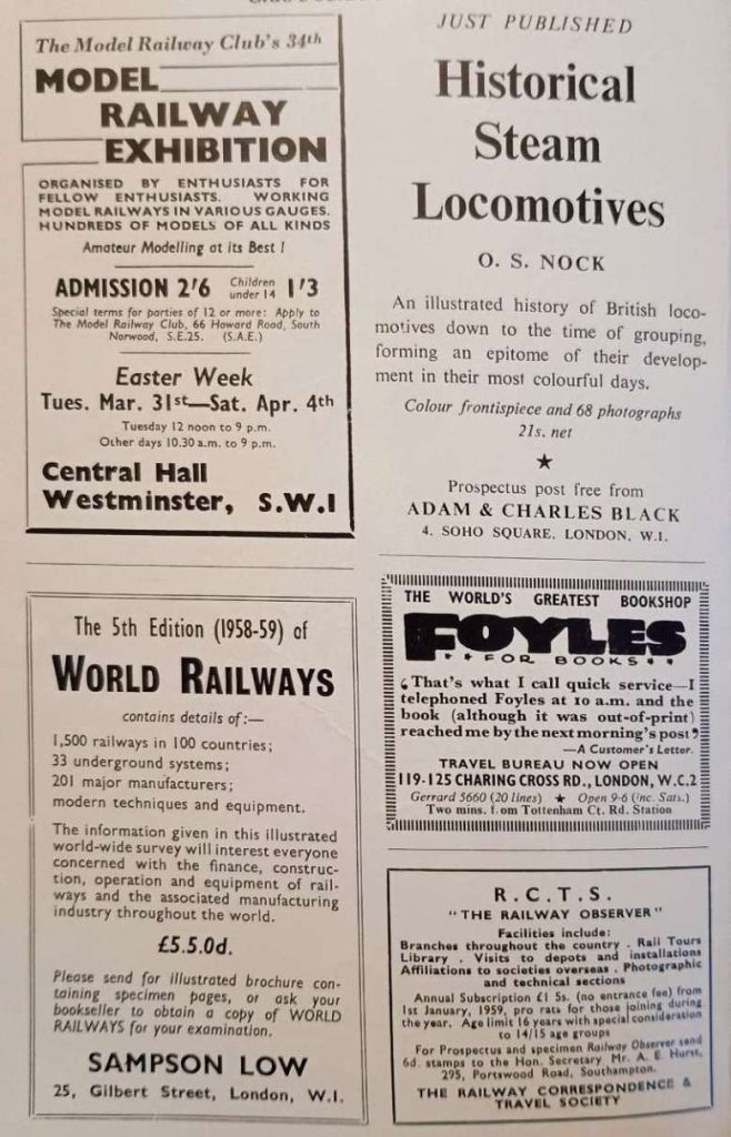
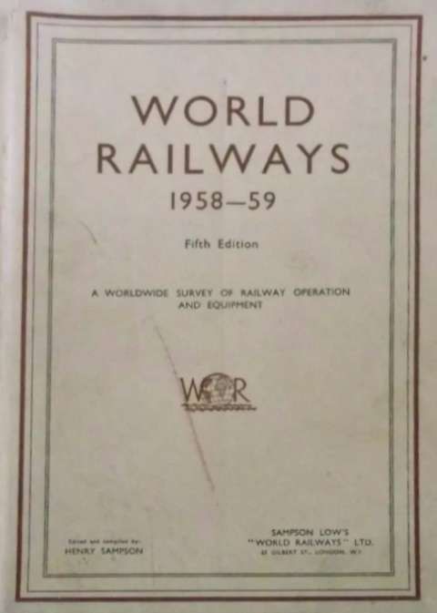

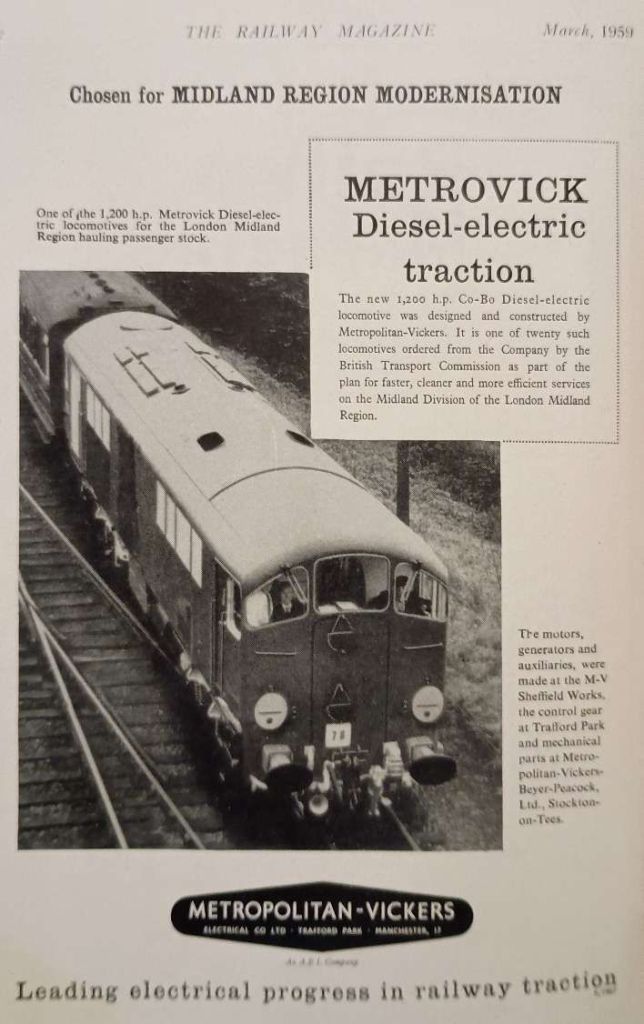

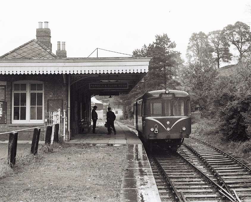
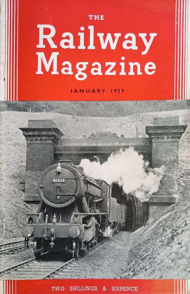
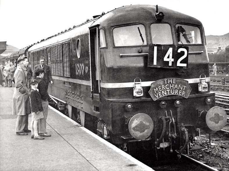
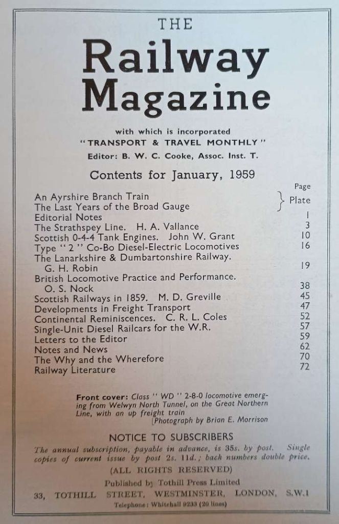


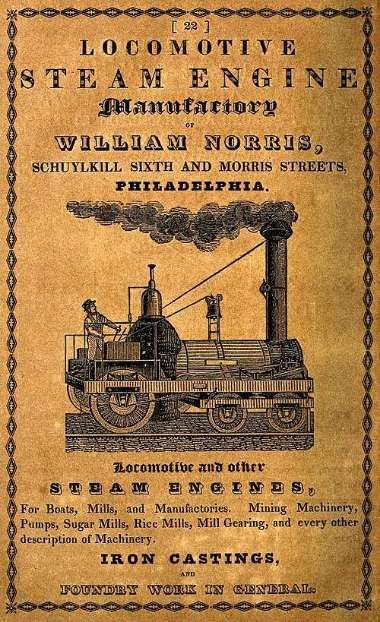
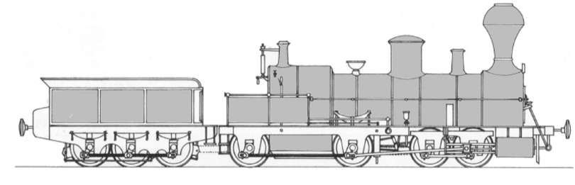
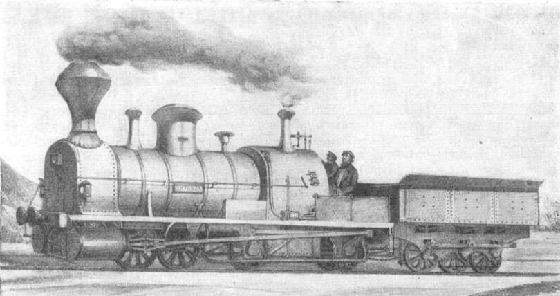
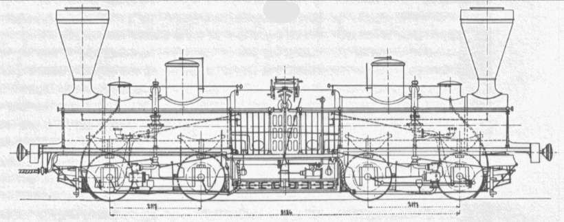
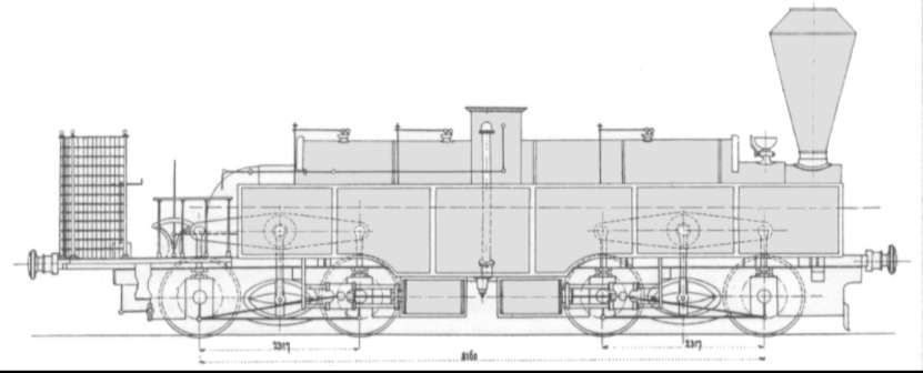
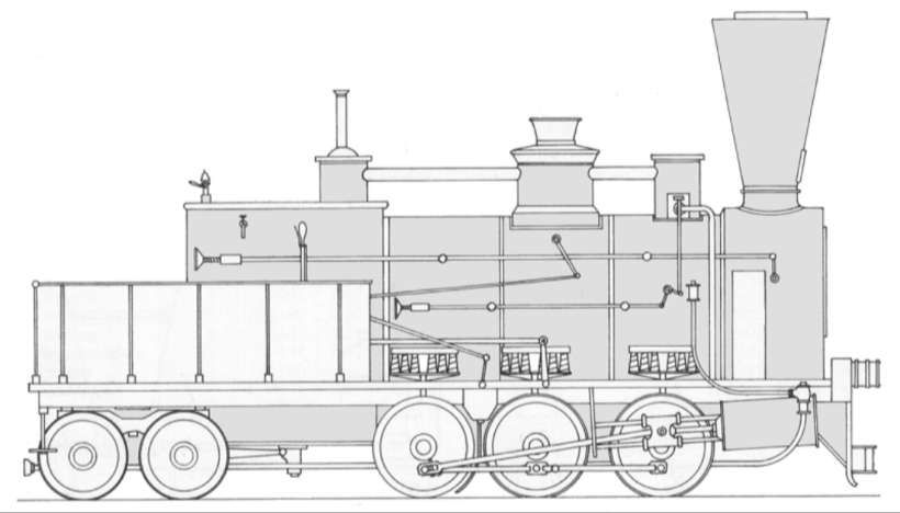
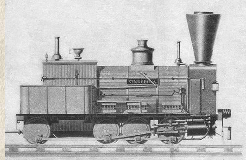
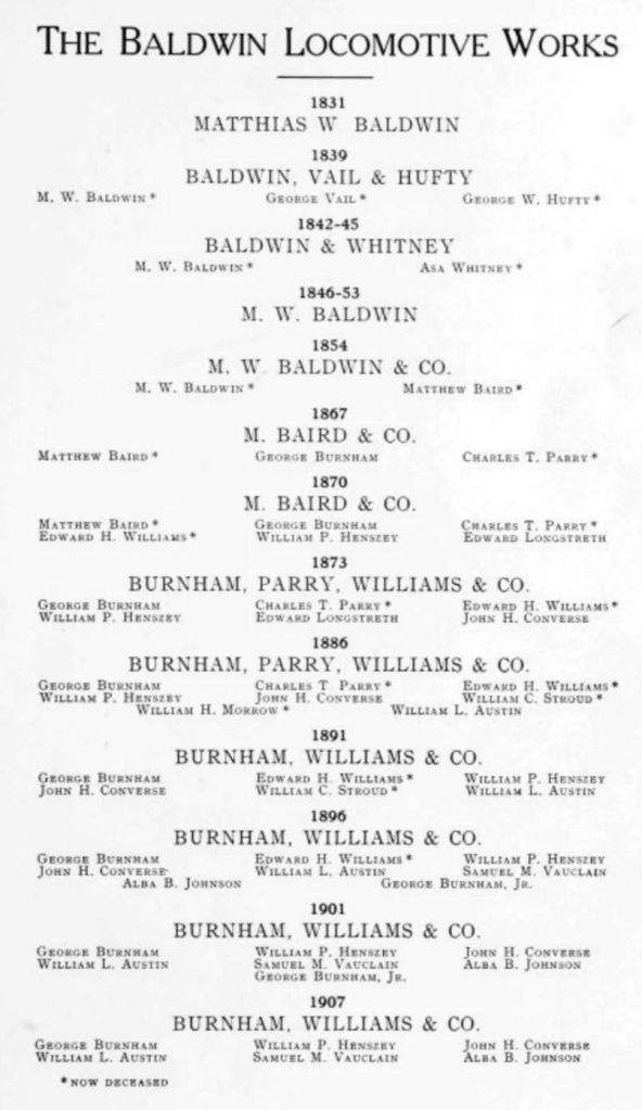
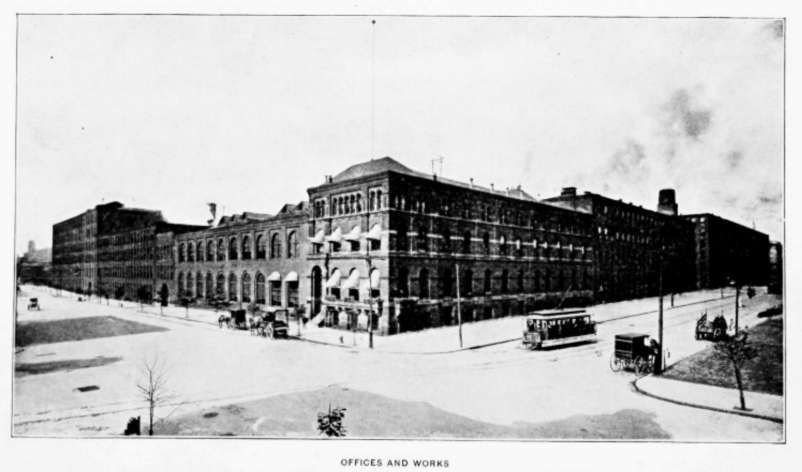
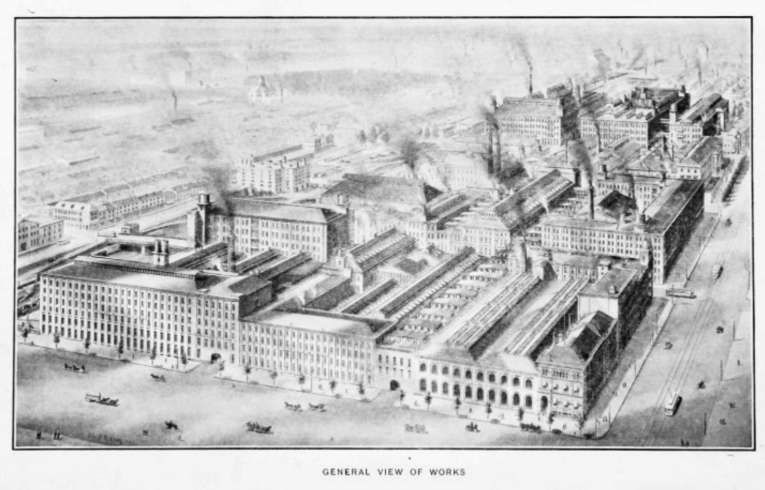
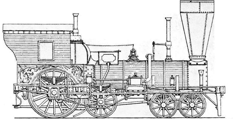
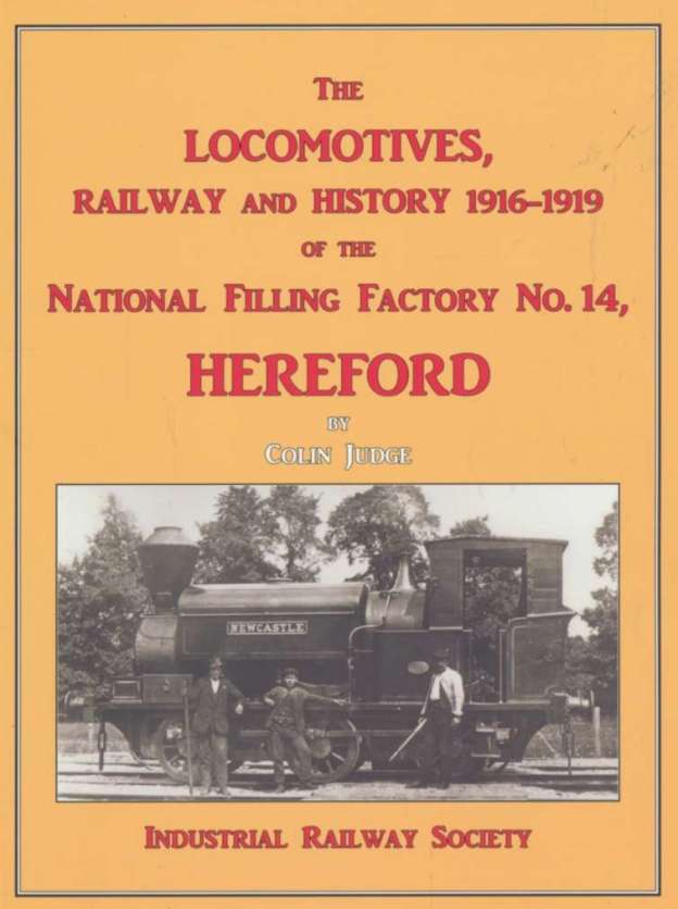


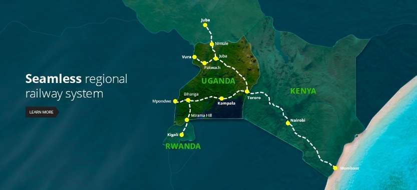

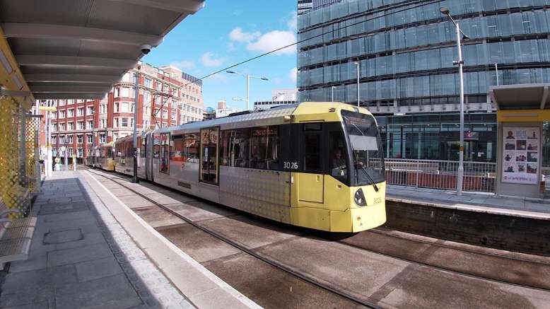


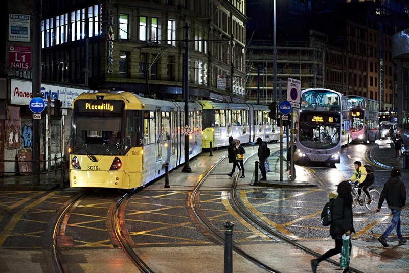

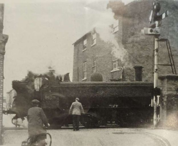
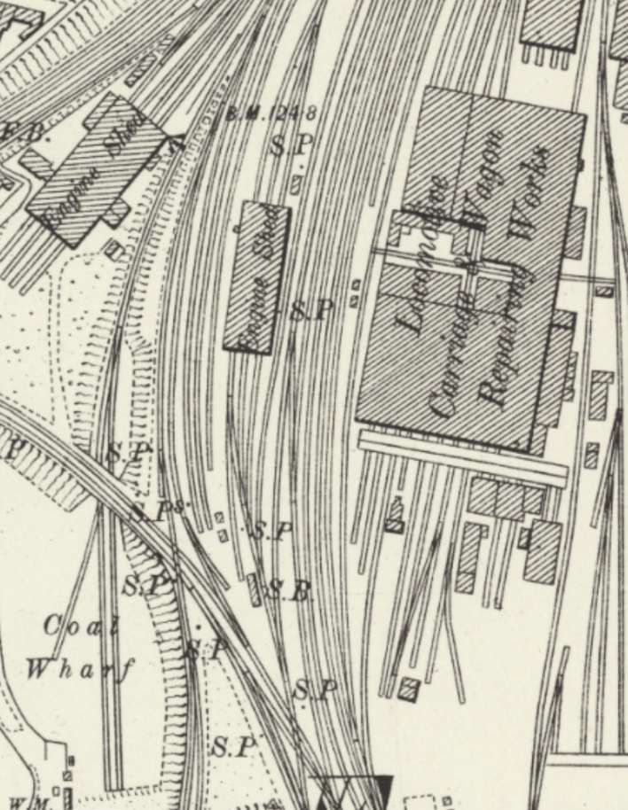
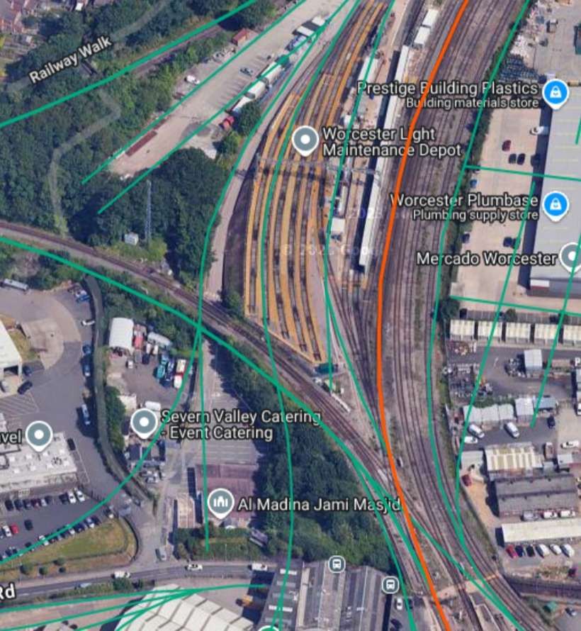
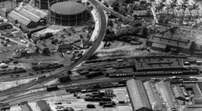
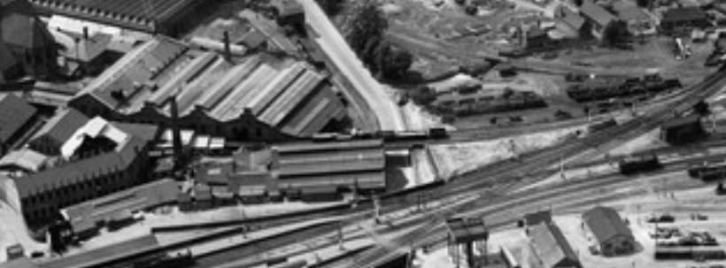
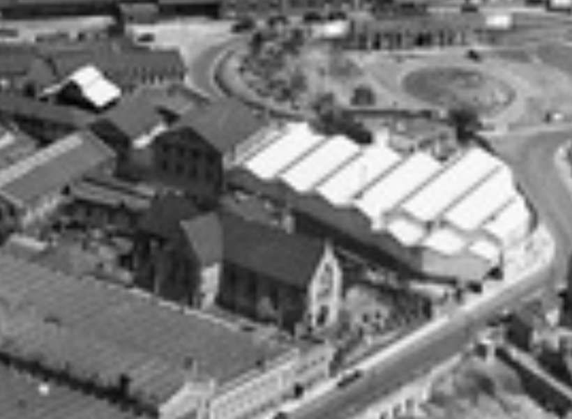
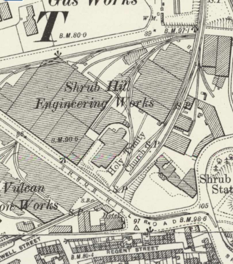
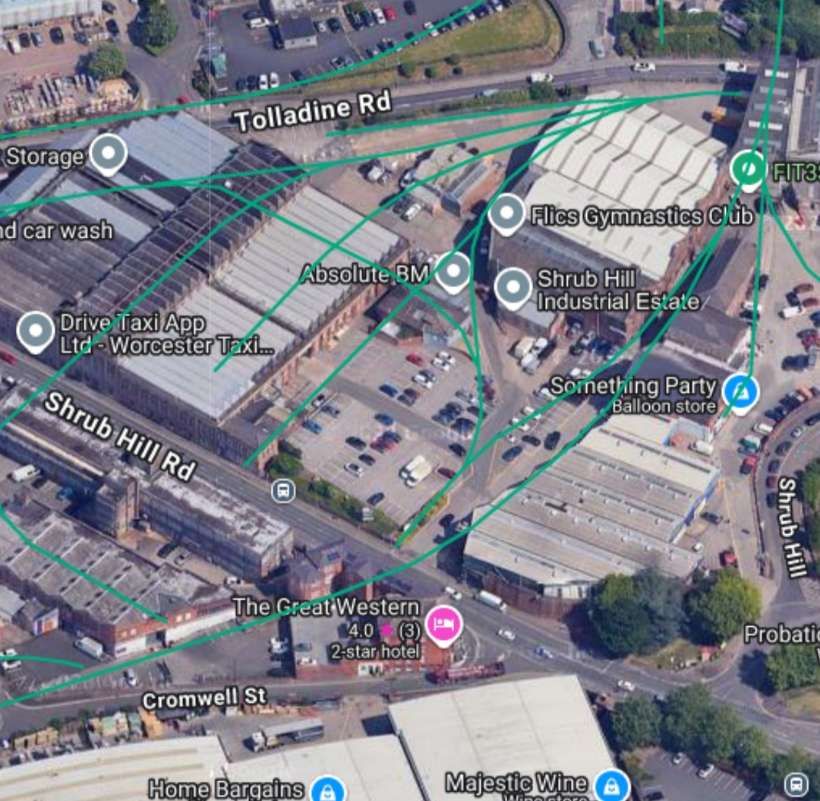
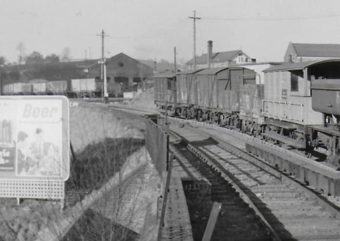
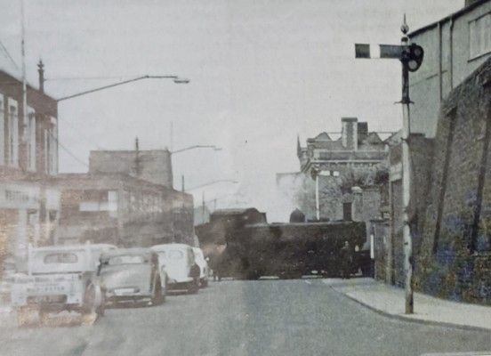
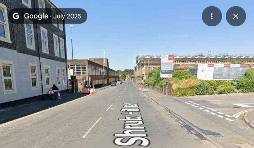
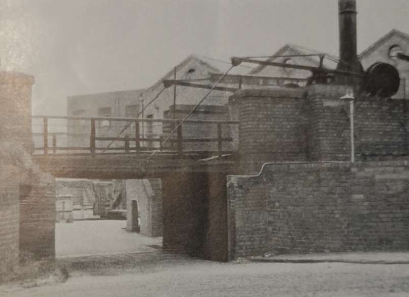
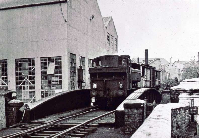
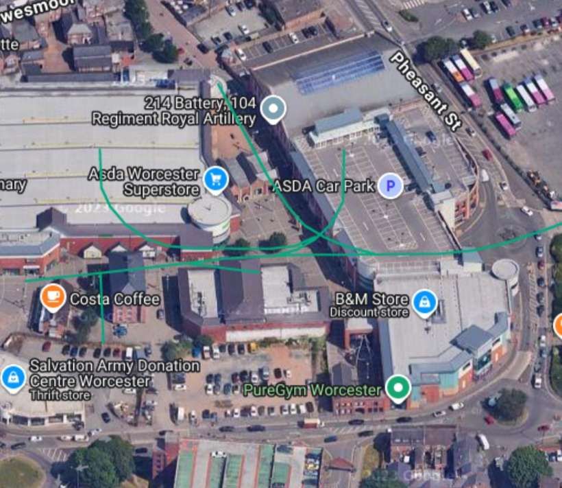


.JPG)
.jpg)