
The western Usambara Hills were characterised by precipitous cliffs and deep gorges. The provision of a rail link between Mkumbara and Neu Hornow was not considered practical.
A 9 km long ropeway was constructed, under the ownership of “the firm of Wilkens and Wiese, and designed to carry cedar from the Shume plateau to the railway, an enterprise that was never an economic success. The longest span of the ropeway, 907 metres, was said to be the longest in the world when it was built in the years 1910-1911.” [1: p75] Wood was transported via the Goatal/Ngoha Valley in the Schumewald/Shume Forest. [2]
The ropeway was constructed by Adolf Bleichert & Co. a German company primarily active in cableway construction . It was founded in 1876 by Adolf Bleichert and was headquartered in Leipzig – Gohlis from 1881. [2] More information about Adolf Bleichert & Co. can be found here. [3]
What follows here is a translation of a German language text with the associated images. [4]
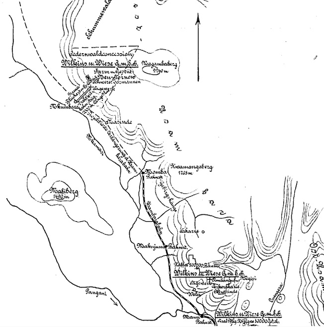
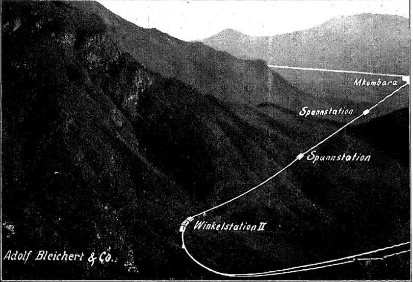
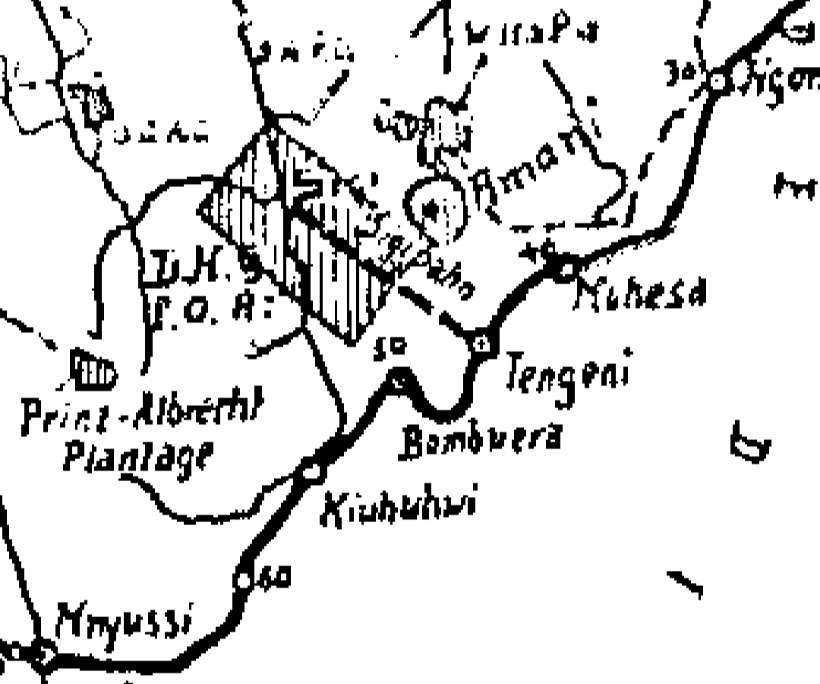
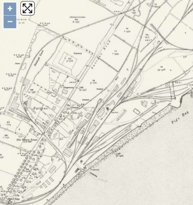
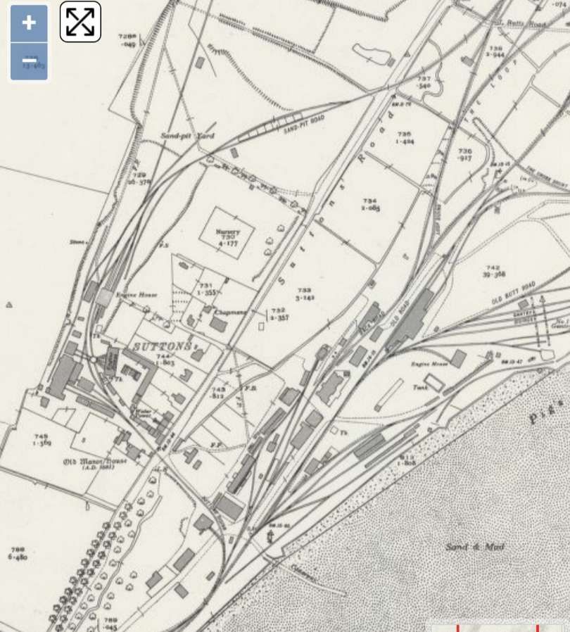
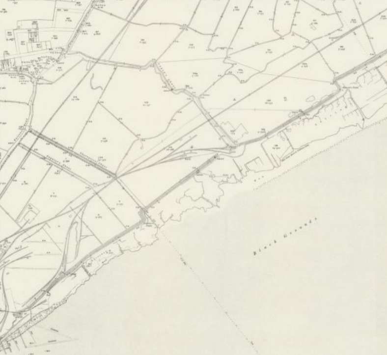
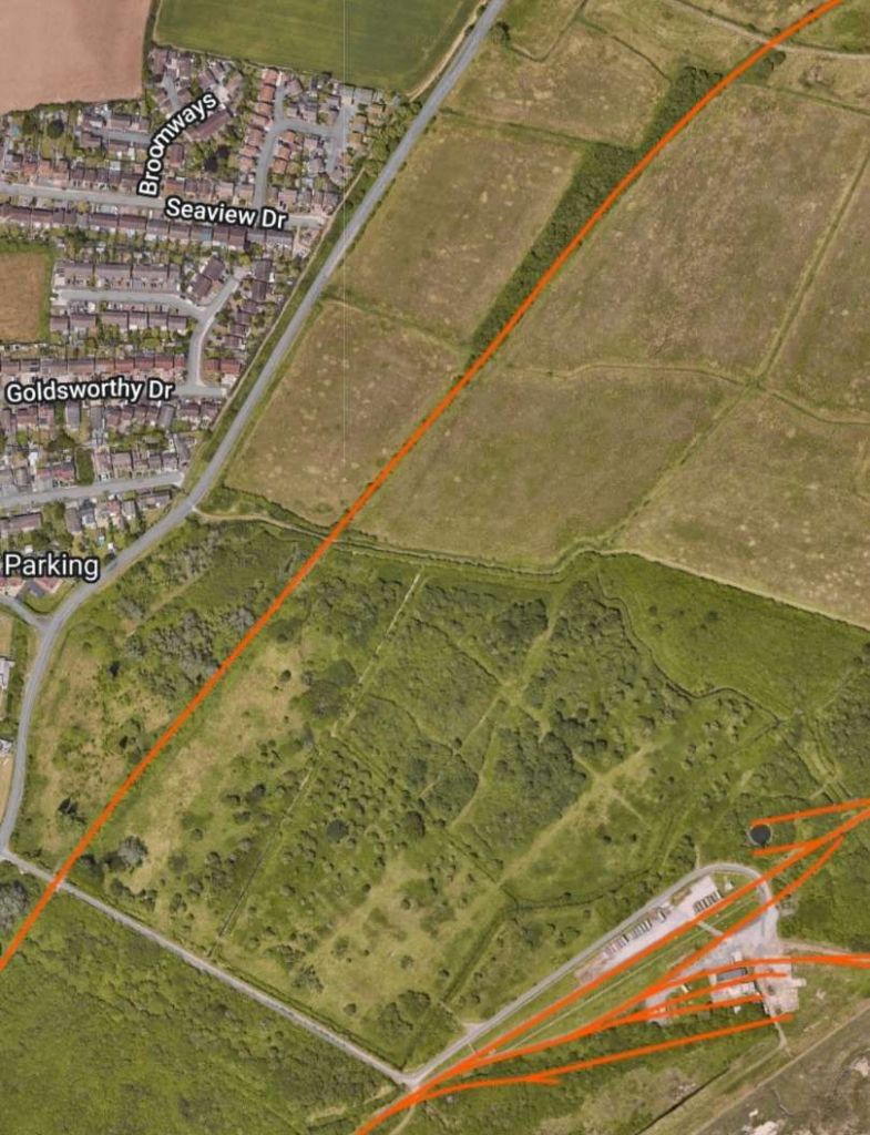
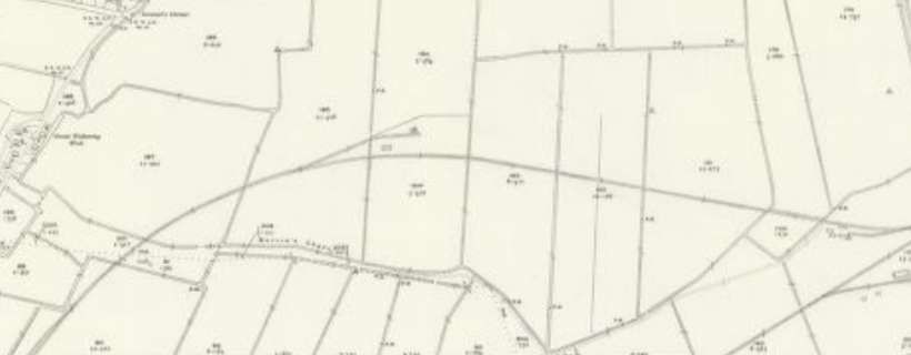
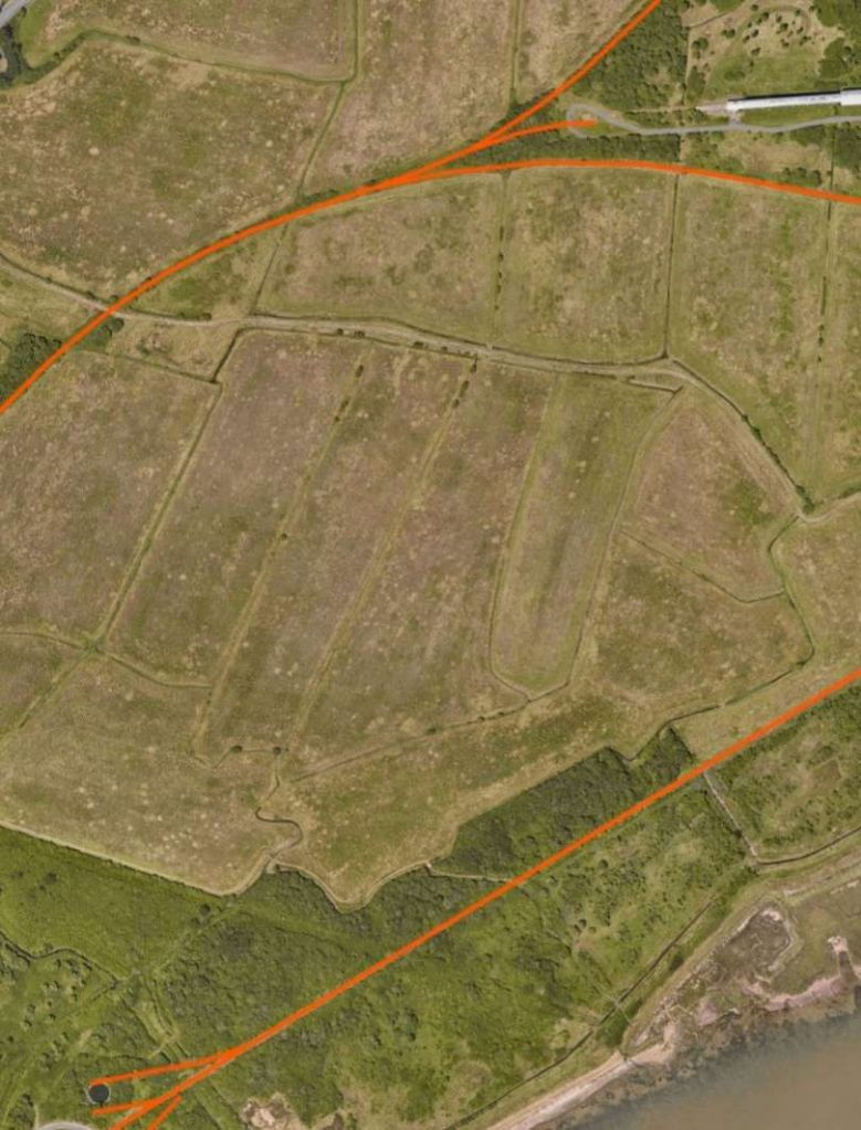
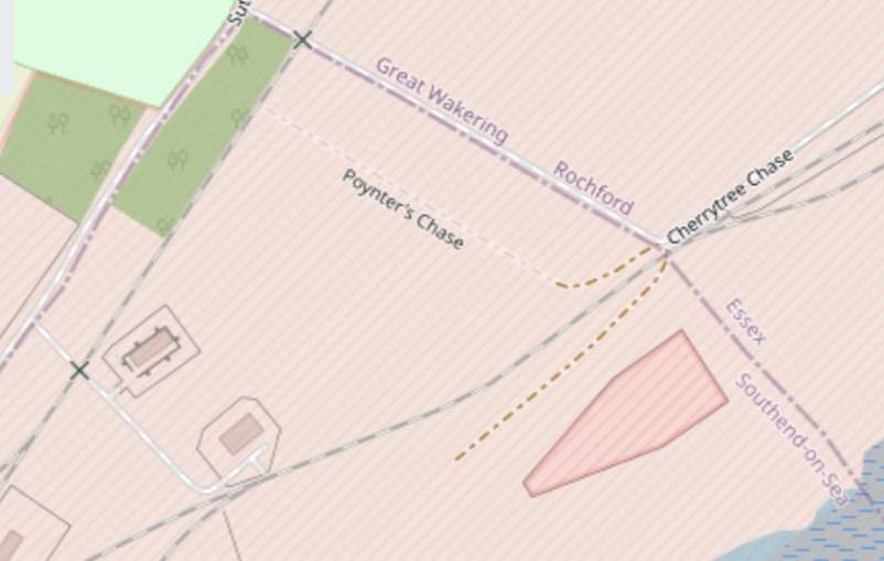
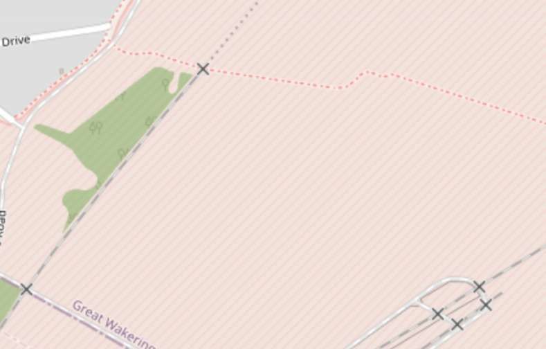
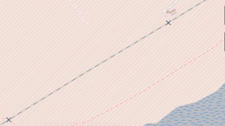
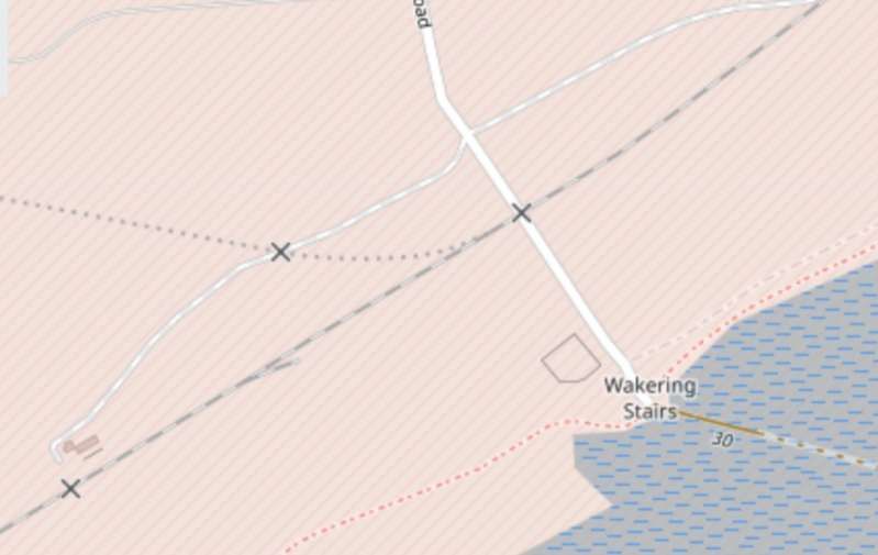
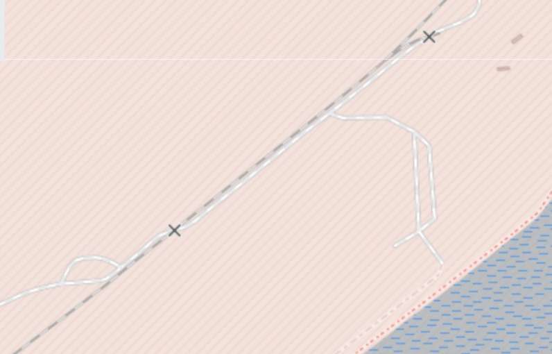
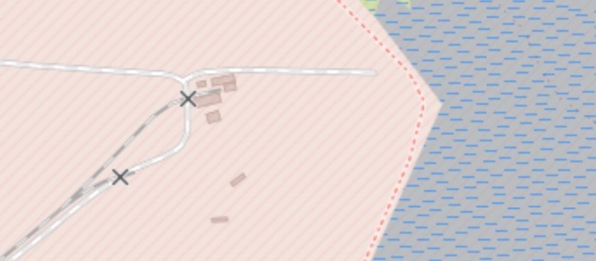
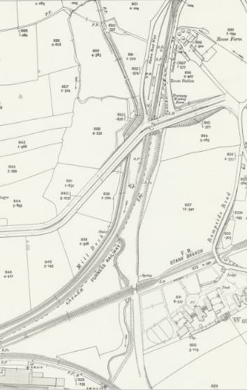
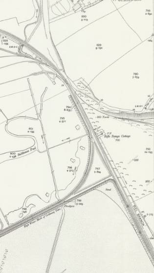
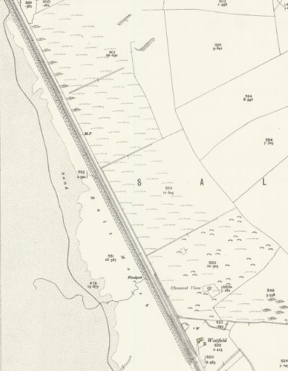
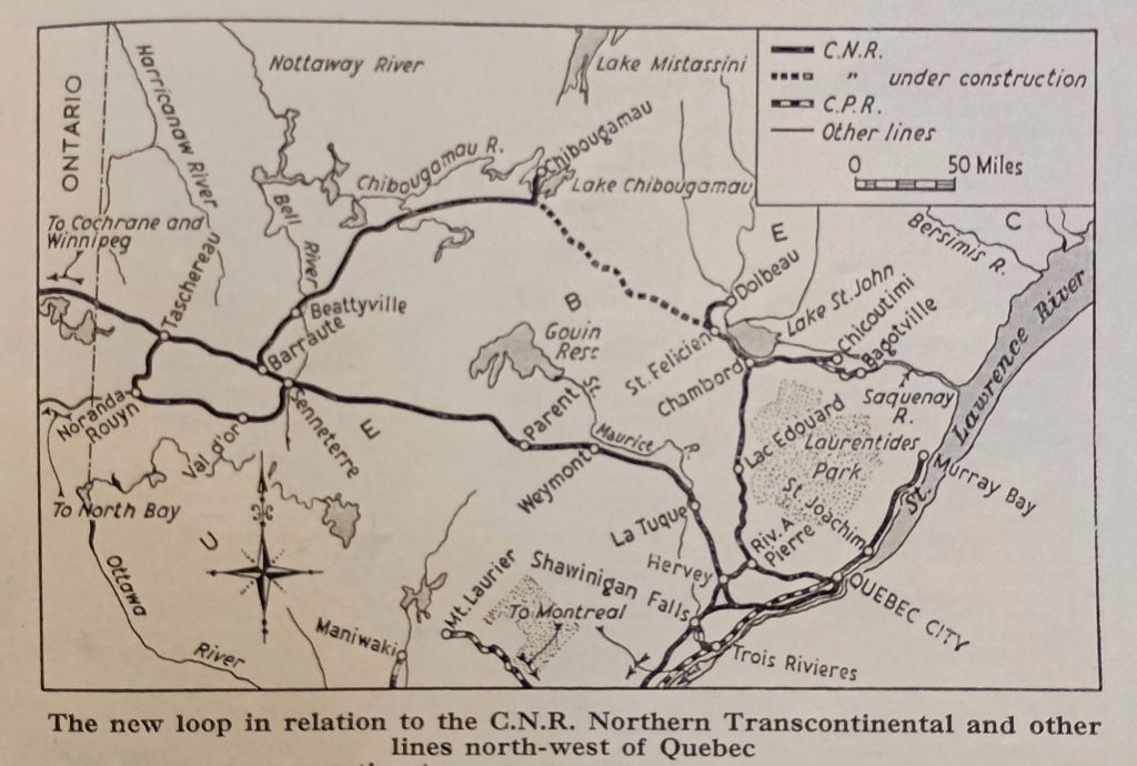
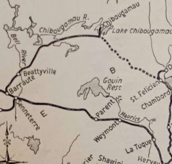
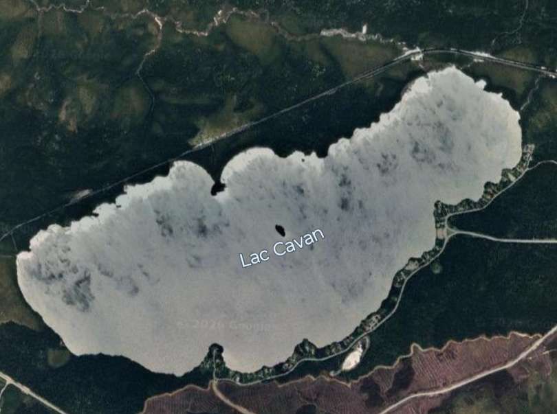
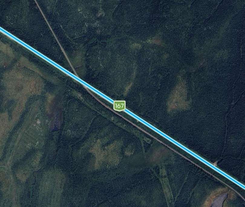
Wilkens & Wiese were aware, when negotiating with the German authorities for a concession to harvest timber saplings in the western Usambara hills and particularly the Schumewald forest, of the difficulty of connecting the steep high plateau with the railway in the plain. A railway or road would have been completely out of the question due to the sharp, steep, and heavily forested slopes of the hills. The only option available to them was a cableway to connect the high plateau with the then-planned station of Mkumbara on the Usambara Railway. In anticipation of the expected difficulties, the cableway was ordered from Adolf Bleichert & Co. in Leipzig-Gohlis andwork commenced in the spring of 1910. The location of the cable car and the timber concession of Wilkins & Wiese are shown below: [4: p17]
The undertaking faced enormous difficulties due to the steep mountain slope. Furthermore, the rock was crumbly and easily weathered, so landslides often disrupted the work. A shortage of workers, the construction of new roads to transport building materials, and last but not least, Sandfly and Mosquitoes tormented workers and hindered completion throughout. Only through sheer energy and great sacrifice was it possible to complete the work. [4: p17-18]
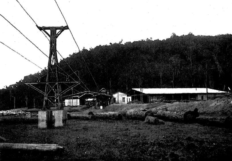
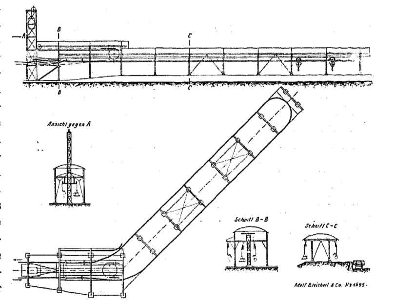
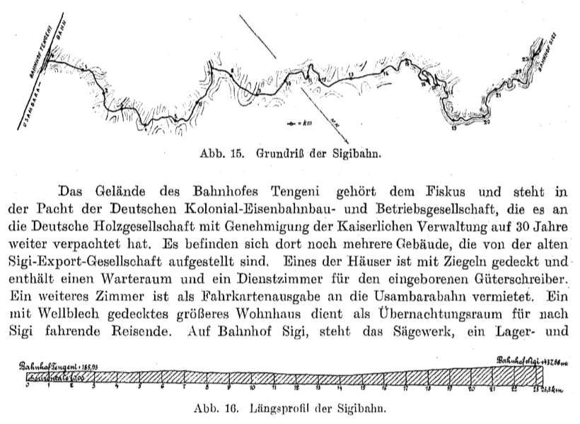
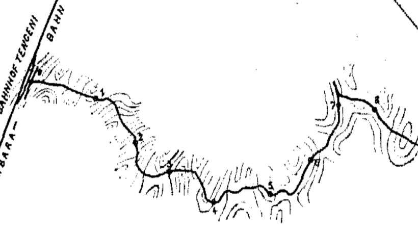
By 1911, the system shown below was fully operational and transported sawn timber, beams, and logs from the sawmill located on the high plateau at 2000 m above sea level to the Mkumbara railway station on a regular schedule. Its horizontal length is 9.0 km, with a height difference of 1435m between the terminal stations. The greatest difference in elevation of the cableway is 1523 m, as shown in the longitudinal profile below. Due to the extremely unfavourable conditions, the line had to be divided into three sections, the uppermost of which first has to overcome a climb of about 90 metres. Therefore, a traction system had to be provided for all eventualities, which would assist if the gradient became too heavily congested with wagons. The cableway’s capacity was designed for ten tons per hour downhill and one tonne per hour uphill. [4: p18]
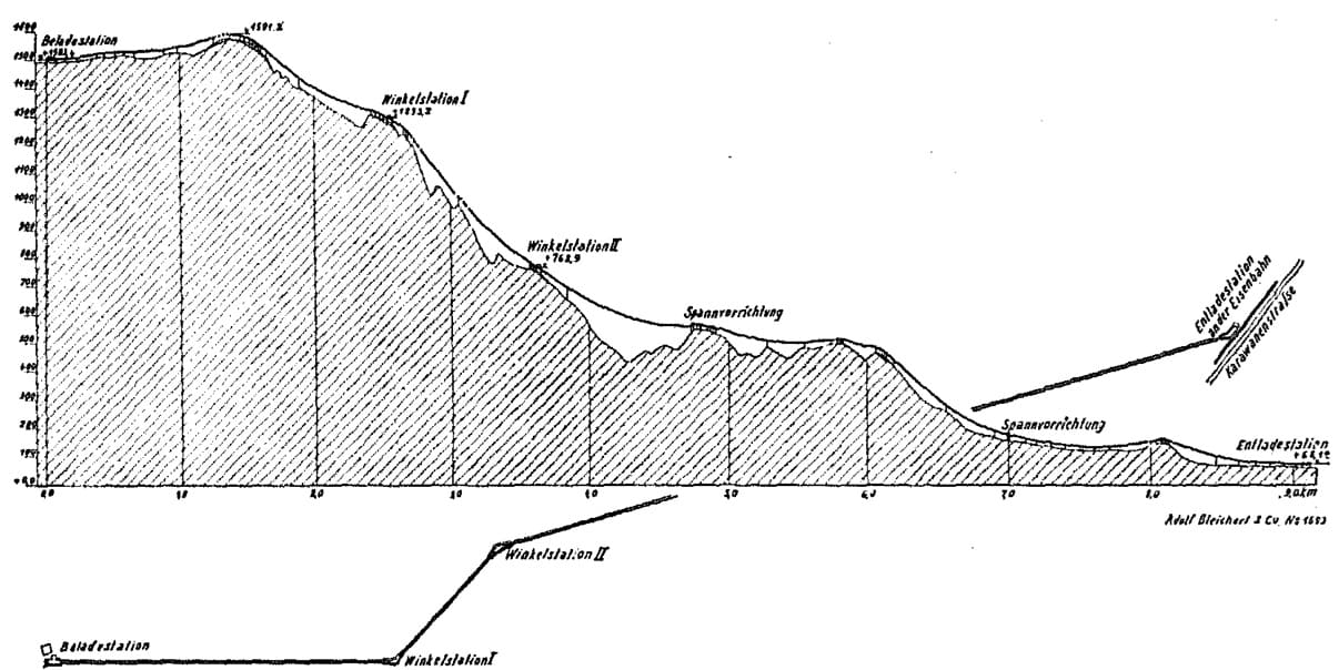
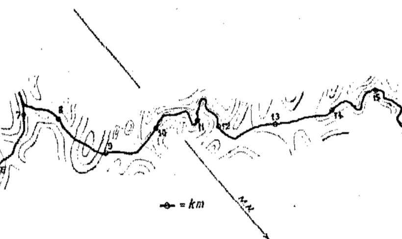
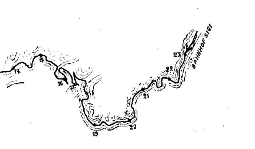
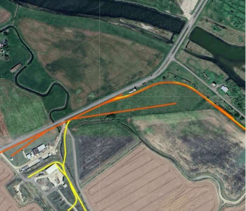
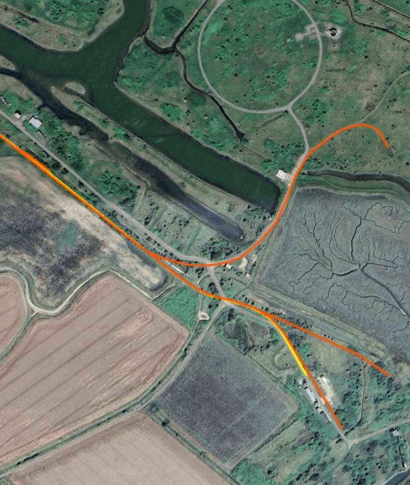
The line began at the loading station near the Neu-Hornow Sawmill at an altitude of approximately 2000 m above sea level. At about 1.2 km from the sawmill, it crosses the edge of the plateau. It then descends quite steeply to an altitude of 1290 m, where it turned through a 45° angle. From here, the cableway had to be routed to a breakpoint, where it turned once again seeking suitable locations for the support towers. The line then continued with two spans of more than 300 metres each to another breakpoint, the junction station at an altitude of 770 metres. Then the cableway heads for Mkumbara, crossing the uniquely beautiful Ngoha Valley with a free span of 100 metres. Prior to reaching the bottom station at an altitude of 68 metres, the railway has a tensioning and anchoring station at 660 metres and a double tensioning station at 170 metres. The journey of a load takes about one hour.
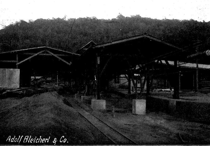
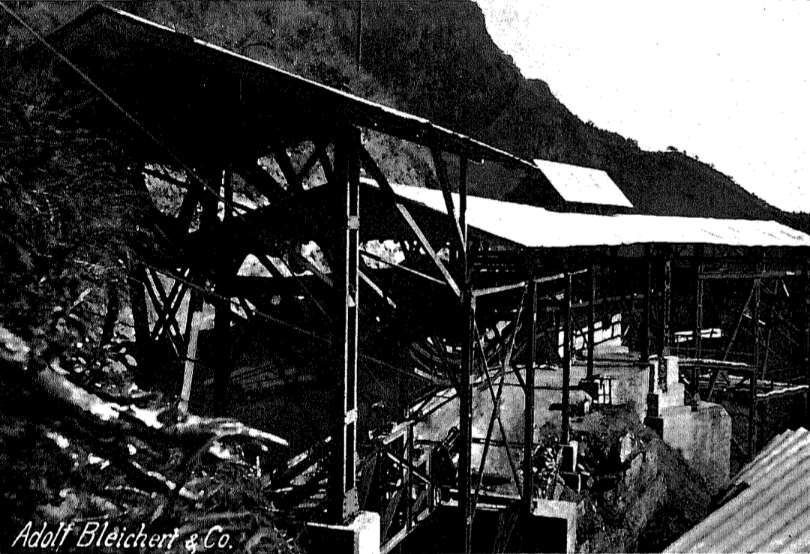
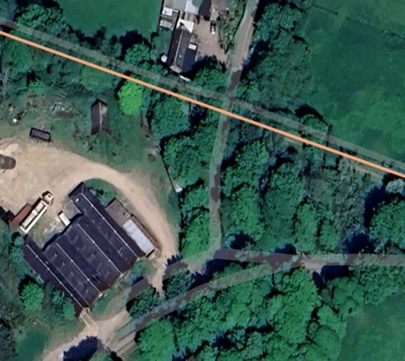
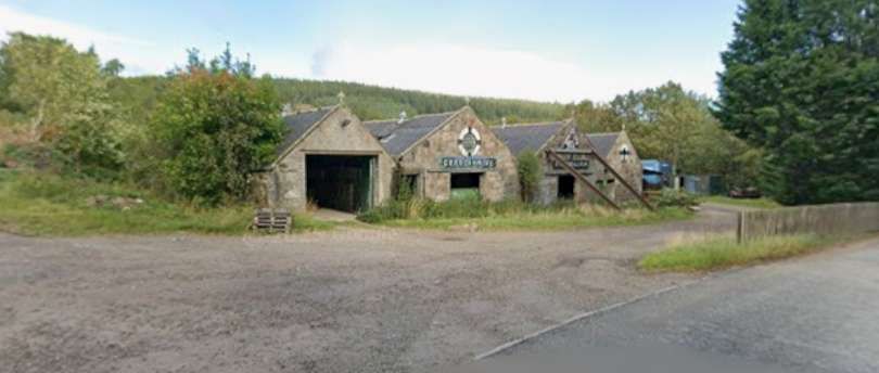
The Neu-Hornow sawmill has several standard frame saws on which logs can be cut into beams and processed into lumber. The loading station, shown below, is equipped with fixed hanging rails. In addition to the necessary guide rails for operation, it also has a storage area for empty hangers.
The points at which hangers attach and detach from the cable/rope are visible on the right of the drawing. These points allow the incoming cars to detach automatically from the haul rope, while the outgoing cars automatically reconnect to the haul rope. Patented Bleichert apparatus is used as the attaching device. [4: p19]
The end guide pulley was equipped with two hand brakes, each with a disc diameter of approximately 2 metres, capable of braking 50 horsepower, with one serving as a safety brake. The brakes were only applied when the train was stationary. During operation, an automatic brake regulator controlled the train speed. This regulator (a hydraulic brake), along with the cableway’s drive system, was housed in a separate engine room next to the loading station. There was a 1.6 m³ reservoir on the roof of the loading station and two concrete tanks in front of the engine house, in which water supplies for the summer were collected. [4: p19]
The cableway needed both effective braking and a good quality drive system. Sometimes heavy loads had to climb the first length from the loading station without sufficient weight on the longer descent to balance the load. A higher capacity engine was required so that the cableway would also be used to generate electricity to power the sawmill. so a 50 PS electric motor was installed and performed well. [4: p19-20]
The hydraulic regulator consisted mainly of a capsule structure with a relieved throttle valve, which was driven by a belt from the cableway countershaft. The mechanism drew water from a reservoir and pushed it back into the box through slots of the regulating slide. The regulating slide is fully actuated by a centrifugal force governor, which may also be driven by the drive shaft of the track via a belt. As soon as the revolutions per minute of the countershaft begin to increase, the centrifugal force governor moves the regulating slide into action. [4: p20]
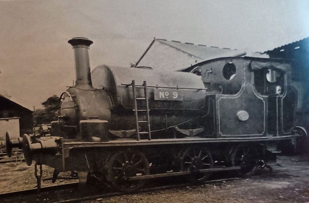
The frame saw is driven by a Lanz Lokomobile/traction engine. (A Lokomobile was a portable, self-propelled, or towable steam-powered (or sometimes internal combustion) engine used historically to provide power to machinery like threshing machines or sawmills. Mounted on wheels or skids, these versatile, mobile power units were commonly used in agriculture and industry, frequently featuring a steam boiler and a single-cylinder engine.) [5]
Given the extremely difficult road conditions on the mountain, the firm Wilkins & Wiese undoubtedly acted uneconomically in choosing a locomobile as the drive system, because it was foreseeable that it would cause enormous difficulties to transport this large and heavy 10 hp machine up the mountain, and that the profit from saving on assembly costs compared to a stationary engine and boiler system to be transported disassembled would be far outweighed by the extraordinarily high transport costs of the fully assembled locomobile. [4: p21]
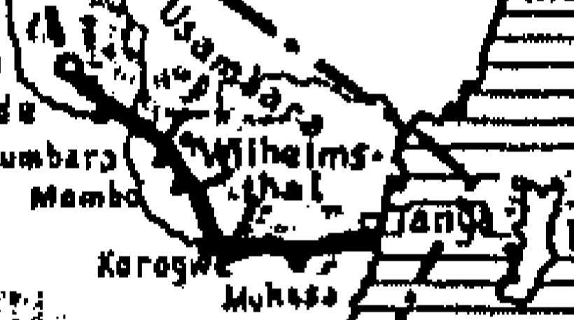
The locomobile/traction engine had to be transported 60 km from Mombo, the then terminus of the Usambara Railway, via Wilhelmsthal to Neu-Hornow. Two to three Europeans and 100 labourers worked continuously on the transportation of the traction engine for about seven months. The boiler was mounted on a railway wagon frame, which was then moved forward on a track. The track was then removed behind the wagon and reattached at the front. Depending on the difficulty of the route, distances of 100 to 1000 metres were covered daily.
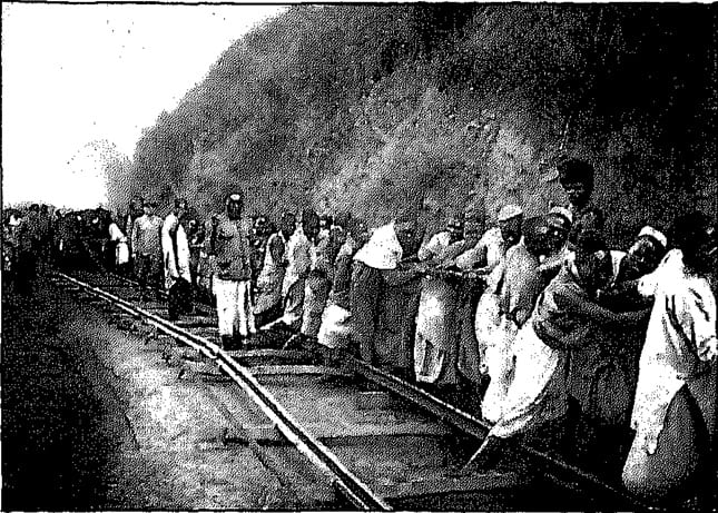
This required building roads and bridges, widening and reinforcing existing paths, and blasting rocks. Often the machine hovered over the abyss, in danger of plunging down and destroying months of expensive work. Using animals for transport was impossible because the tsetse fly was native to this area. Since the traction engine also had to provide the power for the initial commissioning of the cableway, the transport of the locomobile to Neu Hornow was a major contributor to delays in commissioning the cableway. [4: p21]
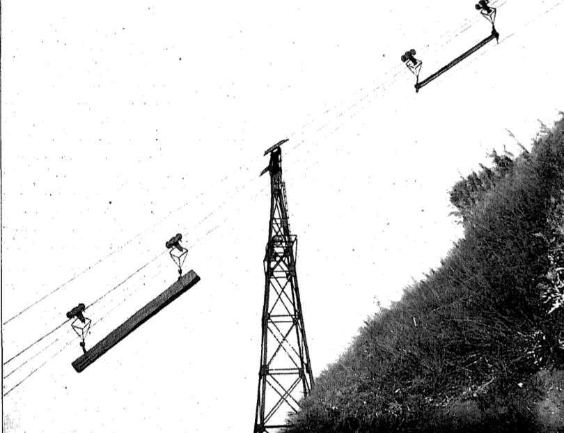
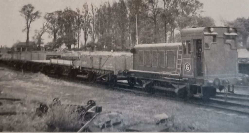
From the loading station, the track gradually ascended to its highest point. The log wagons, illustrated in the image below, which transported logs up to 14 m long and weighing up to 1000 kg, consisted of two carriages connected by the haulage rope. To increase the clamping force of the lead-weighted coupling mechanism on these steep inclines, stops were provided to the right and left of the suspension of the carriage, against which the suspension bracket was applied to inclines. Under the influence of a load, it acts like a lever on the pull piece of the clamp, thereby achieving a correspondingly increased clamping force, which ceases immediately when the incline decreases, so that the positive characteristics of the automatic coupling device reappear. Among these, the great protection afforded to the haul rope is particularly noteworthy, as the clamping force was not greater than absolutely necessary. The slings were designed with a lightweight construction, yet possessed the required stability during idling and when entering stations due to the use of a counterweight. [4: p22-23]
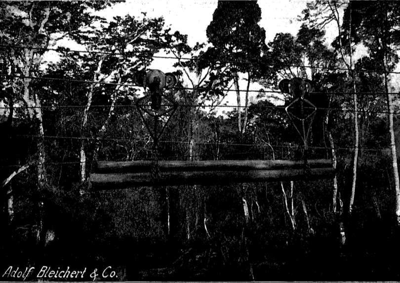
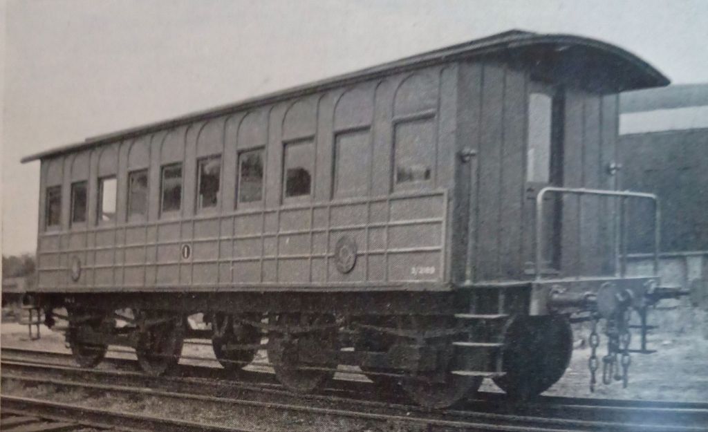
Platform wagons were used for transporting sawn timber down the valley and for transporting various goods up the mountain. These wagons were also used for passenger transport. [4: p23]
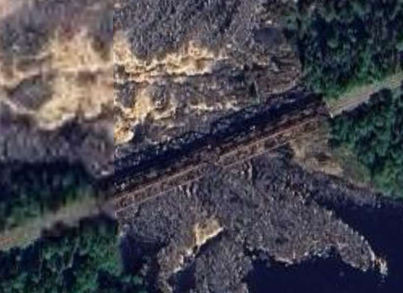
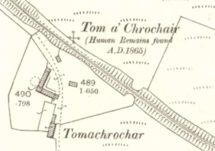
The highest point of the line was at 2011 m above sea level, 1591.2 m above the survey base, was reached 1.2 km from Neu-Hornow, 1523 m above the unloading station. To obtain the most favorable line alignment, a simple cut had to be made at the crossing over the edge of the plateau (shown in the image below). This presented no difficulties due to the firm clay layer, but in light of the heavy tropical downpours, special safety measures for the support foundations were required. For this purpose, the line was laid at an angle and equipped with a lateral drainage ditch. Sloping ditches were also dug in front of the supports to divert the water. The slope of the ground followed the profile of the cableway and accordingly had a gradient of 1:2. [4: p24]
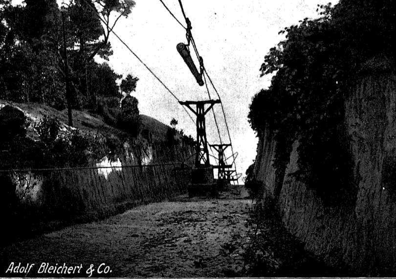
Ahead down the line was a gorge-like valley which the cableway panned on its way to the first ‘angle-station’, making use of a 30 metre high support stanchion.
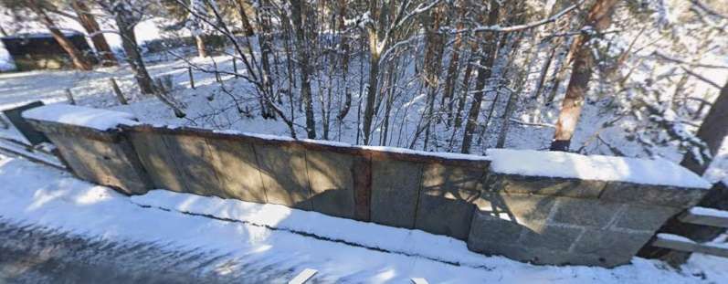
The first angle-station (winkelstation) son the side of a promontory of rock above the gorge mentioned in the last paragraph. In order to accommodate the ‘winkelstation’, excavation was necessary at the top of the promontory. This cause difficulties as the ground proved friable and the easily crumbling and weathering rock fractured in two directions. Repeated collapses significantly delayed the completion of the cableway. Stability was finally achieved by building a significant retaining wall and by concreting the rock fissures. [4: p24-25]
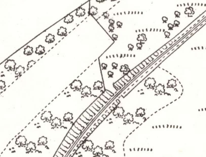
The ‘winkelstation’ sat immediately above/behind the retaining wall and required some excavation of the rock to create a plateau. A sketch diagram appears below:
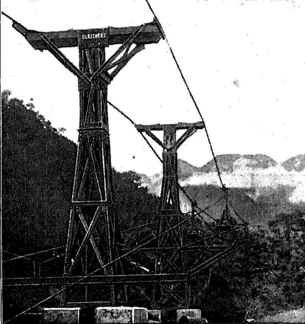
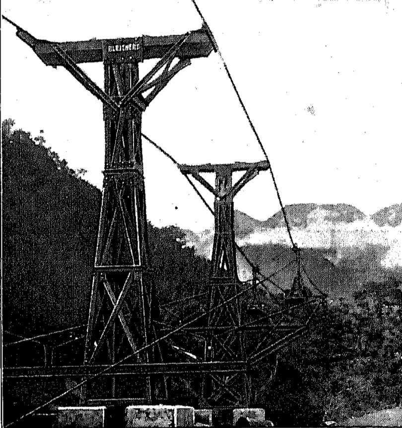
Beyond Winkelstation No. 1, the railway crosses a short rocky ridge, then continues supported in the middle of two spans of approximately 300 metres each, across several hundred metres of steep gullies to the Willkelstation No. 2, located on the side of another rocky ridge and accessible only via difficult paths. Given the exceptionally unfavorable terrain, the central support between winkelstations I and II had to be maintained at a height of approximately 33 metres.
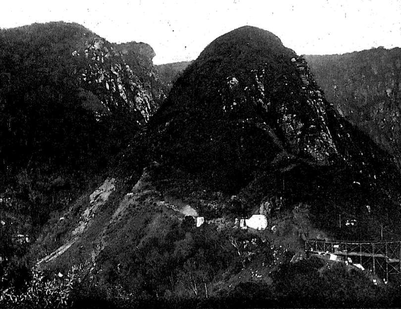
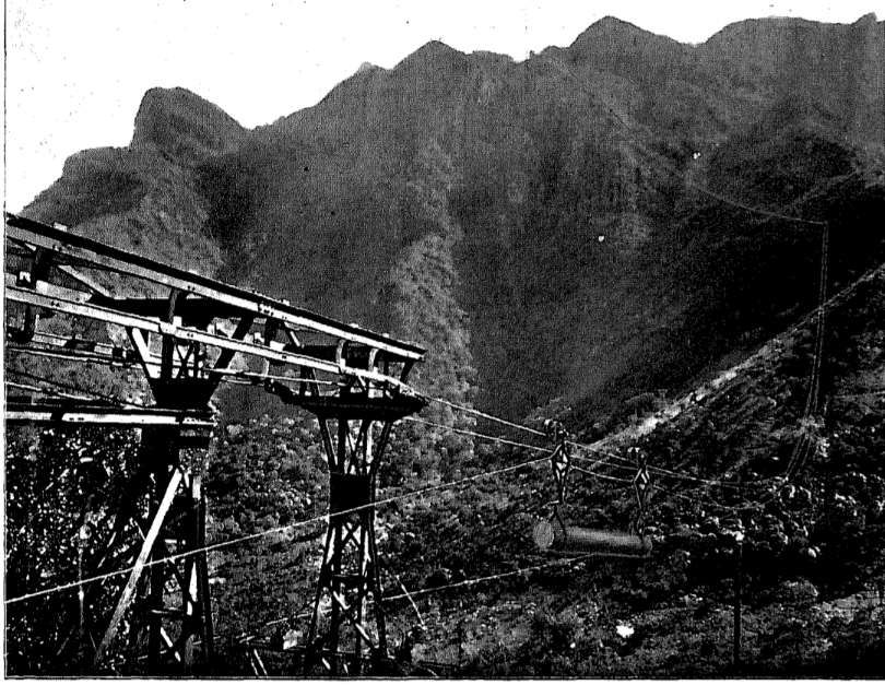
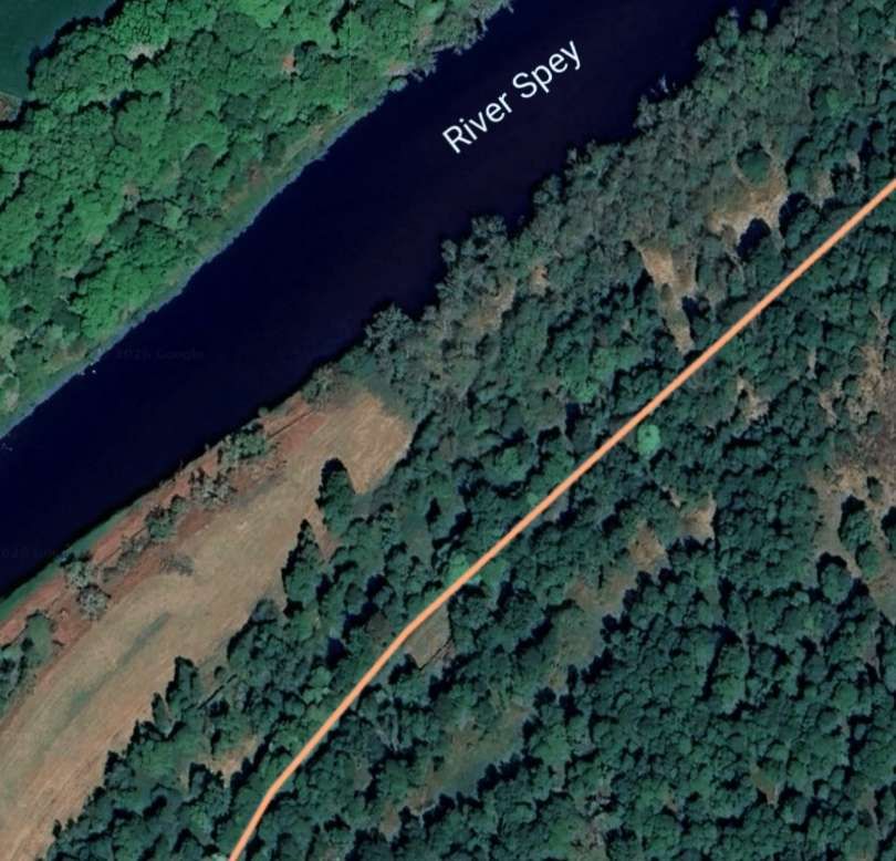
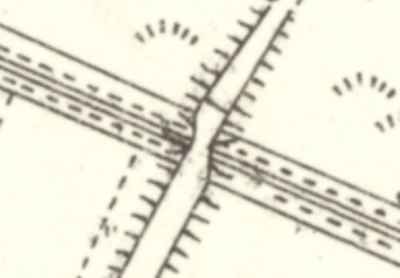
The section between the two Winkelstations is of particular interest because at the time of construction it was the steepest continuously operating cableway in the world. The location is shown in the image immediately below. Here, the gradient was 41° = 1 in 1.15 or 86 %). However, such inclined lifts with shuttle operation are not uncommon. The Bleichert company stated that this gradient was only surpassed by a few cable cars in the canton of Salzburg and the Wetterhorn lift near Grindelwald. The steepest gradient at the Wetterhorn lift, reaching up to 200%, corresponding to approximately 87°!
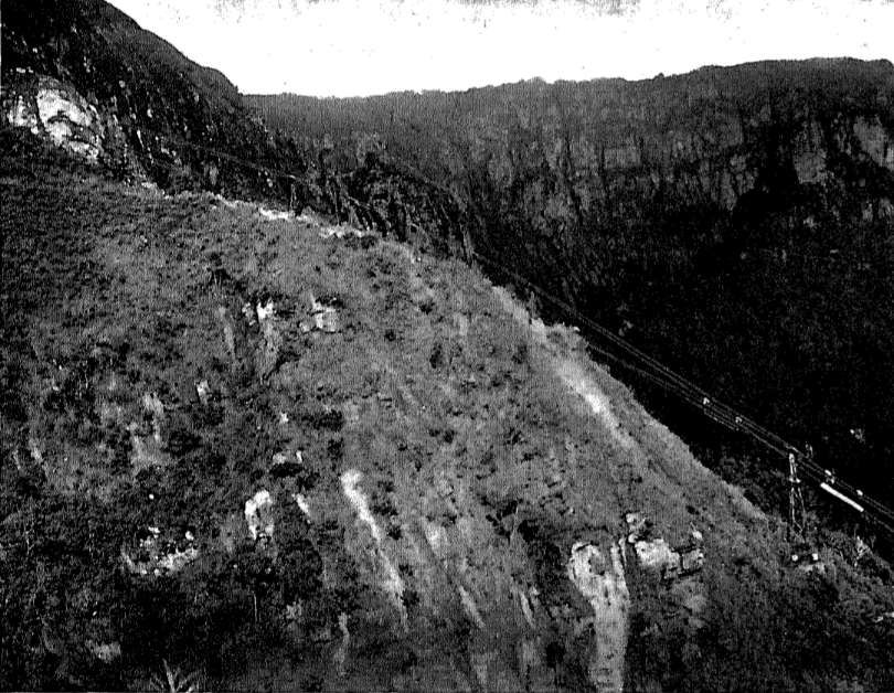
Even funicular railways lag behind the Neu-Hornow cableway. The maximum gradient on a funicular railway is 70% on the Virgelbahn near Bolzano, which operates with a reciprocal carriage system. The photograph below shows just how steep this section of the cableway is.
Over the longer spans, the haul rope had to be guided as far away as possible from the track rope to prevent entanglement in the track rope. Based on these considerations, a support design generally emerged that deviated from the normal design due to the large distance between the haul rope guide and the support shoe.
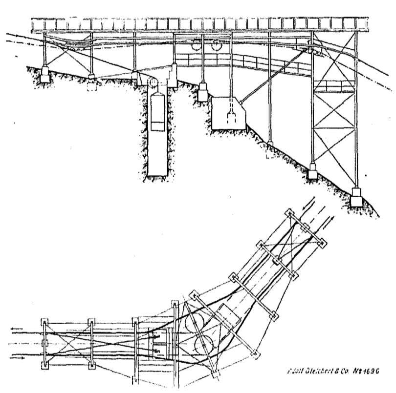
In Winkelstation No. 2 (shown diagrammatically below), the track cables of the second section are tensioned by counterweights. To gain the necessary space for the counterweights, a pit had to be blasted. The haul rope from Neu-Hornow terminates at this station. However, it is inextricably linked to the haul rope for the final section to Mkumbara, so that the speed of both ropes is the same.
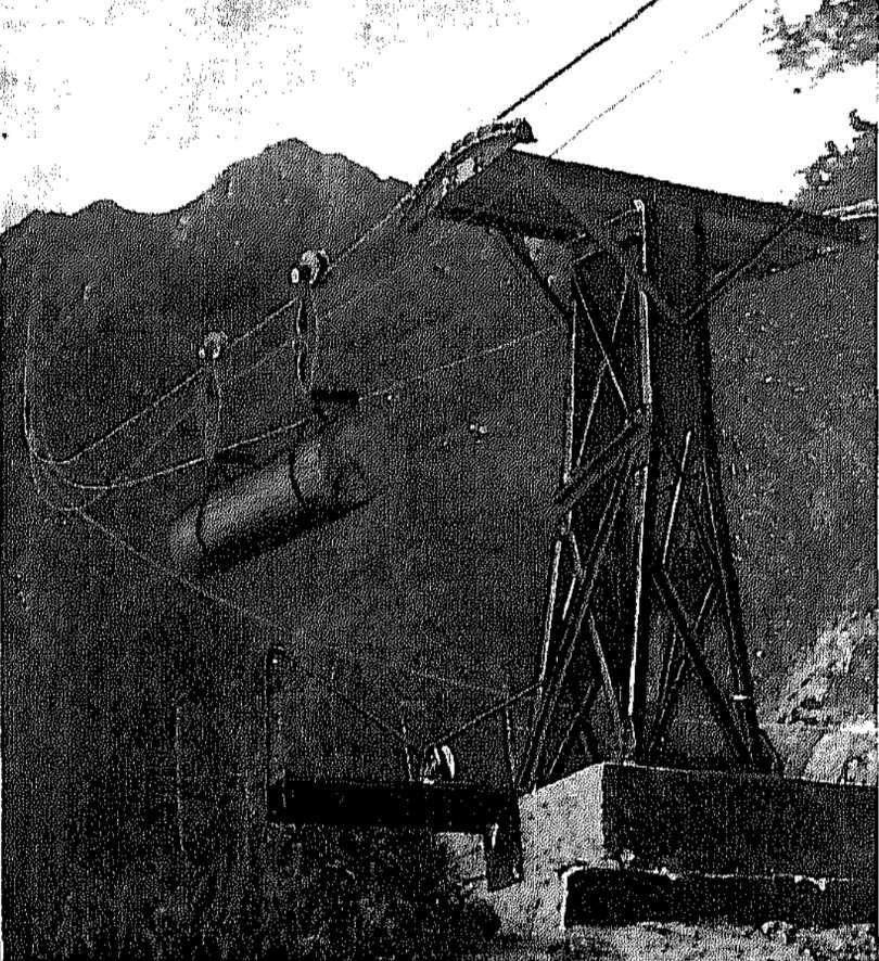
Handbrake operation for the further descent did not seem reliable enough. It was much more practical to also apply the brake regulator installed in Neu-Hornow to the last section of the cableway. Furthermore, for this last section, with its relatively gentle gradient compared to the higher sections, there was a risk that the haul rope would stop if there was a large uphill load and a poorly occupied downhill section. Therefore, at Winkelstation No. 2, the traction cable of the upper two sections is guided around a pulley on the end guide shaft of the lower traction cable run, thus achieving the necessary positive connection. The traction cable of the upper section then passes over an end guide pulley mounted in a tensioning frame and is tensioned by tightening the tensioning lever due to weight distribution. In this station as well, the wagons are manually guided onto the following sections for the reason already mentioned. Winkelstation No. 2 is shown in the photograph immediately below. The coupling points are visible at the entry and exit points. To find space and support points for the installation, costly blasting and foundation work was also necessary here. [4: p28-29]
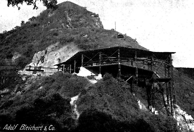
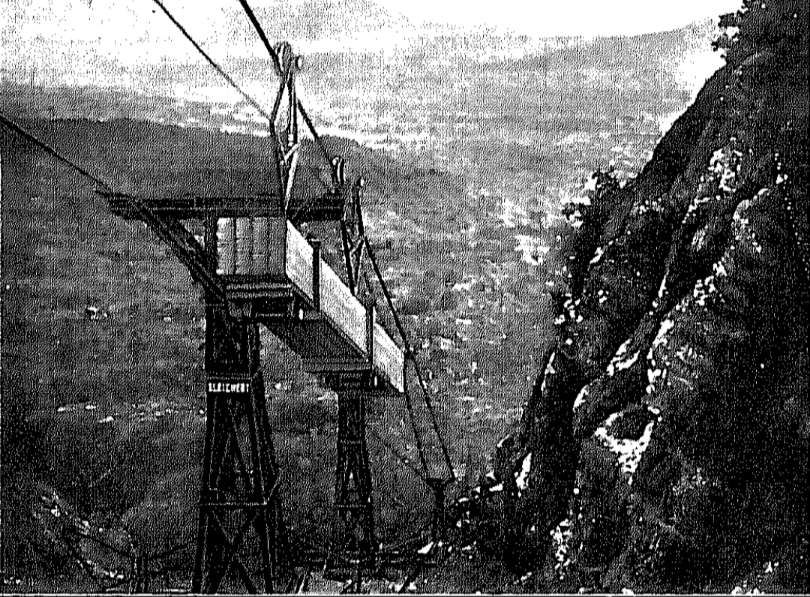
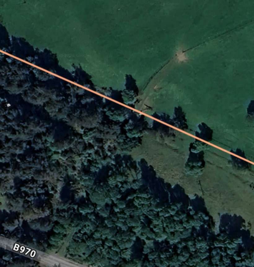
As far as the terrain allowed, naturally existing support points were utilized. For example, just below Willkelstation No. 2, a support could be erected just before the drop into the Ngoha valley; however, beyond this point, no support was possible before the opposite valley edge, which was 210 m lower and 100 m away.
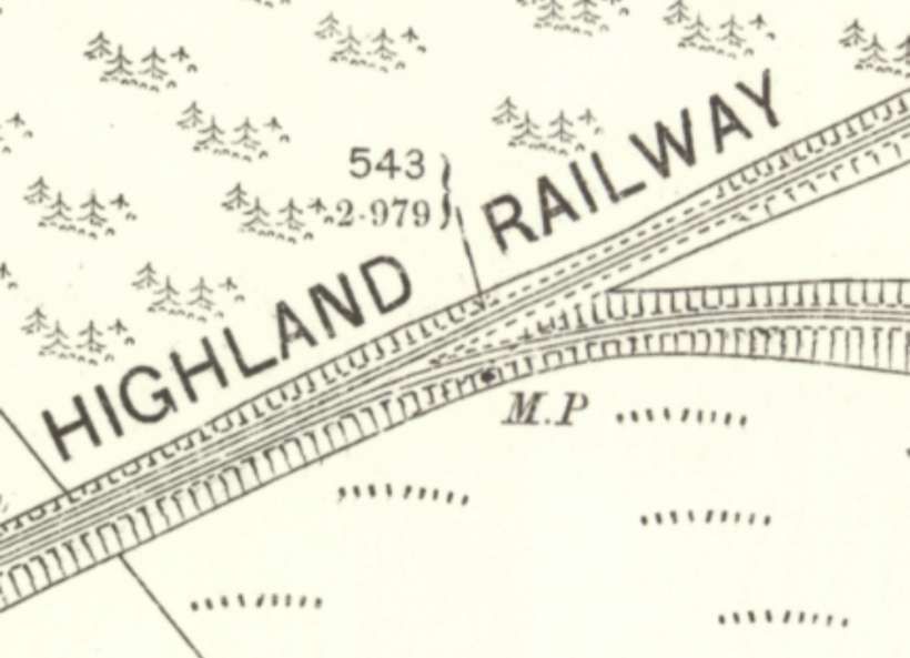
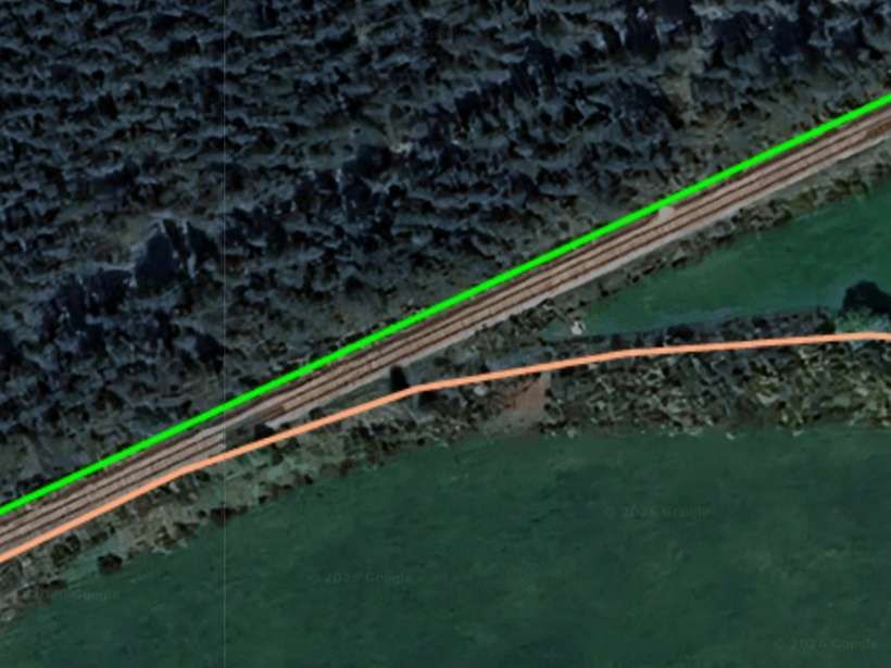
The railway descends from the first suspension station shown in the above photograph at a gradient of 1 in 3. Cuts had to be made in the affected ridges, the first of which, at support No. 59 (shown below), was particularly troublesome. Supports had to be spaced 10 m apart, and an allowance had to be made for very unstable ground where the substrata was highly fissured and where rockfalls were frequent. Due to the continued disruption, more than 6000 cubic metres of rock had to be moved,
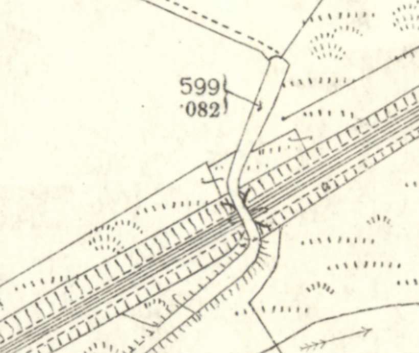
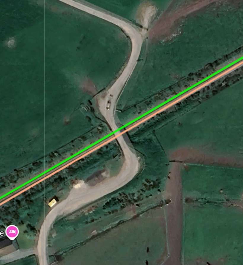
About 100 metres before the lower terminal station there was a double tensioning station where the suspension cables leading to the lower station were tensioned because the lower terminal station did not offer enough space for the weights. It was necessary to create pits for the tensioning weights. [4:p31]
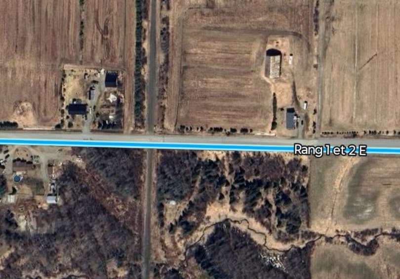
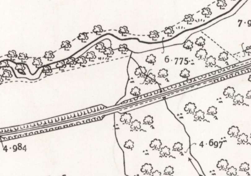
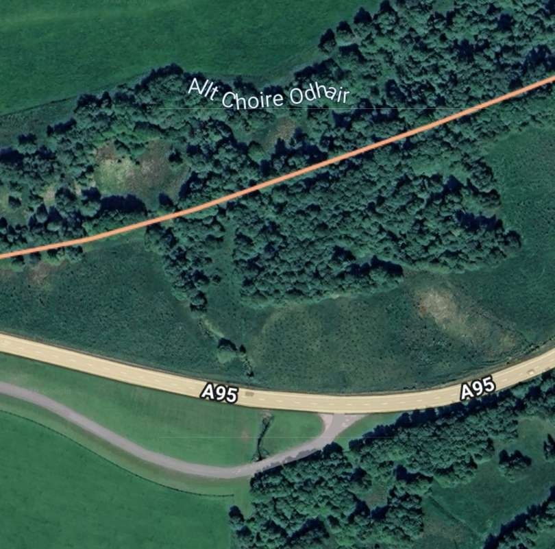
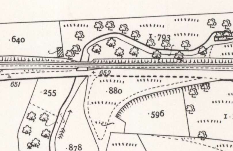
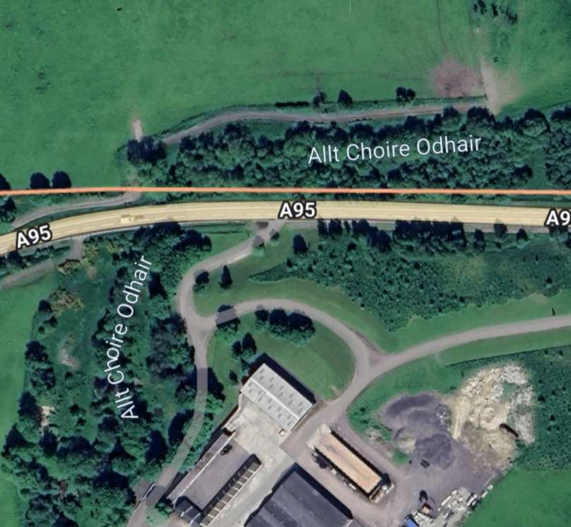
From the tensioning station the cableway crossed level ground to reach the terminus in Mkumbara. [4: p32]
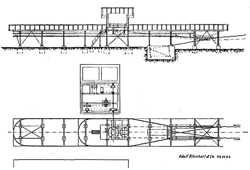
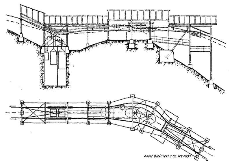
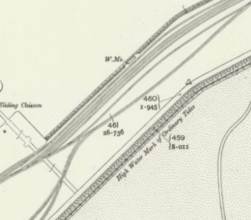
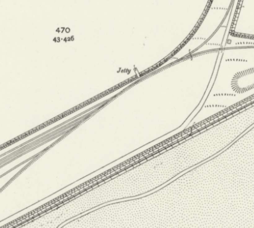
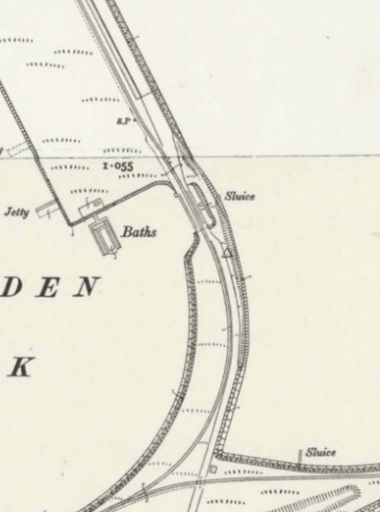
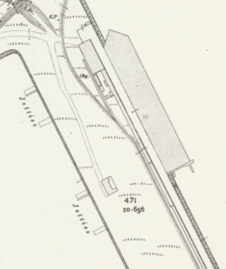
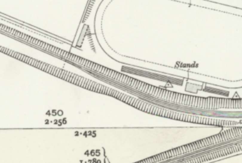
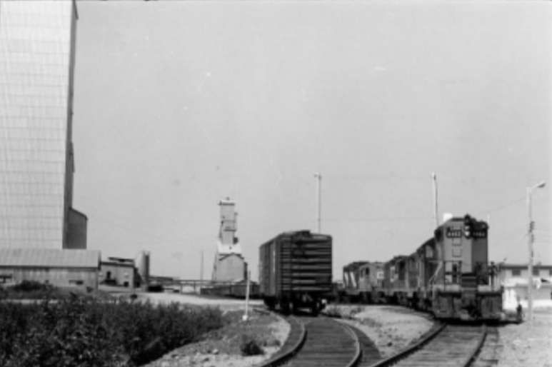
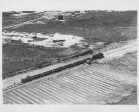
The terminal station (shown in plan and section below) was angled, due to the direction of the connecting track to the Usambara railway. The ground below the station was piled shaped to create a loading ramp from which the logs could be easily rolled into the railway wagons on the metre-gauge siding. The unloading of the cableway was carried out in the same way as the loading, using a mobile ‘table’ that was moved under the arriving logs and raised by a simple winch. The sling chains were then released. The table was then tilted towards the ramp, whereupon the logs rolled off in the desired direction. Sawn timber was unloaded by hand. To prevent any delays in railway operations, a siding was provided alongside the main line. [4: p32-33]
Perhaps of interest is the fact that permission to operate the railway telephone was granted only after great difficulties and subject to revocation, because telephone lines longer than 500 m, even if they ran entirely on the owner’s land, were within the protected area of the Tanganyika postal monopoly. [4: p33]
All the railway structures were made of iron to protect against termites, and the telephone poles were made of Mannesmann tubing. [6] This increased the construction costs. Freight costs for shipping and rail transport were within the normal limits appropriate to the size of the project. [4: p33]
In contrast, the costs of transporting the components to the construction site from the then-terminus of the Usambara Railway at Mombo, the execution of the foundation work, and the procurement of cement, water, etc., required considerable expenditure, especially since, neither the cattle-herding Maasai from the surrounding areas were available to work, nor could draft or pack animals be kept due to the tsetse fly. Roads also had to be built almost everywhere for transporting the materials, along which the supports, station components, and building materials were hauled individually by porters, during which many a sack of cement and many a barrel of water leaked quite by accident along the way, thus becoming lighter. The wages were relatively low, amounting to 45 heller or 60 pfennigs per day with free board including rice. The workers’ housing was also inexpensive to build. They consisted of reed sheds or reed huts, which, at best, were covered with clay. [4: p33-34]
Taking into account all the factors that delayed and complicated construction, it is understandable, despite the low wages paid to the workers, that the total construction costs exceeded those of the actual delivery of mechanical parts for the cableway many times over, and it does not seem implausible that the construction as a whole cost between 1.75 and 2 million marks according to one account, and between 2 and 2.5 million marks according to another. [34]
Writing in the early 20th century, Hand Wettich said, “The question must now be raised whether these considerable costs for a private branch line of 9 km in length will also achieve the desired success, but it can be stated that the system is already well on its way to doing so. In 1909/10, as already mentioned, 1240 cubic metres of cedar wood were exported from Neu-Hornow, and exports are constantly increasing.” [4: p34]
The influence of the timber transport cableway on plantation farming.
The company (Wilkens & Worse), which, like so many others, was only brought into being by the construction of the Usambara Railway, developed in a direction that was hardly expected beforehand. …. For logging, the construction of roads, field railways, and houses, the company Wilkens & Wiese needed to keep a large number of native workers and hauling the timber required the keeping of cattle. As an alternative, earlier in the 20th century, two stallions and ten Norman mares were purchased in Marseille and transported to Africa. Despite the contaminated coastal areas, they arrived safely in the mountains at that time. Initially, some animals died, but the majority began to acclimatize, as evidenced by a number of foals. The success of the stud farm was limited, although the animals were at least protected from the tsetse fly on the heights of western Usambara and otherwise found favourable conditions. The number of horses was insufficient for the needs of the sawmill. Therefore, oxen, the humped cattle of the country, were also raised. [4: p35]
Keeping people and animals forced the plantation society to engage in agriculture on the Usambara plateau. On the protected clearings, maize, turnips, and oats were cultivated. Barley, in particular, yielded exceptionally good harvests, albeit in a small area. Barley was preferable to oats as it was less susceptible to damage from the numerous buffalo and wild boar of the Schummewald forest, which caused considerable damage to the oat fields. Potatoes yielded up to 100 hundredweight per acre, but the potato harvests were threatened by severe night frosts, which at the time of writing of Wettich’s article had destroyed almost the entire year’s crop. [4: p35-36]
These developments, which came about almost accidentally, provided the possibility that both arable and livestock farming on the plateau could meet needs across German East Africa. In addition, non-food crops might be able to be cultivated – hemp, rubber, tannins, coffee, quinine , cotton, etc. – all these could be transported to the plains via the cableway. Neu Hornow and its cableway seemed to have a very bright future.
The scale that Wilkens & Wiese’s plantation business had reached was demonstrated by the company’s development, which began 13 years before with two Europeans and 100 native-born workers and by 1907 employed 10 to 12 Europeans and about 2,500 native-born workers. The company was started with a maximum capital of 500,000 marks, which gradually grew to 3,500,000 marks (as of 1907). [4: p36]
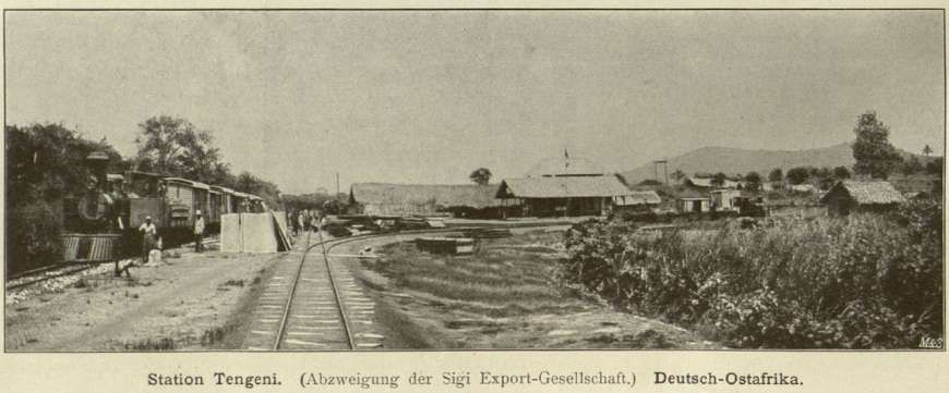
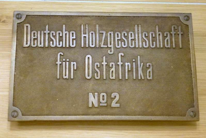
Just as the firm Wilkens & Wiese secured its business by expanding from timber harvesting, so too other timber companies established or acquired plantations for the same reason. For example, Elie Deutsche Holz-Gesellschaft für Ostafrika (Elie German Timber Company for East Africa) took over the rubber plantation of 3,000 Manihot Glaziovii trees [7] established directly at Sigi by the former Sigi Export Company. The three- to four-year-old trunks were tapped for the first time in 1910. Wettich was unable to comment on the quality of the rubber harvest because it was only at the time en route to Hamburg; however, the company was convinced of a good future for its plantation. [4: p36]
References
- M.F. Hill; Permanent Way Volume II: The Story of the Tanganyika Railways; East African Railways and Harbours, Nairobi, Kenya; Watson & Viney, Aylesbury & Slough, 1957.
- https://de.wikipedia.org/wiki/Adolf_Bleichert_%26_Co, accessed on 5th March 2025.
- https://web.archive.org/web/20081008211723/http://petervb.com/pdf/Clips_-_WireRopeNews.pdf, accessed on 5th March 2026.
- Hans Wettich; The development of Usambara under the influence of the East African Northern Railway and its private branch lines, with special consideration of the Mkumbara-Neu-Hornow cable car; Simion, Berlin 1911. Reprint from: Proceedings of the Association for the Promotion of Industry 90 (1911), Issue 6; via https://publikationen.ub.uni-frankfurt.de/frontdoor/index/index/docId/11924, accessed on 24th February 2026.
- https://commons.wikimedia.org/wiki/File:Lokomobile.jpg, accessed on 6th March 2026.
- Mannesmann tubing refers to high-quality, specialized steel tubes produced by Mannesmann Precision Tubes GmbH and Mannesmann Line Pipe GmbH, which are subsidiaries of the Salzgitter Group. The brand is known for pioneering the “Mannesmann process” for creating seamless steel tubes. Products are characterized by high dimensional accuracy, tight wall thickness tolerances, and minimal eccentricity. For more information see: https://en.wikipedia.org/wiki/Mannesmann and https://www.mannesmann-precision-tubes.com, accessed on 8th March 2026.
- Manihot Glaziovii is also known as Tree Cassava or Ceara Rubber Tree. It is a species of deciduous flowering plant in the spurge family, Euphorbiaceae, that is native to eastern Brazil. The tree cassava was used as a source of rubber, instead of Hevea brasiliensis throughout the world. The plant is introduced largely in the world, but now it is classified as one of the most highly invasive plants in the world. See: https://en.wikipedia.org/wiki/Manihot_carthaginensis_subsp._glaziovii, accessed on 8th March 2026.


.jpg)