A, then, recent exhibition at Battersea Wharf Goods Depot of British Railways and British Road Services freight vehicles and handling equipment prompted a review in The Railway Magazine of January 1959, [1] of developments in the handling of freight. The emphasis of the exhibition was on the improvement of door-to-door services. It was part of the broader Modernisation and Re-Equipment of the British Railways plan launched in 1954, which sought to modernize and improve freight services in the late 1950s and early 1960s.
The location of Battersea Wharf Goods Depot as it appears on the 1913 25″ Ordnance Survey which was published in 1916. [17]
The Freight Transport Exhibition at Battersea Wharf Goods Depot in London was held from 28th–30th October 1958. It was a major showcase organized by the British Transport Commission.
The exhibition highlighted initiatives to streamline freight transport, including the increased use of containers, modern cranes for lifting heavy containers, and the transition from traditional to motorized handling. A major goal of the exhibition was to demonstrate to traders and manufacturers the efficiency of using both rail and road services to move goods directly from factory to destination, aiming to recapture traffic lost to road transport.
Battersea Wharf Goods Depot, near Chelsea Bridge, was an area with significant railway goods activity in the 1950s.
Displays included mobile cranes lifting heavy containers, emphasizing the faster, safer, and more reliable methods for moving freight. The exhibition also featured, among other things: bulk cement wagons with compressed air unloading; the ‘Penman‘ ramp; numerous types of pallets and containers; and automatic coupling of wagons.
Wikipedia tells us that the Modernisation Plan failed to successfully redefine “what the purpose of the railways was. British Railways remained bound by the Railway and Canal Traffic Acts that obligated it to provide carriage for virtually any type of goods, regardless of quantity (large or small) between any two stations on the network, at set and published rates. This legislation dated back to the 19th century to prevent the railways abusing their monopoly as the sole practical long-distance transport provider for much of the country, but the growth of road transport had left the railways locked into a highly disadvantageous position. Road freight operators had no legal restrictions and could turn down work that was uneconomic, which BR could not, and could easily undercut BR’s carriage rates which the railway could not alter without legal consent.” [2]
“The Railway and Canal Traffic Acts also saddled BR with the necessity to maintain thousands of goods yards and other facilities, plus rolling stock and staff to service them, even when there was ever-decreasing demand for those services and such traffic as did exist was rarely profitable. This issue had been identified during the Great Depression, and the Big Four had campaigned for repeal of the Railway and Canal Traffic Acts as a ‘Fair Deal’ during the 1930s. However, this did not happen until the Transport Act 1962 gave BR freedom of contract, and until then the Modernisation Plan had to commission locomotives, rolling stock and facilities to manage the ever-declining but legally required wagonload freight traffic.” [2]
“The timing of the Modernisation Plan was also unfortunate, as just months after its publication the train drivers’ trade union, ASLEF, called a strike that lasted for 17 days, causing major disruption to the network. Many of BR’s long-standing freight customers – especially smaller business and industrial users which provided much of the remaining wagonload and less than carload freight traffic – were forced by necessity to start using road transport and never returned to the railways, which hastened the decline in railway freight traffic and rapidly undermined the logic and business case for the Plan’s renewal and expansion of large marshalling yards.” [2]
The exhibition in 1958 was an attempt to recover some of the freight movements lost road transport.
The Railway Magazine reported that in recent years “considerable progress [had] been made in extending and improving the service offered by British Railways to the trader and industrialist for the movement of freight of all kinds. Many of the major developments concerned with freight in the modernisation plan [were] of a long-term character: though they [were] being pushed forward with vigour, their full benefits [would] not be realised for some time. In many directions, however, other lesser but nevertheless important projects which [had] been completed [were] producing results … and [were] enabling the railways to provide freight services of growing reliability and speed.” [1: p47]
“Main policy developments [lay] in the direction of speedier movement of bulk supplies over long distances on trunk routes; extending door-to-door services; more economical handling of small loads; more detailed planning to meet customers’ requirements and the introduction of new vehicles, rolling stock and other equipment to meet changing conditions.” [1: p47]
“The relationship between rail and road [was] being thought of more and more in terms of co-operative arrangements designed to combine the best features of each in the common interest of the customer and the transport undertaking.” [1: p47]
The ‘Penman’ Ramp
The Penman Ramp was an intriguing device designed to enhance the transfer of containers by which the motion of the rail or road vehicle lifts the container from one on to the other. The Penman ramp was being used experimentally by British Railways.
The Railway Magazine reported that the Penman Ramp, “consists of two raised rails with inclined sections at either end which are positioned one at each side of a siding. The containers have pull-out metal skids near each corner and, as the vehicle moves between the raised rails, the skids engage with the inclined sections at the rail ends, and the container is raised from the vehicle. When the rail or road vehicle to which it is being transferred is moved into position between the raised rails, a hinged flap under the container engages with a batten on the vehicle floor and the container is pushed along the rails and down the inclined sections, to settle gently on the lorry or wagon. With this system, there are few costs; the equipment is robust and the mechanics are simple.” [1: p47,49]
Online archive material from the Commercial Motor magazine similarly reports that:
“The Penman ramp is being experimentally used. This simple device is designed to ease the task of transferring containers between rail and road vehicles in the railway siding. It consists of two raised rails with inclined end sections which are set up on each side of the railway line. The containers are provided with pull-out skids at each corner and these engage with the guide rails as the vehicle moves between them.
“Thus, a railway conflat wagon can he driven between the guide rails, the skids are rolled up the incline and the container is left in the elevated position while the wagon is removed and replaced by the lorry. In the reverse motion, a hingedt flap under the container engages with a batten on the floor of the vehicle, the motion of which draws the container gently downwards on to the platform.
“Perhaps the greatest factor in reducing handling costs is the use of the unit load, either in a container or on a pallet. Containers are available in a large number of types and sizes, for both rail and road use. They are, howeVer, expensive consignments when travelling empty. An effective solution of this problem lies in the collapsible container, an example of which has been developed for the railways by T.I. (Group Services), Ltd.” [3]
The ‘Penman’ transhipment ramp, showing containers being lifted onto the ramp by dismounting tubes as the railway wagons are shunted in by a tractor. [1: p48]Drawing off a container onto a road trailer: a hinged flap beneath the container is engaged by a batten on the floor of the road vehicles. [1: p48]
The ‘Freightlifter’ Fork-lift Truck
The Railway Magazine reported that a heavy duty fork-lift truck had been developed which could lift over 8 tons as a fork-lift and which could act as a mobile crane capable of lifting 6.75 tons, and which, with a lifting frame could handle containers of up to 7.25 tons in weight. The report continued: “It can also be converted into a searcher crane for removing articles weighing up to a ton from the corners of covered wagons. It has alternative driving positions, and can be driven on the road.” [1: p49] By the beginning of 1959, some fifty Freightlifters were in use in British Transport facilities.
A ‘Freightlifter’ truck raising a prototype light&alloy container, with a 7.5 ton crane in the background. [1: p49]
A model produced by Oxford Diecast of a Shelvoke & Drewry Freightlifter operated by British Railways. This is an N Scale model of a 1957 Shelvoke and Drewry Dualdrive Model 100 Freightlifter Forklift from Oxford Diecast featuring a metal body, window glazing and realistic decoration. [4]
The Freightlifters purchased by British Railways were of the ‘Dualdrive’ version. They could “be driven like a normal truck between sites at 22 m.p.h. and then controlled from a separate cabin. It was developed after the magistrates, at Slough, convicted British Railways for using a vehicle on the road in which the driver’s vision was obscured by a ‘jungle of steel’. This example could lift 18,000 lbs and carried special container lifting equipment.” [5]
Shelvoke & Drewry were based in Letchworth in Hertfordshire. Shelvoke & Drewry Ltd was formed in October 1922 by Harry Shelvoke (1878 – 1962) and James Drewry (1883 – 1952) who were employed by the Lacre Company that moved to Letchworth Garden City in 1910.
Mr. Shelvoke was General Manager, and Mr. Drewry was Chief Engineer.
Initially, they produced a low loadbed, smaller vehicle called the ‘Freighter’. “Early customers included the L.M.S. Railway, Carter Paterson, Express Dairy and J. Lyons. But the municipal potential was soon realised and by the end of 1924, when the hundredth vehicle had been built, there were 35 freighters in municipal service. The first order being from Deptford in September 1923.” [5]
The company became known for a range of refuse disposal vehicles and also, after a request from the London Brick Company, for the Freightlifter range of forklift trucks (which first came off their production line in 1952). The Company fulfilled 170 orders from London Brick where some of the vehicles were in service for 21 years. The Company built forklift trucks until 1974. [5][6] The ‘Dualdrive’ version was produced from 1957.
The ‘Dualdrive’ forklift known as a ‘Freightlifter’ [7]
Freightliners
The Railway Magazine also reported on British Railways plans for Freightliner trains. Two wagons with containers were on display at the show. The Railway Magazine noted that British Railways were “shortly to run in an entirely new experimental service [which] consists of flat-top wagons permanently kept together. The rake [would] run to a regular timetable between main centres at high speeds. Freightlifters or cranes [would] remove or load containers at stopping places.” [1: p49]
The Railway Magazine noted that in January 1959 there were “over 44,000 containers in service on British Railways alone, and many more [were] being produced. They [varied] from what [was] virtually an open box, adaptable for the conveyance of a wide variety of goods, to specialised highly-insulated types for ice-cream and quick-frozen foods. Sizes [ranged] from the large B.R.S. container, 24 ft. long, to a British Railways small wheel container that can be pushed by hand. Experimental collapsible containers, and ones made of light alloy, [were]being tested.” [1: p49]
In March 1959, British Railways introduced the Condor service, a pioneering overnight container train operating between London and Glasgow. Known as a precursor to the modern ‘Freightliner’ concept, it offered door-to-door container service using roller-bearing flat wagons and was often hauled by Metro-Vic Co-Bo diesel locomotives.” [8]
In the end the ‘Feightliner’ service did not commence until November 1965. “Initially, the new Freightliner service was intended for the domestic movement of freight in containers between points in Great Britain, with 16 terminals in operation in 1968, and Southampton and Tilbury under construction. However, in 1968 a London to Paris working was started which relied upon the Dover to Dunquerke train ferry, and by 1969, the service was linked into ports with a short-sea and a deep-sea service to other countries. By the end of the 1960s, liner trains (united transport) were carrying 12,900,000 tonnes (14,200,000 tons) per year. By the end of 1978, this average was 39,300,000 tonnes (43,300,000 tons). In 1969, British Rail transferred ownership of Freightliner to the National Freight Corporation, but with BR supplying the wagons and locomotives. It was returned to BR in 1978.” [9]
“By 1981, Freightliner was operating to 43 terminals, 25 of their own and 18 privately used locations. In 1982, the Port of Felixstowe was despatching three daily freight trains with containers on. In 1983, a second terminal opened (Felixstowe North), and between the two terminals, the amount of containers transhipped to and from rail was about 80,000 per year. … When a third terminal was opened in 2013 (named Felixstowe North, with the previous one being renamed Felixstowe Central), over 40 million TEUs (twenty-foot equivalent units) with 36 daily departures carrying containers were being handled. In 1986 and 1987, several terminals were closed, including four in Scotland (Aberdeen, Clydeport [Greenock], Dundee and Edinburgh) despite the potential for long-distance services from these terminals. British Rail deemed it more efficient to load containers at Coatbridge in Glasgow, and use electric traction south on the West Coast Main Line. Before the closures, Freightliner operated 35 terminals, including ports, compared with 19 under privatisation.” [9]
More on the history of freightliner intermodal services can be found here. [9]
Pallet Vans(Palvans, Diagram 1/211)
First procured in 1952, by January 1959 “nearly 1,500 specially-built railway pallet vans [were] in service and many more [were] on order for the exclusive conveyance of palletised loads. The typical example shown at Battersea [had] extra wide doors for easy access by mechanical handling equipment. It was built to accommodate the most common sizes of pallets, but [could] be adapted for any size by removable partitions and shields which also prevent movement during the journey. There [were] also over 1,200 pallet brick wagons used for the conveyance of refractory bricks.” [1: p49-50]
Ultimately, “BR built a total of 2388 Palvans with heavy doors at diagonal corners using two distinctive brake riggings. Although all had auxiliary suspension they rode poorly causing accidents so most were withdrawn by the mid 1960s, with a few surviving with UIC suspension. Note that some, in internal use with plain bearings, may have been built with roller bearings which were swapped out before allocation as internal user.” [10]
Two typical pallet vans are shown immediately below. …
Palvan No. B778771 at Ruddington Fields Station, Great Central railway Nottingham, 2010. [11]Palvan No. WGB 4023 alsoat Ruddington Fields Station in 2010. [11]
Transformer Wagons
Also exhibited at Battersea Good Depot was a specially designed “British Railways transformer wagon. … It [had] 24 wheels, [was] 92 ft. long, and [could] carry electric transformers weighing up to 135 tons. The wagon [was] equipped with traversing mechanism which enables an exceptionally wide load to be slewed sideways to avoid obstructions. The side girders [were] removed to load the vehicle.” [1: p50]
One object of the exhibition at Battersea Goods Depot was to show that the bulk-carrying capacity of British Railways and British Road Services was being continuously expanded. In a, then, “recent year British Railways produced over 33,000 all-steel 16-ton mineral wagons, 4,500 hopper wagons of 21-tons capacity, 1,300 25½-ton iron-ore hopper wagons, and 530 of 33-ton capacity. The 16-ton mineral wagon [was] the general wagon for bulk cargoes, but a great volume of coal and other minerals [was] carried daily in 21-ton hopper wagons of which there are now 36,000. There [were] also some 10,000 21-ton flat-bottomed mineral wagons, many of which [ran] in block trains direct from the collieries to merchants in main industrial and residential centres. The largest hopper wagon in service [was] the 56-ton bogie ore vehicle. A train of nine of these vehicles [could] carry 500 tons and the unloading time, through power-operated doors, [was] less than 60 sec. for the complete train.” [1: p50]
Wagons Requiring Specialised Equipment
“Of wagons for commodities which require specialised equipment, a cement wagon was shown. This special 20-ton all-steel enclosed wagon, which [could] be pressurised with air for pneumatic discharge through a flexible pipe to a road vehicle, or to a storage silo, overcame many difficulties. It [was] also suitable for alumina, salt, fuller’s-earth, powdered lime, pulverised fuel, and slate dust.” [1: p50]
The pipe discharge of cement from a British Railways bulk-carrying wagon, into which compressed air was fed through a valve below the side frame. Loading was by gravity through roof doors. [1: p47]
Bulk Liquid Carriers
“The exhibition also included a selection of rail and road vehicles designed for carrying liquids in bulk. There were tanks which [were] fixed to a railway chassis and [could] carry 10,000 gal. at a time; others which are demountable and can be placed on a road vehicle; and some road trailers designed to be carried ‘piggy-back‘.” [1: p50]
Bulk liquid transport on British Railways featured a transition from the end of the 1950s from traditional four-wheelers to larger, high-capacity bogie tankers. Key vehicles included Class A and B tankers for oil/petrol, TTA two-axle tank wagons for various liquids, and specialized containers for milk, chemicals (like chlorine), and beer. TTA Wagons were used extensively for industrial hot tar, agricultural cold milk, and high-octane aviation fuel.
Interfrigo and Transfesa Wagons
“Among wagons shown at Battersea, which are used in international traffic to and from the Continent by the train ferry services, was the ‘Interfrigo’, fitted with electrical ventilation, and the ‘Transfesa’, a large-capacity wagon some 40 ft. long, used for transporting citrus fruit and other perishables from Spain, returning with export machinery. The axles of the latter vehicle can be changed to enable it to travel on both the wide-gauge Spanish railways and standard-gauge lines in Europe.” [1: p51]
“Intercontainer was established, originally, as a not for profit cooperative partnership between principal European rail companies, in 1967. In 1993 the business acquired and operations were pushed together with those of another not for profit cooperative partnership called Interfrigo which had been founded in 1949 and specialised in timely refrigerated rail transport of high volume goods, notably bananas carried from the port of Rotterdam to principal European markets such as Germany and Switzerland. The resulting combination now became known as Intercontainer-Interfrigo. In 2003 the company was converted into an ‘Aktiengesellschaft’ (a form of Joint-stock company) as defined under Belgian law.” [13]
“On 26th November 2010 the owners placed the business in liquidation with the stated intention of minimizing disruption to customers by transferring operation of the company’s 145 or so weekly trains to the rail companies themselves.” [13]
Interfrigo was an international organisation owned by a consortium of European railways and set up to provide specialist refrigerated wagons. This example was built to fit the British loading gauge. [15]
“Transfesa was founded in 1943, early operations were centered around the domestic transport of livestock. During 1952, it received its first freight wagons to be constructed with interchangeable axles, permitting freight movements between Spain and the rest of Europe without the need from transhipment, thus accelerating service speeds and lowering costs. Throughout the 1950s and 1960s, international traffic grew based around the carriage of fruit exports to western Europe using company’s own ventilated wagons.” [14]
“During the 1960s and 1970s, Transfesa opened numerous branches across Europe, such as in Germany and Switzerland.[2] In 1972, it expanded into the British market as well.[3] During the 1970s and 1980s, the company found new business in the automotive sector, transporting complete cars by rail to dealerships throughout the continent, as well as parts between manufacturing sites. In the 1990s, Transfesa branched out into ancillary activities such as rolling stock maintenance and terminal management services.” [14]
“An experimental automatic coupler manufactured by Dowty Hydraulic Units Limited also was demonstrated. It incorporate[d] the vacuum brake pipe, and [would] engage and lock in a wide range of track curvature and gradient conditions; uncoupling is achieved simply by operating a lever mounted on either side of each wagon. When coupling wagons not fitted with automatic couplers, the unit can be swung through 90 deg. to present a standard draw hook. It is interchangeable with conventional draft gear without modifications having to be made to the wagon.” [1: p51]
The Dowty experimental automatic goods wagon coupler. The horns are about to engage, during trials on sharply-curved track. An uncoupling lever is provided on each side of every wagon. [1: p50]
This final image shows the Dowty Coupler not in active use or, as in the image title, in swung aside position. [16]
References
Developments in Freight Transport; in The Railway Magazine January 1959; Tothill Press, London, 1959, p47-51.
Following on from a couple of articles about the Tanat Valley Light Railway written some years back, I was reading some older rather tatty magazines and found an article entitled “Rails up the Tanat Valley” in an issue of the Ian Allan publication ‘Railway World‘ – the June 1990 edition. [1]
The Tanat Valley Railway and associated lines. [1: p365]
In his article, Colin Ganley recounted the rise and decline of the minor lines running west from Oswestry, the last remnant of which by 1990 had been ‘mothballed’.
Colin Ganley wrote: “In October 1988, the last train ran between Gobowen and Biodwell Quarry in Shropshire. For some years the line had carried only stone trains, bringing out ballast to the requirements of the Area Engineer. The trains, normally Class 31-hauled, traversed the remains of five different branch lines, which in their heyday provided Oswestry and the eastern end of the Tanat Valley with a fascinating and complicated array of lines to serve local industry. With the decision to cease using ballast from Blodwell, traffic on the line came to an end, marking the final cessation of all rail services connected with the delightful one-time Tanat Valley Light Railway.” [1: p364]
He continued: “For the present, this surviving section is in suspended animation. As there is a possibility that the stone traffic may restart in the future, the railway is being left in place. Traffic will resume if BR returns to this source of ballast. If not, eventually a decision will be made to lift the track and dispose of the land: unless the Cambrian Railways Society, based at Oswestry, is in a position to take an active interest in its future.” [1: p364]
Parts of the derelict line at Nant Mawr which were once the western end of the Old Potts Railway are now owned by ‘The Tanat Valley Light Railway’ which is a modern charity that aims to preserve and restore this line.
“The original Tanat Valley Light Railway was the first cross border light railway crossing from England into Wales, meandering up the fantastic Tanat Valley from Llynclys Junction to Llangynog and providing links to Llanymynech and Llanfyllin via its other branches.” [2] It was opened in 1904, mainly as a direct result of the 1896 Light Railways Act, but, says Ganley, “before taking up its story it would be useful to look at its associated lines and also earlier schemes to provide the picturesque village of Llangynog with railway transport. At the height of railway mania in 1845, the Shrewsbury, Oswestry and Chester Junction Railway obtained powers to build a line from Shrewsbury to Chester with a branch from Gobowen to Llanymynech. All that was built of the branch was the 2.25 miles from Gobowen to Oswestry, which opened on 23rd December 1848. In 1854 this line became part of the Great Western Railway.” [1: p364]
He continues: “The second portion of line to be constructed was the Oswestry & Newtown Railway, which was incorporated in 1855. to link these two towns. The section between Oswestry and Pool Quay opened on 1st May 1860 with the remainder to Newtown opening on 14th August. … The company, which was to be the foundation of the later Cambrian Railways, opened a 1.25-mile freight-only branch from Llynclys Junction, some 3.5 miles south of Oswestry, to Porthywaen. This branch served important quarries, some of which are still operating today, and became the railhead for the industries of the Upper Tanat Valley, Shortly after the Porthywaen branch was opened, a mineral line was built from it to serve some collieries at Trefonen. These collieries however were not very successful and this line was abandoned as early as 1881.” [1: p364]
“In the meantime there had been several proposals to build a line up the Tanat Valley. One such proposal envisaged a great trunk line from Worcester to Porth Dinllaen, near Nefyn on the Caenarvonshire coast, with the object of providing an alternative route for Irish Mail traffic. In 1860, a similar proposal was put forward as the West Midlands, Shrewsbury & Coast of Wales Railway which planned a railway from Shrewsbury to Portmadoc via Llanymynech, Llangynog and Bala. This route would have included a 1.5-mile tunnel under the Berwyn Mountains between Llangynog and Bala.” [1: p364]
“However, the project had trouble raising support and money. … Proposals for a similar route were resurrected in 1862 as the Shrewsbury & North Wales Railway. Powers were obtained by 1865 to build a line from Abbey Foregate, Shrewsbury, to Llanymynech but before this section was completed the company had merged with another scheme to provide a railway from Stoke-on-Trent to Shrewsbury. The combined efforts brought forth the grand title of the Potteries, Shrewsbury & North Wales Railway (or POTTS for short) and extended the original plans to include an extension from Llanymynech to Nantmawr over which passenger trains were to run as far as Llanyblodwell (later renamed Blodwell Junction). The financial troubles of the POTTS and its rebirth as the renowned Shropshire & Montgomeryshire Light Railway [3] are outside the scope of this article, but the result was the working of the Llanymynech to Nant Mawr section by the Cambrian Railways from 1881. At this time goods traffic only was operated, the passenger service between and Llanymynech and Lianyblodwell having ceased in 1880.” [1: p364-365]
“The Light Railways Act of 1896 made possible the construction of railways to remote agricultural areas that hitherto had had difficulties in raising capital and several places along the Welsh border benefited from such schemes, one being the Tanat Valley. The Act saw the birth of two schemes to provide, at last, rail transport to the Upper Tanat Valley and the industries of Llangynog. The unsuccessful proposal was for a 2ft 6in gauge railway from the Llanfyllin terminus of the Cambrian branch from Llanymynech.” [1: p365]
“This plan, the Llanfyllin & Llangynog Light Railway, was to cross sparsely populated country between Llanfyllin and Penybontfawr and would not have benefited the lower part of the Tanat Valley. It nevertheless could have been a fascinating line had it been constructed, though the change of gauge at Llanfyllin would have proved a disadvantage.” [1: p365]
“The scheme that was selected by the Light Railway Commissioners was for a standard gauge line from the Cambrian’s Porthywaen mineral branch straight up the valley Liangynog. The plan also envisaged using a short section of the Nantmawr branch. The Tanat Valley Light Railway received its Light Railway Order in 1898 and was constructed by J. Strachan of Cardiff who employed about 125 men on the work. The total cost of the line proved to be about £92,000 which was around £20,000 more than the company had hoped for. This shortfall, not helped by a delay in construction, meant that the Tanat Valley Co was impoverished from the outset and had to approach the Treasury for more grant aid. During construction in 1903 some directors found that the contractor was giving a ‘free’ train service over the partially finished railway but as the contractor was allowed to finish the job it can be assumed that any quarrel was rectified.” [1: p365] For the earlier articles about this line, please follow these two links:
Colin Ganley continues: the Tanat Valley Light Railway “opened on 5th January 1904 to both passengers and freight and was worked by the Cambrian from the start. It became wholly part of the Cambrian in 1921, passing to the Great Western Railway and then to the Western Region of British Rail. The length of the linc from Llynclys Junction to Llangynog was some 15 miles 71 chains and included 11 stations or halts, one of which was former POTTS station of Llanyblodwell which was renamed Blodwell Junction. The stations were of typical light railway pattern with rather mean corrugated iron clad buildings and, except for Liangedwyn and Llanrhaiadr Mochnant, had only one platform. Original plans for some stations did consider refreshment rooms in effort to build up tourism but the company’s lack of capital put an end to such plans.” [1: p365-366]
“With the opening of the Tanat Valley line, passenger services were restored between Llanymynech and Blodwel Junction as this had been a condition of securing support from potential opponents during the planning stages. The opening of the Tanat Valley line also restimulated the slate quarries at Llangynog which had all but closed by 1900. Slate quarrying continued intermittently until 1939 but lead mining, which had effectively ceased in 1877, was never to resume on any commercial scale. The railway also assured the development of granite quarrying at Llangynog, the Berwyn Granite Co. providing much traffic until World War 2. The quarry survived into the mid 1950s but at the end offered virtually no traffic to the railway.” [1: p366] Berwyn Granite Quarries Ltd. remains an active company with headquarters in Wellington, Shropshire. [4]
Colin Ganley continues: “Initially the passenger service consisted of four trains each weekday with an extra trip on Wednesdays. Many trains were mixed and the journey to Oswestry took no less than 75min on some trains. Two trains a day carried a through coach to Llanymynech, detached at Blodwell Junction, but this practice ceased in 1915 and was replaced by a connecting service. The Blodwell Junction to Llanymynech service ceased completely as from 1st January 1917, having been hardly ever used and only operated to fulfil an agreement. Freight traffic over this section ceased in 1925, the Nantmawr traffic then being worked via Porthywaen, and most of it was lifted between 1936 and 1938.” [1: p366]
By 1923, “the number of passengers being carried was half the level of 1913 and continued to decline during the GWR years. By 1925 services, which normally consisted of two four-wheeled carriages, were reduced to three trains each way, though certain extras ran on Wednesdays and Saturdays. In 1929, the GWR introduced a rival bus service which was taken over by Crosville in 1933. The bus served the centres of villages far better than the train as certain stations. Llanrhajadr Mochnant in particular, were badly situated. This, coupled with the elongated journey times caused by the adherence to light railway practices, reduced traffic even further.” [1: p366-367]
“During World War 2 the passenger service was reduced to two trains each way, by now composed of a single Cambrian brake third. After the war, despite petrol rationing, few people were making the delightful trip up the Tanat Valley by rail. Goods traffic was also on the wane and on 15th January 1951 passenger services ceased because of a grave coal shortage, never to return. Official closure took place on 1st July 1952 and at the same time freight traffic was also withdrawn between Llanrhaiadr Mochnant and Llangynog. The track on this section remained in situ for several years, not being lifted until 1958. Freight traffic to Llanrhaiadr Mochnant ceased abruptly on 5th December 1960 after the river bridge near Pentrefelin was badly damaged by flooding,” [1: p367]
“Services on neighbouring lines were savaged in the mid-1960s. All passenger traffic between Welshpool and Whitchurch and also over the Llanfyllin branch were withdrawn on 18th January 1965, leaving Oswestry with the Gobowen diesel shuttle service, which ceased in November the following year. By 1967, just the single track South of Oswestry to Porthywaen and Nantmawr was left, along with the line from Gobowen. Reduction in traffic over the ensuing years left just the Blodwell Quarry service. All the sidings at Oswestry and Porthywaen disappeared. The section west of Blodwell Junction had been lifted by 1965 and though the Nantmawr branch has not seen a train for 20 years the track is still in-situ, although with sturdy trees growing between the sleepers.” [1: p367]
“No account of the Tanat Valley would be complete without a brief mention of its quaint motive power. From the outset, the Cambrian normally provided three Sharp Stewart 2-4-0Ts, Nos 57, 58 & 59 of 1866 vintage. They became GWR Nos. 1192, 1196 and 1197 respectively, and although No 1192 was withdrawn in 1929 after being sent to Devon, Nos 1196 & 1197, both in a rebuilt state, survived at Oswestry until 1948.” [1: p367]
Sharp, Stewart and Co. “was a steam locomotive manufacturer, originally based in Manchester, England. The company was established in 1843 following the dissolution of Sharp, Roberts & Co.. In 1888, it relocated to Glasgow, Scotland, where it later amalgamated with two other Glasgow-based locomotive manufacturers to form the North British Locomotive Company.” [5]
Ganley tells us that the two surviving Sharp Stewart locomotives were “assisted by No. 1308 Lady Margaret, an Andrew Barclay 2-4-0T built in 1902 for the Liskeard and Looe Railway and taken over by the GWR in 1909. This locomotive also did yeoman service in the Tanat Valley until it too was withdrawn in 1948.” [1: p367]
“Other locomotives were seen up the Tanat Valley at various times, including old Cambrian Sharp Stewart 0-6-0s dating from 1875 and the odd Dean Goods. In the latter years passenger traffic was the preserve of ‘5800’ class 0-4-2 tanks, numbers 5808 & 5812 being particular regulars. Goods traffic that remained was normally entrusted by the early 1950s to the Ivatt Class 2 2-6-0s.” [1: p367]
“Various types of diesels handled the surviving quarry services, including Classes 25, 31 and 37. A Class 31 had the privilege to be the last railway locomotive to operate a commercial train (so far) in this region of complex and fascinating railway history. It remains to be seen whether the Cambrian Railways Society will be able to continue the railway traditions of the area if they can successfully launch a private steam service from their Oswestry base.” [1: p367]
Ganley was writing in 1990, things have moved on over the past 36 years. Cambrian Heritage Railways, in the 2020s, operate a service on selected days from their Oswestry Station to Weston Wharf, featuring steam, vintage diesel and diesel multiple units. The 1.75-mile scenic route leads to Weston Wharf with its period station with a café, picnic area, and railway artifact displays. Cambrian Heritage Railways also operate the ‘Llynclys Railway Centre’ which is open on select dates – at Llynlcys South Station. [6][7]
References
Colin Ganley; Rails up the Tanat Valley; in Railway World; Ian Allan, June 1990, p364-367.
This short line originated from a proposal made by the stationmaster at Wendover. [1: p97]
The featured image for this short article is a photograph of a OO-Gauge model of Wendover Railway Station built by David Dan Givens and covered in the September 2018 edition of Hornby Magazine. The image shows the Northwest approach to Wendover Station. The branch line to RAF Halton leaves the main line just off camera to the left. [17]
The Halton Light Railway grew out of proposals made by the stationmaster at Wendover Station (bottom-left on this map extract). The line was less than 2 miles in length. It had a short 2ft-gauge extension across the Icknield Way into the beech woods on the slopes of the Chilterns. [1: p97]A very similar area, on modern satellite imagery. [Google Maps, March 2026]
Wendover Railway Station serves the town of Wendover in Buckinghamshire, England, and villages including Ellesborough and Wendover Dean. It was opened by the Metropolitan Railway in 1892 and is on the London Marylebone to Aylesbury line and, in the 21st century, is served by Chiltern Railways trains. It sits between Great Missenden and Stoke Mandeville stations. [4]
A narrow gauge railway link to Wendover station, which had been used to transport timber from beech woods on the Halton Estate in support of the [First World] war effort, was replaced in 1917 with a standard gauge branch line, to bring in coal and building materials to the RFC workshops. Timber from Halton Woods was used as trench props on the Western Front. [7]
Opened in 1917 after an eight-week construction period, the line ran for 1.75 miles (2.82 km) and was constructed by German prisoners of war during World War I. The railway was originally built, earlier in WW1 to carry timber from local beech woods to Wendover Station and building materials into the site of RAF Halton for construction of the workshops and other units. It also forwarded coal to the boilers on the camp. [7]
Wikipedia says that the line was originally built as a narrow gauge line and “was later converted from a narrow gauge of 1 ft 11 1⁄2 in (597 mm) to 4 ft 8 1⁄2 in (1,435 mm) standard gauge and was used to bring timber out of Halton woods.” [2]
The Railway has a Monument Record and appears on Buckinghamshire County Council’s Heritage Portal. It is Monument Record No. 0951006000. [7]
The Historic Monument Record says that the Railway is shown on historic mapping NG 6″ Provisional Edition 1955-62 and NG 10k Edition 1972-90. Labelled as ‘dismantled railway’ on 25k digital raster map. It appears to be disused even by 1955-62 edition. [7]
A railway dating from the 20th century is visible on historic aerial photographs and remote sensing data as extant structures, earthworks and levelled earthworks and was mapped as part of the Aylesbury Vale Aerial Investigation and Mapping project (EBC18604). Located on the north side of the town of Wendover and centred at SP 86991 08905. The railway line, originally built as a narrow-gauge line, was constructed to extract timber from the woods at Halton, felled by Canadian lumberjacks, for use in the trenches in World War I. [8: p81] Aerial photographs from 1961 appear to show the railway still present but it does not show on those from 1967. Images of the railway and the station at West Camp are on the ukairfields website for Halton. [7]
The conversion of boilers on the RAF station from coal fired to oil fired, allowed road-tankers to take over the inward flow of fuel and accelerated the demise of the railway and the last train ran on 29th March 1963 with closure following two days afterwards.[7]
The majority of the track has since been removed, including the original bridge over the Grand Union Canal which was replaced by a modern footbridge, however much of the line is designated a permissive footpath (rail trail).
A video covering this line can be found here. [5] This is one of a series of videos under the overall title of “Henry’s Adventures.”
The Route of the Line
Leaving Wendover heading Northwest, trains serving the Halton RAF Station ran alongside the main line before turning away to the Northeast.
The line crossed Aylesbury road at a level -crossing. …
Looking Northwest along Aylesbury Road, the crossing sat adjacent to Castle Park. This image was shared by Rod Bacon on the Wendover Memories Facebook Group on 28th March 2025. [18]The crossing gates on the Southeast side of Aylesbury Road. This image was shared by Rod Bacon on the Wendover Memories Facebook Group on 4th April 2025. [19]The line of the Light Railway is marked in this and later satellite images by a brown line superimposed on the image by RailMapOnline.com. [14]Looking Southwest from Aylesbury Road. The hedge immediately in from of the camera masks the line of the old railway. [Google Streetview, September 2025]Looking Northeast from Aylesbury Road, the track ahead of the camera and the hedge line to its left are on the line of the old railway. [Google Streetview, September 2025]
Further East the line crossed the Wendover Arm of the Grand Union Canal. …
The location of the railway bridge over the Wendover Arm of the Grand Union Canal. The rail line followed the field boundaries, running from the bottom-left corner of this image to the top-right. [Google Maps, March 2026]
Beyond the Canal, the line turned Northeast before reaching RAF Halton where a station building and platform received and despatched trains. A fan of sidings sat to the right of the line.
A short length of 2ft-gauge line remained in use until it was closed in 1941. It sat to the Northeast of the sidings and crossed Icknield Way before coming to its terminus.
RailMapOnlne.com records the railway lines in the immediate vicinity of RAF Halton in brown and orange, as shown here. The standard-gauge line (brown) is much as shown on the first plan/map above. The 2ft-gauge line is different to that shown on the map/plan near the head of this article. If we make the assumption that there would be a need to tranship timber from the 2ft line to the standard-gauge line, then the layout shown here is the more likely. The two maps have the crossing point over the Icknield Way (B4009) at approximately the same location. [14]The crossing over the Icknield Way was at the approximate location shown by the orange line superimposed on the satellite imagery from RailMapOnline.com. [14]Looking West from Icknield Way along the line of the old 2ft-gauge line. [Google Streetview, March 2025]Looking East from Icknield Way along the line of the old 2ft-gauge line. [Google Streetview, March 2025]
Locomotives
I have not been able to establish a locomotive roster for the RAF lines at Halton. One locomotive in particular was identified by Frank Jones in the 1960s. ….
Manning Wardle 0−4−0 saddle tank R.A.F. No.2 was photographed by Frank Jones, presumably after the closure of the branch line and after she had been through the hands of John F. Wake’s Geneva Engineering Works in Darlington. Frank Jones submitted a photograph of No. 2 to the Industrial Railway Record in October 1968. It can be seen here. [6]
Modelling
Hornby Magazine covered an OO-Gauge Model of Wendover Railway Station which included the first few metres of the branch line. The layout featured in the September 2018 edition of the magazine. [17]
The RAF Halton Branch is represented by the line at the centre of this image which has a very short train heading away along the branch. [17]
This image shows the branch locomotive which was a Manning Wardle 0-4-0ST heading for RAF Halton. [17]
Wendover’s Goods Shed and Signal Box (shown here) sat immediately Southeast of the junction. [17]
References
Clive Foxell; The Story of the Met & GC Joint Line; Clive Foxell, Chesham, Buckinghamshire, 2000.
Shoeburyness was once a fortified place guarding the Northern flank of the Thames Estuary. It appears in the Anglo-Saxon Chronicle of 894 CE, and it was assumed for many years to have been built as a ‘Danish Camp’ by the Viking leader Haesten as those chronicles say that while King Alfred headed West towards Exeter, Danish marauding parties, “gathered at Shobury in Essex, and there built a fortress.” [1][2: p60]
However, in 1998, archeological excavations unearthed classic Iron Age interior features and just a year later found evidence of a Middle/Late Bronze Age pottery associated with the visible remains of the ramparts. [1] These excavations took place after the closure of Shoeburyness Barracks while the site was being prepared for redevelopment. Subsequently Southend Borough Council sought to create a Conservation Area centred on the site. [3]
Speaking of this site, Historic England (List Entry 1017206) says: “The defended prehistoric settlement at Shoeburyness has been denuded by the development of the 19th century military complex, although the southern half of the enclosure has been shown to survive extremely well and to retain significant and valuable archaeological information. The original appearance of the rampart is reflected in the two standing sections, and the associated length of the perimeter ditch will remain preserved beneath layers of accumulated and dumped soil. Numerous buried features related to periods of occupation survive in the interior, and these (together will the earlier fills of the surrounding ditch) contain artefactual evidence illustrating the date of the hillfort’s construction as well as the duration and character of its use. In particular, the recent investigations have revealed a range of artefacts and environmental evidence which illustrate human presence in the Middle and Late Bronze Age and a variety of domestic activities in the Middle Iron Age, including an assemblage of pottery vessels which demonstrate extensive trading links with southern central England. Environmental evidence has also shown something of the appearance and utilisation of the landscape in which the monument was set, further indications of which will remain sealed within deposits in the enclosure and on the original ground surface buried beneath the surviving sections of bank. Evidence of later use, or reuse, of the enclosure in the Late Iron Age and Roman periods is of particular interest for the study of the impact of the Roman invasion and subsequent provincial government on the native population; the brief reoccupation of the site in the Anglo-Saxon period, although currently unsupported by archaeological evidence, also remains a possibility.” [4]
Despite the extensive destruction wrought by the occupation of the site by the Board of Ordnance in 1849 (and successors), much more of the original survives than might be expected.
Historic England’s listing continues: “The settlement, which many 19th century antiquarians associated with historical references to a Danish Camp, lay in a rural setting until 1849 when Shoebury Ness was adopted as a range finding station by the Board of Ordnance and later developed into a complex of barracks and weapon ranges. The visible remains of the Iron Age settlement were probably reduced at this time leaving only two sections of the perimeter bank, or rampart, standing. This bank is thought to have originally continued north and east, following a line to East Gate and Rampart Street, and enclosed a sub-rectangular area of coastal land measuring some 450m in length. The width of the enclosure cannot be ascertained as the south eastern arm (if any existed) is presumed lost to coastal erosion. The surviving section of the north west bank, parallel to the shore line and flanking Warrior Square Road, now lies some 150m-200m inland. It measures approximately 80m in length with an average height of 2m and width of 11m. The second upstanding section, part of the southern arm of the enclosure, lies some 150m to the south alongside Beach Road… [Trial excavations within the enclosure during 1998] revealed a dense pattern of well preserved Iron Age features, including evidence of four round houses (identifiable from characteristic drainage gullies), two post- built structures, several boundary ditches and numerous post holes and pits. Fragments from a range of local and imported pottery vessels date the main phase of occupation to the Middle Iron Age (around the period 400-200 BC).” [4]
Our primary interest in this article is in the later development of the site from 1849 onwards and the construction and extension of a military tramway and railways associated with the Ordnance depot and other military sites along the coast close to Shoeburyness.
The land was first purchased here for Experimental artillery ranges in 1849. “Shoeburyness was chosen because of its position close to the Maplin Sands, Where a huge expanse left dry at low tide could be used in conjunction with the sparsely inhabited coast of Essex adjacent. In 1856, Lord Panmure, Secretary of State for War, submitted a recommendation that the work of proof experimentation should be severed from that of instruction. The outcome was the creation of a separate school of gunnery, which was opened on 1st April 1859.” [5: p239]
Throughout the immediate vicinity of Shoeburyness there are a lot of older buildings associated with the Military Depot. A number of these buildings can be found here. [31]
The Standard-Gauge Military Tramway
Shoeburyness changed rapidly from a hamlet to a bustling military establishment. And by 1873, and the completion of the construction of the site, “the original portion of the Shoeburyness Military Tramway had been built as an integral part of it. The line was linked to three piers to facilitate unloading and transport by river from Woolwich and elsewhere, of stores, equipment and guns, brought and destined for various parts of the garrison.” [5: p239]
The use, officially, of the word ‘tramway’ for what is in fact a ‘railway’ was derived from the term’s use in respect of colliery tramways and “is rooted in the legislation under which it was extended and worked. … Had the original line impinged on any highway, the Tramways Act of 1870 would have been applied to it, but having been laid on land already held from which the public were rigorously excluded, the Act was not invoked. By the time the first extension was required. the Military Tramways Act of 1887 had been passed, a measure designed to strengthen rather than to supersede the Act of 1870, which was intended primarily for street tramways.” [5: p239]
The main Shoeburyness military tramway was standard-gauge, but the military site also featured separate narrow-gauge sections of both 2 ft- and 2 ft 6 in-gauge. The standard-gauge line was constructed by the army to connect various installations within the experimental range and was later connected to the main railway network in 1884. The site used standard gauge lines extensively to serve its numerous buildings.
The separate narrow-gauge lines were often used in high-risk areas, such as shell filling huts, where steam locomotives were considered a fire hazard. These lines typically used hand-pushed or sometimes horse-hauled trolleys.
When the tramway was extended to New Ranges in 1890, the whole line was brought within the provisions of the Act of 1887. (But thirty years later, it appears that the extension to Havengore Island did not conform with the Act). “The Shoeburyness Military Tramways Order of 1893 authorised, retrospectively, an extension north-eastward for a distance of 1 mile 20 chains. from a junction with the original tramway, 21 chains South of Campfield Road, to where new artillery ranges had been brought into use on 5th April 1890.” [5: p239-240]
“By permission given in April 1889, the tramway passed through the London, Tilbury & Southend Railway station yard alongside its southern boundary: and an Agreement dated 8th July 1891 anticipated a rail connection there, for which £1000 had been voted in accordance with the Army Estimates for 1886/1887 This having been accomplished, fresh terms were embodied in a second Agreement dated 4th July 1895. Administrative buildings and the railway centre were placed in and around a seventeenth century property known as Suttons,” [5: p240] or Sutton Manor.
The now Grade II listed Sutton Manor was “built in 1681 of red brick and is surrounded by a red brick wall and gate. The interior has wooden panelling. An oak staircase with a dining room, servant quarters and around 9 bedrooms. The land was owned by Daniel Finch (2nd Earl of Nottingham) but the House itself was most likely built by Francis Maidstone (a dealer in woollen textiles). He may have demolished a previous house standing on site.” [6] Suttons is a Category A structure on the Historic England Heritage at Risk Register. [7]
In 1906, the line was further extended 1 mile 52.22 chains from New Ranges to Havengore Point. The War Department completed the acquisition of New England and Foulness islands in 1914/1915. In August 1915, a contract was placed with Findlay & Co Ltd. For the supply and erection of a Scherzer Rolling Lift Bridge over Havengore Creek. Scherzer was an American Company from Chicago. The contract for the viaduct to run either side of the bridge was placed with Braithwaite Thirsk in February 1917 and piling started in June. There were a number of problems with the piling and completion of the viaduct stretched out to 1919 when the lift bridge was erected.
The bridge had a split counterweight and was originally hand operated carrying a road and a military tramway which enabled the tramway to be taken to a terminus on Havengore Island by 1925. [11]
The bridge was shown on the 25″ Ordnance Survey of 1920/1921, published in 1923. However it was not connected to the standard-gauge military tramway network at this time. [23]
In 1959, this was still the terminus of the line. … The road across the bridge ran to Churchend and Fisherman’s Head was completed in 1922-23. [11]
Back to the Southwest, in 1957, work commenced on a new line, 1,300 yards long moving the line from the South side of Suttons to the North. By the beginning of 1958, track was laid along the length within the perimeter of New Ranges and earthworks were completed over the remainder of the realigned route. [5: p240]
The line was designed to relieve congestion Southwest of Suttons. It eliminated two sharp curves on the original line and opened in November 1958, after which the older line was removed.
At the time of the writing of The Railway Magazine article, the School of Gunnery had just closed. With that closure the primary purpose of the tramway became the support of the “requirements of the Ministry of Supply which [had] controlled the Proof and Experimental Establishment since 1939. Although the War Department still own[ed] the tramway and the land on which it [was] built, the right to its use and control … passed to the Ministry. For convenience, the War Department operated[d] the tramway because, [as of that date], railway operation and maintenance [was] a branch of army training.” [5: p241]
“The greatest length of the tramway [was] 5 miles, and its total track mileage [was] 24. Havengore Bridge, the only engineering feature of note, [was] a cantilever structure of 55 ft. span for road and rail.” [5: p241] The steepest gradient on the line was 1 in 52 on the eastern approach to Havengore Bridge. “Conveyance of increasingly heavy pieces of ordnance … necessitated the use of rail weighing 98 lb. per yd. The track [was] variously ballasted with slag, clinker, Thames ballast or granite. Weed-killing on the main line [was] by motor-driven spray on a diesel-hauled wagon, and on sidings by hand-spray on a plate-layers’ trolley. Points are hand-operated, sixty percent of them by MacNee tumbler lever boxes [9] and the rest by Williams two-way spring levers. [10] Facing points [had to be held down by the fireman (the word ‘Stoker’ – foreign to railway terminology – [was] used officially), although responsibility for the train’s safe passage rest[ed] with the driver. The radius for curves and turnouts varie[d] between 600 and 320 ft.” [5: p241]
Freight train at Suttons hauled by a 110-h.p. diesel locomotive built by the English Electric Co. Ltd. in 1926. [5: p241]
At one time, signals were installed to protect road crossings and these were operated by gate-keepers. In practice, they were not needed. Even so, they were only gradually removed – the last survived until the mid-1950s.
A census of locomotives and rolling stock on site in June 1957 showed that the Ministry of Supply owned “6 railcars, 99 open wagons, 71 flat-top wagons, 45 assorted vans and 28 cranes (18 steam and 10 electric). The biggest crane weigh[d] 200 tons, and ha[d] a lifting capacity of 60 tons.” [5: p241] Also on site, but owned by the War Department, were “17 locomotives (11 steam, 5 diesel and one diesel-electric) and 12 passenger coaches.” [5: p241]
One passenger vehicle, used as a drawing office, was a celebrity! It carried a plaque inscribed: ‘This coach did service on the Suakin-Berber Railway. It is reputed to have been the saloon coach used by Lord Kitchener’.
“In December, 1899, at the close of his campaign in the Sudan, Lord Kitchener left Khartoum for South Africa, whereas Suakin and Berber were not linked by rail until 1905. The reference intended probably is to Kitchener’s famous military railway built across the Nubian Desert in 1897, and completed to Berber and the Atbara River in 1898. The letters T.V.R. are moulded into the ornamental brackets supporting the lug gage racks. Built by the Metropolitan Carriage & Wagon Company of Saltney, the coach is one of a pair of 32-ft. clerestory carriages which, in common with other passenger stock, has been saved from the scrap heap by acquisition for service on the Shoeburyness Military Tramway – the so-called Kitchener coach in 1898, the other in 1900.” [5: p243]
The ‘Kitchener Coach’ built in 1898 and in use, in the late 1950s as a drawing office at Shoeburyness. [5: p242]
Locomotives, etc.
Sequestrator reports that the motive power on the tramway network fell into three categories, “steam locomotives, diesel locomotives and railcars. The maximum weight permissible on the … bridge being 20 tons, steam engines [were by 1958] confined to the west of Havengore Island. To overcome this limitation, electric battery locomotives were introduced, and diesel engines [then] superseded them. The railcars [were] for the transport of gangs with tools and light equipment or for use as inspection cars.” [5: p243]
Taken at Camp Field terminus, a WD 0-6-0ST Iain charge of a two coach train. The locomotive was delivered in 1945, the two corridor- coaches were built at Derby for the Midland Railway in 1906/7. [5: p239]
Of the steam locomotives, “ten [were] of one ubiquitous type, having been built to standard specification by various firms in 1943-45: five by the Hunslet Engine Co. Ltd., two by W. G. Bagnall Limited, and one each by Robert Stephenson & Hawthorns Limited, Andrew Barclay Sons & Company, and the Vulcan Foundry Limited. All [were] 0-6-0 saddle-tank engines with 4 ft. 5in. wheels, and inside cylinders using saturated steam at 170 lb pressure. The water capacity [was] 1,200 gal. and the weight empty 371 tons. The eleventh steam locomotive, built by Hudswell, Clarke & Company in 1923, [was] smaller and lighter, but [was] a favourite with the men for efficiency and ease of working.” [5: p243]
The Tramway’s oldest locomotive (as of the late 1950s) a Hudswell, Clarke & Co. 0-6-0ST of 1923. [5: p242]
The lined-out brown livery in use prior to WW2 had, by the late 1950s, given way to plain light apple-green for all steam locomotives. Locomotives and rolling stock were kept in excellent condition. Each engine carried three numbers. That displayed most prominently was the local number by which locomotives were distinguished for rota purposes. “Every engine owned by the War Department [had] a W.D. number, irrespective of the particular railway on which it [was] in service. There [was] also a makers’ number.” [5: p243]
“Most of the traffic [was] internal, and at times as many as twelve motive-power units [could] be at work simultaneously. Transfers to and from British Railways [took] place on an exchange siding – a single line just over 100 yd. long – on the extreme south of the station yard at Shoeburyness.” [5: p243] By the late 1950s, river-borne consignments were rare, and the piers were little used.
Military Standing Orders and Bye-laws
Military standing orders for train working, which correspond to the rule book in normal railway practice, incorporate the original bye-laws dated 11th August 1896, which were framed in compliance with the Act of 1887. Government Records [8] hold a copy of the bye-laws in place on the line. These bye-laws were promulgated by the War Department with the approval of the of Trade, under the provisions of the Military Tramways Act, 1887. Additional bye-laws were made in April 1915. The bye-laws are included immediately below. [8]
It may also be of interest to read the bye-laws covering the military ranges on the MOD site. These can be read here. [39]
Sequestrator comments that in general the bye-laws “enforce the use of the train staff on the one-engine-in-steam principle, regulate the closure of crossing gates, prohibit regular traffic after dark, and forbid anyone but the magazine attendant to ‘travel in or on the Powder Wagon’. A general speed limit of 12.5 m.p.h. is imposed. At one time the tramway system itself played a part in providing flying target practice, and a special supplementary bye-law. signed by Lord Kitchener on April 2 1915, permitted a speed of up to 35 m.p.h. by an engine and vehicle over a specified stretch near Wakering Stairs. The train staff is carried only west of Suttons, where, in passing through a semi-built-up area, the line [had] several sharp curves, some of them blind. Eastward, however, the railway crosse[d] flat, open land, where branch-lines and sidings [led] to firing platforms and testing sites, and where a collision at 12.5 m.p.h. would be inexcusable.” [5: p243]
“Administration [was] delegated to army officers of the Royal Engineers, whose responsibility [was] divided between motive power, civil engineering, track maintenance and traffic control. The staff [were] wholly civilian; their working day begins at 6.45 am, and ends at 6 p.m. Engine-drivers work[ed] on a daily rota system, which [was] set out on a ‘detail board’. Steam locomotives [were] sent to the makers for overhaul every five years, but normal repairs and maintenance [were] done in War Department’s own workshops at Suttons.” [5: p243-244]
The full extent of the Shoeburyness Military Tramway as shown in The Railway Magazine article of April 1959. [5: p239]
A Journey Along the Line
We start our journey at the Southwest end of the network.
The next two satellite images cover approximately the same area as the three map extracts above. RailmapOnline.com seeks to show all the different track layouts which once graced the MOD site. It appears to be a ‘cats’ cradle’ of different lines! …
This image shows the area of the MOD depot immediately to the North of the rail junction shown in the street level photographs above. [17]
These next two satellite images show the lines at the Western edge of the site and the buildings that they serve. …
The two buildings at the western edge of the MOD site and the lines that serve them. [Google Maps, February 2026]
Attempting to show all the lines on the site on satellite images at a larger scale bill be more confusing than helpful, so contemporary Ordnance Survey maps, and the diagrams of track layout from RailMapOnline.com will suffice, together with 21st century OpenStreetMap mapping.
In these two images, the same area as covered in the three map extracts above is shown. A myriad of different lines criss-crossed the site. [17]Access from the sidings met the main line again as shown on the right of this map extract. The double-junction in the bottom-right of this image appears at the centre-top of the satellite image immediately above. [21]The same location appears bottom-left in this satellite image. [17]Of the two lines seen on this map extract, that on the left of the image ran Northeast. In 1925, it was extended to Havengore Bridge. That running diagonally across the extract served the various coastal ranges. Both appear in the next satellite image below. [32]The road running diagonally across the bottom-left of this image appears towards the top of the last RailMapOnline.com satellite image above. [17]By 1925, the line to Havengore Bridge left the line at the left of this extract and headed North-northeast. [33]This extract from RailMapOnline.com’s satellite imagery continues to follow both lines, with the line heading to Havengore Bridge leaving the top of this image. [17]The bottom half of this TailMapOnline.com shows two lines converging to a junction off the right of the image. The line leaving the top of the image runs towards Havengore Bridge. [17]The line in the above extract ran West to join the line serving the coastal ranges. [33]The same area as it appears on modern satellite imagery. [17]The end of the coastal line was close to Haven Point (Havengore Point?). [34]This satellite image covers the remaining length of the line which served the coastal ranges. [17]The other line ran North-northeast to cross Havengore Bridge. [23]Havengore Bridge in the 21st century. The original bridge was shared by both road and rail. [17]The extension of the military tramway across Havengore Bridge was not completed until 1925. [5: p239]
The remaining extracts from the satellite imagery provided by RailMapOnline.com show the route of the line to its terminus at the eastern extremity of Havengore Island. …
Three images extracted from the satellite imagery from RailMapOnline.com’s satellite imagery take us to the full extent of the line on Havengore Island. [16]
The series of extracts from OpenStreetMap.org below shows the railway layout within the military site North of the junction on the last Google Maps satellite image some distance above (near the crossing at Brodie Road). The layout is considerably different to that in place in the 1920s and at the beginning of WW2. These extracts purport to show what remains of the rail network in the 21st century…
The biggest changes in the network appear in these first two extracts from OpenStreetMap.org. [26]
Further Northeast on the site the railway layout is much reduced from that shown on earlier series of images. …
The line that once ran across Havengore e terminated towards the top of this map extractThe coastal line still terminated close to Havengore Point.
In the 21st century, the site is managed by QinetiQ and consists of a range covering a land area of 7,500 acres (3,000 ha) with 35,000 acres (14,000 ha) of tidal sands and 21 operational firing areas. MOD Shoeburyness is also a centre of excellence for environmental testing of ordnance, munitions and explosives. The Environmental Test Centre on site also simulates extreme environmental conditions to evaluate military vehicles and equipment. [24]
Several buildings and structures on the site are listed, including the cart and wagon shed, which is used as a heritage and community centre; together they are described by Historic England as constituting “a complete mid-19th century barracks”. [25] As of 2016 many of these have been refurbished for sale as private houses, and additional housing is being built in the vicinity. A tower was planned to stand in the Shoeburyness Garrison housing development. The tower was to be 18 storeys high and designed to mark the start of the Thames Gateway development. [24]
The history of the site, in pictures, can be found here. [27]
Buildings on the site include the Air Blast Tunnel below:
Understandably full details of buildings on the site and their military uses are difficult to obtain!
Passengers
The passenger service on the line was limited to use by Government employees. The service began when the line was extended to New Ranges. By 1959, Old Ranges Station had been demolished, and the old station at Camp Field partly so. Chapel Road Station and Magazine Station were disused. Platforms in use in 1959, “were built long enough to accommodate six-coach trains, in anticipation of a large influx of troops which did not materialise; but Magazine could take only one coach, and the rest four coaches, which, until three or four years [before] was the normal complement.” [5: p244]
“All intermediate stations except Village Crossing were conditional stopping-places and Magazine and Camp Field (old station) were untimed. The bye-laws of 1893 oblige[d] trains to stop before crossing the road, and state that ‘a man with a danger flag shall warn the Public of the approach of trains’. For this reason Village Crossing ha[d] two platforms, both on the south side of the single line, but one on each side of the crossing, thus enabling passengers to alight while the train [was] waiting for the gates to open.” [5: p244]
Sequestrator tells us that average passenger numbers were: 166/day in the year to 31st March 1895; 276/day in the year to 31st March 1896; just below 140 passengers/day in January 1957. “In 1894-5 it was calculated that the cost of conveyance per mile per passenger was 0.065d. In this computation no allowance was made for depreciation, maintenance or interest on capital.” [5: p244]
Passenger train times were provided as an appendix to standing orders, and up to 1929, with each major change, the new times were printed in a pocket folder for distribution to those entitled to use the service. “The timetable for 1910 shows eight up and nine down trains on ordinary weekdays, each with a journey time of ten minutes. The first [left] the southern terminal station (then named Engine Shed) for New Ranges at 8.20am, the departure of the last, also a down train, [was] at 4.50 p.m. There [were] two additional trains each way on Saturdays during the summer, and one in winter. The schedule for 1913 [was] similar but mark[ed] the withdrawal of all Saturday afternoon trains.” [5: p244]
March, 1922, saw the service in a transitional stage, “with six trains each way between New Ranges and Old Ranges (renamed). Two more start[ed] from, and terminate[d] at, Camp Field, the latter, as well as Magazine, being names which appear for the first time. With the issue of the last printed timetable, in June 1929, … the passenger service between Camp Field and Old Ranges [was] withdrawn, and six trains each way (five in winter) beg[an] and end[ed] their journeys at a terminal station, built in 1924, on a spur at the site of an old quarry north of Campfield Road. For the benefit of employees with children attending school, one down and two up ‘children’s trains’ (untimed) [we]re introduced.” [5: p245]
A passenger service managed by a WD Austerity 0-6-0ST crossing the road at ‘ Village Crossing’, approaching the eastern platform of the station, in the later days of the passenger service. [5: p244]
“Passenger trains were withdrawn on 1st September 1958. There were at that time three trains each way daily except on Saturdays and Sundays, leaving New Ranges at 7.50 a.m. and 12.40 and 1 p.m., and returning at 8.50 a.m. and 12.50 and 1.50 p.m. The actual time for the journey of just over one mile was six minutes, compared with an allowance of eight minutes in 1929. In orders and official notices the army’s own 24-hour system of time recording was incorporated. … The two coaches, once resplendent in Midland livery with coats of arms, [we]re painted over a dull brown. Inside, though first and third class compartments [we]re still distinguishable, the plush upholstered seats [we]re covered with hessian. Above them [was] a glass-framed gallery of faded pictures redolent of the England of Edwardian days – Neidpath Castle, Rowsley Bridge, Ambleside, Sulgrave Manor, Chatsworth House with here and there a black-out notice, and the once-familiar poster depicting the individual with long furry ears erect listening to the careless talk of fellow-citizens which might cost lives. They [we]re ladies of quality, these coaches, 24 to 28 tons apiece, … fallen on hard times but still well cared for and comfortable to ride in. [In use,] they screech[ed] querulously on cruel curves; and no wonder, for the driver sa[I’d] he ha[d] to keep a good head of steam to pull them round.” [5: p245]
Havengore Bridge Replacement
The Replacement Havengore Bridge was completed in 1988. It spans Havengore Creek and provides the only vehicle crossing point to Foulness Island. No provision for a tramway was made in the design of the bridge. [12] The bridge is a single leaf, counter-weighted bascule bridge raised by a pair of double acting hydraulic cylinders. [13]
Following many years of service, it was identified that the second bridge’s lifting mechanism and associated control system were in need of refurbishment and upgrading and Fairfield Control Systems were appointed to conduct the work. This included: [13]
Comprehensive survey and inspection of the hydraulic systems, mechanical components and control systems
Refurbishment and upgrade of hydraulic control, including redesign and replacement of cylinder manifold blocks and HPU control manifold
Replacement of the two 4m main lifting cylinders
Repair of tail-locking bolts and fixings
Installation of upgraded lifting control, control desk, safety and diagnostic systems
Replacement wigwag warning lights and barrier repairs
Refurbishment of ancillary steelworks
Work was undertaken in 2019 & 2020. [13]
As the island is used for the testing of new munitions and the destruction of old ones. When these tests are in progress, the bridge cannot be used. However, the bridge is staffed for two hours either side of high water (during which time the creek is navigable) during daylight hours only, 365 days of the year.
Narrow-Gauge Tramways
In addition to the standard-gauge military tramway, the area was criss-crossed by a series of narrow gauge tramways which were primarily industrial, serving the area’s extensive brickworks, coastal gun ranges, and military depots between the late 19th century and WWII.
There was a 2ft-gauge line connecting East Beach brickfields to Elm Road and wartime, ammunition storage tracks on the New Ranges, with some remnants remaining visible at East Beach, as can be seen above. This and other lines predated the arrival of the London, Tilbury & Southend Railway. The coming of the railway saw the growth of the town and its expansion into what were the sites of brickworks.
A significant 2ft-gauge tramway network connected East Beach with the area in and around Elm Road. [17]Tramways serving the brickworks in the area between Elm Road and the Railway Station in 1896. This map extract comes from the 25″ Ordnance Survey of 1896, published in 1897. Some of these tramways remained in use as late as the 1920s. [36]
This next series of map extracts come from the 6″ Ordnance Survey of 1873, published in 1880 and they show an earlier incarnation of the tramways in the area to the North of the railway station (which had yet to be built).
A first length of tramway ran from East Beach across the North side of the old settlement. [37]The line ran North with a short branch off it to the North-northwest. [37]The end of the short branch line appears on the extract, the main line heads North and another branch heads East. [37]The line continued to the North. [37]The end of the line was a short distance to the Northwest. [37]The branch line heading East towards the coast. [37]
The different incarnations of tramway ran to the coast at East Beach where there were further brickworks and where bricks were loaded into barges on piers. The tramway crossed the standard-gauge military tramway on the level. [38]
Military Lines
The Ministry of Defence (MoD) and War Department (WD) operated narrow-gauge lines within their firing range area. These included, 2ft-gauge lines, with evidence of a 2ft-gauge Ruston diesel locomotives operating there.
East Beach Remains:
A tramway system existed near East Beach, which may be that pictured above. It was re-purposed or re-installed by the WD in 1943 for ammunition storage, connecting to the, New Ranges.
Maplin Sands Line
A separate, small-gauge, tramway existed on Maplin Sands in connection with the gun ranges.
Largely independent of the main standard-gauge line that ran into the Shoeburyness station, these systems were crucial to the town’s early industrial and military, infrastructure.
The Macnee patent was for a hand-operated point lever (or “lever box” as they were known in the trade). Although holding the patent, Macnee sold his manufacturing plant to Anderson Foundry, a significant supplier of rail chairs. Victorian patent, business relationships and tendering processes were fairly murky, but it is probable Daniel Macnee would have received his commision per unit (he was still working as a London based agent for Andersons) till his death in 1893 and afterwards to his heirs. He had business connexions with Dugald Drummond and Sons, the Caledonian Railway and the L&SWR. The levers could be positioned on either side as safety dictated, and the lever position would sit towards the V for the “main” line and pulled “back” for the diverging road. … These notes have been extracted from a post on the Caledonian Railway Association Forum (https://www.crassoc.org.uk/forum/viewtopic.php?t=38), accessed on 13th December 2025.
The Barrow-in-Furness Tramways Company operated a steam-powered tram service from 11th July 1885 until electrification in 1904. Using a 4 ft (1.219 m) gauge, the tramway reached Ramsden Dock by 1886 and continued expanding through the electric era to locations such as Bigger Bank. Ultimately, on 5th April 1932 the tramway network was closed in favour of buses. [1]
From 1876 to 1901 the Kitson built over 300 steam tram engines and steam railmotor units, which were developed from a design by W. R.Rowan. [6][7]
The tramway network connected the town centre with areas like Ramsden Dock (1886) and eventually extended to Biggar Bank on Walney Island in 1911. After the network was bought by British Electric Traction, the company embarked on a modernisaton programme and the network saw its first electric service in 1904. [1]
Barrow-in-Furness Corporation took over operation of the service on 1st January 1920 at a cost of £96,250 (close to £5 million in 2026). Technological advancements in the form of petrol and diesel powered buses resulted in the closure of the tramway, with the last service running on 5th April 1932. [1]
The Network in 1899/1890
The steam tram network appears on the 1889/1890 6″ Ordnance Survey which was published in 1895. Three element can be identified:
1. Priors Lea to Ramsden Dock Station
One axis of the steam tramway appears to have run from Priors Lea in the North to Ramsden Dock in the South via Ramsden Square. … The route appears on the next eight extracts from the 6″Ordnance Survey of 1889/1990 which was published in 1895.
At the Priors Lee terminus, Top-right a tram engine had to run round its carriage. [5]The same length of Abbey Road in the 21st century, as shown above. [Google Maps, February 2026]Looking South on Abbey Road approximately at the location of the old tramway terminus. [Google Streetview, November 2024]Trams ran up and down Abbey Road. [5]The same length of Abbey Road in the 21st century, as shown above. [Google Maps, February 2026]A Methodist Chapel and Congregational Chapel sat to the West of the line. [5]A similar length of Abbey Road. [Google Maps, February 2026]Travelling South down Abbey Road. [Google Streetview, November 2024]The line crossed Abbey Road Bridge, with the Station a short distance away to the Northwest. [5]A similar length of Abbey Road in the 21st century. [Google Maps, February 2026]Looking Southwest along Abbey Road. Ahead is the bridge carrying the road over the railway. [Google Streetview, November 2024]At Ramsden Square the tramway turned Southeast along Duke Street. [5]Abbey Road, Ramsden Square, Duke Street and the very top of Michaelson’s Bridge Road. [Google Streetview, February 2026]The approach to Ramsden Square along Abbey Road. [Google Streetview, May 2022]Having turned left into Duke Street, trams continued in. Southeasterly direction. [Google Streetview, May 2022]A roundabout now sits at the top end of Michaelson Road. Trams would have been confined by the road layout of earlier time and swept round to the right on the near side of the modern roundabout. [Google Streetview, May 2022]It then turned Southwest along Michaelson Bridge Road [5]Michaelson Road Bridge carried the Tramway across the Devonshire & Buccleuch Docks. [Google Maps, February 2026]Looking South along the line of the old tramway across Michaelson Bridge. [Google Streetview, May 2022]Further South down Michaelson Road trams turned to the left into Ramsden Dock Road. [Google Streetview, May 2022]Trams ran along Ramsden Dock Road from its right-angle junction with Michaelson Road. [5]Approximately the same area in 21st century. [Google Maps, February 2026]Trams followed Ramsden Dock Road sweeping round to the South. [Google Streetview, May 2022]A relatively sharp curve to the right followed Ramsden Dock Road after the road had bridged the dock railways. [Google Streetview, May 2022]Ramsden Dock Road has now been closed to traffic. This photograph in 2009 appears to have been taken as the work to close the road was underway. [Google Streetview, April 2009]The steam tram served Ramsden Dock Station at its Southern terminal, where a loop was provided to obviate the need for the steam tram to run past its carriage. [5]The same length of the route of the old tramway as is shown on the above map extract. [Google Maps, February 2026]This final photograph faces South along the line of the old tramway towards the location of Ramsden Dock Station. [Google Streetview, May 2022]
2. A Line to Roose Station
A line left the route to Ramsden Dock Station at the North end of Michaelson Road, continuing Southeast on Duke Street and then along Strand to Cambridge Hall Mechanics Institute where it turned Northeast.
This tramway route ran along Duke Street and Strand to Cambridge Hall Mechanics Institute and the old Strand Station where it turned Northeast at St. George Square. [5]The roads mentioned above still remain – Duke Street, Strand. St. George’s Square still exists but Salthouse Road now runs through it to meet Strand. [Google Maps, February 2026]Duke Street immediately beyond the roundabout. [Google Streetview, May 2022]Duke Street meets Strand, the tramway ran round to the left, almost straight on. [Google Streetview, May 2022]Further along Strand with the old railway station in the distance. [Google Streetview, May 2022]Trams turned from Strand onto Salthouse Road. [Google Streetview, May 2022]
The tramway then ran along Salthouse Road on the North side of the Furness Railway Works.
From St. George’s Square the line ran along Salthouse Road on the North side of the Railway Works. [5]The area of Furness Railway Works appears to be underdevelopment in this image. Salthouse Road runs across the top of the site. [Google Maps, February 2026]Salthouse Road with the old Furness Railway Works on the right. The rod curves round to the right. [Google Streetview, May 2022]Further East on Salthouse Road. [Google Streetview, May 2022]Close to the Vulcan Foundry was a tramway depot on the South side of Salthouse Road. The tramway then passed under the viaduct carrying the line Northwest from St. Luke’s Junction to Barrow Central Station. [5]The same area in the 21st century. A housing estate sits on the site of the Vulcan Steel & Forge Works. [Google Maps, February 2026]The tramway depot on the South side of Salthouse Road, as it appears on the 1910 25″ Ordnance Survey. [8]The Viaduct carrying the railway from what was St. Luke’s Junction, Northwest towards Barrow Central Station. Google Streetview, May 2022]St. Luke’s Junction is bottom left of this next map extract, St Luke’s Church is at the right side of the image. The tramway continues Northeast up Roose Road. [5]The same location in the 21st century. [Google Maps, February 2026]Further East, the old tramway ran ahead along Roose Road. [Google Streetview, May 2022]Further East the tramway continued along Roose Road. [Google Streetview, May 2022]The tramway continued East on Roose Road. [5]The same area in the 21st century. [Google Maps, February 2026]Continuing along Roose Road. [Google Streetview, May 2022]Approaching Roose Station and the terminus of the tramway, the road and tramway turned Northeast before bridging athe railway at the South end of Roose Railway Station. A loop was provided to allow a steam tram to run round its carriage. [5]The final length of the tramway was on Roose Road. The terminus was to the East of the railway line and Roose Station. [Google Maps, February 2026]Roose Road bends round towards the Northeast. [Google Streetview, May 2022]Approaching the location of Roose Station, the road curves back towards the East a crosses a railway bridge. Google Streetview, May 2022]The location of the tramway terminus, the photograph is taken facing away from Barrow in an East-northeast direction. Google Streetview, May 2026]
3. A Short Line Serving the Steelworks
Just two map extracts are all that is needed to cover the length of this short line which ran along Duke Street between the Steelworks and Ramsden Square.
A triangular junction was formed at the Northwest end of Duke Street. A short length of tramway with its mid-point at the junction with Duke Street, ran North-South on Walney Road outside the Steelworks. From there the line ran Southeast along Duke Street. [5]The line continued Southeast on Duke Street and met the wider tramway network at Ramsden Square. [5]
The full length of the line is shown on modern mapping below. ….
The old tramway ran from Walney Road to Ramsden Square along Duke Street. [Google Maps, February 2026]The View Northwest along Duke Street towards the junction at Walney Road. In times past this view would have been dominated by the Steelworks and no doubt shrouded in a pall of smoke. Google Streetview, May 2022]A view along Duke Street, facing Southeast towards Ramsden Square. [Google Streetview, May 2022]Looking Southeast along Duke Street close to Ramsden Square. [Google Streetview, May 2022]
Changes Immediately After Electrification
The short line along Duke Street serving the Steelworks does not feature on the 1910/1911 25″Ordnance Survey published in 1911/1913.
A new tramway line left Michaelson Road at its junction with Bridge Road. The surface of Bridge Road was littered with a whole series of different lines. The tramway sat on the North side of the road and ran on Northwest into Ferry Road, terminating opposite the Walney Bridge Approach Road.
Summary
Steam powered trams in Barrow-in-Furness, like elsewhere we’re a relatively short-lived phenomenon which last only until electrical technology had advanced sufficiently to be used on street networks.
“Kitsons entered the steam tramway locomotive field in 1876 building some combined steam cars to W.R. Rowan’s design. In 1878 they built three to their own design with vertical boilers, four coupled wheels and inclined outside cylinders. Motion was by means of a modified version of Walschaerts valve gear. All was enclosed in bodywork and the wheels and motions were surrounded by protective plates. The condensing system was placed on the roof and consisted of a series of copper tubes through which the exhaust steam passed, the surrounding air cooling the steam and the condensate returning to the feed water tank. After many trials it was decided to replace the vertical boiler by a horizontal type and this was standardised for future steam trains. Various types of condensers were tried and the final type was a series of arched transverse tubes which were a great improvement.
In Kitson’s patent valve-gear, a modification of Walschaert’s valve gear, the ends of a floating lever are linked to the crosshead, the valve-spindle, and intermediately at a point near the valve-spindle; the lever is pinned to the radius-link, which receives its rocking movement through an arm linked to the coupling rod. The motion of the valve and its spindle is a compound of two movements: one, a movement directly the inverse of that of the piston, on a reduced scale, for the lead; the other a reduced duplicate of the vertical movement of the coupling rod, to open the port for steam” (D. K. Clark Tramways, their construction and working, 2nd Ed., 1894).
More than 300 units were built and besides supplying many to the tramway systems of the British Isles, others were sent to New Zealand. Australia and the continent. The last one built was in 1901 for the Portstewart Tramway (Works No. T302). Work numbers for tram locomotives were kept separate and bore a prefix T.”, via, https://steamindex.com/manlocos/kitsons.htm, accessed on 16th February 2026.
Barrow-in-Furness Railway Station is shown in the featured image above and repeated in the first image below. It featured a large, distinct covered roof over the platforms, as seen in this vintage postcard view from the south. The prominent locomotive is one of the Furness Railway K2 Class locomotive, often referred to as “Larger Seagulls”. [4]
Barrow was featured in The Railway Magazine in March 1959. [1] The rebuilding of the old Central Station at Barrow-in-Furness which was virtually destroyed (please see the images below) in the air-raids of 1941 was completed in the late 1950s. The replacement buildings marked another link broken with Barrow’s past. Originally known as Barrow Central Station and the headquarters of the Furness Railway, it was, by the end of the rebuilding renamed Barrow-in-Furness. Early in the 20th century, the borough boasted ten stations. It had grown from a hamlet of a few farms with a population of around 100 to “a seething steel-town of 60,000 in under forty years.” [1: p149]
The most significant factor in the dramatic increase in population was apparently “the progress in railway development in the 1830s. The two dukes had toyed with the possibility of a mineral line for some years, but it was not until George Stephenson’s plan for the Caledonian, West Cumberland & Furness Railway was made known in 1837 that serious attention was given to the idea. Though this scheme for crossing the Duddon Estuary and Morecambe Bay came to nothing, a survey for embanking and reclaiming land and for a mineral line in Furness was carried out in 1841 by James Walker at the request of the Earl of Burlington (later seventh Duke of Devonshire).” [1: p149]
The coming of the railway made the exploitation of vast iron ore deposits feasible. Large ironworks, steelmaking, and shipbuilding industries developed, attracting thousands of workers and causing rapid population growth, urbanization, and infrastructural development. Barrow village had been shipping iron ore for many years and was chosen as a suitable port for iron ore from Lindal-in-Furness and slate quarries at Kirkby-in-Furness.
Google Maps satellite imagery shows the relative location of Kirkby-, Lindal-, and Barrow-in-Furness. [Google Maps, 21st December 2025]
The person directly responsible for the organisation of the Bill and for the affairs of the new Furness Railway Company was Benjamin Currey, Clerk of the House of Lords and Agent of the Devonshire Estates. He visited Furness frequently at this period and was able to influence the local population in favour of the railway. [1: p149-151]
It appears that a strong influence on the development of railways in the area was the purchase of Roa Island by J. A. Smith, who, in conjunction with the Preston & Wyre Railway at Fleetwood, planned to build a pier to accommodate a ferry service between Furness and Fleetwood.
Roa Island lies just over half a mile (1 km) south of the village of Rampside at the southernmost point of the Furness Peninsula in Cumbria. [2]
Roa Island in the 21st Century. This view looks North towards the village of Rampside. [3]Roa Island sits to the South of the Furness Peninsula and North of Piel Island and Piel Castle. [Google Maps, December 2025]
Smith’s plans meant that the Furness Railway Company needed to provide a connecting line to the pier. Two trips between Fleetwood and Roa Island were made daily from 24th August 1846.
A superb diagrammatic map of the railway system around Barrow-in-Furness giving details of the network in 1959 with dates on railways previously proposed but not built and others which had already been removed. The present main line from Ulverston enters the sketch map in the top right. The line to Whitehaven leaves the map centre-top. [1: p150]The wider Furness Railway network and its connections to other companies’ railways in the pre-grouping era. [1: p151]
Initially the Furness Railway Company built a single line North from the pier on Roa Island. The competing needs of mineral and passenger traffic could not be accommodated. The solution was the doubling of the track running North-South between Millwood Junction and Roose Junction. Timetables were published in Bradshaw but Smith’s ferry was not ready in time for the new season. Unsurprisingly, relationships between Smith and the Furness Railway Company were strained!
Indeed, the relationship continued to be difficult, seemingly with Smith seeking to persuade the Furness Railway to purchase his interest in the pier. Eventually, after significant damage occurred to the pier in a storm on 27th December 1852. The Furness Railway saw an opportunity to deal with the problem and bought out Smith’s interests in the pier and in any of Smith’s schemes to access mineral reserves in Furness. Apparently the buy out cost £15,000. However Smith’s pier continued in use until the opening of Ramsden Dock Station in 1881. The pier “was rebuilt in 1867-8 to accommodate the Midland Railway boat trains (which began in 1867) and survived until 1891, when it was finally demolished.” [1: p152]
Andrews continues: “During the early years Barrow grew slowly, as railway workshops were built and its pier gradually enlarged, and it was not until 1859 that the stage was set for the boom that hit this village in the 1860s. In 1846 a young man named James Ramsden, from Wolverton Works, had been appointed Locomotive Superintendent of the Furness, and from the outset had shown considerable promise as an administrator. He was appointed Secretary and Superintendent of the Line in 1850.” [1: p152]
Continuing developments saw the line to Kirkby-in-Furness extended in 1848 to Broughton and the Whitehaven & Furness Junction Railway opened to Whitehaven in 1850. The line to Dalton was continued to Ulverston by 1854 and the Ulverston & Lancaster Railway opened through to Carnforth by 1857. In Barrow, the first blast furnaces opened in 1859.
“With the local production of iron and the establishment of through rail communication, Ramsden was able to put into operation his plan for a new Barrow – a model industrial town and port. The first stage was the construction of a dock between Barrow Island and the mainland, when it would be possible to build up passenger and freight steamer services with Belfast and the Isle of Man. Stage two was the development of an industrial estate on Barrow Island and on the mainland shore, with a residential area inland.” [1: p152]
1863 saw an Act obtained for the construction of the Devonshire and Buccleuch Docks. The Devonshire Dock was opened in September 1867. During that year: Barrow became a County Borough; a ferry service from Piel Pier to the Isle of Man commenced; the Belfast ferry service opened (in the Autumn); and the population of Barrow exceeded 11,000; and the Barrow Haematite Iron & Steel Company paid a 30% divided to shareholders.
“Negotiations with the Midland Railway led to the Furness & Midland Joint line scheme of 1863 which included the moving of the Midland steamer services from Morecambe to Piel Pier.” [1: p153]
It seems that the “Midland Railway was anxious that a communication should be provided for affording better access to the Lakes in connection with the Yorkshire districts.” [8]
Andrews tells us that, “During the 1860s, the Furness Railway … absorbed its neighbours one by one. The Ulverston & Lancaster, which had been heavily subsidised by the Furness during its construction, was bought in 1862 and … the Whitehaven & Furness Junction Railway was taken over in 1866.” [1: p154]
There were plans for the construction of a viaduct to span the Duddon Estuary which would have been part of a new line running North along the coast from a point near to the Iron Works and Steel Works at Hindpool. The scheme failed to gain parliamentary approval because it constricted access to the small port at Borwick Rails.
After a depression in the late 1860s, a return to prosperity in 1870 brought with it a fresh wave of development plans. These included:
Moving the ferry/steamer service from Piel Pier to a new Dock Station.
Two loop lines intended to relieve congestion on the mainline, one the Gleaston loop between Lindal and Salt-house, and the other the Barrow loop from Salthouse to Ormsgill. Later the Gleaston scheme was abbreviated to a single line branch to Stank Mines (opened in 1873. The Barrow loop was slowed by the depression of the late 1870s and was not opened until 1882;
Completion of the docks, which ultimately proved to be somewhat over scale. However the deep water berth at Ramsden Dock was a great improvement over Piel Pier.
High capital expenditure in the 1870s meant that resources for railway development were limited in the 1880s. In the 1890s, exhaustion of local iron ore stocks and the lower cost of imported iron ore saw local freight traffic decline rapidly. In 1893, the Midland Railway gave three years’ notice to the Furness Railway as it had developed its own harbour at Heysham. Some services remained at Barrow until the first world war. Services declined further after the railway grouping, iron ore traffic dwindled away, leaving only that between Hodbarrow and the iron works/docks.
A century of gradual decline brought changes to the rail network. The original line entered Barrow “at Millwood Junction, where the Kirkby and Dalton branches joined, and then ran down the narrow valley to the ruins of Furness Abbey, where a station and hotel were completed in 1847. This became an important interchange station when the lines through to Carnforth and Whitehaven were open, and although a curve was opened between the two branches on 1st August 1858, most trains continued to reverse at Furness Abbey until 1873 when Dalton took over the exchange traffic; the now-unused bays at Dalton were for the Barrow branch trains. Furness Abbey was still used for dividing boat trains into portions for the dock and Barrow until 1904, and the down loop used for this existed until the 1930s. An up bay at Furness Abbey was used in the 1880s for a service from and to Coniston, but this was discontinued in 1891. The first part of the original Kirkby branch from Millwood to Park Junction (renamed Goldmire in 1882) fell rapidly into disuse after this as Whitehaven-Barrow traffic used the Park loop after 1882. Millwood Junction was finally removed in 1898.” [1: p155]
In 1959, Roose had “a reasonable passenger traffic from the surrounding housing estates. The main road originally crossed the line on the level and it was at these gates that trains first stopped by signal in the 1850s. The old junction with the Piel line was where the bridge carrying the main road now stands (which was completed with the [station present in 1959] in 1875).” [1: p156]
“The Piel line curved away to the left, following the shore for about a mile before entering a cutting to reach Rampside Station.” [1: p156]
The three map extracts below show the line as it appeared on 25″ OS mapping of 1889, published in 1890. The chord running South towards Rampside Station had, by this time, already been removed. …
The next sequence of satellite images shows the line to Rampside Station and Roa Island superimposed on modern satellite imagery. The main line can be seen curving away to the West after passing South through Roose Railway Station. …
This sequence of three satellite image extracts from Railmaponline.com show the line serving Piel Pier. Rampside Station was closed to the Concle Inn at the top of the third of the images. [10]
The two map extracts below show Rampside Station and Roa Island as they appear on the 25″ OS mapping of 1889, published in 1890.
Rampside Railway Station was a single platform station opened on 24th August 1846 as Concle Station, [14: p37] it was renamed Rampside in 1869. The station remained operational until 1936 when it closed along with the line and the following station at Piel, which had been reachable via the Roa Island Causeway. The station building and entire branch line had been demolished by the 1980s. [15]
Roa Island in 1889. The Pier Hotel has the benchmark on its West side. [13]This view faces South on Roa Island, the Pier Hotel is now a private dwelling, Piel Station was to its West side (on the right of the Hotel in this image). [Google Streetview, October 2024]
Returning to the main line: South and West of Roose Railway Station the main line curves round towards what was Salthouse Junction.
Only the main line remains to the East of Salthouse Junction. To the West, a single line leaves the main line at Salthouse Junction on the South side of the main line, heading West alongside Cavendish Dock.
Andrews tells us that a significant embankment was built from Salthouse Junction to Barrow Island. A line was laid along this which separated the Ramsden and Buccleuch Docks, running to the South of what was the old line to Strand Station. After the building of the embankment, land to its North was reclaimed and the old Strand Station was closed together with the line which approached it on a rather tortuous/sinuous route. Parts of the embankment for this old line were still visible in the late 1950s.
Andrews tells us that “The original Barrow Station, a wooden structure with one platform, rapidly became inadequate to deal with the expanding traffic of the town and was converted into an engine shed in 1862.” [1: p156] Apparently, in the late 1950s, it was still in use “as a carpenters’ shed and offices, although the lines leading to it were closed in January 1871. … The main line was taken round the outside of the works [shown below] to reach the newer Strand Station in 1862. This, [in the late 1950s,] the Railway Institute, had to be enlarged again in 1873 and the old carriage shed … converted into an arrival station. However, hardly had these alterations been completed in the Strand, than the intention to build a large new station in the centre of the new town.” [1: p156]
This extract from the 1911 Ordnance Survey shows the railway works and sidings. [11]This image is an extract from Railmaponline.com’s satellite imagery showing the same area as the map extract above. So much railway infrastructure has been lost. [10]
The line from St. Luke’s Junction through Barrow Central Station was not opened until 1882. Andrews continues: “by which time it had been put on a through route to the North by the completion of the Park loop line. A curve between Oaklea and Goldmire Junctions allowed the station to be approached from Carnforth in both directions. This curve [shown dashed in the adjacent image] was closed in 1904.” [1: p156]
Andrew’s describes Central Station as having “a large, all-over roof covering Platforms 1 and 2. No. 3, the other side of the island platform, was uncovered and was used by the local service to Piel which ran from 1881 to 1936. These trains approached the Piel line by a curve from Salthouse Junction built in 1873; the line from Roose Junction to Parrock Hall was closed in 1881, after the boat trains were diverted to Ramsden Dock.” [1: p156]
Central Station appears top-centre on the extract from the sketch map of Barrow’s railways below. We will return to look at this later in this article
Andrews continued: “From 1881, the boat trains left the main line at Salthouse Junction and proceeded down the embankment to Loco Junction, where the curve from St. Lukes Junction, on the Central line, came in on the up side, and where the line to the Barrow goods yard and old Strand Station curved away. The passageway between the Ramsden and Buccleuch Docks was crossed by a swing bridge, replaced by the present lift bridge in 1907.” [1: p156-157]
And again: “Shipyard Junction was reached in a cutting and the line to the Naval construction works curved off to the right. A station, Island Road, was built in 1899 for workmen’s trains and these have used the platforms ever since. The line is now used for out-of-gauge loads to Vickers Works, near Island Road Station, and normal freight traffic is worked over Devonshire Bridge from the goods yard.” [1: p157]
Andrews continued: “Reaching the shore, the line to the docks branched off at Dockyard Junction and the passenger line curved away to the left to reach Ramsden Dock Station, which consisted of a long covered platform and a short bay. A goods shed separated the platform from the quayside and at low tide passengers embarked through a tunnel under the lines. The station was completed in 1885. Regular steamboat traffic to the Isle of Man, Belfast and Fleetwood ceased at the outbreak of the first world war, but excursion boats were run from the station, mainly to Blackpool, until 1936. The station was pulled down in 1938.” [1: p157]
Although the docks, seen on satellite imagery, seem substantially as shown on the drawing in Andrews’ article, closer inspection will reveal substantial changes. [Google Maps, February 2026]
Before looking at the rail infrastructure of the 21st century it is right to at least try to show what existed in around 1910 and which has since been substantially lost.
It is difficult to give an effective account of the complexity of the railway infrastructure around the docks at the turn of the 20th century, although the sketch map from 1959 is particularly helpful for understanding the mid-20th century situation. The following extracts from the 25″ Ordnance Survey from around 1910 may do more to obfuscate than to illustrate!
The Buccleuch Bridge of 1907 is shown in this extract. [20]
The location of the 1907 lift bridge as it appears in the 21st century. [Google Maps, February 2026]
As we have noted, the lift bridge mentioned by Andrews in 1959, is long gone, as is all of the network to the West of the bridge. That network was substantial. … A line ran from the bridge Southwest before curving round to the Southeast to head into Ramsden Dock Station.
Ramsden Dock railway station (also known as Barrow Island and officially as Barrow Ramsden Dock) was the terminus of the Furness Railway’s Ramsden Dock Branch. [26]
The station operated between 1881 and 1915. Located at the southern tip of Barrow Island alongside Ramsden Dock it primarily served the adjacent Walney Channel passenger ferry terminal. It was accessible by Ramsden Dock Road and the Barrow-in-Furness Tramway. [26]
The station building was demolished in the 1940s, while the rail line leading to it was completely removed in the 1990s. No evidence of either remain and a windfarm operations centre has been built on the site. [26]
Running parallel to the line through Ramsden Dock Station were lines which served the various sidings in the docks. These lines can be seen in the extract above entering at the third-point along the top from the left of the image, and appear on the extract below, running diagonally across the image from the top-left corner.
A tree of sidings curved off the feeder line and ran East-West. The lines leaving the bottom of the extract at the third-point from the right enter the last extract from the quarter-point from the left. [20]Anchor Basin and the Anchor Line Sheds circa 1910. [20]South of the extract above, the extract shows the Dock Basin which had a lock gate to open water at its Southwest end with Cattle Sheds to its Southeast. [20]A grain store sat to the Southeast of Anchor Basin and a lock linked it with the Dock Basin in the last extract. The Northeast end of the Cattle Sheds can be seen at the bottom of this extract. [20]Approximately the same area as covered by the four map extracts above, as it appears in the 21st century! [Google Maps, February 2026]Lines ran between the Southeast dock wall of Ramsden Dock and the shore. [20]At the Southeast corner of Ramsden Dock, one line remained close to the shore with another turning North to run between Ramsden Dock and Cavendish Dock. The line along the Southeast side of Cavendish Dock and close to the shore led across to the Piel Branch curving round to the North to make a junction with the Branch. [20]The line heading North linked back to the line that ran along the Northwest edge of Cavendish Dock and crossed the Buccleuch Bridge. [20]This length of line is part of the remnants of what was on an extensive rail system. [20]Approximately the same area as covered by the four map extracts above in the 21st century! [Google Maps, February 2026]
Much more has changed since 1959. The significant network of dock railways has been replaced by a single line running down the East side of Ramsden Dock.
Associated British Ports’ “Port of Barrow plays a key role in serving the offshore energy industry in the region described as Britain’s “energy coast”. The port has 15ha of secure open storage and is the site of BAE Systems’ submarine design and manufacturing facility. … The Port of Barrow … handles over 100,000 tonnes of cargo each year, comprising an array of different products including limestone, sand, aggregates, granite and woodpulp. Heavy lift projects are also routinely and efficiently carried out to support the offshore energy sector.” [19]
To the Northwest of the dock lines we have been looking at, were the Naval Engineering Works and Shipbuilding Yard. These were served from the Southeast by a line heading West-northwest from Shipyard Junction which ran round the Southern side of the stadium and then in the surface of Island Road.
The road layout in the area of the Steelworks and to their immediate South has changed significantly. The image immediately below looks North-northwest along the line of the old and new Ironworks Road which now accommodates Northbound traffic on the A590.
Looking at the lines further to the North, Andrews said in 1959 that, “The economy drive which closed the Piel branch in 1936 also abolished the junction into the goods lines at Ormsgill north of the Central Station, and now trains from the north of the iron works have to work round through Loco Junction and Barrow yard.” [1: p157]
Ormsgill Junction is at the bottom-left of this sketch map. Lines to Hawcoat Quarry and Roanhead Iron Mines were similarly closed by the late-1950s. [1: p150]
But to complete our look at the central area of Barrow, we follow the line up through Barrow Central Station to the North.
Barrow Central Station after the turn of the 29th century. [21]The site of the station as it appears on the ESRI satellite imagery supplied by the National Library of Scotland. [21]Barrow Central Station seen from the South on the Station Approach in the 21st century. [Google Streetview, August 2018]Barrow Central Station seen from Abbey Road Bridge looking Northwest. [Google Streetview, May 2022]
Andrews said in 1959: “The buildings at the new Barrow in Furness Station have been constructed on the site of the old, and are mainly steel framed. A considerable amount of glass has been introduced in the infilling panels forming windows to both the road and platform elevations. Multi-coloured rustic bricks have been used, with slate window sills and fascia over the high-level windows of the front entrance. The platform awnings are of light steel decking, with continuous roof glazing in line with the face of the external wall adjacent to No. 1 platform. The flooring of the booking hall and cafeteria-waiting rooms is laid in precast tiles, and polished hardwood has been used extensively as a decorative wall lining in the cafeterias, and for the framing to the ticket windows and internal window frames. The walls of the booking hall are finished in glazed tiles to the top of door height, with a glossy finish above, and re-erected on the south wall is the Furness Railway 1914-18 war memorial, Loudspeakers have been installed through out the station, and the open platform lighting is fluorescent, incorporating the station name within the light fitting.” [1: p200]
Looking North from the end of the station platform towards what was the location of the carriage sheds. [Google Streetview & Vextrix Surveys, November 2021]Carriage Sheds to the Northwest of Barrow Central Station in the early 20th century. Note the single industrial siding serving British Griffin Chilled Iron Works. [21]A similar area in the 21st century! [21]By the early 1930s, the provision for local industry close to the carriage sidings had increased significantly! This extract comes from the 25″ Ordnance Survey of 1931, published in 1933. [35]The lines passed under Devonshire Road. [23]The same location in the 21st century. [23]This photograph was taken in the late 1950s from a point somewhere Southeast of Devonshire Road. The carriage sheds are on the right of the photograph. There are two tracks on the left of the main line which served industrial premises. The Ordnance Survey shows the first of these sidings serving British Griffin Chilled Ironworks. This image was shared by Ralph Sheppard on the Barrow-in-Furness in Old Photos Facebook Group on 29th December 2019. [34]Looking Southeast from Devonshire Road towards the maintenance facilities and the station beyond. [Google Streetview, November 2024]Looking Northwest from Devonshire Road. [Google Streetview, November 2024]Continuing Northwest, the lines passed under Walney Road. [23]The same location in the 21st century. [23]Looking Southeast from the A590, Walney Road, along the line of the railway towards Barrow Railway Station. [Google Streetview, November 2024]
We finish our survey of Barrow’s Railways at this northern point. Towards the end of his 1959 article, Andrews commented about the first half of the 20th century: “The last fifty years have shown a steady decline in Barrow’s railway system, the inevitable result of the failure of James Ramsden’s vision to become reality. Although the iron ore brought a temporary and easy prosperity, the geographical situation was a permanent setback to the port. The industrial centres of Lancashire and Yorkshire were just too far away and the Furness main line was not built for real speed. Moreover, the Furness Railway Company just failed to establish sufficient variety of local industry to keep the port busy with local trade and the town came in the end to rely almost entirely on the shipbuilding industry. Since the last war, however, there have been signs of a reversal in this downward trend; sidings are being laid in to serve new factories at Salthouse and Sandscale, and Barrow is to become a divisional centre in the L.M.R. de-centralisation scheme. It is hoped that some of the prosperity of the old days is on the way back.” [1: p157]
From 1959 to 2026, Barrow-in-Furness transitioned from a traditional heavy industrial town into a specialized hub for nuclear submarine construction and offshore energy. While iron and steel industries closed by 1988, the BAE Systems shipyard became the town’s primary economic driver, cementing its role in national defense.
British Cellophane (1959) and Kimberly Clark (1967) established manufacturing plants in Barrow and the 1980s saw the development of gas terminals for the Morecambe Bay gas field.
The vast majority of the industrial railway heritage has disappeared. The town is left with its mainline service which serves the Cumbrian Coast and connects the town to the wider UK, and a branch line which runs down to the ABP port facilities.
References
M. J. Andrews; The Railways of Barrow; in The Railway Magazine, Tothill Press, London, March 1959, p149-157 & 200.
This is the third article following the Strathspey Line. The first can be found here. [3] The second can be found here. [4]
The featured image above is a Manson O class 4-4-0 locomotive. When the GNSR Directors requested larger engines to handle increasing passenger traffic loads, and Manson designed his Class O (LNER D42) locomotives to meet this need. Initially allocated to main line passenger duties between Aberdeen and Elgin, as later 4-4-0s (e.g..the D40s) were introduced, they were displaced to secondary duties. By the time of the Grouping (1923), they could be found across the GNSR system, including at Boat of Garten working the Speyside Line. [32]
We start this next leg of the journey at Ballindalloch Railway Station.
Ballindalloch Railway Station as it appears on the 25″ Ordnance Survey of 1902, published in 1905. [5]The location of Ballindalloch Railway Station as it appears on the satellite imagery provided by railmaponline.com. [6]
The scenery undergoes a change beyond Ballindalloch, and the woods that have so far characterised the journey give place to the wilder moorland country of upper Strathspey. [2: p6]
Just to the West of Ballindalloch Railway Station the line bridged the Burn of Ayeon. [7]The same location in the 21st century with the line of the old railway superimposed on modern satellite imagery. [6]The warehousing on the above satellite image seen from the road, the old railway was beyond these buildings. [Google Streetview, September 2025]As the line curved towards the South following the course of the River Spey, a cattle-creep allowed access from the fields to the river bank. [8]The same location in the 21st century. [6]Near Church Yard Pool on the River Spey, two Futher small burns were bridged by the railway just prior to meeting the river. The first encountered is Achvochkie Burn, the next was Faeshellach Burn. [9]The same location in the 21st century. [6]As the line headed Southwest two further burns were crossed, the first is shown here, Caechan Ruadh. [9]Approximately the same area in the 21st century as that in the Ordnance Survey extract above. [6]The second and more substantial burn is the Burn of Advie. [9]Approximately the same area in the 21st century as that in the Ordnance Survey extract above. [6]Advie Railway Station at the turn of the 20th century. [10]Approximately the same area in the 21st century as that in the Ordnance Survey extract above. This is the location of Advie station as shown on the railmaponline.com satellite imagery. [6]
Photographs of Advie Station when the line was operating and after the track had been lifted can be found here. [15]
The original Advie station, opened on 1st July 1863 as a simple halt at the north end of the road from Mains of Advie, was short-lived and relocated westward, with the replacement Advie station opening on 1st September 1868 to better accommodate growing needs. This second station featured a single platform on the south side of the line, initially short but later extended, along with a timber waiting room building, a goods yard accessed from the west including a siding, and facilities supporting local freight such as agricultural produce and goods from nearby Tormore Distillery. Today, remnants of the station, including the platform and a former railway building, survive as part of the disused line now incorporated into the Strathspey Way long-distance footpath. [11]
Looking East from the bridge at the East end of the Advie station site. [Google Streetview, September 2025]The view West from the bridge in 2009. By 2025 vegetation had grown so that this view was impossible. [Google Streetview, March 2009]The view East through the station from the West end of the platform. [Google Streetview, August 2011]
The line curved round to the South following the river.
Burn of Duiar was bridged close to the Bridge of Duiar. [12]The same location in the 21st century. [6]The view from the Bridge of Duiar towards the route of the old railway line. [Google Streetview, September 2026]
“Six miles separate the non-crossing stations of Advie and Cromdale, but when the line was opened this section was broken by a rather isolated station at Dalvey (spelled Dalvie in the very early timetables). Closed in 1868, the buildings and platform have long since been dismantled, but the site of the station, some three miles from Advie, can still be identified.” [2: p6]
“At Cromdale, a branch serves a distillery more than a mile south-east of the station.” [2: p6]We will follow the line of this branch before returning to the Strathspey Line Southwest of Cromdale Station.
Cromdale village sat on the East side of the Branch. The main road through the village bridged the branch line. [14]The same location in the 21st century. [6]The view North from the A95 towards Cromdale Station Yard along the line of the old branch line.Looking South from the A95 along the line of the old railway towards Balmenach Distillery. [Google Streetview, September 2025]The line followed the Balmenach Road towards the distillery. Looking South the line was on the left of the road. [Google Streetview, September 2025]The terminus of the branch at Balmenach- Glenlivet Distillery, South of Cromdale. [15]The same location in the 21st century. [6]The view back to the North from the Distillery entrance along the shallow embankment which used to carry the branch line. [Google Streetview, September 2025]Turning through 180°, the line continued on a slight embankment into the distillery site [Google Streetview, September 2025]A final view from the end of the branch looking back along the embankment which carried the line North away from the distillery. [Google Streetview, April 2022]
Beyond Cromdale, “The train crosses the boundary between Morayshire and Inverness-shire beyond Cromdale, and reaches Grantown-on-Spey, 24.25 miles from Craigellachie.” [2: p6]
Continuing Southwest on the Strathspey Line. ….
We pass under the road bridge and head Southwest along the Strathspey Line. Seen here from the road bridge. [Google Streetview, September 2025]
The line curved round to the South and began to run alongside the Spey once again. …..
An access road from the Mains of Cromdale bridged the line and ran South alongside it. Just to The North of the bridge the line was joined by a short siding which served old gravel pits. This is the 25″Ordnance Survey from the turn of the 20th century again. [18]The same length of the old railway as it appears on the satellite imagery from railmaponline.com. [6]The line bridged two small tributary burns of the Allt Choire Odhair. [19]The same location in the 21st century. [6]It then bridged the Allt Choire Odhair itself. [19]The same length of line shown on 21st century satellite imagery. [6]
Across the River Spey from Speybridge the railway ran into Grantown Railway Station. …
More photographs of the station can be found here. [29]
“Founded in 1776, Grantown-on-Spey is laid out on a spacious and regular plan on the western (Morayshire) side of the Spey. In addition to its importance as a local business centre, it enjoys considerable favour as a holiday resort. The station on the Strathspey line (now designated Grantown-on-Spey East, to distinguish it from the former Highland Railway station) is on the opposite side of the river, in a rather isolated position, more than a mile from the town, and is in Inverness-shire. The layout and the buildings are similar to those at the other crossing stations.” [2: p6]
Three images follow below, of the site of Grantown East Railway Station as it appears in the 21st century. …
The three images above show the Grantown Railway Station site as it appears in the 21st century. [Google Streetview, September 2025]Looking back along the line of the railway from the West end of the station site. [Google Streetview, September 2025]Looking West along the route of the old line from the same location as the last image. [Google Streetview, September 2025]As it left the station heading West it bridged the old road from Speybridge to the Southwest. [22]The same location in the 21st century. [6]Looking West-northwest along the line of the old railway. The Speyside Way rejoins the line of the old railway just a few hundred metres ahead. The view looking back towards Grantown Railway Station from this point is obscured by vegetation. [Google Streetview, May 2025]
“Between Grantown and Nethy Bridge, the railway reaches its summit, 702 ft. above sea-level, the highest on the former Great North of Scotland Railway. The gradual ascent from Craigellachie (270 ft. above sea-level) is in complete contrast to the steep fall into Strathspey from Dufftown, and involves no gradient steeper than 1 in 75, and that for short distances only. The summit is in open moorland country, and snow fences protect the railway from drifts during winter blizzards.” [2: p6 & 8]
A short distance along the line it spanned three streams in short succession.
The length of line referred to above. The most northerly stream is Auchernack Burn. The other two are not named on the OS mapping. [23]The area is heavily wooded so little is visible other than the tree canopy on satellite imagery. The railmaponline.com mapping shows the lines of the streams in the 21st century most clearly.
The line was then bridged by an access road. …
A farm access road bridged the line. [24]The same location on railmaponline.com mapping. [6]The access Road to Balliefurth Farm also bridged the line. [27]The same access road in the 21st century. [6]The bridge over Allt Mor. [20]The same location in the 21st century. [Google Maps, February 2026]Another farm access crossed the line South of Allt Mor. [25]The same location in the 21st century. [Google Maps, February 2026]Nethy Bridge Railway Station at the turn of the 20th century. [26]The location of the Nethy Bridge Railway Station in the 21st century. [6]The platform at Nethy Bridge Railway Station, seen in the snow, from the Speyside Way. [Google Streetview, March 2023]Nethy Bridge Railway Station, seen in the snow, from the Speyside Way. [Google Streetview, March 2023]
A series of photographs of Nethy Bridge Railway Station can be found here. [30]
“Originally named Abernethy when it opened on the Strathspey Railway, the station was renamed Nethy Bridge on 1st November 1867 to avoid confusion with another Abernethy station near Perth, after which misdirected goods deliveries occurred.” [31]
“Construction of the station was straightforward, reflecting its rural setting in the sparsely populated Abernethy area, with a basic single-platform layout designed for modest traffic volumes. Key engineering features included a substantial rail bridge spanning the River Nethy immediately adjacent to the station, whose stone supports remain visible today as remnants of the original infrastructure.” [31]
“The name change for the station prompted a corresponding renaming of the nearby village from Abernethy—known in Scottish Gaelic as Obar Neithich—to Nethy Bridge, reflecting the influence of the expanding rail network on local identity; however, Abernethy remains in common local use for the broader parish area.” [31]
“In the station’s early years through the late 19th century, operations focused on fundamental passenger and goods handling along the single-track Strathspey Railway, which connected remote Highland settlements to broader networks at Craigellachie and later Boat of Garten. The station primarily accommodated local residents traveling for work, markets, and social purposes, while also supporting the nascent tourism to Speyside’s scenic landscapes and sporting estates, with basic platforms and a modest goods shed facilitating timber, agricultural produce, and visitor luggage.” [31]
“Safety measures were implemented from the outset on this lightly trafficked branch line, including a signal box to control train movements and manned level crossing gates at the nearby road intersection, essential for managing single-line working and preventing collisions in the rural setting.” [31]
Looking back into Nethy Bridge Station site along the line of the old railway from what was a level-crossing. [Google Streetview, May 2025]Turning through 180° and looking ahead along the line of the old railway. [Google Streetview, May 2025]
Immediately after crossing the road at the South end of the station site, the railway bridged the River Nethy. The railway then turned “sharply westward, and crosses the Spey for the third time on a girder bridge of five spans supported on masonry piers. It then curves back towards the south, and runs beside the main line of the former Highland Railway to Boat of Garten, 33.5 miles from Craigellachie. Throughout the final stages of the journey, the Cairngorms rise boldly on the eastern horizon, their dark outlines relieved by the snow which frequently lingers in the corries until midsummer.” [2: p8-9]
“The southbound platform at Boat of Garten Station is an island, the outer face of which is used by the Strathspey trains. The layout includes a run-round loop, and sidings for the exchange of traffic. The only physical connection between the two railways formerly was at the south end of the station, but [in the 1950s] an improved junction, allowing trains to run direct between Strathspey line and the Highland line platforms, [was] provided at the north end.” [2: p9]
Services on the Strathspey Line
H.A. Vallance describes services on the line: “The early train services on the Strathspey line call for little comment. The trains stopped at all stations, and were characterised by their leisurely progress. There were three trains in each direction in summer, and two in winter, but with the gradual improvement of services on the Great North after the early 1880s, the number of services was increased, and there was some improvement in speed. At least three trains were run throughout the year, and in summer there were additional trains, some of which worked only between Craigellachie and Ballindalloch. The services suffered some reduction during the first world war from which they never fully recovered. In [the period before Vallance was writing] there [were] three trains in each direction, and the journey time for the 33.5 miles between Craigellachie and Boat of Garten [was] about 1.25 hour.” [2: p9]
“In the early years of the [20th] century, the GNSR introduced a summer programme of long-distance half-day excursions by special trains from Aberdeen on Wednesdays and Saturdays. The first of these trips to the Speyside line was on 17th June 1905, and the fare for the return journey to Boat of Garten (101.25 miles each way) was 2s. 6d. The train ran non-stop between Aberdeen and Craigellachie (68 miles) in 85 min., and reached Boat of Garten in 2.25 hours.” [2: p9]
During the summer of 1906, the journey “was extended for 17 miles over the Highland Railway, from Boat of Garten to Kingussie, but this innovation lasted for one season only. By 1909, the non-stop run had been shortened to 64 miles by the addition of a stop at Dufftown. The GNSR. had no restaurant cars, but lunches provided by the Palace Hotel, Aberdeen, owned by the railway company, were served on the outward journey in saloon carriages fitted with tables. Teas were served on the return journey.” [2: p51]
“After being withdrawn during the first world war, these excursions were re-introduced by the London & North Eastern Railway, but at increased fares. The catering arrangements were improved by the provision of a fully-equipped restaurant car, and the trains also ran on Sundays, thus becoming the first Sunday services on the Strathspey line. The trains were again withdrawn on the outbreak of the second world war, and [were not] restored.” [2: p5]
“The sharp curves on the lines between Keith and Elgin are said to have led the GNSR to use locomotives with a leading bogie at an early date. For many years after its opening in 1863, the Strathspey line was worked by some of the first 4-4-0s built for the company. ” [2: p51]
“Successive locomotive superintendents perpetuated the 4-4-0 wheel arrangement for general mixed-traffic duties, and, as the older locomotives were withdrawn from service, several of these types appeared on the Boat of Garten trains. Six-coupled engines were unknown on the line until after grouping, when 4-6-0s from the former Great Eastern Railway were sent to North-East Scotland, and were used on the Strathspey excursion trains. In [the 1950s], British Railways standard 2-6-0s … worked the passenger services, and class “K” 2-6-0s [worked] goods trains.” [2: p51]
“On 3rd November 1958, the services on the Strathspey line were re-organised by the introduction of one of the new diesel railbuses. … These vehicles, which [had] seats for 56 passengers, and a top speed of 55 m.p.h., [were] designed for use on routes on which traffic [was] light. The railbus [made] three journeys in each direction daily on the Strathspey line, and the only remaining steam-hauled passenger service [was] the late evening train from Craigellachie, on Saturdays only, which convey[ed] a through coach from Aberdeen.” [2: p51]
“Advantage [was] taken of the ease with which a diesel unit can be reversed to extend the railbus journeys over the main line between Craigellachie and Elgin. The introduction of through services between Strathspey and Elgin was among the suggestions made in an article on the possibilities of light diesel units in the North of Scotland, which appeared in The Railway Magazine for January, 1956. Two journeys in each direction also [were] extended between Boat of Garten and Aviemore. distance from Aviemore to Elgin via Craigellachie is 51 miles, and the railbus [was] thus covering a daily mileage of almost 300, or 1,800 miles a week.” [2: p51]
A significant series of photographs at locations along the line can be seen here. [42]
References
The Railway Magazine Volume 105 No. 693, Tothill Press, London, January 1959.
H.A. Vallance; The Strathspey Line; in The Railway Magazine Volume 105 No. 693, Tothill Press, London, January 1959, p3-9 & 51.
We start this next leg of the journey in Dufftown at the Railway Station which is the terminus of the Keith & Dufftown Railway.
Dufftown Railway Station at the turn of the 29th century. [3]
Beyond Dufftown we continue a descent at 1 in 78 and 1 in 80 through the Fiddich Gorge. “The engineering works on this section include two masonry bridges over the Fiddich, a deep rock cutting at Corbie’s Craig, and a diversion of the river to enable an embankment to be formed on what had been the bed of the stream. The line emerges from the gorge at Craigellachie, a short distance from the confluence of the Fiddich and the Spey.” [1: p5-6]
A short distance North of Dufftown Railway Station, the line bridged an access road. [4]The A941 runs alongside the route of the old railway (shown orange on this extract from the satellite imagery provided by railmaponline.com). The house which appears top left matches that which appears in the same location on the map extract. Duff Town is a new access road. The original road under the line turned East close to the house. [5]The next location along the line was a bridge carrying an access road to Balvenie House. [6]The same location in the 21st century. [5]The line bridged the next minor road which crossed the line to the North of Balvenie House. [6]The same location in the 21st century. [5]The next structure was a bridge over the River Fiddich which the line has been following since Dufftown. [7]The same location in the 21st century. [5]Construction of the line required the diversion of a short length of the River Fiddich. [7]The same location in the 21st century. [5]
The railway continues its sinuous way down the valley of the River Fiddich before reaching Popine Mills. …
An excellent photograph of steam at Craigellachie can be found here. [23]
Craigellachie Junction Railway Station was opened as Strathspey Junction on 1st July 1863 by the Great North of Scotland Railway. It was renamed Craigellachie on 1st June 1864. There was a large goods yard to the west. The station closed to passengers on 6th May 1968 and to goods traffic on 4th November 1968. [13]
This was a three platform station and junction, with two platforms on the route between Elgin East and Keith via Dufftown and one platform on the Strathspey route to Boat of Garten. Almost immediately after leaving the station, trains for Elgin crossed the Craigellachie Bridge to reach Dandaleith.
The erstwhile railway bridge over the River Spey. It should not be confused with Thomas Telford’s road bridge further to the West of this location. This railway bridge carried the line to Elgin. [14]The same location in the 21st century as shown on the ESRI satellite imagery supplied by the National Library of Scotland (NLS). [14]
The main station building at Craigellachie Junction Railway Station was a long single-storey building situated on the platform between the Elgin line and the Boat of Garten line. There was a smaller waiting room structure on the platform that served Dufftown trains from Elgin. There was a goods yard on the West side of the station site. A turntable sat at the Southwest corner of the site.
The station had three signal boxes, all opened in 1900. The South box, “located on the east side at the south end of the station at the junction between the Boat of Garten and Elgin East routes and the turn out for the goods yard. This box above the west bank of the River Fiddich with a large stone base. The line crossed over the Fiddich just to the south by a girder bridge.” [17]
The other two signal boxes, the West box and the North box were at the North end of the two platforms.
Vallance wrote of Craigellachie Station: “Craigellachie Station … has three, platform faces, of which two serve the Elgin line, and the third the Boat of Garten trains. Sidings and a run-round loop for locomotives adjoin the third platform.” [1: p6]
In a relatively deep cuttings, the Speyside Line curved away from Craigellachie Station to the West and then Southwest. [18]The same location in the 21st century. The Speyside Way follows the old railway formation. [Google Maps, January 2026]Looking back into the station site from the modern A95 bridge. The Goods Shed once sat to the right of this image. [Google Streetview, June 2025]Looking forward along the Speyside Way (which follows the old railway route) from the A95 overbridge. [Google Streetview, June 2025]
Vallance continues: “The Strathspey line reaches the right bank of the Spey a short distance beyond the station, and a glimpse is caught of Telford’s graceful iron bridge. with embattled towers, erected in 1815 to carry the Elgin road over the river. The train then passes through a short tunnel (65 yd. long), the only one on the line, and one of the very few on the former Great North of Scotland Railway.” [1: p6]
Vallance continues: “A run of 4.75 miles beside the wooded banks of the river takes the train past the crossing station of Aberlour to the single-platform halt of Dailuaine.” [1: p6]
The line spans a tributary of the River Spey – the Burn of Allachoy. [28]The same location in the 21st century. [14]Looking North from the A95 towards the River Spey, which can just be seen in the photograph, from adjacent to the Bridge of Allachoy. The track running parallel to the road and crossing the field access is the formation of the old railway and now The Speyside Way. [Google Streetview, June 2025]Aberlour Railway Station and Goods Yard at the turn of the 20th century. The village’s full name is Charlestown of Aberlour. [29]The same area in the 21st century. [14]
The village was founded by Charles Grant of Elchies in 1812 – with the name of Charlestown of Aberlour after his son Charles. It is commonly referred to simply as Aberlour. [30] The railway Station closed to passengers in 1965 and to freight in 1971. The station building is now the Speyside Way Visitor Centre and Cafe. [31]
Looking Northeast through Aberlour Railway Station from the footbridge carrying a public right of way over the line at the Southwest end of the station site. When opened, Aberlour was a single platform station. The goods yard was to the Northeast of the station, accessed from the North. The loop, signal box and second platform were added in 1910. The signal box sat at the Northeast end of the additional platform, directly opposite the Goods shed. The station closed to passengers in 1965. The signal box closed 3 years later, when the Aberlour became the terminus of the linefrom Dufftown. The station closed to freight in 1971. [31]The original station building at Aberlour Railway Station, seen from the East. [Google Streetview, June 2025]Aberlour Railway Station building, seen from the South. The running lines were beyond the building and would have been visible to the left of the building. [Google Streetview, June 2025]Only a short distance to the Southwest of the station the line bridged the Burn of Aberlour which spilled into the River Spey a short distance to the Northwest of the line. [32]
The next significant location on the line was some distance further to the Southwest bridging another stream close to Dailuaine Halt.
The Dailuaine-Glenlivet Distillery was South of this location. The railway bridge over the tributary of the Spey is shown here on an extract from the 25″ Ordnance Survey revision of 1903, published 1905. The distillery remains active and is owned by Diageo in the 21st century. [24]The location of Dailuaine Halt. The halt opened in November 1933 and closed to both passengers and goods on 18th October 1965. [25]This extract from the railmaponline.com satellite imagery shows the site of the Dailuaine Distillery. The Speyside line runs across the top-left corner of this extract. The thinner orange line is the short branch which served the distillery. [14]A dedicated Barclay locomotive served the branch. [26]
More photographs of the Dailuaine Distillery branch and its locomotive can be found here. [27]
On its way West the line passed under the access road to Carron House. [33]The same location in the 21st century. [14]
A short distance to the West. The industrial line formed a junction with the main line before the line crossed the River Spey and entered Carron Railway Station. in so doing, the line left “Banffshire, and [crossed] to the Morayshire side of the Spey on [the Bridge of Carron] with a central iron span of 150 ft., flanked on each side by a single masonry arch, which also [carried] a public road.” [1: p6]
Before reaching the Bridge Of Carron the line bridged a minor road which continued alongside the line and crossed the Bridge of Carron alongside the railway. [33]The same location shown on railmaponline.com,’s satellite imagery. [14]Seen from the South, this is the location where the line bridged the road. [Google Streetview, September 2025]Railway and Road crossed the Bridge of Carron over the River Spey on the same structure. [34]The Bridge of Carron as shown on the satellite imagery from railmaponline.com. [14]The Bridge of Carron seen from the Southeast. Trains crossed the bridge to the left of the road. The Speyside Way now uses the railway route over the bridge. [Google Streetview, September 2025]
The Bridge of Carron was built for the Strathspey Railway in 1863, to a design by Alexander Gibb, an engineer for the Great North of Scotland Railway. It was fabricated by the iron founders William McKinnon and Co. It originally carried both the railway and a roadway. [35]
Once over the Bridge of Carron the goods yard of the railway station opened out alongside the road with a Saw Mill and timber yard immediately next to the road. The railway curved gently through the Station.
An August 1978 view of the station after closure can be found here, [38] and another view, here. [39]
Vallance continues: “Carron Station … has a crossing loop, and its solidly-constructed stone buildings are typical of those provided by the G.N.S.R. at many other roadside stations. The large whisky distilleries at Carron and at Knockando, 2.5 miles further on, bring a considerable amount of traffic to the railway.” [1: p6]
Imperial Distillery which was immediately to the South of the Station, was built by Thomas Mackenzie in 1897. In 1925, Imperial joined The Distillers Company, in 1989, it was sold to Allied Distillers. The distillery was demolished in 2013 and a new distillery, Dalmunach, established on the site in 2015. [40]
At Millhaugh the line bridged the Ballintomb Burn. [42]The same location on mapping provided by railmsponline.com. Satellite imagery shows very little of interest at this location as the area is heavily wooded. [14]Another burn is bridged just a short distance to the West. [43]The same location on railmaponline.com’s mapping. Tree cover means that it is impossible to see features below the canopy on the satellite imagery. [14]
The line continues on the North bank of the Spey running by Knockando distillery.
Vallance writing in 1959, says that, “When the railway was opened, there was no station between Carron and Blacksboat, a distance of 4.75 miles, but on 1st September 1869, a platform, at which certain trains called by request, was opened at Knockando, 1.25 miles from Carron. This platform (now known as Knockando House Halt) ranks as an unadvertised private station for the Knockando estate. On 1st July 1899, a public station was brought into use at a distillery siding, 1.25 miles south of the private platform. Known at first as Dalbeallie, the name of this station became Knockando on 1st May 1905.” [1: p6]
More about the Tamdhu Distillery and its whisky can be found here. [47]
As trains left the station travelling West they crossed the Knockando Burn and ran to the South of the Tamdhu Distillery. The distillery was rail served from sidings alongside the Speyside Line.
The Tamdhu Distillery – a set of three sidings ran parallel to the main line with further sidings on the West side of the distillery. [48]
Beyond the Tamdhu Distillery, the Speyside Line curved round to the South following the river bank and crossed the burn shown on the map extract below. Vallance, writing about this location, says: “About three-quarters of a mile beyond Knockando, the railway crosses the Allt Arder, a tributary of the Spey, on a masonry bridge of three spans, one of 50 ft. and two of 40 ft. Difficulty was experienced in obtaining sound foundations for the piers of this structure, and after loose boulders and shingle had been excavated to a depth of 16 ft., piles had to be driven for a further 15ft.” [1: p6]
Blacksboat Railway Station opened on 1st July 1863. It had a rectangular-shaped building and a wooden goods shed. The station closed to both passengers and goods traffic on 18th October 1965. [52] It had a single platform on the West side of the line and a small Goods Yard to the South. The station building is well-preserved.bdetsils of the building can be found here. [53]
Looking South, this is the station building in the 21st century. [53]Close to the Mill of Pit-chroy the line bridged Allt a’ Gheallaidh (Burn of the Promise). [54]The satellite imagery from railmaponline.com shows very little as the tree canopy hides the topography. The mapping shows that the original road alignment has been changed significantly in the area close to the Allt a’ Gheallaidh. Following the line of the road on Google Streetview it is not possible to identify the location of the stream. [14]The next significant structure on the 25″ Ordnance Survey from the turn of the 20th century is this bridge over the line. It gave access to Dalnapot (just off the bottom of this map extract. [55]A wider area is shown on this extract from the satellite imagery from railmaponline.com. [14]O er this length of the line the road runs at the top of the cutting which carried the old railway. At the location of the bridge shown on the OS Map extract above it is just possible to make out the parapet wall of the bridge in this modern view. [Google Streetview, September 2025]
The access road to Dalnapot ran down the far side of the cutting from the bridge. That lane has been abandoned in favour of a more direct route between the B9102 and Dalnapot Futher South along the line of the old railway.
Looking Southeast from the B9102 into the access road to Dalnapot the old railway crosses the access road at level just a short distance down the access road. [Google Streetview, September 2025]
Vallance continues his narrative: “Beyond the single-platform station of Blacksboat, the train returns to the Banffshire side of the Spey on a lattice girder bridge of 198 ft. span, and reaches Ballindalloch Station, 12.25 miles from Craigellachie. In less than a mile, however, the county boundary crosses to the eastern side of the river, and Morayshire is re-entered.” [1: p6]
Ballindalloch Viaduct crosses the Spey at Ballindaloch, linking the parishes of Inveravon in Banffshire and Knockando in Moray. It is a wrought iron lattice girder bridge, with a single-span of 195 feet (59 metres), supported by rubble abutments, and with plate girder spans at either end giving an overall length of around 250 feet (75 metres). The viaduct was designated a Category A listed building in 1987, and was a scheduled monument until 2006. It is open to pedestrians and cyclists, forming a part of the Speyside Way. [57]
Immediately after crossing the River Spey over Ballindalloch Viaduct, trains entered Ballindalloch Railway Station which was situated on a relatively tightly curved length of the Strathspey Line.
Ballindalloch Railway Station opened on 1st July 1863 by the Great North of Scotland Railway. To the north was Cragganmore distillery, which had opened because it was close to the railway. There were two goods sheds: a two-storey goods shed that connected with the distillery and the other was in the middle of the large goods yard which was to the east of the station site. The two-storey goods shed was used to store whisky from the distillery. The station closed to both passengers and goods traffic on 18th October 1965. [60]
References
The Railway Magazine Volume 105 No. 693, Tothill Press, London, January 1959.
H.A. Vallance; The Strathspey Line; in The Railway Magazine Volume 105 No. 693, Tothill Press, London, January 1959, p3-9.
The original source for this image has not been recorded. It was shared on the BR: Disused Railway Stations: Britain and Ireland Facebook Group by Mark Davidson on 26th December 2025, https://www.facebook.com/share/p/1D2Xsot4Un, accessed on 27th January 2026.
The featured image for this article shows a Bagnall saddle-tank engine and train of two 100-seat workmen’s cars in L.N.W.R. livery on the Wolverton and Stony Stratford Tramway.
Wolverton Works
The LNWR works at Wolverton. The tramway crosses this plan on Stratford Road. [13: p19]
An enlarged key to the plan above which details the use of each building on the LNWR Site. [13: p19]
“Mainly by reason of the growth of the London North Western Railway works at Wolverton in the late 1870s, and the establishment of McCorquodale’s printing works alongside in 1878, a scheme to link the old market town of Stony Stratford, on Watling Street, with the London & North Western Western Railway station at Wolverton by means of a light railway began to take tangible form in 1882.” [1: p547]
Wolverton Railway Works was established in Wolverton, Buckinghamshire, by the London and Birmingham Railway Company in 1838 at the midpoint of the 112-mile-long (180-kilometre) route from London to Birmingham. The line was developed by Robert Stephenson following the great success of the Liverpool and Manchester Railway line. [2]
“The Victorian era new towns of Wolverton and New Bradwell were built to house the workers and service the works. The older towns of Stony Stratford and Newport Pagnell grew substantially too, being joined to it by the Wolverton and Stony Stratford Tramway and the Wolverton to Newport Pagnell Line (a branch line), respectively. The trams were … hauled by steam locomotives: the tram cars were certainly the largest ever in the UK and possibly the world.” [2]
After a survey of all possible sites for the London and Birmingham Railway works, “Wolverton was chosen due to its co-location alongside the wharfing facilities of the Grand Union Canal, thereby also enabling the railway company to gain an easy agreement to build a viaduct over the canal company’s land at this point.”
“In 1837, Edward Bury of Bury Curtis & Kennedy of Liverpool was appointed Locomotive Superintendent of the London to Birmingham railway with his headquarters at Wolverton. However, as Wolverton was simply considered to be a repair shop for the engines his Liverpool firm supplied to run on the line, he left the running of the Works to his Shop Foreman.” [3]
It became necessary for expansion to take place to accommodate, service and repair the increasing amount of rolling stock owned by the Company. “A large engine shed was built, said to be cathedral sized, together with all supporting facilities which also enabled the Works” [3] to produce, locomotives in house.
J E McConnell was appointed Superintendent in 1847. He built his first locomotive in 1849. This was “the prototype of the ‘Bloomer’ class (the wheels and works being more exposed the engines became know as Bloomers after Mrs Amelia Bloomer who was trying to reform ladies dress). During his time at Wolverton he made many innovations such as train heating, failsafe braking, hollow axles, boilers, fireboxes etc. Early in 1851, the first Bloomer engines were running.” [3]
Bloomer was a name used to refer to three similar classes of 2-2-2 express passenger locomotives designed by James McConnell. “A total of seventy-four were built between 1851 and 1862. The classes were similar in design and layout but differed in dimensions.” [4]
A LNWR engine No. 602, a Small Bloomer Class Locomotive. The photograph was taken circa. 1868 at Rugby’s coke sheds. The Class was introduced in 1854, they were inside-cylinder inside-frame single-wheelers with 6′-6″ driving wheels. [4]
“In 1859, thirty four engines were transferred from Crewe to Wolverton which involved further expansion of the Works. Under McConnell the Works flourished but unfortunately for him Mr Richard Moon was appointed Chairman of the Company and there was a clash of personalities resulting in McConnell retiring. A year or two after his retirement the engineering works were transferred to Crewe. Before the transfer to Crewe, 165 engines had been built at Wolverton.” [3]
“Expansion of the Works again took place during 1864 when Wolverton became the Carriage Works for the LNWR and the manufacturing shops were converted to enable carriages to be built, painted and repaired. In 1869 two Royal Saloons for Queen Victoria were built at Wolverton. Sadly in 1872 the locomotive shop finally closed and Wolverton became exclusively a carriage works until in 1877 it was the largest in Britain.” [3]
It seems that the original railway main line through Wolverton crossed land which was needed for the expansion of Wolverton Works. Two previous stations had been situated in the original route of the main line. “The first station was built for the opening of the London and Birmingham Railway on 17th September 1838, on the embankment just north of the canal above Wolverton Park. It proved to be temporary as the railway company purchased an additional 13.5 acres to the south, where they built a larger, more permanent station in 1840, at the east end of Church Street.” [8]
To avoid passing through the Wolverton Carriage Works, a railway main line deviation to the east was opened in August, 1881. The present Wolverton Station was built on the new line.
This rather fuzzy extract from the 25″ Ordnance Survey of 1898, published in 1900 shows the extent of the Railway Works at that time. To the West of the Railway Works was the site of McCorquodale’s Printing Works which can just be made out at the left edge of this map extract. The Grand Junction Canal sits between the Works and the Railway Station. [9]
McCorquodale’s Printing Works
McCorquodale’s Printing Works were one of a series of such establishments. McCorquodales built premises in Wolverton in 1878. The firm specialised in registered envelope manufacture, but undertook many other government and security printing contracts. The “history of the company commenced in 1841. George McCorquodale opened a stationers shop in Liverpool which became the Liverpool Printing and Stationery Company Ltd. The company prospered and five years later George opened the first McCorquodale printing works at Newton-le-Willows in Lancashire, specialising in providing a service to the ever expanding railway network.” [5]
Further factories were opened in Glasgow and London in the 1870s. In Wolverton, men were employed in the railway works but their daughters remained unemployed. “Sir Richard Moon, Chairman of the London & North Western Railway had an idea for solving the problem and contacted his friend George McCorquodale and suggested that he build a printing works in the town. George thought it an admirable suggestion and in 1878 he opened his registered envelope factory – success was immediate. The works rapidly increased in size and diversified into printing books, forms and commercial stationery.” [5]
“By 1886, McCorquodales of Wolverton was known as one of the finest printing factories in the country and employed 120 women and 20 men. Most of the girls started work at the age 13 or 14 and were normally employed until they married. Girls were encouraged to remain in the factory as long as possible and a £10 wedding grant was given to those who had completed 10 years service. Until 1909 staff worked a 54 hour week starting at 6am with a half day on Saturday. The company were also quick to provide the best welfare and working facilities in the area, and the staff were provided with dining, reading and recreation rooms. A Good Samaritan Society was started and pension funds paid for holidays and service bonuses.” [5]
Lee tells us that in 1882 a special meeting of Stony Stratford ratepayers considered a proposal to apply to the Board of Trade for an Order to sanction a tramway between Wolverton and Stony Stratford. “The ratepayers approved, subject to the track nowhere exceeding 6 ft. in width. A company was formed, apparently by these local interests, and was incorporated on 4th November 1882, as the Wolverton & Stony Stratford Tramways Co. Ltd. The Chairman was Abraham Culverhouse, and the Secretary John George Ventris Field Johnson. The company failed to get under way, and was placed in voluntary liquidation on 3rd September 1883. One of its few corporate acts seems to have been the granting of consent, two days after it went into liquidation, to the registration of a new company with a similar (but not the same) name.” [1: p547]
“Meanwhile, a Tramways Order had been promoted by Frederick Charles Winby, a civil engineer and contractor, and this was granted on 16th July 1883. It authorised [a tramway] 2 miles 54 chains [in length], mainly of single line, 4 ft. gauge, from the new Wolverton Station (opened in August, 1881) to the northern end of High Street, Stony Stratford.” [1: p547]
Wolverton to Stony Stratford and beyond
From the new station the tramway ran South along the road built to bridge the diversion line and the Canal at the South end of the site of Wolverton Railway Station. This road had once been a footpath.
The fullest extent of the tramway. [1: p549]
The company promoted by Winby took the name, ‘The Wolverton & Stony Stratford & District Tramways Co. Ltd‘. It acquired all the rights and interests of Winby in the Tramways Order of 1883. Lee tells us that “It had an authorised capital of £20,000 in £1 shares, which was increased to £30,000 on 27th October 1883. The latter fact seems to have been forgotten, although it was duly registered and the requisite stamp duty paid. Indeed, the company had very little regard for the niceties of the Companies Acts, and actually varied its corporate name on the Memorandum and Articles of Association respectively. Thereafter, it could never remember the precise title shown on the certificate of registration, which is the one used above. Winby contracted to build the line, and to take part of the price in shares, but the whole arrangement fell through. The company was dormant until 1886, and only 34 shares were issued.” [1: p548]
C.H. Wikinson, a local contractor that promoted a number of schemes in the area (such as a link between Newport Pagnell and Olney), “entered into a contract with the company on 18th August 1886, to build the line for £13,325, and on 8th September 1886. agreed under an indenture to accept £2,000 in shares. The name of the company was changed on 5th October 1886, to the Wolverton, Stony Stratford & District Light Railways Co. Ltd., and its shares were offered for sale. They were taken up by a large number of local [people], and the work proceeded rapidly.” [1: p548]
Lee continues: “The line as authorised in 1883 received Board of Trade sanction on 20th May 1887, in respect of 2 miles 15 chains single line and 40 chains double. It was built to the 3 ft. 6 in. gauge instead of the 4 ft. originally authorised. Public passenger traffic was begun on 27th May 1887, between the Barley Mow Inn, Stony Stratford, and Wolverton Station, with tramway-type steam locomotives hauling very large covered-top double-deck tramcars. The ordinary fare was 2d., with a special cheap rate for workmen, whereas the horse bus that had previously served the route charged 6d.” [1: p548]
Allan Edwards says: Wolverton “grew rapidly to an austere and symmetrical pattern, its housing owned by the railway company and leased to its employees; it seemed almost to be a northern industrial town misplaced in the agricultural heart of England. Stony Stratford meanwhile declined, becoming largely a dormitory town for its now larger neighbour. … By 1880, hundreds of workmen were walking daily to Wolverton from Stony Stratford and the surrounding villages. An alternative form of transport was a horse bus from Stony Stratford but the fare for this was 6d (22p) for a single journey, a price beyond the wage of the workmen of the now London & North Western Railway Co., or the new McCorquodale’s printing works whose average wage was only 30 shillings per week (£1.50).” [13: p15]
The old bus service did not run to a timetable, only travelling when there were sufficient passengers. “Average bus receipts were between £2 and £3 a week, but the tramway takings rapidly became £45 a week, largely by reason of the use of the line made by employees at the Wolverton carriage Works and at McCorquodale’s. Weekly tickets were issued to them at 1 shilling and entitled them to 4 journeys a day.” [1: p548]
Wolverton was a railway town built to accommodate the workers. It has since expanded significantly. Much of the old Works site and the railway ‘village’ of terraced housing form a Conservation Area in the 21st century.
Allan Edwards describes the route of the tramway through Wolverton like this: Outside Wolverton Station goods yard there was a turning triangle on a steeply descending section of road and a link into the station goods yard. From this location, trams “climbed steeply on a right-hand curve to the road bridge over the 4-track railway line where tramway passengers could board outside the overline buildings of the LNWR station. The tramway then continued up and over the lines leading into the railway works. … With its track in the centre of the highway the tramway passed the railway workshops, the town of Wolverton being entirely on the left-hand side. Virtually continuous brick walls to the right sealed off first the LNWR works and then McCorquodale’s printing factory. It was nearly three quarters of a mile before the tramway line abruptly left the town behind, moving to the lefthand side of the road.” [13: p17]
McCorquodale’s Printing Works were beyond the western extent of Wolverton’s railway town. [12]The tramway continued West along Stratford Road. [12]The area today is much more developed! [14]Continuing West along Stratford Road following the route of the old tramway. The Tesco Superstore is behind the brick built buildings on the right of this image. [Google Streetview, September 2023]The old tramway continued along Stratford Road. [Google Streetview, September 2023]And again, further West on Stratford Road. [Google Streetview, September 2023]
The next three images continue to show Stratford Road running along the South side of the site of Wolverton Works. …
[Google Streetview, September 2023][Google Streetview, September 2023][Google Streetview, September 2023]
We are now beyond the West end of the Works site. The next three images show Stratford Road heading West towards a modern roundabout at Old Wolverton Road. …
[Google Streetview, September 2023][Google Streetview, September 2023][Google Streetview, September 2023]
Edwards says that, “The route was almost straight but a fierce hill faced engines travelling towards Wolverton at almost the halfway point of the route where the old road to Wolverton (the remaining buildings of the original hamlet somewhat west of the new industrial town having by this time received the suffix ‘Old’) diverged from the newer, more direct course that the tramway traversed.” [13: p17]
Old Wolverton Road meets Stratford Road at an acute angle. The tramway continued West along Stratford Road. [12]In the 21st century, Old Wolverton Road has been realigned to meet Stratford Road at a roundabout as part of a western bypass around Wolverton. [14]
The next three Google Streetview images take the route of the tramway across the modern roundabout at the junction between Stratford Road and Old Wolverton Road to the original junction between the two roads. …
[Google Streetview, September 2024][Google Streetview, September 2024]Wolverton Park is to the North of the junction in this Streetview image. [Google Streetview, September 2024]
Lee provides just one paragraph which relates to the route travelled. He tells us that “In its maximum form, the undertaking began at the cattle sidings, Wolverton Station, and ran as a single line in the middle of the road through Wolverton. It then kept to its own track for about a mile, on the south side of the road to a point half a mile before the Wolverton Road joins the main Holyhead Road. The line there crossed over the Wolverton Road to its own track on the north side, but transferred once more to the middle of the public road through Stony Stratford. It thus traversed Wolverton Road to the junction, and turned sharply to the right (north west) along the Holyhead Road, here called High Street, and later Watling Street. At Old Stratford, the Deanshanger extension turned even more sharply to the left from Watling Street, and ran on its own track on the left-hand (south-east) side of the road.” [1: p549]
As we have already seen, Edwards description gives a little more detail: “Shortly before entering Stony Stratford the line abruptly cut across to the opposite side of the road. More than one pioneer motorist was apparently taken unawares by the sudden appearance of a steam tram engine and its trailers across his bows!” [13: p17]
This photograph was taken a few hundred yards from Stony Stratford. Allen Edwards says that the line crossed the road just ahead of the camera. A sign was provided as a warning, but apparently the sudden movement of the tram across the road surprised many pioneer motorists. [13: p17]After the junction with Old Wolverton Road Descent to Wolverton Park, the tramway continued West-southwest on Stratford Road. [12]The road and tramway ran to the South side of Wolverton House. [12]And continued West-southwest towards Stony Stratford. [12]This extract from railmaponline.com’s satellite imagery covers much the same length of the Stratford Road as shown in the three OS map extracts immediately above. The A5 dual carriageway is clearly an addition to the landscape. As is the road immediately to its West. [14]Stratford Road facing Southwest with the modern A5 spanning the route of the old tramway. [Google Streetview, September 2024]To the West of the A5 Stratford Road crosses Queen Eleanor Street. [Google Streetview, September 2024]
This next smaller map extract brings the line to the edge of the Ordnance Survey map sheet and shows the beginning of the housing at the eastern edge of Stony Stratford. [12]
Edwards continues his description of the line: “Entering the town the line again took up position in the centre of the road. It had traversed just one mile from Wolverton. After a few hundred yards the road came to a T-junction with Watling Street outside The Forester’s Arms public house.” [13: p17]
This next extract is from the 1923 Ordnance Survey, published in 1925. It shows the tramway heading towards the road junction in Stony Stratford. The tramway depot features in the top left of the extract. [15]The tramway depot as shown on the 1898 25″ ordnance survey. At this time, an additional access from the depot to Wolverton Road ran along what, in the 21st century, is known as St. Mary’s Avenue. There was a loop behind the depot which turned South-southeast running through the depot building and down to Wolverton Road along St. Mary’s Avenue. [21]The old tramway runs Southwest towards the road junction in Stony Stratford. Railmaponline.com shows a loop at the location of the tramway depot, but not the detailed track layout in the depot. [14]Facing towards Stoney Stratford just a couple of hundred yards beyond Queen Eleanor Street. [Google Streetview, September 2024]Continuing down Wolverton Road towards the centre of Stony Stratford. [Google Streetview, September 2024]St. Mary’s Avenue was one of the access points to the Tram Depot. [Google Streetview, September 2024]The main access to the Tramway Depot. [Google Streetview, September 2024]The LNWR track plan of the tram depot at Stony Stratford. It comprised a large shed for holding the tramcars, and a smaller one for the engines and the repair facilities. As far as is known all the repairs were undertaken in situ, but there were few machine tools available. Also in the depot were coaling and watering arrangements for the engines. [17]Looking into the Tramway Depot site from the access road. After the tramway closed the building (behind the garage in the foreground, so not visible) was used as a bus depot [Google Streetview, June 2023]The current building on the site of the tramway depot. [Google Maps, January 2026]Continuing Southwest down Wolverton Road. [Google Streetview, September 2024]Approaching the Junction with High Street, Stony Stratford. The Forresters Arms is on the right. [Google Streetview, September 2024]A passing loop occupied the highway with the tramway turning to the Northwest. On this 1898 survey, the tramway is shown terminating just after the 90° turn onto the High Street in Stony Stratford. [15]This extract from the railmaponline.com satellite imagery includes the length of line in the extract above and extends a little to the West. St. Mary & St.Giles Church, which is just beyond the West side of the OS map extract above can be made out towards the left of this image. [14]
The view Northeast along Wolverton Road in Stony Stratford. The depot is behind the housing in the middle distance. To the left of the camera the tramway ran away to the Northwest. The Forresters Arms is on the left side of the photograph. This image was shared on the Stony Stratford Photos Facebook Group by Edward Corney on 20th November 2018. [22]
Edwards says that at the junction adjacent to the Forresters Arms, “The tramway turned right … to continue northwards beyond The Cock and The Bull hotels for another half mile to terminate outside The Barley Mow public house, the last building in the town.” [13: p17]
Looking Northwest along High Street, Stony Stratford. [Google Streetview, September 2024]The 25″ 1898 Ordnance Survey, published in 1900 does not show the tramway running Northwest along High Street, Stony Stratford. Which suggests that it was removed by the publication date in 1900. We know that the line was active until at least 4th September 1899. [15][1: p549]The line ran Northwest along High Street, Stony Stratford passing the Rising Sun public house and originally terminating at the Barley Mow Public House opposite the town’s Gas Works. [15]This extract from the railmaponline.com satellite imagery shows the length of the route of the old tramway from St. Mary & St. Giles Church (bottom-right) to the River Great Ouse (top-left). [14]The Barley Mow Public House was the terminus of the first length of the line and the point at which the extension to Deanshanger started. The length of Watling Street shown on this OS map extract is within the length of the line shown on the last extract from the railmaponline.com satellite imagery above. [15]St. Mary’s & St. Giles Church, High Street, Stony Stratford [Google Streetview, September 2024]Looking Northwest along High Street from just outside the church. [Google Streetview, September 2024]Further Northwest on High Street, looking towards the River Great Ouse. [Google Streetview, September 2024]Heading towards the River Great Ouse along the line of the old tramway. The Stony Stratford by-pass (Queen Eleanor Street) joins the road ahead of the camera. [Google Streetview, September 2023]
An extension, which opened fully in 1898, continued Northwest from the Barley Mow towards the River Ouse and the County border.
Lee tells us that from the outset, it had been intended to cater also for goods traffic: “this was not begun until March, 1888. A contract was made with the LNWR. to deliver its goods, which was stated to save the main-line railway £500 per annum. With an eye to goods traffic principally, Wilkinson promoted an extension from High Street, Stony Stratford, to Deanshanger, which was sanctioned by Order of 19th July 1887, authorising 2 miles 3 chains of 3 ft. 6 in. gauge. Deanshanger was the location of the Britannia Ironworks, the agricultural implement works of E. & H. Roberts, established in 1820.” [1: p548]
Allan Edwards tells us that, “Leaving The Barley Mow and taking its normal position in the middle of the road the extension travelled straight for almost three quarters of a mile over the embankment that carried the highway across the floodplain of the River Ouse. The river was the county border. Climbing very steeply into the Northamptonshire village of Old Stratford, the line then swung sharp left onto the Buckingham road. A separate depot and workshop for this section of line was established at this corner. … The line then ran parallel to the Buckingham arm of the Grand Junction canal to Deanshanger where it terminated on the village green outside The Fox & Hounds public house. This extension was sanctioned by the Board of Trade on 24th May 1888 and immediately came into public use.” [13: p18]
It seems that a section of 14 chains from the bottom of High Street, across the Great Ouse, to Old Stratford, was built quite quickly and opened later in 1887. “The major portion of the extension was complete at the time a visit to the undertaking was paid by the Civil & Mechanical Engineers Society on Saturday, 12th May 1888, and the party was given a run over the new line. Sanction of the Board of Trade was given on 24th May 1888, to 1 mile 56 chains single and 13 chains double of the Deanshanger extension, and this appears to have been brought into use for public passenger and goods traffic forthwith, extending from Old Stratford to The Green, Deanshanger, near the Fox & Hounds Inn. The intended extension to the Dukes Head Inn was never buiit. From Wolverton to Deanshanger, the through fare was 4d. This section seems to have remained Wilkinson’s property, and to have been leased to the company.” [1: p548]
The road bridge over the River Great Ouse can be seen in the bottom right of this next extract from the 1898 25″ Ordnance Survey. [15]Only a short distance further Northwest at the junction adjacent to the Swan Inn and Smithy in Old Stratford, the tramway extension turned left and soon found itself following the Buckingham Branch of the Grand Junction Canal. [15]This extract from the railmaponline.com satellite imagery covers the same length of the old line as the two extracts from the OS mapping immediately above. [14]The Tramway route crossed the River Great Ouse on the road bridge. [Google Streetview, September 2024]The Tramway turned left at the junction in Old Stratford onto what in the 21st century is called Deanshanger Road. [Google Streetview, September 2024]Heading South-southwest along Deanshanger Road, along what was the route of the extension to the tramway to Deanshanger. [Google Streetview, September 2024]The tramway continued South-southwest alongside the canal. [15]And again the tramway route followed the Buckingham Branch of the Grand Junction Canal. [15]The tramway continued South-southwest as the canal turned away towards the West. [15]This extract from the railmaponline.com satellite imagery covers the majority of the length of the line as shown on the three OS map extracts immediately above. [14]Deanshanger Road facing South. [Google Streetview, September 2024]A relatively tight curve appears to have taken the tramway onto the road to Deanshanger. However, the research that was done to prepare the railmaponline.com representation of the line suggests that the line left the highway and ran on its own formation for a few hundred yards. [18]This extract from the railmaponline.com satellite imagery takes the line as far as the OS map extract above. The route of the old line is shown in this image following the Buckingham Branch of the Grand Junction Canal. A modern public footpath/cycleway is shown taking a tighter curve. Could the alignment of the footpath/cycleway be that of the old tramway? [14]The modern Deanshanger Road joins the A422 as it heads South. The route of the old tramway is probably followed by the tarmac footpath to the left of the no entry sign. It follows the line of the old road. [Google Streetview, September 2024]The footpath shown on the right of this image matches the line of the old tramway. [Google Streetview, September 2024]If the footpath/cycleway is on the line of the old tramway, then the bridge over roundabout is on the line of the old tramway. [Google Streetview, July 2018] Running parallel to the canal but a distance to the South, the tramway/road headed towards Deanshanger. [18] Continuing to the West on the South side of Northfield’s farm and the Buckingham Branch of the Grand Junction Canal the edge of the Ordnance Survey map sheet is reached before the road entered Deanshanger. [18]This final extract from the Ordnance Survey mapping of the turn of the 20th century shows the settlement of Deanshanger with its Iron Works. The tramway terminated adjacent to the Fox & Hounds Inn, the intended extension to the Dukes Head Inn in the bottom-left of this map extract. [19]The remaining length of the tramway as shown on the railmaponline.com satellite imagery. [14]Heading West along the line of the old tramway on Stratford Road. [Google Streetview, May 2023]Further West on Stratford Road. [Google Streetview, May 2023]Approaching The Green, Deanshanger where the tramway terminated. [Google Streetview, May 2023] The line beyond the Fox & Hounds was not built. It was also intended to link the Iron Works to the tramway as shown here. This short link was also never built. Britannia Iron Works was owned by E.H. Roberts. The Iron Works was always satisfied with using the canal for exporting its finished products and could not be persuaded to use the tramway. [20]Krauss Engine and 50-seater tramcar at the Green, Deanshanger, in 1888. [1: p550]
Operation
Edwards tells us that “On Friday 17th May 1887 prior to the Whitsuntide holiday horses pulled the first tram from Wolverton station goods yard to Stony Stratford tram depot. On board were Charles Aveline (the Managing Director) and other officials of the tram company. For the return journey the horses were replaced by one of the two Krauss tram engines. Local school children were given free tickets.” [13: p17]
By 1st September 1887, Lee tells us, “the issued capital was no less than £20,000, which must be regarded as a gross over-capitalisation. Nevertheless, the nominal capital was increased on 21st June 1889, by £5,000, stated to be beyond £20,000, as the nominal increase of 1883 had been forgotten, and additional stamp duty was paid. A further change of name was also made at this period, and became effective on 26th July 1889, whereby the legal title became the ‘Wolverton, Stony Stratford & District Tramroads Co. Ltd.’ Shortly afterwards, the company declared itself insolvent, and went into voluntary liquidation on 4th September 1889. This was not acceptable to the creditors, and by Court Order of 26th October the winding up was made compulsory, and subject to the Court. The undertaking was placed in the hands of the official liquidator on 17th December, and the line was closed. Much of it was never reopened.” [1: p549]
The original portion, between Wolverton and Stony Stratford, was purchased by a syndicate of Bedford businessmen who reopened the Wolverton to Stony Stratford section in November 1891 and it was known as the ‘Wolverton, Stony Stratford District New Tramway’ and this was formally incorporated on 15th September 1893 with a capital of £5000 in £100 shares. The nominal capital was increased by £3000 (30 shares) at the end of January 1907. It ran until liquidation in 1919. The Deanshanger extension never re-opened. [16][1: p551]
Lee continues: “For many years the Stony Stratford terminus was at the Cock Hotel, but by 1910 the line was curtailed to a few yards in High Street, and in 1919 the terminus was at the Foresters Arms. After the first world war, the line was rapidly approaching derelict condition, and the company’s financial difficulties compelled it to go into liquidation on 17th July 1919; George Henry Margrave (then Secretary and Manager) was appointed liquidator. The local authorities refused to take over the line, and it seemed that the service would be finally abandoned, despite the fact that it had been conveying some 700 workmen daily, principally employees of the Wolverton Carriage Works and of the printing works of McCorquodale & Co. Ltd.” [1: p551]
Grace’s Guide continues: “In the early 1920s the line was taken over by the London and North Western Railway (LNWR) who purchased a new W. G. Bagnall tram locomotive. After the LNWR was merged into the London, Midland and Scottish Railway (LMS) the line was soon closed, in 1926.” [16]
After purchase by the LNWR, the tramway was completely re-laid with concrete placed beneath the rails to strengthen them. Lee tells us that “under LNWR management the staff consisted of three drivers, three conductors, one fitter, one bricklayer and two labourers.” [1: p551]
Under LNWR management prior to the ‘grouping’, the surviving rolling stock “comprised three small four-wheel locomotives, five bogie double-deck cars, and two 10-ton coke trucks. The passengers continued to be principally Stony Stratford men employed at the Railway Works or at McCorquodale’s in Wolverton. They then numbered about 600 daily, of whom some 550 were weekly season-ticket holders. Although the number of men employed at the works increased as time went on, the working loss to the L.N.W.R. increased also, on account of the competition of motorbuses which gave a quicker service. In 1926, no fewer than 12 of these vehicles plied between Wolverton and Stony Stratford, and the trams, with their speed limit of 8 m.p.h. were almost deserted. Schemes of electrification were considered by the railway company (by now the L.M.S.R.), but they all proved too costly, and the climax came with the General Strike of that year, when on 4th May the service was suspended, never to be resumed. Latterly, the services (which, according to the railway company’s timetable, were run “subject to the condition of roads and other circumstances permitting”) had comprised about 14 trips each way, with one or two additional on Saturdays. There were three cars in each direction on Sundays. The journey time was 15 minutes. The official abandonment was announced on 19th May 1926, and it was stated that the company had been losing £2,000 a year on the service. Latterly the total takings were only about £30 a week. [1: p553]
The LMS negotiated with Buckinghamshire County Council (BCC) which took over the track in 1927 with the Ministry of Transport’s consent. BCC immediately began lifting the track and reconstructing the road surface. Work began in June 1927, by November 1927 the length between Watling Street and Clarence Road in Stony Stratford was completed. The section between Clarence Road and McCorquodale’s Printing Works was addressed between October 1933 and June 1934.
Rolling Stock– Locomotives
Lee tells us that, “the original locomotives consisted of two German engines supplied by Krauss & Company of Munich to a standard design then used in many continental cities for steam tramways. Some accounts of the line have stated that three, and even four, engines were provided at first, but the Board of Trade Returns to 30th June 1887, show only two, and others (if any) were presumably on loan. They had outside cylinders 8 in. in diameter by 12 in. stroke, wheels 2 ft. 6 in. in diameter, and a 5 ft. wheelbase. The working pressure was 175 lb. per sq. in. and they were non-condensing. Stephenson valve gear was used.” [1: p553]
Edwards tells us that these Krauss locomotives, “with their distinctively European canopies and massive oil lights, soon earned the tramway the nickname ‘the little German‘.” [13: p17]
These Krauss locomotives were similar to tram locomotives sent to the Chiemseebahn in the same year, but smaller. They were rated at 40 hp and were governed to run no faster than 10 mph (16 km/h). Board of Trade regulations also required that the running gear had to be shrouded, steam exhaust had to be directed into condensers to avoid visible steam, smoke as well had to be invisible and had to be almost noiseless. [24]
This is one of the Krauss 0-4-0 metre-gauge tram locomotives built for the Chiemseebahn in the same year as those built for the Wolverton & Stony Stratford Tramway – this is Works No. 1813 of 1887. It is in excellent condition in the 21st century, operable and in frequent service. It is unique – in that this is the only example still working in regular commercial service on the line for which it was supplied. A diesel-powered replica now helps out. [25]
Sadly, unlike the locomotives sent to the Chiemseebahn, the Krauss locomotives supplied to the Wolverton & Stony Stratford Tramway “were found to be unable to handle the heavy passenger rolling stock, and two, more powerful, engines were supplied in 1887 by Thomas Green & Son of Leeds, designed to haul two large passenger cars fully loaded. These had 9 in. cylinders by 14 in. stroke, 2 ft. 6 in. wheels, and a 5 ft. wheelbase; the working pressure was 175 lb. These engines were of the tramway type with atmospheric condensers on the roof. The total loaded weight was 9-9.5 tons. A further locomotive was secured in 1900 from the Brush Electrical Engineering Co. Ltd., Falcon Works, Loughborough, which was generally similar to the Green engines, and had inside cylinders 7.5 in. in diameter by 12 in. stroke. This also worked at 175 lb. pressure and had an atmospheric condenser.” [1: p553]
Thomas Green commenced building tramway locomotives in 1882. [27] These locomotives were initially of the Wilkinson’s patent, built under licence. This design used a vertical boiler and a vertically mounted engine which drove one set of wheels through gears. The second pair of wheels was driven through coupling rods. The exhaust passed through a chamber in the firebox to provide reheat, which in principle would make the steam invisible. The speed governor was an “Allen” paddle type which acted on the reversing gear. [26]
Thirty-nine Wilkinson type trams were delivered before Green’s developed their own design using a horizontal boiler, inclined cylinders and Joy valve gear. These tram engines first appeared in August 1885. The machine quickly evolved such that Green’s tram engines became one of the market leaders. [26][27] It was Green’s own design of tram engine that was supplied to the Wolverton & Stony Stratford Tramway.
Lee continues: “After the acquisition of the line by the LNWR., a four-coupled saddle-tank engine was secured, in 1921, from W. G. Bagnall Limited of Stafford. Excepting that the motion was boxed in, this locomotive was of conventional railway design, without the tramway type casing over the upper works. Outside cylinders were 10 in. in diameter by 15 in. stroke the coupled wheels 2 ft. 9.25 in. in diameter, and the wheelbase 5 ft. The working pressure was only 150 lb. The saddle tank carried 300 gal. of water and the side bunkers had a capacity of 18 cu. ft. The total weight in working order was 16 tons. This engine was finished in standard LNWR. livery. As the standard chimney was found to be too short for the comfort of upper deck passengers, an ugly stove-pipe extension was added.” [1: p553]
The passenger rolling stock consisted of large double-deck covered-top tramway cars which were mounted on bogies; “there were at first five in all, built by the Midland Carriage & Wagon Company, then of Shrewsbury, and these lasted throughout the life of the undertaking. The three of the largest type each seated 100 and were 44 ft. long and 5 ft. 9 in. wide; they were intended for the workmen and were said to be the largest tramway vehicles in the country. ” [1: p554]
Edwards comments that the 44ft long 100-seat tramcars were the largest “to run in this country until the Swansea and Mumbles Railway built their gigantic electric cars many years later. The coaches had two inward-facing benches on the lower deck and a single continuous slatted bench on the upper deck where passengers faced outwards. The upper sides were open to the elements apart from waist-high decency boards above which were fitted canvas blinds.” [13: p18]
Edwards continues: “Capstan-operated brakes were fitted on each end platform, the locomotives also being equipped to operate the trailer braking by pull-rods and chains. The couplings of these cars were attached to the bogie centres. Originally the illumination was provided by oil lamps but acetylene lighting was later installed to be replaced again by conventional Pinsch gas lighting after the takeover of the line by the LNWR.” [13: p18]
Lees says that “Another car, upholstered, accommodated 80 passengers and was 38 ft. long and 6 ft. wide; and one [which] seated only 50 passengers, was 24 ft. 6 in. long, and 5 ft. 9 in. wide.” [1: p554]
Edwards mentions that the 80-seat tramcar had “neither decency boards or blinds on the upper deck as first built and, most unusually and inconveniently, internal landings to the staircases from the platforms. Decency boards and blinds were added later.” [13: p18]
The 50-seat tramcar “was the only one to be fitted with upholstered seating. One presumes that it was intended for use at times when the workmen would not be travelling. None of the tramcars carried external numbers and all of those mentioned were to last the lifetime of the undertaking.” [13: p18]
“A sixth car is shown in the Board of Trade Returns for the year ended 30th June 1888, and continued to feature until 1911. This was a small single-deck open-sided vehicle with curtains, seating 20 passengers, which does not appear to have been used after the closure of the line in 1889. For many years it remained in the depot at Stony Stratford.” [1: p554]
Other Rolling Stock – Goods
In its early years the undertaking had a number of parcel vans and small goods wagons, as well as 10-ton coal and coke trucks, 24 ft. long, also built by the Midland Carriage & Wagon Company. Eight goods trucks were shown in the return to the Board of Trade for 30th June 1888, at the time goods traffic was begun. It seems that goods traffic declined quite early in the history of the undertaking and all the parcel vans and most of the wagons were sold for scrap. Two of the wagons were of interest in having wheels with adjustable flanges so as to be capable of operating either on rail or road. The flanges were in sections and so arranged that they could be withdrawn inside the tread surface. When the train reached the Cock Hotel, they were, hauled off the line by horses to effect delivery at the door of the consignee. Two horses are shown in the company’s stock in 1888 and 1889. In its later years, the traffic was wholly passenger, apart from the carriage of mails.” [1: p554]
And finally
Grace’s Guide says that, “The line was unusual for a British street tramway being entirely worked by steam locomotives; indeed it was the last steam worked street tramway in the United Kingdom.” [16]
References
Charles E. Lee; The Wolverton and Stony Stratford Tramway; in The Railway Magazine, Volume 98 No. 616; Tothill Press, London, August 1952, p547-554.
The featured image captures the Metropolitan Railway locomotive No. 23 during the London Underground centenary celebrations in 1963. The locomotive is an ‘A’ Class 4-4-0T condensing steam engine, built by Beyer Peacock in Manchester in 1866. It was designed specifically for use on the Metropolitan Railway’s Inner Circle line, where it was intended to limit smoke emissions in the tunnels. It was withdrawn from underground use in 1905 after the lines were electrified. Its appearance in 1963 at Neasden was a special event, marking 100 years of the London Underground. [93]
I received a few very welcome gifts for Christmas 2025. This article is the third in a short series:
Colin Judge; The Locomotives, Railway and History 1916-1919 of the National Filling Factory No. 14, Hereford; Industrial Railway Society, Melton Mowbray, Leicestershire, 2025. [1]
Anthony Burton; The Locomotive Pioneers: Early Steam Locomotive Development – 1801-1851; Pen and Sword, Barnsley, 2017. [2]
Christian Wolmar; The Subterranean Railway: How the London Underground was Built and How it Changed the City Forever (2nd extended Edition); Atlantic Books, 2020. This edition includes a chapter on Crossrail.
Neil Parkhouse; British Railway History in Colour Volume 6: Cheltenham and the Cotswold Lines; Lightmoor Press, Lydney, Gloucestershire, 2025.
3. The Subterranean Railway
Christian Wolmar’s book published by Atlantic is a 2nd extended edition of a book published in 2004, dating from 2020. The chapter about Crossrail is the last chapter of the book on pages p323-342. This article provides a potted history of the London Underground and a quick look at other similar systems around the world, which comes out of reading Wolmar’s excellent book.
“Since the Victorian era, London’s Underground has played a vital role in the daily life of generations of Londoners. ‘The Subterranean Railway’ celebrates the vision and determination of the 19th-century pioneers who made the world’s first, and still the largest, underground passenger railway: one of the most impressive engineering achievements in history. … From the early days of steam, via the Underground’s contribution to 20th-century industrial design and its role during two world wars, to the sleek and futuristic Crossrail line, Christian Wolmar reveals London’s hidden wonder and shows how the railway beneath the streets helped create the city we know today.” [3: back cover]
Simon Jenkins: “A total delight… Brings a much-neglected period of the city’s history splendidly to life.”
Tom Fort, Sunday Telegraph: “I can think of few better ways to while away those elastic periods awaiting the arrival of the next east-bound Circle Line train than by reading [this book].”
Christian Wolmar wrote his preface to the 2nd edition at a time when the London Underground was carrying fewer passengers than at any time since the Second World War. As a result of the Covid-19 pandemic the whole of Transport for London was a on life support. He was concerned enough about the state of the Underground to suggest that the future of the system was in doubt. Writing this article in 2025, his concerns seem to be a little dramatic. It is already quite difficult to remember just how disturbing life in the pandemic really was.
Wolmar comments: “While the crisis caused by the pandemic will eventually be overcome, the situation it will leave behind is mixed. On the positive side, there is much to cheer. Compared with when the first edition of this book was published more than a decade and a half ago, there have been substantial improvements, with new trains, refurbished stations and easier ticketing systems. Crossrail, now to be called the Elizabeth Line, provides the most significant improvement to London’s railway network in a generation, if not since 1906-7 when three Tube lines were opened within a year. The Elizabeth Line is rather misnamed since it is not like the existing Tube services, but rather it is a full-sized railway running under the centre of the capital, built to modern standards of safety and space. Air-conditioned, with platform doors and serving nine large below-the-surface stations in central and southeast London, it will relieve overcrowding on several Underground lines and will give many people far quicker access to the centre of the city than was hitherto possible, as it will obviate the need for many to access the Underground via a mainline station. Although Crossrail’s opening, now expected, though not confirmed, to be in 2021, has been delayed by three years and costs have gone up by at least £3bn to £18bn, Londoners will be amazed when the services start running. It is a genuine twenty-first century railway, quite unlike the dingy Tube lines, and will offer a standard of comfort that is far above that on any other local rail services in the capital.” [3: pxiii]
“Yet, hanging over the future of the London Underground is the concern about whether the peak numbers attained in the late 2010s will ever be reached again. There is no doubt that many people will have discovered the possibility of working at home, at least for part of the week, and therefore passenger numbers are bound to be depleted for some time to come. It goes further than that. The very nature of the central London economy is dependent on the hustle-bustle created by its cafés, restaurants, sandwich bars, cinemas and theatres. If a significant number stop going to work, offices will become empty, and the kind of inner-city decline seen the world over in the post-war car-oriented period will return. We have got so used to complaining about overcrowded trains and buses that we have forgotten that without these vast numbers using public transport, it no longer becomes viable. Therefore, if many of these passengers fail to return to use the system, not only will it reduce the likelihood of further investment and perhaps a return to the dog days of the post-war period described in this book, but also it may result in a much wider loss: the vibrancy and buzz of one of the world’s most successful cities. The London Underground is the beating heart of the capital and when it is ailing, so is London.” [3: pxiv]
On 24th November 2023, passenger numbers exceeded 4 million/day for the first time since the pandemic. [5] This was up 7.6 per cent on the equivalent day in 2022 (24th November 2022), when ridership was about 3.76m.
In 2023/24 daily rider numbers averaged around 3.23 million.
Before the pandemic (around 2019), the London Underground saw much higher usage, with daily ridership often hitting 5 million journeys.
Transport usage in London over the years. [6]
The graph above shows that passenger numbers have been gradually recovering from a very low ebb. The picture is considerably better than Wolmar feared.
Wolmar, in his introduction to the 2nd edition says: “Oddly, even many biographies of London pay little attention to the system hidden anything from thirty to 250 feet beneath its surface. Of course there are many books which concentrate on the engineering achievements of the railway and its haphazard construction. The spectacular feat of building a railway underneath a built-up area, a concept so brave and revolutionary that it took nearly forty years for any other country to imitate it, should not be underestimated. The people who devised and developed the concept were visionaries, ready to risk ridicule and bankruptcy to push forward their ideas. This book explains how they did it, but the achievements of the Underground go way beyond its mere construction. Its role in the development of London and its institutions is probably greater than that of any other invention apart, possibly, from the telephone. Without the Underground London would just not be, well, London. Oddly, that is recognized more often abroad where the famous roundel, the ‘logo’ of the system created long before that word was ever in common parlance, is the emblematic image of the English capital.” [3: p5]
Wolmar says that his book is an attempt “to do justice to the achievement of the Underground pioneers not only for having produced a transport system which, for a time, was unparalleled anywhere in the world, but also for having helped create and transform the city. It tells both their story and that of the system they made, and shows that their achievements go far beyond the realm of transport.” [3: p8]
Chapter 1 – Midwife to the Underground
As Wolmar tells the story, the Underground was a concept invented by Charles Pearson who was born in the late 18th century – October 1793, more than two decades before Napoleon met his Waterloo.
Pearson was the City of London solicitor who set out an idea in a pamphlet in 1845 – “a railway running down the Fleet valley to Farringdon that would be protected by a glass envelope. … The trains were to be drawn by atmospheric power so that smoke from steam engines would not cloud the glass. This, of course, was not the scheme that was eventually built, but Pearson’s concept was certainly the kernel of the idea that was to become the Metropolitan Railway two decades later along broadly the same route.” [3: p9]
It was Pearson who masterminded the financing of the Metropolitan which saved the scheme at the eleventh hour. It could also be argued that had he failed in his mission, the underground may never have been built as other transport solutions became available in following decades. However, Paris Metro (1900) and the New York underground (1904) learnt much from London’s experience.
Before the underground, London was growing too fast and its burgeoning traffic was throttling the life out of the economy. Various schemes sought to address the problem: horse drawn omnibuses; horse drawn trams. Both resulted in an even faster growth in the population. London was “a vortex, sucking in an ever greater proportion of the nation’s population. It was the most exciting city in the world and everyone wanted or needed to live there.” [3: p13] A failure of imagination by railway companies left the immediate areas outside the compact city limits with very few stations. No one appreciated the lucrative market that would develop if it was resourced effectively. The railways as a result had a much lesser effect on London than they did in the regions. [7]
Land values South of the Thames were lower than on the North side of the river and overground services developed alongside urban expansion to the South of the river in a way that just was not possible North of the river. The first of those lines, the London & Greenwich was built on 878 arches and its promoters sought to serve the local population rather than long distant destinations. “The line was soon carrying 1,500 people per day … on trains that ran every quarter of an hour throughout the day. … By the mid-1840s, … 5,500 people were being carried daily. … It was not until the invention at the end of the nineteenth century of tube railways,which ran deep into the London clay,that the underground system was to reach across the Thames.” [3: p15-16]
The popularity of the London & Greenwich Railway showed that railways could successfully be used for short journeys. Pearson’s vision transcended modes of transport, he sought to create affordable housing outside the city linked by affordable transport which would allow even lowly paid workers access to good housing and onto the city for work. Pearson was a campaigning social reformer but faced opposition in most areas where he sought to bring reform. It seems as though “his tenacity, perhaps prompted by these setbacks, brought the scheme for an underground railway to fruition.” [3: p19]
The Royal Commission on Metropolitan Railway Termini of 1846 ruled against the vast majority of proposals seeking to access the core of the City of London. Seventeen of the nineteen proposals were rejected, and only conditional assent to two schemes which were extensions South of the Thames. This commission’s decisions effectively created the need for the underground.
A map of London in 1836 overlaid with the area confirmed by the Royal Commission into which railways should be prevented from entering Map: J Henshall (engraver and printer). Outline: David Cane based on description contained Royal Commission’s report. This image is licenced for reuse under a Creative Commons licence (CC BY-SA 4.0). [27]
The next inquiry took place in 1854-1855. It again rejected the majority of railway schemes but recommended an ‘orbital’ railway connecting the various Termini, the Post Office and the docks, and foreshadowed the Metropolitan Railway.
Pearson’s plan for an underground railway required “bloody-minded persistence … to persuade investors to stump up the money, even though the scheme had been endorsed … by Parliament.” [3: p26]
Chapter 2 – The Underground Arrives
Wolmar takes some time to outline the nefarious practices of the Metropolitan Railway driving their line down the Fleet valley. The Company was not alone in these practices. Wealthy landowners fought either to keep the railway off their land or to maximise the compensation paid. Most people, particularly slum-dwellers, were unable to fight powerful companies. Railways probably picked the alignment of their lines so as to avoid those most able to fight them. They were required to report the numbers of those displaced. The official figure for those displaced on the length from Paddington to Farringdon Street was 307. A contemporary source (Wolmar cites George Godwin) [8] claimed that the actual numbers for the length from King’s Cross to Farringdon Street were 1000 houses demolished with approximately 12,000 people displaced.
However, by 1857, the Metropolitan Railway was struggling to draw together enough finance for the scheme and were closed to winding up the business. Instead, in 1858, they decided to spend £1000 in a final attempt to attract investors. Pearson (not a director of the Company) came to the rescue, persuading the City of London Corporation to invest in the project. It was the congestion on the streets that ultimately convinced the Corporation that the project was necessary. Construction began in 1860 [3: p33]
Despite some significant obstacles to be overcome the line opened officially on 9th January 1863. The first length of the Metropolitan Railway, the world’s first underground railway, was 3¾ miles (6 km) long, running between Paddington (Bishop’s Road) and Farringdon Street.
The first length of the Metropolitan Railway ran between Paddington Railway Station and Farringdon Street. [12]
Apart from various difficulties during construction, Wolmar tells that “the most intractable problem … was for the Underground’s engineers to devise a way of operating trains that did not choke their passengers. As one account puts it, ‘Pearson’s main problem was finding an engine suitable for use underground. The users’ problem was managing to breathe’. [9: p132] In fact it was more Fowler’s problem than Pearson’s and, canny engineer though he was, not all his ideas were sensible. He had originally envisaged that trains should be blown through an airtight container using giant compressors at each terminal but … the problem with such ‘atmospheric railways’ was the difficulty of keeping a tight seal.” [3: p39]
Smoke pollution and steam emissions were a very significant problem. A hybrid system was designedby Robert Stephenson “at Fowler’s behest – known as Fowler’s Ghost – which used bricks as heat storage when in tunnels and operated normally outside, proved to be too unreliable, and was rejected after trials.” [3: p40] Daniel Gooch was then asked to design an engine that would divert steam into a cold water condensing tank. This engine used coke rather than coal to minimise smoke emissions. Coke was, however, proven to be more toxic than coal andthe Metropolitan later reverted to coal. [3: p40]
Pearson died in September 1862, still refusing to accept any reward for his work beyond his salary from the Corporation! His widow, however, was granted an annuity of £250/year despite Pearson not being a Company employee.
Chapter 3 – London Goes Underground
Wolmar tells us that the Metropolitan Railway was very popular. On the first day of timetabled services, 10th January 1863, 30,000 people travelled on the line! The takings that day amounted to £850.
Problems with smoke and steam persisted and complaints increased. The Company installed ventilation shafts between King’s Cross and Edgware Road in the early 1870s. Wolmar comments that these acted like “boreholes whose sudden emission of smoke and steam frequently startled passing horses.” [3: p47] Whatever was tried to alleviate the problem, it remained an issue until electric trains replaced steam in the first decade of the 20th century.
Rather than continuing to employ standard steam locomotives, the Company “ordered eighteen tank locomotives from … Beyer, Peacock. … The key feature was the condensing equipment which prevented most of the steam from escaping in the tunnels although partly this depended on the diligence of the driver who needed to refill the water as often as possible in order to keep it cool. … They were beautiful little engines, painted green and distinguished particularly by their enormous external cylinders. The design proved so successful that eventually 120 were built, providing the basis of traction on the Metropolitan and all the other early ‘cut and cover’ Underground lines until the advent of electrification.” [3: p48]
Instead of steam exhausting up the chimney, it was redirected along pipes back into side tanks where it condensed, for re-use. Although not massively successful, it was an active attempt to address tunnel conditions. [13]
Metropolitan Railway ‘A’ class 4-4-0T locomotive No. 27. These locomotives were first turned out in green. Their later livery was maroon in colour. [14]
Wolmar comments that despite all the problems, “Londoners seemed to have been prepared to venture down to use the line. Indeed, the bad publicity before the opening may even have contributed towards the Metropolitan’s success by lowering expectations so that travellers were then surprised to find it was not quite as bad as they had been led to expect. By the standards of Victorian railway building the Metropolitan was highly successful, even in financial terms. In the first full year of operation, 11.8 million people used the line, more than four times the population of the capital – a daily average, including Sundays, of 32,300, which was a remarkable achievement given the limited route it served. … The peak day in the first year for the Metropolitan was Saturday, 7th March, when Princess Alexandra of Denmark arrived in London for her marriage to the Prince of Wales: 60,000 people, double the usual number, travelled on the line.” [3: p50]
In May 1864 the Metropolitan Railway’s gross receipts were £720/mile/week. The comparative figure for the London, Chatham & Dover, which was the next best performing line, was £80. Profits in the first year were £102,000 and a dividend of 6.25% was paid to shareholders. In its first 44 years the Metropolitan Railway “did not experience a single railway accident resulting in the death of a passenger, which is extraordinary given the intensity of service, the use of steam engines and high passenger numbers. Indeed, according to the definitive history of London’s transport, ‘during the whole period of steam operation, there was no fatal accident to any passenger in these cuttings and tunnels’ [15: p118] caused by a train collision or derailment. The first serious accident on the underground system involved a head-on collision near Earls Court in August 1885 between a District train and a Great Western service, which killed the two crew of the Great Western train.” [3: p54]
The Metropolitan was not just a local passenger line. The GWR ran through passenger trains via Paddington and the Great Northern via King’s Cross to and from Farringdon Street Station. The Metropolitan Railway was also used for freight. In fact, “freight was carried until well after World War Two.” [3: p62]
Wolmar goes on to identify the development of the underground network:
The Metropolitan Railway’s own expansion plans took time to realise (a quarter of a century), but various connections and lines were added to allow the major railway companies in the capital to make use of the line. The short line became even more profitable!
Its success resulted in what Wolmar says were 259 different projects for creating 300 miles of railway. Wolmar says that “if all the lines had been built, four new bridges would have been needed across the Thames and only a quarter of the existing city would have been left standing.” [3: p62]
It seems that the City could not contemplate a free-for-all. It set new parameters for railway schemes in the capital and referred around 20 schemes to a joint committee of both Houses of Parliament. That committee rejected all but four of the lines affecting the Metropolitan. Three were for sections of what would become the inner Circle and one which would allow the company to expand out from Baker Street to the Northwest. [3: p63]
The Metropolitan expanded first by widening (adding tracks) to accommodate heavy traffic loads which were added to by the completion of St. Pancras and its connection to the Metropolitan. It then extended into the City via Aldergate Street to Moorgate (1865). The London, Chatham & Dover Railway crossed the Thames in 1864 and joined the Metropolitan at an extended Farringdon Street Station in 1866. [3: p64]
By 1871 when a connection was made between Snow Hill Junction and Smithfield, there were half a dozen main line railways connected to the Metropolitan Railway and it provided the only North-South cross-London rail route.
While passenger services began to decline in the early years of the 20th century with the advent of more direct bus services, goods trains remained heavy users of the line. “The vital link through the Snow Hill Tunnel fell into disuse in the 1960s but was reopened in 1988 … and is used by heavily loaded Thameslink trains.” [3: p66]
The Metropolitan’s first extension left Baker Street and ran as far as Swiss Cottage in April 1868. This insignificant line became “the start of a major extension of the Metropolitan that would stimulate growth of a whole quadrant of London.” [3: p67]
The Metropolitan began to spread its tentacles, but first London was to get its Circle line. “The line would be controlled by two rival companies, led by railway pioneers who hated each other: James Starts Forbes and Edward Watkins.” [3: p70]
Chapter 4 – The Line to Nowhere
Wolmar says that before completion of the Circle line, the Metropolitan was little more than a tunnel under London. “The Circle changed that. London would, thereafter, have a genuine underground railway with many journeys both starting and ending beneath the streets.” [3: p71]
In 1863, a House of Lords Committee determined “that a connection between the main line termini would best be achieved by extending the Metropolitan eastwards from Moorgate and westwards from Paddington, eventually meeting the Thames.” [3: p72]
A second committee, a joint committee of the Lords and Commons, examined proposals submitted by Sir John Fowler and a series of other schemes and decided in favour of Fowler’s proposals. Three bills were quickly drawn up and we’re on the statute books in July.
Work between Paddington and South Kensington began immediately and by 1868 the line to South Kensington was open. The planned connection to the District line was under construction from Kensington to Westminster. It took 3 years to build and because of the constraints placed on it cost £3 million.
Construction of the Underground was used as a catalyst for reshaping large swathes of London. Reading Wolmar’s description of these changes suggests that it was an excellent excuse for the redevelopment of different areas. [3: p73-85]
Work on the Embankment started in 1869 which was meant to include a stretch of the District line. The District line wanted time to recover from the excessive costs associated with construction between Kensington and Westminster. The Metropolitan Board of Works pressed for the railway to continue construction. It took until 1870 for the District to obtain powers to raise the necessary £1.5 million. But by May 1870, the line was open through to Blackfriars. [3: p75]
Wolmar says that, six weeks after the extension to Blackfriars, the Embankment was opened but “the East and West Ends were very different worlds and it would be another fifteen years before the underground linked them as well.” [3: p76]
Once the line reached Mansion House (July 1871, [16]), services on the District Line ran all the way round to the Metropolitan’s new terminus at Moorgate. Both companies had over-extended themselves. The obvious way forward was for the two companies to merge. However, each company had appointed an individual to lead them out of financial difficulty. The two individuals concerned, J.S. Forbes and E. Watkins, had a shared history that meant cooperation would be extremely unlikely! [3: p76]
Wolmar comments: “Forbes and Watkin were very different characters who had headed rival railways. James Staats Forbes had worked for Brunel on the construction of the Great Western and had gone on to save the London, Chatham & Dover Railway – which had been on a path of almost suicidal expansion and cut-throat competition with the South Eastern – from bankruptcy. He started there as general manager in 1862, taking the railway out of receivership and then going on to stay nearly four decades, the last twenty-five years as chairman and described as a past master in the art of bunkum’, [17] and was, on the surface, an easygoing and cultured character who built up an extensive art collection with the money he made from the railways. He also had a steely backbone that was to help fuel the thirty-year feud with Watkin, who had an even more aggressive and domineering personality. The District’s directors were so desperate to obtain Forbes’s services that they reduced their own allowance by £1,250 in order to pay him a salary of £2,500 without imposing a further financial burden on the shareholders. Forbes became the managing director of the District in 1870 and chairman when he ousted the Earl of Devon a couple of years later. ” [3: p76-77]
Wolmar describes Forbes as a company doctor resolving a legacy of unrealistic expansion. He describes Watkins as a great visionary, ever espousing grand plans. He had access to family wealth and associates who could help promote his railway ambitions. He was a campaigner, seeking the provision of public parks, and pushing for workers to have Saturday afternoons off. He was an MP for a while. Wolmar tells us that, “At one time or another during his long career he was a director of most of the major main line railway companies in England, and he was involved in many railway projects abroad, notably in Greece, and in Canada where his efforts to save the Grand Trunk Railway ensured that the country eventually obtained a transcontinental line.” [3: p77]
Wolmar cites a few sources that described Watkins and which build up a picture of someone who, “was a difficult man to work with. Although he was, at times, extremely affable, he was ruthless and enjoyed nothing more than a good fight, including public disputes with the directors of companies he chaired. His belligerence resulted in a battle with Forbes that lasted for over three decades, but fortunately for Londoners, most of the conflict between the pair was fought out in the Kent countryside. Even today, the pattern of the railway network and the existence of two stations in many modest-sized towns such as Maidstone, Sevenoaks and Margate, serving different London termini, is a reflection of the long battle between the two railways when they were led, respectively, by Forbes and Watkin. Watkin was secretive and abrasive in negotiations, while Forbes, possibly disingenuously, presented himself as more amenable. Forbes refused to bow to pressure from his rival and set out to expand to survive. The ruinous competition, which was to the detriment of both passengers and shareholders of the two railways, only ended when Waking retired in 1894; within five years the two companies had effectively merged.” [3: p78]
Although not as wasteful as in the Kent countryside, Forbes and Watkin’s animosity cost their respective companies dear. The Metropolitan’s expansion eastward came to a halt after connecting with Liverpool Street Railway Station, Bishopsgate and Aldgate in 1876. Cut and cover construction was just too expensive to contemplate further expansion.
James Forbes expanded south-westward, connecting the towns of Ealing, Richmond and Wimbledon to Westminster by 1879. As much of the land was not heavily developed, it was significantly cheaper to build above ground out west than to go underground in central London. The expansion was popular, and facilitated London’s growth to encompass many once separate towns and villages. [17]
Meanwhile, Edward Watkin was creating new branches of his railway, going west and north. His intention was to link his underground section in London to the other railways he owned in the North of England. It was a project which ran out of funds, and ground to a halt 50 miles outside of the capital. [18]
He intended his scheme to be considerably more grand than Eiffel’s scheme in Paris. He planned an hotel, a theatre and restaurants. Eiffel was asked to design the landmark, but declined.
But we have digressed from the time line of the creation of the Underground and slipped away from Wolmar’s story. …
Wolmar tells us that, “The need for the completion of the Circle was apparent from the high usage of the sections that were already built. By 1875, the Metropolitan was carrying 48 million passengers per year, and the District, though continuing to struggle, managed to carry around half that number, still a substantial achievement. Three quarters of these passengers used third class, suggesting they were manual workers and low-paid clerks attracted by the low fares, but interestingly, as it expanded, the Underground managed to attract a substantial body of first-class passengers.” [3: p82]
Interestingly, “rather than the Underground eating into the traffic of its main rival, the horse drawn omnibus, usage of both … increased after the creation of the Metropolitan. The number of omnibus users rose from 40 million in the year of the Metropolitan’s opening to nearly 50 million in 1875.” [3: p83]
There was an early recognition in some locations in London of the need for an integrated transport system. “In some cases, the Underground companies had to subsidize … feeder services in order to boost passenger numbers on their trains. When the District first opened, there was no public transport between Regent Street and Church Lane (now High Street) Kensington, or anything along Park Lane or Palace Road. … In this affluent area of Central and West London people could afford their own carriages. … The District had to guarantee the revenue for the first omnibuses between Victoria and Paddington along Park Lane. Similarly, the Metropolitan paid for services from Piccadilly along Regent Street to what is now Great Portland Street station.” [3: p83]
‘Fun London Tours‘ comment: “with Watkin and Forbes going every which way but round, by the 1880s the government was getting frustrated with the lack of a Circle Line, so a third, separate company was formed to fill in the gaps between the Metropolitan and District Railways. Watkin wasn’t happy with this at all, bought it out and decided to finish the job himself.” [20] This somewhat over simplifies what actually happened..
Wolmar talks of the two companies ailing, and of others trying to fill the gap. A group of city financiers formed the Metropolitan Inner Circle Completion Company (MICCC) in June 1873. They planned to build the link between Mansion House and Bow and to link with three other railways’ metals (the North London, the Great Eastern and the East London [21][23][25]). “This scheme … obtained Parliamentary powers in 1874 [which] prompted a couple of years of wheeling anddealing, with Watkins, as ever, behaving badly.” [3: p84]
When the MICCC failed to raise enough capital, only one solution was left. Forbes and Watkin would have to work together!
Wolmar tells the story: “A contractor, Charles Lucas, compersuaded the two enemies, Forbes and Watkin, to meet and agree a short-term peace agreement in order at last to complete the Circle. They managed to persuade the Commissioners of Sewers to raise their offer to £250,000 and the [Metropolitan Board of Works] to £500,000. Even then, it took an outsider to knock the heads of the two companies together. With several other schemes being put forward by promoters, there was an inquiry chaired by Sir John Hawkshaw who, arbitrating, recommended that the joint scheme by the two existing railways should be selected, presumably on the basis that the involvement of a third party would have led to chaos.” [3: p85]
The first train to travel in a loop around London was at the opening of the final link on 17th September 1884. Public services started on 6th October 1884. It appears to have been chaos! … “In addition to the 140 trains scheduled on the inner Circle in each direction, a further 684 were timetabled to use part of the line, entering at Cromwell Road from the west, Praed Street (near Paddington) from the north-west and Whitechapel from the east. That meant a total of 964, around a hundred more than the line could cope with. The financial arrangements between the Metropolitan and the District were at the root of this attempt to run too many trains as the District essentially paid a fixed fee irrespective of the number of trains it operated.” [3: p87][28]
Wolmar extensively describes the turmoil which occurred on pages 87 to 90 of his book. In addition, financial problems, mostly due to the high capital costs of construction but exacerbated by the route being designed (effectively) by parliamentary commission.bWhen the first short section of the Metropolitan Railway opened there were 9.5 million journeys each year, receipts of £101,000 and a healthy divided for shareholders. “In the first year of operation of the Circle there were 114.5 million passengers. However, that was still not enough to pay adequate dividends given the expenditure on the Circle’s construction and the cost of operating the line.” [3: p90]
Wolmar highlights factors which affected the comparative viability of the underground service and particularly the District line: [3: p90-92]
Cheaper omnibus fares meant that those horse-drawn services were still attractive to the paying customers. Operators could keep prices lower because: turnpike tolls and mileage duties had been scrapped; business rates for the omnibus companies were subsidized; road conditions were much improved along routes followed by the underground as surfaces were renewed as part of the construction of the underground; the railways had to pay a passenger tax for all fares above a penny a mile; new highways had been introduced as part of a city-wide project to create wider and better streets which unblocked congestion; horse-trams were excluded from central London giving free-reign to the omnibuses on the streets. the price of maize for horse-feed dropped considerably in the 1880s.
Completion of the Circle did little to improve the situation for the District (many prospective passengers from South of the Thames could choose their London terminus to avoid having to change onto the Underground)
The geography of the line was not helpful to the District (at the East the progress of trains was held up by watering at Aldgate and congestion ahead on the line, it was often quicker to walk into the City and particularly to the Bank of England which was some distance from any available underground station).
In effect, while the northern section could be profitable, the Southern section may well never be. Ultimately though, Wolmar states, “Underground entrepreneurs … were building a fantastic resource for Londoners whose value could never be adequately reflected through the fare box which was their only source of income.” [3: p93]
Chapter 5 – Spreading Out
In this chapter, Wolmar highlights Sir Edward Watkin’s grandiose vision for the Metropolitan. We have already seen his plans for the Wembley area. He also imagined a line to Worcester and to the Northwest. He dreamt of a line running from the Northwest, through London to the Kent coast and on through a tunnel under the Channel to meet up with one of his French investments which would carry passengers all the way to Paris. He also imagined an extensive suburban network to the Northwest of the City of London. This vision would become known by an unofficial name – Metroland.
Watkin’s original powerbase was the Manchester, Sheffield & Lincolnshire Railway (MS&LR). [3: p96] He was never one to sell himself short. He was an ambitious visionary, and presided over large-scale railway engineering projects to fulfil his business aspirations, eventually rising to become chairman of nine different British railway companies. [30]
His vision for the Northwest suburbs of London was allied to his desire to see his MS&LR connected to the capital. Although other projects did not come to fruition, both Metroland and the MS&LR’s London Extension (opened in 1899 and which became the Great Central Railway) certainly did. [30]
In addition to his railway interests, Watkins was three times an MP before becoming a Baronet. From April to August 1857 he was an MP for Great Yarmouth. He was an MP for Stockport from 1864 to 1868, and for Hythe from 1874 to 1895. He was Baronet of Rose Hill from 1880 until his death in 1901. [30]
Watkins had cultivated relationships in Parliament and across the establishment which meant that his schemes were given credence and considered seriously. Ultimately, however, despite some geological promise and early digging success, [31] Watkin’s Channel tunnel scheme failed because:
military concerns about it being used by invading forces outweighed perceived benefits; [32]
Watkin’s scheme and other similar proposals could not garner sufficient political support in Parliament; [33] and,
insufficient financial support could be envisaged. [35]
I suspect that until electrical technology had developed significantly beyond what was available in the 1880s, a suitable form of propulsion would not have materialised. Problems experienced with steam and smoke on the Underground and no effective method of dealing with those problems having been found, would have meant that Watkin’s scheme would have foundered technically.
This short digression to focus on Watkin’s ultimately unsuccessful Channel tunnel scheme, supported by a series of notes below, shows something of Watkin’s capacity to move from ideas towards practical implementation of large projects through the political process. The suburban area to the Northwest of the City of London and the London extension of the MS&LR benefitted from those skills! [37]
Returning to Wolmar’s book about the Underground and its expansion. … He says that, at least in Watkin’s thinking, his goal of creating what would become the Great Central Railway might more readily be achieved politically by the Metropolitan Railway breaking out of London than for the MS&LR to break in. [3: p96][38: p22]
Watkin first focussed on developing the potential of the short stubby single track line from Baker Street to Swiss cottage. “Once out of the immediate vicinity of central London, the railway was built on the surface, which … was much cheaper. Powers were … obtained for the tunnel to be continued from Swiss Cottage to Finchley Road and then for the railway to run in the open air through to West Hampstead, Kilburn and Willesden Green, which was reached in 1879.” [3: p97]
Harrow was reached in 1880. Within five years the Harrow line reached Pinner. Rickmansworth and Chesham were added by the end of the 1880s.
Aylesbury Railway Station was rebuilt by the Metropolitan by 1892 and the Metropolitan then extended 50 miles from central London. The MS&LR was to connect to the Metropolitan at Aylesbury but Watkins quickly realised that Baker Street would be an inadequate terminus. He pushed for a new terminus at Marylebone, leaving Baker Street to serve suburban services, either stopping there or running onto the Underground.
When Watkins died in 1901, he had not seen the astonishing future of his line and the creation of ‘Metroland’.
Wolmar also covers the history of the East London line which was built to make use of the tunnel built by Marc and Isambard Brunel. This line was something of an anomaly on the London underground map until refurbishment and reopening as part of the London Overground.
We have spent quite a bit of time focussing on Watkins and his schemes (of which the East London became one) Wolmar now turns to look at Forbes’ plans. He “had ambitions for the District to make … incursions into East London, but [would have] to wait until 1902, just two years before his death, when the long-mooted Whitechapel and Bow section finally opened.” [3: p103] It extended to Upminster and opened up areas of what was the Essex countryside.
It was a different story to the West of the City, although with none of the aspirations of the Metropolitan to become a main line. The District spread westwards. Wolmar says that Forbes “looked to Hammersmith, Kew and Richmond as potentially lucrative markets.” [3: p105] Hammersmith was reached in 1874 (10 years after the Metropolitan). It became the area to the West of London best served by the Underground. Three years later, the District reached Richmond (partly using London & South Western Railway metals).
The District reached Ealing in 1879. A connection with the GWR, meant that trains could provide a service from Mansion House to Windsor, although the service was not well-patronised.
Local interests promoted a new company – the Hounslow & Metropolitan high linked Hounslow to the District’s Ealing Branch. It was completed in 1886 and was worked by the District.I
In the South, the line to West Brompton was extended towards the Thames and Putney Bridge and opened in March 1880, just in time for the Oxford and Cambridge Boat Race.
After a campaign by local interests the planned line across Wimbledon Common to Wimbledon was diverted to avoid the Common. Wolmar states: “Apart from an extension to South Harrow and then Uxbridge (the latter actually eventually passed to the Metropolitan), and a loop to South Acton, all completed in the first decade of the new century, this was the end of the District’s expansion westwards.” [3: p108]
Chapter 6 – The Sewer Rats
Arguably, the District did more than the Metropolitan to stimulate suburban development because of the relative density of its lines. The District’s tracks were incredibly busy. By 1880, trains were serving Fulham, Richmond and Ealing. By 1904, the District was carrying 51 million passengers per year and, on average, running nearly twenty trains per hour between South Kensington and Mansion House, with more during the peak. [3: p109]
Wolmar says: “The vexed issues of ventilation had never gone away and remained a source of controversy until the electrification of the lines in 1905.” [3: p110] He allocated a number of pages to a description by the journalist Fred Jane of travel on the Underground in the days of steam. [3: p110-114] Another quoted is R.D.Blumenthal. [3: p114]
“The District … sponsored many bus services, run by contractors, to feed into its system and it made sure that it laid on extra services for special events. … Exhibitions were a major source of traffic and many were held at the then open grounds between the Albert Hall and South Kensington.” [3: p115] Until December 1908, when tolls were abolished, the District controlled access via a pedestrian subway under Exhibition Road from South Kensington station. “The opening of the passage in May 1885 coincided with the start of an Inventions Exhibition and thereafter the District, rather meanly, only allowed it to be used on special occasions. … Many of the … exhibitions … in the 1880s attracted huge crowds, including fisheries (attended by 2.75 million people), health, and ‘colonial & Indian’ (the biggest, which brought in 5.5 million). … After 1886, when the site was developed for what is now Imperial College, the exhibitions moved to Earls Court.” [3: p115]
Passenger traffic on the Underground was enhanced by a booming entertainment industry – theatres and music halls. While Wolmar notes the importance of leisure travellers to the financial health of underground companies, he emphasises the fact that in the case of the underground it was the presence of the railways that brought about demand and significant long-term growth. [3: p117]
Once the main line companies recognised the fact that suburbs were developing around stations on the Underground and the suburban network. “Whole swathes of the Greater London area were filled in as railways focussed on local traffic. In particular, the railways made travel to the outer suburbs such as Croydon, Bromley, Harrow, Wanstead and Walthamstow possible, as no other form of transport could have brought so many people into the capital fast enough.This was mostly a middle class phenomenon. The working classes could not afford the cost of commuting added to the rents which, in most of the areas reached by the railways, were still relatively high.” [3: p119]
The Underground in particular played, “a vital role in stimulating this growth not just because of the suburban incursions made by the District and Metropolitan but also because it took people right into the heart of the City and the West End, whereas rail passengers were left on the fringes. Without the Underground to connect the various termini, the extensive development in the second half of the nineteenth century could never have taken place so quickly. London grew from a population of 2.8 million in 1861 to over 7 million fifty years later. That outward push was further accelerated by the development of a new office economy, centred around the West End which had a burgeoning number of offices and was also establishing itself as London’s premier retail centre. Employment in the City was also expanding, with many former residences being turned into offices, and resulting in more commuting.” [3: p120]
Wolmar comments: “Despite the Underground’s success in attracting custom, until electrification, travelling on it remained an experience which ranged from broadly acceptable to downright awful, depending on the passengers’ stoicism. There was growing pressure from the passengers for better conditions. … While there had been some improvements, such as heaters on trains and station indicators on platforms, during the last few years of the nineteenth century there was a growing clamour for a major improvement of the system. There were suggestions of doubling the District line on its busy section between Earls Court and Mansion House, possibly through a deep tube railway, but this expensive project was never really feasible. Instead, electrification was seen as the only way of making the required modernization.” [3: p123]
In spite of the clamour, and the fact that the first tube railways, the City & South London Railway (which opened in 1890), was electrically powered, [39] the Metropolitan and District railways were slow to embrace the new technology. It was not until 1905, that steam was finally replaced.
Wolmar notes that, “The construction of the second deep tube railway, the Central, which ran parallel to the two main east-west sections of the Circle, together with increased competition from horse buses and the rising price of the high-quality coal which the Underground companies were forced to use in order to limit pollution in the tunnels, meant that by the turn of the century electrification could be put off no longer. The more affluent Metropolitan braved the issue first, installing two conductor rails as test track on a long siding in Wembley Park in 1897. More substantially, in 1898, the District and the Metropolitan made an agreement to conduct an experiment by electrifying the short section of track between High Street Kensington and Earls Court with power being supplied from a third rail. The line was opened to the public in May 1900, offering the chance to ride in the large and very heavy purpose-built six-car electric trains for a shilling. That was not a great bargain since for the past decade Londoners had been able to ride on the City & South London for a mere twopence and the following month the Central opened with the same fares.” [41][3: p124]
The Metropolitan favoured overhead lines, surprisingly Forbes also favour overhead lines, but little did that matter. He was ousted from the board of the District by Charles Yerkes, an American businessman with experience of the use of third rail in the USA. He forced through a third rail policy at the District, and immediately clashed with the Metropolitan. It took the Board of Trade to step in and arbitrate. The judge working for the Board of Trade found in favour of the District’s third rail. [3: p125] The decision was based on the proven technology in use on the City & South London.
The idea of cooperation remained an anathema! It would not be countenanced by the Metropolitan and the District. “The District built an enormous power station at Lots Road on the Fulham and Chelsea border, a site chosen for ease of access for the barges bringing coal along the Thames. … The Metropolitan obtained most of its electricity from a plant at Neasden in Northwest London, where the coal could be delivered easily by rail.” 3: p129]
For 44 years steam operated in cramped tunnels without major mishap! Across the world, the early years of the 20th century saw a number of underground networks constructed – all bar two were operated by electricity. Glasgow: opened in 1896, used stationary steam engines hauling a cable to pull trains; [43] and Liverpool: the trains if the Mersey Railway were steam-hauled from 1886 until electrification in 1903. [44]
By 2nd September 1907 all steam passenger services had been replaced by electric-powered service. All that remained powered by steam were some maintenance trains and overnight freight services which continued until the 1960s. [3: p128]
Wolmar goes on to describe underground systems in:
Budapest: the first line (now known as M1) was built to serve a major exhibition in the main city park in 1896. [3: p129] In fact, this was the first of a number of lines in Budapest. Between 1970 and 1990 the metro was extended with metro line M2 and M3. Metro line M4 was completed in 2014. Since 2014 the length of the entire metro system is 39.4 kilometers and it has 52 stations. … Among the railway’s innovative elements were bidirectional tram cars; electric lighting in the subway stations and tram cars; and an overhead wire structure instead of a third-rail system for power. [45]
Vienna: the idea of an underground railway was mooted as early as 1843 but it was the late 1890s when the Stadtbahn opened. “While there were some tunnel sections on the three lines, most of this steam-operated railway was at street level or above.” [3: p130] … The system was opened in stages between 11th May 1898 and 6th August 1901. [47] Sadly, the Stadtbahn proved to be inadequate, less effective than the city’s tramway network. A series of different schemes were considered over the years. [48] An extended article about the Vienna network can be found here. [49]
A Stadtbahn train at the Josefstädter Straße station with trams in the foreground. [49]
Paris: Wolmar tells us that, “the system which opened in 1900 was electrically powered.” [3: p130] The Paris Metro’s history began with construction in 1898 for the 1900 World Exposition, opening Line 1 on 19th July 1900, to serve the games and boost city mobility, utilizing innovative underground engineering for a largely subterranean system with electric trains, becoming an instant success and rapidly expanding into one of the world’s most extensive urban rail networks by the 1930s. A history of the Paris Metro can be found here. [50]
New York: Wolmar says that the new subway in New York was electrically-powered. “Elevated railways built above roads had proliferated from 1872, being preferred to underground railways on the grounds of cheapness and because of the lack of historic buildings whose aspect would be ruined by unsightly railways. … New Yorkers finally tired of the noisy, steam-hauled trains passing their second-floor windows at all times of the day, and work on a subway system, using electric trains to replace some of them, started in 1901.” [3: p130] “The first underground line of the subway opened on 27th October 1904, almost 36 years after the opening of the first elevated line in New York City. … The 9.1-mile (14.6 km) subway line, then called the “Manhattan Main Line”, ran from City Hall station northward under Lafayette Street (then named Elm Street) and Park Avenue (then named Fourth Avenue) before turning westward at 42nd Street. It then curved northward again at Times Square, continuing under Broadway before terminating at 145th Street station in Harlem.” [52] A detailed history of the New York Subway can be found here. [52]
Wolmar then discusses the results of electrification of the London Underground, which were not as significant as the companies hoped. Nonetheless, “by the early years of the 20th century, London had an extensive, mostly electrified overground network linking in with the Underground. … But the real task was to improve services in central London, given its rapidly growing employment, and this could only be done through … new tunnelling techniques.” [3: p131-132]
Chapter 7 – Deep Under London
Marc and Isambard Brunel developed a shield to build the first tunnel under the Thames. Later, Peter Barlow improved the technique utilising cast-iron circular segments bolted together to form the tunnel as the shield moved forward. [3: p134] It was 20 years after Barlow’s scheme that the first tube tunnel was completed using technology enhanced by a former pupil of Barlow, James Greathead. He perfected a system which allowed concrete to be cast behind the advancing shield preventing collapse.
Under much of London is a thick layer of clay with an overburden of gravel. The clay is relatively easy to cut through. The tube tunnels were bored between 45 ft. and 105 ft. below ground but to avoid any potential conflicts with basements or old foundations the tunnels followed, as much as possible the route of highways. Wolmar says that this was shortsighted as it meant harsh gradients and sharp curves which, although no problem for the shield during construction, were to prove operationally difficult.
The City & South London Railway (C&SLR), the first constructed in this way, opened in November 1890. Its most significant problems were that the electricity supply was inadequate for the demand and the locomotives underpowered.
When opened the line had six stations and ran for 3.2 miles (5.1 km) in a pair of tunnels between the City of London and Stockwell, passing under the River Thames. The diameter of the tunnels restricted the size of the trains, and the small carriages with their high-backed seating were nicknamed padded cells. The railway was extended several times north and south, eventually serving 22 stations over a distance of 13.5 miles (21.7 km) from Camden Town in north London to Morden in south London. [56]
The next line after the City & South London to obtain approval was the Central London line in 1891 and that was quickly followed by a series of applications. “No fewer than six tube railways bills were put to Parliament in 1892 and … a joint select committee was appointed to set out some principles for this type of development. … It agreed that tube railways could use the subsoil under public property without having to pay compensation, which made future developments economically feasible.” [3: p144]
Wolmar notes that, “several schemes which were to form the basis of London’s tube network were given the go-ahead following the committee’s deliberations but all struggled to find money, notably the lines that were to become the Bakerloo and the Northern line’s Charing Cross branch. As Hugh Douglas put it, ‘Acts, acts, acts. They were everywhere in the nineties but where was the cash to implement them?… Commercial enterprises offered far greater returns to investors than railways’.” [58: p 139]
Wolmar describes a complex, convoluted process that promoters of underground schemes had to negotiate, often against a backdrop of a Parliament that was predisposed to side with objectors and doubters. There was also a perception that a left leaning London City Council might at any time in the future municipalize the underground network. It was a decade after the C&SLR was opened that the Central was finally opened. [3: p144-145]
The Central Underground Railway (CLR) in London refers to the Central Line, London’s longest and busiest Tube line, known as the “Twopenny Tube” at its 1900 opening due to its flat two-pence fare, connecting Epping in the east to Ealing Broadway and West Ruislip in the west via central London. It was London’s first Tube to serve the city center and featured early innovations like electric lighting and large ventilation fans. “The CLR opened on 30th July 1900 as a cross-London route from Shepherd’s Bush to Bank. It was extremely well used from the outset, partly because of the flat fare of two old pence (2d), which inspired the name the ‘Twopenny Tube’. The fact that it appealed to shoppers as well as commuters was also crucial. In 1908, the line was extended West to Wood Lane to serve the White City exhibition site, and four years later was extended eastwards from Bank to Liverpool Street. In 1920, the line was further extended West to Ealing Broadway.” [59]
However, the first line to receive Parliamentary consent following the partial success of the C&SLR “was to become London’s only underground line that could accommodate full-size main line trains. Such large tunnels had been ruled out on cost grounds but the Great Northern & City from Moorgate to Finsbury Park was conceived as a bypass to King’s Cross for the Great Northern’s suburban trains. … The line was authorised … in 1892.” [3: p146] It took more than a decade to come to fruition, during which time the Great Northern first lost interest in the project and then became quite hostile to it. Ultimately, it was never used for its intended purpose.
Wolmar cites this as another example of the way in which competition failed to produce a worthwhile outcome. He compares London to Paris, “where the first Metro lines were being built as a network of six lines conceived by the local municipal council.” [3: p146] Lack of strategic planning resulted in this line not being extended beyond Moorgate and it became little more than an historical footnote!
Wolmar complains that the private system of commissioning of these underground lines made any strategic plan impossible and prevented any effective linking of the suburban networks North and South of London. [3: p147]
Another scheme which achieved Parliamentary approval was the Waterloo and City (W&CR). It was designed to take LSWR passengers on from Waterloo Station into the City.
Wolmar comments that, “The most innovatory aspect of the Waterloo & City was that the trains were operated by powered motor coaches at each end, a system that was common in the USA, rather than a separate locomotive. There were four, later five, cars, including the two powered coaches which, apart from the section occupied by the motors, could be used by passengers. This was the first use of such electric multiple units in the UK and it meant that the trains were much lighter, and consequently cheaper to operate. Painted in a chocolate and salmon livery, they looked elegant and were so robust that they lasted forty years. Another innovation was sliding doors which gave access to platforms between the coaches that were protected by folding iron gates.” [3: p149]
The W&CR fulfilled a significant need and was well patronised.
These smaller schemes were not the most significant developments resulting from the Parliamentary committee’s work. These were embryonic forms of the Bakerloo line and the Northern (Charing Cross branch) line. But these were slow to come to fruition. The Central, on the other hand made much more rapid progress. Its funding stream was secure and Wolmar explains some of the intricacy integral to it. One significant innovation was to build stations at “the top of slight inclines which meant that trains automatically were slowed down by the gradient as they approached the station and sent faster on their way on departure.” [3: p151]
After it’s opening in 1900, “people flocked to the [Central] line. Within weeks, 100,000 were travelling on the railway daily. On the day of the triumphal return from the Boer War of the City Imperial Volunteers, who made a state entry into the capital, a staggering 229,000 travelled on the Central. During the early 1900s, the annual total was around 45 million annually, nearly 125,000 daily.” [3: p157] In the 21st century, the Central Line is the second busiest tube line after the Northern with 600,000 users daily on weekdays!
It seems that there were a number of reasons for this success. “First, the line was on a transport artery and took a lot of existing business off both buses and the underground lines. … As its directors had feared when they objected to the building of the Central, the Metropolitan, still steam-hauled, lost out heavily to the new line with its modern electric trains. Secondly, the Central had been built to a high standard. Even the Board of Trade inspector reckoned the stations and passageways were ‘commodious’. Access to the trains was by lift and the bigger stations had three or four – there were forty-eight in the whole system. Thirdly, the line benefited from the growing economy which boosted not only employment but travel to the growing number of shops in Oxford Street; when, in 1908, Harry Gordon Selfridge was building his eponymous store, he wanted Bond Street station to be renamed Selfridges and tried to connect it with a passage under Oxford Street, but in the end was unsuccessful in both enterprises. And finally, the supportive press coverage provided free advertising for the line.” [3: p157-158]
Wolmar notes that, “blessed with such good patronage, the Central, uniquely of the majority underground lines, paid good dividends right from the start. There were such large numbers travelling on the line that the operating expenses only represented just over half the revenue. … The company managed to pay a healthy 4% divided in each of its first 5 years and 3% until its merger into the Underground Group shortly before … the First World War.” [3: p159]
At first, the line used locomotives but it was quickly discovered that their size and weight caused significant vibrations at the surface. Management addressed this in very short shrift and ordered replacement motor coaches which were operational by 8th June 1904.E
The early success of the line led to plans for extensions and also spawned plans from competitors. Another Parliamentary joint committee was set up to evaluate the different proposals.
Chapter 8 – The Dodgy American
We have already encountered Charles Tyson Yerkes. More than anyone else, he was responsible for creating the greatest possible integration across the London Underground network. An American businessman, Yerkes left the USA under something of a cloud. Wolmar gives an account of his life before London and then the convoluted story of his acquisition of the Charing Cross, Euston and Hampstead Railway (eventually to become the Charing Cross branch of the Northern Line) and the way in which that purchase led to him being helped to acquire a majority share in the District line in June 1901. He soon also took on two projects which would become the Bakerloo and the Piccadilly lines. The three projects (Charing Cross, Bakerloo and Piccadilly) opened between March 1906 and June 1907. Wolmar tells us that it would be another 61 years before another deep tube line, the Victoria, was dug under central London. [3: p164-170]
Wolmar notes that “between 1903 and 1907, if one includes the Great Northern & City and the Angel to Euston extension of the City & South London, a staggering twenty-six and a half miles of tube railways were built under London. The construction of each of these railways is a complex and intertwined story of Parliamentary bills, heroic efforts to raise capital, opaque financial deals and amazing feats of engineering and construction, most of which passed off with remarkably few mishaps.” [3: p170]
Wolmar goes on to describe the development of the Baker Street & Waterloo Railway (which became known as the Bakerloo line – which was partly developed by another American,Whittaker Wright before his company fell into bankruptcy. Yerkes bought the partially completed line and merged it with his other interests “to create the Underground Electric Railways Company of London Limited (UERL), which was to run much of London’s transport network until the creation of London Transport in 1933. The UERL gained control of the other two big tube projects: the Great Northern, Piccadilly & Brompton Railway, the central section of the future Piccadilly Line; and the Charing Cross, Euston & Hampstead Railway; … as well as the District Line. That left only the Central, the City & South London and the Metropolitan outside UERL control and before the start of the First World War the first two of these would be incorporated into the empire created by Yerkes.” [3: p173]
Yerkes then set about raising finance and was surprisingly successful. It was during a period when large amounts of American capital were moving into Britain. Without US investors, the tube network would never have been built. Investors in Boston and New York bought nigh on 60% of the shares, with the British taking a third and the rest being bought by Dutch investors. [3: p175]
Even so, Yerkes had to resort to an Edwardian version of junk bonds which were sold on the basis that their value was bound to increase. His scheme brought in the remainder of what was required. He raised £18 million to invest in the Underground. (Investors were to live to regret their decisions!)
It is possible, however, that Yerkes had even more devious plans relating to property. It seems that his underground schemes may well have been a device with which to enhance land values. He seems to have invested in land on and around the proposed routes of underground lines. Wolmar mentions the Finchley Road & Folders Green Syndicate as the most likely vehicle through which Yerkes purchased land. [3: p176][15: Volume 2, p82-84]
Once Yerkes had his investment funds he was quick to proceed with work on the Baker Street & Waterloo line. Apart from being required to rebuild his Oxford Circus station, work proceeded without major incident. The first section of the line (Kennington Road (later Labeth North) to Baker Street).was opened in March 1906. The scheme included a “host of innovations – all of US origin – which helped improve both performance and safety:
automatic signalling using track circuits to indicate when a train was in a particular section of the line, a system that became universal throughout busy sections of Britain’s railways;
a train stop system, a mechanical device which stopped trains automatically if they went through a signal at red;
people management systems which could be reversed at different times of the day, aiding flow to and from lifts and platforms.
Electric multiple units were used from the start of operations
Wolmar notes that the London Evening News called the line ‘Baker-loo’ in an early article and by July 1906 ‘Bakerloo’ was adopted officially by the railway – something that The Railway Magazine deplored. [3: p178]
While 37,000 travelled on the line on its opening day, generally patronage was well below what had been anticipated. Even so, it was “soon extended further south to Elephant & Castle. By June 1907 it had reached Edgware Road to the north and had 11 stations. … The next extensions were not built until 1913, when the line opened to Paddington. Other stations followed despite the outbreak of the First World War in August 1914. New tunnels enabled a connection to Willesden in 1915 and over the London & North Western Railway’s lines as far as Watford Junction two years later.” [60]
The next of Yerkes’ lines to open was the Great Northern Piccadilly & Brampton Railway. Work was done to pull a series of smaller proposed schemes into one larger scheme. Yerkes got construction work started some 5 years after approval by Parliament. But only once a major obstacle in the form of J.P. Morgan was dealt with. Wolmar tells the story of how Yerkes outsmarted Morgan, eventually causing Morgan to withdraw from his involvement with the London Underground. [3: p182-185]
Effectively with the field to himself, Yerkes got on with developing the Underground, “melding various sections of the Great Northern and Brompton schemes into what became the Piccadilly.” [3: p185]
Once on site, the work proceeded without major mishap. The line was effectively complete by the autumn of 1906. It was opened on 15th December 1906. Innovations on the Piccadilly included:
the first functioning railway escalator in London which was opened on 4th October 1911 at Earls Court, between the Piccadilly and District line platforms.
the practice of skipping less-used stations in order to reduce running times. This was a short-lived practice used for stations placed very close to each other.
The modern Piccadilly line is a 45.96 mile (73.97 km) long north–west line, with two western branches splitting at Acton Town, serving 53 stations. At the northern end, Cockfosters is a four-platform three-track terminus, and the line runs at surface level to just south of Oakwood. Southgate station is in a tunnel, with tunnel portals to the north and south. Due to the difference in terrain, a viaduct carries the tracks through Arnos Park to Arnos Grove. The line then descends into twin tube tunnels, passing through Wood Green, Finsbury Park and central London. The central area contains stations close to tourist attractions, such as the London Transport Museum, Harrods, Buckingham Palace and Piccadilly Circus. The 9.51 miles (15.3 km) tunnel ends east of Barons Court, where the line continues west, parallel to the District line, to Acton Town. A flying junction, in use since 10th February 1910, separates trains going to the Heathrow branch from the Uxbridge branch. [62]
The Heathrow branch remains at surface level until the eastern approach to Hounslow West station, where it enters a cut-and-cover tunnel. West of Hatton Cross, the line enters tube tunnels to Heathrow Airport and branches to the Terminal 4 loop or to a terminus at Terminal 5. On the Uxbridge branch, the line shares tracks with the District line between Acton Town and south of North Ealing. Traversing terrain with cuttings and embankments, it continues to Uxbridge, sharing tracks with the Metropolitan line between Rayners Lane and Uxbridge.bThe distance between Cockfosters and Uxbridge is 31.6 miles (50.9 km). [62]
A geographically accurate route map of the Piccadilly line. [62]
The third line, the scheme which was Yerkes’ first investment in London, took time to come to fruition. The Charing Cross, Euston & Hampstead line saw a contractor appointed in 1897 but no work had been undertaken before Yerkes took an interest in the line. Wolmar says that, the company was bought by Yerkes in October 1900 for £100,000. A variety of different plans were considered for the line before a final version of the route was determined. Yerkes decided to seek Parliamentary approval for an extension to Golders Green. Gaining local support took some time and tunneling work only began in September 1903. It was completed by December 1905.
Various preconstruction proposals for the line. [63]
Most things went well during construction, a few things are worth noting:
“There were very few problems with tunnelling, except at Euston where watery sand proved an obstacle.” [3: p189]
At the original Charing Cross terminus, lack of coordination between railway companies caused unnecessary difficulty “because the South Eastern Railway, rather than seeing the arrival of the Tube as a great boon, was more concerned with ensuring that there would be no interference to the cab traffic at the front of Charing Cross.” [3: p189] Apartment, this was resolved when the arched roof of Charing Cross Station collapsed on 5th December 1905. A 3 month closure of the station permitted the tube contractors to dig out the forecourt and erect a steel girder structure over the site of the underground station before replacing the station forecourt.
A final alteration to the route of the line was authorised by Parliament. It “allowed for a split into two branches at Camden Town, with the eastern section, originally planned to go only as far as Kentish Town, stretching as far as Archway. On the western side, permission had been obtained to continue another four miles to Hendon and Edgware, but that extension was not built until the 1920s; a plan to reach Watford never materialized. The Hampstead tube would remain as a separate railway to the City & South London until after the Great War and the name ‘Northern line’, by which both routes are now known, was not used until 1937.” [3: p189]
The line was opened on Saturday 22nd June 1907. 127,000 people took advantage of free travel on the line on that day!
Wolmar notes how the sighting of the terminus of the line at Golders Green was an example of the way in which the building of the tube encouraged the expansion of London. [3: p190-191]
Wolmar explains that the timing of the construction of the tube lines was fortuitous as anything beyond a ten year delay and the growing competition for the motor bus would have discussed investors. Yerkes was an absolutely crucial player in the game. Poor to his involvement, all planned schemes had gained Parliamentary approval, but had stalled through the vagaries of the planning system and by financial difficulties. [3: p195]
Wolmar comments that, “The depth of Yerkes’s achievement is made greater, too, by the fact that he built the central parts of the system, which were the most expensive and technically difficult, rather than bringing in a semi-suburban railway to meet the Circle line at the edge of the capital in the hope of raising revenue to continue work. Moreover, Yerkes bravely raised all the funds in one huge deal. What he told the investors to persuade them to stump up the money is unclear, but the poor souls did not make any money.” [3: p196]
Yerkes died on 29th December 1905 at the age of 68. He did not see the fruits of his efforts. His debts ate up most of his intended bequests. His great legacy, the UERL survived with Yerkes’ banker at the helm.
Wolmar tells us that “When the UERL took over two more tube lines just before the Great War, the City & South London section of what became the Northern, and the Central, it would become known as the Combine, controlling all major underground lines apart from the Metropolitan. Thanks to Yerkes, London had its tube system. Melding it into a coherent network was the task of his successors” [3: p196]
Chapter 9 – Beginning to Make Sense
The laissez-faire approach of the establishment to the Underground, with no central government control or direct planning involvement meant that the Underground was effectively “a random collection of uncoordinated lines.” [3: p197] This had to change and “the next two decades of Underground history were more about consolidation and creating a coherent administrative structure following the exciting Edwardian period of development.” [3: p197]
Wolmar notes that, after WW1, there were significant extensions into the London suburbs and the establishment of the London Passenger Transport Board was a triumph. This period did not need pioneers as such but still needed two significant players who would bring about change:
Educated in America, Stanley was determined to become an engineer. It was arranged for him to start working with the Detroit Citizens’ Street Railway Company (a horse tram operator) when he was fourteen years old. His abilities and ambition helped him progress rapidly and he was made general superintendent by the time he was 28 years of age. Albert Stanley joined the Street Railway Department of the Public Service Corporation of New Jersey as Assistant General Manager in 1903. By 1907, he had been appointed General Manager and had built a reputation as one of the leading managers of urban transit in the U.S. He was appointed General Manager of UERL in 1907 and Managing Director in 1910. [68]
Frank Pick was born on 23rd November 1878 in Lincolnshire, into a devout Quaker family. From 1897, he worked for a York solicitor. He joined the UERL at a junior managerial level in 1906 and eventually became the chief executive of London Transport.
In 1902, Pick earned an honours degree in Law from the University of London. However, that same year he decided on a dramatic career change by joining the Traffic Statistics Office of the North Eastern Railway Company (NERC) under general manager Sir George Gibb. In 1907, Pick was put in charge of publicity. He effectively created this job for himself since, at that time, separate publicity and design departments did not exist. It was in this role that his talents became evident. He changed the look of the new underground system. Pick eliminated the clutter from stations where, until then, commercial advertising could be displayed anywhere. He designated far larger areas for essential Underground signage, including route maps and station names. It was Pick who developed the Roundel.
The Underground Roundel: designed by the publicity department which was managed by Frank Pick. He commissioned the calligrapher Edward Johnston to design a company typeface and by 1917 the proportions of the roundel had been reworked to suit the new lettering and incorporate the Underground logotype. The solid red disc became a circle, and the new symbol was registered as a trademark. [68][69]
George Gibb was managing director of the UREL and appointed both Stanley and Pick as employees before WW1.
Before moving on to Pick and Stanley’s era, we need to consider the period before WW1.
Together with Speyer the UERL chairman and banker, Gibb managed to persuade shareholders that bankruptcy of the network was inevitable unless they agreed to a financial restructuring. They managed to convert £7 million worth of junk bonds (which Yerkes had promised to redeem) into long-term debt, redeemable in 1933 and 1948. [3: p200] (By a strange coincidence, these years were momentous in the future of London’s transport system: the creation of London Transport and it’s nationalisation.)
By the time of the debt rescheduling, Gibb and Speyer were working to reduce costs and increase revenue. Gibb tried to bring the disparate lines under one management. Shareholders resisted this plan. It would be 1910 with Stanley in charge that saw Gibb’s plan come to fruition.
Increasing income from ticket sales would not have occurred without abandoning the flat fare policy in place under Yerkes’ tenure. There was even an attempt in 1907 to harmonise fare policies across the majority of London’s transport undertakings, bus and tram operators were only involved in discussions for a short period before withdrawing. The Underground operators formed a joint committee to generate cooperation rather than competition. This resulted in the creation of: a joint booking system; illuminated ‘UndergrounD’ signs at stations; joint promotional literature; the Roundel (station names shown on a bar across a red circle); next lift indicators; line diagrams inside trains; coordination of lift departures with train arrivals; timetabling trains to run at regular intervals; strip tickets (carnets) which were later dropped and not revived until the late 1990s. (These allowed regular passengers to buy a strip of half a dozen tickets at a small discount, enabling them to avoid the rush hour queues.)
Stanley was instrumental in these endeavours and devoted much time to reducing journey times and delays, and increasing train frequencies. Wolmar says that on the District line “he managed to increase the number of trains from a maximum of twenty-four per hour in 1907 to an amazing forty per hour i.e. just ninety seconds apart by the end of 1911, rather more than today’s maximum of thirty per hour, albeit today’s trains are longer.” [3: p204]
A system of express services was introduced on the Hampstead branch with some trains not stopping between Golders Green and Euston. A system of alternate trains stopping at every other station reduced travel time between termini to 28 minutes. Frequency on tube lines was increased. The Bakerloo ran 34/hour and the Hampstead (South of Camden Town) ran 42/hour. A host of changes on UERL lines meant that the Metropolitan had to respond by increasing services and reducing journey times.
Perhaps the most interesting individual change on the Metropolitan was the introduction of Pullman services. “Two coaches, Mayflower and Galatea (named after the two yachts which competed in the 1886 America’s Cup), were each fitted with nineteen upholstered armchairs at which meals were served. The 8.30 a.m. from Aylesbury reached Liverpool Street at 9.57, suggesting that those who could afford such luxury did not have to be in the office as early as their underlings, who would have started at least an hour before that. People who had been to see a play in London could enjoy a late dinner on the theatre special which left Baker Street at 11.35 p.m.” [3: p205]
Stanley’s agenda was always to unify and integrate all of London’s transport. “Early in 1912, he took a giant step towards that goal by gaining control of the largest bus company, the London General Omnibus Company. … This acquisition not only allowed Stanley to integrate the services in such a way that direct competition against his … underground lines was reduced, but also ensured that he could weaken the remaining three lines outside of his control by using buses to run against them. … After the merger, … the hidden subsidy from buses underpinned the economics of London’s transport system and protected the much weaker finances of the Underground network.” [3: p207]
The result was that on 1st January 1913, the Central and the City & South London became part of Stanley’s empire. The Metropolitan remained independent but took over the Great Northern & City. The Waterloo & City remained in LSWR ownership and thrived.
An effect of the acquisition of the road transport network which was mentioned in passing by Wolmar (and noted above) was the way in which bus and tram network could be adapted to serve as a feeder network for the Underground. The image below shows how these feeder services were advertised.
During the immediate pre-war period, there were several improvements and short extensions to improve connectivity. For example, in November 1912, work to connect the two Oxford Circus stations below the surface.
One major pre-war development was to the Bakerloo line which, having reached Paddington, was extended further outwards. Wolmar says that, “this is the first example of a tube line expanding far out into the open air in order to generate traffic and was to become a model that was later widely adopted, creating a dual role for London’s tube railways as an underground system in the centre and a suburban one outside. Outside the centre, construction, which was mostly on the surface, was, of course, much cheaper and the tube lines were in many respects following in the path of their sub-surface predecessors.” [3: p210]
The District was able to offer day trips to the seaside. A service ran “from Ealing to Southend and included a stop at Barking to change from an electric to a steam locomotive. These day trips to the seaside stimulated the opening of resort cafés which were entirely dependent on this trade.” [3: p210]
Progress was interrupted by WW1. Stanley had negotiated a deal with the LNWR to link underground lines to the LNWR at Watford, and for the LNWR to use technology compatible with the Underground. Work on the Bakerloo line was deemed permitted activity in the war years. By May 1915, Bakerloo trains were running to Willesden and by 1917 to Watford.
Chapter 10 – The Underground in the First World War
Wolmar collates a series of facts and incidents relating to the Underground during WW1:
There were thirty-one bombing attacks on London by Zeppelins or aircraft during the war and a total of 4,250,000 people sought protection on the Underground;
On 17th February 1918, 300,000 crowded onto the system, well above its official capacity;
The greatest social impact of the war on the Underground was the employment of women for the first time – women were essential in keeping the network running, but were not permitted to be drivers or guards on the trains;
The disused platform at Aldwych was sealed off, and in September 1917 over 300 pictures from the National Gallery, about one tenth of the collection were housed there until December 1918;
The miniature post office railway was used to store parts of the collections of the Tate, the National Portrait Gallery, and the Public Records Office.
A spare Underground tunnel in South Kensington was used by the Victoria & Albert Museum and Buckingham Palace.
Wolmar is clear that the Underground was not a primary target for the bombing. It was more affected by the authorities’ decision to suspend all underground and main line traffic during raids than by any consequent damage.
During the war, patronage of the Underground increased “The growth continued throughout the war and by 1917 was causing such overcrowding on the tube system that it engendered widespread criticism in the press and even Parliament. The limitations of the technology as originally designed were beginning to be felt. The attendant-operated lifts were slow and there was a shortage of rolling stock, exacerbated by the difficulty of getting spares during the war, which meant many trains were shorter than normal. … Despite all the problems, overall use of the Underground increased by two thirds during the course of the war, and by the end of the conflict half of all passenger journeys in the capital were on the Underground system. ” [3: p220]
Chapter 11 – Reaching Out
Wolmar states: “The war … marked the end of the pretence that the Underground could be a solely private enterprise; all future work would have a public component in its funding.” [3: p222]
Stanley returned to the Underground after two years in government during the War and became Lord Ashfield of Southwell in the 1920 New Year’s Honours list. Wolmar believes that “the Underground would not have developed so comprehensively and extensively over the next two decades,” [3: p223] without him at the helm.
With the Bakerloo extension completed during the War, the next project was to convert a freight only extension of the Central, which served Ealing Broadway, to passenger use – electrification and the construction of intermediate stations was required. Services on the line were inaugurated on 3rd August 1920. A series of other extensions were mooted:
Golders Green to Edgware on the Hampstead railway;
Shepherd’s Bush to Gunnersbury on the Central (not built);
Extending the District to Sutton (not built);
Linking Highgate with Muswell Hill (not built);
Extending the Piccadilly beyond Hammersmith
With the post war boom turning to recession and with close to 2 million unemployed by 1921, the government brought in legislation (the Trade Facilities Act) to encourage public works that would relieve unemployment through Treasury guarantees. Lord Ashfield put forward a £5 million scheme which included the Hampstead scheme, 250 new carriages, and the linking of the Hampstead and the City & South London to form the Northern Line.
Wolmar says that “the extension to Edgware marked a new departure for the tube railways, the first journey deep into the countryside without an existing main line railway to run alongside, in contrast to the Bakerloo’s line to Watford which ran beside the London & North Western. At last Ashfield was beginning to achieve his ambition of enabling London to grow by creating lines which stimulated development.” [3: p224] In parallel, because he had ownership of many tram and bus routes, Ashfield was able to start what would come to be known as an ‘integrated transport system’.
By this time, Pick was now assistant managing director of the company and engaged the architect, S.A. Heaps [65] to develop a new type of suburban station for the Edgware extension which opened in the summer of 1924. At that time, Edgware was a village with a population of about 1,000 and had a train every 10 minutes which took only 30 minutes to reach the West End! Rapid population growth was to be expected.
Meanwhile, the line South to Morden was opened on 13th September 1926. That opening marked the end of the first post-war Underground expansion programme funded on cheap government money. Wolmar says that this was the first of three times that the Underground benefitted from government measures that encouraged expansion. Rather than being about a commitment to a cheap and efficient transport system, the schemes were all aimed at dealing with unemployment. [3: p228]
The Underground set up what may have been the first ‘park and ride’ scheme. Wolmar talks of an extensive network of single-decker buses from places like Cheam, Sutton, Mitcham and Banstead to take passengers to Morden station. The Company also built a large shed close to the station for commuters to park bicycles and cars.
The Piccadilly was also extended between the wars – Finsbury Park out towards Hertford.
The transport interchange at Finsbury Park was a bottleneck with two railways terminating there. Campaigning started as early as 1919 for an extension to Hertford. Until the mid-1920s this was resisted by the GNR and its successor the LNER as a threat to its suburban passenger traffic, but mounting pressure finally forced the LNER to relinquish its veto and lift its objections to the Underground making an extension. [70]
But there was no money to build an extension. While maintaining this position, Pick and Ashfield bought properties along the line of the proposed route. A recession in the 1920s was at its height in July 1929 when the new Labour government brought in the Development (Loan Guarantees and Grants) Act which guaranteed the payment of interest on capital raised for major works and making the interest paid on a loan over its first fifteen years into a grant. [3: p230-231]
With financial support from the government, the Underground began construction of an extension of the Piccadilly line northwards to Cockfosters and the first section, to Arnos Grove, opened on 19th September 1932. The route to Cockfosters was opened fully on 31st July 1933. [70][71] Cockfosters remains the northern terminus of the Piccadilly Line in the 21st century.
The northern extension of the Piccadilly Line. [72]
The other end of the Piccadilly Line has two branches, one serves Heathrow and the other, Uxbridge. The story of this extension of the Piccadilly Line is relatively complex. “The Metropolitan Railway (Harrow and Uxbridge Railway) constructed the line between Harrow on the Hill and Uxbridge and commenced services on 4th July 1904 with, initially, Ruislip being the only intermediate stop. At first, services were operated by steam trains, but track electrification was completed in the subsequent months and electric trains began operating on 1st January 1905.” [73]
“Progressive development in the north Middlesex area over the next two decades led to the gradual opening of additional stations along the Uxbridge branch to encourage the growth of new residential areas. Rayners Lane opened as Rayners Lane Halt on 26th May 1906. … On 1st March 1910, an extension of the District line was opened from South Harrow to connect with the Metropolitan Railway at Rayners Lane junction east of the station enabling District line trains to serve stations between Rayners Lane and Uxbridge from that date. On 23rd October 1933, District line services were replaced by Piccadilly line trains.” [73][74]
“The expansion of the underground in the first 30 or so years of the 20th century helped spur a [major] suburban boom. Improved transport links allowed people to travel more easily for work and live further away from the centre of London. Property developers built numerous speculative estates around the newly built stations, and other buildings followed, for leisure, education and other needs.” [67] The next few images are illustrations of developments close to Edgware Station at the end of the Northern Line.
Wolmar quotes an example of the kind of profits available to those who invested in land close to Underground stations later in his book: A developer called George Cross “bought seventy acres of farmland in Edgware for just £12,250 and had made a profit of nearly five times that amount within six years.” [3: p255]
Meanwhile, Wolmar tells us, “the Piccadilly’s extensions transformed the districts they served even more rapidly than [other] lines because the transport and economic pre-conditions happened to be just right. By the time they opened, the London Passenger Transport Board (which almost immediately became known as London Transport or LT) had been created and its control of buses and trams ensured the provision of a more coherent and comprehensive network of other transport services linking into the Underground stations.”[3: p232-233]
The gradual climb out of the Depression came at just the right time to enhance suburban growth. With house prices low, the early 1930s saw a housing boom which peaked in 1934.
Around the station at Rayners Lane hundreds of new homes were built including an estate called Harrow Garden Village. Other stations saw similar rapid growth in their immediate areas. “Rayners Lane, which had been a sleepy Metropolitan station with just sixty daily users in 1930, became a big interchange with 11,000 people using it every day a mere seven years later.” [3: p234]
In central London significant changes were taking place. Wolmar notes that “several central London stations had been transformed from modest little entrances, often with poor transfer arrangements between lines, to magnificent modern interchanges. The most ambitious was at Piccadilly Circus, where the Piccadilly and the Bakerloo intersect. Opened in 1928, this was designed by Holden, who created a huge circular tiled hall underneath the roundabout.” [3: p234]
An exploded view of the underground at Piccadilly Circus. As originally built it had a surface booking hall. The development of traffic before and after World War I meant that the need for improved station facilities was acute – in 1907, 1.5 million passengers used the station, by 1922 it had grown to 18 million passengers!
Chapter 12 – Metroland, The Suburban Paradox
As Wolmar describes it, the idea, or concept sold to the public and which quickly became known as ‘Metroland’, was misleading. Advertising encouraged people to move out of the central core of London into a rural idyll which could only be destroyed by the building of estates of homes to accommodate the movement of the population. Wolmar says that while the population of central London declined by around 500,000 between 1901 and 1937, that of the suburbs grew by 2.5 million and the population of Greater London reached 8 million. [3: p245]
A sketch map of the Metropolitan Railway shared by Ian Goldsworthy on the Metropolitan and Great Central Railways, and Metroland Facebook Group on 16th January 2026. [79]
The housing boom intended by the Metropolitan was to become a major social migration from inner London and elsewhere to these rapidly developing suburbs:
Local Councils took advantage of government support to build large, relatively good quality, housing estates. Essentially the programme started in 1920 reached a peak in 1927. [3: p246]
The Metropolitan Line encouraged development on significant tracts of land which it had purchased as part of its expansion. The first was Cecil Park in Pinner. [3: p239]
Other landowners undertook developments encouraged by Bonar’s Law (1923) which offered house-builders a 15% subsidy on house-building costs. [3: p237, p246]
The Wembley exhibition of 1924 and 1925 was a catalyst for developments Northwest of central London which included not only homes but industrial development too. [3: p243-245, p247]
Wolmar mentions, too, the growth of building society savings accounts which left those building societies with money to invest in mortgages and which, as a result, saw deposits for first-time buyers drop from 20% to 5%. [3: p246-247]
The pressure of rapid development brought growing concern that London “might destroy itself by becoming too large.” [3: p254] “Watching the growth of Metroland and other London suburbs, [Pick] began to be concerned.” [3: p253] He began to support an idea that would be one known as “Greenbelt”, an idea that gained currency in the 1930s and which would become the basis of planning policies for London after WW2.
Chapter 13 – The Perfect Organization?
London Transport (LT)(London Passenger Transport Board) was formed under a Labour government in 1933. Wolmar says that this “was the first example of how a public body could be invested with commercial as well as social responsibilities, and carry out both aspects successfully.” [3: p258]
Wolmar continues: “London Transport was the right solution at the right moment, coming at a time when the Depression had alerted governments around the world to the limits of the free market. It represented the apogee of a type of confident public administration run by people imbued with a strong ethos of service to the public and with a reputation that any state organization today would envy. Its birth was a result of the vision and socialist drive of [Herbert] Morrison [as transport minister], but its success during the years leading up to the Second World War was only made possible by the brilliance of its two … leaders, Ashfield and Pick, who became LT’s first chairman and chief executive respectively.” [3: p258]
Wolmar talks of Ashfield and Pick’s working relationships as a “fortuitous and fruitful partnership whose legacy would survive well beyond both men.” [3: p258]
Morrison’s vision of an integrated public transport system for London was shared by Ashfield with one substantial difference. Ashfield was unhappy with the whole idea of public ownership of the network. He won the initial battle. The Labour administration of 1923 chose to implement the previous Conservative administration’s Bill. It meant that, rather than a public network, the Ministry of Transport, advised by local interests would regulate routes. The legislation “did nothing to address the fundamental problem of the absence of integration between the various transport concerns. This lack of coordination meant that the trams and the buses were often rivals to the Underground trains, rather than complementary, and passengers still faced all sorts of difficulties in buying tickets which could take them right across London.” [3: p263]
Once the law was in force, Ashfield focussed on gaining control of the London County Council tram network. Morrison opposed Ashfield and ultimately it was Morrison that triumphed albeit with an amended scheme, not a LCC controlled/owned network but a public corporation. …. Very soon, Ashfield was on board, he realised that “the public corporation was not such a bad compromise. It delivered the unified management that was essential and stopped fruitless competition.” [3: p266]
On 1st July 1933, when London transport formally came into being, “Lord Ashfield became Chairman of the Board, while Pick was appointed chief executive.” [3: p269]
In the early 1930s, “Pick had the job of sorting out five railway companies (the suburban services of the four mainline companies had a complex pooling arrangement with LT), fourteen council-owned tramways, three private tram companies, sixty-six omnibus and coach companies and parts of sixty-nine others.” [3: p269-270]
In 1933, “LT employed over 79,500 staff, which rose to almost 100,000 by 1947. LT … encompassed the whole supply chain, … designed its own trains and buses, ran a myriad of support services such as food production and engineering shops and looked after its employees in a benevolent way.” [3: p270]
By 1933, the Underground was in relatively fine fettle. Many of its central stations had been refurbished, its extensions stretched out into the suburbs and were well-used. Overcrowding was still a problem but, with new rolling stock and an enhanced capacity, many people’s perception of the network was favourable. [3: p271] A New Works programme was to start in 1935, passenger numbers were growing (416 million in 1934) and it had a new headquarters building at 55, Broadway. It was the tallest building in London when it opened in 1929.
55, Broadway – the former headquarters of London Underground and London Transport – is a Grade I listed building on Broadway close to St James’s Park in London. Upon completion, it was the tallest office block in London. In 1931, the building earned architect Charles Holden the RIBA London Architecture Medal. In 2020, it was announced that it will be converted to a luxury hotel. [76]
London Transport occupied the building from 1933 to 1984, followed by its successors London Regional Transport from 1984 to 2000, and Transport for London (TfL) from 2000 to 2020. TfL vacated the building in 2020. … The British Transport Commission (BTC) occupied the eighth and ninth floors from its formation at the end of 1947 until late 1953, when with the abolition of the Railway Executive (RE), the BTC moved into the RE’s offices at 222 Marylebone Road. [76]
The New Works Programme of 1935 was “a joint plan with the railways of which the main elements for the Underground were extensions both eastwards and westwards to the Central; taking the Highgate section of the Northern out to East Finchley and, eventually, High Barnet, Bushey and Alexandra Palace (sadly the latter two were dropped); sorting out the bottleneck between Baker Street and Waterloo; reconstructing several stations including King’s Cross; and various other important ancillary works such as improving the power supply. The total estimate of the cost was £40m, later increased to £45m, financed by money raised with government backing, which meant it cost £330,000 less in interest annually than if it had been borrowed at commercial rates.” [3: p272-273]
It is at this point in his narrative that Wolmar focuses on Pick’s responsibility for the design of the Underground’s publicity literature from 1909. Although not qualified in this field he had an eye for design and established the image of London Transport as we know it. “Every poster had a message to convey which was part of a wider purpose, that of convincing the public that the Underground system was an easy, convenient, fast, reliable and safe form of transport. The legacy of London Underground in commissioning art works is unique among transport organizations or, probably, among commercial business of any kind.” [3: p274]
Perhaps the most enduring image of the Underground was introduced by Pick. Its designer, Harry Beck, was a junior draughtsman for the Underground. It took a while for him to persuade Frank Pick and his publicity committee that his novel design of map was worth supporting. Apparently, he may well have been paid no more than five or ten guineas. His original design did not have the bright colours we know today. It was quickly adapted for issue and, after a trial proved successful, 750,000 were printed for free release to the public. Wolmar says: “The cleverness and durability of Beck’s work is demonstrated by the ease with which nine lines has now become fourteen but still retain the same look. Beck’s stroke of genius was to look at the problem of the map from the passengers’ point of view, rather than in the way for that those running the Underground perceived it. The map tidies up the chaos of the city, giving the impression that the city is of a size and design that is comprehensible to both its inhabitants and visitors.” [3: p279] The Beck map, the roundel and the typeface designed at around the same time established the image of London across the world.
By and large, the Underground kept running throughout WW2, as well as providing shelter during bombing raids. [3: p281]
“The extensive use of bomber aircraft against London and major cities was widely anticipated.” [77]
“Air Raid Precautions (ARP) plans were put in place and 1.25 million people were evacuated from London in August and September 1939, with London Transport heavily involved. … The authorities were reluctant to use the Underground network as a source of shelter, partly due to a misconception that doing so could have a detrimental impact on civilian morale and behaviour. … The ferocity of the Blitz changed everything. On 7th September 1940 the first raid of this near continuous period of bombing left 430 dead and 1,600 injured. This was nearly the same number of casualties as sustained in all the raids on London in the First World War. … Thousands flocked to the natural shelter of the Underground network, forcing a rapid change of policy. Deep-level Tube stations again became dual-purpose spaces, with shelterers bedding down for the night on walkways, platforms and even de-electrified tracks.” [77]
Wolmar comments: “Banning people from seeking protection was always going to be a difficult policy to maintain. Had the authorities built a series of deep shelters elsewhere in the capital, perhaps that line could have held. But they had done little to protect their citizens – brick shelters had beenbuilt in the streets but these were clearly vulnerable to a direct hit and were highly unpopular. The tubes, in contrast, were perceived as safe havens. They were easily accessible and provided companionship and warmth, in what appeared to be a completely safe environment away from much of the noise of aircraft and their bombs, which could only occasionally be heard even underground.” [3: p282-283]
Wolmar also writes of a popular resistance movement to the authorities ban on the use of the underground as shelters. That movement sought proper provision of deep level shelters. Promises were made that new deep level shelters would be built.
“Sheltering in stations became better organised, with improved facilities and ticketing to ensure fairness and avoid overcrowding.” [77]
Gradually the provision at underground stations was regularised and rules were made and, to a greater or lesser extent, enforced. Chemical toilets were eventually provided, a plague of mosquitoes was kept under control. Food and drink began to be provided by underground staff. Refreshment trains became standard across the network, medical posts were provided and libraries appeared at some stations. Wolmar notes that some groups of shelters produced their own newsletters. [3: p283-288]
“Conditions remained basic. For many, this became part of wartime daily life. … Over the next eight months until the Blitz ended in May 1941, around 30,000 civilians in London were killed.” [77]
“By the middle of the Blitz, all seventy-nine tube stations were in use as shelters. There were , too, various redundant or partly built sections of the Underground which had been turned over to the shelters with official blessing, such as the disused stations at South Kentish Town, British Museum and City Road, and the unfinished section of lines at Bethnal green,the largest in the capital with accommodation for 5,000, and Highgate.” [3: p289]
Although provisions for sheltering became more organised, the promised deep level shelters were not available for use during the Blitz. London Transport had been commissioned to “construct eight purpose-built deep-level shelters. These were completed by 1942, by which time air raids on London had significantly diminished. … However, in response to the Allied landings on mainland Europe in June 1944, Nazi Germany launched a renewed air offensive. From July 1944, Germany began using V1 flying bombs, and later V2 rockets, particularly against London and the south east. People again sought refuge in Tube stations and the newly opened deep-level shelters. As Allied land forces advanced and took the German launch sites, the raids came to an end in March 1945. In total, these attacks using V-weapons resulted in over 30,000 casualties.” [77]
“The eight deep-level shelters were built under London Underground stations. Ten shelters were originally planned, holding 100,000 people — 10,000 in each shelter. However, the final capacity was around 8,000 people in each shelter, and only eight were completed: at Chancery Lane station on the Central line and Belsize Park, Camden Town, Goodge Street, Stockwell, Clapham North, Clapham Common, and Clapham South on the Northern line. The other two were to be at St Paul’s station on the Central line, which was not built because of concerns about the stability of the buildings above, and at Oval station on the Northern line, not built because of difficult ground conditions encountered as the work started. The working shaft for the shelter at Oval now functions as a ventilation shaft for the station.” [78]
“After the war, the Goodge Street shelter continued to be used by the army until a fire on the night of 21 May 1956, after which the government decided the shelters were not suitable for use by large numbers of the public or military. The Chancery Lane shelter was converted into Kingsway telephone exchange. … It has since been incorporated into a new residential development. … In 1948, the Clapham South shelter was used to house 200 of the first immigrants from the West Indies who had arrived on the HMT Empire Windrush for four weeks until they found their own accommodation. In 1951, it became the Festival Hotel providing cheap stay for visitors to the Festival of Britain, but was closed after the aforementioned fire in the Goodge Street shelter. The shelter was used for archival storage for some years, but is now a Grade II listed building with pre-booked tours arranged by the London Transport Museum via its “Hidden London” programme.” [78]
“All the shelters, with the exception of Chancery Lane, were sold by the government to Transport for London in 1998. The Clapham Common shelter was leased in 2014 by the Zero Carbon Food company, who use the shelter as a hydroponic farm.” [78]
Wolmar notes that during WW2, women were once again employed in large numbers. This time, however, at the end of the war, many who wanted to, kept their jobs.
He concludes his chapter on the war years with these comments: “The war came at just the wrong time for the Underground, not only halting its investment programme but cutting short its heyday. Had Ashfield and Pick been in control for a few more years of peacetime, they might have created such a robust structure that it could not have been dismantled although financially LT was hamstrung by the arrangements created at its birth and would have needed refinancing had the war not intervened. As it was, within a very short time after the conflict ended, the brilliant reign of Ashfield and Pick would be a distant memory and the system would be in seemingly terminal decline.”[3: p294]
Chapter 15 – Decline – and Revival?
The fifty years after the end of WW2 saw chronic underinvestment and overcrowding. Wolmar comments that “the story of the Underground since the war is a sad tale of missed opportunities, displaying a lack of foresight over the need for new lines and based on the mistaken notion that the usage of the system would decline as a result of the near universal ownership of the motor car. “[3: p295]
Wolmar describes the decision to nationalise London Transport as part of the British Transport Commission (BTC) as disastrous. LT became part of an organisation with a national focus. It was just one arm of the BTC which was controlled by the Treasury. “The Underground consistently lost out in competition for investment because … it had benefited from successive government-funded schemes between the wars, and therefore was in a relatively good state, compared with the railways.” [3: p297]It was hamstrung by a requirement to get BTC approval for any expenditure above £50,000. “It was something of a miracle that the partly built extensions of the Central, both eastward (to Epping) and westwards (to West Ruislip), were completed by the end of the 1940s, thanks to a decision made by the board of LT on the orders of the government before its takeover by the BTC. These extensions aside, the system that was lauded as the best in the world started its long, slow process of decline.” [3: p297]
Wolmar talks of very limited investment in the 1950s, of deteriorating income from bus, tram and trolley bus service and if questionable investment decisions. The 1960s saw increased investment but little expenditure on the existing network. The purchase of much needed rolling stock and preparations for the first new tube line in many years (the Victoria Line) both took precedence over vital maintenance of infrastructure.
The main purpose of the Victoria line was “to relieve congestion on the underground system in central London, which had been recognized as far back as the 1930s. The line which was extended to Brixton in 1971 took twenty-three years to build, from its acceptance as a worthwhile project to the opening of the full line at a cost of £90m, rather than the £38m first estimated for a railway that would have gone four miles further south to Croydon.” [3: p302]
Wolmar says that “the Victoria line was pioneering in one key respect: the trains are driven automatically under supervision from a control centre. The person at the front is really a guard with the ability to make emergency stops and take over driving if there is an equipment failure.” [3: p302-303]
When the BTC was abolished in 1963 and the Underground came under direct control from the Ministry there was little improvement. I. 1963, £1.1 million was made available for improvements to the existing network and about £16.5 million was allocated to the Victoria line and new rolling stock. [3: p303]
In 1970, LT was placed under the control of Greater London Council (GLC), by which time it had suffered from three decades of neglect and had accumulated a debt burden of £270 million. GLC successfully argued that the debt should be written off before it would take over the responsibility for running the system.
The GLC put forward an ambitious programme of investment, £275 million over 10 years. But even so, most of this was spent on trains escalators and lifts rather than on overall station refurbishment. The GLC had a short life, only 14 years or so, it swung between Tory and Labour control at each election which meant rapid changes in policy. Central Government was to decide that the local government in the capital was too strong. The matter came to a head when the GLC sought to address the long-term decline in passenger numbers. In 1981, the new Labour administration intended to reduce the decline. “After flirting with the notion of abolishing fares entirely, the councillors imposed a cut of a third and gave their policy the catchy slogan of ‘Fares Fair’. The long-mooted zonal system of fares was introduced, a move that was to prove more significant in the long term because it allowed for Travelcards, now the routine way for Londoners to travel around the capital. The concept had first been proposed by Yerkes but rejected by successive LT managements on the basis that it would lose revenue, but in fact it was to help generate substantial increases in usage.” [3: p306]
The battles which ensued saw Margaret Thatcher abolishing the GLC. The Fares Fair policy had the immediate effect of increasing daily patronage of the Underground from 5.5 to 6.0 million people. A legal challenge to the policy from Bromley Council was taken, eventually, to the House of Lords which ruled against the policy. The GLC doubled the fares, patronage dropped, the Government insisted that a workaround should be found. A reduction was agreed and implemented in May 1983. But Margaret Thatcher buoyed by an election victory implemented a process which would see the GLC abolished in 1986 along with a number of similar councils further North. In doing so, she effectively renationalised LT putting it under the control of London Regional Transport under the control of the Ministry of Transport.
The GLC “helped bring about the Heathrow extension, the Jubilee Line and the long-deferred modernization of lifts and escalators, and … enabled the introduction of Travelcards. Later, in 2003, control of the Underground was handed back to local government in the form of the Mayor of London.” [3: p308]
Under London Regional Transport, still known by the public as London Transport (LT) the engineering functions of LT were separated into ‘client’ and ‘contractor’ and the contractor roles were put out to competition in the private sector.
Tight Treasury control meant that, more often than not, inadequate monies were made available for the investment needs of the Underground. The cycle of bids was annual which meant that no long-term planning was possible.
Wolmar says that, “The worst two disasters on the Underground system, at Moorgate and King’s Cross, occurred during this period when underinvestment and short-term political interference had almost brought the system to its knees. While that may have been a coincidence in the case of Moorgate, it certainly was not at King’s Cross. Apart from these two catastrophes there has been no Underground accident in peacetime in which more than a dozen people have been killed, a remarkable and proud record for the system during its 140 years.” [3: p309]
He describes the events at Moorgate Station as essentially an unlucky event. But those at King’s Cross were a disaster “that illustrated everything that has gone wrong with the system in the previous forty years since nationalisation. Not only was it eminently preventable, there was a certain inevitability about the disaster. At 7.45 p.m. on 18th November 1987 a fire that had been smouldering for half an hour under the Piccadilly line escalator suddenly erupted into a fireball that killed thirty-one people. The accident and subsequent report by Desmond Fennell revealed a shocking state of affairs in the Underground, symptomatic of an organization in decline. There was a long catalogue of reasons why the fire, probably started by a lighted match from a smoker, spread so quickly: junk, much of it inflammable, had been left under the escalator for years; station employees were allowed to ‘bunk off’ work, either simply not turning up or having extended meal breaks, leaving the concourse severely understaffed; fires were treated as an unavoidable routine hazard rather than as preventable; there had been no training in emergency procedures; and the management was sloppy and remote.” [3: p310-311]
After the accident, management systems were reorganised and modernised. There was a welcome rush of investment funding but within a couple of years, money for routine maintenance and refurbishment was in short supply. Most capital spending was allocated to the Jubilee Line Extension.
By 1997, when the Labour Government was elected, there had been a gradual rise in investment but nothing quite like what was to come. John Prescott implemented a complicated scheme of Private Public Partnership (PPP) which was ultimately to “fail but was nevertheless the catalyst for record levels of investment in the Tube. … The … PPP … represented a part privatisation, … but in a manner so complicated that few people were ever able to understand it.” [3: p313]
Prescott was a late convert to PPP, forced into accepting it by Gordon Brown under some duress – either PPP or no money! Prescott chose the money but had wanted to keep the whole network in the public sector. Wolmar says that the proposed PPP arrangements were “a brave, indeed foolhardy experiment. … While it may have been the wrong plan, the PPP was well-founded. … At last there was an agreed plan to refurbish the Underground by government with guaranteed funding which was, in fact, the most ambitious programme in its history, dwarfing the investment programmes of the 1930s.” [3: p316]
He says that the “sums of money involved were gargantuan. The PPP, which was put forward as a £30bn programme to refurbish the Tube over thirty years, was an unprecedented amount of money, if it could be delivered.” [3: p317]The initial PPP program was proposed as a £30bn, thirty-year project. £455 million was spent on lawyers, consultants, and reimbursed bidders’ costs for creating the contracts. The overall extra cost to the taxpayer, compared to a conventional procurement exercise, was estimated to be at least £1 billion.
What were intended to be thirty year contracts with the three companies all failed before 25% of the time (7.5 years) had passed. During the PPP scheme fiasco (and the day after London had been awarded the 2012 Olympics) the Underground suffered its worst ever catastrophe. On 7th July 2005, suicide bombers detonated bombs on the Piccadilly and Circle Lines and on a bus in Tavistock Square. 52 people were killed and more than 700 injured, many severely.
In 2020, the COVID-19 pandemic brought the system to its knees. At the peak of the pandemic passenger numbers fell to less than 10% of normal, and in 2025/2026 numbers are only gradually recovering!
Wolmar comments that since the first edition of his book was published in 2004, “it is no exaggeration to say that London’s rail network has been transformed.” [3: p321]In summary, the transformation of London’s rail network since 2004, includes significant improvements:
The Thameslink extension allows 24 trains per hour between King’s Cross and Blackfriars.
The London Overground and new Underground trains have increased service reliability and capacity in previously underserved areas.
Major stations like London Bridge, St Pancras, King’s Cross, and Blackfriars have been improved.
But future projects like Crossrail 2 face uncertain prospects due to funding issues.
Chapter 16 – London’s New Subterranean Railway
Wolmar concludes his book with a chapter about Crossrail. He was writing in 2020 in the midst of the pandemic and before Crossrail opened as the ‘Elizabeth Line’. It opened to passengers on 24th May 2022. The system was approved in 2007, and construction began in 2009. Originally planned to open in 2018, the project was repeatedly delayed, including for several months as a result of the COVID-19 pandemic. The service is now named after Queen Elizabeth II, who officially opened the line on 17th May 2022 during her Platinum Jubilee year. Passenger services started a week later. [80]
The line runs for more than 70 miles between Reading in the West and Brentwood in the East. London has always struggled to provide effectively for East-West and West-East journeys because of the way the Thames squeezes the available transport routes into narrow corridors.
In comparing various options the Crossrail Study ascertained that an East-West route with tunnels large enough for main line trains had the best business case. The scheme was slow coming to fruition and the Jubilee Line Extension jumped ahead of Crossrail in the queue for rail funding. There was even a possibility that a line between Chelsea and Hackney would get the go ahead rather than Crossrail. Cross rail won out and LT were asked to prepare a detailed design and a Bill for parliament by Autumn 1991.
The Bill entered committee stage at the end of 1991 and failed to pass scrutiny on the basis that funding had not been secured – the Treasury was opposed to the scheme. Wolmar notes that the scheme was not abandoned but, rather, put on life support and the route of the line was safeguarded. [3: p329] LT was keen to ensure that the £157 million spent on design should not be wasted.
With the election of a Labour government in 1997, John Prescott included the Crossrail scheme in his ten year plan, Transport 2010, which was published in 2000. By this time, a London-wide local government had been set under a Mayor and a Greater London Assembly. Crossrail, as a result had a champion with real clout. [3: p329]
A new study, London East-West Study, was commissioned by the Strategic Rail Authority. It analysed three possible routes and found in favour of a route between Paddington and Liverpool Street stations. Money was promised by the Department of Transport (£154 million) to finalise the route and design the scheme.
The project stuttered forwards, further reviews occurred in the first decade of the new millennium. The notion of funding the scheme with private money was quietly dropped, costs had soared to around £10 billion. Income was anticipated from development above the stations on the route, once the line was built. The Mayor was permitted to place a levy a supplementary rate on businesses with a rateable of £55,000 or more (later increased to £70,000).:that levy raised around £3.5 billion towards the cost of the scheme. Larger landowners/businesses made addition contribution (these included BAA, Canary Wharf and Berkley Homes).
Passage through Parliament was a struggle even though many local interests were in favour of the scheme. A large Parliamentary Committee, which was effectively the planning authority, received the scheme and with it a nine volume Environmental Statement, backed by 14,000 pages of technical assessment. The committee also received 457 petitions from objectors ( ranging from house owners to large corporations.
A similar but shorter process followed in the Lords and the Bill was passed in July 2008 with traffic expected on the new line by 2017.
After the 2010 General Election the incoming Chancellor, George Osborne, ordered another review. This shaved about £1.6 billion off the cost, which had, by then, reached £17.8 billion. The opening date was rescheduled for 9th December 2018.
Wolmar says that “there were two major phases to the project: the carving out and construction of the tunnels, and then the fitting out of the railway and the stations. The tunnelling, which was carried out by eight huge tunnel-boring machines, would be by far the biggest such project built under London since the construction of the Jubilee Line Extension and was on a far larger scale than anything previously undertaken, given the size and length of the tunnels. In all there would be twenty-six miles of main tunnels with a further nine miles of passageways, walkways, shafts and connecting corridors.” [3: p333-334]
Remarkably, there were very few delays experienced as a result of the tunneling work, it was the fitting out, the second part, of the project which brought the delays and the December 2018 deadline being missed.
Some of the stations were, by the summer of 2918, notably Whitechapel and Bond Street, far from being finished. When Wolmar was writing in 2020, the costs of the scheme had risen and an outturn cost of around £18 billion was anticipated. [3: p336]
The actual outturn cost was around £18.8 billion. Around 28% higher than the budget, before work started, of £14.8 billion. The main causes were:
Some Tunneling Complexity: Unexpected geological issues, particularly at Bond Street station, slowed progress.
Contract Management: Splitting the work into too many contracts (36) complicated management.
Integration: Underestimating the integration of different project components between 2016-2018.
Delays: The project was delayed by about three and a half years from its original 2018 target, with the central section opening in stages.
Funding had come from a number of sources, including the Government, Transport for London (TfL), the Greater London Authority (GLA), and London businesses.
The notes immediately above have been pulled together from a number of sources. [81]
In the final few pages of his book, Wolmar notes the relatively high levels of funding which were sustained until Labour’s Sadiq Khan became mayor in 2016. After that date support from the Tory government began to dry up. When Wolmar was writing in 2020 the government had decided that Transport for London (TfL) would be required to run all its services – buses, trams, trains and Underground – with no central government subsidy. But, it is also true that politicians regard the Underground as an essential part of making the capital a world-class city. Improvements in the Underground have been part of a city-wide strategy which has seen very significant improvements in train services under the London Overground banner. Thameslink services have also been greatly expanded.
The Northern line has been extended by the provision of a branch from Kensington to Battersea Power Station. The extension formed a continuation of the Northern line’s Charing Cross branch and was built beginning in 2015; it opened in 2021.
Various improvements still remain in the future. Wolmar mentions:
An extension to the Bakerloo line from Elephant & Castle. Ken Livingstone announced in 2006 that Camberwell could be connected to the Underground within 20 years. [3: p340] Three proposals were considered with the one chosen in 2018 being a line out to Lewisham via the Old Kent Road and New Cross Gate. A second phase, through Hayes to Beckenham Junction is envisaged. However, consultations continue and Wolmar suggests the earliest possible opening date will be in the 2030s. [3: p341] TfL are currently attempting to pull together funding from the line as far as Lewisham. [88]
The proposed line from Elephant & Castle to Lewisham. [88]
Crossrail 2 – has its origins in the Chelsea – Hackney line first put forward in the 1970s. Wolmar says that no trains will run at least until the 2030s. In 2020, the estimated cost was about £30 billion, and its future looked very uncertain. Indeed, by the Autumn of 2020, as part of the Transport for London Funding Agreement, a decision was made to pause further work on the design and development of Crossrail 2. The work undertaken so far was fully documented so that the project could restart when the time was right. TfL continues to manage the Crossrail 2 Safeguarding Directions on behalf of the Secretary of State for Transport and continues to work with stakeholders whose developments are affected by the Safeguarding. This is to ensure it can continue to protect the route until such time as the railway can be progressed. [89]
The proposed route of Crossrail 2. [90]
An extension to the Docklands Light Railway is intended. It would run to Thamesmead and serve the Beckton Riverside and Thamesmead redevelopment areas of East London. In November 2025, the HM Treasury gave approval in the November budget for TfL and the Greater London Authority (GLA) to be loaned money to build the extension. Estimated to cost between £700m and £1.3bn, construction could start in 2027 and the extension could open in the “early 2030s. [91]
TfL have significant future plans for Greater London which also include all modes of non-car transport, too many to list in this overlong article. Plans can be found here. [92]
Wolmar concludes his book by looking back to Charles Pearson’s original vision and claims that with the advent of Crossrail that vision has truly been realised. [3: p342]
Christian Wolmar; The Subterranean Railway: How the London Underground was Built and How it Changed the City Forever (2nd extended Edition); Atlantic Books, 2020. This edition includes a chapter on Crossrail.
Neil Parkhouse; British Railway History in Colour Volume 6: Cheltenham and the Cotswold Lines; Lightmoor Press, Lydney, Gloucestershire, 2025.
“The North London Railway (NLR) company had lines connecting the northern suburbs of London with the Port of London further east. The main east to west route is now part of London Overground’s North London Line. Other NLR lines fell into disuse but were later revived as part of the Docklands Light Railway, and London Overground’s East London Line. The company was originally called the East and West India Docks and Birmingham Junction Railway (E&WID&BJR) from its start in 1850, until 1853.” [22] It is not surprising that the company needed its new name in 1853!
The Great Eastern Railway (GER) was a pre-grouping British railway company, whose main line linked London Liverpool Street to Norwich and which had other lines through East Anglia. It was formed in 1862 through the merger of the Eastern Counties Railway, the Eastern Union Railway, and others. The company was grouped into the London and North Eastern Railway in 1923. [24]
The East London Railway, now the core of the London Overground’s East London Line, is a historic north-south railway using the Thames Tunnel, connecting East London & Docklands to South London, famous for its early use of the Brunel tunnel and later integration into the Tube before becoming part of London’s Overground rail network with extensions to Highbury & Islington, New Cross, Crystal Palace, and Clapham Junction. “The East London Railway (ELR) was created by the East London Railway Company, a consortium of six railway companies: the Great Eastern Railway (GER), the London, Brighton and South Coast Railway (LB&SCR), the London, Chatham and Dover Railway (LCDR), the South Eastern Railway (SER), the Metropolitan Railway, and the District Railway. The latter two operated what are now the Metropolitan, Circle, District and Hammersmith & City lines of the London Underground. The incorporation of the East London Railway took place on 26th May 1865 with the aim of providing a link between the LB&SCR, GER and SER lines.” [26]
Wolmar notes that this was a problem which was to be repeated over a century later when Railtrack was privatised in 1996 and found itself under an obligation to allow trains onto its network without the capacity to cope with them! However, it seems that this might be an over simplification of the issues involved in privatisation. Access magazine’s analysis is that “the atomization of BR created administrative chaos. When BR was dismantled, a unified, military-style command structure was replaced by a heinously complex web of contractual relationships between almost a hundred pieces of the old BR plus numerous subcontractors. Because of the uncertainty of the relationships, contracts attempted to account for all possible future situations with an elaborate system of payments and penalties. This led to an adversarial system in which the parties were frequently sniping at each other, pointing fingers, and demanding compensation.” [29]
“Functions that cried out for integration were separated. First, although Railtrack owned the track, it did not own the maintenance companies. And the maintenance companies did not own the companies that actually did the repair work. Without an effective in-house engineering department, Railtrack was in no position to supervise the contractors. Thus, despite Railtrack’s nominal control, the maintenance and repair companies actually called the shots.” [29]
“Another problem was caused by the separation of train operations from the track. Because Railtrack was required to compensate the TOCs for delays, the companies endlessly squabbled over who was to blame for them. The system for attributing fault was mind-numbingly complex and onerous, involving 1,900 checkpoints, 204 predefined delay causes, and 1,300 delay-attribution points. Railtrack employed fifty people just to account for delays in the Southern region alone. Bitter disputes and legal action ensued.” [29]
“This leads to another explanation for the failure of Railtrack: perverse incentives. The TOCs had an incentive to increase service in response to the boom in traffic in the late 1990s. But since ninety percent of the access fees Railtrack charged to the TOCs were fixed, Railtrack had little interest in approving new train paths or adding additional capacity. Thus, to the consternation of the TOCs, investment in the system languished.” [29]
“The problems were not limited to the private side of the equation. The role the government played in the (mis)management of the railways was considerable. A confused tangle of organizations with overlapping responsibilities oversaw the railways, including the Office of Passenger Rail Franchising, the Office of the Rail Regulator, Her Majesty’s Railway Inspectorate, the British Railway Board, the Rail Passengers Council, and the Transport Secretary. Although these were supposed to complement each other, they produced duplication, paralysis, and turf battles.” [29]
“Labour, which assumed power in 1997, fared little better. It took virtually all of its first term to pass any significant legislation. Eventually, Labor How 5created yet another body, the Strategic Rail Authority, to tackle the ills of the industry. But this simply added one more layer of bureaucracy.” [29]
“Plain old bad management also played a part in privatization’s demise. Many of the people in important positions had little or no experience with railways. Railtrack CEO Gerald Corbett and his successor Steven Marshall had been executives at a food and drink company prior to their association with Railtrack. Old railway hands felt their advice was ignored by newcomers who did not understand the business and had little interest in learning.” [29]
“In the opinion of many, the culture of the railways, carefully nurtured under BR, was destroyed. Employees had to cope with the dismemberment of their beloved paternal organization. Widespread staff cuts bred a climate of fear and the need for many to work excessive hours. A new emphasis on cost-cutting frustrated employees, who felt the economies were irrationally conceived and operationally damaging. A great intangible— pride in their jobs and pride in the railway—deteriorated, and there was considerable nostalgia for the old organization and the sense of belonging it fostered.” [29]
“Culture change, after all, was an explicit goal of privatization. In the view of privatization’s supporters, the railways were a bastion of union militancy and poor public-sector work habits. Although there may be a degree of truth in this perception of the industry’s ills, it cannot be denied that morale under the privatized regime suffered.” [29]
“Railtrack alienated its employees, its investors, its passengers, its regulators, and just about everyone else. Its demise was thus greeted with considerable relief across Britain—it was, opined the Economist, like ‘putting down a very sick dog’.” [29]
Watkins, speaking in the Commons, asked the House “to sanction no new legislation, but merely to enable a number of private individuals, who had done the public service by devoting their time and money to an attempt to solve the question, to provide, as a joint stock company, further money, with a view of solving the question whether the Tunnel could be made or not. …. He … quoted [an article] from The Times of that morning [which] spoke very doubtfully as to whether the continuity of the stratum through which the Tunnel would have to pass was an ascertained fact. Now, the measures were in the same position and of the same thickness on both sides of the Channel, and if any doubt existed as to the reasonable proof of continuity, he thought that would be an argument for allowing the experiments to proceed. At the same time, he was bound to say that the French Tunnel Company, who held a Charter under the French Government, had made about 11,000 soundings of the Channel, and if there had been any fault or any breach of continuity between the two sides of the Channel, the geological presumption was that that fault would have been discovered.” [36]
After Watkin’s scheme failed, several more tunnel bills, in “the period to 1895, … were introduced in Parliament, but all failed to surmount military objections. … Despite British equivocation the French remained enthusiastic about the prospects, none more so than Albert Sartiaux, General Manager of the Nord Railway, who drew up a tunnel scheme in 1904‑6. This attempted to counter military objections by incorporating a viaduct close to the tunnel mouth, which could be disabled in the event of a war. However, attempts to progress the scheme on the British side, in 1907 and 1914, proved unsuccessful. Military and naval objections, together with insular sentiment, remained paramount.” [34]
“With the inter-departmental committee unable to make a firm decision one way or the other, the matter passed to a special ‘scientific’ committee appointed by the War Office. Led by Major-General Sir Archibald Alison, it was asked to report on the military safeguards that would be needed to render the tunnel useless to an enemy power. Unsurprisingly, this committee found in May 1882 that neither Watkin’s project, nor its rival scheme, complied with the suggested requirements. In the process, it became clear that the number of influential tunnel opponents exceeded the number of supporters, the former including the Chancellor of the Exchequer and the Governor of the Bank of England. The public debate culminated in the appointment of a joint parliamentary select committee in 1883, chaired by Lord Lansdowne. Lansdowne was in fact a tunnel supporter, but he was unable to carry his committee with him, and it eventually voted 6‑4 to withhold parliamentary approval of the scheme. The intensification of Anglo-German rivalry then made success less likely.” [34]
“The large sums required, the long gestation period before revenue streams, and often uncertain returns, … historically deterred the private sector from participating in many major transport investments without some form of public sector support.” [34]
Clive Foxell; The Story of the Met and GC Joint Line; Clive Foxell, 2000.
“The City and South London Railway (C&SLR) was the first successful deep-level underground “tube” railway in the world, and the first major railway to use electric traction. The railway was originally intended for cable-hauled trains, but owing to the bankruptcy of the cable contractor during construction, a system of electric traction using electric locomotives – an experimental technology at the time – was chosen instead.” [40]
“The Central line is a London Underground line that runs between West Ruislip or Ealing Broadway in the West, and Epping or Woodford via Hainault in the north-east, via the West End, the City, and the East End. Printed in red on the Tube map, the line serves 49 stations over 46 miles (74 km), making it the network’s longest line. It is one of only two lines on the Underground network to cross the Greater London boundary, the other being the Metropolitan line. One of London’s deep-level railways traversing narrow tunnels, Central line trains are smaller than those on British main lines.” [42]
Starting in 1910, plans were considered for an underground system, but were interrupted by the First World War, which also necessitated closing the Stadtbahn to civilian use. After the war, the economic situation of a smaller and poorer country ruled out continuing with the plan. However, starting on 26th May 1924 the Stadtbahn was electrified, something that many had called for before the war, and from autumn 1925 it was integrated with the tramway rather than the railways. The frequency of trains tripled. Plans for a U-Bahn dating from 1912–14 were revived and discussions took place in 1929, but the Great Depression necessitated abandoning planning. Both in 1937 and after the Anschluß, when Vienna became the largest city by surface area in Nazi Germany, ambitious plans for a U-Bahn, and a new central railway station, were discussed. Test tunnelling took place, but these plans, too, had to be shelved when the Second World War broke out. … Severe war damage caused the Stadtbahn system to be suspended in some areas until 27th May 1945. The redevelopment of stations took until the 1950s. Meanwhile, Vienna was occupied by the four allied powers until 1955, and in 1946 had returned three quarters of the pre-war expanded Greater Vienna to the state of Lower Austria. Two proposals for U-Bahn systems were nonetheless presented, in 1953 and 1954. Increasing car traffic led to cutbacks in the S-Bahn network that were partially made up for by buses. The U-Bahn issue was also politicised: in the 1954 and 1959 city council elections, the conservative Austrian People’s Party championed construction of a U-Bahn, but the more powerful Social Democratic Party of Austria campaigned for putting housing first. The city council repeatedly rejected the U-Bahn idea in the late 1950s and early 1960s. Extensions of the Stadtbahn system had always been discussed as an alternative to building a new U-Bahn. But it was not until the late 1960s, when the Stadtbahn and the Schnellbahn were no longer able to adequately serve the ever-increasing public traffic, that the decision to build a new network was taken. On 26th January 1968, the city council voted to begin construction of a 30 km (19 mile) basic network (Grundnetz). Construction began on 3rd November 1969 on and under Karlsplatz, where three lines of the basic network were to meet, and where central control of the U-Bahn was located. Test operation began on 8th May 1976 on line U4, and the first newly constructed (underground) stretch of line opened on 25th February 1978 (five stations on U1 between Reumannplatz and Karlsplatz). … Since that time the network has been gradually developing. [47]
Stanley A. Heaps (1880–1962) was an English architect responsible for the design of a number of stations on the London Underground system as well as the design of train depots and bus and trolleybus garages for London Transport. [66]
These sources include: the House of Commons Library, [82] the New Civil Engineer, [83] Wikipedia, [84] the office of the Mayor of London, [85] and the BBC. [86]

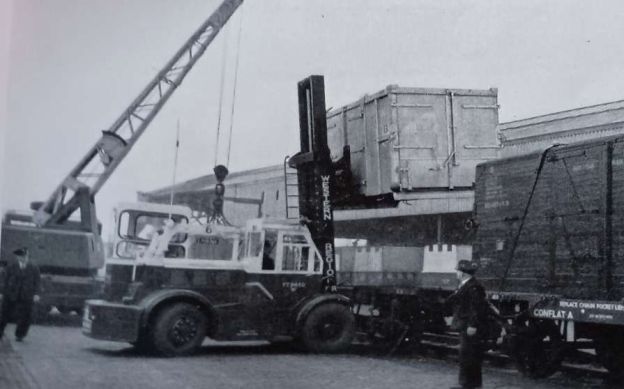
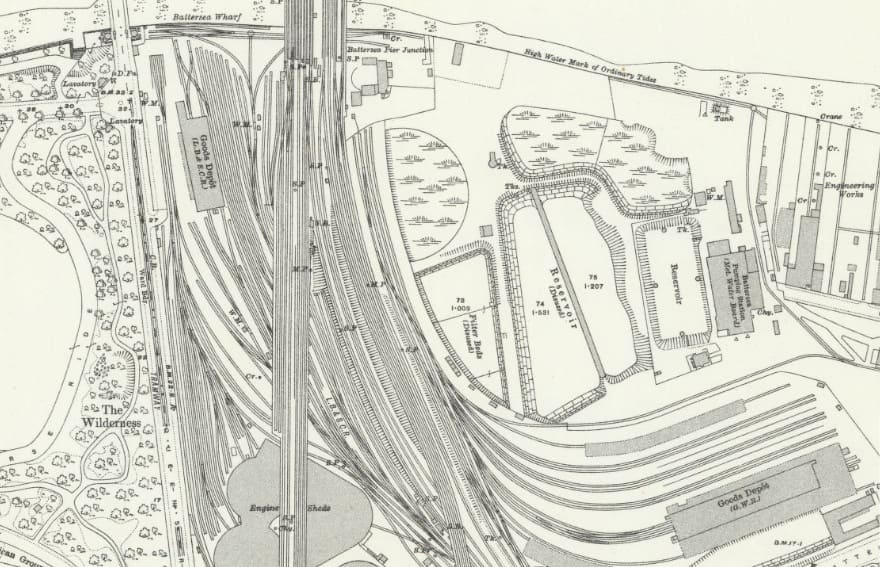
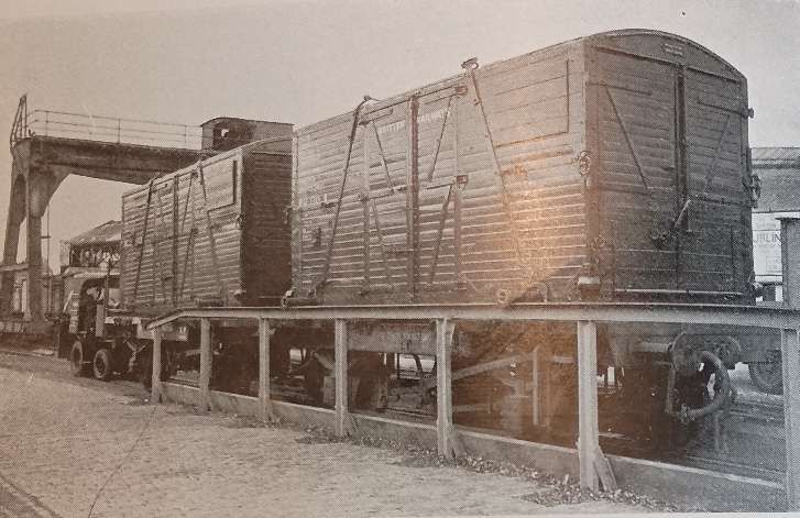
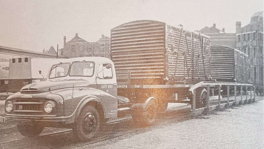
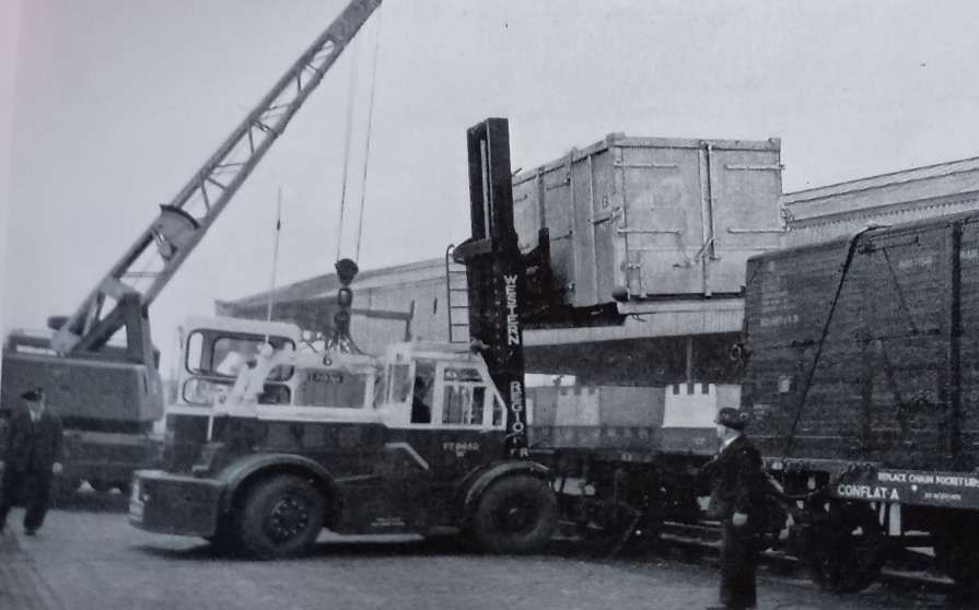
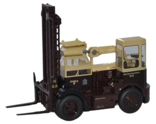
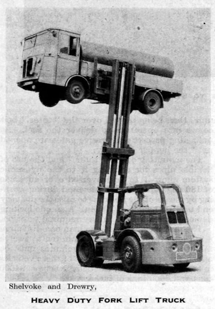
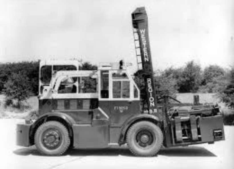
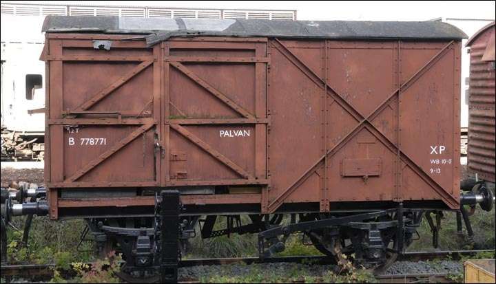
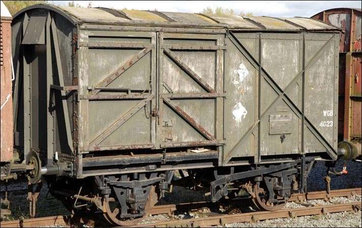
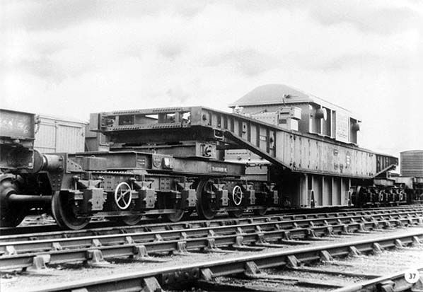
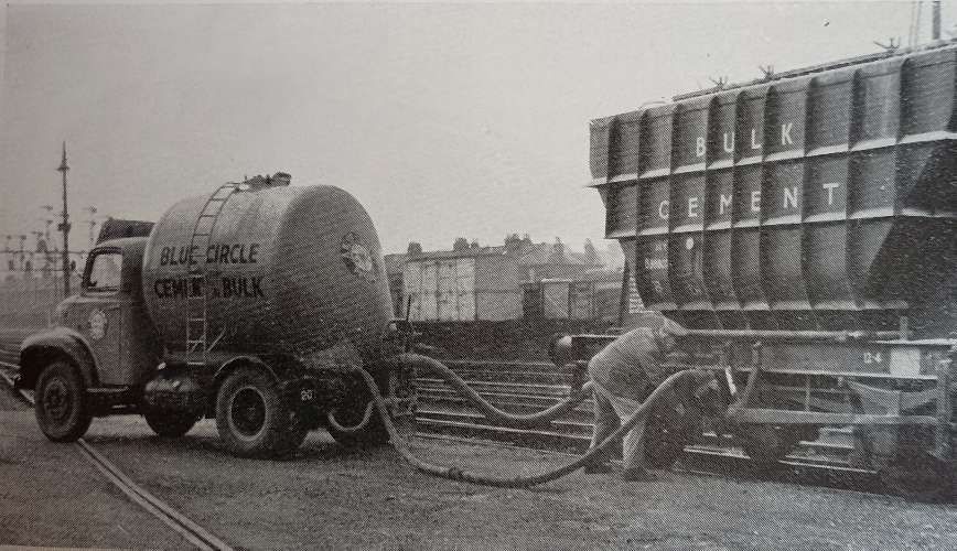
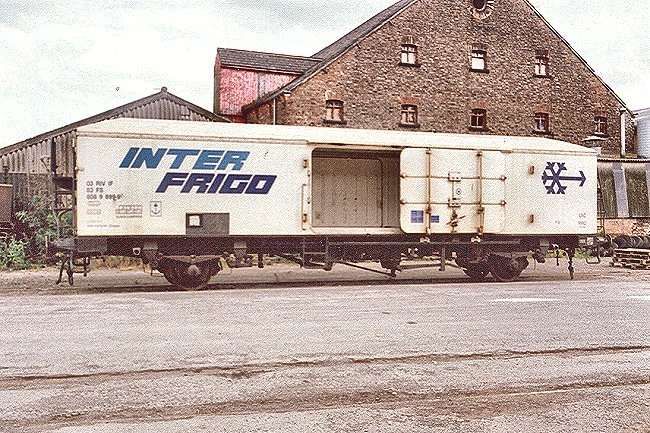
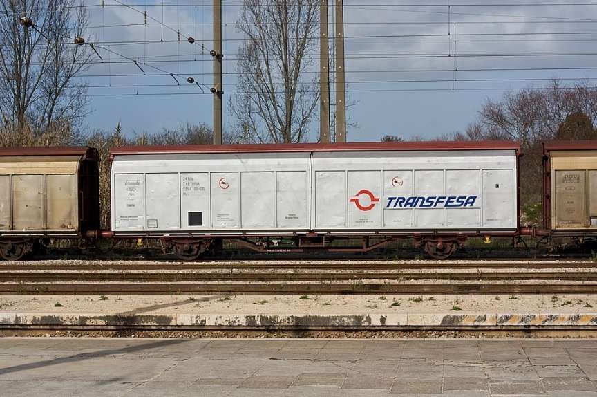
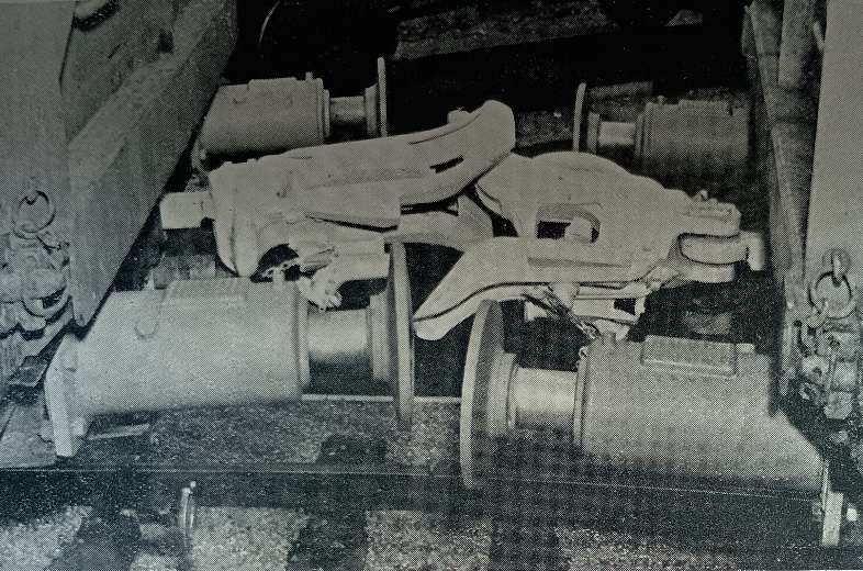
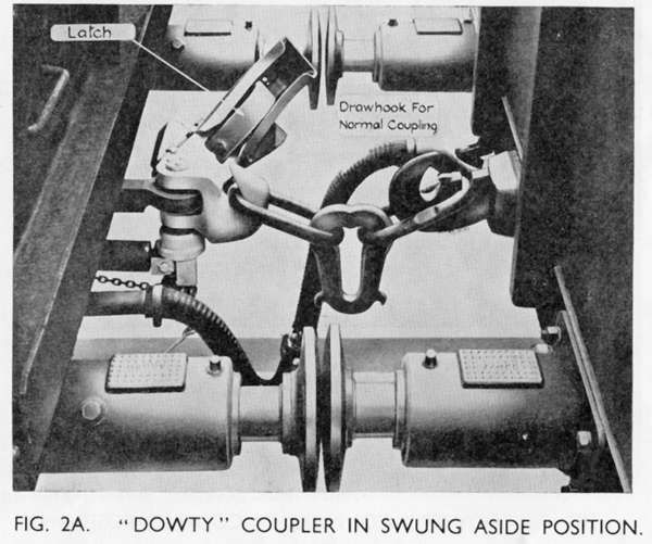
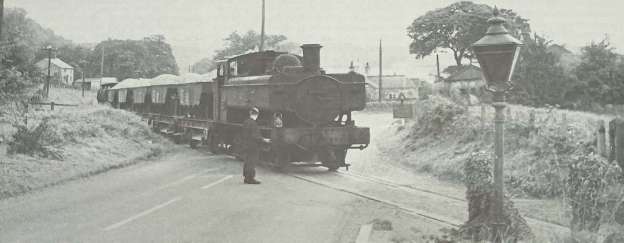
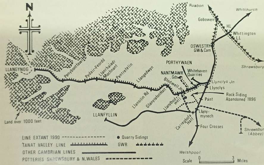
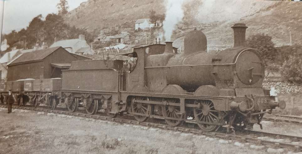
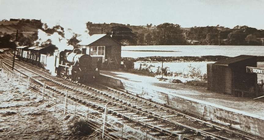
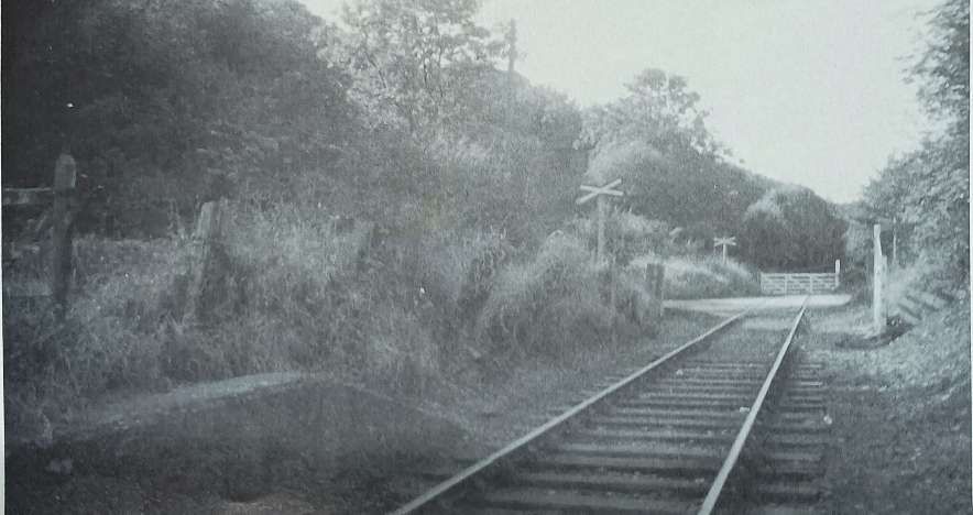
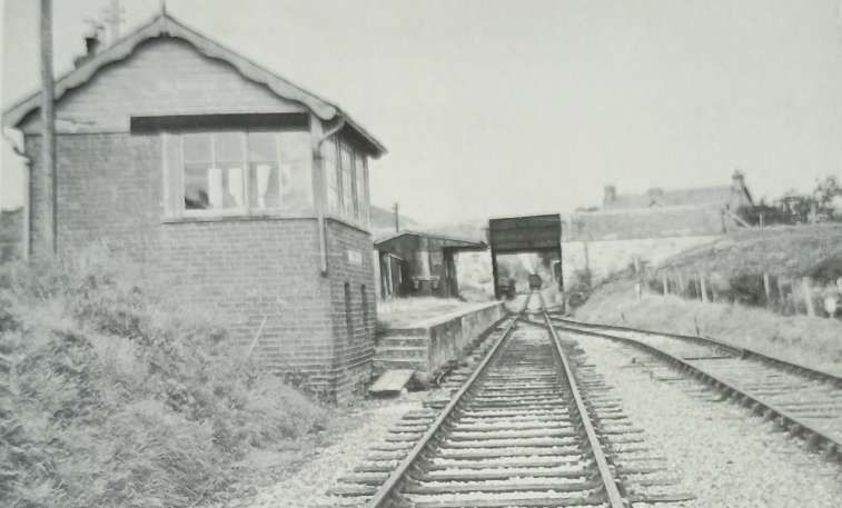
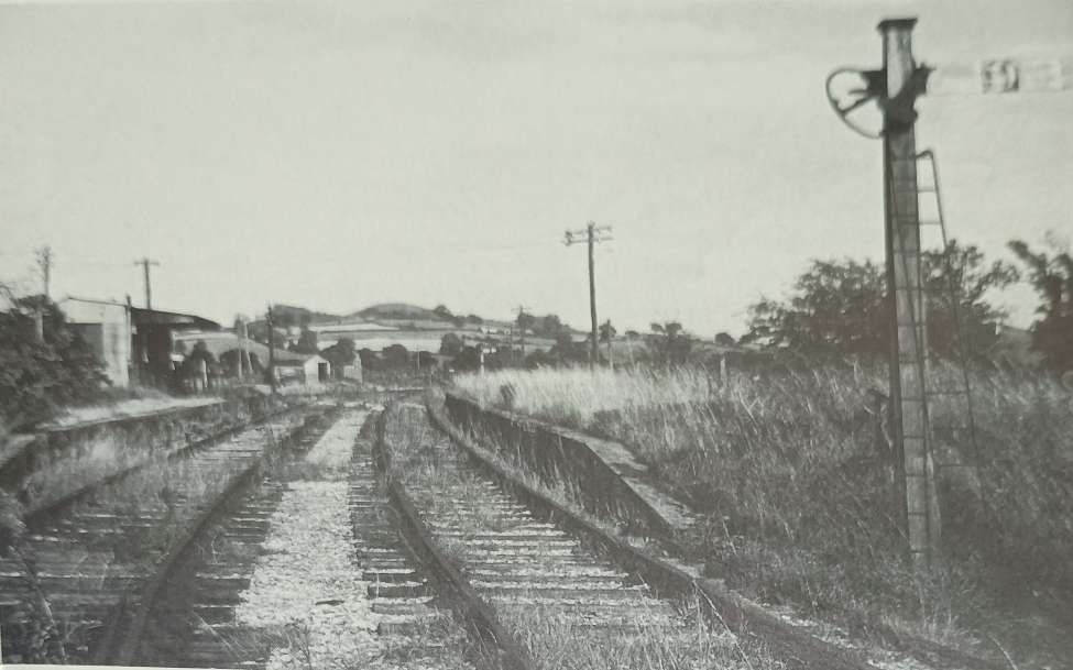
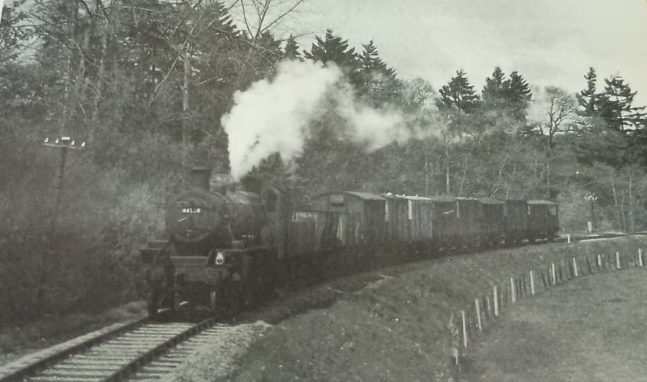
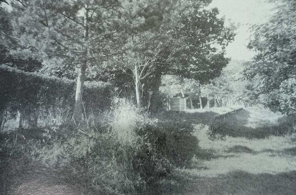
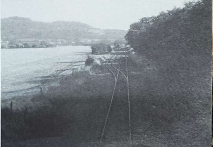
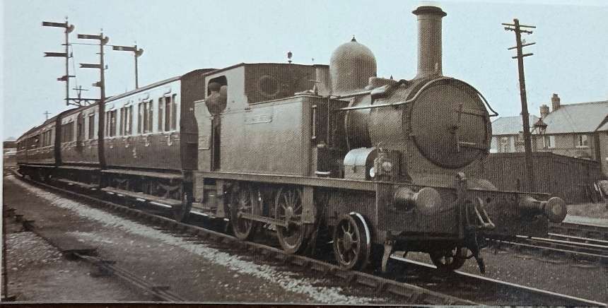
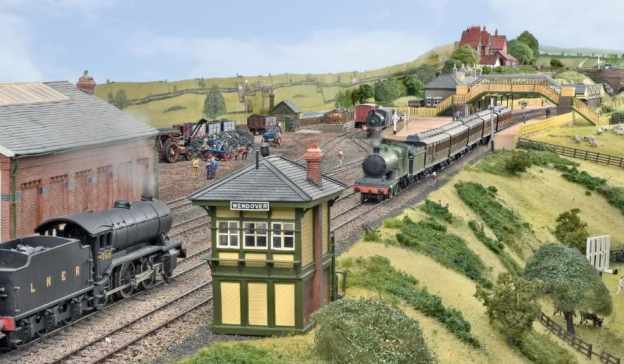
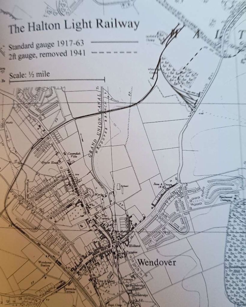
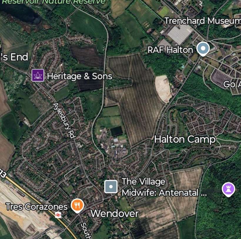
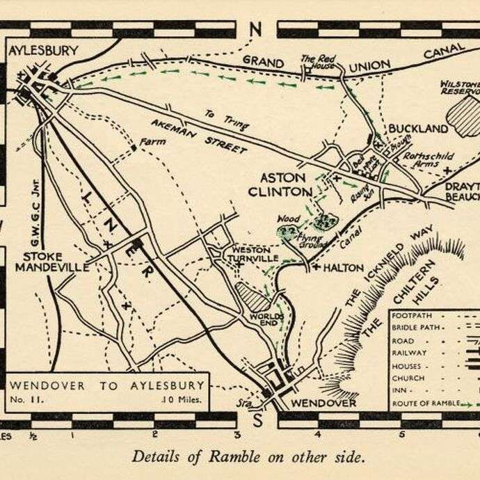
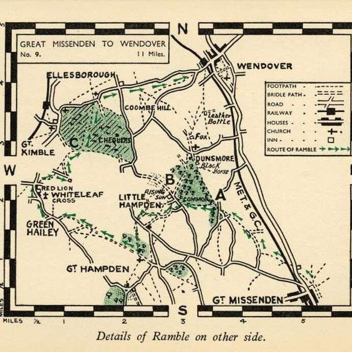
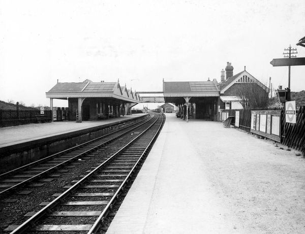
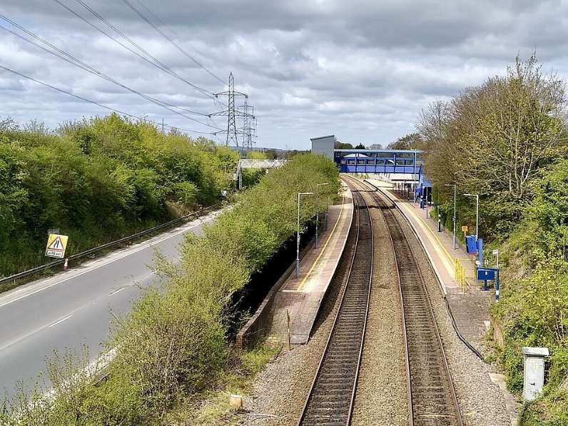
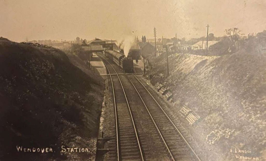
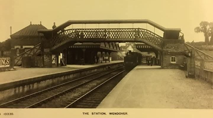
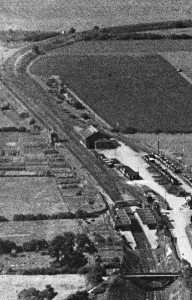
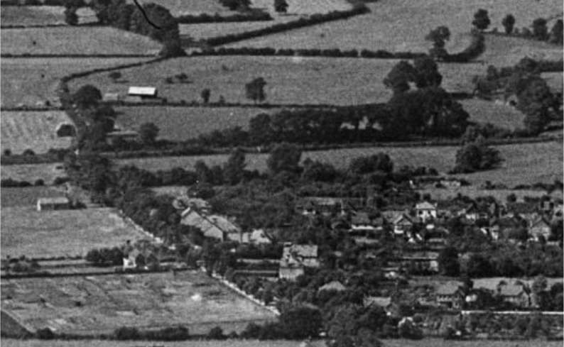
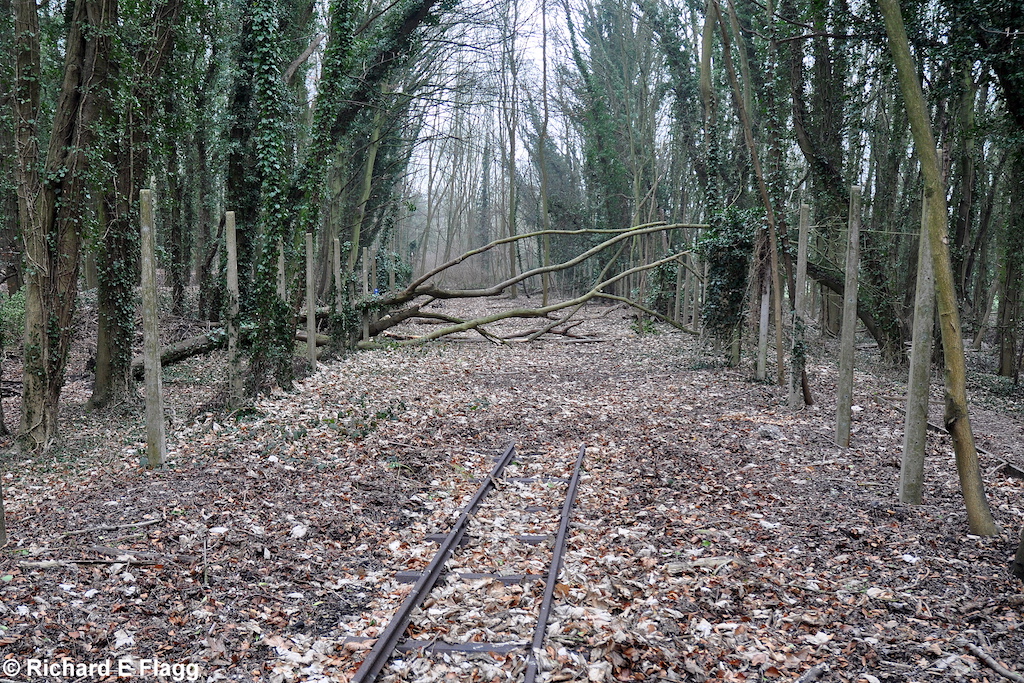

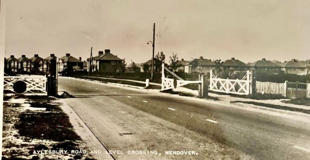
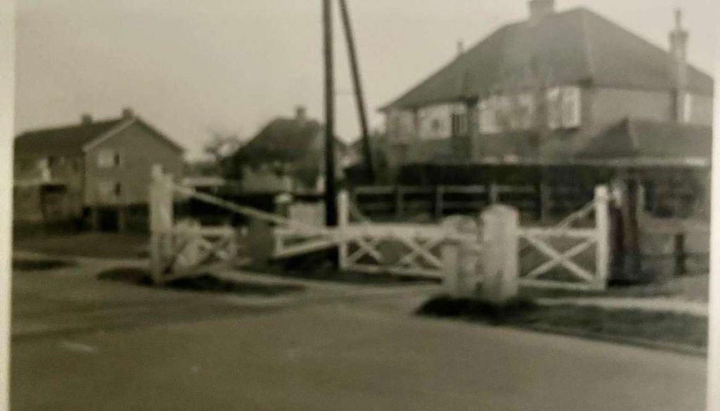
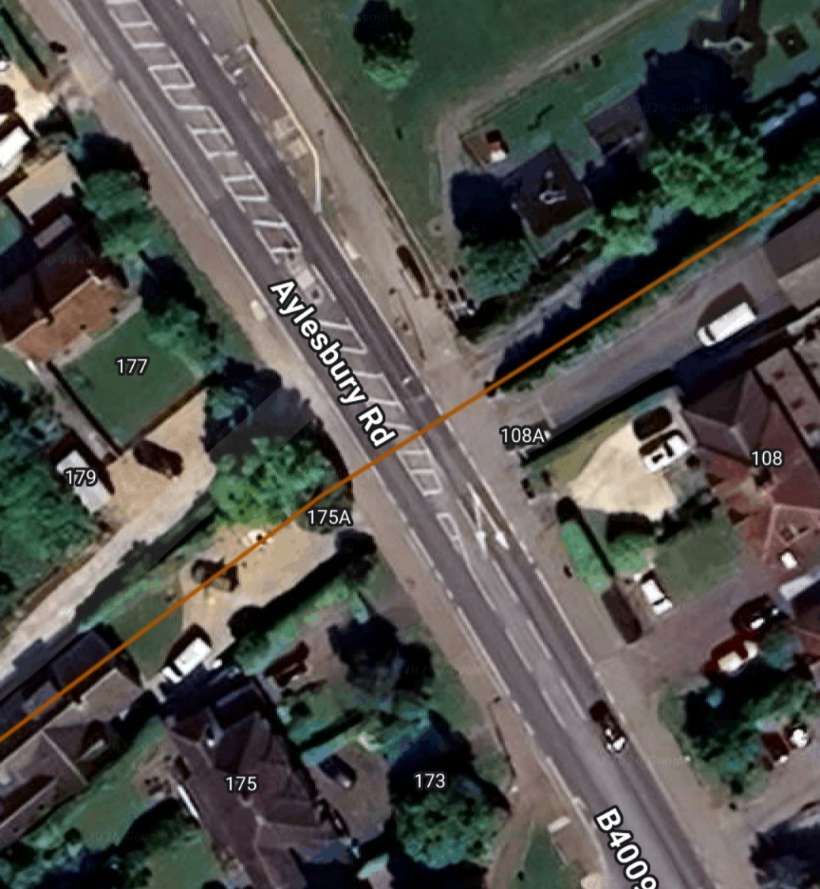
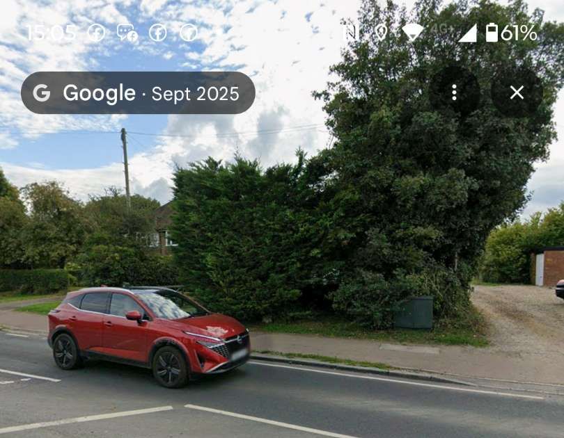
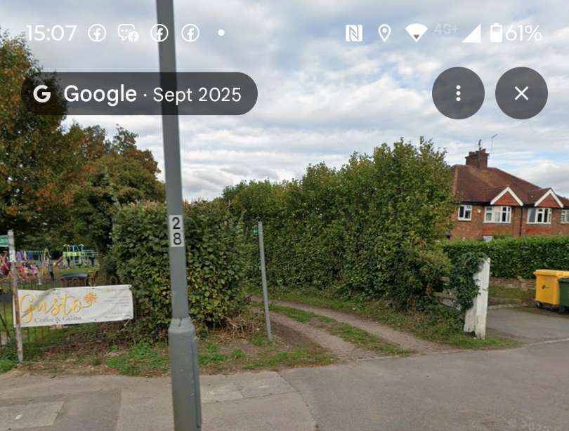
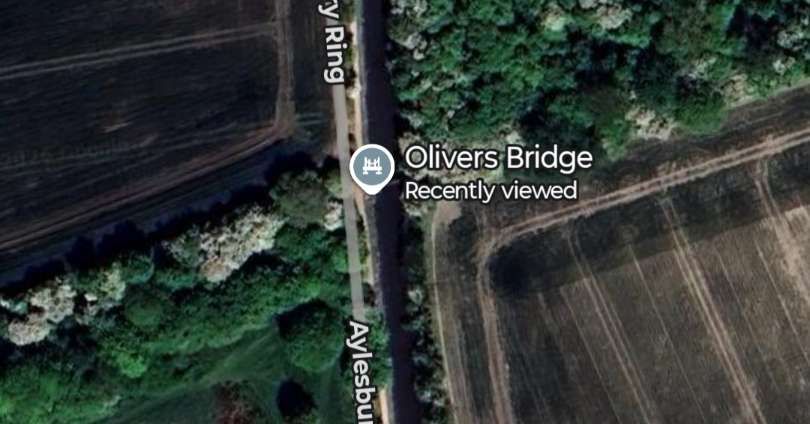
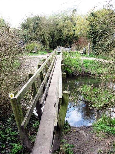
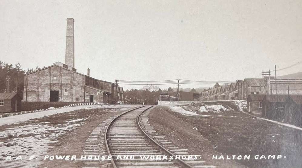
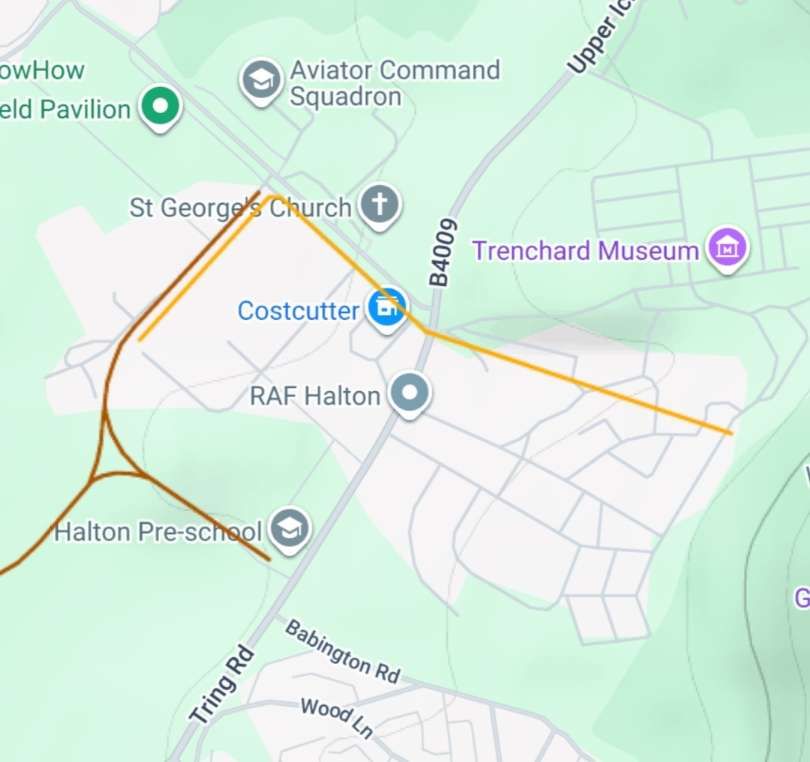
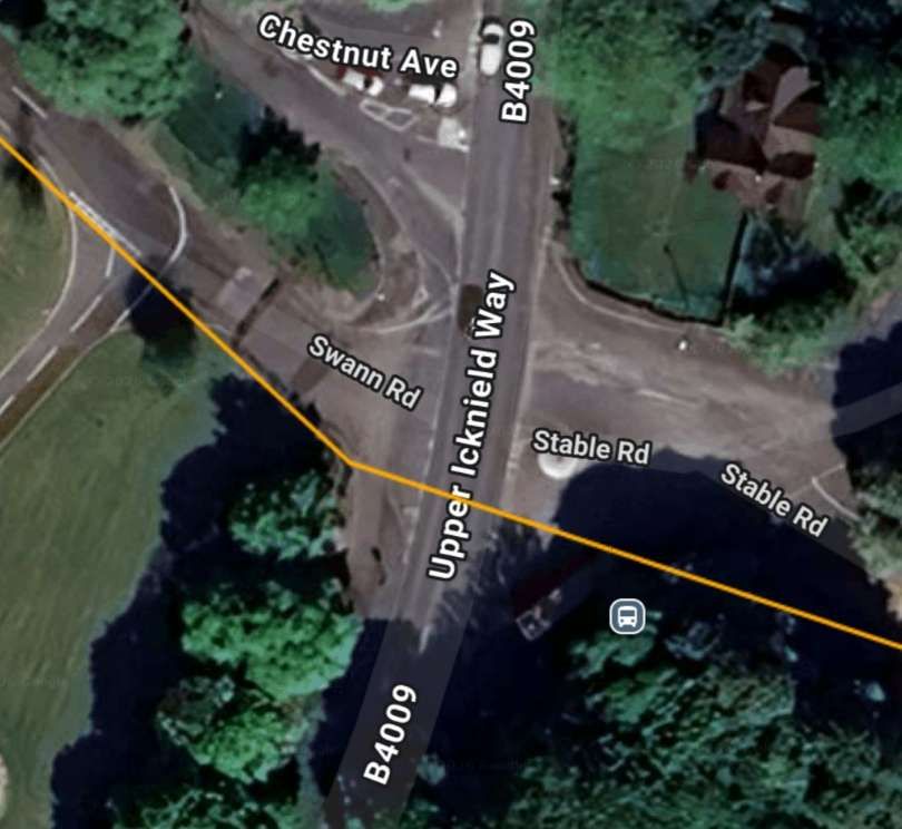
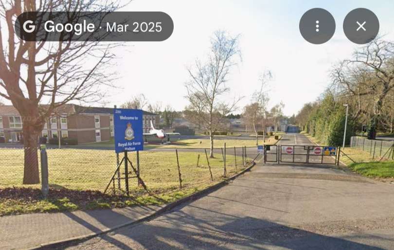
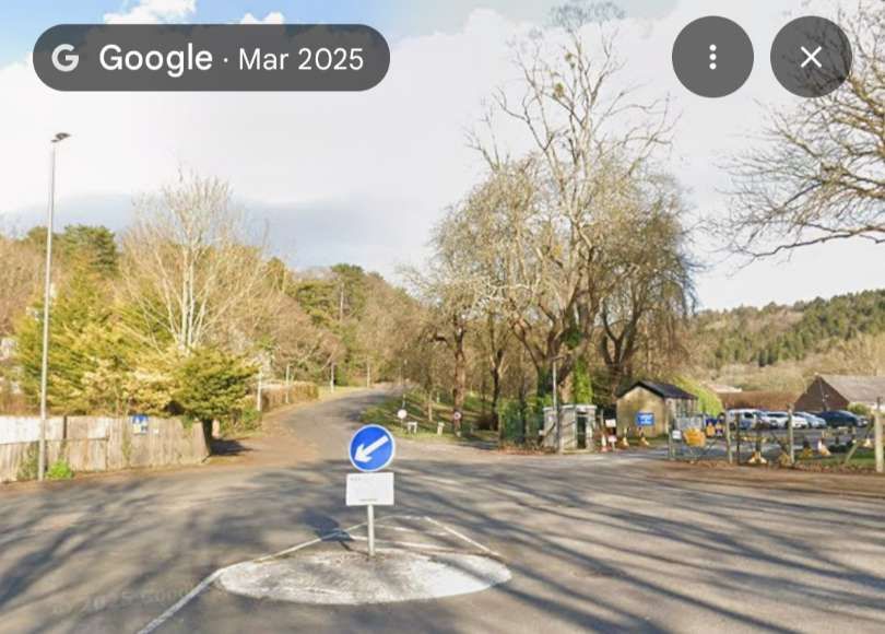
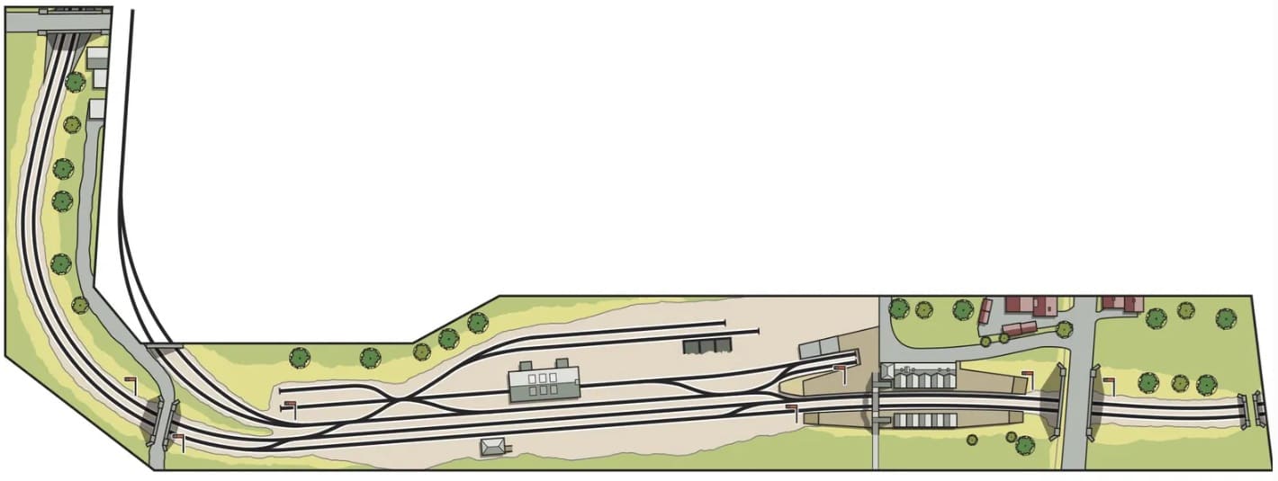
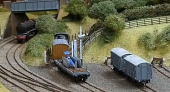
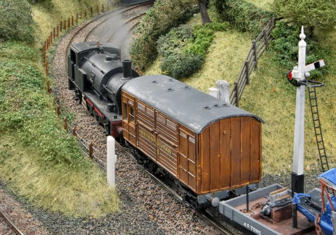
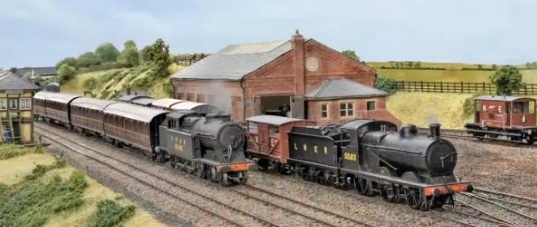
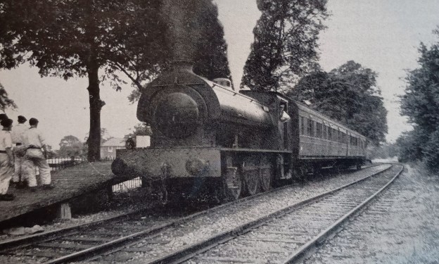
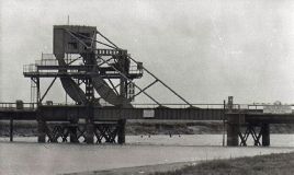
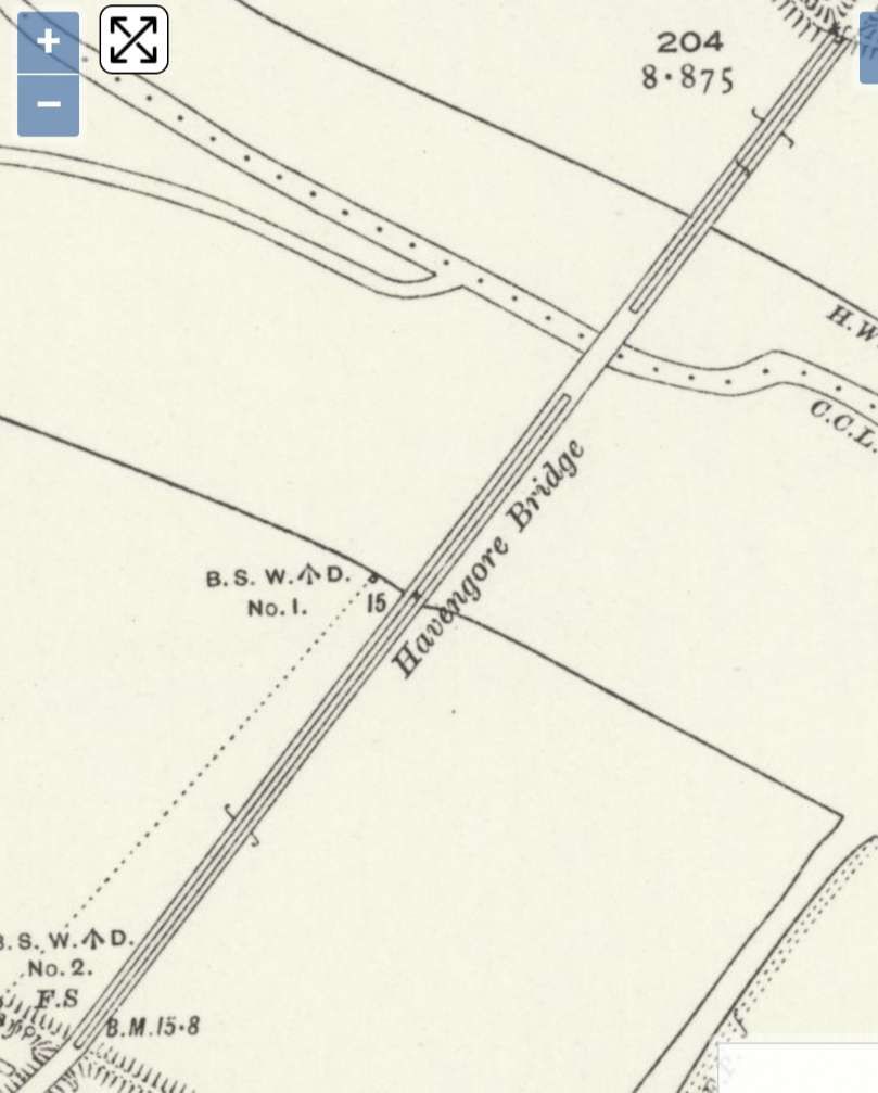
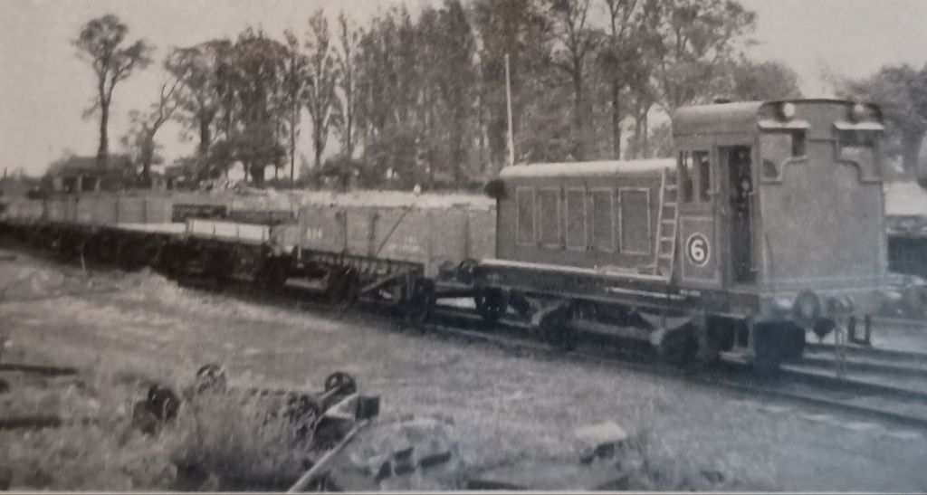
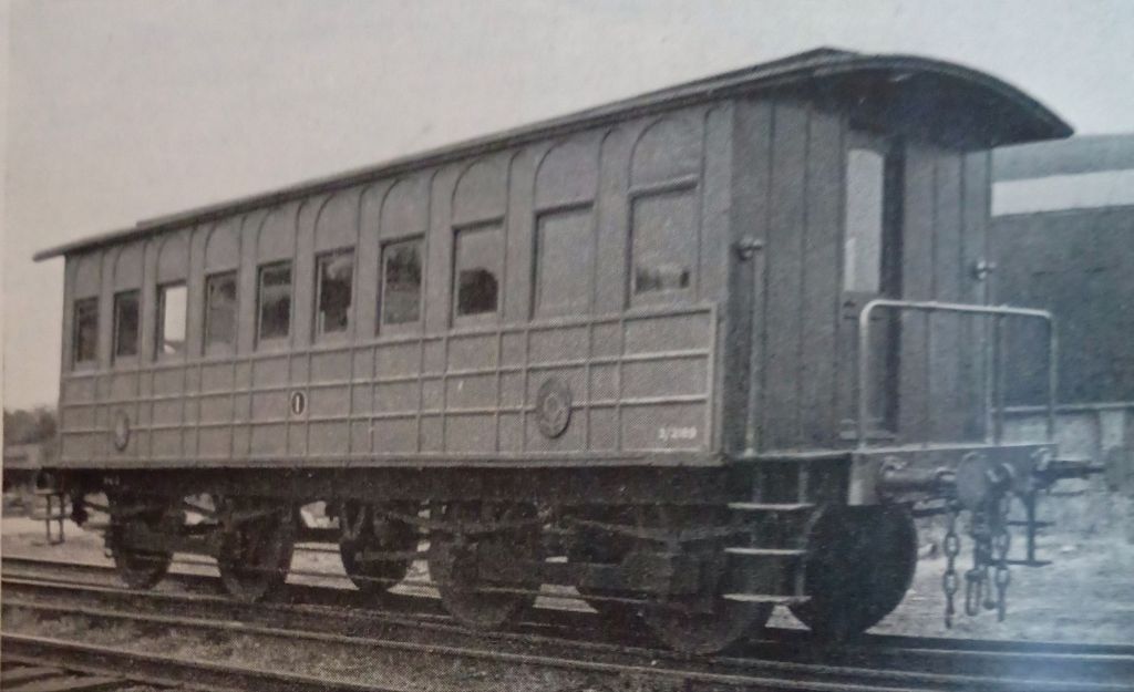
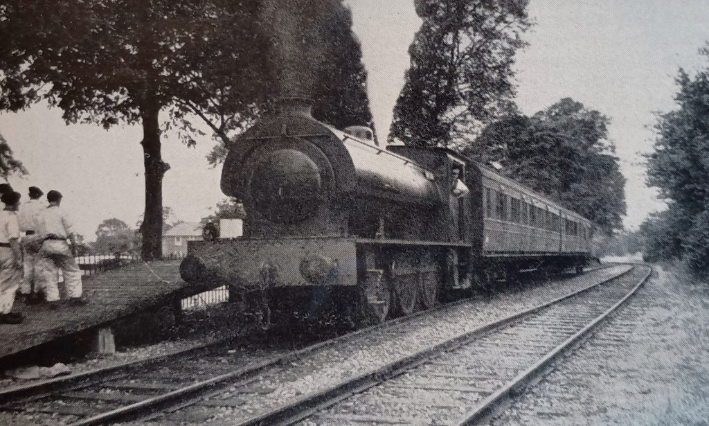
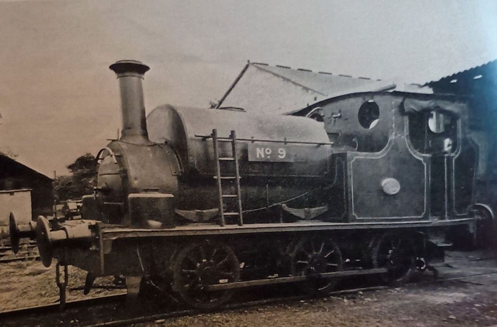
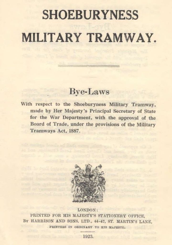
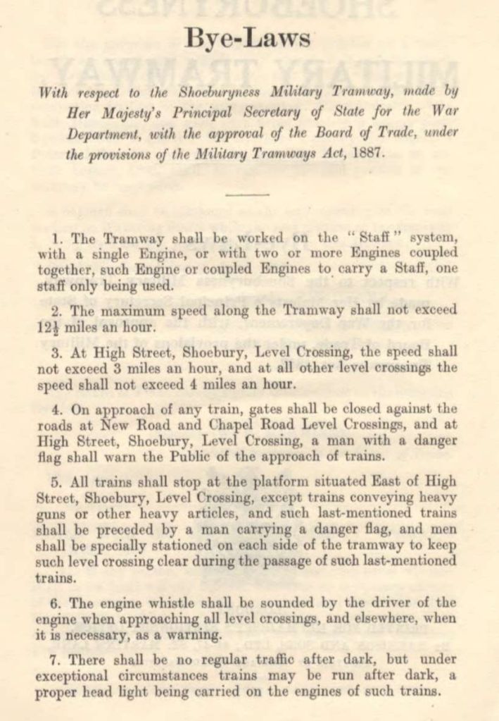
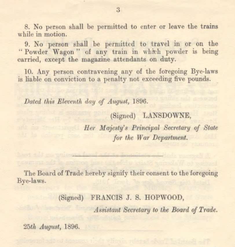
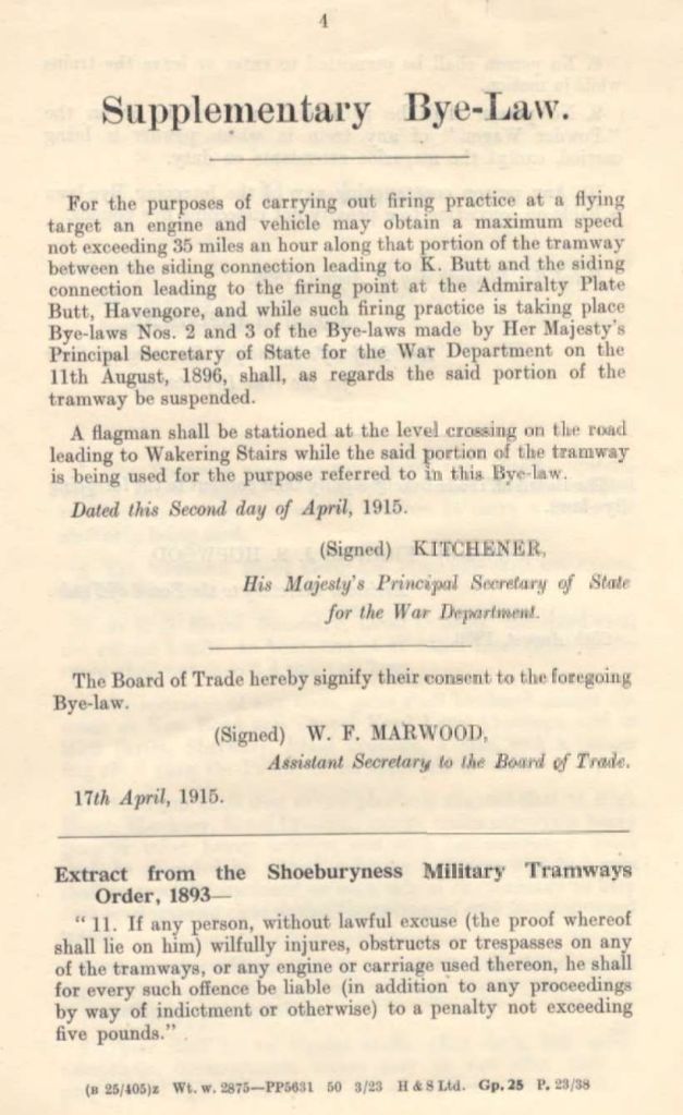
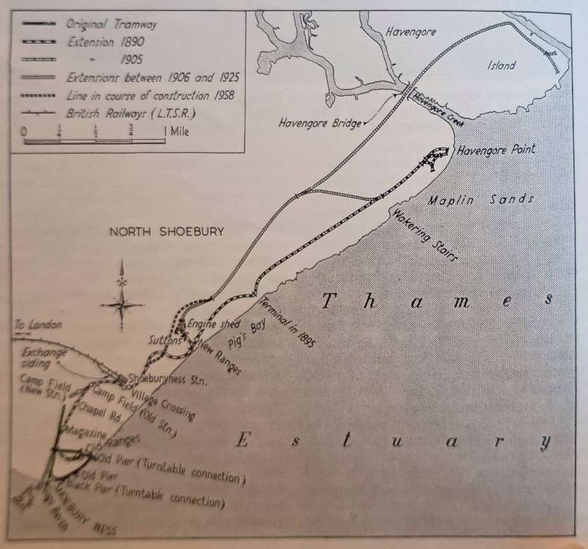
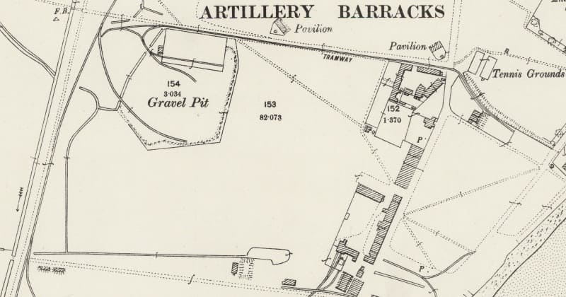
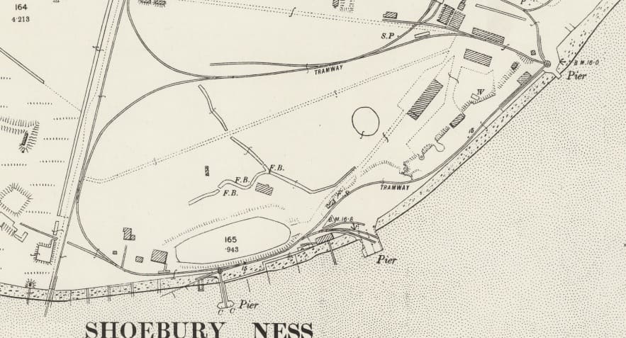
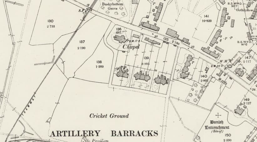
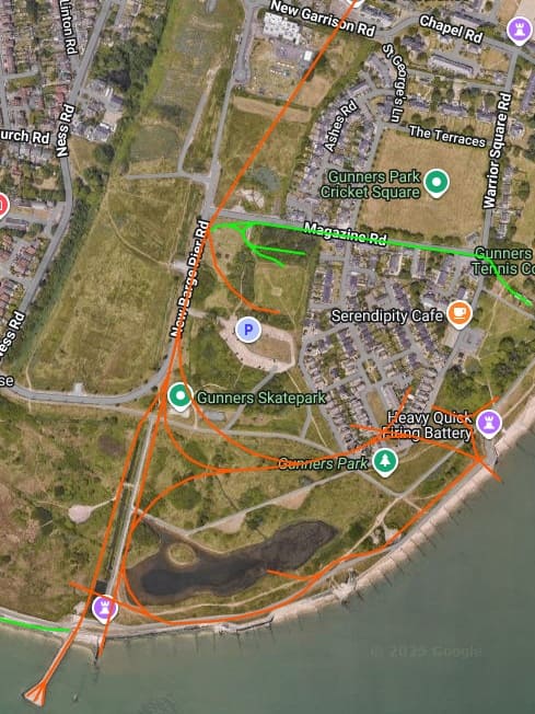
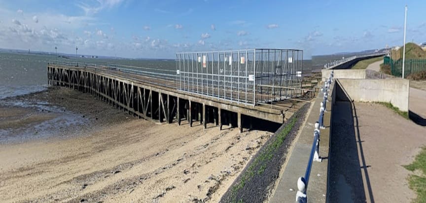
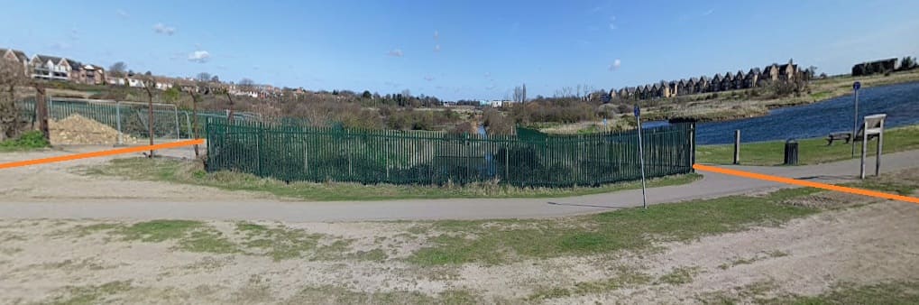
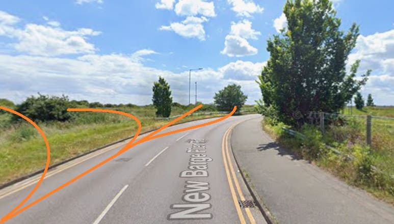
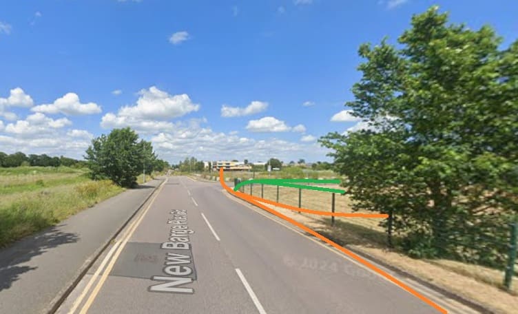
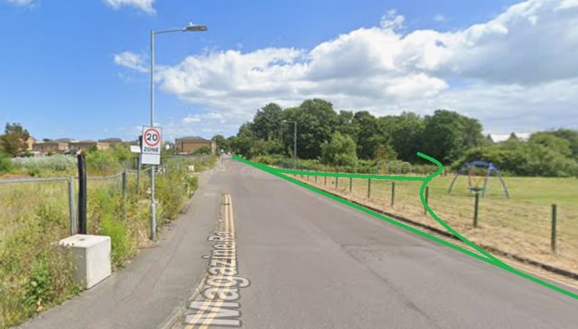
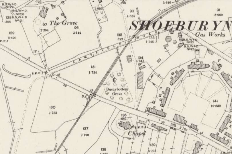
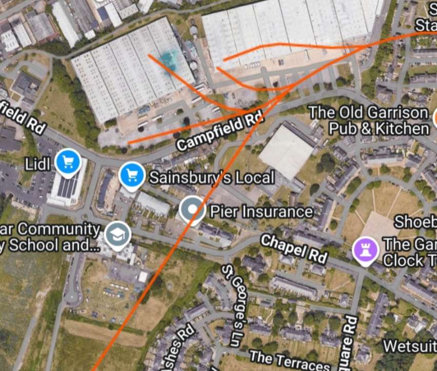
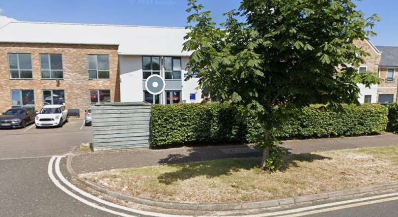
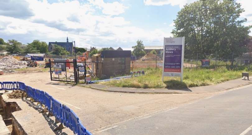
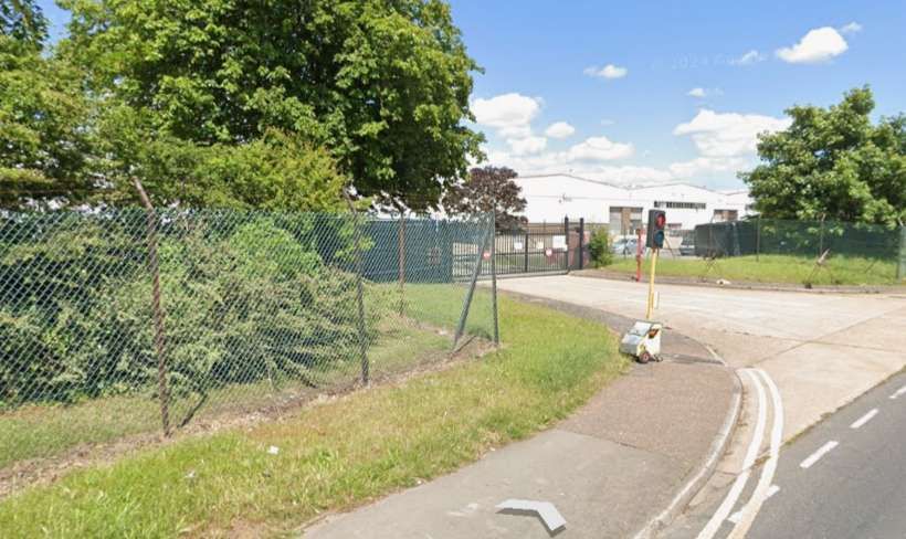
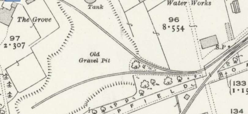
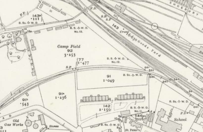
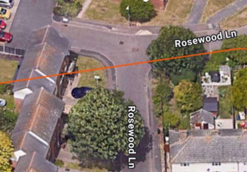
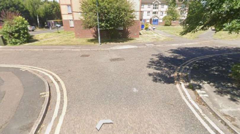
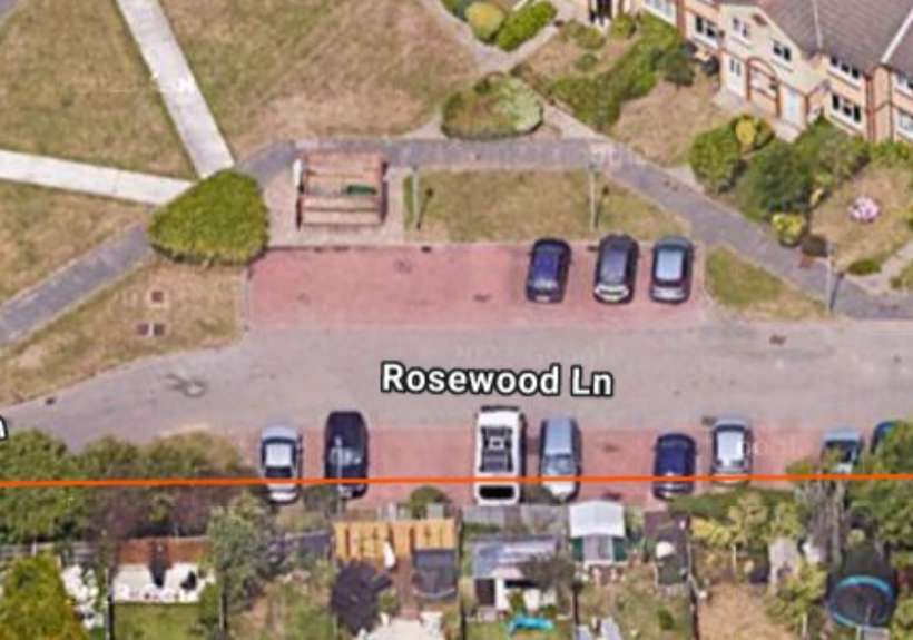
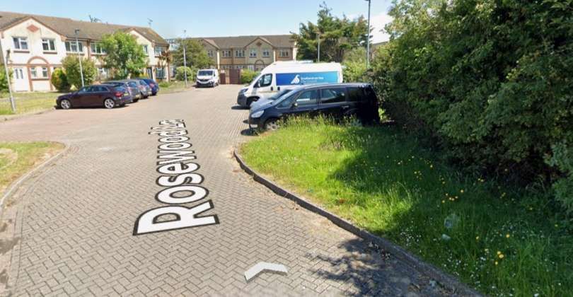
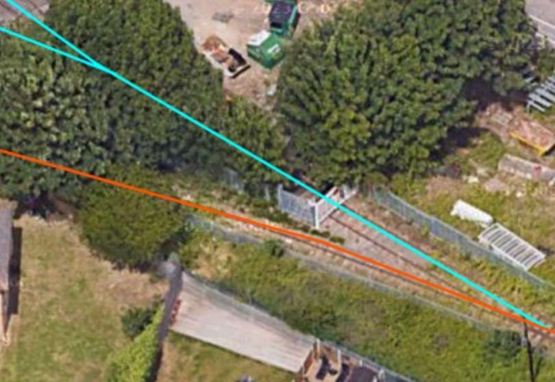
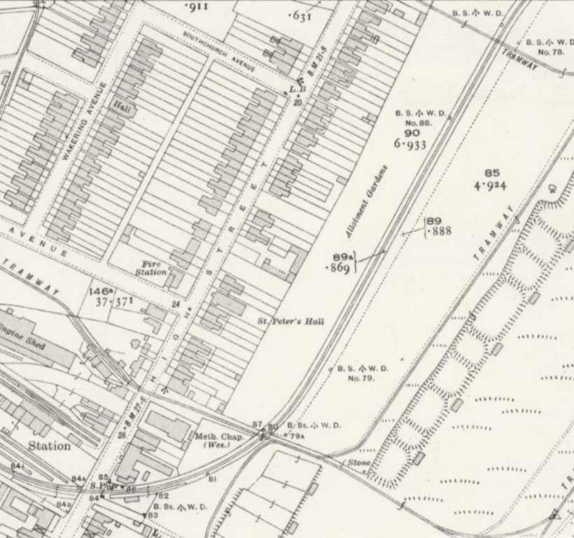
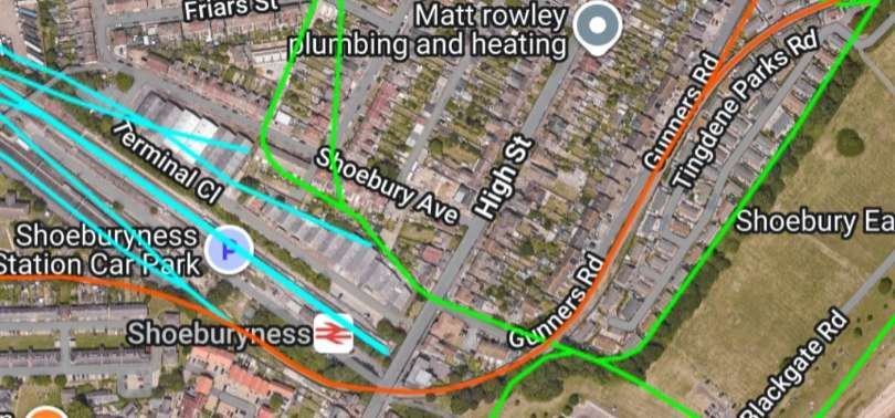
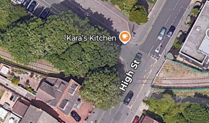
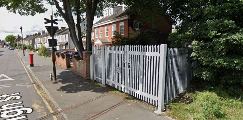
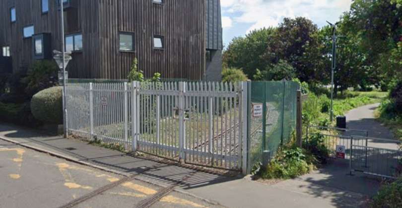
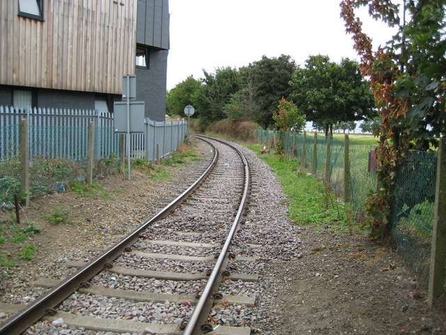
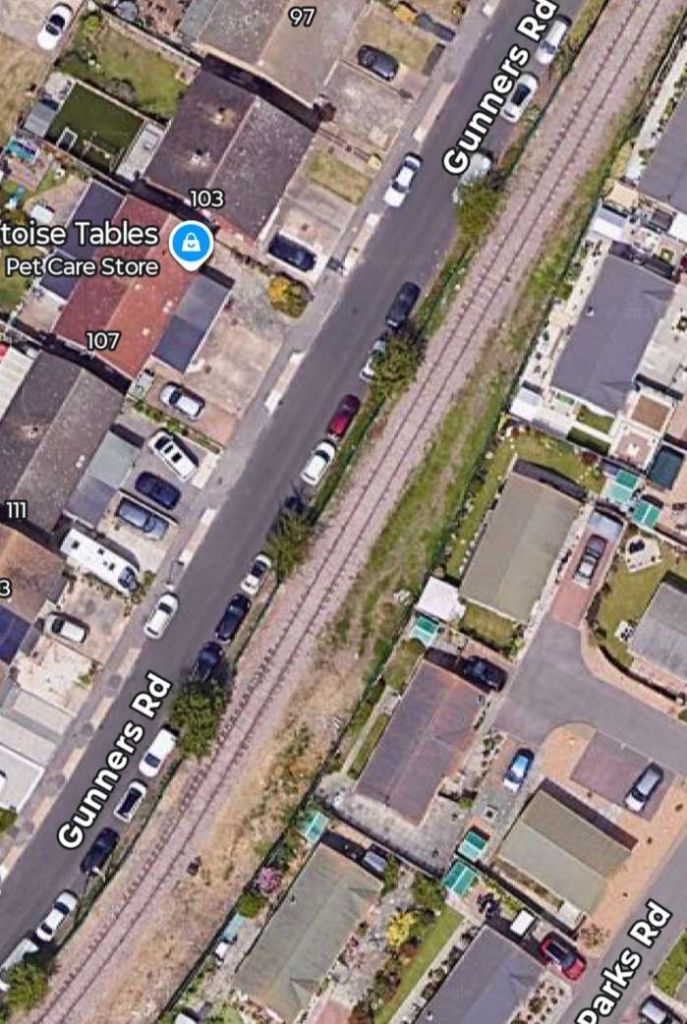
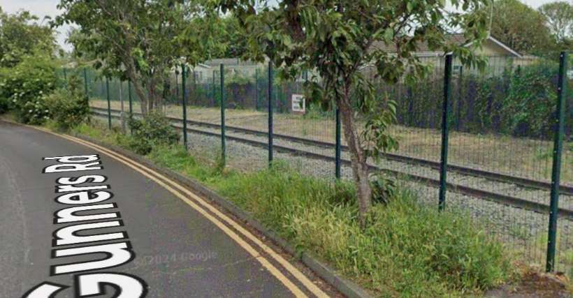
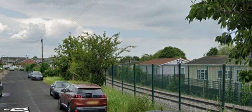
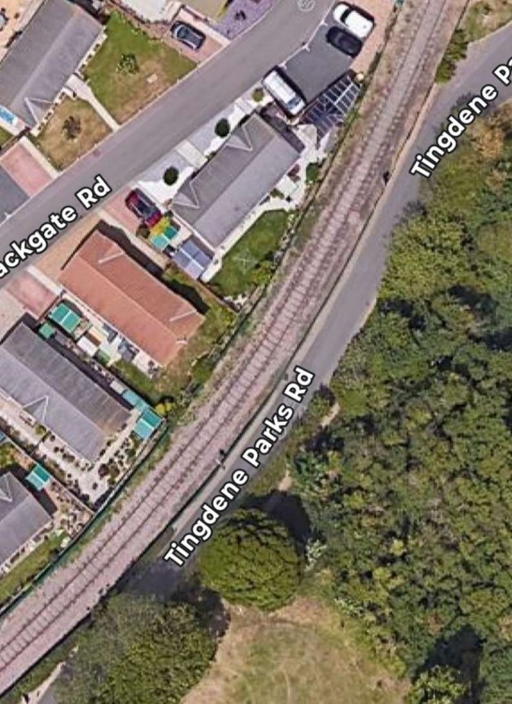
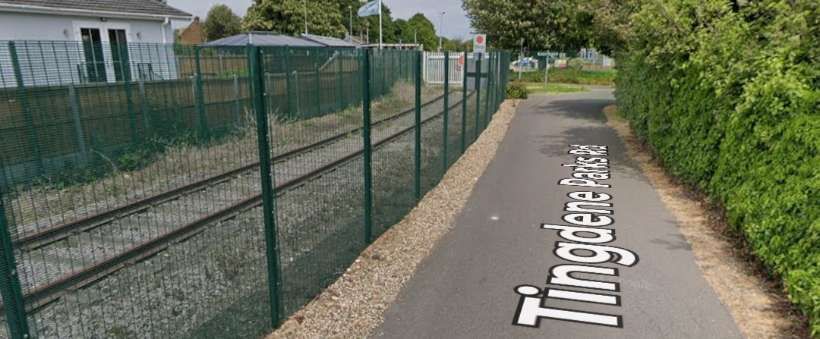
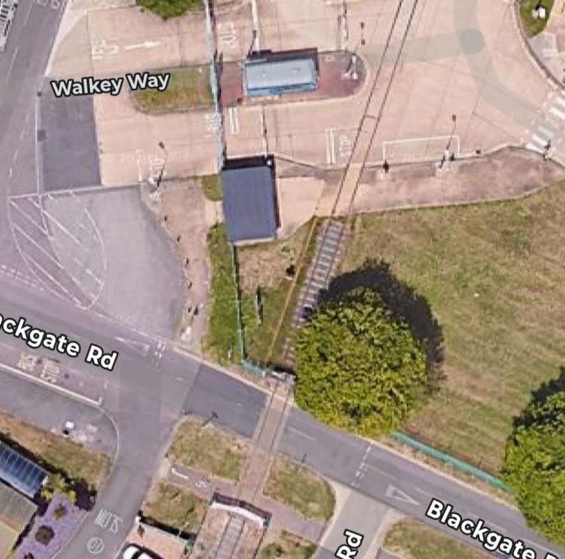
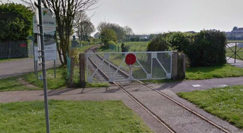
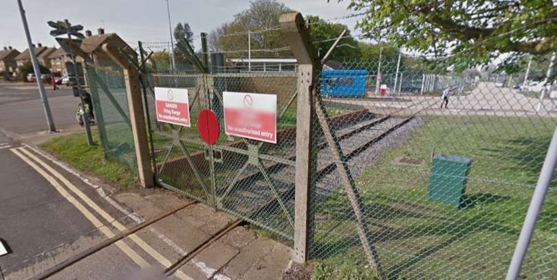
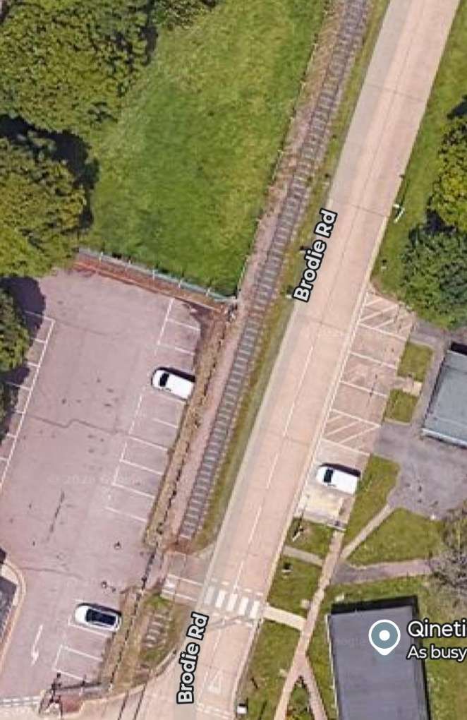
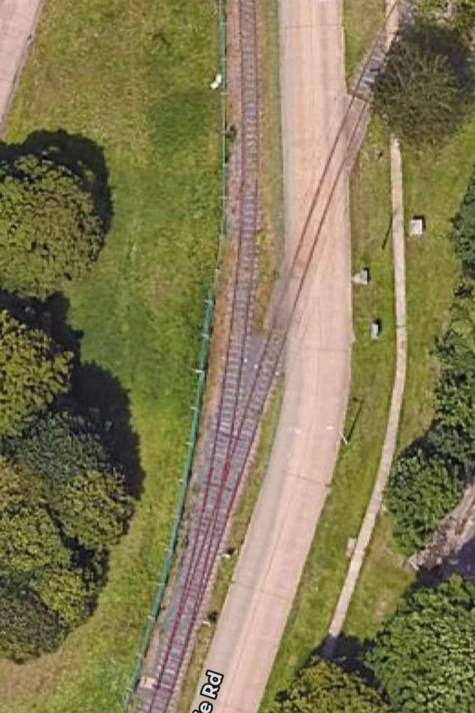
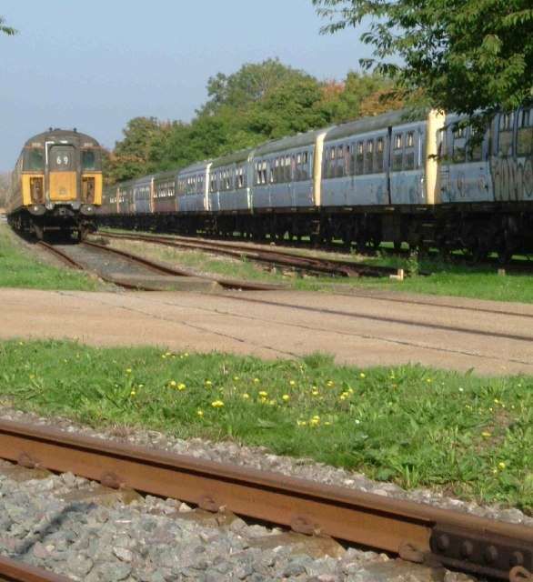
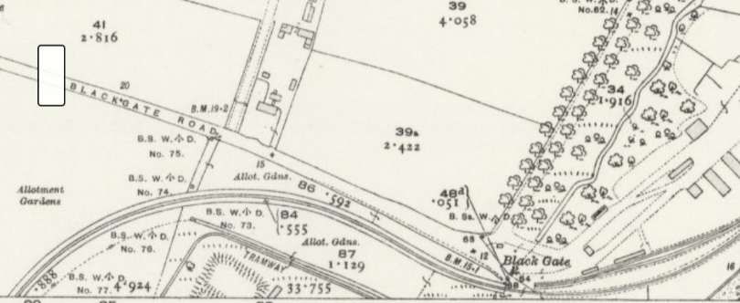
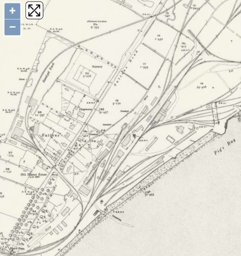
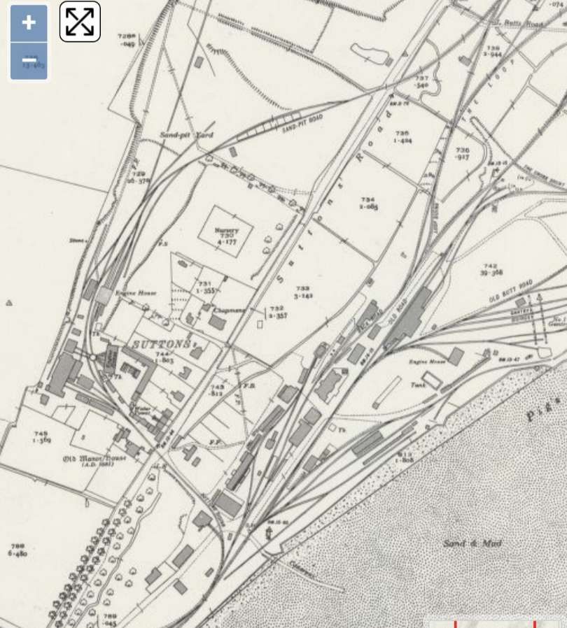
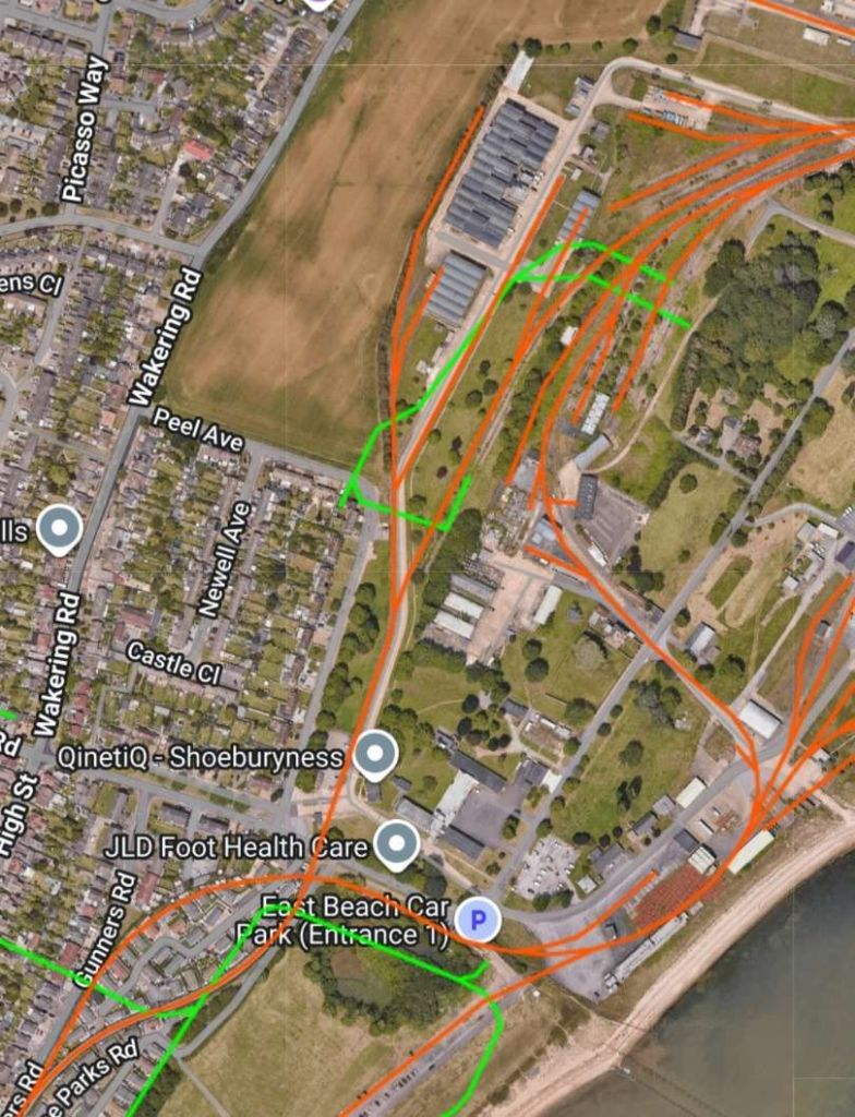
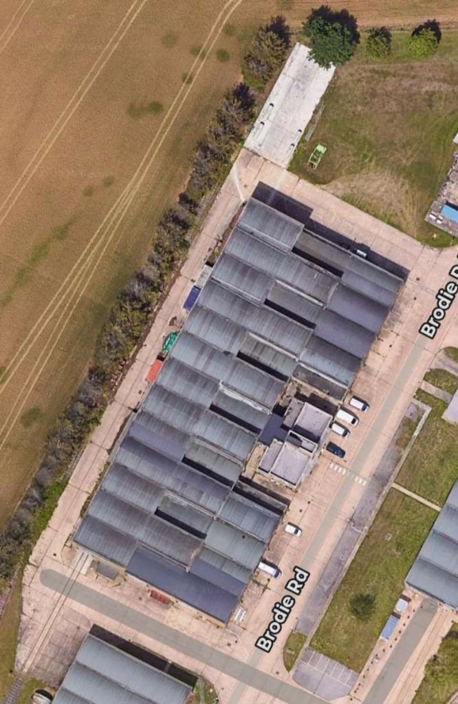
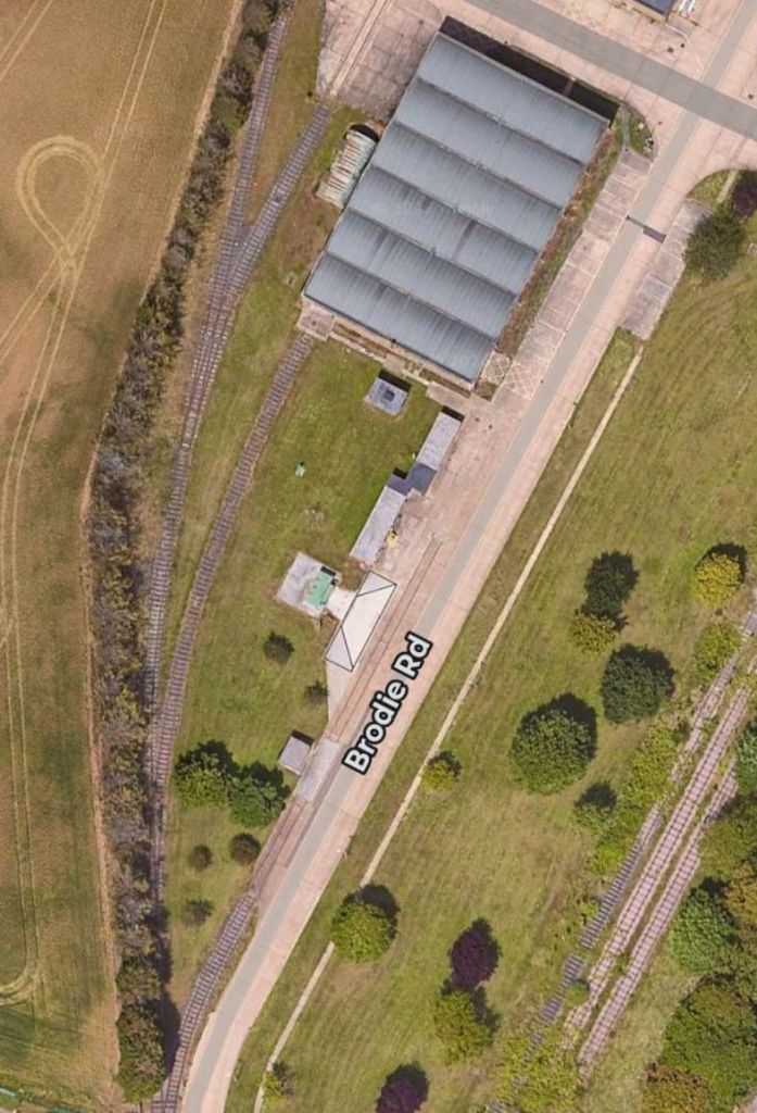
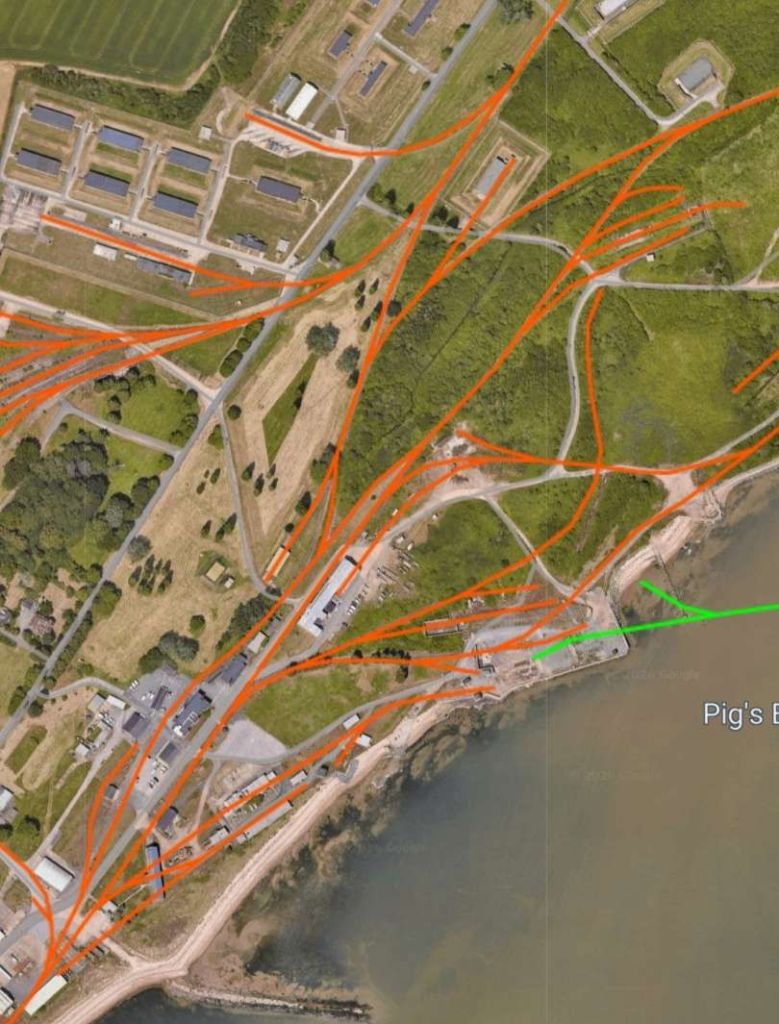
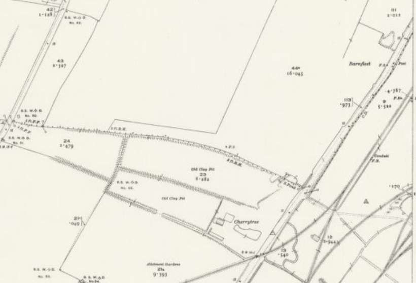
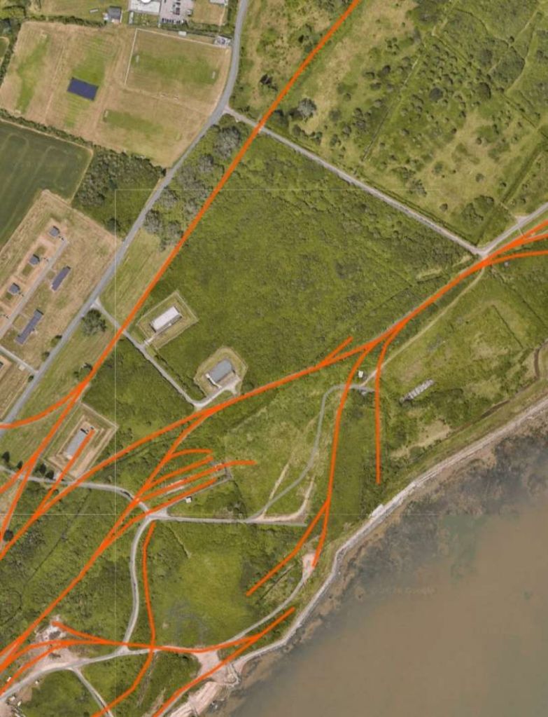
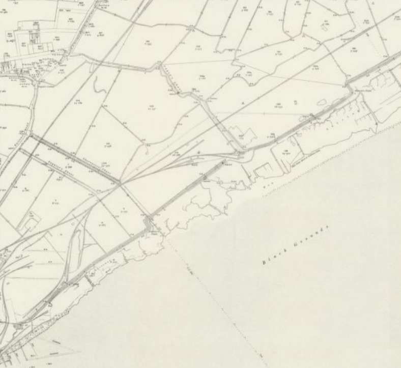
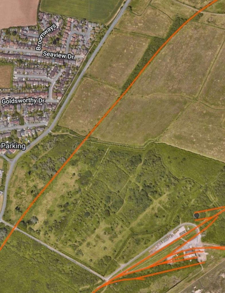
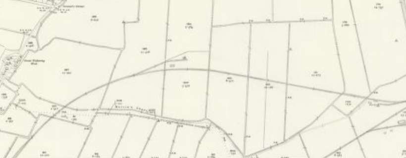
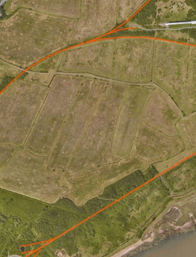
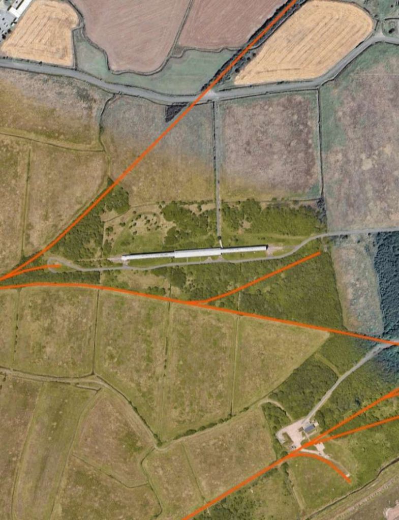
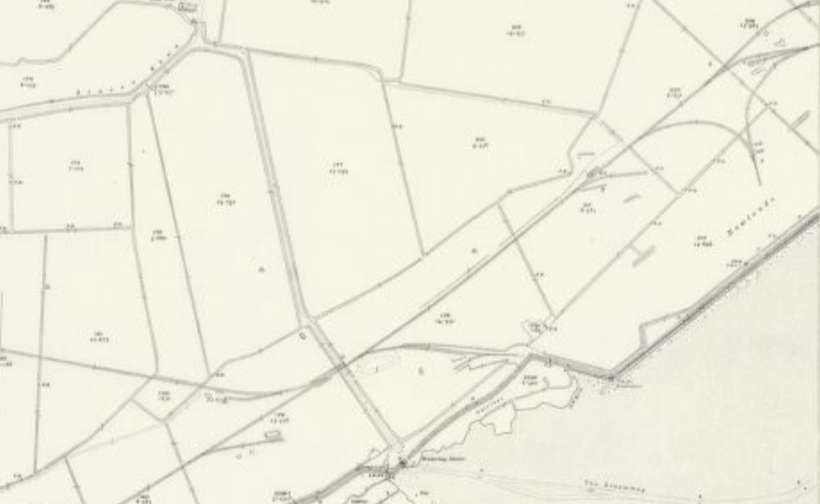
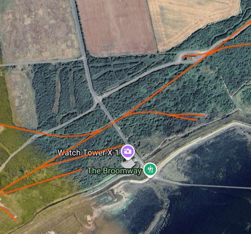
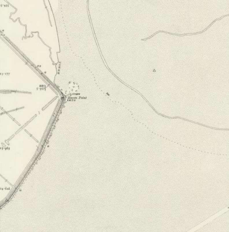
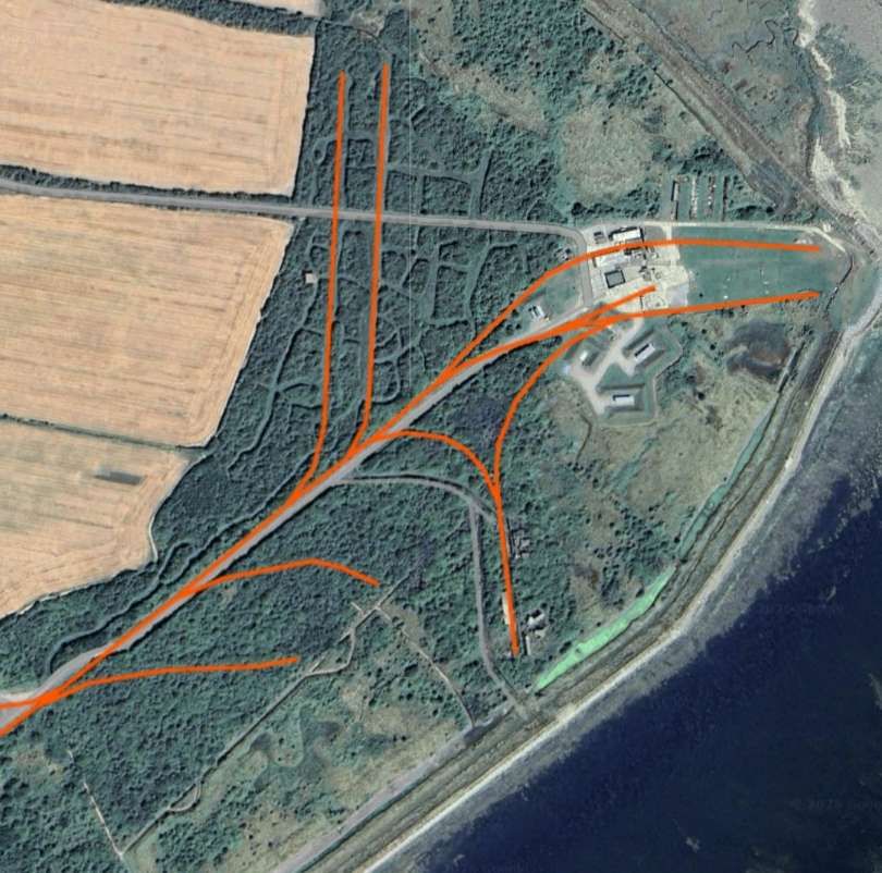
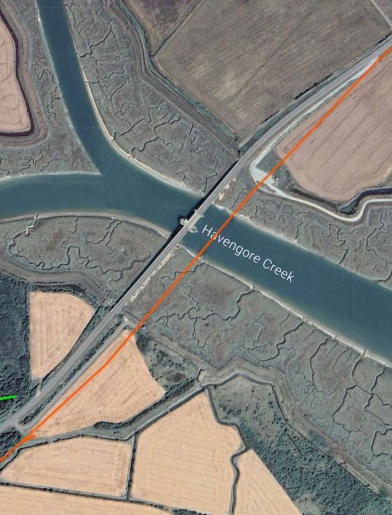
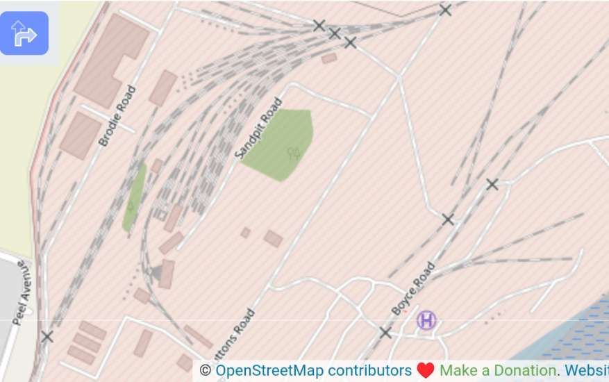
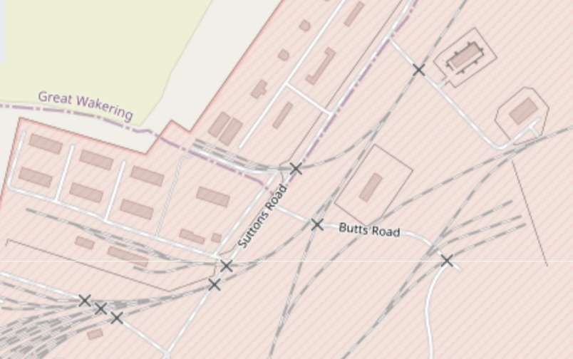
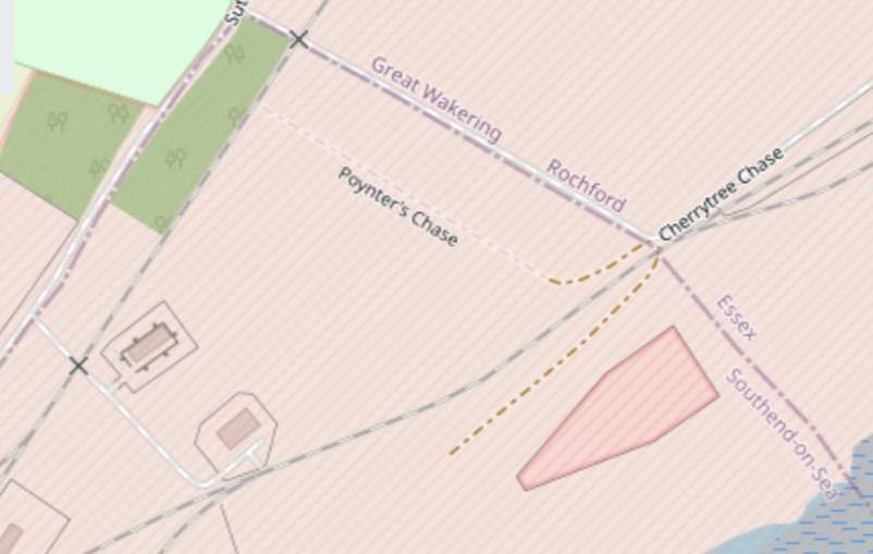
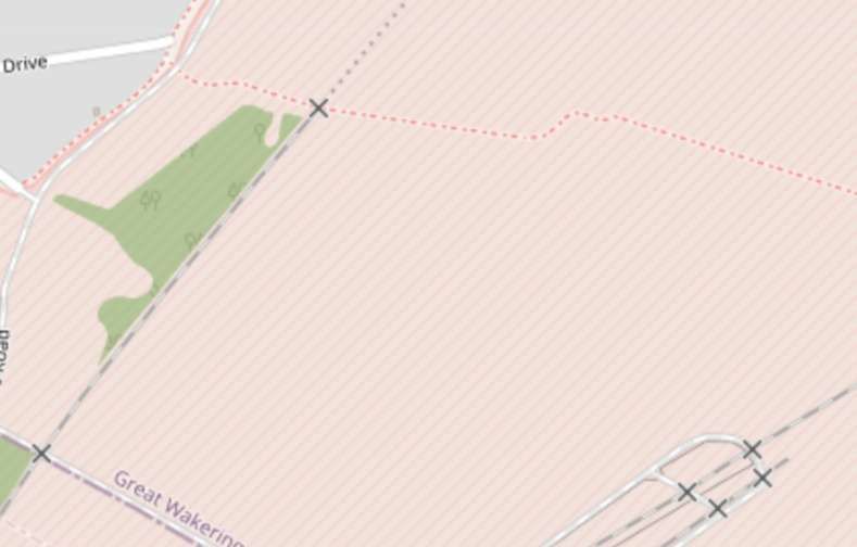
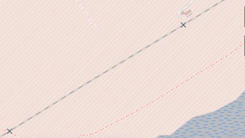
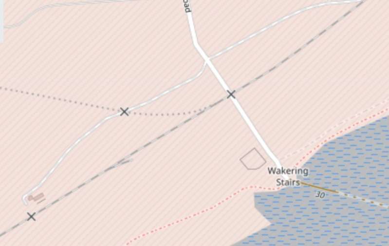
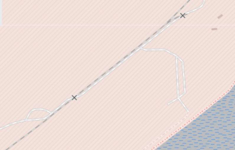
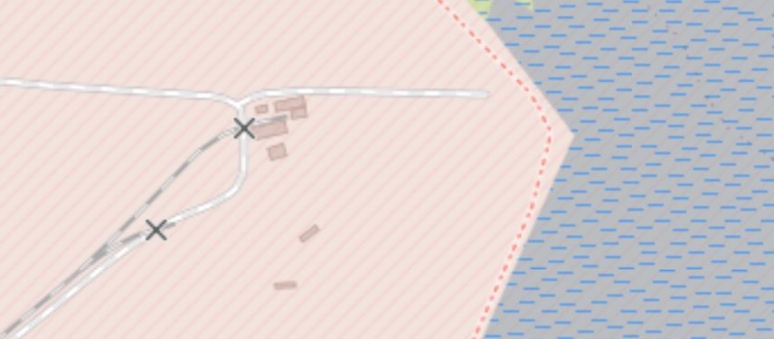
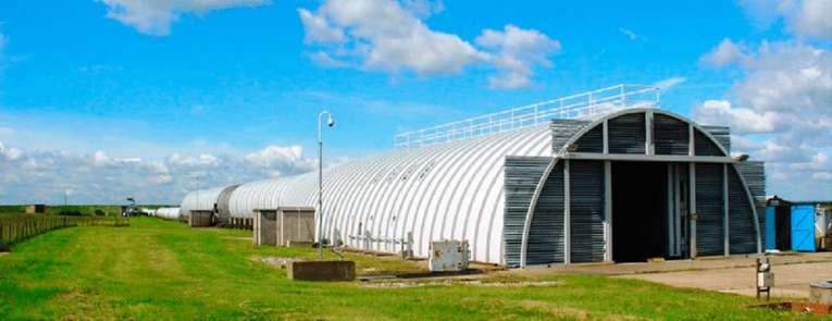
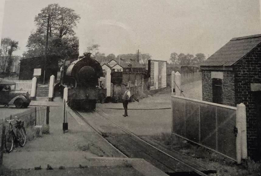
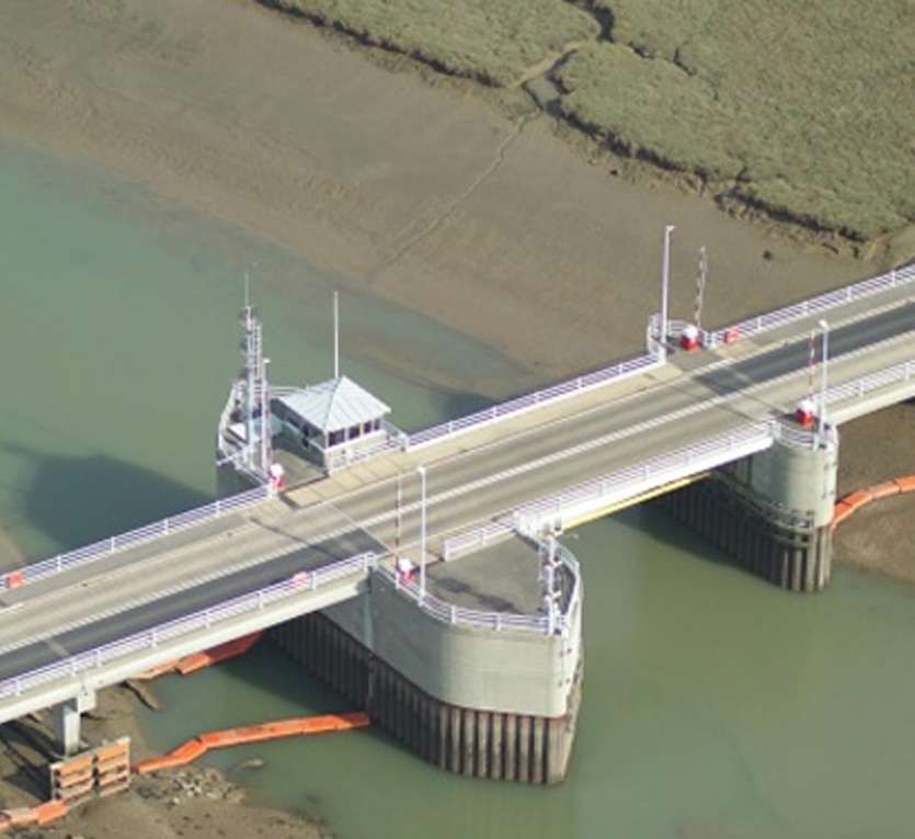
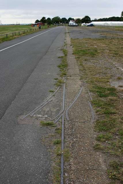
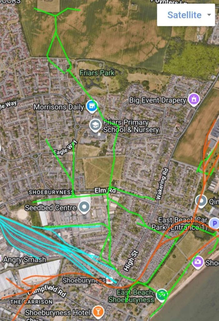
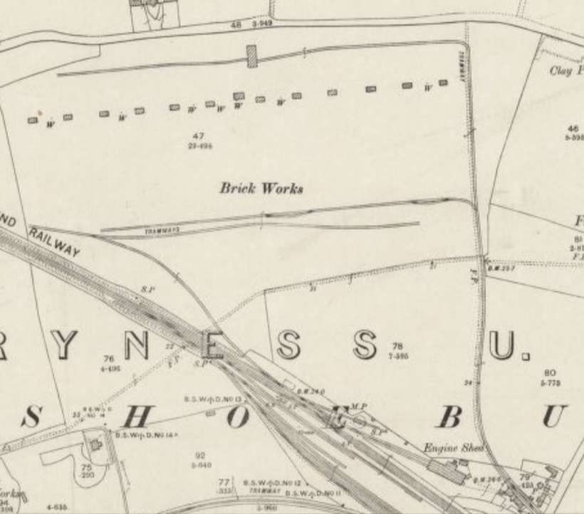
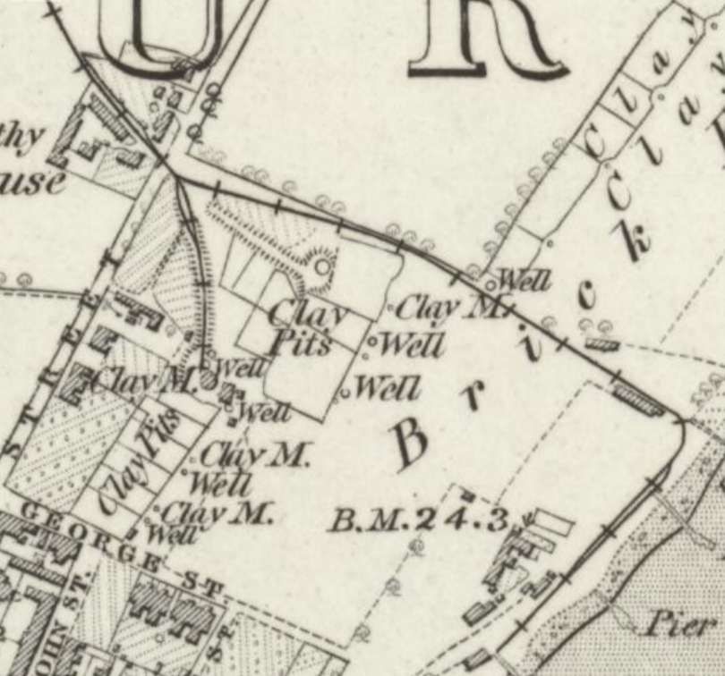

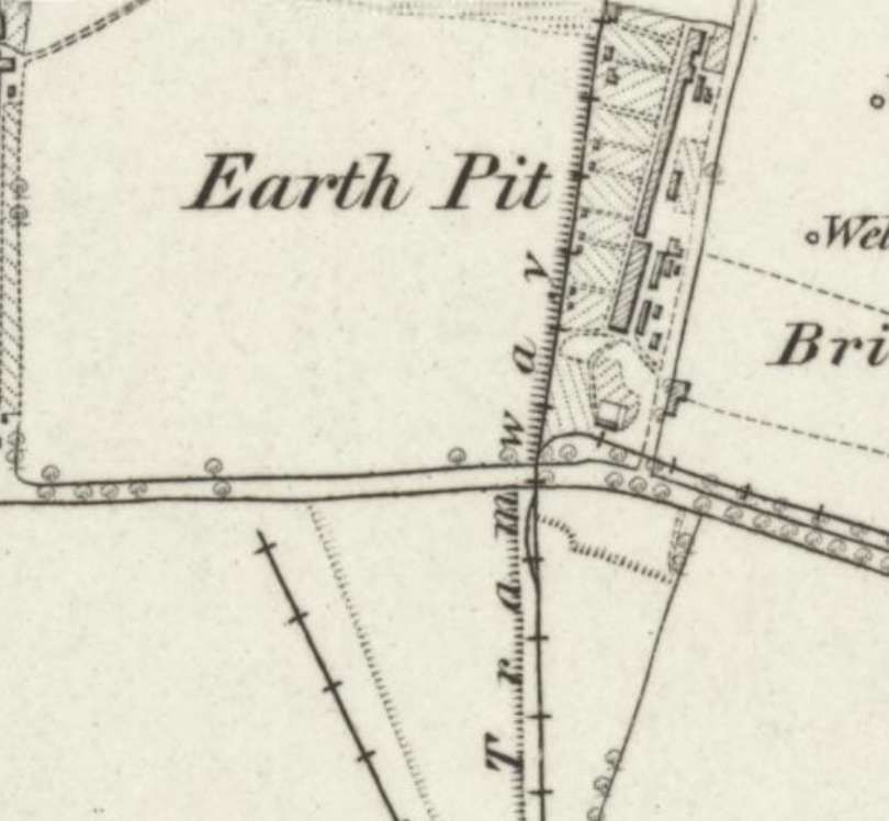
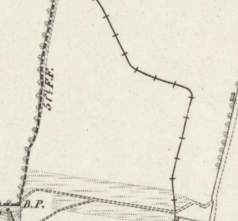
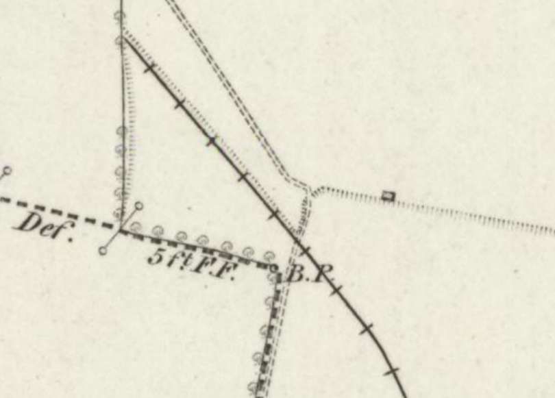
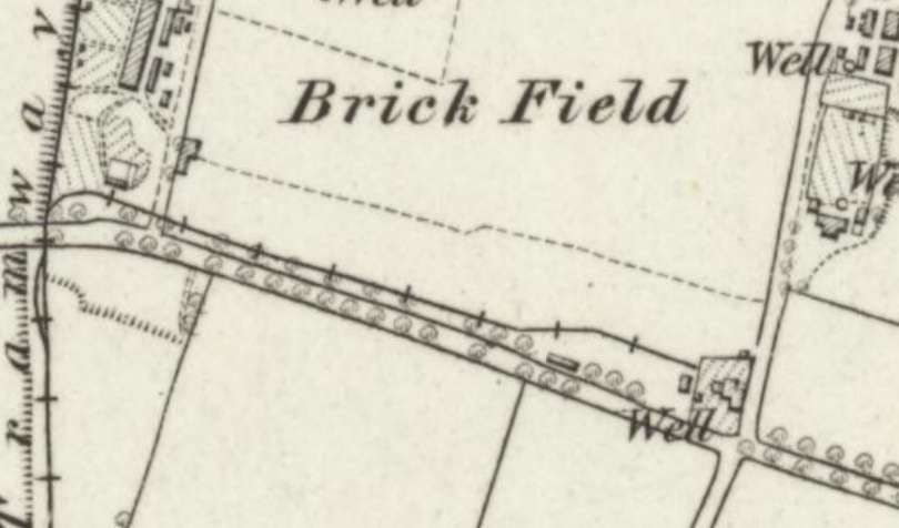
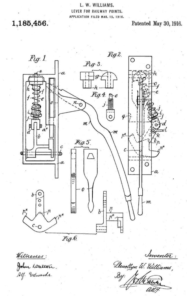
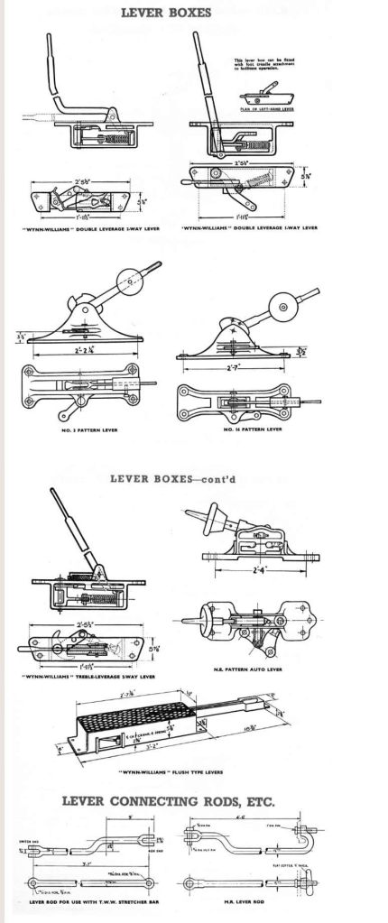
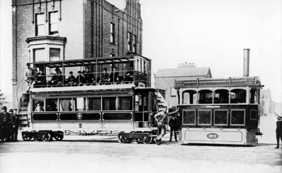
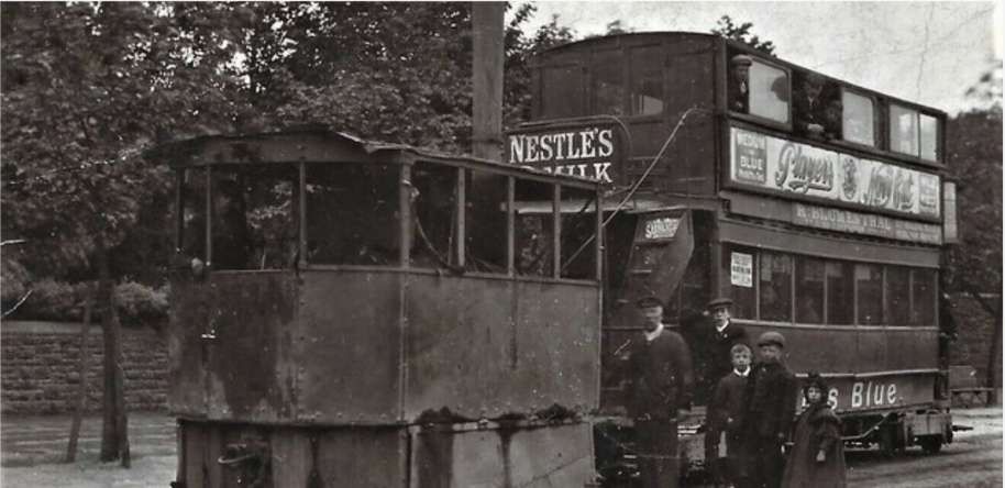
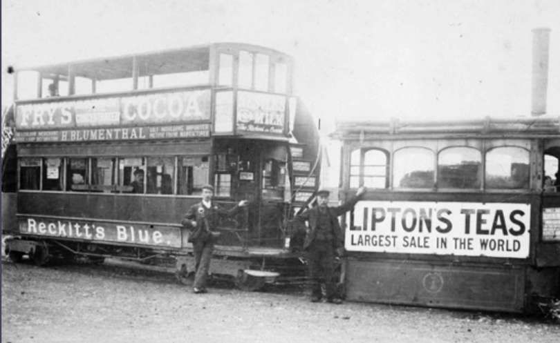
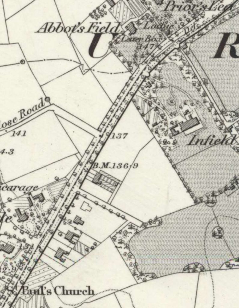
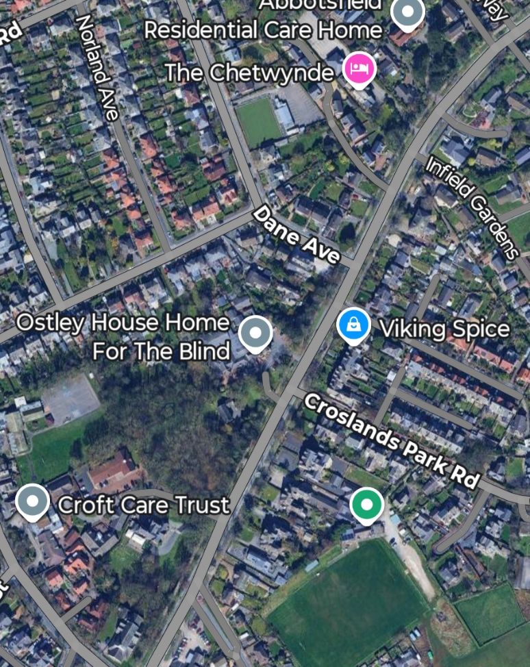
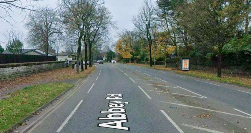
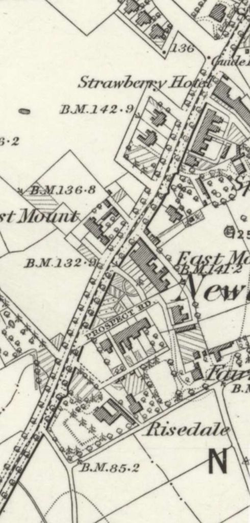
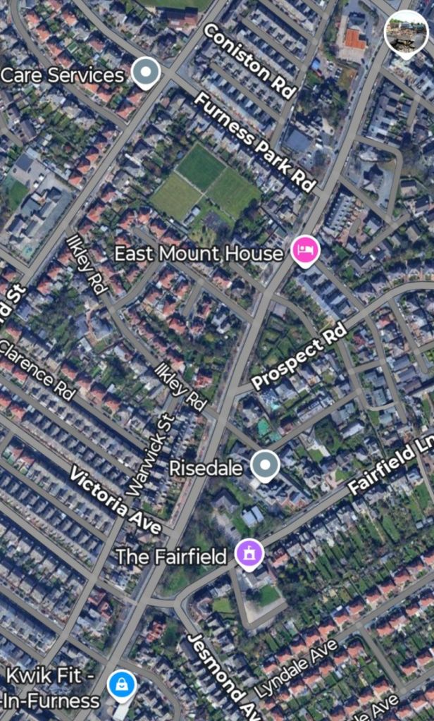
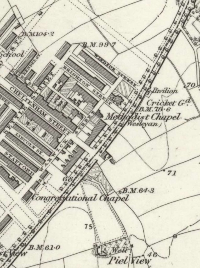
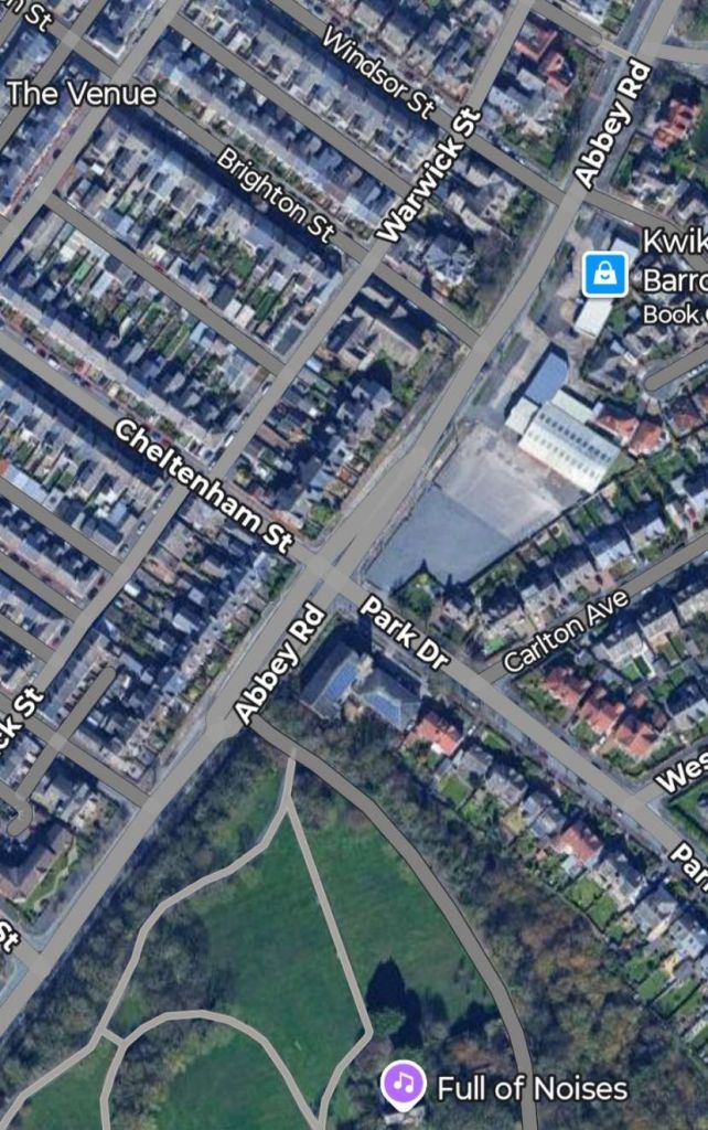
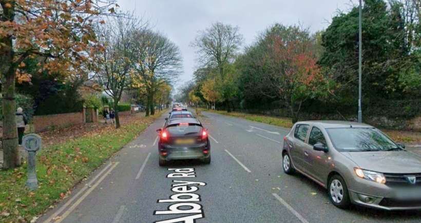
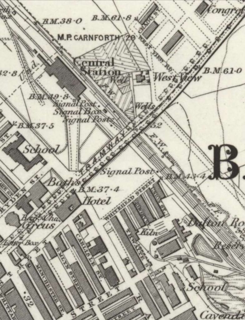
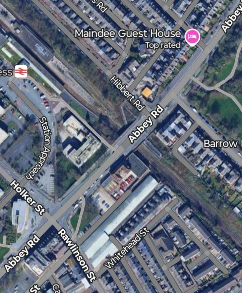
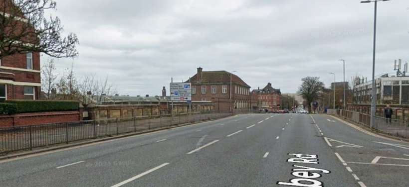
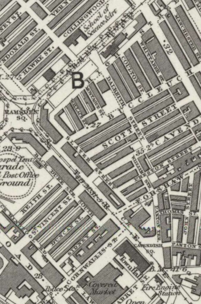
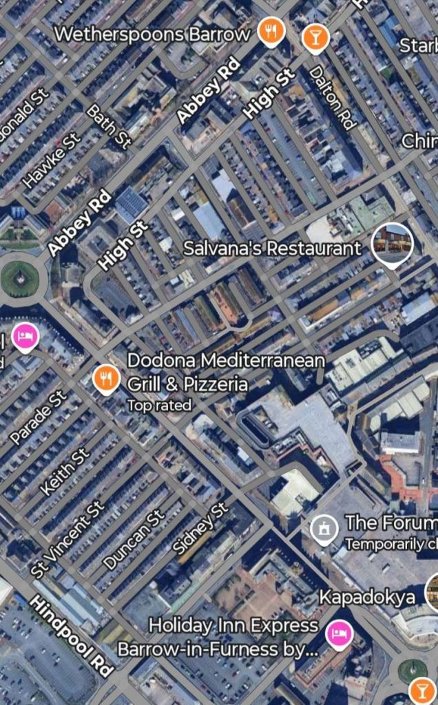
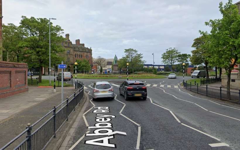
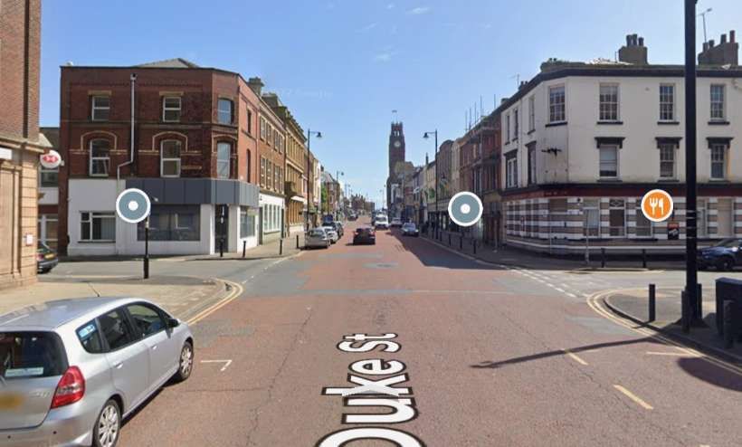
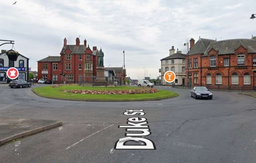
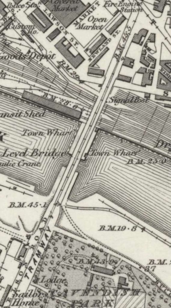
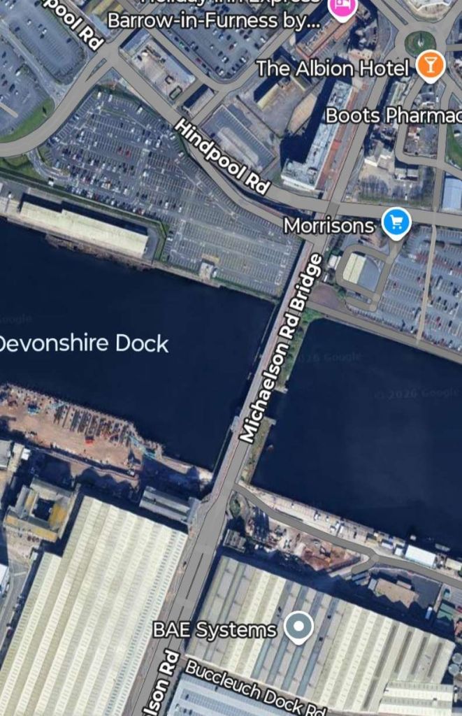
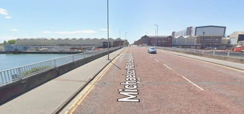
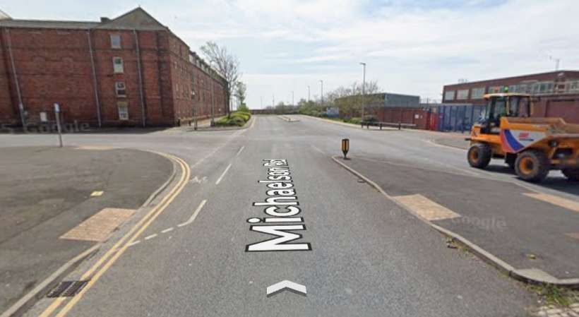
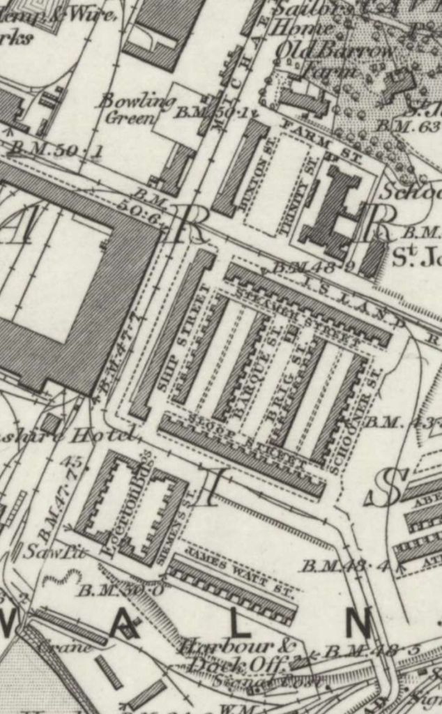
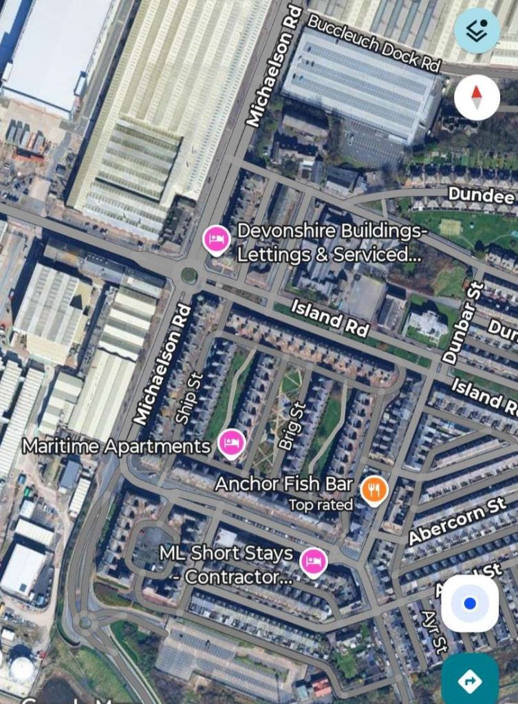
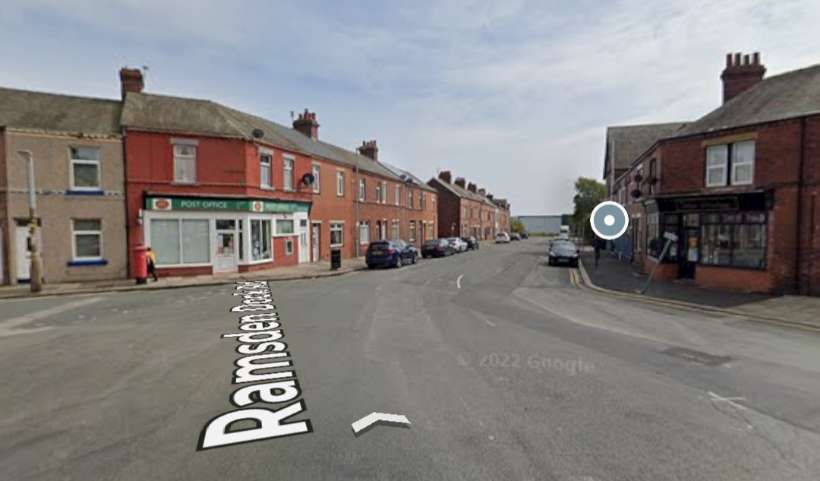
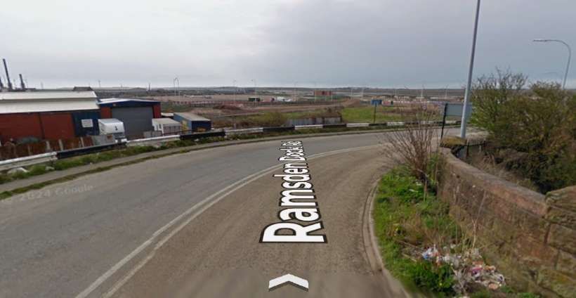
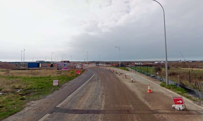
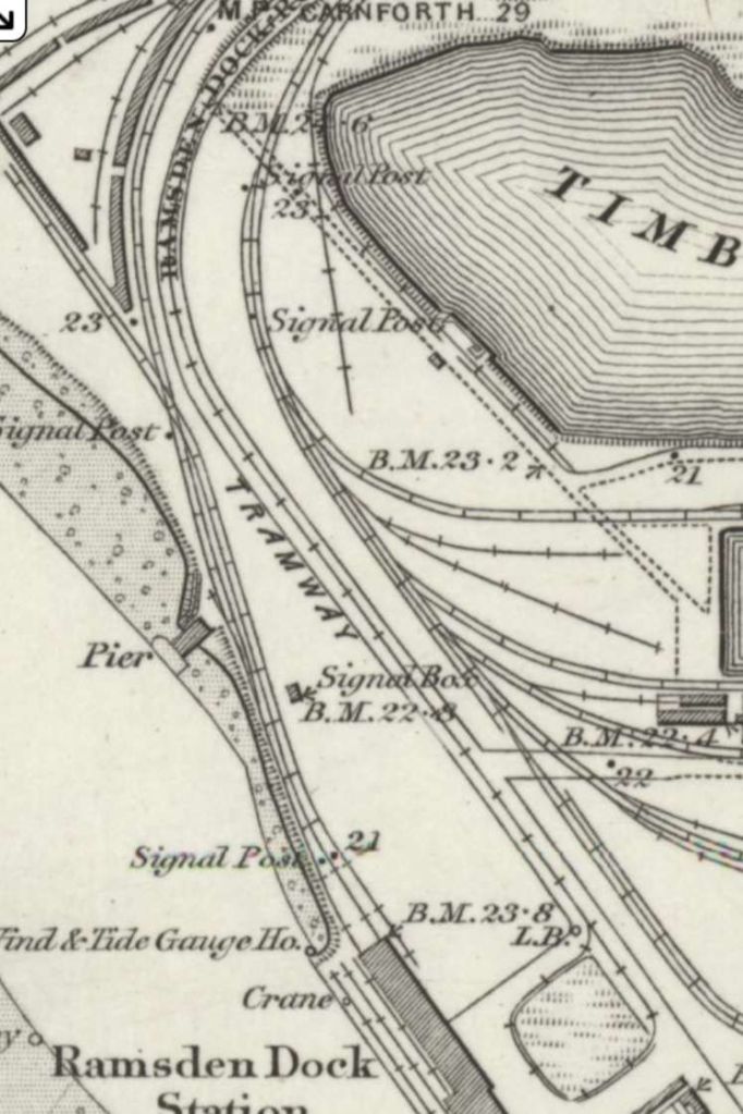
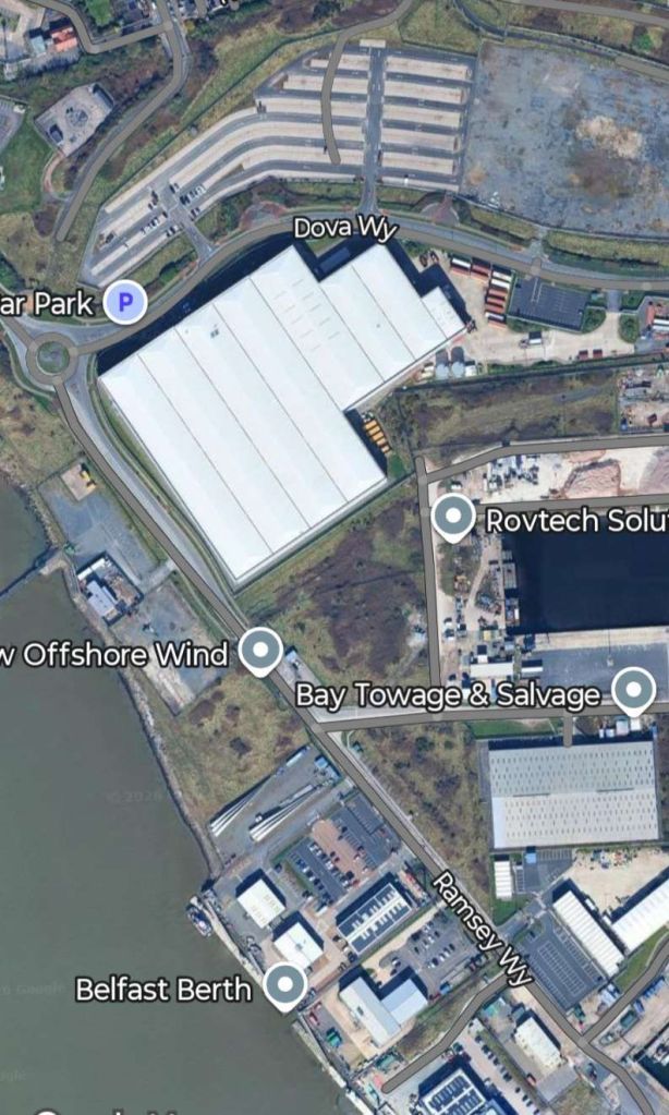
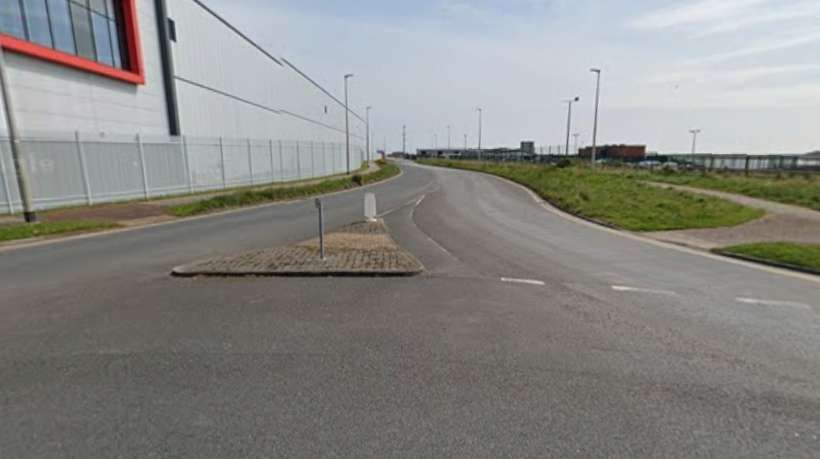
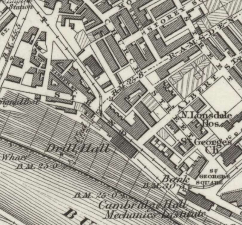
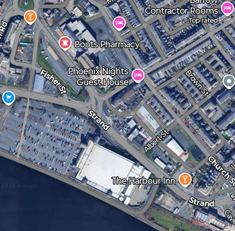
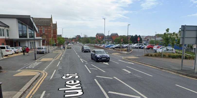
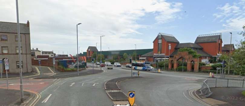
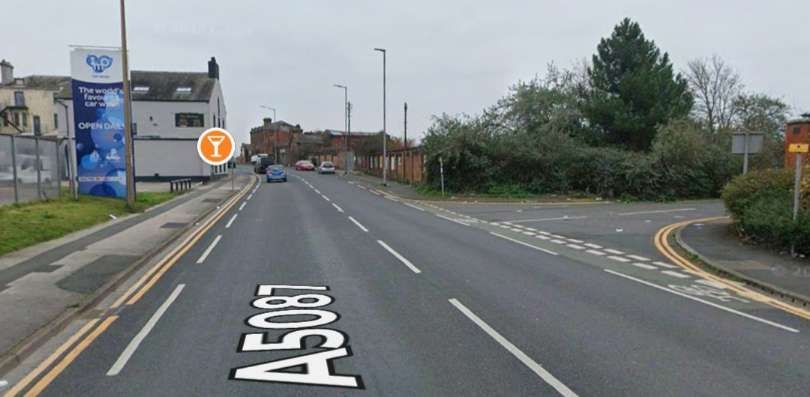
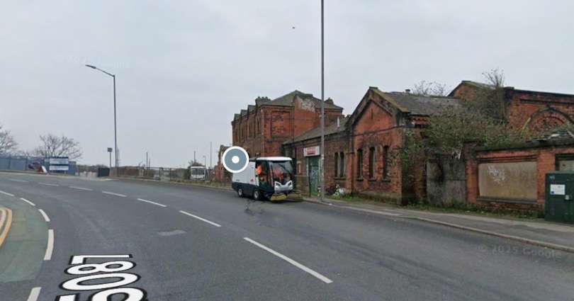
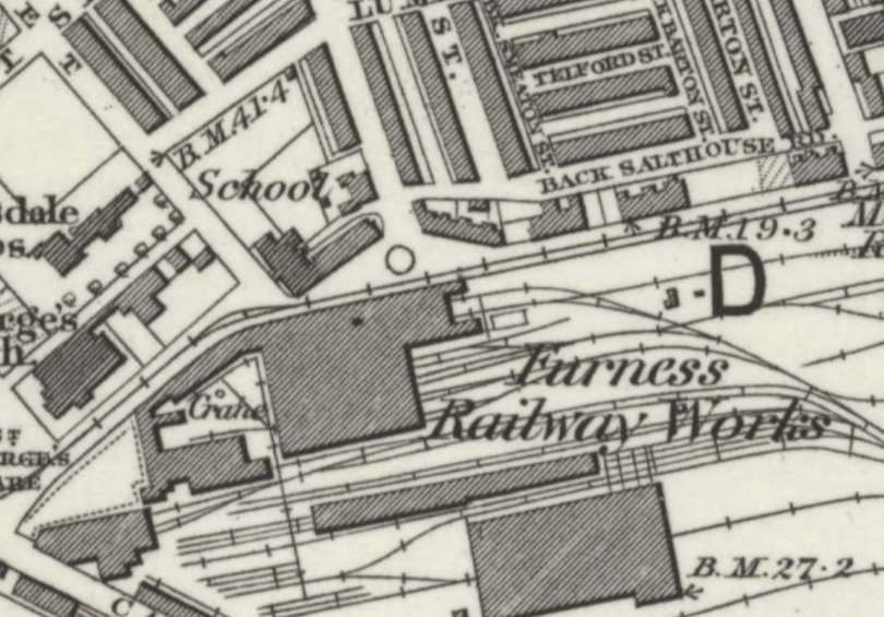
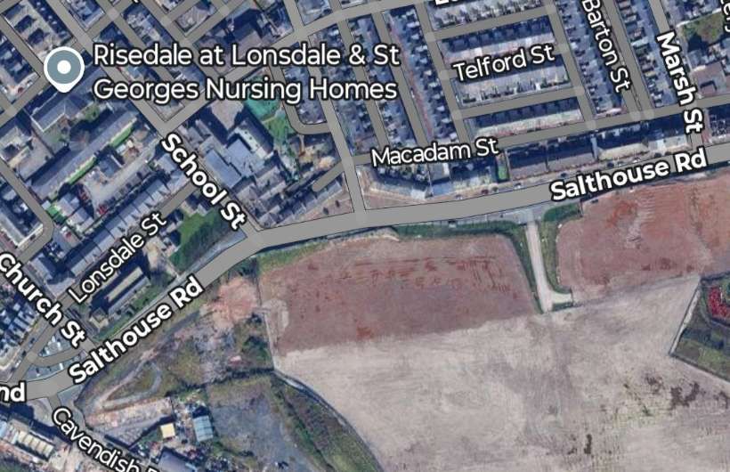
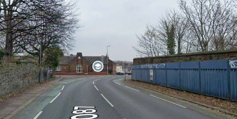
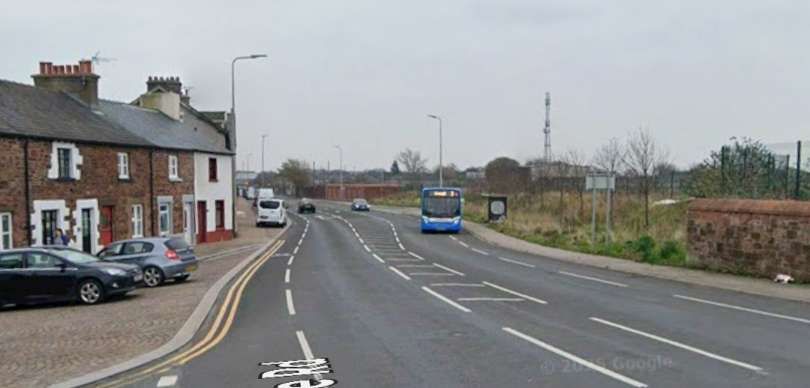
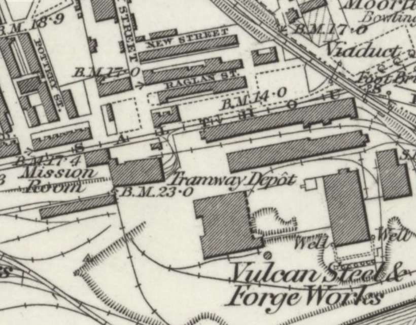
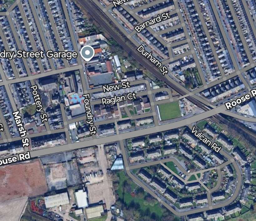
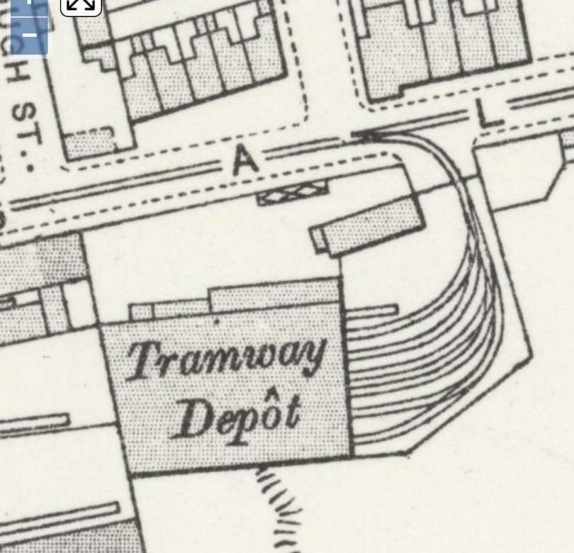
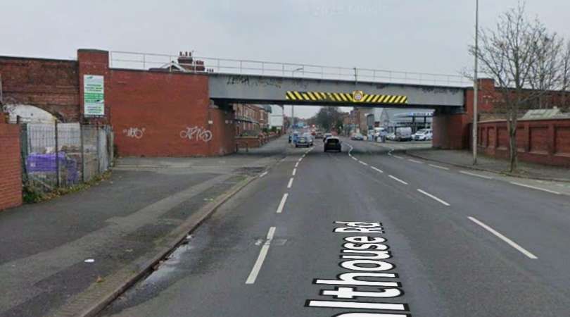
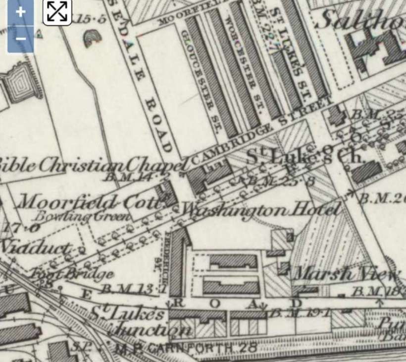
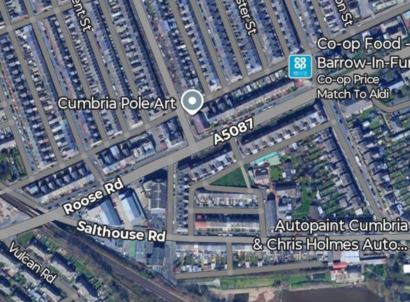
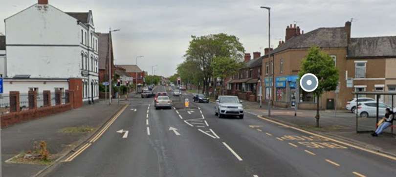
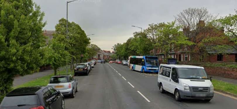
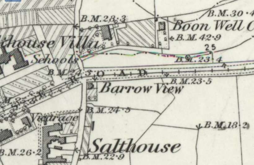
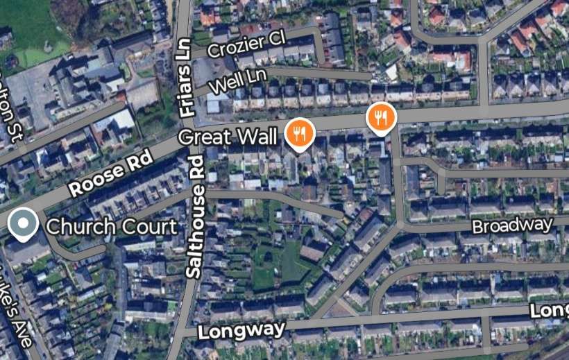
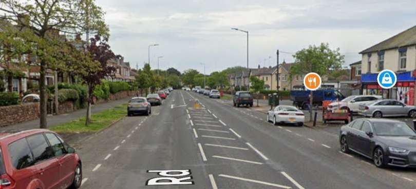
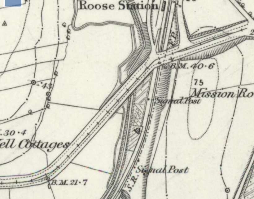
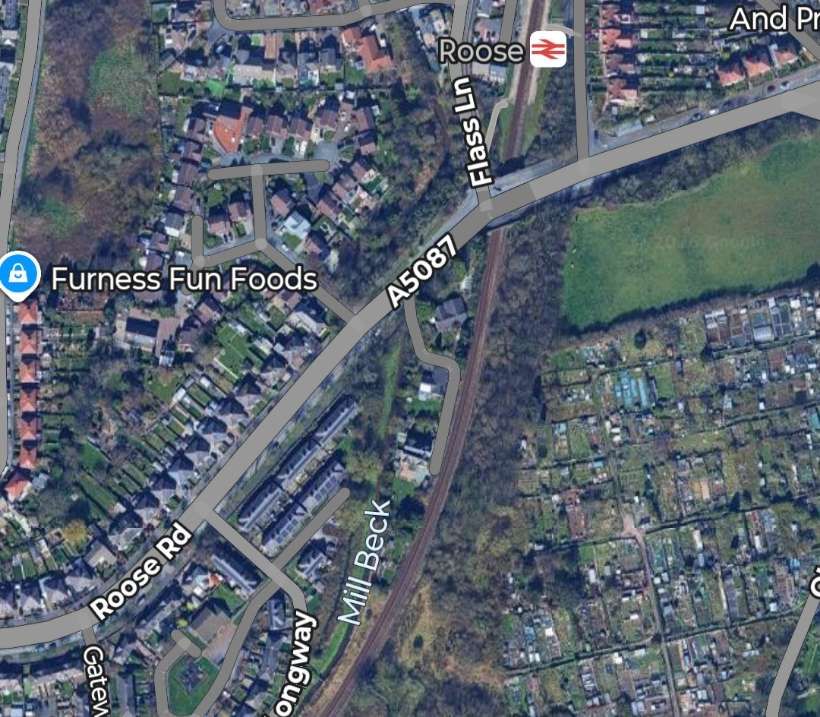
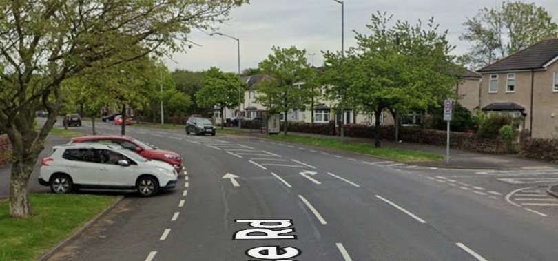
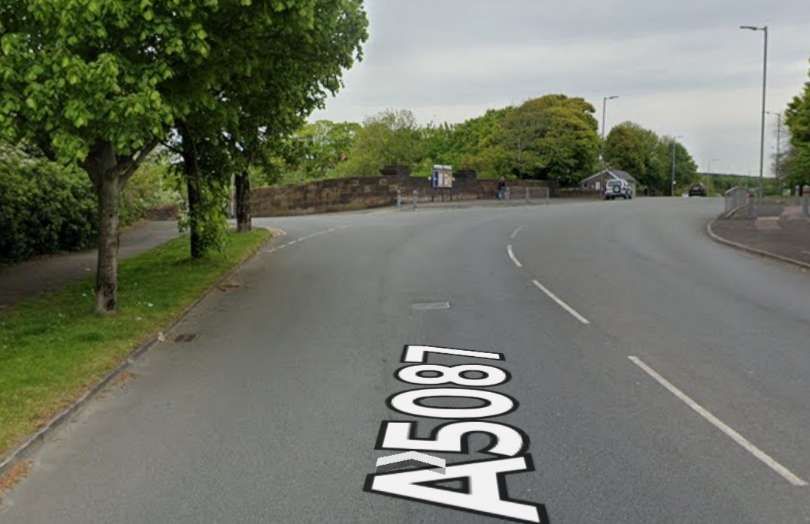
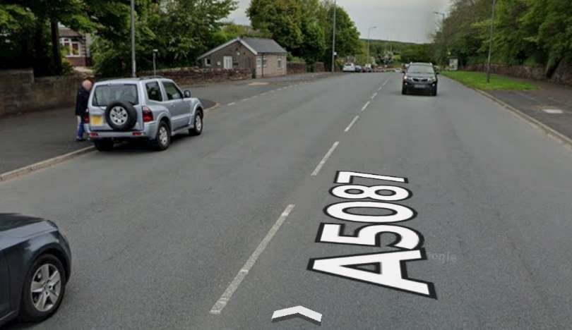
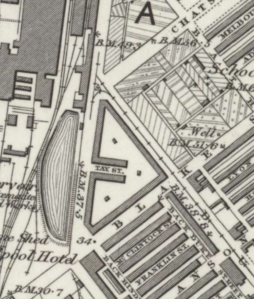
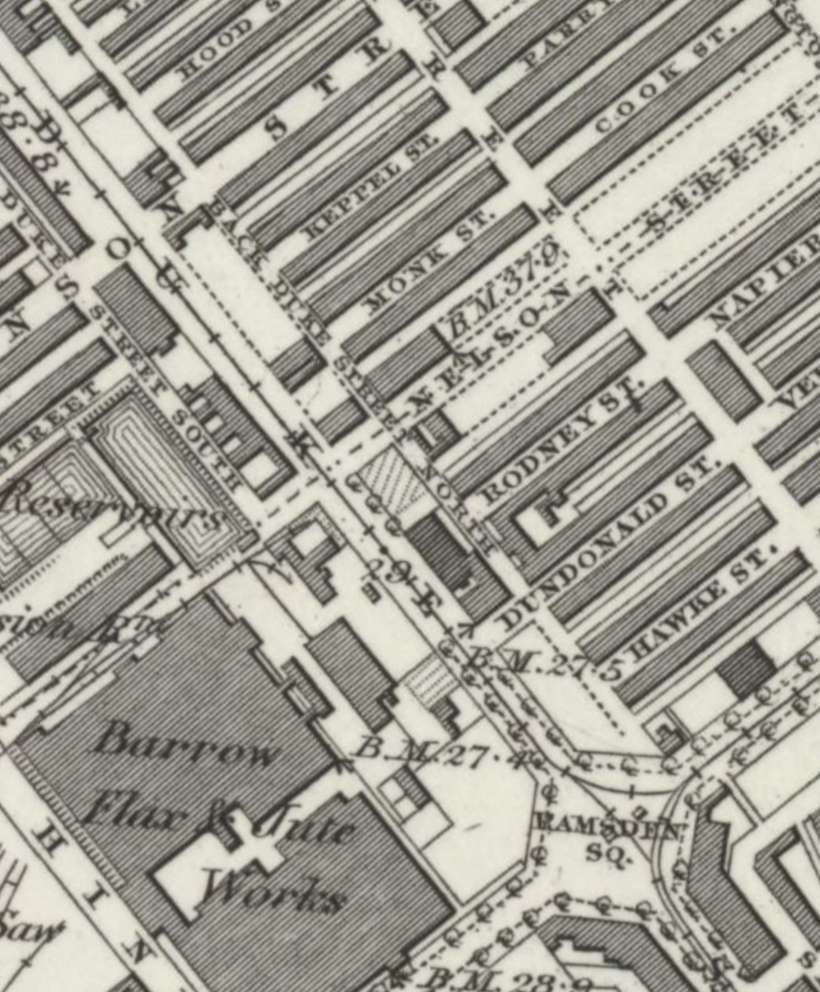
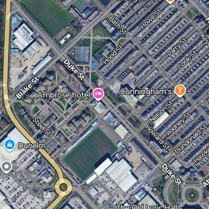
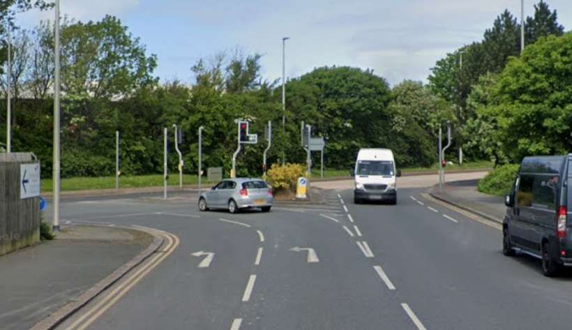
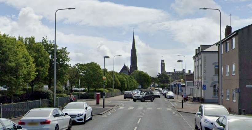
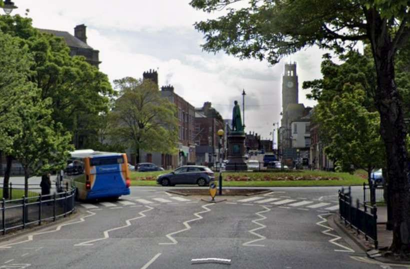

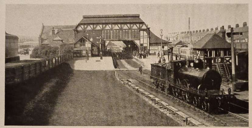
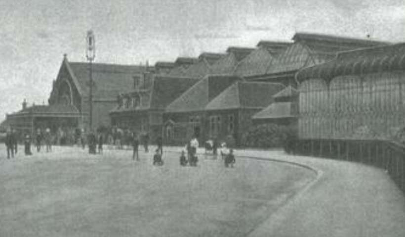
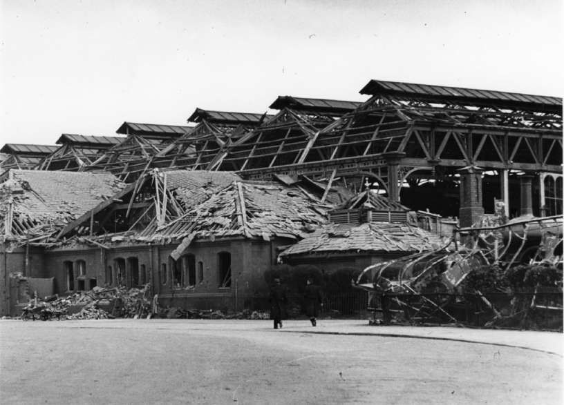
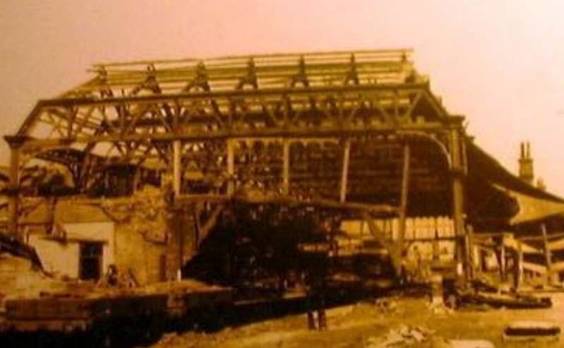

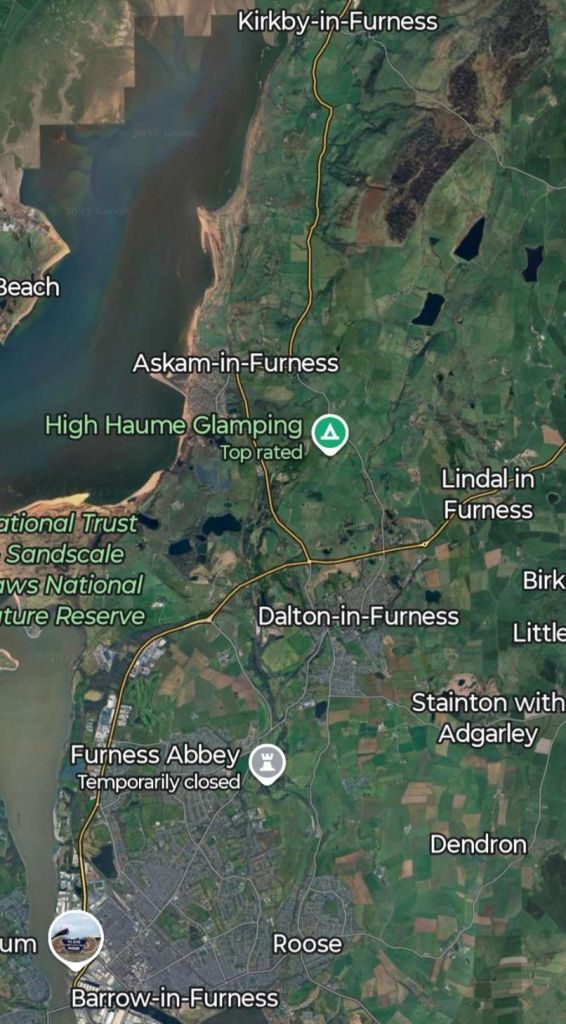
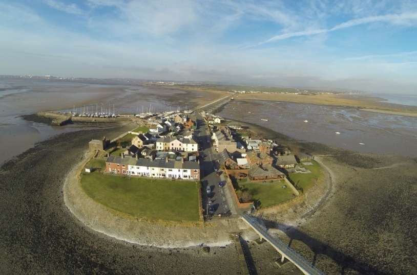
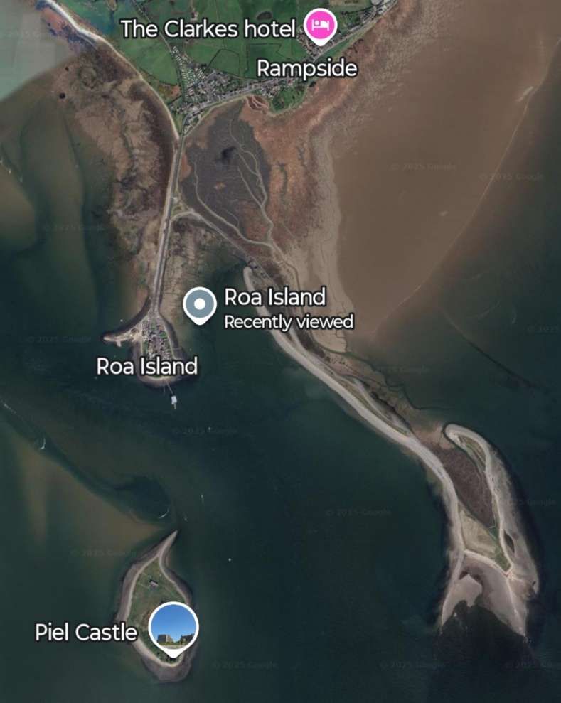
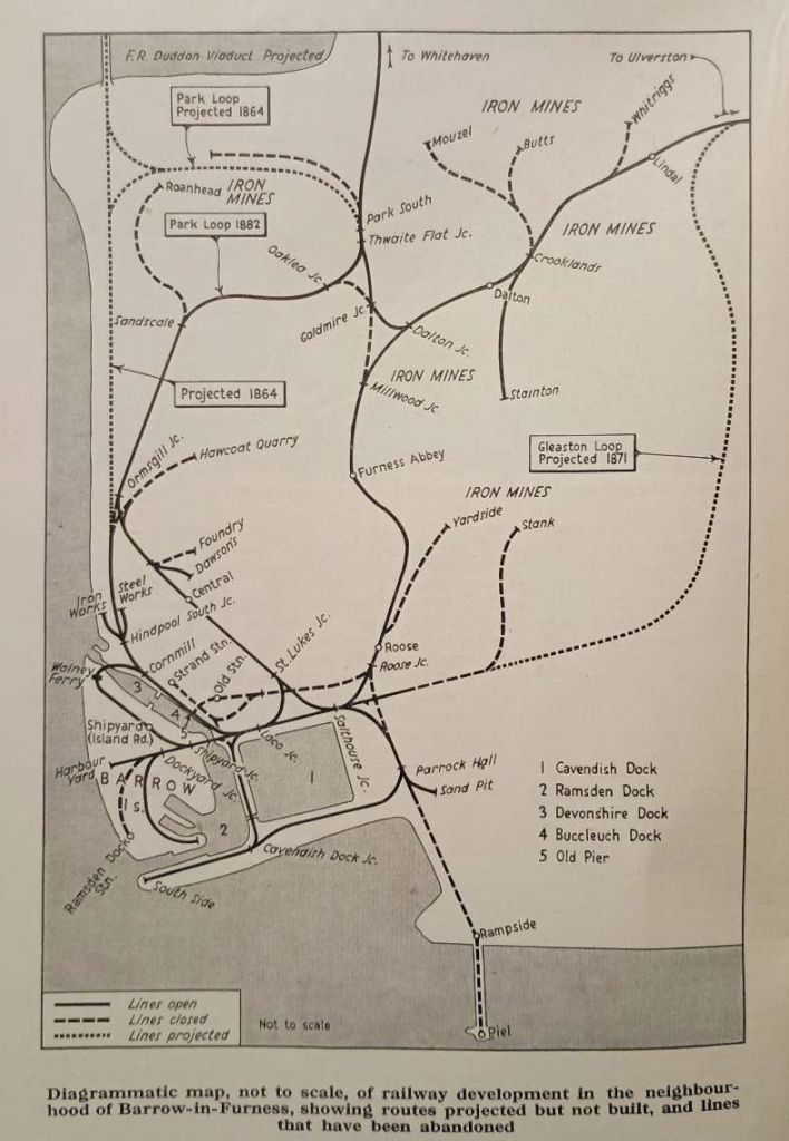
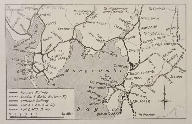
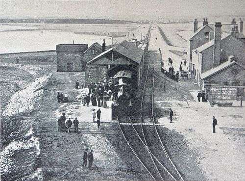
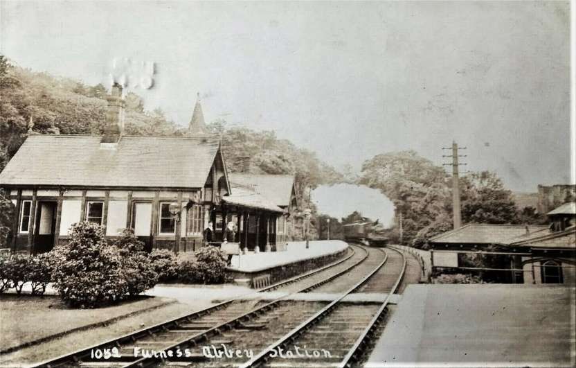
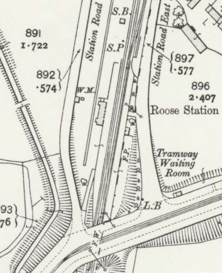
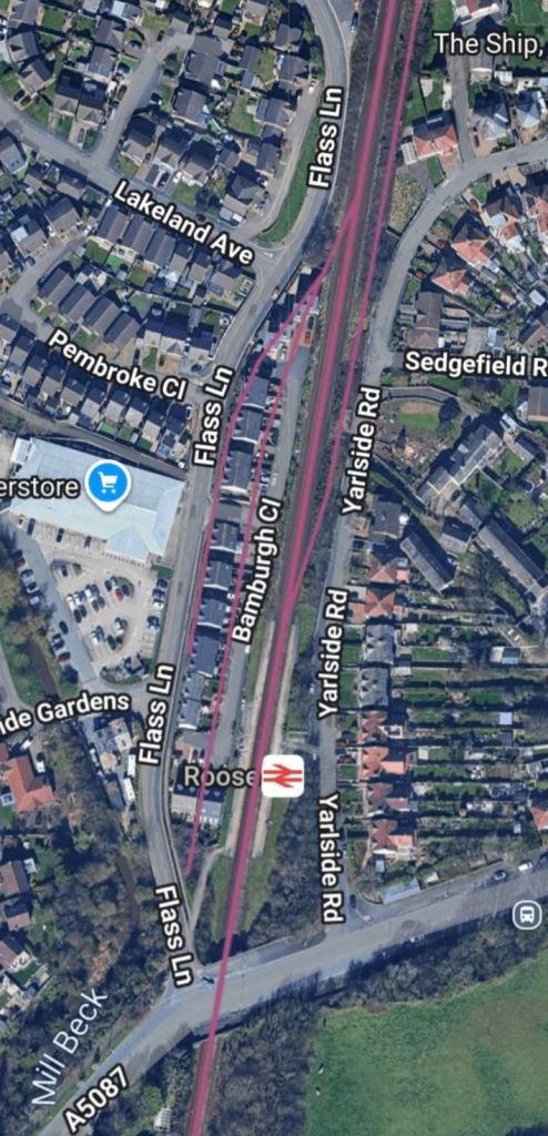
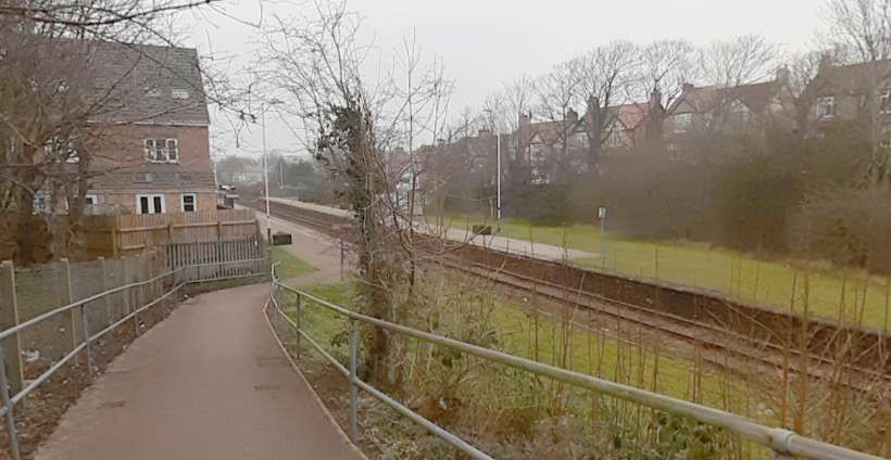
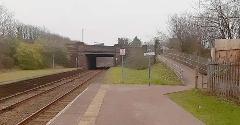
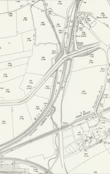
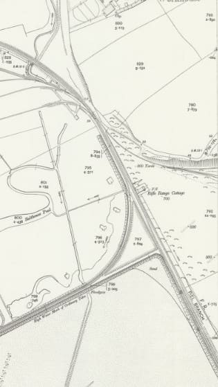
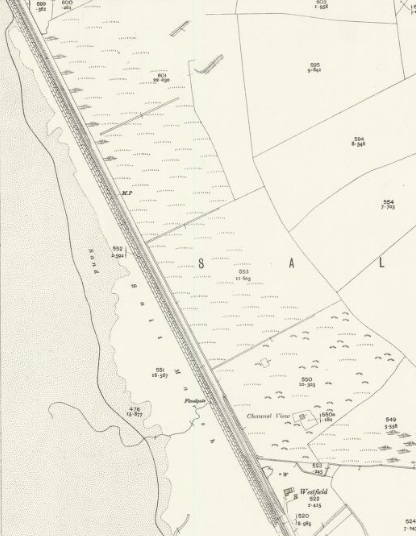
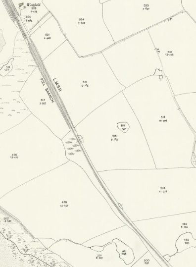
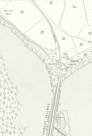
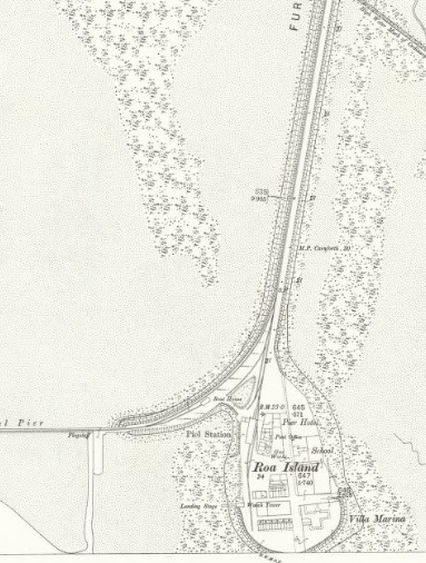
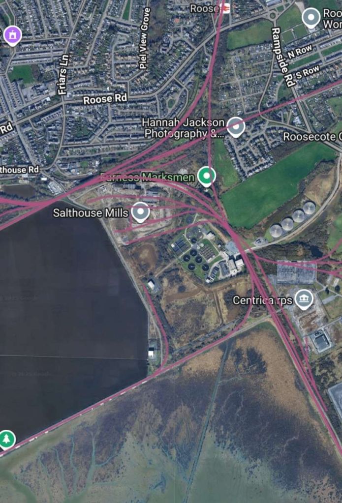
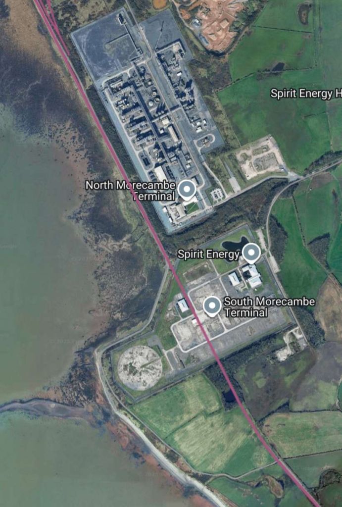
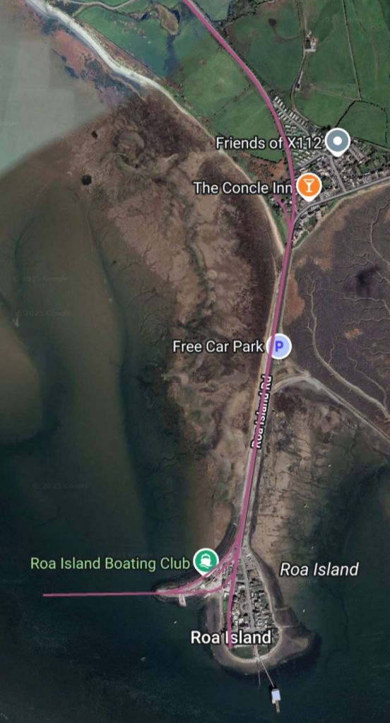
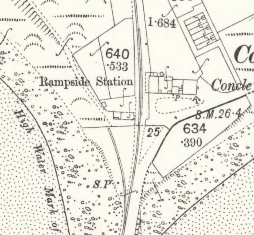
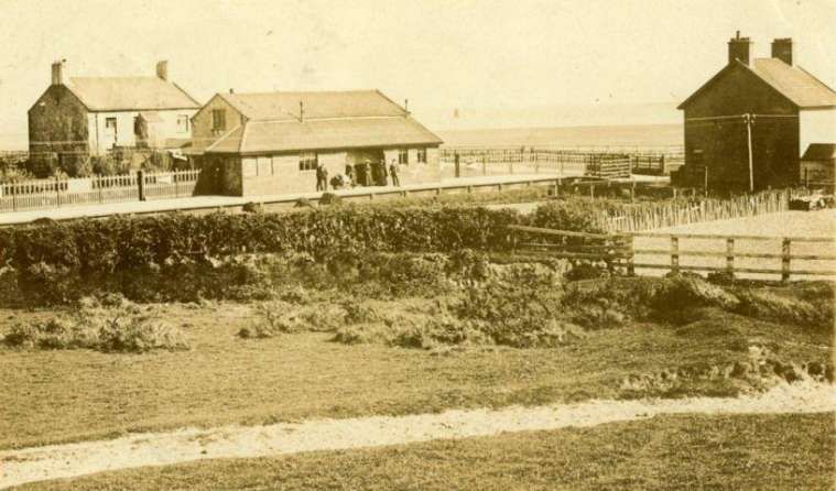
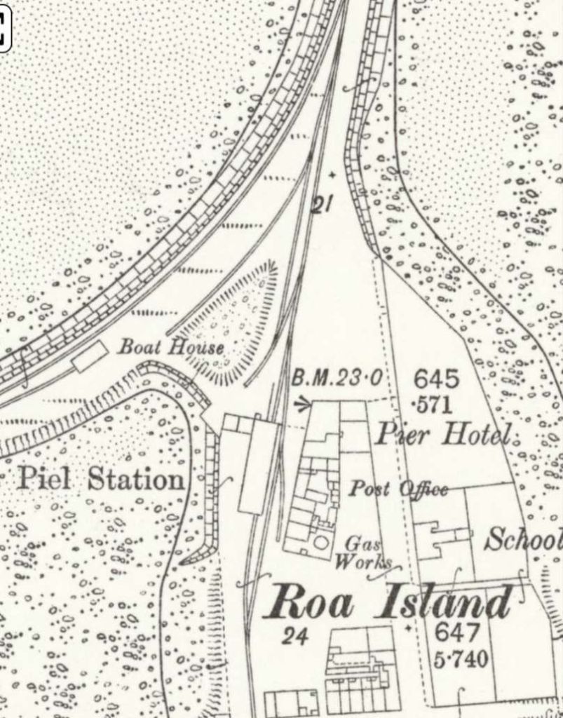
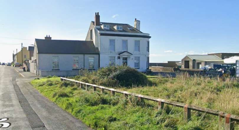
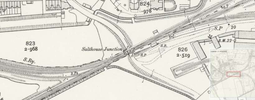
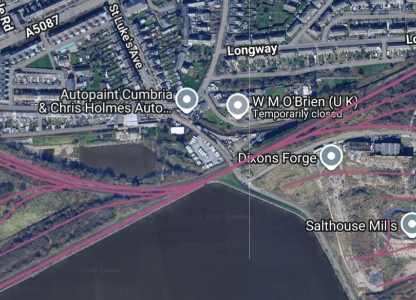
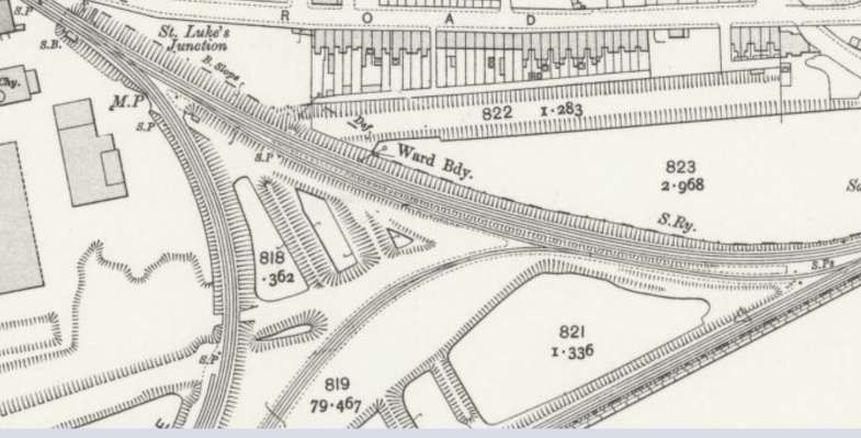
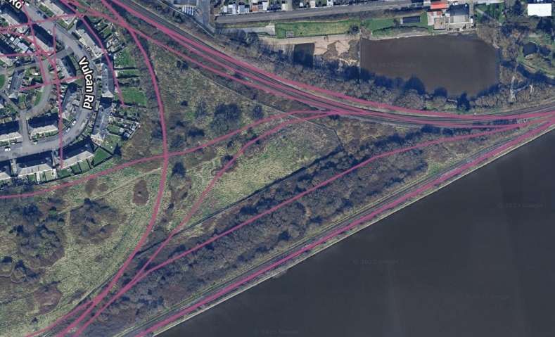
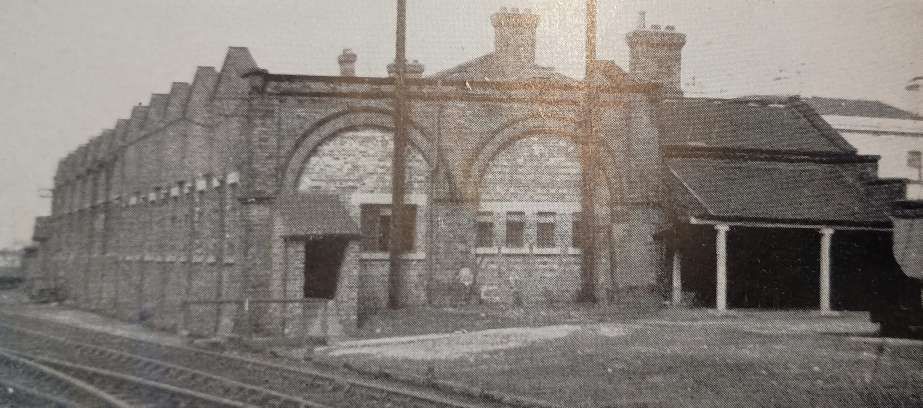
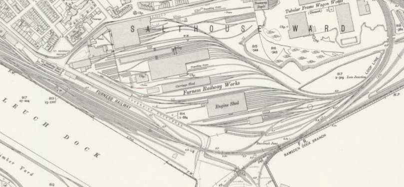
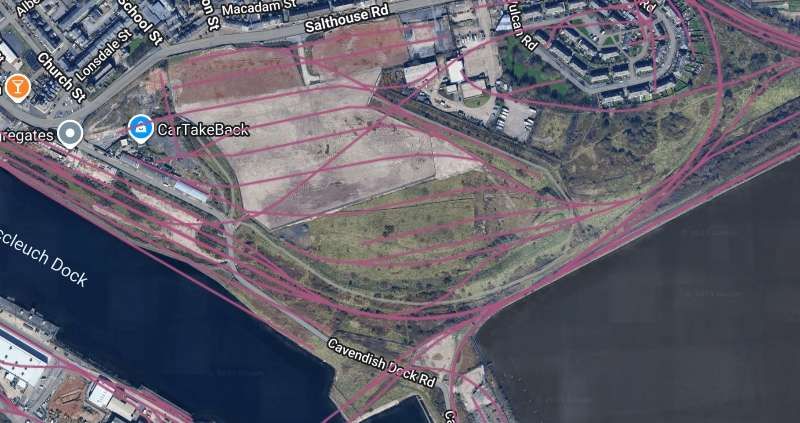
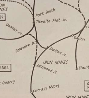
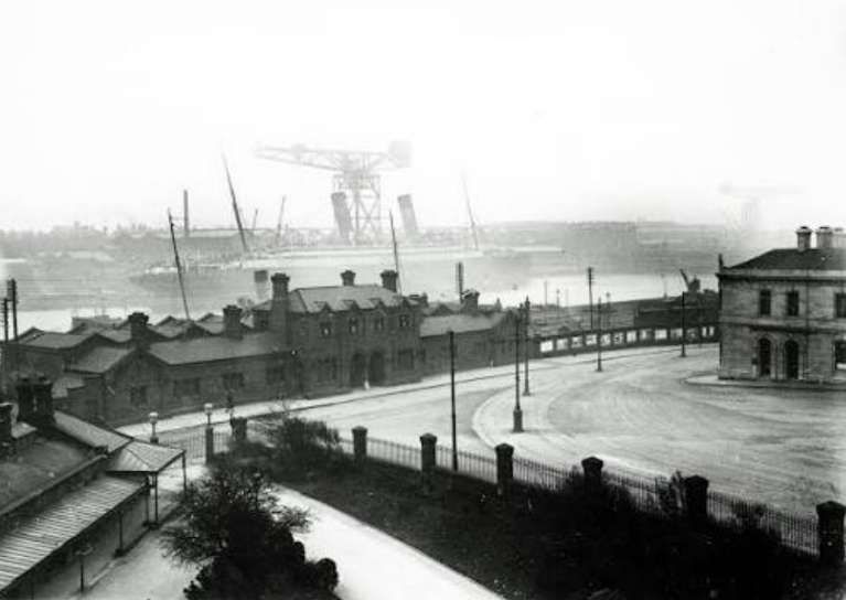
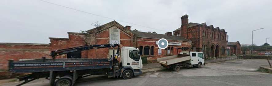
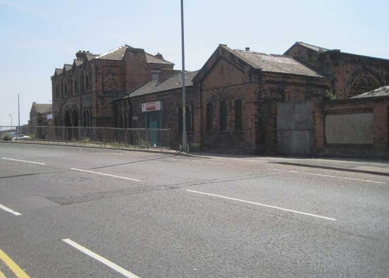
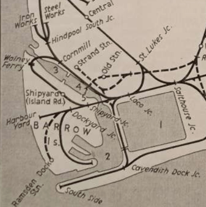
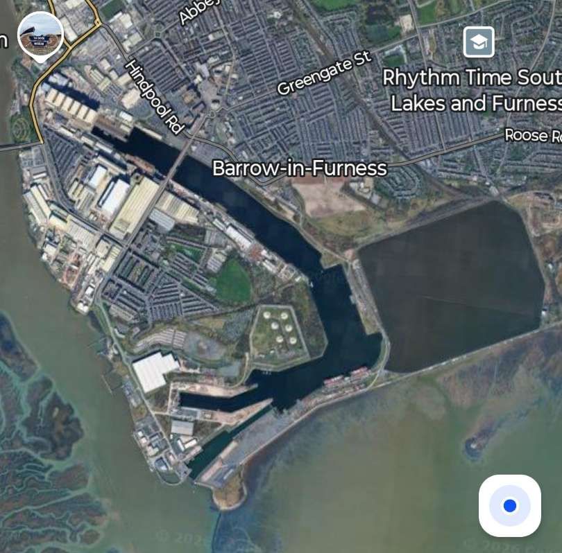
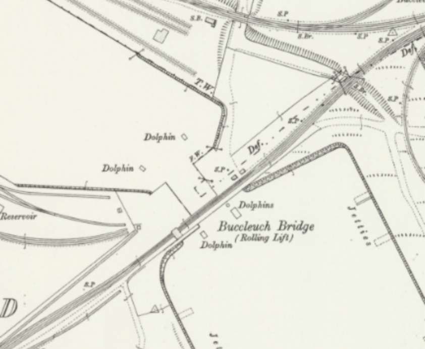
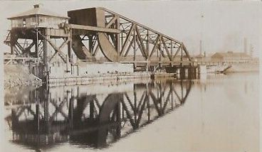
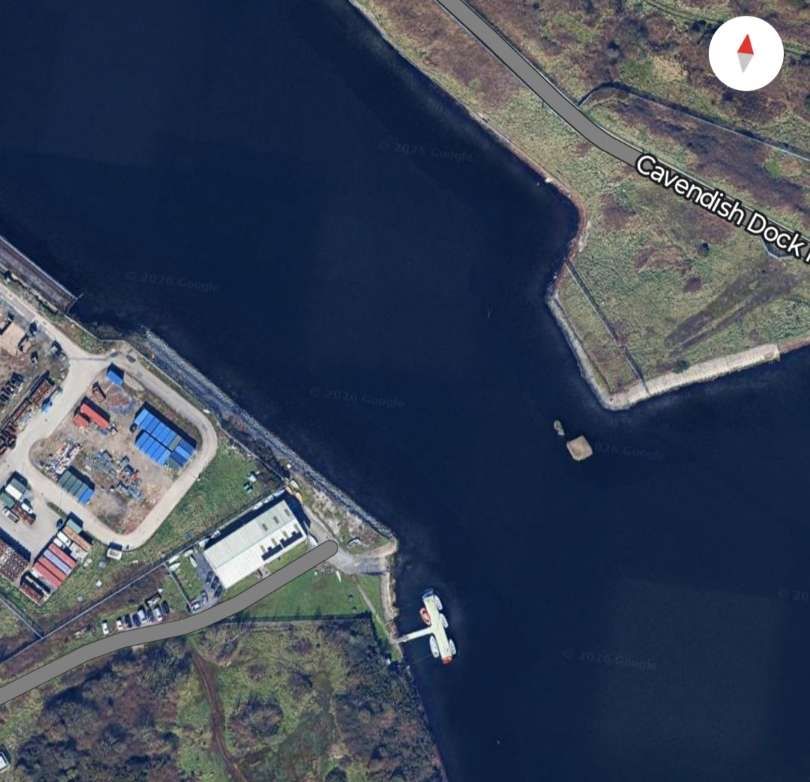
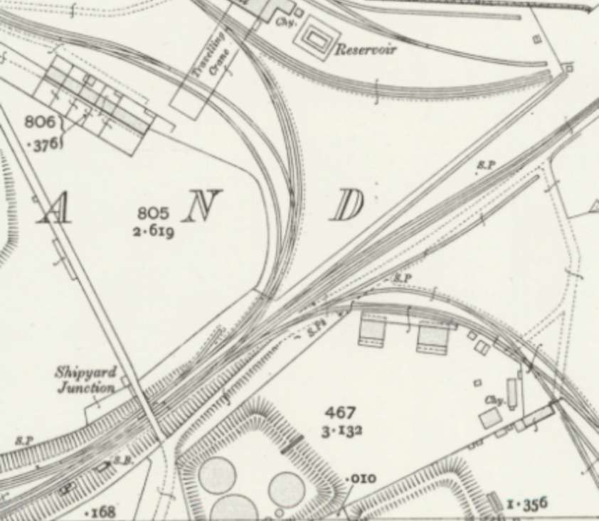
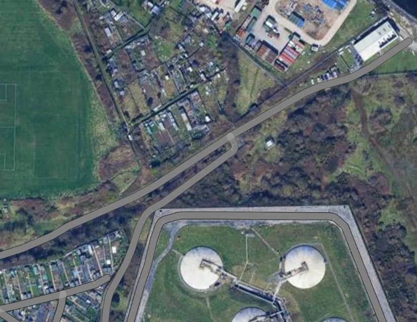
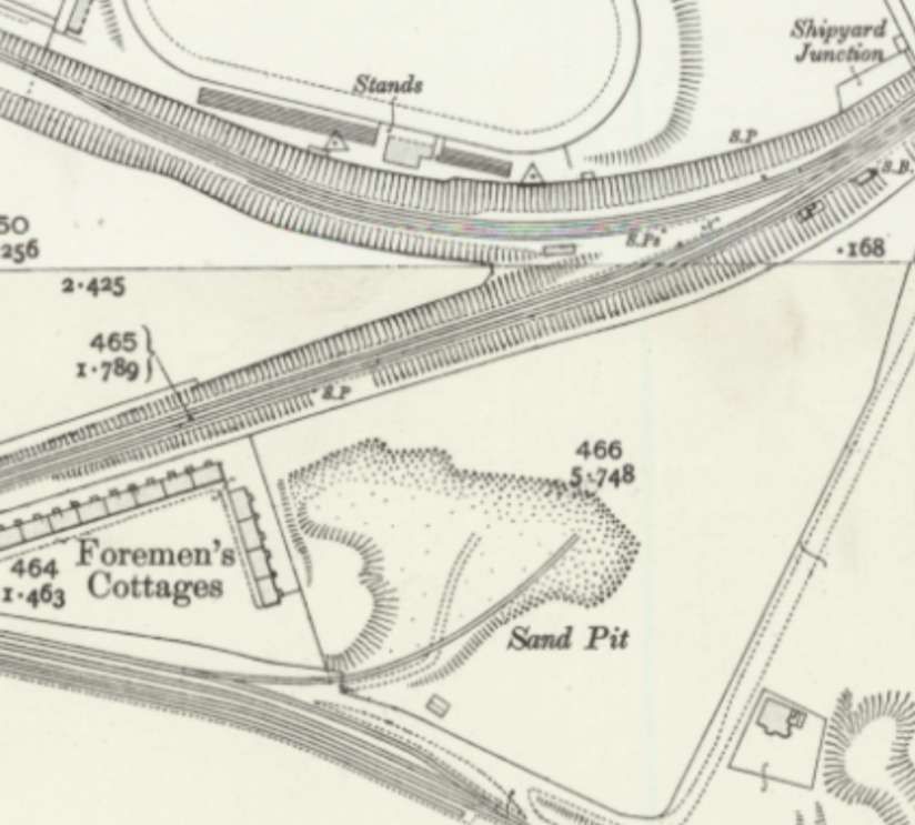
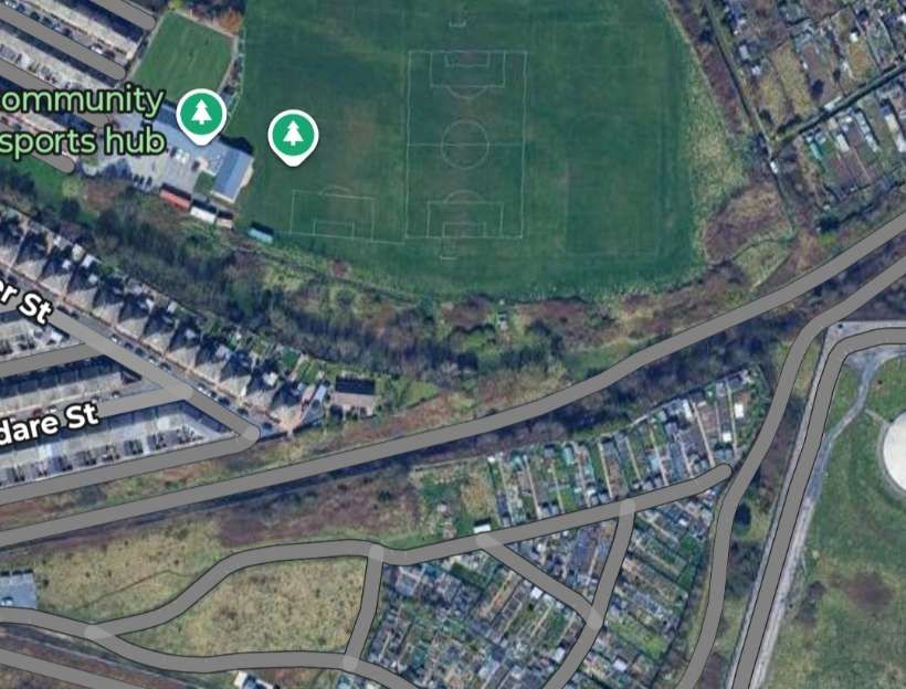
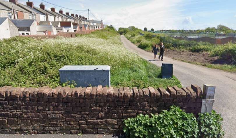
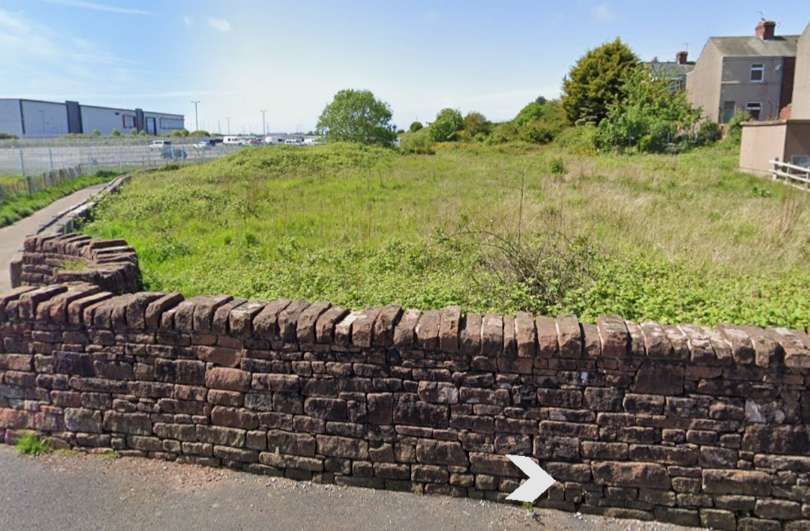
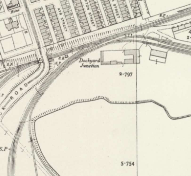
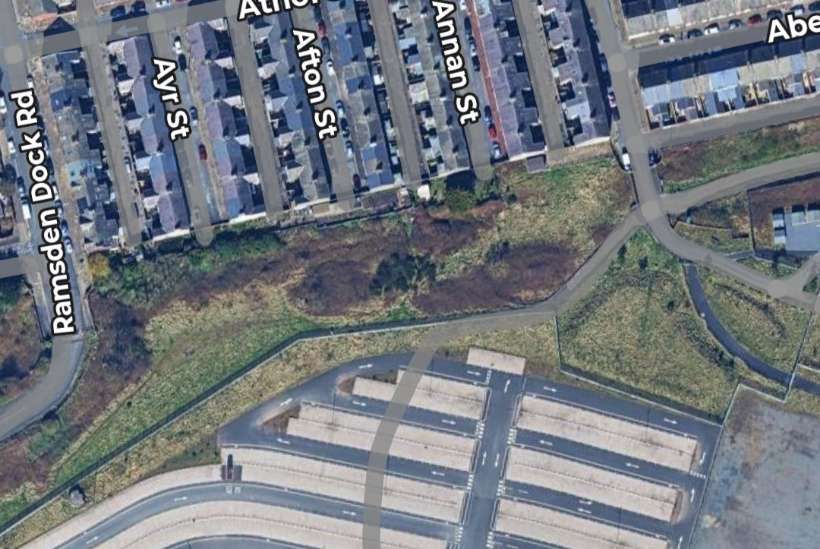
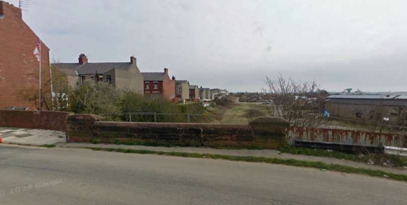
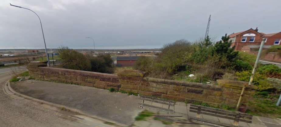
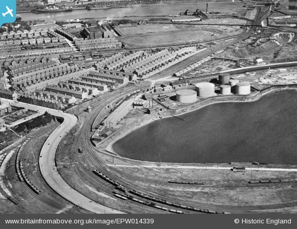
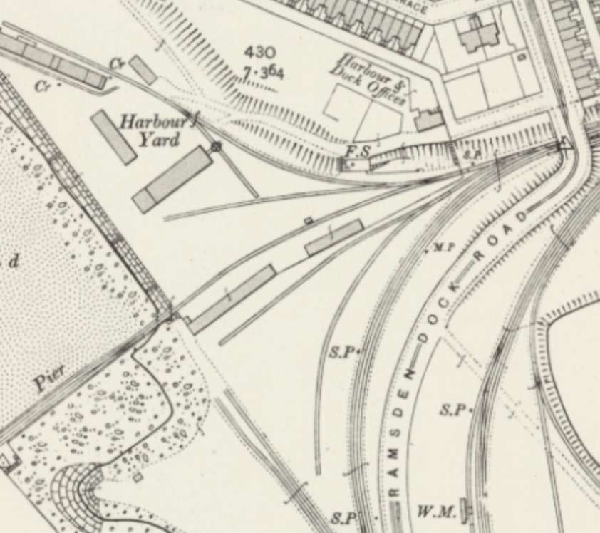
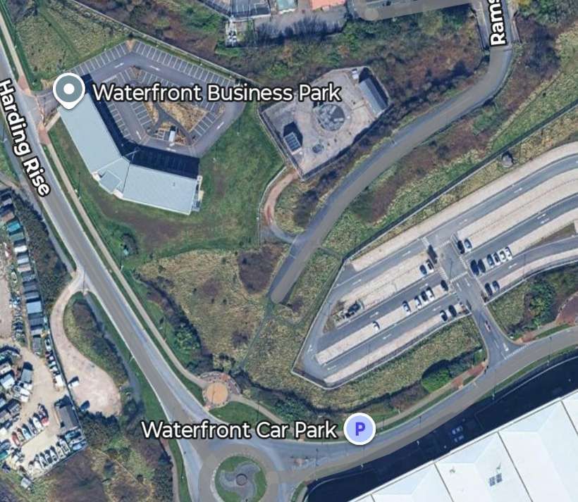
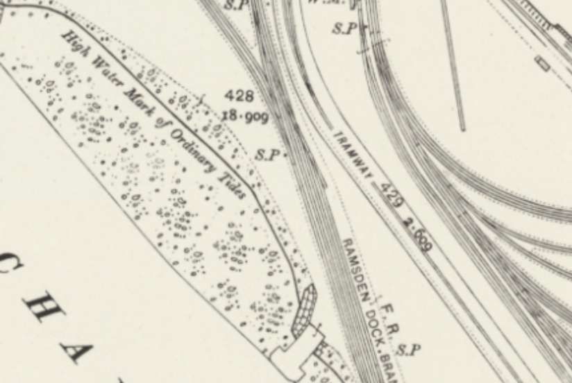
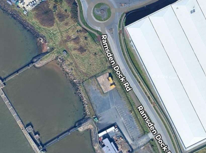
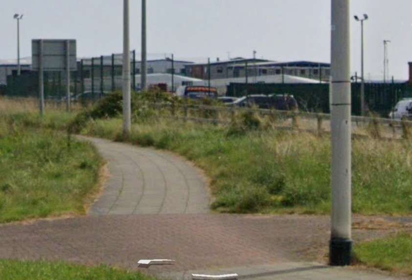
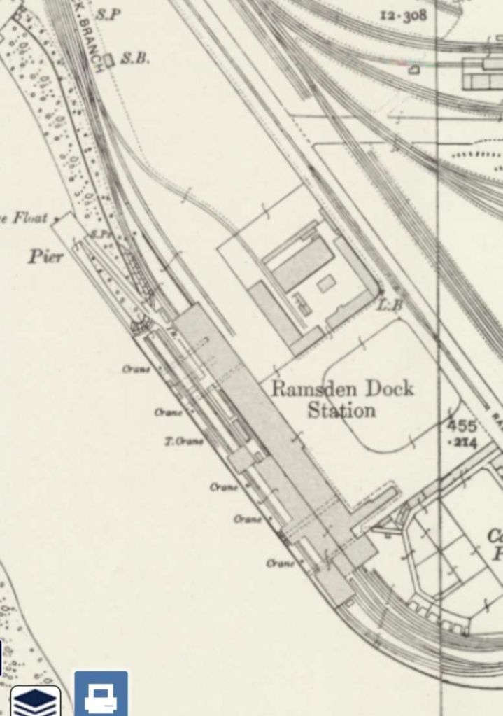
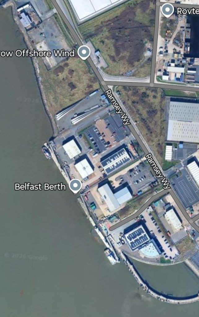
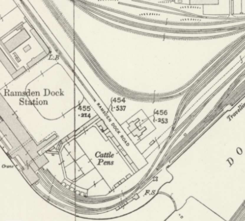
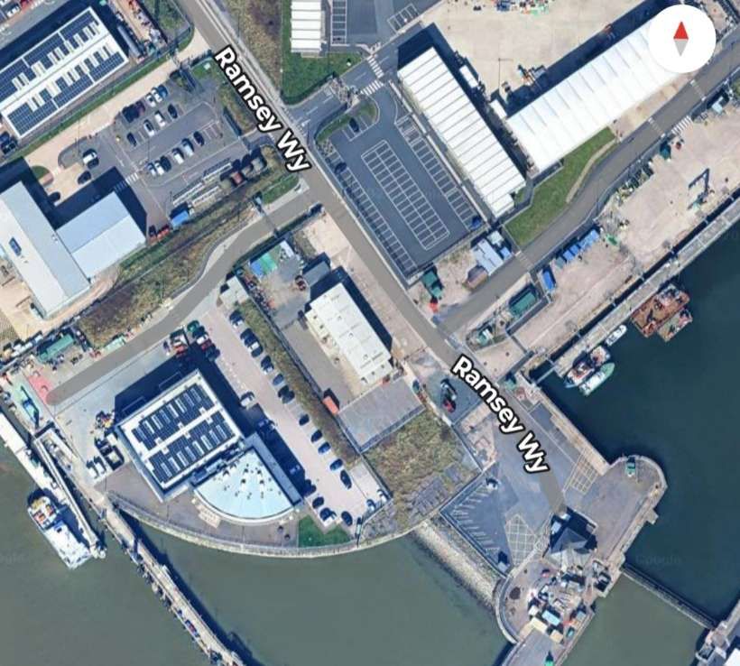
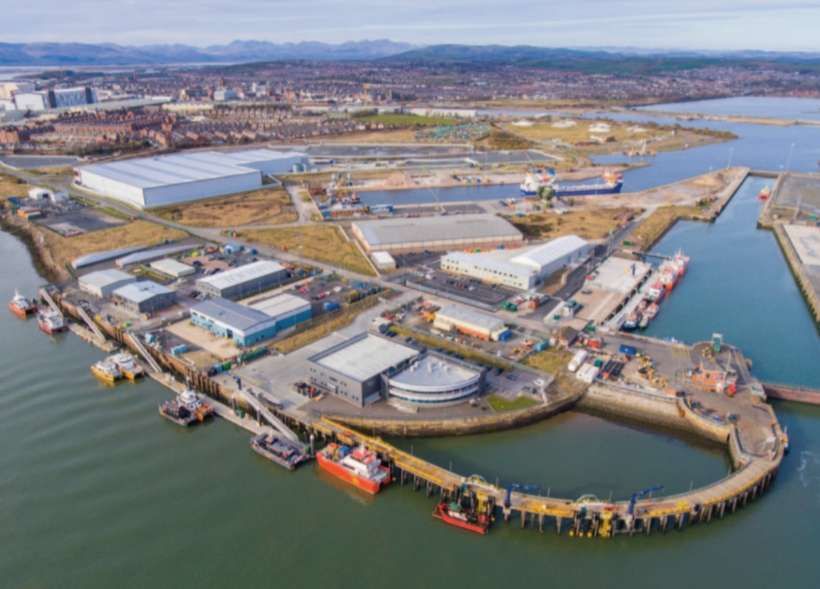
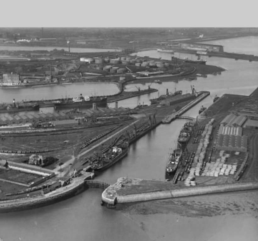
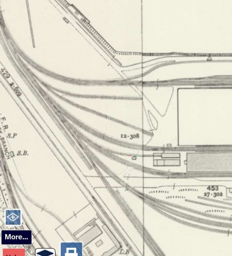
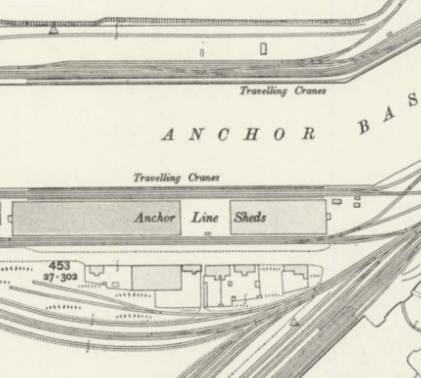

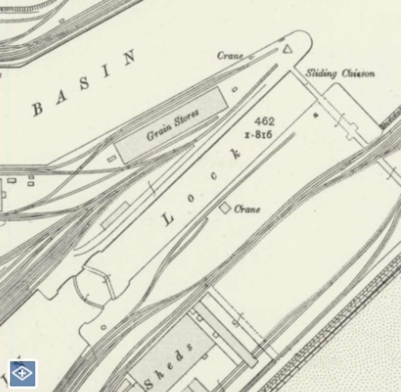
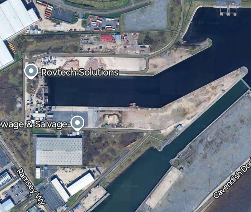
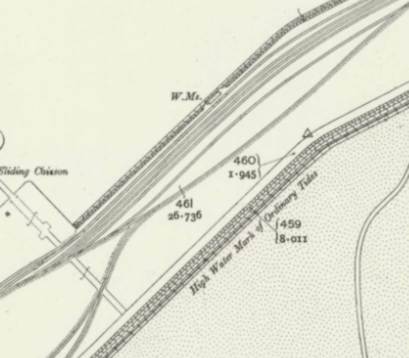
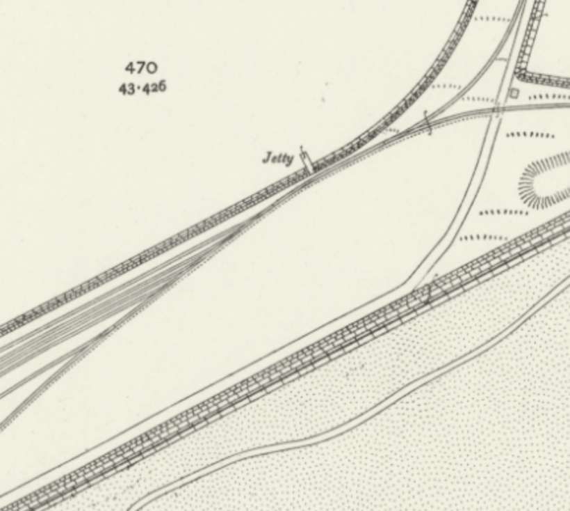
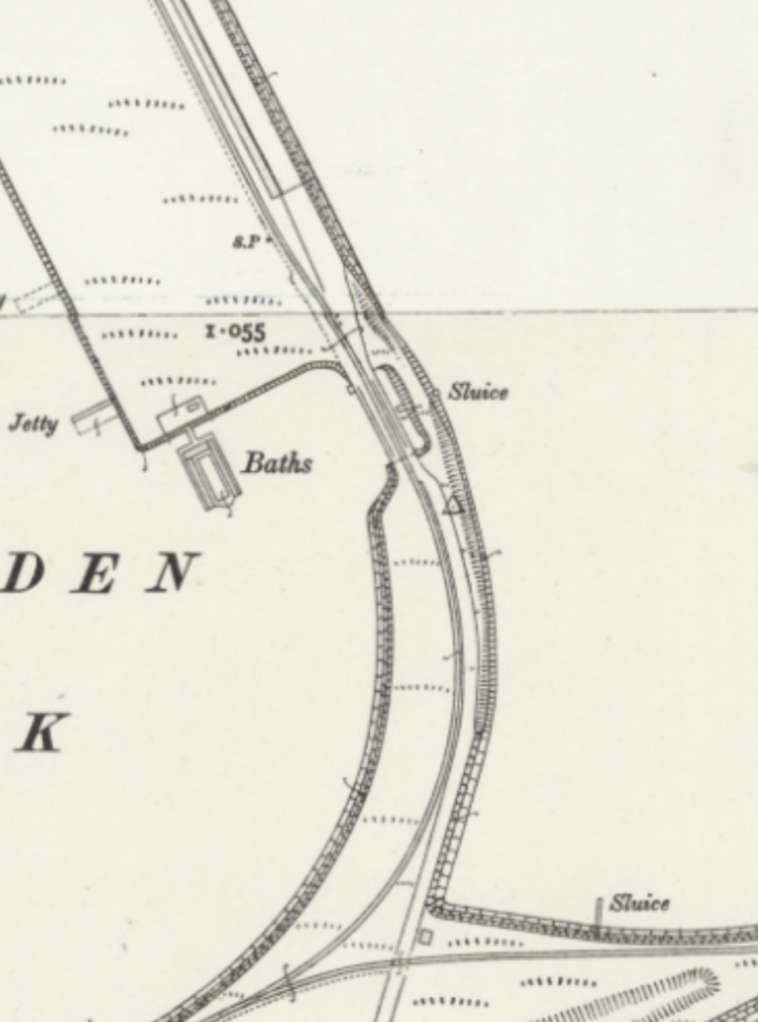
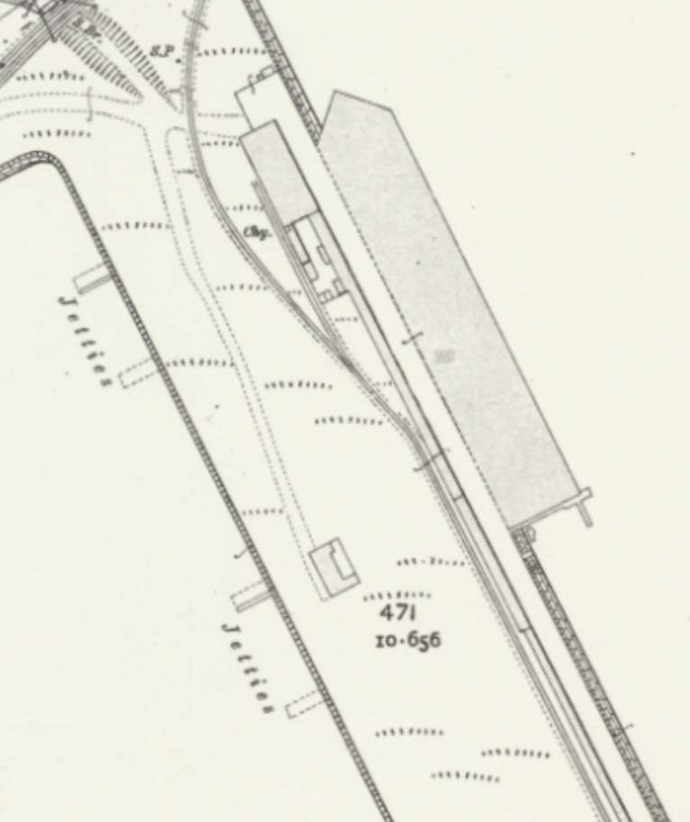
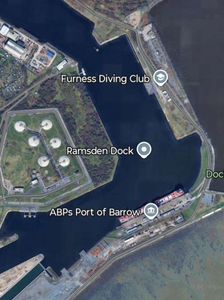
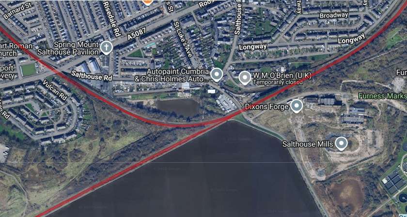
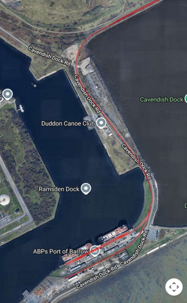
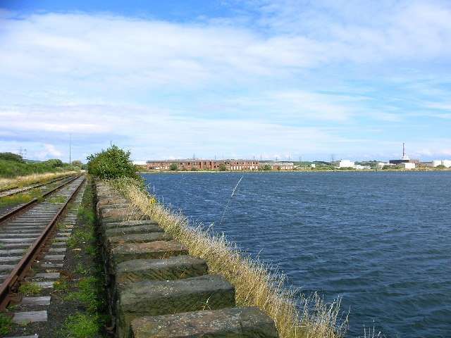
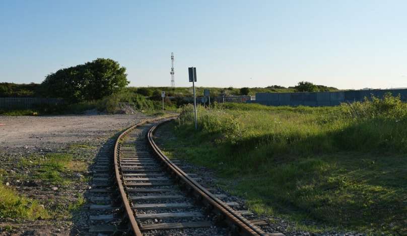
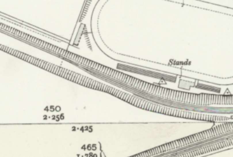
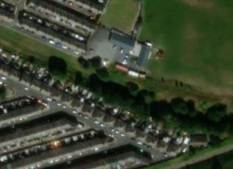
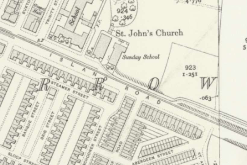
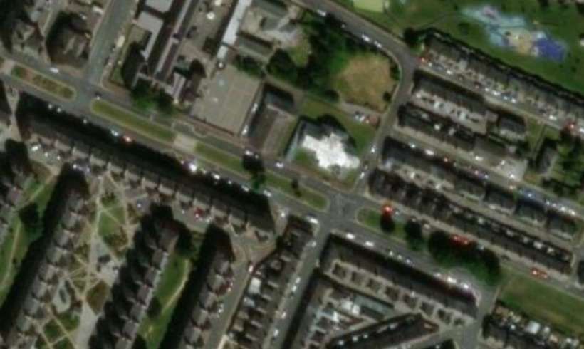
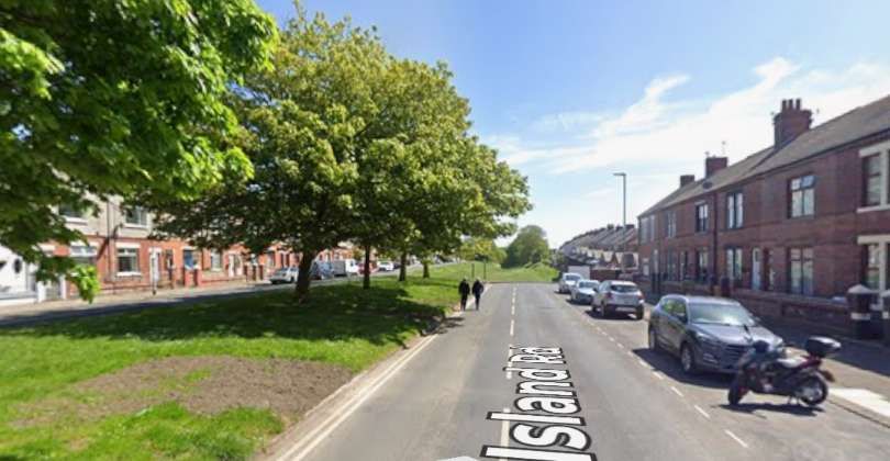
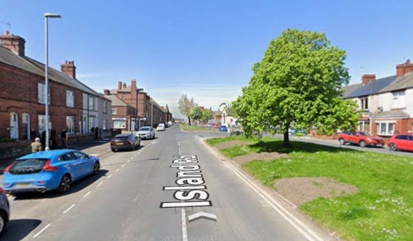
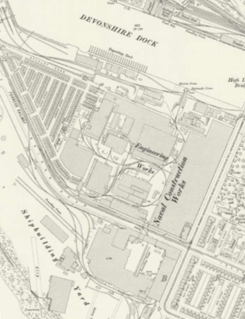
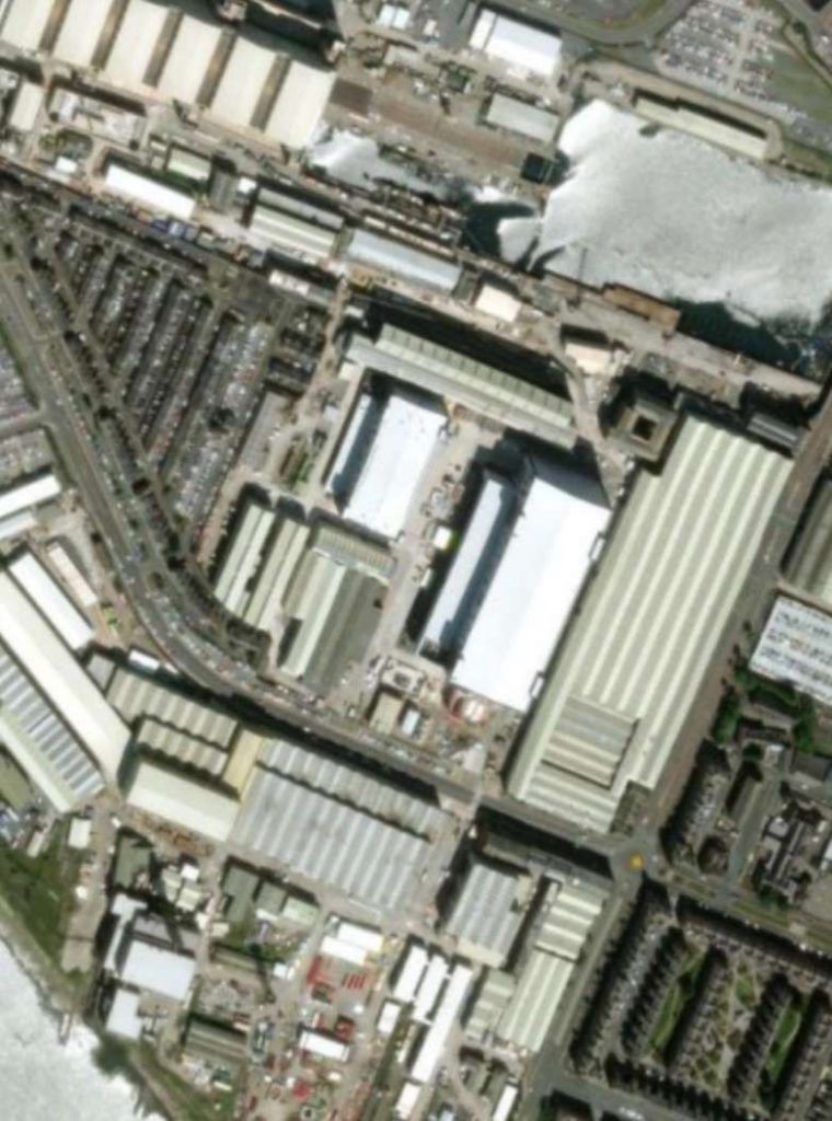
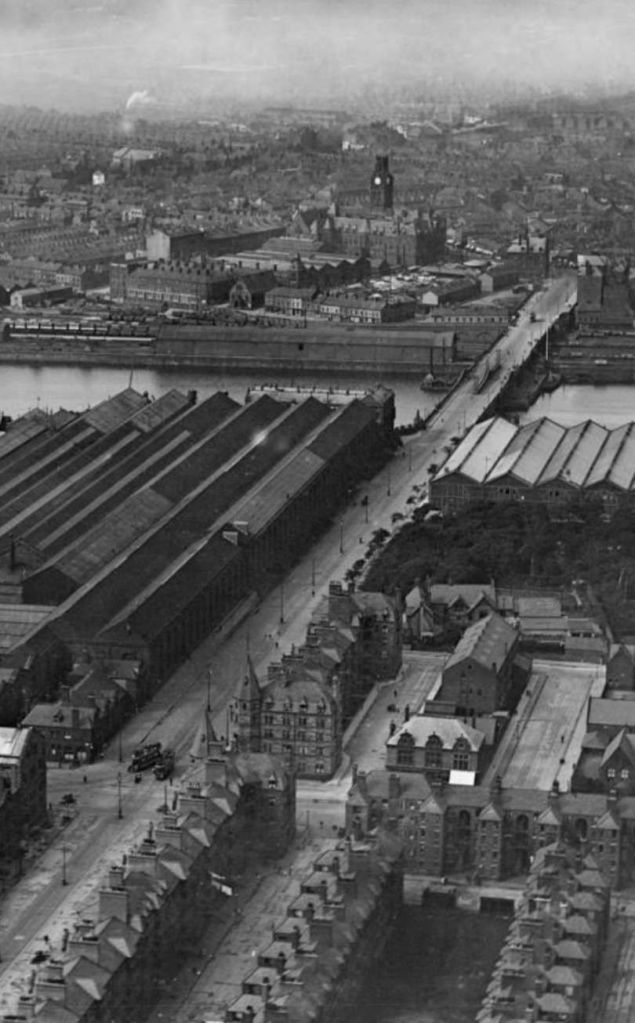

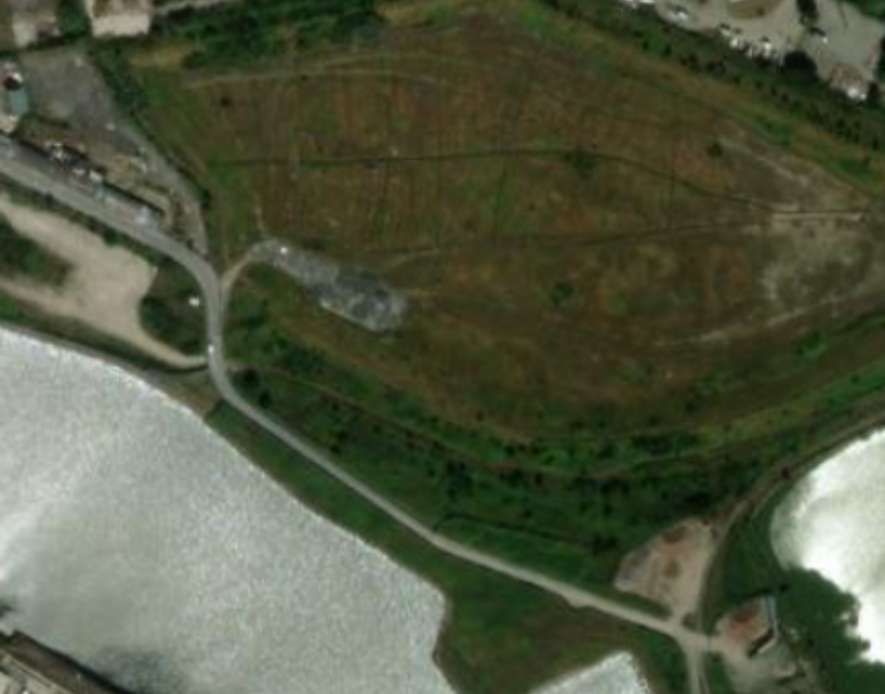
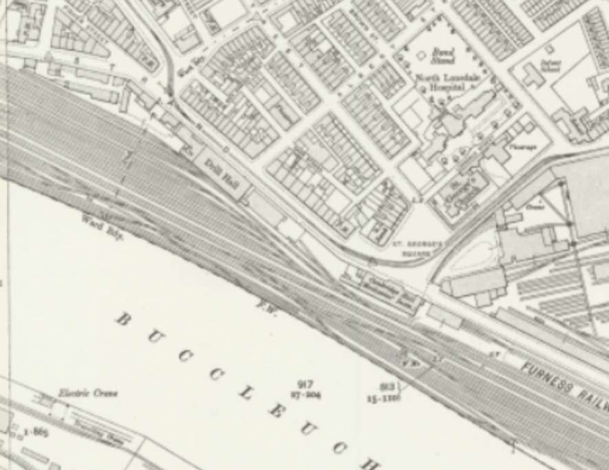
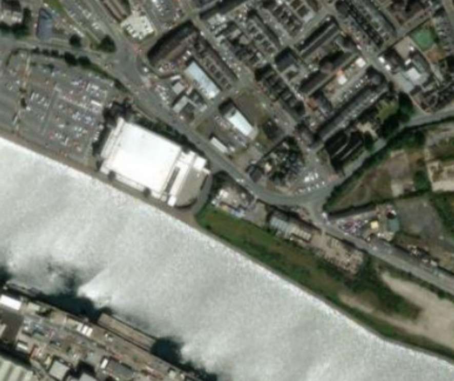
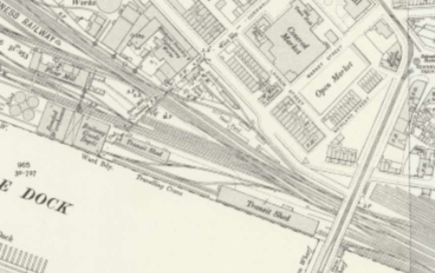
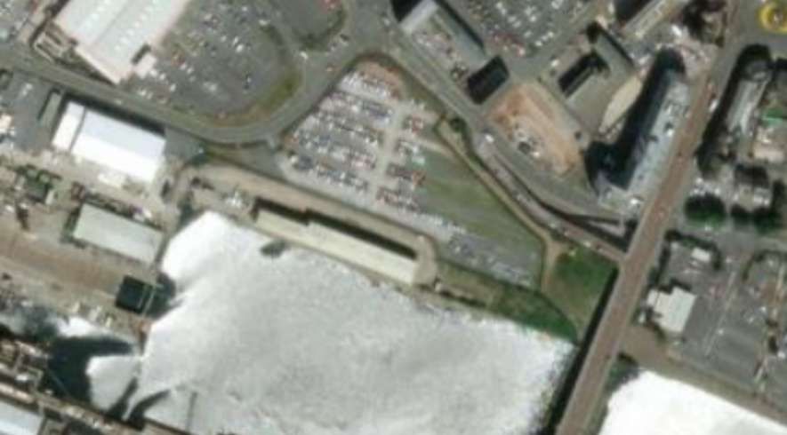
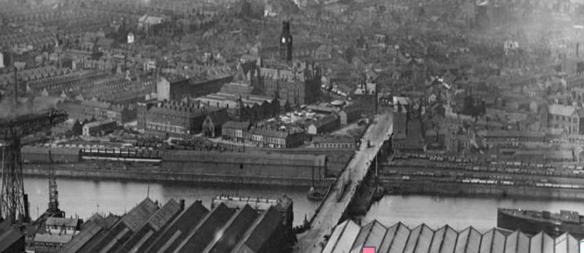
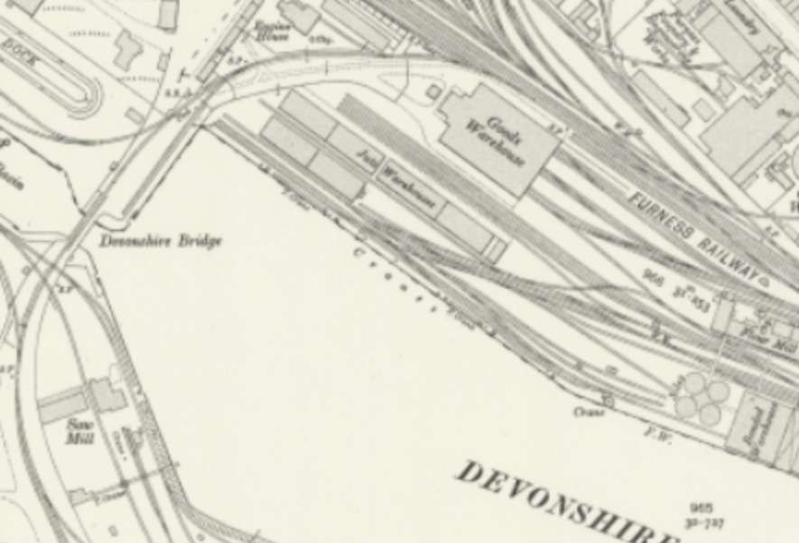
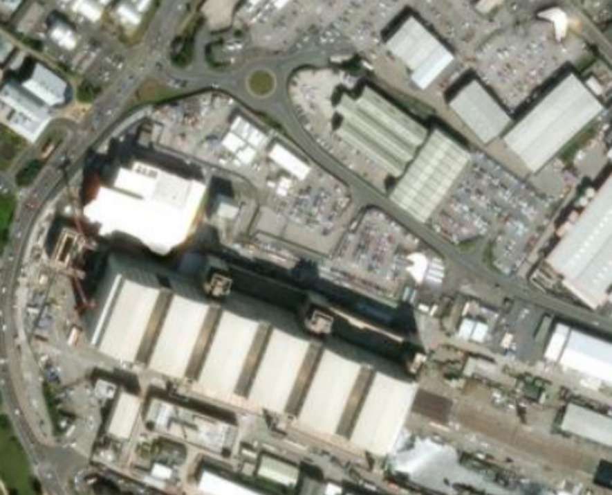
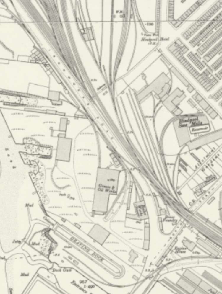
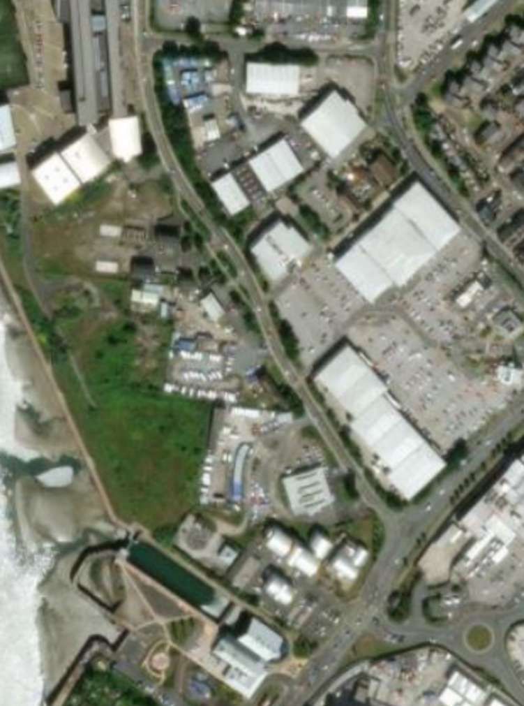
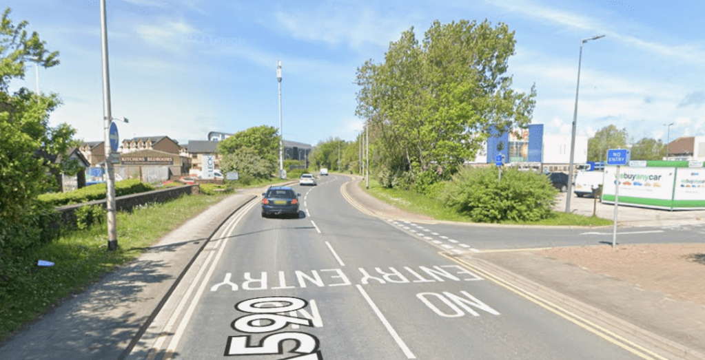
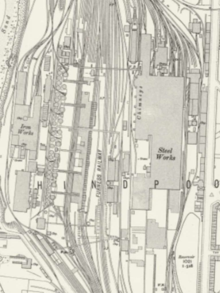
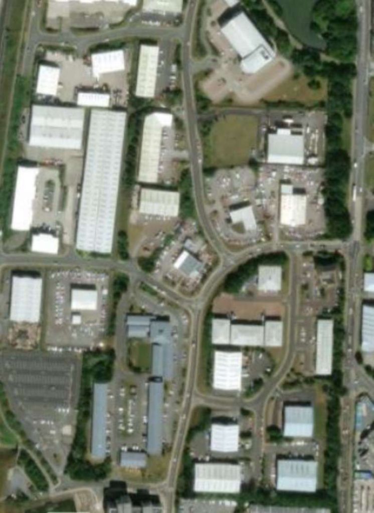
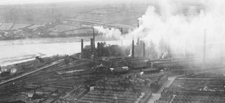
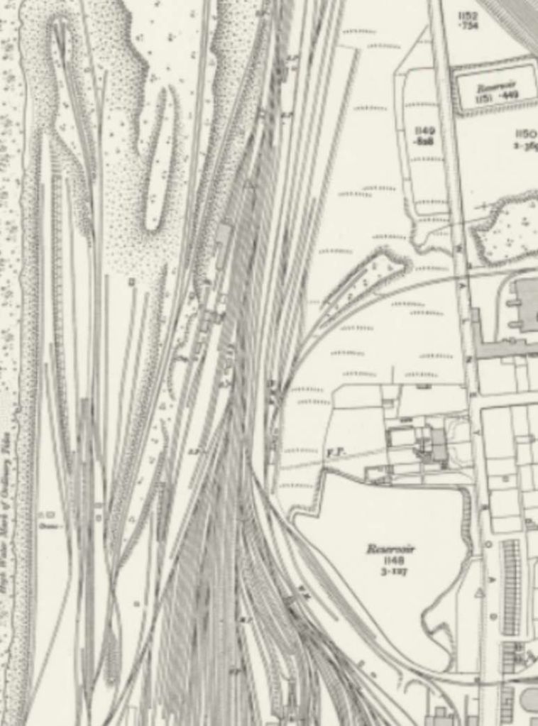
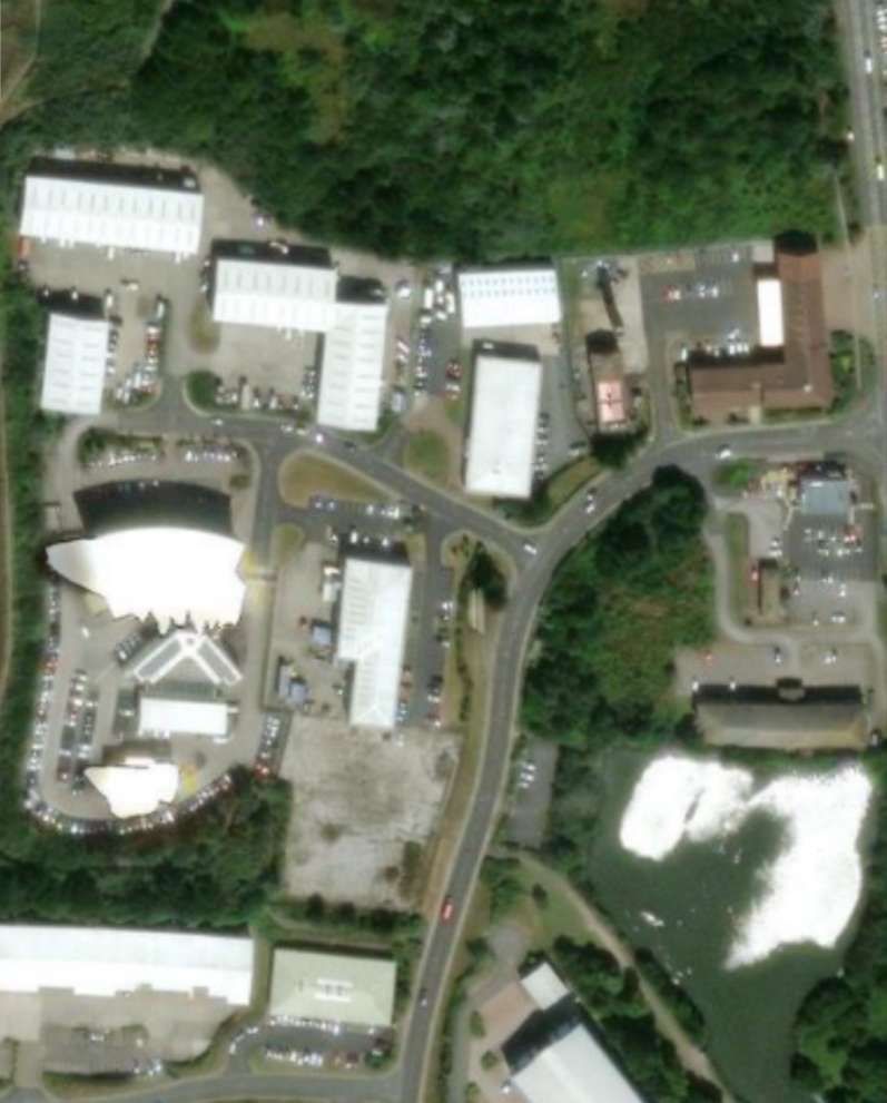
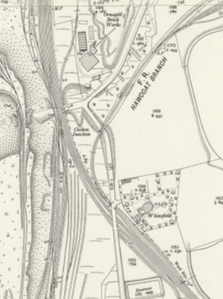
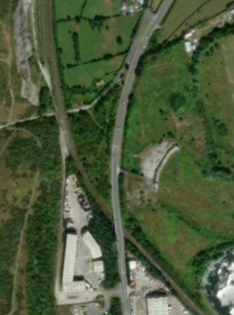
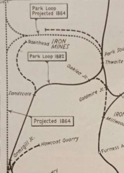
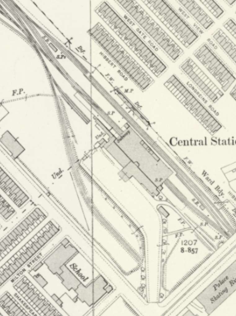
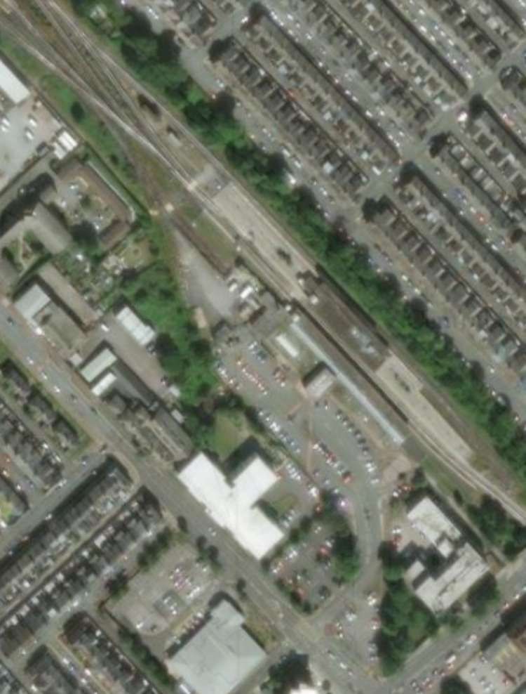
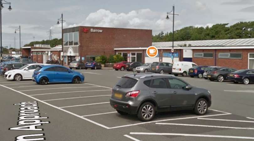
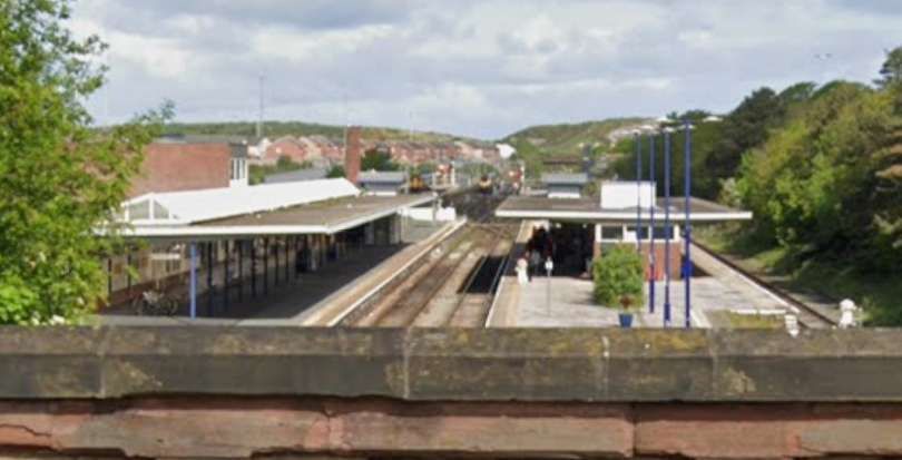
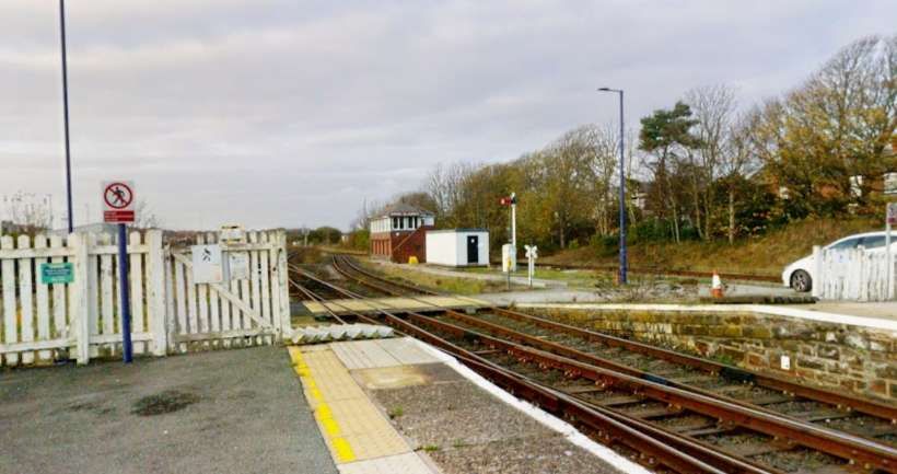
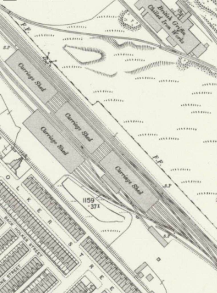
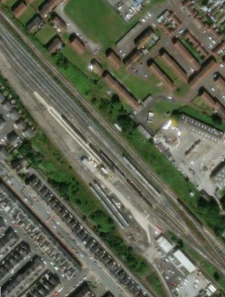
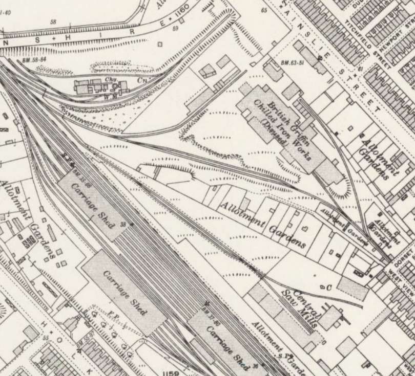
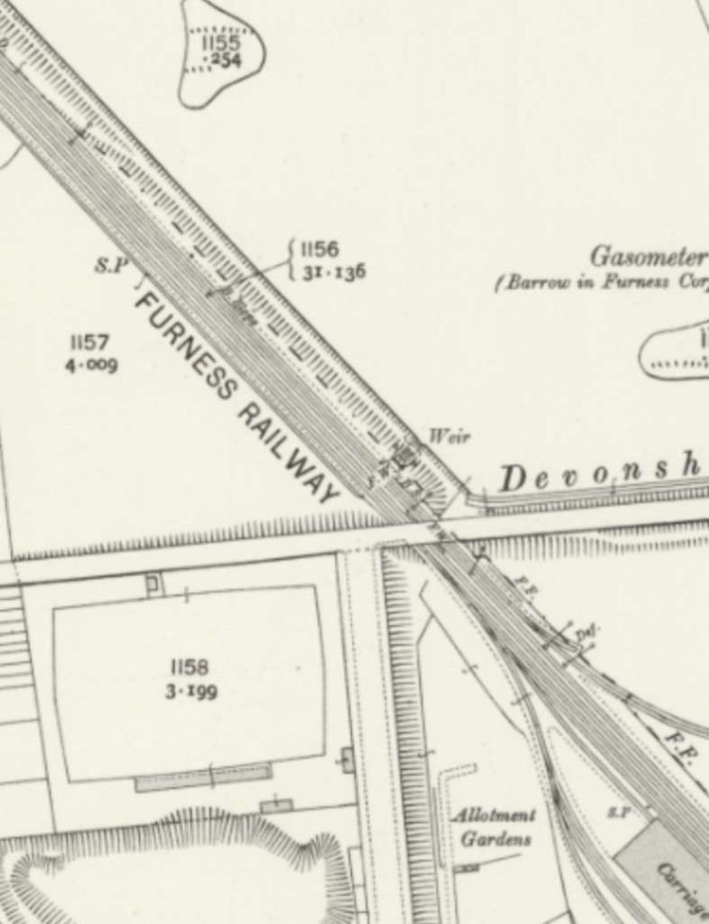
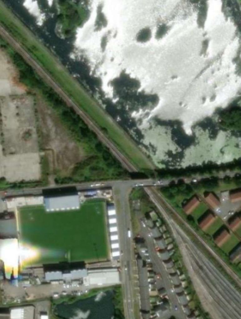
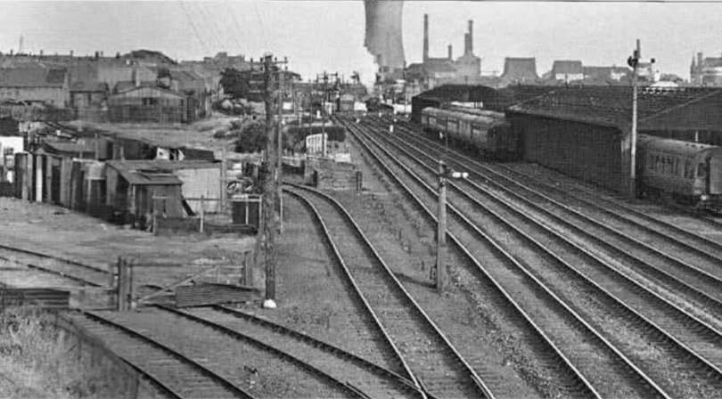
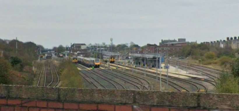
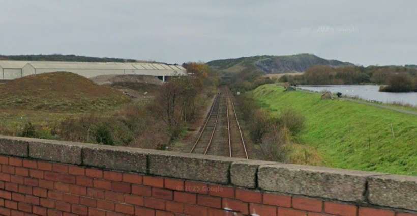
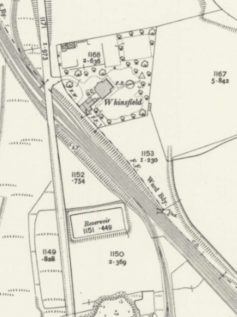
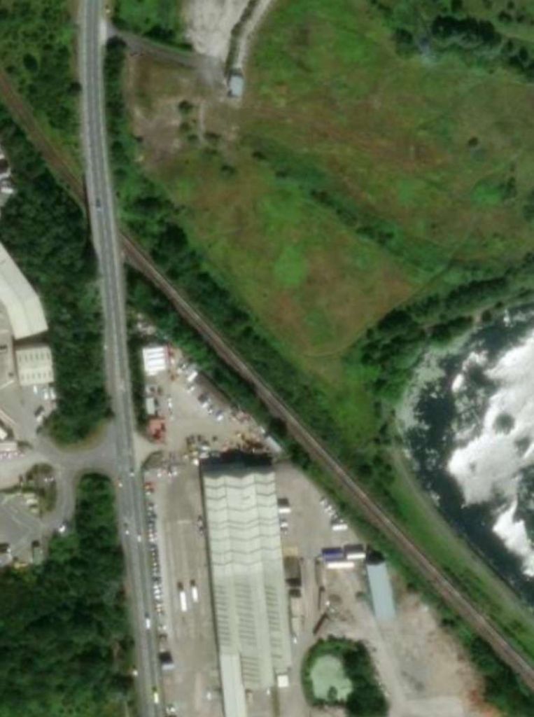
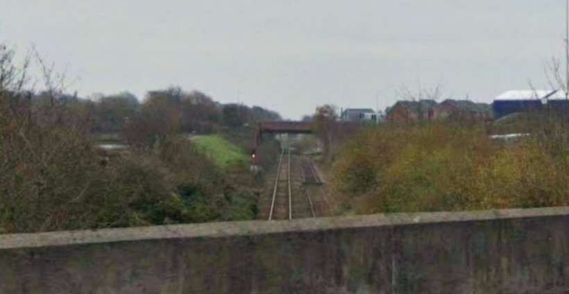
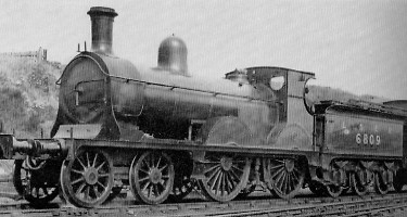
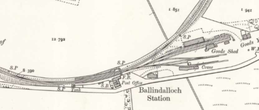
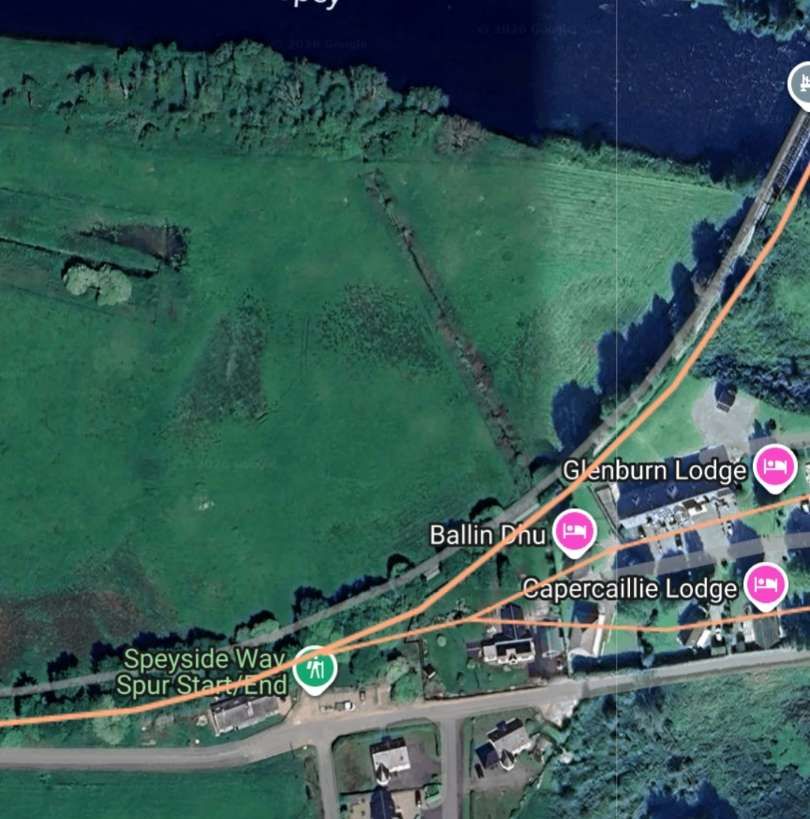
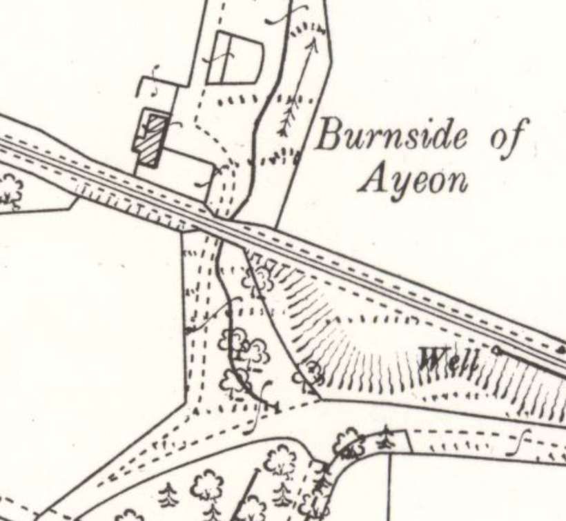
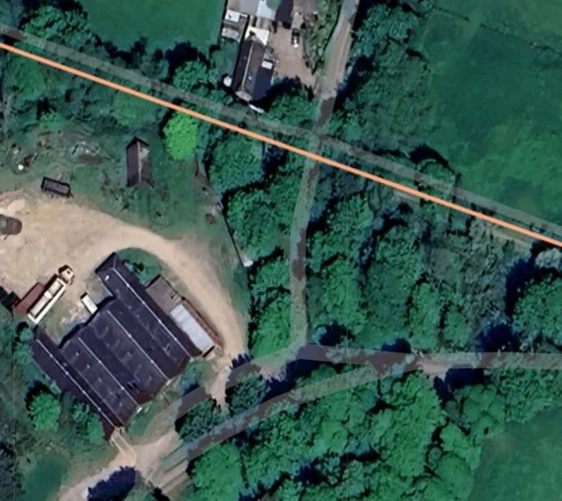
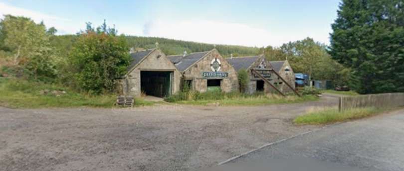
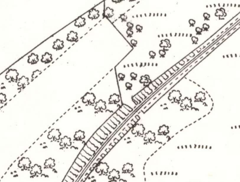
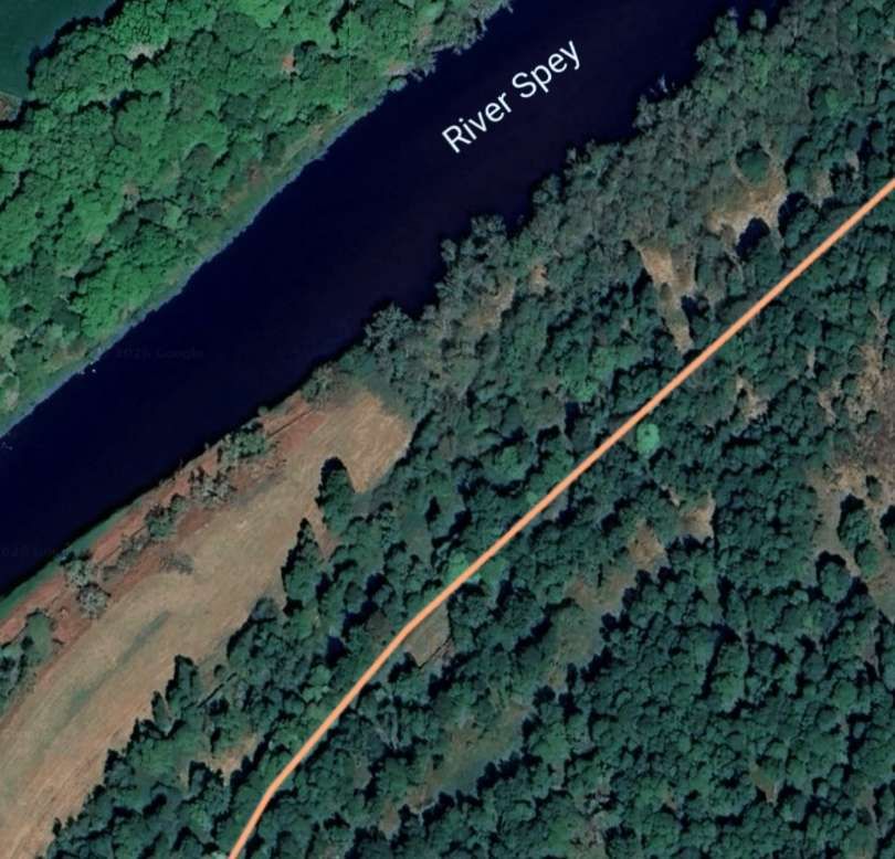
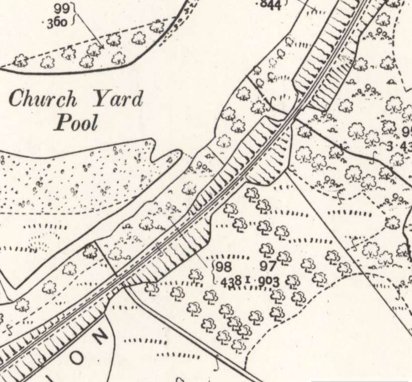
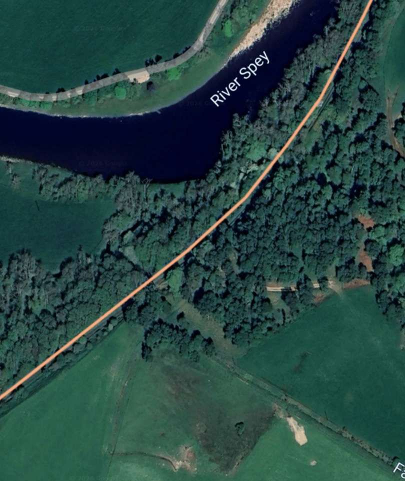
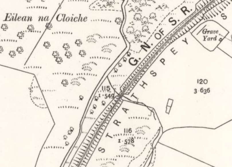
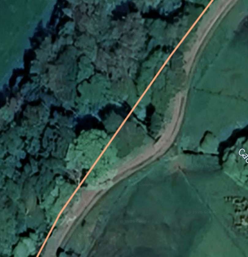
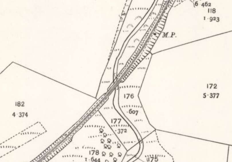
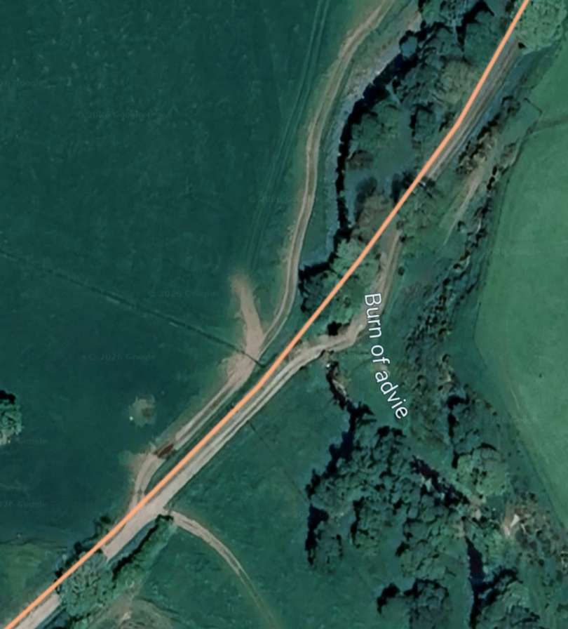
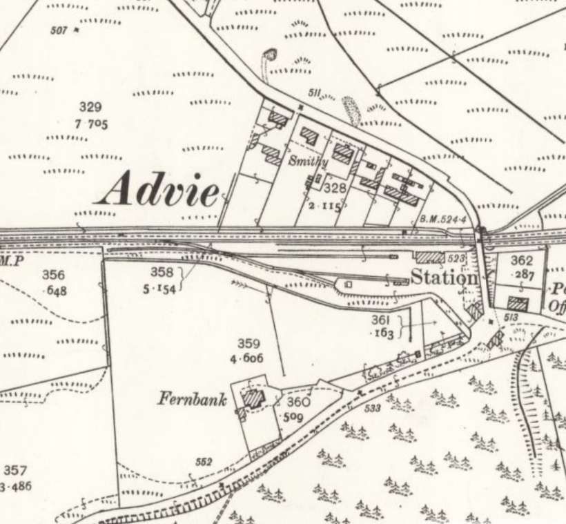
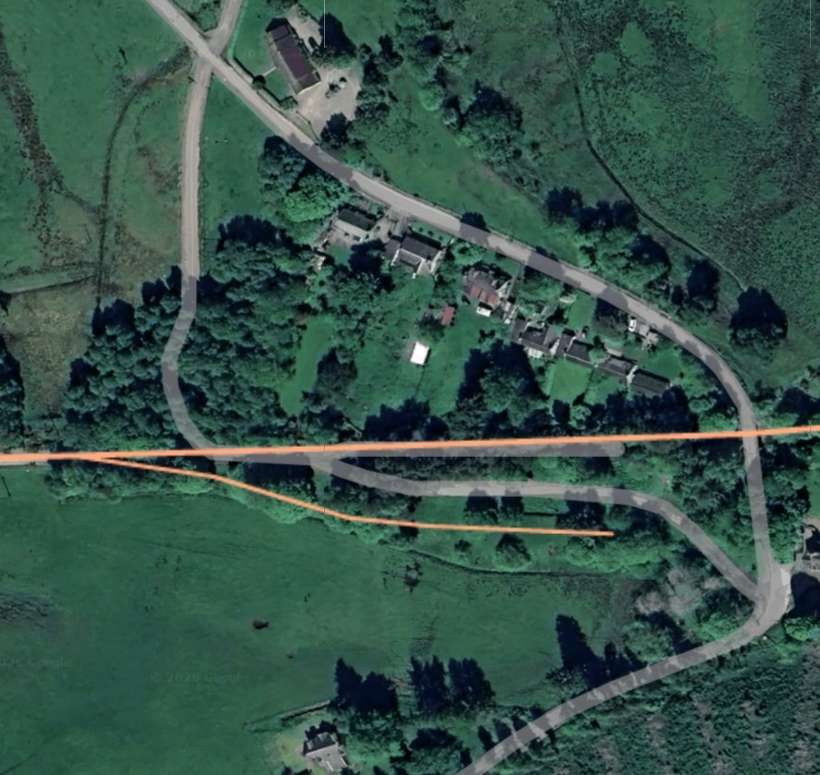
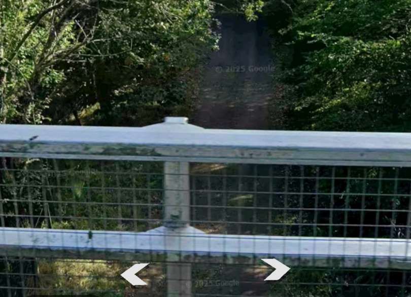
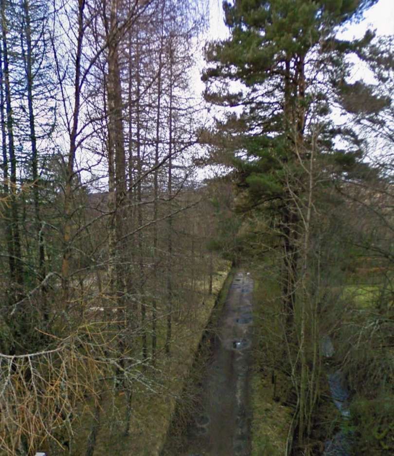
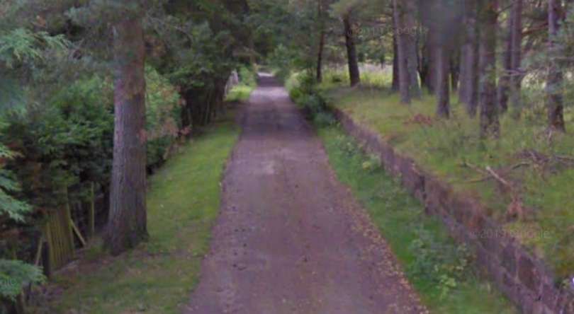
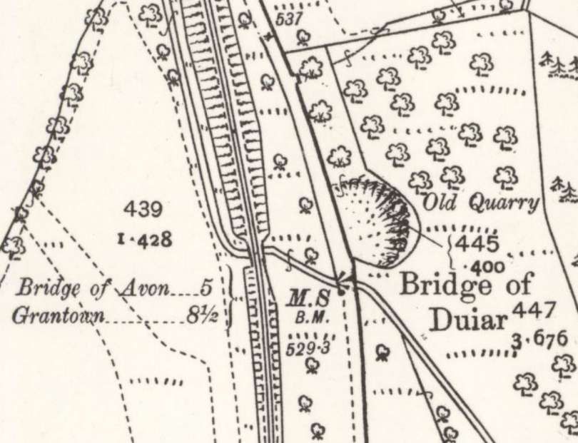


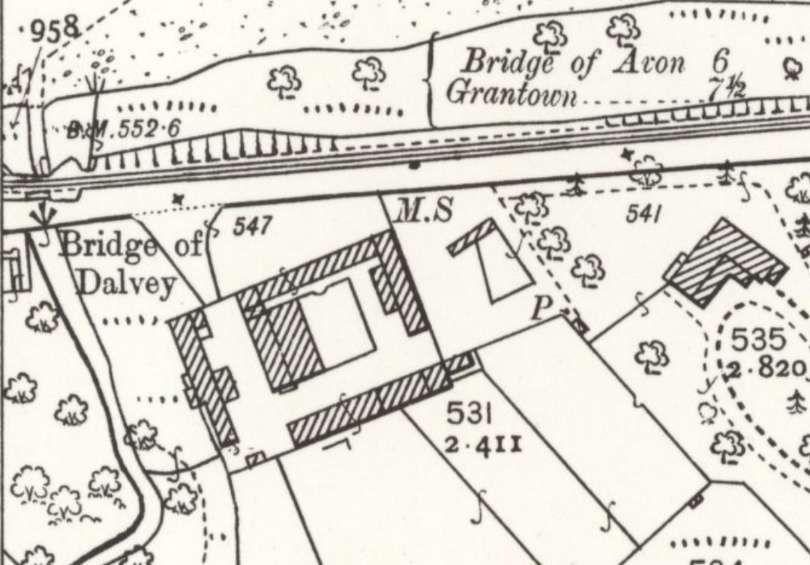
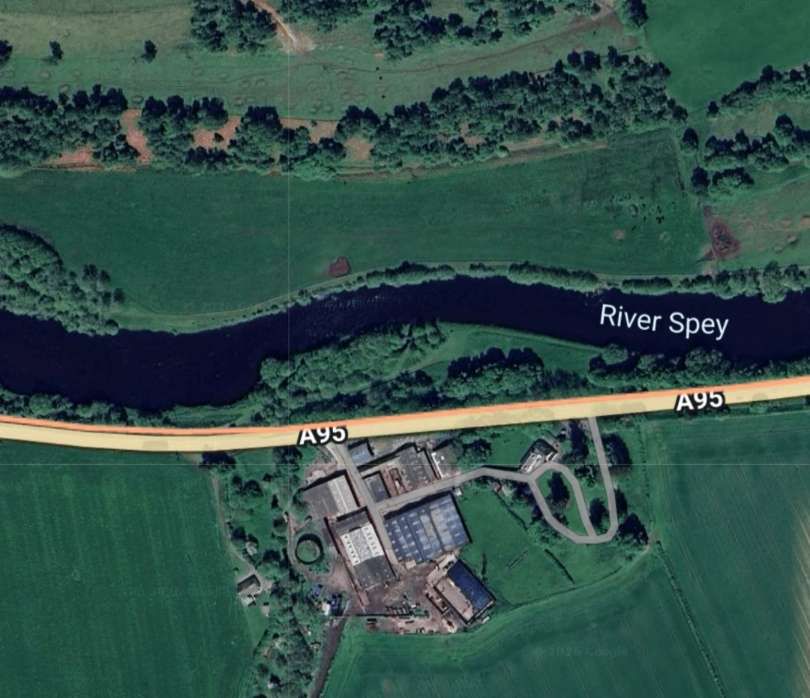
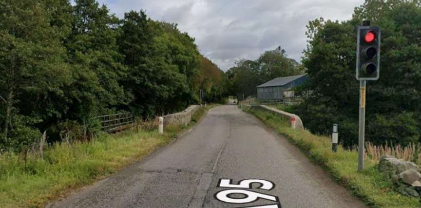
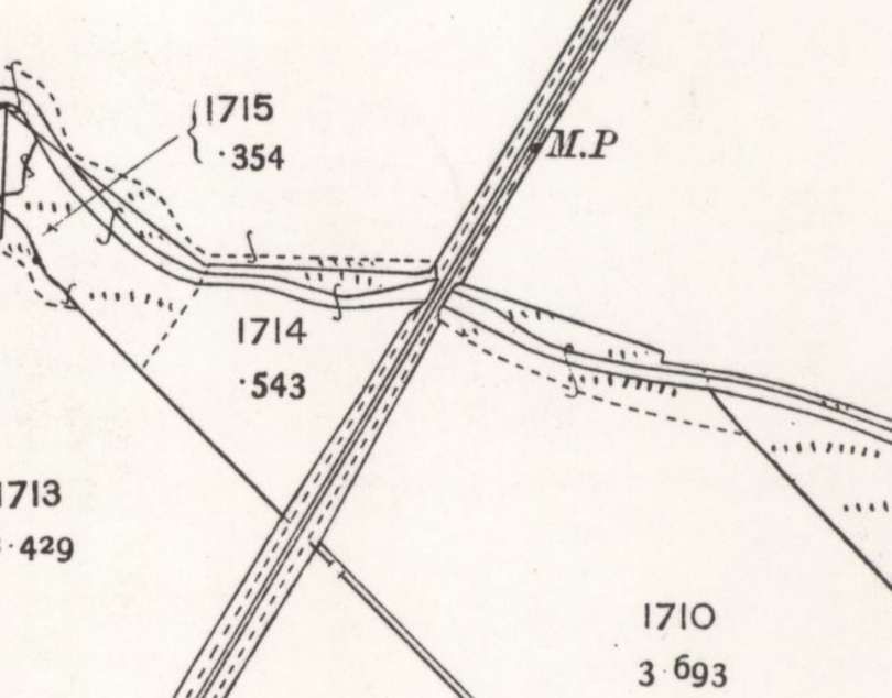
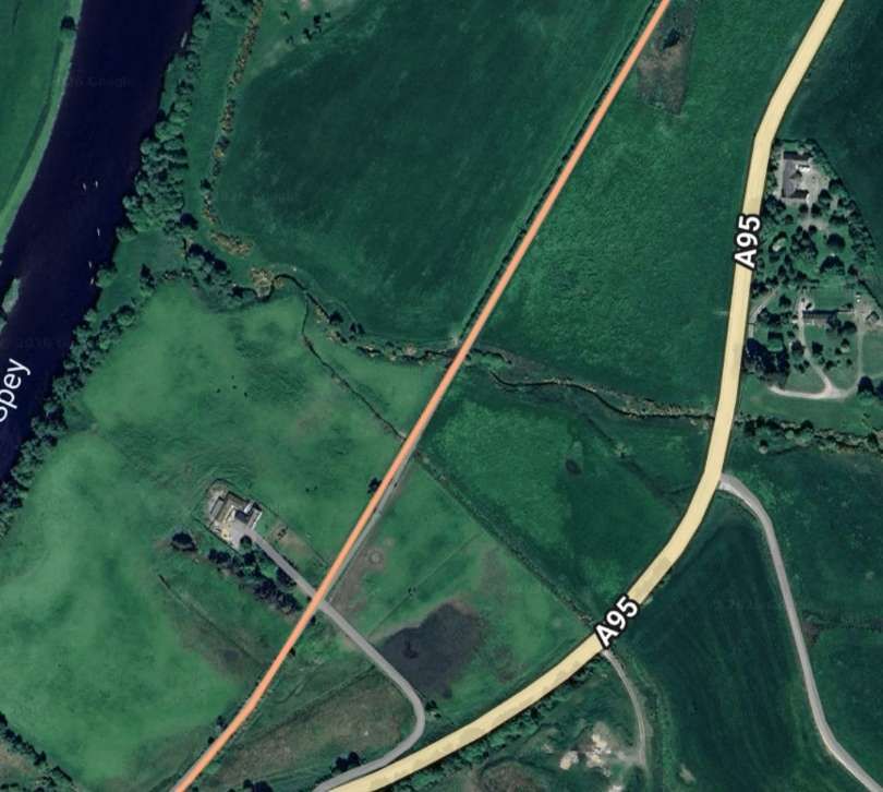
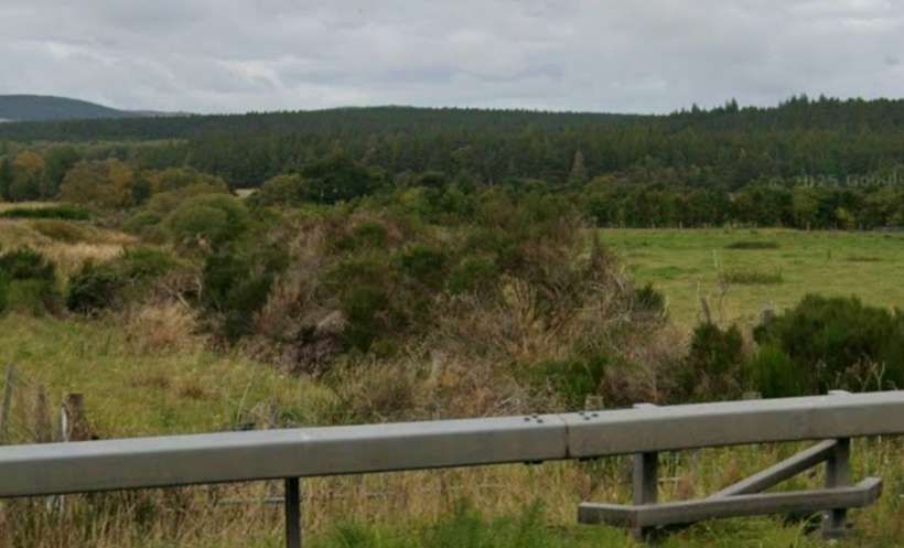
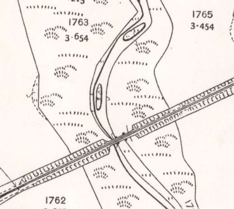
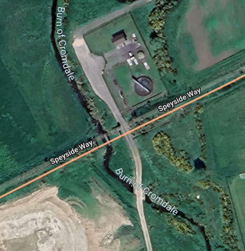
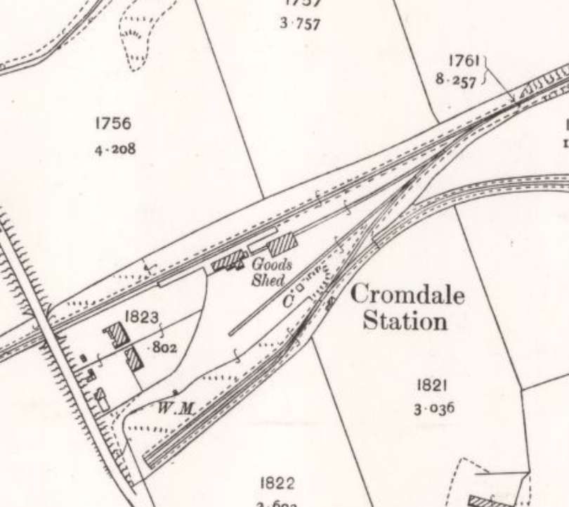
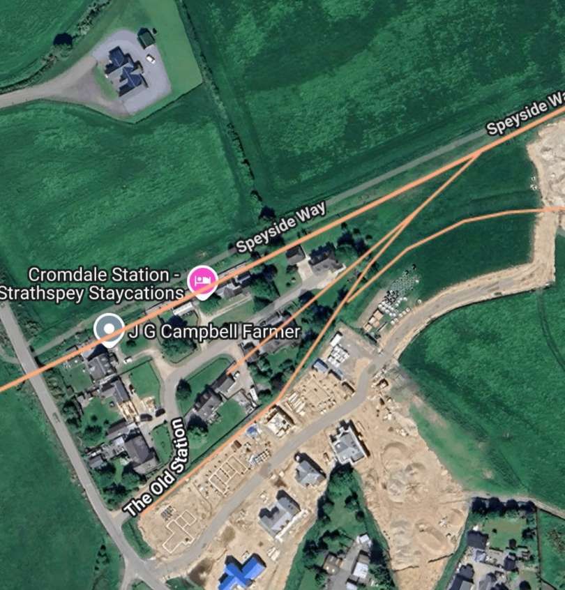
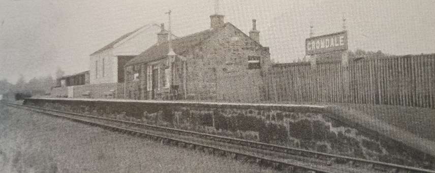
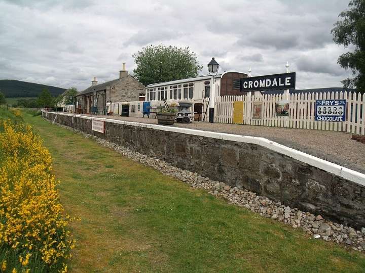
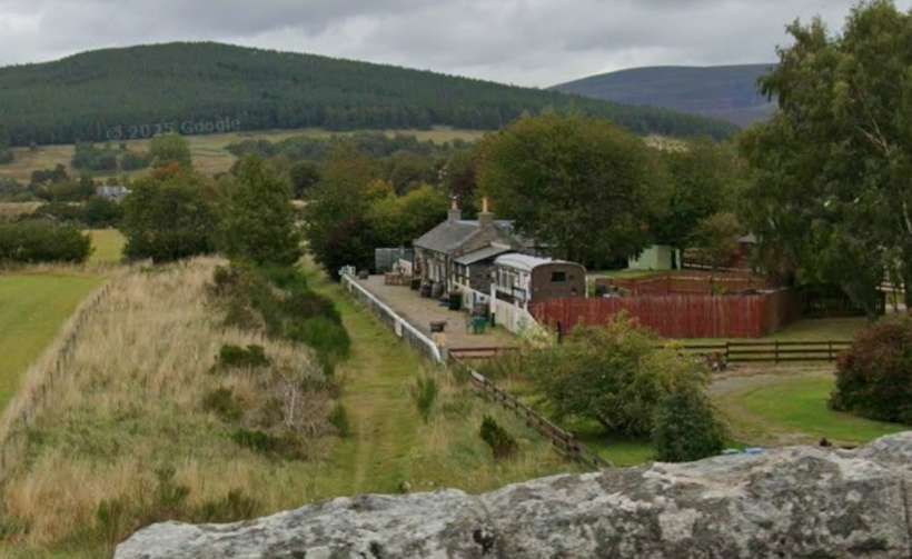
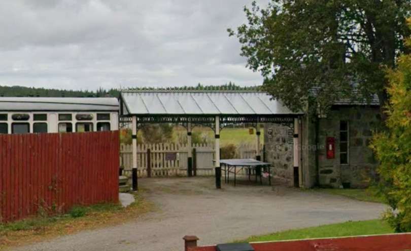
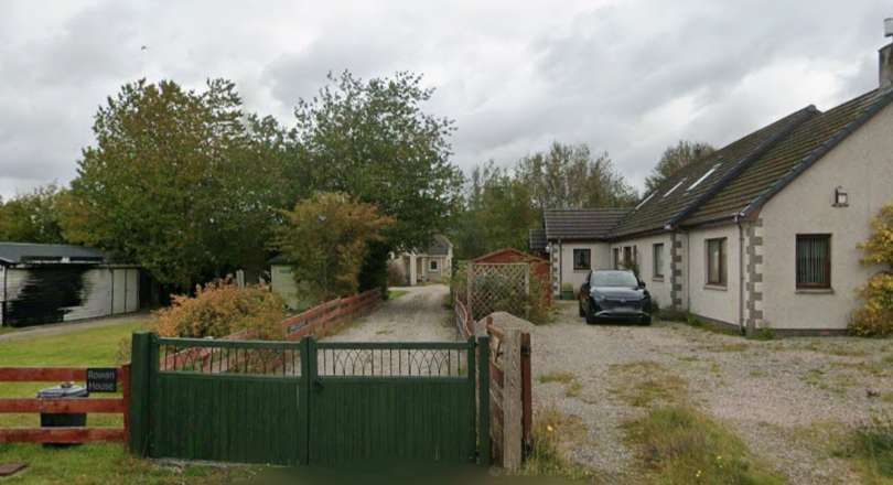
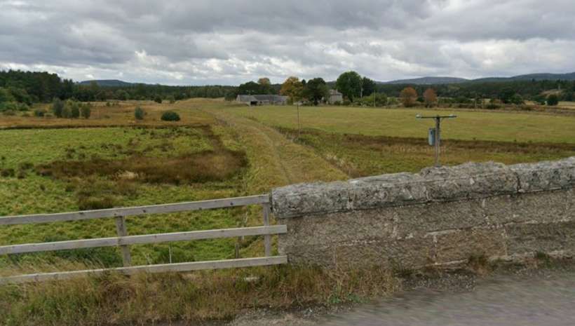
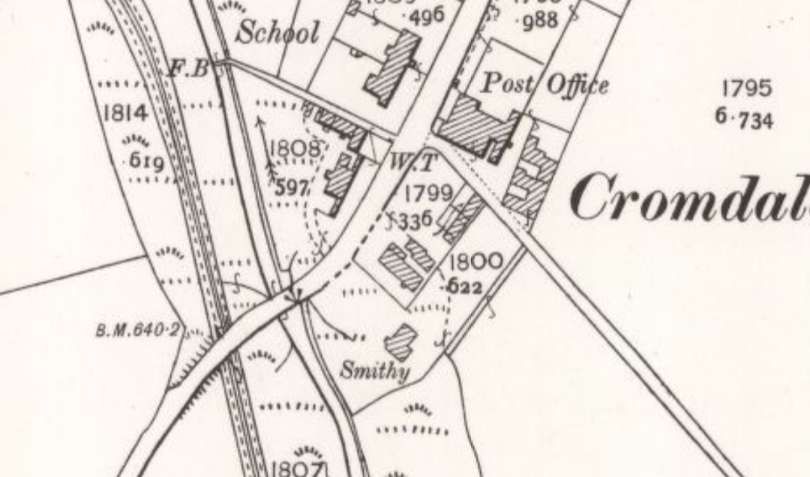
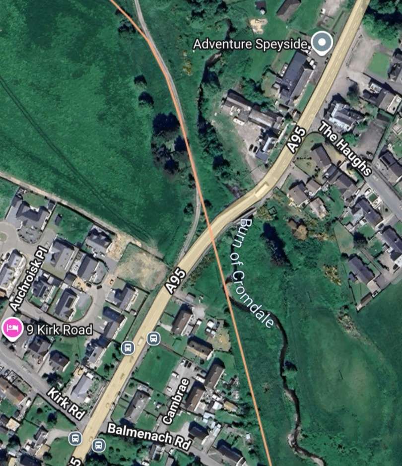
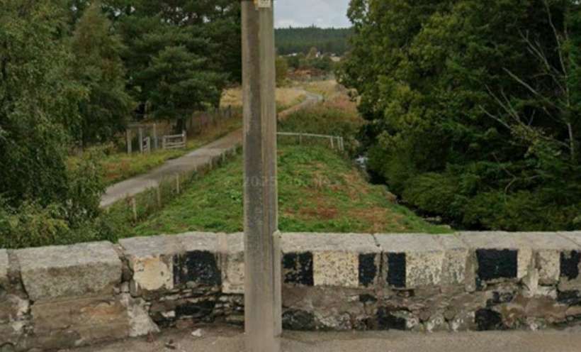
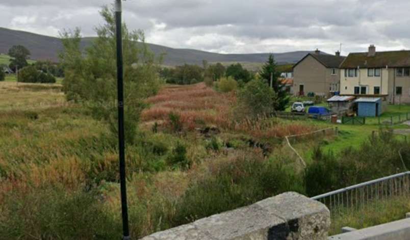
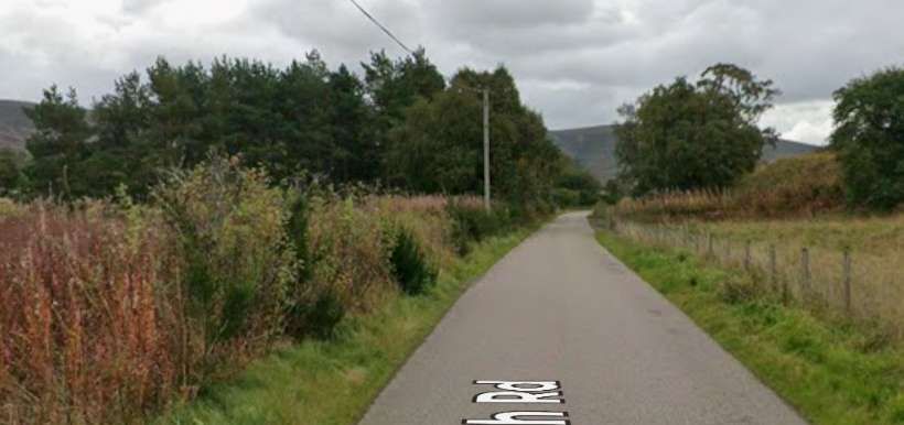
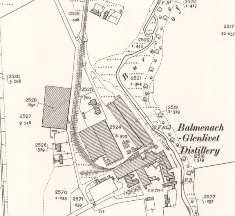
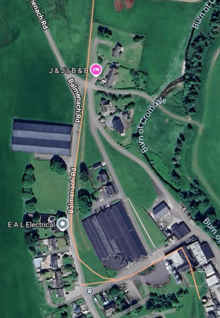
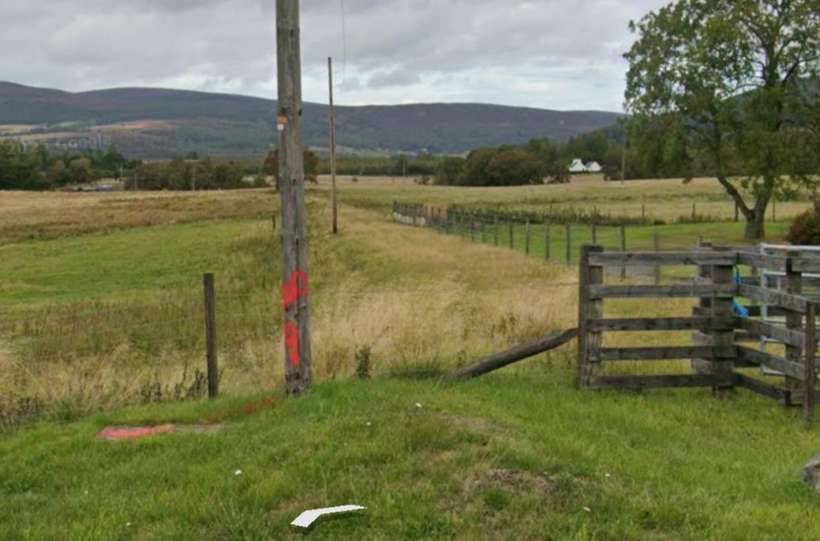
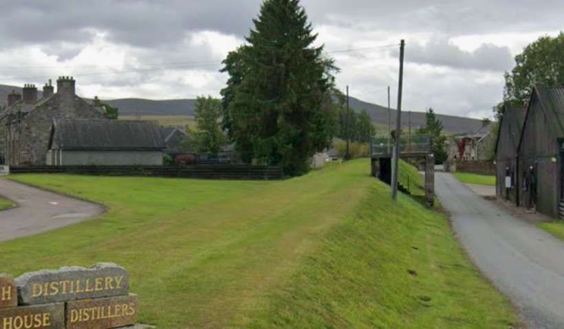
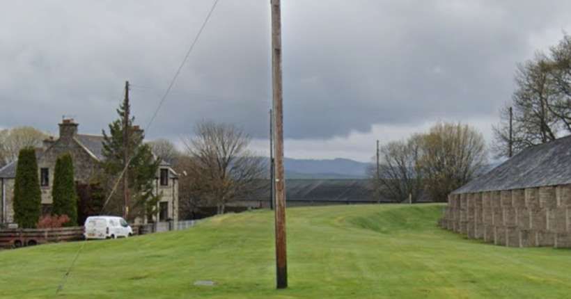
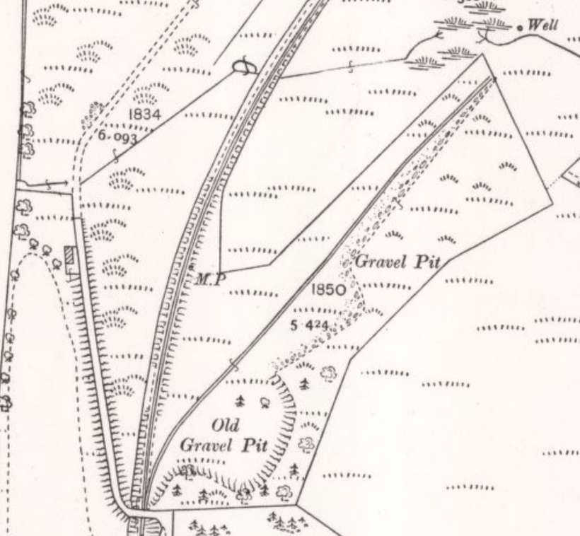
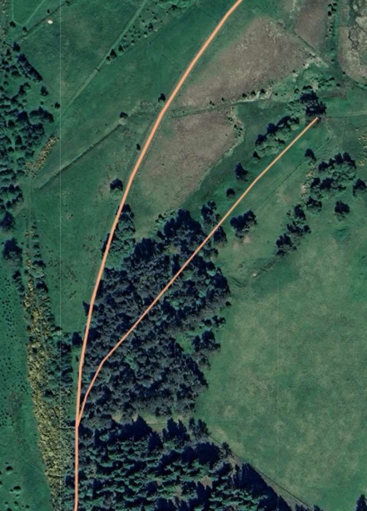
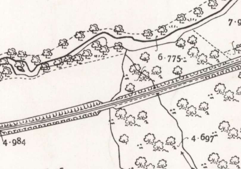
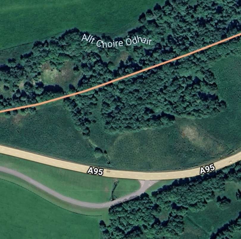
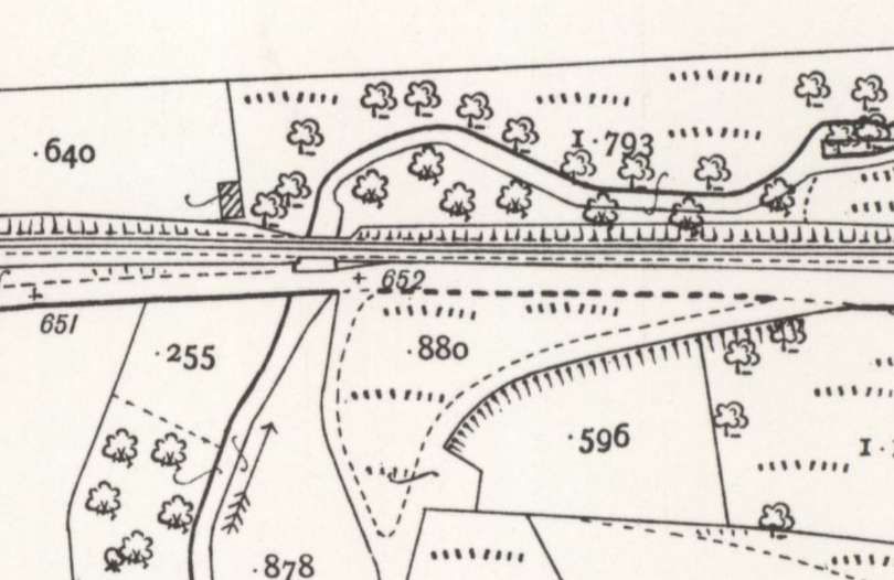
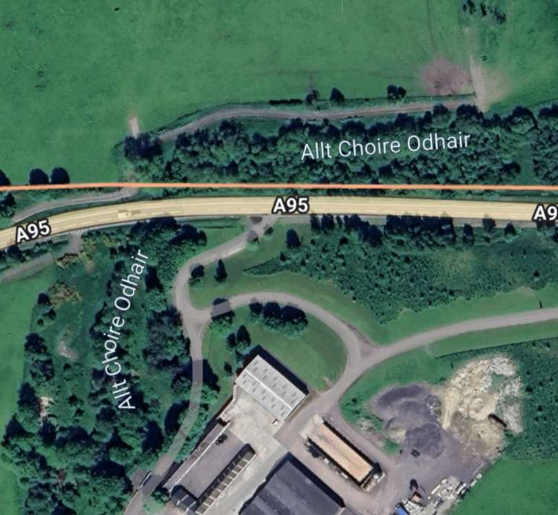
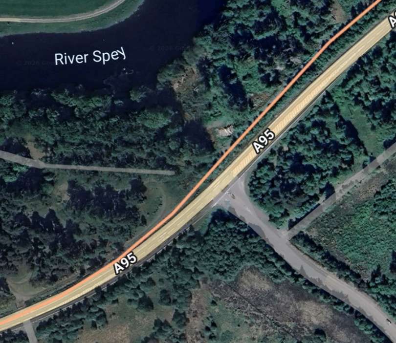
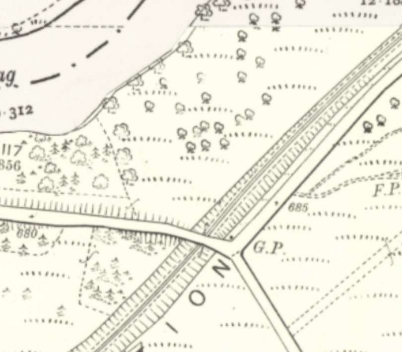
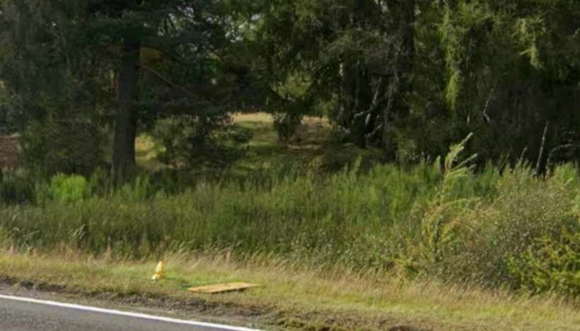
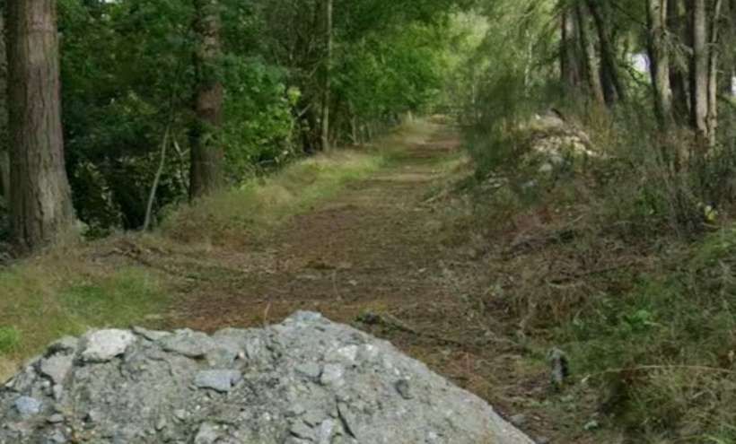
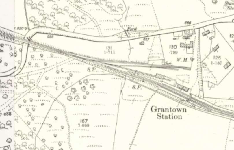
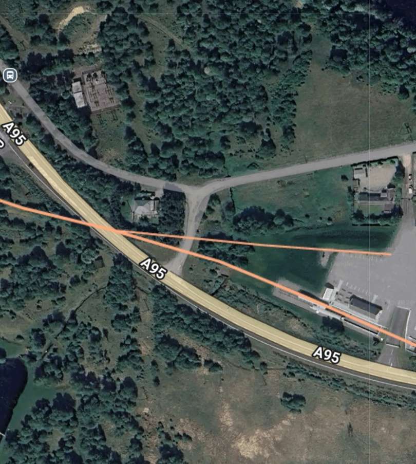
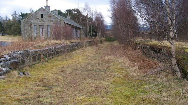
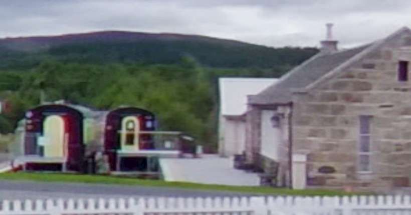
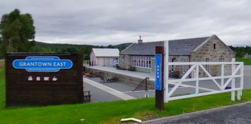
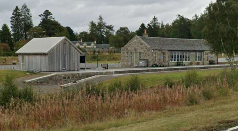
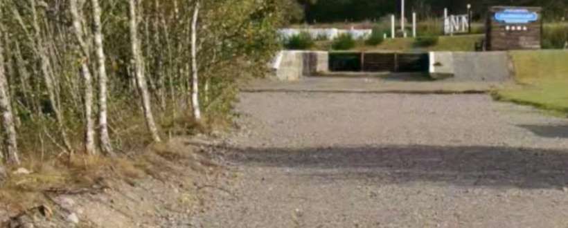
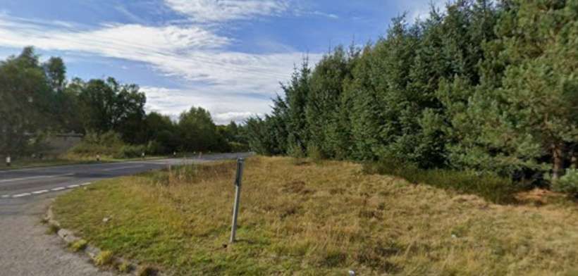
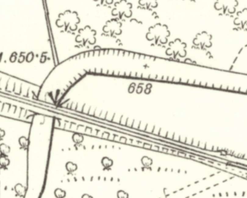
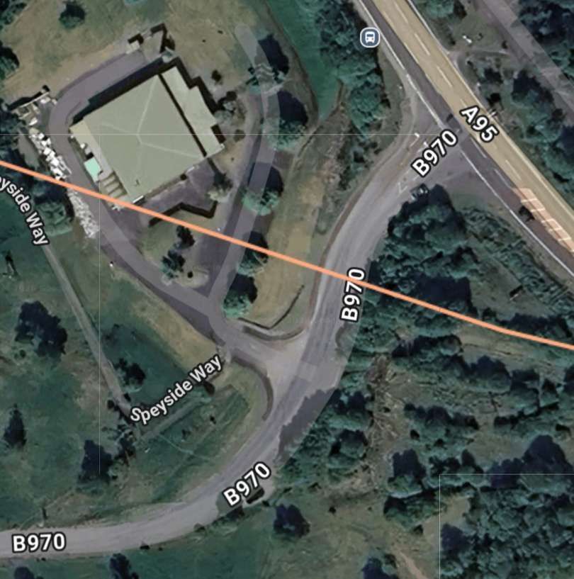
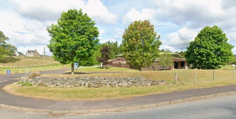
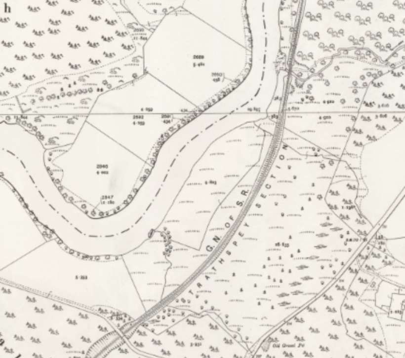
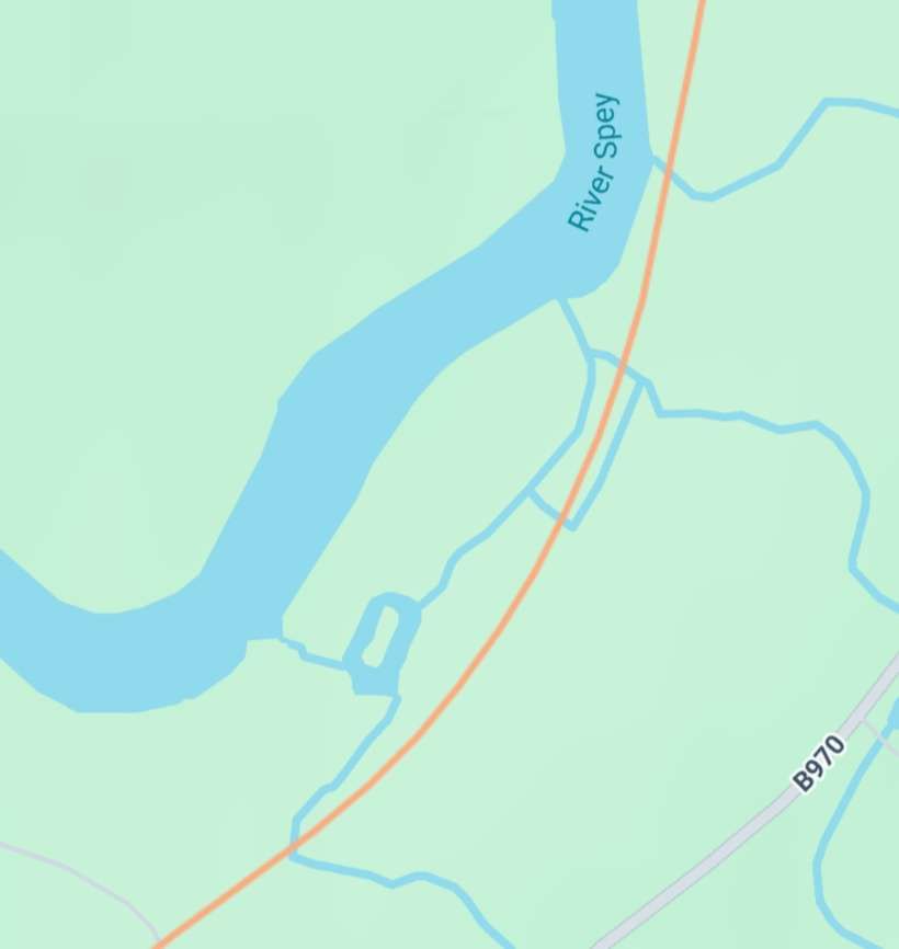
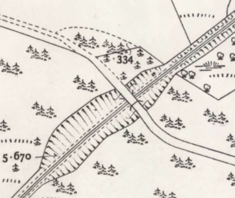
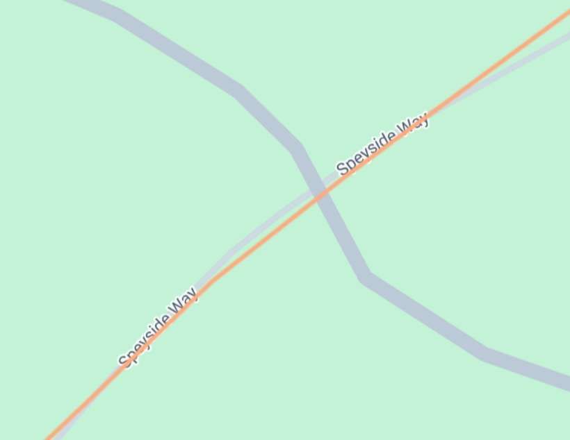
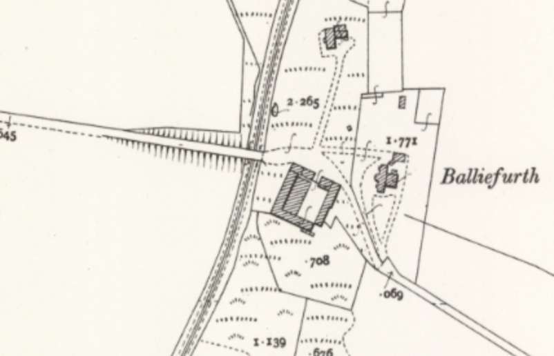
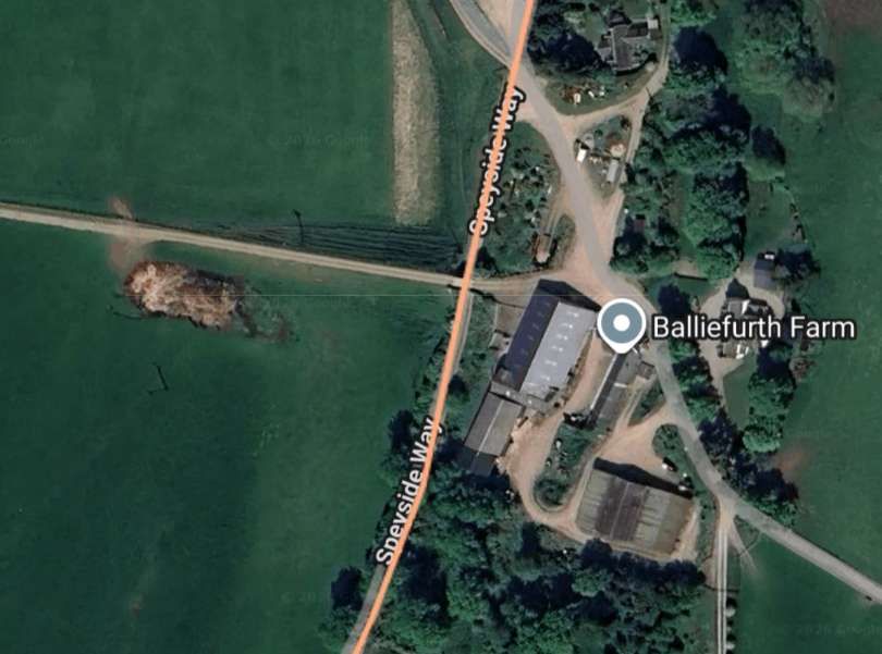
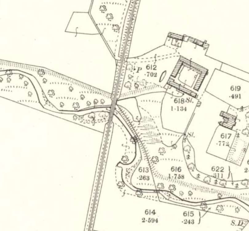
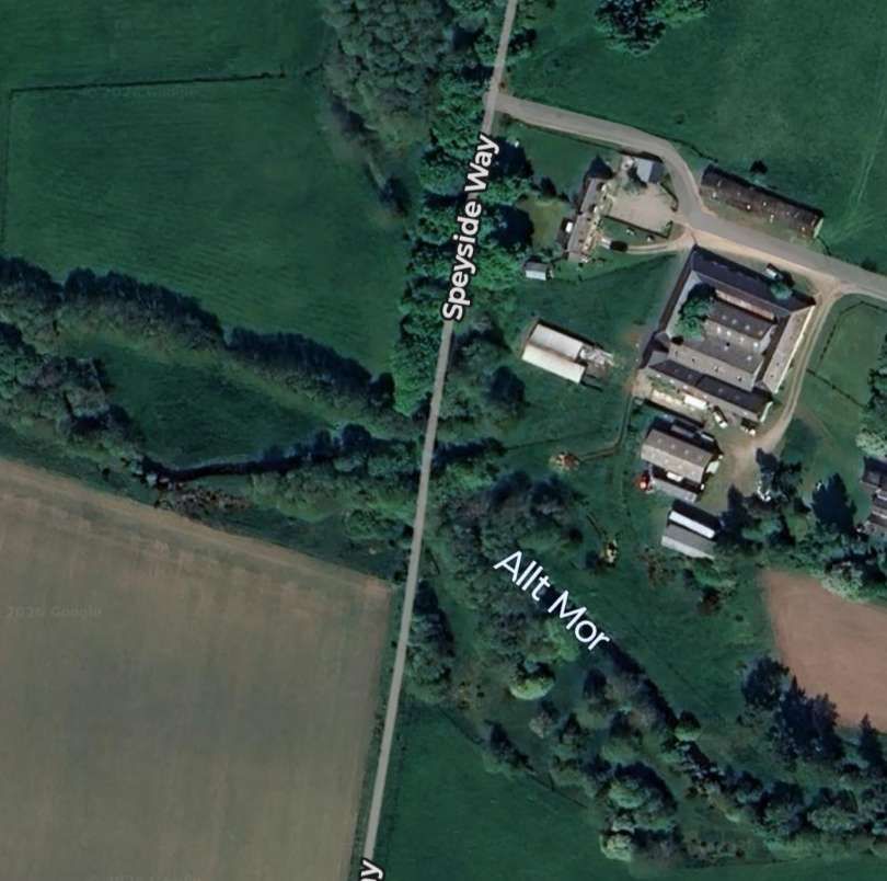
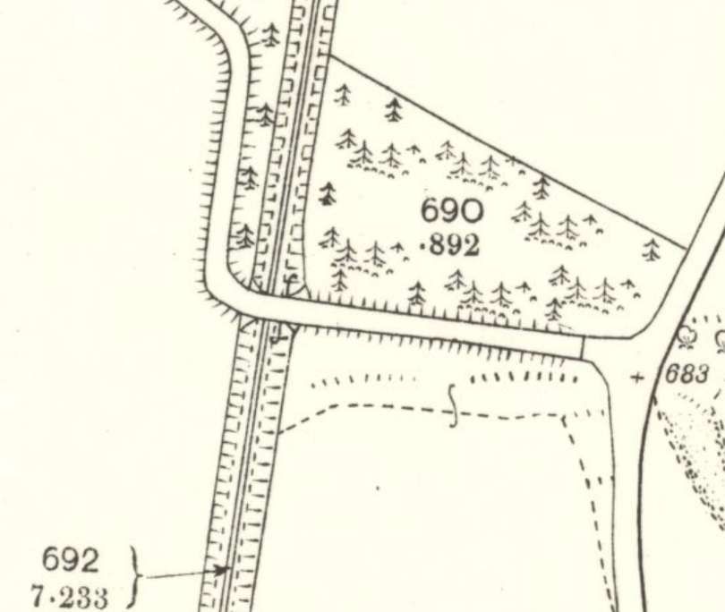
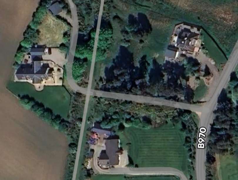
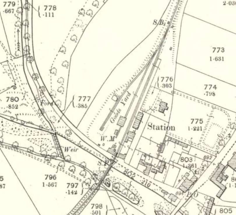
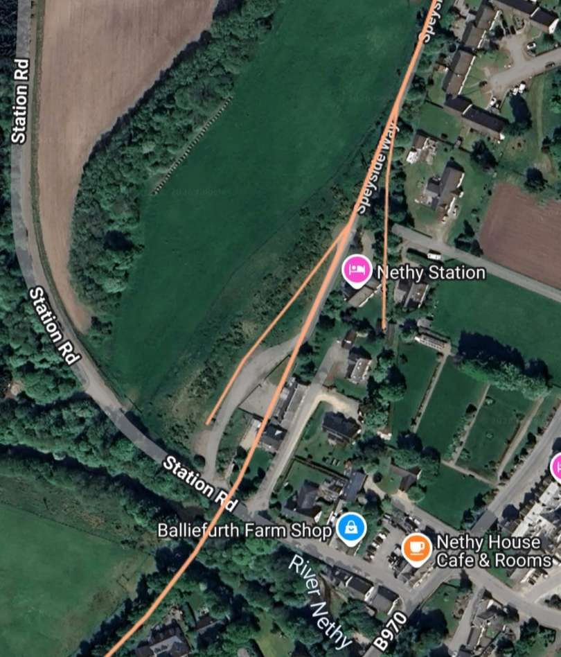
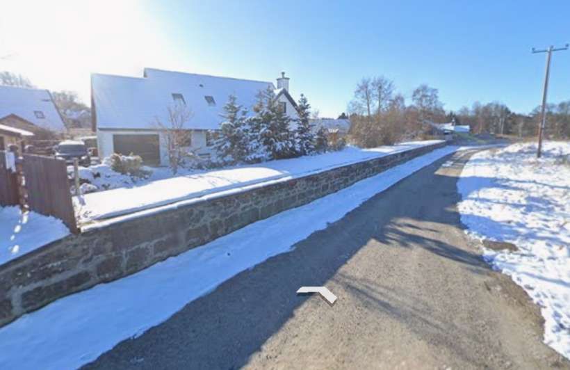
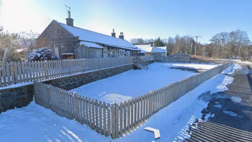
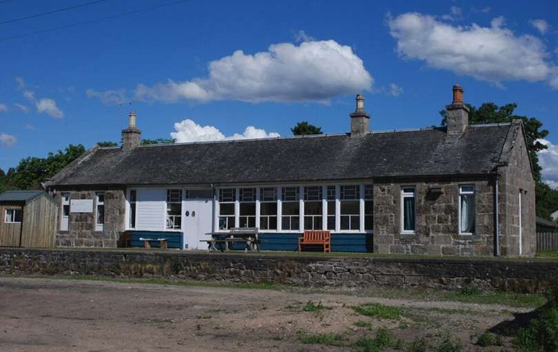
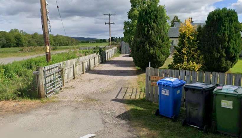
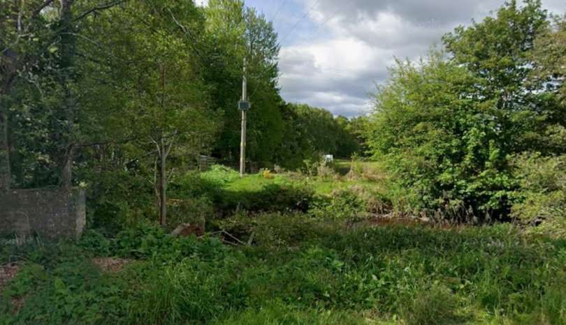
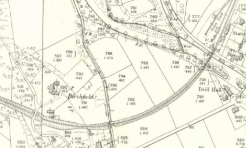
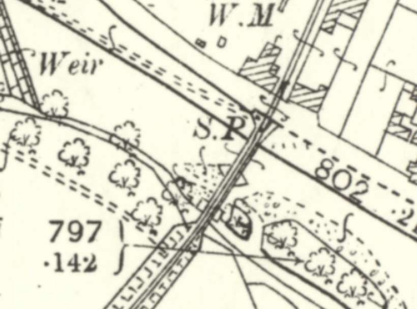
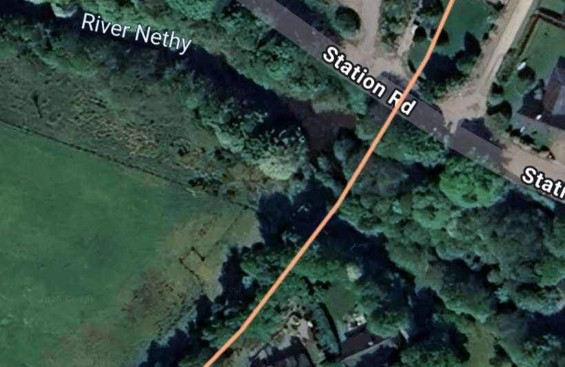
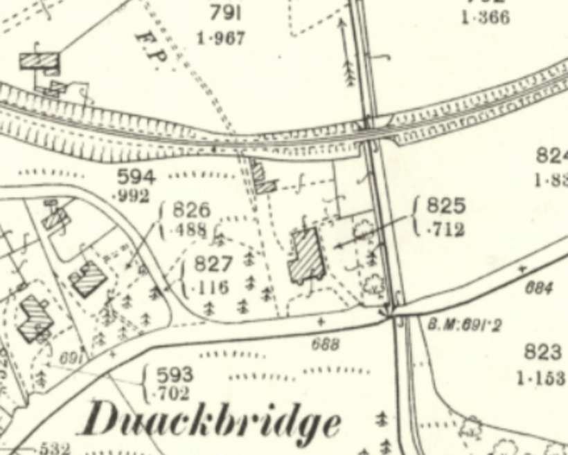
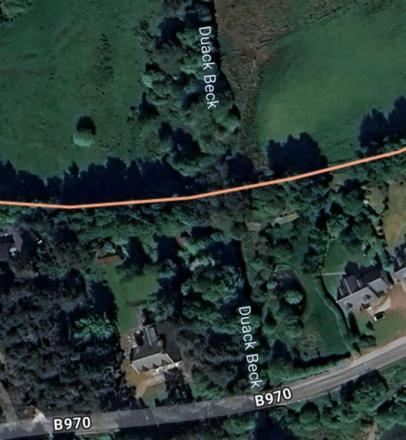
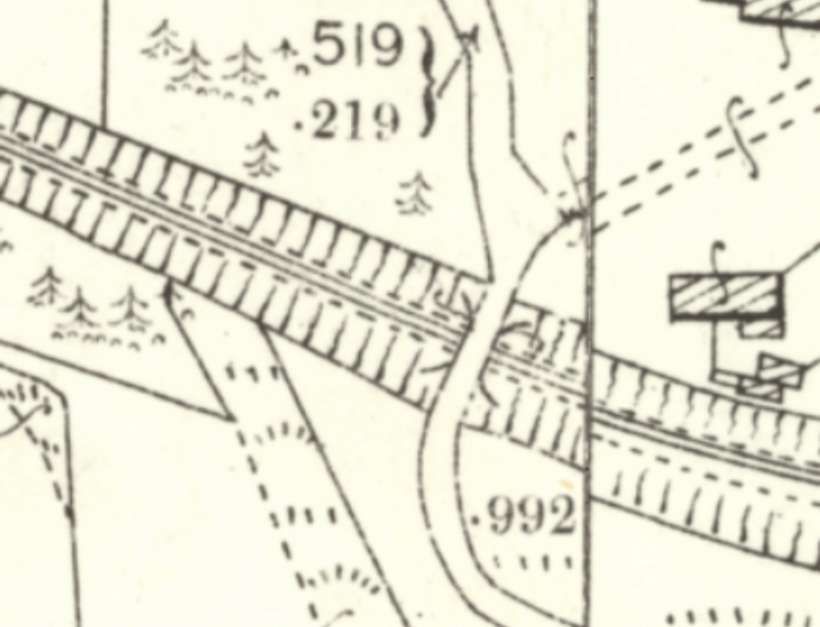
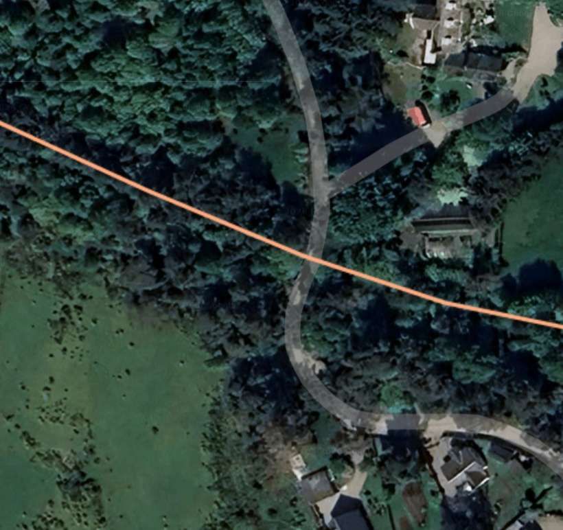
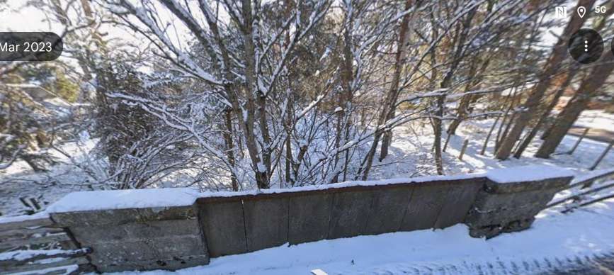
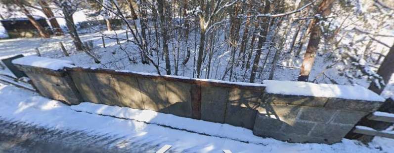
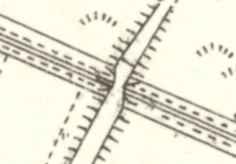
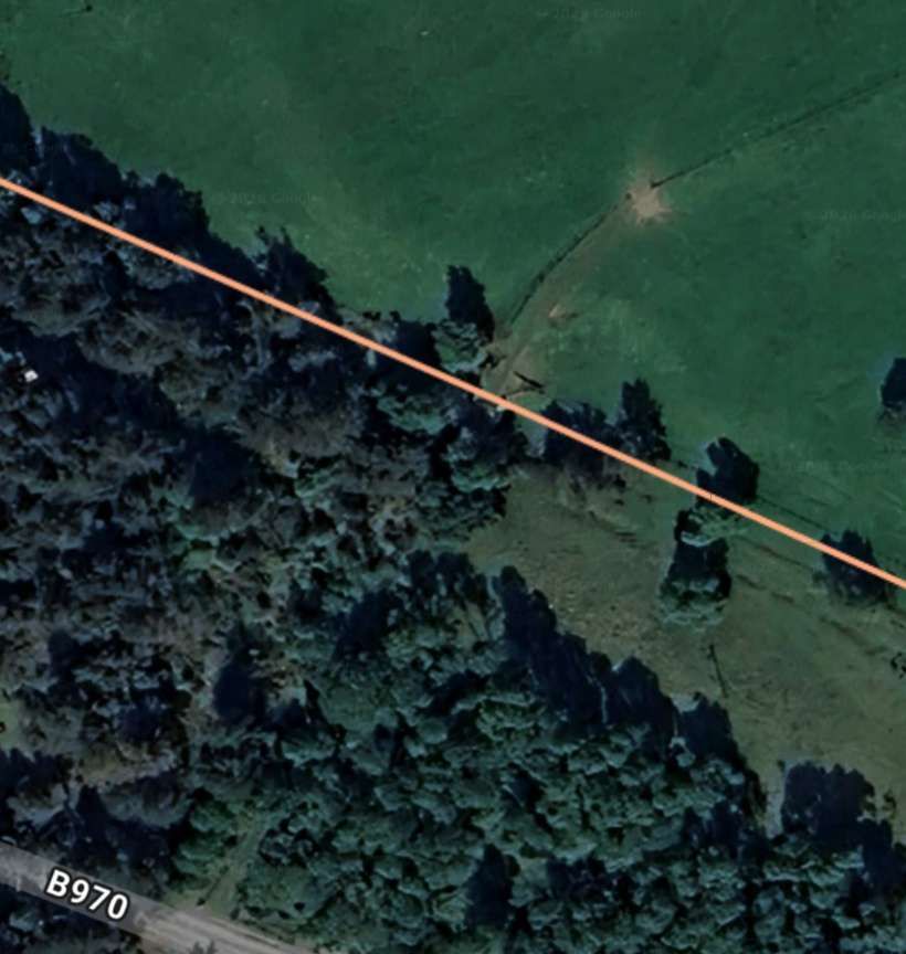
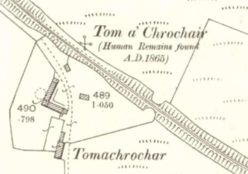
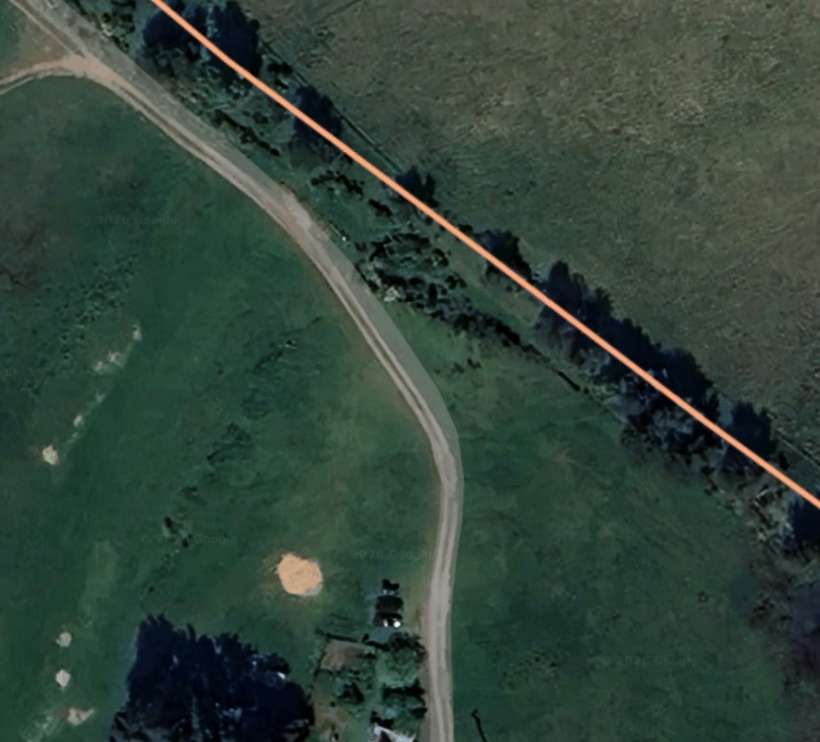
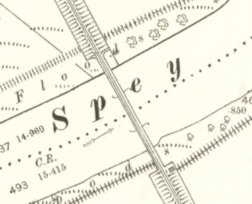
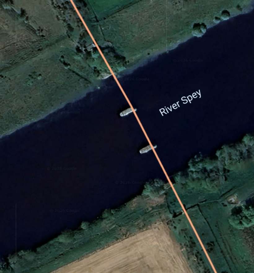
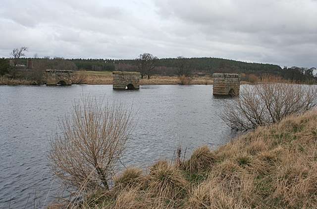
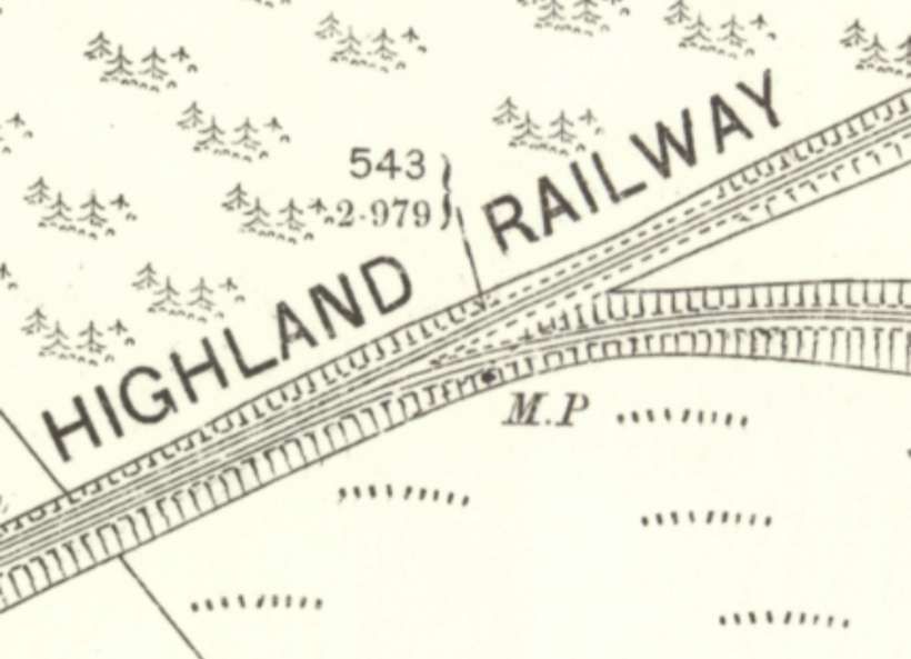
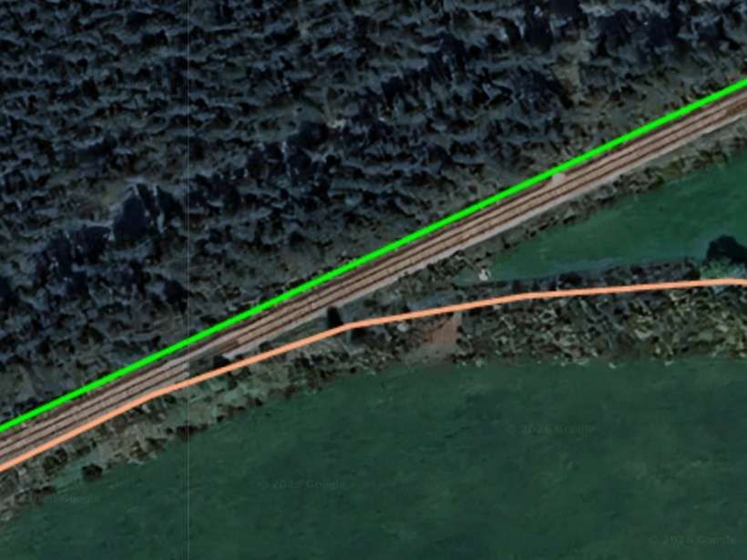
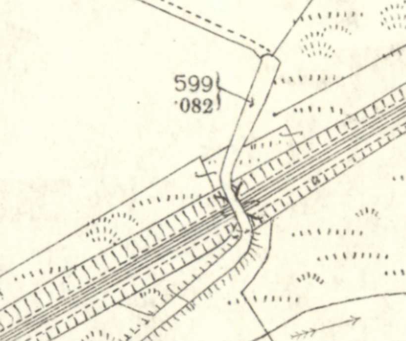
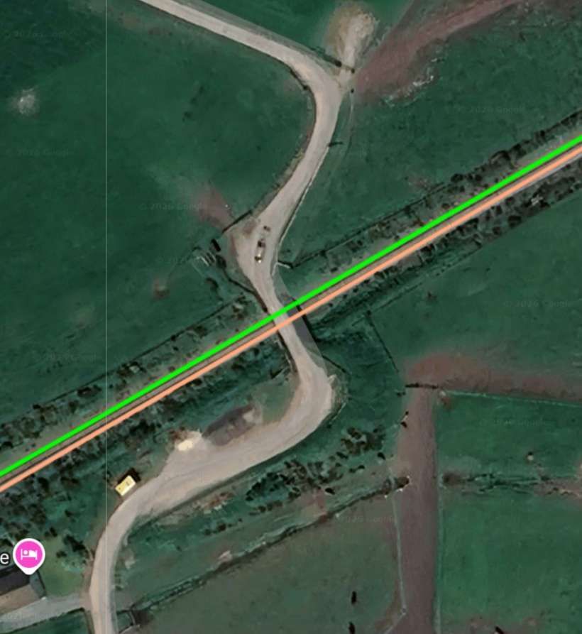
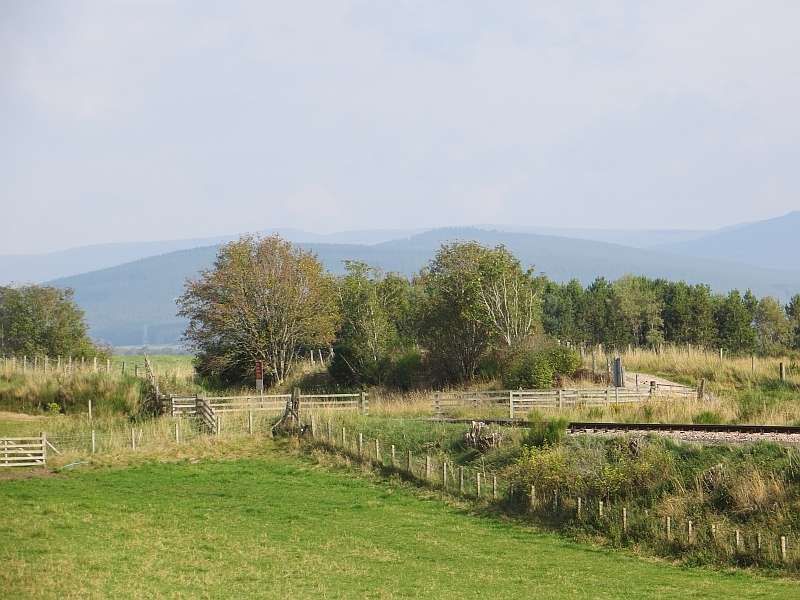
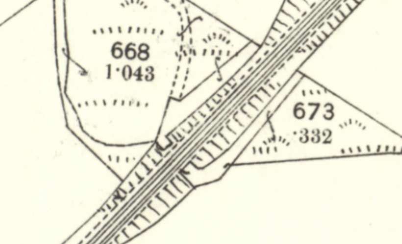
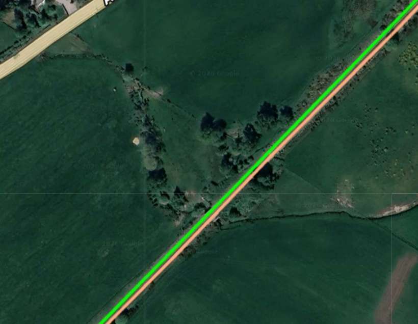
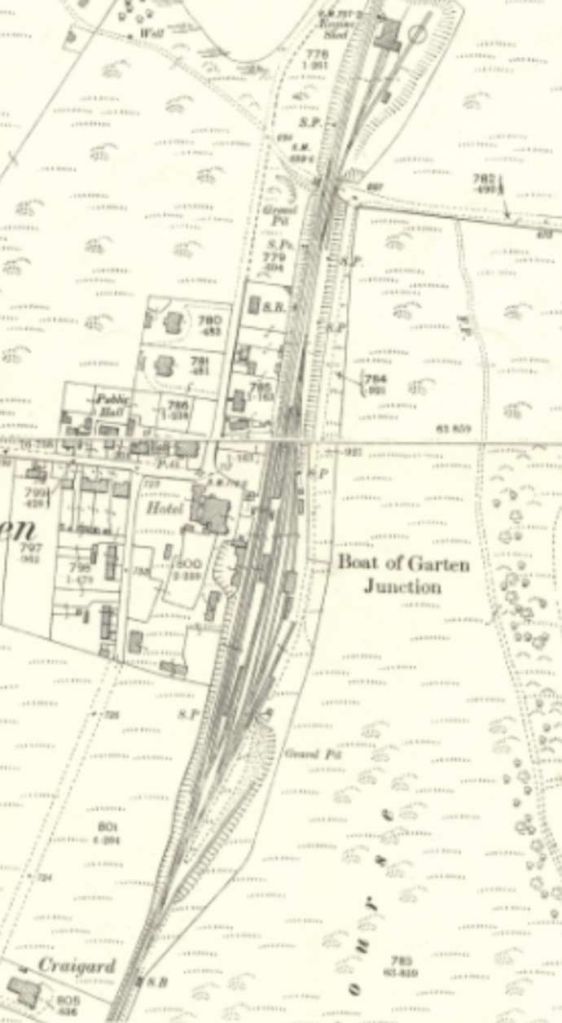
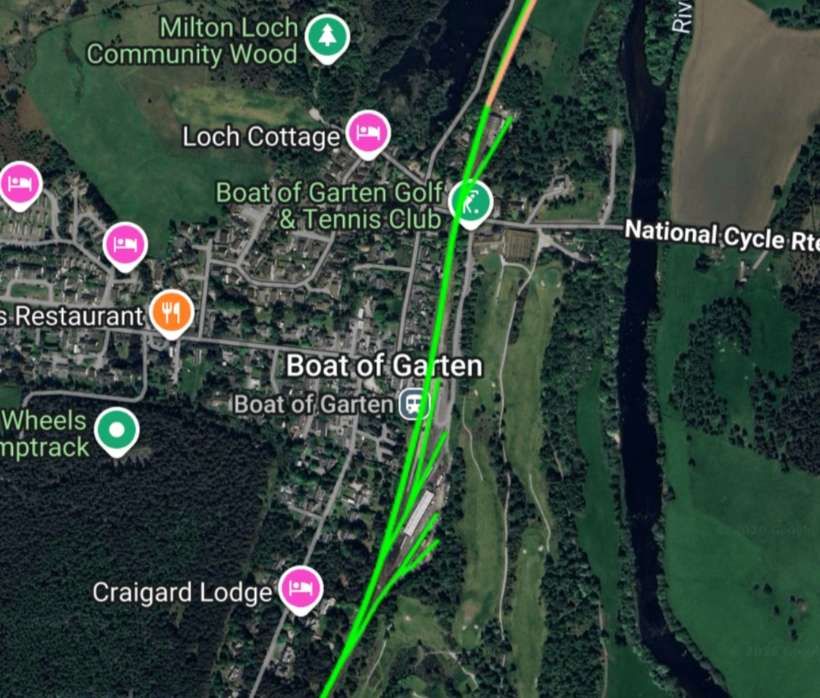
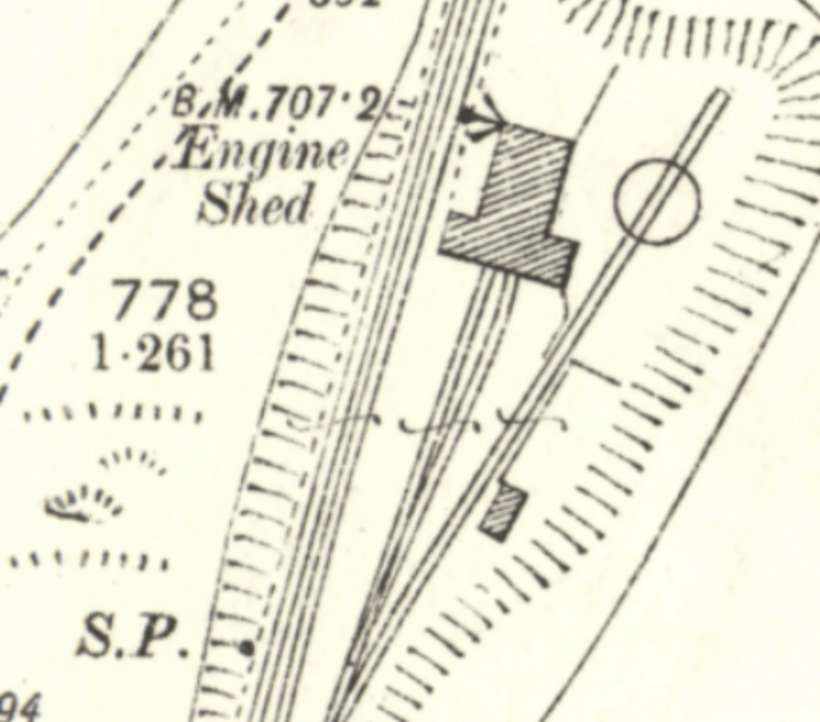
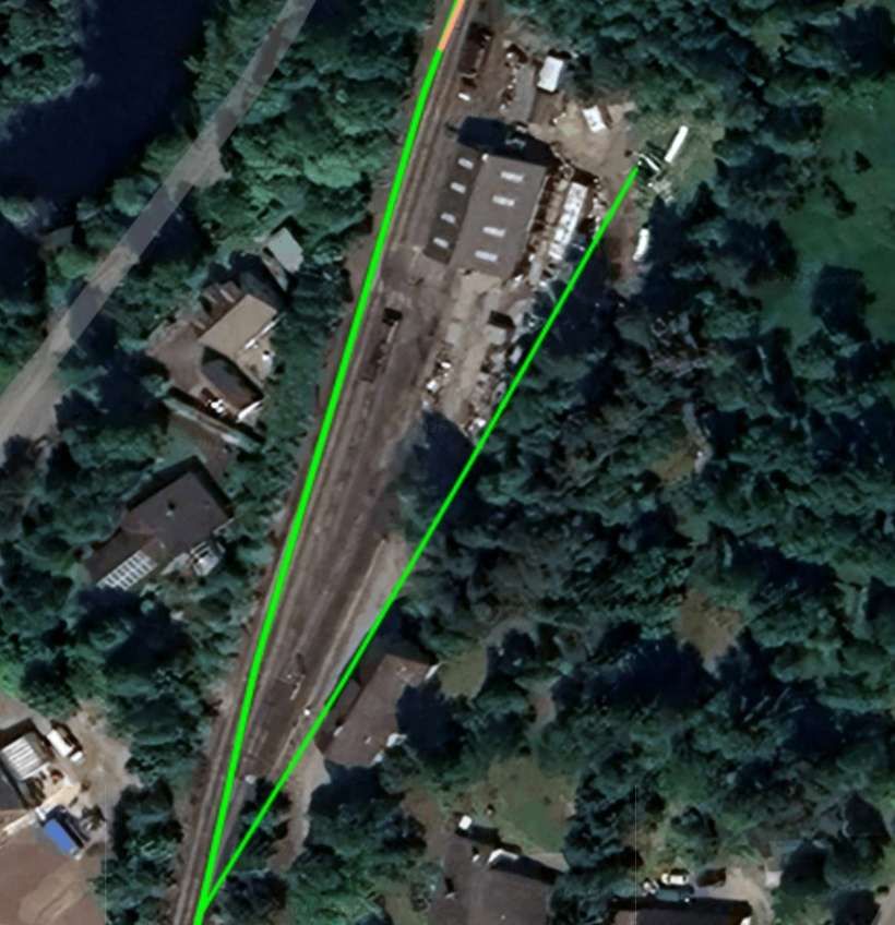
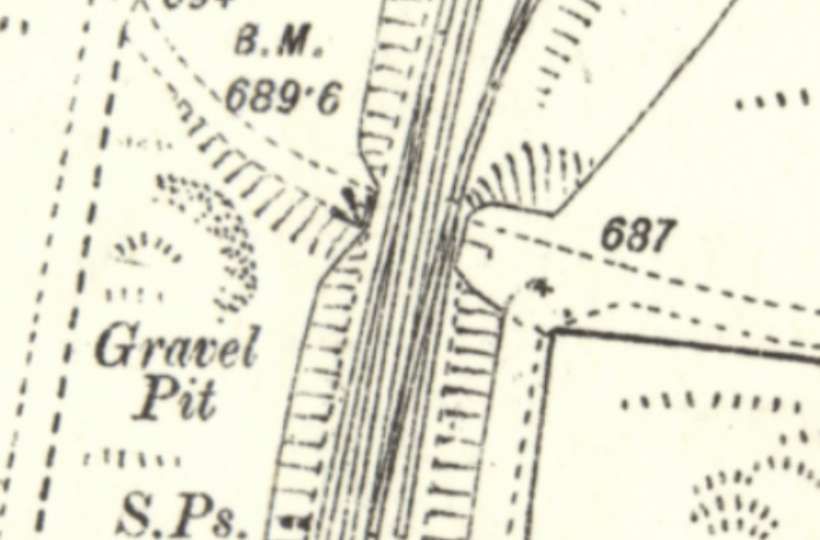
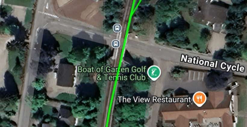
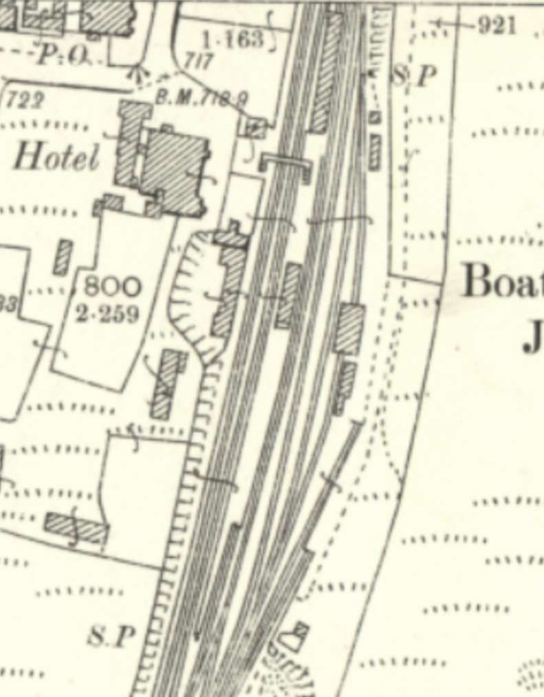
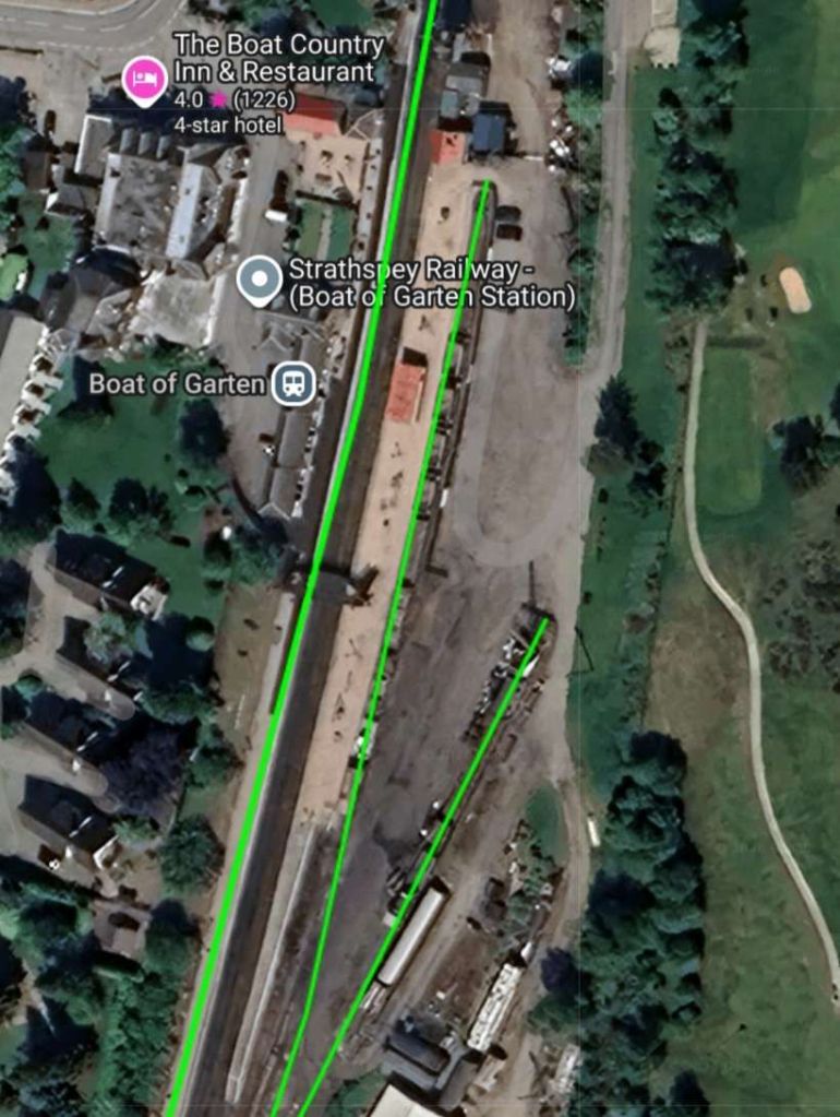
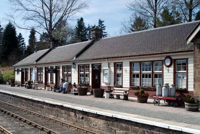
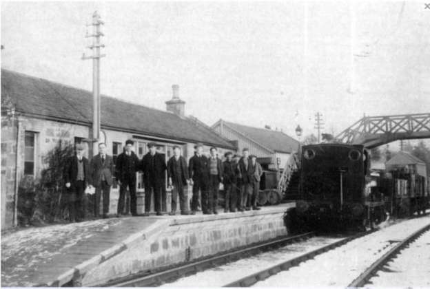
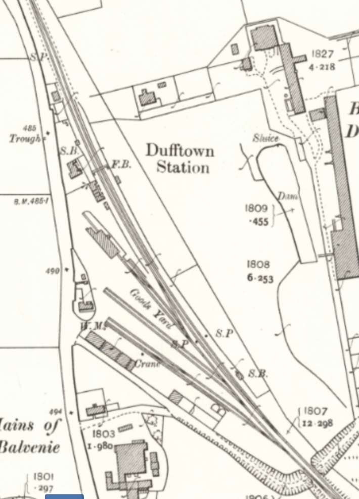
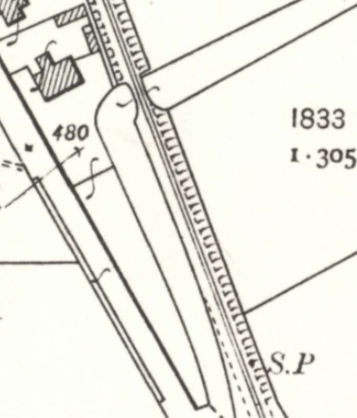
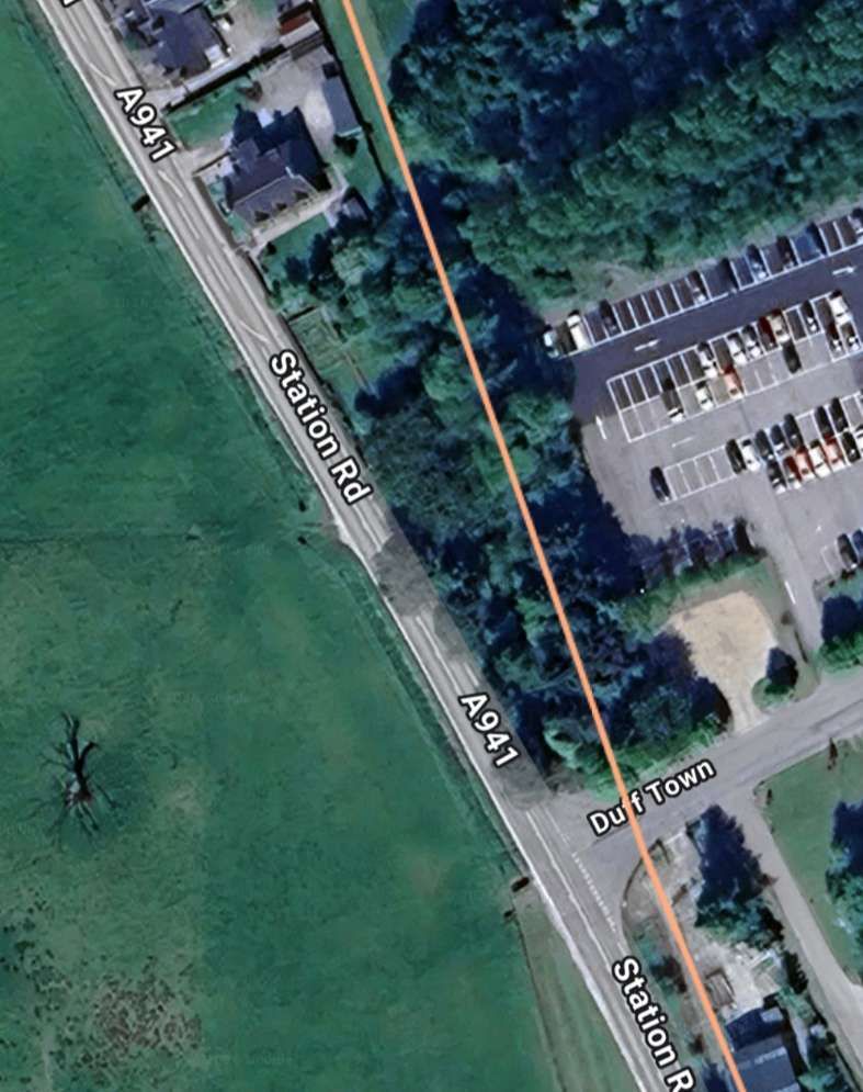
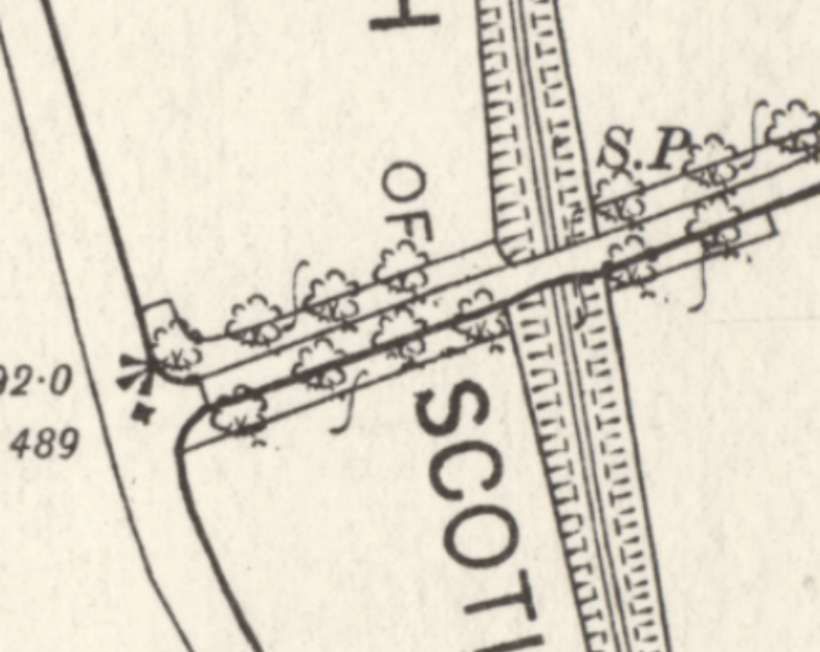
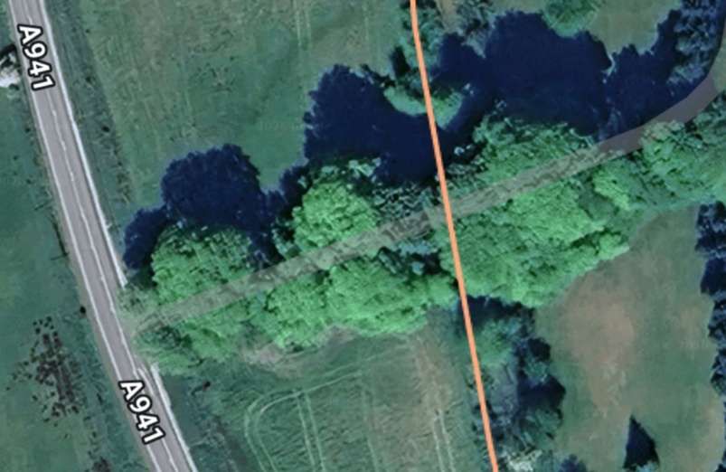

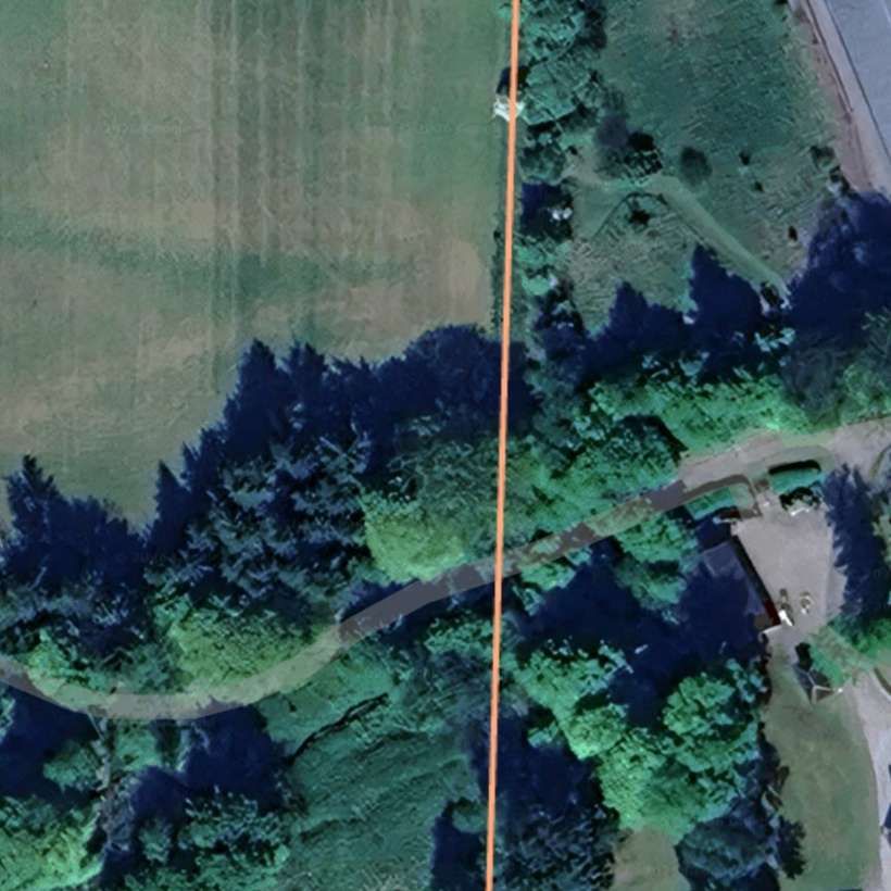
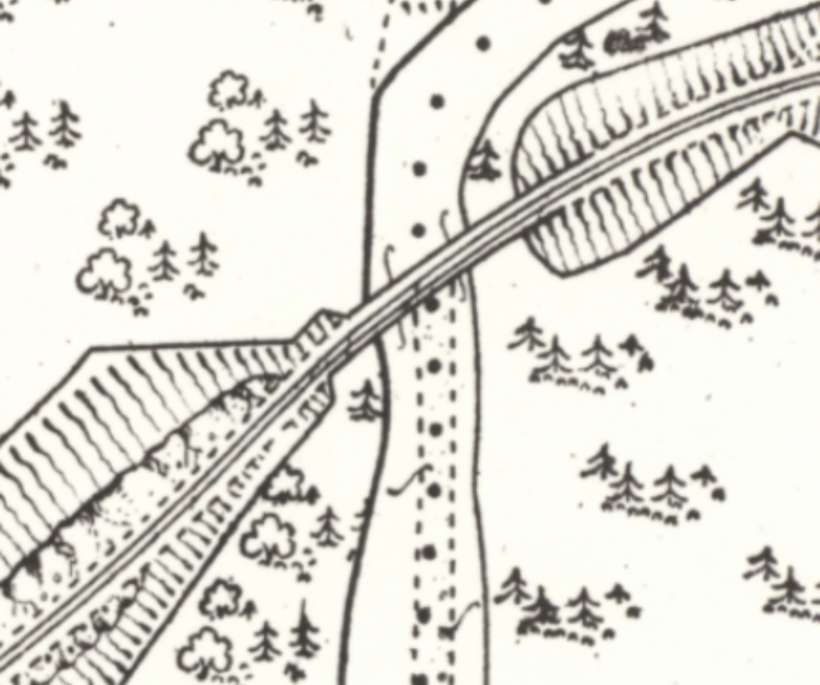
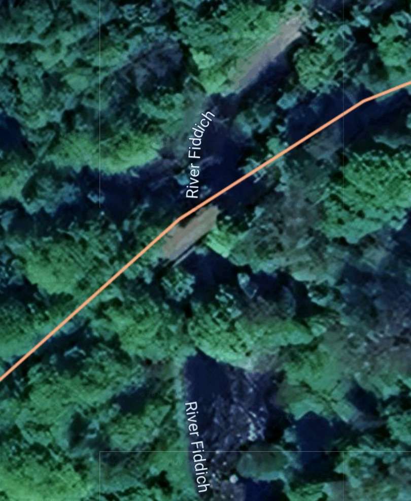
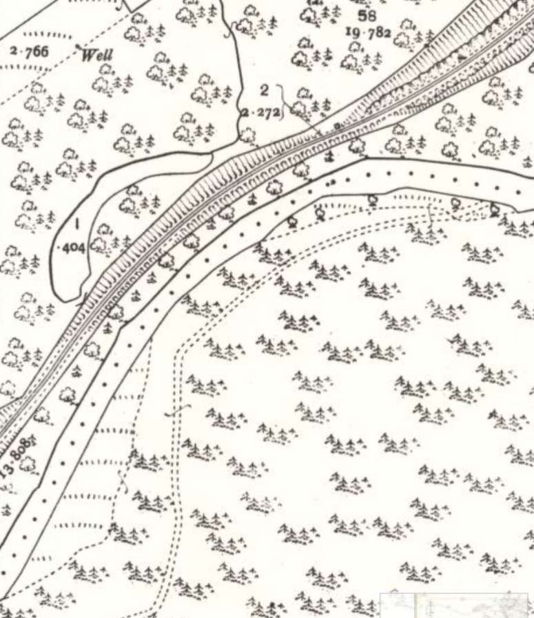
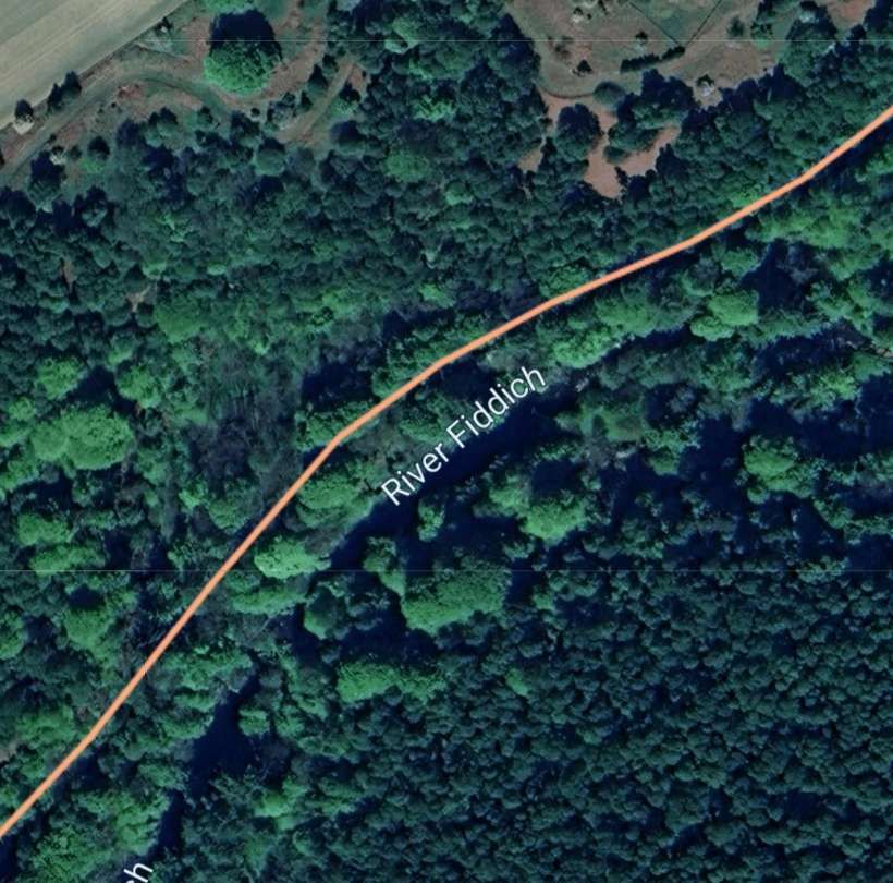
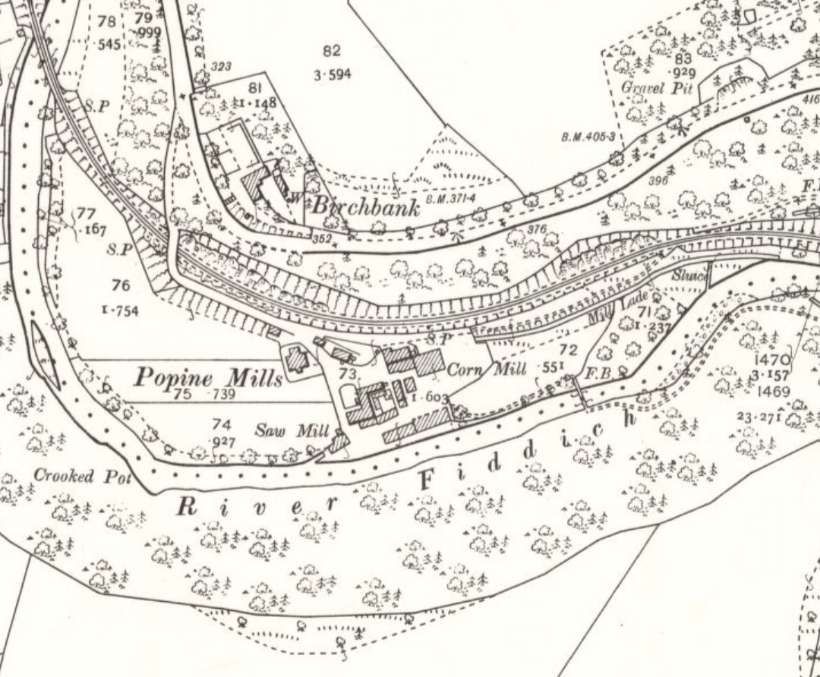
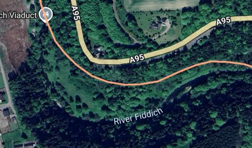
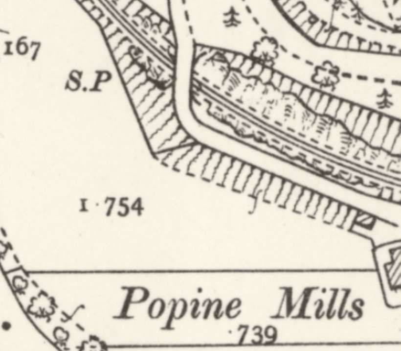
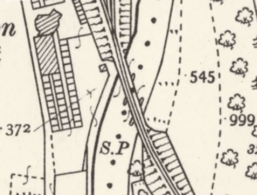
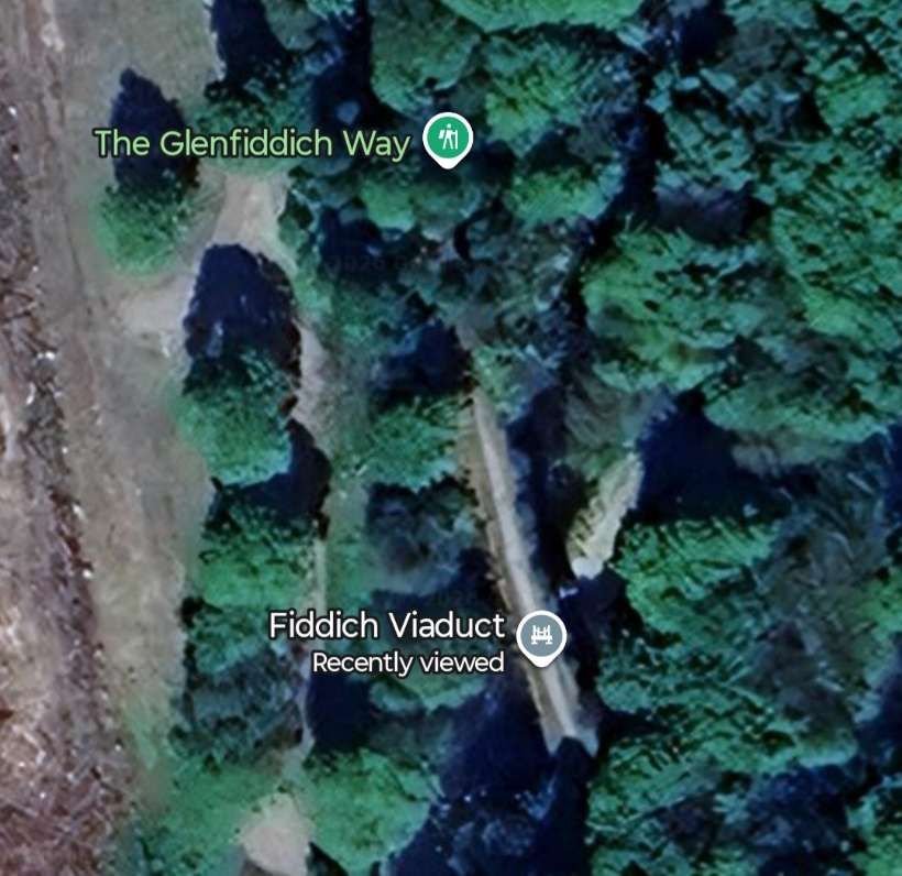
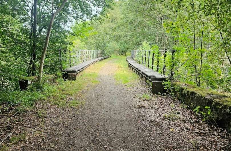
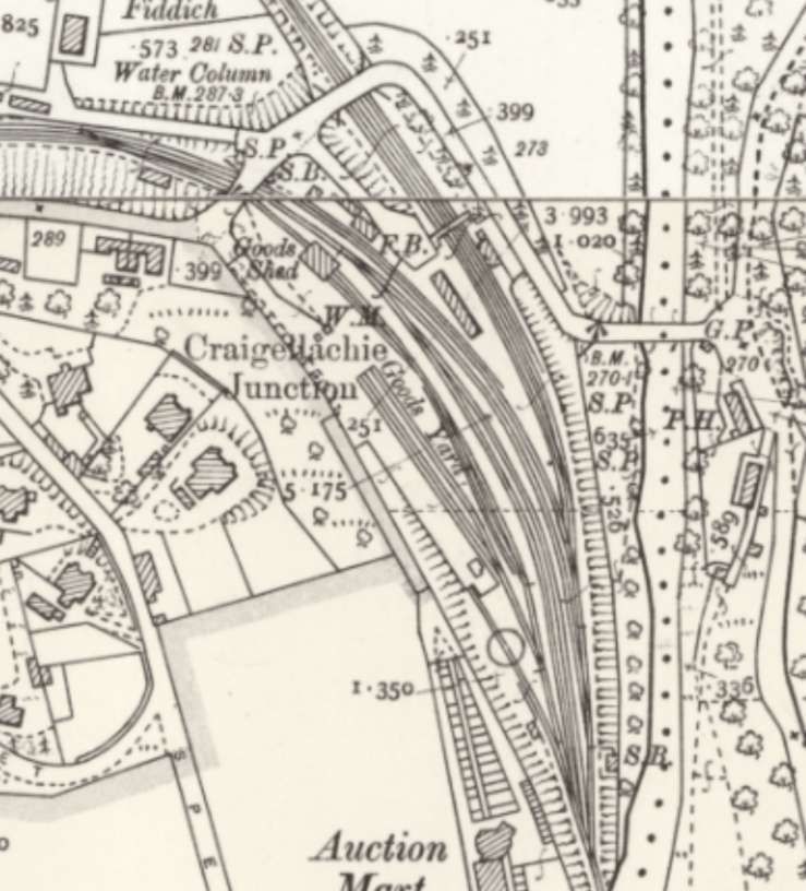
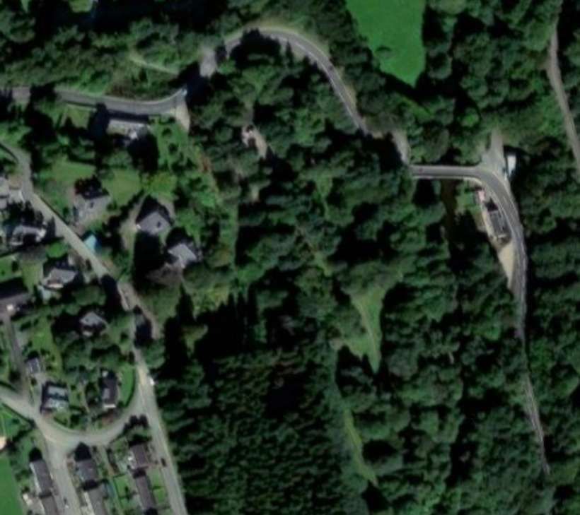
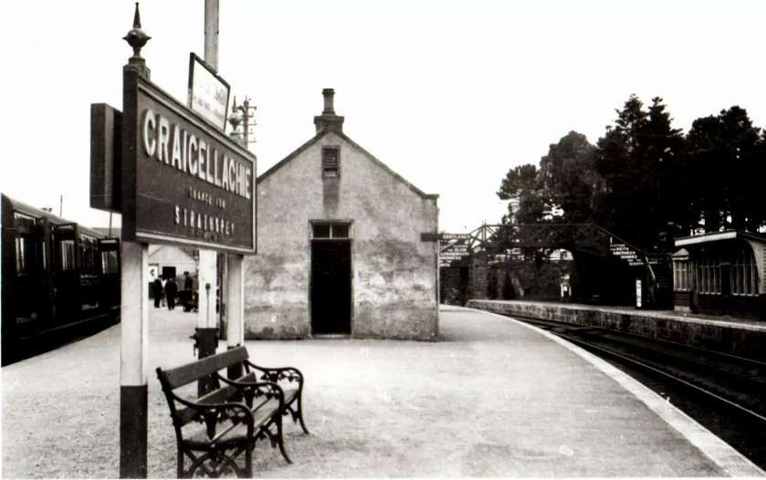
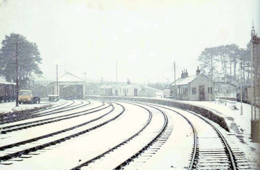
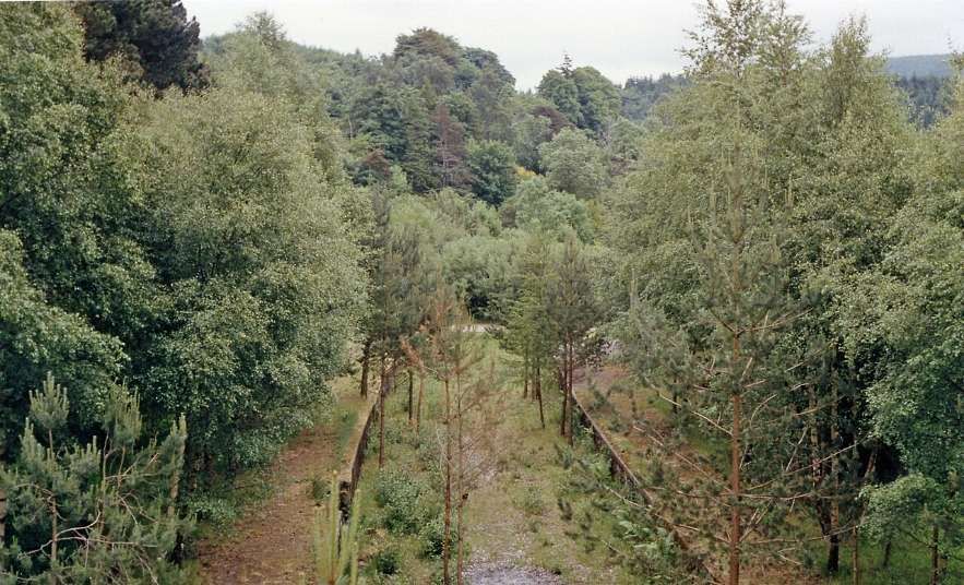
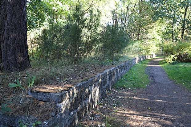
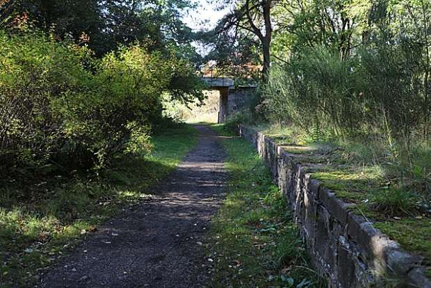
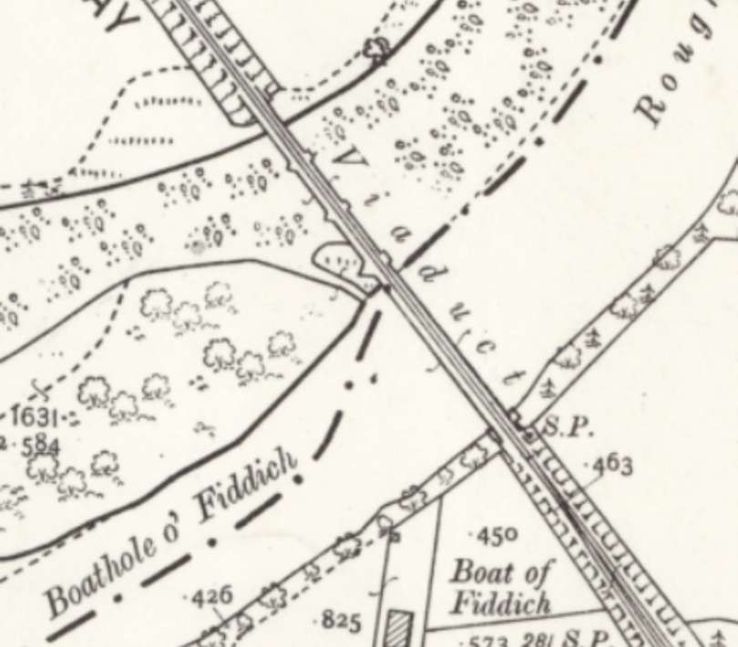
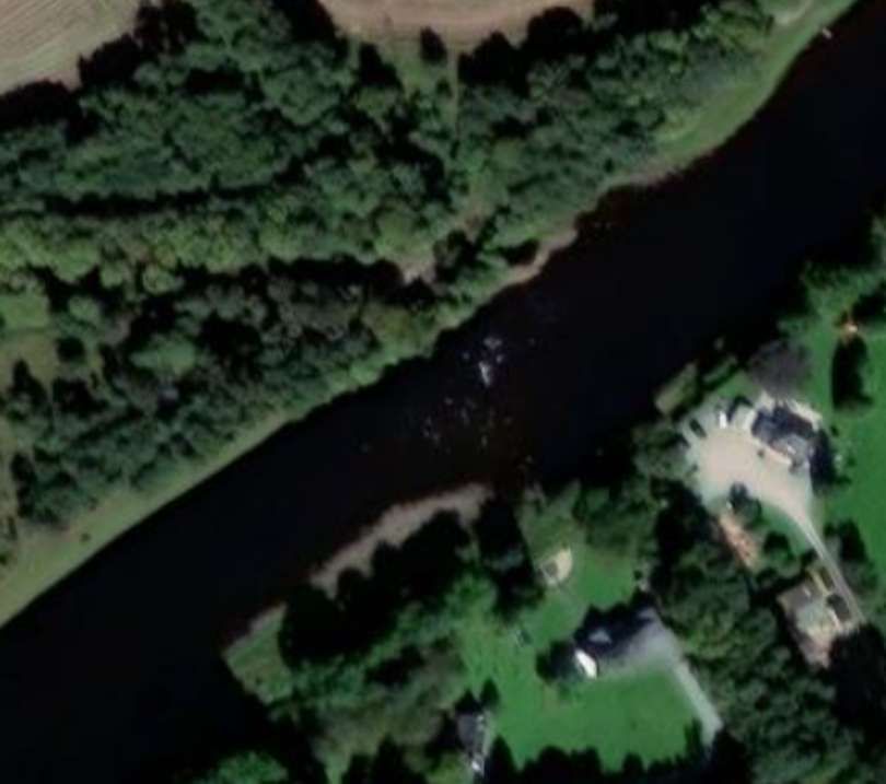
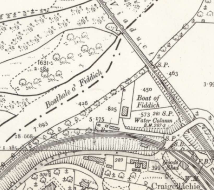
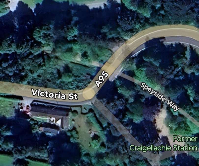
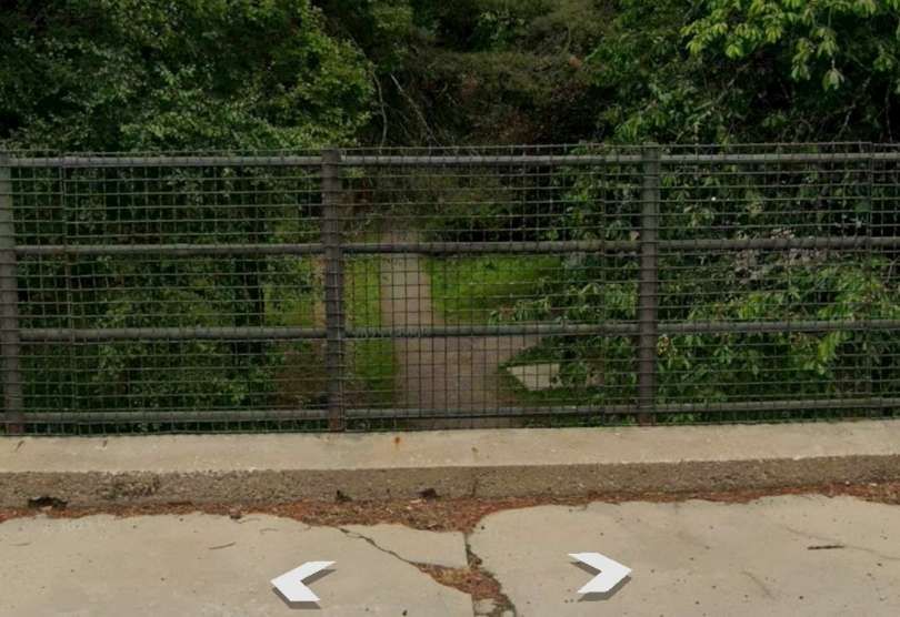
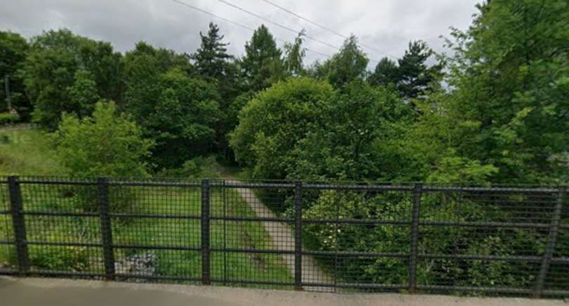
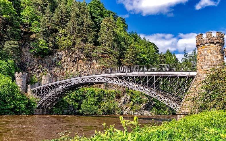
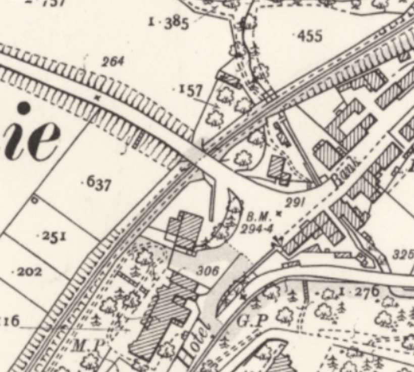
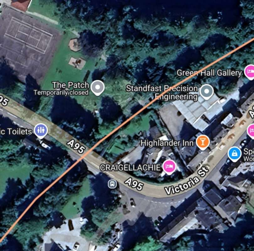
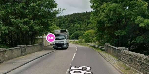
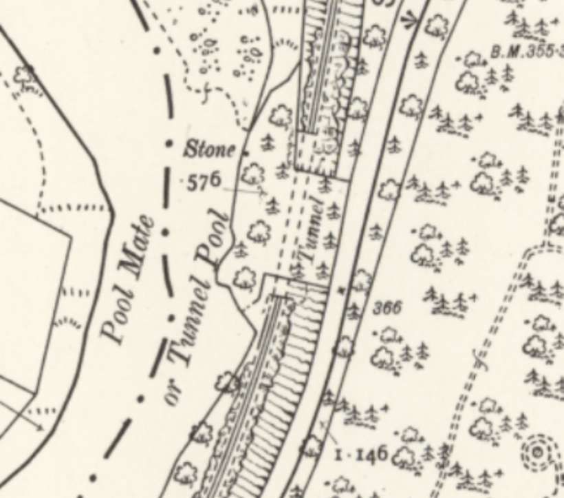
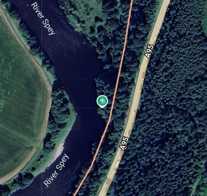
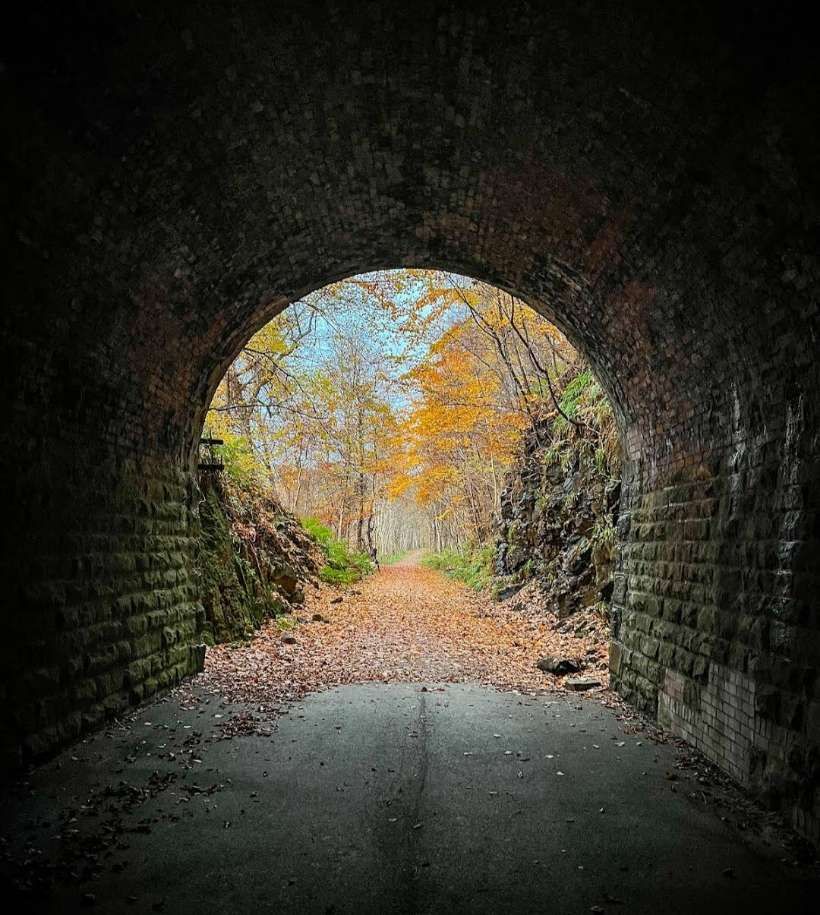
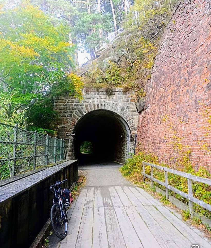
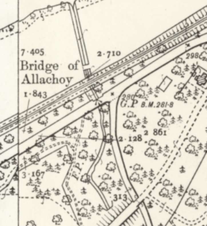
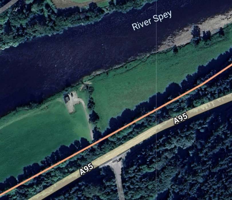
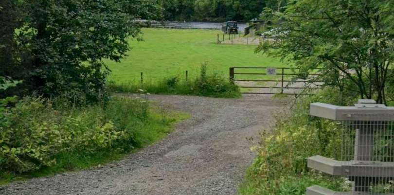
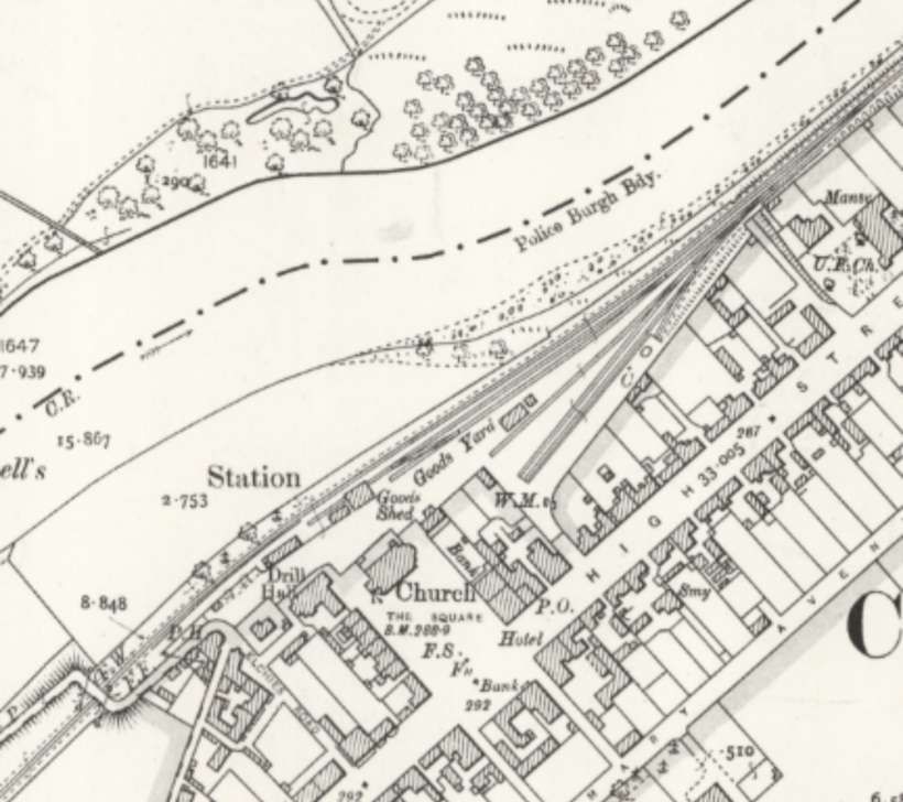
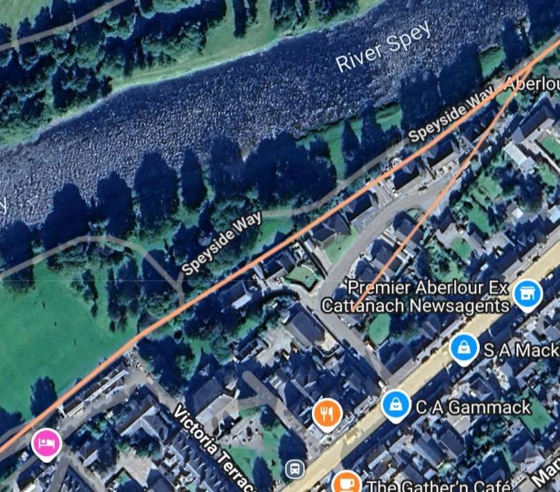
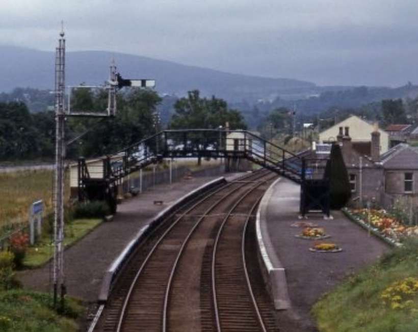
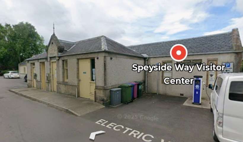
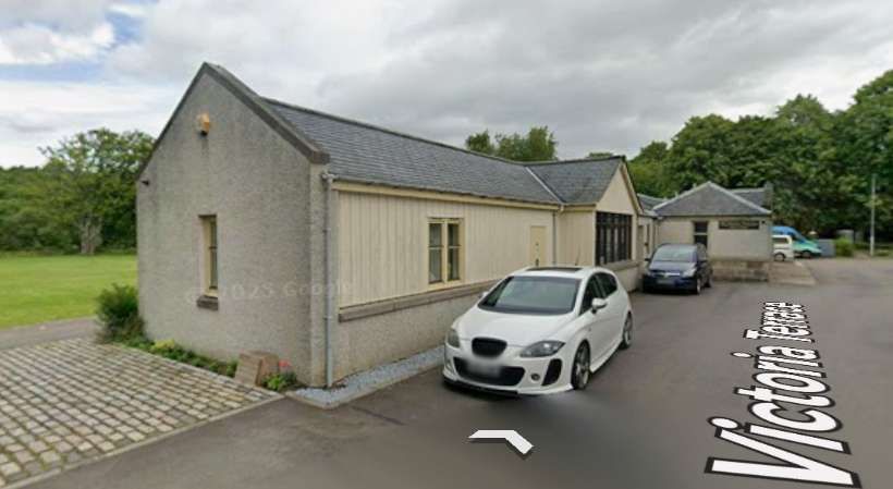
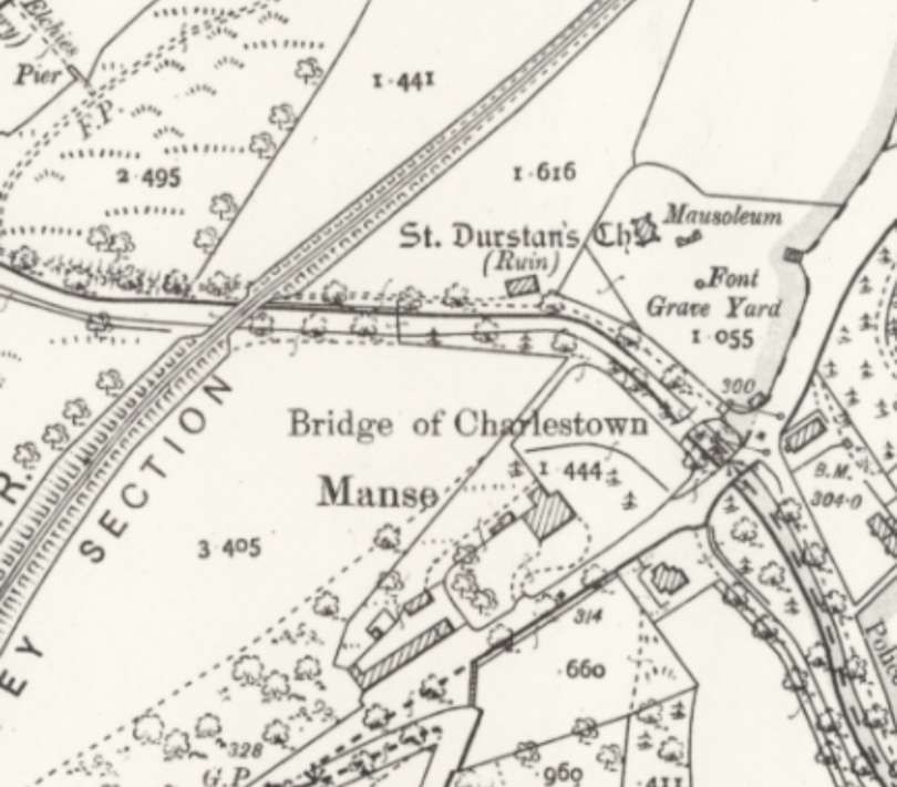
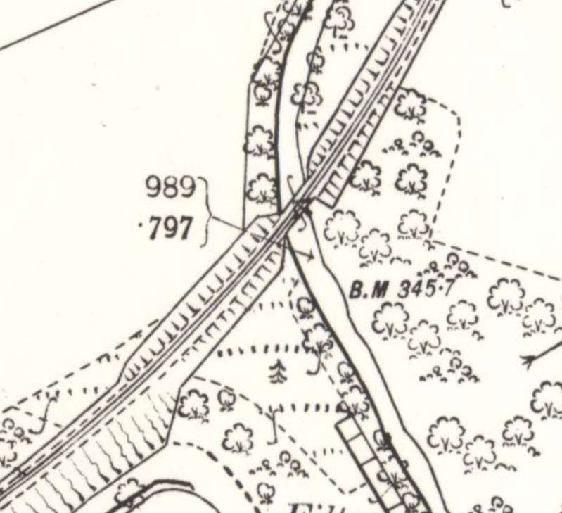
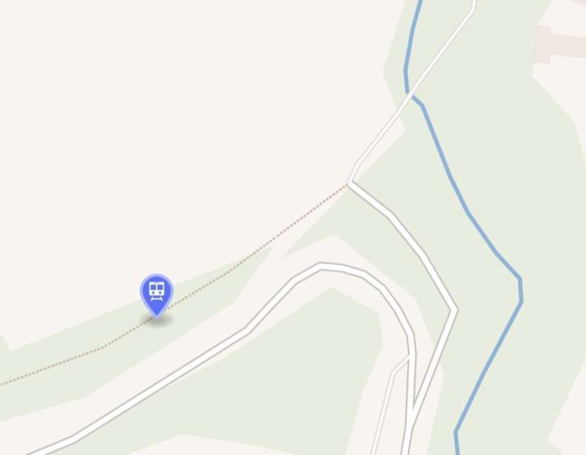
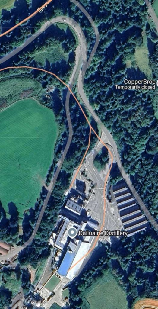
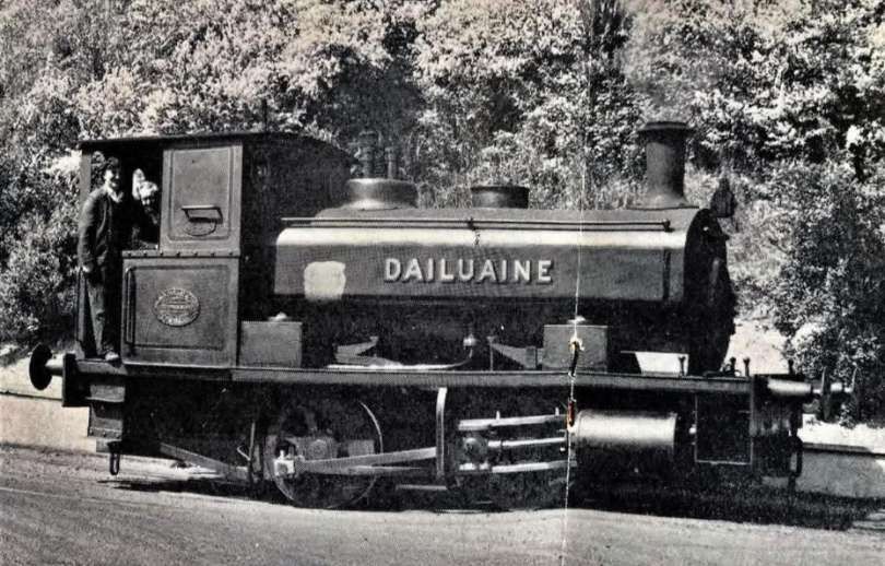
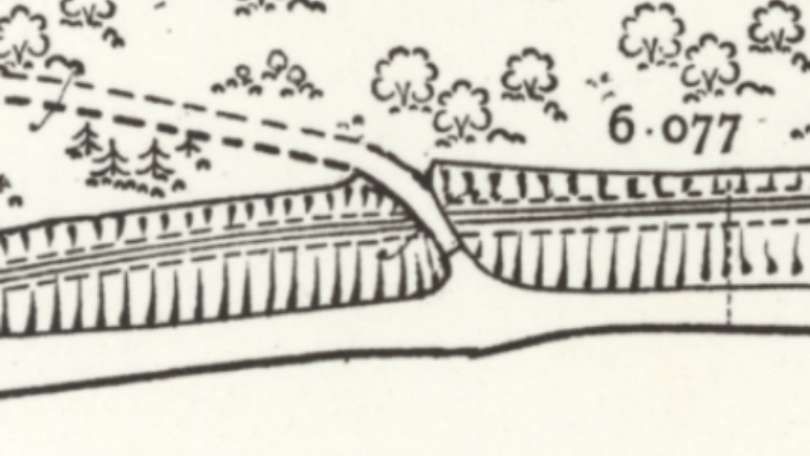
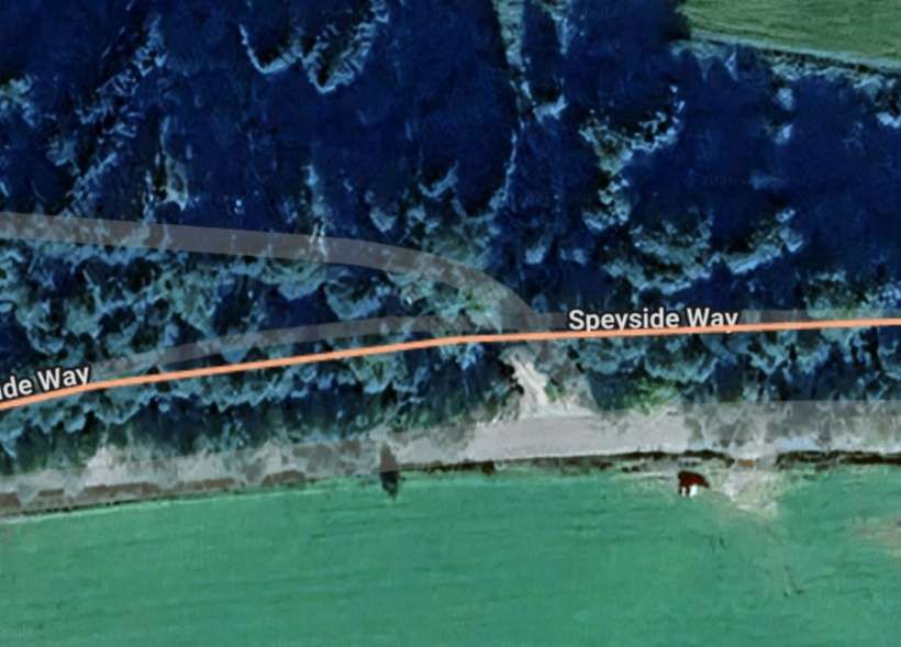
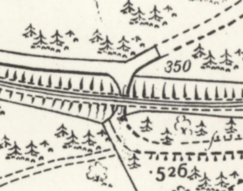
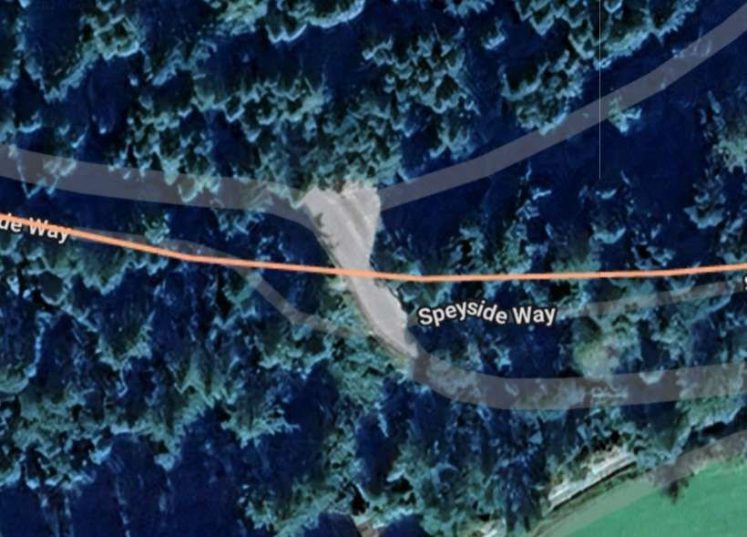
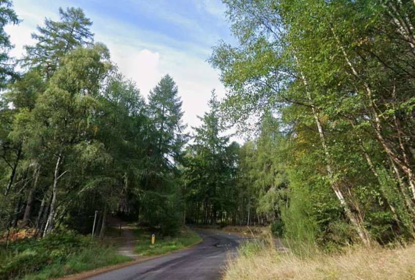
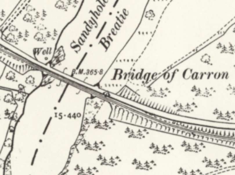
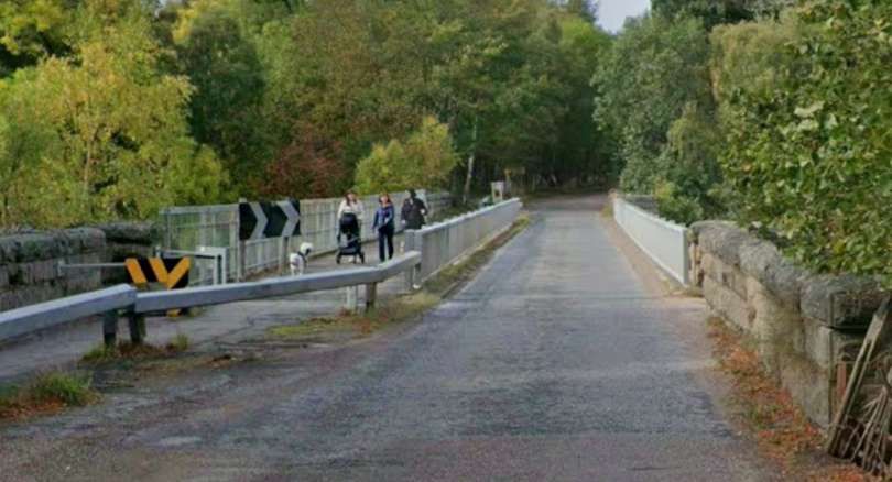
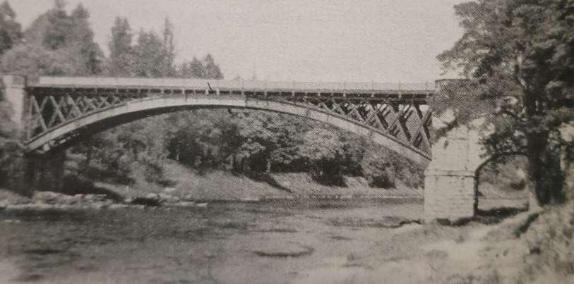
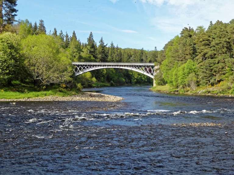
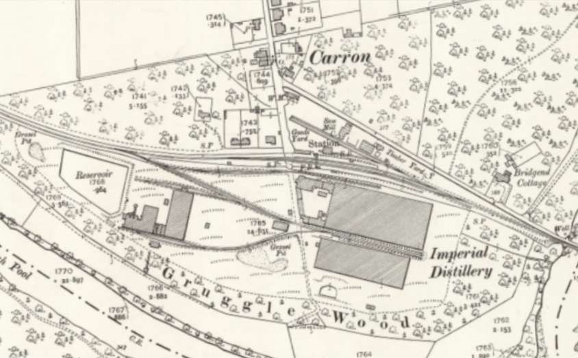
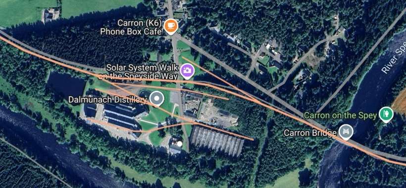
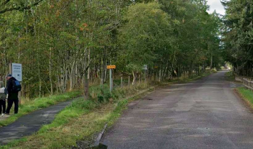
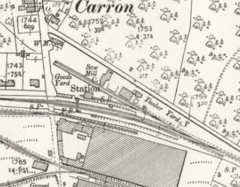
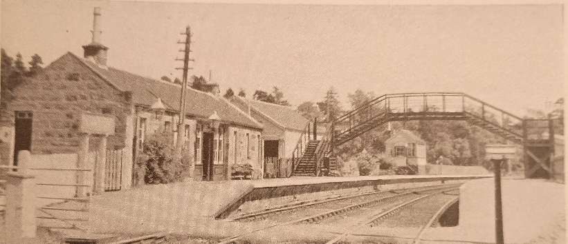
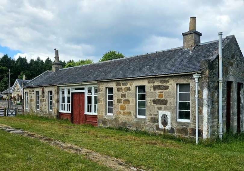
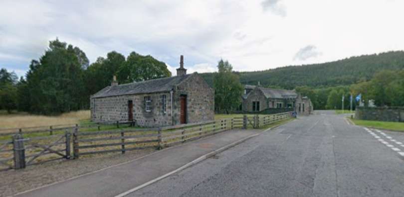
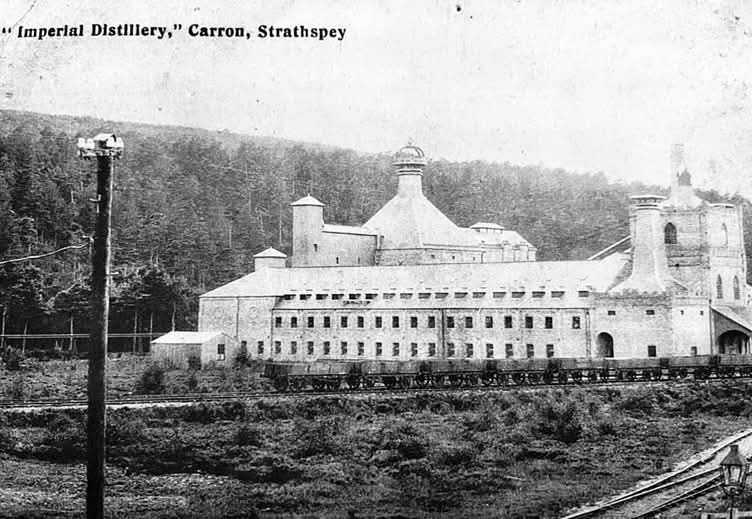
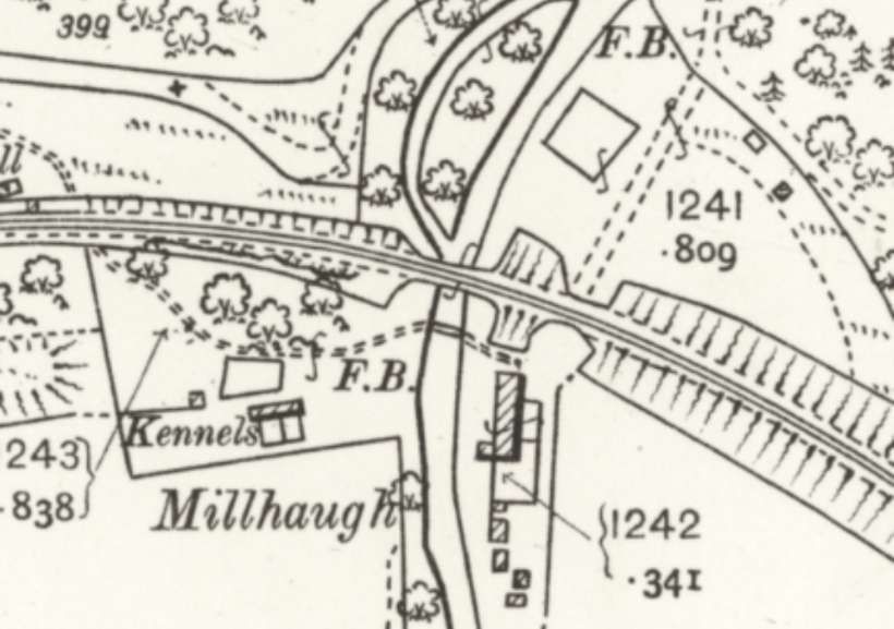
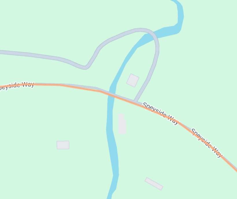
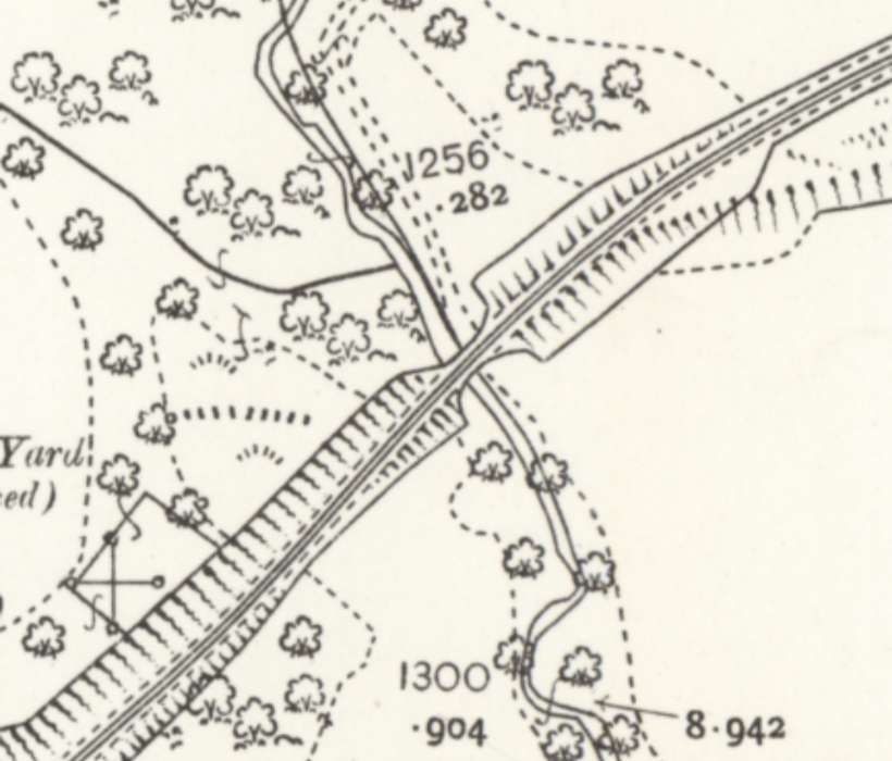
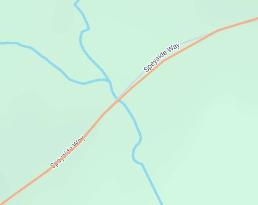
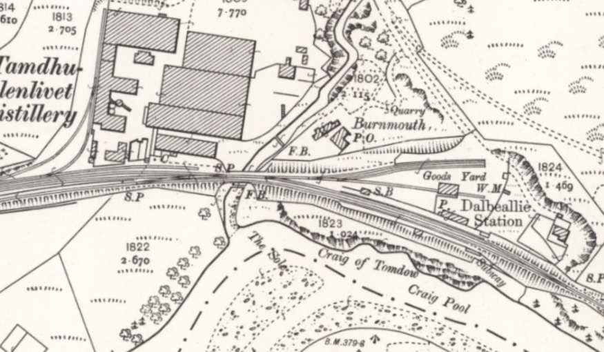
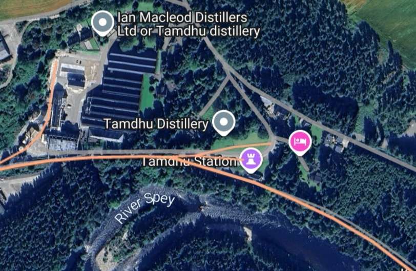

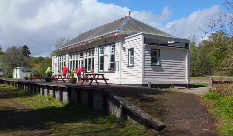
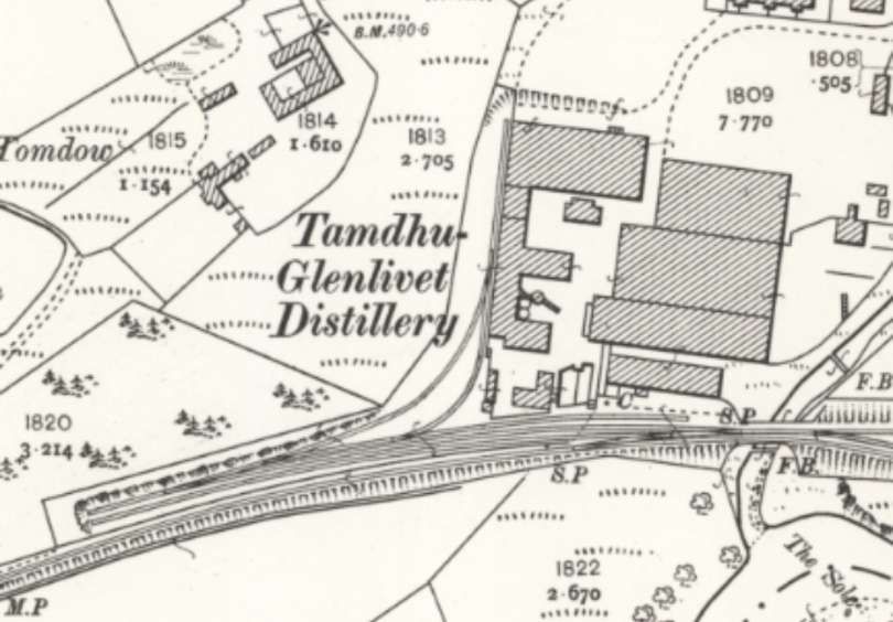
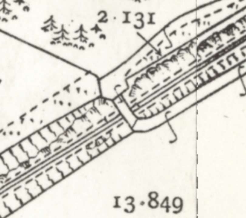
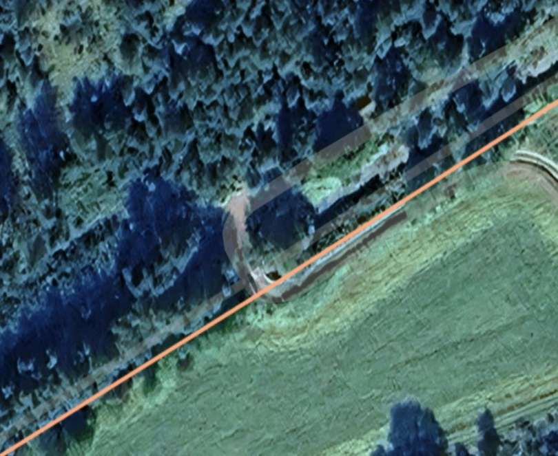
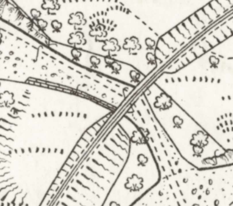
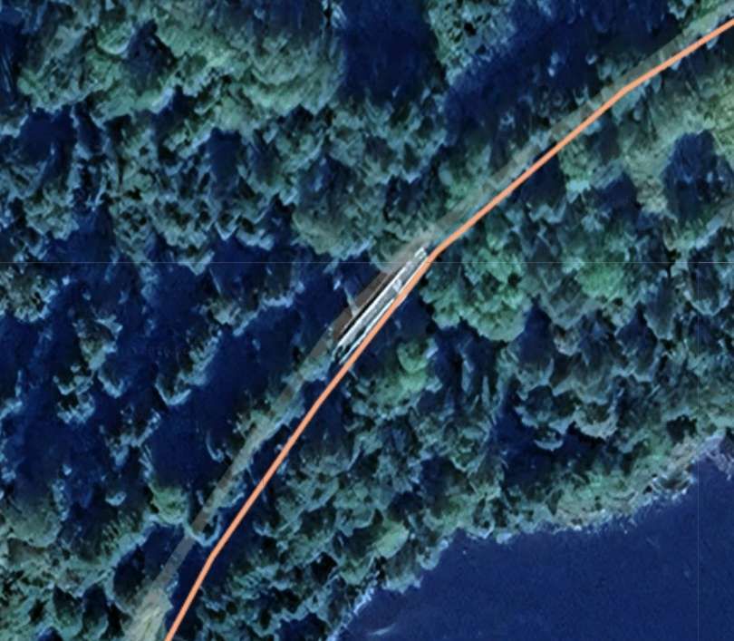
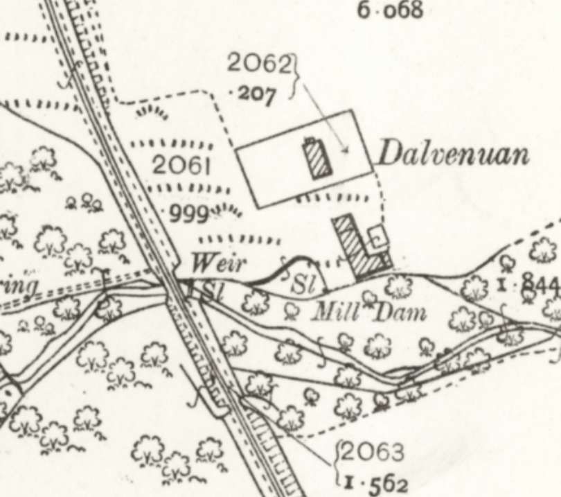
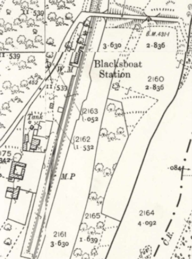
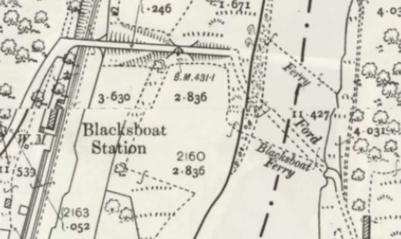
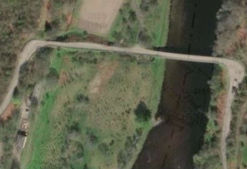
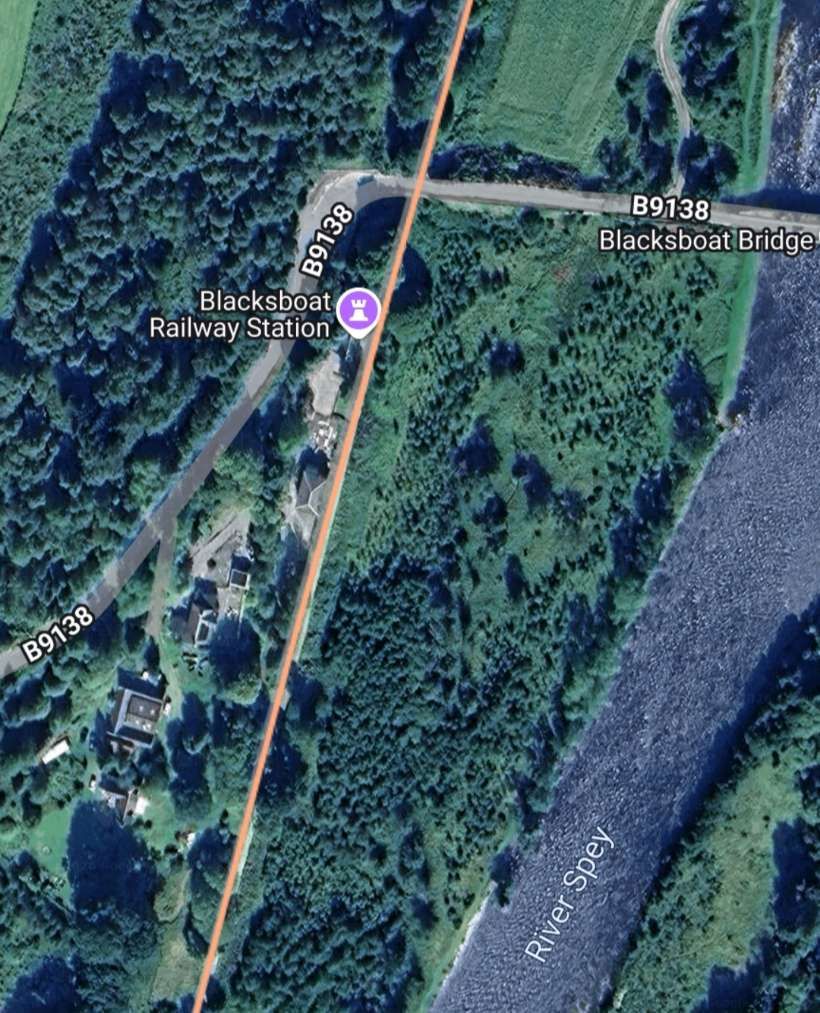
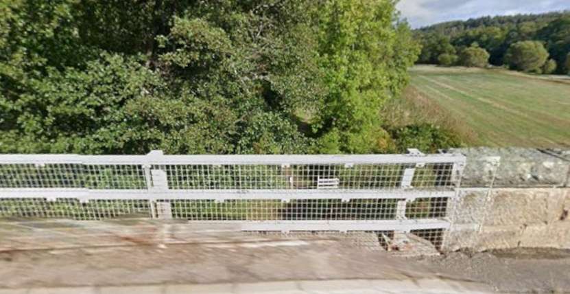
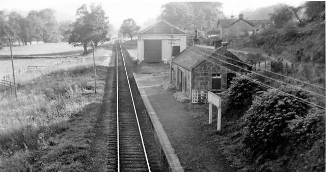
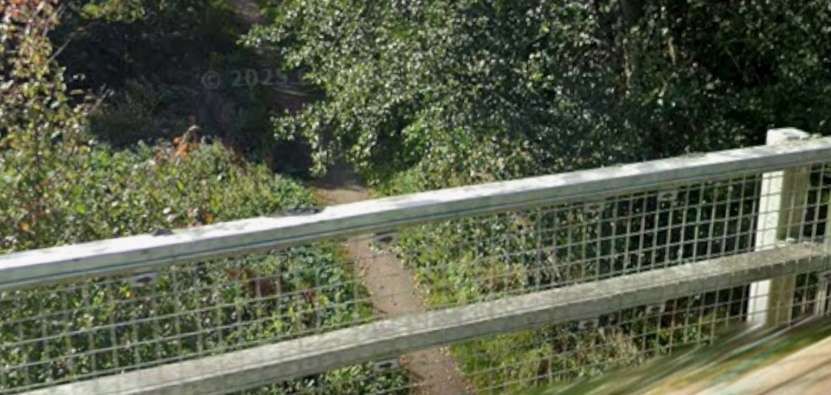
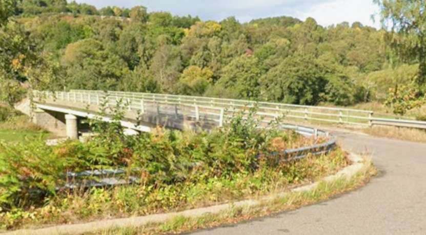
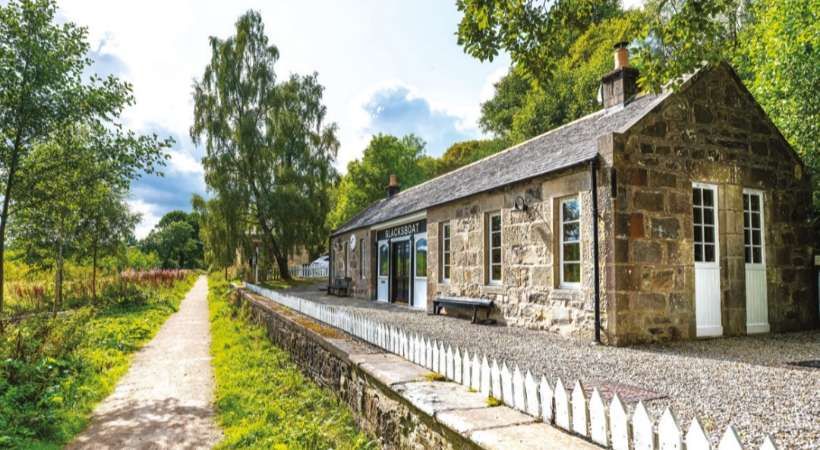
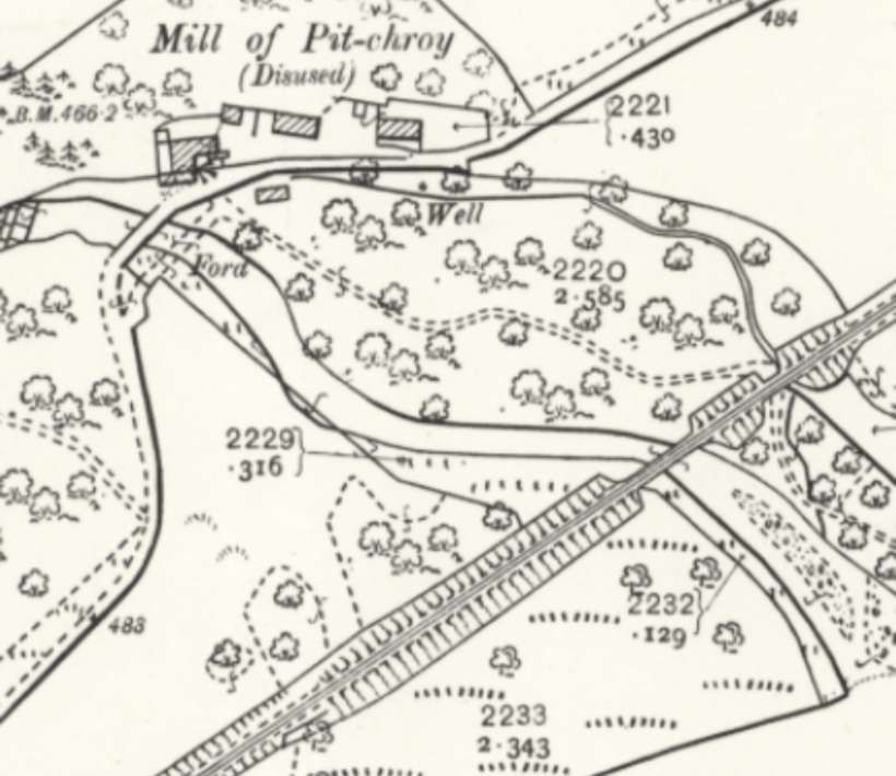
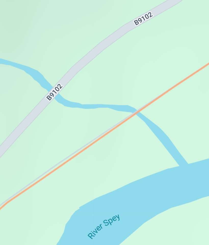
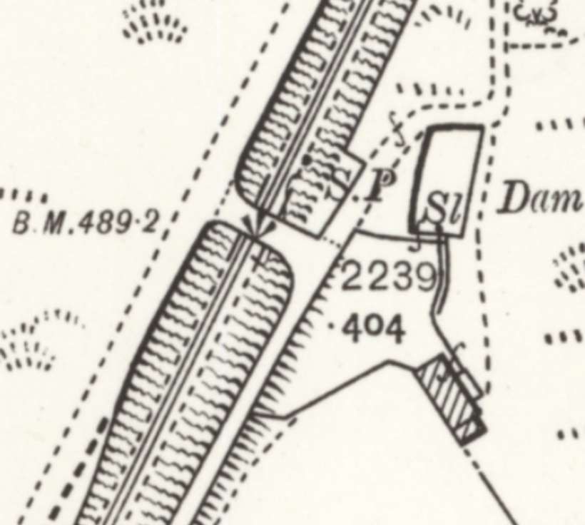
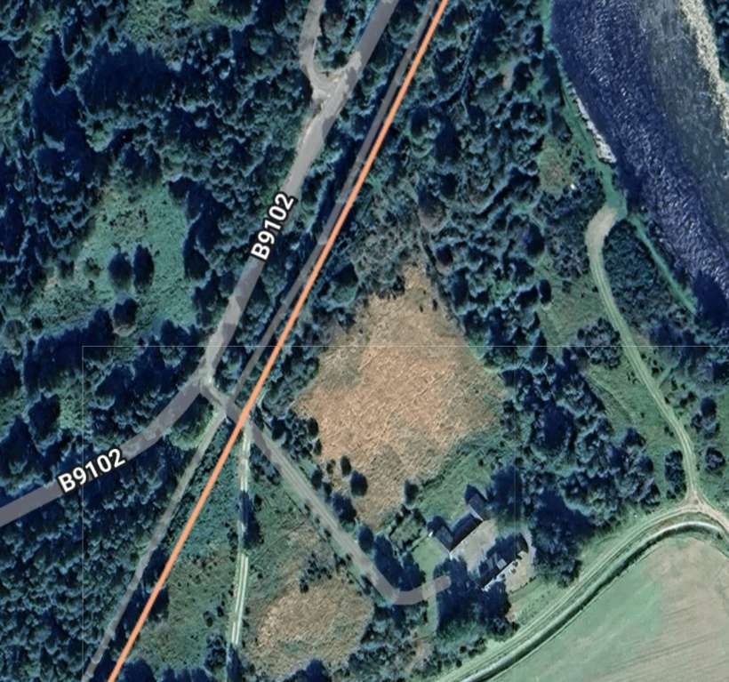
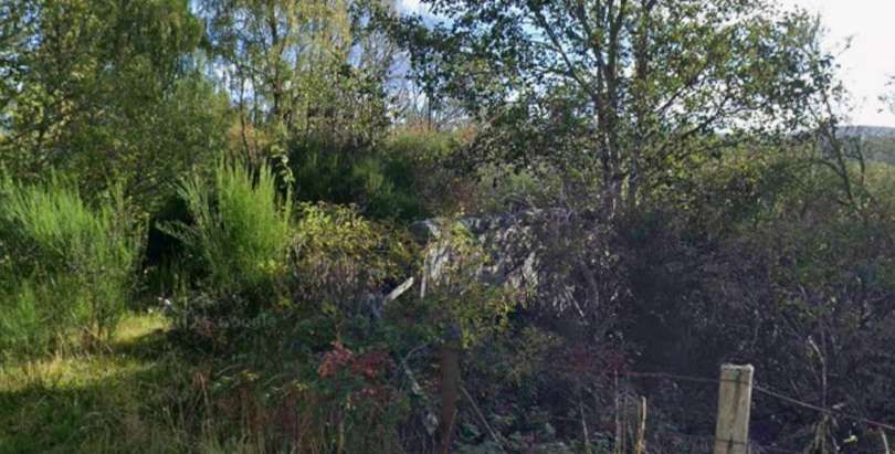
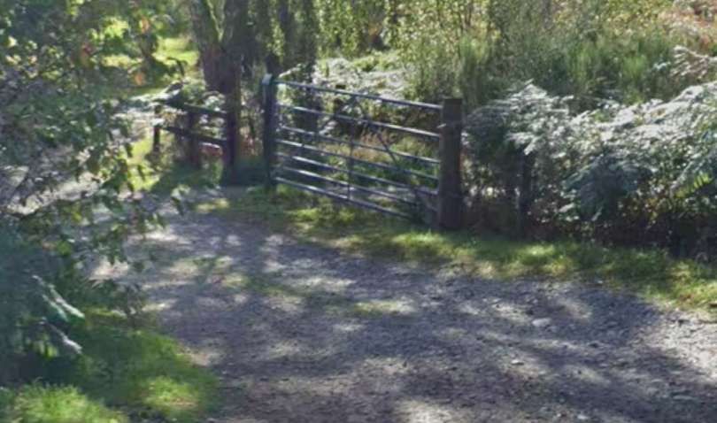
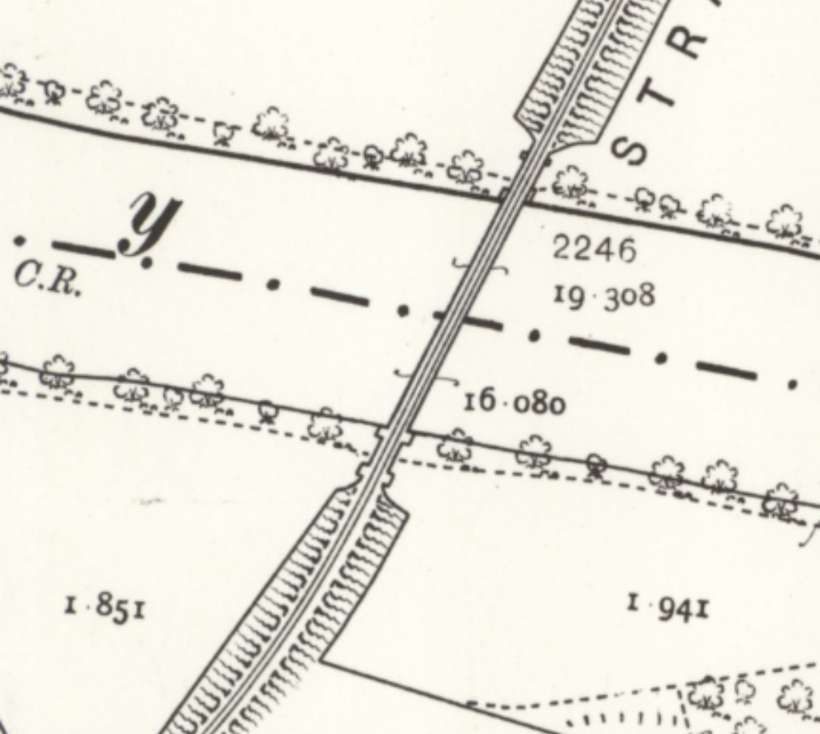
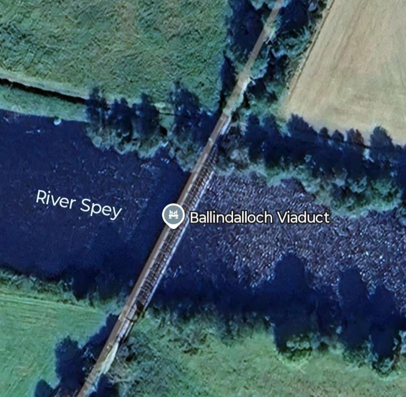
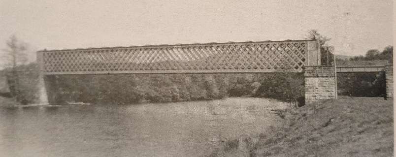
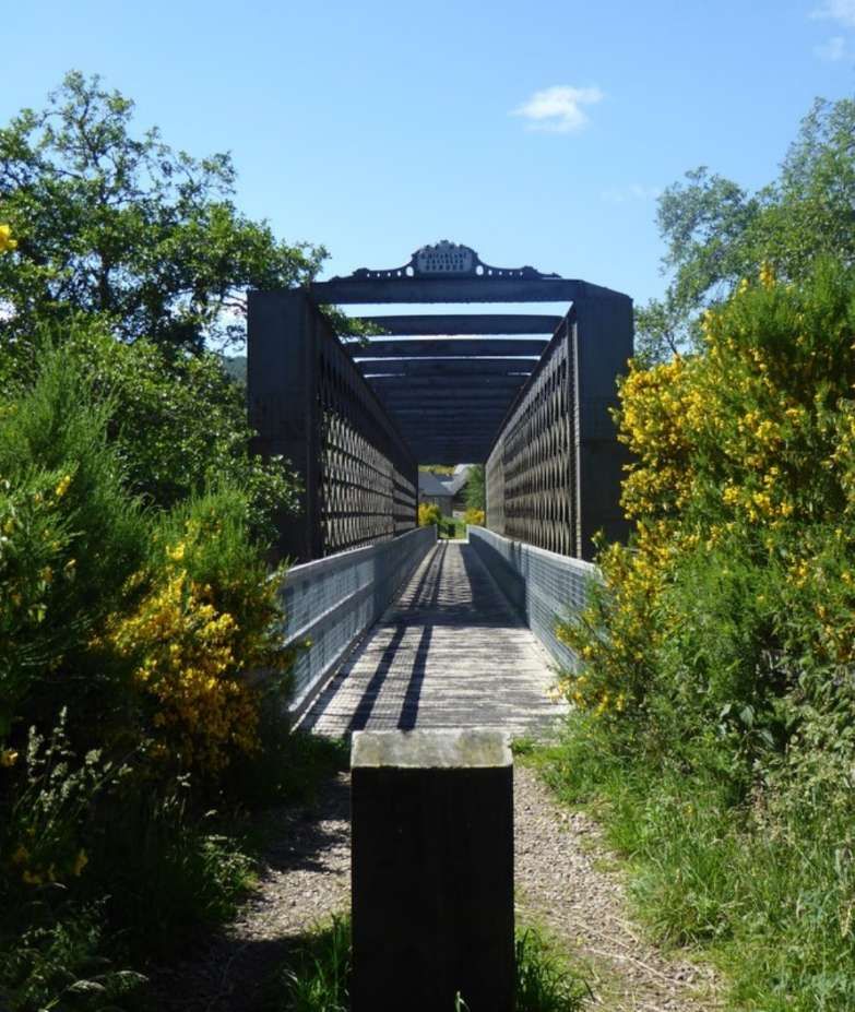
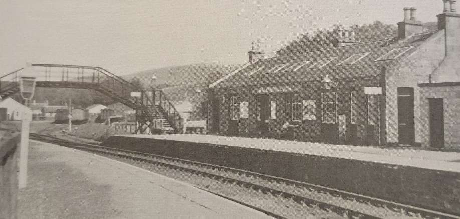
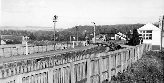
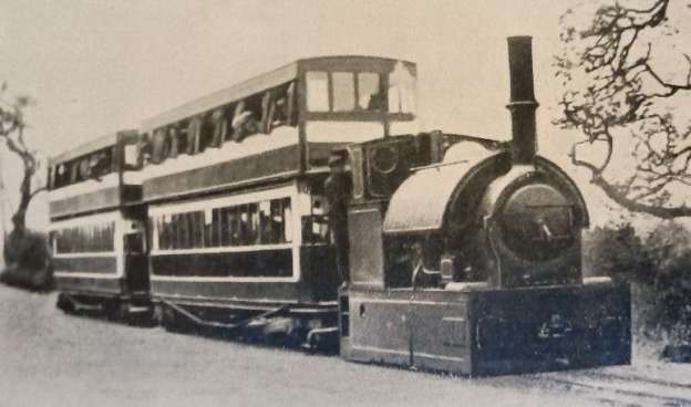
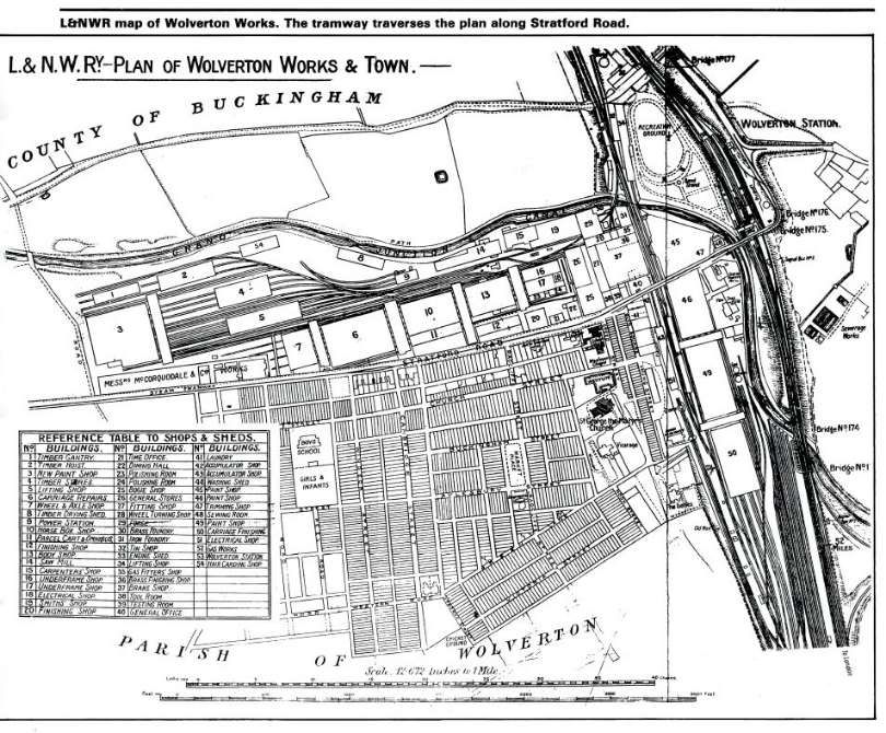
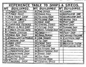
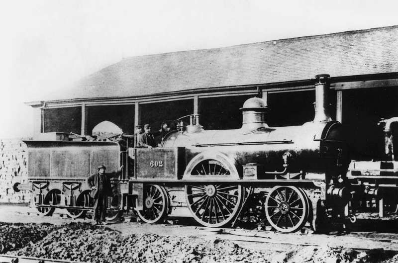
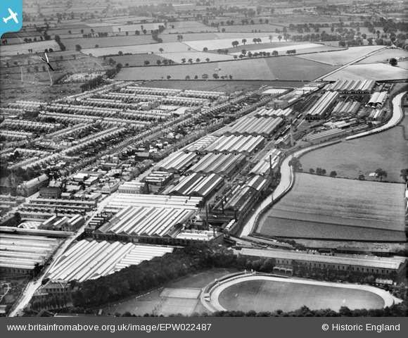
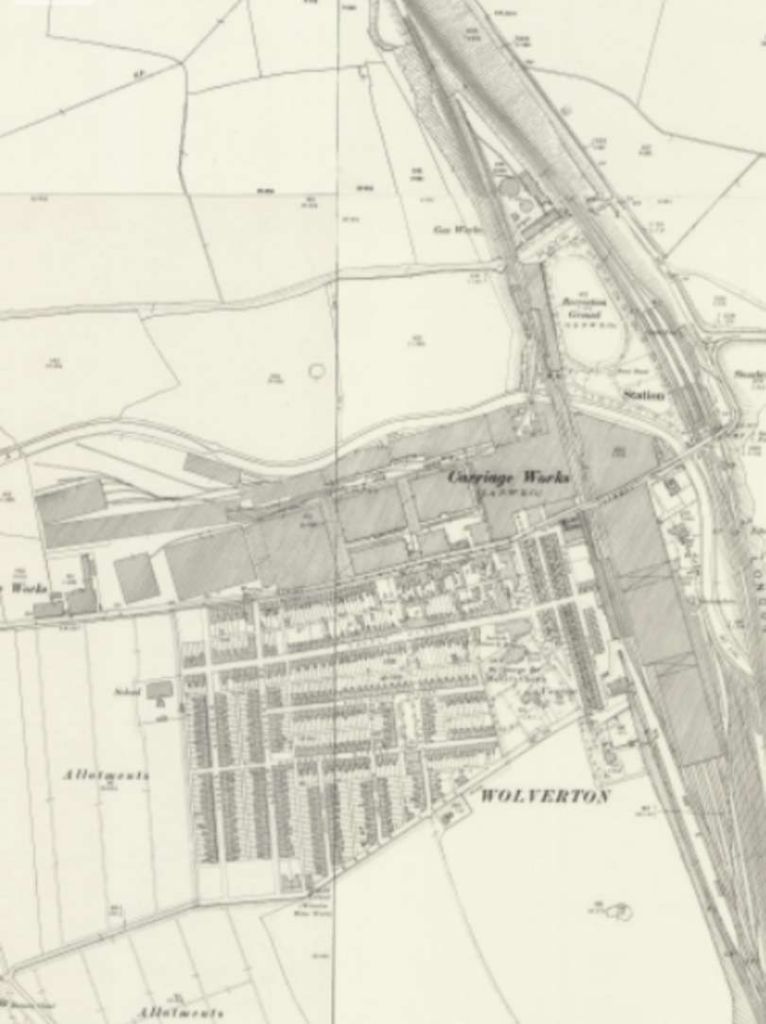
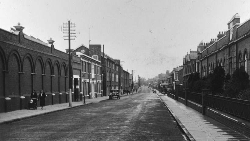
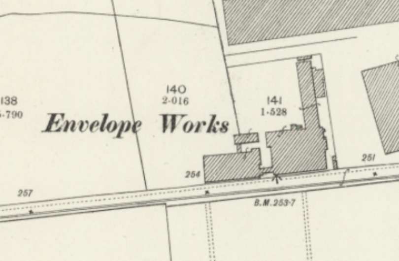

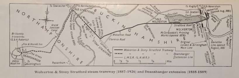
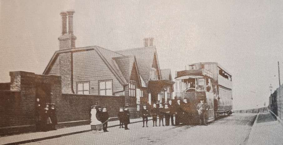
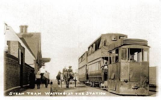
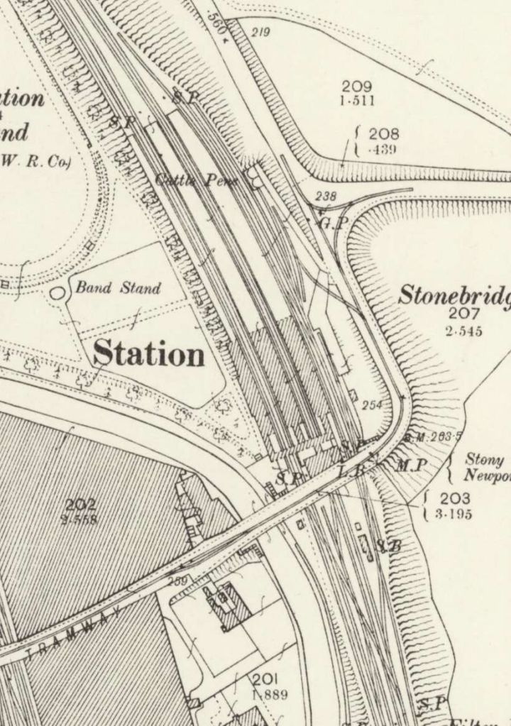
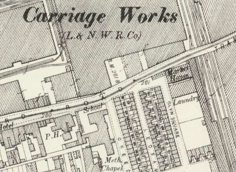
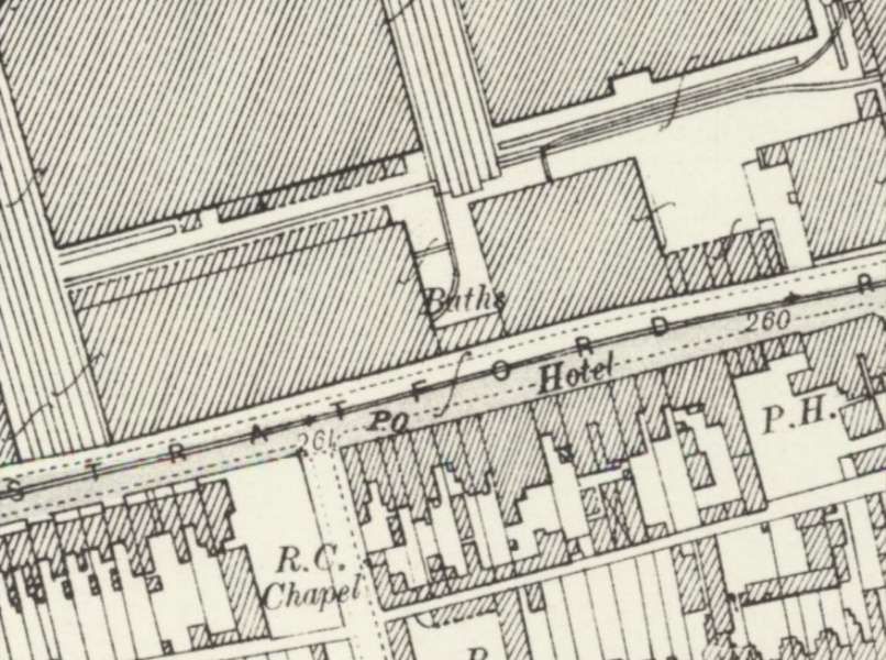
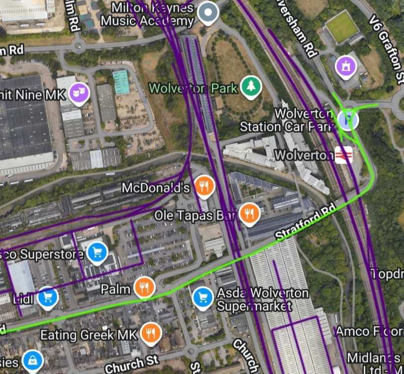
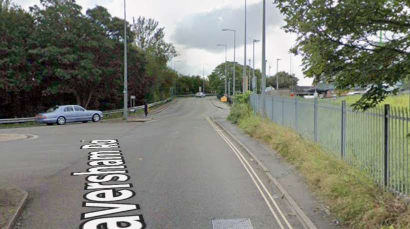
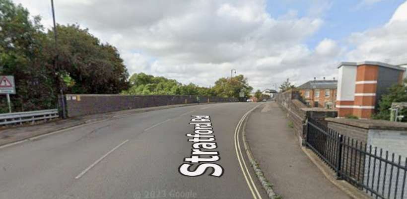

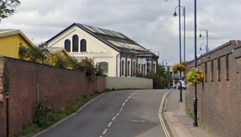
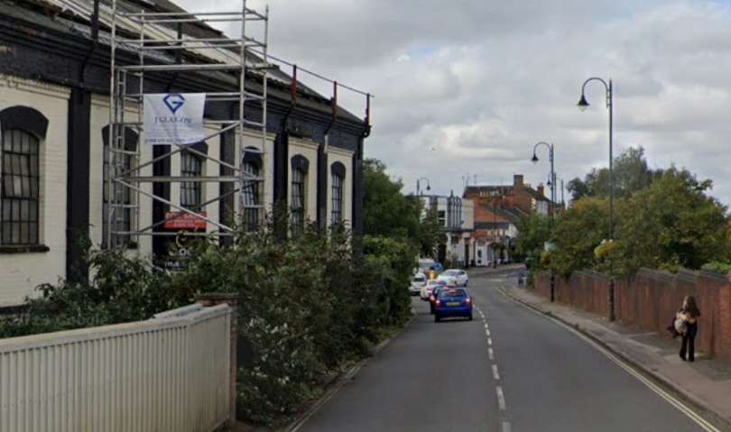
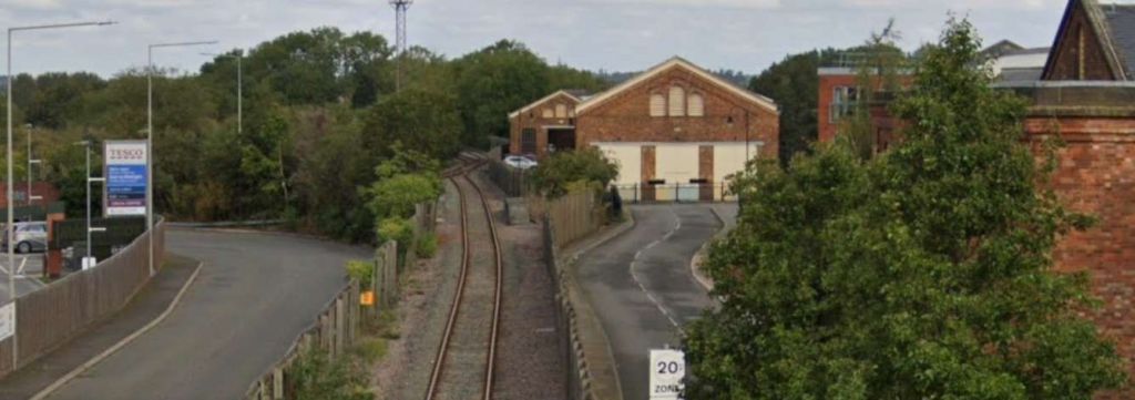
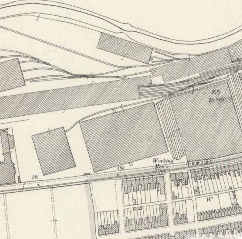
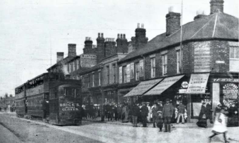
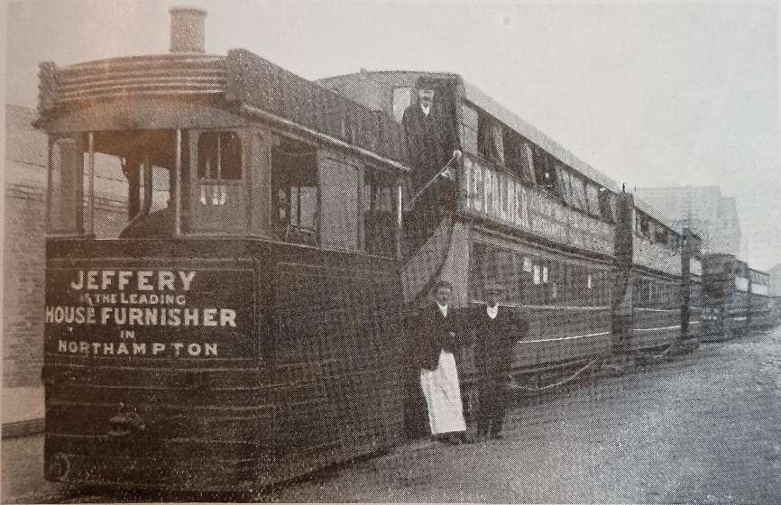
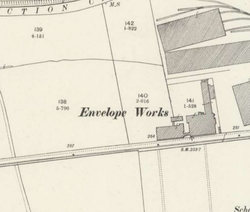
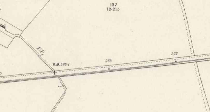
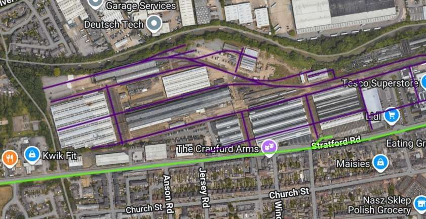
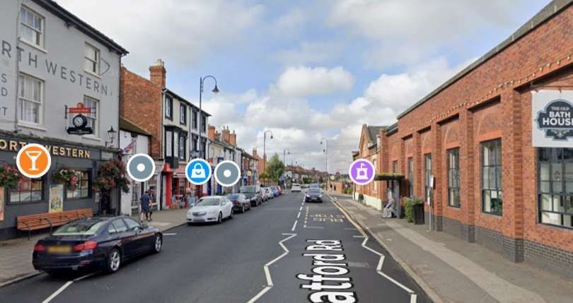
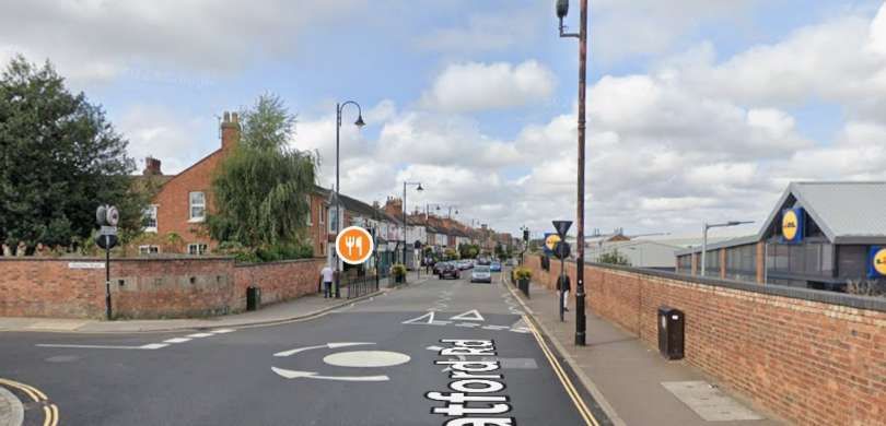
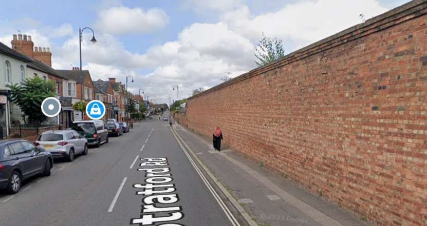
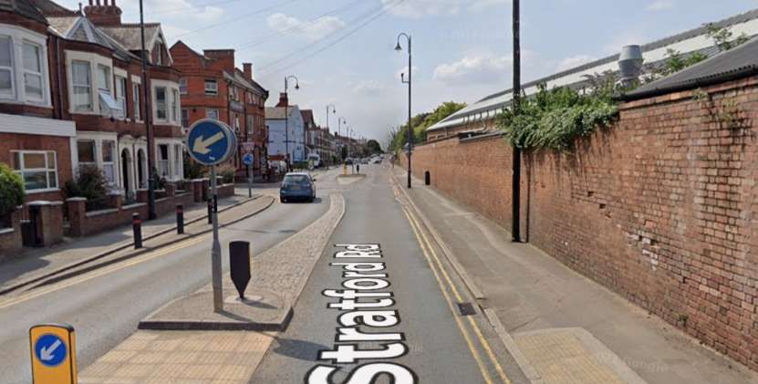
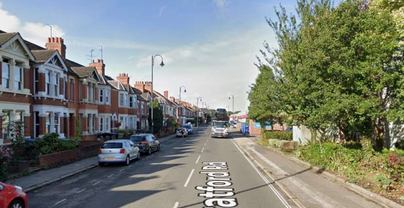
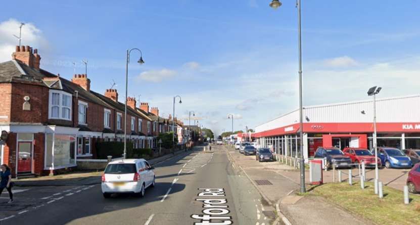
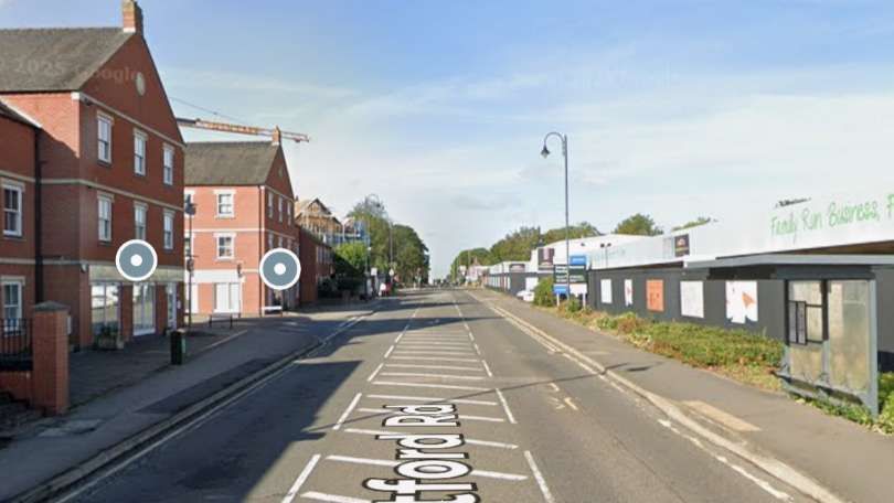
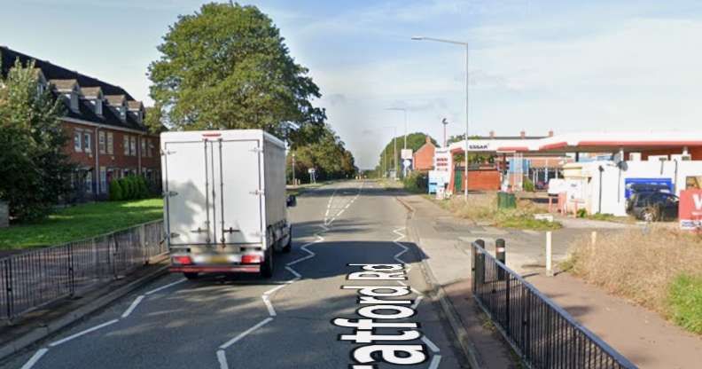
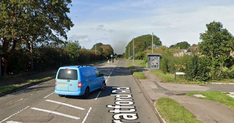
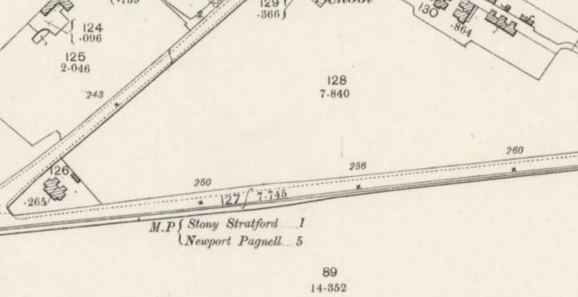
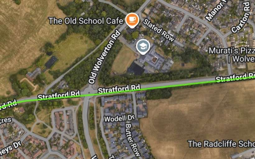
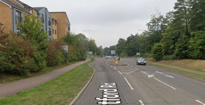
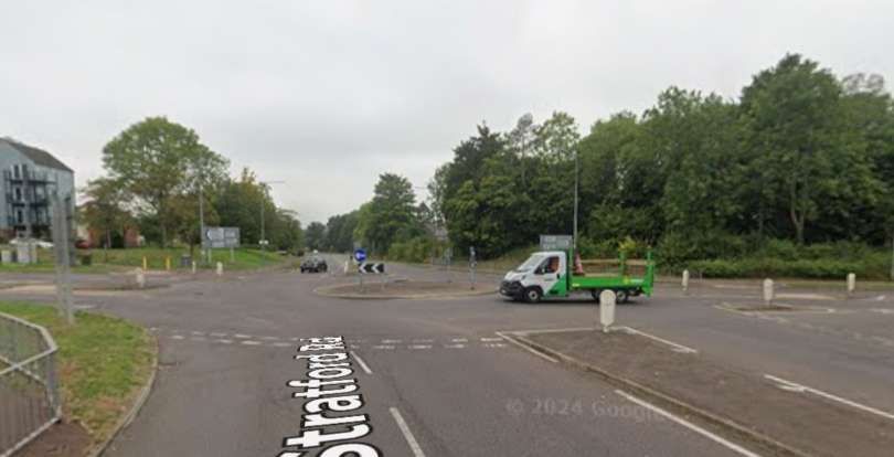
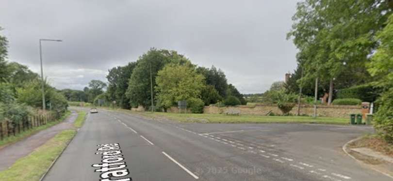
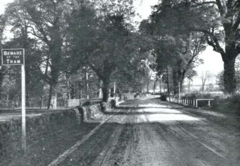
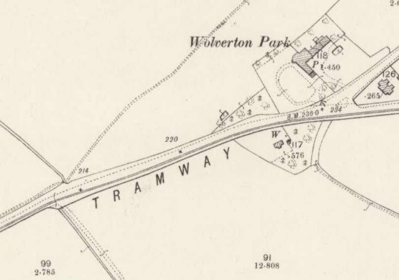
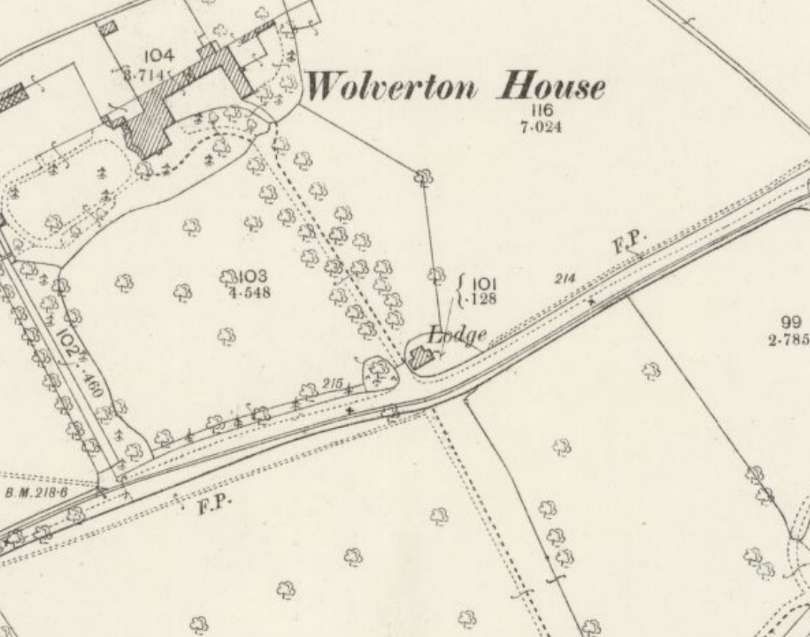
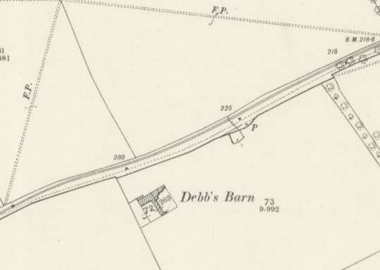
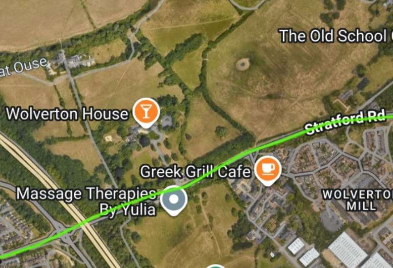
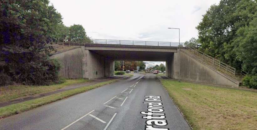
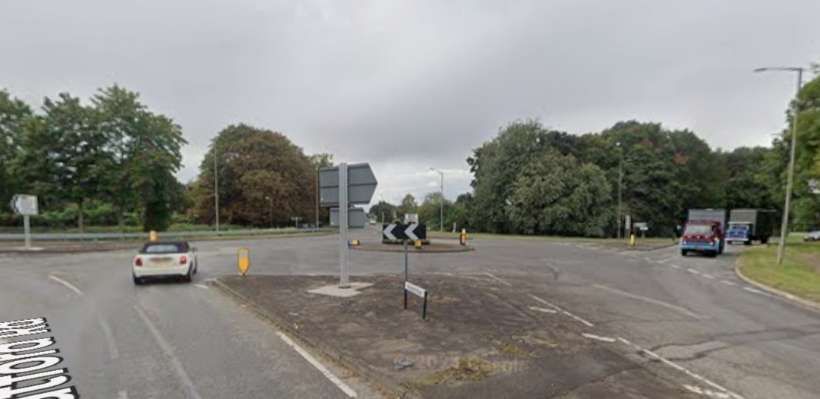
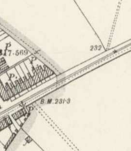

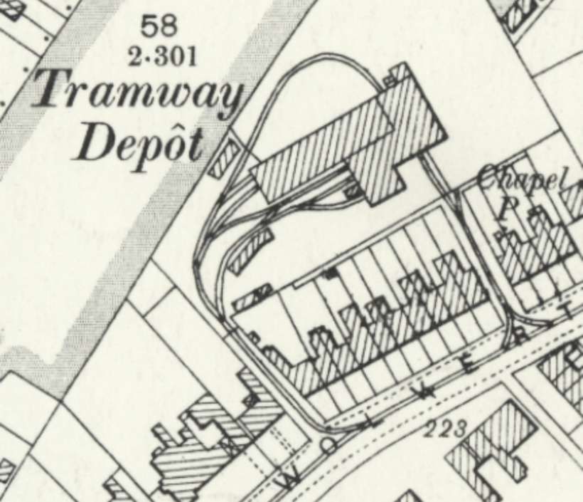
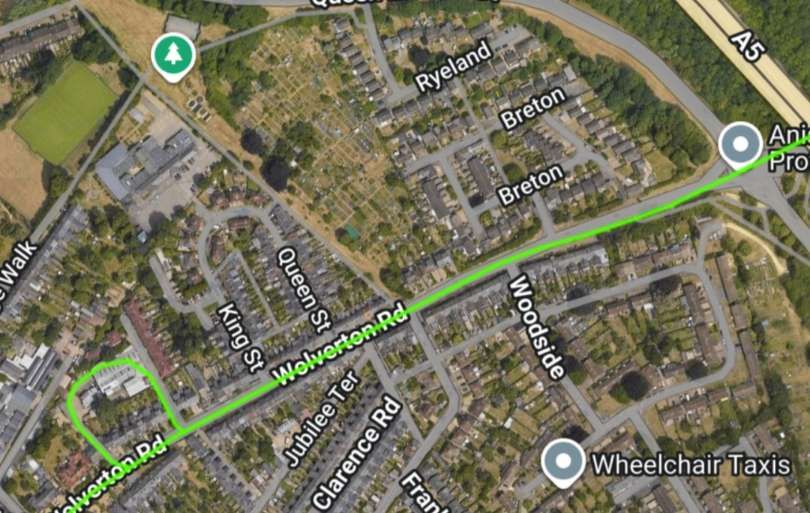

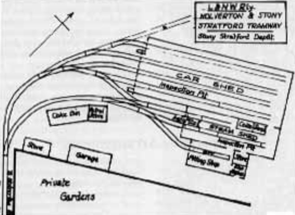
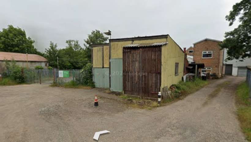
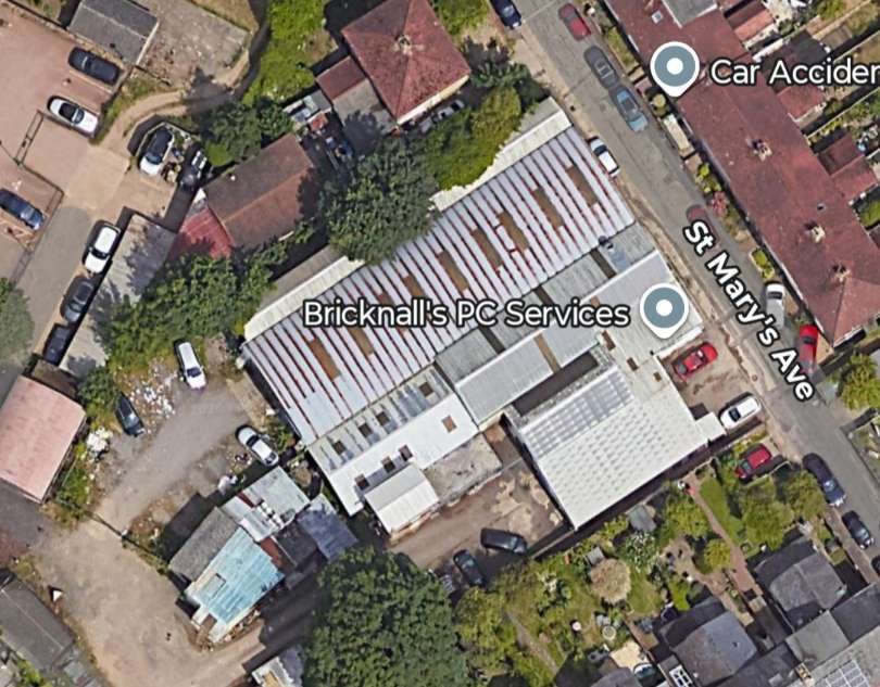
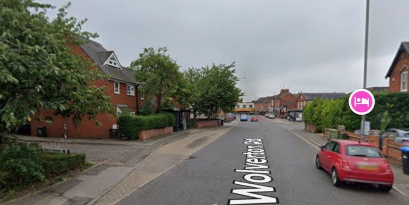
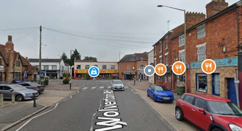
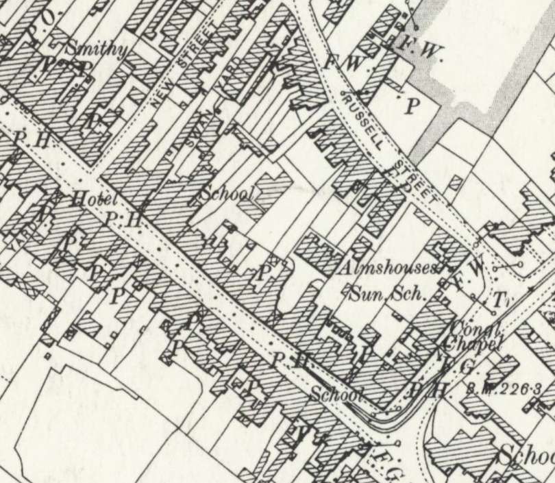
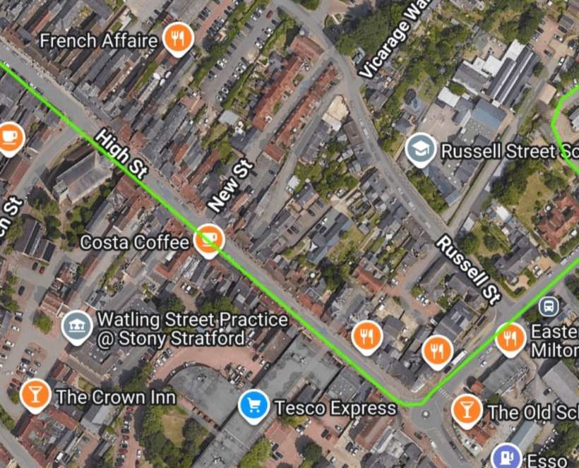
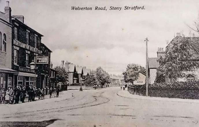
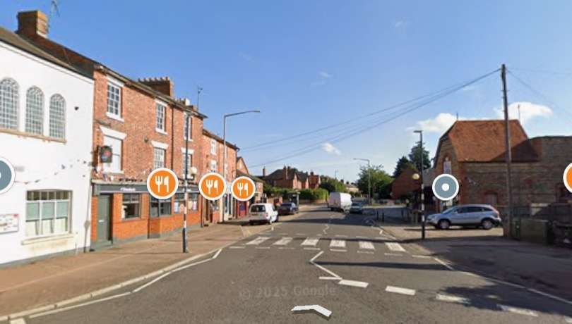
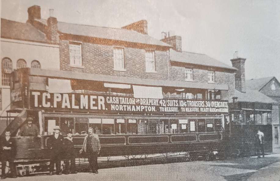
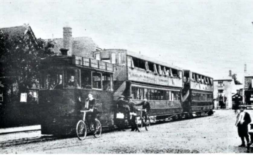
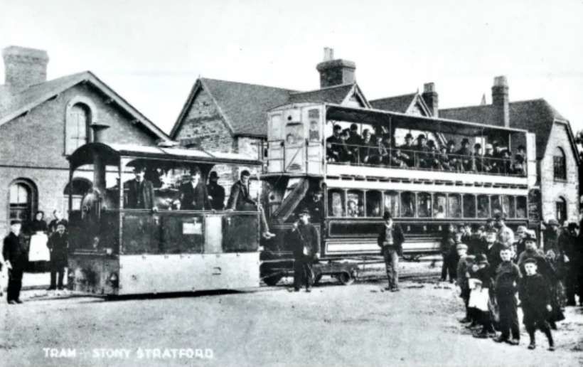
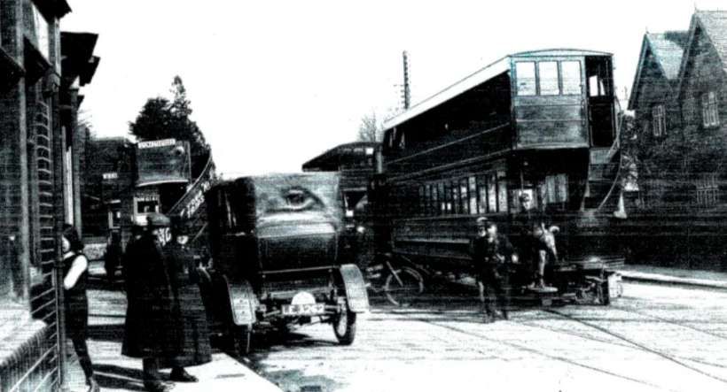
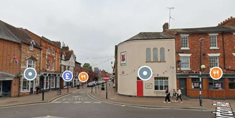
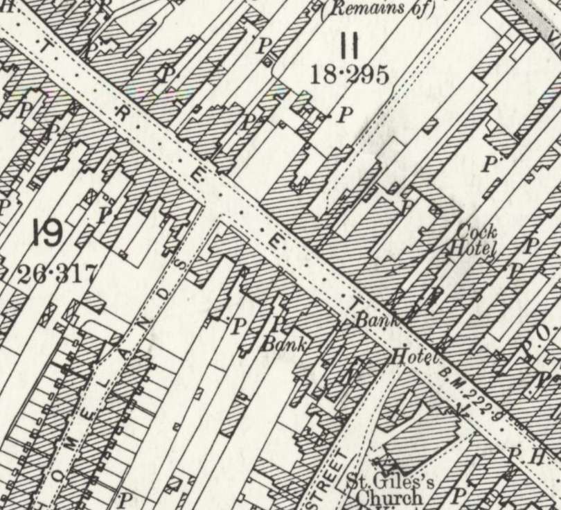
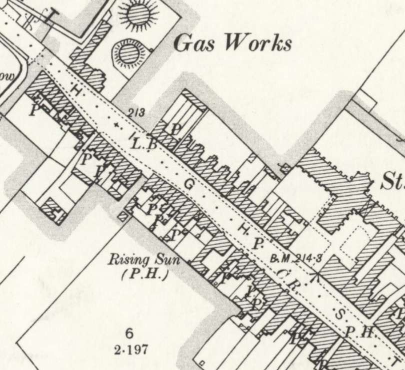
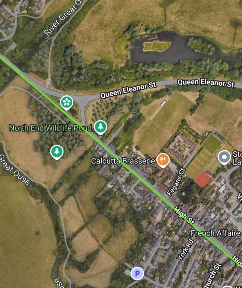
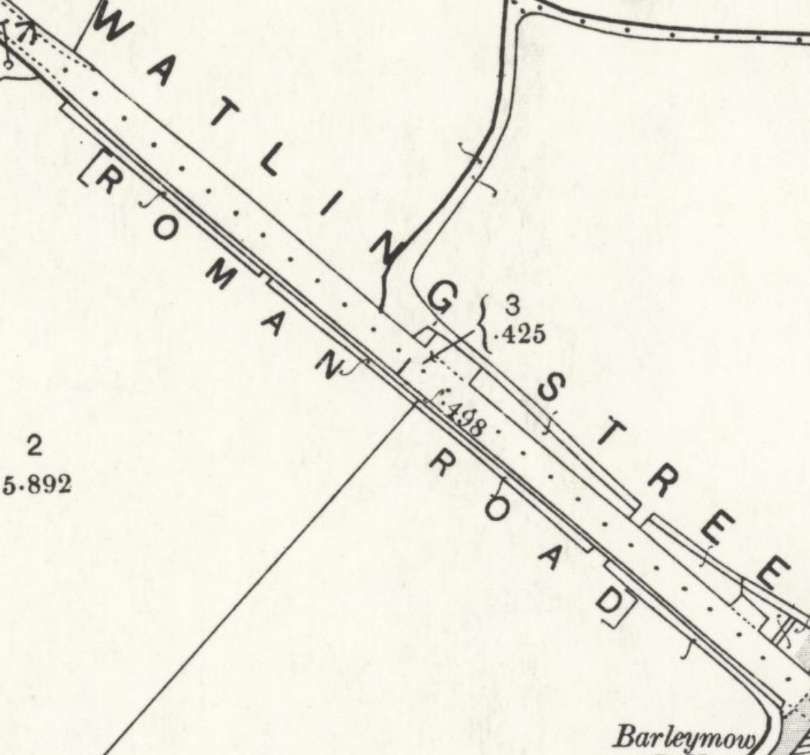
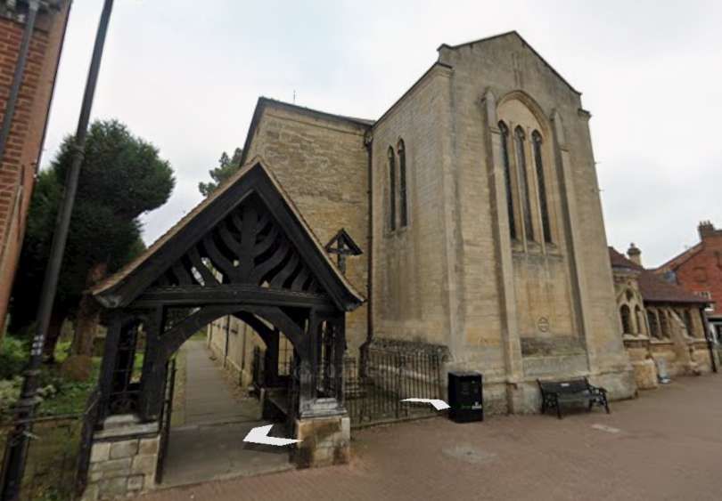
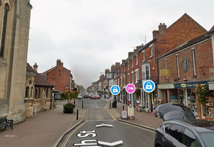
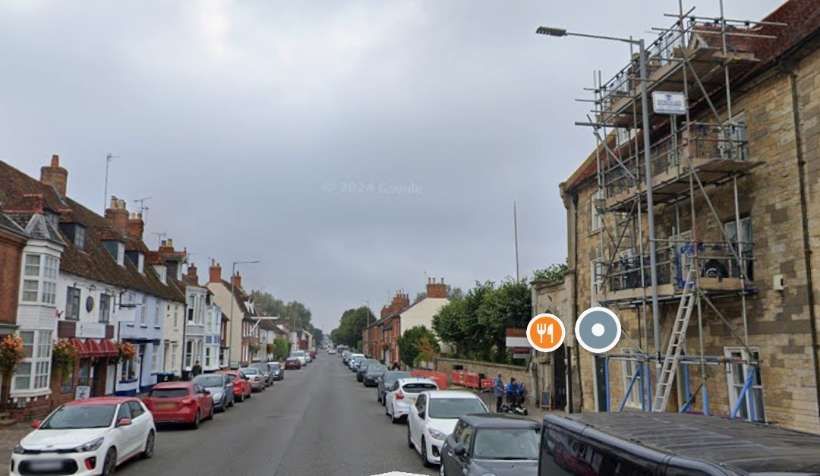

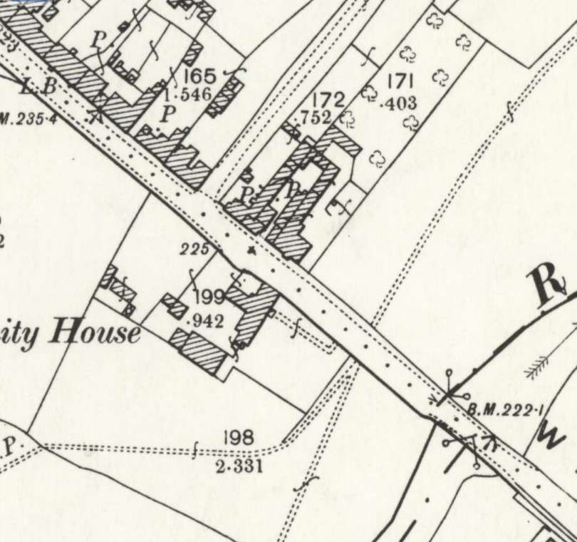
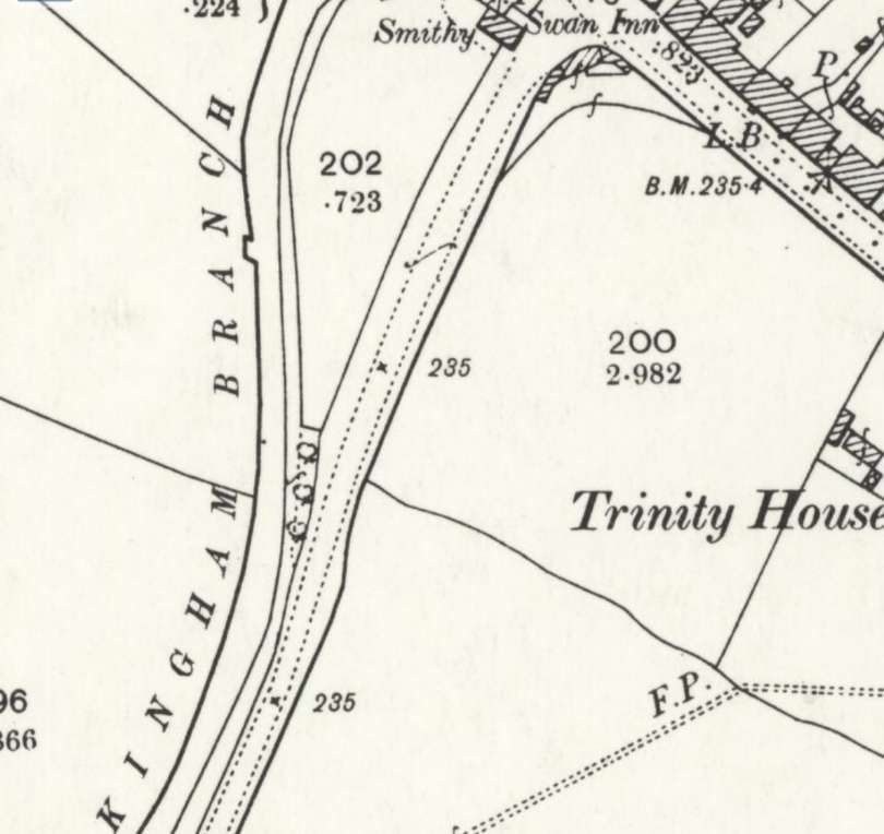
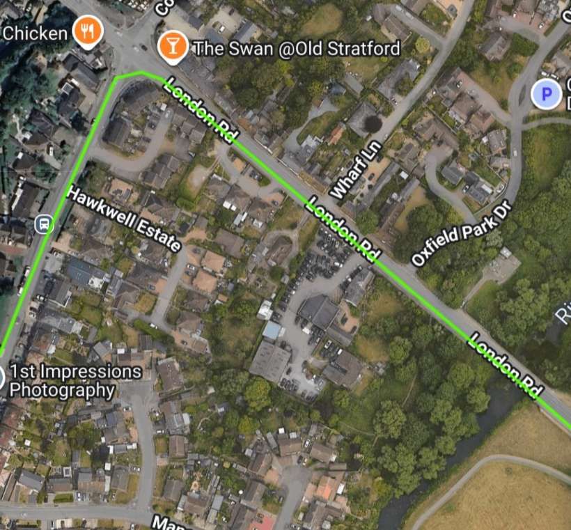
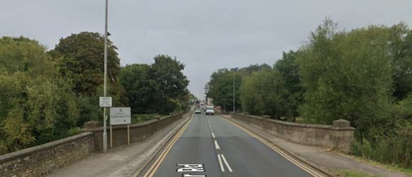
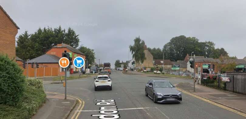
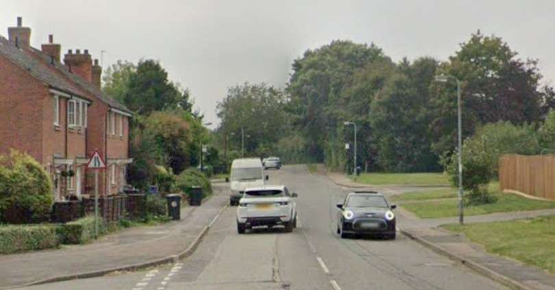
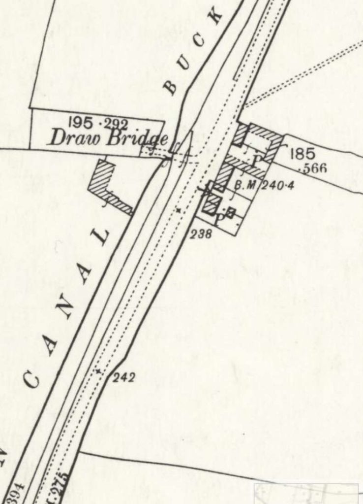
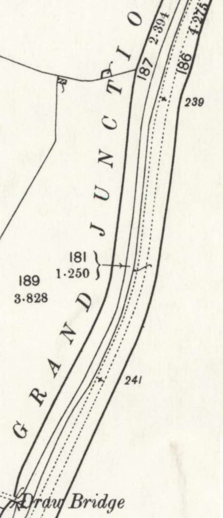
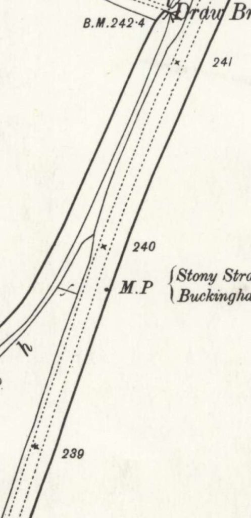
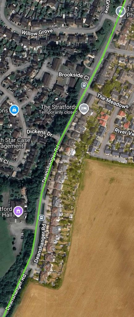
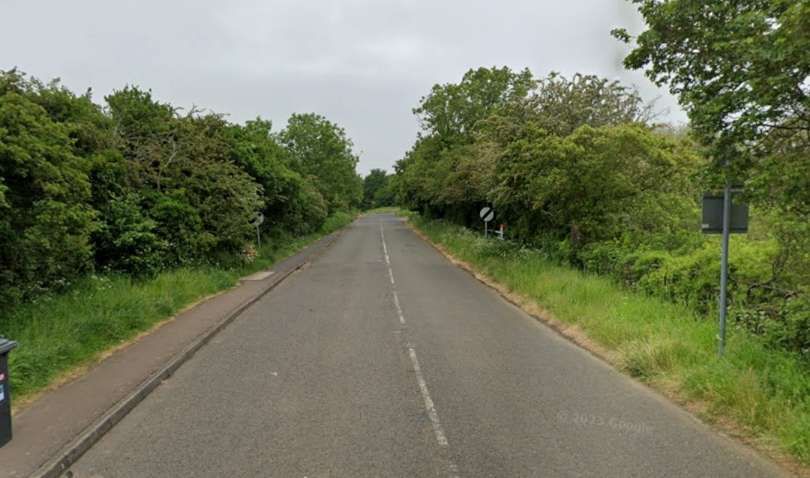
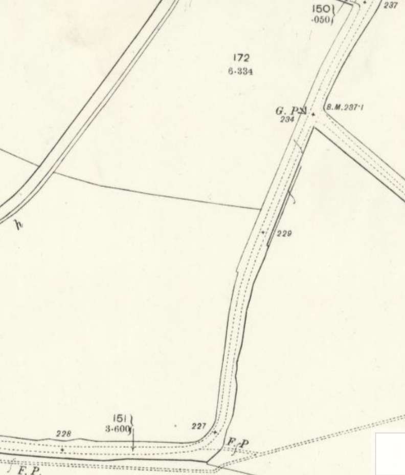
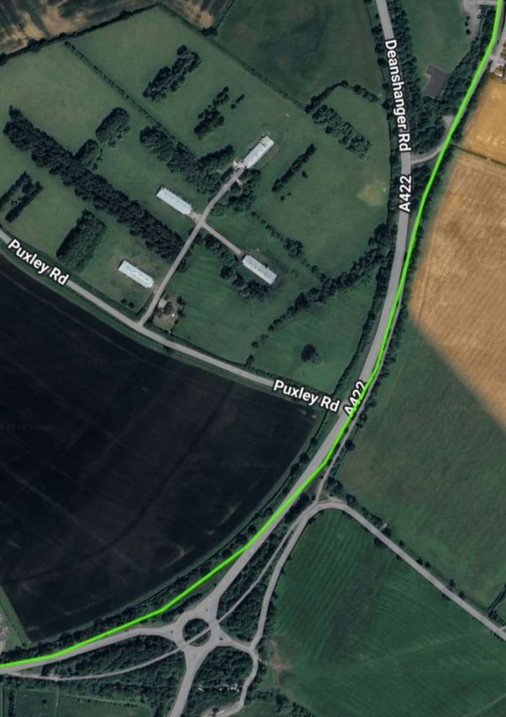
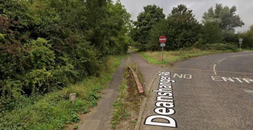

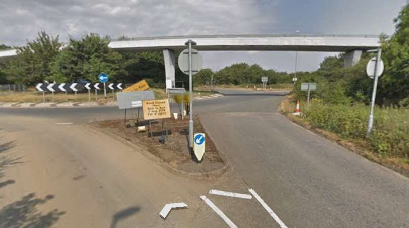
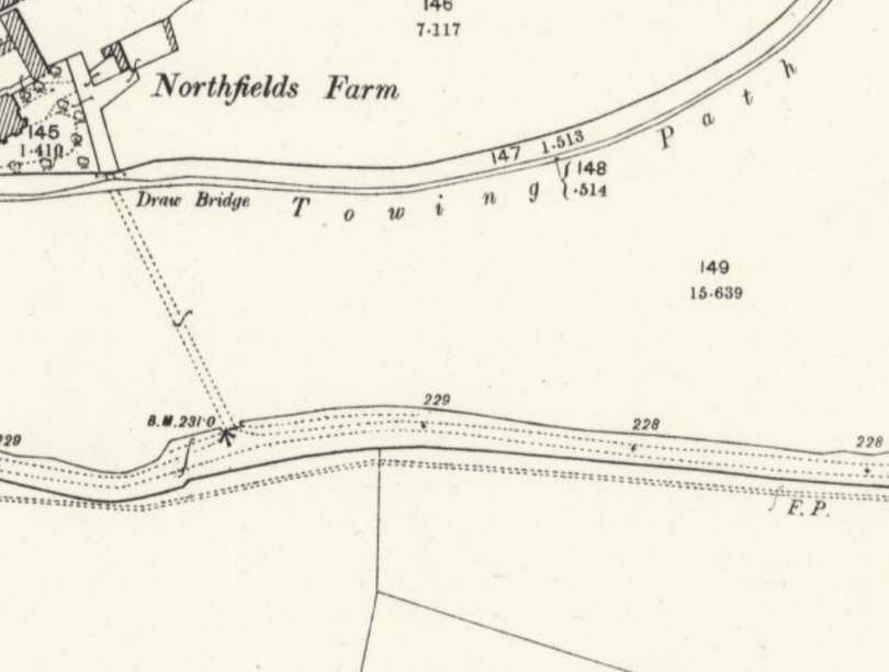
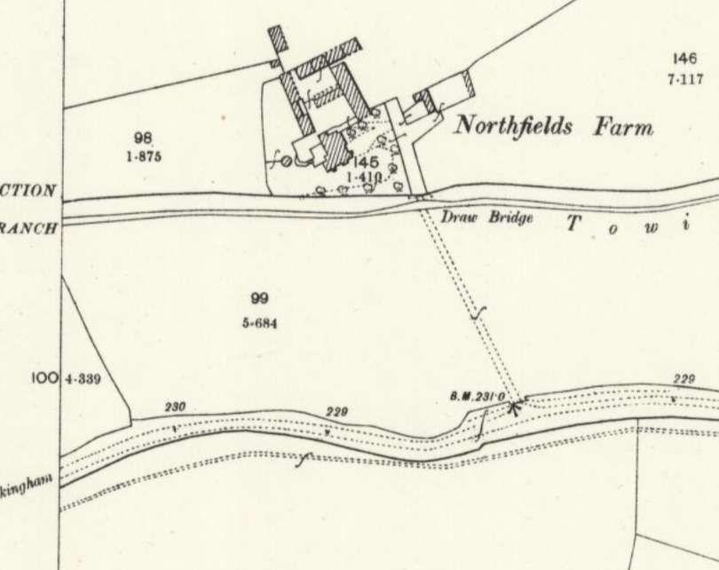
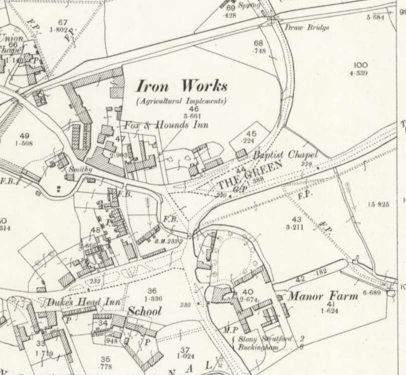
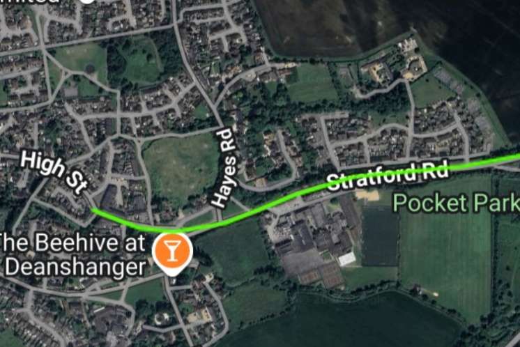
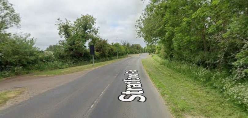
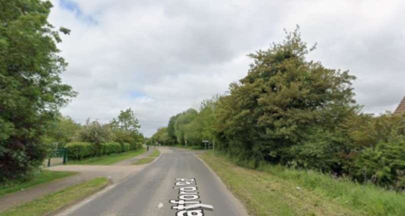
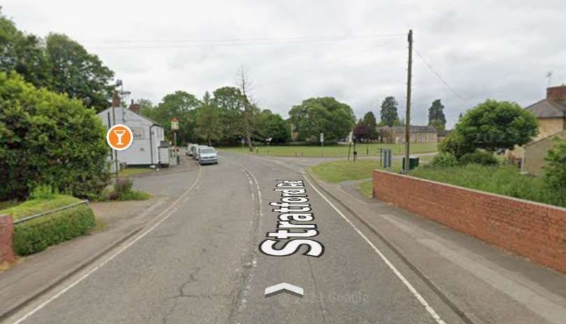
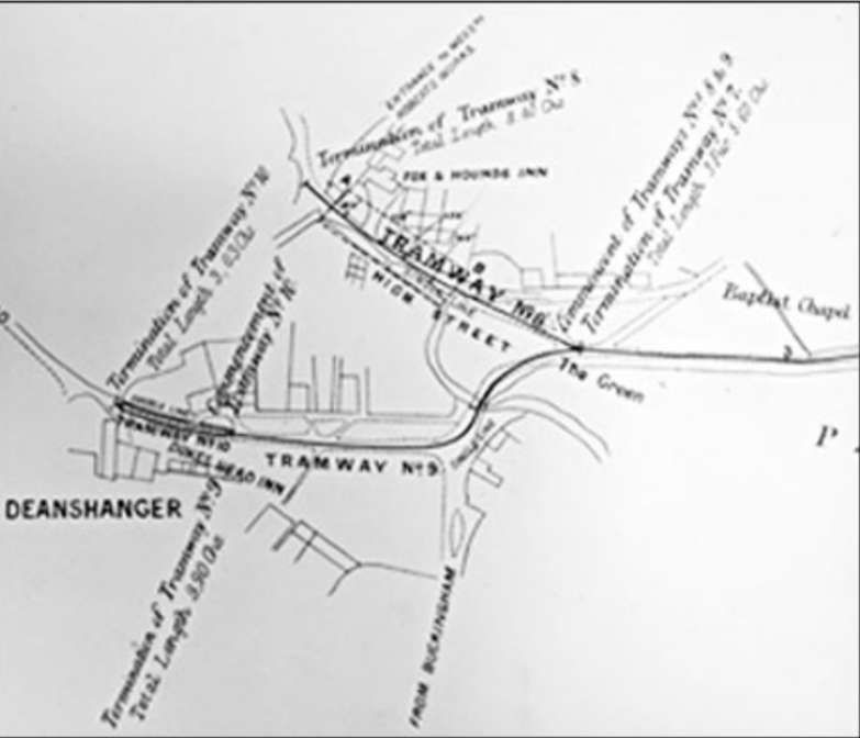
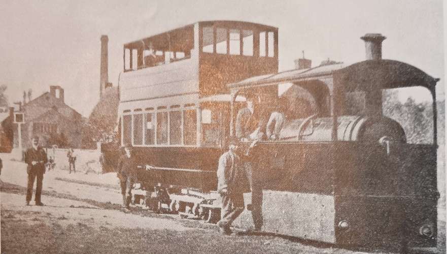
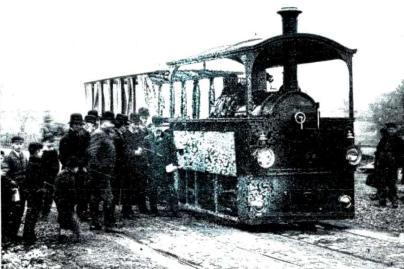
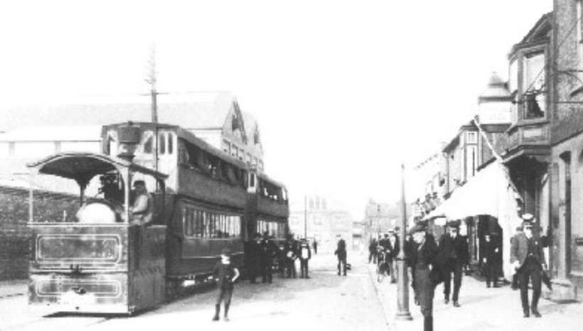
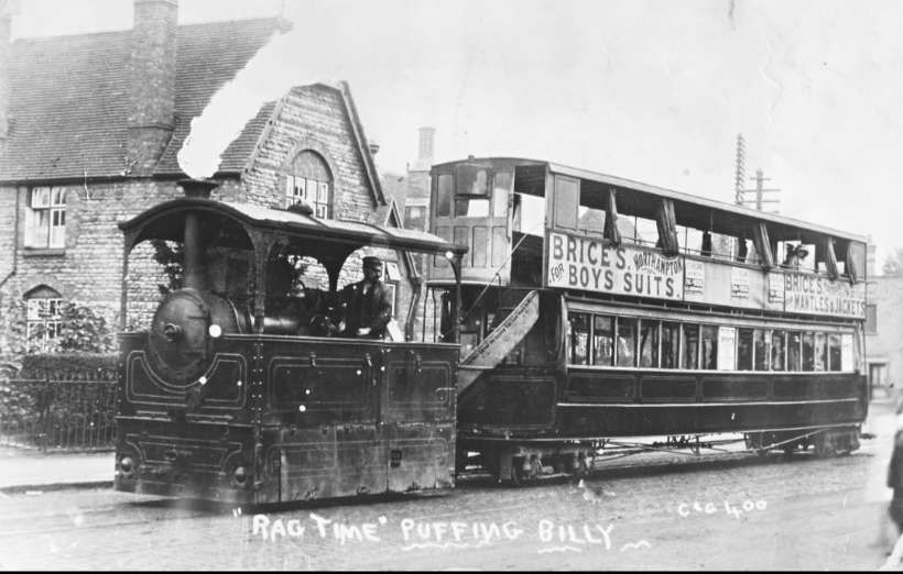
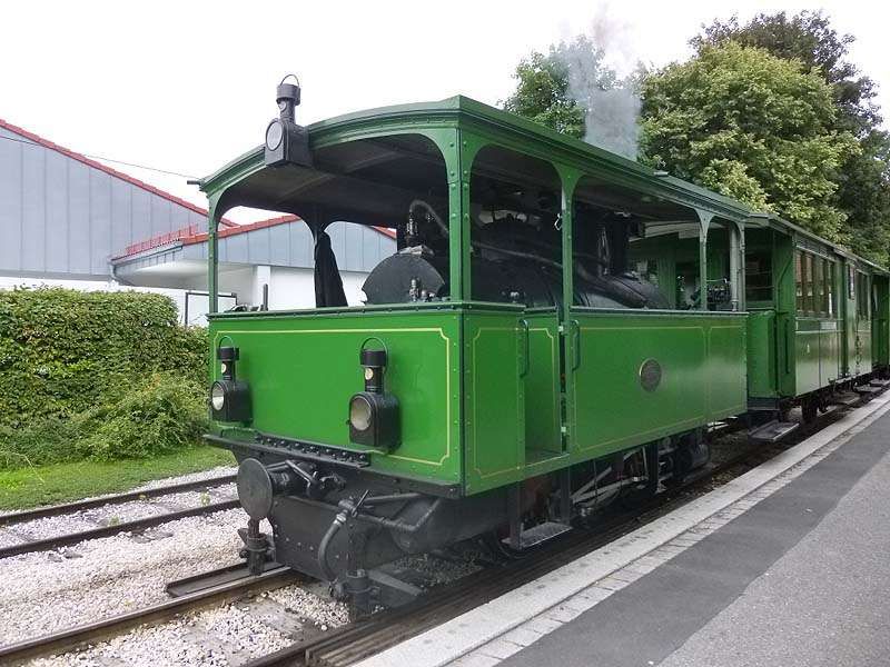
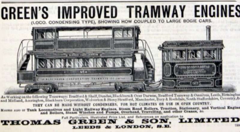
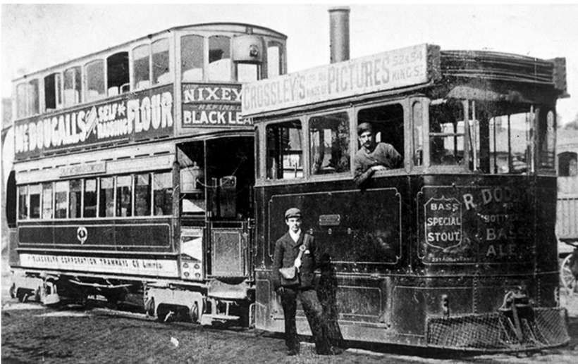
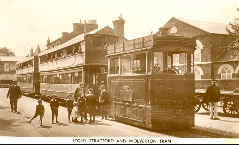
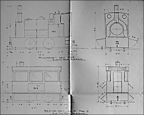
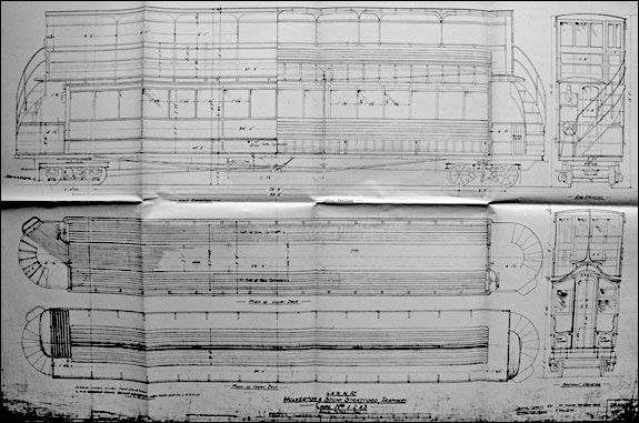
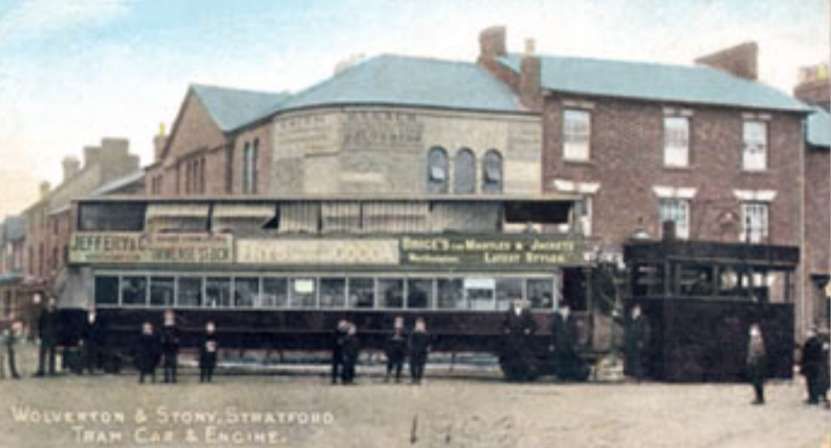
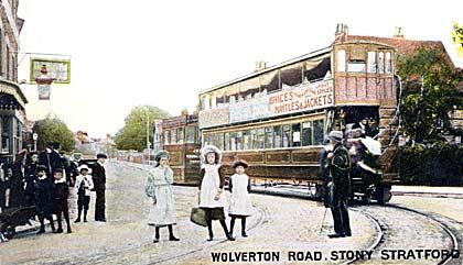
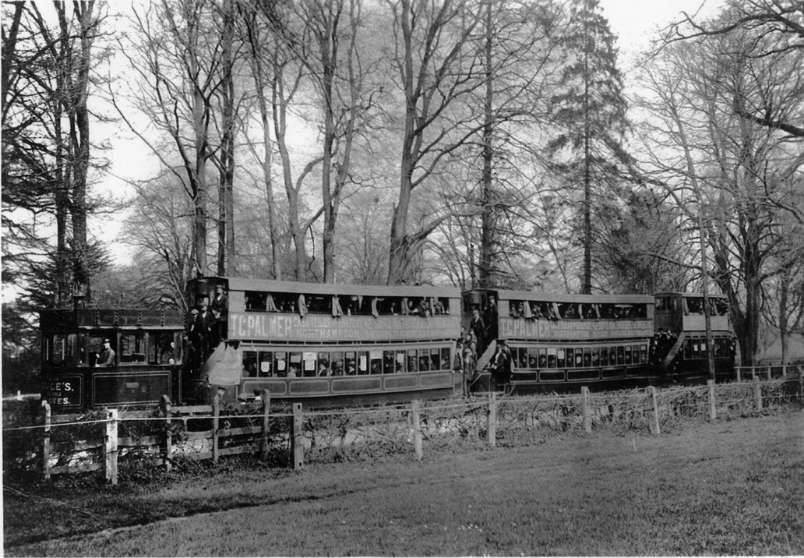
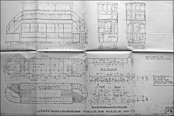
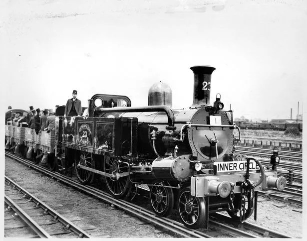
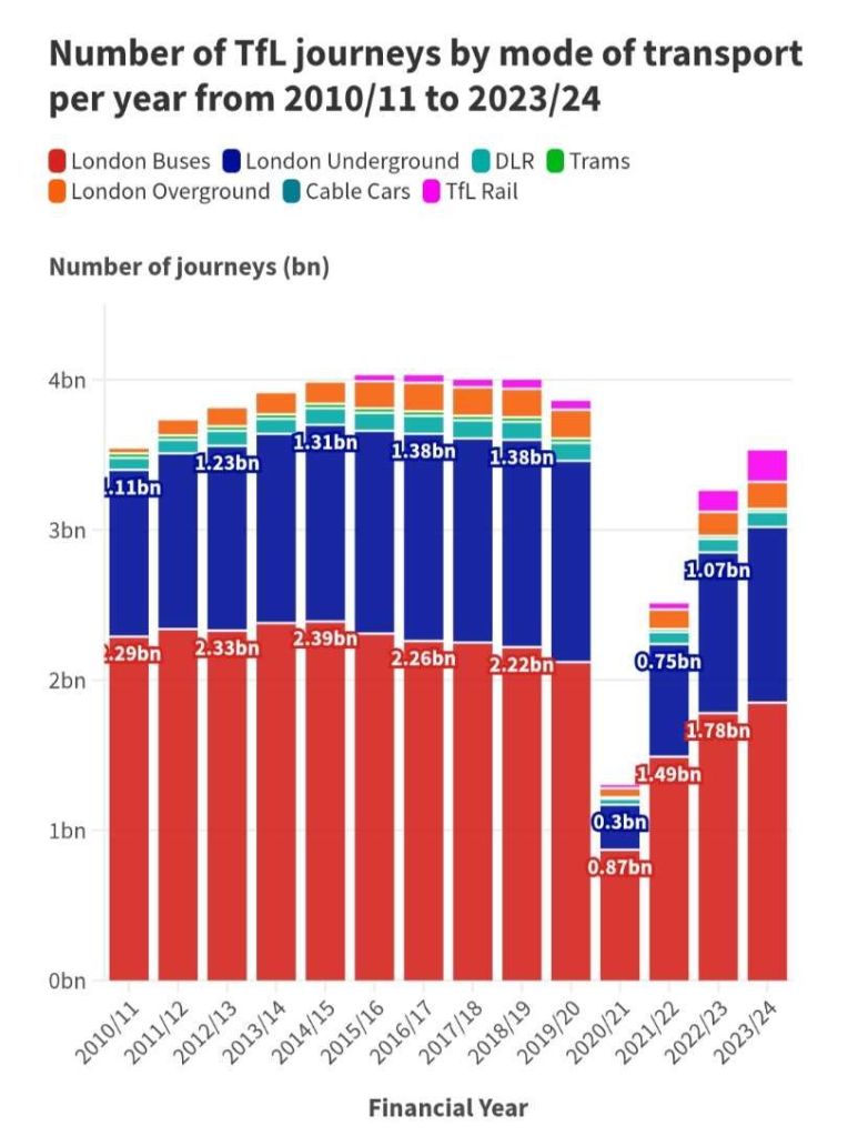
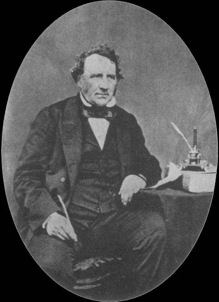
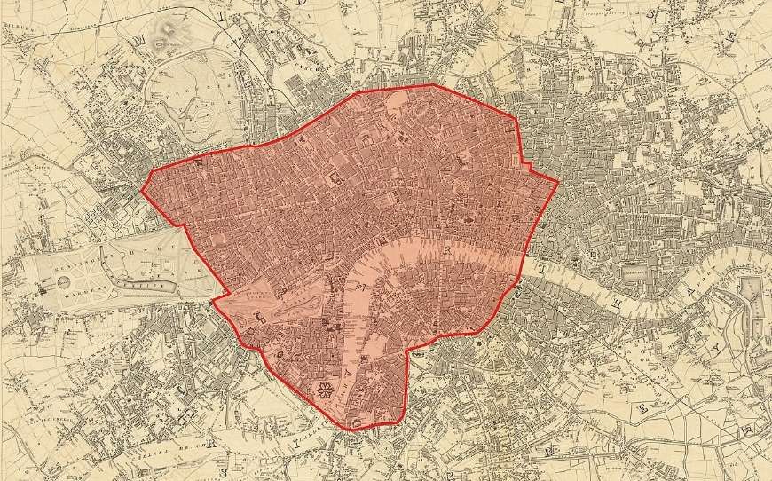
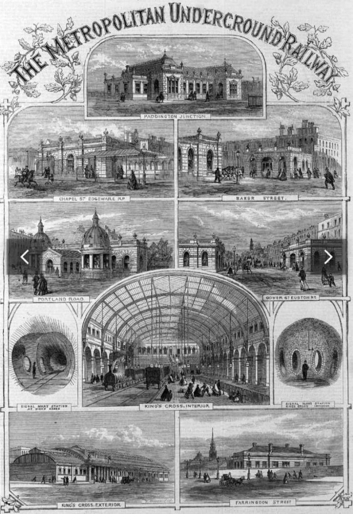
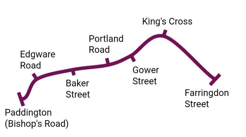
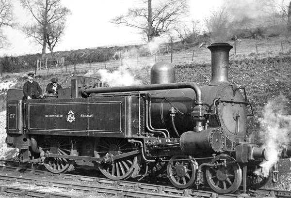
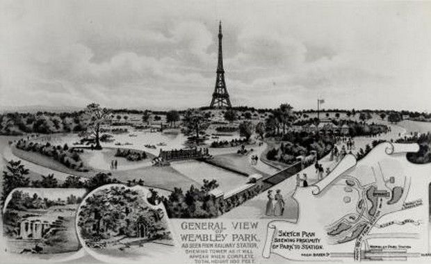
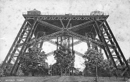
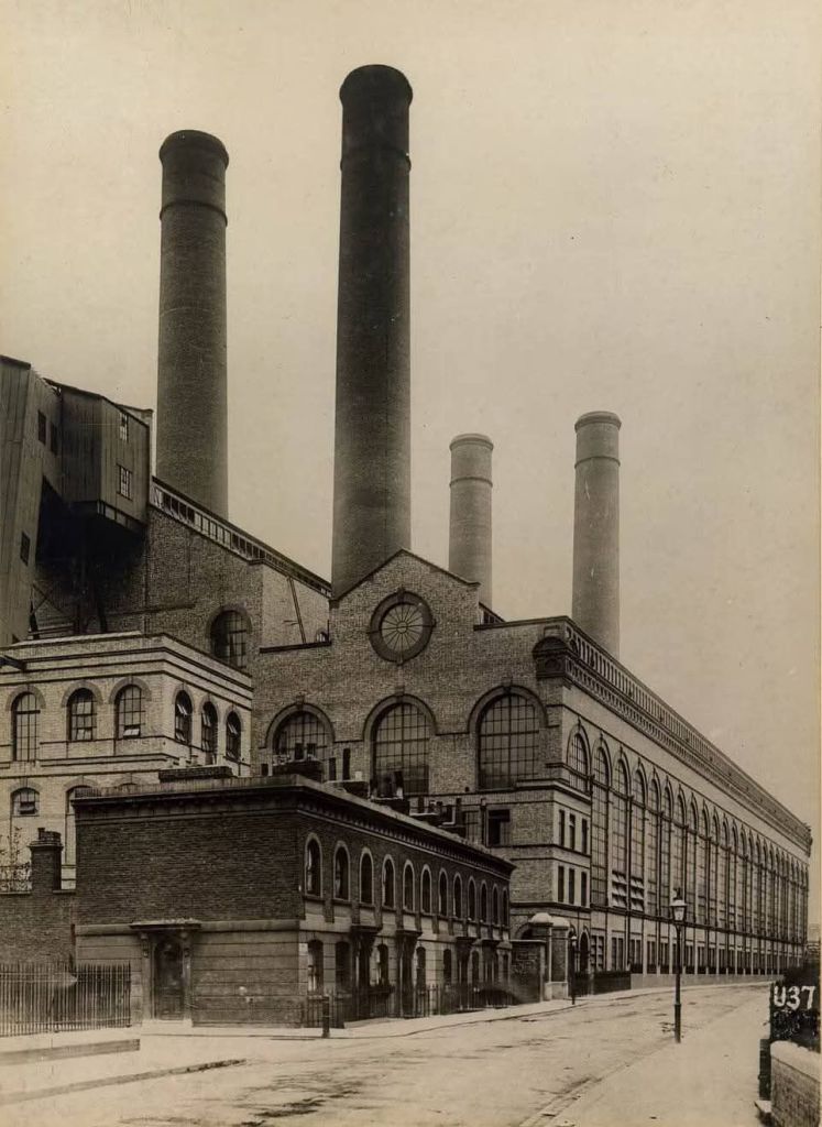
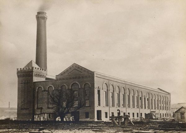
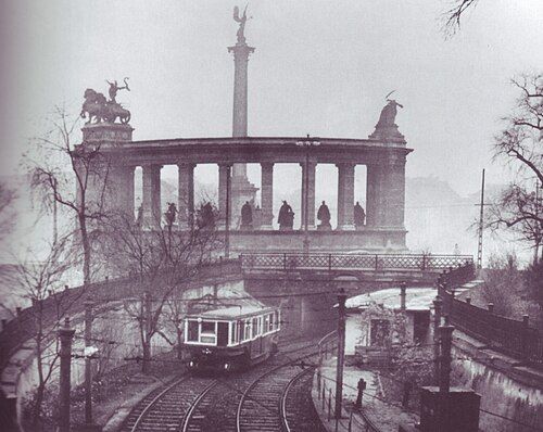
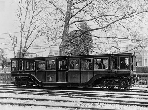
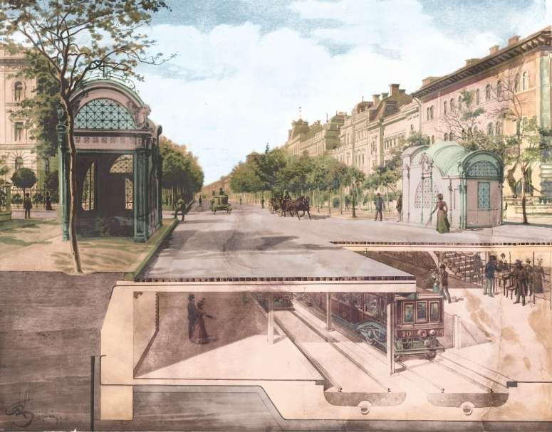
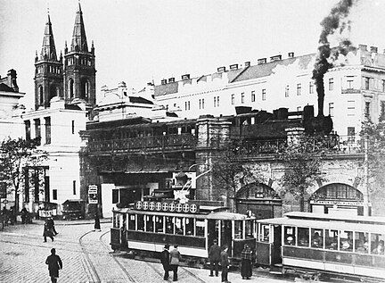
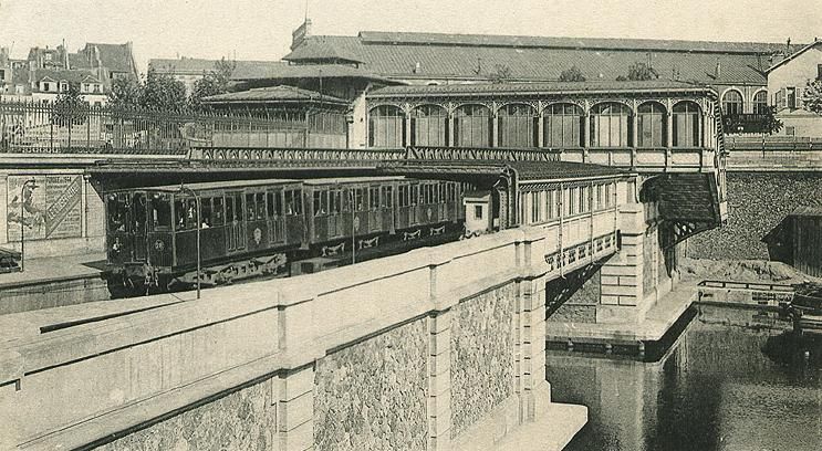
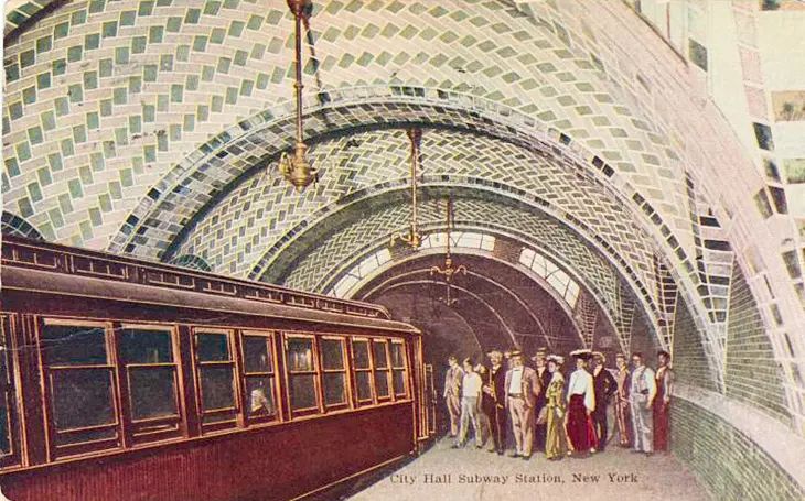
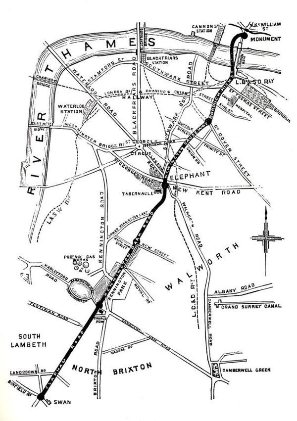
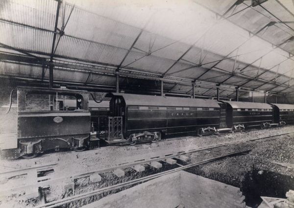
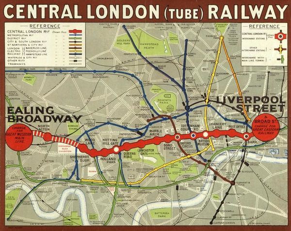
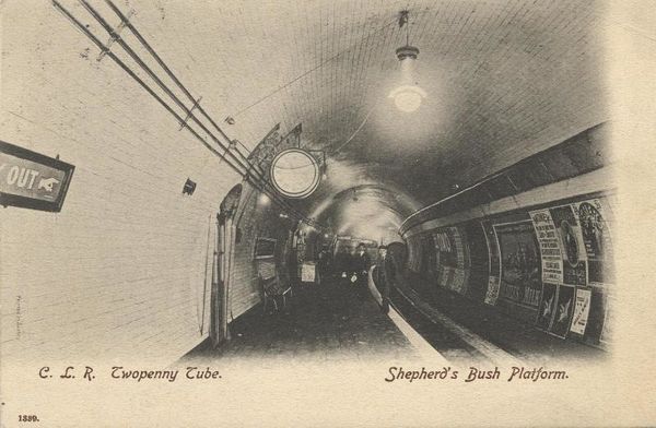
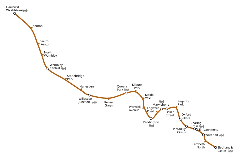
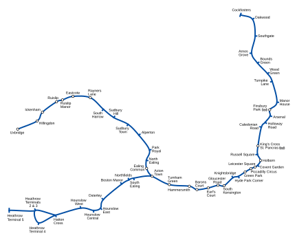
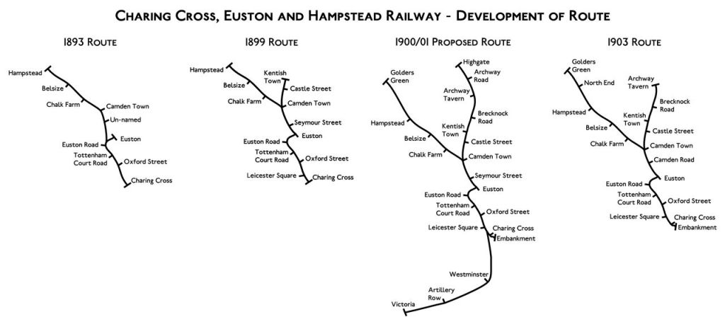
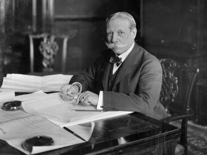
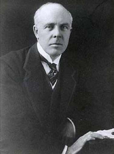
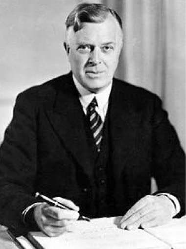
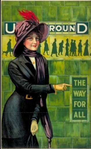
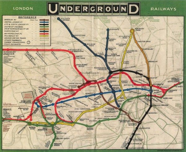
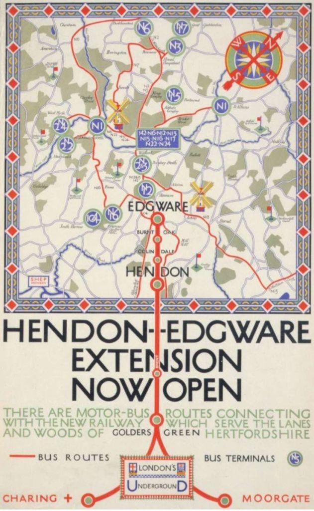
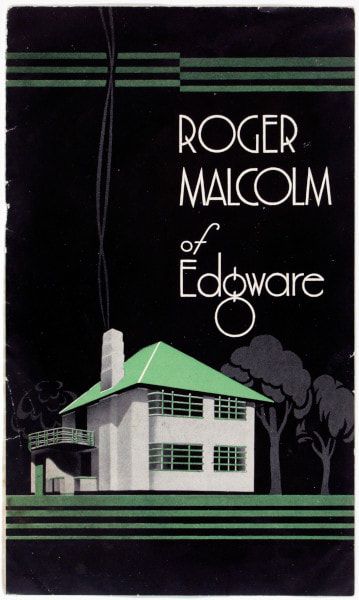
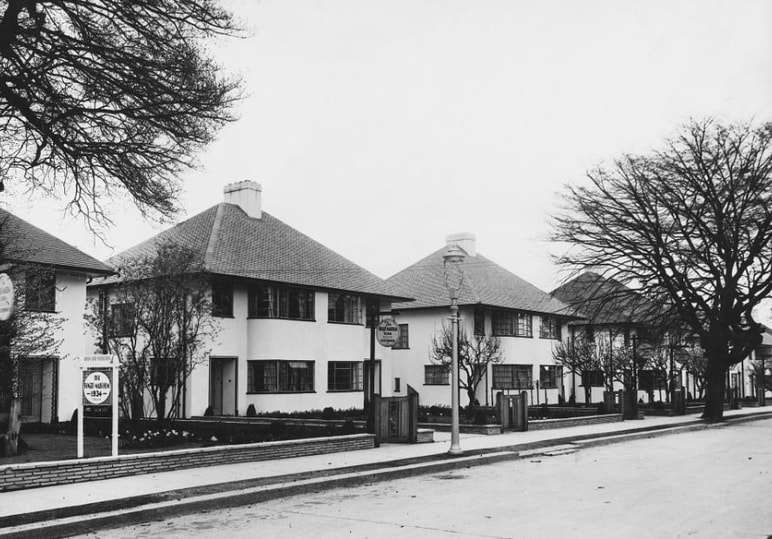
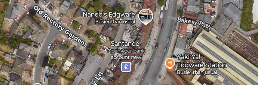
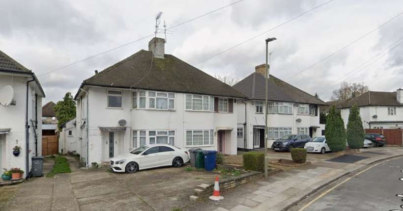
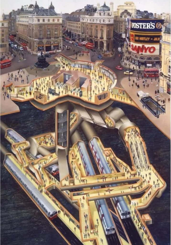
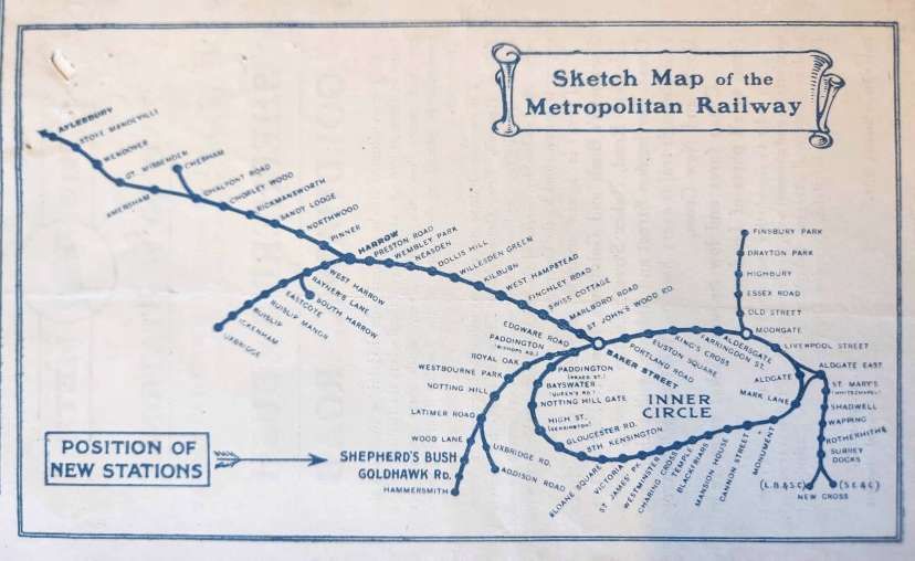
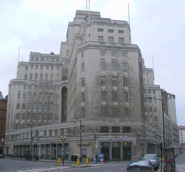
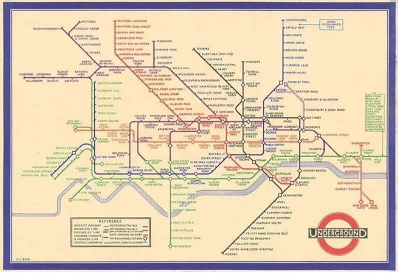
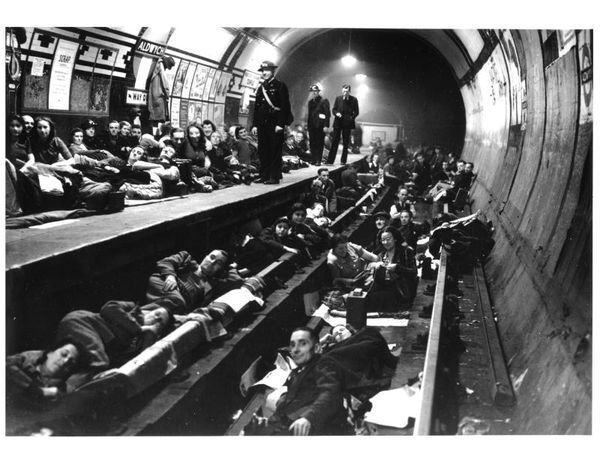
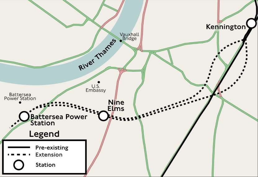
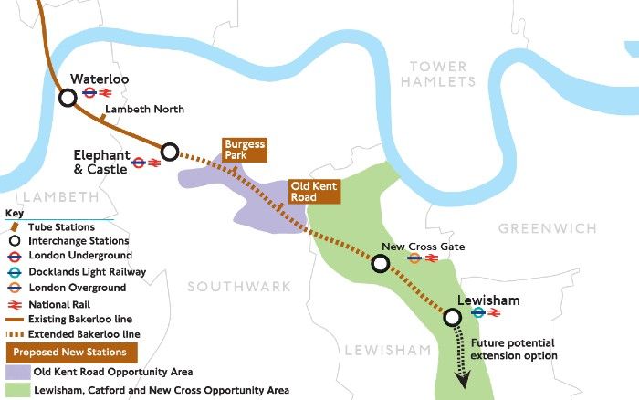
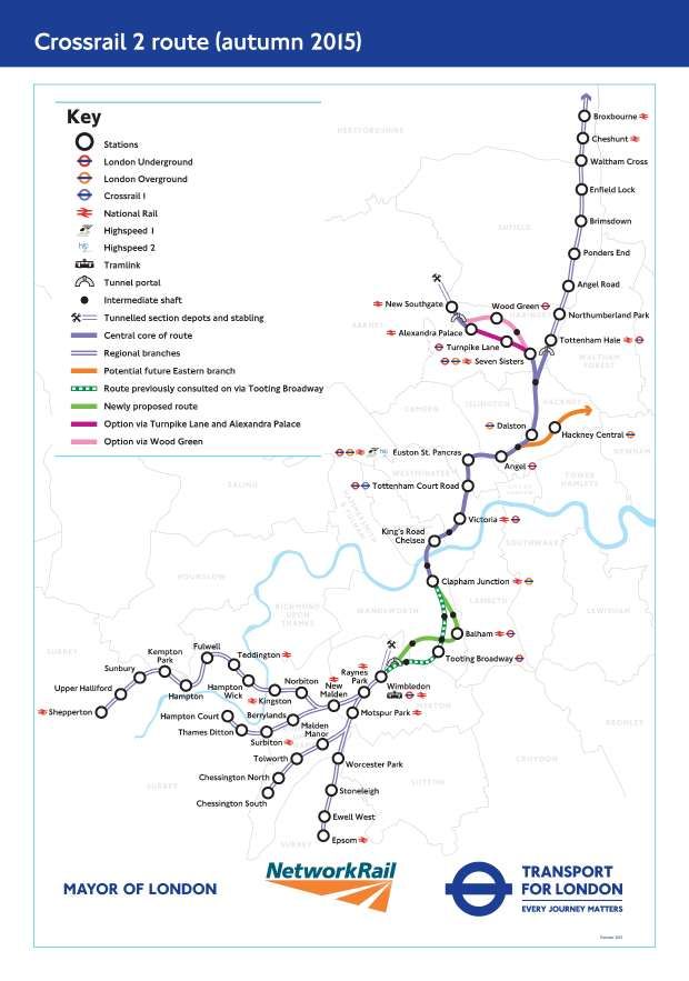

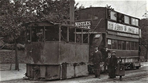