The featured image above shows an unidentified steam locomotive crossing the highly unusual Viaduc de Bevera. The train is heading toward Sospel.
In the first five articles about the line from Cuneo to the sea we covered the length of the line from Cuneo to Breil-sur-Roya and then to Ventimiglia. These articles can be found here, [9] here [10] here, [11] here, [12] and here [13]
I want to acknowledge that a series of stills from a video of the train journey from Breil-sur-Roya to Nice have been used in this article. The video can be seen here. [4]
This article begins the journey from Breil-sur-Roya to Nice.
South of Breil-sur-Roya a junction allows direct access to Ventimiglia and to Nice. The map below shows the two routes as they existed prior to the alteration of the border between France and Italy after the Second World War.
The lines Nice to Tende and Ventimiglia to Tende in the period from 1928 to the Second World War, before the annexation, in 1947, of St-Dalmas de Tende and Piene to France. [40]
The project was finally agreed by the PLM on 7th January 1907 but various portions of the work would be delayed by disputes relating to the transfer of land. “Acquisitions began in the suburbs of Nice in May 1907, at Saint-Roch … and Roccabiliera, where the PLM had decided to build a vast facility with a goods station, marshalling yard and engine depot to relieve congestion at Nice central station, whose rights of way, enclosed in the urban fabric, could no longer expand. This program for the redesign of Nice’s railway facilities also provided for a 3,610 m connection between the new Saint-Roch station, Riquier station and the port. In the hinterland, events also began to take shape and in December 1908, a section of engineers set up in Fontan and undertook the first work along the Roya the following January.” [1: p90]
Banaudo et al continue: “In 1909, Chief Engineer Paul Séjourné (1851-1939), then fifty-eight years old and already renowned for his original designs for civil engineering structures, took over the direction of the construction department. The line from Nice to the Italian border would give him the opportunity to exercise his talent in the design of structures that were as daring as they were harmoniously integrated into the landscape.” [1: p90]
In this series of articles, we have already seen Séjourné‘s Scarassoui Viaduct spanning La Roya to the North of Breil-sur-Roya.
The line from Breil-sur-Roya to l’Escarene. [
This article follows the line South from Breil-sur-Roya to l’Escarene in two parts. The first from Breil to Sospel and the second from Sospel to l’Escarene.
1. The Line South from Breil-sur Royato Sospel
Banaudo et al tell us that, “In December 1912, tranches 8 and 9 were awarded in turn for a length of 10,500 m from Sospel to Breil to the François Mercier company, of Moulins-sur-Allier. The work included three tunnels with a combined length of 5,307 m, including the Mont Grazian and Caranca structures established at double-track gauge and equipped with defensive devices, as well as seven bridges and viaducts representing twenty-five masonry arches and two metal spans. Among them, the exceptional structure of the Bévéra viaduct. There were also three culverts and three level crossings in this section.” [1: p102-103]
Banaudo et al take up a significant part of Volume 1 of the story of the line with an album of photographs of the construction work on the French side of the border. [2: p152-331] A superb record of the work undertaken.
On the Sospel-Breil section of the line the contract works were gradually completed. By the end of 1921, the Bancao and Caranca tunnels were completed. The Mont Grazian tunnel was finished in 1923. The Bévéra viaduct’s abutments and masonry arch were ready by then and only awaited the delivery of the metalwork of the decking. [1: p141]
The length of the lien from Breil-sur-Roya (top-right) to l’Escarene (bottom-left). [8]
This drawing/map shows the two routes heading South from Breil-sur-Roya. [40]
As with the line immediately to the North of Breil-sur-Roya, the works to the South and Southwest were constructed by the French. Both of the lines heading South from Breil-sur-Roya entered tunnels just a short distance South of Breil.
The first length of the line South of Breil-sur-Roya is common with the line to Ventimiglia. The two lines separate at the Lavina bridge.
A colourised postcard view of Breil-Sur Roya Railway Station looking North through the station site in advance of the official opening in 1928. This colourised image was shared on the Stura-Cuneo Facebook Page on 20th February 2020, (c) Public Domain. [29]Breil-sur-Roya station during its very early operation (1928-35), before electrification, with numerous passenger carriages standing idle. The passenger building is in the background; in the foreground are the buildings on the second platform, the only ones today significantly reduced in height and length, publisher Frédéric Laugier, (c) Public Domain. [30]Breil-sur-Roya Railway Station at the height of its development, with electrification completed (1935), with the passenger building, the large freight yard filled with wagons, and the concrete sheds with arched vaults. Those in the background still exist but are used for non-railway purposes. The Breil Ecomuseum is now located on the north side, half-hidden by the foliage of the tree in the foreground. The photograph was taken from the hillside to the Northwest of the station site and faces Southeast, (c) Public Domain. [30]After the war, the line to Nice was reopened in 1947, but the station, reduced to the simple terminus of a secondary section, was greatly simplified, removing almost all the sidings (the long straight lines of which can still be made out). In the background, the line to Fontan still features the electrification poles (removed from the rest of the station), but it was naturally abandoned and remained there until its reconstruction in the 1970s. In the 21st century, platform 2, which had been removed at the time, has been restored, the buildings on the second platform have been scaled down, and the third platform has been eliminated. The turntable, which still exists, is part of the Ecomusée, publisher Lapie à Saint-Maur, 1955, (c) Public Domain.[31]Breil-sur-Roya Railway Station in 2013, (c) Gilles Tagadaand licenced for reuse under a Creative Commons Licence (CC BY-SA 3.0). [32]The southern end of the railway station site in Breil-sur-Roya. Two lines leave the station heading South-southwest. [Google Maps, August 2025]
The view from the cab of a Nice-bound service waiting to set off from Breil-sur-Roya. [4]
South of the station adjacent parallel bridges cross the Voie de la Première Dfl and Vallon de la Lavina (the Lavina Bridge).
Lavina Bridge seen at rail-level from the cab of the Nice-bound train. [4]
Looking East under the railway bridges (the Lavina Bridge) along Voie de la Première Dfl. [Google Streetview, October 2008]Looking West under the railway bridges (the Lavina Bridge)along Voie de la Première Dfl. [Google Streetview, October 2008]A short distance to the South the two lines can be seen to be separating both geographically and in level. This view looks Northeast with the station off to the left. [Google Streetview, October 2008]The view South from the cab of a Ventimiglia-bound train. Again, the separation in level is quite marked. [55]At the same location, this view looks Southeast. Both lines enter a tunnel just to the South. One tunnel mouth is visible on the left of the image at a lower level. The other tunnel mouth is behind the vegetation on the right of this image. [Google Streetview, October 2008]
The two tunnel mouths seen from the cab of a Nice-bound service. [4]
The two tunnel mouths. On the left, that of Gigne Tunnel, on the right, that of Caranca Tunnel. Left for Ventimiglia, right for Nice! The whole structure is provided with a series of small openings to facilitate the holding of the tunnels in the event of war. [17]
Caranca Tunnel North Portal prior to vegetation growth. The tunnel was built to accommodate double-track to allow for possible future growth in traffic. [20]
The North portal of Caranca Tunnel in the 21st century (915 metres long). [4]
This extract from the OpenStreetMap mapping shows the close correlation of the two different routes over the first fe kilometres. The short red lines are the locations of tunnel mouths. [14]
The route of Caranca Tunnel crosses twice over the Gigne Tunnel which is on the Ventimiglia line. The lines to both Nice and Ventimiglia are shown as dotted lines when in tunnel. [1: p126]
Nice-bound trains exit Caranca Tunnel heading Southeast. This is the view from the cab of a Nice-bound train. [4]
Turning round to face the Tunnel portal, this is the Southeast portal of Caranca Tunnel. [20]
The next tunnel is Tunnel de Bancao (508 metres long). This is the North portal of the tunnel. [4]
The North Portal of Bancao Tunnel is at the higher level. the lower tunnel mouth is that o Sanfurian Tunnel. [19]
The South portal of Bancao Tunnel gives way onto Viaduc Bancao. [19]
The line leaves Bancao Tunnel and immediately crosses Bancao Viaduct. [4]
Bancao Viaduct on the line from Breil-sur-Roya to Ventimiglia is a single span arch close to the D6204 on this extract from OpenStreetMap. The line to the West is the line we are now following from Breil-sur-Roya to Nice which is at a much higher level and its viaduct is a multi-span structure. [15]
Both the Nice line and the Ventimiglia line can be seen in this image. That to Nice is at the higher level. The longer viaduct at the lower level is Viaduc Eboulis. Viaduc Bancao is at the higher level. [18]
An earlier monochrome view of Viaduc Bancao. The viaduct has eight 9 metre arches. [18]
Looking West from the D6204/E74, a small culvert close to the road is dwarfed by the bridge carrying the line to Ventimiglia which in turn is dwarfed by the viaduct carrying the line to Nice. [Google Streetview, April 2008]
Viaduc de Bancao on the Nice to Breil-sur-Roya line appears, in part, at the top of this image.
The two rail lines are still running in parallel, only beginning to separate significantly at the bottom of this extract from Open StreetMap.
The line we are following enters the Mont Grazian Tunnel, bottom right of this OpenStreetMap extract. [16]
Before the Tunnel three structures are crossed – two 10 metre-span arched bridges and then Viaduc d’Arbousset none of the three are marked on this map extract. The Viaduct sits at the point where the line which has been curving round to the South begins to turn to the Southwest, just before entering Mont Grazian Tunnel. [16]
Viaduc d’Arbousset (63 metres long with three 7 metre arches). Ahead the line curves to the right and enters Mont Grazian Tunnel. [4]
The Northeast portal of the Tunnel de Mont Grazian, seen from the cab of a Nice-boud train. [4]
The Mont Grazian Tunnel was built wide enough to accommodate double-track to allow for possible future traffic growth. “It was lined with defensive measures at both ends, a precaution imposed by the major strategic importance of this structure, which connects the Roya and Bévéra valleys.” [1: p94] Details of the defensive measures can be found here. [27]
The Northeast portal of Tunnel de Mont Grazian. This view from above shows the Viaduc d’Arbousset and the high retaining wall on the right of the mouth of the tunnel. [27]
Tunnel de Mont Grazian is 3891 metres in length. [27]
The view Southeast from the cab of the Nice-bound service as it leaves the tunnel mouth. A very short distance beyond the tunnel mouth the line crosses Viaduc de Bassera. [4]
Turning through 180, the Southwest portal of the Tunnel de Mont Grazian. [27]
The Southeast portal of the Mont Grazian Tunnel before the opening of the line in 1928. Viaduc de Bassera is in the foreground. There are detailed differences between the appearance of the tunnel entrance in this view and the photograph of the entrance above. As part of the Maginot strategic defence plan for the SFAM (Alpes Maritimes Fortified Sector) the Southeast portal of Mount Grazian Tunnel had fortified side chambers with loopholes overlooking the tunnel to guard against enemy incursion. More details can be found here. [27]A different postcard view of the Bassera Viaduct and the tunnel mouth of the Mont Grazian Tunnel. [46]
The Bassera Viaduct is curved with seven 12-metre arches and crosses the Basséra River.
A broader view of the Viaduc de Bassera at the time of its construction, (c) Public Domain. [23]
In this image, Viaduc de Bassera is on the right and Viaduc Cai (over the River Bevera) is on the left. [23]
The two bridges as seen on Google Earth. [Google Earth, August 2025]
The original bridge over the Bevera (Pont de Cai) which was built in time for the opening of the line in 1928. More details can be found here. [24]
A very short distance beyond the end of Viaduc de Bassera, the line crosses the River Bevera on another viaduct – Viaduc Cai. [4]
This extract from OpenStreetMap illustrates the proximity of the two viaducts and Mont Grazian Tunnel. [22]
Due to its proximity to the Italian border, this unused tunnel (marked with a red arrow) was built for strategic reasons as part of the Maginot Plan for the defense of the SFAM (Fortified Sector of the Alpes Maritimes). [28]
It was intended to provide an emergency route in the event that the large neighboring Caï viaduct needed to be destroyed, and to store the metal spans of a replacement viaduct. [28]
Halfway along its length, on the left wall, it has an annex gallery (tunnel window – marked by the yellow arrow) which opens onto the western abutment of the Caï viaduct. More information can be found here. [28]
The Bevera River flows West to East (its confluence with La Roya (Roia) is adjacent to the village of Bevera which sits on the North bank of the Bevera River). Once across the Bevera River on the Cai Viaduct, the line heads up a gradient of 17 mm/m to Sospel Railway Station.
The route of the line between Breil-sur-Roya and Sospel was determined by the military. The military authorities dictated that the line should be routed to ensure that it could “be easily intercepted by the artillery of The Barbonnet fort, above Sospel, in the event of an infiltration attempt from the Roya valley.” [1: p92 & 94]
The Cai or Bevera Viaduct “crosses the river at a very acute angle. [This] inspired an original arrangement by Paul Séjourné: the deck, formed of two metal spans of 45.30 m, framed by four masonry arches of 8 m, rests 30 m above the river on a perpendicular arch of 25 m opening and egg-like in shape, resting transversely on the walls of the gorge.” [1: p94]
The line follows the valley side to the South of the Bevera rising, as we have already noted at a gradient of 17 mm/m. It crosses a minor road by means of a level crossing (Route de Suez).
The level crossing at Route de Suez, seen from above. [Google Maps, August 2025]
The level crossing at Route de Suez seen from the cab of a West-bound train. [4]
The next level crossing on the line is immediately at the East end of Sospel Railway Station site. [Google Maps, August 2025
The same crossing seen from the cab of the Westbound train approaching Sospel Railway Station. [4]
The road crossing of the line (seen from the South) is on the left of this image. The track to the right heads back towards the Viaduc de Cai. A small culvert can be seen alongside the road at this location. [Google Streetview, October 2008]The road crossing of the line (also seen from the South) is on the right of the image. The track to the left heads into Sospel Railway Station. [Google Streetview, October 2008]
Further West and fully within what was the station site but which in the 21st century is an open plateau of unused land. [4]
The station passing loop seen at its eastern end from the cab of the Westbound train. [4]
The final approach to Sospel railway Station from the East. [4]
Sospel Railway Station was to be a station “with substantial facilities which would allow the reception of military convoys in the event of conflict with neighboring Italy.” [1: p92] Arriving on Sospel, trains from Breil-sur-Roya pass through a large flat open area which was designed to accommodate the needs of the military.
The town was, in the middle of the 19th century, the second city of the County of Nice. “The location of Sospel … in … a basin where the Bévéra Valley widens, is very unique. From wherever one arrives from France, one must cross a pass: the Braus pass coming from Nice, the Castillon pass towards Menton, the Brouis pass towards Breil and La Roya, and the Turini pass towards La Bollène and La Vésubie. Towards Italy, the Vescavo Pass road connects Piena and Olivetta, while downstream, the Bévéra flows in impassable gorges where one could only venture on foot.” [1: p101-102]
The year 1912 was quite momentous in the history of Sospel not only was construction work getting underway but on 15th April 1912 the Compagnie des Tramways de Nice et du Littoral (TNL) opened its Menton-Sospel tramway. More about the tramway can be found here, [36] here [37] and here. [38]
Closer to the centre of Sospel, this is the terminus of the Menton-Sospel Tramway. [46]
Banaudo et al comment that “The Gianotti company immediately took advantage of this opportunity to transport the tools and equipment from Nice that would be used for the construction of the Braus tunnel. … In the initial stages of the construction, the Gianotti brothers used a network of portable 0.60 m gauge railways, on which Decauville dump trucks pulled by horses ran. Later, one-metre gauge tracks were laid, on which steam locomotives pulled larger capacity trains, consisting of Koppel wagons with a load of 6 m³ or wooden-bodied wagons with a capacity of 3 m³. Several locomotives from the contractor were brought to site via the tramway, coupled to a ‘mortrice electrique’ (an electric tram engine) as a safety measure on the steeply graded tramway.” [1: p102]
“In the early months of 1913, the Mercier company got to work and obtained permission from the TNL company to open a special branch line at each end of the Menton-Sospel tramway line. The construction site’s supplies then provided the tramway with more than half of its freight traffic. In July 1913, two to three round trips ran daily, and in October, Mercier received 745 tons of materials in Sospel. In May 1914, the Gianotti brothers opened their own branch line in the Careï Valley in Menton, but soon, the saturation of the small freight yard and insufficient equipment forced the TNL to limit shipments to five wagons per day.” [1: p103]
2. Sospel to l’Escarene
The journey from Sospel to l’Escarene takes the line through and under the mountains of the Col de Braus.
The line climbs through a series of embankments and cuttings on a gradient of 9.5 mm/m and enters the Tunnel de Braus.It continues to climb within the tunnel to a high point of 420 metres above sea level. Within the tunnel the gradient then changes to a 2 mm/m downward grade towards l’Escarene. The tunnel was double-track both to aid ventilation and to allow for possible expansion of services if demand required it. At the insistence of the military defensive fortifications surrounded the two tunnel mouths. [1: p92]
Of the 12 tranches of contract work on the French side of the international border, two tranches covered the 9.7 km length between Sospel and l’Escarene – lots 6 and 7. The work was awarded in December 1911 and April 1912 to Jean and Antonin Gianotti. Banaudo et al tell us that the work included over 6.4 km of tunnel. “As well as a few secondary structures: three culverts, four level crossings, two underpasses and six overpasses, most of which were built using the new reinforced concrete technique.” [1: p101]
After waiting for a Breil-sur-Roya-bound service to clear the line ahead, we set off in a Westerly direction from the station at Sospel.
A Nice to Breil-sur-Roya service arriving at Sospel. [4]
As the Nice-bound train sets off from Sospel Station it crosses Rte d’Erc at a level-crossing. [4]
Rte d’Erc crosses the railway at the West end of the Sospel Station site. [Google Maps, August 2025]Looking back East towards Sospel Railway Station. [Google streetview, August 2022]A departure for Nice in 1947. The steam locomotive has just crossed the level-crossing over Rte d’Erc. [47]A similar view looking back East towards Sospel Railway Station from close to the level crossing featured above. [44]A view from the railway house which sits beside the level-crossing which shows Sospel Railway Station in very early days! [45]Looking ahead along the railway towards l’Escarene (on the left of this post and image), the town of Sospel is laid out in front of the camera. In the text of this article we mention the use of concrete on the line. Two bridges of reinforced concrete construction can be seen on the left of this image. [46]Looking West towards the bridge carrying Mnt des Capuchins over the railway. The station passing loop ends just to the West of the Rte d’Erc level crossing. [Google Streetview, August 2022]
A closer view of the bridge carrying Mnt des Capuchins. [4]
Rte de la Penetrante passes under the railway. [Google Maps, August 2025]Rte de la Penetrante (D2566A) is crossed by means of a stone arch bridge. This is the North elevation of the structure. [Google Streetview, October 2022]The South elevation of the same structure. [Google Streetview, October 2022]Chemin de la Saint-Roch bridges the line a short distance further West. [Google Maps, August 2025]
The bridge carrying Chemin de la Saint-Roch over the line as seen from the cab of a Nice-bound train. [4]
The overbridge carrying Chemin de la Saint-Roch, seen from the North. [Google Streetview, April 2013]Looking back along the line towards Sospel Railway Station. [39]
The next overbridge carries the D2204 (boulevard de l’Egalite over the line. [4]
Boulevard de l’Egalite (D2204) bridges the line a short distance further West. [Google Maps, August 2025]Looking Souttheast from Boulevard de l’Egalite towards Sospel Railway Station. [Google Streetview, October 2022]Looking Northwest from Boulevard de l’Egalite. [Google Streetview, October 2022]
The next structure visible form the cab of the Nice-bound train is an accommodation bridge which carries a driveway to a larger property running Northeast from La Condamine. [4]
An accommodation bridge carries a driveway from La Condamine over the line. [Google Maps, August 2025]Rte du Moulinet (D2566) passes under the railway. [Google Maps, August 2025]Just a short distance to the Northwest from the bridge above. The bridge over Rte du Moulinet is seen here from the Northeast. [Google Streetview, August 2021]The same structure, seen from the Southwest on the D2566. [Google Streetview, August 2021]
A short distance further West the line crosses Rte Sant-Antoine by means of a level-crossing. [4]
Rte Saint-Antoine crosses the line at level a little further to the West. [Google Maps, August 2025]Looking East from Rte Saint-Antoine towards Sospel. [Google Streetview, October 2008]Looking West from Rte Saint-Antoine. [Google Streetview, October 2008]
The D2566 crosses the line (heading North-northwest) with the line travelling in a southwesterly direction. [4]
Rte de Moulinet (D2566) crosses the line again. [Google Maps, August 2025]Looking Northeast from Rte du Moulinet towards Sospel. [Google Streetview, August 2016]Looking Southeast towards l’Escarene from the same bridge over the line. [Google Streetview, August 2016]
In deep shade, this is the mouth of Tunnel de Braus, seen from the cab of an approaching Nice-bound train.[4]
The same tunnel mouth in better light. [31]
The full length of Tunnel de Braus (5.94 km long), as it appears on OpenStreetMap. [30]The full length of Tunnel de Braus as it is recorded in the French Inventory of Tunnels. The yellow dot marks the approximate location of a significant water flow intersected by the construction work which required significant remedial works before the construction of the tunnel could proceed. More information and drawings can be found here. [31]
As we have already noted, both the tunnel portals were fortified at the insistence of the military. … Completing the tunnels also required significant additional work to deal with a very high level of water ingress during construction.
The Southwest portal of Tunnel de Braus is flanked to the Southeast by a very high retaining wall and to the Northwest by a water channel created for the Ruisseau de Redebraus. [31]
The Tunnel de Braus was built to accommodate a double-track line to allow for possible future growth in traffic.
This extract from Google’s satellite imagery shows the various structures from above – the river bridge is towards the bottom-left of the image with the tunnel mouth in the top-right. [Google Maps, August 2025]
The view from the cab of the Nice-bound train as it leaves the tunnel behind. [4] The first couple of hundred metres beyond the tunnel portal are within a narrow, damp and dark defile.
The bridge over the Ruisseau de Redebraus. [4]
The Nice-bound train approaches the halt at Touët-de-l’Escarène. [4]
Touët-de-l’Escarène Railway Station (Halt). The village is to the North of the Station. [Google Maps, August 2025]
Touët-de-l’Escarène Railway Station. [4]
Three older images of Touët-de-l’Escarène follow. Two while the station was under construction. …
Touët-de-l’Escarène Railway Station, seen from the South and under construction, seen from the Southwest. [49]Touët-de-l’Escarène also under construction, seen from the West. [49]Touët-de-l’Escarène, the completed line, seen heading away towards the Tunnel de Mont Grazian. [49]
The line beyond Touët-de-l’Escarène continues West along the North side of the Ruisseau de Redebraus towards the next tunnel. …
The next tunnel is Tunnel de l’Escarène or Tunnel de Coalongia (527 metres in length). [34]
The East portal of the Tunnel de l’Escarène. [4]
The view from the cab of a Nice-bound train as it leaves l’Escarene Tunnel. The points which provide the passing loop at l’Escarene Railway Station sit just outside the tunnel mouth. [4]
The West portal of the Tunnel de l’Escarène. [34]
Within the tunnel the line has begun to turn towards the South and the relatively tight curve continues until between the platforms at Sospel Station the line is on a North-South axis.
The final approach to l’Escarene Railway Station. [4]
L’Escarene Railway Station. [4]
These two images show the Station site from above. The red ring highlights the location of the station turntable which, in the 21st century, is the location of the town’s fire station. [35]]
L’Escarene sits at the top of a long climb from Nice. We will follow the line through to Nice in the next two articles in this series. (The next article can be found here. [5]) Like Sospel, l’Escarene Railway Station had substantial facilities on a wide open plateau designed to allow the reception of military convoys in the event of conflict with neighboring Italy. [1: p92]
References
Jose Banaudo, Michel Braun and Gerard de Santos; Les Trains du Col de Tende Volume 1: 1858-1928; FACS Patrimoine Ferroviaire, Les Editions du Cabri, 2018.
Jose Banaudo, Michel Braun and Gerard de Santos; Les Trains du Col de Tende Volume 2: 1929-1974; FACS Patrimoine Ferroviaire, Les Editions du Cabri, 2018.
Jose Banaudo, Michel Braun and Gerard de Santos; Les Trains du Col de Tende Volume 3: 1975-1986; FACS Patrimoine Ferroviaire, Les Editions du Cabri, 2018.
Franco Collidà, Max Gallo & Aldo A. Mola; CUNEO-NIZZA History of a Railway; Cassa di Risparmio di Cuneo, Cuneo (CN), July 1982.
Franco Collidà; 1845-1979: the Cuneo-Nice line year by year; in Rassegna – Quarterly magazine of the Cassa di Risparmio di Cuneo; No. 7, September 1979, pp. 12-18.
Stefano Garzaro & Nico Molino; THE TENDA RAILWAY From Cuneo to Nice, the last great Alpine crossing; Editrice di Storia dei Trasporti, Colleferro (RM), EST, July 1982.
SNCF Region de Marseille; Line: Coni – Breil sur Roya – Vintimille. Reconstruction et équipement de la section de ligne située en territoireFrançais; Imprimerie St-Victor, Marseille (F), 1980.
The featured image for this article, above is an FS Series 320 0-6-0 (030 in Italian notation) steam locomotive which was used in the early days of operation on the southern section of the Ventimiglia-Cuneo line, before the North and South sections could be linked. The locomotive depicted is FS3620 and carries a nameplate – ‘Terni’. 201 locomotives of this Class were built between 1904 and 1908. [8]
In the first four articles about the line from Cuneo to the sea we covered the length of the line from Cuneo to Breil-sur-Roya. These articles can be found here, [9] here [10] here, [11] and here. [12]
I also want to acknowledge the assistance given to me by David Sousa of the Rail Relaxation YouTube Channel https://www.youtube.com/@RailRelaxation/featured and https://www.railrelaxation.com and particularly his kind permission given to use still images from rail journeys that he has filmed on the Cuneo-Ventimiglia railway line. [35][55]
South of Breil-sur-Roya a junction allows direct access to Ventimiglia and to Nice. The map below shows the two routes as they existed prior to the alteration of the border between France and Italy after the Second World War.
The lines Nice to Tende and Ventimiglia to Tende in the period from 1928 to the Second World War, before the annexation, in 1947, of St-Dalmas de Tende and Piene to France. [40]
This article follows the line South from Breil-sur-Roya to Ventimiglia in two parts: the first as far as Airole and the second from Airole to Ventimiglia. ….
1. The Line South from Breil-sur Royato Airole
This drawing/map shows the two routes heading South from Breil-sur-Roya. [40]
As with the line immediately to the North of Breil-sur-Roya, the works to the South were constructed by the French. Both of the lines heading South from Breil-sur-Roya entered tunnels just a short distance South of Breil.
Breil-sur-Roya to Piene. [22]A colourised postcard view of Breil-Sur Roya Railway Station looking North through the station site in advance of the official opening in 1928. This colourised image was shared on the Stura-Cuneo Facebook Page on 20th February 2020, (c) Public Domain. [29]Breil-sur-Roya station during its very early operation (1928-35), before electrification, with numerous passenger carriages standing idle. The passenger building is in the background; in the foreground are the buildings on the second platform, the only ones today significantly reduced in height and length, publisher Frédéric Laugier, (c) Public Domain. [30]Breil-sur-Roya Railway Station at the height of its development, with electrification completed (1935), with the passenger building, the large freight yard filled with wagons, and the concrete sheds with arched vaults. Those in the background still exist but are used for non-railway purposes. The Breil Ecomuseum is now located on the north side, half-hidden by the foliage of the tree in the foreground. The photograph was taken from the hillside to the Northwest of the station site and faces Southeast, (c) Public Domain. [30]After the war, the line to Nice was reopened in 1947, but the station, reduced to the simple terminus of a secondary section, was greatly simplified, removing almost all the sidings (the long straight lines of which can still be made out). In the background, the line to Fontan still features the electrification poles (removed from the rest of the station), but it was naturally abandoned and remained there until its reconstruction in the 1970s. In the 21st century, platform 2, which had been removed at the time, has been restored, the buildings on the second platform have been scaled down, and the third platform has been eliminated. The turntable, which still exists, is part of the Ecomusée, publisher Lapie à Saint-Maur, 1955, (c) Public Domain.[31]Breil-sur-Roya Railway Station in 2013, (c) Gilles Tagadaand licenced for reuse under a Creative Commons Licence (CC BY-SA 3.0). [32]The southern end of the railway station site in Breil-sur-Roya. Two lines leave the station heading South-southwest. [Google Maps, August 2025]
South of the station adjacent parallel bridges cross the Voie de la Première Dfl and Vallon de la Lavina (the Lavina Bridge).
Looking East under the railway bridges (the Lavina Bridge) along Voie de la Première Dfl. [Google Streetview, October 2008]Looking West under the railway bridges (the Lavina Bridge)along Voie de la Première Dfl. [Google Streetview, October 2008]This extract from the OpenStreetMap mapping shows the close correlation of the two different routes over the first fe kilometres. The short red lines are the locations of tunnel mouths. [13]A short distance to the South the two lines can be seen to be separating both geographically and in level. This view looks Northeast with the station off to the left. [Google Streetview, October 2008]The view South from the cab of a Ventimiglia-bound train. Again, the separation in level is quite marked. [55]At the same location, this view looks Southeast. Both lines enter a tunnel just to the South. One tunnel mouth is visible on the left of the image at a lower level. The other tunnel mouth is behind the vegetation on the right of this image. [Google Streetview, October 2008]The two tunnel mouths. On the left, that of Gigne Tunnel, on the right, that of Caranca Tunnel. Left for Ventimiglia, right for Nice! [54]
The approach to the junction from Ventimiglia. The line from Nice is at the higher level on the left. [35]
The mouth of Gigne Tunnel (1188 metres in length), seen from the cab of the Ventimiglia-bound service. The tunnel is S-shaped. Trains heading South turn to the East within the tunnel and then, close to the East Portal, begin to turn to the South again. [55][1: p126]
The view North from the North Portal of Gigne Tunnel, seen from the cab of a Northbound train. [35]
The route of this tunnel crosses twice under the Caranca tunnel on the Nice line. [1: p126]
Just beyond the East Portal of Gigne Tunnel the line begins to curve South again. [55]
The East Portal of Gigne Tunnel, seen from the cab of a Northbound train. [35]
The North Portal of Sanfurian Tunnel (260 metres in length) was in deep shade when this image was taken from the cab of a Ventimiglia-bound train. [55]
The view Northwest from the same portal of Sanfurian Tunnel. [35]
The view South from the mouth of Sanfurian Tunnel. Note the high retaining walls to the right of the image. [55]
The South Portal of Sanfurian Tunnel, seen from the North end of Eboulis Viaduct. This viaduct has eight 18 metre stone arches and nine 7 metre stone arches. [35][1: p126]
The view from the North along the Route de Ventimiglia with the railway viaduct alongside the road. [Google Streetview, July 2014]
Eboulis Viaduct facing South. [55]
Eboulis Viaduct looking North, seen from the cab of a Northbound train. [35]
Eboulis Viaduct before the construction of the road between it and the River Roya. The quality of this image is not perfect but it is still possible to make out the South portal of Snfurian Tunnel towards the right of the image. [49]
The view along the E74/D6204 from the South with the viaduct to the left of the road and the river to the right below the road. [Google Streetview, July 2014]
Looking South over Bancao Viaduct. [55]
Looking North along Bancao Viaduct. [35]
Bancao Viaduct on the line from Breil-sur-Roya to Ventimiglia is close to the D6204 on this extract from OpenStreetMap. The line to the West is the line from Breil-sur-Roya to Nice which is at a much higher level. [14]
Looking West from the D6204/E74, a small culvert close to the road is dwarfed by the bridge carrying the line to Ventimiglia which in turn is dwarfed by the viaduct carrying the line to Nice. [Google Streetview, April 2008]
The bridge carrying the line to Ventimiglia is also known as the Bancao Ravine Bridge. [1: p126]
The length of the line South of Bancao Viaduct. The two rail line are still running in parallel, only beginning to separate significantly at the bottom of this extract from Open StreetMap. Cottalorda Tunnel begins towards the bottom of this map extract. [15]
The line can only be seen fleetingly from the road.
It runs in front of the terracotta-coloured building near the centre of this image. Railings at the edge of a retaining wall supporting the line can be seen to the right of the image. [Google Streetview, July 2014]
The North portal of Cottalorda Tunnel (297 metres long). [55]
Turning through 180°, this is the view North at the same location. [35]
Just a glimpse of the tunnel mouth and the associated retaining wall can be seen from the D6204/E74. [Google Streetview, July 2014]
The view South from the southern portal of Cottalorda Tunnel. [55]
The southern portal of Cottalorda Tunnel. [35]
Looking back towards Breil-sur-Roya and the mouth of Cottalorda Tunnel. Note the arcaded retaining wall on the left, typical of the retaining walls on this length of the line. The D6204 runs alongside and below the line to the right. [35]
This next length of the line from the South portal of Cottalorda Tunnel runs immediately adjacent to the E74/D6204. [16]
This smaller image, looks South along the D6204/E74. The railway can be seen adjacent to, but above the road. To the West side of the line, large retaining walls create space for the line on the steeply graded valley side. {Google Streetview, July 2014]
A little further South the Hydroelectric Plant is now visible. [Google Streetview, July 2014]
This View looks North. The building beyond the trees is Breil’s Hydroelectric Power Station (below). [35]
Now just beyond the Power Station , again looking South with a high retaining wall above the railway which sits a few metres above road level on the right. Three arcades carrying the line are followed by the three stone arches of the Riou Viaduct. [Google Streetview, July 2014]
Construction work on the Italian length of the line in the lower Roya (Roia) Valley began in Ventimiglia. Banaudo et al have chosen to follow the line from South to North to reflect the way this section of the line was constructed. We continue to follow the line from North to South.
The length of the line from the border at Piena (Piene) to Airole was completed before the first world war but traffic along this part of the line had to wait for completion of the length of the line in French territory. The Italian authorities decided that services would commence only between Ventimiglia and Airole. That length is covered later in this article.
The international border at the time of construction was just to the North of Piena (Piene). That border line remained the same through the interwar years. Services North from Airole via Piena to Breil-sur-Roya had to wait until 1928 and the opening of the full line.
The Riou Viaduct (three 6.25m masonry arches) was the location of the international boundary. Banaudo et all tell us that the point that the line crossed the boundary is marked by the letters I and F engraved in a stone on the deck of the structure. [1: p125]
The Riou Viaduct straddled the centuries old border between Genoa and Savoy which became the border between Italy and France. This view looking South along the D6204/E74 shows the arcade retaining wall (3 bays) followed by the three-arch viaduct. [Google Streetview, July 2014]This view looks North along the D6204/E74 towards Breil-sur-Roya. The three arches of the Riou Viaduct are on the left of the image. [Google Streetview, July 2014]
Immediately to the South of the Riou Viaduct, Piene (Piena) Station was built as a frontier station below the village of Piena-Alta which, Banaudo et al tell us, was for centuries the outpost of the Genoese republic and the border with the States of Savoy. [1: p125-126]
Close to the road border post at Piena-Bassa, the “Italian administration decided to establish a station intended for police and customs control operations. There were three platform faces, a two-story passenger building and a customs clearance hall of the same size for goods, comprising a warehouse, offices and two apartments on the upper floors. The site was hemmed in by the tunnel to the South, the French border to the North, the mountainside to the West, and the Roya River to the East, necessitating the construction of the station, cantilevered over a masonry gallery supported by seven arches, above the SS 20 roadway.” [1: p126]
This photograph was taken in 1925 facing upstream.. It shows Piene (Piena) Railway Station sitting at high level, above the Ventimiglia road, (Collection of J. L. Taylor) (c) Public Domain. [26]
Also facing up stream, this image shows the structures at this location in 2006, (c) Markus Schweiss and licenced for reuse under a Creative Commons Licence, (CC BY-SA 3.0). [33]
Since the photograph above was taken a netting protection has been applied to the principal buildings at rail level. This photograph taken in 2019 also faces upstream, (c) Eugenio Merzagora/Structurae and made available for reuse under their non-commercial licence. [34]
This view looks South along the D6204/E74. it is taken a couple of hundred metres South of the Riou Viaduct where the road passes what was Piene Railway Station building. The site was tight and in order to accommodate the necessary station buildings, they were built over the road. [Google Streetview, October 2008]
Piene Railway Station (closed) seen from the cab of a Southbound train. [55]
Piene Railway Station (closed) seen from the cab of a Northbound train. [35]
Writing about the length of the line between Ventimiglia and the border at Piena (Piene), Banaudo et al say: “In the lower Roya Valley, the seven tranches of the Ventimiglia – southern border section were successively awarded in 1908, 1910, 1911, 1912, and 1913. Despite the lower altitude, the route was as difficult as on the purely Alpine section of the line, with steep gorges and terrain that offered highly varied resistance to earthworks: unstable marly limestone, very hard black limestone, clayey marl, schist, sandstone, etc. Of the 17,260 m route, nearly half way to be in tunnels, with nineteen structures totaling 8,259 m, fifteen bridges and viaducts representing sixty-four masonry arches, as well as various secondary structures for crossing waterways and rural roads.” [1: p118]
Piene Railway Station to Airole Railway Station. [22]
South of Piene (Piena) a series of structures carry the line over or through the obstacles in its path:
• the Fromentino Tunnel, 645 m long; • a viaduct with three 10 m arches; • the Arme Tunnel, 333 m long; • a viaduct with four 10 m arches; • the Agrie Tunnel, 820 m long; • the Fanghetto tunnel, 419 m long, extended by a gallery (the post-WW2 border was established at the North end of this tunnel); • the Sardinesca Tunnel, 820 m long; • a single span arch bridge over the Tron valley.
These are all illustrated below.
The North Portal of Fromentino Tunnel (645 metres in length) in shade. [55]
The view from the North portal of Fromentino tunnel. [35]
It is just possible to see the tunnel mouth above, when looking up from the road. [Google Streetview, October 2008]
The view South from the D6204/E74 above the South portal of Fromentino Tunnel. Before reaching the Arme Tunnel, the line crosses a 3-viaduct of three 10 m span arches. The stone parapets of the viaduct can be seen below the top rail of the parapet immediately in front of the camera. [Google Streetview, September 2010]
The view South from the cab of a Ventimiglia-bound train at the southern portal of Fromentino Tunnel. The viaduct parapets are in the foreground. [55]
Turning round, this is the view of the South Portal of Fromentino Tunnel. [35]
Looking toward the northern portal of Arme Tunnel (333 metres long) which again is in shade. [55]
A view looking north along the railway from the road immediately above the North portal of Arme Tunnel. The parapets of the viaduct can again be seen between the two tunnel mouths. [Google Streetview, September 2010]
A similar view back towards Breil-sur-Roya from the cab of a Northbound service the mouth of Arme Tunnel. [35]
This next length of the line is heading South-southeast. Arme tunnel is at the top of this extract from OpenStreetMap. The line bridges (on a four-arch viaduct) a tributary of La Roya before being swallowed by Agrie Tunnel.
The view South from the mouth of Arme Tunnel. [55]
Turning through 180°, this is the South portal of the Arme Tunnel. [35]
The railway and the bridge are just visible over the edge of the road, looking East. The bridge is a viaduct of four 10 m spans. [Google Streetview, September 2010]
The northern portal of Agrie Tunnel (820 metres in length). [55]
The view from the cab of a Northbound service leaving Agrie Tunnel. [35]
A better view is obtained from the road above the North portal of Agrie Tunnel. This view shows the viaduct mentioned above. [Google Streetview, September 2010]
This is the view from the cab of a Southbound train at the South portal of Agrie Tunnel. The train is travelling at 68 km/hour and the still image from the video is much less distinct. [55]
A similar view but from the road. A metre high wall separates the road and the railway. [Google Streetview, July 2014]
Turning through 180°, we see the mouth of the Agrie Tunnel from the cab of the Northbound service. [35]
A similar view from the road. It is at this location that we cross into Italy! The border was adjusted as part of reparations after WW2. [Google Streetview, July 2014]
At high speed the video stills are less distinct. This is the northern mouth of the Fanghetto Tunnel which is in shade. This tunnel is 419 metres in length and trains cross the border between France and Italy as they enter it. [55]
A much more distinct view from the road of the mouth of Fanghetto Tunnel. [Google Streetview, July 2014]
Here, we are looking from Italy into France in this view back towards Breil-sur-Roya from the mouth of the Fanghetto Tunnel. [35]
The southern end of the Fanghetto Tunnel is galleried/arcaded with low level arches letting in light before the tunnel mouth is reached. [55]
The arcades close to the southern mouth of Fanghetto Tunnel seen from the East side of the valley. [Google Streetview, July 2021]
The view along the line from the southern portal of Fanghetto Tunnel. [55]
The southern portal of the Fanghetto Tunnel. [35]
With the Southbound train now travelling at 75 km/hr, small structures (like this accommodation bridge) whizz by and, certainly in this direction with the bridge face in shadow, it is impossible to make out any detail.. [55]
The structure is seen in better light, from the cab of the Northbound service. [35]
The northern mouth of Sardinesca Tunnel (820 metres long) again in shadow and indistinct because of the speed of the train. [55]
Looking back towards Breil-sur-Roya from the cab of a Northbound train at the mouth of the Sardinesca Tunnel. [35]
The view South beyond the southern portal of Sardinesca Tunnel. The parapets of a single span arch bridge are visible close to the camera. [55]
Turning through 180° we get a look at a footbridge over the line just outside Sardinesca Tunnel. [35]
The same footbridge seen from the SS20 road. the arch bridge over the Tron, a tributary of the Roya, can be seen on the left of the image. [Google Streetview, August 2021]
An extract from Google’s satellite imagery showing the same location. Note the tunnel mouth and adjacent footbridge in the top-left quadrant of the photograph. [Google Maps, August 2025]
Next comes the Olivetta-San-Michele Station and the San-Michele Tunnel (133 m long).
A very short distance South of the footbridge is Olivetta San Michele Railway Station. [Google Maps, August 2025]
Olivetta San Michele Station, seen from the cab of the Ventimiglia-bound service. [55]
A better railside view of the station building at Olivetta San Michele, this time from the cab of a Northbound train. [35]
The station building seen looking South from the SS20/E74 road. [Google Streetview, August 2021]
The station building seen from the East, (c) Pampuco and licenced for reuse under a Creative Commons Licence (CC BY-SA 4.0). [36]
The view ahead along the line towards Ventimiglia from the cab of the Southbound train as it pulls out of Olivetta San Michele Station. The tunnel ahead is San Michele Tunnel which is 126 metres in length. [55]
A view, looking South from the SS20, of the northern mouth of San Michele Tunnel with an Italian Locomotive heading into the tunnel (I may well need correcting on this) is shown in more detail below… It appears to be a Belgian locomotive (SNCB) No. 7336 with the name, ‘Mexico’. [Google Streetview, August 2021]
This picture it taken just a short distance to the South of the image above. It shows a side-on view of the same locomotive. I would not expect to see this locomotive at this location! [Google Streetview, August 2021]
This is SNCB 7304 – the image is provided by Wikipedia. The family resemblance with 7336 is manifest. The Class 73 locomotives formed the backbone of the SNCB/NMBS shunting locomotive fleet. [20]
Class 73 locomotives were built in three batches: 7301-7335 during 1965–1967, 7336-7375 during 1973-1974 and finally 7373–7395 in 1976–1977. [20]
This is the view North through the station site as seen from the cab of a Northbound service at the North postal of the San Michele Tunnel. [35]
Looking out from the Southeast portal of San Michele Tunnel, the line ahead crosses Roya IV Bridge which is 126 metres in length and then enters Mantici Tunnel which is 604 metres long. [55]
One hundred metres further South and turning through 180°, this is the view across Roya IV Bridge towards the San Michele Tunnel. Note that the road tunnel is just above the railway tunnel, although on a different line. [35]
The view from the road above the Southeast portal of San Michele Tunnel. The mouth of Mantigi Tunnel (604 metres long) can be seen at the end of the railway viaduct. [Google Streetview, August 2021]
A very short distance along the road a somewhat better view of the viaduct. [Google Streetview, August 2021] More views of the viaduct can be seen here, [17] here, [18] and here. [19]
Roya IV Bridge was also known as the San-Michele Viaduct. It was made up of five 15 metre arches. [1: p125]
The Mantigi tunnel has a short section where it is very close the the surface of the ground above, Banaudo et al, tell us that this allowed the provision of a vertical ventilation shaft. [1: p125]
Trains travelling South to Ventimiglia crossed the viaduct and ran on through Mantigi Tunnel. Airole Railway Station was originally on a large plateau beyond the Southeast portal of Mantigi Tunnel.
The original location of Airole Railway Station. The substantial passenger building remains. The walls of one other building can be seen to the Southeast of the passenger facilities. [Google Maps, August 2025]
Banaudo et al tell that “Airole station was located in an olive grove to the North of the village, in the only place where the shallower slope of the left bank of the Roya allowed the construction of a retaining wall to support all the railway infrastructure: the passenger building, three platform tracks and two freight tracks with a goods shed and high platform, as well as a water column for the locomotives.” [1: p121]
The station was built in 1914 and remained operational until, sadly, the station site was abandoned in the 1970s when it was replaced by a single platform halt in the centre of Airole. [25]
At the southern end of Mantigi Tunnel, trains enter a passing loop (Airole Loop), which is all that is left of the original railway station, before entering another tunnel! [55]
Looking back towards Breil-sur-Roya from within the passing loop. Immediately to the North of the loop, Northbound trains plunge into the Mantigi Tunnel. [35]
Looking North from the cab of a Northbound train approaching the old railway station building. It is evident from both these pictures that there were originally sidings at this location – confirmation that the station facilities at Airole were once quite significant. [35]
At the end of the passing loop trains enter Madonna Tunnel (249 metres long). [55]
Looking back towards Breil-sur-Roya from the portal of Madonna Tunnel. The passing loop is still provided at this location as there is no room at the present Airole Railway Station for more than a single track. [35]
Leaving Madonna Tunnel trains immediately pass under a local road bridge which appears as not much more than a silhouette as eyes get used to the light on leaving the tunnel. [55]
Airole Railway Station seen from the cab of a Ventimiglia-bound train passing under the accommodation bridge shown above. [55]
The view West from the bridge which carries Via Giacomo Matteotti over the line. [Google Streetview, August 2021]
Turning to face East, this is the present Airole Railway Station as seen from Via Giacomo Matteotti. [Google Streetview, August 2021]
A Northbound train is stationary at Airole Railway Station. This is the view ahead, West towards Olivette San Michele. The road over bridge sits a few metres closer to the station than the mouth of Madonna Tunnel. [35]
Airole Railway Station seen from the cab of a northbound service entering the station from the East. [35]
A similar view but this time the camera is on Via G. Biancheri which crosses the railway line above the West portal of Airole Tunnel (153 metres in length). [Google Streetview, August 2021]
This extract from Google’s satellite imagery shows the village of Airole which sits over the line. Airole Tunnel curves to the Northeast. Its West Portal is bottom-left in this image, its Northeast portal is top-right. [Google Maps, August 2025]
The view Southwest from the cab of a Ventimiglia-bound train at the Northeast portal of Airole Tunnel. [55]
The Southwest portal of Para Tunnel (754 metres long). [55]
Looking Southwest from Via Luigi Trucchi the Northeast portal of Airole Tunnel can be seen below the village of Airole. [Google Streetview, August 2021]
The view from Via Nazionale of the short bridge (Airole Bridge, one 10 metre arch) which sits to the Southwest of the mouth of Para Tunnel. The stonework of the tunnel portal can be seen above and to the right of the viaduct. Para Tunnel is over 747 metres long. [Google Streetview, August 2021]
This is the view back towards Airole Village and Railway Station from the mouth of Para Tunnel. White fencing sits on top of the parapet walls of Airole Bridge. [35]
Para Tunnel curves round to the Southeast. This is the view from the cab of the Southbound train as it exits Para Tunnel and crosses La Para II viaduct (four 10 metre arches). [55]
The viaduct mentioned above can be glimpsed from Via Natzionale. [Google Streetview, August 2021]
This is the view back into the mouth of Para Tunnel. [35]
The Northwest portal of Pian de Para Tunnel. The tunnel is 184 metres long. [55][1: p125]
A view of the Northwest portal of Pian de Para Tunnel from Via Nazionale. There is a single-span arch bridge carrying the line close to the tunnel mouth. [Google Streetview, August 2021]
The next length of the line as it appears on OpenStreetMap and annotated with the tunnel names. [21]
The Southeast portal of Pian de Para Tunnel seen from the cab of the Northbound train. [35]
Immediately to the Southeast of the tunnel portal Southbound trains cross La ParaI Viaduct. The Viaduct appears to have three 5 metre spans. This image looks Northeast from Via Nazionale. [1: p125]
The Southeast portal of Pian de Para Tunnel can be seen in the top-left of this image, looking North from a point a little further along Via Nazionale. [Google Streetview, August 2021]
The Southbound train is now travelling at over 80 km/hr. This is the portal of the next tunnel on the route – Gambetto Tunnel (173 metres in length. [55] [1: p125]
Turning through 180°, this is the view back towards Airole from the mouth of the Gambetto Tunnel. [35]
Gambetto Tunnel opens out onto the next bridge over La Roya – Roya No. III Bridge. [55] This structure is also known as the Lamberta Viaduct, it is made up of three 14 metre arches and two 10 metre arches. The gallery beyond the bridge is the route of the modern SS20. [1: p125]
Turning through 180°, this is the mouth of the Gambetto Tunnel from the cab of a Northbound service. [35]
With the railway running South-southeast towards Bevera and Ventimiglia, it alternates between tunnels and viaducts switching sides of La Roya (Roia) river. [23]
The Roya No. III bridge is also known as the Lamberta Viaduct. [1: p125]
The Roya No. II bridge is also known as the Colombo Viaduct. [1: p125]
A view of Roya No. III bridge from the bridge carrying Via Nazionale of the Roya to the West of the railway. [Google Streetview, August 2021]
The old road, Via Nazionale passes under the five stone arches of La Roya No. III bridge – three 14 metre arches and two 10 metre arches. The concrete gallery allows light into the tunnel carrying the modern SS20/E74. [Google Streetview, September 2011]
A view of La Roya No. III bridge from the Via Nazionala further to the East along the valley. [Google Streetview, September 2011]
Southbound trains then plunge into Lamberta Tunnel which is 750 metres in length. [55]
Turning through 180°, this is the view across Roya III bridge from the mouth of the Lamberta Tunnel. [35]
Leaving Lamberta Tunnel at its southern end, Southbound trains immediately crossed La Roya again on Roya No. II bridge. [55] The bridge is also known as the Colombo Viaduct. [1: p125]
Turning through 180° we see the Lamberta Tunnel Portal. [35]
Once across La Roya on No. II bridge trains ran on into Colombo Tunnel. [55]
Looking back across La Roya from the mouth of the Colombo Tunnel. [35]
Roia (Roya) No. II Bridge, seen from the viaduct carrying the SS20/E74 across the river. The old road down the valley (Via Nazionale) can be seen crossing the river at a lower level. The northern portal of Colombo Railway Tunnel can be seen on the left of this image. [Google Streetview, August 2021]A similar view, looking West from the Via Nazionale. [Google Streetview, September 2011]The view from the West of Roia No. II bridge, looking East. The tunnel mouth visible in this photograph is the southern portal of the Lamberta Tunnel. [Google Streetview, September 2011]
Looking South across Roia (Roya) No. 1 bridge (also known as the Bocche Viaduct) from the South portal of Colombo Tunnel. [55]
Roia No. I bridge, seen from the West on Via Nazionale. [Google Streetview, September 2011]Roia No. I bridge, seen from the East on Via Nazionale. The tunnel mouth visible on the left of the image is the northern portal of Delle Bocche Tunnel. [Google Streetview, September 2011]
The northern tunnel mouth of Delle Bocche Tunnel. [55]
Looking back from the Delle Bocche tunnel mouth across the Roia No. 1 bridge. [35]
Banaudo et al tell us that the length of the Roia (Roya) Valley that we have just traversed is known as the ‘Bocche’, “the wild gorges of the Roya which for a long time represented an abstacle to communications between the Ligurian lands of the Republic of Genova and the Piedmontese domain of the Kingdom of Sardinia. It was only in 1893that the … road from Ventimiglia to Breil was completed … after lengthy construction work hampered by the difficult terrain and the reluctance of the military authorities. The railway tamed this gorge through an uninterrupted succession of tunnels and viaducts.” [1: p121, 125]
Delle Bocche Tunnel (927 metres long) ends at the top of this OpenStreetMap extract. There is a short bridge which carries a length of the line before Southbound trains enter d’Allaveri Tunnel which, although it appears as one tunnel on the map extract is actually two tunnels with a very short open length in between. The Aqueduct illustrated on the map passes under the railway in that opening in pipes, (Pont sur les conduites forcées de la centrale hydroélectrique de Bevera). The first length of the tunnel is named d’Allaveri Tunnel (69 metres long), the second length is known as Serro Soprano Tunnel (245 metres long).
Once beyond these tunnels, Southbound trains have a clear run down to Bevera Railway Station. [24]
Looking South from the South portal of Delle Bocche Tunnel. [55]
Looking back to the North, this is the South portal of Delle Bocche Tunnel. [35]
A glimpse of the line from a local road (Localita Madonetta) at a point a couple of hundred metres South of the South portal of Dell Bocche Tunnel. The camera is facing Northeast. [Google Streetview, November 2011]
A short distance further South the line bridges a shallow valley and crosses a minor access road. This is the East elevation of the Varese Viaduct (three 8 metre arches) seen from Via Comunale di Varase. [Google Streetview, November 2011][1: p121]The western elevation of the same structure, seen from the Southwest. [Google Streetview, November 2011]
A little further Southwest the line is carried on a low bridge under another minor road. This view looks West from Via Comunale di Varase. [Google Streetview, November 2011]
The same structure seen from the West. [Google Streetview, November 2011]
Continuing South the line is carried alongside the River Roia (Roya) and above Via San Rocco on retaining walls and a series of nine 8 metre arches. The arches comprise one structure known as the Allaveri Viaduct. The North portal of d’Allaveri Tunnel can be glimpsed just to the right of centre in this photograph. [Google Streetview, November 2011]
The North portal of d’Allaveri Tunnel. This and the next tunnel are in the vicinity of the hamlet of Varese and the Bevera Hydroelectric Power Station. [55]
The view North from the cab of a Northbound train at the North portal of d’Allaveri Tunnel. [35]
This extract from Google’s satellite imagery shows the two tunnels at this location and Bevera’s Hydroelectric power plant which is immediately adjacent to the railway. It is the white-roofed building just above the centre of this image.
D’Allaveri Tunnel is the very short tunnel to the North of the Hydroelectric plant (71 metres in length). Serro Soprano Tunnel (244 metres long) extends South from the building to a point near to the bottom of this image.
The grey area at the bottom of the image (surrounding the tunnel mouth) is a series of greenhouses. As shown below.
[Google Streetview, July 2019]
An overexposed photograph showing the view South from the southern portal of d’Allaveri Tunnel. The Aqueduct which carries water under pressure to Bevera’s hydroelectric plant can be seen on the right. The line bridges the penstock on three 5 metre arches before southbound trains enter Serro Soprano Tunnel ahead. [55]
Another over-exposed view, this time facing North at the North portal of Serro Soprano Tunnel. The southern mouth of d’Allaveri Tunnel can be seen ahead.[35]
Looking South towards Bevera at the mouth of Serro Soprano Tunnel. [55]
The South portal of Serro Soprano Tunnel. [35]
An accommodation bridge North of Bevera Railway Station, seen from the cab of the Southbound service. [55]
The accommodation bridge, seen from above. [Google Maps, August 2025]
The same structure seen from the cab of the Northbound train. [35]
As we head South towards Bevera Railway Station, the valley of the Roia widens significantly and we enter the suburbs of Ventimiglia, of which Bevera is one part. Beverea Railway Station was built with a large “classically designed passenger building, two platform faces and and two freight tracks with a goods shed and loading platform.” [1: p121] In the 21st century Bevera is a single platform halt.
A Southbound train approaches Bevera Railway Station. [55]
Bevera Railway Station seen from above. [Google Maps, August 2025]
Bevera Railway Station building and forecourt seen from the Northwest. [Google Streetview, October 2010]Bevera Station building seen from the South adjacent to a low underpass under the railway. [Google Streetview, July 2019]A second underpass just a little further to the South. [Google Streetview, August 2021]
The Northbound service sits at Bevera Railway Station which is a single platform halt. [35]
The Southbound train, stationary at Bevera Railway Station. [55]
Bevera to Ventimiglia. [22]
Looking North into the Bevera Station site
South of Bevera Railway Station the railway bridges the Bevera River (Torrente).
The bridge over the Bevera Torrente. The river is quite a significant tributary to the Roia (Roya). [Google Maps, August 2025]The railway bridge over the Bevera, seen from the main road to the East. The viaduct has four16.35 metre arches and spans the Bevera close to its confluence with the Roia. [Google Streetview, August 2021][1: p119]
The same bridge, seen from the Northwest. [Google Streetview, August 2021]
The view North along the line from the cab of a Northbound train as it crosses the bridge over the Bevera River. [35]
The line runs on to the South on embankment through the suburbs of Ventimiglia.
The bridge over Via Madeira seen from the East. [Google Streetview, August 2021]
The same bridge seen from the West. [Google Streetview, August 2021]
Looking back along the line towards Bevera Railway Station from Pont Bevera (Viadotto Autoporto). [Google Streetview, August 2021]
Facing towards Ventimiglia this image taken from the cab of the Ventimiglia-bound service looks through Pont Bevera (Viadotto Autoporto). [55]
Facing North towards Bevera and looking under Pont Bevera (Viadotto Autoporto). [35]
Looking ahead along the line towards Ventimiglia Railway Station from Pont Bevera (Viadotto Autoporto). [Google Streetview, August 2021]
The North portal of Maneira Tunnel (171 metres in length) is in shadow and difficult to make out from the cab of the ventimiglia-bound train. [55][1: p119]
Turning through 180°, this is the view North from the cab of a Northbound service as it leaves the North portal of Madeira Tunnel. [35]
The view South from the South portal of Maneira Tunnel. [55]
Turning through 180°, this is the South portal seen fr
The line continues on embankment with low height underpasses to provide vehicular access under the line as shown below. [Google Streetview, August 2021]…
In between the second and third underpasses shown above the line passes through d’Isnardi Tunnel (168 metres in length). The North portal is so much in shade that the view from the cab of the Ventimiglia-bound service does not provide any detail. [55] That is the first image below…
The North portal of d’Isnardi Tunnel is so much in shade that no details can be made out from the cab of the Ventimiglia-bound service. [55]
Turning through 180° this is the view North from the North portal of the tunnel. [35]
The view South from the South portal of d’Isnardi Tunnel. [55]
Turning through 180° the South portal is seen from the cab of a Northbound service. [35]
The next few images come from above the level of the line further to the South – the first two from alongside to the West of the line and then from over bridges. ….
The first two of the images above look back along the line and then forward towards Ventimiglia Railway Station from Via Peglia. [Google Streetview, November 2011] The second pair of images look back and forward along the line from the bridge carrying Via Gallardi over the line. [Google Streetview, August 2021] The final par of images look back (across a curve in the line) and then forward along the line from the E80 (close to the toll booths). In the first of this pair of images the bridge carrying Via Gallardi over the line can be seen. [Google Streetview, July 2019]
The next two images show the bridge carrying Via Gallardi over the line. [55][35]…
This next pair of photos show the overbridge which carries the E80. [55][35] …
The next batch of photos continue towards Ventimiglia Railway Station. …
Two further underpasses are shown in the first two images above, the second pair of images are taken from the bridge carrying the SS20 over the line, the first looks back to the West towards the point where the double-track line from Nice begins to run alongside the single-track line from Cuneo. The second looks forward from the same bridge towards Ventimiglia Railway Station. The last two images are underpasses that the 3 lines cross on their way East. [Google Streetview, September 2024]
A cab level view of the diverging tracks seen in the third of the six views in the gallery above. The double-track line heading towards Nice diverges to the left. It is just approximately 6 kilometres to the international border. [35]
The next pair of images show the bridge carrying the SS20 as seen from cabs on services to and from Cuneo. [55][35] The first faces towards Ventimiglia, the second towards Bevera. …
The next three images show the final approach into Ventimiglia Railway Station. [55] …
The middle image above shows a shunter idling in a siding alongside the main running lines – TS D100 Shunter [Vossloh G1000 BB]. The Vossloh G1000 BB is a class of off-centre cab diesel-hydraulic B’B’ 4 axle locomotives built by Vossloh in Kiel since 2002. The class is based upon the standard Vossloh locomotives design, and they are a higher powered development of the Vossloh G800 BB which were produced mainly for the Austrian Federal Railways, with a 1.1 MW (1,500 hp) MTU engine replacing the 0.8 MW (1,100 hp) Caterpillar engine in the G800; as a result the front engine compartment is enlarged, whilst other features: bogie frame and overall dimensions remain the same. [27]
Another view of the TS D100 Shunter [Vossloh G1000 BB], this time from the cab of the Cuneo-bound service. [35]
Looking Northwest from the cab of a Cuneo-bound train about to depart from Ventimiglia Railway Station. [35]
Ventimiglia Railway Station is on a Northwest to Southeast axis. [Google Maps, August 2025]
A postcard view of Ventimiglia taken from the hillside to the Northeast of the Railway Station which features in the foreground of the image. [44]
Banaudo et al write that “the single track of the Col de Tende line runs alongside the Nice double track for a few hundred metres. [Initially] they crossed the Roya River together on a six-span metal viaduct, which was soon replaced by a new structure with eight 17-metre stone arches. Immediately beyond the bridge, the two routes separate and the Cuneo route climbs up the right bank of the river, at a gradient of 13 mm/m, the valley is still relatively wide. A bundle of three service tracks called Scalo Roia is located to the left of the main track. The Isnardi tunnel (168 m long) and Maneira tunnel (171 m long) precede a four-arch viaduct (with 6-metre arches).” [1: p119] This description assumes that the line is followed West out of Ventimiglia Railway Station.
Banaudo et al comment thatwhile construction was just beginning between“Breil and the southern border, the work begun in 1908 by the Italian companies from the coast was nearing completion. While awaiting the connection to France, the FS decided to operate the Ventimiglia-Airole section (11.970 km), which entered service on 16th May 1914. The service was provided by three round trips, including two local passenger trains and one mixed train, which covered the entire route in about thirty minutes uphill and twenty-five minutes downhill. Traction was provided by three-axle 030 locomotives with separate tenders, Group 320 (formerly the 3600 of the Rete Mediterranea), based to the newly created Savona depot.” [1: p142]
In France, WWI caused the cessation of all work on the line and in the aftermath of the conflict, “the resumption of construction proved very difficult. The PLM’s construction department received only meager allocations from the state, with priority funding being allocated to the recovery of the disaster-stricken regions of the northeast.” [1: p138]
On site, the years of inactivity had allowed serious deterioration, particularly of the tunnels on the unopened line. Following a three-day inspection tour of the entire line, the French decided to begin work once again.
The contractors made a significant investment in manpower and materials at the beginning of 1920 but discovered that rather than dealing with the PLM, the works would be directly funded by the government. The government determined that the budget for the work on French soil would be reduced from 104 to 75 million Francs and indicated that the maximum spend in 1920 would be 17 million Francs. This inevitably led to redundancies and to slower progress of the works. [1: p140]
When the authorities indicated in June 1920, that “only 700,000 Francs of credit remained to complete the year, … the elected officials of the Alpes-Maritimes immediately rushed to Paris to meet with representatives of the Ministry and the PLM management. Following discussions, a new budget was allocated by the State for railway construction. The PLM had a budget of 41 million Francs, 25 of which were allocated to the Nice-Cuneo line. Work could [continue], but the engineers and contractors in charge of it would have to take into account the irregular arrival of funds until the end when organizing their work.” [1: p140]
Work on the Nice to Breil-sur-Roya line and the remaining length of the line between Ventimiglia and Breil ran in parallel. The increased budget meant competition to attract staff was strong and people had to be hired from Italy, Spain, Portugal and Morocco. Stonemasons were in particularly short supply. We will probably see more about what this meant for the work when we follow the line from Breil-sur-Roya to Nice.
Banaudo et al note that in the early 1920s the line was opened between Ventimiglia and Airole for passengers and was used also to supply the French construction site on the length of the line between Breil-sur-Roya and Piena (Piene).
“From Breil to the southern border, the [railbed/formation]was passable by 1921 and the final track was immediately laid, while the FS did the same between Airole and Piena on the section removed during the war. On30thJanuary 1922, the Italian and French rails were finally connected on the Riou bridge, and the Borie company obtained from then on the authorization to directly route its materials from Nice to Breil by rail.” [1: p142]
Once the line opened fully between Ventimiglia and Cuneo, the line “retained the Ventimiglia-Airole service created before the war, while on the Cuneo San-Dalmazzo-di-Tenda line, the timetable included three daily three-class buses and a seasonal train running on public holidays from July to September. The 58 km journey took 2 hours 30 minutes in the north-south direction and 2 hours 10 to 15 in the opposite direction. This service included one less return journey than in 1915, because a fast Cuneo Nice bus connection was introduced in 1921 following an agreement between the FS and the Compagnia Generale dei Tramways Piemontesi (CGTP), to avoid the inconvenience of transhipment while waiting for the railway to be fully operational.” [1: p143-146]
In December 1923 it was agreed that on the length of line between the two borders, “all trains … would be hauled by the FS, including maintenance trains; in the event that they had to be exceptionally handled by a French locomotive, the latter would be accompanied by a pilot from the FS. The San-Dalmazzo Piena section would be equipped with Morse-type telegraph devices. The protection signals for Breil station on the Fontan-Saorge and Piène sides would be Italian, but the departure signals for all directions would be the PLM-type. The organization of customs controls between San-Dalmazzo, Fontan-Saorge, Breil and Piena was also [agreed].” [1: p146]
Banaudo et al provide a significant series of photographs of the construction work on the lines between Cuneo, Nice and Ventimiglia which takes up a large proportion of Volume 1 of Les Trains du Col de Tende. The photographs and drawings are predominantly from the French lengths of the line. [1: p152-311] It is a very significant collection of images which stand as a superb tribute to the amazing work of the various contractors employed on the line.
Opening of the line from Cuneo to Ventimiglia to passenger traffic had to wait for the completion of all of the French construction work. “Finally in October 1928 the lines were all completed – the celebrations must have been fantastic events. At last the small towns and villages along the route had access to jobs, schools and universities, cultural activities, hospitals … everything the cities had to offer.” [39]
The next article in this short series will look a the line heading out of Breil-sur-Roya towards Nice. It can be found here. [5]
References
Jose Banaudo, Michel Braun and Gerard de Santos; Les Trains du Col de Tende Volume 1: 1858-1928; FACS Patrimoine Ferroviaire, Les Editions du Cabri, 2018.
Jose Banaudo, Michel Braun and Gerard de Santos; Les Trains du Col de Tende Volume 2: 1929-1974; FACS Patrimoine Ferroviaire, Les Editions du Cabri, 2018.
Jose Banaudo, Michel Braun and Gerard de Santos; Les Trains du Col de Tende Volume 3: 1975-1986; FACS Patrimoine Ferroviaire, Les Editions du Cabri, 2018.
Franco Collidà, Max Gallo & Aldo A. Mola; CUNEO-NIZZA History of a Railway; Cassa di Risparmio di Cuneo, Cuneo (CN), July 1982.
Franco Collidà; 1845-1979: the Cuneo-Nice line year by year; in Rassegna – Quarterly magazine of the Cassa di Risparmio di Cuneo; No. 7, September 1979, pp. 12-18.
Stefano Garzaro & Nico Molino; THE TENDA RAILWAY From Cuneo to Nice, the last great Alpine crossing; Editrice di Storia dei Trasporti, Colleferro (RM), EST, July 1982.
SNCF Region de Marseille; Line: Coni – Breil sur Roya – Vintimille. Reconstruction et équipement de la section de ligne située en territoireFrançais; Imprimerie St-Victor, Marseille (F), 1980.
The first decade of the 20th century saw the existing roster of locomotives on the line South of Cuneo supplemented by two additional series :130s (UK, 2-6-0) tender locos of the FS 630 series; and 040T (UK, 0-8-0T) tank locos of the FS 895 series. The featured image for this article is one of the tank locomotives of the FS 895 series. [65]
In the first two articles about the line from Cuneo to the sea we covered the length of the line from Cuneo to Vievola. These articles can be found here [9] and here. [10]
I also want to acknowledge the assistance given to me by David Sousa of the Rail Relaxation YouTube Channel https://www.youtube.com/@RailRelaxation/featured and https://www.railrelaxation.com and particularly his kind permission given to use still images from rail journeys that he has filmed on the Cuneo Ventimiglia railway line. [35][55]
The Line South from Vievola
Our journey South down the line continues from Vievola. …
Vievola Railway Station, seen from a north-bound train in the 21st century. [35]
Vievola Railway Station, seen from slightly further South from the cab of a train heading North through the station back in the 1990s. [8]
A postcard view from 1910 of Vievola Railway Station. The image faces South. [66]
Before we can head South from Vievola on the railway, it needs to have been built! This, it turns out, was dependent on international agreements and their ratification by national parliaments. This process was fraught with difficulty! It would take until 21st March 1906 for agreements to be ratified!
Banaudo et al tell us that over the final decades of the 19th century, the various interests on the French side of the border sought to persuade the French government that the line from Nice to Cuneo was an important investment which should be made. As a result, the French government “invited the PLM company to undertake a route study from Nice to Sospel in circular dated 30th September 1890, renewed on 28th January 1892, given the lack of response from the railway administration. On 12th May, a prefectural decree authorized the company’s engineers to enter properties to conduct the first surveys.” [1: p57]
Banaudo et al continue: “To meet the requirements of the Ministry of War, the route had to include Lucéram. This resulted in a 15 km extension of the direct route between Nice and Sospel. In 1895, the General Staff showed an initial sign of goodwill by agreeing to the study being extended beyond Sospel towards Italy, subject to certain conditions. On 19th April 1898, Gustave Noblemaire (1832-1924), director of the PLM company, submitted a preliminary proposal for a line from Nice to the border via the Paillon de Contes valley, the Nice pass, L’Escarène, the Braus pass, Sospel, Mount Grazian, Breil and the Roya valley. The Lucéram service was included as a branch line from L’Escarène, other solutions were not technically feasible.” [1: p57-59]
The military response arrived on 27th September 1899, when the principle of the branch line was accepted. It was a few months, 10th January 1900, before the military confirmed their requirements, specifically: “commissioning of the Lucéram branch line at the same time as the L’Escarène – Sospel section; construction of the extension beyond Sospel after reinforcing the installations at Fort du Barbonnet and orientation of the tunnel under Mont Grazian so that it could be held under fire from the fort in the event of war; development of mine devices and defensive casemates at the heads of the main tunnels between L’Escarène and the border; and authorization for Italy to begin laying the track from San-Dalmazzo-di-Tenda to Fontan only after the completion of the Nice-Fontan section by France.” [1: p59]
Cross-border discussions took place between the French departmental Bridges and Roads Department and “its counterpart in the civil engineering department of the province of Cuneo to determine the main technical characteristics of the railway line built by the RM between Cuneo and Vievola, in order to adopt equivalent standards for the French section in terms of grades, curves, and gauge.” [1: p59]
Banaudo et al continue: “At the dawn of the 20th century, while the choice of a route from Nice to the Italian border at San-Dalmazzo via the Paillon, Bévéra, and Roya rivers was no longer in doubt in France, the same was not true in Italy. Indeed, although this solution was preferred by Piedmontese business circles, it was opposed by multiple pressure groups weary of twenty years of French policy of opposition and uncertainty. For many localities on the Riviera or in the Ligurian hinterland, as well as for a persistently Francophobic segment of the general staff, the construction of a line entirely within Italian territory appeared to be the best way to avoid diplomatic and strategic complications.” [1: p59]
In Italy, Piedmont and Liguria had differing views about the appropriate railway routes. Piedmont secured a promise, in the Italian parliament, to extend the railway to Tende and a decision to connect it to the coast soon. In Liguria, the desire was to secure a connection to Ventimiglia via either the Roya Valley or the Nervia Valley. Serious consideration was given to a tramway in the Roya Valley, the central section of which would run through French territory but this was rejected by the French military. [14]
A number of alternative schemes were put forward by Italian interests and by the city of Marseille. The city of Turin appointed a commission to look at all the options and after its report “concluded that it preferred the most direct route via the Col de Tende and the Roya, towards Ventimiglia and Nice. Similarly, the French Chamber of Commerce in Milan supported this choice in March 1900, also proposing the construction of a new 47 km line between Mondovi and Santo Stefano Belbo, designed by the engineer Ferdinando Rossi to shorten the journey between Cuneo, Alessandria and Milan.” [1: p60-61]
In 1901, French and Italian diplomats and then the Turin authorities agreed the main principles for an international agreement. On 24th January 1902 the PLM was granted the concession for the railway from Nice to the Italian border via Sospel, Breil-sur-Roya, and Fontan, as well as the beginning of the line from Breil-sur-Roya to Ventimiglia. This was ratified by law on 18th July 1902.
After this a further military inspection led to the strategic Lucéram branch being temporarily left aside with the possibility of a replacement by an electric tramway from Pont-de-Peille to L’Escarène, to be operated by the Compagnie des Tramways de Nice et du Littoral (TNL).
Banaudo et al continue: “On Monday 6th June 1904, delegations from both countries met in Rome to sign the bipartite convention regulating the terms and conditions of operation of the future line and its implementation into international service. … In its broad outline, the agreement provided for the completion of the works within eight years (i.e. by 1912) and the possibility for the Italian railway administration to have its Ventimiglia-Cuneo trains transit French territory, with reciprocal authorization for the French operator to run its own vehicles in Italy on direct Nice-Cuneo trains and to establish a local service between Breil, Fontan and San-Dalmazzo-di-Tenda. … Initially, passenger services on the line would be provided by three direct daily connections Nice-Cuneo and Ventimiglia-Cuneo, and vice versa, offering carriages of all three classes.”
Banaudo et el describe the main points of the convention in respect of the transport of people and goods, particularly for transit between the two borders. “Police and customs controls would be simplified as much as possible for nationals of both countries. Nevertheless travelling between two Italian stations via the international section would require a passenger to have a valid passport. Italian postal vehicles would be permitted to travel duty-free on this section, as would goods and baggage in transit, provided they were placed in sealed vehicles and, for livestock, had undergone a prior health inspection at an Italian station. A special clause authorized the passage of Italian military transports of men, equipment, and animals through French territory, while conversely, the French army would be permitted to transit its consignments from Nice to Breil via Ventimiglia. Article 20 of the convention regulated a legal situation that was probably unique in Europe, that of the Mont Grazian tunnel, whose straight route would pass over a distance of 2,305 metres in Italian subsoil, although its two portals would be in France: ‘It is understood that for the part of the Mont Grazian tunnel located under Italian territory, the Italian government delegates to the French government its rights of control over the railway and its police and judicial rights’. This unusual situation resulted from a modification of the route decided at the request of the General Council of the Alpes-Maritimes. … This more direct route passing under Italian soil was finally preferred to the entirely French route under the Brouis pass, which would have been longer and would have moved the Breil station further from the village.” [1: p62-63]
In Italy, the ratification of the agreements made at the convention took three weeks – it was all done by 28th June 1904. In France thins would be quite different. “On 27th March 1905, as the convention was about to be submitted to a parliamentary vote, the Ministry of War decided to abandon the branch line to Lucéram, which was too costly and difficult to implement. Instead, the nearest stations, L’Escarène and Sospel, would need to be equipped with facilities for the rapid disembarkation of troops and equipment. At L’Escarène in particular, the station would need to be able to accommodate ten twenty-car trains per day and would have to include a military platform opening onto a large open area, an engine shed, and several water columns/supplies. In addition, the road from L’Escarène to Lucéram would need to be improved to facilitate access to the defensive sector of L’Authion.” [1: p63]
Banaudo et al comment: “The French Chamber of Deputies finally ratified the agreement on 3rd July 1905, more than a year after its Italian counterpart, but the Senate would continue to procrastinate until 8th March 1906. The senators demanded financial participation from the Alpes-Maritimes department in the land acquisition costs, and the French Consul in Italy, Henri Bryois, made numerous appearances in Paris to convince them. The day after the Senate’s vote, on 9th March 9, a parade, speeches, and demonstrations of sympathy for France enlivened the streets of Cuneo. … On 20th March, a final law officially ratified the agreement. … The municipality of Nice organized a grand celebration to celebrate the culmination of fifty years of effort. On 21st March 1906, Prime Minister Giolitti and Ambassador Barrère exchanged the documents ratified by the parliaments of both countries. Work could finally begin!” [1: p63]
In Italy, the ratification of the international convention led to the money for the completion of the works being set aside (24 million lire for the length South from Vievola to the then border, and 16 million lire for the length North from Ventimiglia to the southern border). In addition, the decision was taken to build the new station in Cuneo to accommodate the increased traffic that would arise from the new line.
A year later, on 1st July 1905, the Italian state brought all nationally significant rail routes/networks under the direct authority of the Ministry of Public Works (the Ferrovie dello Stato (FS)). This had only a limited impact on the Cuneo-Vievola line. “The 3200, 3800, and 4200 series locomotives of the Rete Mediterranea now formed series 215, 310, and 420 of the [FS}. … At that time, the Torino depot had a complement of 128 locomotives, including 20 from the 215 series and 18 from the 310 series deployed in the line, to which were added ten locos from the 320 series. These were also 030s [in UK annotation, 0-6-0s] with three-axle tenders, initially ordered by the RM as series 3601 to 3700 and gradually delivered by five manufacturers between 1904 and 1908.” [1: p64]
The first decade of the 20th century saw the existing roster of locomotives supplemented by two other series:
130s (UK, 2-6-0) tender locos of the FS 630 series; and
040T (UK, 0-8-0T) tank locos of the FS 895 series.
Locomotive No. 6301was a 2-6-0 (130) locomotive in the FS 630 series. [64]Locomotive No. 8955 was an 0-8-0T (040T) locomotiv3 in the FS 895 series, [65]
In 1906, a subsidised bus service was introduced to complement and replace the various horse-drawn and motor services already in existence on the roads between Vievola, Ventimiglia and Nice. [1: p64][c.f. 14] The connection to Nice was later (in 1912) taken over by the Truchi company of Nice. [1: p64]
Vievola to Tende
Banaudo et al, again:“In August 1907, the first of eleven work packages between Vievola and the [then] border were awarded: package 1 from Vievola to the Gaggeoetlen tunnel, and package 4 of the Cagnolina tunnel to Tenda. In June 1911, it was the turn of package 2, between the Gaggeo and Alimonda tunnels, and the following month, package 3 from Alimonda to Cagnolina. These contracts were signed with the Tuscan companies Sard and Faccanoni and the Ghirardi company, originally from the region of Lake Maggiore. Over 8.2 kilometres, the line crosses Triassic and Permian terrain cut by Jurassic, Cretaceous, and Carboniferous veins. There are ten tunnels covering a distance of 5.90 kilometres, or 72% of the route, as well as seven bridges and viaducts totaling seventeen masonry arches. The section has no level crossings, but seven “caselli” (houses) were built to house the road workers and their families. Some are isolated in the mountains, sometimes between two tunnels, and accessible only by railway.” [1: p64-67]
A schematic representation of the line from Vievola to Tende. [18]
A short video embedded from YouTube, taken at Vievola Railway Station in 2010. [23]Vievola Railway Station is at the centre of this extract from Google’s satellite imagery. The hamlet is Northeast of the Station just beyond the top of the image. Trains for Tende and beyond set off to the Southwest. The railway bridge can be seen at the bottom left of this image. [Google Maps, July 2025]
From Vievola, the line begins its journey down the valley of La Roya by crossing a single-arch bridge over the Dente valley which suffered some disruption resulting from Storm Alex in October 2020.
A closer focus on the bridge spanning the River Dente. This image appears to be taken after the inundation which occurred with Storm Alex in 2020. [Google Maps, July 2025]This pair of images are taken from a report into the majority damage caused by Storm Alex. The image on the left is the condition of the area prior to the storm, that on the right shows the situation after the storm. [15]The bridge that spanned the Dente, in the immediate aftermath of Storm Alex in October 2020. In the view of the engineers checking the line, the bridge was unstable because of erosion. This image was shared on the Ferrovia Internazionale Cuneo-Ventimiglia-Nizza Facebook Group by Osservatorio Ferrovia del Tenda on 3rd Aprilb2924 and credited to Damien Board. [16]The same bridge after further flooding at Easter 2024. This image was shared on the Ferrovia Internazionale Cuneo-Ventimiglia-Nizza Facebook Group by Gianluca Morelli on 4th May 2024. [17]
A short distance South of the bridge over the river, looking North towards Vievola from the cab of a north-bound train. [35]
Taken from a point a little further to the South, this photograph shows the parapets of a bridge over a small stream to the South of the Dente river. This image is also taken from the cab of a north-bound train in the 2020s. [35]
After crossing the 12 metre span bridge the line enters the 1273 metre long Branego horseshoe tunnel.
This photograph looks North from the mouth of the Branego Tunnel towards Vievola Railway Station. It is taken from the cab of the same North-bound train. [35]
The 1273 metre long Branego Tunnel. The bridge in the Dente valley is top-left and the Vievola (Chapel) Viaduct is middle-right in this image. [19]
The tunnel opens onto the right bank of La Roya about 25 metres above the river. The Vievola Viaduct spanned the river on five 15 metre masonry arches. Banaudo et al tell us that, “this structure would later be called the ‘Chapel viaduct’ due to its proximity to the Sanctuary of the Visitation or Madonna of Vievola.” [1: p67]
The East Portal of Branego Tunnel taken from the cab of a train approaching Vievola Railway Station from the South. [35]
The Vievola (Chapel) Viaduct seen from the cab of a train approaching it from Tende. [35]
I believe that the viaduct was fatally damaged by the German forces retreating at the end of WW2. It has been rebuilt in concrete as a 5-span concrete viaduct.
Looking South along the E74/D6204 under the railway viaduct. [Google Streetview, April 2008]Looking North along the E74/D6204 torads the railway viaduct. [Google Streetview, April 2008]The same location on Google satellite imagery shows a denuded valley floor after Storm Alex. [Google Earth 3D, July 2025]
Now on the left bank of La Roya, the line passes through a series of tunnels with very brief open lengths spanning narrow valleys or slight depressions. The first tunnel on the Left bank is shown below. …
After crossing the Chapel Viaduct trains heading for Tende ran straight into Gaggio Tunnel (373 metres long) which curves towards the Southeast. [20]
The Southeast Portal of Gaggio Tunnel seen from the cab of a Northbound train at the mouth of Devenzo Tunnel. The parapets of the 12-metre span arched bridge over the San Pancrazio valley can be seen between the two tunnels. [35]
The Bridge over the Vallon Pancrasio (the San Pancrazio valley) is a 12 metre span arch bridge. [21]The San Pancrazio valley as it appears on Google’s satellite imagery after the damage from Storm Alex. [Google Earth 3D, July 2025]A closer look at the railway bridge spanning the San Pancrazio valley. [Google Earth 3D, July 2025]
The tunnel portals are generally made of local stone as are the arched bridges. The next tunnel is the Devenzo tunnel, shown below. …
The Devenzo Tunnel (732 metres long) extends Southeast from the San Pancrazio valley to the Mezzora Valley which seems little more than an ‘indentation’ in the valley side. A shorter tunnel is beyond the opening (the Mezzora Tunnel – 351 metres long) which opens out onto the Alimonda Valley at the bottom-right of this map extract. [22]
This photograph is another still from a video taken from the cab of a train travelling North from Tende. It shows the short length of open line mentioned above. The parapets are those of the viaduct of two 6 metre arches. [35]
This Google Earth satellite image shows the railway line breaking cover to cross the Alimonda valley near the top of the image. The E74/D6204 is at the bottom-left of the image. [Google Earth, July 2025]The same location as it appears on OpenStreetMap. The bridge over the Alimonda valley is at the top-right of the image and the E74/D6204 is in the bottom-left. [24]
The Southeast portal of the Mezzora Tunnel can be seen in this image taken from the tunnel mouth of the Alimonda Tunnel. It is possible to see along the full length of this tunnel to the short opening mentioned above. In the course of travelling this short length of open line the railway crosses the Alimonda Valley. [35]
The next tunnel, the Alimonda Tunnel begins immediately the Alimonda valley has been crossed. The tunnel is 380 m long.
The Alimonda Tunnel: the bridge over the Alimonda Valley is top-left in this map extract, the bridge over the Scara Valley is bottom-right. [25]The bridge over the Scara Valley is on the right of this map extract. There is very little of the railway open to the elements at this location. [26]
The short length of track and bridge in the Scara Valley between the Alimonda Tunnel and the Frera Tunnel, seen from the cab of a service which has just left the Frera Tunnel heading for Vievola and on to Cuneo. [35]
Before entering the Frera Tunnel, it is worth pulling back a little to see the route of the line ahead. This is the first ‘spiral’ on the line down towards Ventimiglia and Nice. A large section of the spiral is within one tunnel but the engineers made use of the Valley of the Refrei to avoid having to put the entire spiral in tunnel. [36]
The Frera Tunnel (498 m long) runs North-northwest to South-southeast passing over the line ahead which is at a lower level – both are tunneled out of the rock. There is an open length of the line and a bridge at the bottom-right. [27]
The short length of track and the bridge between the Frera and the Rio Freddo tunnels. [35]
After crossing the bridge noted above the line soon disappears into the Rio Freddo Tunnel (376 m long). The bridge is top-left. The tunnel opens out for a short length at the right of this map extract. [28]A short length of line is open to the elements to the North of the valley of the Refrei and between the Rio Freddo and Morga Tunnels. [29]
The short length of line between the Rio Freddo and the Morga Tunnels, seen from the cab of a train just leaving Morga Tunnel. The Rio Freddo tunnel mouth is ahead. Between the two tunnel mouths is the Morga Bridge (two 8-metre arches). [35]
Banaudo et al tell us that “from the exit of the Rio-Freddo tunnel [on the North flank of the Refrei valley], the village of Tenda (Tende) appears below and the railway describes a helical loop which ends at [the lower end of] the Cagnolina tunnel. … This loop loses about sixty metres of altitude in less than 3 km of travel.” [1: p70]
After the very short open length of line to the East of the Rio Freddo Tunnel, another short tunnel ensues – the Morga Tunnel (160 m long). [30]Another short open length of line sits between the Morga and Gerbo Tunnels. [31]
The short open length of track between Morga and Gerbo tunnels, seen from the cab of a Cuneo-bound service and framed by the Southwest mouth of Gerbo Tunnel. [35]
Pulling back a little enables the full length of Gerbo Tunnel (279 m long) to be seen, together with the open length of line and viaduct to the East – Gerbo Viaduct. [32]
The Northeast Portal of Gerbo Tunnel seen from the cab of a Cuneo-bound train in the 2020s. [35]
A short distance further along the line, the Bazara Viaduct (of five 8 m arches) is seen here, with the Gerbo Tunnel beyond – these are seen from the cab of a Cuneo-bound service in the 21st century. [35]
After a short length of line to the Northeast or Gerbo Viaduct the line enter Cagnolina Tunnel and under many tons of rock swings round to travel West while on a downward grade. [33]
Here the Cuneo-bound train is just leaving the South Portal of Cagnolina Tunnel (at the right of the above map extract) and crossing a small bridge close to the tunnel mouth. [35]
Still in tunnel, the line passes under the line we have just travelled before breaking out into the valley of La Roya. It then bridges the river and heads down the the valley side on the left bank of La Roya to Tende Railway Station. [34]
The lower (West) portal of the Cagnolina Tunnel and the bridge over La Roya. Taken from the cab of a train heading North from Tende. The bridge over La Roya has a 12 metre span. [35]
A significant retaining wall to the West of the line, above which runs the E74/D6204. [35]
A short tunnel (Tende Galleria) part way along the length that the E74/D6402 run parallel and in close proximity to each other. The view looks North-northwest along the line. [35]
A train from Cuneo arrives at Tende Railway Station in February 2023. [37]
The Tende Railway Station today has a passenger building and two platform faces. In the past, it had three platform faces and a goods shed of classic Italian design, “the station had a number of goods tracks, two reinforced concrete water tanks supplying two hydraulic cranes, as well as an 8.50 metre turntable which was probably transferred from Vievola when the line was extended.” [1: p70]
Wikipedia tells us that Tende Railway Station “opened on 7th September 1913. [40: p146] … Tende remained the temporary terminus for almost two years, until the opening of the Tende – Briga Marittima – San Dalmazzo di Tende section, which took place on 1st June 1915.” [39][40: p149]
The station and yard were electrified along with the line in 1931. [40: p171-172]
Tende “became isolated from the railway network after the destruction of bridges and tunnels by the retreating Germans between 15th and 26th April 1945.” [39][41: p15] .
“It remained under the jurisdiction of the Italian State Railways (FS) until 15th September 1947 and was passed into the hands of the Société Nationale des Chemins de fer Français (SNCF) the following day, when the upper Roja valley was separated from the province of Cuneo and became French territory by virtue of the peace treaty with France.” [39]
“After thirty-four years of inactivity, it was reopened on 6th October 1979 , the day of the inauguration of the rebuilt Cuneo-Ventimiglia line.” [39][40: p243]
The station yard was originally of a significant size. [42: p81] For the reopening of the Limone-Ventimiglia line to traffic … it was initially planned that the Tende station would be transformed into a stop equipped with only a single track, but it was subsequently decided to build a loop [43: p34] with a useful length of 560 metres and a single track serving the loading platform and the goods warehouse. [43: p29]
The Goods Shed and Passenger building at Tende seen from Avenue du 16 Septembre 1947 and looking Southeast. [Google Streetview, July 2014]
A French and an Italian train pass at Tende in 2022. The train on the right is, I believe, an ALe501 trainset commissioned by Trenitalia in the early 2000s and produced by Alstom Ferroviaria, (c) Tomas Votava. [Google Maps, August 2025]
TER No. 76671 on the Train des Merveilles service from Nice stands at Tende Station, (c) Kenta Yumoto. [Google Maps, August 2025]
We have travelled as far as Tende Railway Station and noted that the line reached the village in 1913 and remained the terminus of the line from Cuneo until 2015. While the line as far as Tende was still under construction, Banaudo et al tells us that there were continued contacts “between the Italian and French authorities to resolve the remaining issues concerning the connection between the two networks in the Roya Valley. On 3rd January 1910, the Ministers of Public Works of both countries … met to discuss the problems of Franco-Italian communications. On 15th May 1910, the Cuneo Chamber of Commerce approached the government to request the acceleration of work between Vievola and Tenda. … During the same period, … efforts were being made to produce [hydroelectric power]. … The first plants were installed in Airole and Bevera in 1906, and later in San-Dalmazzo between 1909 and 1914.” [1: p70-74]
“The Roya hydroelectric power plants were intended to supply the Vallauria Mining Company and its ore processing facilities, public lighting, industries and the tramways of the Ligurian Riviera as far as Savona and Genoa.” [1: p74]
In France, two small power plants were built at the beginning of the century at Pont d’Ambo, downstream from Fontan, and in Breil. Between 1912 and 1914, a larger power plant was built opposite the village of Fontan.
Banaudo et al tell us that “In both France and Italy, the simultaneous construction of the railway and power plants turned the Roya Valley into a huge construction site for a dozen years. The companies had to house, feed, and entertain several hundred workers, most of them from other regions of Italy.” [1: p74]
After the opening of Tende Railway Station in September 1913, “the FS improved the service which had remained unchanged for a quarter of a century. Four Cuneo – Tenda return trips would now run every day, including a mixed goods-passenger one. From July to September, a fifth return trip was added. The 50 km journey took an average of 1 hour 50 minutes.” [1: p75]
Meanwhile, the project to divert the railway line and build a new station on the Altipiano in Cuneo which we noted in the first of these articles, [9] was being developed. Work began in September 1913 [1: p80] but it was to be 7th November 1937 before the new station opened! [44]
“While the line was creeping southwards from Cuneo to Tenda, work had begun in Ventimiglia on the northbound line up the Roya Valley. However, by the outbreak of World War I it had only covered 20 kilometres to Airole. Meanwhile, and again interrupted by the war, another line was being built northeast from Nice to join the Cuneo-Ventimiglia line at Breil sur Roya.” [39] Progress on these two lines is covered in other posts in this series of articles. [45][46][47][48]
From Tende to St. Dalmas de Tende(San Dalmazzo di Tenda)
“In the first half of 1912, calls for tenders were issued for six lots of the section between Tenda, Briga, San-Dalmazzo, and the northern border of the Paganin Valley, followed in April 1913 by the award of the seventh and final lot. Here again, the tunnels, fifteen in number, account for more than two-thirds of the route, or 8,576 metres out of 12,335 metres. There are also seven bridges and viaducts, comprising a total of thirty-five masonry arches, about ten short-span structures, and there were ten roadside houses.” [1: p127]
The length of the line from Tende to San Dalmazzo di Tenda (San Dalmas de Tende). [51]Schematic plan of the line from Tende South to the former Italian border via La Brigue and Saint Dalmas de Tende. [18]Tende Railway Station in the 21st century, seen from the Southeast, from the cab of a northbound train. [35]
Tende Railway Station seen from the cab of a South-bound service. [55]
Leaving Tende Railway Station, the line soon passes onto the curved viaduct spanning the Roya River opposite the village. The viaduct has one 20-metre arch and eleven 15-metre arches.
The southern end of the station site and the viaduct which crosses the valley of La Roya. [53]
A South-bound service crosses Tende Viaduct. This is the view from the cab. [55]
We were in Tende in November 2023 so saw something of the major work being undertaken after Storm Alex hit the area in October 2020 and took these photographs of the viaduct
The northern half of the viaduct. [My photograph, Wednesday 22nd November 2023}The larger viaduct arch span over La Roya. [My photograph, Wednesday 22nd November 2023]The southern length of the viaduct. [My photograph, Wednesday 22nd November 2023]Tende Viaduct seen from the South from the cab of a train heading for Tende Railway Station. [35]
Once across the viaduct, trains heading South ran on through three tunnels on the left bank of La Roya on a falling grade of 25mm/m. These were:
Borgonuovo Tunnel (200 metres long) …
The approach to Borgonuovo Tunnel, seen from the cab of a South-bound train. [55]
Looking North from the mouth of Borgonuovo Tunnel, from the cab of a North-bound train. [35]
The view South from the mouth of Borgonuevo Tunnel., [55]
The southern portal of Borgonuovo Tunnel, seen from the cab of an approaching train. [35]
The view from above the South portal of Borgonuovo Tunnel, (c) Tito Casquinha, June 2019. [Google Maps, August 2025]
The same length of line seen from across the valley. [Google Streetview, October 2008]
Bijorin Tunnel (248 metres long) …
The North portal of the Bijorin Tunnel. [55]
The view from the northern portal of Bijorin Tunnel. [35]
The view South from the mouth of Bijorin Tunnel. Colombera tunnel is just visible ahead. [55]
The length of line between Bijorin and Colombera tunnels, seen from the far side of the valley of La Roya. [Google Streetview, October 2008]
The South portal of Bijorin Tunnel is ahead in this still from a video taken from the cab of a North-bound train. This image also shows avalanche warning wires above the line. [35]
Colombera Tunnel (212 metres long) …
The North portal of Colombera Tunnel. [55]
The view North towards Bijorin Tunnel from the mouth of Colombera Tunnel. [35]
An over exposed view South from the South Portal of Colombera Tunnel. [55]
The South Portal of Colombera Tunnel seen from the cab of a Northbound train. [35]
This OpenStreetMap extract shows the three tunnels named above, and the lengths of open railway line between. [54]
A short distance further South the railway bridges a minor road. These are the bridge parapets seen from the cab of a South-bound train. The minor road is just visible to the left of the image. [55]
The next tunnel is Bosseglia Tunnel. The railway and the main road separate as the line heads into the tunnel which is S-shaped and 1585 metres in length. The southern portal of the tunnel opens out into the Levenza valley, a short distance to the East of La Brigue Railway Station. Banaudo et all refer to the station as Briga-Marittima station, which appears to be the name of the station in Italian. [1: p127]
The Bosselgia Tunnel (which is over 1.5 km long) and the railway station at La Brigue as they appear on OpenStreetMap. [56]
Looking South, this is the northern portal of the Bosseglia Tunnel. [55]
Looking North from the mouth of Bosseglia Tunnel. [35]
Looking West from the southern portal of Bosseglia Tunnel towards La Brigue Railway Station. [55]
Turning through 180 degrees, this is the southern portal of the Bosseglia Tunnel seen from a North-bound train. [35]
La Brigue Railway Station once comprised a passenger building, two platform faces (a third would be built during electrification), three freight tracks with a good shed and a raised platform. The modern station is situated to the East of the old station. [1: p127]
Looking West from the modern La Brigue Station through the site of the original station. [55]
Further through the site of the old railway station and continuing to face West down the Levenza valley. The old goods shed is on the left. [55]
The site of the two La Brigue Railway Stations. The modern station is on the right of this map extract, the old station and goods shed are left of centre. [58]The station at La Brigue is a short distance to the West of the village. [Google Maps, August 2025]
The original station building at La Brigue, seen from the cab of a train heading for Ventimiglia. [55]
The bridge over the D43 and the River Levenza. [59]
The bridge over the D43 and the River Levenza. [55]
The bridge which carries the railway over the D43 and the River Levenza, seen from the East. [Google Streetview, August 2016]
The bridge which carries the railway over the D43 and the River Levenza, seen from the West. [Google Streetview, August 2016]
The view back across the bridge over the River Levenza towards La Brigue Railway Station. The D43 can just be made out to the right of the bridge. [35]
Leaving La Brigue Railway Station the line resumes following a falling grade of 25 mm/m. This continues through the Levenza viaduct, which, as we have seen consists of three 8-metre arches abutting a single span road bridge. Beyond this is the Levenza tunnel (418 m long). …
The Northeastern portal of the Levenza tunnel. [55]
The view back along the line from the Northeast portal of the Levenza tunnel. [35]
This overexposed view looks Southwest from the Southwest tunnel mouth of the Levenza tunnel. [55]
The Southwest portal of the Levenza tunnel seen from the cab of a North-bound service. [35]
Beyond the Levenza Tunnels is and an unnamed viaduct of three 8-metre arches) and the line then enters the Rioro Spiral Tunnel.
The Rioro Tunnel forms a loop which describes a circle of 300-metre radius and accommodates a 30-metre drop.
Banaudo et al tell us that the tunnel “is officially divided into two sections: Rioro I (282 m) and Rioro II (1527 m), connected by an artificial tunnel with a lateral opening closed by a gate. At this opening, a ‘casello’ (a ‘hut’) was built into the mountainside to house a road worker and his family.” [1: p127]
Looking Northeast from the mouth of the Rioro spiral tunnel. [35]
The Northeastern portal of the Rioro sprial tunnel. [55]
The Rioro Spiral Tunnel between La Brigue and St. Dalmas de Tende is 1828 metres in length. [60]
Trains are within the tunnel for some minutes as they cover nearly two kilometres of turning track within the tunnel. This view comes from the cab of a South-bound train. [55]
Facing Southwest along the line at the mouth of the Rioro Spiral Tunnel. The picture is overexposed as the camera is reacting to daylight after running through the tunnel. [55]
The Southwest Portal of the Rioro Spiral Tunnel, seen from the cab of a North-bound train. [35]
The Rioro Spiral Tunnel opens onto the left bank of the Levenza River, just before its confluence with the Roya River.
To the Southwest of the tunnel, the line is carried alongside the River Levenza on a retaining wall. The parapet of this wall, protected by railings, can be seen on the right of this image. [55]
The River Roya is crossed by the San-Dalmazzo I viaduct. Banaudo et al tell us that “the seven 15-metre masonry arches of this structure were widened to carry three tracks to accommodate the approach to the station, built on a vast embankment. An underpass beneath it provides a route for the [E74/D6204].” [1: p127]
The line is retained above the Levenza River and then crosses La Roya on a viaduct of seven 15-metre masonry arches. A short tunnel under the wide embankment to the Southwest of the river allows the D6204 to pass under the railway. [61]
A postcard view of the viaduct and station at the centre of St. Dalmas de Tende. The station building is to the right of this image, the viaduct in the centre. The photograph was taken on the hillside to the North of the village. This image was shared on the Ferrovia internazionale Cuneo-Ventimiglia-Nizza Facebook Group by Luisa Grosso on 1st November 2021. [63]
The bridge over La Roya on the approach to St. Dalmas de Tende. [55]
The bridge over the Avenue de France (the D6204/E74) seen from the North. The road is in tunnel as a large area was dedicated to the station complex at St. Dalmas de Tende as it was originally a border station in Italy. [Google Streetview, August 2016]
The same bridge/tunnel seen from the South on the Avenue de France. [Google Streetview, August 2016]
A long double-track section of the line runs through the station at St. Dalmas de Tende. A small yard remains on the North side of the line entered vis the point seen in this image. [55]
The final approach to St. Dalmas Railway Station from the Northeast. [55]
St. Dalmas de Tende Railway Station seen, looking Southwest, from the cab of a South-bound train. [55]
St. Dalmas de Tende Railway Station as show on OpenStreetMap. [62]A postcard image overlooking the station site at St. Dalmas de Tende prior to the construction of the large station building. [5]The station during construction work. There is scaffolding on the main station building, which appears to have been built in sections with a completed length nearest to the water tower. The engine shed is under construction, centre-right. This image was shared on the Ferrovia Internazionale Cuneo-Ventimiglia-Nizza Facebook Group by Mauro Tosello on 12th June 2022. [6]A postcard view of the Railway Station at St. Dalmas de Tende, taken from the East. The tunnel at the Southwest end of the station site can be seen on the left of the photograph. This image was shared on the Ferrovia internazionale Cuneo-Ventimiglia-Nizza Facebook Group by Luisa Grosso on 1st November 2021. [63]The locomotive Depot at St. Dalmas de Tende. The depot was on the Southeast side of the running lines opposite the railway Station and close to the Biogna River. The road shown on the OpenStreetMap plan of the modern station to the Southeast of the site is the road shown at the top of this plan. This drawing comes from From the December 1929 Technical Magazine of Italiane Ferrovie. It was shared on the Ferrovia Internazionale Cuneo-Ventimiglia-Nizza Facebook Group on 13th February 2024 by Francesco Ciarlini Koerner. [4]
St. Dalmas de Tende Railway Station seen, looking Northeast, from the cab of a North-bound service. [35]
St. Dalmas de Tende (San-Dalmazzo-di-Tenda in Italian) was “the last station on Italian territory, before the northern border. This is where the French Forces would install a large-scale border station that will handle customs clearance operations in addition to the French facilities at Breil. In the first phase, a temporary passenger building and a small freight shed were built on the vast embankment created from the spoil from the tunnels upstream of the confluence of the Roya and Biogna rivers. The original layout includes four through tracks, one of which is at the platform, five sidings, three storage tracks, a temporary engine shed, a 9.50 m turntable, and a hydraulic power supply for the locomotives.” [1: p127]
It is here, at St. Dalmas de Tende, that we finish this third part of our journey from Cuneo to the coast.
Located at the confluence of the Roya River with the side valleys of the Levenza and Biogna, San-Dalmazzo-di-Tende “was built around a former Augustinian convent that became offices of the Vallauria mining company and then a spa. Since the border was established in 1860 a few kilometers downstream in the Paganin Gorges, first a few dozen, then hundreds of workers, employees, and civil servants gradually settled in San-Dalmazzo with their families. Jobs were plentiful, with the development of mining in the neighboring Val d’Inferno, the creation of a sawmill, the construction of dams and hydroelectric power plants, the emergence of tourism, and the permanent presence of a large number of police, customs, and tax guards. This influx … was reinforced during the railway works, which attracted many workers: earthmovers, masons, stonemasons, miners, carpenters, etc. These newcomers, who mostly came from other regions, sometimes far away, slowly integrated into the local population.” [1: p130]
The line to San-Dalmazzo-di-Tende was opened on 1st June 1915. The three of the four daily services were connected to the Southern arm of the line which by this time had reached Airole, by a coach shuttle. [1: p131]
A temporary station was provided as a terminus of the line from Cuneo. It was sited to the Northeast of the present large station building which was not built until 1928.
The next length of the line can be found here. [67]
References
Jose Banaudo, Michel Braun and Gerard de Santos; Les Trains du Col de Tende Volume 1: 1858-1928; FACS Patrimoine Ferroviaire, Les Editions du Cabri, 2018.
Jose Banaudo, Michel Braun and Gerard de Santos; Les Trains du Col de Tende Volume 2: 1929-1974; FACS Patrimoine Ferroviaire, Les Editions du Cabri, 2018.
Jose Banaudo, Michel Braun and Gerard de Santos; Les Trains du Col de Tende Volume 3: 1975-1986; FACS Patrimoine Ferroviaire, Les Editions du Cabri, 2018.
Franco Collidà, Max Gallo & Aldo A. Mola; CUNEO-NIZZA History of a Railway; Cassa di Risparmio di Cuneo, Cuneo (CN), July 1982.
Franco Collidà; 1845-1979: the Cuneo-Nice line year by year; in Rassegna – Quarterly magazine of the Cassa di Risparmio di Cuneo; No. 7, September 1979, pp. 12-18.
Stefano Garzaro & Nico Molino; THE TENDA RAILWAY From Cuneo to Nice, the last great Alpine crossing; Editrice di Storia dei Trasporti, Colleferro (RM), EST, July 1982.
SNCF Region de Marseille; Line: Coni – Breil sur Roya – Vintimille. Reconstruction et équipement de la section de ligne située en territoireFrançais; Imprimerie St-Victor, Marseille (F), 1980.
This image appeared on an Italian Facebook Group but I did not record which one and cannot now find the image or the group, accessed on 1st October 2025.
In the first article about the line from Cuneo to the sea we covered the length from Cuneo to Vernante. The article can be found here. [9]
The Line South from Vernante to Limone
A schematic drawing showing the main locations on the line from Vernante to Limone. [17]
Banaudo et al write that “It was only in 1886, after the creation of the Rete Mediterranea, that the work on the fourth tranche from Vernante to Limone was awarded. It was 8,831 m long and had a gradient of 203 m, which was to be compensated for by a continuous ramp of up to 26 mm/m. This value would not be exceeded at any other point on the line. On this section, the rail remained constantly on a ledge on the steep slope on the right bank of the Vermenagna, where it was anchored by eleven bridges and viaducts totaling sixty-three masonry arches, as well as nine tunnels with a combined length of 4,416 m, or just over half the route:” [1: p28]
the Tetti-Chiesa tunnel which is 122 m long;
the Elicoidale tunnel (the Vernante Spiral tunnel) is 1,502 m long;
the Rivoira viaduct has fourteen 15 m arches and one 23 m arch;
the Rivoira tunnel is 251 m long;
the Santa Lucia viaduct has three 12 m arches;
a short span masonry arch over a minor road;
the Santa Lucia-Noceto tunnel is 348 m long with two openings;
the Noceto viaduct has six 8 m arches;
the Marino viaduct has two 8 m arches and two 12.50 m arches;
the Marino tunnel is 202 m long;
the Mezzavia viaduct, three 11 m arches;
the Mezzavia tunnel is 444 m long;
the bridge over the Ceresole valley has two 10 m arches;
the Boglia tunnel is 1,086 m long;
the San Bernardo viaduct over the Sottana valley has two 6 m arches and three 10 m arches;
the Cresta-Molino tunnel is 335 m long;
the Boschiera viaduct has twelve 10 m arches;
the Rocciaia tunnel is 126 m long;
the Rocciaia bridge is a single arch;
the first Rocciaia viaduct has four 8 m arches;
the second Rocciaia viaduct has eight 8 m arches.
We start this next length of the journey at Vernante Railway Station and head Southeast.
A plan of Vernante Railway Station. [10]Vernante Railway Station: the route to Limone leaves at the bottom-right of this image. [Google Streetview, July 2025]The view Southeast from the station car park, after demolition of the old goods shed. The main station building features at the centre of the image. [Google Streetview, June 2025]The main station building at Vernante seen from the West. [Google Streetview, June 2025]
Photographs showing the station building and the goods shed prior to its demolition can be seen here. [58] “Inaugurated in 1889, the station served as the terminus for the Cuneo-Ventimiglia line for nearly two years, until it was extended to Limone Piemonte. The passenger building features classic Italian architecture, with two levels. It is square, medium-sized, and well-maintained. Its distinctive feature is the two murals depicting scenes from the Pinocchio fairy tale, adorning its façade. The lower level houses the waiting room and self-service ticket machine, while the upper level is closed.” [58]
A photograph from the cab of a Cuneo-bound train arriving at Vernante. The passenger building is on the left with the goods shed beyond. [8]
The view from Via Frederi Mistral which passes over the tunnel mouth at the Southeast end of Vernante Railway Station. [Google Streetview, June 2025]
The very short tunnel (Tette-Chiesa, 122 metres in length) at the Southeast end of Vernante Railway Station. [Google Maps, July 2025]
The southern portal of the Tette-Chiesa Tunnel seen from a Cuneo-bound train. Immediately beyond the far portal trains would have to stop to manually engage a point for the running line or the train would end up on the safety siding provided for runaways on the steep downward gradient. [8]
The large retaining wall on the left of this image supports the railway as it runs immediately adjacent to the E74/SS20 but at a higher level. [Google Streetview, June 2025]The height of the retaining wall decreases as the E74/SS20 gains height. [Google Streetview, June 2025]
Banaudo et al comment: “Leaving Vernante, the track describes a complete spiral loop at Rivoira, which allows it to rise about fifty metres over a circular length of two kilometres. This loop includes the 1,502 m long ‘Elicoidale’ tunnel, which was completed on 30th December 1889, and the imposing viaduct over the Salet torrent. With its fifteen arches, from the top of which the rail dominates the lower level of the loop by 45 m, this structure can be considered by its proportions as the most imposing of the whole of line. [25] It is built entirely of cut stone, with the exception of the intrados of the arches which are of brick, and its seven central arches are reinforced at their base by a series of arcades forming an additional level, following a technique very popular in the 19th century.” [1: p30] The lower arcades are seen clearly in the 1929 postcard below.
This photograph is taken from the road at the point that the E74/SS20 begins to turn away from the lower railway (which can be glimpsed through the undergrowth) the viaduct high above both the road and the railway comes into view. This view looks North from the E74/SS20. A spiral tunnel allows the railway to gain height at this location. [Google Streetview, June 2025]This satellite image shows the portals of the Spiral tunnel to the East of Vernante. The line leaves Vernante Station and passes through a short tunnel before running alongside the E74 ‘Corso Torino’ to another tunnel mouth to the West of the side road. The line then climbs as it circles under that road twice and reappears high above the first length of line towards the top-left of this image. The height gained then means that the line needs to pass over a high viaduct before once again entering a tunnel (the Rivoira Tunnel) and then, at the bottom-right of the image, crossing another side valley on a bridge. [Google Maps, July 2025]OpenStreetMap shows the same location and illustrates the spiral tunnel quite well. [44]The lower portal of the spiral tunnel with the high viaduct (Rivoira Viaduct) visible to the left. [11]
The portal of the spiral tunnel at the top-left of the satellite image above, seen from a Cuneo,-bound train. Trains heading for Tende and beyond gained height while turning through 360 from the tunnel portal shown in the image immediately above. [8]
The Southeast portal of the short tunnel at the bottom-right of the satellite image above. This is the Rivoira Tunnel. [8]
The Santa Lucia viaduct just to the Southwest of Rivoira Tunnel. [8]
Between the Rivoira Tunnel and the Santa Lucia & Noceto Tunnel, the line crosses a minor road serving a few small hamlets. [Google Streetview,
The Santa Lucia & Noceto Tunnel runs diagonally across this extract from Google’s satellite imagery. [Google Maps, July 2025]
The Southeast Portal of the Santa Lucia & Noceto Tunnel seen from the cab of a Cuneo-bound train. [8]
The Noceto Viaduct to the Southeast of the Santa Lucia & Noceto Tunnel spans a local stream. [8]
This bridge is a short distance further Southeast. [8]
The Marino Viaduct further to the Southeast. All these views look towards Vernante and are taken from the cab o a Cuneo-bound train. [8]
The Southeast portal of the Marino Tunnel. [8]
Another viaduct over a short side valley to the Southeast of the Marino Tunnel, this is known as the Mezzavia Viaduct. [8]
The East portal of the Mezzavia Tunnel. [8]
Immediately to the East of the Mezzavia Tunnel the line bridges a stream before entering the Boglia Tunnel. The bridge spans the Ceresole valley. [8]
The view of the line looking West from Frazione Ceresole, above the West portal of the Boglia Tunnel. [Google Streetview, June 2025]
The Boglia Tunnel carries the line around a significant curve. This is the South-southwest portal of the tunnel from the cab of a train which has recently left Limone. Trains from Cuneo enter the tunnel traveling East and leave in a south-southwesterly direction. Just beyond the South-southwest portal the line bridges another side road serving a number of hamlets. It is the San Bernardo viaduct over the Sottana valley. [8]
The bridge shown in the image immediately above is at the centre of this satellite image. The tunnel to the North-northeast is Boglia Tunnel, that to the South-southwest is Cresta Molino Tunnel. [Google Maps, July 2025]
Looking East along the Sottana Valley, it is difficult to believe that the San Bernardo Viaduct has two 6 m arches and three 10 m arches, it is so well camouflaged by vegetation. [Google Streetview, June 2025]Looking West along the road through the structure, it is possible to see three of the five arches. [Google Streetview, June 2025]
The Cresta Molino Tunnel curves throughout its length (see below). Towards the South portal, it has an open gallery facing out into the valley. [8]
The Cresta Molino Tunnel curves form a South-southwest bearing to just to the East of South along its length. The gallery shown above is at its southern end. [Google Maps, July 2025]
The South portal of the Cresta Molino Tunnel is the South end of the gallery. [8]
After a very short length of track open to the elements, the line enters another short tunnel, the Rocciaia Tunnel. This tunnel is also on a curve with the line leaving the tunnel heading Southeast. [Google Maps, July 2025]
The Southeast portal of the Rocciaia Tunnel. After this tunnel the line crosses a bridge and two viaduct on its way into the station at Limone. [8]
The length of the line from Rocciaia Tunnel to the station throat at Limone is shown on the satellite image below. The parapet railings associated with the Rocciaia Bridge can be seen on the image of the South portal of the tunnel above. There are then two viaducts, as shown on the satellite image below. They cast shadows onto the valley side to the east of the line.
The bridge mentioned above, seen Looking Northwest from the cab of a Cuneo-bound train. [8]The viaduct immediately to the North of Limone Railway Station, also seen looking Northwest. [8]
Limone Piemonte as shown on OpenStreetMap. Note the bridge at the South end of the station site and the tunnel that trains enter soon after crossing that bridge. [18]
The good shed at Limone Station with the passenger facilities beyond. This image is a still from a video taken from a train heading for Breil-sur-Roya. [31]
Limone Railway Station as it appears on Google’s satellite imagery. [Google Maps, July 2025]
Looking North from the end of Via Colonello Domenico Rosetto.The goods shed is close to the centre of this image. [Google Streetview, June 2025]Limone Railway Station building and forecourt. [Google Streetview, June 2025]
A few more photographs of Limone Railway Station can be found here, [22] here, [23] and here. [24]
Express services took 1 hour 30 minutes to travel from Cuneo to Limone, mixed goods and passenger trains were scheduled to take 2 hours. Services from Limone to Cuneo were scheduled for 1 hour 20 minutes and 1 hour 50 minutes respectively [1: p31]
Banaudo et al tell us that a single third class ticket between Cuneo and Limone cost 1.65 lire. The service was deemed to be a local service and as a result the RM allocated older stock to the line, “consisting mainly of single-axle coaches, side door stock, and brake vans acquired from other companies. Traction was provided by 030 [in the UK these would be 0-6-0] locomotives coupled to two- or three-axle tenders, from the RM 3201 to 3550 series (future 215 FS Class),” [1: p31] out-stationed to the Cuneo shed by the Turin Shed. These locos had a range of different manufacturers in Italy, France, Belgium, Great Britain, Austria and Germany. [1: p31]
The construction costs for the length of line from Cuneo to Limone “did not exceed 10 million lire, a remarkable figure given the difficulty of the work and the number of engineering structures completed over nine years: nineteen bridges and viaducts, fourteen tunnels, and a large number of culverts, aqueducts, road overpasses and underpasses, and level crossings. The buildings of the seven stations are of classical design, conforming to the standard plans with hipped roofs used in Italy, as are the twenty-four ‘caselli’, roadside houses, distributed along the line near the level crossings and the main underpasses to house the track maintenance workers and their families. The bridges and viaducts, with the exception of two brick structures, are made of stone masonry with brick arch vaults and metal angle railings. The single track tunnels are lined with brick vaults and dressed stone portals, except where the solidity of the ground allows the exposed natural rock to be preserved.” [1: p32]
Banaudo et al note that “the first years of operation were not easy, … snow and falling rocks sometimes hampered train traffic. On 2nd October 1898, following torrential rains in the high valleys of Piedmont, the Gesso overflowed and the bridge between Boves and Borgo-San-Dalmazzo was destroyed. By December, the installation of a temporary wooden bridge by contractor Salvatore Vignolo of Genova-Sampierdarena allowed service to be restored. A permanent structure would be rebuilt the following year in the form of a single-span 74-metre steel truss bridge.” [1: p32]
Limone to Vievola: Crossing the Col de Tende
The next length/tranche running South from Limone was 10.5 kilometres long and extended the line from Limone to Vievola(in the valley of the River Roya).
Looking into Limone Railway Station from the tunnel mouth South of the Station. A short two-span bridge
At the South end of the Limone Station site the railway bridged Piazza Risorgimento/Viale Valleggia at the East end of Piazza Risorgimento and the River San Giovanni (Valleggia Torrent) on two adjoining bridges. [Google Maps, July 2025]The two bridges carrying the railway over both the road and the river. [Google Streetview, August 2011]
Omitting mention of the section of the bridge over the road, Banaudo et al tell us that, leaving Limone Station, “the line crosses the San Giovanni valley … on a 13-metre masonry single-arch bridge, then enters the 423-metre-long Limone Tunnel which passes under the San Secondo hill. A 26 mm/m gradient leads to the tunnel under the ‘Colle do Tenda’ … where the gradient eases to 2 mm/m as far as the highest point on the line, 1040 [metres above sea level, in the tunnel]. From this point a 14mm/m gradient extends to the South portal of the tunnel … at 990 [metres above sea level]. At the Southern end of the tunnel, … a single-span 19.90 m steel truss bridge crosses the Roya River. … A short 25 mm/m slope then leads to Vievola Station.” [1: p34]
The railway is protected by two galleries at the South end of Limone Tunnel. The first effectively extends Limone Tunnel southwards. This is the South portal seen from a train approaching Limone Railway Station. [8]
Also seen from the South from the cab of the same train, this is the South portal of the Short second gallery. The gallery entrance to the tunnel above can be seen only a very short distance beyond this gallery to the North. [8]
A level-crossing on the line just to the South of the galleries illustrated above and also seen from a Limone-bound train. [8]
The northern approach to the tunnel under the Col de Tende as it appears on Google’s satellite imagery. Sadly, the tunnel mouth, in the top-left quadrant of this image, is in shade. [Google Earth 3D, July 2025]
Open Streetmap shows the line heading South into the tunnel. [32]
This image shows the North Portal of the tunnel under the Col de Tende. It is taken from the cab of a train heading for Breil-sur-Roya in the late 20th century. [31]
Interestingly, the two tunnels on this length of the line are large enough to accommodate two tracks – this facilitates ventilation but also allows room for expansion should traffic levels later require it. [1: p34]
Another schematic drawing which this time shows the main locations on the line from Limone to Vievola. [17]
While all the previous construction tranches ended up in populated locations, Vievola was just a place name in the commune of Tende with a few farms and a chapel dedicated to the Visitation of the Madonna scattered in a small green area at the confluence of the Roya and the Dente rivers. Nowhere was available to house workers on the railway. So before works began at the southern end of the tunnel under the Col de Tende, the contractor had to construct a temporary village.
After initial surveys were completed late in 1889, tunneling under the Col de Tende began at both ends. Banaudo et al explain that the 8.1 kilometre tunnel passed through various different strata: “Jurassic, Triassic and Cretaceous limestone, Permian quartz, Liassic marly schists and Eocene sandstone. The work progressed normally until September 1893, when the works reached a dislocated gneiss bed interspersed with clayey layers made fluid by the infiltration of water from the Roya, whose bed passes three times above the axis of the tunnel. Soon, mud floods invaded the approach tunnel with each attempt to advance over the course of ten months. The working face advanced only a dozen meters, while some forty flows of various materials obstructed the tunnel, sometimes over a length of 40 metres, while the vault suffered as much as 1.7 metres subsidence in places.” [1: p32][33]
The works from the South were suspended in July 1894 about 1.6 km from the tunnel mouth. Attempts were made to divert ground water from the route of the tunnel with little success and a further collapse occurred in October 1894. [33]
Meanwhile, work progressed from the North until at about 2.7 km from the tunnel mouth ground water started entering the tunnel at a rate of 60,000 litres/minute. The bed of the River Royal above the tunnel began to collapse. The contractor admitted defeat and refused to continue work on the line. [1: p34][33]
After a few months delay and with the work now being undertaken by the state a renewed effort was made to take the work-faces forward. The solution was to bore the tunnel using compressed air drills inside a metal shield and with water being removed by a parallel collector channel. It took 470 days to progress the works beyond the difficult strata. Banaudo et al say that once work was 43 metres beyond the critical zone, the contract was handed back to the original contractor on 31st March 1896. The total delay was 34 months at a cost of 300,000 lire! [1: p34][33]
On 15th February 1898 at 1pm, the team working from the North end of the tunnel broke through the remaining rock to meet the team working from the South.Remaining contract works would mean that opening of the line between Limone and Vievola would not take place until 1st October 1900. [33][34: p116][1: p35]
When trains left the confines of the 8 kilometre tunnel their crews were probably grateful for the fresh air. I cannot imagine what it must have been like for the crews of steam engines on the line. Electrification could not come soon enough. “The tunnel was equipped with a two-wire contact line when the electrification of Cuneo Gesso – San Dalmazzo di Tenda line in three-phase alternating current 3.6 kV – 16⅔ Hz took place with electric traction starting from 15th May 1931.” [33][35: p171-172]
South of the tunnel, the railway crosses the River Roya before entering Vievola Railway Station.
This satellite image shows the line leaving the tunnel (at the very top of the image) and crossing La Roya (towards the bottom of the image). [Google Maps, July 2025]
It is not possible to see the tunnel mouth in this panoramic photograph taken from the E74 (D6204), nor is it possible to see the railway bridge over La Roya. The railway can be seen, as can the buildings close to the tunnel mouth on the East side of the line. The railway bridge over the river is behind the trees in blossom one a line from the camera to the red-roofed buildings. [Google Streetview, April 2008]As the E74 (D6204) descends along the valley of the Rya, the railway bridges it, adjacent to a road (off to the right of the picture) which serves Vievola Railway Station. [Google Streetview, October 2008]
The completion of the fifth contract still required the development of Vievola station. It was to be built on a large platform created using spoil from the tunnel works on a vast embankment formed from the tunnel spoil, with an underpass provided for the then SS20 (now E74/D6204) and shown above.
The approach to Vievola Railway Station from the South, as seen from the cab of a Northbound train. [8]
Banaudo et al tell us that, at the station, “The two platform tracks for passenger service were supplemented by two sidings and a dead-end track running alongside the goods shed and the military platform. At the western end of this section, a small wooden shed, an 8.50 m temporary turntable, a water tower, and two hydraulic cranes allowed locomotives to use this temporary terminus as they would at any terminus. In the same area, a wooden buffet building was built, which a shrewd manager, no doubt hoping to take advantage of the cosmopolitan movement of connecting passengers, dubbed a ‘restaurant’ in French.” [1: p40]
Vievola was a railway terminal for traffic to and from Piedmont and a hub for road connections onwards to Nice and Liguria. Banaudo et al point us to a magazine published in 1899, which mentions a trial of a steam-powered road vehicle which it was hoped would provide a service to Nice and the coast until such time as a railway was built. [1: p40][37] The service was a trial organised by the House of Ascenso et Cie, and ran from Vievola to Ventimiglia. The journey, lasted a total of six hours, including a 43-kilometre climb. The vehicles used were Scotte trains. The car wagon carries a 27-horsepower engine and seated 14 passengers; it also towed a second 24-seater wagon. [1: p40][38]
“Due to their slowness, the difficulties of driving cars on the narrow roads of the time and the damage caused to the cobbled and cylindered roads,” [1: p40] the ‘Trains Scotte’ were not a success, they probably did not circulate for more than a few months or weeks. ….
The next length of the line can be found here. [46]
RM 3201-3519 (FS 215)Locomotives
Banaudo et al tell us that throughout the 19th century and on into the 20th century passenger stock and freight wagons were unchanged. Improved 0-6-0 tender locomotives came available as they were delivered by the Breda and Mavag companies, these were more powerful and faster locomotives than the RM Nos. 3201 to 3519 (which became group 215.001 to 215.398 at the FS). They were given RM Nos. 3801-3868 (which became the FS 310 series).
Banaudo et al also comment that “genuine mountain locomotives made occasional appearances: these were 040s [ in UK annotation 0-8-0s] with a three-axle separate tender, series RM 4201 to 4487 (future series 420 FS), built from 1873 to 1905 based on an Austrian model by a dozen Italian, Belgian, German and Austro-Hungarian firms. These machines, reserved primarily for the main lines of the Alps and the Apennines, occasionally intervened on the Col de Tende line, during bridge tests for example. At this time, Cuneo still had no allocation of machines and those going up to Limone and Vievola were attached to the Torino depot and the Moretta shed, on the Cuneo Airasca line.” [1: p41]
An FS Class 420 locomotive. [41]
“In the early 1870s, the SFAI needed a locomotive suitable for heavy work on the most important mountain lines, such as the Giovi railway and the Turin-Modane railway, for which the 0-6-0 locomotives were becoming increasingly inadequate. The Ufficio d’Arte di Torino chose a 0-8-0 locomotive of the Wiener Neustädter Lokomotivfabrik (then known as “Sigl”), very similar to the Südbahn Class 35 a that it already produced.” [41][42: p190][43: p31]]
“The Class 420 was a typical long-boiler, inside-frame 0-8-0 locomotive of the era, that showed its Austrian derivation with its two-shutters smokebox door, and its outside Stephenson valve gear. The locomotives built before 1884 had the distinction of having curved foot plating over the wheels, while later units had straight foot plating and small splashers. Some of the locomotives were given a replacement boiler before 1914, but their performance remained mostly unchanged.” [41][43: p31]
“The first 60 locomotives were built by Sigl (from which they derived the nickname with which they were known for their whole career) for the SFAI. Production continued until 1890, from both foreign (such as Maffei) and Italian firms (such as Ansaldo and Breda), for a total of 189 locomotives; all these were divided in 1885 between the Rete Adriatica and the Rete Mediterranea. Building of further locomotives for the RM resumed in 1897, and continued until 1905, bringing the total of the Class to 293.” [41][42: p190-192]
References
Jose Banaudo, Michel Braun and Gerard de Santos; Les Trains du Col de Tende Volume 1: 1858-1928; FACS Patrimoine Ferroviaire, Les Editions du Cabri, 2018.
Jose Banaudo, Michel Braun and Gerard de Santos; Les Trains du Col de Tende Volume 2: 1929-1974; FACS Patrimoine Ferroviaire, Les Editions du Cabri, 2018.
Jose Banaudo, Michel Braun and Gerard de Santos; Les Trains du Col de Tende Volume 3: 1975-1986; FACS Patrimoine Ferroviaire, Les Editions du Cabri, 2018.
Structures on the french side of the border would, when built, compete with the dimensions of the Rivoira Viaduct. The Eboulis Viaduct is 270 metres long and the bridge at Saorge is 60 metres high. However, the combination of these two dimensions (length and height) makes Rivoira Viaduct the most imposing on the line.
Franco Collidà; 1845-1979: the Cuneo-Nice line year by year; in Rassegna – Quarterly magazine of the Cassa di Risparmio di Cuneo , No. 7, September 1979; p12-18.
Franco Collidà, Max Gallo & Aldo A. Mola; “Cuneo-Nizza: History of a Railway; , Cassa di Risparmio di Cuneo, Cuneo (CN), July 1982.
Industrialist Joanny Scotte, originally from Epernay in the Marne department, began his business in the mid-1880s producing steam-powered cars. From 1897, he offered road trains consisting of a tractor or a steam-powered car, pulling one or more trailers designed for the transport of passengers or goods. These vehicles travelled on roads using solid tyres. They never really went beyond the experimental stage due to their slowness, the difficulties of driving the vehicles on the narrow roads of the time and the damage caused to the cobbled and cylindered roads. [1: p40] Scotte road train services were reported in the last decade of the 19th century in the Île-de-France region (Fontainebleau, Pont-de-Neuilly, Courbevoie), in the Aube region (Arcis-sur-Aube – Brienne-le-Château), in the Manche region (Pont-l’Abbé-Picauville – Chef-du-Pont), in the Drôme region (Valence – Crest), and for military use. Scotte partnered with the Lyon-based car manufacturers Buire and Audibert-Lavirotte to produce some of its vehicles. [1: p41]
Giovanni Cornolò; Locomotive a vapore; in TuttoTreno (in Italian), May 2014.
P. M. Kalla-Bishop; Italian state railways steam locomotives: together with low-voltage direct current and three-phase motive power; Tourret, Abingdon, 1986.
The railway from Nice PLM Station to Tende was completed in 1928. It was long in the gestation and in construction. The story stretches back more than a century and a half. ‘Le Chemin de fer du Col de Tende’ is historically a significant local and international line. Its inverted Y-shaped layout and its crossing of international borders means that it is known by a number of different names:
in Nice it is known as the Nice – Coni Line;
generally in Italy it is officially Ferrovia Cuneo Ventimiglia
in the Piedmont city of Cuneo’s economic/political circles, sitting at the top of the inverted ‘Y’, it is often referred to as the Cuneo – Nizza line in recognition of good relations with the community of Nice.
Its story is a saga of significant technical achievement: gaining 1000 metres in height ; having a dozen tunnels longer than 1 kilometre (including those of the Col de Tende (8098 m), the Col de Braus (5939 m) and the Mont Grazian tunnel (3882 m), which are among the longest structures on the French and Italian networks); having four complete helical loops, several S-shaped loops and a multitude of bridges and viaducts (some of which, such as those of Scarassouï or Bévéra, are architecturally significant railway structures. Of a total route of 143.5 km, 6.5 km are on bridges or viaducts and over 60 km are in tunnels. This means that close to 42% of the journey along the line(s) is on or within structures.
The line warrants a comprehensive detailed treatment and Jose Banaudo, Michel Braun and Gerard de Santos have provided just such a work. The 3 volumes of their work cover three distinct periods in the life of the line:
Volume 1: 1858 until the completion of construction in 1928; [1]
Volume 2: 1929 through to 1974 [2]
Volume 3: 1975 to 1986. [3]
The line’s construction spanned over 40 years and as a result a variety of different structural techniques were used. The first length built in Italy in the 19th century has some substantial stone and brick structures. Later work on the length from Nice to Fontane which was built between the two world wars employs much lighter design techniques. Then even later, after sections of the line were destroyed in the second world war, prestressed concrete construction techniques were used in the rebuilding of the line. [1]
The history of the area through which the line has been built has been tumultuous. This meant that the process of developing the line was tortuous. It took more than 75 years for the line(s) to be completed and then after a few short years of operation, the lines usage was disturbed by the machinations of dictatorships and then the second world war literally destroyed the region. Post war recovery was slow but nowhere more so than the length of the line between Ventimiglia and Breil-sur-Roya which was not fully reopened until 35 years after the end of the second world war. [1]
The reopening of the line after the second world war was vital for the economic development of Piedmont, the Riviera dei Fiori, and the Côte d’Azur – between which there was no efficient road connection and where the difficult terrain favored rail access. [1]
The immediate area offered tremendous tourism potential, both the train itself and the region it served. Ski resorts became accessible, particularly Limone, excursion trains came from all over Europe. But, after just a few decades of development the approach of the 21st century saw increased bureaucracy, financial disputes between the increasing number of partners, contradictory regulations and increased journey times. The result was that the line’s value and existence was called into question and that too sparked further conflict. “Paradoxically, European unification, which should have fully promoted this symbolic communication route, marginalized it!” [1: p5]
In 2014, my wife and I stayed in the village of Saorge in the valley of La Roya for the first time. We had travelled by train from Nice to Tende in an earlier year. In 2014, we had a hire car and on one occasion we followed the old road to the Col de Tende. In subsequent years it was not possible to drive up the old road as works on the much more modern tunnel seemed to have blocked access to the old road. On a more recent visit, we stayed in Saorge a year after serious flooding had destroyed much infrastructure in the valley. Travel towards the Col de Tende from Tende was not possible.
Early attempts to create a route from Cuneo toTende
In 2014, we drove up a road which was constructed by le duc Charles-Emmanuel 1er de Savoie (Duke Charles Emmanuel 1st of Savoy). It seems that he constructed a road over the pass between 1592 and 1616. Of this road, Banaudo et al say that, “the northern road [up to the pass] has about twenty hairpin bends, while access from the south requires an extraordinary … sixty hairpin bends.” [1: p9]
Our hire car was a very small vehicle, but nonetheless needed some careful manoeuvring at each hairpin bend. Once at the top, we were able to walk quite a distance between the different forts that stood on the ridge.
Banuado et al, tell us that since that route was constructed, a series of attempts were made to tunnel from lower points on the pass. Attempts from the North were made: in 1612 (achieved just 75m of tunnel before being halted); in 1781 which was abandoned 3 years later (164m of tunnel was achieved). [1]
In 1784, a carriage managed to traverse the pass for the first time.
Banaudo et al. Tell us that “the public works engineer Deglioli submitted an initial report on 3rd June 1852, supported by the diplomat Francesco Sauli (1807-1893), on the extension of the Marseille-Var railway, then planned in France, to Nice, Ventimiglia, the Roya Valley, and Piedmont, namely Cuneo or Mondovì.” [1: p11]
In 1854, the first train of the Società della Ferrovia Torino Cuneo arrived in Cuneo from Turin (via Trofarello, Savigliano, and Fossano). The first terminus was built in the Cuneo suburb of “Madonna-dell’Olmo, on the left bank of the Stura below the city. Ten months later, the time required for the completion of the viaduct over the Stura, Cavour and the Minister of Public Works, Pietro Paleocapa (1788-1869), presided over the inauguration of the new Cuneo platform/station on 5th August 1855, established in a temporary location at Basse-di-San-Sebastiano. The permanent station would not be built until 1870 on the plateau preceding the confluence of the Stura and Gesso rivers.” [1: p11]
In 1856, “Victor Emmanuel II, King of Sardinia, Cyprus and Jerusalem, Duke of Savoy and Aosta, Prince of Piedmont, Count of Nice and Tende, visited [Nice and] personally promised [a] railway to the people of Nice and distributed a lithograph depicting him, ostentatiously bearing a map bearing the dedication ‘Ferrovia da Cuneo a Nizza. Ai Fedeli Nizzardi’. … The Minister of Public Works commissioned a Roman military engineer, Filippo Cerrotti (1819-1892), to conduct a more in-depth study. On 29th May 1856, Cerrotti submitted a preliminary design for a standard-gauge line from Cuneo, ascending the Gesso and Vermegnana valleys, crossing the Col de Tende through a 6.5 km tunnel accessible by inclined planes powered by hydraulic funiculars, to emerge in the Roya River, which it followed to Airole. From there, two tunnels successively would take it through the Bévéra Valley and then into the Latte Valley, through which it reached the coast, which it then followed to Menton, Monaco, and Nice.” [1: p11]
The Nicois authorities accepted the proposed scheme in September 1856, their counterparts in Cuneo quickly endorsed the plans in principle but asked that an alternative route via the Col des Fenestres and the Vésubie, be explored and that a modification to the initial proposal should be explored, specifically a locomotive-powered line without the use of inclined planes. The municipality of Nice then commissioned another survey of alternative routes by Louis Petit-Nispel, but proposals were rejected by the Ministry of Public Works on 4th March 1858. [1: p11, p14]
Nothing happened, so the Nice authorities sent a petition to the Sardinian parliament (16th July 1858) but the request got lost in the midst of political machinations which surrounded the cession of Savoy and the County of Nice to France which was eventually confirmed on 22nd April 1860.
“During his first visit to the new border department in September 1860, the French Emperor promised the people of Nice a rapid connection to Marseille and the rest of the country via the Paris-Lyon-Mediterranean Railway Company (PLM) line, whose construction was then well advanced beyond Toulon.” [1: p14]
Nice got its connection to Marseille by 18th October 1864, but hopes for a Nice to Cuneo link were overshadowed by the desire to have a direct link between Marseille and Turin via Sisteron, Gap, Briançon, the Col de l’Echelle, and Bardonecchia – a plan was eventually shelved (even though it was favoured by the French government and the PLM company) as a result of the deal-making associated with the Saint-Gothard line.
In the mid-1860s the Piedmontese railway network became part of the Società per le Ferrovie dell’Alta Italia (SFAI). Its focus became developing internal infrastructure in Italy, with the exception of a very large project … a 13.7 km (8.5 mile) long tunnel, carrying the Turin-Modane railway line under Mont Cenis, linking Bardonecchia in Italy to Modane in France under the Fréjus. [1: p17][8]
Despite this, economic and political groups in Cuneo remained committed to having a rail link and in 1868 proposed a joint commission of French and Italian engineers. The following year, “the provincial authorities granted a loan of 500,000 lire to the Lombard engineer Tommaso Agudio (1827-1893), who sought to develop the possibilities offered by funicular traction. He, in collaboration with the engineer Arnaud, recommended the construction of a narrow-gauge railway alongside the SS 20 national road, along its entire route from Cuneo to Ventimiglia. This hypothesis suggested curves with a radius of less than 50 m and gradients of 45 mm/m. The Tende Pass was to be crossed by the planned road tunnel, with two access ramps sloping at 87.5 mm/m, on which traction would be provided by a hydraulically counterweighted cable.” [1: p17]
His project was approved by the Italian parliament in 1862 but no progress was made on the French side of the border. The project failed and Tommaso Agudio moved on to other things, “experimenting with his cable traction system in 1874 in Lanslebourg, then by applying it in 1884 to the railway linking the Turin suburb of Sassi to the famous Basilica of Superga.” [1: p17]
With little progress being made on a rail link, road links became paramount, a commission chaired by the civil engineering inspector Sebastiano Grandis (1817-1892) renewed interest in 1870 in a road tunnel under the Col de Tende which Grandis imagined would obviate the need for a railway.
“Following the fall of the Empire, France and Italy were finally connected by rail, first through the Fréjus Tunnel, opened between Modane and Bardonecchia on 17th September 1871, and then through the Menton and Ventimiglia on the coast on 23rd February 1872. At the same time, traffic between Piedmont and the former County of Nice was growing at an encouraging pace: the Fontan customs post recorded an annual transit of 22,000 tons of goods and 76,447 head of cattle. Under these rather favorable conditions, Nice’s business community sought to revive discussions with a view to attracting to their port a share of the benefits of the upcoming opening of the Saint-Gothard line, whose traffic, they feared, would exclusively benefit Genoa via the Via Giovi, or Marseille in the event of the construction of the Col de l’Echelle route. In April 1871, a group of industrialists and politicians from the region, including the mayor of Nice, Auguste Raynaud (1829-1896) and his counterpart from Toulon, Vincent Allègre (1835-1899), founded a Syndicate for the Nice Cuneo Line with the support of the Alpes-Maritimes Chamber of Commerce. On 7th November, the municipal council sent a personal letter to Adolphe Thiers, the new President of the French Republic, to express the desire of the people of Nice to see this project, which had been on hold for some twenty years, realized. On 29th November, the syndicate appointed a study commission headed by engineer Joseph Durandy (1834-1912), … to establish contacts with interested Italian parties and determine the advantages and disadvantages of each proposed route.” [1: p19]
“In March 1872, the engineer Henry Lefèvre (1825-1877), a public works contractor and member of parliament for the Alpes-Maritimes, published an ambitious programme comprising two railway lines, Nice – Digne and Nice – Cuneo. They would run as a common trunk up the Var valley to the confluence of the Vésubie; from there, the branch towards Piedmont would follow this river to its source, crossing the Pagari pass under a 7000 m tunnel drilled at an altitude of 1300 m, to then reach Cuneo via the Gesso valley. The gradients would not exceed 35 mm/m, which would however require several reversals from Venanson, as well as the use of articulated Fairlie locomotives.” [1: p19][9]
Lefèvre’s project was based on poor maps and went through areas with a high risk of avalanches and heavy snowfall. Durandy suggested that a longer tunnel (almost 15km long) could be employed, Delestrac suggested following the undulations/contours on the left bank of the Vésubie as much as possible to reduce the number of engineering structures and limit the gradients to 25 mm/m.” [1: p19] Both these suggestions significantly increased the costs of Lefèvre’s 120 km project.
Other projects were proposed:
In 1872, Séraphin Piccon proposed a “103 km long narrow-gauge route, crossing the Col de Tende through a 5100 m tunnel at a height of 1150 m. Descending the valley of la Roya to Piena, reaching the Bévéra basin and Sospel through a 1300 m tunnel under the Col de Vèscavo, then heading up the Merlanson valley to pass under Mont Méras through a new tunnel leading to Peille, and thence to Nice through down the valley of the Paillon. Access to the Col de Tende would be via two inclined planes with inclinations of 40 to 85 mm/m totaling a length of 6100 m, while a 60 mm/m gradient over 4700 m would allow the line to gain altitude north of Peille.” [10] On these steep gradients, traction would be assisted by a rack or an auxiliary central rail (the Fell System). [11][1: p20]
Also in 1872, Baron A. Cachiardy de Montfleury of Breil submitted a renewed proposal to the Conseil General, based on the Narrow-Gauge route between Cuneo and Ventimiglia funicular sections developed by engineers Agudio and Arnaud. [12][1: p20]
Then in April 1873, Baron Marius de Vautheleret. presented a proposal for a narrow-gauge Cuneo-Ventimiglia line using the planned Col de Tende road tunnel, passing through Briga, then through a 13,000 m tunnel under the Marta peak and then along the Nervia valley to its mouth near Ventimiglia. This route aimed to simplify administrative procedures by bypassing French territory, even if it meant creating a costly underground tunnel to connect the Roya to the Nervia river valleys. Gradients would not exceed 35 mm/m except for 22 km on either side of the Col de Tende, where gradients of 38 to 40 mm/m would require the adoption of a rack or hydraulic funicular. [13][14][1: p20]
These last two projects were discarded, partly because they were narrow gauge and required steep gradients, neither of which would suit the anticipated important international traffic and partly because they only linked two Italian cities while passing through French territory and not serving Nice. Both the protagonists continued to push their case until the end of the 19th century.
The first project proposal by Piccon was also deemed incompatible with heavy traffic flows but in its favour was the intent to link the railway to Nice. The “Durandy Commission preferred this option, subject to significant technical adjustments, such as adopting the standard gauge and replacing the inclined planes with longer base tunnels. On this route, the syndicate hoped for annual freight traffic of 90,000 tons despite a higher cost per kilometre than the routes via the Tinée or the Careï, as well as a revival of passenger traffic.” [1: p20]
The PLM had little enthusiasm for the proposed line as their experience of lines in the Alps encountered technical difficulties and had profitability problems
In 1878, the Minister of Public Works, Charles de Freycinet (1828-1923), asked regional authorities to consider possible lines to become part of a network of secondary lines across the country. The Prefect of the Alpes-Maritimes submitted the line ‘from Nice to the Italian border’, running from Nice to Turin via the Paillon Valley, the Col de Nice, L’Escarène, the Col de Braus, Sospel, the Col de Brouis, Breil, the Roya Valley, and the Col de Tende. This route was registered No. 142 in the network in the law of 17th July 1879, where it appeared alongside the Nice – Digne via Saint-André and Nice – Draguignan via Grasse lines. [1: p21]
While the Cuneo-Nice line was a low priority for the national government in Italy, but Piedmont and Liguria did not give up, encouraged by the interest on the French side of the border. A number of different schemes were considered (from Baron de Vautheleret, Giacomo Pisani and Domenico Santelli).
Renewed interest at a national level led, in April 1876, the ‘conseil superieur des Travaux Publics’ approved the principle of a Cuneo – Ventimiglia railway, following the Roya along its entire course, including crossing French territory. The estimated cost for the 86 km on Italian soil was 38 million lire.
Two years later, while France was preparing its “Freycinet plan”, Italy had its ‘loi Baccarini’ (law 5002) which was passed in parliament on 25th July 1879 and included for a secondary line ‘from Cuneo to the sea’, “leaving all options open South of the Col de Tende so as not to prematurely offend any interests.” [1: p23]
By the end of July 1879, the process seemed well underway but no one allowed for the political machinations that would follow.
“The first disappointments emerged in France in 1880 during the budget debates, where the President of the Chamber of Deputies, Léon Gambetta (1838-1882), postponed the vote on construction funding. On 22nd July, the General Council of Bridges and Roads rejected an initial project, which included 30 mm/m gradients and 300 m radius curves, as too costly. In November 1881, the Ministry of War was even more categorical, formally opposing the extension of the railway beyond Sospel, and demanding that it serve the village of Lucéram from L’Escarène, the supply base for the defensive sector of L’Authion, Turini and Peïra-Cava. In this case, the line would have to adopt even more severe characteristics: 40 mm/m gradients, 150 m radius curves, switchbacks to cross the Col de Nice and helical loops to reach Lucéram…” [1: p24]
“In 1882, an important step towards opening up the Haute Roya region was taken with the commissioning of the Col de Tende road tunnel. … This structure, remarkable for its time, was designed for the movement of carts, horses, pedestrians and. cannons, because the defense of the Tenda and Briga area was a major concern for the Italian general staff! The journey now avoided the countless hairpin bends of the pass and the risk of snowstorms and avalanches.” [1: p24]
The Col de Tende Road Tunnel and the border between France and Italy. [17]
But while economic and emotional ties remained strong between Cuneo and Nice, they were weakening between Rome and Paris due to political, commercial, and colonial rivalries that would poison relations … for about fifteen years. The attitude of the city of Marseille was also difficult. The business community in Marseille was hostile to a new rail link between Nice and Italy. Fearing the expansion of the port of Nice at their expense. They lobbied against any possible expansion of the port of Nice, even to the extent of thwarting standard-gauge lines from Nice to Digne and Draguignan, ensuring that the lines were built to metre-gauge (with less transport capacity and obligatory double-handling of loads). [1: p24]
Locally, in Nice, some pushed for the line to be metre-gauge, thinking that might iron out the technical difficulties and strategic objections. [1: p24] Faced by the administrative impasse which stalled the project in France , the French Ministry of Public Works decided to close its Nice design office on 1st September 1887. Italy, however, worked unilaterally with the intention of opening up the Haute Roya without prejudging the continuation of the route towards France. [1: p24]
From 1882 until 1900 it was the Italians that took the initiative. A delegation from Cuneo secured 29.5 million lire from the Italian Minister of Public Works. The first length of the scheme received local approval on 25th March 1882. Work on site started in April 1882 on the length of the line from Cuneo to Vernante.
The present railway station in Cuneo dates from the late 1930s the older station is known as Cuneo Gesso Statzione. At the time of the building of the Line from Cuneo towards Nice and Ventimiglia, Cuneo’s railway station sat alongside the Gesso River across the town from the present station.
The original Cuneo Railway Station from which the line to Nice and Ventimiglia left in a southerly direction. This image was taken in 1903. It was shared on the Facebook Nel dipartimento della Stura – Cuneo – pagina. [19]This second photograph of Cuneo’s original railway station which was on the banks of the River Gesso shows both the station building and the bridge which carried the railway over the river. This image was taken in 1905. It was shared on the Facebook Nel dipartimento della Stura – Cuneo – pagina on 16th November 2017. [20]Although dated 6th October 1979 this postcard image originated in the early years of the 20th century. It shows the Cuneo Gesso Station as it was at the turn of the 20th century. The postcard was made to commemorate the reopening of the international railway line that connects the city of Cuneo with the city of Nice. This image was shared on the Facebook Ferrovia Internazionale Cuneo-Ventimiglia-Nizza page on 11th December 2017. [21]
The railway initially arrived from Turin, via Fossano. It came as far as Madonna dell’Olmo opposite Cuneo across the Sturia River on 16th October 1854 where a small building was built to serve as a temporary station. On 5th August 1855 the inaugural train from Cuneo left for Turin. In the same year the municipality built a bridge over the Sturia (at its own expense). After the construction of the bridge over the Stura, a second temporary station was built on an embankment in the San Sebastiano plain (where Giuseppe Garibaldi had arrived to visit his “Alpine Hunters” in 1856). Only in 1870 was a significant edifice completed which became Cuneo’s railway station. It was alongside the Gesso River and it was again built entirely at the town’s expense. [19]
The complete opening of the Cuneo-Ventimiglia line, which took place on 30th October 1928, caused significant logistical problems for both travellers and rolling stock at Cuneo station. The old depot, dating back to 1864, soon became insufficient to house the locomotives of the new line, [23: p41] a hastily built locomotive depot was provided (because of delays creating the new line and new railway station, and in the construction of the large mixed-use viaduct over the Stura di Demonte. [24][25]
The Locomotive Depot at Cuneo Gesso Station which was used until the new depot close to Cuneo Altipiano Railway Station was opened. The site was repurposed – it became a sawmill. This plan comes from From the December 1929 Technical Magazine of Italiane Ferrovie., It was shared on the Ferrovia Internazionale Cuneo-Ventimiglia-Nizza Facebook Group on 13th February 2024 by Francesco Ciarlini Koerner. [62]
The new depot was placed beyond the embankment of the road to Mondovì. A double track arched bridge took the tracks under the road. [26][27] On 7th November 1937[24] the new Cuneo Altipiano station was opened, located to the west of the city centre and connected to the new locomotive depot built on the right side of the Stura River. [24][25]
Cuneo Gesso quickly lost importance, remaining active only as a stopping point for the lines to Mondovì and Boves , the latter closed to traffic in 1960. [23: p55-57][25]
Near the station was the terminus of the Cuneo-Dronero, [28] Cuneo-Saluzzo [29] and Cuneo-Boves [30] tramways, active for different years between 1879 and 1948 [25][31: p120]. The Cuneo Boves line opened in 1903 and closed in 1935.
Ex Stazione Ferrovia Di Cuneo Gesso as it appears on Google Maps satellite imagery. he river is the Gesso Torrent and a modern concrete bridge now spans the river. The line heading South from the station originally served a temporary Locomotive depot but now serves the sawmill that replaced the depot. [Google Maps, July 2025]The old station buildings seen from the Southwest. The building is in use as a cafe/bar. Tracks remain in place beyond the building. [Google Streetview, May 2025]The bridge which now carries the railway over the River Gesso. [Google Streetview, 2022]
Construction of the new line started in 1882, it left the station to the South curving sharply to the left to cross the Gesso River on a 3-arch brick viaduct (each span was 24.8 metres) shared with the line from Cuneo to Mondovi which was under construction at the same time. [1: p25]
The line to Mondovi remains today, but no passenger trains use the line any longer. The line we are following from Cuneo to Vernante, left the line to Mondovi heading Southwest and passing through the villages of Boves and Fontanelle-di-Boves. Provision for freight and passengers was made at Boves, just for passengers at Fontanelle-di-Boves.
Preparing for this article, I found a document from 1904 which included the plans and profiles of the line on the Ferrovia Internazionale Cuneo-Ventimiglia-Nizza Facebook Group. It was shared as a series of photographs by Davide Franchini on 2nd March 2022.
The 1904 document cover. [47]The first plan shows the bridge crossing the River Gesso with the line heading for Nice and Ventimiglia bearing away from the line to Moldovi. [47]The line heading South. [47]The route of the old railway from Cuneo Gesso to Borgo-San-Dalmazzo, (c) Ale Sasso and licenced for reuse under a Creative Commons Licence, (CC BY-SA 4.0). [32]
As far as I can tell, the line to Boves has been built over. It seems to have followed the route of Via del Borgo Gesso South from the river bridge, then Via Bisalta, then Highway SP21 to Boves where the line curved back towards the River Gesso. Boves station was on a relatively sharp curve in the line. [33]
Boves Railway Station building. [35]A similar view of Boves Railway Station in the 21st century. [Google Streetview, June 2025]The altered station building as seen from the Southeast. [Google Streetview, 2012]The goods shed/warehouse seen from the East. [Google Streetview, 2012]The goods shed at Boves, seen from the West on the SP21. The original station building can be seen on the left of this image. [Google Streetview, June 2025]The location of Boves Railway Station in the 21st century. Via Gastalato (SP21) runs along the old railway line. The main station building has a silver coloured roof and sits at the centre of this satellite image. The goods warehouse costs to the West of the main station building and has a red roof. [Google Maps, July 2025]
Boves station had a passing loop and two sidings. The passenger building, converted into residential housing several years ago, was adjacent to a goods warehouse, now used as a provincial warehouse. [35]
Boyes Railway Station plan. [47]The line beyond Boves Railway Station ran through Fontanelle di Boves and then crossed the River Gesso again. [47]
The hamlet of Fontanelle di Boves was just a short distance beyond Boves Railway Station. It had its own passenger station which opened in 1942 after the line from here back to Cuneo was replaced by a new line on the other side of the River Gesso which ran into the new station at Cuneo. Just a short distance further down the line was the viaduct which took the line back over the River Gesso. Originally, this was a masonry structure of three 24.8 metre arched spans. [1: p25] The viaduct was overwhelmed and destroyed by a flood of the Gesso on the afternoon of 2nd October 1898. It was then replaced with the current 74 m metal truss girder bridge. [34]
This photograph shows the immediate aftermath of the destruction of the bridge between Fontanelle-di-Boves and Borgo San-Dalmazzo. It was shared on the Ferrovia Internazionale Cuneo-Ventimiglia-Nizza Facebook Group by Mario Zauli on 29th February 2024. As well as appearing on the Facebook Group, Banaudo et al include the picture in their book. They comment: “On 2nd October 1898, the Southern Alps suffered violent floods that swept away the three-arched masonry viaduct over the Gesso between Boves and Borgo San-Dalmazzo, built in 1883. It was rebuilt as a metal truss bridge, but initially trains used a temporary structure on wooden beams. In December 1898, this was tested by the passage of locomotive No. 4333 of type 040, series 4201 to 4493 of the Rete Mediterranea. (Photo Giacinto Garaffi – Diego Garel collection).” [37][1: p26]
The bridge is known as Ponte di Sant’Andrea, a second truss was positioned alongside the railway bridge and together the two bridges now carry the SP21.
After crossing the River Gesso and at about 12 km from Cuneo the line arrived at Borgo-San-Dalmazzo.
This schematic map shows the two rail routes. The solid line shows the original alignment that we have just been following. The dotted line shows the route built at the end of the 1930s. The two lines met to the West of Pont Sant’Andre. The 1937-built station is on the banks of the Stura River on the West side of Cuneo and on the dotted line. [34]The bridge (Ponte di Sant’Andrea) is flagged in the bottom-right, the newer line from Cuneo enters this image middle-top and runs down to the bottom-left. The older line curved round from the SP21 and its route is marked by the curved field boundary. [Google Maps, July 2025]
Returning to the 1937-built Cuneo Railway Station, the line from that station leaves Cuneo in a South-southwest direction. It is easiest to see the route of the line on a sequence of extracts from global mapping provided by OpenStreetMap. …
Cuneo’s Railway Station in the 21st century. [OpenStreetMap, July 2025][38]
A twilight view of Cuneo railway station taken from the cab of a multiple unit entering the station from the Southwest. [45]
The line runs alongside the locomotive depot to the South of the passenger facilities at Cuneo Railway Station and then enters a tunnel which turns South under the city. [39]The tunnel mouth to the South of Cuneo Railway Station can be made out at the centre-top of this image. [Google Earth 3D, July 2025]This time looking North, the Southern portal of the tunnel to the South of Cuneo Railway Station can be made out below the roundabout at the centre-top of this image. [Google Earth 3D, July 2025]
A rain-spattered cab view from the South, taken in the late evening, of the Southern portal of the tunnel which sits to the South of Cuneo Railway Station. [45]
After leaving the tunnel, the line began to curve round to the Southwest passing under Via Fontanelle and then under the roundabout at the junction of Via Mellana and Viale Federico Mistral. [40]
Looking North in the evening light under a footbridge close to Via Giuseppe Scagliosi through the cab widow of a multiple unit on the line. [45]
The view North from the bridge carrying Via Fontanelle across the line. [Google Streetview, 2019]Looking South from the bridge carrying Via Fontanelle over the line. The bridge in the distance sits underneath a roundabout at the junction between Via Mellana and Viale Federico Mistral. [Google Streetview, 2019]
A three arch bridge carries Via Fontanelle over the railway, seen again in the evening light from the South through the rail-spattered cab widow of a multiple unit. [45]
A short tunnel carries the roundabout at the meeting of Via Mellana and Viale Federico Mistral over the railway, seen again from the South through the rail-spattered cab widow of a multiple unit. [45]
Vegetation around the roundabout means that it it not possible to see into the cutting from the road.
The line continues in a Southwesterly direction running alongside Viale Federico Mistral. [41]
A brick-ringed arch bridge carries the railway over a side road off Viale Federico Mistral. This view is from the Southeast. The structure is at the top-right of the map extract immediately above. [Google Streetview, June 2025]
A very similar arch bridge carries the railway over a further side road off Viale Federico Mistral. The bridge is located in the bottom-left quadrant of the map extract above. [Google Streetview, June 2025]
Now on a more Southwesterly course the line passes under a footbridge, obscured on the map extract by the words Tetto Bidetti in the top-right corne of the extract.
Silhouetted in the evening light, this bridge crosses the line carrying a footpath over the railway. The image, again comes from the cab of a multiple unit heading for Cuneo. [45]
Close to Cascina Tallone, the line crosses Lungo Gesso by means of another brick ringed arch. This view looks under the railway from the Southeast. [Google Streetview, May 2022]
Near Cascina David another brick-arched bridge pierces the railway embankment where Via David passes beneath the railway. Again this view is from the Southeast on Via Sant’Andre. [Google Streetview, May 2022]
Near Cascina Landra another brick-arched bridge pierces the railway embankment. Again this view is from the Southeast on Via Sant’Andre. Thestructure appeasr bottom-left on the map extract above and top-right on the extract below. [Google Streetview, May 2022]
And close to where the line of the older route meets the newer route the line is heading South-southwest and turns towards the Southwest. [43]Now in Borgo San-Dalmazzo we have reached the point where the older line curved in from the East having crossed the River Gesso. [44]
Via Sant’Andrea passes over the line. This view looks Northeast towards Cuneo. [Google Streetview, May 2022]
Also taken from the bridge carrying Via Sant’Andrea over the railway, this view looks across the road SP21 towards Borgo San-Dalmazzo. [Goog;e Streetview, May 2022]
The view Southwest from the bridge carrying the SP21 over the railway. The route of the older line is marked by the field boundary visible to the left of the line. [Google Streetview, June 2025]
The older line curved round to the Southwest and followed a straight course towards Borgo-San-Dalmazzo Railway Station. The newer line has taken its place on the approach to the Station from the Northeast.
San-Dalmazzo is a very old trading town located at the crossroads of three valleys: the Stura, the Gesso and the Vermenagna. The station had three platforms, a goods yard, a 5.50 m turntable and a large overflow yard that could be used for the embarkation and disembarkation of military units deployed in the area. “When the railway arrived in Borgo-San-Dalmazzo, this small town had already had a rail service for several years. In fact, private entrepreneurs Ercole Belloli and Carlo Chiapello opened a 1.445 m gauge horse-drawn tramway between Cuneo and Borgo in 1877, passing through the San-Rocco-Castagnaretta district on the left bank of the Gesso. Horse-drawn traction was replaced by steam locomotives on this modest 8-km line in 1878.” [1: p27][48]
The Cuneo-Borgo San-Dalmazzo-Demonte tramway linked the cities of Cuneo, Borgo San Dalmazzo and Demonte from 1877 to 1948. In the late 1870s, following the success of similar initiatives in the Turin area, the construction of tramways was pursued in the province of Cuneo. [48] As we have already noted, this was just one of a number of such tramways in the area.
The Cuneo Borgo-San-Dalmazzo tramway was extended in 1914 to Demonte (26.4 km) and converted on this occasion to a 1.10 m gauge to facilitate the exchange of goods with the Compagnia Generale dei Tramways Piemontesi (CGTP) which operated the Cuneo Boves line (8.3 km) from 1903. The Boves steam tramway disappeared in 1935 and that of Borgo and Demonte in 1948. [1: p28] The story of these tramways seems worth investigating, but their histories are a matter for a different article!
The station had an ignominious place in history. During the Second World War two convoys of Jewish deportees departed from the Borgo San Dalmazzo railway station bound for Auschwitz , coming from the adjacent Borgo San Dalmazzo concentration camp. The first convoy, on 21st November 1943, completed its journey via Nizza Drancy with 329 people on board. Only 19 survived. The second convoy, on 15th February 1944, with 29 people on board, headed instead for the Fossoli transit camp where it was combined with transport no. 8 bound for Germany. Only 2 survived. [49][50]
The Deportation Memorial , with a row of cattle wagons similar to those used then (the wagons are from 1953) commemorates the names of the deportees, their age and nationality and their family relationships. [50][51]
Burgo San-Dalmazzo to Robilante: The second construction contract covered the length from Borgo San-Dalmazzo to Robilante. Work began in late 1883. From Burgo San-Dalmazzo the line leaves the plain and begins its ascent up the Vermenagna Valley, heading towards the Tende Pass. The route, was designed to accommodate heavy traffic, so the line does “not include any curves with a radius less than 300 m, with two exceptions: one at the southern end of Cuneo station and one at the exit from Borgo station, where the route curves sharply to the left in a 257-meter curve to reach the left bank of the Gesso River. There, a 21 m three-arched masonry viaduct, shared by the railway and the SS20 road, crosses this Alpine torrent for the third and final time.” [1: p27]
This satellite image shows the sharp curve from the Railway Station at Borgo San-Dalmazzo to the viaduct across the River Gesso. [Google Maps, July 2025]
As the railway curves round towards the river its embankments are pierced twice to allow local roads to pass beneath the line.
This is the first structure. [Google Streetview, June 2025]The second structure, closer to the River Gesso. [Google Streetview, June 2025]
The southern approach to Borgo San-Dalmazzo Railway Station, seen from the cab of a multiple unit. The line to the right of the image is a siding which terminates close to the River Gesso. [45]
The 3-span viaduct across the River Gesso carries both the railway and the SS20. [Google Streetview, June 2025]Looking South along the SS20 as it crosses the Gesso. The railway cantenary is on the left with the tracks hidden behind the dividing fence. [Google Streetview, June 2025]
A view from the South showing the road on the left. This is a view from the cab of the multiple unit again. [45]
Once over the river the road and railway remain at a high level with an access road to the SS20 passing under both the railway and the road. [Google Streetview, June 2025]
After crossing the river the line ran on through Roccavione. …
Roccavione Station is a simple station with two public platforms and one track serving a military platform. Another level crossing sits beyond the South end of the station site.
Looking back from the level-crossing at Via Piano Sottano towards Roccavione Railway Station. [Google Streetview, June 2025]
A similar view looking North into Roccavione Railway Station from the cab of the multiple unit. The station has no passing loop. [45]
The view Southwest across the level-crossing. [Google Streetview, June 2025]Looking South-southeast as the line continues up the Vermenagna valley. [Google Streetview, June 2025]
The line follows an easy gradient between the SP259 (which used to be the SS20) and the left bank of the River Vermenagna to Robilante Railway Station. [1: p27]
The line runs Northwest to Southeast across this extract from Google Maps satellite imagery. It runs close to the SP259 between Roccavione and Robilante. [Google Maps, July 2025]A link road under the railway and under the SP259 beyond. It provides access from Via Piano Sottano to the SP259. [Google Streetview, June 2025]What in the UK we might choose to call an underpass or cattle-creep under the railway. Apologies for the slight distortion of the image which comes from the way in which Google’s algorithm merges the 360° camera photographs. [Google Streetview, June 2025]
Robilante Railway Station had three platform tracks, a small goods yard, a water feed, a 8.50m turntable and an engine shed. Beyond the station track gradients increased significantly and provision needed to be made for banking engines in steam days. [1: p27]
Robilante Railway Station. [Google Maps, July 2025]The station building sat on the Southwest side of the line, This view looks through the station to the Southeast, (c) Gum Gum. [Google Maps: July 2023]Robilante Station building and forecourt seen from the Northeast on Via Roma. [Google Streetview, June 2025]This view looks Northwest through the station towards Cuneo, (c) Mattia Vigano. [Google Maps: April 2019]
A similar view to that immediately above but taken from the driver’s cab on a multiple unit. In the distance in this image the old goods shed can be seen to the left of the line. The shed is no longer present in the more modern image above. [45]
A station plan for the station at Robilante. The line is oriented Northwest to Southeast. The turntable is located at the Northwest end of the yard. The engine shed is opposite the passenger building. The goods shed was Northwest of the passenger facilities and is shown here with a single siding passing through the building. The bridge, shown in images below crosses the station throat at the Southeast end of the station site. Not shown on this early plan are five sidings added for clinker wagons from the Buzzi Unicem cement plant nearby. [47][53]
Robilante Goods Shed seem from the cab of a multiple unit. As noted above, the shed has now been demolished. [45]
This image taken from the Southeast of the station from the cab of an approaching Cuneo service gives a broader view of the station site. [45]
A broader view of Robilante Station taken from a road at the Southeast corner of the station site. [Google Streetview, June 2025]The road overbridge at the Southeast end of the station site. [Google Streetview, June 2025]The view Northwest from the road bridge which carries Via Luigi Emina over the line. [Google Streetview, June 2025]The view Southeast from the same road bridge. [Google Streetview, June 2025]The bridge which carries Via Luigi Emina over the line, seen from the Southeast. [Google Streetview, June 2025]
The second phase of the construction work on the line terminated in Robilante. “The preliminary design for the third phase from Robilante to Vernante was submitted to the Ministry of Public Works on 11th January 1884, and work began the following summer. On this 6,419-meter-long section, the railway crosses the mountain with gradients of 25 mm/m.” [1: p27]
This extract from Google Maps satellite imagery shows the length of the line from Robilante to VernanteVia Ferrovieri runs immediately adjacent to the railway for some distance, passing under a road over bridge along with the railway. This view looks ahead up the Vermenaga valley. [Google Streetview, June 2025]The same bridge seen from the Southeast. [Google Streetview, June 2025]
The two images immediately above were taken at the end of a road serving a small industrial area. The first looks Northeast, the second, Southeast. [Google Streetview, September 2023]
After passing under the SS20, the line runs alongside the road for a kilometre or so.
Trains can be seen passing immediately adjacent to the road. [Google Streetview, June 2025]
A short distance further South a side road from the SS20, Via Tetto Pettavino, bridges the line. The two photographs below were taken from the bridge.
Looking North towards Robilante. [Google Streetview, June 2025]Looking ahead along the line towards the viaduct over the River Vermenagna. [Google Streetview, June 2025]The railway crossed the Vermenagna River by means of a viaduct of 5 arched spans – three of 21 metres flanked at each end by an 8 metre span. [Google Maps, July 2025][1: p27]
A photograph of the viaduct over the Vermenagna surrounded by trees can be found here on Flickr. [54]
Banaudo et al tell us that seven further significant structures were included in the contract which covered the line as far as Vernante [1: p27] all of which sit within approximately 3 kilometres along the line:
the Rio Vermanera masonry viaduct, with three 8-metre arches;
the Ponte Nuovo Tunnel, 425 metres long;
the Brunet Tunnel, 161 metres long;
the Corte-Soprano Tunnel, 95 metres long;
the San Giovanni masonry viaduct, with six arches measuring 7.90 m, three measuring 13.75 m, and one measuring 6 m;
the San Giovanni Tunnel, 138 metres long; and
the Costa Tunnel, 147 metres long. [1: p27]
The first of these – the Rio Vermanera Viaduct is pictured below.
The Rio Vermanera masonry viaduct, seen from the West, one span of which crosses the Strada Vermanera, another spans the Vermaners stream. [Google Streetview, June 2025]
The same viaduct seen from the East. [Google Streetview, June 2025]
Strada Vermanera provides road access to a number of small hamlets to the East of the railway line. [Google Maps, July 2025]
The Ponte Nuovo Tunnel: this extract from OpenStreetMap shows the tunnel curving significantly. It ran from just to the South of the Rio Vermanera Viaduct to open out immediately adjacent to the SS20/E74 but at a higher level. [55]
Immediately beyond the southern portal of the Ponte Nuovo Tunnel, a masonry retaining wall supports the railway above the SS20/E74.
Looking back towards the South portal of the Ponte Nuevo Tunnel the parapet railings of the retaining wall can be seen on the left of this image. [45]
The southern portal of the Ponte Nuovo Tunnel is at the far end of this retaining wall. Immediately at the Southeast end of the retaining wall is the short Brunet Tunnel (161 metres long) [Google Streetview, June 2025]
The Brunet Tunnel is shown dotted on this extract from OpenStreetMap. [56]
The South Portal of the Brunet Tunnel. [45]
The next tunnel is only 200 metres or so along the line, the Corte-Soprano Tunnel is even shorter at only 95 metres in length. [57]
The South Portal of the Corte-Soprano Tunnel. [45]
Just to the Southeast of the tunnel portal is the next structure, the San Giovanni Viaduct. masonry viaduct, with six arches measuring 7.90 metres, three measuring 13.75 metres, and one measuring 6 metres. [Google Maps, July 2025]
It is not feasible to get a photograph of the full length of the viaduct. The three images below give a good impression of its length and height.
Two further short tunnels, the San Giovanni Tunnel (138 metres long) and the Costa Tunnel (147 metres long) follow in the next few hundred metres.
The two tunnels are only separated by a short length of the line. [Google Maps, July 2025]
The South portal of the San Giovanni Tunnel. [45]
The South portal of the Costa Tunnel. [45]
The railway continues to climb higher on the eastern slope of the Vermenagna Valley and reaches Vernante, about 23 km from Cuneo.
Another of the plans and profiles that we encountered earlier in this article. This one shows the final approaches to Vernante Railway Station. Some of the structures described above can be seen on this plan. [47]
On the final approaches to Vernante Railway Station two further structures can be seen on the plan above. They carry the line over minor roads. The first spans Via La Tina, the second spans Vicolo Castello/Strada da Castello.
Looking East through the underpass which takes Via La Tina under the railway. [Google Streetview, June 2025]Looking East through the structure that carries the railway over Strada da Castello. [Google Streetview, June 2025]
Vernante Railway Station was the end of the third tranche of works on the railway. Vernante is “a busy centre of livestock breeding and craftsmanship where renowned knives are produced. Vernante station … has two platform faces with a passing loop, … [a goods shed] and platform for goods traffic, a 5.50 m turntable and a curious installation, unique on the line, the “binario di salvamento”. This is a counter-slope safety [line which leaves the main running line close to the station throat] on the Limone side. The switch is permanently positioned to provide access to the safety line, so that any vehicle drifting down the 26 mm/m gradient south of the station can enter it, be slowed down by the opposite gradient and then come to a stop. Each descending train must stop before the switch, so that it can be maneuvered on site to allow normal entry into the station. This simple but effective precautionary measure applies to other steep-gradient lines on the Italian network, in the Alps and the Apennines.” [1: p27]
A plan of Vernante Railway Station. [47]Vernante Railway Station. [Google Streetview, July 2025]The view Southeast from the station car park, after demolition of the old goods shed. The main station building features at the centre of the image. [Google Streetview, June 2025]The main station building at Vernante seen from the West. [Google Streetview, June 2025]
Photographs showing the station building and the goods shed prior to its demolition can be seen here. [58] “Inaugurated in 1889, the station served as the terminus for the Cuneo-Ventimiglia line for nearly two years, until it was extended to Limone Piemonte. The passenger building features classic Italian architecture, with two levels. It is square, medium-sized, and well-maintained. Its distinctive feature is the two murals depicting scenes from the Pinocchio fairy tale, adorning its façade. The lower level houses the waiting room and self-service ticket machine, while the upper level is closed.” [58]
A photograph from the cab of a Cuneo-bound train arriving at Vernante. The passenger building is on the left with the goods shed beyond. [45]
While construction work was underway on the first three tranches (Cuneo to Vernante), the Italian rail network was undergoing a major reorganization. The Law passed on 27th April 1885, placed control of the railways into the hands of “the new Società per le Strade Ferrate del Mediterraneo, more commonly known as Rete Mediterranea (RM), … including the route ‘from Cuneo to the sea’.” [1: p28]
In 1887, the time had come for the first trains! “The Cuneo-Robilante section was inaugurated on Saturday, 16th July 1887, and opened for service on Monday 18th. Less than two weeks later, Francesco Crispi became President of the Council of Ministers, and relations between Italy and France would soon be strengthened. Then came the beginning of the future Cuneo-Mondovi line, which opened on 2nd October 1887, as far as Roccadebaldi. The Roccadebaldi and Robilante lines thus formed a common section for 359 meters, starting from Cuneo [Gesso] station and crossing the Gesso River on the same viaduct. … Two years later, the Robilante-Vernante section was … opened on 1st September 1889.” [1: p28]
As footnotes to this article we note that:
Banaudo et al comment: “construction of the Ceva Ormea branch line began in the upper Tanaro Valley. With a terminus about 30 km from Vernante or 25 km from Tenda and Briga, this line would play an important role in the battle of interests that would unfold in the final years of the century to confirm a definitive route to the sea.” [1: p28]
They also give details of the locomotives used on the line in these very early years, by Rete Mediterranea (RM). The locomotives were 030s (in the UK 0-6-0s) with tenders and came from the roster of the Turin depot and loaned to the Cuneo-Gesso Locomotive depot. They belonged to just one series: “Nos. 3201 to 3519 RM, which became group 215.001 to 398 at the FS. [The series was built] between 1864 and 1892 based on a model derived from the French “Bourbonnais” locomotives of the PLM. These 450 hp engines were equipped with saturated steam, single expansion, and Stephenson internal distribution. The [later] Cuneo depot, established in 1907, still had five type 215 locomotives in 1922, mainly operating service trains.” [1: p86] It is also worth noting that some of the locos used on the line after 1899 came from a second series of locomotives (“Nos. 3801 to 3869 RM, later 3101 to 3169, then group 310.001 to 069 at the FS, built from 1894 to 1901 [1: p86]). While these locomotives were old enough to have served in the period from 1887 to 1891, they only arrived on the line during 1901. … I anticipate there being a separate article about motive power on the line in due course.
We finish this first part of the journey from Cuneo to the sea at Vernante. The next article about the line will begin at Vernante and head South towards Limone and Vievola. It can be found here. [61]
References
Jose Banaudo, Michel Braun and Gerard de Santos; Les Trains du Col de Tende Volume 1: 1858-1928; FACS Patrimoine Ferroviaire, Les Editions du Cabri, 2018.
Jose Banaudo, Michel Braun and Gerard de Santos; Les Trains du Col de Tende Volume 2: 1929-1974; FACS Patrimoine Ferroviaire, Les Editions du Cabri, 2018.
Jose Banaudo, Michel Braun and Gerard de Santos; Les Trains du Col de Tende Volume 3: 1975-1986; FACS Patrimoine Ferroviaire, Les Editions du Cabri, 2018.
“The locomotive developed by the Scottish engineer Robert Francis Fairlie (1831-1885) from 1869 on the Ffestiniog narrow gauge railway in Wales, had two boilers connected by a single central firebox. Each boiler supplies steam to a pair of cylinders driving an independent group of axles. This system was developed in France from 1888 by artillery captain Prosper Péchot (1849-1928) and engineer Charles Bourdon (1847-1933), creators of an articulated narrow gauge locomotive widely used by the French army.” [1: p21]
Séraphin Piccon; Etude Comparative de Deux Lignes de Chemin de Fer Entre Nice et Coni; 1872.
The Fell System which created “additional adhesion using a raised central rail, patented by British engineer John Barraclough Fell (1815-1902), was first applied in the Alps in 1868 on the railway running along the Mont Cenis route between St. Michel-de-Maurienne and Susa, pending the completion of the Fréjus Tunnel in 1871.” [1: p21]
A. Cachiardy de Montfleury; Chemin de Fer de Nice a Coni; Imprimerie Cauvan, Nice, 1872.
Marius de Vautheleret; Chemin de Fer Cuneo Ventimiglia – Nice Traversant le Col de Tende; Editions Giletta, Nice, 1874.
Marius de Vautheleret; Chemin de Fer Cuneo – Nice par Ventimiglia et le Col de Tende; Kugelmann, Paris, 1883; Trajet direct de Londres à Brindisi par le Col de Tende; Kugelmann, Paris, 1884; Ligne directe Londres – Brindisi par le Col de Tende; Retaux, Abbeville, 1890; Le Grand Saint-Bernard et le Col de Tende Ligne Ferrée Directe de Londres à Brindisi avec Jonction à la Méditerranée; Malvano & Mignon, Nice, 1897.
Stefano Garzaro & Nico Molino; La Ferrovia Di Tends Da Cuneoba Nizza, L’ultima Grande Traversata Alpina, Colleferro (RM); E.S.T. – Editrice di Storia dei Trasporti, Luglio, 1982, (Italian text)
Ferrovie dello Stato; Circolare Compartimentale del Compartimento di Torino 54/1937, (Italian text).
Franco Collidà, Max Gallo & Aldo A. Mola; Cuneo-Nizza: Storia di una ferrovia, Cuneo (CN); Cassa di Risparmio di Cuneo, Luglio, 1982, (Italian text).
The locomotive depot area, left vacant after the opening of the new Cuneo station, was later reused by a sawmill connected by a siding to the Gesso station. [25]
The Metropolitana di Genova is, in 2024, a single-line, double-track light rapid transit system that connects the centre of Genova, Italy with the suburb of Rivarolo Ligure, to the north-west of the city centre. It runs through to Brignole Railway Station in the East of the city. In 2024, the service is managed by Azienda Mobilità e Trasporti (AMT), which provides public transport for the city of Genoa. [1]
The Metro is a 7.1 kilometres (4.4 mi) long 1,435 mm (4 ft 8 1⁄2 in) (standard gauge) double-track line and is electrified with overhead lines at 750 volts DC. It has a direct connection with Trenitalia’s mainline railway station, Principe. [1]
The origins of a subway in Genoa date back to the beginning of the twentieth century; in 1907 Carlo Pfalz, who had already designed the Zecca-Righi Funicular, [2] was the first to explore the construction of an underground railway with electric traction. Several projects, including that of the engineer Angelo Massardo and those of Renzo Picasso (1911 and 1930), were proposed without being realized. Instead, a tram system at surface level was built which ultimately was abandoned in 1966. An attempt to introduce an alternative means of transport was made on the occasion of the International Exhibition of Marine and Maritime Hygiene of 1914: it was a ‘Telfer’, an elevated monorail that connected the Port (Giano Pier area) to the exhibition area in Piazza di Francia, in front of the Brignole station. The infrastructure was then abandoned and finally demolished in 1918. [1]
An article about the Telfer can be found here. [3]
The underground ‘Metro’ was built in a series of phases. “The first section, opened on 13th June 1990 in time for the 1990 FIFA World Cup, was 2.5 kilometres (1.6 miles) [6] between the stations of Brin and Dinegro. [7] The line was extended to Principe in 1992, [6] to San Giorgio-Caricamento in 2003, [6] to De Ferrari (the underground station at Piazza De Ferrari) in 2005, [6] and to Brignole in 2012.” [8]
Since 2024, citizens of Genoa have been able to use the subway free of charge without any time restrictions.[9]
Stations
Brin Station – is currently (2024) the Northwest terminus of the line. It is situated along Via Benedetto Brin in the neighbourhood of Certosa in Rivarolo Ligure, a suburban area in the north-western outskirts of Genoa, Italy. The station, currently the terminus of the line, is located just west of the tunnel mouth on the line from Dinegro station. [10] It is built on a viaduct, which allows for the line to be extended to the north.
The station was designed by architect Renzo Piano, the station’s official opening took place on 13th June 1990. [10]
Dinegro Station is located under Via Milano, adjoining the Piazza Dinegro from which it derives its name, in the Fassolo area of Genova. It is just East of the business district of San Benigno and close to the ferry terminal.
Darsena Metro Station is located on Via Antonio Gramsci close to Piazza della Darsena. ‘Darsena’ translates to ‘dock’ in English. The station serves the old port area of the city. [15]
San Georgio Station is located under Piazza della Raibetta beside the Palazzo San Giorgio, after which it is named. It is in the Old Harbour area near the Aquarium of Genoa. It was opened together with Darsena Station on 25th July 2003 and saw its first trains on 7th August 2003. [17]
The tracks of the San Giorgio station run beneath the Piazza Caricamento underpass and its underground architecture is similar to the model adopted for the Principe and Darsena stops, that is, with the tracks on the sides of the single central platform. During 2006, some electronic display boards were installed to inform users of the arrival times of trains. [17]
Sarzano/Sant’Agostino Station is located in the historical centre of Genoa. The main entrance is in the Piazza di Sarzano near the Church of St. Augustine, now deconsecrated and turned into a museum, with a second entrance on the Mura della Marina, the old seawall. It opened on 3rd April 2006. [19]
De Ferrari Station is close to Teatro Carlo Felice, Galleria Mazzini, the Doge’s Palace, and Via XX Settembre. It opened on 4th February 2005. It was originally designed, like others, by Renzo Piano with finishing touches by Renzo Truffelli. This used to be the last station on the line until the easterly extension towards Genova Brignole Railway Station opened in 2012. [21][22]
The entrance to de Ferrari Station. [23]Platform level at de Ferrari Station. [€23]
Corvetto Station – In March 2024 3Ti Projeto announced that the design of Corvetto Station had been approved by the municipality. Work is expected to cost around 38.3 million Euros and be completed late in 2024 or early in 2025. [24][25][26]
These two images show the 3Ti Projeto design for Corvetto Station. [24]
Brignole Station – sits close to the main line Brignole Station to the West of the city centre. It opened in 2012. [27]
Wikipedia tells us that Genova is just (in 2024) bringing a fourth generation of trams into service. The three previous generations each served the city well.
First Generation Rolling Stock – consisted of 6 sets of articulated cars, built by Ansaldo, and introduced in 1990. They were derived from the Zurich Tram 2000 tram used in Switzerland, but altered for standard gauge running. Each vehicle had two sections with one central articulation. They were supported on three bogies The two outer bogies were motorised. The vehicles were bidirectional and had four sets of doors on each side. They had blue seats in a transverse arrangement. The train were numbered 01 to 06. [1][29]
Second Generation Rolling Stock – was made up of a group of 12 trains. Numbered 12 to 24. Like the first generation, each train was made up of two sections resting on three bogies, with the outer two motorised. The trains were bidirectional with six doors on each side, and the seats were arranged longitudinally. The trains were built by Ansaldo and introduced in 1992. [1][30]
Third Generation Rolling Stock – these trams/trains significantly differ to the previous two. They were delivered by Hitachi Rail Italy in 2016. There are 7 trains numbered 31 to 37. The trains are longer than previous generations at 39 metres and four articulated sections with five bogies. Of the five bogies, the central three are motorised. There are a total of four doors per side of the bidirectional sets. [1][31]
Fourth Generation Rolling Stock – In anticipation of the planned extensions (see below) and considering the now thirty-year service of the first generation trains, in 2020 the Municipality obtained a loan of 70 million Euros to purchase 14 new generation trains. [32] In 2021, Hitachi Rail signed the contract to supply the new trains on a rolling programme, monthly by month, to coincide with the inauguration of the Brin-Canepari and Brignole-Martinez routes. [33]
In June 2024, Sustainable Bus E-magazine reported that the first of these new units had arrived in Genoa. [26]
New tram/train No. 42. [26]
The new units will be numbered 41 to 54. “Each of the 14 new vehicles is made up of four half-cars, resting on five bogies, for a total length of 39 metres, will be able to accommodate up to 290 passengers, will be bidirectional, and will also run in double formation for a total length of 78 metres and a capacity of 580 passengers.” [26]
“In order to ensure greater operating flexibility, these trains will also be able to operate in double traction with the 7 third-generation vehicles, the 31-37 series delivered in 2016, currently in service.” [26]
The new units entry into service will “allow the scrapping of the 6 first-generation trains, series 01-06, … the average age of the fleet will thus be lowered from 18.5 years to 9.8 years. The 10-series trains (11-22 series) built between 1991 and 1995 will be kept in operation.” [26] The fleet will therefore consist of the 21 trains of the 30, 40 and 10 series trains.
Extensions to the Network
In 2022, the Railway Gazette reported that Genova municipality had approved plans for a 3 km western branch of the metro with four stations, linking Fiumara with the city centre. [4]
The western extension of Genoa’s Metro is shown in blue. [4]
In September 2024, the city secured 74.5 million Euros to significantly expand the Metro network as shown on the map below. [5]
The planned Metro network for Genoa (Genova) as reported in September 2024. [5]
As can be seen in the map above these significant additions to the network include a length up the Val Bisagno of elevated railway (SkyMetro).
The planned SkyMetro, running up the valley of the River Bisagno. [34]
The planned investment is over 400 million Euros at 2022 prices. Genoa will receive 418.9 million Euros to finance the SkyMetro of Val Bisagno, the extension of the metro from Brin to Via Canepari and work associated with the Rio Maltempo. The majority of the new money (398.8 million Euros) is intended for the construction of the SkyMetro.
During rush hour, the new line will be able to transport eighty percent of the valley’s users, resulting in a significant reduction in the production of exhaust fumes from private cars. It will be seven kilometers long and will have a neutral energy balance thanks to the photovoltaic system mounted on the roof, which will make the SkyMetro partially sustainable. The project will reach as far as Molassana but the city has every intention to take the scheme further, as far as Prato. [34]
Veronica Pallotta; Metropolitane: Genova, Comune e Ferrovie siglano accordo per il prolungamento verso Canepari; in Ferrovie.Info (in Italian), 30th December 2020, accessed on 24th February 2022.
Victoria’s and South Australia’s railways were 5ft 3in broad gauge. New South Wales’ railways were standard-gauge, Queensland’s were 3ft 6in gauge. And, as of 1899, the authorities were in no sense inclined to yield up their gauge to progress. [1: p417]
Perhaps we need a review of the historical context. Wikipedia provides a narrative which aids in understanding why Australia ended up with three different railway gauges.
“In 1845, a Royal Commission on Railway Gauges in the United Kingdom was formed to report on the desirability for a uniform gauge. As a result, the Regulating the Gauge of Railways Act 1846 was passed which prescribed the use of 4 ft 8 1⁄2 in (1,435 mm) in England, Scotland and Wales (with the exception of the Great Western Railway) and 5 ft 3 in (1,600 mm) in Ireland. … In 1846, Australian newspapers discussed the break of gauge problem in the United Kingdom, especially for defence [and] in 1847, South Australia adopted the 4 ft 8 1⁄2 in gauge as law.” [5]
“In 1848, the Governor of New South Wales, Charles Fitzroy, was advised by the Secretary of State for the Colonies in London, Earl Grey, that one uniform gauge should be adopted in Australia, this being the British standard 4 ft 8+1⁄2 in gauge. The recommendation was adopted by the then three colonies.[10][11][12] Grey notes in his letter that South Australia has already adopted this gauge.” [5] As at that time, Victoria and Queensland were part of New South Wales. It would seem as though this instruction should have settled the question of a suitable railway gauge for the Australian continent. However, communication with the UK took anything between 2 1⁄2 and 7 months before the installation of the Australian Overland Telegraph Line and under-sea cable communications in 1872 and debate over matters of consequence could be very protracted. In 1850, the NSW legislature sought a change of gauge to match the Irish standard gauge of 5 ft 3 in (1,600 mm). This was endorsed by the NSW Governor, and Colonial Secretary Earl Grey in London. That agreement was confirmed in 1851. In the meantime, a new engineer, James Wallace, was appointed by the railway company. He preferred the British standard gauge. “The government was persuaded to make the change back to 4 ft 8 1⁄2 in and in January 1853 they advised the company that the Act requiring 5ft 3in (1,600mm) would be repealed.” [5]
In February 1853, the other colonies (Victoria having separated from New South Wales in 1851) were sent a memorandum advising them of the pending change and it was recommended they likewise adopt 4 ft 8 1⁄2 in. IIn Victoria, the colonial government decided that it preferred the 5 ft 3 in (1,600 mm) gauge and an order for locomotives and rolling-stock was and placed.land communicated to suppliers in the UK.
“In July 1853, the Government of Victoria advised New South Wales that it would use the broader gauge and later appealed to the British Government to force a reversal of New South Wales’ decision. Subsequently, the Melbourne and Hobson’s Bay Railway Company opened the first railway in Australia in 1854, as a 5ft 3in (1600mm) a broad gauge line, and the South Australian Railways used the same gauge on its first steam-hauled railway in 1856.” [5]
Despite a request by the Secretary of State for the Colonies to reconsider the alteration to standard-gauge, in 1855, “the NSW Governor William Denison gave the go-ahead for the 4 ft 8 1⁄2 in Sydney to Parramatta railway, which opened in September of that year. … Concerns over the gauge difference began to be raised almost immediately. At a Select Committee called in Victoria in September 1853, a representative of the railway company which had not replied to Charles La Trobe’s earlier memorandum, reported a preference for 5 ft 3 in (1,600 mm), but when asked if Victoria should follow NSW he answered: ‘We must, I conclude of necessity, do so’. In 1857, the NSW railway engineer John Whitton suggested that the short length of railway then operating in New South Wales be altered from 4 ft 8 1⁄2 in gauge to 5 ft 3 in (1,600 mm) to conform with Victoria but, despite being supported by the NSW Railway Administration, he was ignored.” [5] At that time, there were only 23 miles (37 km) of track, four engines and assorted rolling-stock on the railway. “However, by 1889, New South Wales, under engineer Whitton, had built almost 1,950 miles (3,500 km) of standard gauge line.” [5][6: p186]
The problem was exacerbated when Queensland Railways opened their first line in 1865. They chose a narrow gauge, 3 ft 6 in (1,067 mm), on the supposition that it would be constructed more cheaply, faster and on tighter curves than the wider gauges. This line, between Ipswich and Grandchester, was the first narrow gauge main line in the world.
“South Australia first adopted this gauge in 1867 with its line from Port Wakefield to Hoyleton. The main reasons for choosing this were reduced cost, and the expectation that the narrow gauge would never connect to broad gauge lines. ‘Overbuilt’ English railways were criticised. The Wakefield line was also envisaged as a horse-drawn tramway. … Later narrow gauge lines went towards Broken Hill and to Oodnadatta and from Mount Gambier.” [5]
The Western Australian Government Railways adopted the narrow-gauge in 1879 for its first line from Geraldton to Northampton. [6: p186}]
“The Tasmanian Government Railways opened its first railway from Launceston to Deloraine in 1871 using 5 ft 3 in (1,600 mm) broad gauge, but converted to 3 ft 6 in (1,067 mm) narrow gauge in 1888.” [5][6: p186]
Queensland Railways train at Spring Bluff Station [1: p420]Spring Bluff Railway Station in 2024. Spring Bluff is best known for its heritage listed Railway Station, in the Spring Bluff valley tucked into the ranges north of Toowoomba. Spring Bluff Railway State is a favourite day trip for visitors, with the landscaped gardens and steam train rides attracting thousands for the spring exhibit during Toowoomba Carnival of Flowers. [14]
“South Australia first adopted this gauge in 1867 with its line from Port Wakefield to Hoyleton. The main reasons for choosing this were reduced cost, and the expectation that the narrow gauge would never connect to broad gauge lines. ‘Overbuilt’ English railways were criticised. The Wakefield line was also envisaged as a horse-drawn tramway. … Later narrow gauge lines went towards Broken Hill and to Oodnadatta and from Mount Gambier.” [5]
The Western Australian Government Railways adopted the narrow-gauge in 1879 for its first line from Geraldton to Northampton. [6: p186}]
“The Tasmanian Government Railways opened its first railway from Launceston to Deloraine in 1871 using 5 ft 3 in (1,600 mm) broad gauge, but converted to 3 ft 6 in (1,067 mm) narrow gauge in 1888.” [5][6: p186]
“Until the 1880s, the gauge issue was not a major problem, as there were no connections between the separate systems. The focus of railway traffic was movement from the hinterland to the ports and cities on the coast, so governments were not concerned about the future need for either inter-city passenger or freight services. It was not until 1883 when the broad and standard gauge lines from Melbourne and Sydney met at Albury, and in 1888, narrow and standard gauge from Brisbane and Sydney met at Wallangarra that the break of gauge became an issue.” [5]
“The issue of rail gauge was mentioned in an 1889 military defence report authored by British army officer Major General James Bevan Edwards, who said that the full benefit of the railways would not be attained until a uniform gauge was established. Until the turn of the 20th century, the benefits of a uniform gauge were not immediately apparent, since passengers had to pass through customs and immigration at the intercolonial border, meaning that all goods would have to be removed for customs inspection. It was only with [the anticipation of] Federation in 1901 and its introduction of free trade between the states that the impediment of different gauges became apparent.” [5]
The November 1899 edition of The Railway Magazine engaged in the discussion with the first of a series of three articles on the subject.
Indooroopilly Girder Bridge, Queensland Railway. [1: p417]The Indooroopilly Railway Bridge is still.in use in the 21st century. It now sits alongside a road toll-bridge. The railway bridge is undergoing refurbishment which started in 2022 and which is due to be completed by 2025. Eptec Services have been engaged to do the refurbishment work which will involve cleaning, sandblasting and repainting the bridge structure which is made up of steelwork fabricated in Italy. [15]
“All the aspirants for State rights and an Australian nationhood not unnaturally contend that the respective gauges now in use within their territorial boundaries are well adapted for their own requirements in the proposed Commonwealth.” [1: p417] So starts the first in a series of articles in The Railway Magazine (November 1899).
Despite the evidence tendered to those debating the formation of the new Commonwealth of Australia by accredited railway experts, the unification of railway gauges was “ultimately dropped as being beyond the grasp of Conventional solution.” [1: p418]
By 1897, the deliberations of the working group set up to address the difficulties brought about by the different gauges, resulted in a recommendation to their respective governments that the New South Wales standard-gauge be adopted at a probable cost of £2,400,000 to bring all of the colonies into line. (A better estimate of the cost, according to The Railway Magazine would be a minimum of £8,000,000). [1: p418]
Perhaps in the light of the expenditure involved in unifying the different gauges, the same working group met again in late 1898 to look at “several ingenious mechanical contrivances to overcome the break of gauge difficulties … [but these proposals] were deemed inadequate to the requirements of the proposed Commonwealth’s railway system.” [1: p418] The meeting endorsed the decision of 1897 with one dissenting voice, that of the Queensland representative, Mr R.J. Gray who reaffirmed his commitment to the 3ft 6in gauge.
In an article written in 1897, Gray’s deputy, Mr J.F. Thallon had indicated that no common gauge would, at that time, be agreed between the different jurisdictions. He proved “most clearly that the narrow gauge [had] been more cheaply constructed, worked and maintained than either the 4 ft. 8 1⁄2in. or 5 ft. 3 in., and that in Queensland, where the 3 it. 6 in. gauge [had] been adopted, the people [had] lower fares and freights than in New South Wales or Victoria; also, that the narrow gauge [was] capable of earning a revenue four times as great as the [then] present revenue of the Victorian railways and [was] therefore the best and cheapest gauge for a progressive Queensland.” [1: p418-419]
‘Rebus’ commented that “it will be readily admitted by all … that a uniform gauge throughout Australia would be a decided advantage. That need not be discussed, but a very pertinent question, if an alteration is to be made, is ‘Which is the best gauge for Australia?’ It is not the cost of conversion only we have to consider, but the extension of railways in the future, and the annual expenditure that will fall upon the generations yet to come. It is not a question of having one gauge from Brisbane to Sydney, or from Sydney to Melbourne, leaving the other lines in Queensland the same gauge as at present. Such a scheme would only perpetuate and intensify the evil, seeing that the traffic between Darling Downs and Gymple, Bundaberg, would all have to be transhipped in Brisbane. If a break of gauge is to remain anywhere, it could not be better placed than at Wallangarra, where there is little traffic. If a change of gauge is to be made it must … be complete, and include one and the same gauge for all Australia. Some have suggested a third rail between certain points, but the proposal cannot be treated seriously. To lay down a third rail in Queensland would cost more than to alter the gauge, and it would be much less satisfactory to all concerned.” [1: p419]
He continues: “The cost of converting the Australian railways to one uniform gauge, whichever be adopted, would be stupendous, involving, as it would, the absolute necessity of discarding and replacing enormous quantities. of rolling-stock, as well as the reconstruction of the permanent way of the converted lines. So far as mileage is concerned, the 3 ft. 6 in. gauge already almost equals (and adding extensions now in progress in Queensland and Western Australia, will quite equal) the other twoput together.” [1: p419-420]
By 1899, the lengths of each gauge open to public traffic were: 3ft 6in gauge, 5,280 miles; 5ft 3in gauge, 3,615 miles; and 4 f. 8 1⁄2in gauge, 2,531 miles. It was obvious to ‘Rebus’ that “to convert all lines to the 3 ft. 6 in. gauge would cost the community less in money, in time, and in public inconvenience than to adopt either of the other two. To alter the 4 ft. 8 1⁄2in. to 5 ft. 3 in. (which is the next important as regards mileage) would not be attended with insuperable difficulties, and it would have one substantial advantage, viz., that the rolling-stock of the 4 ft. 8 1⁄2in. gauge could be readily disposed of, whereas the 5 ft. 3 in. rolling-stock, if discarded would be a comparative drug on the market; but 5 ft. 3 in. as the uniform gauge would be decidedly objectionable, seeing it [was] all but obsolete. The question, so far as Australia [was] concerned, therefore reduces itself to 4 ft. 8 1⁄2in. or 3 ft. 6 in.” [1: p420]
‘Rebus’ goes on to review how the different gauges compared with each other in regard to cost of construction, revenue and expenditure, rates, fares, etc. He used the average expenditure of previous years to estimate the cost of construction and equipment: New South Wales had by that time spent £37 million on its railways, an average cost of £14,560/mile; Victoria had spent over £38 million on its railways, an average cost of £12,206/mile; Queensland had spent over £17 million on the miles of its network, £6,947/mile. He argued that it was vital to minimise cost of construction as the interest burden on each of the colonies was at about 50% of all expenditure!
Whilst, the cost burden of government borrowing was a significant argument. ‘Rebus’ seems to ignore the great advantages of increased speed and loading capacity available to networks of the wider gauges. Perhaps this was not so apparent at the end of the 19th century as it would become in later generations. It is clear that, in ‘Rebus” world, speed is of little value, cost is seemingly far more significant, perhaps this is indicative of the predominant concern being the transport of imperishable goods, rather than passengers or perishable goods.
‘Rebus’ goes on to argue that the cost per head of population was not particularly relevant but it was “very much the same in all three colonies, ranging from £29 in New South Wales to£36 in Queensland.” [1: p421-422] The length of railway per head of population was perhaps of greater significance – close to 28 ft in Queensland; 10 1⁄2ft in New South Wales; and 14 ft in Victoria! ‘Rebus’ argues that it was important to keep this disparity in mind when comparing the relative merits of different gauges, “because it is length of railway, not width, which is required to open up and develop the resources of Australia.” [1: p422]
He further argued that if the cost of servicing loans, the cost of maintenance and working expenses were aggregated, then “the New South Wales railways must earn a gross revenue of about £1,200 per mile in order to pay their way, Victoria £984, and Queensland £563. Taking the latest published returns, New South Wales earned £1,114 per mile, Victoria £769, and Queensland £483. In this respect,” he said, “the colonies of Australia [were] far behind other colonies where a uniform gauge of 3ft 6in is in operation.” [1: p422]
‘Rebus’ provides this table to allow a comparison of the percentage of net earnings to capital spent. [1: p422]
In the table above it can be seen that the return on investment in the two colonies in South Africa was significantly higher than all the networks in Australia and New Zealand. ‘Rebus’ pointed out that narrow-gauge lines could live with much lower traffic levels than the wider gauges of New South Wales and Victoria.
Of some interest may be the comparative figures ‘Rebus’ provides for revenue per head of population. The figures in Australia were:
New South Wales: £2 3s 10d
Victoria: £2 0s 10d
Queensland: £2 9s 4d
He compares this with revenue per head of population in the UK:
England & Wales: £1 18s 4d
Scotland: £1 16s 9d
He suggests that it would be unwise to assume an annual revenue higher than £2 10s per head of population.
He accepts that “gross receipts per mile of railway and per head of population may not prove a very reliable criterion of the practical advan-tage of one gauge over another, and it can without doubt be contended that the wider gauges, having more powerful locomotives and a larger population settled alongside, can carry at a much cheaper rate, and thus the residents of New South Wales and Victoria should gain indirectly a counterpoise to the very apparent disadvantage of the greatly increased initial cost in those colonies.” [1: p423]
He, therefore, compares a few rates and fares taken from the then latest published lists and in operation in 1899.
‘Rebus’ says that, “it will be observed that the ordinary fares in Queensland are very much lower per mile than in either of the other two colonies. In the case of holiday excursion fares the difference is even more favourable to Queensland, the figures being:” [1: p424]
Comparison of long-distance fares in Australia. [1: p424]
‘Rebus’ also provides a fare comparison for shorter distances based on the price of season tickets:
Monthly Season Ticket Comparison for 1899 in Australia shows that New South Wales prices are the highest. [1: p424]
‘Rebus’ continues to look at livestock transport costs and he demonstrates that the narrow-gauge of Queensland achieved cattle transport at about 75% of the cost in the other network areas. Sheep were again transported at lower rates/mile than on the other two networks. However, he seems to avoid drawing attention to the fact that cost per animal rather than per mile would not be as advantageous to his argument as the distances involved were much larger in Queensland.
This seems to be a weakness in each of the comparisons made by ‘Rebus’ for dairy products and grain as well.
Unfortunately, I don’t have access to the later articles which seek to put the case for the other two gauges. There are weaknesses in the arguments made by ‘Rebus’ and we have noted them in the text above. Possibly, however, as time went by and the 20th century unfolded, it increasingly became clear in many parts of the world that narrow gauge lines struggled with road competition and were handicapped by the longer transit times than possible on the larger gauges.
“With Federation in 1901 and the removal of trade barriers, the short sightedness of three gauges became apparent, [but] it would be 94 years before all mainland state capitals were joined by one standard gauge!” [2]
In those 94 years it became clear that the 3ft 6in gauge would, if chosen as the national gauge, have needed replacement with a wider gauge.
“At the time of Federation, standard gauge was used only in NSW, but was favoured for future construction. Work on gauge conversion was assisted by section 51 (xxxiii) of the Constitution of Australia, which made specific provisions for the Commonwealth Parliament to make laws with respect to railway acquisition and construction. An agreement was made with the South Australian and Western Australian state governments for the Trans-Australian Railway from Port Augusta to Kalgoorlie, with work started in 1911 and completed in 1917. However, with the different gauges, to transport goods from Queensland to Perth required four transshipments!” [2]
The Wikipedia article continues: “In October 1921, a royal commission into uniform rail gauge recommended gauge conversion of large areas of the country and that:
the gauge of 4 feet 8 1⁄2 inches be adopted as the standard
no mechanical, third rail, or other device would meet the situation
uniformity could be secured by one means only, viz., by conversion of the gauges other than 4 ft 8 1⁄2 in.” [5][7]
“The subject was discussed at a conference of the Prime Minister with the Premiers in November 1921, when it was decided to adopt 4 ft 8 1⁄2 in as the standard gauge for Australia and it was resolved that adoption of a uniform gauge was essential to the development and safety of the nation.” [5] [8]
“By the outbreak of World War II in 1939, there were still 14 break-of-gauge locations, with upwards of 1600 service personnel and many more civilians employed to transfer 1.8 million tons of freight during the conflict.” [5]
Strikingly, in 1922, 273 inventions to solve the break-of-gauge were proposed, and none adopted. [9]
In 1933, as many as 140 devices were proposed by inventors to solve the break-of-gauge problem, none of which was adopted. [10]
Even dual gauge with a third rail for combining Irish gauge and standard gauge was rejected as too reckless, as the gap between these gauges of 6.5 inches (165 mm) was considered to be too small. [11] Dual gauge combining Irish gauge and narrow gauge where the gap was 21 in (530 mm) was also rejected. [12]
“After the Second World War a report on uniformity of railway gauges was commissioned from former Victorian Railways Chief Commissioner Harold Clapp for the Commonwealth Land Transport Board. The report produced three main recommendations:
Gauge standardisation from Fremantle and Perth to Kalgoorlie, all of South Australian and Victorian broad gauge lines, all of the South Australian south east and Peterborough division narrow gauge lines, and acquisition and conversion of the Silverton Tramway. Costed at £44.3 million.
A new standard gauge “strategic and developmental railway” from Bourke, New South Wales to Townsville, Queensland and Dajarra (near Mount Isa) with new branch lines from Bourke via Barringun, Cunnamulla, Charleville, Blackall to Longreach. Existing narrow gauge lines in Queensland would be gauge converted, including Longreach – Linton – Hughenden – Townsville Dajarra and associated branches. Costed at £21.6 million.
A new standard gauge line to Darwin, including a new line from Dajarra, Queensland to Birdum, Northern Territory, and a gauge conversion of the Birdum to Darwin narrow gauge line. Costed at £10.9 million.
The report wrote that if only main trunk lines were converted, it would introduce a multitude of break of gauge terminals and result in greatly increased costs. It also recommended abandoning part of the existing Perth to Kalgoorlie narrow gauge line, and build a flatter and straighter route using third rail dual gauge, as modernisation was just as important as standardisation.” [5]
Wikipedia has reconstructed the railway network changes proposed by the Clapp Report. This file is made available under the Creative Commons CC0 1.0 Universal Public Domain Dedication [2]
None of the states in Australia were happy with the report. It seems to have been shelved, but “gauge conversion continued, with the South Australian Railways’ Mount Gambier line from Wolseley to Mount Gambier and associated branches converted to broad gauge in the 1950s, on the understanding it would change again to standard gauge at a later date, which would have made it the first and only railway in Australia to have successfully been converted to all three gauges.” [2] But it closed in 1995. Standard gauge lines were also built, with the line between Stirling North and Marree opened in July 1957. [2][6: p188]
“In 1956, a Government Members Rail Standardisation Committee was established, chaired by William Wentworth MP. It found that while there was still considerable doubt as to the justification for large scale gauge conversion, there was no doubt that work on some main trunk lines was long overdue. Both the committee and the government strongly supported three standardisation projects at a cost of £41.5 million:
Albury to Melbourne (priority 1)
Broken Hill to Adelaide via Port Pirie (priority 2, built third)
Kalgoorlie to Perth and Fremantle (priority 3, built second).” [2]
The Wikipedia article continues to describe individual projects in the 1960s, 1970s, 1980s, 1990s and on into the 21st century as late as 2018. [2]
As of 2022, there were 11,914 kilometres (7,403 miles) of narrow-gauge railways, 18,007 kilometres (11,189 miles) of standard gauge railways and 2,685 kilometres (1,668 miles) of broad gauge railways. [13]
References
‘Rebus’; Uniformity of Gauge in Australia – The Case for 3ft 6in Gauge; in The Railway Magazine, November 1899, London, 1899, p417-425.
“Standardisation of Railway Gauges“. Year Book Australia, 1967. Australian Bureau of Statistics. 25th January 1967, accessed on 9th September 2024.
“Break of Gauge“. The Daily News. Perth. 12th January 1922. p. 2. Retrieved 26th October 2013 – via National Library of Australia, accessed again, 9th September 2024.
“Break of Gauge”. The Brisbane Courier. Brisbane. 14th August 1933. p. 15. Retrieved 27th August 2011 – via National Library of Australia, accessed again, 9th September 2024.
“Great Western Railway”. The Argus. Melbourne. 11th March 1926. p. 7. Retrieved 26th August 2011 – via National Library of Australia, accessed again, 9th September 2024.
“Standard Gauge Plan Postponed”. The Argus. Melbourne. 17 February 1941. p. 5. Retrieved 26 August 2011 – via National Library of Australia, accessed again, 9th September 2024.
“Trainline 9” (PDF). Bureau of Infrastructure, Transport and Regional Economics. Department of Infrastructure, Transport, Regional Development and Communications. 26 May 2022. Retrieved 27 May 2022, accessed again on 9th September 2024.
Uganda has begun restoring a disused branch of a railway line built under the British Empire, which it hopes will offer a cheaper way to transport goods to neighbouring countries. … Work has begun to restore nearly 400 kilometres of the tracks between Tororo in eastern Uganda, near the border with Kenya, and Gulu in the north, near South Sudan.
“Our ambition is to move all long-distance bulk cargo transportation onto rail from roads in a few years because rail is cheaper in terms of cost and time,” a spokesperson for for state-run Uganda Railways Corporation, John Linnon Sengendo, told Reuters news agency.
Uganda decided to revamp the old network after plans to build a separate, modern line failed to secure funding from China.
The government cancelled its contract with a Chinese firm earlier this year and is now seeking a new contractor for the project, which would see the construction of a standard gauge railway linking the Ugandan capital Kampala to the Kenyan border, where it would join up with Kenya’s modern lines.
Another Chinese contractor, China Road and Bridge Corporation, will repair the old line over two years at a cost of 200 billion shillings (50.6 million euros) to the Ugandan government, Sengendo said.
Uganda’s railway network fell into disrepair during the country’s economic collapse in 1970s and early ’80s.
Ugandan officials hope once the link is restored, rail will replace trucks in shipping transit goods to South Sudan and north-eastern Democratic Republic of Congo.
Under its East African Railway Master Plan, the East African Community regional bloc is aiming to revive lines serving Tanzania, Kenya, Uganda and extend them to Rwanda and Burundi. Ultimately it hopes to add South Sudan and Ethiopia to the network too.
A recently relaid section of metre-gauge track in Kampala, (c) Sylvia Katushabe
Uganda’s planned overhaul of the metre gauge railway to cut transport costs on the Northern Corridor and improve trade competitiveness has entered its final stages, even as the country faces a shortage of equipment, wagons, and trains.
The EastAfrican has learnt [that] Spanish firm Imathia Construction has completed replacing steel sleepers with concrete beams on the Namanve-Kampala section of the line, which is expected to be handed over this month, Uganda Railways Corporation (URC) publicist John Lenon Sengendo said, adding that the contractor will then embark on the final section, Namanve-Mukono.
This will be the second section of the track to be completed after rehabilitation of the Tororo-Namanve line, including the line to Jinja Pier, which was completed a year ago. While the Malaba-Namanve metre gauge track is now in fair condition, importers, exporters, and shippers remain sceptical about switching to rail, citing a shortage of rolling stock and inefficiency, which has resulted in 90 percent of traffic on the Northern Corridor being carried by road and only about seven percent is carried by rail because of the poor state of rail infrastructure.
As a result, transport costs are comparatively high on the Northern Corridor, ranging from 20 cents to 25 cents per tonne per kilometre for road transport, while the cost for rail transport ranges from US cents 6 to US cent 12 per tonne per kilometre, depending on the type of cargo.
The shortage of rolling stock is partly blamed on URC. A June 2022 Uganda’s Auditor General after reviewing URC’s asset register, had 521 wagons located in different parts of Kenya.
But only 128 wagons exist, leaving a balance of 393 wagons unaccounted for, raising fears of a possibility of URC overstating its asset values in the financial statements.
[A] URC accounting officer explained that “there were many wagons left in Kenya by RVR (U) Ltd upon concession termination. A repatriation exercise to return these assets to Uganda commenced in July 2021 and by December 2021, a total of 243 wagons had been brought back.”
Under this project, Uganda is to buy 3,000 horsepower locomotives by 2026. The number of Uganda government-owned wagon ferries is also expected to increase from the current two to four, a development set to help URC meet the growing traffic demand on Lake Victoria.
The other financiers are the African Development Bank, which will provide $233.2 million, and the African Development Fund to provide $100.7 million – both concessional loans to finance the construction and purchase of rolling stock, which includes locomotives, wagons and coaches.
URC’s target is to move cargo from road to rail, and we expect to be moving six million tonnes a year.
In its efforts to revamp the metre gauge railway, Uganda is also reviving the route from Tororo in Eastern Uganda to Gulu City in the north. The line is currently under construction. Significantly, the city also hosts the Gulu Logistics Hub, whose phase one is also under construction. … The hub – which will be rail-linked – was planned as a strategic location connecting to the growing markets of Congo and South Sudan.
Kenyan government to spend $731m on new trains, SGR revamp
An SGR cargo train at the Naivasha Inland Container Depot in Kenya. Kenya’s National Treasury report shows Transport ministry will receive $714.7 million for the “Development of Standard Gauge Railway” between July this year and June 2026. [2]
The government of Kenya has stepped up expenditure on the Nairobi-Mombasa standard gauge railway (SGR) with a plan to hit Ksh100 billion ($731.53 million) in the next three years to revamp the line, build new sidings and buy more locomotives and cargo wagons.
A report by Kenya’s National Treasury shows that the country’s Transport ministry will receive an additional Ksh97.7 billion ($714.7 million) for the “Development of Standard Gauge Railway” between July this year and June 2026.
This reverses a trend where the previous government had cut allocations to the SGR and will push the spending related to this line beyond KSh780 billion ($5.7 billion) by June 2026.
Beginning July, the Kenyan government has allocated Ksh37.4 billion ($275.79 million) from the Railway Development Levy Fund (RDLF) for the Nairobi-Mombasa SGR.
A Mombasa-bound SGR passenger train on the extended viaduct in the ‘Maneaters Area’. The line is set at high level to allow the safe passage of wildlife, (c) Wachira Mwangi. [2]
The bulk of the allocation, according to the breakdown shared with the Business Daily from transport, has been earmarked for the acquisition of additional locomotives and freight wagons at a cost of Ksh11.9 billion ($87.1 million).
Kenya last bought its 1,620 locomotives and wagons from China in 2018.
State had no plans for extension – The allocations to transport ministry show that the government had no plans to extend the SGR beyond Naivasha to Kisumu and finally Malaba in the next three years.
The rest of the funds, which have been allocated under the “Mombasa to Nairobi SGR” vote will largely be used to build new feeder lines and rehabilitate the old metre gauge railway (MGR) lines.
Charged at the rate of two percent, the Railway Development Fund (RDF) is levied on all goods imported into the country for home use.
“The purpose of the levy shall be to provide funds for the construction of a standard gauge railway network in order to facilitate the transportation of goods,” reads part of the Miscellaneous Fees and Levies Act which establishes the kitty.
Budgetary allocations for the acquisition of locomotives and wagons are projected to increase to Ksh16 billion ($117 million) in Financial Year 2024/25 and Ksh22.2 billion ($162.4 million) in the Financial Year 2025/26 taking the total allocations for the three years to Ksh50.1 billion ($366.5 million).
Another Ksh5.9 billion ($43.16 million) will be spent on the rehabilitation, remanufacturing or overhaul of locomotives, wagons and coaches, according to a breakdown of the Ksh37.4 billion ($273.6 million) allocation.
The new feeder lines will link some of the sections of the modern railway such as the Mombasa SGR Terminus to critical urban centres.
This includes Ksh4.48 billion ($32.77 million) for the construction of the Riruta-Lenana-Ngong Railway Line and Ksh2.96 billion ($21.65 million) for the construction of a Railway Metro Line linking Embakasi Station and Ruai town.
In the next 12 months, the government will also build a new 2.8-kilometre Metre Gauge Railway (MGR) link from Mombasa SGR Terminus to Mombasa MGR station at a cost of Ksh2.5 billion ($18.29 million).
These funds will also be used to construct a railway bridge across the Makupa causeway that links Mombasa Island to the Kenyan mainland.
New MGR line – A new Metre Gauge Railway (MGR) line linking the Naivasha Inland Container Depot to the existing Longonot Railway Station has been allocated Ksh1.6 billion ($11.7 million) in the next financial calendar.
The construction of a Railway Metro Line connecting Athi River Station to the East African Portland Cement has been allocated Ksh400 million ($2.93 million).
This is projected to rise to Ksh1.17 billion ($8.56 million) in the Financial Year starting July next year and Sh1.36 billion in Financial Year 2025/26.
Another Railway Metro Line connecting Athi River Station to NSSF and Mavoko will absorb Ksh450 million ($3.3 million), a figure that is set to increase to Ksh1.56 billion ($11.4 million) and Ksh1.89 billion ($13.83 million) in 2024/25 and 2025/26.
The money will also be used to rehabilitate the line between Longonot and the Western border town of Malaba, which is aimed at facilitating the movement of cargo from the port city of Mombasa to Uganda.
Also in this border town, which is prone to congestion, the State plans to build Malaba Cargo Handling Yard. Around Ksh474 million ($3.45 million) has been set aside for this project.
Other spending items will be the acquisition of plant and equipment, which shall take up Ksh3.8 billion ($27.8 million) in the next fiscal year, Sh1.1 billion in Financial Year 2024/25 and Ksh600 million ($4.4 million) in the Financial Year 2025/26.
Logistics Hub – A logistics hub is planned for Athi River with the state putting aside Ksh1.125 billion ($8.23 million).
The allocation for this planned logistics hub will reduce to Ksh375 million ($2.74 million) in the year ending June 2025.
Initial plans were to extend the SGR to Uganda; however, this has since stalled with the Treasury not getting funds for the extension to Kisumu and finally to Malaba.
Murkomen at the beginning of this year said the Kenya Kwanza administration in partnership with the Chinese government is keen on extending the SGR from Naivasha’s Mai Mahiu to the border of Uganda through a five-year plan that will see the multibillion-dollar railway line run through Narok, Bomet, Nyamira, Kisumu, and Malaba.
“In the long run, we would like to complete the connection of the SGR from Suswa to Kisumu through Bomet, Nyamira, parts of Kisii and later to Malaba. Later, we can think of upgrading the existing MGR via Nakuru to Kisumu and via Eldoret to Malaba,” he said on December 15, 2022.
With the additional expenditure, the government hopes the country’s most expensive piece of infrastructure will help to grow the economy and improve the standard of living for Kenyans.
The administration of former President Uhuru Kenyatta borrowed Ksh656.1 billion ($4.8 billion) in three tranches for the construction of the two phases of the SGR, contributing to a major build-up of Kenya’s stock of debt.
Kenya will use Ksh11.9 billion ($87 million) to acquire rolling stock that will be used to ferry cargo on the SGR from Mombasa to Naivasha.
Grand $15 billion plan to expand Kenya SGR to Kisumu, Malaba, Isiolo
The standard gauge railway line at the Naivasha Inland Container Depot, a transhipment hub for Kenya’s SGR from Mombasa, which is to extend to the proposed Malaba railway line in Uganda. [3]
Kenya has set sights on a Ksh2.1 trillion ($15.3 billion) plan to extend the standard gauge railway (SGR) to Kisumu, Malaba and Isiolo by the end of June 2027, a government document seen by the Business Daily shows.
According to the plan, the State Department of Transport will build another 2,746 kilometres of the SGR at $15.3 billion, a move that will push the total spend on the modern railway to more than Ksh2.75 trillion ($20 billion).
The plan, lifted from the Jubilee Government’s grand scheme on SGR (so far Kenya’s most expensive project), is part of the Ksh3.42 trillion ($24.9 billion) Lamu Port South Sudan-Ethiopia Transport (Lapsset).
Lapsset is aimed at opening up northern Kenya and revamping the northern corridor by spurring movement within Kenya, South Sudan and Ethiopia.
It is an ambitious scheme that will not only see the modern railway reach the border town of Malaba via Kisumu, as it was initially envisioned, but also Isiolo, Moyale and the island of Lamu.
The line will move from Mariakani in Mombasa County to Lamu to Isiolo. From Isiolo, the SGR will be connected to the northeastern town of Moyale which borders Ethiopia.
From Isiolo, the government will extend the SGR to Nairobi, connecting the country’s capital city and commercial hub to northern Kenya and finally to Ethiopia.
From Naivasha, the SGR is extended to Malaba through Kisumu.
The bulk of the financing for these additional kilometres of the SGR, around Ksh1.8 trillion ($13 billion), will be from external financiers that the document has not revealed while the rest will come from the Kenyan government.
So far, the SGR from Mombasa to Naivasha has been financed by the Chinese at a total cost of Ksh656.1 billion ($4.7 billion)
The longest stretch of the planned SGR, 753.2 kilometres, will be from Isiolo to Nakodok, a small town near the border between Kenya and South Sudan.
The Transport Ministry, headed by Kipchumba Murkomen, has cost this phase of the SGR at Ksh443.2 billion ($3.2 billion).
From Lamu to Isiolo, a distance of 544.4 kilometres, the Ruto administration plans to build the rail line at Ksh348.7 billion ($2.5 billion).
From Isiolo to Moyale, a distance of 475.9 kilometres, the country is expected to use Ksh317.8 billion ($2.3 billion) to build a new SGR line.
The line connecting Mariakani to Lamu of 325.3 kilometres will cost Ksh257.3 billion ($1.8 billion).
Locations on Kenya’s planned SGR network. [3]
There will be another line of 278 kilometres connecting Nairobi to Isiolo that will consume Ksh239.2 billion ($1.7 billion).
Phase 2B of the SGR from Naivasha to the lakeside city of Kisumu will cost Sh380 billion while the last leg, 2C, from Kisumu to Malaba bordering Uganda will take another Ksh122.9 billion ($896 million).
The document from the State Department of Transport reveals what appears like a near-impossible feat of the government wanting to complete the entire transport circuit in four years from 2023 to 2027.
Although the ministry’s document indicates that construction of these railway lines is to begin at the start of July this year, no budgetary allocation has been made for the SGR for the next three financial years.
In 2014, the government entered into a tripartite agreement with the governments of Rwanda and Uganda to construct a standard gauge railway from Mombasa through Kampala to Kigali, Rwanda.
However, the SGR ended abruptly in Naivasha with China reportedly declining to finance the last leg of the modern railway after failing to strike an agreement with Uganda.
The new administration of President Ruto has rekindled plans to complete the SGR.
Through a partnership with the Chinese government, Mr Murkomen said earlier this year the government wanted to extend the SGR from Naivasha’s Mai Mahiu to the border of Uganda through a five-year plan that will see the multibillion-dollar railway line run through Narok, Bomet, Nyamira, Kisumu, and finally Malaba.
“In the long run, we would like to complete the connection of the SGR from Suswa to Kisumu through Bomet, Nyamira, parts of Kisii and later to Malaba. Later, we can think of upgrading the existing MGR via Nakuru to Kisumu and via Eldoret to Malaba,” the CS said in a statement on December 15 last year.
The Transport Ministry has been allocated Ksh100 billion ($729 million) from the Railway Development Levy Fund (RDLF) for the next three years to revamp the existing SGR line from Mombasa to Naivasha via Nairobi and build new sidings.
The money will also be used to buy more locomotives and cargo wagons, which are aimed at improving the freight capacity of the modern railway which is still facing cut-throat competition from trucks.
Plans to revamp the SGR involve mostly building new metre gauge railway (MGR) or rehabilitating them.
New Concrete Sleepers for the Metre-Gauge in Uganda
New Vision reported that, on 1st September 2023, President Yoweri Museveni opened a new Concrete sleeper making facility at Kawolo, Buikwe District, Kampala. The sleepers are to be used in the rehabilitation of the metre-gauge railway line.
The traditional steel sleepers are no longer in favour. Thefts and vandalism mean that alternatives have had to be sought. [6]
The old steel sleepers on the right. The new concrete sleepers in ballast on the left. [7]
The sleepers are being used on the Kampala to Namanve line before being rolled out to other projects. The construction of the factory valued at over 19 million Euros (about 76 billion Uganda Shillings) started in June 2020.
On-going work on the Kampala to Namanve line. [8]
The use of concrete sleepers on the suburban lines will be supplemented by the procurement of diesel multiple units and additional coaches.
“In August 2020, URC said the Government had secured funding from the Spanish government and African Development Bank (AfDB) to the tune of shillings 1.3 trillion to revamp the Metre Gauge Railway by rehabilitating about 250 kilometres from Malaba to Kampala.” [6]
On 1st February 2024, work on the Kampala to Namanve line was close to completion and a predicted opening in March 2024. [9]
Kenya Railways puts proposed Lapsset SGR costs at $16 billion: bulk on Isiolo-Nakodok line
Kenya will need at least Ksh 2.4 trillion ($16 billion) to construct a proposed Standard Gauge Railway (SGR) on the Lamu Port-South Sudan-Ethiopia-Transport (Lapsset) corridor, according to projections by the Kenya Railways Corporation.
According to the parastatal, it would cost Ksh 523.05 billion ($3.49 billion) to build a 544.4 km SGR link to connect Lamu and Isiolo and a further Ksh 476.7 billion ($3.178 billion) to extend the line from Isiolo to Moyale over a distance of 475.9 km.
The largest spending would be on constructing the SGR line from Isiolo to Nakodok town on the border between Kenya and South Sudan over a distance of 753.2 km at a cost of Ksh664.65 billion ($4.431 billion).
Kenya Railways has estimated that a further Ksh 358.8 billion ($2.392 billion) will be required to link Isiolo and Nairobi via SGR over a distance of 278.6 km and a further Ksh 385.95 billion ($2.573 billion) for the 325.35 km stretch between Lamu and Mariakani.
The entire stretch will cover a total of 2,377.45 km, translating into a cost of Ksh 1 billion ($6.667 million) for every kilometre of the SGR.
But the cost of undertaking such a colossal venture, which would be by far the most expensive in Kenya’s history, will be far higher than Kenya Railways’ estimates considering the company did the costing at an exchange of Ksh150/US dollar.
The parastatal has nonetheless expressed confidence in raising Ksh275.9 billion ($1.84 billion) or 11.4 percent of the total project cost by the financial year 2027/28 through funding from the government, collections from the Railway Development Levy Fund (RDLF) and loans.
Kenya in 2014 began construction of Phase 1 of the SGR line between Mombasa and Nairobi covering 472km. Phase 2A Nairobi-Naivasha (120km) was constructed in 2017. The project was funded by a $5.08 billion loan from China.
“The SGR line has led to expansion of the Inland Container Depot (ICD) in Nairobi at Embakasi, and construction of the ICD – Naivasha at Mai Mahiu,” said Kenya Railways.
The firm added: “This has contributed to decongestion of the seaport of Mombasa and facilitated seamless transit of goods destined to Western Kenya and neighbouring countries.”
Already, two studies have been undertaken to explore the feasibility of a Lapsset corridor railway by Japan Port Consultants in 2009 and China Civil Engineering Construction Company (2015). The latter study estimated the cost of the project at $10.4 billion with a financial rate of return of between nine percent and 12 percent.
The proposal to build an SGR line along the Lapsset corridor is however not feasible yet as the Lapsset project has failed to take off due to lack of funding as well as insecurity. Kenya is also facing a huge debt pile which has been worsened by the rapid depreciation of the Kenyan shilling leading to a surge in foreign currency external loans.
A short history of the line is followed by some information about the locomotives used on the line. This first article then focusses primarily on the horse-powered tramroad which preceded the later Penrhyn Quarry Railway.
Penrhyn is the Welsh word for ‘promontory’.
“The history of Port Penrhyn can be traced back as early as 1713 when it was recorded that 14 shipments totalling 415,000 slates had been sent to Dublin. In 1720, another 8 shipments totalling 155,000 slates were sent to Dublin, two to Drogheda (20,000) and one to Belfast (35,000). Two years later, a shipment of 80,000 slates were sent to Dunkirk. After these few shipments only coastal traffic left from Aber-Cegin (Port Penrhyn) until Richard Pennant took over the ownership of Penrhyn Estates and appointed Benjamin Wyatt in 1786 as agent.” [23]
Porth Penrhyn in the mid- to late- 19th century. [23]
The Penrhyn Railway opened as a tramroad in 1801 which ran from quarries a few miles inland from Bangor in North Wales to the coast at Port Penrhyn. The gauge of the tramroad was 2ft 0.5in. It was constructed by Lord Penrhyn at a cost of around £175,000. [1][2] The alignment was as shown on the map immediately below.
The Penrhyn Railway 1801 to 1878: rendered with Maperitive, text and integration: Pechristener Wales in United Kingdom.svg: TUBS United Kingdom location map.svg: NordNordWest • CC BY 3.0. [1]
It was thought that there was an earlier line which ran between Port Penrhyn and Llandegai. That tramway, if it existed, was constructed in 1798. Its route paralleled that of the northern end of Lord Penrhyn’s tramroad. One theory is that this earlier tramway was operational until 1831. [1] There appear to have been two inclines on the Llandegai Tramway, one close to the port and the other directly adjacent to Llandegai Penlan Mill at Llandegai at the Southern end of that line. Both are shown on the image below.
The Llandegai Tramway: rendered with Maperitive, text and integration: Pechristener Wales in United Kingdom.svg: TUBS United Kingdom location map.svg: NordNordWest • CC BY 3.0. [1]
Research in 2021 suggests that the earlier tramway did not exist. [2]. If it did, it is likely that it was subsumed into the tramroad built by Lord Penrhyn. There is also research, undertaken in 2019, which suggests that a tramway was probably constructed in 1798 in connection with the Penrhyn Mills on the lower Ogwen. [35] My thanks to David Elis-Williams for providing a link to this research by Barrie Lill.
Lill comments that the Penrhyn Mills at Llandegai had a part in the development of the tramway/tramroad which eventually served the Penhryn Quarry: “The mill had what David Gwyn believes to be part of the first iron-railed overland edge railway of any length in the world, and the first iron edge railway built for the mass movement of stone. However, whereas James Boyd conjectures that originally the Penlan railway only extended from Port Penrhyn to the mill at Llandegai, pre-dated the Penrhyn Quarry Railway by three years, and was only later extended to the Quarry, [36] Gwyn does not agree. Instead he believes that the Penlan line merely was an off-shoot from the Quarry Railway. [37] At present there is no available evidence to confirm either theory, although there is a belief that prior to publishing his book on the Penrhyn Quarry Railways, Boyd had obtained supporting documents which no longer are publicly available. Irrespective of the above it seems unlikely that the mill would have opened without an adequate transportation system such as some simple form of tramway being in place, and in this scenario it is likely that the problems encountered with the working of this system are what prompted Wyatt to adapt the system and introduce the iron-railed edge railway to which David Gwyn refers.” [35]
Lord Penrhyn was persuaded by William Jessop to build the tramroad. “Jessop and his partner Benjamin Outram were then constructing the Little Eaton Gangway in Derbyshire. Samuel Wyatt was also involved in the construction of the gangway, and his brother Benjamin was the Penrhyn estate manager.” [1][2]
“Benjamin Wyatt was put in charge of building the tramway. Construction started on 2 September 1800, with the first slate train travelling on 25 June 1801. … The track used oval rails designed by Benjamin Wyatt, and their quoted gauge of 2 ft 1⁄2 in (622 mm) was measured between the centres of the rails. The railroad was operated by horse power along with gravity and three balanced inclines – “Port” (sometimes called “Marchogion”), “Dinas” north east of Tregarth and “Cilgeraint” a short distance north of Coed-y-Parc workshops in Bethesda. The longest was 220 yards (200 m).” [1]
Before the tramroad was constructed, slate was transported to the port by horses along mountain paths. After the tramroad was brought into service the local costs of transport fell from 4 shillings/ton to 1 shilling/ton. [1][4: p42-43]
In 1832, “Wyatt’s oval rails were replaced with more conventional … rails. The gauge of this new track was 1ft 10.3⁄4in (578 mm), measured between the inner edges of the rails – the conventional way of measuring track gauge.” [1][3]
In 1876 the tramroad was “rebuilt on a new course with steel rails laid on wooden sleepers. Steam locomotives were introduced, supplied by De Winton & Co. Engineers of Caernarvon.” [5]
Thomas Middlemass tells us that De Winton supplied ten locomotives to the line. “Seven were to be used at the quarries, three were to work the ‘main line’ to the coast, and all* were vertical-boilered 0-4-0 tanks.” [6: p16] They had two cylinders secured below the running plate with direct drive to one axle. The total weight varied between 4 and 5 tons. [7]
* … It appears that Middlemass has overlooked the fact that 3 of the 10 locomotives were fitted with horizontal boilers and were 0-4-0ST locos. They were named ‘Edward Sholto’, ‘Hilda’ and ‘Violet’, and were supplied in 1876, 1878 and 1879 respectively. [34]
Between 1882 and 1909 the Hunslet Engine Company of Leeds supplied sixteen four-wheeled locomotives for use in the quarry and on the line to Port Penrhyn.” [5]
One surviving Penrhyn locomotive is 0-4-0 vertical-boiler tank engine “George Henry,” which was built in 1877 and still looks good 140 years later at the Narrow Gauge Railway Museum in Tywyn, Wales.
The new route to suit steam-power obviated the need for the inclined planes, maintaining the easiest possible gradients. “Between coast and quarry it rose 550 feet, and, allowing for a stretch of 1/4 mile at 1 in 37 and 3 miles at 1 in 40, the average gradient emerged as 1 in 91. Flat bottomed rails were laid at first, but these were replaced in 1894 by the 50 lb bullhead variety.” [6: p15-16]
The new route of the Penrhyn Railway which opened in 1879: rendered with Maperitive, text and integration: Pechristener Wales in United Kingdom.svg: TUBS United Kingdom location map.svg: NordNordWest • CC BY 3.0. [1]
“The first locomotives used on the new railway were three De Winton’s. … Although successful, these locomotives were not powerful enough for the substantial traffic that passed down the line.” [1]
In 1882 the railway ordered ‘Charles’, a large 0-4-0ST from Hunslet. Charles proved very successful and was followed by ‘Blanche’ and ‘Linda’ in 1893 to the same basic design. These locomotives were the mainstay of the railway for the rest of its life.
In 1882 Penrhyn switched to more conventional locomotion, ordering “‘Charles’, a large 0-4-0ST from Hunslet. Charles proved very successful and was followed by ‘Blanche’ and ‘Linda’ in 1893 to the same basic design. These locomotives were the mainstay of the railway for the rest of its life.” [1]
“Between then and 1909 a positive spate of tank locos flowed, new, from Hunslet Engine Co. All were 0-4-0 saddle tanks, with weight and power variations introduced to meet specific Penrhyn requirements. Three were designed to work the ‘main line’, three were employed shunting at Port Penrhyn. Four of the smallest were confined to quarry work, and these were supplemented a few years later when six larger tanks arrived. As it happened, the latter were the last new purchases by Penrhyn.” [6: p16]
Among the Hunslet locomotives were the Penrhyn Port Class of three locomotives “built for the Penrhyn Quarry Railway (PQR). These locomotives were built by the Hunslet Engine Company between 1883 and 1885 and supplied specifically to work at Port Penrhyn near Bangor, North Wales. They were a variant of the standard Dinorwic Alice Class design.” [8]
“The Penrhyn Main Line class was a class of three narrow gauge steam locomotives built for the Penrhyn Quarry Railway (PQR). These locomotives were built by the Hunslet Engine Company between 1882 and 1893 and supplied specifically to work the railway that connected the Penrhyn Quarry near Bethesda in north Wales to Port Penrhyn on the Menai Strait.” [9]
“All three locomotives were preserved after the closure of the PQR. Charles was donated to the Penrhyn Castle Railway Museum. Linda was loaned to the nearby Ffestiniog Railway in July 1962. For the 1963 season the locomotive was re-gauged to the Ffestiniog’s 1 ft 11.5 in (597 mm) and purchased, along with Blanche at the end of the year. Both have since received extensive modifications including tenders, pony trucks and superheating.” [9]
The post-First World War years brought such economic instability that second-hand locos were not hard to find. Penrhyn bought 15 such from 1922 onwards. [5]
In 1923, three ex-US Army Baldwin 2-6-2Ts were also imported for ‘main line’ use, but, as happened elsewhere in Britain, they were never popular, and their working life was short.
The railway was private, providing no public service for either goods or passengers. Quarrymen’s trains were run, paid for by the quarrymen themselves.” [5]
“Today Porth Penrhyn in Bangor still serves the Penrhyn Quarry at Bethesda. Although today slate production and exports are not at 19th century levels it continues to be a key part of the business of slate. Exports of crushed slate (aggregate) by Penrhyn Quarry, through Porth Penrhyn currently to Rotterdam, or ports along the south coast of England, have grown to become a significant proportion of Welsh Slate sales in addition to several containers of roofing slates being shipped every month to Australia alone (taking approximately 45 days).” [23]
“Welsh slate is now covering the roofs of buildings as prestigious as the New South Wales Supreme Court and historic as Unwin’s Stores, both in Sydney Australia, as well as the Arts Centre in earthquake-hit Christchurch, New Zealand 2012. Europe also is a prime destination for Welsh slate with shipments of slate and decorative aggregate within Europe continuing to grow and evolve in particular.” [23]
All rail connections to the quarry disappeared in the mid-20th century under competition from road transport
The Post-1879 Route of the Railway
We start at the North end of the old railway at Porth Penrhyn. Porth Penrhyn) is a harbour located just east of Bangor in north Wales at the confluence of the River Cegin with the Menai Strait.
We follow the route on the Ordnance Survey 6″ Maps from around the turn of the 20th century as supplied by the National Library of Scotland (NLS). [10]
Before the future A5 was developed as a turnpike in 1820, the tramroad ran within the width of the old highway from this point for a few hundred yards. When the turnpike was created, the road level was lifted and the tramroad crossed beneath the renewed highway and ran along the Southwestern side. The sketch below shows this.
The old tramroad which was operational until 1879 was diverted to accommodate the construction of the turnpike. We start following the route of that old Tramroad. This sketch is based on a drawing in James Boyd’s book. [36: p11] He refers to the diversion in the text of the book as well.[36:p22]In this extract from the 6″ Ordnance Survey from around the turn of the 20th century, the short standard-gauge branch meets the mainline. The route of the old tramroad has now crossed the A5. The Penrhyn Quarry Railway only appears fleetingly in the top left corner if the map extract. [24]The same area as shown in the 6″ OS map above, as recorded on the ESRI satellite imagery provided by the NLS. The colour coding remains the same as in previous satellite images. [24]
A. The old tramroad
Beyond this point, we first follow the line of the old Tramroad to Penrhyn Quarries. …..
This next extract from the 6″ Ordnance Survey shows the route of the old tramway flanked by walls and passing in front of the Grand Lodge of Penrhyn Castle at Llandegai. [25]The same area now shown on the ESRI satellite imagery provided by the NLS. The lodge can be made out just to the Northeast of the red line which shows the approximate route of the old tramway crossing the roundabout on the A5 at Llandegai. [25]The approximate route of the old tramway is marked on this picture, as before, with a red line. The photograph is taken from the roundabout on the A5 at the entrance to Llandegai Industrial Estate which is in the top left of the satellite image above. The line ran just a few metres to the Southwest of what is now the A5. [Google Streetview]The approximate line of the old tramway runs across the next roundabout on the A5 before curving round to the South. [Google Streetview]Looking along the line of the old Tramroad from the modern roundabout, with the A5 heading South on the right. [Google Streetview]This is a repeat of the sketch shown earlier which is based on a drawing from James Boyd’s book. [36: p11] After being diverted from its original route, the tramroad ran on the Southern side of the highway before turning away to the South. The Smithy shown in the sketch appears on the 6″ map extract below. Just to the North of the Smithy there was a branch from the old tramroad which served the bottom of the Llandegai Incline which connected the Upper Penrhyn Mill to the tramroad. There were two level crossings at this location, one of which became an over ridge when the turnpike was built in 1820.The route of the old tramway continues on this next extract from the 6″ Ordnance Survey. At the top of the extract it is just to the left (West) of the Smithy. It crosses the standard-gauge line which is in tunnel at this point the Llandegai Tunnel). Further the south the formation, at the time of the survey was being used as an accommodation road to access ‘Bryn’ and then even further South, it was being used as a footpath. [26]This is an extract from ‘RailMapOnline’ which shows the route of the old railway plotted on modern satellite imagery. The purple line close to the top of the image is the line of the Llandegai Tunnel on the standard-gauge mainline. [27]Just to the South of the underground route of the standard-gauge mainline (Llandegai Tunnel), the old tramroad alignment crosses the access road to the A5 and runs South along the accommodation road visible to the left of the road in this image. [Google Streetview]The old tramroad route followed this lane South. [Google Streetview]At the end of the lane, a footpath can be seen running South. The hedge ahead in this image partially blocks the route but allows pedestrian access. [Google Streetview]The route of the old tramroad and the later footpath remain on the same alignment as far as the top corner of the woods shown in this map extract. From that point southwards the Tramroad route crossed the fields in a Southeasterly direction. [28]The same area as shown on the 6″ Ordnance Survey extract above. The North Wales Expressway is the notable modern addition to the image [27]The obvious features on this next extract from the 6″ Ordnance Survey which mark the line of the tramroad are the walls to the rear (West) of the cottages at Tyddyn-Iolyn. South of these properties the tramroad ran alongside the road for a very short distance. After which it curved away to the Southwest before curving back towards the Southeast to a point to the South of Llan-isaf Cottage. [29]The route described in the notes to the 6″ map extract immediately above are illustrated on this satellite image. [27]Facing South along the lane to the South of Tyddyn-Iolyn, showing the approximate line of the old tramroad in red. [Google Streetview]Looking back to the North along the lane to Tyddyn-Iolyn showing the point at which the old tramroad crossed the line of the lane. To the East of this point the Tramroad turned to the South and then to the West. [Google Streetview]The walled route of the Tramroad can still easily be picked out on the 6″ Ordnance Survey. After a short distance travelling in an West to East direction and before reaching the banks of the Afon Ogwen at a point to the North of Tyddyn-Dicwn it turned once again towards the South. [30]On the modern satellite imagery from RailMapOnline, the tramroad route appears to be within the width of the modern A5. There are signs that the actual formation of the old tramroad runs through the woodland to the South of the A5. Boyd shows this diversion on his map of the route. [36: p11] Its route can be picked out some metres to the South of the A5 but then rather than following a curving hedge line to the North and the East of Tyddyn-Dicwn at the bottom right of this satellite image. It continued towards the road junction, crossing the Southbound road just to the South of the junction. [27]The probable route of the old tramroad at the point where it crossed the road South towards Tregarth. From this point it travelled South between the road and the Afon Ogwen for a few hundred yards. [Google Streetview]The route of the old tramroad can again be picked out easily on the West Bank of the Ogwen passing an old quarry and then running immediately adjacent to Pen-isa’r-allt and on to meet Lon Ddinas. [31]RailMapOnline shows the tramroad crossing fields to the South of Lon Ddinas to join the route of the later Penrhyn Quarry Railway. This extract shows that route. Looking at the gradients involved and the 6″Ordnance Survey, it seems possible that this was the case only if an incline was used. There is no evidence of this on the ground. It seems more likely that Lon Ddinas runs along the line of the old Tramroad and may well, in times past have shared the same formation. The gradient along Lon Ddinas would have been much more suitable. However, records indicate that there was an incline at this location – known as the Ddinas Incline. [27]The lane which can easily be confused with the route of the old tramway is clearer on the 6″ Ordnance Survey. However, the Ddinas Incline followed the present field boundaries from close to Ddinas Farm up the relatively steep escarpment to meet the later Penrhyn Quarry Railway route. [32]
“The Ddinas Incline was one of three gravity-worked inclines on the original line of the Penrhyn Railway, built 1800-1801 to transport slate from the Penrhyn quarries to Port Penrhyn. … About half-way up the incline was an overbridge carrying a minor road, now widened and straightened at this point. To the north a cutting can still be seen, but the lower part of the incline has been destroyed by construction of a sewage works. To the south the line is visible as a terrace in the field. A ruined wall constructed of large roughly squared stone blocks near the top of the incline may be a surviving fragment of the winding house.” [33] W J Crompton, RCAHMW, 5 November 2009.
From this point on, the old Tramroad and Penrhyn Quarry Railway followed approximately the same route. The second article about these lines will follow the Penrhyn Quarry Railway to this point at Tregarth.
Dan Quine; The development of Port Penrhyn, Part One: 1760-1879; Archive. No. 110. Lightmoor Press, June 2021.
James I.C. Boyd; Narrow Gauge Railways in North Caernarvonshire, Volume 2 The Penrhyn Quarry Railways; The Oakwood Press, Usk, 1985. (The British Narrow Gauge Railway No. 5.)
Susan Turner; The Padarn and Penrhyn Railways; David & Charles; Newton Abbot, 1975.
This post includes a selection of news items about Kenya Railways in the period from 2018 to the Autumn of 2022. The items included are by no means exhaustive but they might be of interest! ……..
The Birth of a Nation: preserving records on the Kenya-Uganda railway line (EAP1143)
In 2018 the British Library funded a small pilot project undertaken in Nairobi Railway Museum’s archive. This was a low cost 6 month pilot which identified the condition of the archived documents and photographs and improved storage and access to them.
The photographs which were digitised all seem to predate the construction of the railway and document the life and times of people who lived on its route. [1]
The Standard-Gauge Line
In 2018, NPR reported that the “Standard Gauge Railway station in Nairobi is easily the most impressive public building in Kenya.” [8] The station is “adventurous. It’s all gray and modern. Geometric shapes form an abstract locomotive, and red neon announces the “Nairobi Terminus.”” [8]
The Standard-gauge Railway Station at Nairobi. [8]
NPR continues: “The train runs 293 miles from Kenya’s capital city to the port of Mombasa and back twice a day and represents the biggest infrastructure project since Kenya’s independence 54 years ago. The Chinese financed it; a Chinese company built it; and the Chinese will operate it for many years to come. … The project, which launched in the summer of 2017, has not only come to signify Kenya’s ambitions, but also China’s ambitions on the African continent. In the past decade, China has become the biggest lender to governments in Africa. The money has helped build ports, roads, bridges, airports and trains. But critics warn the loans are full of traps that could leave African countries in the lurch. Kenya alone owes $5.3 billion to China.” [8]
On 16th October 2019, VOA News reported that Kenya opened the second phase of the Standard Gauge Railway Project: “Kenya’s President Uhuru Kenyatta officially opened on Wednesday the second phase of his flagship infrastructure project: a Chinese-funded and built railway that will eventually link the port of Mombasa to Uganda. … The latest stretch of track cost $1.5 billion and runs from Nairobi to the Rift Valley town of Naivasha.” [9]
After the official opening, the president then joined the first ride along the line. … “The train stopped at every station, where a cheering crowd awaited the president. He promised them that the new railway will bring prosperity. … Kenyatta said that if the railway comes here, development also comes here.” [9]
The new track is 120 kilometers (75 miles) long and has 12 stations. Passengers can ride the trains, but the railway is mainly for cargo. The track will eventually lead to an inland container depot, (see below) from where containers will be distributed to Uganda and Rwanda, and to South Sudan. [9]
On 20th August 2021 the Ugandan newspaper, ‘The Independent’ reported that Kenya’s Standard-gauge railway line transported 2.31 million tons of cargo between January and the end of May that year: “an increase of about 45 percent from the similar period in 2020, according to data released on Thursday from the Kenya Railways Corporation.” [10]
“The rise in cargo volumes saw an increase in revenue generated during the months to 6.2 billion shillings (about 57 million U.S. dollars), up from 41.4 million dollars generated from January to May in 2020, it said. … The number of passengers using the train during the first five months of 2021 nearly doubled amid COVID-19 pandemic. … Some 601,201 passengers were ferried between the capital Nairobi and the coastal city of Mombasa during the period, up from 330,232 in 2020 when the country grappled with COVID-19 pandemic, the corporation said. … This generated revenue of 5.9 million dollars, up from 3.3 million dollars generated between January and May in 2020.” [10]
Refurbishment of Nairobi Central Station
Major renovations at Nairobi Central Station began on 27th July 2020. By January 2021, the work was well-advanced. Kenya Railways reported that the work would facilitate the use of the new DMUs due to arrive in the country.
Renovation work at Nairobi Central Station in January 2021. [5]
Kenya Railways stated on 13th January 2021 that, “as the rehabilitation works continue[d], stringent measures [were] put in place to safeguard daily commuters as they access[ed] the station.” [5]
Designated boarding points were set for various trains to facilitate safe movement of passengers within the Nairobi Central Station. For instance, Kikuyu and Ruiru trains, the boarding point was designated on the Western end of the Nairobi Central Station and it was to be accessed from Railways Police station. While passengers boarding Syokimau & SGR Link trains boarded the trains from the Eastern end of the station with the access point being adjacent to Guava restaurant.
Kenya Railways stated that, “The rehabilitation of Nairobi Central Station will not only give it a new face but also show KR is dedicated in making transportation better.” [5]
Plans for the full renewal of Nairobi Central Station were published in May 2022. The project has been sponsored by both the British and Kenyan Governments.
Design office view of the proposed renewed Central Station. [6]
THE British and Kenyan governments unveiled the final design of Nairobi’s new Central Railway Station and surrounding public area, which has been developed as part of the Nairobi Railway City redevelopment programme. [6]
The IRJ reported that, “The design was developed by SNC-Lavalin subsidiary Atkins and submitted to Kenya Railways and the Ministry of Transport. … The station is designed to accommodate up to 30,000 passengers per hour at peak periods, and will have 6000m2 of concourse space. The station will offer a new covered public space for the city with retail outlets and other amenities …. It features separate entrance and exit routes to avoid conflicting flows and ensure passengers can get to and from the platforms efficiently. … Three existing platforms will be joined by six additional passenger platforms, and four dedicated freight lines will be built. Two platform bridges will be built, with one for passengers entering the station and one for passengers exiting.” [6]
A few design office perspective views are shown below:
The SGR to MGR link at Naivasha
In July 2022, President Uhuru Kenyatta officially commissioned the Standard Gauge Railway – Metre Gauge Railway Passenger Rail Link at the Kenya Railways Mai Mahiu Station in Naivasha, Nakuru County. The ceremony took place on Tuesday, 26th July 2022.
The 5km link will enable passengers traveling to Western Kenya by train to switch from the standard-gauge service to that of the metre-gauge and vice versa. Kenya Railways reported that it would as a result be possible to travel exclusively by rail from Mombasa through Kilifi, Kwale, Taita Taveta, Makueni, Machakos, Kijiado and Nairobi onwards to Nakuru, Kisumu, Eldoret, Kitale, Nyahururu, Nanyuki, Malaba and Bungoma. [2]
Naivasha Inland Container Depot
On the same day (26th July 2022) the Naivasha Inland Container Depot (ICD) was officially opened by President Uhuru Kenyatta.
The Naivasha ICD facility which incorporates both the Standard Gauge Railway and the Metre Gauge Railway line will handle mainly transit cargo to the Great Lakes Region including Uganda, South Sudan, DR Congo, Northern Tanzania, Rwanda, and Burundi, which account for around 30% of imports and exports through the Port of Mombasa.
The SGR/MGR Link referred to above will greatly facilitate the transshipment process. All Transit cargo can now be delivered to the facility straight from the Port of Mombasa as either Through Bill of Lading (TBL) or merchant haulage (Non-TBL), while exports and empty containers can also be consolidated at the Naivasha ICD and railed to the Port of Mombasa for onward shipping.
Kenya Railways reported that, “The depot is linked to the Mombasa Port container terminal by a rail-tainer service on the Mombasa to Suswa Standard Gauge Railway line. It will serve to bring port services closer to customers and reduce congestion at the Port of Mombasa, Nairobi Inland Container Depot and on the roads. It is convenient for East African partner states who will not have to cover an entire 572 kilometres by road between Mombasa and Naivasha. From Naivasha ICD to Malaba Railway Yard, cargo will be transported over 36 hours and it will cost $860.”
Kenya Railways also affirmed that, “The Naivasha ICD includes a one-stop centre for ease of operations and efficient service delivery. The port houses all the Government agencies involved in handling of cargo namely Kenya Railways, Kenya Ports Authority, Kenya Revenue Authority, Kenya Bureau of Standards, Port Health (Public Health) and Revenue Authority officers from partner states of Uganda, Rwanda and Tanzania.” [3]
Nakuru Railway Station
President Uhuru Kenyatta officially commissioned the revitalized 217km Nakuru-Kisumu Metre-Gauge Railway (MGR) and the 465km Longonot–Malaba segment as well as the refurbished Nakuru Railway Station.
Kenya Railways reported on 28th July 2022 that the re-commissioning had taken place: “The iconic Nakuru Railway Station is a key transit station for cargo and passenger train services to and from Western Kenya, and is the aggregation hub for farm produce from the agriculturally rich Central Rift region for onward freight to the Coast for export.” [4]
“Nakuru town started as a railway station on Kenyan-Uganda railway line at the turn of 20th century. It was built in 1900 and later expanded in 1957. It sits on the east side of the centre of Nakuru. The town is part of the famous ‘White Highlands settlement’ areas established by the British during the colonial era. The areas surrounding Nakuru town are mainly known for their vast agricultural potential especially cash-crop farming i.e wheat, barley, pyrethrum, sisal, maize and beans. Nakuru Railway Station was built in order to serve the rapidly growing economy of the town.” [4]
Refurbished Nakuru Railway Station [7]
“Later branch lines were built to link the station to farming areas. Among these was the line linking the station to the sisal producing Solai area. Just 6.9 kilometres from Nakuru town lies Nakuru Junction station. This is the point at which the lines to Malaba and Kisumu diverge.” [4]
Suburban Services in Nairobi
Nairobi Commuter Rail Services now run regularly to Ruiru, Embakasi Village, Limuru, Syokimau and Lukenya in Kitengela. There is also a Madaraka Express Commuter Service that operates between Nairobi Terminus and Ngong station and a link service between Nairobi Central Station and the Standard-gauge Station runs at 0630hrs, 1200hrs and 2010hrs each day. [11]

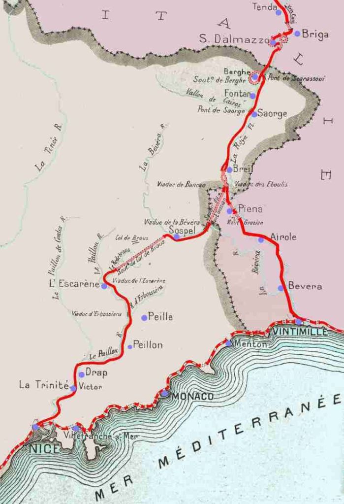
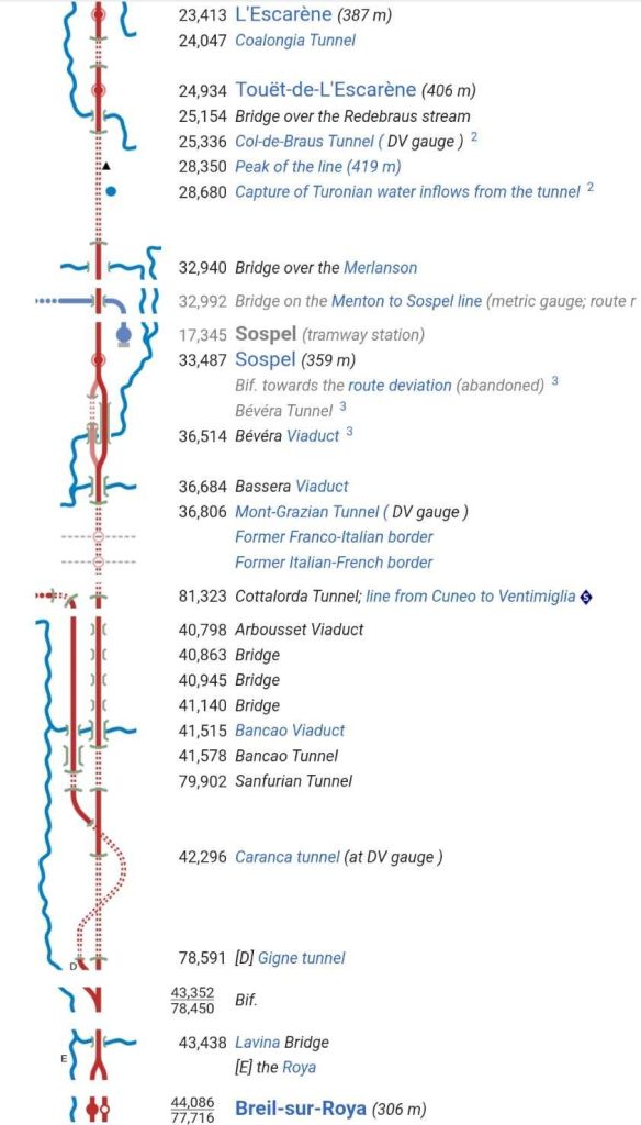
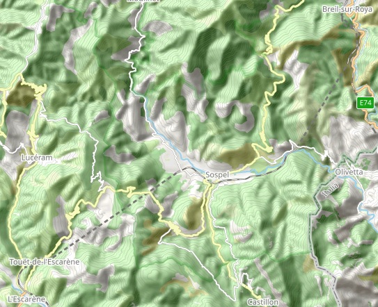
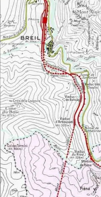
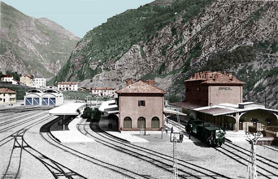
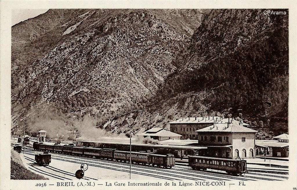
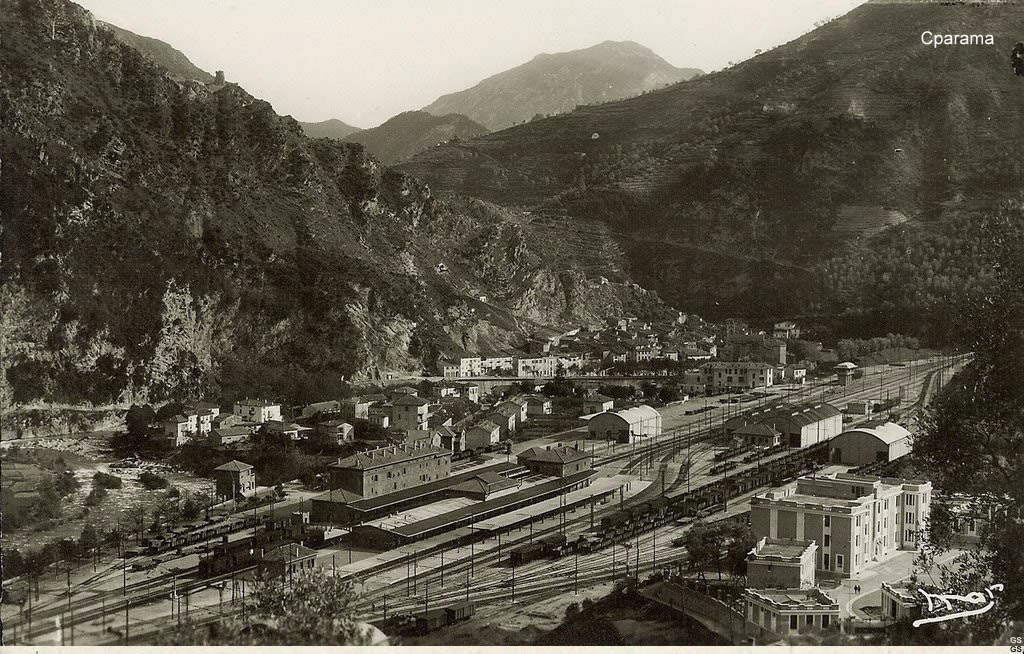
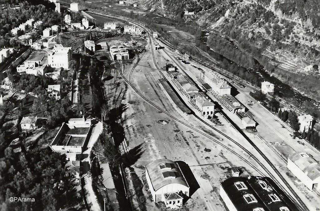
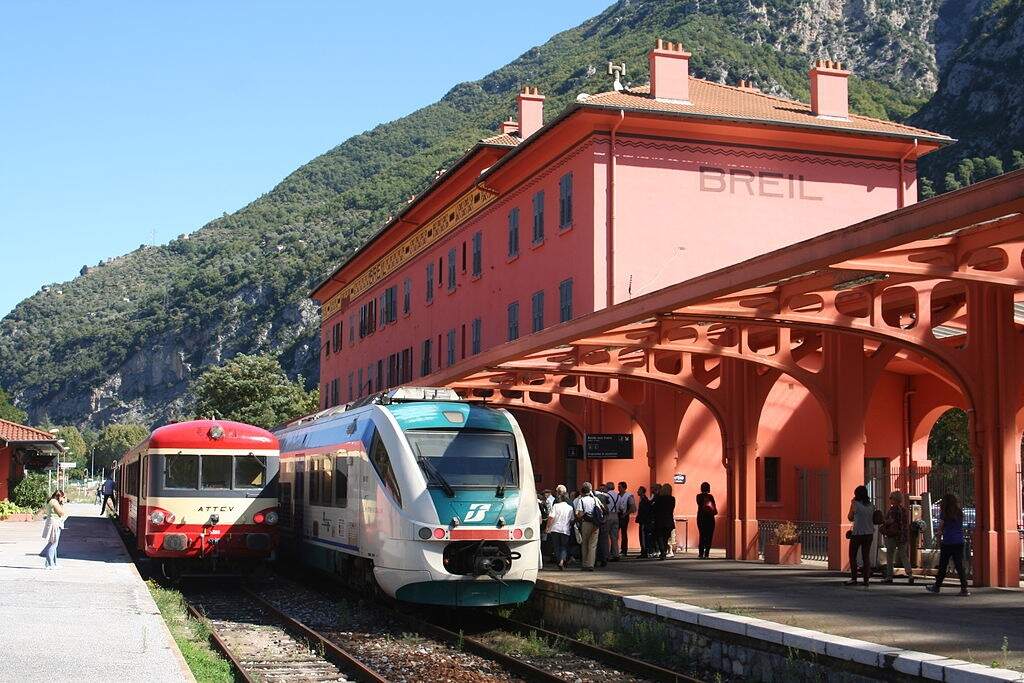
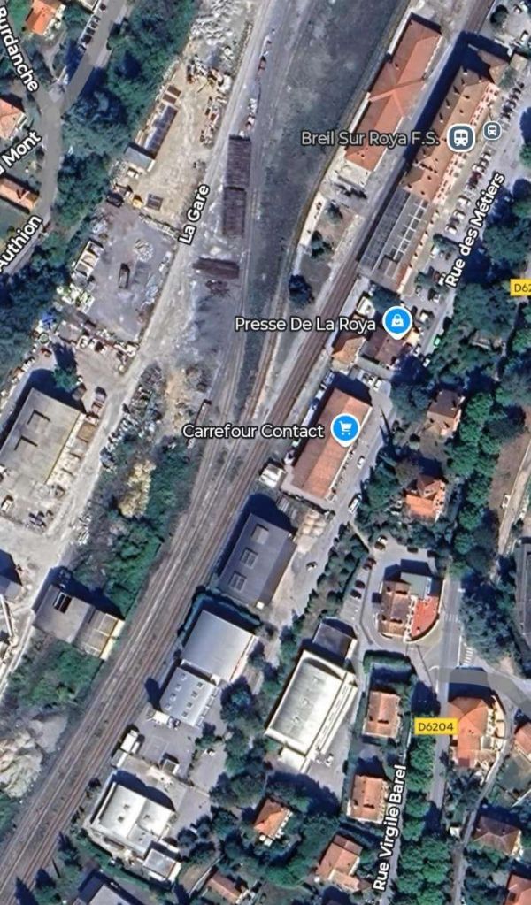
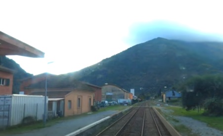
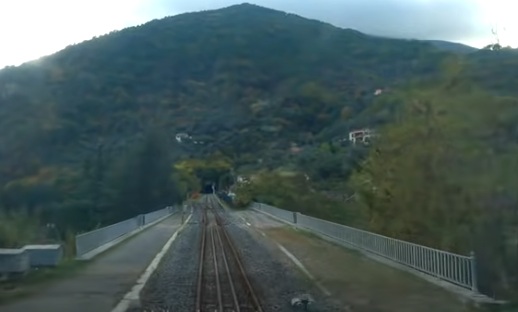
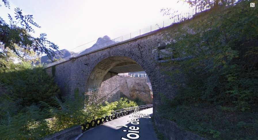
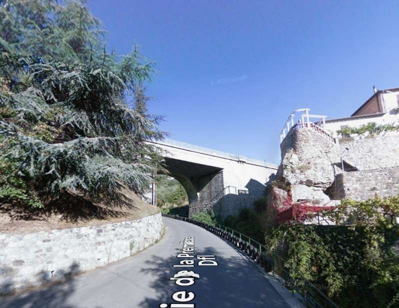
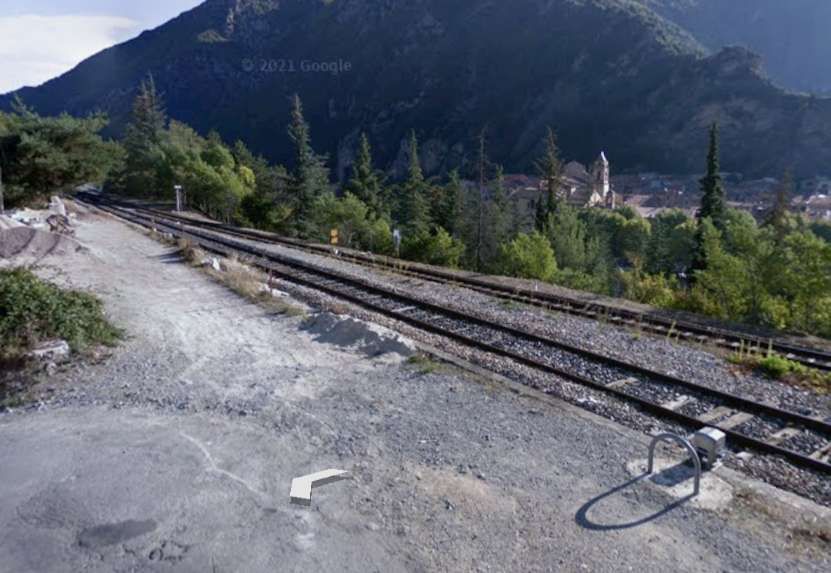
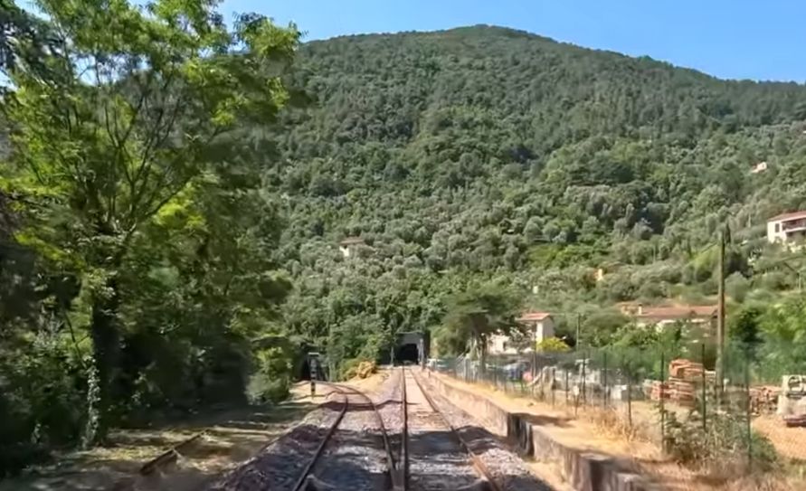
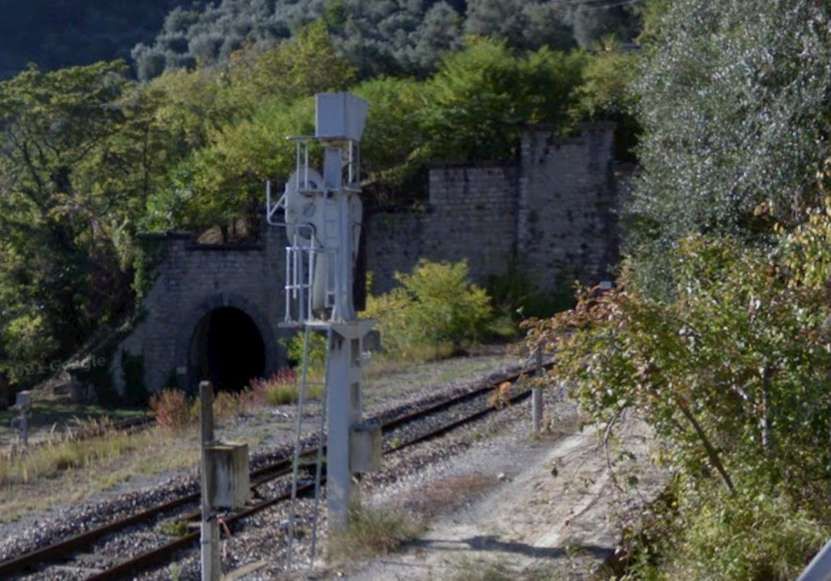
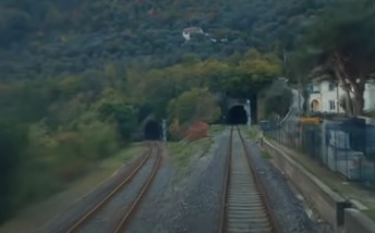
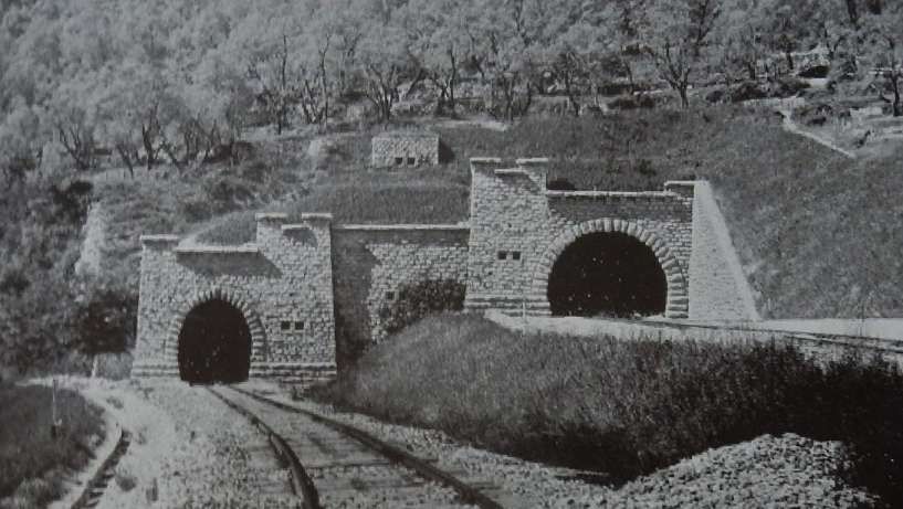
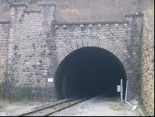
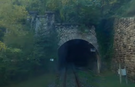
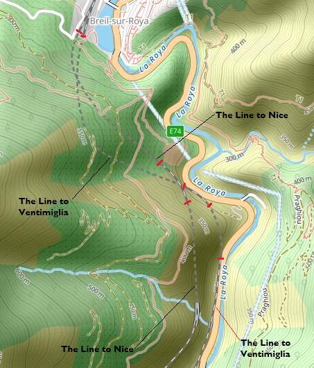
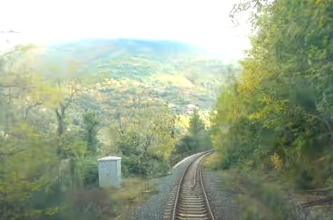
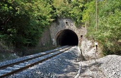
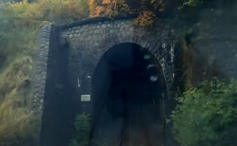
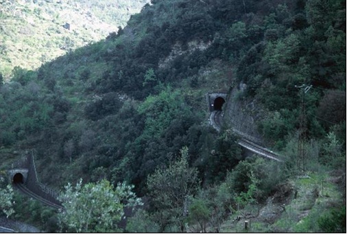
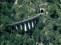
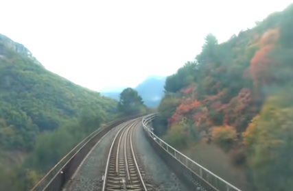
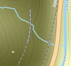
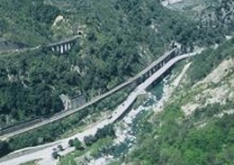
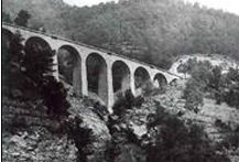
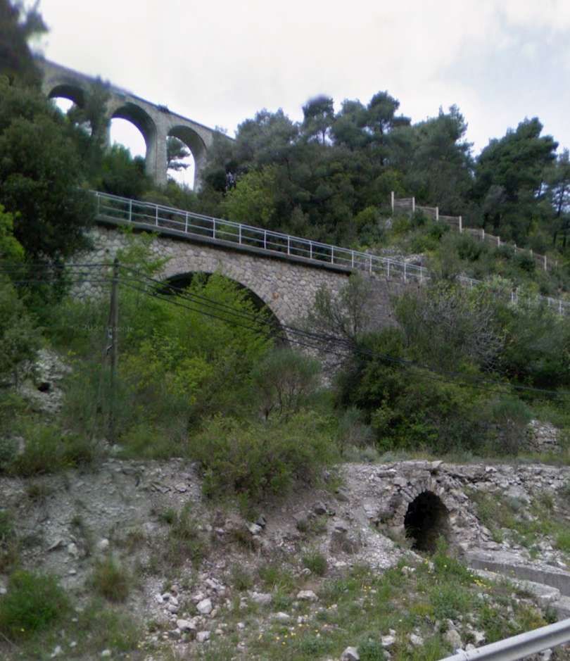

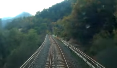


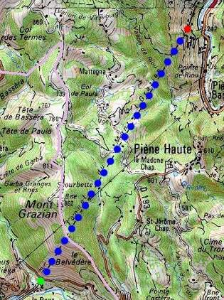
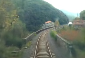
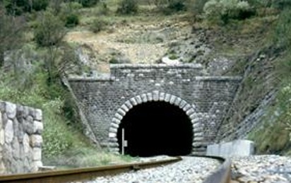
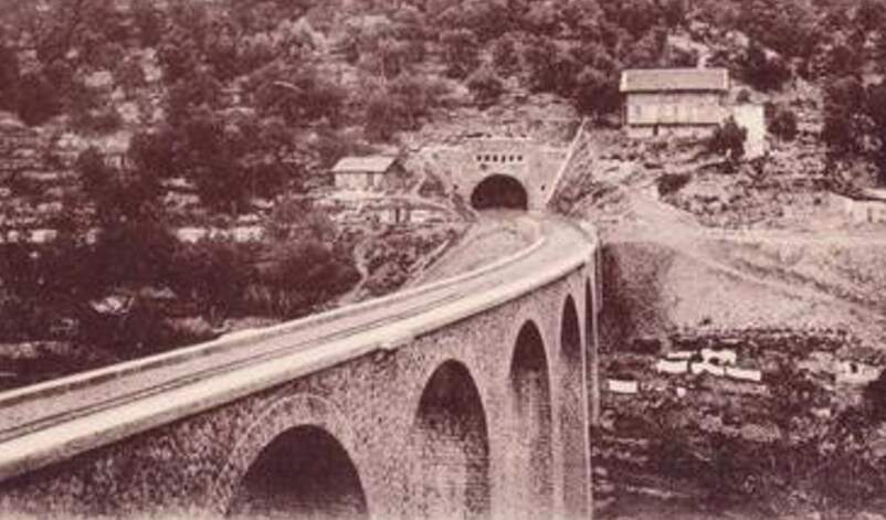
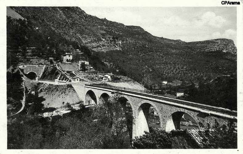
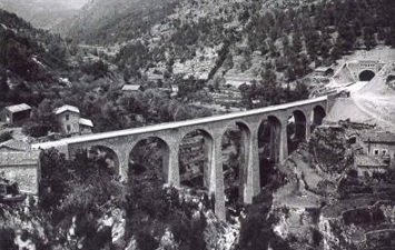
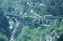
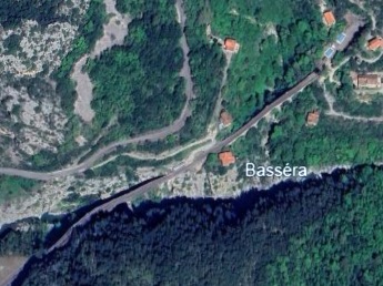

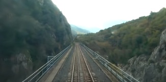
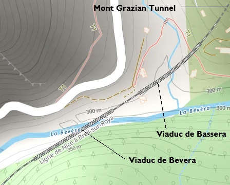
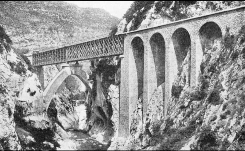
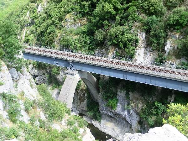
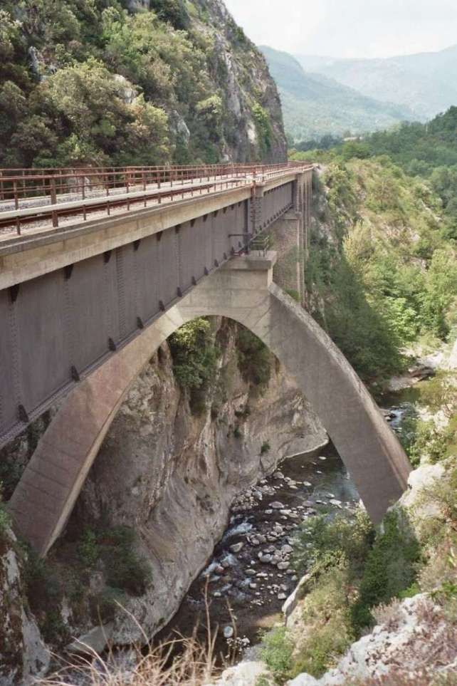
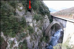
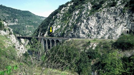
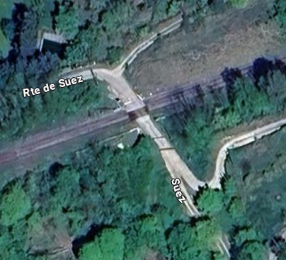
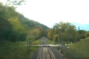
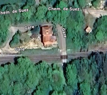
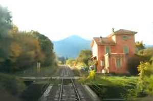
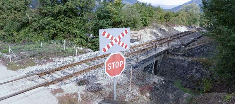
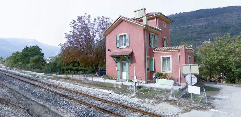
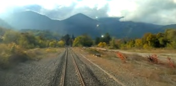
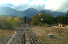
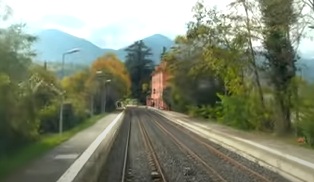
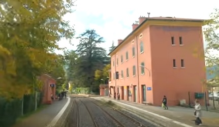
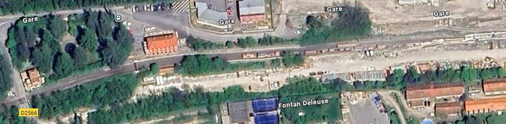
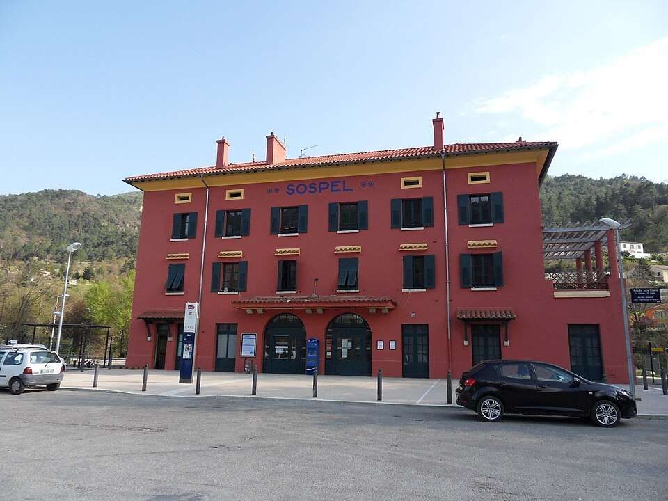
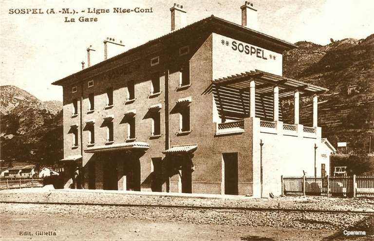
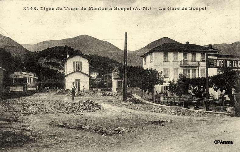
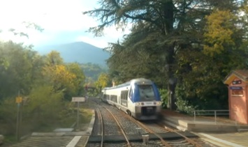
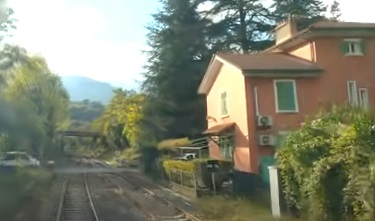
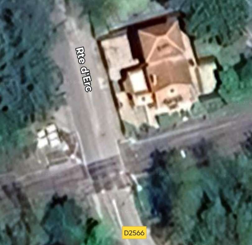
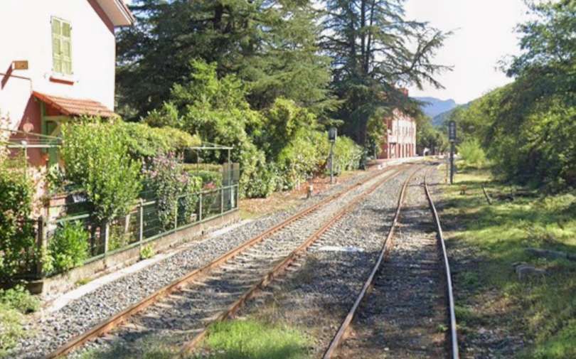
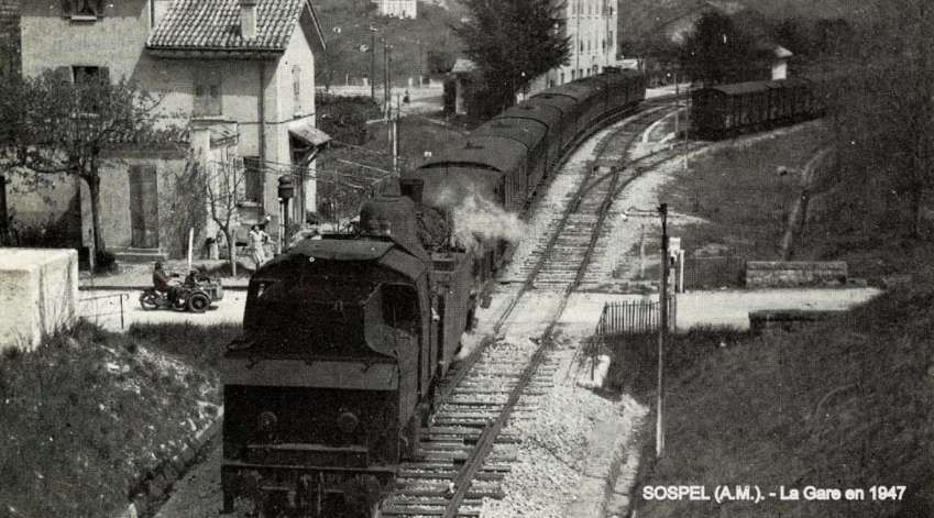
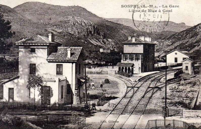
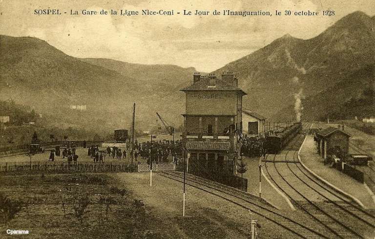
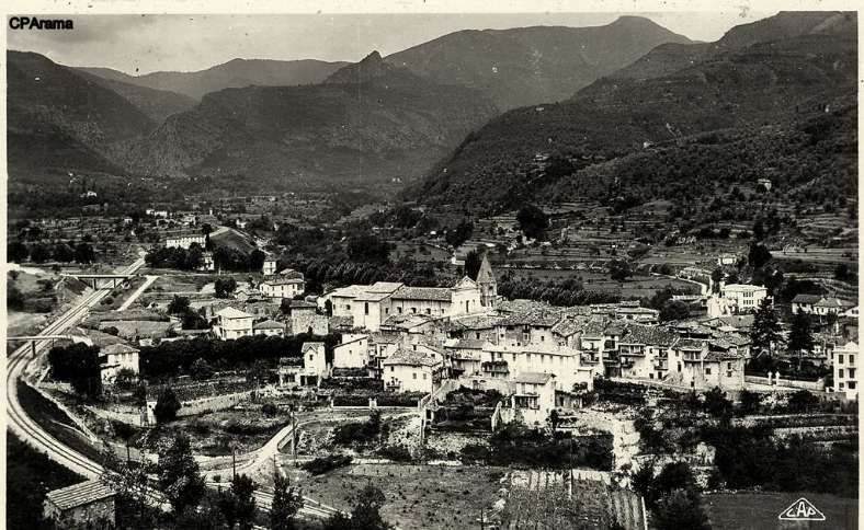
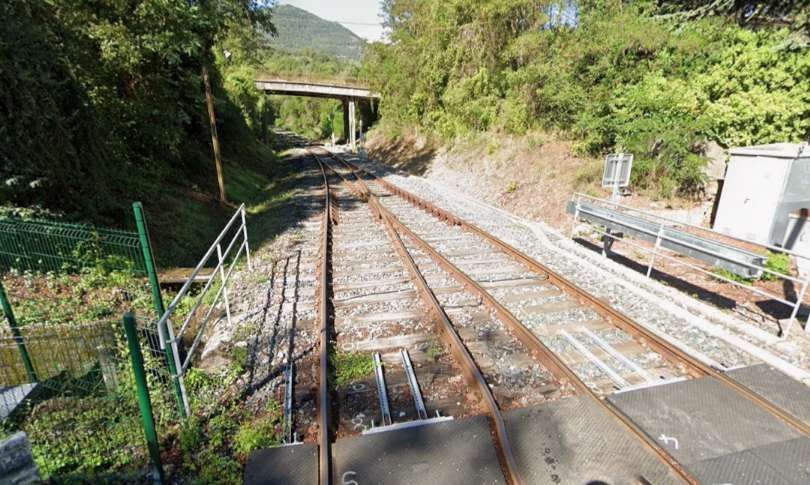
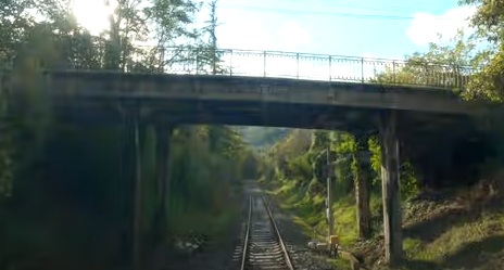
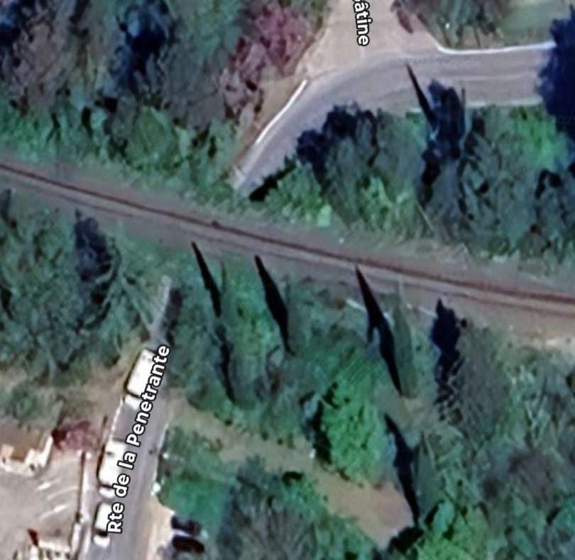
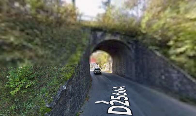
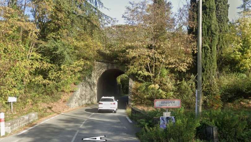
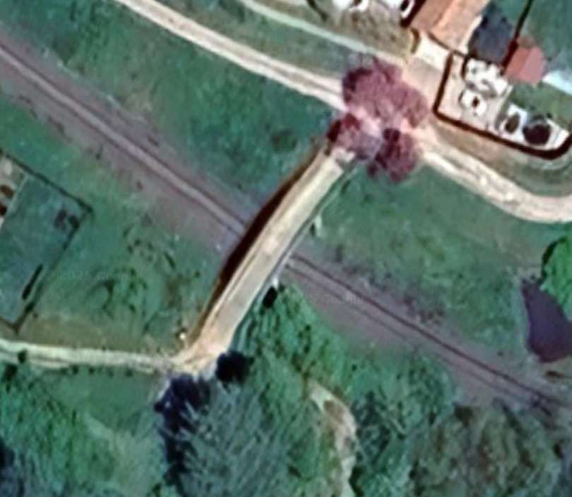
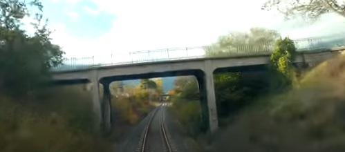
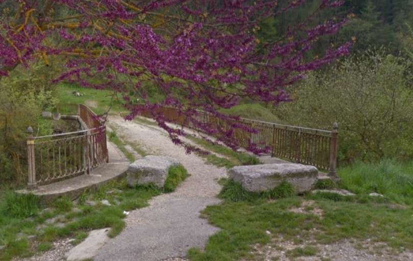

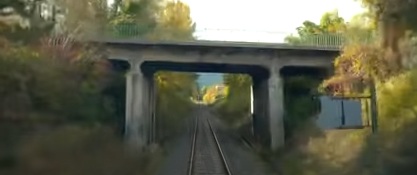
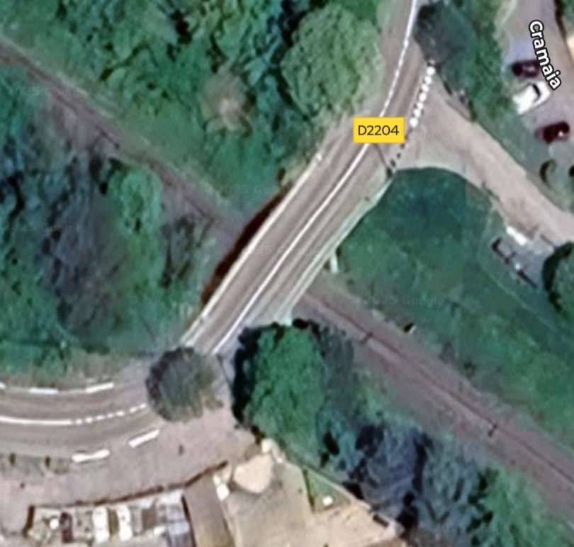
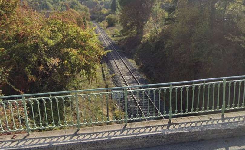
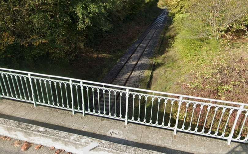
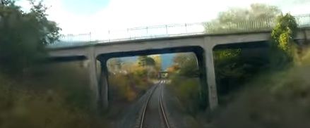
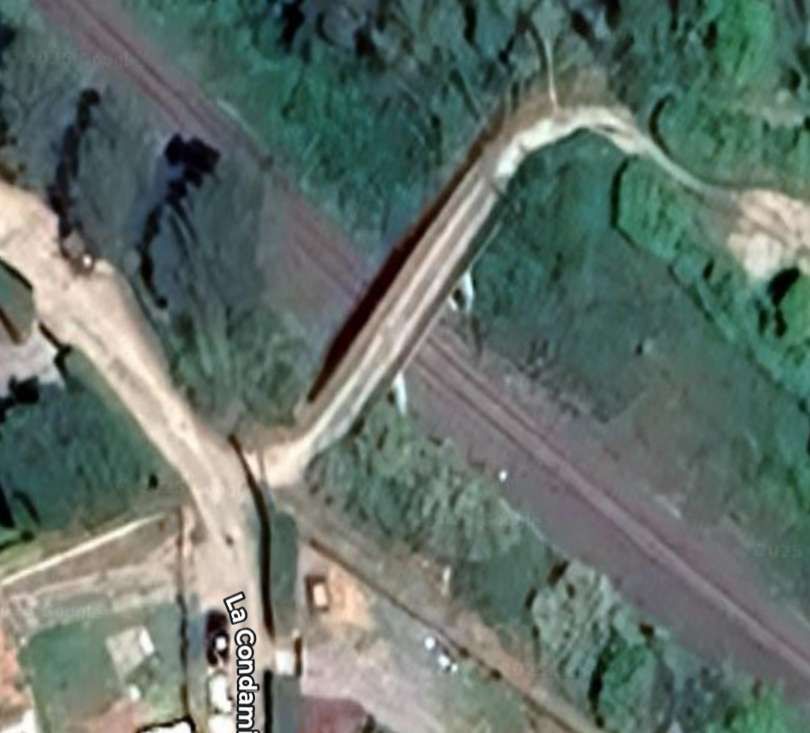
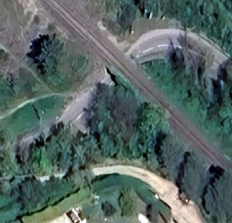
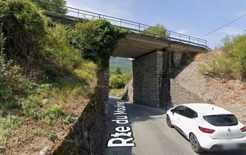
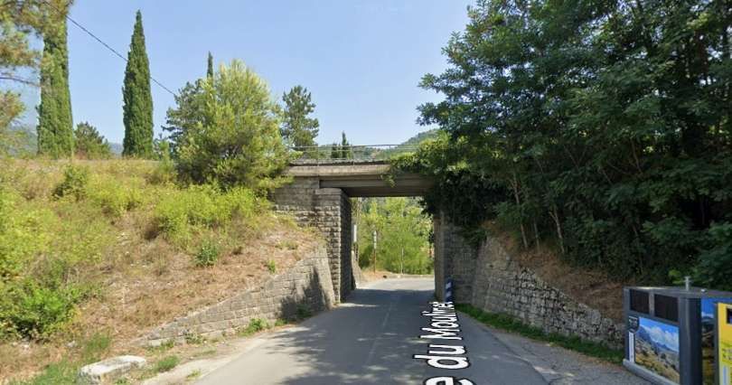
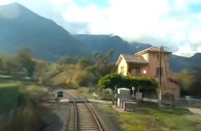
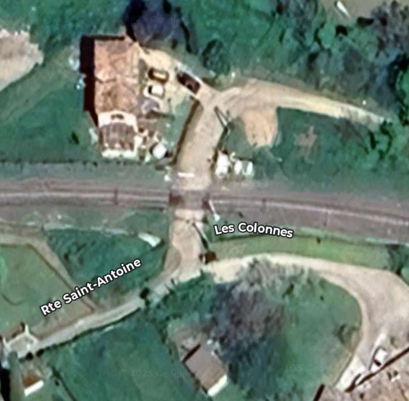
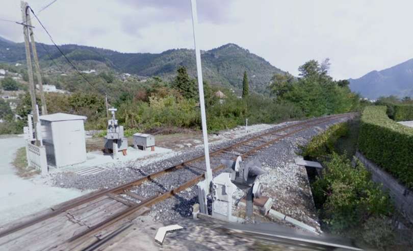
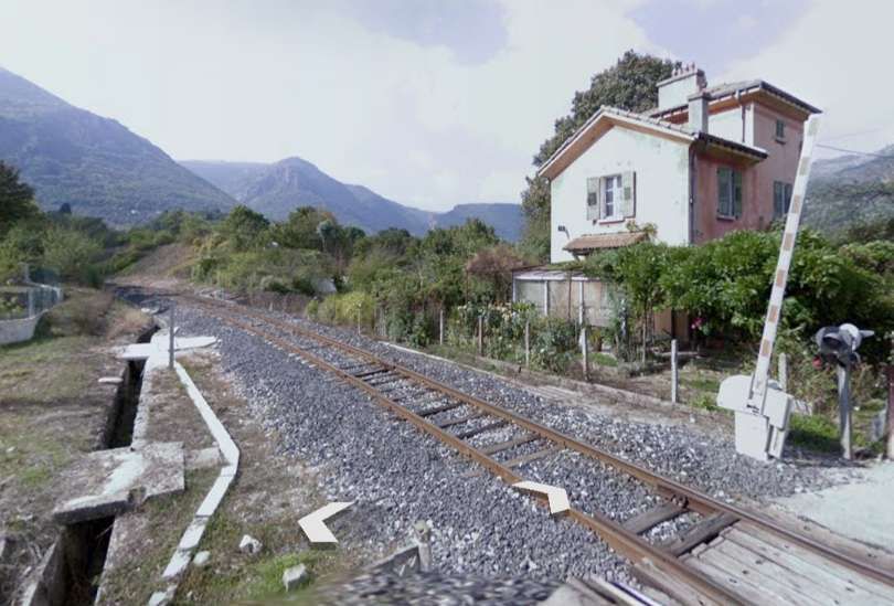
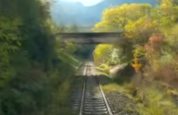
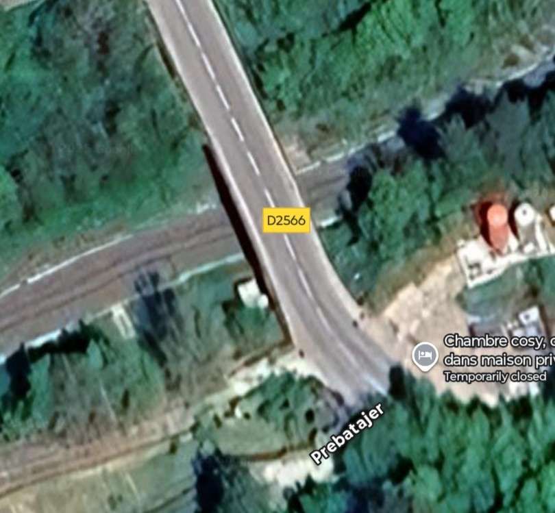
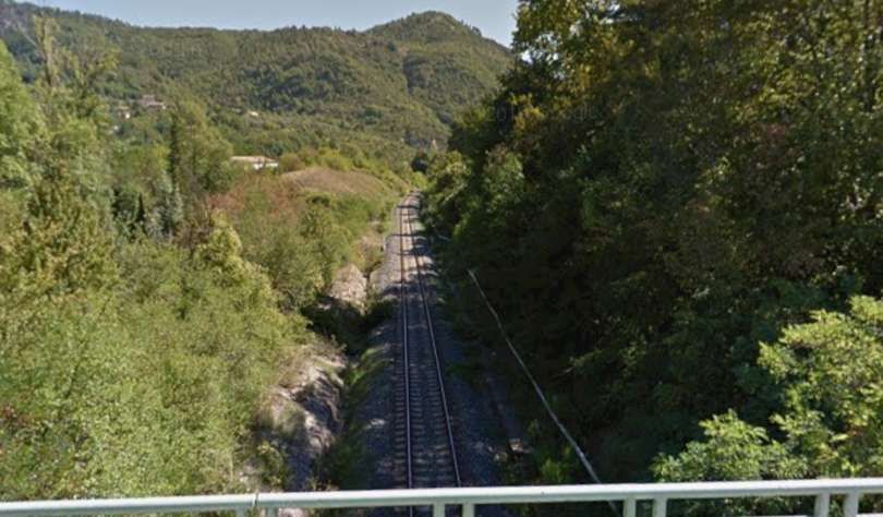
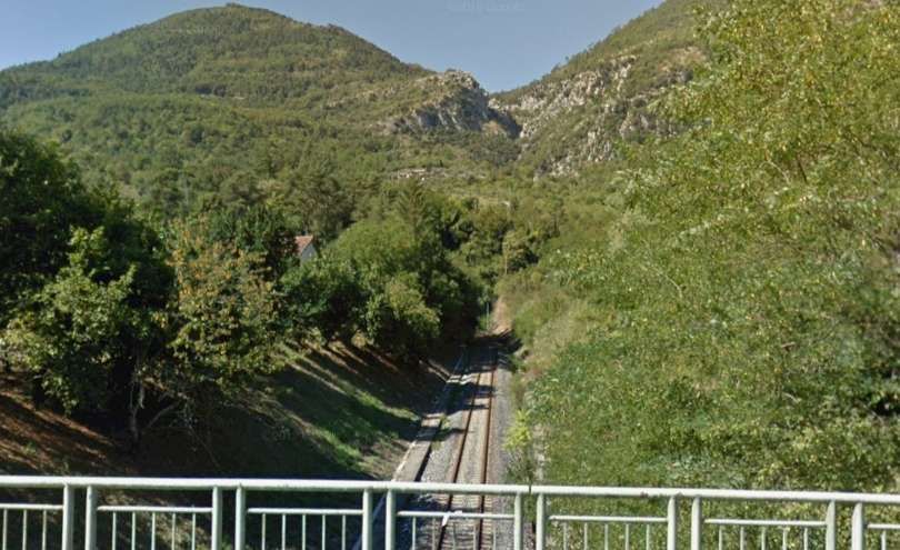
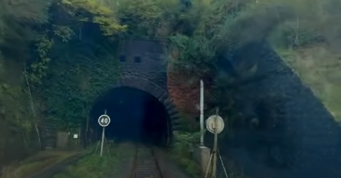
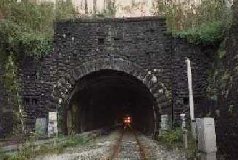
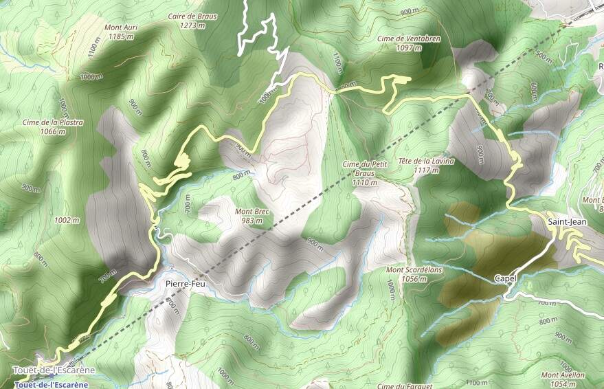
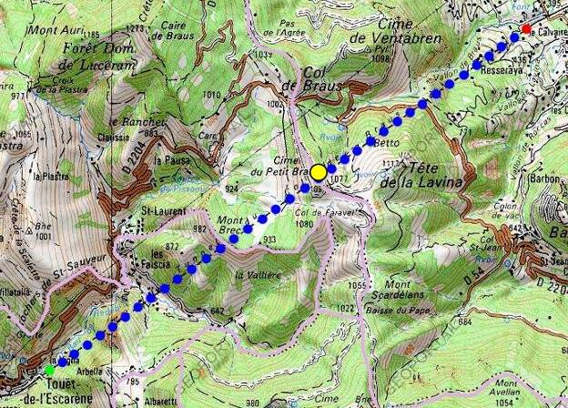
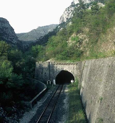
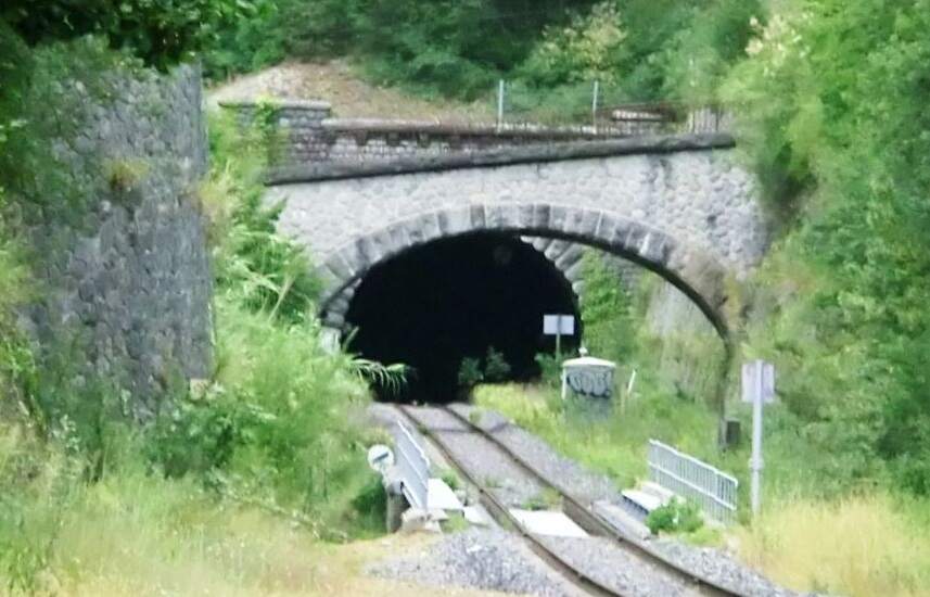
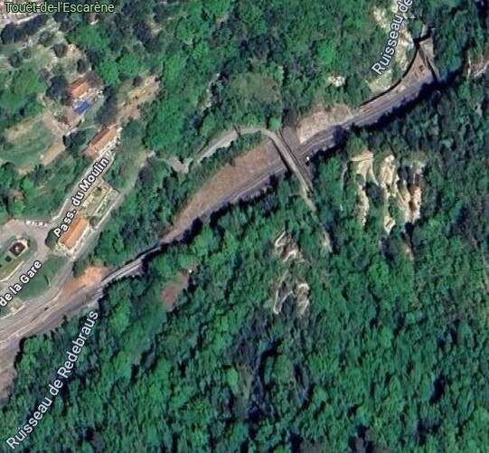
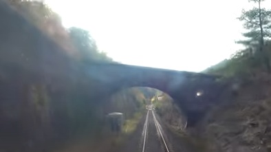
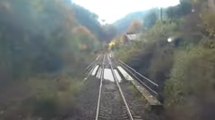
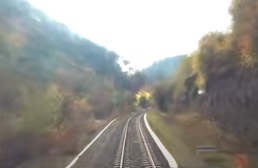
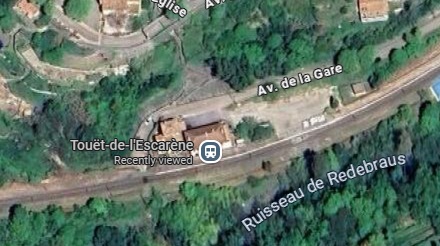
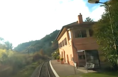
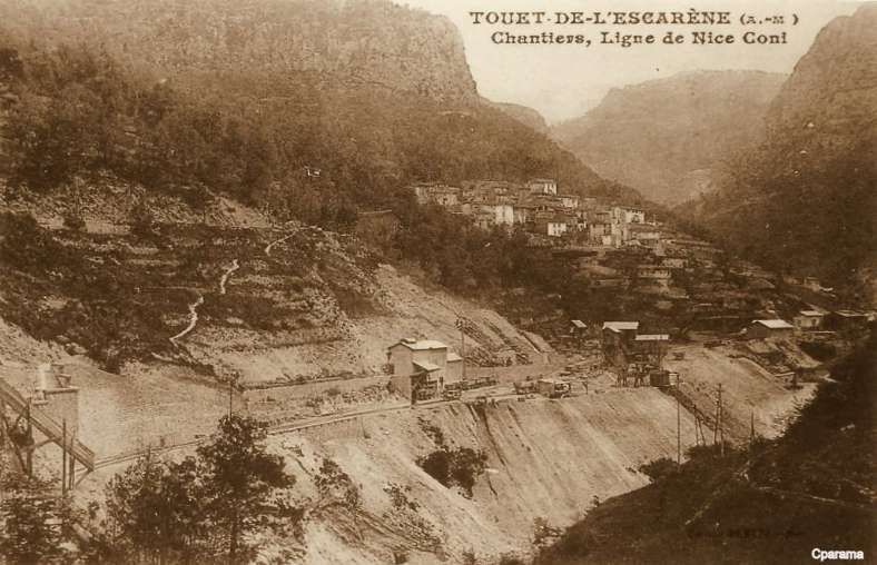
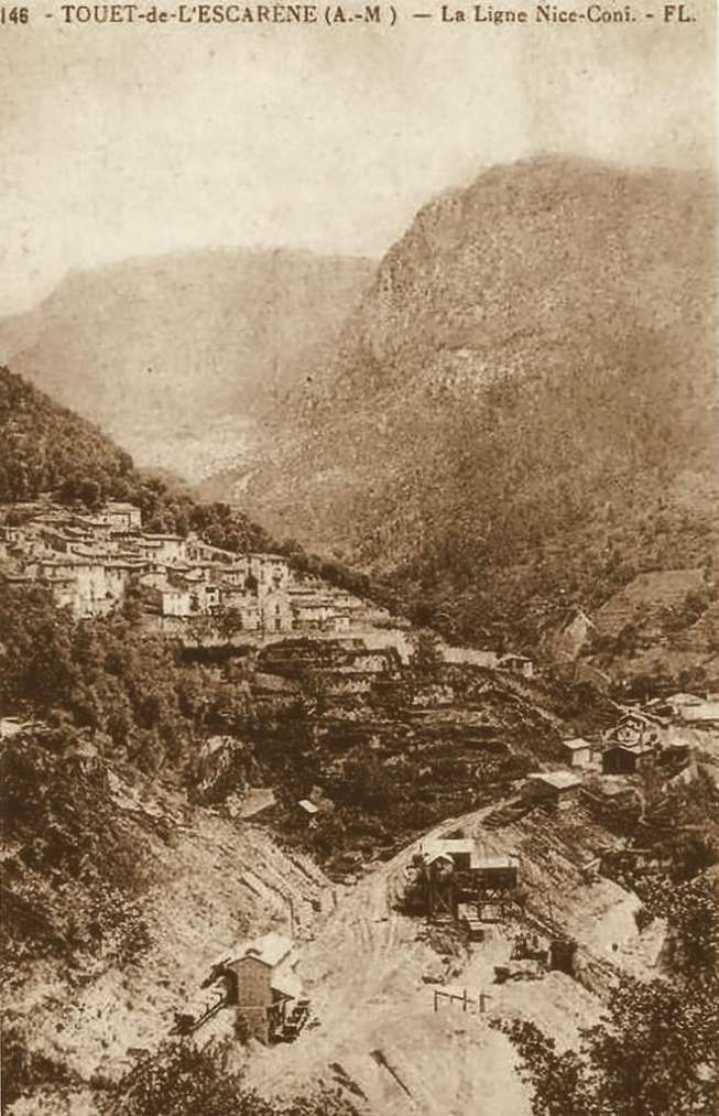
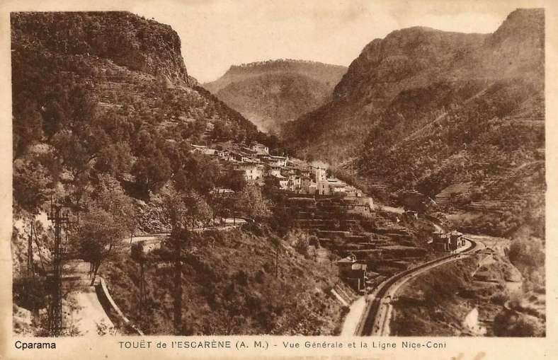
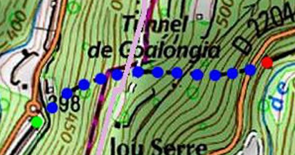
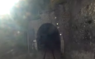
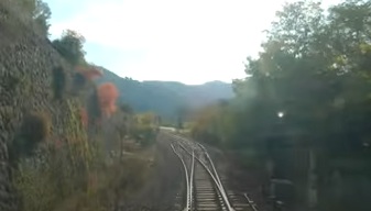
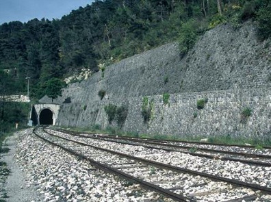
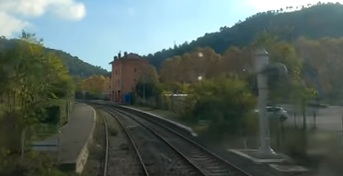
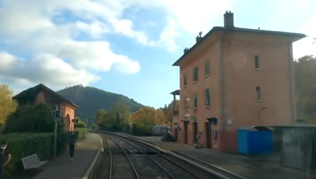
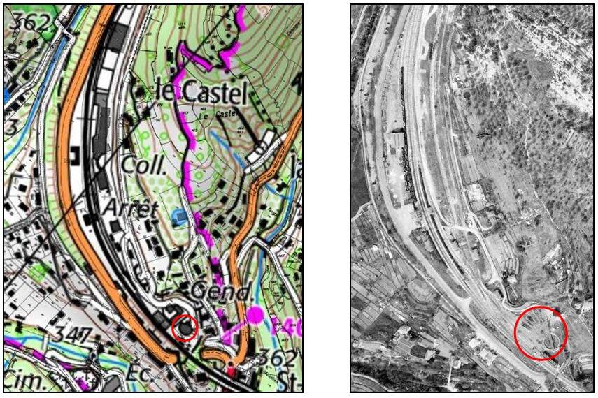
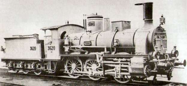
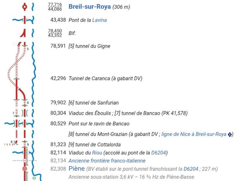
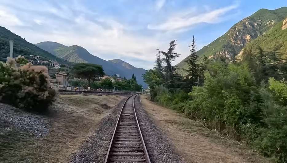
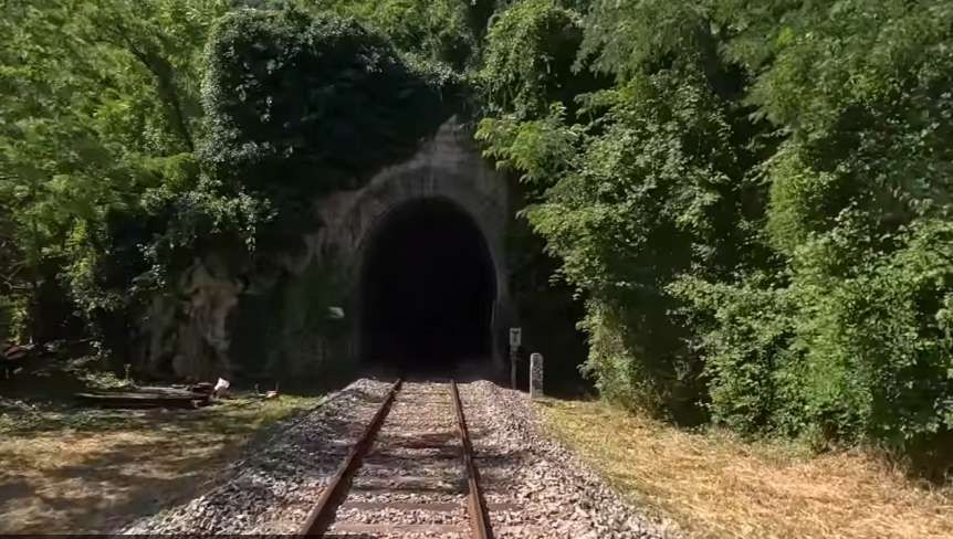
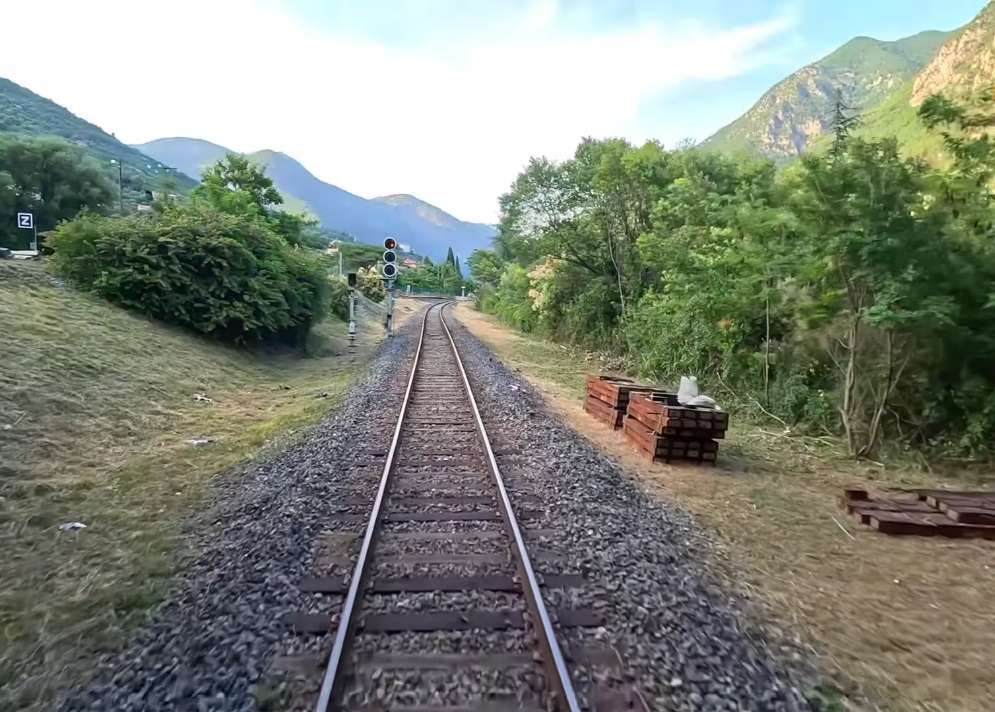
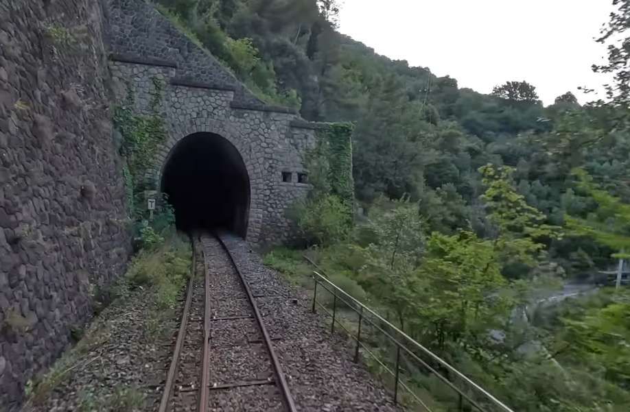
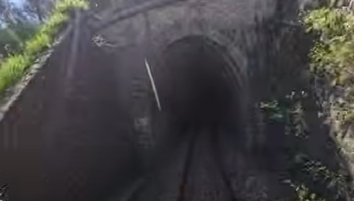

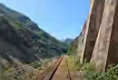
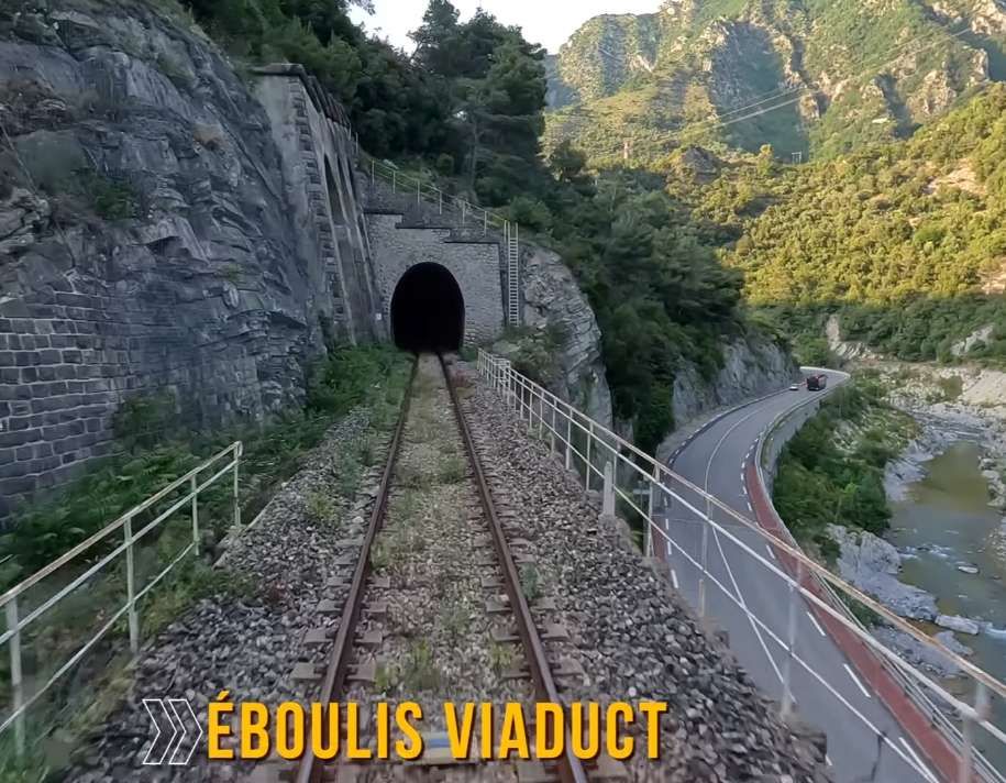
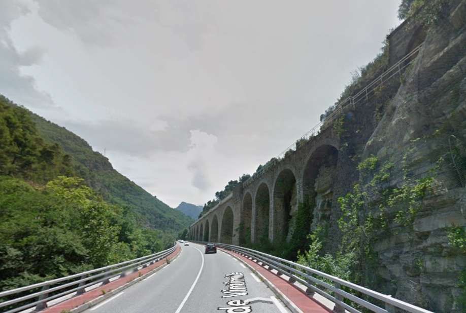
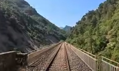
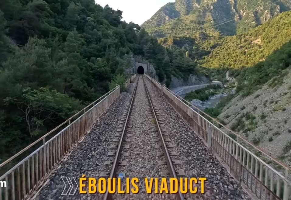

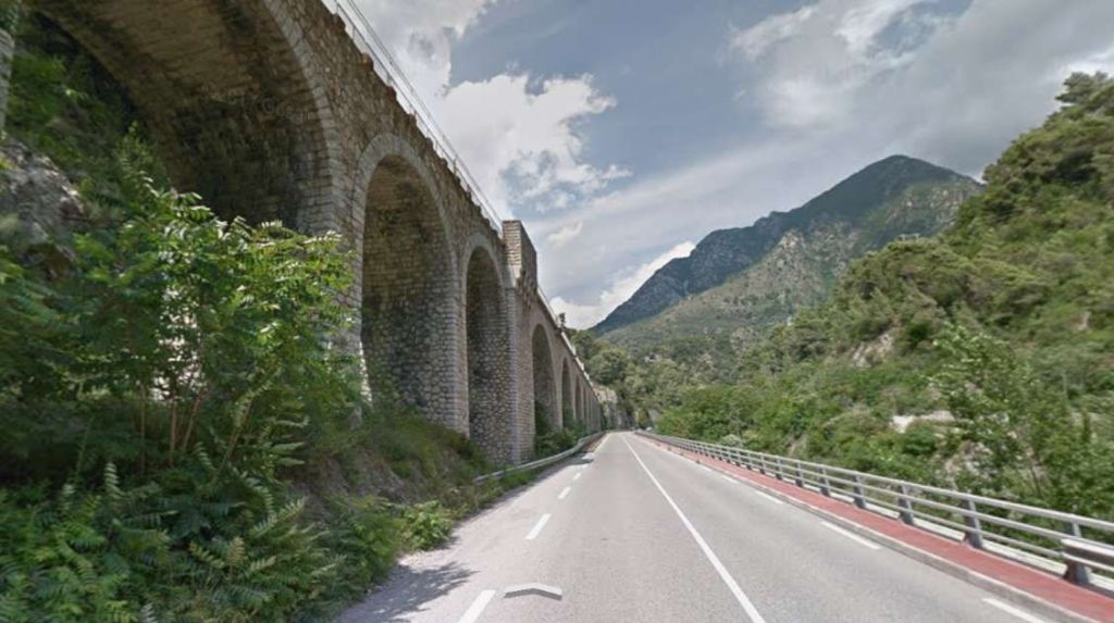
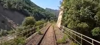
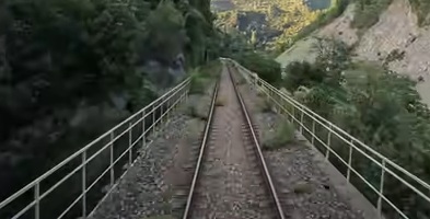
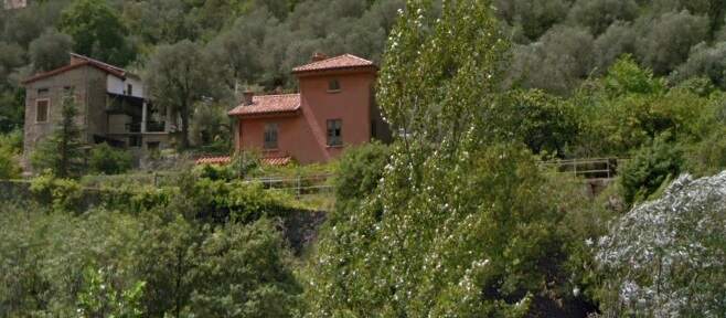
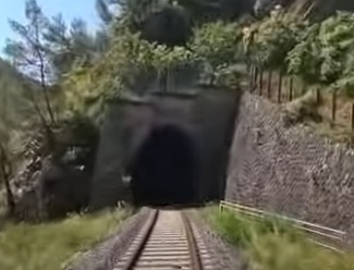
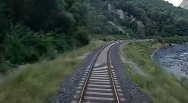
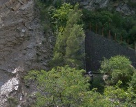
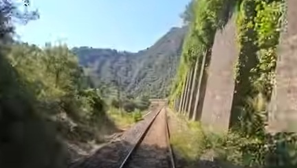
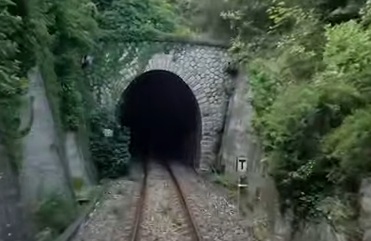
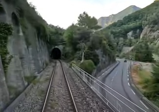
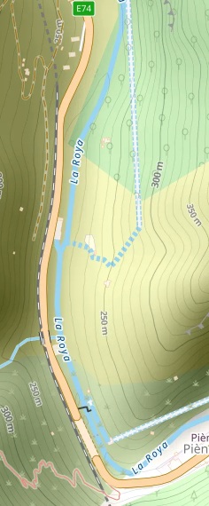
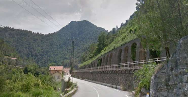
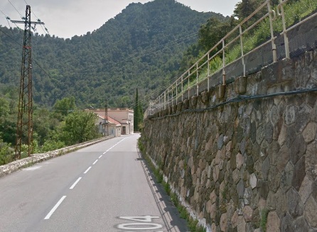
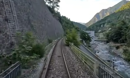
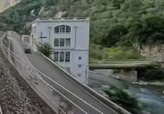
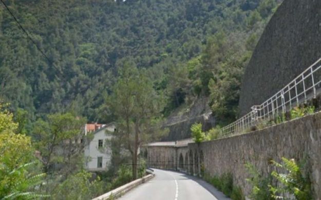

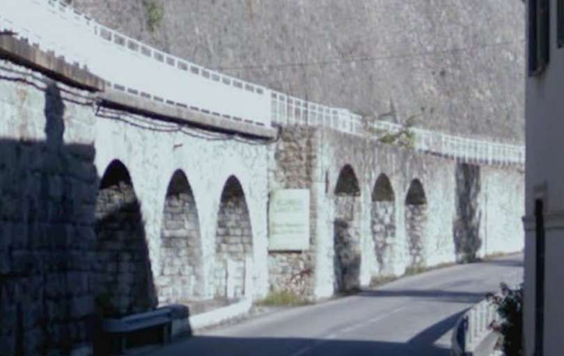
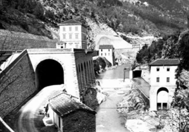
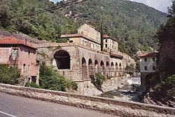
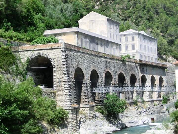
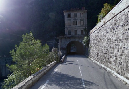
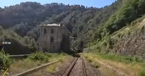
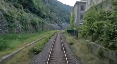
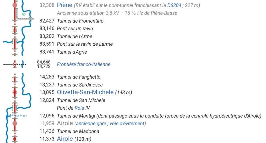
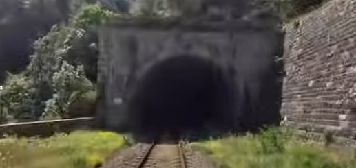
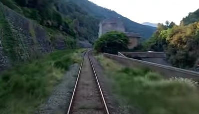
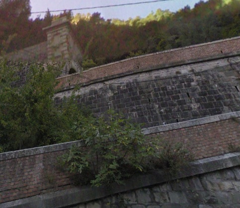
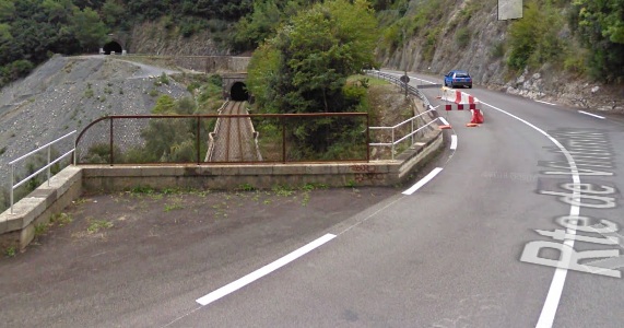
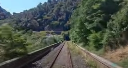
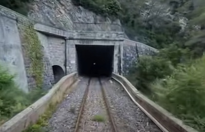
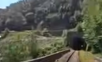
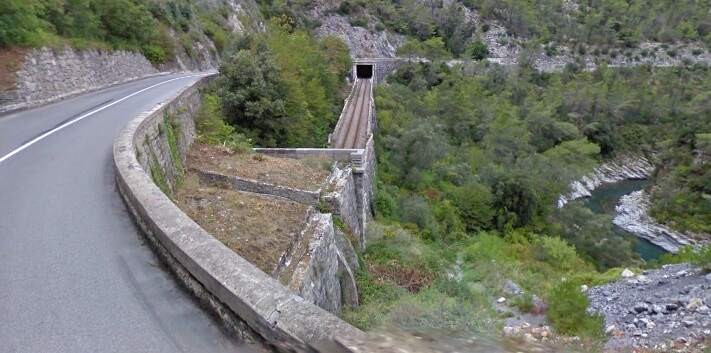
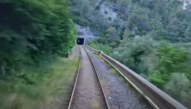
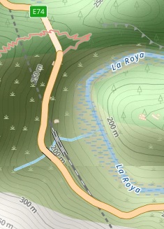
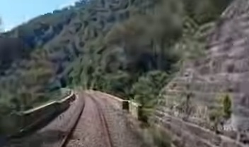
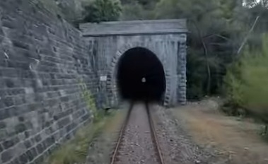
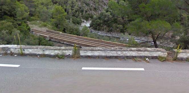
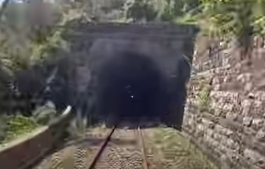
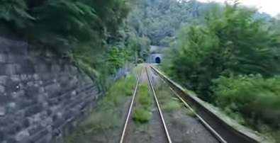
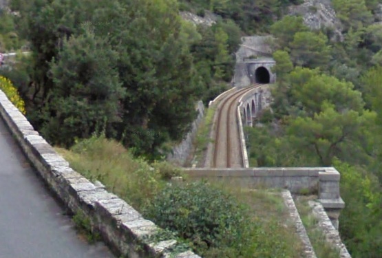
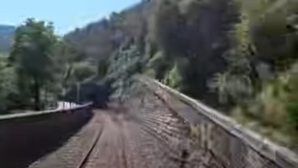
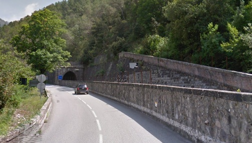
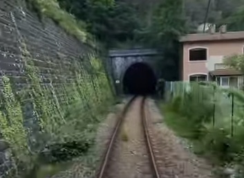
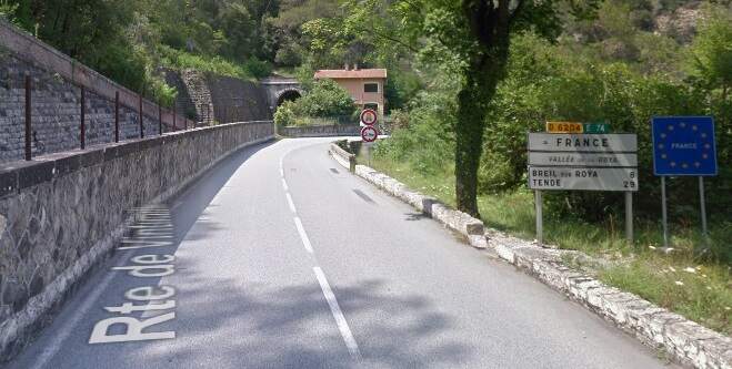
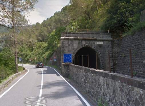
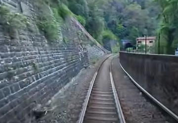
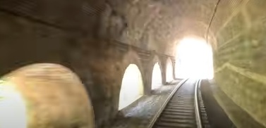
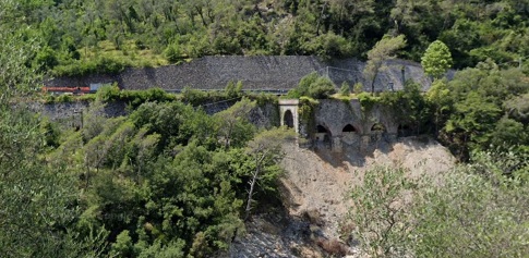
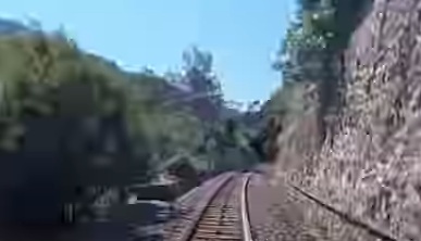
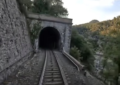
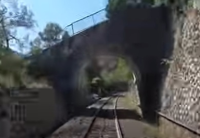
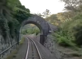
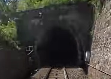
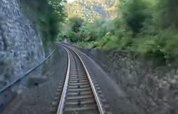
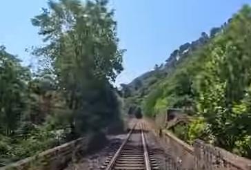
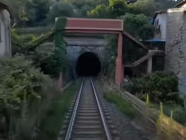
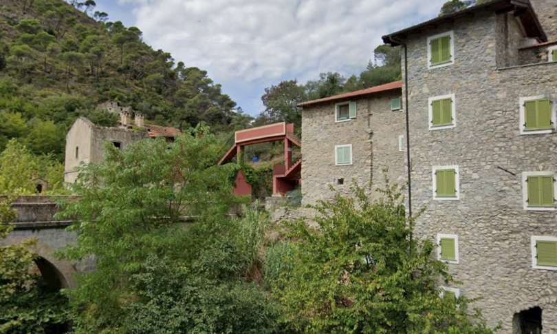
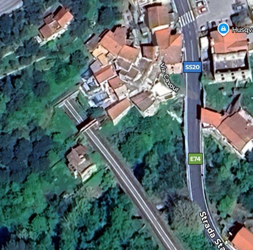
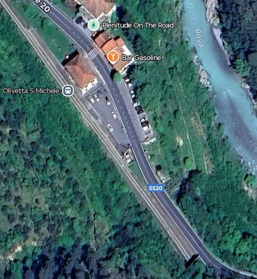
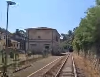
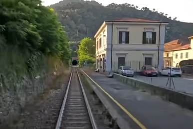
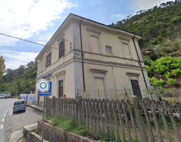
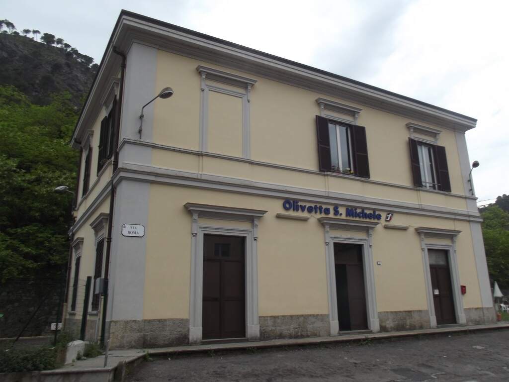
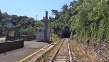
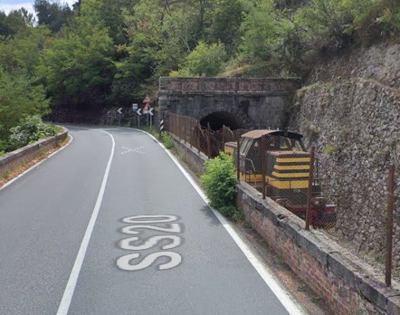
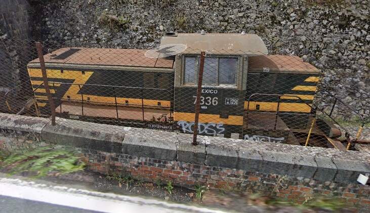
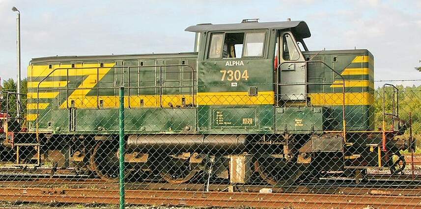
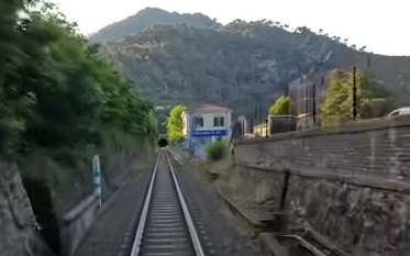
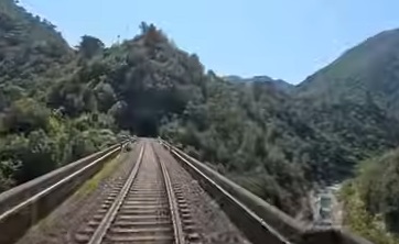
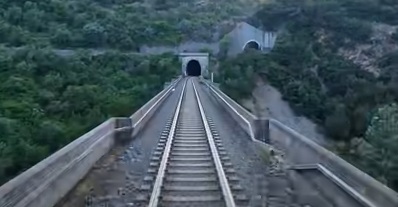
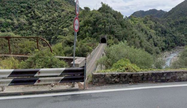
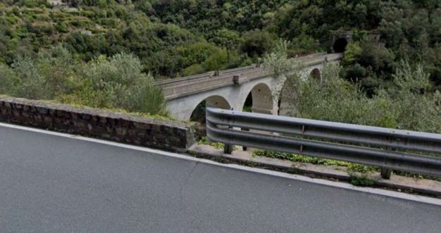
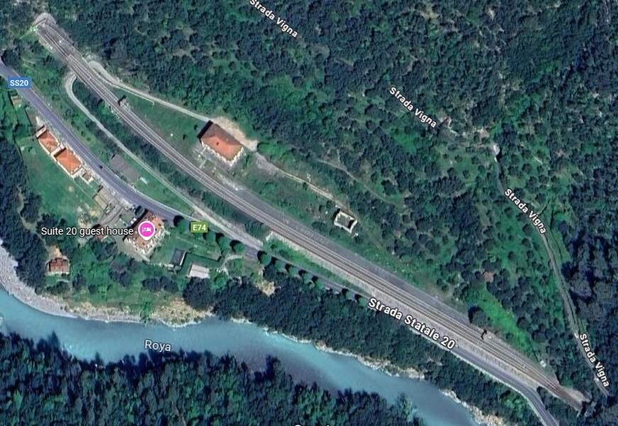
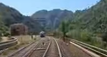
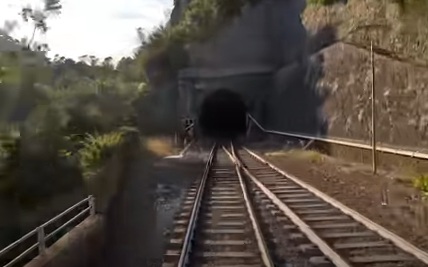
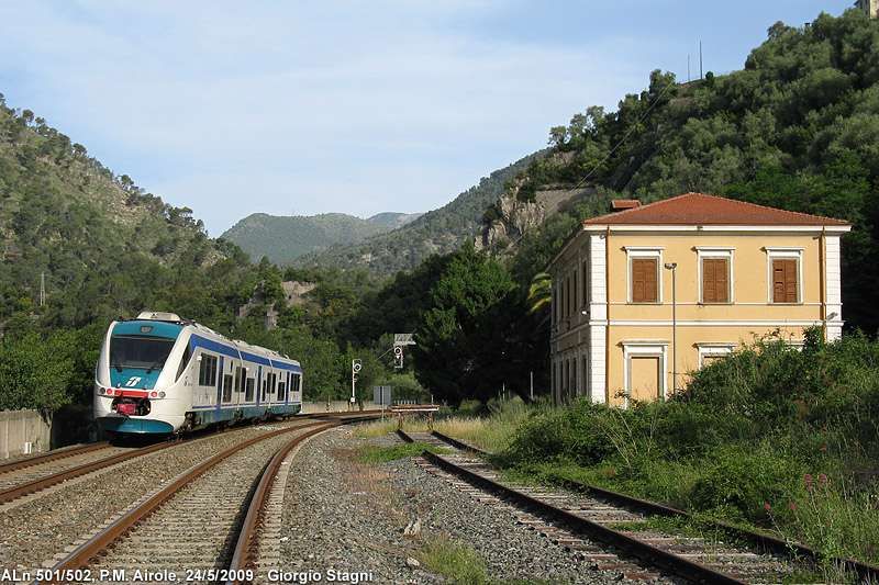
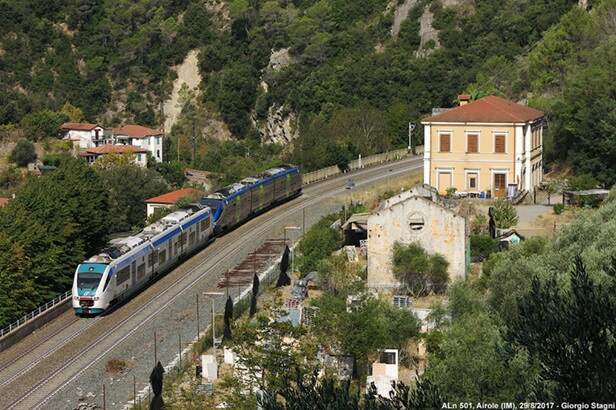
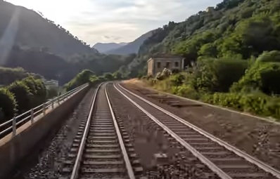
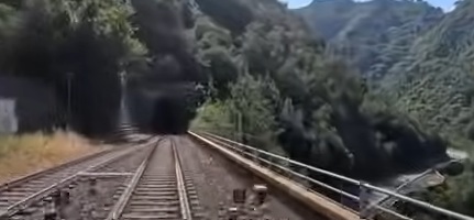
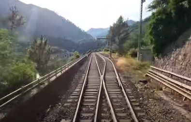
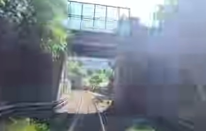
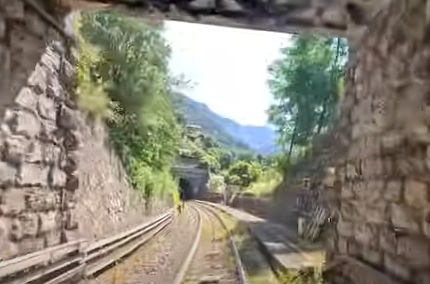
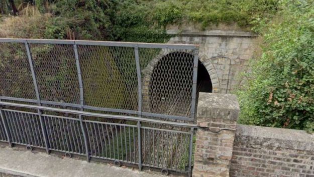
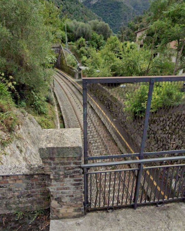
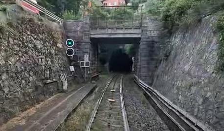
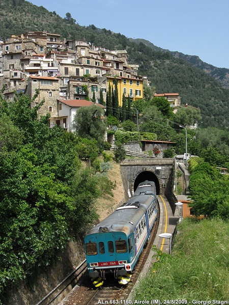
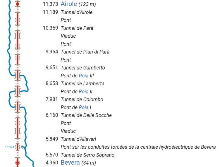
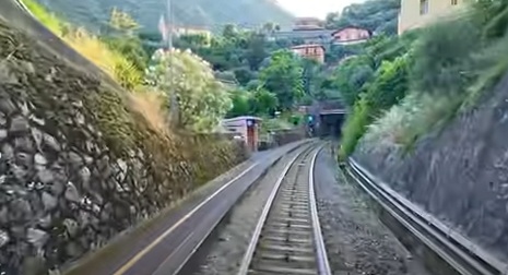
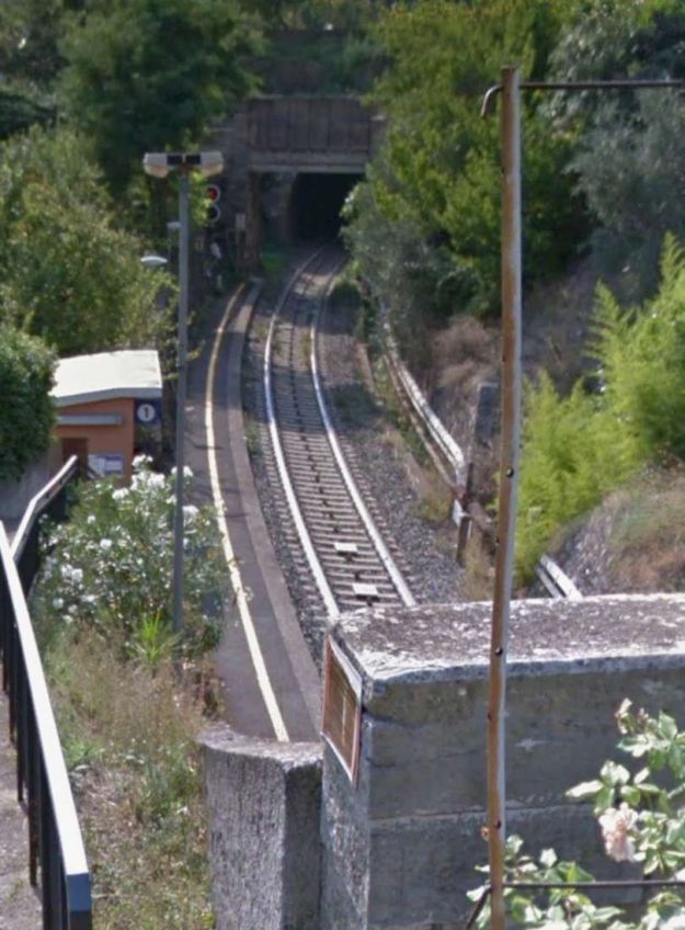
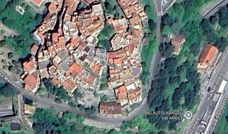
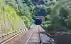
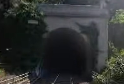
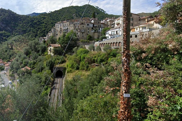
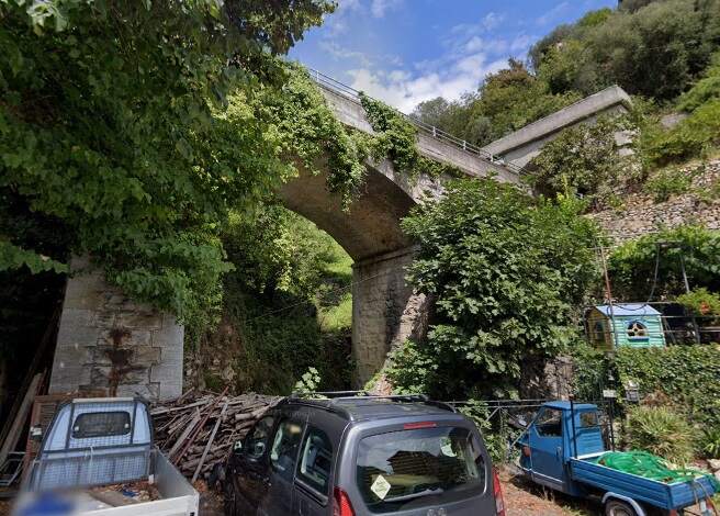
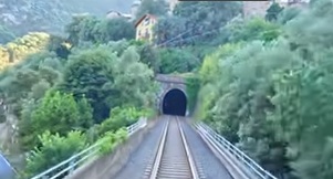
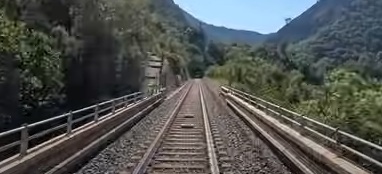
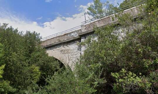
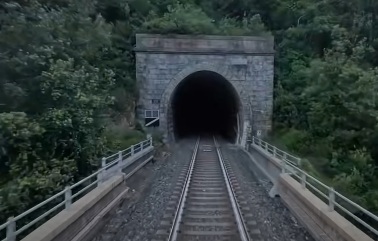
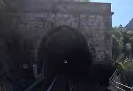
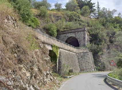

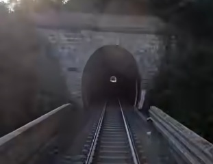
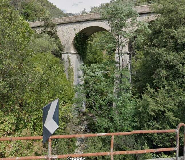
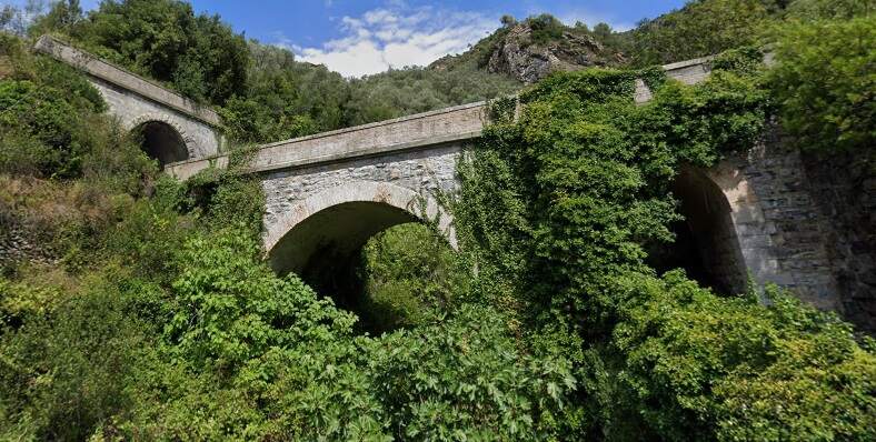
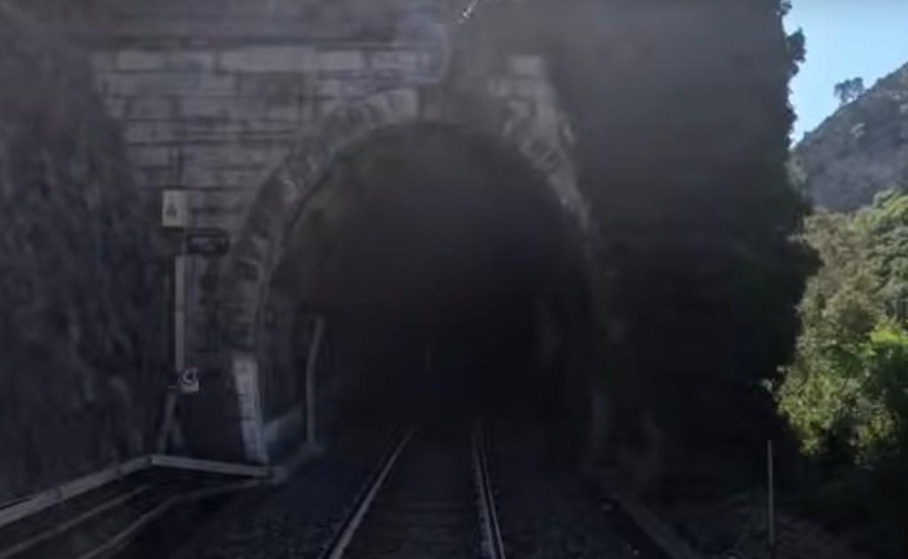

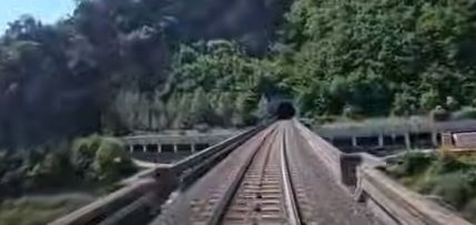
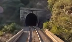
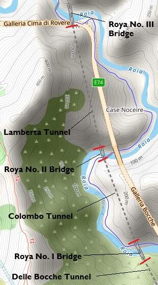
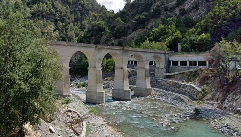
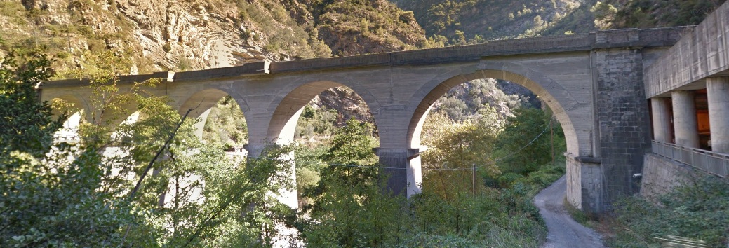
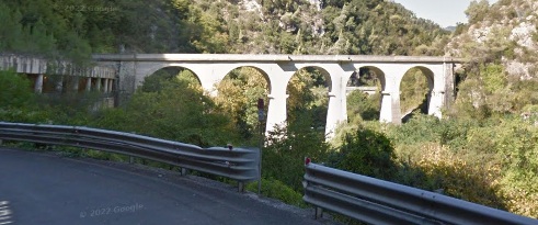
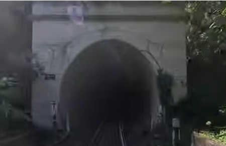
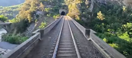
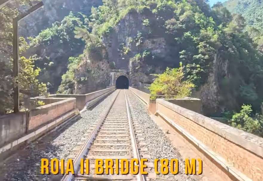
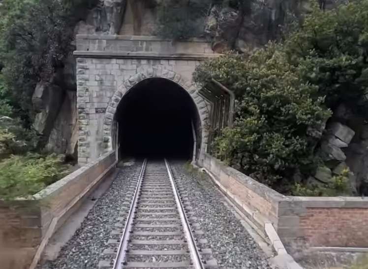
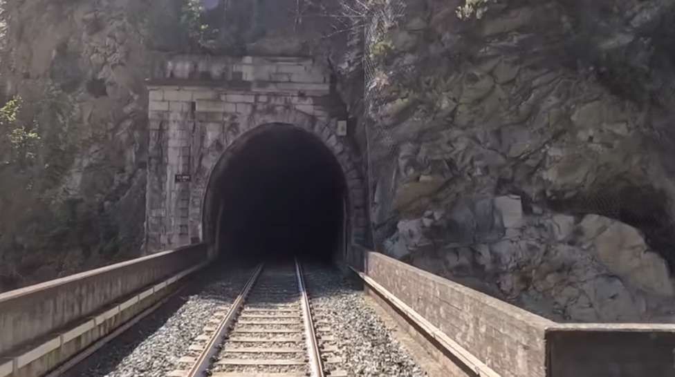
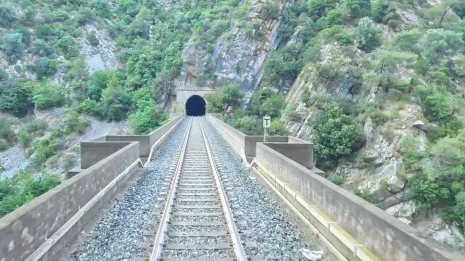
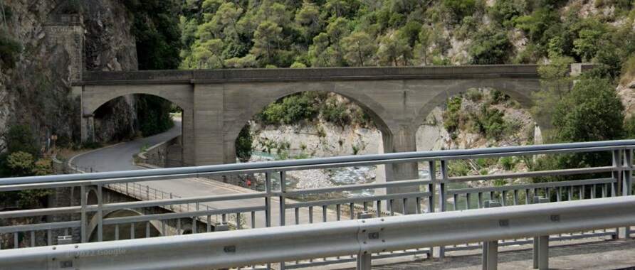
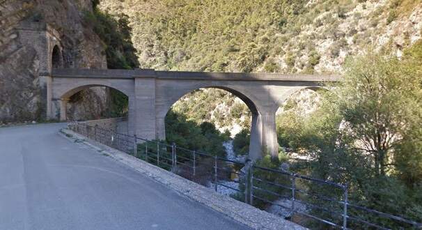
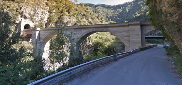
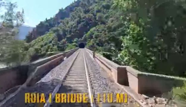
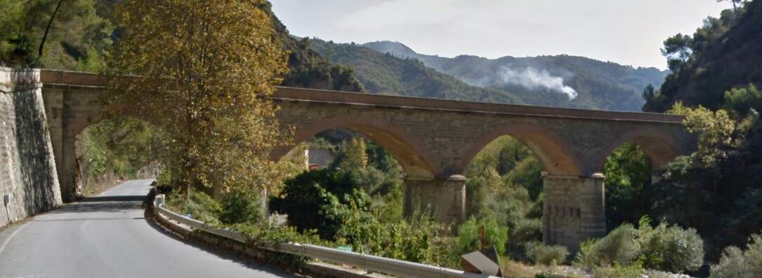
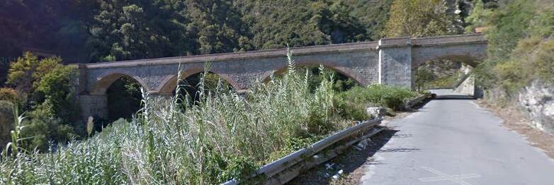
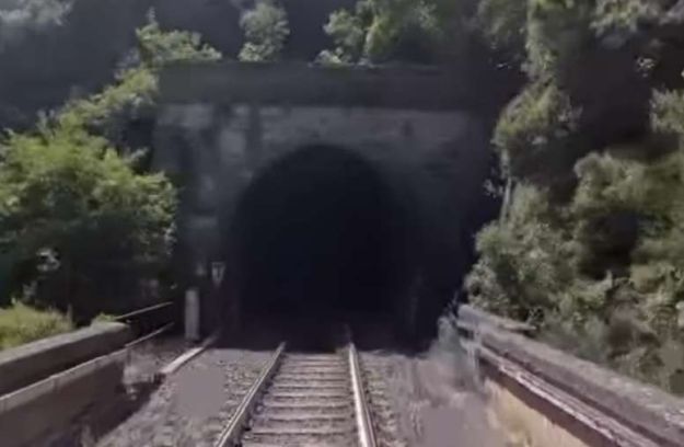
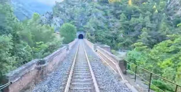
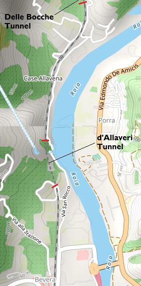
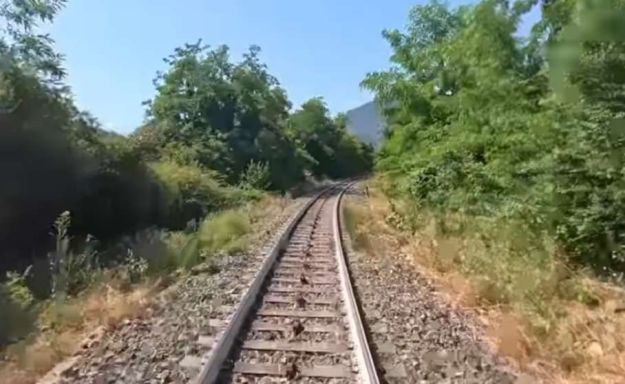
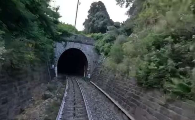
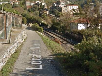
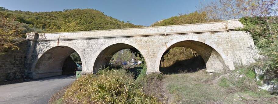
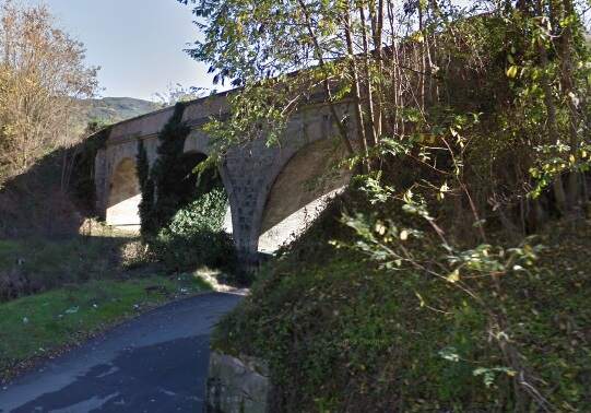
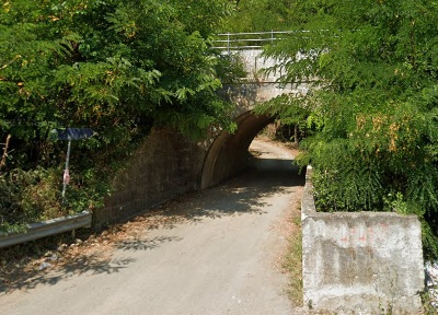
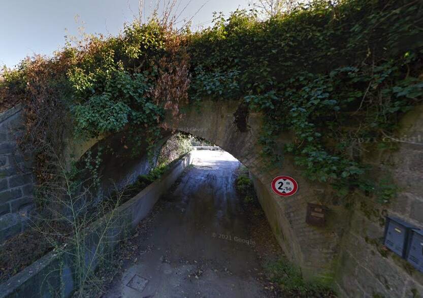

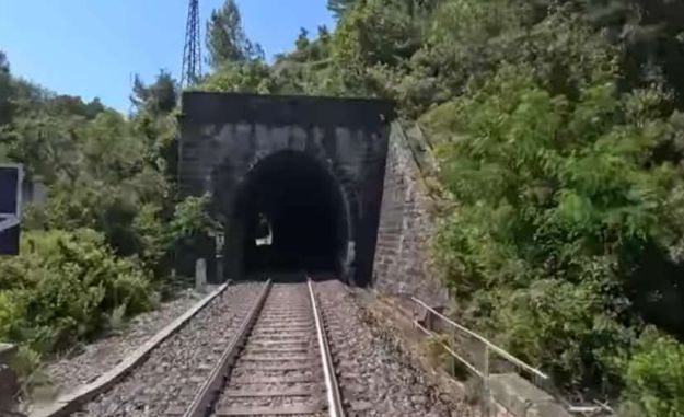
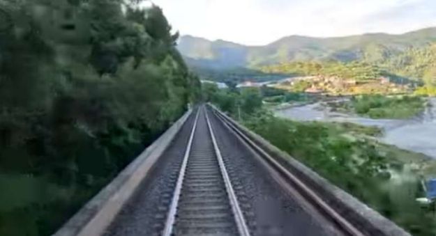
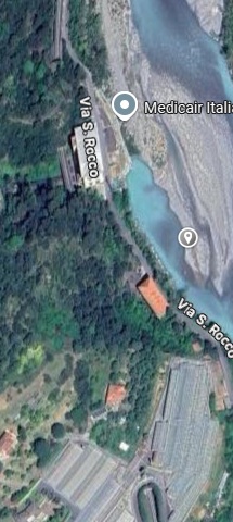
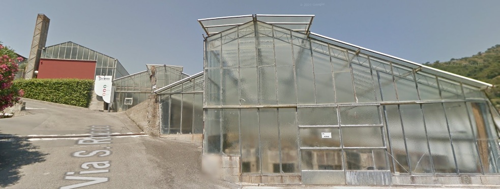
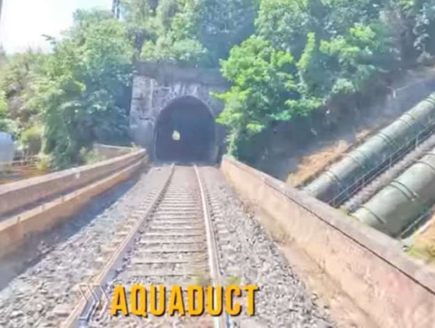
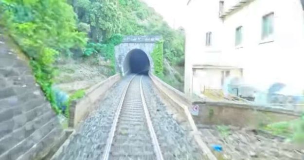
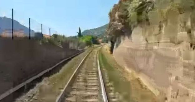
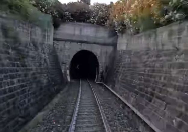
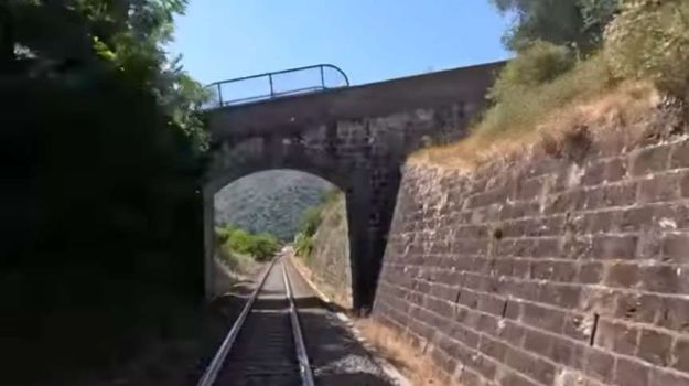
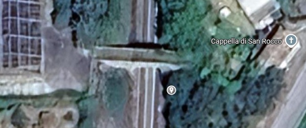
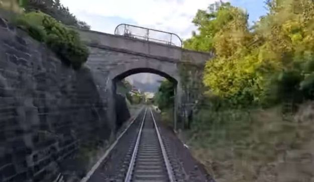
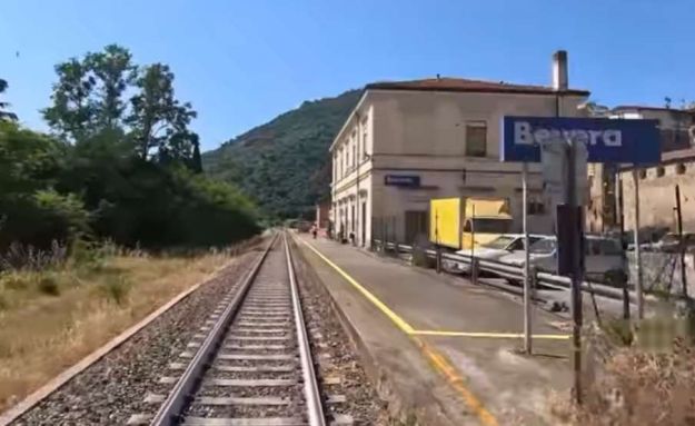
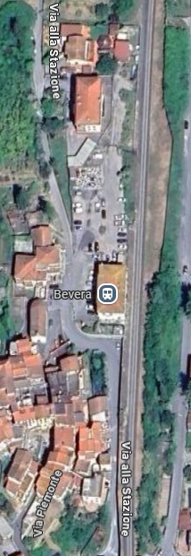
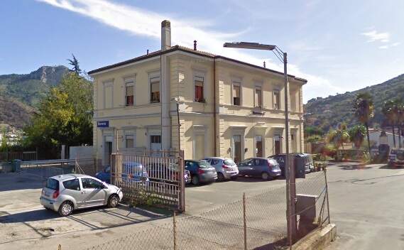
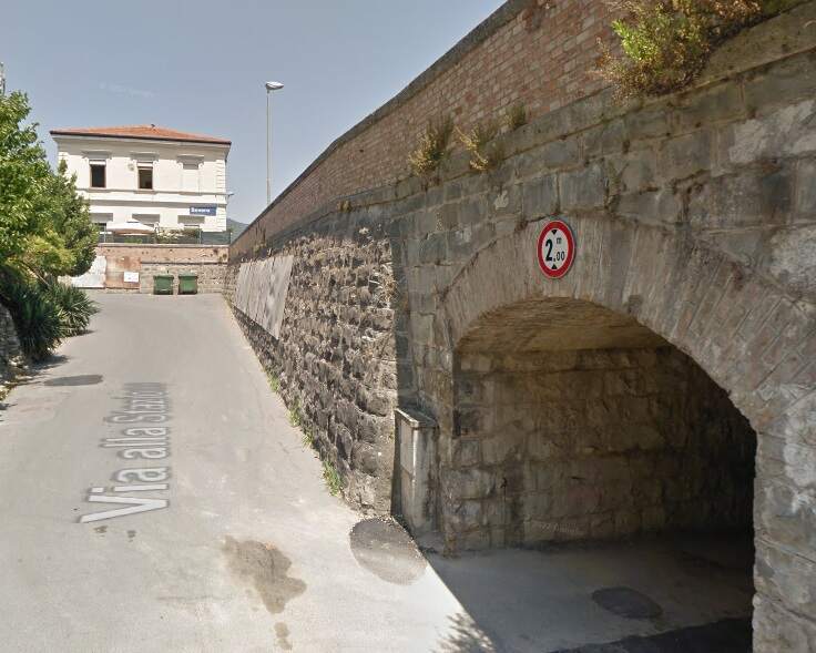
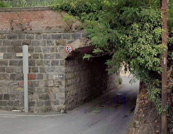
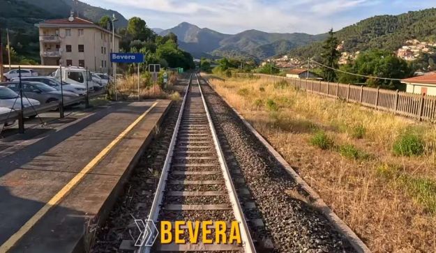
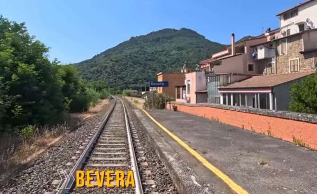
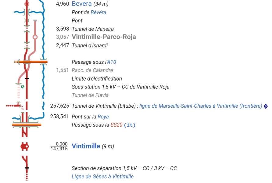
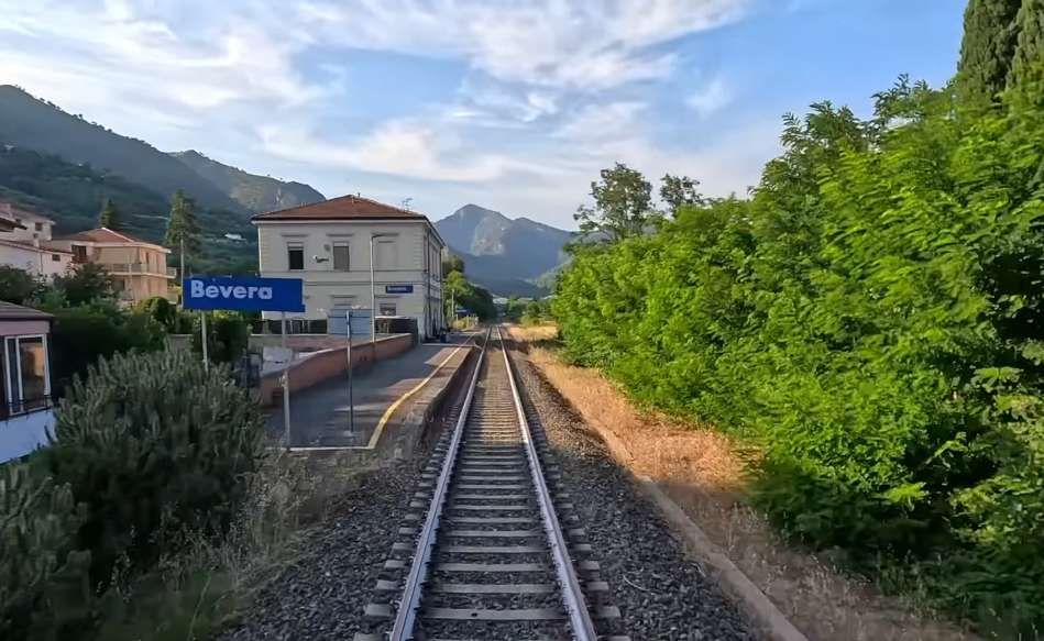
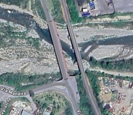
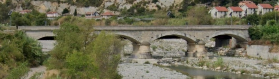
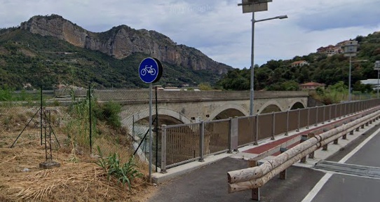
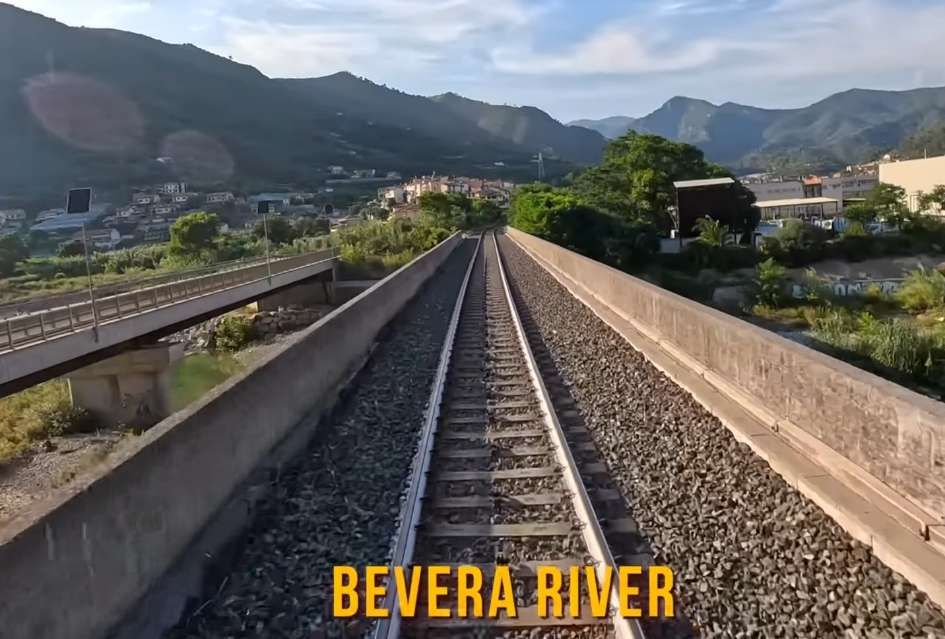
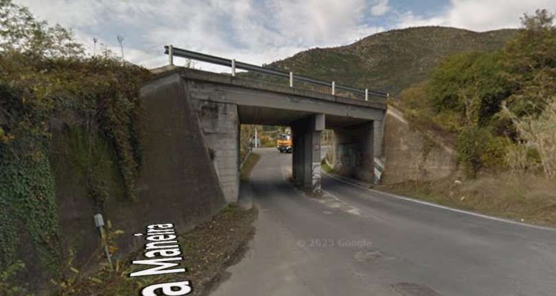
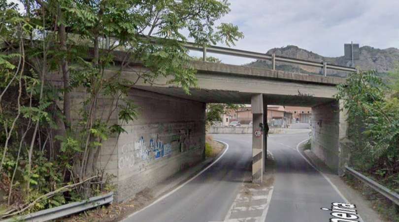
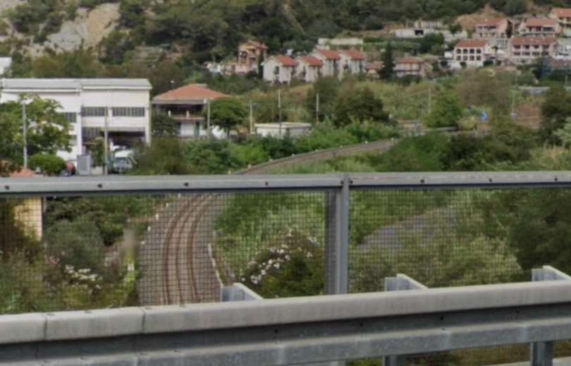
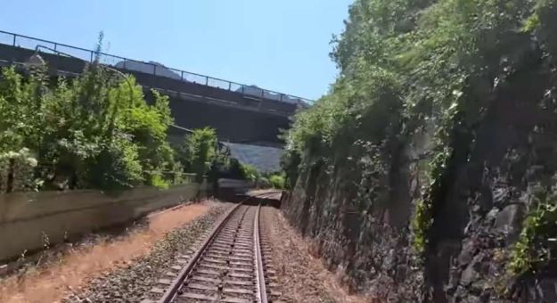
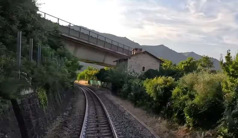
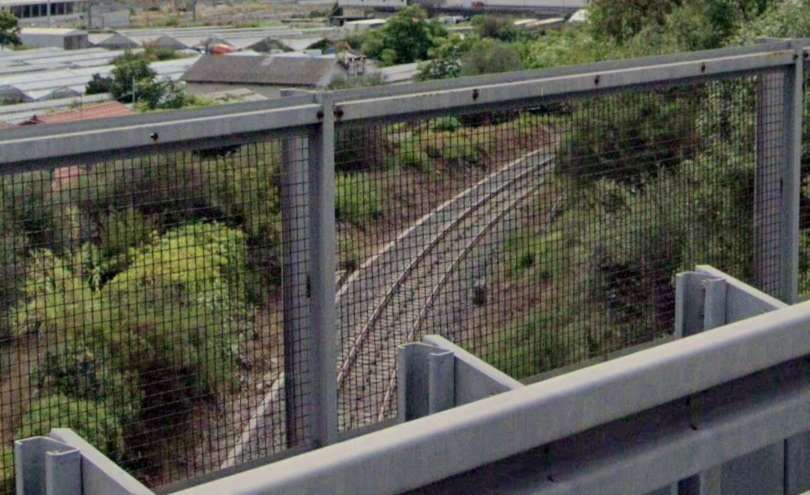
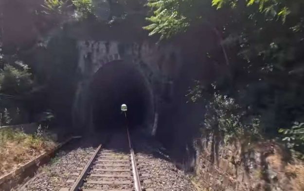
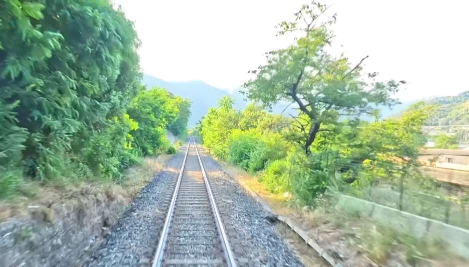
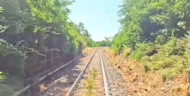
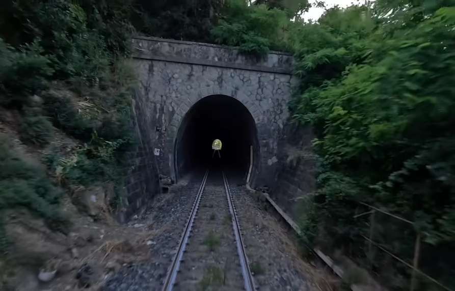
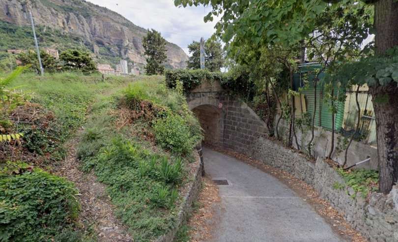
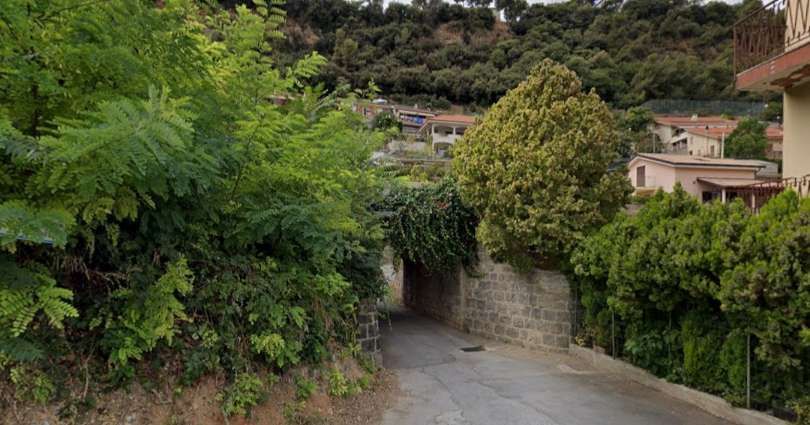
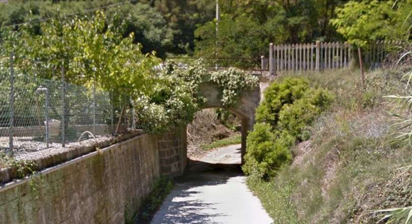
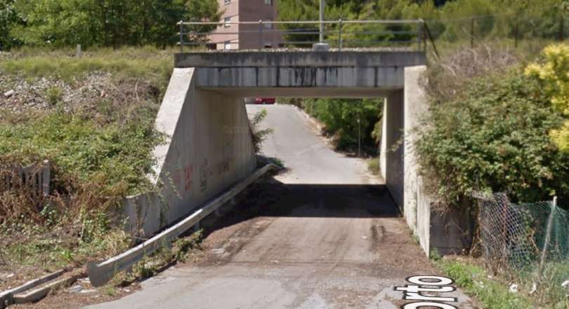
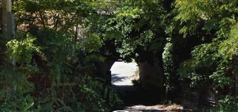
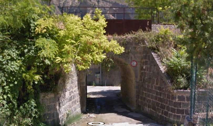
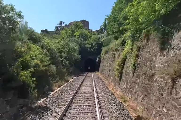
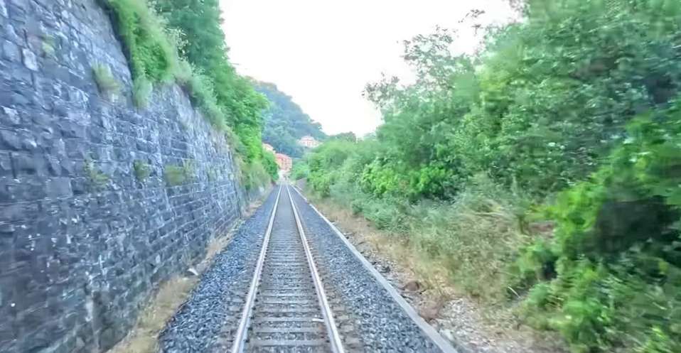
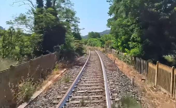
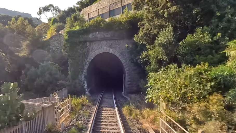
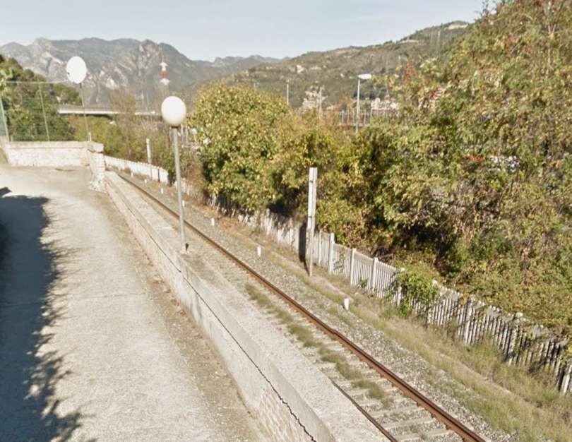
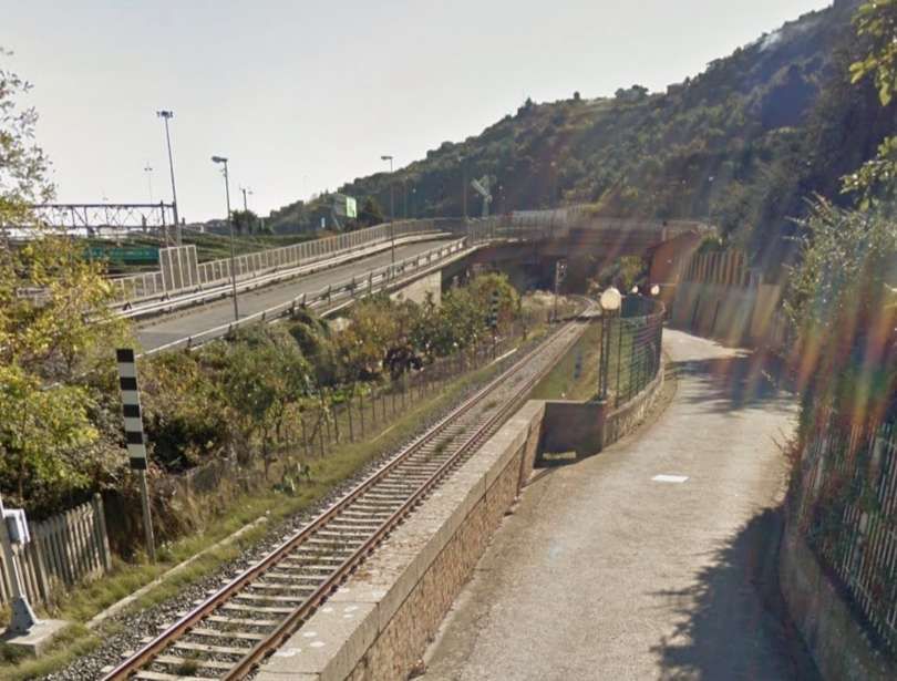
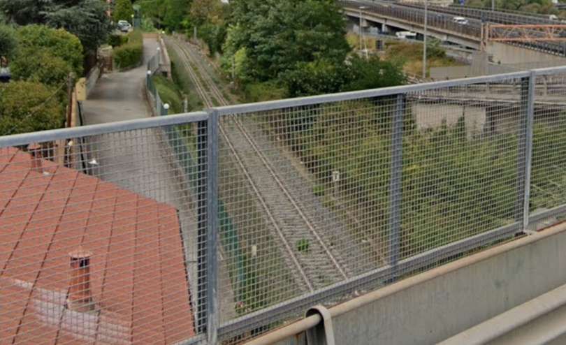
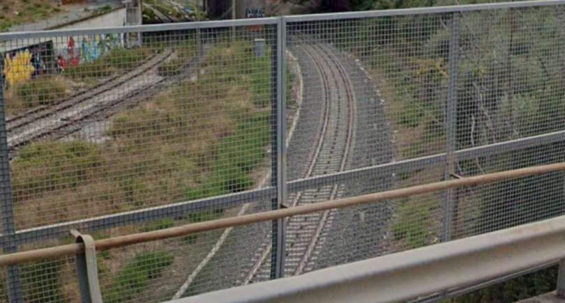
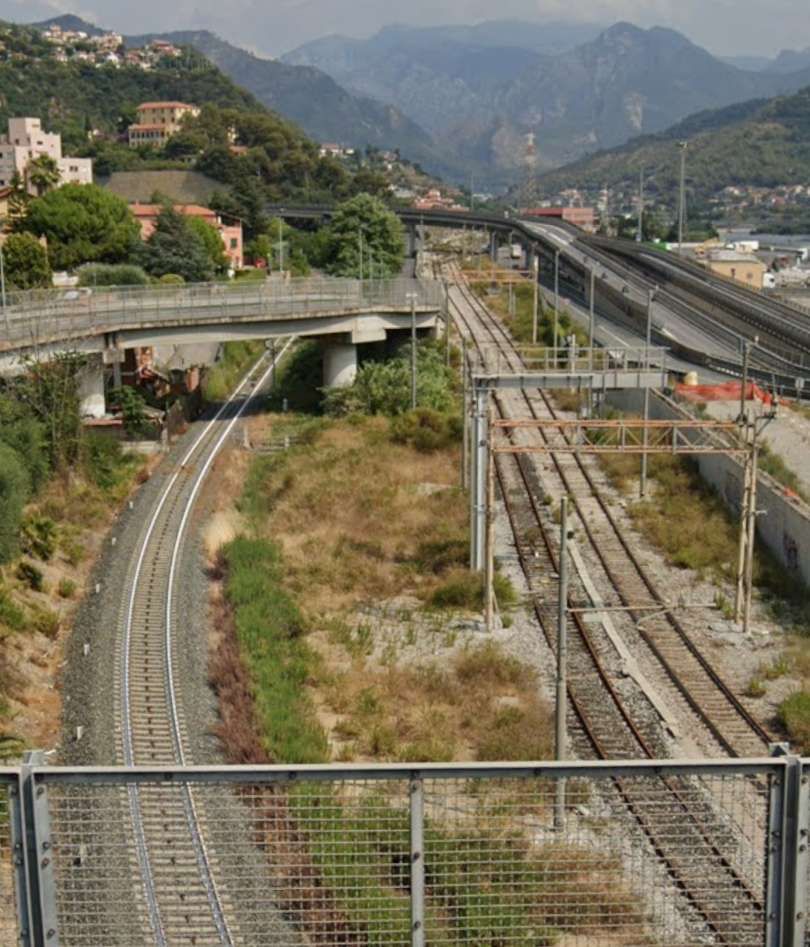
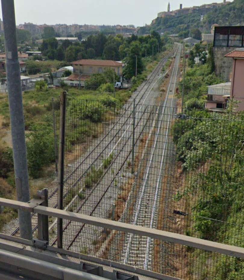
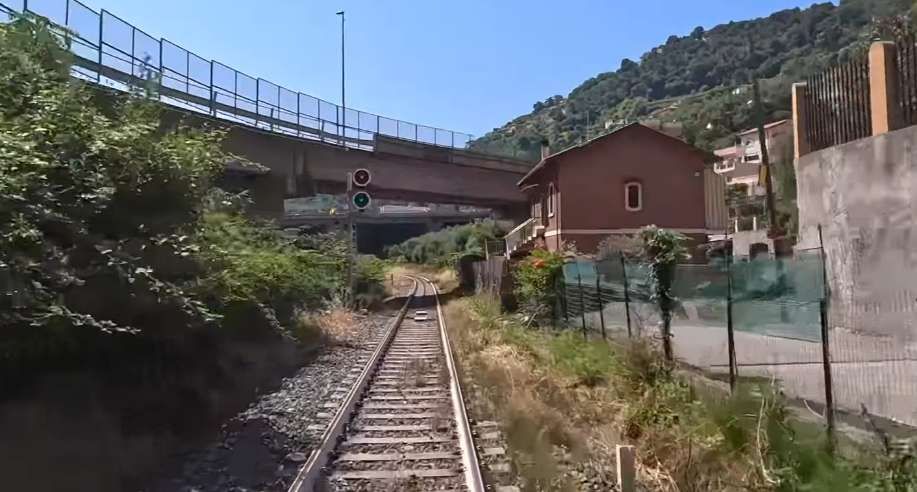

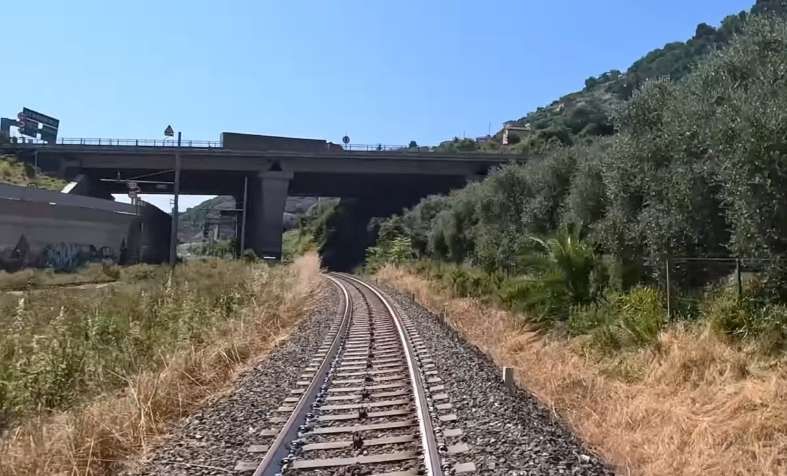
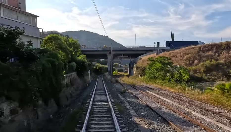
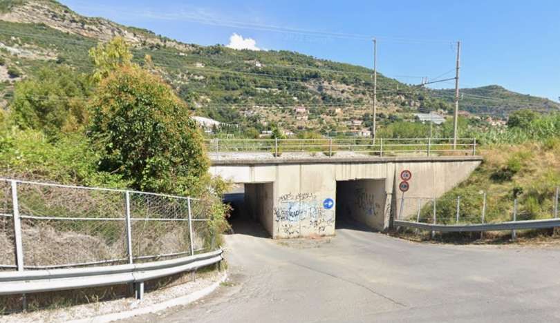
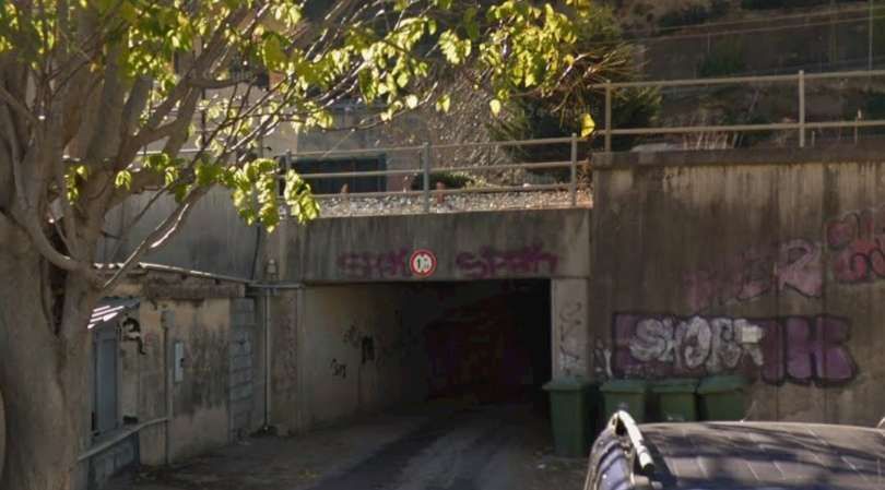
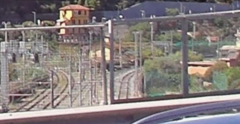
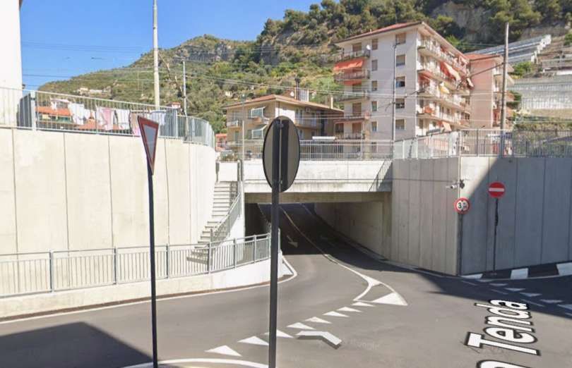
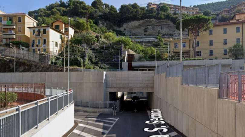


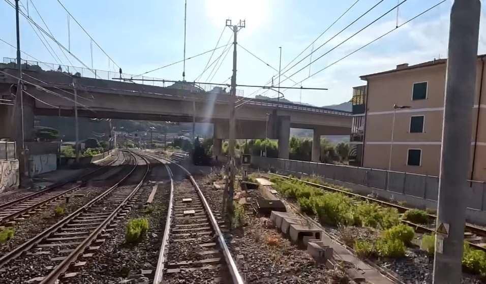
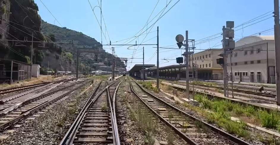
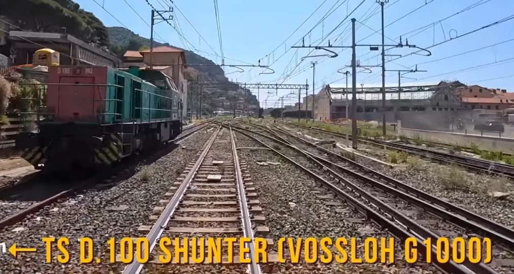
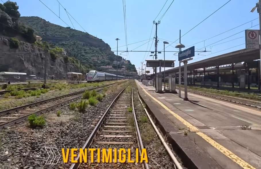
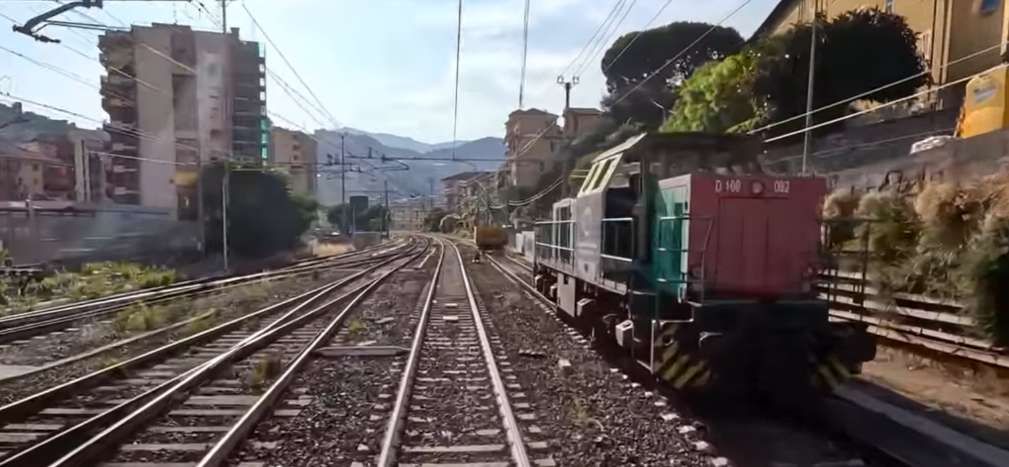
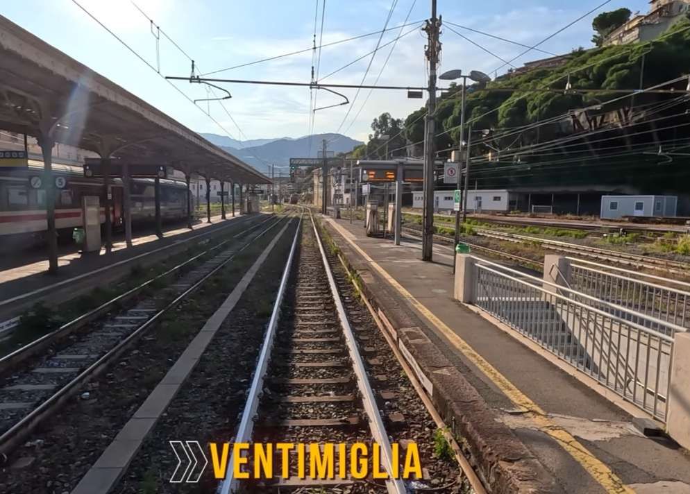
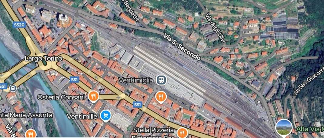
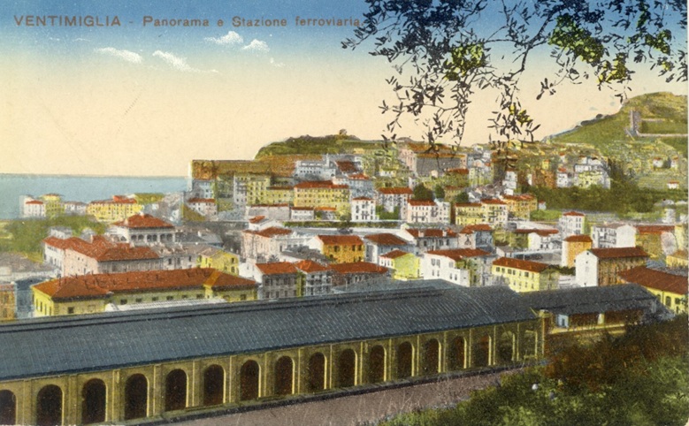
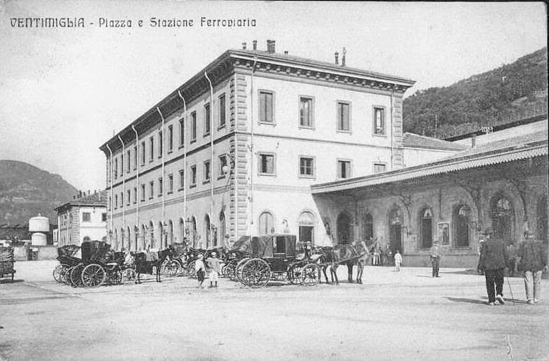
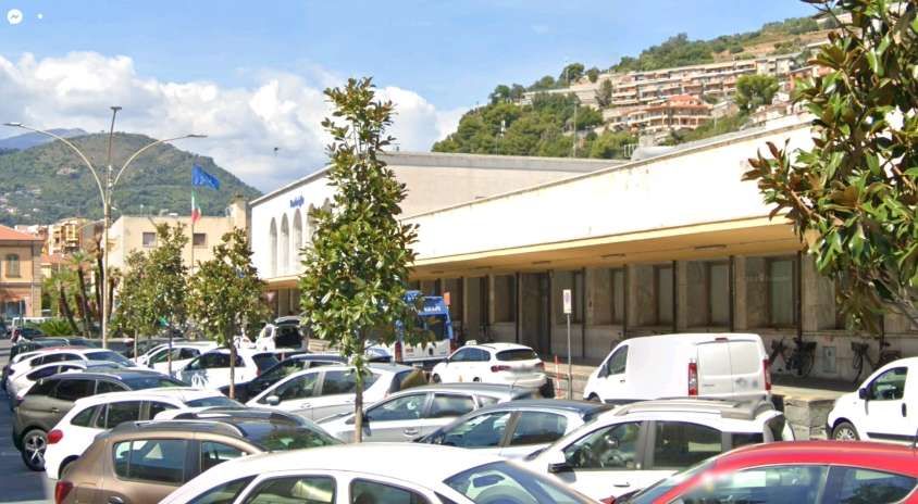
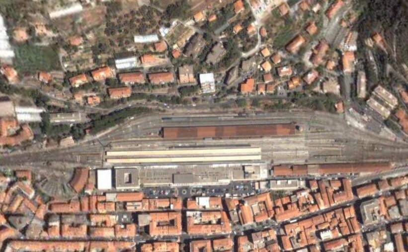
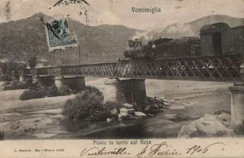

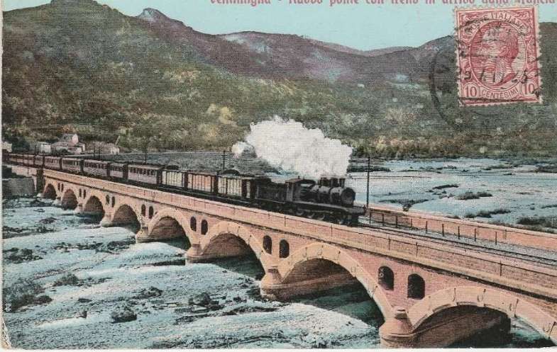
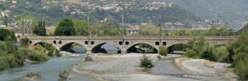
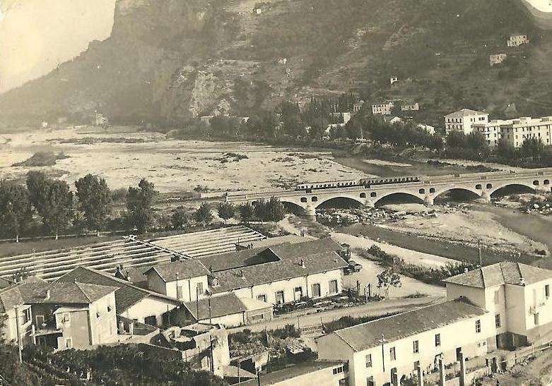
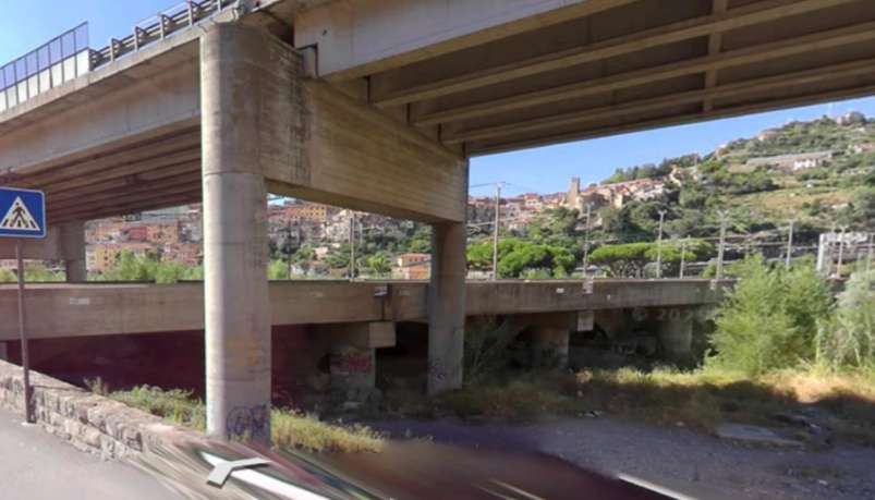
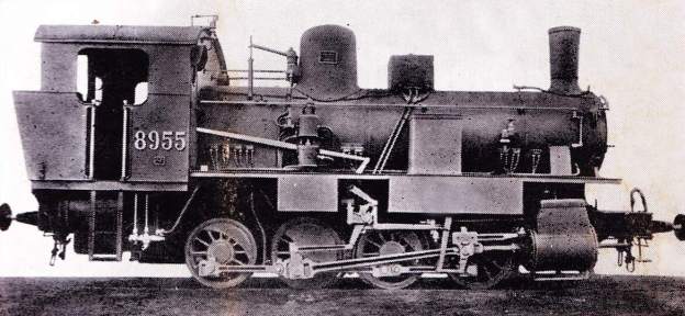
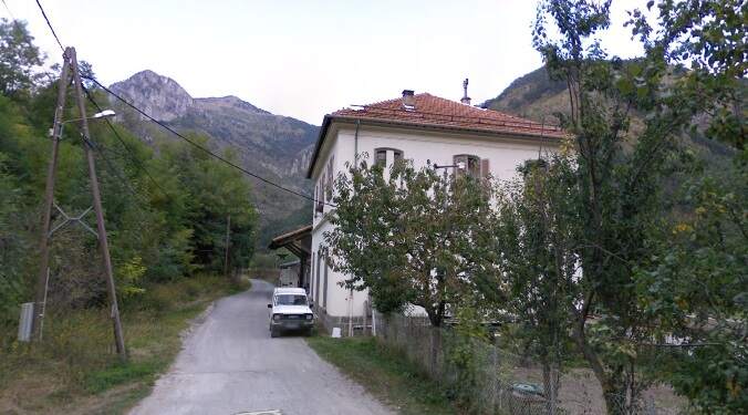
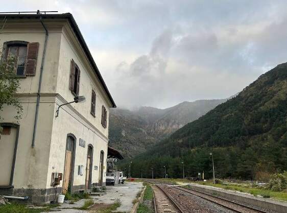
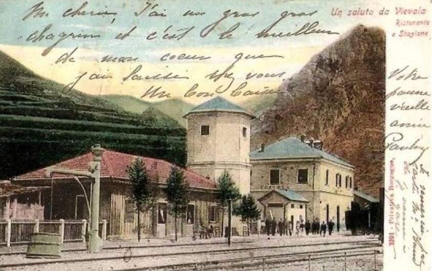
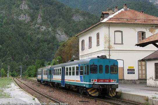
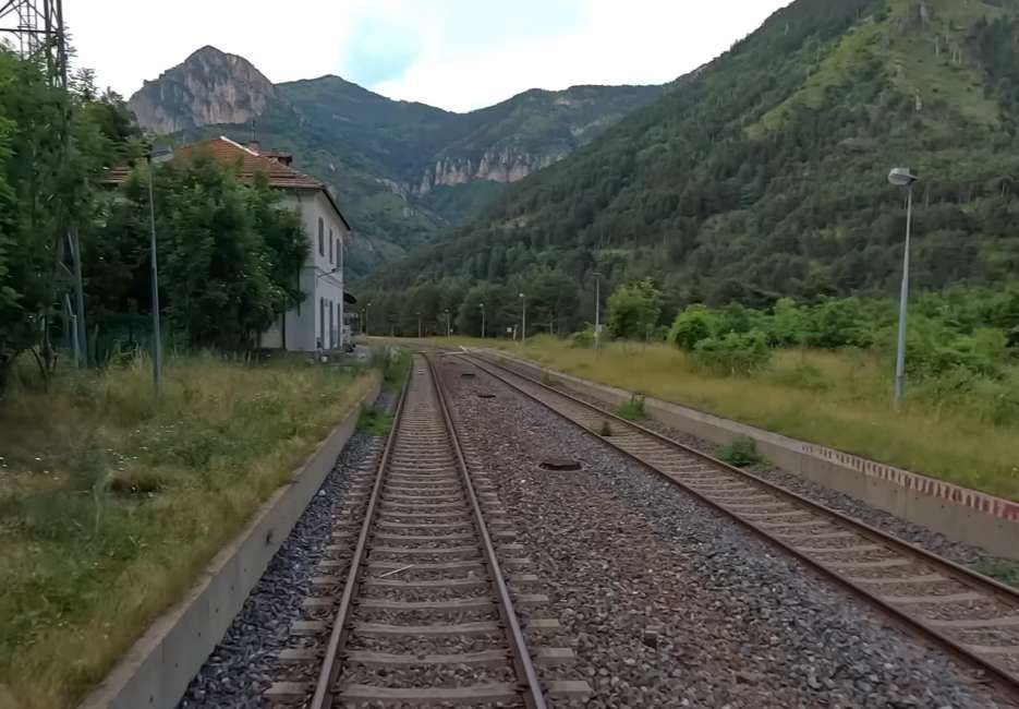

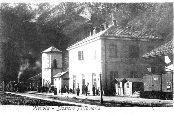
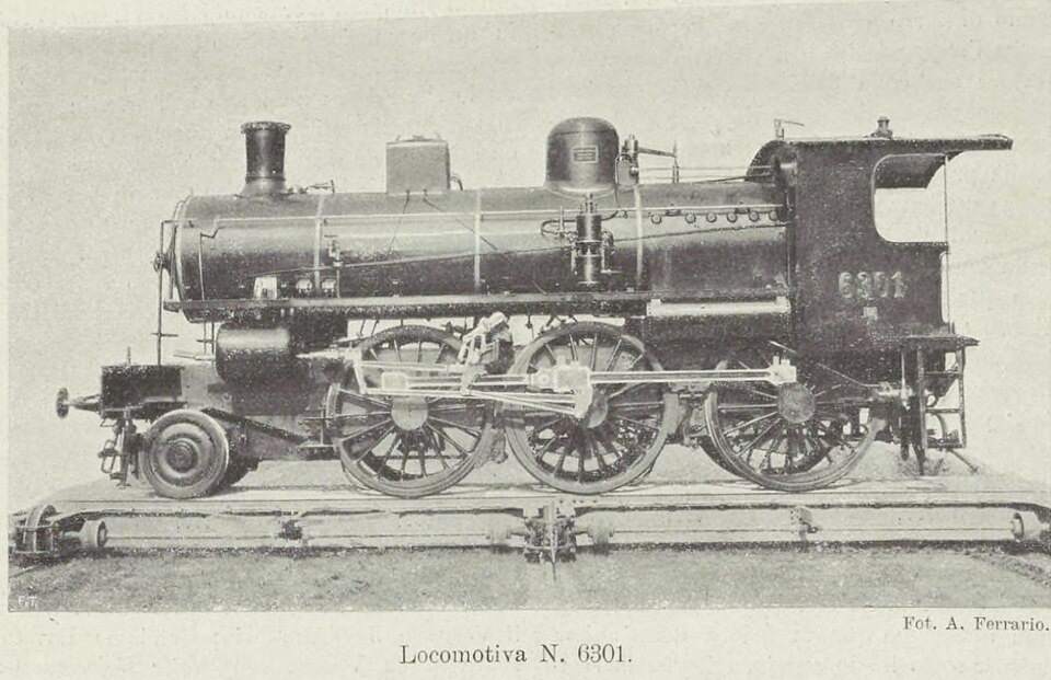
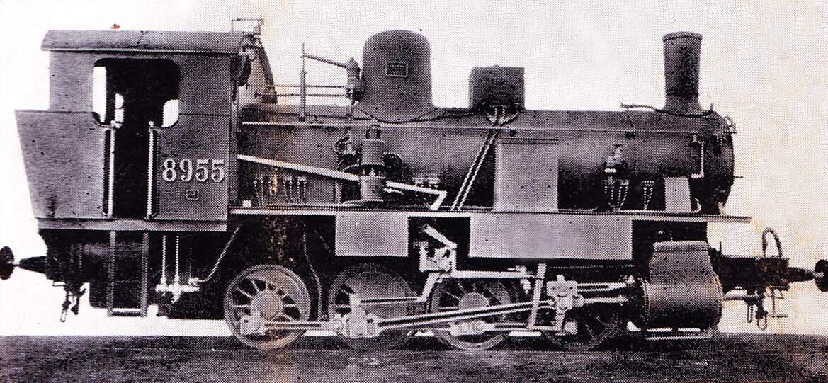
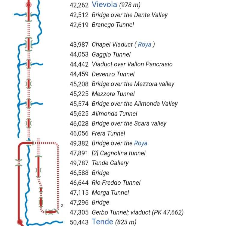
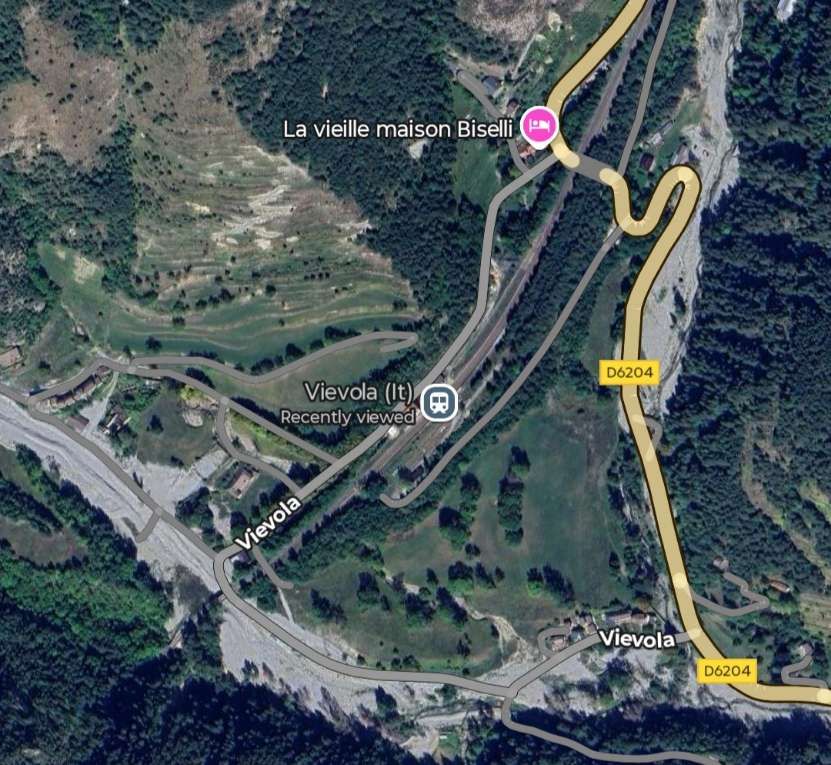
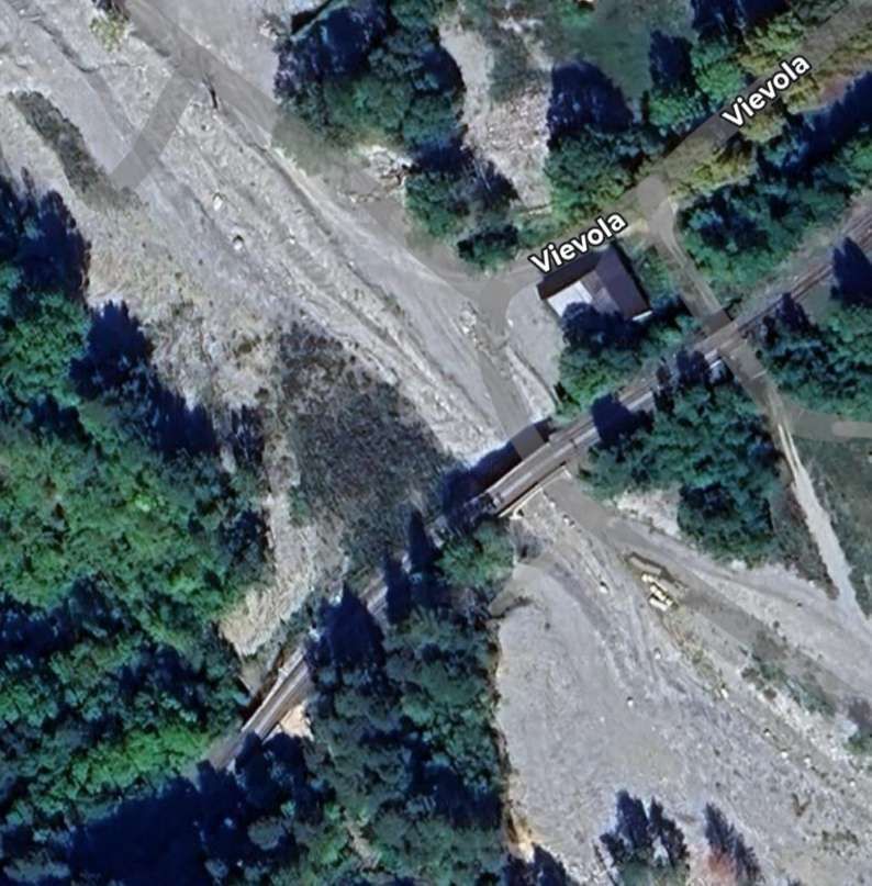
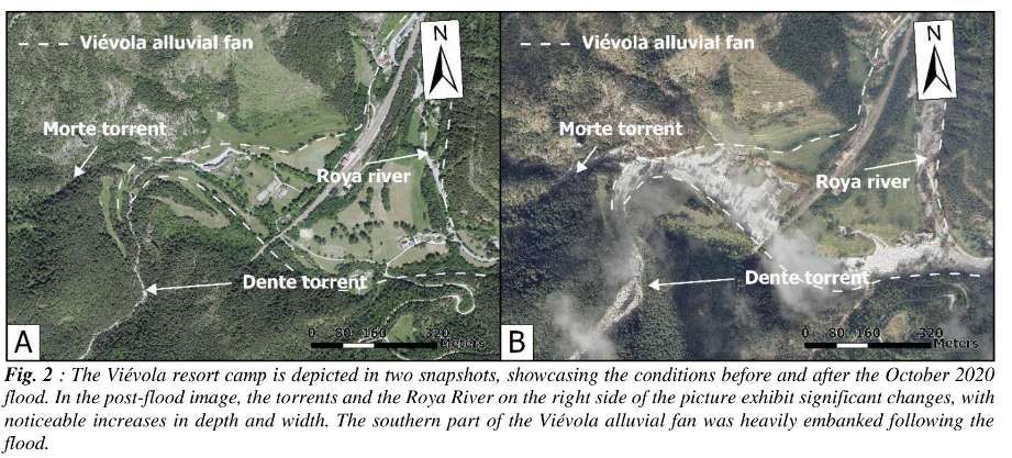
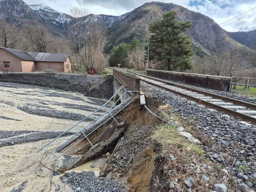
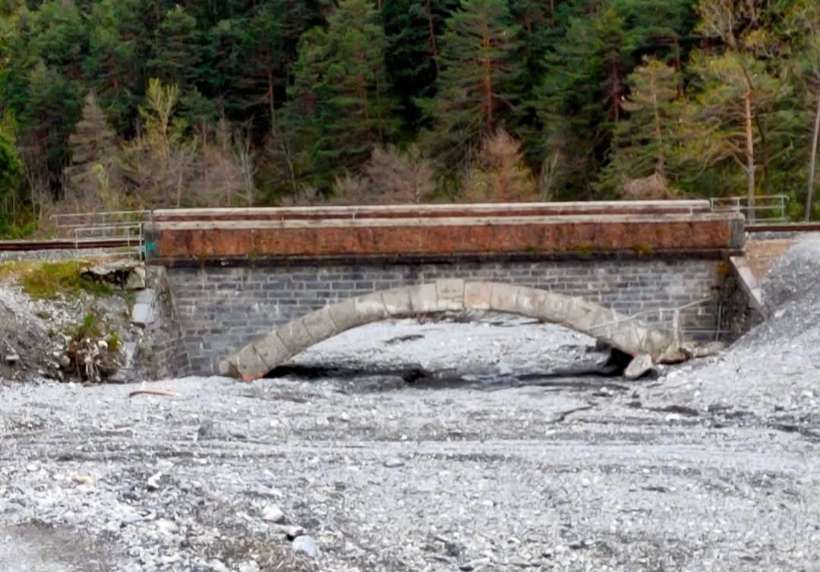
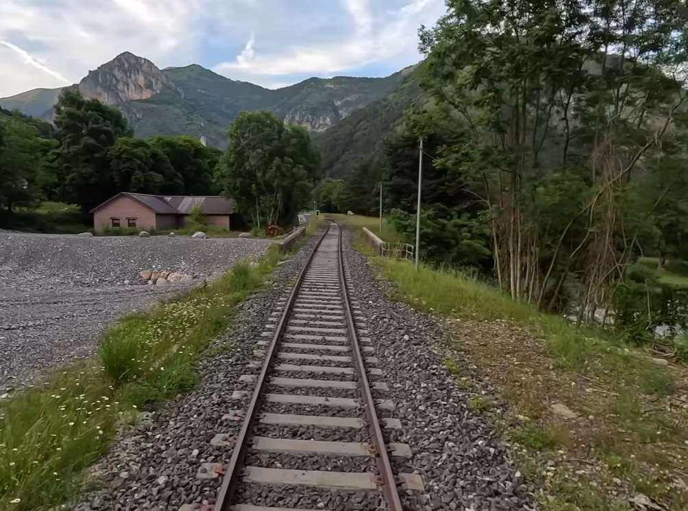
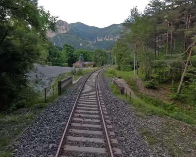
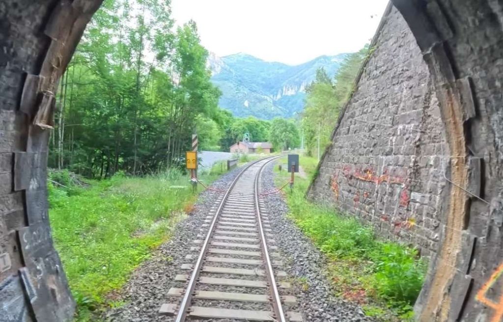
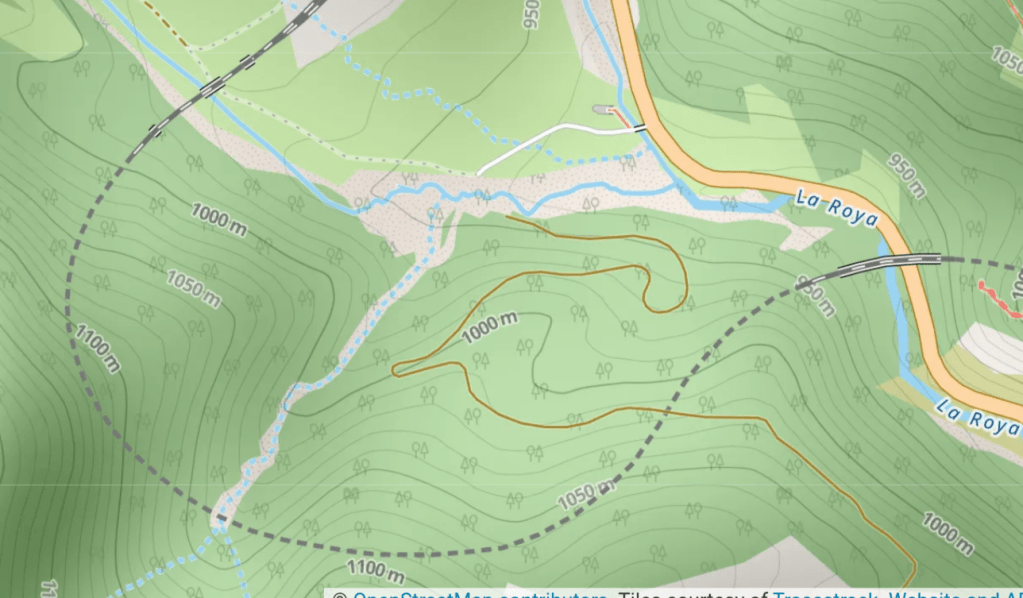
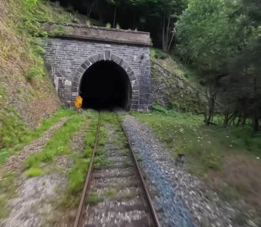
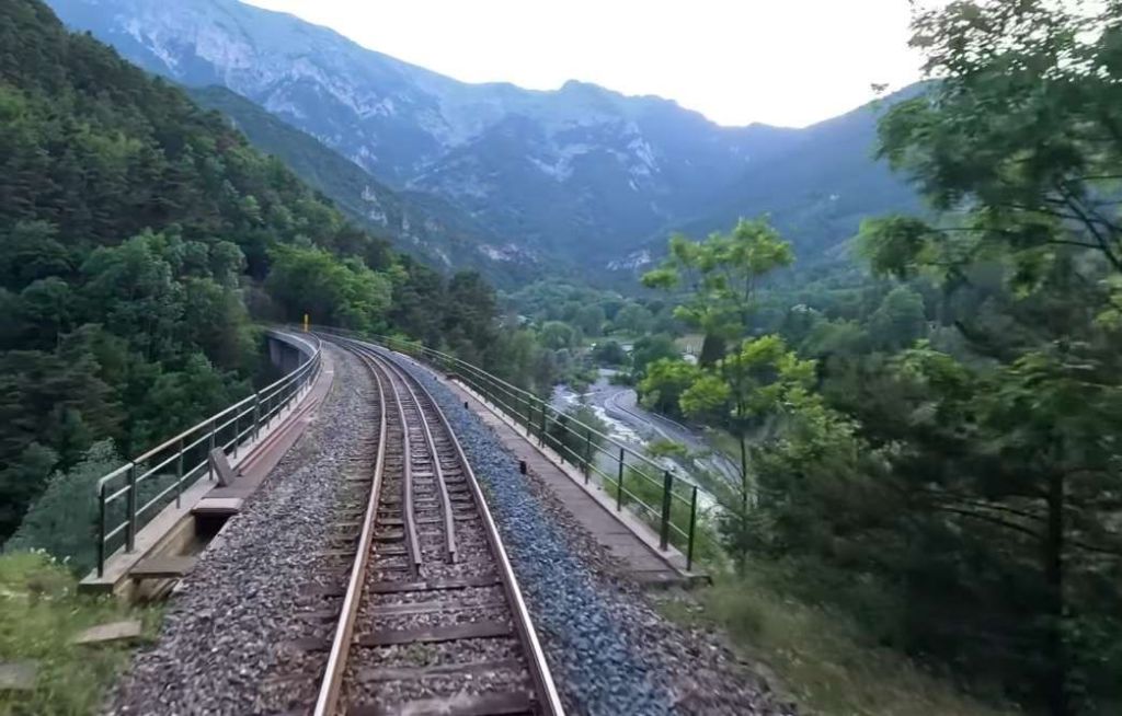
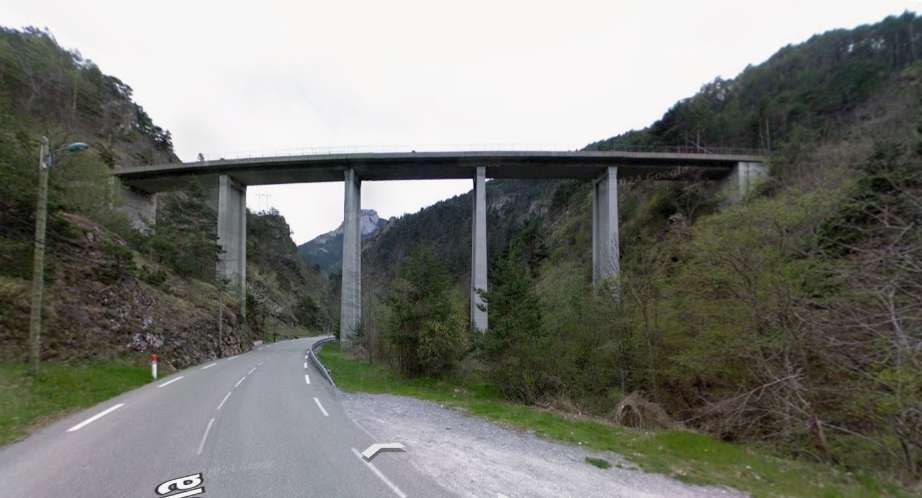
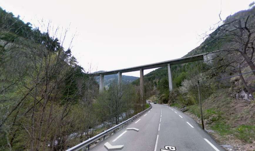
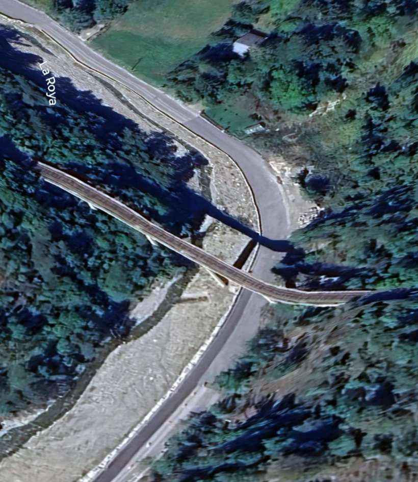
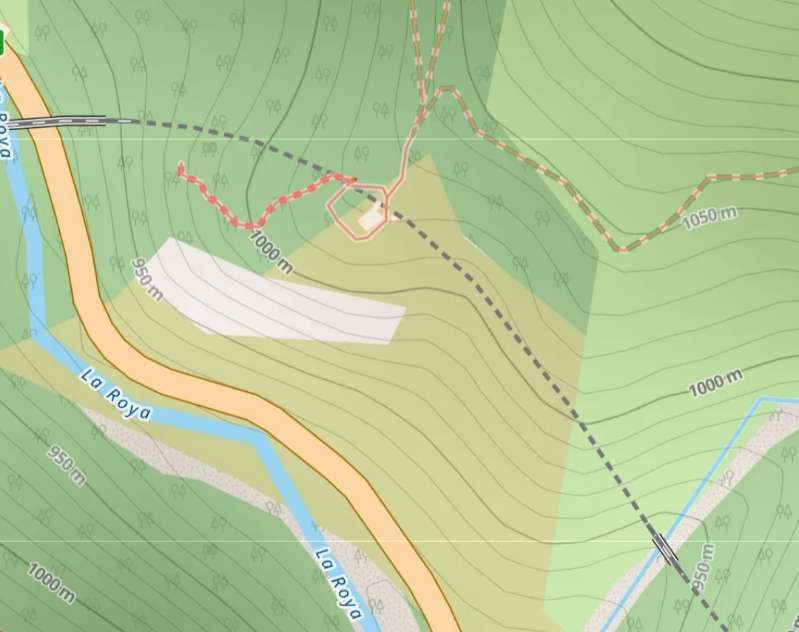
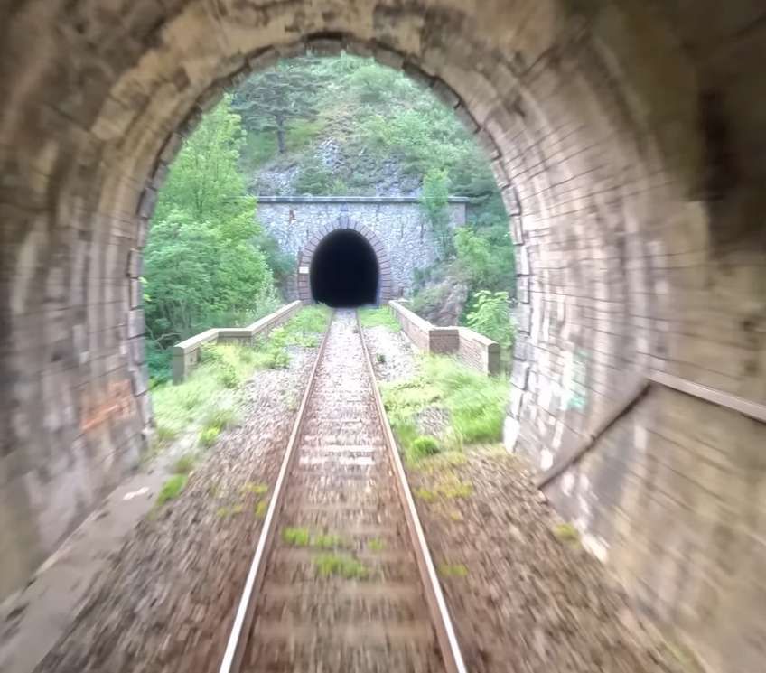
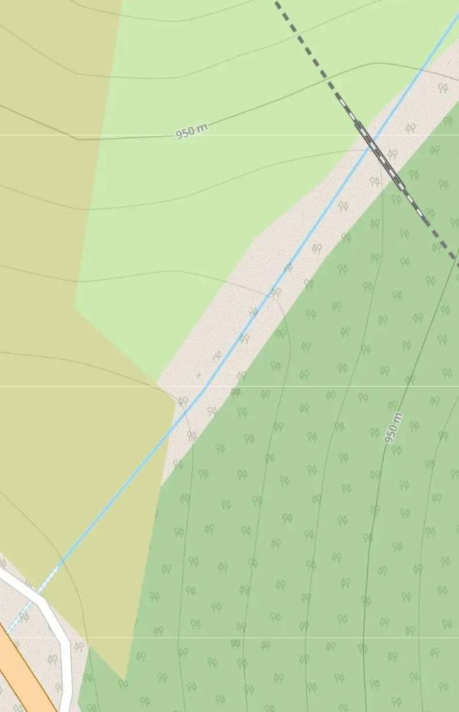
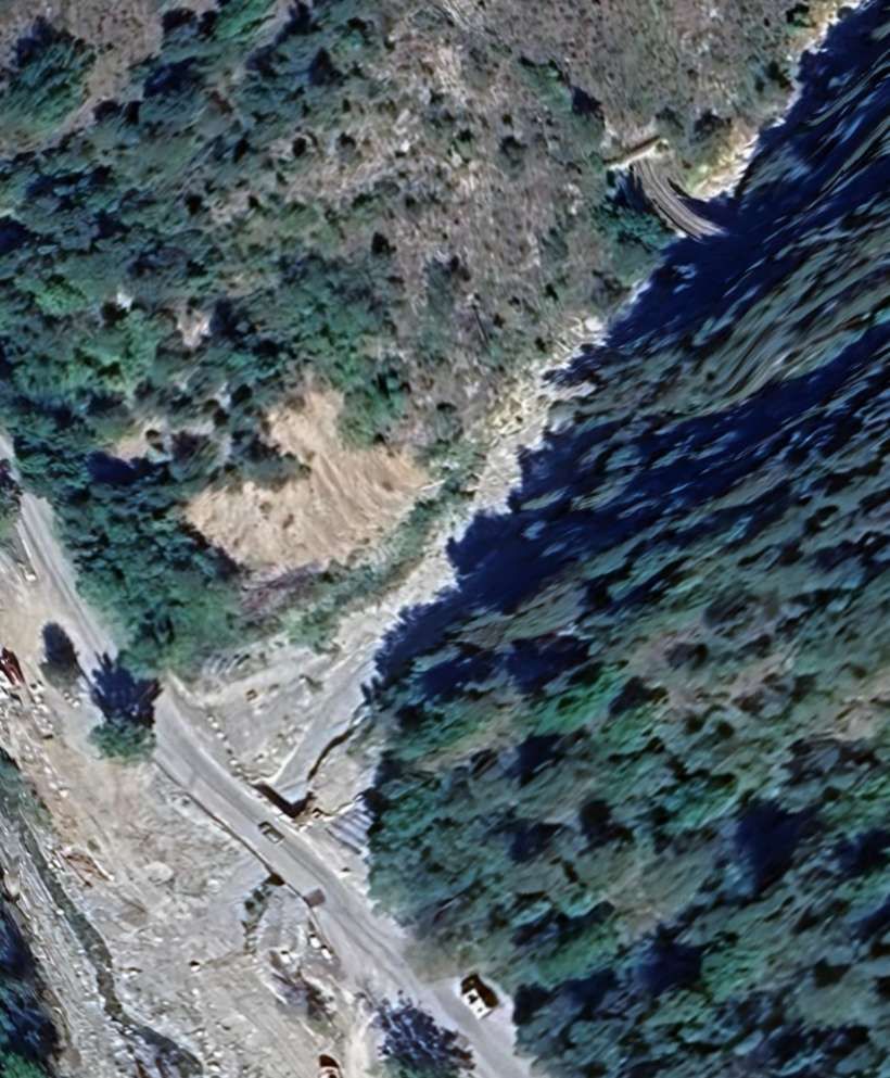
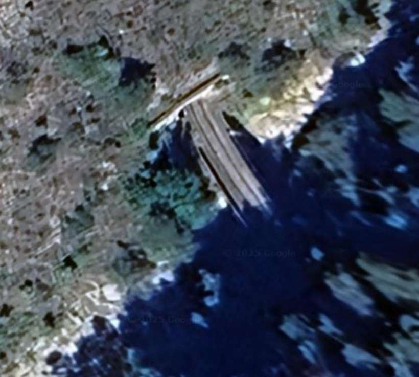
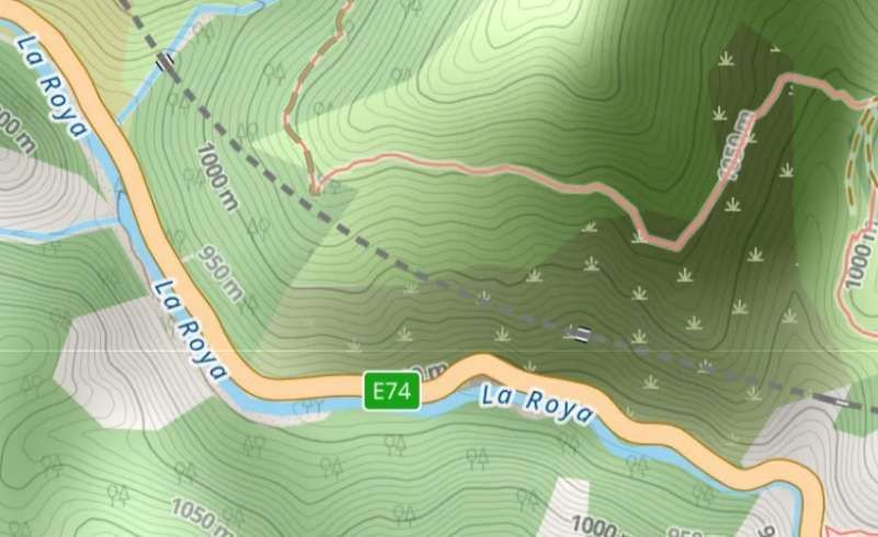
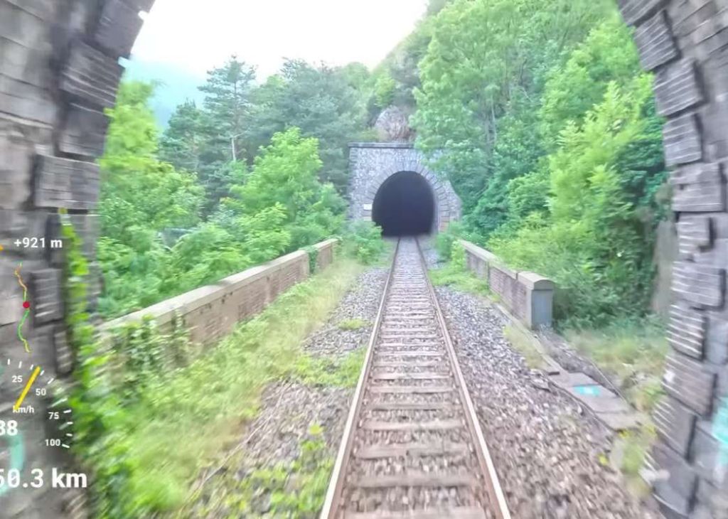
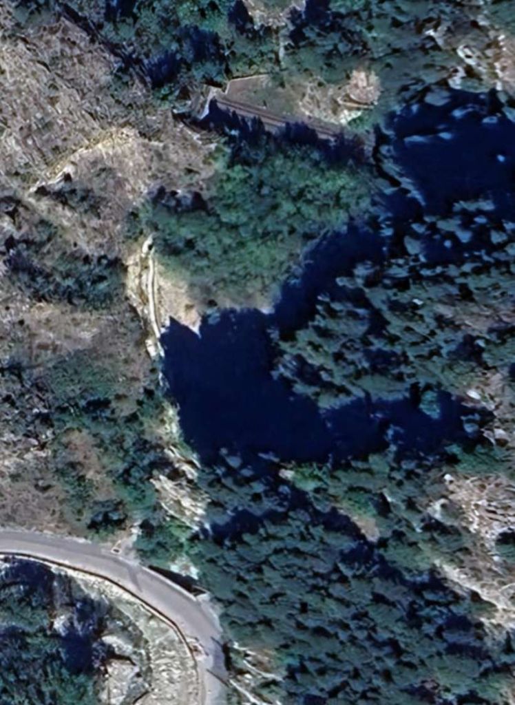
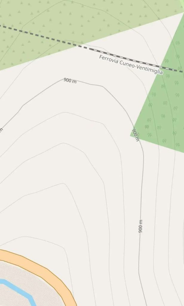
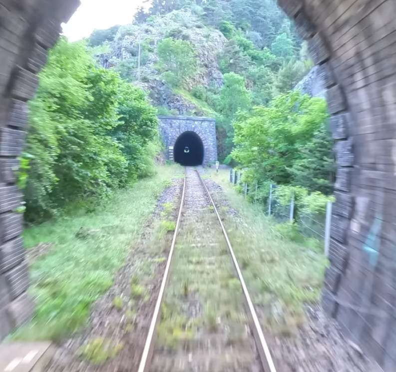
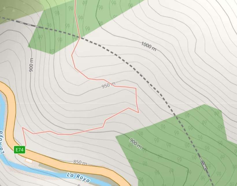
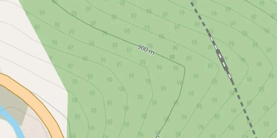
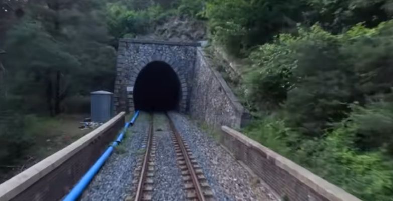
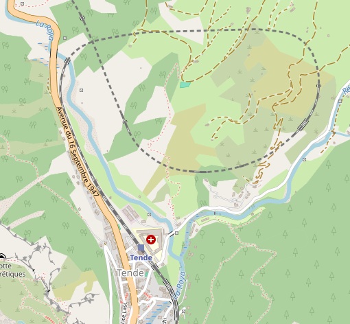

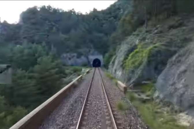
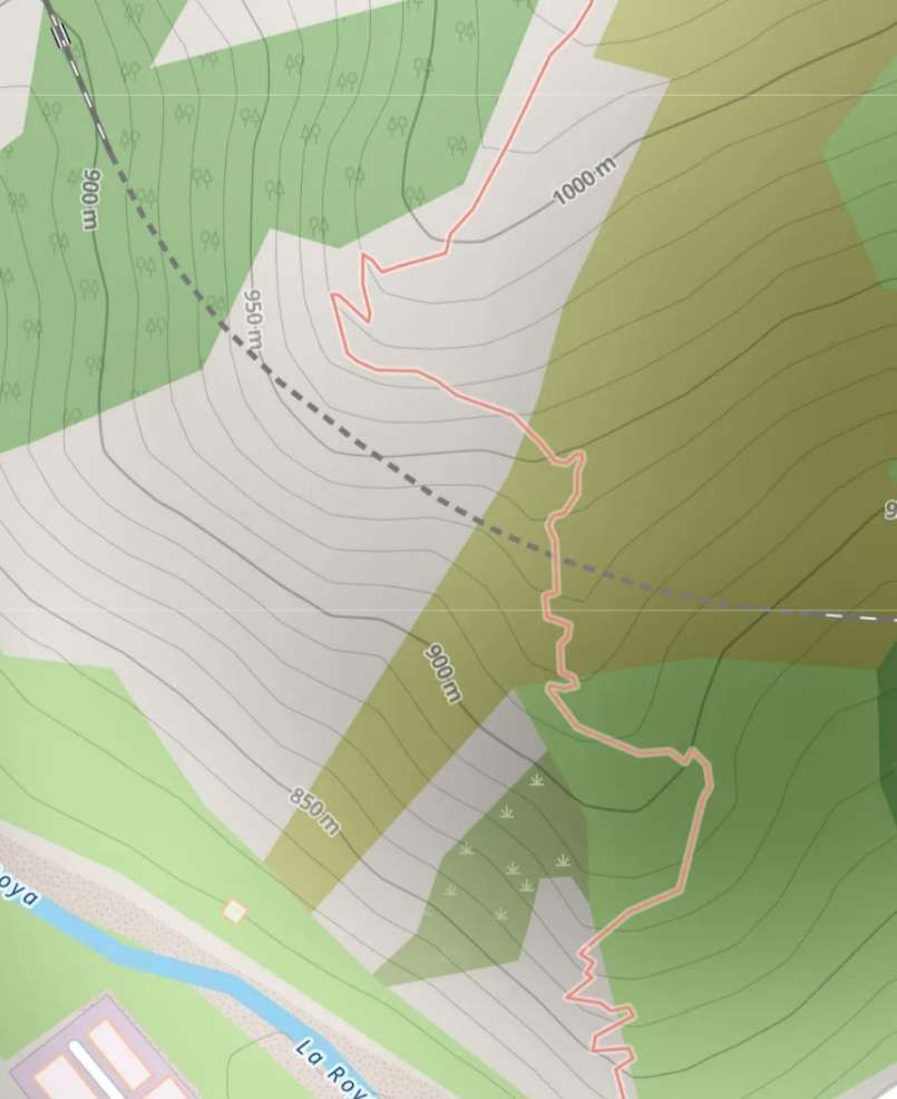
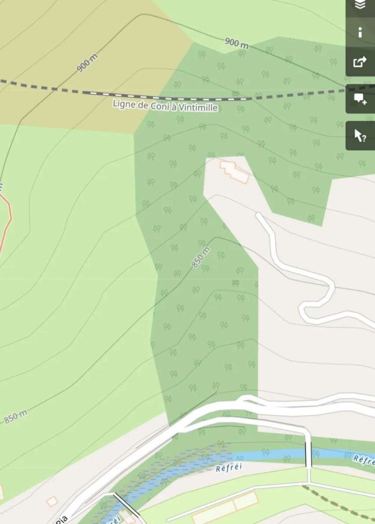
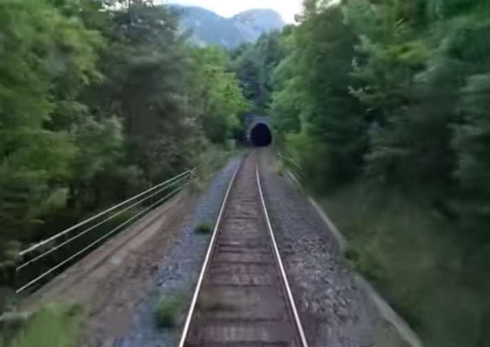
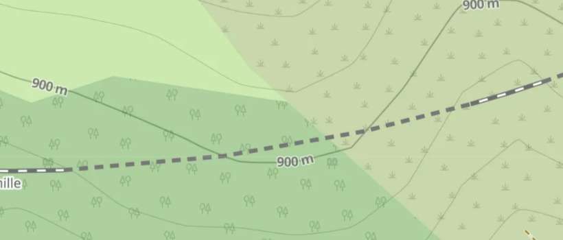
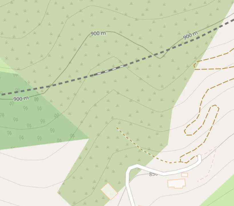
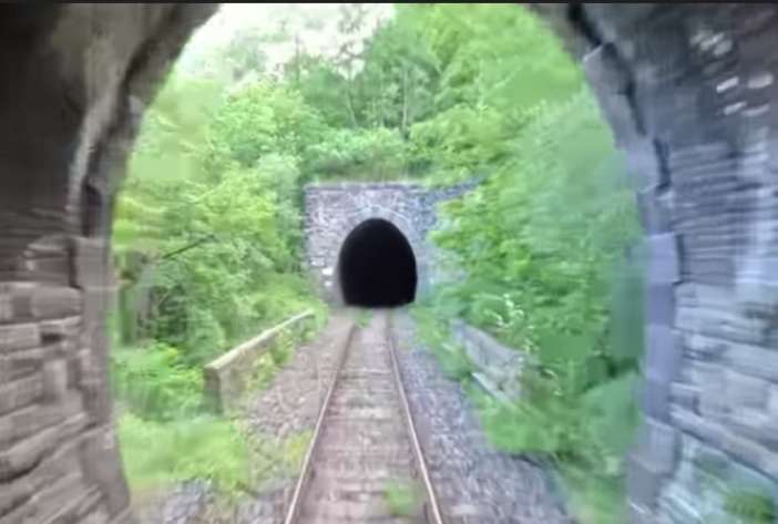
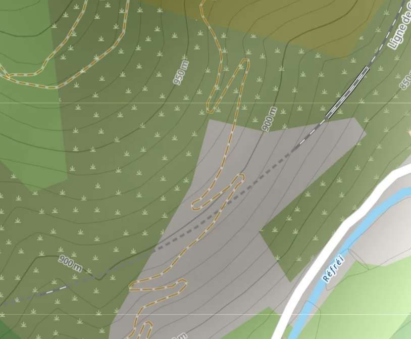
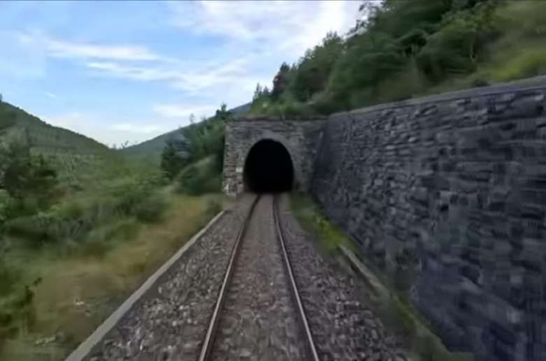
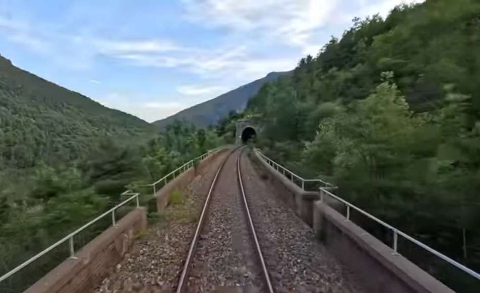
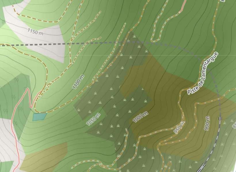
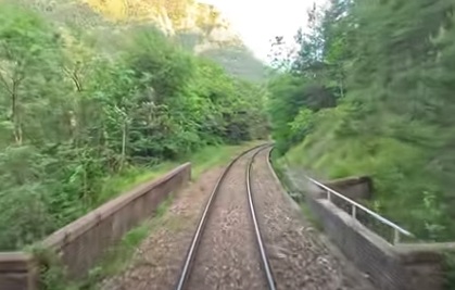
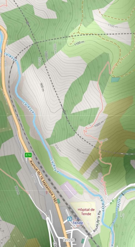
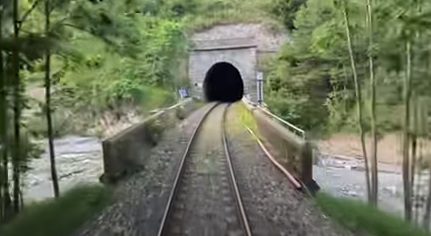
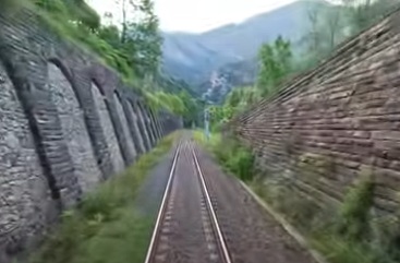
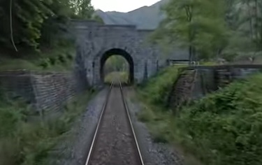
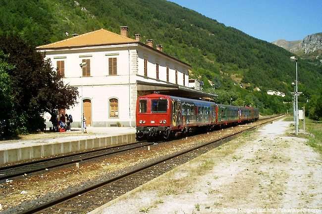
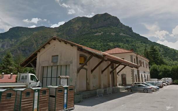
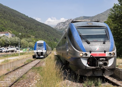
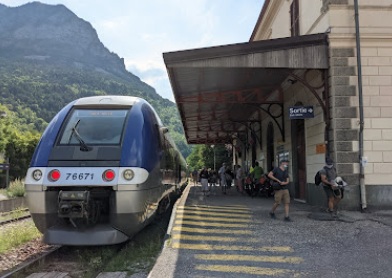
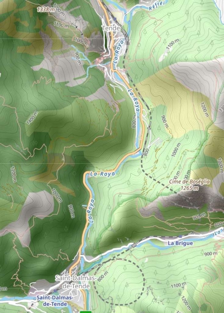
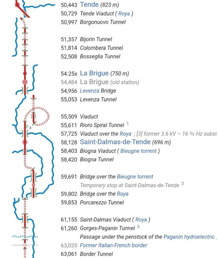
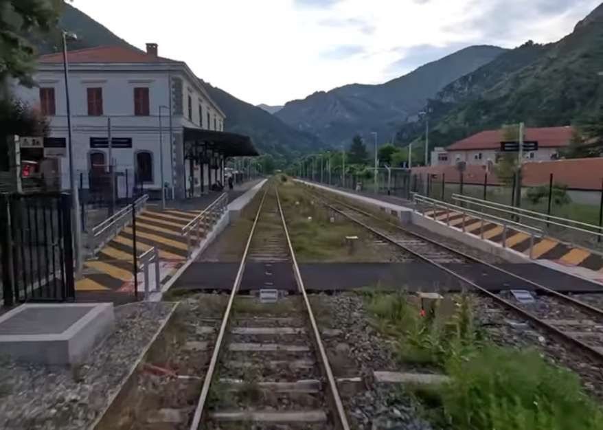
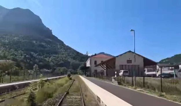
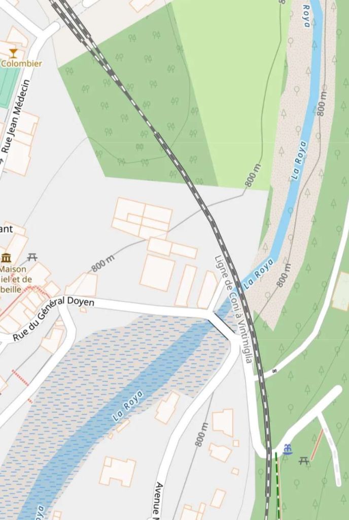
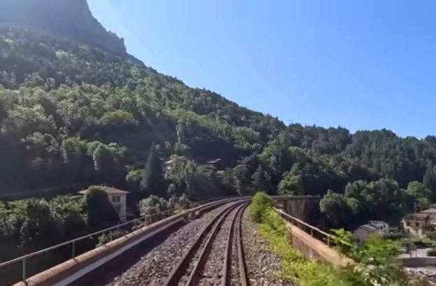
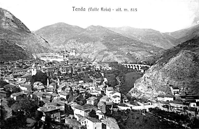
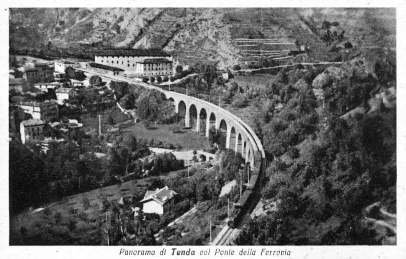
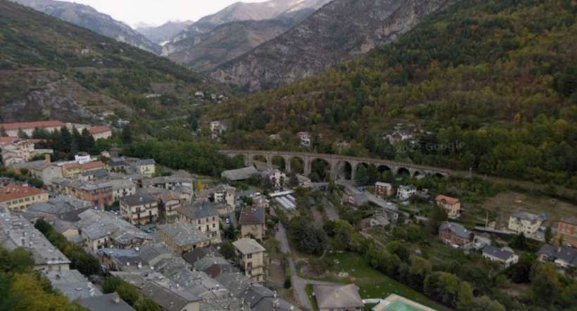
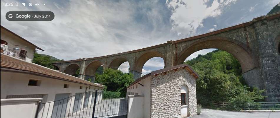
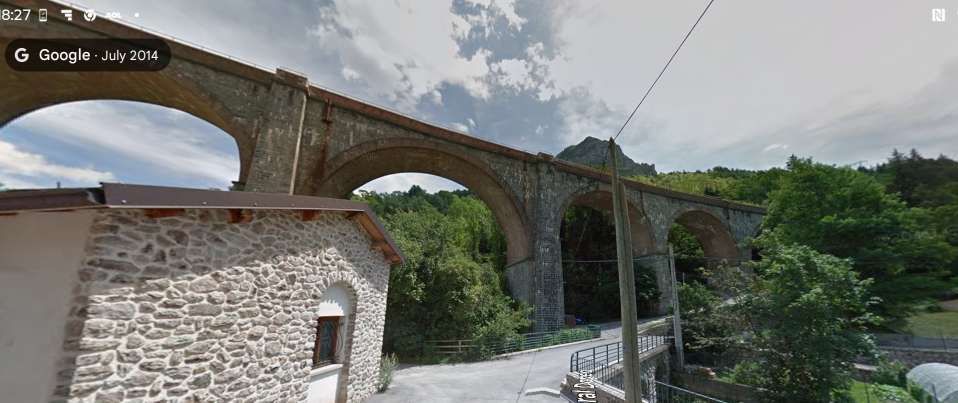
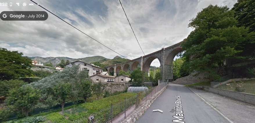
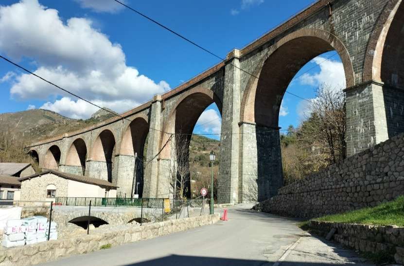

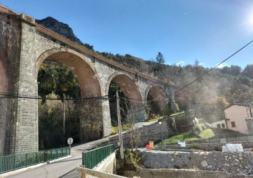
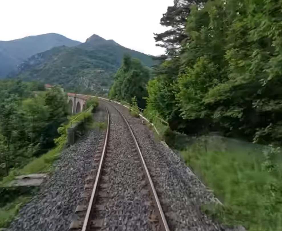

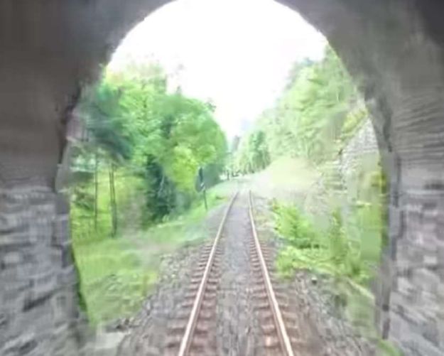
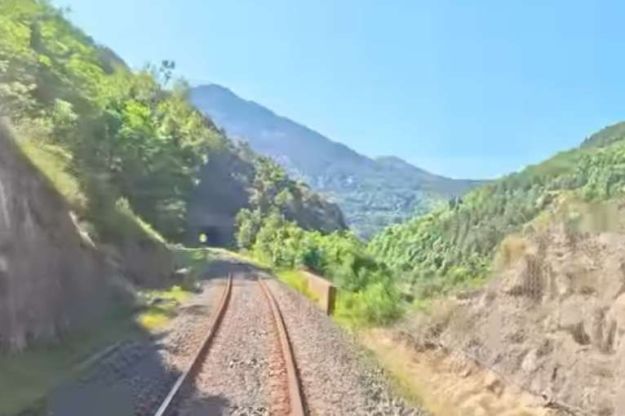
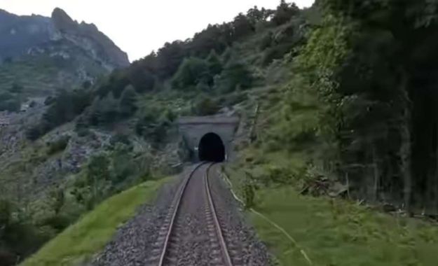
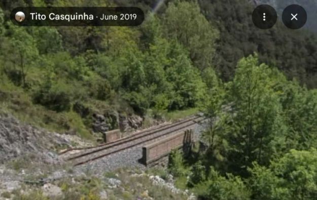
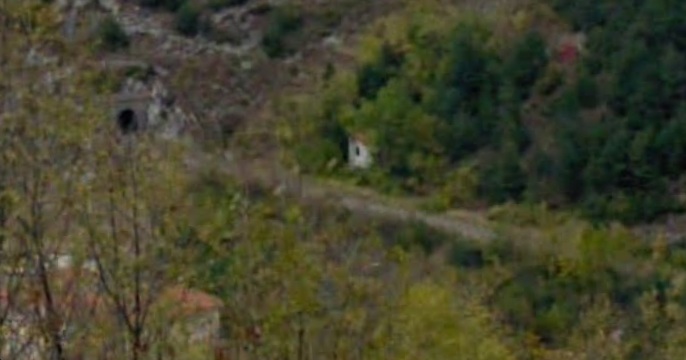
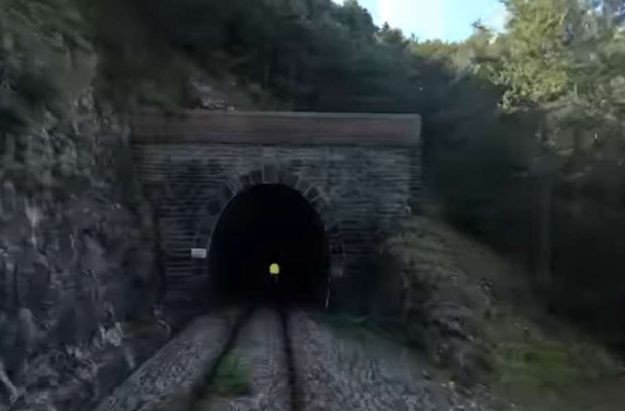

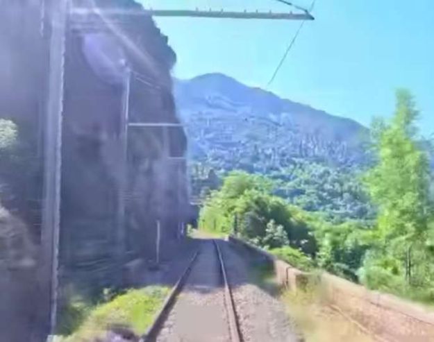
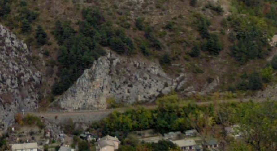
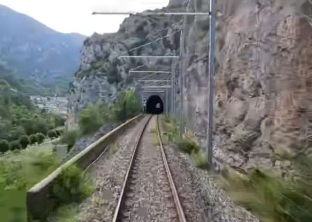
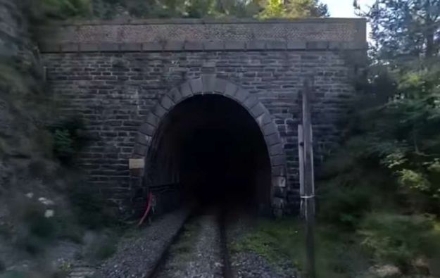
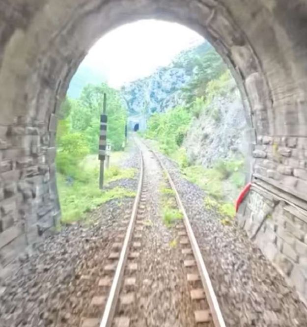
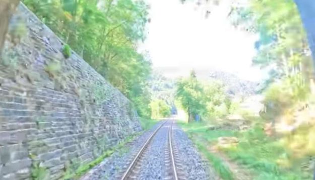
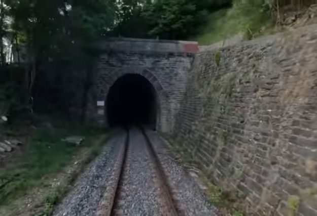
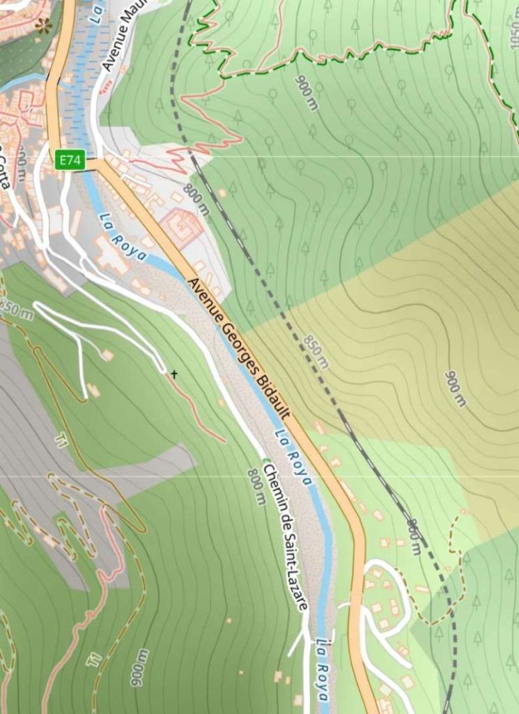
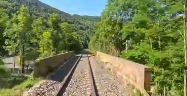
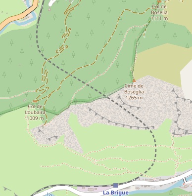
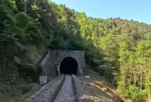
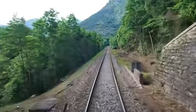
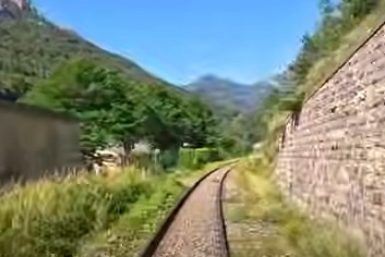
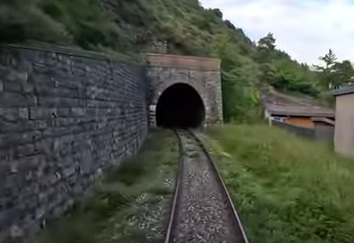
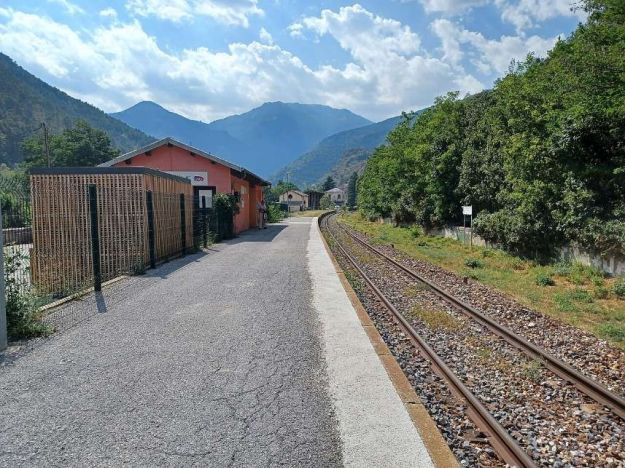
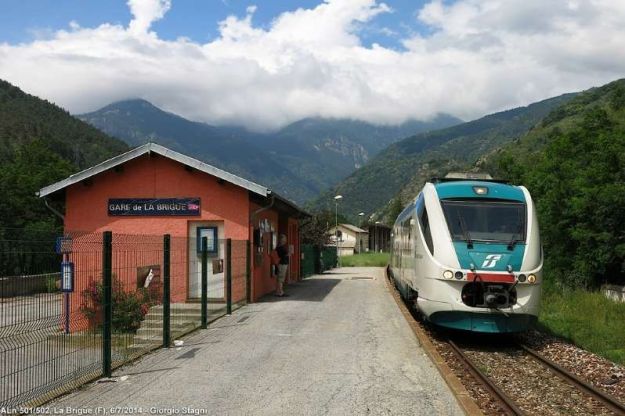
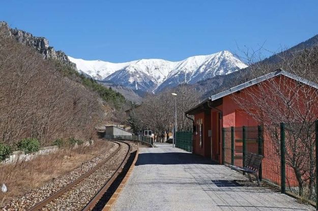
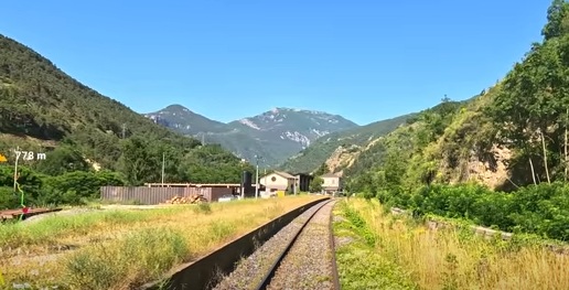

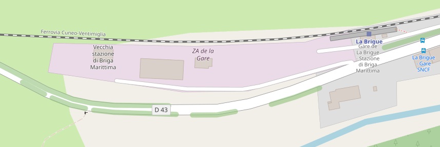
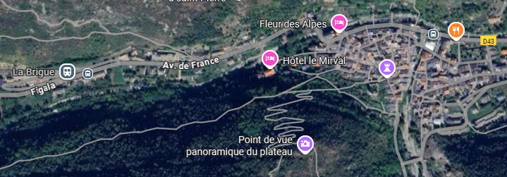
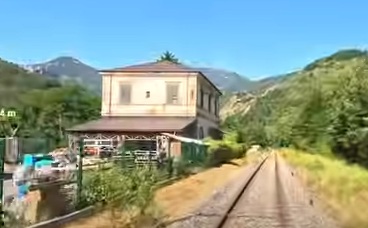
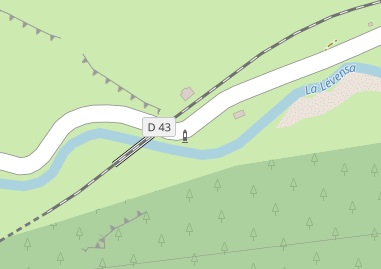
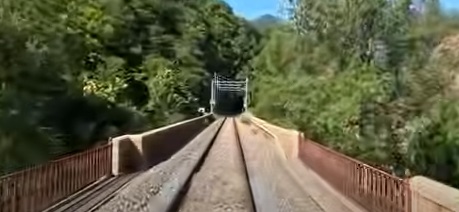
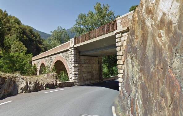
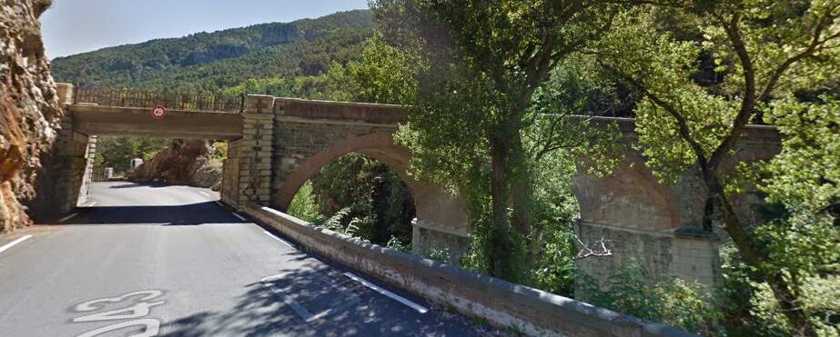
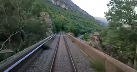
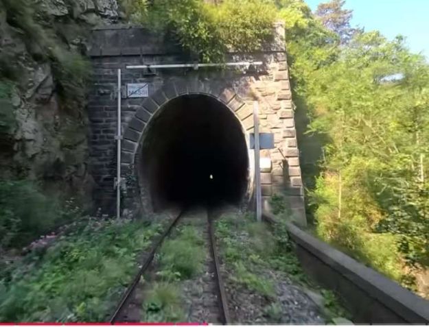
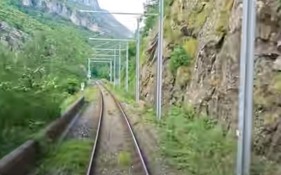
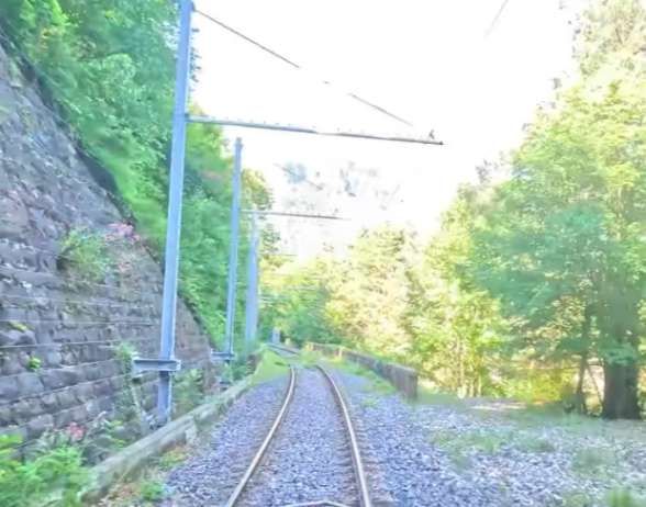
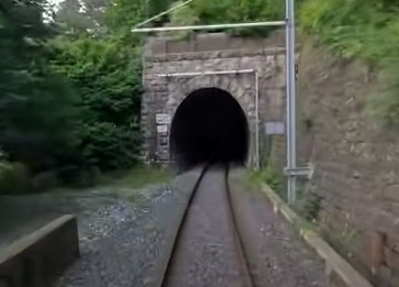
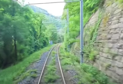
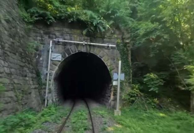
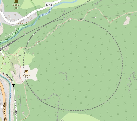
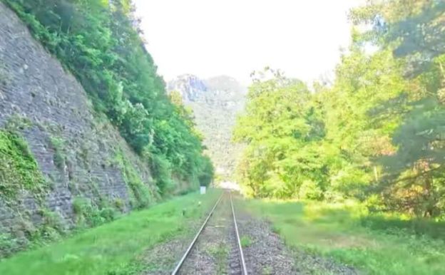
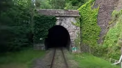
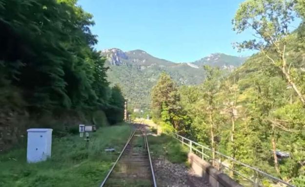
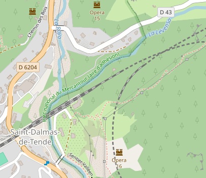
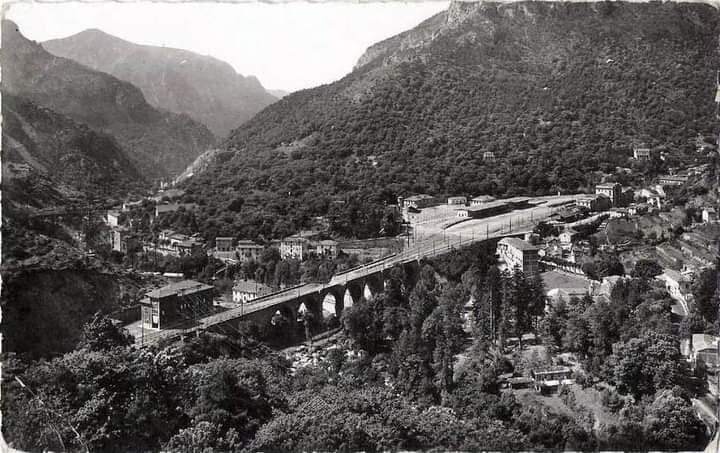
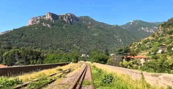
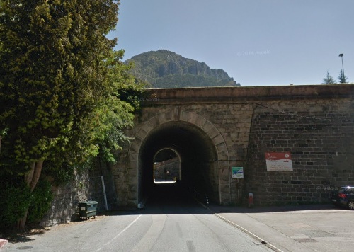
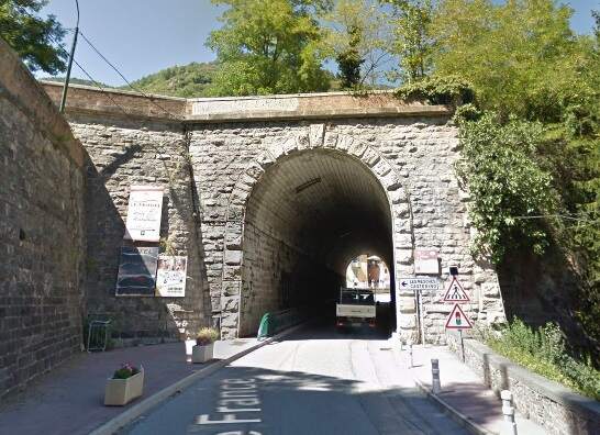
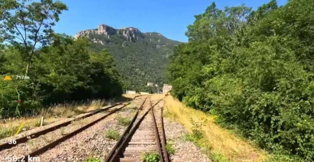
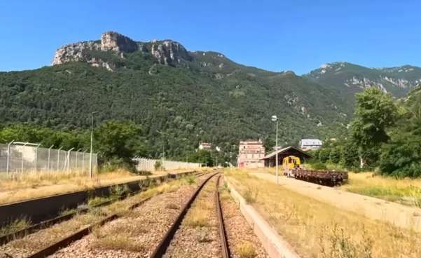
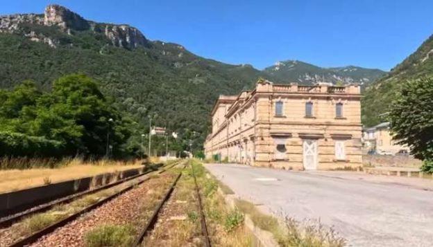
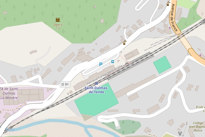
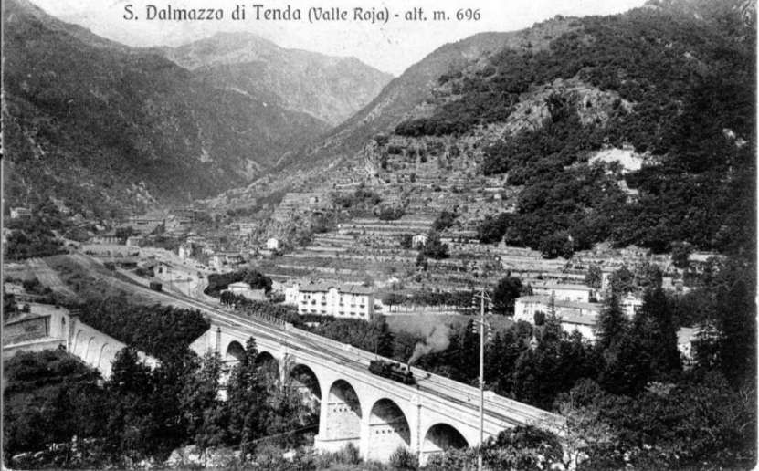
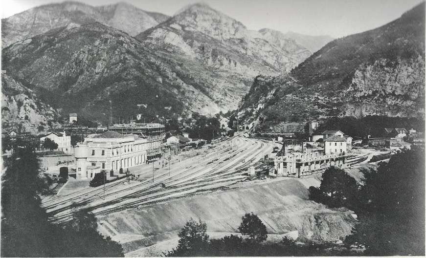
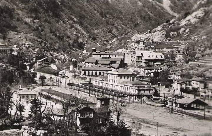
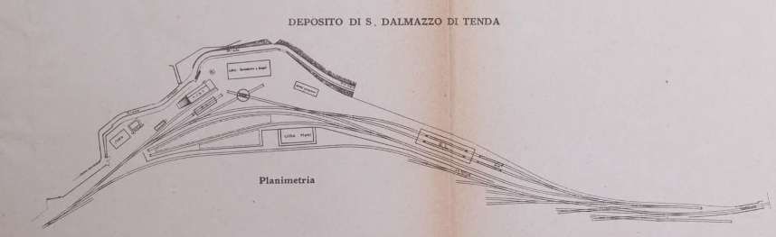
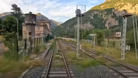
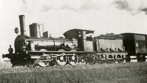
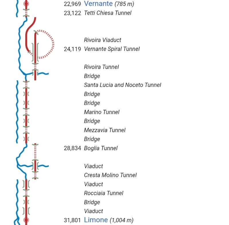
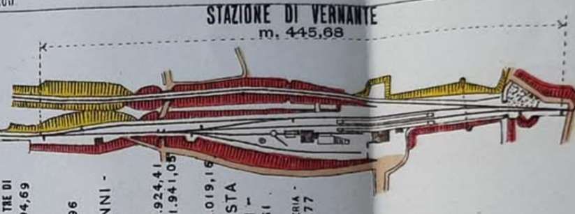
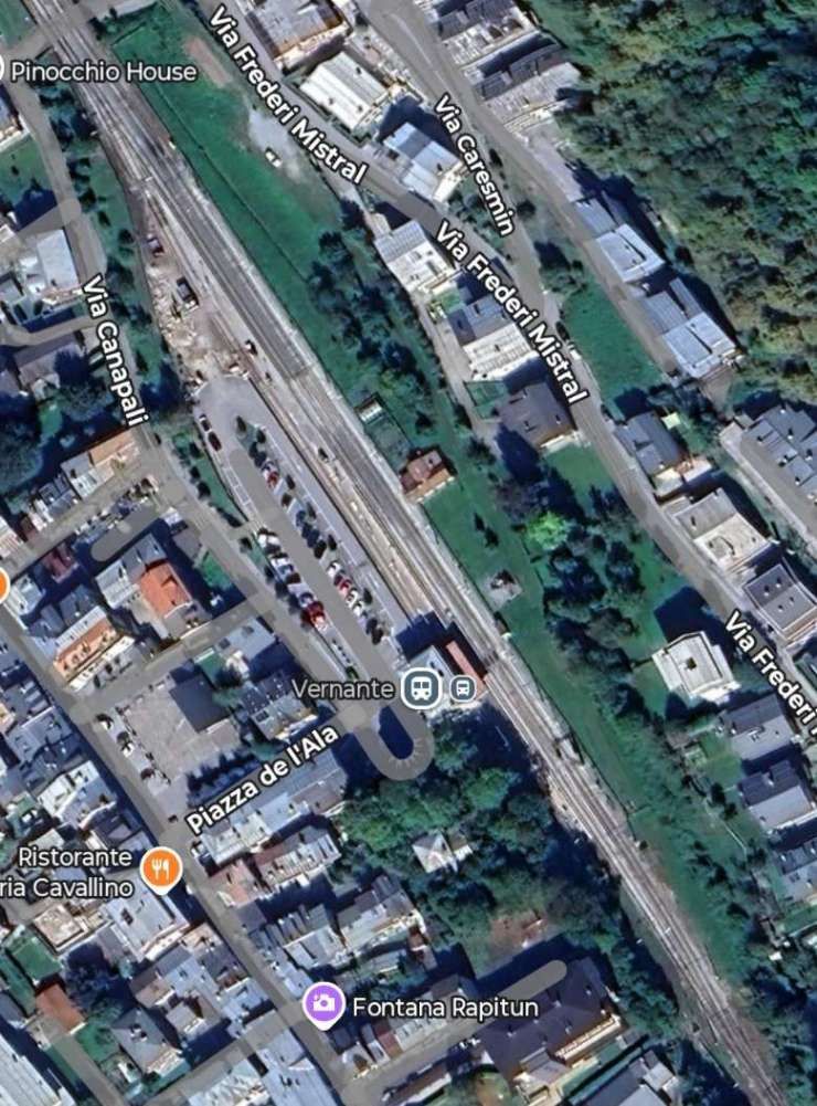
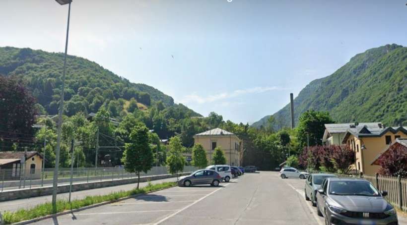
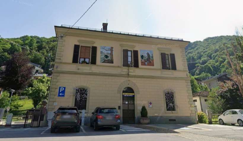
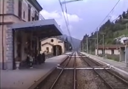
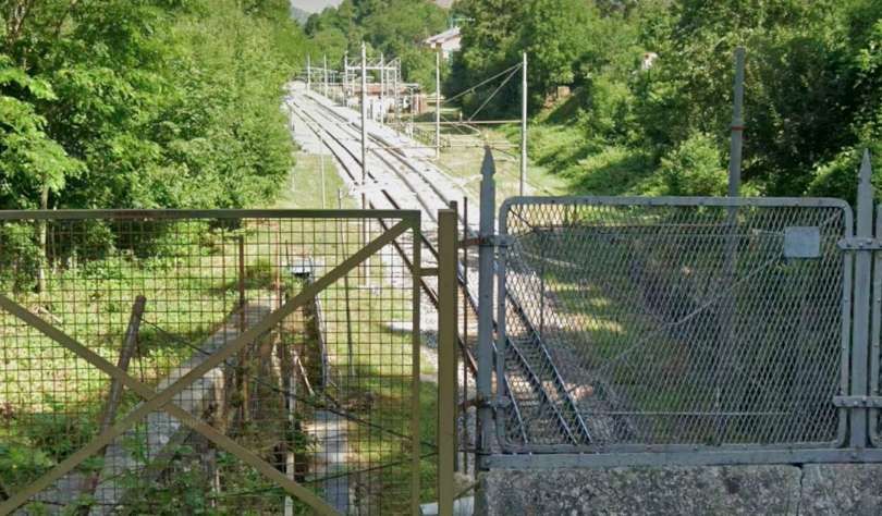
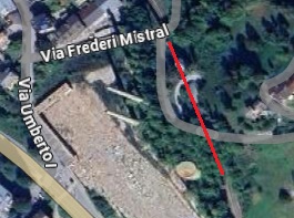
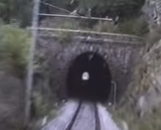
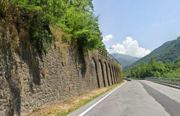
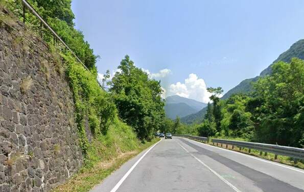
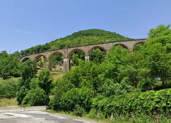
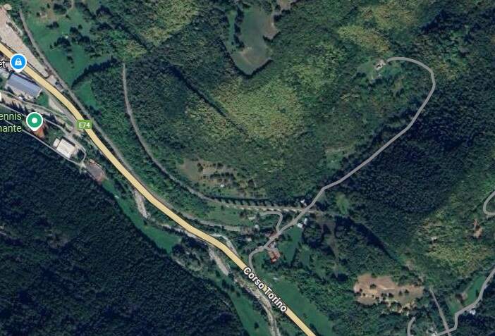
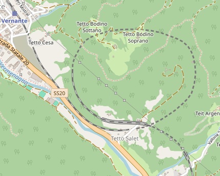
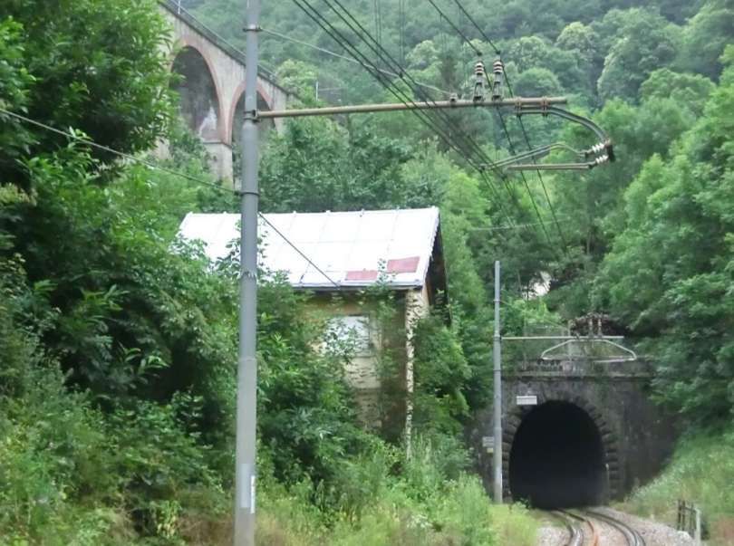
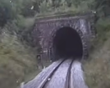
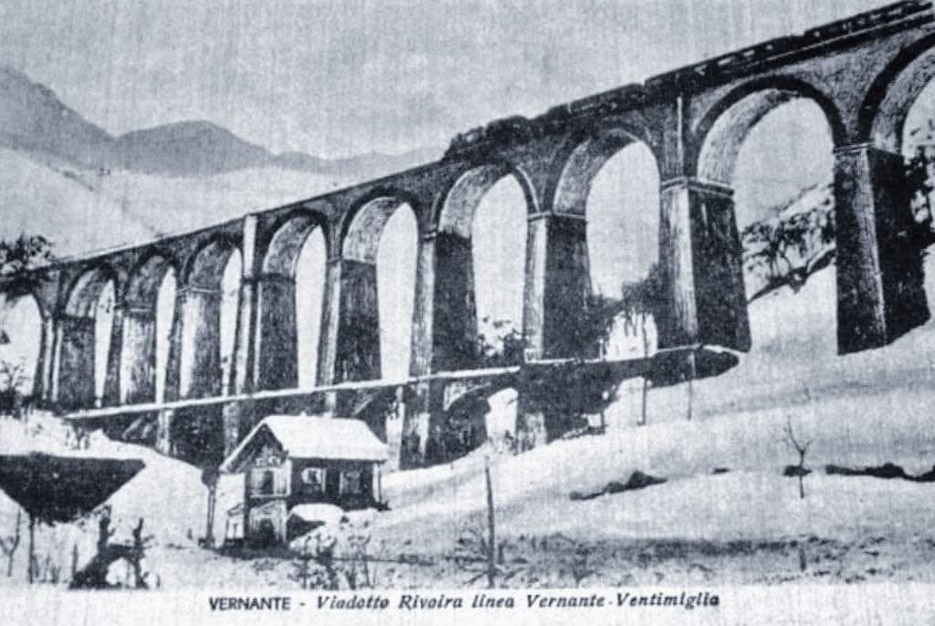
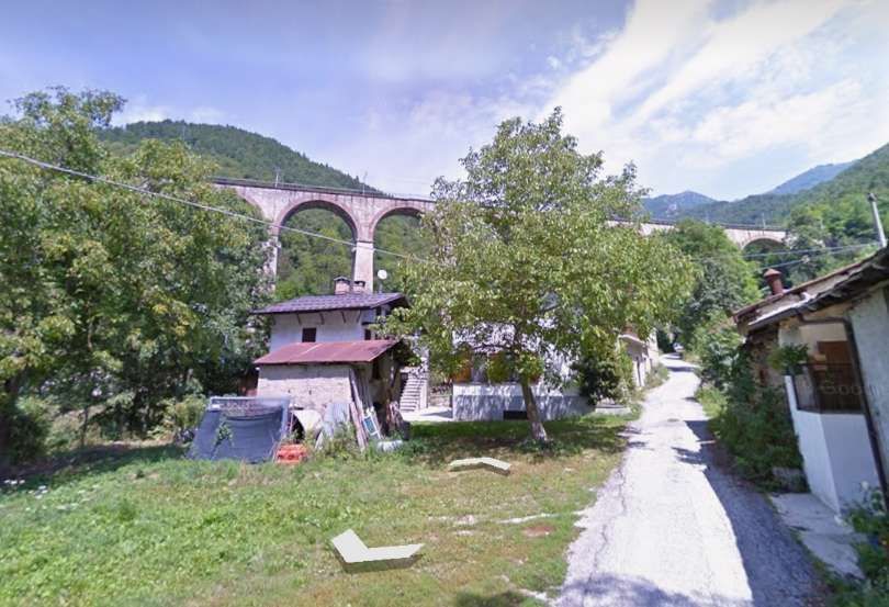
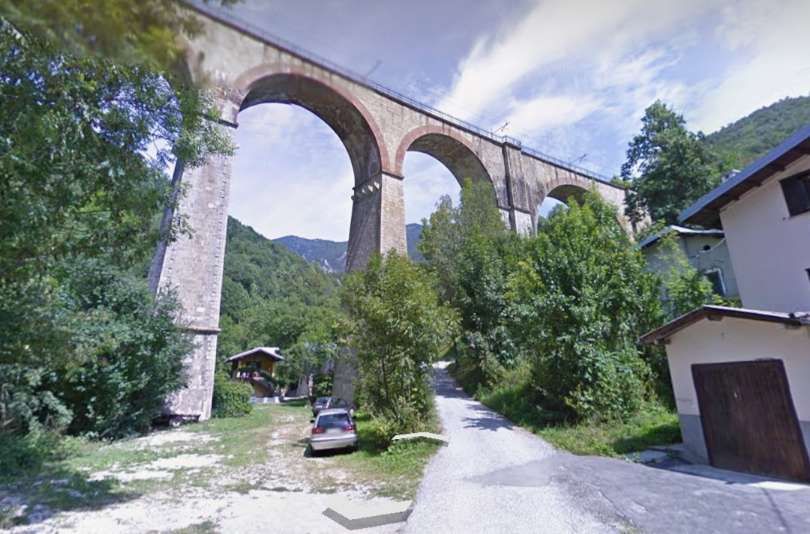
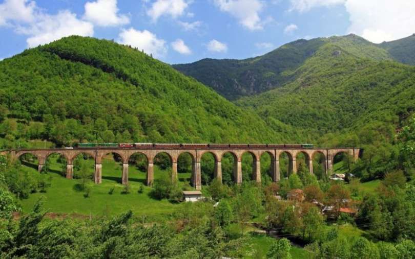
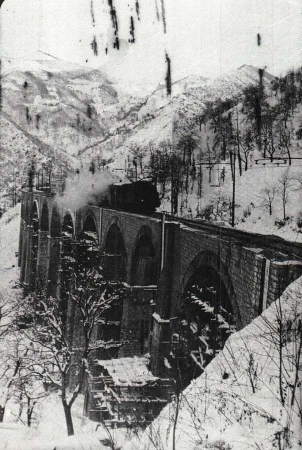
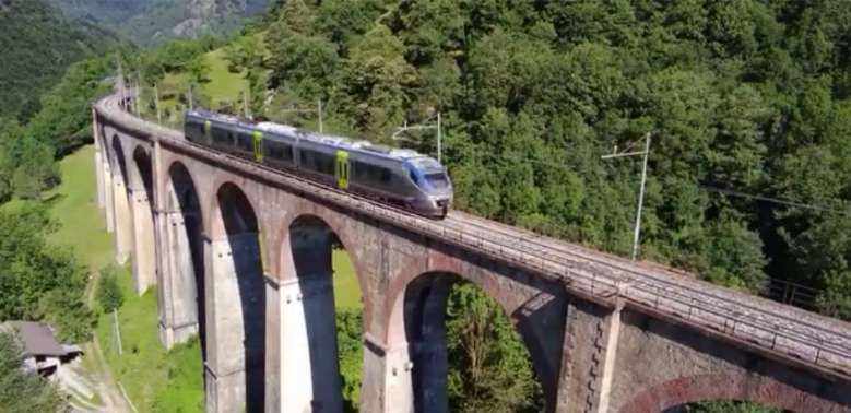
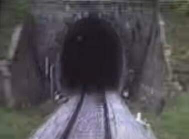
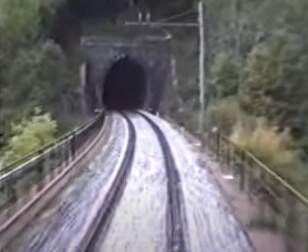
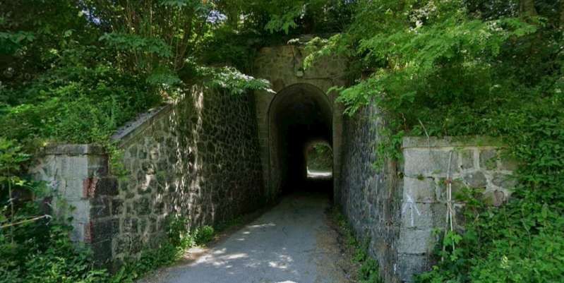
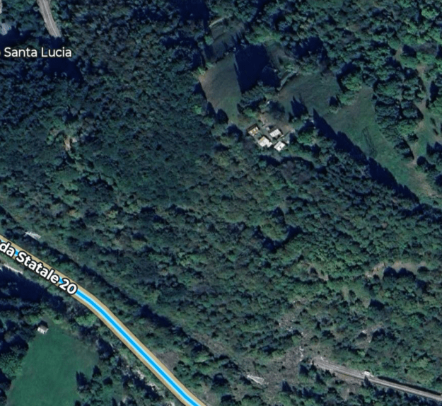
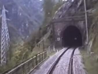
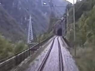
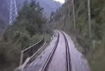
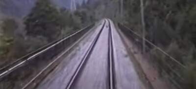
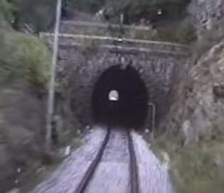
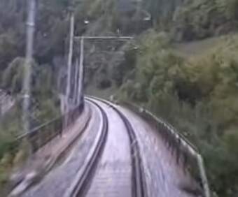
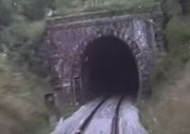
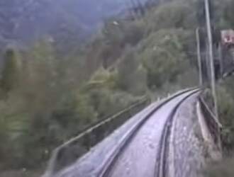
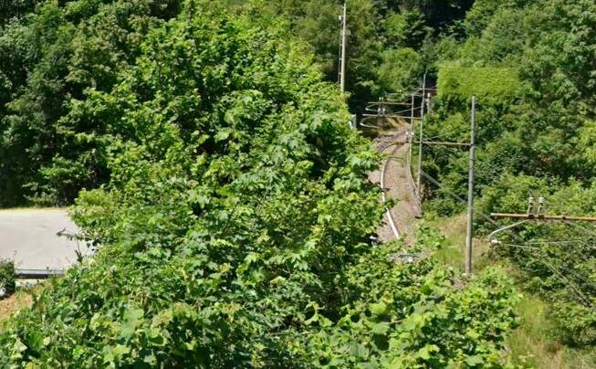
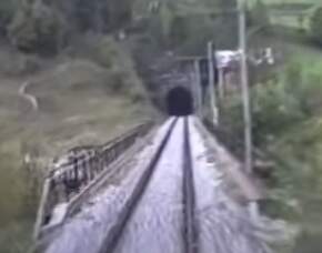
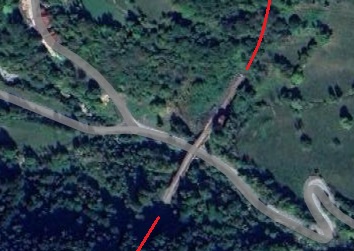
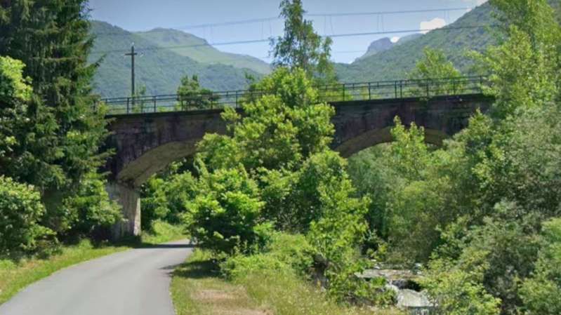
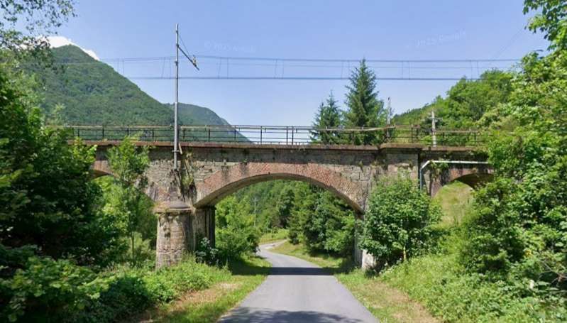
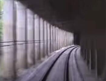
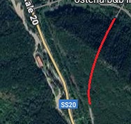
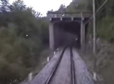
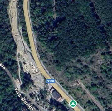
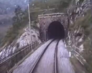
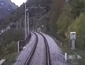
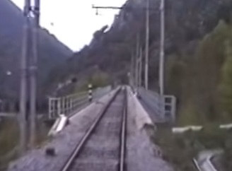
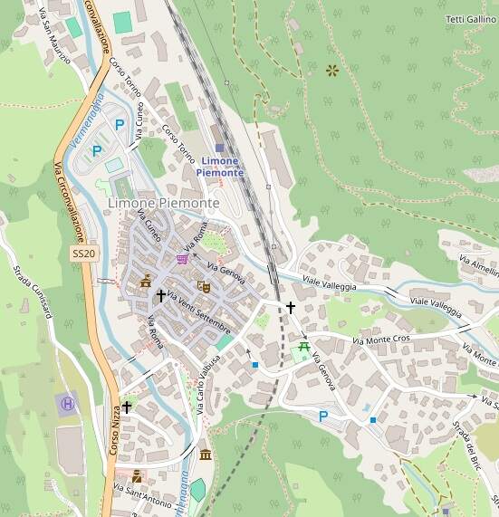
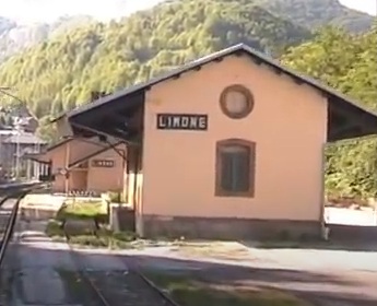
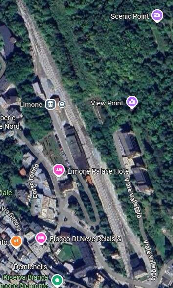
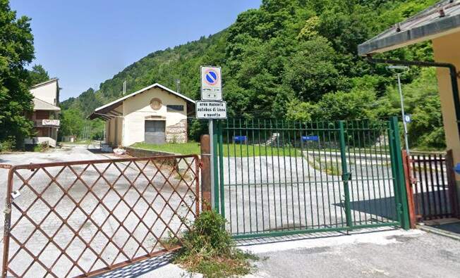
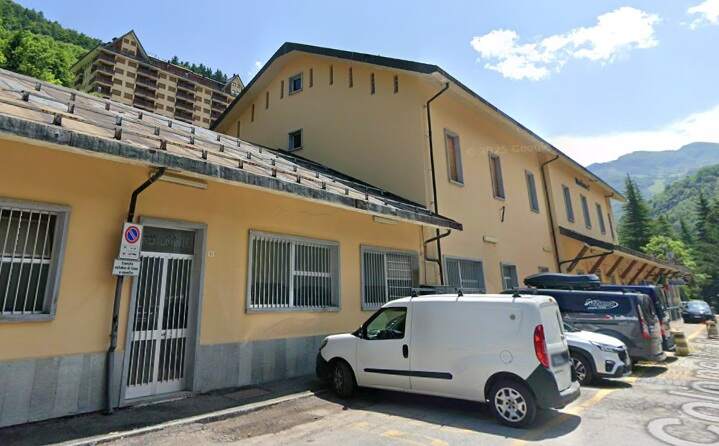
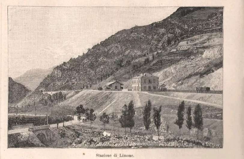
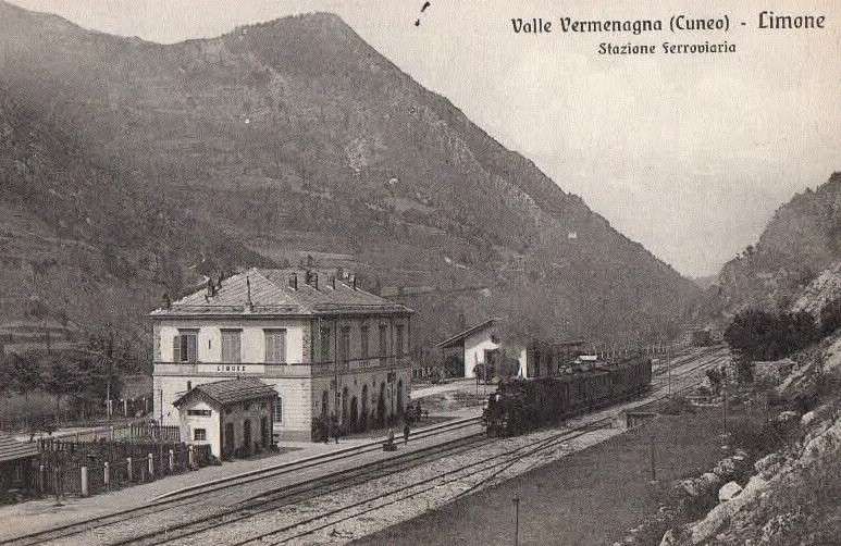
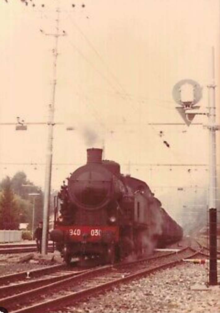
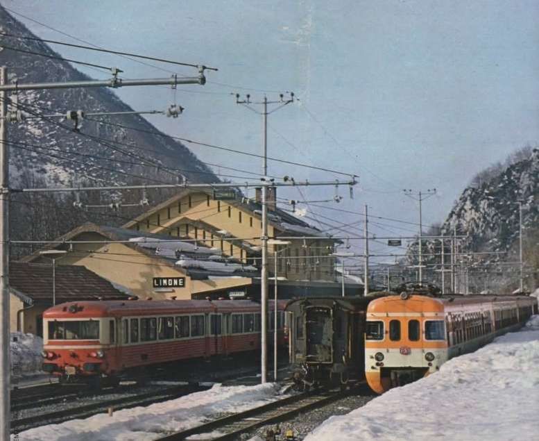
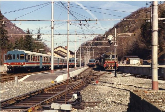
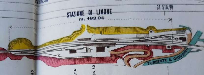
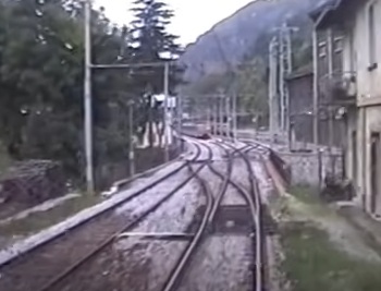
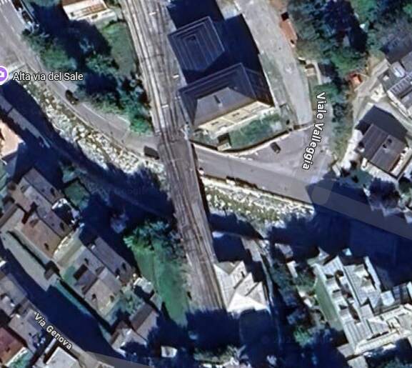
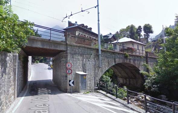
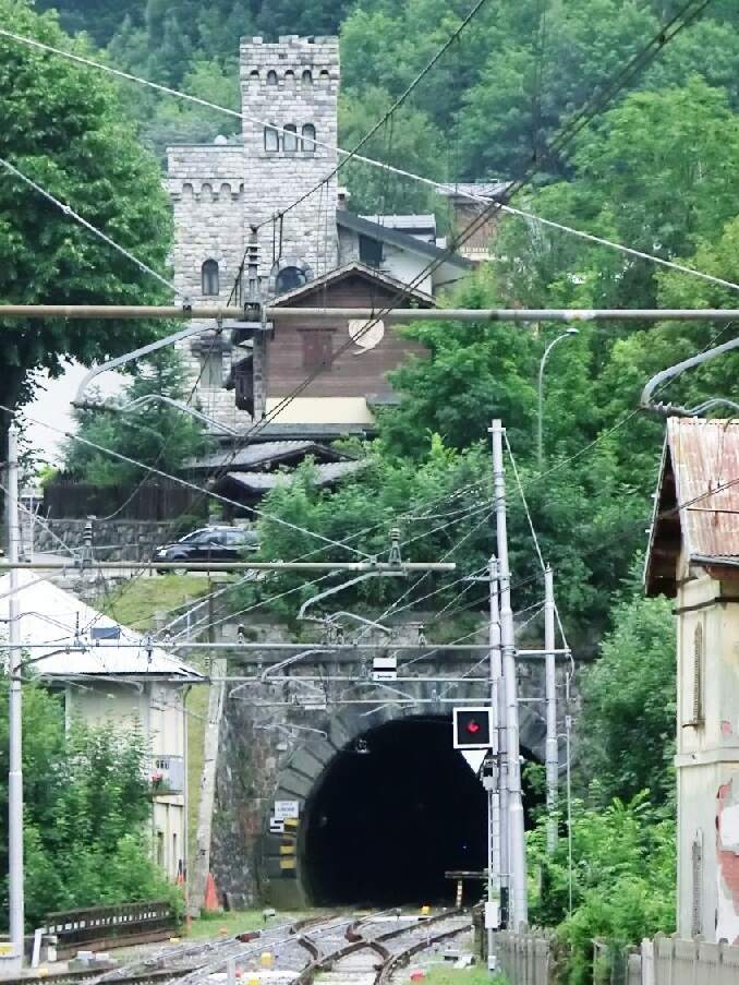
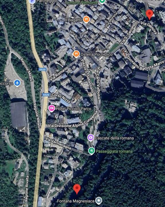
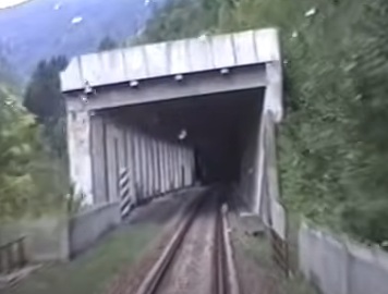
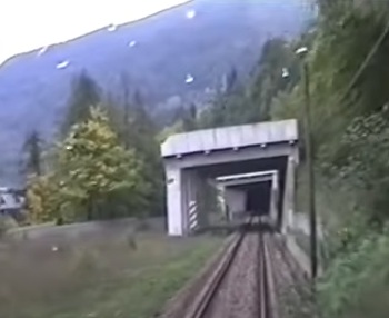
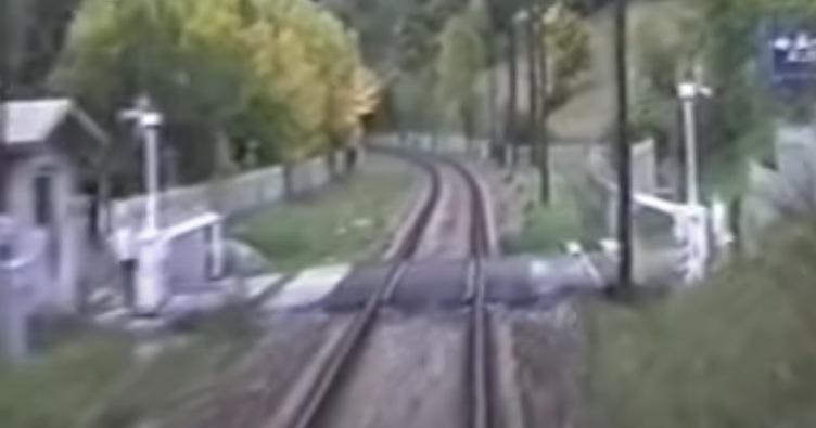
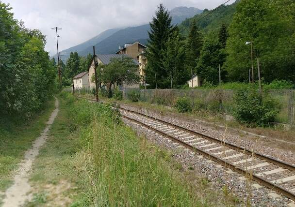
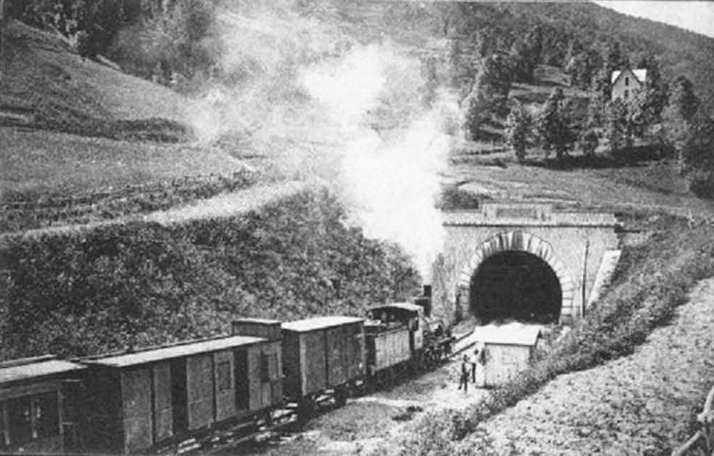
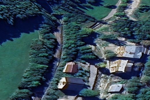
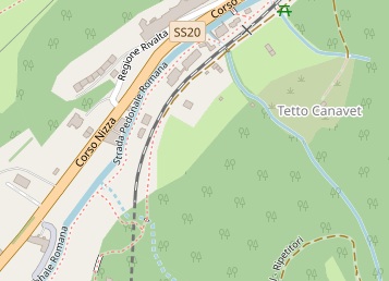
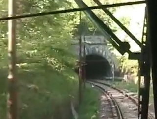
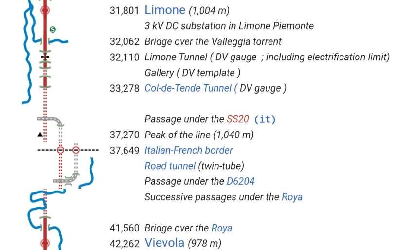
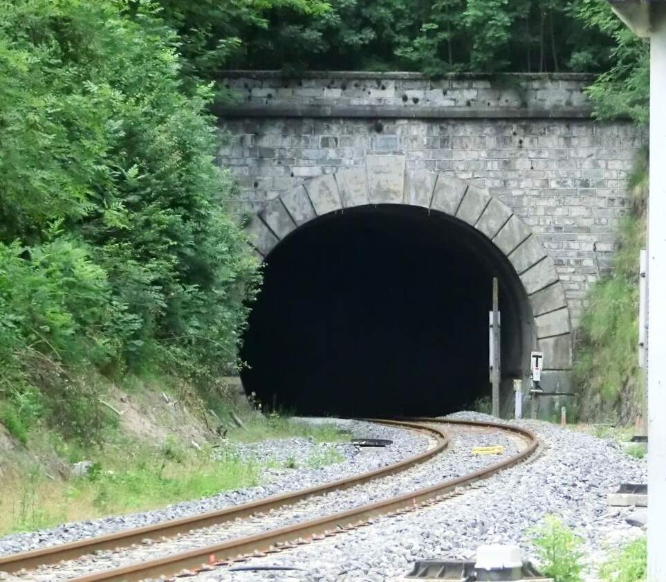
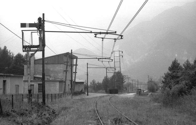
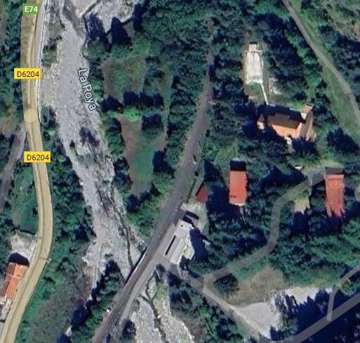
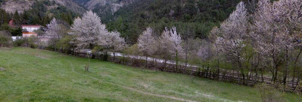
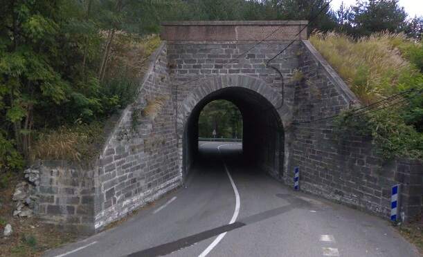
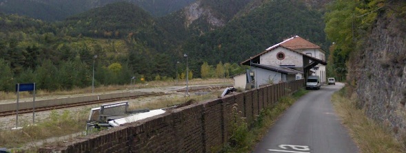
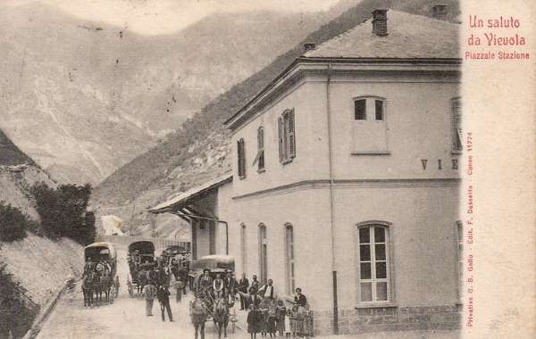

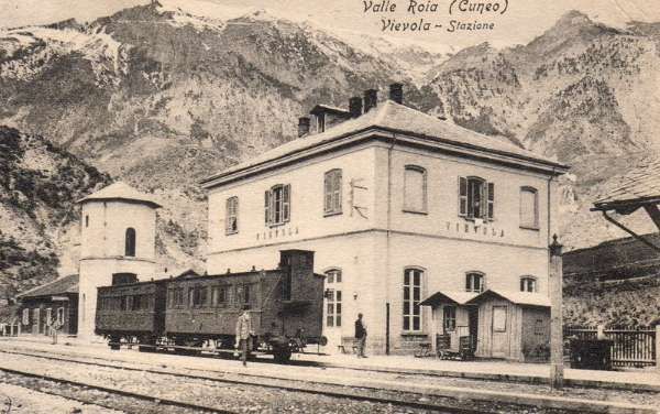
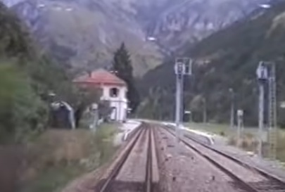
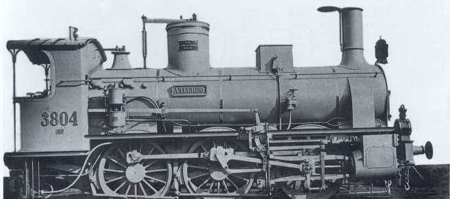
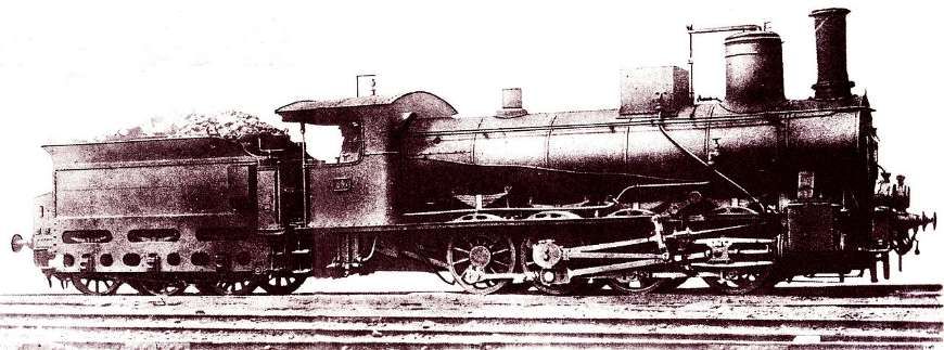
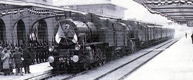
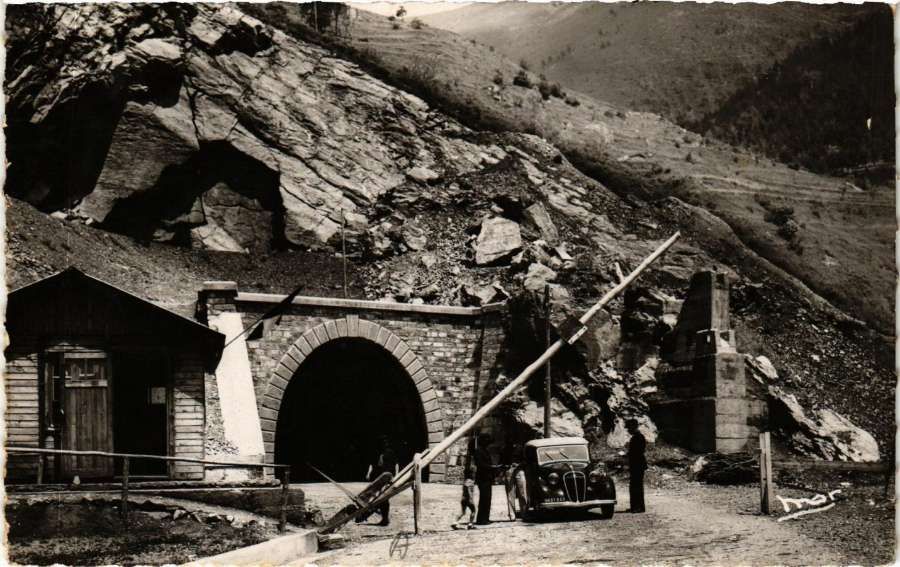
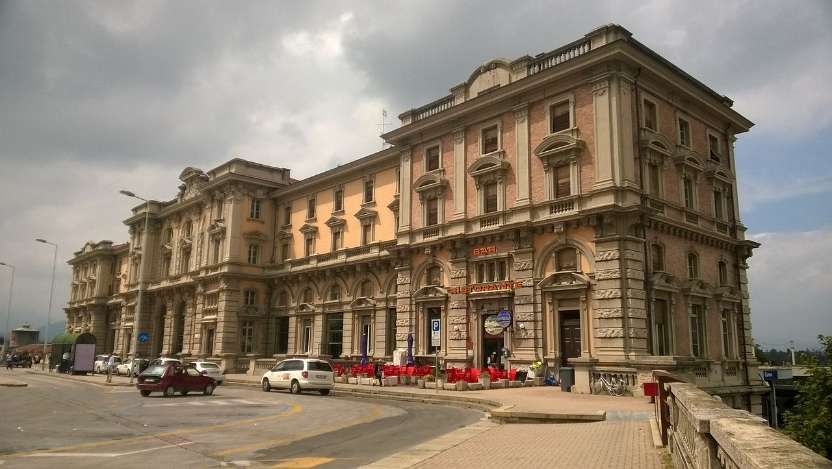
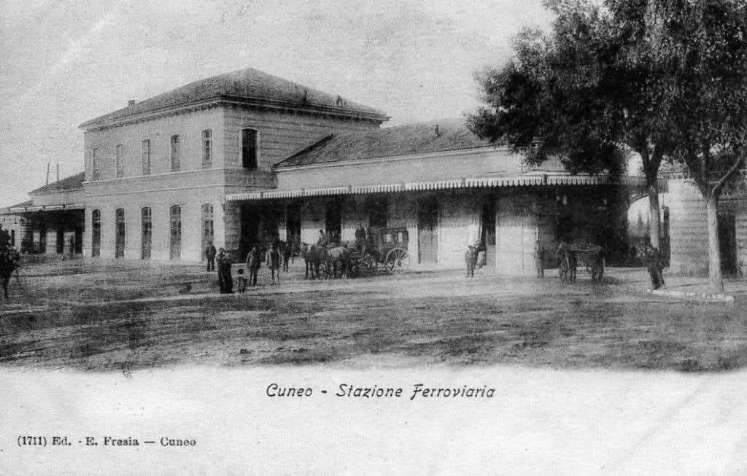

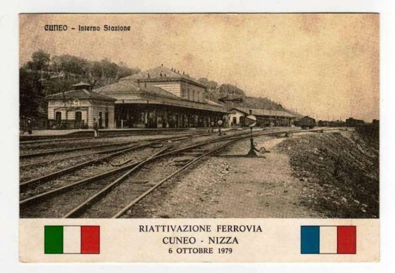
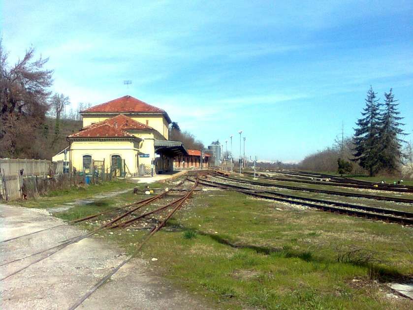
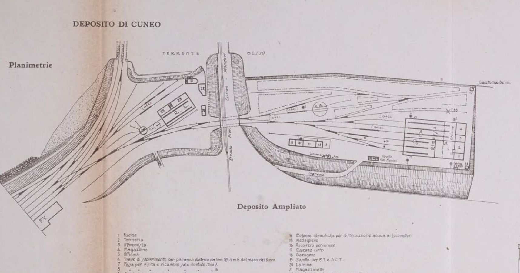
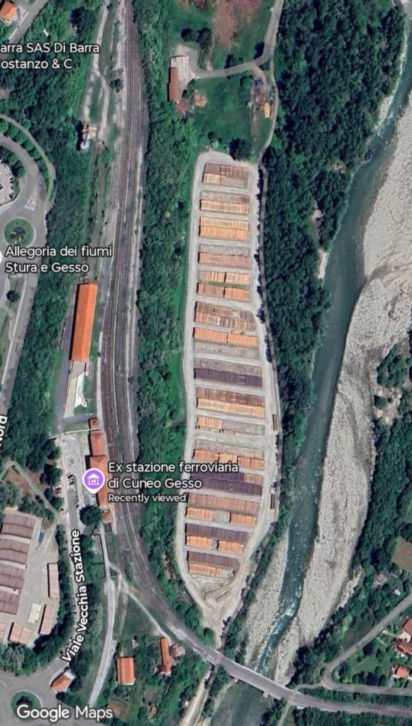
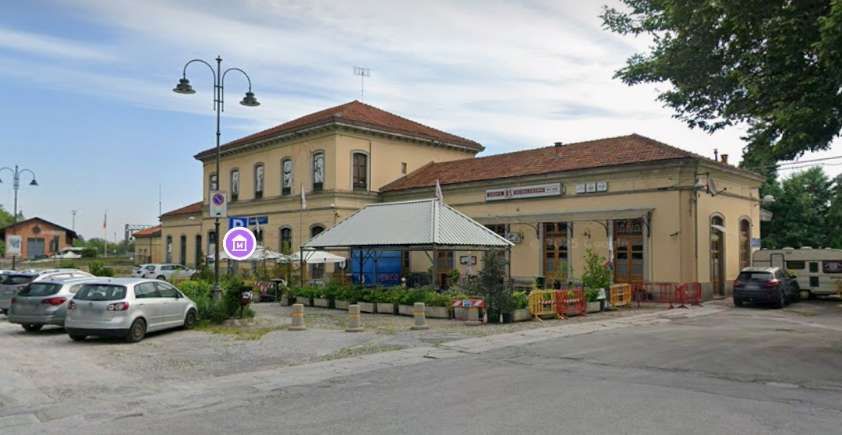
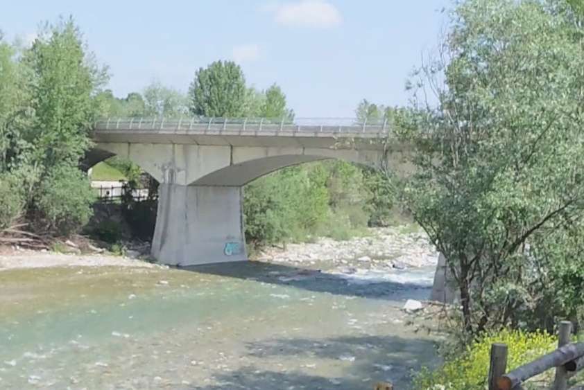
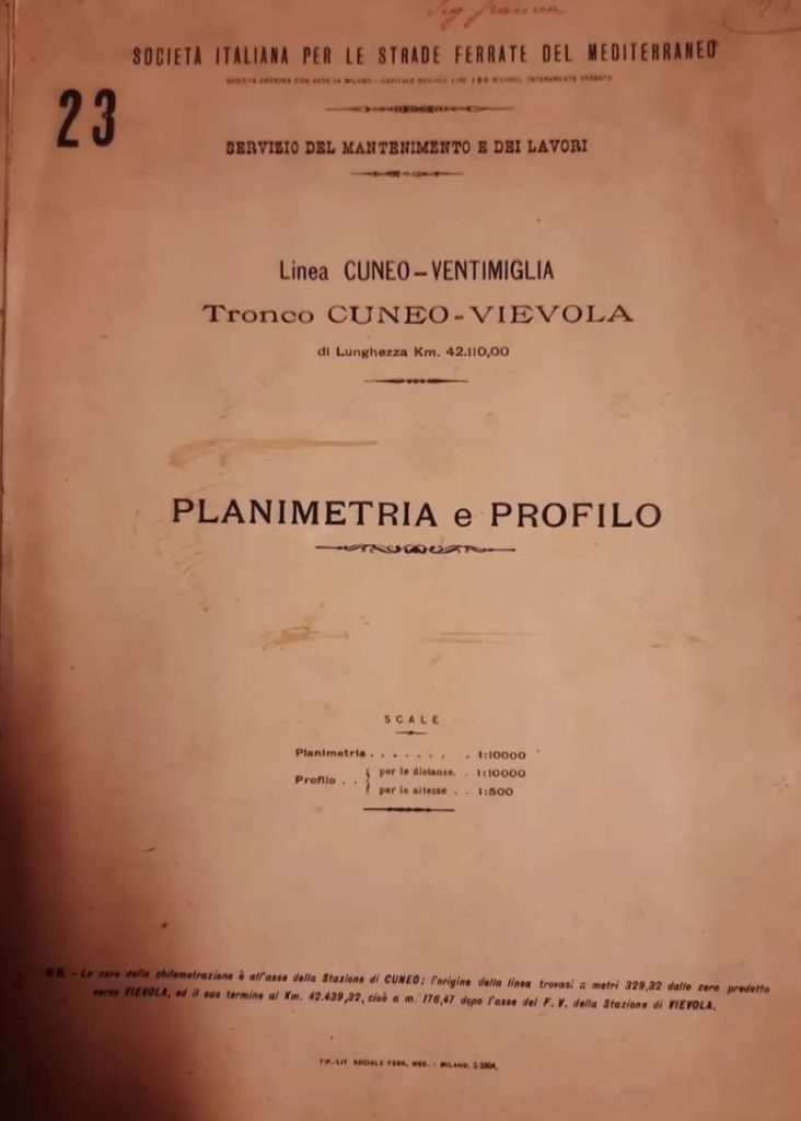

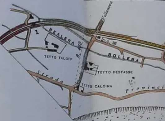
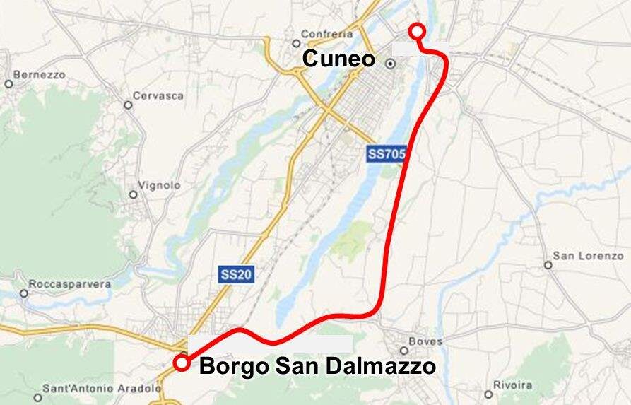
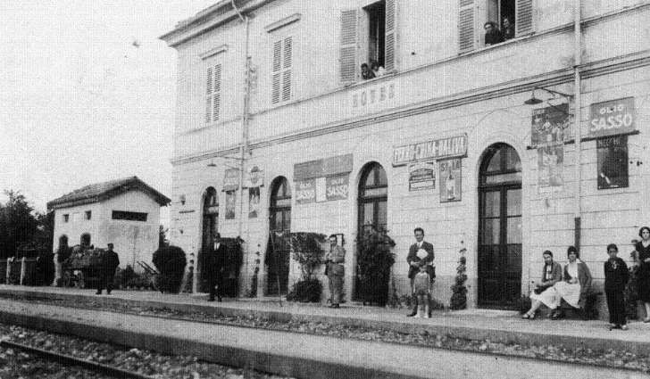
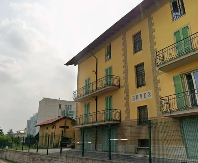
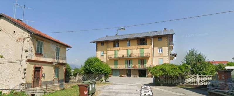
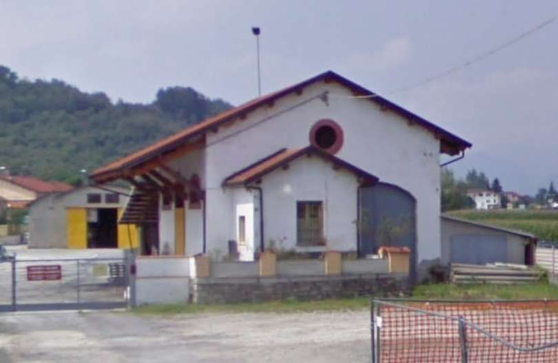
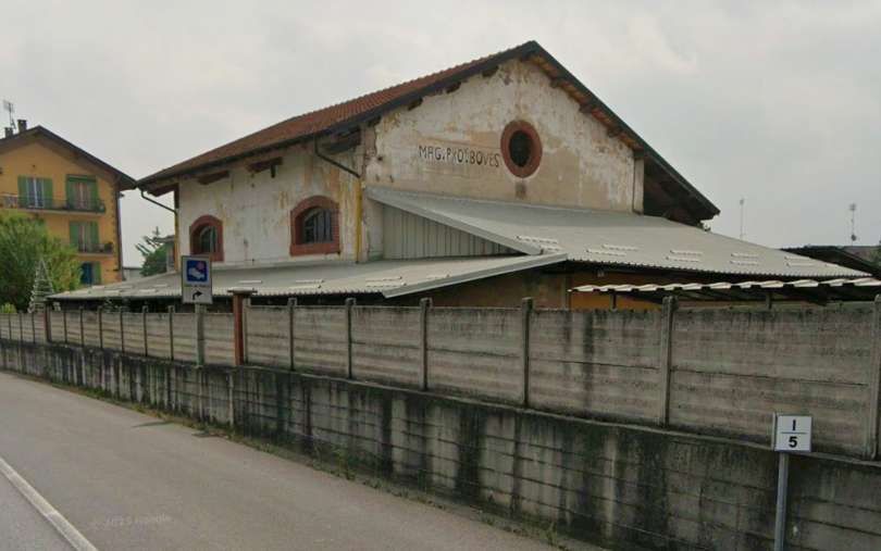
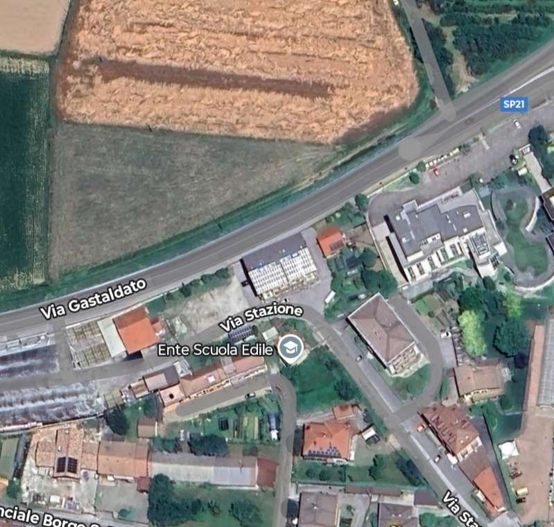
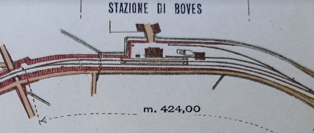
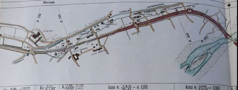
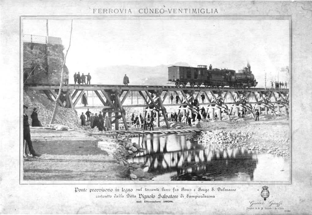
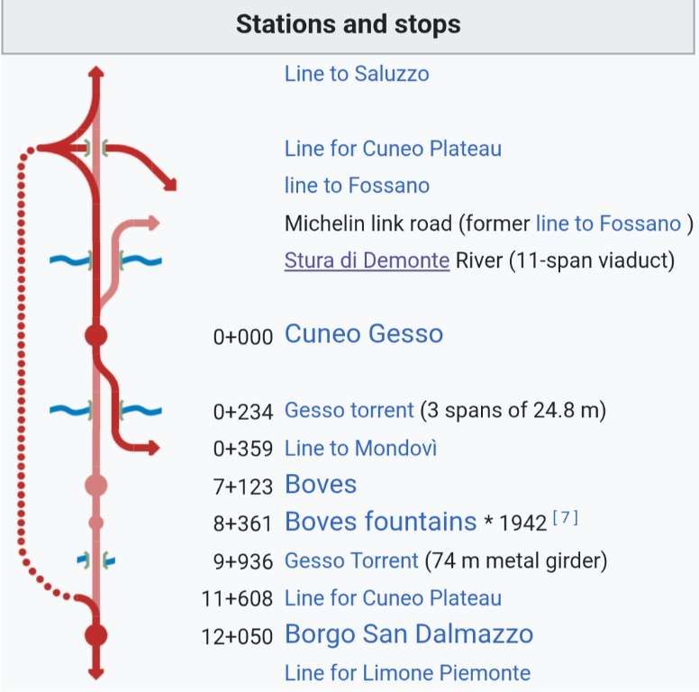
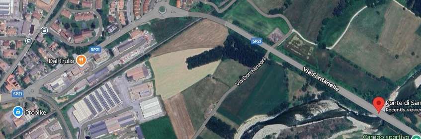
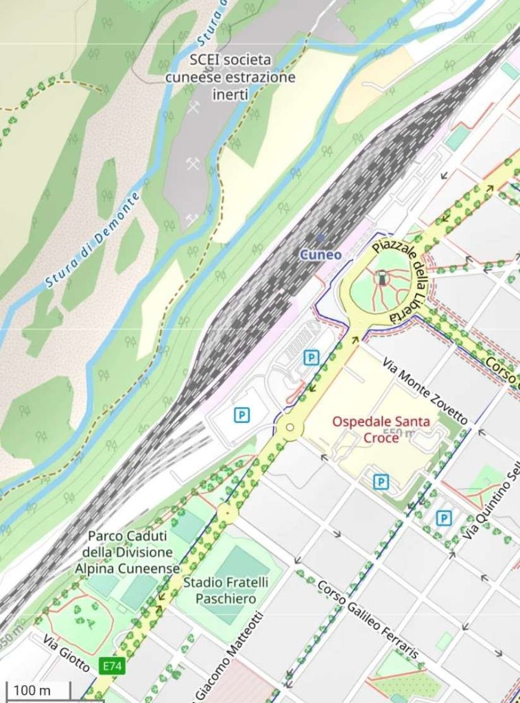
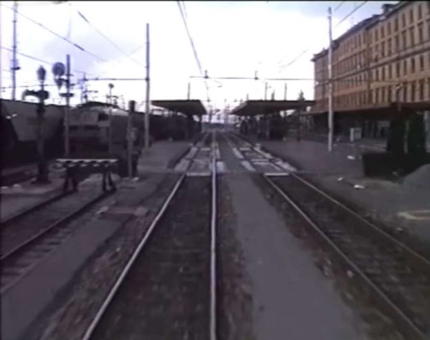
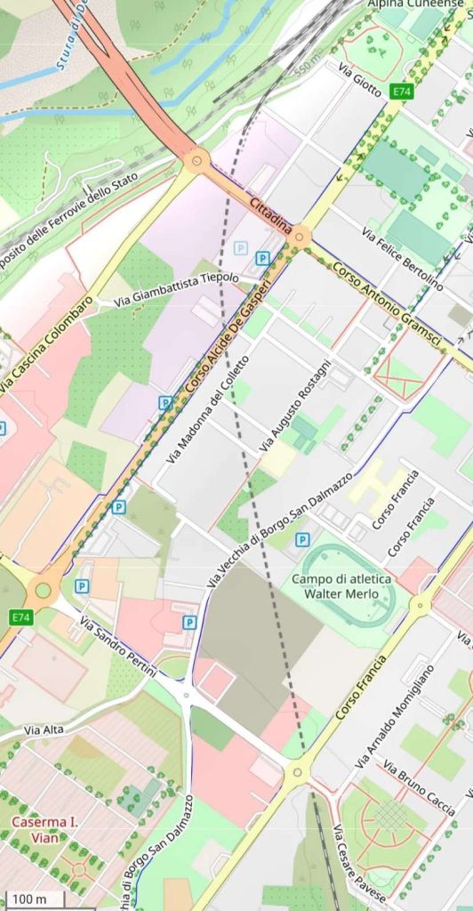
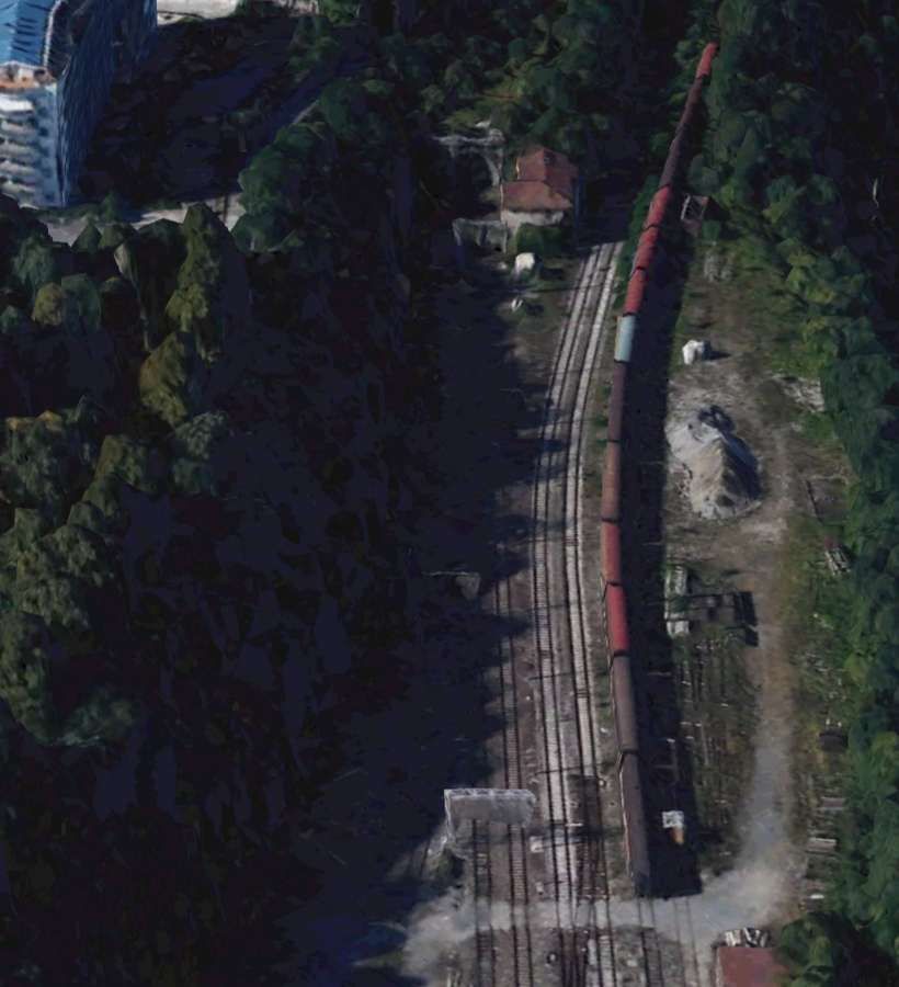
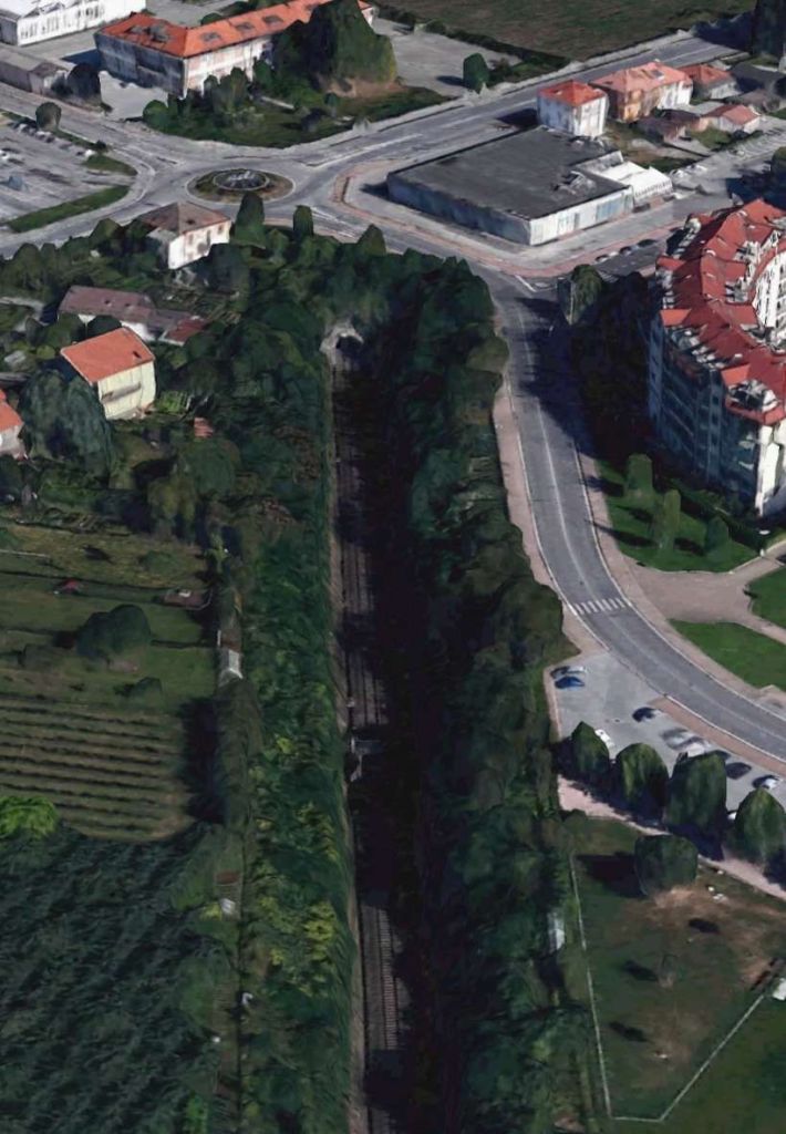
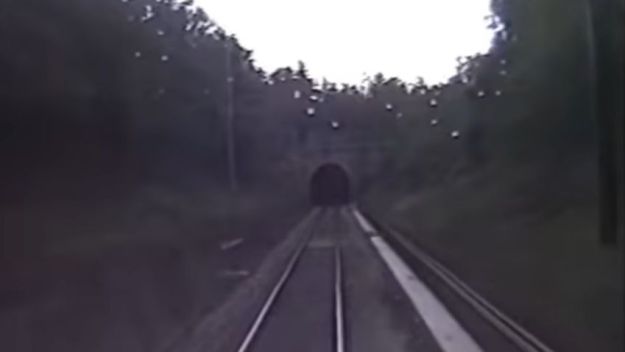
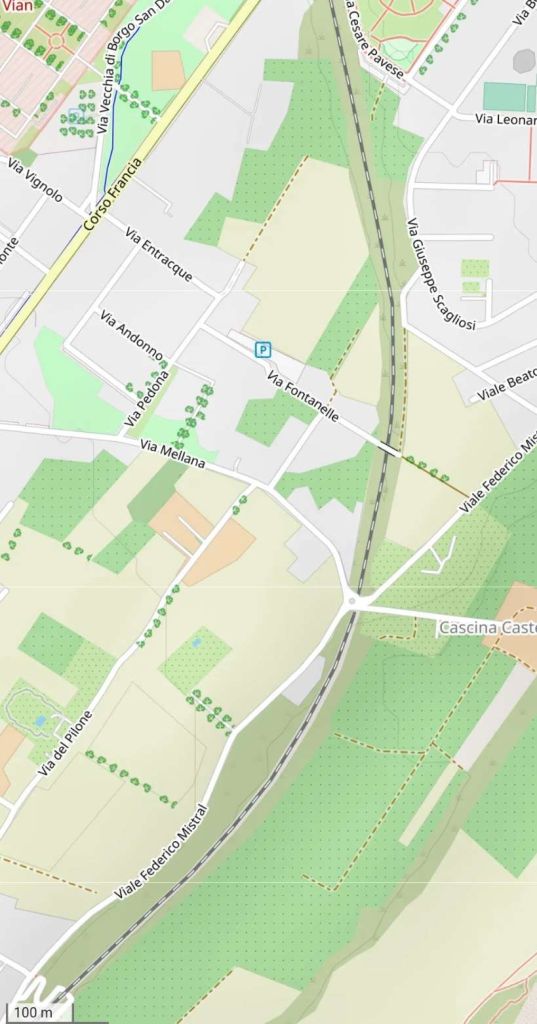
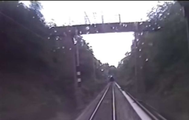
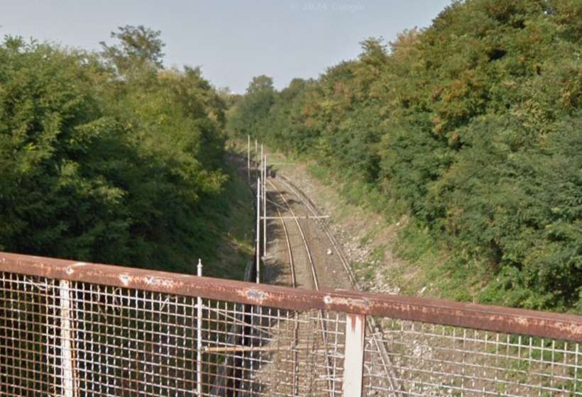
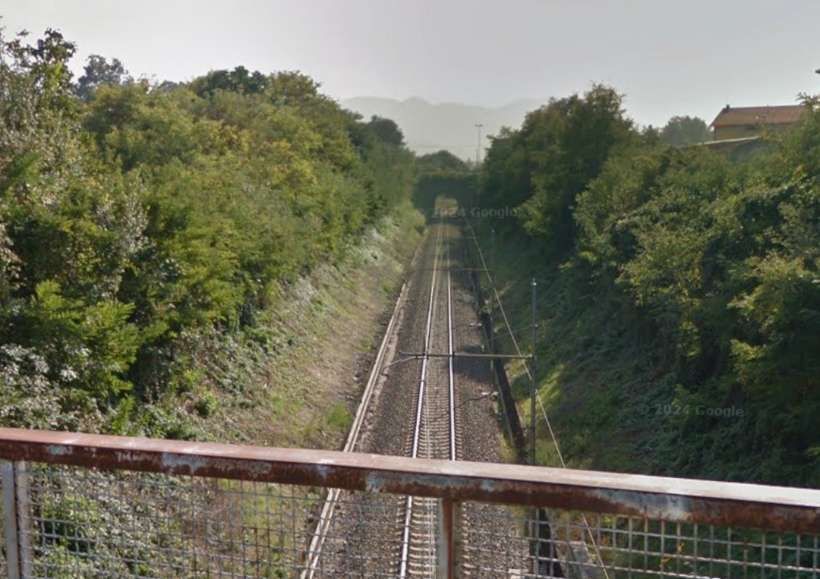
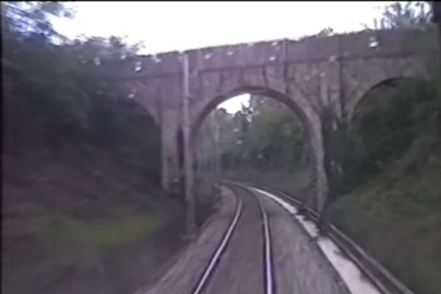
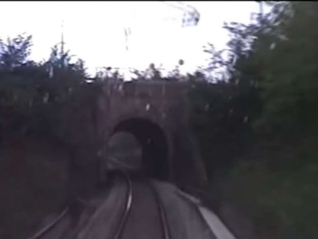
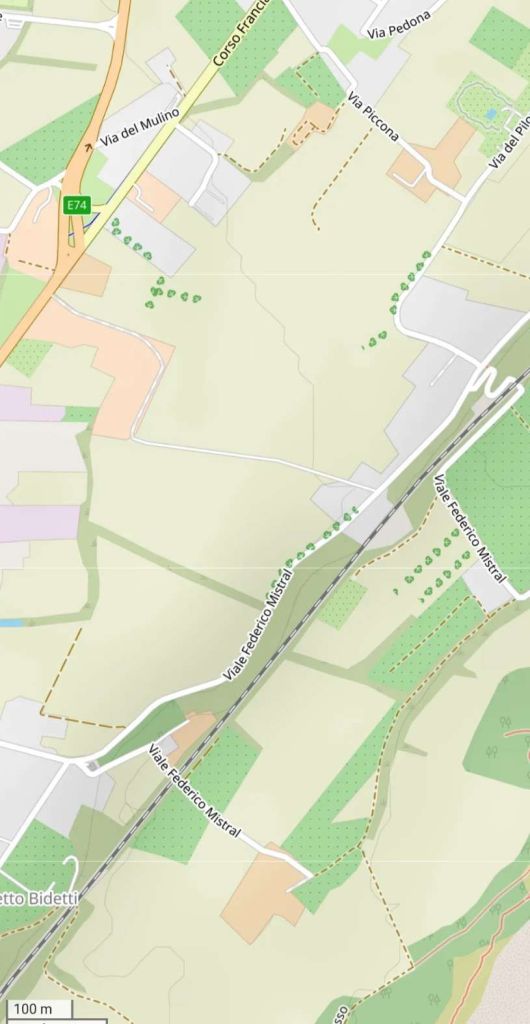
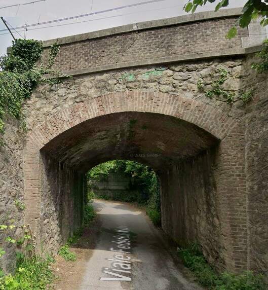

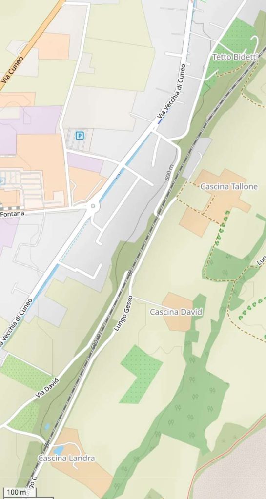
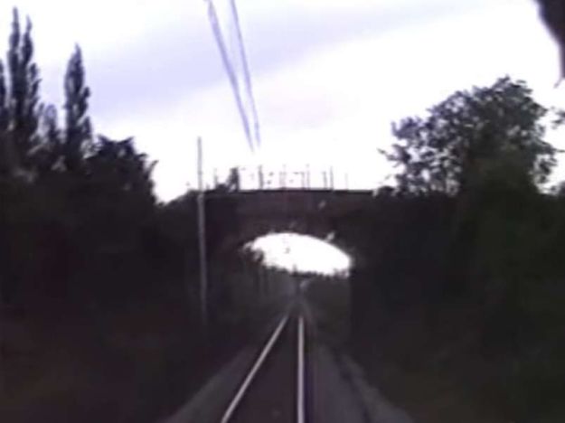
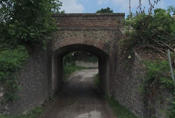
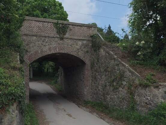
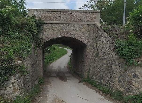
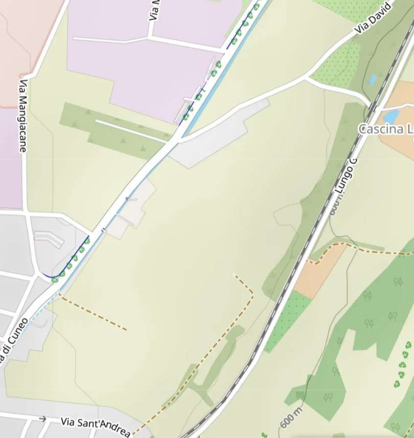
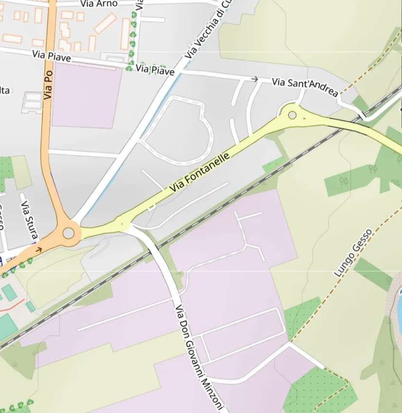
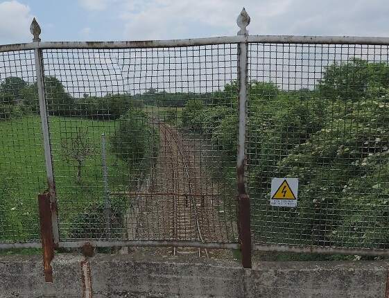
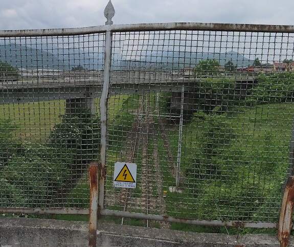
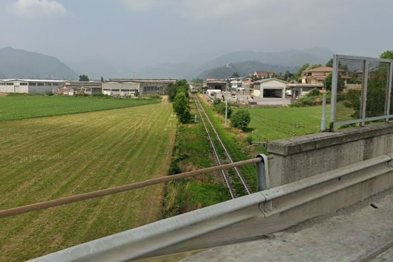
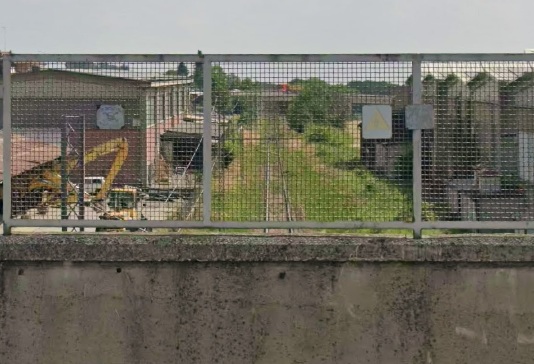
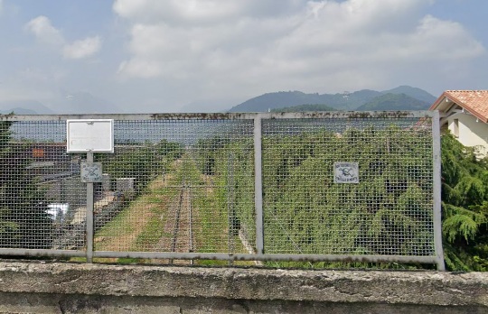
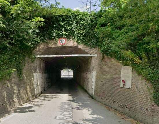
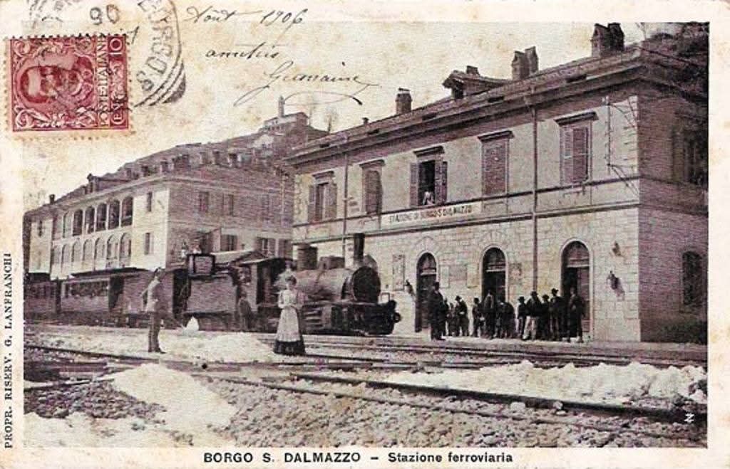
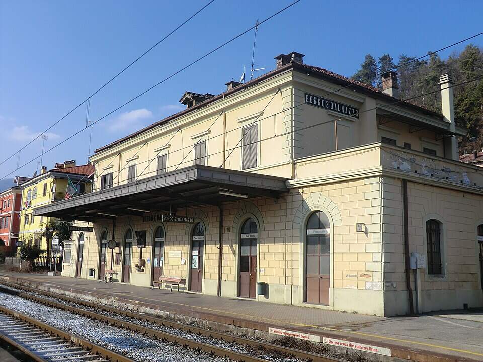
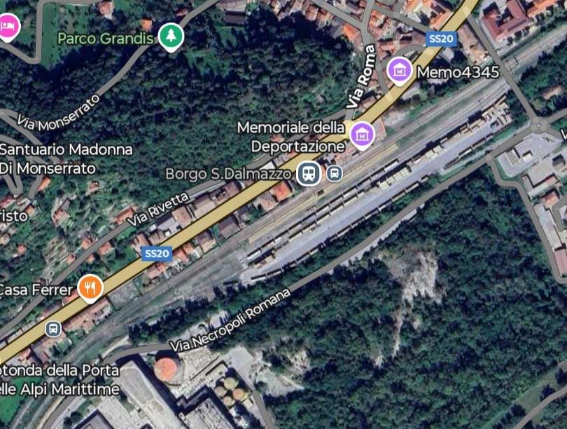

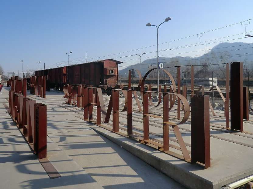
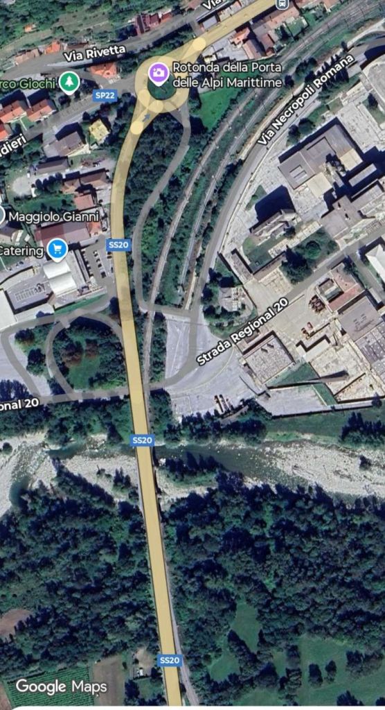
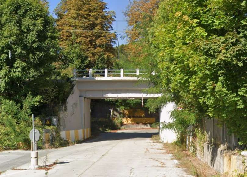
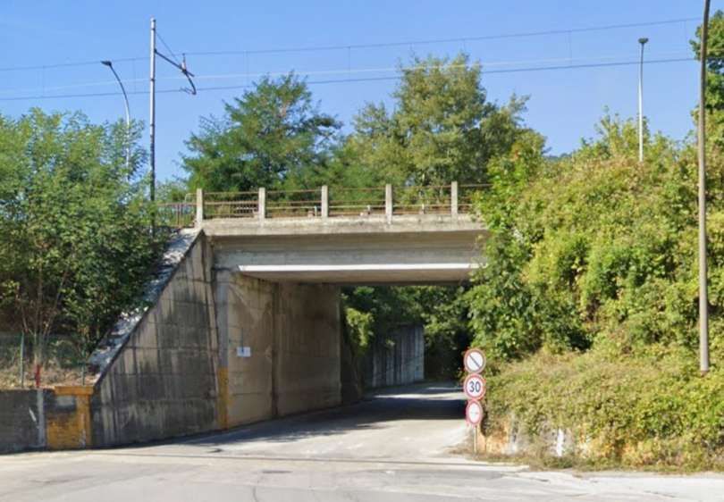
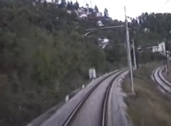
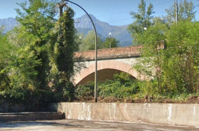
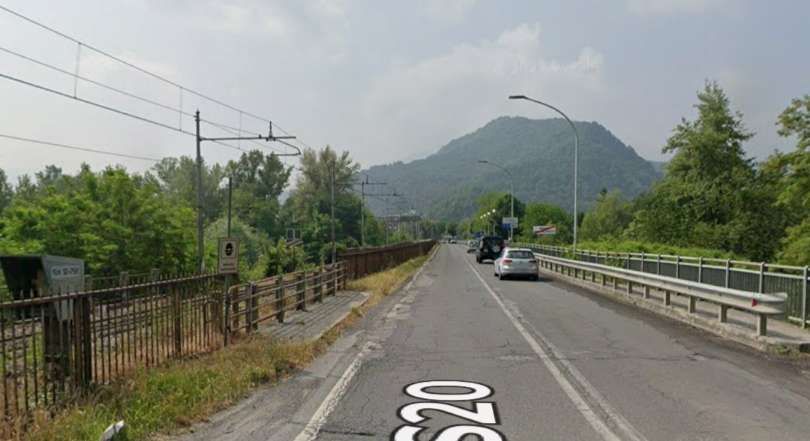
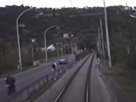
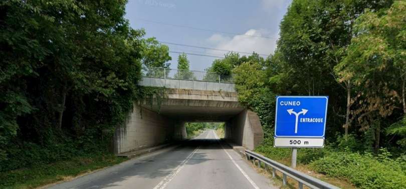
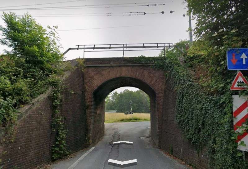
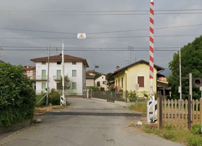
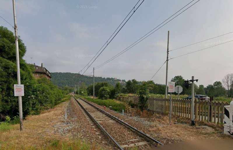
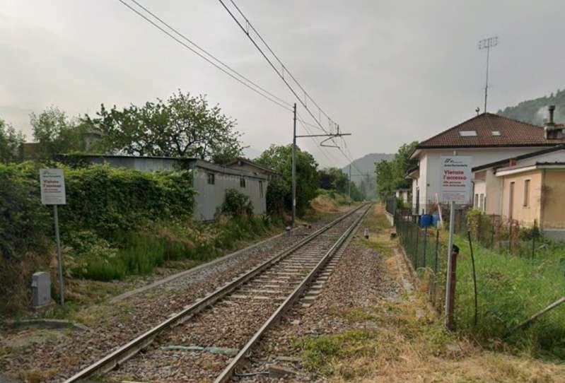
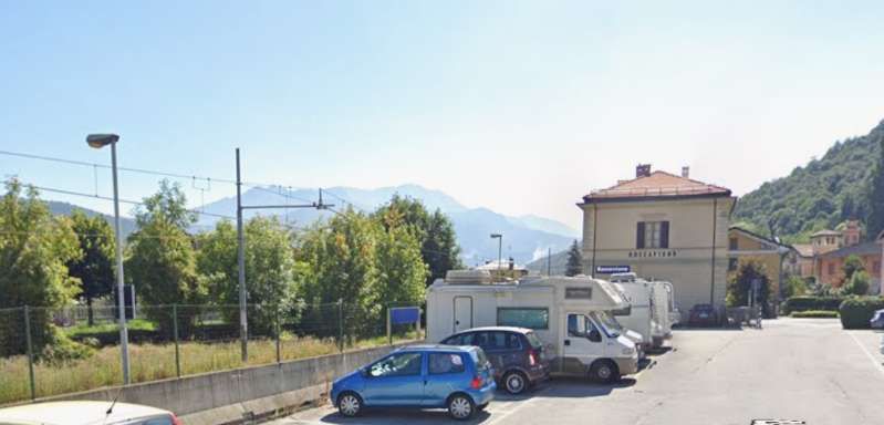
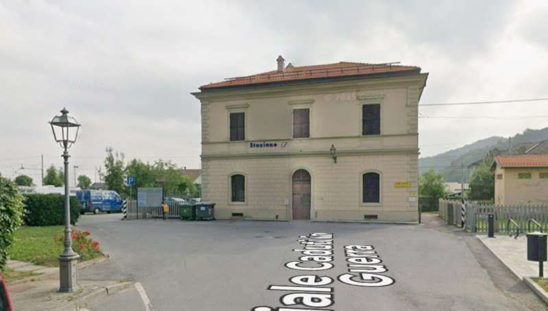
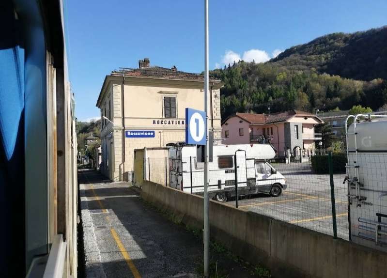
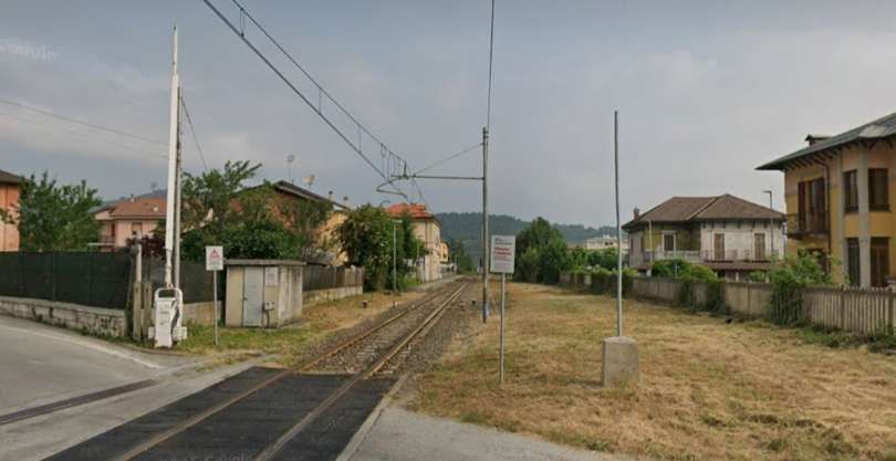
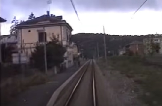
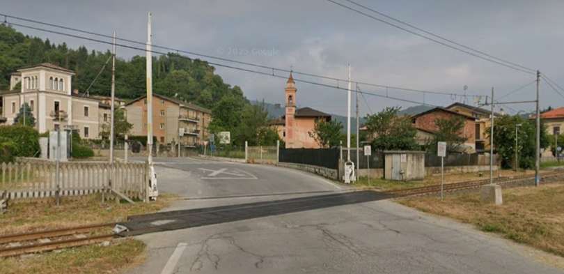
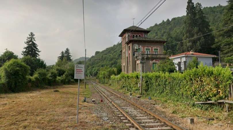
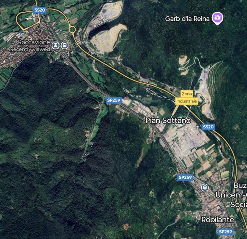
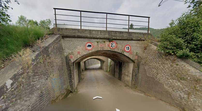
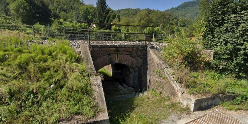
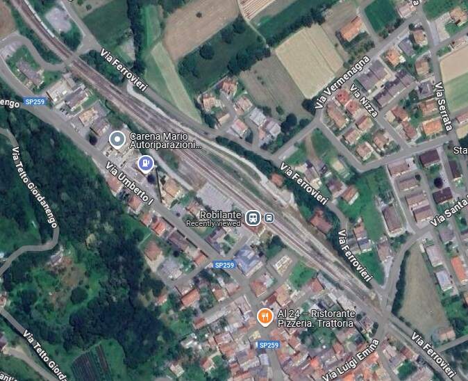
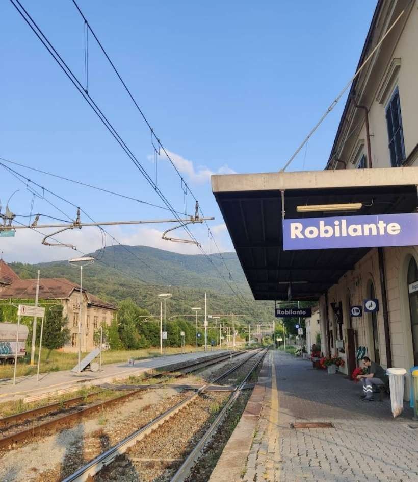
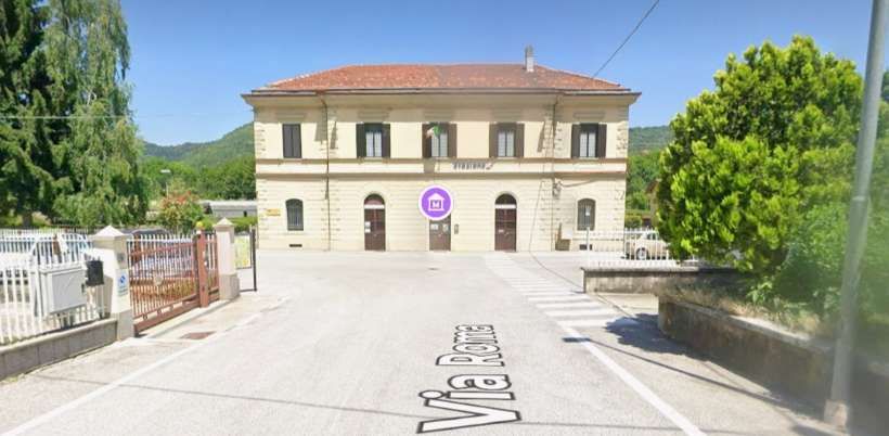
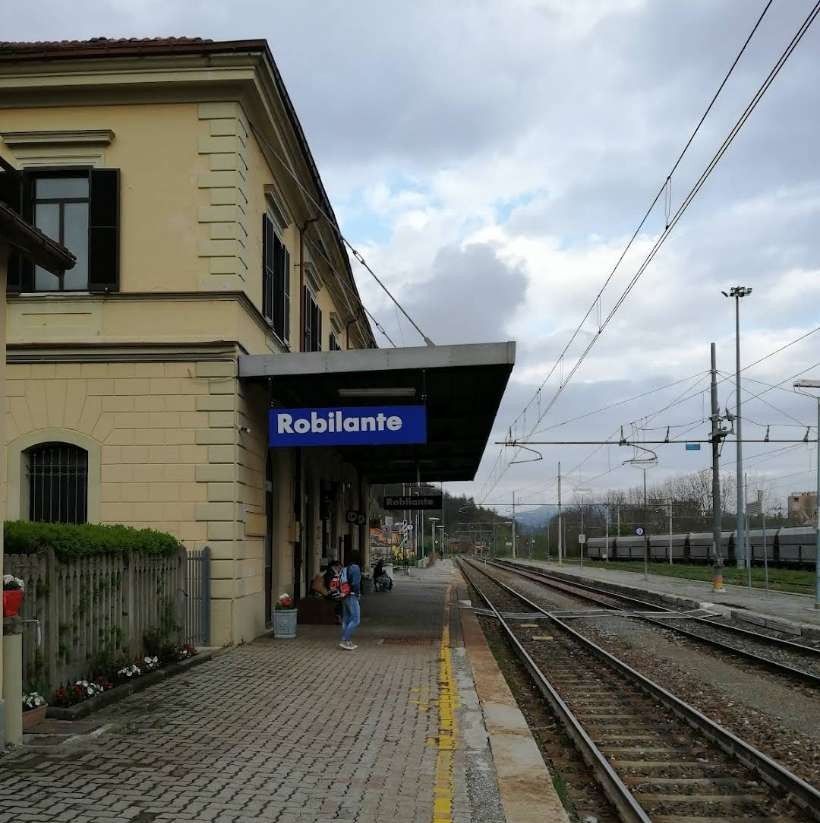
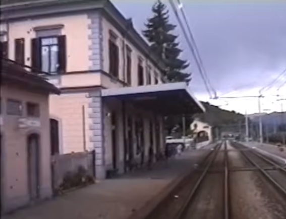
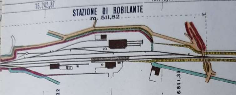
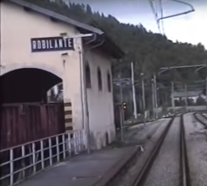
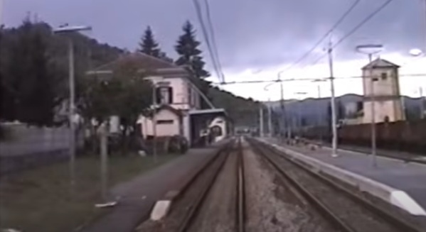
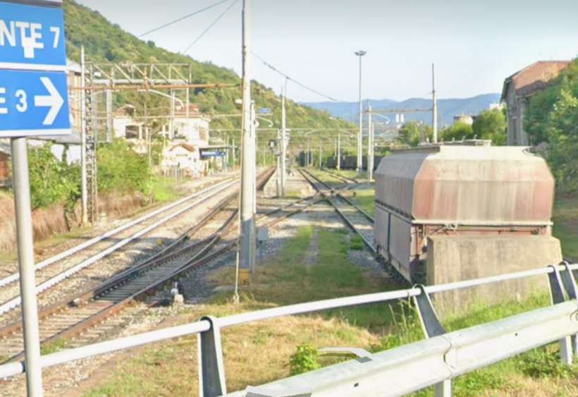
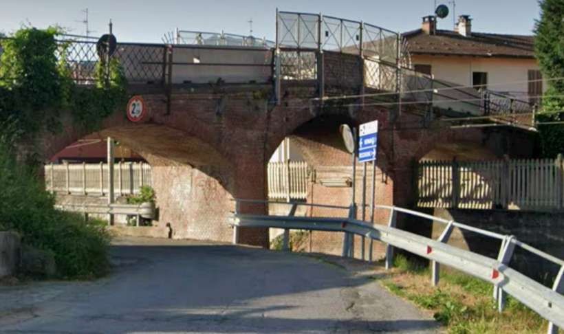
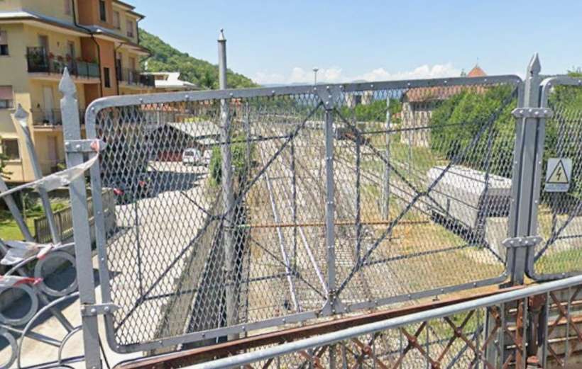
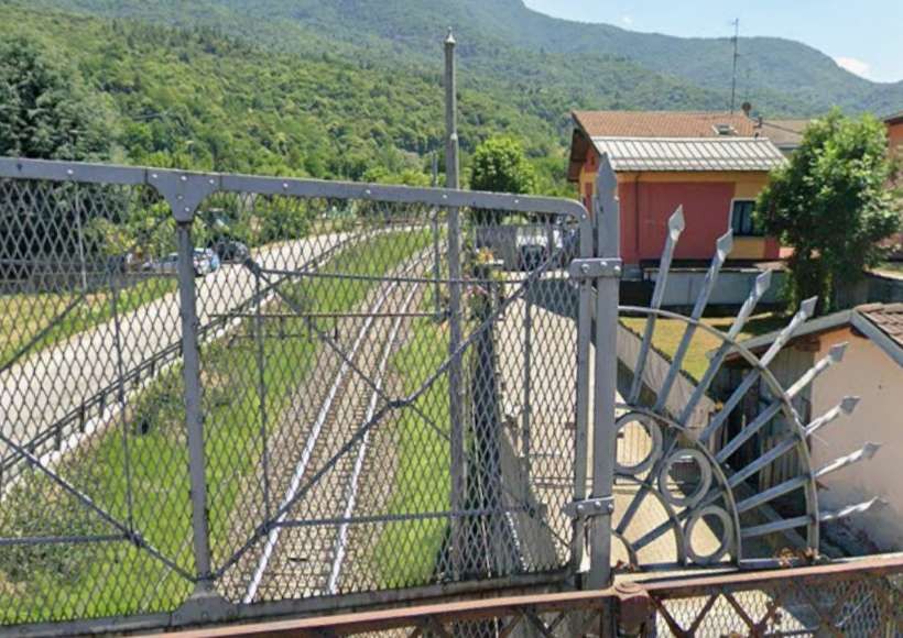
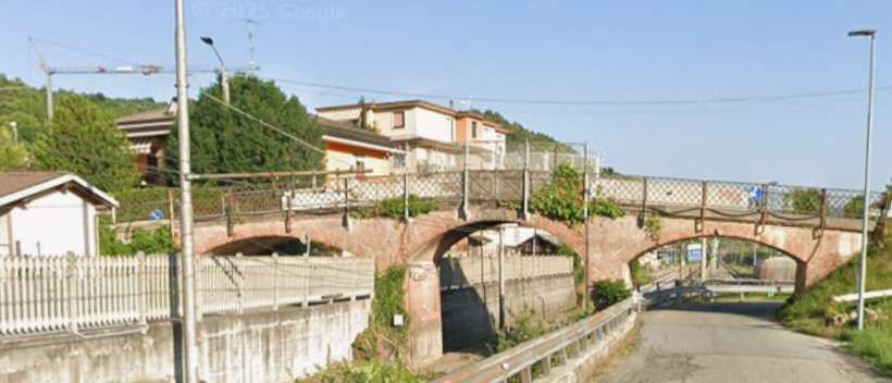
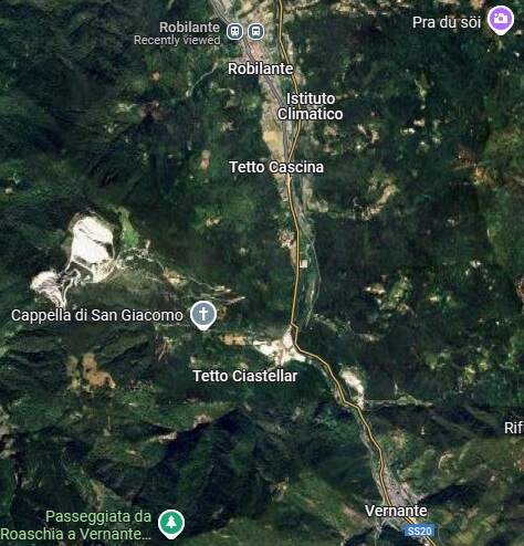
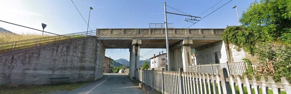
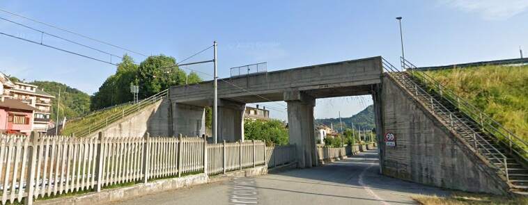
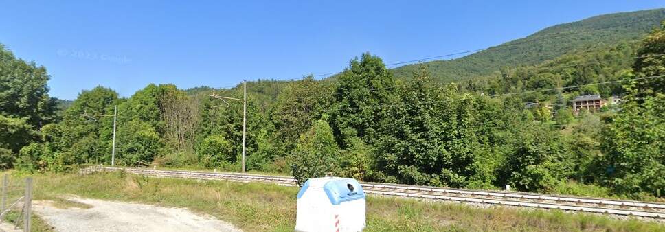
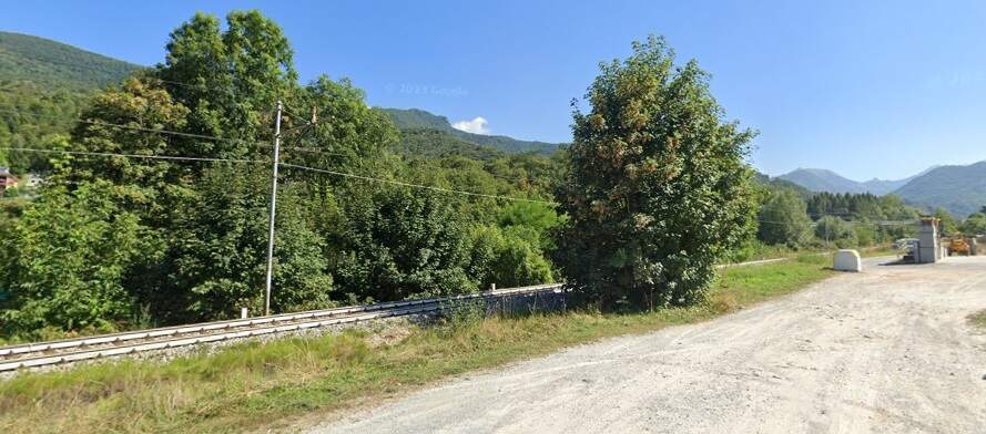
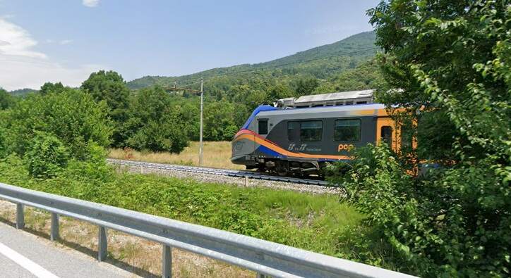
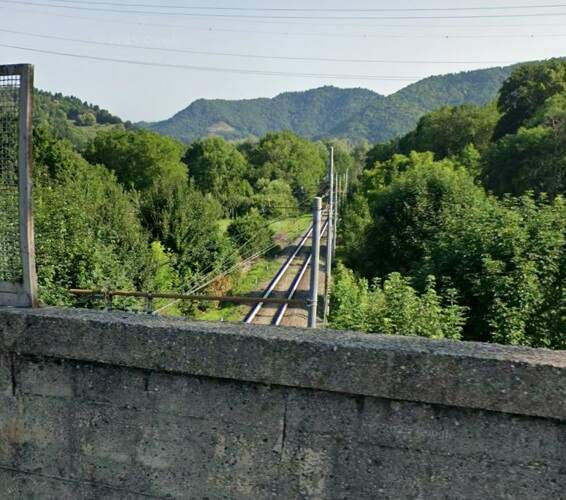
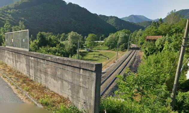
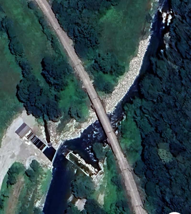
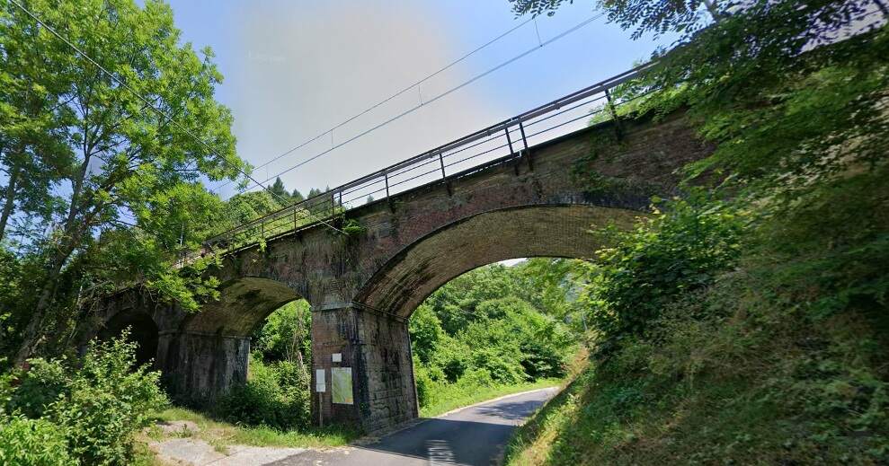
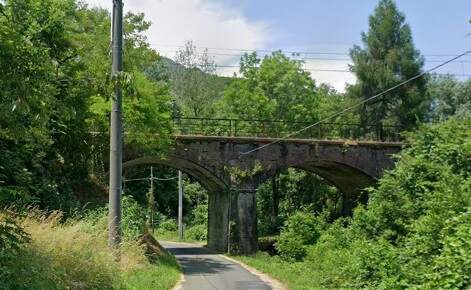
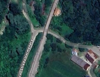
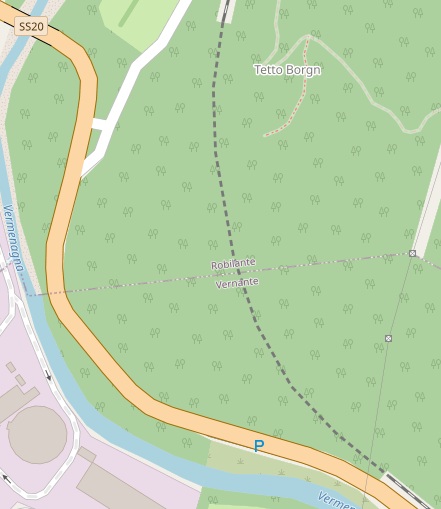
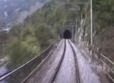
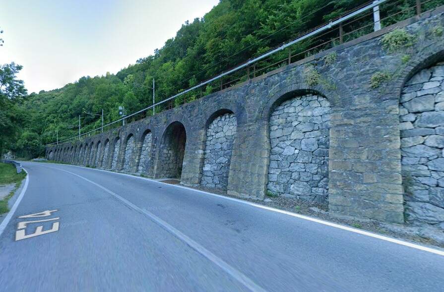
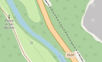
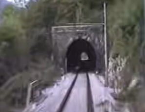
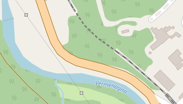
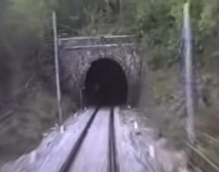
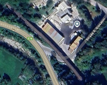
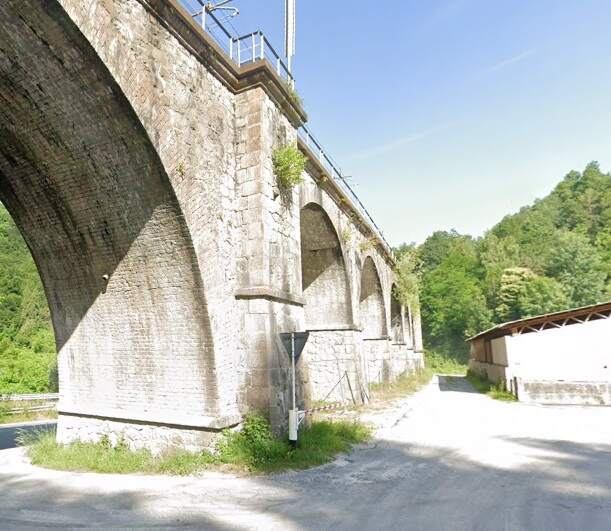
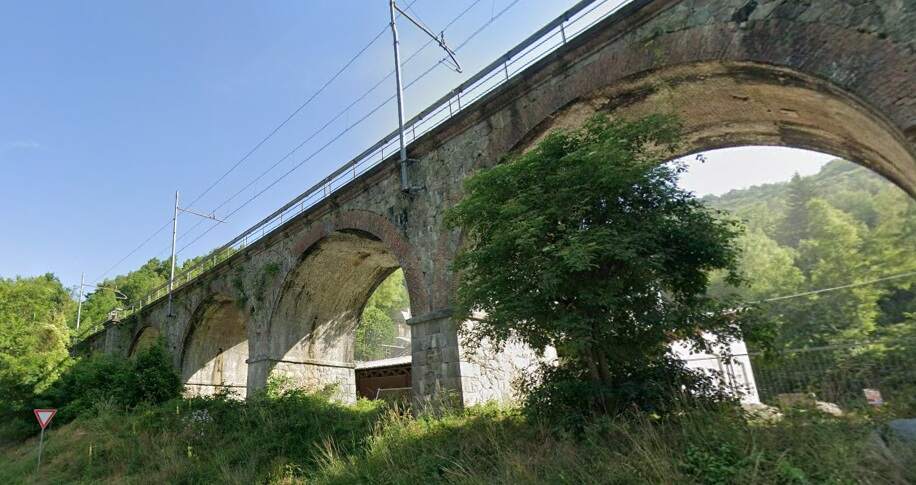
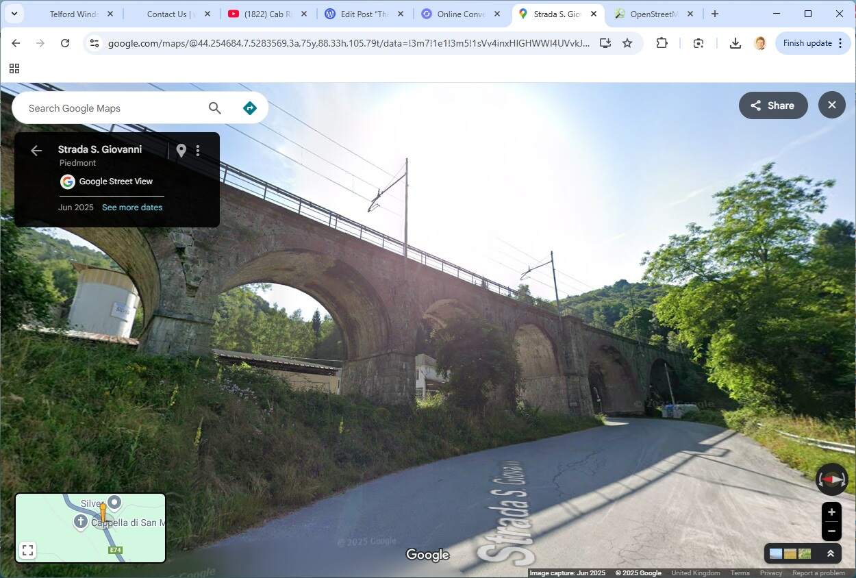
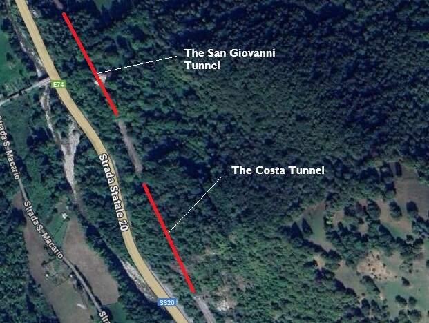
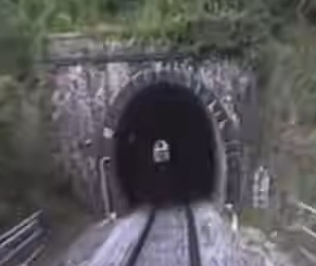
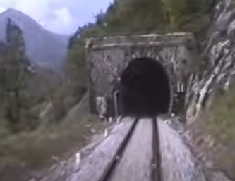
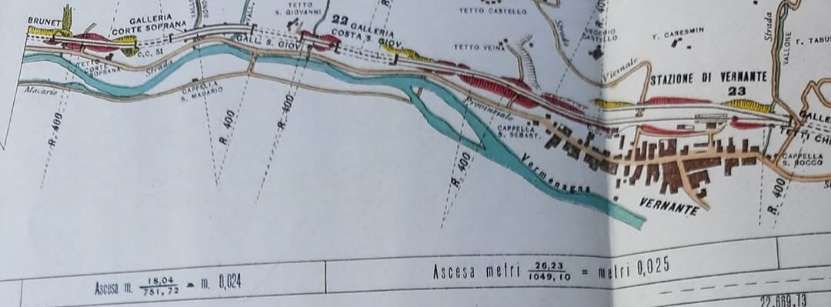
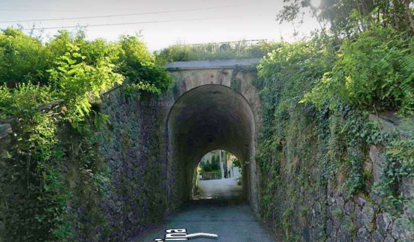
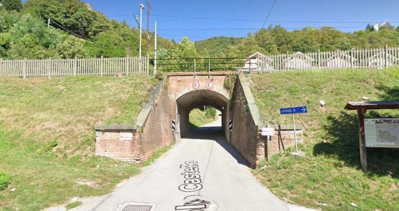
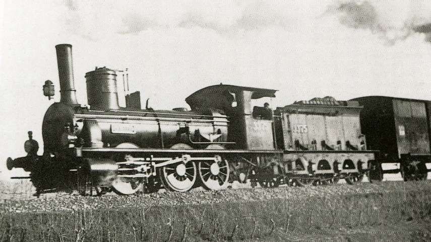

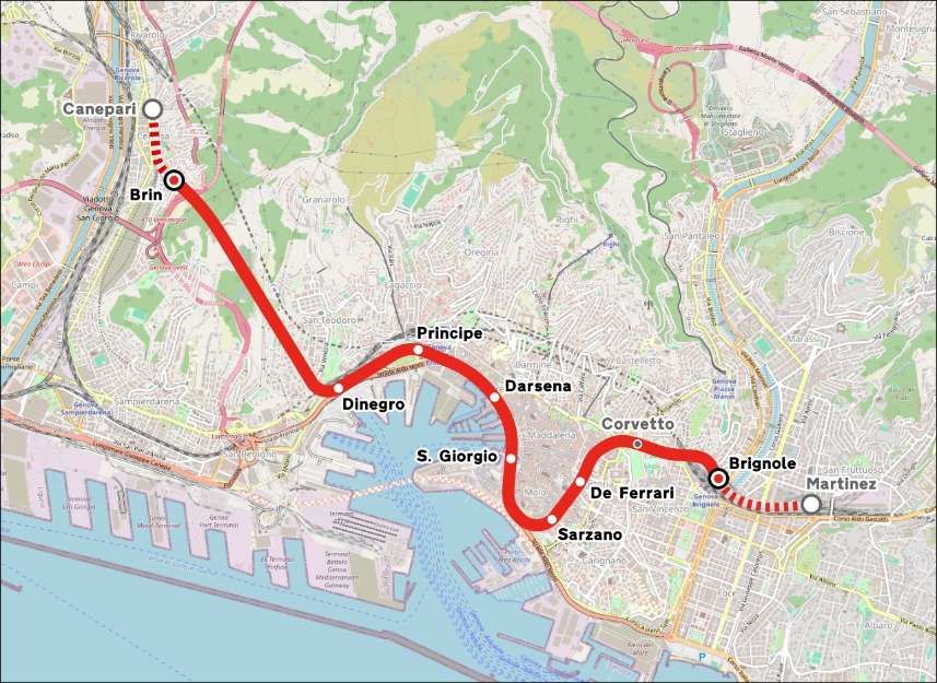
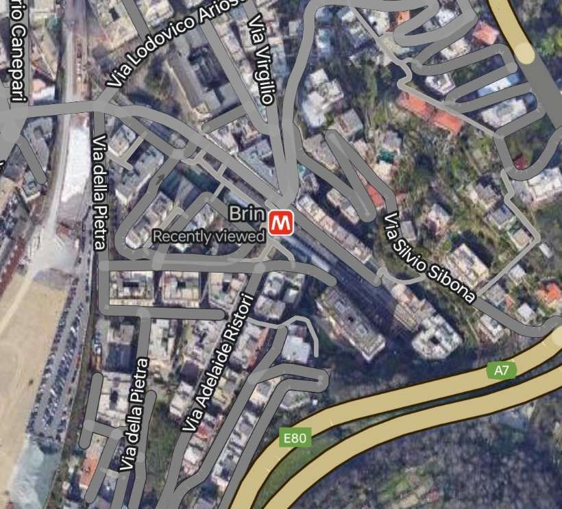
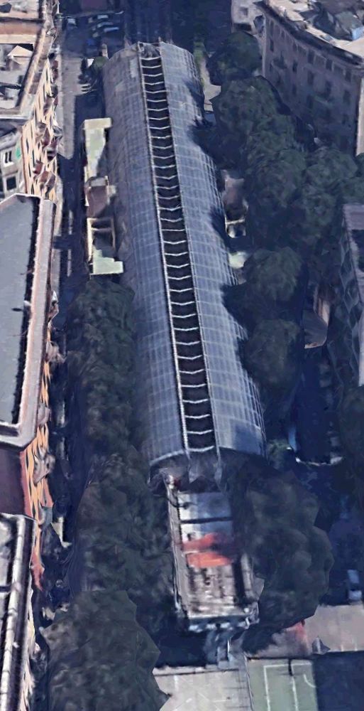
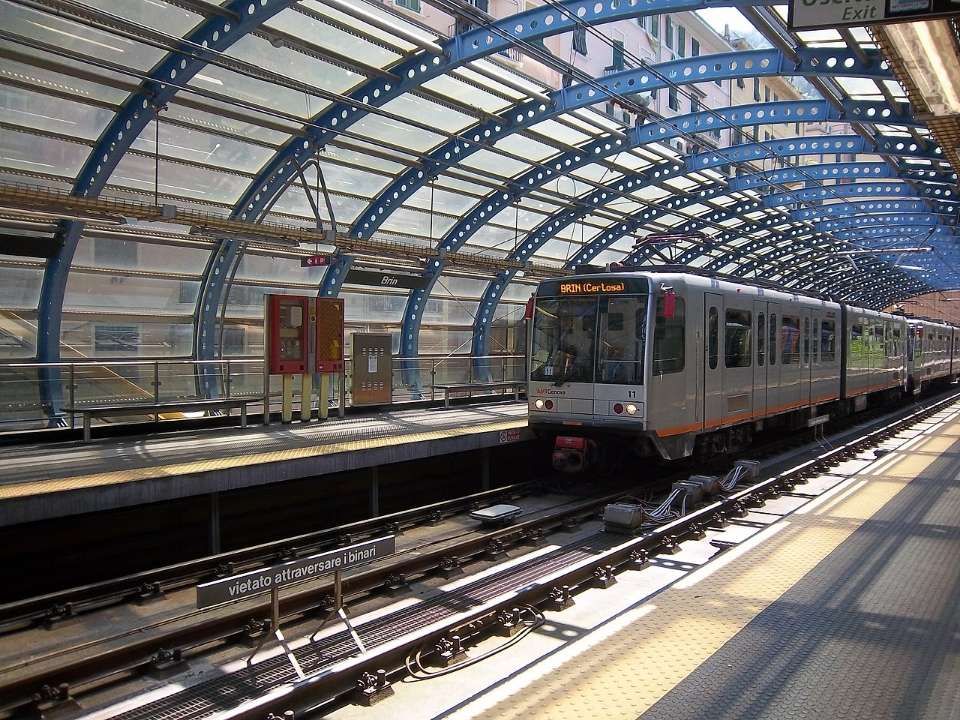
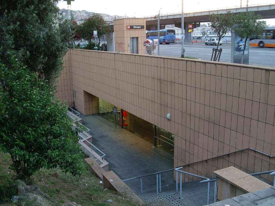

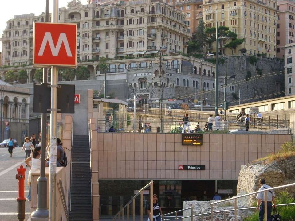
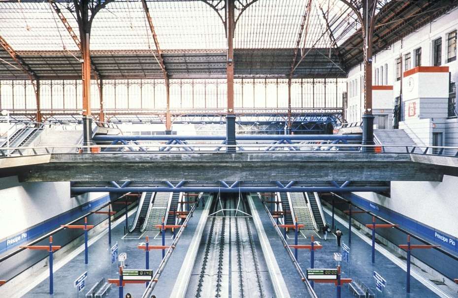
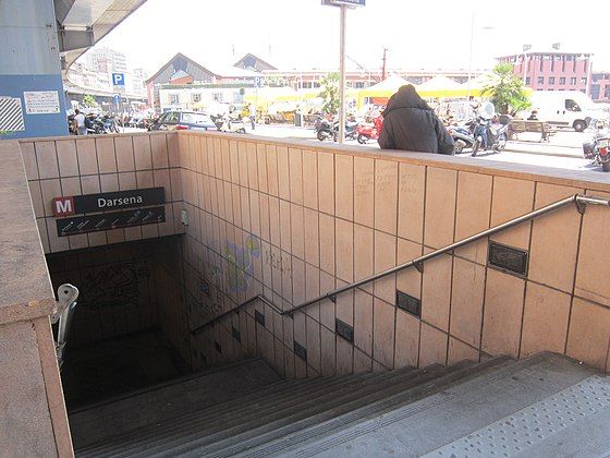
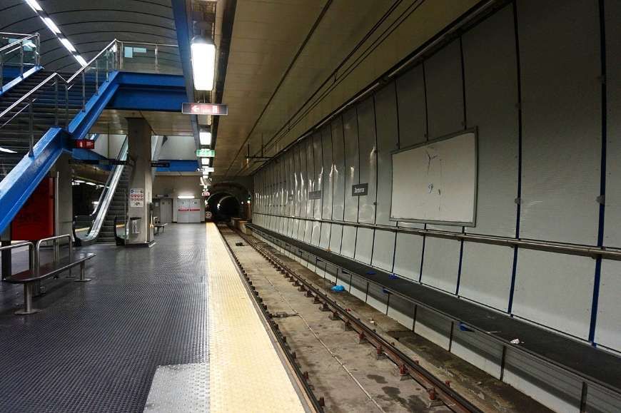
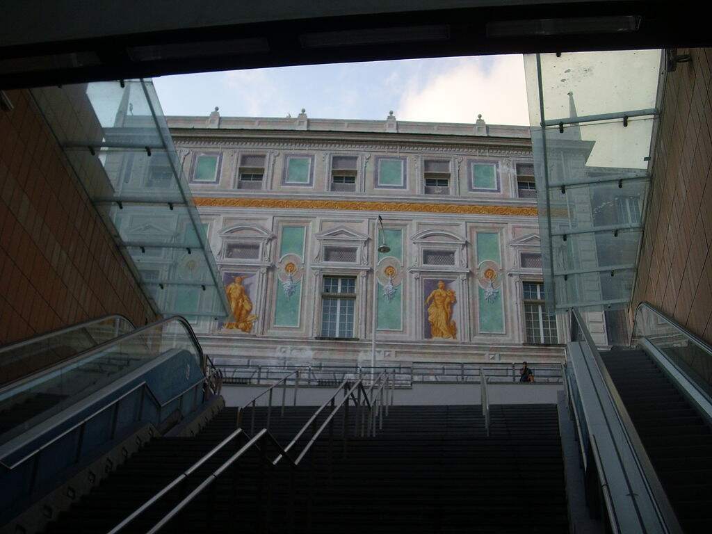
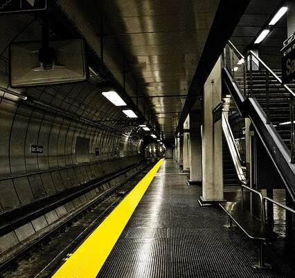
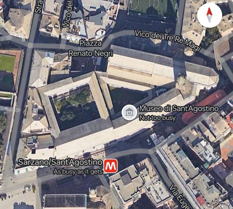
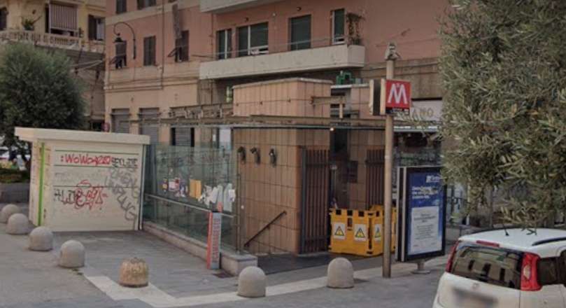

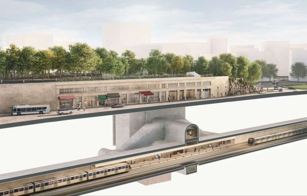
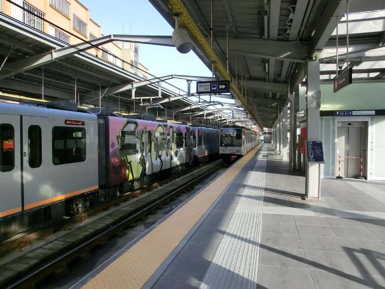
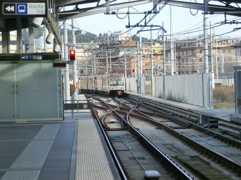
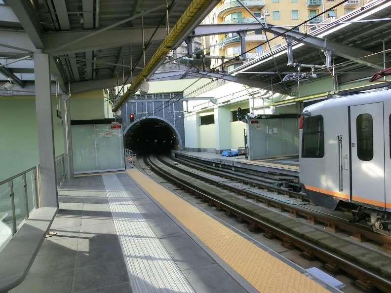
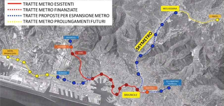
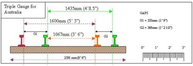
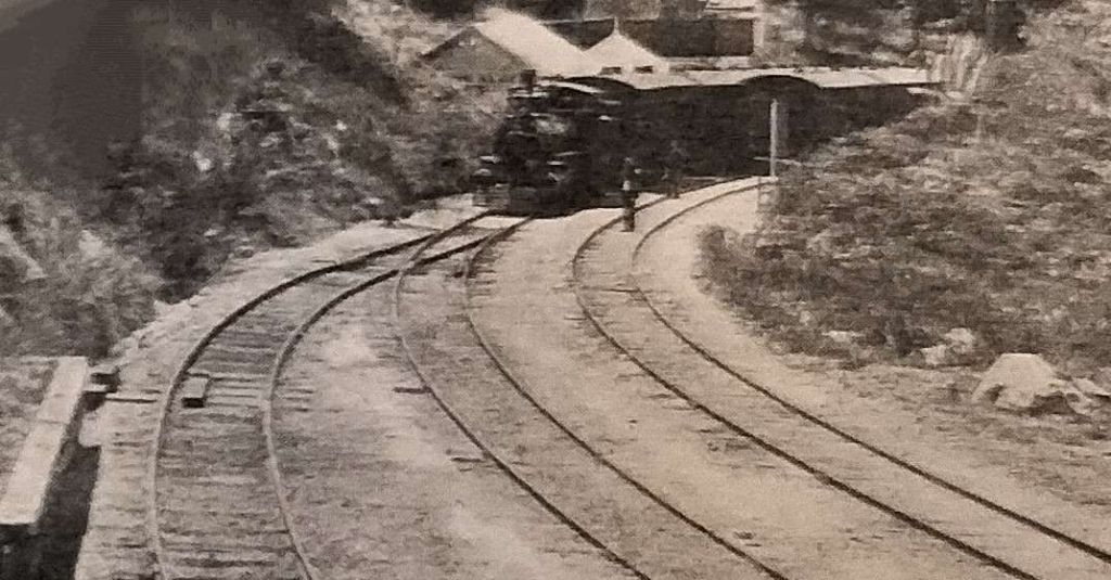
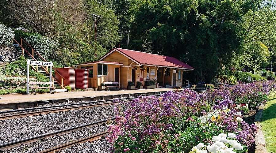
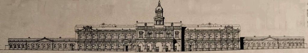
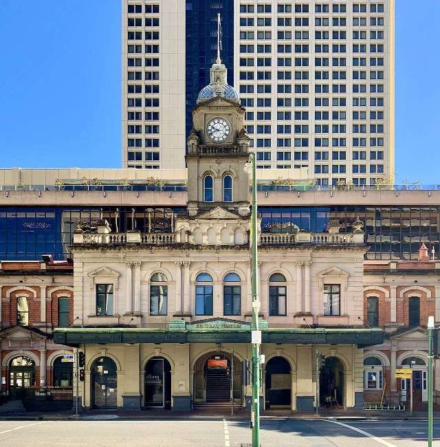
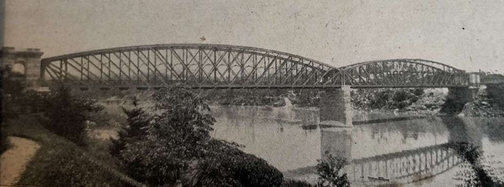
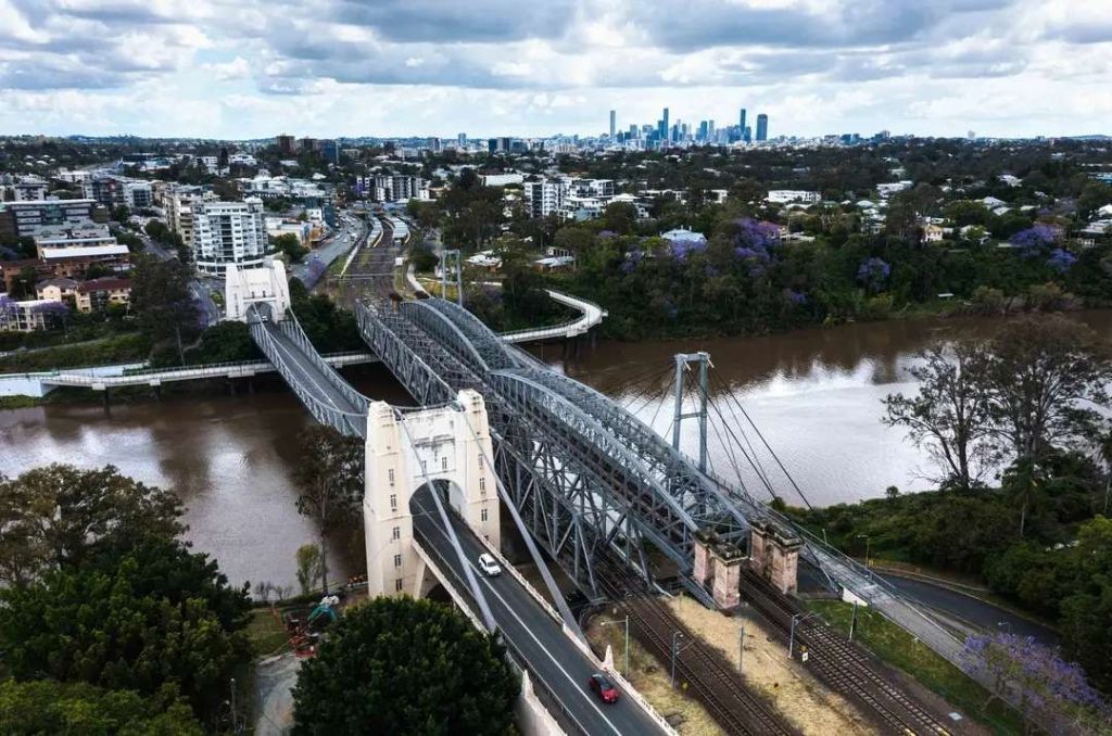
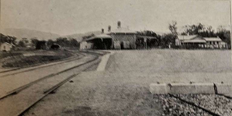
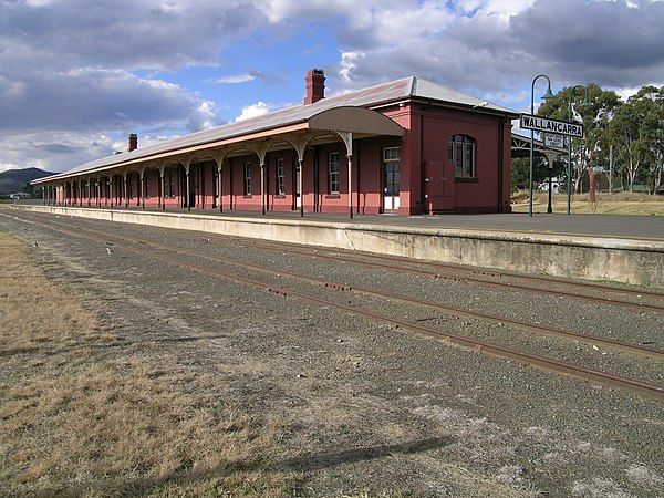
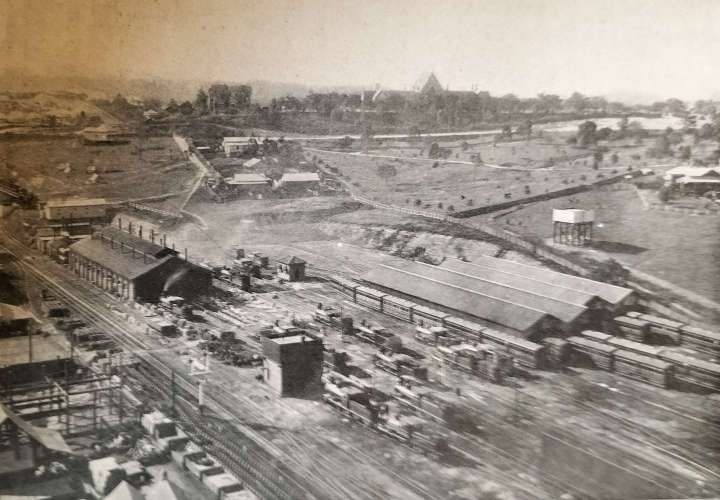
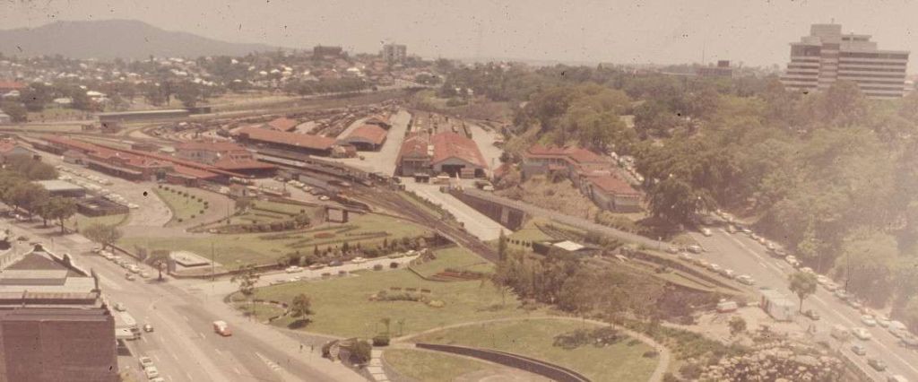
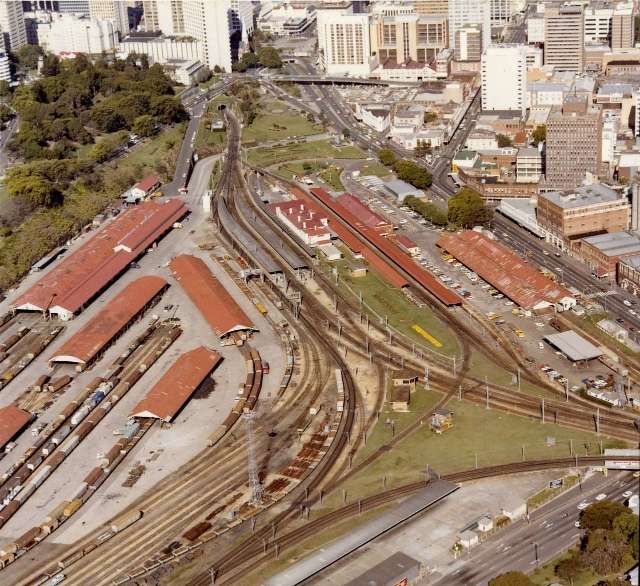

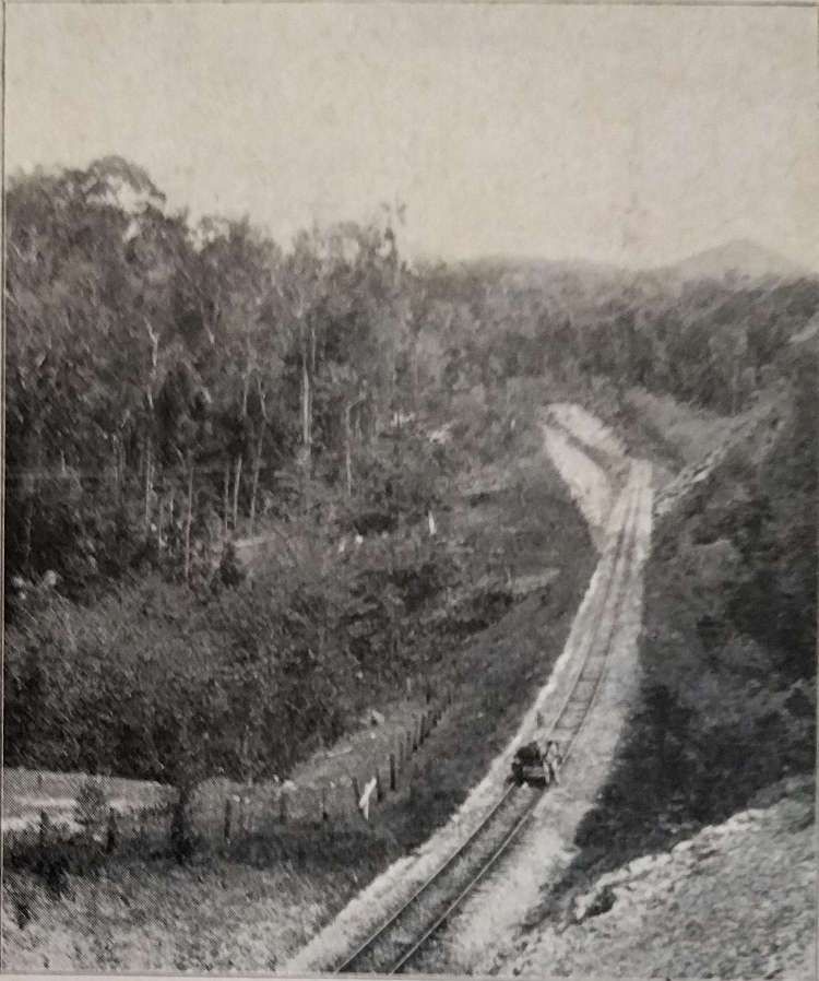
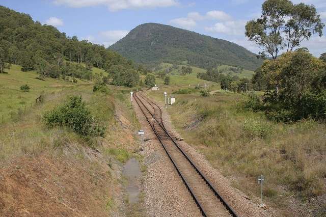
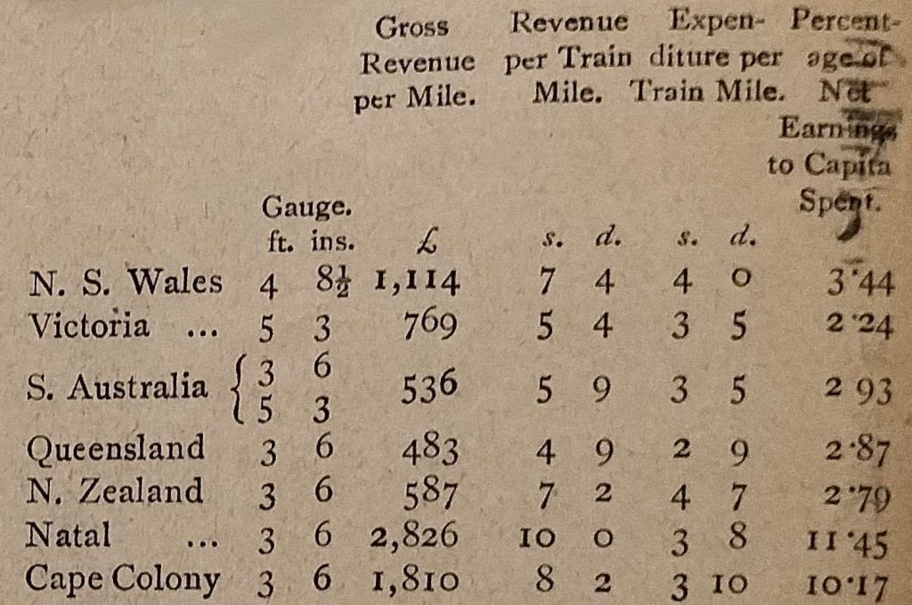
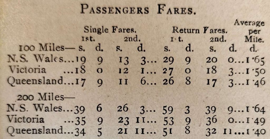
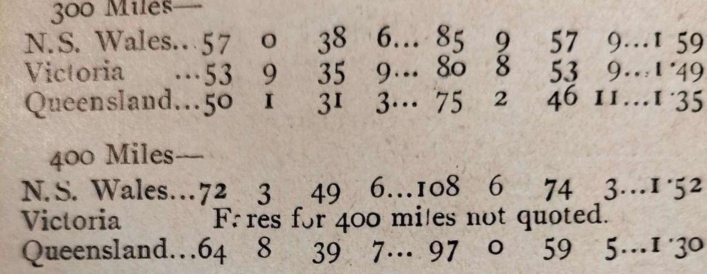
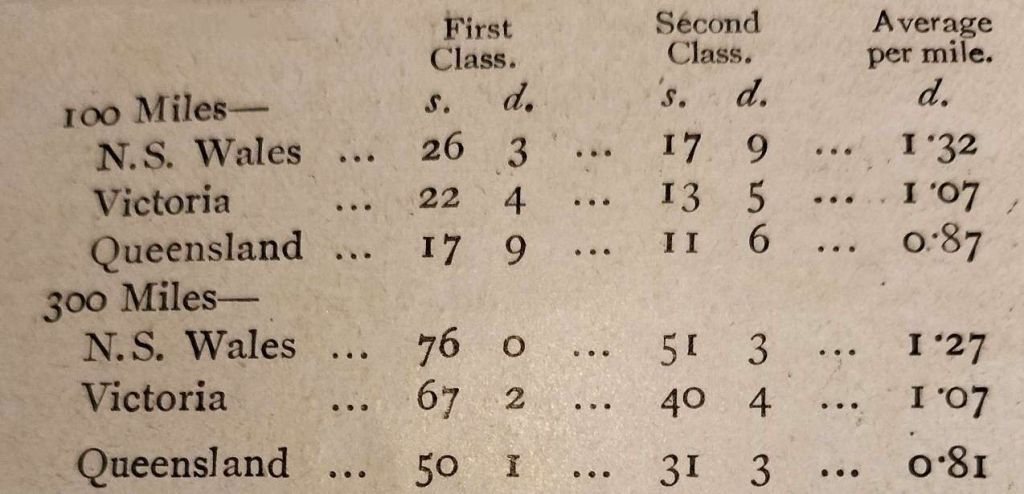
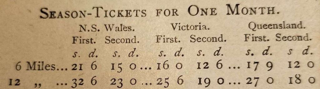
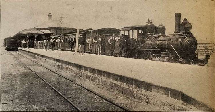
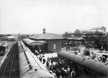
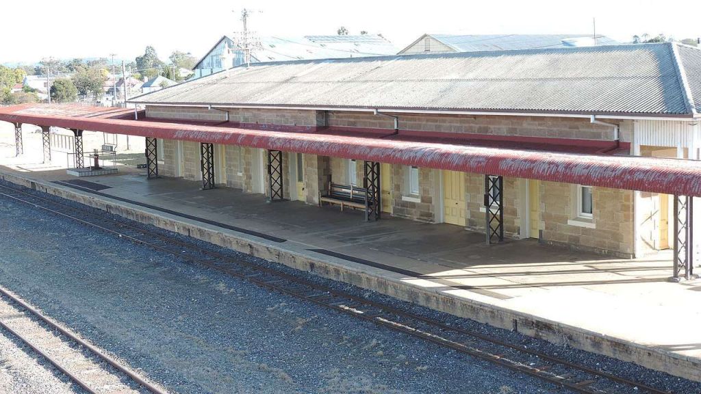
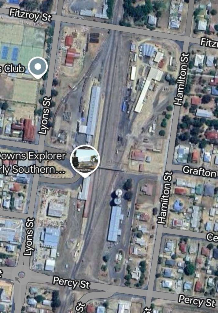
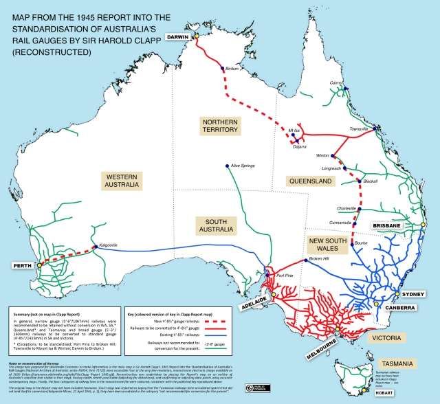
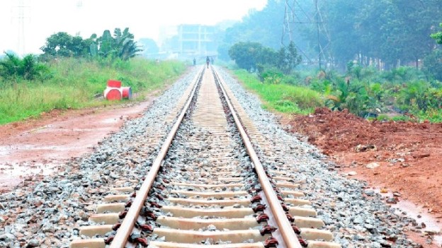


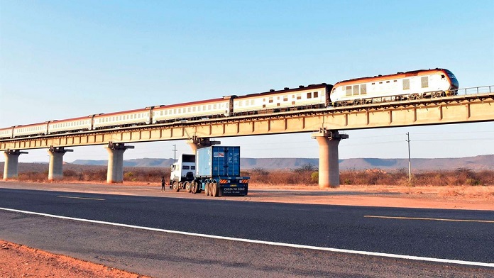

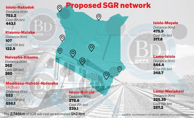


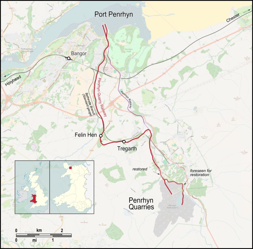

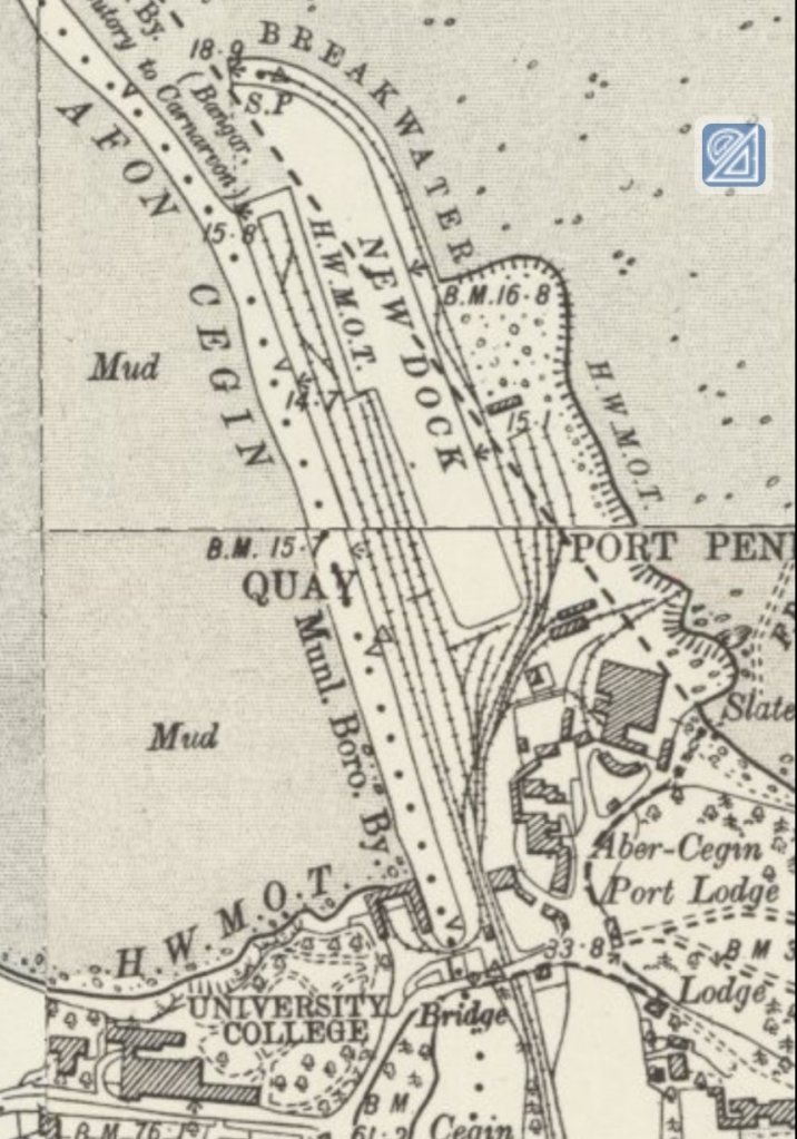
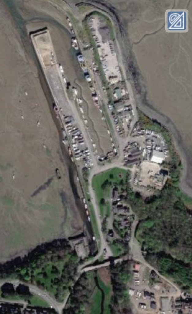


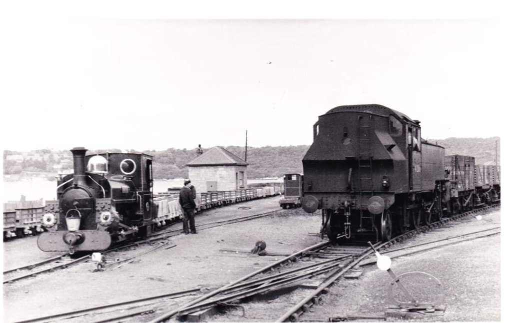
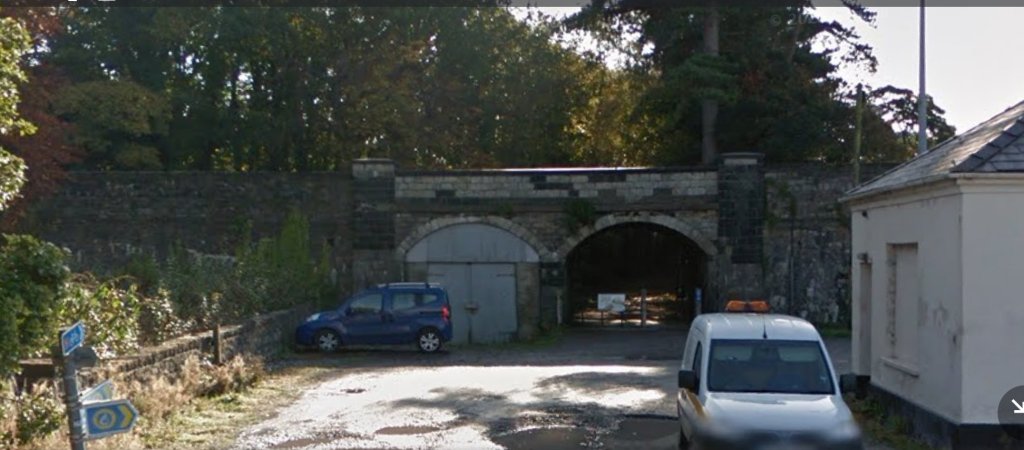
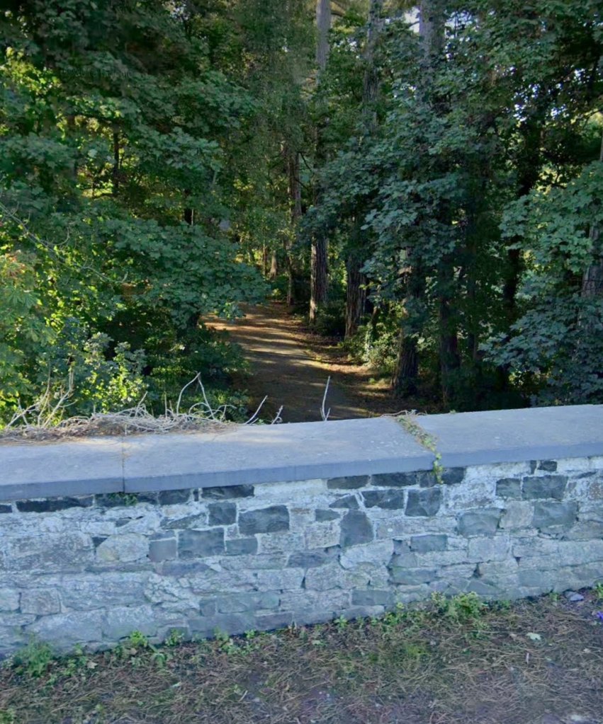

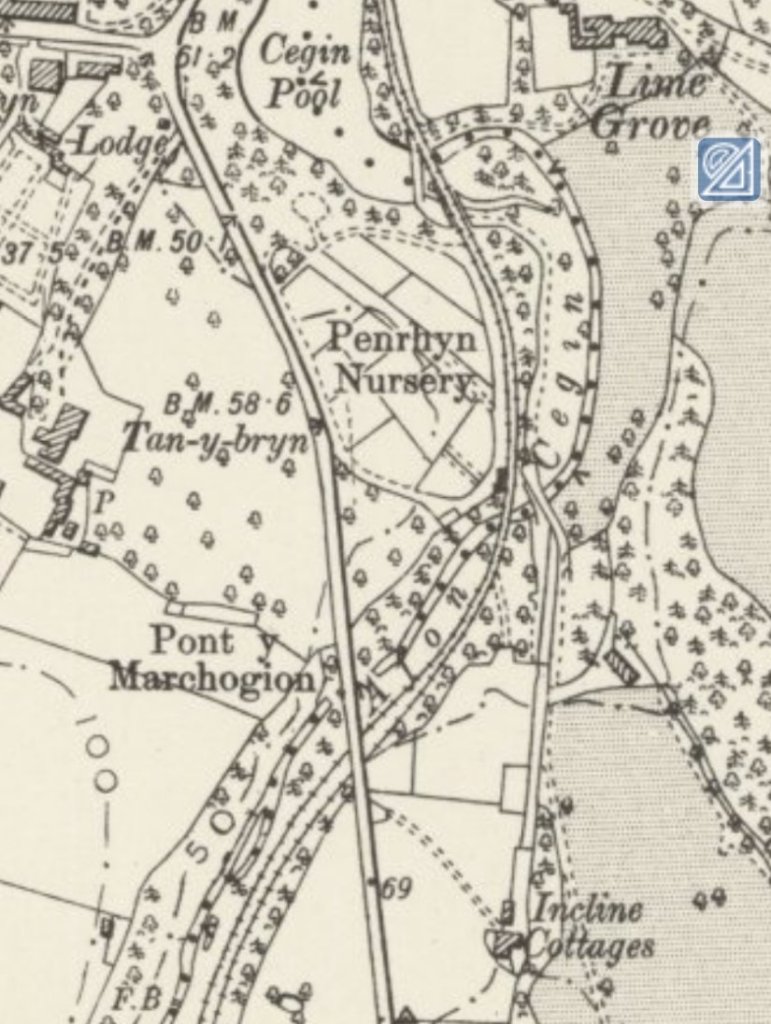


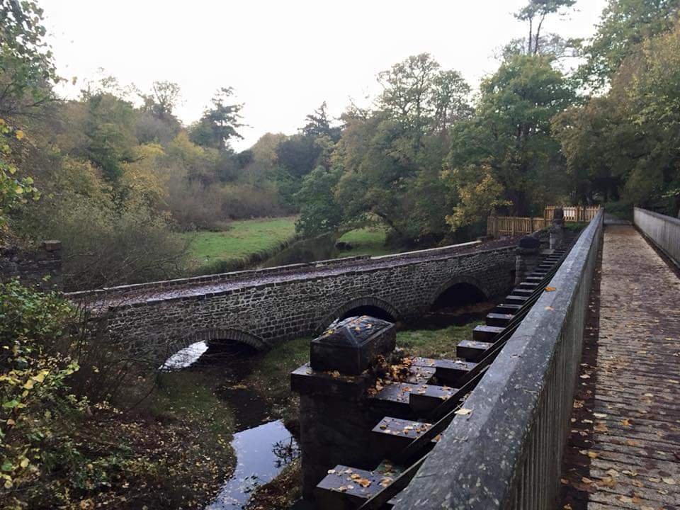
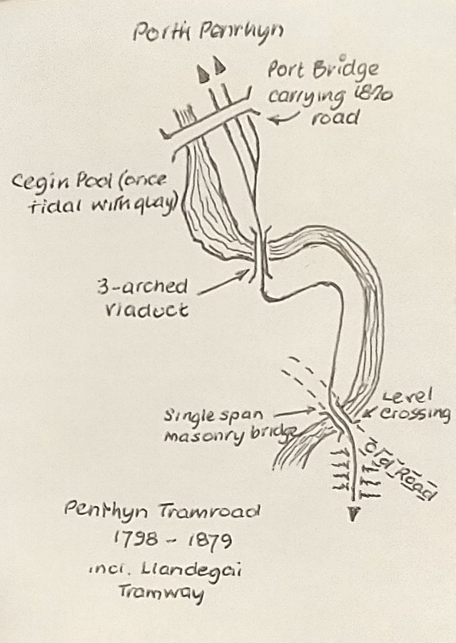
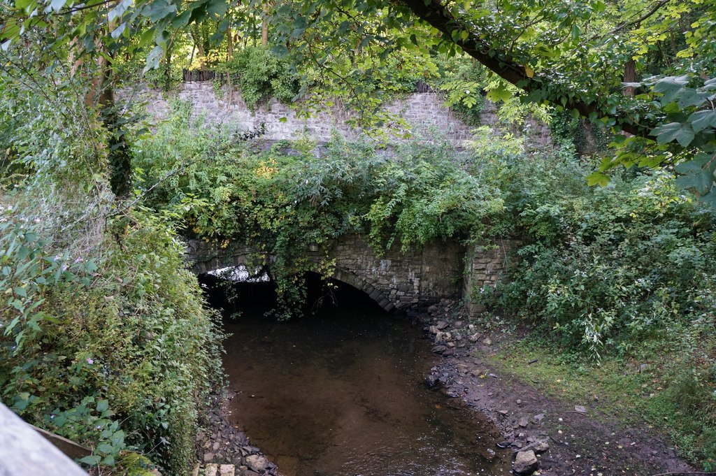

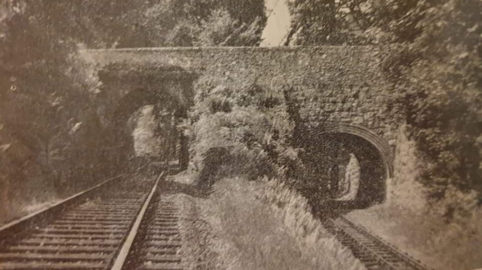
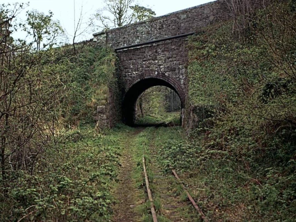
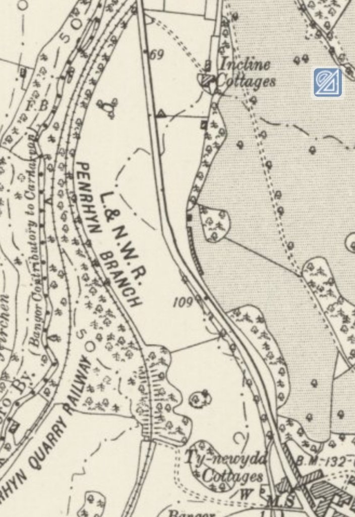

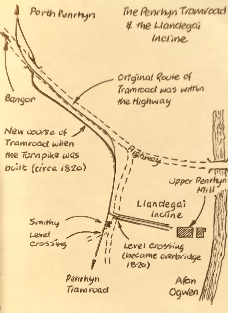
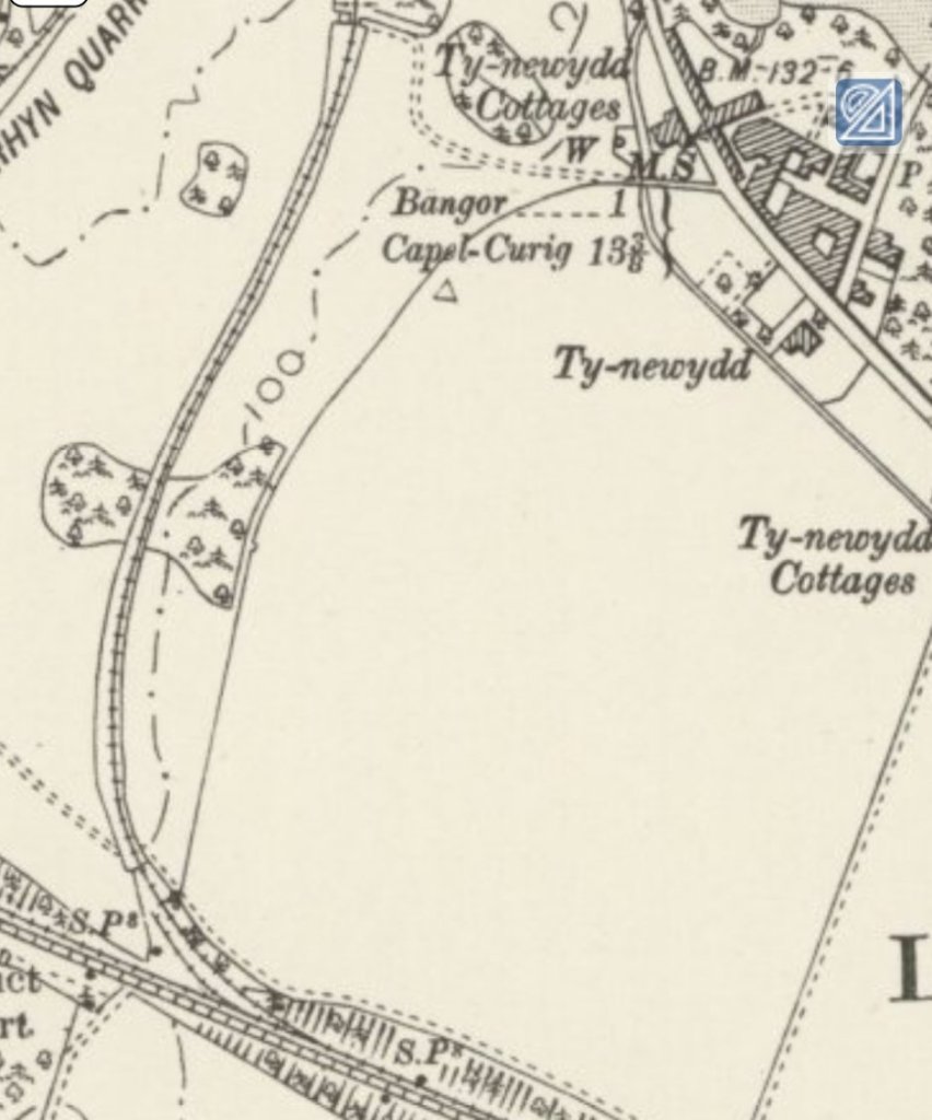
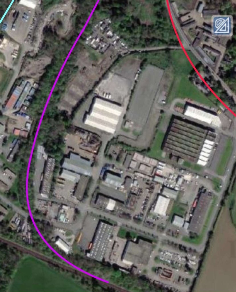
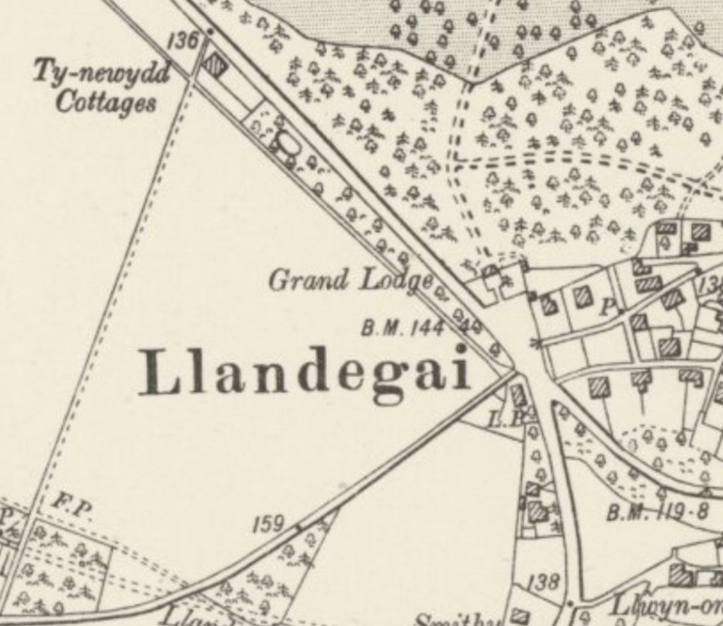


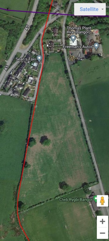

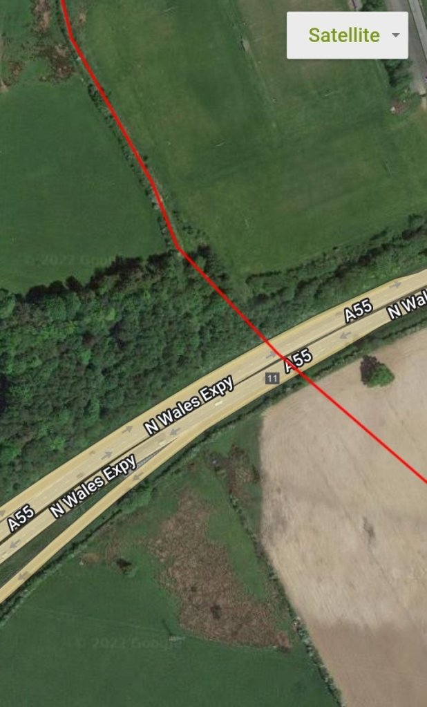

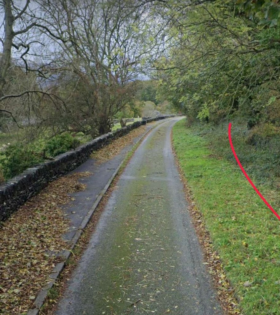

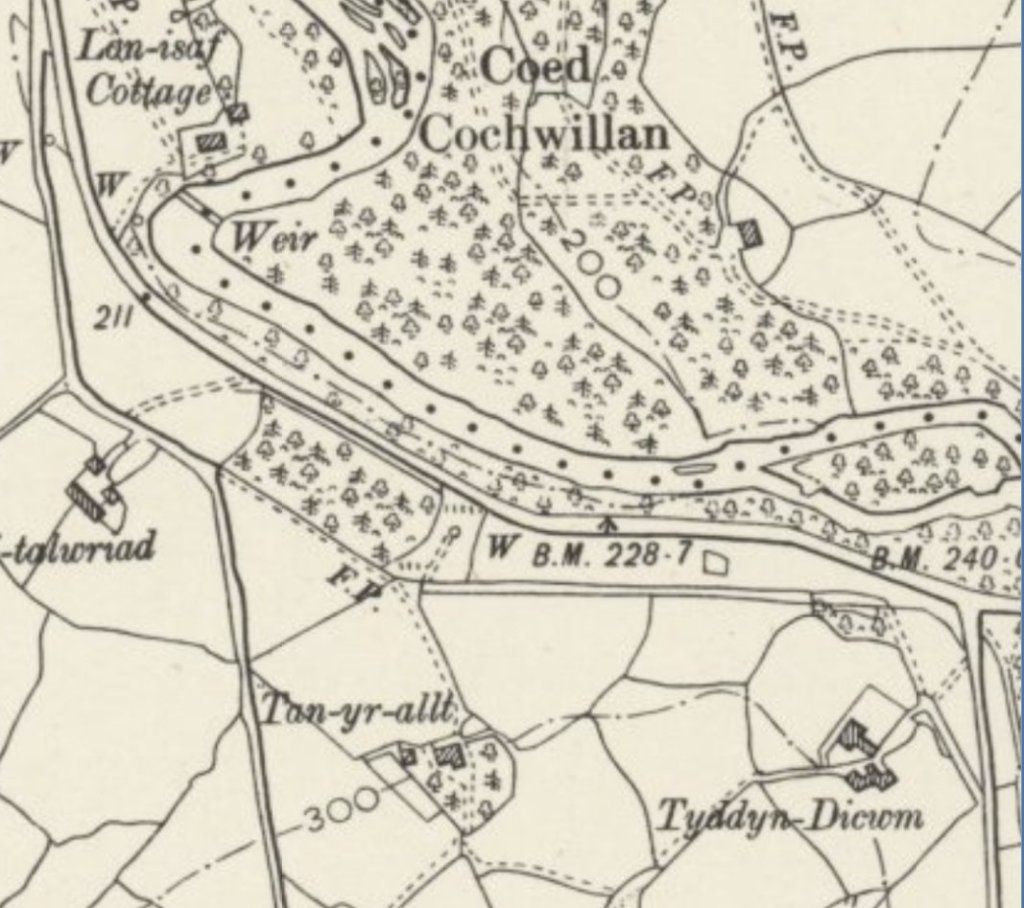
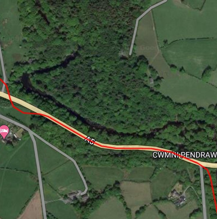
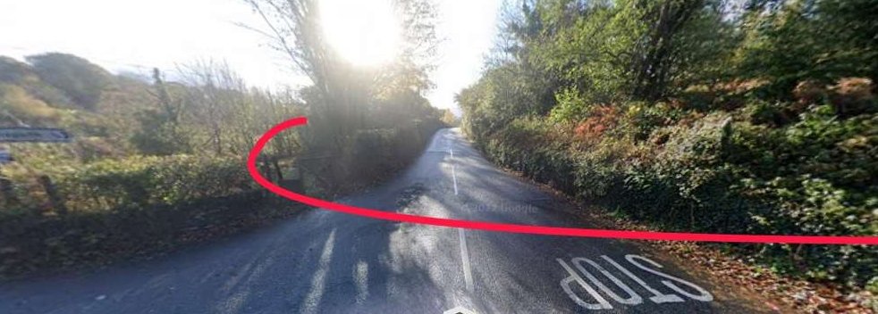
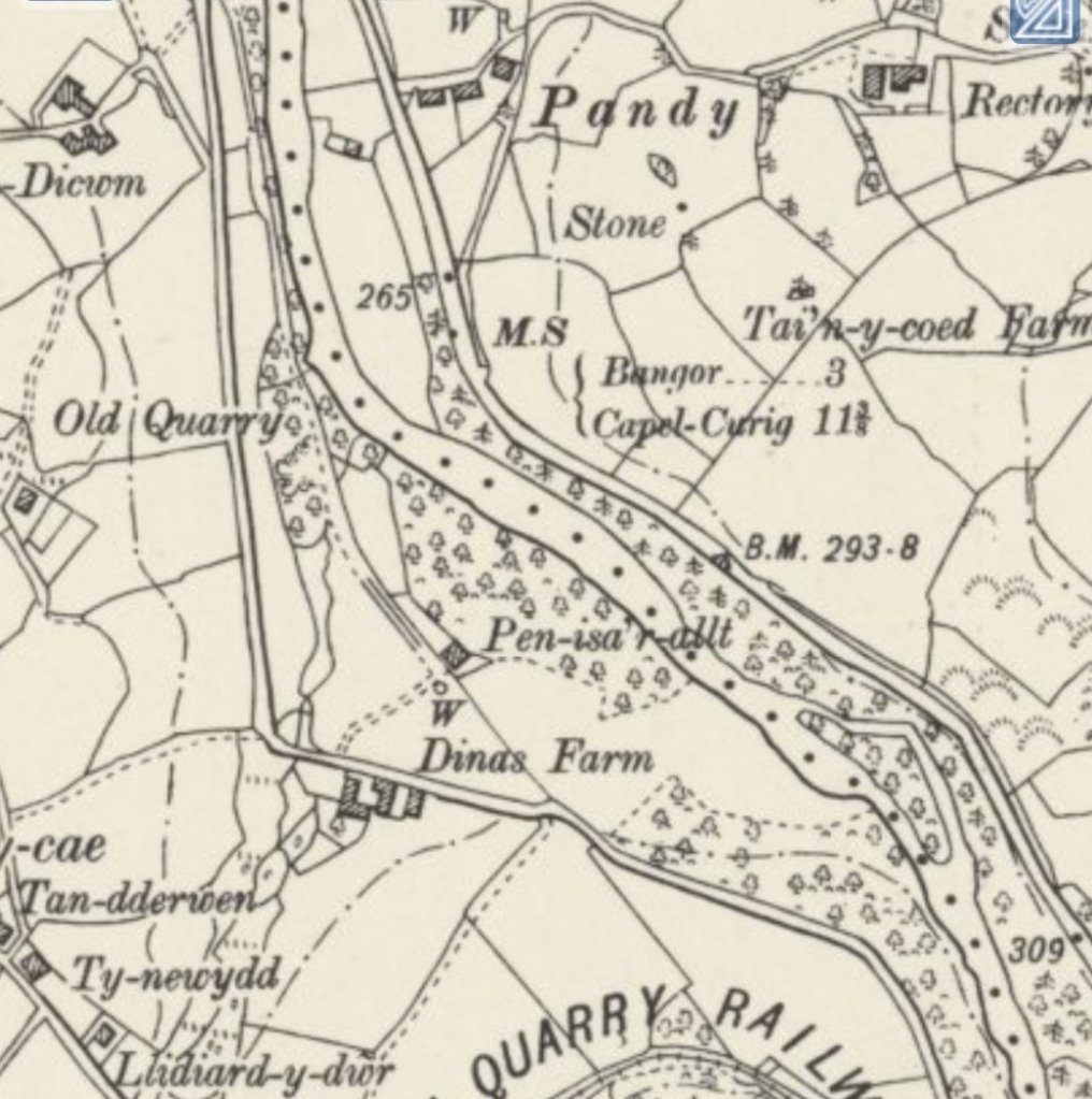

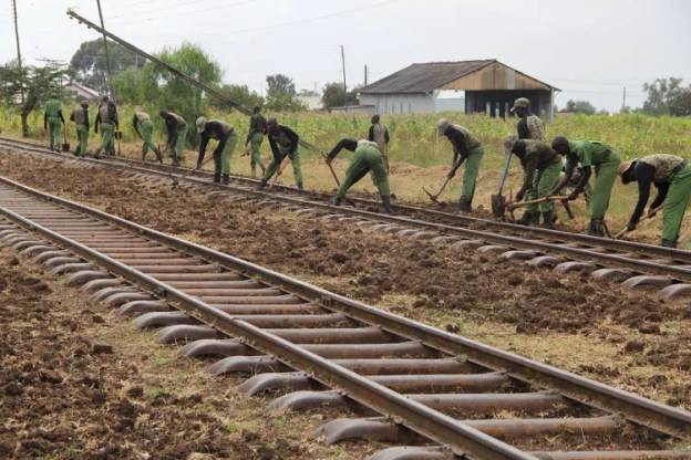
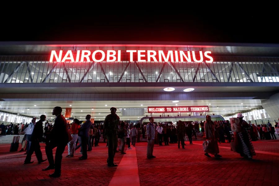
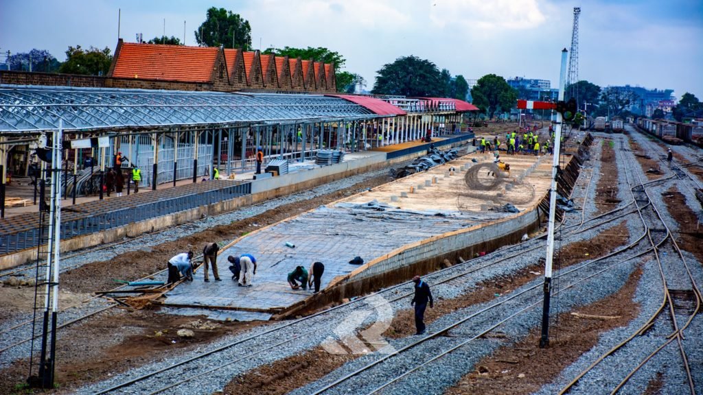


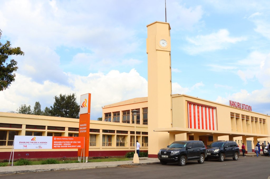

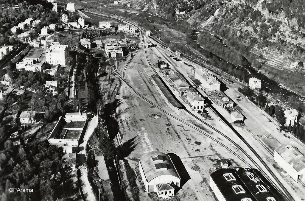
.jpg)
#/media/File%3AL04_163_Hp_Dinegro%2C_ET_37.jpg)