Flicking through a number of old magazines passed to me by a friend here in Telford, I came across a supplement published by The Railway Magazine in December 1990, “Eric Treacy: The Classic Years.” [1]
The Rt. Revd. Eric Treacy MBE, LLD, Lord Bishop of Wakefield from 1968 until 1976, died on Appleby Station on 13th May 1978. He left behind a large collection of railway photographs, taken over more than four decades.
In 1932, he was ordained deacon in the Church of England and priest a year later, serving as curate at Liverpool parish church from 1932 to 1934. [4] Wikipedia tells that “he took up railway photography, being inspired by visiting Liverpool Lime Street and getting to know his parishioners who worked on the railway. His photographic work appeared in various magazines during the 1930s.” [3]
His railway photography “was interrupted by the Second World War when he served as Military Chaplain. On 12th March 1940, he was commissioned as Chaplain to the Forces 4th Class (equivalent to captain). [5] On 10th May 1945, it was announced that Treacy had been Mentioned in Despatches ‘in recognition of gallant and distinguished services in North West Europe’. [6] He was promoted to a Chaplain to the Forces 3rd Class (equivalent to major). On 24th January 1946, he was appointed a Member of the Order of the British Empire (MBE).” [7][3]
In 1946 Treacy published his first book which contained images of L.M.S. locomotives. [8] On demobilisation he became Rector of Keighley and in 1949 was appointed Archdeacon of Halifax. [9] In 1961, he became Bishop of Pontefract [3] and in 1968, Treacy became Bishop of Wakefield. [1: p2]
The Railway Magazine Supplement comments that Treacy was “a devout man of the church as well as a talented lineside photographer (and frequent footplate passenger!) his atmospheric work never failed to portray his passionate love of railways, quickly establishing him as one of Britain’s foremost railway photographers.” [1: p2]
By 1935, “he was sending work regularly to The Railway Magazine signed ‘Rev E. Treacy, 2 Edge Lane, Liverpool’, showing London Midland & Scottish trains, many of them still worked by former London & North Western Railway locomotives, around that great city. Shap was an early discovery, and he spent many hours walking the fells and awaiting Anglo-Scottish expresses as they slogged their way to the summit. The zenith of his work undoubtedly came with the Stanier Pacifics, and to those who remember, it is virtually impossible to think of Eric Treacy without also the thunderous reminder of a ‘Princess Royal’ or ‘Coronation’ Pacific unleashing its full fury against that formidable climb with 15 bogies and more in tow.” [1: p2]
Lorna Hogger says that “Treacy befriended drivers and firemen in his congregation and often persuaded them to make smoke effects for his pictures. … He took time to plan his photographs days in advance, checking the weather and position of the sun at the time the train was due, and coming to know the locations well. Treacy rarely took unplanned shots, the equipment and large glass negatives being too expensive for acting on impulse.” [8]
Lorna Hogger also tells us that Treacy “joined the Railway Photographic Society in 1935, but unlike many of his peers he described his pictures as ‘emotional rather than technical’, enabling him to create stunning landscapes. This is evident in the photograph below which shows a goods train crossing the Ribblehead Viaduct.” [8]
The Railway Magazine Supplement continues: “No less atmospheric were his photographs of departures from major stations: think of Treacy, and sooty masterpieces of ‘Royal Scot’ or ‘Patriot’ 4-6-0s getting to grips with heavy trains at the foot of the deep rock cuttings out of Liverpool Lime Street come to mind, or perhaps an A4 Pacific trying to find its feet at the head of an Edinburgh-bound express at Kings Cross.” [1: p2]
The Railway Magazine Supplement concludes: “Throughout the transformation of the ‘Big Four’ to British Railways, and into modernisation when diesel locomotives began appearing on major routes, Treacy was there, and his legacy of ‘Deltics’ at Leeds or ‘Peaks’ on trans-Pennine services have all the richness and imagination of his steam photos.” [1: p2]
Photograph albums of Treacy’s work include:
Canon Eric Treacy; My Best Railway Photographs: No.1 L.M.S.; Ian Allan Ltd, London, 1946.
Eric Treacy; Roaming the Northern Rails; Ian Allan Ltd, London, 1976.
Eric Treacy; Roaming the East Coast Main Line; Ian Allan Ltd, London, 1977.
Eric Treacy; Lure of Steam; Ian Allan, London, 1969, 1980.
Eric Treacy; Glory of Steam; Ian Allan, London, 1981 (reprint?)
G. Freeman Allen; Great Railway Photographs by Eric Treacy; Peerage Books, London, 1982.
P.B. Whitehouse & G. Freeman Allen; Eric Treacy: Railway Photographer; David and Charles, Newton Abbott, 1983.
P.B. Whitehouse & J. Powell; Treacy’s Routes North; 1985.
P.B. Whitehouse & J. Powell; Treacy’s British Rail; 1990.
Eric Treacy; Portrait of Steam; 1991(reprint).
Eric Treacy; The Best of Eric Treacy; Atlantic Transport Publishers, 1994.
David Jenkinson & Patrick Whitehouse; Eric Treacy’s L.M.S.; Oxford Publishing Company, 1988.
References
Eric Treacy: The Classic Years; in The Railway Magazine (supplement), December 1990.
A significant proportion of the August 1925 edition of The Railway Magazine [1] was dedicated to coverage of the Centenary celebrations at Darlington. Given the short timescale between the event and the publication date of the August issue of the magazine (?late July?), and given that modern digital techniques were in no way available, the achievement of publication in such a short time is to be admired.
Writing at the end of 2024, in just a few months the 200th anniversary will occur, it will be interesting to see what celebrations will be taking place in the Summer of 2025. See, for example, the National Railway Museum‘s plans for 2025. [42]
G.A. Sekon offered The Railway Magazine’s congratulations to the organisers of the 1925 exhibition on their organisational achievements and on the “comprehensiveness and interest of the exhibits brought together.” [1: p101] He also notes that the opportunity was taken by the King to appoint many different leading railway officers to the Order of the British Empire these included: four CBEs (Mr. R. C. Irwin, Secretary, L.M.S.R., Mr. E. A. Bolter, Secretary, G.W.R., Mr. G. Davidson, Divisional General Manager, North Eastern Area, L.N.E.R., and Mr. G. S. Szlumper, Assistant General Manager, Southern Railway), eight OBEs and fourteen MBEs.
The ‘main event’ was the procession which was “witnessed at ease and in comfort by many hundreds of thousands in view of the accessibility of the route practically from end to end and the arrangements whereby landowners generously allowed access to fields adjoining the line.” [1: p103]
The event was opened by HRH. the Duke of York, accompanied by the Duchess of York. (The Duke of York being the future George VI who became King unexpectedly following the abdication of his brother, King Edward VIII, in December 1936.)
In his opening address Mr. W. Whitelaw made it clear that, “The Exhibition was the result of the co-operation of five great railway companies, assisted by many friends from all parts of the country, who possessed interesting relics of the first passenger railway in the kingdom. It seemed very fitting that the commencement of the celebration of what took place on 27th September 1825, should be in that great railway town of Darlington. If Darlington did not own all the credit for the science of railways, at any rate no one could deny or challenge the statement that Darlington was the home of the first great railway statesman, Edward Pease.”
The Procession
A short (20 minute) film of the procession/cavalcade can be viewed here. [35]
“The centenary celebrations were held in July to allow guests from foreign countries visiting the International Railway Congress to take part. An exhibition of rolling stock at the new Faverdale Wagon Works in Darlington was opened by the Duke and Duchess of York (later King George VI and the Queen Mother). The following day the royal couple watched as procession of locomotives passed between Stockton and Oak Tree Junction, starting with a Hetton Colliery locomotive that had been built in 1822 and finishing with a replica train of ten chaldron waggons and ‘the company’s coach’ hauled by Locomotive No.1 propelled by a petrol engine in a specially built tender.” [45] A copy of the original programme for the procession can be found here. [46]
The procession was due to have 54 items, one of which had to be withdrawn (the North British Locomotive Company’s geared turbine condensing locomotive). [1: p123] The final list was: [8]
1. Hetton Colliery locomotive – 1822.
2. S. & D.R. “Derwent” – 1845.
3. NBR 0-6-0 No. 381 (LNER J31 10114) – 1867.
4. NER 0-6-0 No. 1275 – 1874.
5. LNER J26 0-6-0 No. 517 (ex NER) – 1905.
6. LNER B16 4-6-0 No. 934 (ex NER) – 1921.
7. LNER K3 2-6-0 No. 203 – 1925.
8. LNWR 0-8-0 No. 1881 (LMS 8900) – 1901.
9. LMS 0-8-0 No. 9446 (ex LNWR) – 1922.
10. LNER 02 2-8-0 No. 3501 – 1924.
11. GWR 2-8-0 No. 4700 – 1919
12. LNER P1 2-8-2 No. 2393 – 1925.
13. LNER electric loco No. 9 (hauled by J71 0-6-0T 317) (ex NER) – 1914.
14. GWR 2-2-2 “North Star”(replica), (on wagon, hauled by J71 0-6-0T No. 181) – 1837.
Of these items, The Railway Magazine chose to highlight a number of these including:
1. The Hetton Colliery Locomotive
“The procession was headed by the old Hetton Colliery engine, built in 1822 by George Stephenson and Nicholas Wood, previous to the establishment of Stephenson’s works at Newcastle-on-Tyne. The engine, by the way, was rebuilt in 1857, and again in 1882, when the link motion, at present fitted, was added.” [1: p109]
“Next in order came the old ‘Derwent’, a mineral engine of Timothy Hackworth’s design, which was built in 1845 by William and Alf Kitching, of the Hopetown Foundry, Darlington, for the Stockton and Darlington Railway. The ‘Derwent’ also ran under its own steam.” [1: p109]
“Then followed a number of engines more or less familiar to the present generation [1925], although two of them were built over 50 years ago. A 1925 modern goods express 2-6-0, with special valve gear, and a mineral engine 2-8-0 with three cylinders, were a great contrast to the veterans that had passed earlier. Then followed a “Mikado” type of locomotive built at the Doncaster works of the L.N.E.R., for fast mineral work, but even greater interest was shown in a model of the old North Star, built in 1837 by Robert Stephenson and Co., which was mounted on a Great Western ‘crocodile’, drawn by a locomotive. Several specimens of the single-driver expresses popular in the latter half of the [19th century] were in the procession, including the Cornwall, which has a driving wheel of 8 ft. 6 in. in diameter the largest locomotive driving wheel still in service in the world.” [1: p109]
4.0-6-0 Stockton & Darlington Goods
Fourth in the procession was a typical 0-6-0 locomotive from the Stockton and Darlington (S&D) Railway. This was probably NER No. 1275 which was the only NER 1001 Class locomotive to survive into LNER ownership. It was built by Dübs & Co., Glasgow, and was delivered to the S&D in May 1874. 1275 entered into LNER ownership with an official mileage of 908,984 miles. Still in its NER livery, it was quickly withdrawn on 16th February 1923. [6]
This locomotive is preserved as part of the National Collection and is on static display at the National Railway Museum at York. [6]
NER No. 1275 is preserved in the National Railway Museum in York: Science Museum Group. NER 0-6-0 ‘1001’ class steam locomotive and tender, No 1275, 1874. 1975-7009 Science Museum Group Collection Online. [7]
The LNWR Class B was a class of 0-8-0 steam locomotives introduced in 1901. These locomotives were a development of the three-cylinder compound Class A (though this letter classification was not introduced until 1911), they had a 4-cylinder compound arrangement. 170 were built between 1901 and 1904. [9]
“The London and North Eastern Railway Class P1 Mineral 2-8-2 Mikado was a class of two steam locomotives designed by Nigel Gresley. They were two of the most powerful freight locomotives ever designed for a British railway. It was initially intended they be a more powerful 2-10-0 version of the earlier Class O2 2-8-0s. The design was submitted in August 1923, for use between Peterborough and London, and also between Immingham and Wath marshalling yard. The power was quoted as being 25% more than the O2.” [21]
“No. 2393 was completed in June 1925, just in time for the Stockton & Darlington Centenary celebrations in July. It was fitted with a Robinson superheater, whilst No. 2394 (completed in November) had the “E Double” superheater recommended by The Superheater Co.” [22]
14. GWR 2-2-2 ‘North Star’ (replica)
North Star was the first GWR locomotive, it on 31st May 1838 it worked the inaugural train for the company’s directors. More details can be found on the Preserved British Steam Locomotives website. [10]
Built in 1847, ‘Cornwall’ is a preserved steam locomotive. She was built as a 4-2-2 at Crewe Works in 1847, but was extensively rebuilt and converted into her current form in 1858. [12]
Wikipedia tells us that, “In 1858, Ramsbottom redesigned Cornwall almost completely. Little survived unchanged, other than the outside frames and the centres of the drivers. The boiler was … moved entirely above the driving axle, without any notches, channels or tubes. … New cylinders and valve gear were provided. … The wheel arrangement was [changed to] 2-2-2. … Ramsbottom also included his newly designed tamper-proof safety valves.” [12]
There was another minor rebuild in the 1870s providing a typical LNWR style of cab, with a short roof and semi-open sides. It was renumbered 3020 in June 1886. [12]
The Great Northern Railway (GNR) No. 1 Class Stirling Single was a class of steam locomotive designed for express passenger work. Designed by Patrick Stirling, they were characterised by a single pair of large (8 ft 1 in) driving wheels which led to the nickname ‘eight-footer’. Originally the locomotive was designed to haul up to 26 passenger carriages at an average speed of 47 miles per hour (76 km/h). It could reach speeds of up to 85 mph (137 km/h). [14]
“The first of the class, No. 1 is the only engine to be preserved. It is exhibited at the National Railway Museum, York. It was restored to running order during the 1930s for the fiftieth anniversary of the Race to the North and steamed again during the 1980s.” [14]
The three locomotives shown in the image above are:
19. 1875 built NER Class 901 2-4-0 No. 910;
20. 1885 built LNER E5 2-4-0 No. 1463 (ex NER);
21. 1892 built LNER D17/1 4-4-0 No. 1620 (ex NER)
The LNER Encyclopedia says that “Fletcher’s ‘901’ class was his final express passenger design for the … NER. The ‘901’ Class was created in 1872 to provide new more powerful express locomotives to replace the 16in cylinder locomotives still being used by the NER for express work. The first two locomotives, Nos. 901/2, were built at Gateshead in 1872. Whilst these were being built, two batches of ten each were ordered from Beyer, Peacock & Co and Neilson & Co. These twenty engines were built and delivered in 1873. A further 33 were built at Gateshead between 1873 and 1882 in four batches.” [17]
The LNER Encyclopedia says that the “new E5 locomotives were direct descendents of Fletcher’s ‘901’s. The cab design was changed, and a completely new tender design was used. A total of twenty E5s were built in 1885, with Darlington and Gateshead building ten each.” [18]
E5 No. 1463 is owned by the National Collection, but is on loan to the Darlington ‘Head of Steam’ Museum, now known as ‘Hopetown Darlington’s. [18]
The LNER Encyclopedia also notes that the NER Class M1 (later Class M) locomotives were Wilson Worsdell’s first express passenger locomotives for the North Eastern Railway (NER). … Twenty Class M1 locomotives were built at Gateshead between 1892 and 1894. More information can be found on the LNER Encyclopedia website. [19] These NER M1 locomotives became the LNER D17/1 Class at the grouping. [20]
The LNER operated a surprising variety of electric locomotives and multiple units. Although its electric operations were eclipsed by the Southern, the LNER had the largest electric locomotive stud of the Big Four companies. More about the various electric locks and multiple units can be found on the LNER Encyclopedia website. [27]
“Sir Vincent Raven was a great believer in the electrification of main lines. After the success of the Shildon-Newport electrification, he planned to electrify the North Eastern Railway’s (NER) stretch of the East Coast main line from York to Newcastle. As a part of this plan, authorisation was granted in March 1920 to build the prototype electric passenger locomotive No. 13. This had a 2-Co-2 (4-6-4) wheel arrangement, and was built at Darlington with electrical equipment provided by Metropolitan-Vickers.” [28] The loco was completed in 1922 just before the NER became part of the LNER in 1923.
The Lancashire and Yorkshire Railway (L&YR) Hughes 4-6-4T class of steam locomotives were a 4-6-4T version of the L&YR Class 8 (‘Dreadnought’ Class 4-6-0), hence they were known as ‘Dreadnought tanks’. All were actually built by the LMS in 1924 after the grouping, albeit at the L&YR’s Horwich Works. Withdrawals started in 1938, with three engines (11112, 11115, 11116), one each in 1939 and 1940 (11113 and 11111 respectively), four in 1941 (11114, 11117–11119) and the last (11110) in January 1942. No examples were preserved. [23]
Another example of the same class, No. 11114. [23]
41. GWR 2-8-0T Locomotive No. 5225
The 4200 class of 2-8-0T engines was designed to work the heavy short-haul coal and mineral trains in South Wales. They were designed using standard GWR parts as used in the 2800 class. A total of 205 locomotives were built (including the 5205 class) between 1910 and 1940. They were the only 2-8-0T to run in Britain. [24]
“The first engine to be built was 4201 in 1910 (4200 was a later engine built in 1923). Between 1910 and 1930 195 were built numbered 4200-4299 and 5200-5294. 5205 onwards had larger cylinders and other minor alterations and were known as the 5205 class.” [24]
“Five examples of the 4200 class and three members of the 5205 class have been preserved (4247, 4248, 4253, 4270, 4277, 5224, 5229 and 5239). There are also three locomotives preserved from the 7200 class which were rebuilds of the 5205 series 5264 rebuilt as 7229, 5275 rebuilt as 7202 and 5277 rebuilt as 7200).” [24]
42. LNER ‘Garratt’ Locomotive No. 2395
“The London and North Eastern Railway Class U1 was a solitary 2-8-0+0-8-2 Garratt locomotive designed for banking coal trains over the Worsborough Bank,[i] a steeply graded line in South Yorkshire and part of the Woodhead Route. It was both the longest and the most powerful steam locomotive ever to run in Britain. It was built in 1925 with the motion at each end being based on an existing 2-8-0 design. The original number was 2395, and it was renumbered 9999 in March 1946, and then 69999 after nationalisation in 1948, although it retained its cab-side plate bearing its original number throughout its life. The locomotive ran for some time as an oil burner, and was tried out on the Lickey Incline in 1949–1950 and again, after the electrification of its home line, in 1955. These trials were unsuccessful, and so the locomotive was withdrawn in 1955 and scrapped.” [26]
The locomotive was constructed in just 3 weeks in 1925, perhaps with the Stockton & Darlington centenary celebrations in mind. It was ready just in time and sent in the standard outshopped grey livery before being painted black. [26]
43. LNER Petrol Railcar/Railmotor No. 130Y, later 2105Y
The 1920s were quite an era for experimentation on the railways of the UK. This Railcar/Railmotor is included in a number looked at elsewhere on this blog. The relevant article can be found here. [30]
The North Eastern Railway (NER) “authorised the construction of the experimental Petrol Autocar No. 2105 on 21st September 1922. On 19th October, Raven reported the purchase of a 6-cylinder 105hp Daimler engine from the Slough Trading Estate Co. Ltd. The remainder of the vehicle was built at York Carriage Works and was completed in July 1923. By this time, Grouping had occurred, and the autocar was given the LNER number 2105Y. It was later renumbered as No. 22105 in August 1926.” [31]
Sentinel produced a significant number of steam railcars/railmotors. They are covered elsewhere on this blog. Please click here. [33]
The LNER arranged for trials of two Sentinel railmotors in 1924. After those trials, adaptations were made including providing larger boilers. The result was ideal for LNER uses and a series of 80 units were purchased. The first two large boiler railcars were ordered on 11th December 1924. These railcars used the bodies from the trial railcars and the cost was discounted accordingly. Numbered Nos. 12E & 13E, the railcars entered service with the LNER in May 1925 and were classified as Diagram 14600-614E. [34] They were ‘state of art’ units available just in time for the Stockton & Darlington celebrations.
46. LNER 0-8-0 Q7 (formerly NER T3) with mineral wagons.
The North Eastern Railway Class T3, classified as Class Q7 by the LNER, was a class of 0-8-0 steam locomotive designed for heavy freight. Five were built by the NER in 1919 and a further 10 by the LNER in 1924. No. 904 was put in charge of a rake of mineral wagons for the procession. [32]
This train consisted of a series of tableaux depicting the history of the wheel. It was described in the publication ‘Railway Wonders of the World’ like this: “The tableaux consisted of six wagons each carrying a separate ‘picture’. The first was allegorical and depicted a number of astrologers grouped at one side of a symbolic wheel, with a scene showing modern engineering practice on the other. The two scenes were joined through the spokes of the wheel by a huge chain, representing the links of time. The second tableau showed a tribe of prehistoric men, who, having felled a tree with their flint axes, were shown transporting the trunk on logs used as rollers – the earliest form of the wheel. Then came an Egyptian scene in which one of the royal Pharaohs was being drawn on a wheeled platform by slaves, showing how the Egyptians started the wheel in its manifold forms so that, through the ages that followed, progress successively moved on the wheels of chariot, wain, and coach. This was followed by the fourth tableaux showing how the wheel was discarded for a time when Sedan chairs were used, and the fifth depicting the story of the wheel in transport opening its most famous chapter when Stephenson mounted an engine on wheels and steam locomotion began. On one side of this wagon Stephenson was explaining the working of a model of “Locomotion No. 1” to a group of friends and workmen, whilst on the other side modem mechanics were working with present-day materials and tools. The final tableau showed how the railways of the world have grown from the few miles of permanent way uniting Stockton and Darlington.” [37]
48. GNSR 4-4-0 No. 45A and train of old 4-wheel coaches
The locomotive was one of a Class which transferred to the LNER. More details can be found here. [38]
No. 45A was repainted in GNSR green to take part in the Stockton & Darlington Centenary celebrations. It was withdrawn on 31st July 1925 shortly after its return. There was some talk of preservation, and it was temporarily employed as a shunter at the Inverurie Works. However, preservation was not to be, and No. 45A was scrapped soon afterwards. [38]
LMS 4-6-0 No. 10474 was a Class 8 4-6-0 steam locomotive to a Lancashire & Yorkshire Railway design that was built for the LMS by Horwich Works in 1925. 10474 and its siblings were used on express passenger trains for the LMS. [36]
Its train is made up of nine vestibule carriages built at Derby and used on the West Coast route to Scotland. [1: p124]
No. 4082 ‘Windsor Castle’, “was chosen as the Royal engine from the time that it was driven from Swindon works to Swindon station by King George V accompanied by Queen Mary on 28th April 1924. Plaques were mounted on the side of the cab to commemorate the occasion.” [39]
No 111 ‘Viscount Churchill’ (converted into a Castle class 4-6-0 from ‘The Great Bear’) took charge of a train of express passenger articulated coaches. Didcot Railway Centre says that the new GWR articulated coaches “came as a surprise to many as the railway press was unaware they had been developed. The train had one two-coach unit and two three-coach units. The formation was one brake first, one first, one first restaurant car, one kitchen car, one third restaurant car, two third-class coaches and a brake third. The first-class coach interiors were finished in walnut and the third-class in mahogany.” [40]
The LSWR N15 class was a British 2–cylinder 4-6-0 express passenger steam locomotive designed by Robert Urie. The class had “a complex build history spanning three sub-classes and ten years of construction from 1918 to 1927. The first batch of the class was constructed for the London and South Western Railway (LSWR), where they hauled heavy express passenger trains to the south coast ports and further west to Exeter. After the Lord Nelsons, they were the second biggest 4-6-0 passenger locomotives on the Southern Railway. They could reach speeds of up to 90 mph (145 km/h).” [41] The Southern Railway (SR) publicity department gave the N15 locomotives names associated with Arthurian legend; the class hence becoming known as King Arthurs.
53. LNER Train of Articulated Stock behind LNER A2 4-6-2 No. 2400 ‘City of Newcastle’
The LNER Class A2 4-6-2 steam locomotive was designed by Vincent Raven for the North Eastern Railway (as NER class 4.6.2). Two were built by the NER in 1922 before the grouping and another three by the LNER in 1924. Their LNER numbers were 2400–2404. All five locomotives were named by the LNER. ‘City of Newcastle’ was the first of the class. [43]
The replica train pulled by a modern incarnation of ‘Locomotion No.1’ was the last element of the procession/cavalcade. It was somewhat shorter than the original train of September 1825. ..
On 27th September 1825, Locomotion No. 1 hauled the first train on the Stockton and Darlington Railway, driven by George Stephenson. The train consisted of Locomotion No.1, eleven wagons of coal, the carriage ‘Experiment’, and a further 20 wagons of passengers, guests, and workmen. Around 300 tickets had been sold, but about twice as many people were believed to have been aboard. The train, which had an estimated weight of 80 metric tons and was 400 feet long, reached a maximum speed of 12 mph, and took two hours to complete the first 8.7 miles of the journey to Darlington, slowed by a derailed wagon and a blocked feed pump valve for an average speed of 8 mph. [44]
“Locomotion No. 1 (originally named Active) … was built in 1825 by … George and Robert Stephenson at their manufacturing firm, Robert Stephenson and Company. It became the first steam locomotive to haul a passenger-carrying train on a public railway … [It] was ordered by the Stockton and Darlington Railway Company in September 1824; its design benefitted from George Stephenson’s experience building his series of Killingworth locomotives. It is believed that Locomotion No. 1 was the first locomotive to make use of coupling rods to link together its driving wheels, reducing the chance of the wheels slipping on the iron rails. However, the centre-flue boiler proved to be a weakness, providing a poorer heating surface than later multi-flue boilers. … Locomotion hauled the first train on the Stockton and Darlington Railway, the first locomotive to run on a public railway. On 1st July 1828, it was heavily damaged when its boiler exploded at Aycliffe Lane station, killing its driver, John Cree. It was rebuilt, but as a consequence of the rapid advances in locomotive design, [it] became obsolete within a decade. It was used on the railway until 1850, after which it was converted into a stationary engine. In 1857, as a consequence of its historical importance, Locomotion was preserved and put on display. Between 1892 and 1975, it was on static display at one of the platforms at Darlington Bank Top railway station, and was then on display at the Head of Steam museum based at Darlington North Road railway station between 1975 and 2021. It was then moved to the Locomotion museum in Shildon. A working replica of Locomotion was built, and following years of operation at Beamish Museum was put on display at the Head of Steam museum.” [44]
The Exhibition
At the Railway Centenary Exhibition held in the LΝΕR’s Faverdale Wagon Works and Sidings at Darlington “was gathered together the biggest and most interesting collection of railway appliances, locomotives, rolling stock and other material ever exhibited in this country. The locomotives and rolling stock on rails at the exhibition sidings numbered 99, whilst in the building were three locomotives and about 650 other items. … The railways were naturally the chief exhibitors, but many extremely interesting items were loaned from private collections.” [1: p127]
The Railway Magazine went on to list all the major exhibits, some of which were in the cavalcade/procession covered above.
The details given in The Railway Magazine are reproduced in the Appendix below.
The exhibition was comprehensive, giving an outstanding insight into the world of railways in Great Britain.
Appendix – Exhibition Items
The Railway Magazine … [1: p127-130]
In the outdoor catalogue were: the model of North Star, constructed for the exhibition, utilising the original driving wheels. Nearby was the Invicta, Canterbury and Whitstable Railway, built by R. Stephenson & Co., in 1830, and a 2-2-2 engine constructed by Bury, Curtis & Kennedy in 1846 for the Great Southern Railway. Two locomotives came from Belgium, one a 2-2-2 saddle tank, with tender built for the 3-ft. 7-in. gauge Anvers-Gand Railway in 1844, the other a full-size model of a 2-2-2 engine built in 1835 for the Belgian State Railways. Other old locomotives included the Derwent, Cornwall and the Hetton Colliery locomotive, which led the van in the Centenary procession. There was also the historic Locomotion, and a full size model of the Rocket. The remaining locomotives are tabulated according to groups, subdivided on the basis of original ownership.
Of these, the sections of the LNER were responsible for 33 locomotives.
The NER‘s total was 14:
No. 949 0-4-4 5-ft. passenger tank built by Neilson & Co. in 1874, designed by E. Fletcher;
No. 1334, 0-4-4 5-ft. 11-in. passenger tank built at Darlington in 1901, designed by Wilson Worsdell;
No. 2151, 4-4-4 5-ft. 9-in. passenger tank, 3 cylinders, built at Darlington in 1913, designed by Sir Vincent Raven;
No. 1275, 0-6-0 5-ft. mineral engine, built in 1874 by Dubs & Co., designed by W. Bouch;
No. 517, 0-6-0 4-ft. 74-in. mineral engine built at Gateshead in 1905, designed by W. Worsdell;
No. 934, 4-6-0 5-ft. 8-in. express goods engine, 3 cylinders, built at Gateshead in 1921, designed by Sir Vincent Raven;
No. 902, 0-8-0, 4-ft. 71-in. 3-cylinder mineral engine, built at Darlington in 1919, designed by Sir Vincent Raven;
No. 910, 2-4-0, 7-ft. express passenger engine, built at Gateshead in 1875, designed by E. Fletcher;
No. 1463, 2-4-0 7-ft. express passenger engine, built at Darlington in 1885, “Tennant” type;
No. 1620 4-4-0 7-ft. 1.25-in. express passenger engine, built at Gateshead, 1892, by W. Worsdell;
No. 2207, 4-4-2, 6-ft. 10-in. express passenger engine, 3 cylinders, built at Darlington, 1911, designed by Sir Vincent Raven;
No. 2006, 4-6-0 6-ft. 11-in. express passenger engine, built at Gateshead, 1900, designed by W. Worsdell, Gold Medal, Paris, 1900;
No. 9, 0-4-4-0 4-ft. electric freight engine, built at Darlington, 1914, designed by Sir Vincent Raven;
No. 13, 4-6-4, 6-ft. 8-in. electric express engine, built at Darlington, 1922, designed by Sir Vincent Raven.
The Great Central section was represented by four engines:
No. 6499, 0-6-0, 3-ft. 9-in, saddle tank shunting engine, built by Manning Wardle & Co., 1876, for the Manchester, Sheffield and Lincolnshire Railway;
No. 5088, 4-6-2 5-ft. 7-in. passenger side tank engine, built at Gorton, 1923, designed by J. G. Robinson;
No. 5972, 4-2-2 7-ft. 9-in. inside cylinder express passenger engine, built at Gorton, 1900, designed by H. Pollitt;
No. 6169, Lord Faringdon, 4-6-0 6-ft. 9-in. 4-cylinder express passenger engine, built at Gorton, designed by J. G. Robinson.
Two locomotives represented the GE section
No. 7133 was a 0-4-0 3-ft. 1-in. enclosed tramway engine built at Stratford in 1897;
No. 8900 (1900), Claud Hamilton, 4-4-0 7-ft. express passenger engine, built at Stratford, 1900, designed by J. Holden. Gold Medal Paris Exhibi- tion, 1900.
The GN section showed three engines:
The celebrated No. 1, 4-2-2 8-ft. 2-in. express engine, with outside cylinders, built at Doncaster, 1872, designed by P. Stirling:
No. 3990 (No. 990), 4-4-2 6-ft. 8-in. express engine, built at Doncaster, 1898, designed by H. A. Ivatt, the first “Atlantic” engine constructed in Great Britain;
No. 3251 (No. 251), 4-4-2 6-ft. 8-in. express engine, built at Doncaster, 1902, designed by H. A. Ivatt, the first engine on a British railway with a wide firebox.
The NBR section was represented by two engines:
No. 10114, 0-6-0 5-ft. 13-in. goods engine, built by Neilson & Co. in 1868, designed by T. Wheatley;
No. 9902, Highland Chief, 4-4-2 6-ft. 9-in, express engine, built by R. Stephenson & Co., 1911, designed by W. P. Reid.
The GNSR section was represented by No. 45A, 4-4-0 5-ft. 61-in. mixed traffic engine, built in 1866 by Neilson & Co., designed by W. Cowan.
The remaining seven locomotives exhibited by the LNER. were built since the grouping of the railways:
“Garratt” type 2-8-0+0-8-2, built by Beyer Peacock & Co., 1825, fitted with H. N. Gresley’s valve gear, driving wheels, 4-ft. 8-in. diameter, 6 cylinders (three to each truck), the first 6-cylinder “Garratt” locomotive, weight in working order, 176tons;
No. 203, 2-6-0 3-cylinder 5-ft. 8-in. express goods engine, built an Darlington, 1925, designed by H. N. Gresley (No. 202, a similar engine, was shown in the Exhibition building);
No 3499, 2-8-0 3-cylinder 4-ft. 8-in. mineral engine, built at Doncaster, 1924, designed by H. N. Gresley;
No. 2393, “Mikado” type (2-8-2) 3-cylinder 5-ft. 2-in. mineral engine, fitted with “booster” to drive trailing wheels, built at Doncaster, 1925, designed by H. N. Gresley;
No. 2563, William Whitelaw, 4-6-2 3-cylinder 6-ft. 8-in. express engine, designed by H. N. Gresley;
No. 2400, City of Newcastle, 4-6-2 3-cylinder 6-ft. 8-in. express engine, built at Darlington, 1922, designed by Sir Vincent Raven.
The LMS exhibit of modern locomotives comprised six engines: …
Three LNWR engines: …
No. 1881, 4-cylinder compound 4-ft. 3-in. mineral engine, built at Crewe, 1901, designed by F. W. Webb;
No. 9446, 0-8-0 4-ft. 2-in. goods engine, built at Crewe, 1922, designed by C. J. B. Cooke;
No. 5900, Sir Gilbert Claughton, 4-cylinder, 6-ft. 3-in. express engine, built at Crewe, 1913, designed by C. J. B. Cooke.
The Midland section exhibit was No. 679, 4-2-2 7-ft. 91-in. express engine, built at Derby, 1899, designed by S. W. Johnson.
The L&YR section showed No. 10474, 4-6-0 4-cylinder 6-ft. 3-in. express, built at Horwich, designed by G. Hughes.
The LMS specimen was No. 11112, 4-cylinder 6-ft. 3-in. passenger tank, built at Horwich, 1924, designed by G. Hughes.
The Somerset & Dorset Joint Railway No. 86 2-8-0 4-ft. 71-in. mineral engine, built by R. Stephenson & Co., 1825, designed by Sir H. Fowler (LMS)
The GWR was represented by three modern locomotives:
No. 5225, 2-8-0 4-ft. 7-in. mineral tank engine, built at Swindon, designed by G. J. Churchward;
No. 4700, 2-8-0 5-ft. 8-in. express goods engine, built at Swindon in 1919, designed by G. J. Churchward;
No. 4082, Windsor Castle, 4-6-0 4-cylinder 6-ft. 8-in. express, built at Swindon, designed by C. B. Collett. This is the locomotive the King and Queen drove at Swindon.
The SR was represented by No 449, Sir Torre, at the head of the train of modern coaches.
In addition there were: the City and South London Railway‘s old electric engine supplied for the opening of the railway in 1890. The LNER showed a petrol bus for rail service, a petrol autocar, and a Sentinel-Cammell steam coach.
Modern rolling-stock-passenger and freight was represented in profusion: …
A complete train by each of the four groups: …
GWR – showed an articulated rake of coaches and a 10-compartment third-class corridor coach, 70ft long;
LNER – showed a similar articulated rake and an electric coach, a Post Office van, a sleeper with first-class berths and third-class compartments, a twin (articulated) sleeper, a ‘triplet’ dining set, corridor third etc.;
SR – sent Pullman Car ‘Lydia’, whilst the Pullman Car Company exhibited ‘Niobe’;
London Electric Railways by one of the latest tube coaches.
Also in view were:
The “Dandy” coach from the Port Carlisle Railway;
A Stockton & Darlington carriage built circa 1850;
A GNSR coach from circa 1865.
The wide range of modern freight vehicles was well shown by the 18 wagons, etc, of different types exhibited by the LNER, varying from a four-wheeled horse-box to a set of three 60-ton flat wagons tight coupled for conveying 160-ton guns. The GWR showed a 20-ton mineral wagon, a 35-ton well trolley, a 30-ton articulated gun wagon, and a 70-ft. rail or timber truck. There were a few items of old goods rolling-stock, including a ‘Chaldron’ coal wagon built in 1826.
Within the building the fine display of signalling appliances from the earliest days, through the crude interlocking of some sixty years ago to the present perfect locking apparatus, electrical and mechanical, attracted much attention. So did the many specimens representing all periods during the past 100 years of the rails, chairs, and sleepers that go to make up the permanent way. Chief interest was taken in the numerous models, many on a large scale, and as regards locomotives chiefly working models, actuated by compressed air. Of the 46 locomotive models there were two of the Locomotion, while several GWR. broad-gauge engines made a fine display. The Metropolitan Railway was a big exhibitor in this section, showing seven or eight models of locomotives of various railways. A quarter-size model of the GNR’s 8-ft. 1-in. single (Stirling’s famous 4-2-2 type) was prominent, as, too, was the Dandy Cart, with horse aboard, as attached to the rear of horse-hauled mineral trains. Here also were models in plenty of railway bridges and viaducts, railway coaches, steamers, &c. Early railway tickets, bills, time-tables, passes, medals, &c., were to be seen in profusion, with specimens of Edmondson’s ticket-dating presses and ticket-printing machines invented in 1840, and taken from actual work to be shown at Faverdale. Railway-station bells, besides early signal and hand lamps of various types, were represented, whilst the many loan collections of literature and maps relative to early railways provided information of rare value to those interested in the development of the railway system.
References
G.A. Sekon, ed.; 1825-1925: The Railway Centenary Celebrations at Darlington, 1st to 3rd July 1925; in The Railway Magazine, London, No. 338, August 1925, p101-142.
C.R. Henry of the South-Eastern & Chatham Railway wrote about this line being the second public railway opened in England in an article in the October 1907 edition of The Railway Magazine. [1] Reading that article prompted this look at the line which was referred to locally as the ‘Crab and Winkle Line‘.
There are a number of claimants to the title ‘first railway in Britain’, including the Middleton Railway, the Swansea and Mumbles Railway and the Surrey Iron Railway amongst others. Samuel Lewis in his ‘A Topographical Dictionary of England’ in 1848, called the Canterbury & Whitstable Railway the first railway in the South of England. [2][3]
The Crab and Winkle Line Trust says that in 1830, the “Canterbury and Whitstable Railway was at the cutting edge of technology. Known affectionately as the ‘Crab and Winkle Line’ from the seafood for which Whitstable was famous, it was the third railway line ever to be built. However, it was the first in the world to take passengers regularly and the first railway to issue season tickets. The first railway season tickets were issued at Canterbury in 1834 to take people to the beach at Whitstable over the summer season. This fact is now recorded on a plaque at Canterbury West railway station. Whitstable was also home to the world’s oldest passenger railway bridge.” [17]
Henry explains that in 1822, “the possibility of making Canterbury a virtual seaport was engaging much thought and attention on the part of the inhabitants of that ancient city. Canterbury is situated on the banks of a small river called the Stour, having an outlet into the sea near Sandwich, and this river was a very important waterway in Roman and Saxon times, but by the date above-mentioned, it had fallen into a state almost approaching complete dereliction, being quite unnavigable for ships of any appreciable size. The resuscitation and improvement of this waterway was considered to be the only solution of the problem of making Canterbury a seaport, and as a result of a very strong and influential agitation by the citizens a scheme of revival was announced by a number of commercial men who had formed themselves into a company for the purpose. The scheme comprised many improvements to the river, such as widenings, new cuts, etc., with the provision of a suitable harbour at Sandwich, the estimated cost of the whole being about £45,700. It was submitted to Parliament in the session of 1824, but the Bill was rejected by a motion brought forward by the Commissioners of Sewers, who complained that the works had been hurriedly surveyed and greatly under-estimated. Nothing daunted, however, fresh surveys and estimates were prepared and presented to Parliament in the following year. This second Bill was successful, and when the news that it had passed the third reading in the Upper Chamber was made known in Canterbury, the event occasioned much jubilation amongst the inhabitants, who, according to local records, turned out with bands of music and paraded the streets exhibiting banners displaying such words as ‘Success to the Stour Navigation’.” [1: p305-306]
It is worth noting that it was as early as 1514 that an Act of Parliament promoted navigation on the River Stour. There remains “a Right of Navigation on the river from Canterbury to the sea. After two weirs above Fordwich, the river becomes tidal.” [4]
C.R. Henry continues:
“While the city was so enraptured with its waterway scheme, influences of a quieter nature were steadily at work with a view to making Canterbury a virtual seaport by constructing a railway from thence to Whitstable. One day in April 1823, a gentleman – the late Mr. William James – called on an inhabitant of Canterbury to whom he had been recommended, to consult with him on the subject of a railway. It was arranged between these two gentlemen that a few persons who it was thought might be favourable to the project should be requested to meet the next day: several were applied to, but the scheme appeared so chimerical that few attended. At the meeting the gentleman stated he had professionally taken a cursory view of the country, and he thought a railway might be constructed from the copperas houses at Whitstable (these houses used to exist on the eastern side of the present harbour) to St. Dunstan’s, Canterbury. This line, he observed, was not so direct as might be the most desirable, but there would not be any deep cutting, and the railway would be formed on a regular ascending and descend. ing inclined plane. He also urged that by the construction of a harbour at Whitstable in conjunction with the projected railway, the problem of making Canterbury an inland seaport would be effectually solved, and that the railway offered undoubted advantages over any waterway scheme in point of reliability and rapidity of conveyance, as well as being only half the length of the proposed navigation.
The railway scheme met with scant support at first, but by 1824 a few private and commercial gentlemen had been found who were willing to form themselves into a company for the prosecution of the project, and they elected to consult Mr. George Stephenson as to the feasibility of their idea. The projector of the Canterbury and Whitstable Railway, as already said, was the late William James, well-known for the part he took in the Liverpool and Manchester Railway and other lines, and it was no doubt through his influence that it was decided to consult Stephenson, with whom he was very friendly at the time. George Stephenson, however, was too occupied with larger undertakings in the North to give the Canterbury and Whitstable Railway much of his personal attention, so he deputed his assistant, Mr. John Dixon to survey the line.
George Stephenson advised that the railway be made to pass over the ground situate between the [present] tunnel through Tyler Hill and St. Thomas’s Hill onwards through the village of Blean, then to Whitstable, terminating at precisely the same spot as it now does [in 1907], this route being an almost level one, and not necessitating many heavy earthworks. But the proprietors did not behold this route with favour: they wished for the novelty of a tunnel, so a tunnel Stephenson made for them, thereby altering the whole line of railway he first proposed, and causing it to traverse some very undulating and steep country. A survey of the new route was made, which was to the right of the original one, and plans, sections and estimates were duly deposited with Parliament for the Session of 1825.
The Canterbury and Whitstable Railway Bill was not assailed with great opposition, the only body really opposing it being the Whitstable Road Turnpike Trust, who, however, were compromised by the insertion of a clause in the Bill to the effect that ‘should the project be carried into execution, the Company, when formed, will indemnify the Trust to the full amount which they may suffer by traffic being diverted, and that for 20 years’. The Act received Royal Assent on 10th June 1825.” [1: p306-307]
So it was, that work on the railway and harbour went ahead and the improvements to the Stour Navigation were left in abeyance, and the then insignificant village of Whitstable became one of the first places to have a railway.
The Company was formed with a nominal capital of £31,000 divided into £50 shares. Joseph Locke was appointed ‘resident engineer’ and a host of experienced workers (navvies) were brought down from the North of England to work on the line.
North of the railway corridor the route of the old railway, shown in pale orange, runs North-northwest. It crosses Hanover Place twice and runs ups the West side of Beverly Meadow. The route is tree-lined as far as Beaconsfield Road. A footpath runs immediately alongside to the route. That footpath appears as a grey line on the satellite imagery adjacent to this text.
North of Beaconsfield Road the line of the old railway has been built over – private dwellings face out onto the road. North of the rear fences of these properties a tree-line path follows fairly closely the line of the old railway between two modern housing estates as far as the playing fields associated with The Archbishop’s School. [15]
C.R. Henry continues:
“The Canterbury and Whitstable Railway was laid out with gradients almost unique in their steepness, necessitating the major portion of the line being worked by stationary engines. At Canterbury the terminus was situated in North Lane, whence the railway rises in a perfectly straight line on gradients ranging between 1 in 41 and 1 in 56, to the summit of Tyler Hill, a distance of 3,300 yards.
On this section is the Tyler Hill tunnel which the proprietors were so anxious to have. This peculiar little tunnel may be termed the principal engineering feature of the Canterbury and Whitstable Railway: it is half a mile long, and was constructed in four different sections, each of varying gauge. The working face evidently started at the Whitstable side of Tyler Hill, since as it advances towards Canterbury each section becomes larger than the preceding one. The first three sections are the usual egg shape, but the final section, i.e., at the Canterbury or south end, has perpendicular instead of bow walls, and is the largest of the four. In the very early days the Canterbury end of the tunnel was closed at nighttime by wicket gates, and the rides upon which the gates hung are still to be seen in the brickwork. The bore of the tunnel is unusually small specially constructed rolling stock having to be used for the present day passenger service over the line.” [1: p309]
Tyler Hill Tunnel runs underneath the Canterbury Campus of the University of Kent. Its South Portal was adjacent to the Archbishop of Canterbury’s School at the bottom-right of the adjacent satellite image. [15]
Giles Lane appears on both the early OS map extract and this satellite imagery. [8][15]
The North portal of the tunnel is highlighted by a lilac flag on the adjacent satellite image. [15]
Two photographs below show North Portal as it is in the 21st century. It is fenced and gated for safety and security purposes. The first shows the spalling brickwork of the tunnel ring, and the boarding-off of the entrance provided with an access gate. for maintenance purposes. Both were shared on Google Maps.
Tyler Hill Tunnel North Portal, (c) Enigma “Enigma” Hyena. (August 2021)Tyler Hill Tunnel North Portal, (c) Enigma “Enigma” Hyena. (August 2021)The route of the old railway is clearly visible as a straight line in the middle of a wooded strip of land running North-northwest from the North Portal of Tyler Hill Tunnel. [Google Maps, December 2024]Looking North toward the site of the stationary engines from Tyler Wood Road. [Google Streetview, October 2022]
Henry continues his description of the line:
“At the top of the steep bank from Canterbury there stood two 25 h.p. stationary engines for winding the trains up the incline. From where the first engine house stood the line is straight and practically level for the next mile to Clowes Wood summit, where there were two fixed engines of the same type and h.p. as those at the previous stage. The line then descends at 1 in 28 and 1 in 31 for the next mile to a place called Bogshole, so named owing to the once spongy condition of the ground in the vicinity, which was a constant source of trouble during the early days of the railway, as whenever wet weather set in the track invariably subsided with sometimes consequent cessations of traffic for a whole day, and even longer. At Bogshole commences the South Street level, which continues for a mile to the top of Church Street bank, whence the line again falls for half a mile at 1 in 57, the remaining half mile to Whitstable being almost at level.” [1: p310]
The two extracts from railmaponline.com’s satellite imagery above show the route of the old line as it runs down across the line of the modern A299 (at the top of the first image and at the bottom of the second image). In each case, if you cannot see the full image, double-click on it to enlarge it. For the majority of this length the old railway line followed a straight course. [15]
Looking South from the A299 along the route of the old railway, nothing remains to show that this was once the location of the old railway. [Google Streetview, August 2024]Looking North from the A299 along the line of the old railway – there is nothing to see. [Google Streetview, August 2024]At the bottom of the incline the old railway curved a little to the Northwest and met South Street tangentially. A level-crossing took the line across what is now Millstrood Road. [11]The length of the line shown on the OS Map extract above is the bottom half of the old line as it appears on this modern satellite image from railmaponline.com. [15]
The old railway route continues North and after passing through the rear gardens of houses on South Street runs, for a short distance immediately adjacent to South Street.
“Just below the top of Church Street bank is situated the only public road bridge on the railway. This is a narrow brick arch spanning Church Street, and stands today in its original form, notwithstanding the several but fruitless efforts of the local traction engine drivers to affect its displacement with their ponderous machines.” [1: p310]
The bridge to which Henry refers is long-gone in the 21st century. We can still, however, follow much of the route of the old railway.
“Before the completion of these works, … the company had twice to recourse to Parliament for additional capital powers, having exceeded those already granted with the railway in a half-finished state. The first was in 1827, when it was stated that the works authorised in 1825 had made good progress, but for their successful completion a further sum of money to the tune of £19,000 would be required, and for which they now asked. This Act also empowered the company to become carriers of passengers and goods, their original intention being to only levy tolls on all wagons and carriages passing over their line, the railway company providing the tractive power. The Act received royal assent on 2nd April 1827, but the larger portion of it was repealed by another in following year, the directors having found that the £19,000 previously authorised would prove inadequate for their purpose; so in 1828 they again went to Parliament for powers to raise £40,000 in lien thereof, and also petitioned for powers to lease the undertaking should they so desire, for a term not exceeding 14 years. These powers were conceded, and the Act received Royal Assent in May 1828. … The capital of the company aggregated £71,000 before the opening of the railway took place, which sum was further increased by a subsequent Act. … By May 1829, the works were nearing completion [and] … the question of permanent way and the gauge to which it was to be laid, had to be [considered.] … The Stephenson gauge of 4 ft. 8 1/2 in, was adopted. The permanent way … was laid with Birkenshaw’s patent wrought-iron fish-bellied rails and castings, of which George Stephenson highly approved. These rails were rolled in lengths of 15 ft.and weighed 28lb to the yard. The castings were spiked to oak sleepers placed at intervals of 3 ft., and the sheeves upon which the winding ropes of the stationary engines ran were situated in the centre of the track fixed to the sleepers at intervals of 6 ft.” [1: p310-311]
Henry continues:
With “all earthworks completed, engine houses, engines and stationary engines erected, permanent way laid, and everything generally ready to be brought into use, excepting the harbour, which was not completed for a year or two later, the Company announced the formal opening of the railway for 3rd May 1830.” [1: p311]
Of that day in 1830, the Kent Herald wrote:
“The day being remarkably fine, the whole City seemed to have poured forth its population, and company from the surrounding country continuing to augment the throng. By eleven o’clock, the time appointed for the procession to start, the assemblage of spectators was immense. The fields on each side of the line of road being crowded by well-dressed people of all ages, presented one of the most lively scenes we have witnessed for some time. The arrangements were so judiciously made, that by a quarter past eleven the procession was set in motion, the signal for starting having been given by telegraph. The bells of the Cathedral rang merrily at intervals during the day, and flags were displayed on the public buildings and railway. The following is the order of the procession:
1. Carriage with the directors of the Railway Company wearing white rosettes.
2. A coach with the Aldermen and other Members of the Canterbury Corporation.
3. A carriage with ladies.
4. A carriage with a band of music.
5. Carriages with ladies.
6 to 20. Carriages containing the Proprietors of the Railway, their friends, etc., in all amounting to near three hundred.
The procession was drawn forward in two divisions until it arrived at the first engine station, in which manner also it entered Whitstable, preceded by the locomotive engine. The various carriages contained nearly 300 persons, consisting of the principal gentry, citizens, and inhabitants of Canterbury and its neighbourhood. At Whitstable an excellent lunch was provided for the company by the Directors at the Cumberland Arms.” [14]
The inaugural train sets off from Canterbury and approaches Tyler Hill Tunnel South Portal. [1: p305]The return journey with the inaugural train leaving Whitstable and heading South for Canterbury. [1: p312]‘Invicta’ – the first engine used on the Canterbury’s and Whitstable Railway standing in 1950 on a plinth in Dane Jon Park, Canterbury. [19: p107]
The Kent Herald continues:
“On returning, the procession was joined at the Engine Station, and the whole went forward into Canterbury together.
The motion of the carriages is particularly easy and agreeable, and at first starting the quiet power with which the vast mass was set in motion dispelled every fear in the passengers. The entrance into the Tunnel was very impressive – the total darkness, the accelerated speed, the rumbling of the car, the loud cheering of the whole party echoing through the vault, combined to form a situation almost terrific – certainly novel and striking. Perfect confidence in the safety of the whole apparatus
The Crab and Winkle Line Trust tells us that the locomotive that pulled that first passenger train on the line was ‘Invicta’. They go on to say that the ‘Crab and Winkle Line’ became:
“the ‘first regular steam passenger railway in the world’ as stated in the Guinness Book of Records. … The ‘Invicta’ was based on Stephenson’s more famous ‘Rocket’ which came into service four months later on the Liverpool to Manchester line. Unfortunately with just 12 horse power the ‘Invicta’ could not cope with the gradients and was only used [regularly] on the section of line between Bogshole and South Street. The rest of the line was hauled by cables using steam driven static winding engines at the Winding Pond in Clowes Wood and the Halt on Tyler Hill Road. The Winding Pond also supplied water to the engines. … By 1836 the ‘Invicta’ was replaced and a third winding engine was built at South Street. The line was a pioneer in railway engineering using embankments, cuttings, level crossings, bridges and an 836 yard (764 metre) tunnel through the high ground at Tyler Hill. The railway was worked with old engines and ancient carriages always blackened by soot from the journey through the tunnel. It was said that goods trains tended to slow down for their crews to check pheasant traps in the woods and to pick mushrooms in the fields.”
“Journey times in the 1830s were approximately 40 minutes, but by 1846 with improvements to both the line and the locomotive, the trip took just 20 minutes. This is a very respectable time especially when compared with today’s often congested roads. … In 1839, the ‘Invicta’ was offered for sale as the three stationary engines were found to be adequate for working the whole line. The one enquiry came to nothing and the locomotive was put under cover. In 1846, The South Eastern Railway reached Canterbury and acquired the Canterbury and Whitstable Railway in 1845. The branch was relaid with heavier rail and locomotives replaced the stationary engines. For many years the ‘Invicta’ was displayed by the city wall and Riding Gate in Canterbury. The ‘Invicta’ is now displayed in the Canterbury museum.” [17]
A later article about the Canterbury & Whitstable Railway, written by D. Crook, was carried by The Railway Magazine in February 1951. [19]
Crook says that the Canterbury & Whitstable was “the first railway in England to convey ordinary passengers in steam-hauled trains. … In 1832, Whitstable Harbour was opened and … a steamer later ran … between Whitstable and London. During the 1840s, the South Eastern Railway took an interest in the Canterbury & Whitstable line. The S.E.R. leased it in 1844, commenced working it in 1846, and eventually bought it outright in 1853. From 6th April 1846, it was worked throughout its length by locomotive traction, when a junction was made at Canterbury with the South Eastern line from Ashford to Margate.” [19: p125] It was at this time that the stationary engines became surplus to requirements.
“The financial receipts improved steadily and throughout the remainder of the nineteenth century the line was prosperous. In 1860, the London, Chatham & Dover Railway reached Whitstable, and shortly afterwards was extended to Margate. The South Eastern Railway opposed the construction of this line and, of course, there was no connection between the two railways at Whitstable. Early in the [20th] century intermediate halts were built at South Street, and Tyler Hill, both serving scattered communities between Whitstable and Canterbury, and a new station was provided at Whitstable Harbour, on a site just outside the harbour. In 1913, the South Eastern & Chatham Railway, into which the L.C.D.R. and S.E.R. had merged, built the present Whitstable & Tankerton Station on the main line. The Canterbury & Whitstable Railway crossed over this line just beyond the end of the platforms, and a halt was built on the bridge at the point of crossing. Steps connected the two stations and special facilities, such as cheap day tickets between Herne Bay and Canterbury via Whitstable, were commenced. After the first world war, local bus competition became intensive and the inevitable decline followed. In 1930, it was decided to close the line to passengers and the last passenger train ran on 31st December of that year. This decision must have brought the Southern Railway more relief than regret, for, in consequence of the one tunnel (Tyler Hill) on the route, clearances are very limited, and only selected engines and special coaching stock can work over it. From 1931 onwards the line has been used regularly for goods traffic, and today [in 1950], with total closure a possibility in the near future, it provides a wealth of interest.” [19: p125-126]
In 1950, Crook took his own journey along the Canterbury & Whitstable Railway which began at “Canterbury West Station, the bay platform from which the Whitstable trains ran [was] now disused. The railway [curved] sharply towards Whitstable, and immediately [left the main] line. The single track [climbed] up through the outskirts of Canterbury, and [entered] the first railway tunnel to be built in the world.” [19: p126]
We need to pause for a moment to note that Tyler Hill’s claim was actually to being the first tunnel which passenger services passed through. (Haie Hill Tunnel in the Forest of Dean was an earlier structure but was only used for goods services.)
Tyler Hill Tunnel restricted the dimensions of locomotives and rolling-stock on the line. Nothing wider than 9ft. 3in. or higher than 11ft. could work through the tunnel which was nearly half a mile in length. The gradient through the tunnel (1 in 50) continued North of the tunnel for a total length of two miles.
Crook mentions passing Tyler Hill level crossing but noted that there was no sign of the passenger halt which once stood there. He continues: “Entering woodland country, the line … begins to drop sharply towards Whitstable. The gradients on the descent have been widely quoted as 1 in 31 and 1 in 28, but [Crook notes] the gradient boards [he saw] show them as 1 in 32 and 1 in 30. In any case, they are among the steepest to be found on a British railway. At the foot of this bank, the woods are left behind and another level stretch follows: it was at this point that Invicta used to be coupled on to the trains. The line then approaches South Street Halt, of which the platform has been removed and the waiting room only remains. The level crossing gates there, and similarly at Tyler Hill, are operated by the resident of a nearby house, the train indicating its approach by prolonged whistling. Nearing the outskirts of Whitstable, the line passes under an imposing road bridge built in 1935 by the Kent Kent County Council and carrying the A299 road which takes the bulk of the road traffic to the Kent coast. … The final steep drop into Whitstable is at 1 in 57 and 1 in 50. A road is crossed on a picturesque brick arch, which is still in its original condition, although it is undoubtedly awkward for road traffic because of its narrowness and oblique position. Immediately beyond this bridge is a much more modern one carrying the railway over the main Victoria-Ramsgate line at a point (as mentioned earlier) just clear of the main line Whitstable Station. Not a trace remains of Tankerton Halt.” [19: p126-127]
“By 1914, the railway was running regular services for day-trippers and Tankerton was becoming a thriving tourist destination, with tea shacks and beach huts springing up along the coast. 1914 also saw the outbreak of WW1 and the Crab and Winkle Railway was passed into the hands of the Government for the next 5 years. Passenger services were halted and the railway and harbour were used to transport much needed resources to the Western Front. These included livestock, horses, ammunition and trench building equipment.” [18] After the war, the return of passenger services did not result in the same level of patronage as before the war.
Crook continues his 1950s commentary: “Half a mile on lies the harbour, from the railway viewpoint, a pathetic sight. Both stations are still standing, the original inside the harbour gates, and the later one just outside and separated from the harbour by the main road through Whitstable. Level-crossing gates are provided there. The original station is completely derelict, and the later station, now closed for over 20 years, from the outside at least, is little better. This building has been leased for various purposes, and at present is the headquarters of the local sea cadets. Devoid of paint, and with the platform surface overgrown with weeds, it makes a very sad commentary on the march of time. The small signal box which stood there has been completely removed. A loop is provided for the engine to work round its train and this is the only section of double track along the whole six miles. The harbour itself is as pathetic as the derelict stations, with a profusion of sidings which could hold without difficulty 70 to 80 trucks. Thus the handful of trucks, rarely more than 15, lying in one or two of the sidings, serve only to remind of a past prosperity now not enjoyed. Small coastal steamers and barges carrying mostly grain and stone use the harbour, which suffers badly from the disadvantage of being tidal.” [19: p127]
It is worth commenting that Whitstable has seen a renaissance in the late 20th- and early 21st- centuries. It is a pleasant place to wander and has seen a real recovery in its economy.
Crook continues his 1950s commentary: “There are now no signals along the track but the telegraph wires appear intact, though off their poles in some places. A modern touch is provided by standard Southern Railway cast-concrete gradient signs and mile posts. The latter give the route miles to London via Canterbury East and Ashford, and, as a point of interest, by this route London is [76.25] miles from Whitstable compared with 59 miles by the Victoria-Ramsgate main line. … Originally two goods trains each day were needed to keep abreast of the traffic, but now one is ample. It takes half-an-hour to arrive from Canterbury, there is an hour’s leisurely shunting in the harbour, and the return to Canterbury is made at about 1 p.m. There is no train on Sundays. Goods carried mostly are confined to coal into Whitstable and grain into Ashford. At one time coal from the Kent mines was exported from Whitstable, but now the coal which comes this way is entirely for local use and is not a product off the local coalfields alone, but mostly from the Midlands. In the other direction, grain is unloaded at Whitstable from class “R1” six-coupled freight tanks which are in accord with the historical traditions of the line, for no fewer than three Chief Mechanical Engineers have shared in producing the version seen today. Originally known as Class ‘R’, they were built between 1888 and 1898 by the South Eastern Railway and were among the last engines to appear from Ashford under the Stirling regime, 25 being built in all. On the formation of the S.E.C.R.. some of the class were modified by Wainwright and classified R1, a total of 23 ‘Rs’ and ‘R1s’ survived to be included in the Southern Railway stock list. Nine of these subsequently were further modified to enable them to work over the Canterbury & Whitstable line and succeeded some of Cudworth’s engines. At the end of 1950, all the ‘Rs’ and all but 10 of the ‘R1s’ had been scrapped. The surviving ‘R1s’ which can work this route are Nos. 31010, (now 61 years old). 31069, 31147, 31339, and these engines all make regular appearances.” [19: p127-128]
Because of the gradients on the line, working rules stipulated that trains had to be limited to 300 tons (18 loaded trucks) from Canterbury to Whitstable, and 200 tons in the other direction, but by the early 1950s loads rarely approached these figures. “Modifications were necessary to reduce the height of the ‘Rs’ and ‘Ris’ so that they could negotiate the tunnel on the branch, these alterations included the fitting of a short stove pipe chimney, a smaller dome, and pop safety valves. The ‘R1’ rostered for duty on the Canterbury and Whitstable line spends the rest of its day as yard pilot in the sidings at Canterbury West. It is coaled and watered there, and returns to Ashford only at weekends.” [19: p128]
The reduced headroom in the tunnel also meant that while most open type wooden and steel trucks were permitted over the route, no closed wagons were. “For the grain traffic, special 12-ton tarpaulin hopper wagons were used. These [had] fixed side flaps and [were] all inscribed with the legend ‘When empty return to Whitstable Harbour’. Special brake vans [were] used also. Because of weight restrictions, the ‘R1s'[were] not allowed over all the harbour sidings, and trucks there [were] horse drawn or man-handled.” [19: p128]
Crook concludes his article with some comments which were topical at the time of writing: “In recent years there has been strong agitation for the railway to be re-opened for passengers, but these efforts have been unsuccessful. It had been suggested that, as Canterbury is to be a local centre for the Festival of Britain, and the line has such an historical background, a passenger service should be reinstated for a trial period during the coming summer, but this was considered impracticable. … Perhaps specially-built diesel railcars would provide a satisfactory solution. On the other hand however strong the case for re-opening, it must be admitted that the need for special rolling stock constitutes a serious difficulty.” [19: p128]
“The line was in use for over 120 years. Passengers were carried until 1931 after which the line was used for goods only. The line finally closed on the 1st of December 1952, but was re-opened for several weeks in 1953 after the great floods cut the main coastal line on the 31st of January. The line was offered for sale in the late 1950s and large sections of the line were sold to private landowners. … The world’s oldest railway bridge in Whitstable was knocked down in 1971 to make way for cars. Thirty metres of the tunnel collapsed in 1974 and by 1997 the whole route was disused built on, or overgrown, almost entirely forgotten…” [17]
Two short notes about the Canterbury and Whitstable Railway:
A. A Canterbury and Whitstable Echo (The Railway Magazine, June 1959)
“Indignation has been expressed by residents in Whitstable at a recent substantial increase in the local rates, and the Urban District Council has been criticised for purchasing the harbour last year from the British Transport Com-mission for £12,500. This purchase accounts for 5d. of the 4s. 4d. increase in the rates. Whitstable Harbour was the first in the world to be owned by a railway company; it was among the works authorised by the Canterbury & Whitstable Act of incorporation of June 10, 1825. The railway was closed completely in December, 1952, and has been dismantled. In present circumstances, it probably is but cold comfort for the disgruntled residents to stress the historical interest of the harbour, quite apart from its commercial value. For them the fact remains that the purchase by the local authority of this adjunct to the pioneer railway in Kent has resulted in an increase in their rates.” [22]
B. Whitstable Harbour (The Railway Magazine, September 1959)
“Sir, Your editorial note in the June issue is of considerable interest to railway historians, for in addition to the fact that Whitstable Harbour was the first in the world to be owned by a railway company, it was also via this harbour that one of the earliest combined railway and steamboat bookings was introduced … In 1836, a local steam packet company agreed with the Canterbury & Whitstable Railway for the issue of tickets between Canterbury and London, and advertised that the ship William the Fourth, with Captain Thomas Minter, would leave Whitstable at 12 o’clock every Monday, Wednesday and Friday, and that the connecting train from Canterbury would leave that station at 11 o’clock. The journey from London would be made on Tuesdays, Thursdays, and Saturdays. The advertised single fares (including the railway journey) from Canterbury to London were in chief cabin 6s., children 4s.; and in fore cabin 5s., children 3s. 6d. The advertisement was headed with a small picture of the steam packet and the words, ‘Steam to London from Whitstable and Canterbury to Dyers Hall Steam Packet Wharf near London Bridge‘.” [23]
NB: There is at least a question mark to the assertion that Whitstable Harbour was the first in the world to be owned by a railway company. We know that Port Darlington was opened in December 1830. Whitstable harbour was built in 1832 to serve the Canterbury and Whitstable Railway which opened earlier. [24]
References
C.R. Henry; The Canterbury and Whitstable Railway: The Second Public Railway Opened in England; in The Railway Magazine, London, October 1907, p305-313.
In April 1920, a couple of paragraphs in The Railway Magazine focussed on a new experimental Railmotor constructed by New South Wales Railways. [1]
Railmotor No. 1
In April 1920, The Railway Magazine reported that New South Wales’ Railway Commissioners introduced a railmotor service on the Lismore line, an isolated section on the North Coast. The railmotor car was provided by converting and lengthening to 8 ft. 6 in. the chassis of a five-ton Moreland motor lorry. The front pair of wheels were also replaced by a four-wheeled bogie. The railmotor provided seating accommodation for 33 passengers, and was designed and constructed at the carriage and wagon shops of the system at Eveleigh, Sydney. [1]
Before being placed in service, a severe trial run was made, and proved in every way to be most successful; a I in 40 grade being taken at a speed of 18 m.p.h. The time-table was arranged for speeds up to 25 mph. The Railway Magazine noted that if found satisfactory in continued service similar rail-motor services would be introduced on other branch lines. [1]
NSW Railmotor No. 1 was powered by a 42 hp 4-cylinder American Waukesha petrol engine. This engine was later replaced by a 40 hp British Thornycroft 4-cylinder petrol engine. This vehicle proved a success on the line between Lismore and Grafton. [3]
“The wooden body … was finished in narrow tongue and groove boards. It was divided into three separate sections, accommodating 33 passengers and 2 crew. The first section was the cab, which accommodated the train crew (the driver and the guard). The second section (the forward compartment) accommodated 23 passengers and the third section (the rear compartment) was a smoking area and accommodated 10 passengers. The two passenger compartments were fitted with transverse seats and drop type windows, and each compartment had two doors, which opened outwards. There was no interconnection between the three compartments. Steps were fitted under each of the doors to allow passengers to alight from the vehicle to ground level.” [3]
“The Railmotor was designed to run in one direction only and draw-gear was fitted to the trailing end so that a trailer could be attached for hauling light goods and parcels. A collapsible tricycle (trike) was also carried for the train crew’s use in case of an emergency or breakdown in the section. This was carried on the back of the Railmotor.” [3]
“In November 1925, after six years of reliable service, [this vehicle] was withdrawn from passenger traffic and it took on a new role as the Signal Engineer’s inspection car. It subsequently lost its title of Railmotor No.1 as this was re-allocated to one the newly designed 42-foot Railmotors in November 1926.” [3]
“No. 1 was finally withdrawn from railway service in 1930. The body was sold and it began a new life as a house in the Coffs Harbour region, while the chassis was scrapped.” [3]
As we have already noted, one drawback with Railmotor No.1 was that it was only single ended and needed to be turned at the terminus for the return journey. Therefore double-ended operation was to be provided in the next prototype vehicle, Railmotor No.2, built in 1921. [3] Both trial vehicles were sufficiently successful to mean that the railway company went on to use a number of Railmotors.
Railmotor No. 2
Railmotor No. 2 (Kathleen)! “An end-platform suburban type carriage, FA 1864, was chosen for this experimental vehicle. Eveleigh Carriage Works converted this carriage to a Railmotor while its mechanical parts and the petrol engine were designed and built in Eveleigh Locomotive Works.” [3]
Configured as a railmotor, Kathleen (never its official name) “was divided into 4 sections, accommodating 53 passengers and 2 crew. [A] driving [cab was] positioned at each end. The First Class section accommodated 16 passengers, while the Second Class section accommodated 37 passengers. … Driving cabs were mounted in the centre of the end platforms at each end of the vehicle. Entry to the cab was gained through a back door that opened into the passenger compartment. The driving controls were arranged to allow the vehicle to be driven from either end and this meant the vehicle did not have to be turned for the return journey.” [3]
The first class section of the Railmotor “occupied one third of the vehicle’s length and the second class area occupied the remaining two thirds. Access to either area was gained through a door contained in a wall separating the two compartments. The engine protruded through the floor of the second class area and was covered by a padded fixture providing seating for an additional 5 passengers. This fixture measured 10′ 6″ x 3′ 6″. Battery boxes were also located in this central area and these to were covered with padded seats providing seating for 12 passengers.” [3]
“Railmotor No. 2 was powered by a 6-cylinder 100 hp (@1,000 rpm) petrol engine manufactured in the Eveleigh Railway Workshops. This engine was regarded as a fine piece of engineering, as it was reversible. That is, it could be turned in either direction and it contained features such as coil ignition, seven bearing crankshaft, together with overhead valves and camshaft. To make the engine turn in the opposite direction a camshaft containing two sets of cams was slid into position by means of compressed air. This engine weighed 22 cwt. A three-speed gearbox was coupled by cardan-shaft to both axles on one bogie. The vehicle was geared to give a road speed of 40 mph (@1,425 rpm) in top gear. Total weight of the vehicle of 26 tons 7 cwt 2 qtr.” [4]
“As the Railmotor could run in either direction, buffers, cowcatchers and standard screw drawgear were mounted on headstocks at either end and electric headlights were mounted above each of the driver’s windscreens. Electric lighting was used for the cab and compartment areas.” [4]
“Railmotor No.2 ran trials between Tamworth and Barraba on the 29th April, 1921. On the 15th October, 1922, the public timetable officially showed the railmotor, which provided a faster daily service (except Sundays) in place of the three times weekly mixed train service.” [4]
“No.2 failed to complete about two thirds of its allotted mileage during the first twelve months of operation and this poor performance was put down to undulating grades on the Barraba branch. The unit was eventually withdrawn from this working in November 1924. The unit proved a little more successful when it was trialled on the easier graded Burren Junction to Pokataroo branch during 1925.” [4]
It was withdrawn from service “in November 1925 and reverted to its original role as a suburban carriage number FA 1864. The engine that powered No.2 found a new life driving a water pump at Armidale and later at Valley Heights. … A proposal to construct another five cars similar to Kathleen but with an increased seating capacity lapsed. New designs proceeded and the standard 42-foot railmotor emerged.” [4]
References
Petrol Railmotor Car: New South Wales Government Railways; in The Railway Magazine, April 1920, p230.
Both the Rimutaka Incline and the Raurimu Sprial were highlighted by Will Lawson in an article in The Railway Magazine in 1909. [1]
The Rimutaka Incline
Will Lawson wrote about the mountain railways of New Zealand in the August 1909 issue of The Railway Magazine. [1] The two principal lines on the South Island were under construction at the time of his article. Those on the North Island were already in use.We look first at the Rimutaka Incline. …
“It is raining at Cross Creek, that lonely railway outpost at the foot of the Rimutaka Incline. Heavy vapours cling to the mountain, and out across the valley only a cloak of mist is to be seen. In the winter twilight, the mail train from Napier arrives. The engine which has hauled it over the plains is uncoupled. With her big driving – wheels, she could hardly propel herself up the 1 in 15 grade which now confronts her, and she gives way to two black, squat-funnelled Fell engines, which already are moving out from the running-shed to be attached to the train. They are followed by No. 66, a huge freight engine, which rolls along with an air of supreme disgust, as though this business of climbing mountains was beneath her contempt. These grimy black monsters, with never a gleam of brass about them, take the mail to the summit-No. 66 in the lead, and the two Fell engines at convenient distances, sandwiched among the carriages, while three brake-vans bring up the rear. These have powerful brakes, which operate on a centre rail laid between the usual rails carrying the wheels. On this rail the Fell engines also grip with their bevel grip-wheels. The carriage lamps are lighted, and the Cyclopean eye of each steel Goliath gleams through the rain. It is 21 miles to the summit, on a greasy rail, up the side of a black, wet mountain. Yet a glance at the hissing, steaming engines now attached to the train gives reassurance. They have an air of irresistibility that is most convincing, and they apparently scorn the grade which rises abruptly outside the level station yard. The leading engine blows her whistle; the sound is echoed by the other two; white steam shoots skyward; and the train glides away from the lonely settlement.
Standing on the level, the water-gauges appear to be empty, but as the engine meets the hill and her bevel-wheels slide on to the centre rail to be firmly clutched thereon by a powerful lever, the water, owing to the tilt of the engine, rises in the glass to a normal level. One reason for not filling the boiler up when on the level is that if there is too much water in the boiler, the heavy blast of the exhaust steam causes ‘priming’. This, of course, is fatal to effective driving.
The bevel wheels on the Fell are driven by an engine distinct from that which drives the ordinary driving-wheels, and as both sets of wheels slip occasionally, the exhaust from the Fell engines occurs with some irregularity. The effect is peculiar, suggestive of an asthmatic Samson climbing a greasy pole. In contrast, the steady thrash! thrash! of No. 66 has dignity. The pace is the merest crawl, scarcely exceeding a walking pace, and the din from the three engines is deafening. This is due to the extremely high pressure at which the boilers are worked. The exhaust steam, mingled with smoke, shoots up for a distance of some 30 ft., and there swirls and hangs in a heavy cloud, which, dimly seen in the coming darkness, marks the progress of the train along the mountain side. The glare from the open fire-doors transforms the cloud of steam into a mass of wicked red vapours, which, with the black, foggy mountains and yawning ravines, makes the scene almost Mephistophelean in its luridness. The train of carriages appears as a procession of glow-worms crawling through a night of foggy density.
On the Incline the shovel is never idle, and in the half-hour occupied in making the ascent the fireman exerts enough energy to run her 20 miles or so on the level. Even on the ends of the hair of his head drops of perspiration cling. In the cab there is only that shielded lamp, so designed that it throws its light on the water-gauge and steam-gauge. The driver’s eyes are shielded from it, as they also are from the furnace glare. Drivers and firemen may elect to work on this section of line or not, as they choose. Extra pay is given them, and in the busy season a great deal of overtime is to be earned. There is one driver who has continued on this run for 20 years, and there are others who are content to stay, despite the, to the lay mind, severity of the ordeal to be gone through in each up-run, especially on thick, wet nights. On such occasions the engine eats coal – one may almost hear her chewing it, and the resulting smoke is suffocating in the tunnels of which there are three – two short ones on the way up and a long curving one at the summit. Best Coalbrookdale is burned – the hottest, cleanest coal obtainable.
Now, some distance up the track looms the first tunnel, piercing an outstanding spur. The engine whistles, there is a sound of slamming windows, with which the engines are fitted, and then such a pandemonium of sound as cannot be imagined. It is an inferno. The 30-foot column of expanding steam and smoke is confined by the tunnel’s arch about 2 ft. above the funnel, and there follows a terrific compression which forces the hot vapours into the engine-cab in spite of windows. Each thrash of the spouting funnel stuns like a blow, the sulphur suffocates, the heat scorches. And on top of all these the fireman opens the fire-door and tosses coal in. Then it seems that there is no air to breathe at all. The wet rail is making the pace slower than usual, though the leading engine, having a dry rail in the tunnel, is exerting herself to get out as quickly. as possible. Still the stuttering, thrashing exhaust thuds on the tunnel’s arch: the tiny lamp in the cab gleams faintly through the smoke; the wicked red shafts from the air-holes in the fire-door radiate their redness in the suffocating atmosphere. Then the clamour of the funnel quietens; the windows are shot open; driver and fireman lean out to breathe God’s air once more. The men in the second and third engines have a worse time than those in the leader, as the tunnel becomes hotter and more foul with the passage of each engine. Onward, upward, she goes – slipping and racing – sanding and swearing. When the wheels slip, sand is thrown upon the rail, but before this is done, steam is shut off. If the sand were thrown under the spinning wheels while steam is on, possibly every rod and crank would be broken owing to the sudden check to the revolving wheel jarring these parts and throwing undue strain upon them.
Another tunnel is passed through, after which the pace quickens. The ‘long straight’ is reached. Here the grade is easier, and the line is straight. So the engines quicken their stroke, and when the last tunnel appears, they are making better time. Into this horseshoe shaped hole in the mountain crest the one-eyed, black giant of steel thunders. She crashes and rumbles along, her crew coughing in the smoky atmosphere. Then clang-clang! clang-clang! A bell, swung at the side of the tunnel and rung by the wheels of each passing vehicle, cries weirdly, telling that the uphill fight is over, the level road is here at last. The engine’s beat becomes more rapid as each carriage tops the grade to the ringing of the bell. As the other engines reach level ground the pace becomes the normal pace of a train running into a station. Ding-dong! ding-dong! A deep-toned bell moans its message through the vaulted place. The grade is a down one now, into the Summit station. The centre grip-rail ends abruptly, and the train rolls into the Summit yard, where an engine of the usual tank type takes it over from the monsters of the mountains, and away down the 1 in 35 grades which lead to Wellington.” [1: p123-126]
The Rimutaka Incline was built in the early 1870s and, as of 1909, was the steepest commercial railway in the world (the only railway on a grade of 1 in 15 on which ordinary rolling stock was used). “It [crossed] a spur of the Tararua Range at an elevation of 1,114 ft. above sea-level, and about a dozen trains [passed] over it in each direction daily.” [1: p121] It avoided what would have been a 25 mile (or more) deviation. Until the middle of the first decade of the 20th century, the line was worked by Fell locomotives alone, by 1909 a Mallet type of locomotive (designed and built in New Zealand specifically for work on the incline) was included in the roster.
Fell locomotives operate conventionally on regular gradients but are equipped with an extra four laterally-set wheels, which grip an additional centre-rail laid between the usual rails. The “lateral wheels are driven by a separate set of engines located under the smoke-box, and they are pressed to the rail by a lever which the fireman moves when the engine reaches the place where the centre-rail begins. Until that place is reached, progress is made by the usual driving wheels. The pressure exerted by the four grip wheels amounts to 70 tons, and, in addition, the engine has two powerful brakes, having jaws which grip the centre- rail in case of a stoppage and when descending the incline.” [1: p122]
In 1909 the relatively new Mallet-type loco, No.66, was proving to be highly effective. It was “65 tons in weight, carried on 12 driving-wheels and two leading wheels, an articulated tank engine working at a pressure of 200 lbs. to the square inch. The driving-wheels [were] in two [six-coupled sets], each set being driven by compound engines, the exhaust from the rear cylinders occurring through a pipe on the top of the engine cab. On the incline this engine [could] pull a train weighing 110 tons, and to accomplish this she [burned] half a ton of coal. Usually, however, she [took] the train up the hill in conjunction with the Fell engines.” [1: p122]
The incline was on the line from Wellington to Napier with the steep upward grade being on the Napier to Wellington service.
Wikipedia tells us that the “Rimutaka Incline was a 3-mile-long (4.8 km), 3 ft 6 in (1,067 mm) gauge railway line on an average grade of 1-in-15 using the Fell system between Summit and Cross Creek stations on the Wairarapa side of the original Wairarapa Line in the Wairarapa district of New Zealand. … The incline formation is now part of the Remutaka Rail Trail.” [2]
These notes come from the Wikipedia entry about the incline. …
The construction of a railway from Wellington to Masterton was authorised in the Railways Act passed on 13th September 1871. Julius Vogel, Colonial Treasurer, travelled to England to raise finance for a major public works programme for railway construction. Vogel returned via the United States, where he studied rail systems.
After the Act was passed, a survey party investigated four different routes. A commonality between all the proposals was the section from Upper Hutt to Kaitoki (later Kaitoke). Between Kaitoke and the Wairarapa, the four proposals were the Tauwharenikau Route, Mr Sinclair’s Route, a coastal route and the Pakuratahi Route.
While the government was conducting its surveys, Wellington Province Superintendent William Fitzherbert instructed his Provincial Engineer, Charles O’Neill, to investigate the possibility of a railway through the Rimutaka Valley (the route of the road between Featherston and Upper Hutt), with a tunnel through the dividing range. The survey was carried out between May andJuly 1871, and O’Neill reported that a tunnel 130 chains (2.6 km) long would be required, with the line rising at 1 in 60 from the Pakuratahi to the tunnel then descending at 1 in 40 to Featherston. This survey was forwarded to the Minister for Public Works.
In mid-1873 the route to Featherston was chosen after a final survey for the route from Upper Hutt to Summit.
For the line between Summit and the Wairarapa, several proposals were considered. The first, with gradients up to 1 in 30, was dismissed. It was found that to keep the gradient to no steeper than 1 in 40, curves of three chains (60 m) radius would be required. This would have required special rolling stock and heavy earthworks and was thus abandoned.
Another proposal was known as the Birch Spur Incline. This would have involved the line continuing from Summit to Birch Spur from where a rope-worked incline would convey traffic to the valley floor where the railway would continue through a narrow valley to the Wairarapa plains. The Public Works Department engineers investigating this proposal were unable to locate a suitable incline, so this proposal was also abandoned.
The last option was a three-mile (4.8 km) incline with gradients averaging 1 in 15 “to be worked by locomotives of an unusual nature”. This line was the most favourable from an engineer’s point of view, and required not unreasonable earthworks. The final decision was made by the head of the Public Works Department, John Carruthers. He determined that an incline worked by the Fell system would be suitable, and cited the Mont Cenis Pass Railway as an example. Though special locomotives would be required, factors in its favour were that ordinary rolling stock could be used and it was a proven system. It was to be the third and last Fell system employing the centre rail for both tractive power and braking, and the longest surviving. Though it was considered to be a “temporary” measure, it outlasted the second such system in Brazil by 72 years. [2]
Construction
Construction of the Rimutaka Incline was included in two contracts that were let for the building of the original Wairarapa Line. These contracts were known as the Summit contract and the Incline contract. [2]
The Summit Contract included the excavation of Summit station yard and related drainage, Summit tunnel, and formation work to a point 26 chains (523 m) beyond the tunnel. It was the shortest contract of those let for the line, it was finished by the original contractor, and it had the fewest alterations. Work was to start on 12th July 1874 and to be completed by 22nd July 1876, at which time the Pakuratahi contract was due to be completed. [2]
Summit yard was a large cut into the hillside, 120 feet (37 m) wide and 500 yards (460 m) long initially. Excavations removed material to a depth of 15–20 feet, with this fill being dumped on the opposite side of the yard to form level ground. On the hillside above the yard, further ground was levelled and houses erected thereon. [2]
After the yard had taken shape, work commenced on the tunnel. The approach to the tunnel was about 6 chains long and up to 60 feet (18 m) deep. The line entered the tunnel on a downward grade of 1 in 1,000, steepening to a grade of 1 in 15 at the eastern portal. At that end a small drainage tunnel had to be built to divert a stream that had flowed down a steep gully where the tunnel mouth was to be. The maximum height of the tunnel was 15 feet (4.6 m) above the floor: once rails were laid the maximum clearance was 13 feet 9 inches (4.19 m) The width of the tunnel varied from 10 feet 6 inches (3.20 m) at the floor to 12 feet (3.7 m) at 7 feet 6 inches (2.29 m) above the floor. Despite castigation from various parties, it was not until March 1877 that work on both ends of the tunnel met at the middle, having taken three and a half years to complete. [2]
The Public Works Department lined the tunnel after the rails had reached the site, enabling them to use work trains to bring materials and other supplies in. It was during this phase that the only fatality on this contract occurred: on 3rd May 1878, a sizeable portion of the lining collapsed on two men. One was killed outright, the other lost his eyesight due to severe head injuries. [2]
The Summit contract was completed on 10th December 1877, 17 months behind schedule. [2]
The Incline Contract was let on 5th October 1875 to Charles McKirdy for the sum of £49,029. The contract covered the formation only, with the Public Works Department responsible for track laying. [2]
Work on the contract began on 22nd October 1875. None of the major earthworks seem to have presented any great difficulties, save the lower tunnel, which was plagued by accidents and materials failures largely because of the unstable nature of the rock through which it passed. The tunnel was named Price’s after the manager McKirdy employed for this contract. On 2nd March 1876, two men died due to a cave-in of the tunnel roof. [2]
Between October 1877 and March 1878, platelaying was completed up to Summit. This enabled the use of work trains to haul up materials that were used to line Summit Tunnel. Track laying on the incline commenced in April 1878 and reached Cross Creek the following month. During this work, locomotive H199 was stabled at Summit and used to haul work and ballast trains to the railhead. [2]
Initially, only simple arrangements were made for the station yard at Cross’s Creek, as it had yet to be decided the nature of operations on the Incline. It consisted of the main line, an engine siding of 10 chains, and the runaway siding. [2]
After formation work continued beyond Cross Creek, McKirdy ran out of time and money, with the remainder of his contract being picked up by his guarantors, T. W. Young and Robert Greenfield. They finished the formation to Featherston on 17th August 1878, with track laying finishing the following month. The contract was completed 13 months late. [2]
Operation – Initially, trains on the incline were limited to the weight that could be managed by a single locomotive. After complaints from management of the expense of running too many trains, two locomotives seem to have been used, both at the head of the train. From 1887 trains were worked with multiple locomotives, each at the head of its rated load. As the maximum weight of a train during this period was 150 tons, no more than three locomotives were used per train. Train operations continued to be modified until by 1908 the maximum load allowed per train had increased to 250 tons descending and 260 tons ascending. [2]
When the line opened, there were two Fell brake vans in service, each 12 ft 6 in (3.81 m) long and 5 ft 9 in (1.75 m) from floor to ceiling, with open platforms at either end. The wear on the brake blocks fitted to these vans was so severe that a set of blocks seldom lasted more than one trip down the incline. Like the positioning and loading of the locomotives, the arrangements for positioning of the Fell vans varied until they were largely standardised by 1897. For ascending trains, Fell vans were placed at the rear of the train. For descending trains, a Fell van was placed between the locomotives and the leading vehicle. If the gross weight of the train exceeded 120 tons or included more than 15 vehicles (excluding the locomotives in both cases) a second Fell van was attached to the rear of the train. These rules applied before the introduction of the Westinghouse continuous air brake. The Fell locomotives were never turned, running cab first on descending trains. [2]
As descending trains departed Summit the “through” guard applied the brakes on the leading vehicle, then moved through the train applying the brakes on the other vehicles until he reached the train van, which also had brakes that had to be applied. Each Fell van had its own guard to operate the two sets of brakes. [2]
After the introduction of the continuous brake system in 1903 it became possible to operate trains with five locomotives, and on descending passenger trains up to five Fell brake vans could be used – two next to the locomotives, one in the middle, and two at the rear. As each brake van had its own guard and the train had a train guard and locomotive crews, a train with five brake vans and four locomotives had a crew of 14, which added to the expense of the operation. Moreover, to reduce the strain on couplings, when several locomotives were used they would be distributed through the train, as can be seen from photos. This necessitated significant re-marshalling of the train at either end of the incline. [2]
Instructions issued in 1885 regarding the use of the safety siding required that the points for the incline be set to the safety siding. As descending trains approached the Cross Creek yard, the driver of the leading locomotive sounded a long whistle, which signalled that all was well. On hearing this signal the signalman would set the points for the arrival road. As far as is known no real emergency occurred. Cross Creek had an unusual six-lever partially-interlocked signalling installation and had no “distant” signals so had points indicators which applied to the “main” line (see Heine for station layout), while Summit had a fully interlocked 27-lever frame. [2][3]
Unusual traffic included four royal trains: for the Prince of Wales in 1921; the Duke (later King George VI) and Duchess of York in 1927; the Duke of Gloucester in 1935; and Queen Elizabeth II and the Duke of Edinburgh in 1954. Trains were diverted from the Manawatu line due to slips, floods or other mishaps. [2]
The original yards at Cross Creek and Summit were sufficient for the traffic levels of the time, but increasing traffic brought about incremental additions. The full extent of the Summit yard was reached in 1903, which coincided with the introduction of full signalling and interlocking, not introduced to Cross Creek until 1915. [2]
The Fell locomotives (H class) were not to be operated on any part of the railway other than the Incline, with the sole exception of conveying them to the Petone (and later Hutt) Workshops for maintenance. In the latter case, bunkers, water tanks and boilers were to be empty and the locomotives were to be towed at a speed not exceeding 10 miles per hour (16 km/h). These rules were relaxed to allow the locomotives to travel light engine to Petone and back under their own steam, subject to the same speed restrictions. In 1887 they were permitted to be operated between Cross Creek and Pigeon Bush, later extended to Featherston to enable them to be used for banking purposes. Running rights between Cross Creek and Featherston were revoked about 1943. [2]
Speed limits for trains on the Incline were changed several times. From 1884 to 1888 the limit was 6 mph (9.7 km/h) ascending and descending, except light passenger trains for which the limit was 8 mph (13 km/h). In 1888 these limits changed to 5 mph (8.0 km/h) up, 9 mph (14 km/h) down. The limits were finally 6 mph (9.7 km/h) up, 10 mph (16 km/h) down. [2]
Various classes of locomotives were deployed to supplement the H class when one or more was away for maintenance or repairs, including
W192 and 238 2-6-2T locomotives, built in 1889 and 1891 respectively, which spent most of their time on the Wellington to Summit section until their transfer in 1909;
54-ton We 4-6-4T locomotives rebuilt from 4-8-0 B Class locomotives, rated to haul passenger trains up to 55 tons and goods trains up to 60 tons, until 1906, after which they were used mainly on the Upper Hutt to Summit section and rated to haul passenger trains up to 130 tons, mixed trains 150 tons and goods trains 155 tons, and were then later sent to work on the Rewanui Incline on the South Island;
65-ton E 66, rated to haul 80 tons up the Incline, and nicknamed Pearson’s Dream. In 1910 it was transferred to banking duties on the Wellington to Johnsonville section, but it was never popular with crew. (This is interesting, given Lawson’s very positive description of the loco in use on the Incline);
Wg 480 4-6-4T locomotive, during the first World War.
After the Great War traffic was well within the capabilities of the six H class Fell locomotives. [2]
The mileages run by the H class locomotives show notable increases that correspond to economic and other major events, such as the opening of the Wairarapa Line as far as Masterton, completion of the line to Woodville, and the nationalisation of the Wellington and Manawatu Railway. With the opening of the railway to Masterton the annual mileage of the H class rose from less than 7,000 to more than 8,000, in 1883–1897 to 34,000, and to 42,000 when the line was opened to Woodville and began carrying traffic from the Hawke’s Bay. Mileage peaked at 64,123 in 1906–07, about 10,687 miles per locomotive or 1,780 return Incline trips. [2]
Wairarapa railcars
In 1936 seven lightweight Wairarapa railcars, RM 4–10, were introduced between Palmerston North, Masterton and Wellington. They were specifically designed for the Incline, and were built at the Hutt Workshops. They were named after historic Maori canoes: Maahunui, Mahuhu, Mamari, Matahourua, Mataatua, Arai-te-Uru and Arawa. Initially powered by 130 horsepower (97 kW) Leyland petrol engines, they were upgraded after several years to 120 horsepower (89 kW) diesel engines. They had a single rear driving axle with 38½” (978 mm) diameter wheels, necessitated by the need for the axle and final drive unit to have sufficient clearance above the Incline’s centre rail. Because of the large rear wheels the floor of the passenger compartment was 52½” (1334 mm) above rail level, more than 12 inches (300 mm) higher than normal. They were rated for a maximum speed of 60 mph (97 km/h) and expected to climb the Incline at 15-17 mph, but actually managed only 10–12 mph. Nevertheless, they greatly speeded up passenger trains on the route and immediately proved popular. They were withdrawn in 1955 when the Incline closed. [2]
Several options for an alternative to the Incline were considered in the 20th century, but it was not until after WWII that a route through a tunnel between Maymorn and Lucena’s Creek was selected. Construction was started in 1948 by the Public Works Department and completed by a private contractor in 1955. The tunnel and deviation opened on 3rd November 1955, five days after this the Incline closed. [2][6]
Demolition was swift, with the removal of track between Cross Creek and Pigeon Bush largely completed by March 1956. H 199 was used to haul the work trains that removed the track between Cross Creek and Summit. The buildings were sold at auction, on site. Some of the rails were sent to the Rewanui Incline, as were a couple of the Fell brake vans. Five of the six H class locomotives were towed to the Hutt Workshops, later to Silverstream, to be scrapped. [2]
Today
A resurgence of public interest in the incline followed the publication of a book in 1976 and the opening of the Fell Engine Museum in the early 1980s, prompting the New Zealand Forest Service to re-establish access to Cross Creek in 1984. [5: p40] Interest increased following the publishing of an article in the NZ Runner magazine “Try this Run” in the November-December 1984 issue, which promoted this incline as a backcountry running opportunity [Issue No 35]. The official opening of a rail trail using the formation of the original railway line from Cross Creek to Kaitoke followed in 1987. [5: p41] It is today one of the more popular recreational facilities in the region and forms part of the Remutaka Forest Park. [5: p41]
The Raurimu Spiral
“The Raurimu Spiral is a single-track railway spiral, starting with a horseshoe curve, overcoming a 139-metre (456 ft) height difference, in the central North Island of New Zealand, on the North Island Main Trunk railway (NIMT) between Wellington and Auckland. It is a notable feat of civil engineering, having been called an ‘engineering masterpiece’. [8] The Institute of Professional Engineers of New Zealand has designated the spiral as a significant engineering heritage site.” [7][9]
A bird’s eye view of the Raurimu Spiral, seen from the West and taken in November 2007, (c) Duane Wilkins and licenced for reuse under a Creatiev Commons Licence (CC BY-SA 2.0). [10]
“During the construction of the central section of the NIMT, a major obstacle arose: how to cross the steep slopes between the North Island Volcanic Plateau to the east and the valleys and gorges of the Whanganui River to the west? … South of Taumarunui, the terrain is steep but not unmanageable, with the exception of the stretch between Raurimu and National Park, where the land rises too steeply for a direct rail route. A direct line between these two points would rise 200 metres (660 ft) in a distance of some 5 kilometres (3.1 mi), a gradient of 1 in 24. The area was thoroughly surveyed during the 1880s in an attempt to find a route with a lesser grade, but the only viable possibility seemed to require a 20-kilometre (12 mi) detour and nine massive viaducts. Even then, the gradient would have been steeper than 1 in 50.” [9]
“The problem was solved in 1898 by a surveyor in the employ of Robert Holmes, Public Works Department engineer. He proposed a line that looped back upon itself and then spiralled around with the aid of tunnels and bridges, rising at a gradient of 1 in 52. Though costly and labour-intensive, the scheme was still cheaper than the previous plan by Browne and Turner which required 9 viaducts down the Piopiotea River.” [9]
Wikipedia tells us that the railway “forms an ascending spiral southwards, with two relatively short tunnels, a circle and three hairpin bends. From the north, trains pass Raurimu before going round a 200° bend to the left in a horseshoe curve, climbing above the track on which they have just travelled. Two sharp bends to the right follow, after which the line passes through two short tunnels, the Lower Spiral Tunnel (384 m) and the Upper Spiral Tunnel (96 m). Trains then complete a full circle, crossing over the Lower Spiral Tunnel through which they have just passed which is 23-metre (75 ft) below, before continuing towards Wellington. Two kilometres (1.2 mi) further on the line has two more sharp bends, to the right and then to the left. … After the second of these bends a train has risen 132 metres (433 ft) and travelled 6.8 kilometres (4.2 mi) from Raurimu– the straight-line distance is 2 kilometres (1.2 mi). Some of the sharp curves are only 7½ chains (150 m) radius. … A masterly feature of Holmes’ layout is the way in which it uses natural land contours so that no viaducts are needed, and only two short tunnels.” [9]
The line to Auckland was only completed in November 1908. The work on construction of the line across the feet of substantial mountains such as Mt. Ruapehu, Mt. Tongariro and Mt. Ngaruhoe (still an active volcano) proved arduous and held back the opening of the route. Overall, the “line rises to 3,000 ft. above sea-level. The maximum grade in the 90-mile mountain section is 1 in 50, and the sharpest curve has a radius of 7. 5 chains.” [1: p126]
At Raurimu, the railway rises 700 ft. in 7 miles, of which 4 miles constitutes the spiral. For the main lengths of the trunk route New Zealand Railways designed 72-ton four cylinder balanced compound Class ‘A’ locomotives. For the 90-mile mountain section a bigger beast of an engine was required! The Class ‘X’ “mountain engine [was] a monster weighing 92 tons. … The ‘A’ was probably the first narrow gauge locomotive, (3ft 6in gauge) in the world to be fitted with inside as well as outside cylinders, and the ‘X’ [was] similarly equipped. She [was] a four-cylinder engine, with eight-coupled 3ft. 9in. driving-wheels, which, carrying about 50 tons of her weight, [gave] her immense grip of the rail, her tractive force being 30,000 lbs. The ‘A’ (six- coupled 4ft. 6in. wheels) [had] a force of 17,000 lbs. So the ‘X’ [pulled] nearly double the load an ‘A’ [could] haul. A four-wheeled leading bogie and a two-wheel trailing truck [completed] her wheel arrangement. New Zealand, in the design and construction of this engine, [had] taken a stride which [brought] her narrow gauge on almost level terms with the standard one. The only fault which [could] possibly be found in the ‘X’ [was] in the width of the locomotive in the region of her fire-box. Her furnace and tubes [had] a heating surface of 2,000 square ft., and she [worked] at a pressure of 250 lbs. of steam to the square inch. Consequently, she [had] an enormous fire-box, which [overhung] at the sides. But, having length as well, she [had] symmetry and stability. At a high speed she [would have been] inclined to roll. Her speed, however, rarely [exceeded] 30 miles an hour, her business being to pull a heavy train up the hills at a fair pace.” [1: p126-127]
On the mountain section, the rails are 70 lbs., flat-footed (Vignoles) ones, spiked to sleepers and heavily ballasted. “The line [crossed] viaducts of great height, two of them curved ones, and it [pierced] many tunnels, one of which [had] an S-curve in its length. Altogether, the engineering conditions [were] severe, making the maintenance of a service of fast travel over this section a strenuous task.” [1: p127]
Train ascending the Raurimu Spiral in the early 1900s, (c) Frederick George Radcliffe/Auckland Libraries and authorised for reuse without restriction (Public Domain). [12]
Lawson goes on to describe a journey South over the spiral:
“There is bustle and babel on the railway platform at Taumarunui when the south-bound overland train is due. Her strident whistle sounds through the wintry morning air. A porter hurries along, his lantern gleaming in the dark, bidding all stand back, and he has hardly walked the length of the station when the express engine rushes past, bringing as her train six passenger cars, and the mail and baggage cars, three in number. She has come headlong from Te Kuiti, 50 miles away, through the long Poro-o-tarao tunnel and along the banks of the beautiful Ongaruhe River. But her ‘beat’ ends here. To fill her place comes a broad-backed monster whose bulging flanks overshadow her narrow wheel base. This is the ‘X’ engine, the monster of the mountains which will carry the mail, careering, where all Nature is, like herself, colossal. Her footplate is wide and her cab roomy and comfortable, after the American pattern. When her fire-door is opened it discloses an enormous cavern whence a stinging glare strikes out to the eyes. Beneath her tremendous energy one can almost feel the giant quiver. A shrill whistle is blown, and the fireman, watching for the guard’s starting signal, says, ‘Right away!’ There is a deep hoot from her whistle, and her throttle is opened slowly. So gently does she apply her strength, that the first sign of her moving is a gentle puff from her funnel 20 ft. away. Gathering way, she blows out a steady succession of muffled puffs, for there is nothing noisy about this locomotive until occasion in the shape of hard work demands it. Soon she is warming up and getting into her stride along the gently-rising track which leads to Piriaka. Originally it was intended that no grade on this line was to exceed 1 in 70, which, if not an easy one, is not unusual when cost of construction has to be studied, but the trend of the land towards the mountains compelled a maximum of 1 in 50, as already stated. Except on the Spiral, the maximum is 1 in 55. The big engine is making light work of her train of 9 heavy cars. Her fireman finds time to lean out and watch the carriage lights twinkling away in perspective. Past Kakahi and Owongo to Oio (surely the shortest railway name in the world!) and then the grades begin. Her furnace yawns for coal, her funnel’s roar rises in tone and intensity, her fireman mops his brow. Presently her hoarse, booming whistle hoots at the lights of Raurimu, the station at the foot of the Spiral. She steams into the station and makes her first stop after a 30-mile run. The engine is uncoupled, and runs along to a tank to water. This done, she returns to the train, and again her whistle blows for a starting signal. ‘X’, now thoroughly warmed to her work, makes haste to gather speed on the level stretch below the Spiral. It is a brave effort, and when she meets the rise she has attained some pace. Looking back, one may see where the grade begins. Some of the cars are still on the level. One by one they lift their noses to the grade until the whole train is hanging heavily on the engine’s draw-bar. Round to the left we sweep, and faintly can be heard the flange of a carriage wheel crying on the curve. Round and upwards for a mile.
Then nearly 100 ft. below, pale in the coming dawn, gleam the lights of Raurimu. One mile to gain a hundred ft. – that is, approximately, the achievement of Raurimu Spiral. Up we go: the engine blowing stentoriously, the fireman firing furiously, the carriages following unwillingly, and the speed a good 20 miles an hour. There is never a slip from the 8 driving-wheels, though there is a slight frost on the mountain side. The driver is watchful, and sands the line judiciously. A hoot from her whistle, and we are in the long 35-chain tunnel, and we feel it to be a relief when we are out in the pure mountain air once more.
Round and upwards, the big ‘X’ roars, steaming well. At last, the spiral motion ceases, and we rush out on to a length of straight line, which carries us over the long tunnel just passed through, which is 85 ft. beneath us. The mail rushes southward to the muffled measure of deep sound which her wheels toss out. Suddenly the thunder of our speed changes to an echoing, hollow-crashing sound. The earth which choked and deadened the uproar has dropped away, and a deep gorge, crossed by a towering entanglement of steel, echoes and re-echoes the sound. At either side of the engine, white handrails gleam. We are on Makatote Viaduct, the tallest in New Zealand, standing 260 ft. above the river-bed. Soon after, two curved viaducts are crossed: Toanui and Hapuawhenua. Then the train runs into Ohakune, which is half-way between Auckland and Wellington. After a short pause, we speed on across the Karioi Plains, and climb up to Waiouru, which is 2,659 ft. above the sea, and is the highest railway point in New Zealand. Snow-clad Ruapehu, the nearest and highest of the trio of mountains, shows bravely in the morning sunlight, and the wind that blows from the mountain is bitterly cold. So far, there has not been need for a snow-plough here, yet the possibility of one being required is always to be reckoned with. Last winter (1908), on the Central Otago Line, in the South Island, a snowstorm swept the high lands traversed by the railway, effectually blocking the line. One train was cut off from civilisation, and the engine belonging to it was set to the task of clearing the line. A snow-plough was devised by fastening a stout beam from the point of the cowcatcher to the top of the funnel, resting also against the smoke-box. Then all around were arranged timbers bound with iron. The engine, one of the “B” type of the New Zealand railways – 4-8-0, with 3ft. 6.25in. driving-wheels, weight 65 tons – patrolled the line, and finally succeeded in clearing the road again. Her enginemen had a cold time, working in a blizzard at 2,000 ft, above the sea. At one time it was freezing so hard, that icicles were formed on the engine. Whether such conditions will be met with on the North Island Trunk Line remains to be seen. Even the ‘X’ engines will find it hard work to climb the Raurimu Spiral if there are ‘ice-whiskers’ on the rails.” [1: p127-129]
A Wf class tank engine climbing the Raurimu spiral in 1909 Original photographic prints and postcards from file print collection, Box 5. Ref: PAColl-5800-54. Alexander Turnbull Library, Wellington, New Zealand. (c) A. Williams/Alexander Turnbull Library and made available without restriction provided reproduced as taken with no alteration. [13]
References
Will Lawson; New Zealand’s Mountain Railways; in The Railway Magazine, August 1909, p121-129.
Richard Leitch, David; Scott, Brian (1995). Exploring New Zealand’s Ghost Railways (1998 ed.). Wellington: Grantham House.W. Heine; Semaphore to CTC: Signalling and train working in New Zealand, 1863-1993; New Zealand Railway and Locomotive Society, Wellington, 2000.
The June 1922 issue of The Railway Magazine celebrated its Silver Jubilee with a number of articles making comparisons between the railway scene in 1897 and that of 1922 or thereabouts.
In celebrating its Silver Jubilee, The Railway Magazine was also offering, in its June 1922 edition, its 300th number.
Reading through the various celebratory articles, a common theme encountered was statistical comparisons between 1897 and 1922.
This started in the first few words of J.F. Gairns article, Twenty-five Years of Railway Progress and Development: [1]
“Railway mileage in 1897 was officially given as 21,433 miles for the British Isles, of which 11,732 miles were double track or more. In the course of the past 25 years the total length of railway (officially stated as 23,734 miles according to the latest returns available) has increased by 2,300 miles, and double track or more is provided on no less than 13,429 miles. Detailed figures as to the mileage laid with more than two lines in 1897 cannot be given; but there are now about 2,000 miles with from three to 12 or more lines abreast. Therefore, while the total route mileage increase is not so great indeed, it could not be, seeing that all the trunk lines and main routes except the Great Central London extension were completed long before 1897, and additions are therefore short or of medium length – there has been a very large proportionate increase in multiple track mileage. As the extent to which multiple track is provided is an important indication of traffic increase, this aspect calls for due emphasis. … The total paid-up capital of British railways, including in each case nominal additions, has increased from £1,242,241,166 to £1,327,486,097, that is, by some £85,000,000, apart from the cost of new works, etc., paid for out of revenue.” [1: p377]
Gairns went on to highlight newly constructed railways during the period which included:
The London Extension of what became the Great Central Railway in 1899;
The Cardiff Railway at the turn of the 29th century, which “involved a number of heavy engineering works. … Nine skew bridges, five crossing the Merthyr river, three across the Glamorganshire Canal, and one across the River Taff. Near Nantgawr the River Taff [was] diverted. The various cuttings and embankments [were] mostly of an extensive character. Ten retaining walls, 12 under bridges, 10 over bridges, a short tunnel and a viaduct contributed to the difficult nature of the work.” [2]
The Port Talbot Railway and Docks Company, which “opened its main line in 1897 and reached a connection with the Great Western Railway Garw Valley line the following year. A branch line to collieries near Tonmawr also opened in 1898. The lines were extremely steeply graded and operation was difficult and expensive, but the company was successful.” [3]
The London Underground, which had its origins in “the Metropolitan Railway, opening on 10th January 1863 as the world’s first underground passenger railway. … The first line to operate underground electric traction trains, the City & South London Railway… opened in 1890, … The Waterloo and City Railway opened in 1898, … followed by the Central London Railway in 1900. … The Great Northern and City Railway, which opened in 1904, was built to take main line trains from Finsbury Park to a Moorgate terminus.” [4] Incidentally, by the 21st century, “the system’s 272 stations collectively accommodate up to 5 million passenger journeys a day. In 2023/24 it was used for 1.181 billion passenger journeys.” [4]
Many Light Railways “by which various agricultural and hitherto remote districts have been given valuable transport facilities.” [1: p377]
Brackley Viaduct was one of many heavy engineering works entailed in the construction of the GCR extension to London which opened formally on 15th March 1899. It was built to carry the railway across the Great Ouse and the river’s flood plain, the 22 arch 755 foot viaduct was perhaps the most striking piece of architecture on the London Extension. It was demolished in the late 1970s. [1: p377][10]
Gairns goes on to list significant lines by year of construction:
“In 1897, the Glasgow District Subway (cable traction, the first sections of the Cardiff and Port Talbot Railways, and the Hundred of Manhood and Selsey, and Weston, Cleveland and Portishead Light Railways were brought into use.
In 1898, the Lynton and Barnstaple narrow gauge (1 ft. 11 in.), Waterloo and City (electric tube, now the property of the London and South Western Railway), and North Sunderland light railways, were added.
In 1899, … the completion and opening of the Great Central extension to London, the greatest achievement of the kind in Great Britain in modern times.
In 1900, the Rother Valley Light Railway was opened from Robertsbridge to Tenterden, and the Sheffield District Railway (worked by the Great Central Railway) and the Central London electric railway (Bank to Shepherd’s Bush) were inaugurated. …
In 1901 the Bideford, Westward Ho! and Appledore (closed during the war and not yet reopened), Sheppey Light (worked by South Eastern and Chatham Railway), and Basingstoke and Alton (a “light” line worked by the London and South Western Railway, closed during the war and not yet reopened), were completed.
In 1902, the Crowhurst and Bexhill (worked by the South Eastern and Chatham Railway), Whitechapel and Bow (joint London, Tilbury and Southend – now Midland – and Metropolitan District Railways, electric but at first worked by steam), Dornoch Light (worked by Highland Railway), and Vale of Rheidol narrow gauge (later taken over by the Cambrian Railways) railways were opened.
[In 1903], the Letterkenny and Burtonport Railway (Ireland), 49 miles in length 3 ft. gauge; [the] Llanfair and Welshpool, Light (worked by Cambrian Railways), Lanarkshire and Ayrshire extension (worked by Caledonian Railway), Meon Valley and Axminster and Lyme Regis (worked by London and South Western Railway), Axholme Joint (North Eastern and Lancashire and Yorkshire – now London and North Western Railways), and Wick and Lybster Light (worked by Highland Railway) railways were opened.” [1: p377-378]
A number of the lines listed by Gairns are covered in articles on this blog. Gairns continues:
In 1904, the Tanat Valley Light Railway (worked by the Cambrian Railways), Great Northern and City Electric (now Metropolitan Railway), Leek and Manifold narrow gauge (worked by North Staffordshire Railway but having its own rolling-stock), Kelvedon, Tiptree and Tollesbury Light (worked by Great Eastern Railway), Mid-Suffolk Light and Burtonport Extension Railways were opened.
1905 saw the Cairn Valley Light (worked by Glasgow and South Western Railway), and Dearne Valley (worked by Lancashire and Yorkshire Railway, now London and North Western Railway) railways opened.
1906 includes quite a lengthy list: part of the Baker Street and Waterloo electric (now London Electric), Bankfoot Light (worked by Caledonian Railway), Amesbury and Bulford Light (worked by London and South Western Railway), Burton and Ashby Light (Midland Railway, worked by electric tramcars), Corringham Light, North Lindsey Light (worked by Great Central Railway), Campbeltown and Machrihanish (1 ft. 11 in. gauge), and Great Northern, Piccadilly and Brompton (now London Electric) railways.
In 1907, the Charing Cross, Euston and Hampstead Railway(now London Electric) was added.
In 1908, the Bere Alston and Callington section of the Plymouth, Devonport and South Western Junction Railway, worked with its own rolling-stock, was opened.
In 1909, the Strabane and Letterkenny (3 ft. gauge) Railway in Ireland. Also the Cleobury Mortimer and Ditton Priors Light, Newburgh and North Fife (worked by North British Railway), and part of the Castleblaney, Keady and Armagh Railway (worked by Great Northern Railway, Ireland) in Ireland.
In 1910, the South Yorkshire Joint Committee’s Railway (Great Northern, Great Central, North Eastern, Lancashire and Yorkshire – now London and North Western – and Midland Railways) was opened.
1911 saw passenger traffic inaugurated on the Cardiff Railway, and the Shropshire and Montgomeryshire Light, East Kent, and Mawddwy (worked by Cambrian Railways) lines opened.
In 1912 the Cork City Railway was opened, the Dearne Valley line brought into use for passenger traffic, and a section of the Derwent Valley Light Railway opened.
In 1913 the Elsenham and Thaxted Light Railway (worked by Great Eastern Railway) was opened, and a part of the Mansfield Railway (worked by Great Central Railway) brought into use for mineral traffic.
Then came the war years, which effectively put a stop to much in the way of new railway construction, and the only items which need be mentioned here are: a part of the old Ravenglass and Eskdale, reopened in 1915 as the Eskdale Railway (15 in. gauge), and the Mansfield Railway, brought into use for passenger traffic (1917). The Ealing and Shepherd’s Bush Electric Railway, worked by the Central London Railway, was opened in 1920.
A lengthy list, but including a number of lines which now count for a great deal, particularly in regard to the London electric tube railways, … It must be remembered, too, that except where worked by another company and as noted, most of these lines possess their own locomotives and rolling-stock.” [1: p378-379]
Despite the extent of these new lines, Gairns comments that it is “the extensions of previously existing railways which have had the greatest influence.” [1: p379] It is worth seeing his list in full. It includes:
“In 1897, the Highland Railway extended its Skye line from Stromeferry to Kyle of Lochalsh, and in 1898 the North British Railway completed the East Fife Central lines. 1899 was the historic year for the Great Central Railway, in that its London extension was opened, giving the company a main trunk route and altering many of the traffic arrangements previously in force with other lines. Indeed, the creation of this ‘new competitor’ for London, Leicester, Nottingham, Sheffield, Manchester and, later, Bradford traffic, materially changed the general railway situation in many respects. In the same year, the Highland Railway direct line, from Aviemore to Inverness was opened, this also having a considerable influence upon Highland traffic. In 1900 the London, Brighton and South Coast Railway completed the new ‘Quarry’ lines, giving an independent route from Coulsdon to Earlswood.
In 1901, the Great Western Railway opened the Stert and Westbury line, one of the first stages involved in the policy of providing new and shorter routes, which has so essentially changed the whole character of Great Western Railway train services and traffic operation. In that year, also, the West Highland Railway (now North British Railway) was extended to Mallaig, adding one of the most scenically attractive and constructionally notable lines in the British Isles. The Bickley-Orpington connecting lines of the South Eastern and Chatham Railway, brought into service in 1902, enabled trains of either section to use any of the London termini, and this has essentially changed the main features of many of the train services of the Managing Committee.
In 1903, the Great Western Railway opened the new Badminton lines for Bristol and South Wales traffic, a second stage in the metamorphosis of this system. In 1906 the Fishguard-Rosslare route was completed for Anglo-Irish traffic, while the opening of the Great Central and Great Western joint line via High Wycombe materially altered London traffic for both companies in many respects. The same year saw the completion of connecting links whereby from that time the chief route for London-West of England traffic by the Great Western Railway has been via Westbury instead of via Bristol.
The year 1908 provided still another Great Western innovation, the completion of the Birmingham and West of England route via Stratford-on-Avon and Cheltenham.
In 1909 the London and North Western Railway opened the Wilmslow-Levenshulme line, providing an express route for London-Manchester traffic avoiding Stockport. In that year also the Thornhill connection between the Midland and the then Lancashire and Yorkshire Railway introduced new through facilities.
In 1910 the opening of the Enfield-Cuffley line of the Great Northern Railway provided the first link in a new route for main line traffic to and from London, though this is even yet only partially available, and opened up a new suburban area for development. The same year saw the advent of the Ashenden-Aynho line, by which the Great Western Railway obtained the shortest route from London to Birmingham, with consequent essential changes in the north train services, and the inauguration of the famous two-hour expresses by that route and also by the London and North Western Railway.
In 1912 the latter railway brought into operation part of the Watford lines, paving the way for material changes in traffic methods, and in due course for through working of London Electric trains between the Elephant and Castle and Watford, and for electric traffic to and from Broad Street and very shortly from Euston also. In 1913 part of the Swansea district lines were brought into use by the Great Western Railway, and in 1915 the North British Railway opened the new Lothian lines. [1: p379-380]
Many of the changes over the 25 years were far-reaching in character others were of great local significance, such as station reconstructions, widenings, tunnels, dock/port improvements and new bridges.
New long tunnels included: Sodbury Tunnel on the GWR Badminton line; Ponsbourne Tunnel on the GNR Enfield-Stevenage line; Merstham (Quarry) Tunnel on the LB&SCR ‘Quarry’ line.
Reconstructed/new/enlarged stations included: Victoria (LB&SCR); Glasgow Central (CR); Manchester Victoria (L&YR); Waterloo (L&SWR); Birmingham Snow Hill (GWR); Euston (LNWR); Crewe (LNWR) and Paddington (GWR)
Among a whole range of Capital Works undertaken by the GWR, was the new MPD at Old Oak Common. The LNWR’s new carriage lines outside Euston and the Chalk Farm improvements were significant, as were their system of avoiding lines around Crewe.
The MR takeover of the LT&SR in 1912 and their works between Campbell Road Junction and Barking are noteworthy. The L&SWR undertook major electrification of suburban lines, built a new concentration yard at Feltham, and made extensions and improvements at Southampton.
The LB&SCR’s widenings/reconstructions of stations on the ‘Quarry’ lines, which enabled through trains to run independently of the SE&CR line through Redhill were of importance. As we’re the SE&CR’s works associated with the improvements at Victoria, the new lines around London Bridge, the new Dover Marine Station and changes throughout their system.
The GCR London Extension is equalled in importance by the High Wycombe joint line and the GCR’s construction and opening of Immingham Dock in 1912. Gairns also points out that the NER and the H&BR works associated with the King George Dock in Hull should not be forgotten.
Also of significance were some railway amalgamations and some other events of historic interest between 1897 and 1922. Gairns included:
In 1897, the Manchester, Sheffield and Lincolnshire Railways name changed to ‘Great Central Railway’.
In 1899, the South Eastern and Chatham Joint Committee was set up.
In 1900, the Great Southern & Western Railway took over the Waterford & Central Ireland Railway and absorbed the Waterford, Limerick & Western Railway in 1901.
In 1903, the Midland Railway took over the Belfast & Northern Counties Railway.
In 1905, the Hull, Barnsley & West Riding Junction Railway & Dock Company became the Hull & Barnsley Railway; the Great Central Railway headquarters were moved from Manchester to London.
In 1906 the Harrow-Verney Junction section of the Metropolitan Railway was made joint with the Great Central Railway.
In 1907, the Lancashire, Derbyshire & East Coast Railway was amalgamated with the Great Central Railway; the Dublin, Wicklow & Wexford Railway became the Dublin & South Eastern Railway; and the greater part of the Donegal Railway was taken over jointly by the Great Northern of Ireland and Midland (Northern Counties section) under the County Donegal Railways Joint Committee.
In 1912, the London, Tilbury & Southend Railway was taken over by the Midland Railway.
In 1913, the Great Northern & City Railway was absorbed by the Metropolitan Railway.
Gairns also noted “the now almost universal provision of restaurant cars and corridor carriages of bogie type, Pullman cars upon many lines, and through carriages providing a wide variety of through facilities, culminating in the introduction last year of direct communication without change of vehicle between Penzance, Plymouth and Aberdeen, Southampton and Edinburgh, etc.” [1: p382]
In the period from 1897 to 1922, there had been essential changes to traffic characteristics:
“notably in the abolition of second-class accommodation by all but a very few lines in England and Scotland, though it is still retained generally in Ireland and to some extent in Wales.” [1: p382]
“the generous treatment of the half-day, day and period and long-distance excursionist, who in later years has been given facilities almost equal, in regard to speed and comfort of accommodation, to those associated with ordinary traffic.” [1: p383]
Gairns also provides, in tabular form, comparative statistics which illustrate some remarkable changes over the period from 1827 to 1922. His table compares data from 1897, 1913 and 1920.
Table showing comparative statistics for 1897, 1913 1920 and, in the case of cash receipts and expenditure, 1921. The year of 1913 was probably chosen as it was the last full set of statistics available prior to the start of the first World War. [1: p383]
In commenting on the figures which appear in the table above, Gairns draws attention to: the decline in numbers of second class passengers, the dramatic fall and then rise in the number of annual season tickets; the rise and then fall in tonnages of freight carried by the railways; and the significant increase in turnover without a matching increase in net receipts.
In respect of season tickets, Gairns notes that “whereas in 1897 and 1913 each railway having a share in a fare included the passenger in its returns, in 1920 he was only recorded once. … [and] that in later years the mileage covered by season tickets [had] considerably increased.” [1: p383]
He also comments on the way that in the years prior to the War, local tramways took significant suburban traffic from the railways, whereas, after the War, that traffic seemed to return to the railways.
Gairns also asks his readers to note the limited statistical changes to goods traffic over the period and to appreciate that in the 1920 figures freight movements were only records once rather than predicted to each individual railway company.
In respect of gross receipts and expenditure, he asks his readers to remember that in 1920 the Government control of railways under guarantee conditions was still in place and to accept that, “the altered money values, and largely increased expenditure (and therefore gross receipts) figures vitiate correct comparison, so that the 1897 and 1913 figures are of chief interest as showing the development of railway business.” [1: p383]
‘Articulated’ Sleeping Car, East Coast Joint Stock, designed by H.N. Gresley and built at Doncaster. [1: p382]Two different Pullman Cars. The top image illustrates a First Class car on the SE&CR, the lower image shows a Third Class car on the LBSCR. [1: p384]
Gairns goes on to show rolling-stock totals for 1897 and 1920. …
Steam Loco numbers increased from 19,462 to 25,075; ElectricLoco numbers rose from 17 to 84; Railmotor cars rose from 0 to 134; Coaching vehicles (non-electric) increased from 62,411 to 72,698; Coaching vehicles (electric, motor and trailer) rose from 107 to 3,096; Goods and mineral vehicles rose from 632,330 to 762,271.
A GWR Steam Railmotor and Trailer Car. [1: p385]
“In 1897 the 17 electric locomotives were all on the City and South London Railway, and 44 of the electric motor cars on the Liverpool Overhead, and two on the Bessbrook and Newry line, with the 54 trailer cars on the City and South London, and seven on the Liverpool Overhead.” [1: p383-385]
Gairns notes as well that by 1922 there was a “widespread use of power for railway signalling with its special applications for automatic, semi-automatic and isolated signals.” [1: p385]G
Gairns completes his article with an optimistic look forward to the new railway era and the amalgamations that would take place as a result of the Railways Act, 1921. Changes that would come into effect in 1923.
References
G.F. Gairns; Twenty-five Years of Railway Progress and Development; in The Railway Magazine, London, June 1922, p377-385.
The Cardiff Railway in The Railway Magazine, London, April 1911.
The featured image for this short article is the petrol motor-car used by the Croydon District Engineer of the London, Brighton, and South Coast Railway, in connection with his duties. The car is block-signalled in the same way as a train and carries head code discs. It was included in The Railway Magazine of July 1906. [1]
Motorised inspection trolley built by Alldays & Onions, 8 hp. [5]
Alldays & Onions was an English engineering business and an early automobile manufacturer based at Great Western Works and Matchless Works, Small Heath, Birmingham. It manufactured cars from 1898 to 1918. [9]
1907 El Dorado Springs Railway Company Texas Auto Railway Car. [6]
In the United States and Canada, in the 20th century, a particular form of inspection vehicle known often as a ‘Speeder’ was developed. “A speeder (also known as a section car, railway motor car, putt-putt, track-maintenance car, crew car, jigger, trike, quad, trolley, inspection car, or draisine) is a small railcar formerly used around the world by track inspectors and work crews to move quickly to and from work sites. Although slow compared to a train or car, it is called speeder because it is faster than a human-powered vehicle such as a handcar. Motorized inspection cars date back to at least 1896, when it was reported that the U.S. Daimler Motor Company created a gasoline-powered rail inspection car capable of 15 mph (24 km/h).” [10][11]
Much later, in the 1990s, many speeders were replaced by pickup trucks or sport utility vehicles with additional flanged wheels that could be lowered for travelling on rails, called “road–rail vehicles” or “hi-rails” for “highway-railroad”. Speeders are collected by hobbyists, who refurbish them for excursions organized by the North American Railcar Operators Association in the U.S. and Canada and the Australian Society of Section Car Operators, Inc. in Australia.
Three typical ‘Speeders’ are shown below: [10][12]
The three cars above are:
A Fairmont Speeder; [12]
A speeder in use in Santa Cruz, California; [10] and
A former Chessie System (a holding company that owned the Chesapeake and Ohio Railway) speeder at the Linden Railroad Museum, Linden, Indiana. [10]
A contemporary account of the completion of the additional rail bridge over the River Tyne.
This is the Bridge that became known as the King Edward VII Bridge. It is a Grade II listed structure and has been described as “Britain’s last great railway bridge”. [4]
The King Edward VII Bridge, Newcastle, (c) Ardfern and licenced for reuse under a Creative Commons Licence (CC BY-SA 3.0). [5]A map of the North-Eastern Railway at Newcastle -on-Tyne. This sketch comes from the article in The Railway Magazine and suffers from a minor problem that left me struggling, for a short while, to make sense of it. Surely Central Station, Newcastle is on the North bank of the Tyne? It was the lack of a North point on the map that left me confused! [1: p9]
The introduction to the article in the Railway Magazine says:
“Travellers journeying by the East Coast route to and from places north of Newcastle-on- Tyne, have always commented on an anachronism of the twentieth century, that hitherto has required trains to run into a ‘dead end’ station, thus compelling a stop, with consequent delay, whatever might be the stress of competition between the rival routes. Now however, all this is to be altered. Readers of The Railway Magazine are acquainted with the fact that for some years past the North-Eastern Railway has had under construction a duplicate high-level bridge across the Tyne, by means of which trains north to south, and vice versa, will be enabled to pass through the Central Station, without stopping, if necessary, but, at all events, without having the direction in which the train is travelling altered. The plan [above shows] how this improvement is effected by means of the new bridge and connecting lines. His Majesty the King has consented to open the new bridge, and thus inaugurate the improvement, on Tuesday, 10th July, after which date it will be possible to work the North-Eastern Railway trains that pass through Newcastle-on-Tyne in a manner showing a considerable improvement in the system now [pertaining]” [1: p9-10]
The New High Level Bridge Carrying the North Eastern Railway across the Tyne at Newcastle. [1: p10]
From the South side of the River Tyne a triangular junction gives access to the bridge, which is described by The Railway Magazine::
“A stone viaduct of three spans forms the approach to the bridge proper, which consists of four girder spans; the first being 191 ft. between piers, the two centre ones each 300 ft., and the northern span 231 ft. between the piers; this is followed by a stone viaduct of 10 spans each 25 ft. wide. The height of the ten piers of this viaduct, from road level to the spring of the arch, is 18 ft., and the arches are semi-circular, the arch stones being 18 in. in depth. The distance from road level to rail level is 33 ft., the foundations being on clay and averaging about 7 ft. in depth. This arching rests on ashlar piers 4 ft. thick and 51 ft. transversely, each pier being relieved by three 7 ft. arches.
The new line is next carried by a bridge across Pottery Lane, and then enters the well-known Forth goods warehouse of the North-Eastern Railway at the first storey level by steel girders resting on brick piers. The spans through the warehouse are 40 ft., and the foundations for the piers are taken down to good clay beneath the cellar floor. The distance from rail to the bottom of the foundation is 40 ft. The roof of the warehouse is held up by a wind screen, resting on the piers outside the parapet girders, and the corner of the building, cut off by the railway, is now being used as offices for the goods staff.
Beyond the goods warehouse the new line continues to a junction with the Newcastle and Carlisle Railway, a short distance west of the Central station at Newcastle.
The new bridge carries four pairs of metals.
The total length of the main bridge, measuring from the first abutment on the north side to the abutment on the south side is 1,150 ft. The girders measure 48 ft. 6 in. from centre to centre of parapets, and the breadth of steel work overall is 50 ft., so that there is thus provided a space of 6 ft. between the tracks, and room for a pathway for the use of platelayers on either side. The girders are built of double lattice work, with top and bottom booms 3 ft. deep, and are braced together at the top and bottom by transoms, of which the lower are of lattice work and the upper of plate work 164 in. deep, the latter carrying the timberway on which the rails run. Each girder has panels of 23 ft., of which the struts or ties are lattice girders 4 ft. 1 1/2 in. wide.
The girders for the centre spans have a camber of 7 1/2 in. and the north span of 6 in. The parapets, which are 5 ft. high are bracketed to the outside of the girders and are of lattice work, and, in order to carry the railway over the piers, the opposite top booms are bracketed out towards each other leaving a space of 6 in. between the ends of the top booms of the girders. To provide for expansion these girders rest on roller bearings at one end of cast steel, with a base of 38 sq. ft. each. The total weight of steel for each of the spans is: North span, 950 tons; two central spans, 3,482 tons; southern span, 1,350 tons. As the rails begin to diverge on the pier in the southern side of the river they are some distance apart at the next pier, there being then 132 ft. between the parapets. For this span of 191 ft. there are also five girders, but they spread out towards the south like a fan instead of being parallel.
The river piers are of Norway granite, and the foundations have all been taken down to the same depth, namely, 69 ft. below high water, and they have been built in caissons. The adoption of the caisson method of constructing the foundations marks a difference between the new high-level and the old bridge, as the latter was built on piled foundations. It should, however, be remembered that in 1845, when Stephenson’s great work was undertaken, the Tyne could almost be forded at low water, whilst there is now a deep-water channel beneath both bridges.
The total length of the new railway is 4 furlongs 2 chains, whilst the loop to the south-east is 1 furlong 2 chains in length. Of this length of railway 19 chains is straight, including the crossing of the river, but the rails are on a 10-chain curve on leaving the west end of the Central station, and again, on a similar curve on reaching the south side of the river, the south-east curve having a radius of 7 chains. The line is level from the commencement on the north side as far as the pier on the south side of the river, when the main curve falls to the south-west on a gradient of 1 in 132, and the loop falls at 1 in 226. The new high-level bridge has been constructed from the designs of Mr. C. A. Harrison, the chief engineer of the Northern Division of the North-Eastern Railway, and this gentleman laid the foundation stone on 29th July 1902, so that less than four years have been occupied in constructing the bridge and new approach railway to Newcastle Central station.” [1: p10-11]
Another view of the King Edward VII Bridge, Newcastle, (c) Nathan Holth, 13th May 2018. [6]
The original ‘High Level Bridge’ – designed by Robert Stephenson
The first High Level Bridge across the Tyne at Newcastle was opened in 1849. It was designed by Robert Stephenson, that bridge carried rail and road traffic and was the first in the world to do so.
Network Rail tells us that “the Newcastle & Berwick Railway secured the Act to build its line in 1845. It stipulated that the company should construct a combined road and rail bridge across the River Tyne between Newcastle and Gateshead, to be completed within four years. … The bridge was designed by Robert Stephenson and detailed drawings were made under the supervision of Thomas E Harrison. To avoid excessive width, and thereby expense, it was decided to carry the railway above, rather than beside, the roadway. The roadway itself was designed to be 20ft (6m) wide with a 6 1/2ft (2m) footway on either side. The combined width allowed three standard gauge tracks to run across the top rail level of the bridge. The overall length of the bridge was to be 1338ft (408m).” [2]
An extract from the contract drawings for Stephenson’s bridge. [2]
Network Rail goes on to describe the construction of the bridge:
“The bridge was a tied arch (or bow-string) bridge with the main structural elements made of either cast or wrought iron. It had in total six spans each 125ft (38m) in length, the cast iron bows supporting the railway while wrought iron ties supported the road deck below. To enable a level line for the railway across the deep and wide Tyne valley, the roadway was built at 96ft (29m) and the railway 120ft (37m) above high water on the river. Contracts for the production of the ironwork were let to local firm Hawkes, Crawshay & Co. of Newcastle.
The bridge sits on five masonry piers, 50ft (15m) thick and 16ft (5m) wide. Although the River Tyne at the point the bridge is constructed was no more than 3ft (1m) deep at low water, its bed consisted of some 30ft (9m) of silt before underlying bedrock could be reached.
A recent invention, the ‘Nasmyth Steam Pile Driver’, was used for the first time in bridge building, enabling the piles for the bridge foundations to be driven down to the bedrock quickly and efficiently. Rush & Lawton of York were contracted to build the five main masonry piers and the land arches on each side carrying the approaches; 50,000 tons of stone was quarried near Newcastle, mainly at Heddon on the Wall.
To assist in the construction work a wooden viaduct was built immediately to the east of the permanent one. This temporary structure was opened to railway traffic on 29 August 1848, just a year before the High Level Bridge itself was opened by Queen Victoria on 28 September 1849. The public roadway over the bridge was not completed and opened until some six months later.” [2]
A Gallery of photos, drawings and engravings of Stephenson’s High Level Bridge. …..
A coloured early engraving looking downstream (1863). [3]An engraving showing the roadway under the rail bridge in early days. [3]Three lines crossed the bridge. This is a view from the South side of the Tyne at high level. [3]A similar image but this time showing more of the West face of the structure. [3]An aerial view of the High Level Bridge in 1967. [3]The entrance to the road bridge in more modern times, after weight and width restrictions were imposed. [3]A view of the High Level Bridge from the Southeast in 2012, looking upstream. [3]A view of the High Level Bridge in 2014 from the Northwest. [3]A modern DMU (A Class 185 diesel multiple unit) crossing the High Level Bridge in 2015. [3]
References
The New High Level Bridge at Newcastle-on-Tyne; in The Railway Magazine, London, July 1906, p9-11.
An unattributed article about these LNWR units was carried in the August 1922 issue of The Railway Magazine. From 6th February 1922 a ‘reversible’ or ‘push-and-pull’ train was in use for working locally between Manchester (Victoria) and Atherton.
Courtesy of Mr. Ashton Davies, M.Β.Ε., General Superintendent (Northern Division) of the LNWR, The Railway Magazine was able to illustrate and describe the equipment of the train employed:
“The train normally consists of a tank engine adapted to run with two bogie coaches, but can be increased to four or six coaches when the volume of traffic calls for further accommodation. The vehicles adapted for use in this way are arranged in pairs, providing nine third-class compartments in one vehicle, seating 108 passengers, while the composite carriage has two first-class and four third-class compartments seating 64 passengers, together with luggage and driver’s compartments. There is thus total accommodation for 172 passengers for each unit pair of vehicles. The length over buffers of each coach is 57 ft. 7 in. and the width over the body is 9 ft. The engine is a 2-4-2 radial tank, the diameter of the coupled wheels being 5 ft. 8 in. and of the radial wheels 3 ft. 7 in. Cylinders are 17.5 in. diam. and 26 in. stroke: boiler pressure is 180 lb. per square inch; length over buffers, 37 ft. 2 in. When the train is made up to six coaches the total length over buffers is 382 ft. 8 in. In one direction the engine is operated as with an ordinary steam train, but in the other direction the driver operates the engine from the driver’s compartment at the rear end of the train.” [1: p128]
A General View of a Two-Coach Train ‘Unit’ with the Driver’s Control Compartment Leading. [1: p128]
The locomotives used on the push-pull services in the old Lancashire and Yorkshire Railway area of the then very new combined company were Webb’s 2-4-2T locos. [4]
The LNWR 4ft 6in Tank was a class of 220 passenger 2-4-2T locomotives manufactured by the London and North Western Railway in their Crewe Works between 1879 and 1898. The ‘4ft 6in’ refers to the diameter of the driving wheels. “The design was an extension of the earlier 2234 2-4-0T built from 1876 which became known as ‘Chopper Tanks’. They had been designed for working local passenger trains. From 1909 many locomotives of the class were fitted for Push-Pull working, giving the nickname of ‘Motor Tanks’. … Withdrawals started in 1905: 118 were scrapped in the years up to 1923 grouping, leaving 90 to be passed to the London, Midland and Scottish Railway. They were allocated power class 1P, and assigned the numbers 6515–6600 and 6758–6761; although only 37 survived long enough to receive them: withdrawals restarted in 1924, and when the last was withdrawn in June 1936, the class became extinct. None were preserved.” [5]
The 2-4-2T engines were not the only locos adapted by the LNWR for push-pull working. From 1914 onwards some of the LNWR Webb ‘Coal Tanks’ “were fitted with push-pull ‘motor train’ equipment with the first so equipped being 576 and 597 which were then deployed on the Brynmawr to Ebbw Vale service. The system used by the LNWR involved the use of mechanical rods and linkages which ran beneath the axles of the locomotives. By 1921, the company was operating 30 branches by this method with many being worked by ‘Coal Tanks’. As a result, 55 locomotives had been equipped with the necessary equipment.” [2]
Webb built his class of 500 0-6-0 coal locomotives between 1873 and 1892 for slow freight work. Between 1881 and 1897 he built 300 0-6-2Ts which were tank engine versions of his of the 58320 class. These tank engines became known as ‘Coal Tanks’. “They had the same cheaply produced cast iron wheels and H-section spokes as the tender engines. A trailing radial truck supporting the bunker was added also with two similarly cast iron wheels. … They were almost entirely built of Crewe standard parts, including the radial rear axle. … Most were relieved of freight duties when the extent of their appalling brakes (initially made of wood) were uncovered, and some were fitted for motor train working.” [3]
The Interior of the 2-4-2T Locomotive Cab, Showing Regulator Fittings, Steam-Driven Air Compressor, etc. [1: p129]
The Railway Magazine article continues:
“The engine and train are fitted with the automatic vacuum brake. A compressed-air apparatus is installed to operate the regulator handle on the engine, when the driver is controlling from the driver’s compartment.
The regulator handle is shown connected to a rod by means of a French pin; the other end is coupled to an operating air cylinder by means of a bell crank lever. The operating cylinder contains two pistons, one larger than the other; both are mounted on the same piston rod. The chamber between the two pistons is directly connected to an auxiliary reservoir, to which air pressure is supplied through a back pressure valve, so that a sufficient air pressure is always available. The underside of the large piston can be put in communication with the main reservoir or the atmosphere under the control of the driver’s compressed air valve. When air pressure is supplied to the underside of the large piston it is placed in equilibrium, and the air pressure from the auxiliary reservoir then forces up the small piston, and opens the regulator. When the air pressure on the underside of the large piston is destroyed, by opening the driver’s compressed-air valve to atmosphere and closing the air supply from the main reservoir, the air pressure from the auxiliary reservoir forces down the large piston and shuts the regulator. By manipulating the driver’s compressed air valve any desired opening of the regulator may be obtained. … Movement of the regulator on the engine is repeated to the driver by an electrical indicator fixed over the look-out window in the driver’s compartment. The vacuum and pressure gauges are placed on each side of the electrical indicator in the driver’s compartment, above the observation window. A pneumatic whistle is provided to give warning on the road.
A special feature of this train is the driver’s ‘safeguard’ in the event of the driver becoming incapacitated when driving alone from the rear. If he releases his hold of the brake handle in this condition it will act as an ’emergency handle’, immediately shutting the regulator and applying the brake.” [1: p129]
Following the 1923 grouping, the London Midland & Scottish Railway (LMS) became responsible for this fleet of push-pull fitted 2-4-2T and 0-6-2T Locomotives. The LMS took the decision to adopt the Midland Railway’s vacuum-worked push-pull equipment instead of the LNWR system.
As we have already noted, withdrawals of the 2-4-2T locos started as early as 1905: 118 had gone before the 1923 grouping, 90 were passed to the LMS. “They were allocated power class 1P, and assigned the numbers 6515–6600 and 6758–6761; although only 37 survived long enough to receive them: withdrawals restarted in 1924, and when the last was withdrawn in June 1936, the class became extinct. None were preserved.” [5]
In all, 65 of the ‘Coal Tanks’ (0-6-2Ts) received the LMS vacuum-worked push-pull fittings, “12 of them formerly having had the mechanical type. … The use of push-pull equipped ‘Coal Tanks’ was long-lived with the last one running on the Bangor to Bethesda branch as late as 1951.” [2]
References
‘Reversible’ Steam Train, London & North Western Railway; in The Railway Magazine, London, August 1922, p128-129.
An article by Seymour Glendenning in the July 1906 issue of The Railway Magazine focussed on the newly opened Burton & Ashby Light Railway. [1]
The light railway was a 3ft 6in gauge electric tram line supplied with electricity from a diesel generator plant near Swadlincote. [17] The power plant sat alongside the tram depot. [1: p56]
Glendenning explains that the rail network in the area between Burton and Ashby-de-la-Zouch was, of necessity design round the topography of South Derbyshire which resulted in the Midland Railway bypassing some significant industry and associated communities. A branch, built by the Midland Railway, off the main line penetrated the South Derbyshire Hills to serve Bretby Colliery. Another Midland Railway branch line described a rough horseshoe alignment, leaving the mainline not far from the Bretby Colliery line. This second branch served Newhall, Swadlincote and Woodville with a short branch designated as the Woodville Goods Branch.
This network of lines meant that the journey from Burton to Ashby was longer than the two towns might have hoped, and that transport to and from Ashby and Burton and the villages in the hills was much longer than it might be if an alternative could be designed which could cope with the steeper gradients necessary on a more direct route.
Initially local interests brought a bill before Parliament for the construction of a Light Railway. The Midland Railway opposed the bill which was then withdrawn with the Midland Railway agreeing to construct the line. Glendenning notes that it took only two years from the Midland’s agreement to carry out the project to its completion in 1906.
The Light Railways was “an electric railway, laid upon the public highway, with stopping places at all penny stages and intermediate points, while the various villages and towns through which it passes will practically serve as stations. … [Some] of the line … resembles that of a branch railway, fenced or hedged in on either side, this being necessary in consequence of short cuts across fields or garden plots. … The electric current is taken from an overhead cable, suspended from steel poles or standards, placed at frequent intervals along the line of route.” [1: p54]
Glendenning tells us that “the greater part of the track [was] laid singly and on one side of the public highway, a double road being laid at frequent intervals to serve as crossing places. An enormous expense, however, [was] incurred in widenings and clearance. For nearly half-a-mile in Newhall the street … had to be widened, involving the demolition of a number of houses and the clearing away of numerous front gardens. In Ashby itself, also, where the tram [had] to take some very abrupt curves on its tortuous way to the station, valuable property [was] cleared away in Bath Street and Market Street, in order to afford a safe route for the cars.” [1: p54]
The route of the line(s) is shown in black on the map extract below.
The line runs through 3 counties – Staffordshire, Derbyshire and Leicestershire. In 1906, Glendenning starts to describe the route:
“At the western extremity is Burton, with its huge breweries which supply a great part of the world’s beer. It was intended at first that, after crossing the Trent Bridge, the railway should leave Burton up a steep slope between the Winshill and Stapenhill roads, but eventually it was mutually agreed between the town and the railway that the Corporation track should be used as far as Winshill. The new line, therefore, begins at High Bank Road, with a very deep curved gradient up to Moat Bank, where a height of 250 ft. above Burton is reached. A fine stretch of hilly country then opens to view, with Brizlincote Hall on the right; next the line dips 60 ft. to cross a lateral valley. Then it rises again, and follows a number of switchback undulations until it enters Newhall, which is 400 ft. above ordnance survey datum line. Newhall furnishes a strong contrast to the fair country west of it. Collieries, brick yards, and pipe works abound. Newhall displays the characteristics of mining villages, i.e., it is dingy, squalid, and untidy. However, its teeming population will doubtless find the new line a very great convenience, both for business and pleasure purposes, and there seems little doubt but what the Midland Railway Company will reap a continued harvest of fares from the thousands of miners and their families. From Newhall, the level of the track gradually descends until it is below 200 ft., and then leaves the Ashby main road to take a right-angled turn into Swadlincote. Here the line, after going due south for a time, is carried over the old railway the single loop to Swadlincote and Woodville before mentioned on a long bridge of steel girders, resting on blue brick piers. The bridge [as can be seen below] has a switchback appearance, while the [second view below] taken from Swadlincote goods yard, shows a Midland Railway train passing under [the bridge there]. Shortly after crossing the bridge the track takes an abrupt turn to the left, in order to resume its eastward direction. At the same place, there is a branch about two miles long, going first south and then south-west to Gresley. The road towards Ashby rises continuously until it reaches a height of 569 ft. above sea level. It passes through the heart of the Derbyshire Potteries, where a great industry is carried on in the manufacture of furnace bricks, sanitary pipes, and common earthenware. Furnaces and kilns abound in Swadlincote, and the subsidiary industry of crate making is also much in evidence.” [1: p54-55]
Before continuing to follow Glendenning’s description of the line East from Swadlincote, it is worth looking at the first part of the line already described by Glendenning on contemporary mapping from the early 20th century, and as it appears in the 21st century.
The Burton terminus of the line was in Wellington Street, although as we have already noted the route within Burton ran not on Midland Railway metals but on those of the Corporation.
Burton-on-Trent’s tramway network opened on 3rd August 1903. “The system comprised four routes going out from Station Street to Horninglow, Branston Road, Stapenhill, and Winshill. The depot was in Horninglow Road. … The initial 20 tramcars were built by the Electric Railway & Tramway Carriage Works of Preston. A further four cars were obtained in 1919. … The system was closed on 31 December 1929.” [3]
The Burton-on-Trent tramway network. The terminus of the Burton and Ashby Light Railway was to the West of the railway station which sits, in the adjacent map extract, below the second ‘n’ of Burton-on-Trent. The terminus of the tramway was close to the Town Hall on Wellington Street, just beneath the second ‘o’ of Burton-on-Trent.
The terminus of the Burton and Ashby Light Railway was outside the post office on Wellington Street, just a stone’s throw from Burton Town Hall and the railway station just a short distance to the Southeast. The lilac line superimposed on the 1920 25″ OS map (published in 1922), shows the route of the line which ran along the town’s tramway network. [4]The same area in the 21st century. [Google Earth, October 2024]The railway station, seen from the Northwest in 1927. Burton-on-Trent Railway Station Passenger Facilities were at road level above the station platforms. Borough Road ran across the front of the station building, at the centre of this extract from Britain From Above aerial image No. EPW019724. The route followed by trams from the Burton and Ashby Light Railway started off the bottom of the image on Wellington Street and followed Borough Road. [11]The 1920 25″ OS mapping shows the route continuing along Station Street and turning up High Street. [5]Approximately the same area in the 21st century. [Google Earth, October 2024]Burton and Ashby Light Railway trams continued Northeast on High Street. [6]The Light Railway trams continued to follow the track of the Corporation Tramways across Trent Bridge. [7]The Light Railway’s trams continued to the East along Bearwood Hill Road. [7]Trent Bridge and Bearwood Hill Road to the East.
A series of images showing Trent Bridge in tramway days follows below.
After crossing the Midland Branch the Burton and Ashby Light Railway turned of the road that became the A511 (Burton Road) to the South and rather then following a highway picked its own route through the fields.
The Burton and Ashby Light Railway turned South off Burton Road (A511) to the East of what was the Stanhope Arms. [Google Streetview, August 2023]A tram on what appears to be the length of the line between the A511 and Sunnyside, (c) Public Domain. [9]The Burton and Ashby Light Railway followed its own fenced route South as Far as Sunnyside where it turned to the East. [16]The modern satellite image has the approximate route of the tramway superimposed in green. Before reaching Sunnyside, the railway followed what is now the line of ‘The Tramway’ a modern small estate road. It then turned towards the East running down Sunny side and across it junction with Bretby Road. [Google Maps, October 2024]Looking Northwest from Sunnyside, the green line shows the route of the old railway. [Google Streetview, March 2023]Looking Southeast along Sunnyside, the old railway ran down the centre of the road. There was a passing loop immediately in front of the camera. [Google Streetview, March 2023]A view looking Northwest on Sunnyside – on the right of this image a tram can be seen approaching Sunnyside from the North. This image was shared on the Newhall, Stanton & BretbyYesteryears Facebook Group by Keith Townsley on 5th December 2020, (c) Public Domain. [27]On this very similar image, a tram is turning onto Sunnyside. This image was shared on the Newhall, Stanton & Bretby Yesteryears Facebook Group by Marcus Payne on 10th September 2020, (c) Public Domain for the original image. [24]Looking Southeast along Sunnyside towards Bretby Road with the Light Railway rails in the road surface. This image was shared on the Newhall, Stanton & Bretby Yesteryears Facebook Group by Marcus Payne on 12th September 2020, (c) Public Domain for the original image. [24]Looking Southeast from Sunnyside across its junction with Bretby Road and along the line of the Light Railway which ran next to Matsyard Footpath. This image was shared on the Newhall, Stanton & Bretby Yesteryears Facebook Group by Julie Brown on 14th August 2022, (c) Public Domain [25]A similar view in 2024. The Light Railway ran along the line of the footpath. {Google Streetview, February 2023]The view towards Newhall from Bretby Road. This image was shared on the Newhall, Stanton & Bretby Yesteryears Facebook Group by Marcus Payne on 10th September 2020, (c) Simnett, Public Domain for the original. [24]This further extract from the 1920 25″ Ordnance Survey shows the line entering Newhall village alongside Matsyard Footpath and then running along the High Street. [16]Approximately the same area as it appears on Google Maps satellite imagery. The line entered at the top left corner of this image and then ran onto and along High Street (B5353). [Google Maps , October 2024]Looking Northwest from High Street, Newhall along Matsyard Footpath. The green line shows the approximate line of the old railway. [Google Streetview, February 2023]A tram approaching High Street, Newhall from the Northwest. This image was shared on the Newhall, Stanton & Bretby Yesteryears Facebook Group by Marcus Payne on 10th September 2020, (c) Public Domain for the original image. [24]Tram No. 13 entering Newhall at the same location as the Google Streetview image above, (c) Public Domain. [18]High Street, Newhall. This image was shared on the Newhall, Stanton & Bretby Yesteryears Facebook Group by Marcus Payne on 10th September 2020, (c) Public Domain for the original image. [24]A tram on Newhall High Street. This image was shared on the Newhall, Stanton & Bretby Yesteryears Facebook Group by Julie Brown on 16th January 2023, (c) Public Domain [26]The line ran on Southeast along High Street, Union Road and Newhall Road (B5353) passing St. Peter & St. Paul’s Catholic Church (which appears bottom-right on this map extract). [16]A tram on High Street/Union Street, Newhall. This image was shared on the Newhall, Stanton & Bretby Yesteryears Facebook Group by Julie Brown/Keith Townsley on 15th February 2023, (c) Public Domain. [24] Much the same location in the 21st century. [Google Streetview, August 2022]Approximately the same area as that shown on the extract from the 1920 25″ Ordnance Survey. [Google maps, October 2024]Looking Southeast along Newhall Road, B5353 with St. Peter and St. Paul Roman Catholic Church on the right of the image. The Button and Ashby Light Railway ran down Newhall Road towards Swadlincote. [Google Streetview, Aril 2019]
Another extract from the 1920 25″ Ordnance Survey. Trams from Burton-on Trent remained on Newhall Road for only a short distance, turning South along Midland Road. [16]
The same area in the 21st century, as shown by Google Maps satellite imagery. [Google Maps, October 2024]
This next extract from the 1920 25″ Ordnance Survey shows the Burton and Ashby Light Railway heading South towards Swadlincote Market Place along Midland Road. Sitting to the West of the Light Railway Bridge and at a lower level was Swadlincote Railway Station. To its North were some Sanitary Earthenware Works. [20]
The North end of the bridge on Midland Road, a tram is approaching from the North. Three trams are waiting to head out from the depot access road towards the Market Place. [29]
Glendenning provided a photograph of the bridge in this photograph under construction (see above). The bridge appears on the map extract immediately above and is seen here in use by the Burton and Ashby Light Tramway, (c) Public Domain. [19]The bridge over the Swadlincote and Woodville Branch seen from the East. A Midland Railway locomotive is about to depart the yard through Swadlincote Railway Station which is on the far side of the bridge. The station footbridge can be seen beneath the Light Railway Bridge. [1: p57]A similar view in the 21st century. [Google Streetview, August 2022]
The tram depot for the Burton and Ashby Light Railway was accessed at high level off the bridge shown above.
The tram depot off Midland Road, Swadlincote, seen from the West. The trams on the depot are (left to right) Nos. 18, 5, 14, 9 and 10. On the left of the depot is the horse-drawn trolley tower. The map extract immediately below shows the depot (top-left). [17]
We digress a little here to take a quick look at the Midland Railway’s Swadlincote and Woodville Branch which passes under the Light Railway in the image above.
This extract from the 1921 revision of the 252 Ordnance Survey shows the Swadlincote and Woodville Brach to the East of the Light Railway overbridge. Note the Mineral Railway leaving the Branch approximately at the centre of this extract. [21]
To the East of the overbridge a Mineral Railway left the Swadlincote & Woodville Branch in a southerly direction, it served a number of industrial concerns including: Anchor Glazed Brick and Sanitary Pipe Works (which sat to the Southwest of Swadlincote High Street and which were served by means of a bridge under High Street); Swadlincote Sanitary Pipe Works (on the East side of the High Street/Hill Street); Jack i th’ Holes Pottery (by means of a tunnel under Hill Street and Granville Colliery); Middle Sinks & Chimney Pots Works; and Hill Top Works (by means of a tunnel under Granville Colliery.
To the West of the overbridge sat Swadlincote Railway Station and the branch line headed away from Swadlincote to the West-southwest.
Swadlincote Railway Station sits on the West side of Midland Road close to the Light Railway Bridge. The map extract shows the Swadlincote and Woodville Brach heading away to the West-southwest. [20]
West of Swadlincote, the Swadlincote and Woodville branch served a number of industrial concerns, those closest to Swadlincote included: Swadlincote Old Colliery (and associated Brick & Pipe Works); Stanton Colliery (and Hawfields Brickworks); and Cadley Hill Colliery.
Cadley Hill Colliery. [20]Stanton Colliery. [20]Swadlincote Old Colliery. [20]
Returning to the Light Railway, we note that at Swadlincote Market Place a branch left the main line to Ashby-de-la-Zouch which ran South from Swadlincote to serve Castle Gresley.
The Castle Gresley Branch
The branch line to Castle Gresley first ran West-southwest along West Street and then, by means of a relatively wide arc (see the small image below), turned down Alexandra Road. Track was dualled along these two streets as far as a point a little to the South of the Public Library. [20]
The Light Railway turned South into Alexandra Road by means of a wide arc. The green line gives the approximate alignment of the double track tramway at this location. [Google Streetview, March 2023]
Tram No. 10 dropping down Alexandra Road towards Swadlincote Town Centre. Sharpe’s can be seen at the bottom of the hill. This image was shared by Keith Townsley on the New and Old of Swadlincote & Burton on Trent Facebook Group on 10th April 2021. [28]
The line ran South from Alexandra Road into Church Avenue. It then turned to the South-southeast along Wilmot Road before sweeping round to the West on York Road before turning sharply into Market Street. [20]
The Light Railway ran off Wilmot Street in a wide arc through what is now park land. [Google Streetview, March 2023]
The Burton and Ashby Light Railway (Gresley Branch) swept round from Market Street into Church Street. [20]
Trams swept round from Market Street into Church Street. [Google Streetview, April 2019.
The line continued in a generally westerly direction passing Church Sanitary Earthenware Works and Church Gresley Colliery. Sharp right and left curves took the railway through the square at the colliery gates and onto Castle Street. [22]The light Railway served the square outside Castle Gresley Colliery which is now a roundabout. It turned sharply towards the North and then back to wards the West as it left the square. [Google Streetview, March 2023]
A short distance along Castle Street took the line as far as Gresley Railway Station where the Gresley Branch terminated in front of the Station buildings.
The branch line terminated outside Gresley Railway Station buildings. [22]These two views shows the Gresley Station buildings before closure of the Station. Both show the platform elevation of the station, (c) Public Domian, found on the Burton-on-Trent Local History site maintained by Kevin Gallagher. [23]
Gresley Station is long-gone, the railway remains in place in the 21st century.
The location of Gresley Station seen from High Cross Bank Roundabout on the A444. [Google Streetview, March 2023]
References
Seymour Glendenning; The Burton and Ashby Light Railway; in The Railway Magazine, London, July 1906, p53-57.

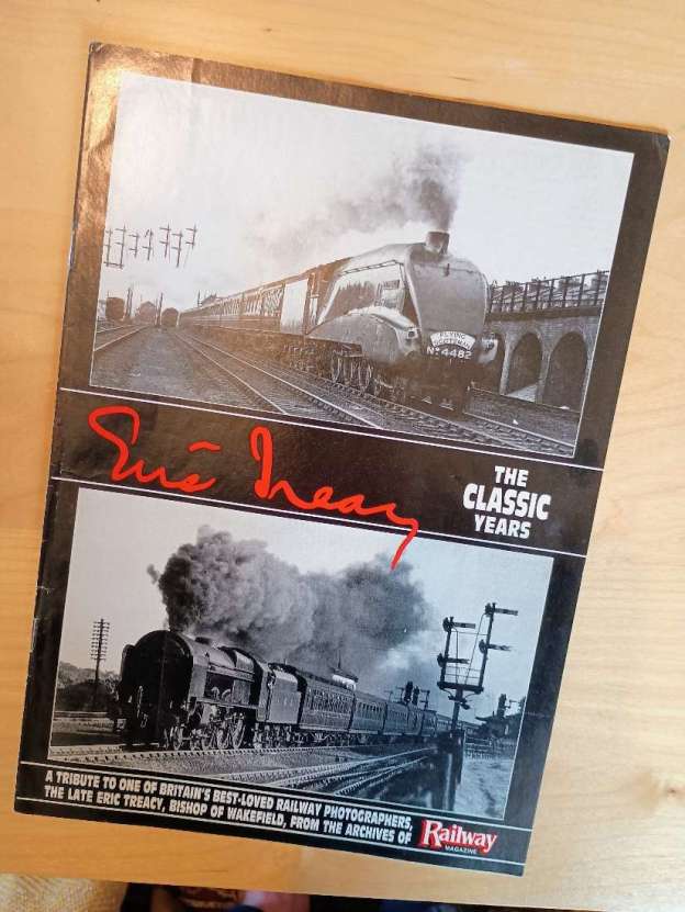
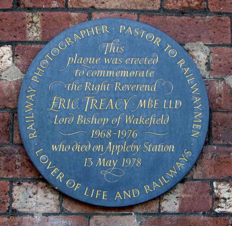
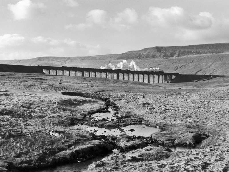
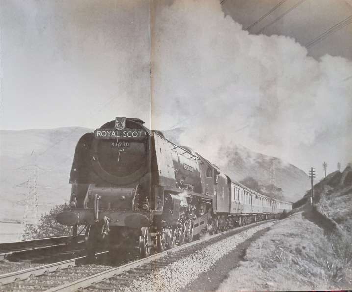
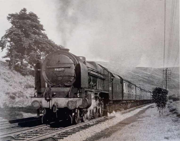
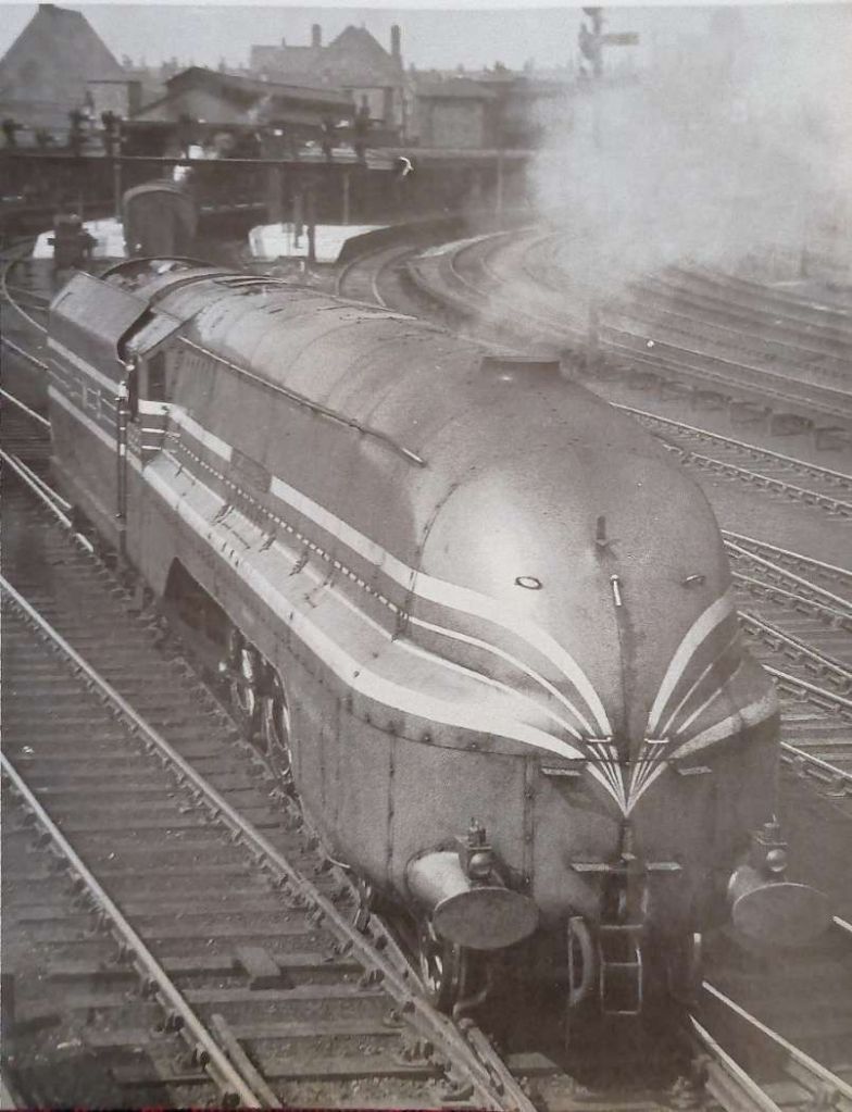
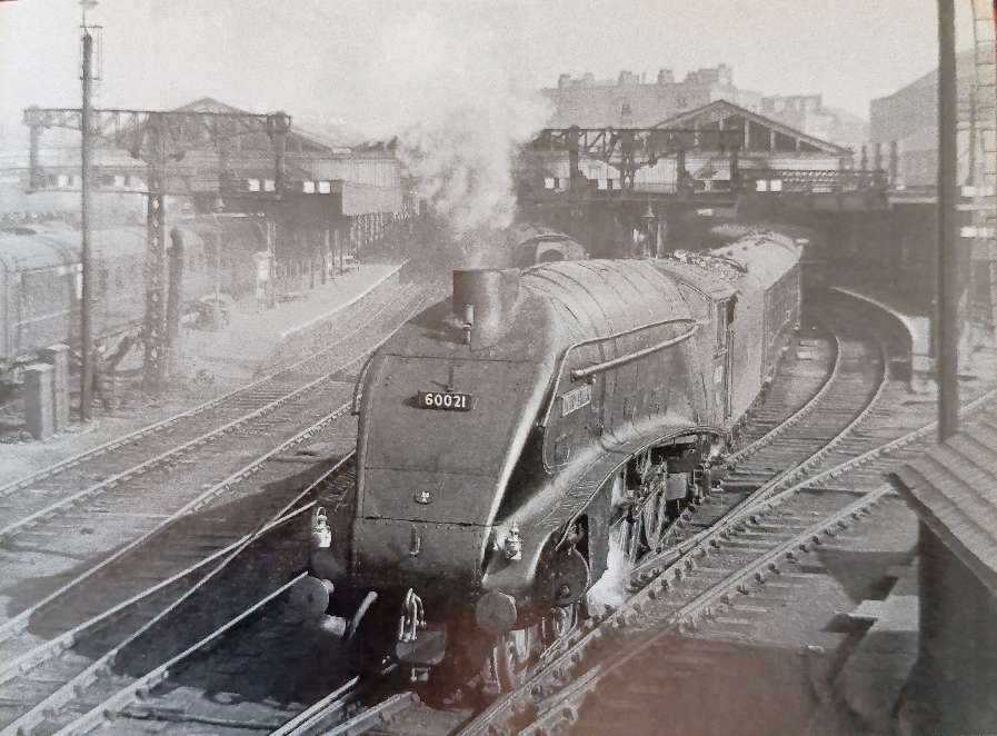
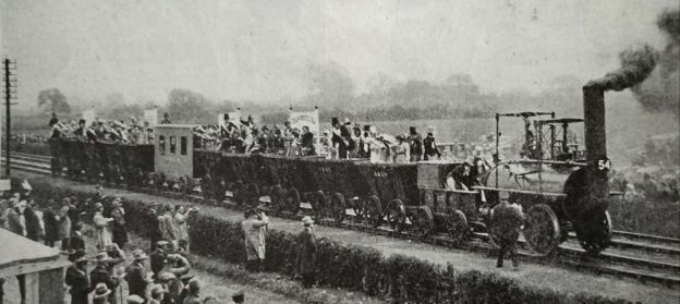
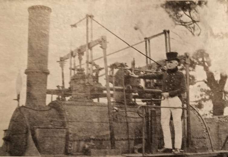
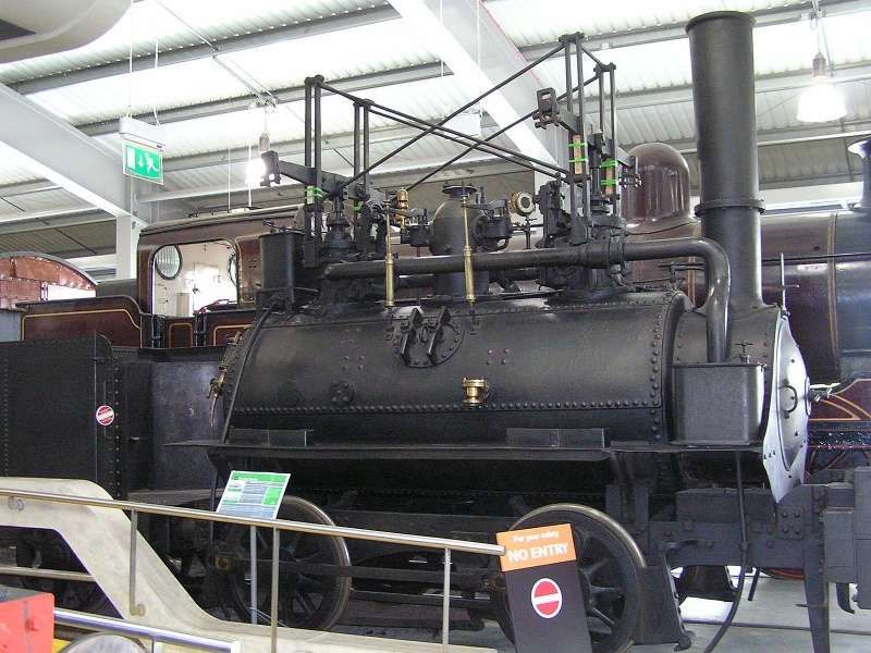
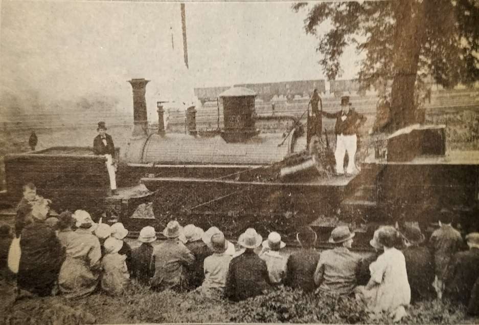
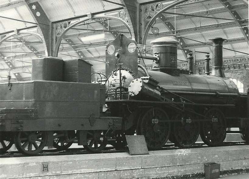
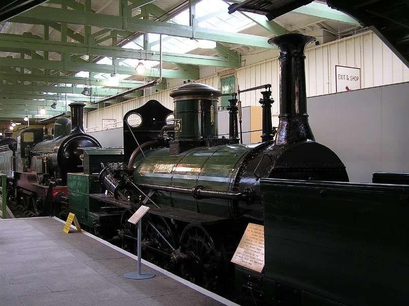
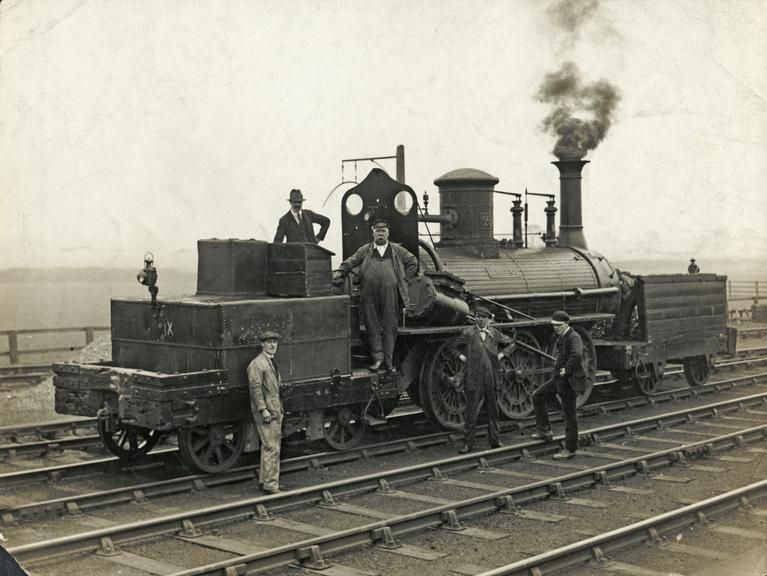
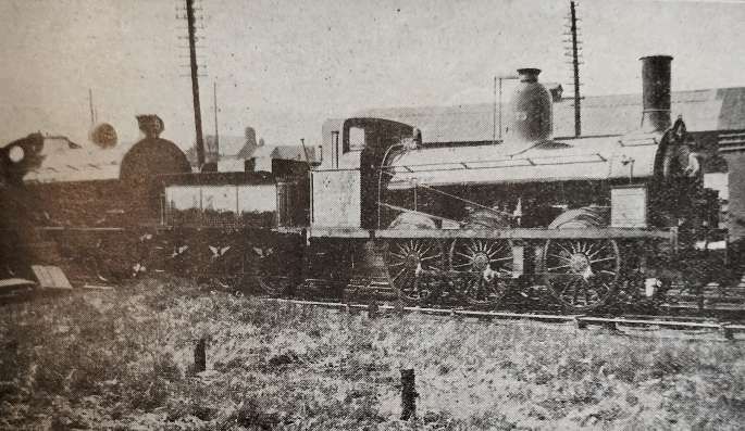

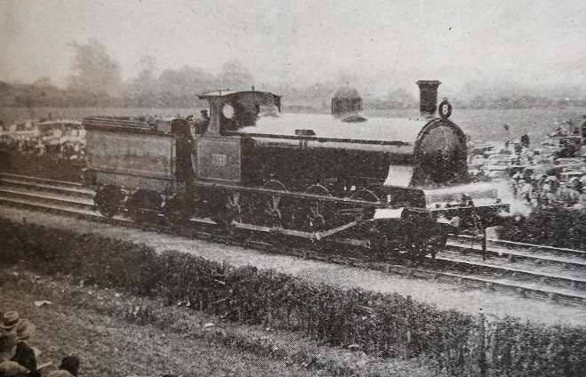
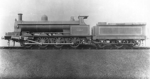
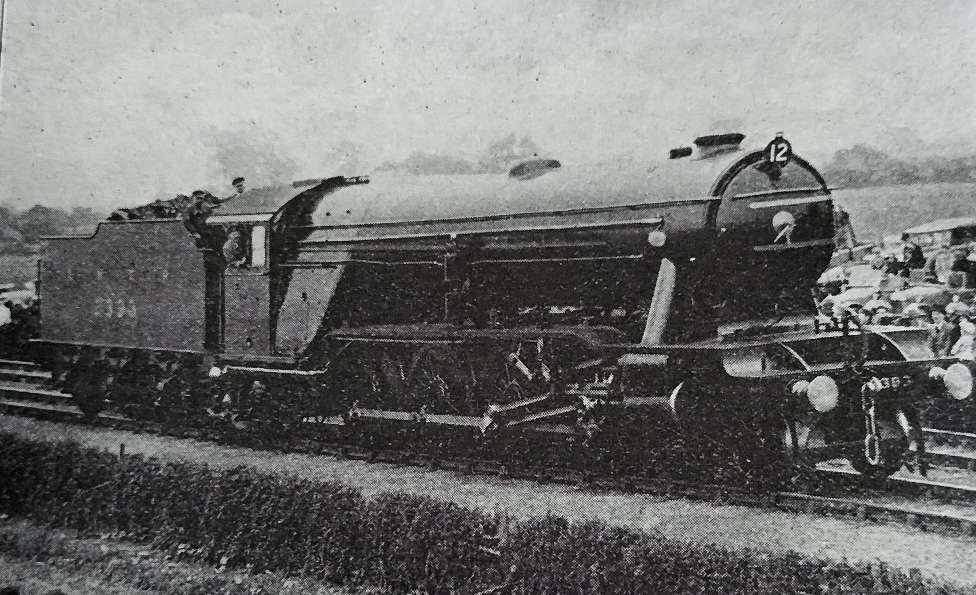
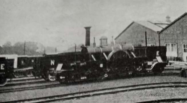
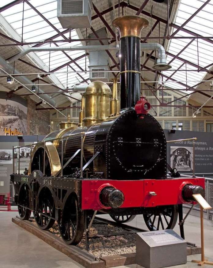
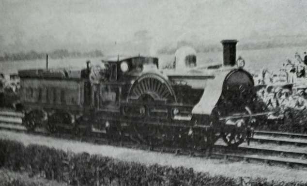
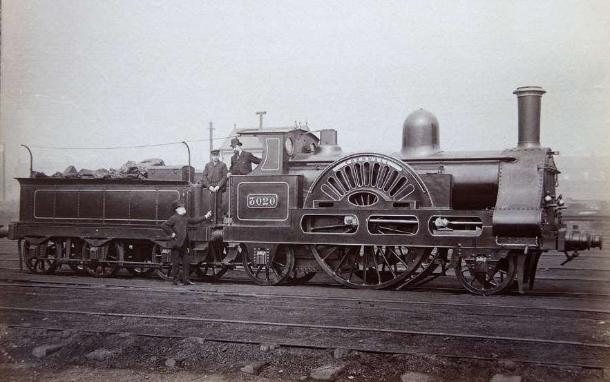
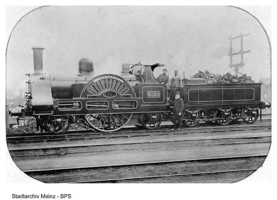
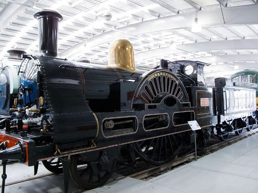
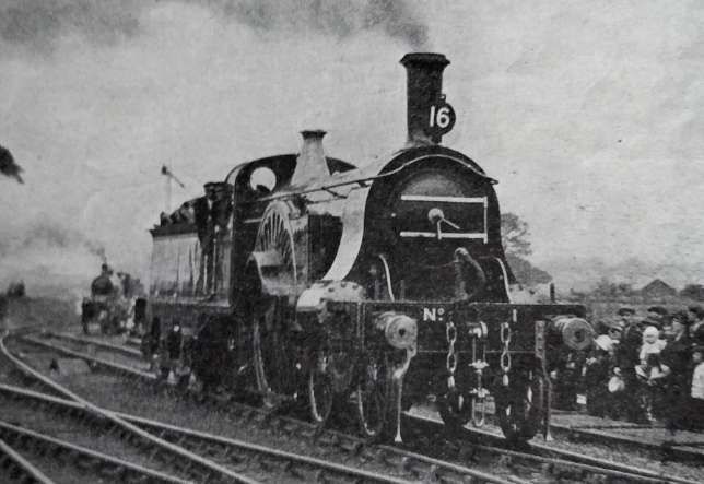
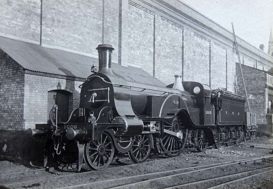
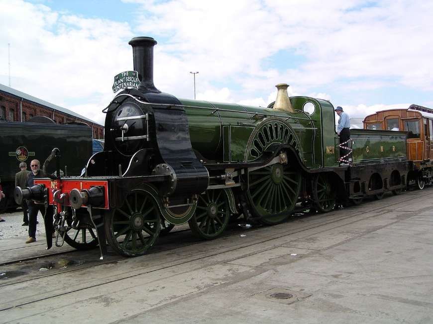
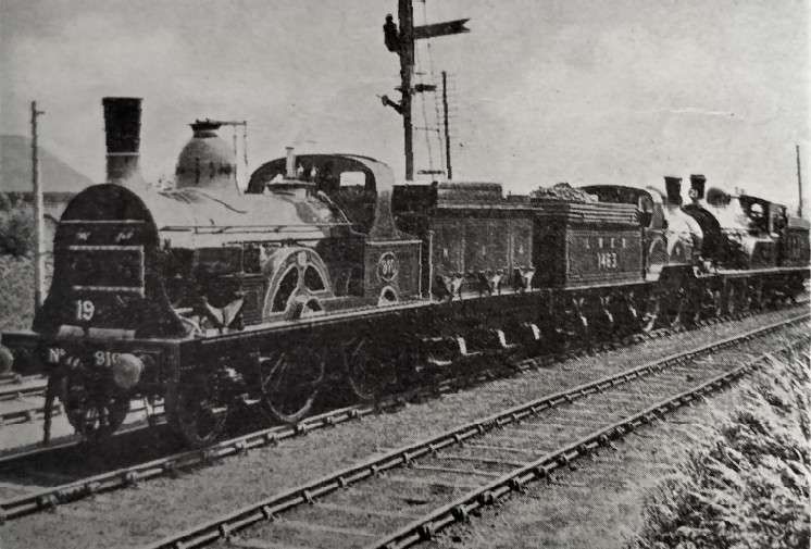
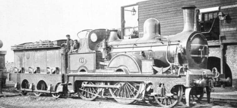
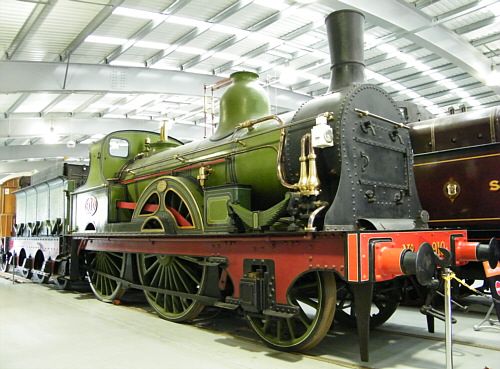
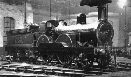
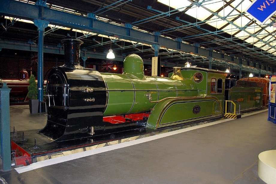

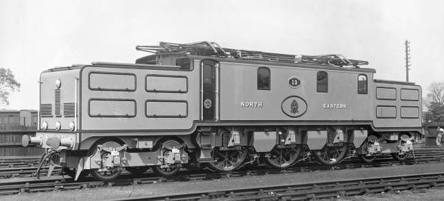
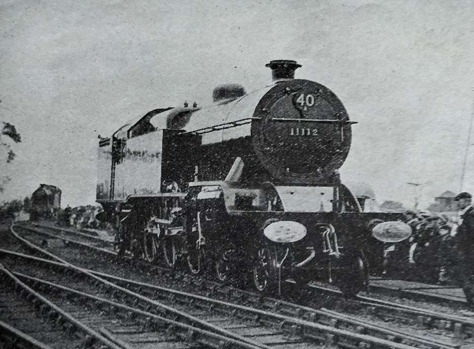
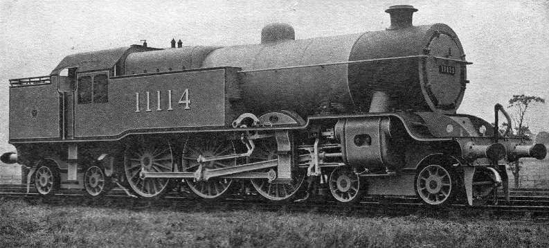
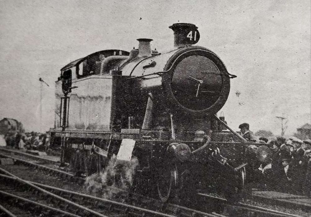
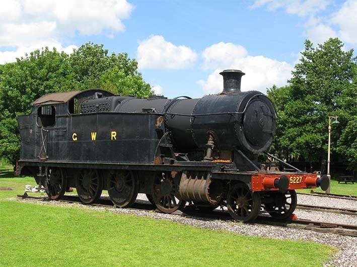
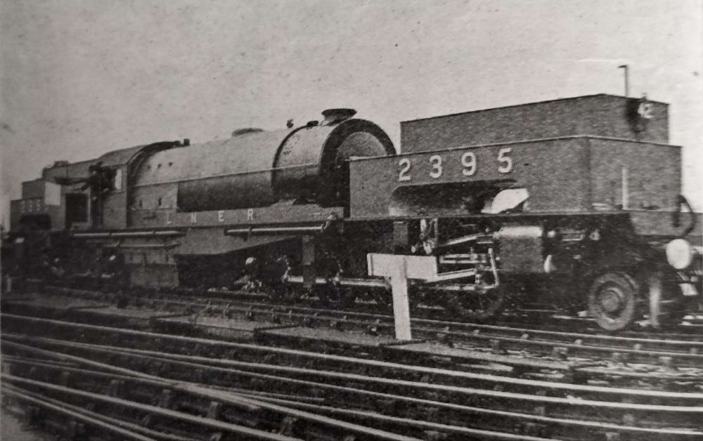
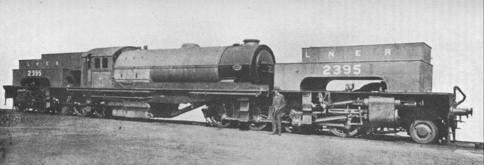
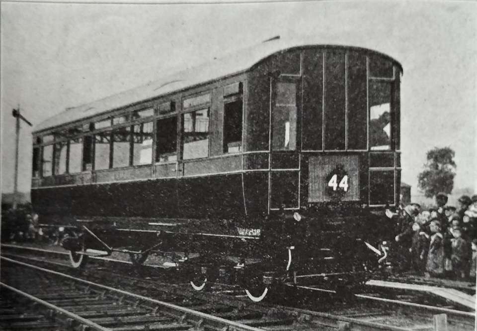
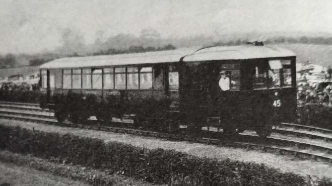
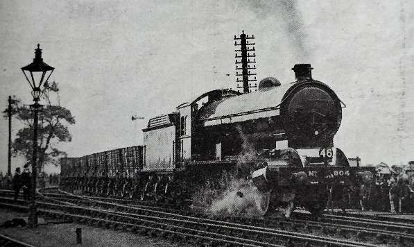

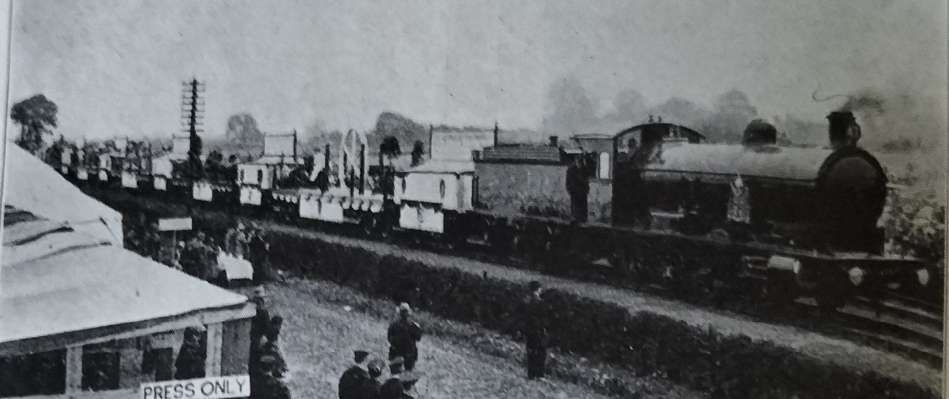
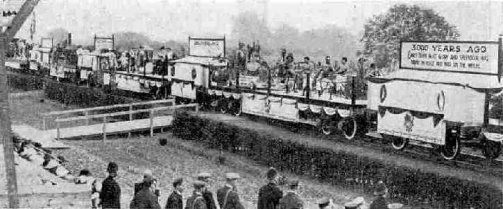
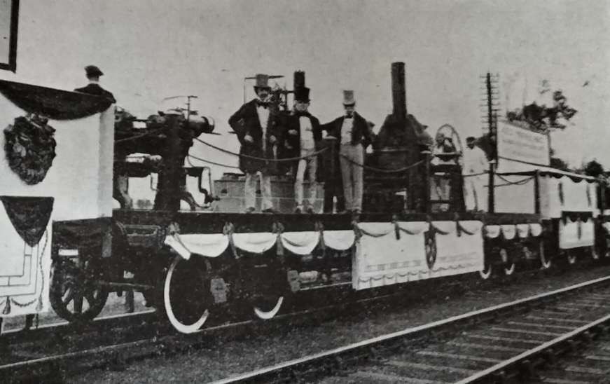
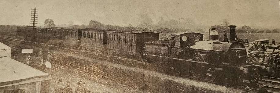
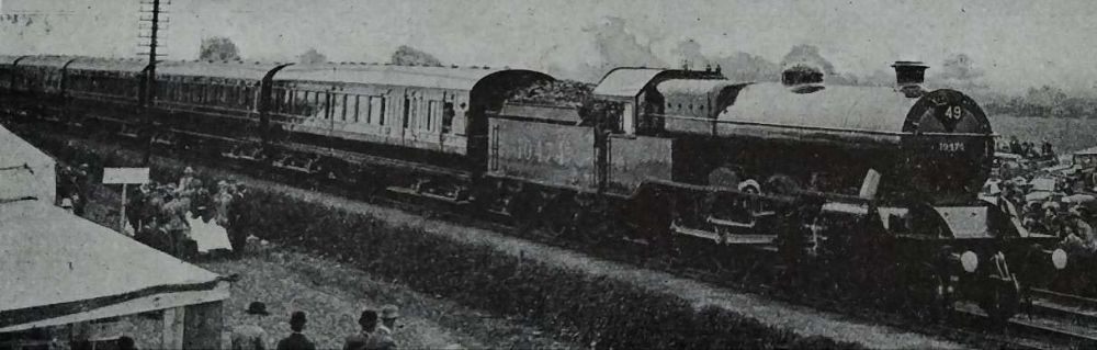
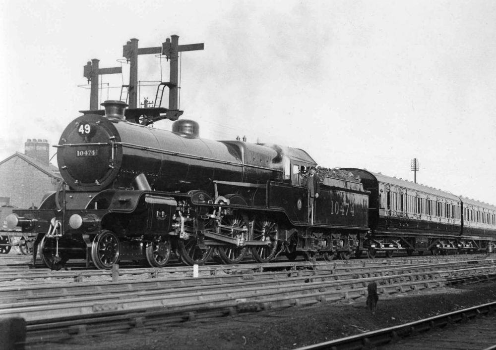
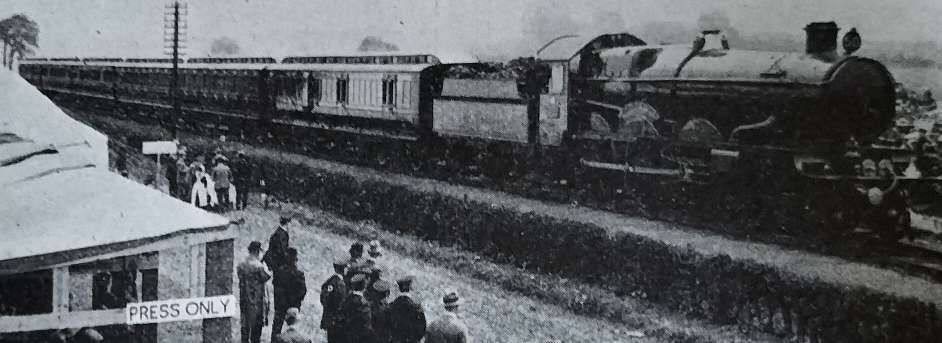
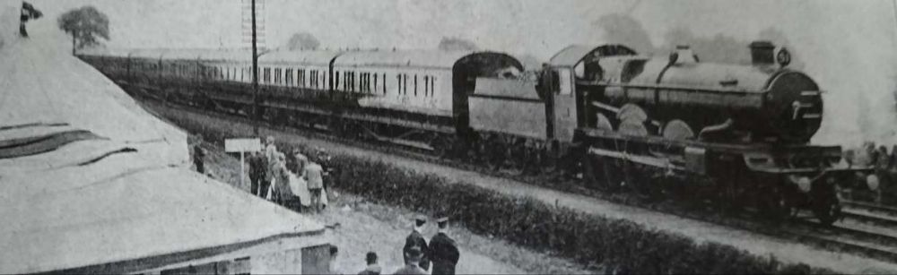
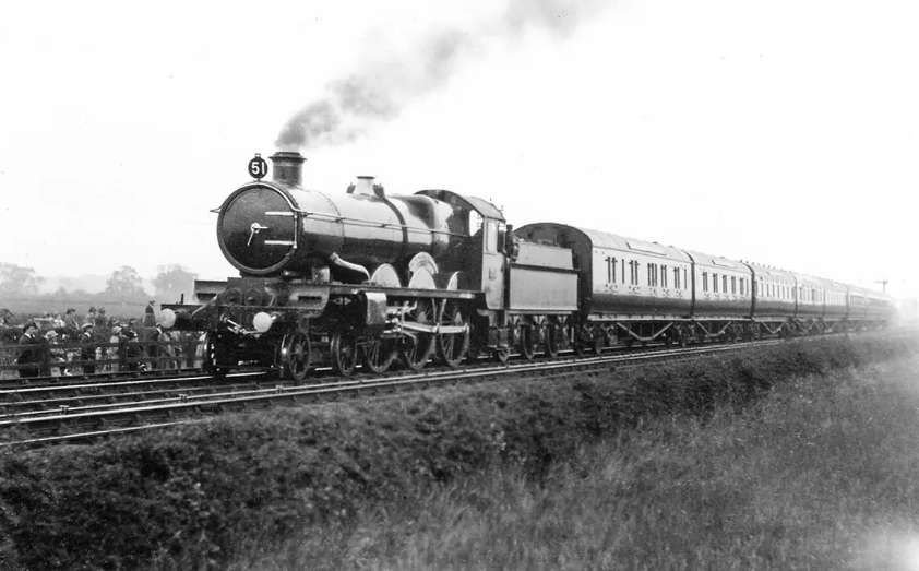
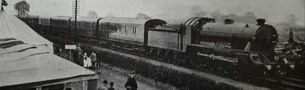
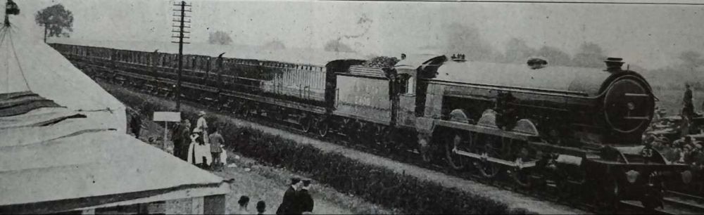

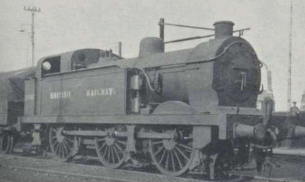
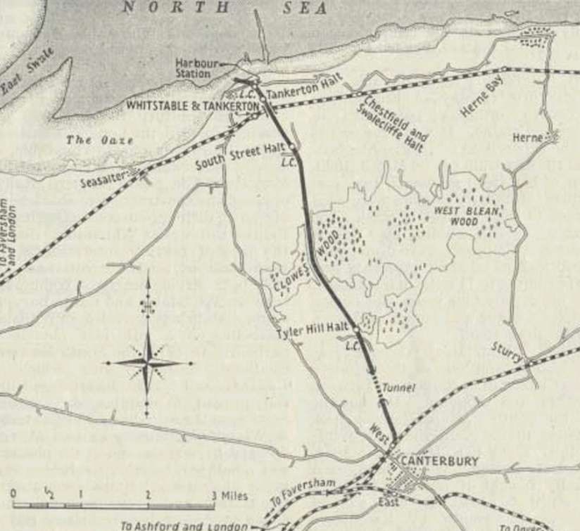
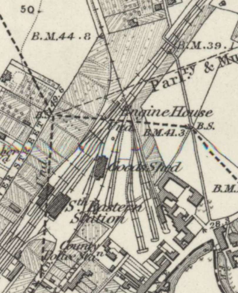
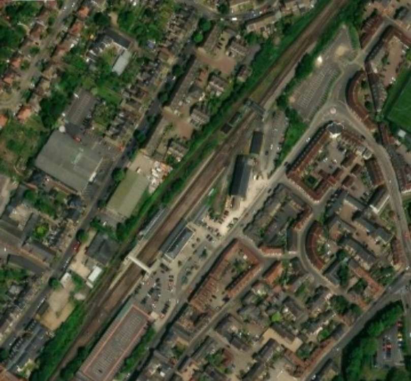
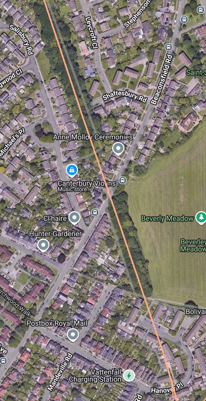
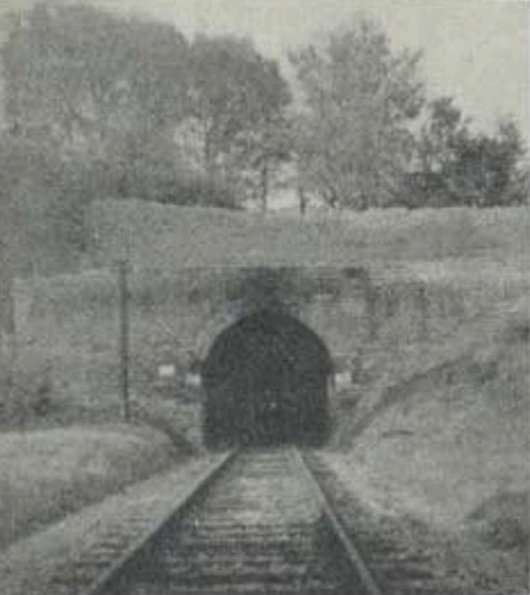
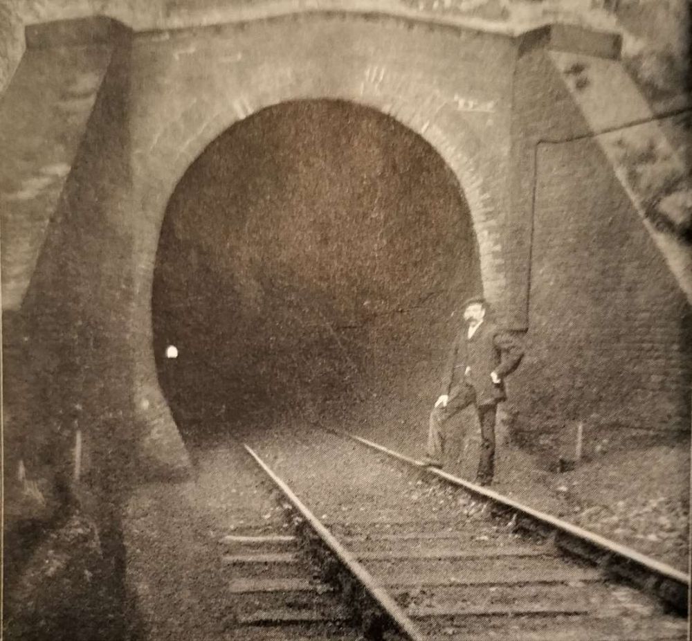
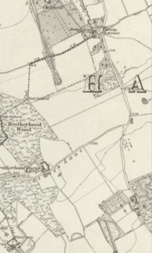
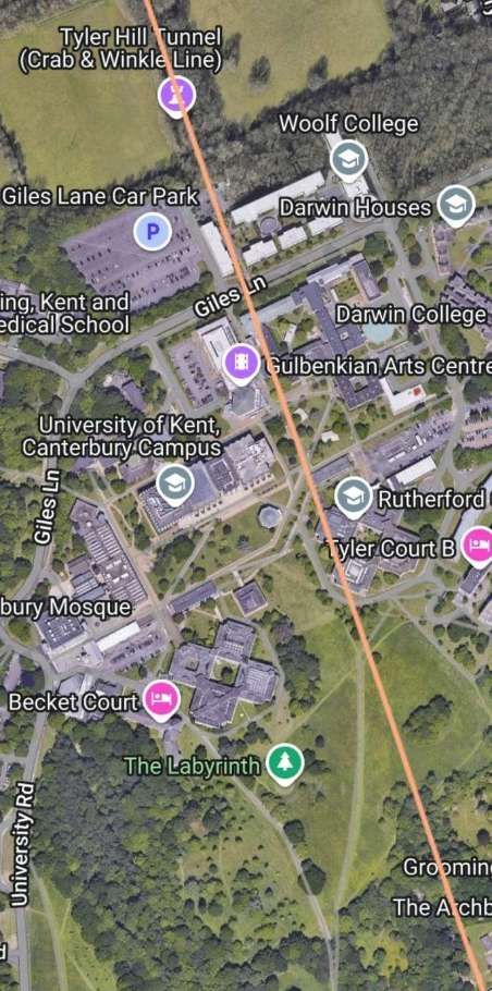
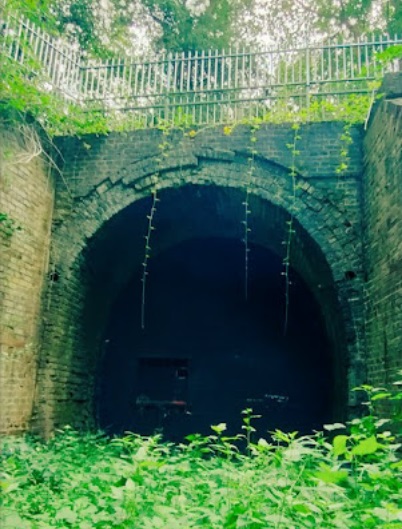
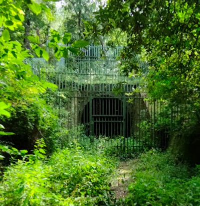
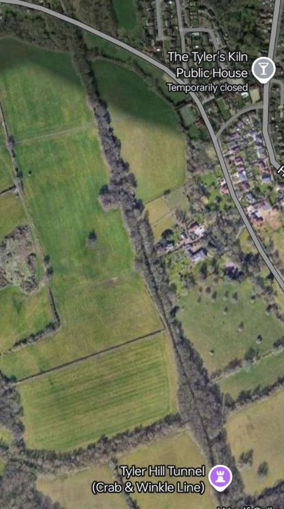
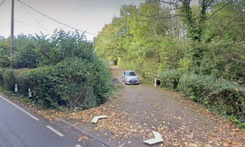
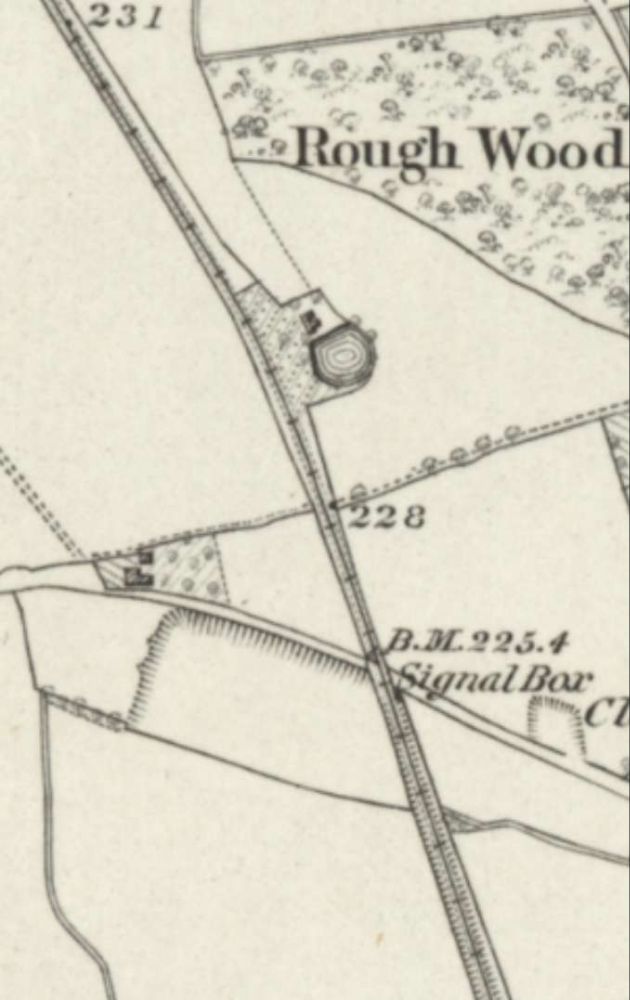
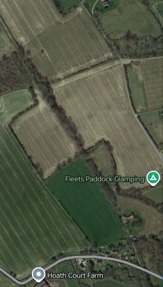
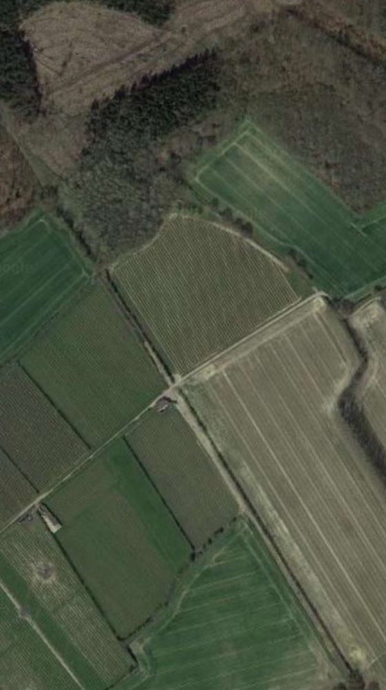
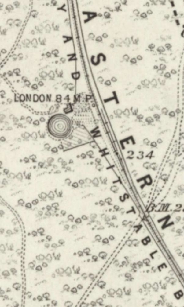
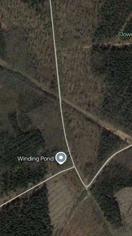
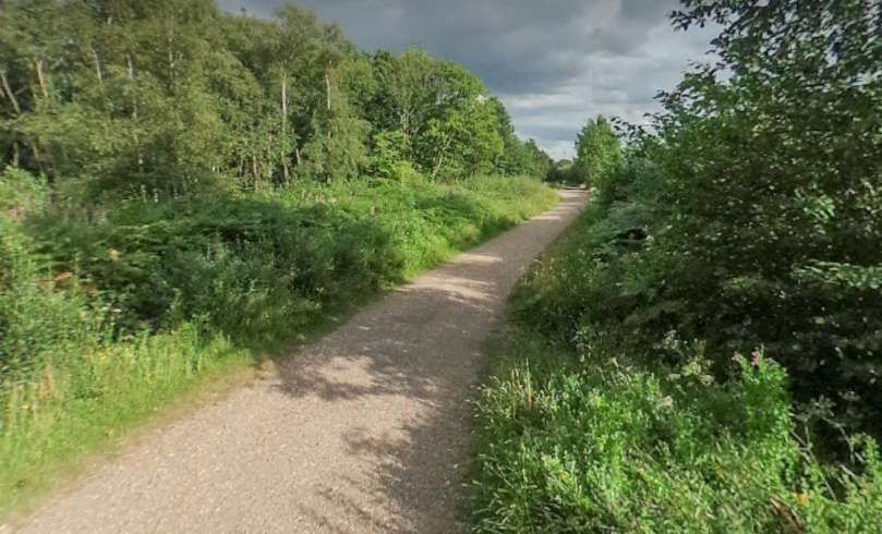
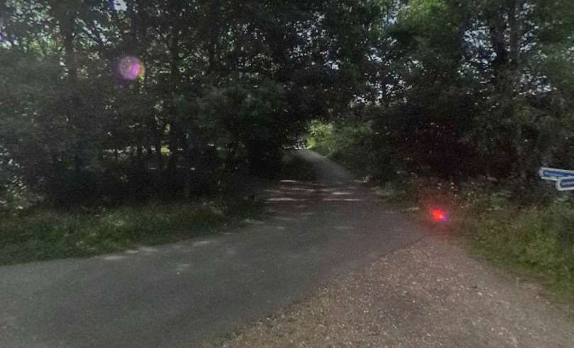

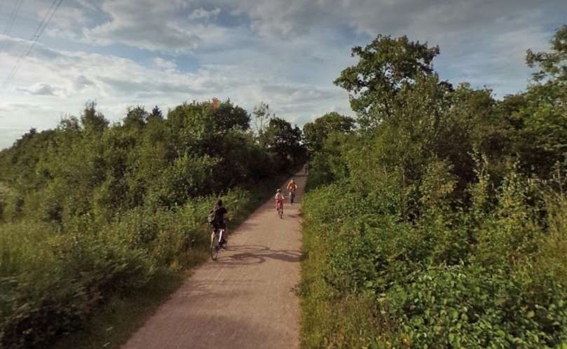
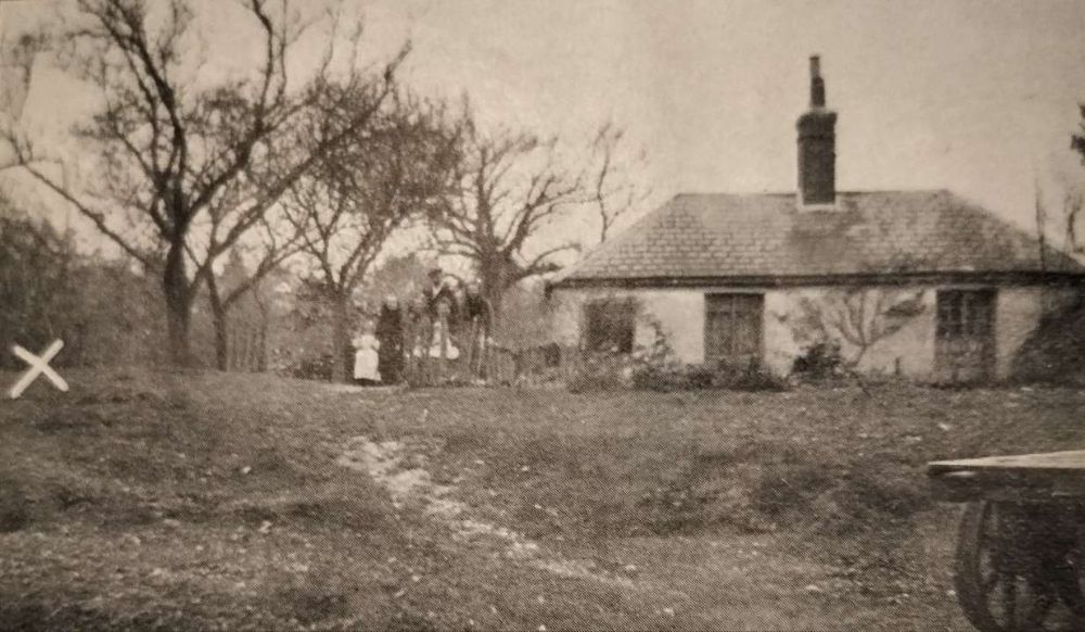
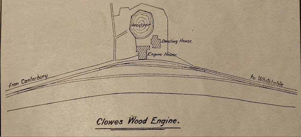
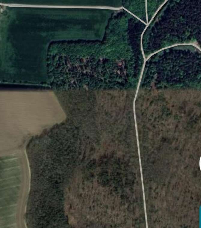
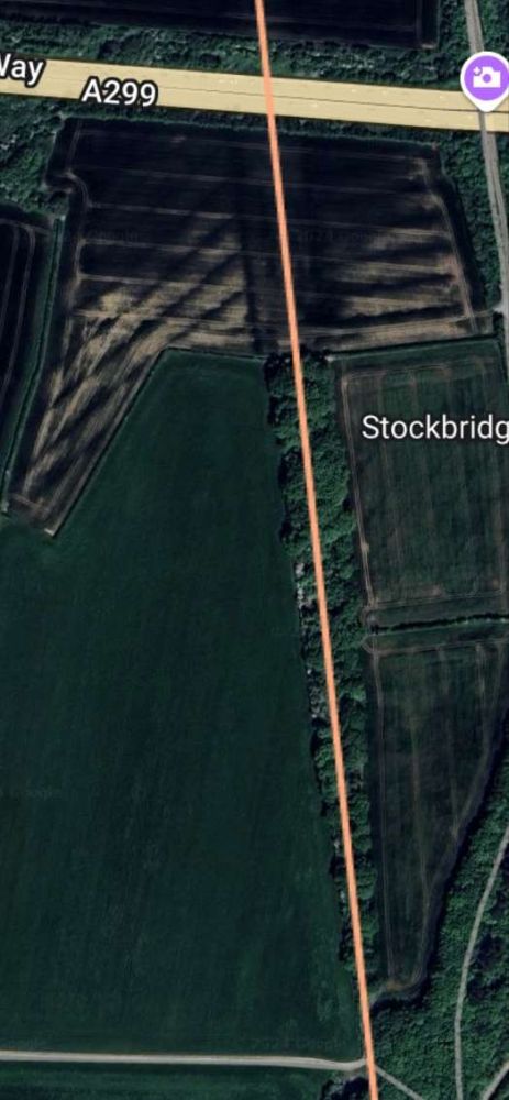
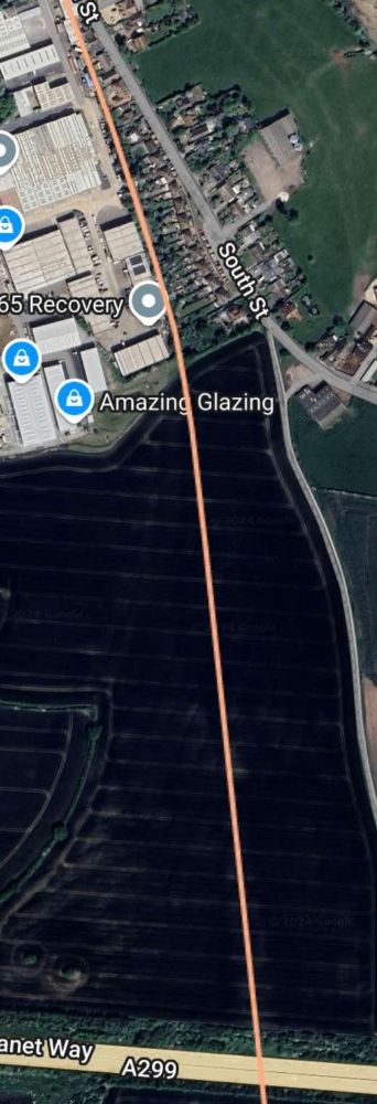
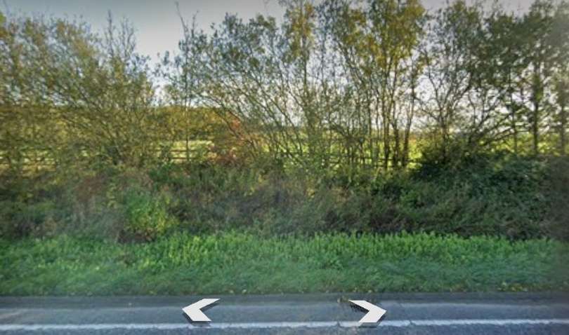
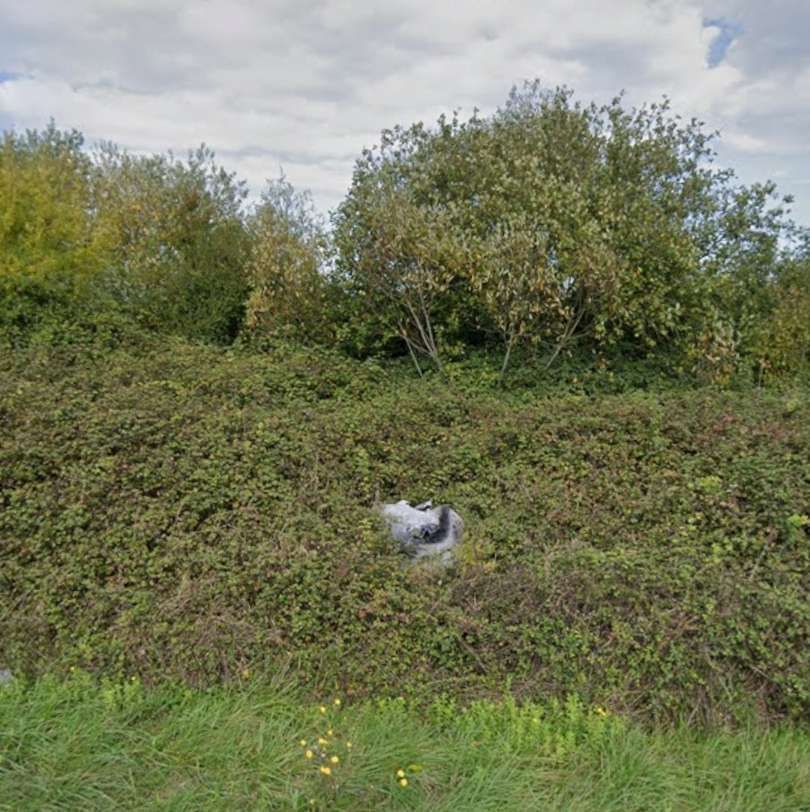
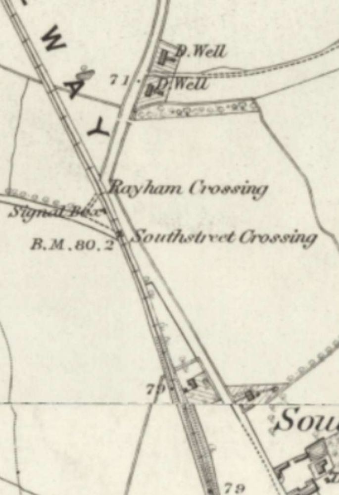
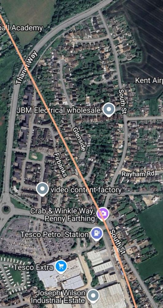
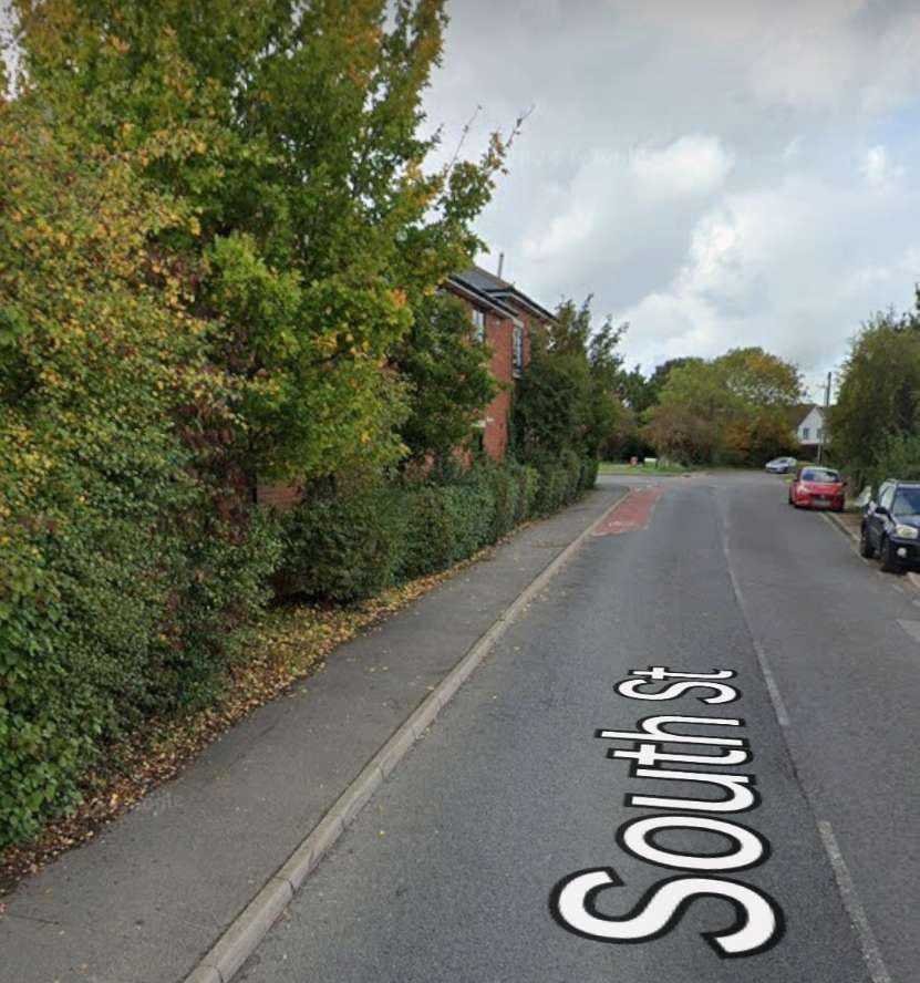
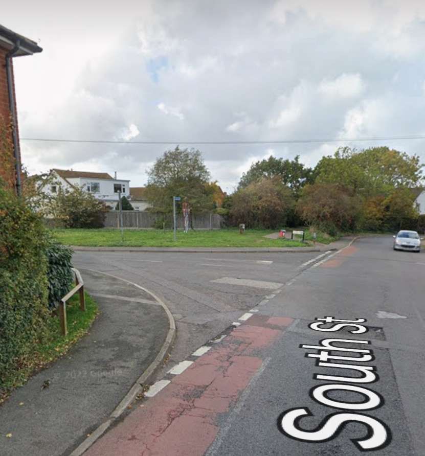
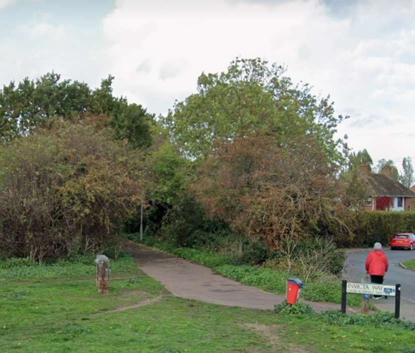
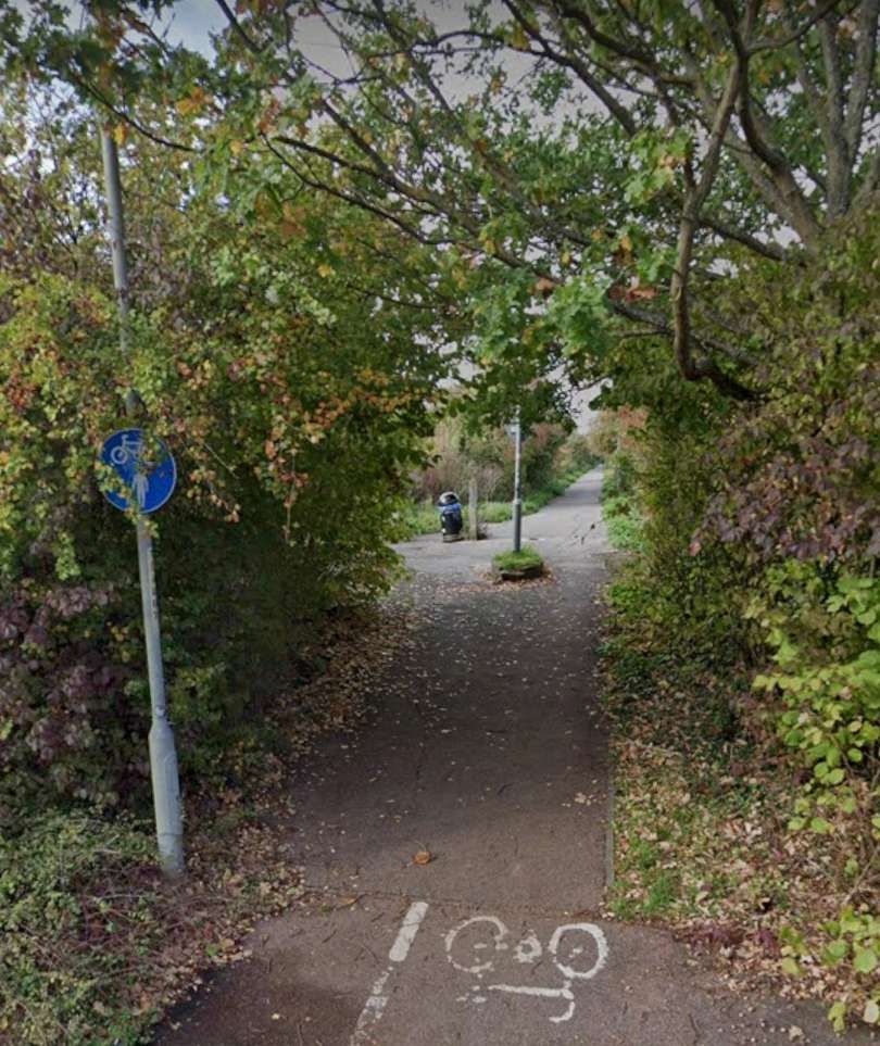
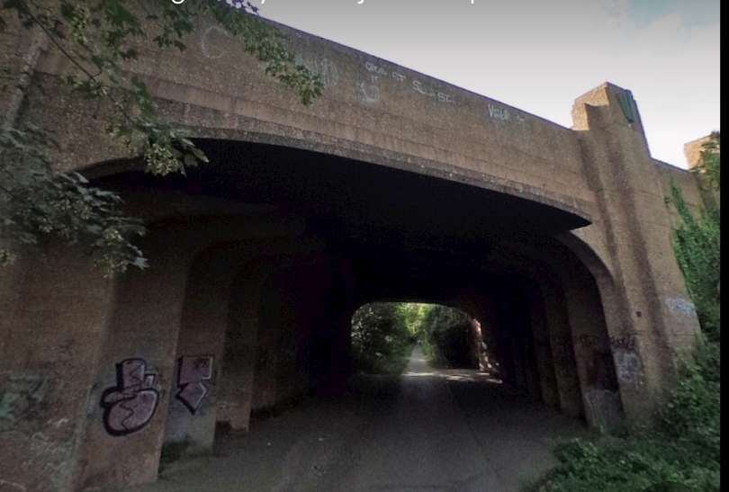
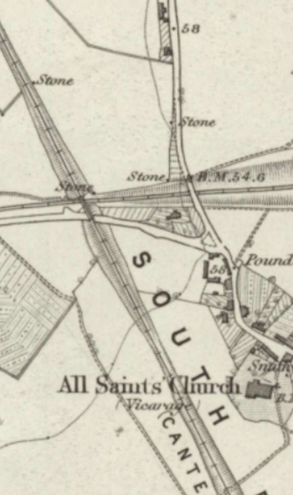
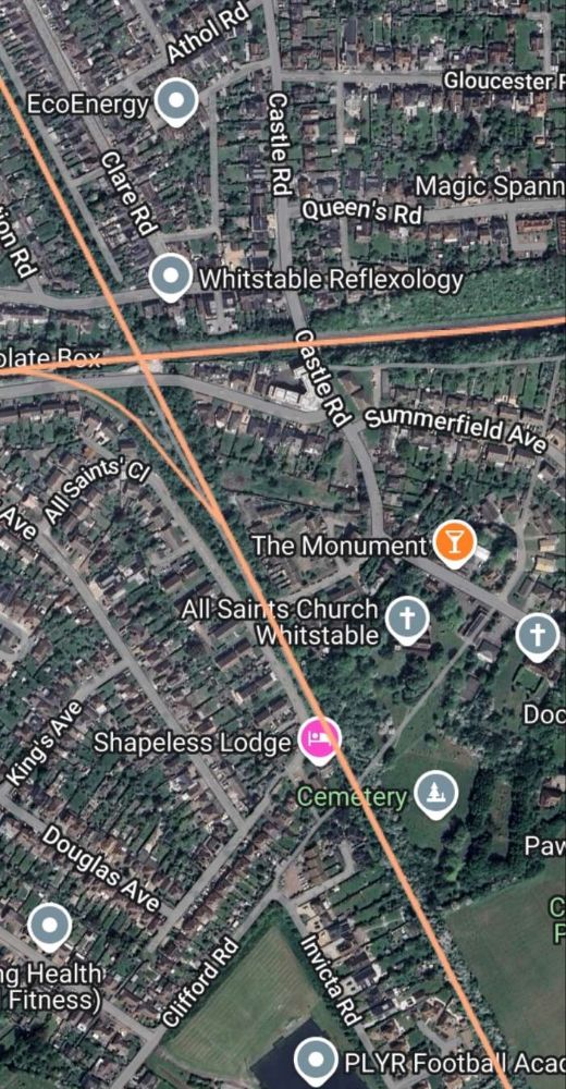
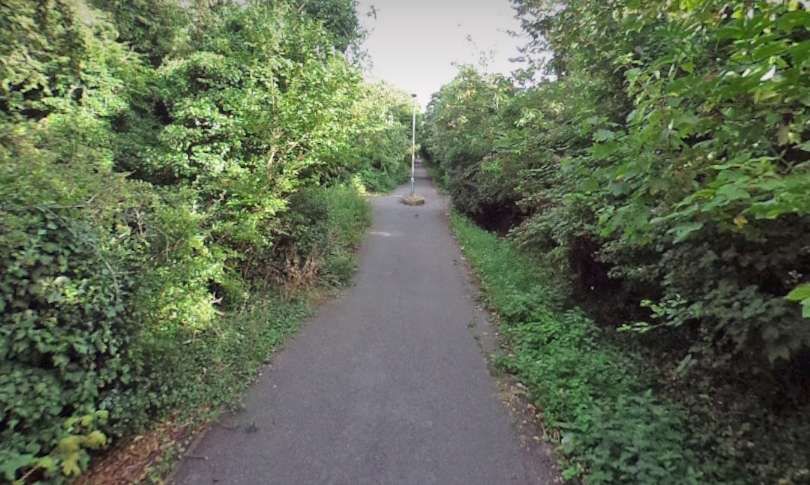
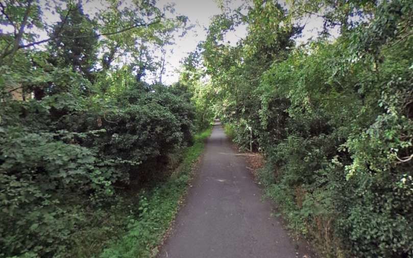
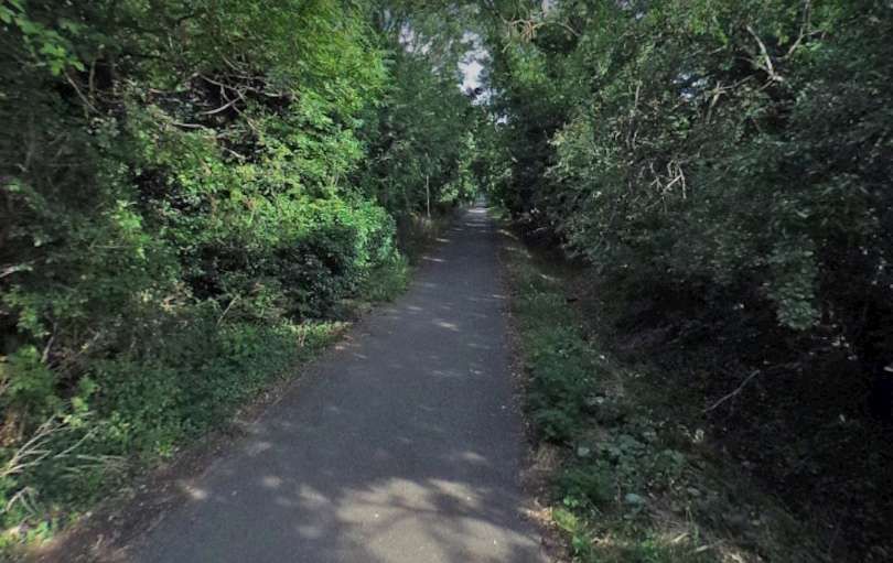
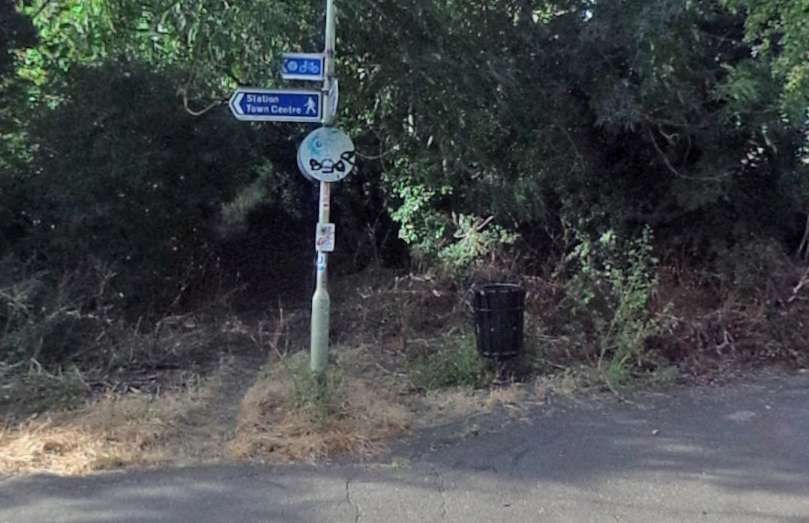
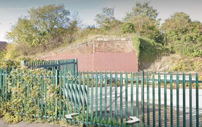
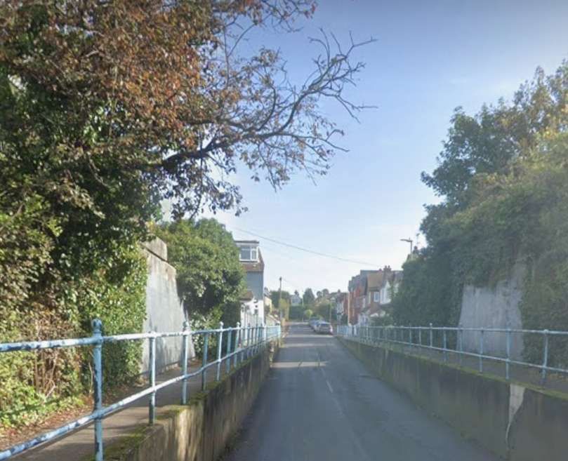
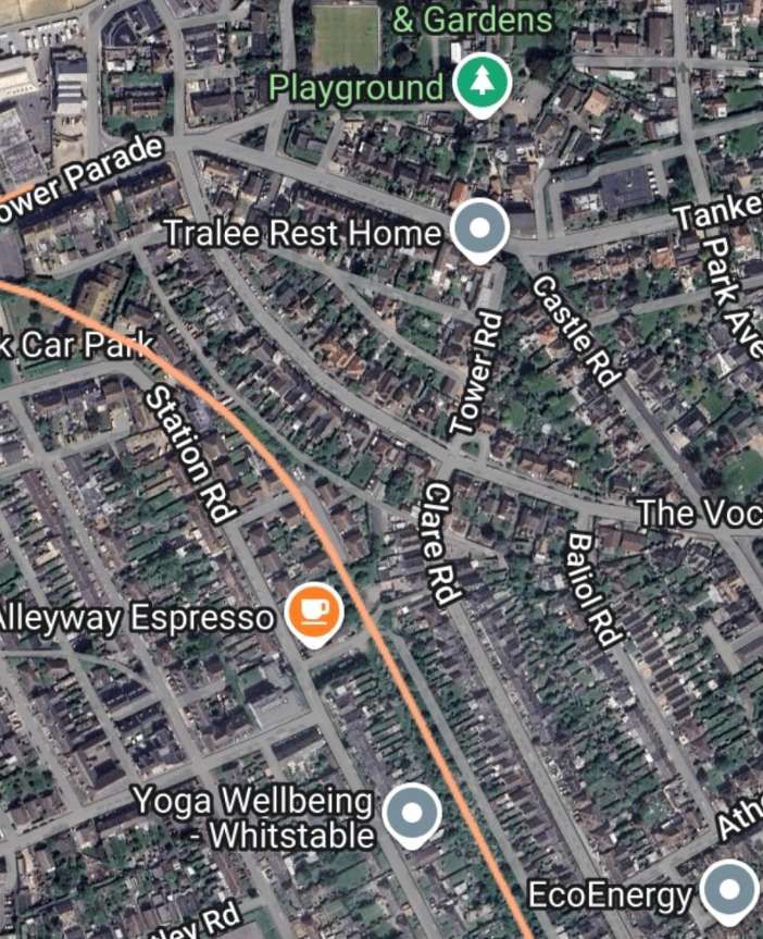
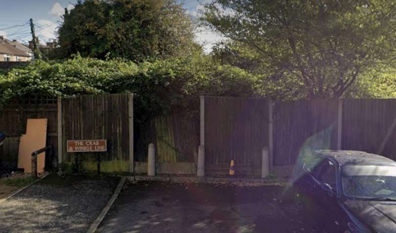
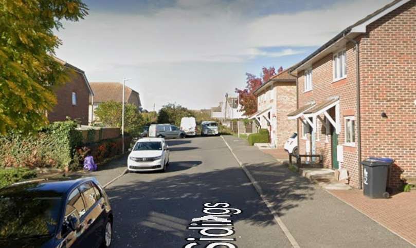
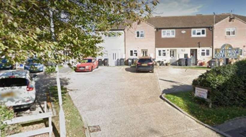
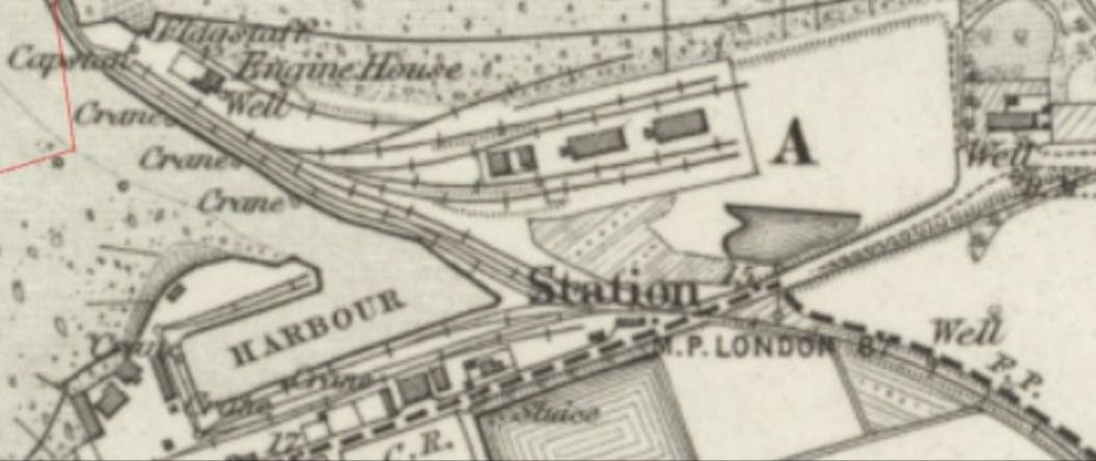
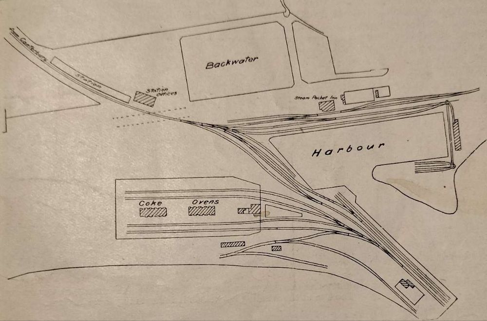
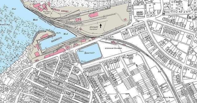
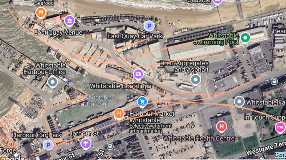
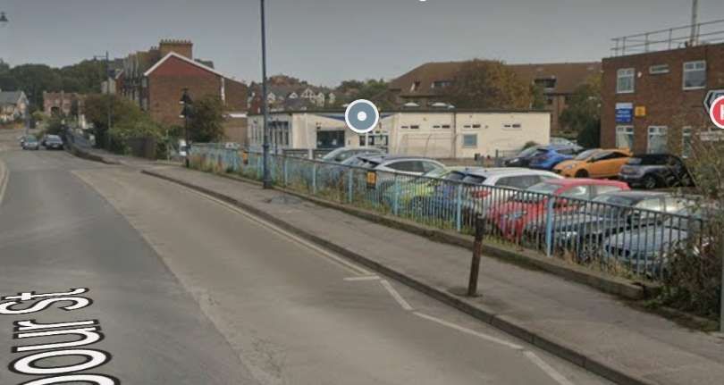
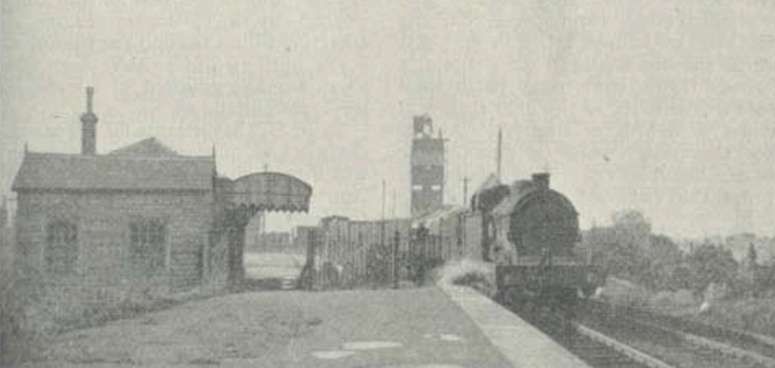
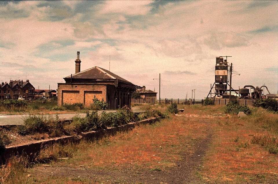
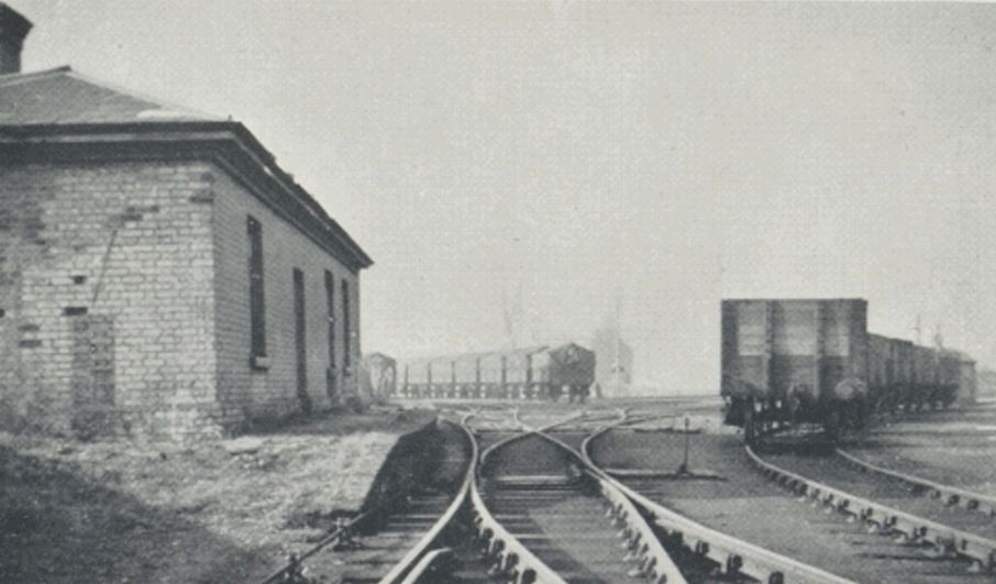
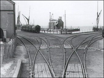
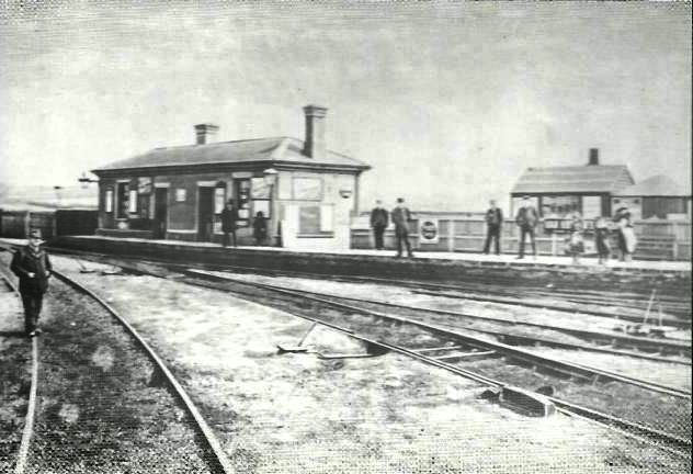
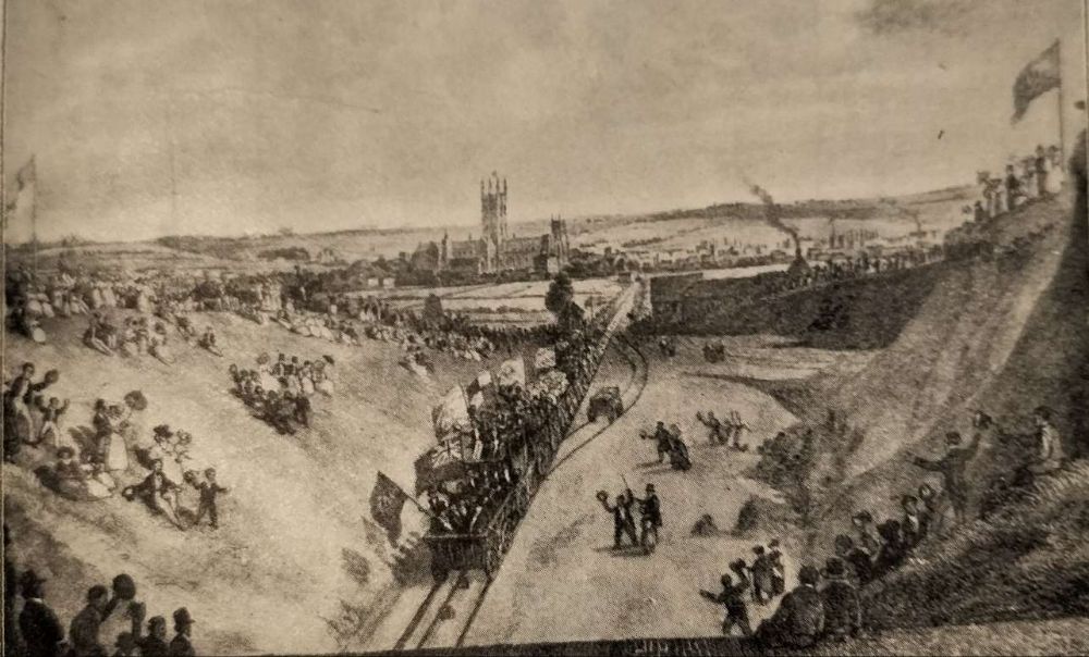
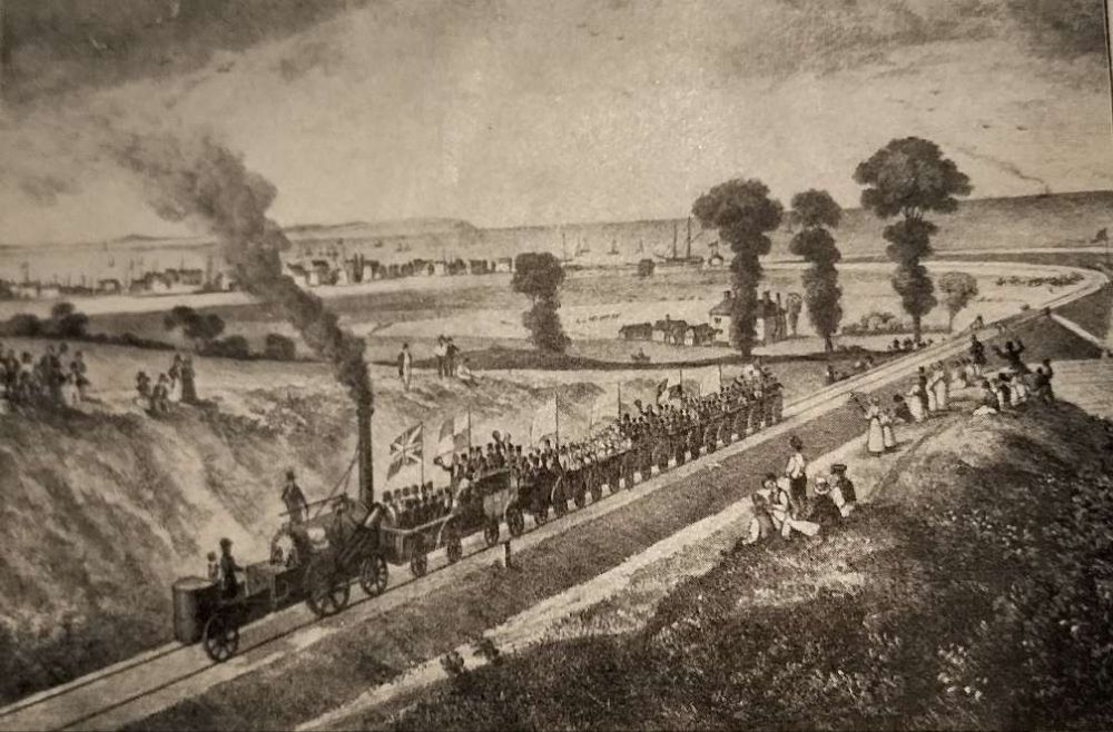
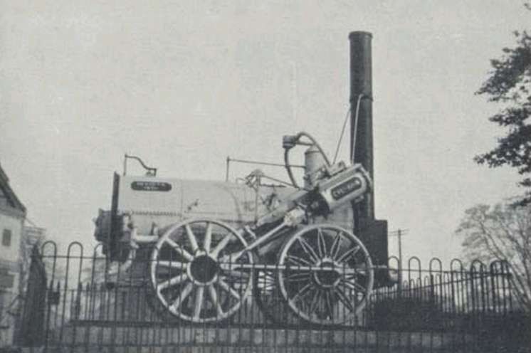
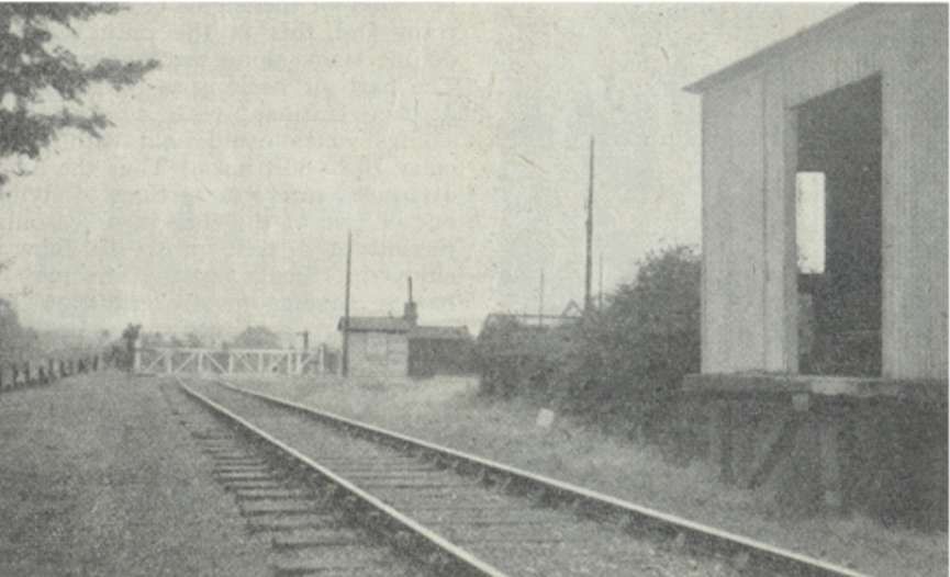
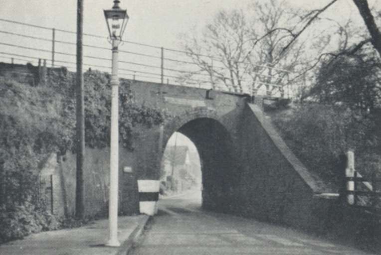
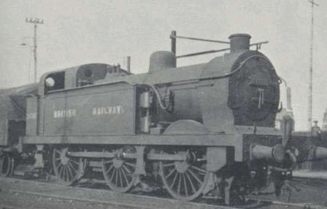
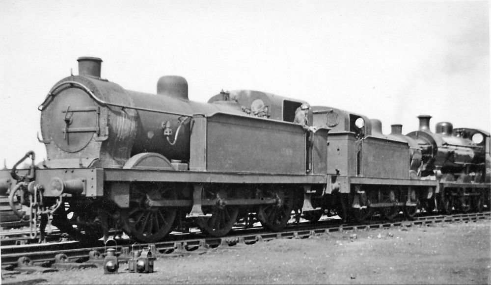
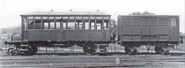
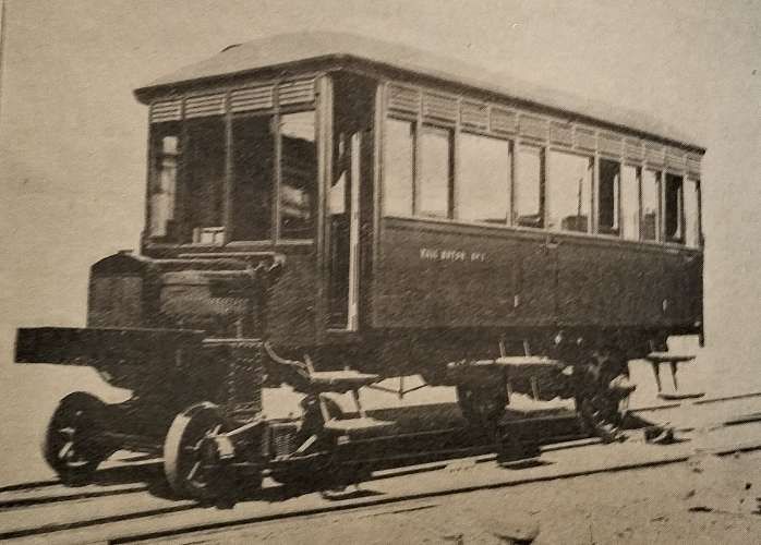
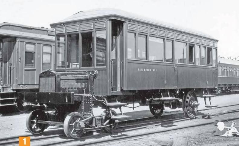
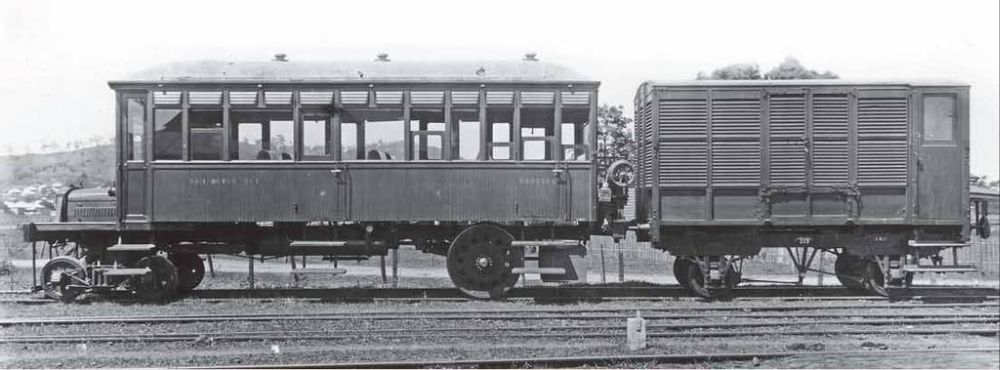
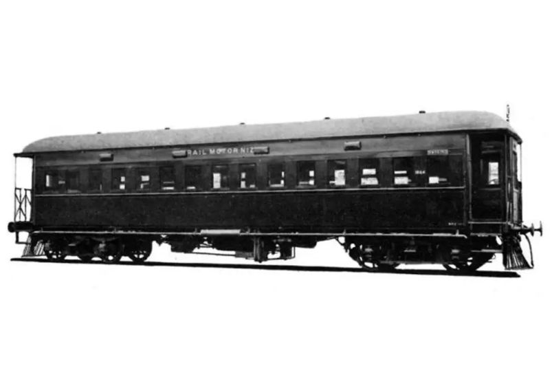
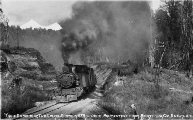
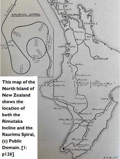
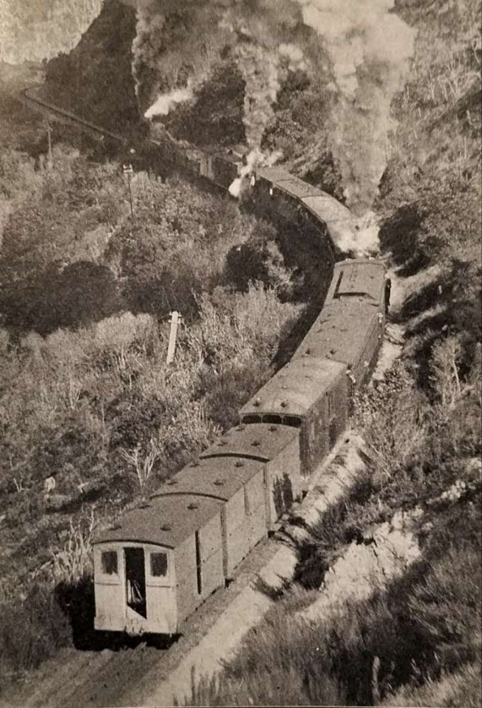
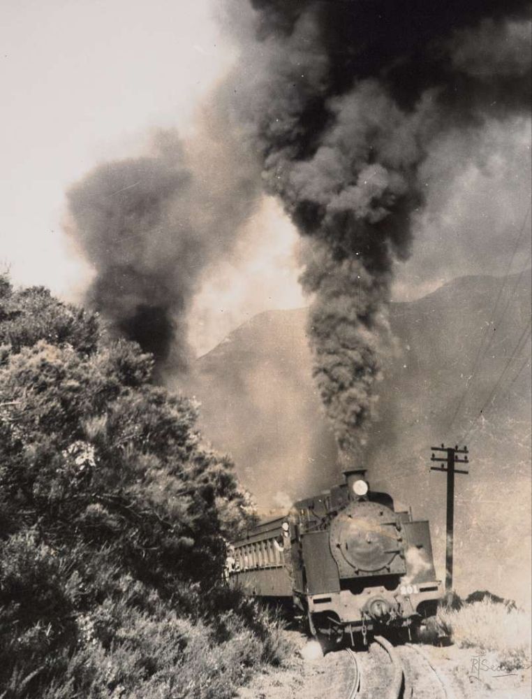
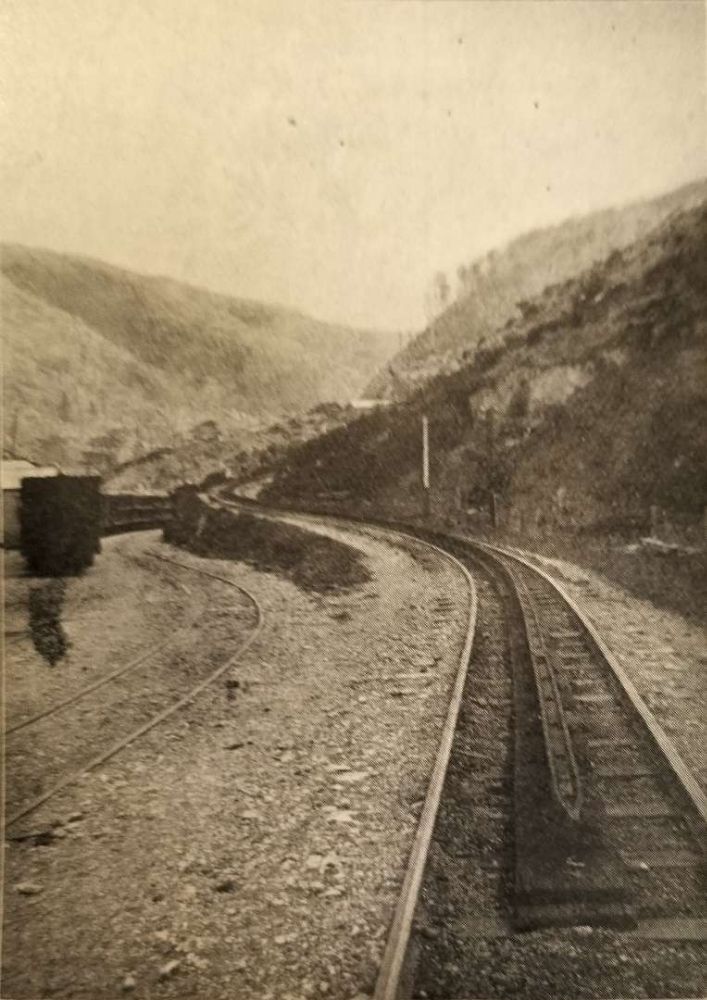
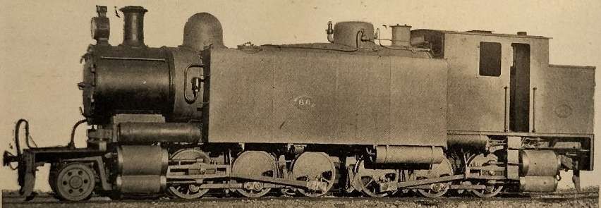
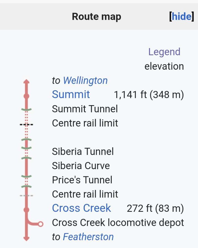
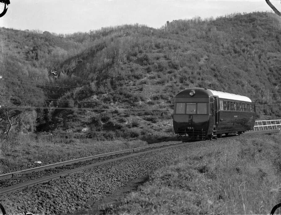
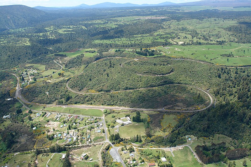
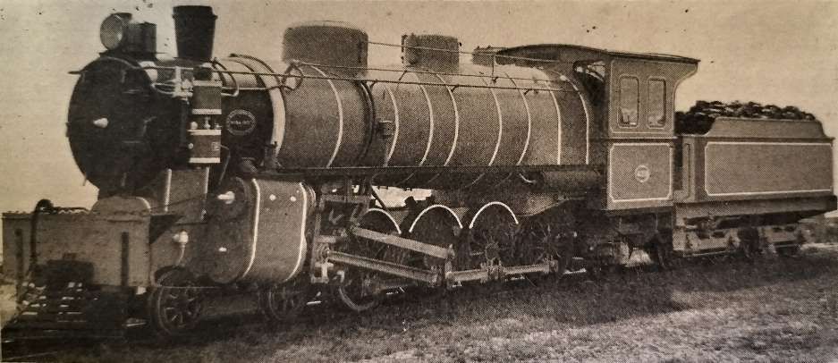
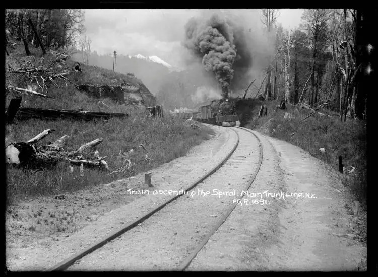

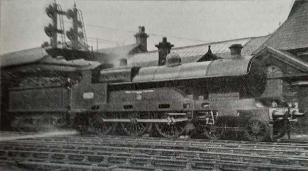
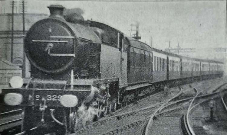
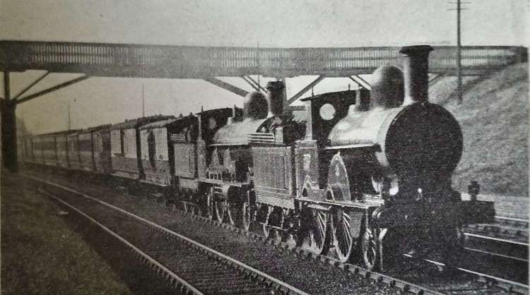
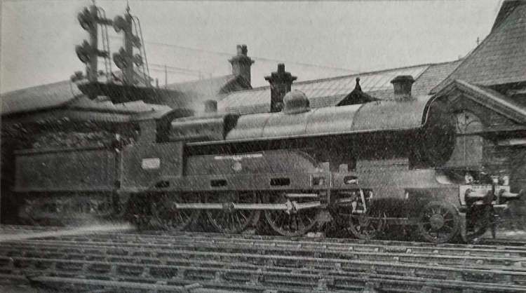
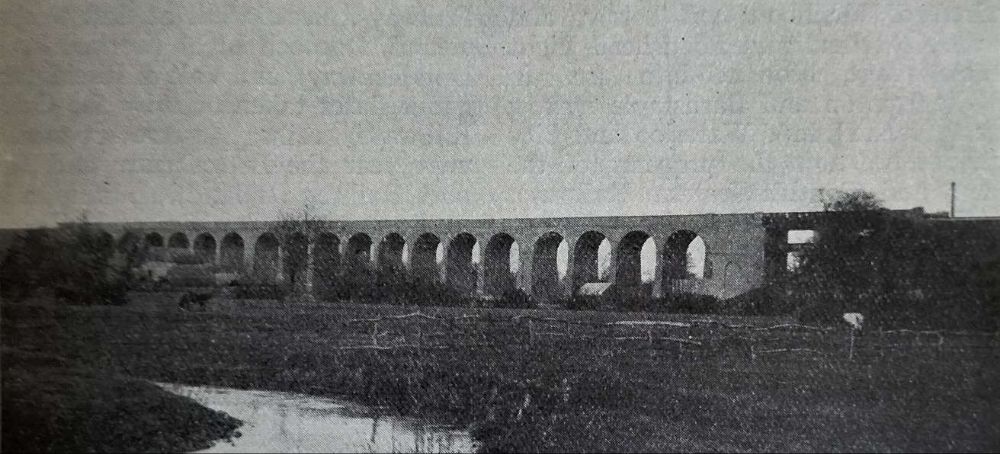
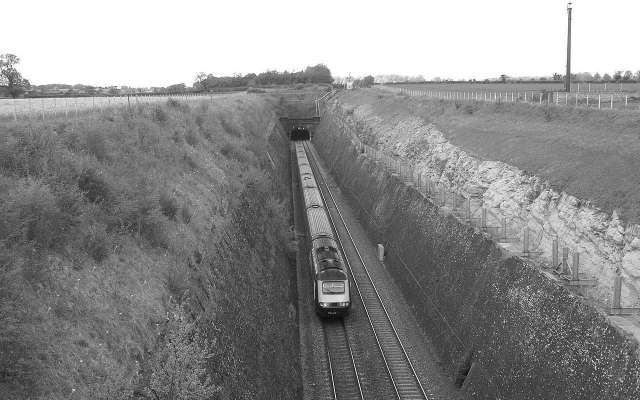
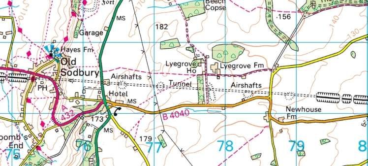
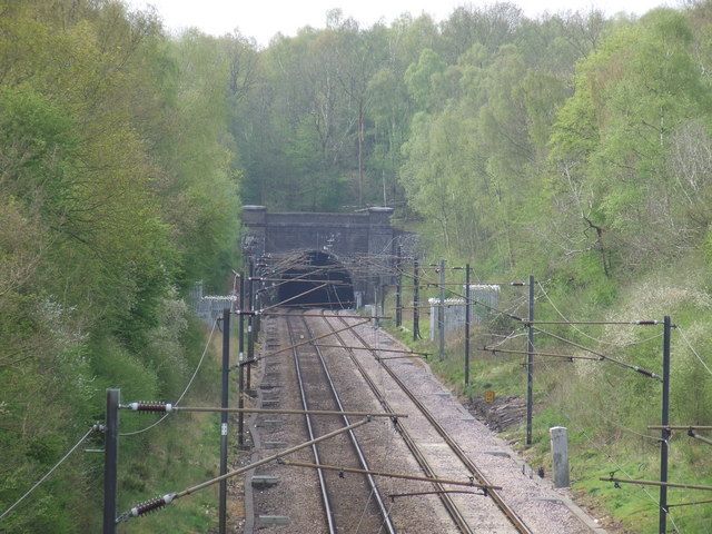
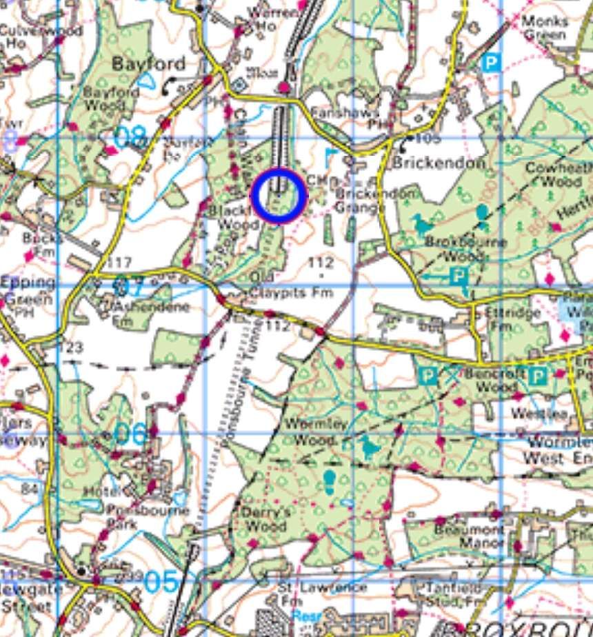
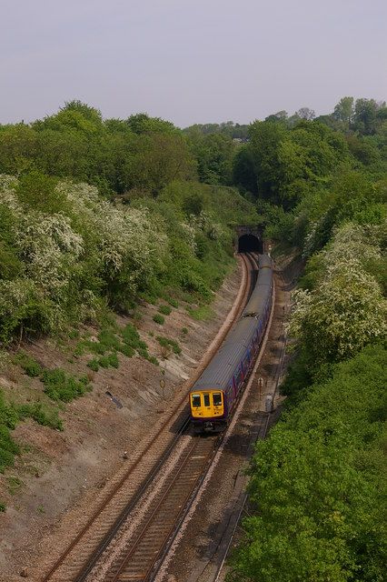
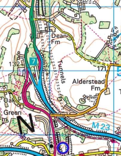
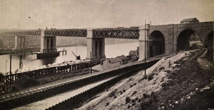
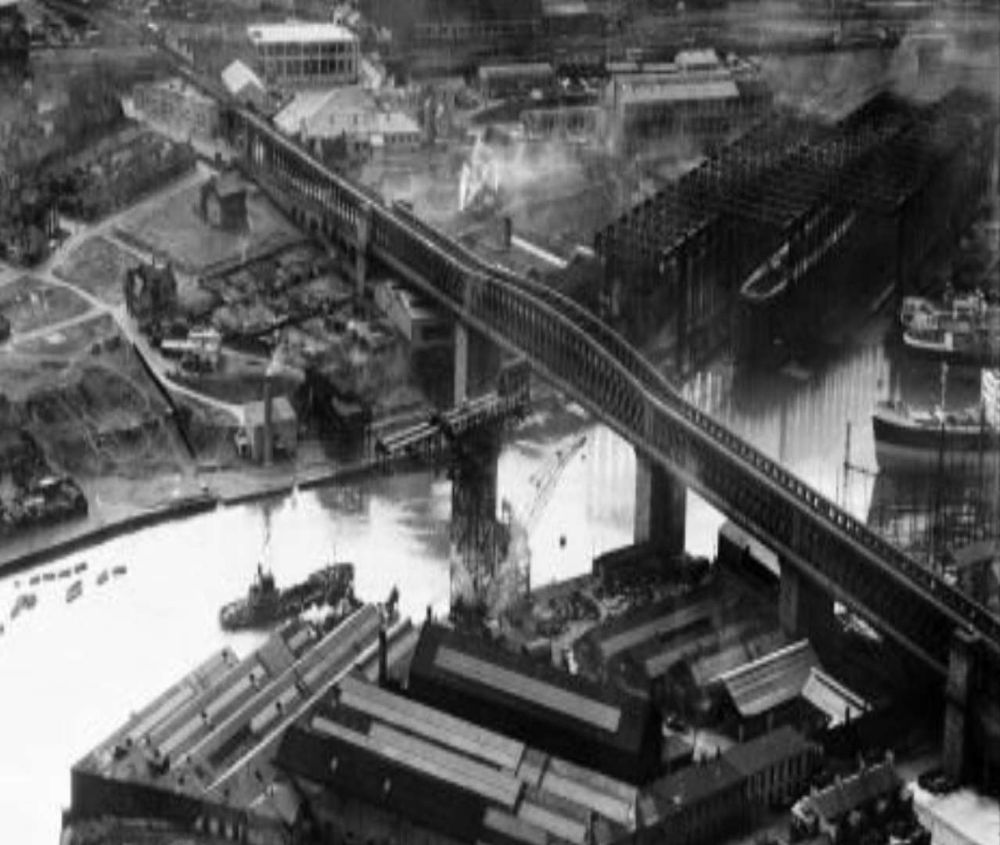
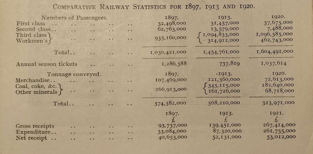
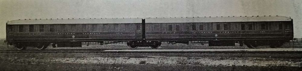
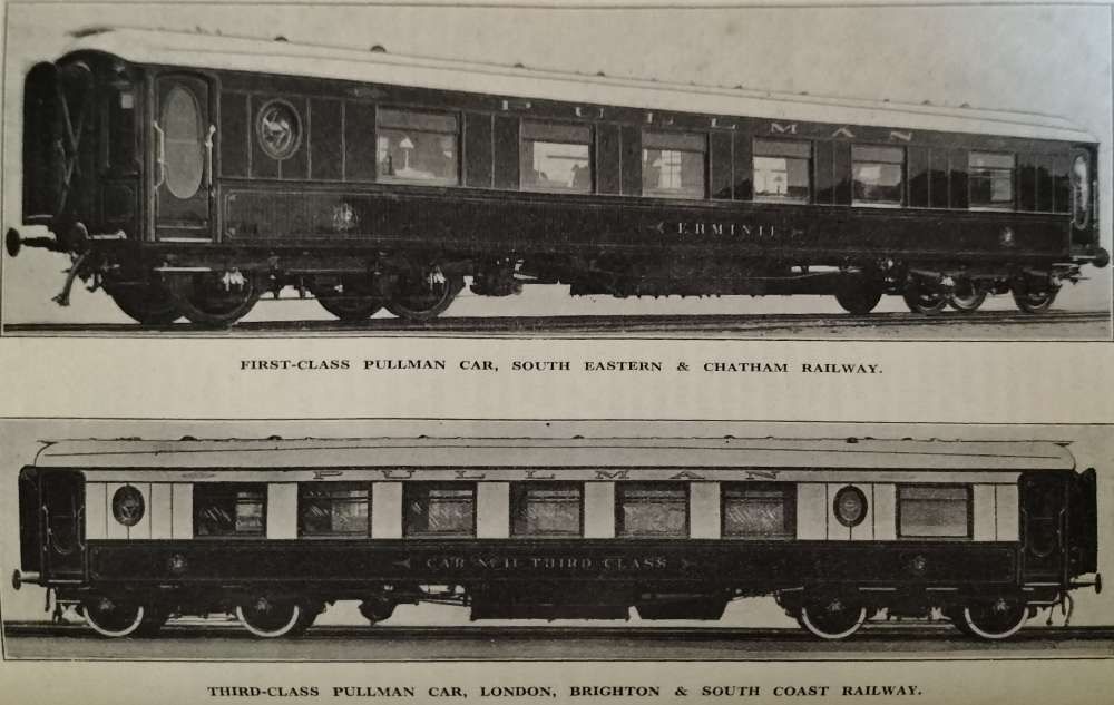
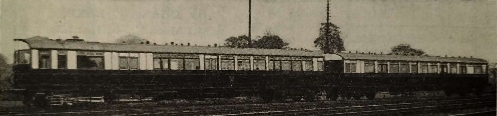
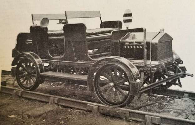

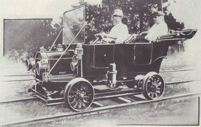
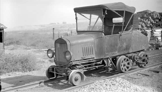
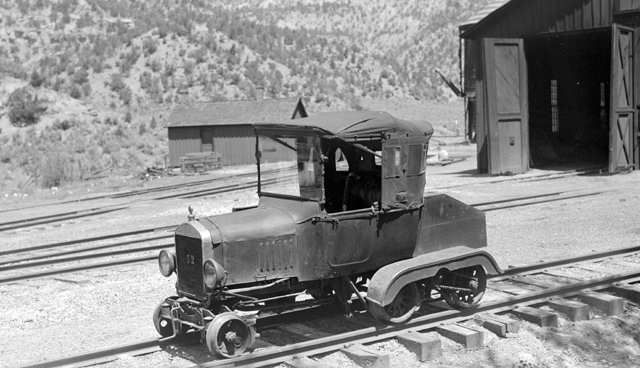
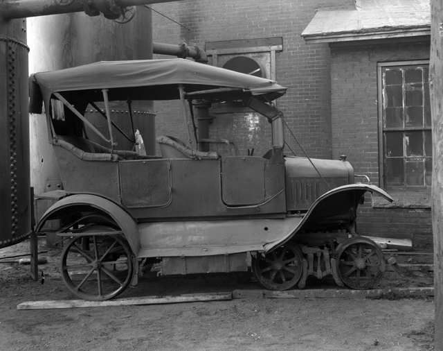
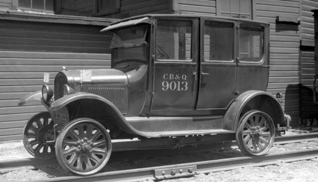
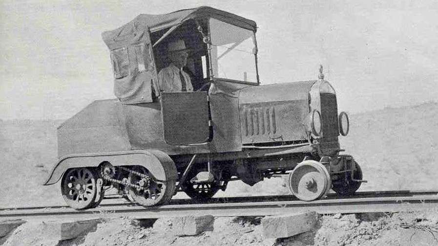
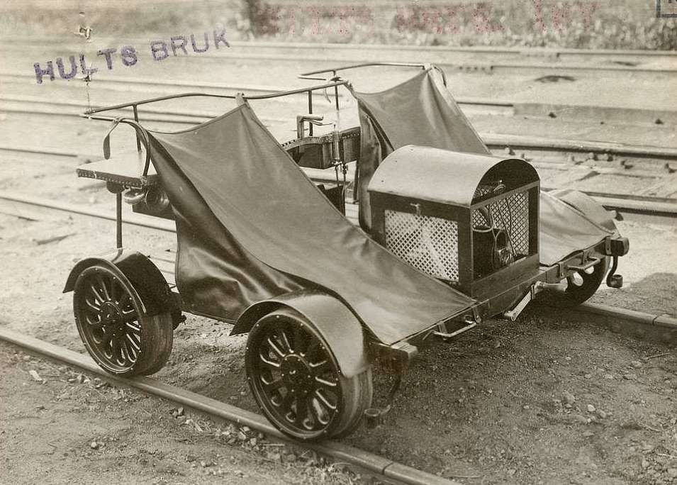
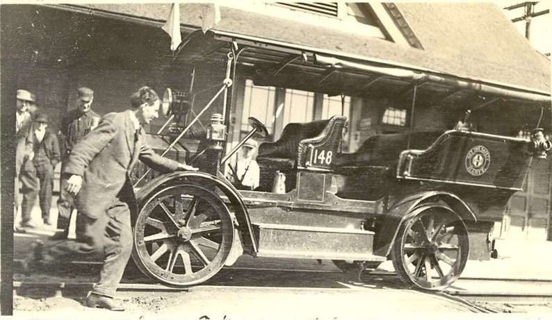
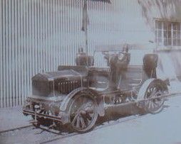
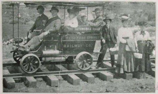


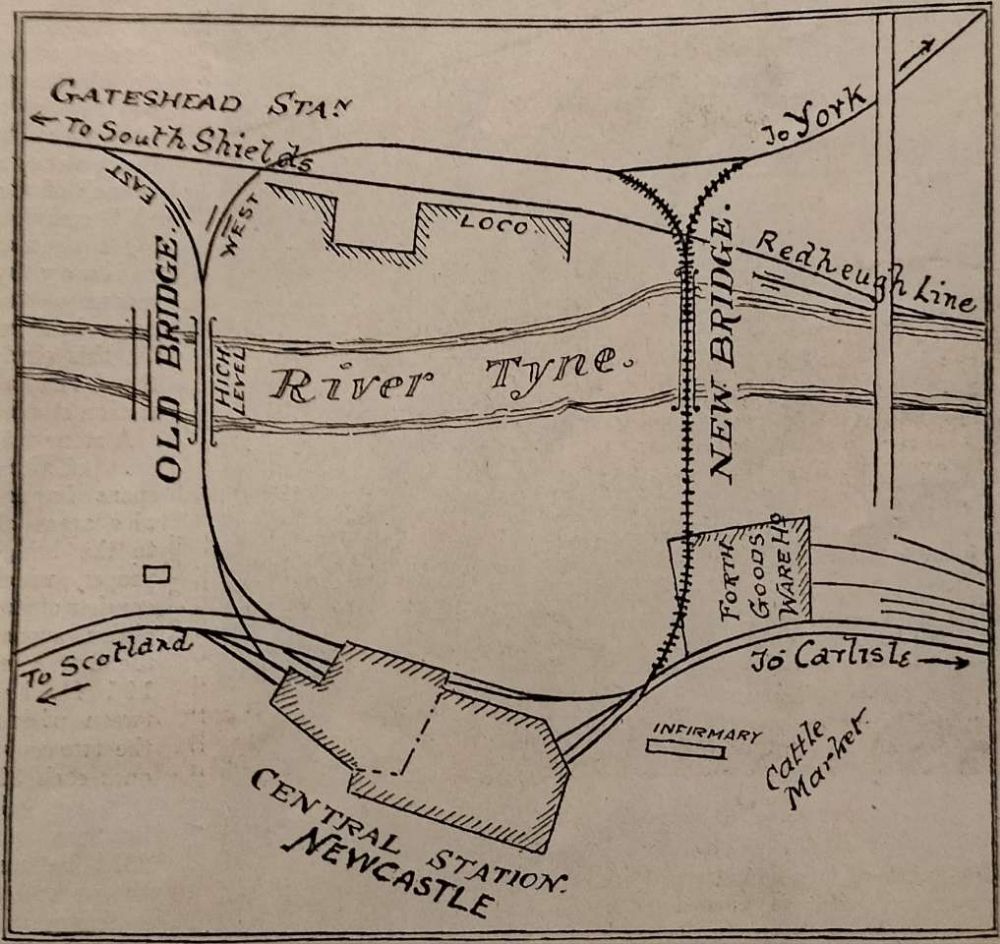
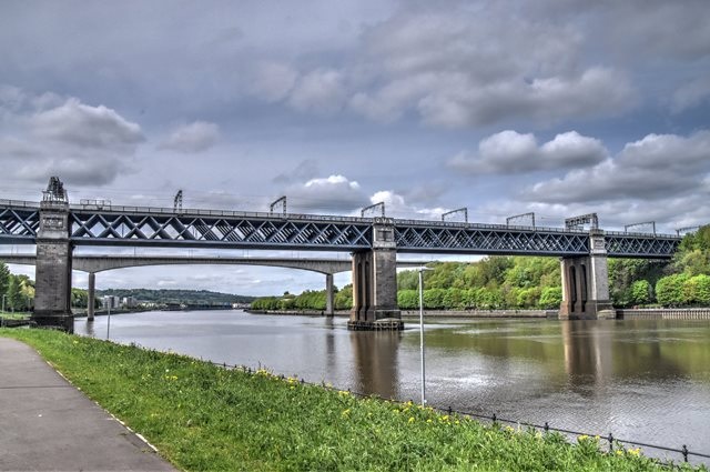
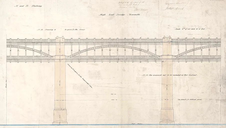
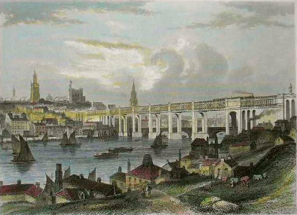
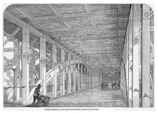
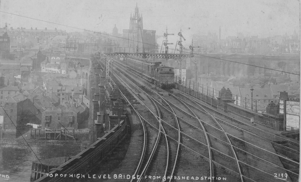
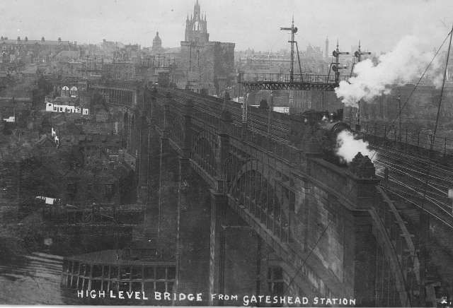
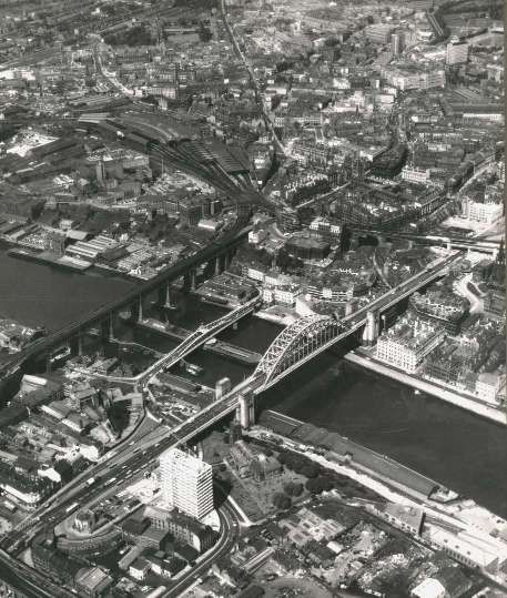
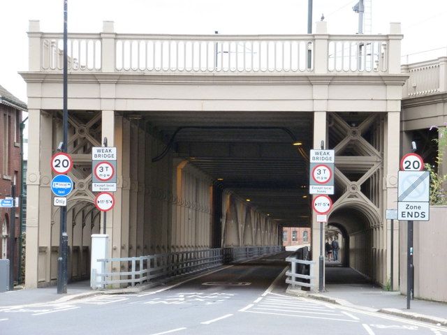
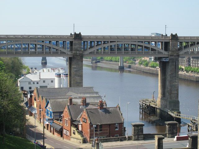


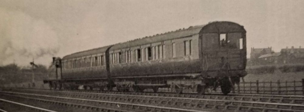
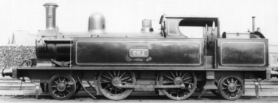
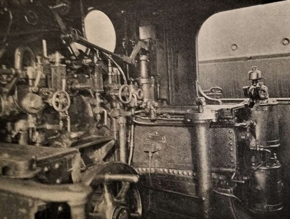
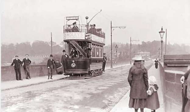
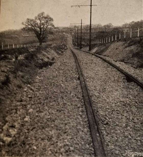
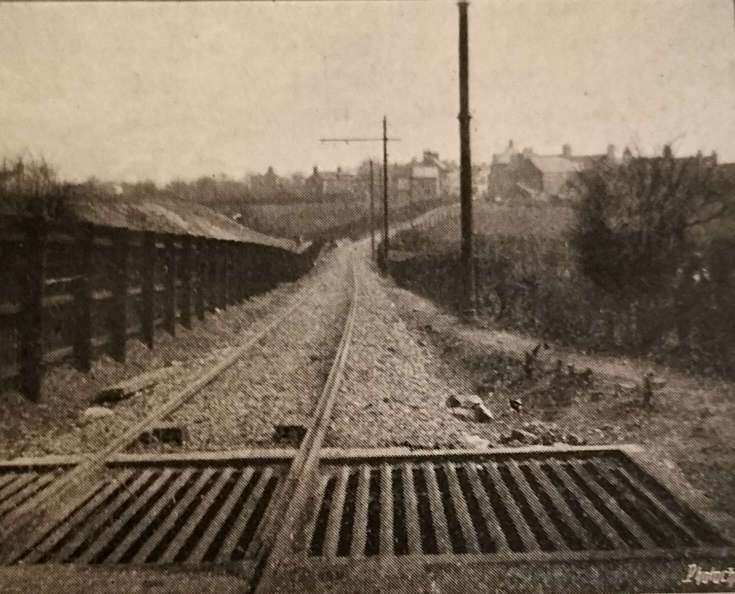

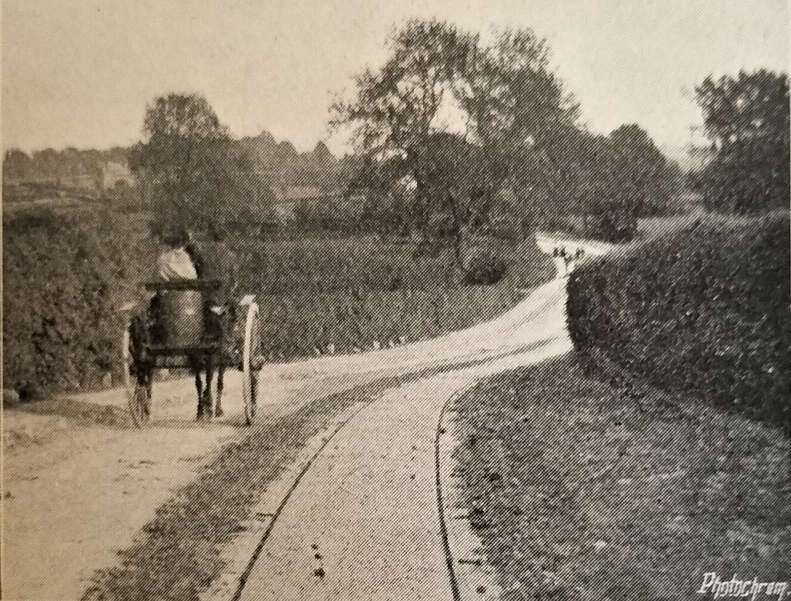
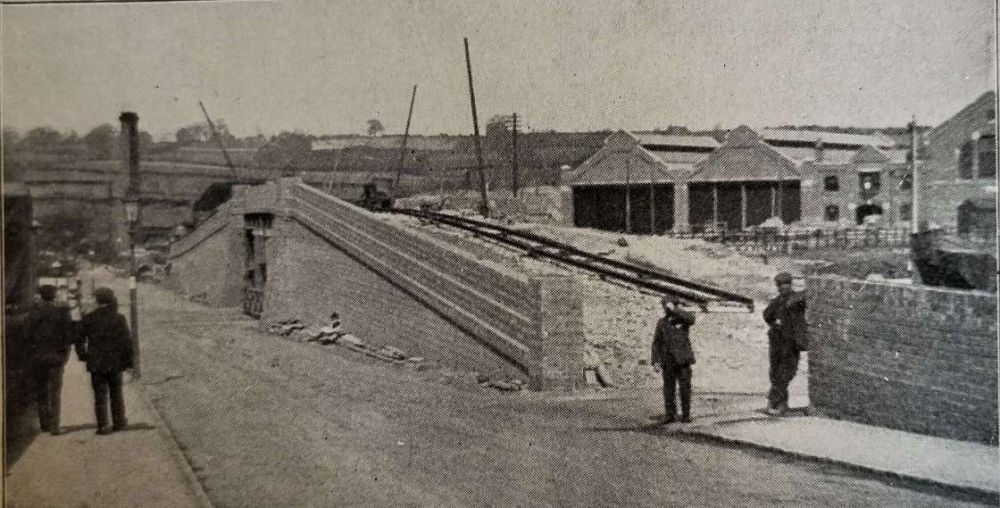
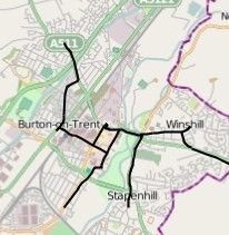
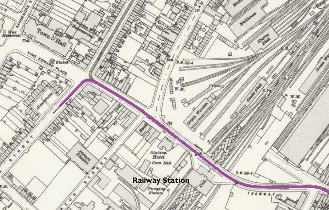
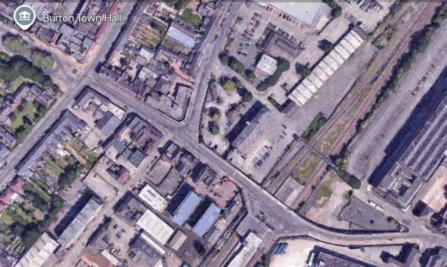
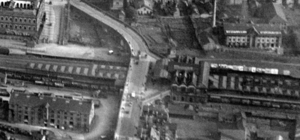
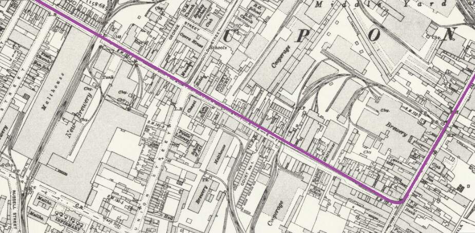
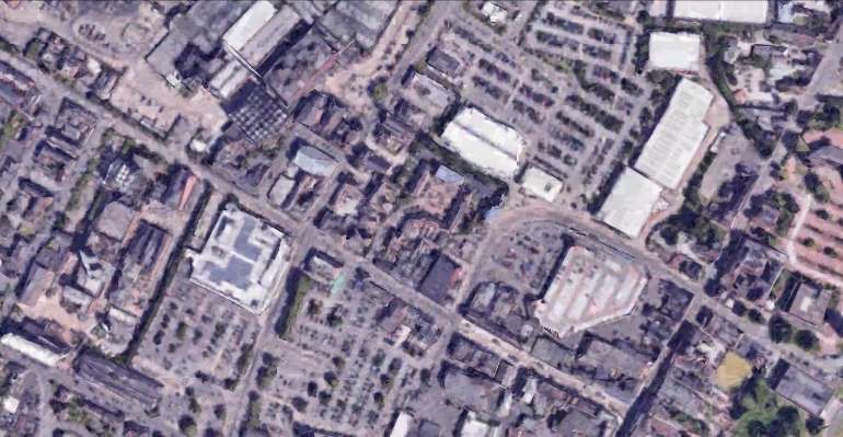
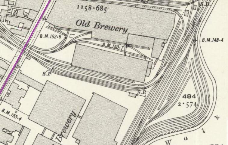
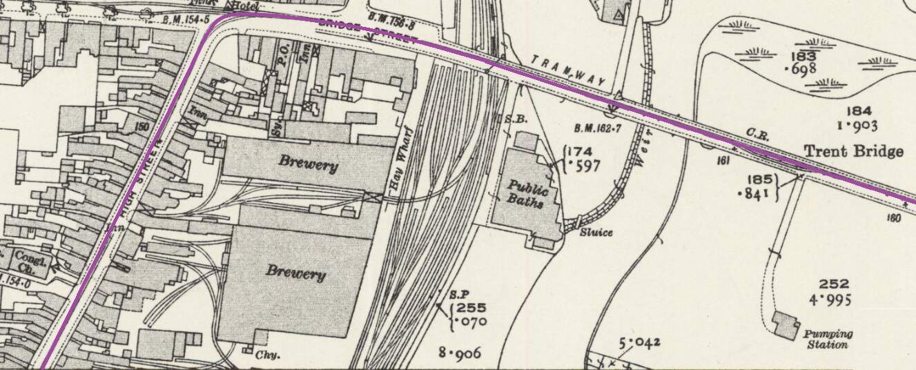
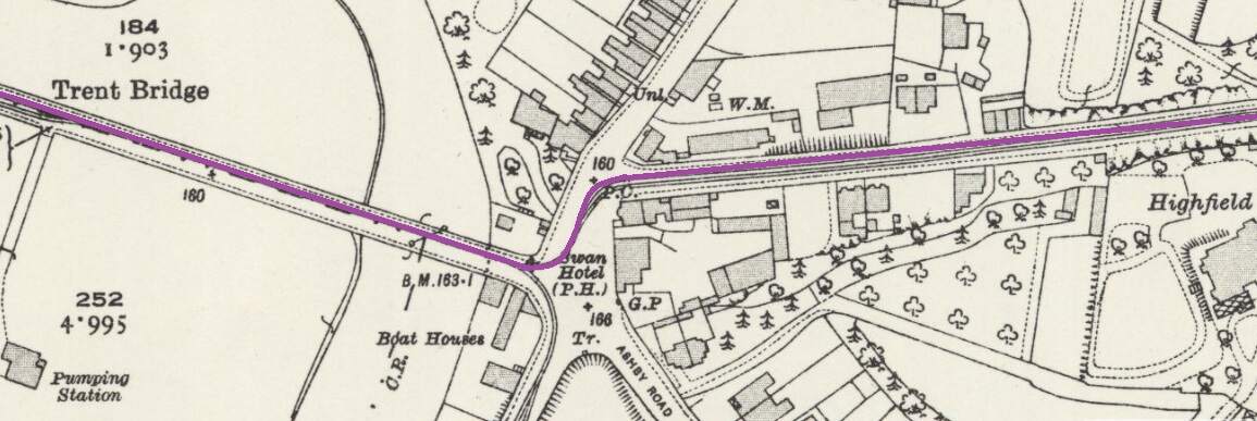
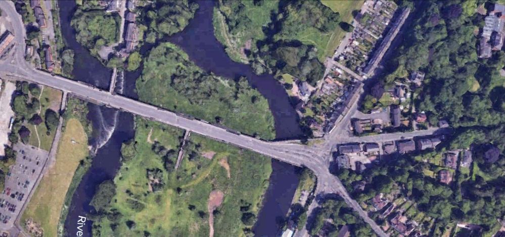
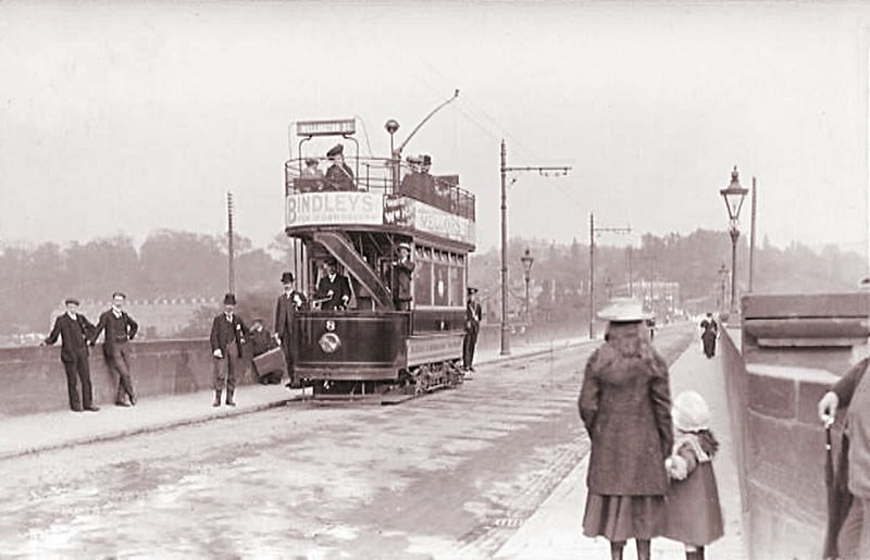
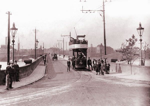
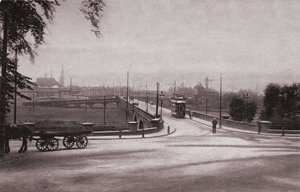
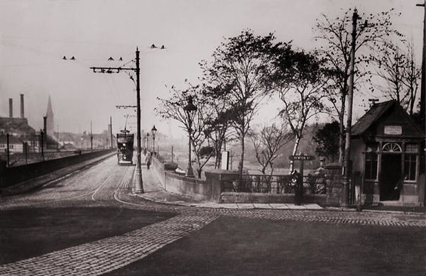
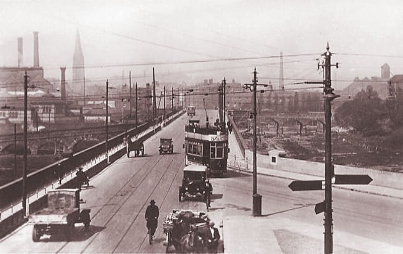
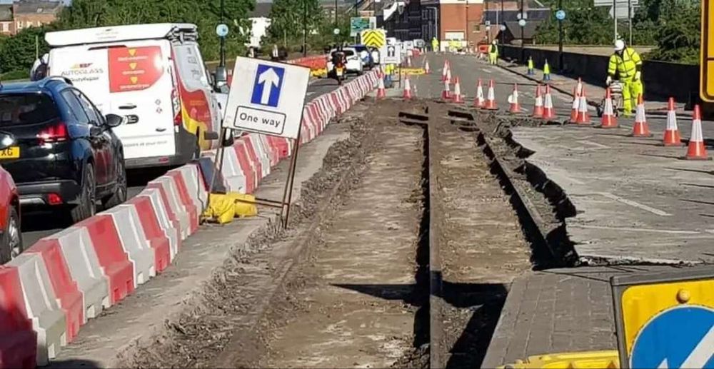
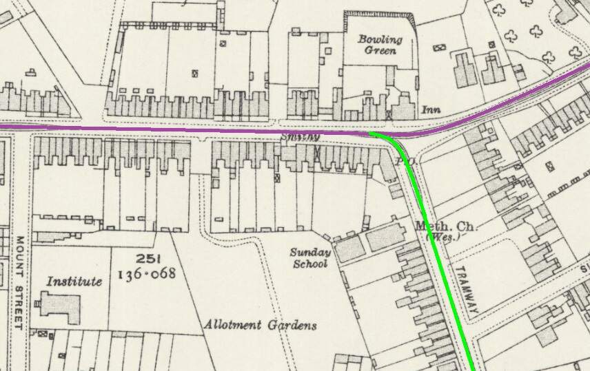
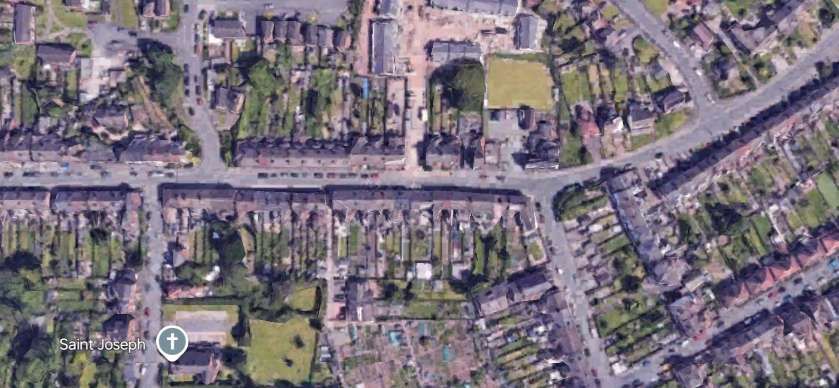
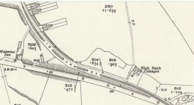
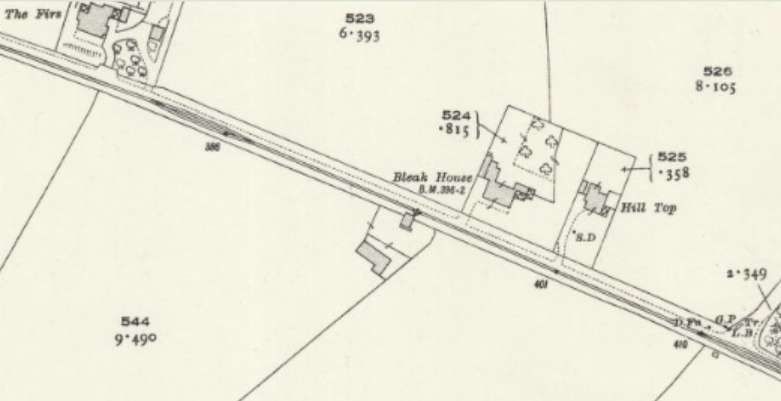
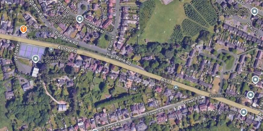
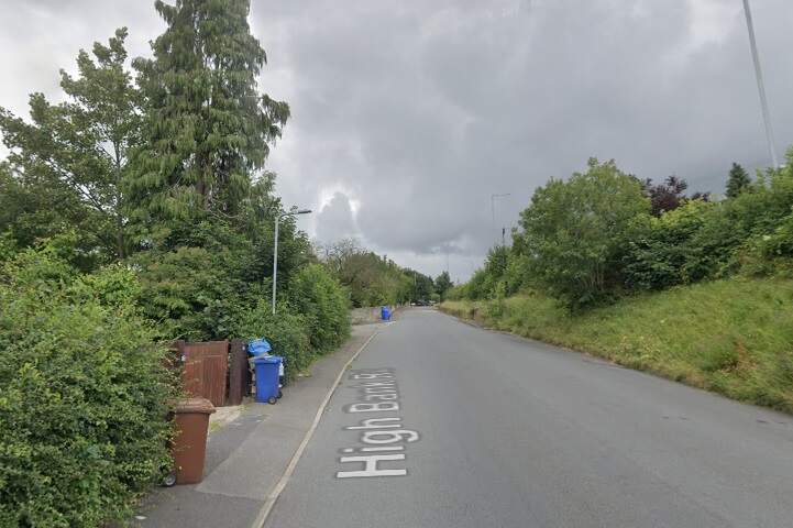
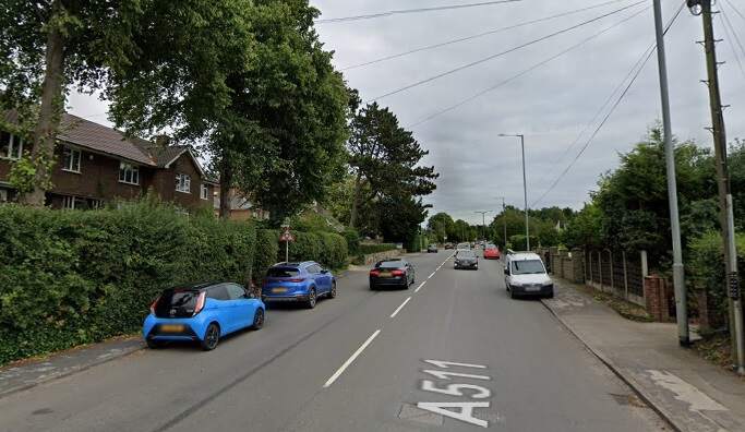
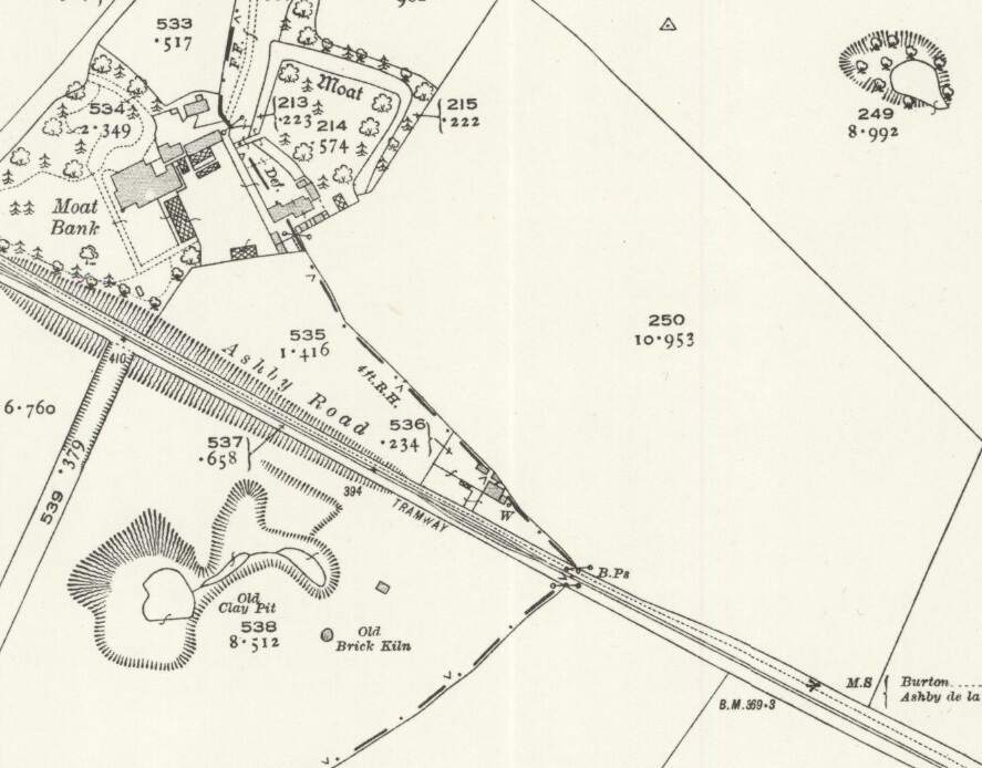
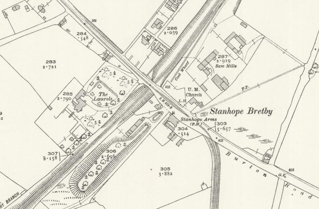
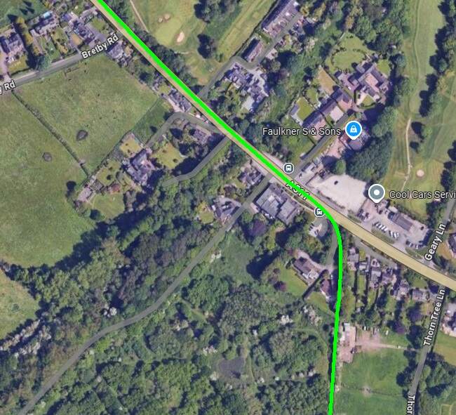
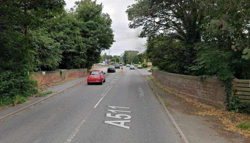
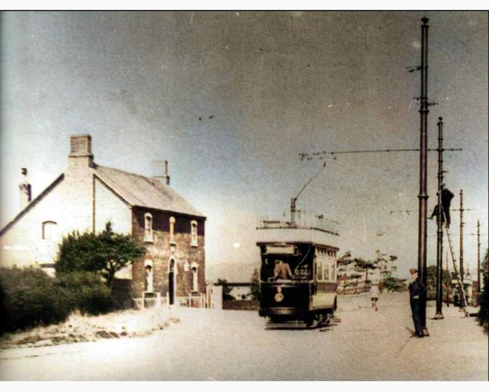
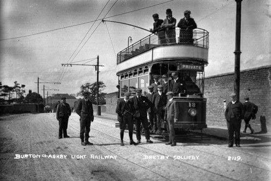
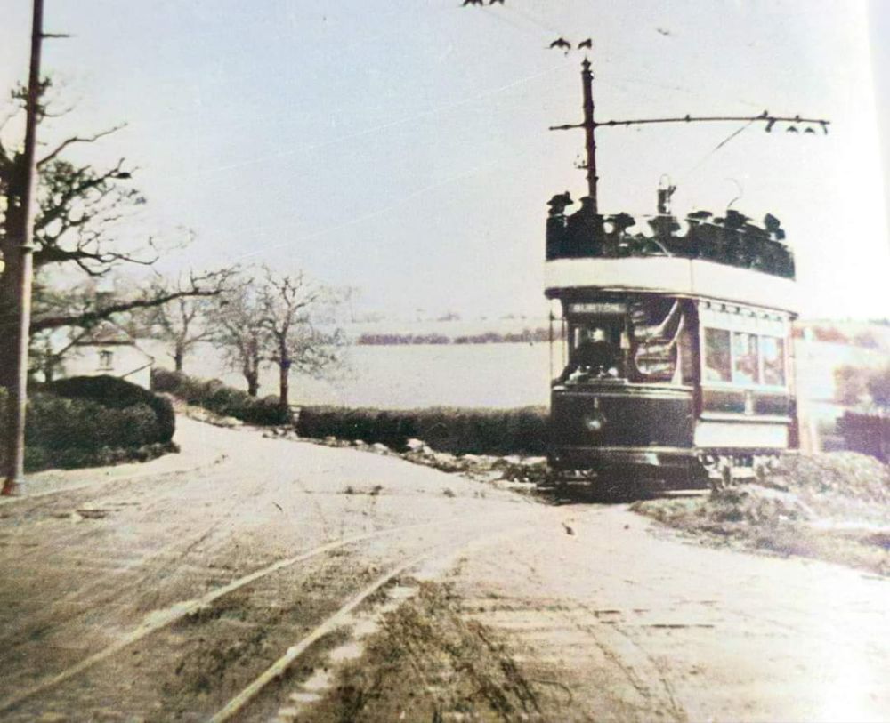
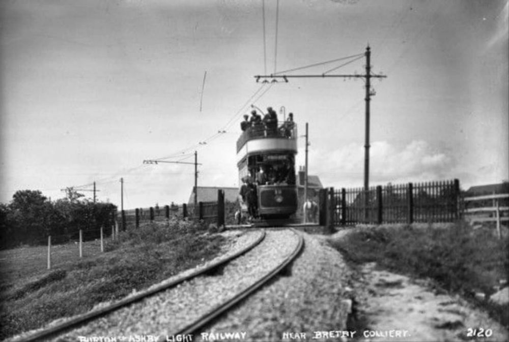
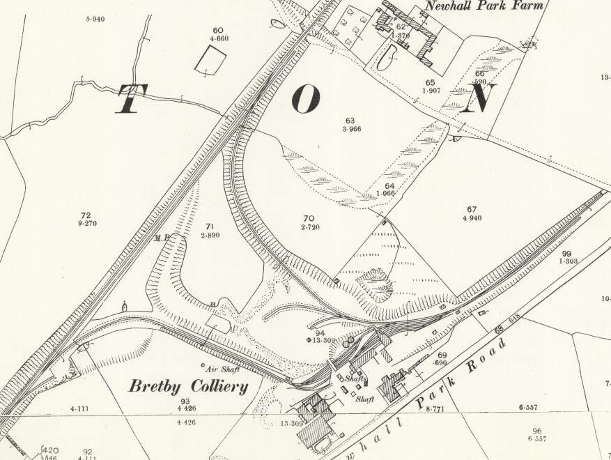
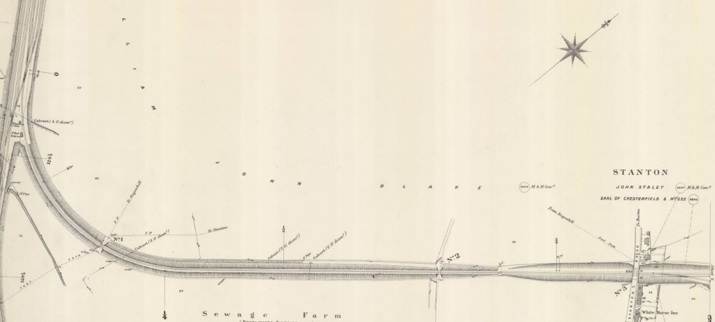
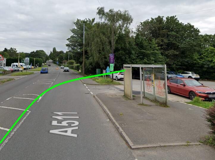
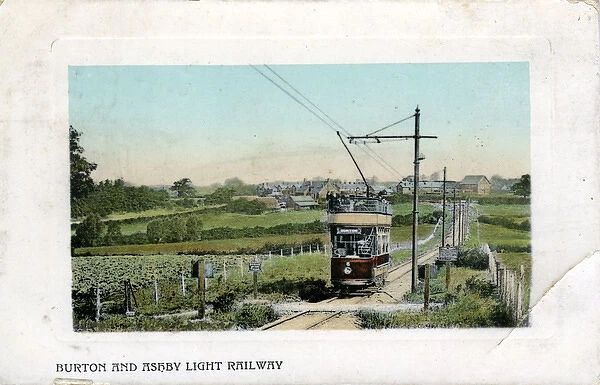
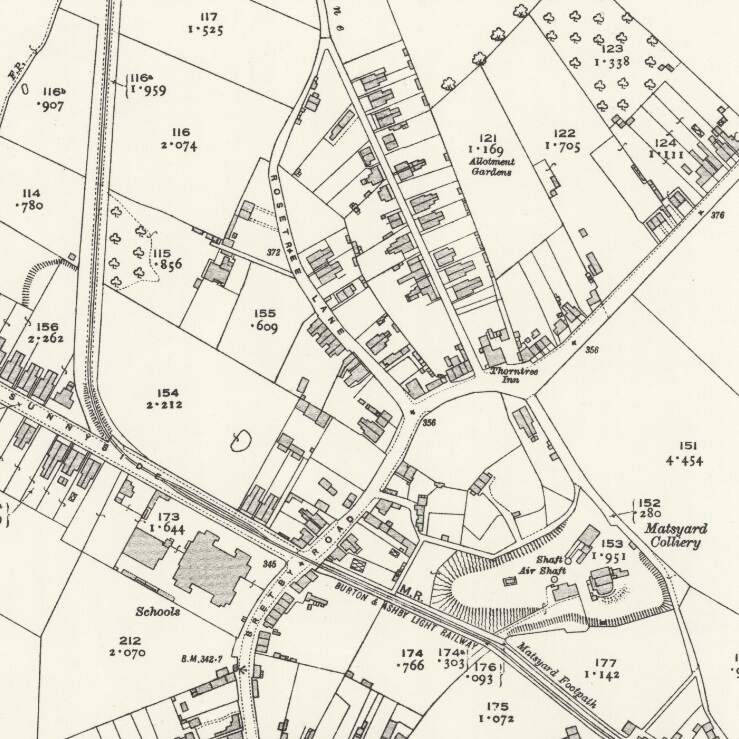
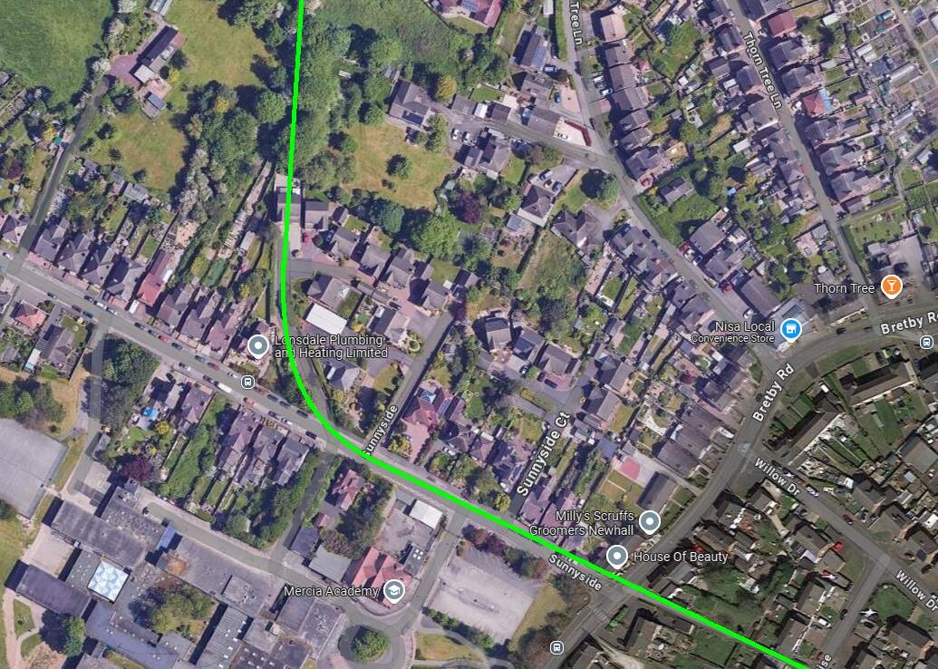
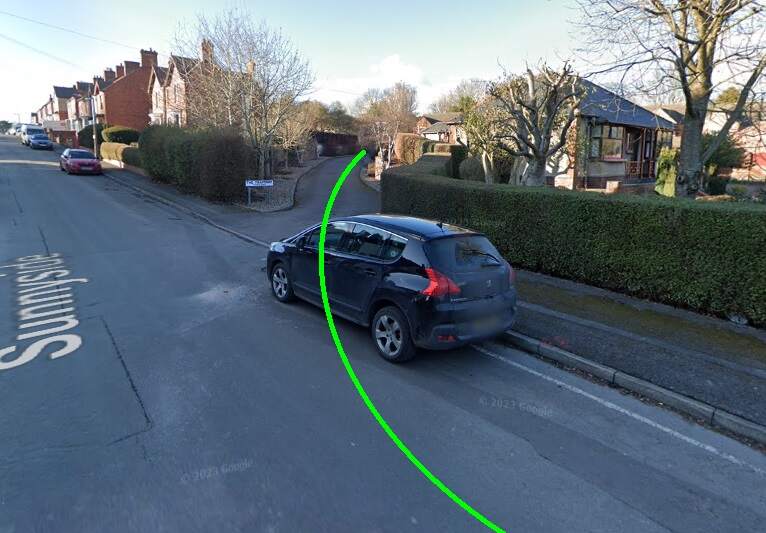
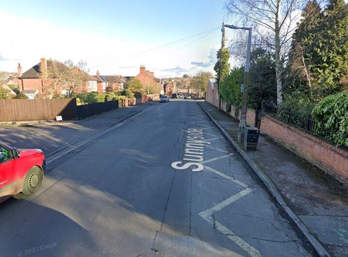
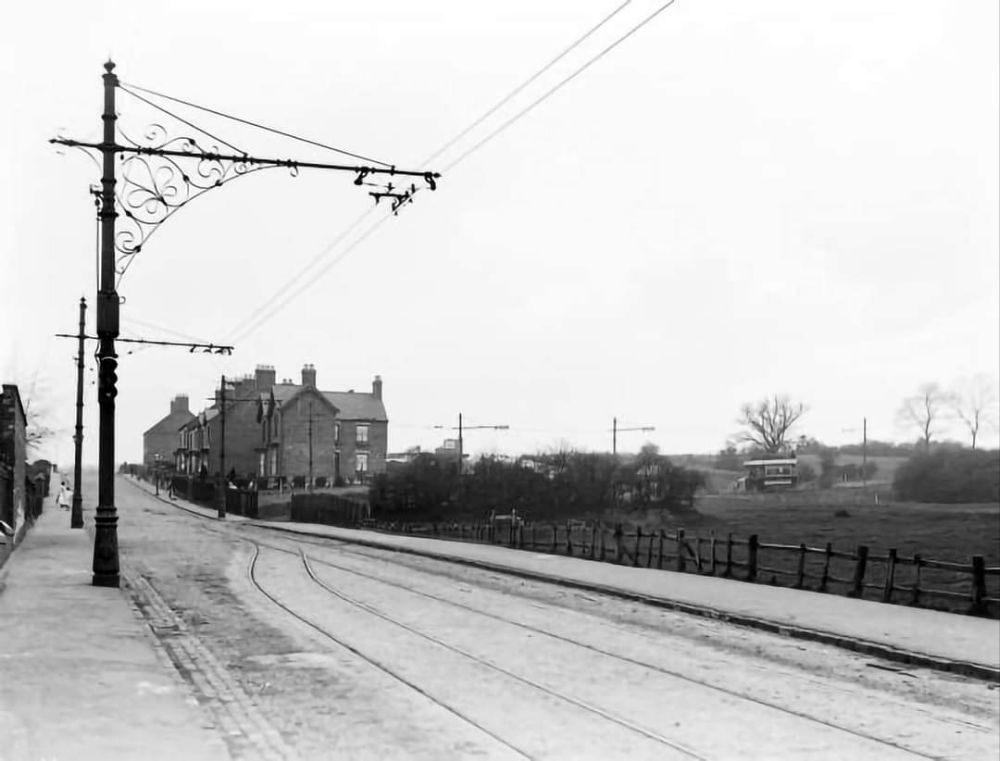
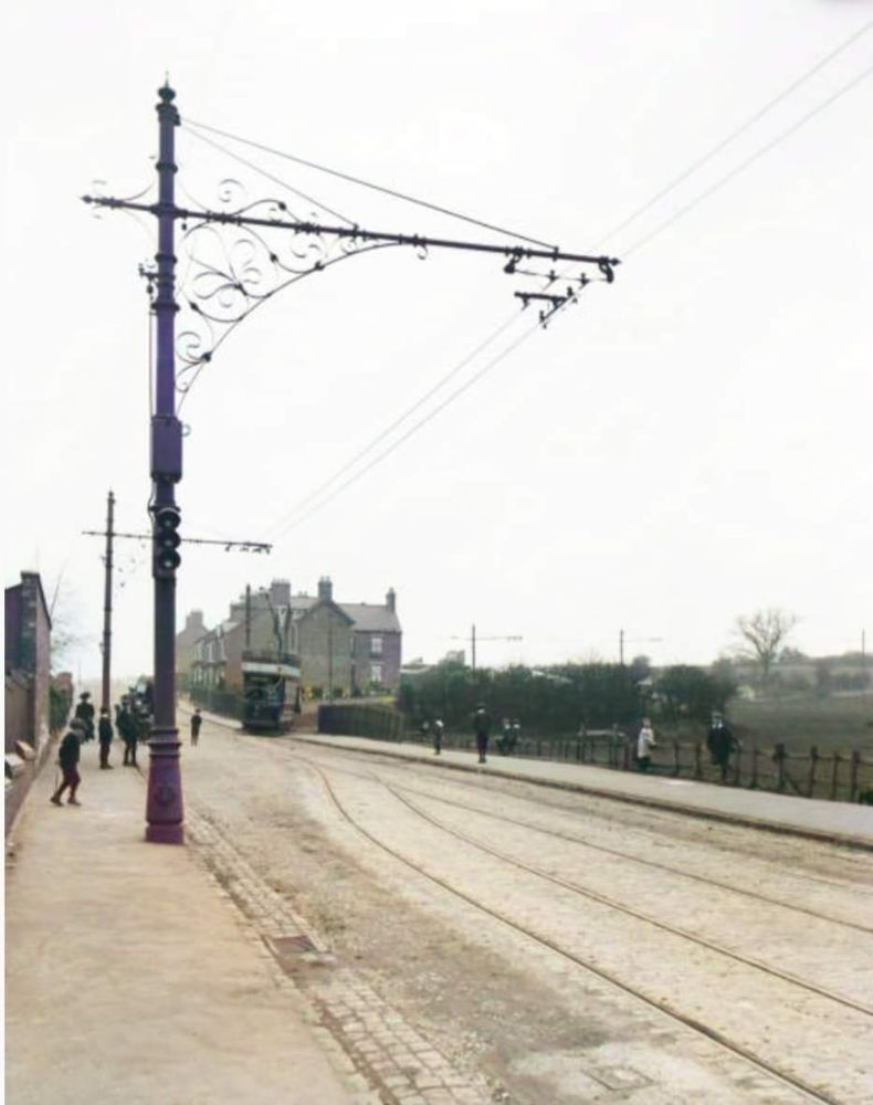
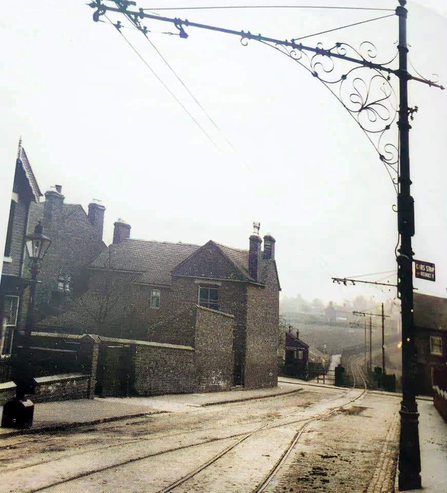
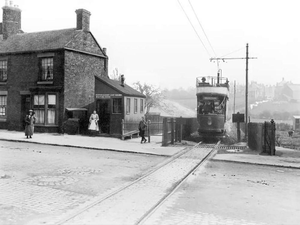
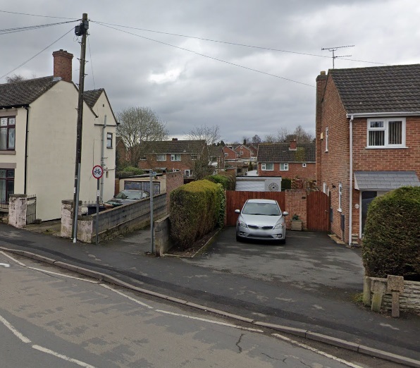
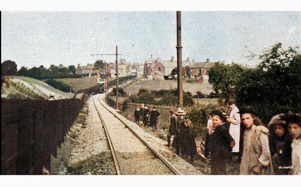
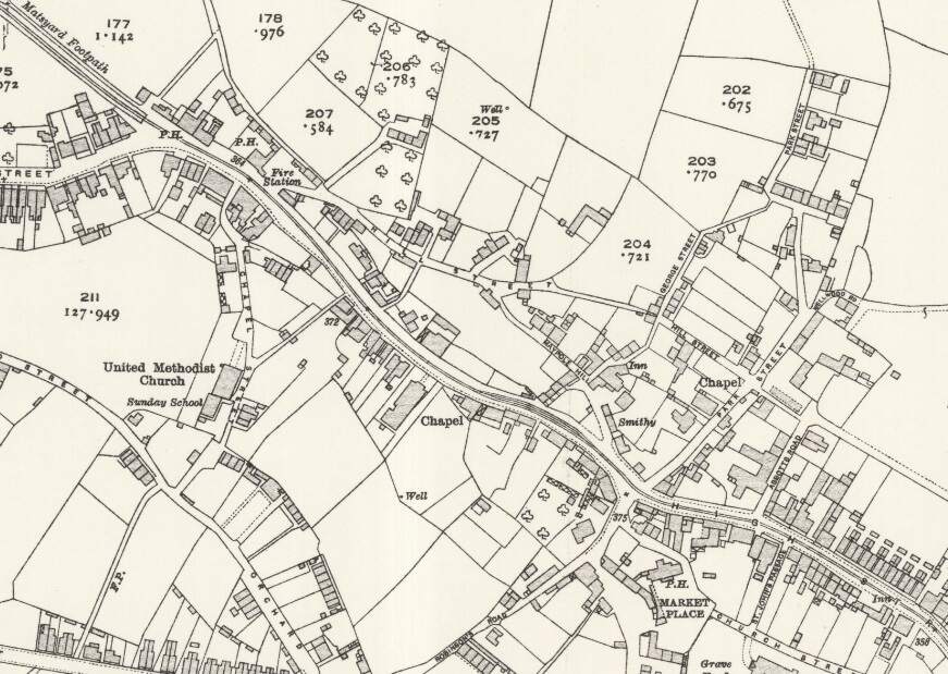
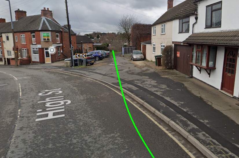
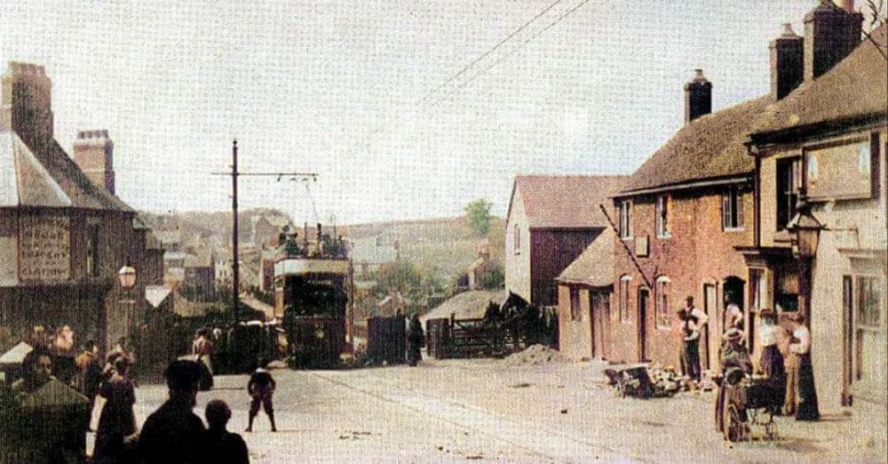
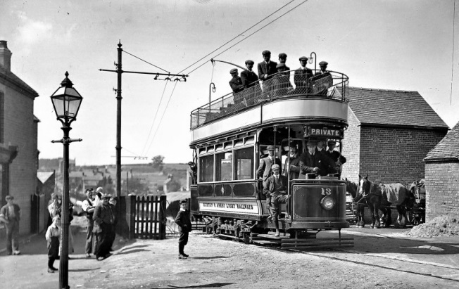
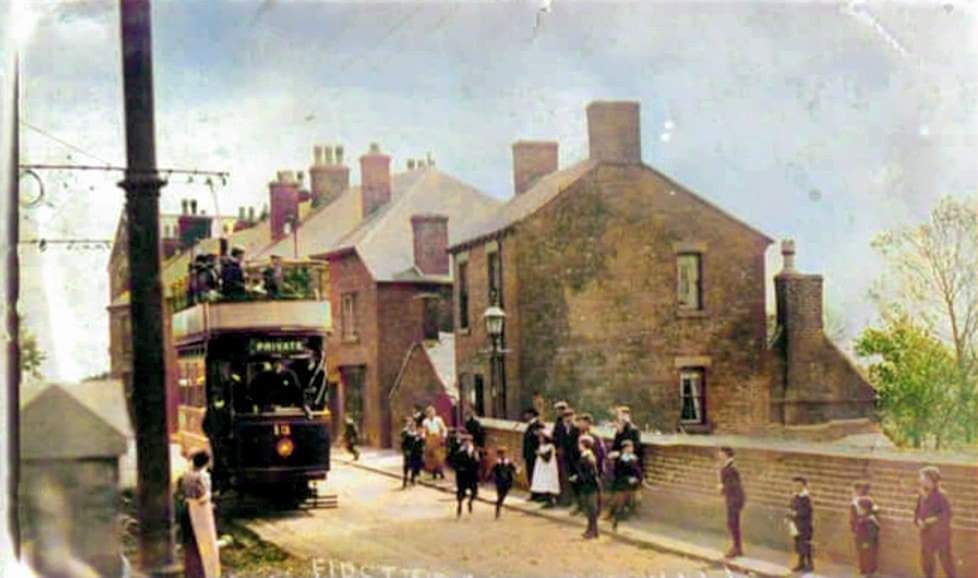

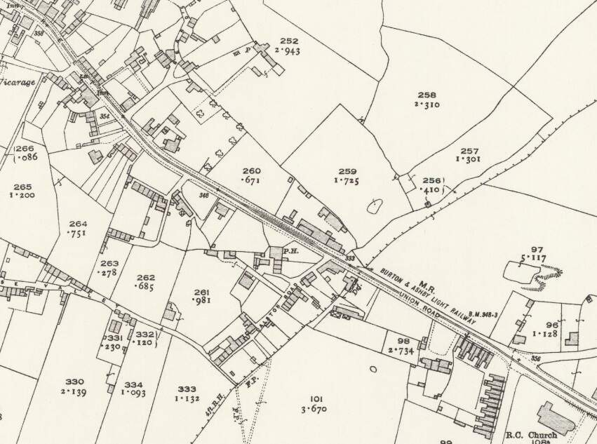
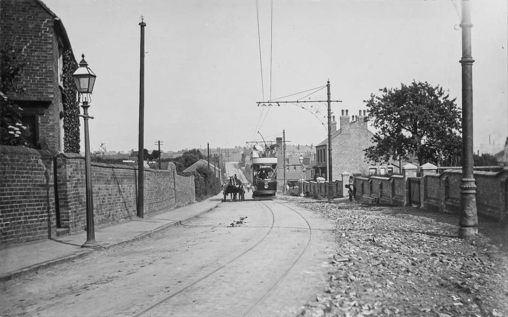
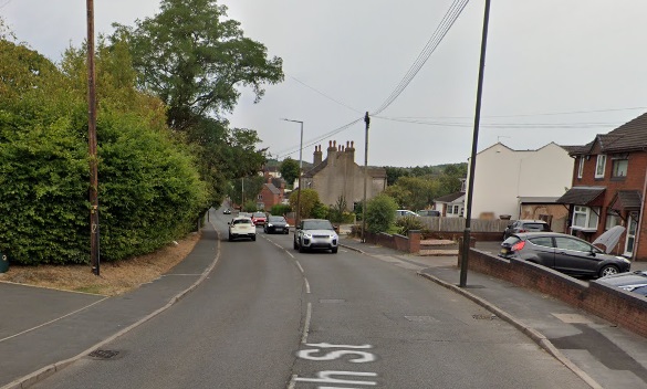
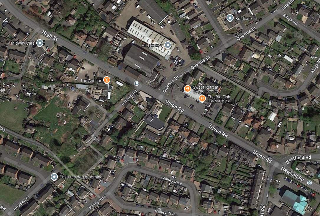
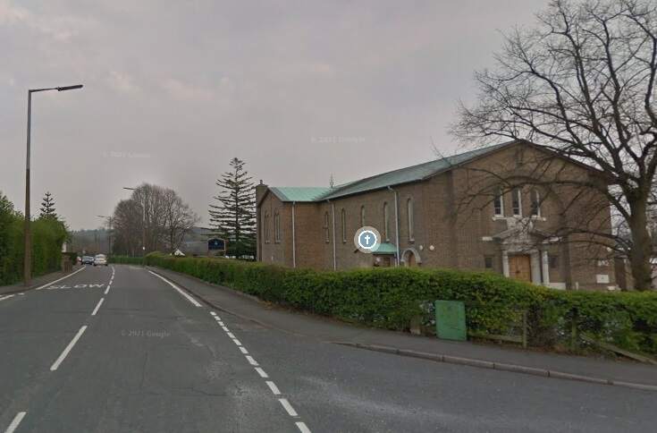
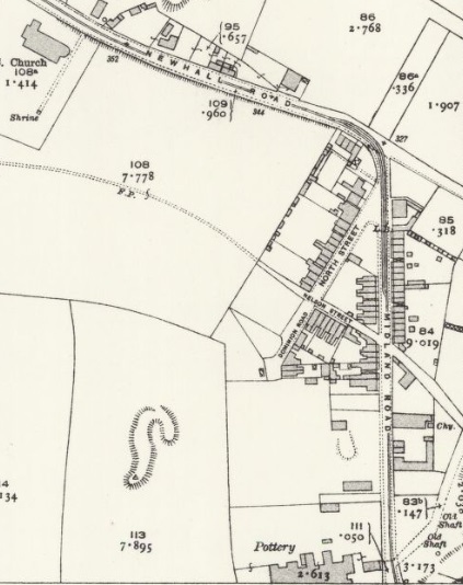
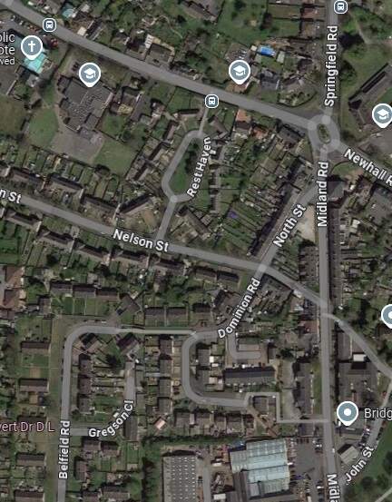
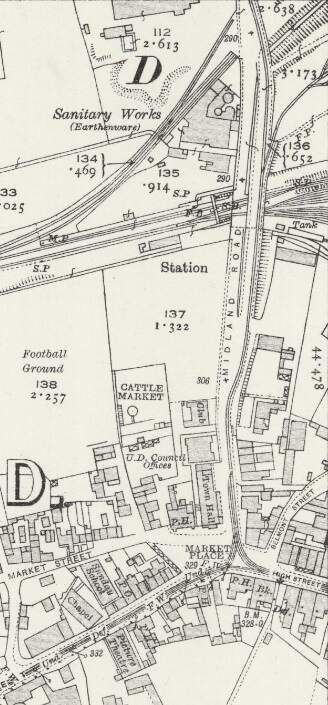
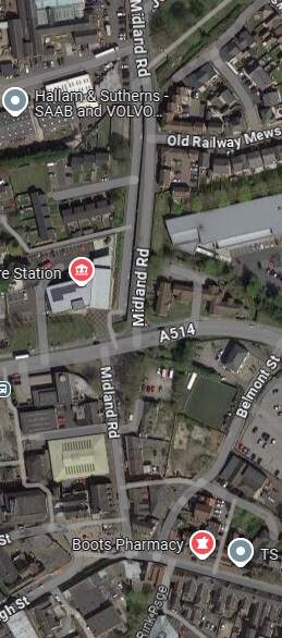
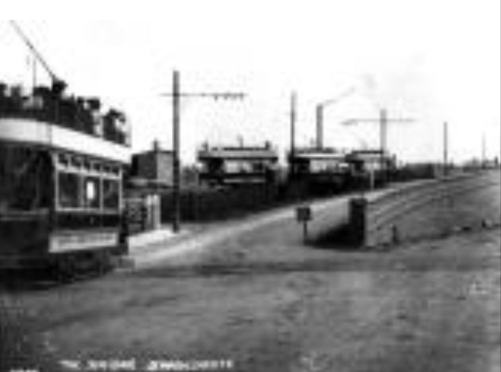
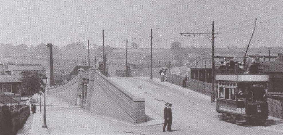
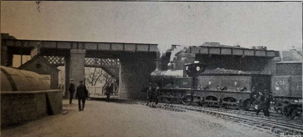
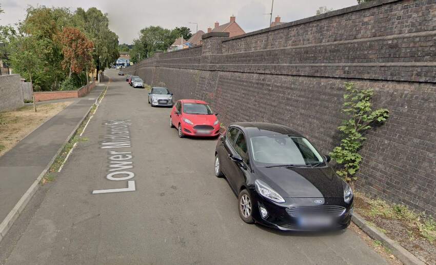
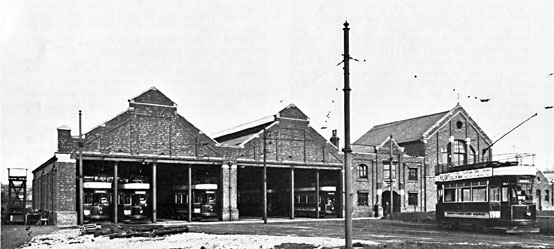
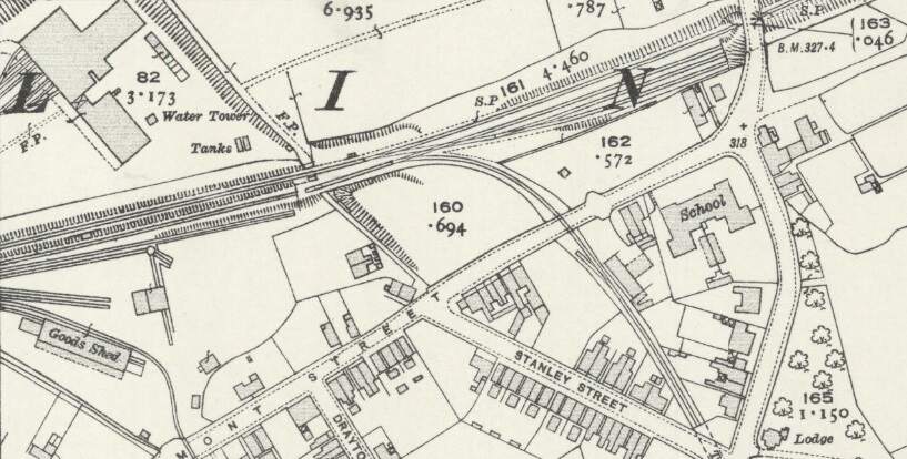
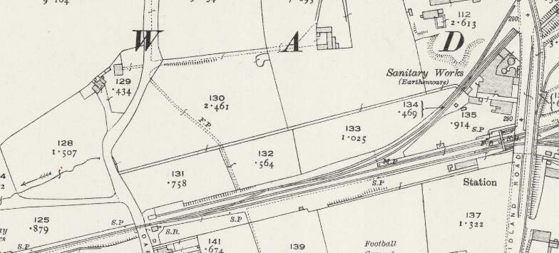
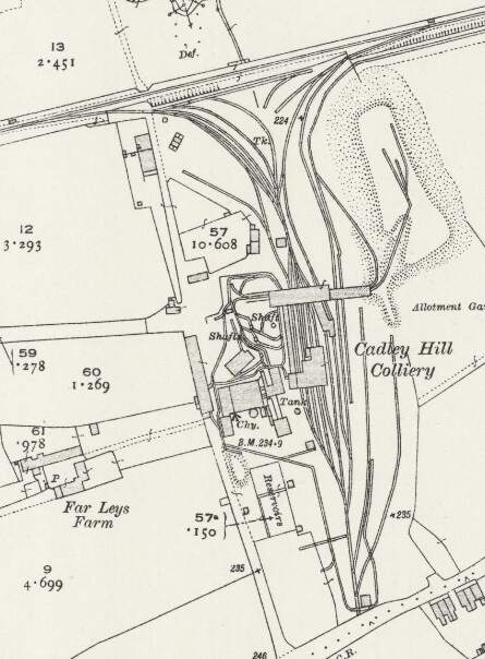
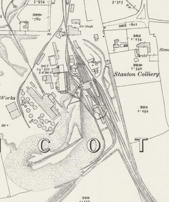
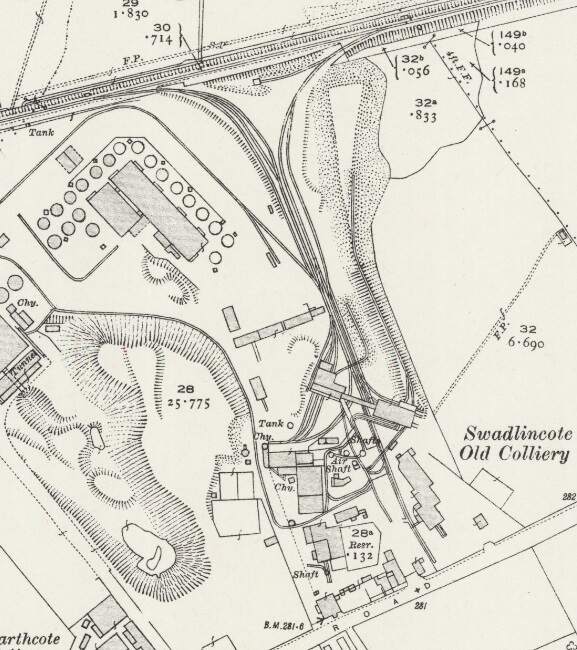
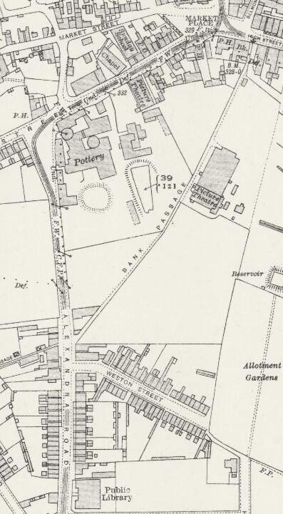
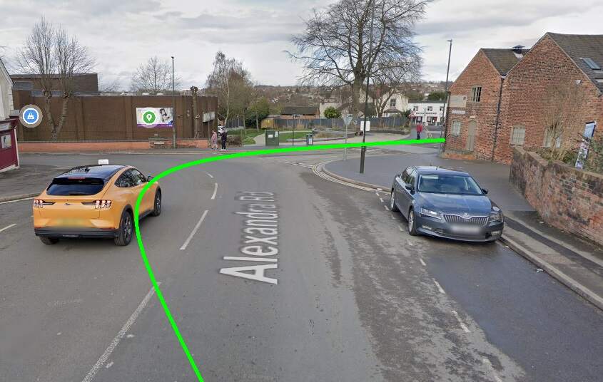
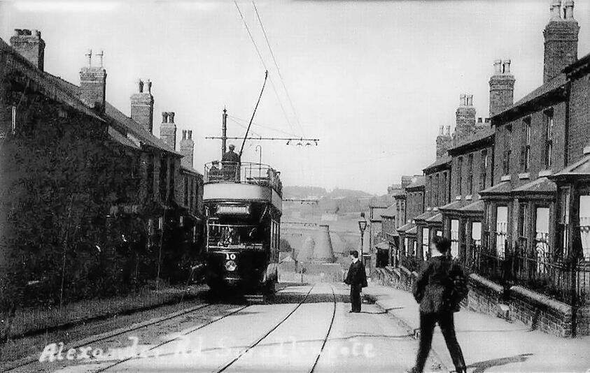
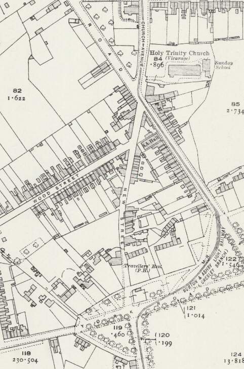
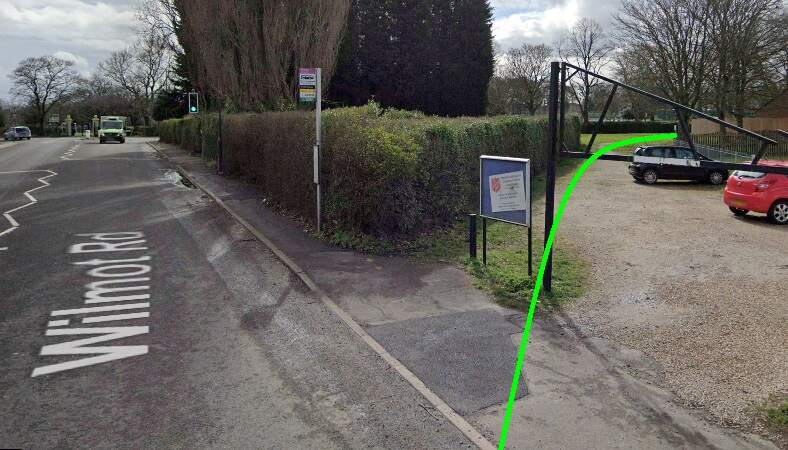
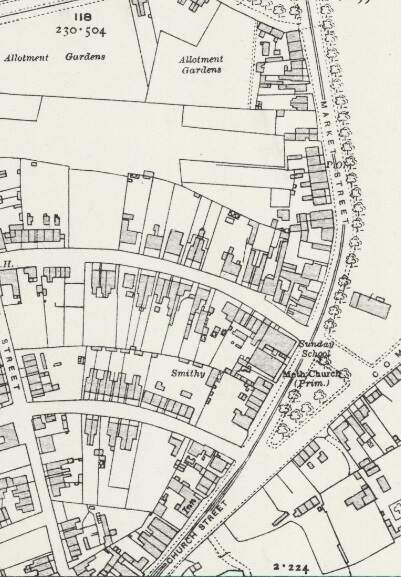
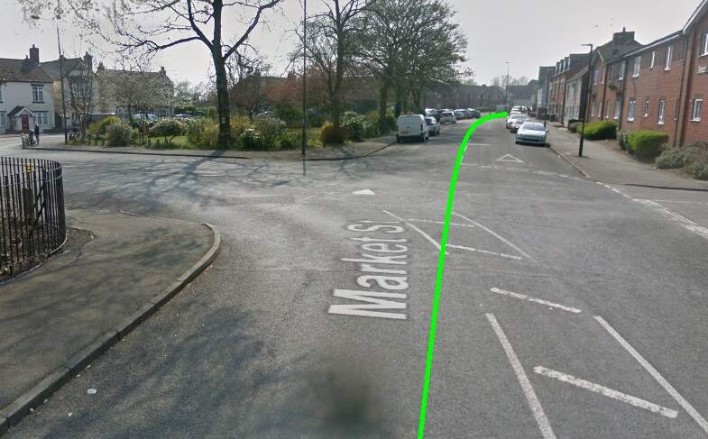
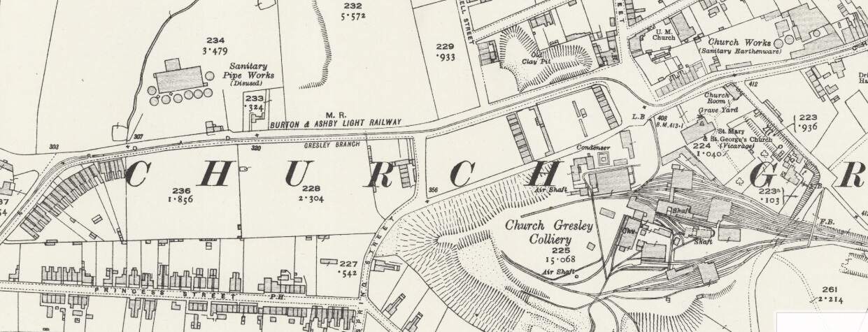
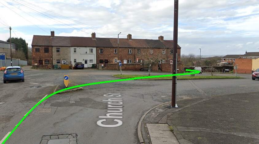
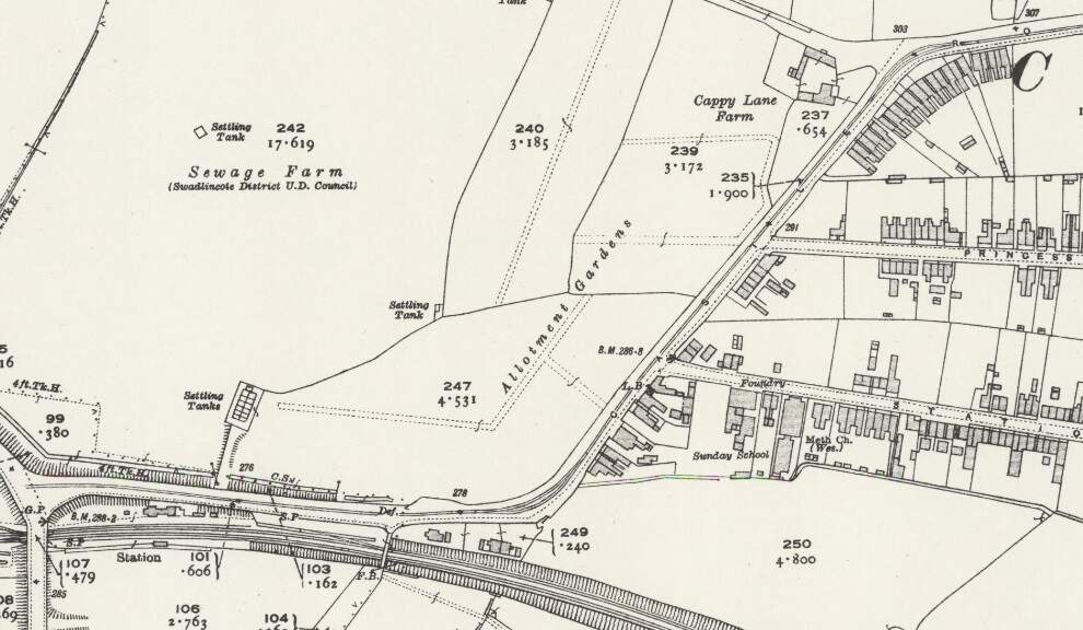
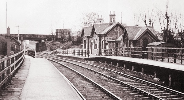
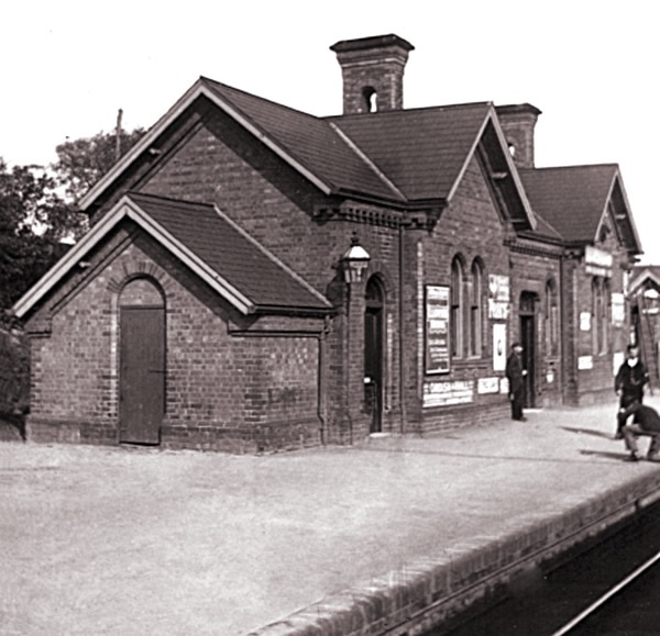


_Locomotion_Shildon_29.06.2009_P6290048_(9989613283).jpg)
.jpg)
.jpg)
.JPG)