

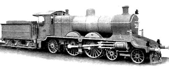
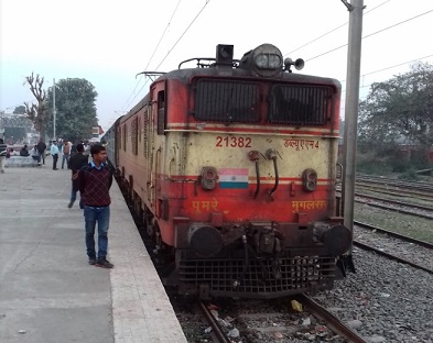
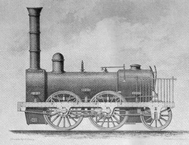
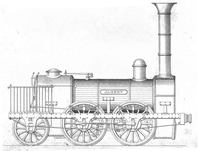
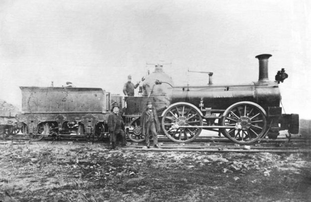
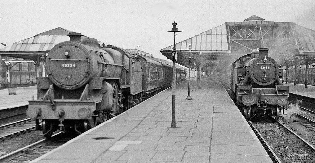
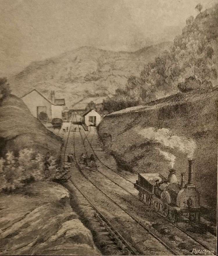
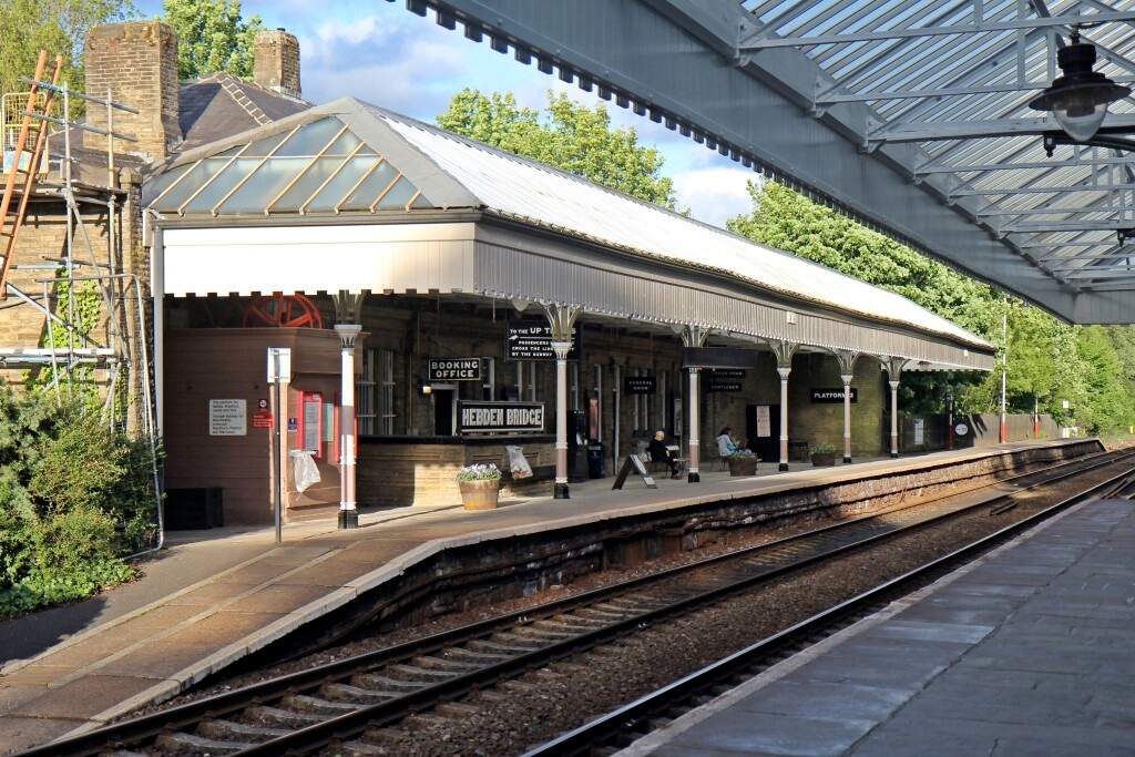
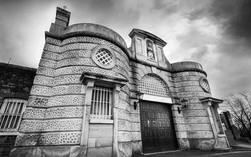
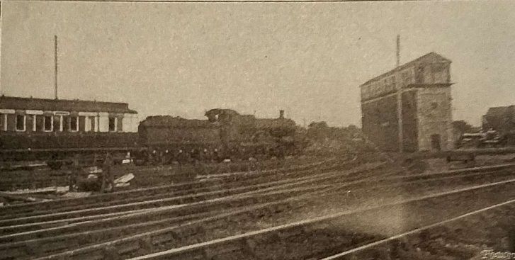
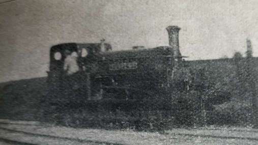
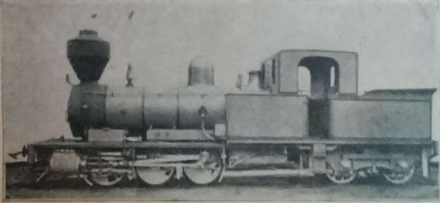
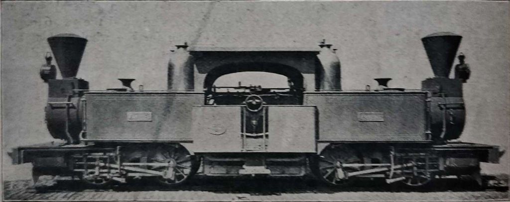
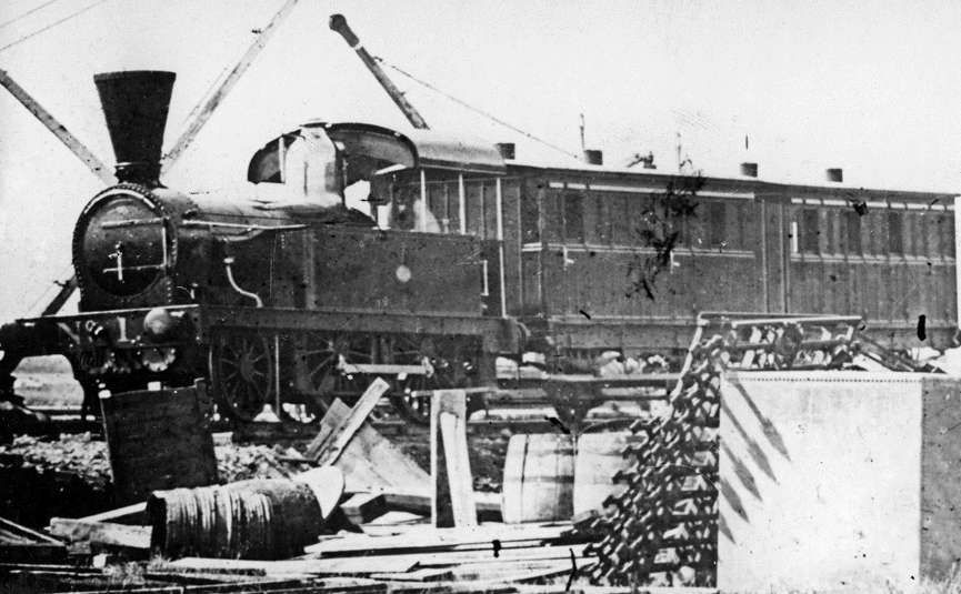
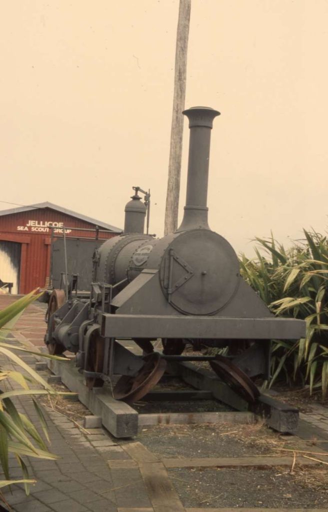
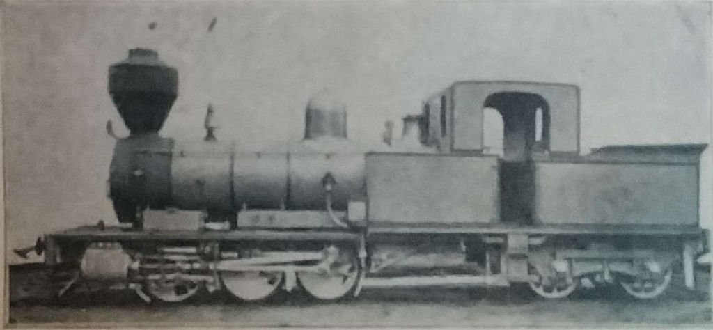
The featured image for this article shows a Class AP 4-4-2 Locomotive of the East Indian Railways. [19]
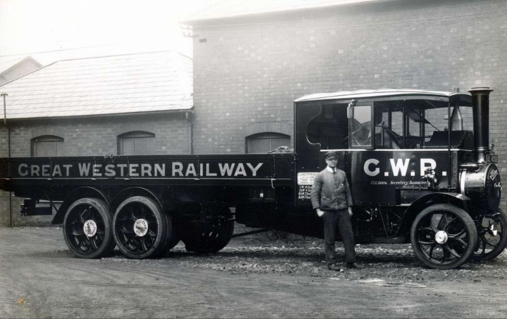
At the end of 1905, G. Huddleston, CLE., was Deputy Traffic Manager (Goods) East Indian Railway. This article is based round the one written by him in the December 1905 Railway Magazine.
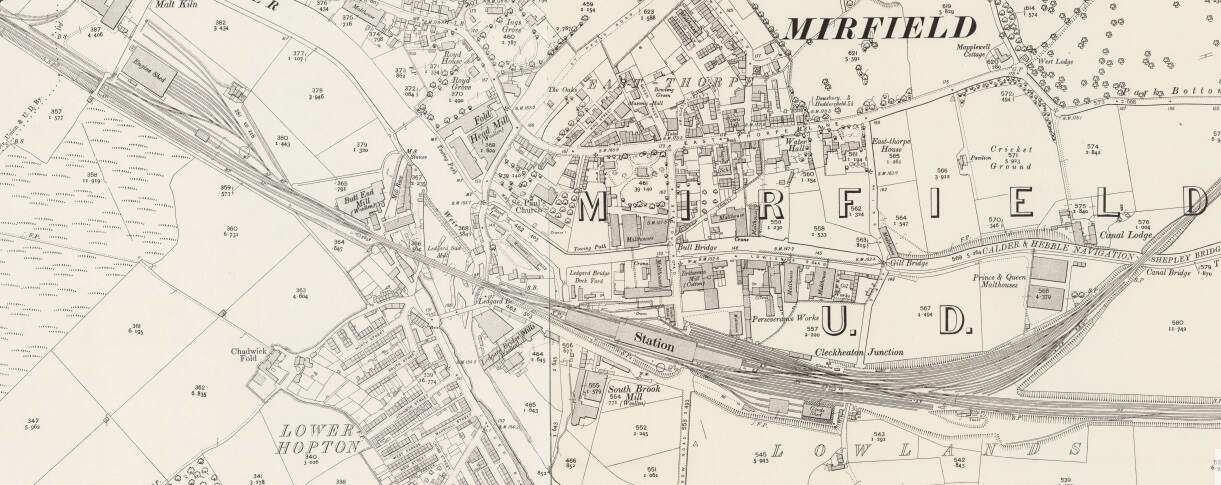
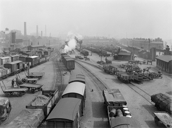
In 1905, there were over 27,000 miles of railway in India: some owned and worked by the State, while other lengths of railway were owned by the State but worked by private railway companies, and others privately owned and worked. Of all of these, the East Indian Railway had the highest traffic figures and earnings. It was worked for the Government by a private company.
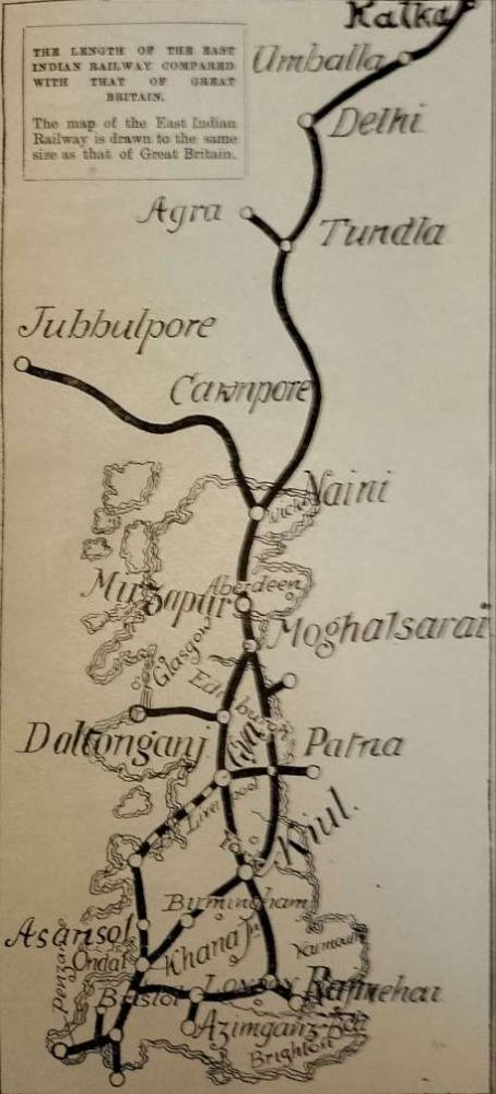
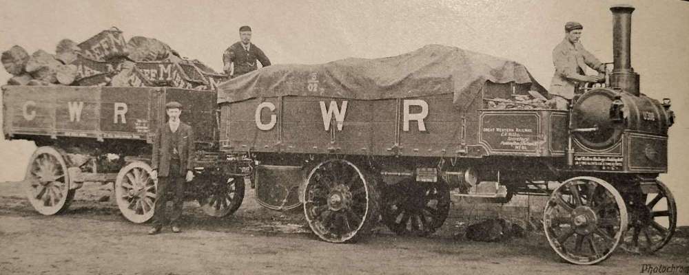
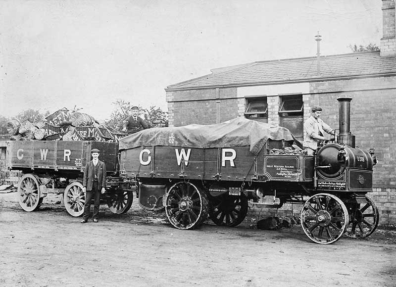
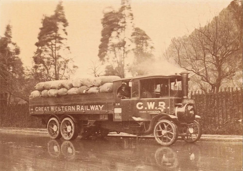
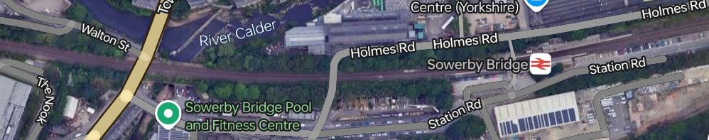
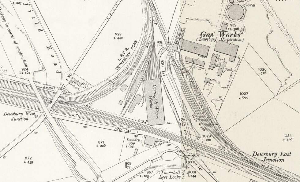
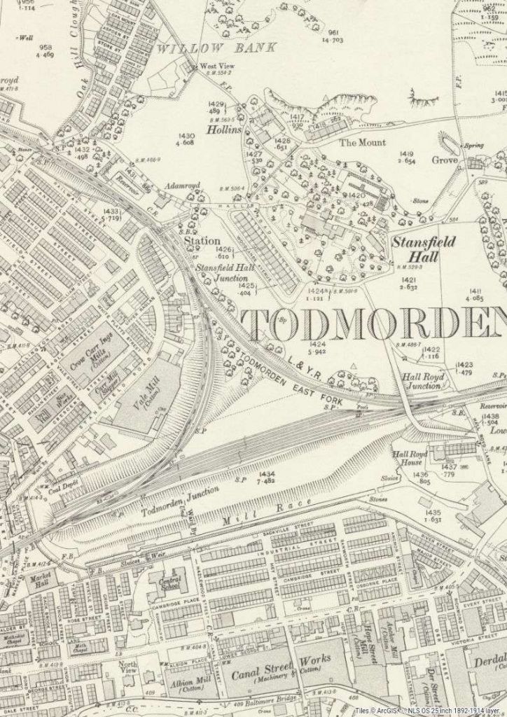
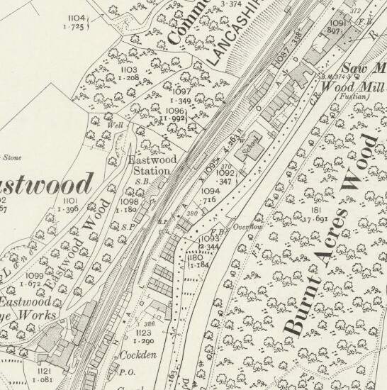
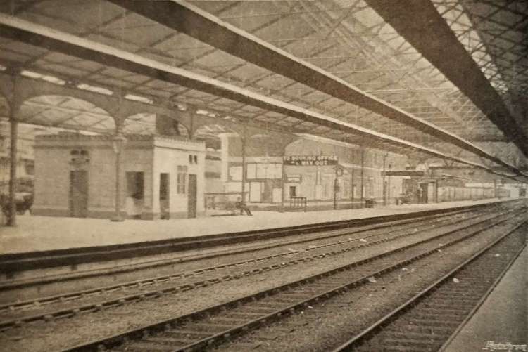
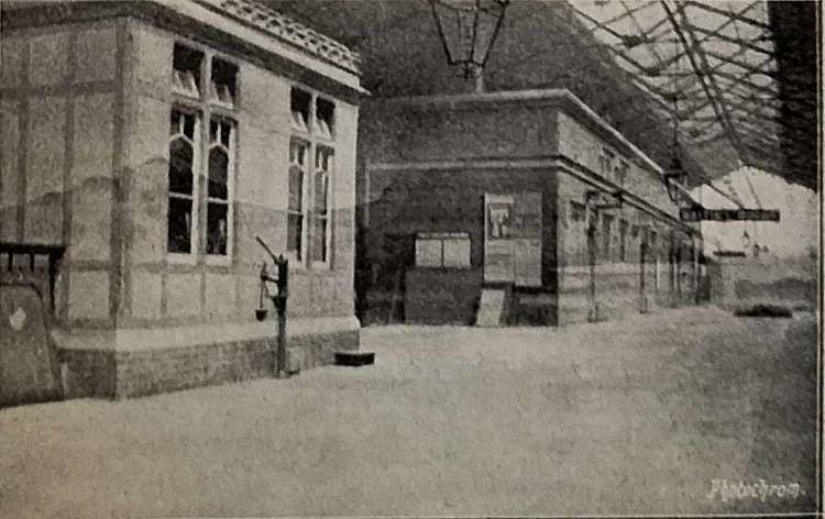
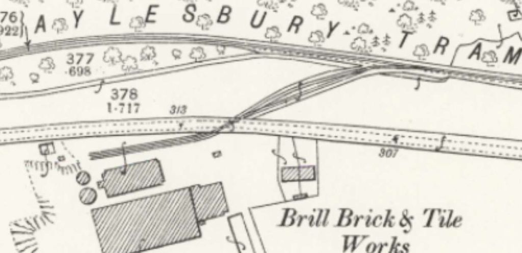
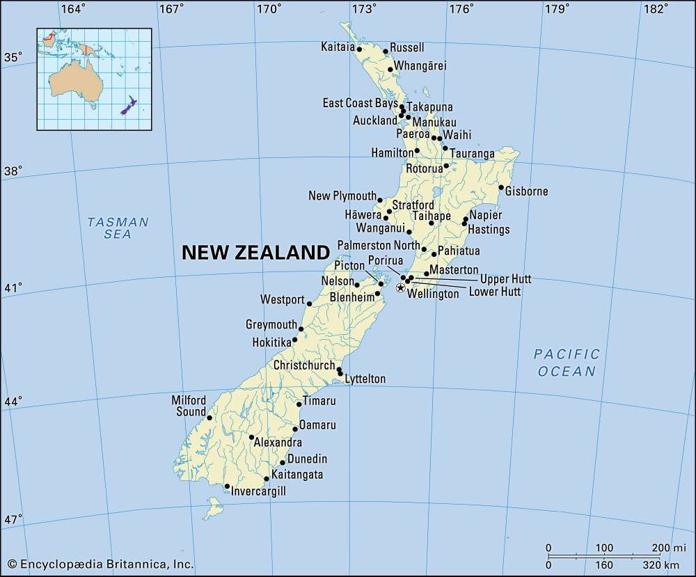
The East Indian Railway (EIR) had a network, including branches and lines worked by it, covering a distance of 2,242 miles. The first image below provides an illustration of what this meant on the ground.
The adjacent sketch map provides a simple comparison between a map of the UK and the network of the EIR – although Kolkata (Calcutta) is not clearly marked. [1: p483]
“Roughly speaking, the East Indian Railway [was] as long as from Land’s End to John-o’Groats and back again, and, in addition, [had] several important branches. It traverses very much the same country as that great waterway, the mighty river Ganges, which, before the days of railways, afforded the chief means of transport for the commerce of Bengal and the North-West, The original main line was, as a matter of fact, constructed to tap the river at various points, and to draw from it the traffic then carried by boat. As indicated by the Chairman (General Sir Richard Strachey) at the last general meeting of the Company, the line [passed] through the richest and most populous districts of British India, following more or less closely the great trade route between the metropolis of Calcutta and the province of the Punjab, which [had] existed for centuries from the time, in fact, of Alexander the Great, if not before.” [1: p481]
The construction of the EIR was commenced before the Mutiny of 1857, “the general idea being to connect the seat of the Supreme Government in Calcutta with Delhi, the ancient capital of Hindustan. … Only 121 miles were open to traffic when the outbreak occurred.” [1: p481-482]
The country through which the EIR passed was for the most part on the level. “In the first 950 miles of its course from Calcutta the line rises less than 700 ft. The absence of heavy gradients [was] naturally a great help towards economical working, …, the [EIR] was probably the cheapest worked line of its size in the world, it’s working expenses being less than 33% of its gross receipts, or about half that on English lines.” [1: p482]
“Leaving Calcutta, where its chief offices were situated the main line ran through more than 400 miles of the Province of Bengal; then traverse[d] the United Provinces of Agra and Oudh, and, crossing the Jumma River, reache[d] the Punjab at Delhi. Here the [EIR] proper end[ed], but the Delhi Umballa Kalka Railway, which [was] worked by the East Indian, continued for another 162 miles to the foot of the Himalayan Mountains, whence a hill railway [ran] to Simla, 7,084 ft. above sea level. … The [EIR] thus connect[ed] the winter and summer headquarters of Government, and [was] not only the route followed by the mails between these points, but [was] the route followed by the mails between Bombay and Calcutta, the Great Indian Peninsular Railway carrying them over the section between Bombay and Jubblepore, where it connect[ed] with the Jubblepore branch of the [EIR].” [1: p482]
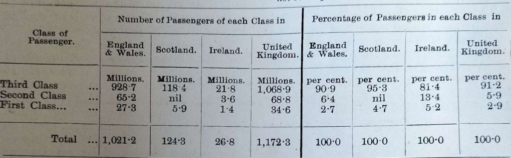
On the EIR, 1st and 2nd class passengers taken together only provided 7% of the passenger income in 1905. 3rd class passengers provided over 70% of the EIR’s income and we’re therefore “all important to the railway, and it is to assist him and to make his journeys as comfortable and pleasant as possible that the efforts of the management [were] mainly directed.” [1: p482]
After the turn of the 20th century, the EIR was carrying more than 20 million 3rd class passengers each year. A significant proportion of these rail users are pilgrims travelling to holy shrines and particularly to/from the sacred River Ganges.
Huddleston comments on the fares paid by 3rd class travellers: The Anna is the equivalent of 1d and there are 12 Pies in one Anna. “The third class fare [was] 2.5 Pies per mile for the first 100 miles, with a still lower rate for distances beyond. … The third class fare [was] considerably below a farthing a mile. If [EIR] fares were charged in England a trip from London to Brighton would [have] cost about 10d., and a journey from London to Edinburgh could [have been] made for about 8s. 6d.” [1: p485]
In 1905, the standard fare for third class rail travel in the UK was 1d per mile, and first class fares were usually 1.5–2 times that. Fares were based on distance traveled, and the shortest route between two places was used to calculate the price. For example, if there were multiple routes between London and Edinburgh, the price for all routes would be based on the shortest route. [3]
Making the assumption that the distance between London and Edinburgh by rail is/was 332 miles then a 3rd class ticket from London to Edinburgh would have cost £1 7s 8d. Rail travel on the EIR was around 30% of that in the UK at the time.
We have noted the importance of 3rd class passengers to the finances of the EIR. Huddleston tells us that, “Still more important [were] the goods and minerals carried, for these contribute[d] nearly 70 per cent of the gross earnings. During the year 1904, the weight of coal and general merchandise transported over the East Indian Railway system amounted to considerably more than 12,000,000 tons, the average distance carried being more than 200 miles, the average freight charged being less than a halfpenny per ton mile in the case of ordinary merchandise, and a fraction over a farthing per ton mile in the case of coal.” [1: p485]
The EIR provides the main means of access to the coalfields of Bengal, from which it carried more than 6,000,000 tons of coal annually. “This traffic, of which a large proportion [was] exported from Calcutta, [had], by cheap rates and by the opening up of new and important coal- producing areas, been enormously developed during the [past] ten years, and [was] still continu[ing] to grow. At the time the construction of the East Indian Railway was started, coal was almost unknown in India, and India’s requirements, which were practically confined to its ports, were met by Cardiff. [After the turn of the 20th century] hardly any English coal [was] sent to India. … and Bengal claim[ed] that it [could] supply all requirements east of Suez.” [1: p485]
In addition to the coal traffic, the EIR also transported “large quantities of wheat, seeds, grain, cotton, salt, and other articles of general merchandise, and in order to enable it to make a profit out of the very low rates charged [paid] great attention to the question of train and wagon loads. The greatest importance [was] attached to traffic statistics. A system of accurately recording ton and passenger unit mileage, together with such other statistics as [were] necessary to judge of work done on a railway, was introduced in India [in the second half of the 19th century. These statistics were] placed each week before the officers concerned in the management of the traffic, so that they [were] continually kept acquainted with its essential features and [were] in a position to watch progress and to remedy defects without loss of time.” [1: p485]
“Since 1872, the average train load on the EIR … increased from a little over 100 tons to more than 275 tons in 1904. … The Indian figures [were] far beyond those on the best worked lines in England.” [1: p485-486]
The EIR uses only its own wagons for the carriage of domestic freight. “The standard of work for each wagon on the line [was] laid down at 75,000 ton miles per half year, and this figure [was] often exceeded. … The average cost of coal consumed on the [EIR was] less than 2s. 8d. per ton. … There [were] … other reasons besides a cheap fuel supply for the great economy in working which the statistics show; labour, for instance, [was] very cheap compared with European standards, and this tend[ed] to keep down the cost of maintenance and the cost of staff generally. But beyond all this the attention paid to detail [was] remarkable. Competition exist[ed], especially between the railway systems serving the rival ports of Bombay and Calcutta, and [that called] for a close watch on every ton of traffic, each fluctuation requiring explanation. The wagon supply, as already indicated, being on a low scale, necessitate[d] every vehicle being looked after; the movements of each wagon [were] known, in fact, from day to day. Train mileage, shunting mileage and detention mileage [were] kept as low as possible, the figures for each section of the line being closely scrutinised every week.” [1: p486-487]
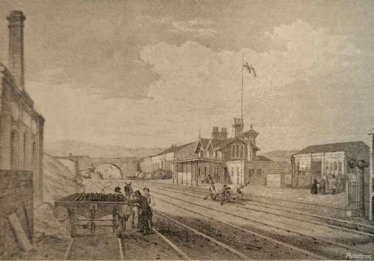
Huddleston then goes on to describe travel for European expats on the EIR Punjab mail train from Calcutta (Kolkata] to Delhi, in 1st class naturally! …
“Suppose yourself, in the month of December, to be a first-class passenger by the Punjab mail train from Calcutta to Delhi; after having taken your ticket, and booked your luggage and a berth at a cost of considerably less than a £5 note, which, by the way, will also cover your return journey if you take a Christmas holiday concession ticket available for a month, you will enter the train at half-past nine in the evening, and your servant will at once make your bed. During the night you will pass through part of the coalfields of Bengal, and travelling along the Chord, or present main line, find yourself at about 6.15 a.m. at Dinapore, 344 miles from Calcutta. Dinapore is a military cantonment, and is the first place on the line from Calcutta at which troops are stationed. Here you will be served with what is called ‘chotahaziri’, or, literally translated, ‘little breakfast’; this usually consists of tea and toast, and is ordinarily taken in India the first thing in the morning.” [1: p487]
“Leaving Dinapore, after a halt of ten minutes, you will dress at your ease, assisted by your servant, who will afterwards roll up your bedding, and leave you to your newspaper and cigarette until half-past nine, when the trin arrives at the important junction of Moghalsarai, a few miles from Benares, the sacred city of the Hindoos. At Moghalsarsi, during a halt of twenty-five minutes, you will proceed to the refreshment room to breakfast, which consists of several courses and coats two shillings. Leaving Moghalsarai, the train passes the old fort of Chunar, now abandoned by the military, but once an important stonghold. Shortly afterwards the city of Mirzapur, famous for its hand made carpets and its brass and metal ware, is passed. The shrines and temples along the banks of the Ganges, on which Mirzapore is situated, are well worth seeing,because of their beautifully carved stone-work. … The train runs on to Allahabad, large civil and military cantonment, in time for luncheon, and the next station of importance is Cawnpore, notorious on account of the massacre of Europeans there during the Mutiny of 1857. Cawnpore is now the junction with several railway systems and a very important centre of trade, with numerous mills and factories; woollen mills, cotton mills, leather works, sugar factories and flour mills are to be found in greater number in Cawnpore than in any other up-country station in India. During the fifteen minutes the train stays there you have afternoon tea, and shortly afterwards, or at about 7 p.m., there is a halt of 30 minutes for dinner. Dinner in India is the big meal of the day, and costs at the railway refreshment room 2s. 8d. – not a very extravagant sum for a substantial meal of at least five courses.” [1: p488]
“The junction for Agra, which, by the way, is on a branch line and 14 miles distant from the main line, is passed shortly after 9 p.m., and Delhi is reached at 1.30 in the morning. Rather an awkward hour at which to alight, but through trains cannot be timed to reach everywhere at convenient hours, and your train has still a long way to go. Delhi is naturally one of the most interesting places in the East; it is a large fortified city on the west bank of the River Jumna, and was, at the time of the Moghal dynasty, the capital of India. … Your journey of 954 miles from Calcutta will have taken you little more than 28 and 1/2 hours and when it is remembered that, in addition to shorter halts, there have been three long stoppages for breakfast, lunch, and dinner, that about half the distance has been over single line, and that the load of the train equal to 18 heavy coaches, the running a is time is by no means bad. … Throughout your journey you will have seen many objects of interest, and will have gained some idea of the extent of our great Eastern dependency. You will have noticed the hundreds of miles of cultivated plain through which your train has passed; great seas of rice, wheat, seeds and other grains and cereals, broken only by villages and trees, without a hedgerow or a single field of grass. You will have crossed some great rivers, among them the Keul, the Soane and the Jumna – the latter at two points, the first at Allahabad, where it runs into the Ganges, the second at Delhi. You will have found throughout a perfect climate, getting colder as you proceed to the north, but always bright, with sunshine every hour of the day. You will have observed great crowds of natives of all creeds and caste, Hindoos and Mahommedans predominating. You will have seen camels, bullock-carts, and other means of transport used by the natives, and, above all, you will have experienced the glorious fascination of the East, which is beyond description.” [1: p488]
Huddleston completes his article in the December 1905 issue of The Railway Magazine at this point with a promise of more articles in future editions of the journal.
We return to Kolkata and attempt to follow the same journey to Delhi over a century later.
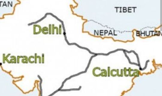
The Route of the East Indian Railway (EIR) from Kolkata to Delhi.
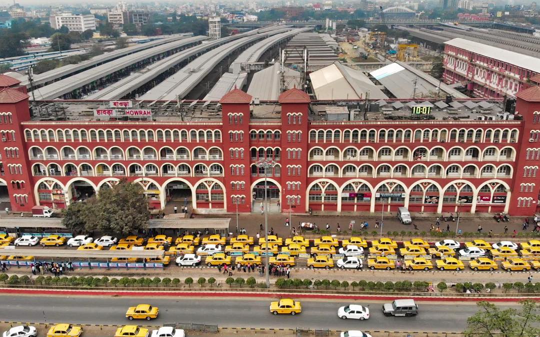
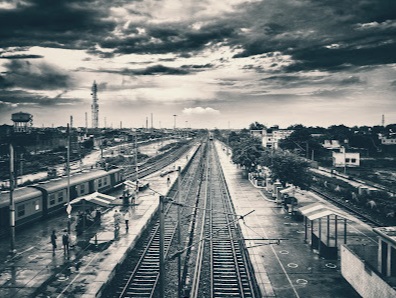
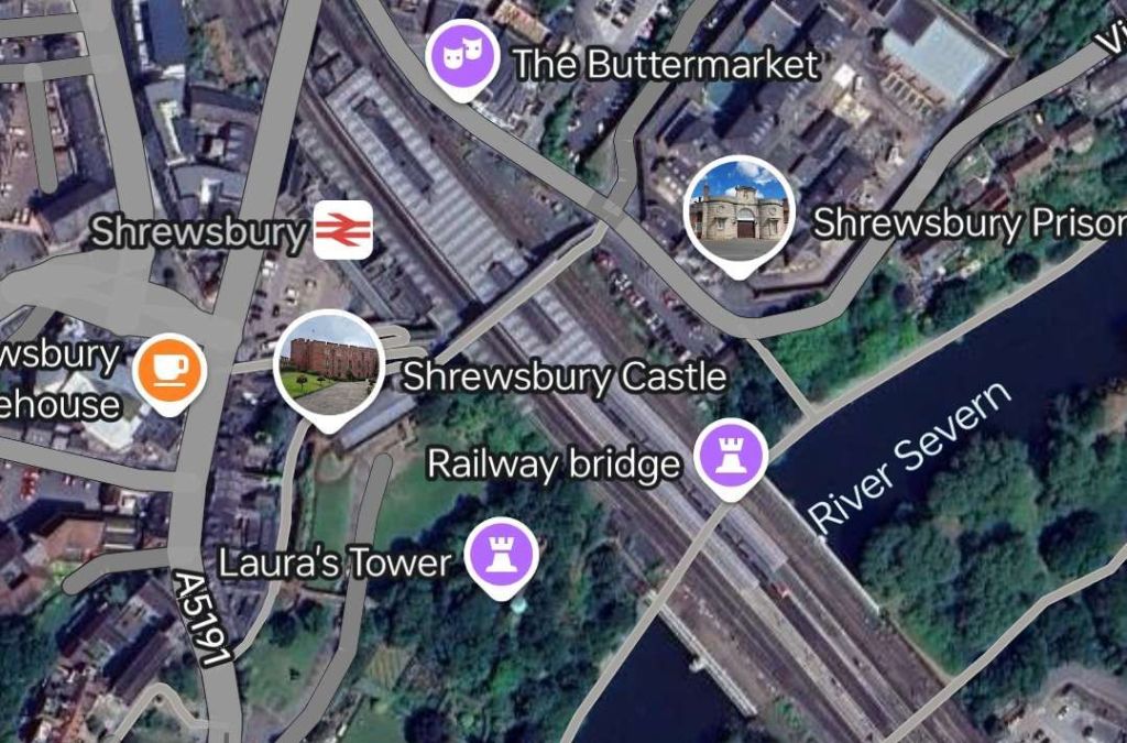
Making a journey from Kolkata West-northwest towards Delhi, we start at Howrah Railway Station on the banks of the River Hooghly. Distances are so vast that it would be impossible to follow every mile of the line. Hopefully what follows gives a good flavour of the line.
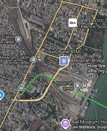
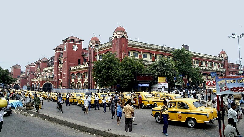
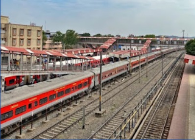
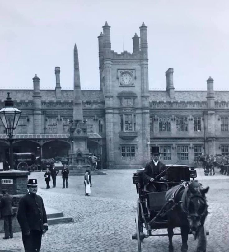
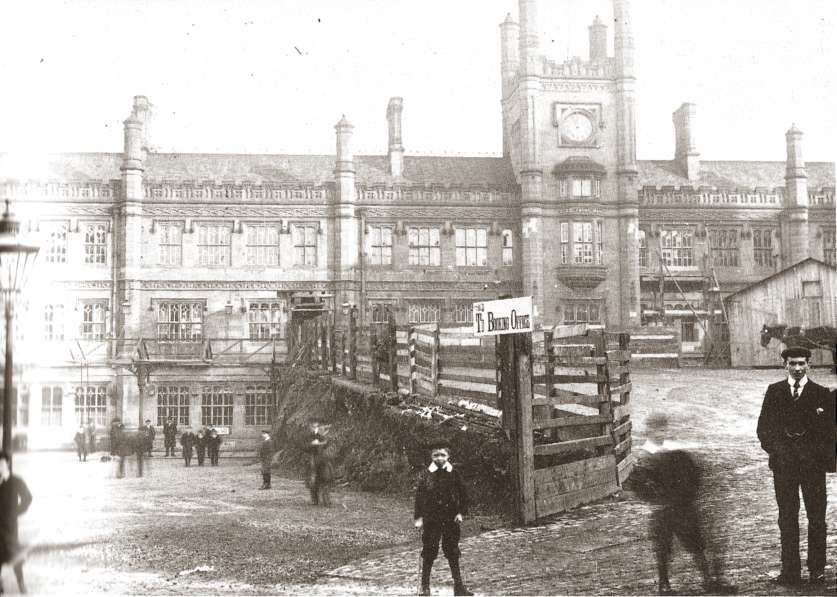
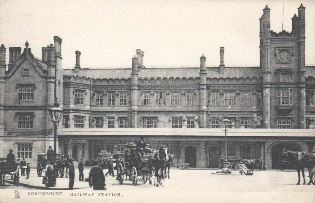
Howrah railway station (also known as Howrah Junction) is a railway station located in the city of Howrah, West Bengal in Kolkata metropolitan region. “It is the largest and busiest railway complex in India as well as one of the busiest and largest train stations in the world. It is also the oldest surviving railway complex in India. Howrah is one of the five large intercity railway stations serving the Kolkata metropolitan area, the others being Sealdah, Santragachi, Shalimar and Kolkata railway station.” [8]
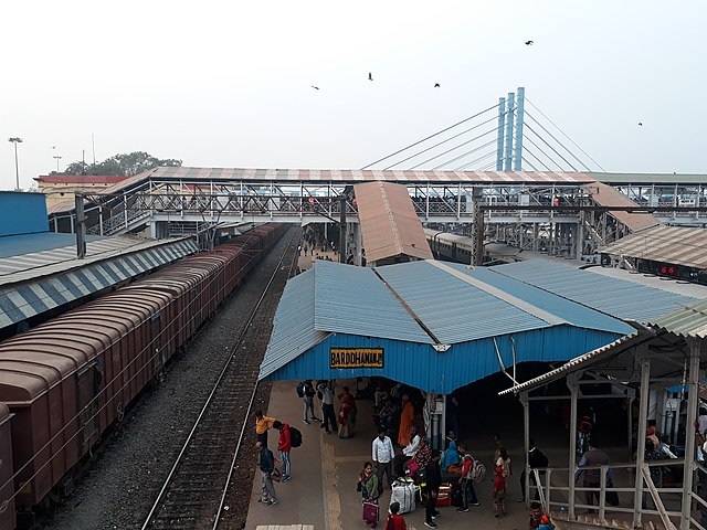
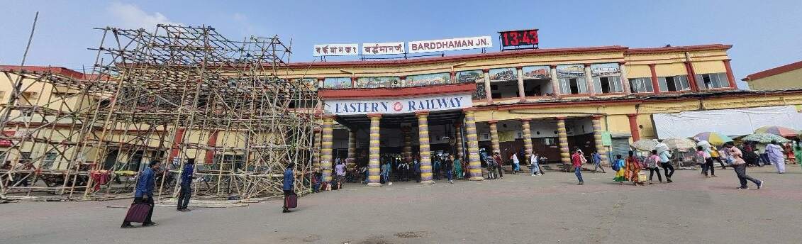
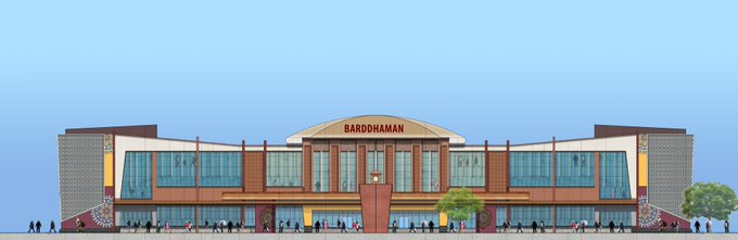
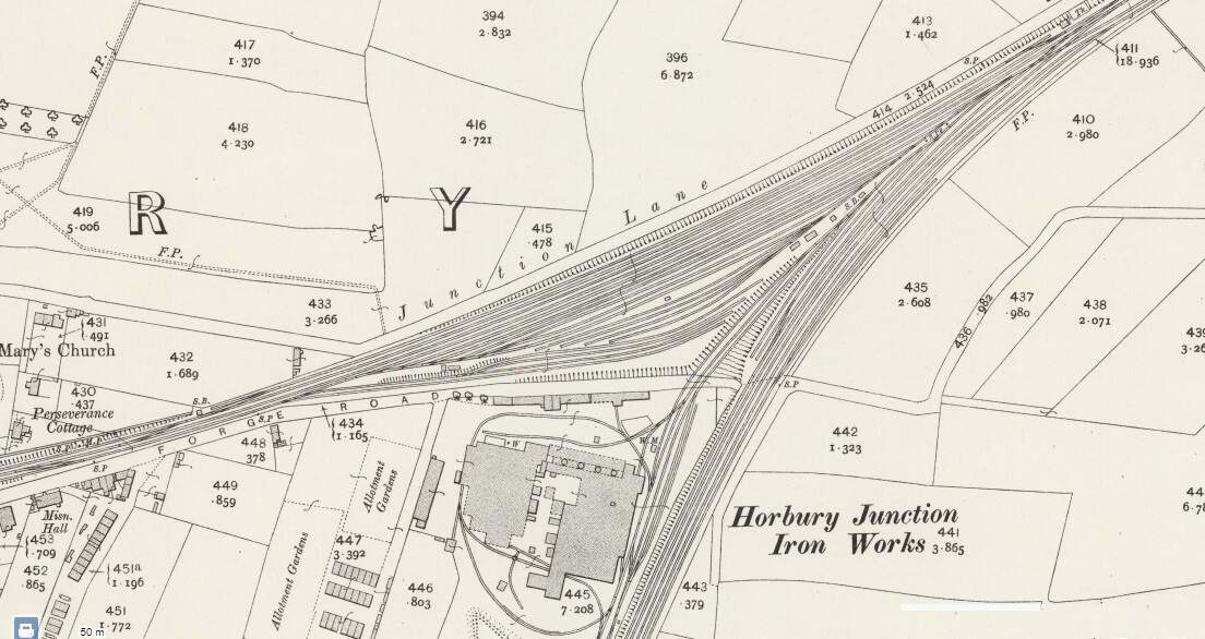
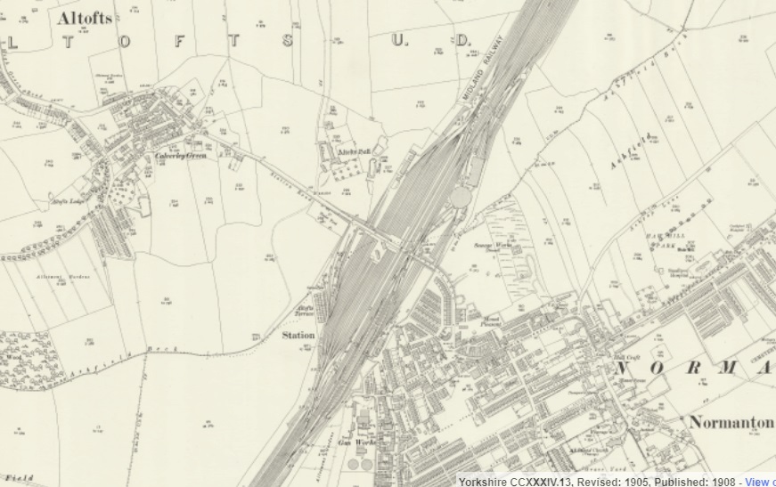
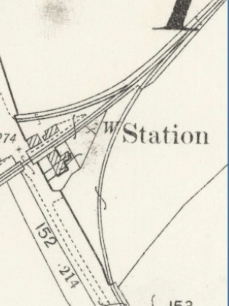
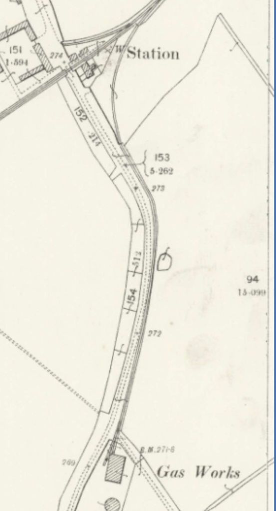
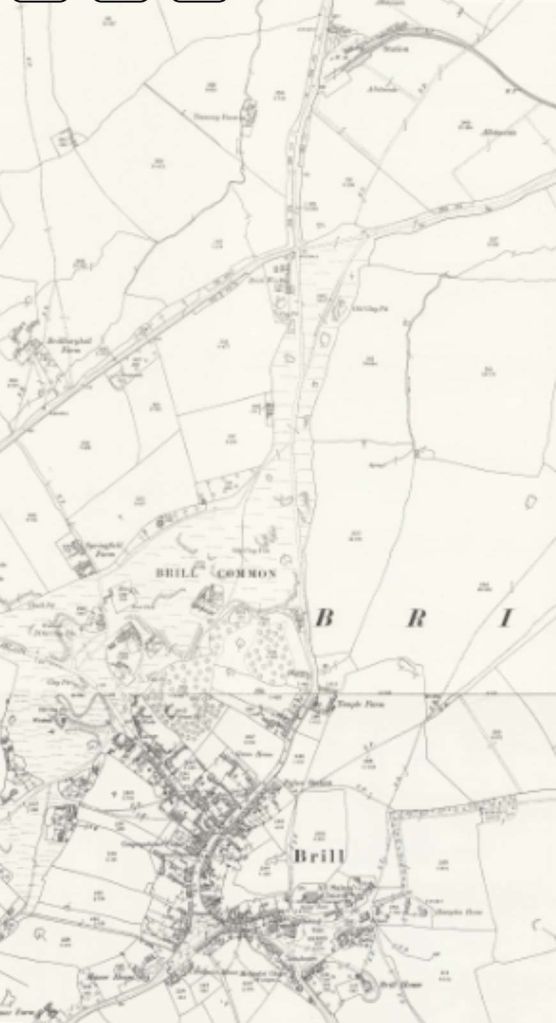
The first significant conurbation outside Kolkata is Barddhaman.

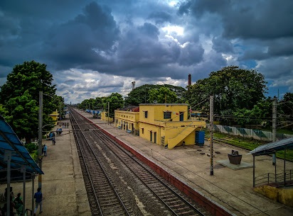
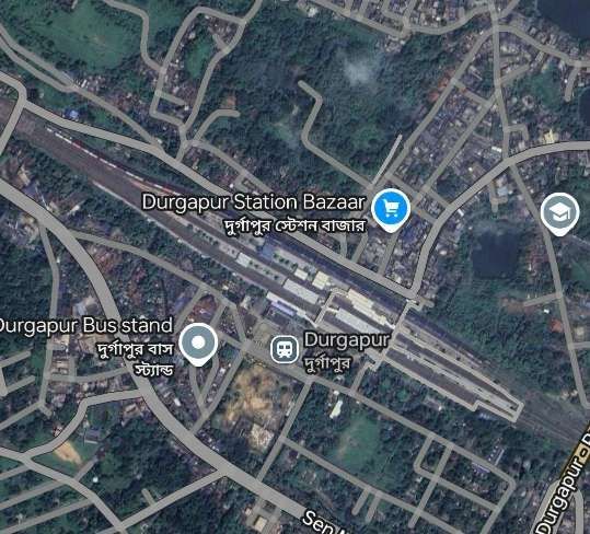
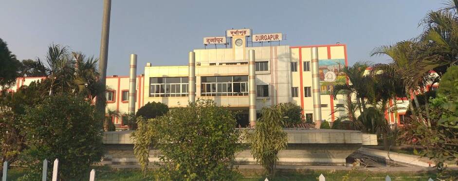
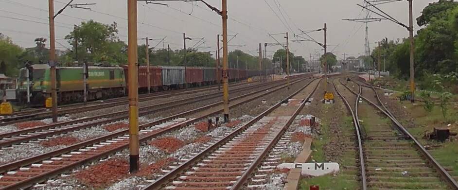
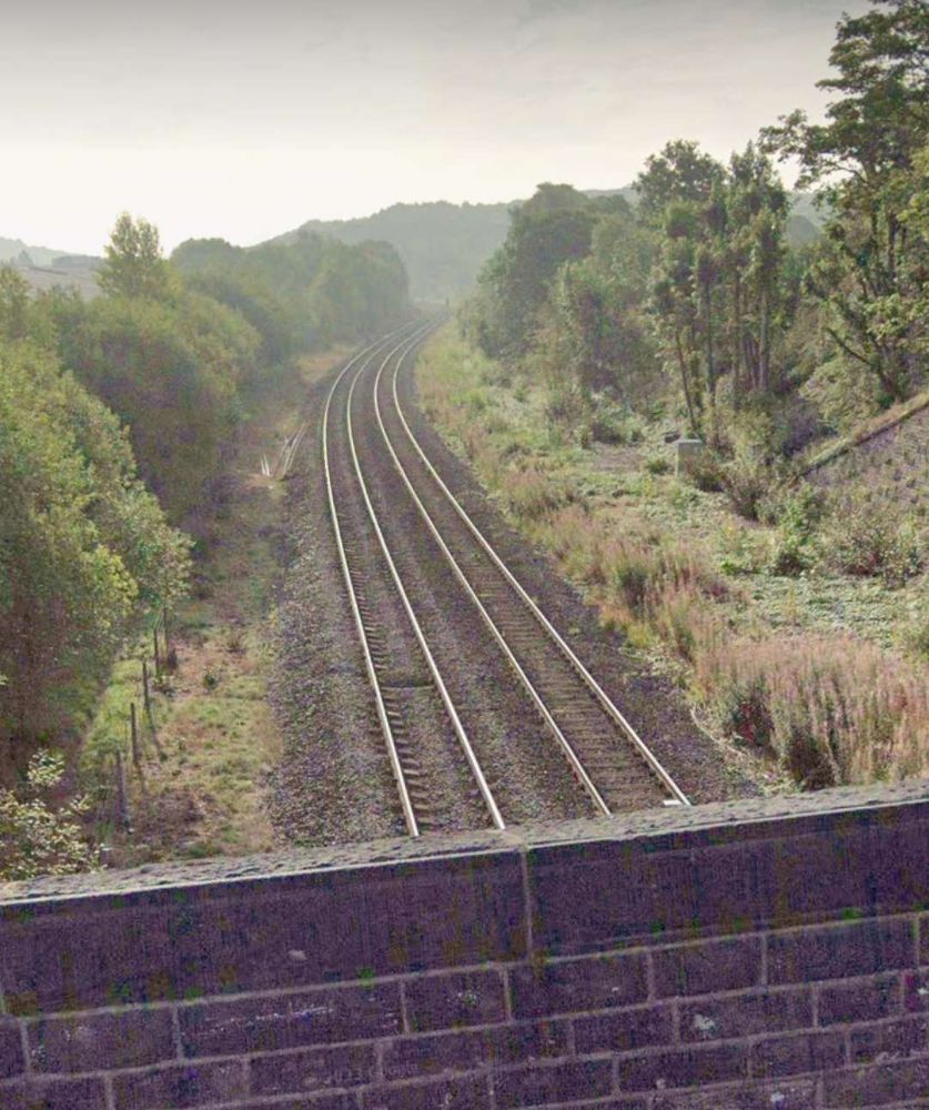
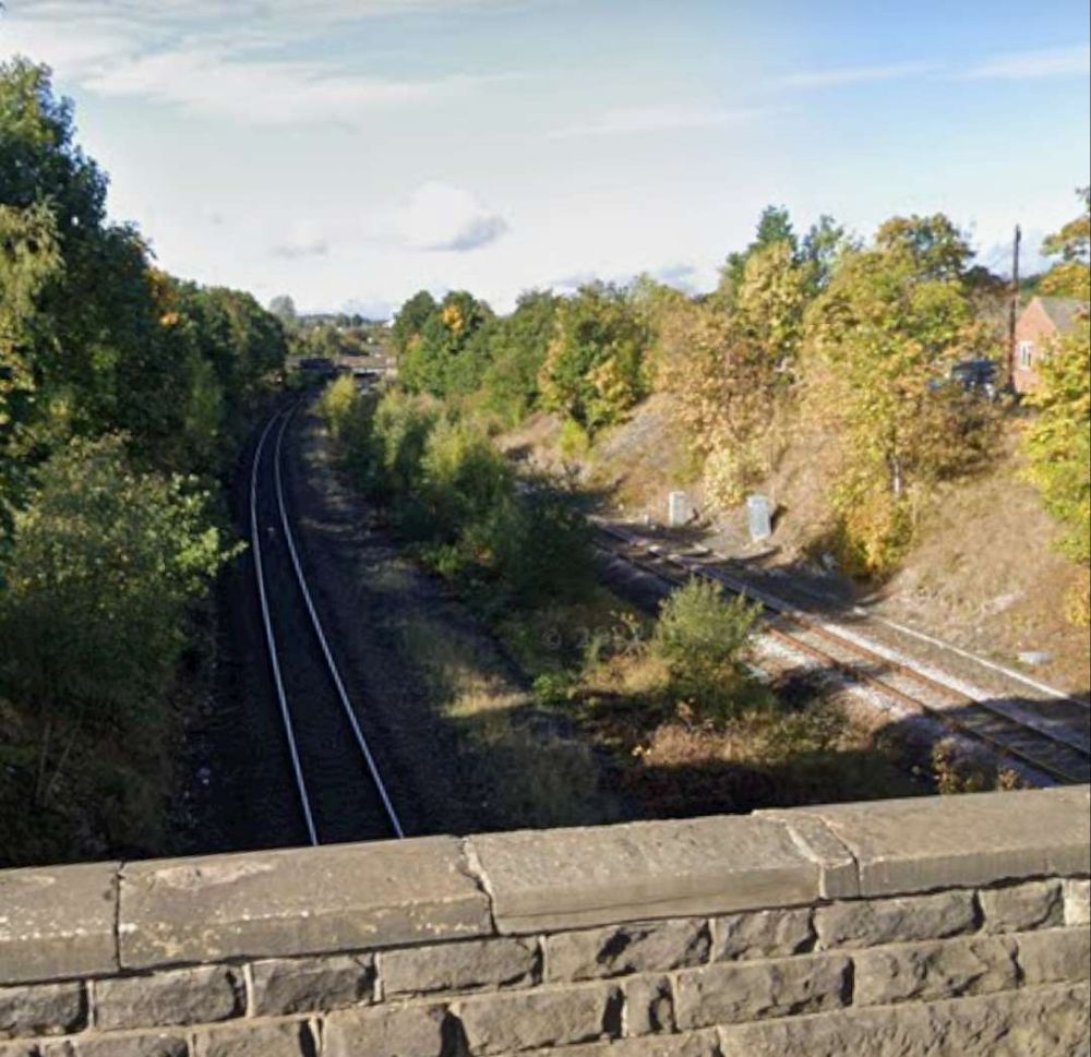
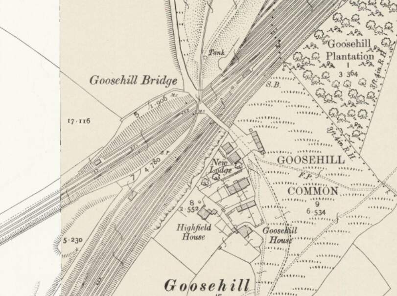
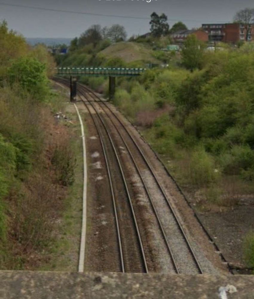
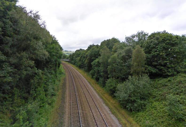
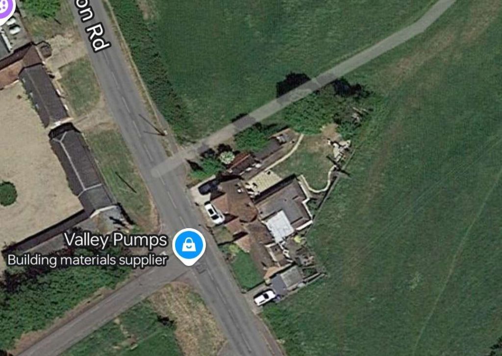
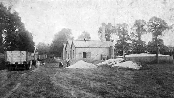
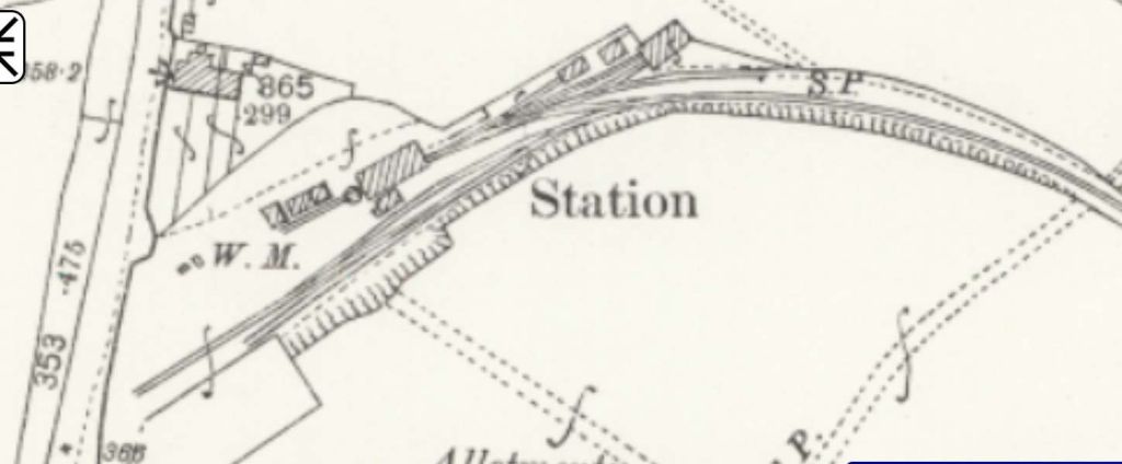
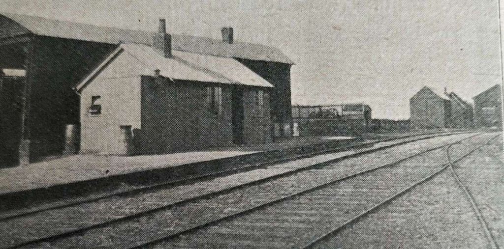
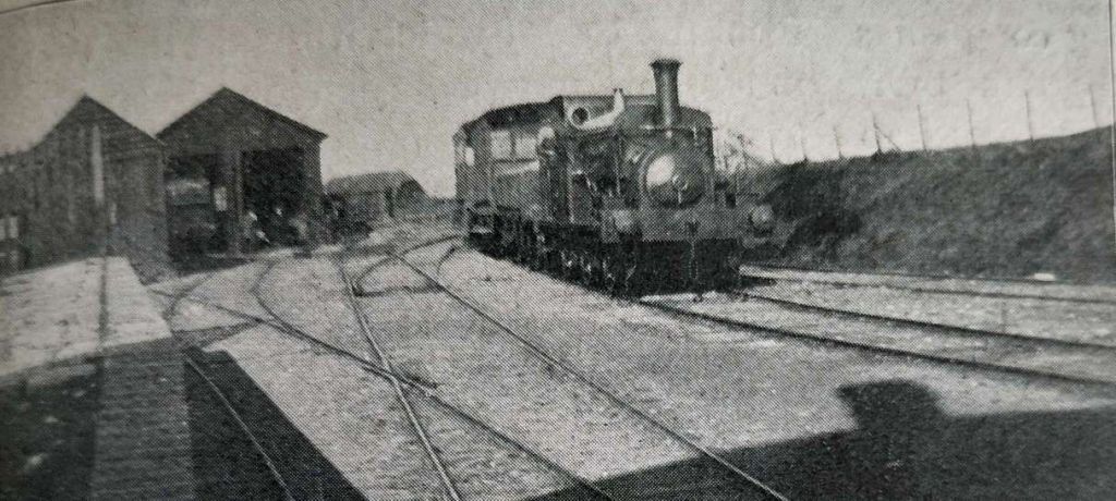
Our next scheduled stop is at Durgapur but on the way we pass through a number of local stations. Just one example is Mankar Railway Station.
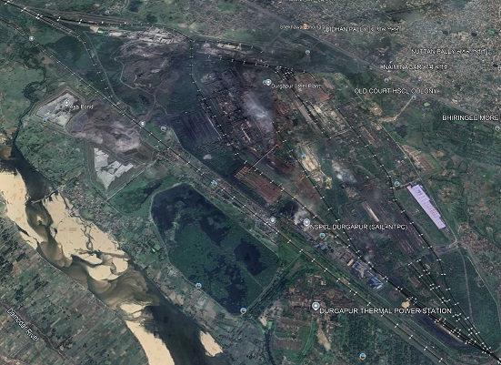
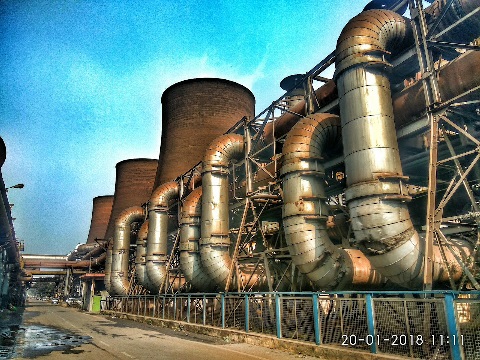
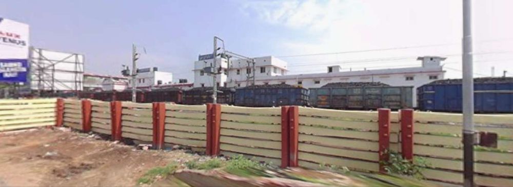
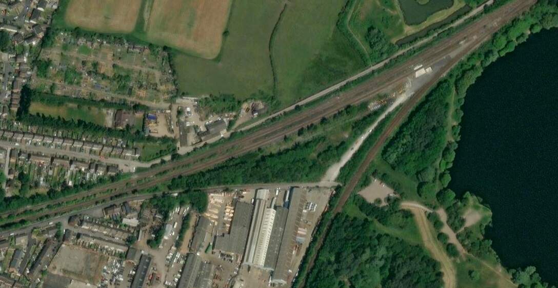
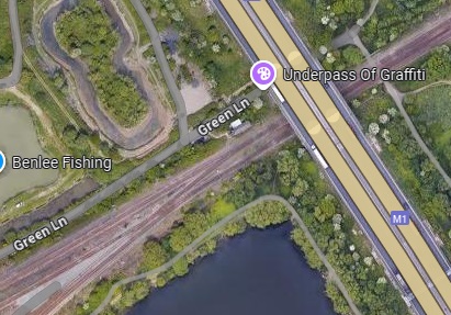
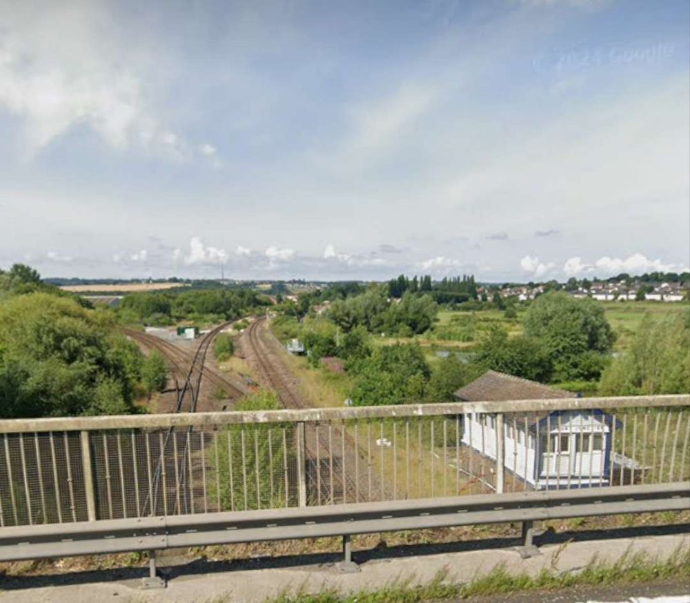
Beyond Durgapur is a very significant steelworks and power station.
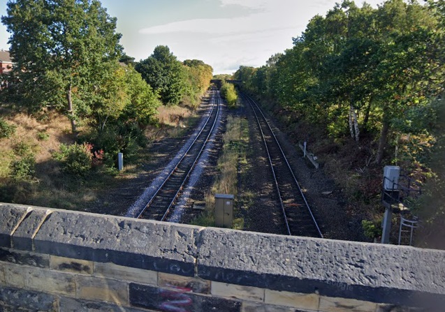
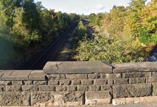
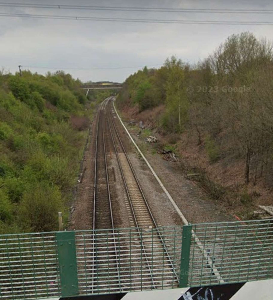
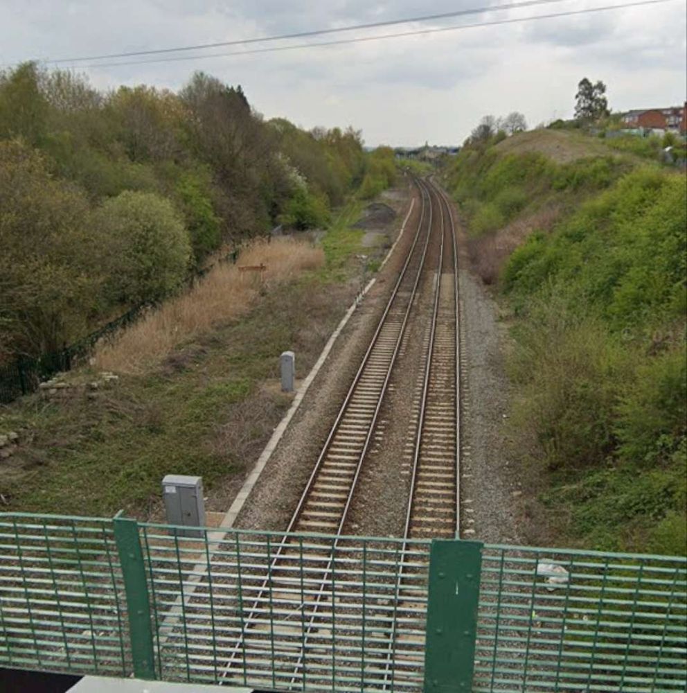
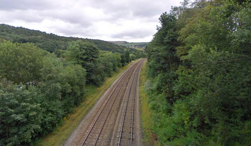
Just a couple of stations en-route to Asansol, our next stop, are shown below.
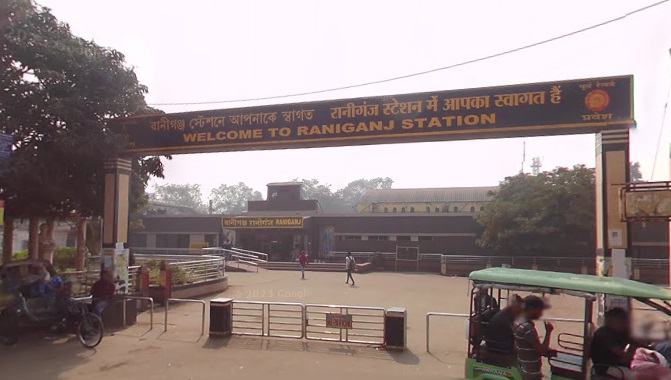
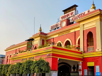
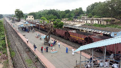
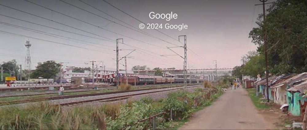
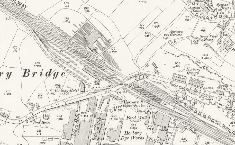
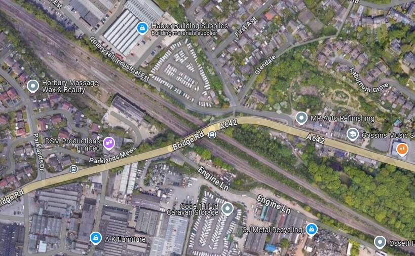
We arrive at Asansol Railway Station. …
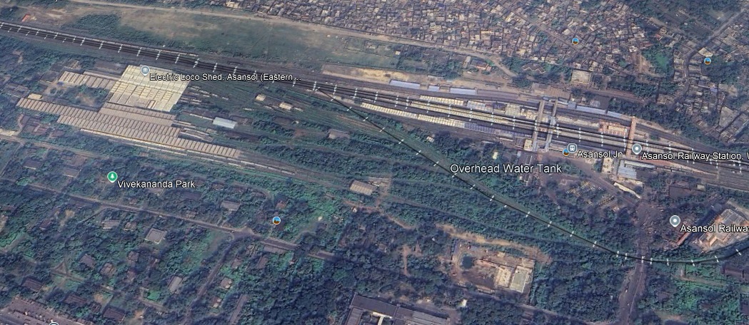
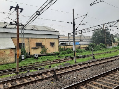
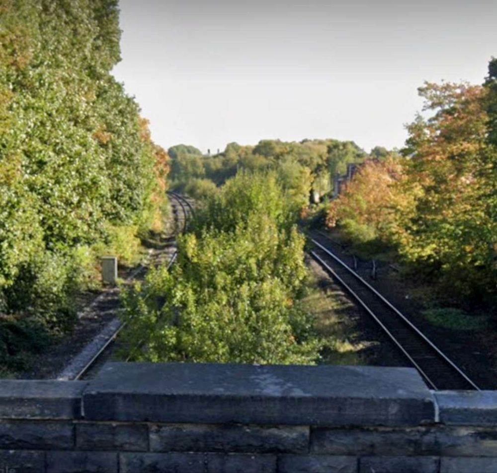
Continuing on from Asansol we pass through Sitarampur and Kulti.
And on through Barakar before leaving West Bengal and entering Jharkhand and crossing the Barakar River.
West of the Barakar River we travel on through Kumardubi, Mugma, Thapar Nagar, Kalubathan, and Chhota Ambana.
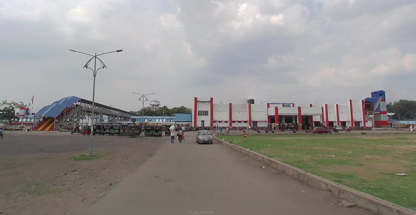
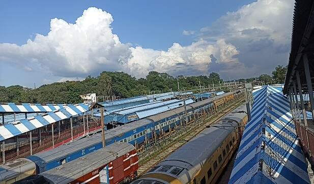
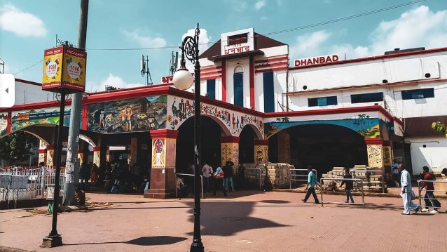
The journey continues through Pradhankhunta Junction and Dokra Halt before arriving at the next significant conurbation, Dhanbad.
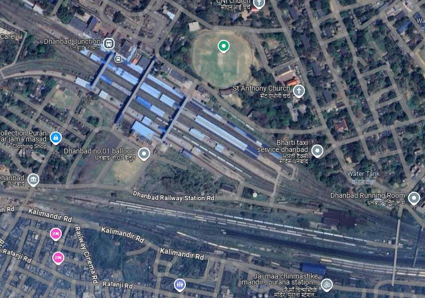
From Dhanbad Railway Station, the EIR ran on through Bhuli to Tetulmari.
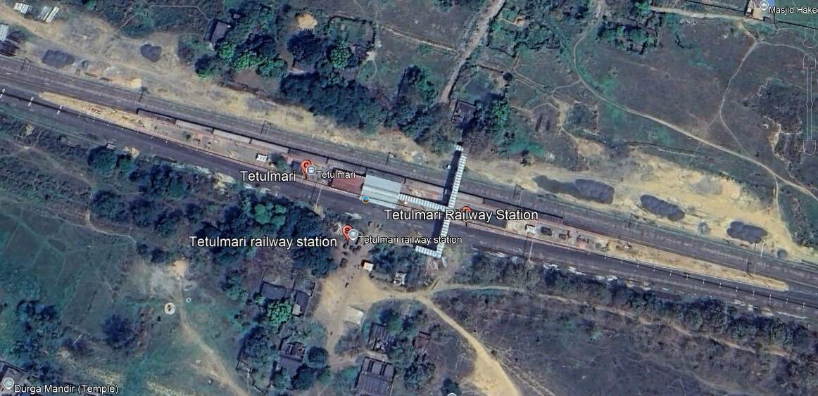
And on from Tetulmari through Nichitpur, Matari and Ramakunda Halt to Gomoh Junction.
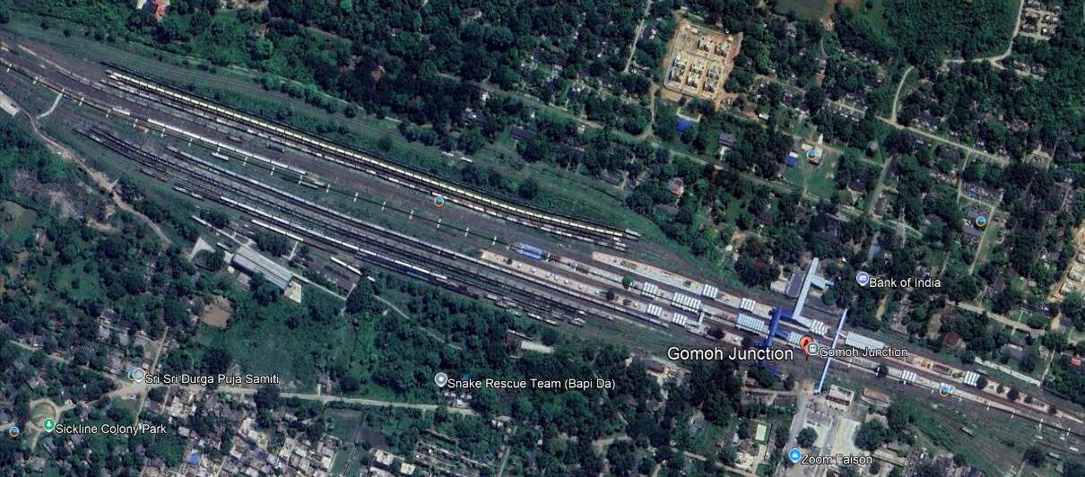
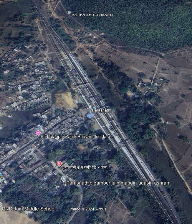
From Gomoh Junction Railway Station the line continued Northwest through Bholidih and Nimiaghat to Parasnath Railway Station.
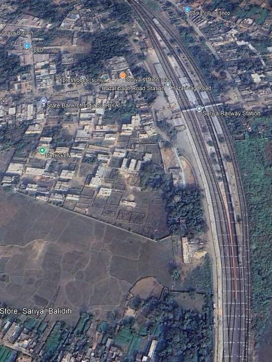
rom Parasnath the line continued Northwest through Chaudhribandh, Chichaki, Garea Bihar to Suriya Railway Station (Hazaribag Road Station).
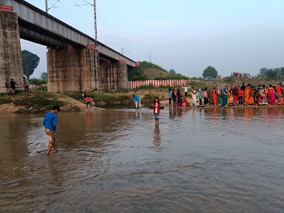
From Suriya we travel on across the Kheruwa River Railway Bridge and the Barsoti River Bridge, through Chaube and Dasara Railway Stations, over the Banka Railway Bridge and through Parsabad Railway Station before crossing the Acto River Bridge and entering Sarmatanr Railway Station.
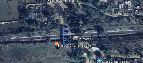
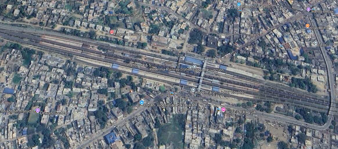
The line continues West from Sarmatanr through Hirodih Railway Station and into Koderma Junction Railway Station.
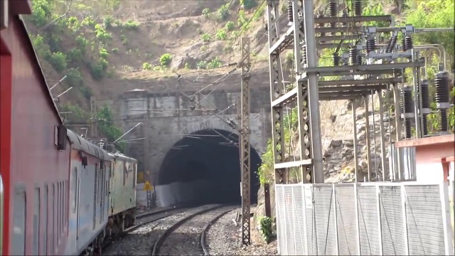
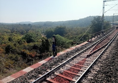
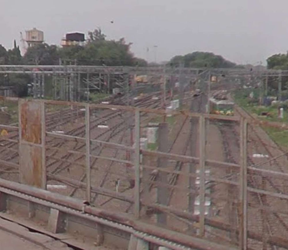
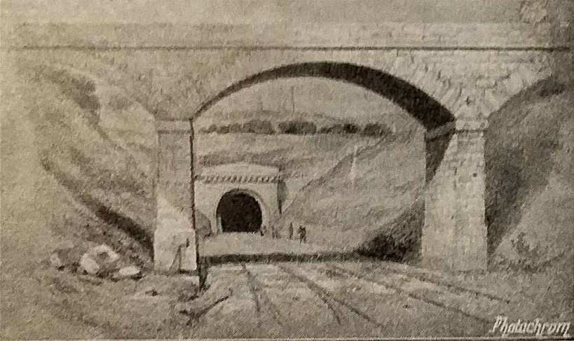
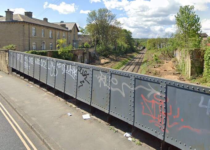
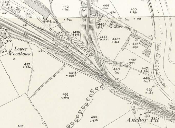
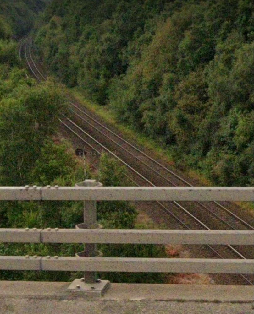
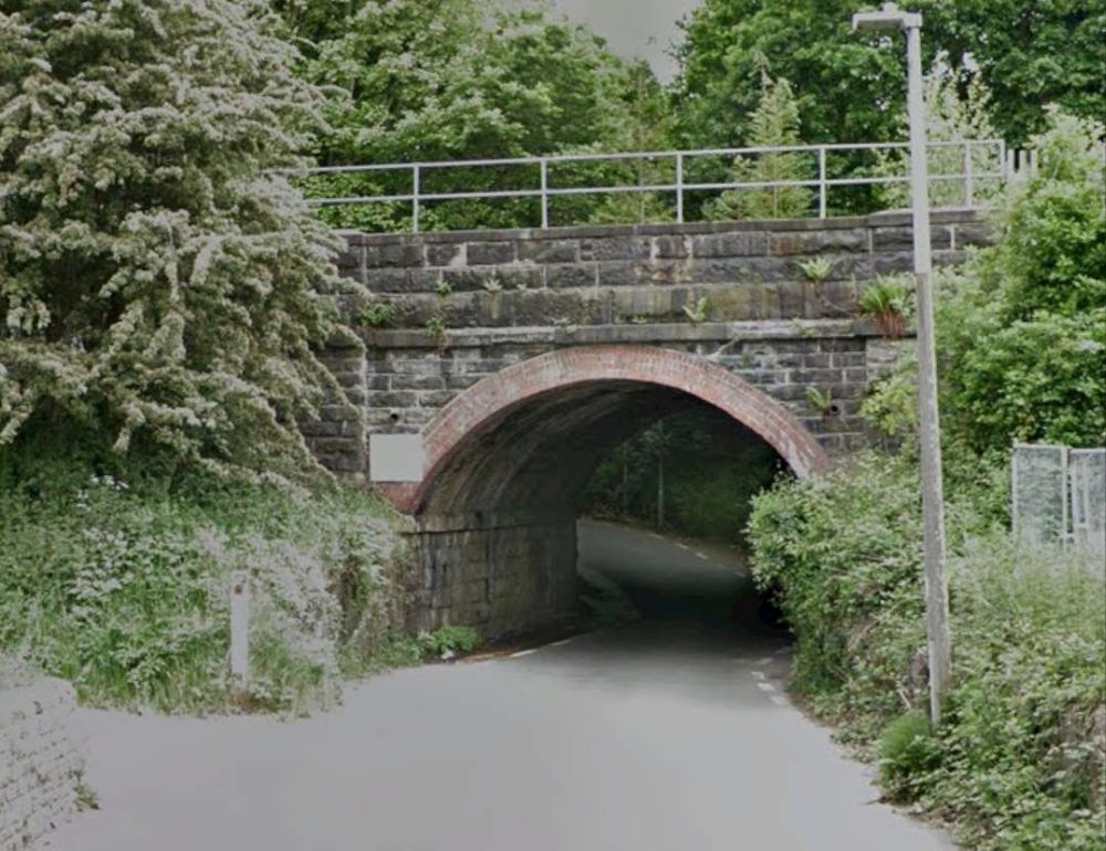
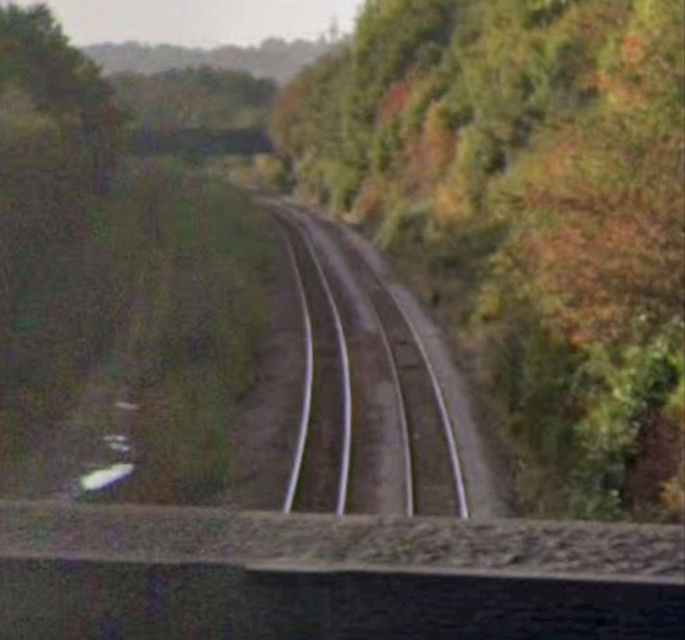
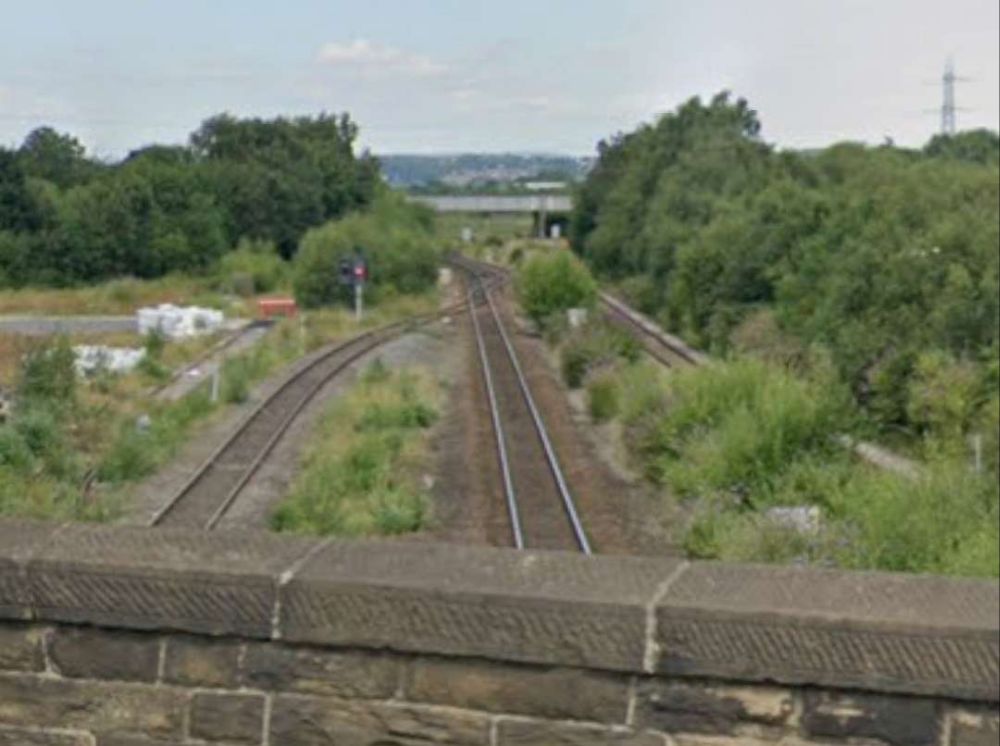
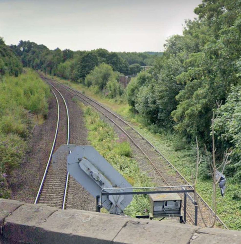
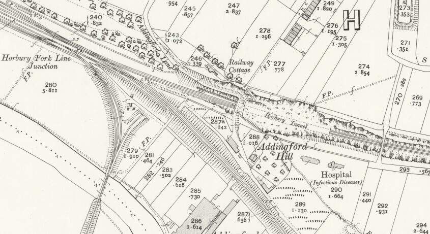
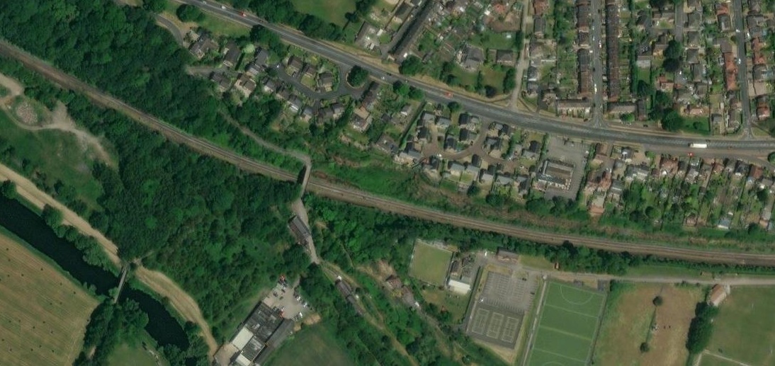
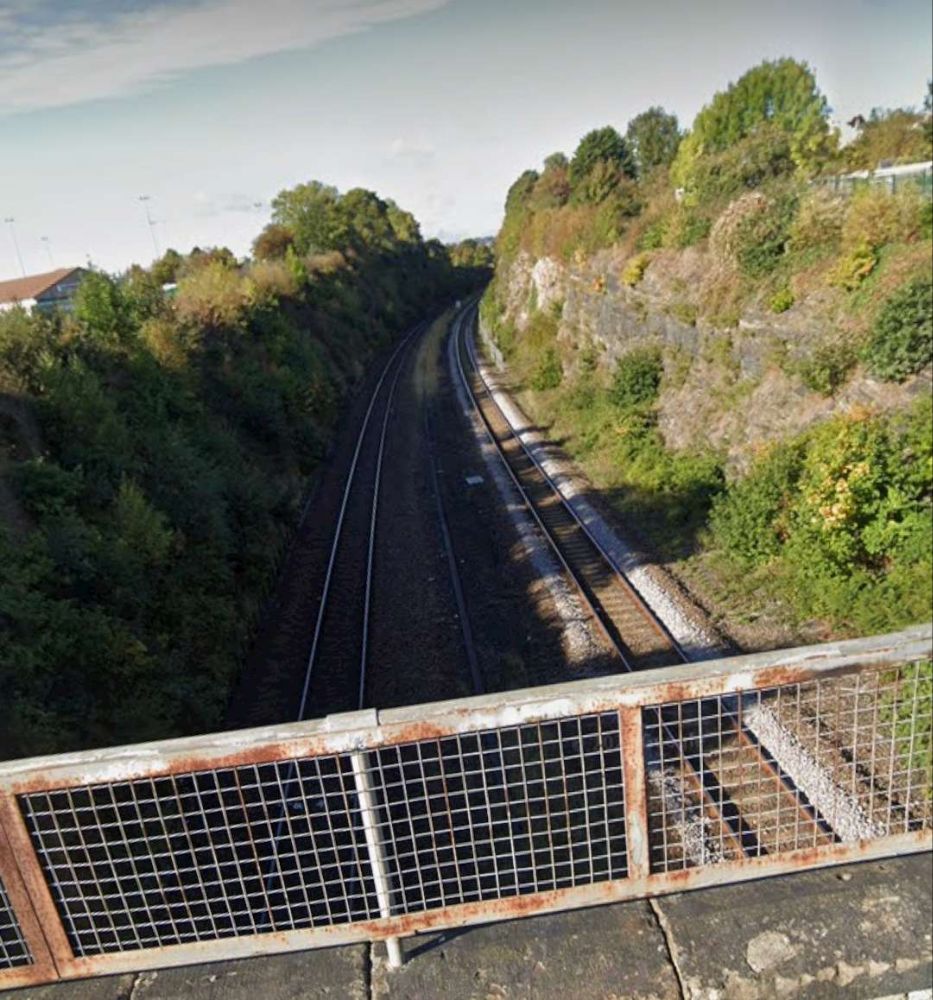
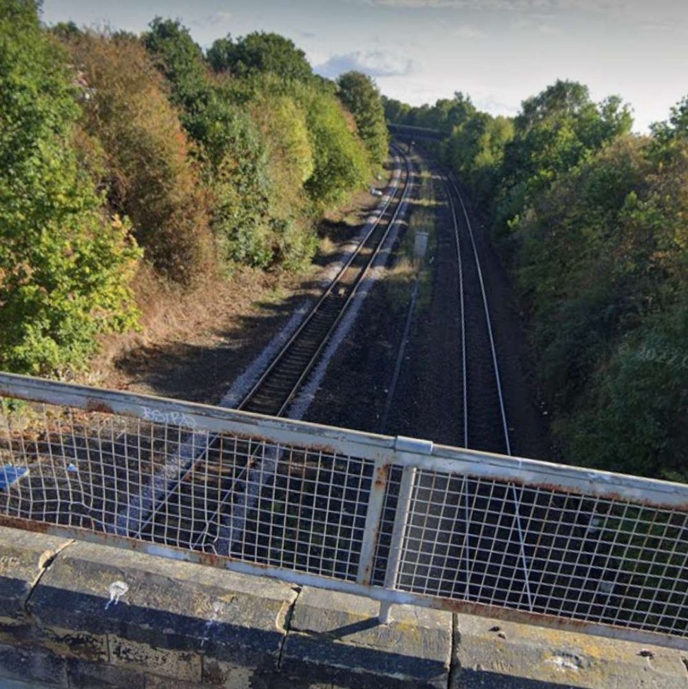
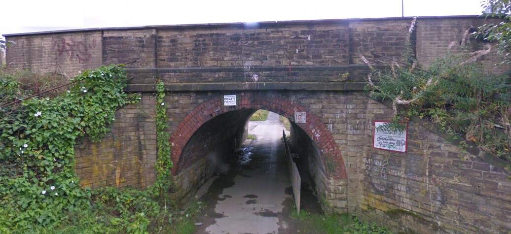
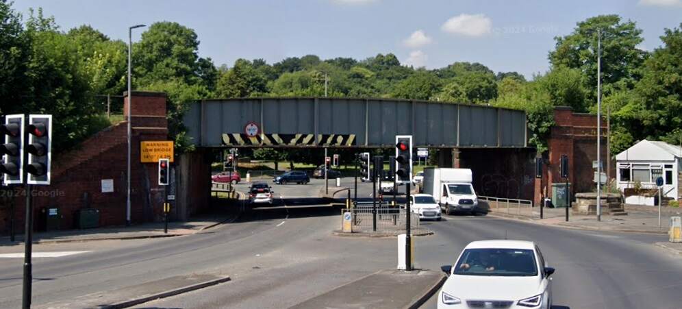
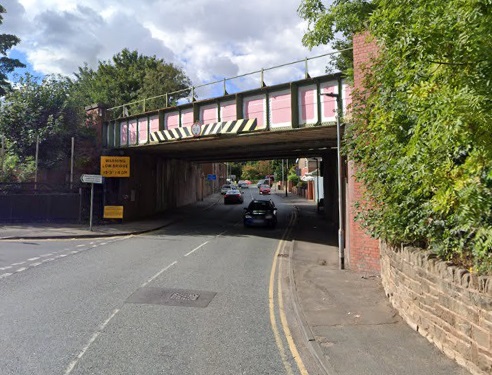
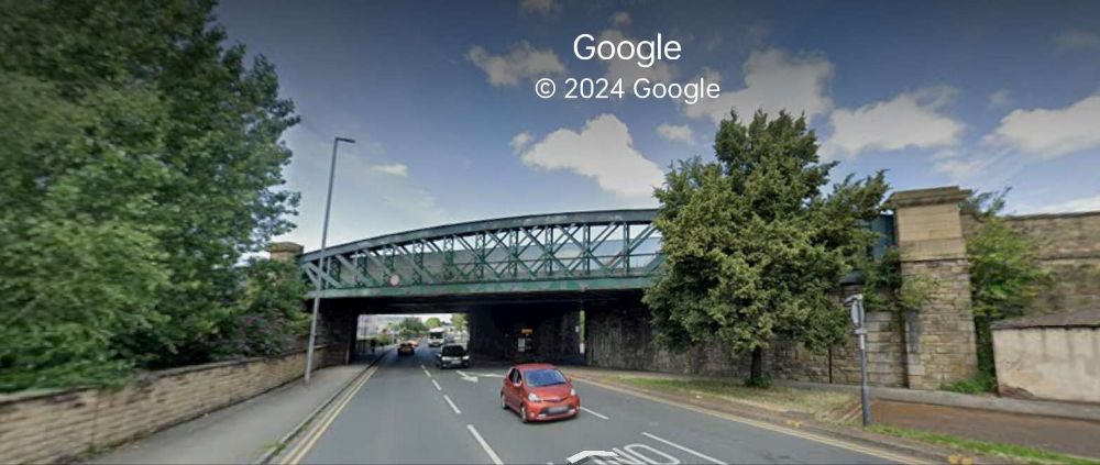
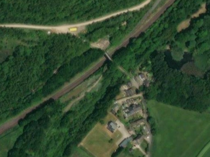
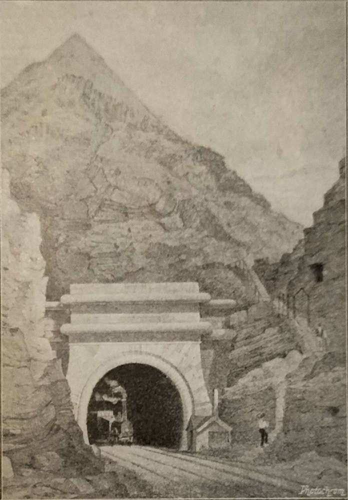
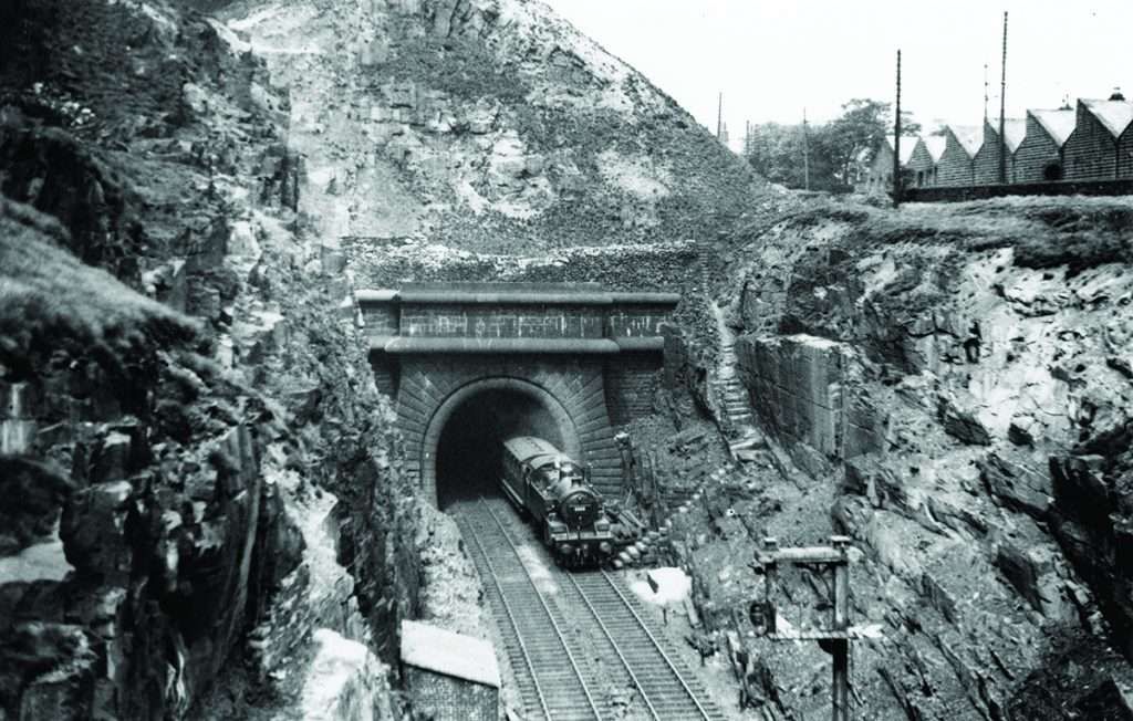
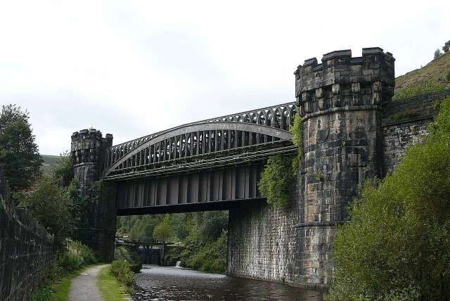
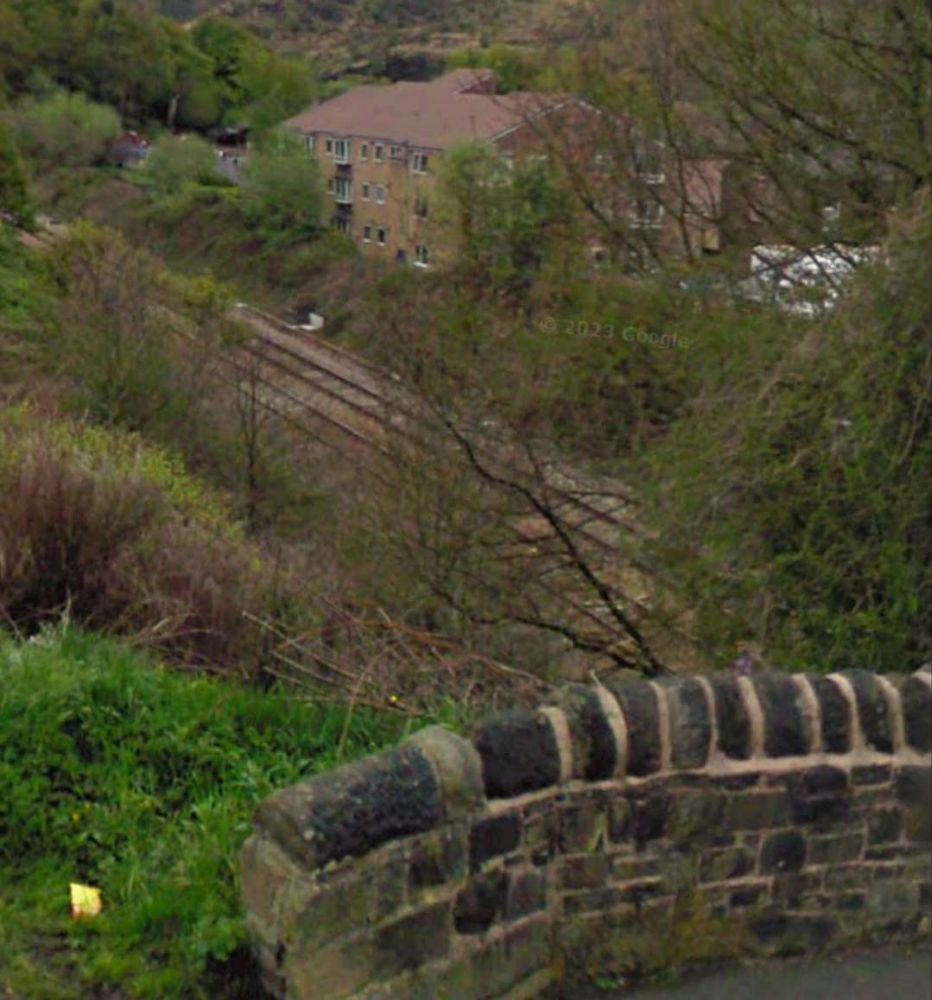
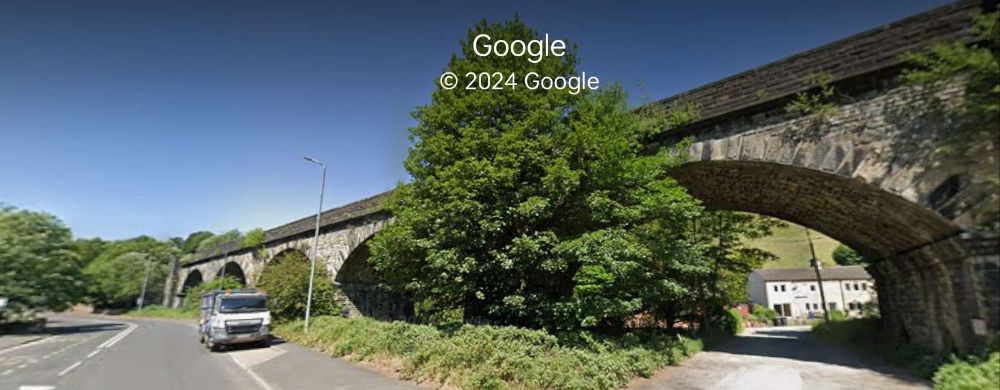
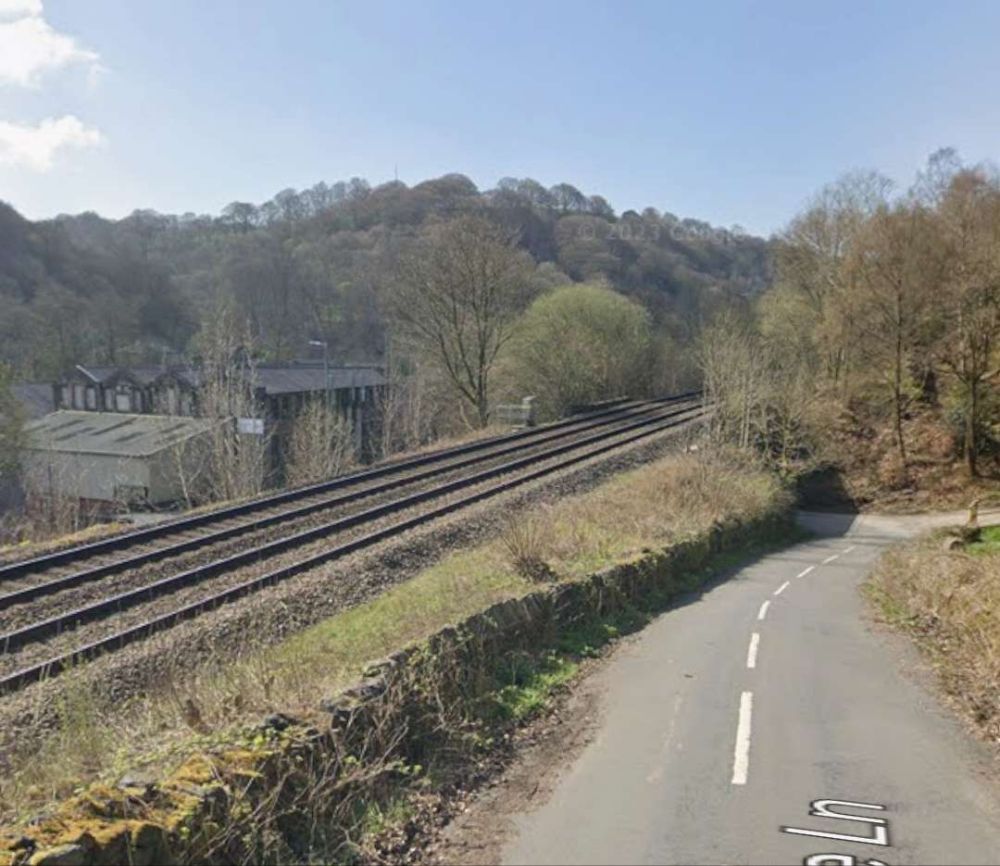
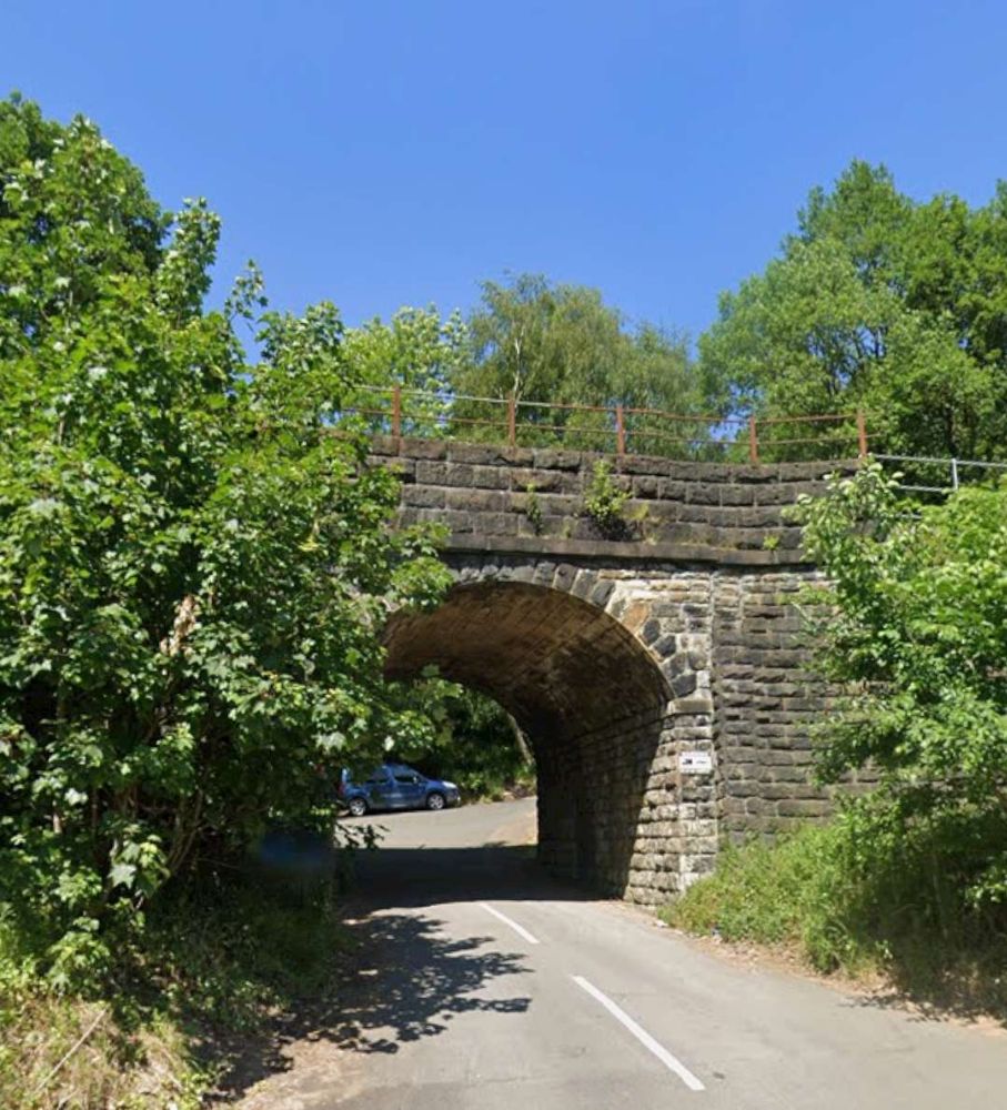
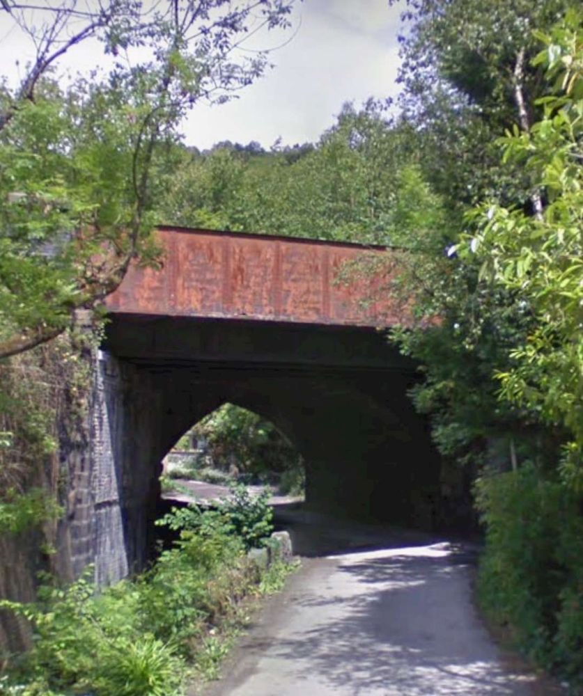
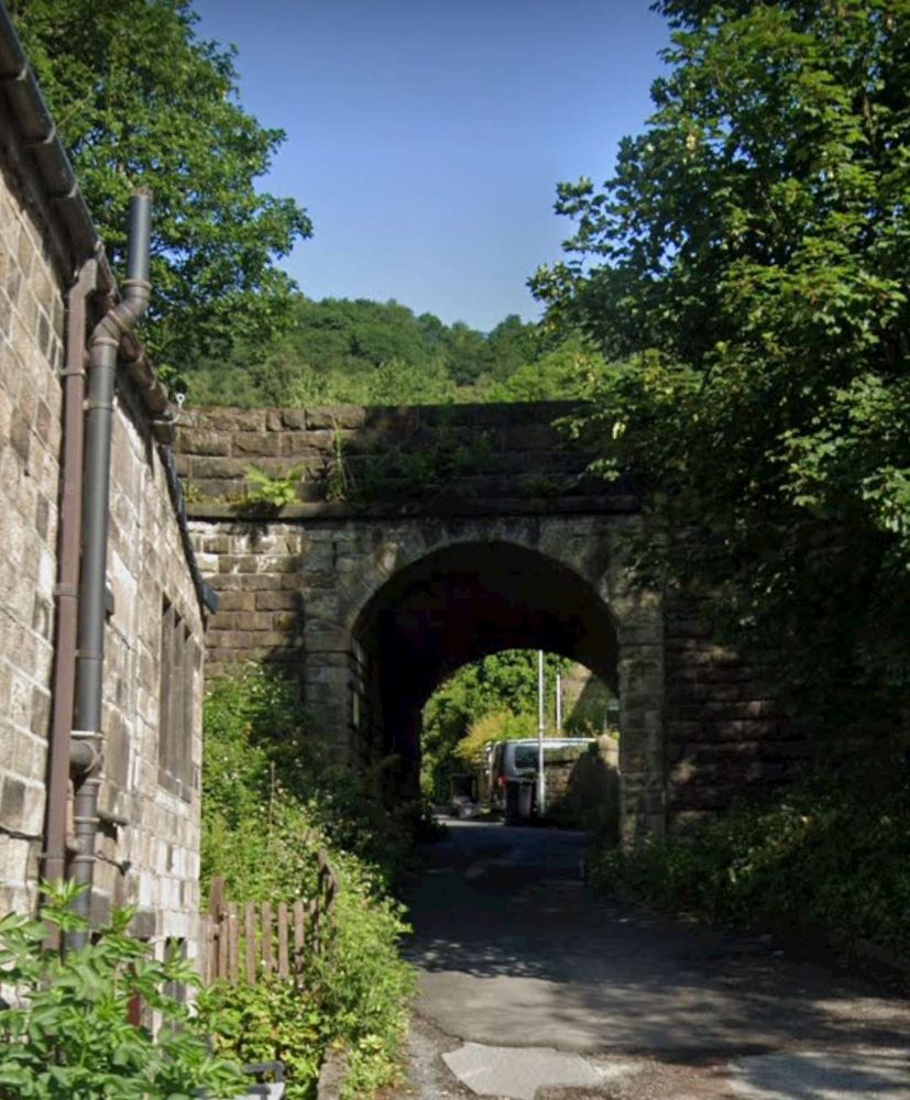
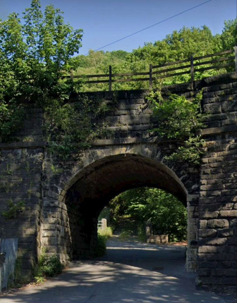
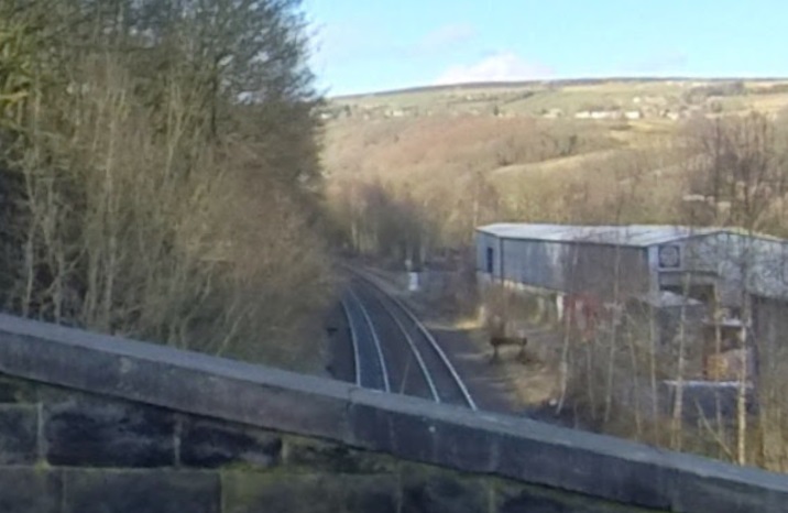
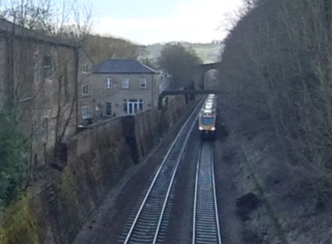
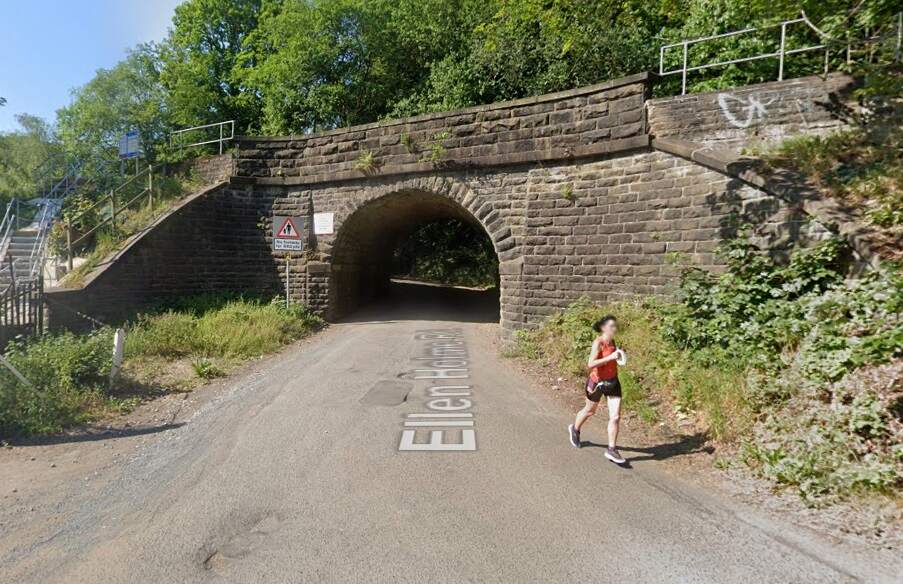
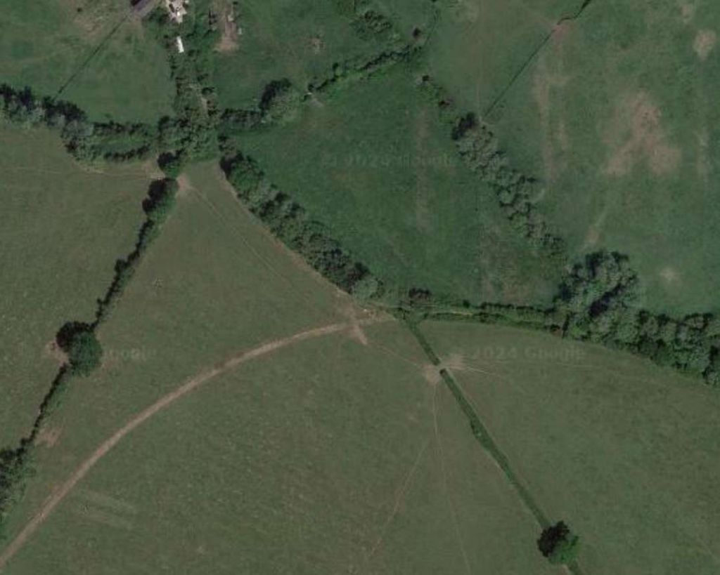
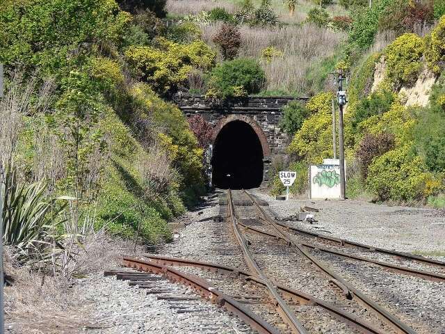
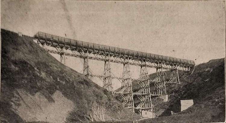
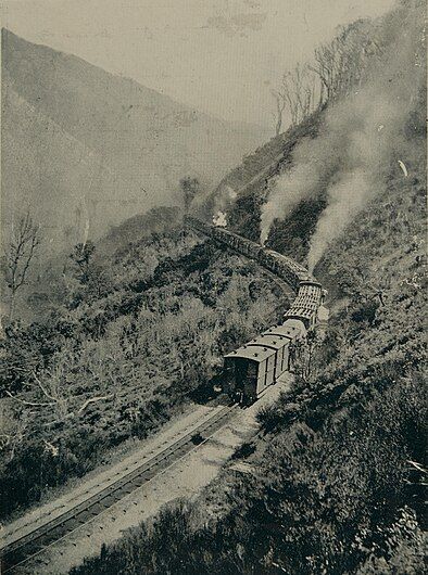
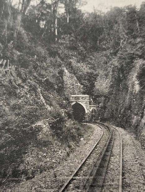
Leaving Koderma Junction travelling West-northwest the line runs on through Gujhandi, Delwa, Nath Ganj The scenery is more rugged, tunnels and sharp curves are needed to keep railway gradients to a minimum. Tunnel No. 3 is shown below.
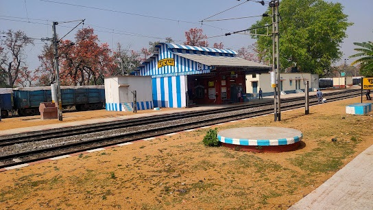
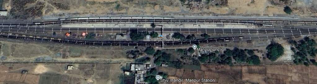
West of Nath Ganj the line passes through Baskatwa B. H. and Gurpa Railway Stations, crosses the River Dhadhar River, runs through Paharpur Railway Station, Bansinala Halt, Tankuppa and Bandhua Railway Stations, before entering Manpur Junction Station.
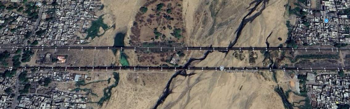
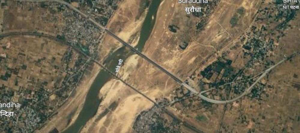
West of Manpur the line crosses the Falgu River Bridges.
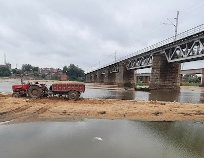
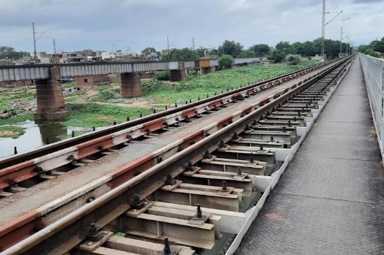
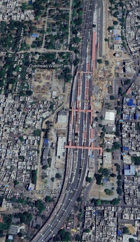
The line continues to the West for only a very short distance before sweeping round to the South into Gaya Junction Railway Station.
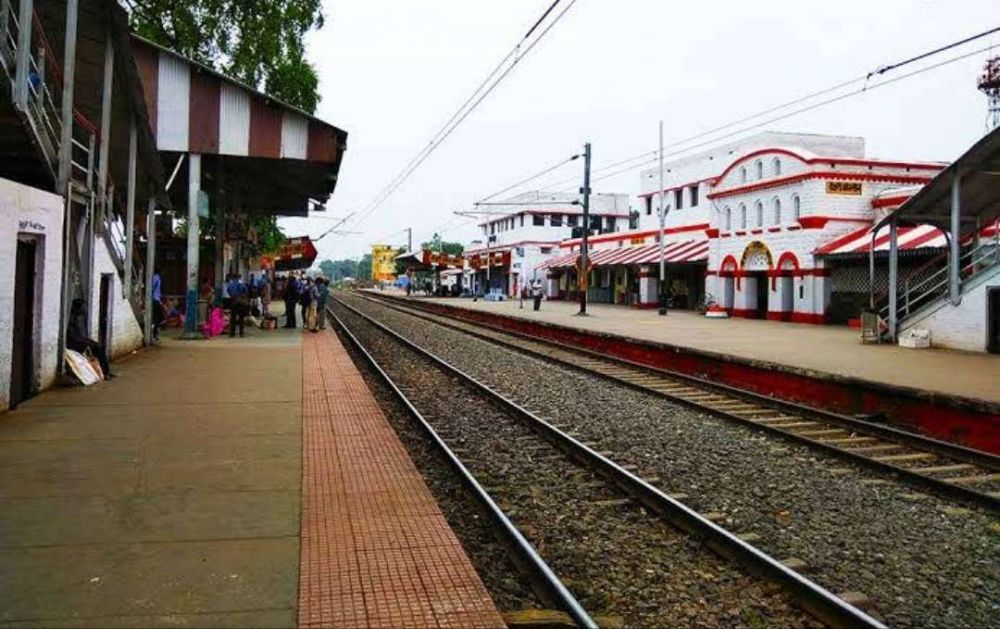
Gaya in Bihar State is the second city in the state. It sits on the West bank of the Falgu (Phalgu) River. Gaya is 116 kilometres (72 mi) south of Patna and has a population of 470,839. The city is surrounded on three sides by small, rocky hills (Mangla-Gauri, Shringa-Sthan, Ram-Shila, and Brahmayoni).
Gaya is a city of historical significance and is one of the major tourist attractions in India. It is sanctified in the Jain, Hindu, and Buddhist religions. Gaya district is mentioned in the great epics, the Ramayana and the Mahabharata. It is the place where Rama, with Sita and Lakshmana, came to offer piṇḍadāna for their father, Dasharatha, and continues to be a major Hindu pilgrimage site for the piṇḍadāna ritual. Bodh Gaya, where Buddha is said to have attained enlightenment, is one of the four holy sites of Buddhism. [10]
Turning sharply to the West at the Railway Station limits, the line runs through Kastha Railway Station and over the Morhar River Bridge.
Once across the first bridge (above) the line passes through Paraiya Railway Station and then crosses the western channel of the Morhar River.
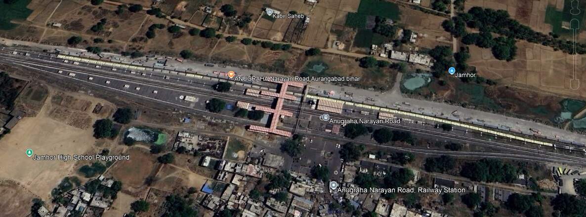
On wards to the West, the line runs through Guraru, Ismailpur, Rafiganj, Jakhim, Phesar, Stations and into Anugraha Narayan Road Railway Station.
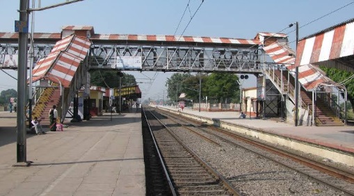
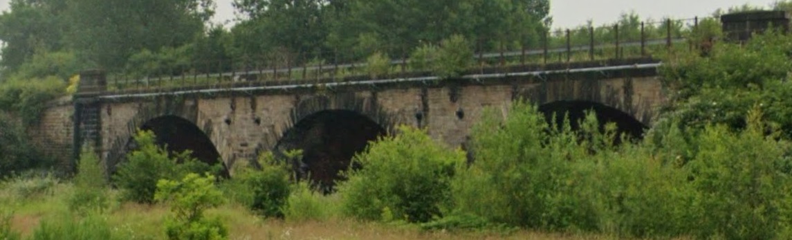
Continuing West, the line crosses the Punpun Railway Bridge passes through the relatively complex Son Nagar Junction and arrives at Son Nagar Junction Railway Station.
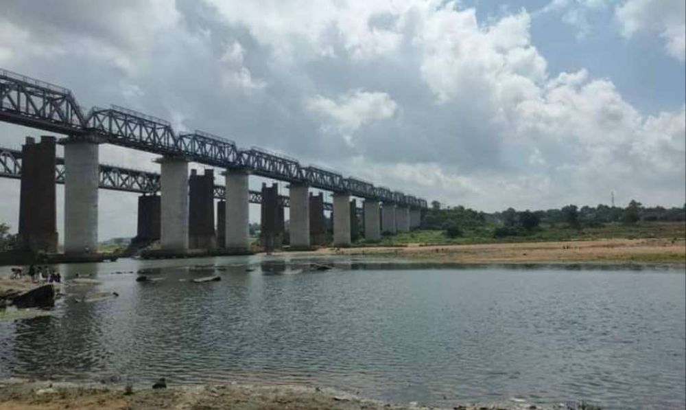
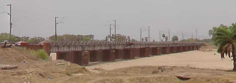
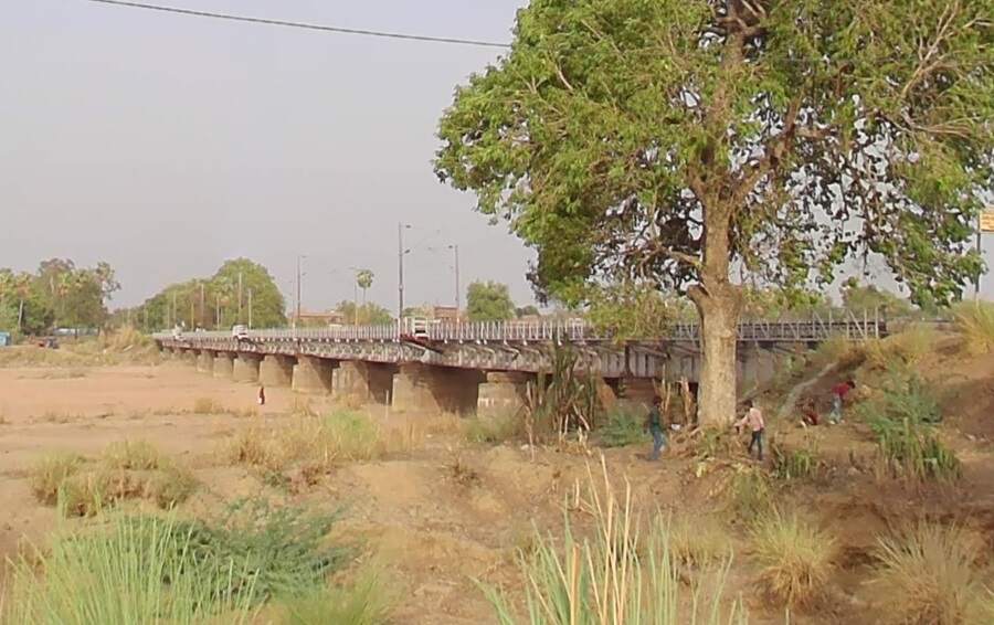
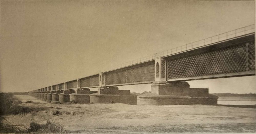
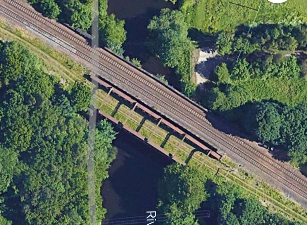
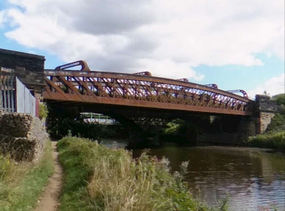
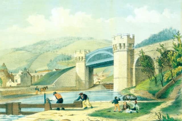
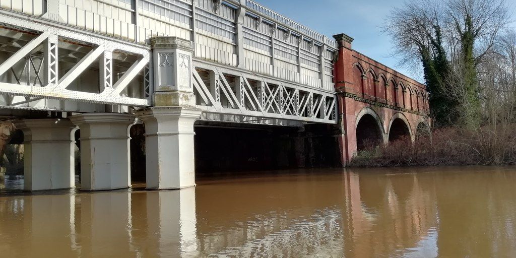
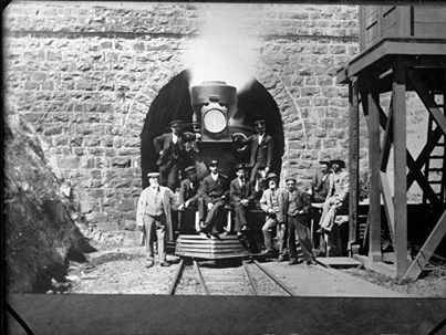
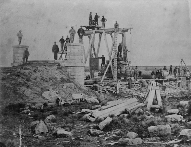
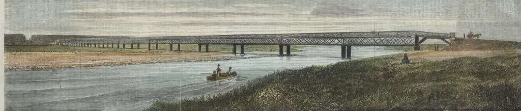
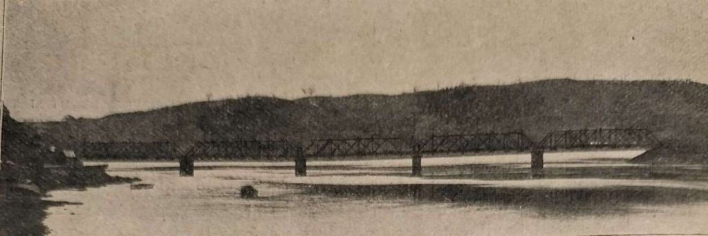
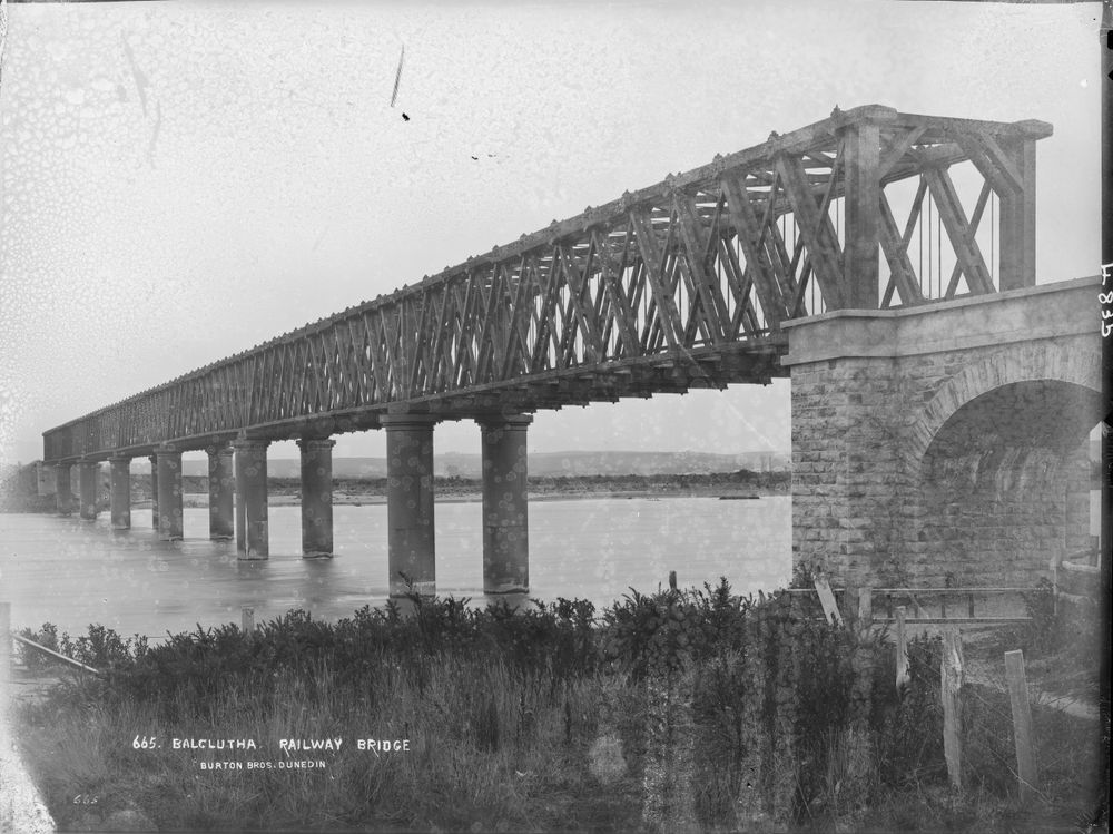
Northwest from Son Nagar Junction Railway Station the railway crosses the River Sone (Soane). Huddleston provided a photograph of the first railway bridge across the river.
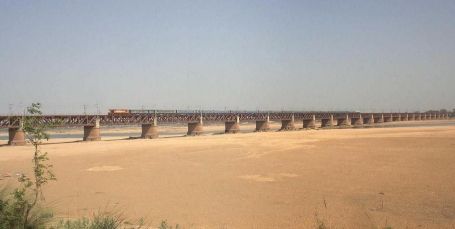
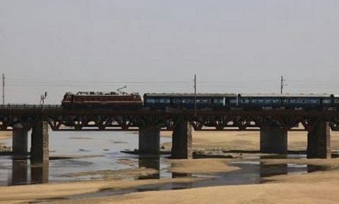
On the West of the River Sone (Soane) the railway runs into Dehri on Sone Railway Station.
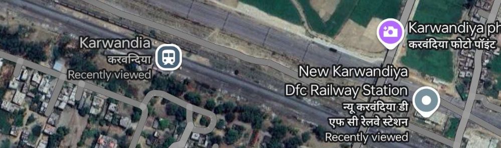
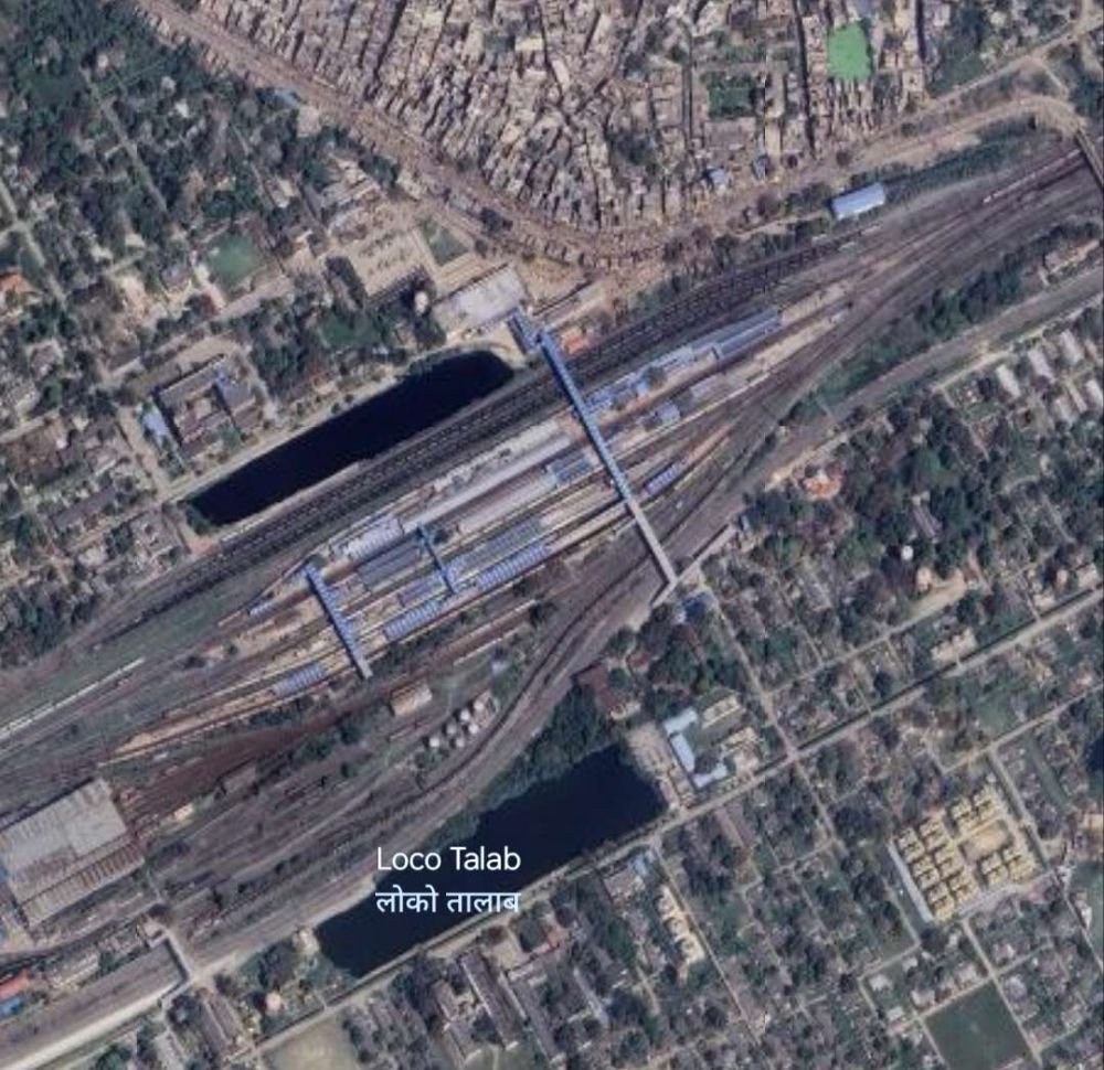
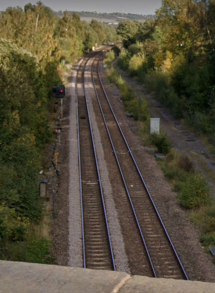
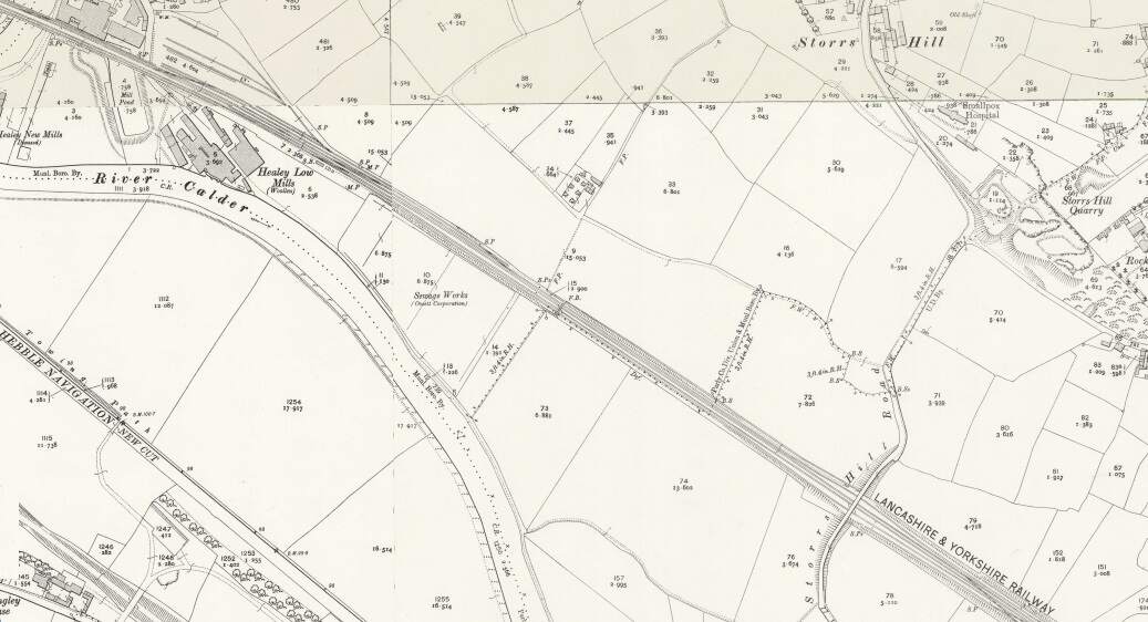
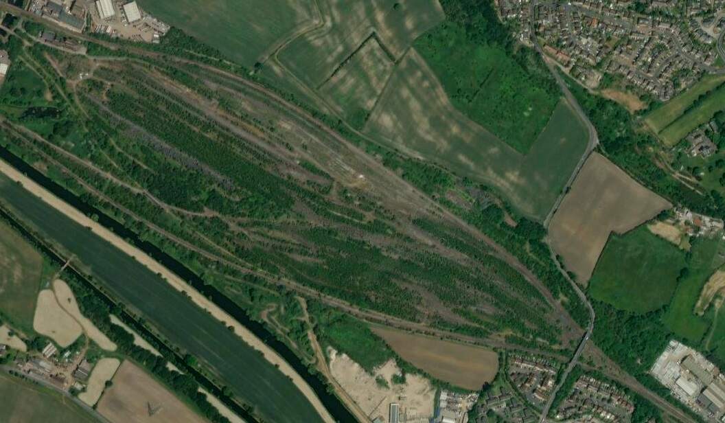
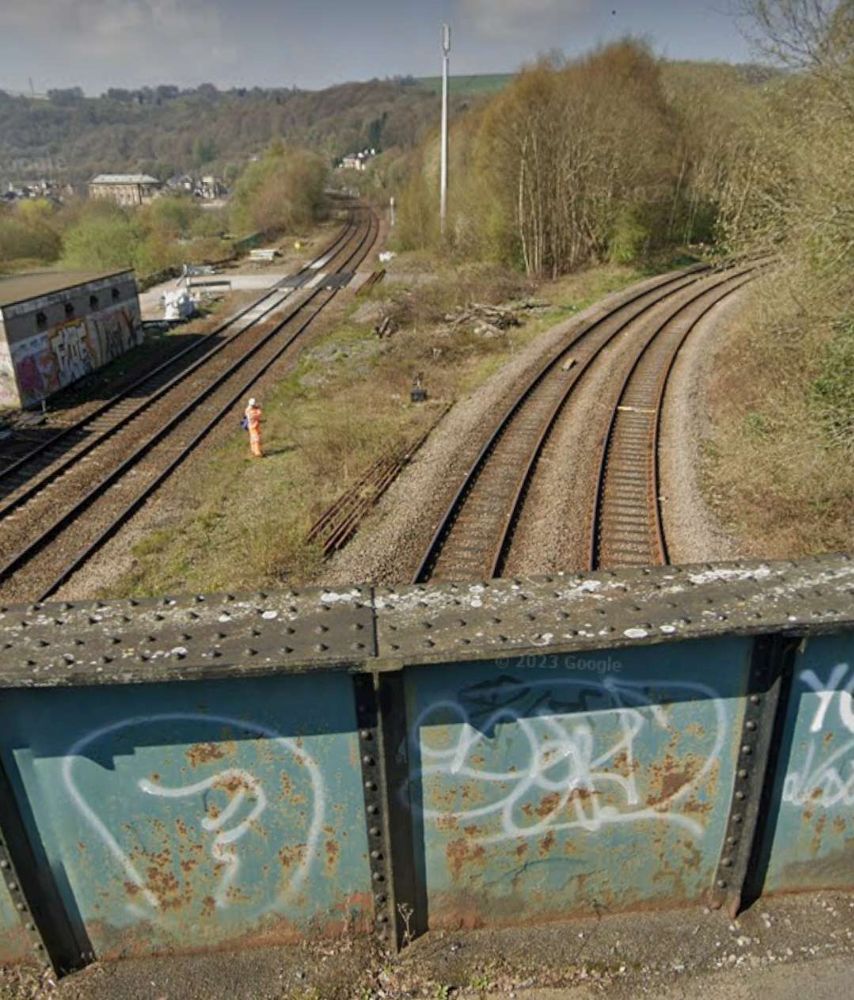
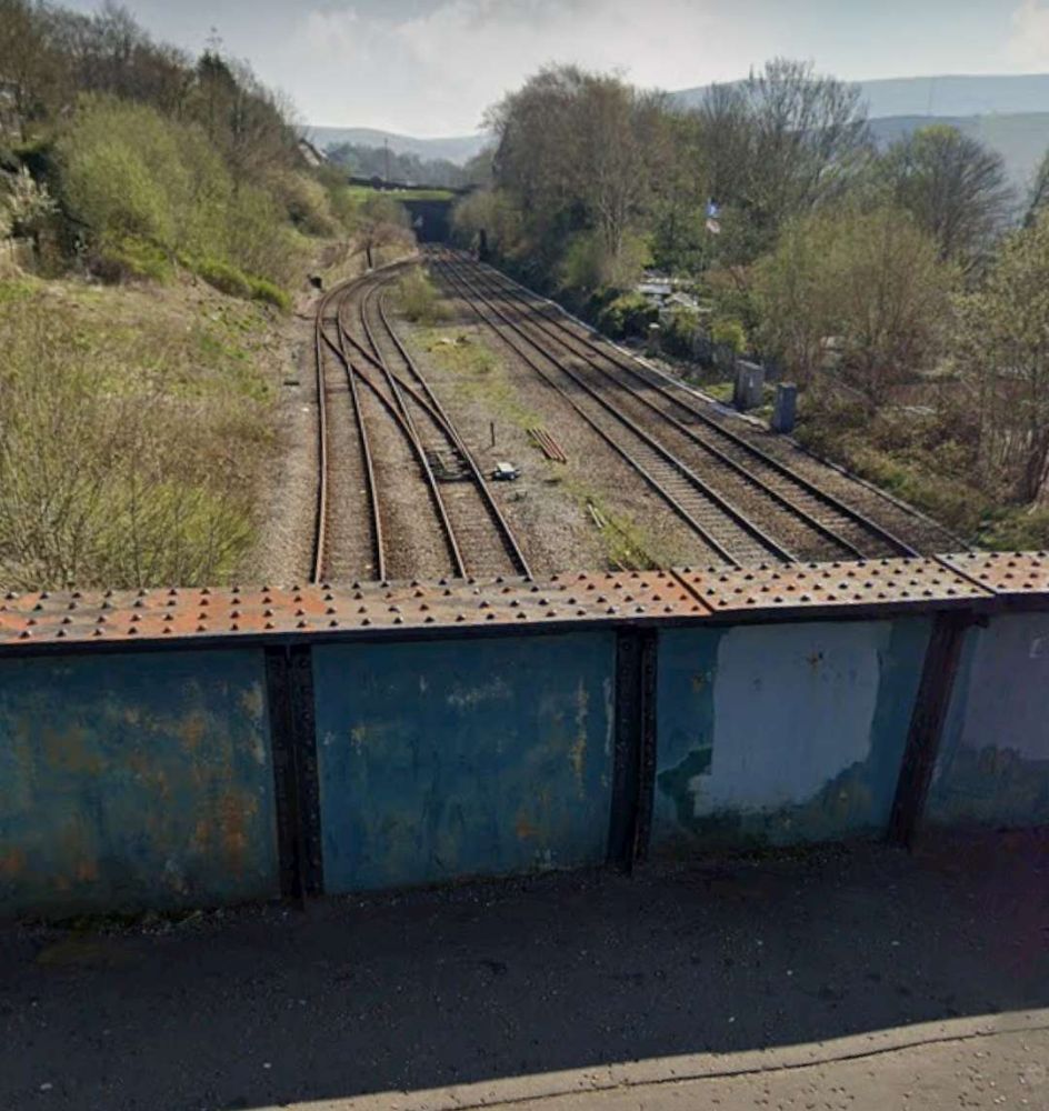
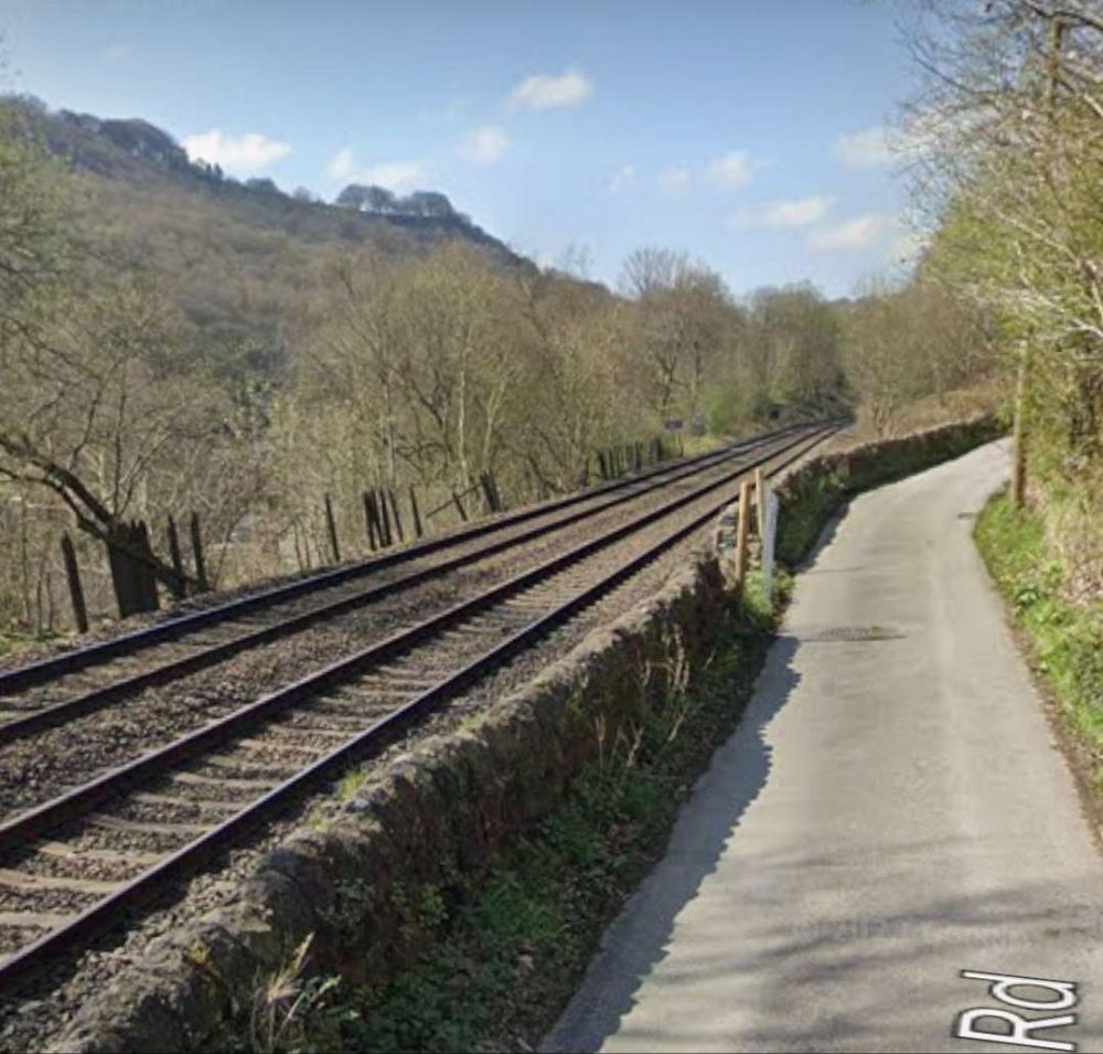
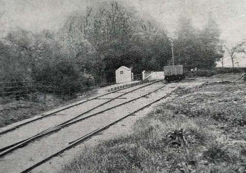
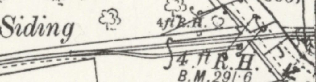
To the West of Dehri the line runs through Pahaleja Railway Station. It is noticeable as we travel to the West that traffic levels must be high. There are significant additional tracks along this length of the line with a number of stations only on the new lines and others only on the older lines.
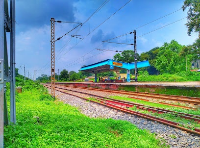
On the new lines we see New Karwandiya DFC Railway Station with Karwandiya Railway Station on the older lines.
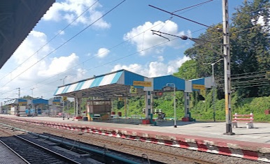
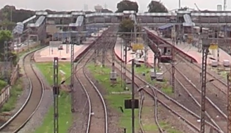
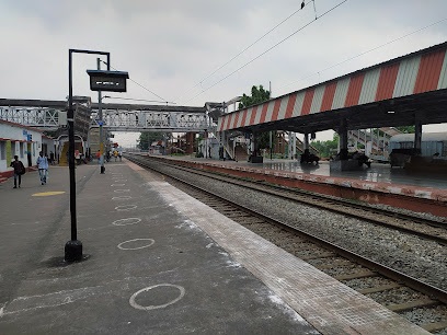
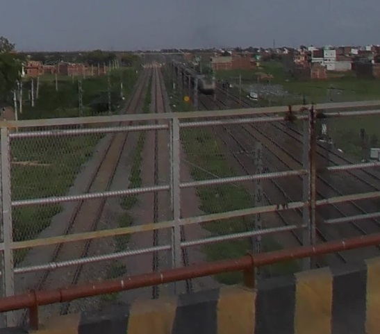
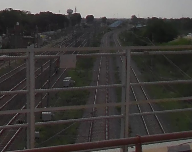
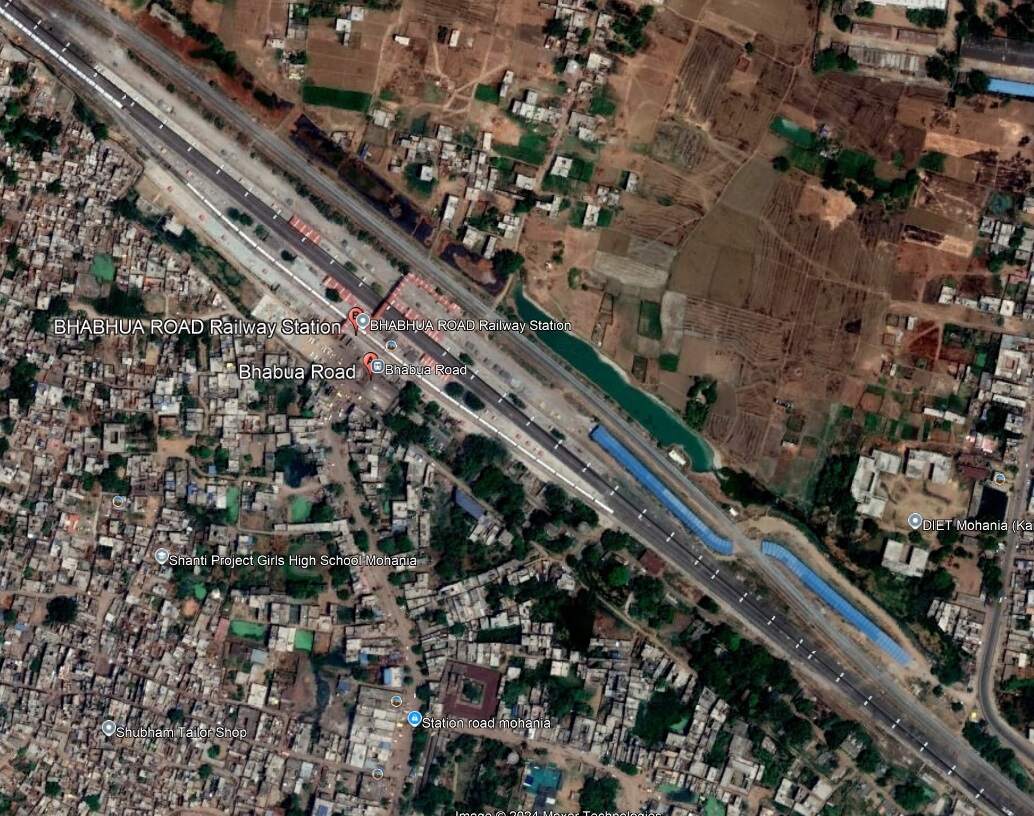
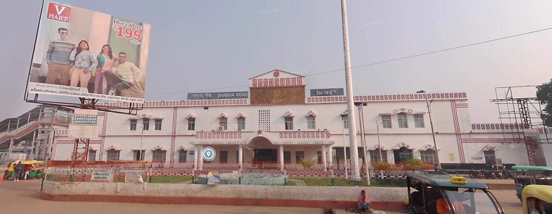
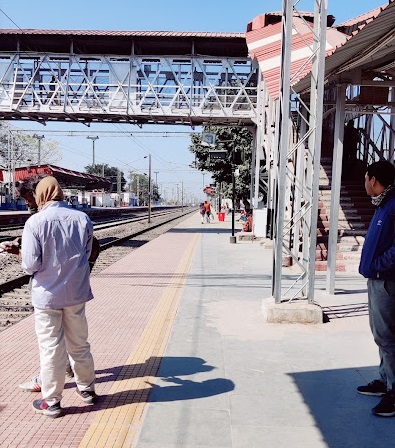
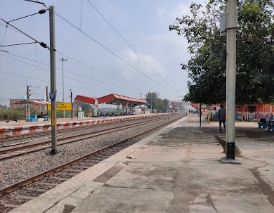
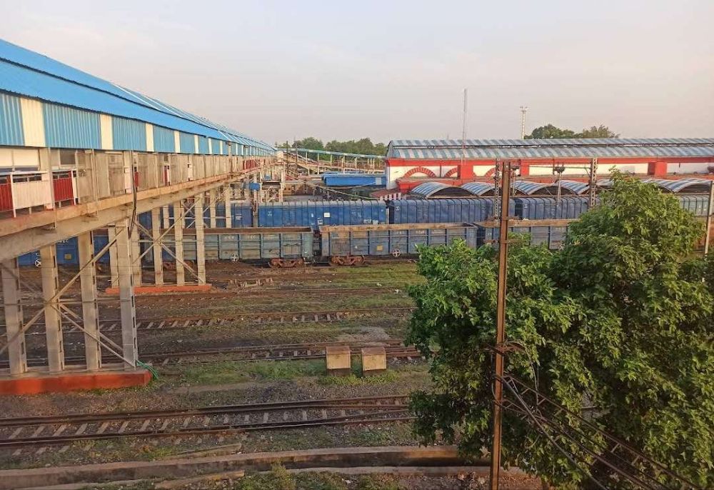
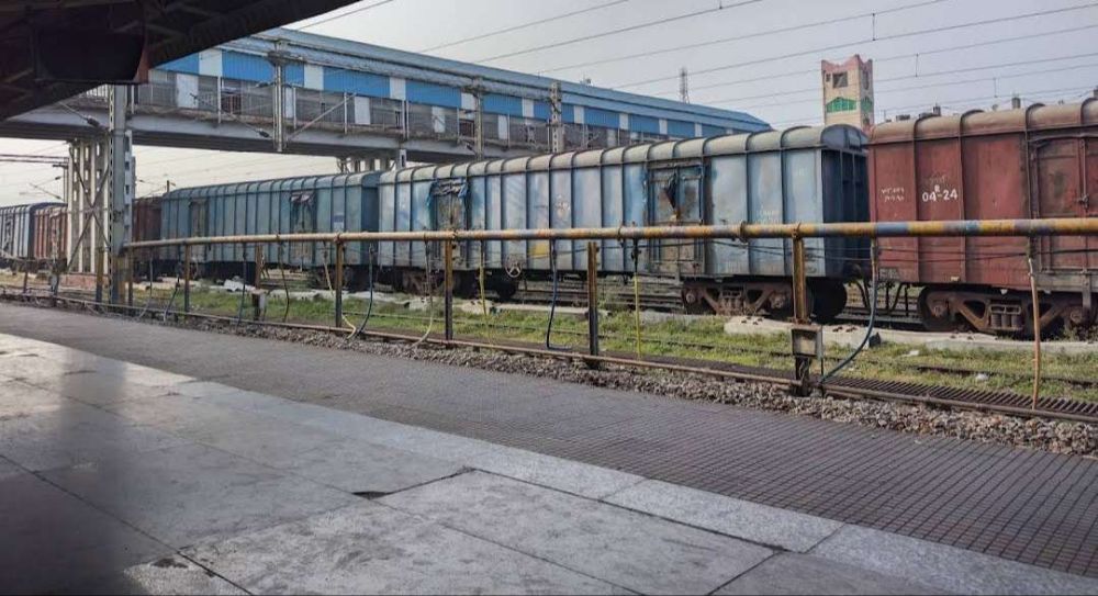
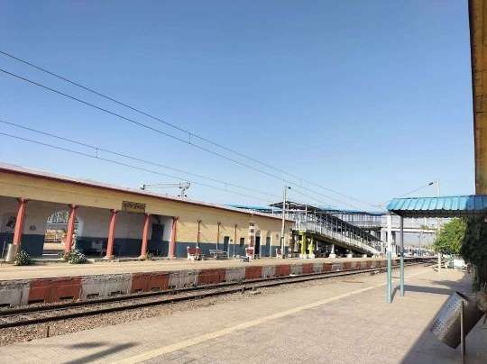
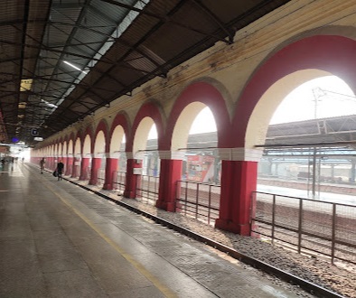
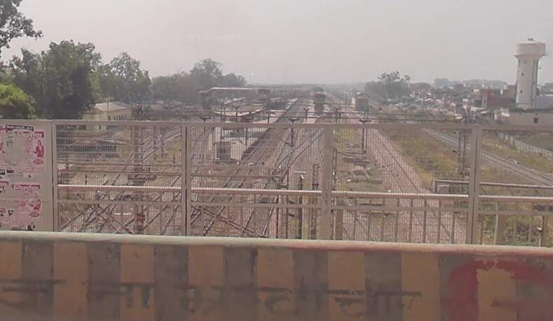
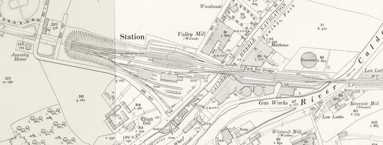
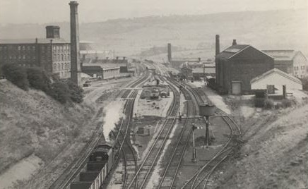
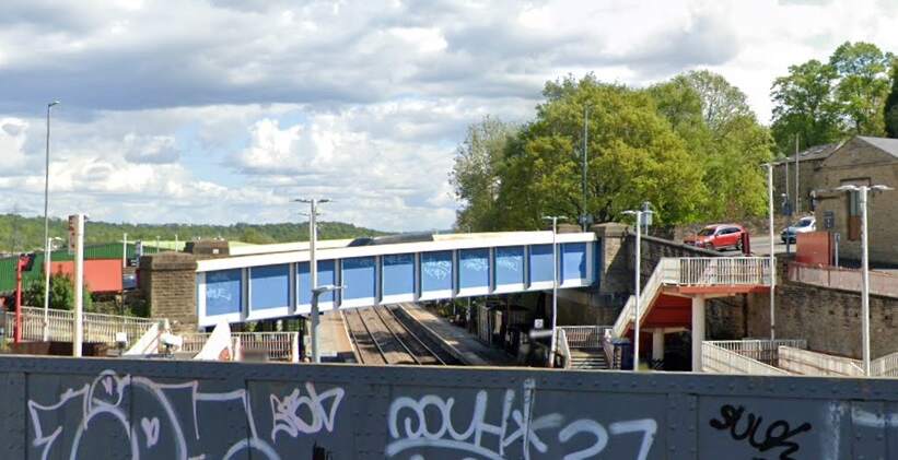
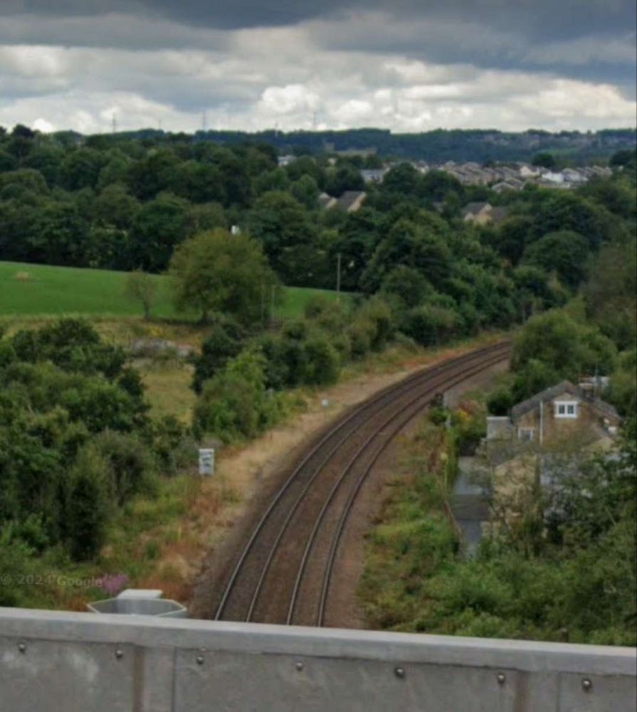
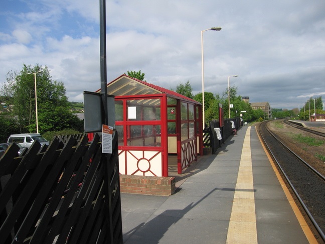
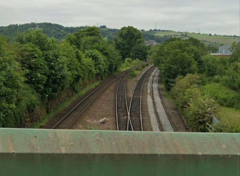
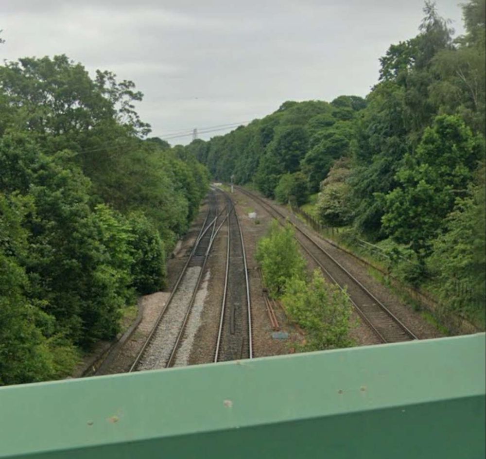
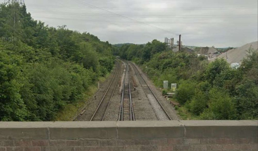
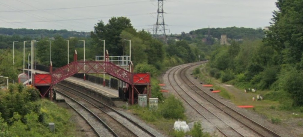
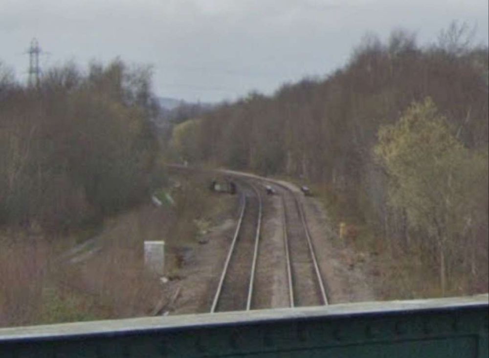
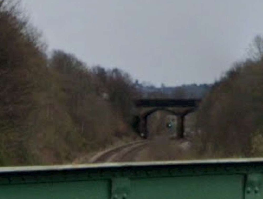
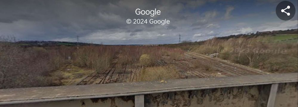
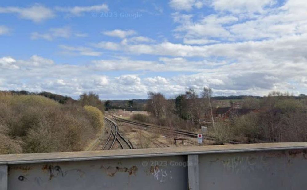
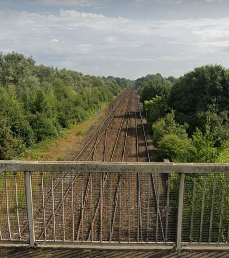
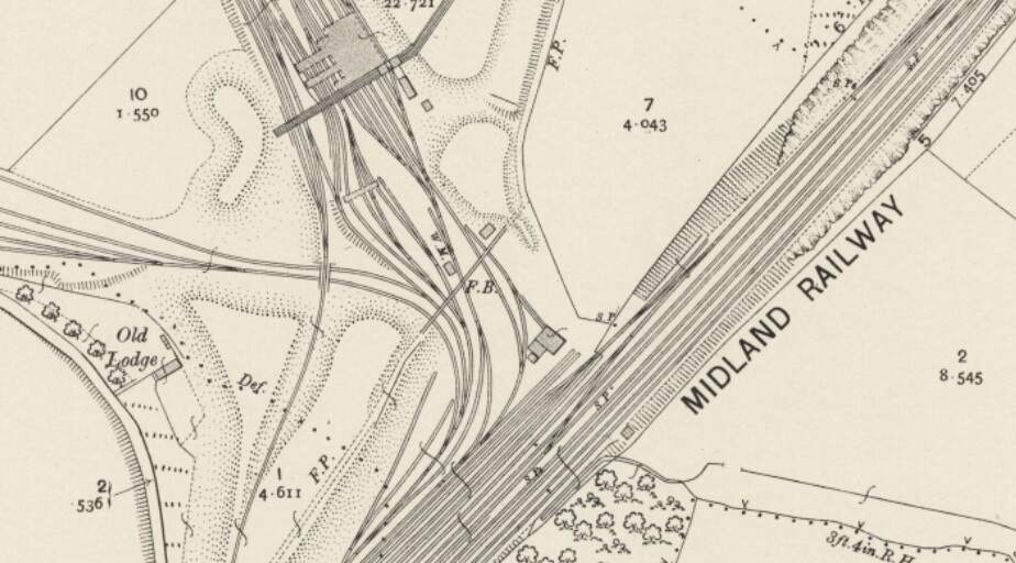
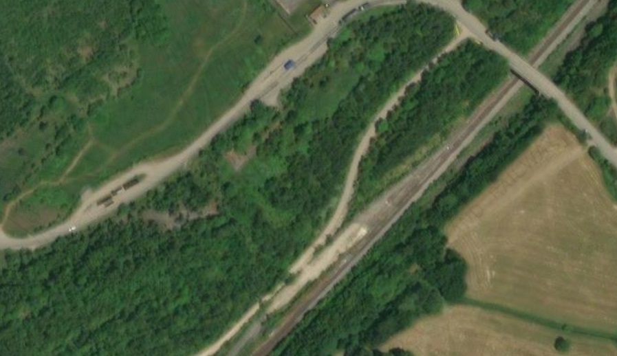
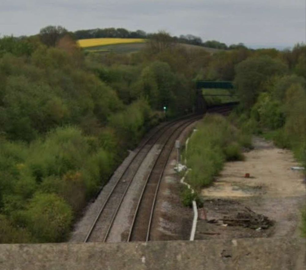
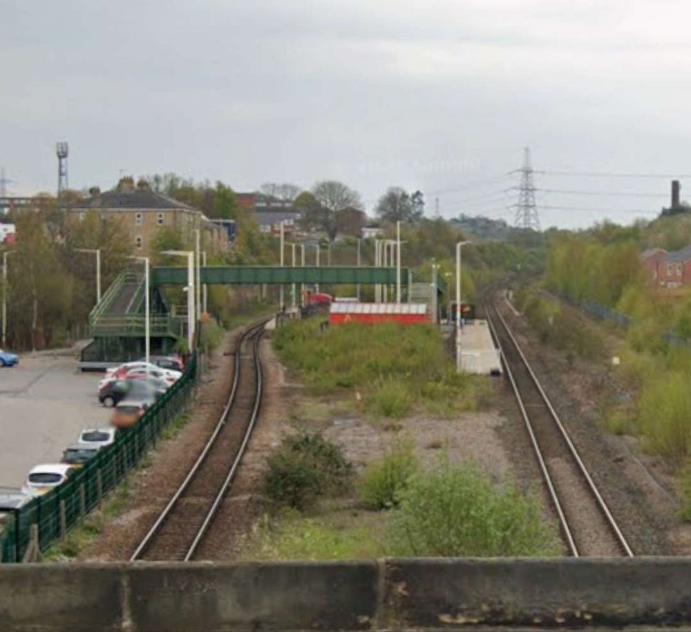
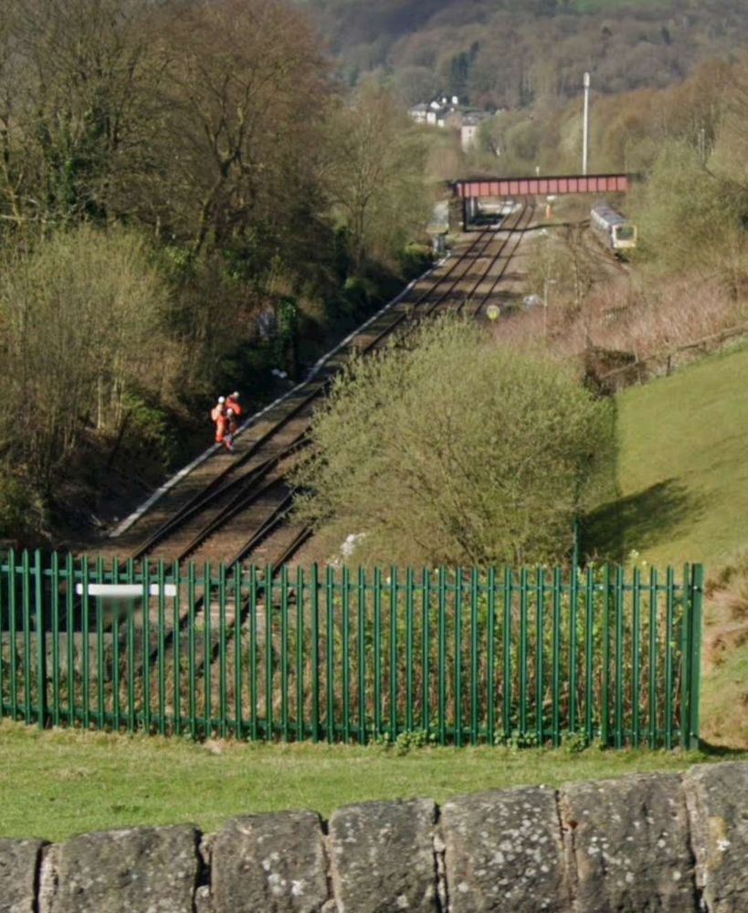
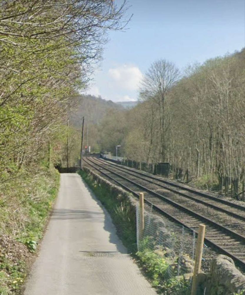
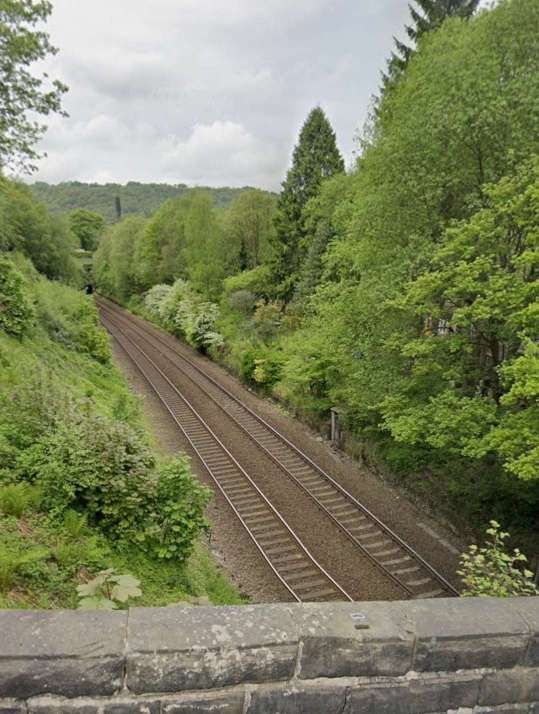
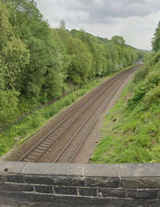
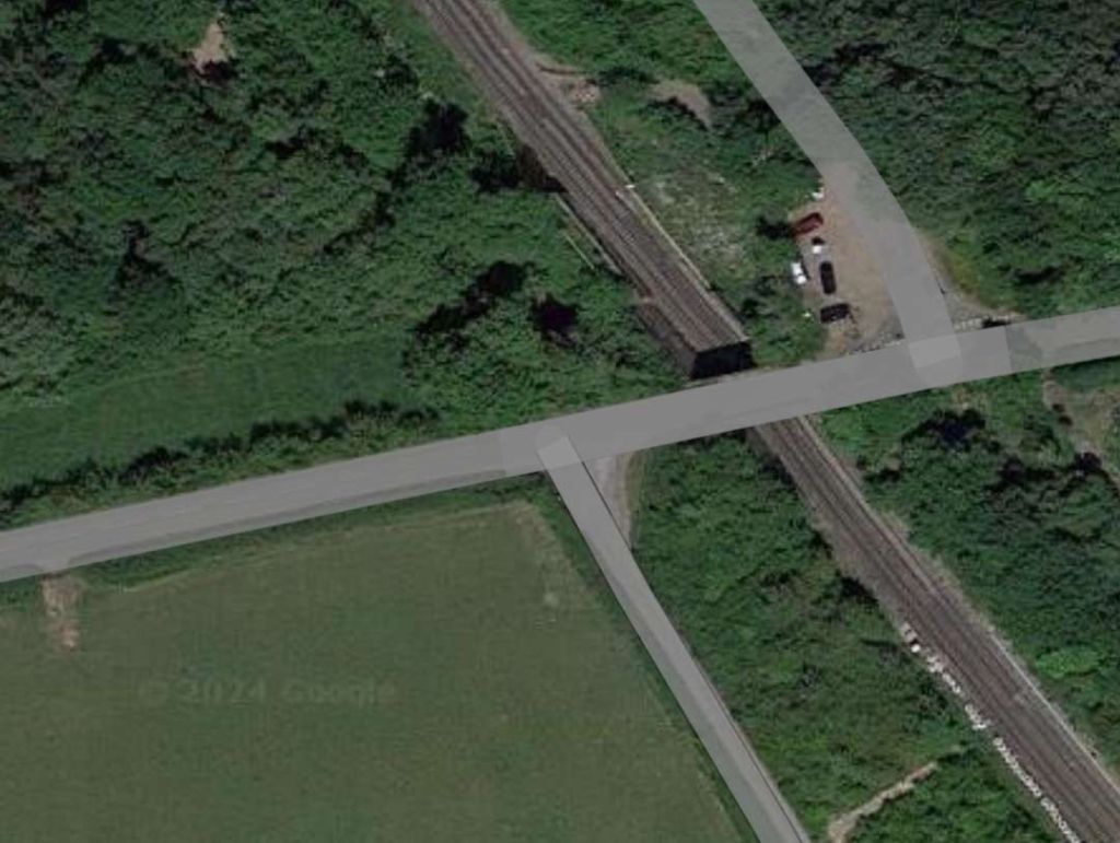
West of Karwandiya, the line runs on through Sasaram Junction Railway Station, Kumahu, Shiu Sagar Road, Khurmabad, New Kudra Junction (and Kundra), Pusauli and Muthani Railway Stations before entering Bhabhua Road Railway Station. The two images below show the 5 main lines in use in the 21stcentury as seen from the overbridge to the Southeast of Bhabhua Road Railway Station.
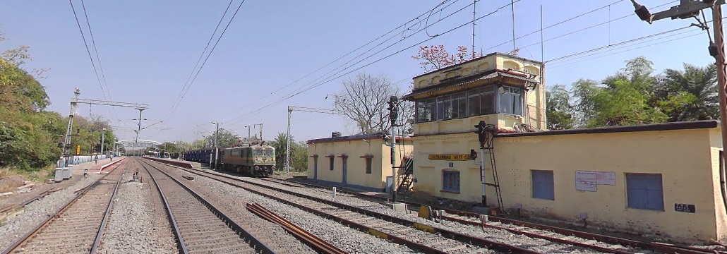
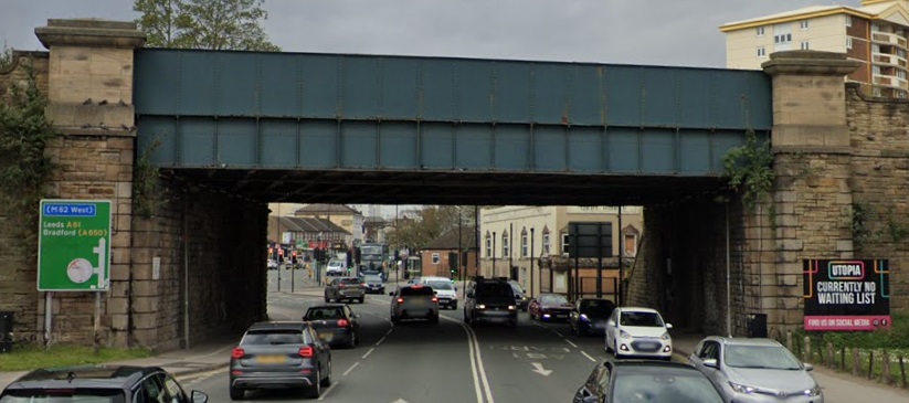
On from Bhabhua heading Northwest the line runs on through New Durgauti Junction (Durgauti), Dhanaichha, Karamnasa, Saidraja, Chandauli Majhwar and Ganj Khawaja Railway Stations, by which now the line is running East-West. Immediately beyond Ganj Khawaja the line turns to the North, then sweeps round to the Southwest through a series of junctions and then through Mughal Sarai Marshalling Yard and DDU Railway Station.
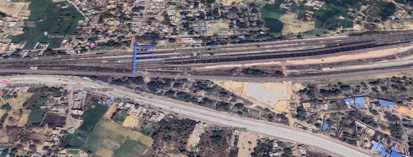
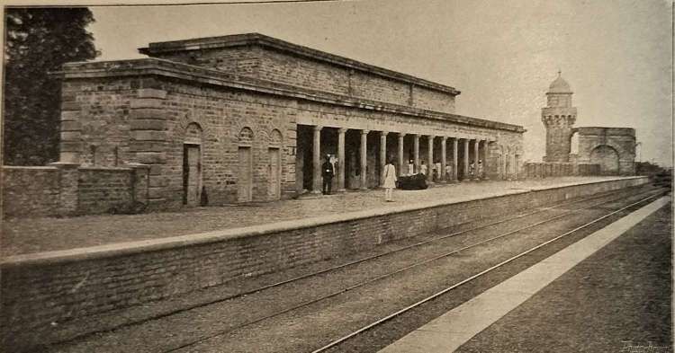
Running on in a Southwesterly direction not far from the Southern bank of the River Ganges, the line runs through Jeonathpur, Narayananpur and Narayananpur Bazar (Ahraura) Railway Stations. On further through Kailahat Station to Chunar Junction Railway Station.
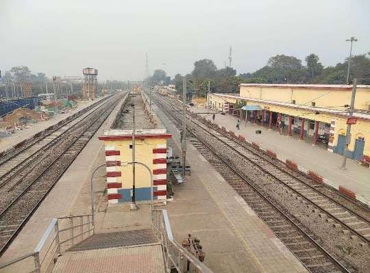
The railway continues West through Dagmagpur, Pahara and Jhingura Railway Stations to Mirzapur Railway Station.
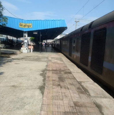
Ankit Tiwari(c) (2018)
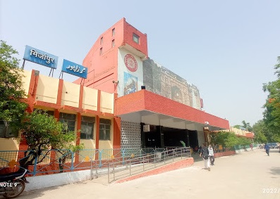
“Mirzapur … is known for its carpets and brassware industries, and the tradition of kajari and birha music. Straddled by the Maikal Hills, it served as the headquarters of the Mirzapur district [of Uttar Pradesh]. … Indian Standard Time is calculated from the clock tower in Mirzapur.” It had a population of 245,817 in 2011. [11]
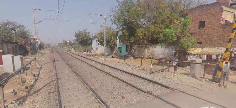
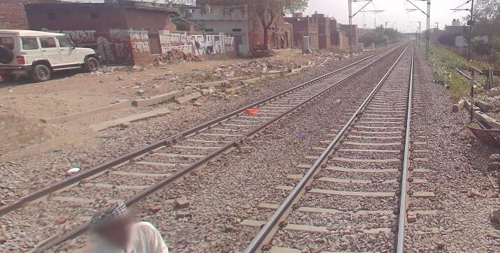
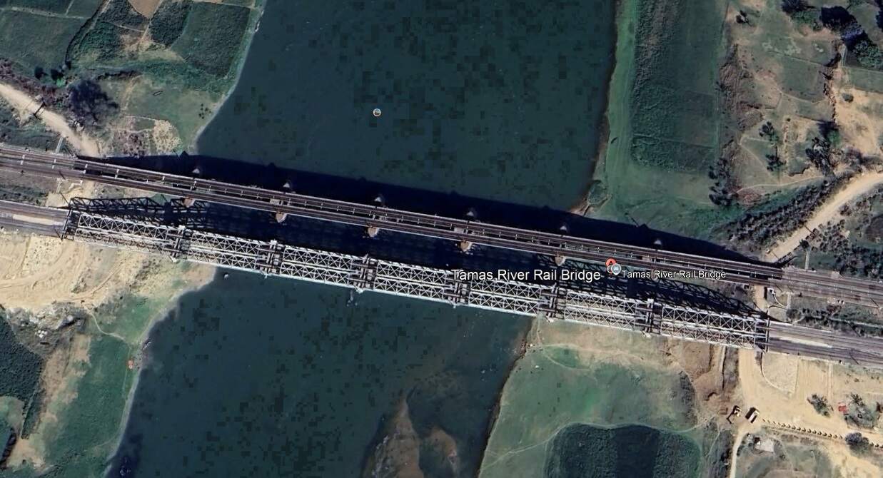
West of Mizapur the line ran on through Vindhyachal, Birohe, Gaipura, Jigna, Mandah Road, Unchdih and Chauraha Railway Stations before crossing the Tamas River Rail Bridges.
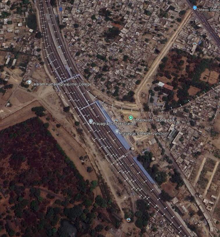
Continuing Northwest, the railway passes through Bheerpur and Karchana Railway Stations before entering Prayagraj Chheoki Junction Railway Station.
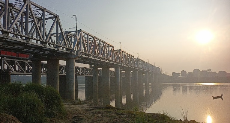
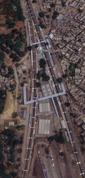
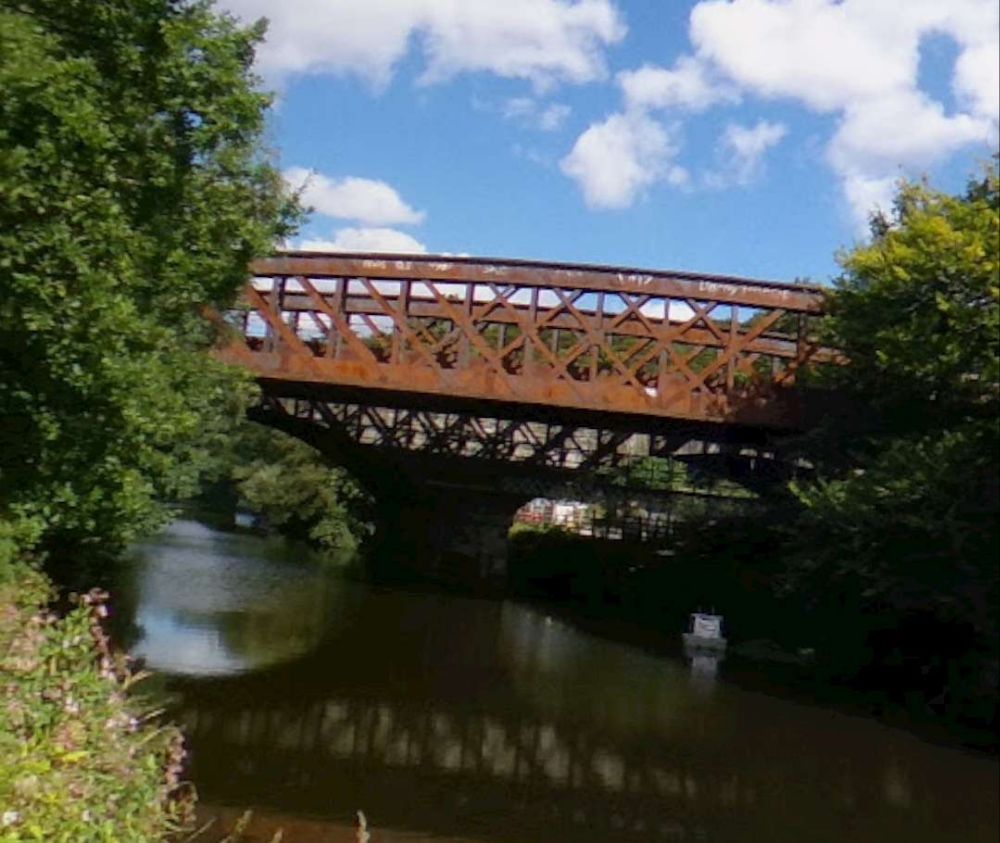
To the Northwest of Prayagraj Chheoki Junction Railway Station the line runs through Naini Junction Station and then crosses the Old Naini Bridge over the Yamuna River.
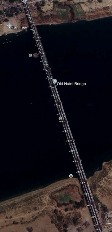
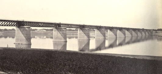

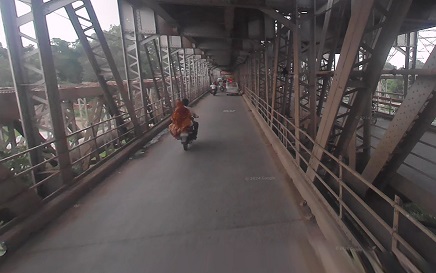
The Old Naini Bridge is situated over the Yamuna River, “just above the confluence with the Ganges at Allahabad. … It opened in 1865 and is a great feat of British engineering; it is over 1,006 metres (3,300 feet) long.” [12] The present structure carries vehicles on a deck below the rail lines.
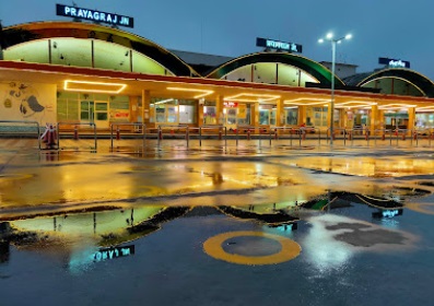
Prayagraj is also known as Allahabad. “The city is the judicial capital of Uttar Pradesh with the Allahabad High Court being the highest judicial body in the state. As of 2011, Prayagraj is the seventh most populous city in the state, thirteenth in Northern India and thirty-sixth in India, with an estimated population of 1.53 million in the city.” [13]
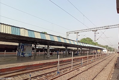
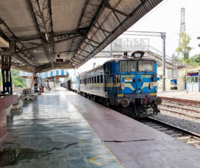
North of the Yamuna River in Prayagraj/Allahabad, the line turns West and enters the main city station,
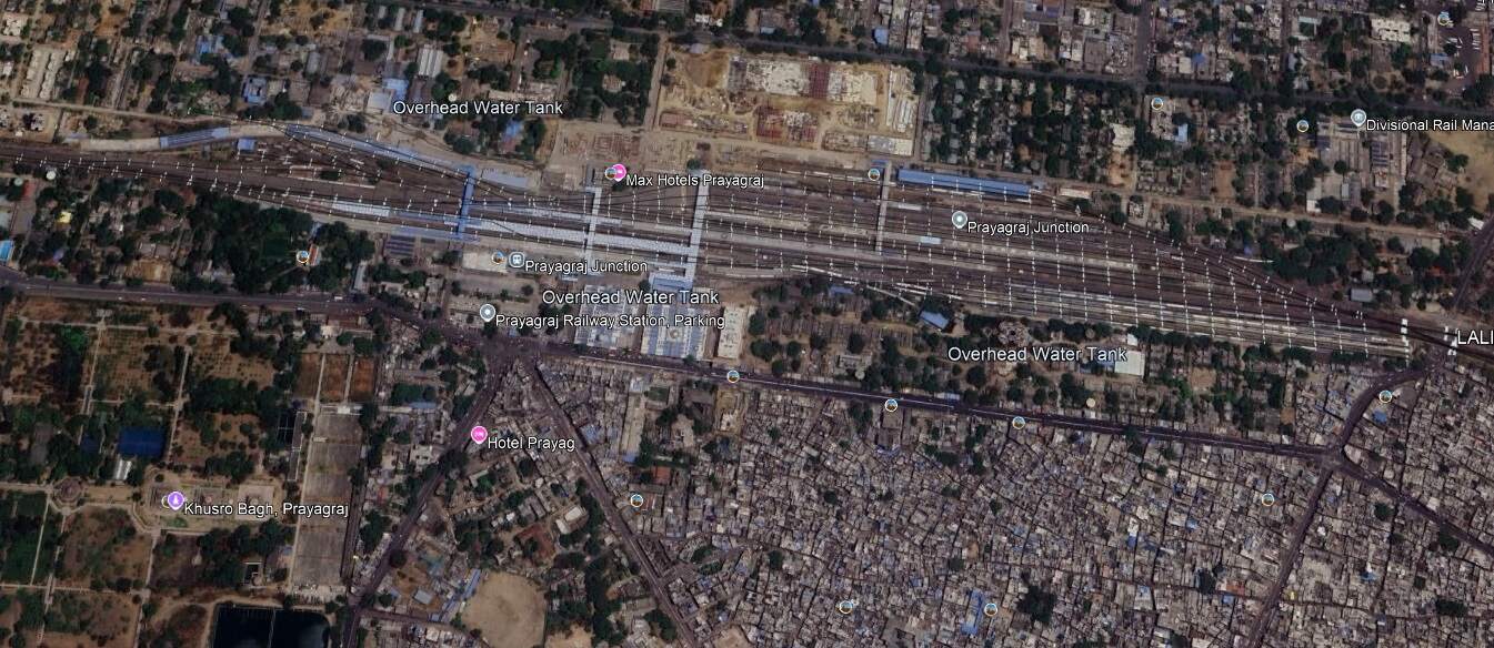
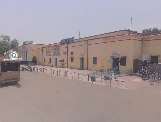
West of Prayagraj Railway Station the line passed through Subedarganj, Bamhrauli, Manauri, Saiyid Sarawan, Bharwari, Bidanpur, Shujaatpur, Sirathu, Athsarai, Kanwar, Katoghan, Khaga, Sath Naraini, Rasulabad, Faizullapur and Ramva Railway Stations before arriving at Fatehpur Railway Station.

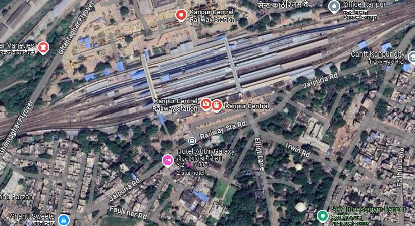
Northwest of Fatehpur, the railway continued on through Kurasti Kalan, Malwan, Kanspur Gugauli, Binki Road, Aung, Karbigwan, Prempur, Sirsaul, Rooma, Chakeri, and Chanari Railway Stations before looping sharply round into Kanpur Central Railway Station.
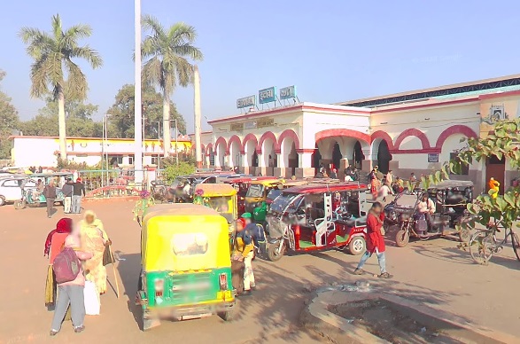
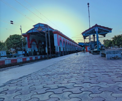
After leaving Kanpur Central Railway station, the line ran through the GMC Marshalling Yard and on through Panki Sham, Bhaupur (and New Bhaupur), Maitha, Roshan Mau, Patra, Rura, Ambiapur, Jhinjhak, Parjani, Kanchausi, Phaphund, Pata, Achalda, Bharthana, Ekdil (and New Ekdil) and into Etawah Junction Railway Station.
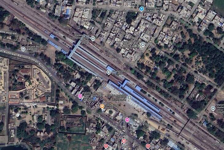
On to the Northwest from Etawah the line passes through Sarai Bhopat, Jaswantnagar, Balrai and Bhadan Railway Stations before entering Shikohabad Junction Railway Station.
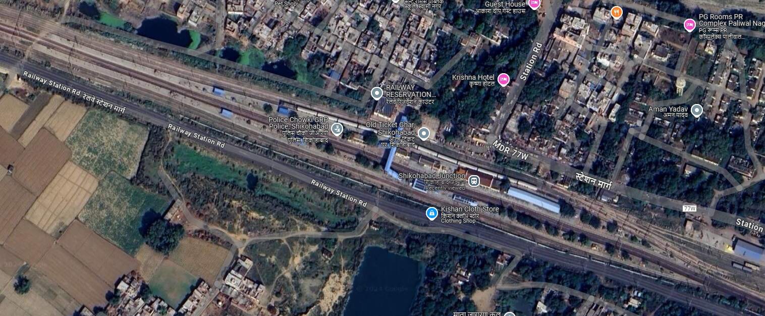
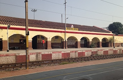
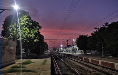
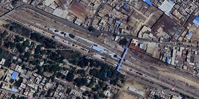
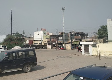
Beyond Shikohabad, we go on Northwest towards Delhi. The line passes through Makkhanpur Railway Station before arriving at Firozabad Railway Station.
After Firozabad Railway Station, the railway continues Northwest through Hirangaon Railway Station and Tundla Goods Train Yard and into Tundla Junction Railway Station.
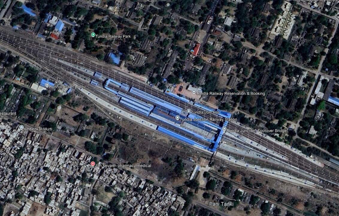
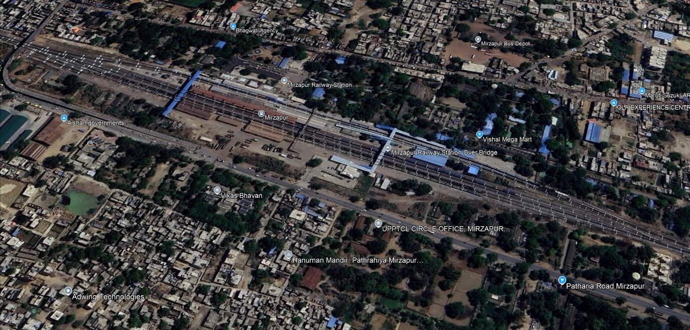
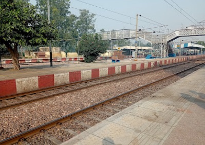
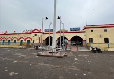
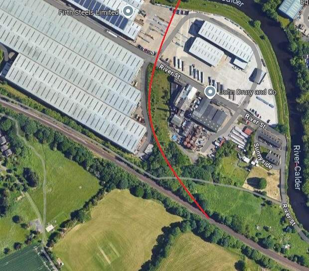
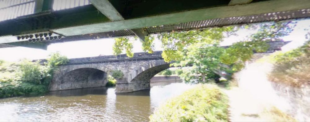
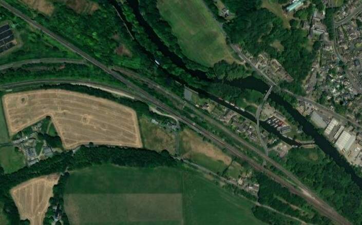
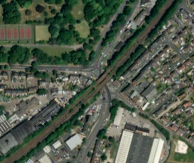
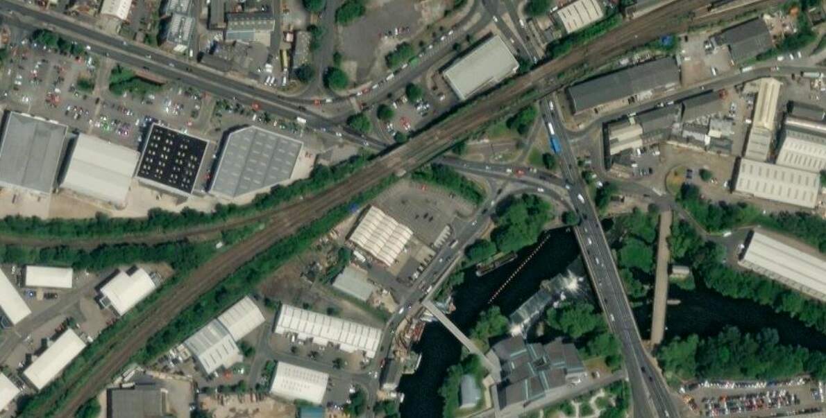
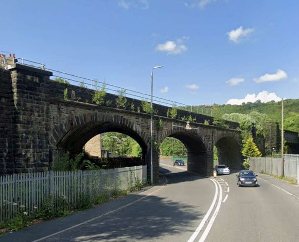
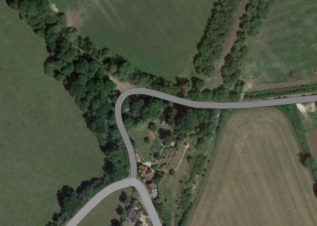
We continue on to the Northwest along the railway line running through Tundla Junction and on in a more northerly direction through Mitawali, Barhan Junction, Chamrola, Jalesar Road, Pora, Hathras Junction (and New Hathras DFCCIL) Railway Station. Just after crossing the station limits at Hathras Junction Station the line passed beneath a Warren Truss Steel Bridge carrying The Kasganj Mathura railway line. While the train is stopped at the station we explore the line carried by the rail overbridge.

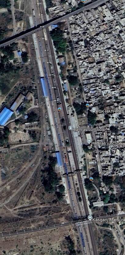
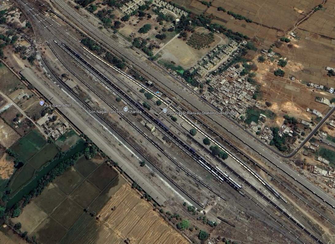
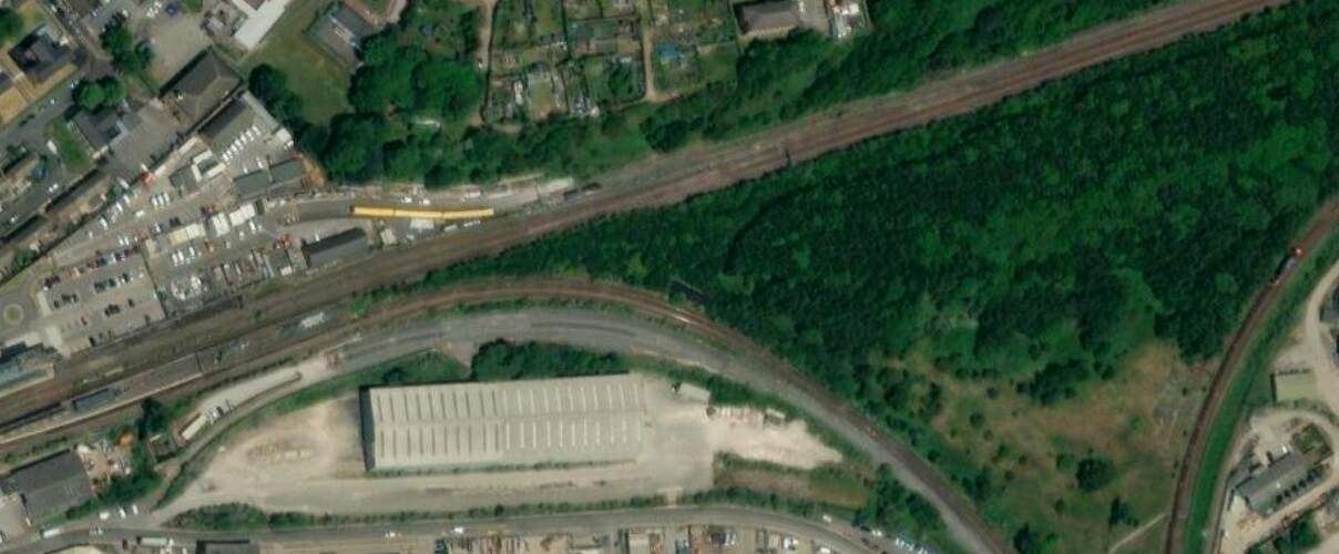
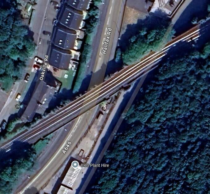
The adjacent extract from Google Earth’s satellite imagery shows Hathras Junction Station. At the bottom of the image a rail overbridge carries the Kasganj Mathura Railway lIne. A scheduled passenger service runs along this line between between Kasganj (KSJ) and Mathura Junction (MTJ). [14]
Mathura Junction Railway Station (MTJ) is an important station on the Agra–Delhi chord of the Delhi–Mumbai and Delhi–Chennai lines. It is located in Mathura district in the Indian state of Uttar Pradesh. It is one of the important North-Central Railway stations. It serves Mathura and Vrindavan.
Mathura is the birthplace of Lord Krishna. He spent his childhood in Vrindavan, 11 km away from Mathura. Therefore, both are major pilgrimage centres for Hindus. [15]
The Kasganj Mathura Passenger train covers a total distance of 105 kilometres. [14] Kasganj Junction Railway Station is situated on the Delhi-Kanpur line, it boasts 5 platforms and connects to various destinations across the country. The station is known for its historical significance, being located near the renowned Kasganj Fort and the historic mosque of Shah Jahan. [16]
Hathras Junction Railway Station serves the small city of Hathras. Hathras is a place in mythology where Lord Mahadev and Goddess Parvati stopped on their way to Brij to visit Lord Krishna at the time of his birth. There are also some significant historical and sites/remains in its vicinity. These include: Hathras Fort, a Monument to Major Robert Naim, a Monument to Samuel Anderson Nichterlein, a mound known as Gohana Khera; and a number of Hindu temples. [17] Hathras Junction Railway Station is about 164 km from Delhi.
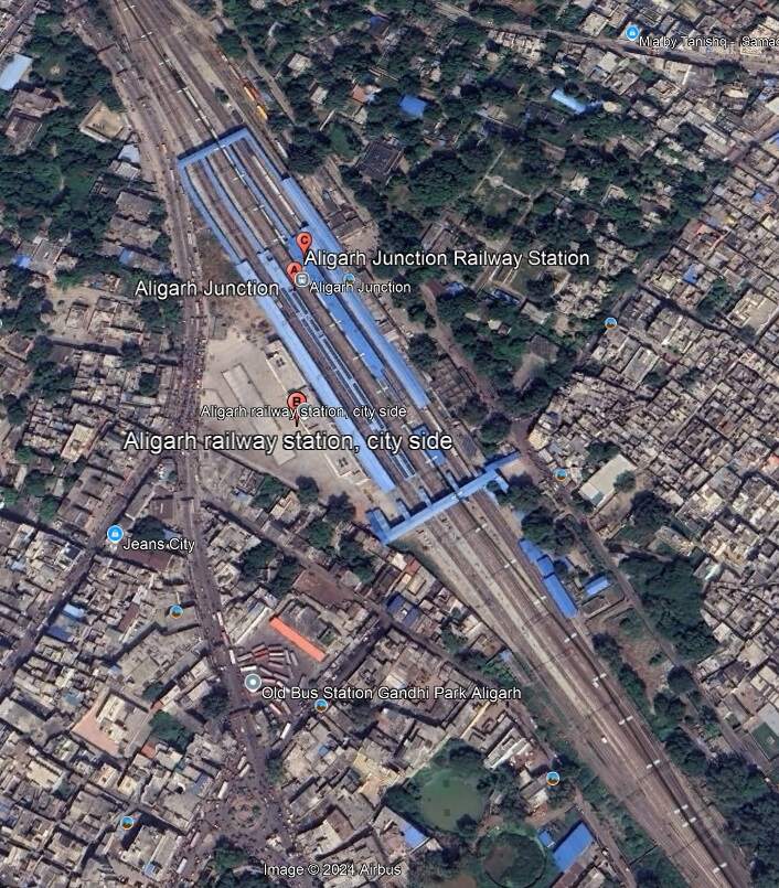
We leave Hathras Junction Station travelling North and pass through Mandrak and Daud Khan Railway Stations before reaching Aligarh Junction Railway Station.
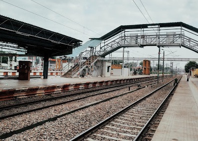
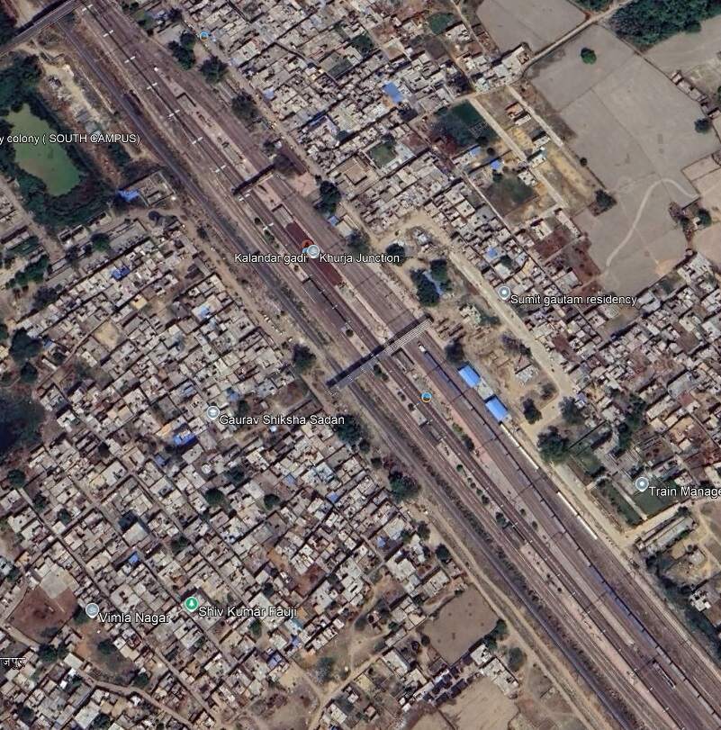
We are now perhaps about 150 kilonmetres from Delhi and travellin North-northwest. The line continues through Mehraval, Kulwa, Somna, Danwar and Kamalpur Railway Stations and into Khurja Junction Railway Station.
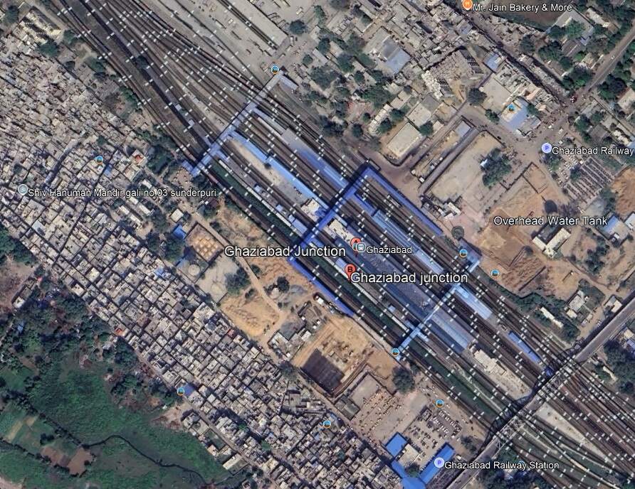
we travel on through Sultanpur and Sikandarpur Stations, Gangraul Halt, Chola, Wair, Fatehpur Makrandpur, Dankaur, Ajaibpur, Boraki, Dadri, Maripat, Chipyana Buzurg Railway Stations and into Ghaziabad Junction Railway Station.
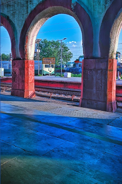

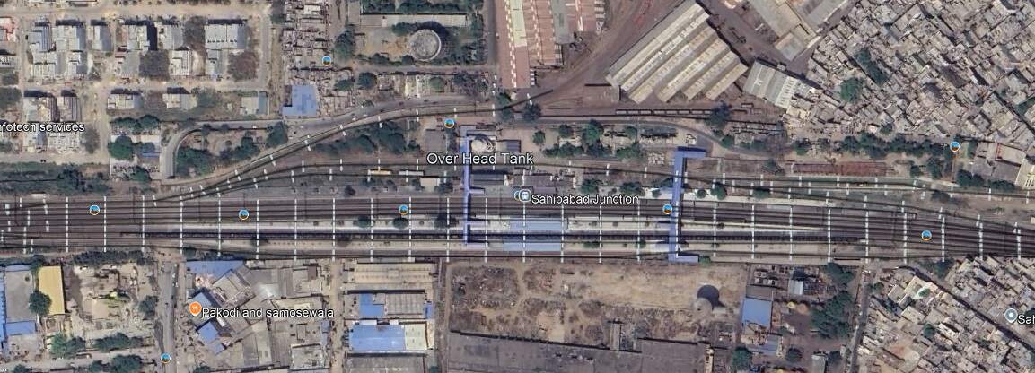
Heading on Northwest towards Delhi trans pass through Sahibabad Junction Railway Station.
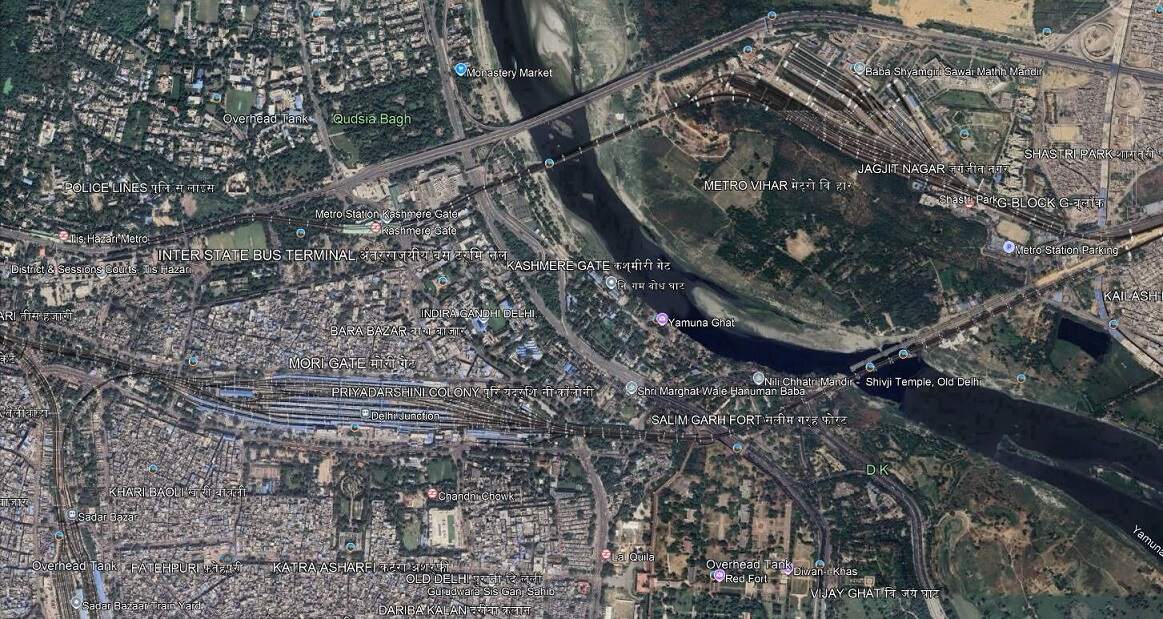
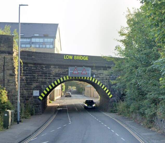
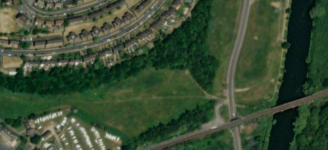
Now running East-West the line continues on through Vivek Vihar Railway Station – the area around the line is now heavily built up. Ahead lies the Old Iron Railway Bridge over the Yamuna River.
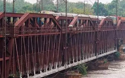
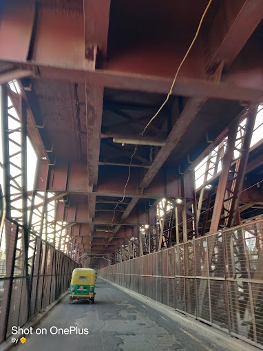
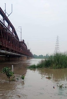
“The old Indian Railways bridge, popularly referred to as ‘lohey ka pul’ (iron bridge) has witnessed many floods and is also a reference point for measuring danger level for Yamuna water levels.” [18] The bridge was first opened for traffic in 1866 and is numbered as Bridge No. 249. It “was constructed initially as a single line, at a cost of £16,355. … It had a total length of 2,640 ft and consisted of 12 spans of 202 ft each. The superstructure consisted of steel lattice girders. … In 1913, the bridge was converted into a double line and later in the 1930s some of the spans were re-girdered and the roadway below was widened. The bridge was taken over by the North Western Railway in 1925 and is currently under the Northern Railway.” [18]
To the West of the Yamuna River, the line entered Delhi Junction Station.
The line runs on to the West through Kishanganj, Delhi Sarai Rohilla, Dayabasti, and Shakur Basti Railway Stations, any of which will allow a traveller to access the city of Delhi.
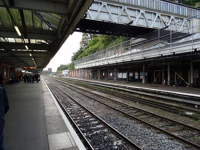
Our journey along the old EIR lines is completed here in Delhi. There may well be more articles in this series looking at some of the other lines initially constructed by the East Indian Railway. What has been most noticeable on the modern journey is the number of tracks required by the line and the frequency of services.
References
- G. Huddleston; The East Indian Railway; in The Railway Magazine, London, December 1905, p481-488.
- http://www.colonialfilm.org.uk/node/4544#:~:text=Between%20November%201905%20and%20March,members%20of%20the%20Royal%20Family, accessed on 9th October 2024.
- https://www.google.com/url?sa=t&source=web&rct=j&opi=89978449&url=https://www.railwaymuseum.org.uk/sites/default/files/2024-08/Rail%2520fares%2520resource%2520pack.pdf&ved=2ahUKEwiJ8Zr0yIGJAxU32QIHHReBFiUQzsoNegQIAhAM&usg=AOvVaw3PS6VobUUgVWMQcx3s9jzo, accessed on 9th October 2024.
- https://en.m.wikipedia.org/wiki/Koilwar_Bridge, accessed on 9th October 2024.
- https://es.pinterest.com/pin/indian-railwaysa-utility-for-the-british-turned-out-to-be-a-boon-for-independent-india-in-2024–603130575127693830, accessed on 9th October 2024.
- https://x.com/EasternRailway/status/1693572897451958538, accessed on 10th October 2024.
- https://commons.wikimedia.org/wiki/File:065.STARTED_FROM_HOTEL_MANISH_ON_14.08.2017_AT_02-30_P.M._FOR_HOWRAH_RAILWAY_STATION_BY_HIRED_TAXI.jpg, accessed on 10th October 2024.
- https://en.wikipedia.org/wiki/Howrah_railway_station, accessed on 10th October 2024.
- https://www.facebook.com/photo/?fbid=1224418747723184&set=a.207457379419331, 10th October 2024.
- https://en.wikipedia.org/wiki/Gaya_(India), accessed on 11th October 2024.
- https://en.wikipedia.org/wiki/Mirzapur, accessed on 13th October 2024.
- https://en.wikipedia.org/wiki/File:Allahabad_railwaybridge1870.jpg, accessed on 13th October 2024.
- https://en.wikipedia.org/wiki/Prayagraj, accessed on 13th October 2024.
- https://www.railyatri.in/trains/route-55339-kasganj-mathura-passenger, accessed on 16th October 2024.
- https://en.wikipedia.org/wiki/Mathura_Junction_railway_station, accessed on 16th October 2024.
- https://indiarailinfo.com/departures/kasganj-junction-ksj/254, accessed on 16th October 2024.
- https://www.hathrasonline.in/guide/about-hathras, accessed on 16th October 2024.
- https://zeenews.india.com/railways/priceless-heritage-know-all-about-indian-railways-157-year-old-yamuna-bridge-in-delhi-2636419.html, accessed on 16th October 2024.
- https://jdhsmith.math.iastate.edu/term/slineir.htm, accessed on 16th October 2024.


_1906.jpg)