The Barrow-in-Furness Tramways Company operated a steam-powered tram service from 11th July 1885 until electrification in 1904. Using a 4 ft (1.219 m) gauge, the tramway reached Ramsden Dock by 1886 and continued expanding through the electric era to locations such as Bigger Bank. Ultimately, on 5th April 1932 the tramway network was closed in favour of buses. [1]
From 1876 to 1901 the Kitson built over 300 steam tram engines and steam railmotor units, which were developed from a design by W. R.Rowan. [6][7]
The tramway network connected the town centre with areas like Ramsden Dock (1886) and eventually extended to Biggar Bank on Walney Island in 1911. After the network was bought by British Electric Traction, the company embarked on a modernisaton programme and the network saw its first electric service in 1904. [1]
Barrow-in-Furness Corporation took over operation of the service on 1st January 1920 at a cost of £96,250 (close to £5 million in 2026). Technological advancements in the form of petrol and diesel powered buses resulted in the closure of the tramway, with the last service running on 5th April 1932. [1]
The Network in 1899/1890
The steam tram network appears on the 1889/1890 6″ Ordnance Survey which was published in 1895. Three element can be identified:
1. Priors Lea to Ramsden Dock Station
One axis of the steam tramway appears to have run from Priors Lea in the North to Ramsden Dock in the South via Ramsden Square. … The route appears on the next eight extracts from the 6″Ordnance Survey of 1889/1990 which was published in 1895.
At the Priors Lee terminus, Top-right a tram engine had to run round its carriage. [5]The same length of Abbey Road in the 21st century, as shown above. [Google Maps, February 2026]Looking South on Abbey Road approximately at the location of the old tramway terminus. [Google Streetview, November 2024]Trams ran up and down Abbey Road. [5]The same length of Abbey Road in the 21st century, as shown above. [Google Maps, February 2026]A Methodist Chapel and Congregational Chapel sat to the West of the line. [5]A similar length of Abbey Road. [Google Maps, February 2026]Travelling South down Abbey Road. [Google Streetview, November 2024]The line crossed Abbey Road Bridge, with the Station a short distance away to the Northwest. [5]A similar length of Abbey Road in the 21st century. [Google Maps, February 2026]Looking Southwest along Abbey Road. Ahead is the bridge carrying the road over the railway. [Google Streetview, November 2024]At Ramsden Square the tramway turned Southeast along Duke Street. [5]Abbey Road, Ramsden Square, Duke Street and the very top of Michaelson’s Bridge Road. [Google Streetview, February 2026]The approach to Ramsden Square along Abbey Road. [Google Streetview, May 2022]Having turned left into Duke Street, trams continued in. Southeasterly direction. [Google Streetview, May 2022]A roundabout now sits at the top end of Michaelson Road. Trams would have been confined by the road layout of earlier time and swept round to the right on the near side of the modern roundabout. [Google Streetview, May 2022]It then turned Southwest along Michaelson Bridge Road [5]Michaelson Road Bridge carried the Tramway across the Devonshire & Buccleuch Docks. [Google Maps, February 2026]Looking South along the line of the old tramway across Michaelson Bridge. [Google Streetview, May 2022]Further South down Michaelson Road trams turned to the left into Ramsden Dock Road. [Google Streetview, May 2022]Trams ran along Ramsden Dock Road from its right-angle junction with Michaelson Road. [5]Approximately the same area in 21st century. [Google Maps, February 2026]Trams followed Ramsden Dock Road sweeping round to the South. [Google Streetview, May 2022]A relatively sharp curve to the right followed Ramsden Dock Road after the road had bridged the dock railways. [Google Streetview, May 2022]Ramsden Dock Road has now been closed to traffic. This photograph in 2009 appears to have been taken as the work to close the road was underway. [Google Streetview, April 2009]The steam tram served Ramsden Dock Station at its Southern terminal, where a loop was provided to obviate the need for the steam tram to run past its carriage. [5]The same length of the route of the old tramway as is shown on the above map extract. [Google Maps, February 2026]This final photograph faces South along the line of the old tramway towards the location of Ramsden Dock Station. [Google Streetview, May 2022]
2. A Line to Roose Station
A line left the route to Ramsden Dock Station at the North end of Michaelson Road, continuing Southeast on Duke Street and then along Strand to Cambridge Hall Mechanics Institute where it turned Northeast.
This tramway route ran along Duke Street and Strand to Cambridge Hall Mechanics Institute and the old Strand Station where it turned Northeast at St. George Square. [5]The roads mentioned above still remain – Duke Street, Strand. St. George’s Square still exists but Salthouse Road now runs through it to meet Strand. [Google Maps, February 2026]Duke Street immediately beyond the roundabout. [Google Streetview, May 2022]Duke Street meets Strand, the tramway ran round to the left, almost straight on. [Google Streetview, May 2022]Further along Strand with the old railway station in the distance. [Google Streetview, May 2022]Trams turned from Strand onto Salthouse Road. [Google Streetview, May 2022]
The tramway then ran along Salthouse Road on the North side of the Furness Railway Works.
From St. George’s Square the line ran along Salthouse Road on the North side of the Railway Works. [5]The area of Furness Railway Works appears to be underdevelopment in this image. Salthouse Road runs across the top of the site. [Google Maps, February 2026]Salthouse Road with the old Furness Railway Works on the right. The rod curves round to the right. [Google Streetview, May 2022]Further East on Salthouse Road. [Google Streetview, May 2022]Close to the Vulcan Foundry was a tramway depot on the South side of Salthouse Road. The tramway then passed under the viaduct carrying the line Northwest from St. Luke’s Junction to Barrow Central Station. [5]The same area in the 21st century. A housing estate sits on the site of the Vulcan Steel & Forge Works. [Google Maps, February 2026]The tramway depot on the South side of Salthouse Road, as it appears on the 1910 25″ Ordnance Survey. [8]The Viaduct carrying the railway from what was St. Luke’s Junction, Northwest towards Barrow Central Station. Google Streetview, May 2022]St. Luke’s Junction is bottom left of this next map extract, St Luke’s Church is at the right side of the image. The tramway continues Northeast up Roose Road. [5]The same location in the 21st century. [Google Maps, February 2026]Further East, the old tramway ran ahead along Roose Road. [Google Streetview, May 2022]Further East the tramway continued along Roose Road. [Google Streetview, May 2022]The tramway continued East on Roose Road. [5]The same area in the 21st century. [Google Maps, February 2026]Continuing along Roose Road. [Google Streetview, May 2022]Approaching Roose Station and the terminus of the tramway, the road and tramway turned Northeast before bridging athe railway at the South end of Roose Railway Station. A loop was provided to allow a steam tram to run round its carriage. [5]The final length of the tramway was on Roose Road. The terminus was to the East of the railway line and Roose Station. [Google Maps, February 2026]Roose Road bends round towards the Northeast. [Google Streetview, May 2022]Approaching the location of Roose Station, the road curves back towards the East a crosses a railway bridge. Google Streetview, May 2022]The location of the tramway terminus, the photograph is taken facing away from Barrow in an East-northeast direction. Google Streetview, May 2026]
3. A Short Line Serving the Steelworks
Just two map extracts are all that is needed to cover the length of this short line which ran along Duke Street between the Steelworks and Ramsden Square.
A triangular junction was formed at the Northwest end of Duke Street. A short length of tramway with its mid-point at the junction with Duke Street, ran North-South on Walney Road outside the Steelworks. From there the line ran Southeast along Duke Street. [5]The line continued Southeast on Duke Street and met the wider tramway network at Ramsden Square. [5]
The full length of the line is shown on modern mapping below. ….
The old tramway ran from Walney Road to Ramsden Square along Duke Street. [Google Maps, February 2026]The View Northwest along Duke Street towards the junction at Walney Road. In times past this view would have been dominated by the Steelworks and no doubt shrouded in a pall of smoke. Google Streetview, May 2022]A view along Duke Street, facing Southeast towards Ramsden Square. [Google Streetview, May 2022]Looking Southeast along Duke Street close to Ramsden Square. [Google Streetview, May 2022]
Changes Immediately After Electrification
The short line along Duke Street serving the Steelworks does not feature on the 1910/1911 25″Ordnance Survey published in 1911/1913.
A new tramway line left Michaelson Road at its junction with Bridge Road. The surface of Bridge Road was littered with a whole series of different lines. The tramway sat on the North side of the road and ran on Northwest into Ferry Road, terminating opposite the Walney Bridge Approach Road.
Summary
Steam powered trams in Barrow-in-Furness, like elsewhere we’re a relatively short-lived phenomenon which last only until electrical technology had advanced sufficiently to be used on street networks.
“Kitsons entered the steam tramway locomotive field in 1876 building some combined steam cars to W.R. Rowan’s design. In 1878 they built three to their own design with vertical boilers, four coupled wheels and inclined outside cylinders. Motion was by means of a modified version of Walschaerts valve gear. All was enclosed in bodywork and the wheels and motions were surrounded by protective plates. The condensing system was placed on the roof and consisted of a series of copper tubes through which the exhaust steam passed, the surrounding air cooling the steam and the condensate returning to the feed water tank. After many trials it was decided to replace the vertical boiler by a horizontal type and this was standardised for future steam trains. Various types of condensers were tried and the final type was a series of arched transverse tubes which were a great improvement.
In Kitson’s patent valve-gear, a modification of Walschaert’s valve gear, the ends of a floating lever are linked to the crosshead, the valve-spindle, and intermediately at a point near the valve-spindle; the lever is pinned to the radius-link, which receives its rocking movement through an arm linked to the coupling rod. The motion of the valve and its spindle is a compound of two movements: one, a movement directly the inverse of that of the piston, on a reduced scale, for the lead; the other a reduced duplicate of the vertical movement of the coupling rod, to open the port for steam” (D. K. Clark Tramways, their construction and working, 2nd Ed., 1894).
More than 300 units were built and besides supplying many to the tramway systems of the British Isles, others were sent to New Zealand. Australia and the continent. The last one built was in 1901 for the Portstewart Tramway (Works No. T302). Work numbers for tram locomotives were kept separate and bore a prefix T.”, via, https://steamindex.com/manlocos/kitsons.htm, accessed on 16th February 2026.
And now these three remain: faith, hope and love. But the greatest of these is love.
FaithOur ‘Faith’ can mean what we believe. … When we talk about the faith of the Church we often mean a list of things that a Christian needs to believe. Over time the church has developed creeds which are intended to help us remember or recall together the important beliefs that we share. Often Christians say ‘The Creed’ when they are in church together on Sundays. Doctrine is very important but it is not what Paul is talking about in 1 Corinthians 13:13.
Our ‘Faith’ can mean what we believe. … When we talk about the faith of the Church we often mean a list of things that a Christian needs to believe. Over time the church has developed creeds which are intended to help us remember or recall together the important beliefs that we share. Often Christians say ‘The Creed’ when they are in church together on Sundays. Doctrine is very important but it is not what Paul is talking about in 1 Corinthians 13:13.
Another way we use the word ‘faith’ is to talk about how much faith we have. …
So, perhaps, we say to someone, if only you had enough faith, you would be healed. … Faith, in this context, seems to be something that we might be able to generate ourselves. There is a bible verse which we often hear like this “faith can move mountains.” And we take it to mean that strong belief and determination will allow us to overcome immense obstacles, achieving seemingly impossible things. I guess we imagine ourselves generating faith, screwing ourselves up to believe.
Just a bit more faith, just a bit more and we will see God work, we will have healing. … Perhaps we even try to demonstrate our faith by giving more generously, praying more earnestly, serving with greater commitment. But if we see faith this way, we have misunderstood what Jesus was talking about in the bible verse that we partially remembered.
In Matthew 17:20 and Mark 11:23, Jesus talks about faith as small as a mustard seed being able to move mountains. Have you ever seen a mustard seed? Mustard seeds are tiny, smaller than a grain of millet. The very point Jesus is making is that it isn’t the size of our faith that matters but where we place the little faith we have.
Throughout the whole New Testament there is only one root Greek word used for faith. It is the word PISTEO. Yes, it might be used in different contexts, tenses and verses. We can use it in many different ways but in the original language of the bible it has one meaning. PISTEO-faith always means ‘faithfulness’, ‘commitment’ and ‘steadfastness’ – faithfulness and commitment to God in Jesus. It is not focussed on what we can do, nor on how strongly we believe. PISTEO-faith is all about the one we have faith in. Mountains in our lives are moved not by the strength of our faith but by the God in whom we trust.
PISTEO-faith is about faithfully following Jesus but it is also about something more. …. I need a chair to illustrate this ……… What do you think of this chair? Is it a beautiful chair? …. What is this chair for? …. It does not matter so much where a chair comes from or how beautiful a chair is. … What matters is that we trust that it will hold our weight. It is no good just hovering over it, no good admiring as a beautiful chair, no good being tentative about it. We have to commit wholly to trusting in the chair and put our weight on it. … Then it does its job.
New Testament PISTEO-faith is just like this. We need to wholeheartedly, faithfully, follow Jesus and when we are faithful, when we place our weight on our faith, we will discover that it holds us secure.
So, that is Paul’s first word FAITH. …..
Hope
In the UK, we sometimes do this … (cross fingers) and we say. “Cross our fingers and hope it works out.” When we do this, we are seeing hope more as ‘wishful thinking’.
Alternatively, we can talk about ‘the power of positive thinking’, as if by just hoping something will happen, we will see it happen.
Sometimes we say to people, “I hope you get better soon.” Then, hope seems to be about wishing something was true.
None of these is Christian Hope. The bible actually has a lot to say about Hope. But for now, here are just three verses.
Psalm 33:20-21: We wait in HOPE for the Lord, he is our help and our shield. In him our hearts rejoice for we trust in his holy name.
Isaiah 40:31: Those who HOPE in the Lord will renew their strength. They will soar on wings like eagles. They will run and not grow weary, they will walk and not be faint.
Romans 8:25: We HOPE for what we do not have and we wait for it patiently.
Christian Hope is not wishful thinking. Nor is it positive thinking. Christian Hope is all about the one in whom we have Hopr. God our Father, the Lord Jesus Christ and God’s Spirit who dwells in us.
When we look forward with Hope, we see the future in God’s hands. We look forward with Hope because we have been made right with God through what Jesus has done for us at the cross. We look forward with HOPE because the Holy Spirit lives in us and leads us on into the future God has for us. … Because we hope in God, as Isaiah says, our strength is renewed. We will soar like eagles, we will have the stamina we need for the journey ahead.
So, FAITH, and HOPE.Paul’s third thing was LOVE. And, Paul says Love is the greatest of all three.
Love
The Apostle John, became the Bishop of Ephesus when he was an old man. We think that he wrote John’s Gospel, three short letters and the book of Revelation.
The first of John’s three letters is all about Love ….
“This is love, not that we loved God, but that God first loved us and sent his Son as an atoning sacrifice for our sin.” (1 John 4:10)
“This is how we know what love is: Jesus Christ laid down his life for us.” (1 John 3:16)
“How great is the love the Father has lavished on us, that we should be called children of God.” (1 John 3:1)
The story is told of John as Bishop of Ephesus, in his old age with his powers failing, sitting in front of his congregation to preach. He began his sermon. … Little children, love one another. …. And he continued: Little children, love one another. … And again: Little children, love one another. Indeed, his whole sermon consisted of the repetition of just 5 words: Little children, love one another.
The following Sunday, Bishop John sat down to preach again. He began his sermon: Little children, love one another. Again, his sermon was just the repetition of those five words: Little children, love one another.
By the next Sunday, the congregation was getting a little restless. John sat down to preach once again. How do you think he started his sermon? Yes, with just those five words … Little children, love one another. At the end of this service a number of people came to speak to him. “Bishop John,” they said, “Why do you just keep repeating those five words. Isn’t it time to move on to something different?”
Bishop John looked quietly at them and said, “My sermon will change when I see evidence that you are loving one another.”
Ultimately, the Gospel is a Gospel of love, nothing significantly more. God is the source of all love. God’s love has made us God’s children. God’s love comes to us in many different forms: …
God’s LOVE comes to us in the New Testament story of Jesus. … Love first came down to us at Christmas. It was born and walked about among us as a human being. Love died for us, love was outpoured for us at the Cross. Love came as sacrifice and service. Love brought dignity and purpose for Jesus’ friends, his disciples. Love brought new roles, new tasks to perform, new gifts to develop and share. Love came in the healing hands of Jesus.
God’s LOVE comes to us now in many different forms. … In the people we know who follow Jesus. In acts of charity which brings real hope into places of despair. In the prayers of faithful friends who hold us up before God when we struggle to pray for ourselves. Surprisingly, love turns up in unexpectedly places. …
St. John as Bishop of Ephesus says: “Little children, love one another for love comes from God.”
The Apostle Paul says: “Faith, Hope and Love abide, these three, and the greatest of these is love.”
FAITH-ful following of a faithful God will make mountains move.
HOPE in God will allow us all to soar on wings like eagles.
But most important of all, God’s LOVE has won our hearts and calls us all to LOVE as Jesus Christ has loved us.
Barrow-in-Furness Railway Station is shown in the featured image above and repeated in the first image below. It featured a large, distinct covered roof over the platforms, as seen in this vintage postcard view from the south. The prominent locomotive is one of the Furness Railway K2 Class locomotive, often referred to as “Larger Seagulls”. [4]
Barrow was featured in The Railway Magazine in March 1959. [1] The rebuilding of the old Central Station at Barrow-in-Furness which was virtually destroyed (please see the images below) in the air-raids of 1941 was completed in the late 1950s. The replacement buildings marked another link broken with Barrow’s past. Originally known as Barrow Central Station and the headquarters of the Furness Railway, it was, by the end of the rebuilding renamed Barrow-in-Furness. Early in the 20th century, the borough boasted ten stations. It had grown from a hamlet of a few farms with a population of around 100 to “a seething steel-town of 60,000 in under forty years.” [1: p149]
The most significant factor in the dramatic increase in population was apparently “the progress in railway development in the 1830s. The two dukes had toyed with the possibility of a mineral line for some years, but it was not until George Stephenson’s plan for the Caledonian, West Cumberland & Furness Railway was made known in 1837 that serious attention was given to the idea. Though this scheme for crossing the Duddon Estuary and Morecambe Bay came to nothing, a survey for embanking and reclaiming land and for a mineral line in Furness was carried out in 1841 by James Walker at the request of the Earl of Burlington (later seventh Duke of Devonshire).” [1: p149]
The coming of the railway made the exploitation of vast iron ore deposits feasible. Large ironworks, steelmaking, and shipbuilding industries developed, attracting thousands of workers and causing rapid population growth, urbanization, and infrastructural development. Barrow village had been shipping iron ore for many years and was chosen as a suitable port for iron ore from Lindal-in-Furness and slate quarries at Kirkby-in-Furness.
Google Maps satellite imagery shows the relative location of Kirkby-, Lindal-, and Barrow-in-Furness. [Google Maps, 21st December 2025]
The person directly responsible for the organisation of the Bill and for the affairs of the new Furness Railway Company was Benjamin Currey, Clerk of the House of Lords and Agent of the Devonshire Estates. He visited Furness frequently at this period and was able to influence the local population in favour of the railway. [1: p149-151]
It appears that a strong influence on the development of railways in the area was the purchase of Roa Island by J. A. Smith, who, in conjunction with the Preston & Wyre Railway at Fleetwood, planned to build a pier to accommodate a ferry service between Furness and Fleetwood.
Roa Island lies just over half a mile (1 km) south of the village of Rampside at the southernmost point of the Furness Peninsula in Cumbria. [2]
Roa Island in the 21st Century. This view looks North towards the village of Rampside. [3]Roa Island sits to the South of the Furness Peninsula and North of Piel Island and Piel Castle. [Google Maps, December 2025]
Smith’s plans meant that the Furness Railway Company needed to provide a connecting line to the pier. Two trips between Fleetwood and Roa Island were made daily from 24th August 1846.
A superb diagrammatic map of the railway system around Barrow-in-Furness giving details of the network in 1959 with dates on railways previously proposed but not built and others which had already been removed. The present main line from Ulverston enters the sketch map in the top right. The line to Whitehaven leaves the map centre-top. [1: p150]The wider Furness Railway network and its connections to other companies’ railways in the pre-grouping era. [1: p151]
Initially the Furness Railway Company built a single line North from the pier on Roa Island. The competing needs of mineral and passenger traffic could not be accommodated. The solution was the doubling of the track running North-South between Millwood Junction and Roose Junction. Timetables were published in Bradshaw but Smith’s ferry was not ready in time for the new season. Unsurprisingly, relationships between Smith and the Furness Railway Company were strained!
Indeed, the relationship continued to be difficult, seemingly with Smith seeking to persuade the Furness Railway to purchase his interest in the pier. Eventually, after significant damage occurred to the pier in a storm on 27th December 1852. The Furness Railway saw an opportunity to deal with the problem and bought out Smith’s interests in the pier and in any of Smith’s schemes to access mineral reserves in Furness. Apparently the buy out cost £15,000. However Smith’s pier continued in use until the opening of Ramsden Dock Station in 1881. The pier “was rebuilt in 1867-8 to accommodate the Midland Railway boat trains (which began in 1867) and survived until 1891, when it was finally demolished.” [1: p152]
Andrews continues: “During the early years Barrow grew slowly, as railway workshops were built and its pier gradually enlarged, and it was not until 1859 that the stage was set for the boom that hit this village in the 1860s. In 1846 a young man named James Ramsden, from Wolverton Works, had been appointed Locomotive Superintendent of the Furness, and from the outset had shown considerable promise as an administrator. He was appointed Secretary and Superintendent of the Line in 1850.” [1: p152]
Continuing developments saw the line to Kirkby-in-Furness extended in 1848 to Broughton and the Whitehaven & Furness Junction Railway opened to Whitehaven in 1850. The line to Dalton was continued to Ulverston by 1854 and the Ulverston & Lancaster Railway opened through to Carnforth by 1857. In Barrow, the first blast furnaces opened in 1859.
“With the local production of iron and the establishment of through rail communication, Ramsden was able to put into operation his plan for a new Barrow – a model industrial town and port. The first stage was the construction of a dock between Barrow Island and the mainland, when it would be possible to build up passenger and freight steamer services with Belfast and the Isle of Man. Stage two was the development of an industrial estate on Barrow Island and on the mainland shore, with a residential area inland.” [1: p152]
1863 saw an Act obtained for the construction of the Devonshire and Buccleuch Docks. The Devonshire Dock was opened in September 1867. During that year: Barrow became a County Borough; a ferry service from Piel Pier to the Isle of Man commenced; the Belfast ferry service opened (in the Autumn); and the population of Barrow exceeded 11,000; and the Barrow Haematite Iron & Steel Company paid a 30% divided to shareholders.
“Negotiations with the Midland Railway led to the Furness & Midland Joint line scheme of 1863 which included the moving of the Midland steamer services from Morecambe to Piel Pier.” [1: p153]
It seems that the “Midland Railway was anxious that a communication should be provided for affording better access to the Lakes in connection with the Yorkshire districts.” [8]
Andrews tells us that, “During the 1860s, the Furness Railway … absorbed its neighbours one by one. The Ulverston & Lancaster, which had been heavily subsidised by the Furness during its construction, was bought in 1862 and … the Whitehaven & Furness Junction Railway was taken over in 1866.” [1: p154]
There were plans for the construction of a viaduct to span the Duddon Estuary which would have been part of a new line running North along the coast from a point near to the Iron Works and Steel Works at Hindpool. The scheme failed to gain parliamentary approval because it constricted access to the small port at Borwick Rails.
After a depression in the late 1860s, a return to prosperity in 1870 brought with it a fresh wave of development plans. These included:
Moving the ferry/steamer service from Piel Pier to a new Dock Station.
Two loop lines intended to relieve congestion on the mainline, one the Gleaston loop between Lindal and Salt-house, and the other the Barrow loop from Salthouse to Ormsgill. Later the Gleaston scheme was abbreviated to a single line branch to Stank Mines (opened in 1873. The Barrow loop was slowed by the depression of the late 1870s and was not opened until 1882;
Completion of the docks, which ultimately proved to be somewhat over scale. However the deep water berth at Ramsden Dock was a great improvement over Piel Pier.
High capital expenditure in the 1870s meant that resources for railway development were limited in the 1880s. In the 1890s, exhaustion of local iron ore stocks and the lower cost of imported iron ore saw local freight traffic decline rapidly. In 1893, the Midland Railway gave three years’ notice to the Furness Railway as it had developed its own harbour at Heysham. Some services remained at Barrow until the first world war. Services declined further after the railway grouping, iron ore traffic dwindled away, leaving only that between Hodbarrow and the iron works/docks.
A century of gradual decline brought changes to the rail network. The original line entered Barrow “at Millwood Junction, where the Kirkby and Dalton branches joined, and then ran down the narrow valley to the ruins of Furness Abbey, where a station and hotel were completed in 1847. This became an important interchange station when the lines through to Carnforth and Whitehaven were open, and although a curve was opened between the two branches on 1st August 1858, most trains continued to reverse at Furness Abbey until 1873 when Dalton took over the exchange traffic; the now-unused bays at Dalton were for the Barrow branch trains. Furness Abbey was still used for dividing boat trains into portions for the dock and Barrow until 1904, and the down loop used for this existed until the 1930s. An up bay at Furness Abbey was used in the 1880s for a service from and to Coniston, but this was discontinued in 1891. The first part of the original Kirkby branch from Millwood to Park Junction (renamed Goldmire in 1882) fell rapidly into disuse after this as Whitehaven-Barrow traffic used the Park loop after 1882. Millwood Junction was finally removed in 1898.” [1: p155]
In 1959, Roose had “a reasonable passenger traffic from the surrounding housing estates. The main road originally crossed the line on the level and it was at these gates that trains first stopped by signal in the 1850s. The old junction with the Piel line was where the bridge carrying the main road now stands (which was completed with the [station present in 1959] in 1875).” [1: p156]
“The Piel line curved away to the left, following the shore for about a mile before entering a cutting to reach Rampside Station.” [1: p156]
The three map extracts below show the line as it appeared on 25″ OS mapping of 1889, published in 1890. The chord running South towards Rampside Station had, by this time, already been removed. …
The next sequence of satellite images shows the line to Rampside Station and Roa Island superimposed on modern satellite imagery. The main line can be seen curving away to the West after passing South through Roose Railway Station. …
This sequence of three satellite image extracts from Railmaponline.com show the line serving Piel Pier. Rampside Station was closed to the Concle Inn at the top of the third of the images. [10]
The two map extracts below show Rampside Station and Roa Island as they appear on the 25″ OS mapping of 1889, published in 1890.
Rampside Railway Station was a single platform station opened on 24th August 1846 as Concle Station, [14: p37] it was renamed Rampside in 1869. The station remained operational until 1936 when it closed along with the line and the following station at Piel, which had been reachable via the Roa Island Causeway. The station building and entire branch line had been demolished by the 1980s. [15]
Roa Island in 1889. The Pier Hotel has the benchmark on its West side. [13]This view faces South on Roa Island, the Pier Hotel is now a private dwelling, Piel Station was to its West side (on the right of the Hotel in this image). [Google Streetview, October 2024]
Returning to the main line: South and West of Roose Railway Station the main line curves round towards what was Salthouse Junction.
Only the main line remains to the East of Salthouse Junction. To the West, a single line leaves the main line at Salthouse Junction on the South side of the main line, heading West alongside Cavendish Dock.
Andrews tells us that a significant embankment was built from Salthouse Junction to Barrow Island. A line was laid along this which separated the Ramsden and Buccleuch Docks, running to the South of what was the old line to Strand Station. After the building of the embankment, land to its North was reclaimed and the old Strand Station was closed together with the line which approached it on a rather tortuous/sinuous route. Parts of the embankment for this old line were still visible in the late 1950s.
Andrews tells us that “The original Barrow Station, a wooden structure with one platform, rapidly became inadequate to deal with the expanding traffic of the town and was converted into an engine shed in 1862.” [1: p156] Apparently, in the late 1950s, it was still in use “as a carpenters’ shed and offices, although the lines leading to it were closed in January 1871. … The main line was taken round the outside of the works [shown below] to reach the newer Strand Station in 1862. This, [in the late 1950s,] the Railway Institute, had to be enlarged again in 1873 and the old carriage shed … converted into an arrival station. However, hardly had these alterations been completed in the Strand, than the intention to build a large new station in the centre of the new town.” [1: p156]
This extract from the 1911 Ordnance Survey shows the railway works and sidings. [11]This image is an extract from Railmaponline.com’s satellite imagery showing the same area as the map extract above. So much railway infrastructure has been lost. [10]
The line from St. Luke’s Junction through Barrow Central Station was not opened until 1882. Andrews continues: “by which time it had been put on a through route to the North by the completion of the Park loop line. A curve between Oaklea and Goldmire Junctions allowed the station to be approached from Carnforth in both directions. This curve [shown dashed in the adjacent image] was closed in 1904.” [1: p156]
Andrew’s describes Central Station as having “a large, all-over roof covering Platforms 1 and 2. No. 3, the other side of the island platform, was uncovered and was used by the local service to Piel which ran from 1881 to 1936. These trains approached the Piel line by a curve from Salthouse Junction built in 1873; the line from Roose Junction to Parrock Hall was closed in 1881, after the boat trains were diverted to Ramsden Dock.” [1: p156]
Central Station appears top-centre on the extract from the sketch map of Barrow’s railways below. We will return to look at this later in this article
Andrews continued: “From 1881, the boat trains left the main line at Salthouse Junction and proceeded down the embankment to Loco Junction, where the curve from St. Lukes Junction, on the Central line, came in on the up side, and where the line to the Barrow goods yard and old Strand Station curved away. The passageway between the Ramsden and Buccleuch Docks was crossed by a swing bridge, replaced by the present lift bridge in 1907.” [1: p156-157]
And again: “Shipyard Junction was reached in a cutting and the line to the Naval construction works curved off to the right. A station, Island Road, was built in 1899 for workmen’s trains and these have used the platforms ever since. The line is now used for out-of-gauge loads to Vickers Works, near Island Road Station, and normal freight traffic is worked over Devonshire Bridge from the goods yard.” [1: p157]
Andrews continued: “Reaching the shore, the line to the docks branched off at Dockyard Junction and the passenger line curved away to the left to reach Ramsden Dock Station, which consisted of a long covered platform and a short bay. A goods shed separated the platform from the quayside and at low tide passengers embarked through a tunnel under the lines. The station was completed in 1885. Regular steamboat traffic to the Isle of Man, Belfast and Fleetwood ceased at the outbreak of the first world war, but excursion boats were run from the station, mainly to Blackpool, until 1936. The station was pulled down in 1938.” [1: p157]
Although the docks, seen on satellite imagery, seem substantially as shown on the drawing in Andrews’ article, closer inspection will reveal substantial changes. [Google Maps, February 2026]
Before looking at the rail infrastructure of the 21st century it is right to at least try to show what existed in around 1910 and which has since been substantially lost.
It is difficult to give an effective account of the complexity of the railway infrastructure around the docks at the turn of the 20th century, although the sketch map from 1959 is particularly helpful for understanding the mid-20th century situation. The following extracts from the 25″ Ordnance Survey from around 1910 may do more to obfuscate than to illustrate!
The Buccleuch Bridge of 1907 is shown in this extract. [20]
The location of the 1907 lift bridge as it appears in the 21st century. [Google Maps, February 2026]
As we have noted, the lift bridge mentioned by Andrews in 1959, is long gone, as is all of the network to the West of the bridge. That network was substantial. … A line ran from the bridge Southwest before curving round to the Southeast to head into Ramsden Dock Station.
Ramsden Dock railway station (also known as Barrow Island and officially as Barrow Ramsden Dock) was the terminus of the Furness Railway’s Ramsden Dock Branch. [26]
The station operated between 1881 and 1915. Located at the southern tip of Barrow Island alongside Ramsden Dock it primarily served the adjacent Walney Channel passenger ferry terminal. It was accessible by Ramsden Dock Road and the Barrow-in-Furness Tramway. [26]
The station building was demolished in the 1940s, while the rail line leading to it was completely removed in the 1990s. No evidence of either remain and a windfarm operations centre has been built on the site. [26]
Running parallel to the line through Ramsden Dock Station were lines which served the various sidings in the docks. These lines can be seen in the extract above entering at the third-point along the top from the left of the image, and appear on the extract below, running diagonally across the image from the top-left corner.
A tree of sidings curved off the feeder line and ran East-West. The lines leaving the bottom of the extract at the third-point from the right enter the last extract from the quarter-point from the left. [20]Anchor Basin and the Anchor Line Sheds circa 1910. [20]South of the extract above, the extract shows the Dock Basin which had a lock gate to open water at its Southwest end with Cattle Sheds to its Southeast. [20]A grain store sat to the Southeast of Anchor Basin and a lock linked it with the Dock Basin in the last extract. The Northeast end of the Cattle Sheds can be seen at the bottom of this extract. [20]Approximately the same area as covered by the four map extracts above, as it appears in the 21st century! [Google Maps, February 2026]Lines ran between the Southeast dock wall of Ramsden Dock and the shore. [20]At the Southeast corner of Ramsden Dock, one line remained close to the shore with another turning North to run between Ramsden Dock and Cavendish Dock. The line along the Southeast side of Cavendish Dock and close to the shore led across to the Piel Branch curving round to the North to make a junction with the Branch. [20]The line heading North linked back to the line that ran along the Northwest edge of Cavendish Dock and crossed the Buccleuch Bridge. [20]This length of line is part of the remnants of what was on an extensive rail system. [20]Approximately the same area as covered by the four map extracts above in the 21st century! [Google Maps, February 2026]
Much more has changed since 1959. The significant network of dock railways has been replaced by a single line running down the East side of Ramsden Dock.
Associated British Ports’ “Port of Barrow plays a key role in serving the offshore energy industry in the region described as Britain’s “energy coast”. The port has 15ha of secure open storage and is the site of BAE Systems’ submarine design and manufacturing facility. … The Port of Barrow … handles over 100,000 tonnes of cargo each year, comprising an array of different products including limestone, sand, aggregates, granite and woodpulp. Heavy lift projects are also routinely and efficiently carried out to support the offshore energy sector.” [19]
To the Northwest of the dock lines we have been looking at, were the Naval Engineering Works and Shipbuilding Yard. These were served from the Southeast by a line heading West-northwest from Shipyard Junction which ran round the Southern side of the stadium and then in the surface of Island Road.
The road layout in the area of the Steelworks and to their immediate South has changed significantly. The image immediately below looks North-northwest along the line of the old and new Ironworks Road which now accommodates Northbound traffic on the A590.
Looking at the lines further to the North, Andrews said in 1959 that, “The economy drive which closed the Piel branch in 1936 also abolished the junction into the goods lines at Ormsgill north of the Central Station, and now trains from the north of the iron works have to work round through Loco Junction and Barrow yard.” [1: p157]
Ormsgill Junction is at the bottom-left of this sketch map. Lines to Hawcoat Quarry and Roanhead Iron Mines were similarly closed by the late-1950s. [1: p150]
But to complete our look at the central area of Barrow, we follow the line up through Barrow Central Station to the North.
Barrow Central Station after the turn of the 29th century. [21]The site of the station as it appears on the ESRI satellite imagery supplied by the National Library of Scotland. [21]Barrow Central Station seen from the South on the Station Approach in the 21st century. [Google Streetview, August 2018]Barrow Central Station seen from Abbey Road Bridge looking Northwest. [Google Streetview, May 2022]
Andrews said in 1959: “The buildings at the new Barrow in Furness Station have been constructed on the site of the old, and are mainly steel framed. A considerable amount of glass has been introduced in the infilling panels forming windows to both the road and platform elevations. Multi-coloured rustic bricks have been used, with slate window sills and fascia over the high-level windows of the front entrance. The platform awnings are of light steel decking, with continuous roof glazing in line with the face of the external wall adjacent to No. 1 platform. The flooring of the booking hall and cafeteria-waiting rooms is laid in precast tiles, and polished hardwood has been used extensively as a decorative wall lining in the cafeterias, and for the framing to the ticket windows and internal window frames. The walls of the booking hall are finished in glazed tiles to the top of door height, with a glossy finish above, and re-erected on the south wall is the Furness Railway 1914-18 war memorial, Loudspeakers have been installed through out the station, and the open platform lighting is fluorescent, incorporating the station name within the light fitting.” [1: p200]
Looking North from the end of the station platform towards what was the location of the carriage sheds. [Google Streetview & Vextrix Surveys, November 2021]Carriage Sheds to the Northwest of Barrow Central Station in the early 20th century. Note the single industrial siding serving British Griffin Chilled Iron Works. [21]A similar area in the 21st century! [21]By the early 1930s, the provision for local industry close to the carriage sidings had increased significantly! This extract comes from the 25″ Ordnance Survey of 1931, published in 1933. [35]The lines passed under Devonshire Road. [23]The same location in the 21st century. [23]This photograph was taken in the late 1950s from a point somewhere Southeast of Devonshire Road. The carriage sheds are on the right of the photograph. There are two tracks on the left of the main line which served industrial premises. The Ordnance Survey shows the first of these sidings serving British Griffin Chilled Ironworks. This image was shared by Ralph Sheppard on the Barrow-in-Furness in Old Photos Facebook Group on 29th December 2019. [34]Looking Southeast from Devonshire Road towards the maintenance facilities and the station beyond. [Google Streetview, November 2024]Looking Northwest from Devonshire Road. [Google Streetview, November 2024]Continuing Northwest, the lines passed under Walney Road. [23]The same location in the 21st century. [23]Looking Southeast from the A590, Walney Road, along the line of the railway towards Barrow Railway Station. [Google Streetview, November 2024]
We finish our survey of Barrow’s Railways at this northern point. Towards the end of his 1959 article, Andrews commented about the first half of the 20th century: “The last fifty years have shown a steady decline in Barrow’s railway system, the inevitable result of the failure of James Ramsden’s vision to become reality. Although the iron ore brought a temporary and easy prosperity, the geographical situation was a permanent setback to the port. The industrial centres of Lancashire and Yorkshire were just too far away and the Furness main line was not built for real speed. Moreover, the Furness Railway Company just failed to establish sufficient variety of local industry to keep the port busy with local trade and the town came in the end to rely almost entirely on the shipbuilding industry. Since the last war, however, there have been signs of a reversal in this downward trend; sidings are being laid in to serve new factories at Salthouse and Sandscale, and Barrow is to become a divisional centre in the L.M.R. de-centralisation scheme. It is hoped that some of the prosperity of the old days is on the way back.” [1: p157]
From 1959 to 2026, Barrow-in-Furness transitioned from a traditional heavy industrial town into a specialized hub for nuclear submarine construction and offshore energy. While iron and steel industries closed by 1988, the BAE Systems shipyard became the town’s primary economic driver, cementing its role in national defense.
British Cellophane (1959) and Kimberly Clark (1967) established manufacturing plants in Barrow and the 1980s saw the development of gas terminals for the Morecambe Bay gas field.
The vast majority of the industrial railway heritage has disappeared. The town is left with its mainline service which serves the Cumbrian Coast and connects the town to the wider UK, and a branch line which runs down to the ABP port facilities.
References
M. J. Andrews; The Railways of Barrow; in The Railway Magazine, Tothill Press, London, March 1959, p149-157 & 200.
The featured image above is a photograph of Saint Felicien Railway Station in 1959. [9]
In the North of Québec, some 300 miles from Montreal, there is an area of extensive mining – deposits of copper, zinc, gold and cobalt wee being mined in the mid-20th century. In the first half of the 21st century, Northern Quebec’s mining sector is a significant part of the province’s economy, focusing on gold, nickel, lithium, graphite, iron, and copper, focusing on gold, nickel, lithium, graphite, iron, and copper, with major operations like Glencore’s Raglan (nickel) and Agnico Eagle‘s Canadian Malartic (gold) leading the way, alongside emerging lithium projects in the James Bay region, leveraging Quebec’s hydropower for cleaner operations and creating jobs in remote areas like Nunavik, despite logistical and environmental challenges.
Raglan Mine is, today, a large nickel mining complex in the Nunavik region of northern Quebec. “It is located approximately 100 kilometres (62 miles) south of Deception Bay. Discovery of the deposits is credited to Murray Edmund Watts in 1931 or 1932. It is owned and operated by Glencore Canada Corporation. The mine site is located in sub-arctic permafrost of the Cape Smith Belt, with an average underground temperature of −15 °C (5 °F).” [1]
In 2025, the mining complex “is served by and operates the Kattiniq/Donaldson Airport, which is 10 nautical miles (19 km; 12 miles) east of the principal mine site. There is a gravel road leading from the mine site to the seaport in Deception Bay. It is the only road of any distance in the province north of the 55th parallel. As the complex is remote from even the region’s Inuit communities, workers must lodge at the mine site, typically for weeks at a time. From the mine site employees are flown to Val D’or, or in the case of Inuit employees, their home community. Ore produced from the mine is milled on-site then trucked 100 km (62 mi) to Deception Bay. From Deception Bay the concentrate is sent via cargo ship during the short shipping season (even by ice breaker it is only accessible 8 months of the year)to Quebec City, and then via rail to be smelted at Glencore’s facilities in Falconbridge, Ontario. Following smelting in Ontario, the concentrate is sent back to Quebec City via rail, loaded onto a ship and sent to the Glencore Nikkelverk in Kristiansand, Norway to be refined.” [1]
Agnico Eagle’s Canadian Malartic is, in 2025, one of Canada’s largest gold mines, located in Quebec’s Abitibi region, transitioning from open-pit to a major underground operation (Odyssey Mine) to extend its life, with Agnico Eagle becoming sole owner in 2023 after acquiring Yamana Gold’s share. This significant asset is a cornerstone of Agnico’s Abitibi operations, aiming for long-term value through expansion and exploration, supporting regional growth. [2]
The Canadian National Railways network to the Northwest of Québec City. [3: p203]
Canadian National Railways were authorised to open up northern Québec by a Bill passed in the Canadian Parliament in 1954. The resulting Act approved the construction of two new lines. “One line was to run from Beattyville to Chibougamau, a distance of 161 miles, and the other for 133 miles from St. Felicien to a junction near Chibougamau with the line from Beattyville.” [3: p201]
Beattyville to Chibougamau – Construction
“The line to Beattyville provided a direct route from the rich mining area around Chibougamau to the ore smelting plant at Noranda, some 250 miles west of the Quebec-Ontario border, and its construction was undertaken without delay. Work started in November, 1954, and the railway was completed in November, 1957, to Beattyville, where it joined the existing 39-mile branch from Barraute, on the CNR northern transcontinental route.” [3: p201] It appears below as a solid line on the extract from the map above. [3: p203]
The line from Beattyville to Chibougamau was completed in November 1957, the line between St. Felicien and Chibougamau was under construction in 1959. [3: p203]
The engineering work (ground, earthworks, drainage and bridge substructures) for the railway between Beattyville and Chibougamau was contracted in two separate contracts: Beattyville to Bachelor Lake and Bachelor Lake to Chibougamau. Trackwork was laid by railway staff and comprised 85-lb. rails on creosoted sleepers, ballasted with gravel obtained from local deposits along the route. Construction presented significant challenges, “arising primarily from the climate and the ‘muskeg’ [bog]. During the long winters, temperatures fell to -95 deg. F., or 63 deg. C below zero, and blizzards were frequent. In summer, 90 deg. F. was common, and the attacks of the vicious black-fly were devastating. Work on the ‘muskeg’ resulted in the formation in the first instance, and later in lengths of newly-laid track disappearing without trace into the treacherous bog. All these conditions made transport and the movement of heavy mechanical equipment exceedingly difficult at different times, and the flies and extremes of temperature were most trying for those engaged on the works.” [3: p202]
The Railway Magazine article highlights work on the Bell River bridge. …
Construction by the cantilever method of the main (western) span of the Bell River Bridge, the eastern span being used as a counterweight with tie backs between the top chords of the two spans. [3: p201] which consists of two 196 ft. 10 in. through girder spans. The Warren trusses are 30 ft. 6 in. high. [3: p203]
The site chosen for the Bell River Bridge was “at the head of Kiask Falls Rapids where the normally-broad Bell River [was] only 200 ft. wide in its main channel and 25 ft. deep; when the water level [was] high, the velocity of the current [was] over 25 m.p.h. The river banks and bed [were] of solid rock, and the concrete abutments and pier [were] founded on it. The western span [was] over the main stream, the eastern being across the shallow part of the river. The trusses were designed to have a roadway cantilevered out from them.” [3: p203]
Although the most difficult to construct, the Bell River Bridge was not the only important structure on the line. The article cited the crossing of the Chibougamau River which “required three spans of 100 ft. each; the first bridge over Opamica Lake ha[d] one span of 90 ft. and two of 45 ft.; and the second bridge ha[d] one span of 200 ft. and two of 45 ft.” [3: p206]
St. Felicien to Chibougamau – Construction
The line from St. Félicien was begun in September, 1955, and was due for completion at the end of 1959. “Except for the first 15 easy miles out of St. Félicien, it passes through considerably rougher country than does the route from Beattyville. It joins that line at a point known as Chibougamau Lake, or Coche Lake, a few miles from Chibougamau.” [3: p206]
Here again “the clearing of the ground, the formation earthwork, and the drain-age were carried out by contract in two sections (1) the first 66 miles from St. Félicien, and (2) the remaining 67 miles to the junction with the line from Beattyville. On the first section, the formation ha[d] been completed [by early 1959], and about 50 miles of permanent way and bridge work [were also] finished. The contract for the second section was not let until 1957.” [3: p206]
Lighter rail (80-lb.) was used on the first 40 miles of the line from St. Felicien, with 85-lb. rails used on the remainder of the route. “The ruling gradient was “1 in 80 and the sharpest curvature about 22 chains. There [were] 14 bridges with single spans up to 196 ft. 10 in., some of considerable height. Construction was plagued by the same difficulties as the line between Beattyville and Chibougamau. In addition, the route required the excavation of deep cuttings and construction of high embankments.
“The first bridge on the line [was] over the Salmon River, less than two miles from St. Félicien. It consist[ed] of two through-type plate-girder spans each of 100 ft. The substructure, built by contract – in common with six other bridges in the first 66 miles – was begun with a coffer-dam for the pier, with the intention of founding it on the rock river bed. It was then found that this rock was of in-sufficient thickness for that purpose and rested on sand. Accordingly, 35-ft. sheet-piling was driven to enable concrete foundations to be constructed.” [3: p206]
At the time that The Railway Magazine article was being written, it noted that “The largest bridge is being built to – span the Cran River Ravine, which has a bottom-width of 400 ft. and a depth of 100 ft. Two 196 ft. 10 in. spans are being used, and the pier is 96 ft. in height above normal water level. Here again, the river is fast-flowing, and a cableway 1,200 ft. long between supports 140 ft. high was erected for the construction. It had a capacity of seven tons. The pier was built in the form of three superimposed arches each 30-36 ft. high. The cantilever trusses of the bridge are nearly 100 ft. above the river.” [3: p206]
Cran River Bridge under construction using the cantilever method aided by a cableway. [3: p202]
“Of the other 12 bridges, one [had] one span of 196 ft. 10 in. and two of 75 ft.; another [had] two spans of 100 ft.; and several [had] 90-ft. spans of the plate-girder type. The considerably more numerous bridges, and the rougher terrain, on the railway from St. Félicien … inevitably made progress less rapid than on the line from Beattyville.” [3: p206]
The line between Chibougamau and Saint-Felicien opened on 28th October 1959. “The opening of the St. Félicien–Chibougamau line was more than a local event—it represented Canada’s broader postwar push to develop its northern frontiers. The project mirrored similar efforts across the country, where railways extended into resource-rich but isolated territories. The line remains a vital part of northern Quebec’s transportation network, used by CN to support freight and industrial traffic. While passenger service eventually declined, the railway continues to play an important role in the forestry and mining sectors, underscoring its enduring importance more than six decades later.” [13]
A Possible Northward Extension
Work was started on a northern extension from Chibougamau but the anticipated traffic on the lines South of Chibougamau did not occur. North of Chibougamau civil engineering work was undertaken but rails were never laid. There remains a visible, overgrown route with a built bridge over the Stain River that’s now only accessible by river or the old railway formation itself. This unfinished project, built for accessing northern mineral wealth in the mid-20th century, remains a testament to early northern development, with its earth embankment and bridge still visible as a “green road” through the forest, despite being washed out in places.
To see something of this abandoned line, please follow this link. [4]
Operation
Concentrated ore was the main commodity being transported by the CN Railroad from Chibougamau followed by lumber and by-products of lumber transformation such as wood chips used to make paper.
However, from the end of the 1980’s, mining operations declined in the Chibougamau region with a resulting drop in the demand for rail transport and a loss of income for the CN.
The Line in the 21st Century
Investigation of the line in the 21st century is hampered by the climate conditions in the area. Google Streetview has limited access to the area and much of what can be provided is of snowbound images with little sign that a railway is in use.
Bing and Google Maps imagery showing the area around the railhead at Chibougamau are reproduced below.
The railhead at Chibougamau. [Bing.com/Maps, December 2025]The same area shown on Bing.com’s satellite imagery. [Bing.com/Maps, December 2025]Whilst superior in some ways Google Maps is less effective at highlighting rail routes. This is the same area on Google Maps. [Google Maps, December 2025]The same area on Google Maps’ satellite imagery, the rail line is a little clearer than on Google’s mapping. [Google Maps, December 2025]
The next five Google Maps satellite images show the length of the line as far as the junction where the routes to Beattyville and St. Felicien diverge. ….
The view West-northwest from route QC167 along the dirt road which leaves the QC167 at the green flag on the above satellite image. [Google Streetview, July 2022]The lines to Beattyville (heading away to the Southwest) and St. Felicien (heading South) diverge at Faribault just to the South of route QC113. [Google Maps, February 2026]Looking North from route QC113 at Faribault. [Google Streetview, July 2022]Looking South from route QC113 at Faribault. At the junction, the line to St. Felicien bears away to the left, that to Beattyville continues straight ahead. [Google Streetview, July 2022]
The location and river are named after George-Barthélemy Faribault (1789–1866). He was a prominent Quebec-born librarian, historian, and archivist known for his extensive collection of Canadian historical documents. The Faribault River flows East towards James Bay. [5]
From Faribault the line to Beattyville and Barraute turns West and runs close to the QC113. …
The line from Faribault to Barraute
Five further satellite images follow the route. Occasionally the line comes close enough to the highway to be seen looking South from the road.
Two satellite images which show the line to Beattyville turning to the West and at one location running very close to the QC113 highway. [Google Maps, February 2026]At the centre of the satellite image above the rails can be seen when looking South from the highway. [Google Streetview, October 2018]Here the line is again close to the highway, but shrouded from it by the dense forest. [Google Maps, February 2026]The line passes to the North of ‘Hydro-Quebec Poste Chibougamau’ [Google Maps, February 2026]And continues West to run to the South side of Barrette-Chapais. [6][Google Maps, February 2026]Careful inspection of this aerial image of Barrette-Chapais which looks West across the site will show the railway at the left side of the image. [Google Maps, 2020]
Barrette-Chapais is both the largest sawmill complex in Quebec and the largest forest management authority in Quebec.
Its facilities include a yard, a sawmill, a planing mill, a thermal power plant, and wood kilns. A wide range of wood products for the construction, energy, and pulp and paper sectors are manufactured there and then distributed in Canada and internationally. It employs 350 people throughout the full year. [6]
Barrette-Chapais provides comprehensive planning, management, and supervision of its forestry operations. The team plans harvesting, land access, and infrastructure alignment with environmental considerations to supply its sawmill complex . A significant amount of management and logistical work is carried out year-round. There are 150 workers in the field with 5 forest camps. [6]
Continuing to the West, the line runs to the South of the township of Chapais.
The town of Chapais and highway QC113 are at the top of this satellite image. The railway can just be made out running across the image from the East, turning to the Northwest after crossing a dirt road left-of-centre. [Google Maps, February 2026]
Somewhere along this length of the old railway the rails disappear, probably having been lifted to allow vehicular use of the formation. The old line continued Southwest alongside the Chemin du Lac Cavan. …
This is just one satellite image which shows the Chemin du Lac Cavan and the railway running Southwest in parallel, just a short distance apart. Google Streetview does not, in 2026, follow the route of this road. [Google Maps, February 2026]
A branch from the main line (also now lifted) appears to have run into Chapais.
As we have already noted, the main line of the railway ran alongside Chemin du Lac Cavan before it passed to the North of Lac Cavan. ….
Lac Cavan with the line of the old railway visible along its North shore. [Google Maps, February 2026]
The route of the old line heads West-southwest into the forested wilderness, passing to the South of Lac Beauchesne, then some distance to the North of Lac O’Melia.
It ran South of Lac Kitty and Lac Ford the line ran along the North shore of Lac du Calumet.
Then it ran to the South of Lac Hancock, to the North of both Lac Eleanor and Lac Barbeau.
Some distance to the South of Lac Mandarino and Lac Cady the line ran closer to the North shore of a body of water that appears to be unnamed on Google Maps, before being found on the South side of part of Lac Father.
The line continued to the North of Lac Relique and between two arms of Lac Father before bridging Lac Father at a point where the width of the channel was relatively limited, before then running along the North shore of another arm of Lac Father. After which it ran on the South side of another arm of Lac Father.
Continuing in a westerly direction the line eventually passes to the South of Lac Bachelor
Near Goeland, the line crossed the QC113 again. …
Looking back along the line from the QC113. There is no sign of rails. [Google Streetview, July 2022]Looking forward along the line from the QC113. Similarly there is no sign of rails in this view. [Google Streetview, July 2022]
The old line ran on, passing South of Lac Waswanipi, heading generally towards the Southwest.
At Miquelon, the route of the railway crossed the QC113 again. …
Looking North, back along the route of the line from the QC113. [Google Streetview, October 2018]Looking South along the route of the line. The girder bridge spanning the river channel at Miquelon can be seen ahead. [Google Streetview, October 2018]The railway bridge at Miquelon, seen from the bridge carrying the QC113. [Google Streetview, October 2018]
The old line continued Southwest, passing Southeast of Lac Burger. Then, through Grevet where Google Maps appears to show at least remnants of the old railway. Just to the Southwest of which, Google Maps shows a triangular junction providing access to a rail head associated with ‘Mine Langlois (NYRSTAR)’
The triangular Junction to the Southwest of Grevet which provides access to a rail head associated with ‘Mine Langlois (NYRSTAR)’ [Google Maps, February 2026]Mine Langlois (NYRSTAR) and its rail siding. [Google Maps, February 2026]
NYRSTAR is a leading international manufacturer of Zinc. Its headquarters are in The Netherlands. The Langlois Mine seems to have stopped production late in 2019. [7] As of February 2026, the rail infrastructure seems to still be in place.
An aerial view of the Langlois Mine in Quebec, seen from the Southeast. The triangular junction can be seen in the top-left of this image with the railhead at the building on the right of the image. [8]
It seems as though the line to the Southwest of Grevet was in regular use while Langlois Mine was operational. The rails remain in place in the third decade of the 21st century.
Another triangular junction is visible on Google Maps at Franquet. …
The triangular junction at Franquet. [Google Maps, February 2026]
The line heading West from the triangular junction above continues West for some distance. It crosses the QC113 and Route 1055 before reaching Les Rapides de l’Ile and Comporte.
Looking Southeast from the QC113 towards Franquet. [Google Streetview, July 2022]Looking Northwest from the QC113. [Google Streetview, July 2022]Les Rapides de l’Ile and Comporte. [Google Maps February 2026]The rail bridge at Les Rapides de l’Ile. [Google Maps, February 2026]
Beyond Comporte, the line gives rail access to mines close to Matagami. The mines were to the South and West of the township.
The mines to the South and West of Matagami can be seen on this satellite image. Top-left is Matagami Mine, bottom-right is Bracemac-McLeod Mine and unnamed mine sits at the heart of the image and top-right close to Matagami township is a mine labelled Matagami Station. A triangular rail junction sits middle -right, North of the Bracemac-McLeod Mine. [Google Maps, February 2026]
Returning to Franquet, we continue South-southwest along the line towards Beattyville and Barraute.
The line passes to the Southeast of Île Kâmicikamak and passes to the Southeast of Quevillon and its nearby ‘Hydro-Quebec – Poste Lebel’.
Continuing Southwest the line bridges the Riviere Bell.
The railway bridge over the Riviere Bell. [Google Maps, February 2026]
Further South and West the line crosses the QC113 again. …
Looking back along the line from the QC113. [Google Streetview, October 2018]Looking ahead towards Beattyville and Barraute. [Google Streetview, October 2018]A short distance further South and West the QC113 runs alongside the line for a few hundred metres. The undergrowth was low enough when this picture was taken, for the railway to be visible from the road. [Google Streetview, October 2018]
Further South, the remains of a turning triangle are visible on satellite imagery at Laas. …
The turning triangle at Laas. [Google Maps, February 2026]
The line continues South and West, passing to the North and then West of Lac Despinassy.
It crosses 6th Avenue North, also at an oblique angle. This is the view North-northeast, back along the line. [Google Streetview, October 2022]This is the view South-southwest, along the line. [Google Streetview, October 2022]
It is only a very short distance to the next road crossing. …
The view North-northeast towards the last road crossing from the crossing at Ranges 3 et 4 East [Google Streetview, October 2022]Looking ahead down the line towards Barraute from adjacent to the same road crossing. [Google Streetview, October 2022]
The next road crossing is at CH Des 1 & 2 Rang. …
Looking back along the line from the road crossing. [Google Streetview, October 2022]The lens on the camera was misted obscuring a view directly along the line towards Barraute, so this is the best view available of the line ahead. [Google Streetview, October 2022]
The line continues in a South-southwest direction crossing a number of roads which did not warrant the use of the Google Streetview camera – 6th & 7th Rang E, Rang 4th & 5th East, Rang 3rd & 4th East. Although for the last of these a distant view of the level-crossing is possible.
We are closing in on the township of Barraute now. I have not been able to identify the location of Beattyville on Google Maps.
The crossing at Rang 1st and 2nd East. [Google Maps February 2026]Looking North from the above crossing. [Google Streetview, October 2024]Looking South from the same crossing. [Google Streetview, October 2024]The triangular junction with the wider Canadian rail network. [Google Maps, February 2026]The line running through the centre of Barraute. [Google Maps, February 2026]A girder bridge spans both a town road and the river at Barraute. This view looks North from 8th Avenue. [Google Streetview, October 2024]This view shows the same bridge from the Northwest on 8th Avenue. [Google Streetview, October 2024]
The next two photographs show the East-West line through the Centre of Barraute.
Looking East from the crossing on QC397. [Google Streetview, October 2024]Looking West from the crossing on QC397. [Google Streetview, October 2024]
Having travelled all the way to Barraute, we now return to the junction South of Chibougamau (at Faribault).
The line from Faribault toSt. Felicien
We are back at Faribault and taking the line to the East from the junction. ….
We now take the more easterly route from the junction at Faribault, which passes to the East of a lake which Google Maps does not name. [Google Maps, February 2026]We head off to the left at the Faribault junction. [Google Streetview, July 2022]The line heads sinuously to the South on the East side of the lake at Faribault. [Google Maps, February 2026]It then heads away to the Southeast. [Google Maps, February 2026]
The line meets the QC167 at a level-crossing close to the South end of Lac Gabrielle, bridging the River South of Lac Gabrielle just to the East of the QC167. …
The line to St. Felicien crosses the QC167 at a level crossing and then is carried over the lake outfall on a steel girder bridge. [Google Maps, February 2026]Looking Northwest along the line towards Faribault. [Google Streetview, October 2018]Looking Southeast along the line towards St. Felicien. [Google Streetview, October 2018]
The line turns to the South and for a short distance runs parallel to both the QC167 and the River Chibougamau before bridging the river via a lattice girder bridge. …
The bridge carrying the line across the River Chibougamau. [Google Maps, February 2026]
A short distance further Southeast the line crosses a dirt road, Chemin du Domain Rustique at a level-crossing. …
The rail crossing seen from the Northeast from the Chemin du Domain Rustique. [Google Streetview, September 2022]A
At Obalski, close to the Chibougamau Marina, the line bridges and arm of Lac Chibougamau
The QC167 and the railway bridge an arm of Lac Chibougamau. [Google Maps, February 2026]The rail bridge seen from the QC167 to the South. [Google Streetview, October 2018]The rail bridge over the Chemin du Lac Chibougamau Sud, seen from the South. [Google Streetview, October 2022]
The railway heads on into the wilderness, first to the East-southeast, then to the Southeast, to the South and to the South-southeast passing to the East of a body of water not named on Google Maps, then between two further unnamed lakes.
The line runs South-southeast on the East side of Lac Dufresne and then to the West of Lac Blondin before crossing the QC167 again and then running alongside it as far as Lac Malo.
The line crosses the QC167 again. [Google Maps, February 2026]A misted lens means that this is the best possible view back along the line towards Chibougamau. [Google Streetview, July 2022]Very damp conditions meant that visibility on the QC167 was poor when this photograph was taken. It does show the line crossing the highway and then running parallel to as it heads first to the Southeast and then to the South. [Google Streetview, July 2022]
Further South the line bridges the River Biosvert near Lac Charron. …
The railway and the QC167 cross the River Boisvert close to Lac Carron. [Google Maps, February 2026]Again in damp conditions, the railway bridge over the River Boisvert can be made out to the East of the QC167 bridge. [Google Streetview, October 2018]
The line continues South on the East side of Lac la Blanche, before running parallel to the QC167 again, although not easily seen from the road because of the density of the vegetation.
Road and railway then cross the Coquille River and run down the East side of Lac Nicabau.
The QC167 and the railway cross the Coquille River with the large Lac Nicabau to the Southwest. [Google Maps, February 2026]A rather fuzzy image showing the railway bridge as seen from the QC167. [Google Streetview October 2018]
The railway continues to run Southeast at varying distances from the QC167 running to the North of Lac Ducharme and on through land dotted with a myriad of lakes of different sizes before once again taking close order with the QC167 to the Northwest of Lac Chigoubiche. It then runs down the Northeast flank of the lake continuing to follow relatively closely, the QC167. Indeed running immediately adjacent to it on one occasion. …
A view South from the QC167 with the railway alongside. [Google Streetview, August 2025]
Beyond this, the line runs directly alongside Lac de la Loutre. Some considerable distance further along the line it passes under the QC167.
The QC167 passes over the line to St. Felicien. [Google Maps, February 2026]Looking back to the West along the line. [Google Streetview, August 2025]Looking ahead along the line to the East. [Google Streetview, August 2025]Looking Northwest from Rue St-Joseph North at La Dore. [Google Streetview, July 2024]Looking Southeast from Rue St-Joseph North. [Google Streetview, July 2024]
We are now approaching St. Felicien. The next road crossed is Rang Riviere Sub Saumons.
Looking back Northwest from the level-crossing. [Google Streetview, May 2012]Looking Southeast towards St. Felicien from the crossing. [Google Streetview, May 2012]The road and rail bridges over the mouth of the Riviere Aux Saumons (the larger river to the North of the rail bridge is the Riviere Ashuapmushuan). [Google Maps, February 2026]The rail bridge on the Google Maps satellite image above, as seen from the bridge carrying the Boulevard du Jardin over the River. [Google Streetview, July 2024]The rail junction to the Southeast of the river bridge where the line from Chibougamau joins the line from Normandin and beyond. [Google Maps, February 2026]
The line continues alongside the Riviere Ashuapmushuan into Saint-Felicien. …
The line crosses Boulevard Sacre Coeur at ground level. [Google Maps, February 2026]Looking back to the North-northwest along towards Chibougamau and Normandin. [Google Streetview, July 2024]The line ahead towards the centre of Saint Felicien. [Google Streetview, July 2024]Just a short distance to the South of Boulevard Sacre Coeur the line divided into three running lines of which two are available for storage at any one time. [Google Maps, February 2026]The three lines return to one just to the North of a bridge over a small tributary to the Ashuapmushuan River. [Google Maps, February 2026]Shortly beyond the stream bridge the line divided once again as it approaches Saint-Felicien Railway Station. It then bridges Boulevard Saint-Felicien on a reinforced concrete three-span bridge. [Google Maps, February 2026]The railway bridge seen from the West on Boulevard Saint-Felicien. [Google Streetview, August 2025]The railway bridge seen from the East on Boulevard Saint-Felicien. [Google Streetview, August 2025]The Northwest end of the station yard. [Google Maps, February 2026]The central area of the station yard with rail buildings on the right of the satellite image. [Google Maps, February 2026]The Southeast end of the station site. [Google Maps, February 2026]Saint-Felicien Railway Station in the late 1950s. [9]The rail buildings at Saint Felicien, seem from the Southeast. [Google Streetview, August 2025]The view Northwest into the Saint Felicien Station site from Rue Notre Dame [Google Streetview, August 2025]The view of the line Southeast from Saint Felicien to the rest of the Canadian network as seen from Rue Notre Dame [Google Streetview, August 2025]
Saint Felicien
In 1911, the government expropriated land under the Indian Act, permitting the James Bay & Eastern Railway the necessary ground for the railway to join Roberval to Saint-Félicien. [10]
We have already seen above that the line from Saint Felicien to Chibougamau was under construction in the late 1950s.
The arrival of the first train from Chibougamau at Saint-Felicien in the late 1950s. [11]
I am writing this article having just returned to Menton where we were staying in November 2025. We travelled to and from Tende which is the terminus of Zest Bus Ligne 25. There was little action to observe at the railway station.
Zest Bus Ligne 25 at the Gare Routiere in Menton, just prior to departure for Tende. [My photograph, 11th November 2025]The goods shed at Tende, November 2025. [My photograph, 11th November 2025]
The line from Nice to Tende via Breil-sur-Roya was closed until the beginning of 2026. The alternative route from Ventimiglia was still active but we did not see a train during the two hours we spent at Tende.
This is the ninth article in a series relating to the railway between Cuneo, Nice and Ventimiglia. In earlier articles about the line from Cuneo to the sea we covered the length of the line from Cuneo to Breil-sur-Roya and then to Ventimiglia, before looking at the line between Breil-sur-Roya and Nice. As we looked at the two routes we also looked at the history of the line over the period before it’s opening in 1928. These articles can be found here, [3] here [4] here, [5] here, [6] here, [7] here, [8] here, [9] and here. [10]
This article covers the period from 1928 to 1939. The primary source for this article is the second volume of Jose Banaudo, Michel Braun & Gerard de Santos’ series ‘Les Trains du Col de Tende‘ which is written in French. …
A. Steam Operation Alone (1928-1930)
The First Months of Operation
The commercial service on the line began on 31st October 1928.
The line between Nice and Breil-sur-Roya was served by the PLM with five passenger services in each direction daily. From Nice to Breil, three were stopping/local trains which Barnardo etc al refer to as ‘omnibus’ services. These took about 1 hr 30 mins to cover the 44km journey. Two were ‘express’ services which stopped only at Nice-Saint-Roch, L’Escarène and Sospel. They covered the distance in about 1 hr 14 mins run in 1 hr 13 or 14 mins. All five trains included direct carriages to destinations beyond Breil.
In the opposite direction, a similar schedule was followed, with three ‘omnibus’ services and two express services.
On the Italian Cuneo-Ventimiglia route, the service was almost the same with five journeys from Cuneo to San Dalmazzo, six between San Dalmazzo and Breil, and then five again between Breil and Ventimiglia. Journey times varied from 3 hrs 15 mins for ‘direct’ services to 3 hrs 50 mins for both ‘omnibus’ and ‘express’ services which included a stop of 10 to 12 mins for customs control and refueling at San Dalmazzo, 17 to 20 minutes at Breil, and 2 to 4 minutes at Piena. [1: p7]
In the opposite direction, the best times were between 3 hrs 45 mins for ‘direct’ trains and 4 hrs 15 mins for ‘omnibus’ services. The longer journey times were because of a longer gradient and a stop of at least 20 minutes in Breil to wait for connections from Nice. From morning to evening, six trains ran in this direction. ‘Direct’ trains ran with only four commercial stops (at Cuneo, San Dalmazzo, Breil, and Piena), but they made at least one stop at Tende, or at Vievola to allow the single line ahead to clear. Refueling also took place at Limone station, even though no commercial stop was shown on the timetable. Isolated between Breil and the northern border, Fontan-Saorge station was served in each direction by four ‘omnibus’ and ‘express’ services, and by the morning northbound ‘direct’ service. [1: p7]
Italian services had an additional class of train to services provided by the French. These were known as ‘accelerato’ services. “The term ‘accelerato’ (accelerated) appeared in Italian railway terminology in 1889 to refer to a train that briefly stopped at every stop, running slightly faster than ordinary ‘omnibus’ services. This term gave way in 1967 to the term ‘local’ trains, which are now known as ‘regional’ trains.” [1: p14]
Banaudo et al tell us that, “In the years following the opening, services were slightly modified to accommodate new needs, particularly in the tourism sector.” [1: p9]
Changes were made to international services on 15th May 1930, and the following summer, the ‘direct’ southbound evening service made a commercial stop at Tende station from 1st July to 30th September, but this trial was not repeated.
Banaudo et all tell us that, “On the French side, the Nice-Breil service was increased to six daily services, plus a seventh service running on Sundays and summer holidays. Fontan-Saorge station continued to be served by Italian trains, supplemented seasonally by one or two Breil-San-Dalmazzo-di-Tenda shuttles.” [1: p14]
From 1928, a daily goods train was “operated by the PLM on the French branch of the line. It left Nice-Saint-Roch station at 9:46am and arrived in Breil at 1:45pm, after serving all stations open to ‘low-speed’ traffic: La Trinité-Victor, Drap-Cantaron, Peille, L’Escarène, and Sospel. Depending on the weight of the train, a second engine was used to bank the train at the rear on the way to Sospel [from Breil-sur-Roya], from where it descended steeply to Nice. The lead locomotive and its driving crew handled shunting operations in Breil. … Another engine and its crew, taking over in Breil, took the return train, departing at 4:48pm, arriving in Nice-Saint-Roch at 9:31pm.” [1: p26-27]
The FS operated a daily goods train from “Cuneo to Ventimiglia. Depending on needs, additional trains were put on to San Dalmazzo or Breil.” [1: p27]
Most of the trade on the two lines “included agricultural products: corn, straw, wheat, vegetables, and wine imported from Italy; [with] timber and bagged potash fertilizers (sylvinite) exported. Manufactured goods and construction materials also arrived in the towns along the line.” [1: p27] The route was also used to convey empty wagons to Liguria to relieve the congested Giovi and Cadibona routes. Livestock from Central Europe, such as pigs from Czechoslovakia, was brought via Cuneo.
In the autumn of 1928, the transhumance of the Roya herds made relatively little use of the railway. (Transhumance is the seasonal movement of livestock between fixed pastures, typically moving from lower valleys in winter to higher mountain pastures in summer). Apparently, this was because of the impracticability of the ‘ low-speed’ train timetable for local farmers. In the spring of 1929, the timetable was adapted to significantly reduce shunting time in the stations. However, the shepherds of Tende and Briga found the complex administrative formalities for crossing the border by train too difficult. They “preferred to reach Breil on foot with their flocks, only loading them onto the train for the final leg to the traditional wintering grounds of the Paillon Valley and the Nice region.” [1: p28]
The new railway was unable to take much advantage of local mineral resources, which were mainly exhausted by 1927, the year before the line opened. [1: p28]
A cable car was installed to transport ore “from Lake Mesce to San Dalmazzo, where Europe’s first electrolytic processing plant was established to produce zinc. In the year of closure, 40,000 tons of zinc concentrates and 5,000 tons of lead were produced, and the metal … was shipped by rail to Italian industries. However, the sudden collapse in metal prices made operations unprofitable and led to the closure of the mine and plant.” [1: p28] A few short years after opening to traffic, tonnages of freight transported by the two lines suffered from the global economic crisis that preceded the beginning of the Fascist government’s protectionist policies. Banaudo et al comment that “the tonnages transported were far from reaching the level hoped for by the promoters of the line. In 1931, they represent 300 gross ton-kilometres compared to 3500 on the Fréjus line and 6000 on the Saint-Gothard line.” [1: p28]
B. Two-Phases of Electrification (1931-1935)
Electric Traction in Italy
Despite the steam locomotives used on the line being designed for mountainous terrain, the use of steam power posed significant problems. Passing through so many tunnels meant that the locomotive drivers and firemen experienced exhaustion, if not more. Smoke and steam together made conditions dirty for both workers and passengers. Train speeds were inevitably low due to the limited power of the engines and the steep gradients.
Banaudo et al say that “In 1930, the two direct trains covered the 100 km from Cuneo to Ventimiglia in 3 hours 10 minutes with three intermediate stops, an average of 31.6 km/h. In the opposite direction, where the climb is almost continuous for 62 km, it takes them 3 hours 35 to 40 minutes to reach Cuneo, an average of between 27 and 28 km/h. Added to this are very high operating costs, due to the absence of a coal basin in continental Italy, which meant that all the coal used as fuel for the FS locomotives had to be imported. … For all these reasons, Italy began to electrify many of its highly-trafficked mountain lines even before the First World War. Following the successful experiments carried out … in the Lombardy valley of Valtellina from 1901, the system chosen as the standard for future Italian electrification was three-phase current of 3400 volts and a frequency of 16 and two-thirds hertz, distributed by a two-wire overhead line. … Electrification was applied in stages from 1911 to 1914 to the Genova – Torino and Milan lines crossing the Ligurian mountains via the Giovi Pass. Next, from 1912 to 1915 on the international Torino – Modane line via the Frejus tunnel. In the post-war years, the number of electrified lines increased until Italy had the largest electrified network in the world in 1926, with 504 locomotives in service and the longest continuous line with electric traction, 450 km from Modane to Livorno.” [1: p34]
From 1920 – 1933 – Three-phase AC reached maturity, and experiments with 3 000v DC began. “3000v DC was first rolled out in 1927 between Benevento and Foggia (part of the Naples-Bari line), and in a few local railways in the following years: Naples’s Cumana, Milan’s FNM, and the newly opened Aosta – Pré Saint-Didier and Rome-Viterbo. After this successful experiment, 3Kv DC was adopted as the blueprint for the big roll-out that happened in the following period.” [11]
The new line across the Col de Tende was ideal for electrification given expected high traffic demand and the proximity of significant hydroelectric resources of the Roya basin. “As early as 27th April 1927, even before the line was put into operation, the Italian Ministry of Public Works expressed its desire to electrify the line to its French counterpart. The French authorities were not opposed, provided that Italy covered all the costs incurred by the operation on French territory.” [1: p34]
“The FS Board of Directors decided to electrify the sections located on Italian territory, namely Cuneo-San Dalmazzo-di-Tenda and Piena-Ventimiglia, as a first step. … Construction began in 1929 with major civil engineering work to adapt … structures … for electrification, the layout of certain curves was straightened, and the original rails, already around forty years old, were replaced north of Limone. The station installations were modified. Those whose track plan included double turnouts (points providing three directions) had these devices replaced by a pair of single turnouts to avoid the inextricable tangle of the contact line wires, which required special insulation measures when crossing the track equipment. At Limone, the track was reworked and the small locomotive shed demolished to make way for a substation. In San-Dalmazzo-di-Tenda, the construction of the substation required major earthworks between the Rioro spiral tunnel and the viaduct, including 3,400 m³ of excavation.” [1: p34]
“The excavated material was “reused to widen the station plateau and expand the goods yard. At Piena, an additional retaining wall was built and a traverser installed to facilitate engine change manoeuvres. This allowed the electric locomotive arriving from Ventimiglia to be released from its train making way for a steam engine, for which, the FS obtained authorization from the French government to extend the overhead line by a few dozen metres beyond the Riou viaduct.” [1: p40]
“The power stations of San-Dalmazzo, Piena and Bevera of the Compagnia Imprese Elettriche Liguri (CIELI) were equipped with new alternators producing three-phase current at the specific frequency of 16 & two thirds hertz (i.e. one third of 50 hertz) adopted at that time by several European railway networks. High-voltage lines of 60,000 volts, connected to the Busca Ceva and San-Dalmazzo-di-Tenda Lavagnola lines, carried the current to five substations built by the FS at Robilante, Limone, San-Dalmazzo, Piena and Ventimiglia. These each had four transformers … except for the San-Dalmazzo substation which was equipped with six transformers. … The voltage was lowered to 4000 volts to be distributed to the railway overhead lines. The substations themselves were connected by a triangular ‘feeder’ at the Arma-di-Taggia substation, on the Ligurian Riviera, to allow mutual reinforcements of power supply between the electrified lines of Liguria and Piedmont.” [1: p40]
Overhead lines were installed at night, avoiding disruption to traffic on the line. Metal poles were provided generally with brackets used In tunnels and suspended 5.5 metres above the track except in stations where a 6 metre clearance was provided.
The current was drawn by the locomotives at an average voltage of 3400 to 3600 volts. To limit voltage drops on the long gradients of the southern section where the power supply was heavily used, the contact wires were doubled, two pairs of wires were used. In the helical loops, additional conductor wires were stretched over pylons between the lower and upper levels of the loop, without following the track layout.
In 1931, the FS powered up a total of 184 km of line. “Operation of the northern branch was entrusted to four E 554 group locomotives based at the Cuneo depot, while to the south, Ventimiglia had two E 550 locomotives, sometimes supplemented by E 551s, for service to Piena.” [1: p41]
The line operated with steam over the central section until the French were in a position to open an electrified line in the Roya Valley on French territory.
Italian Electric Locomotives and Autorails
Banaudo et al’s book includes copious photographs and plans associated with this first phase of the electrification and provides details of the 3-phase electric locomotives employed on the line. Common to all of these locomotives were side panels in the bodywork “housing a liquid rheostat, an oil-filled reversing switch, various auxiliaries, and, on some units, a vertical oil-fired boiler for heating steam trains. Cooling the rheostat and powering the boiler create the astonishing spectacle of an electric locomotive emitting plumes of steam and refueling at stations!” [1: p46]
Banaudo et al continue: “On freight locomotives, connecting the [two] motors in series or parallel allowed for speeds of 25 or 50 km/h. On passenger locomotives, parallel coupling and pole switching achieved speeds of 37.5, 50, 75, or 100 km/h. Each motor was connected to both ends of a Von Kando triangular connecting rod or a Bianchi articulated link system, which transmits power to one of the axles. These are rigidly mounted on the chassis and connected to each other by coupling rods, similar to a steam locomotive. On passenger locomotives, the coupled axle set is flanked by two pony trucks or carrying bogies.” [1: p46]
From 1931 onward, the line over the Col de Tende was primarily operated by five-axle locomotives. “The FS has three series built from 1908 to 1931. The E 554.001 to 183 based in Cuneo initially served the Cuneo San-Dalmazzo-di-Tenda section, while the E 550.001 to 186 and E 551.001 to 183 based in Ventimiglia operated the shuttle to Piena. From 1935, with the electrification in French territory, the E 554s ran the entire line. They developed a power of 2,000 kW and handled trains of approximately 500 [tons] with single traction and 900 [tons] with reinforcement, at a fixed speed of 50 km/h.” [1: p46]
“Later, around 1942, type 1D1 passenger train engines, series E 432.001 to 040, handled the direct Torino – Ventimiglia trains. Depending on the tonnage, an E 550, 551, or 554 were used as bankers on the north section between Cuneo and Limone.” [1: p46]
Banaudo et al have a series of drawings of these locomotives. These include line drawings and the different liveries that the locomotives carried during their working lives. [1: p47-50]
The electrification of the two lengths of the Cuneo-Ventimiglia line, left the portion of the line between the two Italian border stations of San-Dalmazzo and Piena needing dedicated steam locomotives. The role was undertaken by a series of nine FS940 141T locos built in 1922 and 1923. These locos were able to haul a load of 160 tons at 50 km/h on a 25 mm/m gradient.
Banaudo et al comment that the operation of the line markedly improved with partial electrical operation. A constant speed of 50 km/h could be maintained even on steep gradients. “The time savings compared to steam traction were impressive: in the north-south direction, direct trains connected Cuneo to Ventimiglia in 2 hours 35 to 40 minutes, and in the uphill, more rugged, direction, in 3 hours 00 to 05 minutes.” [1: p53] This represented at least a 30 minute improvement in journey times! As a result, the timetable was overhauled with effect from 15th May 1931.
Banaudo et al tell us that, with two pairs of goods trains daily on each line, the number of trains each day at Breil-sur-Roya was thirty-six, plus a few excursion trains.
During the winter of 1934/35 a railcar service was trialed between Ventimiglia and Oulx. Fiat designed these vehicles used. The Fiat automotrici were modern, efficient and beautifully designed. “‘The Littorina’ can be regarded as a co-production of Mussolini and Fiat president Agnelli. The new train type helped achieve Mussolini’s political goals, proudly carrying the symbol of his fascist party on its front.” [16]
Agnelli “acquired pastureland between 1928 and 1931 in the municipalities of Cesana and Pragelato, between Val Cenisio and Val Chisone, not far from the Montgenèvre Pass. There he built hotels, ski lifts, and a resort named Sestriere, which was granted the title of commune by decree of 18th October 1934. For the launch of the first season of “his” resort, Agnelli decided to make a big splash: a fast rail link named ‘Riviera Sestriere’ was opened from 21st December 1934, to 30th March 1935, to transport Ligurian customers to the ski slopes in just a few hours.” [1: p59]
More can be found out about the Fiat Littorina autorail/railcars here. [19]
“The ALb 80.04 railcar, specially refurbished with comfortable seats, sound system, bar and ski storage, ran three times a week. Monday, Wednesday and Friday in [a northerly] direction: Ventimiglia 14:55, Cuneo 16:53 54, Torino-PN 17:53 / 57, Oulx-Claviere-Sestrieres 19:00. From there, a coach leaves at 19:10 for Sestriere, arriving at 19:55. The return journey took place Tuesday, Thursday and Saturday Sestriere 18:45 / 50, Torino-PN 20:10 / 17 according to the timetable Sestriere 18:00, Oulx-Claviere-Cuneo 21:14 / 16, Ventimiglia 23:15. From this station, connections were provided to and from the resorts of the Riviera dei Fiori.” [1: p60]
Banaudo et al continue: “Despite the interest it provoked, the ‘Riviera Sestriere’ was not renewed during the winter of 1935-36: this must be seen as an effect of the international crisis caused by the Ethiopian War, but also the development of the winter sports resort of Limone, served directly by train, which attracted a large proportion of Ligurian customers.” [1: p61]
Banaudo et al take time to look at the brief association between autorails and the Col de Tende line. [1: p64-67]
In September 1933, the arrival in Nice of the first two-axle railcars … gave hope of seeing this equipment appear on the Fontan-Saorge shuttles, but from November 1933 the PLM assigned these four vehicles to the Nice-Menton service. The local press then speculated on the possible use of a 36-seater Micheline Type 15 Express, which ran for two days between Nice and Breil in November 1933. However, this was a demonstration of a pre-production prototype that would never provide regular service on the Côte d’Azur or surrounding areas.
A year later, Italy introduced the Littorina service mentioned above which we have already seen was not to be used in the following winter season. It appears that some charters made use of similar Breda autorails in the winter of 1937-38.
The year 1939 saw the short-lived creation of a Torino San Remo express train, which ran from 15th May to 31st August 1939. A Fiat railcar of the ALn 40 series 1001 to 1025, delivered in 1936-37, was assigned to this prestigious service. These vehicles offered 40 seats in comfortable armchairs, and a small kitchen allowed for the preparation of meals served at the seats. Two 145 hp Fiat six-cylinder diesel engines powered one axle of each bogie via mechanical transmission. This railcar beat the record of the ALb 80 from Riviera to Sestriere by a few minutes four years earlier, covering the distance in a time that has since remained unmatched, as shown in the table on the following page.
A final series of railcars appeared on the Col de Tende line “in 1939, when Fiat tested two ALn 772s 1001 to 1100. These new-generation railcars, which stood out from the classic ‘Littorine’ units previously used by the FS, offered 72 seats and were powered by two 150 hp Saurer six-cylinder diesel engines, with Ljungströms hydraulic transmission and the possibility of coupling into multiple units. This equipment was assigned to Turin in May 1940, but it was not until well after the war that it was seen in regular service between Cuneo and Limone.” [1: p65]
Electrification in France
The FS sustained pressure on France to electrify the length of the line between San-Dalmazzo-di-Tenda and Piena. It submitted a preliminary design to the PLM which was modified to meet French legal issues and PLM company policy. Banaudo et al tell us that to establish the conditions for the electrification of the French section, “two meetings were held between representatives of the two countries, on 20th February 1934, in Breil and on 21st February in Nice. On 18th July, the Franco-Italian agreement was signed. It passed through all the necessary legal hoops by the Autumn. … The entire electrification costs were to be borne by the FS … [with] commissioning of Italian locomotives running on the section of line in question … subject to authorization from the PLM.” [1: 74]
Construction began in mid-January 1935. The work was completed by 17th April 1935. The full cost was covered by the Italians. The new service began on 21st April 1935 although the formal opening did not take place until 28th April.
Full electrification allowed a further acceleration of service in the Roya Valley with the journey towards Cuneo taking a little over 2 hrs 30 mins and the return journey taking 2 hrs 50 mins.
Meanwhile four trains ran each way on the Nice to Breil line with a journey time of less than 1 hr 30 mins for the local service which called at all stations and around 1 hr 10 mins for the fast service which only stopped at Nice-Saint-Roch and L’Escarene.
Steam traction disappeared from the Italian line and traffic through Breil-sur-Roya on that line was almost exclusively handled by Class E554 locomotives. Banaudo et al tell us that the line was serviced by self-propelled vehicles which were stationed as follows:
Cuneo: draisines (railcars) 614.29950 and 508.41462 and auto-echelle (ladder-car) 508.826.
Limone: auto-echelle 508.839.
San-Dalmazzo-di-Tenda: draisine 618.36178, and auto-echelle 509.519.
Breil-sur-Roya: auto-echelle 508.858.
Piena: motorised quadricycle Puch 1119.
At San-Dalmazzo-di-Tenda, electrification removed the need for banking engines and as a result such engines were not available to work the goods yard. Banaudo et al tell us that “A shunting locomotive No. 4120 (later numbered in the 207 series) was therefore assigned to the San-Dalmazzo station upon leaving the factory. It would later be replaced by No. 4146 (renumbered in the 206 series). The latter would be destroyed at Tende station during the war.” [1: p84]
In the period from 1928 to 1936 the Col de Tende line played an important international role. Mussolini’s expansionist, imperialist policies gradually but inexorably saw relations between Italy and France deteriorated. After Mussolini’s Ethiopian campaign between October 1935 to May 1936, the League of Nations imposed sanctions against Italy. Border crossings in the Roya Valley became difficult, the export of Italian and French products across the border was prohibited.
The autumn and spring movement of livestock (transhumance) were particularly affected by border problems.
Some traders found ways to circumvent the embargo to export Italian products to France, under the provisions of earlier laws. When Nice was annexed to France in 1860, the municipalities of Tenda and Briga, remained within the new Kingdom of Italy, secured free entry for their products into France to compensate for the loss of their traditional markets and the difficulties of communication with Piedmont in winter. Products from elsewhere in Italy were labelled as products from the Tenda and Briga area to circumvent the prohibition.
“Despite the political crisis, the international service schedule was maintained without significant changes. Only the Torino San Dalmazzo and return dining car disappeared from the composition of direct trains … starting with the summer timetable of 15th May 1936. That year was marked by the rise of the Limone winter sports resort, which began to attract a middle-class clientele from the towns of the Ligurian Riviera. From December 1936 to March 1937, two “snow trains” ran every weekend: a Torino-Limone on Saturday evening and a Ventimiglia-Limone on Sunday morning with a return working in the evening. For athletes wishing to extend their stay on the slopes, the San-Dalmazzo – Ventimiglia morning service departed from Limone on Monday mornings. These seasonal services would continue for the following two winters.” [1: p90-91]
“During 1933-34, the Lavina bridge, at the southern entrance to Breil station, suffered significant deformations due to the subsidence of the embankment undermined by a vein of gypsum. The structure had to be partially rebuilt: the two main tracks towards Nice and Ventimiglia were placed on a metal span coated in concrete, while the head shunt for the goods sidings remained in place on the original arch.” [1: p91]
During this time fortifications were enhanced by both the French and the Italians along the line. Banaudo et al focus on these works in a dedicated section within their book. Pages 92 to 99 cover the work on fortifications.
“As the months passed, the military headquarters of both countries accelerated the fortification of the border peaks and valleys. Alpine troop maneuvers increased on both sides, involving the stations of L’Escarène and Sospel in France, as well as those of Limone, Vievola, and San-Dalmazzo in Italy. In 1937, as [Mussolini] drew closer to Germany and extended his territorial claims to Tunisia, Corsica, and Djibouti, while eyeing up Savoie and the County of Nice, trade was at its lowest: freight traffic at Breil station that year only accounted for 172 wagons of imports and 232 of exports.” [1: p100]
Also within this timeframe, remodelling of the railways around Cuneo was completed. This work was launched in 1913, interrupted by WWI, progressed slowly because budgets were small, and slowed further because of an economic crisis. The construction work was reactivated by the Fascist regime.
The station building was practically completed by the end of the 1920s, and the stationmaster was appointed in 1932. The premises remained empty and unfinished. Tracks had not yet been definitively laid, and the vast premises remained empty.
Banaudo et al tell us that “the monumental passenger building, in the Piedmontese neo-Baroque style, shares similarities with the one erected at the same time in San Dalmazzo di Tenda. It combines brick, stone, and artificial stone; it is decorated with false columns, and triangular and arched pediments. The central pavilion with three doors, overlooking the ticket hall, is framed by two wings with five doors and two side pavilions with three doors. The premises on the ground floor house a buffet, waiting rooms, a royal lounge, numerous offices, while the upper floors are divided into staff accommodation. Since the station forecourt sits above the level of the tracks, the building has three floors on the courtyard side and four on the track side. Two staircases provide access to the platform, a second flight of steps leads to an underground passageway which connects to two other platforms and passing beneath 6 tracks, five of which have platform faces with a sixth providing a central through road. There are also seven shunting and storage through-tracks for freight trains and six sidings on the South side which serve goods sheds and the freight yard.” [1: p102]
At the southern end of the station, a double track led to a site overlooking the Stura River where the new engine shed was located. The depot included an administrative block with a foyer and canteen, two sheds for storing steam and electric locomotives, a workshop with hoist, fifteen tracks, and an 18-metre turntable powered by a compressed air.
MFP 640.2 (ex 640 122) + 640 008 in reverse on the climb from the Locomotive Depot in Cuneo to the station on the occasion of the implementation of a train from Cuneo to Ventimiglia, 10 years since the reopening of the line itself. October 1989. The exact location of this photograph is not clear. The presence of a high embankment and an over bridge suggests that the loco is closer to Stazione Gesso rather than the present railway station which sits on higher ground. This image was shared on the Ferrovia Internazionale Cuneo-Ventimiglia-Nizza by Notifica Dell’account on 25th June 2025. [23]On 12th January 1995, on tracks closed to the turntable at Cuneo’s Locomotive Depot, various vehicles are stored. On the left, the nearest vehicle is a steam heater carriage/wagon Vrz.808. In the centre, the “Pendolino” ETR.401 which on the following days would be moved to the workshops of Metalmeccanica Milanesio in Moretta for repairs and painting in the new livery. It returned to service in July 1995. On the right, the steam locomotive 640.105 and a “Centoporte” carriage with a metal bodywork are stabled. This image was shared on the Ferrovia Internazionale Cuneo-Ventimiglia-Nizza Facebook Group by Andrea Richermo 30th March 2020. [24]
More photographs of the Locomotive Depot at Cuneo can be found by scrolling down the results of a search on the Ferrovia Internazionale Cuneo-Ventimiglia-Nizza Facebook Group using this search term: ‘Cuneo Stazione Deposito Locomotive‘. It appears not to be possible to provide this search as a link. One further photograph of the ‘Deposito’ from that Facebook Group is below.
The next article in this series will look at the war years (1939-1945)
References
Jose Banaudo, Michel Braun and Gerard de Santos; Les Trains du Col de Tende Volume 2: 1929-1974; FACS Patrimoine Ferroviaire, Les Editions du Cabri, 2018.
Jose Banaudo, Michel Braun and Gerard de Santos; Les Trains du Col de Tende Volume 3: 1975-1986; FACS Patrimoine Ferroviaire, Les Editions du Cabri, 2018.
Marco Chitti; A brief visual history of rail electrification in Italy; 2022; via Substack, https://share.google/OLnbh9pPCydeu15W2, accessed on 18th October 2025.
This is the third article following the Strathspey Line. The first can be found here. [3] The second can be found here. [4]
The featured image above is a Manson O class 4-4-0 locomotive. When the GNSR Directors requested larger engines to handle increasing passenger traffic loads, and Manson designed his Class O (LNER D42) locomotives to meet this need. Initially allocated to main line passenger duties between Aberdeen and Elgin, as later 4-4-0s (e.g..the D40s) were introduced, they were displaced to secondary duties. By the time of the Grouping (1923), they could be found across the GNSR system, including at Boat of Garten working the Speyside Line. [32]
We start this next leg of the journey at Ballindalloch Railway Station.
Ballindalloch Railway Station as it appears on the 25″ Ordnance Survey of 1902, published in 1905. [5]The location of Ballindalloch Railway Station as it appears on the satellite imagery provided by railmaponline.com. [6]
The scenery undergoes a change beyond Ballindalloch, and the woods that have so far characterised the journey give place to the wilder moorland country of upper Strathspey. [2: p6]
Just to the West of Ballindalloch Railway Station the line bridged the Burn of Ayeon. [7]The same location in the 21st century with the line of the old railway superimposed on modern satellite imagery. [6]The warehousing on the above satellite image seen from the road, the old railway was beyond these buildings. [Google Streetview, September 2025]As the line curved towards the South following the course of the River Spey, a cattle-creep allowed access from the fields to the river bank. [8]The same location in the 21st century. [6]Near Church Yard Pool on the River Spey, two Futher small burns were bridged by the railway just prior to meeting the river. The first encountered is Achvochkie Burn, the next was Faeshellach Burn. [9]The same location in the 21st century. [6]As the line headed Southwest two further burns were crossed, the first is shown here, Caechan Ruadh. [9]Approximately the same area in the 21st century as that in the Ordnance Survey extract above. [6]The second and more substantial burn is the Burn of Advie. [9]Approximately the same area in the 21st century as that in the Ordnance Survey extract above. [6]Advie Railway Station at the turn of the 20th century. [10]Approximately the same area in the 21st century as that in the Ordnance Survey extract above. This is the location of Advie station as shown on the railmaponline.com satellite imagery. [6]
Photographs of Advie Station when the line was operating and after the track had been lifted can be found here. [15]
The original Advie station, opened on 1st July 1863 as a simple halt at the north end of the road from Mains of Advie, was short-lived and relocated westward, with the replacement Advie station opening on 1st September 1868 to better accommodate growing needs. This second station featured a single platform on the south side of the line, initially short but later extended, along with a timber waiting room building, a goods yard accessed from the west including a siding, and facilities supporting local freight such as agricultural produce and goods from nearby Tormore Distillery. Today, remnants of the station, including the platform and a former railway building, survive as part of the disused line now incorporated into the Strathspey Way long-distance footpath. [11]
Looking East from the bridge at the East end of the Advie station site. [Google Streetview, September 2025]The view West from the bridge in 2009. By 2025 vegetation had grown so that this view was impossible. [Google Streetview, March 2009]The view East through the station from the West end of the platform. [Google Streetview, August 2011]
The line curved round to the South following the river.
Burn of Duiar was bridged close to the Bridge of Duiar. [12]The same location in the 21st century. [6]The view from the Bridge of Duiar towards the route of the old railway line. [Google Streetview, September 2026]
“Six miles separate the non-crossing stations of Advie and Cromdale, but when the line was opened this section was broken by a rather isolated station at Dalvey (spelled Dalvie in the very early timetables). Closed in 1868, the buildings and platform have long since been dismantled, but the site of the station, some three miles from Advie, can still be identified.” [2: p6]
“At Cromdale, a branch serves a distillery more than a mile south-east of the station.” [2: p6]We will follow the line of this branch before returning to the Strathspey Line Southwest of Cromdale Station.
Cromdale village sat on the East side of the Branch. The main road through the village bridged the branch line. [14]The same location in the 21st century. [6]The view North from the A95 towards Cromdale Station Yard along the line of the old branch line.Looking South from the A95 along the line of the old railway towards Balmenach Distillery. [Google Streetview, September 2025]The line followed the Balmenach Road towards the distillery. Looking South the line was on the left of the road. [Google Streetview, September 2025]The terminus of the branch at Balmenach- Glenlivet Distillery, South of Cromdale. [15]The same location in the 21st century. [6]The view back to the North from the Distillery entrance along the shallow embankment which used to carry the branch line. [Google Streetview, September 2025]Turning through 180°, the line continued on a slight embankment into the distillery site [Google Streetview, September 2025]A final view from the end of the branch looking back along the embankment which carried the line North away from the distillery. [Google Streetview, April 2022]
Beyond Cromdale, “The train crosses the boundary between Morayshire and Inverness-shire beyond Cromdale, and reaches Grantown-on-Spey, 24.25 miles from Craigellachie.” [2: p6]
Continuing Southwest on the Strathspey Line. ….
We pass under the road bridge and head Southwest along the Strathspey Line. Seen here from the road bridge. [Google Streetview, September 2025]
The line curved round to the South and began to run alongside the Spey once again. …..
An access road from the Mains of Cromdale bridged the line and ran South alongside it. Just to The North of the bridge the line was joined by a short siding which served old gravel pits. This is the 25″Ordnance Survey from the turn of the 20th century again. [18]The same length of the old railway as it appears on the satellite imagery from railmaponline.com. [6]The line bridged two small tributary burns of the Allt Choire Odhair. [19]The same location in the 21st century. [6]It then bridged the Allt Choire Odhair itself. [19]The same length of line shown on 21st century satellite imagery. [6]
Across the River Spey from Speybridge the railway ran into Grantown Railway Station. …
More photographs of the station can be found here. [29]
“Founded in 1776, Grantown-on-Spey is laid out on a spacious and regular plan on the western (Morayshire) side of the Spey. In addition to its importance as a local business centre, it enjoys considerable favour as a holiday resort. The station on the Strathspey line (now designated Grantown-on-Spey East, to distinguish it from the former Highland Railway station) is on the opposite side of the river, in a rather isolated position, more than a mile from the town, and is in Inverness-shire. The layout and the buildings are similar to those at the other crossing stations.” [2: p6]
Three images follow below, of the site of Grantown East Railway Station as it appears in the 21st century. …
The three images above show the Grantown Railway Station site as it appears in the 21st century. [Google Streetview, September 2025]Looking back along the line of the railway from the West end of the station site. [Google Streetview, September 2025]Looking West along the route of the old line from the same location as the last image. [Google Streetview, September 2025]As it left the station heading West it bridged the old road from Speybridge to the Southwest. [22]The same location in the 21st century. [6]Looking West-northwest along the line of the old railway. The Speyside Way rejoins the line of the old railway just a few hundred metres ahead. The view looking back towards Grantown Railway Station from this point is obscured by vegetation. [Google Streetview, May 2025]
“Between Grantown and Nethy Bridge, the railway reaches its summit, 702 ft. above sea-level, the highest on the former Great North of Scotland Railway. The gradual ascent from Craigellachie (270 ft. above sea-level) is in complete contrast to the steep fall into Strathspey from Dufftown, and involves no gradient steeper than 1 in 75, and that for short distances only. The summit is in open moorland country, and snow fences protect the railway from drifts during winter blizzards.” [2: p6 & 8]
A short distance along the line it spanned three streams in short succession.
The length of line referred to above. The most northerly stream is Auchernack Burn. The other two are not named on the OS mapping. [23]The area is heavily wooded so little is visible other than the tree canopy on satellite imagery. The railmaponline.com mapping shows the lines of the streams in the 21st century most clearly.
The line was then bridged by an access road. …
A farm access road bridged the line. [24]The same location on railmaponline.com mapping. [6]The access Road to Balliefurth Farm also bridged the line. [27]The same access road in the 21st century. [6]The bridge over Allt Mor. [20]The same location in the 21st century. [Google Maps, February 2026]Another farm access crossed the line South of Allt Mor. [25]The same location in the 21st century. [Google Maps, February 2026]Nethy Bridge Railway Station at the turn of the 20th century. [26]The location of the Nethy Bridge Railway Station in the 21st century. [6]The platform at Nethy Bridge Railway Station, seen in the snow, from the Speyside Way. [Google Streetview, March 2023]Nethy Bridge Railway Station, seen in the snow, from the Speyside Way. [Google Streetview, March 2023]
A series of photographs of Nethy Bridge Railway Station can be found here. [30]
“Originally named Abernethy when it opened on the Strathspey Railway, the station was renamed Nethy Bridge on 1st November 1867 to avoid confusion with another Abernethy station near Perth, after which misdirected goods deliveries occurred.” [31]
“Construction of the station was straightforward, reflecting its rural setting in the sparsely populated Abernethy area, with a basic single-platform layout designed for modest traffic volumes. Key engineering features included a substantial rail bridge spanning the River Nethy immediately adjacent to the station, whose stone supports remain visible today as remnants of the original infrastructure.” [31]
“The name change for the station prompted a corresponding renaming of the nearby village from Abernethy—known in Scottish Gaelic as Obar Neithich—to Nethy Bridge, reflecting the influence of the expanding rail network on local identity; however, Abernethy remains in common local use for the broader parish area.” [31]
“In the station’s early years through the late 19th century, operations focused on fundamental passenger and goods handling along the single-track Strathspey Railway, which connected remote Highland settlements to broader networks at Craigellachie and later Boat of Garten. The station primarily accommodated local residents traveling for work, markets, and social purposes, while also supporting the nascent tourism to Speyside’s scenic landscapes and sporting estates, with basic platforms and a modest goods shed facilitating timber, agricultural produce, and visitor luggage.” [31]
“Safety measures were implemented from the outset on this lightly trafficked branch line, including a signal box to control train movements and manned level crossing gates at the nearby road intersection, essential for managing single-line working and preventing collisions in the rural setting.” [31]
Looking back into Nethy Bridge Station site along the line of the old railway from what was a level-crossing. [Google Streetview, May 2025]Turning through 180° and looking ahead along the line of the old railway. [Google Streetview, May 2025]
Immediately after crossing the road at the South end of the station site, the railway bridged the River Nethy. The railway then turned “sharply westward, and crosses the Spey for the third time on a girder bridge of five spans supported on masonry piers. It then curves back towards the south, and runs beside the main line of the former Highland Railway to Boat of Garten, 33.5 miles from Craigellachie. Throughout the final stages of the journey, the Cairngorms rise boldly on the eastern horizon, their dark outlines relieved by the snow which frequently lingers in the corries until midsummer.” [2: p8-9]
“The southbound platform at Boat of Garten Station is an island, the outer face of which is used by the Strathspey trains. The layout includes a run-round loop, and sidings for the exchange of traffic. The only physical connection between the two railways formerly was at the south end of the station, but [in the 1950s] an improved junction, allowing trains to run direct between Strathspey line and the Highland line platforms, [was] provided at the north end.” [2: p9]
Services on the Strathspey Line
H.A. Vallance describes services on the line: “The early train services on the Strathspey line call for little comment. The trains stopped at all stations, and were characterised by their leisurely progress. There were three trains in each direction in summer, and two in winter, but with the gradual improvement of services on the Great North after the early 1880s, the number of services was increased, and there was some improvement in speed. At least three trains were run throughout the year, and in summer there were additional trains, some of which worked only between Craigellachie and Ballindalloch. The services suffered some reduction during the first world war from which they never fully recovered. In [the period before Vallance was writing] there [were] three trains in each direction, and the journey time for the 33.5 miles between Craigellachie and Boat of Garten [was] about 1.25 hour.” [2: p9]
“In the early years of the [20th] century, the GNSR introduced a summer programme of long-distance half-day excursions by special trains from Aberdeen on Wednesdays and Saturdays. The first of these trips to the Speyside line was on 17th June 1905, and the fare for the return journey to Boat of Garten (101.25 miles each way) was 2s. 6d. The train ran non-stop between Aberdeen and Craigellachie (68 miles) in 85 min., and reached Boat of Garten in 2.25 hours.” [2: p9]
During the summer of 1906, the journey “was extended for 17 miles over the Highland Railway, from Boat of Garten to Kingussie, but this innovation lasted for one season only. By 1909, the non-stop run had been shortened to 64 miles by the addition of a stop at Dufftown. The GNSR. had no restaurant cars, but lunches provided by the Palace Hotel, Aberdeen, owned by the railway company, were served on the outward journey in saloon carriages fitted with tables. Teas were served on the return journey.” [2: p51]
“After being withdrawn during the first world war, these excursions were re-introduced by the London & North Eastern Railway, but at increased fares. The catering arrangements were improved by the provision of a fully-equipped restaurant car, and the trains also ran on Sundays, thus becoming the first Sunday services on the Strathspey line. The trains were again withdrawn on the outbreak of the second world war, and [were not] restored.” [2: p5]
“The sharp curves on the lines between Keith and Elgin are said to have led the GNSR to use locomotives with a leading bogie at an early date. For many years after its opening in 1863, the Strathspey line was worked by some of the first 4-4-0s built for the company. ” [2: p51]
“Successive locomotive superintendents perpetuated the 4-4-0 wheel arrangement for general mixed-traffic duties, and, as the older locomotives were withdrawn from service, several of these types appeared on the Boat of Garten trains. Six-coupled engines were unknown on the line until after grouping, when 4-6-0s from the former Great Eastern Railway were sent to North-East Scotland, and were used on the Strathspey excursion trains. In [the 1950s], British Railways standard 2-6-0s … worked the passenger services, and class “K” 2-6-0s [worked] goods trains.” [2: p51]
“On 3rd November 1958, the services on the Strathspey line were re-organised by the introduction of one of the new diesel railbuses. … These vehicles, which [had] seats for 56 passengers, and a top speed of 55 m.p.h., [were] designed for use on routes on which traffic [was] light. The railbus [made] three journeys in each direction daily on the Strathspey line, and the only remaining steam-hauled passenger service [was] the late evening train from Craigellachie, on Saturdays only, which convey[ed] a through coach from Aberdeen.” [2: p51]
“Advantage [was] taken of the ease with which a diesel unit can be reversed to extend the railbus journeys over the main line between Craigellachie and Elgin. The introduction of through services between Strathspey and Elgin was among the suggestions made in an article on the possibilities of light diesel units in the North of Scotland, which appeared in The Railway Magazine for January, 1956. Two journeys in each direction also [were] extended between Boat of Garten and Aviemore. distance from Aviemore to Elgin via Craigellachie is 51 miles, and the railbus [was] thus covering a daily mileage of almost 300, or 1,800 miles a week.” [2: p51]
A significant series of photographs at locations along the line can be seen here. [42]
References
The Railway Magazine Volume 105 No. 693, Tothill Press, London, January 1959.
H.A. Vallance; The Strathspey Line; in The Railway Magazine Volume 105 No. 693, Tothill Press, London, January 1959, p3-9 & 51.
Originally known as ‘The Cranberry and Small Fry Line’, the Edaville Railroad is a 2ft-gauge narrow gauge line in Massachusetts. [1: p555]
It featured in a short article in the August 1952 issue of The Railway Magazine. This is the next article in a series looking at lines featured in early issues of The Railway Magazine.
Writing in 1952, Edwards comments: “Although never exceptionally numerous, lines of this type assisted materially in the development of many areas. As early as 1877, a 2-ft. gauge line, eight miles long, was inaugurated to link the Massachusetts towns of Bedford and Billerica, but the track and plant were removed to the State of Maine two years later, and used for the Sandy River Railroad. This line proved of great service to many previously isolated communities; its development was rapid, and extensions and branches soon brought its mileage up to 120. Other similar projects followed, mostly in Maine, and a sixty-year period of success resulted. In recent years, however, the usefulness of such small lines has declined. The present economic situation has proved an adverse factor … and nearly all of them have been closed.” [1: p555]
He continues: “Nevertheless, one small American line – the Edaville Railroad, of South Carver, Massachusetts seems to have a long and useful life ahead of it. Not only is it a commercially paying proposition, but it performs a special function each Christmas, bringing delight to thousands of children (and their parents).” [1: p555]
The truth is that the line’s history has proven to be much more chequered than Edwards seemed to envisage in the early 1950s. But that is getting ahead of ourselves. There is plenty of space in the rest of this article to look at the later history of the line.
Returning to Edwards article, he says that the line “owes its existence to a plan of … Ellis D. Atwood, who was developing an area of bog as a cranberry plantation. … [By 1952], the Atwood plantations form[ed] the largest privately-owned cranberry plant in the world. A railway enthusiast himself, Mr. Atwood saw in a small-gauge railroad, not only a fulfilment of a life-long ambition to possess his own system, but the very necessary provision of transport for his workpeople and the materials used in his organisation. For instance, 10,000 cu. yd. of sand are used to preserve the bogs during winter, and the narrow-gauge railway solved this problem in a way that probably no other transport could have met, in view of the soft nature of the terrain. Then, of course, the line is fully occupied at harvest time conveying both the fruit and the pickers at a very low cost to its owners. The coaches are also used by the pickers as shelters during the inclement weather often experienced at harvest time; for this they are sited at convenient spots along the line during working hours.” [1: p555]
Edwards says that “In 1939, the 2-ft. gauge Bridgton & Saco River Railroad in Maine almost the last of the [2-ft.] narrow-gauge systems in the United States decided to dispose of its track and rolling stock. This was Atwood’s great opportunity. He bought the plant and rolling stock, and with the purchase of other equipment acquired by collectors from similar small lines passing out of business, the Edaville Railroad (so named by taking its founders initials) was commenced. This search for equipment, and systematic planning and correct siting, took some six years, but in 1946, the railway, complete with facilities for overhauling and repair of rolling stock, stations, auxiliary tracks, and points systems, came into full operation. The stock was four locomotives, eight coaches, six observation cars of the typical American pattern, a parlour car, and numerous trucks for everyday haulage work.” [1: p555-556]
“Thus it was as a utility-hobby that the Edaville Railroad grew. Originally there was no thought of catering for the public, but quite without any prompting from the owners, public interest was aroused.” [1: p556]
Edaville is located South of Boston, Massachusetts. [Google Maps, January 2026]Magnifying the satellite imagery, Edaville can be seen to be South of the road between Taunton and Plymouth. [Google Maps, January 2026]The Edaville Railroad site is South of Atwood Reservoir, near South Carver. [Google Maps, January 2026]Openstreetmap she’s the location of Edaville. The lake to the North of the site is the Atwood Reservoir. [7]
Wikipedia provides additional detail: “Atwood purchased two locomotives and most of the passenger and freight cars when the Bridgton and Saco River Railroad was dismantled in 1941. After World War II, he acquired two former Monson Railroad locomotives and some surviving cars from the defunct Sandy River and Rangeley Lakes Railroad in Maine. This equipment ran on 2 ft (610 mm) narrow gauge tracks, as opposed to the more common 3 ft (914 mm) narrow gauge in the western United States. Atwood purchased the equipment for use on his 1,800-acre (730 ha) cranberry farm in South Carver. After the 1945 cranberry harvest, Atwood’s employees built 5.5 mi (8.9 km) of track atop the levees around the cranberry bogs. Sand and supplies were hauled in to the bogs, and cranberries were transported to a “screen house” where they were dried and then sent to market. Atwood’s neighbours were enchanted with the diminutive railroad. At first, Atwood offered rides for free. When the demand for rides soared, he charged a nickel a ride. Eventually the line became less of a working railroad and more of a tourist attraction.” [2]
Cranberry pickers at work during the harvest at Edaville with a tourist train beyond. [1: p556]
Edwards says that, “This interest became a clamour, and the Atwood Plantation Company built a station, and opened the line at weekends to passengers, from the spring of each year until harvest time. Throughout the summer, parties from schools, camps, church organisations, and youth groups arrive[d] at Edaville Station for a journey on the last 2-ft. gauge railway in America. While awaiting the trains they [could] visit a railway museum built by the company to house working models of American trains dating back to 1860, and many other interesting railroad relics.” [1: p556]
A schematic drawing of the route of the Edaville Railroad in the 21st century. [2]
At Christmas, the Edaville Railroad really came into its own. After harvest, the railway would close until the first week in December when it reopened for what were quite spectacular Christmas excursions. …
Apparently, “12,000 coloured fairy lights [were] used to illuminate the various buildings on the estate, the 300-acre reservoir, the pine forests, and the cranberry bogs on the 5.5-mile journey.” [1: p556] This is all akin to the Santa Specials and the Polar Express experiences offer by many preservation line in the UK in the run up to Christmas.
As of 1952, Edwards says that these sightseeing rides in winter and summer cost young passengers nothing, although as many as a thousand five-cent tickets were sold as souvenirs each day. [1: p556]
Atwood died in 1950 after an industrial accident. “His widow Elthea and nephew Dave Eldridge carried on operations at Edaville until the railroad was purchased in 1957 by F. Nelson Blount, a railroad enthusiast who had made a fortune in the seafood processing business. The Atwood Estate retained ownership of the land over which the railroad operated, a key point in later years. Blount operated Edaville for the next decade, hauling tourists behind his favorite engine, No 8, and displaying his ever-growing collection of locomotives. Among these was the Boston and Maine Railroad’s Flying Yankee. This helped form the basis for his Steamtown, USA collection, first operating at Keene, New Hampshire, before moving to Bellows Falls, Vermont. (It would later move and be reconstituted as the Steamtown National Historic Site in Scranton, Pennsylvania.)” [2]
Blount was a distant relative of the Atwood family. [6]
Wikipedia continues: “Nelson Blount died in the crash of his light airplane over Labor Day weekend in 1967. Blount’s friend and right-hand man Fred Richardson continued on as general manager until the railroad was sold to George E. Bartholomew, a former Edaville employee, in 1970. … Edaville continued operations for another two decades with Bartholomew at the helm. The railroad operated tourist trains from Memorial Day [through to] Labor Day plus a brief, but spectacular, Festival of Lights in December. …. In the 1980s, Bartholomew’s attention was divided between the narrow gauge Edaville, and the 4 ft 8 1⁄2 in (1,435 mm) standard gauge Bay Colony Railroad he was then forming, running over disused Conrail branch lines. To some observers and former employees, Edaville began to stagnate around this time, although the annual Christmas Festival of Lights continued to draw huge crowds.” [2]
“In the late 1980s, after Mrs. Atwood died and the Atwood Estate evicted Edaville, Bartholomew was forced to cease operations. He eventually put the railroad up for sale in 1991.” [2]
Wikipedia continues: “Edaville ceased operations in January 1992 and much of the equipment was sold to a group in Portland, Maine, led by businessman Phineas T. Sprague. The equipment was to be the basis of the newly formed Maine Narrow Gauge Railroad Museum along the shores of Casco Bay. The sale generated great rancor. Many of the railroad’s employees were not ready to give up on South Carver. Much of the contents of the museum, housed in the former screen house, had been auctioned off the previous fall. But the sale was closed (although the Portland museum took on a debt that would prove all but crushing in subsequent years) and locomotives 3,4 and 8 were trucked to Portland aboard antique trucks loaned for the occasion. Locomotive No. 7, which was owned by Louis Edmonds, left for Maine at a later date.” [2]
Two attempts to revive Edaville during the 1990s foundered. A third attempt in 1999 saw “the new Edaville Railroad opened for operation. Owned and operated by construction company owner Jack Flagg, developer John Delli Priscoli and cranberry grower Douglas Beaton, the railroad acquired a ‘new’ steam locomotive, No. 21 “Anne Elizabeth”, built by the English firm of Hudswell Clarke and a veteran of the Fiji sugar industry. Several of the original Edaville buildings, including the station and the engine house, were demolished with new buildings taking their place. Plans called for the construction of a roundhouse, served by the original turntable, with an enlarged collection of locomotives and rolling stock.” [2]
“By 2005, Edaville Railroad and the land upon which it ran was now owned by a single man, Jon Delli Priscoli. He bought up the Atwood property, bought out partner Jack Flagg, and became the sole owner. Although this removed the railroad/landlord conflict that had plagued Edaville for decades, it proved to be the end of the “old” Edaville. Delli Priscoli turned the land near the milepost known as “Mt. Urann” into a housing subdivision, and pulled up the tracks that ran through the new lots. Late 2005 saw the very last run over the “original line” (pulled by oil-burner No. 21, which had been cosmetically modified to more closely resemble a Maine prototype). When the rails were removed over Mt. Urann, the mainline became a 2-mile (3.2 km) loop, including about half of the line around the old reservoir.” [2]
Wikipedia continues: “In late 2010, the Edaville operators announced that they would not seek to renew their operating lease with Delli Priscoli. Delli Priscoli then put the railroad up for sale for $10 million, and eventually found a potential buyer. However, Priscolli found that the buyer did not intend to continue operating the park, and declined the offer, opting instead to rebuild the park. The restored railroad reopened in September 2011. The following year, the park began a three-year reconstruction project, which includes the installation of additional attractions, refurbishing and repainting existing rides, adding additional parking, and building a new main street entrance and guest services area.” [2]
In the years under Priscoli, Edaville Railroad reopened as Edaville Family Theme Park, an amusement park themed around cranberry harvesting and railroading.
Wikipedia continues: “As of 13th April 2022, Delli Priscoli put Edaville back on the market. The family amusement park [had] closed due to the coronavirus pandemic, and except for the return of the annual Christmas Festival of Lights … has remain closed.” [2]
As of 2025, various options were being explored for re-opening as a more traditional, historic railway attraction. [2] As of January 2026, details of the Christmas Festival of Lights in 2025 can be found here. [6] The then site owners said that “Classic traditions and trains will remain for Edaville’s Christmas Festival of Lights, while a reimagining of the space allows future generations to get to know the joy of Edaville. Long time fans, train enthusiasts, and newcomers can plan to see steam locomotives on trains as much as possible, giving a rare experience as the only operating steam locomotives in Massachusetts!” [7][8]
A significant number of photographs can be found on Tripadvisor. [8]
It remains to be seen whether this attraction survives the next few years and what form it will take. The site was taken over by King Richard ‘s Faire in 2025. [9]
References
Austin Edwards; The Cranberry and Small Fry Line; in The Railway Magazine Volume 98 No. 616; Tothill Press,h London, August 1952, p555-556.
We start this next leg of the journey in Dufftown at the Railway Station which is the terminus of the Keith & Dufftown Railway.
Dufftown Railway Station at the turn of the 29th century. [3]
Beyond Dufftown we continue a descent at 1 in 78 and 1 in 80 through the Fiddich Gorge. “The engineering works on this section include two masonry bridges over the Fiddich, a deep rock cutting at Corbie’s Craig, and a diversion of the river to enable an embankment to be formed on what had been the bed of the stream. The line emerges from the gorge at Craigellachie, a short distance from the confluence of the Fiddich and the Spey.” [1: p5-6]
A short distance North of Dufftown Railway Station, the line bridged an access road. [4]The A941 runs alongside the route of the old railway (shown orange on this extract from the satellite imagery provided by railmaponline.com). The house which appears top left matches that which appears in the same location on the map extract. Duff Town is a new access road. The original road under the line turned East close to the house. [5]The next location along the line was a bridge carrying an access road to Balvenie House. [6]The same location in the 21st century. [5]The line bridged the next minor road which crossed the line to the North of Balvenie House. [6]The same location in the 21st century. [5]The next structure was a bridge over the River Fiddich which the line has been following since Dufftown. [7]The same location in the 21st century. [5]Construction of the line required the diversion of a short length of the River Fiddich. [7]The same location in the 21st century. [5]
The railway continues its sinuous way down the valley of the River Fiddich before reaching Popine Mills. …
An excellent photograph of steam at Craigellachie can be found here. [23]
Craigellachie Junction Railway Station was opened as Strathspey Junction on 1st July 1863 by the Great North of Scotland Railway. It was renamed Craigellachie on 1st June 1864. There was a large goods yard to the west. The station closed to passengers on 6th May 1968 and to goods traffic on 4th November 1968. [13]
This was a three platform station and junction, with two platforms on the route between Elgin East and Keith via Dufftown and one platform on the Strathspey route to Boat of Garten. Almost immediately after leaving the station, trains for Elgin crossed the Craigellachie Bridge to reach Dandaleith.
The erstwhile railway bridge over the River Spey. It should not be confused with Thomas Telford’s road bridge further to the West of this location. This railway bridge carried the line to Elgin. [14]The same location in the 21st century as shown on the ESRI satellite imagery supplied by the National Library of Scotland (NLS). [14]
The main station building at Craigellachie Junction Railway Station was a long single-storey building situated on the platform between the Elgin line and the Boat of Garten line. There was a smaller waiting room structure on the platform that served Dufftown trains from Elgin. There was a goods yard on the West side of the station site. A turntable sat at the Southwest corner of the site.
The station had three signal boxes, all opened in 1900. The South box, “located on the east side at the south end of the station at the junction between the Boat of Garten and Elgin East routes and the turn out for the goods yard. This box above the west bank of the River Fiddich with a large stone base. The line crossed over the Fiddich just to the south by a girder bridge.” [17]
The other two signal boxes, the West box and the North box were at the North end of the two platforms.
Vallance wrote of Craigellachie Station: “Craigellachie Station … has three, platform faces, of which two serve the Elgin line, and the third the Boat of Garten trains. Sidings and a run-round loop for locomotives adjoin the third platform.” [1: p6]
In a relatively deep cuttings, the Speyside Line curved away from Craigellachie Station to the West and then Southwest. [18]The same location in the 21st century. The Speyside Way follows the old railway formation. [Google Maps, January 2026]Looking back into the station site from the modern A95 bridge. The Goods Shed once sat to the right of this image. [Google Streetview, June 2025]Looking forward along the Speyside Way (which follows the old railway route) from the A95 overbridge. [Google Streetview, June 2025]
Vallance continues: “The Strathspey line reaches the right bank of the Spey a short distance beyond the station, and a glimpse is caught of Telford’s graceful iron bridge. with embattled towers, erected in 1815 to carry the Elgin road over the river. The train then passes through a short tunnel (65 yd. long), the only one on the line, and one of the very few on the former Great North of Scotland Railway.” [1: p6]
Vallance continues: “A run of 4.75 miles beside the wooded banks of the river takes the train past the crossing station of Aberlour to the single-platform halt of Dailuaine.” [1: p6]
The line spans a tributary of the River Spey – the Burn of Allachoy. [28]The same location in the 21st century. [14]Looking North from the A95 towards the River Spey, which can just be seen in the photograph, from adjacent to the Bridge of Allachoy. The track running parallel to the road and crossing the field access is the formation of the old railway and now The Speyside Way. [Google Streetview, June 2025]Aberlour Railway Station and Goods Yard at the turn of the 20th century. The village’s full name is Charlestown of Aberlour. [29]The same area in the 21st century. [14]
The village was founded by Charles Grant of Elchies in 1812 – with the name of Charlestown of Aberlour after his son Charles. It is commonly referred to simply as Aberlour. [30] The railway Station closed to passengers in 1965 and to freight in 1971. The station building is now the Speyside Way Visitor Centre and Cafe. [31]
Looking Northeast through Aberlour Railway Station from the footbridge carrying a public right of way over the line at the Southwest end of the station site. When opened, Aberlour was a single platform station. The goods yard was to the Northeast of the station, accessed from the North. The loop, signal box and second platform were added in 1910. The signal box sat at the Northeast end of the additional platform, directly opposite the Goods shed. The station closed to passengers in 1965. The signal box closed 3 years later, when the Aberlour became the terminus of the linefrom Dufftown. The station closed to freight in 1971. [31]The original station building at Aberlour Railway Station, seen from the East. [Google Streetview, June 2025]Aberlour Railway Station building, seen from the South. The running lines were beyond the building and would have been visible to the left of the building. [Google Streetview, June 2025]Only a short distance to the Southwest of the station the line bridged the Burn of Aberlour which spilled into the River Spey a short distance to the Northwest of the line. [32]
The next significant location on the line was some distance further to the Southwest bridging another stream close to Dailuaine Halt.
The Dailuaine-Glenlivet Distillery was South of this location. The railway bridge over the tributary of the Spey is shown here on an extract from the 25″ Ordnance Survey revision of 1903, published 1905. The distillery remains active and is owned by Diageo in the 21st century. [24]The location of Dailuaine Halt. The halt opened in November 1933 and closed to both passengers and goods on 18th October 1965. [25]This extract from the railmaponline.com satellite imagery shows the site of the Dailuaine Distillery. The Speyside line runs across the top-left corner of this extract. The thinner orange line is the short branch which served the distillery. [14]A dedicated Barclay locomotive served the branch. [26]
More photographs of the Dailuaine Distillery branch and its locomotive can be found here. [27]
On its way West the line passed under the access road to Carron House. [33]The same location in the 21st century. [14]
A short distance to the West. The industrial line formed a junction with the main line before the line crossed the River Spey and entered Carron Railway Station. in so doing, the line left “Banffshire, and [crossed] to the Morayshire side of the Spey on [the Bridge of Carron] with a central iron span of 150 ft., flanked on each side by a single masonry arch, which also [carried] a public road.” [1: p6]
Before reaching the Bridge Of Carron the line bridged a minor road which continued alongside the line and crossed the Bridge of Carron alongside the railway. [33]The same location shown on railmaponline.com,’s satellite imagery. [14]Seen from the South, this is the location where the line bridged the road. [Google Streetview, September 2025]Railway and Road crossed the Bridge of Carron over the River Spey on the same structure. [34]The Bridge of Carron as shown on the satellite imagery from railmaponline.com. [14]The Bridge of Carron seen from the Southeast. Trains crossed the bridge to the left of the road. The Speyside Way now uses the railway route over the bridge. [Google Streetview, September 2025]
The Bridge of Carron was built for the Strathspey Railway in 1863, to a design by Alexander Gibb, an engineer for the Great North of Scotland Railway. It was fabricated by the iron founders William McKinnon and Co. It originally carried both the railway and a roadway. [35]
Once over the Bridge of Carron the goods yard of the railway station opened out alongside the road with a Saw Mill and timber yard immediately next to the road. The railway curved gently through the Station.
An August 1978 view of the station after closure can be found here, [38] and another view, here. [39]
Vallance continues: “Carron Station … has a crossing loop, and its solidly-constructed stone buildings are typical of those provided by the G.N.S.R. at many other roadside stations. The large whisky distilleries at Carron and at Knockando, 2.5 miles further on, bring a considerable amount of traffic to the railway.” [1: p6]
Imperial Distillery which was immediately to the South of the Station, was built by Thomas Mackenzie in 1897. In 1925, Imperial joined The Distillers Company, in 1989, it was sold to Allied Distillers. The distillery was demolished in 2013 and a new distillery, Dalmunach, established on the site in 2015. [40]
At Millhaugh the line bridged the Ballintomb Burn. [42]The same location on mapping provided by railmsponline.com. Satellite imagery shows very little of interest at this location as the area is heavily wooded. [14]Another burn is bridged just a short distance to the West. [43]The same location on railmaponline.com’s mapping. Tree cover means that it is impossible to see features below the canopy on the satellite imagery. [14]
The line continues on the North bank of the Spey running by Knockando distillery.
Vallance writing in 1959, says that, “When the railway was opened, there was no station between Carron and Blacksboat, a distance of 4.75 miles, but on 1st September 1869, a platform, at which certain trains called by request, was opened at Knockando, 1.25 miles from Carron. This platform (now known as Knockando House Halt) ranks as an unadvertised private station for the Knockando estate. On 1st July 1899, a public station was brought into use at a distillery siding, 1.25 miles south of the private platform. Known at first as Dalbeallie, the name of this station became Knockando on 1st May 1905.” [1: p6]
More about the Tamdhu Distillery and its whisky can be found here. [47]
As trains left the station travelling West they crossed the Knockando Burn and ran to the South of the Tamdhu Distillery. The distillery was rail served from sidings alongside the Speyside Line.
The Tamdhu Distillery – a set of three sidings ran parallel to the main line with further sidings on the West side of the distillery. [48]
Beyond the Tamdhu Distillery, the Speyside Line curved round to the South following the river bank and crossed the burn shown on the map extract below. Vallance, writing about this location, says: “About three-quarters of a mile beyond Knockando, the railway crosses the Allt Arder, a tributary of the Spey, on a masonry bridge of three spans, one of 50 ft. and two of 40 ft. Difficulty was experienced in obtaining sound foundations for the piers of this structure, and after loose boulders and shingle had been excavated to a depth of 16 ft., piles had to be driven for a further 15ft.” [1: p6]
Blacksboat Railway Station opened on 1st July 1863. It had a rectangular-shaped building and a wooden goods shed. The station closed to both passengers and goods traffic on 18th October 1965. [52] It had a single platform on the West side of the line and a small Goods Yard to the South. The station building is well-preserved.bdetsils of the building can be found here. [53]
Looking South, this is the station building in the 21st century. [53]Close to the Mill of Pit-chroy the line bridged Allt a’ Gheallaidh (Burn of the Promise). [54]The satellite imagery from railmaponline.com shows very little as the tree canopy hides the topography. The mapping shows that the original road alignment has been changed significantly in the area close to the Allt a’ Gheallaidh. Following the line of the road on Google Streetview it is not possible to identify the location of the stream. [14]The next significant structure on the 25″ Ordnance Survey from the turn of the 20th century is this bridge over the line. It gave access to Dalnapot (just off the bottom of this map extract. [55]A wider area is shown on this extract from the satellite imagery from railmaponline.com. [14]O er this length of the line the road runs at the top of the cutting which carried the old railway. At the location of the bridge shown on the OS Map extract above it is just possible to make out the parapet wall of the bridge in this modern view. [Google Streetview, September 2025]
The access road to Dalnapot ran down the far side of the cutting from the bridge. That lane has been abandoned in favour of a more direct route between the B9102 and Dalnapot Futher South along the line of the old railway.
Looking Southeast from the B9102 into the access road to Dalnapot the old railway crosses the access road at level just a short distance down the access road. [Google Streetview, September 2025]
Vallance continues his narrative: “Beyond the single-platform station of Blacksboat, the train returns to the Banffshire side of the Spey on a lattice girder bridge of 198 ft. span, and reaches Ballindalloch Station, 12.25 miles from Craigellachie. In less than a mile, however, the county boundary crosses to the eastern side of the river, and Morayshire is re-entered.” [1: p6]
Ballindalloch Viaduct crosses the Spey at Ballindaloch, linking the parishes of Inveravon in Banffshire and Knockando in Moray. It is a wrought iron lattice girder bridge, with a single-span of 195 feet (59 metres), supported by rubble abutments, and with plate girder spans at either end giving an overall length of around 250 feet (75 metres). The viaduct was designated a Category A listed building in 1987, and was a scheduled monument until 2006. It is open to pedestrians and cyclists, forming a part of the Speyside Way. [57]
Immediately after crossing the River Spey over Ballindalloch Viaduct, trains entered Ballindalloch Railway Station which was situated on a relatively tightly curved length of the Strathspey Line.
Ballindalloch Railway Station opened on 1st July 1863 by the Great North of Scotland Railway. To the north was Cragganmore distillery, which had opened because it was close to the railway. There were two goods sheds: a two-storey goods shed that connected with the distillery and the other was in the middle of the large goods yard which was to the east of the station site. The two-storey goods shed was used to store whisky from the distillery. The station closed to both passengers and goods traffic on 18th October 1965. [60]
References
The Railway Magazine Volume 105 No. 693, Tothill Press, London, January 1959.
H.A. Vallance; The Strathspey Line; in The Railway Magazine Volume 105 No. 693, Tothill Press, London, January 1959, p3-9.
The original source for this image has not been recorded. It was shared on the BR: Disused Railway Stations: Britain and Ireland Facebook Group by Mark Davidson on 26th December 2025, https://www.facebook.com/share/p/1D2Xsot4Un, accessed on 27th January 2026.
The featured image for this article shows a Bagnall saddle-tank engine and train of two 100-seat workmen’s cars in L.N.W.R. livery on the Wolverton and Stony Stratford Tramway.
Wolverton Works
The LNWR works at Wolverton. The tramway crosses this plan on Stratford Road. [13: p19]
An enlarged key to the plan above which details the use of each building on the LNWR Site. [13: p19]
“Mainly by reason of the growth of the London North Western Railway works at Wolverton in the late 1870s, and the establishment of McCorquodale’s printing works alongside in 1878, a scheme to link the old market town of Stony Stratford, on Watling Street, with the London & North Western Western Railway station at Wolverton by means of a light railway began to take tangible form in 1882.” [1: p547]
Wolverton Railway Works was established in Wolverton, Buckinghamshire, by the London and Birmingham Railway Company in 1838 at the midpoint of the 112-mile-long (180-kilometre) route from London to Birmingham. The line was developed by Robert Stephenson following the great success of the Liverpool and Manchester Railway line. [2]
“The Victorian era new towns of Wolverton and New Bradwell were built to house the workers and service the works. The older towns of Stony Stratford and Newport Pagnell grew substantially too, being joined to it by the Wolverton and Stony Stratford Tramway and the Wolverton to Newport Pagnell Line (a branch line), respectively. The trams were … hauled by steam locomotives: the tram cars were certainly the largest ever in the UK and possibly the world.” [2]
After a survey of all possible sites for the London and Birmingham Railway works, “Wolverton was chosen due to its co-location alongside the wharfing facilities of the Grand Union Canal, thereby also enabling the railway company to gain an easy agreement to build a viaduct over the canal company’s land at this point.”
“In 1837, Edward Bury of Bury Curtis & Kennedy of Liverpool was appointed Locomotive Superintendent of the London to Birmingham railway with his headquarters at Wolverton. However, as Wolverton was simply considered to be a repair shop for the engines his Liverpool firm supplied to run on the line, he left the running of the Works to his Shop Foreman.” [3]
It became necessary for expansion to take place to accommodate, service and repair the increasing amount of rolling stock owned by the Company. “A large engine shed was built, said to be cathedral sized, together with all supporting facilities which also enabled the Works” [3] to produce, locomotives in house.
J E McConnell was appointed Superintendent in 1847. He built his first locomotive in 1849. This was “the prototype of the ‘Bloomer’ class (the wheels and works being more exposed the engines became know as Bloomers after Mrs Amelia Bloomer who was trying to reform ladies dress). During his time at Wolverton he made many innovations such as train heating, failsafe braking, hollow axles, boilers, fireboxes etc. Early in 1851, the first Bloomer engines were running.” [3]
Bloomer was a name used to refer to three similar classes of 2-2-2 express passenger locomotives designed by James McConnell. “A total of seventy-four were built between 1851 and 1862. The classes were similar in design and layout but differed in dimensions.” [4]
A LNWR engine No. 602, a Small Bloomer Class Locomotive. The photograph was taken circa. 1868 at Rugby’s coke sheds. The Class was introduced in 1854, they were inside-cylinder inside-frame single-wheelers with 6′-6″ driving wheels. [4]
“In 1859, thirty four engines were transferred from Crewe to Wolverton which involved further expansion of the Works. Under McConnell the Works flourished but unfortunately for him Mr Richard Moon was appointed Chairman of the Company and there was a clash of personalities resulting in McConnell retiring. A year or two after his retirement the engineering works were transferred to Crewe. Before the transfer to Crewe, 165 engines had been built at Wolverton.” [3]
“Expansion of the Works again took place during 1864 when Wolverton became the Carriage Works for the LNWR and the manufacturing shops were converted to enable carriages to be built, painted and repaired. In 1869 two Royal Saloons for Queen Victoria were built at Wolverton. Sadly in 1872 the locomotive shop finally closed and Wolverton became exclusively a carriage works until in 1877 it was the largest in Britain.” [3]
It seems that the original railway main line through Wolverton crossed land which was needed for the expansion of Wolverton Works. Two previous stations had been situated in the original route of the main line. “The first station was built for the opening of the London and Birmingham Railway on 17th September 1838, on the embankment just north of the canal above Wolverton Park. It proved to be temporary as the railway company purchased an additional 13.5 acres to the south, where they built a larger, more permanent station in 1840, at the east end of Church Street.” [8]
To avoid passing through the Wolverton Carriage Works, a railway main line deviation to the east was opened in August, 1881. The present Wolverton Station was built on the new line.
This rather fuzzy extract from the 25″ Ordnance Survey of 1898, published in 1900 shows the extent of the Railway Works at that time. To the West of the Railway Works was the site of McCorquodale’s Printing Works which can just be made out at the left edge of this map extract. The Grand Junction Canal sits between the Works and the Railway Station. [9]
McCorquodale’s Printing Works
McCorquodale’s Printing Works were one of a series of such establishments. McCorquodales built premises in Wolverton in 1878. The firm specialised in registered envelope manufacture, but undertook many other government and security printing contracts. The “history of the company commenced in 1841. George McCorquodale opened a stationers shop in Liverpool which became the Liverpool Printing and Stationery Company Ltd. The company prospered and five years later George opened the first McCorquodale printing works at Newton-le-Willows in Lancashire, specialising in providing a service to the ever expanding railway network.” [5]
Further factories were opened in Glasgow and London in the 1870s. In Wolverton, men were employed in the railway works but their daughters remained unemployed. “Sir Richard Moon, Chairman of the London & North Western Railway had an idea for solving the problem and contacted his friend George McCorquodale and suggested that he build a printing works in the town. George thought it an admirable suggestion and in 1878 he opened his registered envelope factory – success was immediate. The works rapidly increased in size and diversified into printing books, forms and commercial stationery.” [5]
“By 1886, McCorquodales of Wolverton was known as one of the finest printing factories in the country and employed 120 women and 20 men. Most of the girls started work at the age 13 or 14 and were normally employed until they married. Girls were encouraged to remain in the factory as long as possible and a £10 wedding grant was given to those who had completed 10 years service. Until 1909 staff worked a 54 hour week starting at 6am with a half day on Saturday. The company were also quick to provide the best welfare and working facilities in the area, and the staff were provided with dining, reading and recreation rooms. A Good Samaritan Society was started and pension funds paid for holidays and service bonuses.” [5]
Lee tells us that in 1882 a special meeting of Stony Stratford ratepayers considered a proposal to apply to the Board of Trade for an Order to sanction a tramway between Wolverton and Stony Stratford. “The ratepayers approved, subject to the track nowhere exceeding 6 ft. in width. A company was formed, apparently by these local interests, and was incorporated on 4th November 1882, as the Wolverton & Stony Stratford Tramways Co. Ltd. The Chairman was Abraham Culverhouse, and the Secretary John George Ventris Field Johnson. The company failed to get under way, and was placed in voluntary liquidation on 3rd September 1883. One of its few corporate acts seems to have been the granting of consent, two days after it went into liquidation, to the registration of a new company with a similar (but not the same) name.” [1: p547]
“Meanwhile, a Tramways Order had been promoted by Frederick Charles Winby, a civil engineer and contractor, and this was granted on 16th July 1883. It authorised [a tramway] 2 miles 54 chains [in length], mainly of single line, 4 ft. gauge, from the new Wolverton Station (opened in August, 1881) to the northern end of High Street, Stony Stratford.” [1: p547]
Wolverton to Stony Stratford and beyond
From the new station the tramway ran South along the road built to bridge the diversion line and the Canal at the South end of the site of Wolverton Railway Station. This road had once been a footpath.
The fullest extent of the tramway. [1: p549]
The company promoted by Winby took the name, ‘The Wolverton & Stony Stratford & District Tramways Co. Ltd‘. It acquired all the rights and interests of Winby in the Tramways Order of 1883. Lee tells us that “It had an authorised capital of £20,000 in £1 shares, which was increased to £30,000 on 27th October 1883. The latter fact seems to have been forgotten, although it was duly registered and the requisite stamp duty paid. Indeed, the company had very little regard for the niceties of the Companies Acts, and actually varied its corporate name on the Memorandum and Articles of Association respectively. Thereafter, it could never remember the precise title shown on the certificate of registration, which is the one used above. Winby contracted to build the line, and to take part of the price in shares, but the whole arrangement fell through. The company was dormant until 1886, and only 34 shares were issued.” [1: p548]
C.H. Wikinson, a local contractor that promoted a number of schemes in the area (such as a link between Newport Pagnell and Olney), “entered into a contract with the company on 18th August 1886, to build the line for £13,325, and on 8th September 1886. agreed under an indenture to accept £2,000 in shares. The name of the company was changed on 5th October 1886, to the Wolverton, Stony Stratford & District Light Railways Co. Ltd., and its shares were offered for sale. They were taken up by a large number of local [people], and the work proceeded rapidly.” [1: p548]
Lee continues: “The line as authorised in 1883 received Board of Trade sanction on 20th May 1887, in respect of 2 miles 15 chains single line and 40 chains double. It was built to the 3 ft. 6 in. gauge instead of the 4 ft. originally authorised. Public passenger traffic was begun on 27th May 1887, between the Barley Mow Inn, Stony Stratford, and Wolverton Station, with tramway-type steam locomotives hauling very large covered-top double-deck tramcars. The ordinary fare was 2d., with a special cheap rate for workmen, whereas the horse bus that had previously served the route charged 6d.” [1: p548]
Allan Edwards says: Wolverton “grew rapidly to an austere and symmetrical pattern, its housing owned by the railway company and leased to its employees; it seemed almost to be a northern industrial town misplaced in the agricultural heart of England. Stony Stratford meanwhile declined, becoming largely a dormitory town for its now larger neighbour. … By 1880, hundreds of workmen were walking daily to Wolverton from Stony Stratford and the surrounding villages. An alternative form of transport was a horse bus from Stony Stratford but the fare for this was 6d (22p) for a single journey, a price beyond the wage of the workmen of the now London & North Western Railway Co., or the new McCorquodale’s printing works whose average wage was only 30 shillings per week (£1.50).” [13: p15]
The old bus service did not run to a timetable, only travelling when there were sufficient passengers. “Average bus receipts were between £2 and £3 a week, but the tramway takings rapidly became £45 a week, largely by reason of the use of the line made by employees at the Wolverton carriage Works and at McCorquodale’s. Weekly tickets were issued to them at 1 shilling and entitled them to 4 journeys a day.” [1: p548]
Wolverton was a railway town built to accommodate the workers. It has since expanded significantly. Much of the old Works site and the railway ‘village’ of terraced housing form a Conservation Area in the 21st century.
Allan Edwards describes the route of the tramway through Wolverton like this: Outside Wolverton Station goods yard there was a turning triangle on a steeply descending section of road and a link into the station goods yard. From this location, trams “climbed steeply on a right-hand curve to the road bridge over the 4-track railway line where tramway passengers could board outside the overline buildings of the LNWR station. The tramway then continued up and over the lines leading into the railway works. … With its track in the centre of the highway the tramway passed the railway workshops, the town of Wolverton being entirely on the left-hand side. Virtually continuous brick walls to the right sealed off first the LNWR works and then McCorquodale’s printing factory. It was nearly three quarters of a mile before the tramway line abruptly left the town behind, moving to the lefthand side of the road.” [13: p17]
McCorquodale’s Printing Works were beyond the western extent of Wolverton’s railway town. [12]The tramway continued West along Stratford Road. [12]The area today is much more developed! [14]Continuing West along Stratford Road following the route of the old tramway. The Tesco Superstore is behind the brick built buildings on the right of this image. [Google Streetview, September 2023]The old tramway continued along Stratford Road. [Google Streetview, September 2023]And again, further West on Stratford Road. [Google Streetview, September 2023]
The next three images continue to show Stratford Road running along the South side of the site of Wolverton Works. …
[Google Streetview, September 2023][Google Streetview, September 2023][Google Streetview, September 2023]
We are now beyond the West end of the Works site. The next three images show Stratford Road heading West towards a modern roundabout at Old Wolverton Road. …
[Google Streetview, September 2023][Google Streetview, September 2023][Google Streetview, September 2023]
Edwards says that, “The route was almost straight but a fierce hill faced engines travelling towards Wolverton at almost the halfway point of the route where the old road to Wolverton (the remaining buildings of the original hamlet somewhat west of the new industrial town having by this time received the suffix ‘Old’) diverged from the newer, more direct course that the tramway traversed.” [13: p17]
Old Wolverton Road meets Stratford Road at an acute angle. The tramway continued West along Stratford Road. [12]In the 21st century, Old Wolverton Road has been realigned to meet Stratford Road at a roundabout as part of a western bypass around Wolverton. [14]
The next three Google Streetview images take the route of the tramway across the modern roundabout at the junction between Stratford Road and Old Wolverton Road to the original junction between the two roads. …
[Google Streetview, September 2024][Google Streetview, September 2024]Wolverton Park is to the North of the junction in this Streetview image. [Google Streetview, September 2024]
Lee provides just one paragraph which relates to the route travelled. He tells us that “In its maximum form, the undertaking began at the cattle sidings, Wolverton Station, and ran as a single line in the middle of the road through Wolverton. It then kept to its own track for about a mile, on the south side of the road to a point half a mile before the Wolverton Road joins the main Holyhead Road. The line there crossed over the Wolverton Road to its own track on the north side, but transferred once more to the middle of the public road through Stony Stratford. It thus traversed Wolverton Road to the junction, and turned sharply to the right (north west) along the Holyhead Road, here called High Street, and later Watling Street. At Old Stratford, the Deanshanger extension turned even more sharply to the left from Watling Street, and ran on its own track on the left-hand (south-east) side of the road.” [1: p549]
As we have already seen, Edwards description gives a little more detail: “Shortly before entering Stony Stratford the line abruptly cut across to the opposite side of the road. More than one pioneer motorist was apparently taken unawares by the sudden appearance of a steam tram engine and its trailers across his bows!” [13: p17]
This photograph was taken a few hundred yards from Stony Stratford. Allen Edwards says that the line crossed the road just ahead of the camera. A sign was provided as a warning, but apparently the sudden movement of the tram across the road surprised many pioneer motorists. [13: p17]After the junction with Old Wolverton Road Descent to Wolverton Park, the tramway continued West-southwest on Stratford Road. [12]The road and tramway ran to the South side of Wolverton House. [12]And continued West-southwest towards Stony Stratford. [12]This extract from railmaponline.com’s satellite imagery covers much the same length of the Stratford Road as shown in the three OS map extracts immediately above. The A5 dual carriageway is clearly an addition to the landscape. As is the road immediately to its West. [14]Stratford Road facing Southwest with the modern A5 spanning the route of the old tramway. [Google Streetview, September 2024]To the West of the A5 Stratford Road crosses Queen Eleanor Street. [Google Streetview, September 2024]
This next smaller map extract brings the line to the edge of the Ordnance Survey map sheet and shows the beginning of the housing at the eastern edge of Stony Stratford. [12]
Edwards continues his description of the line: “Entering the town the line again took up position in the centre of the road. It had traversed just one mile from Wolverton. After a few hundred yards the road came to a T-junction with Watling Street outside The Forester’s Arms public house.” [13: p17]
This next extract is from the 1923 Ordnance Survey, published in 1925. It shows the tramway heading towards the road junction in Stony Stratford. The tramway depot features in the top left of the extract. [15]The tramway depot as shown on the 1898 25″ ordnance survey. At this time, an additional access from the depot to Wolverton Road ran along what, in the 21st century, is known as St. Mary’s Avenue. There was a loop behind the depot which turned South-southeast running through the depot building and down to Wolverton Road along St. Mary’s Avenue. [21]The old tramway runs Southwest towards the road junction in Stony Stratford. Railmaponline.com shows a loop at the location of the tramway depot, but not the detailed track layout in the depot. [14]Facing towards Stoney Stratford just a couple of hundred yards beyond Queen Eleanor Street. [Google Streetview, September 2024]Continuing down Wolverton Road towards the centre of Stony Stratford. [Google Streetview, September 2024]St. Mary’s Avenue was one of the access points to the Tram Depot. [Google Streetview, September 2024]The main access to the Tramway Depot. [Google Streetview, September 2024]The LNWR track plan of the tram depot at Stony Stratford. It comprised a large shed for holding the tramcars, and a smaller one for the engines and the repair facilities. As far as is known all the repairs were undertaken in situ, but there were few machine tools available. Also in the depot were coaling and watering arrangements for the engines. [17]Looking into the Tramway Depot site from the access road. After the tramway closed the building (behind the garage in the foreground, so not visible) was used as a bus depot [Google Streetview, June 2023]The current building on the site of the tramway depot. [Google Maps, January 2026]Continuing Southwest down Wolverton Road. [Google Streetview, September 2024]Approaching the Junction with High Street, Stony Stratford. The Forresters Arms is on the right. [Google Streetview, September 2024]A passing loop occupied the highway with the tramway turning to the Northwest. On this 1898 survey, the tramway is shown terminating just after the 90° turn onto the High Street in Stony Stratford. [15]This extract from the railmaponline.com satellite imagery includes the length of line in the extract above and extends a little to the West. St. Mary & St.Giles Church, which is just beyond the West side of the OS map extract above can be made out towards the left of this image. [14]
The view Northeast along Wolverton Road in Stony Stratford. The depot is behind the housing in the middle distance. To the left of the camera the tramway ran away to the Northwest. The Forresters Arms is on the left side of the photograph. This image was shared on the Stony Stratford Photos Facebook Group by Edward Corney on 20th November 2018. [22]
Edwards says that at the junction adjacent to the Forresters Arms, “The tramway turned right … to continue northwards beyond The Cock and The Bull hotels for another half mile to terminate outside The Barley Mow public house, the last building in the town.” [13: p17]
Looking Northwest along High Street, Stony Stratford. [Google Streetview, September 2024]The 25″ 1898 Ordnance Survey, published in 1900 does not show the tramway running Northwest along High Street, Stony Stratford. Which suggests that it was removed by the publication date in 1900. We know that the line was active until at least 4th September 1899. [15][1: p549]The line ran Northwest along High Street, Stony Stratford passing the Rising Sun public house and originally terminating at the Barley Mow Public House opposite the town’s Gas Works. [15]This extract from the railmaponline.com satellite imagery shows the length of the route of the old tramway from St. Mary & St. Giles Church (bottom-right) to the River Great Ouse (top-left). [14]The Barley Mow Public House was the terminus of the first length of the line and the point at which the extension to Deanshanger started. The length of Watling Street shown on this OS map extract is within the length of the line shown on the last extract from the railmaponline.com satellite imagery above. [15]St. Mary’s & St. Giles Church, High Street, Stony Stratford [Google Streetview, September 2024]Looking Northwest along High Street from just outside the church. [Google Streetview, September 2024]Further Northwest on High Street, looking towards the River Great Ouse. [Google Streetview, September 2024]Heading towards the River Great Ouse along the line of the old tramway. The Stony Stratford by-pass (Queen Eleanor Street) joins the road ahead of the camera. [Google Streetview, September 2023]
An extension, which opened fully in 1898, continued Northwest from the Barley Mow towards the River Ouse and the County border.
Lee tells us that from the outset, it had been intended to cater also for goods traffic: “this was not begun until March, 1888. A contract was made with the LNWR. to deliver its goods, which was stated to save the main-line railway £500 per annum. With an eye to goods traffic principally, Wilkinson promoted an extension from High Street, Stony Stratford, to Deanshanger, which was sanctioned by Order of 19th July 1887, authorising 2 miles 3 chains of 3 ft. 6 in. gauge. Deanshanger was the location of the Britannia Ironworks, the agricultural implement works of E. & H. Roberts, established in 1820.” [1: p548]
Allan Edwards tells us that, “Leaving The Barley Mow and taking its normal position in the middle of the road the extension travelled straight for almost three quarters of a mile over the embankment that carried the highway across the floodplain of the River Ouse. The river was the county border. Climbing very steeply into the Northamptonshire village of Old Stratford, the line then swung sharp left onto the Buckingham road. A separate depot and workshop for this section of line was established at this corner. … The line then ran parallel to the Buckingham arm of the Grand Junction canal to Deanshanger where it terminated on the village green outside The Fox & Hounds public house. This extension was sanctioned by the Board of Trade on 24th May 1888 and immediately came into public use.” [13: p18]
It seems that a section of 14 chains from the bottom of High Street, across the Great Ouse, to Old Stratford, was built quite quickly and opened later in 1887. “The major portion of the extension was complete at the time a visit to the undertaking was paid by the Civil & Mechanical Engineers Society on Saturday, 12th May 1888, and the party was given a run over the new line. Sanction of the Board of Trade was given on 24th May 1888, to 1 mile 56 chains single and 13 chains double of the Deanshanger extension, and this appears to have been brought into use for public passenger and goods traffic forthwith, extending from Old Stratford to The Green, Deanshanger, near the Fox & Hounds Inn. The intended extension to the Dukes Head Inn was never buiit. From Wolverton to Deanshanger, the through fare was 4d. This section seems to have remained Wilkinson’s property, and to have been leased to the company.” [1: p548]
The road bridge over the River Great Ouse can be seen in the bottom right of this next extract from the 1898 25″ Ordnance Survey. [15]Only a short distance further Northwest at the junction adjacent to the Swan Inn and Smithy in Old Stratford, the tramway extension turned left and soon found itself following the Buckingham Branch of the Grand Junction Canal. [15]This extract from the railmaponline.com satellite imagery covers the same length of the old line as the two extracts from the OS mapping immediately above. [14]The Tramway route crossed the River Great Ouse on the road bridge. [Google Streetview, September 2024]The Tramway turned left at the junction in Old Stratford onto what in the 21st century is called Deanshanger Road. [Google Streetview, September 2024]Heading South-southwest along Deanshanger Road, along what was the route of the extension to the tramway to Deanshanger. [Google Streetview, September 2024]The tramway continued South-southwest alongside the canal. [15]And again the tramway route followed the Buckingham Branch of the Grand Junction Canal. [15]The tramway continued South-southwest as the canal turned away towards the West. [15]This extract from the railmaponline.com satellite imagery covers the majority of the length of the line as shown on the three OS map extracts immediately above. [14]Deanshanger Road facing South. [Google Streetview, September 2024]A relatively tight curve appears to have taken the tramway onto the road to Deanshanger. However, the research that was done to prepare the railmaponline.com representation of the line suggests that the line left the highway and ran on its own formation for a few hundred yards. [18]This extract from the railmaponline.com satellite imagery takes the line as far as the OS map extract above. The route of the old line is shown in this image following the Buckingham Branch of the Grand Junction Canal. A modern public footpath/cycleway is shown taking a tighter curve. Could the alignment of the footpath/cycleway be that of the old tramway? [14]The modern Deanshanger Road joins the A422 as it heads South. The route of the old tramway is probably followed by the tarmac footpath to the left of the no entry sign. It follows the line of the old road. [Google Streetview, September 2024]The footpath shown on the right of this image matches the line of the old tramway. [Google Streetview, September 2024]If the footpath/cycleway is on the line of the old tramway, then the bridge over roundabout is on the line of the old tramway. [Google Streetview, July 2018] Running parallel to the canal but a distance to the South, the tramway/road headed towards Deanshanger. [18] Continuing to the West on the South side of Northfield’s farm and the Buckingham Branch of the Grand Junction Canal the edge of the Ordnance Survey map sheet is reached before the road entered Deanshanger. [18]This final extract from the Ordnance Survey mapping of the turn of the 20th century shows the settlement of Deanshanger with its Iron Works. The tramway terminated adjacent to the Fox & Hounds Inn, the intended extension to the Dukes Head Inn in the bottom-left of this map extract. [19]The remaining length of the tramway as shown on the railmaponline.com satellite imagery. [14]Heading West along the line of the old tramway on Stratford Road. [Google Streetview, May 2023]Further West on Stratford Road. [Google Streetview, May 2023]Approaching The Green, Deanshanger where the tramway terminated. [Google Streetview, May 2023] The line beyond the Fox & Hounds was not built. It was also intended to link the Iron Works to the tramway as shown here. This short link was also never built. Britannia Iron Works was owned by E.H. Roberts. The Iron Works was always satisfied with using the canal for exporting its finished products and could not be persuaded to use the tramway. [20]Krauss Engine and 50-seater tramcar at the Green, Deanshanger, in 1888. [1: p550]
Operation
Edwards tells us that “On Friday 17th May 1887 prior to the Whitsuntide holiday horses pulled the first tram from Wolverton station goods yard to Stony Stratford tram depot. On board were Charles Aveline (the Managing Director) and other officials of the tram company. For the return journey the horses were replaced by one of the two Krauss tram engines. Local school children were given free tickets.” [13: p17]
By 1st September 1887, Lee tells us, “the issued capital was no less than £20,000, which must be regarded as a gross over-capitalisation. Nevertheless, the nominal capital was increased on 21st June 1889, by £5,000, stated to be beyond £20,000, as the nominal increase of 1883 had been forgotten, and additional stamp duty was paid. A further change of name was also made at this period, and became effective on 26th July 1889, whereby the legal title became the ‘Wolverton, Stony Stratford & District Tramroads Co. Ltd.’ Shortly afterwards, the company declared itself insolvent, and went into voluntary liquidation on 4th September 1889. This was not acceptable to the creditors, and by Court Order of 26th October the winding up was made compulsory, and subject to the Court. The undertaking was placed in the hands of the official liquidator on 17th December, and the line was closed. Much of it was never reopened.” [1: p549]
The original portion, between Wolverton and Stony Stratford, was purchased by a syndicate of Bedford businessmen who reopened the Wolverton to Stony Stratford section in November 1891 and it was known as the ‘Wolverton, Stony Stratford District New Tramway’ and this was formally incorporated on 15th September 1893 with a capital of £5000 in £100 shares. The nominal capital was increased by £3000 (30 shares) at the end of January 1907. It ran until liquidation in 1919. The Deanshanger extension never re-opened. [16][1: p551]
Lee continues: “For many years the Stony Stratford terminus was at the Cock Hotel, but by 1910 the line was curtailed to a few yards in High Street, and in 1919 the terminus was at the Foresters Arms. After the first world war, the line was rapidly approaching derelict condition, and the company’s financial difficulties compelled it to go into liquidation on 17th July 1919; George Henry Margrave (then Secretary and Manager) was appointed liquidator. The local authorities refused to take over the line, and it seemed that the service would be finally abandoned, despite the fact that it had been conveying some 700 workmen daily, principally employees of the Wolverton Carriage Works and of the printing works of McCorquodale & Co. Ltd.” [1: p551]
Grace’s Guide continues: “In the early 1920s the line was taken over by the London and North Western Railway (LNWR) who purchased a new W. G. Bagnall tram locomotive. After the LNWR was merged into the London, Midland and Scottish Railway (LMS) the line was soon closed, in 1926.” [16]
After purchase by the LNWR, the tramway was completely re-laid with concrete placed beneath the rails to strengthen them. Lee tells us that “under LNWR management the staff consisted of three drivers, three conductors, one fitter, one bricklayer and two labourers.” [1: p551]
Under LNWR management prior to the ‘grouping’, the surviving rolling stock “comprised three small four-wheel locomotives, five bogie double-deck cars, and two 10-ton coke trucks. The passengers continued to be principally Stony Stratford men employed at the Railway Works or at McCorquodale’s in Wolverton. They then numbered about 600 daily, of whom some 550 were weekly season-ticket holders. Although the number of men employed at the works increased as time went on, the working loss to the L.N.W.R. increased also, on account of the competition of motorbuses which gave a quicker service. In 1926, no fewer than 12 of these vehicles plied between Wolverton and Stony Stratford, and the trams, with their speed limit of 8 m.p.h. were almost deserted. Schemes of electrification were considered by the railway company (by now the L.M.S.R.), but they all proved too costly, and the climax came with the General Strike of that year, when on 4th May the service was suspended, never to be resumed. Latterly, the services (which, according to the railway company’s timetable, were run “subject to the condition of roads and other circumstances permitting”) had comprised about 14 trips each way, with one or two additional on Saturdays. There were three cars in each direction on Sundays. The journey time was 15 minutes. The official abandonment was announced on 19th May 1926, and it was stated that the company had been losing £2,000 a year on the service. Latterly the total takings were only about £30 a week. [1: p553]
The LMS negotiated with Buckinghamshire County Council (BCC) which took over the track in 1927 with the Ministry of Transport’s consent. BCC immediately began lifting the track and reconstructing the road surface. Work began in June 1927, by November 1927 the length between Watling Street and Clarence Road in Stony Stratford was completed. The section between Clarence Road and McCorquodale’s Printing Works was addressed between October 1933 and June 1934.
Rolling Stock– Locomotives
Lee tells us that, “the original locomotives consisted of two German engines supplied by Krauss & Company of Munich to a standard design then used in many continental cities for steam tramways. Some accounts of the line have stated that three, and even four, engines were provided at first, but the Board of Trade Returns to 30th June 1887, show only two, and others (if any) were presumably on loan. They had outside cylinders 8 in. in diameter by 12 in. stroke, wheels 2 ft. 6 in. in diameter, and a 5 ft. wheelbase. The working pressure was 175 lb. per sq. in. and they were non-condensing. Stephenson valve gear was used.” [1: p553]
Edwards tells us that these Krauss locomotives, “with their distinctively European canopies and massive oil lights, soon earned the tramway the nickname ‘the little German‘.” [13: p17]
These Krauss locomotives were similar to tram locomotives sent to the Chiemseebahn in the same year, but smaller. They were rated at 40 hp and were governed to run no faster than 10 mph (16 km/h). Board of Trade regulations also required that the running gear had to be shrouded, steam exhaust had to be directed into condensers to avoid visible steam, smoke as well had to be invisible and had to be almost noiseless. [24]
This is one of the Krauss 0-4-0 metre-gauge tram locomotives built for the Chiemseebahn in the same year as those built for the Wolverton & Stony Stratford Tramway – this is Works No. 1813 of 1887. It is in excellent condition in the 21st century, operable and in frequent service. It is unique – in that this is the only example still working in regular commercial service on the line for which it was supplied. A diesel-powered replica now helps out. [25]
Sadly, unlike the locomotives sent to the Chiemseebahn, the Krauss locomotives supplied to the Wolverton & Stony Stratford Tramway “were found to be unable to handle the heavy passenger rolling stock, and two, more powerful, engines were supplied in 1887 by Thomas Green & Son of Leeds, designed to haul two large passenger cars fully loaded. These had 9 in. cylinders by 14 in. stroke, 2 ft. 6 in. wheels, and a 5 ft. wheelbase; the working pressure was 175 lb. These engines were of the tramway type with atmospheric condensers on the roof. The total loaded weight was 9-9.5 tons. A further locomotive was secured in 1900 from the Brush Electrical Engineering Co. Ltd., Falcon Works, Loughborough, which was generally similar to the Green engines, and had inside cylinders 7.5 in. in diameter by 12 in. stroke. This also worked at 175 lb. pressure and had an atmospheric condenser.” [1: p553]
Thomas Green commenced building tramway locomotives in 1882. [27] These locomotives were initially of the Wilkinson’s patent, built under licence. This design used a vertical boiler and a vertically mounted engine which drove one set of wheels through gears. The second pair of wheels was driven through coupling rods. The exhaust passed through a chamber in the firebox to provide reheat, which in principle would make the steam invisible. The speed governor was an “Allen” paddle type which acted on the reversing gear. [26]
Thirty-nine Wilkinson type trams were delivered before Green’s developed their own design using a horizontal boiler, inclined cylinders and Joy valve gear. These tram engines first appeared in August 1885. The machine quickly evolved such that Green’s tram engines became one of the market leaders. [26][27] It was Green’s own design of tram engine that was supplied to the Wolverton & Stony Stratford Tramway.
Lee continues: “After the acquisition of the line by the LNWR., a four-coupled saddle-tank engine was secured, in 1921, from W. G. Bagnall Limited of Stafford. Excepting that the motion was boxed in, this locomotive was of conventional railway design, without the tramway type casing over the upper works. Outside cylinders were 10 in. in diameter by 15 in. stroke the coupled wheels 2 ft. 9.25 in. in diameter, and the wheelbase 5 ft. The working pressure was only 150 lb. The saddle tank carried 300 gal. of water and the side bunkers had a capacity of 18 cu. ft. The total weight in working order was 16 tons. This engine was finished in standard LNWR. livery. As the standard chimney was found to be too short for the comfort of upper deck passengers, an ugly stove-pipe extension was added.” [1: p553]
The passenger rolling stock consisted of large double-deck covered-top tramway cars which were mounted on bogies; “there were at first five in all, built by the Midland Carriage & Wagon Company, then of Shrewsbury, and these lasted throughout the life of the undertaking. The three of the largest type each seated 100 and were 44 ft. long and 5 ft. 9 in. wide; they were intended for the workmen and were said to be the largest tramway vehicles in the country. ” [1: p554]
Edwards comments that the 44ft long 100-seat tramcars were the largest “to run in this country until the Swansea and Mumbles Railway built their gigantic electric cars many years later. The coaches had two inward-facing benches on the lower deck and a single continuous slatted bench on the upper deck where passengers faced outwards. The upper sides were open to the elements apart from waist-high decency boards above which were fitted canvas blinds.” [13: p18]
Edwards continues: “Capstan-operated brakes were fitted on each end platform, the locomotives also being equipped to operate the trailer braking by pull-rods and chains. The couplings of these cars were attached to the bogie centres. Originally the illumination was provided by oil lamps but acetylene lighting was later installed to be replaced again by conventional Pinsch gas lighting after the takeover of the line by the LNWR.” [13: p18]
Lees says that “Another car, upholstered, accommodated 80 passengers and was 38 ft. long and 6 ft. wide; and one [which] seated only 50 passengers, was 24 ft. 6 in. long, and 5 ft. 9 in. wide.” [1: p554]
Edwards mentions that the 80-seat tramcar had “neither decency boards or blinds on the upper deck as first built and, most unusually and inconveniently, internal landings to the staircases from the platforms. Decency boards and blinds were added later.” [13: p18]
The 50-seat tramcar “was the only one to be fitted with upholstered seating. One presumes that it was intended for use at times when the workmen would not be travelling. None of the tramcars carried external numbers and all of those mentioned were to last the lifetime of the undertaking.” [13: p18]
“A sixth car is shown in the Board of Trade Returns for the year ended 30th June 1888, and continued to feature until 1911. This was a small single-deck open-sided vehicle with curtains, seating 20 passengers, which does not appear to have been used after the closure of the line in 1889. For many years it remained in the depot at Stony Stratford.” [1: p554]
Other Rolling Stock – Goods
In its early years the undertaking had a number of parcel vans and small goods wagons, as well as 10-ton coal and coke trucks, 24 ft. long, also built by the Midland Carriage & Wagon Company. Eight goods trucks were shown in the return to the Board of Trade for 30th June 1888, at the time goods traffic was begun. It seems that goods traffic declined quite early in the history of the undertaking and all the parcel vans and most of the wagons were sold for scrap. Two of the wagons were of interest in having wheels with adjustable flanges so as to be capable of operating either on rail or road. The flanges were in sections and so arranged that they could be withdrawn inside the tread surface. When the train reached the Cock Hotel, they were, hauled off the line by horses to effect delivery at the door of the consignee. Two horses are shown in the company’s stock in 1888 and 1889. In its later years, the traffic was wholly passenger, apart from the carriage of mails.” [1: p554]
And finally
Grace’s Guide says that, “The line was unusual for a British street tramway being entirely worked by steam locomotives; indeed it was the last steam worked street tramway in the United Kingdom.” [16]
References
Charles E. Lee; The Wolverton and Stony Stratford Tramway; in The Railway Magazine, Volume 98 No. 616; Tothill Press, London, August 1952, p547-554.
There is a saying about leopards – I guess you know the one I mean … “Leopards never change their spots”. We use it to talk about someone who has been in prison, or someone who we have caught lying, or someone who has offended us. We can’t believe it when they seem to have changed. And we are convinced that their motives must be odd or that eventually their true base character will show through.
There are other similar phrases:
“Truth will out:” I guess this means that the truth will become known eventually, you can’t hide who you really are for ever. The phrase comes from Shakespeare’s The Merchant of Venice – Launcelot says:
“it is a wise father that knows his own child. Well, old man, I will tell you news of your son: give me your blessing: truth will come to light; murder cannot be hid long; a man’s son may, but at the length truth will out.”
The hidden things we have done and the parts of who we are that we want to hide will always eventually come to the surface and become known.
“Once a thief, always a thief:” … or Once a cheat, always a cheat. These suggest that once you have learned to behave in a particular way you will always revert to type!
I have heard the same formula used in a different way. … “Once a priest, always a priest,” and: “Once a bishop, always a bishop.” … I’ll leave you to decide whether those are positive or negative! … However, what they share is a conviction that a person who’s done a certain kind of job will always have the characteristics of people who do that job, even after he or she no longer does that kind of work.
Is this right? Are we defined by our past?
Hans Christian Anderson tells a very familiar story whose main point is that ugly ducklings can become beautiful swans. We know that ugly caterpillars can become amazing butterflies, tadpoles do become frogs and toads. Things do change.
In our Gospel reading today we hear the story of people being called by Jesus. He chooses them to follow him. James and John, Andrew and Simon Peter.
They encounter Jesus and in so doing are changed for ever.
We don’t know that much about Jesus disciples. We do know quite a bit about Peter. We know that, like James, John and Andrew, he was a fisherman. But we know more than that. What was Peter like?
… Hot-tempered, always making mistakes, a rough diamond, not someone to suffer fools gladly, someone who lived a hard life, a no-nonsense kind of guy. … Perhaps a typical country fisherman.
And then Peter meets Jesus. Something in this person, Jesus, changes Peter for ever. It doesn’t all happen in an instant, but it starts to happen as Peter listens to Jesus speak and when he sees Jesus’ miracles. He is changed as he follows Jesus.
“Peter, I have a job for you, follow me,” Jesus says. Peter I can see the potential in you, I can see who you will become. Peter I want you to be my fisherman now – only you’ll be catching not fish but men and women to be my followers.
And we know how the story ends – this ugly ducking of a man becomes a Swan – he becomes one of Jesus most faithful followers and eventual becomes the leader of the church.
In our Gospel, Jesus does not just call Peter – he calls Andrew, James and John to be his followers. And in just the same way he calls each of us to follow him. Rough diamonds that we are, self-deprecating or over confident, angry or depressed, rude and negative, fearful or fearless, strong or weak, trapped in difficult relationships. All of us called to be his followers, his ambassadors.
And you know, just like Peter, there is potential for change in each of us. Jesus can take me, he can take you, and he can transform us. We no longer need to feel that we are no good – just like Peter we can admit to God our weakness and our failings and then God takes us as we are and makes something special.
Please forgive all the mixed metaphors. … We no longer need to feel like the Ugly Ducking, for God in Jesus sees the Swan that we really are – and as we give ourselves to God – God draws out all the good that is in us. It really is a case for us that a leopard’s spots can change!

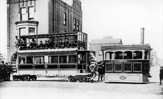
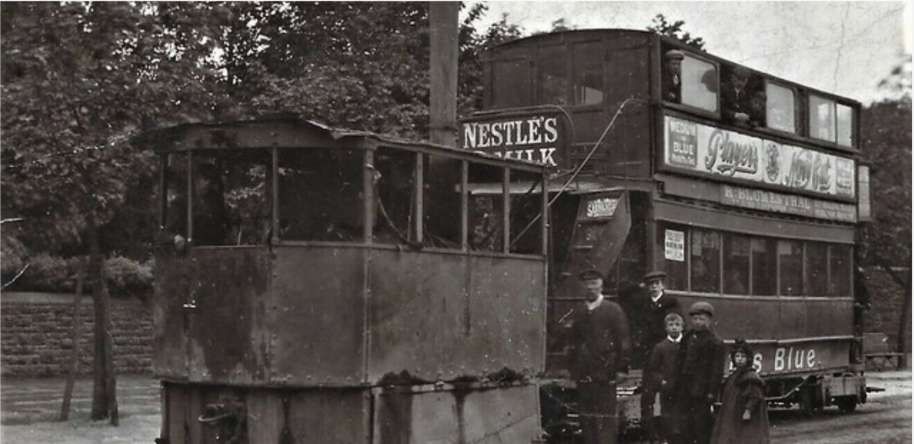
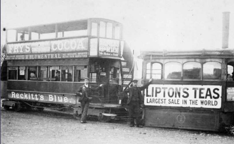
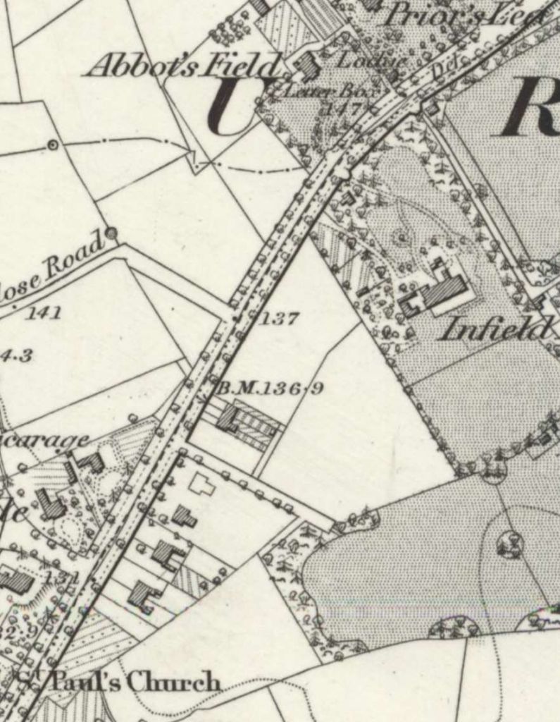
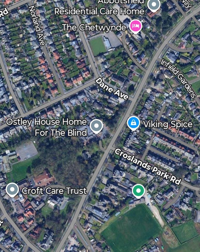
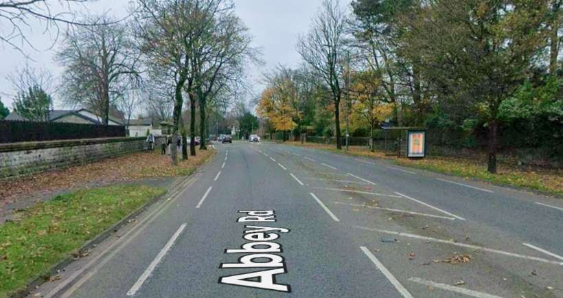
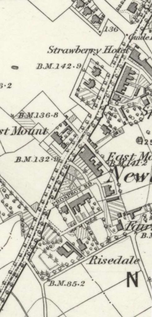
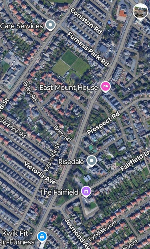
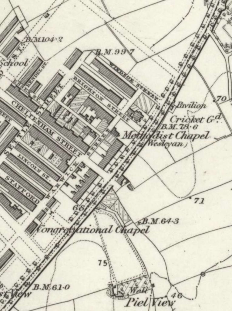
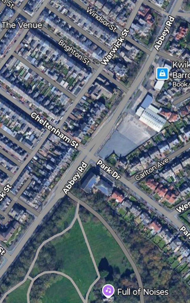
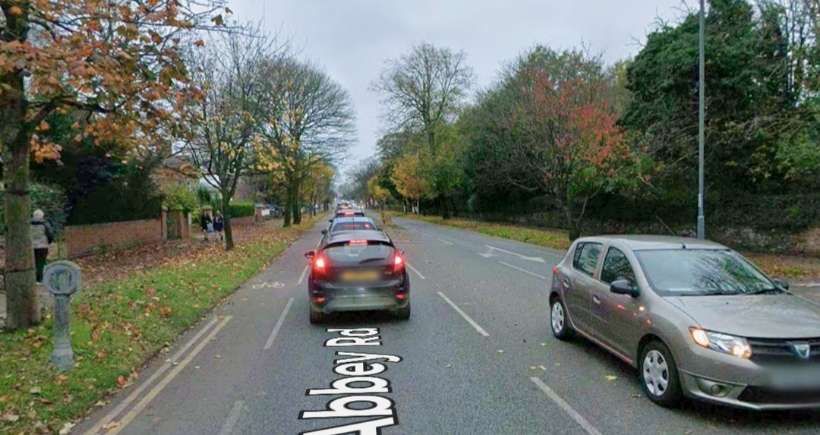
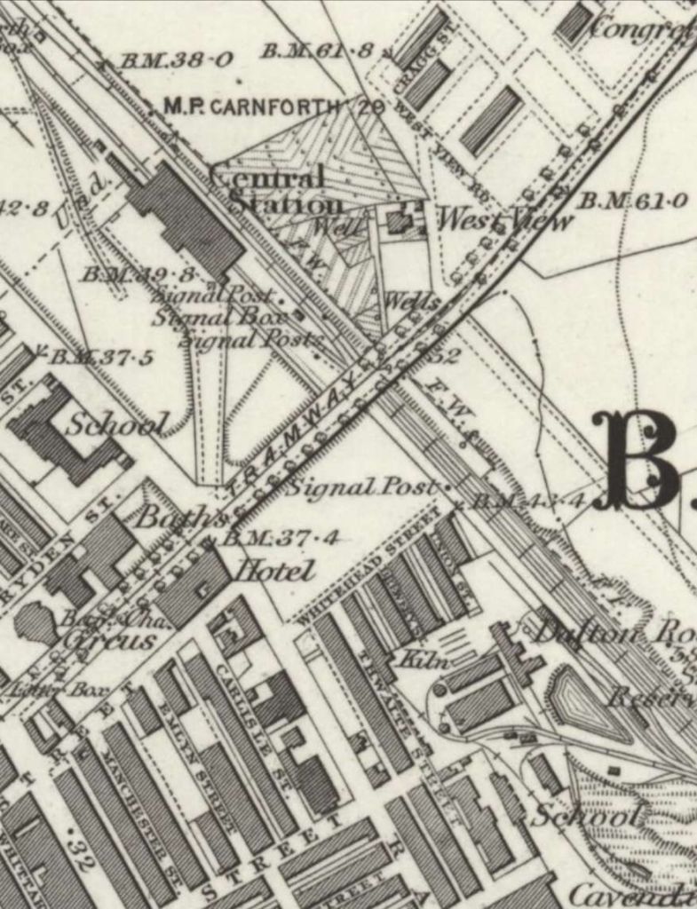
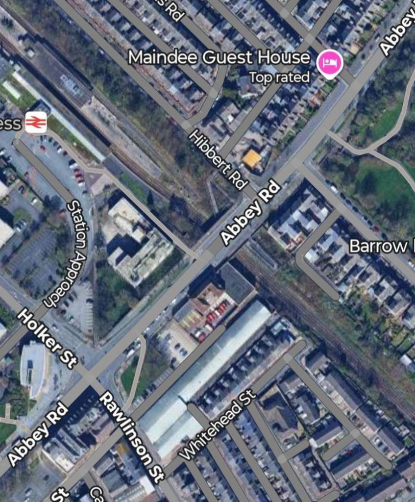
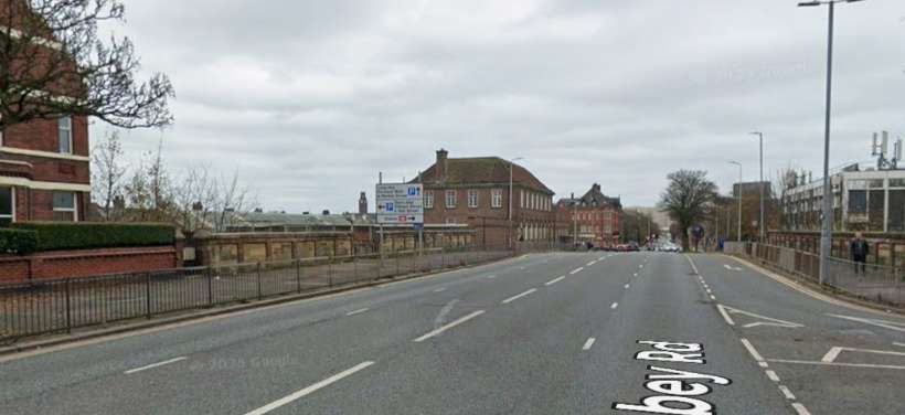
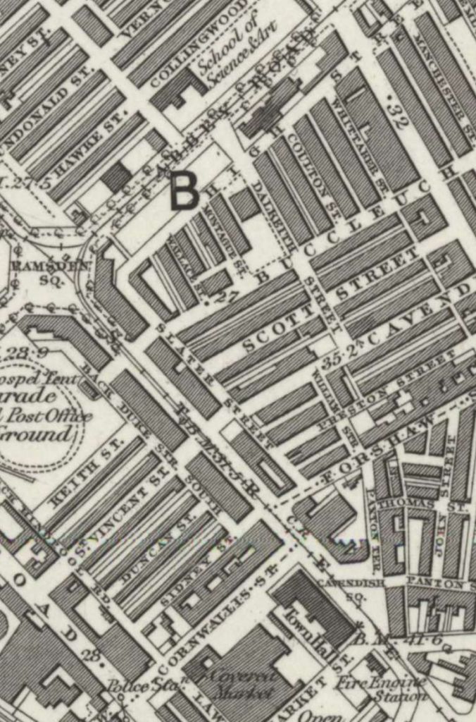
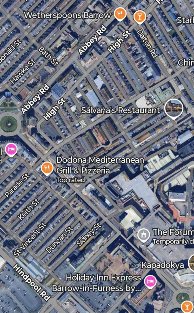
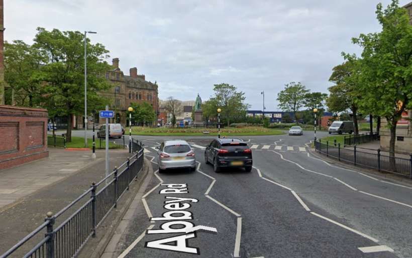
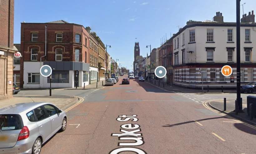
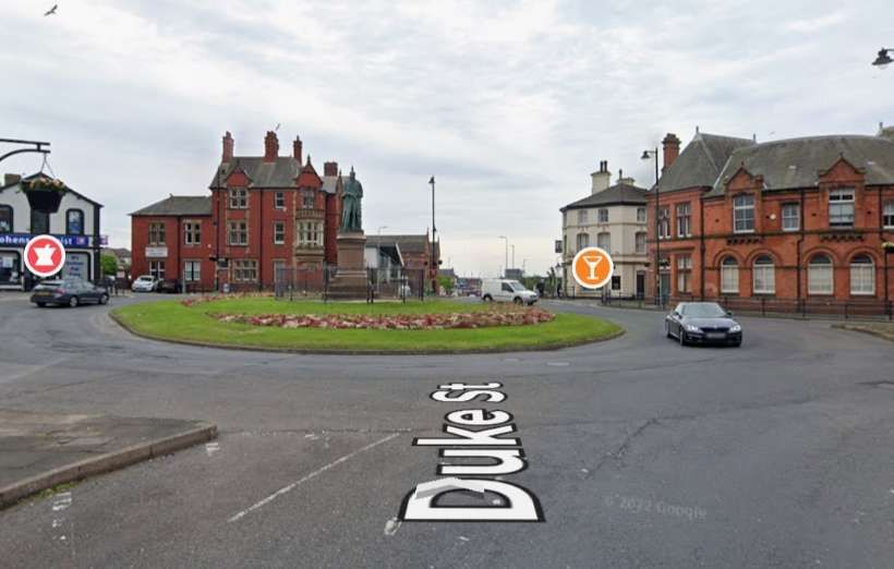
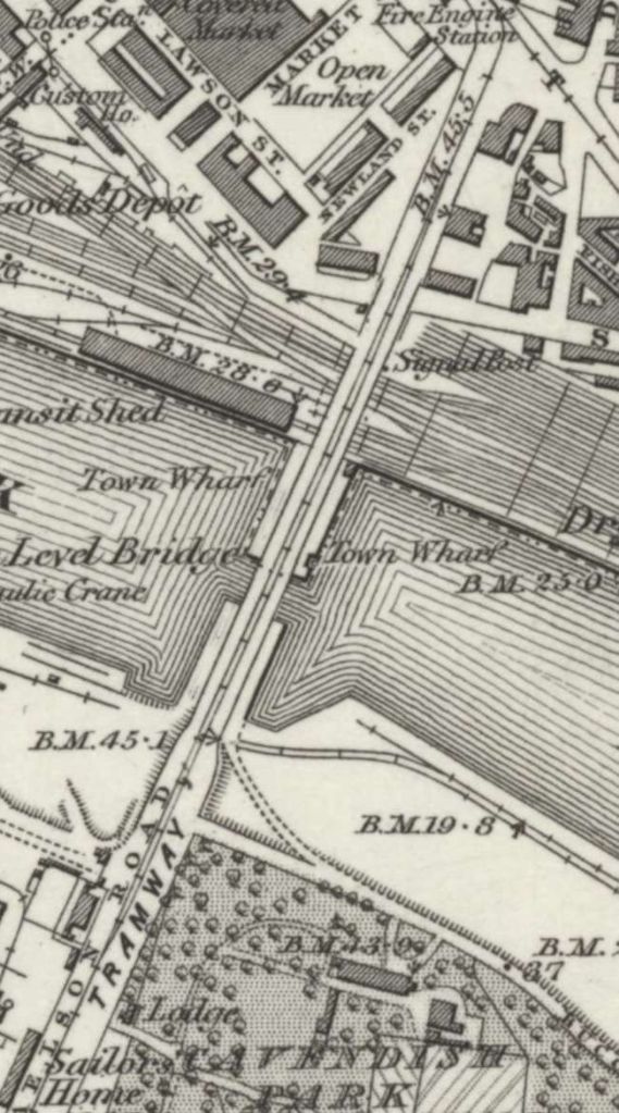
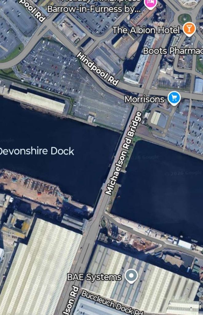
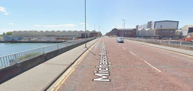
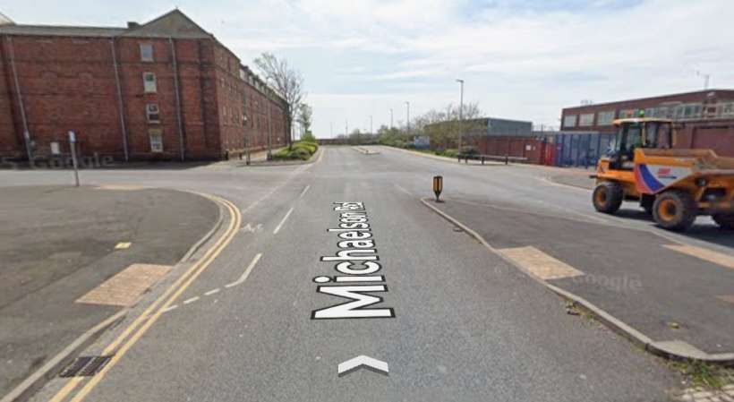
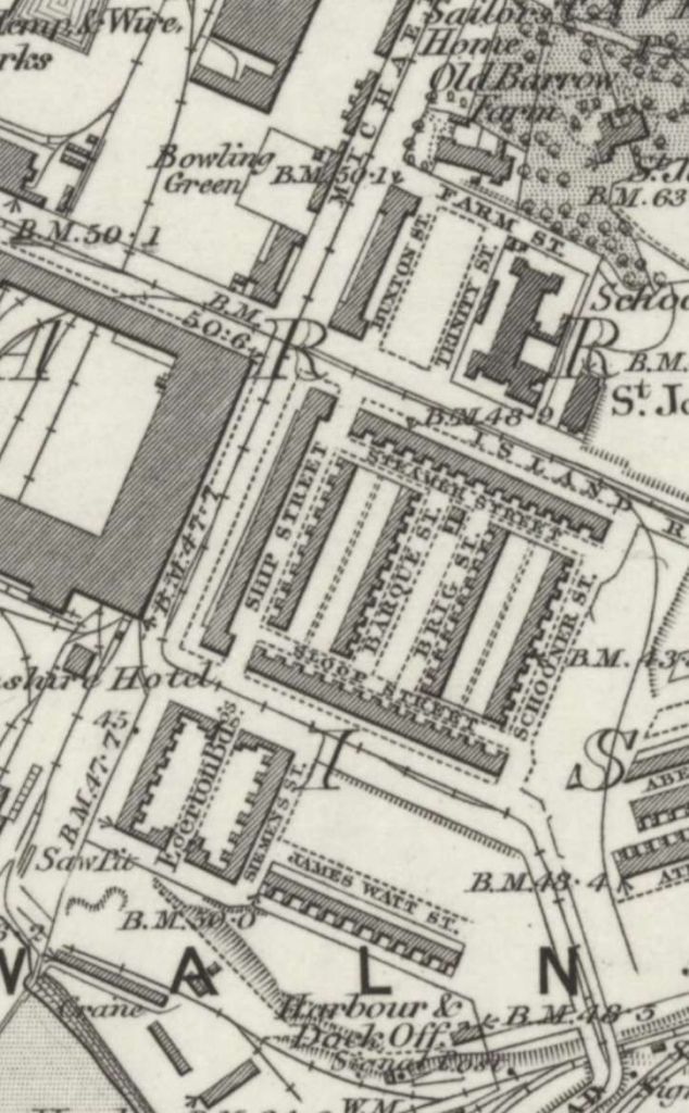
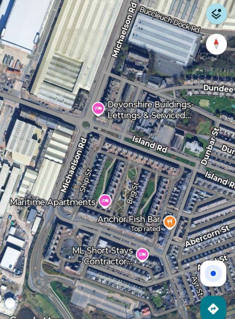
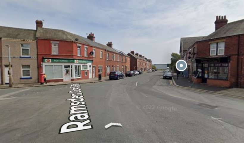
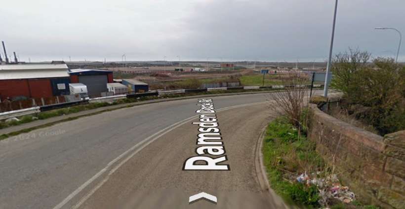
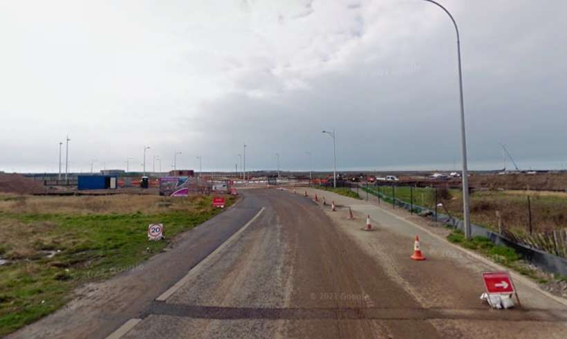
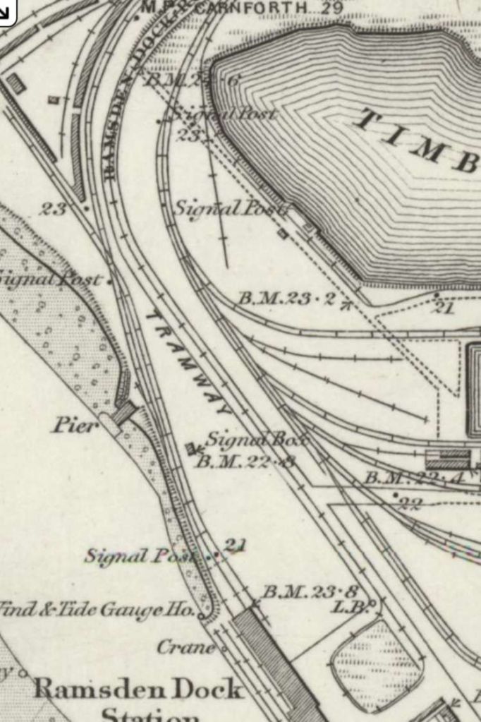
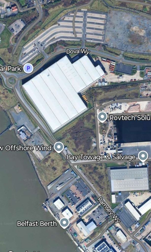
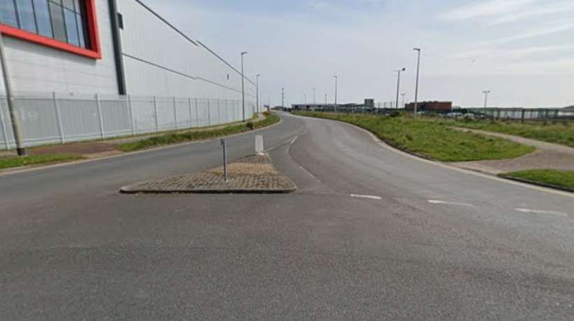
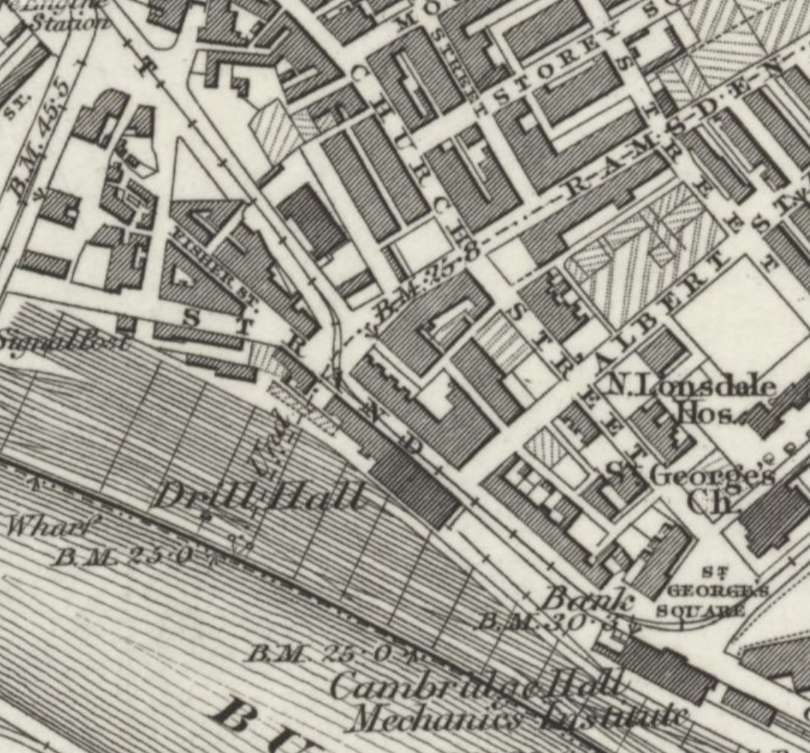
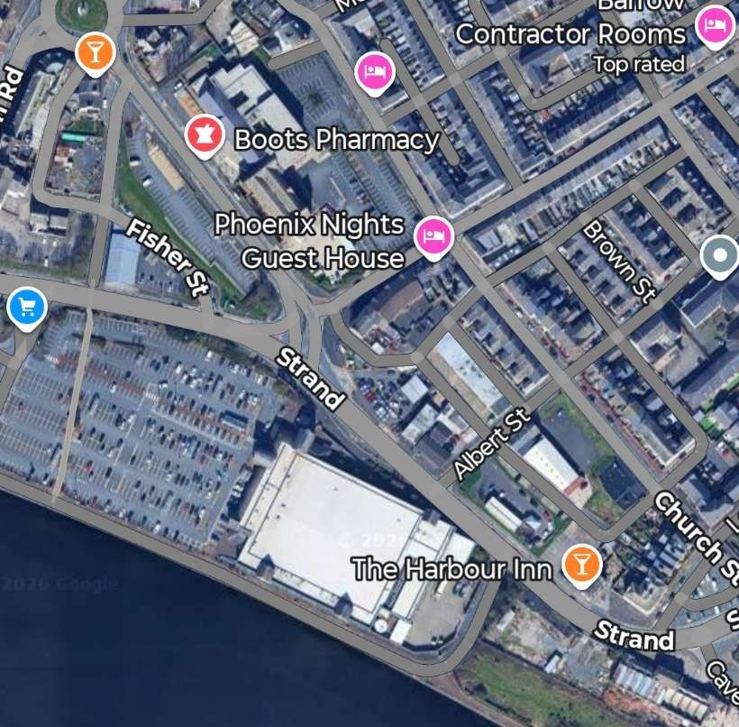
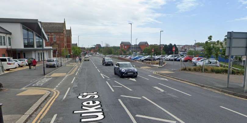
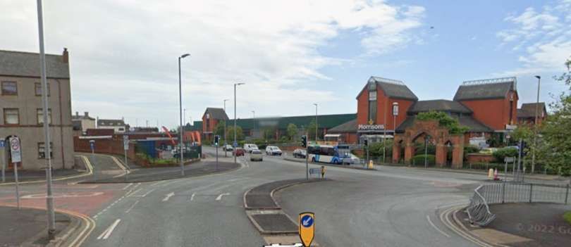
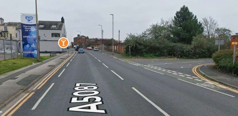
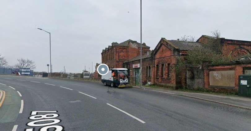
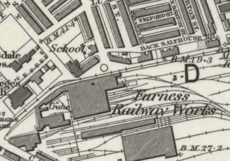
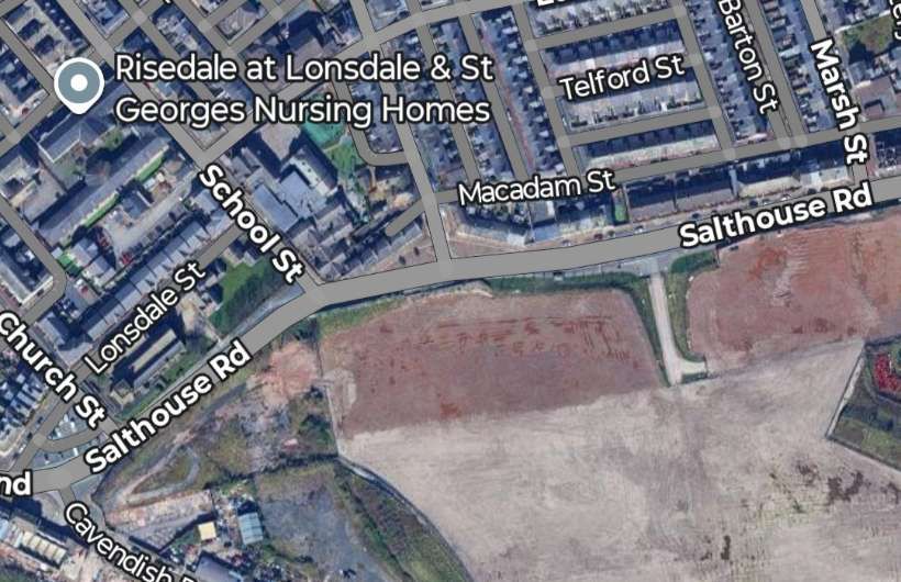
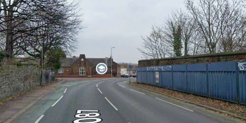
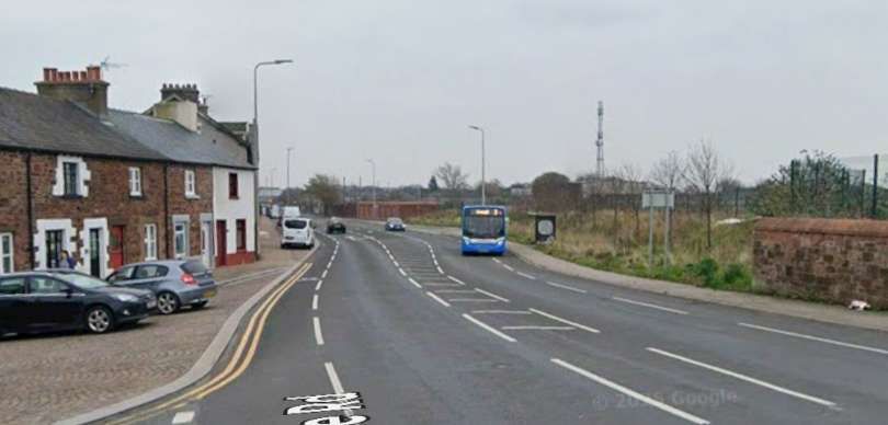
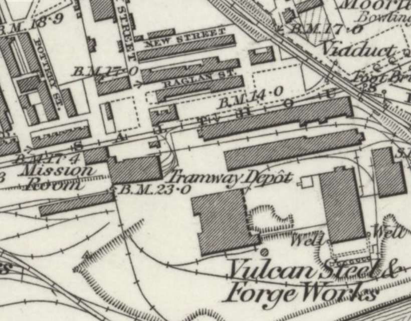
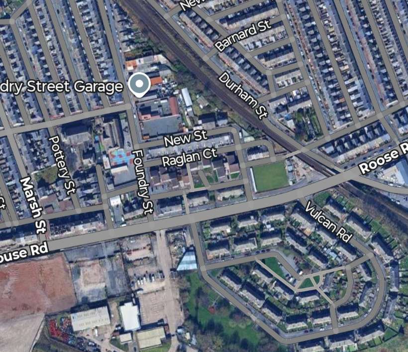
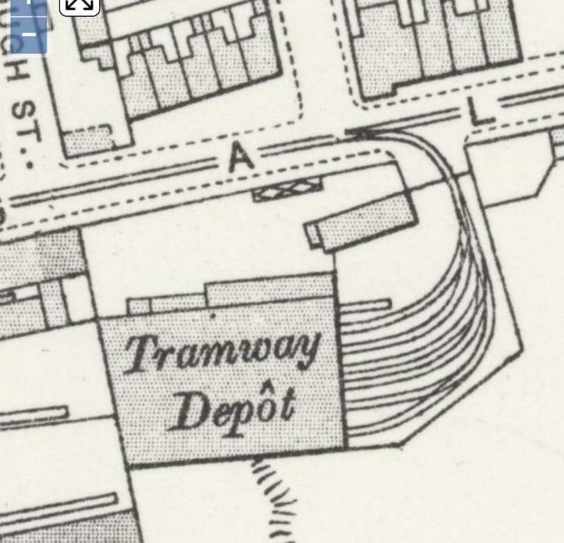
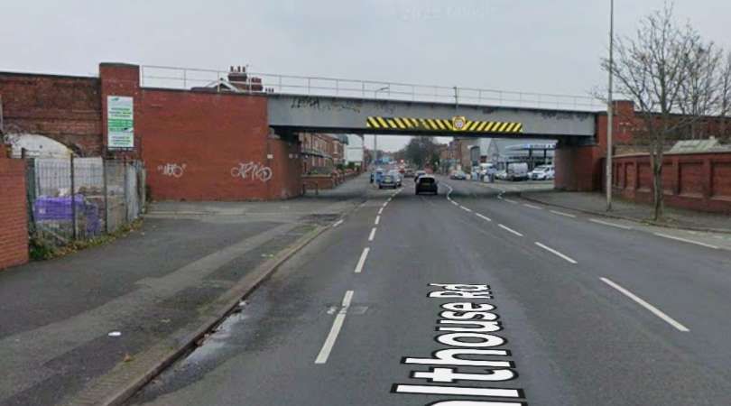
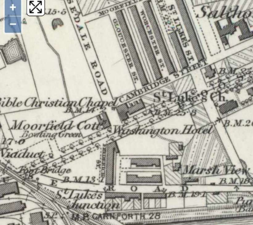
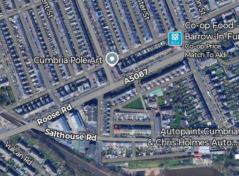
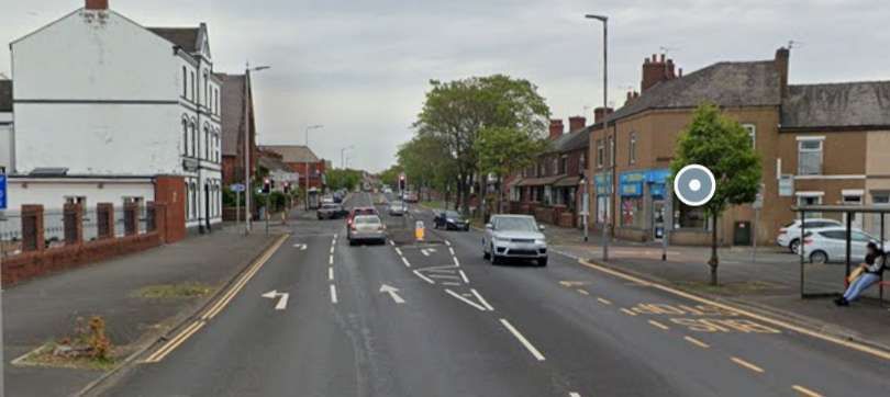
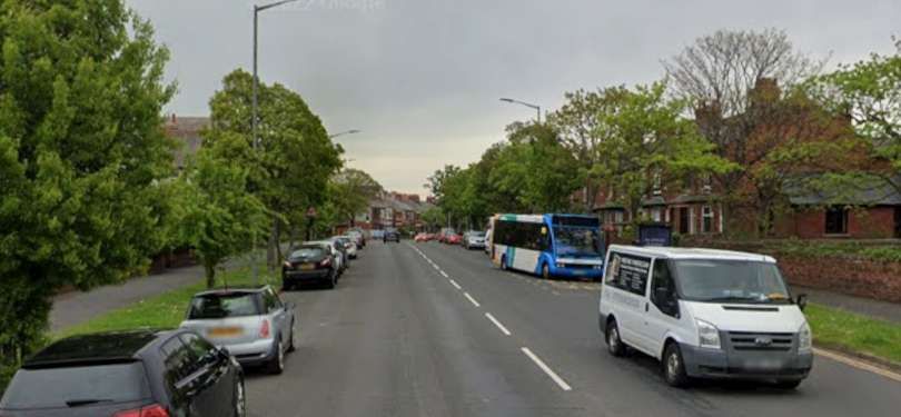
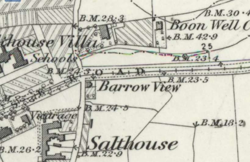
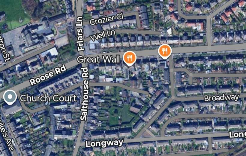
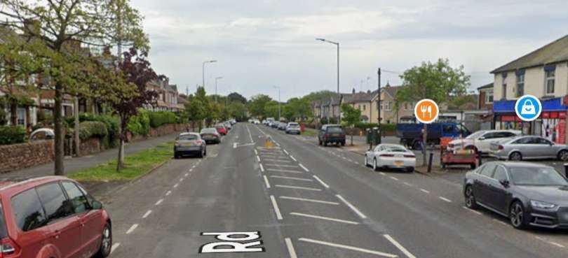
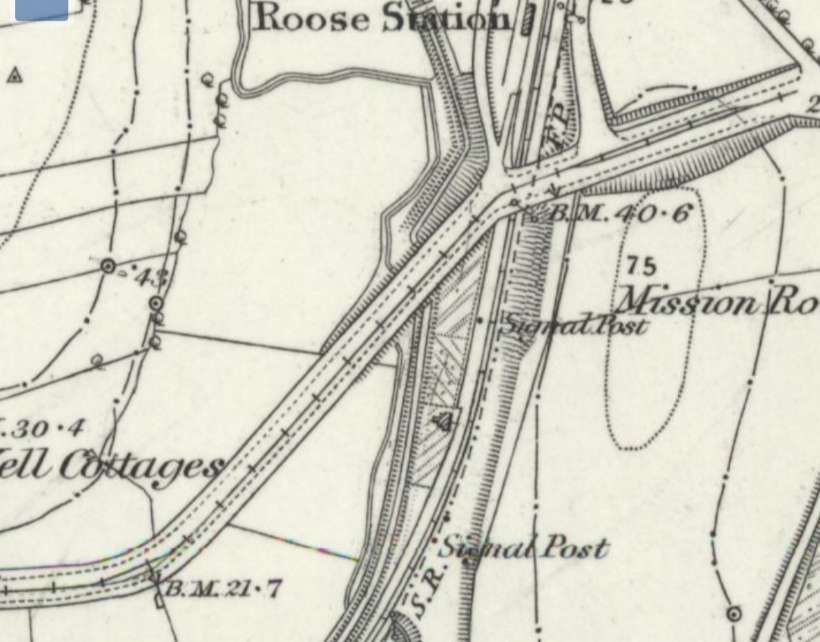
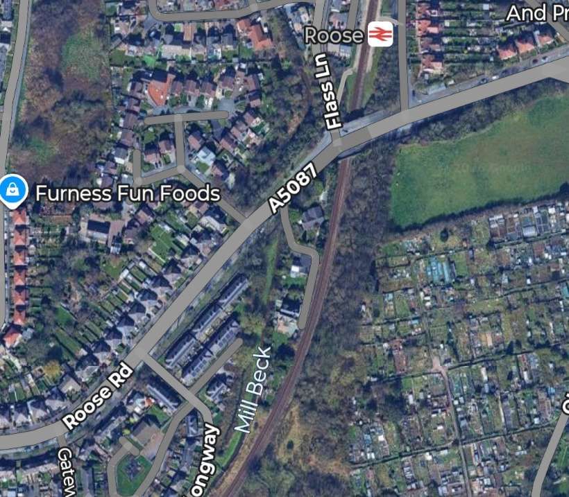
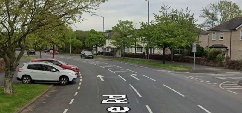
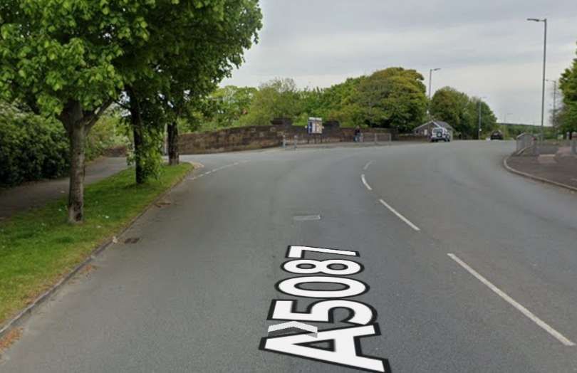
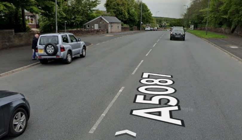
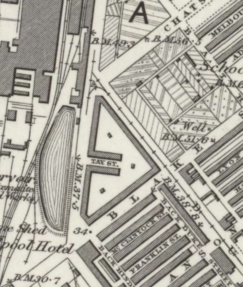
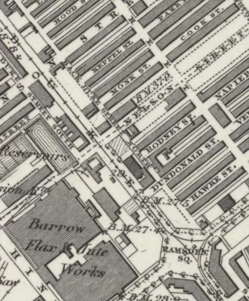
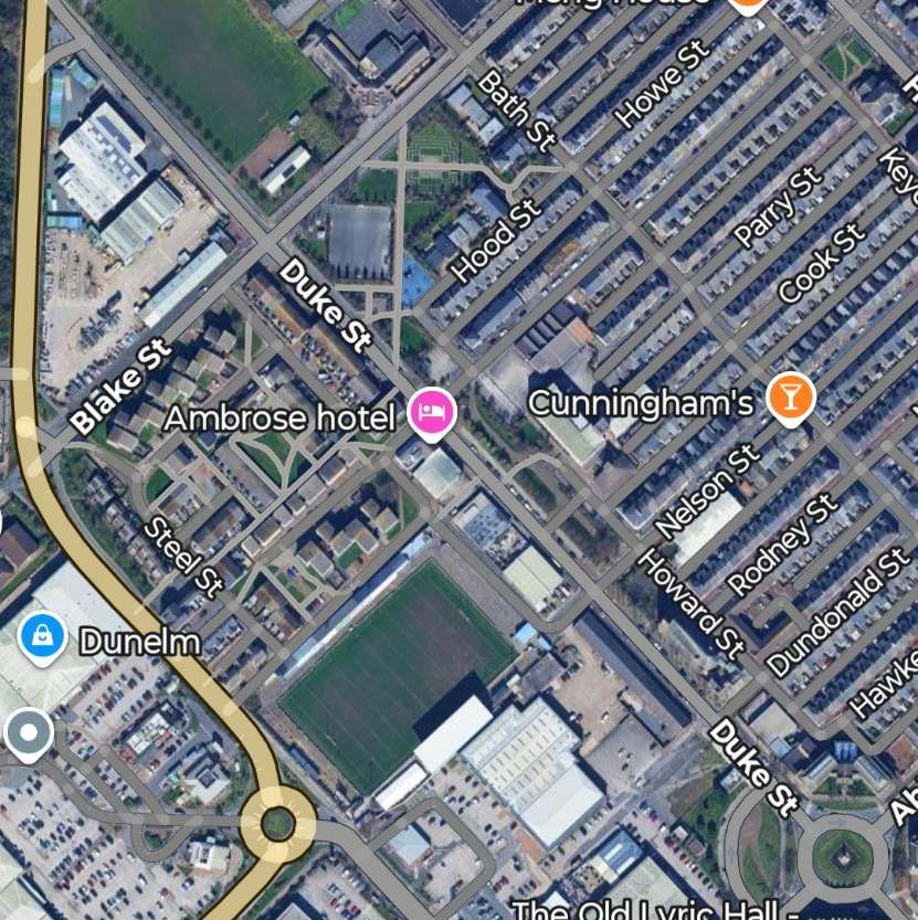
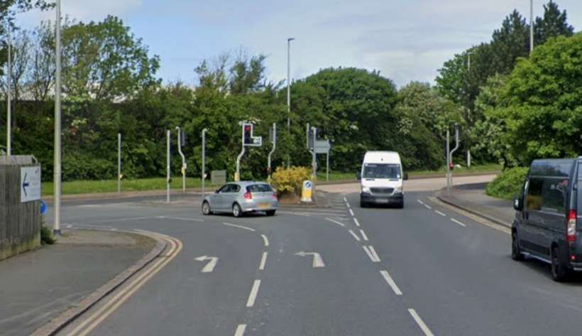
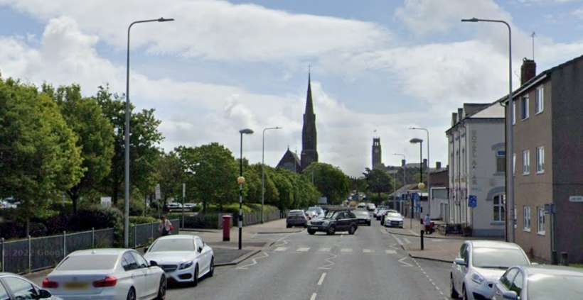
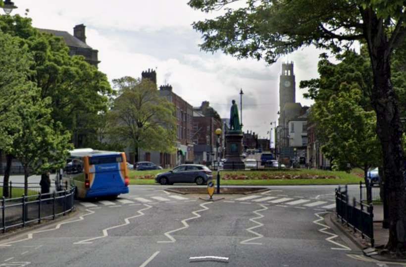


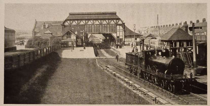
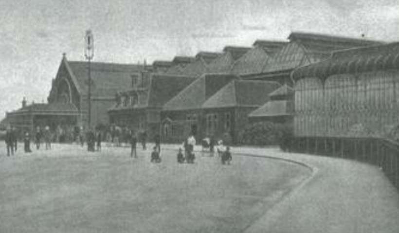
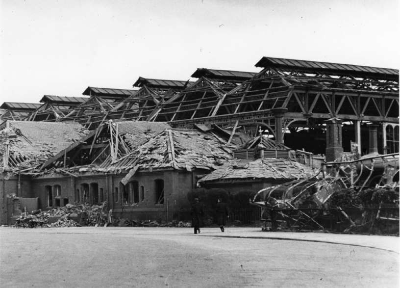
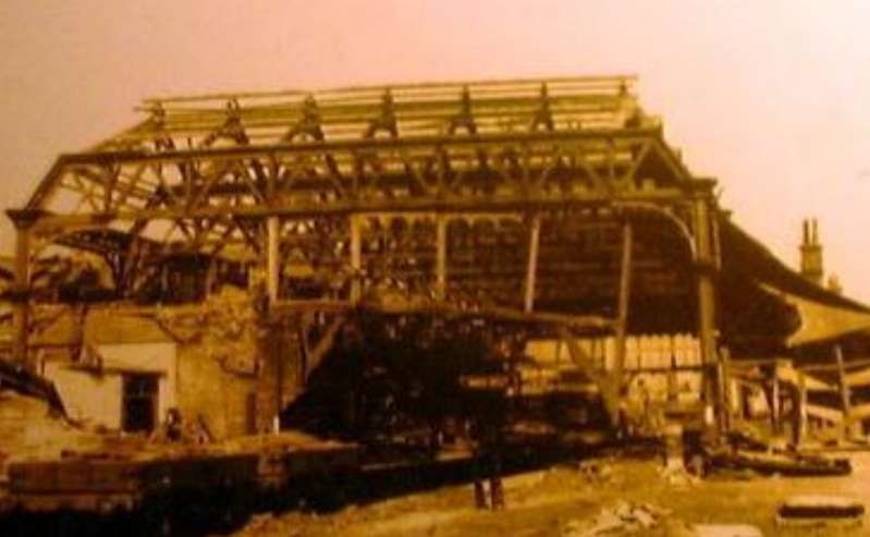

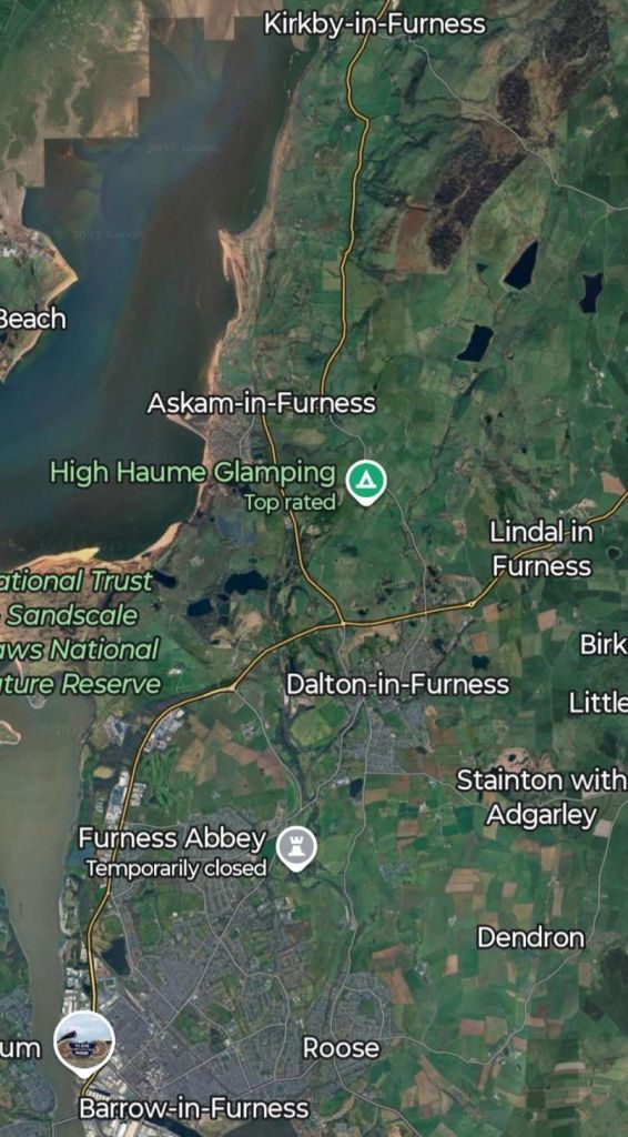
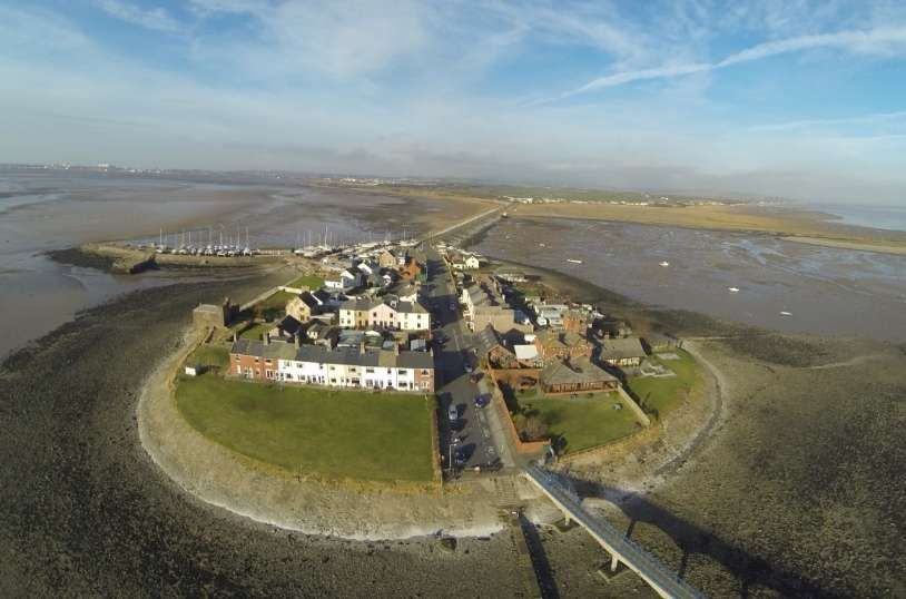
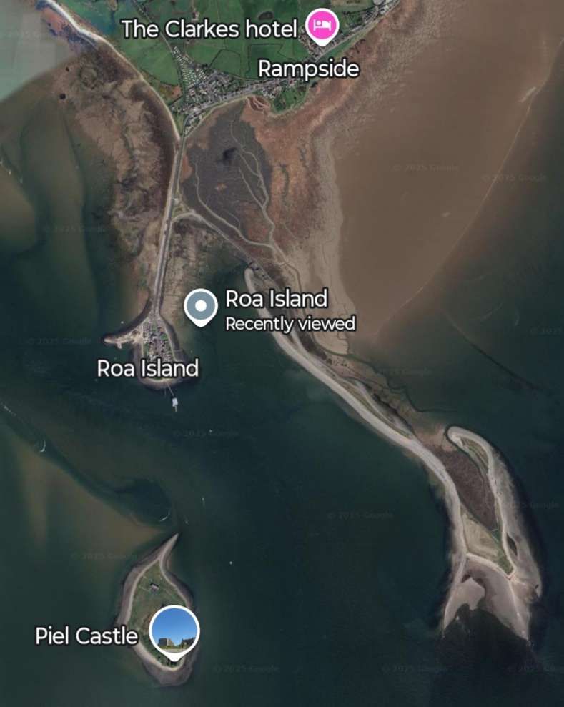
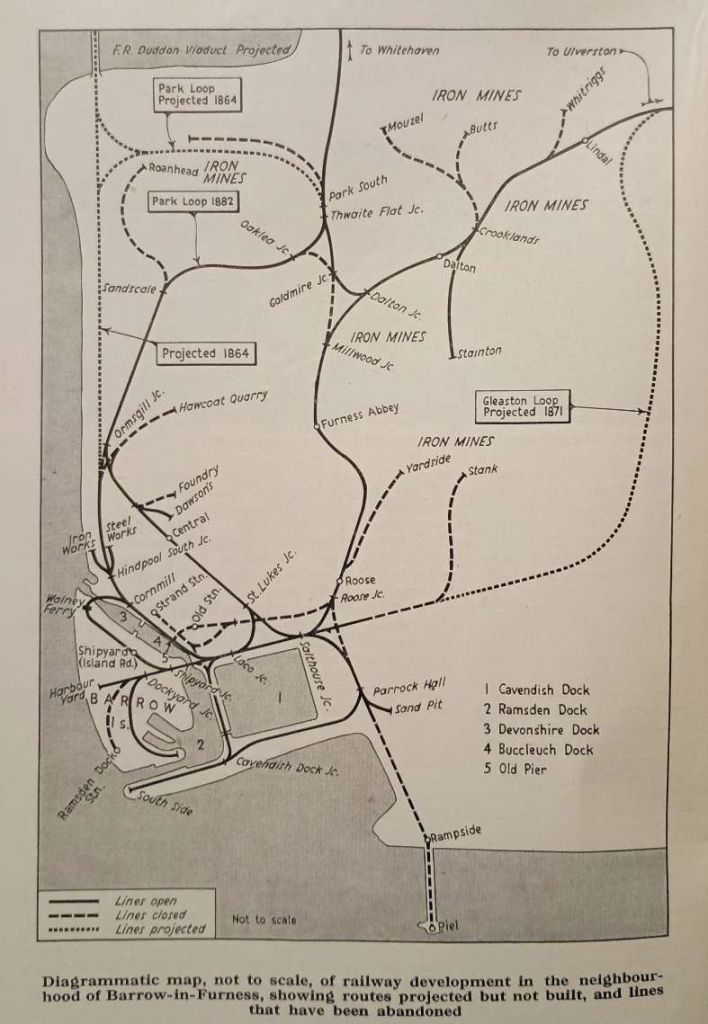
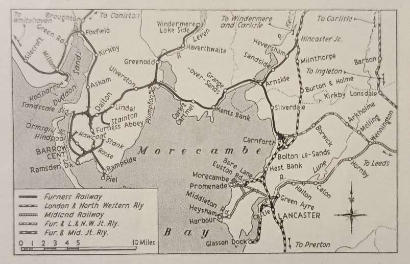
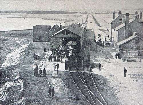
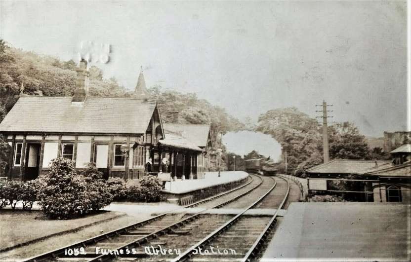
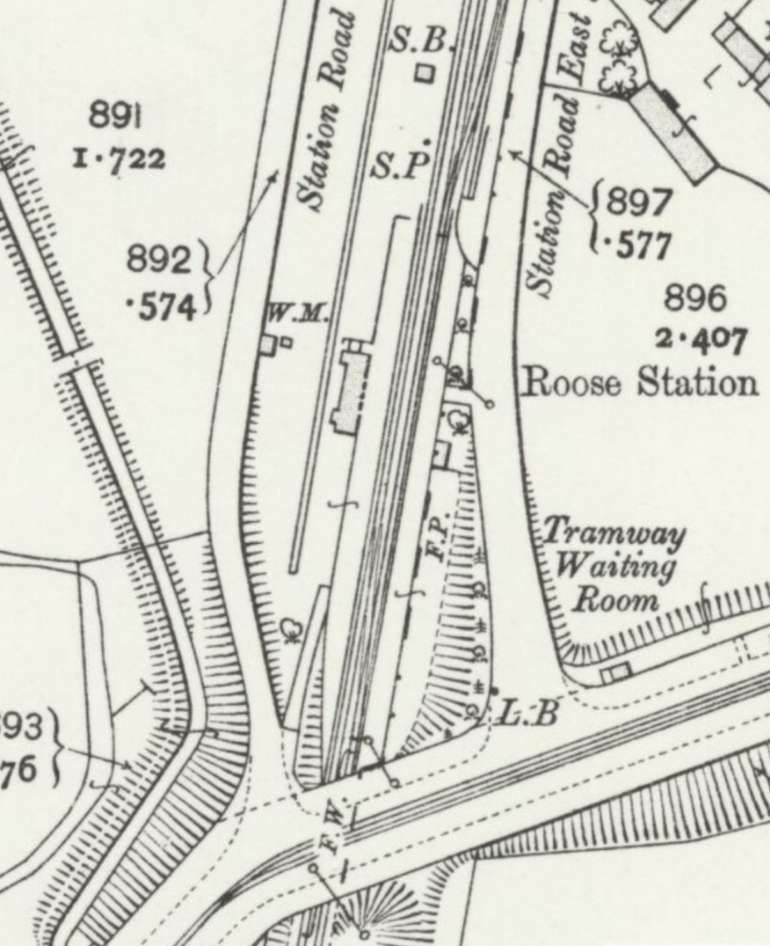
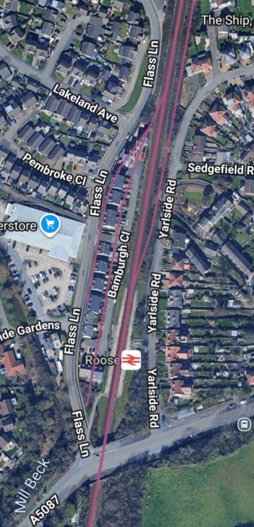
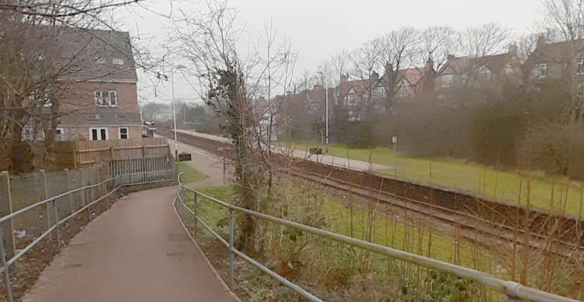
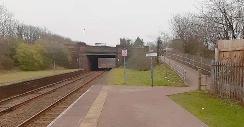
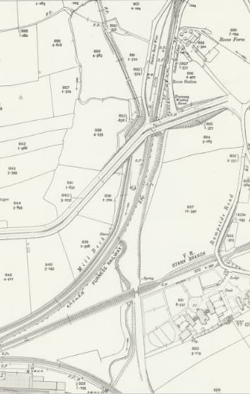
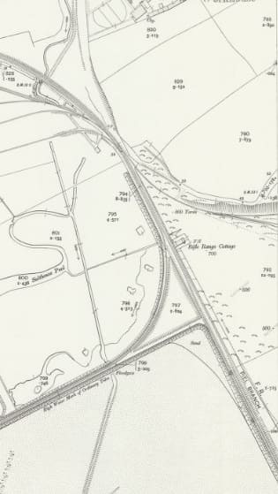
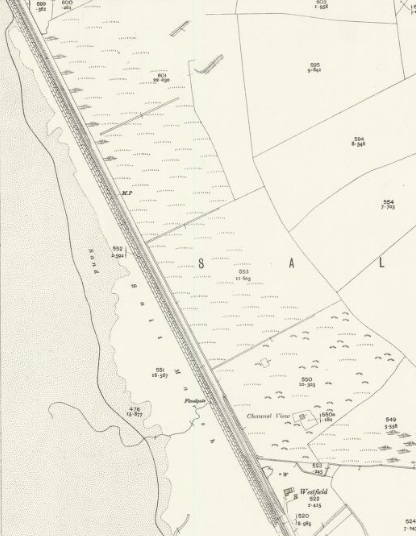
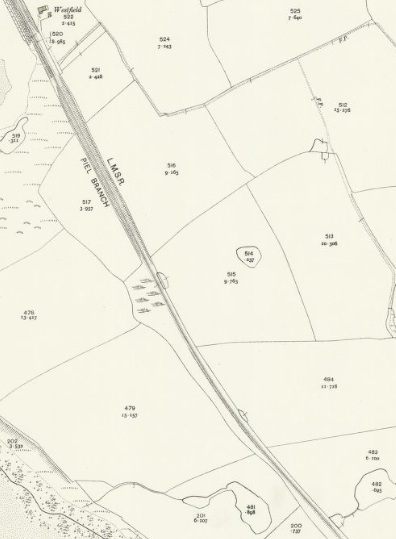
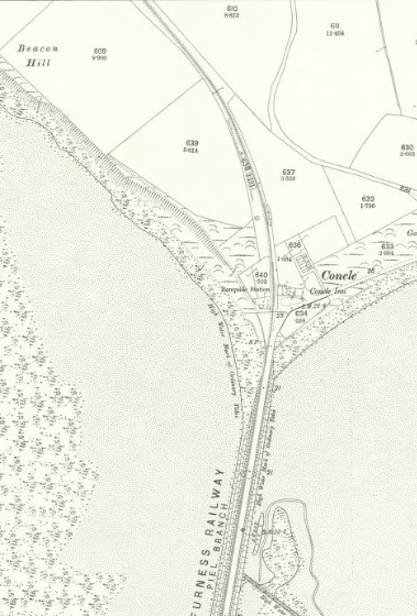
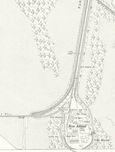
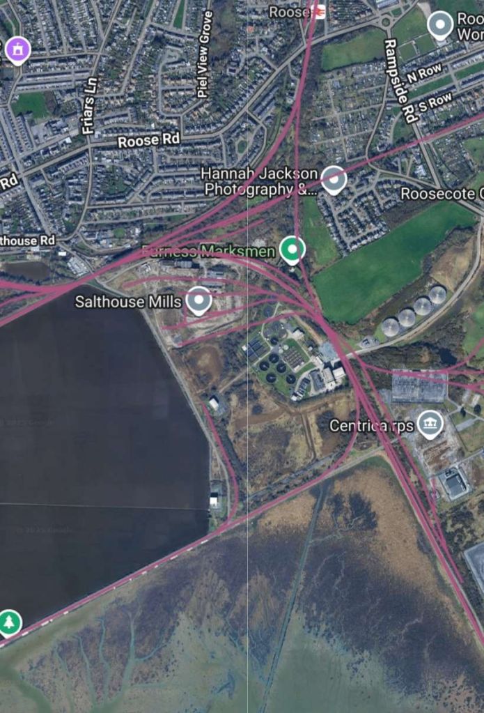
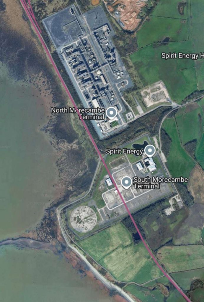
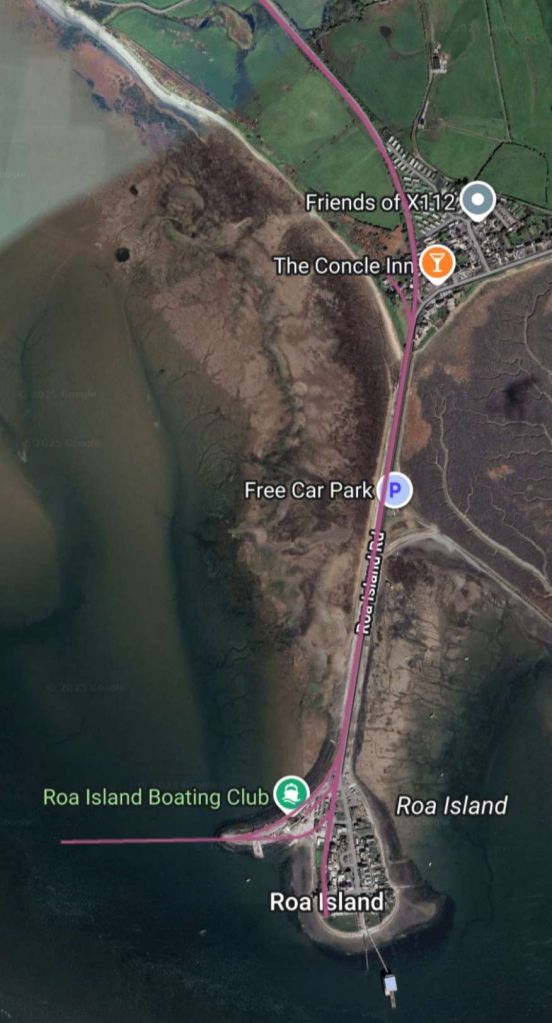
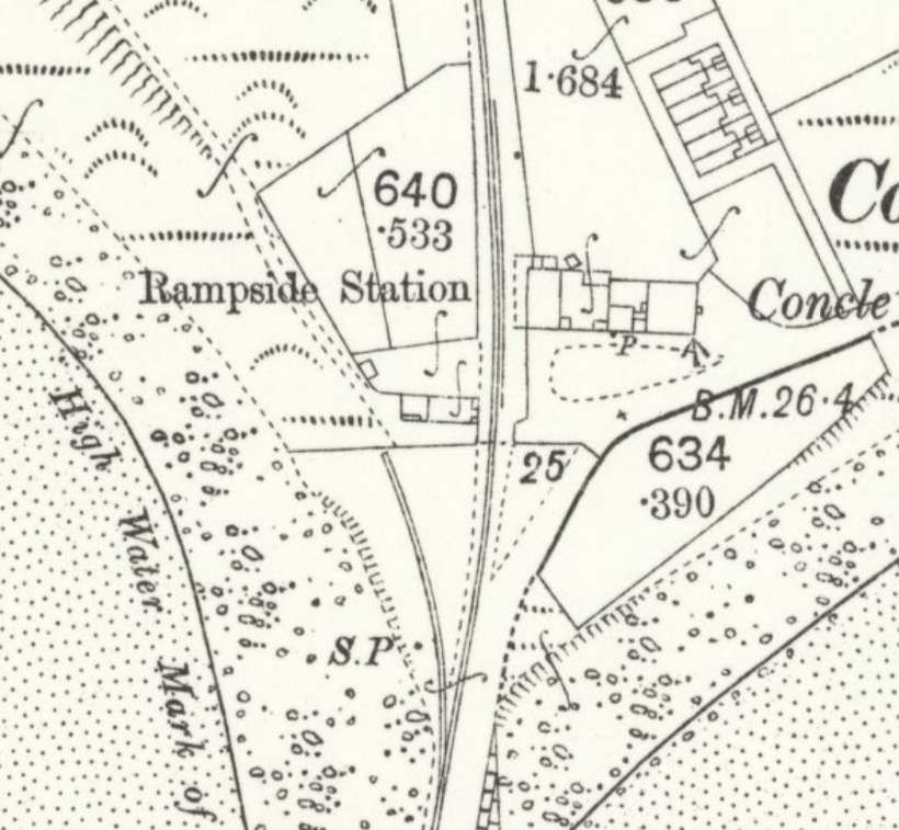
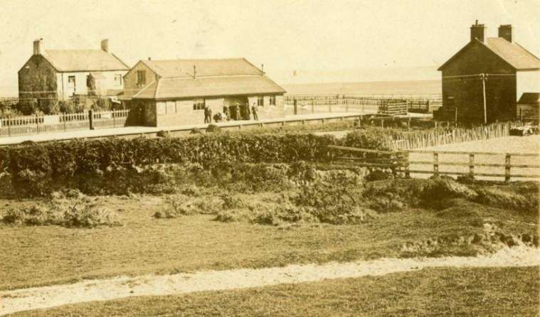
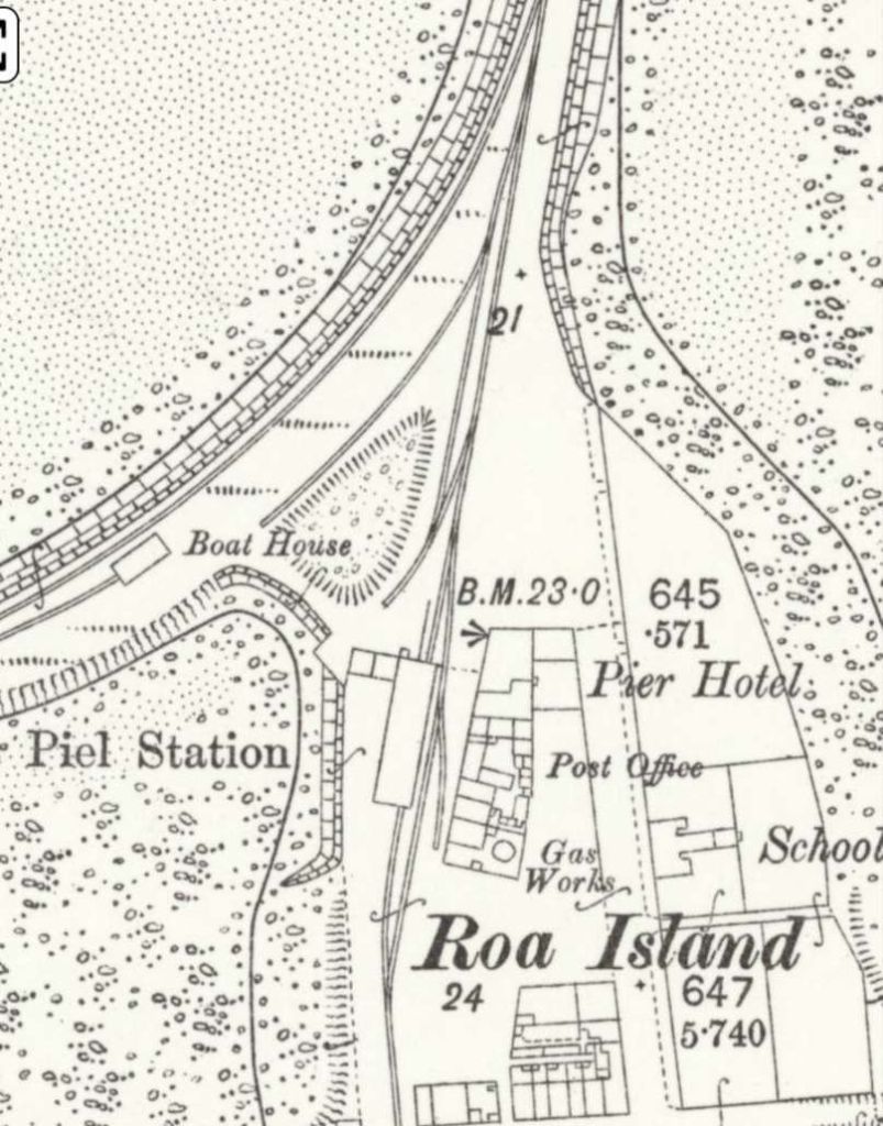
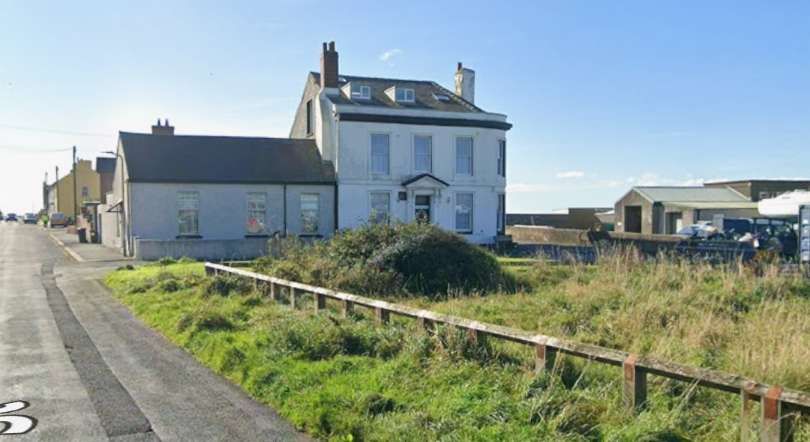
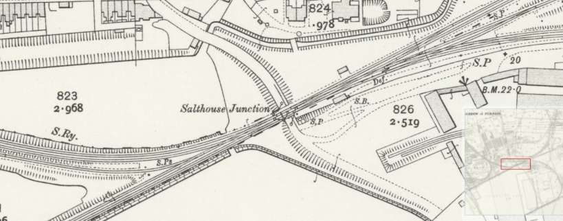
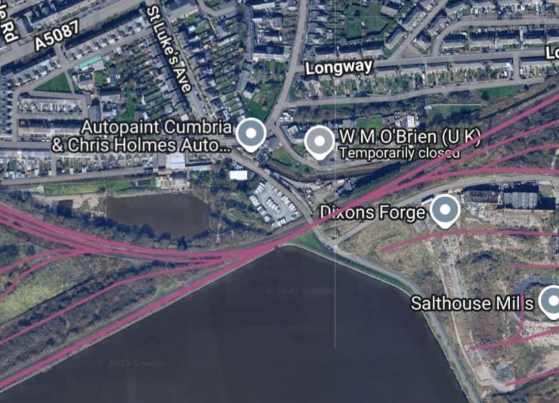
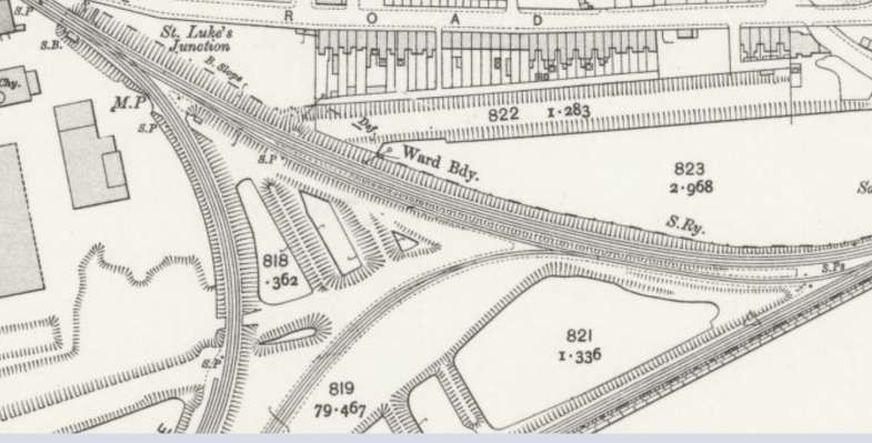
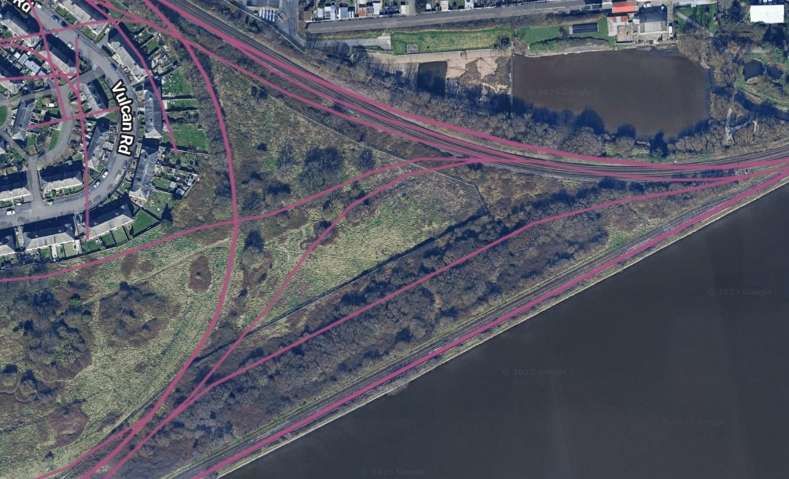
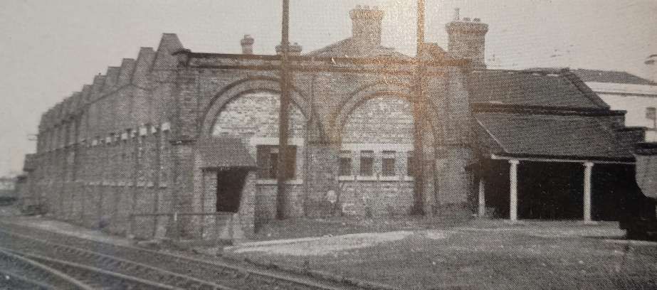
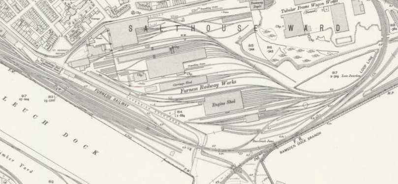
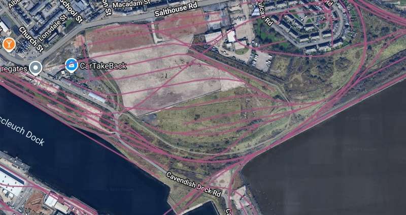
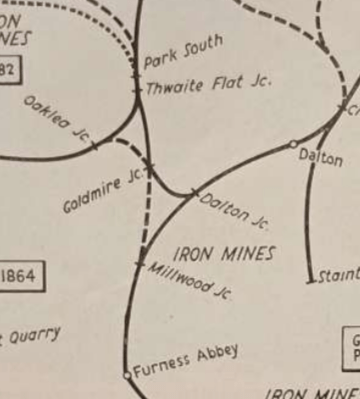
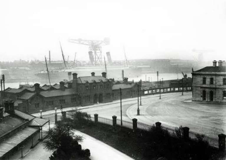
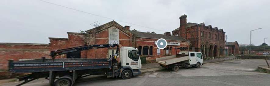
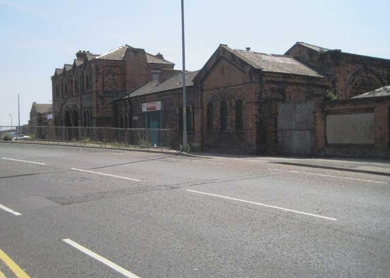
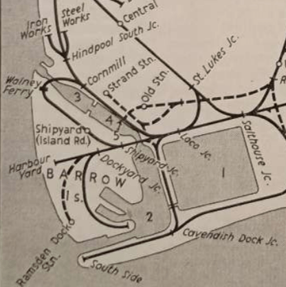
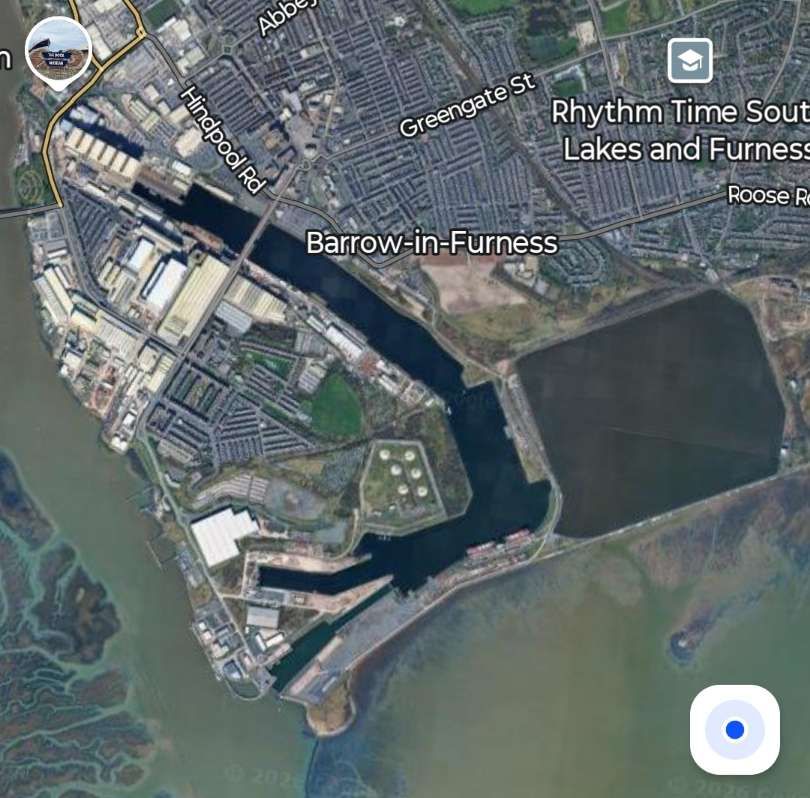
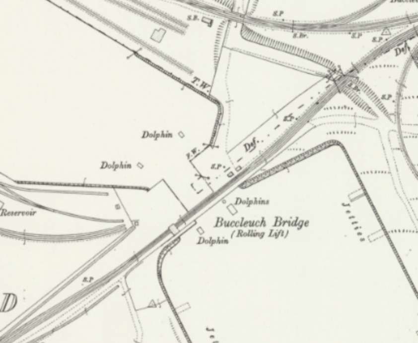
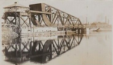
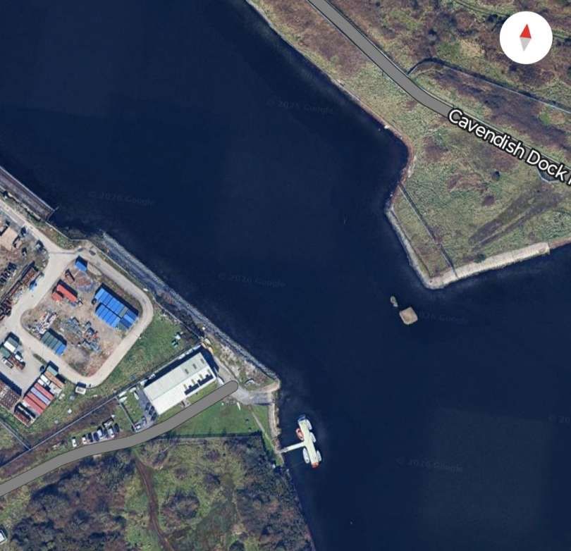
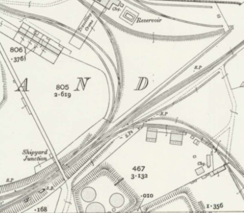
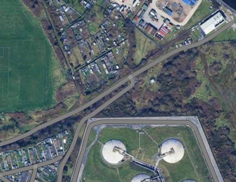
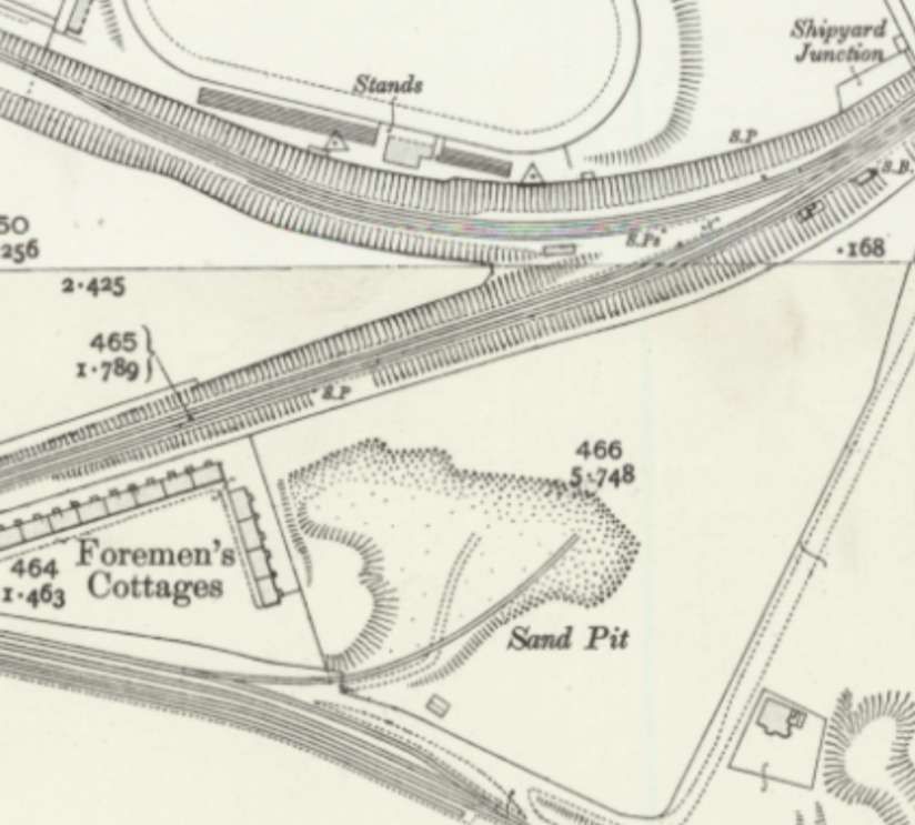
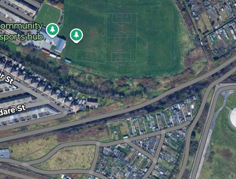
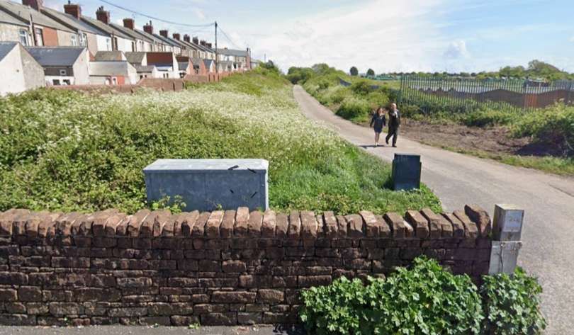
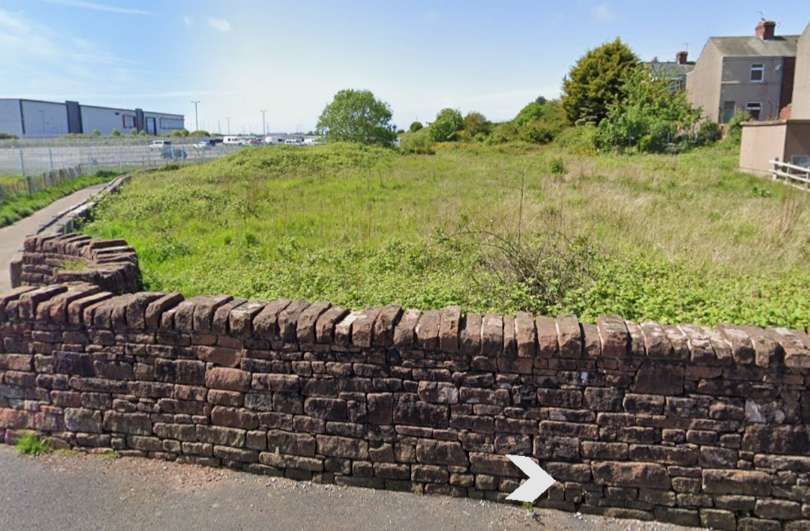
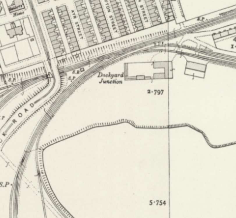
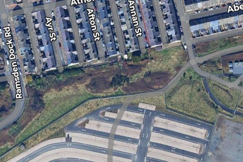
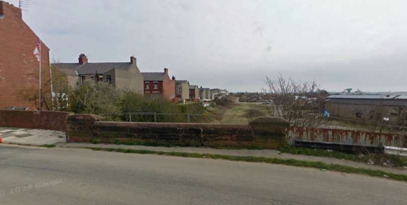
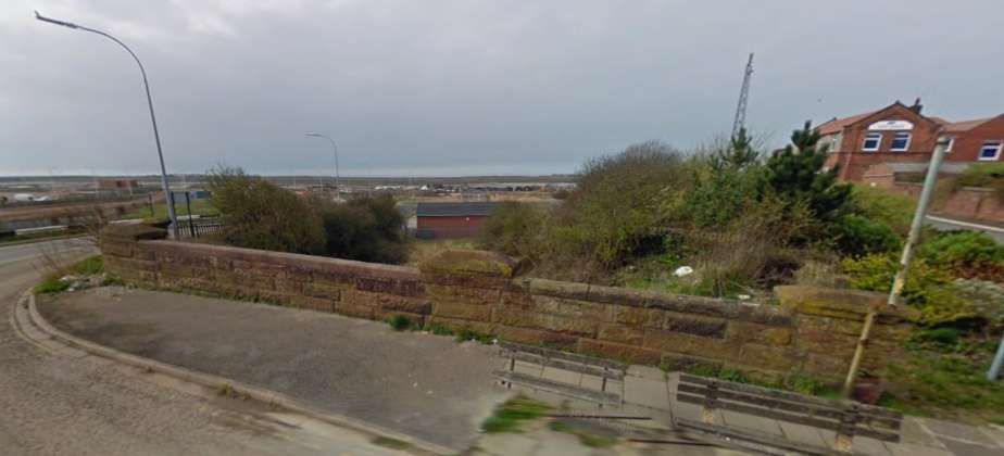
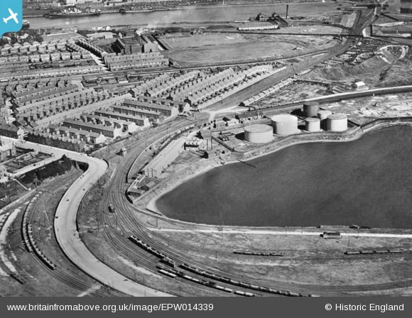
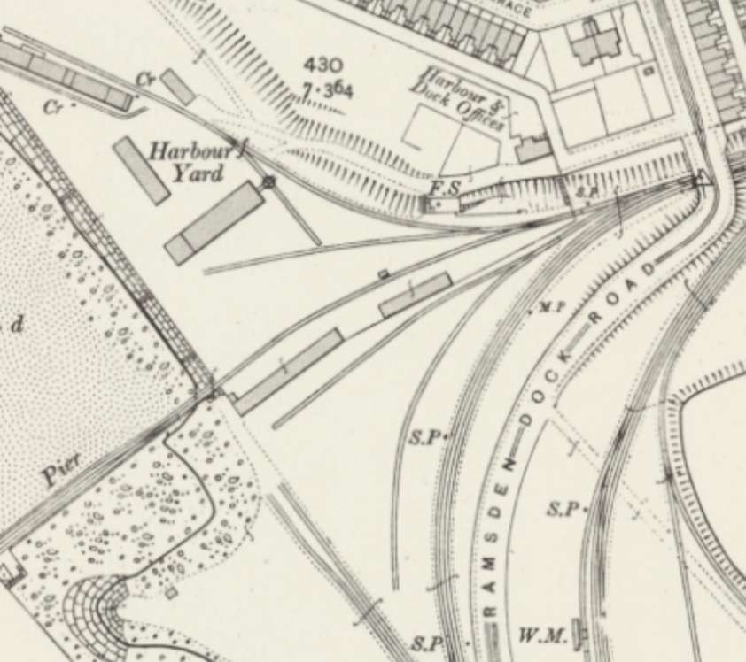
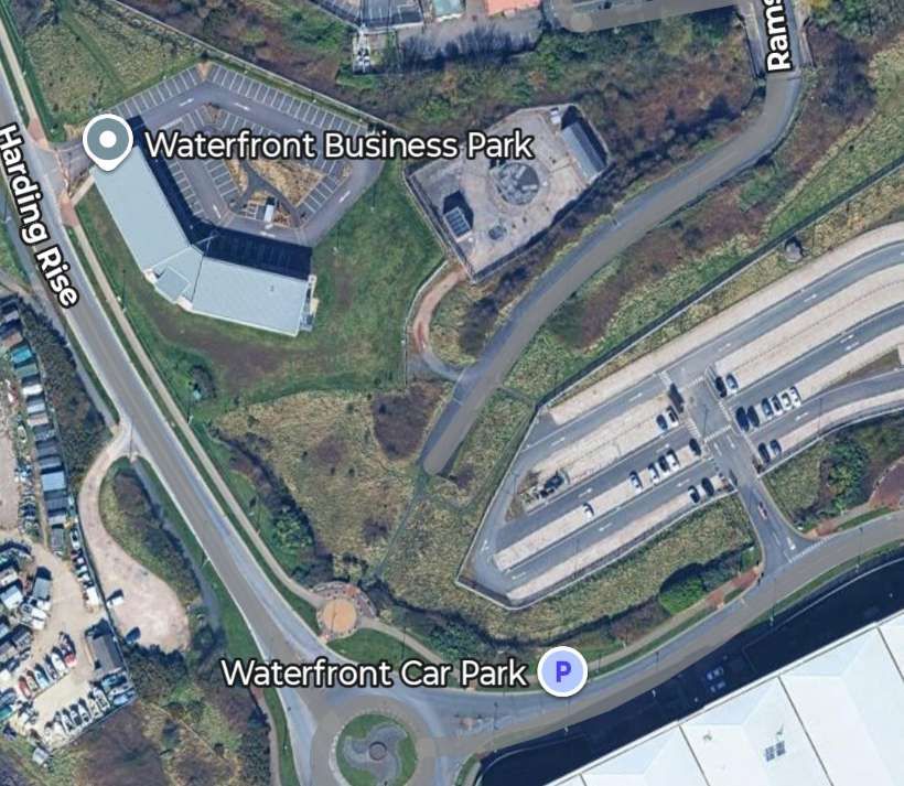
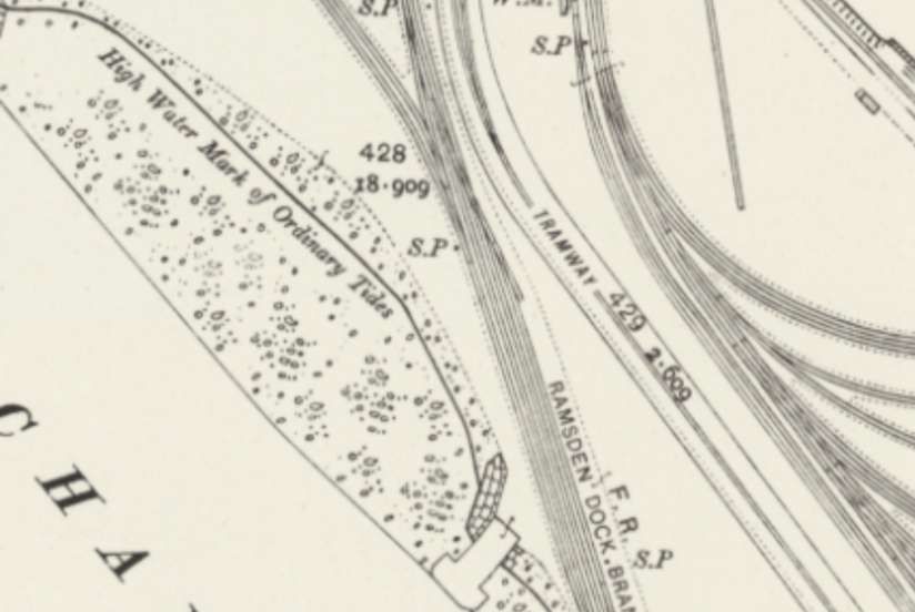
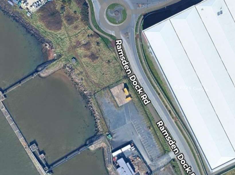
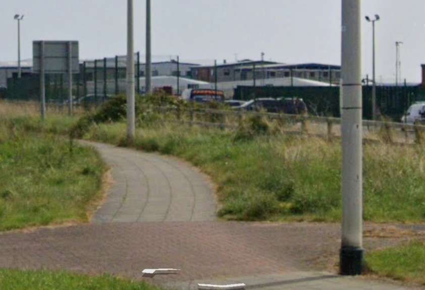
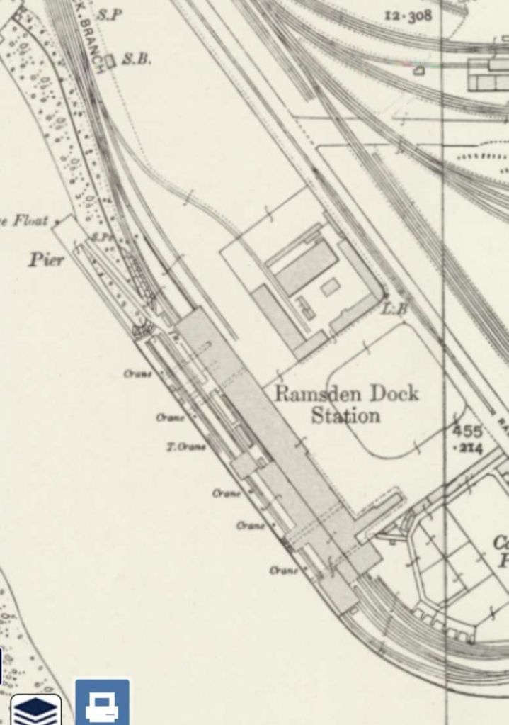
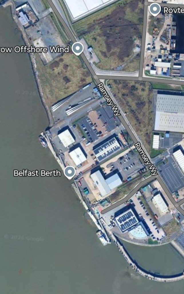
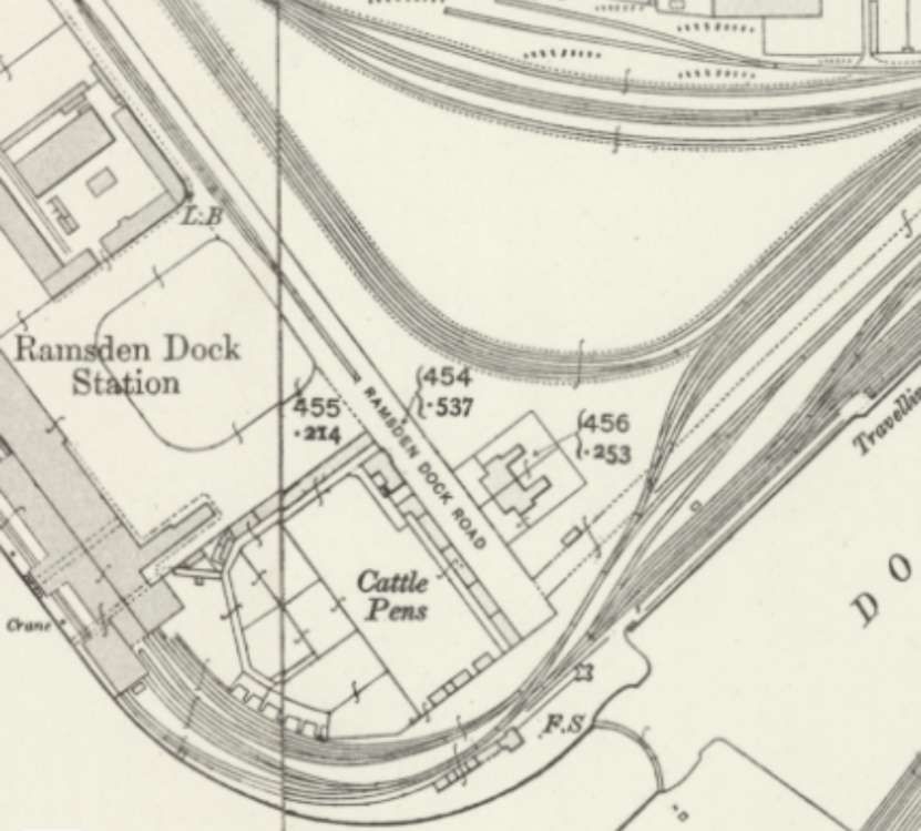
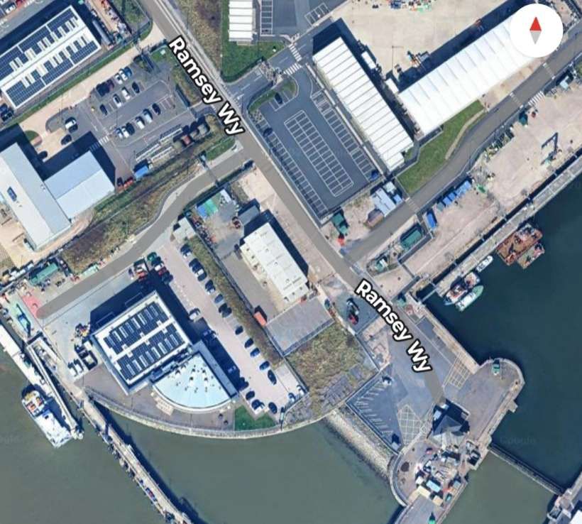
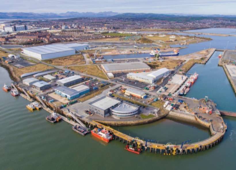
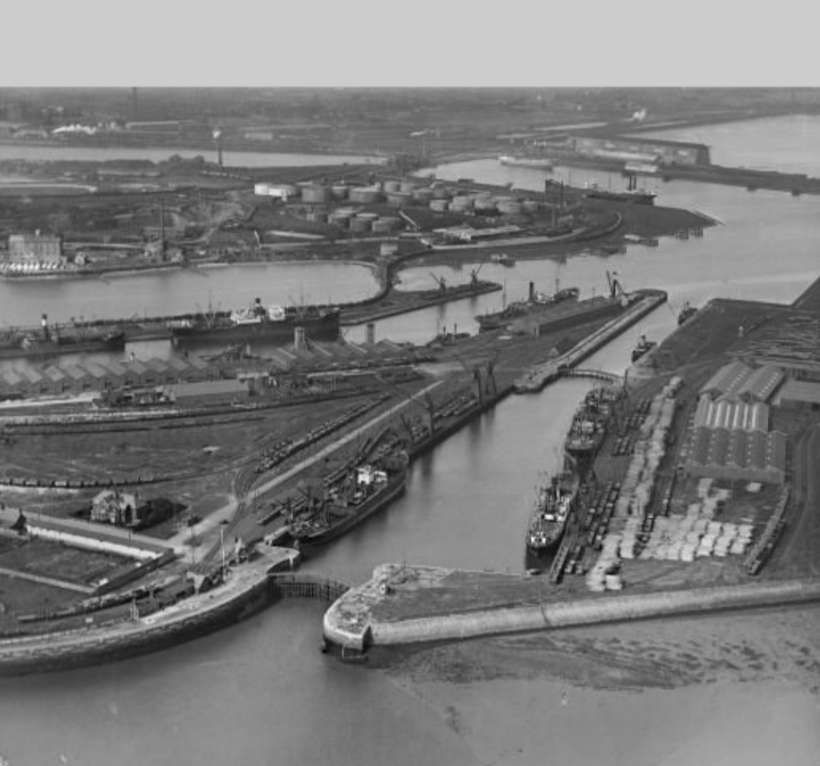
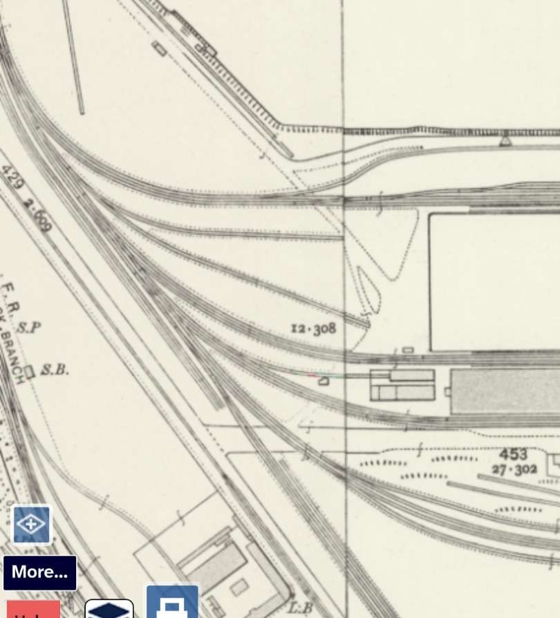
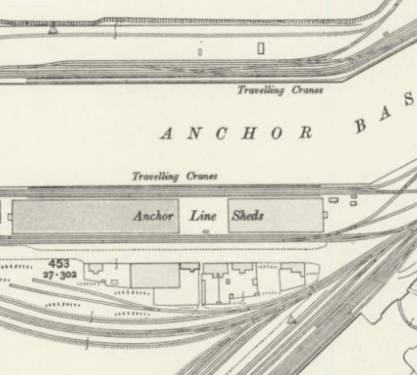

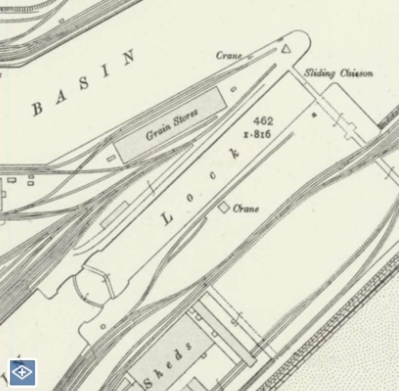
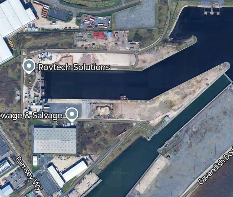
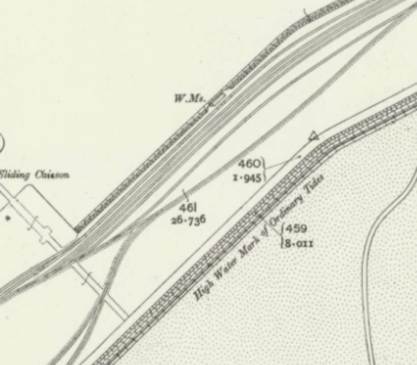
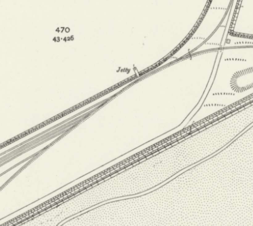
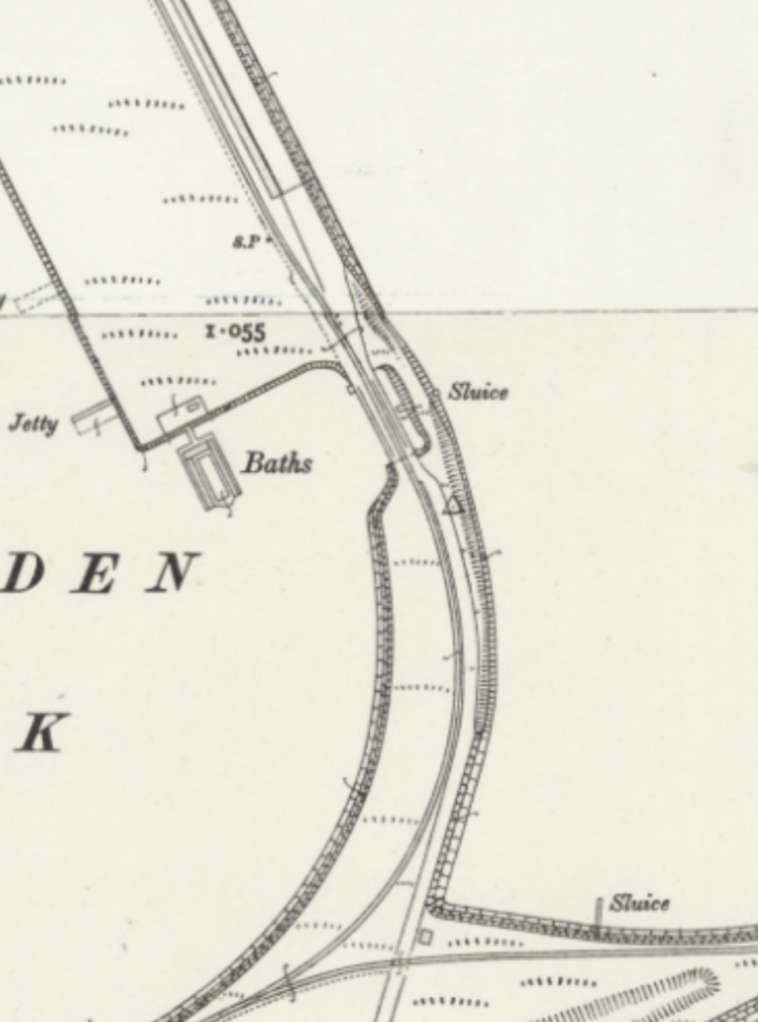
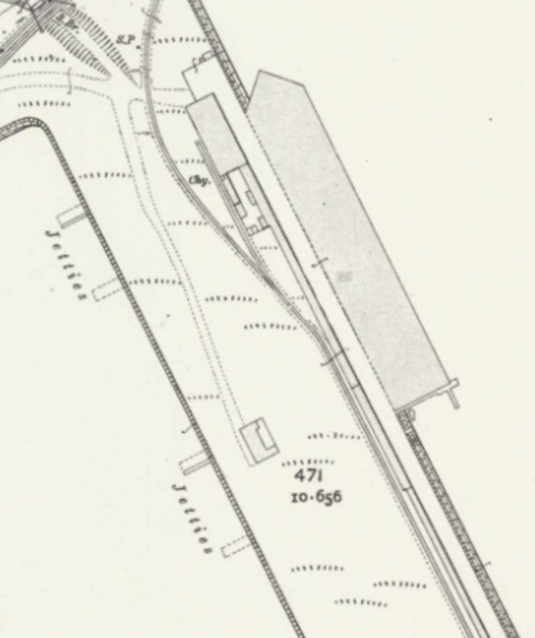
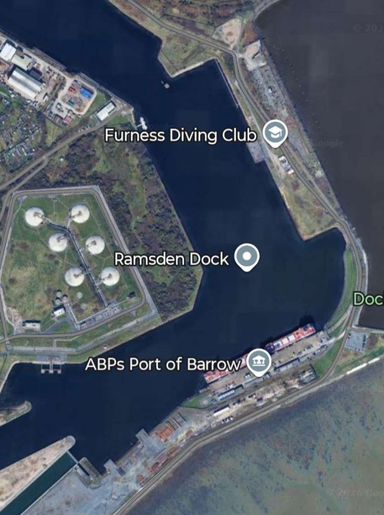
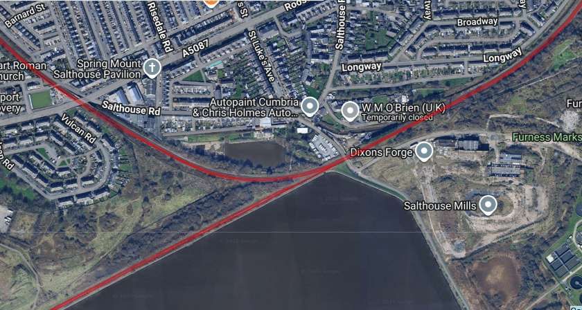
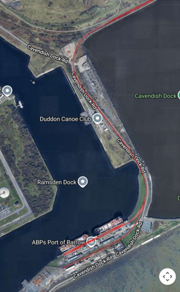
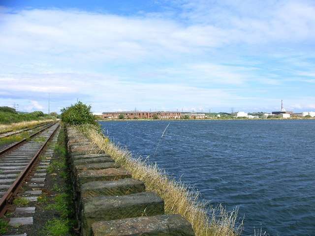
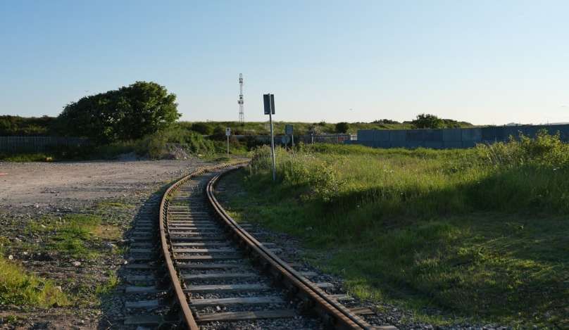
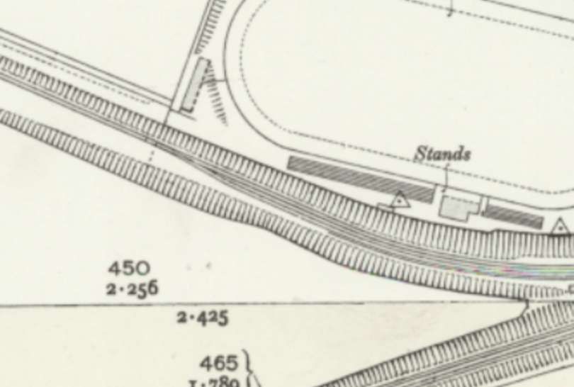
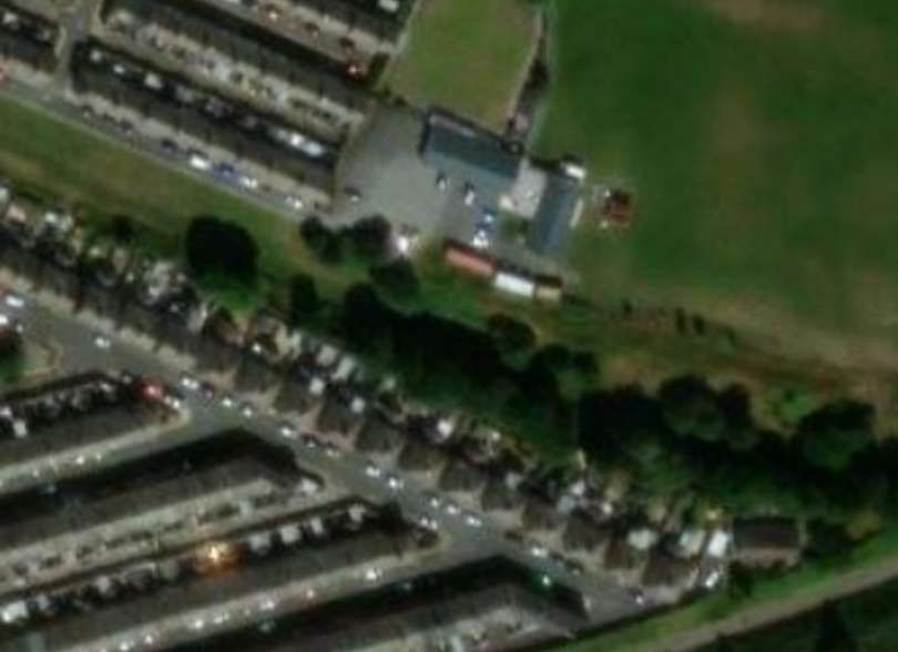
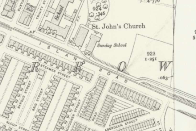
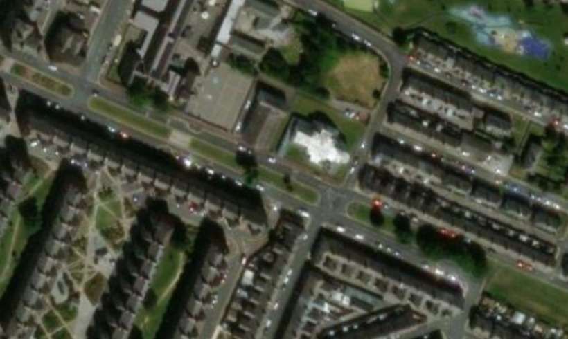
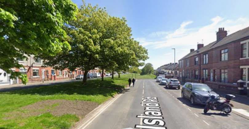
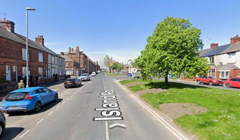
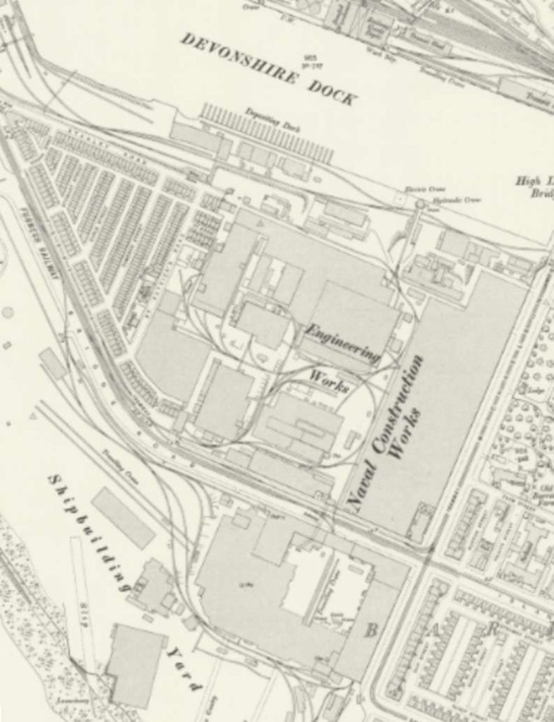
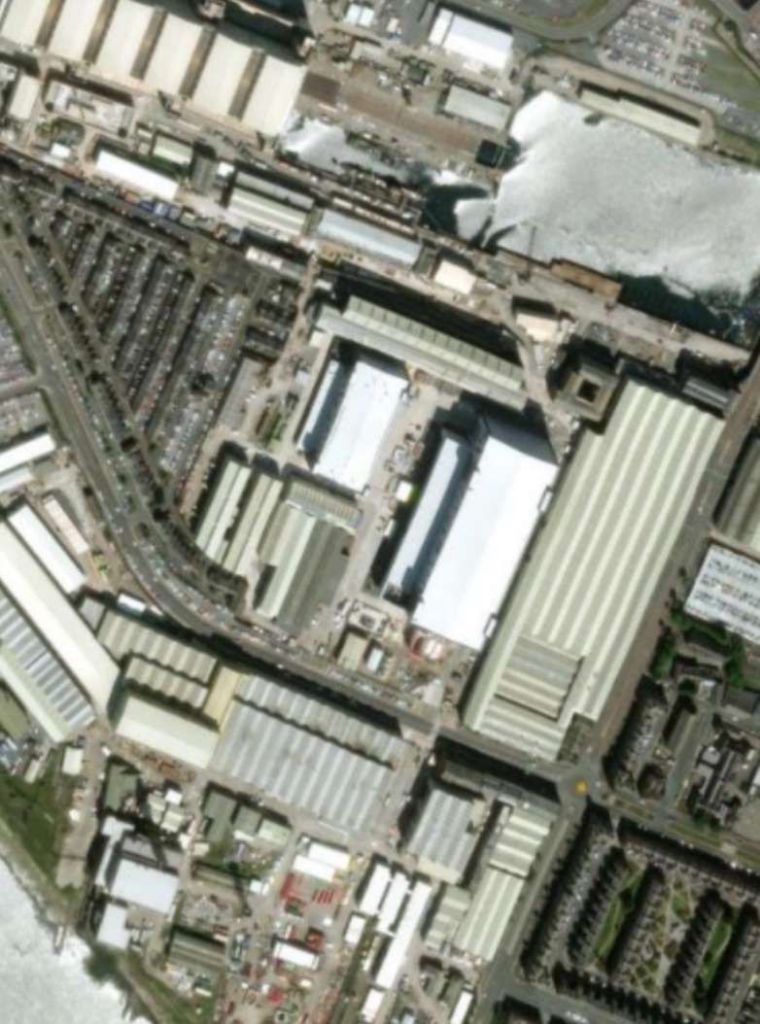
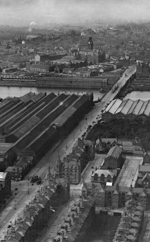
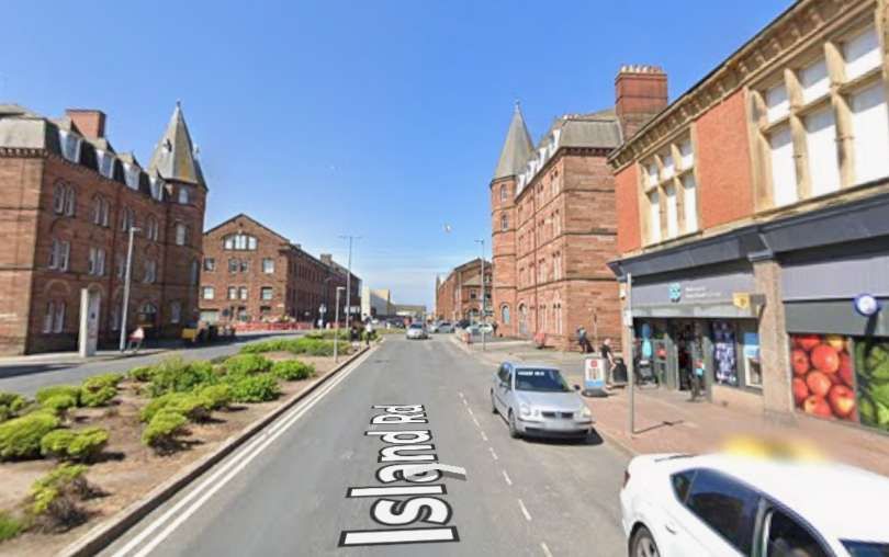
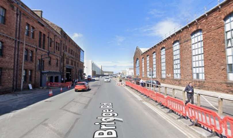
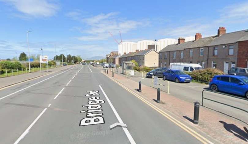
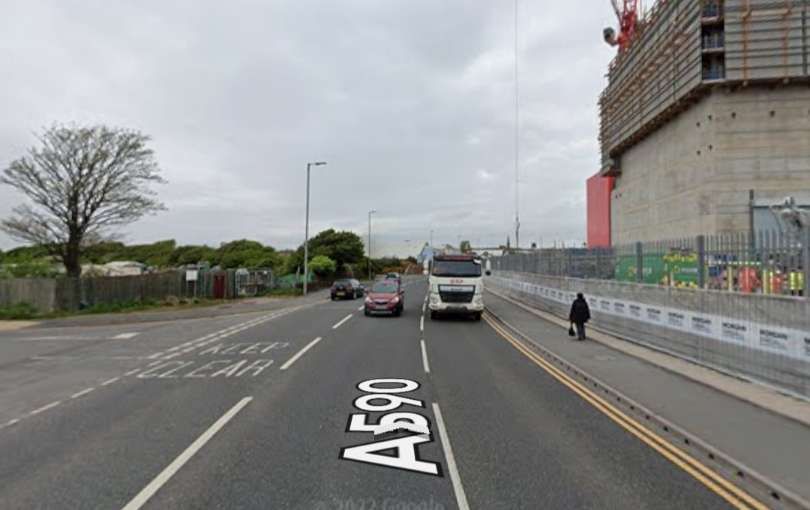

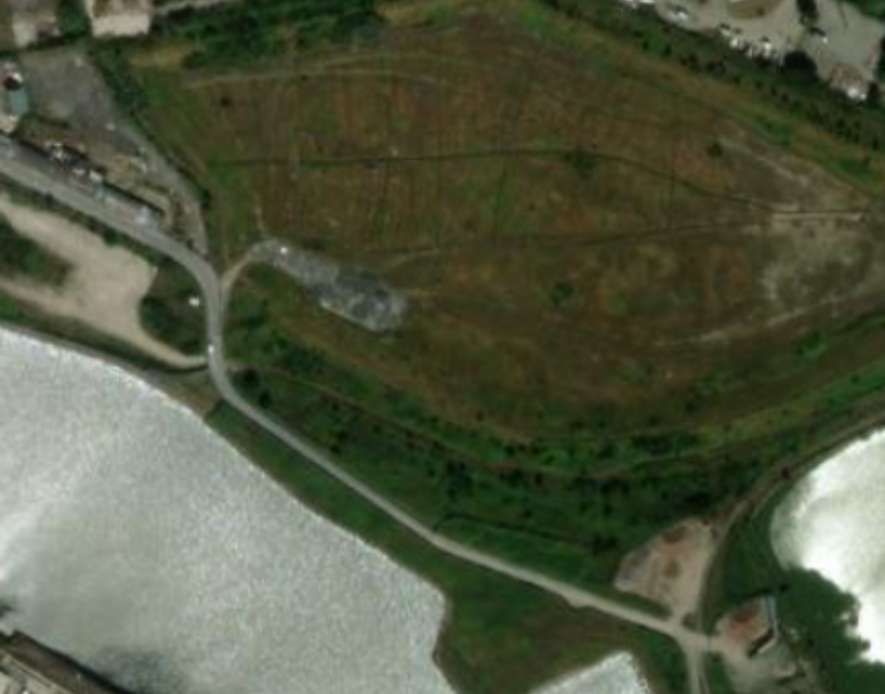
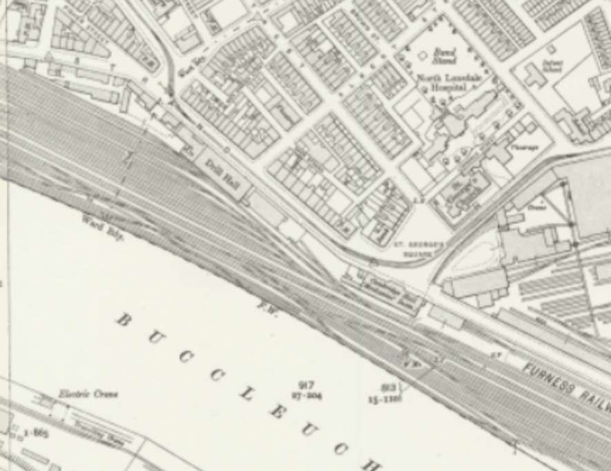
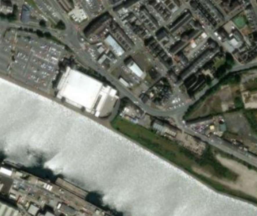
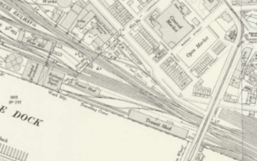
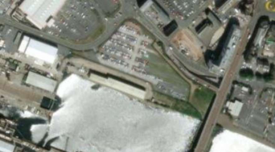
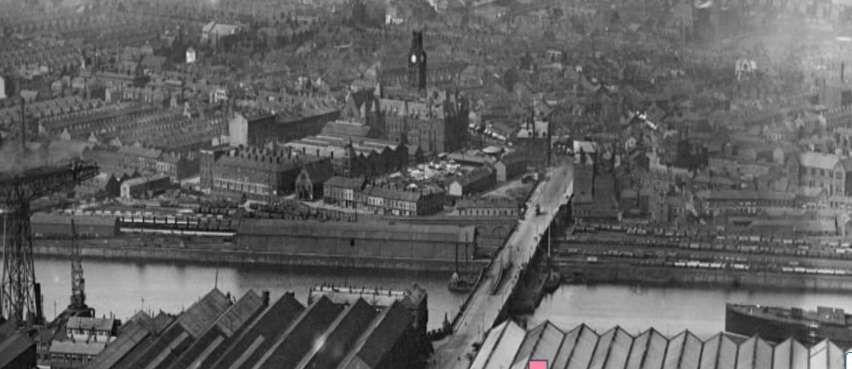
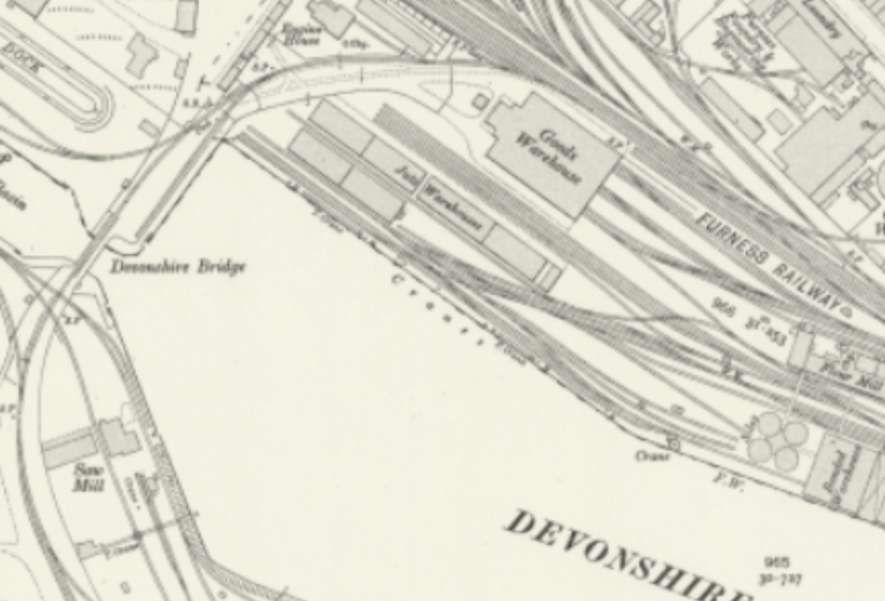
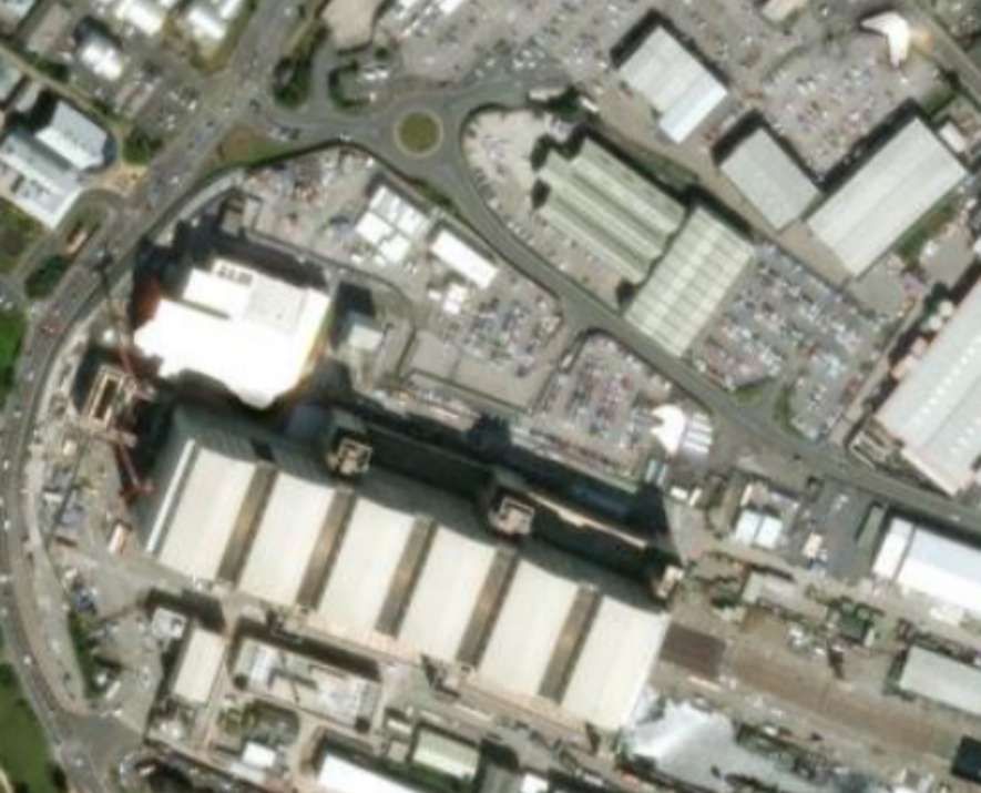
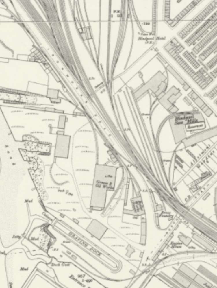
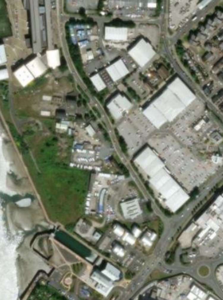
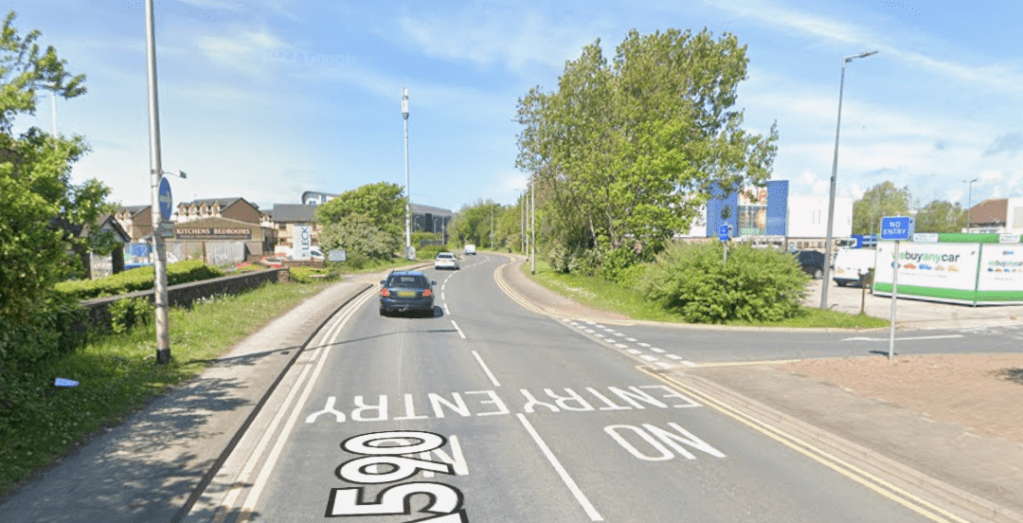
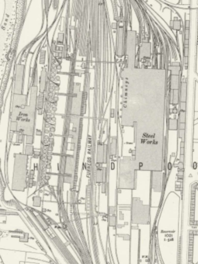
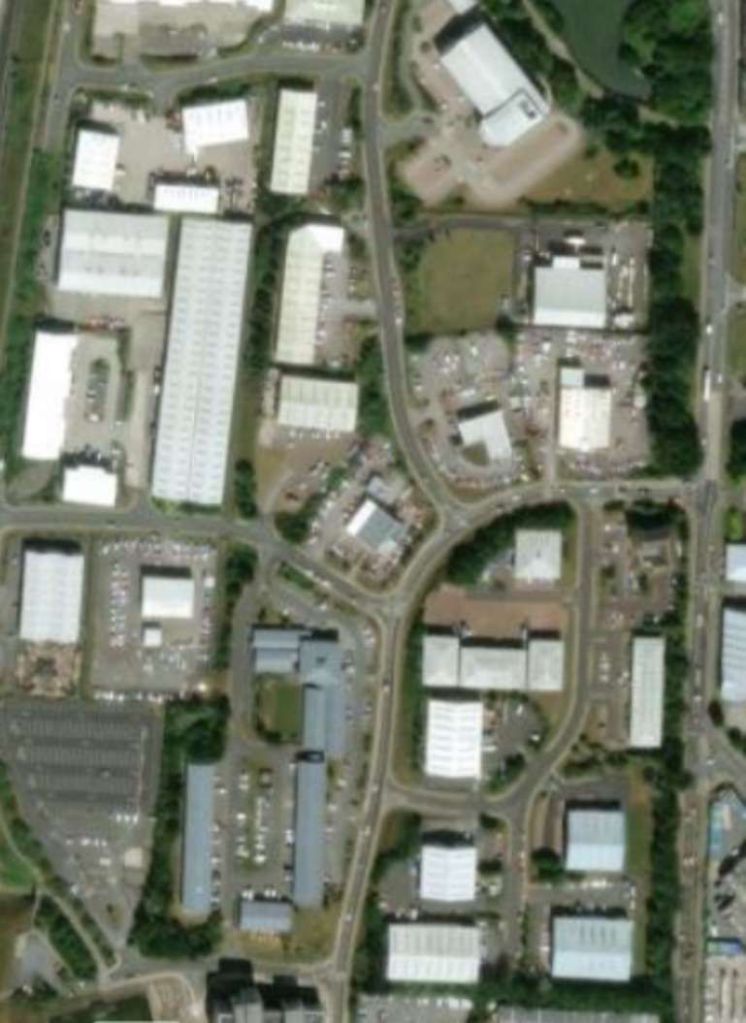
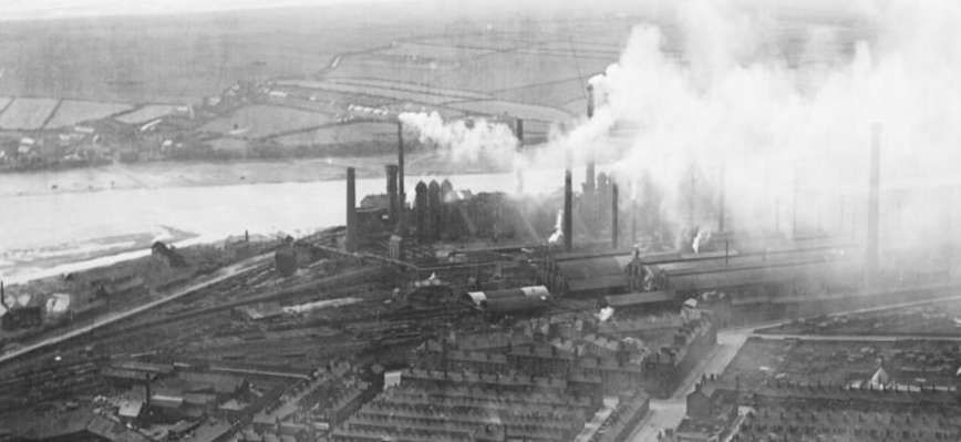
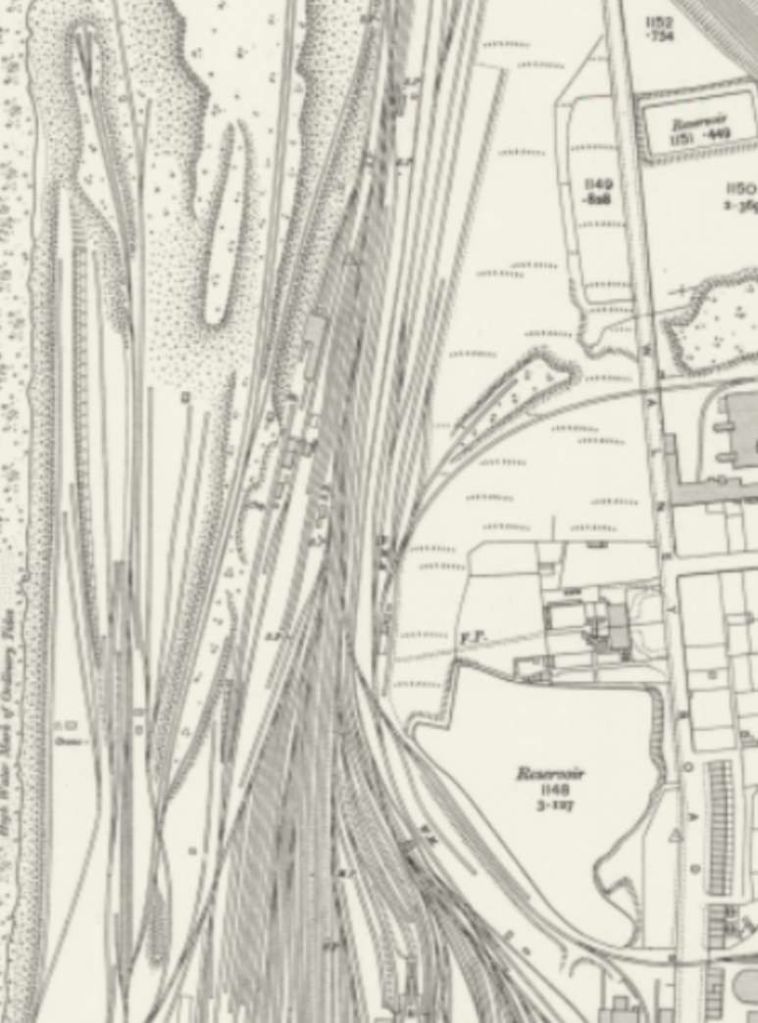
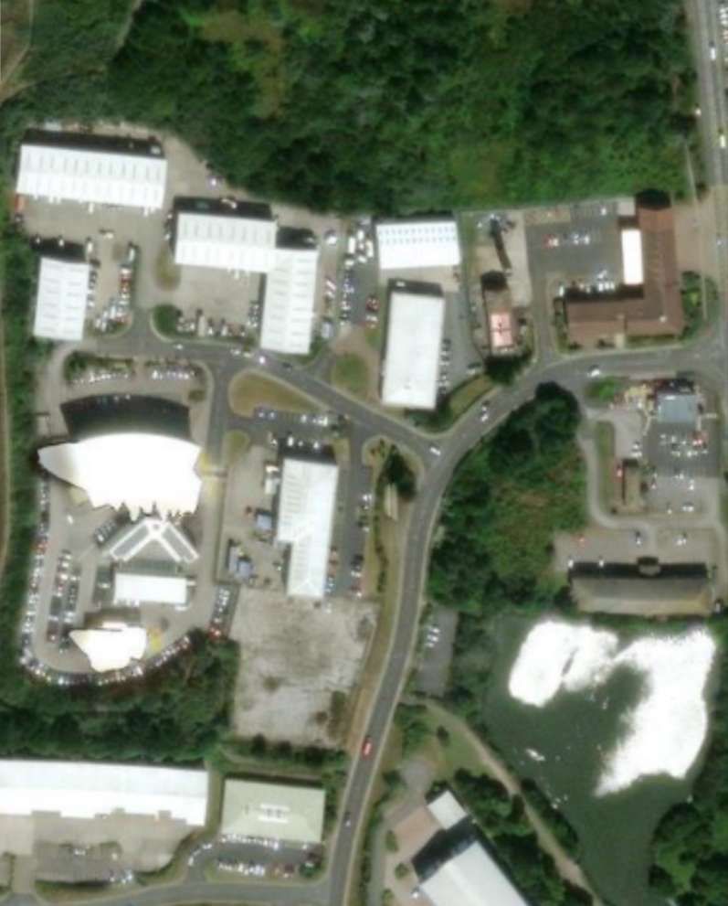
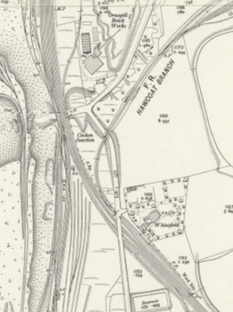
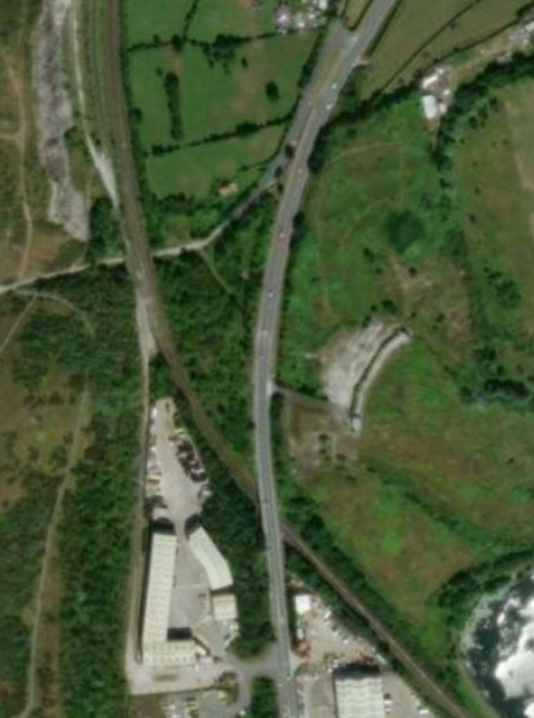
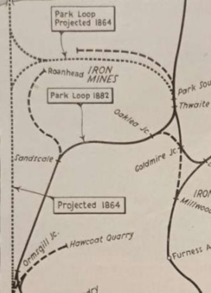
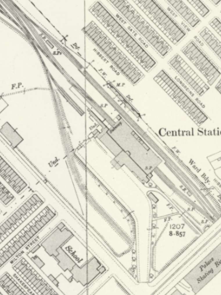
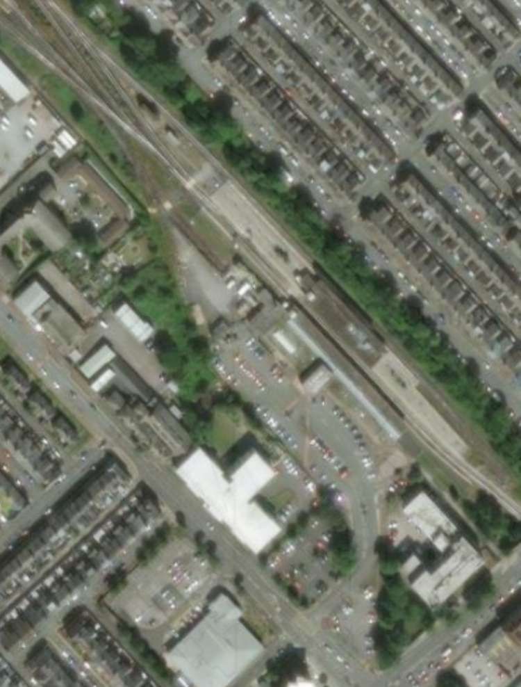
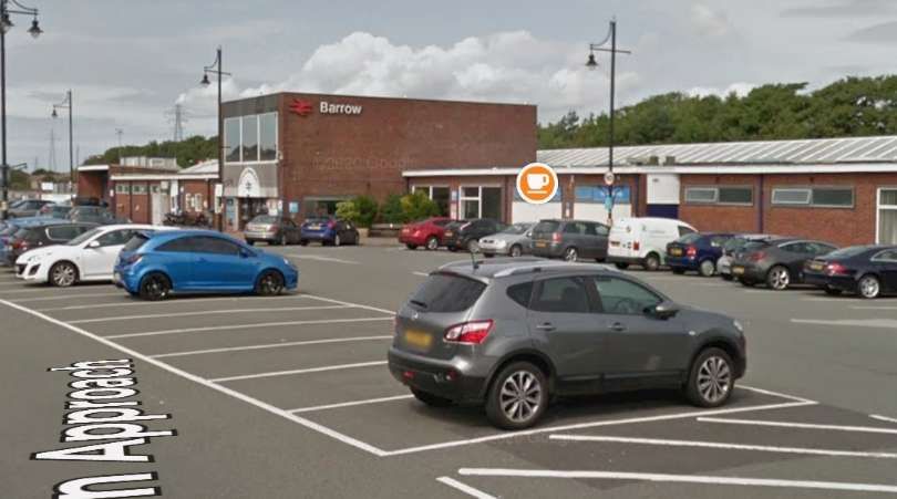
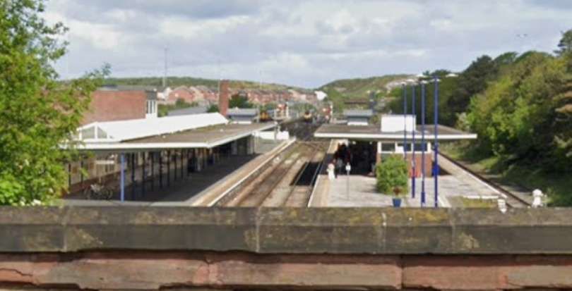
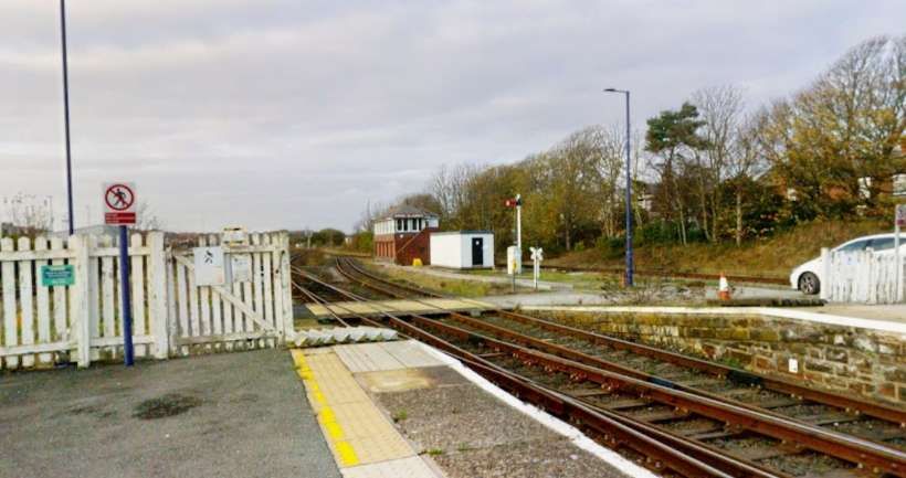
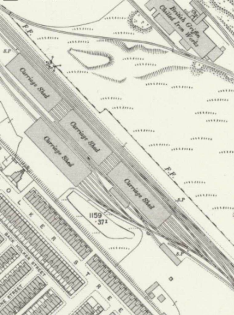
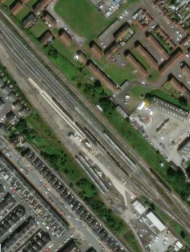
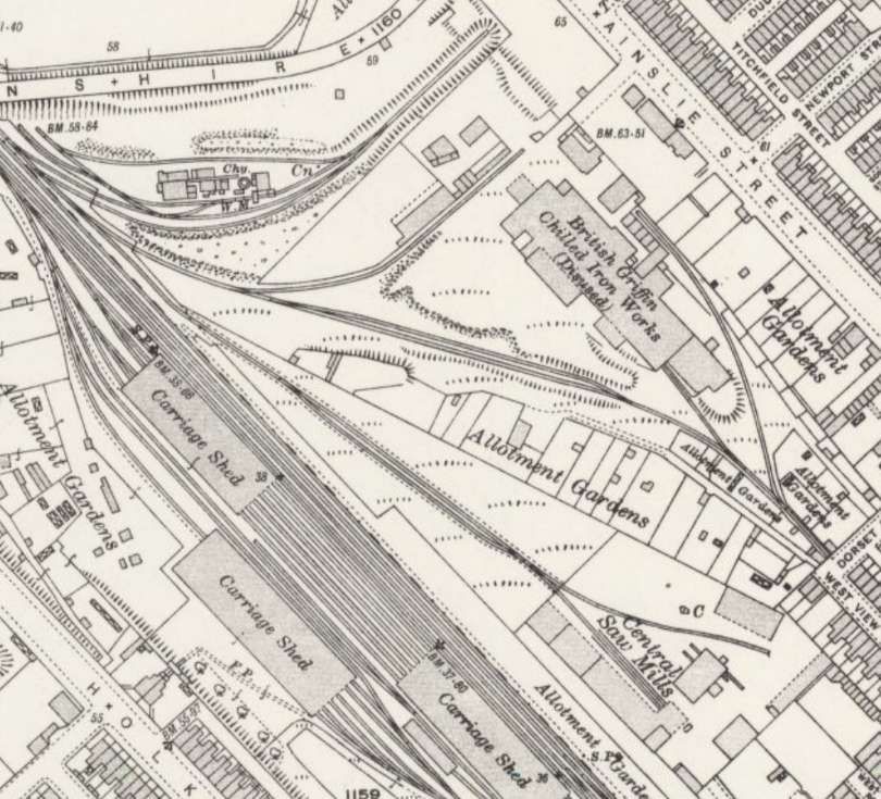
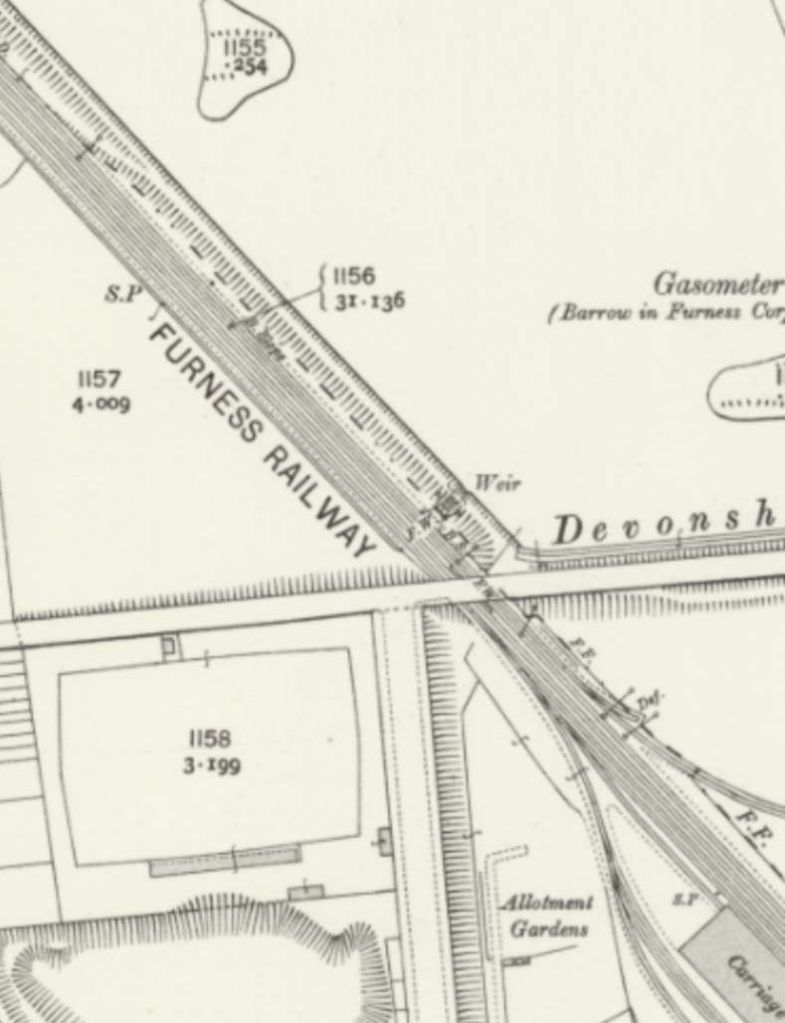
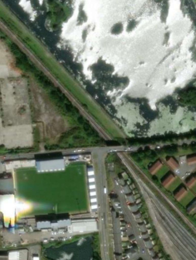
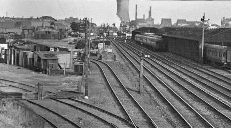
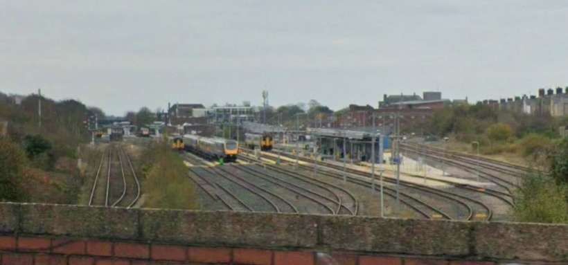
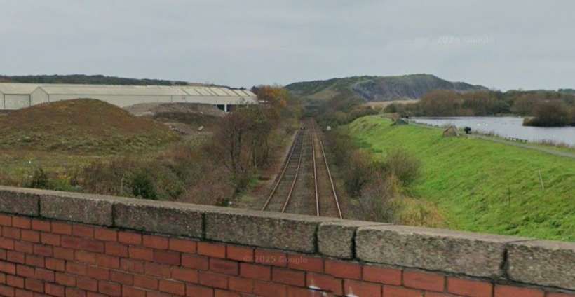
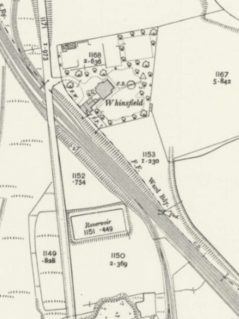
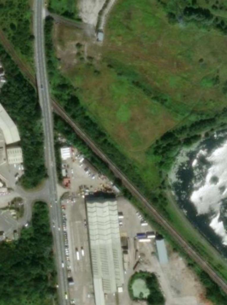
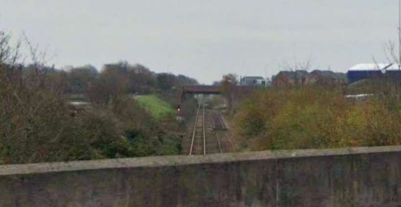
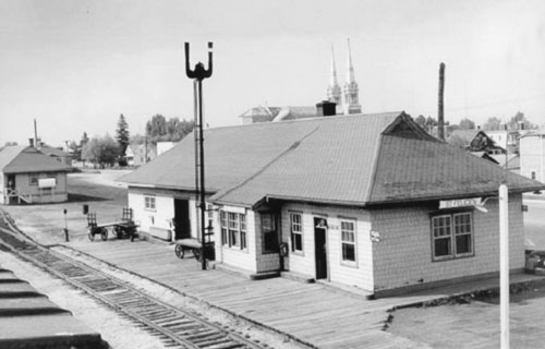
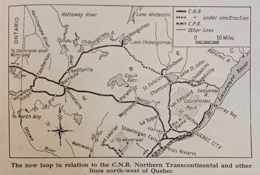
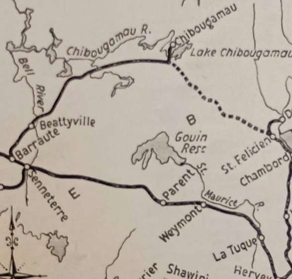
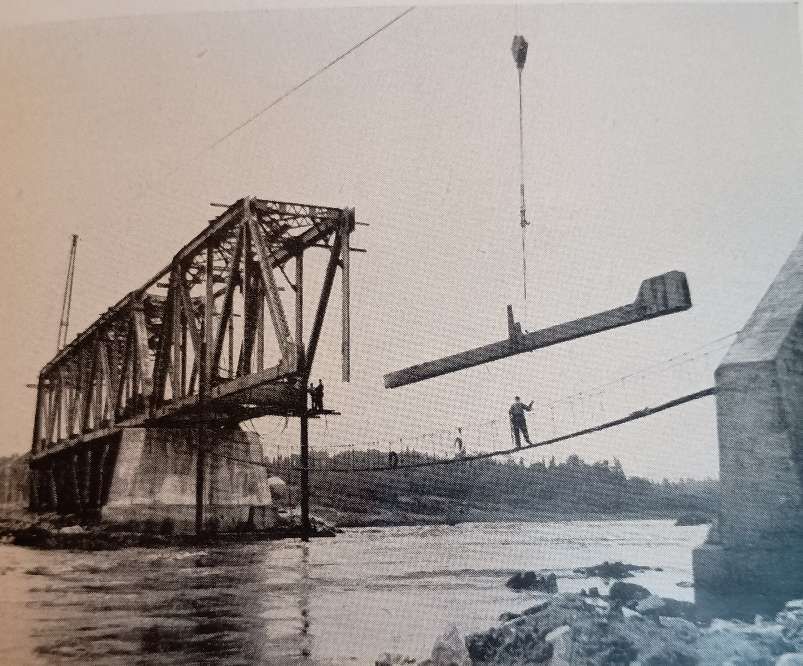
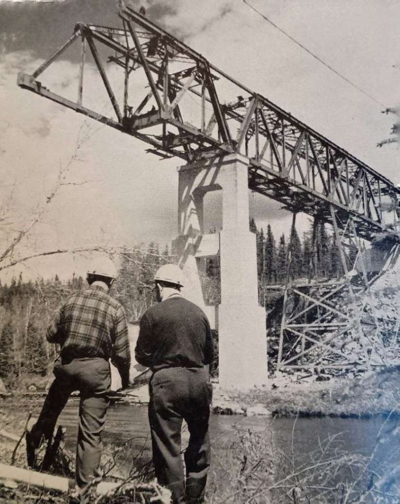
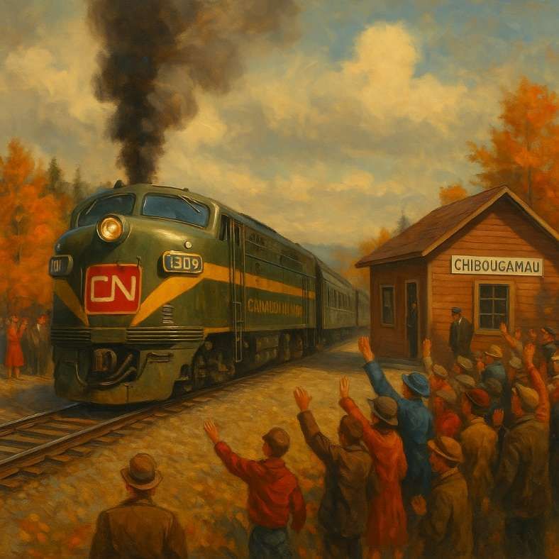
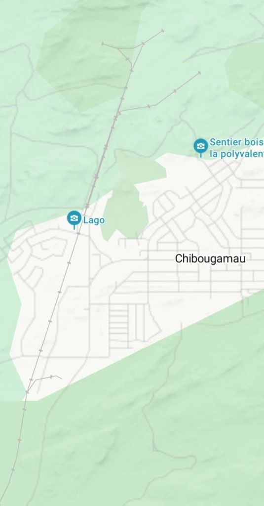
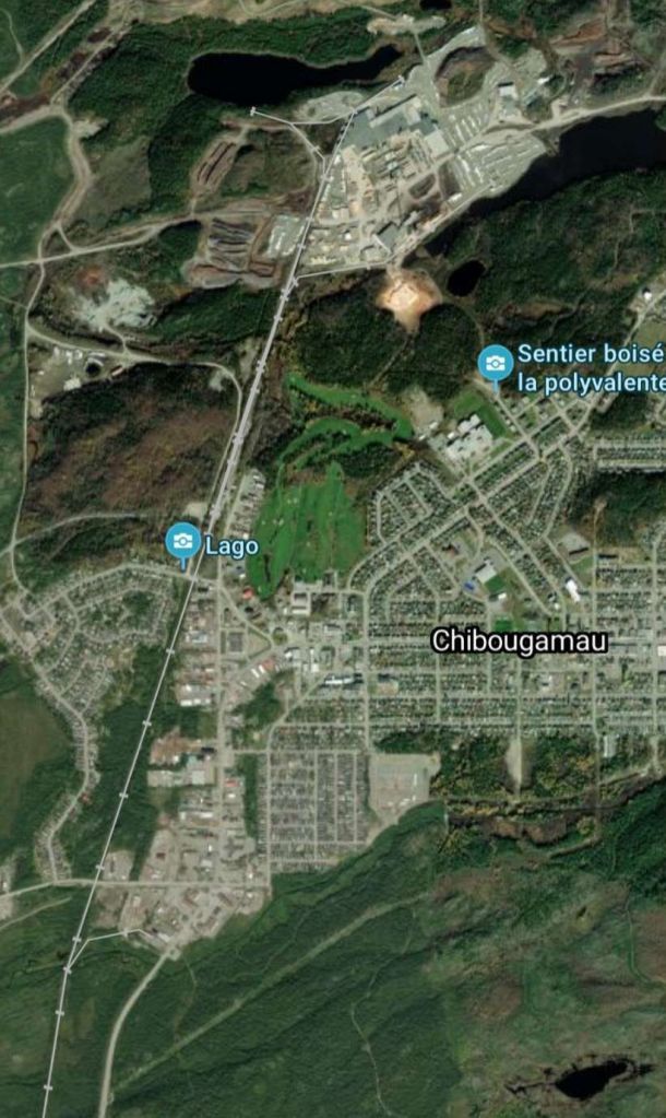
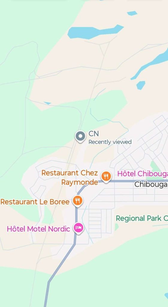
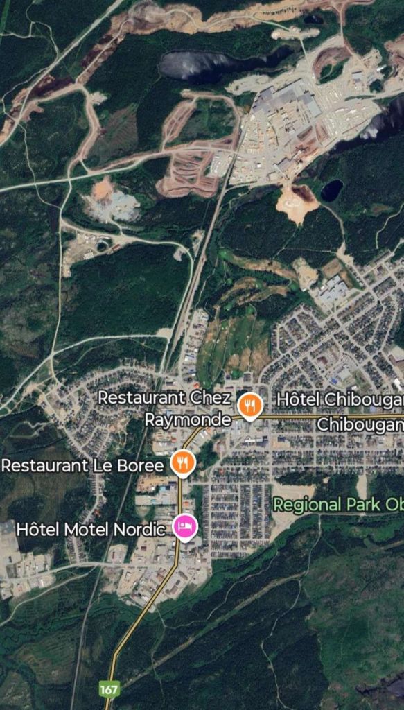
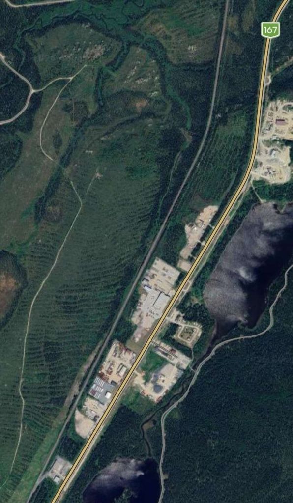
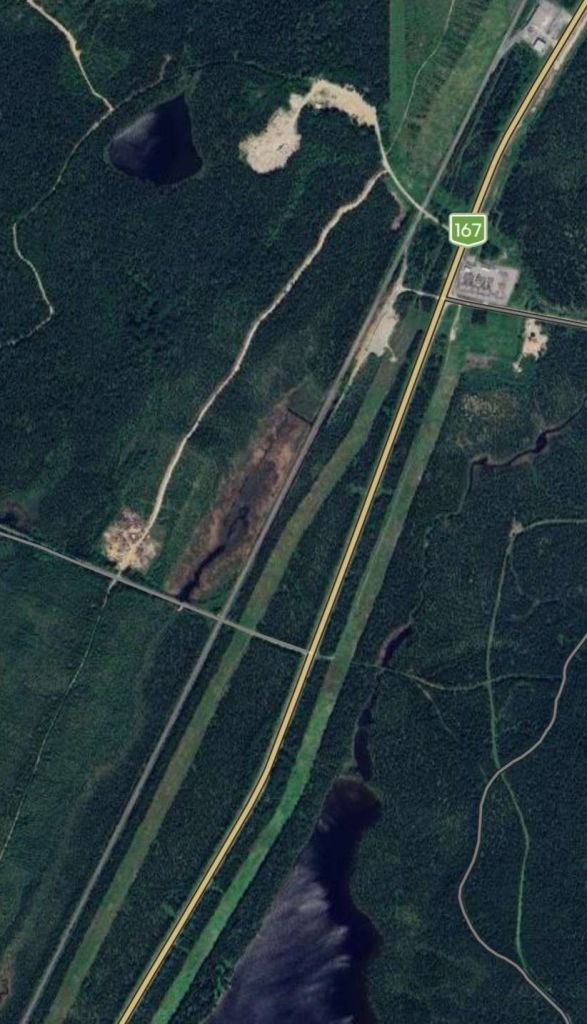
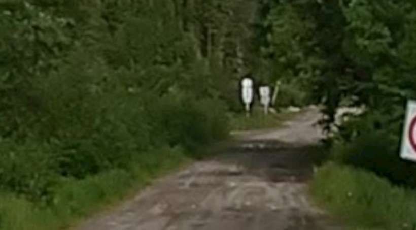
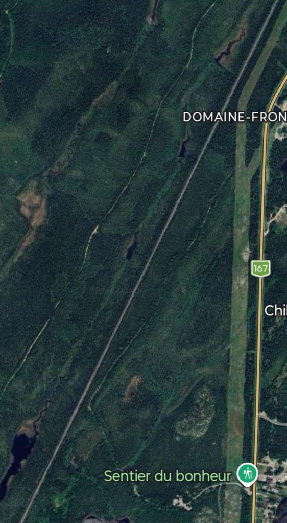
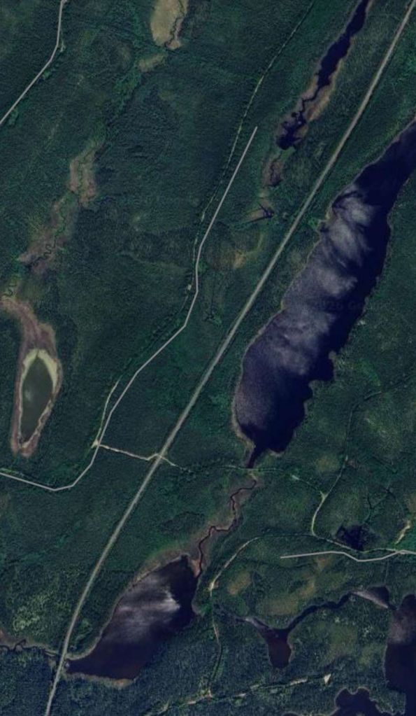
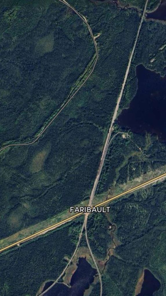
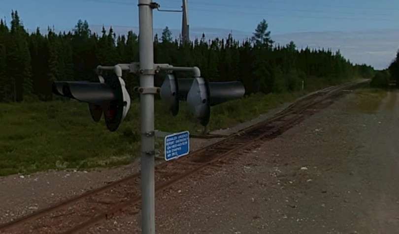

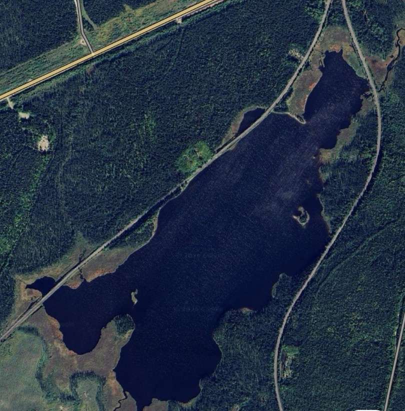
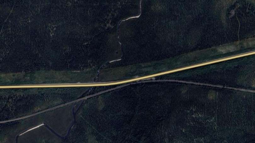
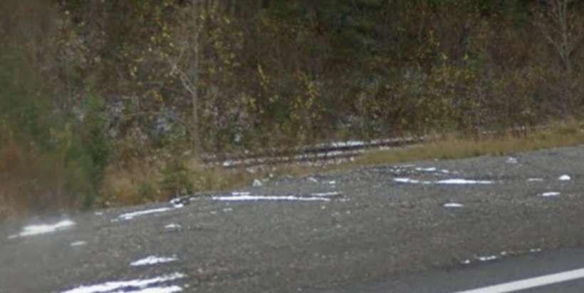
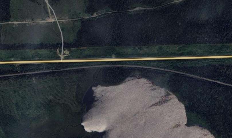
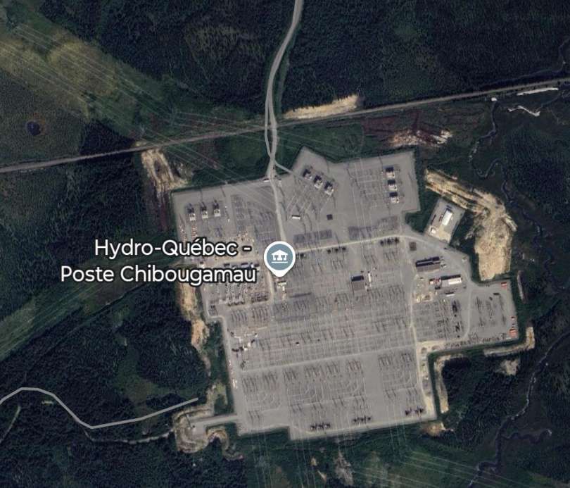
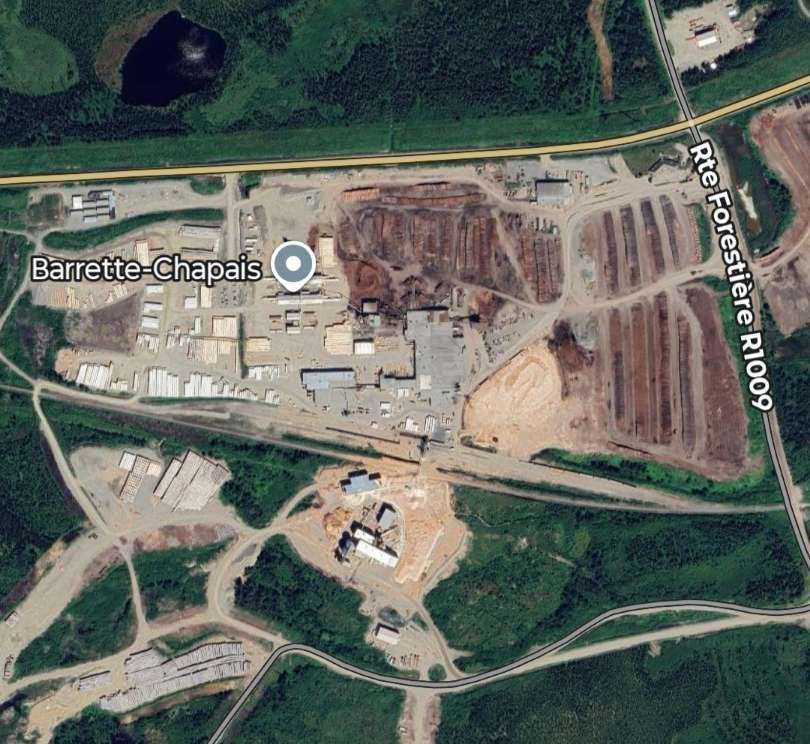
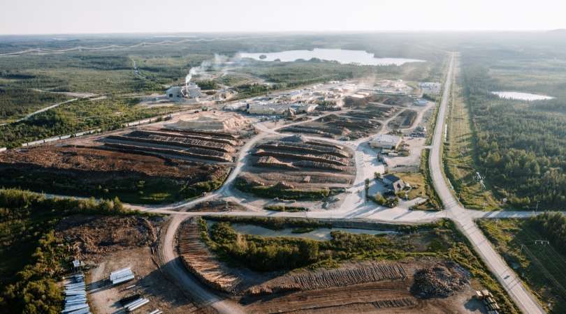
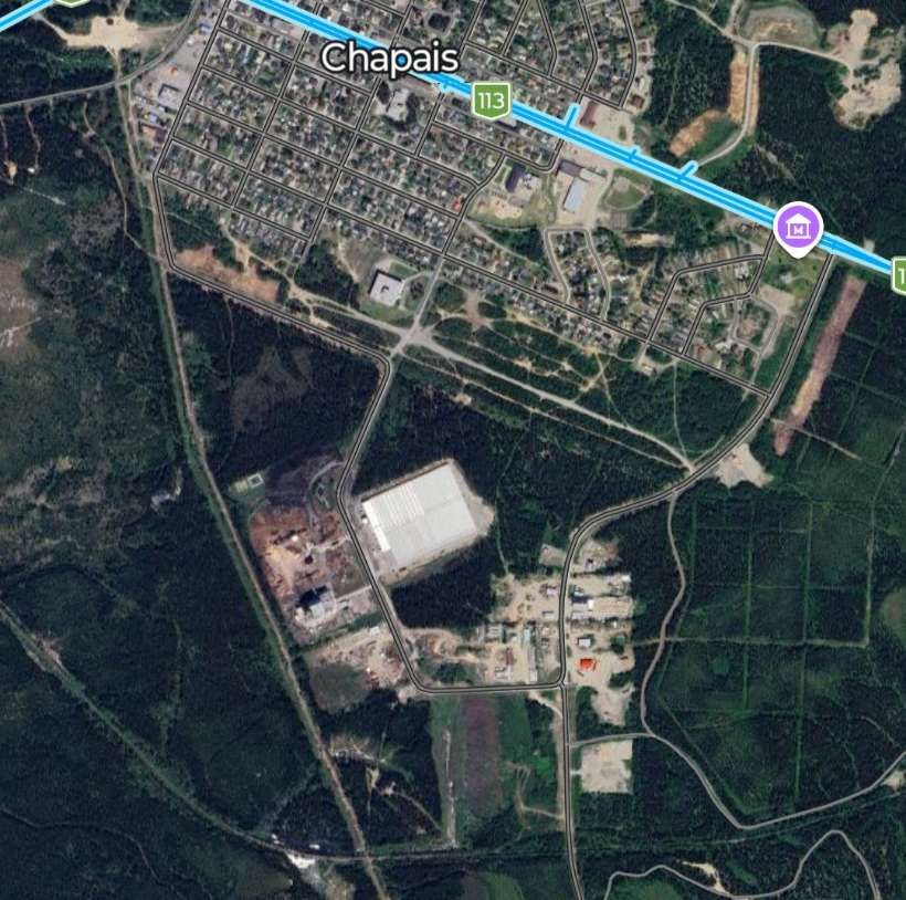
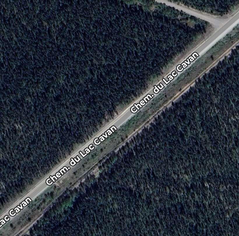
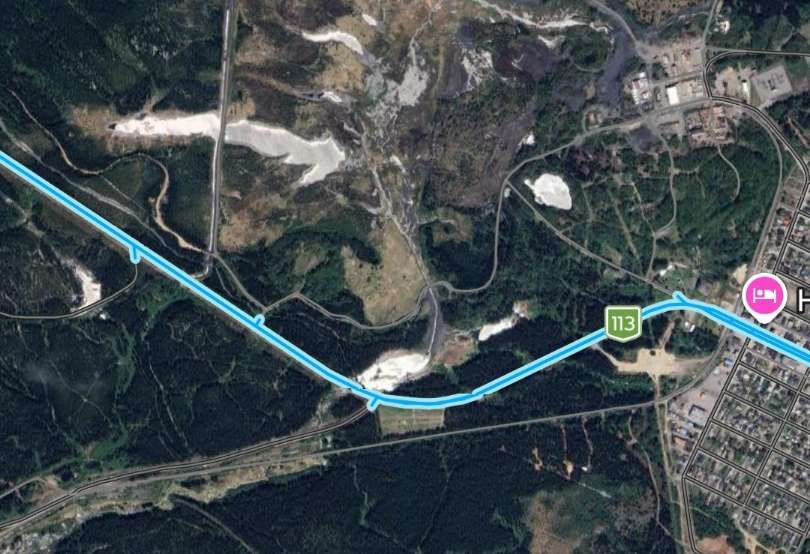
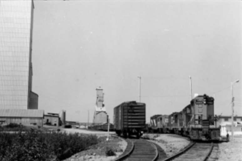
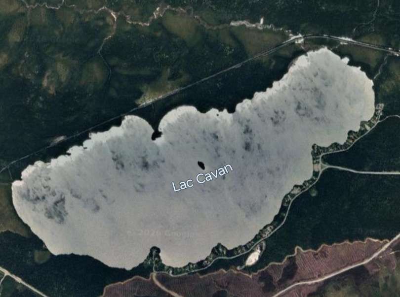
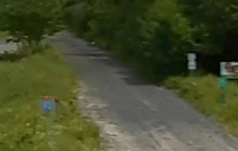
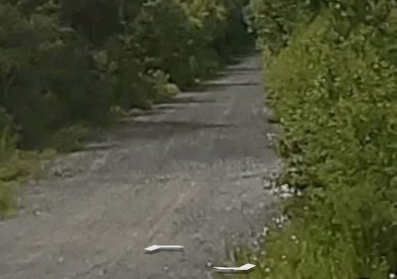
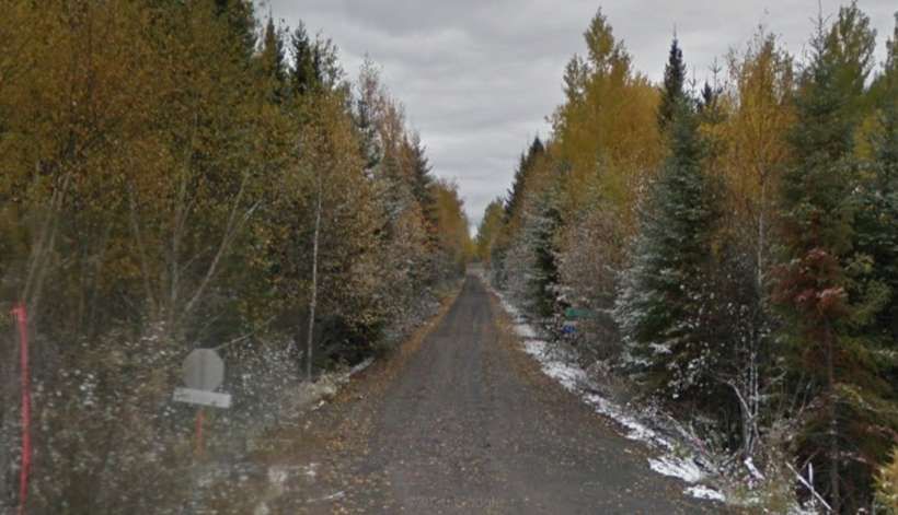
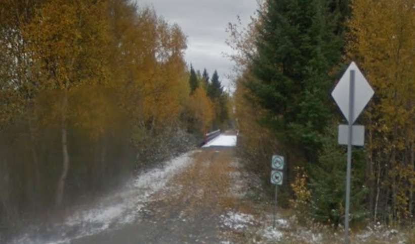
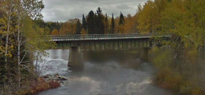
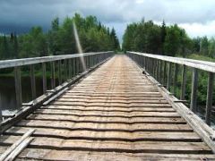
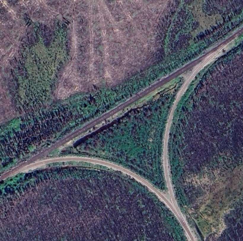
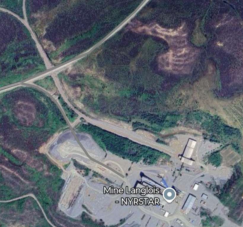
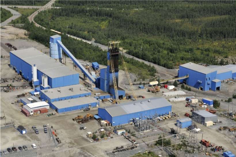
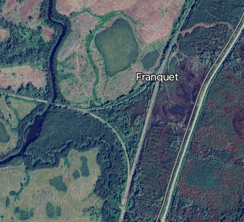
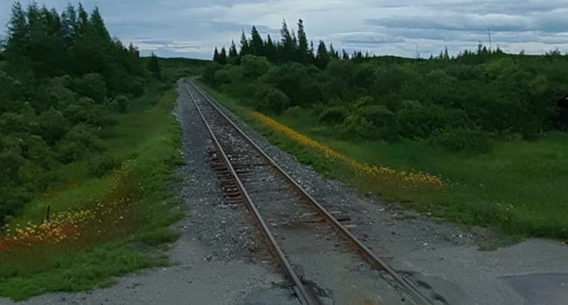

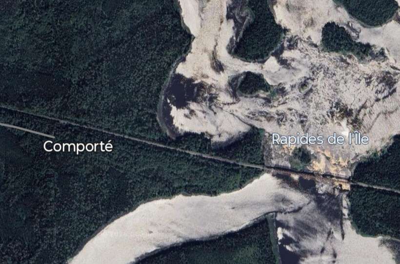
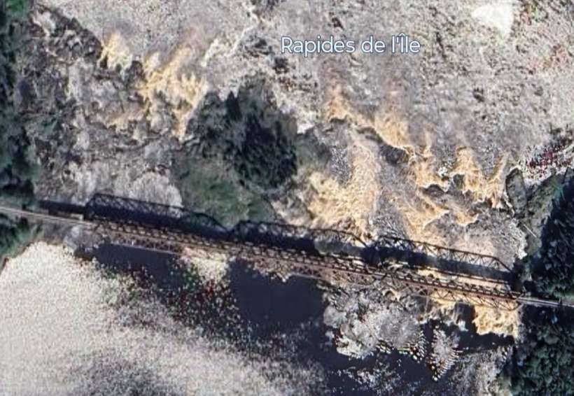
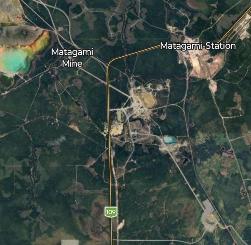
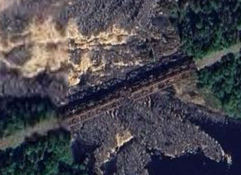
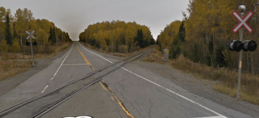
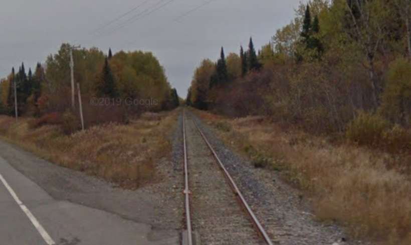
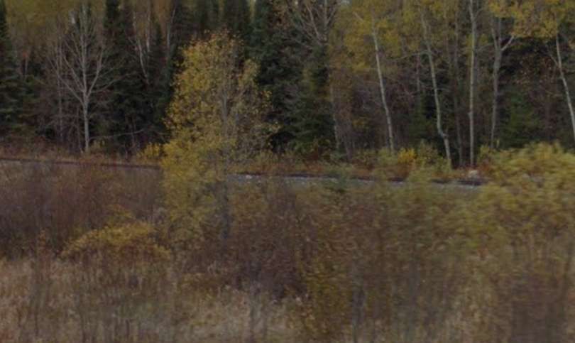
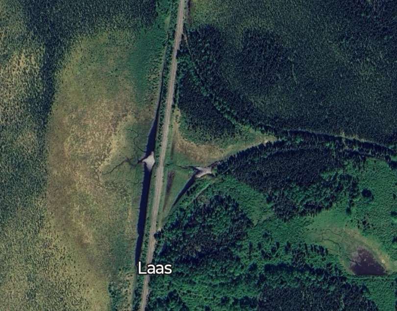
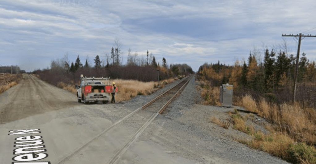
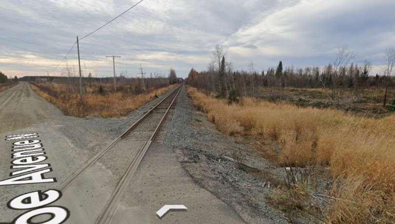
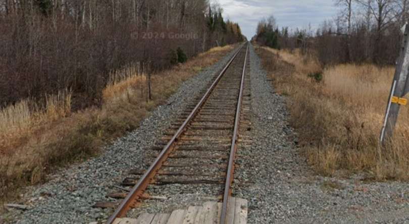
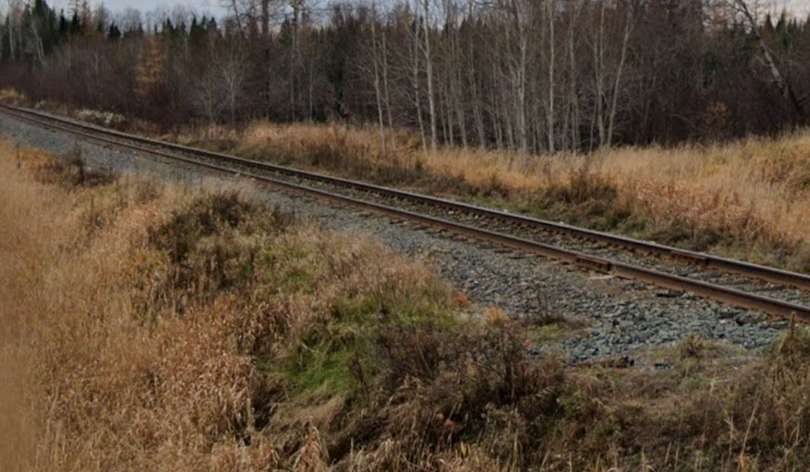
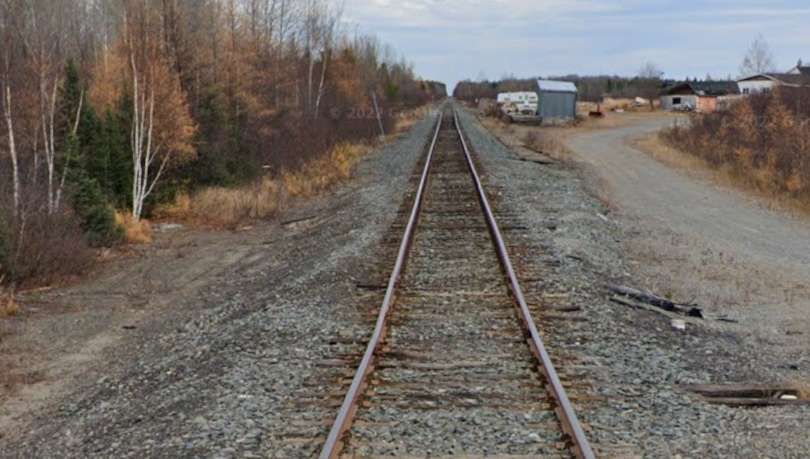
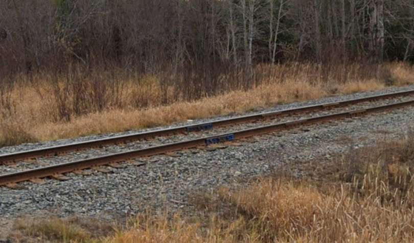
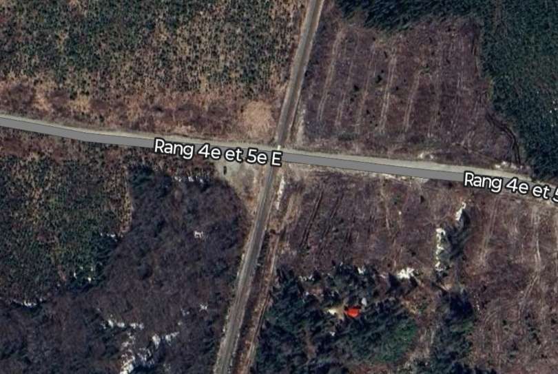
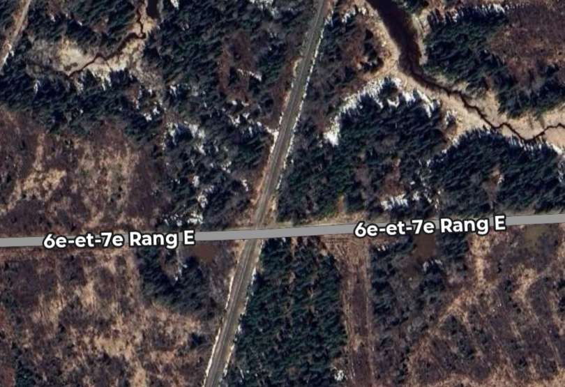
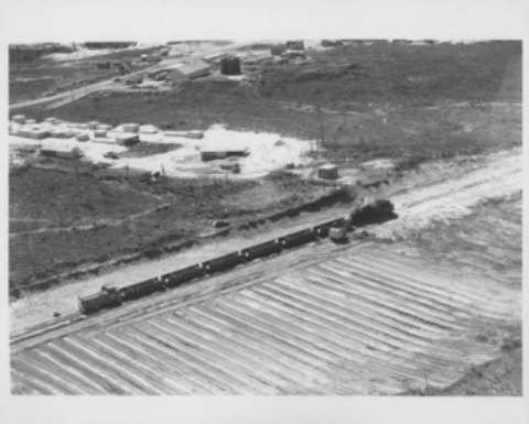
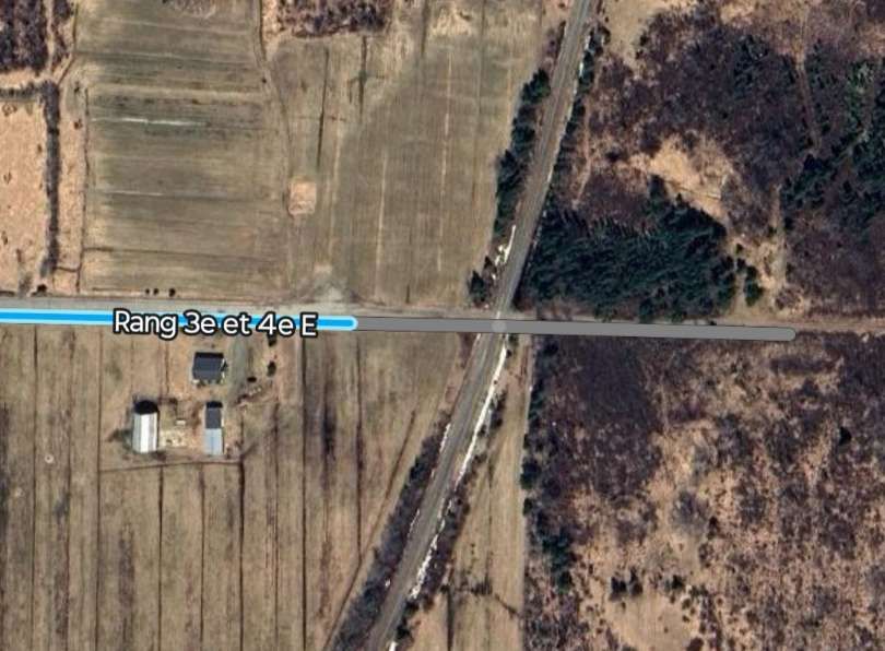
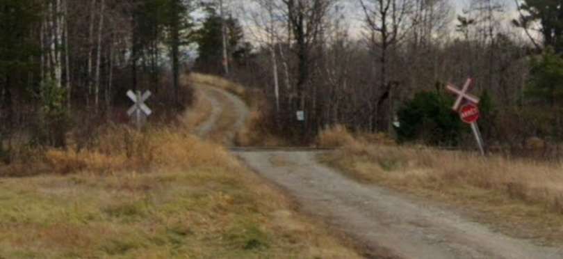
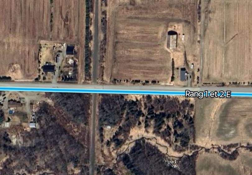
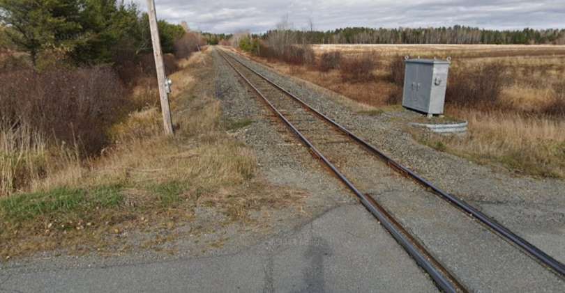
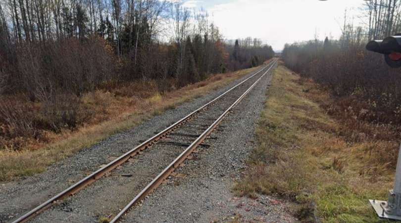
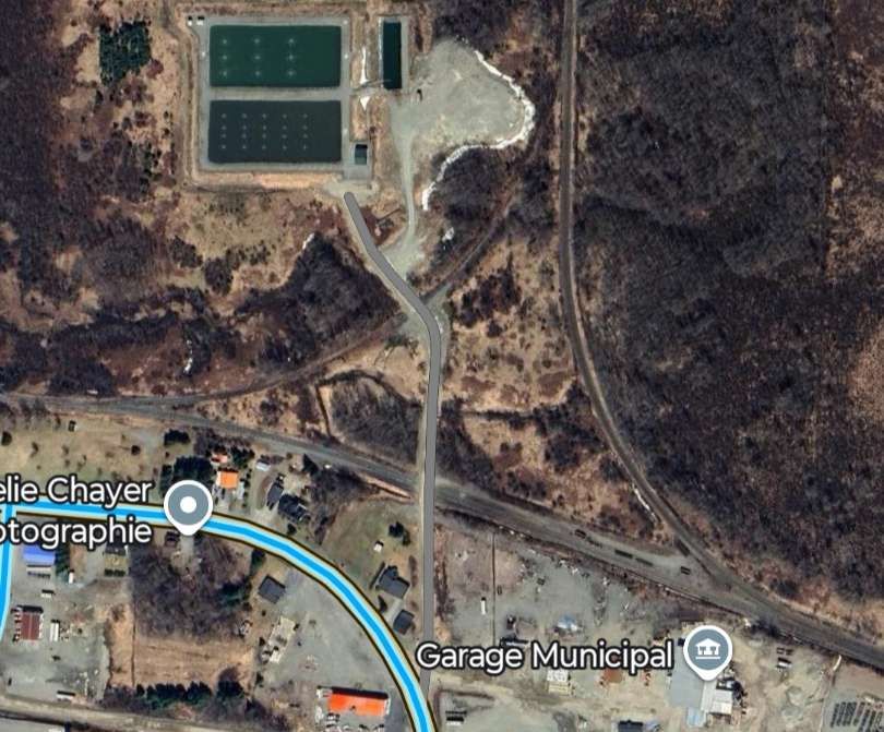
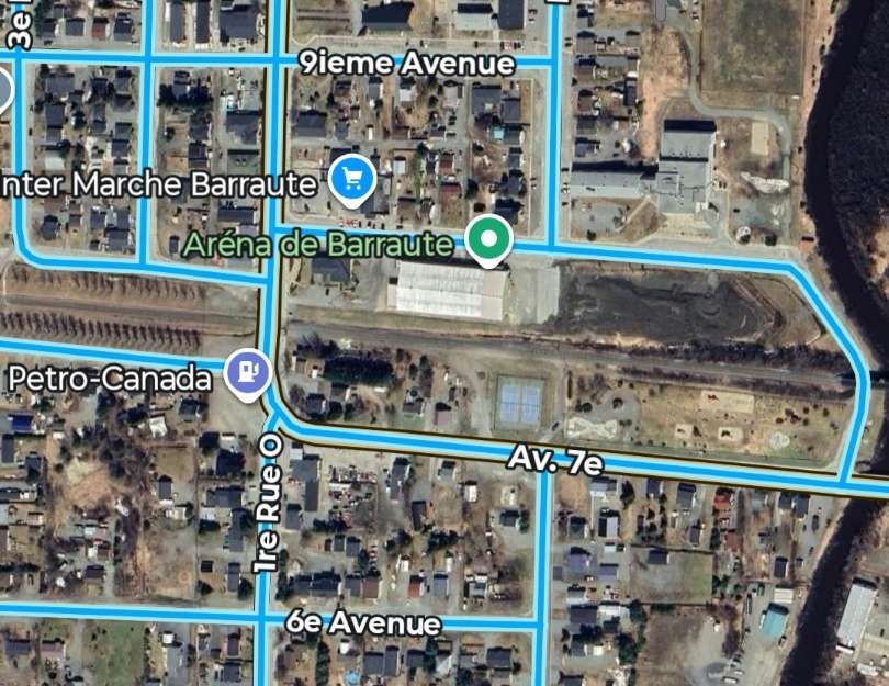
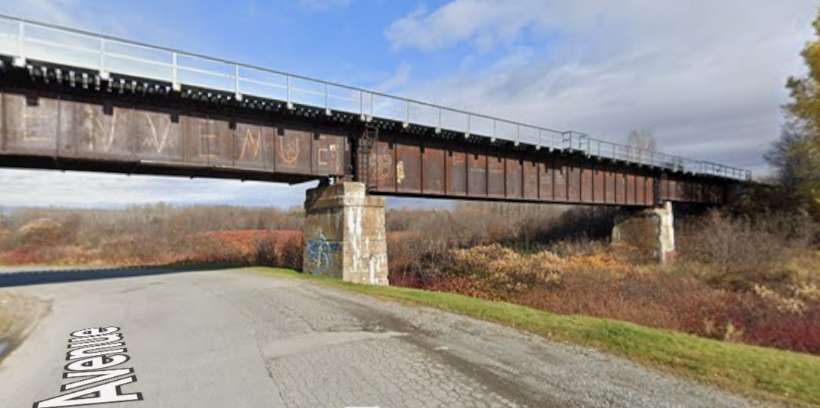
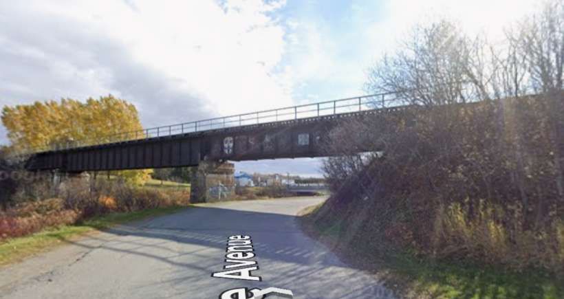
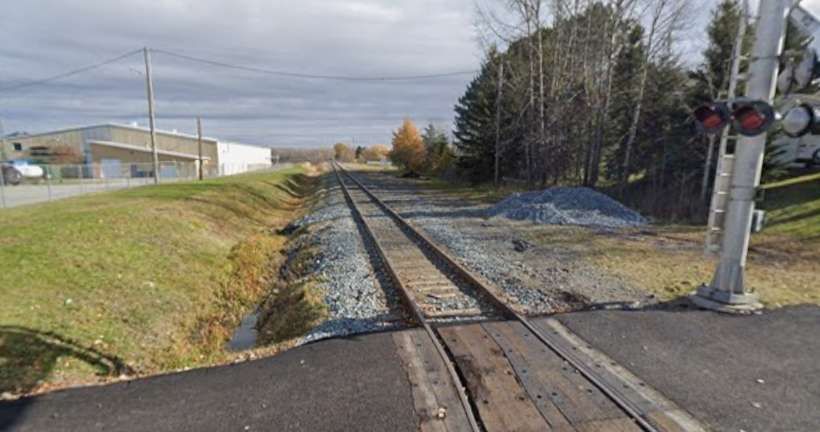
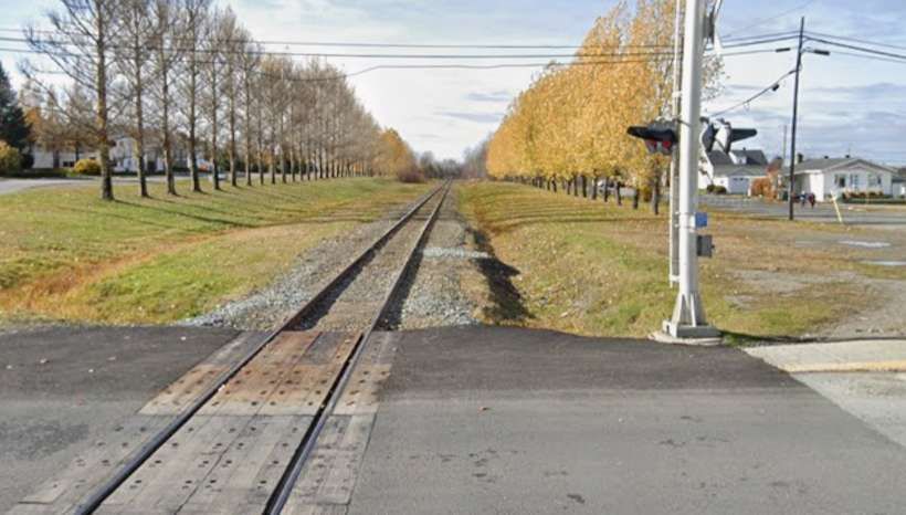
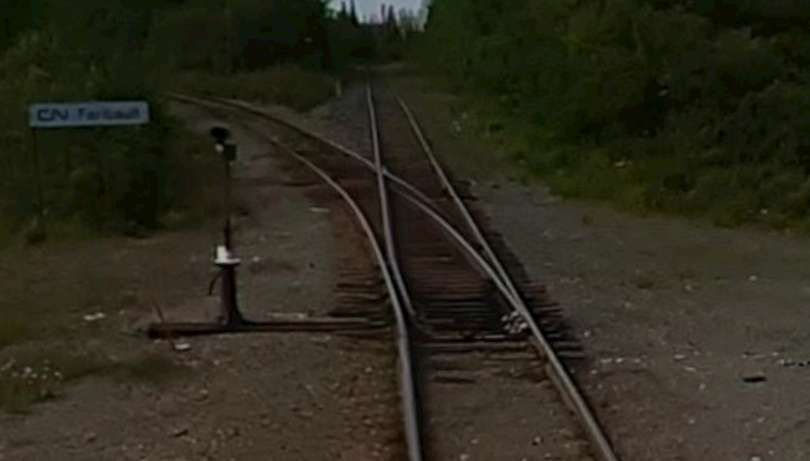
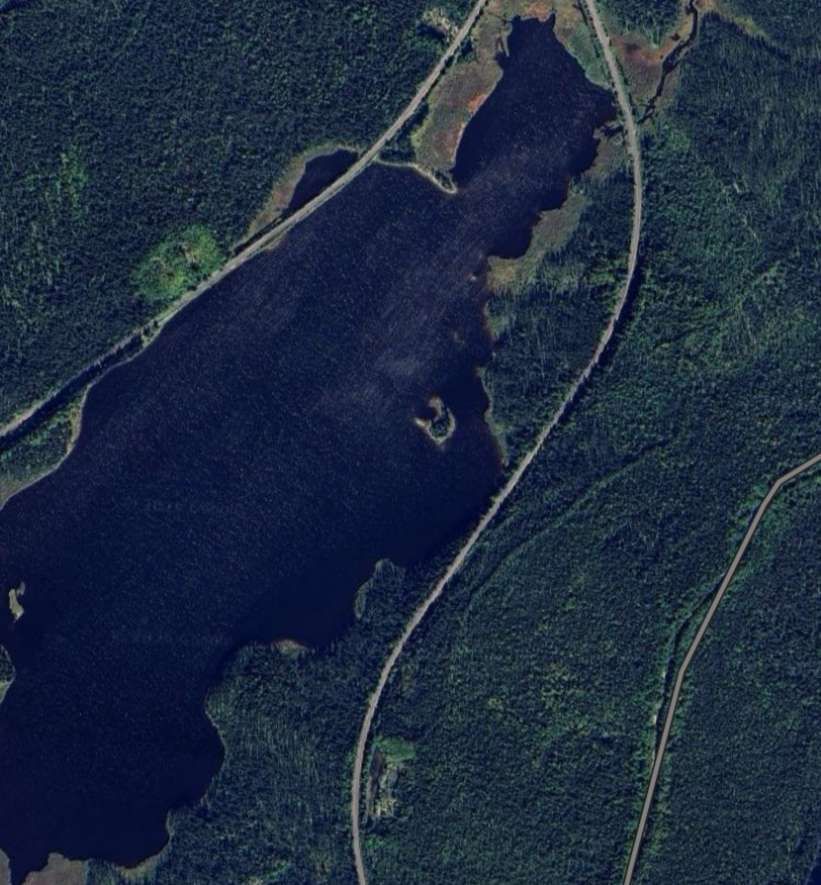
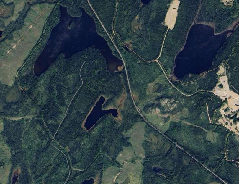
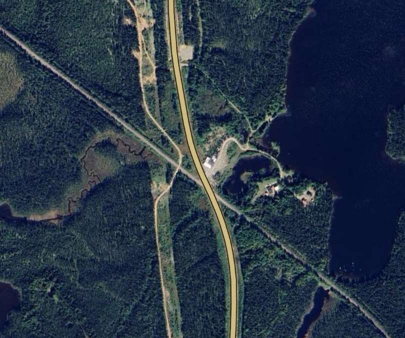
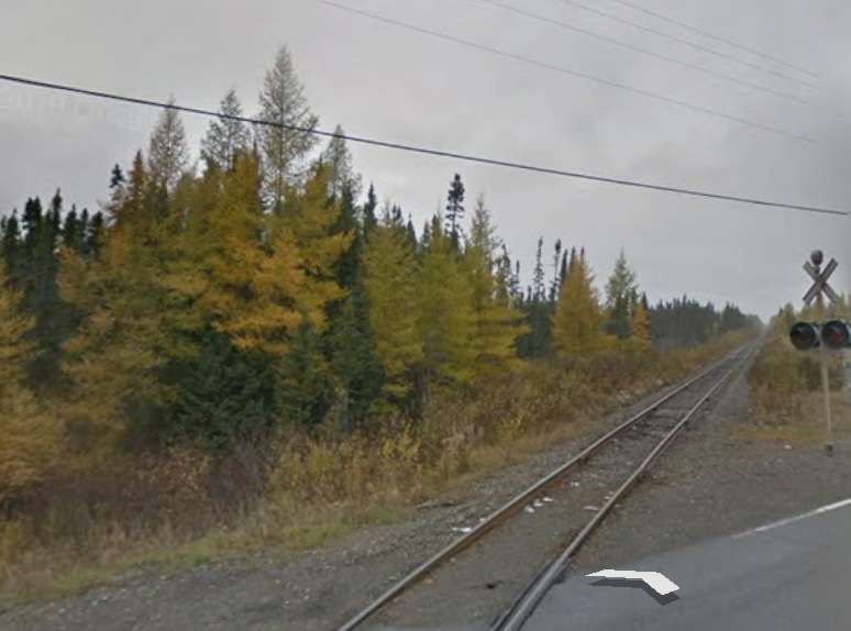
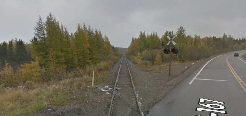
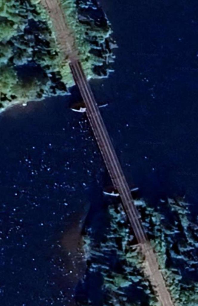
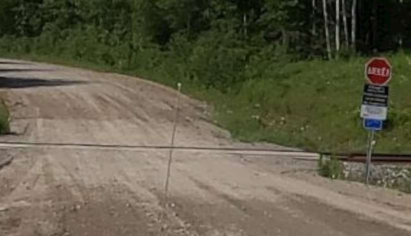
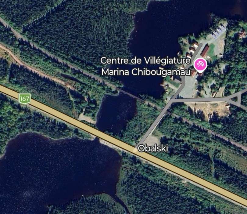
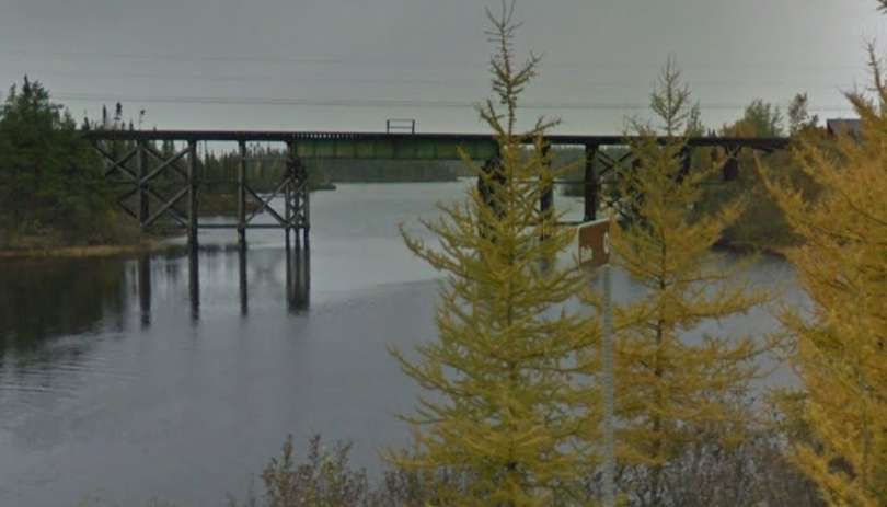
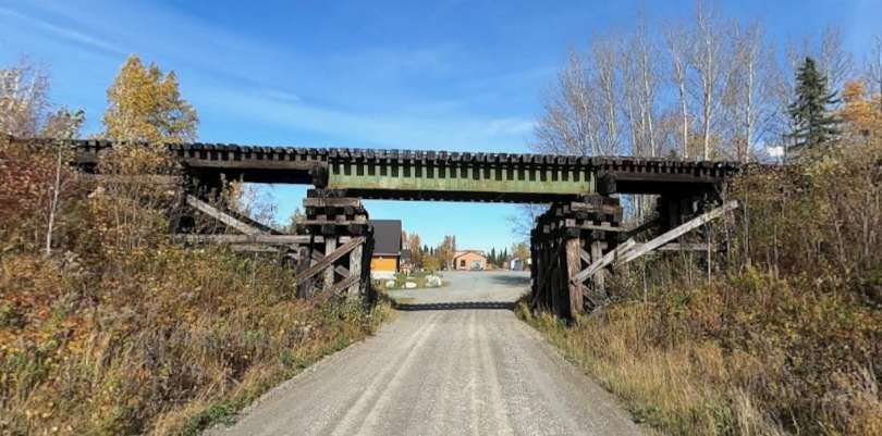
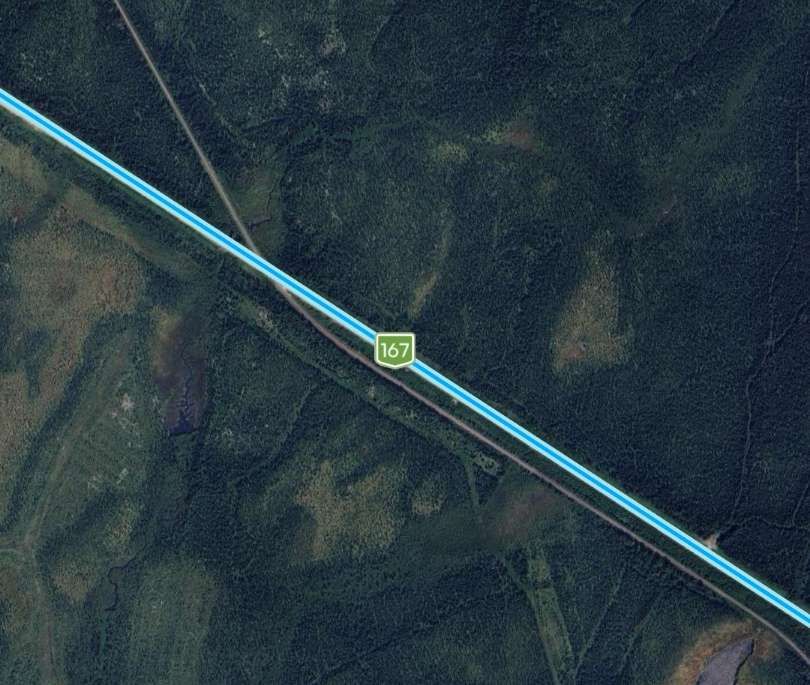
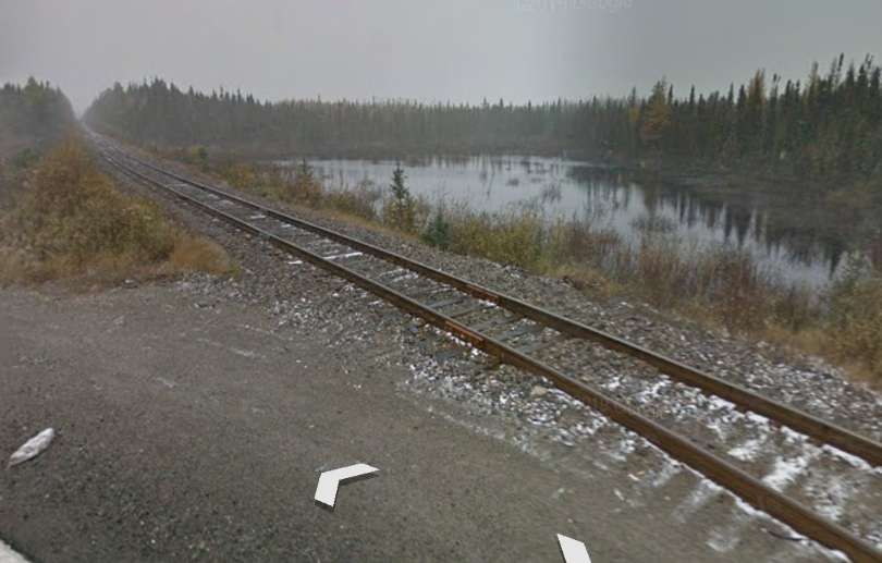
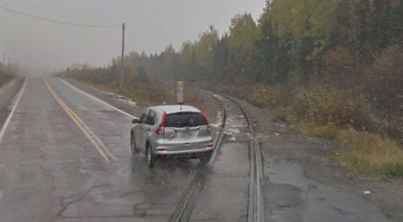
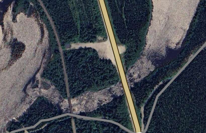
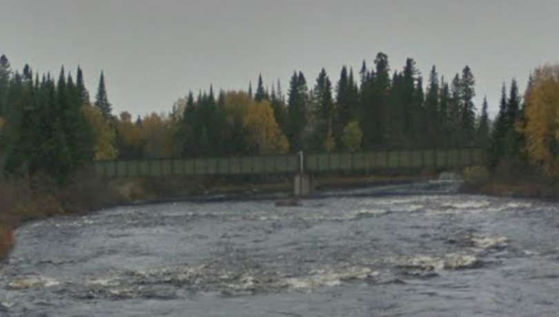
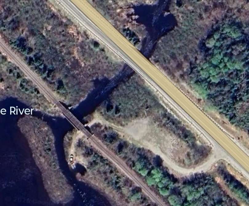
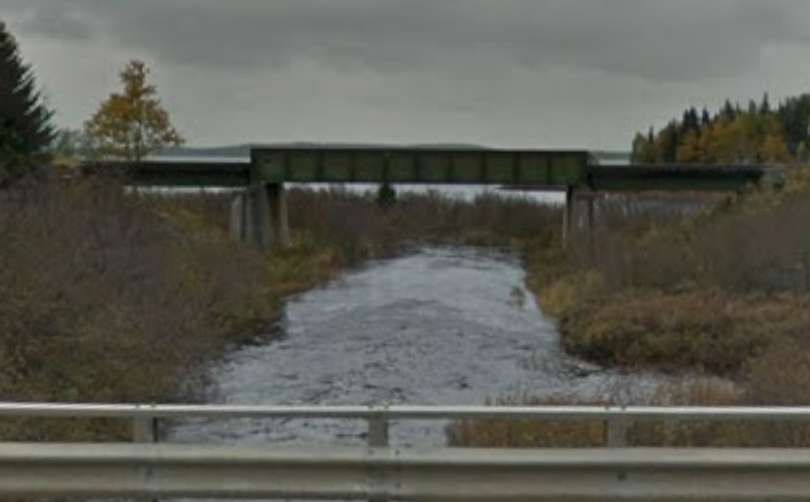
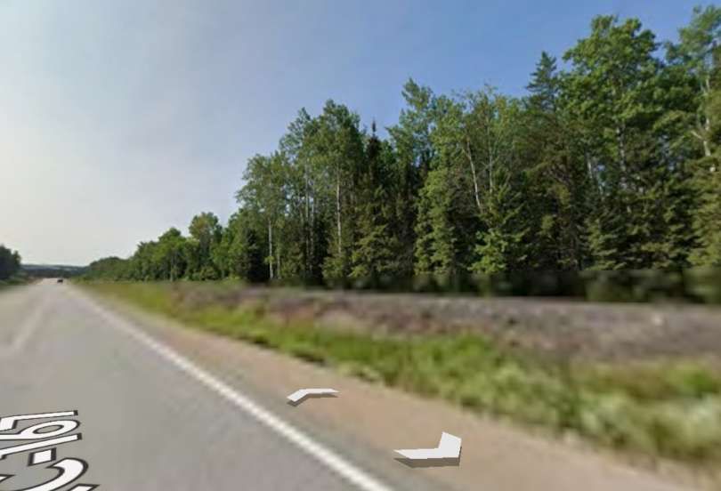
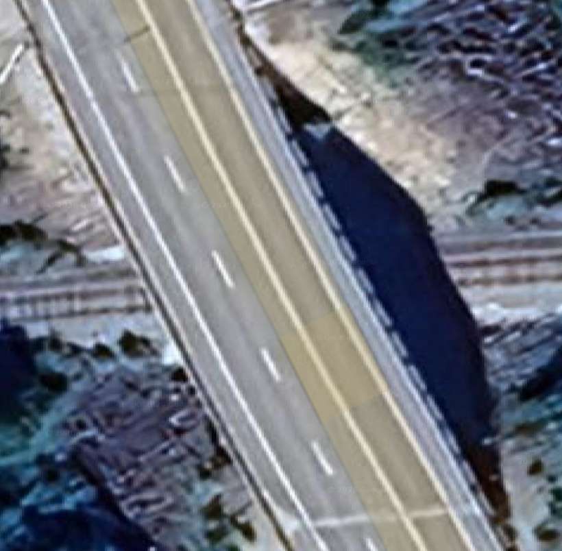
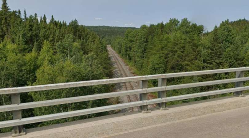
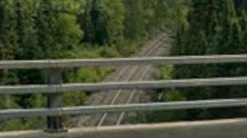
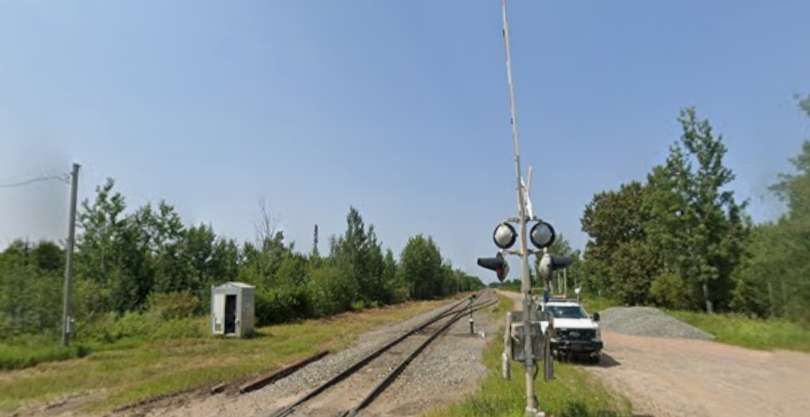
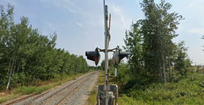
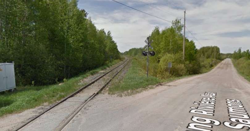
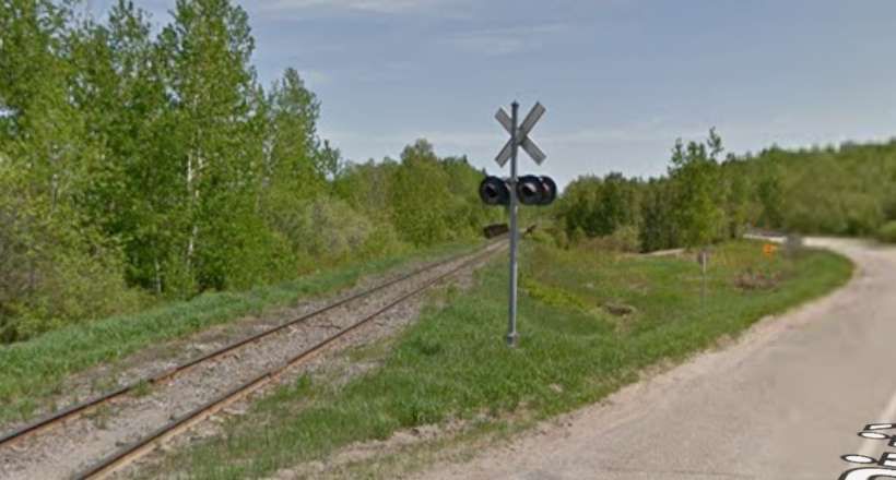
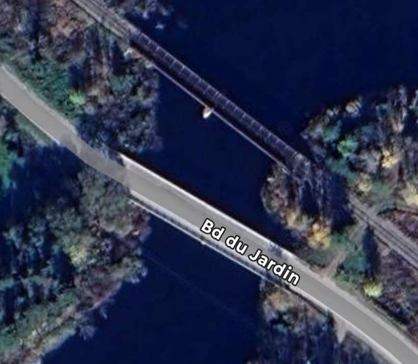
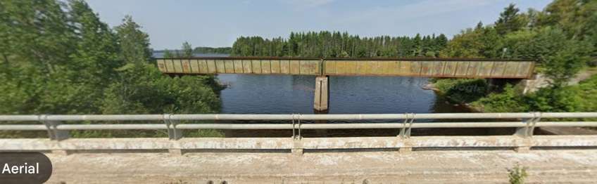
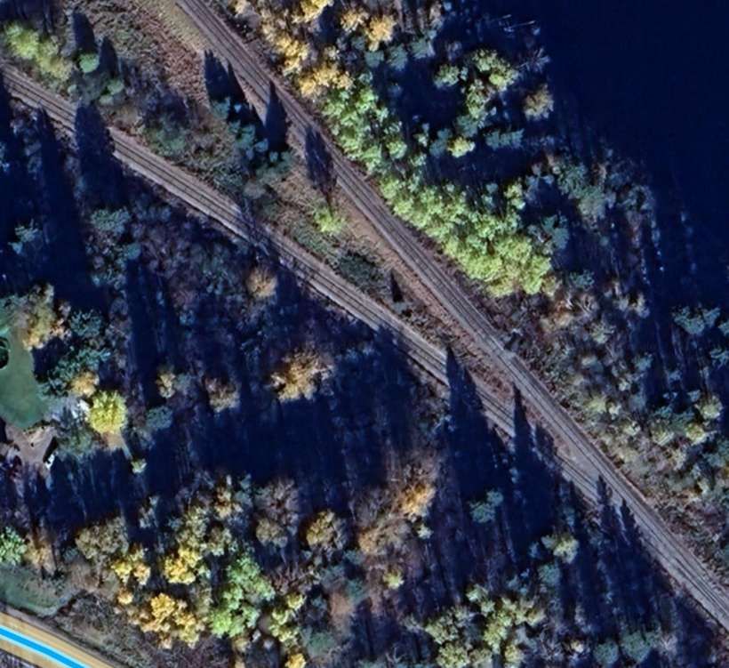
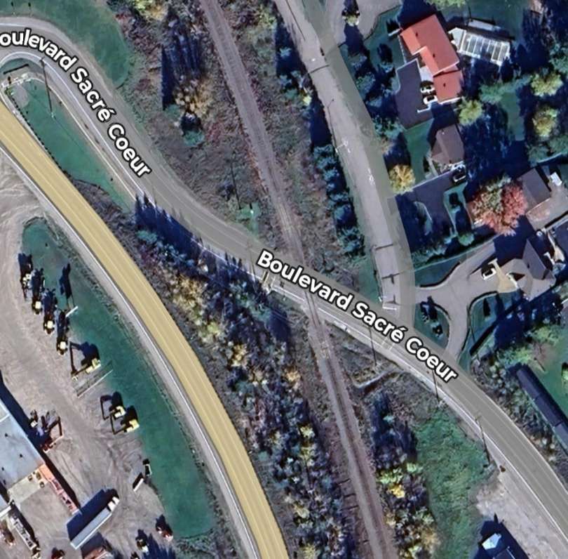
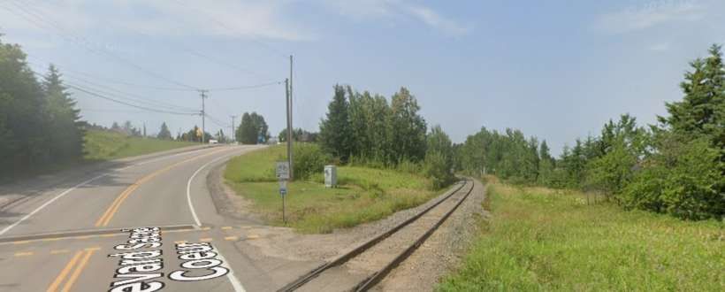
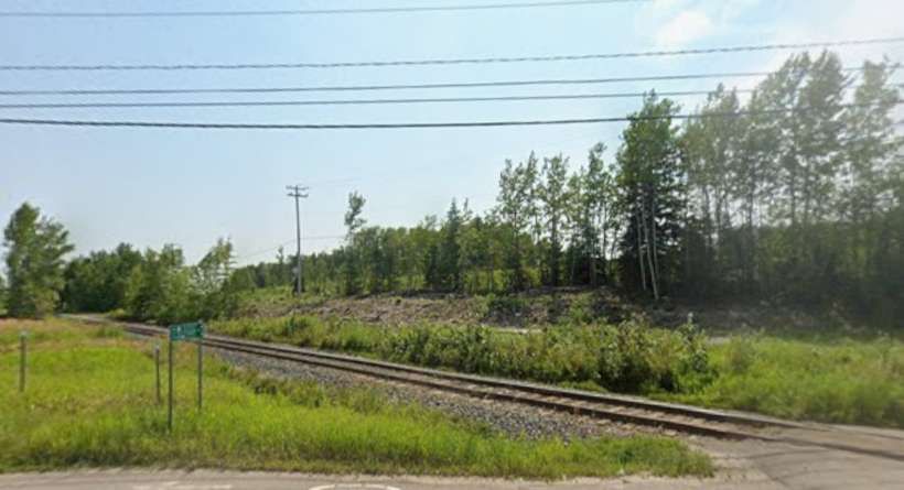
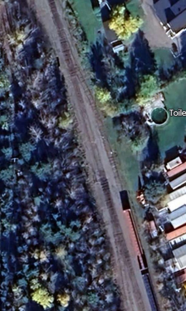
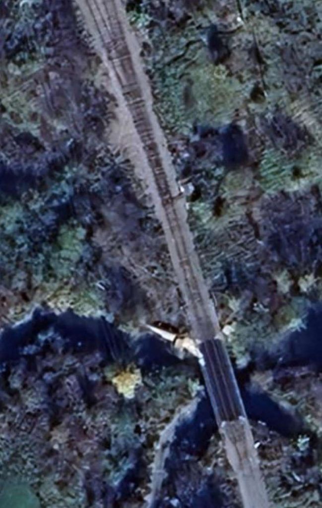
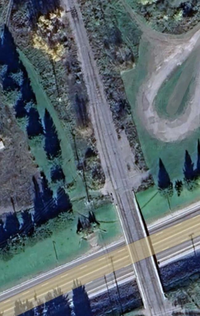
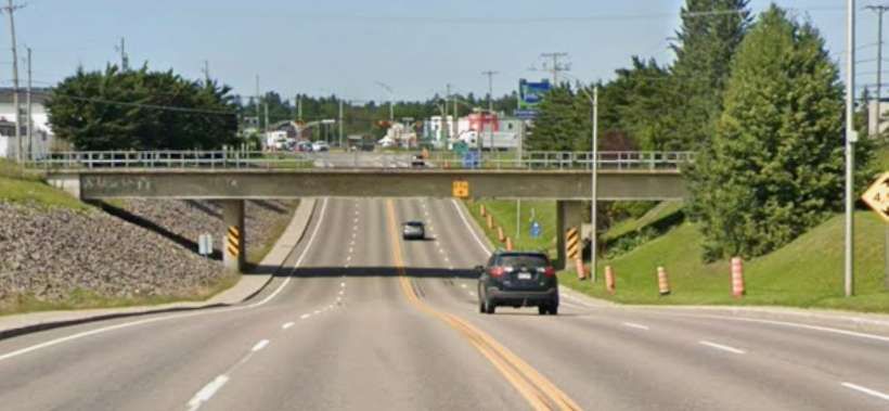
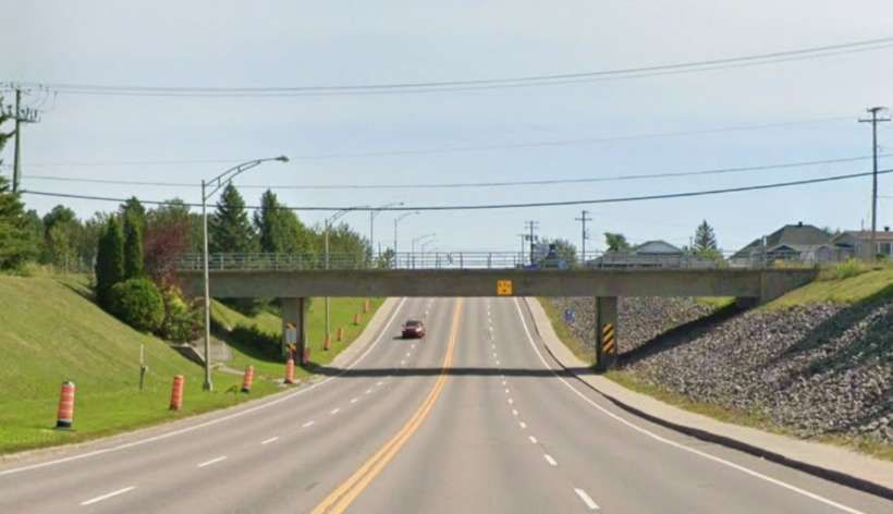
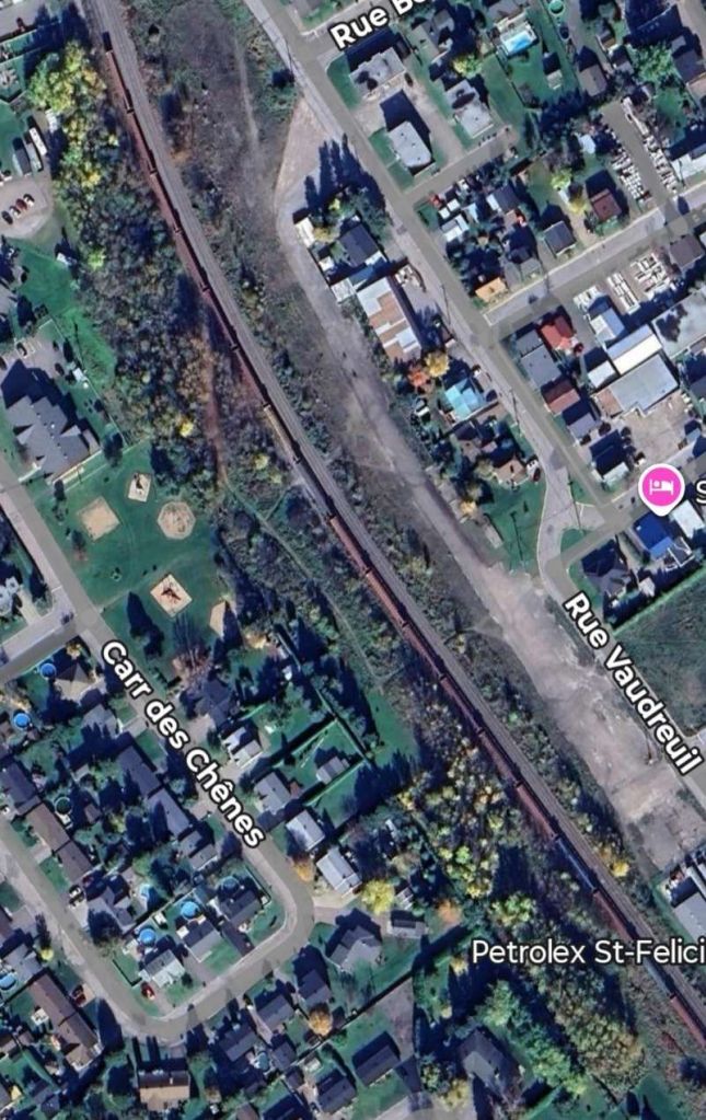
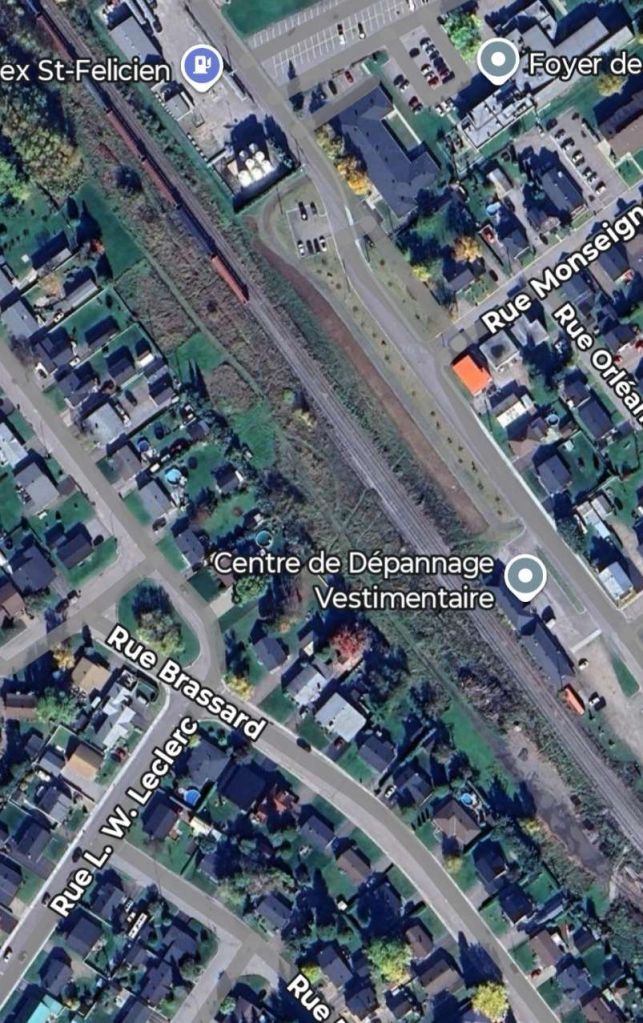
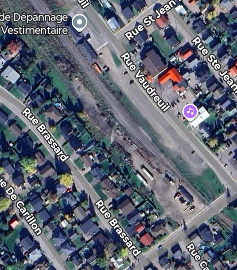
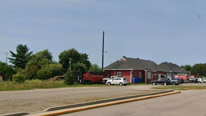
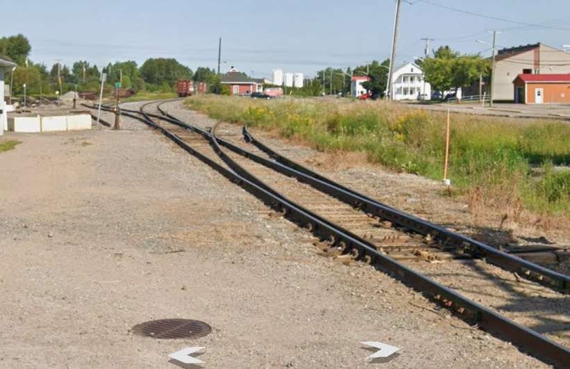
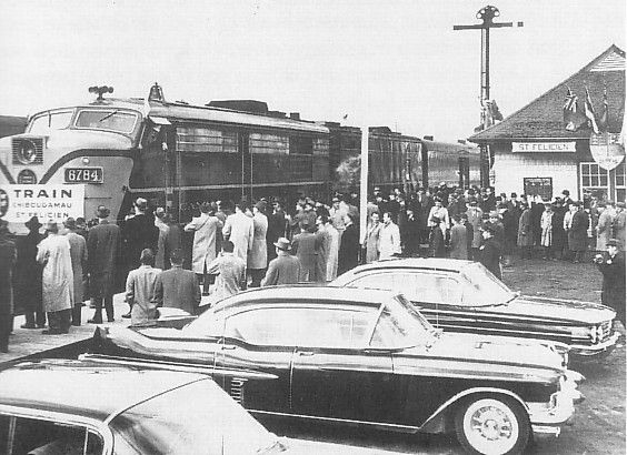

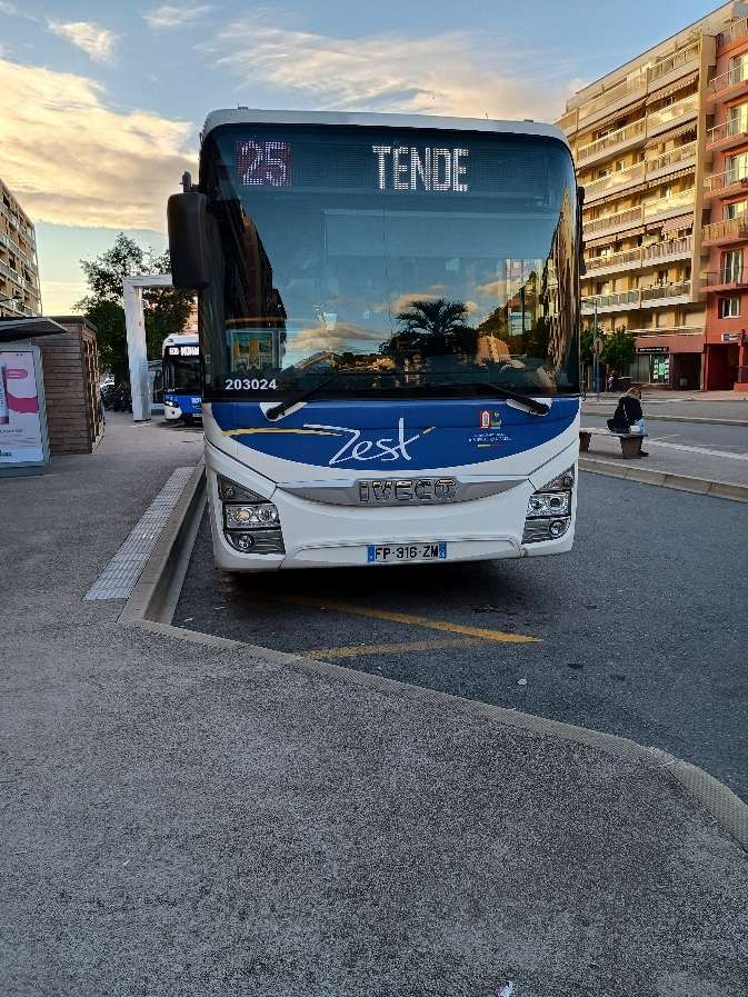
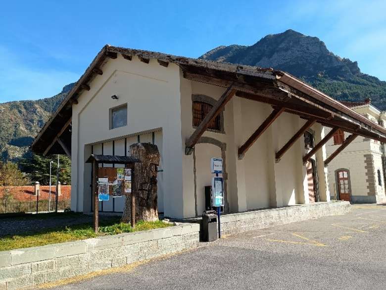
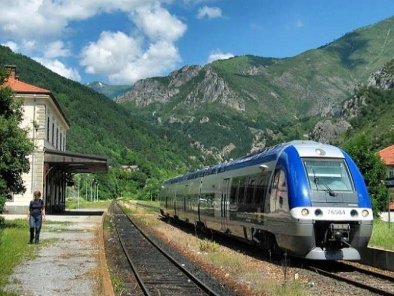
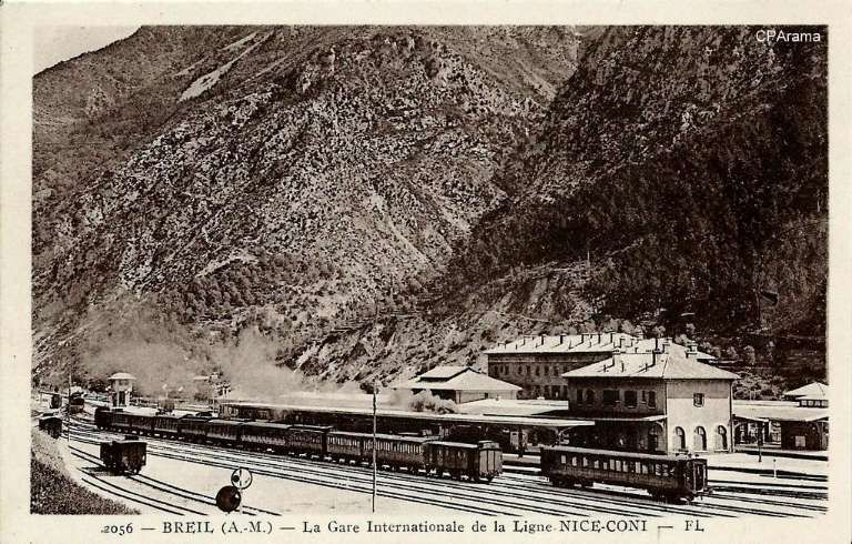
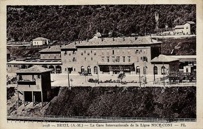
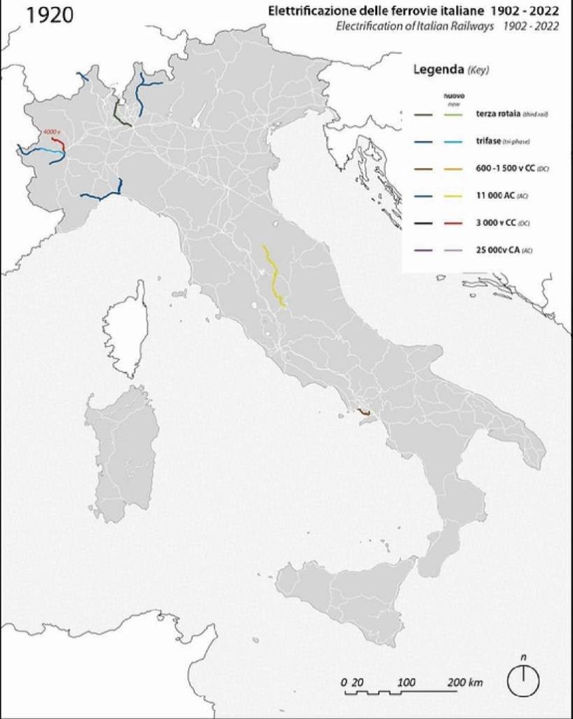
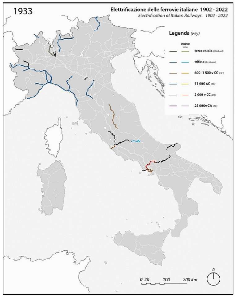
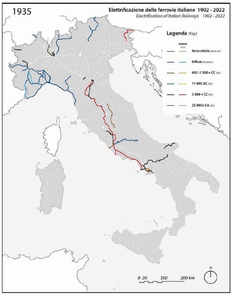
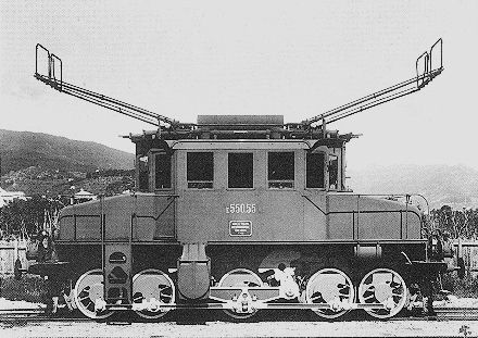
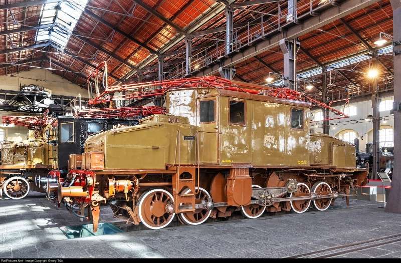
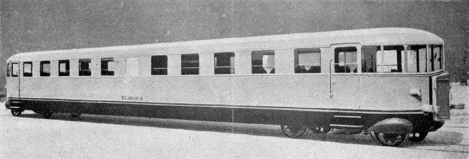
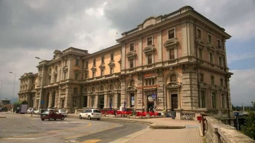

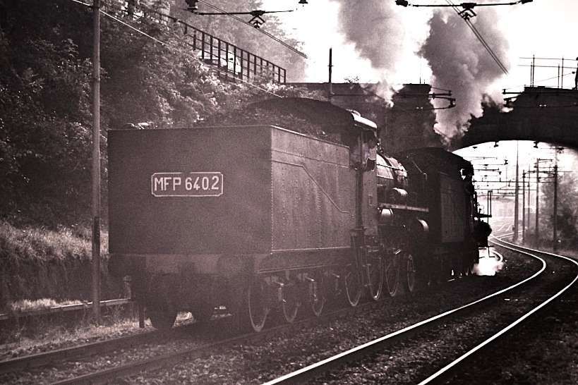
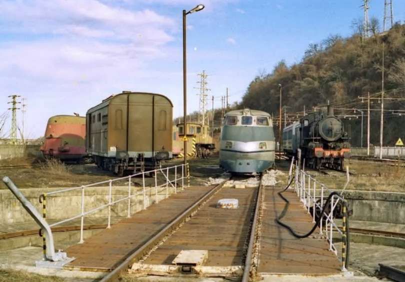
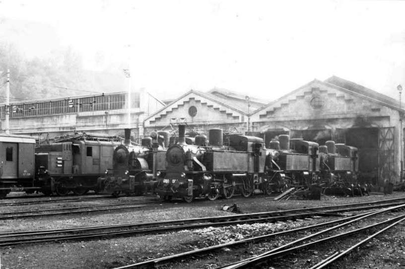
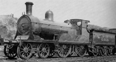
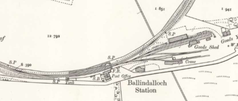
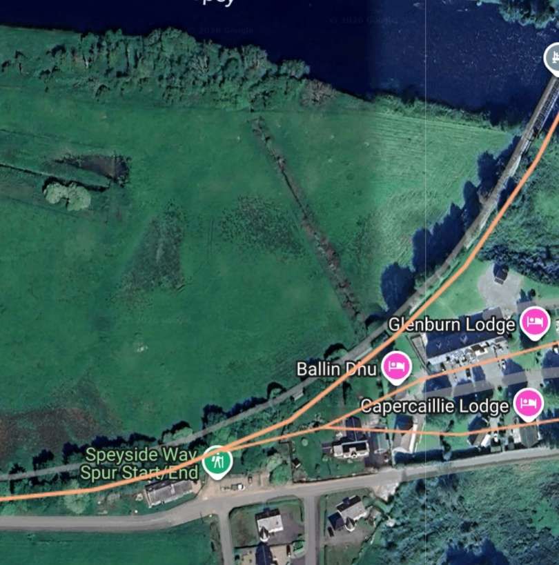
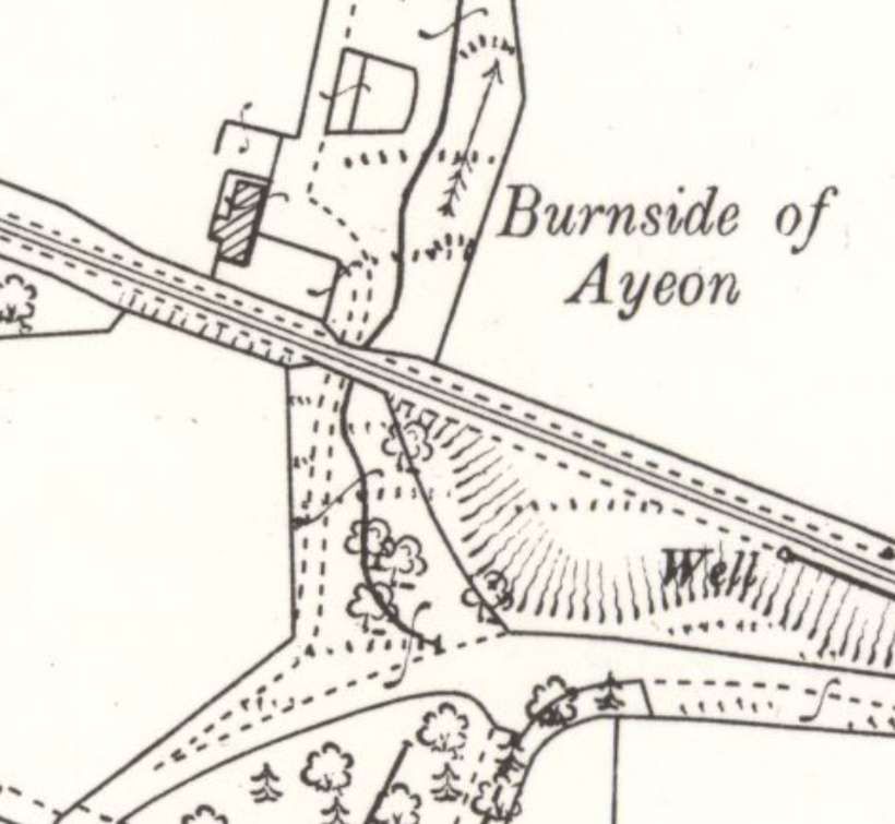
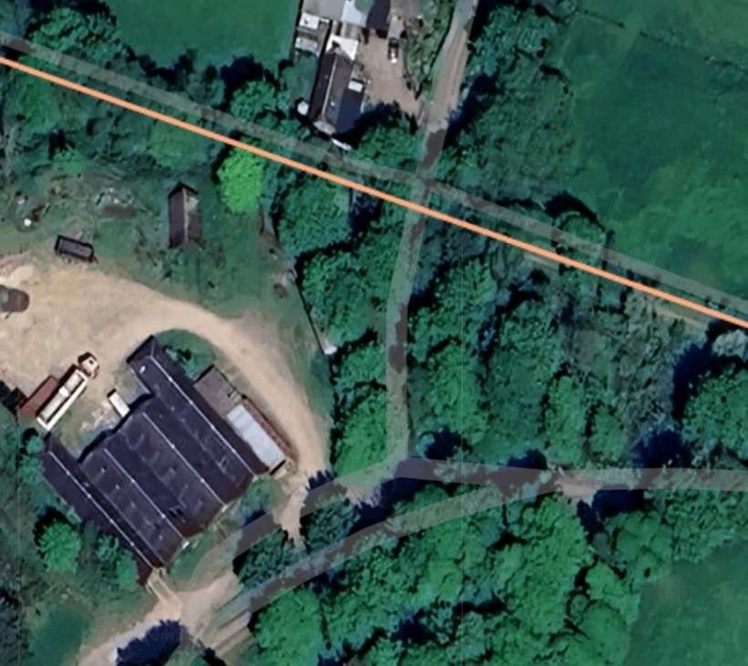
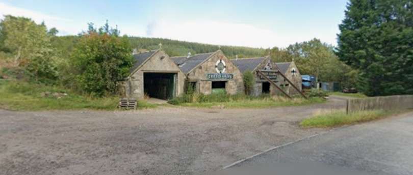
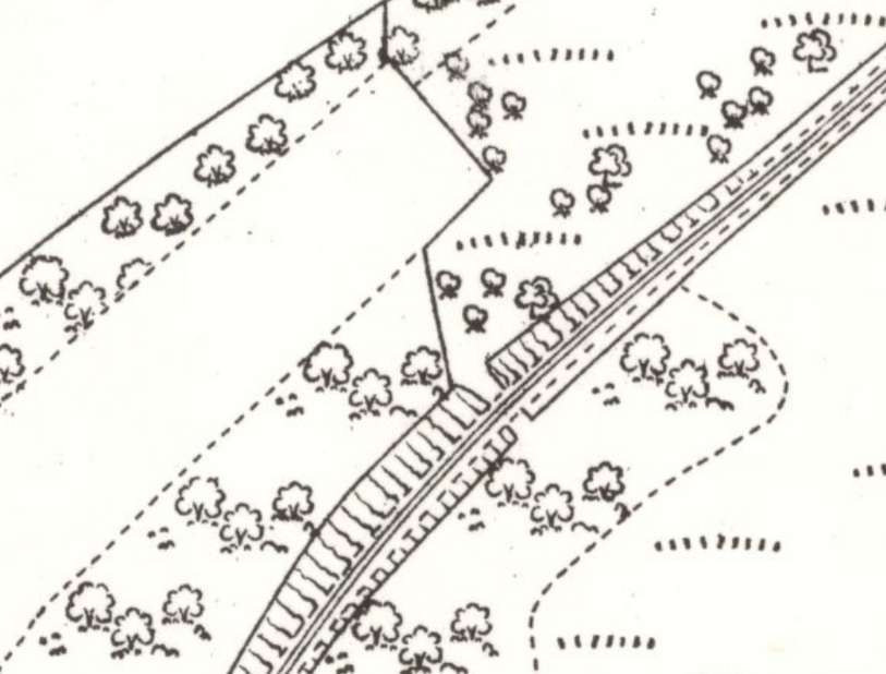
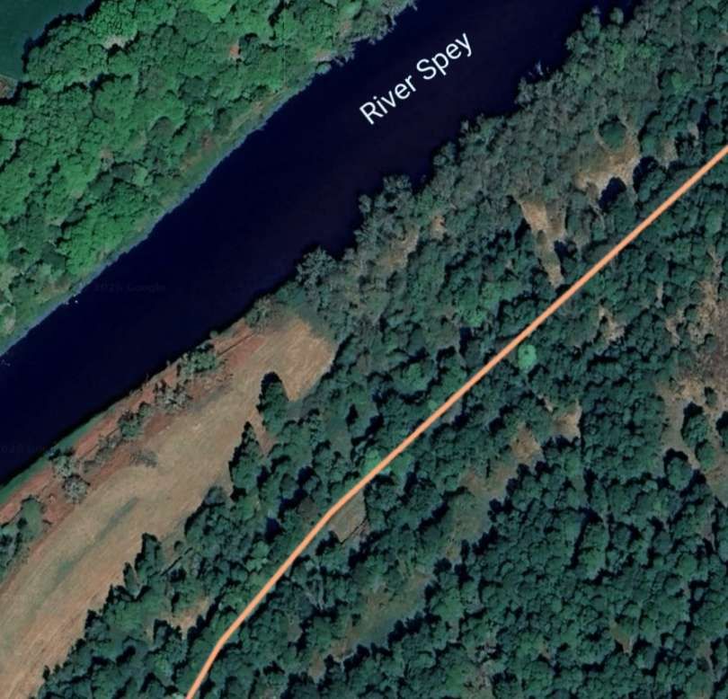
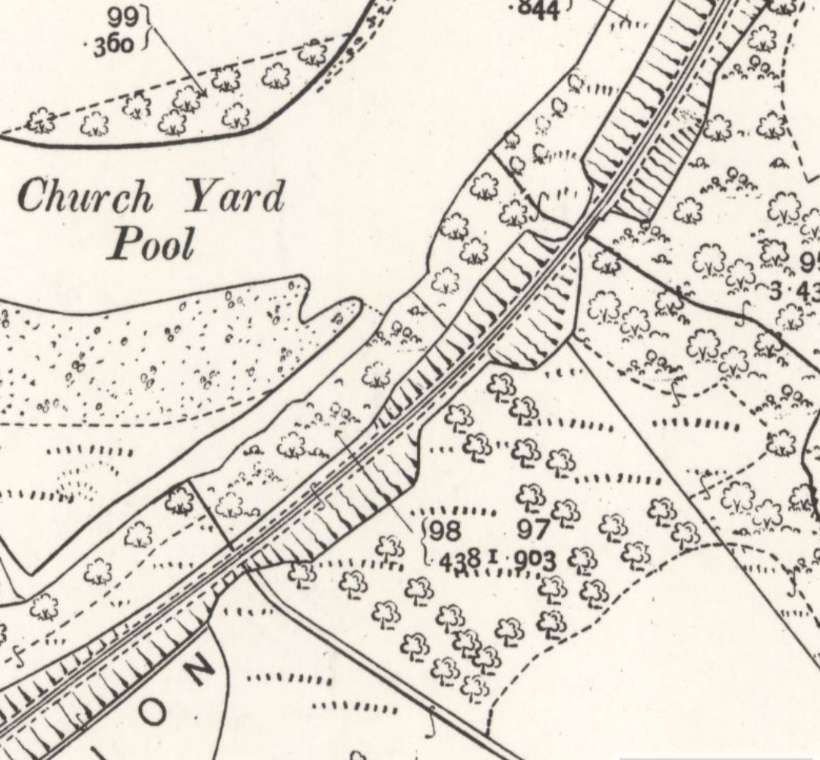
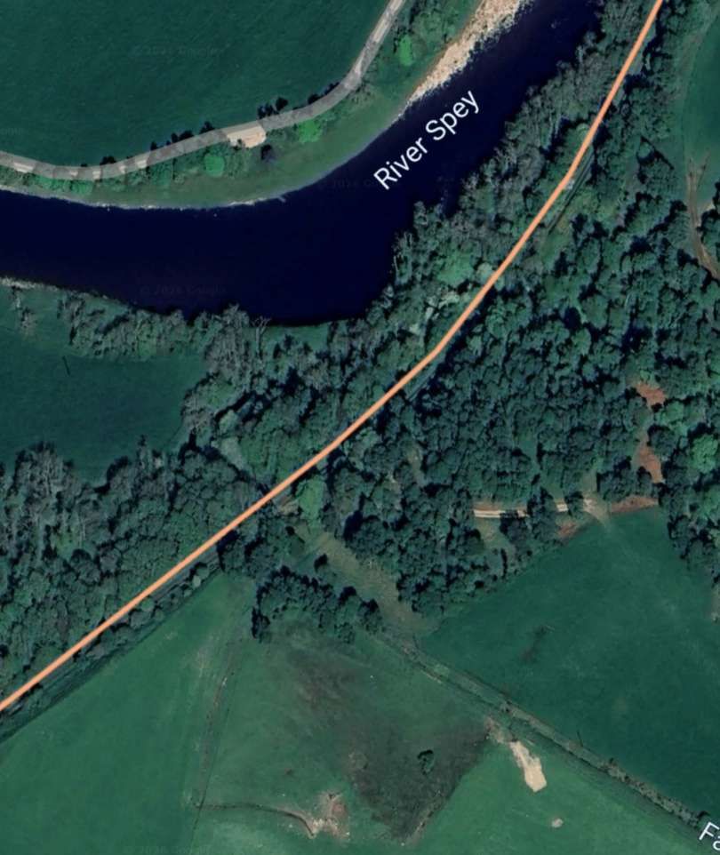
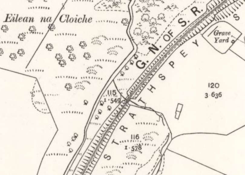
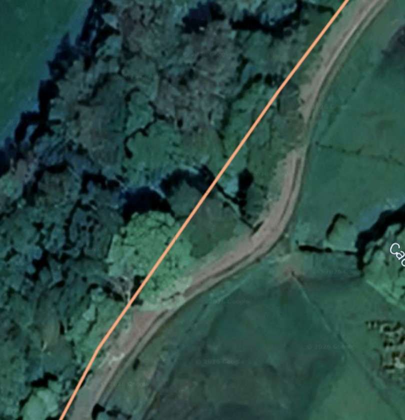
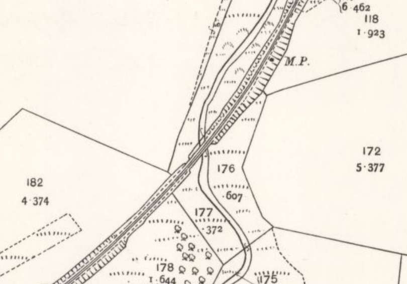
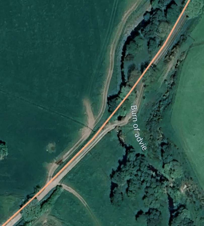
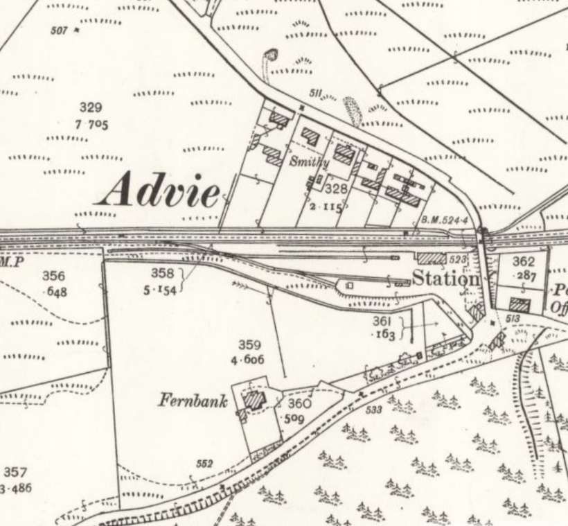
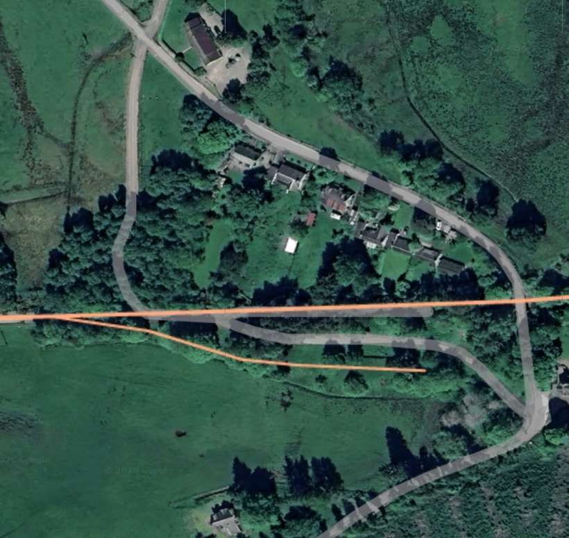
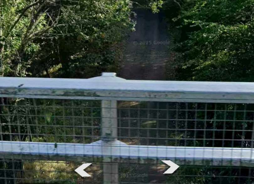
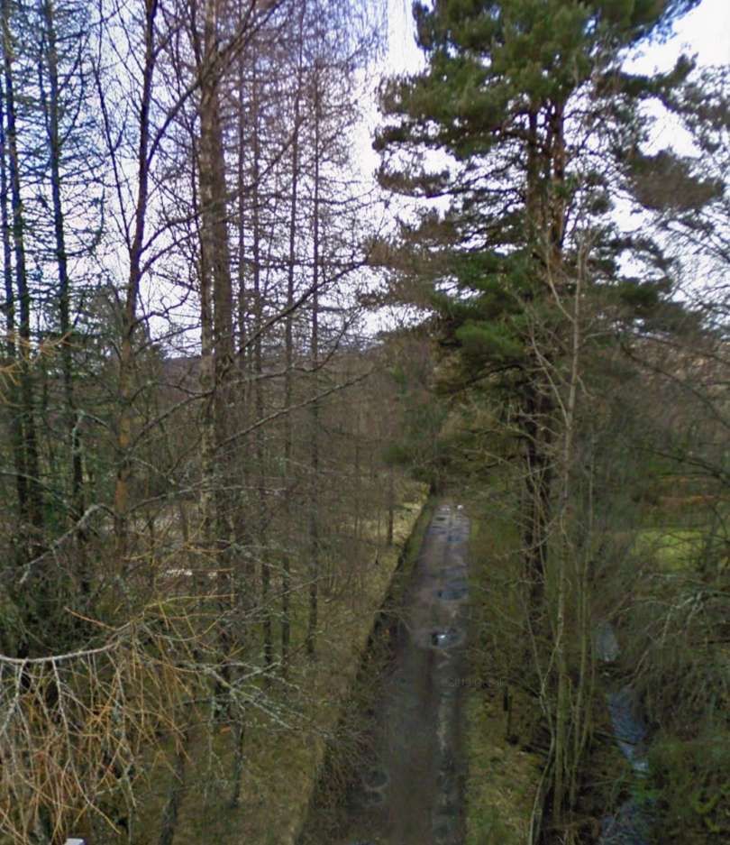
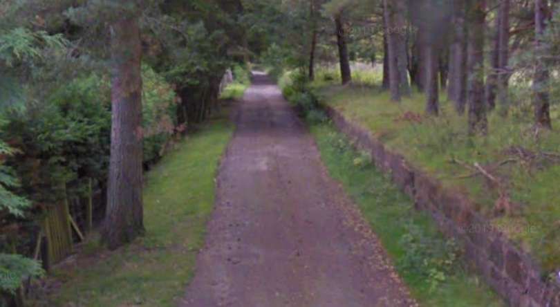
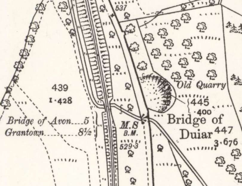


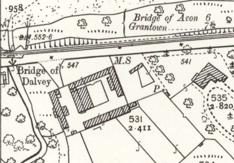
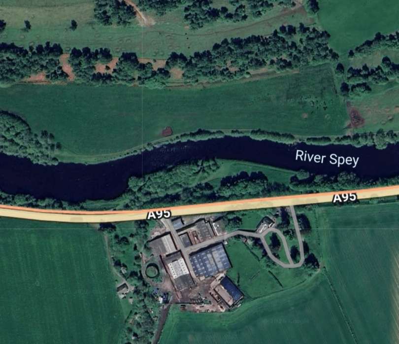
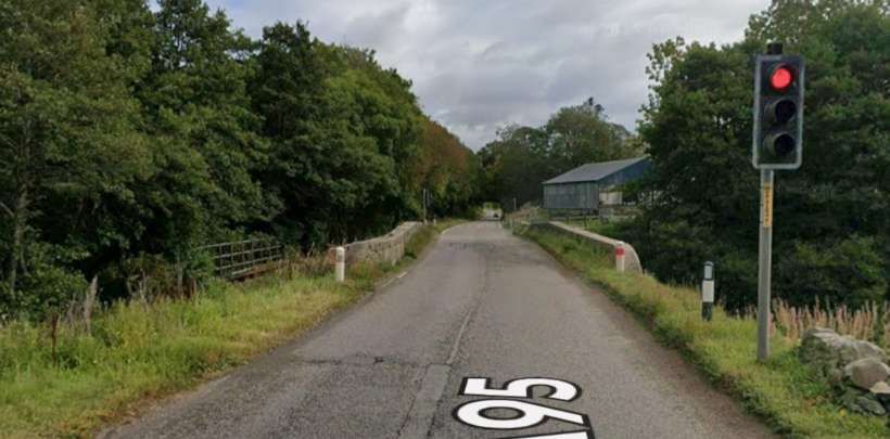
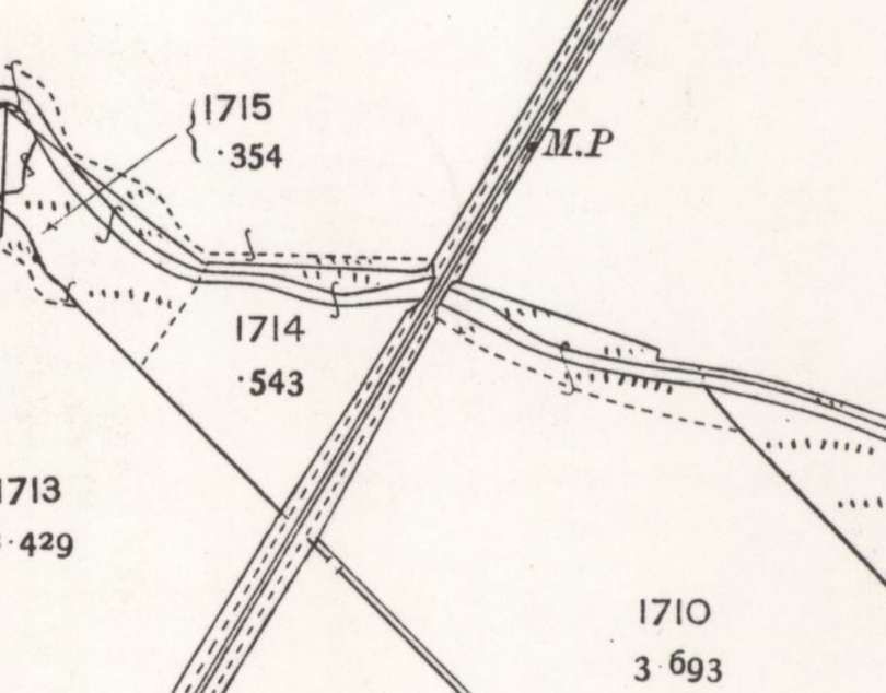
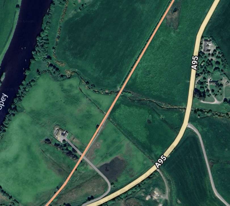
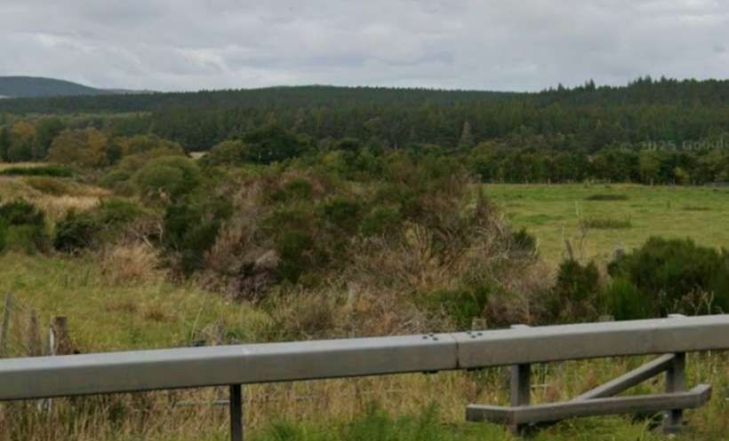
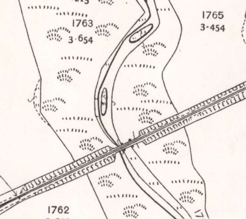
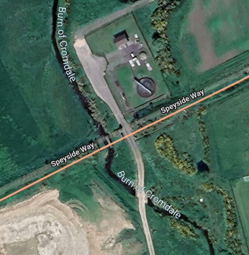
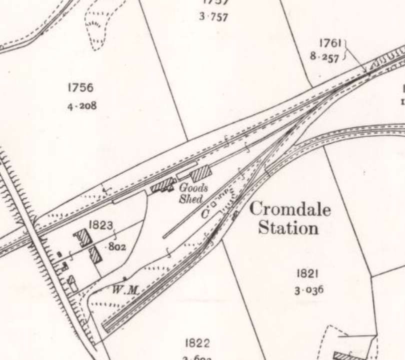
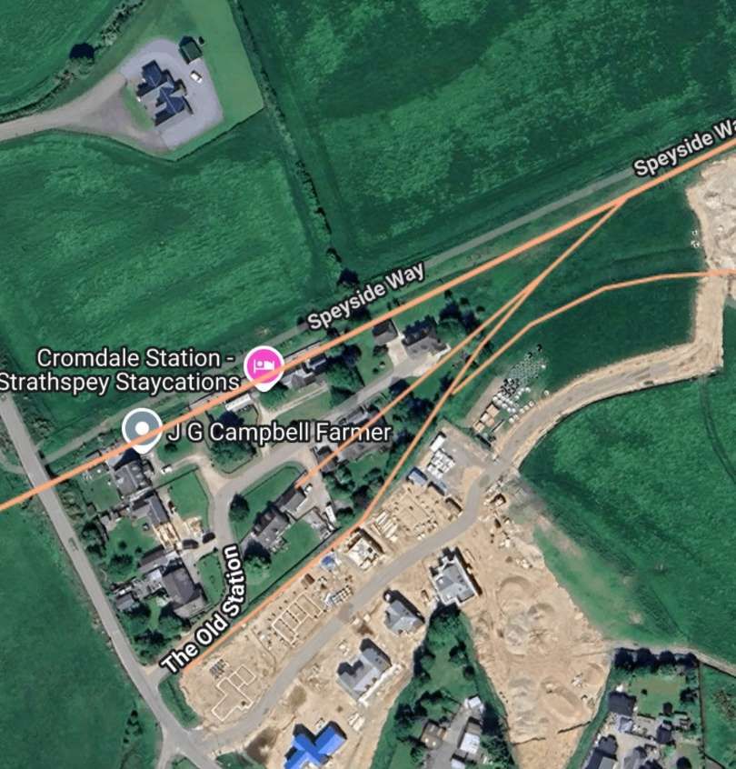
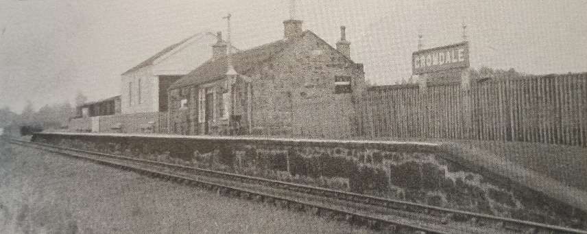
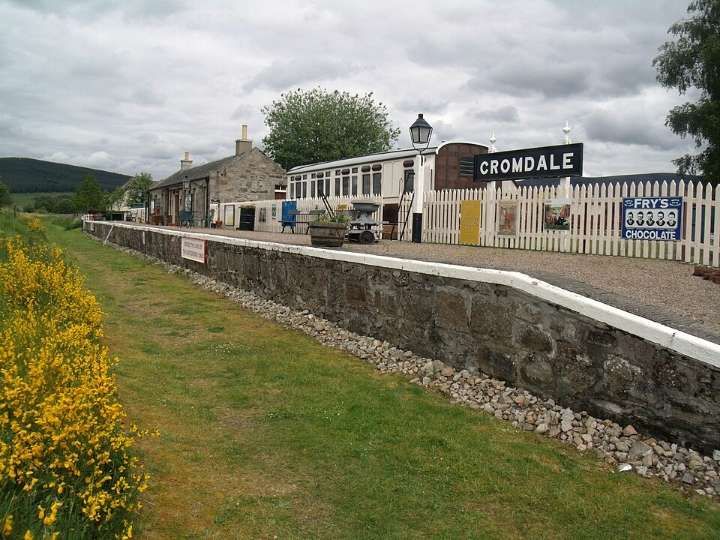
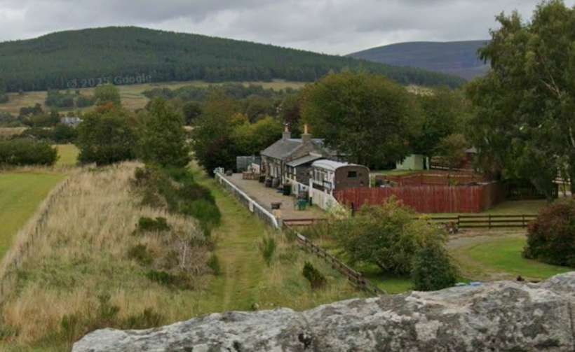
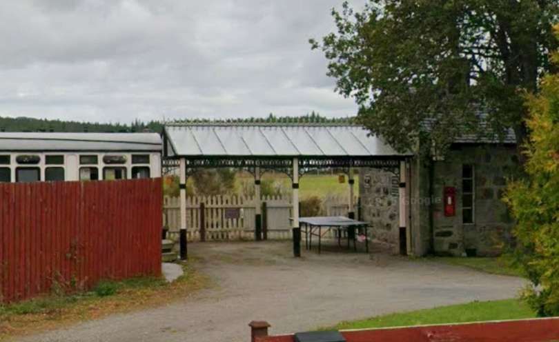
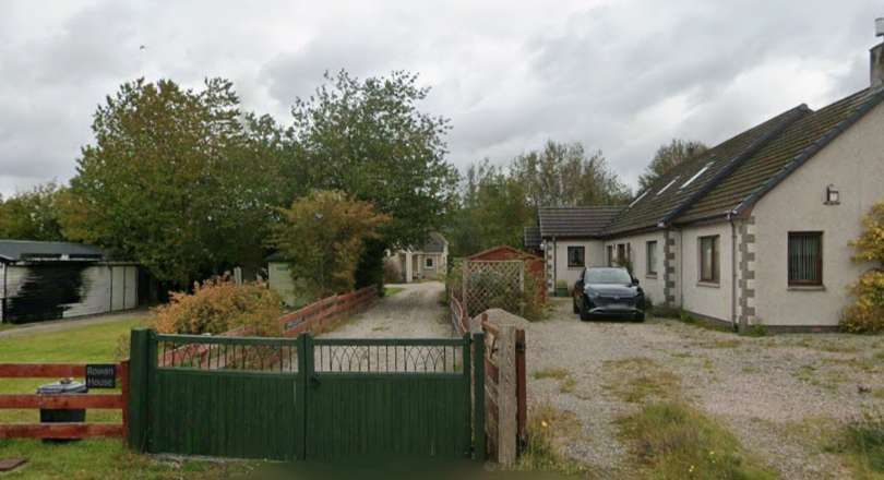
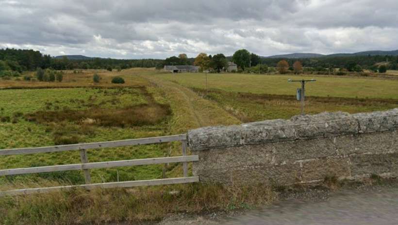
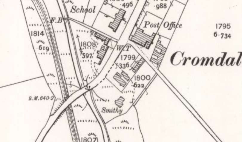
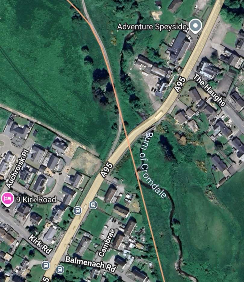
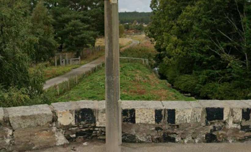
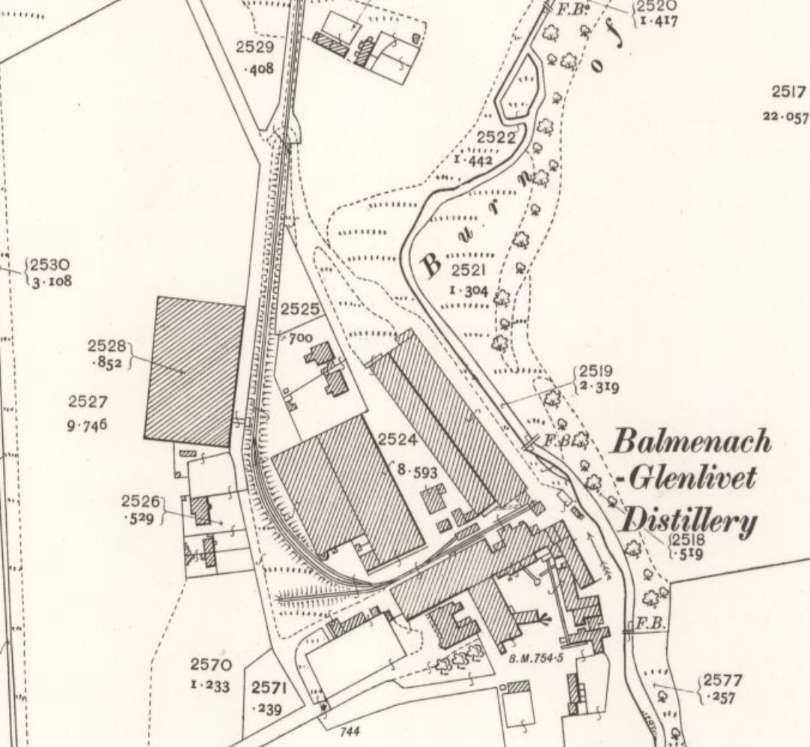
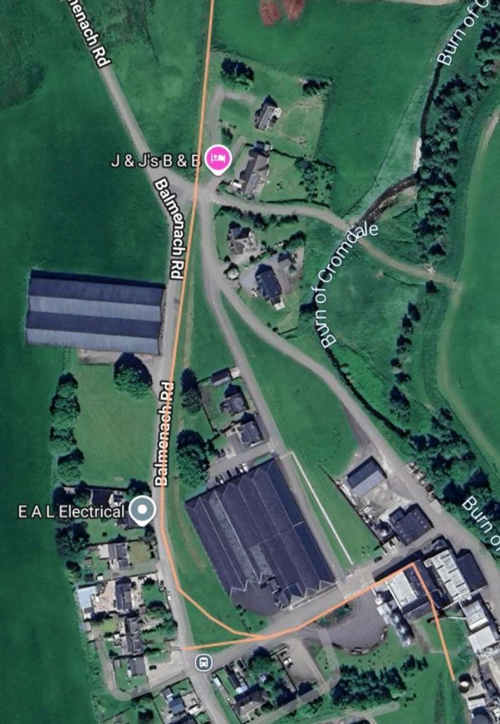
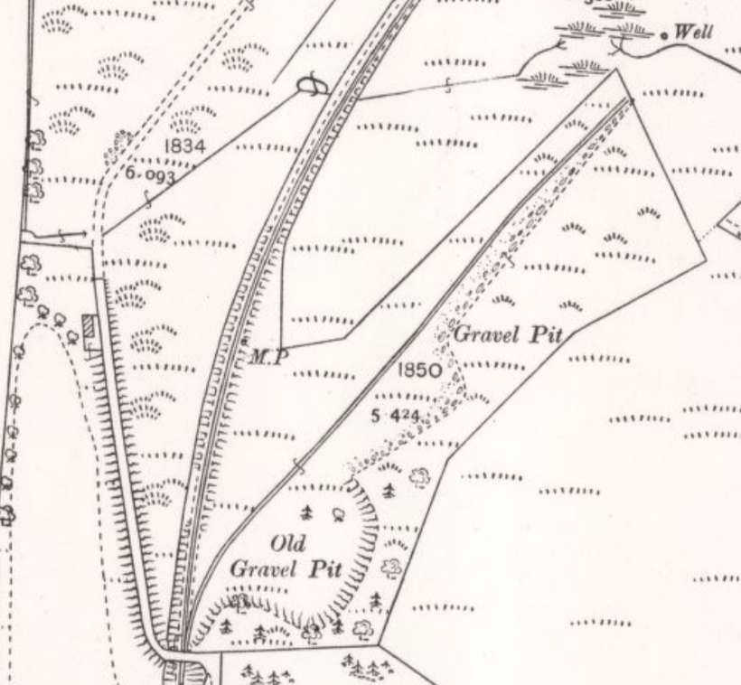
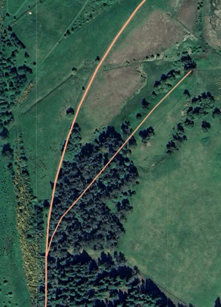
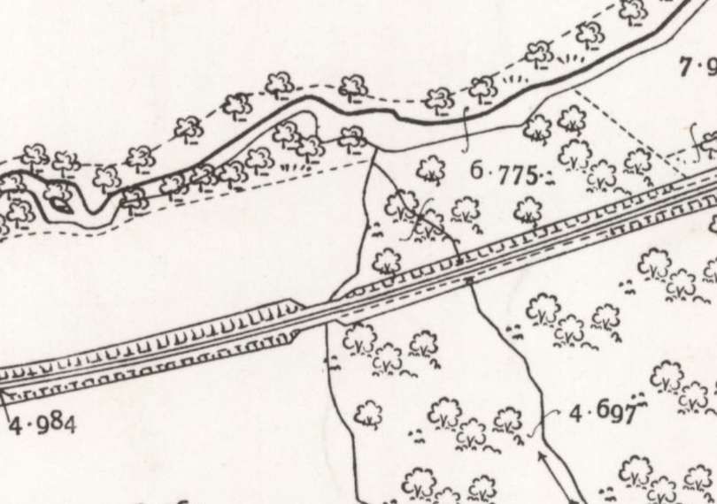
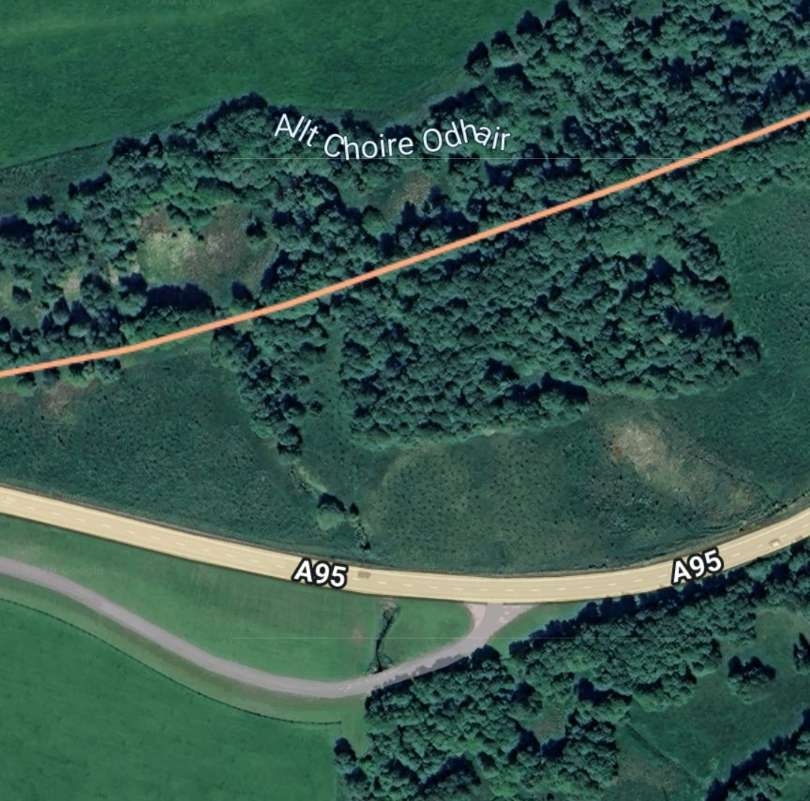
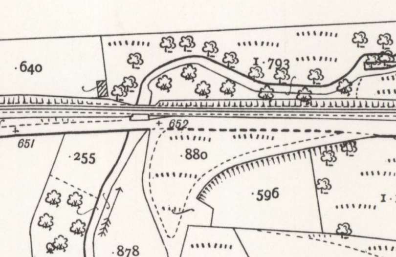
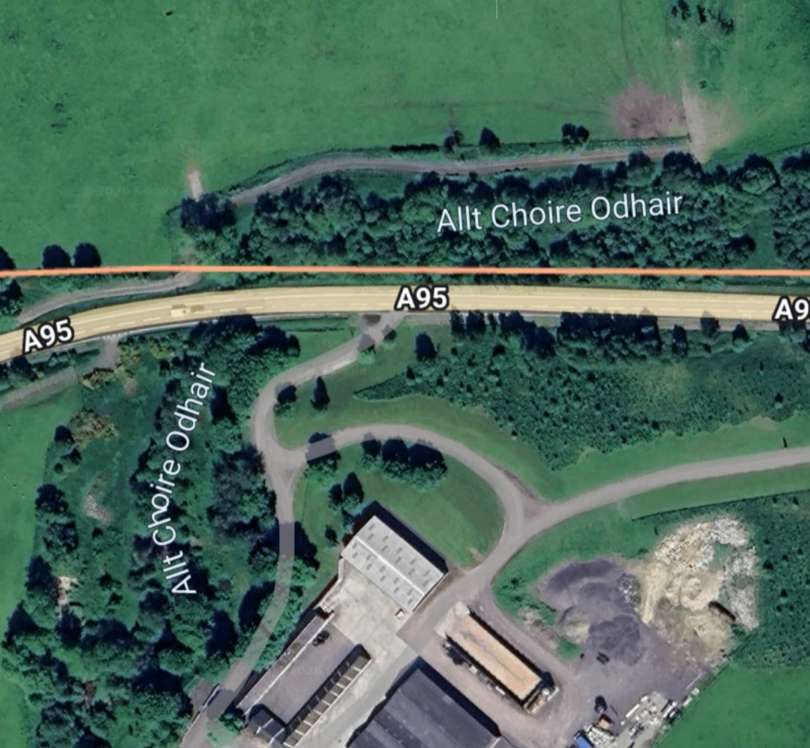
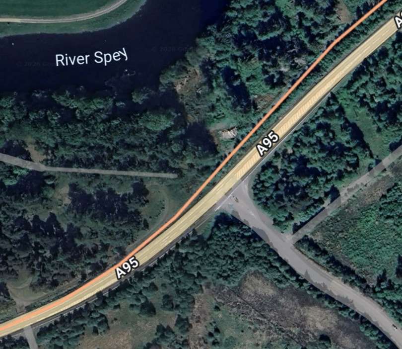
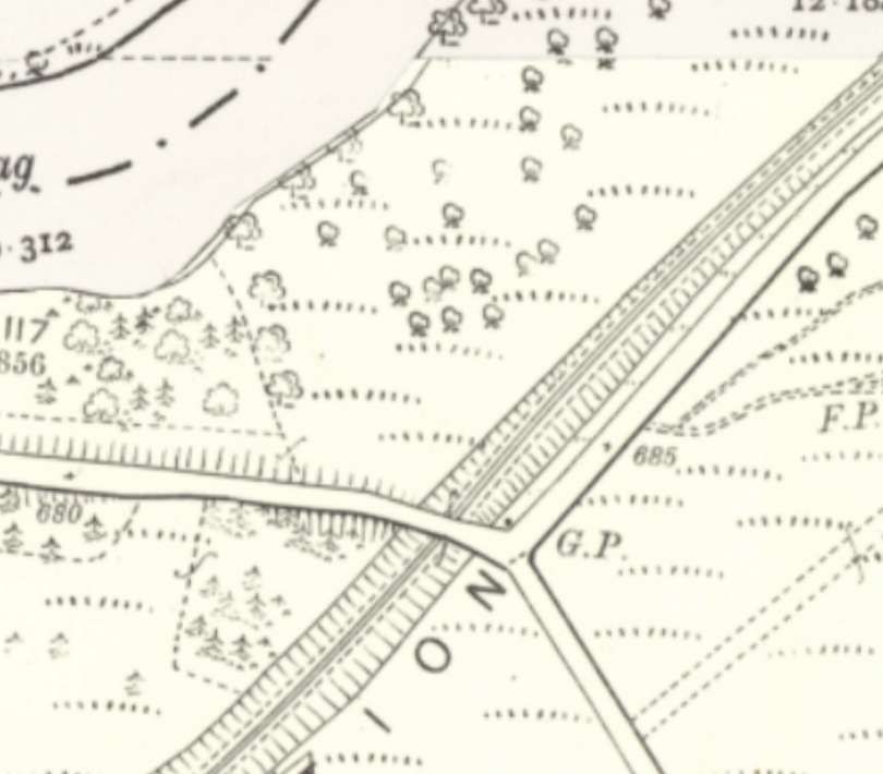
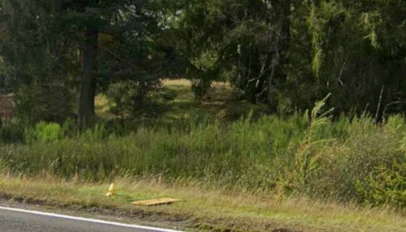
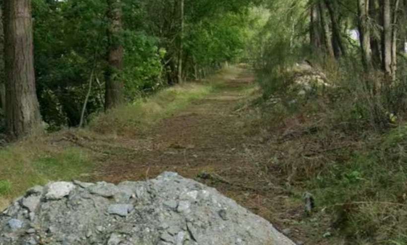
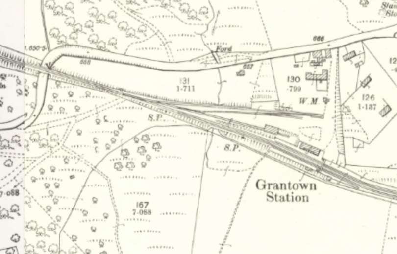
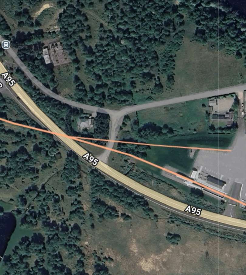
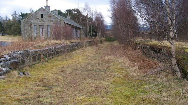
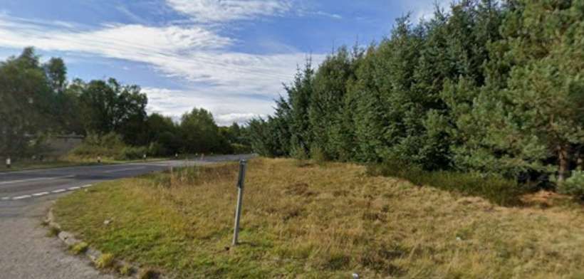
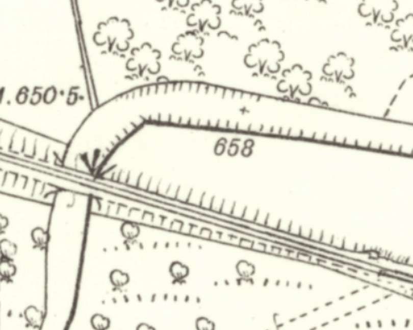
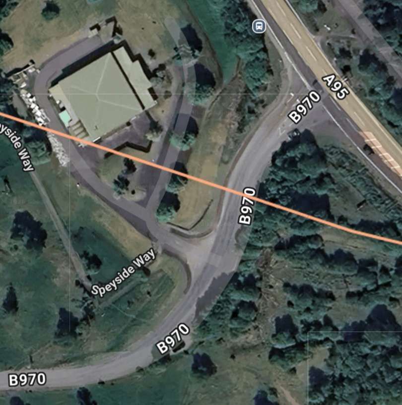
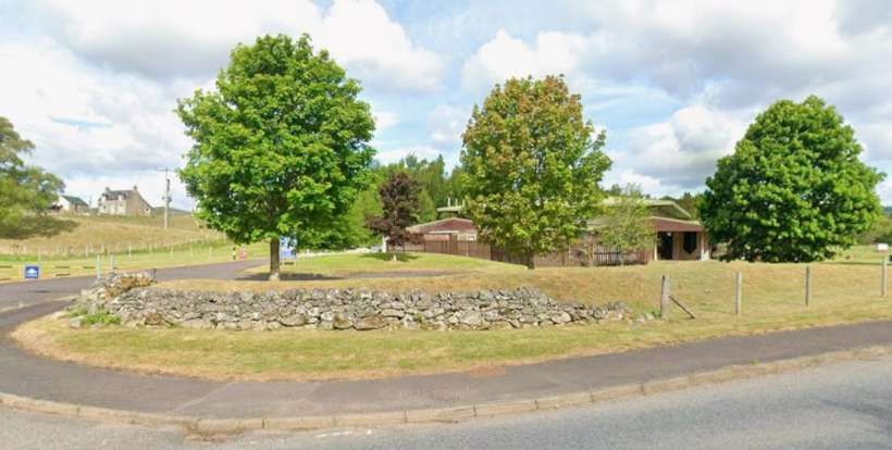
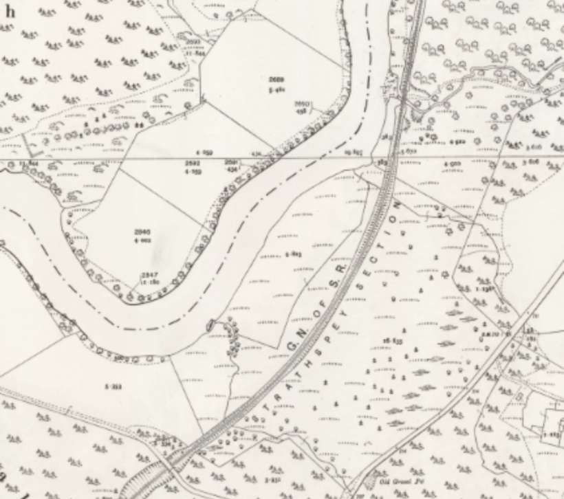
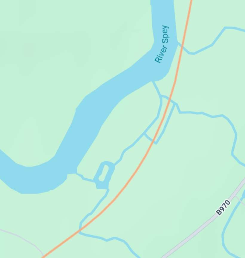
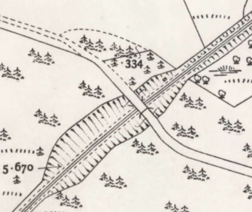
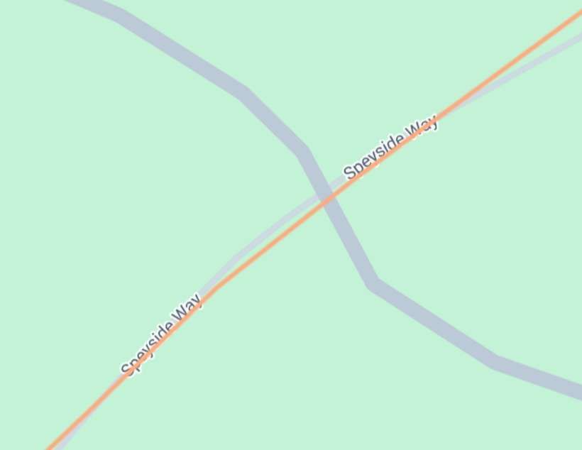
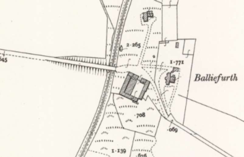
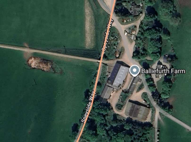
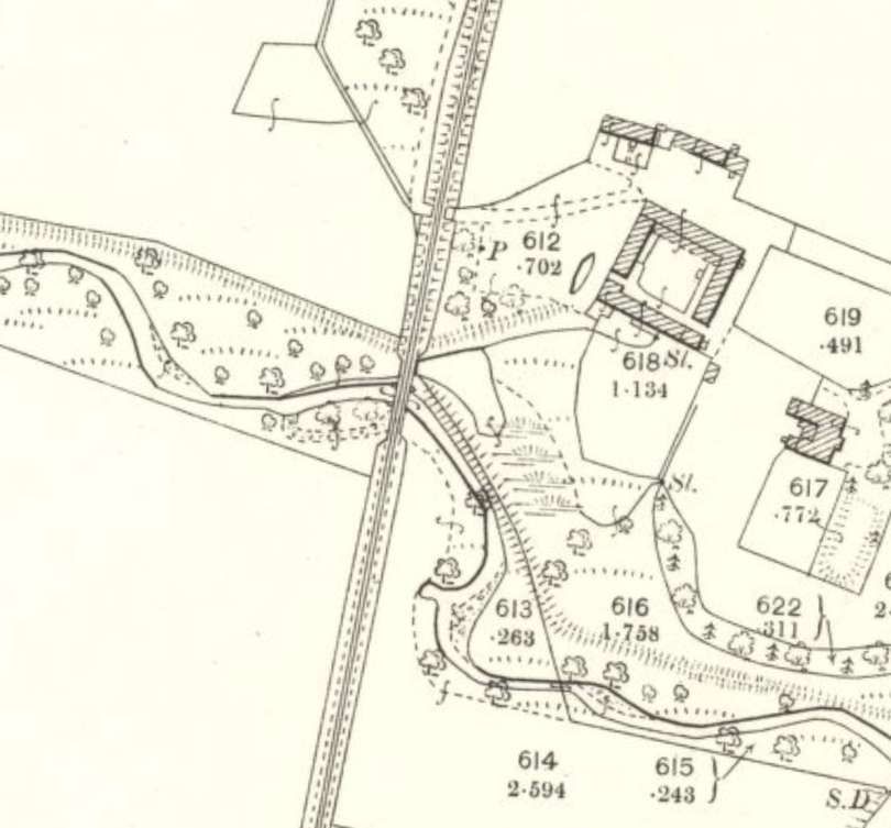
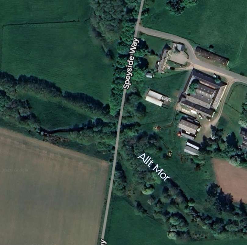
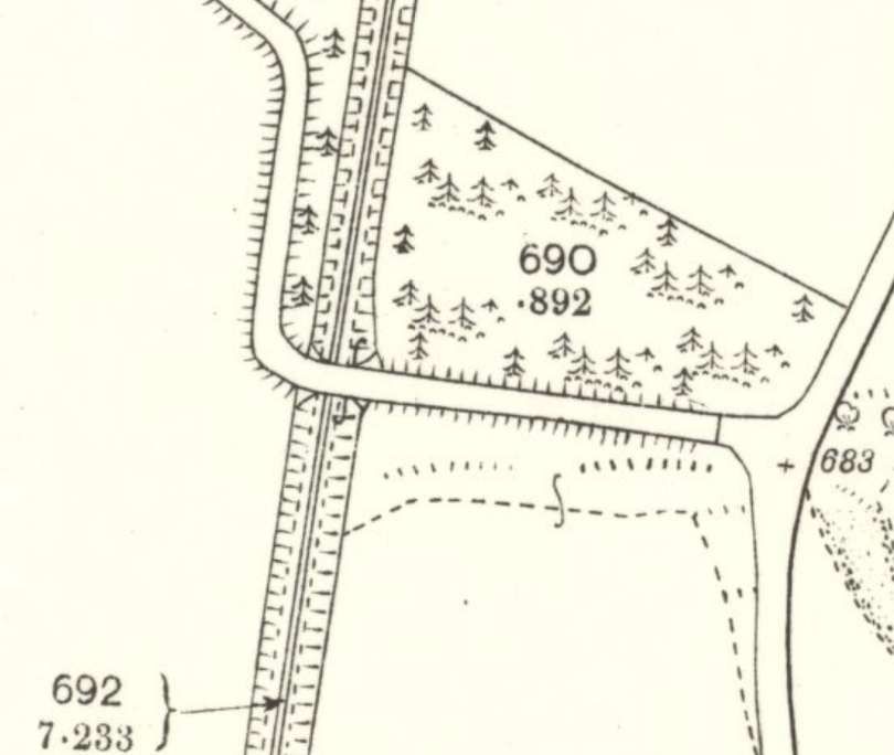
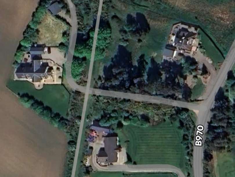
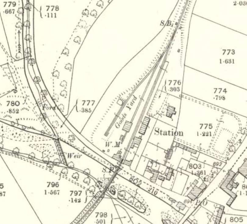
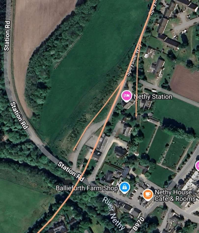
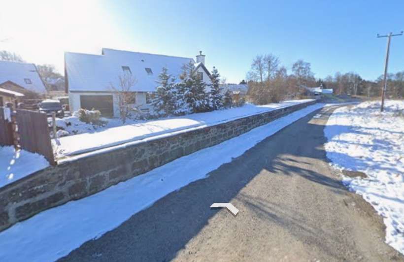
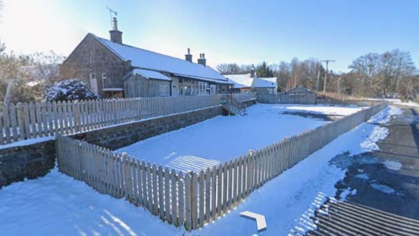
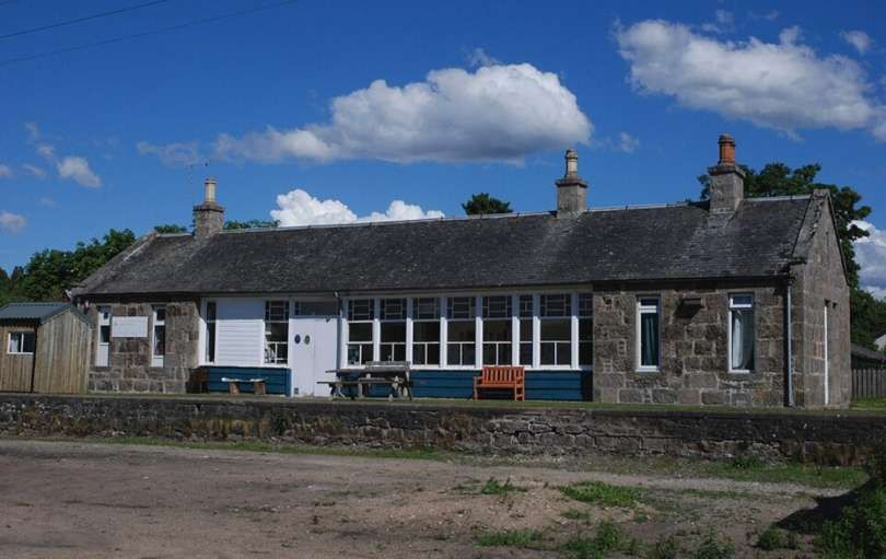
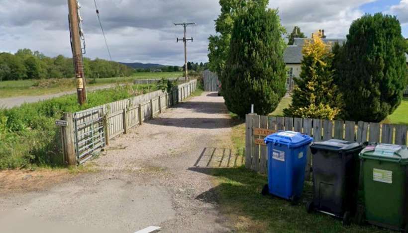
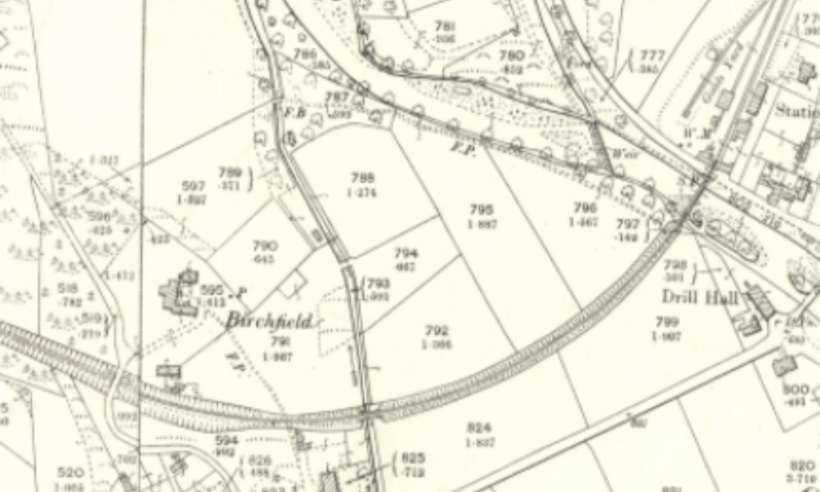
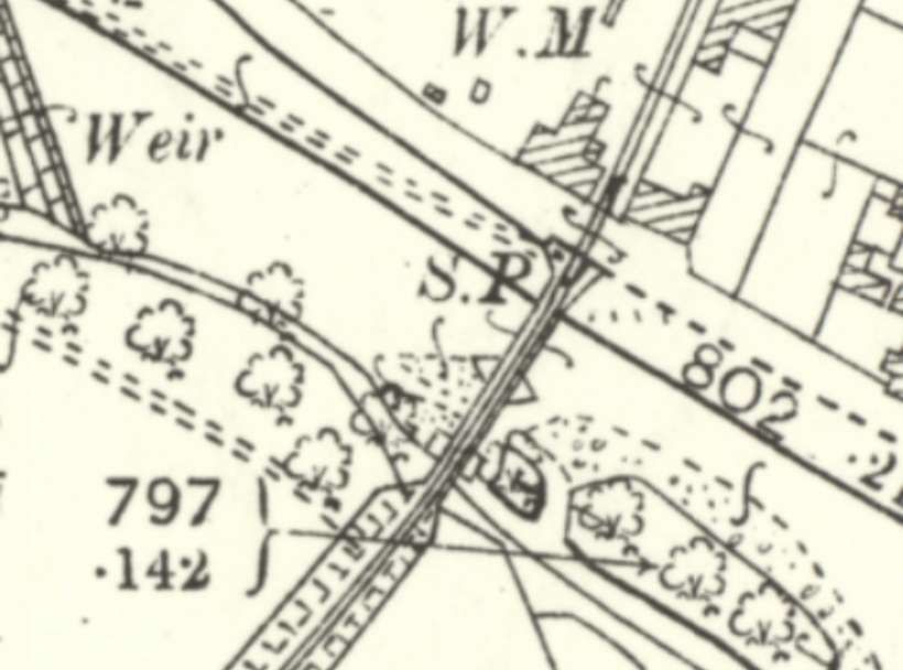
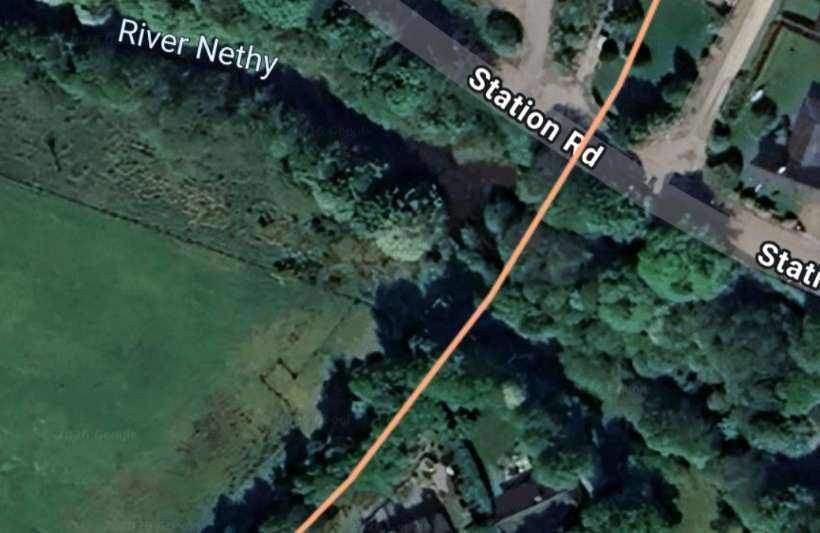
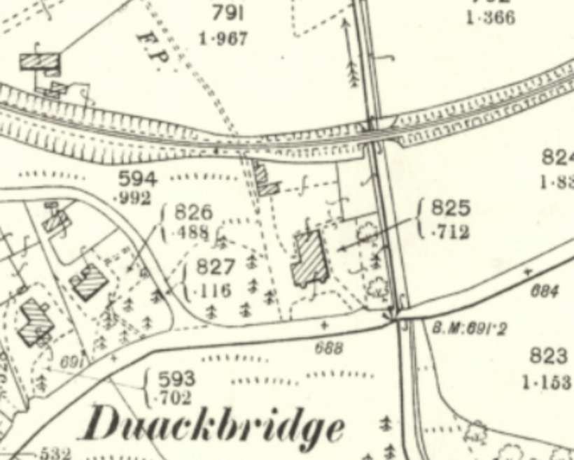
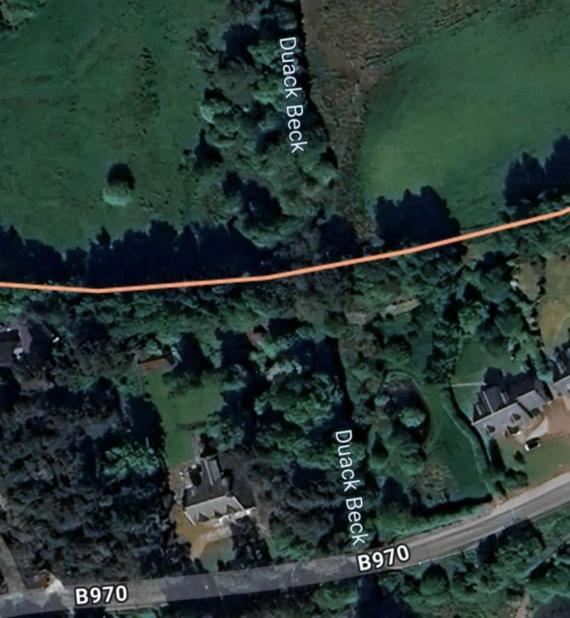
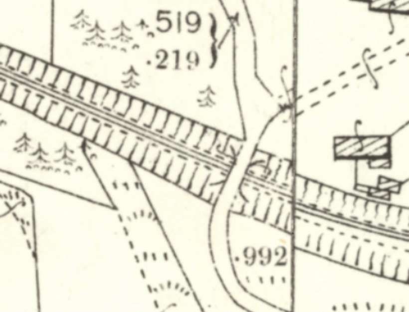
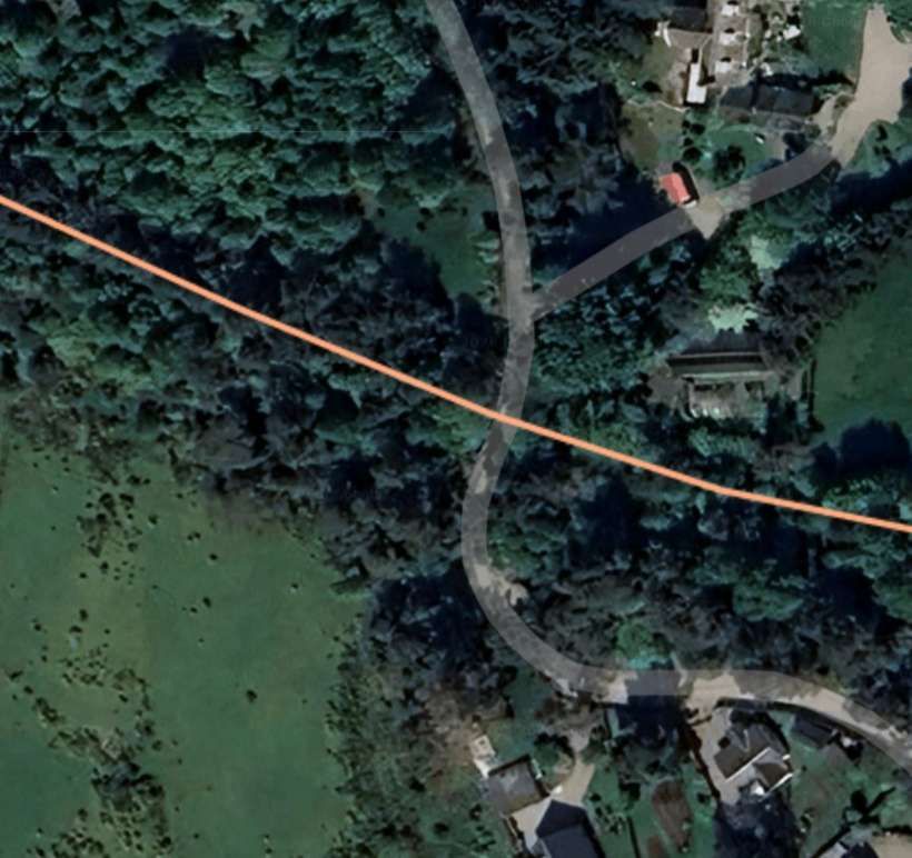
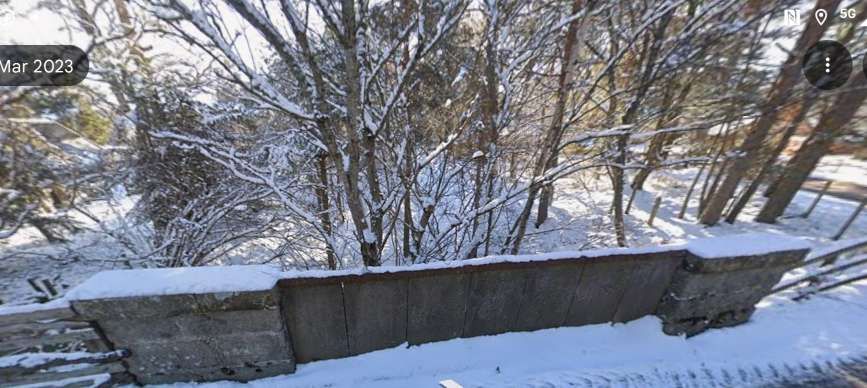
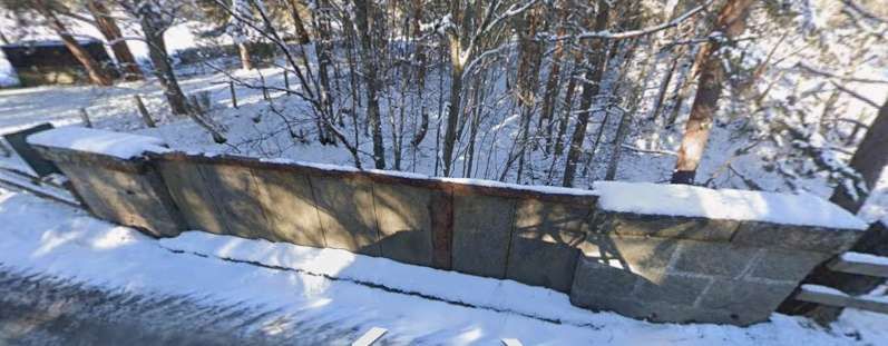
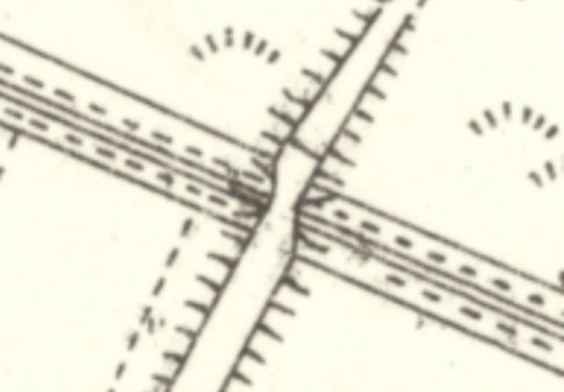
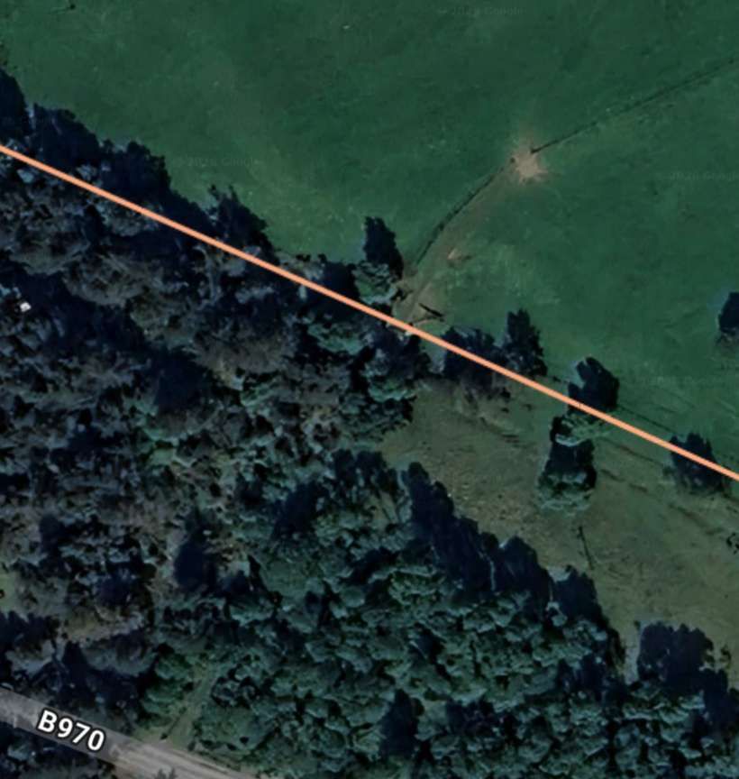
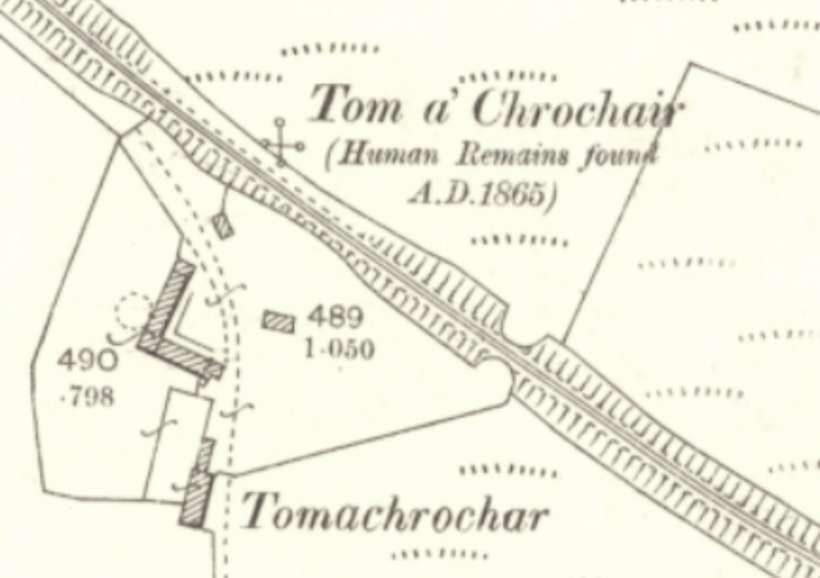
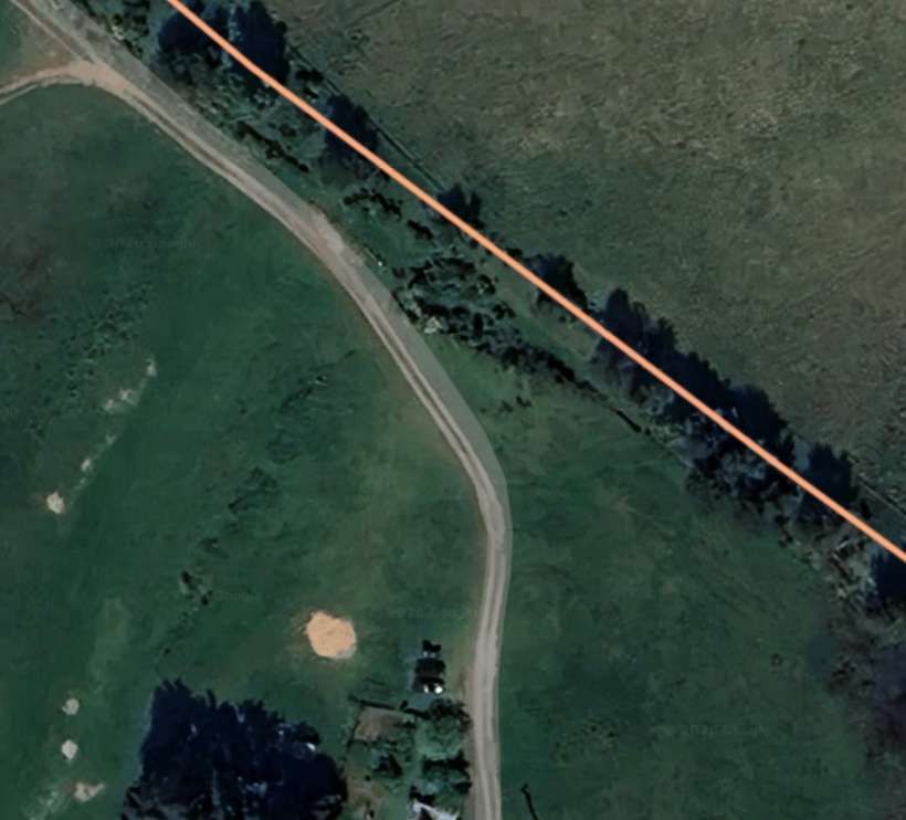
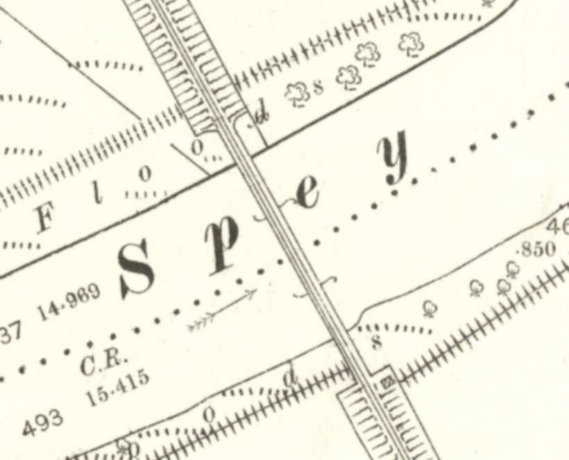
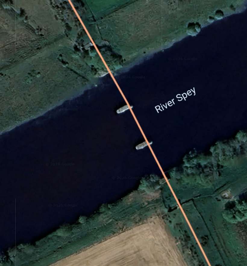
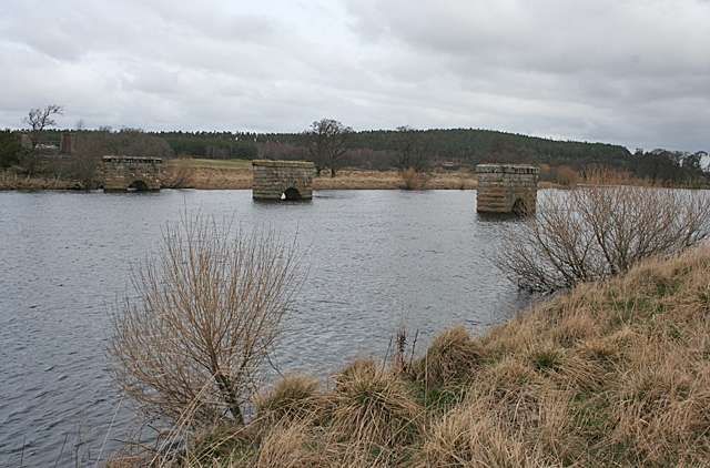
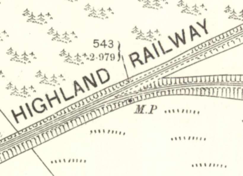
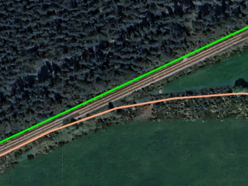
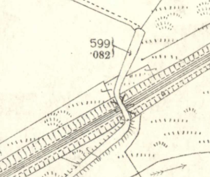
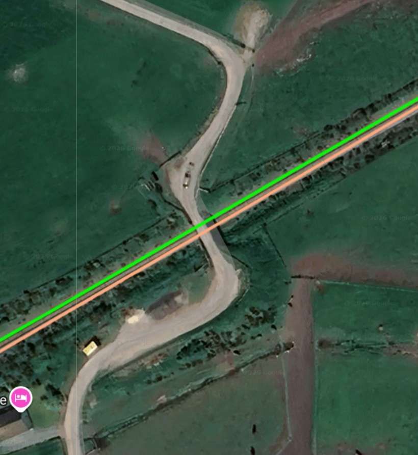
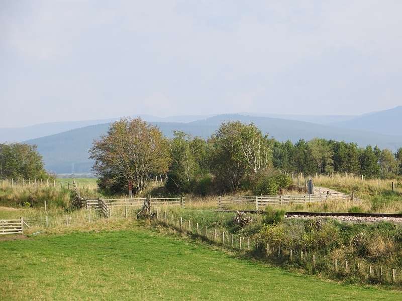
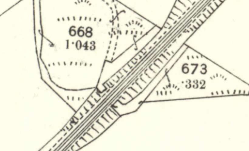
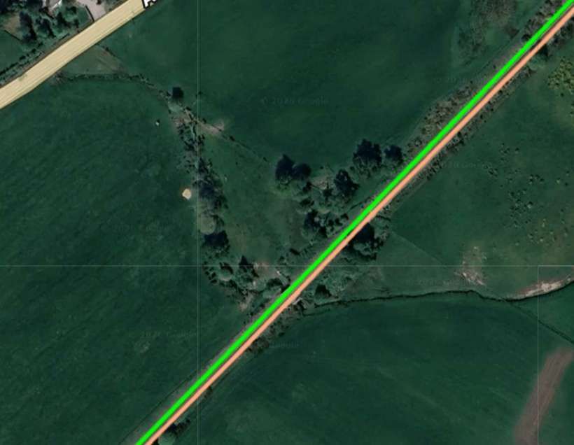
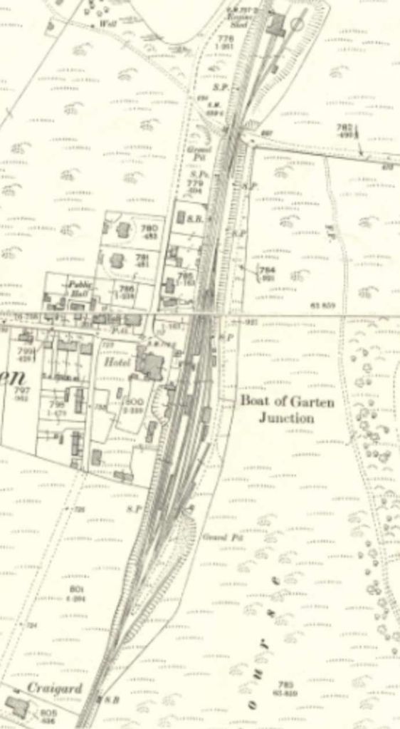
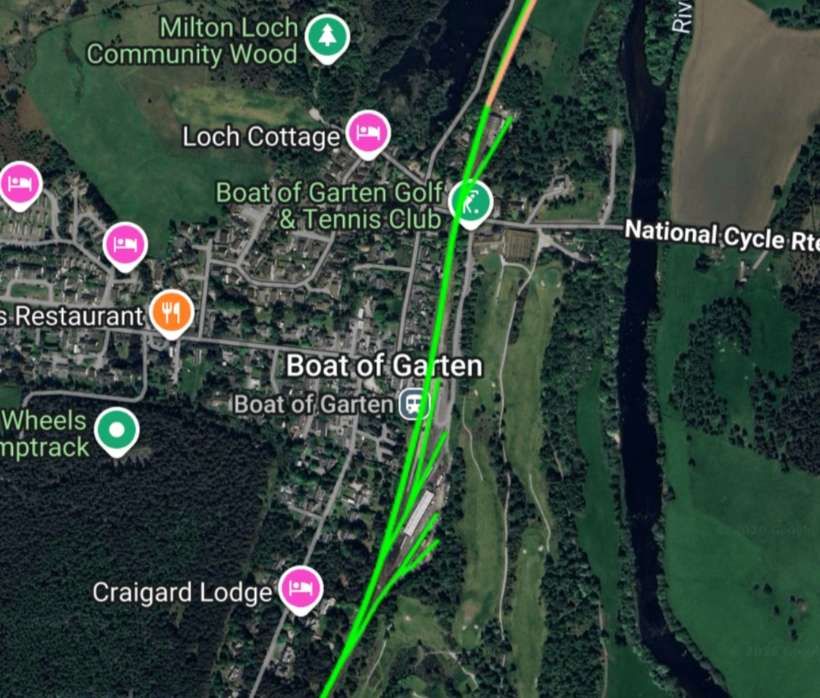
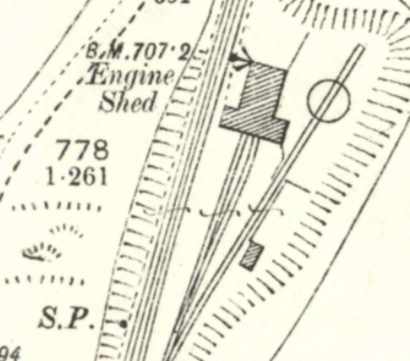
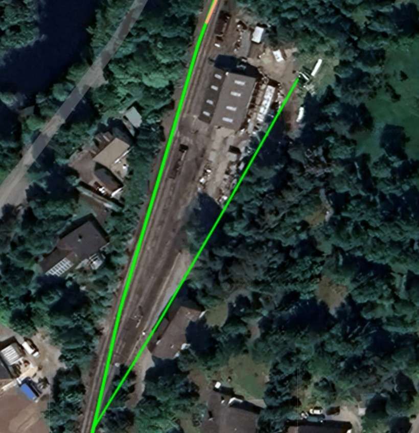
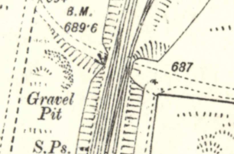
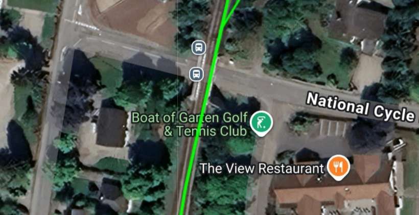
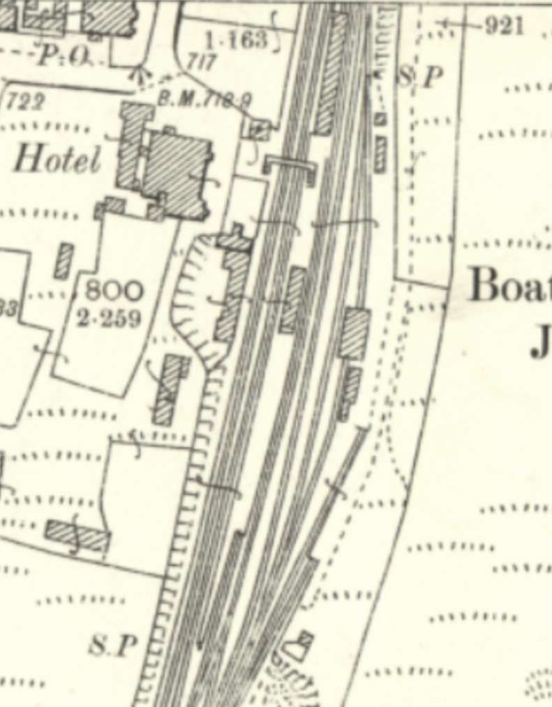
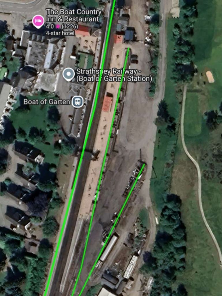
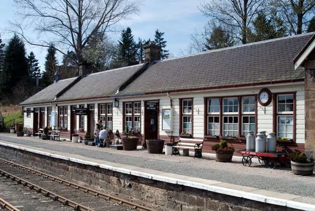
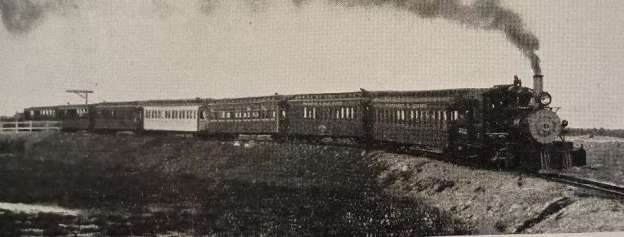
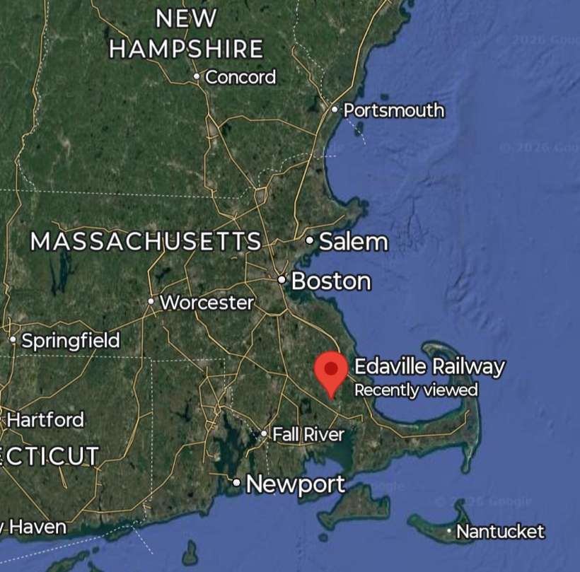
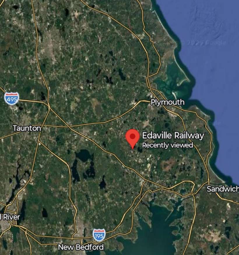
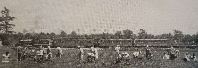
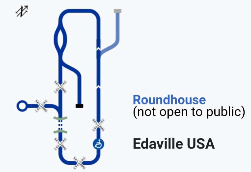
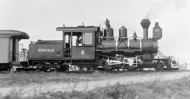
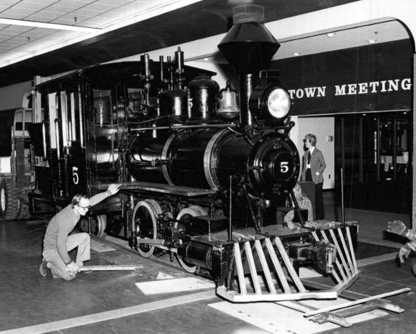
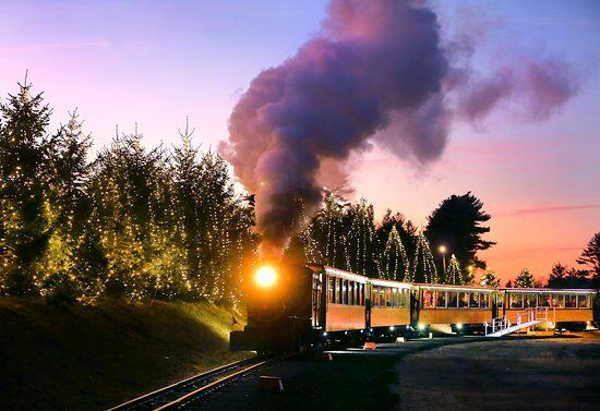
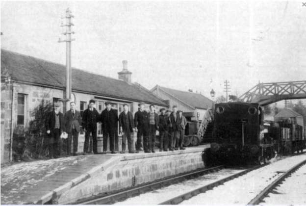
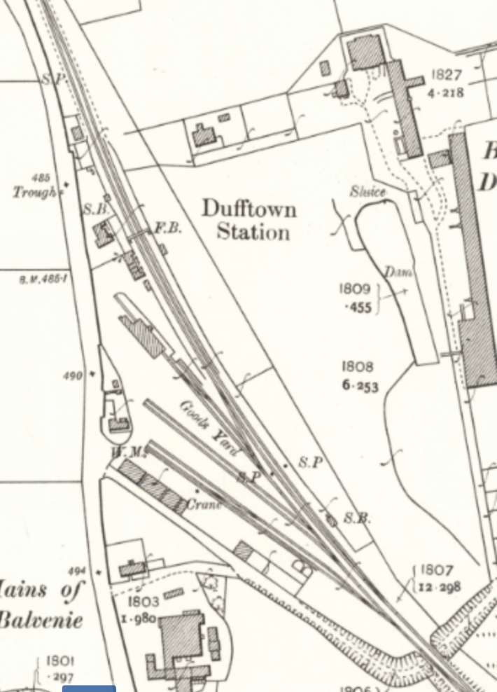
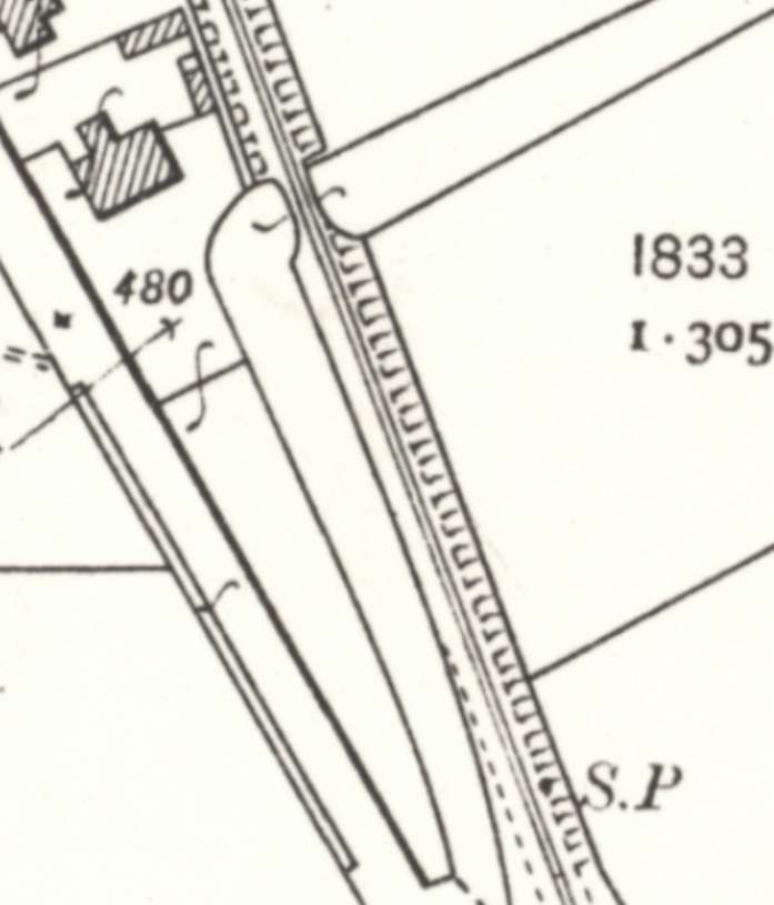
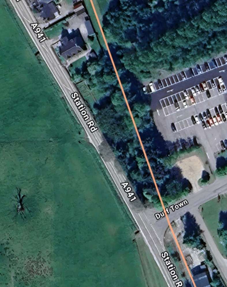
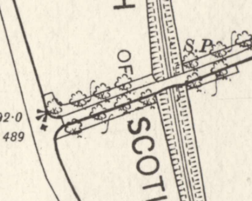
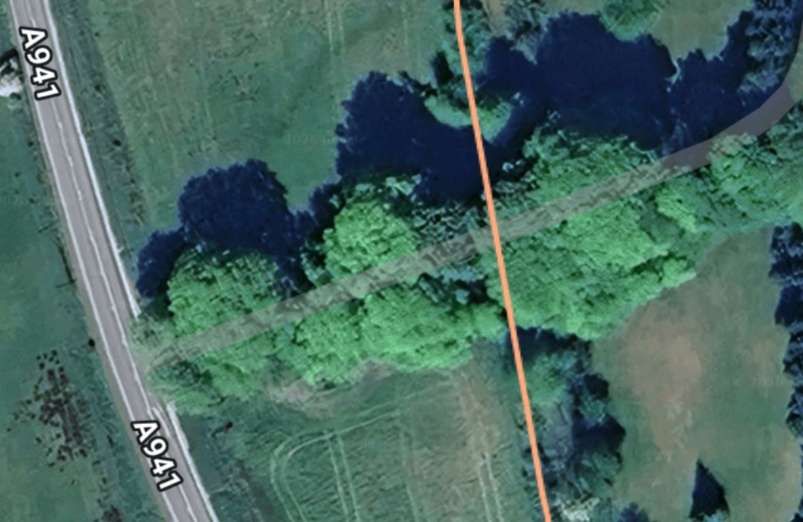

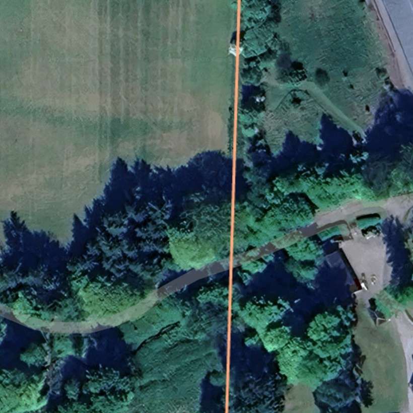
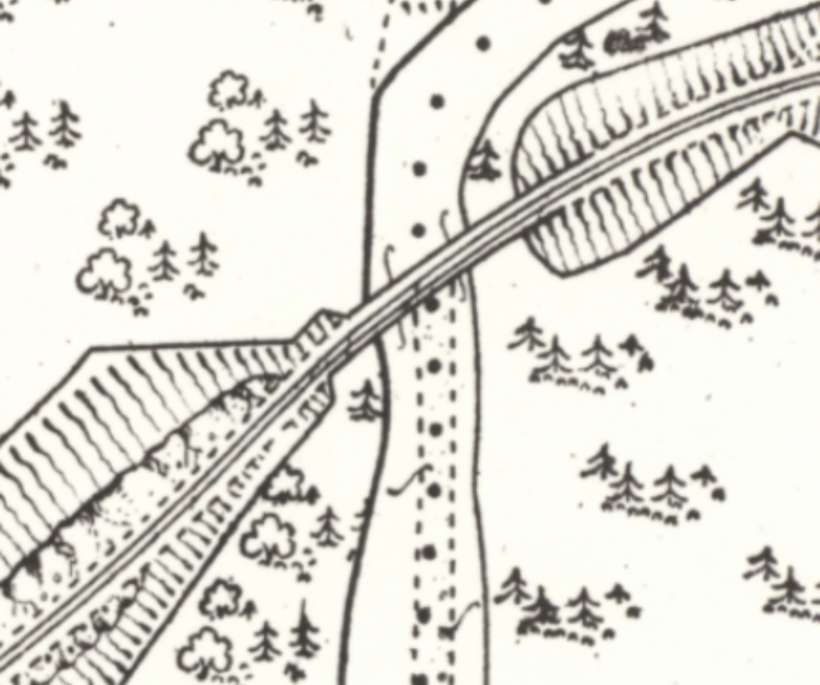
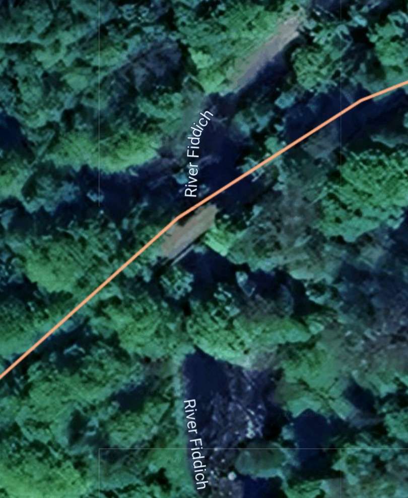
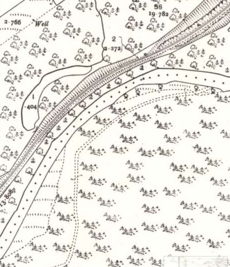
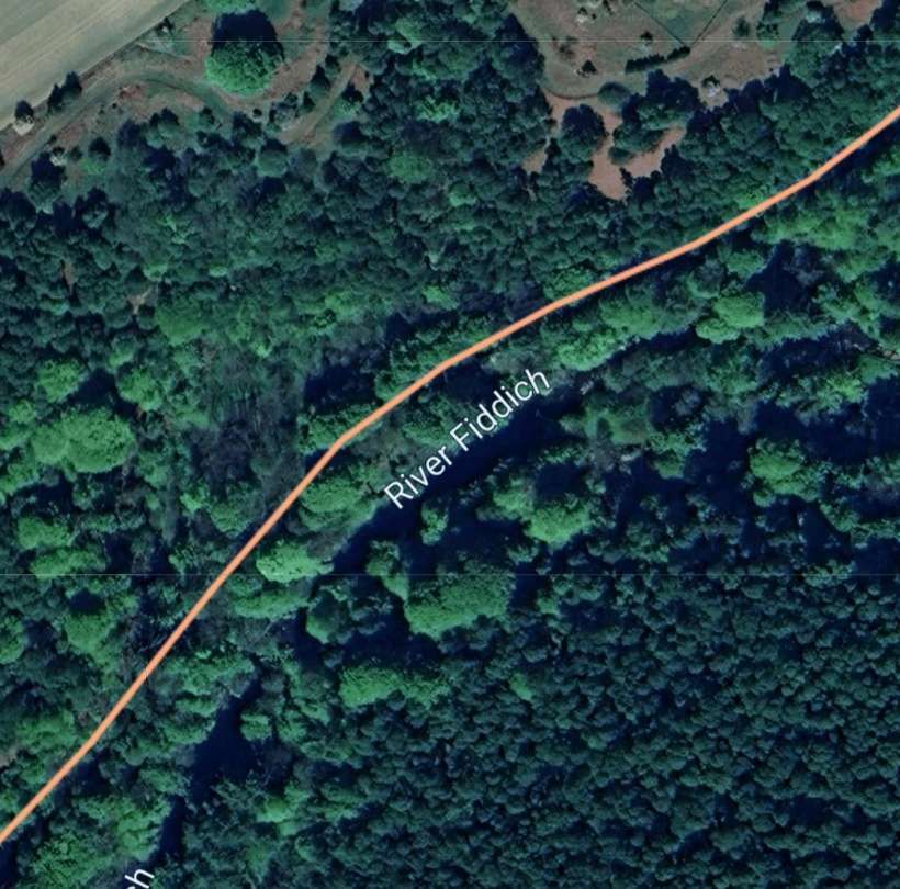
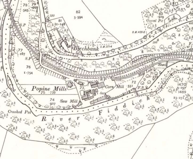
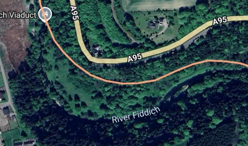
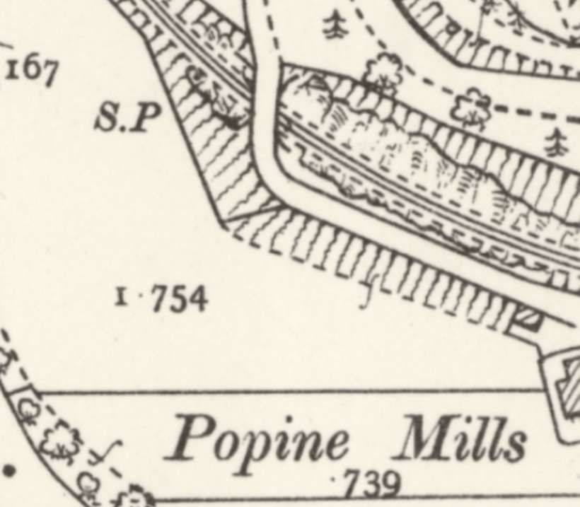
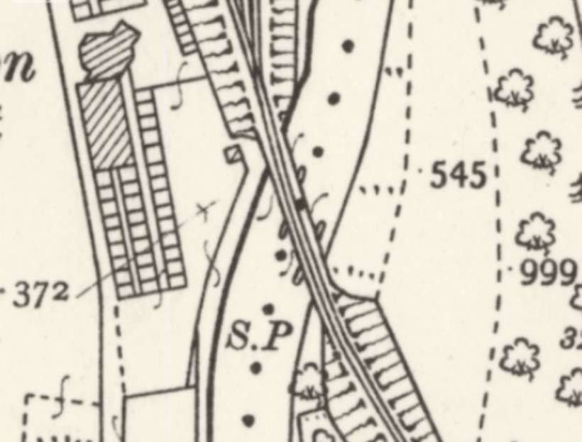
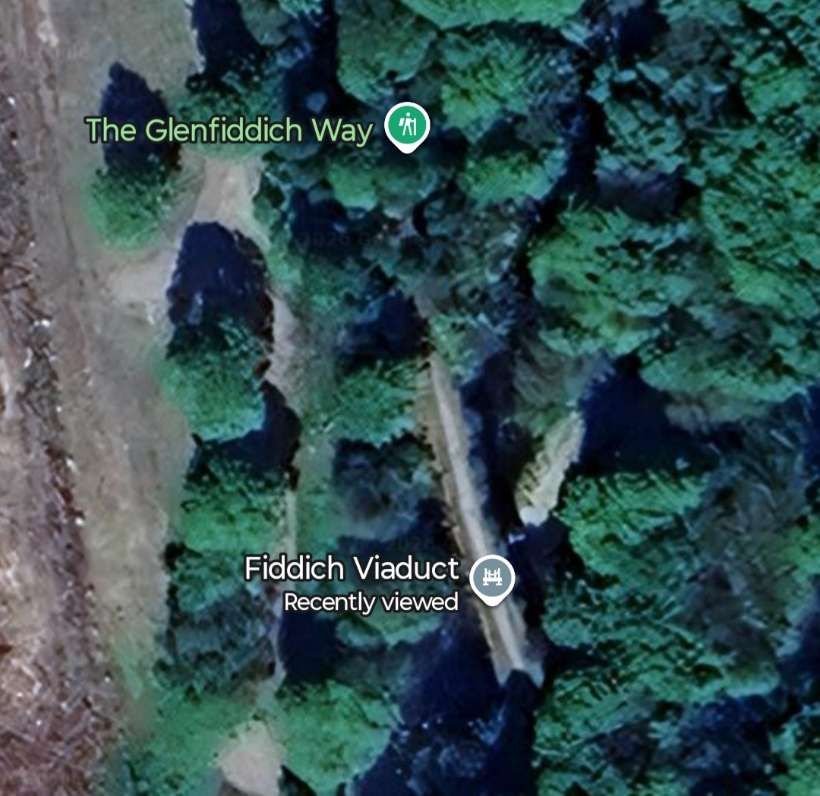
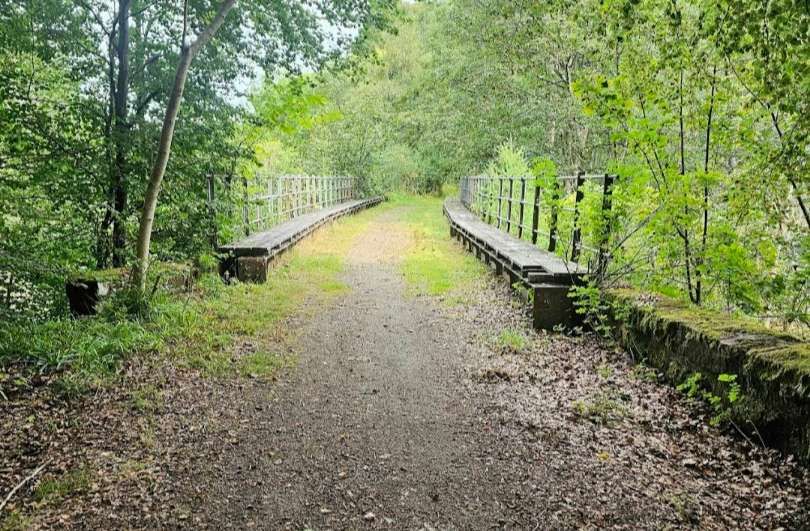
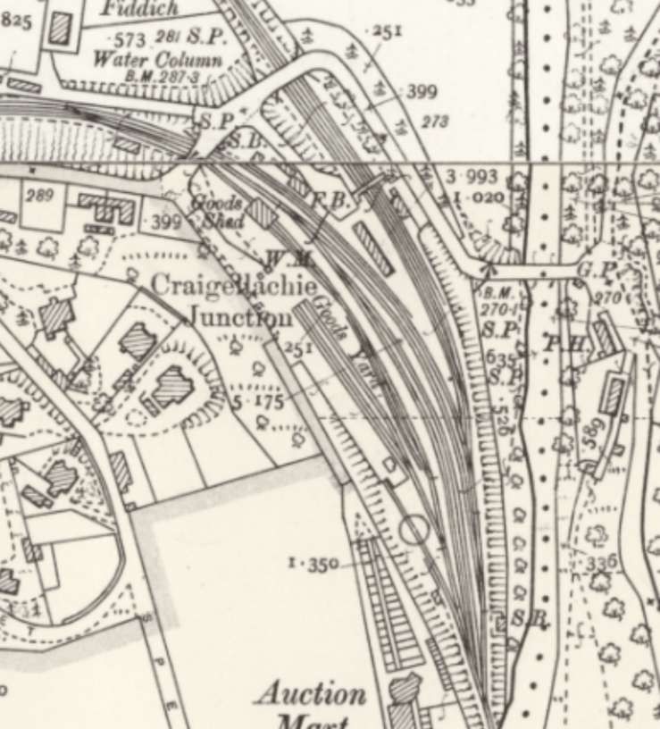
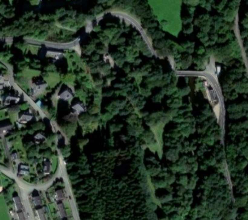
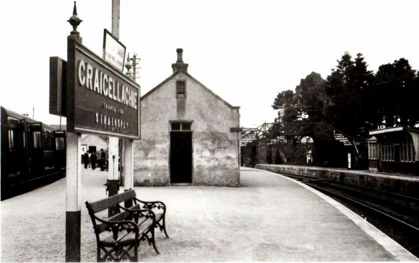
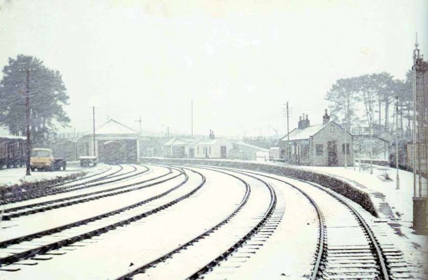
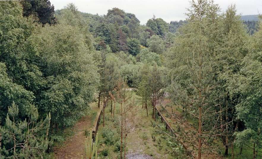
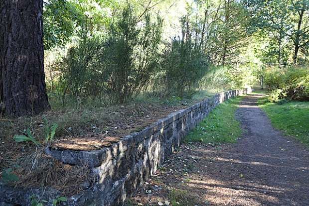
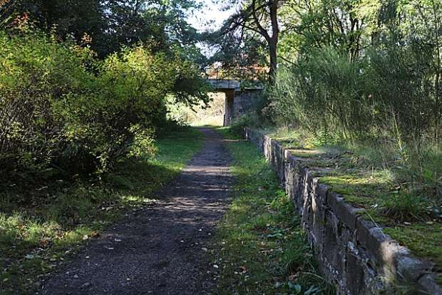
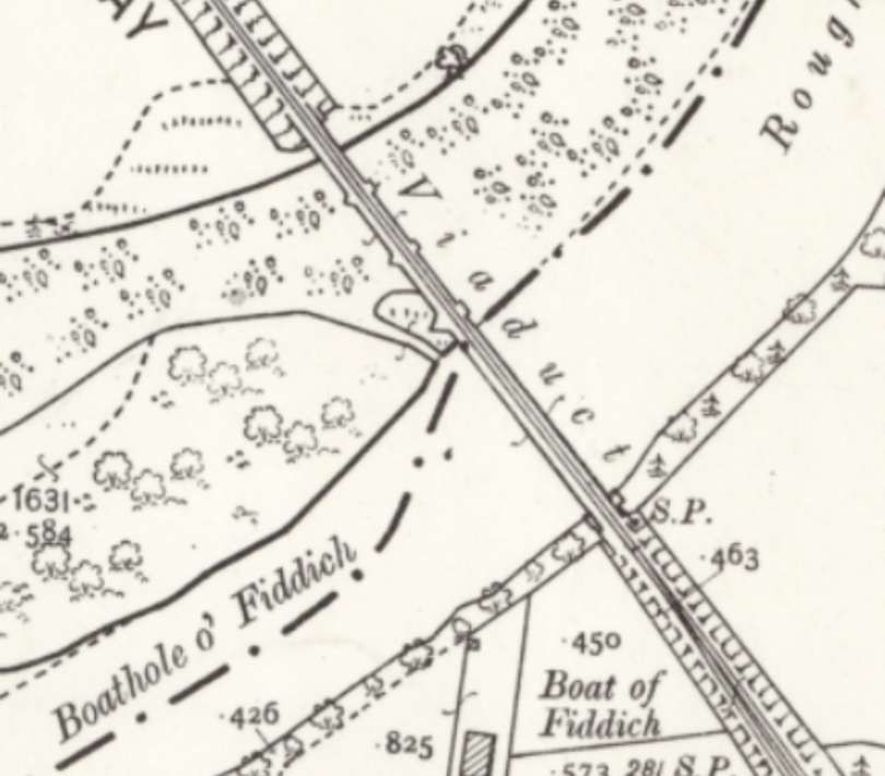
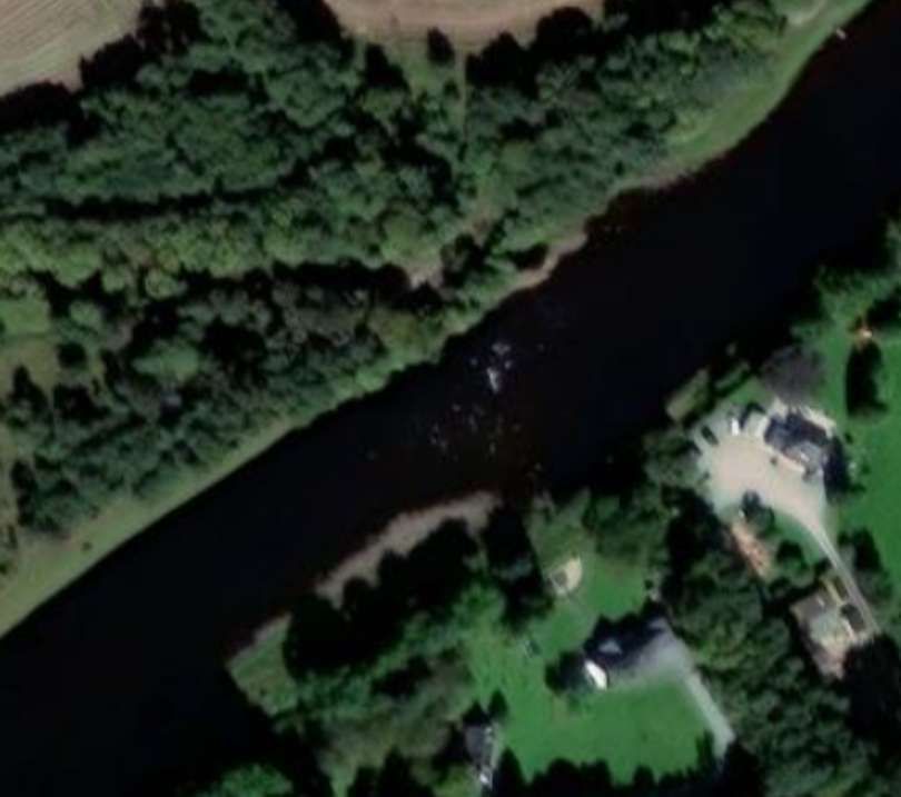
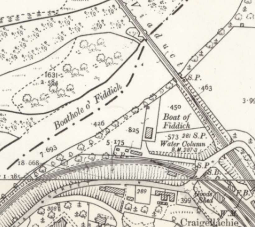
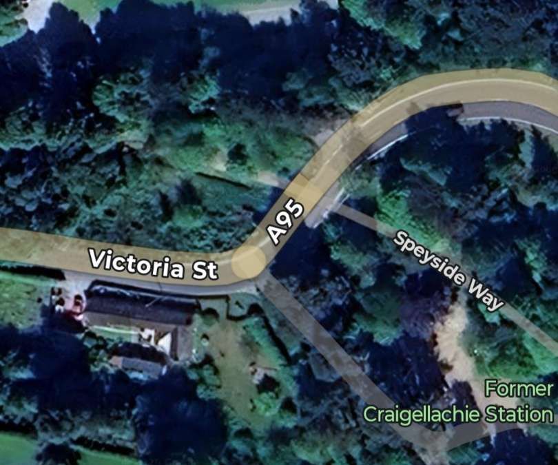
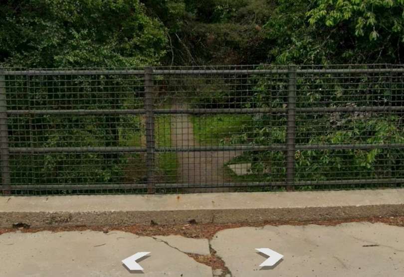
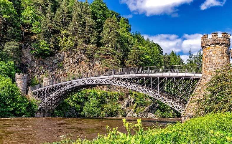
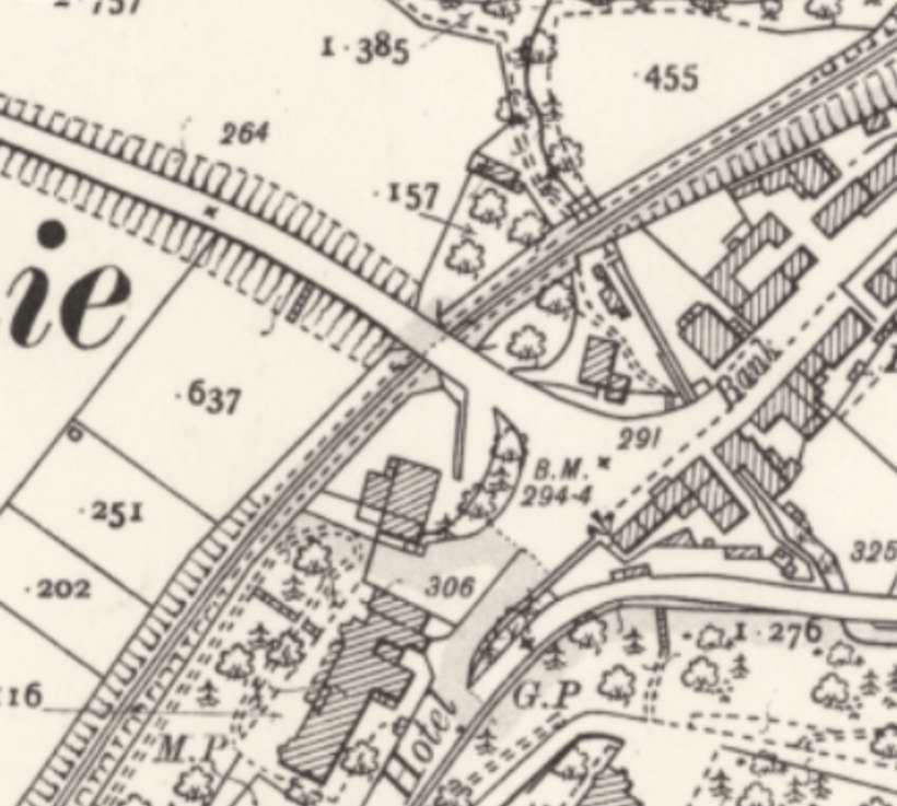
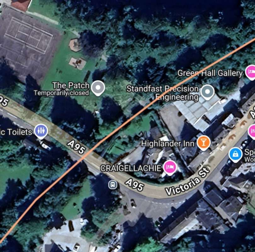
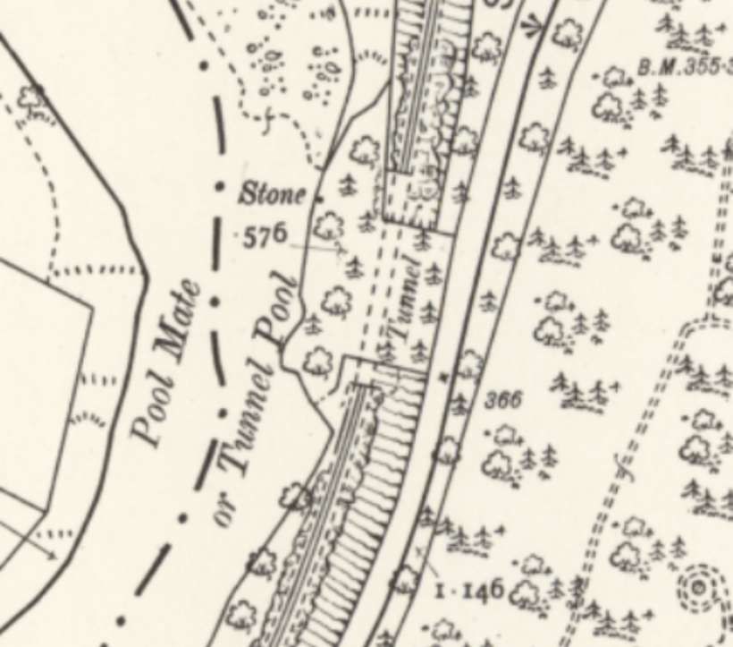
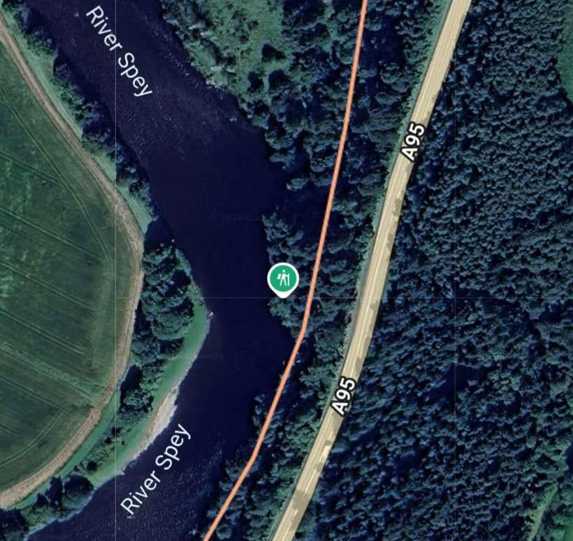
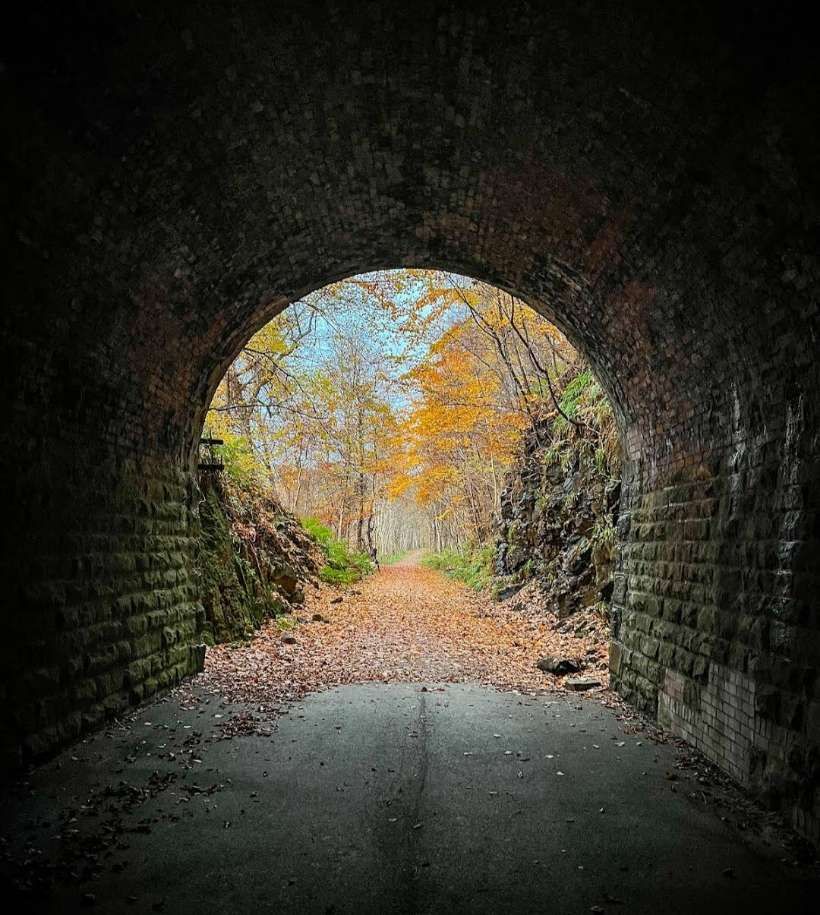
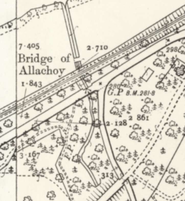
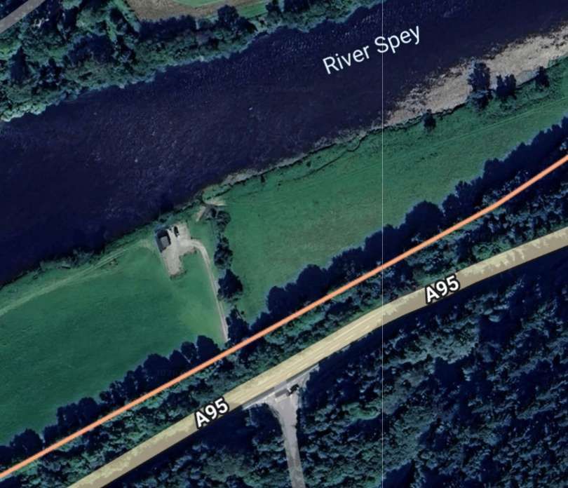
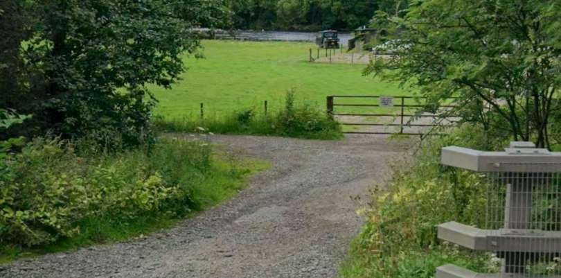
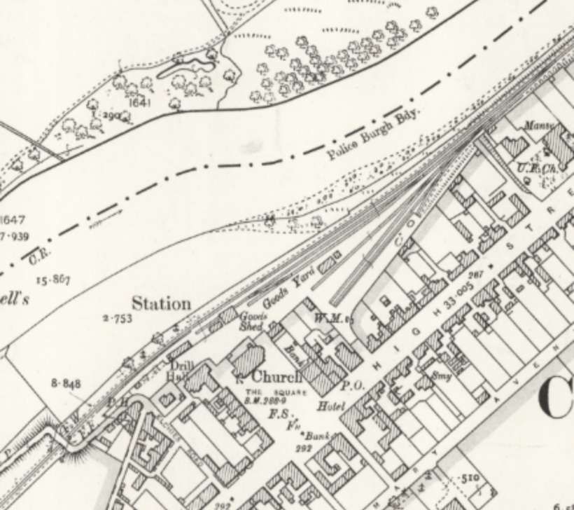
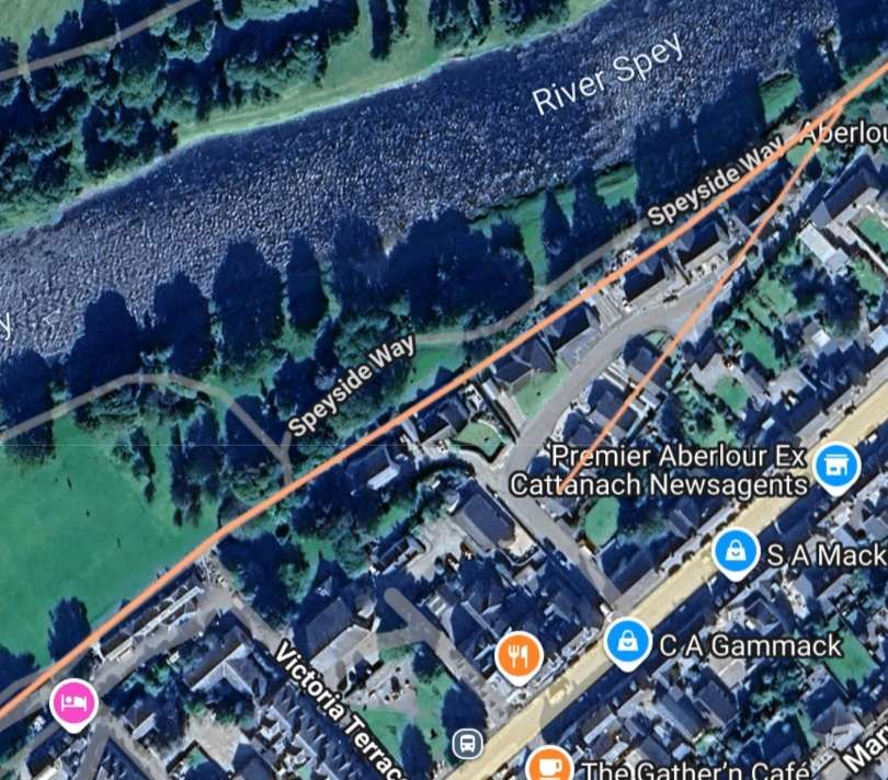
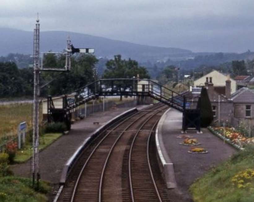
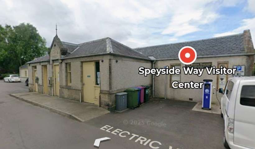
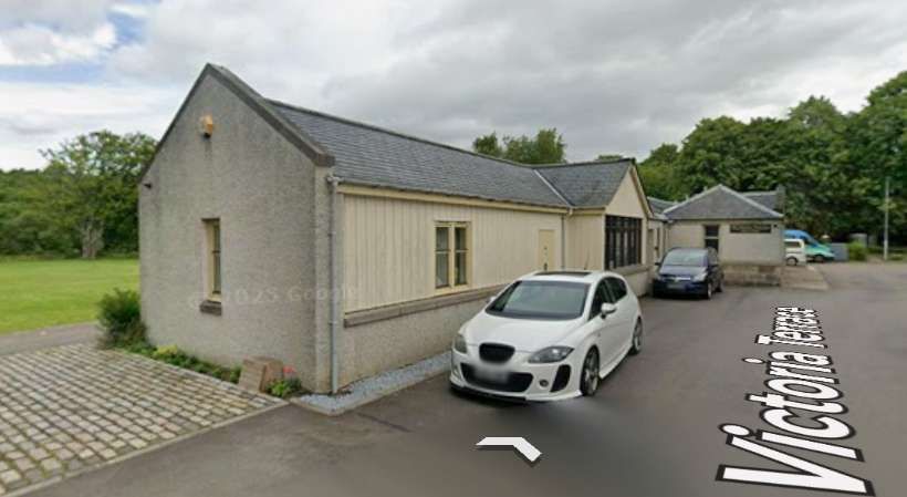
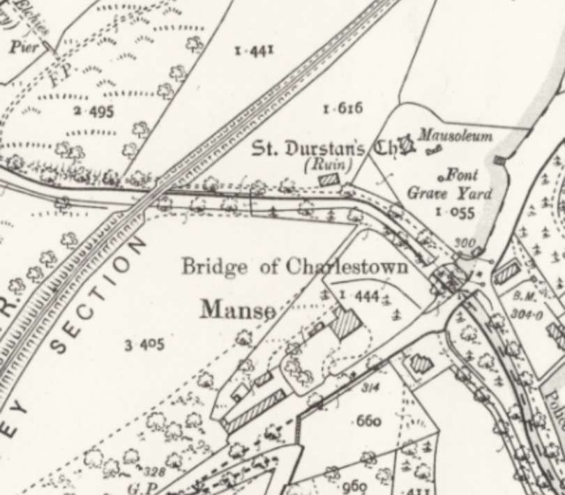
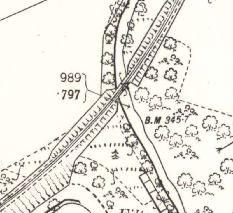
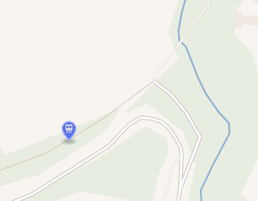
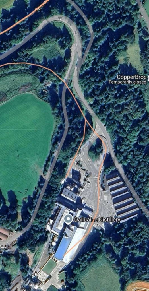
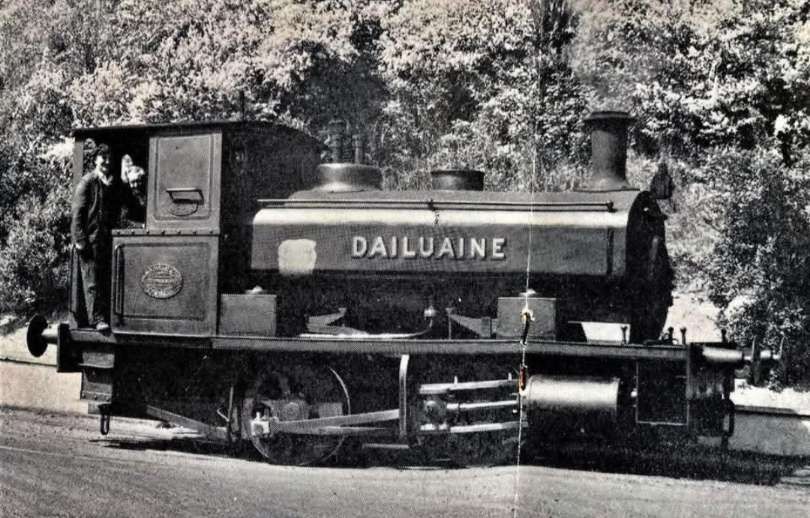
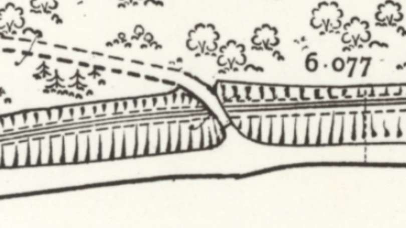
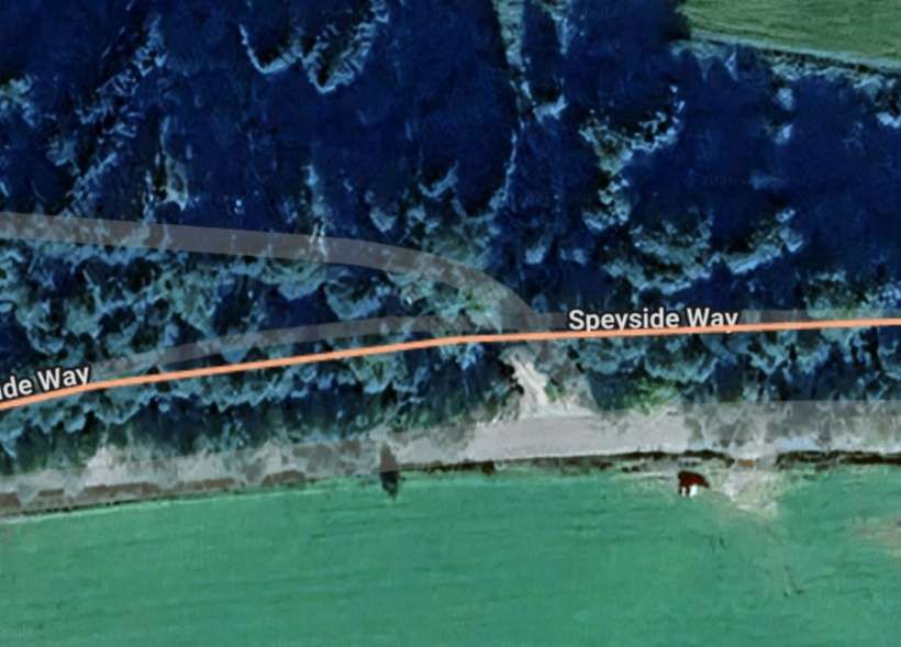
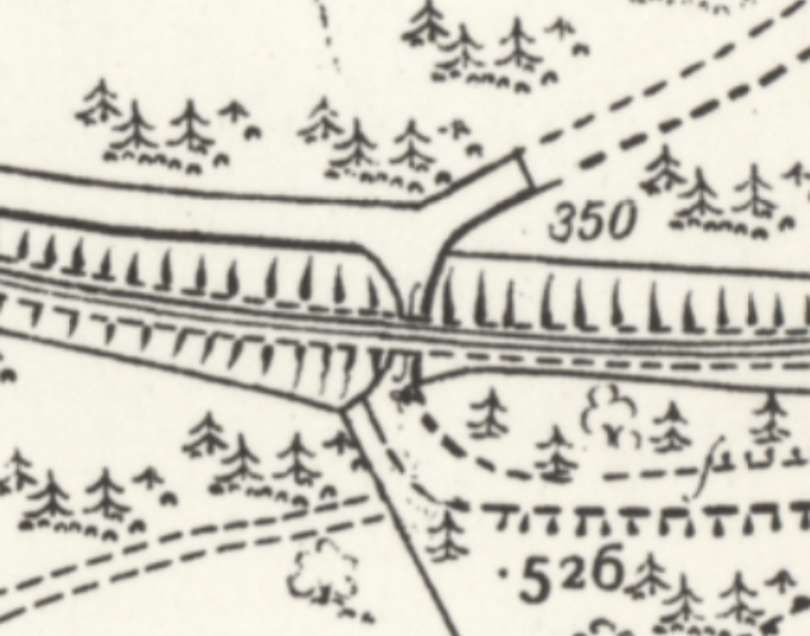
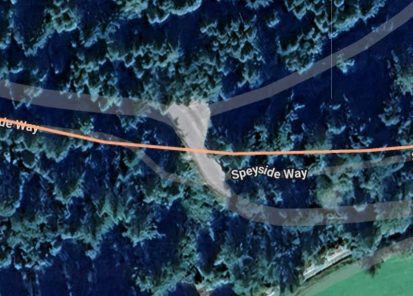
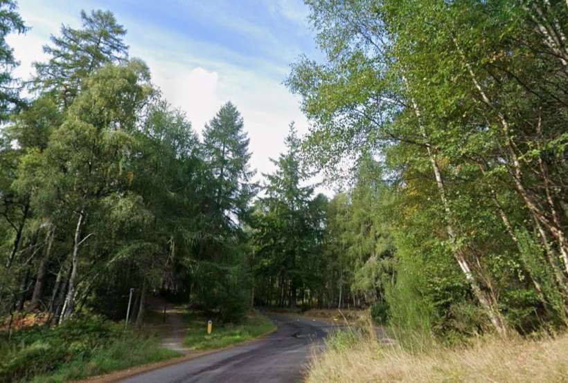
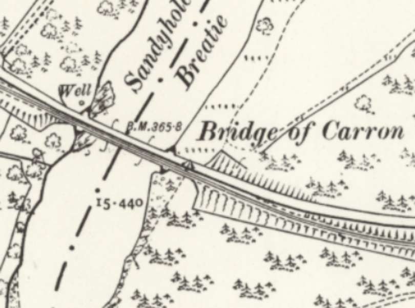
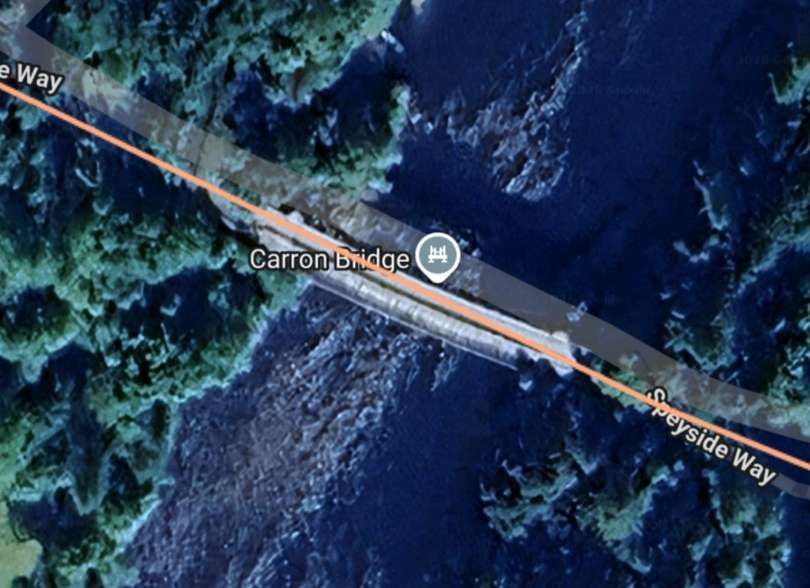
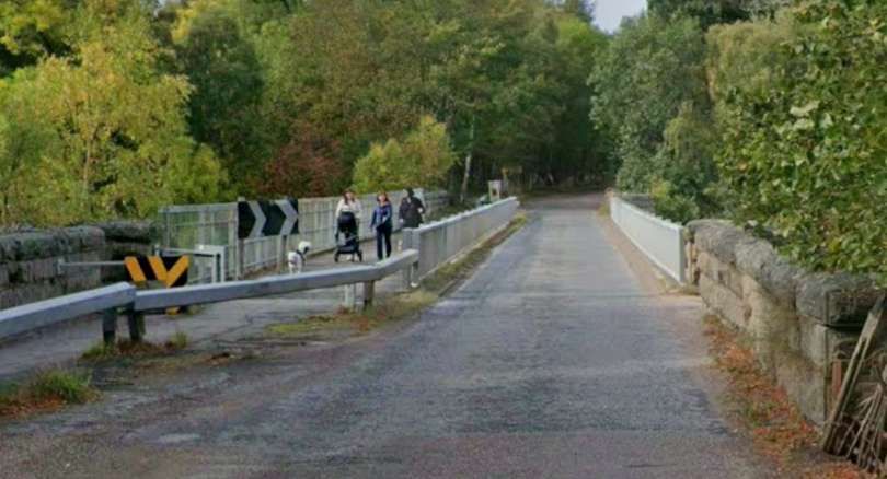
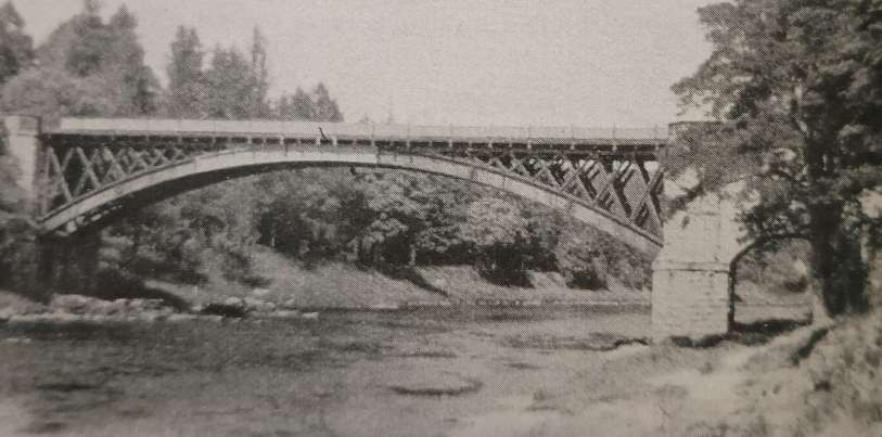
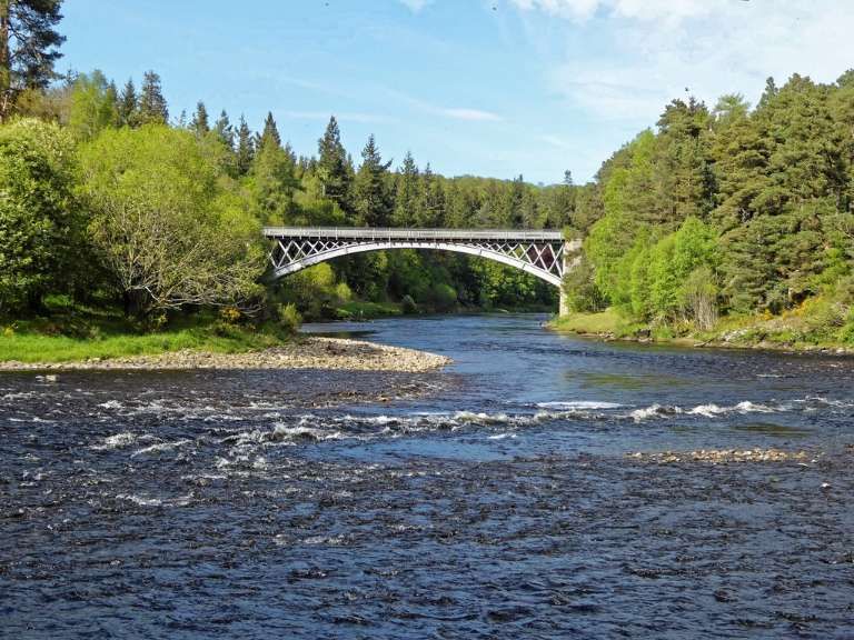
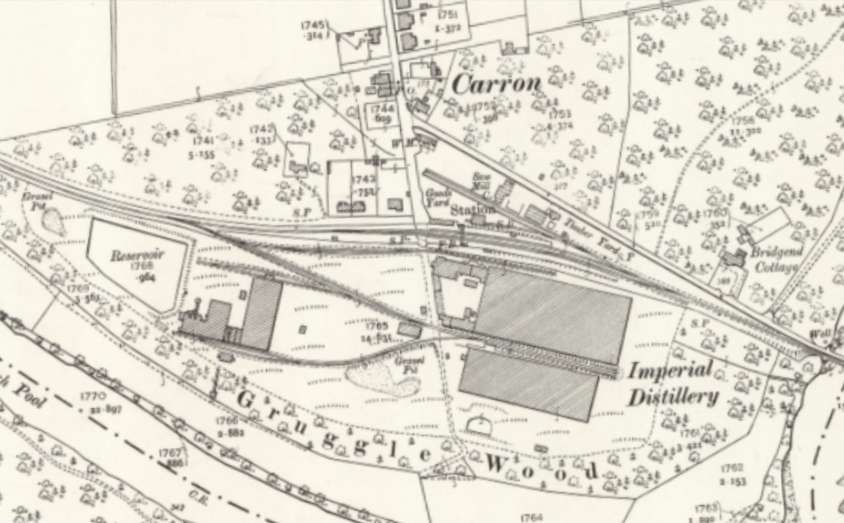
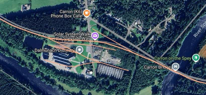
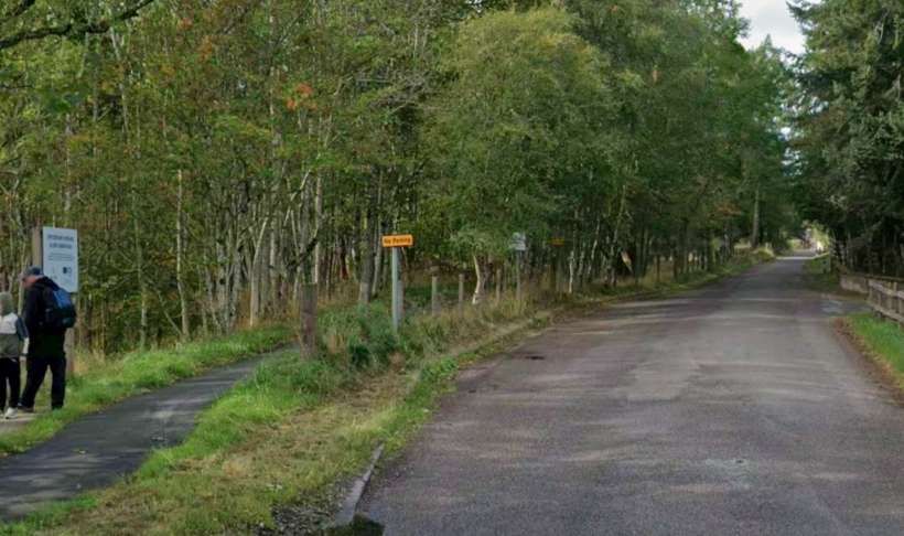
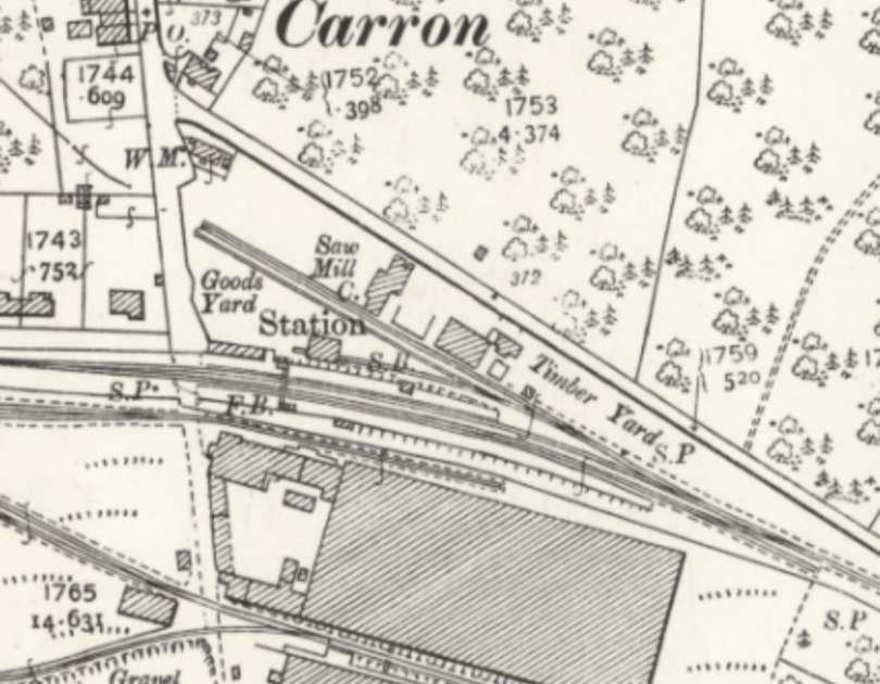
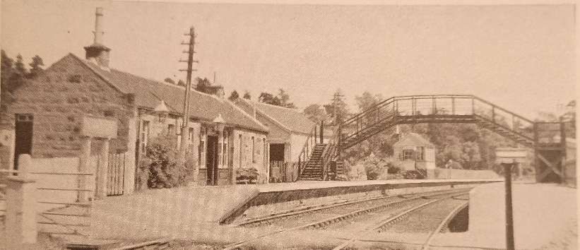
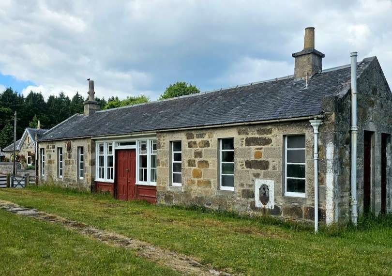
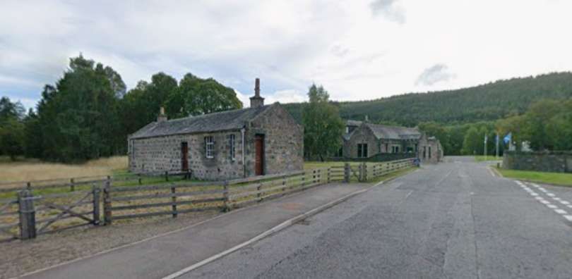
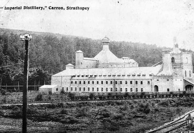
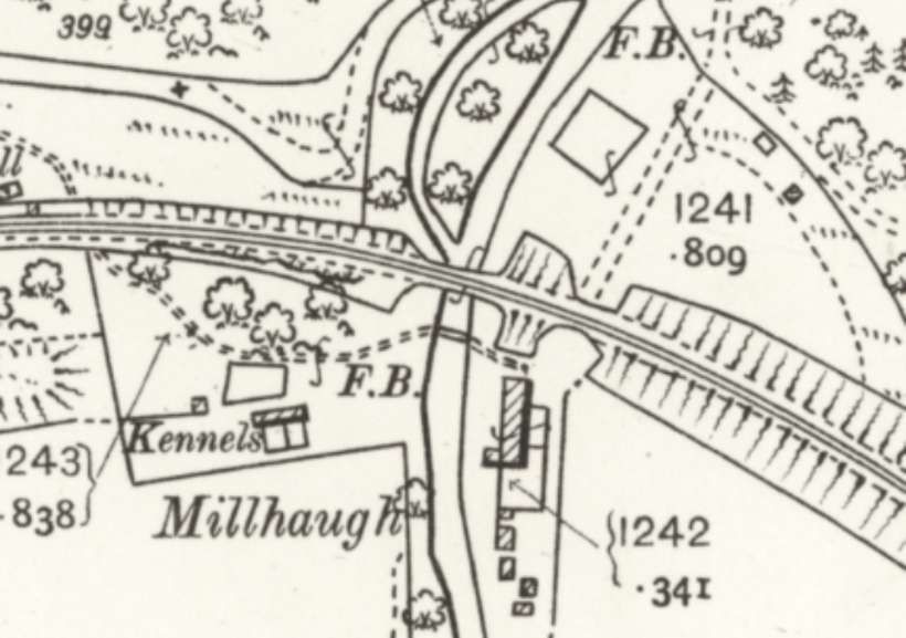
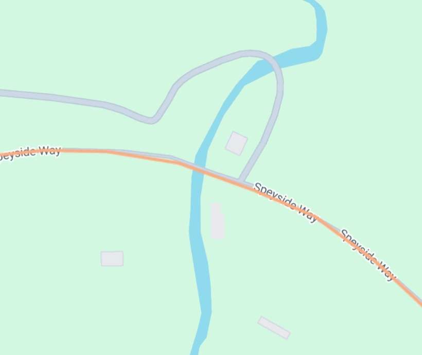
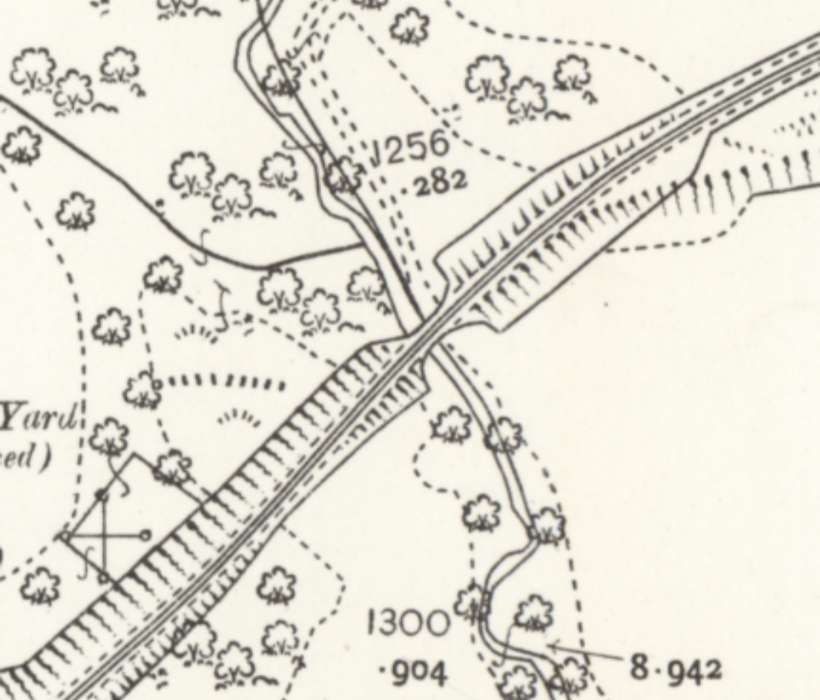
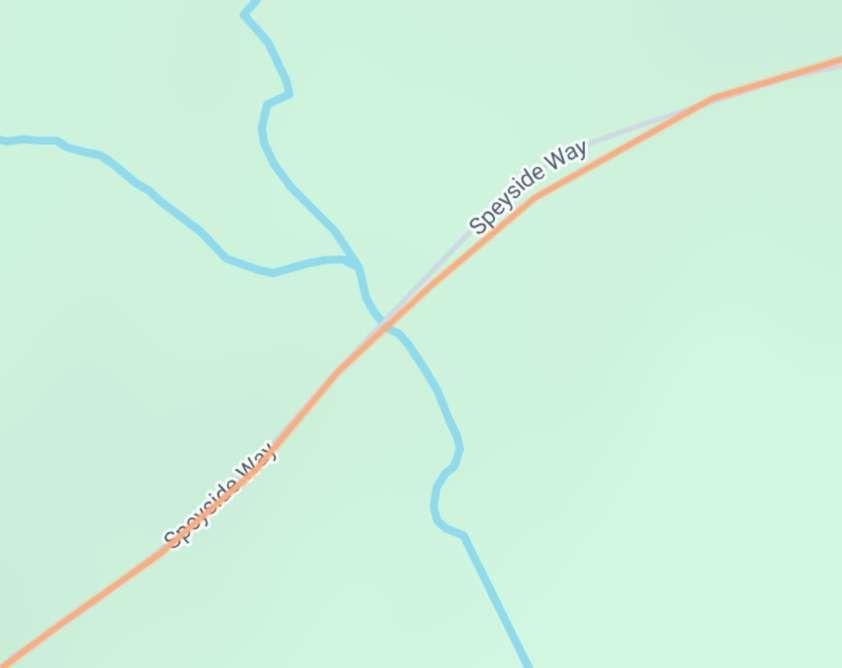
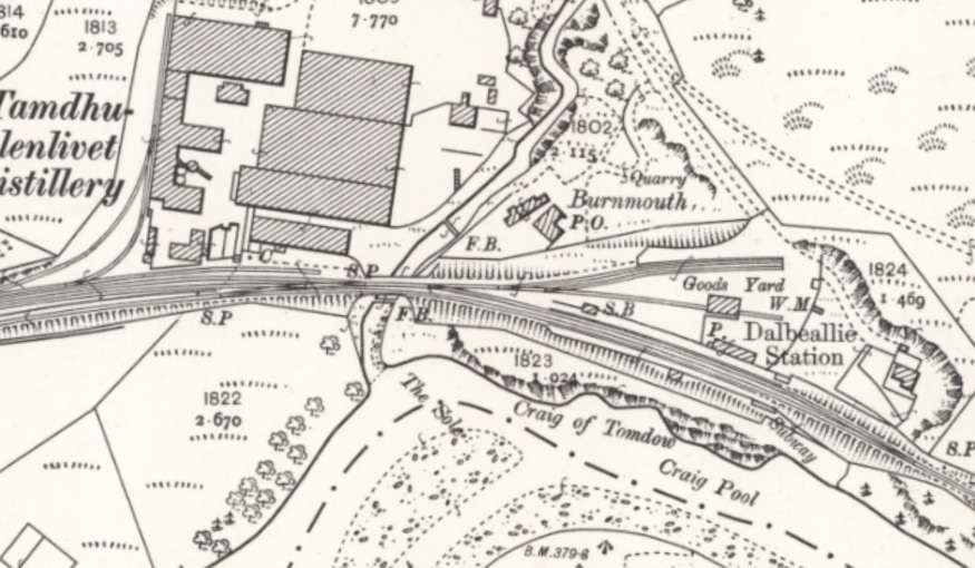
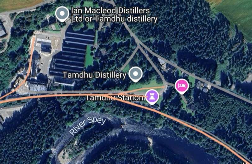

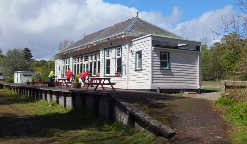
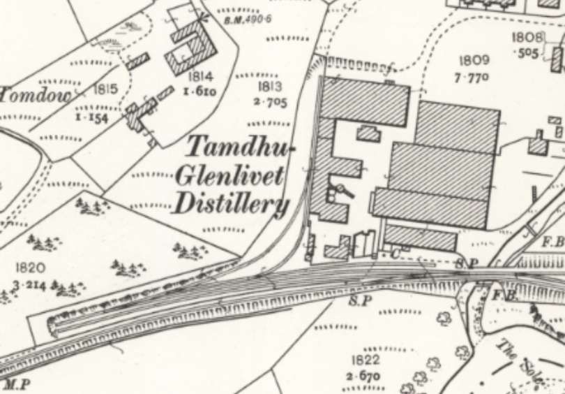
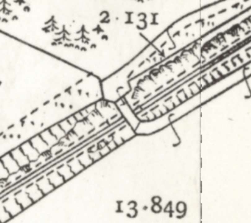
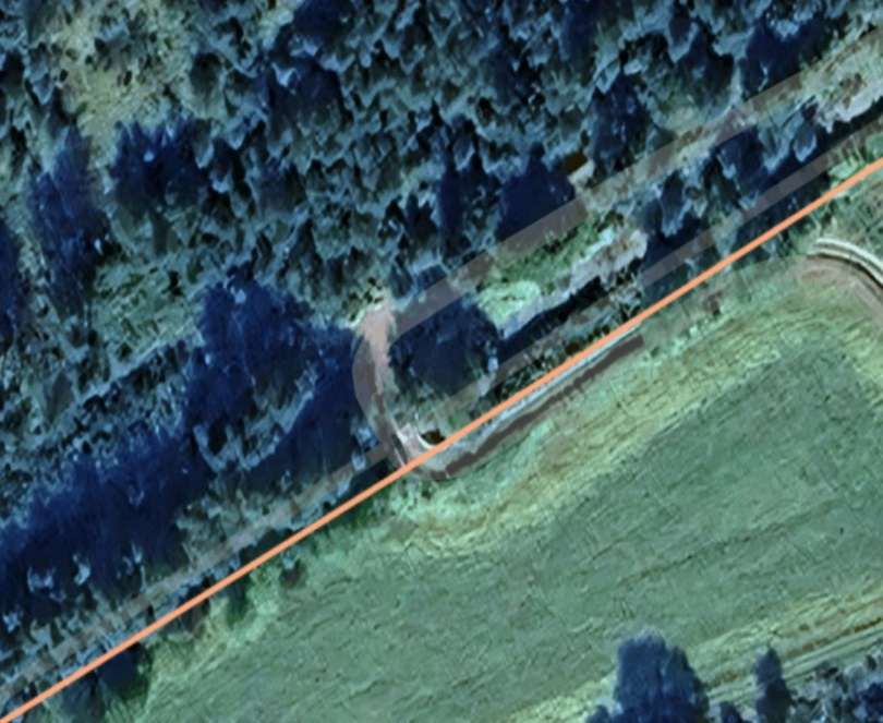
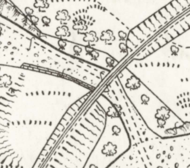
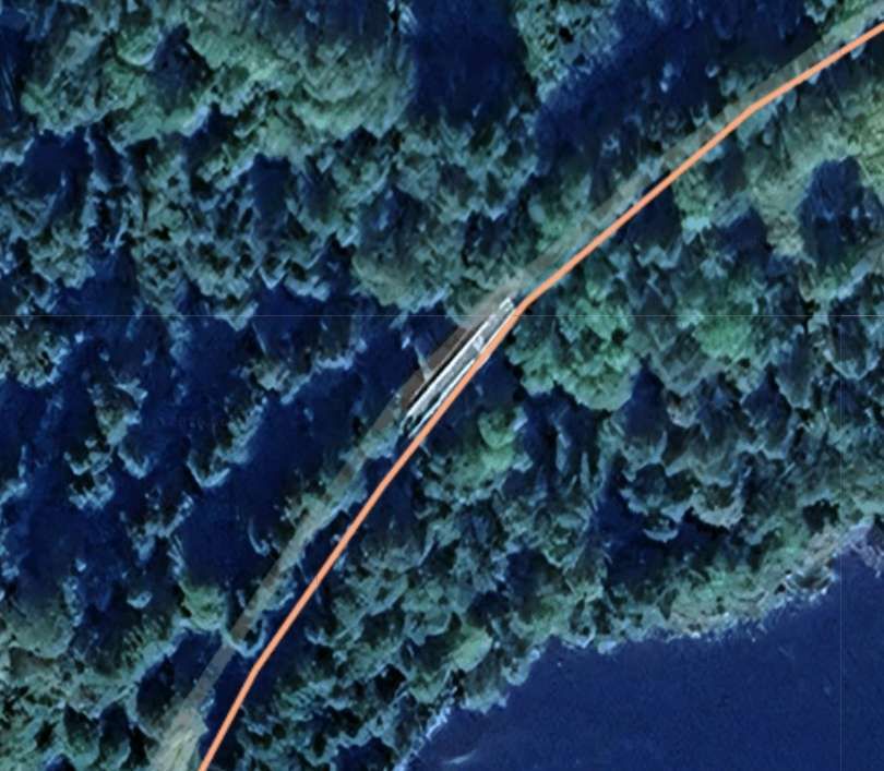
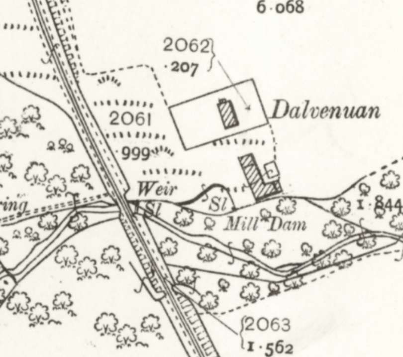
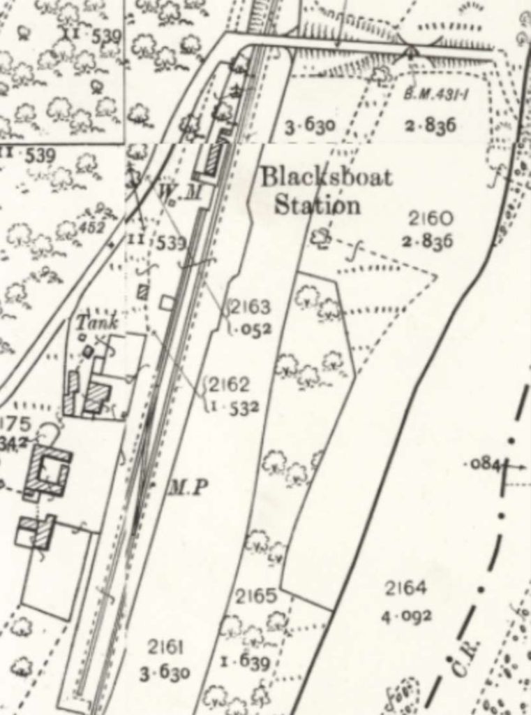
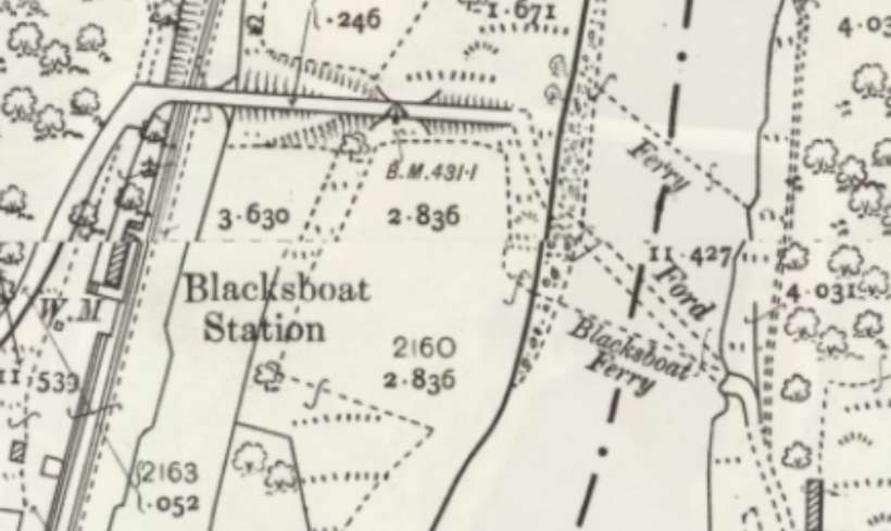
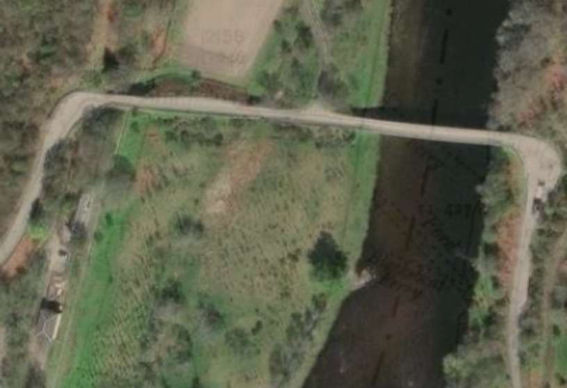
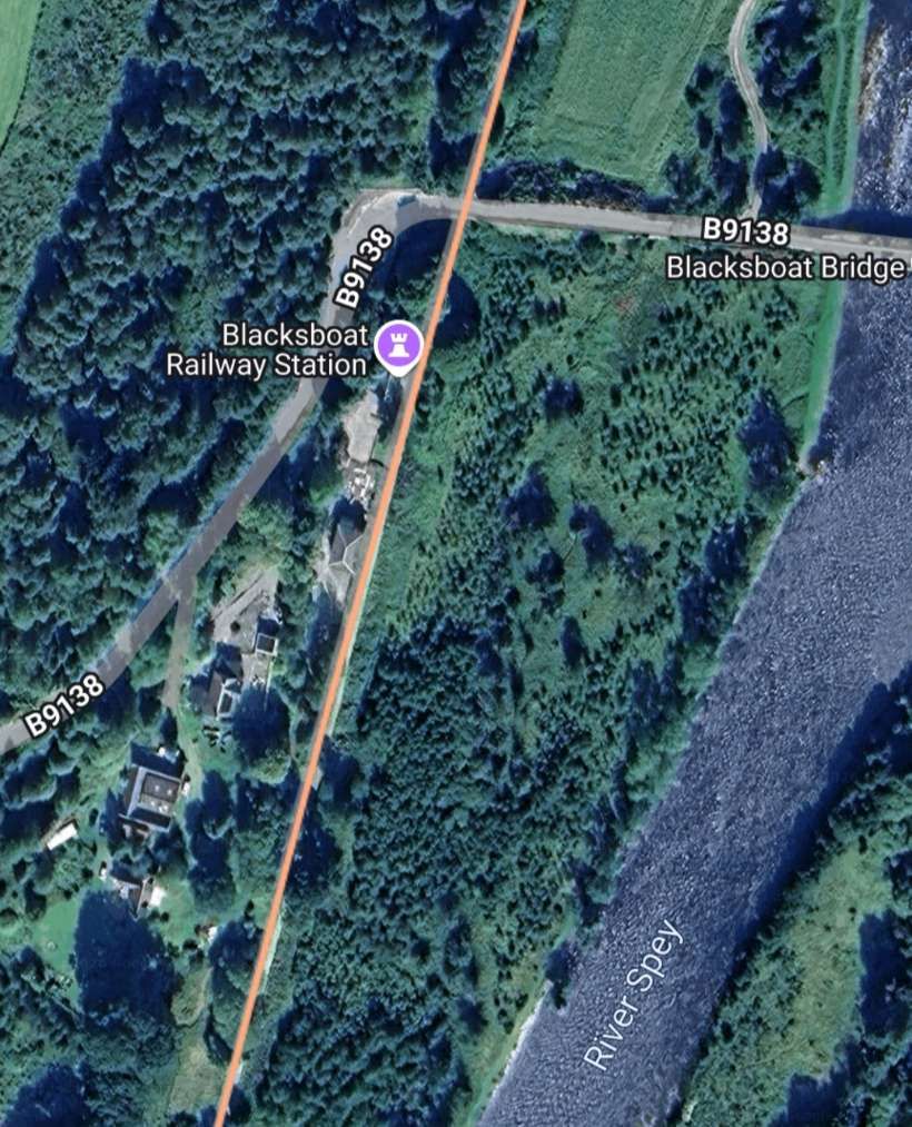
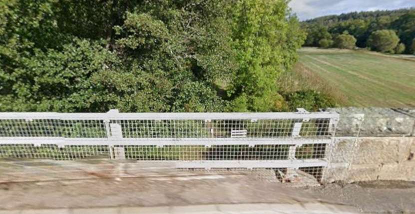
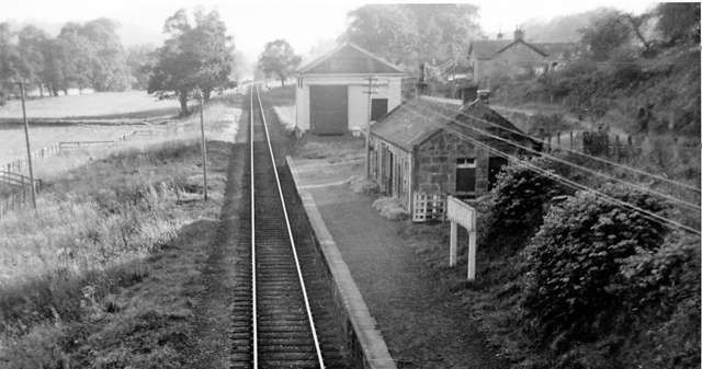
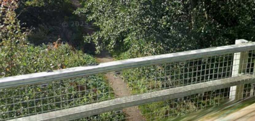
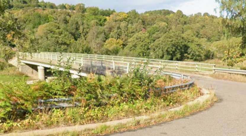
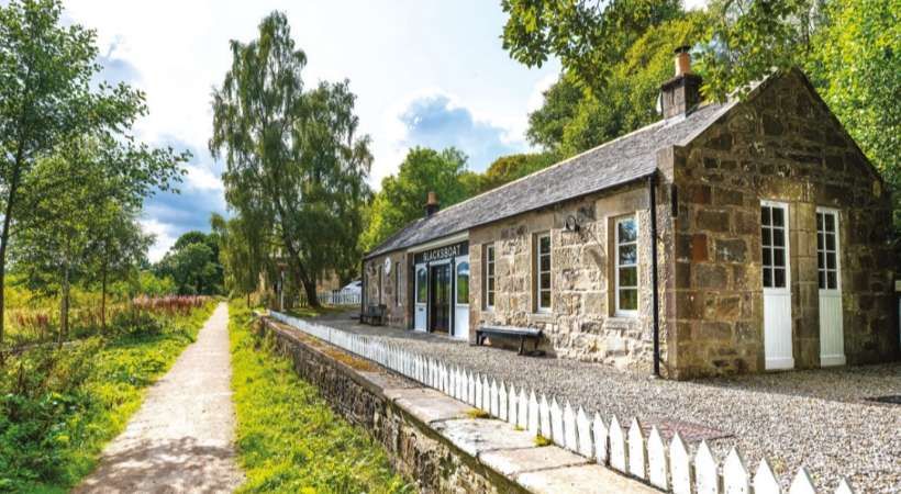
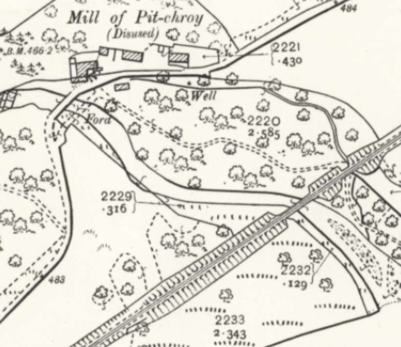
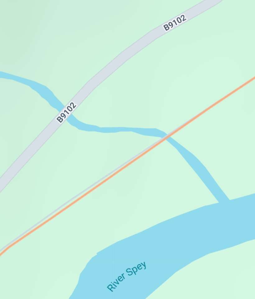
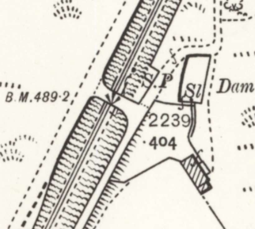
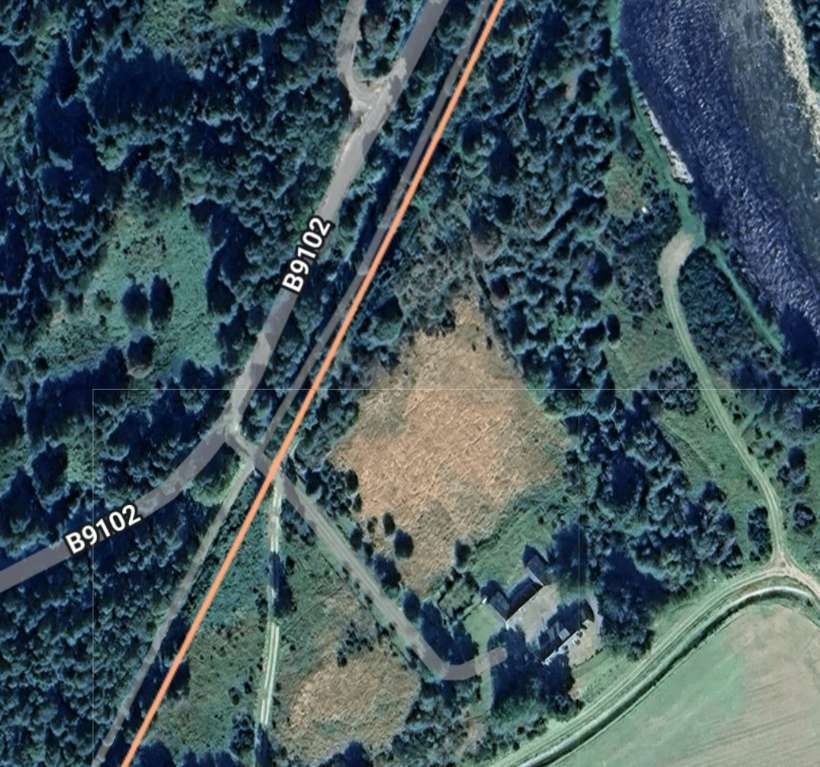
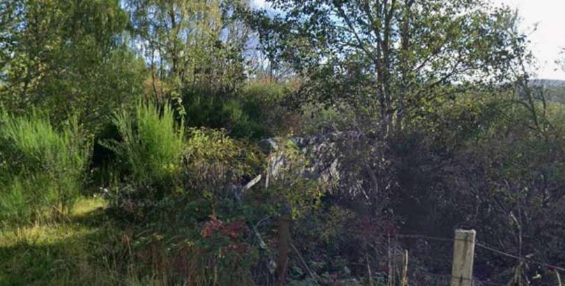
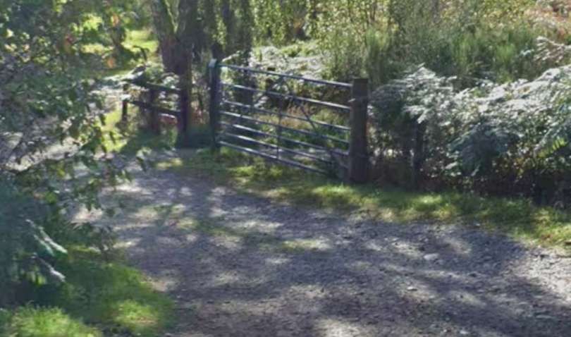
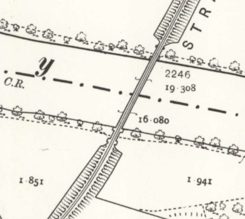
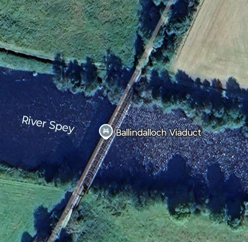
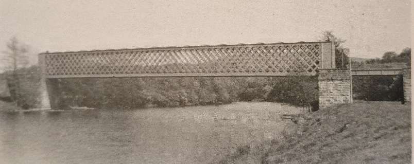
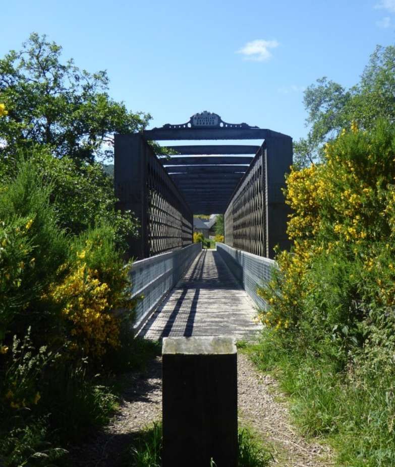
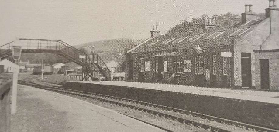
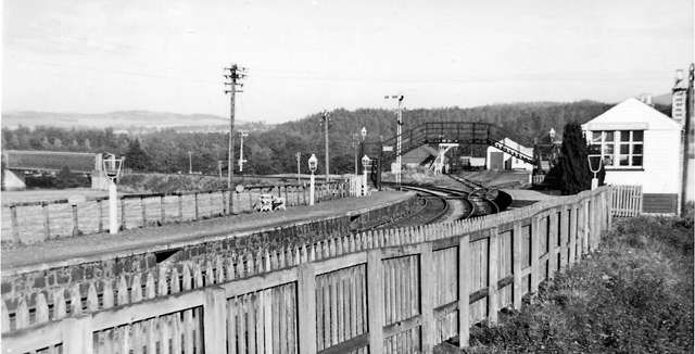
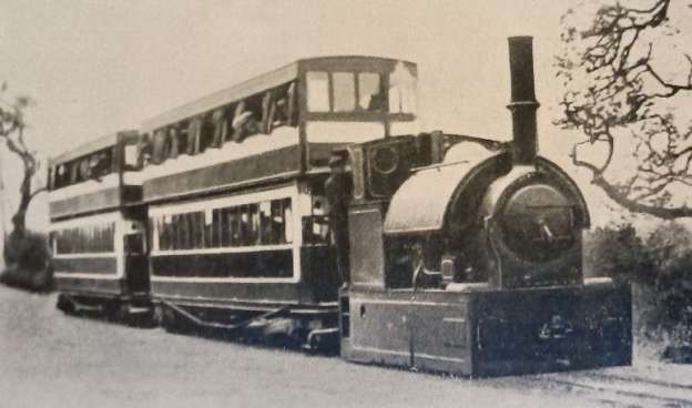
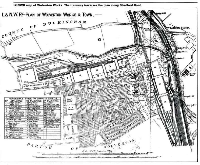
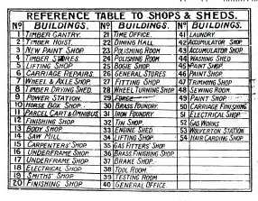
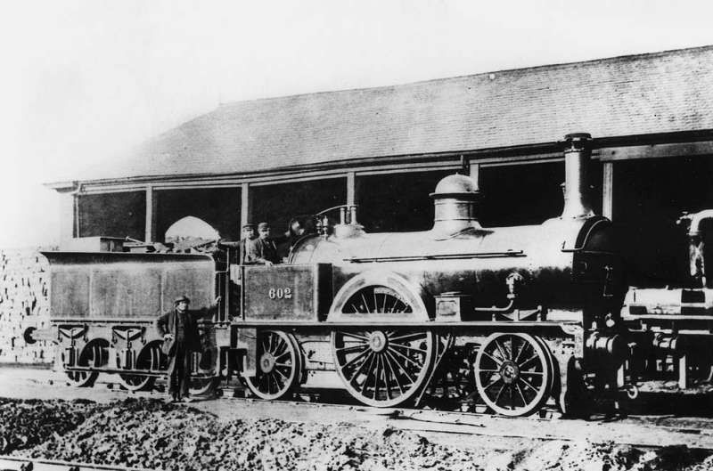
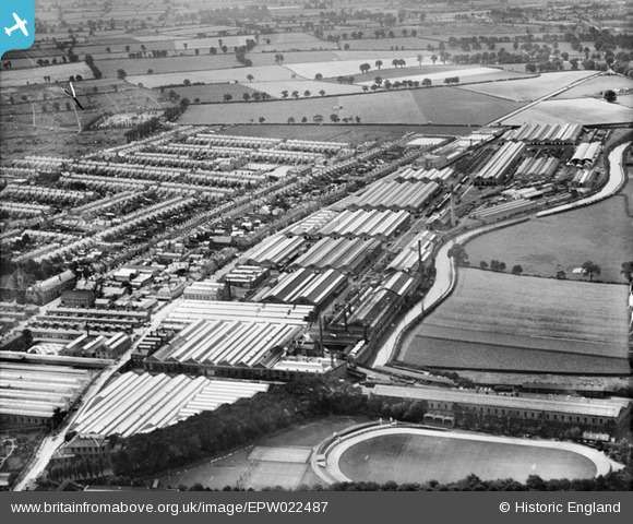
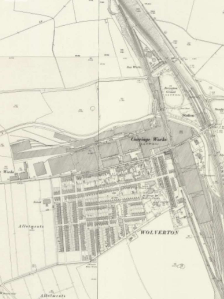
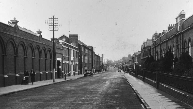
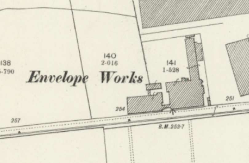

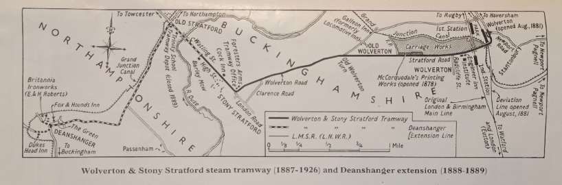
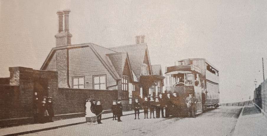
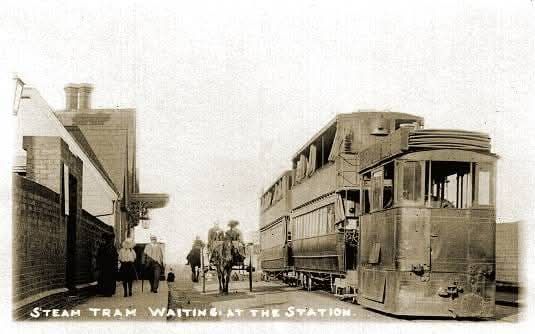
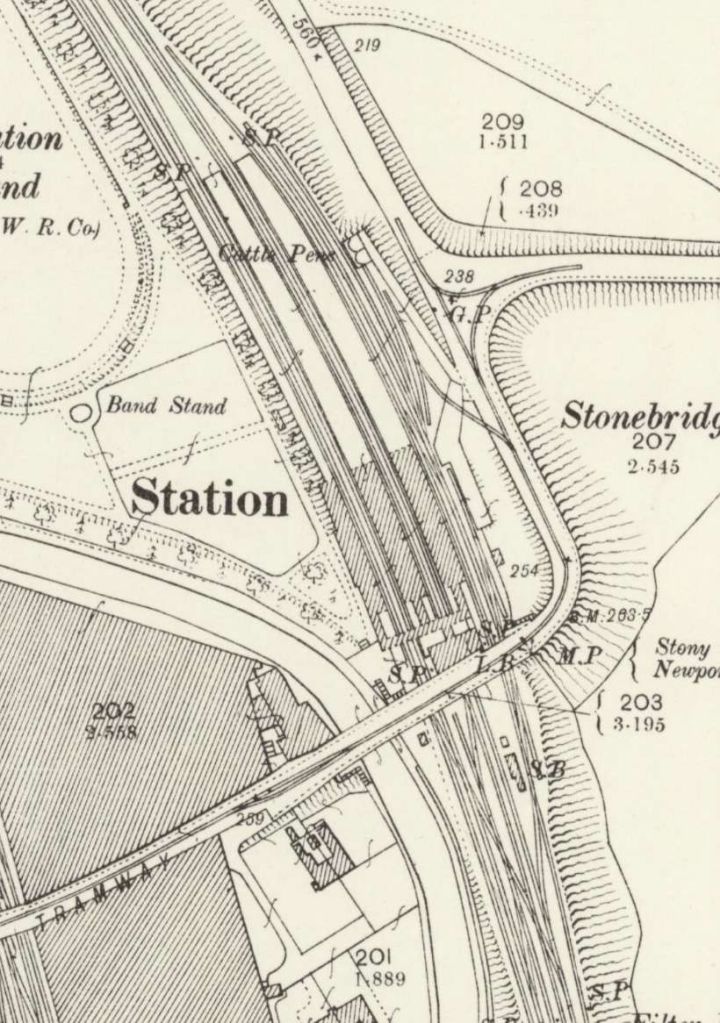
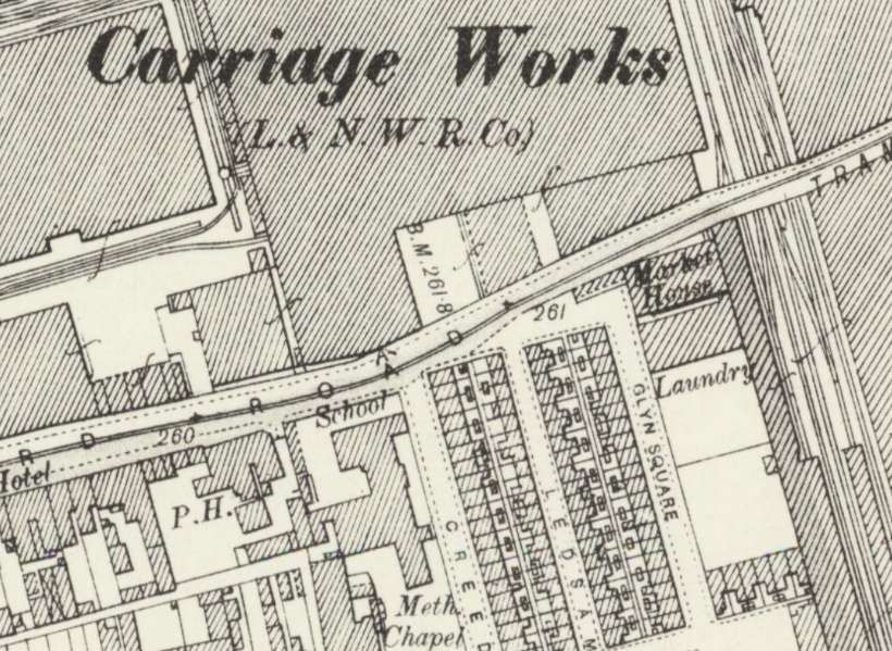
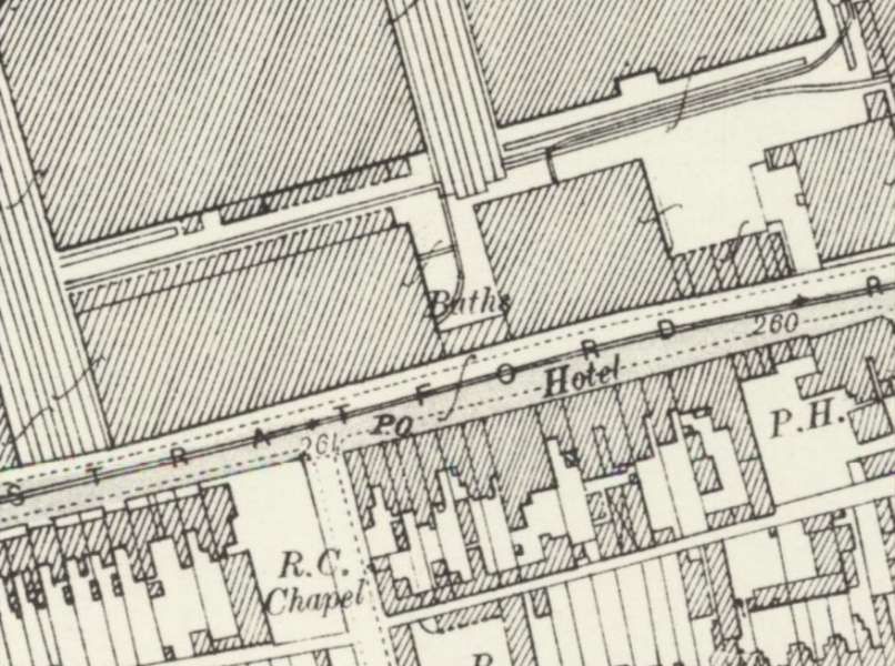
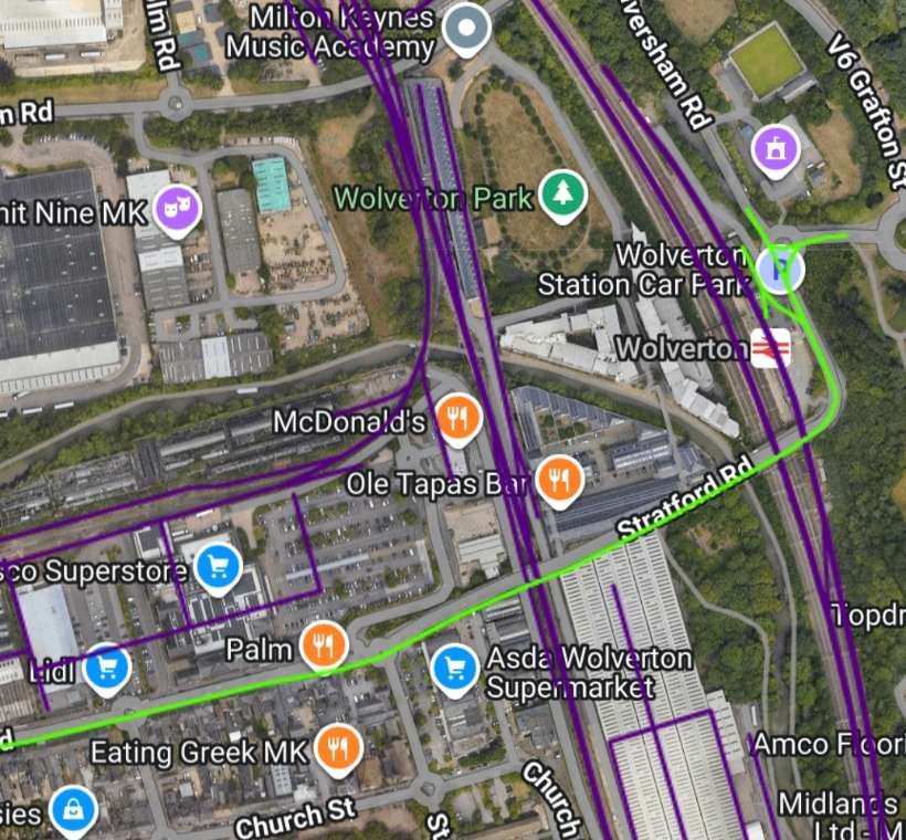
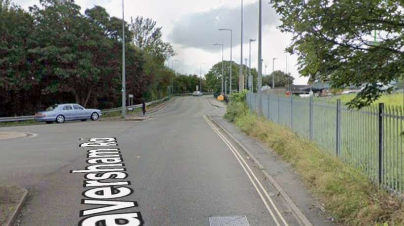
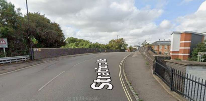

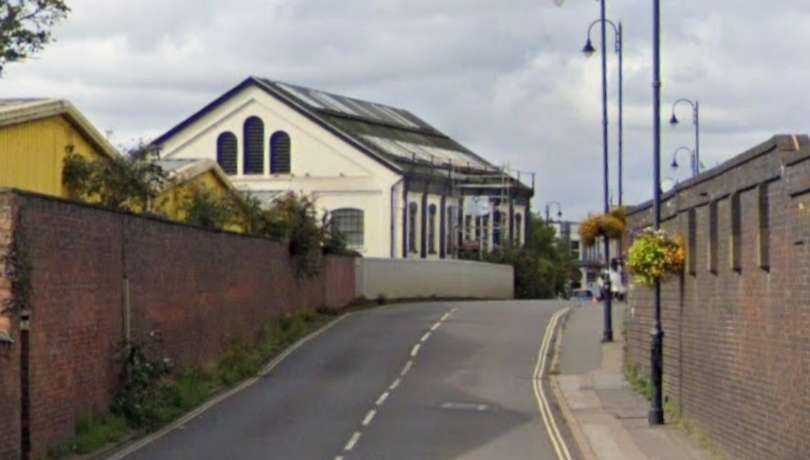
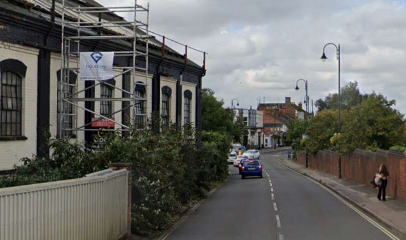
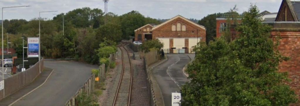
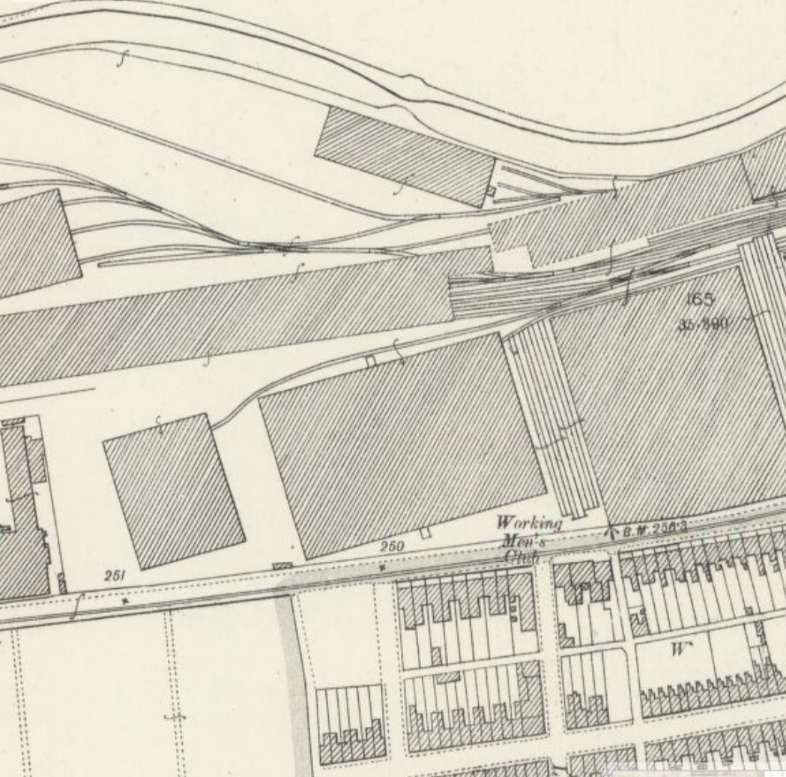
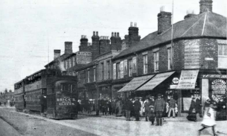
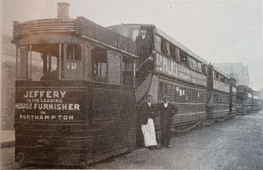
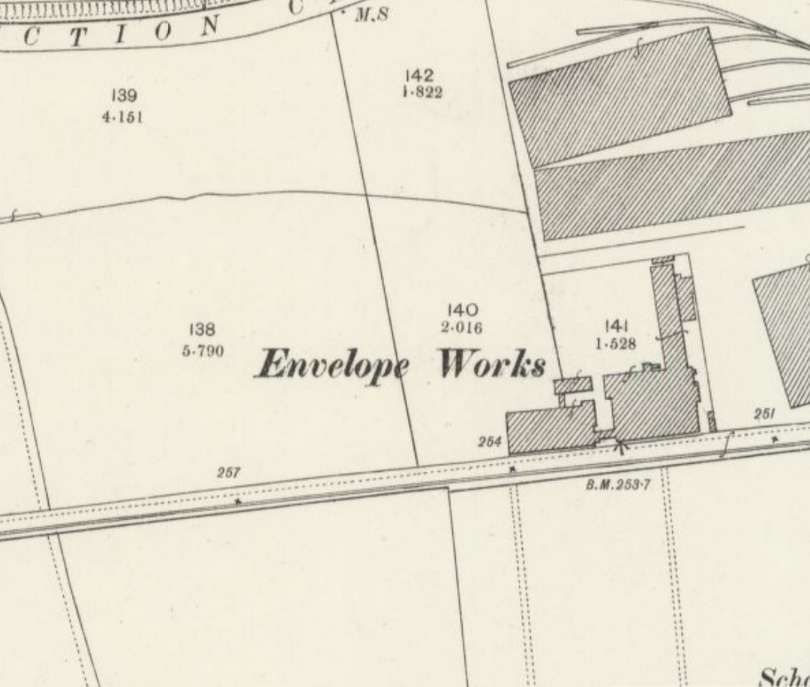
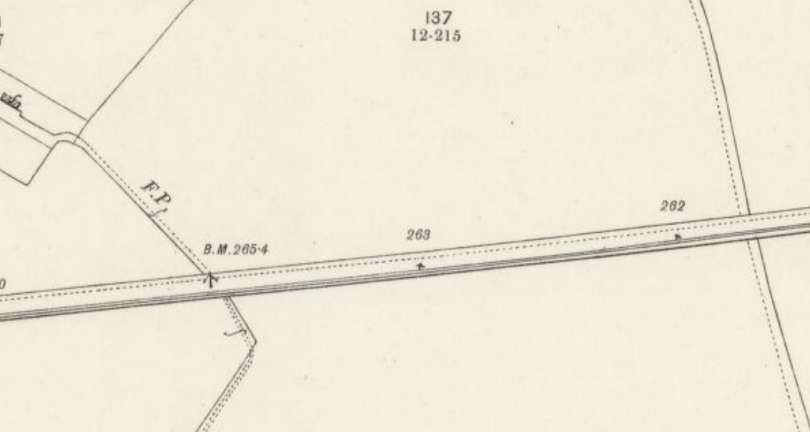
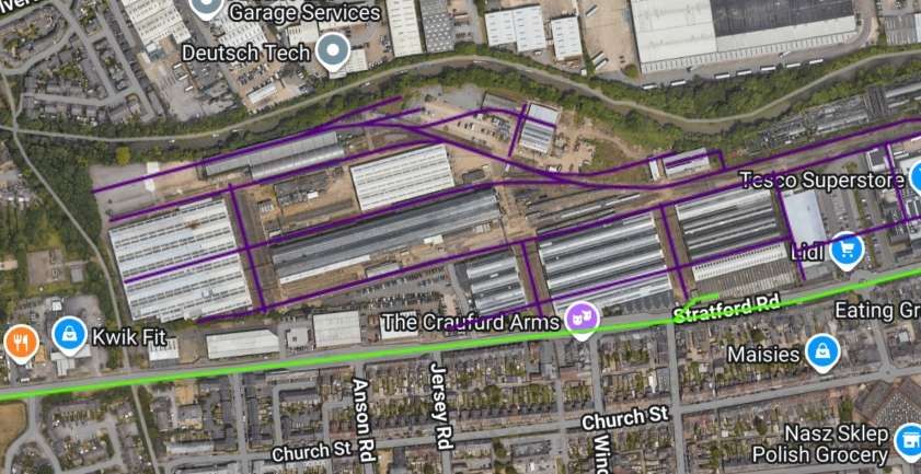
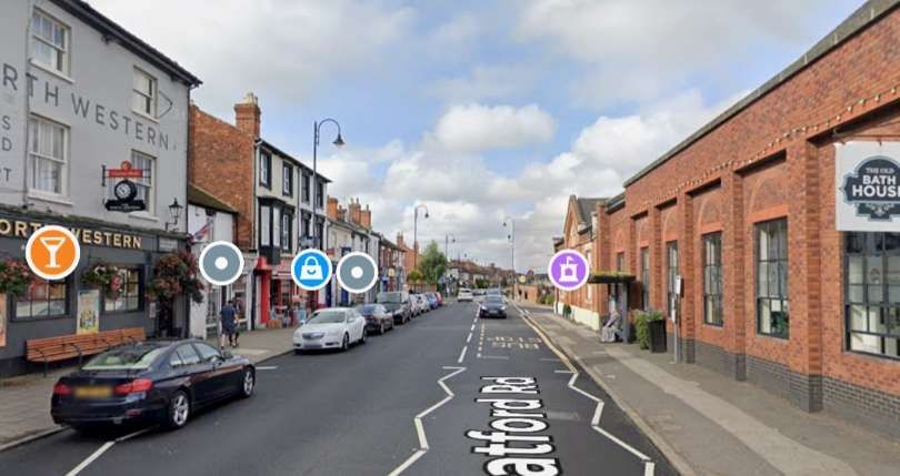
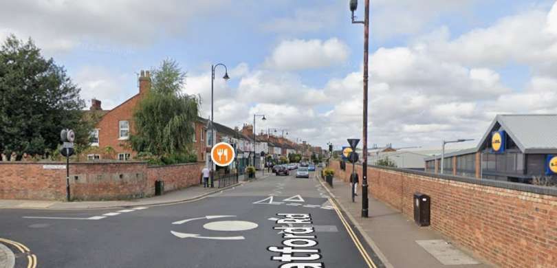
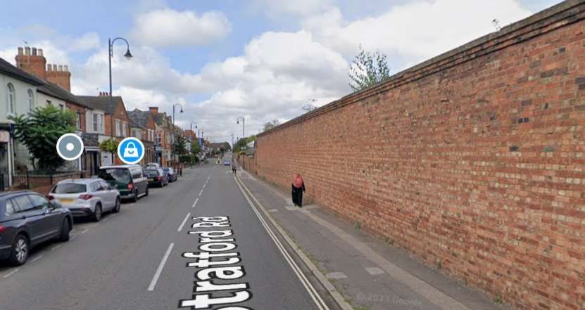
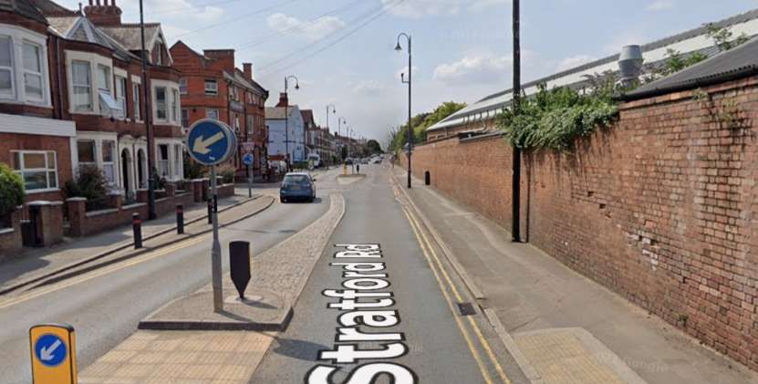
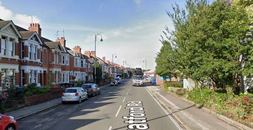
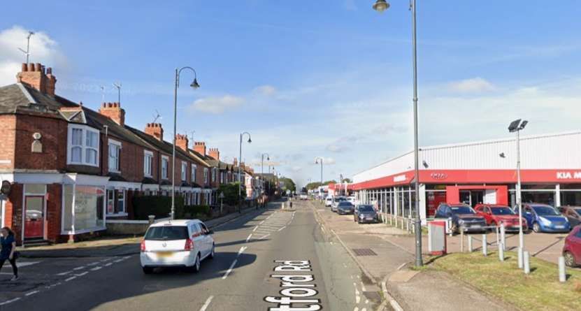
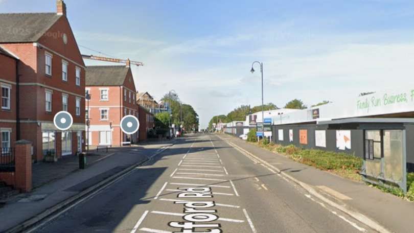
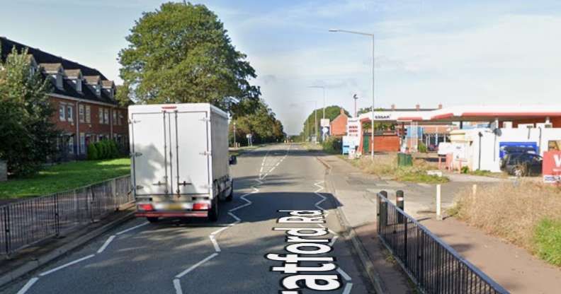
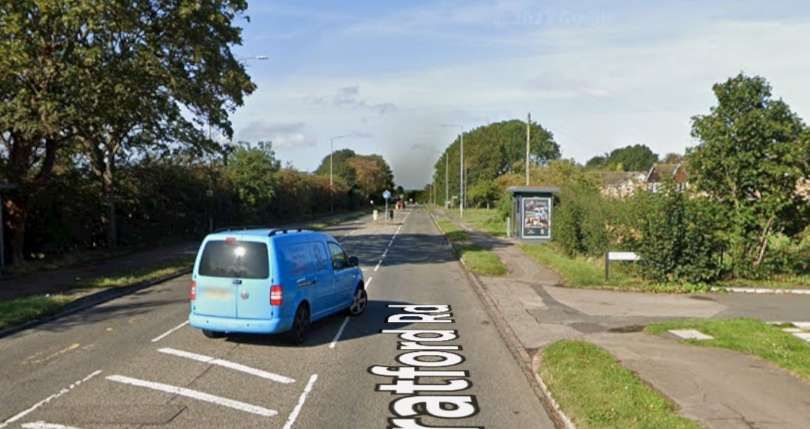
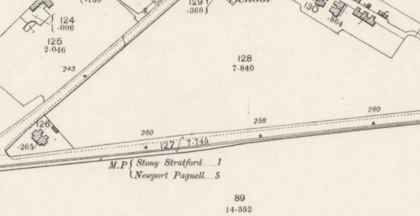
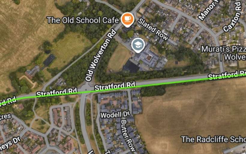
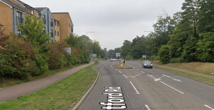
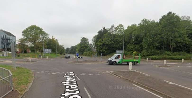
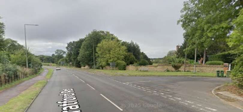
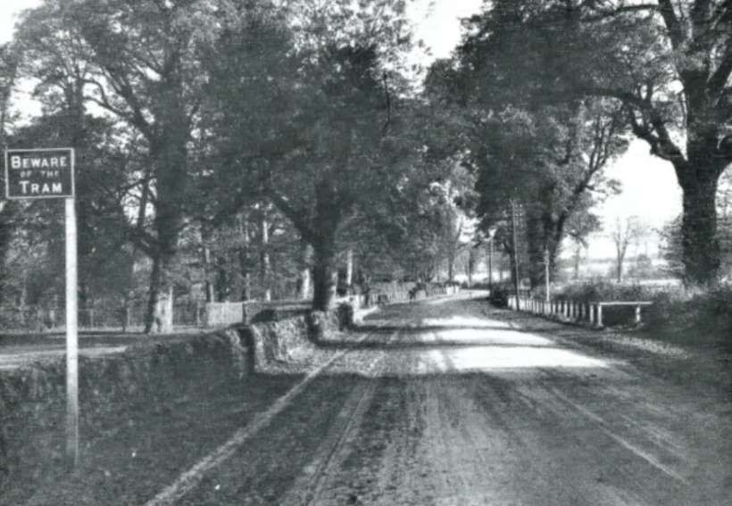
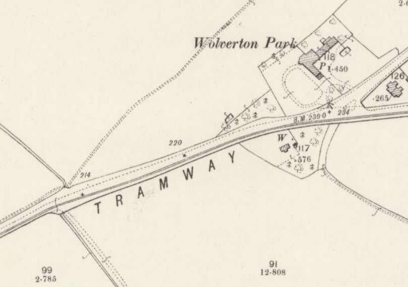
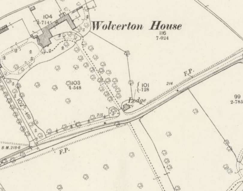
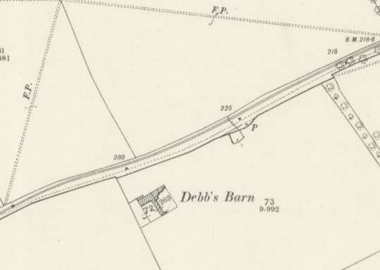
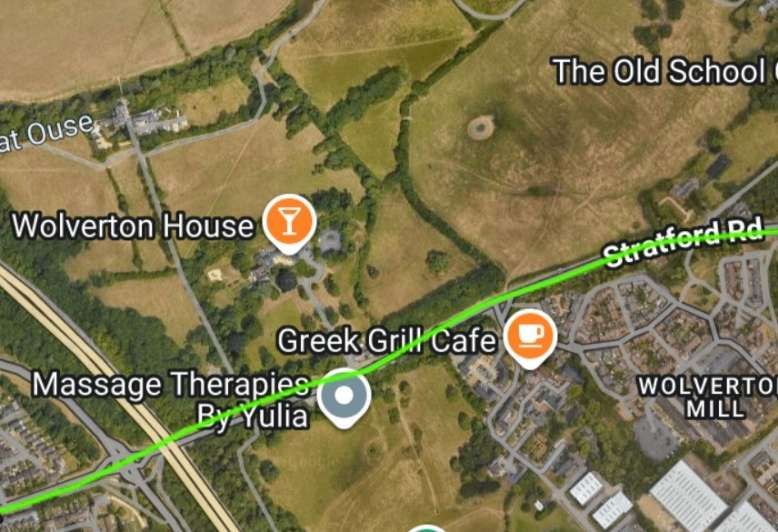
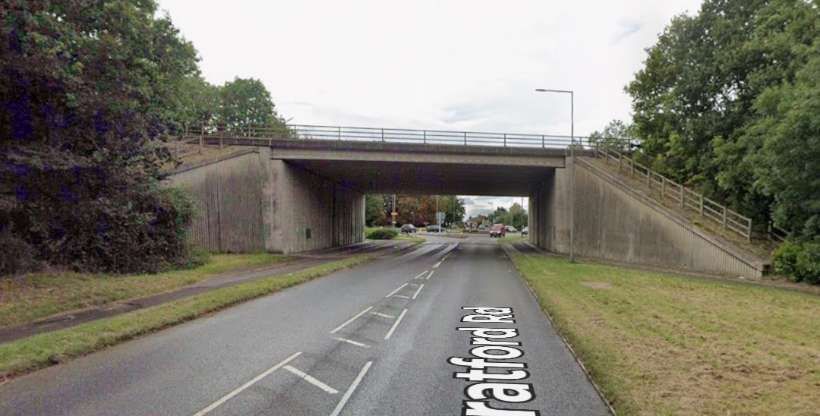
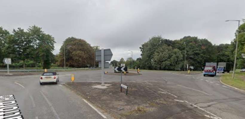
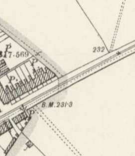

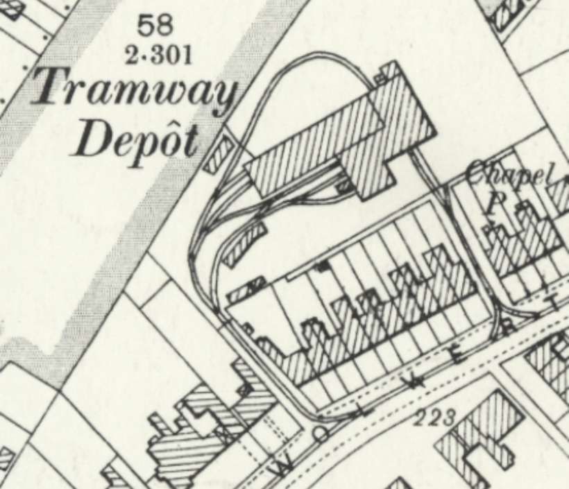
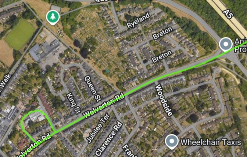

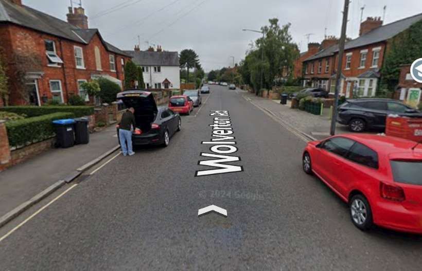
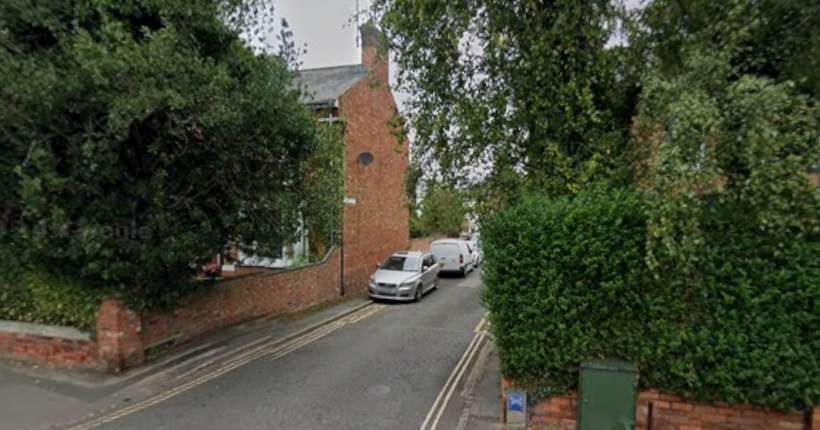
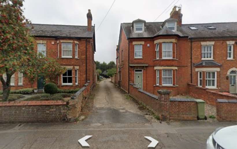
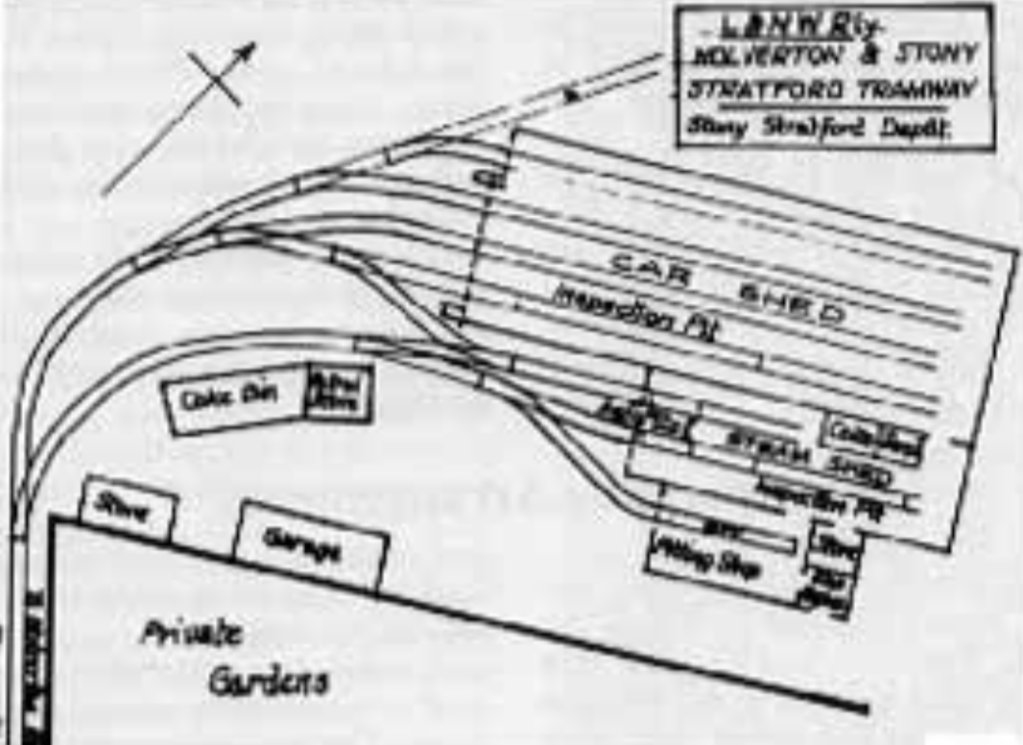
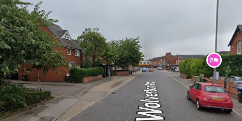
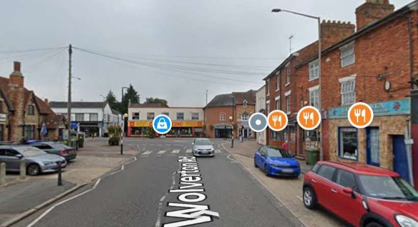
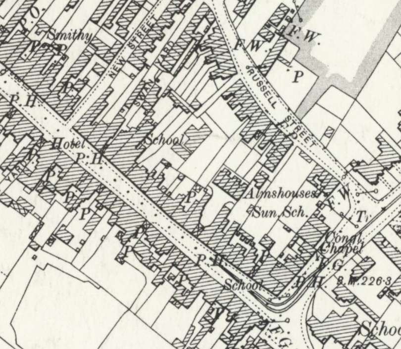
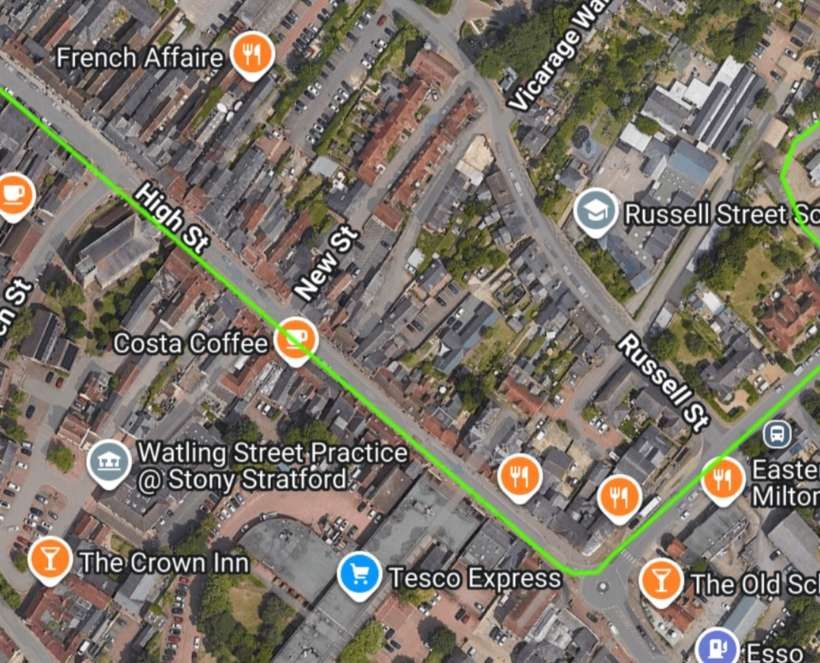
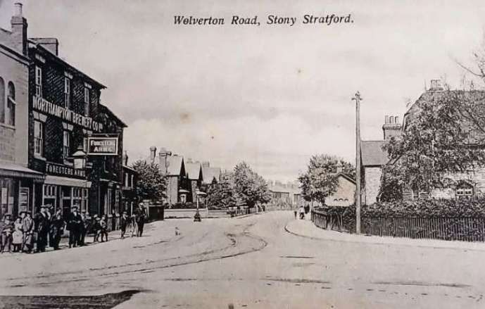
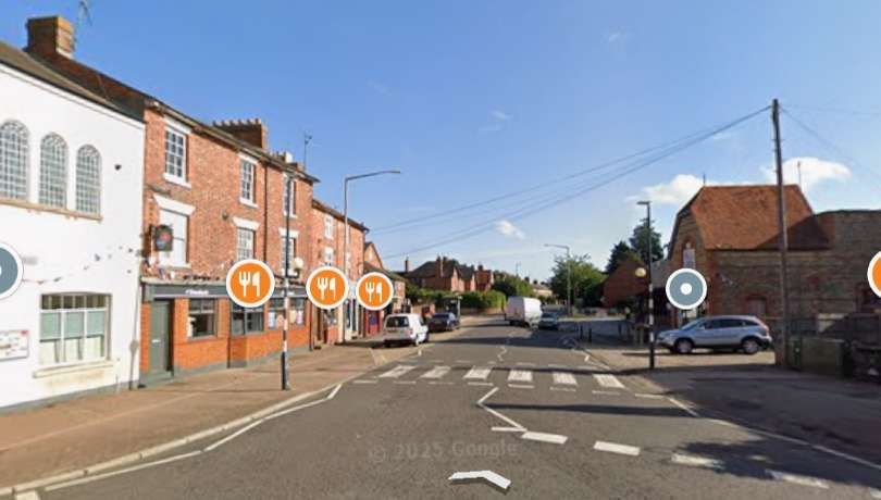
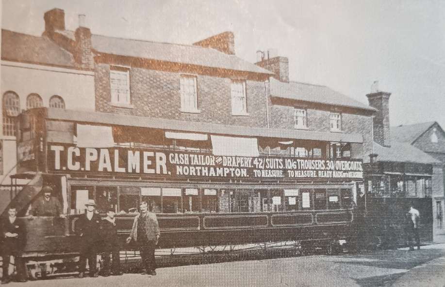
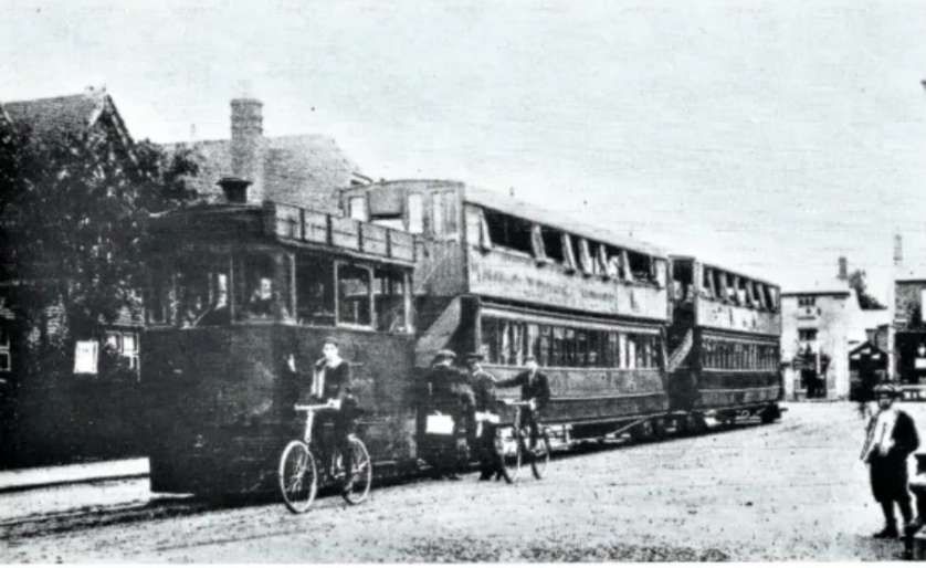
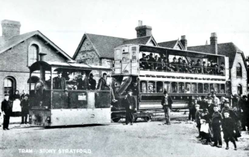
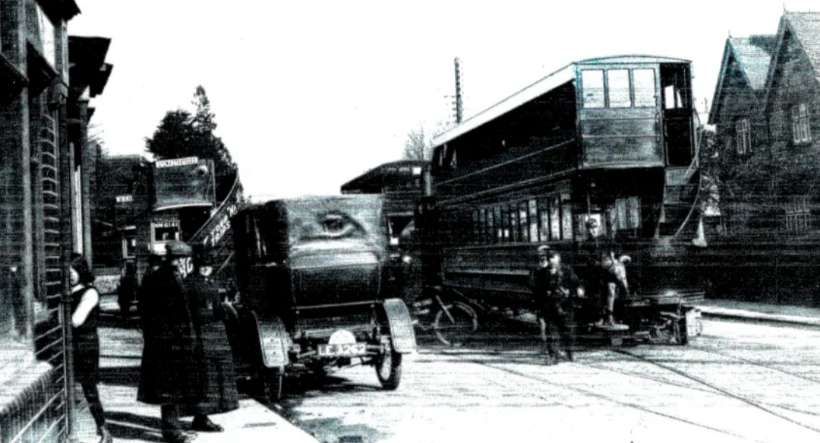
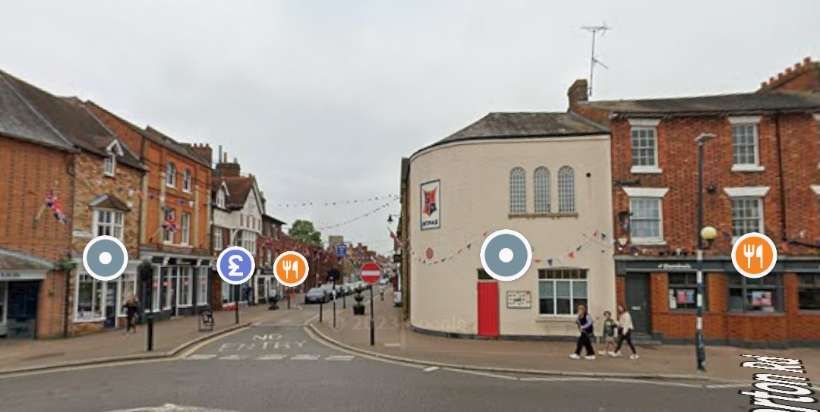
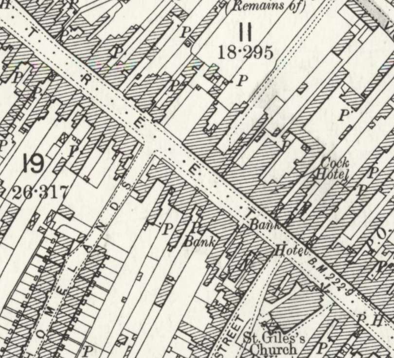
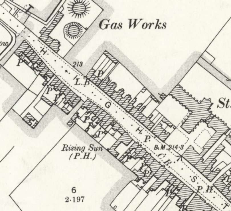
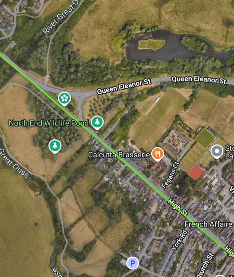
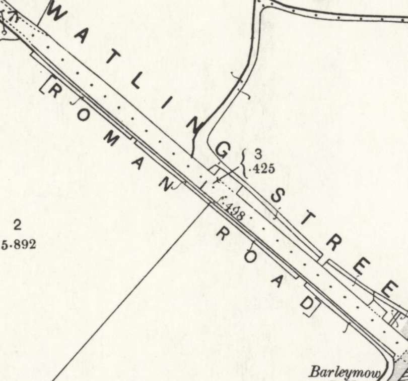
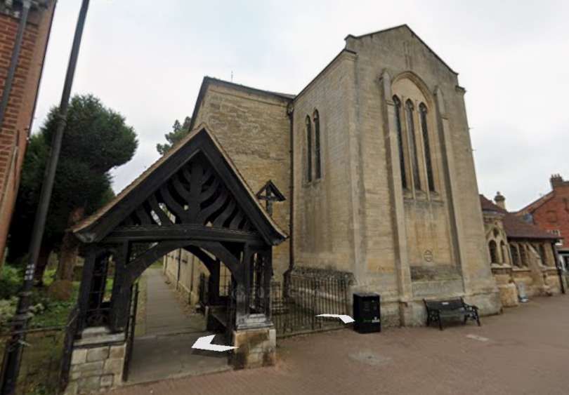
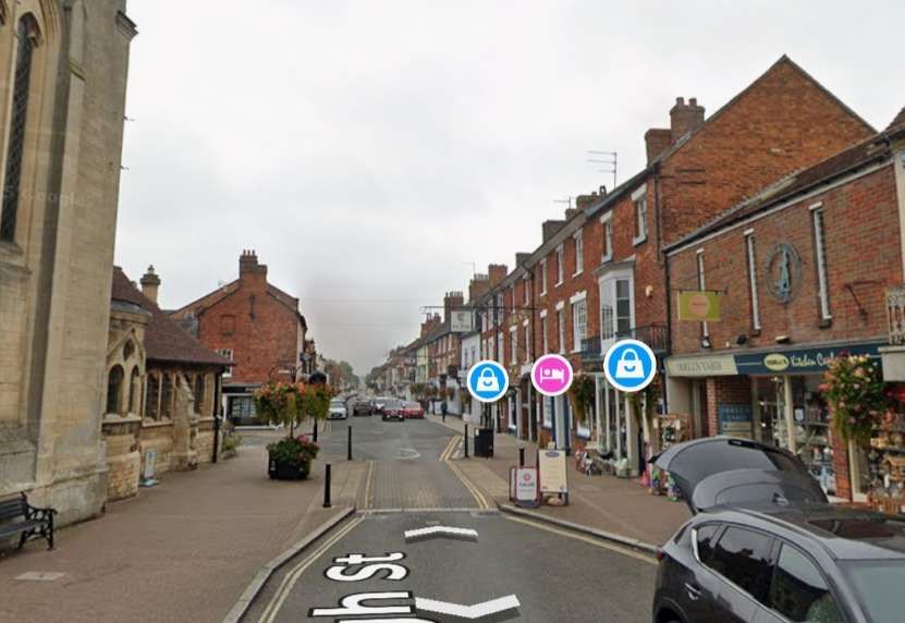
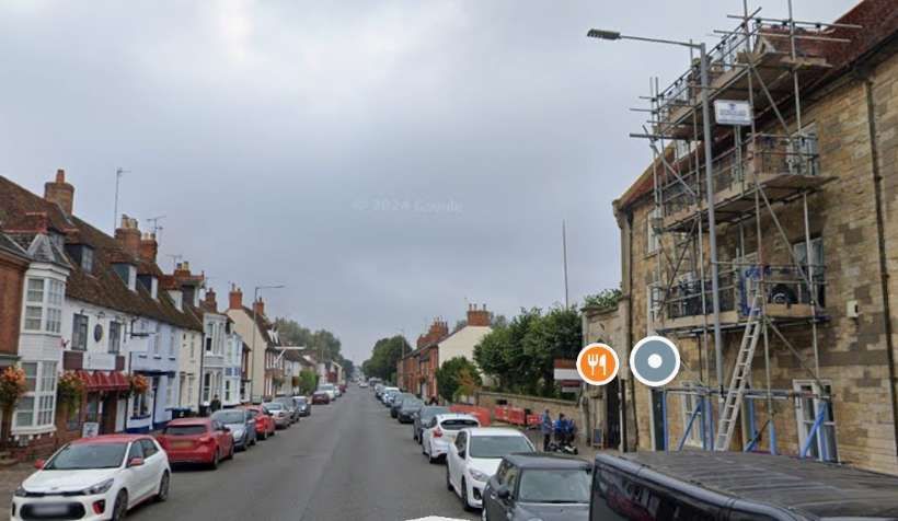

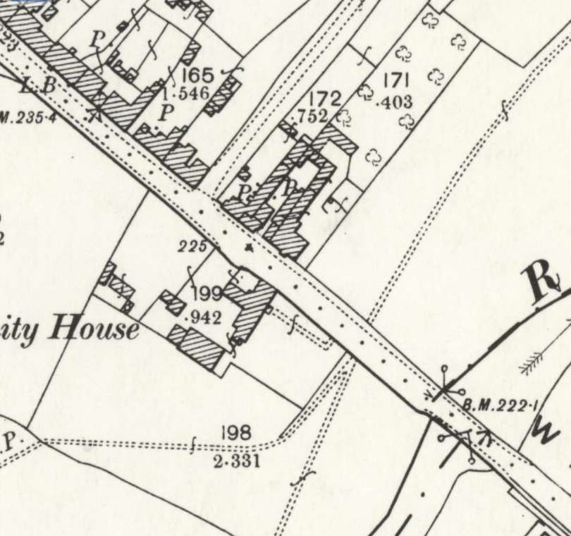
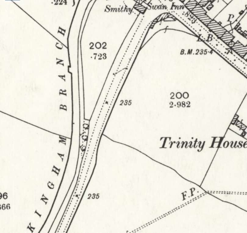
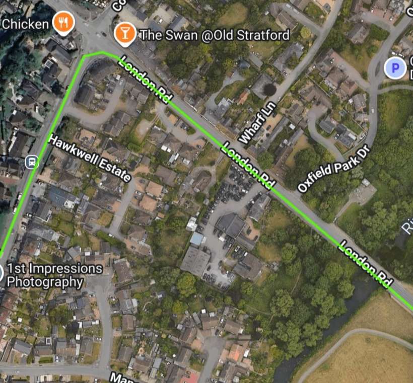
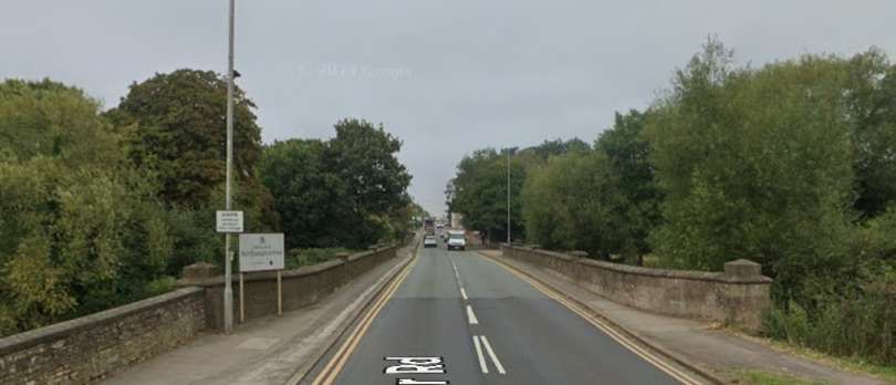
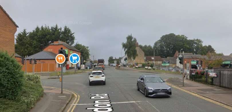
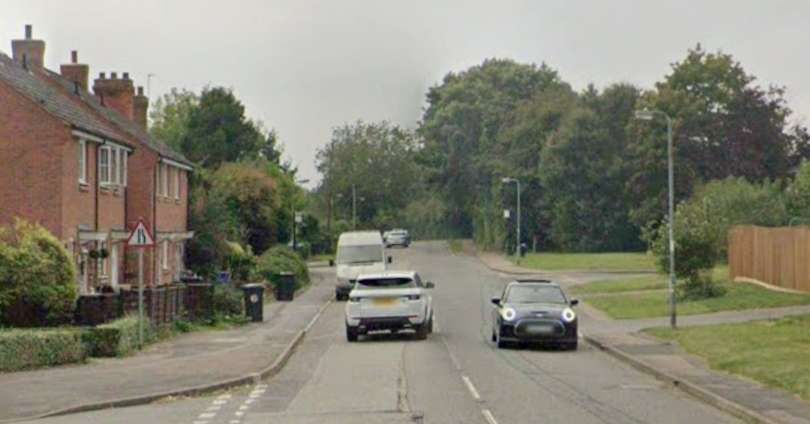
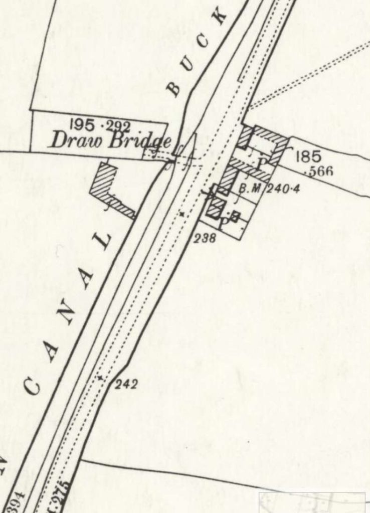
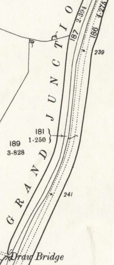
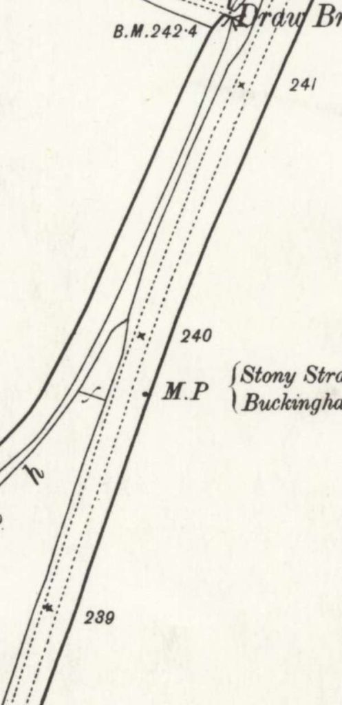
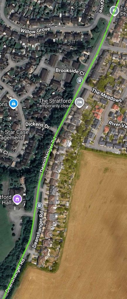
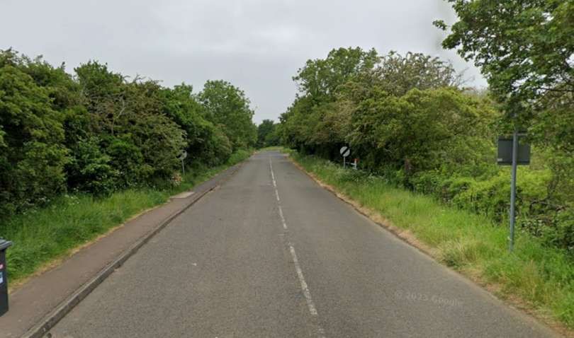
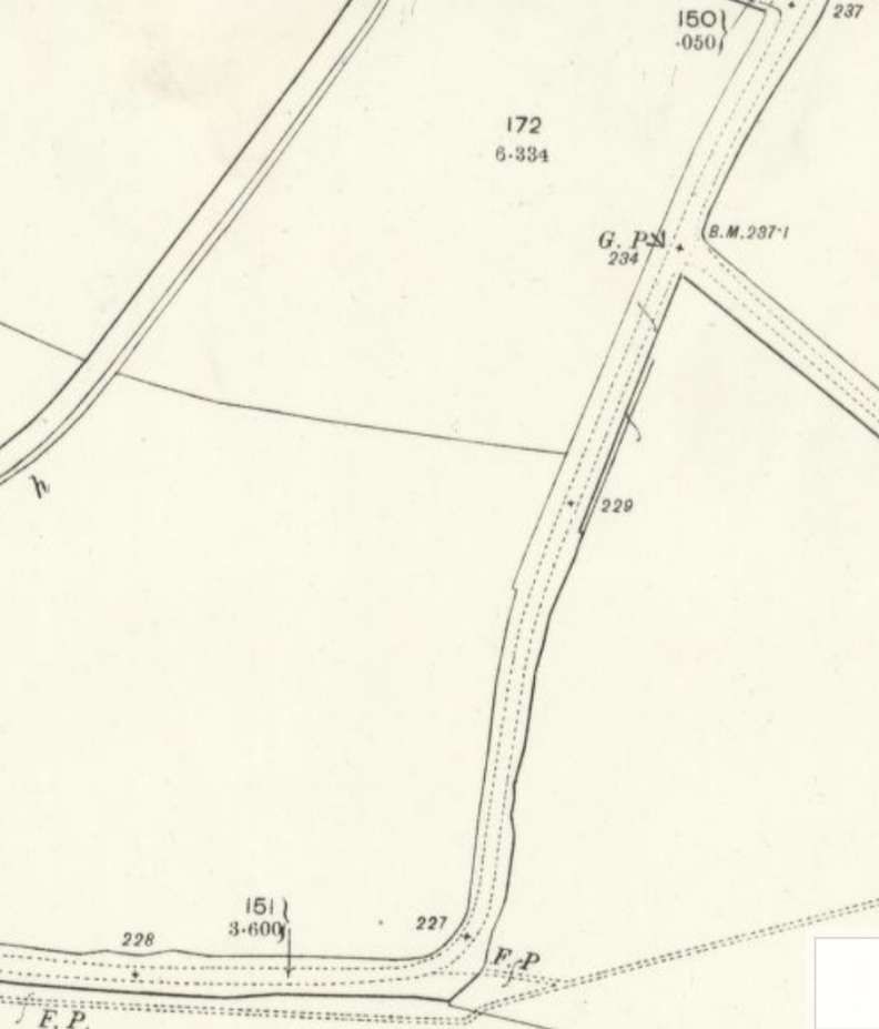
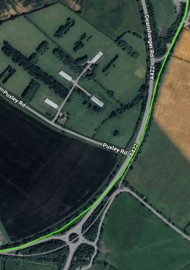
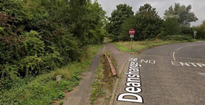

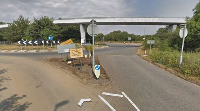
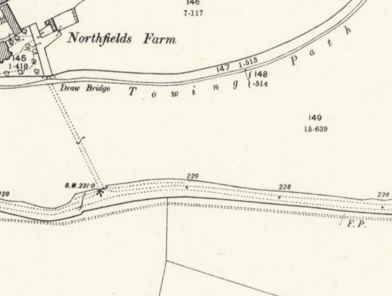
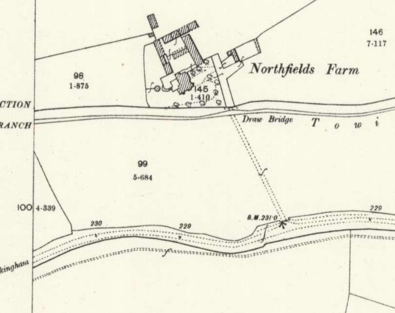
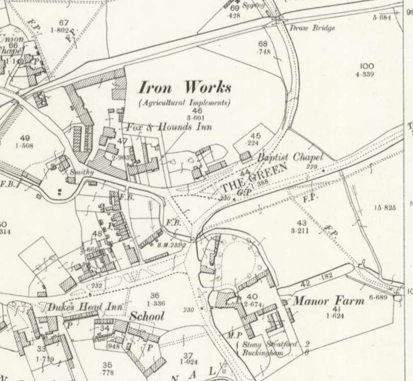
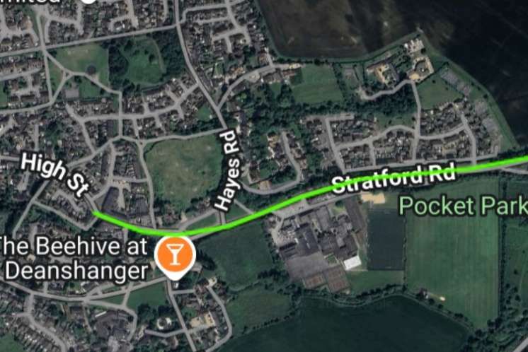
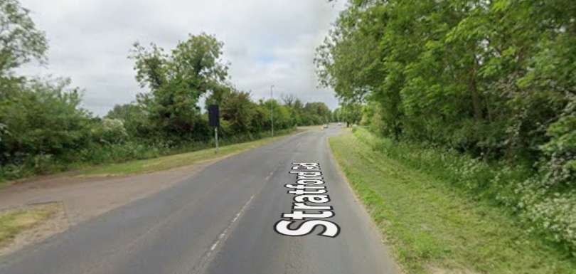
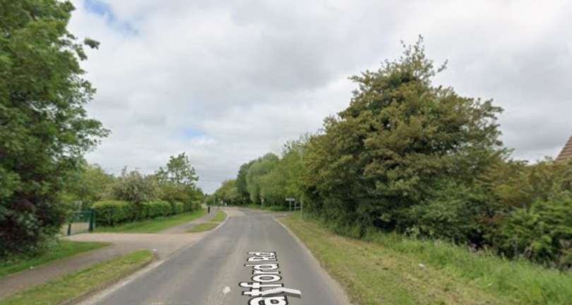
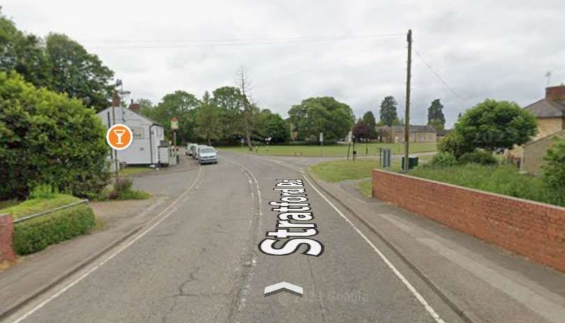
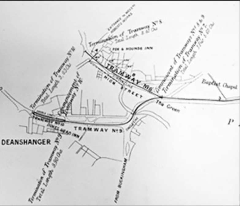
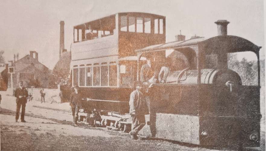
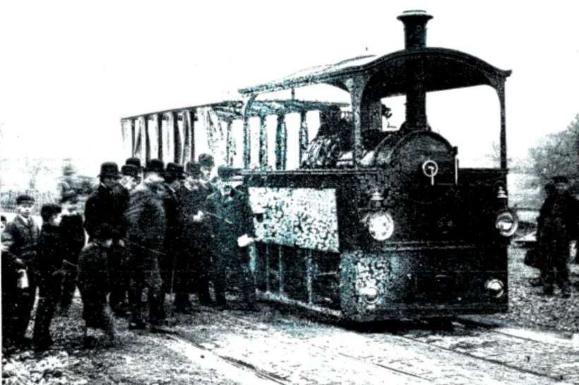
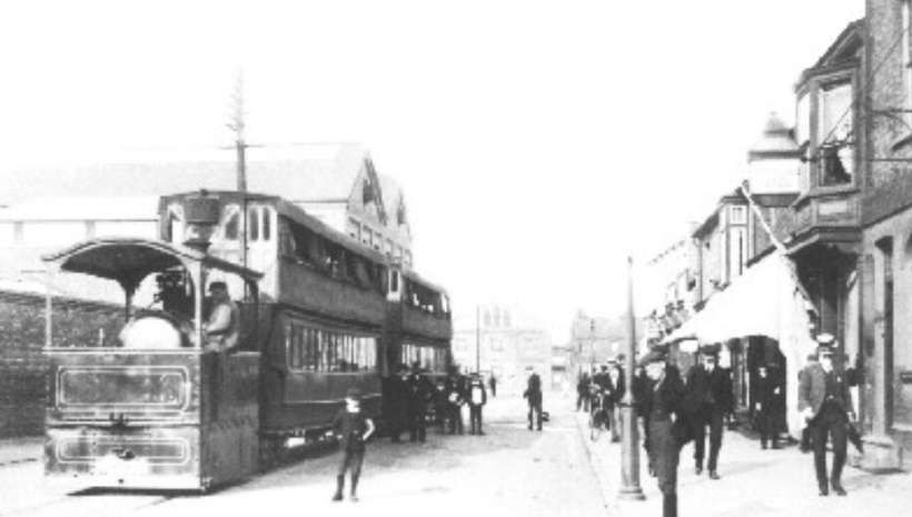
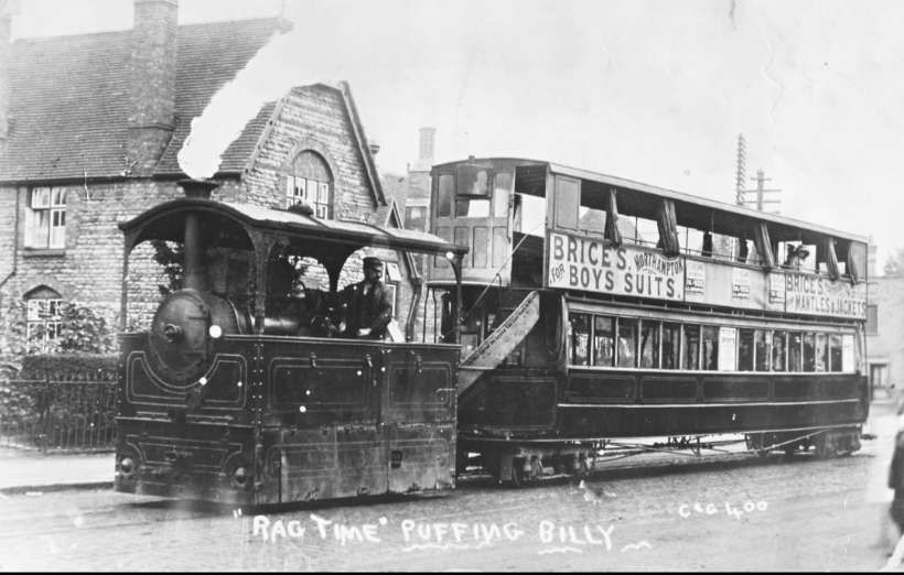
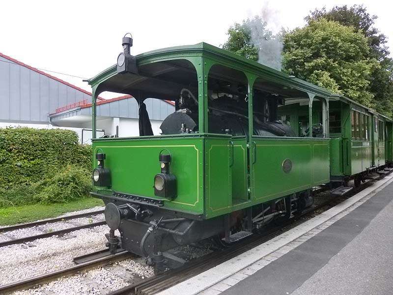
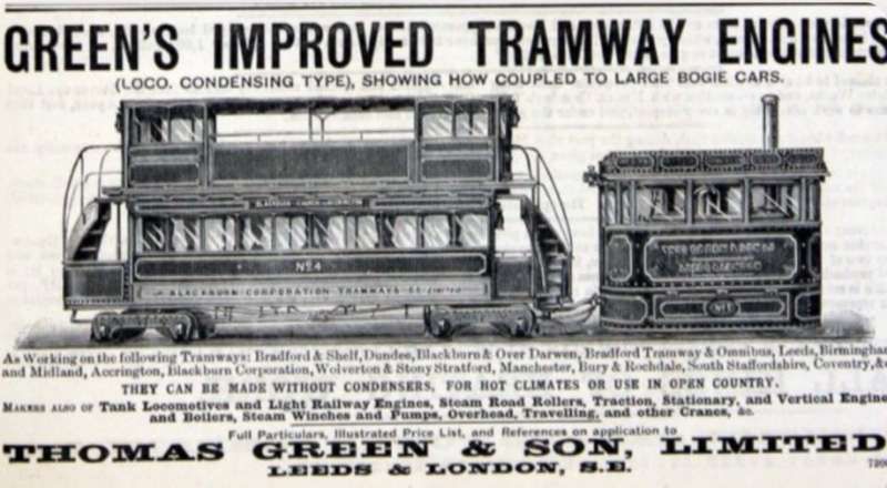
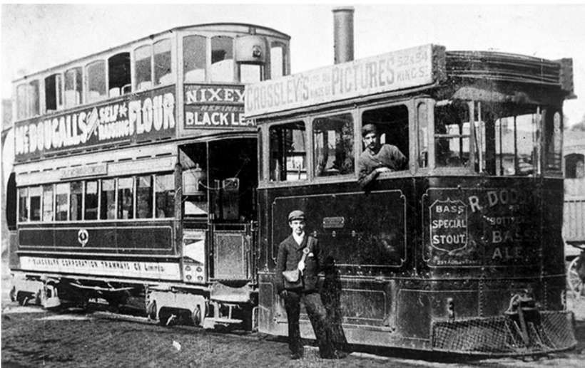
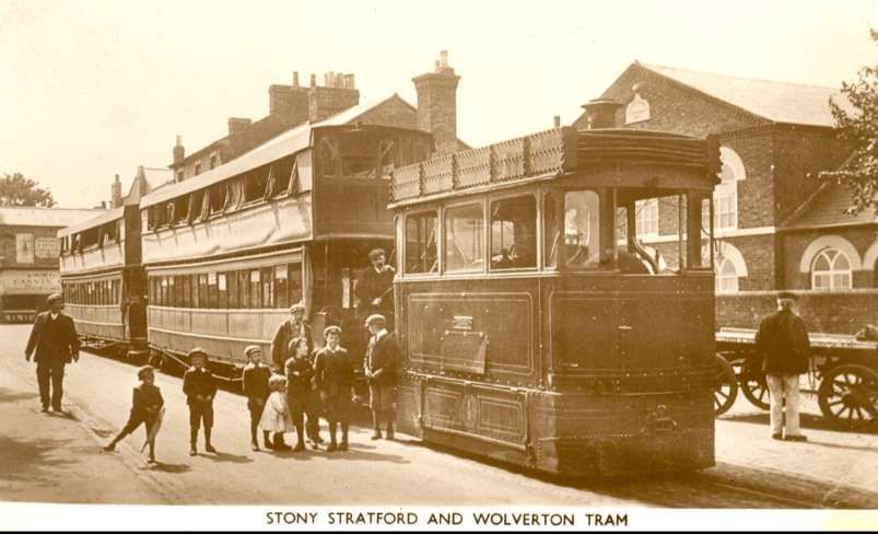
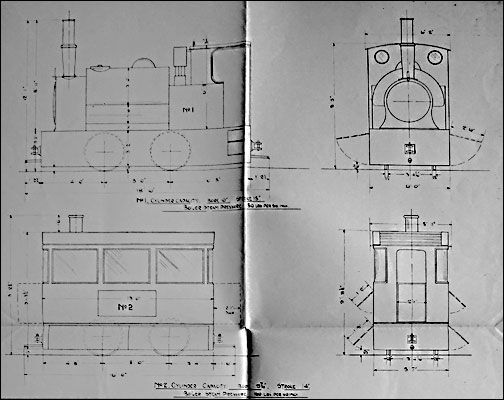
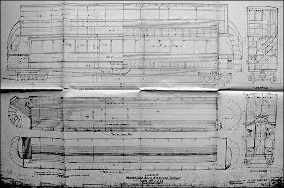
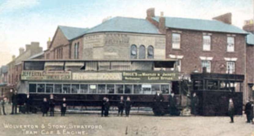
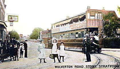
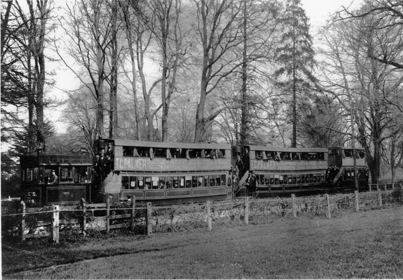
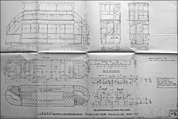

 Hans Christian Anderson tells a very familiar story whose main point is that ugly ducklings can become beautiful swans. We know that ugly caterpillars can become amazing butterflies, tadpoles do become frogs and toads. Things do change.

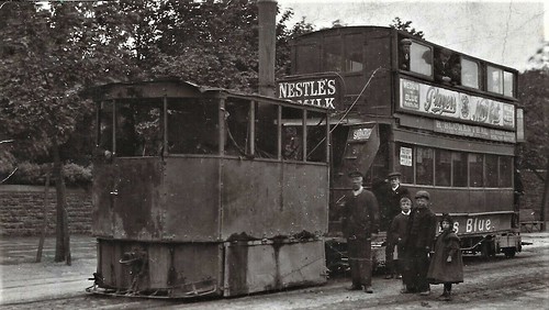
.jpg)