Following on from a couple of articles about the Tanat Valley Light Railway written some years back, I was reading some older rather tatty magazines and found an article entitled “Rails up the Tanat Valley” in an issue of the Ian Allan publication ‘Railway World‘ – the June 1990 edition. [1]
The Tanat Valley Railway and associated lines. [1: p365]
In his article, Colin Ganley recounted the rise and decline of the minor lines running west from Oswestry, the last remnant of which by 1990 had been ‘mothballed’.
Colin Ganley wrote: “In October 1988, the last train ran between Gobowen and Biodwell Quarry in Shropshire. For some years the line had carried only stone trains, bringing out ballast to the requirements of the Area Engineer. The trains, normally Class 31-hauled, traversed the remains of five different branch lines, which in their heyday provided Oswestry and the eastern end of the Tanat Valley with a fascinating and complicated array of lines to serve local industry. With the decision to cease using ballast from Blodwell, traffic on the line came to an end, marking the final cessation of all rail services connected with the delightful one-time Tanat Valley Light Railway.” [1: p364]
He continued: “For the present, this surviving section is in suspended animation. As there is a possibility that the stone traffic may restart in the future, the railway is being left in place. Traffic will resume if BR returns to this source of ballast. If not, eventually a decision will be made to lift the track and dispose of the land: unless the Cambrian Railways Society, based at Oswestry, is in a position to take an active interest in its future.” [1: p364]
Parts of the derelict line at Nant Mawr which were once the western end of the Old Potts Railway are now owned by ‘The Tanat Valley Light Railway’ which is a modern charity that aims to preserve and restore this line.
“The original Tanat Valley Light Railway was the first cross border light railway crossing from England into Wales, meandering up the fantastic Tanat Valley from Llynclys Junction to Llangynog and providing links to Llanymynech and Llanfyllin via its other branches.” [2] It was opened in 1904, mainly as a direct result of the 1896 Light Railways Act, but, says Ganley, “before taking up its story it would be useful to look at its associated lines and also earlier schemes to provide the picturesque village of Llangynog with railway transport. At the height of railway mania in 1845, the Shrewsbury, Oswestry and Chester Junction Railway obtained powers to build a line from Shrewsbury to Chester with a branch from Gobowen to Llanymynech. All that was built of the branch was the 2.25 miles from Gobowen to Oswestry, which opened on 23rd December 1848. In 1854 this line became part of the Great Western Railway.” [1: p364]
He continues: “The second portion of line to be constructed was the Oswestry & Newtown Railway, which was incorporated in 1855. to link these two towns. The section between Oswestry and Pool Quay opened on 1st May 1860 with the remainder to Newtown opening on 14th August. … The company, which was to be the foundation of the later Cambrian Railways, opened a 1.25-mile freight-only branch from Llynclys Junction, some 3.5 miles south of Oswestry, to Porthywaen. This branch served important quarries, some of which are still operating today, and became the railhead for the industries of the Upper Tanat Valley, Shortly after the Porthywaen branch was opened, a mineral line was built from it to serve some collieries at Trefonen. These collieries however were not very successful and this line was abandoned as early as 1881.” [1: p364]
“In the meantime there had been several proposals to build a line up the Tanat Valley. One such proposal envisaged a great trunk line from Worcester to Porth Dinllaen, near Nefyn on the Caenarvonshire coast, with the object of providing an alternative route for Irish Mail traffic. In 1860, a similar proposal was put forward as the West Midlands, Shrewsbury & Coast of Wales Railway which planned a railway from Shrewsbury to Portmadoc via Llanymynech, Llangynog and Bala. This route would have included a 1.5-mile tunnel under the Berwyn Mountains between Llangynog and Bala.” [1: p364]
“However, the project had trouble raising support and money. … Proposals for a similar route were resurrected in 1862 as the Shrewsbury & North Wales Railway. Powers were obtained by 1865 to build a line from Abbey Foregate, Shrewsbury, to Llanymynech but before this section was completed the company had merged with another scheme to provide a railway from Stoke-on-Trent to Shrewsbury. The combined efforts brought forth the grand title of the Potteries, Shrewsbury & North Wales Railway (or POTTS for short) and extended the original plans to include an extension from Llanymynech to Nantmawr over which passenger trains were to run as far as Llanyblodwell (later renamed Blodwell Junction). The financial troubles of the POTTS and its rebirth as the renowned Shropshire & Montgomeryshire Light Railway [3] are outside the scope of this article, but the result was the working of the Llanymynech to Nant Mawr section by the Cambrian Railways from 1881. At this time goods traffic only was operated, the passenger service between and Llanymynech and Lianyblodwell having ceased in 1880.” [1: p364-365]
“The Light Railways Act of 1896 made possible the construction of railways to remote agricultural areas that hitherto had had difficulties in raising capital and several places along the Welsh border benefited from such schemes, one being the Tanat Valley. The Act saw the birth of two schemes to provide, at last, rail transport to the Upper Tanat Valley and the industries of Llangynog. The unsuccessful proposal was for a 2ft 6in gauge railway from the Llanfyllin terminus of the Cambrian branch from Llanymynech.” [1: p365]
“This plan, the Llanfyllin & Llangynog Light Railway, was to cross sparsely populated country between Llanfyllin and Penybontfawr and would not have benefited the lower part of the Tanat Valley. It nevertheless could have been a fascinating line had it been constructed, though the change of gauge at Llanfyllin would have proved a disadvantage.” [1: p365]
“The scheme that was selected by the Light Railway Commissioners was for a standard gauge line from the Cambrian’s Porthywaen mineral branch straight up the valley Liangynog. The plan also envisaged using a short section of the Nantmawr branch. The Tanat Valley Light Railway received its Light Railway Order in 1898 and was constructed by J. Strachan of Cardiff who employed about 125 men on the work. The total cost of the line proved to be about £92,000 which was around £20,000 more than the company had hoped for. This shortfall, not helped by a delay in construction, meant that the Tanat Valley Co was impoverished from the outset and had to approach the Treasury for more grant aid. During construction in 1903 some directors found that the contractor was giving a ‘free’ train service over the partially finished railway but as the contractor was allowed to finish the job it can be assumed that any quarrel was rectified.” [1: p365] For the earlier articles about this line, please follow these two links:
Colin Ganley continues: the Tanat Valley Light Railway “opened on 5th January 1904 to both passengers and freight and was worked by the Cambrian from the start. It became wholly part of the Cambrian in 1921, passing to the Great Western Railway and then to the Western Region of British Rail. The length of the linc from Llynclys Junction to Llangynog was some 15 miles 71 chains and included 11 stations or halts, one of which was former POTTS station of Llanyblodwell which was renamed Blodwell Junction. The stations were of typical light railway pattern with rather mean corrugated iron clad buildings and, except for Liangedwyn and Llanrhaiadr Mochnant, had only one platform. Original plans for some stations did consider refreshment rooms in effort to build up tourism but the company’s lack of capital put an end to such plans.” [1: p365-366]
“With the opening of the Tanat Valley line, passenger services were restored between Llanymynech and Blodwel Junction as this had been a condition of securing support from potential opponents during the planning stages. The opening of the Tanat Valley line also restimulated the slate quarries at Llangynog which had all but closed by 1900. Slate quarrying continued intermittently until 1939 but lead mining, which had effectively ceased in 1877, was never to resume on any commercial scale. The railway also assured the development of granite quarrying at Llangynog, the Berwyn Granite Co. providing much traffic until World War 2. The quarry survived into the mid 1950s but at the end offered virtually no traffic to the railway.” [1: p366] Berwyn Granite Quarries Ltd. remains an active company with headquarters in Wellington, Shropshire. [4]
Colin Ganley continues: “Initially the passenger service consisted of four trains each weekday with an extra trip on Wednesdays. Many trains were mixed and the journey to Oswestry took no less than 75min on some trains. Two trains a day carried a through coach to Llanymynech, detached at Blodwell Junction, but this practice ceased in 1915 and was replaced by a connecting service. The Blodwell Junction to Llanymynech service ceased completely as from 1st January 1917, having been hardly ever used and only operated to fulfil an agreement. Freight traffic over this section ceased in 1925, the Nantmawr traffic then being worked via Porthywaen, and most of it was lifted between 1936 and 1938.” [1: p366]
By 1923, “the number of passengers being carried was half the level of 1913 and continued to decline during the GWR years. By 1925 services, which normally consisted of two four-wheeled carriages, were reduced to three trains each way, though certain extras ran on Wednesdays and Saturdays. In 1929, the GWR introduced a rival bus service which was taken over by Crosville in 1933. The bus served the centres of villages far better than the train as certain stations. Llanrhajadr Mochnant in particular, were badly situated. This, coupled with the elongated journey times caused by the adherence to light railway practices, reduced traffic even further.” [1: p366-367]
“During World War 2 the passenger service was reduced to two trains each way, by now composed of a single Cambrian brake third. After the war, despite petrol rationing, few people were making the delightful trip up the Tanat Valley by rail. Goods traffic was also on the wane and on 15th January 1951 passenger services ceased because of a grave coal shortage, never to return. Official closure took place on 1st July 1952 and at the same time freight traffic was also withdrawn between Llanrhaiadr Mochnant and Llangynog. The track on this section remained in situ for several years, not being lifted until 1958. Freight traffic to Llanrhaiadr Mochnant ceased abruptly on 5th December 1960 after the river bridge near Pentrefelin was badly damaged by flooding,” [1: p367]
“Services on neighbouring lines were savaged in the mid-1960s. All passenger traffic between Welshpool and Whitchurch and also over the Llanfyllin branch were withdrawn on 18th January 1965, leaving Oswestry with the Gobowen diesel shuttle service, which ceased in November the following year. By 1967, just the single track South of Oswestry to Porthywaen and Nantmawr was left, along with the line from Gobowen. Reduction in traffic over the ensuing years left just the Blodwell Quarry service. All the sidings at Oswestry and Porthywaen disappeared. The section west of Blodwell Junction had been lifted by 1965 and though the Nantmawr branch has not seen a train for 20 years the track is still in-situ, although with sturdy trees growing between the sleepers.” [1: p367]
“No account of the Tanat Valley would be complete without a brief mention of its quaint motive power. From the outset, the Cambrian normally provided three Sharp Stewart 2-4-0Ts, Nos 57, 58 & 59 of 1866 vintage. They became GWR Nos. 1192, 1196 and 1197 respectively, and although No 1192 was withdrawn in 1929 after being sent to Devon, Nos 1196 & 1197, both in a rebuilt state, survived at Oswestry until 1948.” [1: p367]
Sharp, Stewart and Co. “was a steam locomotive manufacturer, originally based in Manchester, England. The company was established in 1843 following the dissolution of Sharp, Roberts & Co.. In 1888, it relocated to Glasgow, Scotland, where it later amalgamated with two other Glasgow-based locomotive manufacturers to form the North British Locomotive Company.” [5]
Ganley tells us that the two surviving Sharp Stewart locomotives were “assisted by No. 1308 Lady Margaret, an Andrew Barclay 2-4-0T built in 1902 for the Liskeard and Looe Railway and taken over by the GWR in 1909. This locomotive also did yeoman service in the Tanat Valley until it too was withdrawn in 1948.” [1: p367]
“Other locomotives were seen up the Tanat Valley at various times, including old Cambrian Sharp Stewart 0-6-0s dating from 1875 and the odd Dean Goods. In the latter years passenger traffic was the preserve of ‘5800’ class 0-4-2 tanks, numbers 5808 & 5812 being particular regulars. Goods traffic that remained was normally entrusted by the early 1950s to the Ivatt Class 2 2-6-0s.” [1: p367]
“Various types of diesels handled the surviving quarry services, including Classes 25, 31 and 37. A Class 31 had the privilege to be the last railway locomotive to operate a commercial train (so far) in this region of complex and fascinating railway history. It remains to be seen whether the Cambrian Railways Society will be able to continue the railway traditions of the area if they can successfully launch a private steam service from their Oswestry base.” [1: p367]
Ganley was writing in 1990, things have moved on over the past 36 years. Cambrian Heritage Railways, in the 2020s, operate a service on selected days from their Oswestry Station to Weston Wharf, featuring steam, vintage diesel and diesel multiple units. The 1.75-mile scenic route leads to Weston Wharf with its period station with a café, picnic area, and railway artifact displays. Cambrian Heritage Railways also operate the ‘Llynclys Railway Centre’ which is open on select dates – at Llynlcys South Station. [6][7]
References
Colin Ganley; Rails up the Tanat Valley; in Railway World; Ian Allan, June 1990, p364-367.
This short line originated from a proposal made by the stationmaster at Wendover. [1: p97]
The featured image for this short article is a photograph of a OO-Gauge model of Wendover Railway Station built by David Dan Givens and covered in the September 2018 edition of Hornby Magazine. The image shows the Northwest approach to Wendover Station. The branch line to RAF Halton leaves the main line just off camera to the left. [17]
The Halton Light Railway grew out of proposals made by the stationmaster at Wendover Station (bottom-left on this map extract). The line was less than 2 miles in length. It had a short 2ft-gauge extension across the Icknield Way into the beech woods on the slopes of the Chilterns. [1: p97]A very similar area, on modern satellite imagery. [Google Maps, March 2026]
Wendover Railway Station serves the town of Wendover in Buckinghamshire, England, and villages including Ellesborough and Wendover Dean. It was opened by the Metropolitan Railway in 1892 and is on the London Marylebone to Aylesbury line and, in the 21st century, is served by Chiltern Railways trains. It sits between Great Missenden and Stoke Mandeville stations. [4]
A narrow gauge railway link to Wendover station, which had been used to transport timber from beech woods on the Halton Estate in support of the [First World] war effort, was replaced in 1917 with a standard gauge branch line, to bring in coal and building materials to the RFC workshops. Timber from Halton Woods was used as trench props on the Western Front. [7]
Opened in 1917 after an eight-week construction period, the line ran for 1.75 miles (2.82 km) and was constructed by German prisoners of war during World War I. The railway was originally built, earlier in WW1 to carry timber from local beech woods to Wendover Station and building materials into the site of RAF Halton for construction of the workshops and other units. It also forwarded coal to the boilers on the camp. [7]
Wikipedia says that the line was originally built as a narrow gauge line and “was later converted from a narrow gauge of 1 ft 11 1⁄2 in (597 mm) to 4 ft 8 1⁄2 in (1,435 mm) standard gauge and was used to bring timber out of Halton woods.” [2]
The Railway has a Monument Record and appears on Buckinghamshire County Council’s Heritage Portal. It is Monument Record No. 0951006000. [7]
The Historic Monument Record says that the Railway is shown on historic mapping NG 6″ Provisional Edition 1955-62 and NG 10k Edition 1972-90. Labelled as ‘dismantled railway’ on 25k digital raster map. It appears to be disused even by 1955-62 edition. [7]
A railway dating from the 20th century is visible on historic aerial photographs and remote sensing data as extant structures, earthworks and levelled earthworks and was mapped as part of the Aylesbury Vale Aerial Investigation and Mapping project (EBC18604). Located on the north side of the town of Wendover and centred at SP 86991 08905. The railway line, originally built as a narrow-gauge line, was constructed to extract timber from the woods at Halton, felled by Canadian lumberjacks, for use in the trenches in World War I. [8: p81] Aerial photographs from 1961 appear to show the railway still present but it does not show on those from 1967. Images of the railway and the station at West Camp are on the ukairfields website for Halton. [7]
The conversion of boilers on the RAF station from coal fired to oil fired, allowed road-tankers to take over the inward flow of fuel and accelerated the demise of the railway and the last train ran on 29th March 1963 with closure following two days afterwards.[7]
The majority of the track has since been removed, including the original bridge over the Grand Union Canal which was replaced by a modern footbridge, however much of the line is designated a permissive footpath (rail trail).
A video covering this line can be found here. [5] This is one of a series of videos under the overall title of “Henry’s Adventures.”
The Route of the Line
Leaving Wendover heading Northwest, trains serving the Halton RAF Station ran alongside the main line before turning away to the Northeast.
The line crossed Aylesbury road at a level -crossing. …
Looking Northwest along Aylesbury Road, the crossing sat adjacent to Castle Park. This image was shared by Rod Bacon on the Wendover Memories Facebook Group on 28th March 2025. [18]The crossing gates on the Southeast side of Aylesbury Road. This image was shared by Rod Bacon on the Wendover Memories Facebook Group on 4th April 2025. [19]The line of the Light Railway is marked in this and later satellite images by a brown line superimposed on the image by RailMapOnline.com. [14]Looking Southwest from Aylesbury Road. The hedge immediately in from of the camera masks the line of the old railway. [Google Streetview, September 2025]Looking Northeast from Aylesbury Road, the track ahead of the camera and the hedge line to its left are on the line of the old railway. [Google Streetview, September 2025]
Further East the line crossed the Wendover Arm of the Grand Union Canal. …
The location of the railway bridge over the Wendover Arm of the Grand Union Canal. The rail line followed the field boundaries, running from the bottom-left corner of this image to the top-right. [Google Maps, March 2026]
Beyond the Canal, the line turned Northeast before reaching RAF Halton where a station building and platform received and despatched trains. A fan of sidings sat to the right of the line.
A short length of 2ft-gauge line remained in use until it was closed in 1941. It sat to the Northeast of the sidings and crossed Icknield Way before coming to its terminus.
RailMapOnlne.com records the railway lines in the immediate vicinity of RAF Halton in brown and orange, as shown here. The standard-gauge line (brown) is much as shown on the first plan/map above. The 2ft-gauge line is different to that shown on the map/plan near the head of this article. If we make the assumption that there would be a need to tranship timber from the 2ft line to the standard-gauge line, then the layout shown here is the more likely. The two maps have the crossing point over the Icknield Way (B4009) at approximately the same location. [14]The crossing over the Icknield Way was at the approximate location shown by the orange line superimposed on the satellite imagery from RailMapOnline.com. [14]Looking West from Icknield Way along the line of the old 2ft-gauge line. [Google Streetview, March 2025]Looking East from Icknield Way along the line of the old 2ft-gauge line. [Google Streetview, March 2025]
Locomotives
I have not been able to establish a locomotive roster for the RAF lines at Halton. One locomotive in particular was identified by Frank Jones in the 1960s. ….
Manning Wardle 0−4−0 saddle tank R.A.F. No.2 was photographed by Frank Jones, presumably after the closure of the branch line and after she had been through the hands of John F. Wake’s Geneva Engineering Works in Darlington. Frank Jones submitted a photograph of No. 2 to the Industrial Railway Record in October 1968. It can be seen here. [6]
Modelling
Hornby Magazine covered an OO-Gauge Model of Wendover Railway Station which included the first few metres of the branch line. The layout featured in the September 2018 edition of the magazine. [17]
The RAF Halton Branch is represented by the line at the centre of this image which has a very short train heading away along the branch. [17]
This image shows the branch locomotive which was a Manning Wardle 0-4-0ST heading for RAF Halton. [17]
Wendover’s Goods Shed and Signal Box (shown here) sat immediately Southeast of the junction. [17]
References
Clive Foxell; The Story of the Met & GC Joint Line; Clive Foxell, Chesham, Buckinghamshire, 2000.
This is the third article following the Strathspey Line. The first can be found here. [3] The second can be found here. [4]
The featured image above is a Manson O class 4-4-0 locomotive. When the GNSR Directors requested larger engines to handle increasing passenger traffic loads, and Manson designed his Class O (LNER D42) locomotives to meet this need. Initially allocated to main line passenger duties between Aberdeen and Elgin, as later 4-4-0s (e.g..the D40s) were introduced, they were displaced to secondary duties. By the time of the Grouping (1923), they could be found across the GNSR system, including at Boat of Garten working the Speyside Line. [32]
We start this next leg of the journey at Ballindalloch Railway Station.
Ballindalloch Railway Station as it appears on the 25″ Ordnance Survey of 1902, published in 1905. [5]The location of Ballindalloch Railway Station as it appears on the satellite imagery provided by railmaponline.com. [6]
The scenery undergoes a change beyond Ballindalloch, and the woods that have so far characterised the journey give place to the wilder moorland country of upper Strathspey. [2: p6]
Just to the West of Ballindalloch Railway Station the line bridged the Burn of Ayeon. [7]The same location in the 21st century with the line of the old railway superimposed on modern satellite imagery. [6]The warehousing on the above satellite image seen from the road, the old railway was beyond these buildings. [Google Streetview, September 2025]As the line curved towards the South following the course of the River Spey, a cattle-creep allowed access from the fields to the river bank. [8]The same location in the 21st century. [6]Near Church Yard Pool on the River Spey, two Futher small burns were bridged by the railway just prior to meeting the river. The first encountered is Achvochkie Burn, the next was Faeshellach Burn. [9]The same location in the 21st century. [6]As the line headed Southwest two further burns were crossed, the first is shown here, Caechan Ruadh. [9]Approximately the same area in the 21st century as that in the Ordnance Survey extract above. [6]The second and more substantial burn is the Burn of Advie. [9]Approximately the same area in the 21st century as that in the Ordnance Survey extract above. [6]Advie Railway Station at the turn of the 20th century. [10]Approximately the same area in the 21st century as that in the Ordnance Survey extract above. This is the location of Advie station as shown on the railmaponline.com satellite imagery. [6]
Photographs of Advie Station when the line was operating and after the track had been lifted can be found here. [15]
The original Advie station, opened on 1st July 1863 as a simple halt at the north end of the road from Mains of Advie, was short-lived and relocated westward, with the replacement Advie station opening on 1st September 1868 to better accommodate growing needs. This second station featured a single platform on the south side of the line, initially short but later extended, along with a timber waiting room building, a goods yard accessed from the west including a siding, and facilities supporting local freight such as agricultural produce and goods from nearby Tormore Distillery. Today, remnants of the station, including the platform and a former railway building, survive as part of the disused line now incorporated into the Strathspey Way long-distance footpath. [11]
Looking East from the bridge at the East end of the Advie station site. [Google Streetview, September 2025]The view West from the bridge in 2009. By 2025 vegetation had grown so that this view was impossible. [Google Streetview, March 2009]The view East through the station from the West end of the platform. [Google Streetview, August 2011]
The line curved round to the South following the river.
Burn of Duiar was bridged close to the Bridge of Duiar. [12]The same location in the 21st century. [6]The view from the Bridge of Duiar towards the route of the old railway line. [Google Streetview, September 2026]
“Six miles separate the non-crossing stations of Advie and Cromdale, but when the line was opened this section was broken by a rather isolated station at Dalvey (spelled Dalvie in the very early timetables). Closed in 1868, the buildings and platform have long since been dismantled, but the site of the station, some three miles from Advie, can still be identified.” [2: p6]
“At Cromdale, a branch serves a distillery more than a mile south-east of the station.” [2: p6]We will follow the line of this branch before returning to the Strathspey Line Southwest of Cromdale Station.
Cromdale village sat on the East side of the Branch. The main road through the village bridged the branch line. [14]The same location in the 21st century. [6]The view North from the A95 towards Cromdale Station Yard along the line of the old branch line.Looking South from the A95 along the line of the old railway towards Balmenach Distillery. [Google Streetview, September 2025]The line followed the Balmenach Road towards the distillery. Looking South the line was on the left of the road. [Google Streetview, September 2025]The terminus of the branch at Balmenach- Glenlivet Distillery, South of Cromdale. [15]The same location in the 21st century. [6]The view back to the North from the Distillery entrance along the shallow embankment which used to carry the branch line. [Google Streetview, September 2025]Turning through 180°, the line continued on a slight embankment into the distillery site [Google Streetview, September 2025]A final view from the end of the branch looking back along the embankment which carried the line North away from the distillery. [Google Streetview, April 2022]
Beyond Cromdale, “The train crosses the boundary between Morayshire and Inverness-shire beyond Cromdale, and reaches Grantown-on-Spey, 24.25 miles from Craigellachie.” [2: p6]
Continuing Southwest on the Strathspey Line. ….
We pass under the road bridge and head Southwest along the Strathspey Line. Seen here from the road bridge. [Google Streetview, September 2025]
The line curved round to the South and began to run alongside the Spey once again. …..
An access road from the Mains of Cromdale bridged the line and ran South alongside it. Just to The North of the bridge the line was joined by a short siding which served old gravel pits. This is the 25″Ordnance Survey from the turn of the 20th century again. [18]The same length of the old railway as it appears on the satellite imagery from railmaponline.com. [6]The line bridged two small tributary burns of the Allt Choire Odhair. [19]The same location in the 21st century. [6]It then bridged the Allt Choire Odhair itself. [19]The same length of line shown on 21st century satellite imagery. [6]
Across the River Spey from Speybridge the railway ran into Grantown Railway Station. …
More photographs of the station can be found here. [29]
“Founded in 1776, Grantown-on-Spey is laid out on a spacious and regular plan on the western (Morayshire) side of the Spey. In addition to its importance as a local business centre, it enjoys considerable favour as a holiday resort. The station on the Strathspey line (now designated Grantown-on-Spey East, to distinguish it from the former Highland Railway station) is on the opposite side of the river, in a rather isolated position, more than a mile from the town, and is in Inverness-shire. The layout and the buildings are similar to those at the other crossing stations.” [2: p6]
Three images follow below, of the site of Grantown East Railway Station as it appears in the 21st century. …
The three images above show the Grantown Railway Station site as it appears in the 21st century. [Google Streetview, September 2025]Looking back along the line of the railway from the West end of the station site. [Google Streetview, September 2025]Looking West along the route of the old line from the same location as the last image. [Google Streetview, September 2025]As it left the station heading West it bridged the old road from Speybridge to the Southwest. [22]The same location in the 21st century. [6]Looking West-northwest along the line of the old railway. The Speyside Way rejoins the line of the old railway just a few hundred metres ahead. The view looking back towards Grantown Railway Station from this point is obscured by vegetation. [Google Streetview, May 2025]
“Between Grantown and Nethy Bridge, the railway reaches its summit, 702 ft. above sea-level, the highest on the former Great North of Scotland Railway. The gradual ascent from Craigellachie (270 ft. above sea-level) is in complete contrast to the steep fall into Strathspey from Dufftown, and involves no gradient steeper than 1 in 75, and that for short distances only. The summit is in open moorland country, and snow fences protect the railway from drifts during winter blizzards.” [2: p6 & 8]
A short distance along the line it spanned three streams in short succession.
The length of line referred to above. The most northerly stream is Auchernack Burn. The other two are not named on the OS mapping. [23]The area is heavily wooded so little is visible other than the tree canopy on satellite imagery. The railmaponline.com mapping shows the lines of the streams in the 21st century most clearly.
The line was then bridged by an access road. …
A farm access road bridged the line. [24]The same location on railmaponline.com mapping. [6]The access Road to Balliefurth Farm also bridged the line. [27]The same access road in the 21st century. [6]The bridge over Allt Mor. [20]The same location in the 21st century. [Google Maps, February 2026]Another farm access crossed the line South of Allt Mor. [25]The same location in the 21st century. [Google Maps, February 2026]Nethy Bridge Railway Station at the turn of the 20th century. [26]The location of the Nethy Bridge Railway Station in the 21st century. [6]The platform at Nethy Bridge Railway Station, seen in the snow, from the Speyside Way. [Google Streetview, March 2023]Nethy Bridge Railway Station, seen in the snow, from the Speyside Way. [Google Streetview, March 2023]
A series of photographs of Nethy Bridge Railway Station can be found here. [30]
“Originally named Abernethy when it opened on the Strathspey Railway, the station was renamed Nethy Bridge on 1st November 1867 to avoid confusion with another Abernethy station near Perth, after which misdirected goods deliveries occurred.” [31]
“Construction of the station was straightforward, reflecting its rural setting in the sparsely populated Abernethy area, with a basic single-platform layout designed for modest traffic volumes. Key engineering features included a substantial rail bridge spanning the River Nethy immediately adjacent to the station, whose stone supports remain visible today as remnants of the original infrastructure.” [31]
“The name change for the station prompted a corresponding renaming of the nearby village from Abernethy—known in Scottish Gaelic as Obar Neithich—to Nethy Bridge, reflecting the influence of the expanding rail network on local identity; however, Abernethy remains in common local use for the broader parish area.” [31]
“In the station’s early years through the late 19th century, operations focused on fundamental passenger and goods handling along the single-track Strathspey Railway, which connected remote Highland settlements to broader networks at Craigellachie and later Boat of Garten. The station primarily accommodated local residents traveling for work, markets, and social purposes, while also supporting the nascent tourism to Speyside’s scenic landscapes and sporting estates, with basic platforms and a modest goods shed facilitating timber, agricultural produce, and visitor luggage.” [31]
“Safety measures were implemented from the outset on this lightly trafficked branch line, including a signal box to control train movements and manned level crossing gates at the nearby road intersection, essential for managing single-line working and preventing collisions in the rural setting.” [31]
Looking back into Nethy Bridge Station site along the line of the old railway from what was a level-crossing. [Google Streetview, May 2025]Turning through 180° and looking ahead along the line of the old railway. [Google Streetview, May 2025]
Immediately after crossing the road at the South end of the station site, the railway bridged the River Nethy. The railway then turned “sharply westward, and crosses the Spey for the third time on a girder bridge of five spans supported on masonry piers. It then curves back towards the south, and runs beside the main line of the former Highland Railway to Boat of Garten, 33.5 miles from Craigellachie. Throughout the final stages of the journey, the Cairngorms rise boldly on the eastern horizon, their dark outlines relieved by the snow which frequently lingers in the corries until midsummer.” [2: p8-9]
“The southbound platform at Boat of Garten Station is an island, the outer face of which is used by the Strathspey trains. The layout includes a run-round loop, and sidings for the exchange of traffic. The only physical connection between the two railways formerly was at the south end of the station, but [in the 1950s] an improved junction, allowing trains to run direct between Strathspey line and the Highland line platforms, [was] provided at the north end.” [2: p9]
Services on the Strathspey Line
H.A. Vallance describes services on the line: “The early train services on the Strathspey line call for little comment. The trains stopped at all stations, and were characterised by their leisurely progress. There were three trains in each direction in summer, and two in winter, but with the gradual improvement of services on the Great North after the early 1880s, the number of services was increased, and there was some improvement in speed. At least three trains were run throughout the year, and in summer there were additional trains, some of which worked only between Craigellachie and Ballindalloch. The services suffered some reduction during the first world war from which they never fully recovered. In [the period before Vallance was writing] there [were] three trains in each direction, and the journey time for the 33.5 miles between Craigellachie and Boat of Garten [was] about 1.25 hour.” [2: p9]
“In the early years of the [20th] century, the GNSR introduced a summer programme of long-distance half-day excursions by special trains from Aberdeen on Wednesdays and Saturdays. The first of these trips to the Speyside line was on 17th June 1905, and the fare for the return journey to Boat of Garten (101.25 miles each way) was 2s. 6d. The train ran non-stop between Aberdeen and Craigellachie (68 miles) in 85 min., and reached Boat of Garten in 2.25 hours.” [2: p9]
During the summer of 1906, the journey “was extended for 17 miles over the Highland Railway, from Boat of Garten to Kingussie, but this innovation lasted for one season only. By 1909, the non-stop run had been shortened to 64 miles by the addition of a stop at Dufftown. The GNSR. had no restaurant cars, but lunches provided by the Palace Hotel, Aberdeen, owned by the railway company, were served on the outward journey in saloon carriages fitted with tables. Teas were served on the return journey.” [2: p51]
“After being withdrawn during the first world war, these excursions were re-introduced by the London & North Eastern Railway, but at increased fares. The catering arrangements were improved by the provision of a fully-equipped restaurant car, and the trains also ran on Sundays, thus becoming the first Sunday services on the Strathspey line. The trains were again withdrawn on the outbreak of the second world war, and [were not] restored.” [2: p5]
“The sharp curves on the lines between Keith and Elgin are said to have led the GNSR to use locomotives with a leading bogie at an early date. For many years after its opening in 1863, the Strathspey line was worked by some of the first 4-4-0s built for the company. ” [2: p51]
“Successive locomotive superintendents perpetuated the 4-4-0 wheel arrangement for general mixed-traffic duties, and, as the older locomotives were withdrawn from service, several of these types appeared on the Boat of Garten trains. Six-coupled engines were unknown on the line until after grouping, when 4-6-0s from the former Great Eastern Railway were sent to North-East Scotland, and were used on the Strathspey excursion trains. In [the 1950s], British Railways standard 2-6-0s … worked the passenger services, and class “K” 2-6-0s [worked] goods trains.” [2: p51]
“On 3rd November 1958, the services on the Strathspey line were re-organised by the introduction of one of the new diesel railbuses. … These vehicles, which [had] seats for 56 passengers, and a top speed of 55 m.p.h., [were] designed for use on routes on which traffic [was] light. The railbus [made] three journeys in each direction daily on the Strathspey line, and the only remaining steam-hauled passenger service [was] the late evening train from Craigellachie, on Saturdays only, which convey[ed] a through coach from Aberdeen.” [2: p51]
“Advantage [was] taken of the ease with which a diesel unit can be reversed to extend the railbus journeys over the main line between Craigellachie and Elgin. The introduction of through services between Strathspey and Elgin was among the suggestions made in an article on the possibilities of light diesel units in the North of Scotland, which appeared in The Railway Magazine for January, 1956. Two journeys in each direction also [were] extended between Boat of Garten and Aviemore. distance from Aviemore to Elgin via Craigellachie is 51 miles, and the railbus [was] thus covering a daily mileage of almost 300, or 1,800 miles a week.” [2: p51]
A significant series of photographs at locations along the line can be seen here. [42]
References
The Railway Magazine Volume 105 No. 693, Tothill Press, London, January 1959.
H.A. Vallance; The Strathspey Line; in The Railway Magazine Volume 105 No. 693, Tothill Press, London, January 1959, p3-9 & 51.
We start this next leg of the journey in Dufftown at the Railway Station which is the terminus of the Keith & Dufftown Railway.
Dufftown Railway Station at the turn of the 29th century. [3]
Beyond Dufftown we continue a descent at 1 in 78 and 1 in 80 through the Fiddich Gorge. “The engineering works on this section include two masonry bridges over the Fiddich, a deep rock cutting at Corbie’s Craig, and a diversion of the river to enable an embankment to be formed on what had been the bed of the stream. The line emerges from the gorge at Craigellachie, a short distance from the confluence of the Fiddich and the Spey.” [1: p5-6]
A short distance North of Dufftown Railway Station, the line bridged an access road. [4]The A941 runs alongside the route of the old railway (shown orange on this extract from the satellite imagery provided by railmaponline.com). The house which appears top left matches that which appears in the same location on the map extract. Duff Town is a new access road. The original road under the line turned East close to the house. [5]The next location along the line was a bridge carrying an access road to Balvenie House. [6]The same location in the 21st century. [5]The line bridged the next minor road which crossed the line to the North of Balvenie House. [6]The same location in the 21st century. [5]The next structure was a bridge over the River Fiddich which the line has been following since Dufftown. [7]The same location in the 21st century. [5]Construction of the line required the diversion of a short length of the River Fiddich. [7]The same location in the 21st century. [5]
The railway continues its sinuous way down the valley of the River Fiddich before reaching Popine Mills. …
An excellent photograph of steam at Craigellachie can be found here. [23]
Craigellachie Junction Railway Station was opened as Strathspey Junction on 1st July 1863 by the Great North of Scotland Railway. It was renamed Craigellachie on 1st June 1864. There was a large goods yard to the west. The station closed to passengers on 6th May 1968 and to goods traffic on 4th November 1968. [13]
This was a three platform station and junction, with two platforms on the route between Elgin East and Keith via Dufftown and one platform on the Strathspey route to Boat of Garten. Almost immediately after leaving the station, trains for Elgin crossed the Craigellachie Bridge to reach Dandaleith.
The erstwhile railway bridge over the River Spey. It should not be confused with Thomas Telford’s road bridge further to the West of this location. This railway bridge carried the line to Elgin. [14]The same location in the 21st century as shown on the ESRI satellite imagery supplied by the National Library of Scotland (NLS). [14]
The main station building at Craigellachie Junction Railway Station was a long single-storey building situated on the platform between the Elgin line and the Boat of Garten line. There was a smaller waiting room structure on the platform that served Dufftown trains from Elgin. There was a goods yard on the West side of the station site. A turntable sat at the Southwest corner of the site.
The station had three signal boxes, all opened in 1900. The South box, “located on the east side at the south end of the station at the junction between the Boat of Garten and Elgin East routes and the turn out for the goods yard. This box above the west bank of the River Fiddich with a large stone base. The line crossed over the Fiddich just to the south by a girder bridge.” [17]
The other two signal boxes, the West box and the North box were at the North end of the two platforms.
Vallance wrote of Craigellachie Station: “Craigellachie Station … has three, platform faces, of which two serve the Elgin line, and the third the Boat of Garten trains. Sidings and a run-round loop for locomotives adjoin the third platform.” [1: p6]
In a relatively deep cuttings, the Speyside Line curved away from Craigellachie Station to the West and then Southwest. [18]The same location in the 21st century. The Speyside Way follows the old railway formation. [Google Maps, January 2026]Looking back into the station site from the modern A95 bridge. The Goods Shed once sat to the right of this image. [Google Streetview, June 2025]Looking forward along the Speyside Way (which follows the old railway route) from the A95 overbridge. [Google Streetview, June 2025]
Vallance continues: “The Strathspey line reaches the right bank of the Spey a short distance beyond the station, and a glimpse is caught of Telford’s graceful iron bridge. with embattled towers, erected in 1815 to carry the Elgin road over the river. The train then passes through a short tunnel (65 yd. long), the only one on the line, and one of the very few on the former Great North of Scotland Railway.” [1: p6]
Vallance continues: “A run of 4.75 miles beside the wooded banks of the river takes the train past the crossing station of Aberlour to the single-platform halt of Dailuaine.” [1: p6]
The line spans a tributary of the River Spey – the Burn of Allachoy. [28]The same location in the 21st century. [14]Looking North from the A95 towards the River Spey, which can just be seen in the photograph, from adjacent to the Bridge of Allachoy. The track running parallel to the road and crossing the field access is the formation of the old railway and now The Speyside Way. [Google Streetview, June 2025]Aberlour Railway Station and Goods Yard at the turn of the 20th century. The village’s full name is Charlestown of Aberlour. [29]The same area in the 21st century. [14]
The village was founded by Charles Grant of Elchies in 1812 – with the name of Charlestown of Aberlour after his son Charles. It is commonly referred to simply as Aberlour. [30] The railway Station closed to passengers in 1965 and to freight in 1971. The station building is now the Speyside Way Visitor Centre and Cafe. [31]
Looking Northeast through Aberlour Railway Station from the footbridge carrying a public right of way over the line at the Southwest end of the station site. When opened, Aberlour was a single platform station. The goods yard was to the Northeast of the station, accessed from the North. The loop, signal box and second platform were added in 1910. The signal box sat at the Northeast end of the additional platform, directly opposite the Goods shed. The station closed to passengers in 1965. The signal box closed 3 years later, when the Aberlour became the terminus of the linefrom Dufftown. The station closed to freight in 1971. [31]The original station building at Aberlour Railway Station, seen from the East. [Google Streetview, June 2025]Aberlour Railway Station building, seen from the South. The running lines were beyond the building and would have been visible to the left of the building. [Google Streetview, June 2025]Only a short distance to the Southwest of the station the line bridged the Burn of Aberlour which spilled into the River Spey a short distance to the Northwest of the line. [32]
The next significant location on the line was some distance further to the Southwest bridging another stream close to Dailuaine Halt.
The Dailuaine-Glenlivet Distillery was South of this location. The railway bridge over the tributary of the Spey is shown here on an extract from the 25″ Ordnance Survey revision of 1903, published 1905. The distillery remains active and is owned by Diageo in the 21st century. [24]The location of Dailuaine Halt. The halt opened in November 1933 and closed to both passengers and goods on 18th October 1965. [25]This extract from the railmaponline.com satellite imagery shows the site of the Dailuaine Distillery. The Speyside line runs across the top-left corner of this extract. The thinner orange line is the short branch which served the distillery. [14]A dedicated Barclay locomotive served the branch. [26]
More photographs of the Dailuaine Distillery branch and its locomotive can be found here. [27]
On its way West the line passed under the access road to Carron House. [33]The same location in the 21st century. [14]
A short distance to the West. The industrial line formed a junction with the main line before the line crossed the River Spey and entered Carron Railway Station. in so doing, the line left “Banffshire, and [crossed] to the Morayshire side of the Spey on [the Bridge of Carron] with a central iron span of 150 ft., flanked on each side by a single masonry arch, which also [carried] a public road.” [1: p6]
Before reaching the Bridge Of Carron the line bridged a minor road which continued alongside the line and crossed the Bridge of Carron alongside the railway. [33]The same location shown on railmaponline.com,’s satellite imagery. [14]Seen from the South, this is the location where the line bridged the road. [Google Streetview, September 2025]Railway and Road crossed the Bridge of Carron over the River Spey on the same structure. [34]The Bridge of Carron as shown on the satellite imagery from railmaponline.com. [14]The Bridge of Carron seen from the Southeast. Trains crossed the bridge to the left of the road. The Speyside Way now uses the railway route over the bridge. [Google Streetview, September 2025]
The Bridge of Carron was built for the Strathspey Railway in 1863, to a design by Alexander Gibb, an engineer for the Great North of Scotland Railway. It was fabricated by the iron founders William McKinnon and Co. It originally carried both the railway and a roadway. [35]
Once over the Bridge of Carron the goods yard of the railway station opened out alongside the road with a Saw Mill and timber yard immediately next to the road. The railway curved gently through the Station.
An August 1978 view of the station after closure can be found here, [38] and another view, here. [39]
Vallance continues: “Carron Station … has a crossing loop, and its solidly-constructed stone buildings are typical of those provided by the G.N.S.R. at many other roadside stations. The large whisky distilleries at Carron and at Knockando, 2.5 miles further on, bring a considerable amount of traffic to the railway.” [1: p6]
Imperial Distillery which was immediately to the South of the Station, was built by Thomas Mackenzie in 1897. In 1925, Imperial joined The Distillers Company, in 1989, it was sold to Allied Distillers. The distillery was demolished in 2013 and a new distillery, Dalmunach, established on the site in 2015. [40]
At Millhaugh the line bridged the Ballintomb Burn. [42]The same location on mapping provided by railmsponline.com. Satellite imagery shows very little of interest at this location as the area is heavily wooded. [14]Another burn is bridged just a short distance to the West. [43]The same location on railmaponline.com’s mapping. Tree cover means that it is impossible to see features below the canopy on the satellite imagery. [14]
The line continues on the North bank of the Spey running by Knockando distillery.
Vallance writing in 1959, says that, “When the railway was opened, there was no station between Carron and Blacksboat, a distance of 4.75 miles, but on 1st September 1869, a platform, at which certain trains called by request, was opened at Knockando, 1.25 miles from Carron. This platform (now known as Knockando House Halt) ranks as an unadvertised private station for the Knockando estate. On 1st July 1899, a public station was brought into use at a distillery siding, 1.25 miles south of the private platform. Known at first as Dalbeallie, the name of this station became Knockando on 1st May 1905.” [1: p6]
More about the Tamdhu Distillery and its whisky can be found here. [47]
As trains left the station travelling West they crossed the Knockando Burn and ran to the South of the Tamdhu Distillery. The distillery was rail served from sidings alongside the Speyside Line.
The Tamdhu Distillery – a set of three sidings ran parallel to the main line with further sidings on the West side of the distillery. [48]
Beyond the Tamdhu Distillery, the Speyside Line curved round to the South following the river bank and crossed the burn shown on the map extract below. Vallance, writing about this location, says: “About three-quarters of a mile beyond Knockando, the railway crosses the Allt Arder, a tributary of the Spey, on a masonry bridge of three spans, one of 50 ft. and two of 40 ft. Difficulty was experienced in obtaining sound foundations for the piers of this structure, and after loose boulders and shingle had been excavated to a depth of 16 ft., piles had to be driven for a further 15ft.” [1: p6]
Blacksboat Railway Station opened on 1st July 1863. It had a rectangular-shaped building and a wooden goods shed. The station closed to both passengers and goods traffic on 18th October 1965. [52] It had a single platform on the West side of the line and a small Goods Yard to the South. The station building is well-preserved.bdetsils of the building can be found here. [53]
Looking South, this is the station building in the 21st century. [53]Close to the Mill of Pit-chroy the line bridged Allt a’ Gheallaidh (Burn of the Promise). [54]The satellite imagery from railmaponline.com shows very little as the tree canopy hides the topography. The mapping shows that the original road alignment has been changed significantly in the area close to the Allt a’ Gheallaidh. Following the line of the road on Google Streetview it is not possible to identify the location of the stream. [14]The next significant structure on the 25″ Ordnance Survey from the turn of the 20th century is this bridge over the line. It gave access to Dalnapot (just off the bottom of this map extract. [55]A wider area is shown on this extract from the satellite imagery from railmaponline.com. [14]O er this length of the line the road runs at the top of the cutting which carried the old railway. At the location of the bridge shown on the OS Map extract above it is just possible to make out the parapet wall of the bridge in this modern view. [Google Streetview, September 2025]
The access road to Dalnapot ran down the far side of the cutting from the bridge. That lane has been abandoned in favour of a more direct route between the B9102 and Dalnapot Futher South along the line of the old railway.
Looking Southeast from the B9102 into the access road to Dalnapot the old railway crosses the access road at level just a short distance down the access road. [Google Streetview, September 2025]
Vallance continues his narrative: “Beyond the single-platform station of Blacksboat, the train returns to the Banffshire side of the Spey on a lattice girder bridge of 198 ft. span, and reaches Ballindalloch Station, 12.25 miles from Craigellachie. In less than a mile, however, the county boundary crosses to the eastern side of the river, and Morayshire is re-entered.” [1: p6]
Ballindalloch Viaduct crosses the Spey at Ballindaloch, linking the parishes of Inveravon in Banffshire and Knockando in Moray. It is a wrought iron lattice girder bridge, with a single-span of 195 feet (59 metres), supported by rubble abutments, and with plate girder spans at either end giving an overall length of around 250 feet (75 metres). The viaduct was designated a Category A listed building in 1987, and was a scheduled monument until 2006. It is open to pedestrians and cyclists, forming a part of the Speyside Way. [57]
Immediately after crossing the River Spey over Ballindalloch Viaduct, trains entered Ballindalloch Railway Station which was situated on a relatively tightly curved length of the Strathspey Line.
Ballindalloch Railway Station opened on 1st July 1863 by the Great North of Scotland Railway. To the north was Cragganmore distillery, which had opened because it was close to the railway. There were two goods sheds: a two-storey goods shed that connected with the distillery and the other was in the middle of the large goods yard which was to the east of the station site. The two-storey goods shed was used to store whisky from the distillery. The station closed to both passengers and goods traffic on 18th October 1965. [60]
References
The Railway Magazine Volume 105 No. 693, Tothill Press, London, January 1959.
H.A. Vallance; The Strathspey Line; in The Railway Magazine Volume 105 No. 693, Tothill Press, London, January 1959, p3-9.
The original source for this image has not been recorded. It was shared on the BR: Disused Railway Stations: Britain and Ireland Facebook Group by Mark Davidson on 26th December 2025, https://www.facebook.com/share/p/1D2Xsot4Un, accessed on 27th January 2026.
The January issue of The Railway Magazine usually focussed on Scotland. The January 1959 edition was no exception. [1] Included in the Magazine were articles by:
H.A. Vallance about The Strathspey Line.
J.W. Grant about Scottish 0-4-4 Tank Engines.
G.H. Robin about The Lanarkshire & Dunbartonshire Railway.
M.D. Grenville about Scottish Railways in 1859.
This article picks up on the article by H.A. Vallance, and begins a journey along the Strathspey line which ran down the valley of the River Spey from Keith towards Abernethy. Initially the line ran Southwest along Strathisla before crossing the watershed to Strathspey.
At much the same time (November 1860) as the Highland Railway promoted its scheme from Forrest to Grantown-on-Spey and on across the Grampians by the Druimuachdar Pass into Strathtay, the Great North of Scotland Railway subscribed £100,000 to a nominally independent scheme was promoted by the Keith & Dufftown Railway. In addition to its subscription, the Great North of Scotland Railway undertook to work the railway.
Vallance tells us that from Dufftown, “the Strathspey Railway was to run north-westwards for nearly four miles to Craigellachie, and thence in a south-westerly direction, through Strathspey, for some 28 miles to Abernethy. Connection with the Inverness & Perth Junction Railway (IPJR) was to be provided by a short branch south of Grantown. The railway was authorised on 17th May 1861 (five days before the IPJR), and the construction of the main line went ahead with all possible speed, but the works on the branch at Grantown were not undertaken.” [1: p4]
The railway between Dufftown and Abernethy opened on 1st July 1863. Two months later, on 9th September, the last section of the IPJR was opened. The lack of a physical link between the two lines meant that the Strathspey line suffered financially. Vallance says that powers for the link were obtained on 5th July 1865, “when the Strathspey Company was authorised to extend its railway from Abernethy to a junction with the line to Perth some two miles north of Boat of Garten. Earlier in the year, the IPJR and its associated companies had been amalgamated, and in June had assumed the title of the Highland Railway.” [1: p5]
The Strathspey trains were extended from Abernethy to Boat of Garten on 1st August 1866, but a dispute with the Highland Railway soon arose with the Highland Railway over costs associated with the junction signal box meant a temporary closure of the link until the dispute could be settled. The link reopened 1st June 1868 on the basis that a separate track would provided for the Strathspey, from the original junction as far as the Station at Boat of Gareth where a physical connection would occur.
The Strathspey line also formed a junction at Craigellachie with the Morayshire Railway which gave a cess Loosiemouth via Elgin. The short connection between the Morayshire Railway and the Strathspey line was opened on 1st July 1863. Vallance notes that once the working agreement with the Great North came into force, “the Morayshire Railway virtually lost its separate identity. The Great North thus secured complete control of a route from Keith to Elgin, but many years were to elapse before through trains between Aberdeen and Inverness ran via Craigellachie.” [1: p5]
An extract from a drawing in H.A. Vallance’s article which shows the length of the Strathspey line from Keith through Dufftown and Craigellachie to Boat of Garten. Great North of Scotland lines are shown solid black, those of the Highland Railway are shown dashed. [1: p4]
On 30th July 1866, “the Great North obtained powers to absorb the Keith & Dufftown and the Strathspey Railways, and the fusion became effective two days later. At the same time, the Morayshire Company was authorised to amalgamate with the Great North as soon as mutually acceptable terms had been agreed; but so involved were its finances that it was not possible to reach an agreement until 1880.” [1: p5]
Keith to Dufftown
This length of the line has become the preservation line, the Keith and Dufftown Railway. Their website is on this link. [41]
In the 21st century, “only a single platform remains in full-time use at Keith Railway Station, though the Dufftown branch platform (numbered 1) is available if required for turning back trains from the Aberdeen direction. … The bays have been filled in, having been abandoned and tracks lifted in the early 1970s after the closure of the Moray Coast Line (for which the station was a terminus). A signal box (which retains the name Keith Junction) remains at the eastern end to control a passing loop on the single track main line beyond the station, the now little-used goods yard (formerly used by trains accessing the nearby Chivas Regal whisky plant) and the stub of the Dufftown branch.” [6]
Further information about Keith Railway Station can be found here. [7]
Vallance describes a journey along the line in 1959. Starting from Keith Station (Junction), “the Craigellachie line ascends Strath Isla for some eight miles, past the single-platform station of Keith Town, Auchindachy, and Drummuir.” [1: p5]
The line continues from Keith Town Station, Southwest towards Auchindachy.
Just to the Southwest of Keith Town Station the line passed under two bridges. The first carries Bridge Street which became the A96. The second [11]Approximately the same area in the 21st century as seen on Railmaponline.com’s satellite imagery. [9]The bridge carrying the A96 over the line as seen from the next bridge down the line. [Google Streetview, October 2014]The bridge carrying Old Town over the line to the Southwest of the A96, seen from the South on Old Town. [Google Streetview, October 2014]
Strathisla Mill sat on the banks of the Isla.
Strathisla Mill on the banks of the River Isla was passed just before the line bridged the river. [12]The same location in the 21st century. The older mill buildings are now part of the Strathisla Distillery complex. [Google Maps, January 2026]The bridge over the River Isla to the South of the mill buildings. [12]The same bridge over the River Isla, in the 21st century. [Google Maps, January 2026]The next bridge along the line. [13]The same location in the 21st century. [Google Maps, January 2026]The same bridge seen from the Southeast. [Google Streetview, October 2014]The same bridge seen from the North. [Google Streetview, October 2014]
Further Southwest another overbridge links the Douglasbrae Lime Kilns to the road network. The main road here is now the B9014.
The next overbridge carried the access road to Douglasbrae Lime Kilns over the River and the railway. [13]The same location in the 21st century. I am not quite sure what I think about the two different names given to the site of what we’re on e the Douglasbrae Lime Kilns – Strathisla Pet Crematorium sounds so much better than Douglasbrae Knackery! [Google Maps, January 2026]Looking back to the Northeast from the bridge carrying the access road. [Google Streetview, October 2014]The bridge carrying the access road, seen from the Southwest on the B9104. [Google Streetview, June 2023]The view Southwest along the line from the access road bridge. [Google Streetview, October 2014]
The line continues Southwest towards Bridge of Maisley.
At Bridge of Maisley the line passed under what is now the B9104, close to a junction with a minor road which first served Maisley Lime Works, before running West on the North side of the River Isla. The railway then bridges the river, crossing from the North bank to the South bank. [13]The same location in the 21st century, the three bridges are still evident. [Google Maps, January, 2026.The bridge which carries the B9014 across the railway, seen from the road to the Northeast of the line. [Google Streetview, June 2023]The view back to the Northeast along the railway. [Google Streetview, June 2023]The view ahead to the Southwest along the line. [Google Streetview, June 2023]The railway bridge over the Isla is hidden by vegetation from the B9014. This is the view from the North on the minor road mentioned above. [Google Streetview, March 2022]The railway remains on the South side of the river for a very short distance before crossing back to the other bank, travelling in a southerly direction. [13]The same location in the 21st century. [Google Maps, January 2026]
A short distance to the South, the line approaches Auchindachy Station.
Auchindachy Station as shown on the 1868 25″ Ordnance Survey, published in 1869. [15]The location of Auchindachy Station as shown on the ESRI satellite imagery provided by the National Library of Scotland (NLS). [16]
Auchindachy Railway Station had two platforms set on a gentle curve. Photographs of the station can be found here. [17]
Turning to look to the Southwest. In 2022, the view along the line was completely obscure by tree growth. The photograph below was taken earlier in the 21st century.
Looking Southwest along the line from the bridge carrying the B9014 over the line. [Google Streetview, August 2011]A short distance further Southwest the railway bridges the River Isla again. [20]The same location in the 21st century. [Google Streetview, January 2026]
In short shift trains heading South entered Drummuir Railway Station. …
Drummuir Railway Station at around the turn of the 20th century. [23]The same location in the 21st century. [Google Streetview, January 2026]
Drummuir station was first opened in 1862 by the Keith and Dufftown Railway. The station was closed to passengers by British Railways in May 1968, but the line remained open for freight and special excursions for some time. It was reopened as a preserved station in 2003 by the Keith and Dufftown Railway Association.
Further pictures of Drummuir Railway Station can be found here. [26]
Immediately Southwest of the site of Drummuir Station the line passes under a road bridge and crosses the Burn of Drumhendry. This is the location at the turn of the 20th century. [27]The same location in the 21st century. [Google Maps, January 2026]Looking back to the Northeast through Drummuir Railway Station. [Google Streetview, September 2011]Looking Southwest from the road bridge, the view ahead is obstructed by foliage but it is possible to seethe Burn of Drumhendry after it has passed under the railway. [Google Streetview, September 2011]The bridge over the Burn of Drumhendry seen from a point to the Northwest of the bridge over the railway. [Google Streetview, September 2011]The next structure along the line, again at the turn of the 20th century. [27]The same location in the 21st century. The railway can just be made out but the route of the road is less easy to pick out so its centre-line is highlighted by the blue line. [Google Maps, January 2026]At the same location, the bridge parapet and the view back along the line towards Drummuir. [Google Streetview, May 2022]At the same location, the other bridge parapet and the view ahead along the line. [Google Streetview, May 2022]
“About a mile beyond Drummuir is Loch Park, a narrow sheet of water lying in a wooded gorge. The railway skirts its southern shore on a narrow ledge at the foot of the precipitous hillside.” [1: p5]
Just before passing the dam at the East end of the Loch the line passes under the road which runs across the West end of Loch Park.
Just before the line passes Loch Park it is bridged once again. [27]The same structure in the 21st century. [Google Maps, January 2026]The tidy looking structure seen from the road to the East. [Google Streetview, May 2022]Looking East back along the line from the bridge. [Google Streetview, May 2022]Looking West along the line from the bridge towards Loch Park. Note the well-kept permanent way but between the railway and the road. [Google Streetview, May 2022]A view from the West looking past the platelayer’s hut towards the road bridge. [Google Streetview, May 2022]This modern satellite image shows the railway running alongside Loch Park. Its route appears as a dark line in the trees immediately adjacent to the Southeast shore of the Loch. [Google Maps, January 2026]A very similar area as it appears on the 25″ 2nd Edition OS Map from the turn of the 20th century. [28]
“From the summit at the western end of Loch Park, the line descends at 1 in 60 into the valley of the River Fiddich, which is crossed on a masonry bridge shortly before Dufftown is reached. ” [1: p5]
The next structure to the Southwest appears on the map extract below. …..
The line passes under what will be the B9014. [29]The same location with the B9104 crossing the line in the 21st century. [Google Maps, January 2026]The bridge seen from the Northeast. [Google Streetview, May 2022]Looking Northeast along the line from the B9014 bridge. [Google Streetview, May 2022]Looking Southwest from the same bridge. [Google Streetview, May 2022]
The next map extract shows the junction close to the Parkmore Distillery, where a branch serving Parkmore Lime Works and Glendullan and Mortlach distilleries left the main line. …
The line to Dufftown continued to the West on the South side of the Parkmore Distillery, while the short branch ran south to serve local industry. At the turn of the 20th century, the Parkmore Limekilns had their own short siding. [30]Approximately the same area in the 21st century. [Google Maps, January 2026]The railway bridge over the B9104, seen from the North. [Google Streetview, May 2022]A view from the South on the B9104. The railway bridge carrying the line over the B9104 is on the left. The access road from rail level down to the road network is on the right. The branch line ran through the area which, in the 21st century, is wooded at the right side of the image. [Google Streetview, March 2022]Glendullan Distillery had its own short siding with the line running towards Mortlach Distillery. [31]Glendullan Distillery is owned by Diageo in the 21st century. The alignment of the old railway siding and branch are shown by the orange lines superimposed on the Google Maps satellite imagery. [9]The line curves round the East side of Dufftown. [32]The route of the line as it appears on the railmaponline.com satellite imagery. [9]The bridge carrying the A941 over the route of the old branch to Mortlach Distillery and over Dullan Water – the Bridge of Crachie. [Google Streetview, June 2023]A closer view of the bridge over rail and river. [32]
The branch only ran a short distance beyond the Bridge of Crachie to serve Mortlach Distillery
The short branch terminated at Mortlach Distillery. [33]A similar area in the 21st century with the railway route superimposed again. [9]
Returning to the main line we see it bridging the River Fiddich. …
The main line bridges the River Fiddich and begins to curve round to the Northwest. [34]The route of the line is again superimposed on the modern satellite imagery. [9]The view looking East from Castle Road (B975) towards the bridge over the River Fiddich. [Google Streetview, September 2025]As the line approached Dufftown Station it passed Glenfiddich Distillery. [35]The Glenfiddich Distillery in the 21st century with the original railways shown as orange lines superimposed on the satellite imagery from railmaponline.com. [9]Looking North alongside Glenfiddich Distillery from Castle Road (B975), the line can be seen in a shallow cutting on its approach to Dufftown Railway Station. A DMU can be made out in the middle left of the photograph. [Google Streetview, September 2025]
A remarkable number of distillery buildings survive in the 21st century in the immediate vicinity of Dufftown. The most famous of these is the Glenfiddich Distillery which continues to produce a significant volume of Whisky. [37]
Parkmore Distillery buildings are no longer used for producing Whisky. They were operational from 1894 but mostly silent from 1931, closing officially in 1988; its well-preserved buildings are now used by Edrington Group for whisky warehousing, with its rare existing whisky valued by collectors and its grounds sometimes hosting whisky experiences. [38]
Glendullan Distillery is a significant but often behind-the-scenes producer of single malt Scotch whisky, primarily for Diageo’s blends like Johnnie Walker, though it also contributes to The Singleton range. Founded in 1897, it operates a larger, modern facility built next to the original, which now serves as storage and workshops after its closure in 1985. [39]
And Mortlach also remains active. It was founded in 1823 and is now owned by Diageo. Its Whisky is a key component in several Johnnie Walker bottlings,and Diageo also markets four Mortlach single malts. [40]
Balvenie Distillery, owned by William Grant & Sons Ltd., sits to the Northeast of the Glenfiddich Distillery on the East side of Dufftown Station. Grant left his employment at Mortlach Distillery to set up his own company in 1886 when the foundations of the new distillery were laid. The distillery remains active. “David Stewart MBE, Balvenie’s Malt Master, is one of the industry’s most experienced experts and began working with William Grant & Sons in 1962. He was the first to create the process that would later be known as wood finishing, whereby whiskies are matured in one type of cask, such as ex-Bourbon barrels, then transferred into a second cask type (such as ex Sherry, Port or Rum), resulting in a greater depth and complexity of the final flavour of the whisky. He received his MBE from Queen Elizabeth II on the 5th of July, 2016, for his services to the Scotch Whisky Industry.” [42]
Kininvie Distillery is a Speyside single malt Scotch whisky distillery in Dufftown, owned by William Grant & Sons, built in 1990 primarily to supply their popular blends like Grant’s and Monkey Shoulder, though it now releases its own single malts, often using shared facilities (mash/fermentation) with its sister distillery, The Balvenie. [43]
Dufftoen Railway Station at the turn of the 20th century. [36]Dufftown Railway Station in the 21st century. It is now the terminus of the preservation line. [9]
Dufftown Railway Station “first opened on 21st February 1862 by the Keith and Dufftown Railway. There was a goods yard to the southwest, which is used for stock storage nowadays. The station closed on 6th May 1968 to passengers. The line for westbound trains was lifted shortly after. Goods traffic ceased around 1991. In 2003, the Keith and Dufftown Association reopened the station and the line as a preserved railway and set up their headquarters at the station.” [44]
Some images of Dufftown Station can be found here [45] and here. [47]
We complete this leg of the journey standing on the platform of the preservation railway at Dufftown Railway Station. The next leg of the journey will take us over the watershed into Strathspey.
References
The Railway Magazine Volume 105 No. 693, Tothill Press, London, January 1959.
H.A. Vallance; The Strathspey Line; in The Railway Magazine Volume 105 No. 693, Tothill Press, London, January 1959, p3-9.
I received a few welcome gifts for Christmas 2025. This article is the second in a short series:
Colin Judge; The Locomotives, Railway and History 1916-1919 of the National Filling Factory No. 14, Hereford; Industrial Railway Society, Melton Mowbray, Leicestershire, 2025. [1] This review and notes can be found here. [18]
Anthony Burton; The Locomotive Pioneers: Early Steam Locomotive Development – 1801-1851; Pen and Sword, Barnsley, 2017. [2]
Christian Wolmar; The Subterranean Railway: How the London Underground was Built and How it Changed the City Forever (2nd extended Edition); Atlantic Books, 2020. This edition includes a chapter on Crossrail. [3] The review and notes can be found here. [19]
Neil Parkhouse; British Railway History in Colour Volume 6: Cheltenham and thme Cotswold Lines; Lightmoor Press, Lydney, Gloucestershire, 2025. [4]
2. The Locomotive Pioneers
Anthony Burton’s book published by Pen & Sword is a little older, dating from 2017.
His book comes out of a series of different initiatives that he was involved in as a television journalist and author, such as:
The Past at Work – a series about the remains left from the Industrial Revolution up to 1825 which included two railways (the Middleton Railway and the Stockton & Darlington Railway);
The Rainhill Story – which followed the construction of the replicas of the three engines which took place in the original trials.
A biography of Richard Trevithick – which included seeing more replicas coming to life. He particularly notes a time when he “was invited onto the footplate of the replica of the 1803 engine at the Ironbridge Gorge Open Air Museum and was invited to drive, though, … [he] did nothing more than open and close the regulator but that made it none the less thrilling.” [2: Preface]
He says that these experiences “gave [him] a new appreciation of just how in entice the early engineers were, who has to devise these engines for themselves with no precedents to work on.” [2: Preface]
In his second chapter, Burton navigates us through the complex competitive relationship between Boulton & Watt and Trevithick which seems to have been driven by some very strong egos! He notes the way in which that dispute both strengthened and hampered the development of mobile steam engines on road and rail.
I particularly enjoyed a specific step in the history of steam on the move which Burton says is only sketchily documented – interesting to me as it relates to Coalbrookdale.
“In 1802, Trevithick went up to the famous Darby ironworks at Coalbrookdale to install one of his puffer engines. [5] The letter he wrote from there is remarkable in showing how far he had pushed high-pressure steam in a short time. One has to remember that Watt considered a pressure of 10psi to be more than adequate, but here he was describing an engine working up to 145psi. In a long letter describing the working of this engine he added this intriguing postscript: ‘The Dale Co. have begun a carriage at their own cost for the real-roads (sic) and is forcing it with all expedition.’ The railroad referred to would probably have been one of the tramways linking the works to a wharf on the Severn, along which goods would have been hauled down railed tracks by horses. Some commentators have suggested that the experimental railway locomotive was never built, but there is some evidence that it was completed. The man in charge at Coalbrookdale at that time was William Reynolds and his nephew, W.A. Reynolds, described being given ‘a beautifully executed wooden model of this locomotive’ when he was a boy. He broke it up to make a model of his own, ‘an act which I now repent of as if it had been a sin’. He also recalls the boiler being used as a water tank and seeing other parts of the engine in the yard at a nearby ironworks. A visitor to Coalbrookdale in 1884 also recorded being shown a cylinder, preserved as a relic of the locomotive. None of these relics have survived, but a drawing does exist, dated 1803, simply labelled as the ‘tram engine’, which shows a locomotive fitted with a 4.75-inch diameter cylinder with a 3-foot stroke. For a long time, this was thought to be a drawing for the 1804 engine …, but it now seems more likely to have been for the Coalbrookdale locomotive. So it seems more than probable that an engine was indeed built at Coalbrookdale and if so it can claim to be the world’s very first railway locomotive. The drawing was used as the basis for the replica that now runs at the Blists Hill Museum site.” [2: p14-15]
Burton goes on to follow Trevithick further endeavours, particularly the Penydarren locomotive (although the drawing he provided is unlikely to be a good representation of that locomotive given the height of the bore on a tunnel on the tramway which probably would not have accommodated either the flywheel or the chimney of the locomotive).
Ultimately Trevithick’s locomotive was not used for any significant length of time because it was too heavy for the cast iron L-playe rails use on the tramway in the Taff valley.
Burton notes that ” Trevithick’s importance in the development of the steam locomotive was played down after his death, largely because of the growing reputation of George Stephenson.” [2: p21-22]
Burton’s third chapter focussed on developments resulting from wars with France which significantly increased the price of fodder and resulted in much fewer horses available to operate coal tramways in Leeds and the Northeast of England. Burton takes his readers through the development of the use of Steam on the Middleton Railway and then the work of William Hedley and George Stephenson on industrial railways.
Chapter 4 focusses on the Stockton& Darlington Railway which Burton describes as “in effect, a colliery line that suffered from its predecessors only in the scale of its operations.” [2: p43]
Burton also describes how a breakdown in relationships with William Losh, with whom Stephenson shared a patent for a particular form of cast iron rail, resulting from Stephenson’s recommendation of the use of wrought iron to the Stockton and Darlington Railway board, meant that Stephenson could no longer rely on Losh to build locomotives for him. This, according to Burton, was a significant reason why George Stephenson, Edward Pease and Michael Longbridge decided to set up their own locomotive works. Supported by Pease and Longbridge, George Stephenson and his son Robert Stephenson set up their new works in Newcastle, the first in the world to focus primarily on the building of steam locomotives.
Burton concludes the fourth chapter with these words: “If the Stockton & Darlington was, [as] it is often said to be, a model for later developments, then it was certainly not one without many problems. It remained a hybrid with all the attendant difficulties. Having two companies running the passenger service was not a recipe for smooth working. The locomotives, restricted to moving heavy goods, were built more with the idea of hauling the heaviest loads than with any idea of speeding on their way, but at least the inclines, once initial difficulties had been sorted out, worked well. One other railway was approved in the same year as the Stockton & Darlington opened, the Canterbury & Whitstable, described in [its ] Act as ‘Railway or Tramroad’ … had a number of steep sections, worked by stationary engines, and only used locomotives on short sections. Overseas there were railways being constructed in both Austria, opened 1827, and France, 1828, but both still relied on horses to do the work. The case for the steam railway had not yet been conclusively argued.” [2: p54]
Chapter 5 covers the Rainhill Trials. The early pages of the chapter cover the difficulties that the Liverpool & Manchester Railway had in coming to an agreement over the king of propulsion to be used – stationary engines or travelling engines. Ultimately, the Company decided to undertake a locomotive trial at Rainhill.
A completion was determined to be the best way to proceed and advertisements were placed in the leading northern newspapers. Burton tells us that the conditions entrants had to meet, were exact. “The engine had to ‘effectively consume its own smoke’, which in practice meant that it would have to burn coke not coal. The engine could weigh up to six tons if carried on six wheels and up to four and a half tons on four wheels. The six-ton engine ‘must be capable of drawing after it, day by day, on a well-constructed Railway, on a level plane, a Train of Carriages of the gross weight of Twenty Tons, including the Tender and Water Tank, at the rate of Ten Miles per Hour, with a pressure of steam in the boiler not exceeding Fifty Pounds on the square inch’. The weight to be hauled was to be reduced proportionately with the weight of the locomotive. Other conditions included springing to support the boiler and two safety valves, one of which had to be out of the driver’s reach; the latter clause was a precaution against tampering and boiler explosions.” [2: p63]
Burton then talks his readers through the design and construction of what was to become known as ‘Rocket’. [2: p63-66]
On the first day of the trials Rocket and Sans Pareil made runs at the modest speed of 12 mph while pulling loads. Rocket, running light’ also made a demonstration run at between 15 and 25 mph. It was Novelty that “stole the show, dashing along at great speed and at one point reaching just over 30 mph.” [2: p69]
However, on the second day only one of the locomotive motives was able to complete the required ten double runs up and down the track – Rocket. Burton concludes: “It was as well that the Stephenson engine won as it was the one that contained all the elements that were to be crucial for later development: the multi-tube boiler and separate firebox, exhaust steam blast; and cylinders lowered from their former vertical position. Had Sans Pareil succeeded it could well have been selected if only because it was based on well-established practices and could have been thought more reliable than the rivals. But it was built by an engineer looking back over previous successes, not forward to new developments. Novelty would never have had the power for working a busy line. It was Rocket that proved that a railway really could be worked more efficiently by steam locomotives than by any other means then available. It was the future.” [2: p72]
Chapter 6 is entitled ‘Coming of Age’. Burton highlights two different reactions to the speed of the locomotives. One a nervous and terrified response, the other a sense of exhilaration. The directors of the line couldn’t but be nervous about how the line would be received. The locomotives to be used represented the pinnacle of engineering achievement. The line itself was still a mix of old and new. “Unlike the Stockton & Darlington, which had used a mixture of cast iron and wrought iron rails, Stephenson had this time settled for wrought iron fish bellied rails throughout, but mostly they were still mounted on stone blocks, even though there was no longer any intention to use horses for any part of the traffic. However on some sections, especially over Chat Moss, he had set his rails on transverse wooden sleepers. It was soon discovered that with the heavier, faster traffic of the new line, stone blocks were easily shifted out of place, while the wooden sleepers remained firm. Within seven years of the opening, the stone blocks had all been replaced by the new wooden sleepers that would become the norm for railway construction for many years to come. The changes to the track were important. With an improved permanent way, engineers could feel confident in building bigger, more powerful locomotives. The Liverpool & Manchester would show whether there was a real demand for this kind of transport.” [2: p76]
“It was soon evident that there was a real hunger for rail travel. Up until then, railways had been all about freight, with passenger transport as an afterthought. Now it was becoming obvious that the two types of rail transport were achieving something like parity, and engineers would have to plan accordingly.” [2: p78]
Robert Stephenson was already designing a new series of locomotives named after the first in the class, Planet. Burton goes on to describe the design principles for this new class which was a significant advance over the technology employed on Rocket. He also devotes a few pages to the working replica of Planet which was first steamed in 1992.
Other designers are also covered: Timothy Hackworth, Edward Bury, Foster & Rastrick, and Todd, Kitson & Laird.
Chapter 7 looks across the Atlantic and describes very early developments in the United States. [2: p86-97]
Chapter 8 looks first across the Channel, [2: p p98-105]first at the horse-powered line, the Saint-Etienne a Lyon Railway. Its chief engineer was Marc Seguin, who began experimenting with steam-power after his visit to the Stockton & Darlington Railway. He ordered two locomotives from the Stephenson works in Newcastle, one for testing, and one to work immediately on the line. It seems that Seguin was the first to use a multi-tubular boiler and that Robert Stephenson was the first to combine it with an efficient firebox. Burton tells us that after Seguin, french locomotive development was becalmed for a time.
Burton goes on to write about developments in Russia in which the Hackworth family were to play a part. In the 1830s railways spread to other countries in Europe: Belgium and Germany in 1835; Austria, 1838, the Netherlands and Italy, 1839.
Burton covers developments in Ireland in the same chapter. It entered the railway age with “three lines and three gauges. This meant that two of the three could not order ‘off the peg’ locomotives. … It also meant chaos once a joined-up system was developed. Eventually, a gauge commission was to agree on 5ft 3in as the Irish standard.” [2: p105]
Chapter 9 considers the UK broad gauge and is quite frank about the contradictions that were a part of the personality of the mercurial Isambard Kingdom Brunel. He particularly notes the way in which Brunel could be so exacting in his design of the permanent way yet so contrary in the way he specified locomotives to run on the broad gauge. His appointment of Daniel Gooch as Locomotive Superintendent at the age of 20 (just one week short of his 21st birthday) was an enlightened decision. Gooch was not frightened to challenge Brunel and was the saving of his Great Western Railway. Gooch went on to “design locomotives that would help secure the reputation of the Great Western and the reinterpretation of the initial GWR as God’s Wonderful Railway.” [2: p111-112]
Gooch brought a locomotive from Robert Stephenson’s works originally built for an overseas client at 5ft 6in-gauge Patentee Class locomotive. It was re-gauged to suit Brunel’s broad gauge and became the first successful locomotive on the broad gauge. It was named North Star. Its success encouraged Gooch to “develop the design into a Star class of locomotives. The first of the class, the 2-2-2 Fire Fly went into service in 1840. … On initial trials [it] was recorded as travelling at 58mph while pulling three vehicles. Over the years sixty-two locomotives of this class were built, doing sterling work and the last was retired as late as 1879.” [2: p112-113]
Burton tells us though that the class was not without its problems. But that was not uncommon. “By 1840, there were some thirty works turning out locomotives and few arrived in a condition that allowed them to go straight into service without tinkering or more major adjustments, and servicing and repairs left much to be desired.” [2: p113]
Apparently, Gooch was to go on to develop a larger experimental locomotive, Great Western, with larger, 8ft diameter drive wheels which heralded a new class of which Iron Duke was the first. The class has much larger fireboxes and did not have the large dome of the Firefly class.
Burton tells us that as the GWR expanded westward past Exeter its route took it along the Devon coast through Dawlish, Teignmouth, Newton Abbot and across the edge of Dartmoor. That later length of line required three sections with heavy gradients. Dainton Bank was the most demanding with the steepest length at 1 in 38. There was well-proven technology to address this particular circumstance – cable-haulage by a stationary steam engine. Brunel chose a different option which had mixed success, in 1835 (a failure) and 1840 (a success).
Burton describes the 1840 experiment which was associated with the Birmingham, Bristol & Thames Junction Railway and based on an idea developed by Clegg and improved by Jacob and Joseph Samuda. Over a length of one and a quarter miles, a considerable load was moved using air pressure generated by a stationary steam engine. [2: p114]
Brunel was enthusiastic about the use of this technology (George Stephenson much less so). The technology was first applied on a branch of the Dublin & Kingstown Railway in Ireland, between Kingstown and Dalkley. The system was quite successful. The stationary steam engines created a vacuum behind a piston in a large pipe between the rails. The vacuum sucked the train forward. The system offered potential advantages like speed and efficiency and served for a decade before being replaced. [2: p114-115]
The system was also used in France, on 1.5km length of the Paris to St. Germain Railway which was on a gradient of 1 in 28. The system was technically successful, but the development of more powerful steam locomotives led to its abandonment from 3rd July 1860, when a steam locomotive ran throughout from Paris to Saint Germain. [7]
The London & Croydon Railway also employed the system. It was used on a third track beside the main line. It operated from January 1846 but was abandoned in May 1847.
The use of the system on the branch line in Ireland was enough to persuade Brunel to undertake a much more significant ‘trial’ on his line between Exeter and Newton Abbot. The line between Exeter and Teignmouth was operated as an Atmospheric Railway from September 1847 and to Newton Abbot from 2nd March 1848. Its operation presented problems from the start, with underpowered stationary engines, costly maintenance of leaky leather seals (damaged by tallow-seeking rats and weather), leading to its abandonment in September 1848. [2: p115-117]
Burton comments: “Brunel has been feted as Britain’s greatest engineer, but if he were to be judged purely on his contribution to railway technology it would be difficult to uphold the verdict. His genius can certainly be seen in the civil engineering, culminating in his bridge over the Tamar that brought rails from the rest of Britain to Cornwall. … However logical his decision to build to a broad gauge might have been, it ignored the needs of a national system that was already well under way. … Brunel’s instructions for constructing locomotives for the start of the Great Western were perverse and the atmospheric railway was a costly failure. Looked at solely as a locomotive pioneer, he eouldt be no more than a footnote in most reference books. He was, however, to move on to new worlds, when he famously declared that he saw no reason why the Great Western should stop at Bristol – why not go on to New York? His steamships represented a quite extraordinary achievement and opened up the world to steam navigation. In this he proved himself to be a true genius and worthy of his place in the engineering pantheon.” [2: p117]
Chapter 10 – Valve Gear: A short chapter covers developments in valve gear over the period examined by the book. The simple arrangement of a four-way cock letting steam in or out of the piston was displaced by a number of different inventions. Burton notes:
James Forrester’s 1834 introduction of a new type of valve gear, using two eccentrics on the driving axle, one for forward movement and the other for reverse. [2: p118 & p120]
John Gray’s patented ‘horse leg’ gear of 1838 which was generally ignored by his contemporaries.
William Williams and William Howe appear to have developed a ‘slotted link’ which permitted “the change from forward to reverse to be made smoothly as a continuous operation.” [2: p120] Edward Cook sent Robert Stephenson a model of the new arrangements in August 1942. Their adapted linkage became known as ‘Stephenson Valve Gear’. It was quickly patented by Robert Stephenson. [2: p121]
Stephenson valve gear: the diagram was published in the British Transport Commission’s Handbook for Steam Locomotive Enginemen of 1957 and shows the gear being used in conjunction with a piston valve as opposed to the slide valve of earlier engines, but the general arrangement of the gear remains the same. The forward and backward eccentric rods are suspended from the common reversing shaft and can be raised and lowered by means of a lever on the footplate. The movement is transmitted from the eccentric via the slotted expansion link, allowing for a continuous movement and thus variable cut off, instead of the either/or arrangement of earlier types of where the cut-off point was fixed. [2: p121]
Daniel Gooch was the first to adapt the Stephenson valve gear for his own locomotives. In the Stephenson valve gear ,(see the image above), “the valve spindle is fixed, and the reversing rod moves the expansion link and the forward and backward eccentric rods. In the Gooch system, the arrangement was effectively reversed; the expansion link was attached to a fixed bearing and this time the reversing rod moved the valve rod. It found very little, if any, use other than on the broad gauge lines.
Alexander Allan was the engineer in charge of the Grand Junction Railway’s locomotive works. He devised his own variation on the Stephenson Valve Gear in which the reversing lever moved the eccentric rods, the link and the valve rod.
In Belgium, the first railway opened in 1835 between Brussels and Mechelen. Egide Walschaerts was 15 years old at the time. By the time that he had completed his studies at the University of Liege, the Belgian State Railways had opened workshops at Mechelen. He took a job there and quickly rose to the position of works superintendent. He developed valve gear that worked by a different pattern to the Stephenson valve gear. Walschaert valve gear has “just a single eccentric attached to the eccentric rod, which in turn [is] attached to the expansion link that allows for both reversing and varying the cut-off point. A second system, based on a radius rod attached to both the piston cross-head and the valve spindle, ensures that the lead on the valve remains constant in both directions, regardless of the cut-off point.” [2: p122-123] The Walschaert valve gear was used extensively throughout Europe but not in Britain until the late 19th century.
The Walschaert valve gear: the diagram in the British Transport Commission’s Handbook for Steam Locomotive Enginemen of 1957. Burton tells us that once again, the expansion link is the key to variable cut off. He says that the arrangement is simpler than in the Stephenson valve. [2: p123]
Richard Roberts had a knack for working with machinery and worked at a number of locations picking up knowledge before ending up, in 1814, working with Henry Maudsley (an eminent machine manufacturer). By 1817, Roberts had set up in business for himself in Manchester. Burton tells us that he was soon producing significant machinery: an early planer; a new type of lathe; gear-cutting and slotting machines; and the first successful gas meter. By 1825, he made a self-acting spinning mule which remained in use in the British textile industry until the second half of the twentieth century. In 1828, Roberts “went into partnership with iron merchant Thomas Sharp to form Sharp, Roberts & Co. to manufacture locomotives at their new Atlas Works in Manchester.” [2: p124] … Roberts interest in the company faded, although a brilliant Mechanical Engineer, he was a terrible businessman that ended his days in poverty. Burton tells us about Roberts because it was men like him that made it possible for the celebrity engineers to realise their designs, using templates and gauges to standardise production. “Without men like him, the necessary accuracy of construction for complex valve gears could never have been realised. It is difficult for us to understand just how badly equipped in terms of machine tools even the best workshops were at the start of the railway age.” [2: p124]
Burton entitles his eleventh chapterNew Directions. In that chapter, he highlights:
Developments in railways in North America.
The replacement of stone blocks in Britain with wooden sleepers with metal chairs which maintained the gauge of the track.
A similar arrangement in North America but without the metal chairs which allowed tracks to be laid very quickly with tighter bends, but resulted in a much poorer ride than in Britain.
Locomotive design in North America needing to accommodate poorer track construction and as a result developed locomotives with a greater separation between a front bogie and the drive wheels. The first American standard engines were 4-2-0 locomotives, then 4-4-0 locomotives, and by 1847, the first 4-6-0 engine was in service
The first need in Britain for locomotives from North America. Norris Locomotive Works was at the forefront of locomotive development in North America. Norris locomotives were successful on very steep inclines in North America. The Birmingham & Gloucester Railway which had the 2.5 mile long Lickey Incline with a gradient of 1 in 37, “ordered fourteen engines from Norris, specifically to cope with [that] section of line. They served well as banking engines, joining their more conventional running mates to overcome the obstacle.” [2: p130]
A Norris advert featuring one of their 4-2-0 locomotives. [8] Construction advanced rapidly. In just eleven years, four-wheeled 6.5 ton locos had given way to ten-wheeled locomotives weighing 22 tons. [2: p130] Norris was, by the start of the 1850s, “employing about a thousand men and the works was said to be capable of turning out 159 locomotives a year.” [2: p132]
the way in which Baldwin became the best known of the American manufacturers. Matthias Baldwin started small with a single novelty engine running round a circular track giving rides to passengers. Then he built a locomotive for the Philadelphia, Germantown & Norristown Railroad Co. which was based on the Planet class locomotive supplied by Robert Stephenson & Co. to the Camden & Amboy Railroad. Baldwin inspected the delivered loco, ‘John Bull’ while it was still in pieces. He built a replica but without the leading pony truck. [2: p132]
Baldwin’s move into bigger workshops and that by the end of the next he had built 128 locos. He offered a limited range of three different locomotives, all based on the same design. He worked on standardisation of parts for his locos. He thought that there would be no need for more powerful locomotives than he was producing, but by the 1840s he had to design more powerful locomotives. [2: p134]
Kestler’s rise to prominence in Germany and his willingness to copy Norris’ designs but with alterations based on British practice. All the manufacturers faced the need to produce more powerful locomotives. [2: p135]
Burton’s twelfth chapter focusses on ‘Speed and Power‘. [2: p136-155] He follows developments in the 1840s in Britain. Timetables needed to be published to allow people to plan journeys and James Bradshaw’s Railway Guides came into being (in 1839). Demand for rail transport was increasing at an incredible rate. Requirements for passenger and goods locomotives diverged with dedicated classes of locomotives being developed. Speed was important for passenger services, power to haul the largest load possible was important for goods services.
This twelfth chapter is wide-ranging, showing the relatively slow rate of development in Britain compared to the United States of America noting the problems in Britain caused by the two main line track gauges. Burton looks at developments in braking which culminated with the air brakes, especially the Westinghouse brakes, in the 1860s. He considers developments in continental Europe pointing particularly to the need of the Austro-Hungarian Empire to link its capital (Vienna) with its main seaport on the Adriatic coast (Trieste). The government decided that it needed “arail link between the two, but the line would have to cross the Alps via the Semmering Pass at an altitude of 936 metres. Trains were not required to go quite that high, as a tunnel was created below the summit at an altitude of 878 metres. Even so, the track had to twist and turn and the route out of Vienna had a 29 km section with a gradient that constantly hovered around the 1:40 mark. There was considerable doubt whether any locomotive could manage such a climb, certainly none in existence at that time could have done so. There was talk of relying on fixed engines and cable haulage. A writer to a technical publication pointed out that this was exactly the scenario that had been played out at Rainhill, cable haulage versus locomotive. That had been settled by a trial, so why not have a Semmering Trial?” [2: p151]
Four locomotives were sent to ‘compete’ at the Trial. Burton tells us that these were, Bavaria, Seraing, Neudstadt and Vindobona.
At the trial, “a successful locomotive had to ascend the pass with its train at a speed of 11.5kph and limitations were set that engines should not exceed 14 ton axle load though a very generous boiler pressure for the time was permitted at 120psi. No British companies offered up candidates, but four locomotives by four different European manufacturers were entered.” [2: p151] Burton tells us that these were, Bavaria, Seraing, Neudstadt and Vindobona.
Bavaria: “There were inevitable British connections. The winning entry [Bavaria] came from the company established in 1836 by Joseph Anton Maffei in Munich a company that was to survive in various forms and was still to be at the forefront of locomotive development in the twentieth century. It was designed with the help of the English engineer Joseph Hall. It was unlike anything seen on rails before. There were four axles under the locomotive, the front two mounted on a bogie. All were connected via a mixture of conventional rods and chains. There were a further three axles under the tender, also connected to the drive axles, spreading the tractive effort over engine and tender. The wheels were small, just 3ft 6in diameter and the locomotive managed to haul its 132 ton train up the slope at a very creditable 18 kph, well in excess of the competition target. The three other locomotives also managed to pass the test, but Bavaria was considered the most reliable. This turned out not to be … true in practice, as there were problems with the chain drive almost from the start and it was taken out of service.” [2: p151]
Seraing: “Perhaps the most interesting of the other locomotives came from the John Cockerill Company, which, was by far the most important manufacturing concern in Belgium … by 1840 … it had been taken over by the state, while still retaining the Cockerill name. It was from this factory that the locomotive Seraing was sent to Semmering.” [2: p151]
“Seraing was an articulated locomotive, with a central firebox, and a boiler at each side. The appearance was of two locomotives that had backed into each other and become irretrievably stuck together. A set of four wheels set on a bogie beneath each of the boilers made it possible for this locomotive to have a large boiler capacity, a long overall wheelbase of 27ft, but still be capable of coping with the tight curves of the Semmering. The description of this engine probably sounds familiar; it could, of course, equally well describe the Double Fairlies built for the Ffestiniog Railway. In fact they appear to have been remarkably similar in many respects.” [2: p151-152]
“The Seraing only came third in the competition, but having met the conditions, was bought by the state for 9,000 ducats. The problems that led to its withdrawal were shortage of steam (despite having two boilers) and leakage from the flexible steam pipes.” [9]
Neudstadt: “was built by the Wiener Neudstadt locomotive factory, south of Vienna, the largest locomotive and engineering works in the Austro-Hungarian Empire. It too had two 4-wheel bogies, but a single boiler.” [2: p152]
“The Wiener-Neustadt had two four-wheel bogies, driven by outside cylinders. Power transmission between the axles was by conventional coupling rods. Each bogie was sprung with one set of springs attached to a large beam that equalised the load between the axles; it looks like rather heavy and clumsy way of doing it, but all the weight of it was available for adhesion. Two steam pipes ran down to a set of four telescoping pipes with stuffing-boxes that led steam to the four cylinders. The exhaust steam was routed, via more telescopic piping, to a central pipe that ran forward to the blastpipe in the smokebox. Boiler pressure was 111 psi. Water was carried in side-tanks. … The front bogie had a central pivot, and the rear bogie moved in a radial manner that is not at present clear. According to Wiener the great defect of the locomotive was that the bogies could not move transversely with the respect to the main frame of the locomotive. Presumably this gave trouble with derailments and damaged track.” [9]
Vindobona: “The fourth contender was designed by a Scotsman, John Haswell. Born in Glasgow, he received his early experience at the Fairfield shipyard on the Clyde, before leaving for Austria to help set up the repair works for the Wien-Raaber Railway. He became superintendent of the works, which soon began constructing locomotives and rolling stock as well as repairing them. Their locomotive Vindobona was a rather strange form of 0-8-0, with three axles conventionally placed under the boiler and the other connected by a long connecting rod, under the tender.” [2: p152]
Burton’s twelfth chapter also highlights developments in American design aimed at increasing power in locomotives which were able to accommodate the smaller radius curves on the American network. Baldwin patented a design in 1842 for an unusual type of locomotive. It had “outside cylinders, set at an angle, with long connecting rods to the drive wheels at the rear. These drive wheels were then connected to the other wheels on a form of truck. These were held in a separate frame, and arrangements were made so that the two pairs of wheels could move independently of each other when going round bends. The coupling rods had ball and socket joints to allow for the necessary flexibility.” [2: p153-154]
Baldwin’s patent application (Patent No.2,759) was filed with an accompanying model. The patent was issued on 25th August 1842. It specifically covered a design for a flexible beam truck for the driving wheels of a locomotive. “The goal of the design was to increase the proportion of the engine’s total weight resting on driven wheels thus improving traction and thereby the ability of the engine to pull heavier loads. While then existing locomotives had multiple driven axles, their designs made them unsuitable for use on the tight curves that were common on American railroads at the time. Baldwin’s design allowed for multiple driving wheel axles to be coupled together in a manner that would allow each axle to move independently so as to conform to both to sharp curves and to vertical irregularities in the tracks.” [12][13]
“The new engine was tried out on the Central Railway of Georgia, where it was recorded that the 12-ton engine drew nineteen trucks, loaded with 750 bales of cotton, each weighing 450lb up a gradient of 36ft to the mile with ease. Railroad managers were soon writing in praise of the new design and orders began to flow: twelve engines in 1843; 22 in 1844; and twenty-seven in 1845.” [2: p154]
Baldwin continued to innovate: trying iron tubes instead of copper in boilers. He incorporated developments made by others into his locomotives (e.g. when French & Baird designed a far more efficient stack (chimney) in 1842 (Burton suggests it was 1845), Baldwin adopted it immediately for all of his locomotives). [13]
Later, Baird was to become the sole proprietor of the Baldwin Locomotive Works (in 1866/7). [14]
Burton tells us that Baldwin focussed first on construction of freight locomotives and maximising pulling power. In 1848, he was challenged to make an express locomotive capable of travelling at over 60 mph. He built the Governor Paine in 1849. It was a very different form of 8-wheel engine with a pair of 6 ft 6 in. driving wheels set behind the firebox and a smaller pair of wheels in front of it. The carrying axles at the front of the locomotive were on a conventional bogie.
At the end of his twelfth chapter, Burton comments: “As the 1840s came to an end, the variety of locomotives on lines all over the railway world was remarkable. The number of builders also increased; some small and specialised, others, especially those run by the bigger companies, were developing into massive industrial units employing hundreds and even thousands of workers.” [2: p155]
Chapter 13 – The Works: Burton notes that prior to the opening of the Stockton & Darlington Railway (S&DR) there had been no need for special repair shops as mines already had their own maintenance facilities for their steam piping and winding engines. The S&DR set up its works at Shildon and in doing so set a pattern that was followed by other companies. The Shildon works, “such as they were, consisted of one, narrow building, divided between a joiner’s shop and a blacksmith’s shop with two hearths. There was also an engine shed, which remained roofless for years, which could hold two locomotives. Gradually, more cottages were built and the workforce grew from twenty to fifty men. Machine tools were almost non-existent, consisting of little more than hand operated lathes, and screw jacks for lifting parts for erection. According to an old workman, interviewed in 1872 for the Northern Echo, the place was so cold in winter that tallow from the candles froze as it dripped. The nature of the work ensured that if there was no heating, they were kept warm by their exertions. Wheels were always a problem, frequently cracking, and having to be laboriously hammered on and off the axles. For many years it remained no more than a repair shop, but Hackworth established his own Soho Works for building locomotives close by in 1833. Because of his official duties, he passed over the control to his brother, Thomas, and a local iron founder, Nicholas Downing. By 1840, Hackworth had resigned from the Stockton & Darlington and concentrated solely on Soho. It is interesting to see just how much had changed in a short time.” [2: p156]
By the time Hackworth died in 1850, the Soho works “had developed into a major complex. The main range of buildings consisted of a foundry, with three cupola furnaces, a machine shop and a blacksmith’s shop. There were separate buildings for stores and for the pattern makers and joiners workshops. Unlike the Cockerill works in France, the Soho foundry was not based on a blast furnace fed with iron ore, but on furnaces that were used to melt either pig iron or scrap iron. The wheel lathe was capable of turning wheels up to 10ft in diameter and a boring machine for cylinders up to 8ft diameter. The blacksmiths’ shop had twenty-two hearths, with a fan blast to raise the temperature, and a separate furnace for wheel tyres. The works required skilled craftsmen of all kinds, from machinists to pattern makers.” [2: p156]
Burton goes on to highlight the vital skills of carpenters who had to make wooden patterns for items to be cast – a highly skilled activity which had to be completed to very tight tolerances. Foundry skills and carpentry skills are only examples of a panoply of trades which had to be brought together to achieve the manufacture and maintenance of railway locomotives.
For much larger concerns than the S&DR, works inevitably had to be of truly significant size. The choice of the site for these large works was critical, Gooch prevailed on Brunel to support the proposed Swindon Work. He had to weigh up convenience across the GWR as a whole and selected a location that was not central to the GWR at the time but was situated at the point where a change of locomotive would be required as the profile of the line changed sufficiently to warrant a different class of engine. Gooch’s letter to Brunel is detailed enough to extend to approximately a full page in Burton’s thirteenth chapter. [2: p157-158]
Once a site for a works was chosen there was an inevitable need to provide housing for skilled workers. The S&DR saw the need for some construction work at Shildon and also at their new port, Port Darlington on the Tees which formed the kernel of the urban area that would become Middlesbrough. The GWR created a railway village, New Swindon. Its design needed to be good enough to attract skilled workers and their families. The design of this new community was given to Matthew Rugby Wyatt, the architect of Paddington Station. As the works grew, so did the railway village. By the end of the 1840s it accommodated some two thousand workers and their families. The village grew to include a school, a Mechanics Institute, bath houses and a health scheme. Gas and water were supplied, a brickworks was established, a library and a church were built.
The Swindon works of the GWR began building locomotives in 1846 and it became the centre for all locomotive construction for the broad gauge. By 1847, the wagon department had to be moved to allow expansion of the loco works which in 1847 were completing one new locomotive every Monday morning! Much of the work had to be done by hand. Wrought iron sheets were limited in size. Large objects could only be built by riveting several plates together. Rivets required one man to “push a rivet though the aligned holes and hold the head in place with a heavy hammer. The man on the opposite side would then hammer his end, so that it spread out against the plate, holding the two pieces firmly together. Apart from being hard work, which required speed and precision, it was also incredibly noisy; deafness was a common complaint among boilermakers in later life. The boiler would be made up in short sections that were then butt-ended and joined together.” [2: p163]
“One of the problems in manufacture was wheel construction. … Before 1850, wheel hubs were almost entirely forged by hand. There were various types of spoke, round or square cross section and various methods of attaching them between the hub and the rim. The earliest reference to a lathe specifically designed for turning locomotive wheels appeared in an advert for Nasmyth, Gaskell & Co. in 1839, capable of turning wheels up to 7ft in diameter. Joseph Beattie of the London & South-Western Railway patented a lathe in 1841 that was capable of turning two wheels simultaneously.” [2: p163]
Burton continues to discuss the forging of crank axles for inside cylinder engines. He highlights a major step forward in the manufacture of both railway locomotives and paddle steamers when Jane’s Nasmyth designed a Steam-powered vertical drop hammer.
He goes on to reflect that the work of constructing a locomotive was not organised around a series of standard parts made in a quality controlled way. There was no smooth production line. Rather, disparate groups of workers were “responsible for their particular part of the whole, perhaps consisting of s master craftsman and an apprentice, with one or more labourers.Unifirmity was made more difficult by the absence of standards. ” [2: p164-165]
For example, “centre-to-centre distances for connecting rods were not marked on Crewe drawings until 1859. When a rod was fabricated, it had to be sent to the smithy to be adjusted to fit the actual distance between wheel centres.” [2: p165]
Standardisation was slow to arrive in Britain, perhaps partly because each railway company had its own works. In North America things were different. Railway companies were much more reluctant to set up their own works. They preferred to rely on private manufacturers such as Baldwin and Norris. As early as 1839, Baldwin was stressing the value of standardisation, although it was to be 1860 before standard gauges were introduced.
Burton’s fourteenth chapter focusses on the Great Exhibition of 1851 which had as one of its themes the way in which railways would transform life on every continent of the world. Joseph Paxton’s Crystal Palace was built to hide the exhibition. The building itself reflected the exhibition’s theme of technological innovation. There were some 200 numbered items in the exhibition catalogue which were devoted to railways.
At the time of the Great Exhibition, engineers appear to have agreed that the future for speed on the railways was to be found in locomotives with one driving axles with large wheels. The British scene, however, remained marked by a diversity of manufacturers and products. In America things were different. There was remarkable agreement on what best suited their railroads. The American Standard 4-4-0 locomotive was introduced in the 1830s.
“The 4-4-0 was built continuously through to the end of the 19th century. It handled both freight and passenger assignments, and its use among railroads was nearly universal – so much so that it acquired the name ‘American Standard’, or simply ‘American’. In 1884, 60 percent of all new U.S. steam locomotives were 4-4-0s. … As train lengths and speed increased, the 4-4-0 also grew, with the addition of bigger cylinders, a larger boiler, and a bigger firebox. The 4-4-0 was a well-balanced design with natural proportions. (In other words, the size of the boiler, grate area, firebox, and cylinders were closely matched to its service requirements.) In short, it was hard to build a bad one.” [17]
Classic Trains magazine tells us that it was the widespread application of air brakes in the 1880s that heralded the end of the 4-4-0. “Air brakes made it possible to run longer and heavier trains, and that in turn created a demand for bigger locomotives. Freights that once could have been handled by 4-4-0s soon needed 2-6-0s and 2-8-0s. Passenger trains were put in the charge of 4-6-0s and 4-4-2s. … Once heavier power appeared, major railroads consigned the 4-4-0 to light passenger jobs, often on branch lines, although some short lines continued to use it in freight service. … After 1900 few new 4-4-0s were built, with the very last going to the Chicago & Illinois Midland in 1928. Along with two other Americans received the prior year, the engine was used on a couple of local passenger runs. … By this time, over 25,000 Americans had been built. The 4-4-0 lasted into the diesel era and some examples ran into the late 1950s. Many still exist today in museums and on tourist railroads.” [17]
By 1850, much of what constituted the basic elements of Steam-powered traction was in place. Burton tells us that “there were still innovations to come that would lead to a steady development in all aspects of locomotive power and performance. One of the most important changes in Britain in the 1850s was the change from coke to coal as the main fuel at considerable savings in cost, though it required changes in firebox design. The range of locomotives was increased by the use of steam injectors topping up the boiler while the engine was on the move. These and other changes were improvements rather than revolutionary changes. Perhaps the biggest change of all was not in the railway world itself but in metallurgy, in the manufacture of steel. It would make a great impact on railways as a whole.” [2: p178]
As the decades unfurled, steam-power developed to its zenith in the early 20th century. However, by the 1950s the use of steam-power was in terminal decline across the world. In particular locations it would remain a viable option into the 21st century. Not only was it challenged by factors beyond the rail network: the coming of the mass-produced private car and bus and freight transport by road; but electric power and diesel power would inexorably replace steam on the railways themselves.
Burton concludes his book, which I found to be an enjoyable read: “If one looks back over history it is possible to realise just what an achievement it was to develop the steam locomotive. In the first century since Newcomen’s engine first nodded its ponderous head over a mine shaft, the engine had developed from an atmospheric engine to a true steam engine, but it was still a monstrously large beam engine, rooted to the spot. To turn such an engine into a machine that could thunder across railed tracks at high speed was one of the greatest achievements of the nineteenth century. The pioneers who achieved this feat had no patterns to work from, no precedents to follow and very little in the way of theoretical background to draw on. Yet in just fifty years they transformed the locomotive from an unwieldy contraption, rumbling along at little more than walking speed, to an efficient engine that is easily recognised as having the essentials that would enable it to develop and thrive for another hundred years. It ranks as one of the great achievements not just of their own age but in the whole history of mankind.” [2: p181-182]
Burton’s book concludes with a short Glossary, a Select Bibliography and an Index. [2: p183-192]
References
Colin Judge; The Locomotives, Railway and History 1916-1919 of the National Filling Factory No. 14, Hereford; Industrial Railway Society, Melton Mowbray, Leicestershire, 2025.
Anthony Burton; The Locomotive Pioneers: Early Steam Locomotive Development – 1801-1851; Pen and Sword, Barnsley, 2017.
Christian Wolmar; The Subterranean Railway: How the London Underground was Built and How it Changed the City Forever (2nd extended Edition); Atlantic Books, 2020. This edition includes a chapter on Crossrail.
Neil Parkhouse; British Railway History in Colour Volume 6: Cheltenham and the Cotswold Lines; Lightmoor Press, Lydney, Gloucestershire, 2025.
Puffers: “By the beginning of the nineteenth century Trevithick had already successfully developed his high-pressure steam engine for work in the local mines as a whim engine, hauling men and material up and down the shaft. They became known as ‘puffers’ because of the way the exhaust steam puffed noisily out at each stroke. In a trial against a traditional Boulton & Watt engine to measure their relative efficiency, the Trevithick engine came out the clear winner, which did nothing to improve relations between the two camps. Now Trevithick began working on a puffer that would not merely turn a wheel above a shaft, but would move itself too. His first question was one that we would not even consider today, could a vehicle be moved simply by turning the wheels round, relying on the effect of friction between the wheels and the ground? He settled that matter with a simple experiment by taking an ordinary cart, and, instead of pulling it, simply turned the wheels by hand; it moved. He was now ready to build a prototype. The engine was assembled from a variety of sources; the boiler and cylinder were cast at the works of the Cornish engine manufacturer, Harvey’s of Hayle, an obvious choice as Trevithick had married Henry Harvey’s sister, Jane. The ironwork was prepared by the Camborne blacksmith Jonathan Tyack. Some of the more intricate work was entrusted to Trevithick’s cousin and friend Andrew Vivian, who had his own workshop and lathe.” [2: p9]
“The ‘flexible beam’ referred to heavy iron beams that were connected to each side of the engine’s frame with a vertical, spherical pin so that they could pivot horizontally and vertically in relation to the frame. The beams on each side of the frame moved independently of each other. At each end of the beams were journal boxes for the axles, and these boxes were constructed to an earlier Baldwin patent with cylindrical pedestals that allowed them to rotate vertically inside the beam. The result was that when rounding a curve one driving axle could move laterally in one direction while the other axle could move independently in the other direction thus adapting the wheels to the curve while at the same time keeping the axles parallel to each other. The coupling rods were made with ball-and-socket joints to allow them to adapt to the varying geometry due to lateral axle motion. While this geometry would also result in the coupling rod lengths varying as the axles moved laterally, in actual use the variation was very small – on the order of 1/32 of an inch – and was allowed for via a designed-in slackness in the bearings. The patent was applied by Baldwin to a large number of engines manufactured up until 1859 when the design was superseded by heavier and more advanced engines. … The patent model [was] constructed of wood and metal and … mounted on rails attached to a wooden base. A brass plate attached to the boiler [was] inscribed with ‘M.W. Baldwin Philadelphia’. The boiler [was] painted wood as [were] the cylinders and coupling rods. The engine frame [was] steel, and the wheel rims … made of brass. The key element of the patent, the flexible beams [were] present on the front two axles. The beams and leaf springs [were] made of wood. The vertical pins appear to [have been] made of steel. While the axle journal boxes [were] shown it appears the details of the cylindrical pedestals and other moving parts [were] not modelled.” [12]
I received a few welcome gifts for Christmas 2025:
Colin Judge; The Locomotives, Railway and History 1916-1919 of the National Filling Factory No. 14, Hereford; Industrial Railway Society, Melton Mowbray, Leicestershire, 2025. [1]
Anthony Burton; The Locomotive Pioneers: Early Steam Locomotive Development – 1801-1851; Pen and Sword, Barnsley, 2017. [2] The review and notes can be found here. [7]
Christian Wolmar; The Subterranean Railway: How the London Underground was Built and How it Changed the City Forever (2nd extended Edition); Atlantic Books, 2020. This edition includes a chapter on Crossrail. [3]. The review and notes can be found here. [8]
Neil Parkhouse; British Railway History in Colour Volume 6: Cheltenham and the Cotswold Lines; Lightmoor Press, Lydney, Gloucestershire, 2025. [4]
1. The National Filling Factory No. 14 at Rotherwas
I have an abiding interest in the railways of Hereford and so was delighted to receive Colin Judge’s book as a Christmas present.
Judge’s book focusses on an area to the Southeast of Hereford, surrounding Rotherwas House, which was to become an essential element of the British war effort. Initially, intended to be a reserve filling station, National Filling Factory No. 14 was quickly to become vital when on 1st October 1917, the factory at Morecambe was put out of action by an explosion and a major fire. Later, on 1st July 1918, an explosion at the Filling Factory at Chilwell killed 134 employees, leaving it only able to produce munitions at a much reduced level. No. 14 was critical to the supply of munitions.
The usage of shells during the conflict was frighteningly high, staggering! Judge tells us that during the Battle of the Somme 1,738,000 shells were used, and that at Passchendaele, over 5 million shells were fired. It is difficult to appreciate what those on the battlefield experienced. [1: p4]
This rate of usage demanded an unbelievable level of activity on the home front. 507 acres were purchased for the new factory around Rotherwas House. “The order was then given on the 30th May 1916 to commence the drawings and these were started on the 1st June 1916. The set of drawings for the Amatol section of the factory was finished and sent out to tender on the 12th of June. … Then the remaining drawings, of the Lyddite/Picric area were finished on the 15th of June and again dispatched to the various tenderers … construction [commenced as soon as] the final contractor was chosen.” [1: p15] John Mowlem & Co. Ltd won the contract on the basis of a guaranteed lump sum of £1,200,000 (approx £133,392,000 in 2025!).
Remarkably, in an incredible feat, 3,000 drawings covering the factory and an outpost at Credenhill (an ammunition storage facility) were produced in just a fortnight! All drawn by hand! Even more incredible when a significant design change occurred increasing the required output from the factory from 400 tons of Amatol and 200 tons of Lyddite per week. The new demand was for 700 tons of Amatol and 400 tons of Lyddite each week!
The contract for the construction was signed by both parties on 5th July 1916. Work progressed at speed and the first shell was being filled in the Lyddite area on 11th November 1916. The Amatol side of the factory filled its first shell on 22nd June 1917.
Judge tells us that Mowlem had to assemble the Amatol and Lyddite areas, a huge army ordnance depot (Rotherwas stores), barracks for the guards (alterations to Rotherwas House), hostel accommodation in Hereford for construction workers, stores and barracks at the Credenhill site (6 miles further from Hereford and on the Midland line from Hereford to Hay and Brecon). [1: p18]
The story of the works is copiously illustrated with contemporary plans and photographs and a modern diagrammatic representation of the internal railway system at the factory site. There were more than 27 miles of internal standard-gauge railways! [1: p16-17][5] In addition, the Picric/Lyddite area of the works was served by a significant network of 2ft-gauge lines. [1: p16]
In addition to covering the history of the site during World War 1, Judge describes the fleet of 2ft-gauge locomotives known to be used by John Mowlem &Co Ltd during construction of the site. These included: Kerr Stuart Wren Locomotives, KS2473, KS2474 and KS2477, all built in 1916; and Bagnall works number WB1740. Other locomotives may also have been used during construction: KS1047, KS1142, KS1144, KS 4017, KS 4018.
Judge provides drawings of the Kerr Stuart Wren Class of locomotives [1: p10 & 11] and details/photographs of the Bagnall Locomotive, works No. WB1740. [1: p11-14]
Judge provides notes on the locomotives used at Credenhill [1: p54-63] and at the Rotherwas Site. [1: p77-92] He also includes a chapter which is well-illustrated, focussing on the employees and the operation of the Rotherwas Site.
Chapters headings in Judge’s book are:
Chapter One: Brief History of the Proposed Area for the National Filling Factory No. 14, Hereford.
Chapter Two: Why did Britain need a new National Shell Filling Factory?
Chapter Three: Ministry of Munitions purchase of the land for the National Filling Factory No. 14, Hereford.
Chapter Four: John Mowlem Ltd – the Contractor and his Locomotives used on this site.
Chapter Five: Construction of the National Filling Factory No. 14, Hereford.
Chapter Six: The Great Western Railway, London & North Western Railway and Midland Railway’s involvement in the Factory’s Construction and Operation.
Chapter Seven: Credenhill – Army Ordnance Depot – the NFF Hereford’s Outpost
Chapter Nine: Basic Operations at the Hereford No. 14 Factory, Rotherwas.
Chapter Ten: Details of the Locomotives known to have operated on the internal railway at Hereford No. 14 (Rotherwas) Factory site.
He also includes as an Appendix, a short history of the site throughout the 20th century.
Rotherwas was revived as a Royal Ordnance Factory (Filling Factory No 4) with the onset of the Second World War in 1939, and filled large bombs and 15 inch (38 mm) shells for naval guns. [6]
References
Colin Judge; The Locomotives, Railway and History 1916-1919 of the National Filling Factory No. 14, Hereford; Industrial Railway Society, Melton Mowbray, Leicestershire, 2025.
Anthony Burton; The Locomotive Pioneers: Early Steam Locomotive Development – 1801-1851; Pen and Sword, Barnsley, 2017.
Christian Wolmar; The Subterranean Railway: How the London Underground was Built and How it Changed the City Forever (2nd extended Edition); Atlantic Books, 2020. This edition includes a chapter on Crossrail. [8]
Neil Parkhouse; British Railway History in Colour Volume 6: Cheltenham and the Cotswold Lines; Lightmoor Press, Lydney, Gloucestershire, 2025.
The short paragraph immediately below appeared in the February 1952 edition of The Railway Magazine in reply to a question submitted by G. T. Kaye.
“The Nidd Valley branch of the former North Eastern Railway (which was closed to passengers on 31st March 1951) terminated at Pateley Bridge, 14 miles from Harrogate. In 1900, a Light Railway Order was obtained for a 2 ft. 6 in. gauge line from Pateley Bridge to Lofthouse-in-Nidderdale, six miles further up the valley, but the promoters had difficulty in finding the necessary capital. At that time, the Bradford Corporation was about to undertake the construction of reservoirs in the Nidd Valley, and a railway was required to carry materials to the sites. The Corporation took over the powers for the light railway, and extended it for a further 6 miles, from Lofthouse to Angram. The railway was laid to the standard-gauge, and was opened to passengers between Pateley Bridge and Lofthouse on 1st May 1907. The remainder of the line did not carry public traffic. The line was worked by two 4-4-0 tank engines and passenger coaches purchased from the Metropolitan Railway. The passenger services were withdrawn on 31st December 1929, and the line was closed completely some months later.” [1: p143]
It appeared close to the back of the magazine in the section called, “The Why and the Wherefore”. It seemed like a good idea to explore what further information there is available about the Nidd Valley Light Railway. …….
The Website ‘WalkingintheYorksireDales.co.uk’ has a page dedicated to the railway which can be found here. [2]
A number of images relating to the line can be found here. [13]
The Oakwood Press published a book by D. J. Croft about the line. [3: p3]
Croft wrote: “The valley of the River Nidd, in the West Riding of Yorkshire, is nearly 55 miles long, beginning at Great Whernside, and ending at Nun Monkton where the Nidd flows into the River Ouse. However, the area known as Nidderdale extends for only about a half of the length, and forms a compact geographical region of its own. Despite this length, and great scenic beauty, it remains to this day one of the forgotten valleys of the Yorkshire Dales.” [3: p3]
“The area of Nidderdale can be divided into roughly two equal sec tions, with the market town of Pateley Bridge between the two. The first substantial historical accounts of Nidderdale appeared in Domesday Book of 1086. However, some of the local lead mines were worked in the time of the Brigantes, whilst several surrounding localities suggest Roman occupation.” [3: p3]
“Nidderdale has several industries, notably quarrying and lead mining. and a small textile industry. There is also a small slate quarry, a marble quarry, and a long, thin ironstone vein stretching along the valley. Through-out the ages, however, Nidderdale has had prosperity alternating with decline. As the early mining industry began to decline, so textiles became important around the thirteenth century. This too tended to decline by the seventeenth century, and mining became important once more. Unfortunately, the prosperity of the lead mining era passed, and so too did the prosperity of Nidderdale.” [3: p3]
“This period of decline lasted until 1862, when the North Eastern Railway opened its line from Harrogate to Pateley Bridge, thus opening this remote valley to the outside world. Prior to this, the only roads out of the dale had been to Grassington, Riponand Kirkby Malzeard, and the only regular connection with the outside world had been the Nidderdale Omnibus, a double-deck horse bus, linking Pateley Bridge with trains of the Leeds & Thirsk Railway at Ripley. This operated from 1st August 1849, until the opening of the railway, and ran twice daily.” [3: p3]
The approach of the 20th century brought a new prosperity to the valley, which was to last for the next thirty years or perhaps a little longer. Thid was the period when the Nidd Valley Light Railway was active.
The story of the line is the story of the thirteen or so miles between Pateley Bridge and the head of the valley, for it was there “that the Nidd Valley Light Railway was conceived, constructed and closed. All this happened within a period of less than forty years.” [3: p3]
The Story of the Line
Wikipedia tells us that the origins of a railway in the upper Nidd Valley “can be traced back to 1887–88, when Bradford Corporation began to investigate the valley as a source for the public water supply. … Alexander Binnie, who was the Waterworks Engineer for Bradford at the time, and Professor Alexander Henry Green, a geologist from Oxford, visited the area, and Green advised Binnie that the valley was suitable for the construction of large dams. The Bradford Corporation Water Act 1890 was obtained on 14th August 1890, authorising the construction of four dams. … A second Act of Parliament was obtained on 27th June 1892, by which time the four reservoirs were Angram, Haden Carr, High Woodale and Gouthwaite. Gouthwaite Reservoir was designed as a compensation reservoir, to maintain flows in the Nidd further down the valley.” [4][5: p76-77]
The first reservoir, Haden Carr, was completed in 1899, together with a 32-mile (51 km) pipeline (the Nidd Aqueduct) to deliver water to Chellow Heights reservoir on the outskirts of Bradford. [4][5: p79] “Gouthwaite reservoir was built … between 1893 and 1901.” [5: p84-85] The activity in the valley attracted attention from outside the region and a company from London, Power & Traction Ltd applied for a Light Railway Order “to construct a line from the terminus of the Nidd Valley Railway at Pateley Bridge to Lofthouse. … Following a hearing at Harrogate on 9th October 1900, the Light Railway Commissioners awarded an order to Power & Traction for a 2 ft 6 in (762 mm) gauge railway.” [4] Negotiations with Bradford Corporation over a possible £2,000 investment in the scheme ultimately failed. [5: p86]
“In 1903, Bradford invited tenders for the construction of Angram Reservoir, and … reached provisional agreement with the Nidd Valley Light Railway Company to purchase the powers awarded to them to build the light railway. … Bradford wanted to ask the Light Railway Commissioners for permission to increase [the track gauge] to 3 ft (914 mm). … They also wanted to ensure that they bought enough land to allow a standard gauge railway to be constructed ‘at any future time’. The North Eastern Railway, owners of the Nidd Valley Railway, argued that it should be standard gauge from the outset, since they were running excursions to Pateley Bridge twice a week, and these could continue over the Nidd Valley Light Railway. It would also remove the necessity of transshipping goods.” [5: p86]
Then next three map extracts show the railway facilities in Pateley Bridge while the Nidd Valley Light Railway was active. …
A transfer order was eventually granted, “with powers to borrow up to £30,000 to fund the project. In May 1904, the Board of Trade agreed to a change to standard gauge, and borrowing powers were increased to £66,000 in 1908, because of the extra costs of building the wider formation. The document was signed by Winston Churchill, the President of the Board of Trade.” The contractor working on the Anagram reservoir, John Best, “was awarded a contract to build the light railway to Lofthouse for £23,000, and a tramway from Lofthouse to Angram for £5,385.” [5: p86-87]
Then the intrigue began! A contract had been awarded in April 1902 to Holme and King for the construction of a road from Lofthouse to Angram. Bradford Council “had purchased enough land to allow the light railway to be built beside the road, and although Best was awarded a contact for the railway in 1903, it appears that Holme and King built a 3 ft (914 mm) gauge contractor’s railway beside part or all of the road. They had two locomotives on site, both 0-4-0 saddle tanks, one bought second hand some years earlier and moved to the site in spring 1902, after working on several other projects, [5: p87] and the second bought new for delivery to Pateley Bridge. [5: p89] By mid-1904, there was a 6.5-mile (10.5 km) line from Angram, which crossed the River Nidd on a 20-foot (6.1 m) bridge just before it reached Lofthouse.” [4]
So, Best began extending the line towards Pateley Bridge from the River Nidd rather than starting the work again! Wikipedia tells us that “by 13th July 1904, it had reached a level crossing at Sykes Bank, 0.5 miles (0.8 km) below Lofthouse, and work had commenced at several other sites. On that date, a party of 150 members of Bradford City Council, with invited guests, arrived by train at Pateley Bridge, and were transported to Gouthwaite Dam in carriages. Here there was a ceremony in which the Lord Major cut the first sod for the Nidd Valley Light Railway.” [4] The party “proceeded to Sykes Bank, where a train was waiting, which consisted of 15 wagons fitted with makeshift seats, and two locomotives, one of which was Holme and King’s Xit and the other was Best’s Angram. It took about an hour to reach Angram, where there were presentations, and Alderman Holdsworth cut the first sod for the dam. Refreshments were then served and the party returned to Lofthouse by train and to Pateley Bridge by carriage.” [4][5: p90-91]
The narrow gauge had hardly reached Pateley Bridge and Angram begun its regular duties along the line when standard gauge rails began to be laid starting at Lofthouse and working both up and down the line from there. “When the first standard gauge locomotive arrived, it was towed along the road to Sykes Bank by a Foden steam lorry, its flanged wheels making a mess of the road surface. The main line and sidings became mixed gauge for a while, although the third rail was gradually removed from 1906.” [5: p91 & 93] There was a veritable network of rail lines at the Angram Dam site where, as well as a village built for the workers, “the railway terminated in several sidings, which included a locomotive shed. The sidings were at a similar level to the crest of the dam. A branch left the main line and descended to the valley floor, where there was a cement mixing plant and more sidings. This line included a winch-operated incline which descended on a gradient of 1 in 15 (6.7%). Another incline, of 3 ft (914 mm) gauge, ascended the far side of the valley, giving access to Nidd sluice and lodge. A third incline brought rock down to the main line from a quarry, some 2 miles (3.2 km) below the terminus.” [4][5: p93 & 97]
At the other end of the Light Railway, “at Pateley Bridge, the Nidd Valley Light Railway station was to the north west of the North Eastern Railway’s Pateley Bridge railway station, close to the River Nidd. The two were connected by a single track which crossed a level crossing. There were a series of sidings immediately after the level crossing, with the station and more sidings beyond that. A carriage shed and a locomotive shed were located a little further along the valley of the Nidd.” [4]
Ramsgill Village was served by a stationary Bouthwaite which sat on the opposite side of the River Nidd. This map extract comes from the 25″ Ordnance Survey of 1907, published in 1909. [7]
“Best built two-storey stone buildings for the stations at Pateley Bridge, Wath, Ramsgill and Lofthouse. He built a signal box at Pateley Bridge, with the other stations having ground frames and simple signalling. Operation of the line was controlled by the Tyer’s Electric Train Tablet system, and six machines were ordered at a cost of £360. [5: p101] Both intermediate stations had goods sidings on the eastern side of the main track, while Lofthouse had a passing loop and sidings to the west.” [4]
The Station at Wath sat between the village and the River Nidd. The 25″ Ordnance Survey of 1907/1908 and published in 1909. [8]
“Best had a number of locomotives, both 3 ft (914 mm) gauge and standard gauge, which operated over the entire line from Pateley Bridge to Angram during the construction phase. For the opening of the Nidd Valley Light Railway proper, the 6.5 miles (10.5 km) from Pateley Bridge to Lofthouse, Bradford Corporation ordered six open wagons and two brake vans from Hurst Nelson of Motherwell. Locomotives and carriages were obtained second-hand from the Metropolitan Railway in London. These consisted of ten 4-wheeled coaches and two 4-4-0 Beyer Peacock side tank locomotives. All had become surplus to requirements, as electrification of the line had been completed in 1905. The locomotives were fitted with condensing equipment, for working in the tunnels under London, but the price of £1,350 for the pair included removal of this, and the fitting of cabs. All twelve vehicles arrived at Pateley Bridge, with one engine in steam … The locomotives were named ‘Holdsworth’ and ‘Milner’ after two Aldermen who had served Bradford Waterworks since 1898.” [4][5: p101, 102]
“An official opening took place on 11th September 1907, when a train consisting of three carriages and the Corporation saloon were hauled by ‘Holdsworth’ from Pateley Bridge to Lofthouse, with stops at Wath and Gouthwaite reservoir. At Lofthouse the engine was replaced by one of Best’s engines, and continued to Angram where luncheon was served in the village reading room.” [4][5: p102, 105]
“The two locomotives were much too heavy to comply with the Light Railway Order, which specified a maximum axle loading of 6.5 tons. They weighed 46.6 tons in working order, with 36.7 tons carried by the two driving axles. The Corporation applied for an increase in the axle loading, specifying the weight as “over 42 tons”. Milner, the newest of the two locomotives, dating from 1879, [5: p102] did not perform well, and was replaced by a Hudswell Clarke 0-6-0 side tank, also named Milner in May 1909. The original Milner was sold to the North Wales Granite Company at Conwy in 1914. [5: p102, 111] Following discussions with the Board of Trade in 1906, the Corporation and the North Eastern Railway had obtained permission for three passenger trains per week to pass over the goods yard and sidings at Pateley Bridge, so that excursions could continue up to Lofthouse between June and September only. Despite the agreement, when the first excursion was due to make the journey on 14th September 1907, the NER decided not to allow their stock to pass onto the Nidd Valley Light Railway, nor to allow the Corporation engine and carriages to come to their station, and so the passengers had to walk between the two stations. [5: p110] In order to avoid confusion for parcels traffic, Lofthouse station became Lofthouse-in-Nidderdale on 12th December 1907, and Wath became Wath-in-Nidderdale in February 1908 for similar reasons.” [4][5: p107-108]
Work on Angram reservoir was finally completed in 1916. “Bradford Corporation had already obtained an Act in 1913, allowing them to abandon their plans for a reservoir at High Woodale, and instead to build a much larger one at Scar House. It would submerge the site of Haden Carr reservoir, and the Act allowed them to start construction “when appropriate”. The cost of the new works was estimated at £2,161,500, and although three tenders were received, they decided on 14th May 1920 to build it themselves, using direct labour. Scar village was built between 1920 and 1921, consisting of ten hostels for a total of 640 men, a school, canteen, recreation room, concert hall, mission church and some bungalows.” [4][5: p115]
Plans to electrify the railway using hydro-electric power, were considered in March 1920, but rejected as being too expensive. uneconomic. Holdsworth, was taken out of service in 1866 because it was too heavy for the line, but when no buyers could be found, it was used as a stationary steam supply for another 14 years. There were plans to overhaul Milner, to obtain another lighter engine, and to purchase two railmotor cars. Only one railmotor (‘Hill’) was eventually purchased in 1921. It can be seen in the two images immediately below.
“From August 1920, work was carried out to improve the line between Lofthouse and Angram. This included easing the alignment on many of the curves, the addition of loops near Lofthouse and at Woodale, just below the Scar House site, and the construction of a 180-yard (160 m) tunnel near Goyden Pot, which was used by up trains only.” [4][5: p119-122]. “The line at Angram was extended to a small quarry in 1921, along the trackbed of Best’s 3 ft (914 mm) gauge line beyond the dam. Stone was extracted for remedial work, caused by wind and wave erosion of the southern bank of the reservoir near the dam.” [4][5: p123]
Close to the Scar House dam site, “a network of sidings were constructed, zig-zagging down to the Nidd, and back up the other side of the valley. A double track self-acting incline provided access to the Carle Fell Quarry, to the north of the reservoir, and as the quarry was worked, two further inclines were constructed. One was single track, with a winding engine at the top, and around 1930, an incline worked by locomotives was added. Above the later quarry face, a Simplex petrol locomotive worked on a 2 ft (610 mm) track, removing overburden.” [4][5: p118]
Power for the works “was generated using water from Angram reservoir, which was discharged into Haden Carr reservoir. A 4,775-foot (1,455 m) pipeline supplied the turbines. This was later supplemented by a steam generating station. [5: p123-124] Two locomotive sheds were built, one near the village and another on the north side of the River Nidd, with a further two at Carle Fell Quarry. All had two tracks. Twelve four-wheeled carriages were bought from the Maryport and Carlisle Railway, to provide transport for the workers and their families from Scar House to Lofthouse, and a two-track carriage shed was built to the east of the main complex.” [4][5: p125]
“Six locomotives worked in the quarry. Allenby, Beatty, Haig and Trotter were based at the shed at the top of the main self-acting incline, while Ian Hamilton and Stringer were based in a shed at a higher level. Three steam navvies were used to load stone into the railway wagons, and there were nineteen or twenty steam cranes, all of which were self-propelled and ran on the tracks either in the quarry or on top of the dam.” [4][5: p129]
The main engineering work at Scar House reservoir closed to completion in September 1931 but it was not until July 1935 that filling of the reservoir commenced. “The official opening was on 7th September 1936. Scar House, which gave its name to the reservoir, was demolished. A new Scar House was built, at the foot of the incline from Carle Fell Quarry, which provided a home for the reservoir keeper, and a boardroom for official visits. [5: p130-131] A project to re-route the waters from Armathwaite Gill and Howstean Beck through a tunnel and into the reservoir began in May 1929. A 2 ft (610 mm) gauge line was laid, on which two battery-electric locomotives and twelve wagons ran.” [4][5: p131]
Two 0-6-0ST locomotives ‘Gadie’ and ‘Illingworth’, head a goods train on the line. [12]
Decline
“The start of work on Scar House Reservoir led to an overhaul of existing stock. Seven of the original Metropolitan Railway coaches were upholstered and repainted, while the remaining five were used for the workmen. [The] steam railmotor [Hill] … obtained in 1921, … had previously been owned by the Great Western Railway. It … was fitted with electric lights in 1923. It worked on the public section of the railway, and never travelled beyond Lofthouse. Numerous new and secondhand locomotives were purchased, most for use on construction work, but two, Blythe and Gadie, were fitted with vacuum brakes, and so worked goods trains from Pateley Bridge to Scar House, as well as passenger trains between Scar House and Lofthouse and sometimes Pateley Bridge.” [4][5: p133]
“Passenger trains for the residents of Scar village ran on Tuesdays, Thursdays and Saturdays, the mid-week ones connecting with ‘Hill’ at Lofthouse, and the Saturday ones running through to Pateley Bridge. The 1927 printed timetable showed five trains a day between Pateley Bridge and Lofthouse, but also showed the trains onwards to Scar Village, with a note that these were for exclusive use of residents. Saturday trains were hauled by Blythe or Gadie, but were banked at the rear by another engine above Lofthouse because of the steep gradients.” [4][5: p134]
“Traffic returns showed 106,216 journeys by workmen in 1921, and 41,051 by ordinary passengers. The figure for workmen was not declared after 1922, as the accommodation at Scar Village was available. The peak year for journeys was 1923, with 63,020, after which there was a gradual decline, with 24,906 journeys for the final nine months before closure. The line made a total operating loss of £36,435 between 1908 and 1924, and then made a modest profit until 1929. Fares were cut by one third in early 1929, in the face of competition from motor buses, and a decision was taken to close the line in April 1929.” [4][5: p
“An approach to the London and North Eastern Railway to take over the railway was unsuccessful, and on 31st December 1929, the railway closed to public passenger and goods services. The sections below and above Lofthouse continued to be run as a private railway. [5: p135] The Saturday train to Pateley Bridge for the residents of Scar Village continued until 1932.” [4][5: p133]
The line to Angram was severed by the works at Scar House in 1933. “By 1936, with construction completed, the railway was lifted, and a sale was held at Pateley Bridge on 1st March 1937, where everything was sold as a single lot. … At its peak, the Scar House reservoir project had employed about 780 men, and the population of Scar Village had been 1,135. By 1936, there were just eight houses occupied, and seven pupils at the school, which closed on 31st January 1938.” [4][5: p130 & 138]
A Journey along the Line
“The railway began in Pateley Bridge, close to the River Nidd, with the goods yard just to the north of the B6265 road. The passenger station was a little further north, and is now occupied by a road called ‘The Sidings’.” [4]
The Nidd Valley Light Railway Station, Transshipment Yard and Goods Yard at Pateley Bridge. 25″ Ordnance Survey of 1907/08, published in 1908. [9]The Nidd Valley Light Railway Station Platform at Pateley Bridge in 1907. This image was shared on the Railways Around Harrogate & Yorkshire Facebook Group on 18th January 2024 by Ian McGregor, (c) Public Domain. [17]The same area in the 21st century. ‘The Sidings’ is the cul-de-sac directly above the centre-bottom of the image. The new build further to the North is an extension to Millfield Street. [9]The Sidings. [Google Street view, May 2024]The extension to Millfield Street. [Google Streetview, May 2024]The line’s Carriage Shed and Engine Shed sat to the North of the Station. 25″ Ordnance Survey of 1907/08, published in 1908. [9]The same area in the 21st century. The area of the Carriage and Engine Sheds has now reverted to farmland. [9]
The line headed North “along the east bank of the river, and this section of it now forms part of the Nidderdale Way, a long-distance footpath. Wath station was just to the south of the minor road that crosses Wath Bridge, and had two sidings.” [4]
Wath Railway Station was on the South side of the road between the Corn Mill and Wath Bridge. 25″ Ordnance Survey of 1907/08, published in 1908. [14]The same area in the 21st century. ESRI satellite imagery provided by the National Library of Scotland. [14]Looking South from the minor road into the site of Wath Station. The station building is now a private home. [Google Streetview, May 2024]The line North of the minor road was on a low embankment. [Google Streetview, May 2024]
“The footpath leaves the course of the railway before the station, and follows the bank of the river, crossing over the railway trackbed by Gouthwaite Dam.” [4]
The line passed close to the Northeast end of Gouthwaite Dam. 25″ Ordnance Survey of 1907/08, published in 1908. [15]A very similar area in the 21st century. [Google Maps, October 2025]Beyond the North end of Gouthwaite Reservoir, the route of the old railway can be seen from the minor road which links Coville House Farm to Bouthwaite. This view looks South from the road. The route of the old line is beyond the drystone wall in a shallow cutting. [Google Streetview, May 2024]Turning through 90° to face West, the end of the cutting can be seen on the left of this image, the line ran on beyond the tree at the right side of the photograph. [Google Streetview, May 2024]Further North along the same minor road, the old railway ran to the left of the drystone wall, between it and the electricity pole. [Google Streetview, May 2024]
“The trackbed was close to the shore of the reservoir, and the footpath rejoins it after a deviation to the north west. Ramsgill Station was at Bouthwaite, rather than Ramsgill, just to the south of Bouthwaite Bridge, where the Ramsgill to Bouthwaite road crosses Lul Beck.” [4]
Ramsgill Railway Station at Bouthwaite. 25″ Ordnance Survey of 1907/08, published in 1908. [16]Approximately the same area as it appears on 21st century satellite imagery. The line can easily be picked out close to the bottom-right of this image, to the West of the minor road. The station area remains quite distinct! The route of the line continues Northwest on the North side of the minor road which enters centre-left. [Google Maps, October. 2025]The Station Building at Ramsgill Railway Station in Bouthwaite, the main running line was to the right of the building and crossed the road to the right of the camera. [Google Streetview, May 2924]Looking Northwest from approximately the same place these trees sit on the line of the old railway. Just North of the road, the line bridged the stream running through the village. [Google Streetview, May 2924]
“The footpath rejoins the trackbed briefly at Low Sikes, where there was a level crossing over the Ramsgill to Lofthouse road.” [4]
The level crossing adjacent to the River Nidd at Low Sikes. 25″ Ordnance Survey of 1907/08, published in 1908. [18]The same location in the 21st century. Note the gap in the drystone wall bottom-right which sits on the line of the old railway. [18]Looking Southeast along Nidderdale at Low Sikes. The redline approximates to the line of the old railway in the photograph. Foreshortening of the image significantly tightens the curve of the line. [Google Streetview, May 2024]Looking Northwest alongside the River Nidd from Low Sikes. The line ran approximately straight ahead from the sign post in the foreground. [Google Streetview, May 2024]
The next significant location along the line was Lofthouse Station which sat on the South side of the village of Lofthouse, between the road and the river.
Lofthouse Railway Station sat on the Northeast bank of the River Nidd. The railway crossed the River Nidd on a bridge shared with the highway. [6]A similar area in the 21st century. [6]Lofthouse Railway Station building in 21st century, seen from the Southeast. [Google Streetview, May 2024]Lofthouse Railway Station building in 21st century, seen from the Northwest. The railway and platform were on the right of the building. [Google Streetview, May 2024]This road bridge over the River Nidd was once shared with the light railway, the red line shows the route of the line. [Google Streetview, May 2024]Once across the river the line turned sharply to the North to follow the road to Scar House. It followed the West shoulder of the road with the River Nidd off to the East of the road. [Google Streetview, May 2024]
The metalled road is owned by Yorkshire Water but open to the public. The line continued North remaining on the West shoulder of the road.
“The bricked up tunnel can be seen about 2 miles (3.2 km) from Lofthouse, where the road and river turn sharply west. There is a picnic spot near the southern portal of the tunnel.” [4]
Beyond Goyden Tunnel the original line (still used by Southbound trains after the tunnel was built) bears sharply to the West. [Google Streetview, May 2024]Before the tunnel was constructed a short passing loop was provided on the sharp bend. It was not long enough to allow any significant trains to pass but it mitigated the risk of collision! [19]
Images from two different OS sheets surveyed in the late 1920s show the tunnel noted above. [20]
The line from this point on travelled in a westerly direction. Originally the railway ran through the site of Scar House Reservoir as far as Angram Reservoir. Travellers on the railway would have been able to look down and see a small reservoir formed to secure the intake of the pipeline which served Bradford. Its Dam was called the Nidd Intake Dam.
The Nidd Intake Dam and Reservoir. 25″ Ordnance Survey of 1907/08, published in 1908. This reservoir was swamped by the later Scar House Reservoir. [22]This map extract comes from the 6″ Ordnance Survey of 1907 which was published in 1910. The Light Railway has been built but there is no sign of construction work on the Angram Reservoir. [23]A much later OS Map (1956) showing Angram Reservoir with the route of the old railway marked by red dashes. Note that Scar House Reservoir intrudes at the top-right of this map extract. [24]
At Scar Village there is another picnic spot and a car park. The railway followed the most northerly of the two tracks at this point.
A relatively low grade image showing the area close to Scar House Reservoir on which Scar Village was built. The original line of the railway in the track on the northside of the site of the village. The village historical survey report from which this image has been taken provides details (In some depth) of the site of the village and can be found here. [25]
“At Scar Village there is [a] picnic spot and a car park. The railway followed the most northerly of the two tracks at this point. Another track down to the weirs follows the course of one of the zig-zag tracks across the valley. A footpath crosses the dam to the north side of the lake, where the incline to the quarry is still clearly visible. Another road, open to the public on foot, follows the trackbed along the southern edge of Scar House Reservoir, to reach Angram dam. The course of the railway is clearly visible on the modern 1:25,000 Ordnance Survey map for almost the entire length of the railway.”[4]
A short video about Scar Village and the work on Scar House Dam. [21]
References
The Why and the Wherefore; in The Railway Magazine, February 1952; Tothill Press, Westminster, London, p142-144.
The featured image above is a rather grainy image of steam at Drap-Cantaron Railway Station.
In the first six articles about the line from Cuneo to the sea we covered the length of the line from Cuneo to Breil-sur-Roya and then to Ventimiglia. These articles can be found here, [9] here [10] here, [11] here, [12] here, [13] and here [14]
Woven into the text below are a series of stills from a video of the train journey from Breil-sur-Roya to Nice. The video can be seen here. [4]
This article begins the journey from L’Escarene.
Initially, the line heads Southeast but then gradually turns to the the Southwest through Peille, Peillon and Drap before running into Nice.
The map below shows the two routes which headed from Nice and Ventimiglia North to Cuneo, as they existed prior to the alteration of the border between France and Italy after the Second World War.
The lines Nice to Tende and Ventimiglia to Tende in the period from 1928 to the Second World War, before the annexation, in 1947, of St-Dalmas de Tende and Piene to France. [15]
From l’Escarene to Drap-Cantaron
The line from L’Escarene to Drap/Cantaron. [25]
L’Escarene sits at the head of a long climb from Nice, it was one of the historic staging posts on the old royal road from Nice to Turin. Like Sospel Station, that of l’Escarene has substantial facilities which would allow the reception of military convoys in the event of conflict with neighbouring Italy. [1: p92]
It is only a very short distance to the abutment of the viaduct that carries the line through l’Escarene.
The D2566 passes West-East under the railway and then curves round to join the D2204 and pass North-South under the West end of the railway viaduct. The Anc. Rte de L’Escarène passes through the first arch of the viaduct. The D2204 passes through the second arch of the viaduct. [Google Maps, September 2025]
Setting off from l’Escarene Railway station, this is the first view of the l’Escarene Viaduct from the cab of a Nice-bound train. The viaduct over the Redebraus has eleven 15 metre arches. [4]
Part way across the viaduct the camera in the cab of the Nice-bound service picks up the metal parapet rails of the viaduct and the short tunnel ahead. [4]
The tunnel at the Southeast end of l’Escarene Viaduct is the Tunnel de Brec (382 metres in length. [19]
The Northwest portal of Brec Tunnel seen from alongside the line. [19]
The same crossing on Google’s satellite imagery. [Google Maps, August 2025]
The view Southeast from the mouth of Brec Tunnel. [4]
Turning through 180, provides us this view of the Southeast portal of Brec Tunnel. [19]
A gated crossing over the line a little further to the Southeast. [4]
The view from Rte de Tres, looking back towards l’Escarene Railway Station. [Google Streetview, November 2022] From the same location looking Southeast. Notice the bridge over the line. [Google Streetview, November 2022]
The view of the same bridge from the cab of the Nice-bound train. [4]
The bridge carry Rte de Tres over the line. [Google Maps, August 2025]
Looking Northwest along the line from the bridge carrying Rte de Tres over the line. [Google Streetview, November 2022]
The view Southeast from the same bridge. [Google Streetview, November 2022]
The next overbridge carries Rte de l’Eira over the line. [4]
Looking North from the bridge carrying Rte de l’Eira over the line. [Google Streetview, April 2013]
Looking South from the same bridge. [Google Streetview, April 2013]
Southeast, the line enters Tunnel de Ecluse (136 metres in length). Just before this, there is a footpath access under the embankment. [34]
The underbridge mentioned above, seen from the D21. [Google Streetview, March 2023]
The Northwest portal of Tunnel de Ecluse, seen from the cab of a Nice-bound train. [4]
The same tunnel mouth, seen from the lineside. [34]
The view from the cab of the Nice-bound train at the Southeast portal of Tunnel de Ecluse. [4]
Turning to face Westnorthwest, this is the Southeast portal of the Tunnel de Ecluse. [34]
The next feature on the line is a short tunnel – Tunnel d’Euira (63 metres in length). [32]
Tunnel d’Euira is on the right side of this satellite image. [Google Maps, September 2025]
The North portal of Tunnel d’Euira. [32]
The South portal of Tunnel d’Euira and the galleried retaining structure which carries the line from a point very close to the tunnel portal. [32]
From many an angle, you would be forgiven for thinking that the railway crosses a viaduct. It appears, however, that the structure is a galleried retaining structure which creates a platform for the railway to run on while limiting the wight of the structure on the rock face beneath. [Google Maps, September 2025]
This view of the location from a little further ‘South, shows that the trackbed abuts the rockface on the East side of the line. [32]
Looking East from a short length of the D21, the galleried retaining structure, which is almost a viaduct, can be seen. [Google Streetview, March 2023]
The railway continues on a ‘berm’ built out from the East face of the Paillon valley and high above the D21, until it reaches the Ruisseau d’Euira.
This small extract from Google’s satellite imagery shows Le Paillon, the D21 and the railway in parallel. The railway bridge over the Ruisseau d’Euira is on the right of this image. [Google Maps, September 2025]
The Viaduc d’Euira crosses the valley of the Ruisseau d’Euira. The viaduct has one 30 m arch and two 5 m arches. [31]
The Tunnel de Santa Augusta (754 metres in length) runs under the Ste-Augusta Chapelle. [30]
The South portal of the Tunnel de Santa Augusta. As can be seen the tunnel runs straight between the two portals, allowing the light from the North portal to be seen from outside the South portal. This photograph was taken alongside the track crossing the Viaduc d’Erbossièra. [30]
The Viaduc d’Erbossièra (205 metres in length). [29]
Viaduct de Faquin seen from the West on Chemin de Sainte Lucie in the valley floor. [Google Streetview, January 2011]
The northern mouth of Tunnel de Coletta, seen from a Nice-bound train. [4]
Viaduct de Faquin, seen from the D53 which crossed the line above the tunnel mouth to the South of the viaduct (Tunnel de Coletta). [Google Streetview, April 2023]
Tunnel de Coletta. [23]
Immediately to the South of Tunnel de Coletta the railway enters Peille Railway Station in Grave de Peille.
The approach to Grave Railway Station, seen from the cab of a Southbound service at the mouth of Tunnel de Coletta. [4]
Le Gare de Peille is situated on the East bank of the River Paillon on a pan artificial plateau which was created as part of the construction of the line from Nice to breil-sur-Roya. [26]
Peille Railway Station is located 6 km from the village of the same name, and serves the La Grave district, where the Vicat company operated a quarry and cement factory from 1924. A branch of the TNL tramway network reached this point from Pont-de-Peille. [1: p92]
At the South end of the Station site the line becomes single track once again adjacent to a house built originally for railway staff. [4]
South of Peille Railway Station the line passes this railway-built home, usually these houses were built for railway employees, either at a nearby station or working on track maintenance. [Google Streetview, April 2013]The line continues South towards Tunnel de Nogairet. [Google Streetview, April 2013]
Further South the line passes through Tunnel de Nogairet (32 metres in length). [Google Maps, September 2025]
The North portal of Nogairet Tunnel, seen from the cab of a Nice-bound service. [4]
The view South from the cab of the Nice-bound train at the South portal of Nogairet Tunnel.
Turning through 180°, this is the South portal of the Tunnel de Nogairet as seen from the cab a Breil-sur-Roya-bound train in 1995. [37]
And then a short distance further South trains pass through Tunnel de Bouisses.
Tunnel de Bouisses as it appears on Google’s satellite imagery, (107 metres in length). [Google Maps, September 2025]
The North portal of Tunnel de Bouisses, seen from the cab of a Nice-bound train. [4]
Low sun shines on the cab of the same Nice-bound service as it leaves Tunnel de Bouisses and is about to cross the first of two viaducts with the name ‘Bouisses’ (Viaduc de Bouisses No. 2). [4]
Turning through 180°, this low definition view shows the South portal of Tunnel de Bouisses as seen from the cab of a Breil-sur-Roya-bound train in 1995 which is just about to cross Viaduc de Bouisses No. 2. [37]
Viaduc de Bouisses No. 2 (three 6-metre arches), as it appears on Google’s satellite imagery. [Google Maps, September 2025]
A very short distance South-southwest the line crosses Viaduc de Bouisses No. 1. …
Viaduc de Bouisses No. 1 (six 6-metre arches).[Google Maps, September 2025]
In the light of the low sun this is the view South-southwest across Viaduc de Bouisses No. 1 from the cab of the Nice-bound service. [4]
The two Bouisses viaducts seen from across the valley to the West. No. 1 is on the right, No. 2 is on the left, with the portal of Tunnel de Bouisses visible top-left. [Google Streetview, March 2023]
A little further to the South, after running along a trackbed supported by retaining walls trains travelling towards Nice cross the Viaduct de Adrecia, seen here from the cab of the Nice-bound service. [4]
Viaduc de Adrecia (three 6-metre arches). [Google Maps, September 2025]
Viaduc de Adrecia, seen from the D21. [Google Streetview, April 2023]
The line has curved round to the Southeast before it enters Tunnel de Launa, shown here by the red, blue and green dots. Viaduc de Launa sits immediately to the Southeast of the tunnel. [38]
The Northwest portal of Tunnel de Launa (309 metres in length). [4]
This slightly overexposed image shows the view from the cab of the Nice-bound service as it leaves the Tunnel de Launa. The Viaduc de Launa is just beyond the railway house on the left of the image. [4]
The Southeast portal of Tunnel de Launa with a railway house on the right of the image. The viaduct is immediately behind the camera. Note also the level crossing close to the tunnel mouth. [38]
The view East across the railway on Rte du Vieux Village (D121). [Google Streetview, March 2023]This photograph, taken at the apex of a hairpin bend on Rte du Vieux Village (D121) has the tunnel mouth top-left, the railway house just to the right of centre at the top of the image with the railway in front of it spanning a bridge which carries the road under the railway. [Google Streetview, March 2023]
The bridge carrying the railway over Rte du Vieux Village (D121). [Google Streetview, March 2023]
Viaduc de Launa (100 metres in length – six 12-metre arches over the Galimbert stream) seen from the cab of the Nice-bound train running through the level-crossing. The viaduct was rebuilt during 1992 and 1993 as the first viaduct suffered settlement due to ground movement. [4]
Both this and the next image of the pedestrian crossing at Chemin de Laghet – a couple of hundred metres further along the line toward Nice – are of poor quality because of bright and low sunlight. [4]
Immediately to the West of Peillon-Sainte-Thècle Railway Station, the line crosses Pont de Brauschet (five 9 metre arches), seen here from the South on Avenue de la Gare. [Google Streetview, March 2023]
Pont du Brauschet sits just to the West of Peillon-Sainte-Thècle Railway Station and is marked on this map with a red arrow. It is 70 metres long and is a 5-arch viaduct.
Pont de Brauschet, seen from the cab of a train heading for Nice. [4]
The next structure along the line is Tunnel de Châteauvieux (219 metres in length). This in the East portal of the tunnel. [4]
Tunnel de Châteauvieux is the first of three tunnels which Nice-bound trains now pass through. It is marked by the red, blue and green dots on this image. Immediately to the West of this tunnel are the two side-by-side Viaducs des Mortes. [40]
This is the West portal of Tunnel de Châteauvieux, seen from alongside the line between the tunnel and Viaduc des Mortes. [40]
Just to the West of the Tunnel de Châteauvieux there are 2 viaducts next to each other (Viaducs des Mortes) of which only one is in service; the southern one which gives access to the Tuhet tunnel. The viaduct to the north (which has seven arches) leads to an unfinished tunnel. An accident occurred during the drilling of the original tunnel in 1925. The accident, which caused the death of 3 workers, resulted in the need to drill a new tunnel and, as a result, the construction of another viaduct in 1927 (with five 11 metre arches). The viaducts are named, Viaducs des Mortes, not because of the accident but because the viaducts bridge a footpath which was used to take deceased inhabitants of Borghéas to the cemetery of the neighbouring village of Drap.
The two viaducts mentioned above. [Google Maps, September 2025]
The two viaducts, seen from the North. The green arrow indicates the operational viaduct, the red arrow, the redundant viaduct. [48]
A view of both of the two viaducts and the Tunnel de Tuhet beyond. [46]
The East portal of Tunnel de Tuhet, seen from the cab of a Nice-bound service on the Viaduc des Mortes. [4]
The Tunnel de Tuhet (346 metres long). [46]
The West portal of the Tunnel de Tuhet. [46]
The East portal of Tunnel de la Ribosse. [47]
Tunnel de la Ribosse. [47]
The West portal of Tunnel de la Ribosse. [47]
A short distance further West, the line passes through Fontanil-Drap High School Halt.
Fontanil-Drap High School Halt seen from the Southeast on Route des Croves. [Google Streetview, March 2025]
At the West end of the station/halt, the Route des Croves passes under the line. The low arch bridge seen from the South. [Google Streetview, March 2025]
The same structure seen from the North side of the line. [Google Streetview, March 2025]
The next bridge carries the line over Chemin de de l’Ubac. [Google Streetview, March 2025]
The South side of the same structure. [Google Streetview, March 2025]
A short distance further West the line crosses the D2204, the River Paillon and the D2204B. …
The railway station at Drap also served the village of Cantaron which was on the opposite bank of the River Paillon. This old postcard image was shared by Roland Coccoli on the Comte de Nice et son Histoire Facebook Group on 22nd January 2016. [5]A closer view of the Station at Drap. This postcard image was shared on the Comte de Nice et son Histoire Facebook Group by Charles Louis Fevrier on 5th January 2021. [6]
This length of our journey finishes here at Drap-Cantaron Railway Station.
References
Jose Banaudo, Michel Braun and Gerard de Santos; Les Trains du Col de Tende Volume 1: 1858-1928; FACS Patrimoine Ferroviaire, Les Editions du Cabri, 2018.
Jose Banaudo, Michel Braun and Gerard de Santos; Les Trains du Col de Tende Volume 2: 1929-1974; FACS Patrimoine Ferroviaire, Les Editions du Cabri, 2018.
Jose Banaudo, Michel Braun and Gerard de Santos; Les Trains du Col de Tende Volume 3: 1975-1986; FACS Patrimoine Ferroviaire, Les Editions du Cabri, 2018.
Franco Collida, Max Gallo & Aldo A. Mola; CUNEO-NIZZA History of a Railway; Cassa di Risparmio di Cuneo, Cuneo (CN), July 1982.
Franco Collidà; 1845-1979: the Cuneo-Nice line year by year; in Rassegna – Quarterly magazine of the Cassa di Risparmio di Cuneo; No. 7, September 1979, pp. 12-18.
Stefano Garzaro & Nico Molino; THE TENDA RAILWAY From Cuneo to Nice, the last great Alpine crossing; Editrice di Storia dei Trasporti, Colleferro (RM), EST, July 1982.
SNCF Region de Marseille; Line: Coni – Breil sur Roya – Vintimille. Reconstruction et équipement de la section de ligne située en territoireFrançais; Imprimerie St-Victor, Marseille (F), 1980.
The Coleford Branch between Monmouth and Coleford replaced an earlier tramroad. The Monmouth Tramroad, linked Monmouth with Coleford and opened in 1810. It was the first rail transport in the immediate area.
Wikipedia tells us that the “Monmouth Railway Act was a Parliamentary act from 1810 (50 Geo. 3. c. cxxiii) that authorized the construction of a 3 ft 6 in gauge plateway, a type of early tramroad, from mines east of Coleford to May Hill in Monmouth, running through Redbrook. The purpose was to create a toll road for carriers to transport coal and iron ore, but it would not be operated by the company itself. The line opened in stages between 1812 and 1817.” [4]
For just under half a century this was the only ‘railway’ serving Monmouth. This was true for even longer in respect of Coleford.
It is of interest that this line was originally planned to be at the core of a significant network. It had a long tunnel near Newland and is thought to have been the first railway to include a paying passenger service within its Act. [1]
The original tramway bridge (pictured towards the end of this short article) was a low timber girder on stone abutments crossing a minor road serving a couple of farmsteads. This created a large loop up this side valley, which initial plans for the railway involved amputating and replacing with a gently curving viaduct.
Viaducts are expensive, however, and taking a straight course means going a shorter distance and consequently trains would have to climb more steeply. So the viaduct was dropped from the plans and replaced by a huge embankment which made a smaller loop up the side valley. Through this embankment passed the new bridge for the minor road. Although it is a rather large structure (particularly by single arch standards), the top of the arch is still well below the top of the embankment, which carried a minor single track railway. It now carries an overgrown trackbed which is about the same width as the road below. The railway was built to last and, 92 years after the last train to Monmouth from Coleford, the Dog Kennel Bridge remains in excellent condition.
Dog Kennel Bridge, seen from the Northwest on Whitecliff. The featured image at the head of this article is a photograph taken by me on 3rd September 2025. It shows the same structure, seen from the Southeast on the same minor road. The featured image is repeated below. [Google Streetview, March 2025]The featured image for this short article is a photograph of Dog Kennel Bridge as seen from the Southeast. The bridge is unusual, being more like one span of a tall viaduct than a single-span arches bridge. [My photograph, 3rd September 2025]The red dot marks the location of Dog Kennel Bridge. The line of the branch can be made out as two parallel lines of trees which pass to the West of the ‘flag’ marking the position of Whitecliff Ironworks. [Google Maps, September 2025]The extract from the 25″ Ordnance Survey of 1900, published in 1902, shows the location of Dog Kennel Bridge in relation to the small town of Coleford. The bridge is in the extreme bottom-left of the map extract. Coleford’s two adjacent stations feature in the top-right of the map extract. [2]The red dot marks the location of Dog Kennel Bridge. [Google Maps, September 2025]The 25″ Ordnance Survey of 1900, published in 1902, shows the GWR single-track line crossing Dog Kennel Bridge. The earthworks for the older Monmouth Railway are visible running across the map extract on the South side of the GWR line above Whitecliff Villa, passing under the GWR line to head further up the valley before curving tightly over the road. [3]
Dog Kennel Bridge carried the Coleford Railway, which ran from Wyesham Junction, near Monmouth, to Coleford, over a minor road between Whitecliff and High Meadow Farm. Construction of the line began in 1880, the contractors being Reed Bros & Co. of London, and it was opened on 1st September 1883. In common with other underbridges on the line, Dog Kennel Bridge is predominantly of stone, but the arch is made of brick. It has massive stone abutments and wing walls. The smaller stone bridge abutments of the Monmouth Railway, which the Coleford Railway replaced, are still visible about 100 metres up the lane (SO 56321007) where the old tramroad crossed the valley on a much sharper curve. [5]
The abutments of the tramroad bridge remain on either side of Whitecliff. This is how they appear from the Southeast. [Google Streetview, March 2025]The tramroad (Monmouth Railway) bridge abutments seen from the Northwest. [Google Streetview, March 2025]The relative positions of the older tramroad bridge and Dog Kennel Bridge. [Google Earth, September 2025]
The GWR’s Coleford Branch closed by 1st January 1917, most of the track soon being lifted for the war effort. [5]

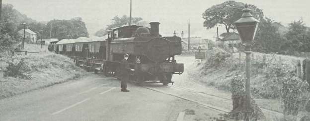
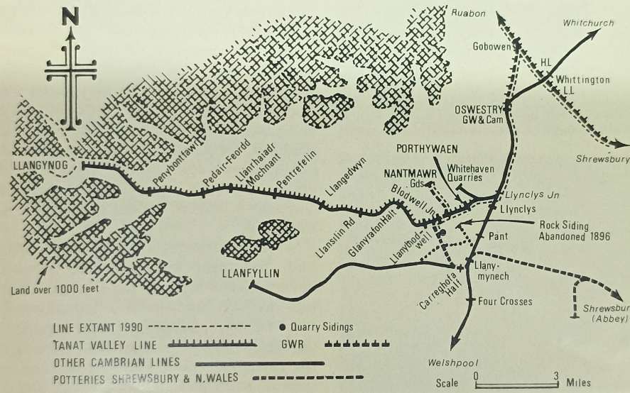
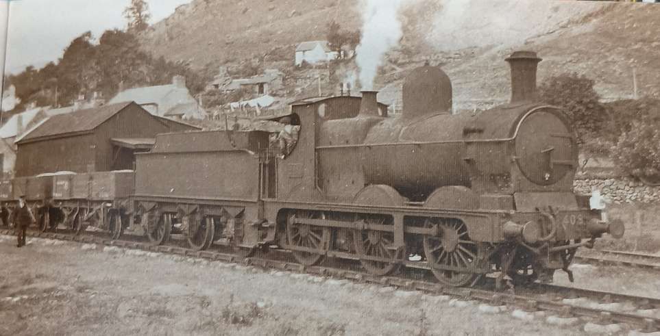
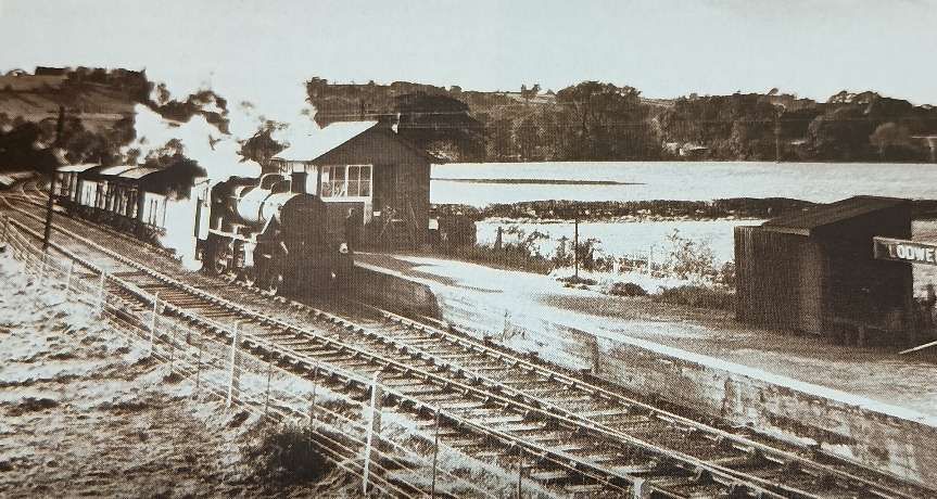
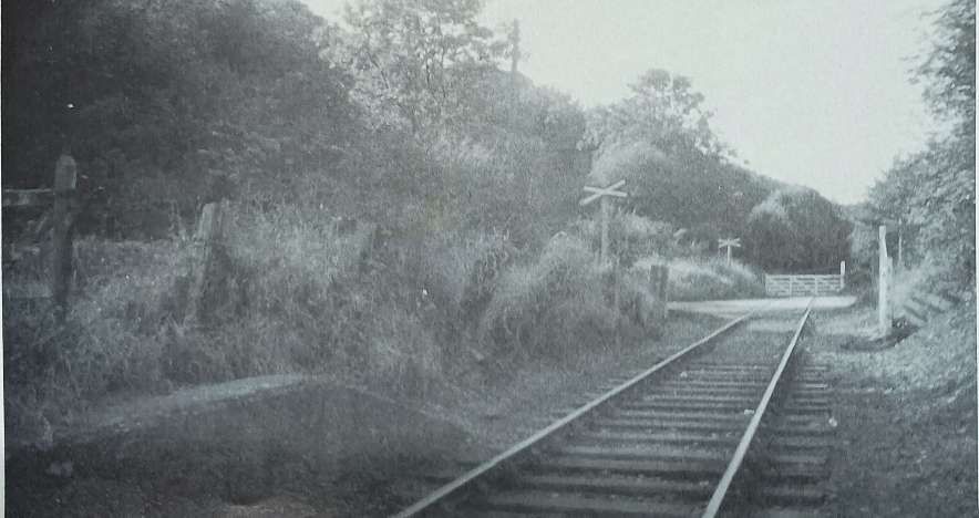
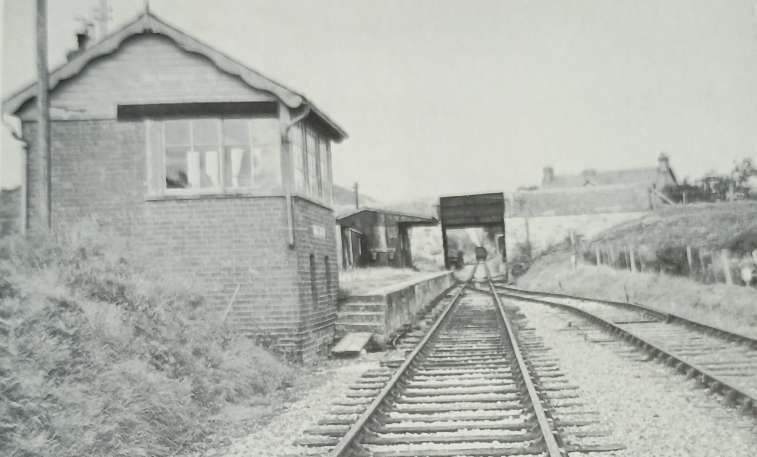
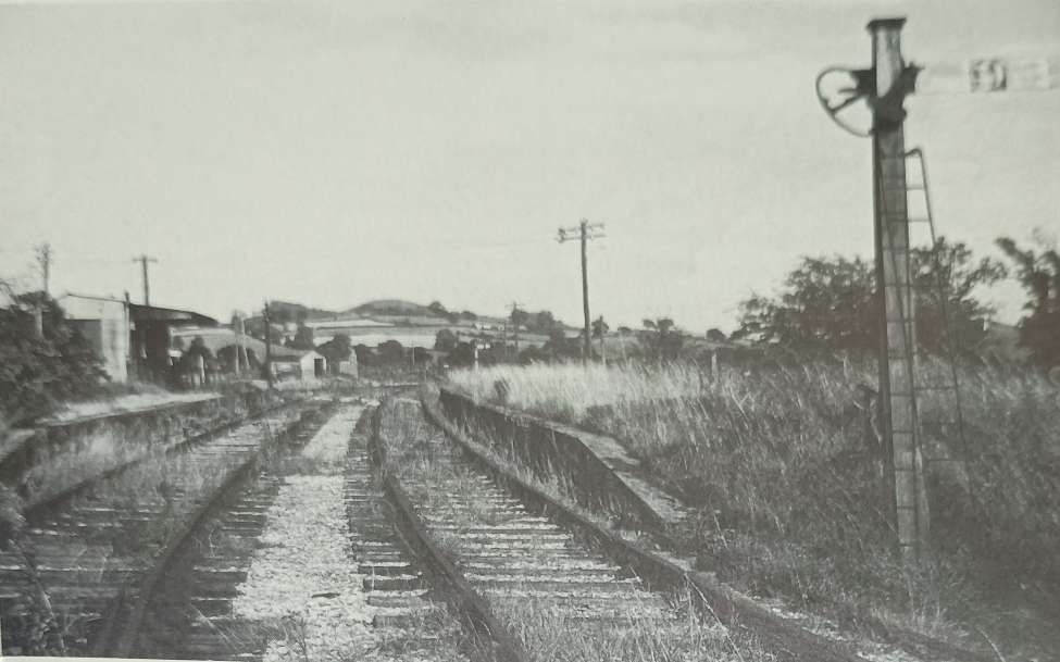
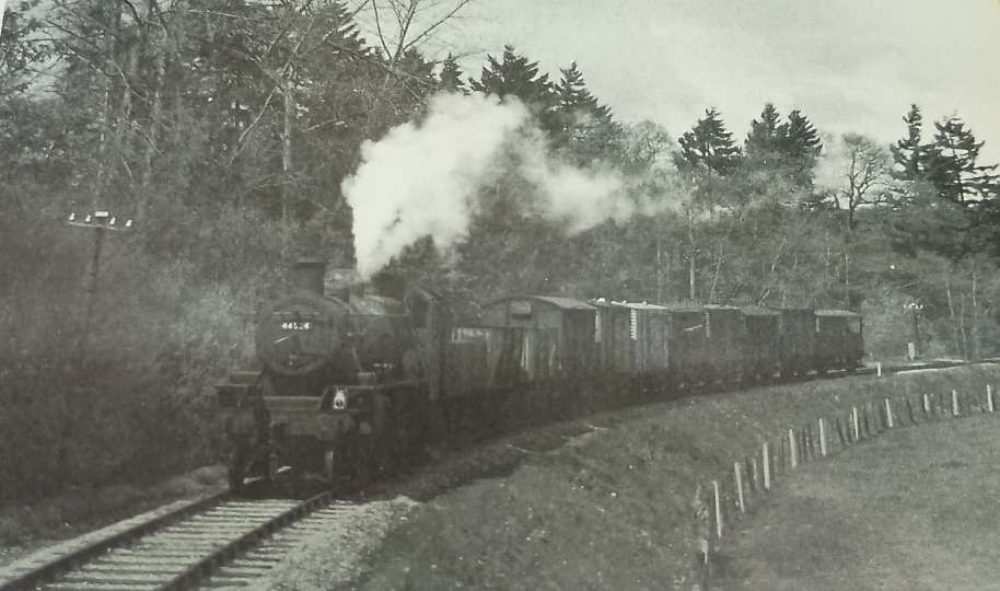
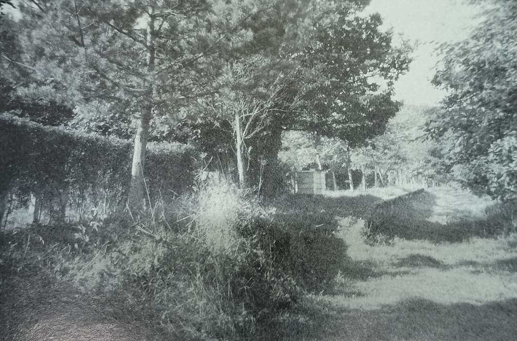
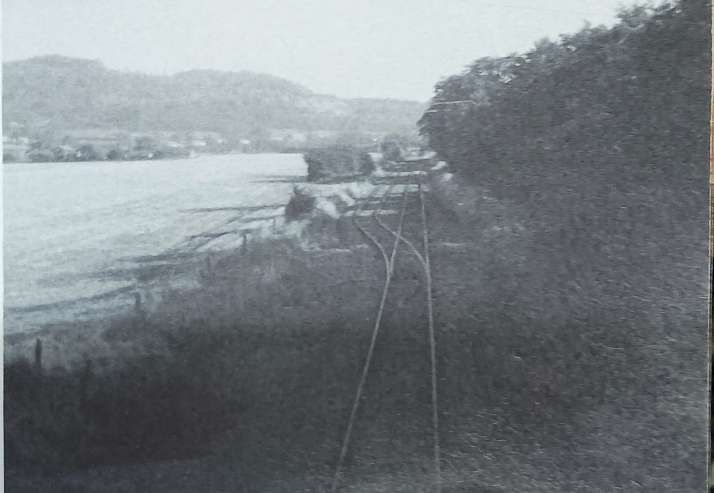
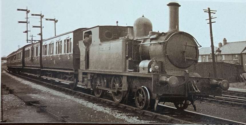
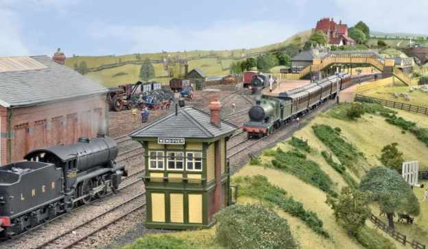
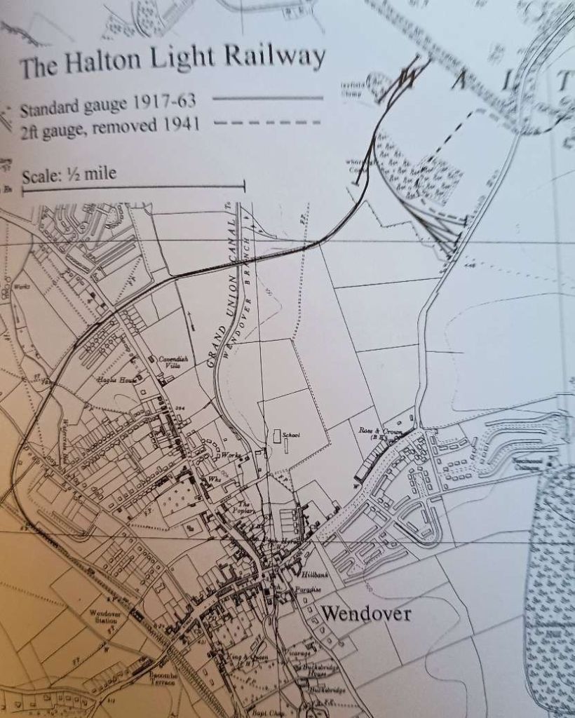
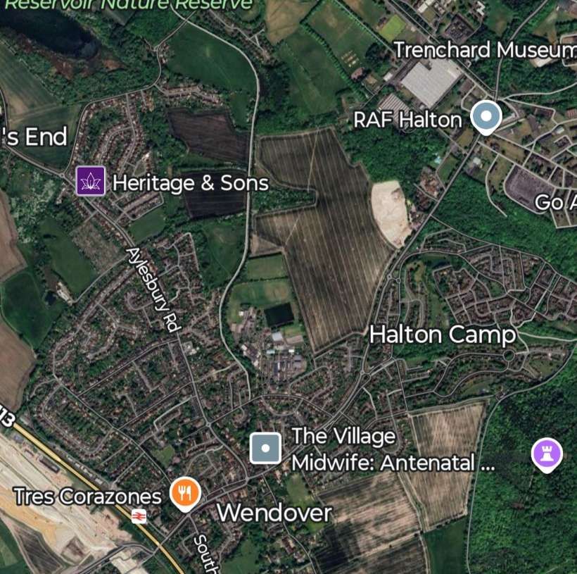
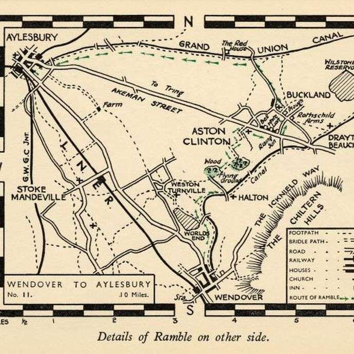
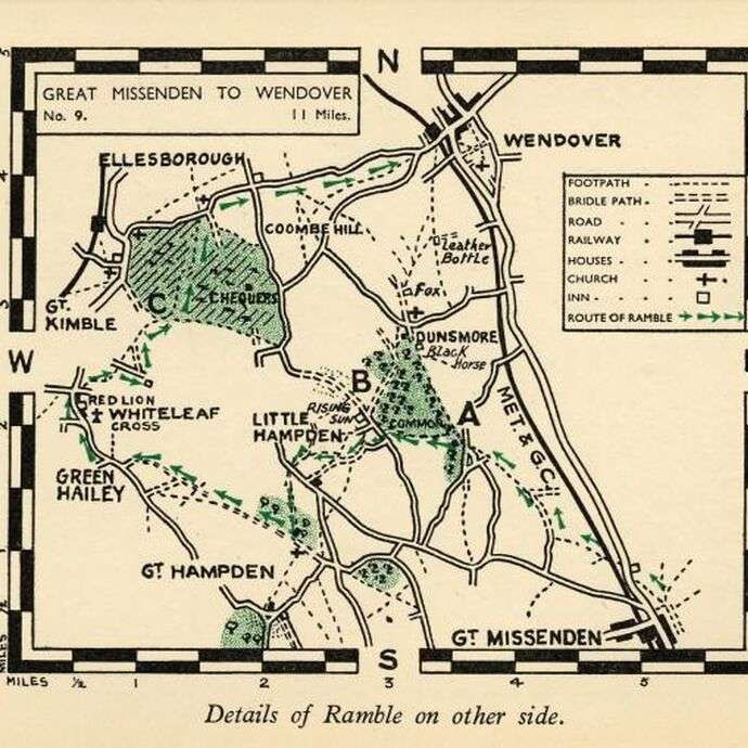
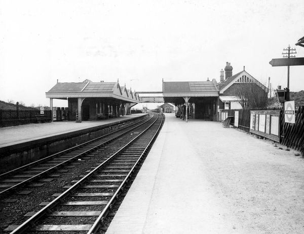
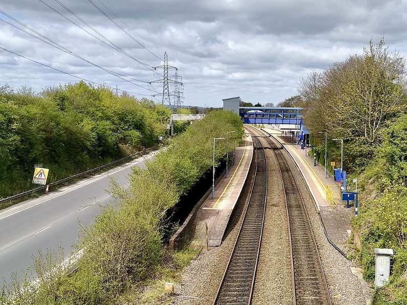
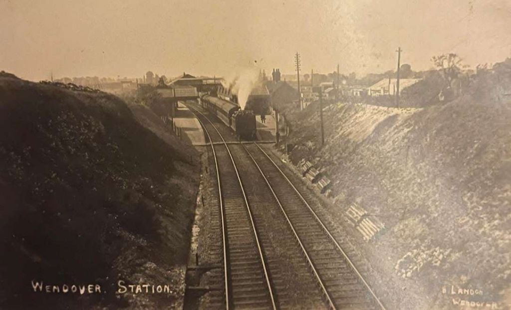
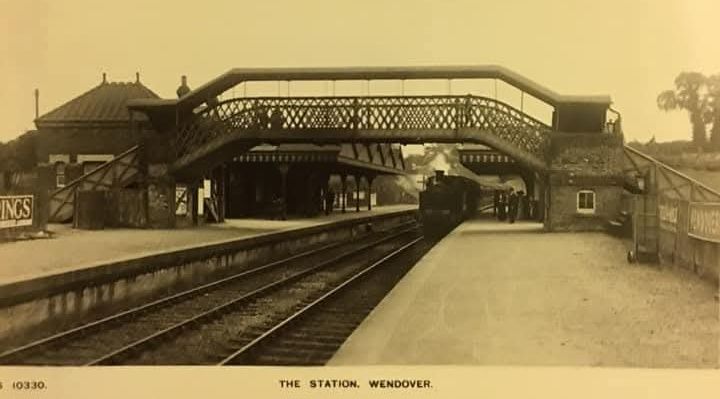
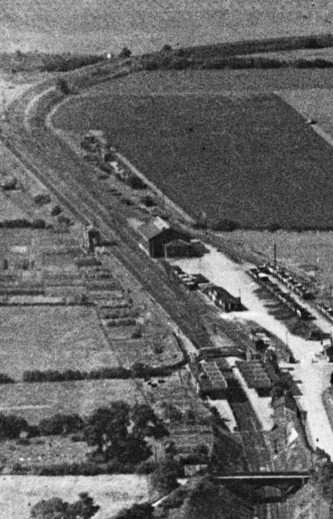
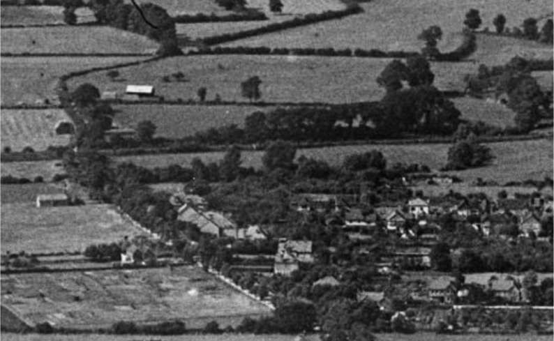
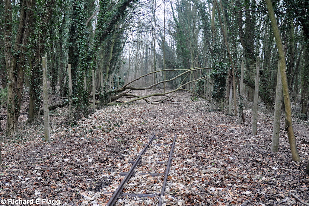

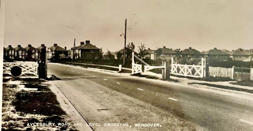
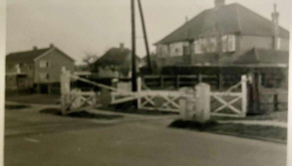
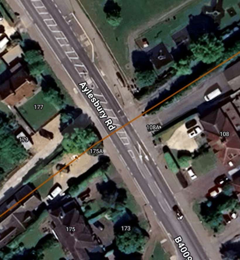
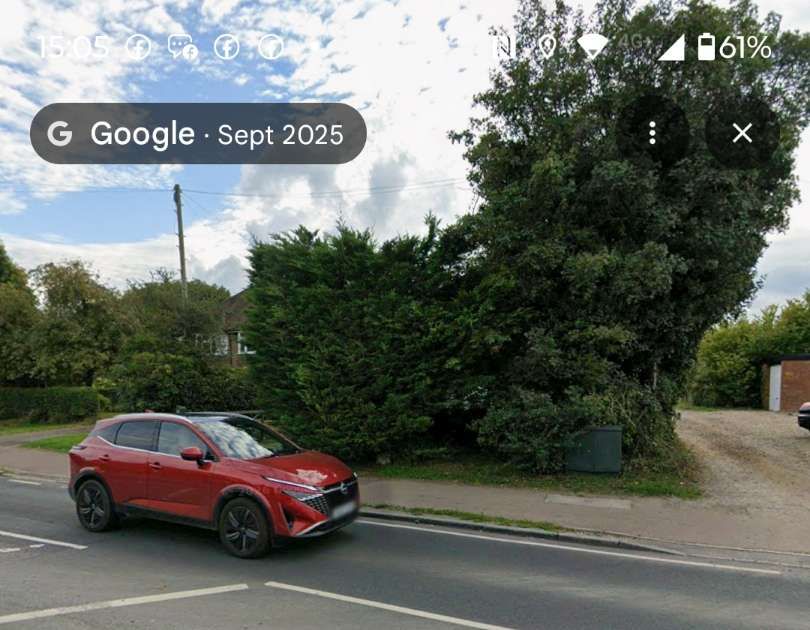
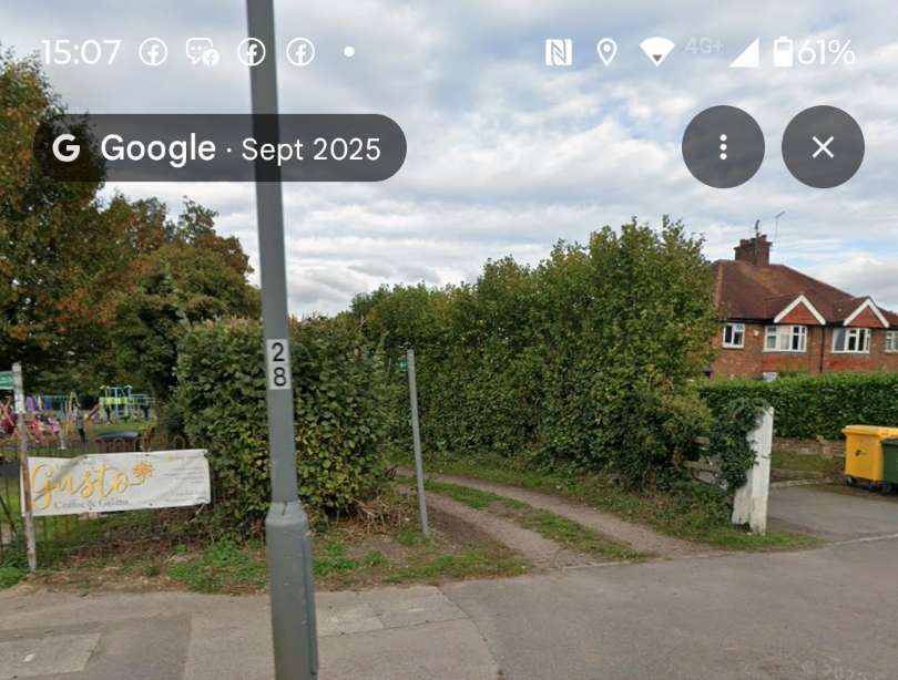
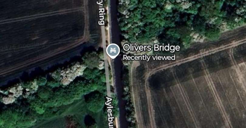
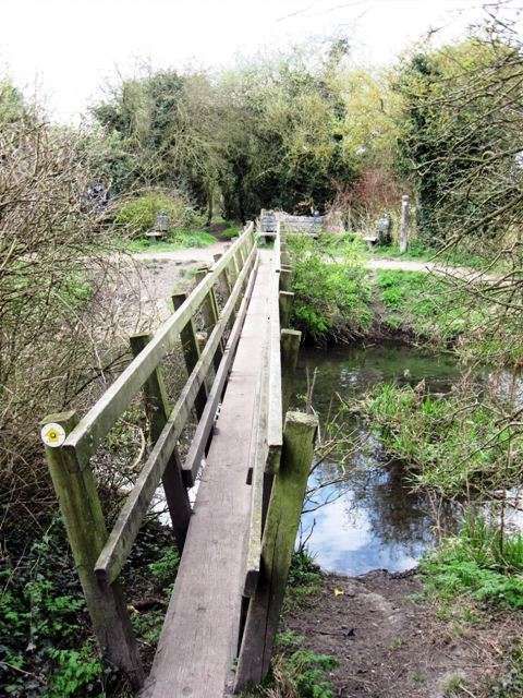
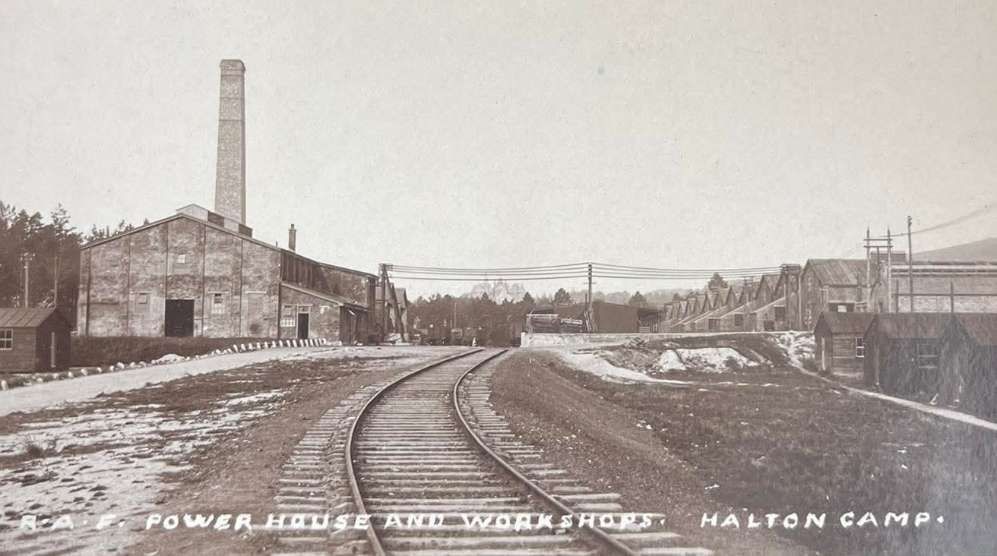
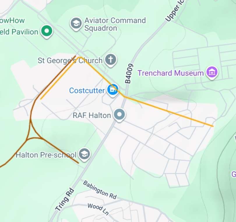
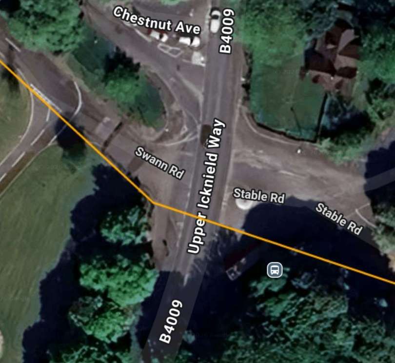
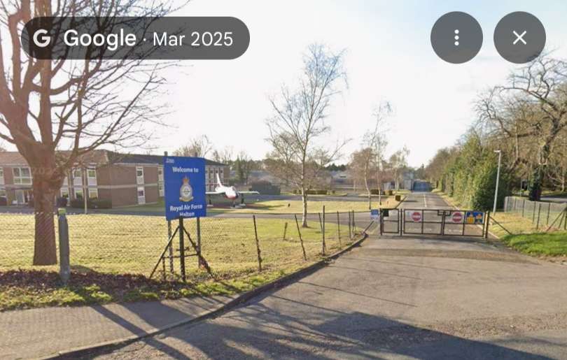
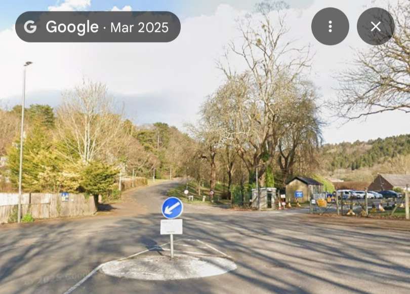
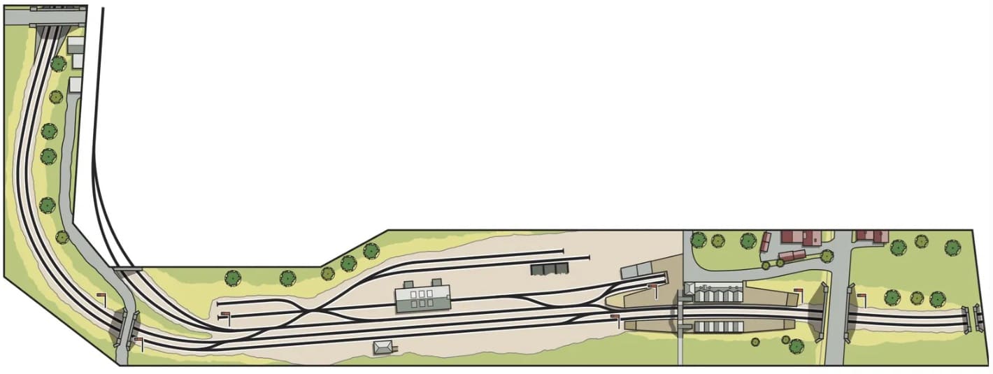
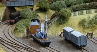
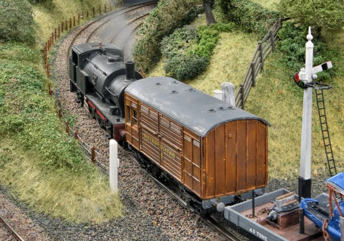
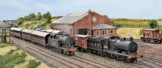
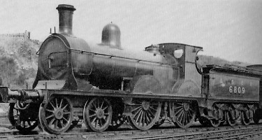
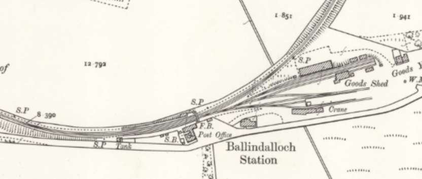
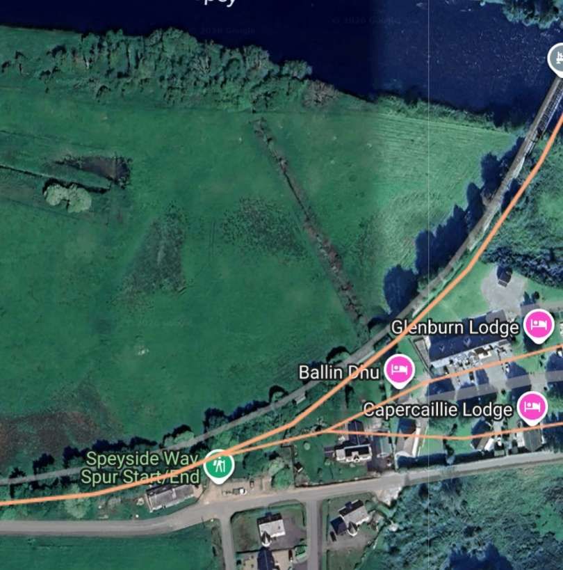
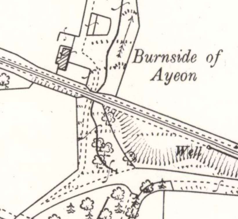
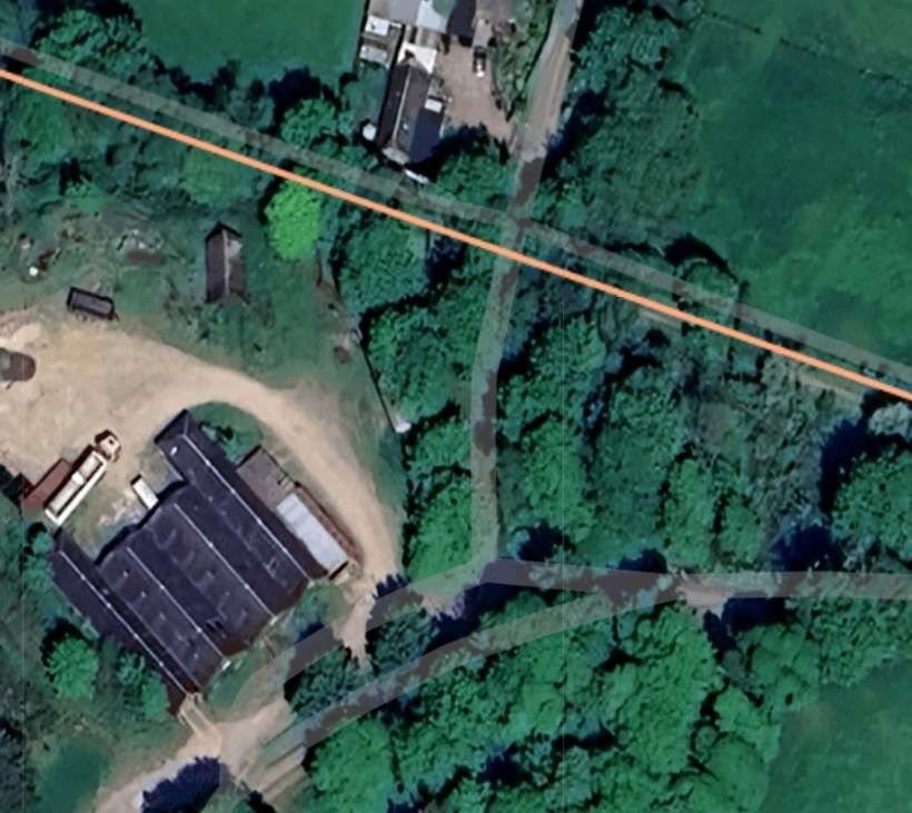
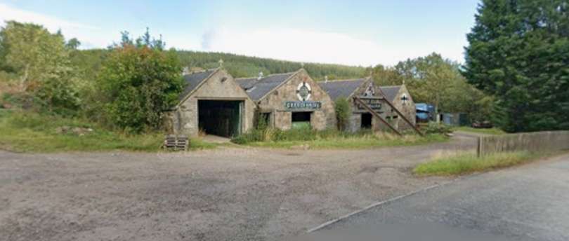
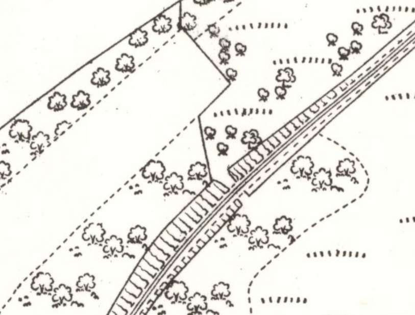
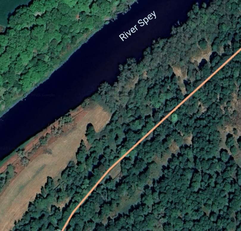
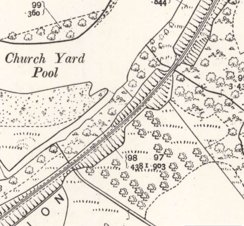
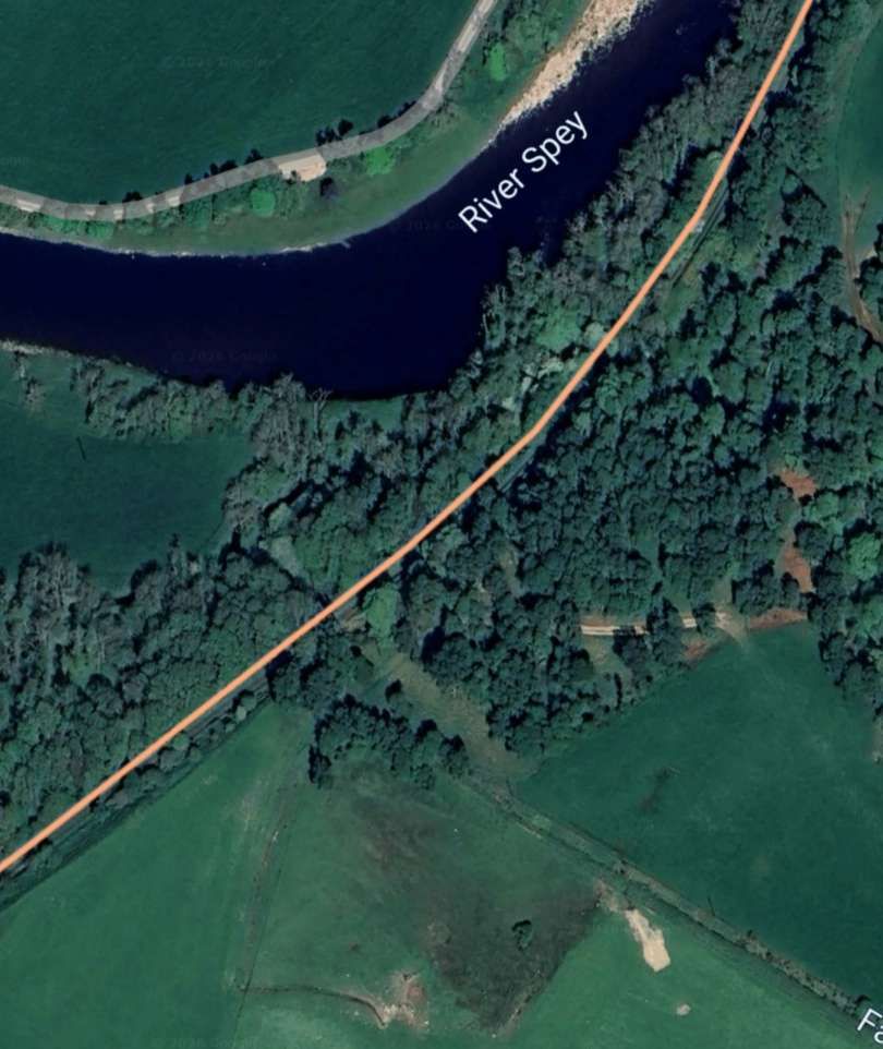
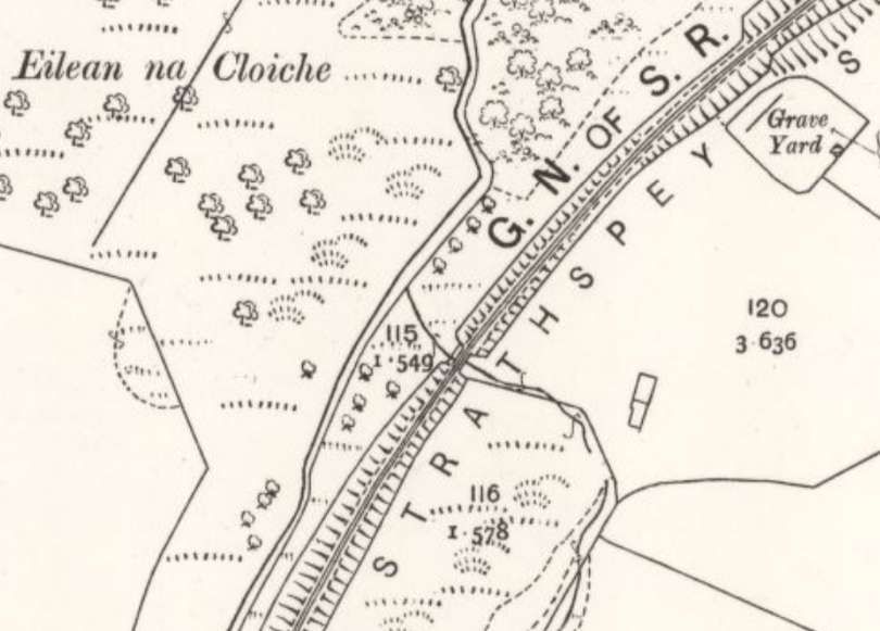
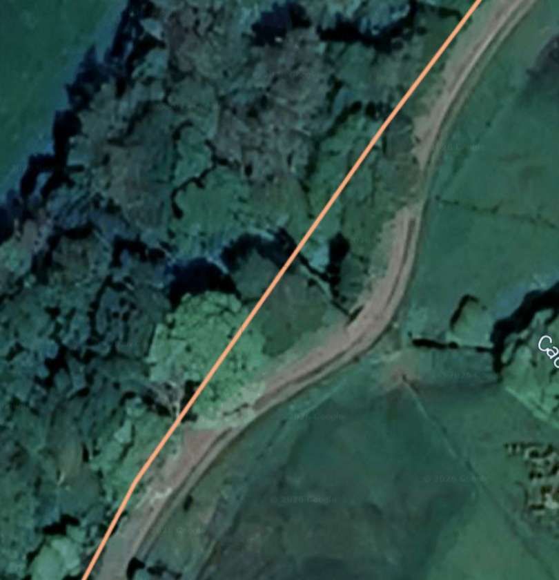
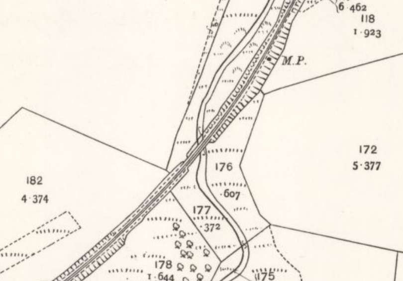
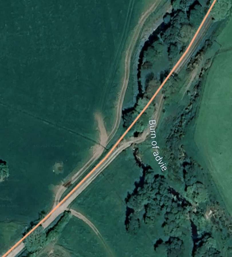
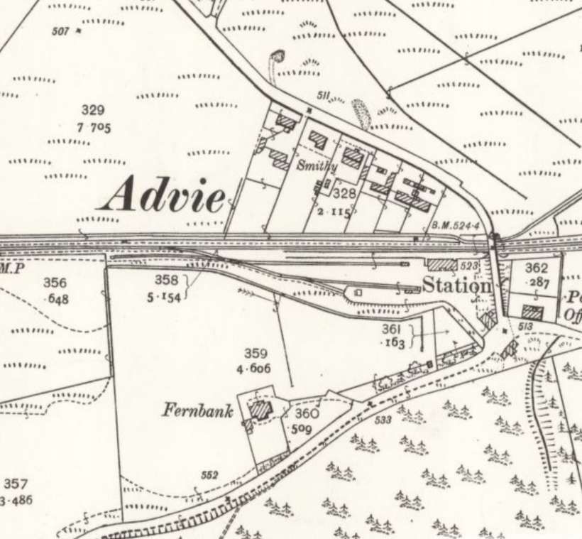
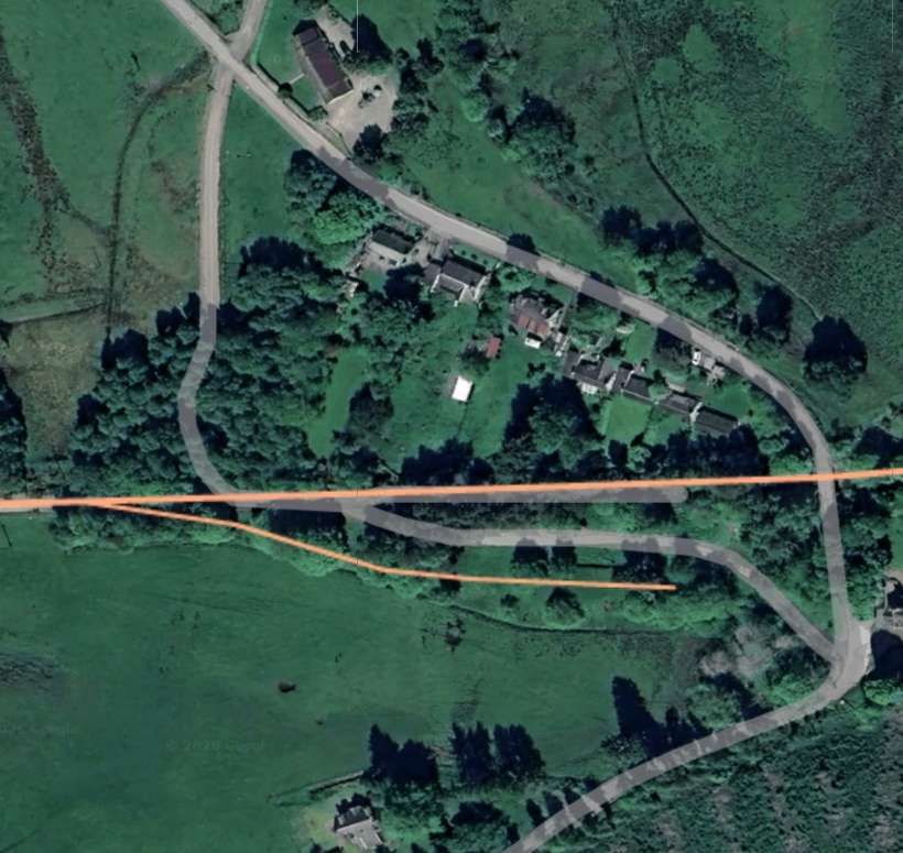
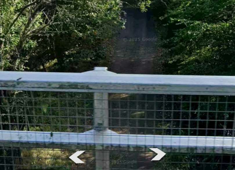
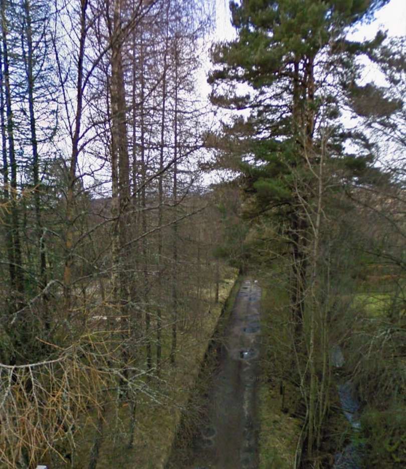
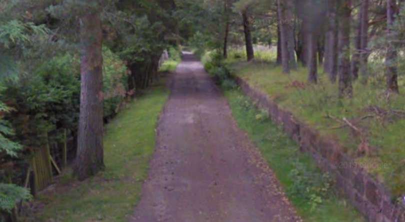
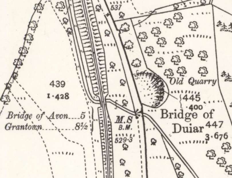


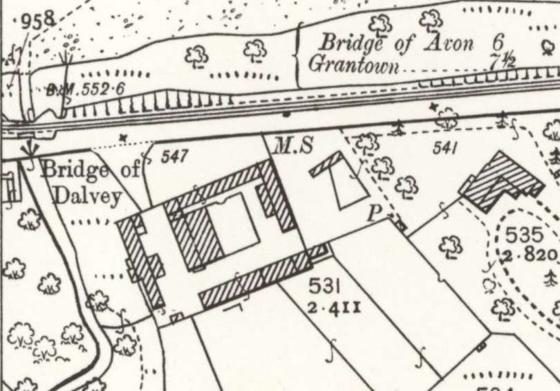
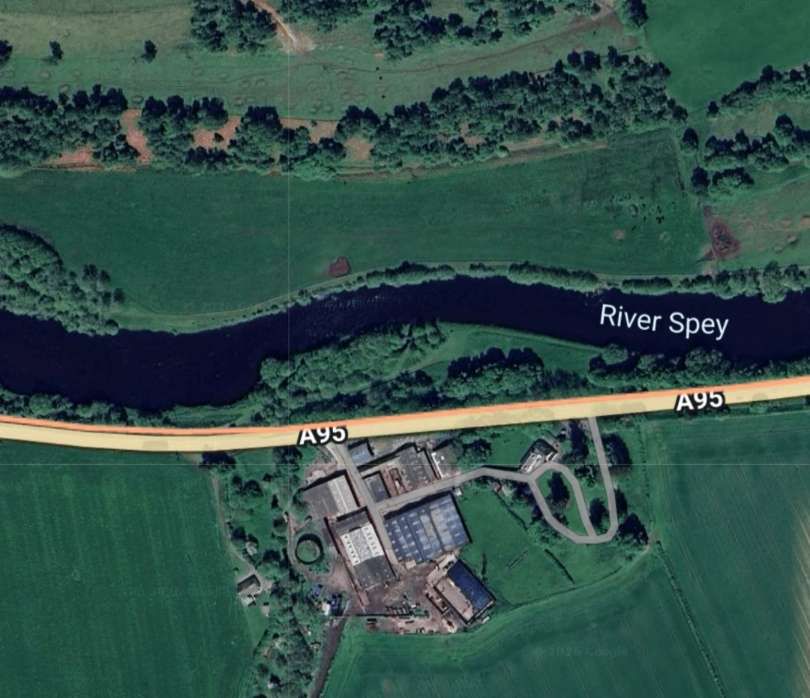
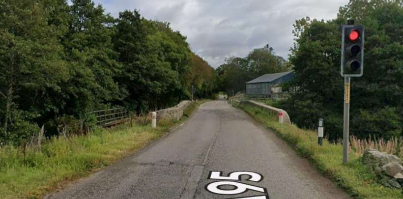
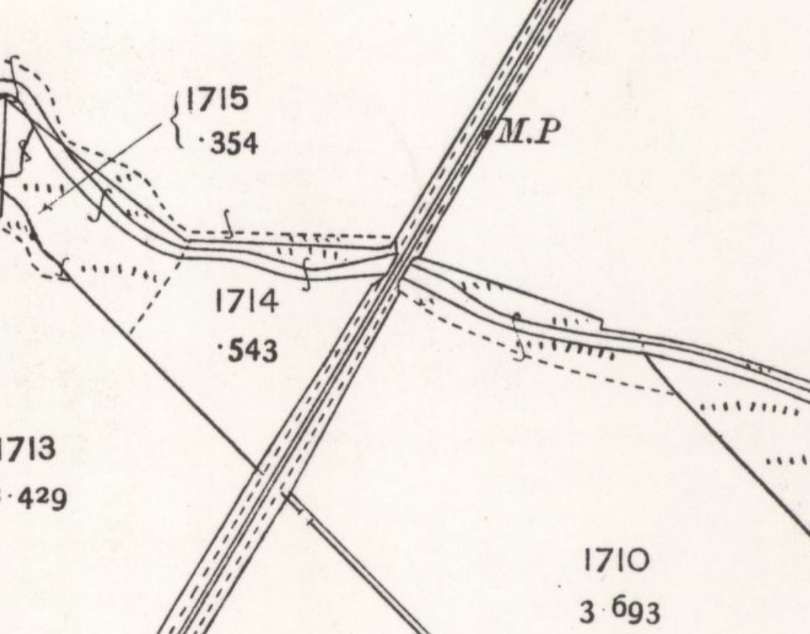
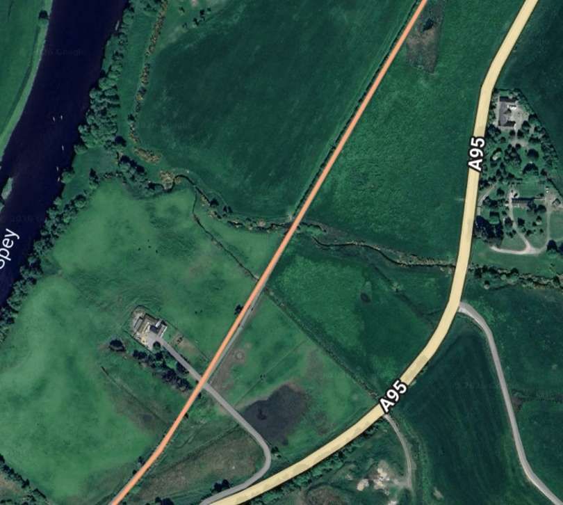
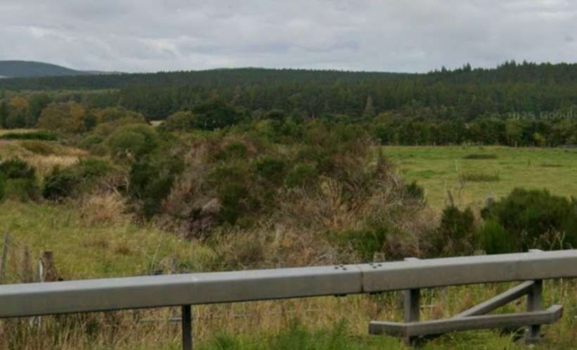
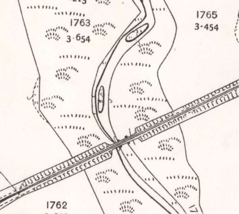
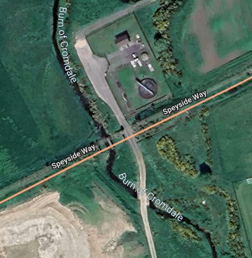
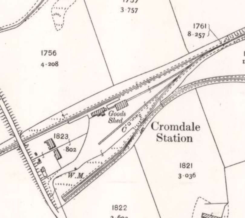
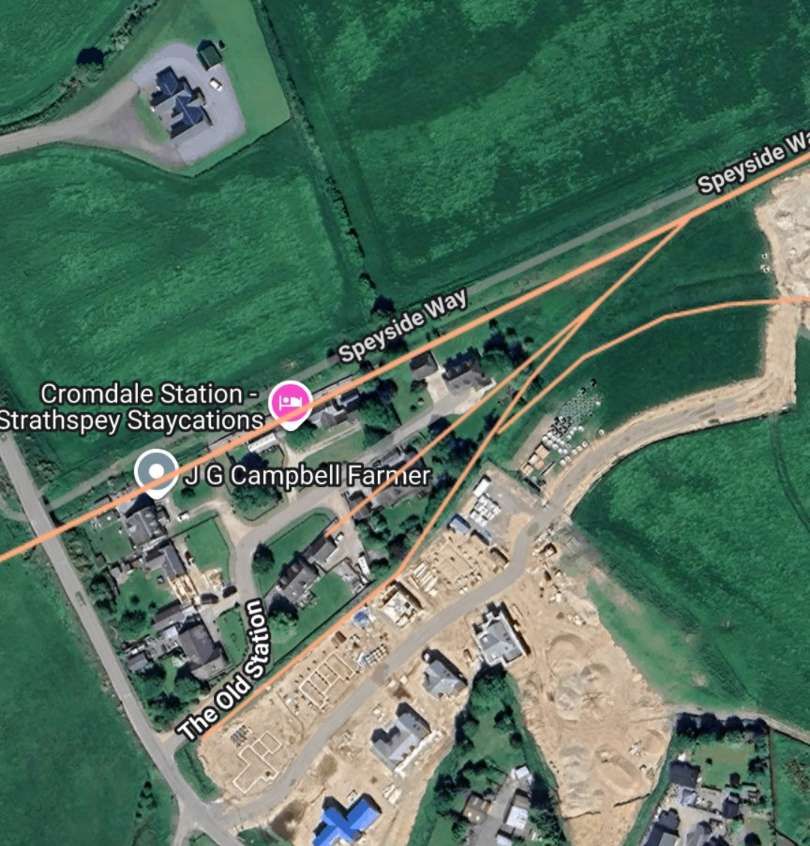
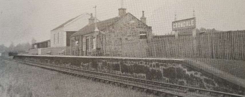
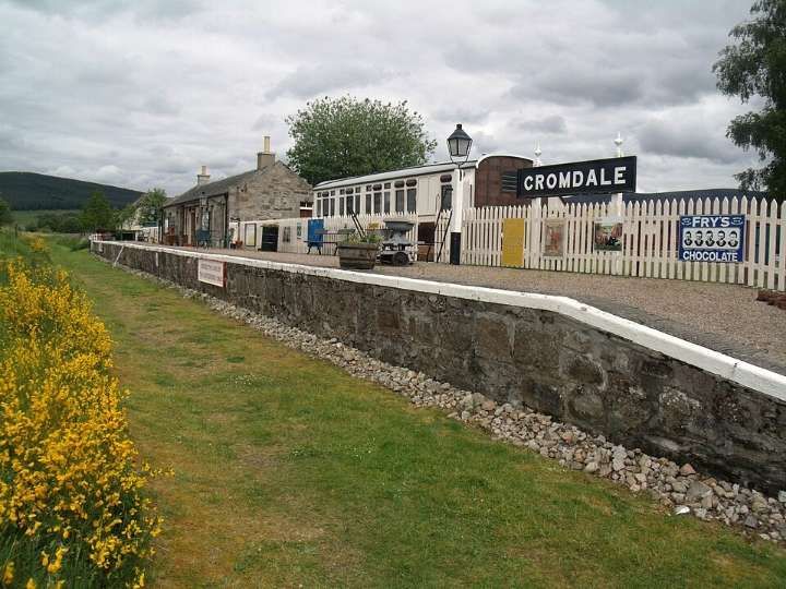
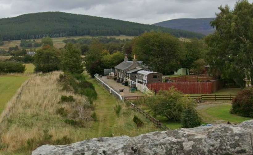
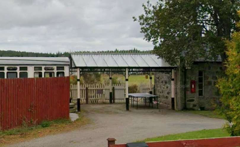
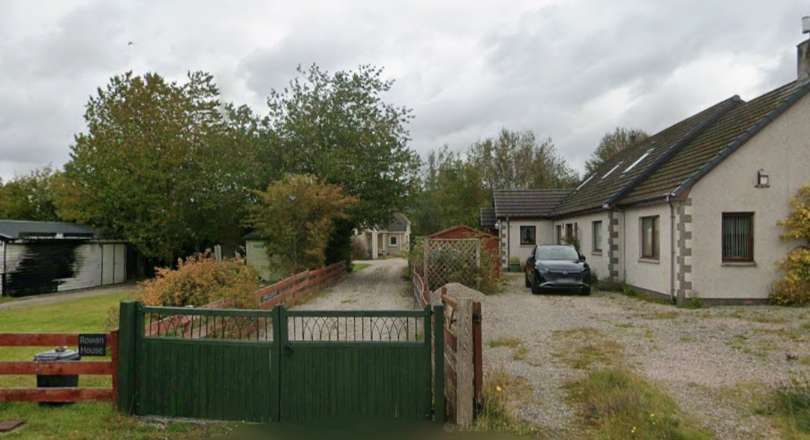
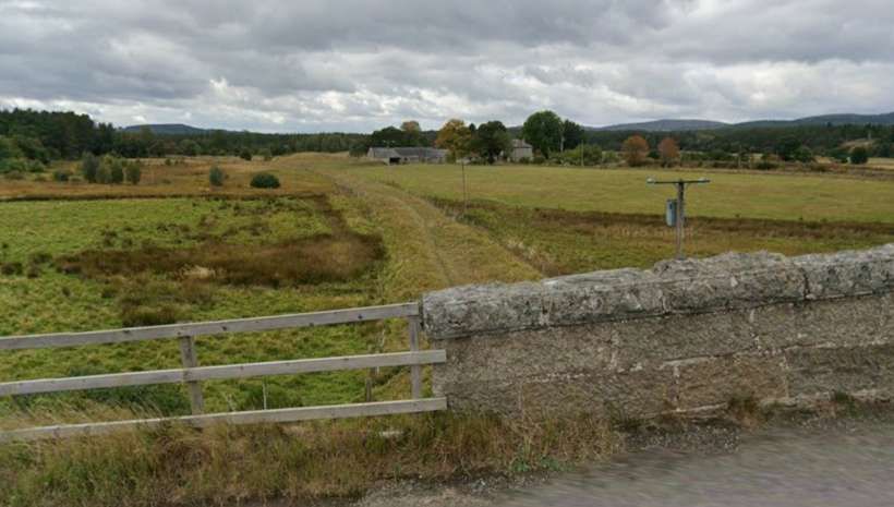
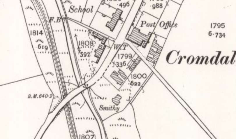
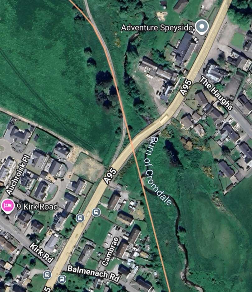
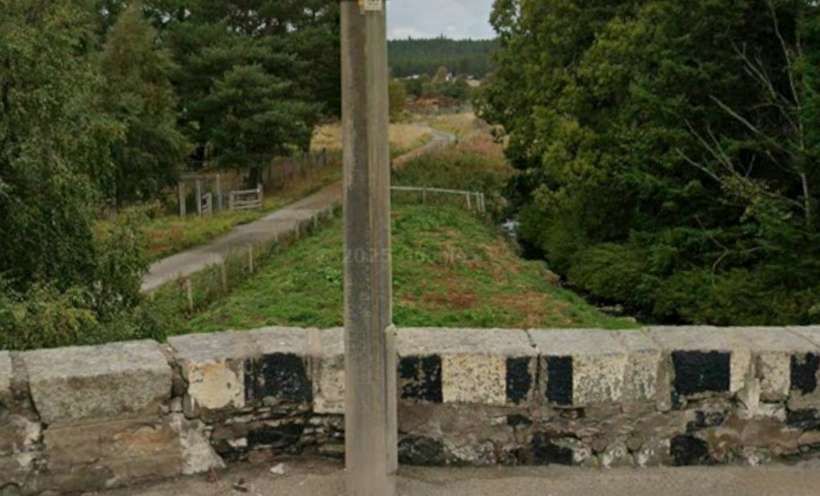
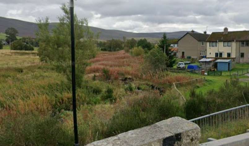
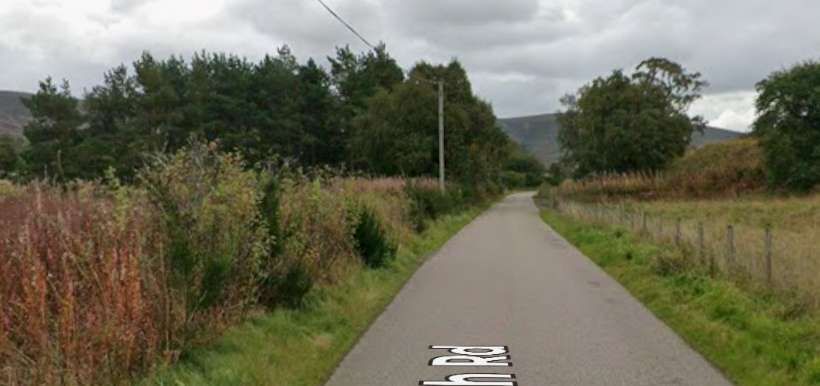
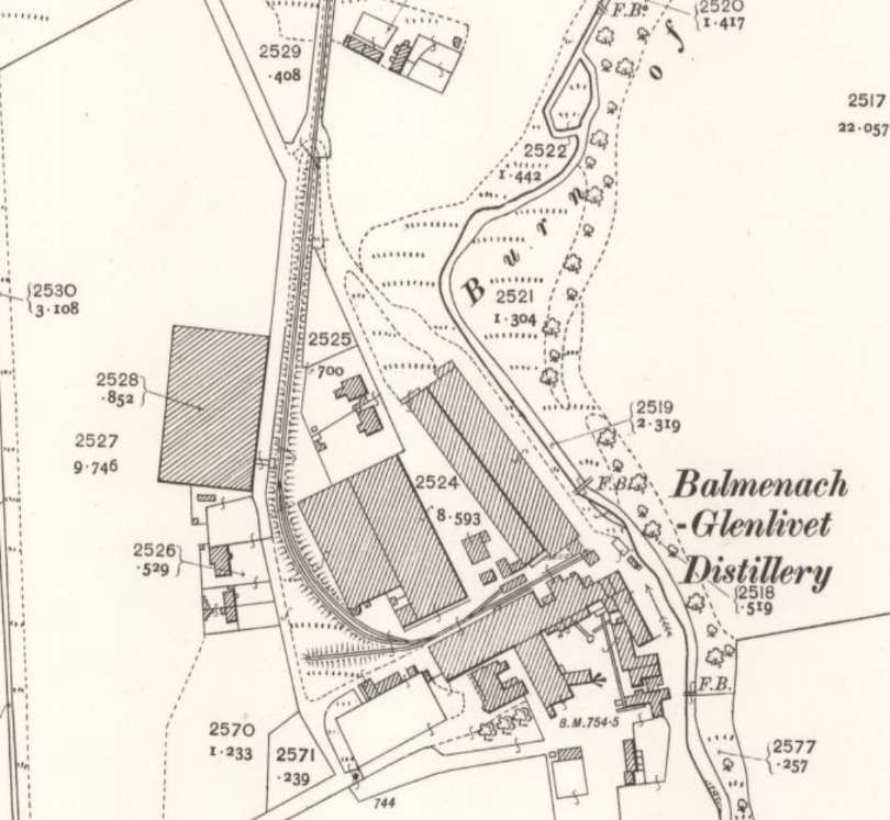
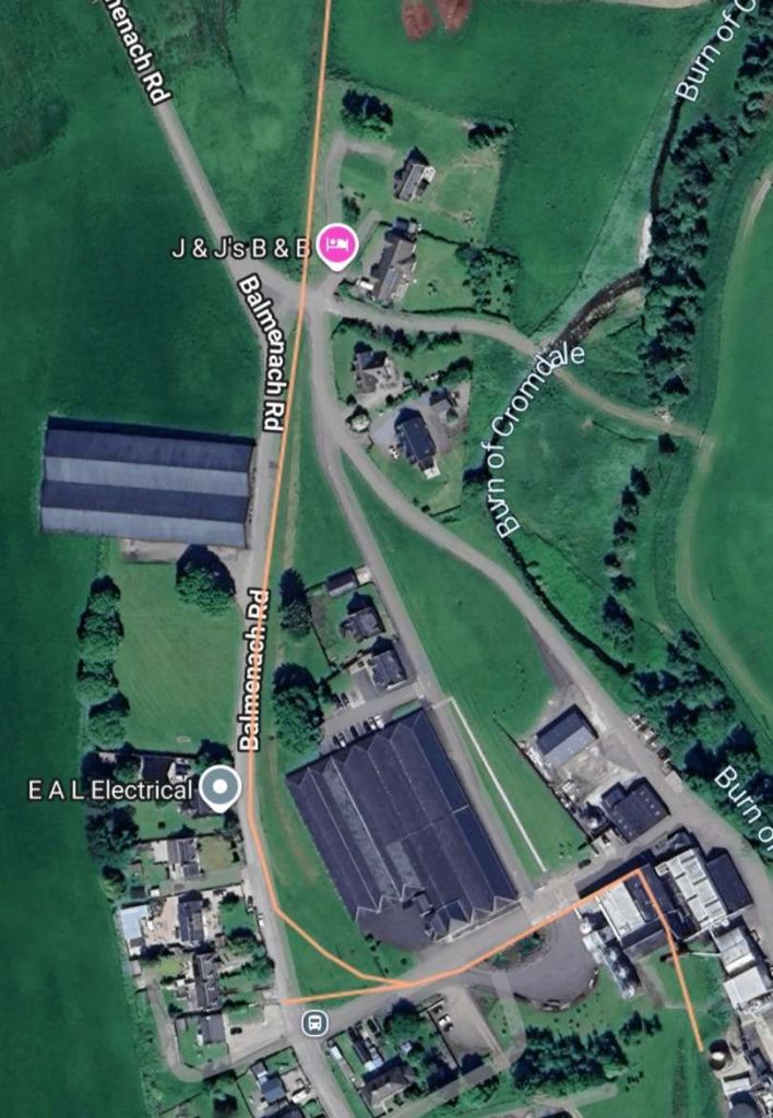
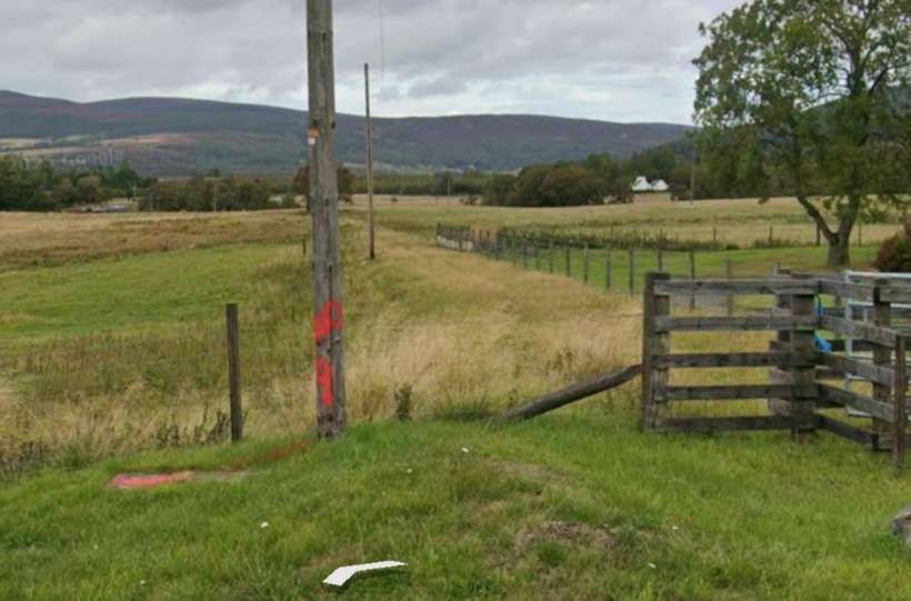
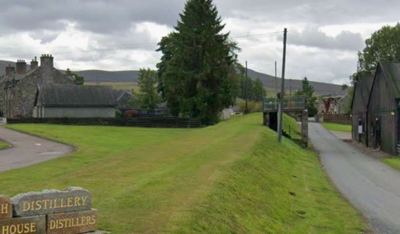
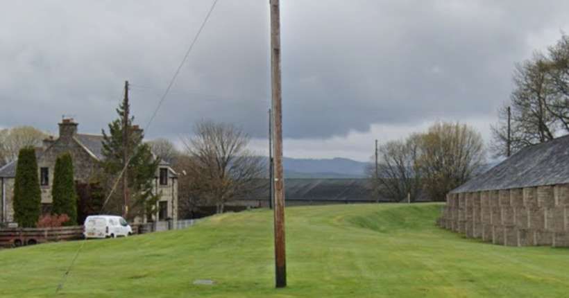
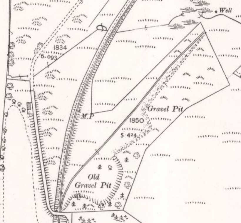
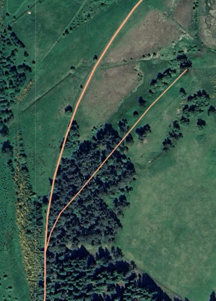
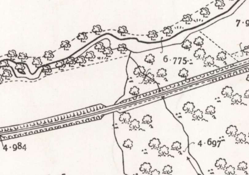
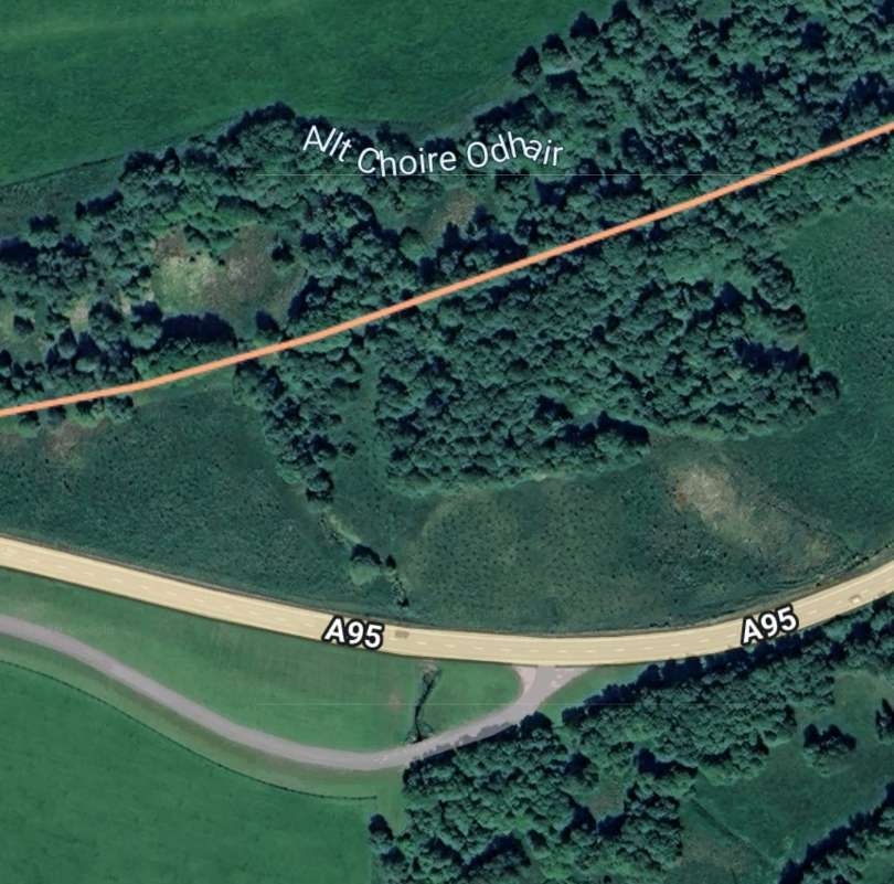
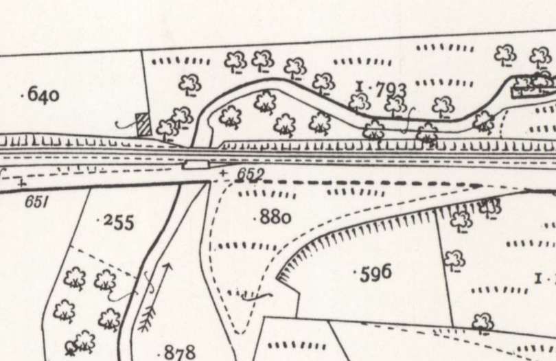
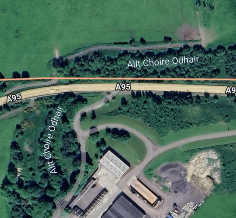
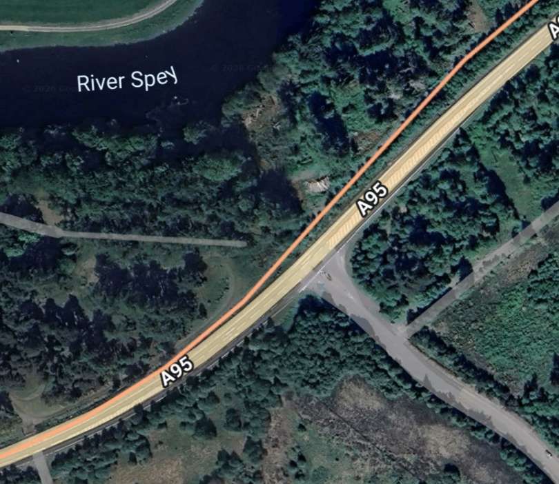
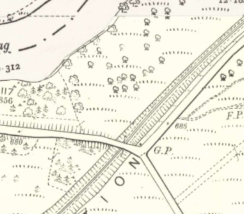
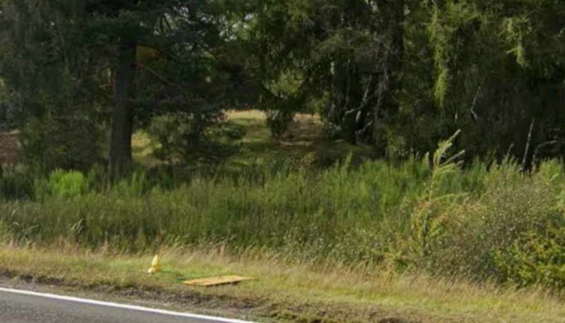
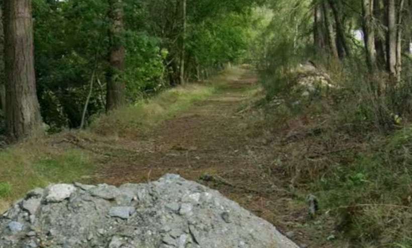
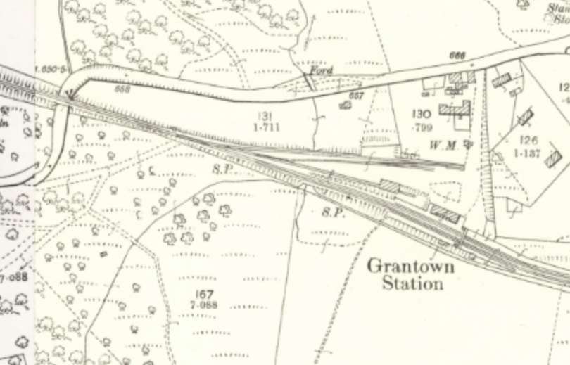
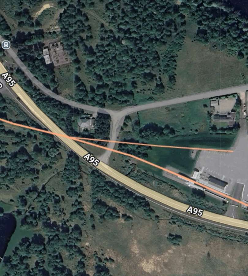
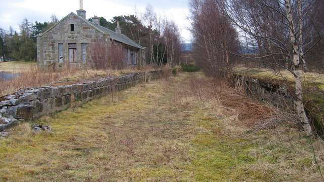
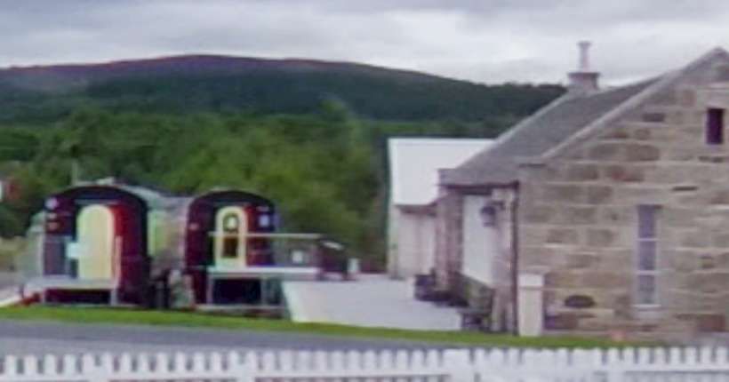
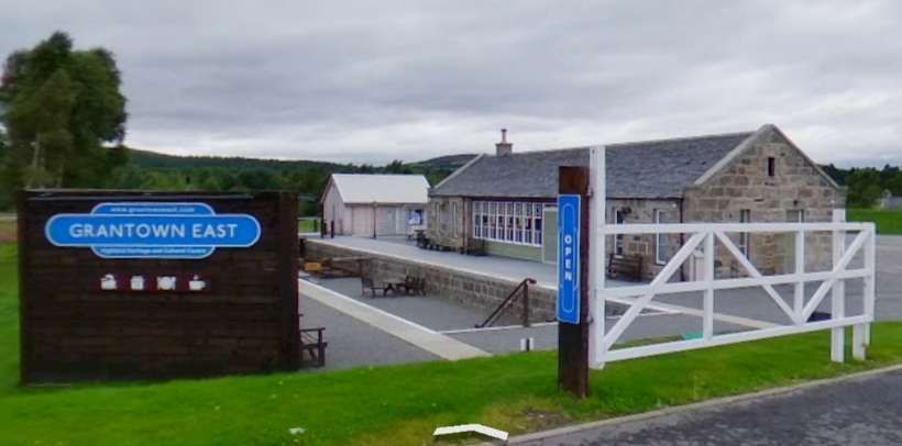
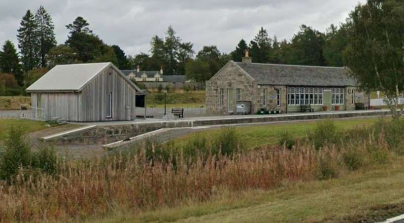
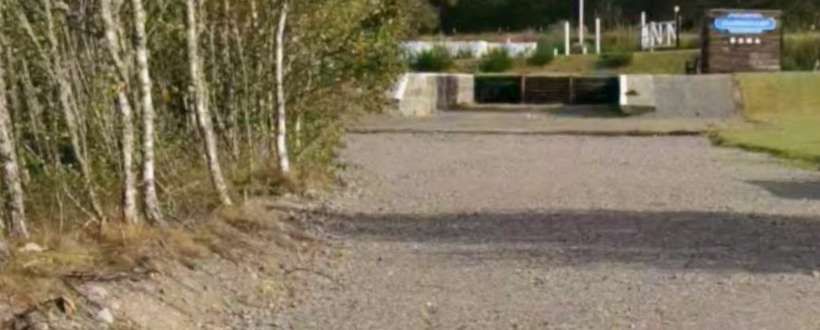
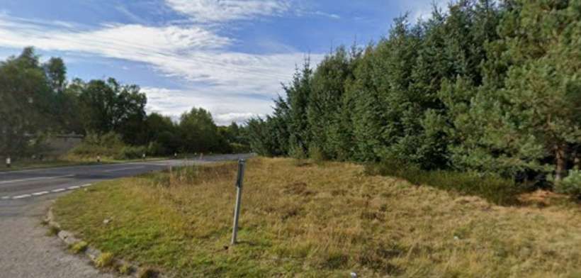
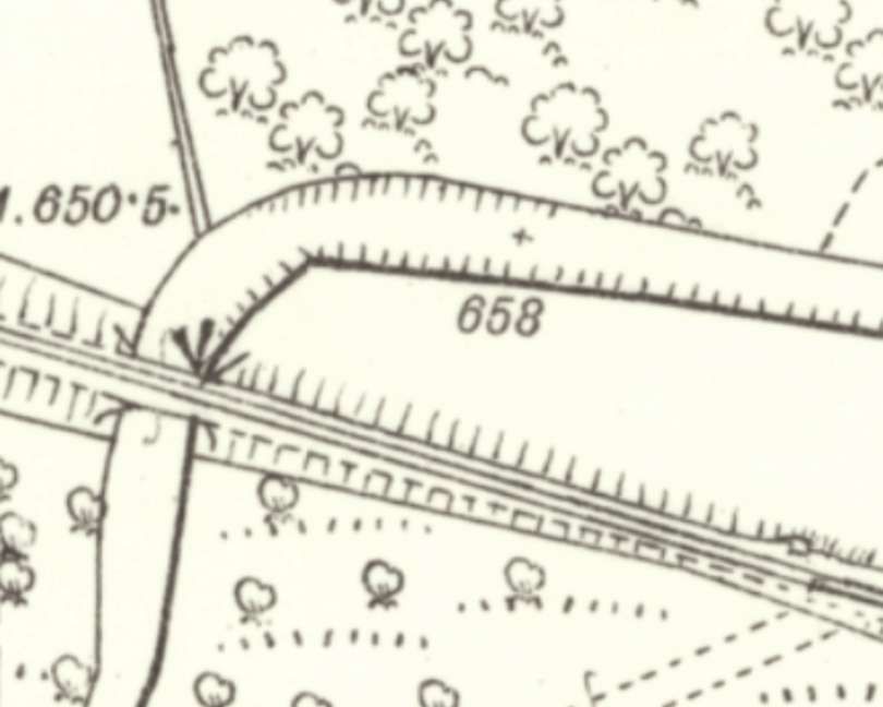
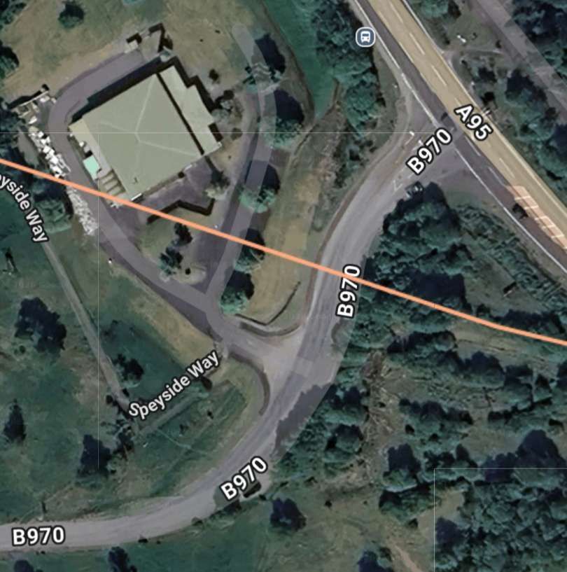
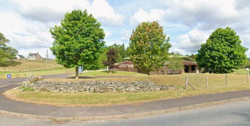
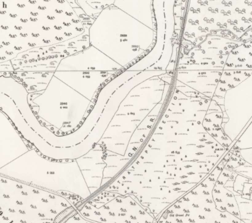
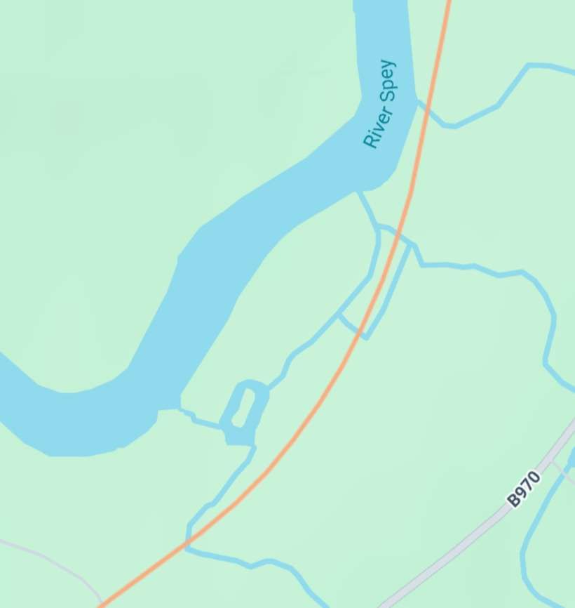
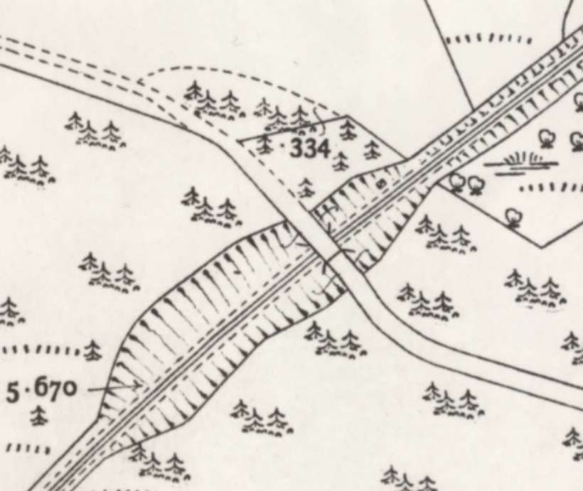
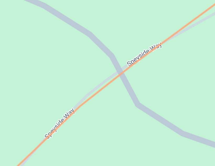
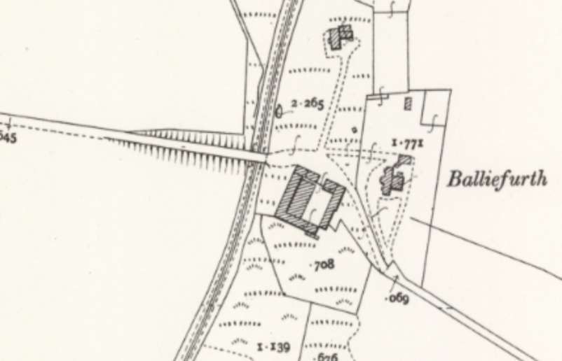
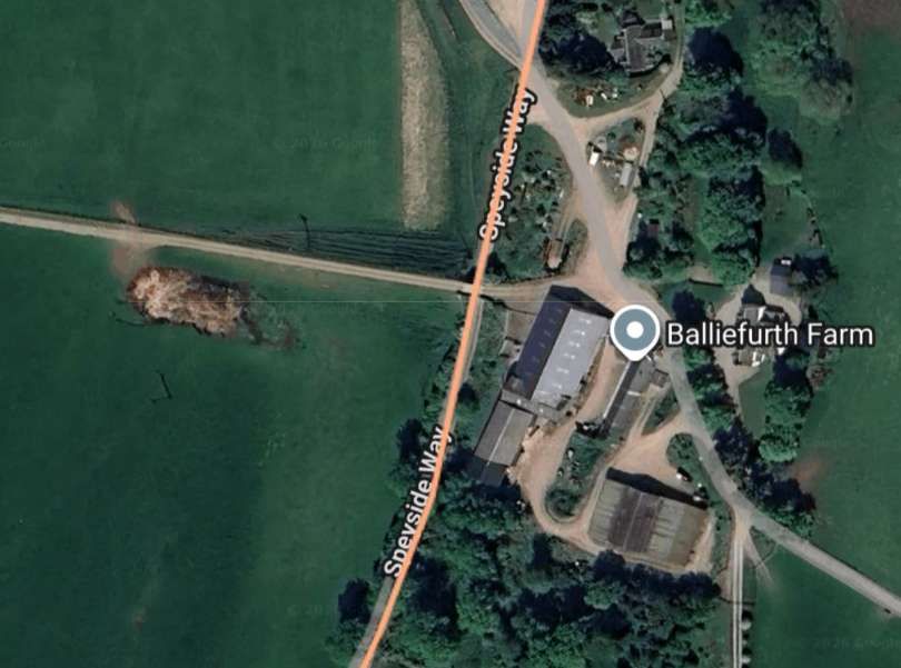
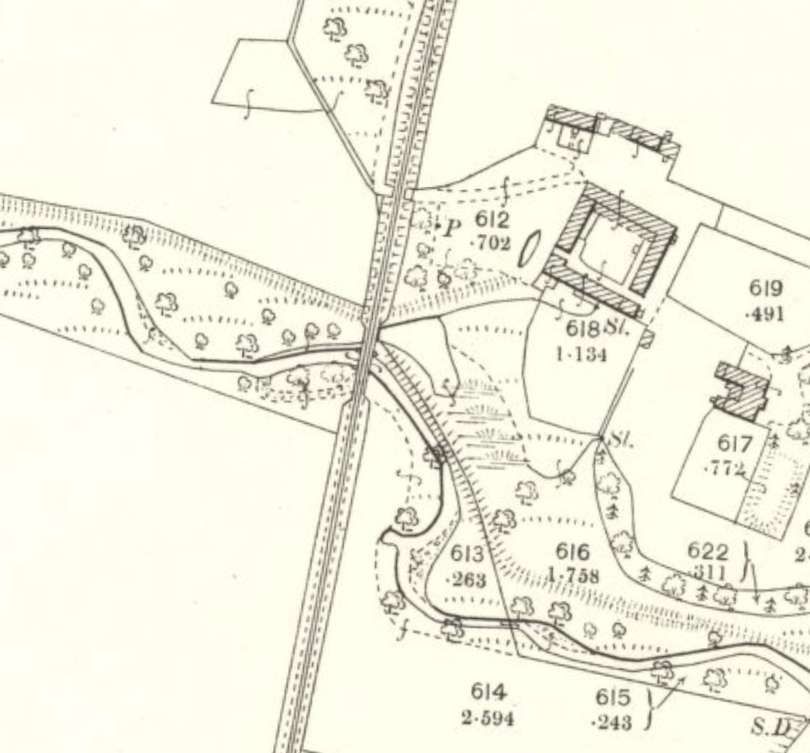
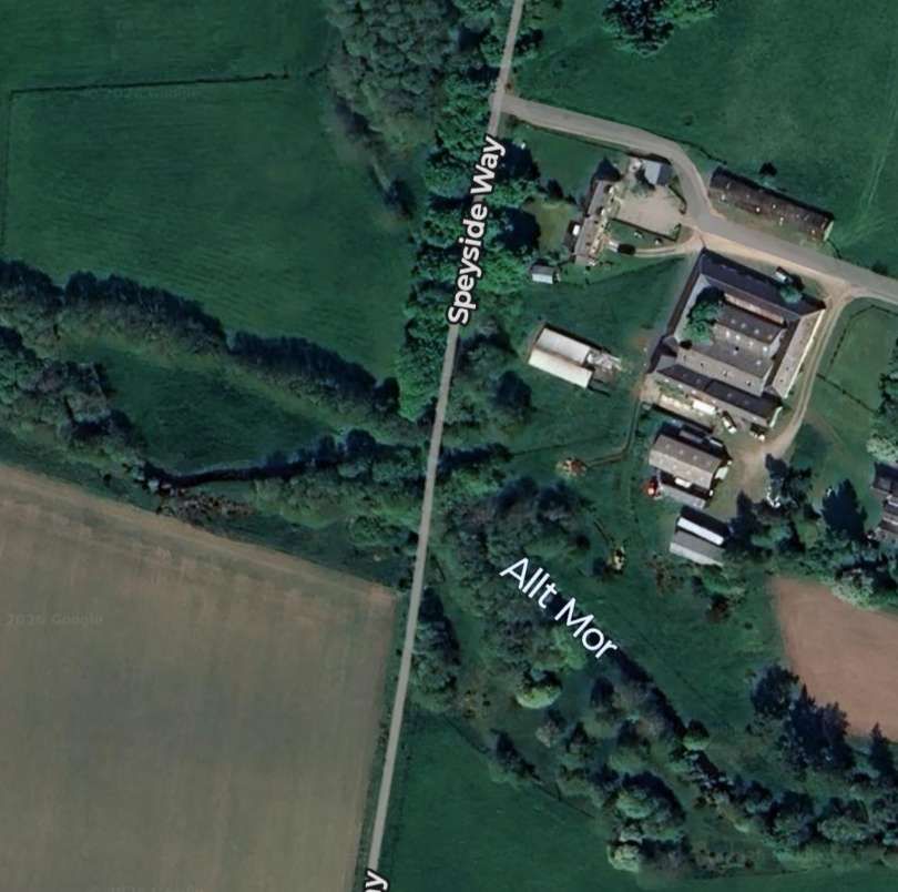
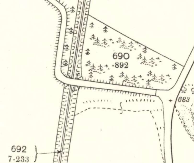
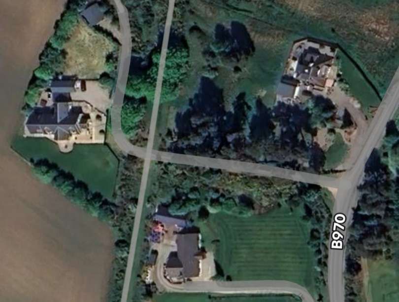
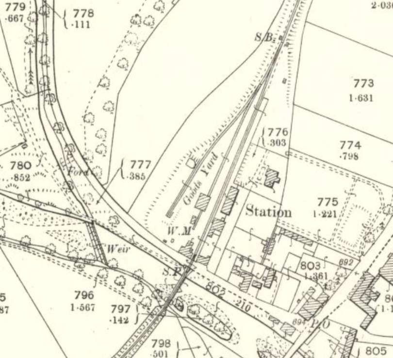
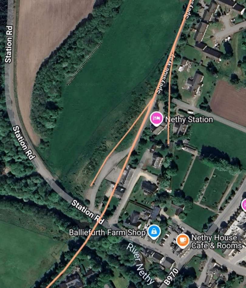
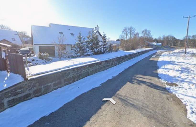
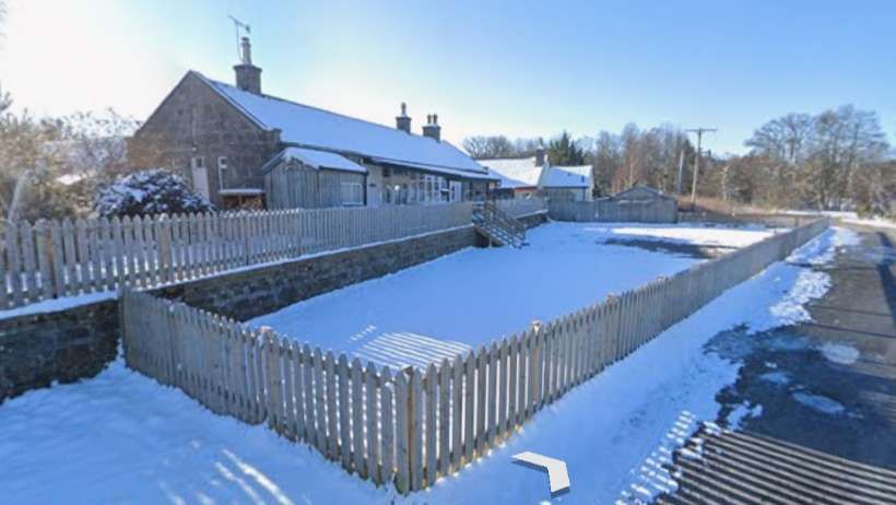
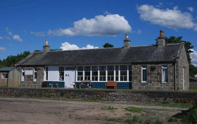
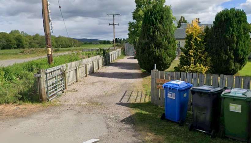
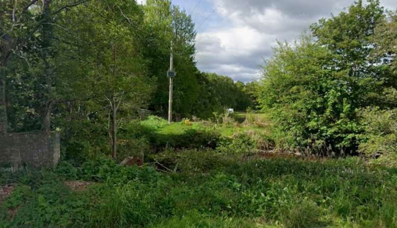
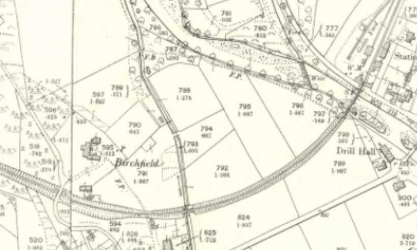
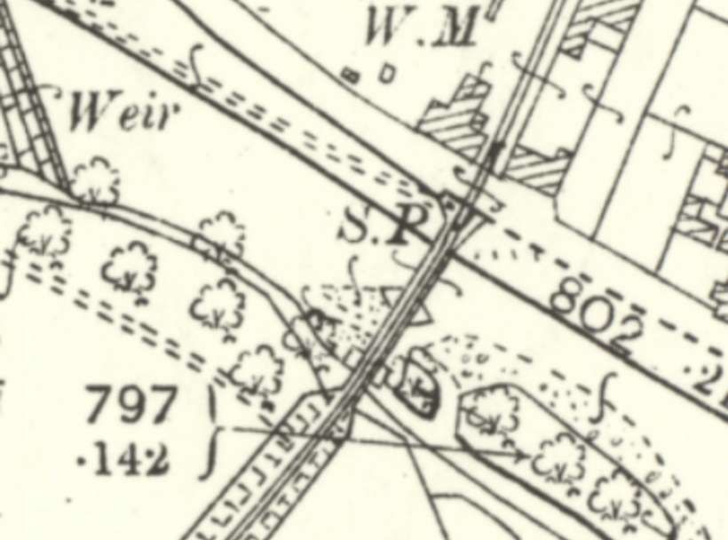
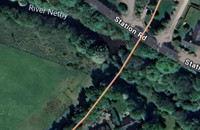
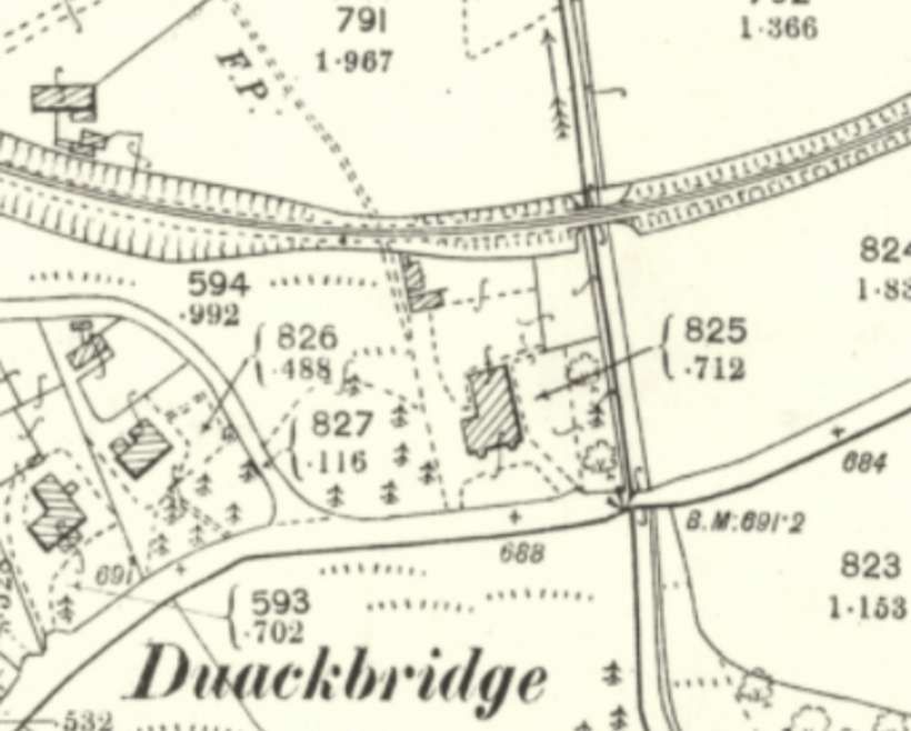
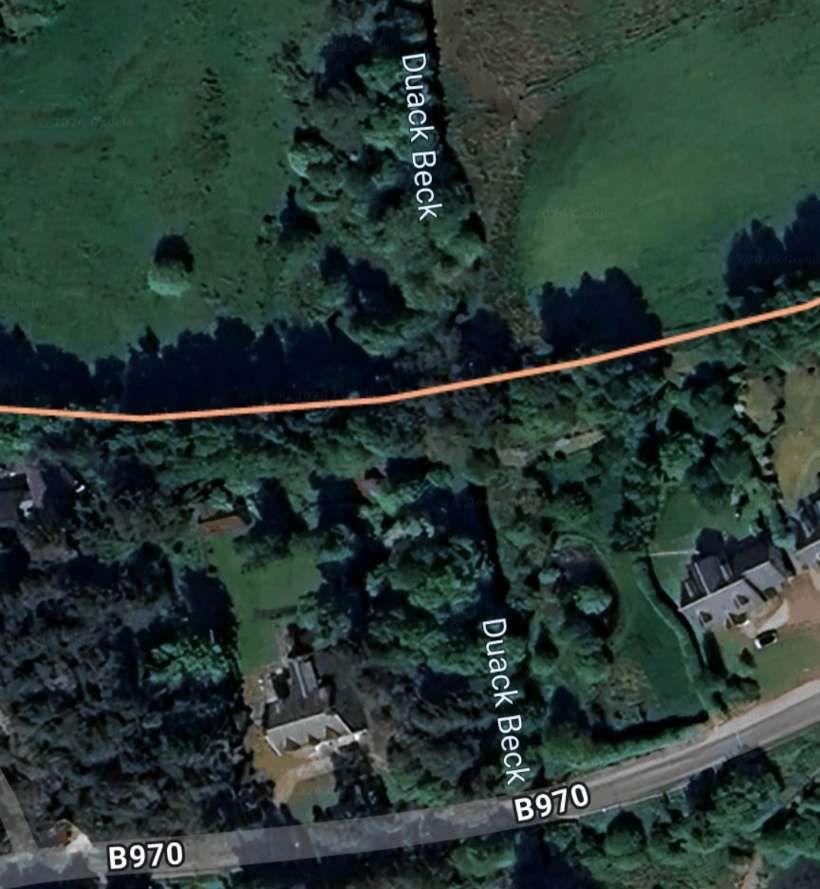
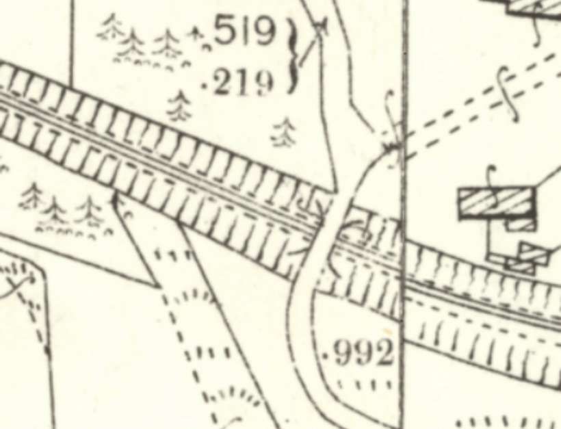
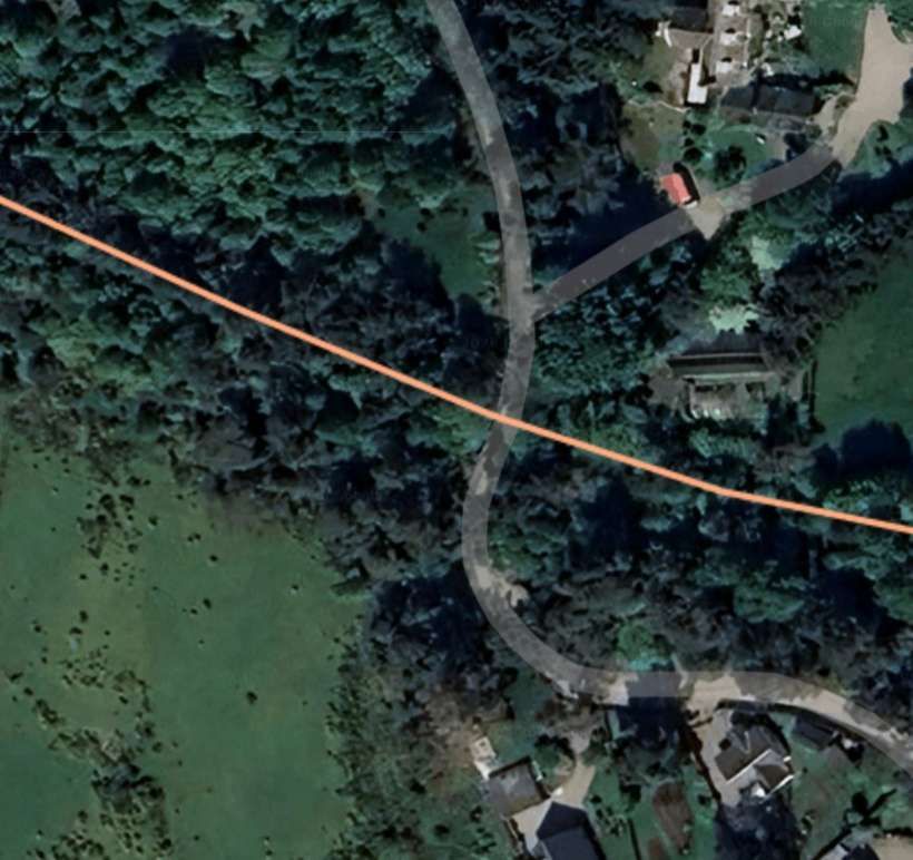
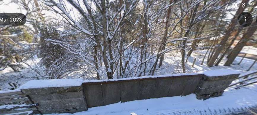
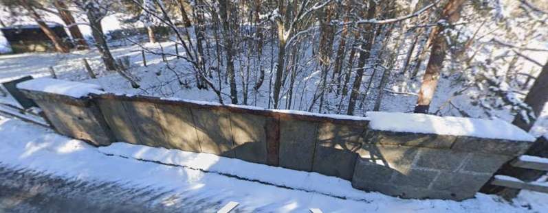
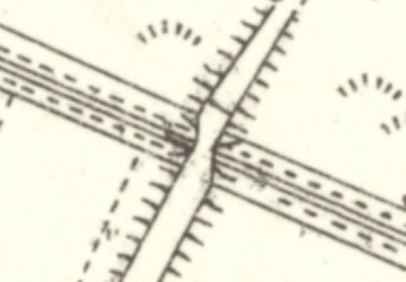
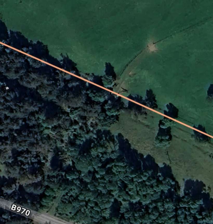
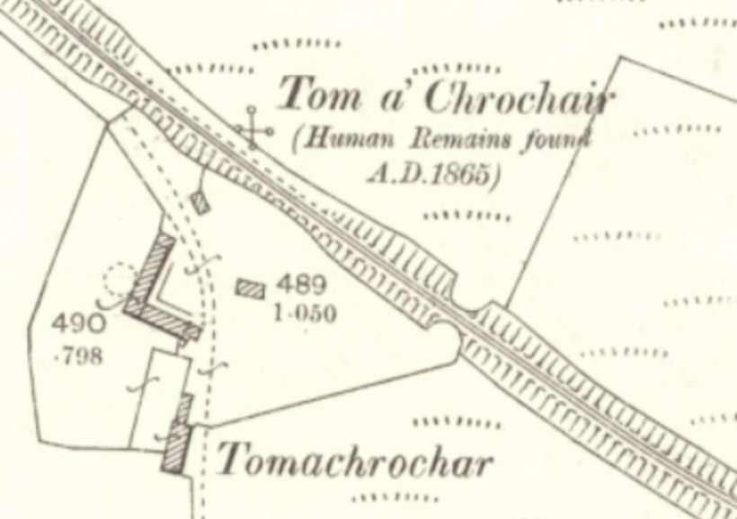
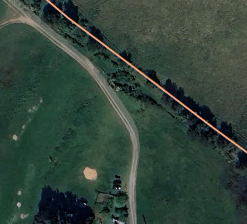
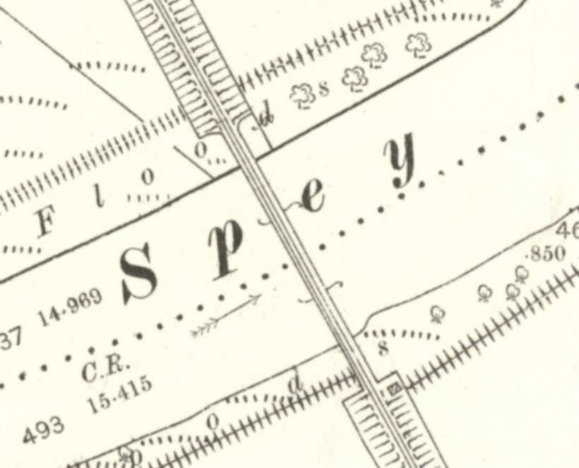
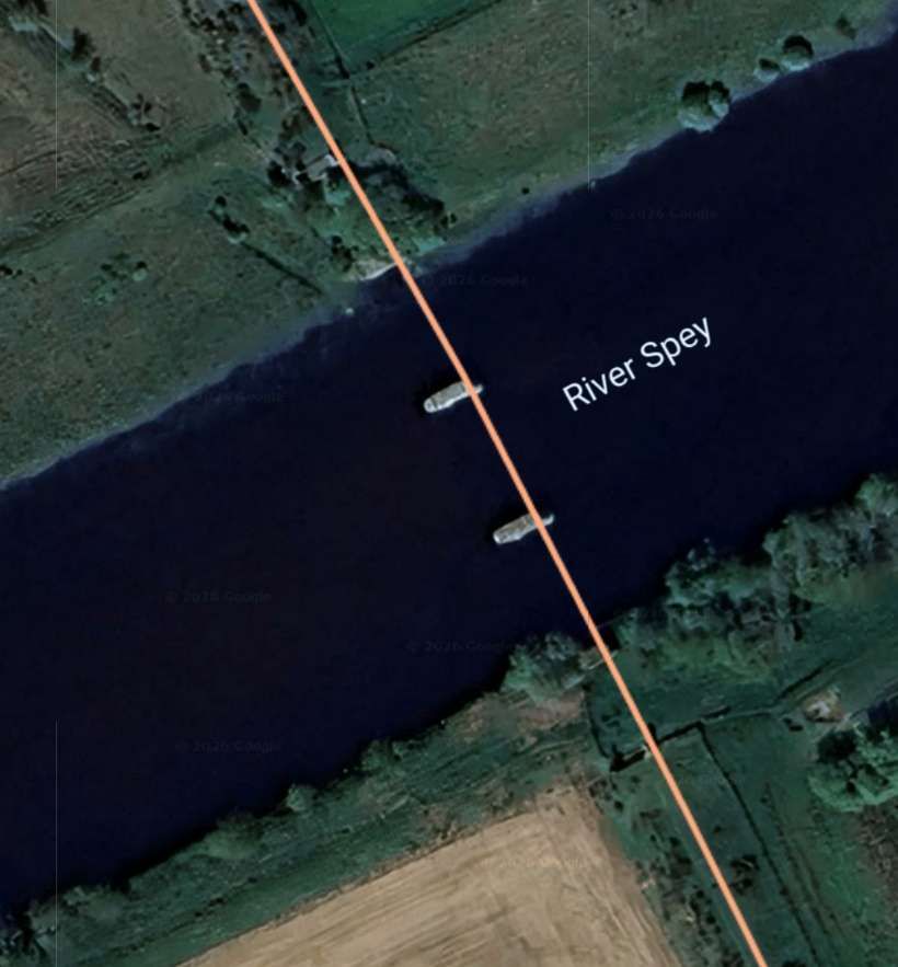
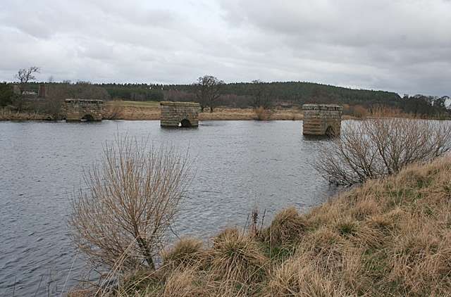
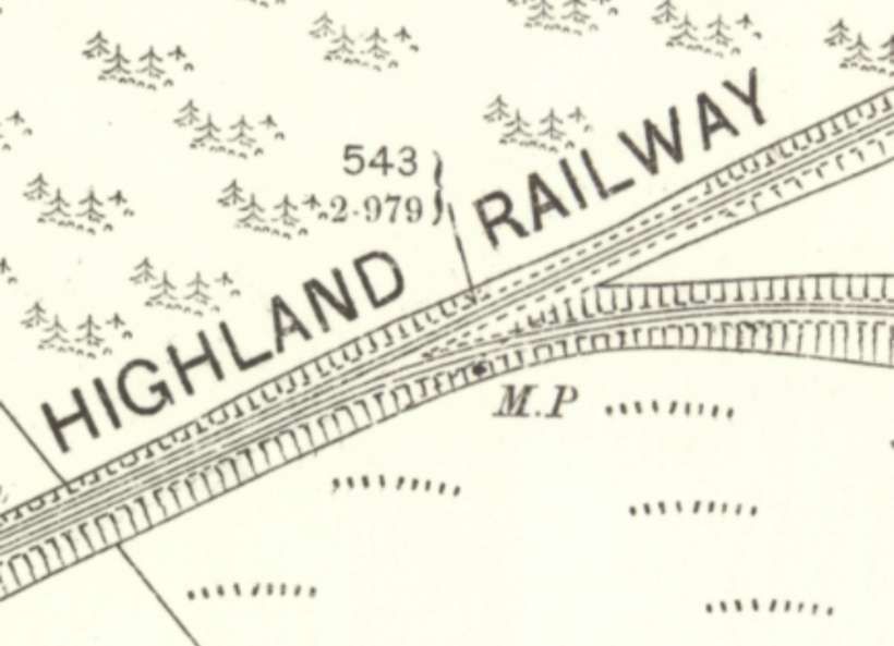
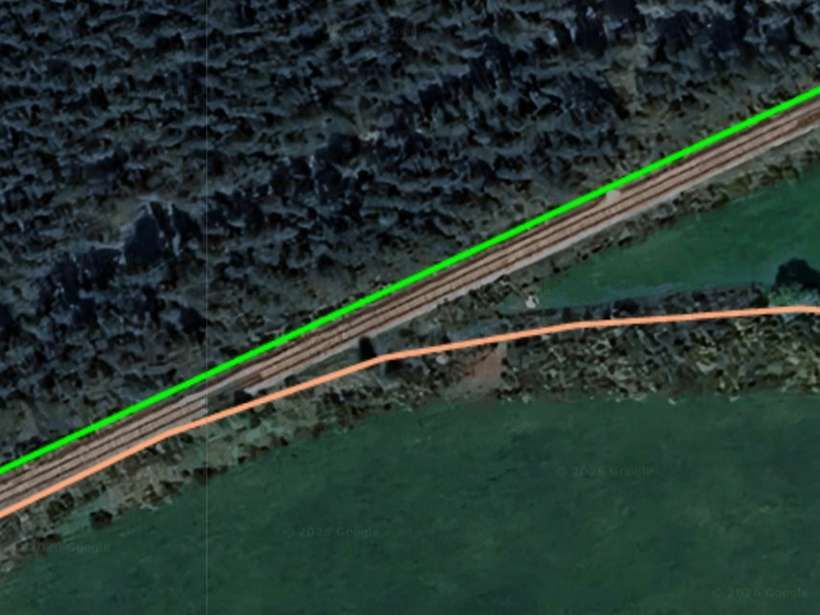
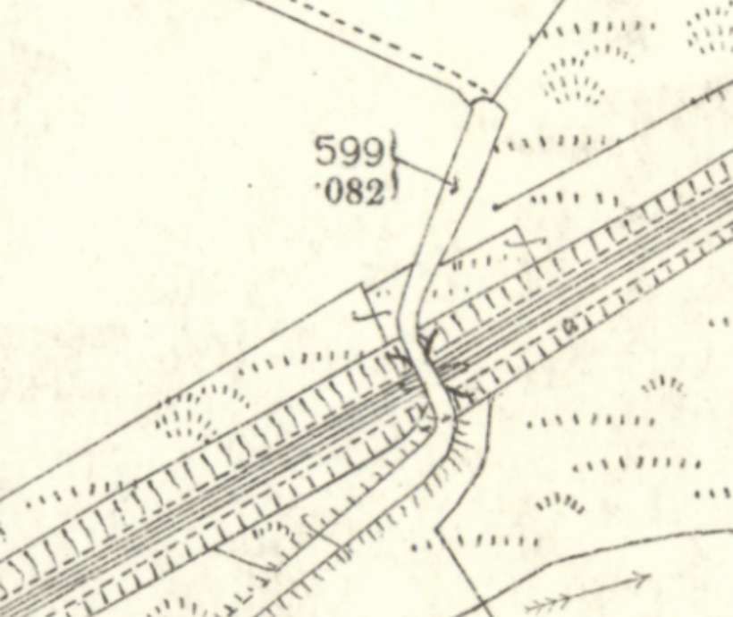
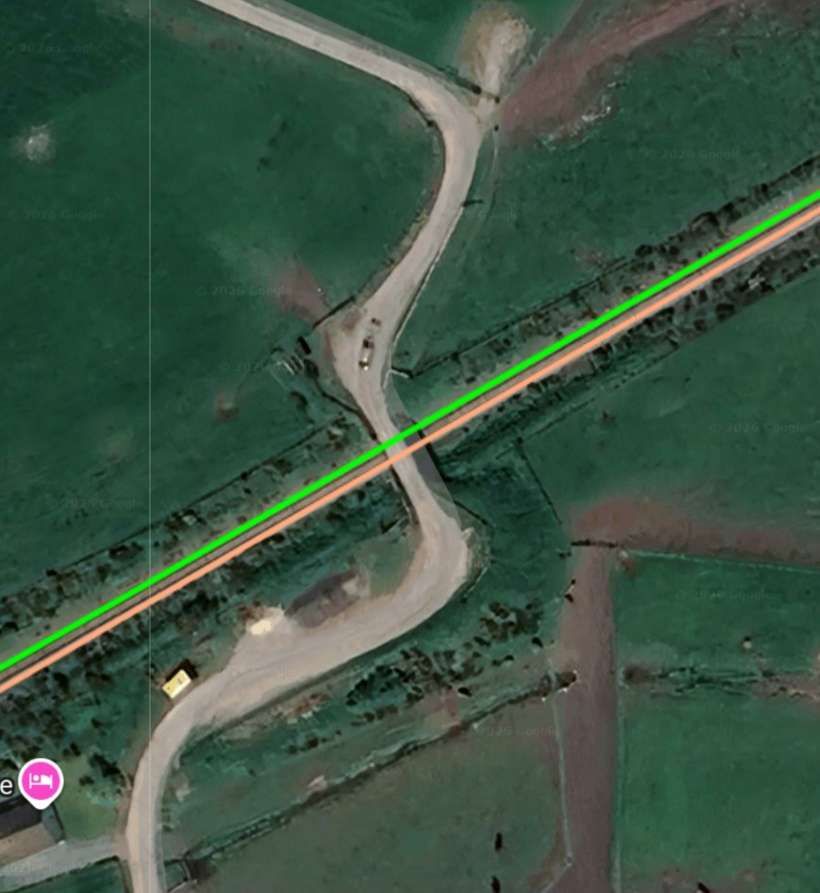
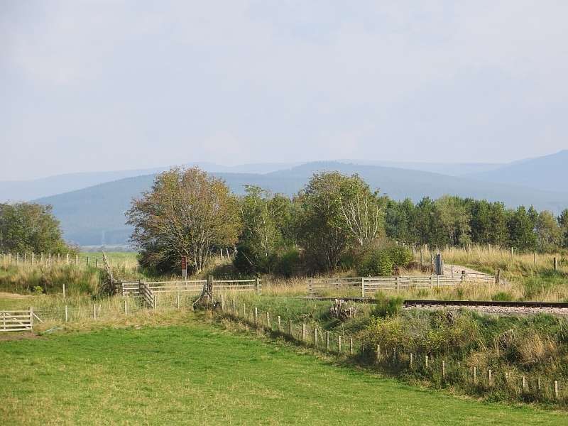
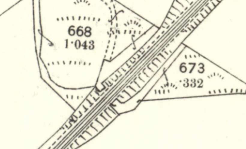
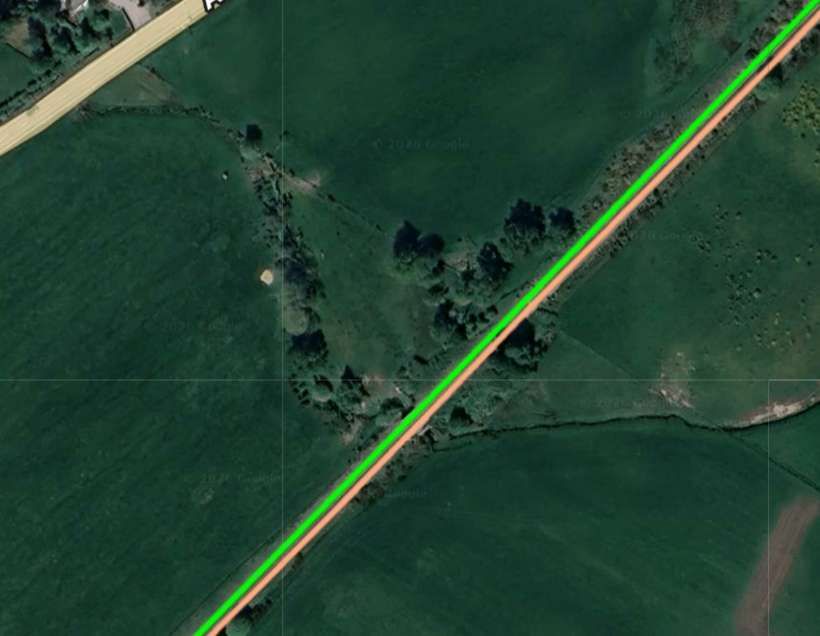
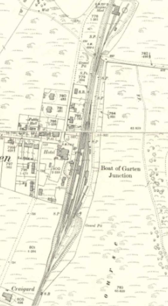
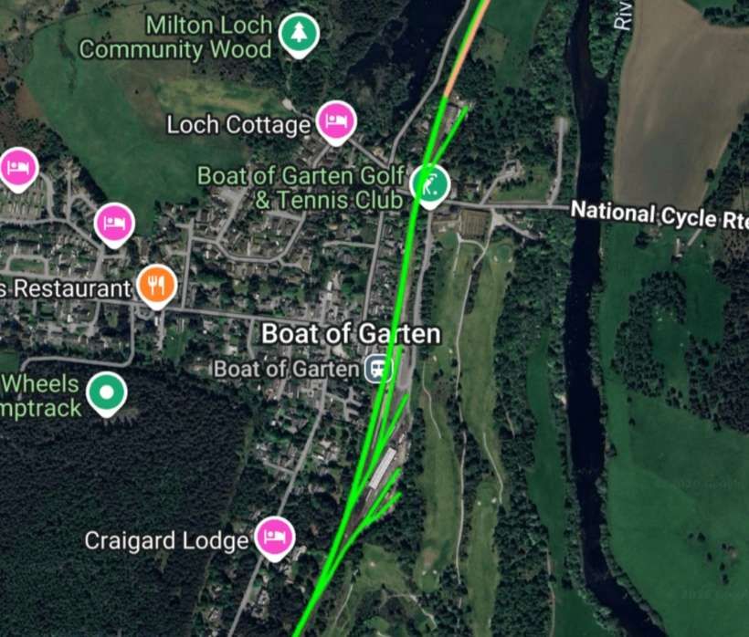
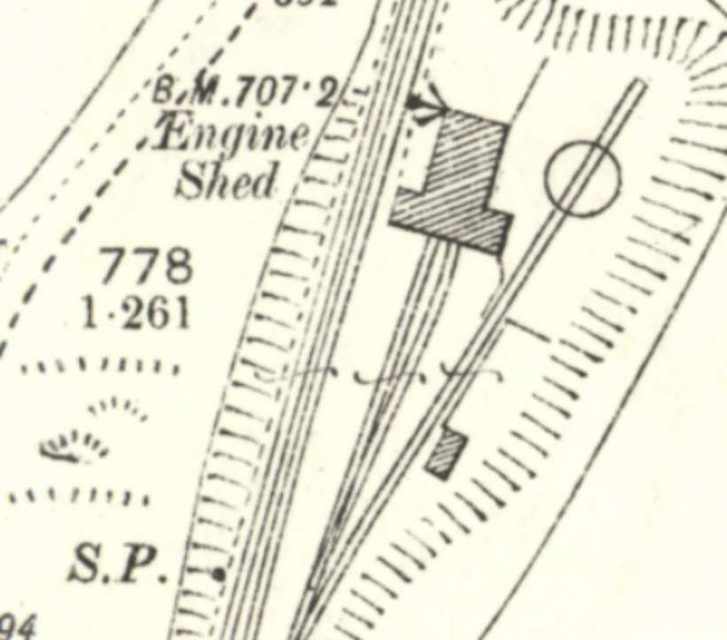
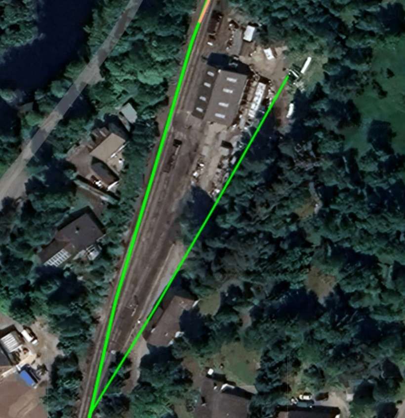
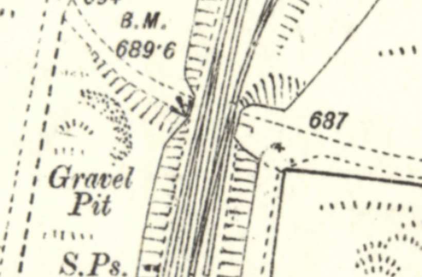
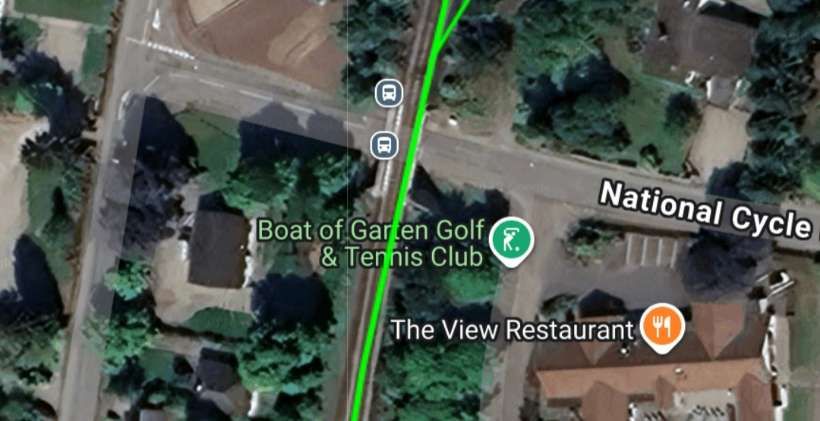
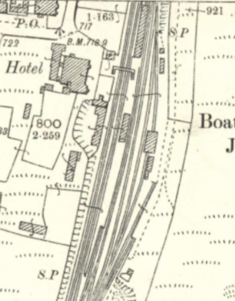
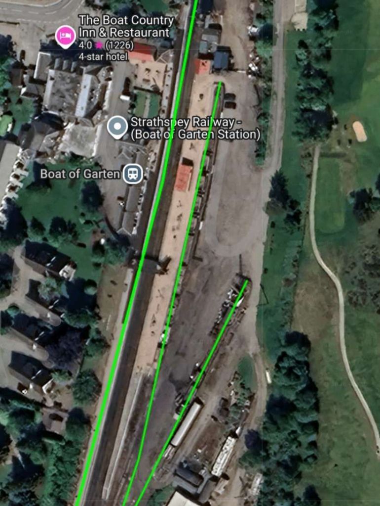
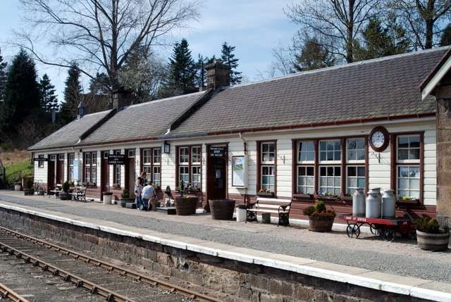
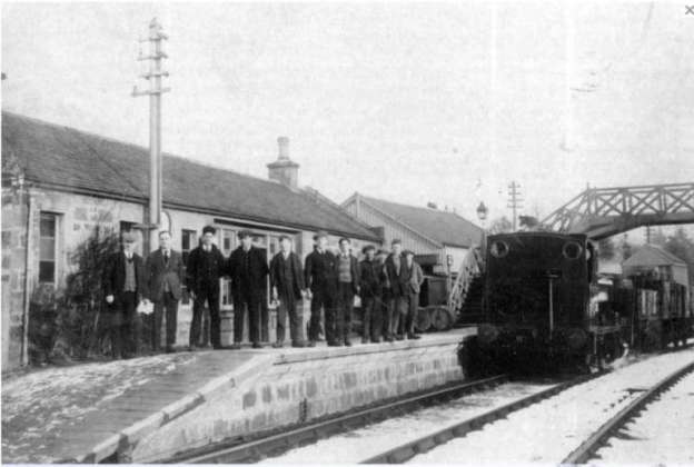
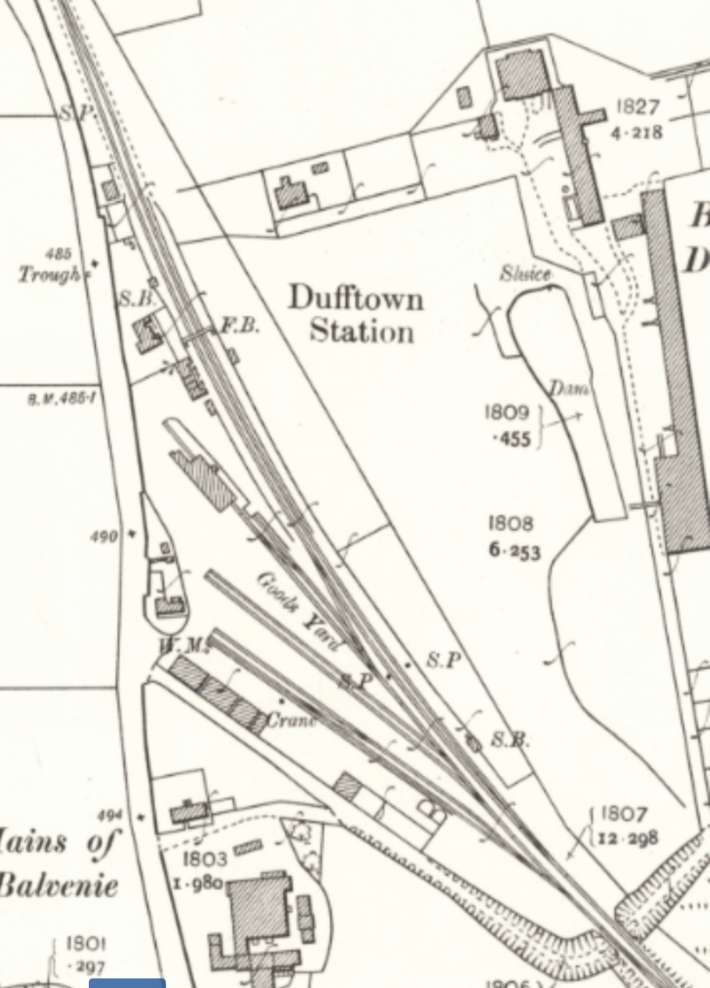
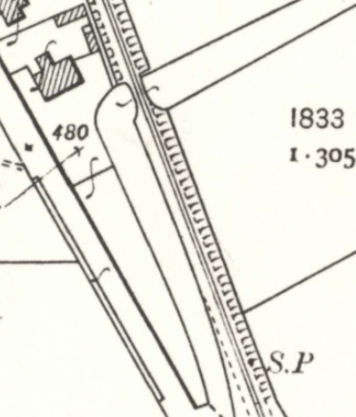
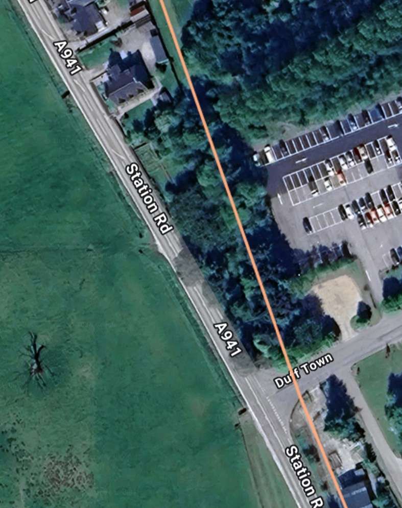
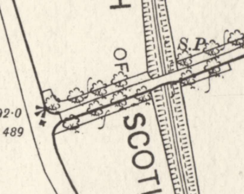
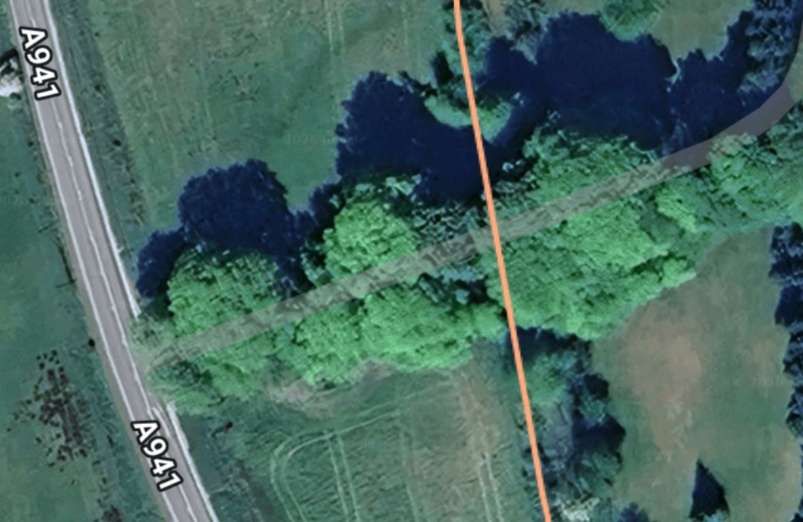

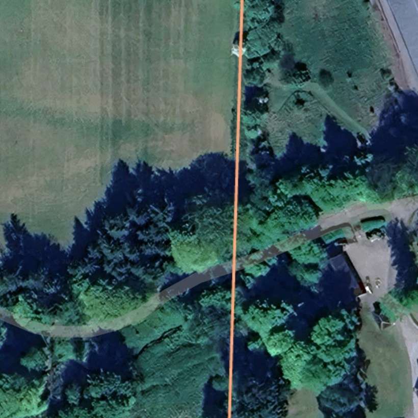
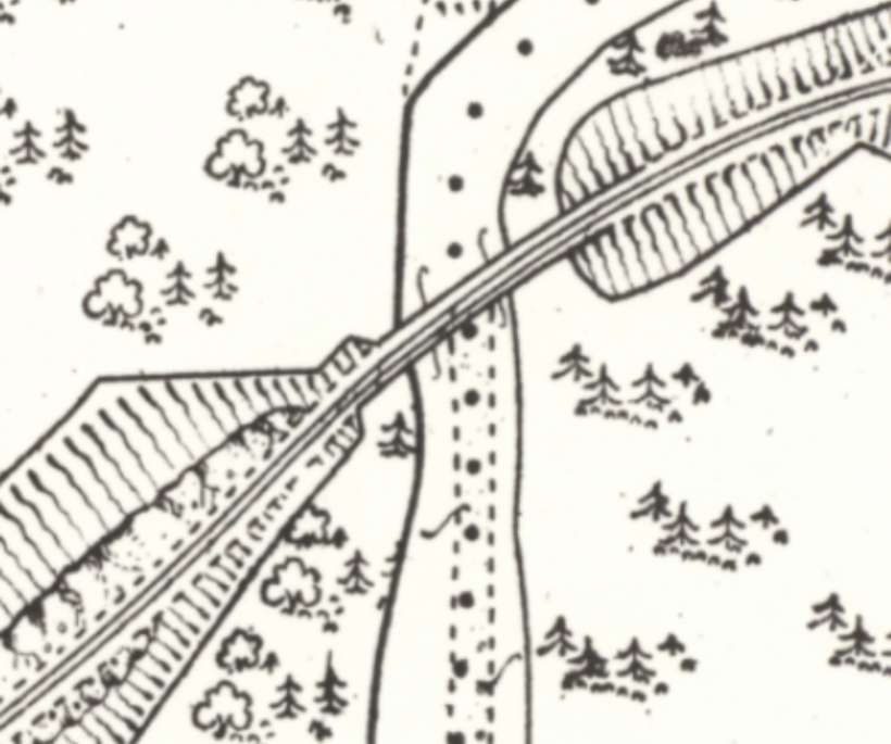
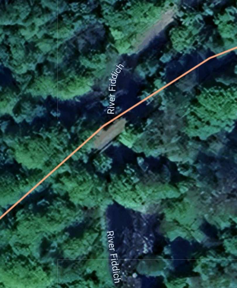
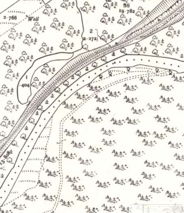
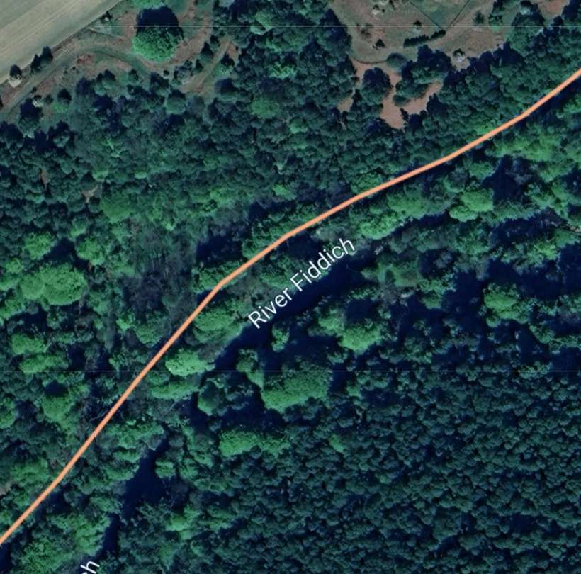
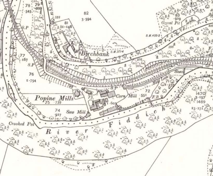
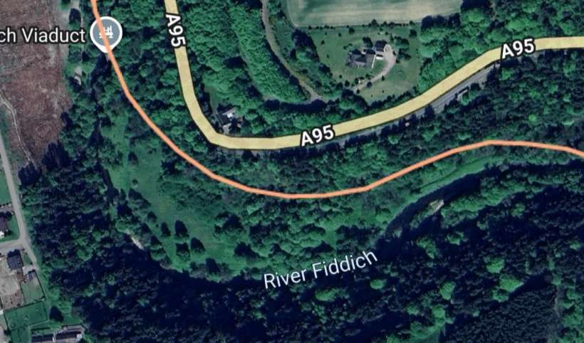
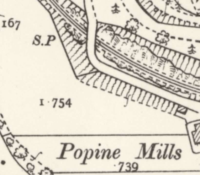
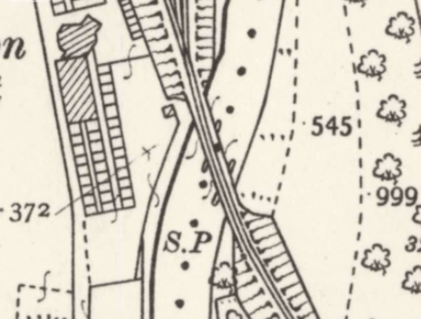
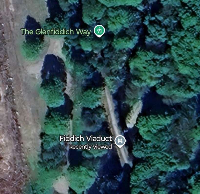
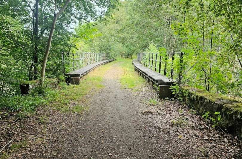
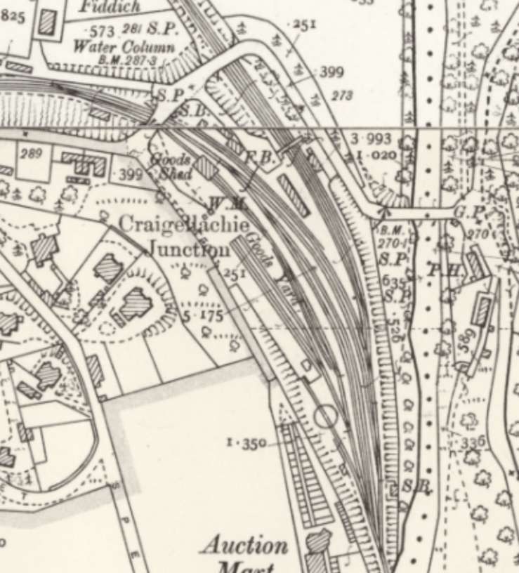
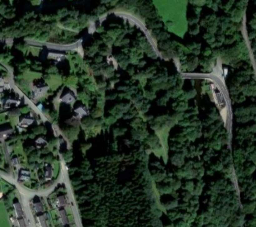
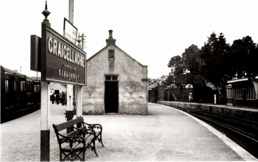
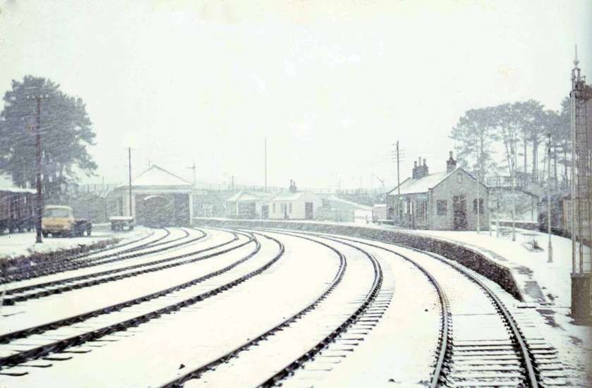
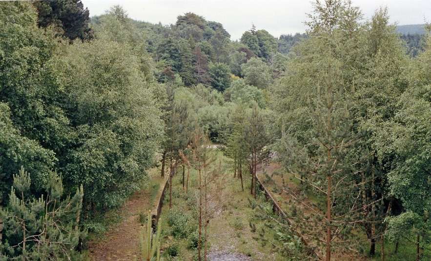
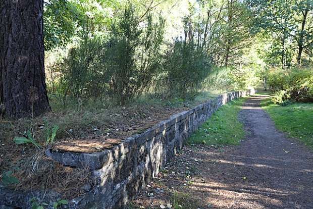
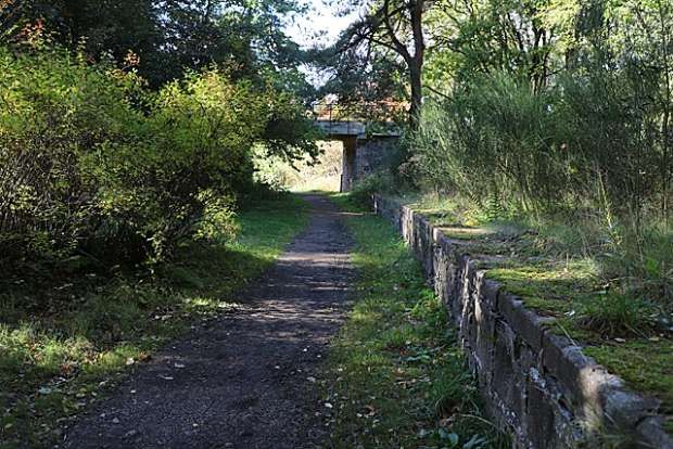
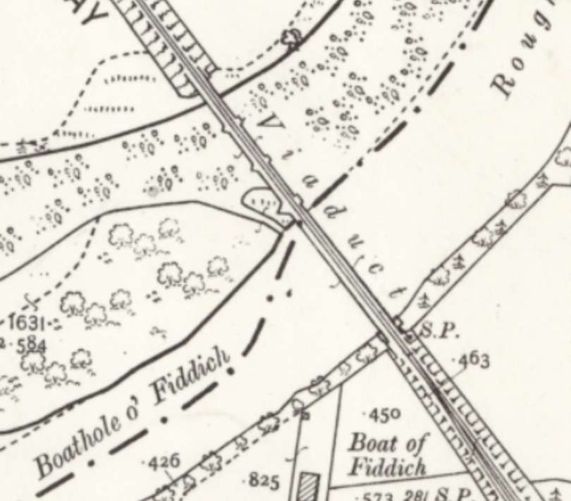
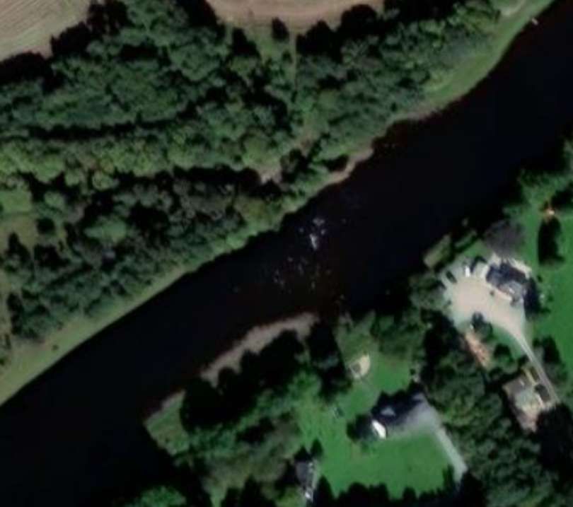
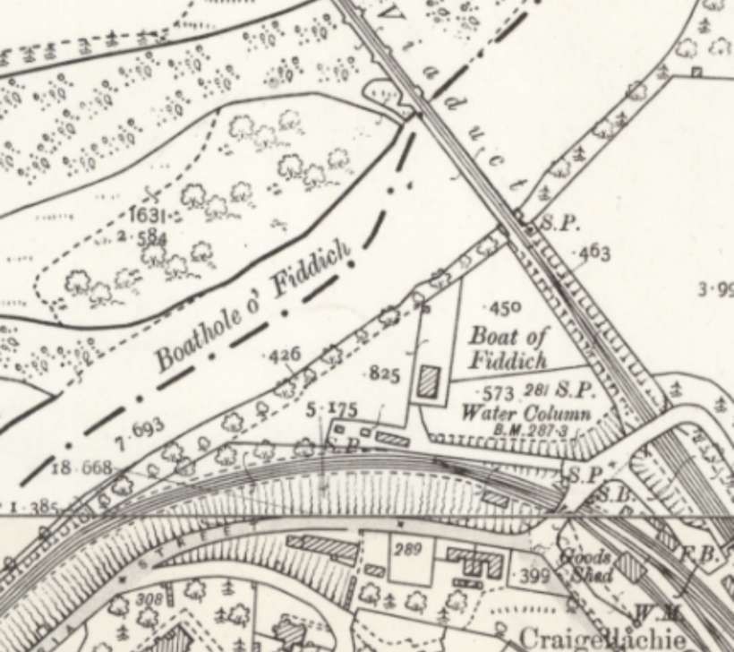
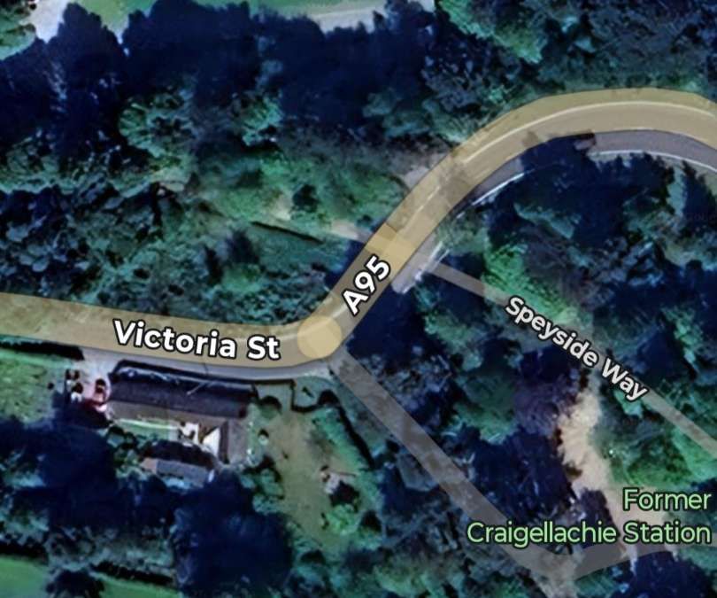
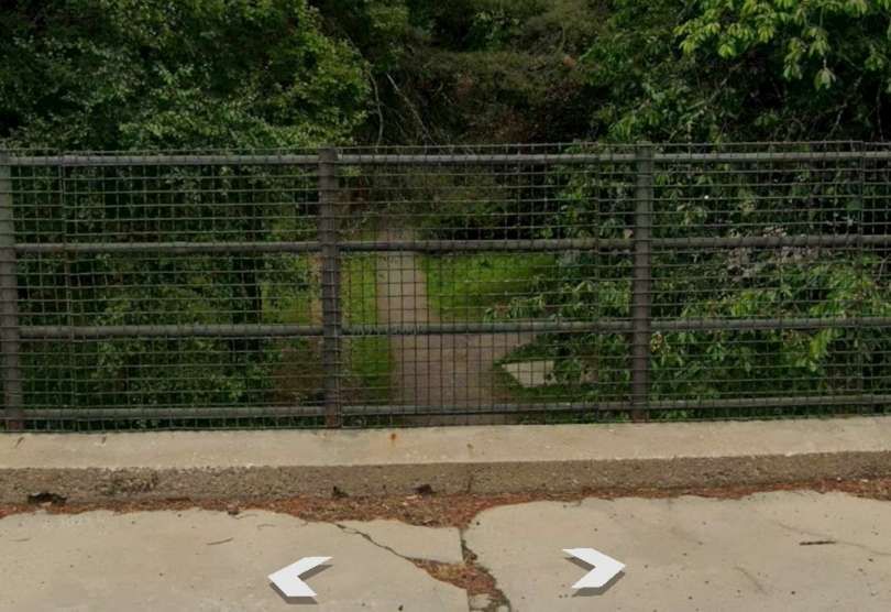
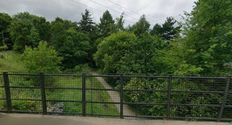
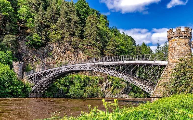
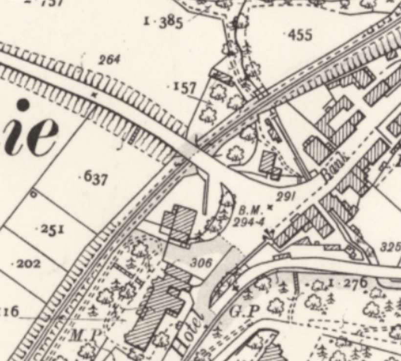
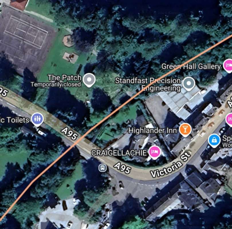
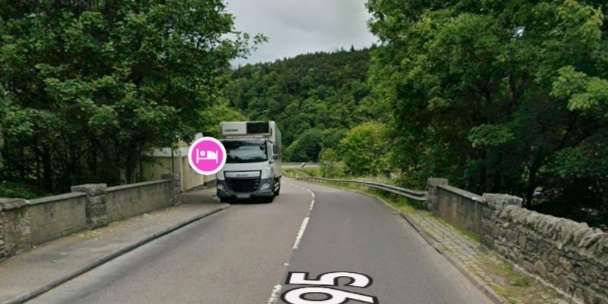
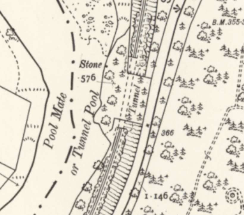
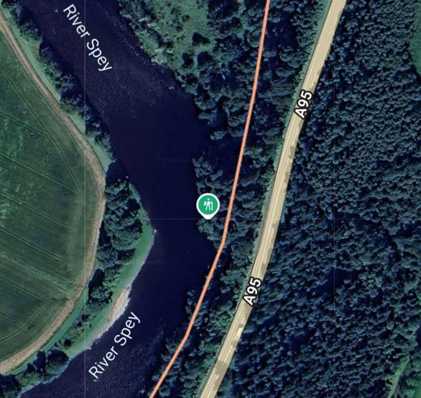
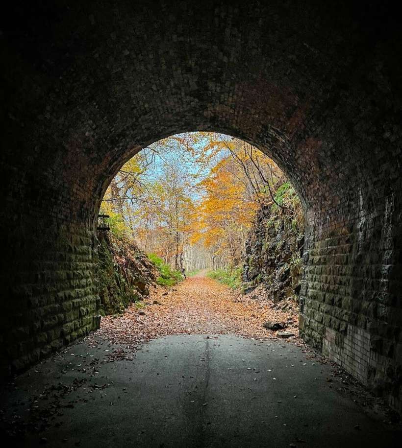
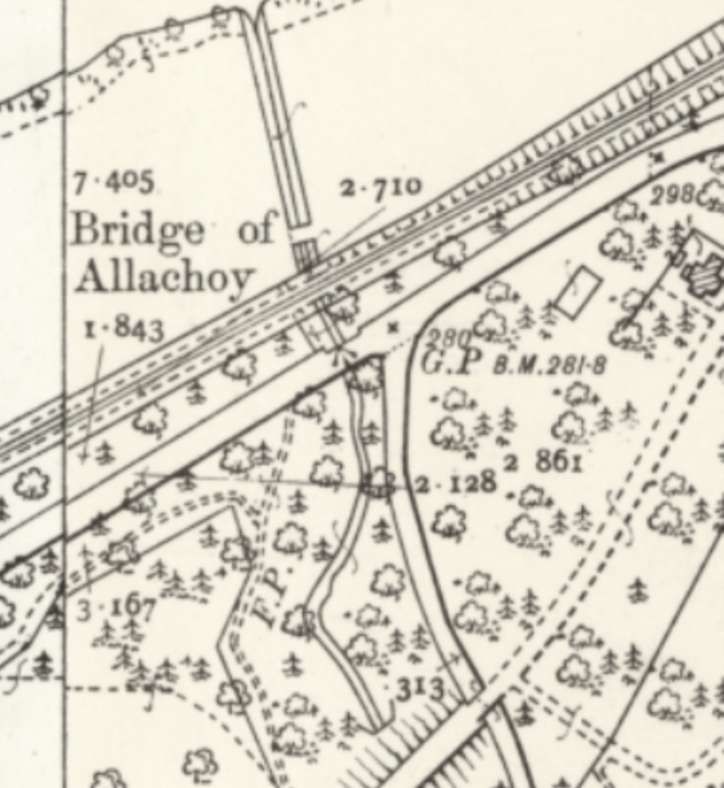
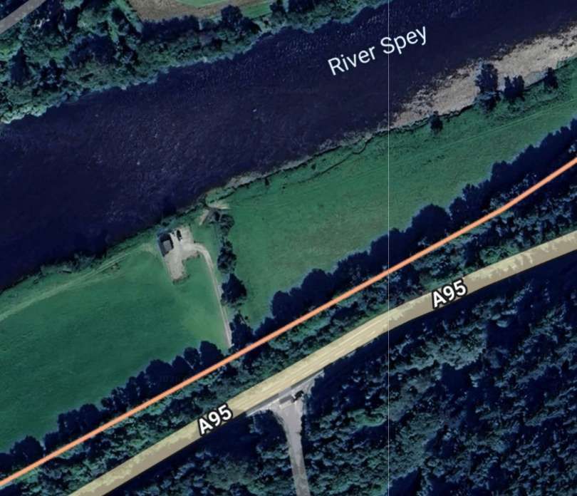
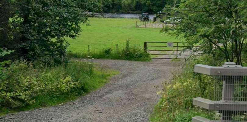
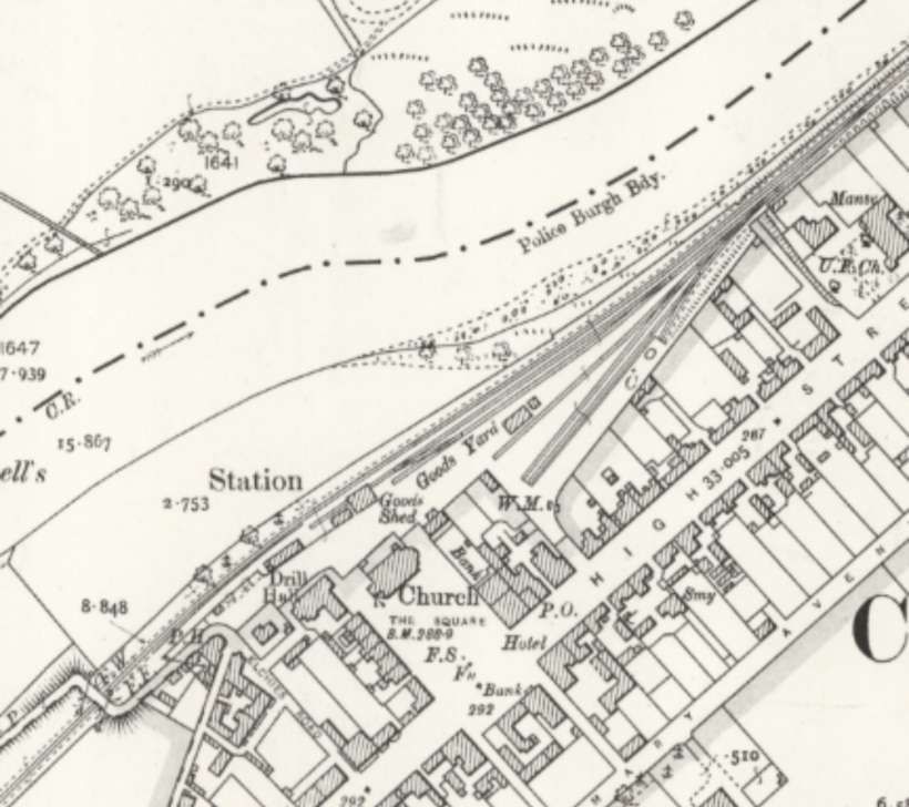
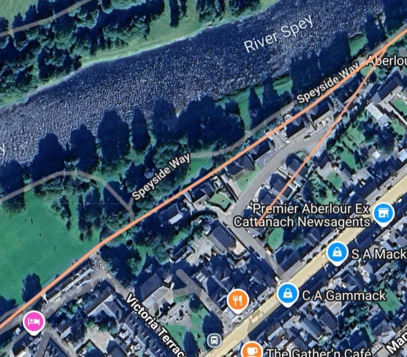
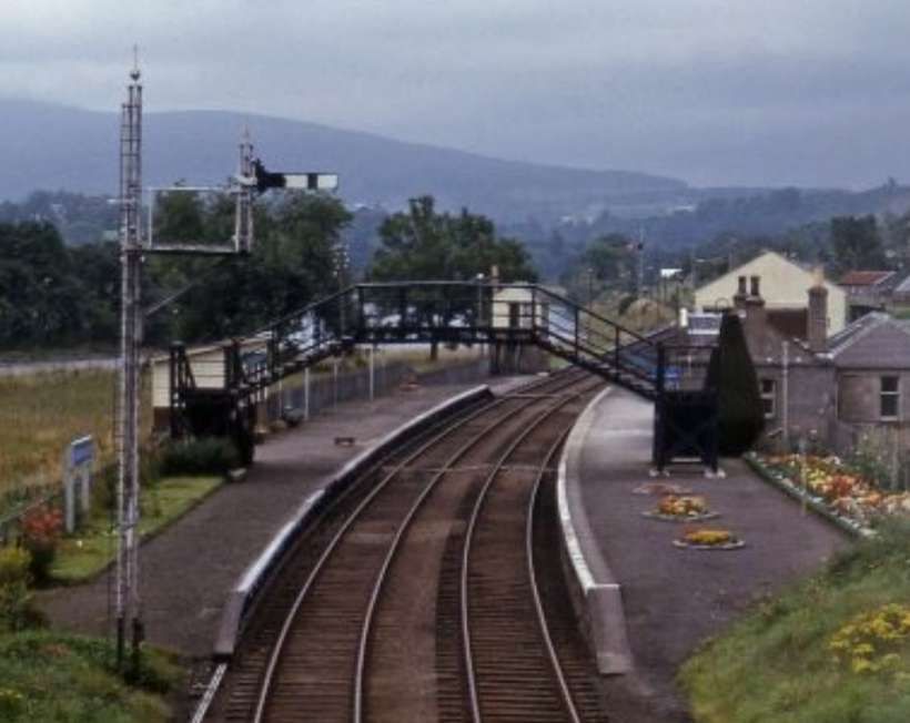
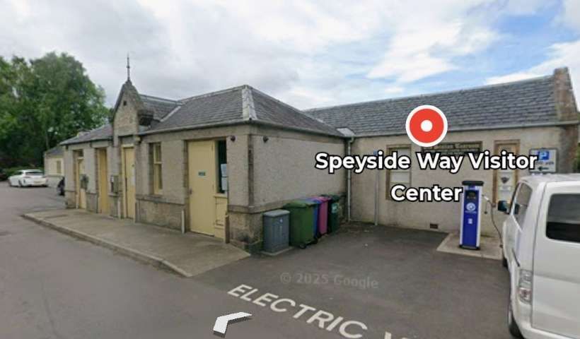
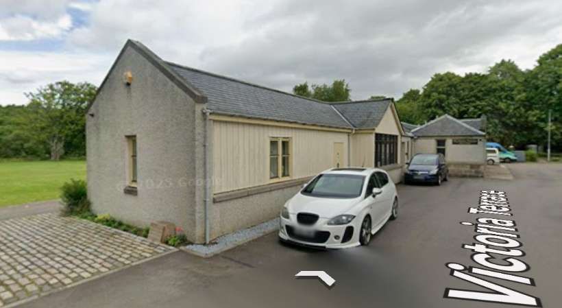
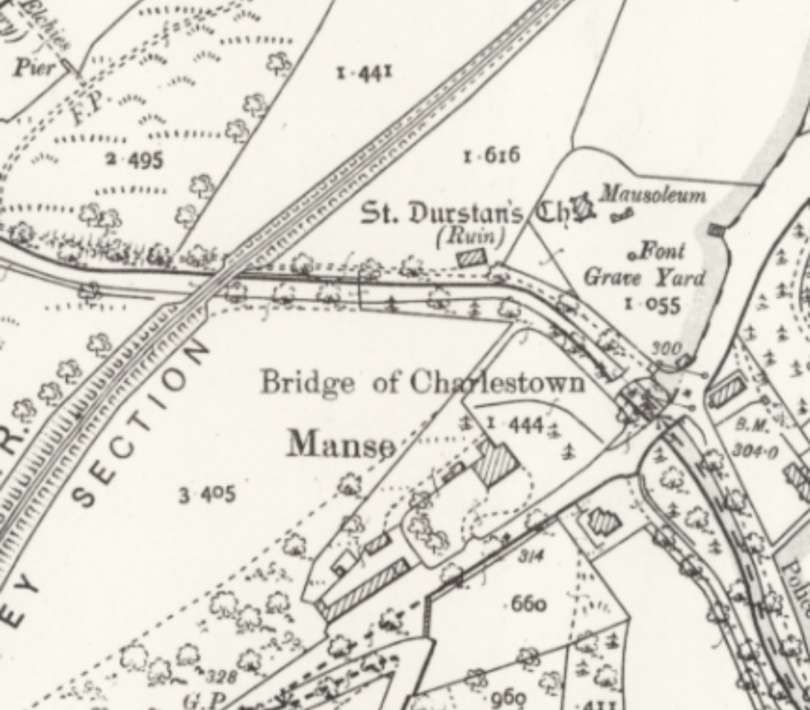
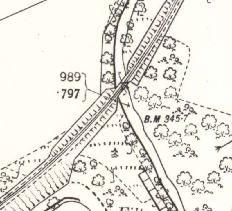
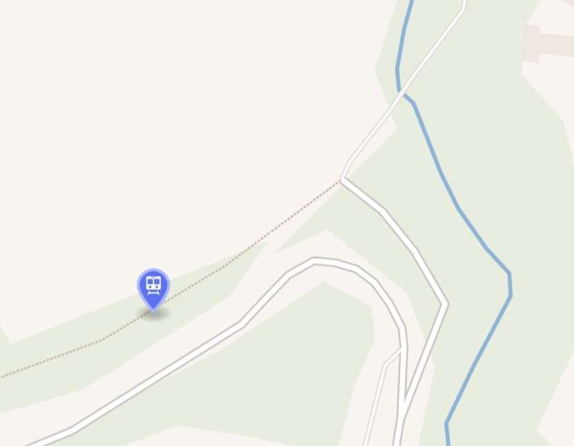
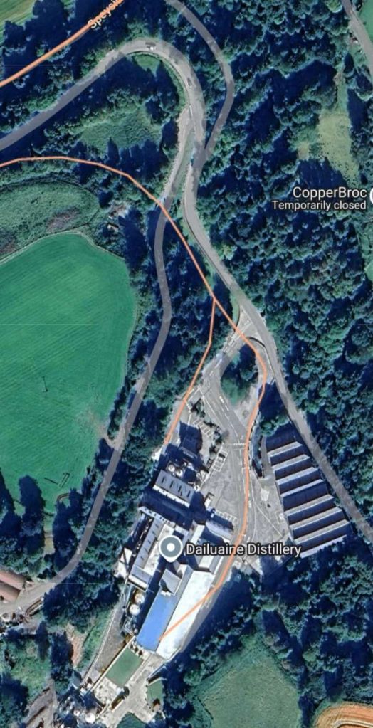
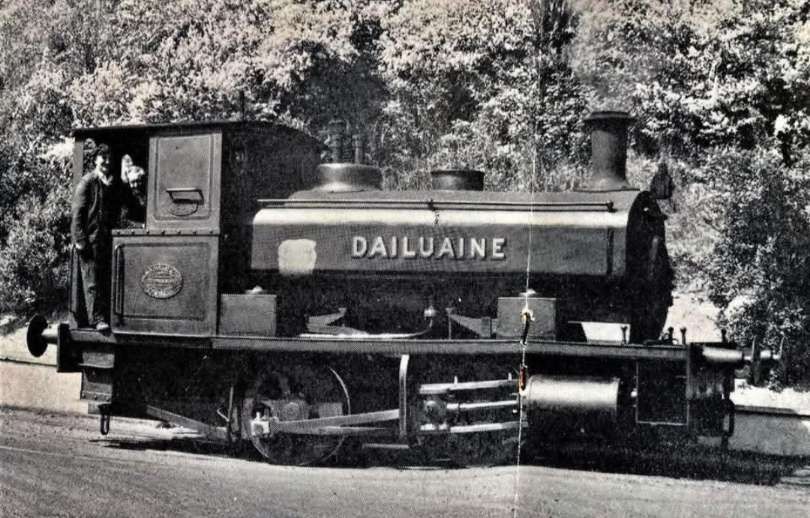
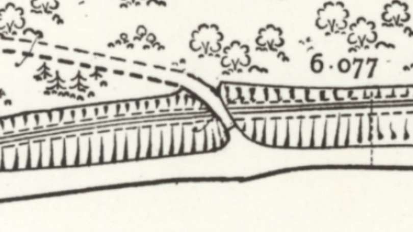
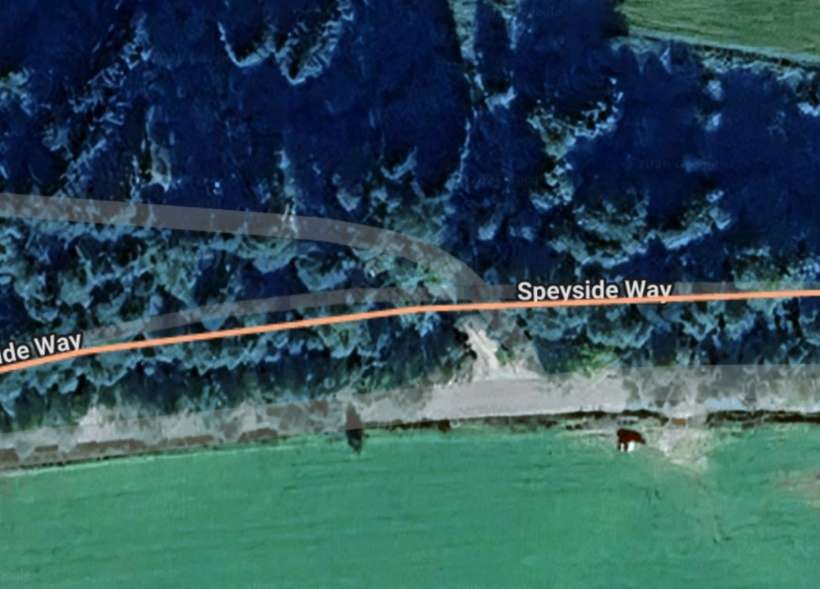
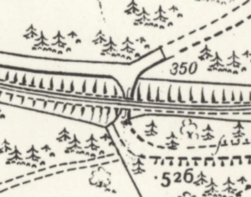
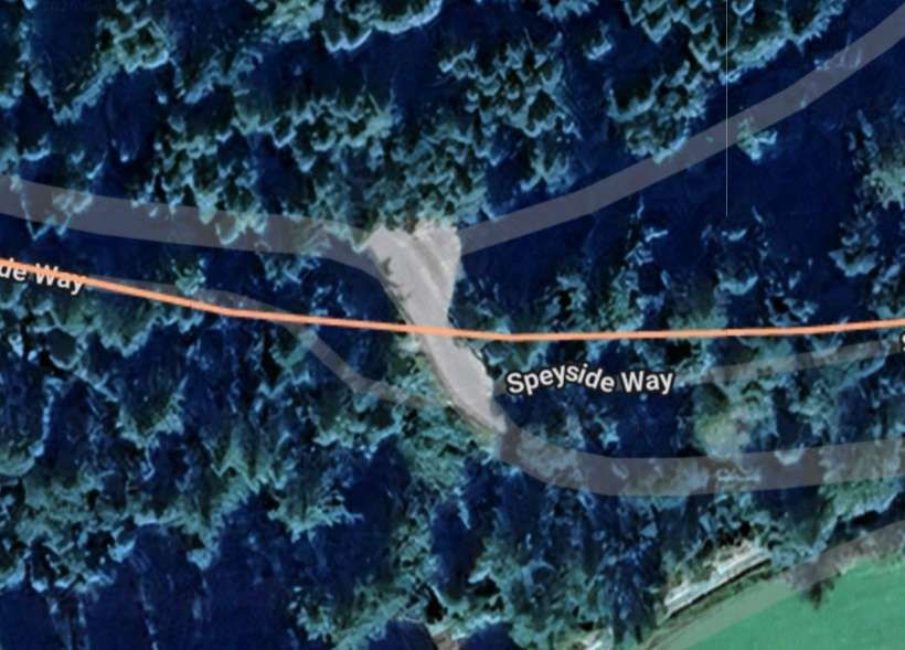
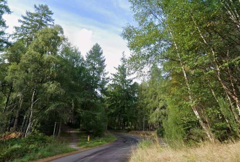
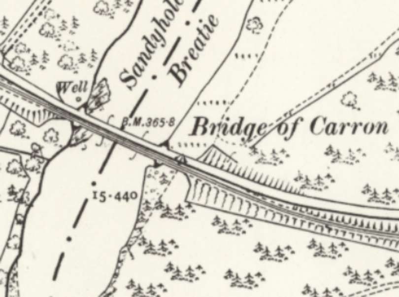
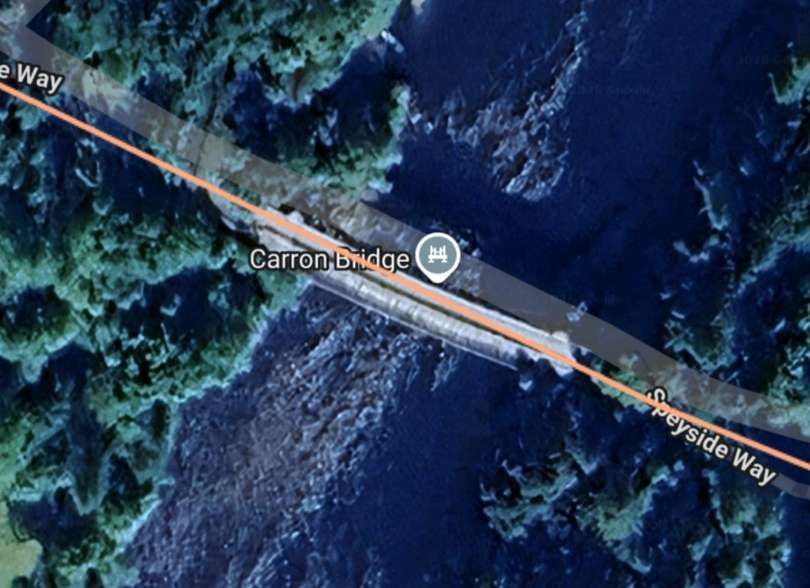
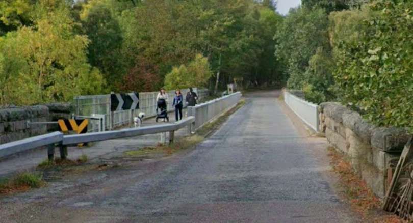
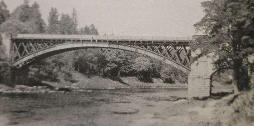
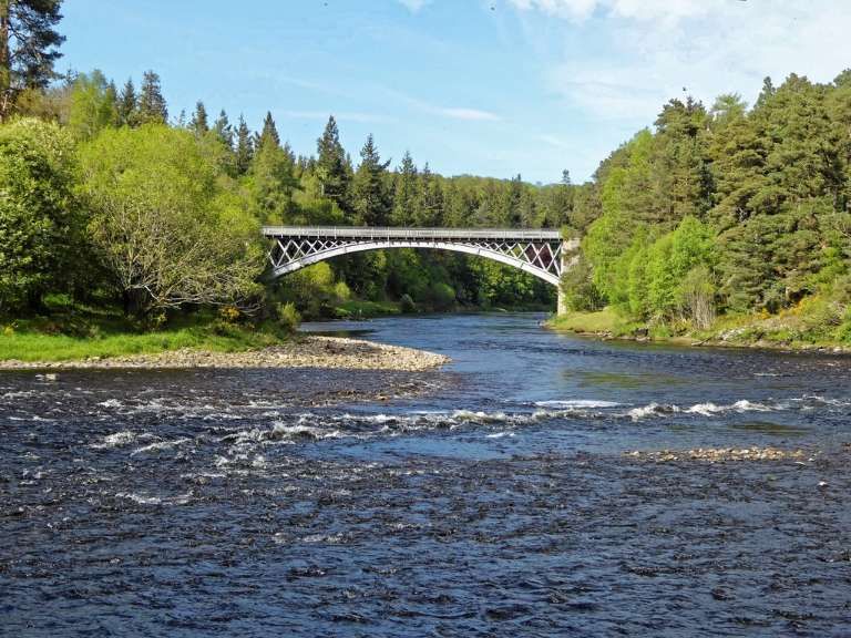
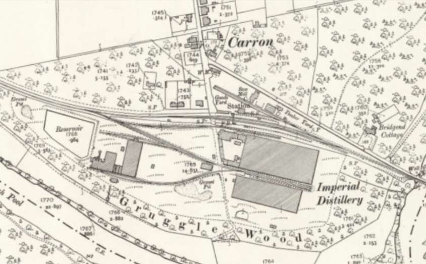
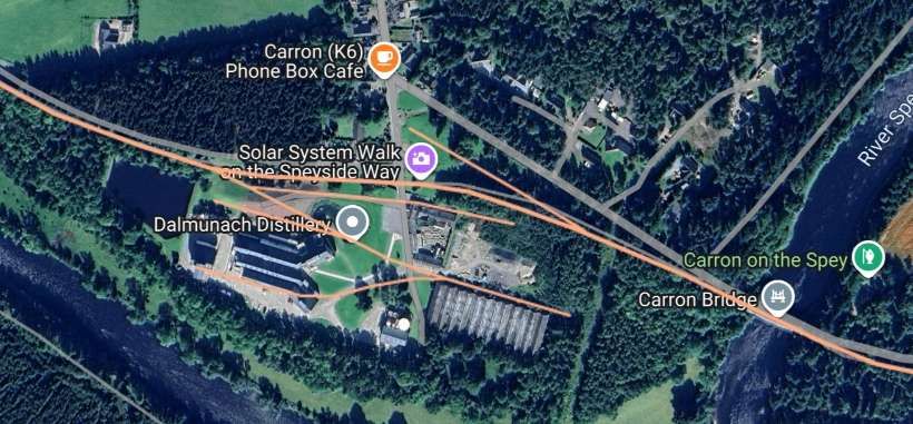
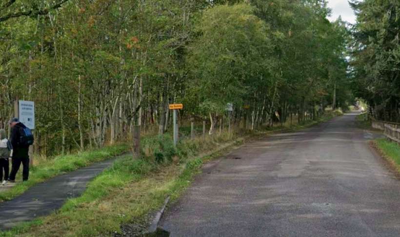
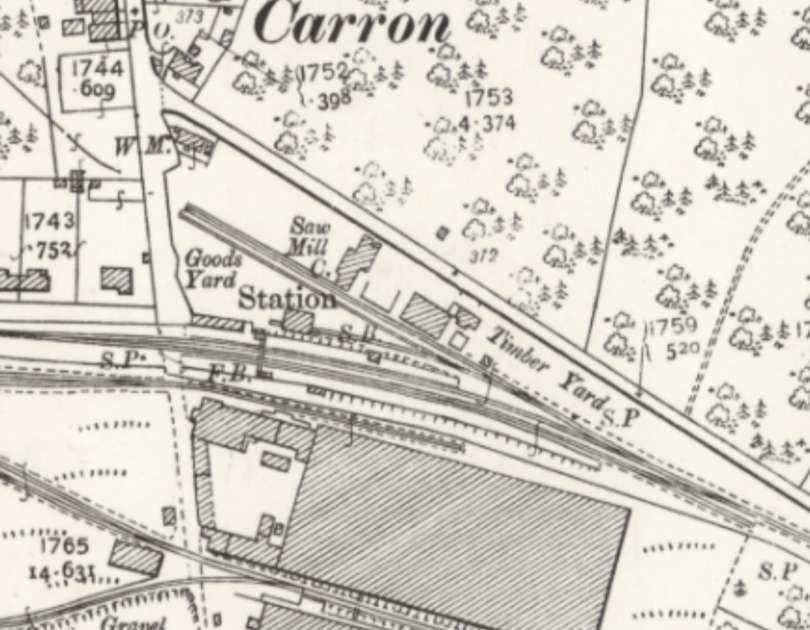
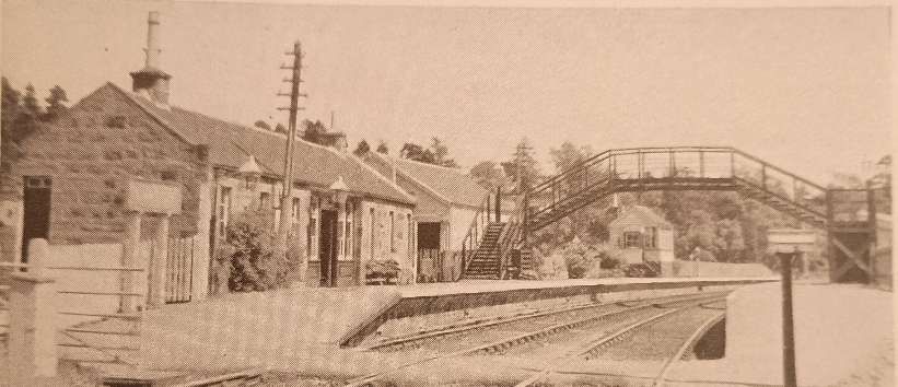
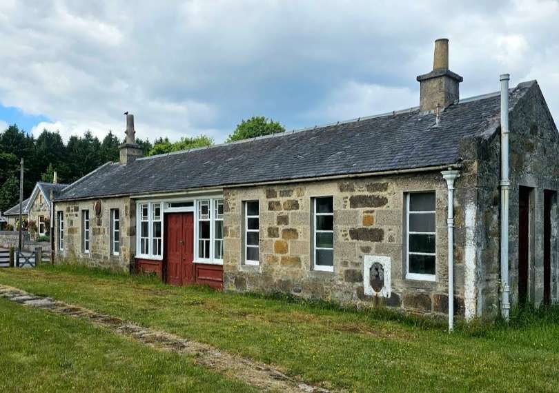
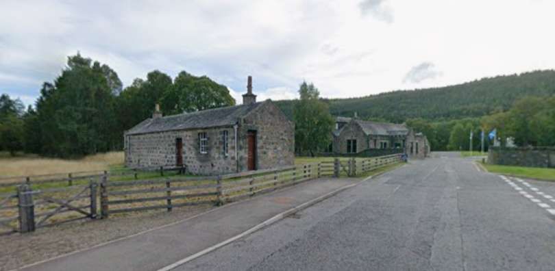
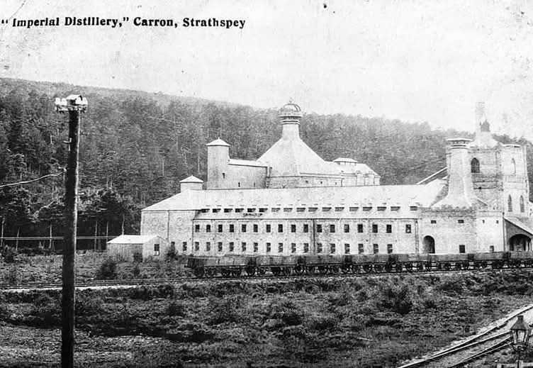
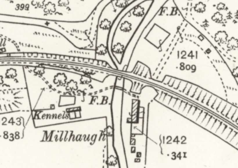
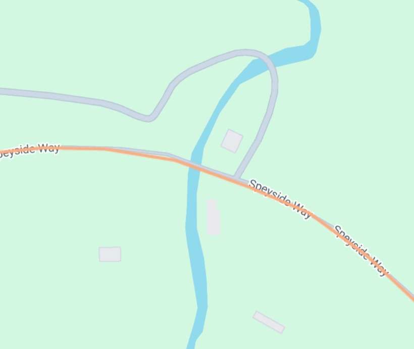
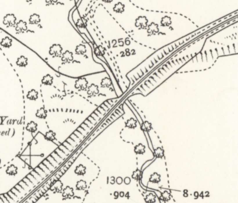
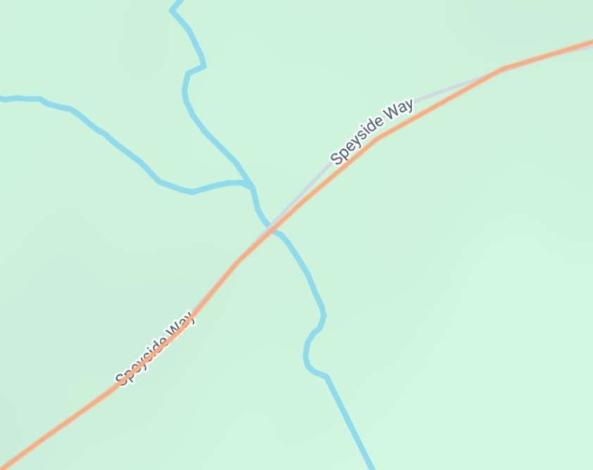
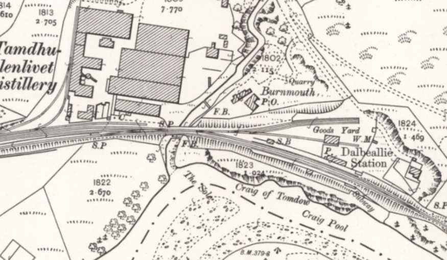
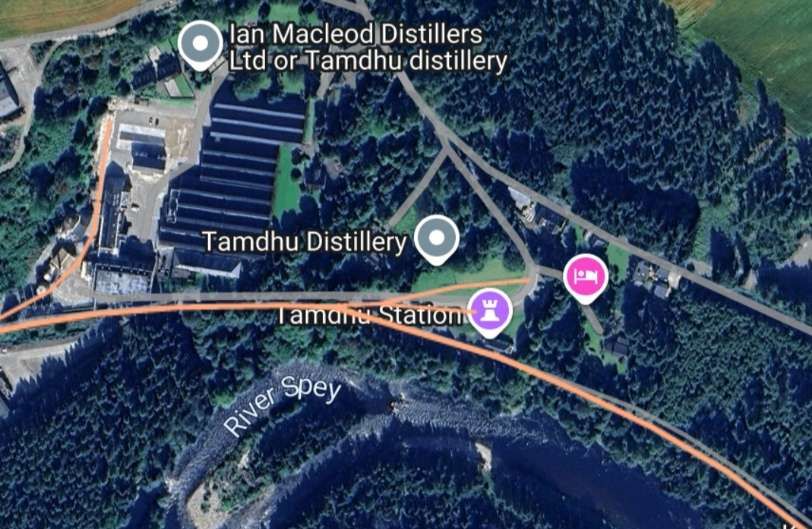

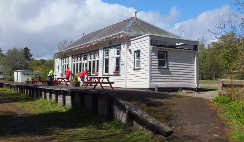
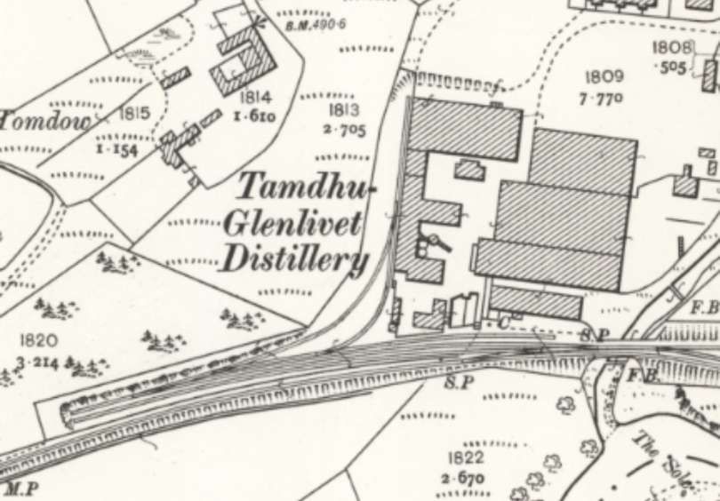
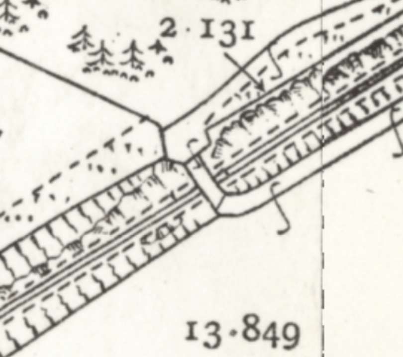
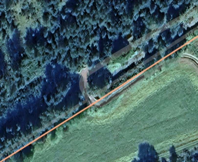
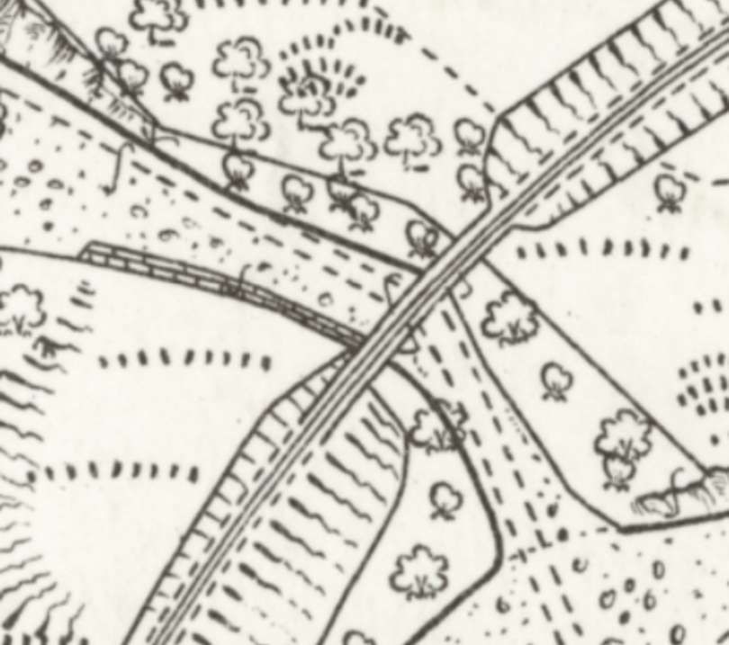
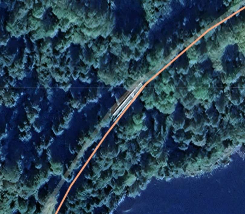
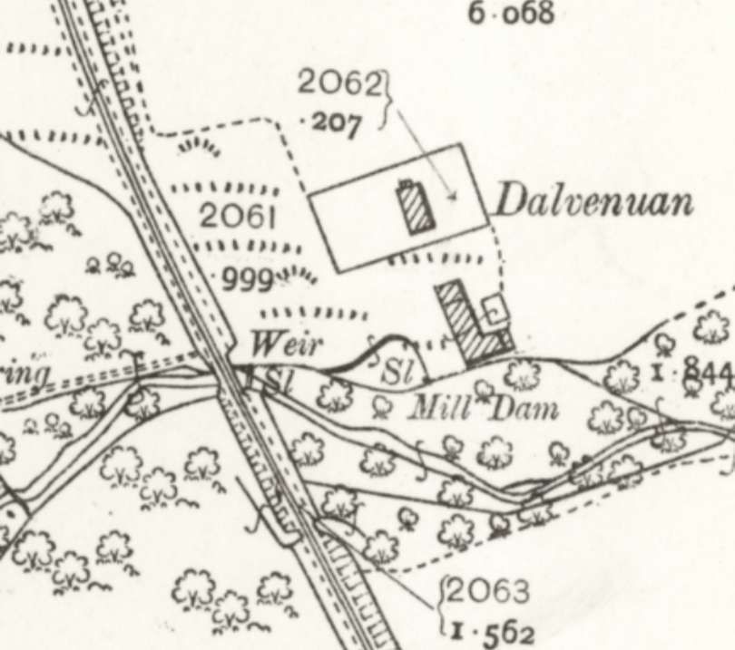
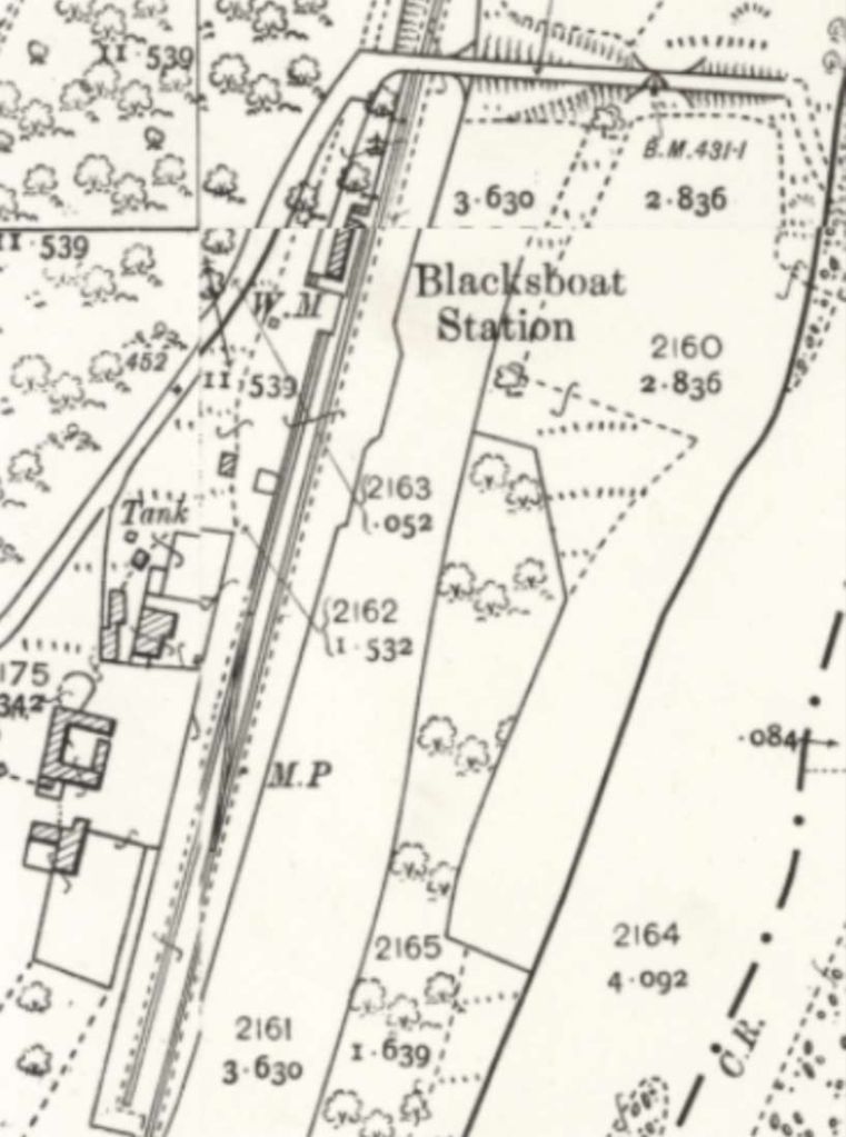
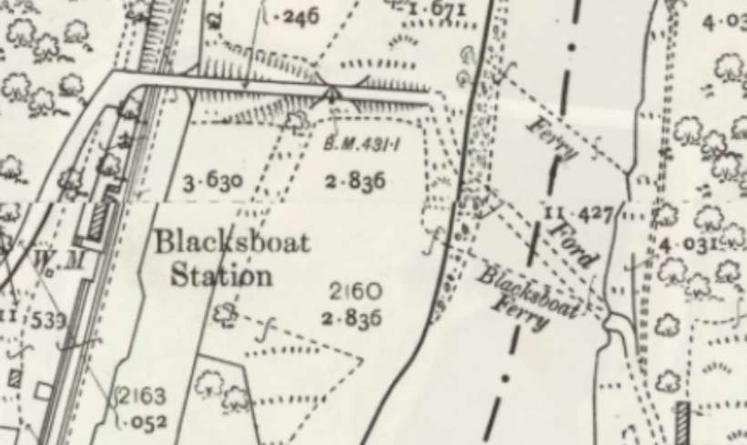
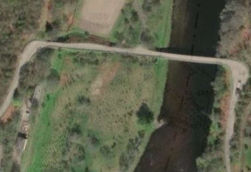
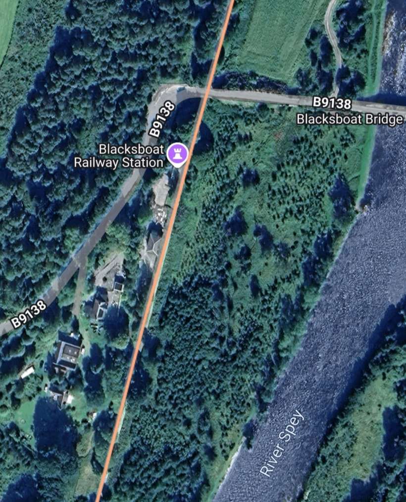
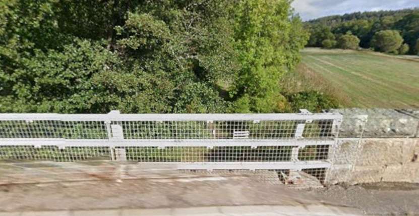
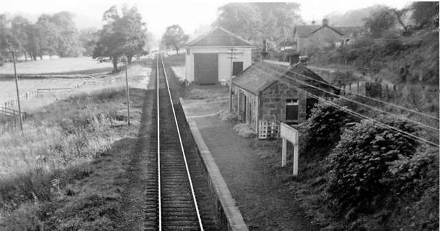
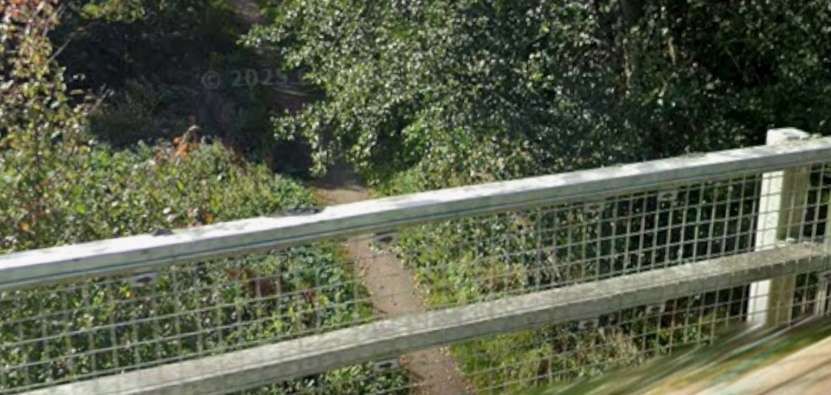
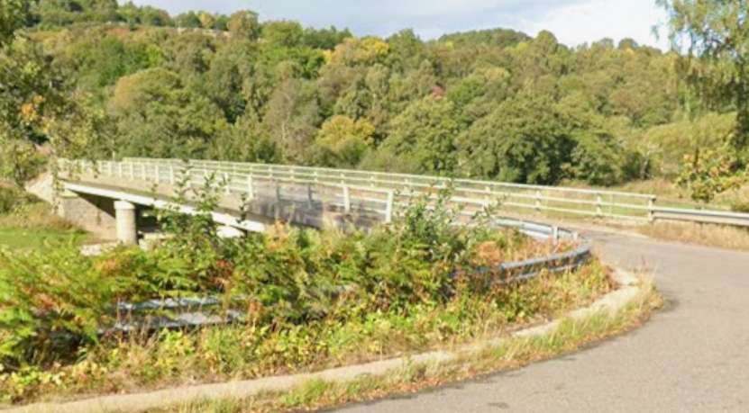
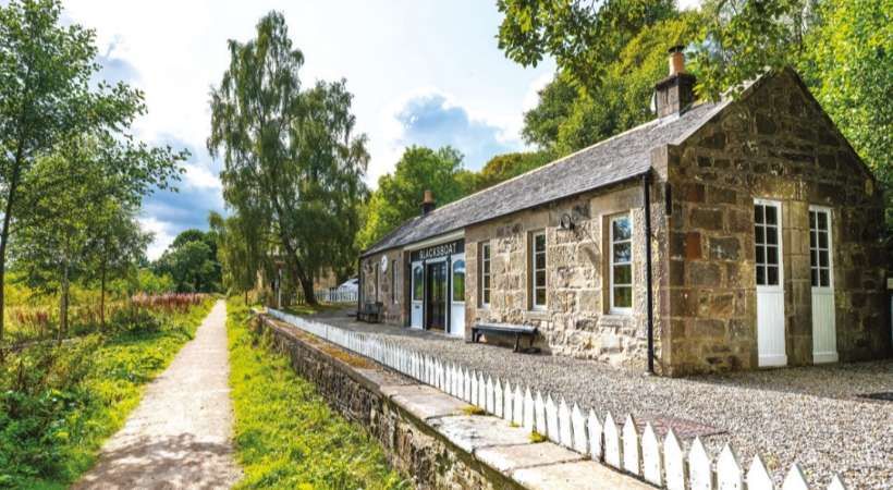
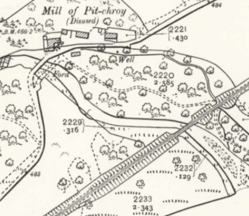
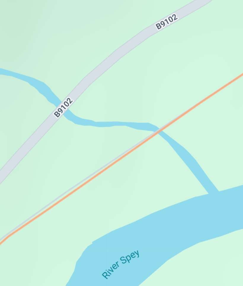
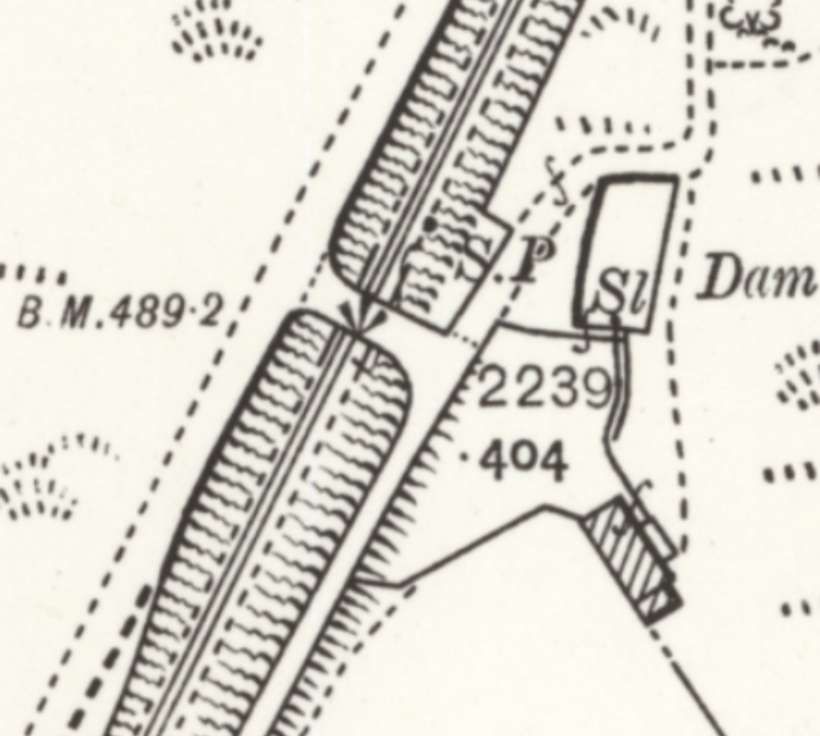
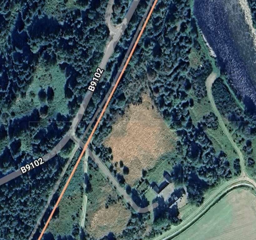
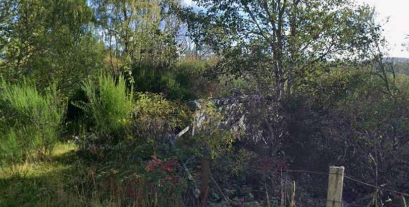
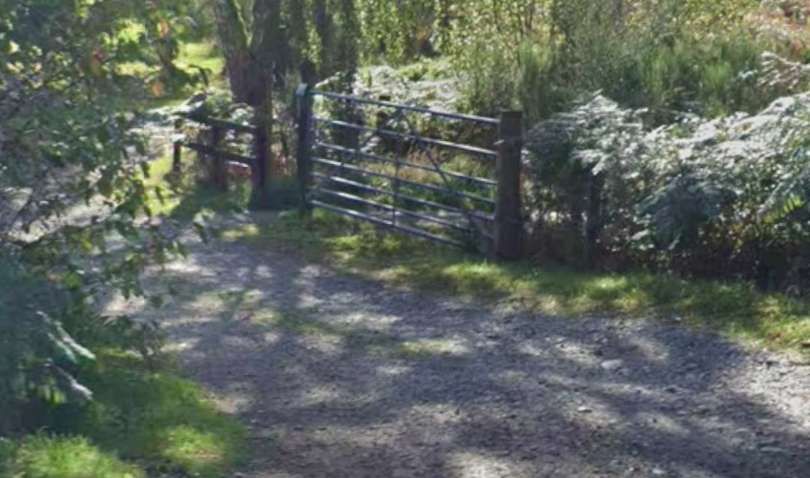
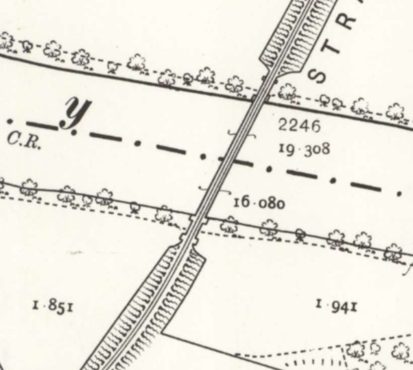
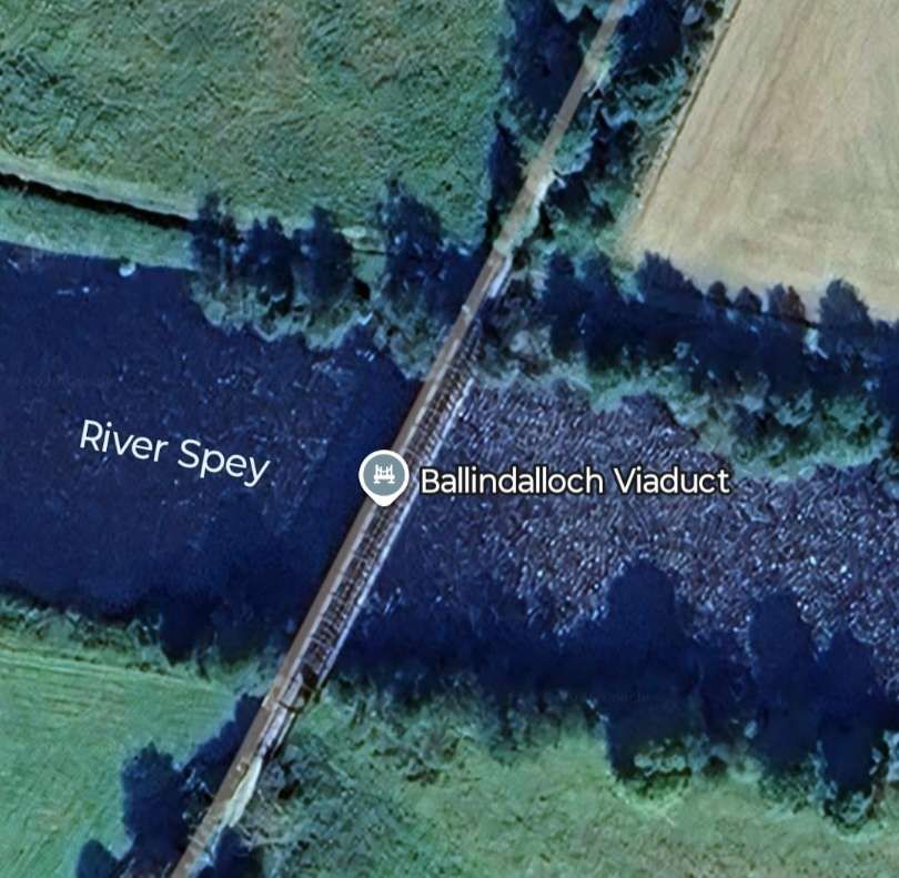
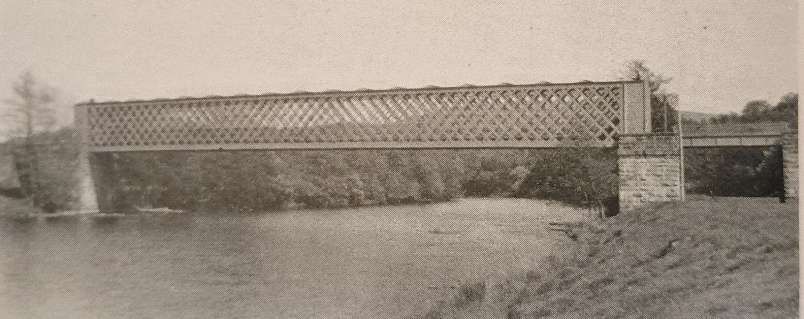
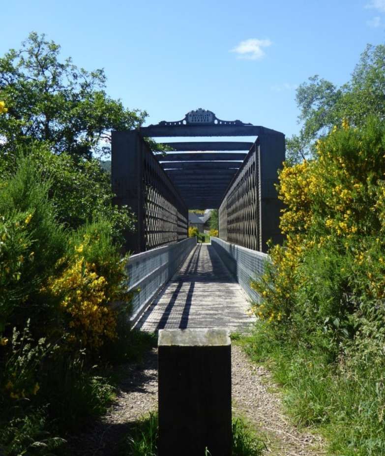
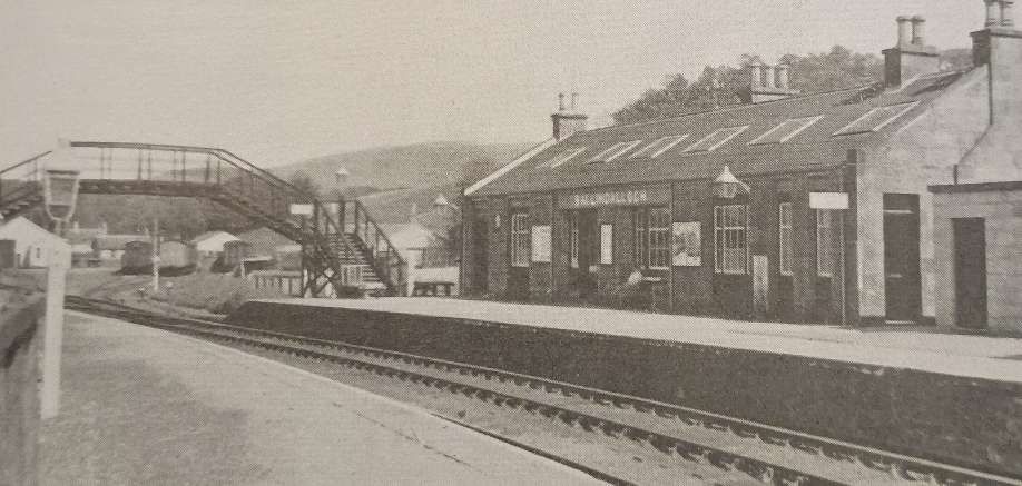
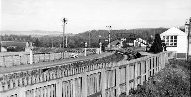
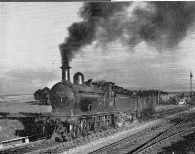
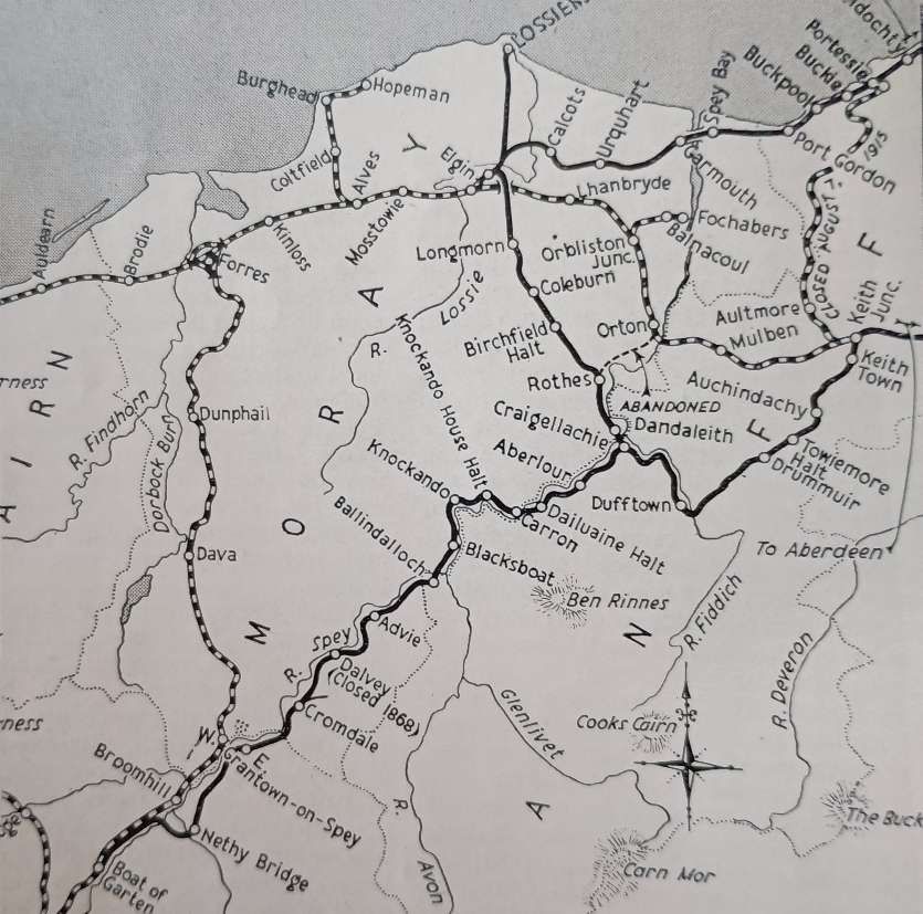
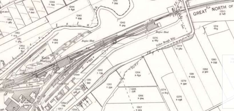
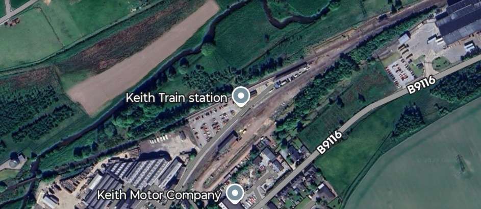
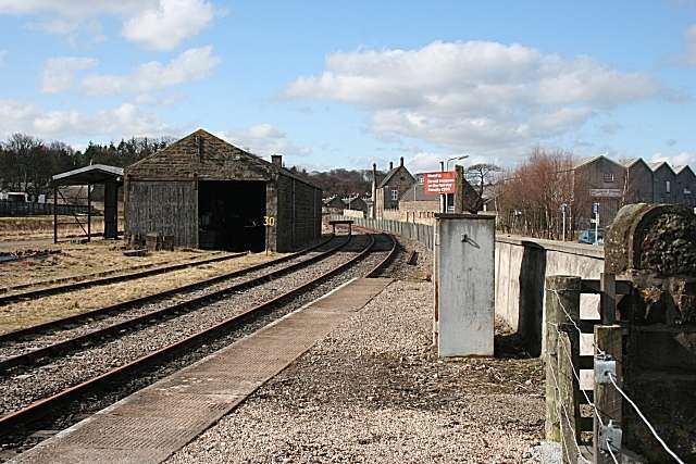
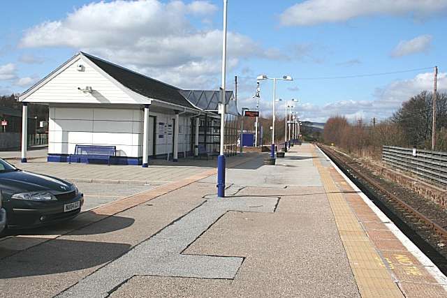
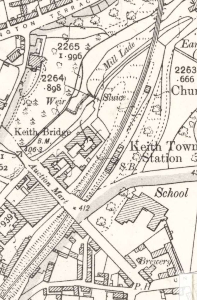
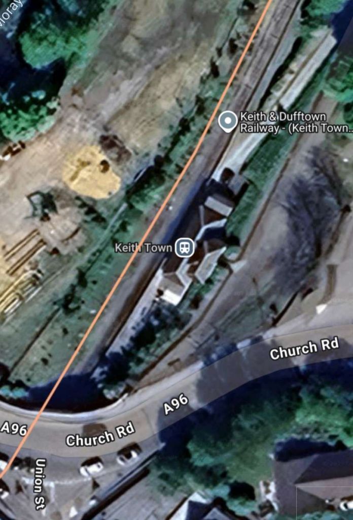
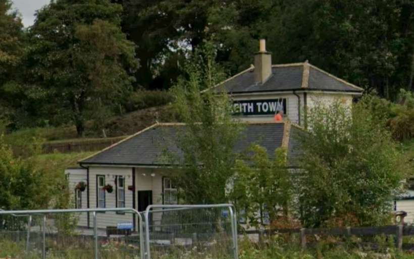
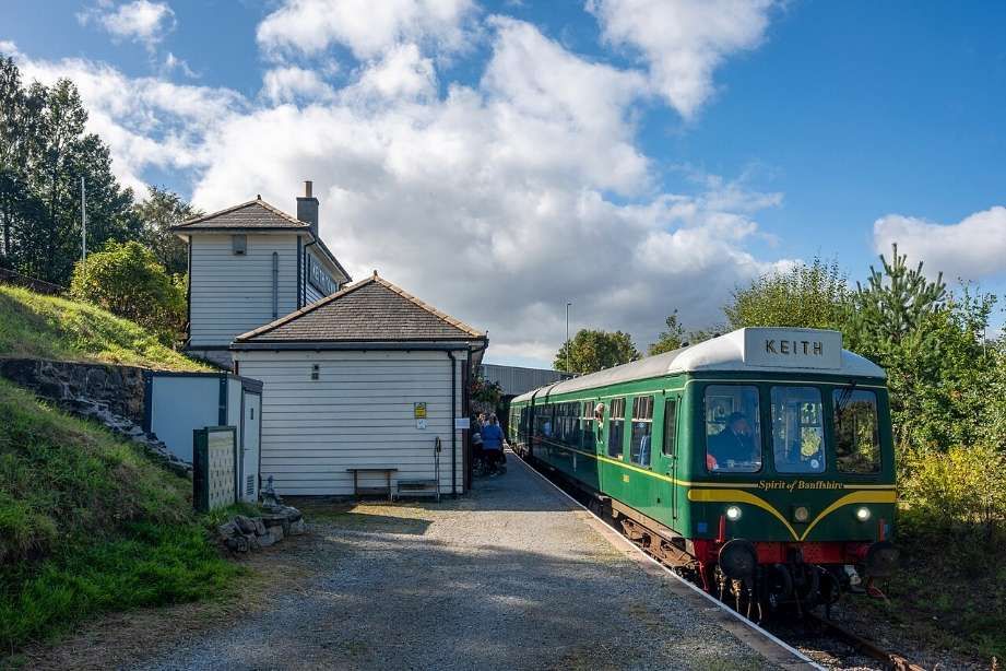
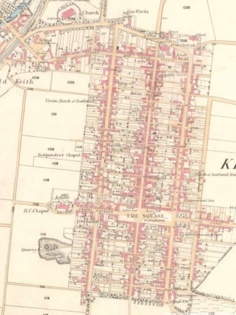
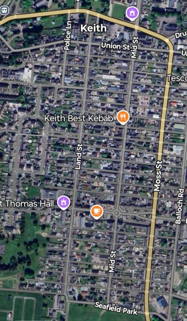
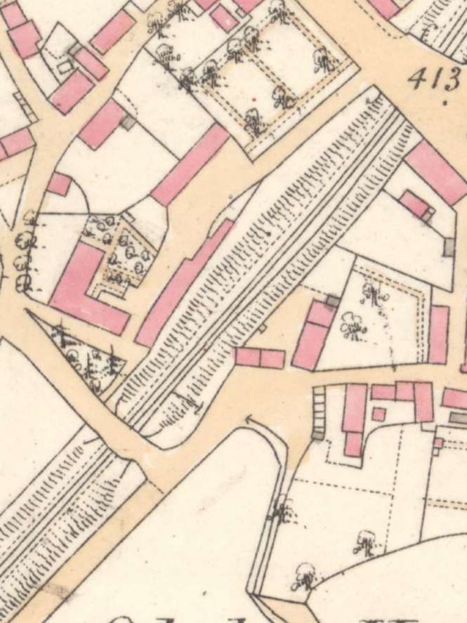
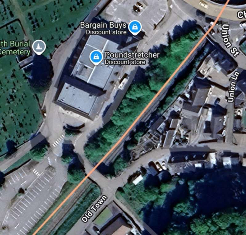
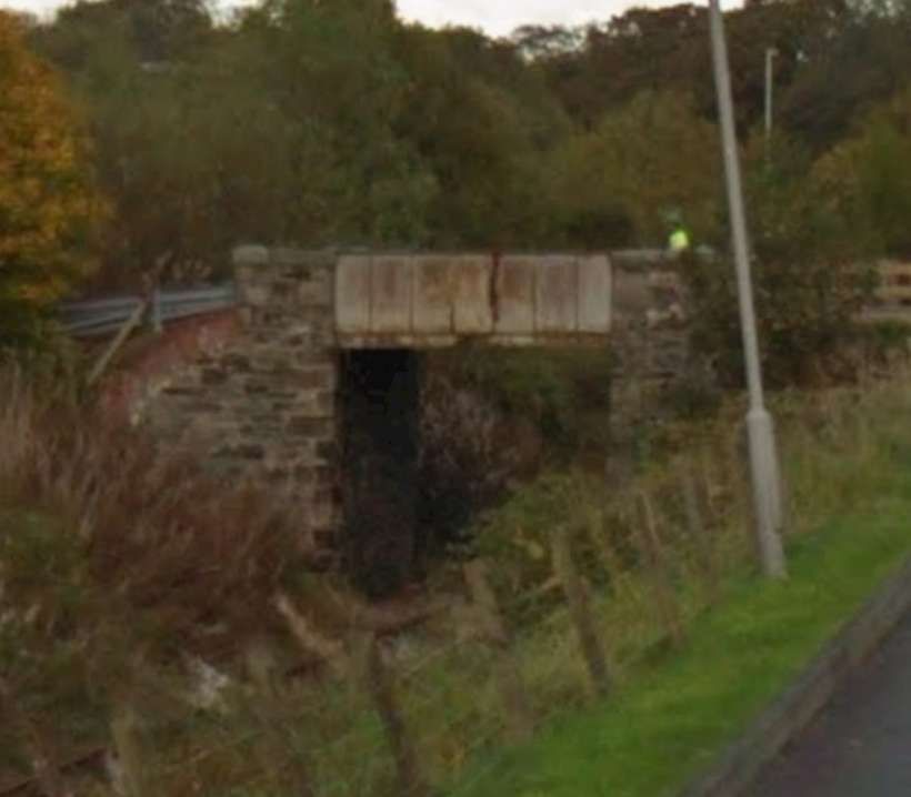
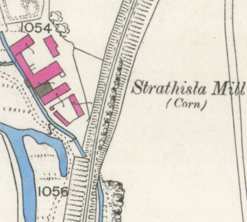
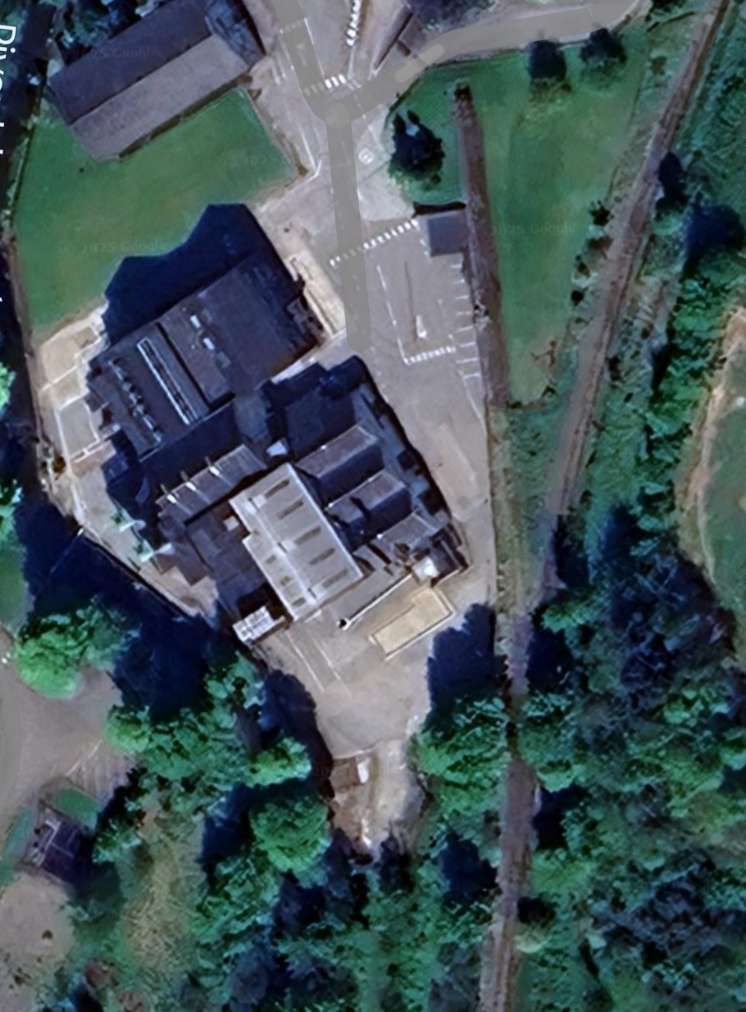
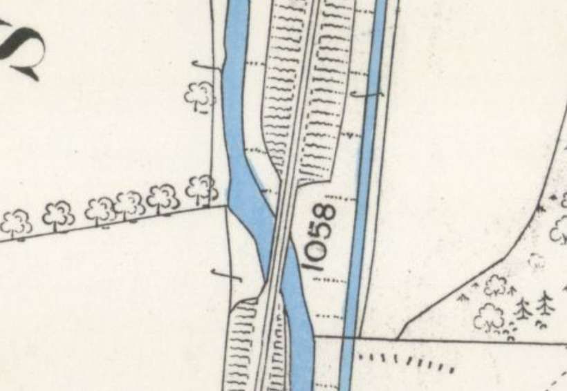
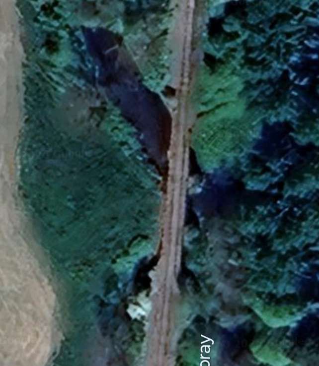
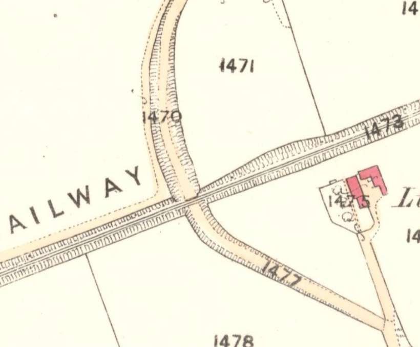
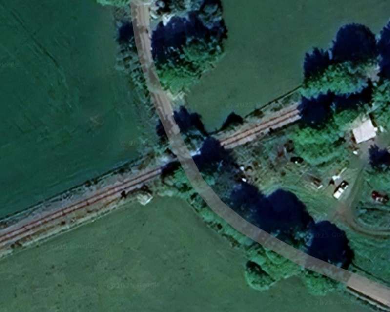
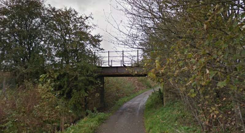
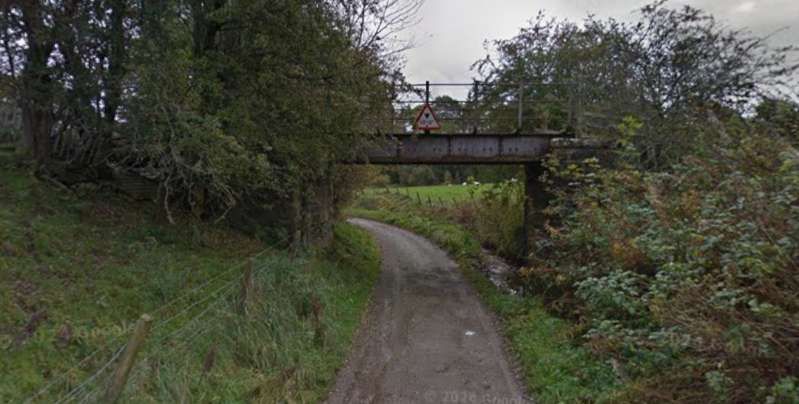
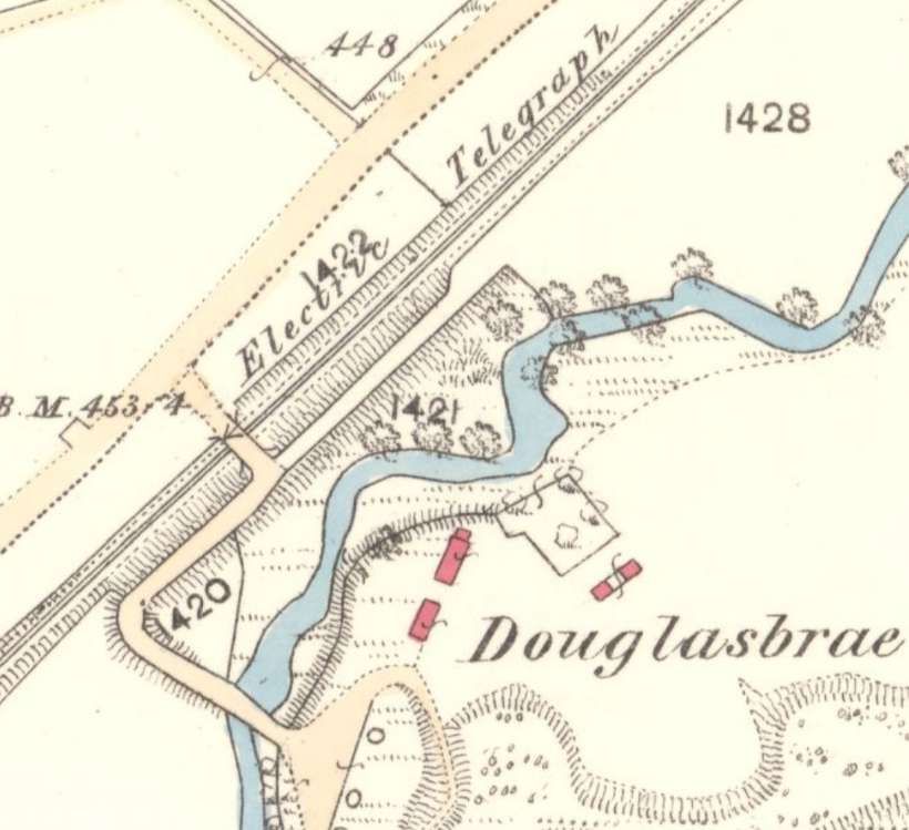
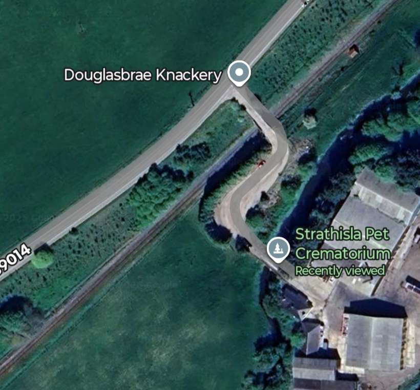
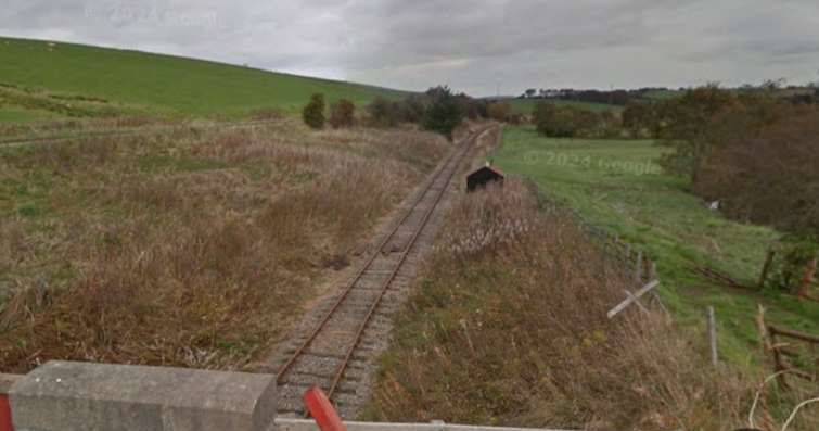
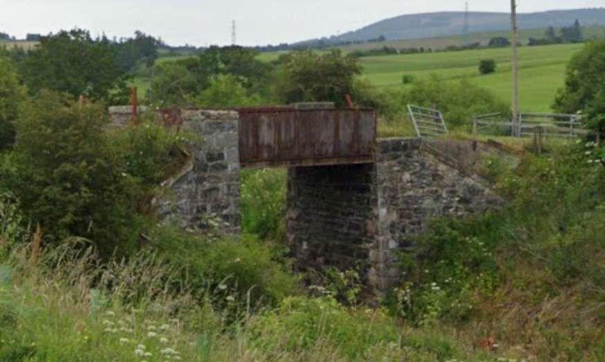
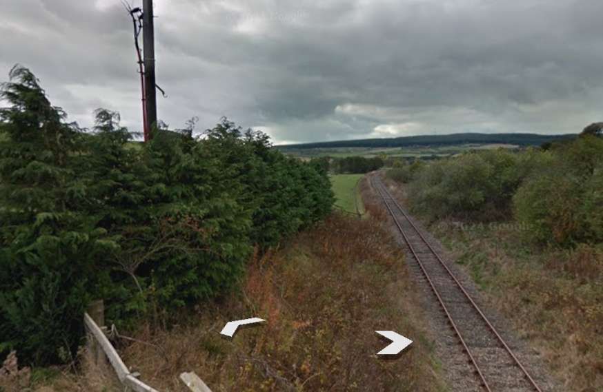
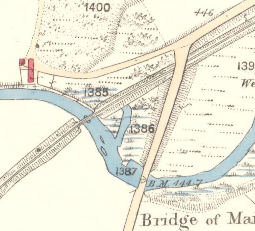
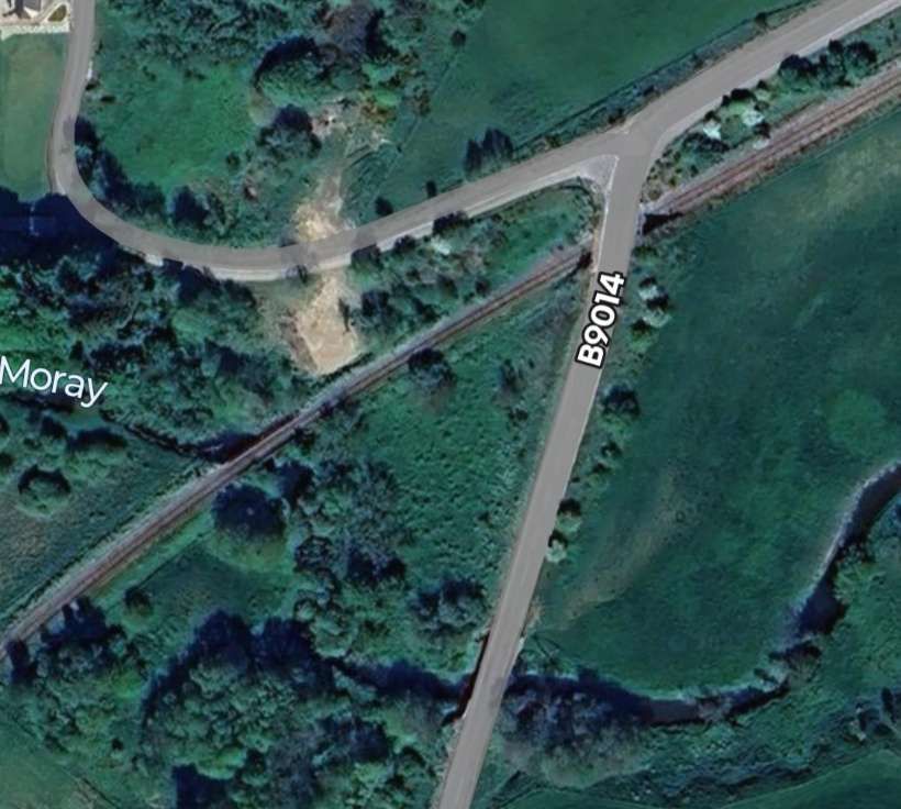

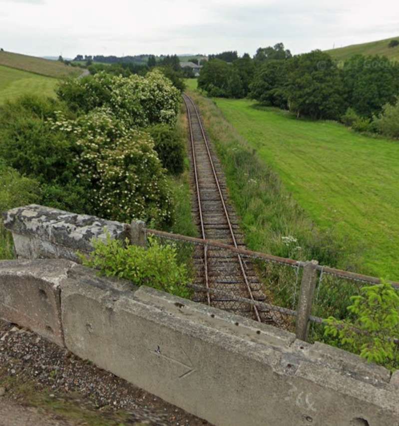
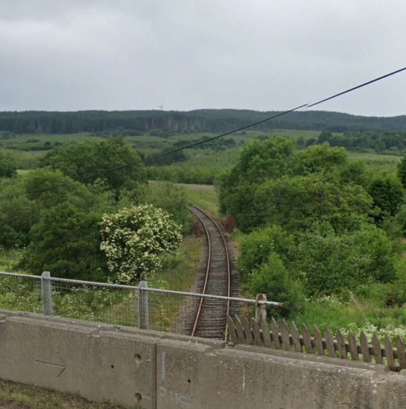
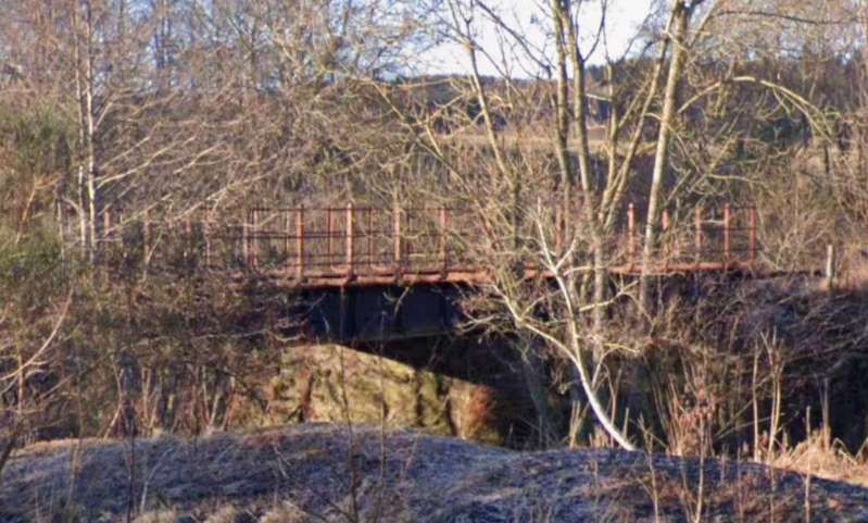
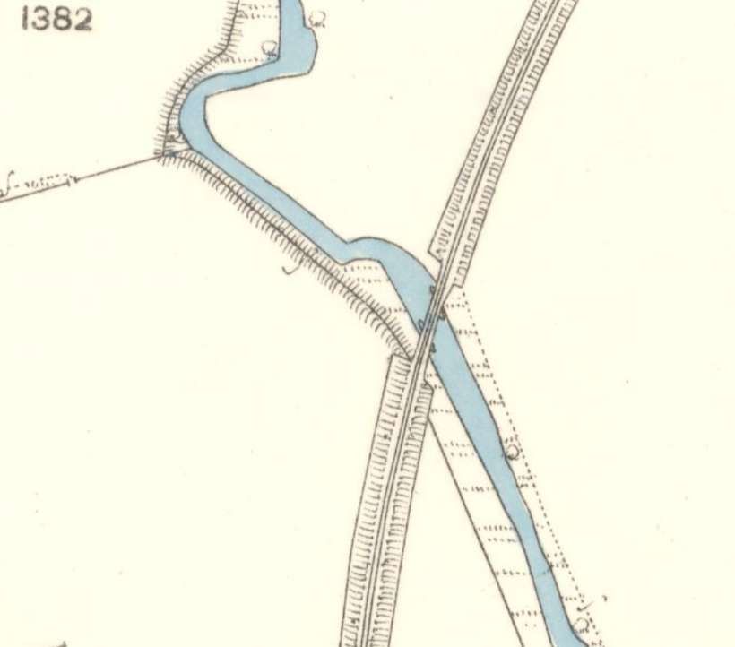
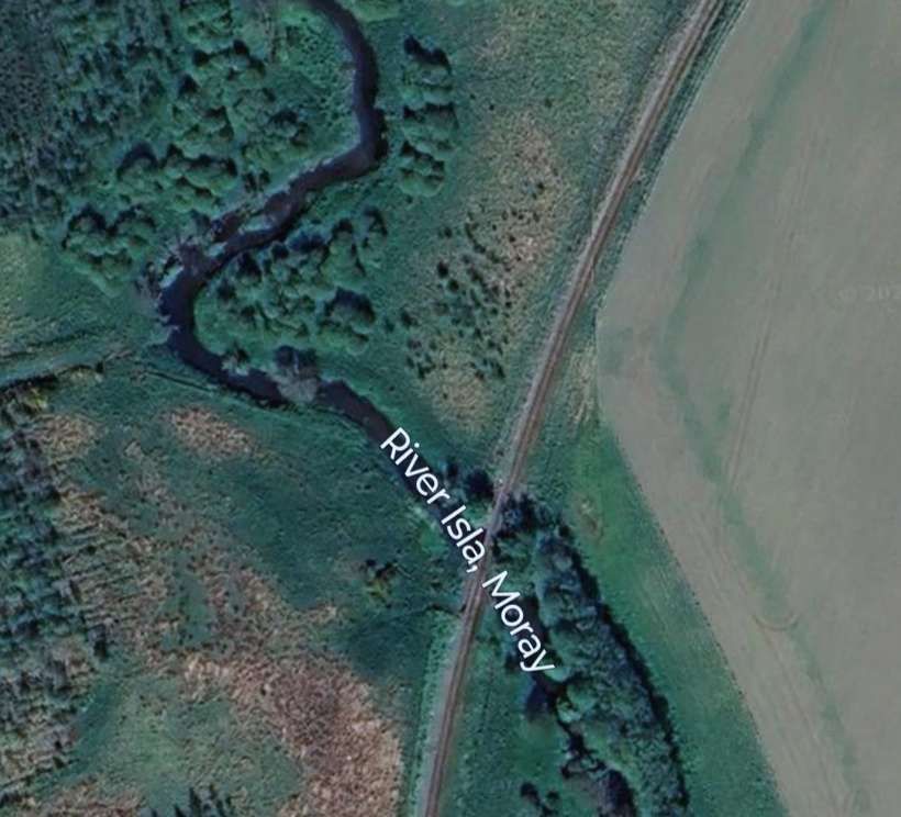
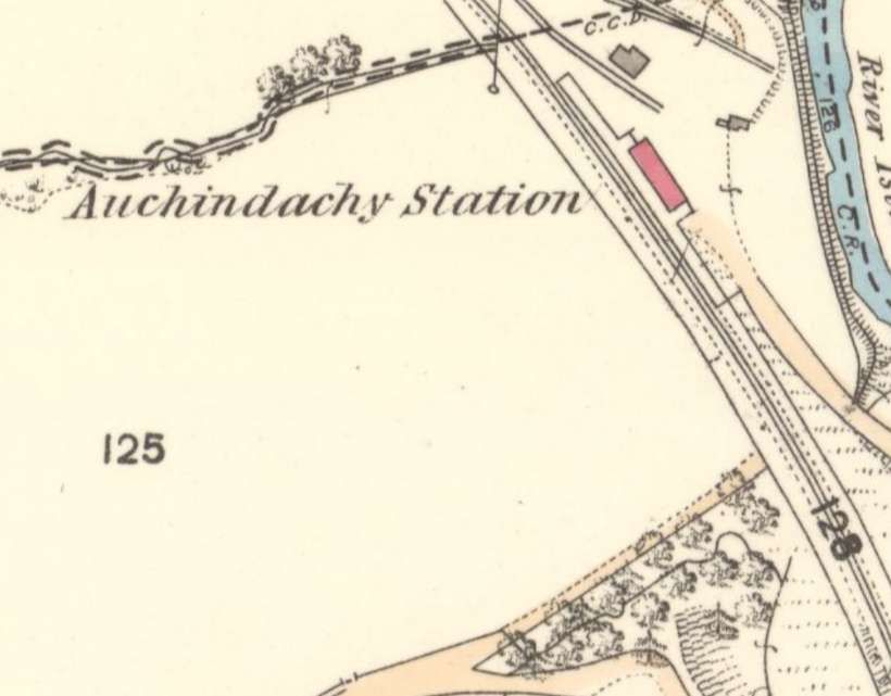
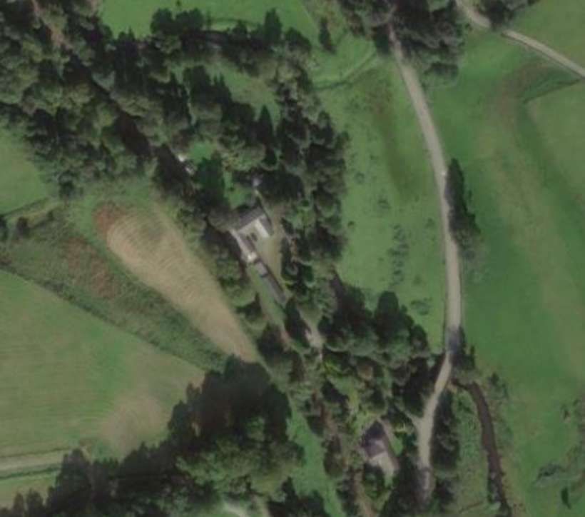
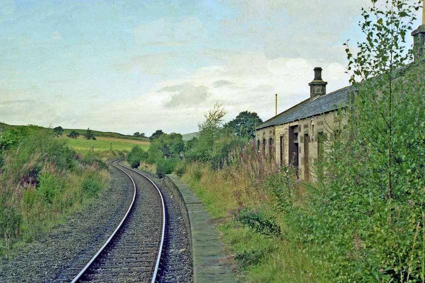
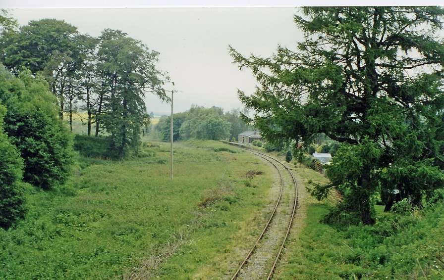
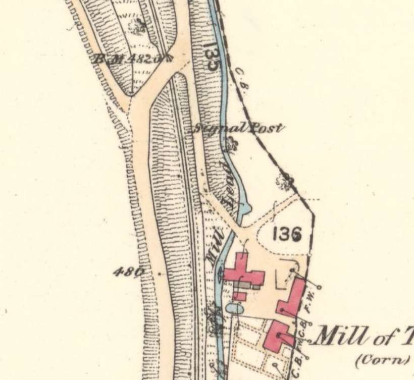
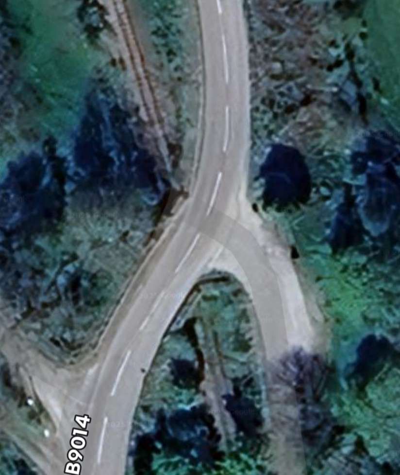
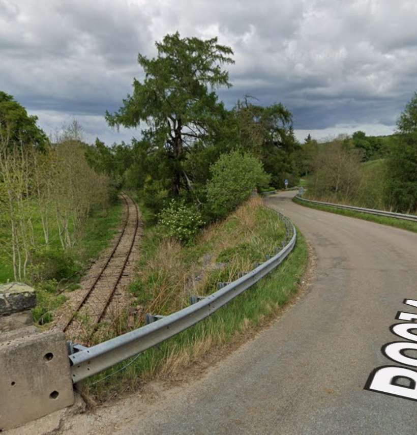
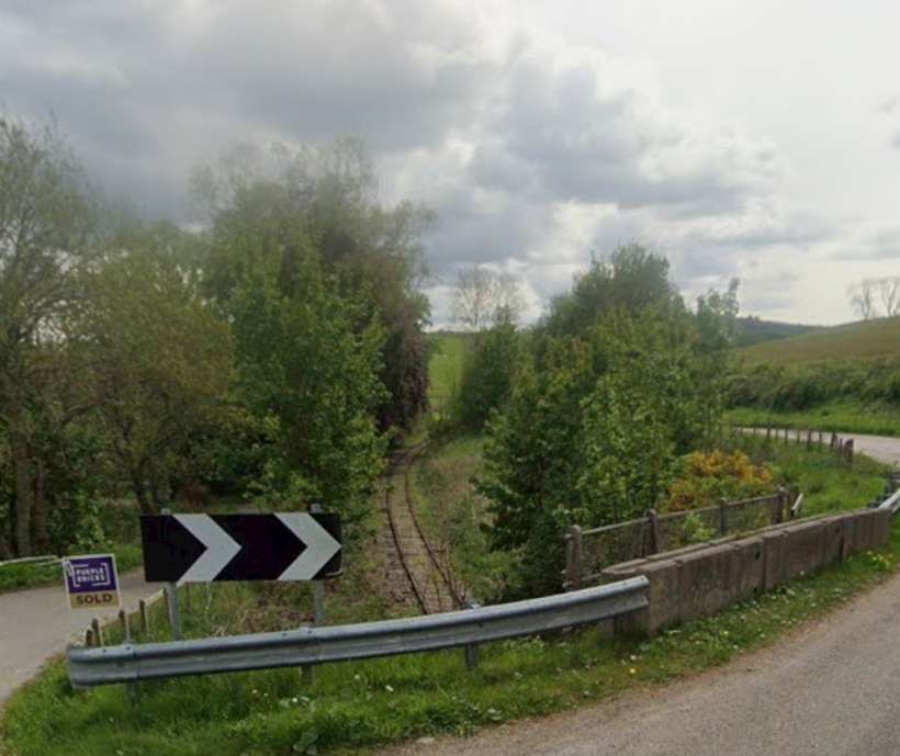
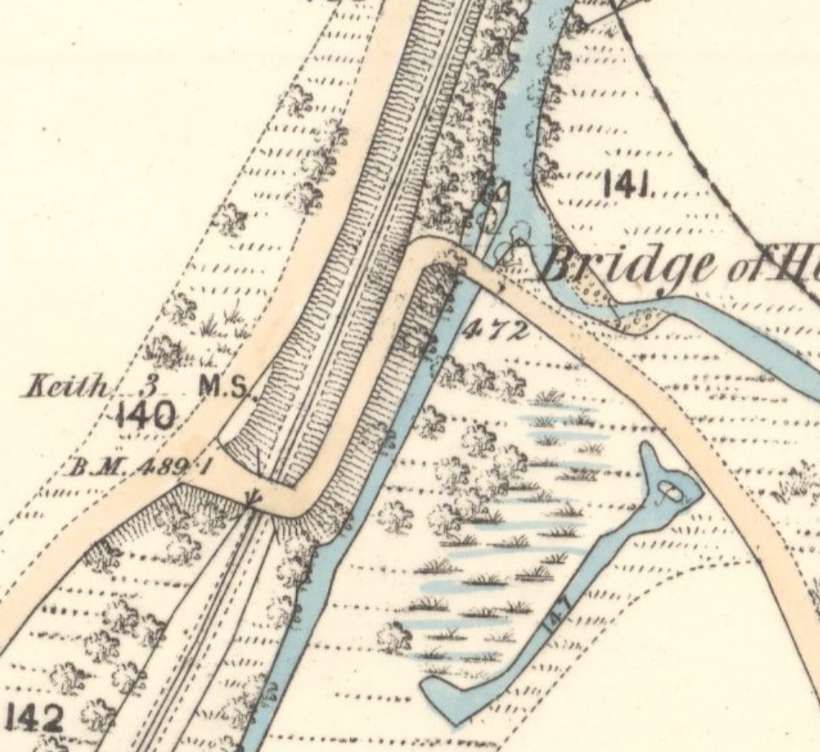
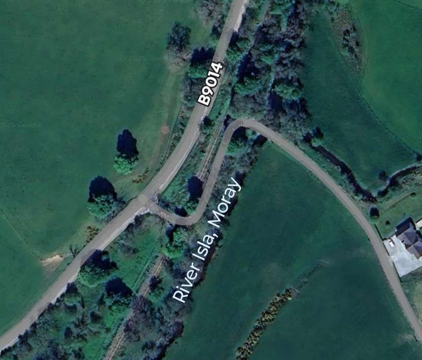
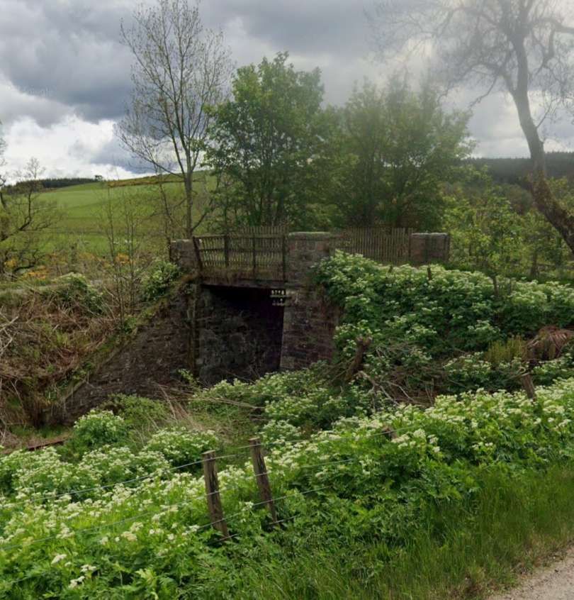
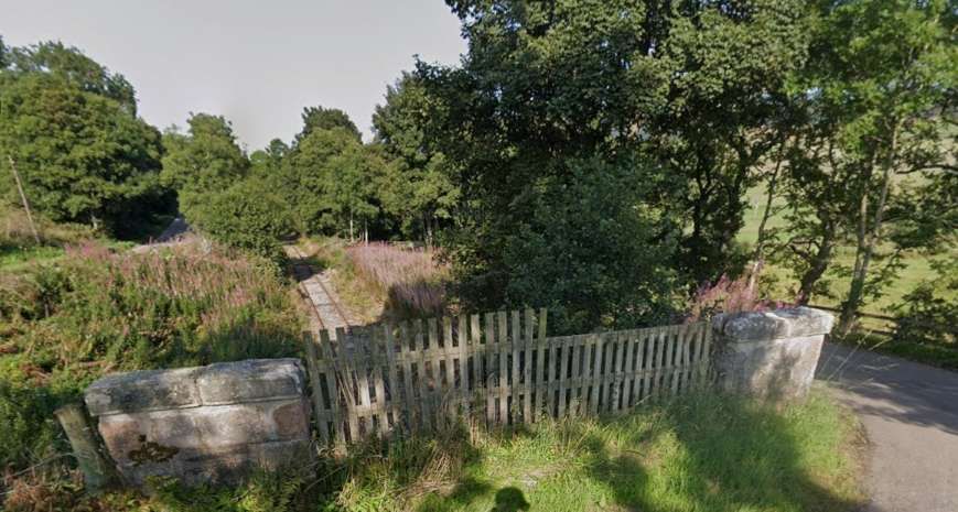
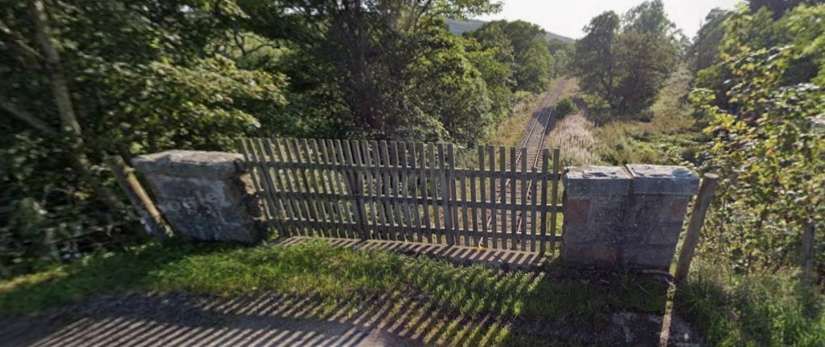
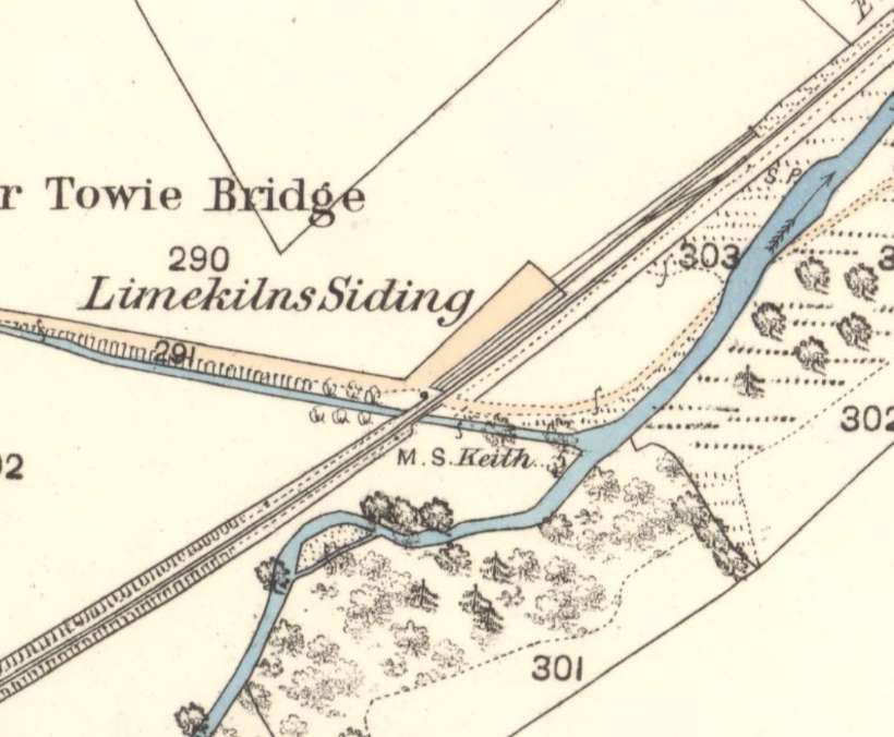
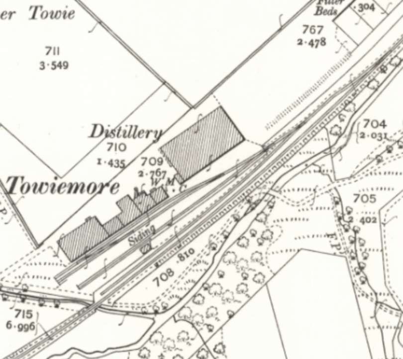
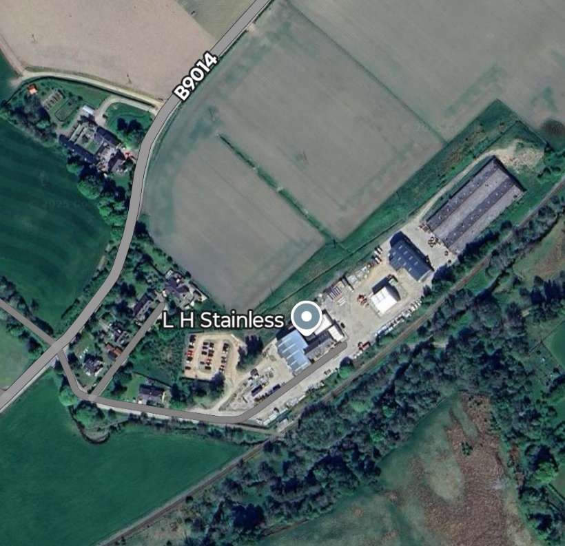
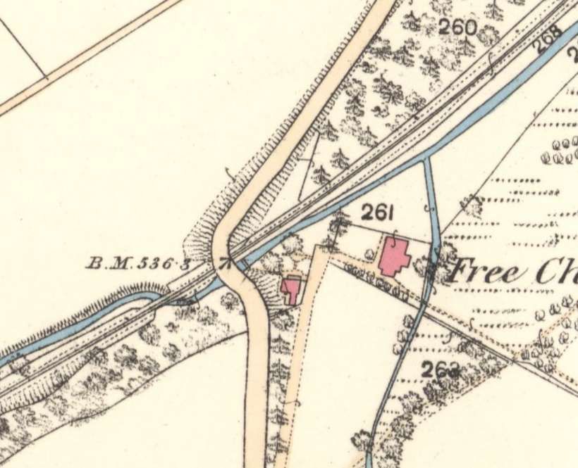
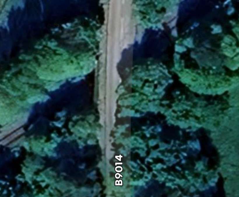
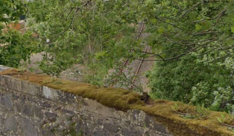
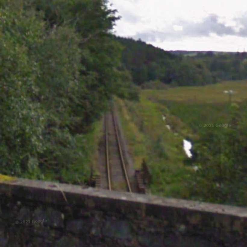
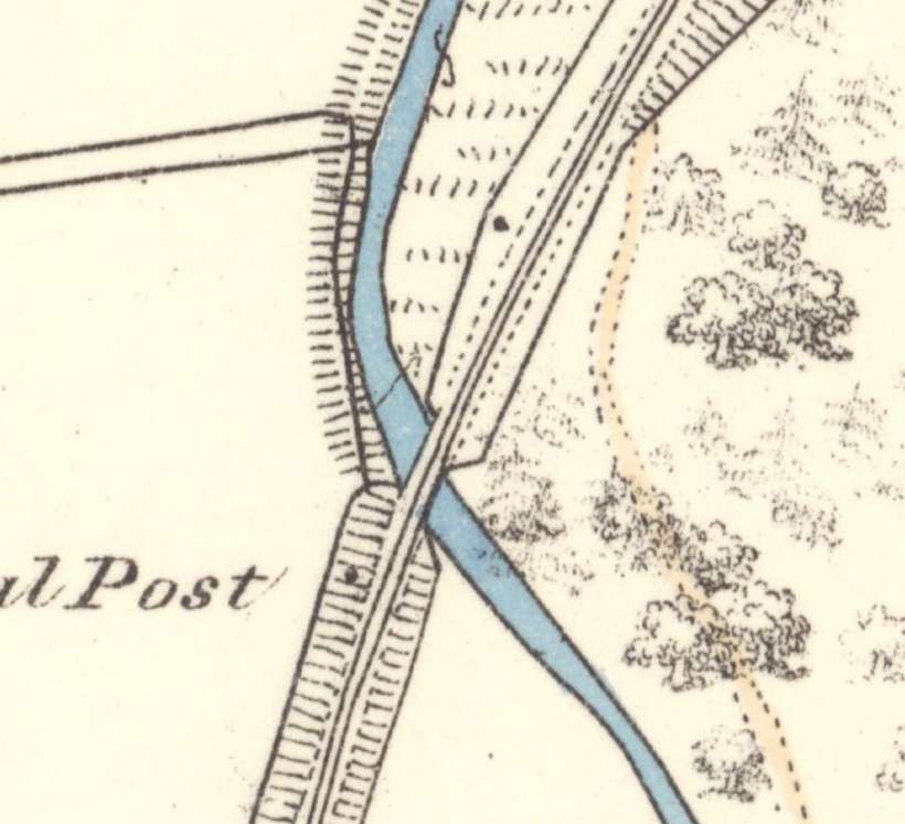
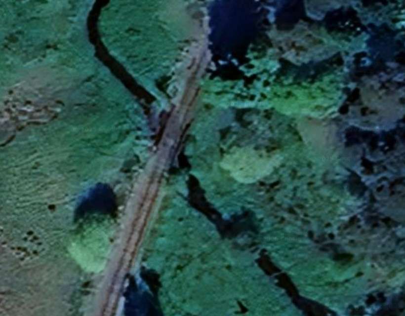
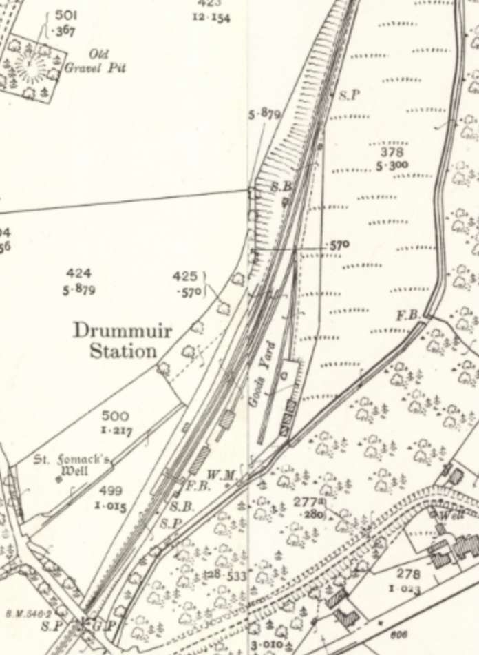
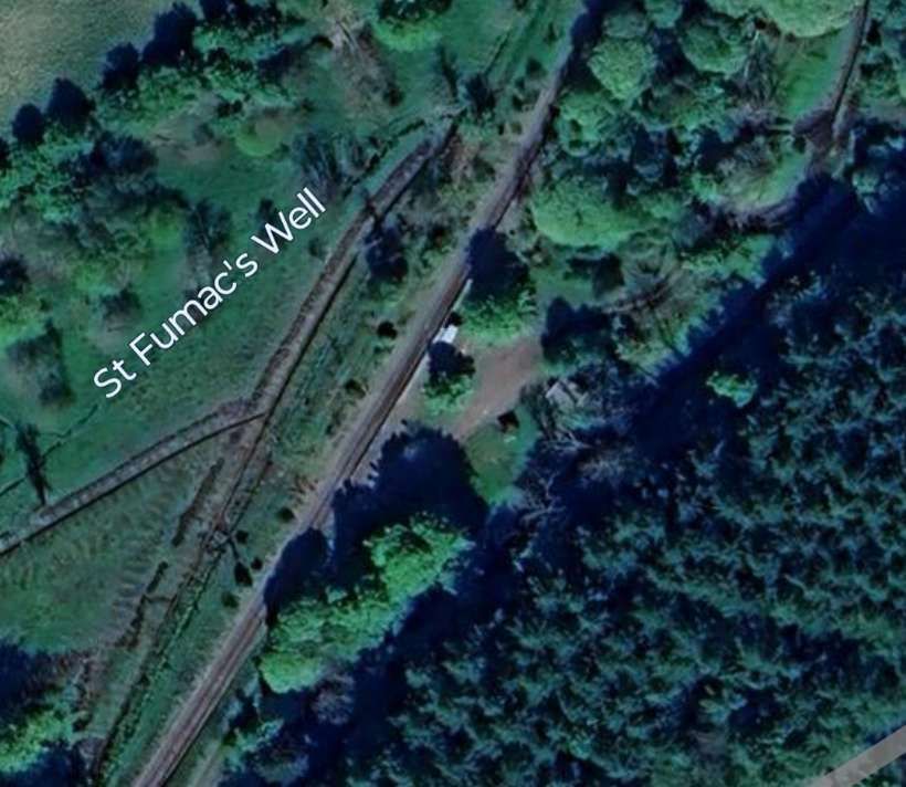
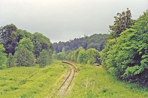
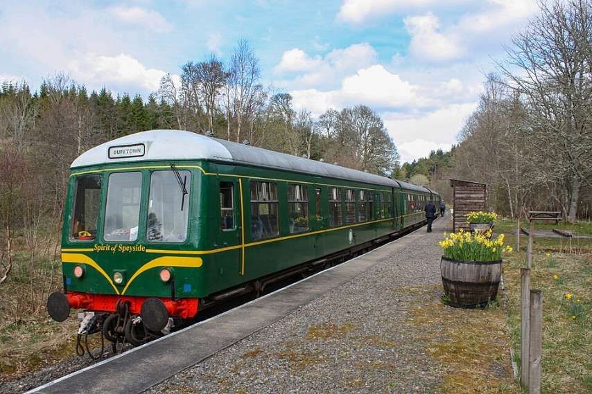
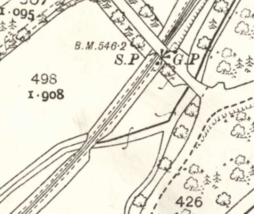
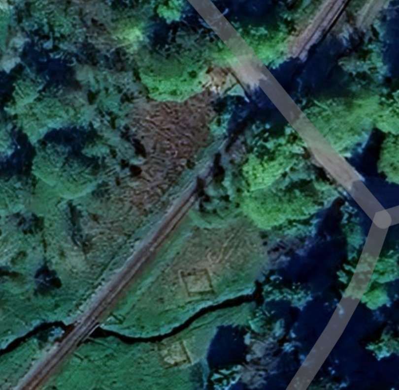
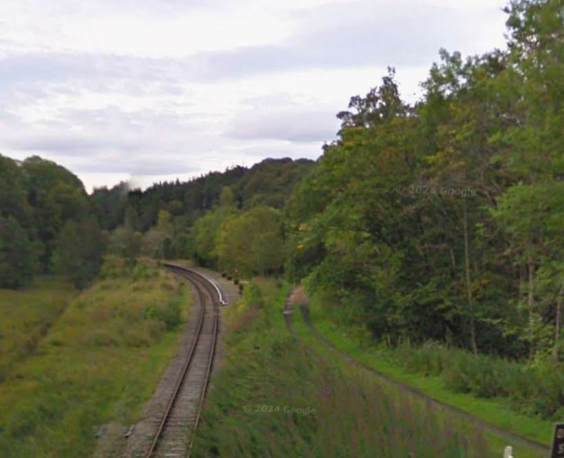
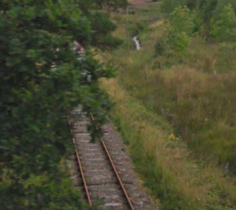


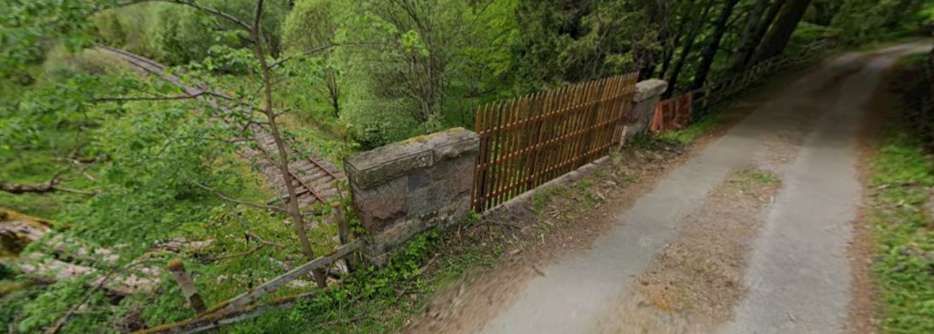
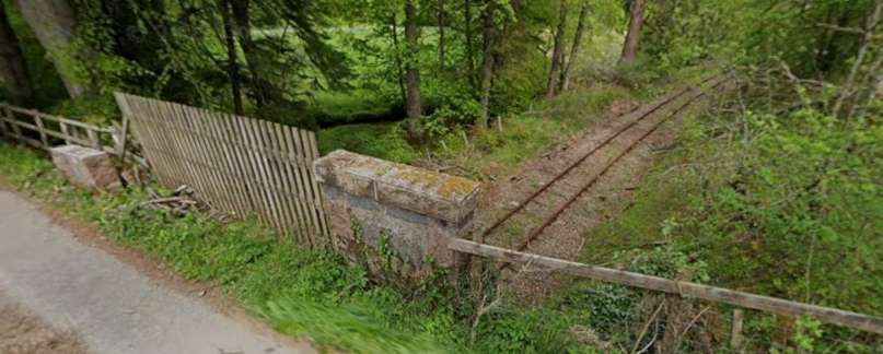
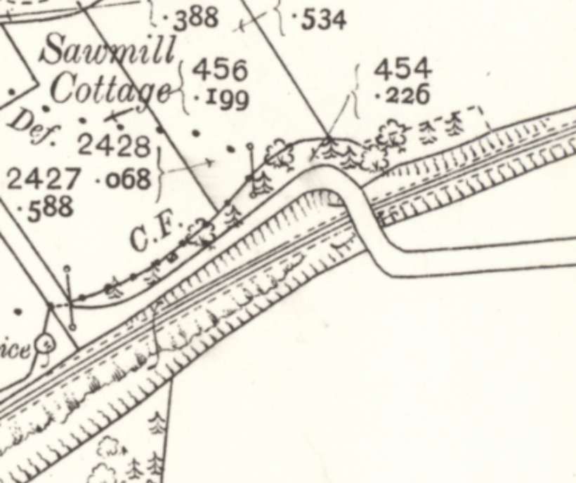
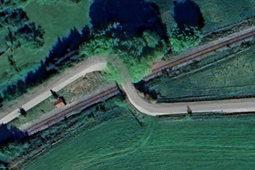
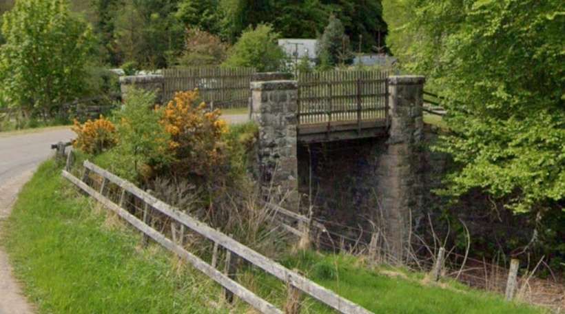
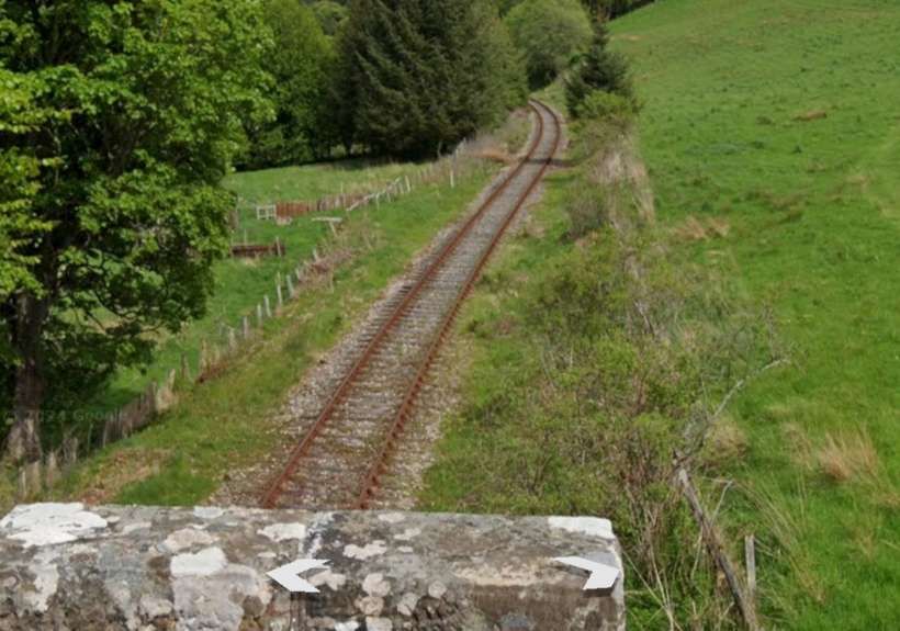
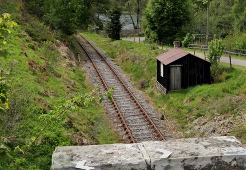
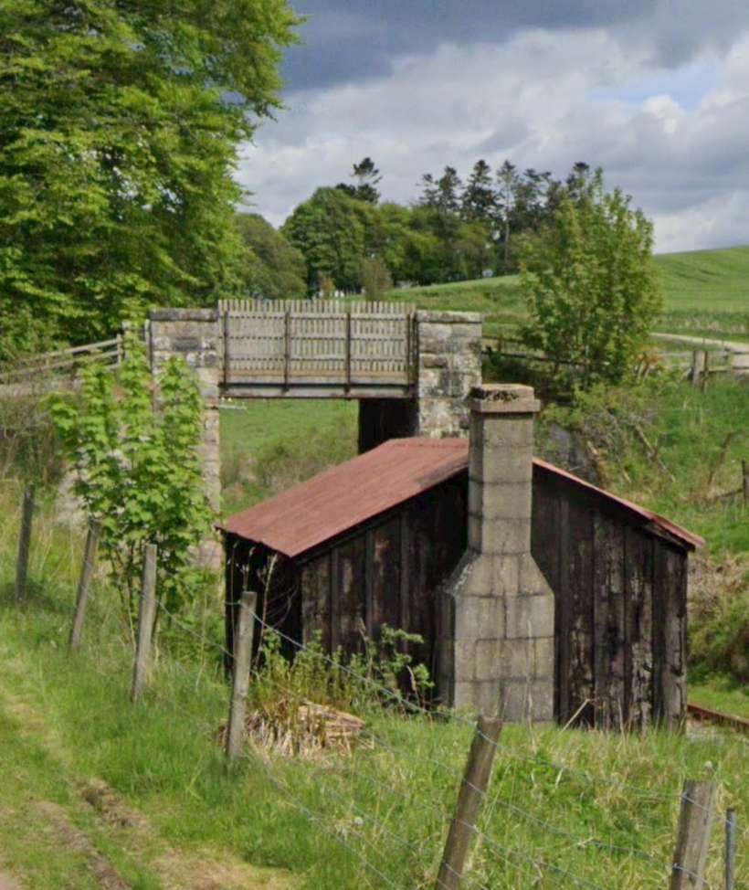
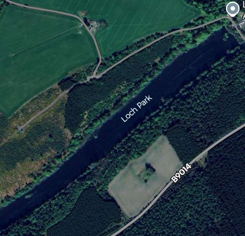
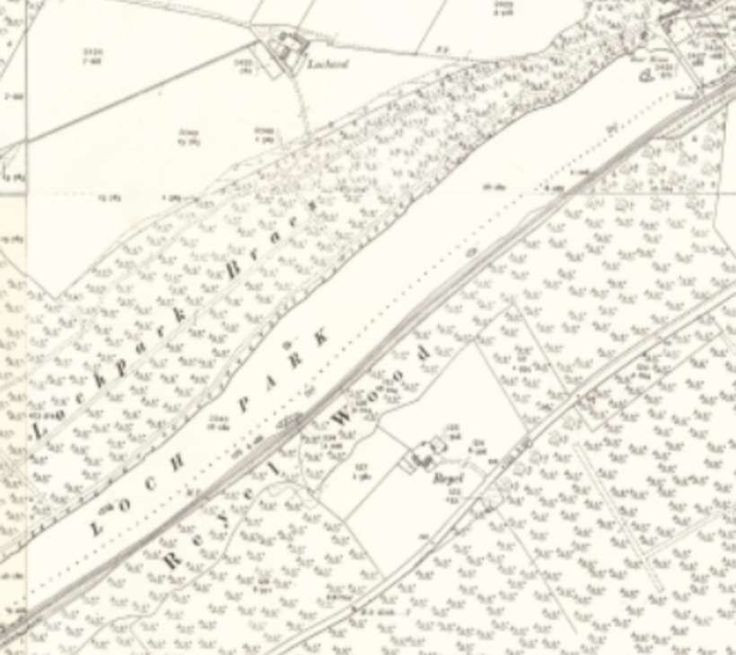
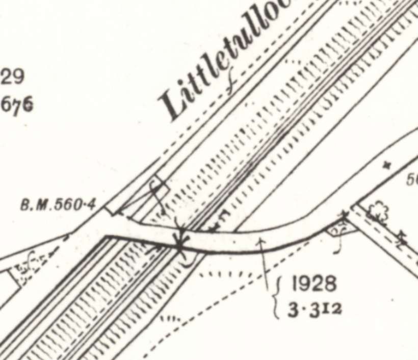
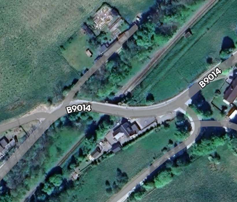
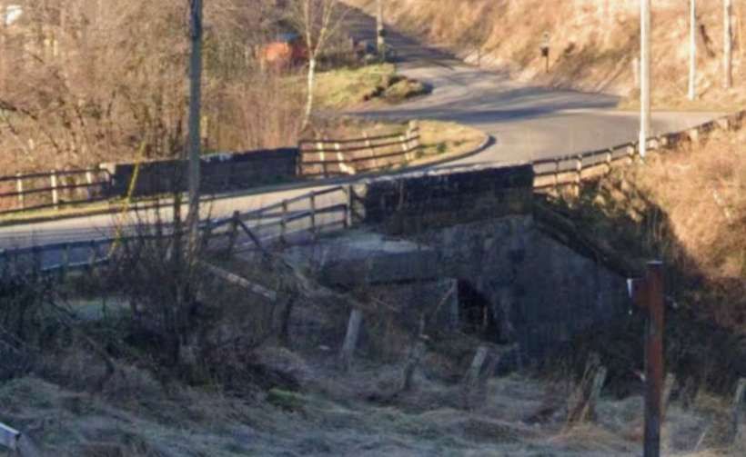
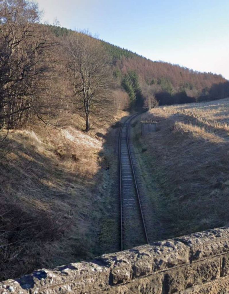
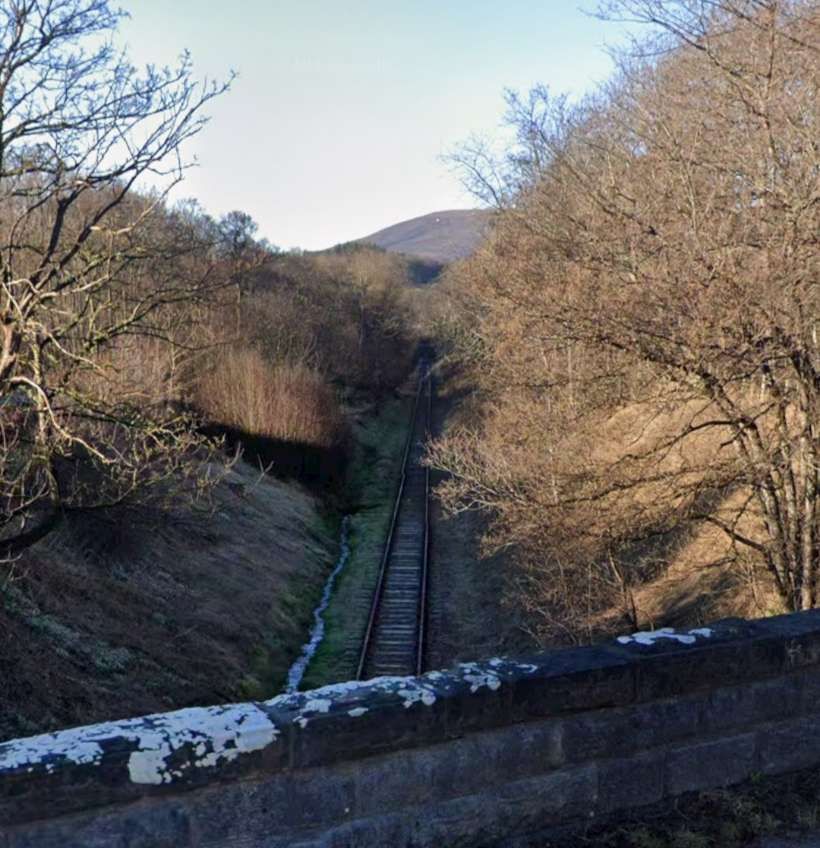
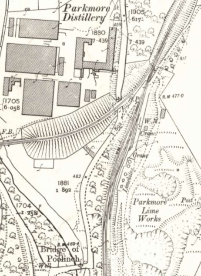
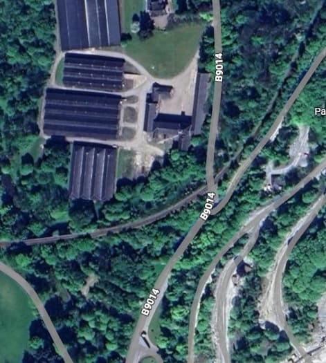
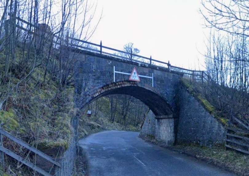
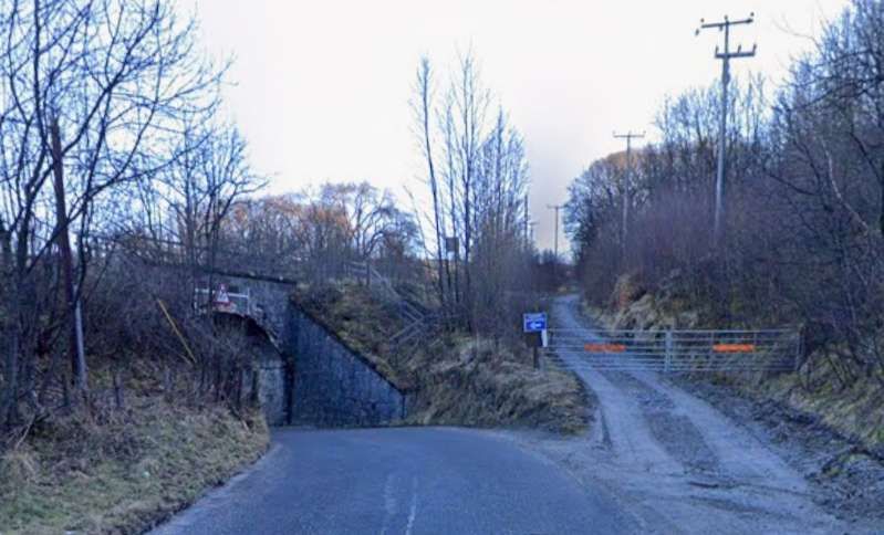
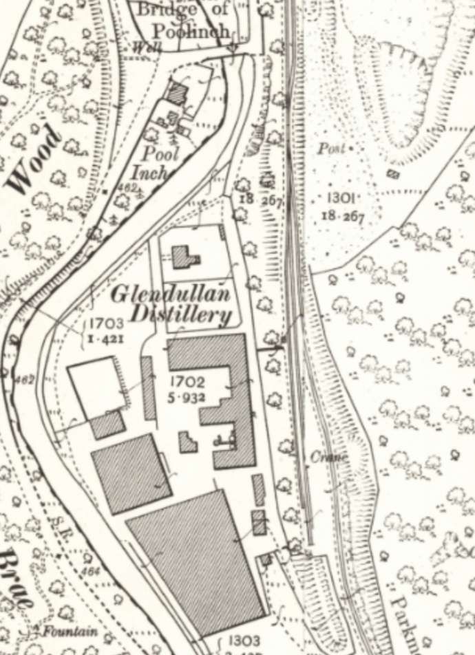

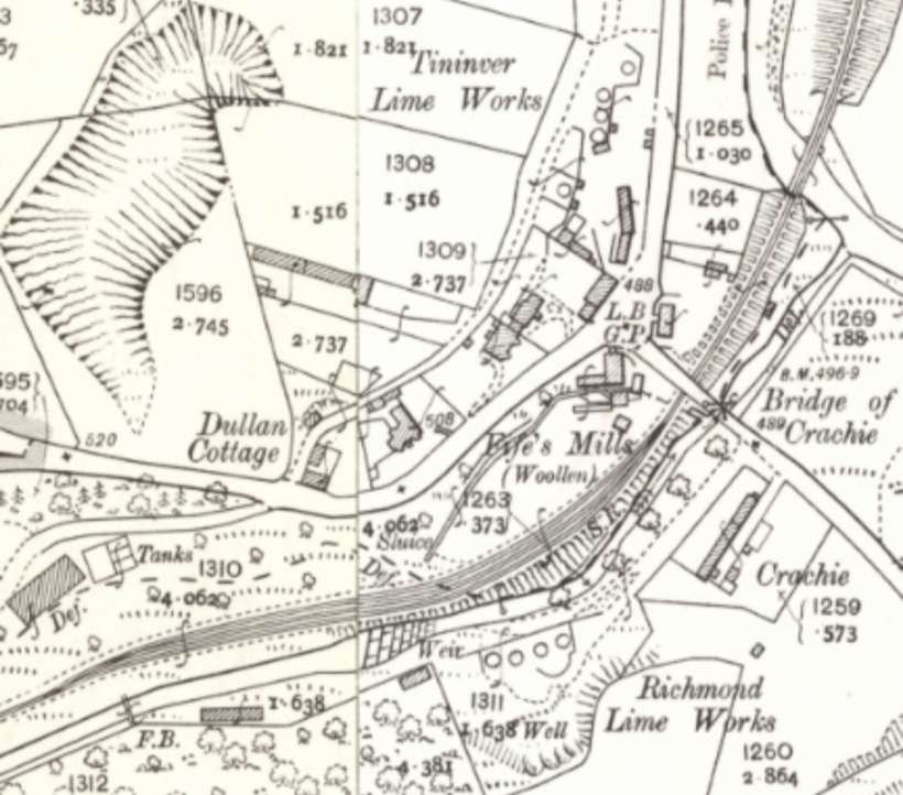
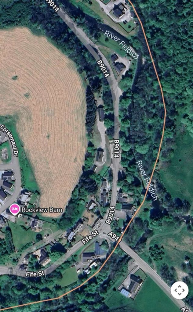
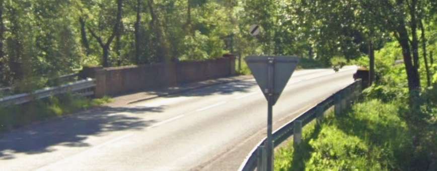
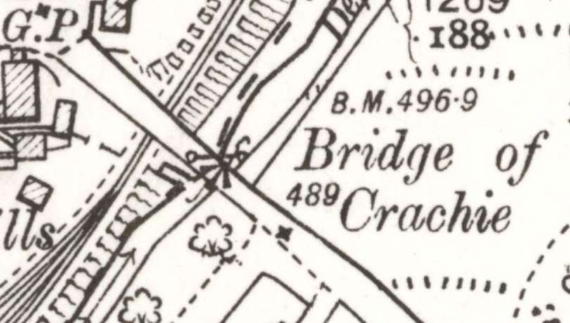
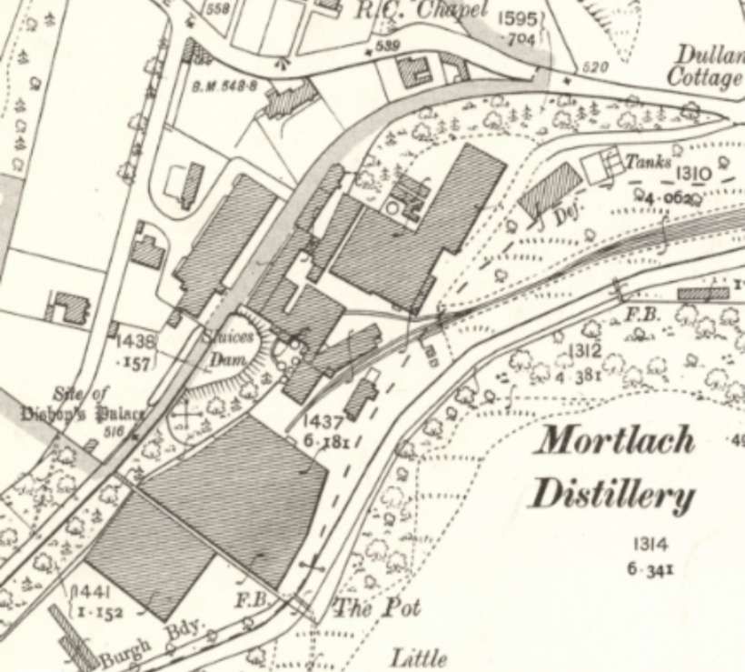

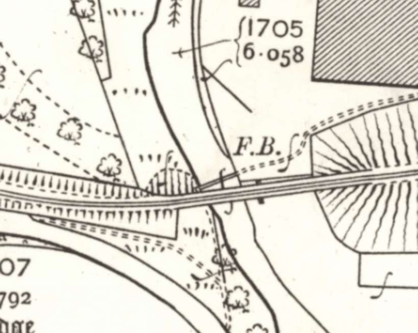
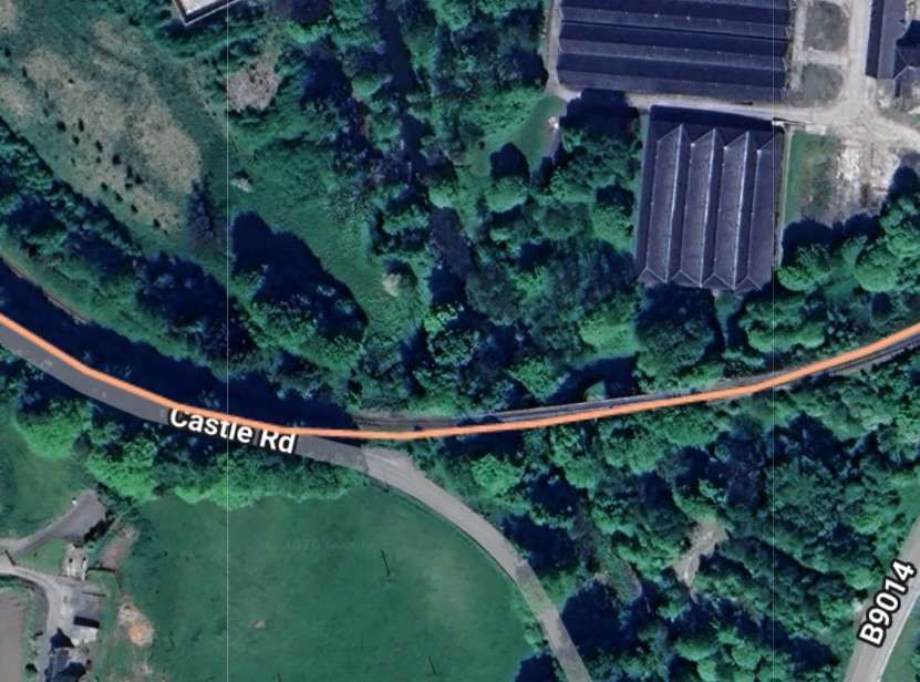
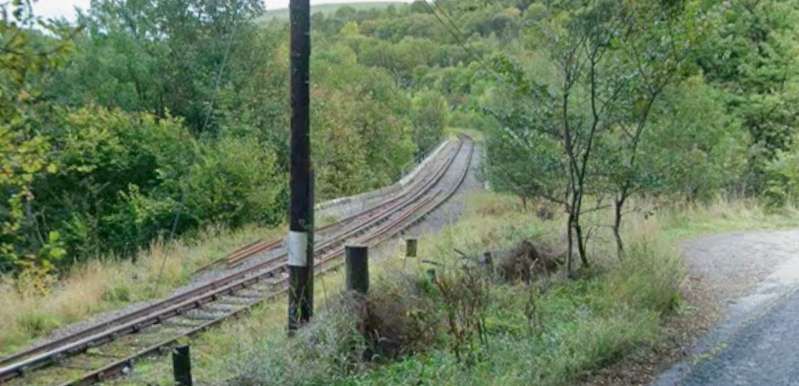
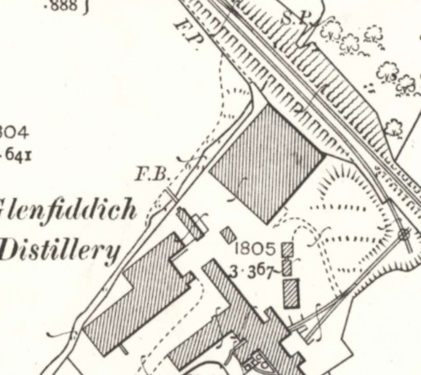
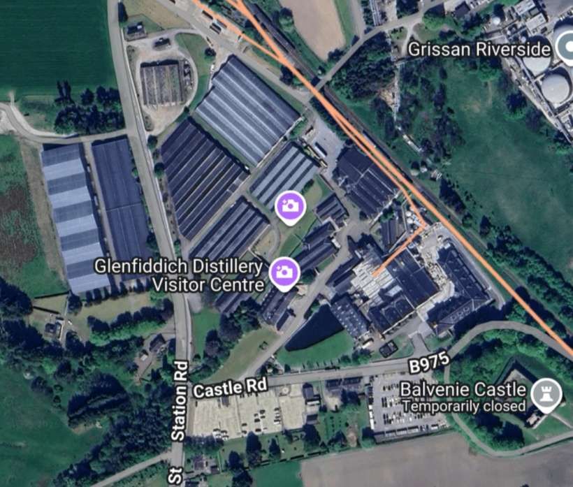
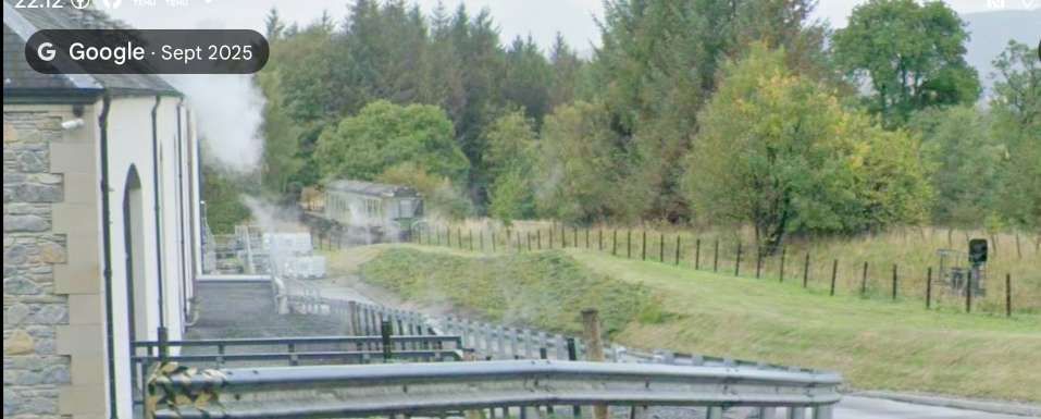
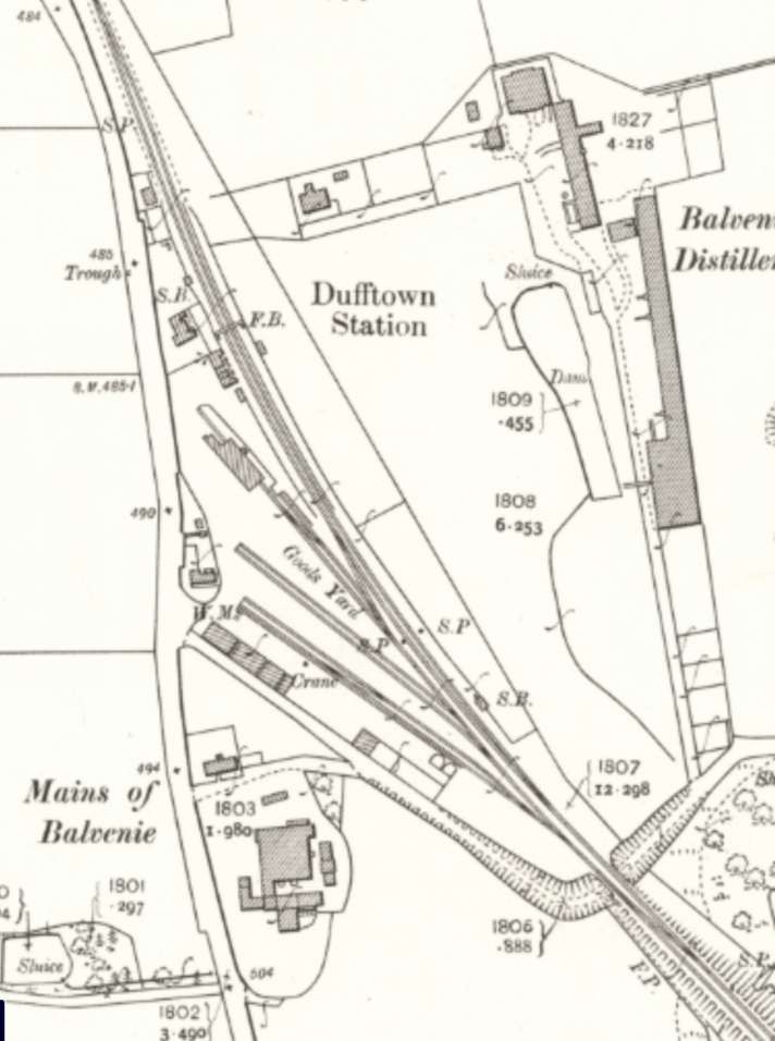
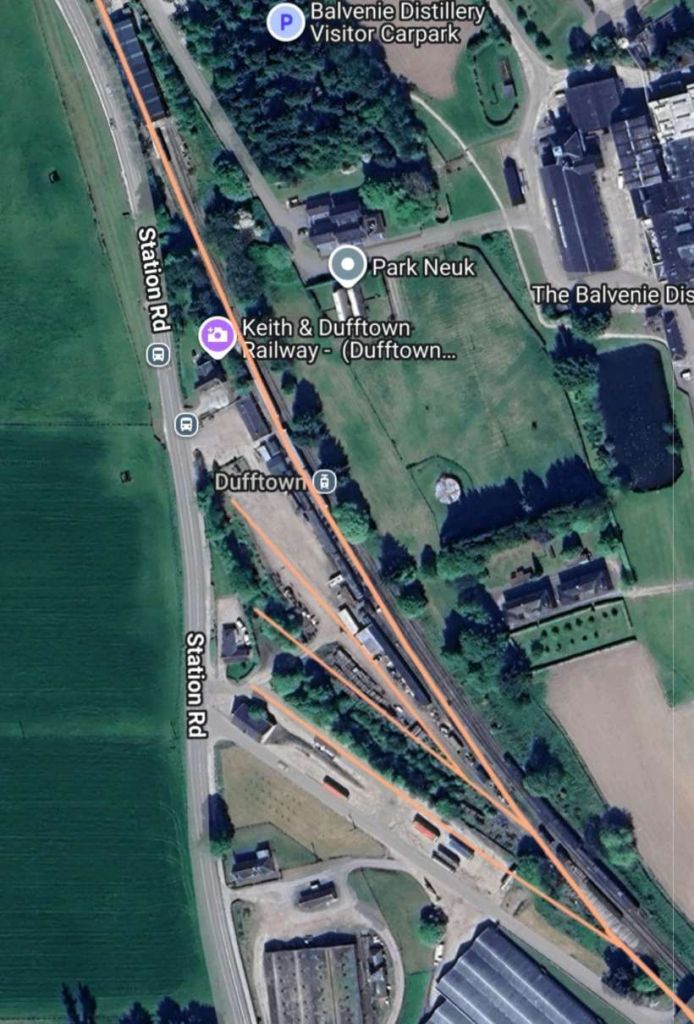
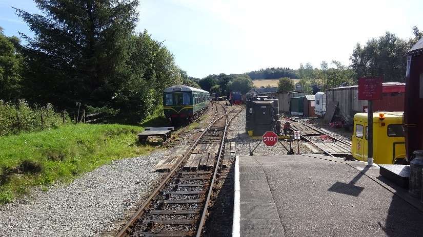
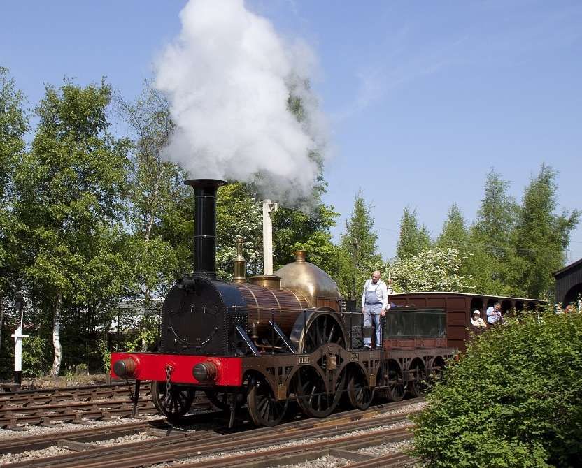


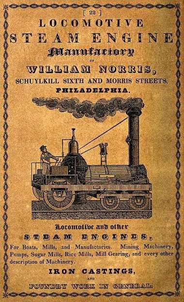
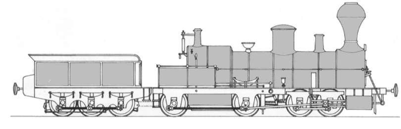
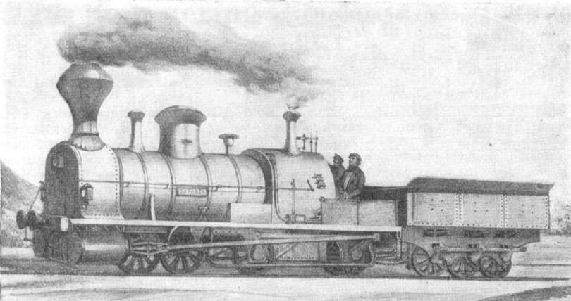
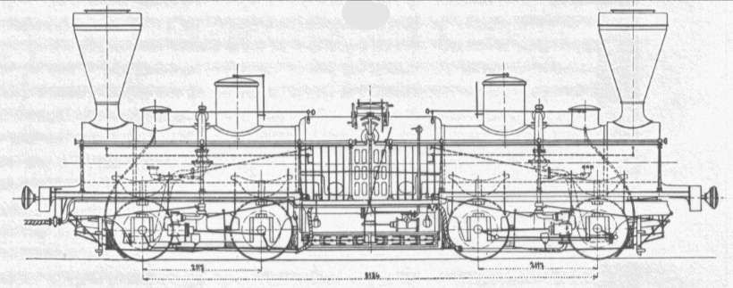
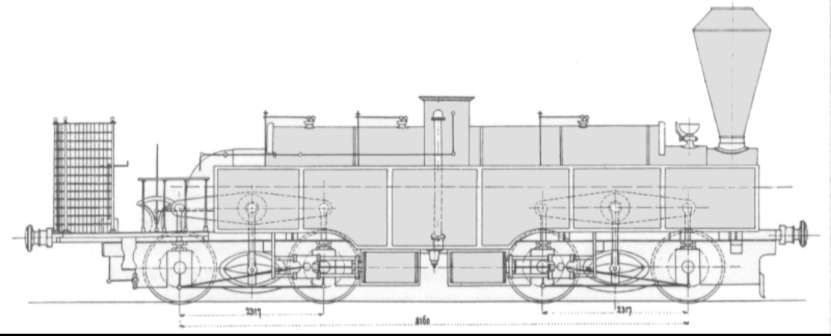
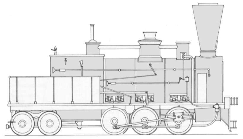
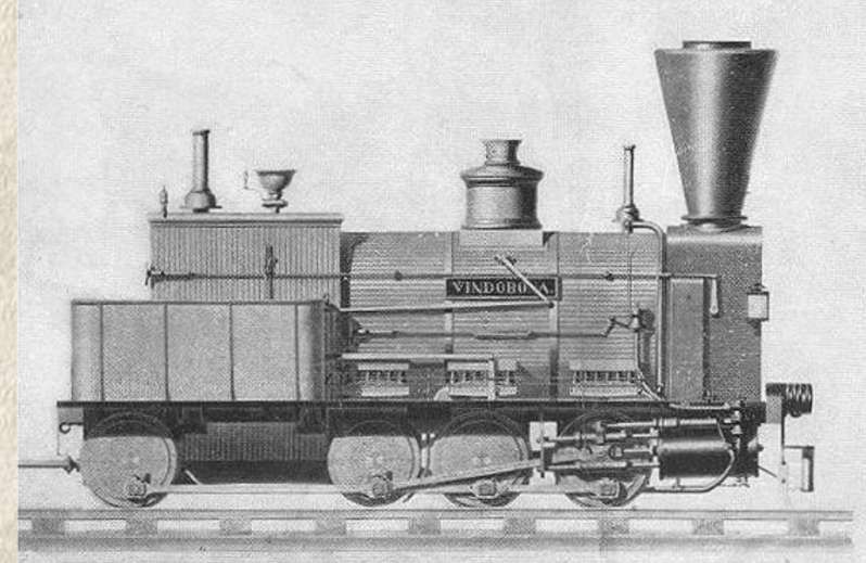
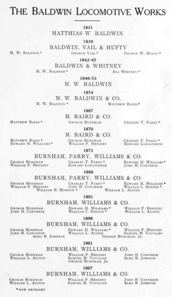
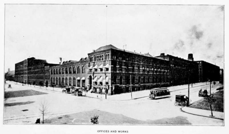
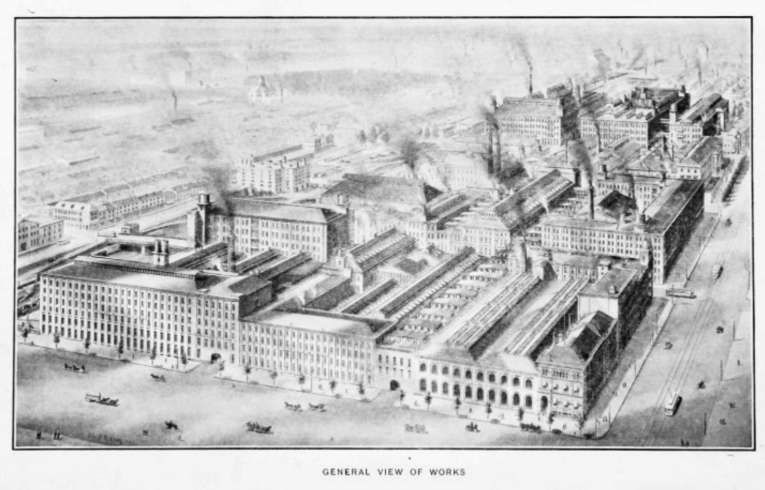
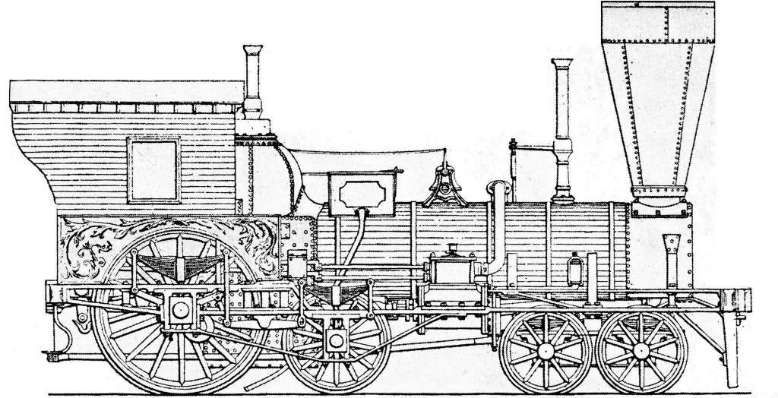

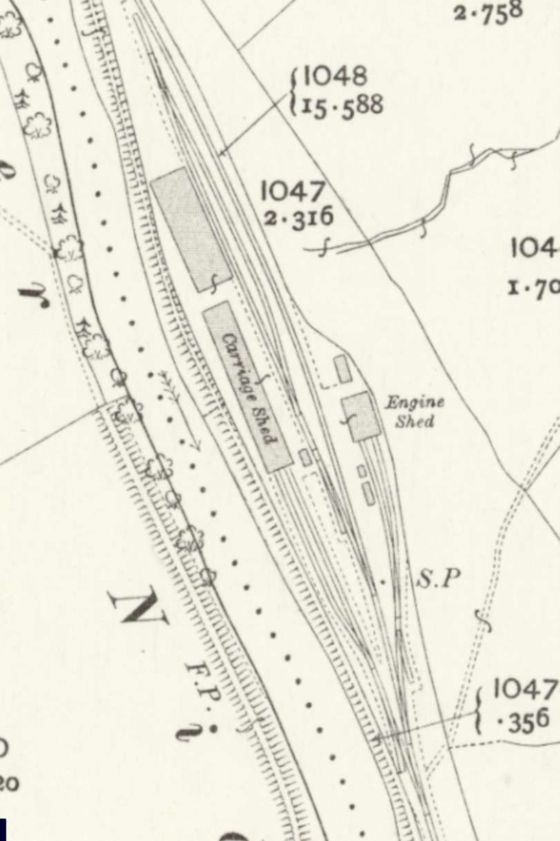

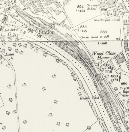
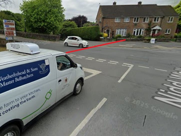
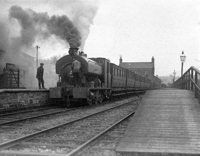
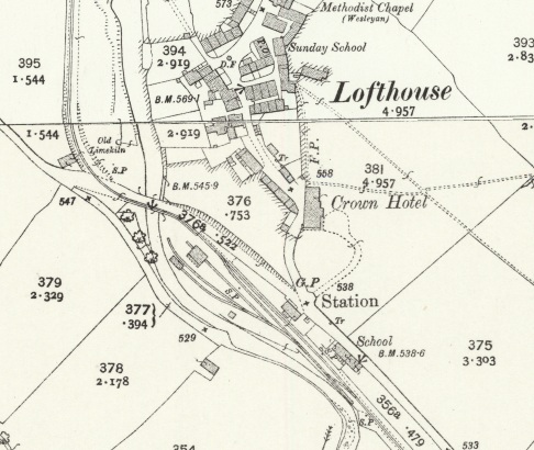
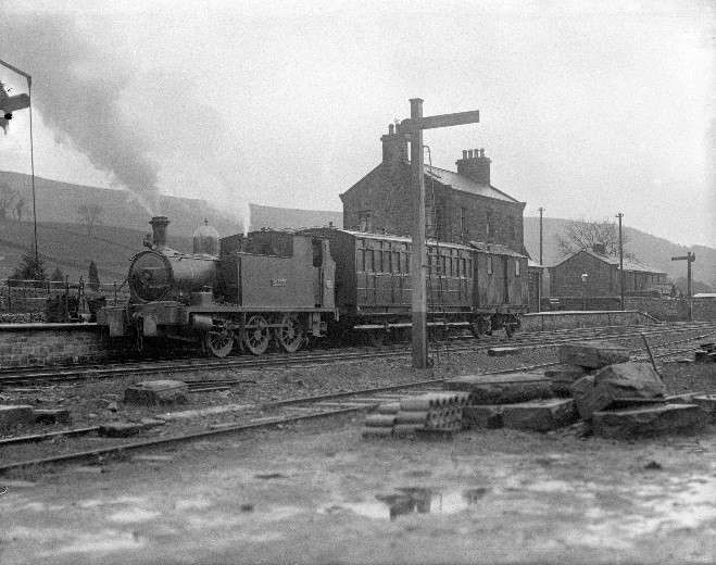
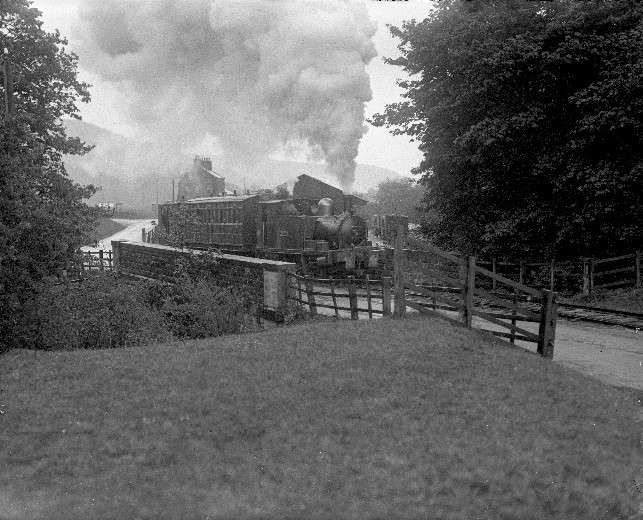
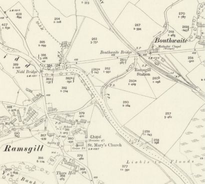
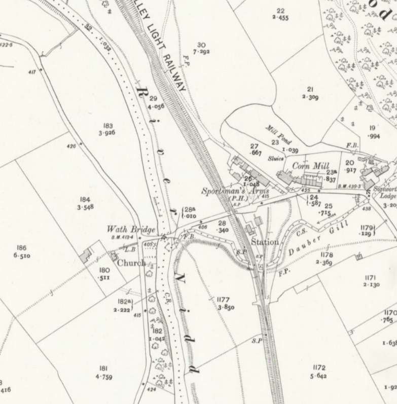
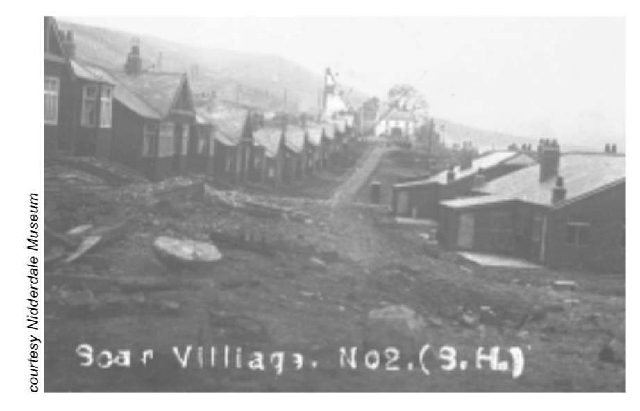
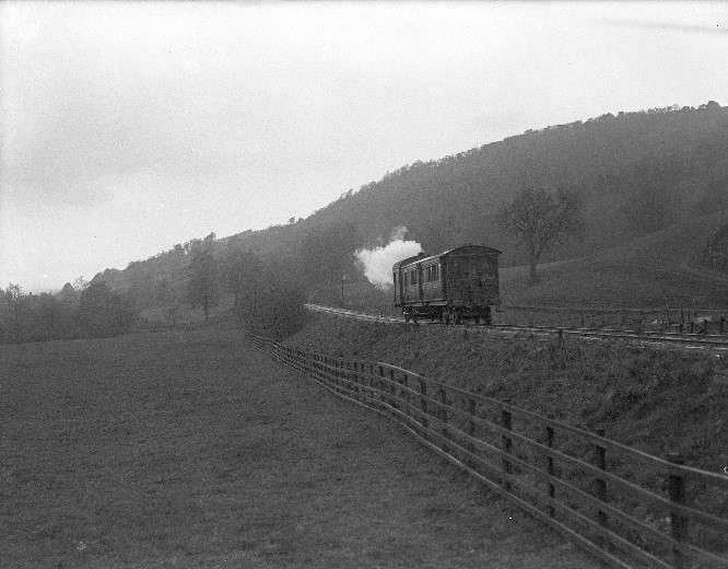
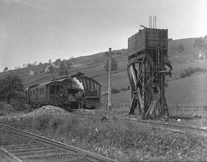
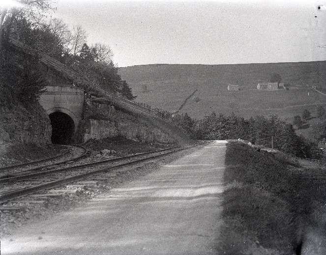
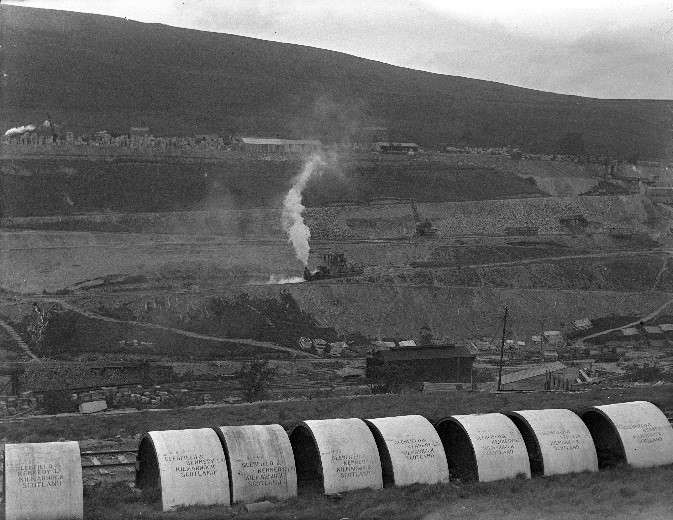
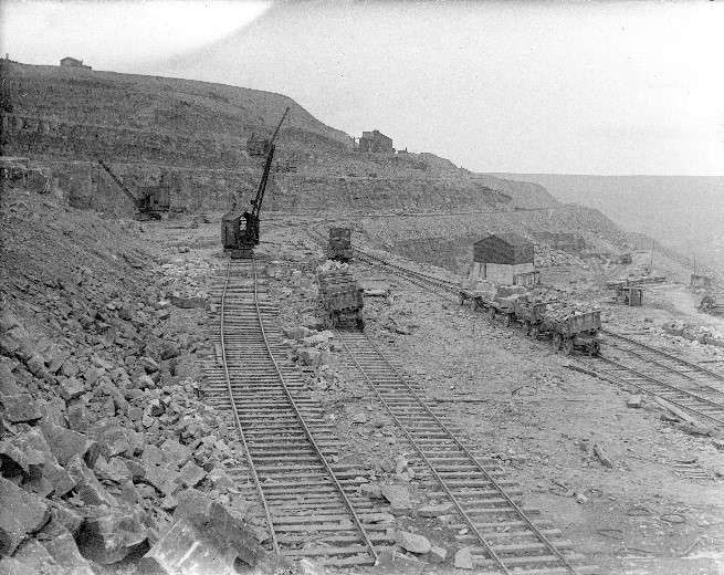
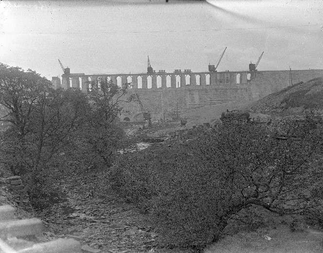
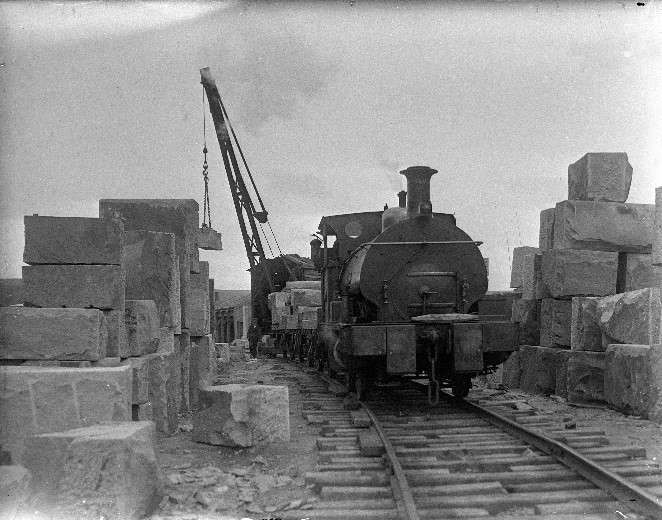
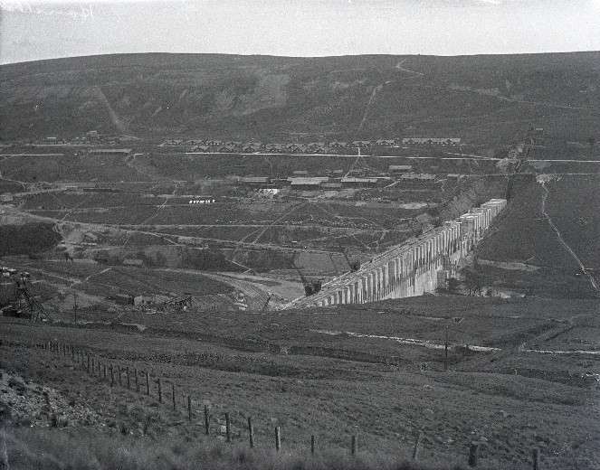
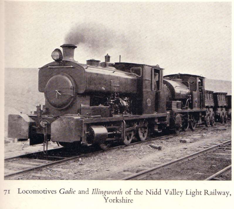
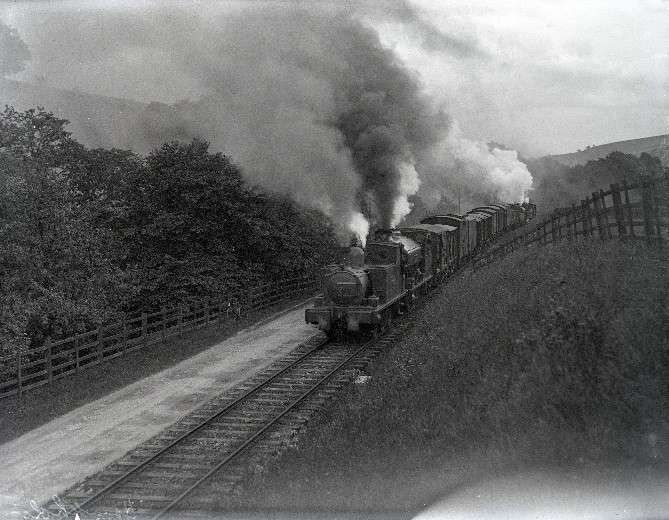
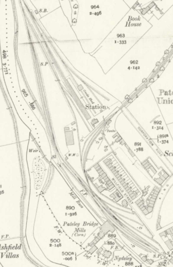
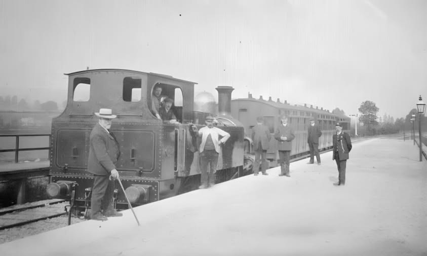
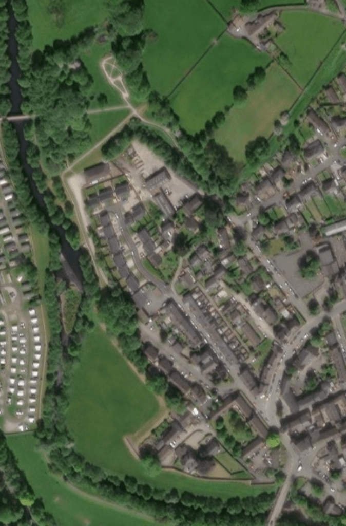
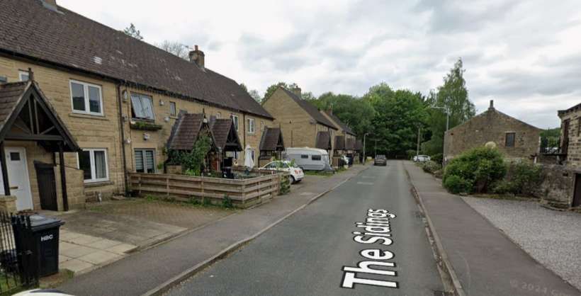
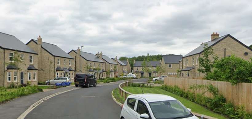
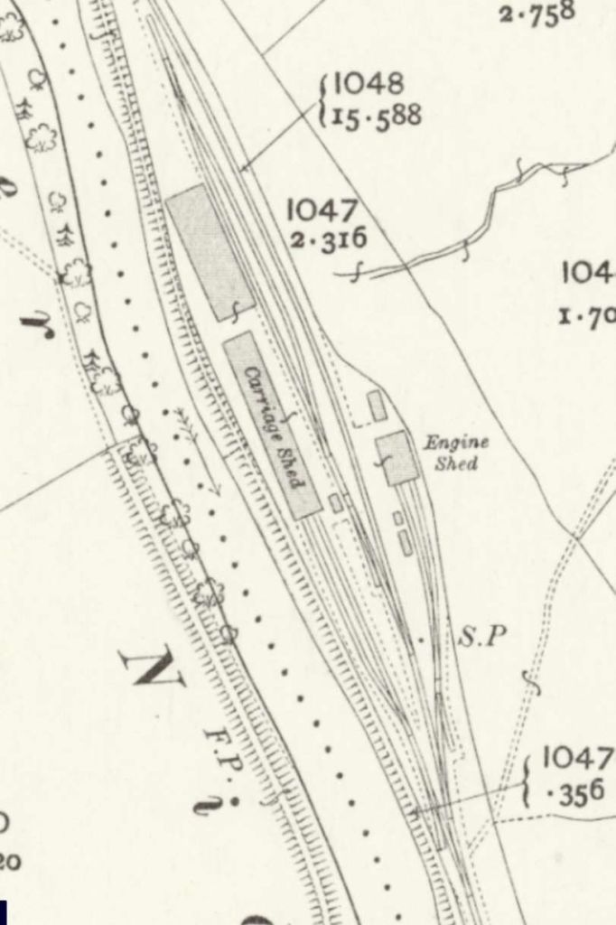
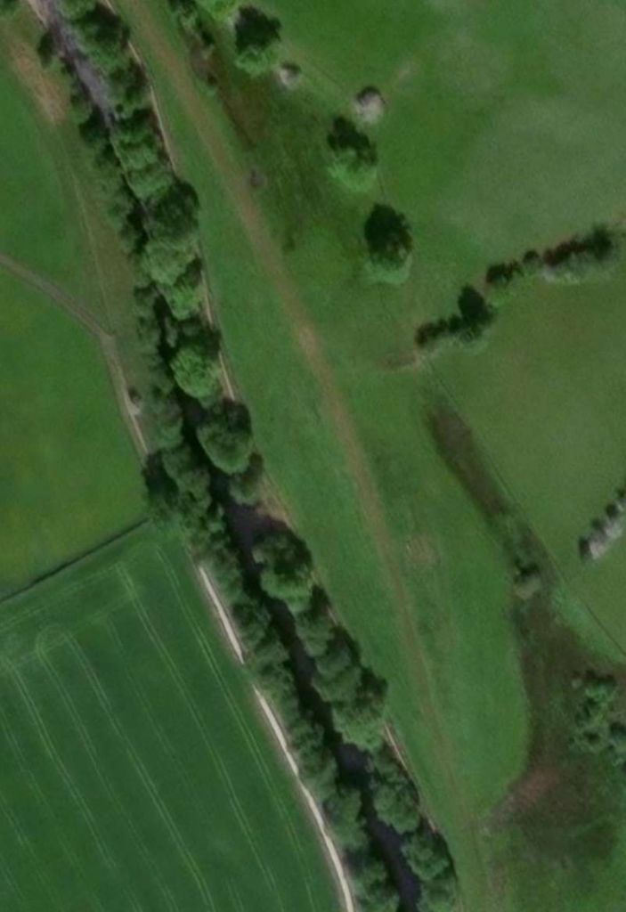
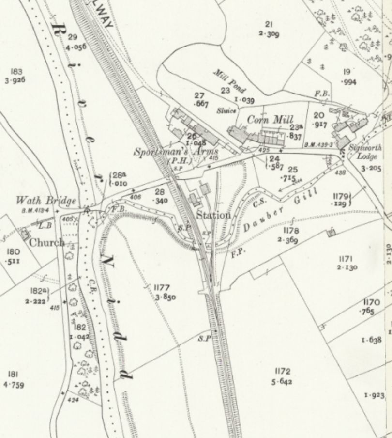
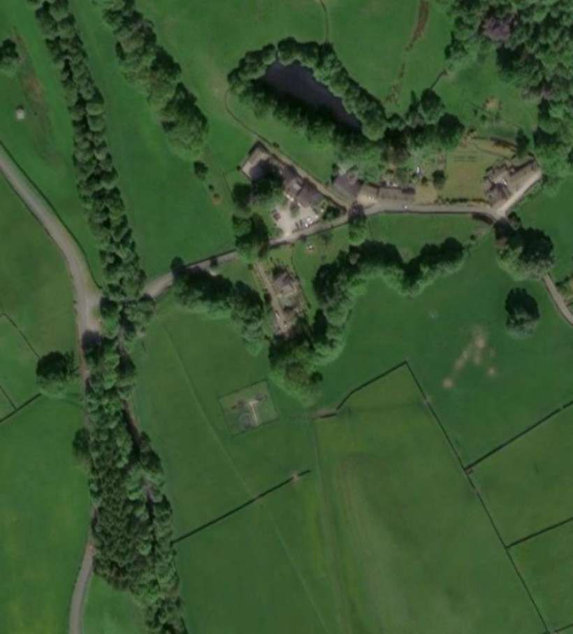
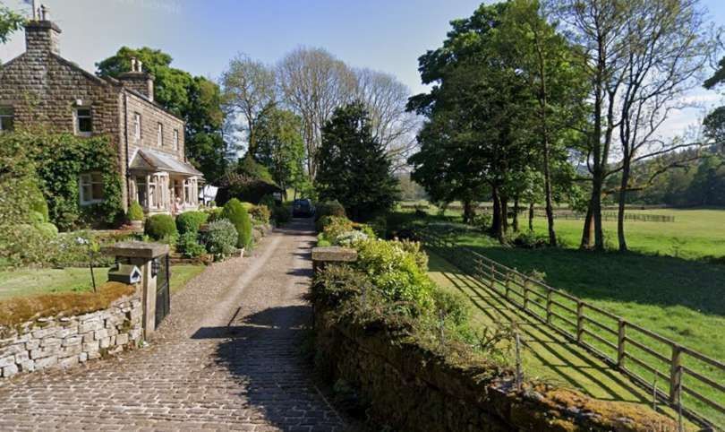
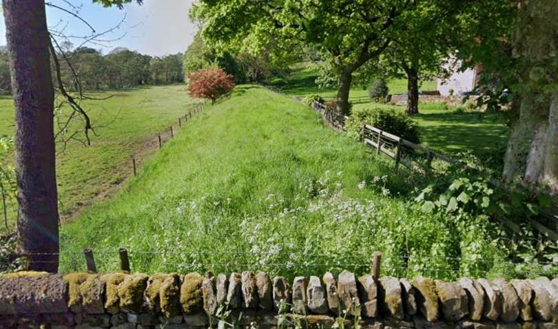
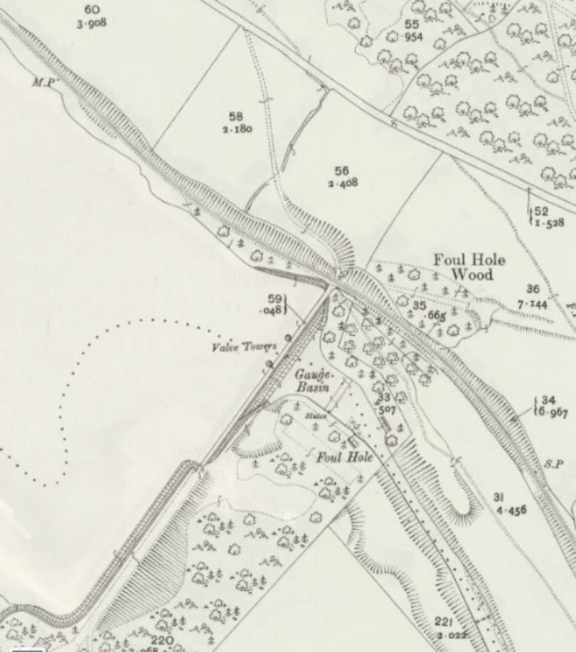
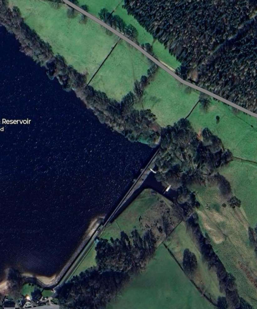
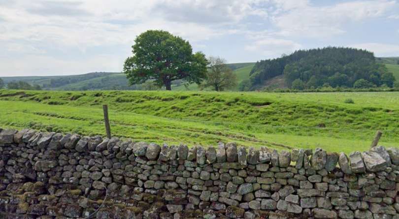
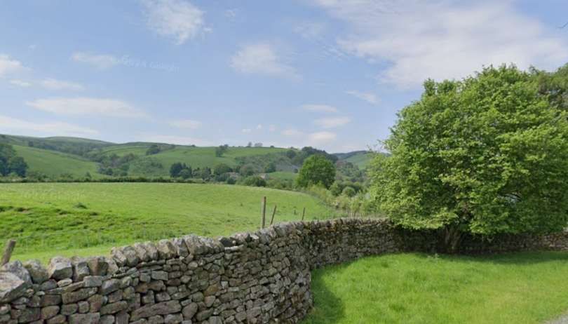
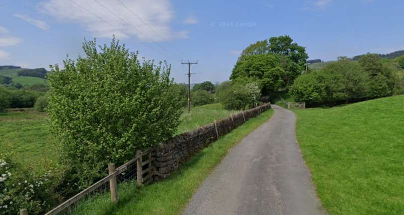
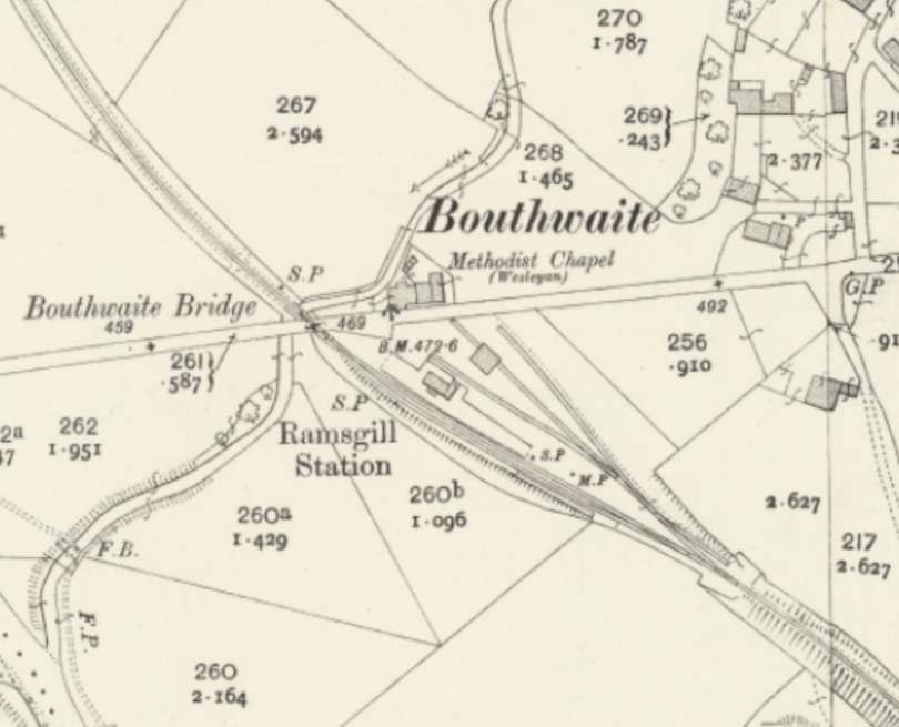
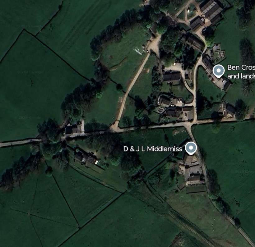
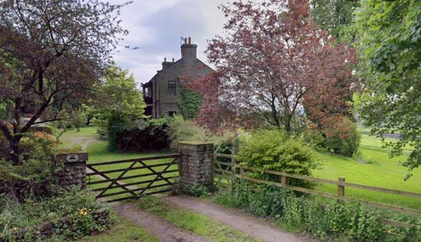
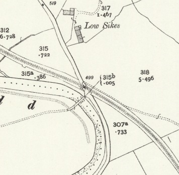

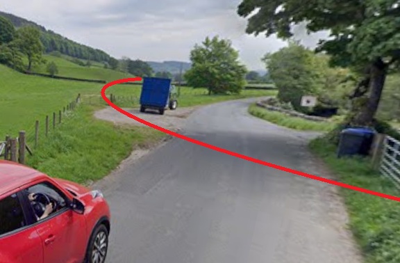
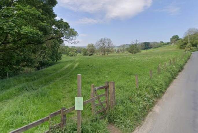
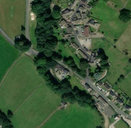
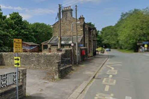
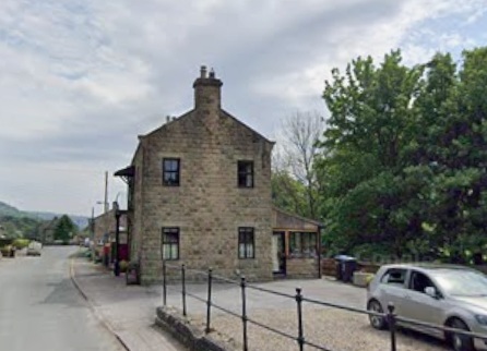
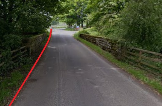
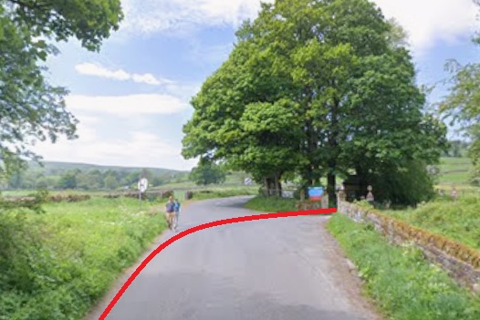

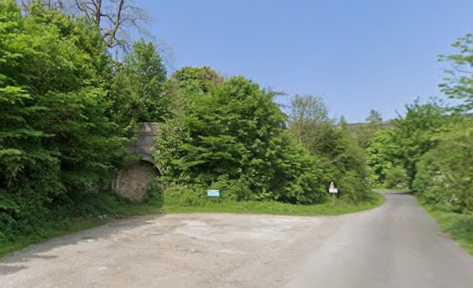
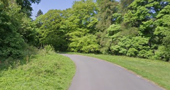
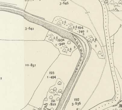
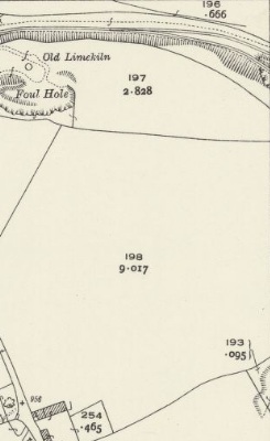
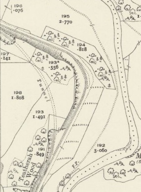

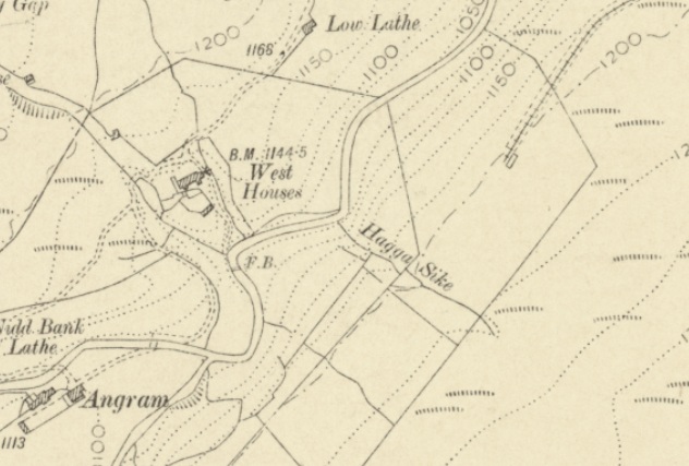
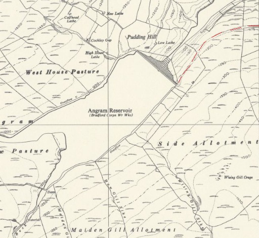
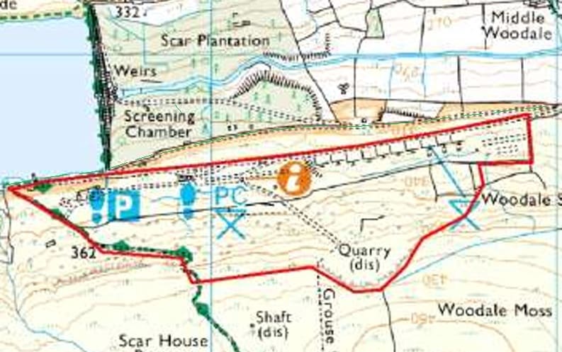
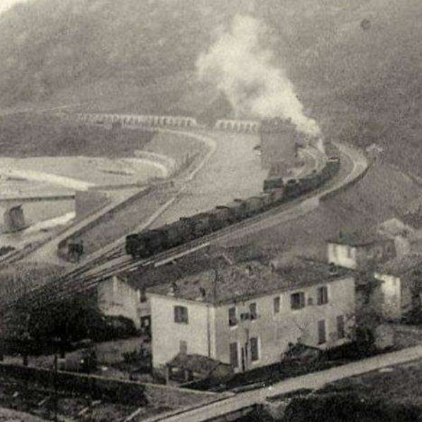
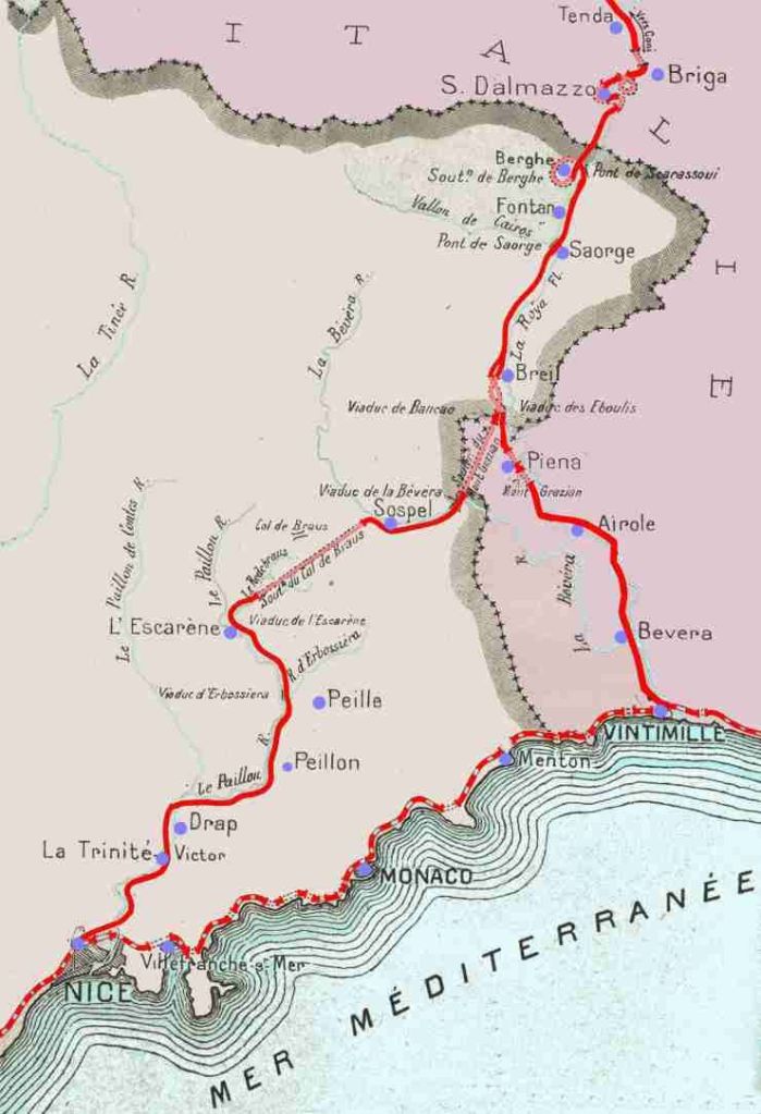
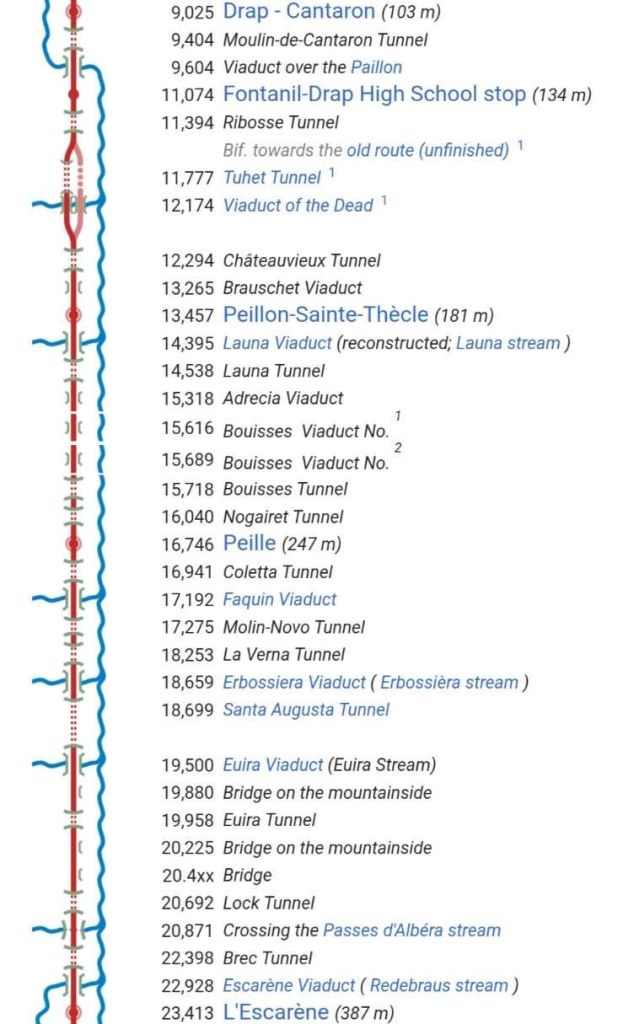
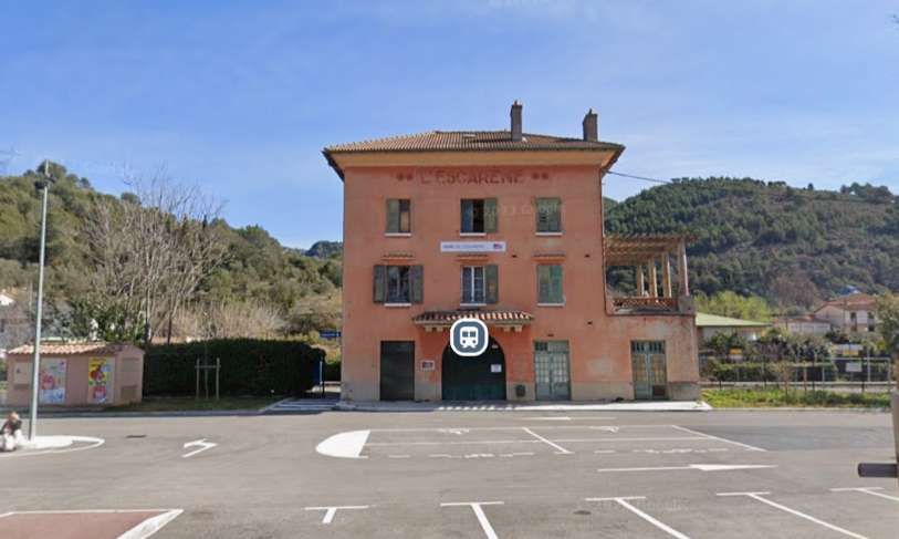
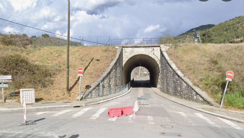
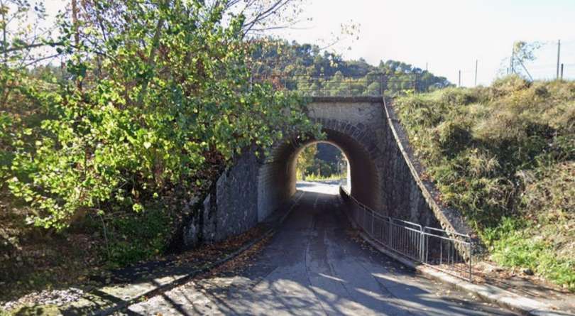
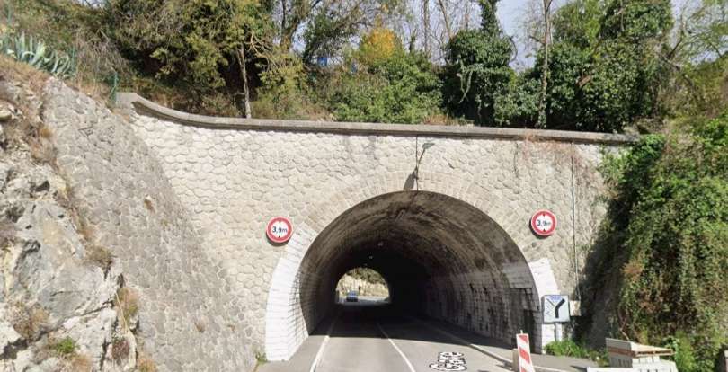
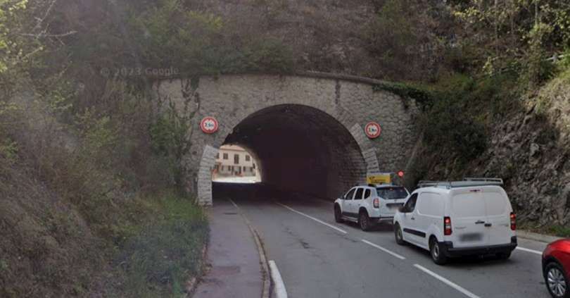
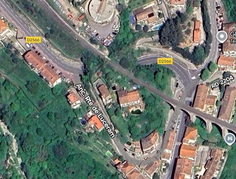
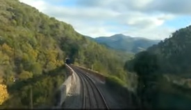
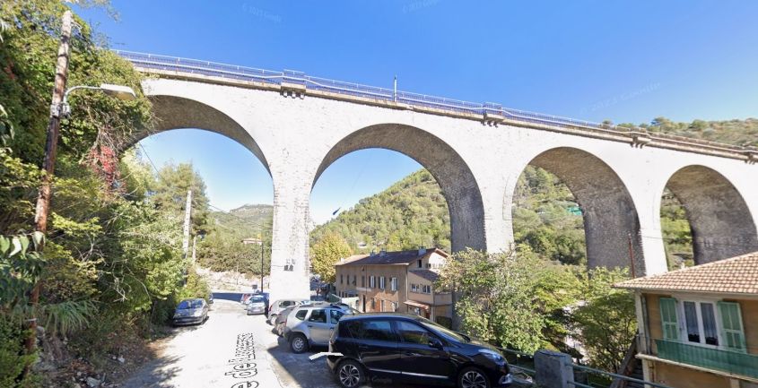
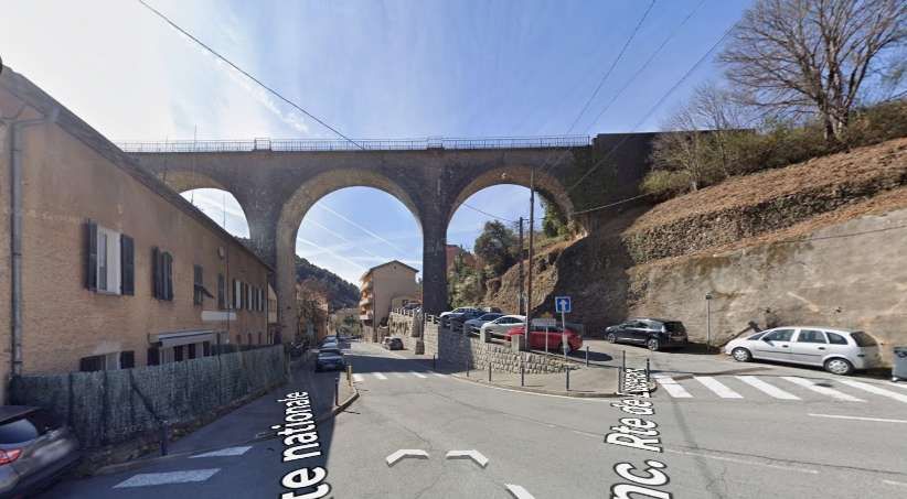
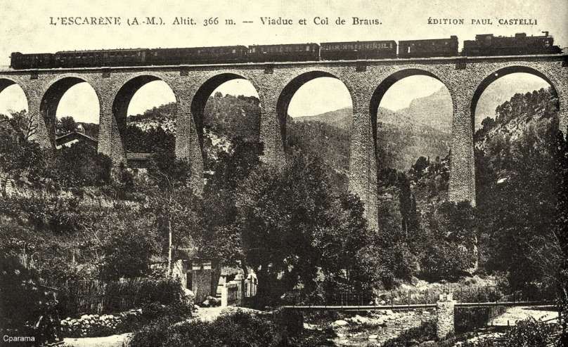
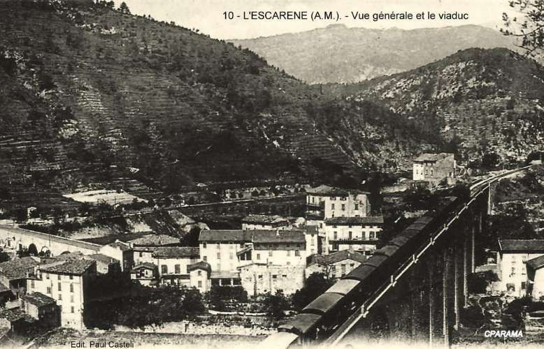

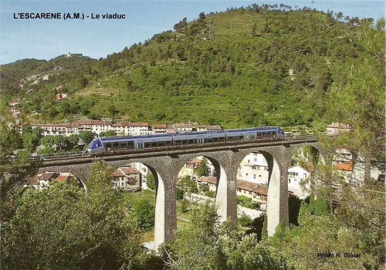
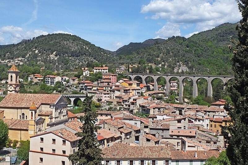
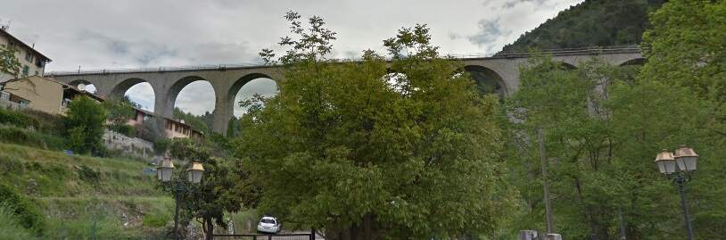
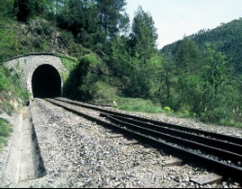
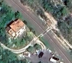
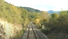
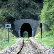
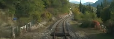
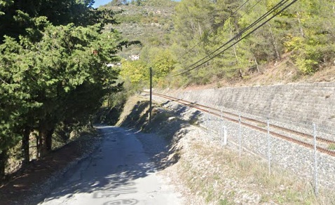

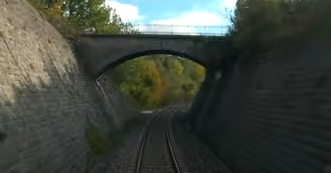
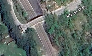
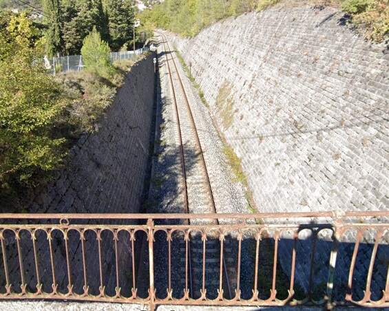
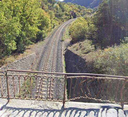
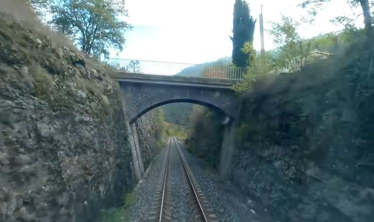
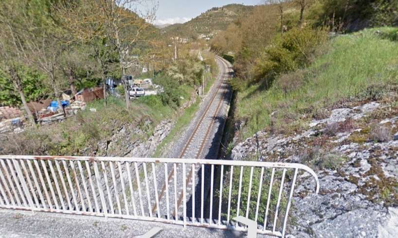
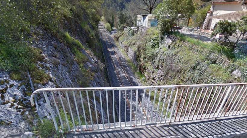
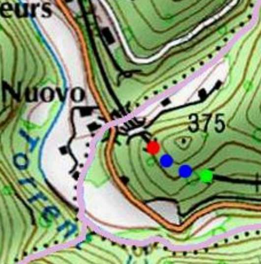
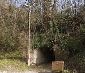
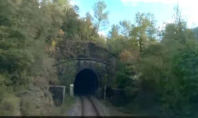
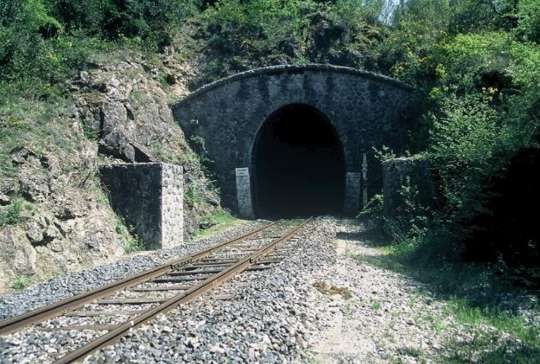
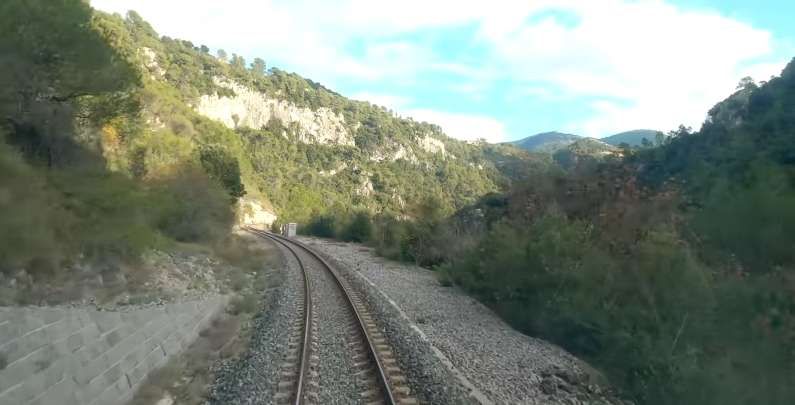
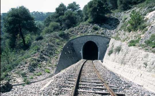
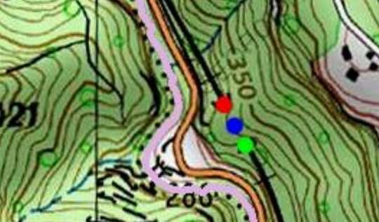
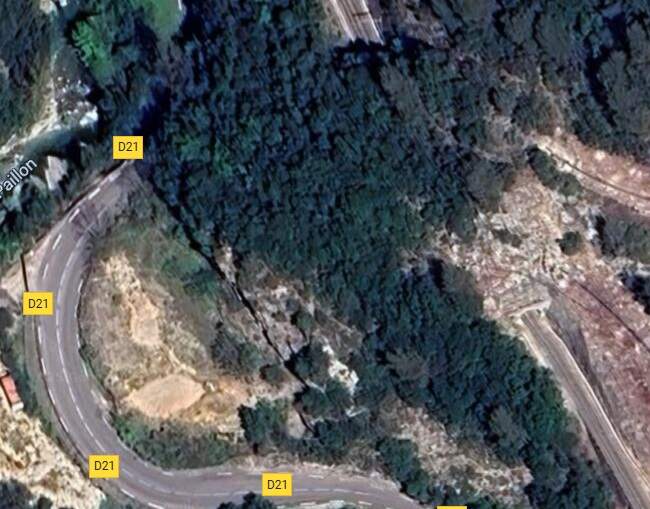
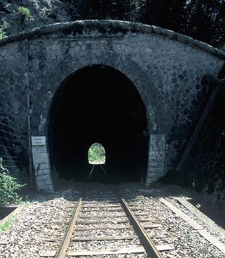
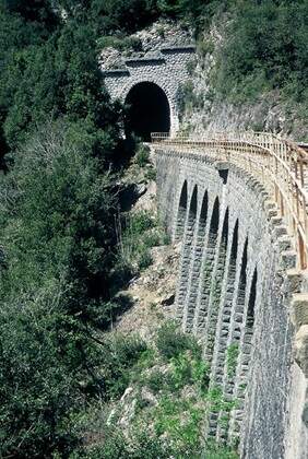
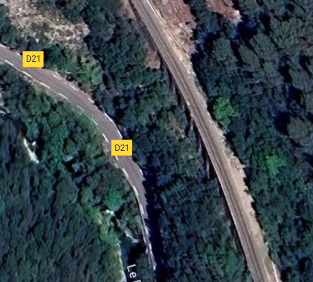
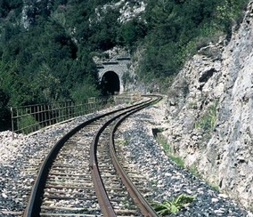
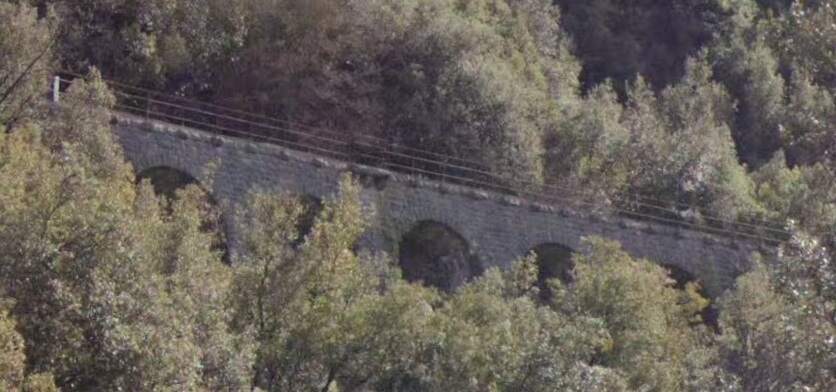
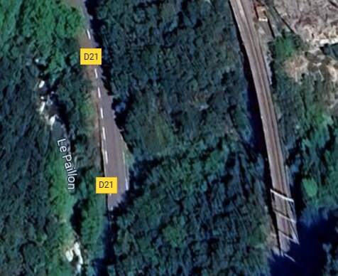
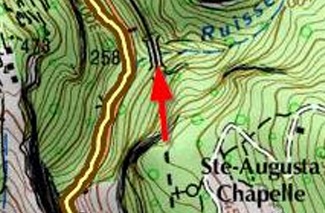
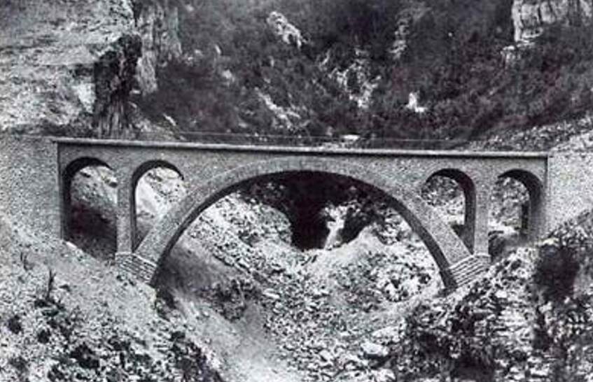

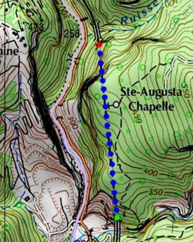
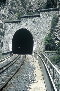
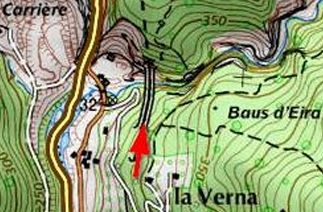
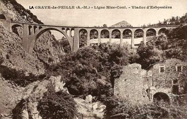
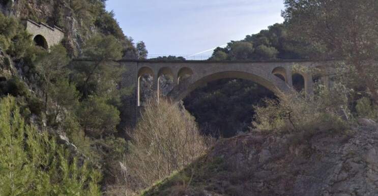
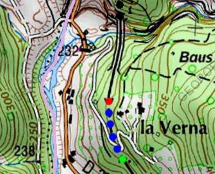
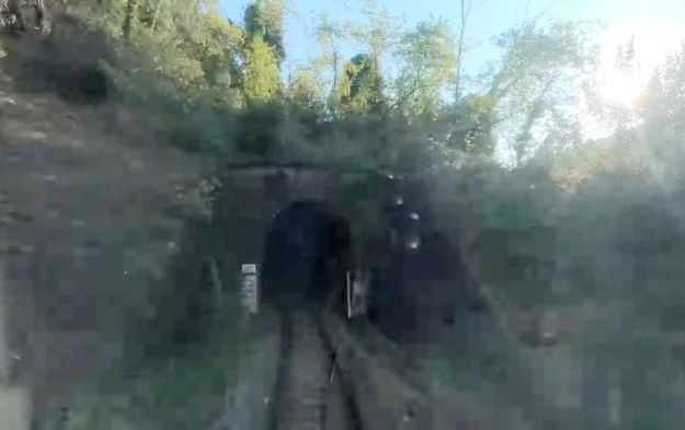
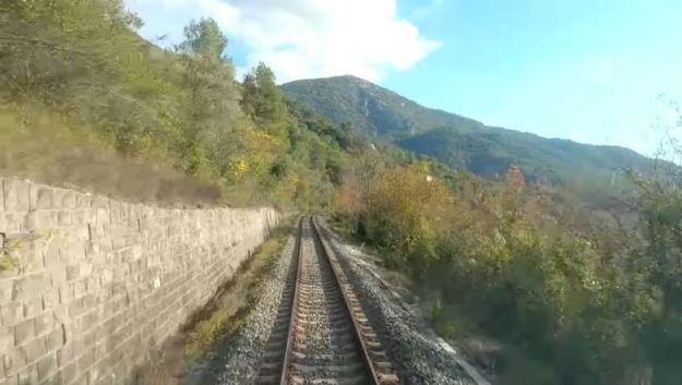
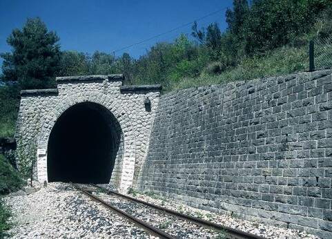
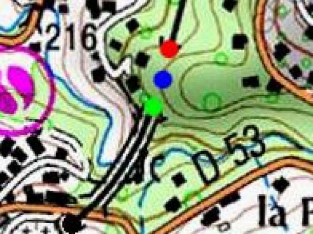
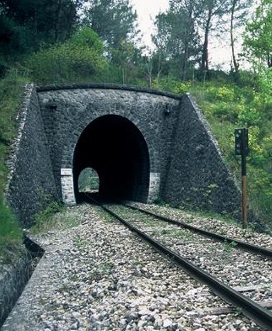
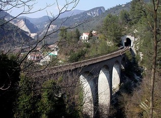
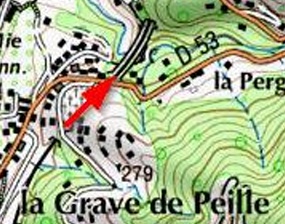
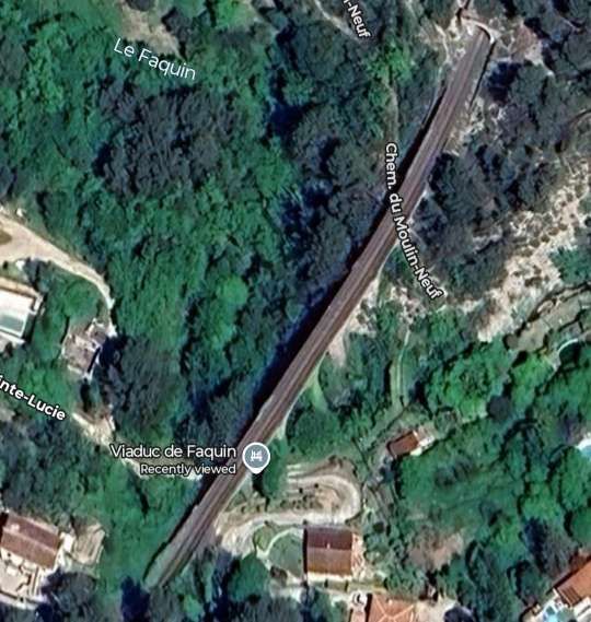
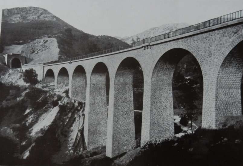
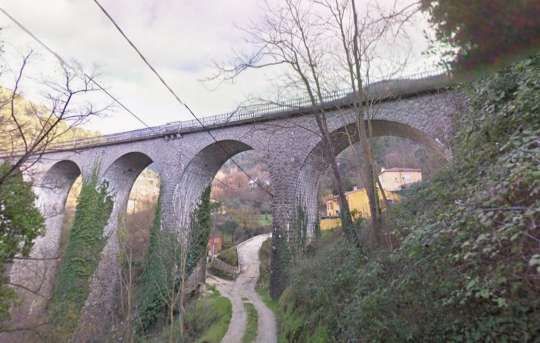
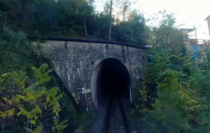
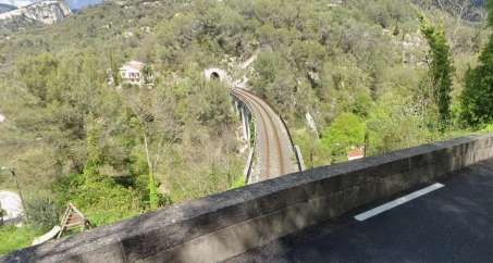
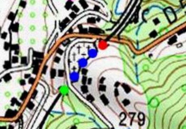
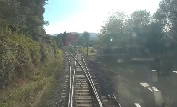
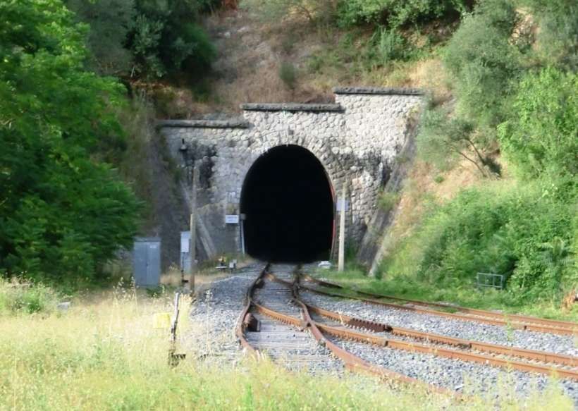
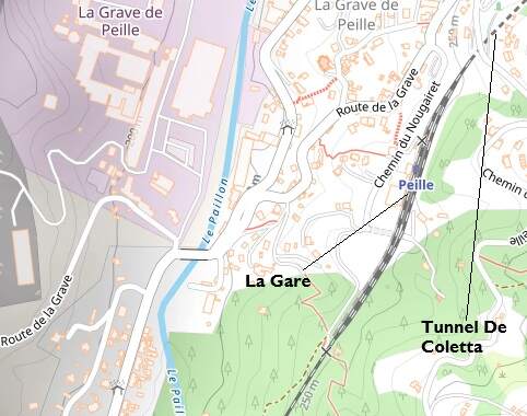
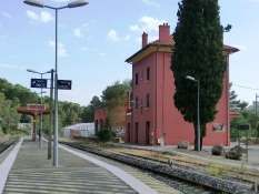
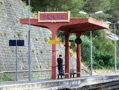
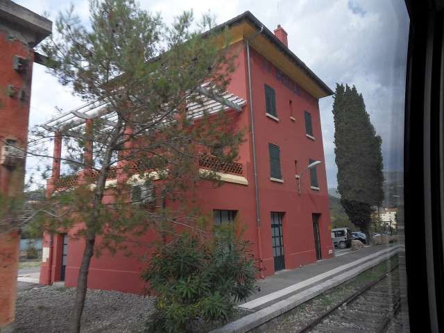
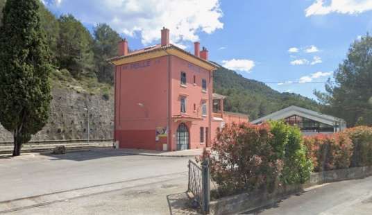
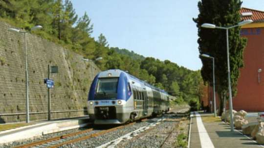
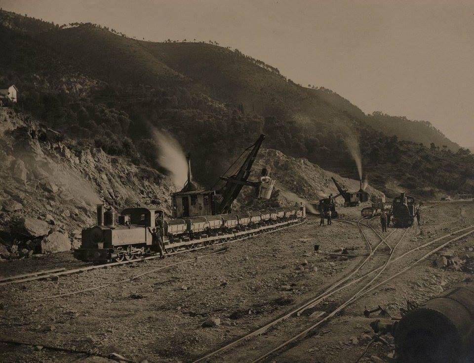
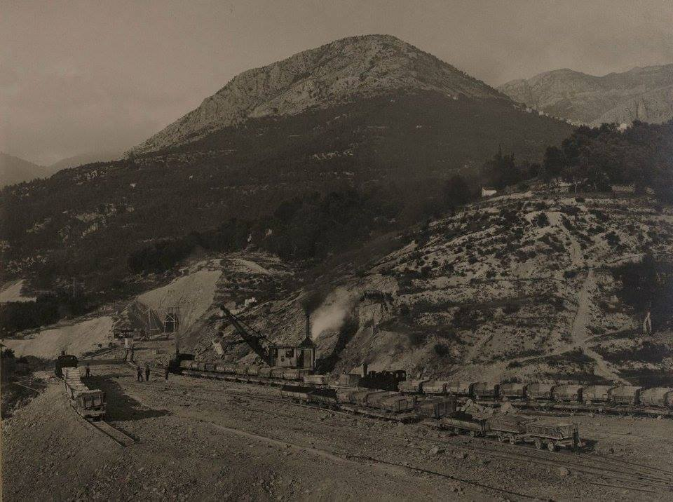
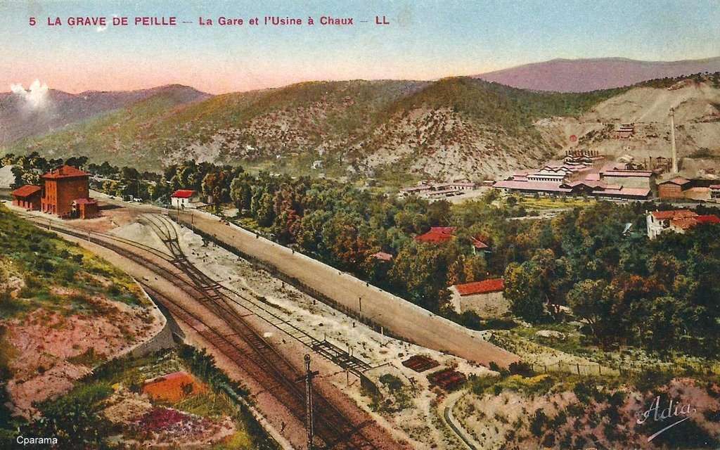
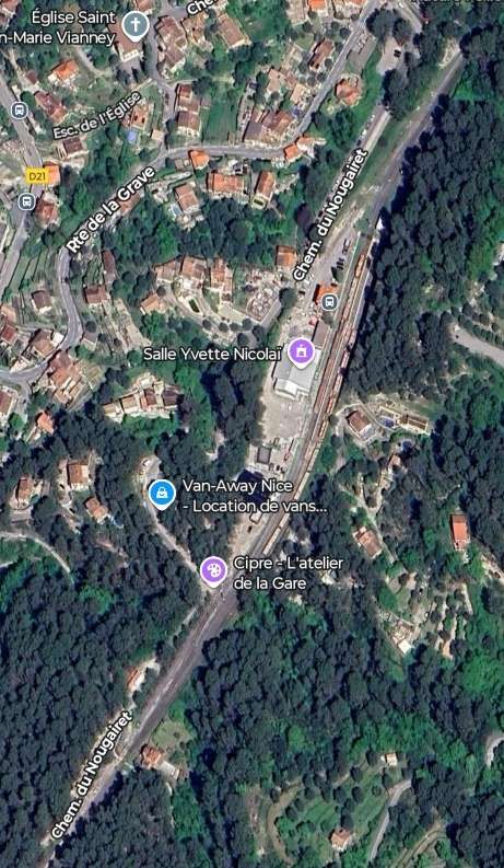
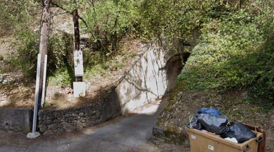
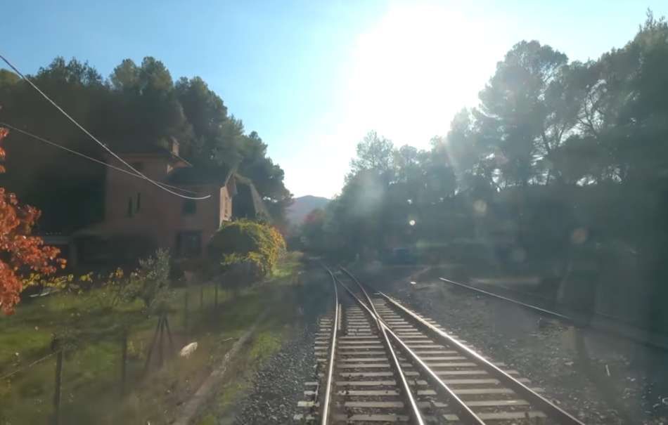
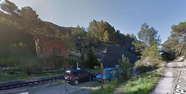
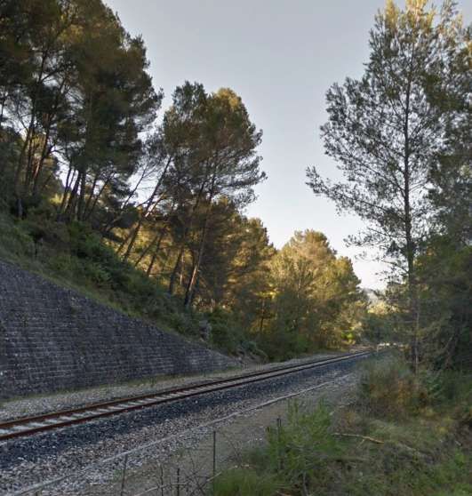
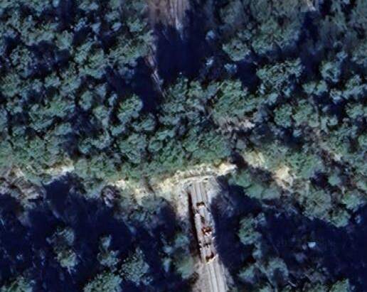
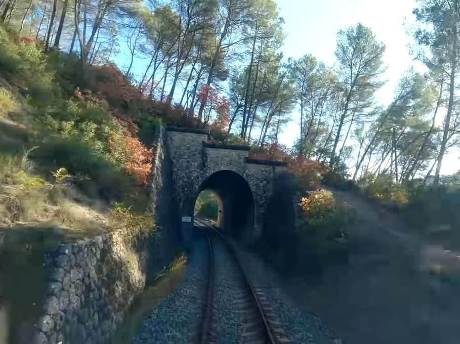
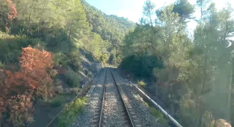

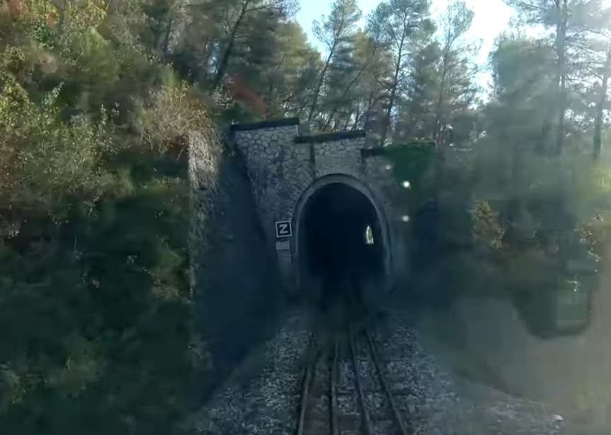
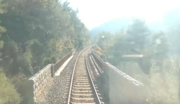
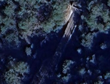

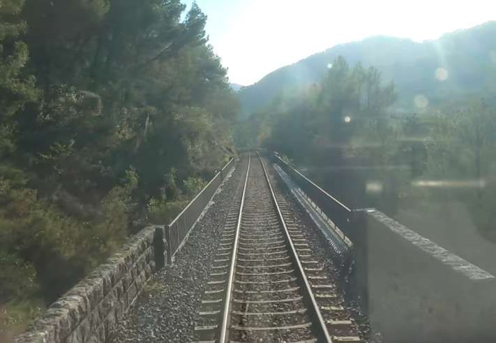
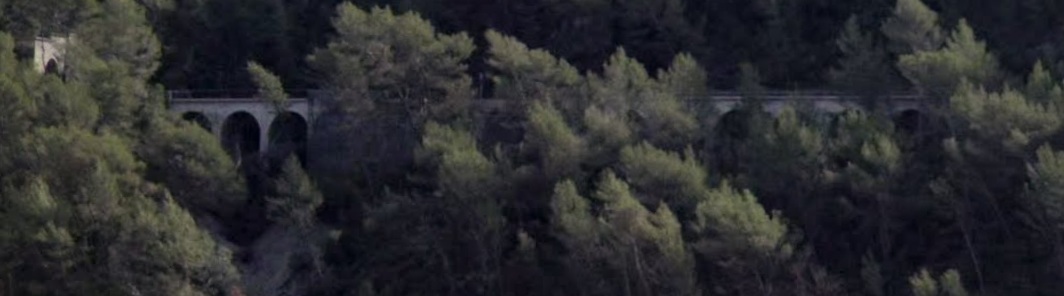
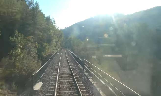
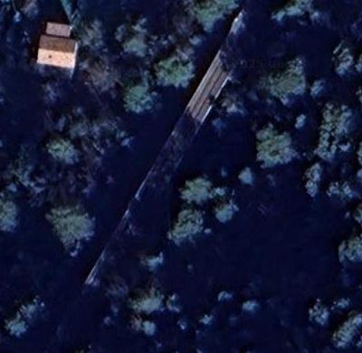
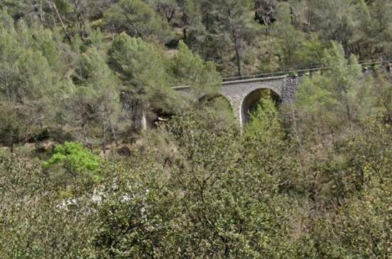
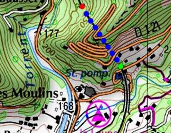
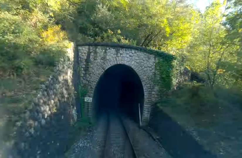
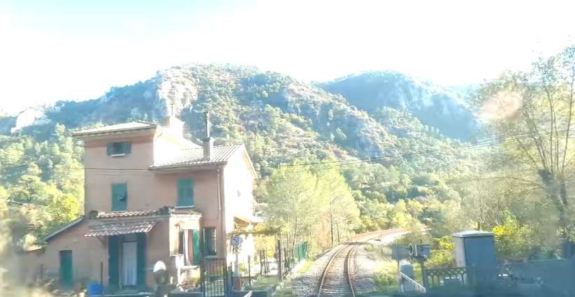
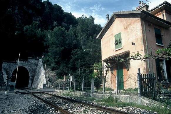
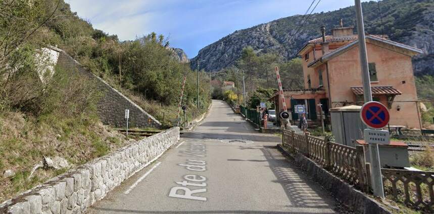
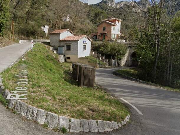
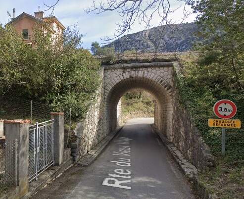
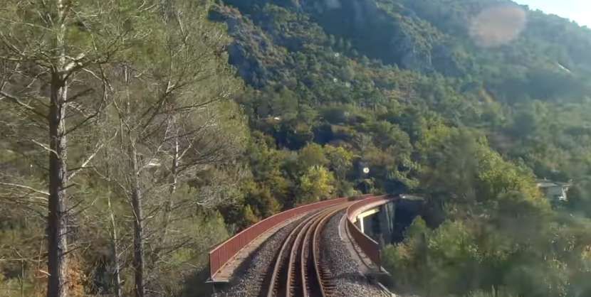
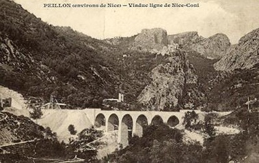
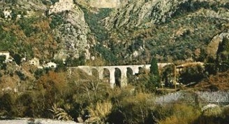
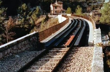
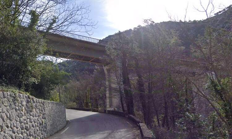
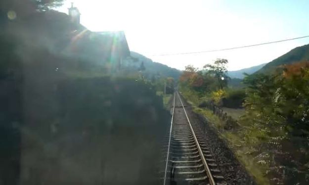
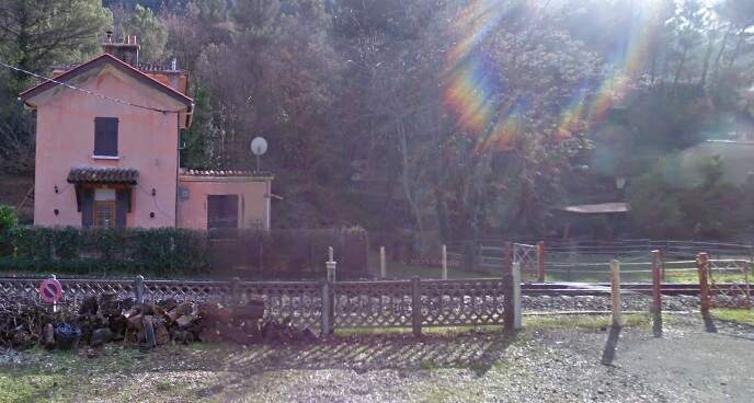
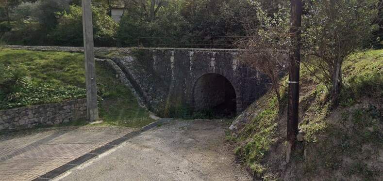
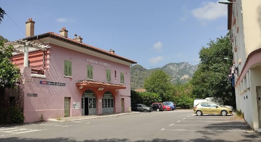
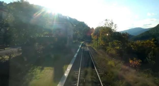
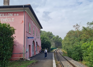
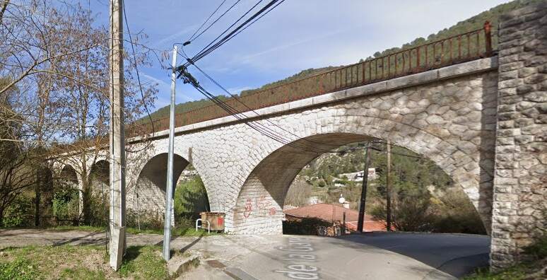
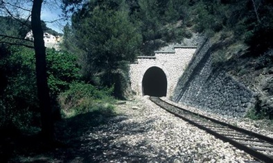
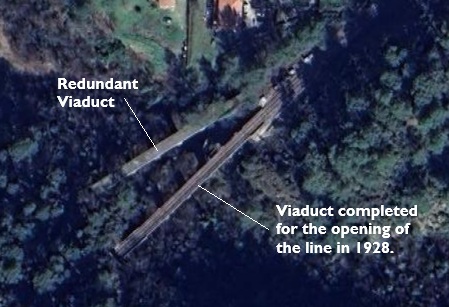
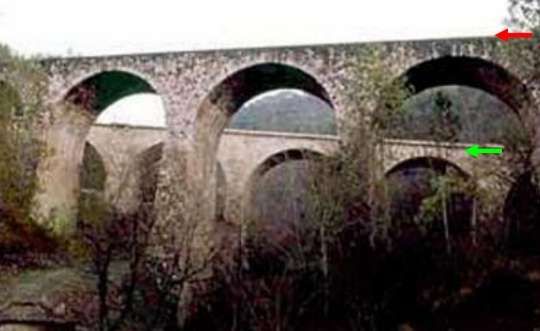
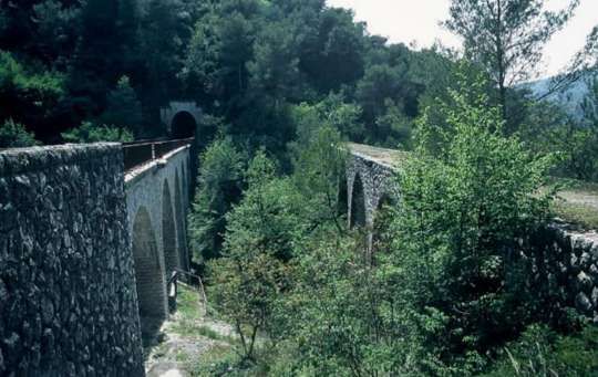
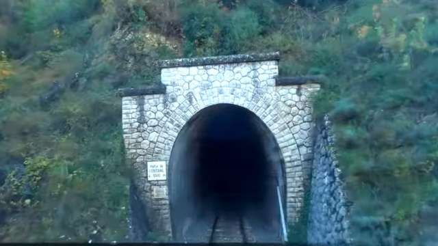
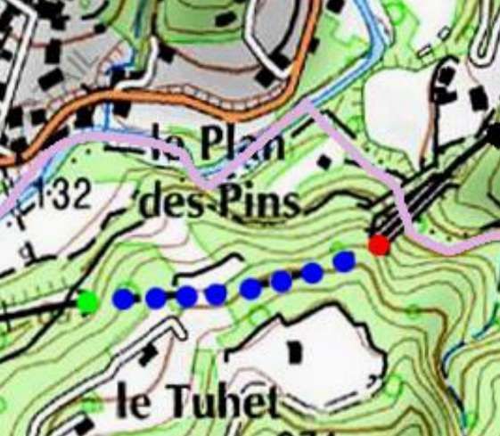
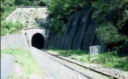
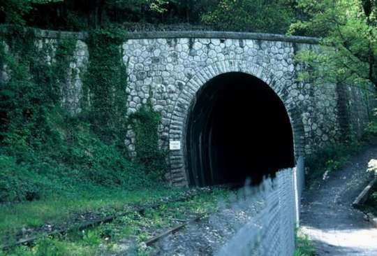
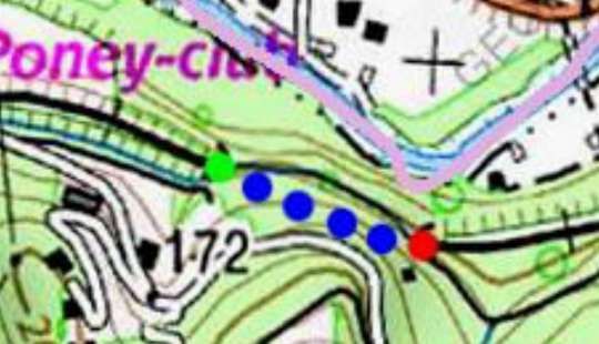
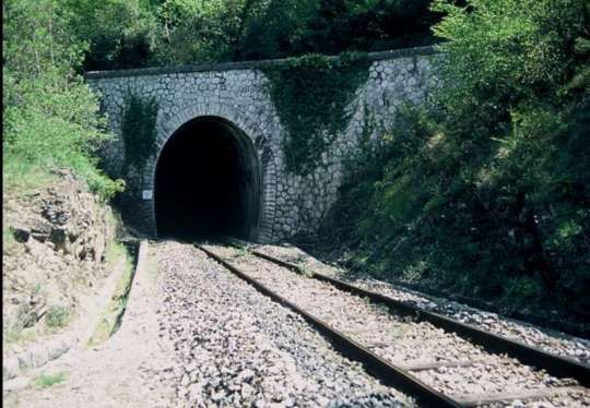
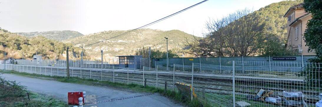
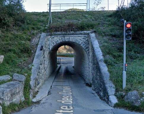
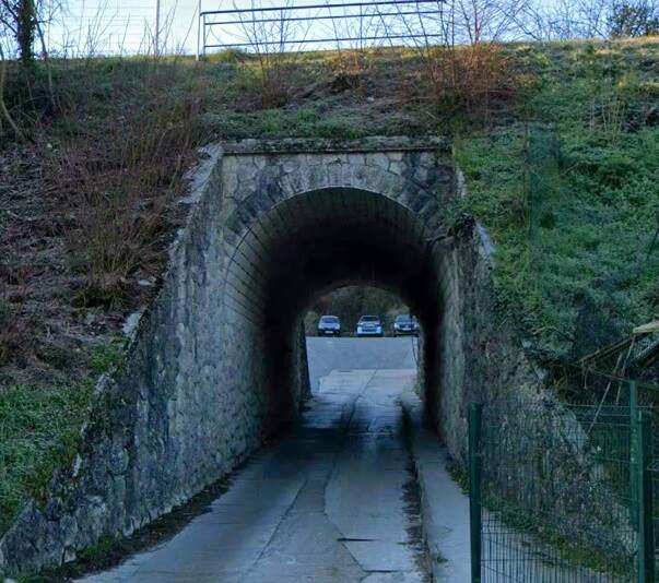
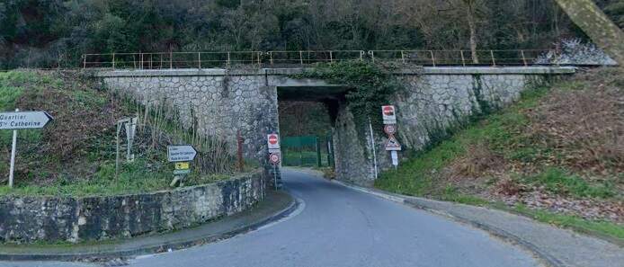
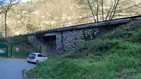
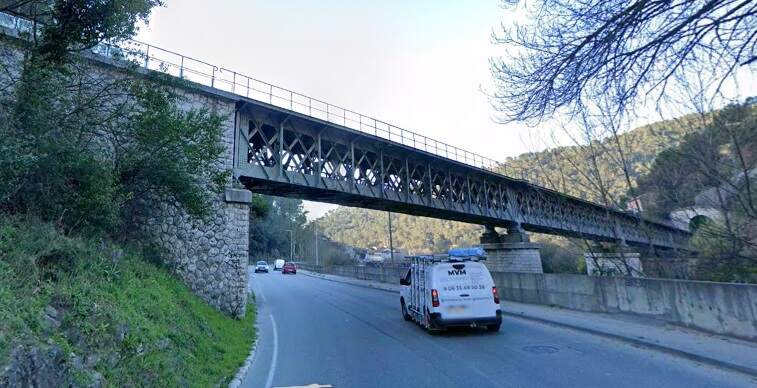
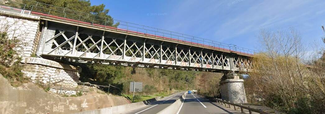
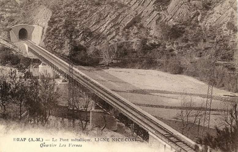
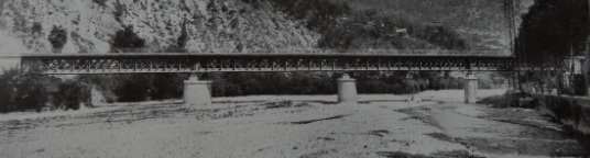
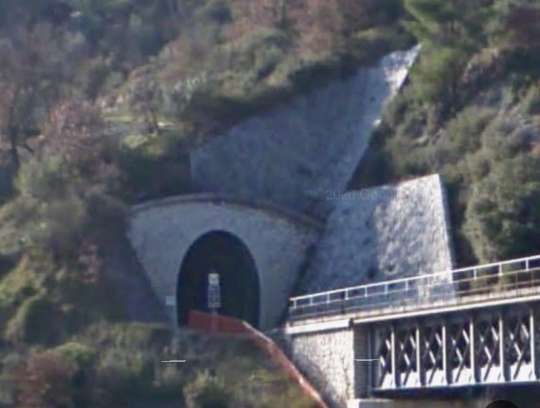
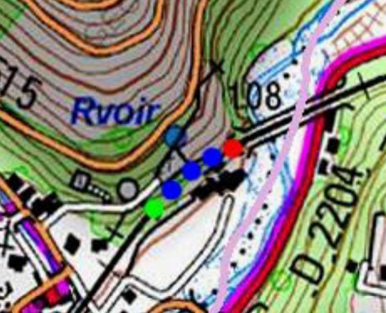
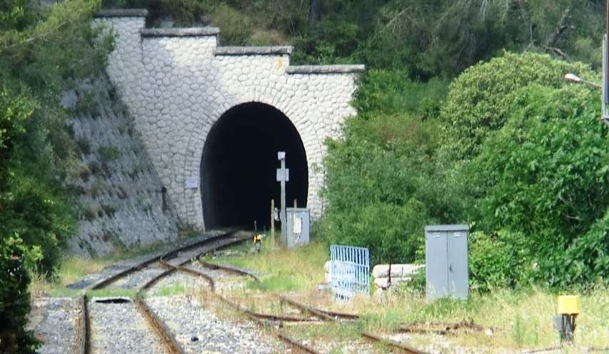
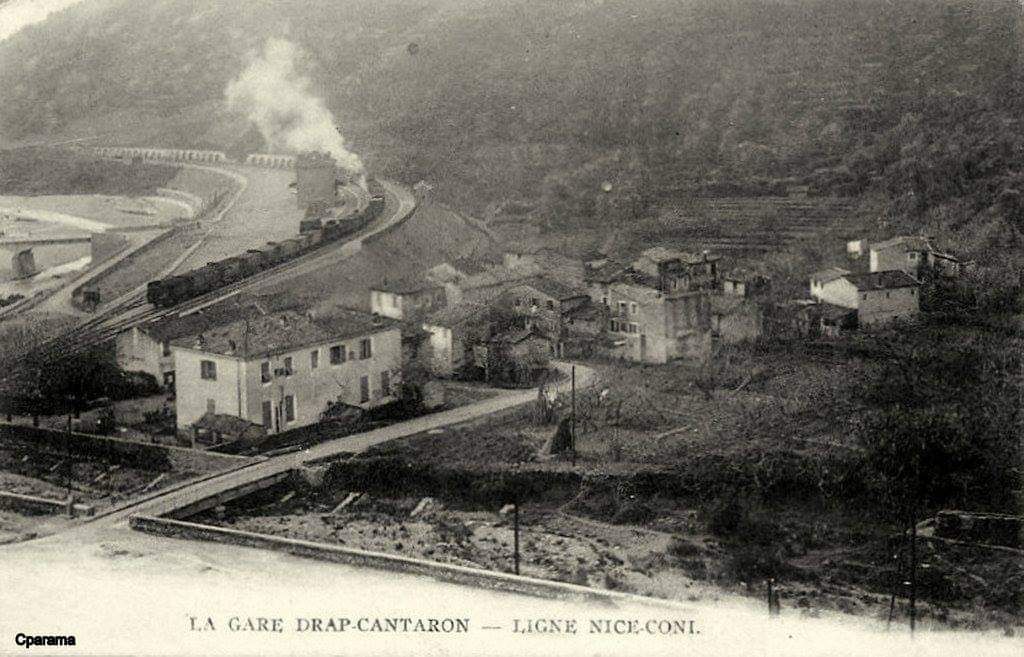
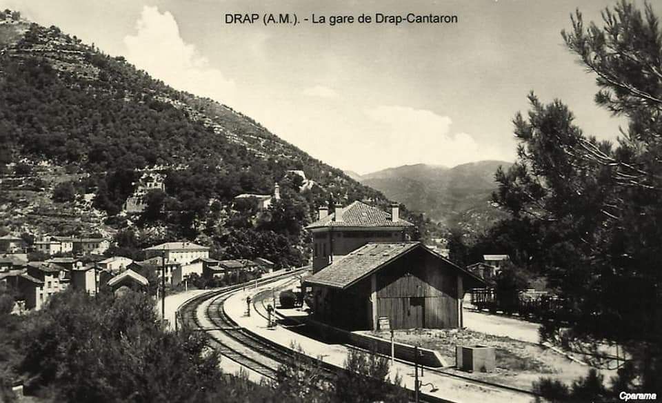
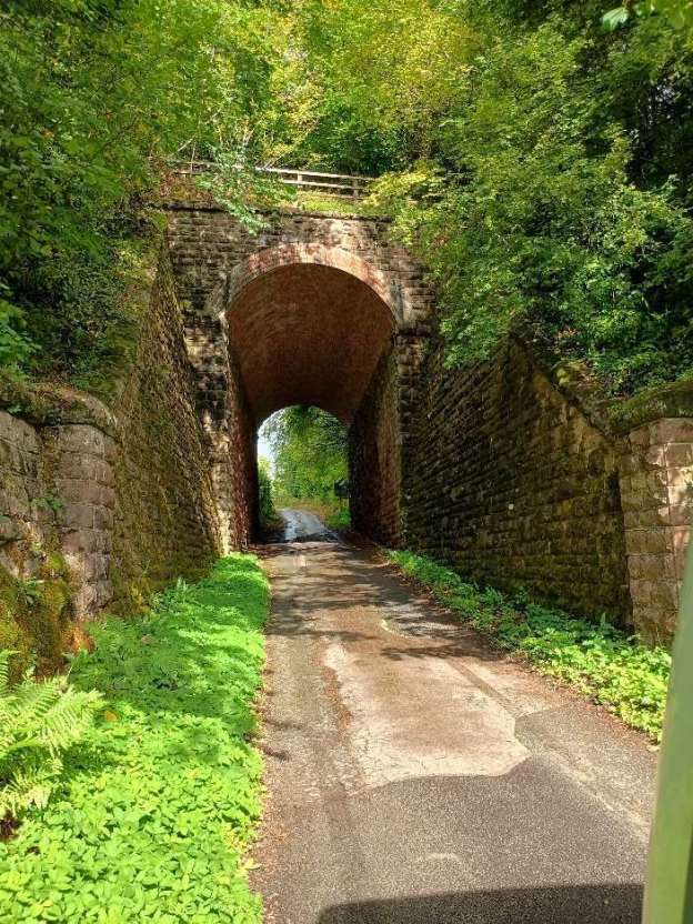
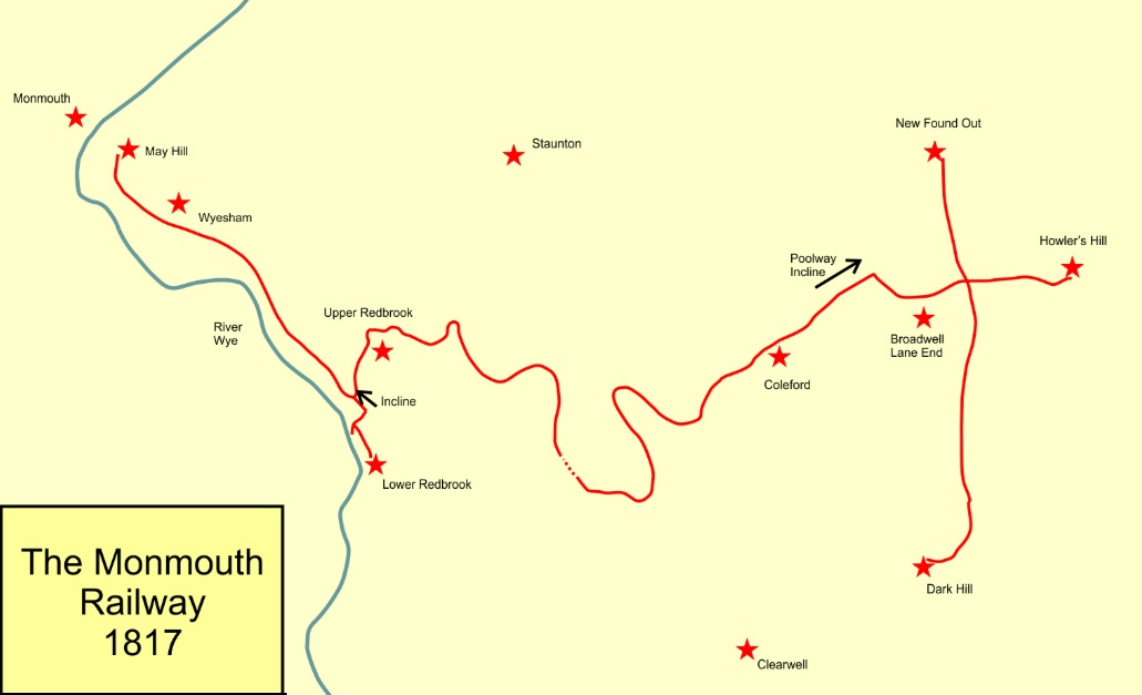
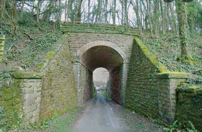

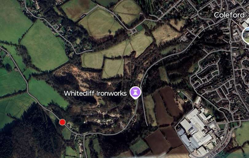
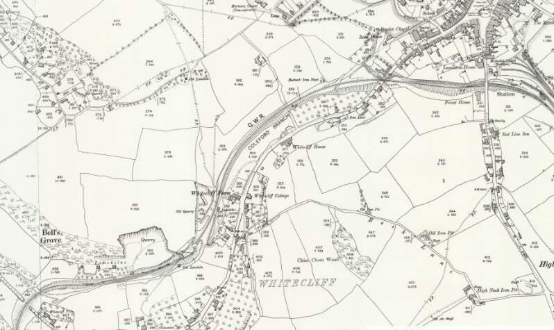
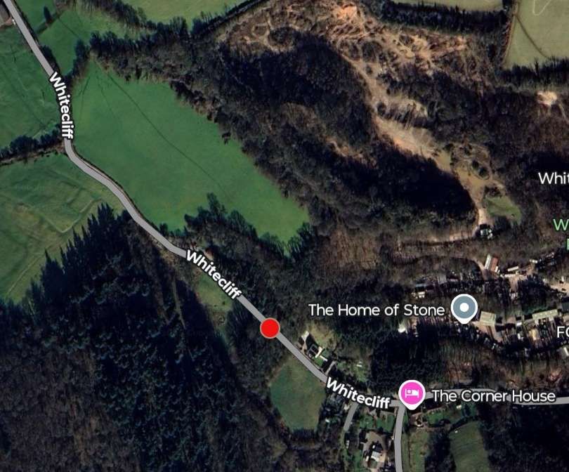
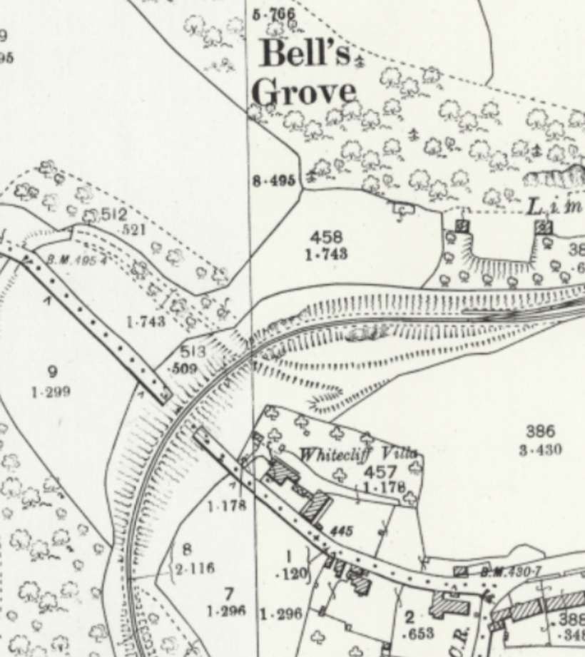
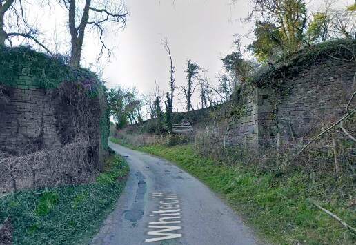
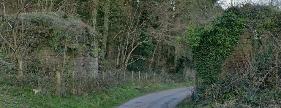
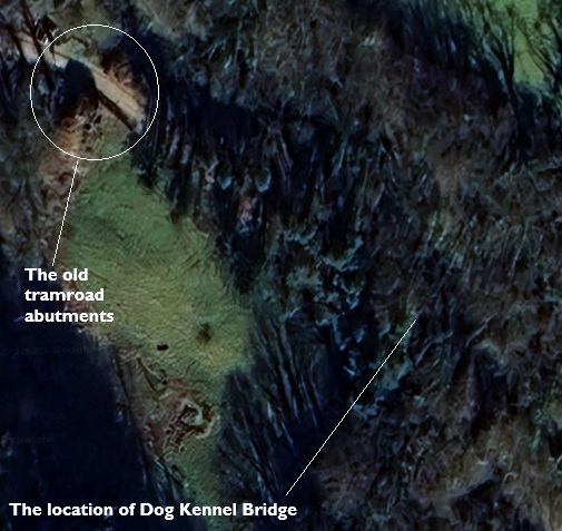

.jpg)
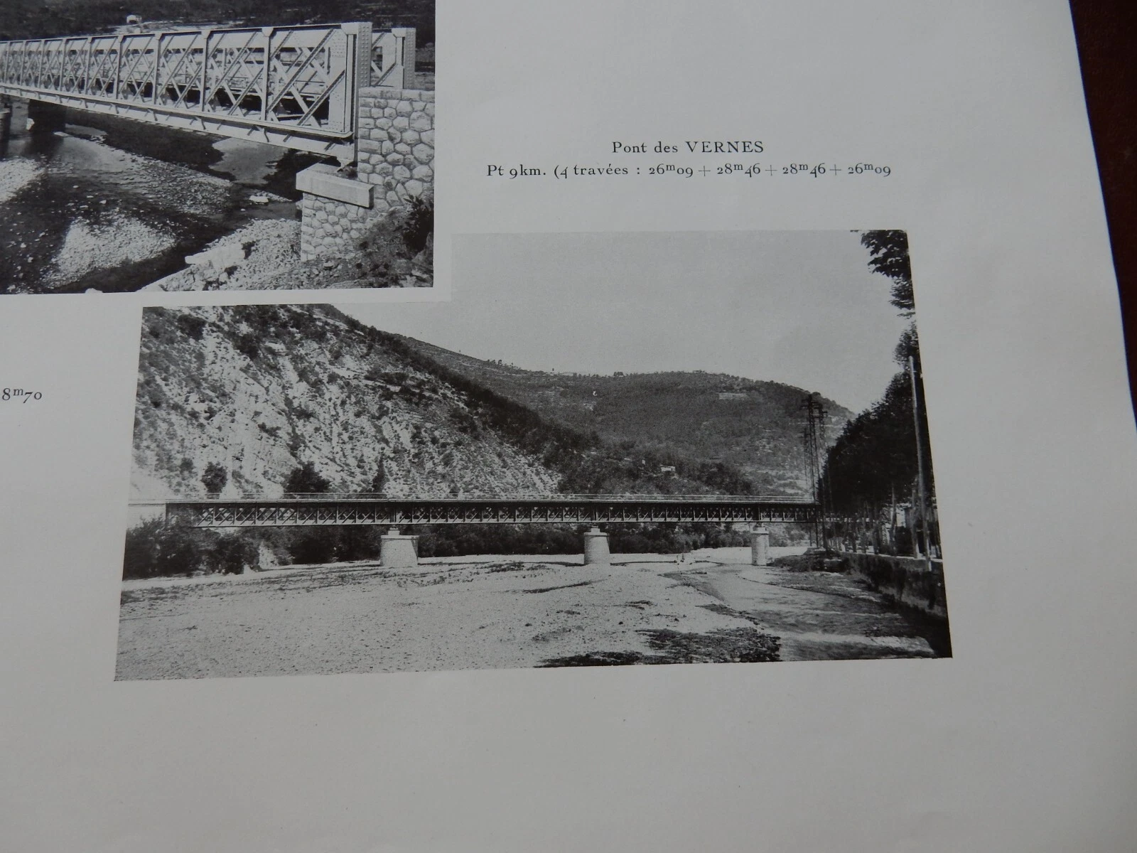