The Whitland & Cardigan Railway was a 27.5 miles (44.3 km) long branch line, “built in two stages, at first as the Whitland and Taf Vale Railway from the South Wales Main Line at Whitland to the quarries at Glogue. It opened in 1873, at first only for goods and minerals and later for passengers. The line to Cardigan opened in 1886; reflected in the company name change.” [2]
“The Company was always short of cash. Huge borrowings made it unable to pay its way; it was taken over by the Great Western Railway in 1886. Still considerably loss-making, it closed to passengers in 1962 and completely in 1963.” [2]
As we have noted, the Whitland & Cardigan Railway (W&CR) opened for public traffic on 1st September 1886 after over ten years in planning and construction. “Thomas Davies, ‘Master Tom’, as managing director of [a] shipping company at Cardigan, was well aware that times were changing, and besides his shipping interests, chose to hedge his bets by investing in railways. Even though the Teifi valley had been the obvious route for a line west to Cardigan, the C&CR (Carmarthen & Cardigan Railway) never advanced beyond Llandyssil, and after the Great Western Railway abandoned the broad gauge in south Wales in 1872 it was only a matter of time before the GWR decided to extend the line as far as Newcastle Emlyn. By then, though, there was little point in taking it further on to Cardigan, because the W&CR had already reached the town by a somewhat sinuous route over the Preseli hills.” [1: p469]
After reaching Crymmych Arms in 1874 “the W&CR obtained powers for an extension to Cardigan in 1877. Construction was slow. … Thomas Davies had become a director of the railway as early as 1880, and although he was plainly interested in his own income, it seems he also aimed to do his best for his home town, too.” [1: p469]
“The formal opening of the Whitland & Cardigan Railway took place on 31st August 1886, the day before the GWR was due to open the public passenger service. The arrival of the opening ‘special’ was accorded due ceremony and the occasion was presided over in part by ‘Master Tom’, Cardigan otherwise known as Thomas Davies, Bank House, the Mayor of Cardigan.” [1: p469]
After speeches, dignitaries dined in the in “the new goods shed at Cardigan station, just to the east of Cardigan bridge, south of the river.” [1: p470]
“The opening of this line was a critical moment for the commercial life of Cardigan, because thereafter influence began to move away from shipping interests towards those ready to use the railway.” [1: p470]
The terminus of the line in Cardigan was on the South side of the Afon Teifi, to the East of the town’s bridge across the river. The 6″ Ordnance Survey of 1887 shows the layout of the station in the later years of the 19th century.
The coflein.gove.uk website carries this description of the station site: “the station had a single passenger platform on the down side and a run-round loop. There was a goods yard, with two sidings and a stone-built goods shed, on the up side and a siding served a small locomotive shed and turntable adjacent to the River Teifi. A further siding on the down side completed the track layout. … The main station building had stuccoed walls of local brick under a low-pitch hipped slated roof with brick chimneys. There were square-headed openings with chamfered stucco surrounds. The canopy projected straight out from the building on moulded cast-iron brackets with a fretted fascia. The goods shed was set on a platform and had walls of slate blocks with dressed quoins and shallow arched heads to the openings. (Source: RCAHMW Cardiganshire Industrial file, SN14NE; notes by A.J. Parkinson).” [24]
Further phots of the station site can be found here, [6] here, [25] here [26] and here. [27] A search on Facebook also found a number of images of the station, the links are provided in references [6]- [13] below.
A model of the railway station was originally held by Y Cardi Bach Museum in Login. In April 2021 it was placed on display in Cardigan Castle. The Tivyside Advertiser reported on 8th April 2021 that the layout was moved to the Castle. [29]
The model of Cardigan Railway Station which was on display in Castle Green House at Cardigan Castle in 2021. [29]Turning to face East, the modern road bridge spans what was the line of the old railway. The trackbed close to Cardigan has been preserved as a footway and cycle path through Teifi Marshes and Wildlife Park, a Site of Special Scientific Interest. The River Teifi is on the left in this photo. [My photograph, 7th September 2022]
C.J. Gammell says that the Cardigan terminus was 27 miles and 38 chains from Whitland. It “is now an industrial estate and a few of the old buildings remain. The spacious layout of the former GWR station included only one platform but there was a goods shed, an engine shed, and warehousing. A good walk from the town and on the other side of the River Teifi, it was very much the traditional railhead.” [4: p233]
Gammell goes on to note that the service from and to Whitland “was extremely leisurely and strictly for the enthusiast, for the railway twisted and turned its way [through] the Prescelly mountains on tight curves and steep gradients. Br provided four trains per weekday which was more or less the same service provided in the line’s earlier years.” [4: p233-234]
Today, the trackbed close to Cardigan has been preserved as a footway and cycle path through Teifi Marshes and Wildlife Park, a Site of Special Scientific Interest.
Railway World magazine in early 1965 carried a two part article about Horwich Locomotive Works.
I always take note of articles about the Works when I find them as my paternal grandfather worked there in the early years of the 20th century, before the great depression when eventually he moved his family to Stapleford in the Derby/Nottingham area and where he took a job at the Loco Works in Derby as a blacksmith.
An article about the Works 18″ internal railway can be found here. [7]
The two-part article in Railway World was written by John Marshall and carried in the January and February copies of the magazine. This present article is substantively based on John Marshall’s work and sections of this article in “italics” come directly from Marshall’s article of 1965. [1]
“On 6th May 1964, Stanier 2-8-0 No. 48756 left Horwich works after a general overhaul, since when, the great works of the former Lancashire & Yorkshire Railway has been occupied entirely with rolling stock and road vehicles. The history of Horwich works goes back to 1884. When the main locomotive works of the L&YR opened under Sir John Hawkshaw in 1846, was on a very cramped and inconvenient site at Miles Platting, Manchester, almost surrounded by slums in the town.” [1: p22]
On 27th April 1873, “a serious fire caused considerable damage to the workshops but the pressure of work was such that the shops had to be rebuilt. It was during this period that ten Ramsbottom Newton class 2-4-0 engines were bought from the L.N.W.R. Repairs to locomotives were also carried out at the old East Lancashire Railway shops at Bury and smaller repairs were undertaken at several locomotive sheds, and it was therefore difficult to achieve any standardisation of work.” [1: p22]
During the 1870s, the L&YR was in a bad shape. “Train services were slow and unpunctual, and stations, carriages, services, goods and locomotive depots alike were some of the worst in the country. … The wretchedness of the railway was a popular theme upon which both counties of the roses were absolutely unanimous. By the early ‘eighties all this was being changed and it was now the turn of the locomotive works. Expansion at Miles Platting was not possible; a quarter of the machinery and other equipment there was out of date and ill-fitted to cope with work on the larger locomotives of W. Barton Wright. The obvious solution was to build a new works on a different site.” [1: p22]
After retiring because of ill health as Locomotive Superintendent of the LNWR in 1871, John Ramsbottom returned to railway work in 1883 and “became connected with the L&YR as a consulting engineer. At the L&YR directors’ meeting on 19th March 1884, he stated that locomotives could no longer be repaired satisfactorily at Miles Platting works and that it was essential to find a new site for the works. He recommended that in selecting a site the principal considerations should be the price of labour, a good supply of cheap water, cheap coal and a fairly central situation to avoid long runs by light engines. Various sites were suggested and Ramsbottom and Barton Wright were instructed to examine them and report back to the next meeting. Wright was also asked to ascertain the rates of wages in locomotive workshops in different parts of the country.” [1: p23]
At the next board meeting on 21st May 1884 it was noted that an estate in Horwich was about to be auctioned. The board authorised a maximum spend of £65,000. The purchase was secured for £36,000.
The site “was centrally situated and within easy reach of Bolton and Manchester. On 14th February 1870, a branch railway had been opened into the town from Blackrod, on the Bolton to Preston line. Horwich, at the foot of Rivington Pike at the western extremity of the Pennines, had a population of 3,761 in 1881.” [1: p23]
On 26th September 1884, Ramsbottom submitted drawings showing ground levels and locations for various buildings/workshops. The question of a curved connection from the Bolton direction was raised. “Plans were prepared and the ‘Fork Line’ was authorised by Parliament on 16th July 1885.” [1: p23]
Horwich Railway Station was close to the centre of Norwich and only a short distance from the proposed location of the Loco Works. The 25″ Ordnance Survey from the turn of the 20th century. [2]
Work on the site required the legal closure or diversion of several footpaths. The Thirlmere Aqueduct, planned by Manchester Corporation, had to be diverted at L&YR expense.
Ramsbottom’s plans of the locomotive and wagon works and offices “showed that the locomotive works would occupy nearly 20 acres and accommodate 112 engines; the wagon works would have occupied about 14 acres, for 1,008 wagons, but they were not in fact built. In January 1885 Wright’s detailed elevation of the office building was approved; this included a clock tower which was later omitted.” [1: p23]
Contractors began work on 9th March 1885; “a siding was constructed to bring materials onto the site and a powerful crane and locomotive were soon at work. By August the excavations for the foundations of the erecting shop were almost complete. The next stage involved the removal of a hill on “old Hart’s Farm” containing some 450,000 tons of earth. To carry out this job in one year meant the removal of 1,500 tons daily, and a force of 350 men and boys, two steam navvies, five locomotives and 130 tipping wagons were employed continuously; work continued at night under electric light. … The erecting shop … [was] a vast building 1,520ft long (well over a quarter of a mile) and 118ft wide with three bays running the whole length, the two outer ones being wider than the centre.” [1: p23-24]
A careful review of the equipment at the Miles Platting and Bury works was undertaken showing that only around 50% was suitable for the new works.
In September 1885, the disposal of surplus land to the northeast of the works began, “Some plots were … reserved, including sites for a hotel and a a bowling green but the rest was … sold for building. … Victoria Road and several streets leading from it were laid out by the company; the names chosen for the various streets … [included] Ramsbottom, Hawkshaw, Fairburn, Stephenson, Webb, Gooch, Brunel, Smeaton, Brindley, Telford, Armstrong and Siemens. … A letter was received the Bishop of Salford offering, one penny a square yard for a plot of land for a church, but the Companyhad already requested fourpence a square yard for a Wesleyan Chapel site.” [1: p24]
“Work on the office block, the boiler shop, the smithy, forge and foundry, a large store shed and a large water tank. The new gasworks was erected at this time. … Work on the Horwich fork line began on 21st September! it was opened for goods traffic on 20th June 1887, and for passengers on 1st July with an improved service between Horwich and Bolton and Manchester.” [1: p24]
This extract from the 25″ Ordnance Survey from the turn of the 20th century shows the Horwich branch with both curves in place from the mainline and with the connection into the loco works evident as well. [2]
On W. Barton Wright’s retirement in October 1887, in his place came J.A.F. Aspinall from Inchicore in Ireland to become Chief Mechanical Engineer. At the time of his appointment Aspinall was only 35 years of age.
He persuaded the Company to introduce a premium apprentice scheme and to fund a Mechanics Institute at Horwich. He also urged the immediate purchase of locomotives as prices at the time were relatively low. Based on his assessment of average mileage per locomotive in various railway companies he demonstrated that the L&YR needed a stock of 1,114 locomotives against an existing complement of 963. The shortage of engines was resulting in over use, engines becoming neglected and breakdowns being too frequent.
As an emergency measure, “Aspinall ordered 30 6ft 4-4-0s of Barton Wright’s design, but with Joy’s valve gear, from Beyer Peacock and from the same firm he ordered two small locomotives, at £250 each, for the 18in gauge internal railway system at the works. A third, ordered in 1887, cost £300. Aspinall quickly showed his concern for the well-being of the workers at Horwich. He was dissatisfied with the way the houses were being built and arranged for better supervision of the work. He also arranged for a local doctor to attend to accidents in the works until a permanent arrangement could be made.” [1: p24]
As construction work on the fitting, painting and erecting shops was nearing completion it was possible to “take in the first six locomotives for repair. They included the Barton Wright 4-4-0 No. 865 Prince of Wales, built by Dübs in 1885 and named in honour of a royal visit to Preston.” [1: p24]
The large office block, 323ft long and 58ft wide was brought into use on 19th February 1887 Beyer Peacock supplied two 18in gauge locos by 7th April and they were set to work in the erecting shop.
The foundry was completed next and work began here on 12th April. “The first castings were small engraved iron paper weights which were presented to the L&YR directors as a memento of the occasion. With the opening of the foundry Henry Albert Hoy, at that time manager at Miles Platting, was appointed works manager at Horwich and on Aspinall’s recommendation his salary was increased from £225 to £300, to become £400 in two years.” [1: p25]
Aspinall submitted further plans to the directors meeting on 27th September 1887, for a “further nine shops at an estimated cost of £26,738. For the whole of the work to be transferred from Miles Platting at an early date, it was necessary to start the brass foundry and copper shop at once and to cover in the space between the foundry and the forge to form the steel foundry. Of the shops proposed, the board sanctioned the erection of the tin and copper-smiths shop, the brass foundry, telegraph shop, steel foundry and an extension of the foundry for rail chairs.” [1: p25]
By the end of 1887, Miles Platting workshops were closed, “a few months later the shops at Bury were also closed, and all locomotive repair work was transferred to Horwich. The Miles Platting shops were converted into carriage sheds and the Bury shops used for stores.” [1: p25]
Horwich Locomotive Works as shown on the 25″ Ordnance Survey from the turn of the 20th century. [2]
In January 1888, “work was started on the first order for new locomotives. This consisted of 10 2-4-2 tank engines of Aspinall’s design, the famous “radials”; the first one No. 1008, left the works on 20th February 1889, the second following in about three weeks. Because the steel foundry was not ready, the wheels and tyres were obtained from Germany, but the other parts of the engines were built entirely at Horwich. The tenth was completed during the following August.” [1: p25]
Work began on the first of the numerous Aspinall 0-6-0s in January 1889. The first order was for 10 engines, the first being completed in September and the last on 27th March 1890. Marshall’s article lists “the building dates of … all batches of locomotives built at Horwich until locomotive work ceased. Between 1891 and 1900 Aspinall rebuilt 230 of Barton Wright’s 4ft 6in 0-6-0s into saddle tanks for shunting. This released an equal number of serviceable tenders, hence the large number of locomotives built without tenders during this period.” [1: p25]
A table showing the building dates of all the batches of locomotives built at Horwich. The table was provided by John Marshall in his article in Railway World. [1: p26]
The Mechanics Institute building was opened in December 1888. Courses in electricity, mechanics, mathematics and machine drawing were introduced. There was a staff of 5 teachers with 90 students per week. “Fees were nominal, but if a student attended less than 21 classes in each subject, the charge was doubled.” [1: p26] The Institute was extended by the addition of a public hall to seat 900 people, a library, reading rooms and class rooms which were opened in October 1895.
By 1892 “the works were in full operation and by this time Horwich had become a fair-sized town, the census of 1891 recorded a population of 12,850, and this continued to grow. Social and recreational amenities were provided by the company including a large dining hall with accommodation for 1,100 men, and a large recreation ground laid out with two bowling greens, tennis courts, a cricket ground and a children’s playground. … A cottage hospital was built and accidents could thus be attended to promptly. To serve the new population the company had about 70 shops erected along Chorley New Road. On 13th April 1900, the Bolton Corporation electric tram service was extended to Horwich and on 19th May a route was opened via Victoria Road and through the main street of the old town, but this was closed in December 1907. There is no doubt that the trams were the cause of the later reduction in the train service to Horwich from Bolton.” [1: p26]
Marshall described the Works soon after they opened: … “The main entrance in Chorley New Road is attractively laid out with gardens and lawns, and beyond, at right angles to the road and the rest of the works, stands the office block. A wide corridor runs down the centre giving access to various offices including the drawing office. This is a long room occupying much of the north-west side of the building. Connected to the office at the far end and conveniently accessible by road and rail is the general store, 198ft long and 111ft wide, arranged on two storeys with a gallery round the four sides leaving the centre open to the roof.” [1: p62]
Marshall goes on to write about the 18in gauge internal railway which linked the stores with every part of the works, the length of track amounting to 74 miles. Eight 0-4-0 steam locomotives worked the system; Robin, Wren and Dot built in 1887, by Beyer Peacock and the others built at Horwich: Fly and Wasp in 1891, Midget and Mouse in 1899 and Bee in 1901. They had no works numbers and do not figure in the tabulated list of new engines above.. They had wheels of 16 in dia. and cylinders 5in dia. by 6in stroke.
He then returns to his description of the Works: … “The boiler shop is 439ft long and 111ft wide and its three bays are traversed by 12 ton and 20 ton capacity overhead cranes. For tapping stay holes Aspinall designed a multiple stay-tapping machine worked by ropes and pulleys. Boilers are rivetted up at the end of the shop in two Tweddle rivetting towers designed by Fielding and Platt. The whole of the machinery and equipment is arranged so that the progress of the work from the entry of the plates to completion proceeds step by step through the shop with no doubling-back or crossing to other machines. From the boiler shop we enter the boiler shop smithy, the same width and 120ft long. This is equipped with fires and hydraulic flanging presses for flanging firebox backs, tube plates, throat plates, ashpans and other pressings. The presses and rivetting towers use water at a pressure of 1,500 lb/sq in.” [1: p62]
Marshall’s narrative goes on to the next section of the building, the forge. It was the same width and 452ft long, and contained a series of Siemens regenerative furnaces for reheating. Among the machines were a 35 ton duplex hammer, one 8 ton and two 5 ton hammers. Beyond the forge, in the same row of buildings, was the steel foundry, 150ft long and 135ft wide, the iron foundry 212ft long and 111ft wide and the chair and plate foundry 124ft long and 128ft wide.
“In 1899 two 2 ton Tropenas Converters were installed in the steel foundry which [was] fitted also with Siemens Martin regenerative melting furnaces and facilities for annealing steel castings. The iron foundry and the steel foundry form[ed] a continuous building in three bays traversed from end to end by overhead 12 ton electric cranes. The ground on the north side of the iron and chair and plate foundries [was] at a higher level and from here the melting furnaces and cupolas [were] charged. In the iron foundry [were] produced railway castings of every type.” [1: p62]
The next row of buildings were narrower, only 47ft wide; “first [was] the tinsmith’s shop, 92ft long, next the motor shop, 153ft long, where electric motors and other equipment [were] maintained; the coppersmith’s shop, 89ft long and the brass foundry, 164ft long. … The central power station, next in the line, produce[d] electricity for the entire works and [was] 32ft long. The adjoining boiler house contain[ed] a battery of Lancashire Boilers, some fitted with underfeed mechanical stokers and Green’s Economisers, and others with forced draught grates for burning inferior fuel. In the fettling shop castings from the foundries [were] dressed. The carriage & wagon wheel shop, 200ft long, [was] equipped with lathes for turning and boring wheels, and presses for pressing tyres on to wheels for forcing wheels on to axles.” [1: p62]The middle row of buildings has a uniform width of 111ft. Opposite the stores is the paint shop, 234ft long, uniformly lit without glare by a north light type roof and maintained at an even temperature of 55 to 60 deg. F. by hot water
Plan of Horwich Locomotive Works in 1961. [5]
The middle row of buildings was uniformly 111ft wide: “Opposite the stores [was] the paint shop, 234ft long, uniformly lit without glare by a north light type roof and maintained at an even temperature of 55 to 60 deg. F. by hot water pipes laid along the engine pits. The shop accommodate[d] about 20 engines on six rows of pits 2ft deep, and include[d] a store from which all colours, oils, varnish and other materials [were] issued and a plant for mixing paints. It was the custom to spend about three weeks painting a new L&YR engine. After the filling and priming operations three coats of paint were applied followed by three coats of varnish.” [1: p62-63]
The testing shop occupied the next 27ft of the building. It was “equipped with a vertical 100 ton Buckton hydraulic testing machine using water at a pressure of 1,000 lb/sq in. Also working at the same pressure [was] a 100 ton horizontal chain testing machine. There [were] machines for preparing test specimens, a steam hammer and appliances for testing oil and springs. The chain smithy occupie[d] the last 28 ft of the building, and beyond it [was] a chain annealing furnace, Between this and the next shop, the yard [was] spanned by a large gantry used for handling boilers and other heavy items. … The millwright’s shop, 143ft long, maintain[ed] the various types of machines used on the railway. Adjoining this [was] the pattern makers’ and joiners’ shop, 164ft long, fully equipped with woodworking machinery and for saw maintenance.” [1: p63]
The fitting and machine shop sat at the centre of the Works. It was 508ft long. “Four 5 ton electric jib cranes travel[led] along the centre of the two outer bays and serve[d] the machines on each side. The end of the building [was] occupied by the points & crossings shop, 72ft long, and signal shop, 128ft long. … Some 150yd beyond the signal shop [was] the bolt shop, 60ft long, and the smithy, 212ft long. Among the equipment here [were] 11 double and 27 single hearths, steam hammers and drop stamps.” [1: p63]
“The fourth row of buildings beg[an] with the engine shed, alongside the paint shop. The heavy machine shop, 360ft long and 48ft wide contain[ed] machines for straightening frame plates, and slotting, radial arm drilling machines and the means for making built-up crank axles. Beyond [was] the spring smithy, 153ft long, where spring plates [were] made. … Finally there [was] the enormous erecting shop … with room for 90 engines and 30 tenders. Access [was] by the ends and by two traversers 32ft wide. The shop [was] divided into five sections each equipped with four 40 ton capacity overhead travelling cranes, two on each side. The total area of the works [was] 81 acres of which the area covered by workshops [was] 17 acres.” [1: p63]
Aspinall was appointed General Manager of the L&YR in June 1899, by then, 677 locomotives had been built at Horwich. He was succeeded by H. A. Hoy, under whom a further 220 locos were built. Hoy was succeeded by George Hughes in 1904. Hughes was an internal appointment and he remained at Horwich until he retired in 1925. “The 1,000th locomotive to be built at Horwich. No. 15, one of the Hughes 0-4-0 Railmotor locomotives, Works No. 983, appeared in March 1907. … During the 1914-18 war Horwich works was engaged in manufacturing military equipment of all types. On 1st January 1922, the L&YR was amalgamated with the LNWR. and George Hughes became CME of the combined company. When the LMS was formed a year later, Hughes was appointed CME of the entire system. … For the next three years [Horwich] this became the CME’s headquarters for the whole of the LMS.” [1: p63]
Change occurred after Hughes retired in 1925. The LMS began centralising activities. “The telegraph shop, signal shop, points & crossings shop, forge, and steel foundry were closed and the work transferred elsewhere. The spring smithy was transferred to the general smithy and the original building became a tube and bar store. In about 1927, the high level boiler house was closed down. During the great depression in 1931, locomotive building was suspended after completion of a batch of 15 standard 0-6-0 tanks on 15th October and locomotive work was confined to repairs. From 1932, after the closure of Newton Heath carriage works, the electric multiple-unit trains on the Liverpool-Southport-Crossens and Manchester-Bury-Holcombe Brook services were taken to Horwich for repair, and occupied the north western end of the erecting shop, this section becoming known as the car shop.” [1: p63-64]
Part of the Works was used between 1939 & 1945 for the manufacture of armoured fighting vehicles and shells. “From May to November 1943, 33 American 2-8-0 engines passed through the erecting shop for some 30 modifications, chiefly the fitting of a Gresham & Craven combination injector and graduable steam brake valve, the overhaul of part of the motion and the fitting of hand brake gear to the tender. … In June 1943 locomotive building was resumed with a batch of Stanier 2-8-0s and tenders.” [1: p64]
“The last steam locomotive to be built at Horwich was B.R. Standard Class 4 2-6-0 No. 76099 which left the works on 27th November 1957. On 20th August 1958 work began on a series of 350 h.p. 0-6-0 diesel shunting locomotives. The last of these, No. D4157, was completed on 28th December 1962.” [1: p64]
Marshall tells us that, “after the war a mechanised foundry was built in the shop which was originally the forge. The casting of chairs was transferred to the new foundry. A typical year’s work during this period included 20 new locomotives, 350 heavy repairs and 240 light repairs to locomotives, and repairs to 200 boilers and 90 electric vehicles, and the general production work of castings, etc. With the closure of Gortonworks in 1963 the manufacture of points and crossings began again at Horwich. During 1963 the number of locomotives for repair declined and the erecting shop was invaded by wagons, many of them the result of the running down of Earlestown works, and the last locomotives entered the shop in April 1964.” [1: p64-65]
“Altogether, some 50,000 locomotives [were] repaired in 76 years, an average of over 680 a year.” [1: p65]
Marshall concludes his articles by noting that Horwich Works were a place of training and development for a number of significant people in the history of railways in the UK: Sir Nigel Gresley, R.E.L. Maunsell, George Hughes and Sir Henry Fowler, and others of significance to railway history around the world, for instance J.P. Crouch, who became CME of the Argentine Central and Rupert Fawker, CME of the Sudanese Railways.
The Works were also an important place of employment for generations of people in Horwich. Inevitably, economic conditions varied over the years, families had to travel around the country to find other work when redundancies occurred.
My paternal grandfather and grandmother found alternative work and a new home in the Midlands. I guess that there were many like them, both in the 1930s and in subsequent generations right through to the eventual closure of the Works for whom redundancy brought family trauma, a loss of dignity and a sense of hopelessness. People who felt trapped in their circumstances, swept along by a tide of events over which they had little or no control. People who had to find a new route through life for themselves and their families and who showed the same courage and commitment in their own circumstances as those who were prime movers in the development of Horwich Locomotive works in the late 19th century.
An aerial view of Horwich Locomotive Works, seen from the Southeast. [4]A closer aerial view of Horwich Locomotive Works, seen from the Northwest. [4]
Of additional interest relating to Horwich Locomotive Works is a short note in The Railway Magazine of September 1909 entitled “The Lancashire & Yorkshire Locomotive Stud.” …
“The usual summer convention of the Institution of Mechanical Engineers which this year was held at Liverpool, after a long interval, will be remembered as a railway convention, particularly as a Lancashire and Yorkshire Railway one. Firstly, because Mr. J. A. F. Aspinall, the chairman of the meeting and president of the Institution, is the General Manager of the Lancashire and Yorkshire Railway; secondly, because the principal paper was contributed by Mr. Geo. Hughes, the Chief Mechanical Engineer of the Lancashire and Yorkshire Railway; and lastly, because of the visit paid to the Horwich Works.” [8]
“Mr. George Hughes’ paper was entitled “Locomotives Designed and Built at Horwich, with some Results.” In it he stated that formerly there were in service on the Lancashireand Yorkshire Railway 29 types of passenger engines and 26 types of goods engines, the total stock being 353 passenger and 647 goods engines. There are now 1517 locomotives, of which 1,052 have been built at Horwich. About 1,100 are in steam daily. Mr. Aspinall, while chief mechanical engineer, had adopted the policy of reducing the number of types, introduced standardization, and, wherever possible, interchangeability. The number of types had now been considerably reduced. Experience with the Druitt-Halpin thermal storage tank had shown that where stopping places were frequent on rising gradients it led to distinct economy, the saving varying from 4 to 12 per cent. Experiments were now being carried out with a super-heater, the results of which would be communicated at a later date. The average life of boilers on the Lancashire and Yorkshire Railway for the three years ended December, 1908, was 14 years, representing an average mileage of 356,268. Copper fire-boxes ran from 150,000 to 275,000 miles, while over a period of 20 years it was found that the life of cylinders varied from 8 to 14 years. With the more severe modern conditions of service the solid type crank axle had been supplanted by the built-up pattern.” [8]
References
John Marshall; Horwich Works – Parts 1 & 2; in Railway World, Ian Allan, January & February 1965.
While looking for information about locomotives built by Fox, Walker &Co. for the Whitland & Taf Vale Railway, I came across the image below, which shows a ‘combined locomotive and carriage’.
Fox’s Combined Locomotive and Carriage. [8]
Grace’s Guide provides no more information about this unit, but more can be found on the Model Engineering website in the form of a short article dated 19th February 1869 which appeared in the journal ‘Engineering’. [9]
“We illustrate above an arrangement of combined locomotive and carriage designed and patented by Mr. Fox of the firm of Messrs. Fox, Walker, and Co., of Bristol. According to this plan a four-wheeled tank engine with a short wheel base is coupled by a strong draw-pin to a passenger carriage, this carriage having a single pair of wheels at the hind end only, the front end being supported by springs fixed on the engine frame, as shown in the plan. The carriage is, however, provided at the front end with a pair of wheels which can, by the arrangement of screw shown, be lowered down so as to bear upon the rail and support that end of the vehicle when it is desired to uncouple it from the engine. The engine shown in our illustration has four coupled wheels 5 ft. 6 in. in diameter, and outside cylinders 8 in. in diameter with 12 in. stroke; it has, moreover, a tank placed at the front end under the smokebox so as to approximately balance the weight placed on the hind end of the engine by the carriage. The total weight of the combined engine and carriage is estimated at 15 tons empty, and 24 tons with the engine in working order, and the carriage containing its full complement of passengers. The greatest weight on a pair of wheels is 9 tons. The engine is intended to draw two carriages, besides the one directly connected with it, and containing in all 150 passengers, at the rate of 40 miles an hour on a level, or its own carriage, carrying 50 passengers, up an incline of 1 in 50 at a speed of 15 miles per hour. To enable it to do this, however, it would be necessary either that the cylinder power should be increased, or that the boiler should be worked at a somewhat higher pressure than is adopted in ordinary locomotive practice. In describing Mr. Fox’s engine it is only fair that we should state that, before receiving his tracings we were shown by Mr. Fairlie the drawings of a combined engine and carriage which he had designed with the same object as led to the production of Mr. Fox’s plans, namely to effect a reduction in the dead weight and working expenses of railway trains, and to produce an arrangement suitable for carrying on a light traffic on a road abounding with sharp curves.” [9]
R.W. Kidner
Back in 1947, R.W. Kidner collaborated with the Oakwood Press to produce a series of monographs about road and rail transport. I had not been able to find a copy of the relevant part of Kidner’s work, [1] before completing the first six articles to which this article is an addendum. The first of those articles can be found here. [2]
This article includes relevant material from Kidner’s monograph. [1]
Kidner separates the period from 1847 to 1947 into three different railcar/railmotor eras: 1847-1899, 1900-1923 & 1923-1947.
1. Early Steam Railcars, 1847-1899
Kidner says that the “earliest railcars in the world were probably Detmole’s 12-seater cyclopede car of 1829, on the South Carolina R.R., and Andraud’s compressed-air-driven 8-seater of 1839 in France. In England, the first was the Express, a steam-driven car devised by James Samuel and W. Bridges Adams, of the Eastern Counties Railway. This little car made its inaugural trip on 23rd October 1847, from Shoreditch to Cambridge, covering the distance in three and three-quarter hours running time.” [1: p110]
J. Samuel’s ‘Express’ of 1847, with 3.5 x 6 in cylinders and 3ft 4in wheels. [1: p111]
Kidner notes that this diminutive vehicle successfully climbed the Lickey incline on the Birmingham & Gloucester Railway. This vehicle’s performance satisfied its designers and resulted in them building the larger six-wheeled vehicle which was 31ft 6in long. As we noted in Part 1, was named ‘Fairfield’, [2] this “became No. 29 on the broad-gauge Bristol & Exeter Railway, and worked the newly-opened Tiverton branch.” [1: p110-111]
The Bristol & Exeter broad gauge ‘Fairfield’ (No. 29) with 7x12in cylinders and 4ft 6in drivers. [1: p111]
Kidner tells us that the next railmotor, the ‘Enfield’, was built in 1849. There is a plan and elevation in the first article. [2] It was “carried on eight wheels and had seats for 42 passengers; on one recorded trip from London to Norwich 126 miles were covered in 215 minutes running time; normally, however, it worked between Enfield and Angel Road.” [1: p111]
Next year came the ‘Cambridge‘; it was a well tank (2-2-0WT) close-coupled to a four-wheeled saloon. Kidner highlights a similar unit, a “Ariel’s Girdle, built by Kitson Thompson and Hewitson and exhibited at the Great Exhibition. This combination seems never to have worked in public service in its original form, though the locomotive portion later worked the Millwall Extension line; in fact, although the rigid engine-cum-coach had given way to the handier flexible type, no great enthusiasm was shown for either.” [1: p111]
This is a Londonderry & Enniskillen Railway unit of 1852 which was similar to the ‘Cambridge’.
Several close-coupled units similar to the Cambridge were operated from 1852 by the Londonderry & Enniskillen Railway but otherwise J. Samuel’s invention was unsuccessful. However, his design work alongside R.F. Fairlie produced “a flexible steam-car embodying all the advantages which brought about the railcar ‘boom’ of 1903-11, virtually the only difference between Samuel’s and Drummond’s cars being that the former employed four-coupled driving wheels.” [1: p112]
The experimental steam railmotor built in 1869 by R.F. Farlie and J. Samuel reproduced in the Illustrated London News on 26th February 1869. Details according to Kidner: Cylinders 8 x 12 in., driving wheels 4ft; although the overall wheelbase was 57ft, curves of 35ft radius could be worked. There were seats for 18 first, 30 seconds, and 40 third class; unladen weight 14 tons. [1: plate XXIX]
Kidner says that “there is no record of this bogie car going into service. It was designed to negotiate curves of 35 ft. radius, and thus by the laying of such reversing curves at termini to avoid running round.”
The next use of a railcar/railmotor was by McDonnell, of the Great Southern and Western Railway of Ireland.
The Great Southern & Western Railway of Ireland 0-4-4T built in 1873 for service on the GSWR(I)’s Castle island branch in Co. Kerry. [1: p112]
Kidner tells us that in 1873 McDonnell built “two small 0-4-4T engines with short staff-carriages mounted at the rear, which were named Fairy and Sprite, and used for pay purposes.” A larger vehicle was built shortly after, and then two 0-6-4T cars were built in 1875 which were “35 feet long and carr[ied] eight first and six third-class passengers. … McDonnell’s cars suffered conversion to normal locomotives (except the eight-wheelers, which were scrapped), and no more railcars seen in passenger service until after the turn of the century.” [1: p112]
Instead, some railway companies chose to create railcars to convey railway executives across their networks.
Three Engineers’ cars: at the top, a Great Eastern Railway inspection car converted by Headley Brothers in 1849 from ‘Eagle’, a well tank (2-2-0WT), to make a six-wheeled inspection car; in the centre, a later GER car (No. 81), rebuilt in 1878 as a 4-2-4T car from a Gooch 2-2-2WT of 1853; and at the bottom, a LSWR 4-2-4T inspection car. [1: p113]A thirty-foot-long engineer’s saloon of the LNWR with twelve seats, lavatory, coal-bunker and verandah attached to the single ‘Locomotion’. [1: plate XXIX]
A colourised photograph of this vehicle appeared on the Abergavenny Railways History Facebook Group
The same vehicle as in the first image above. This image was shared on the Abergavenny Railways History Facebook Group by David Bowen on 26th July 2024. [10]
Rather than rigid-bodied cars, some lines preferred close-coupled units. One of these is shown above. Kidner says that the LNWR “ran a number of these comprising 2-2-2 engines with six-wheeled car attached, and the Wordsell brothers on the North-Eastern had a saloon fitted for reverse running normally attached to a 2-2-4T.” [1: p113]
2. Later Steam Railcars, 1900-1923
Kidner talks of the contemporaries of Dugald Drummond naturally being interested in his experiment just after the turn of the 20th century. [1: p133][3] For here was a “method of providing rapid frequency without the capital outlay of electrification.” [1: p135]
Drummond’s railcar/railmotor “differed little from the Fairlie-Samuel car of thirty years ealier, though it was certainly less powerful; in fact, before going into service on the Southsea branch it was found necessary to replace the vertical boiler with a horizontal loco-type one. Unlike the old cars, however, it was fitted for control from either end, and since its ‘turn round time’ could be cut to the few seconds taken by the driver to walk fifty feet to the other end it was ideally suited for dense traffic on short branches.” [1: p135]
Three Steam Railmotors: at the top, the first LSWR Steam Railmotor of 1903, 56ft long (single driver); at the centre, the Furness Railway Railmotor of 1905, 61ft long (coupled drivers); and at the bottom, North Staffordshire Beyer Peacock railmotor of 1905, 50ft 6in long (single driver). [1: p134]Three more Steam Railmotors: the first is the Great Northern Avonside of 1905, 66ft 6in long (coupled drivers); Rhymney Railway Hudswell-Clarke of 1907, 72ft long (coupled drivers); and at the bottom, Port Talbot Hawthorn of 1908, 77ft long (six-coupled drivers). [1: p134]
As we have already noted, the idea was taken up by the Great Western, in particular and by a significant number of other railway companies. [4][5][6]
Kidner notes that “these cars were undoubtedly successful when properly used, but in words spoken in 1905 by Hurry Riches, of the Taff Vale Railway, ‘when they are used to take trailer cars, and are in fact converted into mixed trains, their advantages soon disappear’.” [1: p135-136]
Isle of Wight Central Railway direct drive steam railmotor, built by Hawthorne Leslie in 1906, 61ft long. [1: Plate XXXVII]
Almost inevitably a variety of different trailers were attached to these railcars/railmotors and as a result their key advantage was lost and their disadvantages dominated contemporary thinking. So, says Kidner writing in 1946/7, “building of steam cars ceased in 1911, and soon those already running were being converted into trailers; some of the Great Western’s 99 cars lasted until just before the late war, and at least one of the Lancashire and Yorkshire cars is running today, but of the rest few lived to see the grouping. Their inventor himself seems to have lost faith early, for in 1906 Drummond turned to separate autotrains.” [1: p136]
3. The Modern Steam Railcars, 1923-1947
Kidner was writing in 1946/7. For him, these later Railmotors were very much ‘Modern’. He comments: “In 1923 the branch railways were beginning to face severe competition from the buses; hundreds of such lines were being ‘carried’ by the main lines, and if they were to remain open something must be done to attract custom.” [1: p142]
We have already covered these ‘modern’ steam railmotors in Part 6 of this series. [7]
The most unusual of this later group of steam railmotors was that used by the Southern Railway on the Dyke branch. This is mentioned at the end of the previous article (Part 6) in this short series. Kidner provides a photograph of that Railmotor in action. [7] …
The Southern Railway Railmotor which was used on the Dyke branch. Shown here in action in 1933. [1: Plate XXXIX]
References
R.W. Kidner; A Short History of Mechanical Traction & Travel – Part 6: Multiple Unit Trains, Railmotors & Tramcars 1829 – 1947; Oakwood Press, South Godstone, Surrey, October 1947, p107-150 with a series of plates before p107 and after p150.
This article follows on from five other articles which covered the Wellington to Severn Junction Railway and this line from Buildwas to Presthope. The first three articles can be found on these links:
Much Wenlock to Presthope and on towards Craven Arms
From the commencement of the building of the line between Buildwas and Much Wenlock, the directors hoped that the line could be extended to Craven Arms via Presthope on Wenlock Edge (linking with the limestone quarries/works at that location).
The directors of the Wellington & Severn Junction Railway were, however, fully occupied with the line from Wellington to Buildwas. Another company was set up to build the ‘Wenlock & Craven Arms and Coalbrookdale Extension Railway‘. The bill went through the parliamentary process unopposed and authorised the ‘Wenlock Railway Company‘ to construct the line. Work started on 23rd October 1861.
By 5th December 1864, the line was open from Much Wenlock to Presthope. (That length is covered in the last online article listed above.) At this time, because it was a freight-only line, the Board of Trade saw no need for an inspection of the line. It had already been agreed at a meeting held on 4th December 1863 not to proceed with the line from Presthope to Craven Arms for the time being. It was to be three years after the line reached Presthope before the connection to the Shrewsbury & Hereford Railway close to Craven Arms was completed. It was finally opened on 16th December 1867.
Presthope to Longville
We begin this article at Presthope Railway Station and travel towards Craven Arms, as far as the village of Longville in the Dale. …….
Ken Jones comments: “On arrival at Presthope station … its complete isolation is striking, the only sign of habitation being the station master’s house standing on a ridge above the station. Although isolated, its importance is magnified by the number of sidings (a mini-marshalling yard on a branch line), because of the extensive quarrying formerly carried out by the Lilleshall Company in this area. A siding [1.5] miles long ran from the station sidings into the Lilleshall quarries. Prior to World War I a special train left Presthope each day for the Lilleshall Company’s furnaces at Priors Lee. However, by the early 1920s the company had ceased quarrying operations in the Presthope.” [1: p97]
The limestone quarry on Moses Benson’s land was the prime reason for the railway reaching Presthope. It was “developed by the Lilleshall Company, the line being opened to this point in 1864 solely for mineral traffic.” [15: p134]
Knowles comments: “The Wenlock Railway Bill stipulated that ‘The Company at their own expense shall make a proper and convenient siding at Presthope at the eastern end of the proposed tunnel, and at their own expense maintain this siding for the exclusive use of Moses George Benson.’ … The Benson family owned the Lutwyche Estate which included much of the land south west of Much Wenlock over which the Craven Arms extension would pass. Extensive limestone quarrying was carried out in the area and the Bensons had accrued wealth by leasing land for limestone extraction. The new railway would facilitate transport of the stone, a benefit to Moses Benson who became a strong advocate of the railway. In 1862 he leased the site of the limestone quarry at Presthope to the Earl of Granville who was acting on behalf of the Lilleshall Company. … The Wenlock Railway duly installed a 50-yard siding which was soon extended right into the quarry by the Lilleshall Company, ready for the start of mineral traffic from Presthope over the Wenlock Railway in 1864.” [15: p53]
The Lilleshall Company Mineral Railway at Presthope
The limestone found on Wenlock Edge is a relatively hard and resistant rock, grey/blue in colour. Its thickness varies from around 35 metres to more than 135 metres. It “has been used from the earliest days as a building stone locally as can be seen in the remaining Priory Walls and the Corn Exchange in Wenlock Town. More significantly, the limestone was used for lime mortar, especially as can be seen in the Roman City of Viriconium, Wroxeter.” [16: p229-230] Historically it was also used as a fertiliser, as a flux in blast furnaces, as a road stone, as bricks and slabs and in the manufacture of artificial stone.
This versatility made the limestone from Wenlock Edge a valuable resource and so very attractive to the Lilleshall Company. It was its use in their industrial processes which made it so important.
As we have already noted, the first 50 yards of the Mineral Railway were built by the railway company under the provisions of the Wenlock Railway Bill. Knowles comments that, “this was then continued by the Lilleshall Company for almost a mile and a half, linking to a network of moveable tramways which extended into the far reaches of the quarry.” [15: p134-135]
Prior to the construction of the Wenlock Branch and the Lilleshall Company Mineral Railway there was a quarry close to what became the tunnel mouth of the extension towards Craven Arms. Associated with that limestone quarry we’re Limekilns which can be seen on the OS map extract above – a series of four circles on the South side of the main line close to the tunnel portal.
The Lilleshall Company worked their quarry until just before WW1. When no longer needed the mineral railway was closed and lifted. “Knowle Lime Works took over part of the site and reopened [the] older working almost adjacent to Presthope Tunnel.” [15: p135]
The 50 yard length of siding provided by the railway company was still in place and Knowle Lime Works provided their own tramway and wharf alongside the original siding for the transhipment of goods for onward transport.
This is an extract from the modern OS Explorer Map as reproduced in the Much Wenlock Neighbourhood Plan with the area of the Lilleshall Company quarries shaded lilac. [19]
The next three extracts from the 25″ Ordnance Survey of 1883 show the length of the Lilleshall Company line from the Inn to their quarries.
Two extracts from the 25″ Ordnance Survey Sheet Shropshire L. 14 of 1883. [17]This map extract comes from the Ordnance Survey Sheet immediately to the South of Shropshire L. 14, Shropshire LVII.2 of 1883. [18]The quarry area and its internal tramways as recorded on the 25″ Ordnance Survey of 1902. [20]The two lines (Quarry Railway and Much Wenlock Branch) continued in Southwesterly directions across this next satellite image, the mineral railway is the more southerly of the two lines shown. The railmaponline.com satellite imagery shows the end of the quarry branch (in the bottom-left of the image), while the line to Craven Arms continues on the Northwest side of Wenlock Edge heading down a relatively gentle incline by following the line of the Edge. [3]Looking Northeast towards Presthope along the line of the Mineral Railway. [Google Streetview, May 2011]Looking Southwest into the site of the Lilleshall Company quarry. [Google Streetview, May 2011]
Presthope Tunnel and the line to the West
Ken Jones comments: “Leaving Presthope Station, to the left of the train was a large outcrop of limestone rock on which were three limekilns, this outcrop with its kilns forming a most dramatic entrance to the 207 yds-long Presthope tunnel driven through the limestone rock.” [1: p97]
Ken Jones says: “On emergence from the tunnel the passenger is rewarded with a panoramic view of the beautiful Ape Dale with its irregular field patterns and isolated farms with the gently rising backcloth of the Stretton Hills in the distance. A sight never to be forgotten on a winter’s morning with the snowcapped hills dominating the Vale.” [1: p97]
The views which Ken Jones mentions above are, in the 21st century, hidden first by the embankment walls close to the tunnel mouth and then by the dense woodland which surrounds the old railway.
We were able to walk the length of the formation of the old railway between Presthope tunnel and Easthope Halt on 24th May 2024. The length walked is covered by the next three extracts from the 1901 25″ Ordnance Survey
This next extract from the 1901 25″ Ordnance Survey covers the bottom-left quarter of the railmaponline.com image above. [22]A further length of the line as it appears on the 1901 25″ Ordnance Survey. Together with the extract below, the length of the line shown on the railmaponline.com extract below is covered. [23]The next length of the line. Easthope Halt was sited just to the West of the lane which passed under the line in the bottom-left corner of this extract. [24]The same length of the line as covered on the two map extracts immediately above. Easthope Halt was located tight into the bottom-left corner of this image, just to the West of the lane which passed under the railway. [3]
These next images come from our walk on 24th May 2024. They show the formation of the old railway at regular intervals. It is now primarily in use as a logging road by the National Trust. There is about 250 metres between each image.
Easthope Halt. This image was shared on the Much Wenlock History Facebook Group by Judith Goodman on 9th December 2020. It looks Northeast towards Presthope Tunnel.The Halt was opened on 4th April 1936 and closed on 31st December 1951. [12]
Ken Jones; The Wenlock Branch; The Oakwood Press, Usk, Monmouthshire, 1998.
The photographs of the pre-contract drawings for the line were taken by myself and show extracts from the construction plans held in the Shropshire Archive. There is a standard charge of £10 per visit for taking photographs of their records.
The photographs of the pre-contract drawings for the line were taken by myself and show extracts from the construction plans held in the Shropshire Archive. There is a standard charge of £10 per visit for taking photographs of their records.
The new companies which came into existence with the grouping in 1923 addressed once again the best way to serve lightly populated rural communities. The options available to them centred on various forms of light railcars. Two forms of propulsion were available, the internal combustion engine and the steam engine. Electricity, in many cases required too large an investment for the likely traffic on the intermediate routes in rural areas.
Given, the lack of success of the steam railmotor experiment in the first two decades of the 20th century, it must have seemed unlikely that steam railcars/railmotors woul prove to be a success in the inter-war years. But the LNER’s persistence and the arrival of a new articulated “form of steam railcar developed by the Sentinel Waggon Works Ltd. in association Cammell Laird & Co. Ltd. [brought about] a renewed assessment of the role of the railcar.” [1: p46]
Jenkinson and Lane say that rather than simply using railcars to replace existing services, the aim became one of enhancement of services. A greater frequency of service would reduce the need for unsuitable powered units to pull trailers. Higher speeds would shorten journey times.
But, to do this “in the steam context … meant using a vehicle which, owing to its lightness and simplicity, needed a smaller and less complicated power unit than was offered by the conventional locomotive style of construction. … A tricky balancing act … because railway vehicles need to be much stronger than the road equivalent, … but the Sentinel-Cammell steam railcars were a very fine attempt.” [1: p46]
The LNER Sentinel Steam Railcars
The “Sentinel Waggon Works of Shrewsbury built their first steam railcar in 1923 for the narrow gauge Jersey Railways & Tramways Ltd. This used coachwork constructed by Cammell Laird & Co. of Nottingham, and was reportedly successful.” [2] This partnership with Cammell Laird continued when Cammell Laird became a part of Metropolitan-Cammell Carriage, Wagon & Finance Co. Ltd (‘Metro-Cammell’) in February 1929.
The first narrow-gauge railcar on Jersey plied its trade on the line between St. Hellier and St. Aubin. [4][2] The remains of a later steam railcar is shown below, It was supplied to Jersey as a standard-gauge railcar.
The remains of Sentinel railcar ‘Brittany’ as it appeared in 1997. It was possibly one of a pair supplied by Sentinel in 1923 which ran on the 3ft 6in gauge lines on the Island of Jersey between St. Hellier and Corbiere. Were the pair articulated? Essery and Warburton say that the total weight of each original unit “was 15 tons 3 cwt 2 quarters … The engine was totally enclosed with 6.25inch diameter cylinder with a 9inch stroke having poppet valves and mounted horizontally above the floor of the engine room. The drive from the crankshaft was by roller chain to an intermediate shaft then by separate chains to each axle of the 7’ 0” wheelbase bogie. The Sentinel vertical boiler with cross water tubes and super-heater supplied steam at 230lbs/sq. inch. Coal consumption was 5.37 lb per mile.” [12: p4]
Essery and Warburton note 3 such vehicles being employed on the narrow-gauge. [12: p7] These vehicles were probably re-gauged to standard-gauge when the narrow-gauge line closed. They also note a later purchase of 2 standard-gauge units. Although they give a date of 1924 for the later units [12: p7] which, given that this unit appears not to be articulated, is quite early. Is this, perhaps, actually one of the later rigid-bodied units? If so it would perhaps have been supplied to Jersey between 1927 and 1932.
This image was shared on the Narrow Gauge Enthusiasts Facebook Group on 20th December 2018 by John Carter, permission to include this image here is awaited. [3]
Sentinel exhibited a railcar at the British Empire Exhibition in 1924, which was noticed by Gresley. “The LNER was in need of vehicles that were cheaper than steam trains but with better carrying capacity than that of the petrol rail bus and autocar on trial in the North East (NE) Area. Hence Chief General Manager Wedgwood informed the Joint Traffic and Locomotive Committees on 31st July 1924 that a railcar would be loaned from Sentinel for a fortnight. If successful, this would be followed by the purchase of two railcars. The trial took place from 17th to 31st August 1924 in the NE Area.” [2]
The successful trial resulted in the purchase of eighty Sentinel steam railcars from 1925 to 1932.[2] (Essery & Warburton suggest that the very early Sentinel railcars were rigid-bodied units with later versions being articulated vehicles. [12: p4] This does not seem to have been the case. Early Sentinels were, in fact, articulated. There was a period when Sentinel railcars were rigid-bodied, Jenkinson and Lane talk of rigid-bodied Sentinel railcars being delivered in the years from 1927 up to 1932, [1: p54] which may have been a response to competition from Clayton. Clayton’s steam Railcars are covered below.)
In addition to the LNER’s own railcars, the Cheshire Lines railcars (4 No.) were maintained by the LNER and the Axholme Joint Railway (AJR) railcar No. 44 was transferred to the LNER when the AJR ceased serving passengers in 1933.
The first two Sentinel railcars purchased by the LNER were set to work in “East Anglia to operate between Norwich and Lowestoft and from King’s Lynn to Hunstanton.” [1: p46]
The East Anglian pair of railmotors “were considered to be lightweight. Later LNER Sentinel railcars were more substantial and included drawgear and buffers. Both railcars were withdrawn from traffic in November 1929 and sent to Metro-Cammell to be rebuilt into heavier railcars.” [2]
Sentinel offered two options. “One scheme was to rebuild the cars so that they resembled the later cars as closely as possible. The LNER chose to rebuild railcar No. 12E to this scheme, and was described as Diagram 153. The second scheme was to rebuild the railcars to the minimum necessary to meet the requirements. No. 13E was rebuilt to this scheme, and was described by Diagram 152.” [2]
Initially No. 13E was rebuilt without conventional drawgear and buffers. This was corrected within a few months of re-entering LNER service in 1930. [1: 46-47][2].
“No. 13E was renumbered as No. 43307 in April 1932 and withdrawn in January 1940 with a mileage of 269,345 miles.” [2]
No. 12E was subject to an almost complete rebuild. It returned to the LNER by Metro-Cammell on 29th May 1930 and started trials at Colwick. After repainting at Doncaster in late June, it entered traffic on 26th September 1930. The body was raised by just over 10 inches and a third step was added below the doors. Drawgear and buffers were fitted before it re-entered service on the LNER network. [2]
“No. 12E was renumbered as No. 43306 in November 1931, and was withdrawn in April 1940 with a mileage of 232,462 miles.” [2]
The RCTS tells us that, “The majority of the Sentinel railcars were named after former horse-drawn mail and stage coaches. The exceptions were the two original cars, Nos. 12E and 13E, No.51915 taken over from the Axholme Joint Railway and Nos. 600-3 on the Cheshire Lines which were all nameless. In addition the two 1927 cars, Nos. 21 and 22, ran without names for a while, before becoming Valliant (sic) and Brilliant respectively. The named cars had a descriptive notice inside detailing what was known about the running of the mail coach from which the car took its name and offering a reward for additional information.” [5: p13]
The story of the various Sentinel Railcars is covered in some detail in the LNER online Encyclopedia here. [2] If greater detail is required, then the RCTS’s Locomotives of the LNER Part 10B considers the Sentinel Railcars in greater depth. This can be found here. [5]
Sentinel produced their steam railcars for the LNER in a series of relatively small batches. Each batch varied in detailed design.
Rigid-bodied railcars were supplied by Sentinel in the period from 1927. The last rigid-bodied units being delivered in 1932. [1: p54,56] The first was an experimental unit which was in use on LNER lines in 1927 but not purchased until June 1928. [1: p58] A further 49 rigid-bodied Sentinels were ordered in 1928, 12 in 1929, 2 in 1930 [1: p56] and 3 further in 1932 [1: p54]
Jenkinson and Lane tell us that a solitary twin unit, LNER Sentinel No. 2291 ‘Phenomena‘, was developed in 1930. The rear bogie on the powered unit was shared with the trailer. They explain that the articulation between the coaches “allowed the individual unit lengths to be reduced compared with a single unit car. A more than doubled carrying capacity was achieved with only a 25% increase in tare weight.” [1: p64]
‘Phenomena’ was an articulated twin, the powered unit had much in common with the rigid-bodied Sentinel Railmotors. This image was carried by ‘The Engineer Journal of November 1930. [17]
As the number of Railcars on the LNER network increased the company felt that it would be prudent to undertake a review of the performance of all its railcars in use on its network. This review covered the year ending 30th September 1934. The best Sentinel steam railcars out-performed others on the network (particularly those of Armstrong-Whitworth). The fleet of “Sentinel railcars recorded over 2.25 million miles in the year, with railcar mileages often exceeding 30,000 miles.” [2].
“With the exception of No. 220 ‘Waterwitch’ which was wrecked in 1929, all of the Sentinel steam railcars were withdrawn between 1939 and 1948.” [2]
The LNER Armstrong-Whitworth Diesel-Electric Railcars
As a quick aside, the Armstrong Whitworth Railcars were direct competitors for the Sentinel Steam Railcars. They were early diesel-electric cars, diesel-powered precursors of what, from different manufacturers, became the dominant form of power source for railcars as the steam railmotors were retired; although what became the dominant form of diesel railcar was to use direct drive rather than traction motors. [1: p71] What became the GWR railcars were privately developed by Hardy Motors Ltd., AEC Ltd., and Park Royal Coachworks Ltd. [1: p72-73] The story of the GWR diesel railcars is not the focus of this article, but the Armstrong Whitworth Diesel-Electric railcars were direct competitors for the Sentinel railcars and, as such, worth noting here.
In September 1919, Armstrong Whitworth became a Sulzer diesel engine licensee. During 1929 the board of Armstrong Whitworth approved the decision to enter the field of diesel rail traction and obtained a license from Sulzer Brothers for the use of their engines in these rail vehicles.
In 1931, Armstrong Whitworth began construction of “three heavy diesel electric railcars [for the LNER] which operated under the names of ‘Tyneside Venturer’, ‘Lady Hamilton’ & ‘Northumbrian’. They were powered by an Armstrong-Sulzer six cylinder 250hp four stroke diesel engine coupled to GEC electrical equipment. The vehicles were 60 feet long with a cab at each end and a compartment for the engine. They weighed 42tons 10cwt, could carry sixty passengers and luggage at 65mph. The bodywork was provided by Craven Railway Carriage & Wagon Co of Sheffield. The body was of sheet steel panels riveted together. Operating costs were expected to be half those of a steam service of similar capacity.” [8]
As well as running singly the railcars could haul a trailer coach.
“A fourth Armstrong-Whitworth diesel-electric vehicle entered service with the LNER in 1933. This was the un-named No. 294 lightweight railbus. Completed in May 1933, it performed six months of trials before entering regular services in the Newcastle area in September 1933. It was not taken into official LNER stock until August 1934, and is believed to have only been kept as a standby for one of the larger railcars.” [9][cf: 1: p70]
All of the Armstrong Whitworth railcars gave their best performances during the initial trials. “During regular operation, the Armstrong Whitworth diesel-electric railcars suffered from gradually declining performance. This was probably partly due to relatively poor maintenance on what was still a steam railway.” [9]
Ultimately, these units retired relatively early in April, May and December 1939. [9]
The LNER Clayton Steam Railcars and Trailers
The LNER on-line Encyclopedia comments that, “Clayton Wagons Ltd of Lincoln started to build steam railcars in 1927. The LNER purchased a total of eleven between 1927 and 1928.” [10]
Jenkinson and Lane note an earlier date for Clayton Wagons Ltd’s entry into the market. They say that the Clayton cars originated in 1925, originally for use in New Zealand.
These cars were handicapped by the financial instability of Clayton Wagons Ltd. [10][1: p50] The LNER at times had to manufacture parts which were not available from suppliers. The first was withdrawn in July 1932. “With increasing maintenance problems, and a shortage of less strenuous short mileage work, the remainder were withdrawn between April 1936 and February 1937. Due to their short lives and persistent problems, none of the Clayton railcars clocked up significant mileages.” [10] Final mileages ranged from 72,774 to 174,691.
Trailer cars were supplied to the LNER by Clayton Wagons Ltd. The trailers were 4-wheeled with very basic accommodation. Their 4-wheel chassis may well have affected their riding quality. [1: p65] They were “classed as ‘Trailer Brake Thirds’, eight only were built and never seem to have very popular. Pictures of them in use are somewhat rare and little is on record of their working life; they were all withdrawn between March 1948 and March 1949.” [1: p55]
Three photographs can be found in Jenkinson and Jane’s book, one external and two internal views. [1:p 65]
The LMS Steam Railcars
In parallel with the LNER, the LMS had its own programme trials of Sentinel railcars. Jenkinson & Lane tell us that trials were carried out in 1925, “with a hired prototype on the Ripley Branch and a fleet of thirteen cars (the prototype plus a production batch of twelve) was put in service during 1926-7, a year or so ahead of the main LNER order. The LMS cars were all of lightweight low-slung design with less of the working parts exposed below the frames and no conventional drawgear. They were unnamed and finished in standard crimson-lake livery.” [1: p49]
In many respects these railcars were very similar to the two early lightweight LNER vehicles. Differences were minor: “the LMS cars had only 44 seats and a slightly over 21T tare weight whereas the LNER lightweights were quoted with 52 seats at 17T tare. … The later … LNER … cars were almost 26T except for the 1927 pair (just over 23T).” [1: p49]
Essery and Warburton say that, “The thirteen LMS Sentinel/Cammell vehicles were authorized by LMS Traffic Minute 1040 dated 28th July 1926 at a cost of £3800 each and were allotted Diagram D1779 and ordered as Lot 312. The numbers first allocated are not known except one that was number 2232 with the 1932/3 renumbering scheme allocating numbers 29900-12 with all receiving the LMS standard coach livery in the first instance. … These early models suffered from poor riding qualities and so in 1928 a gear driven 100 hp vehicle was designed. The boiler was on the mainframe and the vertical two cylinder engine was mounted over the rear axle of the power bogie with the axle driven through gearing. The LNER purchased the only one built (named ‘Integrity’) that suffered from severe vibration.” [12: p4]
Essery and Warburton also provide more detail about the Axholme Joint Railway (AJR) Sentinel railcar. The line was jointly owned by the LMS and LNER “with the motive power supplied initially by the LYR and then the LMS after the grouping. The LMS supplied one of the thirteen steam railcars purchased in 1926/7 to the AJR. In February 1930 a larger car was ordered from Sentinels numbered 44 in the LMS carriage list and carried a green/cream livery carrying the name “Axholme Joint Railway” on each side. On 15th July 1933 the passenger service ceased. The car having done 53,786 miles was then purchased by the LNER and numbered 51915.” [12: p4] It seems as though the AJR railcar was rigid-bodied. [1: p62] Which suggests that the full series of LMS railcars were rigid-bodied. The illustration of the AJR railcar provided by Jenkinson and Lane shows it with drawgear and buffers which must have been added after it’s transfer from the LMS.
The last steam railcar to be devised for use in the UK was an unusual unit supplied by Sentinel to run on the Southern Railway’s steeply graded branch line from Hove to Devil’s Dyke. Its design was signed off by Richard Maunsell at much the same time as the SR was introducing its new electric services to Brighton in 1933. [1: p67]
The unit was a lightweight Sentinel-Cammell railcar. It was numbered No 6 and had wooden wheel centres to reduce noise but this created problems with track circuit operation on the main line and necessitated the provision of lorry-type brake drums. [13][14][15]
Jenkinson and Lane do not have much that is positive to say about this railcar. They talk of, “the strange ‘torpedo’ shape of the solitary Southern Railway Sentinel … that … was designed for one man operation: the Devil’s Dyke branch was very short and the nature of the machinery was such as to make it possible to stoke up for a complete trip at the start of each journey.” [1: p66]
“Instead of using one of the well-proved LNER type cars (or even the lighter weight LMS alternatives), the whole operation was made the excuse for creating a new sort of one-man operated bus unit … [with] a fashionably streamlined ‘Zeppelin’ type body which seemed to be perched on top [of the chassis] as an afterthought.” [1: p67]
References
David Jenkinson & Barry C. Lane; British Railcars: 1900-1950; Pendragon Partnership and Atlantic Transport Publishers, Penryn, Cornwall, 1996.
This illustration appeared in ‘The Engineer’ of 28th November 1930. It was included in the third page about Cambridge in the era of the Big Four on the Disused Stations website: http://www.disused-stations.org.uk/c/cambridge/index6.shtml, accessed on 25th June 2024.
Articulated Steam Railmotors in the First 2 decades of the 20th Century
Jenkinson and Lane comment that although the articulated railmotors were numerically less significant than the rigid type, “the articulated option was to sprout just as many variations, and attracted the attention of a number of eminent locomotive engineers – perhaps because they looked more like ‘real’ trains. Be that as it may, most of them, however short-lived or unsustainable they may have been, were of more than usually pleasant visual aspect.” [1: p26]
Examples of articulated railmotors were those of the Taff Vale Railway (TVR), the Lancashire & Yorkshire Railway (L&YR) the South Eastern & Chatham Railway (SECR), the North British Railway (NBR), the London Brighton & South Coast Railway (LB&SCR), the North Staffordshire Railway (NSR), the Rhymney Railway (RR), the Port Talbot Railway (PTR), the Isle of Wight Central Railway (IWCR), the Glasgow and South Western Railway (G&SWR), and the Great North of Scotland Railway (GNSR).
We have already picked up on the decisions made by Harry Wainwright of the SECR. Others were making the same decisions at roughly the same time. …
The Taff Vale Railway Railmotors
Tom Hurry Riches (1846–1911) “became the Locomotive Superintendent of the Taff Vale Railway in October 1873, and held the post until his death on 4 September 1911. At the time of his appointment, he was the youngest locomotive superintendent in Britain.” [5]
His steam railmotors “were built between 1903 and 1905, … one prototype and three main batches. There were 18 engine units and 16 carriage potions, … permitting stand-by power units to be available. … The pioneer power unit came from the company’s workshops (the last ‘locomotive’ to be built by the TVR in its shops at West Yard, Cardiff) followed by six each from Avonside and Kerr Stuart and a final five from Manning Wardle, the last type being much more powerful than the first three series, which were broadly identical.” [1: p21]
The first-class compartment of Riches prototype was “furnished with longitudinal seats. The third-class compartment [was] furnished with transverse seats arranged in pairs, divided by a central gang-way. The car underframe [was] constructed of steel, and … carried at one end on an ordinary carriage bogie, the wheels of which [were] Kitson’s patent wood cushioned type; the other end of the car [was] carried on the engine.” [7]
All of the TVR Steam Railmotors had transverse boilers and were driven from rearward-placed cylinders onto an uncoupled front axle. [7]
The Lancashire & Yorkshire Railway Steam Railmotors
The Lancashire and Yorkshire Railway (L&YR) operated two classes of twenty steam railmotors in total. [10]
Kerr Stuart Railmotors
Kerr, Stuart & Co. built 4 Steam Railmotors for the L&YR (2) and the TVR (2) as a single batch in 1905. [10]
One of the 2 Kerr Stuart Steam Railmotors on the L&YR. These shared their design, with transverse boilers, with those that Kerr Stuart built from the TVR. [12]
“The locomotive units had transverse boilers … where a single central firebox fed extremely short fire-tubes to a smokebox at each side. … These then returned to a central smokebox and chimney. The outside cylinders were rear-mounted and drove only the leading axle, without coupling rods. The locomotive units were dispatched separately to Newton Heath, where their semi-trailers were attached.” [10][11: p170-171]
Their coaches were semi-trailers, with reversible seats for 48 passengers and electric lighting. There were also a luggage compartment and a driving compartment for use in reverse. Folding steps were provided at each of the two doors on each side. [11: p155] They were built by Bristol Wagon & Carriage Works. [11: p170-171]
Hughes Steam Railmotors
George Hughes (9 October 1865 – 27 October 1945) was … chief mechanical engineer (CME) of the Lancashire and Yorkshire Railway (L&YR) and the London, Midland and Scottish Railway (LMS). [13].
When the L&YR amalgamated into the LNWR in January 1922 he became the CME of the combined group and was appointed the CME of the LMS on its formation at the 1923 grouping. [13][14]
He retired in July 1925 after only two and a half years at the LMS. [11: p198] He was succeeded by Henry Fowler who had worked with him at Horwich Works before moving to the former Midland Railway’s Derby Works. [15: p38]
Hughes designed a second class of railmotors that were then built at Horwich and Newton Heath, in four batches over five years. They were of the “0-4-0T locomotive + semi-trailer type”, with conventional locomotive boilers. [11: p155, 170-171] In total, 18 power units were made to Hughes specification.
In LMS days, sitting at Horwich Loco Works, this is No 10617 and an unidentified passenger portion. [18]
“All were inherited by the London, Midland and Scottish Railway (LMS) in 1923, who numbered the locomotives 10600-17 and gave the trailers separate numbers in the coaching stock series. These were the only self-propelled vehicles numbered in the LMS locomotive series rather than the coaching stock series. The first was withdrawn in 1927, and only one survived by nationalisation in 1948. That railmotor, LMS No. 10617, was withdrawn in 1948 and given the British Railways internal number 50617, but got withdrawn in March of the same year. None were preserved.” [10][16]
The best-remembered of these railmotors was the ‘Altcar Bob’ service from Southport to Barton railway station (also known as ‘Downholland’) (before 1926, it ran to Altcar and Hillhouse) and the ‘Horwich Jerk’ service from Horwich to Blackrod. The latter became the last part of the L&Y System which made use of Hughes Railmotors.[10][16]
Many of the last survivors of these 18 Railmotors ended their lives at Bolton MPD and in their final hours were used on the workmen’s’ trains between that town and the works at Horwich. [17]
South Eastern & Chatham Railway (SECR) Steam Railmotors
These were covered in the 2nd article in this short series:
Jenkinson and Lane comment that the SECR was surprisingly a leader in the field. “Harry Wainwright supervised the design of eight beautifully stylish examples in 1904-5.” [1: p26]
Despite determined efforts over the years to improve their efficiency, the Railmotors were non-too-popular and were scheduled for withdrawal in 1914. The war intervened and gave a longer life to some units, but soon after the war they were all set aside, although some survived unused into the grouping era.
Great Northern Railway (GNR) Steam Railmotors
Ivatt, on behalf of the GNR, had six railmotors built in pairs, with similar passenger accommodation but differing in other details. He had them produced “as part of a GNR experiment with self-propelled passenger units and numbered in a new series 1&2, 5&6, 7&8, the missing 3&4 being kept for two proposed petrol engined cars of which … only one was bought.” [1: p28] All six units utilised the underfloor area of the carriage portion to house the water tanks. [1: p28]
Nos. 1&2 were built by the GNR themselvescat Doncaster in 1905, the passenger portions were among the earliest passenger ‘coaches’ to be given full elliptical roofs. “In 1930, the passenger ends were converted to an articulated twin (Nos. 44151-2) but only lasted until 1937 because of damage received in a mishap at Hatfield.” [1: p27]
Nos. 5&6 were built by Kitson and Co. in 1905. The locomotive portion was of very similar design to Nos 1&2. Their passenger bodies were supplied by Birmingham Carriage and Wagon Works. They had the traditional flatter roofs which tied in with the profile of the roof of the engine portions. [1: p28]
Nos. 7&8 were built by Avonside with carriage bodies from Bristol Carriage and Wagon Works. The Avonside locomotive portion was rather bulky (Jenkinson and Lane describe it as ‘brutish’ [1: p28]) and was soon remodelled because maintenance was hampered by an engine casing which cloaked most of the fitments. The passenger portions of these units were converted to another pair of articulated carriages (Nos. 44141-2) which survived until they were condemned in 1958. They “worked the Essendine- Bourne branch until 1951 and afterwards in such widespread like captions as Mablethorpe, Newcastle-Hawick and finally Bridlington-Scarborough.” [1: p28]
These railmotors lasted in service until 1917 when they were set aside. After the grouping, the LNER saw little use for the units and as noted above “the carriage parts were converted into articulated ‘twins’ … And the engine portions [were] withdrawn. ” [1: p28]
Steam Railmotors on the London Brighton & South Coast Railway (LB&SCR)
Jenkinson and Lane say that the LB&SCR and the North Staffordshire (see below) articulated steam railmotors had much in common, both being built by Beyer Peacock in 1905-6.[1: p30][21: p62] “They displayed a sort of cross-bred powered end, partially enclosed but with smokebox front and chimney projecting in a rather quaint fashion beyond the ‘cab’ – probably very practical for cleaning purposes. The engine portions were identical on both railways but the carriage portions displayed different styling – those of the Brighton line being rather neater. Fortunately, … both types were reasonably well recorded photographically, especially those of the NSR.” [1: p30]
The LB&SCR examples did not seem to be well received and only lasted for a few years, albeit not being formally withdrawn for some time. [1: p30]
Both companies’ railmotors, by comparison with other articulated railmotors, were rather ungainly looking with a sort of tramcar-like passenger part. [1:p30]
LB&SCR Steam Railmotor No. 1 when brand new in 1905. The carriage bodywork was built by the Electric Railway and Tramway Carriage Works of Preston, Lancashire. It did not match the normal company stock of the time but appears quite stylish. Jenkinson and Lane tell us that after the unit was formally withdrawn in 1919, it was sold, in November 1919, to the Trinidad Government Railways. This image was shared on the Ferrovias & Trens Facebook Page on 23rd January 2022. It is a Southern Railway Official Image. [20][1: p30]
The pair of steam railmotors “were stationed at Eastbourne and St Leonards and ran services on the East and West Sussex coast lines. They were both loaned to the War Department in 1918/19 before being sold to the Trinidad Government Railway. [21: p67] There they have never been put in operation. One of the coach parts was converted into the Governor’s saloon and the other into a second class carriage.” [2][22]
North Staffordshire Railway Steam Railmotors (NSR)
As we have already noted, the three [1:p9][23] steam railmotors owned by the NSR were built by Beyer Peacock in 1905-6. Jenkinson and Lane comment that, given their longer active lives, (the three NSR examples ran until 1922), “they must have generated a bit of revenue during the 16 years or so before they went the way of the rest.” [1: p30]
Three steam railmotors were built for the North Staffordshire Railway by the United Electric Car Company which originated as the Electric Railway and Tramway Carriage Works Ltd. in the East Works buildings, Preston, in 1897. These were very similar to the Railmotors Beyer Peacock supplied to the LB&SCR. [24] Jenkinson and Lane note the strong visual locomotive similarities to the Brighton cars and remark on the somewhat less stylish bodywork of the set. [1: p31]
Rhymney Railway (RR) Steam Railmotors
After Tom Hurry Riches moved to the Rhymney Railway he had Hudswell Clarke build a pair of railmotors for the RR. They consisted of an 0-4-0 engine portion semi-permanently articuled with a 64-passenger coach. T. Hurry Riches designed the combination, contracting with Cravens Ltd of Sheffield to build the passenger coaches. All seating was designed for third class and was divided between smoking and non-smoking sections. [27]
In 1911, RR No. 1 “was converted to an independent, mixed-traffic tank locomotive that operated chiefly between Rhymney Bridge, Ystrad Mynach, and Merthyr with four six-wheel coaches. At that time, No. 2 still ran on the Senghenydd branch.” [27]
Port Talbot Railway and Docks Co. (PT&DR) Steam Railmotor
The Port Talbot Railway Railmotor was the largest of the Steam Railmotors and had a six-coupled power section. [31]
Port Talbot Railway and Docks Company (PT&DR) owned a single rigid-bodied steam railmotor, numbered No.1. The GWR persuaded the PTR&DR to purchase it. Tenders were submitted by 15 companies “and a joint tender from Hurst, Nelson & Co. Ltd and R. & W. Hawthorn, Leslie and Company was accepted and the vehicle was delivered in early 1907. This was the largest steam railmotor ever to run in the UK. it was 76 ft 10 in (23.42 m) long, and the bodywork was metal, that covering the engine fashioned to match the carriage. Retractable steps were fitted under each of the four recessed passenger doors, although the steps were later fixed in position.” [28][29]
Hawthorn Leslie built two steam railmotors for use in Great Britain, and at least one for abroad. [30]
“The locomotive was six-coupled with 3 ft diameter wheels; it had a conventional boiler with the firebox leading, 12 by 16 inch cylinders and a boiler pressure of 170 psi and a tractive effort of 9,792 lbs.” It was designed with a trailing load in mind. [28]
It was the only Steam Railmotor in the UK to have a six-coupled power section. [1: p9]
This Railmotor passed through GWR hands to the Port of London Authority (PLA). In 1915, the GWR moved it to their Swindon works then in 1920 it became PLA No.3. It remained in service until the North Greenwich branch of the PLA closed and was scrapped in 1928. [28]
Isle of Wight Central Railway (IWCR) Steam Railmotor
The Isle of Wight Central Railway had a single Railmotor which was built in 1906 by R.W. Hawthorn (engine) and Hurst, Nelson & Co. of Motherwell (carriage). Jenkinson and Lane tell us that this railmotor was delivered in-steam from Hurst, Nelson & Co. works to Southampton Docks.
This advertisement for R. & W. Hawthorn, Leslie and Company Ltd’s Forth Banks locomotive works (Newcastle-on-Tyne, England) is on display at the Head of Steam Railway Museum in the former Darlington North Road railway station in Durham County. The featured vehicle is Isle of Wight Central Railway (IWCR) steam railmotor No. 1. [33]
Once on the island, the railmotor took up duties on “the Merstone to Ventnor Town service, and then transferred to the Freshwater line in 1908. Although highly regarded in terms of economy, … it was … prone to oscillation and … ‘laid aside’ in November 1910.” [1: p34]
Once the railmotor was placed out of service, the two parts of the railmotor were repurposed. The carriage entered the regular coaching stock of the railway (with an added bogie). The engine “was given a small bunker and was used at Newport for occasional shunting, before being sold in 1918.” [1: p34] It was sold to Furness Shipbuilding, Haverton Hill and became their No. 8.
Glasgow & South Western Railway (G&SWR) Steam Railmotors
The G&SWR had three steam railmotors on its books which lasted in service until 1917. Two to one design and the third to a slightly different design.
No. 1 and No. 2 were built at Kilmarnock in 1904. The ‘side tanks’ were used to carry coal with water carried in a 500 gallon well tank. These units were used on the Catrine branch shuttle to Mauchline and from Ardrossan to Largs and Kilwinning. [1: p34-5]
The only image that I have found of Railmotors No. 1 and No. 2 is a copyright protected thumbnail image. It can be seen by clicking here. [34]
No. 3 was not strictly a steam railmotor as the engine and carriage were close-coupled rather than articulated. Jenkinson and Lane winder whether it should be included within the scope of a book about railmotors but decide to include it because “it was designed as an integrated concept … Intended for the Moniaive branch on which one of the G&SWR railmotors certainly ran.” [1: p35]
Great Northern of Scotland Railway (GNSR) Steam Railmotors
The two GNSR railmotors had some unique design features – patented boilers and hemispherical fireboxes. They were, however, not a success and they were withdrawn after just a few years. [1: p34]
The two articulated units were designed by Pickersgill and built by Andrew Barclay & Co. of Kilmarnock and powered by vertical boilers made by Cochran & Co. of Annan. They entered service on the Lossiemouth and St. Combs branches in 1905. [35]
The boilers were new to locomotive work but of a type well-known in other fields. 10 in. x 16 in. cylinders were placed just ahead of the rear bogie wheels and drove on to the leading axle. Walschearts valve gear was used. The 4 wheels of the power unit were 3 ft. 7in. diameter. [35]
A small bunker attached to the front of the coach body formed the back of the cab and held 15 cwt. of coal. Underneath the leading end of the coach there was a 650-gallon water tank.
The coach portion of the rail motor consisted of a long passenger compartment and a small compartment at the rear end, with doors for ingress and egress of passengers, also serving as a driving compartment when the unit was being driven from that end. The passenger compartment was 34 ft. 7in. long and seated 45 while the overall length of the car was 49 ft. 11 ½ in. and the total weight 47 tons. [35]
“The two engine units were numbered 29 and 31, (Barclay’s numbers 1056-7). The coaches were Nos. 28 and 29. Unit 29/28 went to work on the St Combs Light Railway on 1st November 1905, and 31/29 started working on the Lossiemouth branch on the same day.” [35]
The two units were not a success and “in the course of time the engine units were detached from the coaches and used as stationary boilers. Here they were apparently more successful; on the line they were dreadfully noisy and the boilers would not steam properly, and the hopes of their designer were not realized.” [35]
References
David Jenkinson & Barry C. Lane; British Railcars: 1900-1950; Pendragon Partnership and Atlantic Transport Publishers, Penryn, Cornwall, 1996.
National Museum and Galleries of Wales – Amgueddfa Cymru — National Museum Wales – archive; included in Mountfield & Spinks; The Taff Vale Lines to Penarth; The Oakwood Press; via http://www.penarth-dock.org.uk/09_04_090_02.html, accessed on 19th June 2024.
George Hughes; in Grace’s Guide to British Industrial History. Archived from the original on 20th June 2017 and retrieved 22nd August 2019, accessed via https://en.m.wikipedia.org/wiki/George_Hughes_(engineer),accessed on 19th June 2024.
Patrick Whitehouse & David St. John Thomas; LMS 150; David & Charles, Newton Abbot, 1987.
G. Suggitt; Lost Railways of Lancashire; Countryside Books, Newbury, 2003.
D.L. Bradley; Locomotives of the London Brighton and South Coast Railway. Part III.; Railway Correspondence and Travel Society Press, London, 1974.
Locomotives of the Trinidad Government Rlys; in Locomotive Magazine and Railway Carriage and Wagon Review, Vol. 42 No. 522, 15th February 1936, p53–55. Archived from the original on 28th January 2023. Retrieved 19 September 2023, accessed via https://en.m.wikipedia.org/wiki/British_steam_railcars, on 20th June 2024.
Robin G Simmonds, A History of the Port Talbot Railway & Docks Company and the South Wales Mineral Railway Company, Volume 1: 1853 – 1907, Lightmoor Press, Lydney, 2012
A number of different companies bought into the trend of utilising railmotors. Rigid-bodied examples were used as we have already noted, by the LB&SR/LSWR. Please see:
The LNWR built six in 1905-7 and a more powerful unit with a dedicated trailer in 1910. Jenkinson and Lane describe these as being “undeniably stylish – probably more so than any others,save perhaps for those of the Furness and Great Central Railways.” [1: p15-16] The Furness Railway had two Railmotors, the Great Central had three. [1: p9]
The Midland Railway had two Railmotors. [1: p9] These units were what encouraged me to look at the railmotors throughout the UK as a model of one of these units was built in O-Gauge by my late father-in-law, in LMS livery. More about this later.
Somewhat later in the 20th century, after the grouping of railway companies the LNER and the LMSR looked at the possibility of using rigid-bodied steam railmotors. The technological improvements available by the 1920s meant that steam railmotors were worth the investment, particularly for routes most suited to their use. These will be considered in a later article in this series.
Between 1905 and 1907, the LNWR built six rigid-bodied steam railmotors with a powered bogie that could be removed via double doors at the front end. They could accommodate 48 passengers, all in third class. “The cars were fitted with electric lighting, and there was electric bell communication from the rear driving position and the footplate. All six were absorbed into the LMS fleet in 1923 and one, No. 3, survived to be nationalised in 1948, being withdrawn in February that year.” [2][4: p57-59]
Jenkinson and Lane say that “the LNWR cars were especially well built and were technically interesting by way of employing an inside-cylindered power unit. This certainly made them less grotesque when seen in motion from the outside, and almost certainly made them more comfortable in ride quality, if only because the cylinders were nearer to the carriage centre line. They also lasted better than most and even the ruthless LMS style of management found use for them until the late 1920s/early 1930s. One lasted (just) until BR days, and when it was withdrawn from the Moffat branch of the old Caledonian Railway in 1948, it had become the final survivor of any of its kind in Great Britain.” [1: p16]
A fascinating insight into LNWR practice can be found in the June 2024 edition of Bus Archive News (No. 25) which was sent to me by Glyn Bowen.
A 1906 timetable is included in the newsletter for early motor bus services in North Wales provided by London & North Western Railway, as well as the steam-powered railmotor car services it operated on two branch lines. The railmotor and bus services began in 1905 associated with two LNWR branch lines, Prestatyn to Dyserth and Bangor to Bethesda. Three timetable extracts from 1906 appear below. [22]
The LNWR pulled its buses out of the area in 1915.
The front cover of the LNWR timetable/brochure of July 1906. [22: p4]The railmotor timetables for the two branch lines in North Wales. [22: p4]The LNWR bus timetables set in July 1906 were dependent on road conditions. [22: p4]
The Furness Railway Railmotor
Some sources suggest that there were two steam railmotor sets which entered service on the Furness Railway in 1905. Were there two? Or was there, in fact, only one railmotor, numbered No. 1? The Furness Railway Trust in a comment on its Facebook Page talks first of two railmotors and later in the comments says that there was only one. [24] This image of FR Railmotor No. 1 and it’s trailer car No. 123 was shared by the Furness Railway Trust on their Facebook Page on 1st July 2014. [20]A beautiful study of the railmotor and its trailer at Coniston. This image was shared by Russell Barton in the Lost Lines of Furness Facebook Group on 5th October 2021. [23]
The Furness Railway Trust tells us that in 1905, the Furness Railway (FR) had two steam railmotors built. “Designed by W.F. Pettigrew, they were built at Barrow Works. The four-coupled railmotor cars were for use on the FR’s Coniston and Lakeside branches. Set No.2 was written off early in it’s career after a rumoured encounter with a buffer-stop, its classmate No.1 was withdrawn after some nine or ten years’ service on account of excessive vibration.” [20]
Jenkinson and Lane also talk of two railmotor. They say that the sets were “a highly attractive pair of steam railcars with equally good looking four-wheel trailers. … The clerestory form (for the passenger areas only) was distinctly unusual for a steam railcar.” [1: p18] Both, according to Jenkinson and Lane, were out-of-service by 1914.
The Great Central Railway Railmotors
GCR Steam Railmotor No. 1. The GCR owned three of these rigid-bodied units. [19]
Jenkinson and Lane have one photograph (of No. 1, at Barton Station presumably working the Barton-New Holland service) and a drawing at 4mm =1ft. [1: p18] They comment that, “the three Great Central railcars of 1904-5 were stylish units which bore a striking similarity to LNWR cars and also carried a slight hint of the contemporary locomotive hauled stock of the GCR in their visual lines. … In the brown and french grey livery of the period, the three railcars made a handsome sight.” [1: p18]
The K&ESR had one rigid-bodied four-wheeled steam railmotor. It had a steam motor. It had a high speed steam engine together with a form of gearing. Built in 1905 by R.Y. Pickering, “this could seat 31 passengers, but suffered poor ride quality and was taken out of use. It remained on the stock list when the railway was nationalised in 1948.” [2] [4: p110]
The Midland Railway Railmotors
Two different images of Midland Railway Steam Railmotors carried by Grace’s Guide. These two images come from different sources but may be of the same Railmotor which served on the line between Morecambe and Heysham. [16][17]
The Midland Railway only had two [14] early Steam Railmotors which were numbered 2233 and 2234.
The Midland Railway Society produced a monograph about the Midland Railmotors in 2008. Details can be found here. [21]
Jenkinson and Lane tell us that the Midland railmotors “were not the best of their kind, either in technicalities or appearance. Their outside styling was vaguely reminiscent of the Midland’s turn of the century square panelled stock, but without the famous clerestory and the first power units were unreliable and had to be changed. The interiors displayed unpleasant pierced plywood seating whose comfort is best left to the imagination. However, one was converted into an officers’ saloon and as such, rescued by the NRM.” [1: p16]
The Midland Railway steam railmotors were in service only from 1904 until 1907 on the Morecambe to Heysham line. “The Heysham to Morecambe line was electrified on 13th April 1908, extended to Lancaster Green Ayre on 8th June 1908 and to Lancaster Castle on 14th September 1908.” [18] No.2234 was stored until 1917 when the boiler and engine were removed. It was converted by the Midland Railway to become an officer’s saloon for directors and officials. It was hauled by a conventional locomotive across the Midland network when lines needed inspecting, or special visits were made. [15]
“It was preserved in 1968 and became a holiday home in Machynlleth until the National Railway Museum bought it in the late 1970s. It is mahogany and teak and the ‘rooms’ are as they were when it was an officers’ saloon.” [15]
Some years ago now, my father-in-law built an O-Gauge model of one of the Midland Steam Railmotors. He painted it in LMS livery. These next few pictures show the model which now sits in a display case in our lounge on top of my wife’s piano. It was this model which provoked my reading around the different steam railmotors which were in use in the early 20th century.
Three photographs of the O-Gauge model of a Midland Steam Railmotor which is on display in our lounge. [My photographs, 18th June 2024]
The Barry Railway Railmotors
Barry Railway Railmotor No. 2, unknown photographer, licenced for use here under a Creative Commons Licence (CC0 1.0 Universal Public Domain Dedication) Barry Railway Steam Railcar No. 1 and 2 were built in 1904 by NBL and R.Y .Pickering, They were rebuilt as two bogie composite carriages in 1914. [12]
The Barry Railway purchased two steam railmotors from the North British Locomotive Co; “they were very similar to contemporary GWR railmotors. It ran the motor cars between Pontypridd and Cardiff via Tynycaeau Junction and St.Fagans. The service started on 1st May 1905, with the steam railmotors intermingled with conventional trains.” [13]
Warwickshirerailways.com displays a photograph of one of these two Railmotors after conversion to Auto-Trailer No. W4303 sitting in a siding at Widney Manor Railway Station in 1952. The webpage can be found here:
The webpage notes that the auto-coach started life as one of the two Steam Railmotors which were “built jointly by R.Y. Pickering & Co of Wishaw (near Glasgow) and the North British Locomotive Co. (Atlas Works, Glasgow) for the Barry Railway in 1905. R.Y. Pickering furnished and fitted the coach bodywork, while the North British provided the power unit – a vertical steam boiler and coupled four wheeled bogie with outside cylinders. The Steam Railmotor which would eventually become coach No W4303, was numbered No 2 by the Barry Railway. In 1914 both of the steam rail motors were converted at the Barry carriage repair shops into composite trailer coaches. This trailer coach was numbered No 178 and was recorded as having 12 second class and 56 third class seats. In 1921, No 178 together with the other trailer (No 177 converted from Steam Railmotor No 1) were regularly being used together on Barry to Bridgend services via the Vale of Glamorgan Line.” [13]
References
David Jenkinson & Barry C. Lane; British Railcars: 1900-1950; Pendragon Partnership and Atlantic Transport Publishers, Penryn, Cornwall, 1996.
Furness Railway Trust: “There was only ever one Railmotor, plus one trailer.” See the comments on the Furness Railway Trust’s post on its Facebook Page, https://www.facebook.com/share/jo3Q37knF41nXHhB. In this particular post the Trust first talks of a second Railmotor which was written off very early in its career, before then confirming that there was only ever one railmotor.
In addition to the references referred to in the text below, a significant study of the GWR Railmotors can be found in John Lewis’s book, “GWR Railmotors.” [13]
After borrowing a LSWR railmotor/railcar in the early years of the 20th century and running trials between Stroud, Chalford and Stonehouse on the ‘Golden Valley Line’, the GWR embraced this new technology. In fact, out of a total of 197 purpose-built steam railmotors/railcars built in the period from 1902 to 1911 across the UK, the GWR had 99 and was by far the largest user. [1: p9] These 99 units “represented the only truly serious attempt by a major British company to persevere with this particular solution to the fundamental operating problem.” [1: p13]
Talking of the Stroud Valley line M.G.D. Farr had a very short illustrated article about the GWR railmotors/auto-trains on that line carried by the Ian Allan journal, ‘Railway World‘ in January 1965. It followed the closure of the railcar/Railmotor/auto-train service in the valley on 31st October 1964. [14: p30]
GW steam railmotor No. 1 leaving Chalford in 1903. [14: p30]GW steam railmotor No. 2 leaves Brimscombe Bridge Holt for Stonehouse in 1903. [14: p30]
The GWR separated its Railmotors into 2 different types: ‘Suburban’ and ‘Branch line’. The principal difference being the provision of a luggage compartment on those designed for branch line use which was not provided in those intended for suburban use. The first 16 units built did not have luggage space and were designated ‘suburban’. [6]
The majority of the GWR Railmotors were rigid framed with no articulation. Just two exceptions were articulated (No. 15 and No. 16). The remaining examples fell into two different variants. The first had an austere slab-sided appearance with matchboard side panels below the waist. They were flat-ended, as can be seen below. “Two ‘prototypes’ were built in 1903, followed by the main batch in 1904 (Nos. 3-14, 17-28).” [1: p13]
Later GWR Railmotors (Nos. 29-99) were built between 1905 and 1908, were bow-ended and were of a much more attractive design. They had higher waist-lines than contemporary locomotive-hauled coaching stock on the GWR and retained those lines when ultimately converted to auto-trailers. [1: p13]
The GWR Railmotors were generally successful in developing patronage on the lines where they were used. Often generating sufficient traffic to warrant the provision of a passenger trailer car.
The first trailer built had the same flat-ended design as the early GWR Railmotors. The remaining trailers were built to the bow-ended format.
Gibbs tells us that “Such was the demand for trailers that in 1906 existing selected coaching stock was introduced to the conversion programme. Conversion was applied to six 1890s clerestory and two four-wheelers dating back to the 1870s, the 1870s-1900s supplying some of the first conversions, with demand increasing and later periods supplying more examples for conversion, each with varying seating patterns and internal format. Thus the two four-wheel, 28.5ft-long 1870 versions were running with the new 70ft latest additions to the fleet.” [9]
The design of the GWR Railmotors had not anticipated their success. While being adequately powered as single cars they were generally, particularly which had anything but shallow gradients, “incapable of pulling an extra trailer to carry the new customers which their success had generated.” [1: p13]
Inevitably, when passenger loads increased, alternatives to the Steam Railmotors had to be found. “The emerging ‘auto train’ was showing its usefulness and adaptability. Thus we find that, from 1915, the steam railmotors themselves were on the downward path to becoming trailers, and a serious conversion programme was initiated. These were dealt with year by year in varying sized batches, not strictly in order of age, but the match-boarded designs preceded those of wood-panel format, and it will be noted that conversions were not applied to all railmotors and nor were such activities an annual event.” [9]
Generally, the powered-bogie end of each unit was converted to a luggage compartment while the drivers position at the other end of the unit was retained “with controls for regulator and brakes connected through to the tank locomotive, suitably modified.” [9]
GWR Articulated Steam Railmotors
As we have already noted, the vast majority of GWR Steam Railmotors were rigid-bodied. Just two (GWR Nos 15 and 16) were articulated.
Articulated units had the advantage of being relatively easily separated for maintenance purposes and allowed for the possibility of providing more powerful locomotive sections. Throughout the UK, where articulated Railmotors were provided the locomotive section looked more like a small standard locomotive.
Often, additional power units were purchased to allow the immediate replacement of a unit in need of maintenance. An example of this practice was the deployment of articulated railmotors on the Taff Vale Railway. The Taff Vale railmotors were built between 1903 and 1905 “in the form of one prototype and three main batches. There were 18 engine units and 16 carriage portions, thus permitting stand-by power units to be available. … The pioneer power unit came from the company’s own workshops (the last ‘locomotive’ to be built by the TVR in its shops at West Yard, Cardiff), followed by six each from Avonside and Kerr-Stuart and a final five from Manning Wardle.” [1: p21]
GWR Steam Railmotors No. 15 and 16 were ordered from Kerr Stuart. They were built in 1905 to Kerr Stuart’s design. Bristol Wagon and Carriage Company were subcontractors, providing the bodywork for each unit. [1: p32] There being only two units, exchangeable power sections was not an option fiscally.
In 1920 No. 15 was sold by the GWR to J.F. Wake and sold on, in 1921, to the Nidd Valley Light Railway (NVLR). [1: p32]
“Drummond was born in Ardrossan, Ayrshire on 1st January 1840. His father was permanent way inspector for the Bowling Railway. Drummond was apprenticed to Forest & Barr of Glasgow gaining further experience on the Dumbartonshire and Caledonian Railways. He was in charge of the boiler shop at the Canada Works, Birkenhead of Thomas Brassey before moving to the Edinburgh and Glasgow Railway’s Cowlairs railway works in 1864 under Samuel Waite Johnson.” [3]
“He became foreman erector at the Lochgorm Works, Inverness, of the Highland Railway under William Stroudley and followed Stroudley to the London Brighton and South Coast Railway’s Brighton Works in 1870. In 1875, he was appointed Locomotive Superintendent of the North British Railway.” [3]
In 1882 he moved to the Caledonian Railway. In April 1890, he emigrated to Australia, establishing the Australasian Locomotive Engine Works at Sydney, Australia. After only a short time he returned to the UK, founding the Glasgow Railway Engineering Company which was moderately successful, Drummond, “accepted the post as locomotive engineer of the London and South Western Railway [LSWR] in 1895, at a salary considerably less than that he had received on the Caledonian Railway. The title of his post was changed to Chief Mechanical Engineer in January 1905, [4] although his duties hardly changed. [5] He remained with the LSWR until his death” in 1912. [3]
“He was a major locomotive designer and builder and many of his London and South Western Railway engines continued in main line service with the Southern Railway to enter British Railways service in 1947.” [3]
Harry Smith Wainwright was the “Locomotive, Carriage and Wagon Superintendent of the South Eastern and Chatham Railway from 1899 to 1913. He is best known for a series of simple but competent locomotives produced under his direction at the company’s Ashford railway works in the early years of the twentieth century.” [13]
Drummond and Wainwright experimented with steam railmotors/railcars in the early years of the 20th century.
In 1902, Dugald Drummond had two built for a branch line near Portsmouth. [6][7: p7] Intended to provide “an economic service on the LSWR and London, Brighton and South Coast Railway (LB&SCR) joint branch from Fratton to Southsea two steam railmotors were built by the LSWR in 1902, entering service in April 1903, and designated as K11 Class.” [6][8: p118, 123]
The 43-foot (13 m) long carriage-element seated thirty in third class and twelve in first class. The total length of the unit was 53 ft 5 in (16.28 m). The first of these railcars/railmotors to be built was lent to the Great Western Railway, returning with favourable reports. [8: p118] “However, when introduced in summer 1903 the units struggled with passengers on the gradients on the line and it was discovered that the GWR had trialed the unit on level track and without passengers. The units were rebuilt with a bigger firebox and boiler.” [6][8: p118-119][9: p22-25]
Rebuilt LSWR railmotor with a horizontal rather than vertical boiler. [10]
Wainwright introduced similar steam railmotors on the SECR in 1904/5. He ordered 8 in total from Kitson of Leeds. The first two for use on the Sheppey Light Railway. Numbered 1 and 2 (WN 4292 and 4293, date 1904), “the engines were ordinary four-wheeled locomotives and could be detached from the car proper if necessary. They were fitted with the first Belpaire fireboxes on the [SECR]. Both engines and cars, were painted lake, the standard colour for the coaching stock on this line. There was accommodation for 56 passengers. all of one, class. ‘One of the cars had been running experimentally on the Deal branch.” [14] Wainwright’s railmotors, while superficially similar to the early Drummond Railmotors were actually articulated vehicles.
No. 3 is shown below on a public domain image found on the Westerham Heritage website. The same image appears on the dedicated webpage for Westerham Station on the Disused Stations website. [15] Disused Stations website tells us that the apparent side tanks on the locomotive portion of the unit “were actually coal bunkers, … with water carried in well tanks. The rail-motors were of the articulated type and the fairly conventional engine portions were built by Messrs Kitson. … Following eventual withdrawal the carriage portions were converted into four two-car hauled sets circa 1923, two of which were articulated twins while the other two were non-articulated push-and-pull sets.” [15]
SECR steam rail-motor No. 3 stands at Westerham in 1907. It was built by Kitson of Leeds was introduced to the Westerham branch of the SECR in April 1906. It was not popular and was withdrawn from the branch later in 1907. [12]
“The coach portion of [SECR] No. 3 was paired with that of No. 8 to form an articulated twin set No.514. The other articulated twin became set No.513, formed from railmotors 1 and 2. Both articulated pairs, which were unique to the Southern Railway, are known to have survived until at least 1959.” [15]
After his experience with the LSWR Railmotors and after modifications had been made, Drummond ordered a further fifteen steam railmotors for the LSWR. These new railcars/railmotors were numbered 1 to 15. The earliest ‘experimental’ Railmotors were ignored in this new numbering system.
The first two were built in 1904 in two parts, “the engines at Nine Elms and the carriages at Eastleigh, and were designated H12 class. These were two feet (600 mm) shorter than the earlier cars, seated eight in first class and thirty-two in third.” [8: p119-120] Nos 1 & 2 “displayed a fully enclosed engine part, encased in a rather severe ‘tin tabernacle’.” [1: p14]
Thirteen more were built in 1905–6 to slightly different design, as class H13. [8: p120-122] These had the boiler pressure increased from 150 psi (1.0 MPa) to 175 psi (1.21 MPa). Engines and carriages were not detachable and these units were capable of towing an additional carriage. [9: p26,28] After the outbreak of World War I limited the work available for railmotors, the joint stock was taken out of service in 1914 and by 1916 only three units remained in service, to be withdrawn in 1919.” [6][9: p24,28] These units had “a very neatly enclosed locomotive portion embodying ‘coachbuilt’ styling.” [1: p14]
A small steam carriage was designed by James Samuel, the Eastern Counties Railway Locomotive Engineer, built by William Bridges Adams in 1847, and trialled between Shoreditch and Cambridge on 23rd October 1847. It was an experimental unit, 12 feet 6 inches (3.81 m) long with a small vertical boiler and passenger accommodation was a bench seat around a box at the back, although it was officially named ‘Lilliputian’ it was known as ‘Express’. [7][8: p16]
The Fairfield Steam Carriage
It seems that the earliest example of a steam railcar to enter service was another “experimental unit designed and built in 1847 by James Samuel and William Bridges Adams. In 1848, they made the Fairfield steam carriage that they sold to the Bristol and Exeter Railway, who used it for two years on a branch line.” [1] The Bristol & Exeter Railway was broad gauge.
The Fairfield Steam Carriage was built to the design of William Bridges Adams and James Samuel at “Fairfield Works in Bow, London. It was tested on the West London Railway late in 1848, although it was early in 1850 before modifications had been made that allowed Adams to demonstrate that it was working to the agreed standards. The design was not perpetuated by the Bristol and Exeter Railway, instead they purchased small 2-2-2T locomotives for working their branch lines.” [3]
Apparently, the unit worked on the Clevedon and Tiverton branches, and perhaps on the Weston branch too. [3]
“The power unit had a single pair of driving wheels driven through a jackshaft by small 8-by-12-inch (203 mm × 305 mm) cylinders. Originally equipped with a vertical boiler 6 feet (1,800 mm) in height, 3 feet (910 mm) in diameter, this was replaced by a horizontal boiler length 7 feet 7 inches (2,310 mm), diameter 2 feet 6 inches (760 mm). The boiler was not covered by a cab or other bodywork; the two pairs of carrying wheels were beneath the carriage portion. It had seats for 16 first class and 32 second class passengers. It was once timed as running at 52 miles per hour (84 km/h).” [3][4]
Numbered No. 29 in the Bristol and Exeter Railway locomotive list, it was generally referred to as “the Fairfield locomotive”. It was not a great success, and although Samuel & Adams built another couple of steam railmotors at around the same time, the concept did not result in any further orders. [3]
Jenkinson & Lane dismiss this railcar as one of a few “rather weird and impracticable 19th Century ideas.” [2: p9] Nonetheless, it meets their criteria for a railcar. They state that a railcar should “contain within itself the means of propulsion as well as seats for the passengers, … the design should represent an ‘integrated concept’ … [in which] neither could function independently of the other.” [2: p5]
The ‘Enfield’ Steam Carriage
Built at about the same time as the Bristol & Exeter Steam Carriage was one which was purchased by the Eastern Counties Railway. …
The steam railcar ‘Enfield’ which was used by the ECR from 19th January 1849. [6]
‘Enfield‘ was larger than ‘Fairfield’. Built by Samuel and Adams this was used in regular service by the Eastern Counties Railway until the engine was converted into a 2-2-2 tank locomotive. [7][8: p18]
Another Early Example
“More engine and carriage combinations to Samuel designs were built in the 1850s in the Eastern Counties railway works, and another by Kitson & Co. called Ariel’s Girdle. Later, in 1869, Samuel, Robert Fairlie and George England collaborated to build a prototype articulated steam railcar at England’s Hatcham Ironworks that was demonstrated in the works yard. However, England went out of business at about this time and nothing is known about the fate of this vehicle.” [7][8: p19]
William Bridges Adams; “Road Progress, Or, Amalgamation of Railways and Highways for Agricultural Improvement, and Steam Farming, in Great Britain and the Colonies: Also Practical Economy in Fixed Plant and Rolling Stock for Passenger and Goods Trains; George Luxford, London, 1850, p15. George Luxford. p. 15.
“The Fair-Field Steam Carriage“. Illustrated London News. 1849.


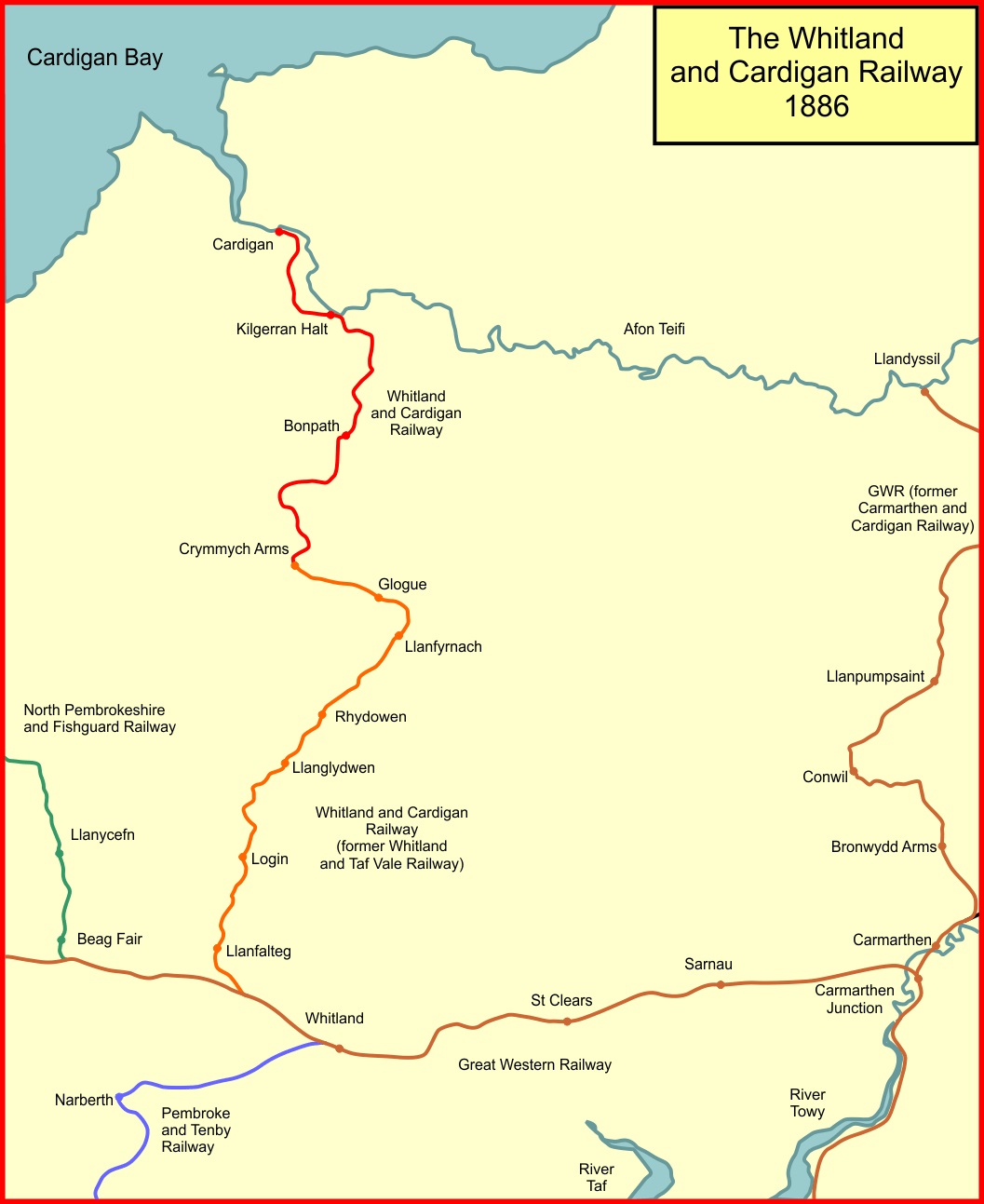
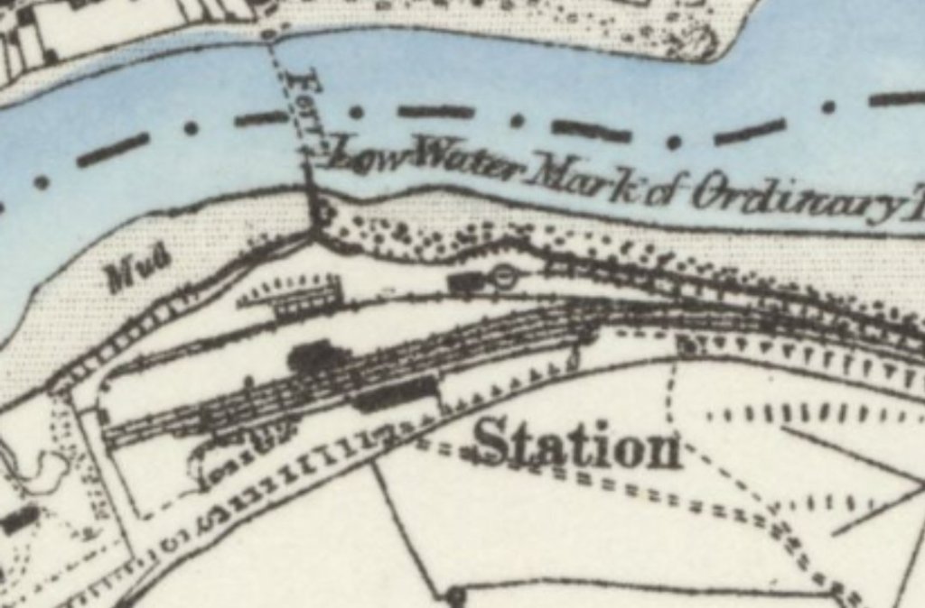
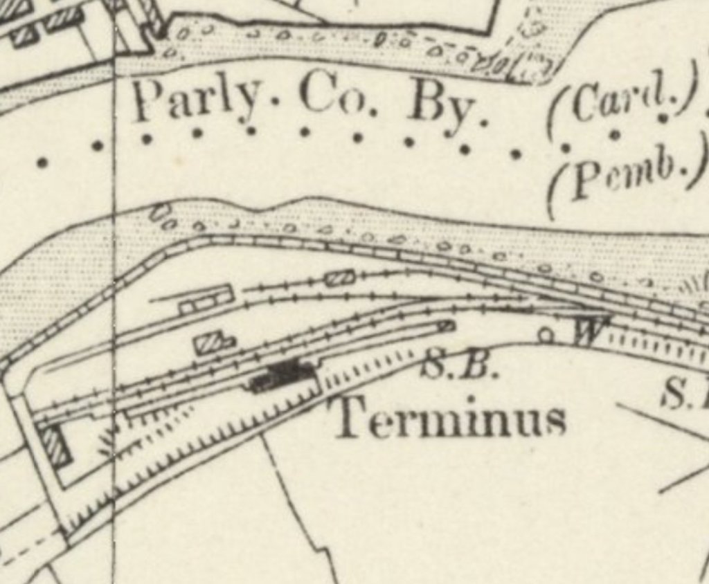
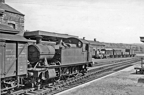
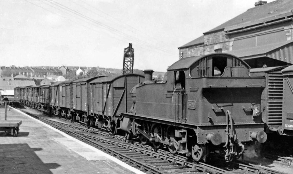
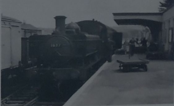
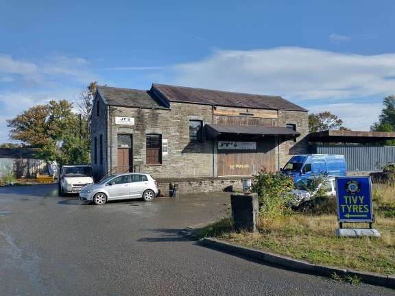
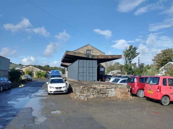
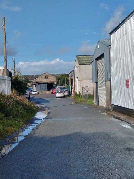

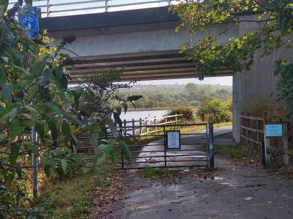
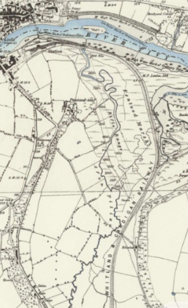
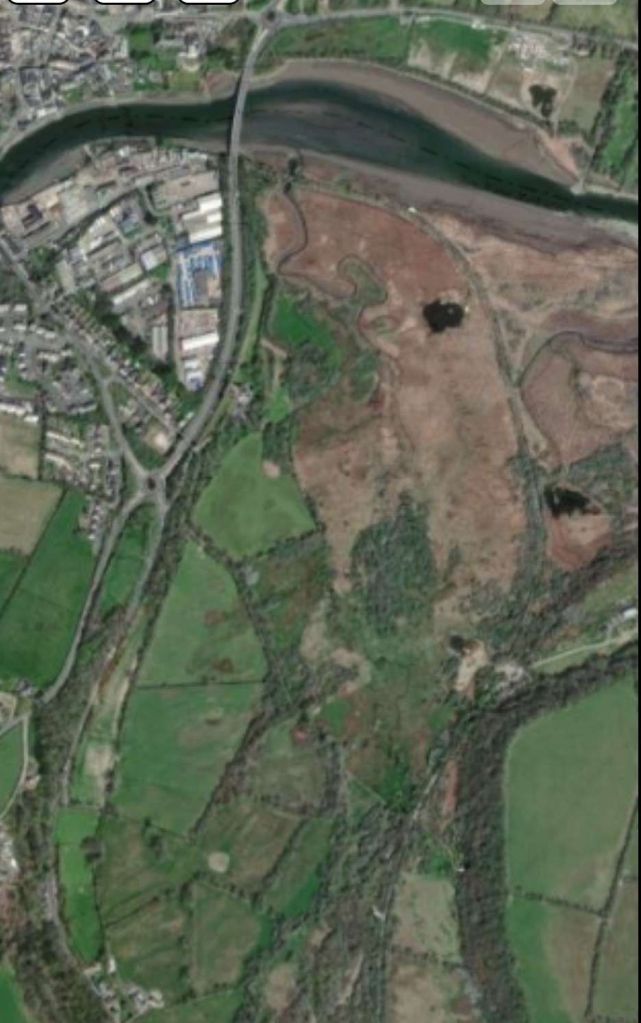
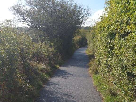
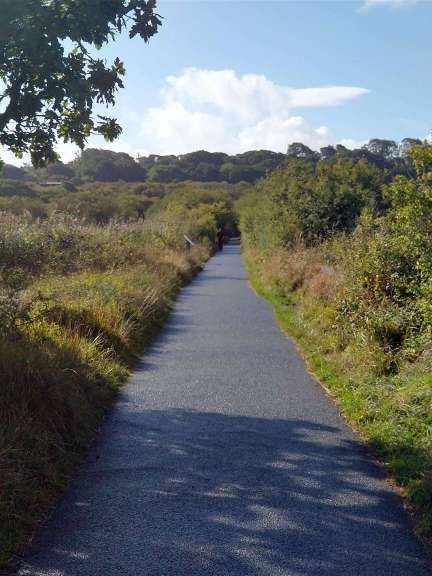
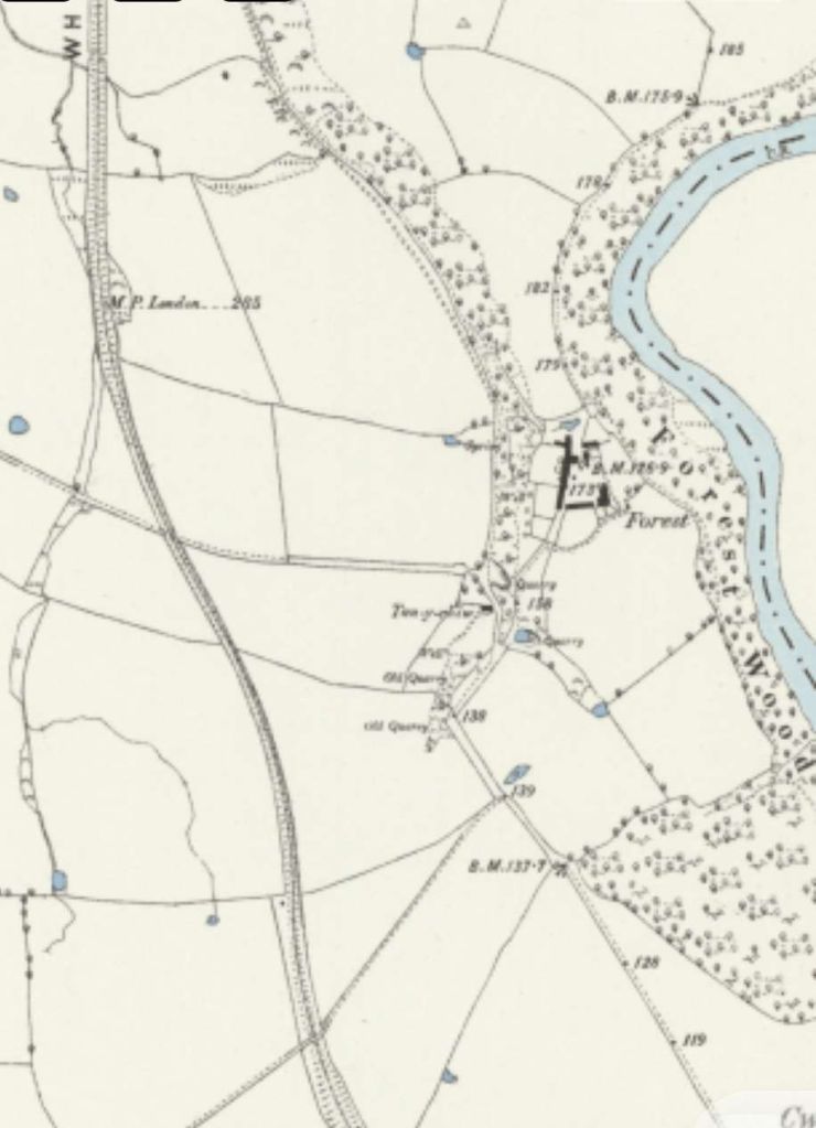
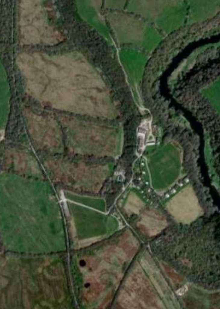
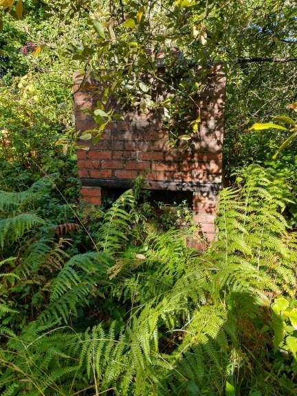
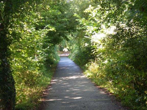
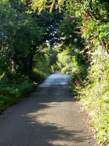
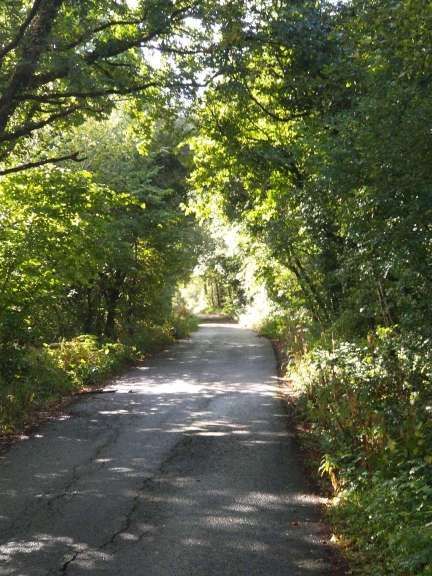
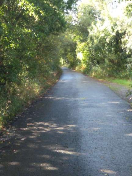
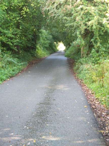
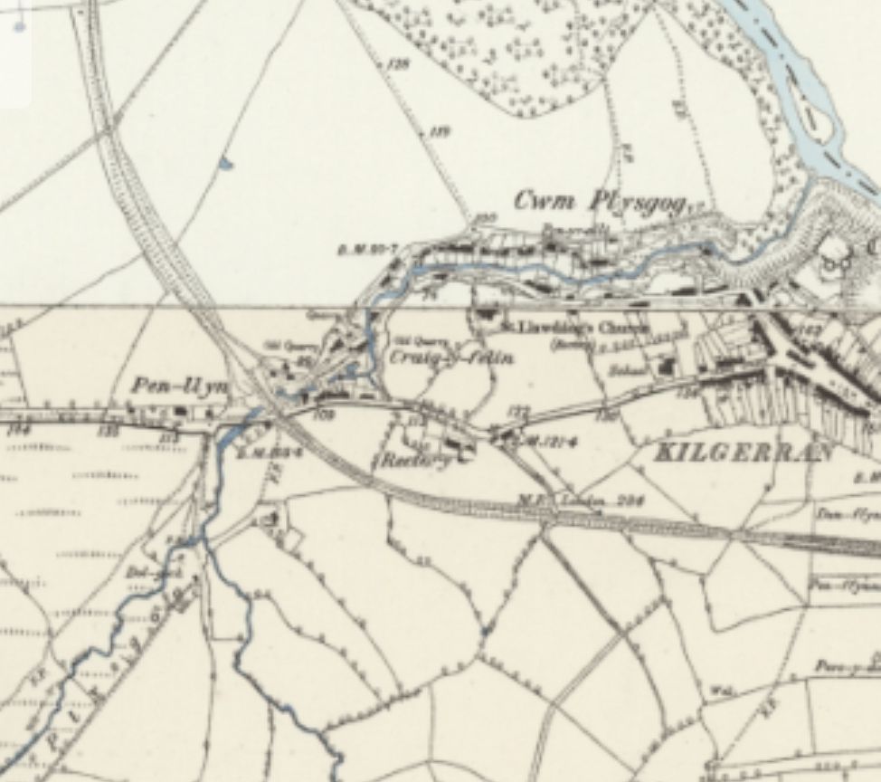
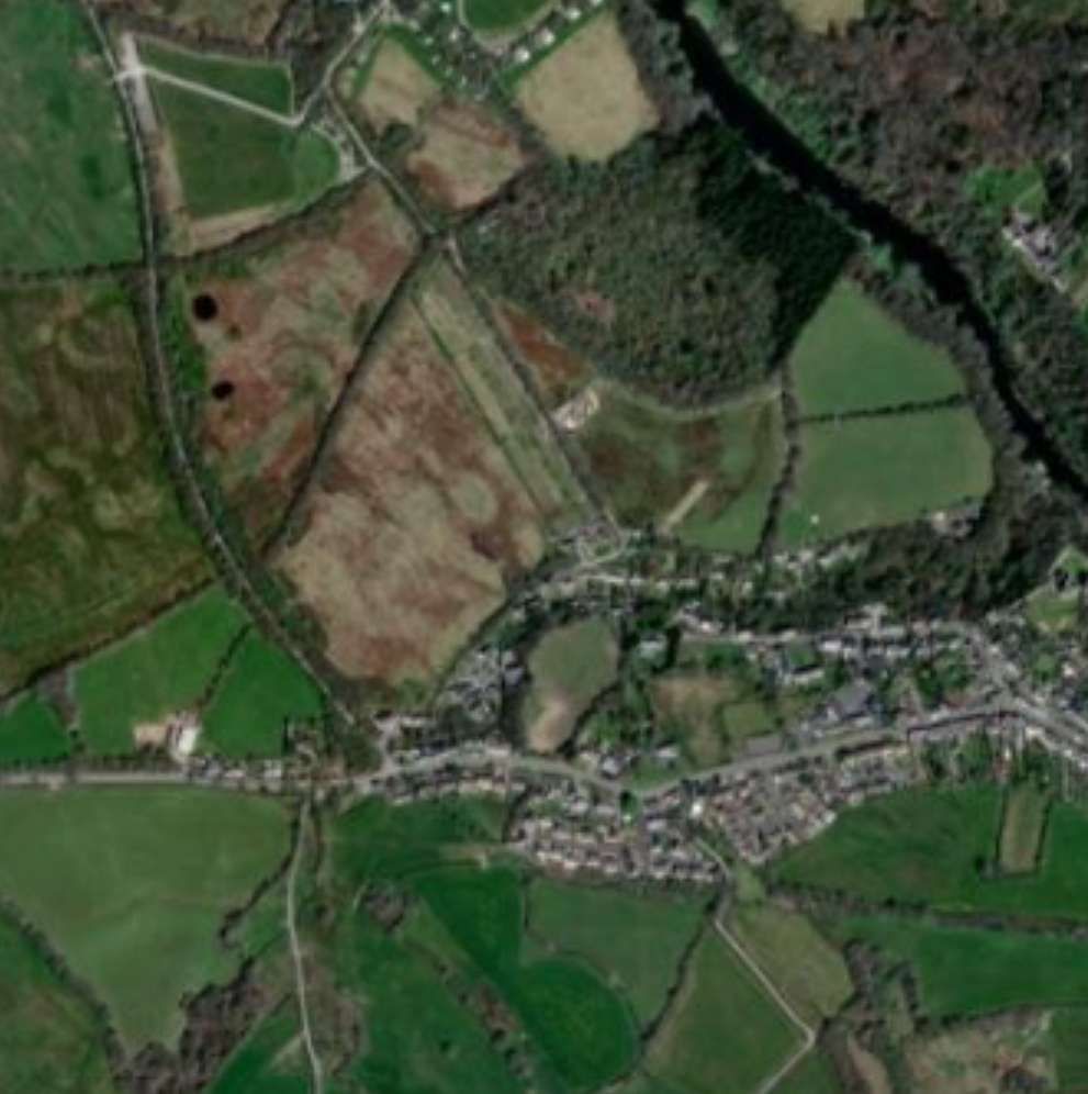
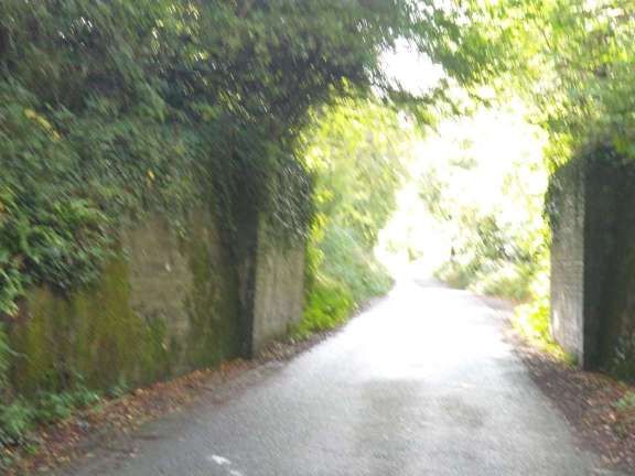
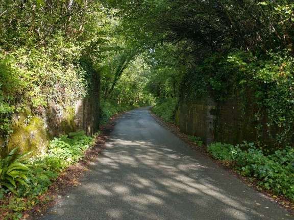
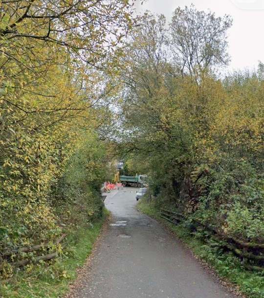
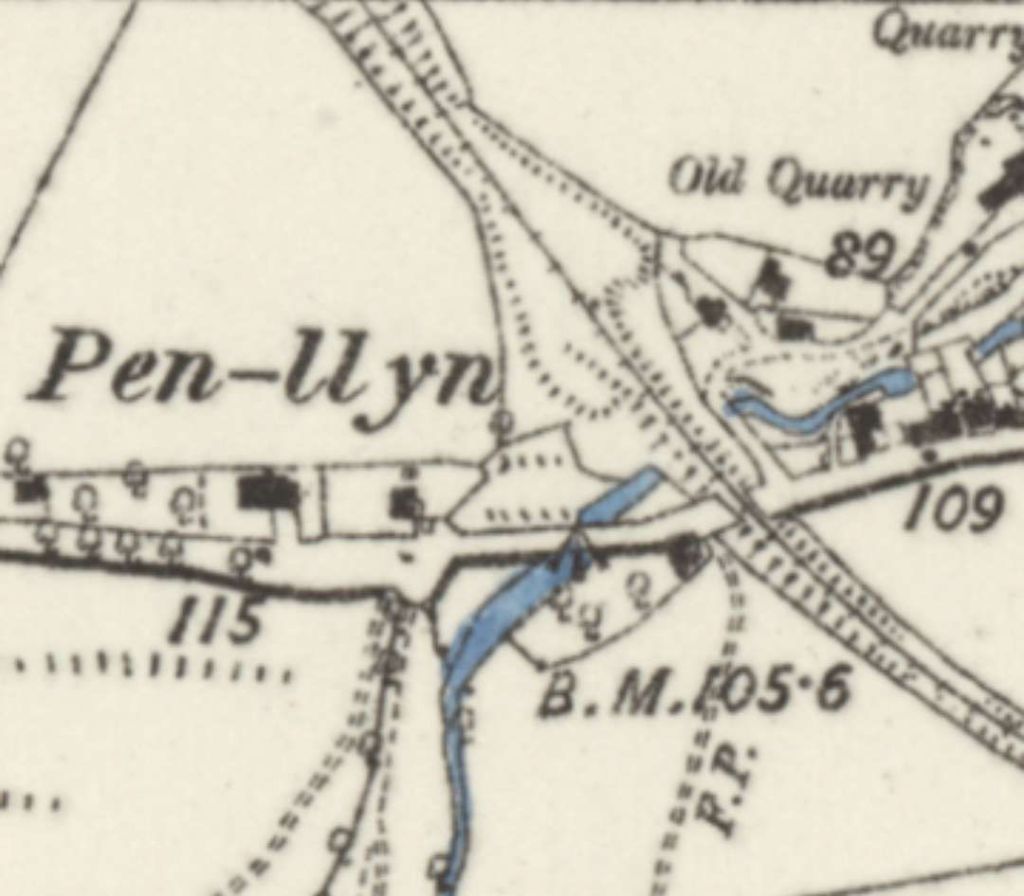
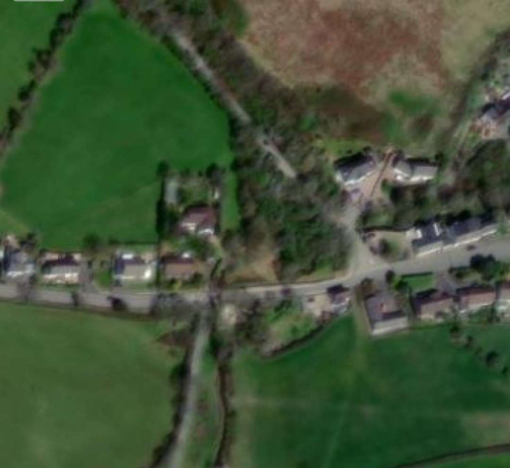
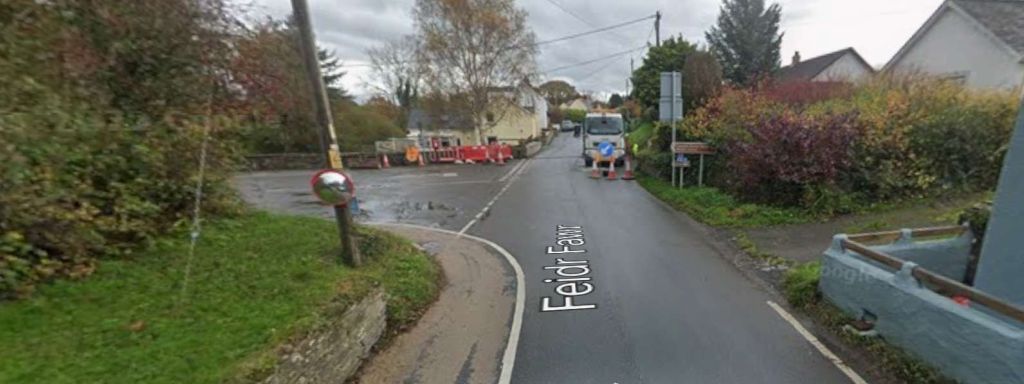
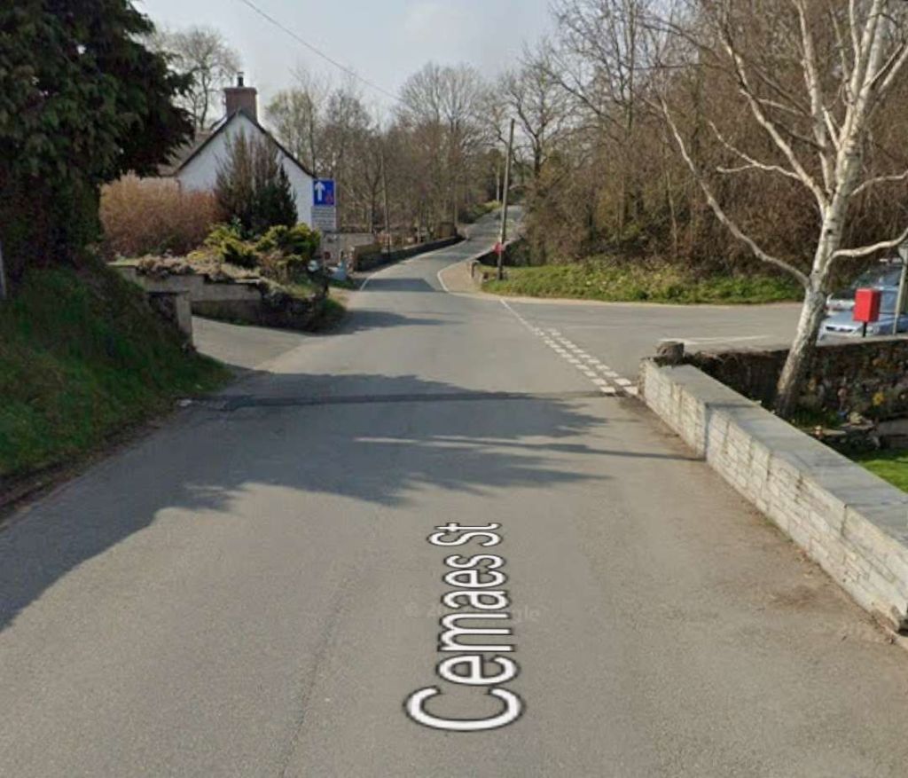
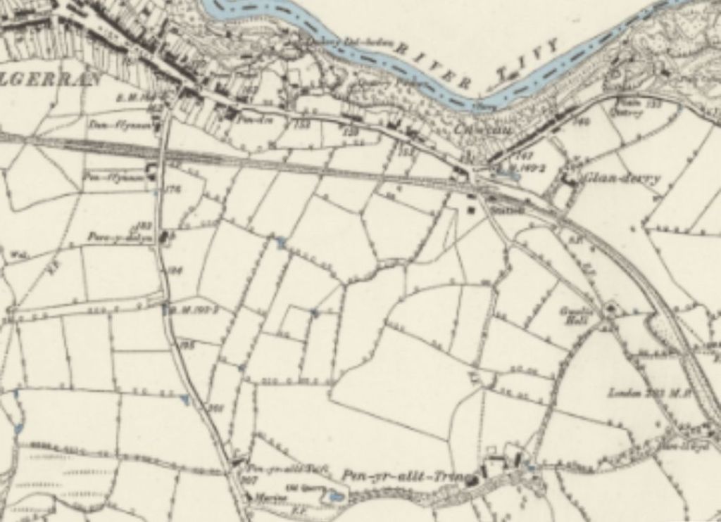
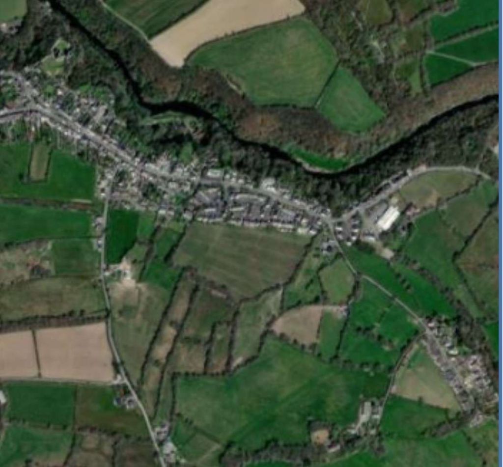
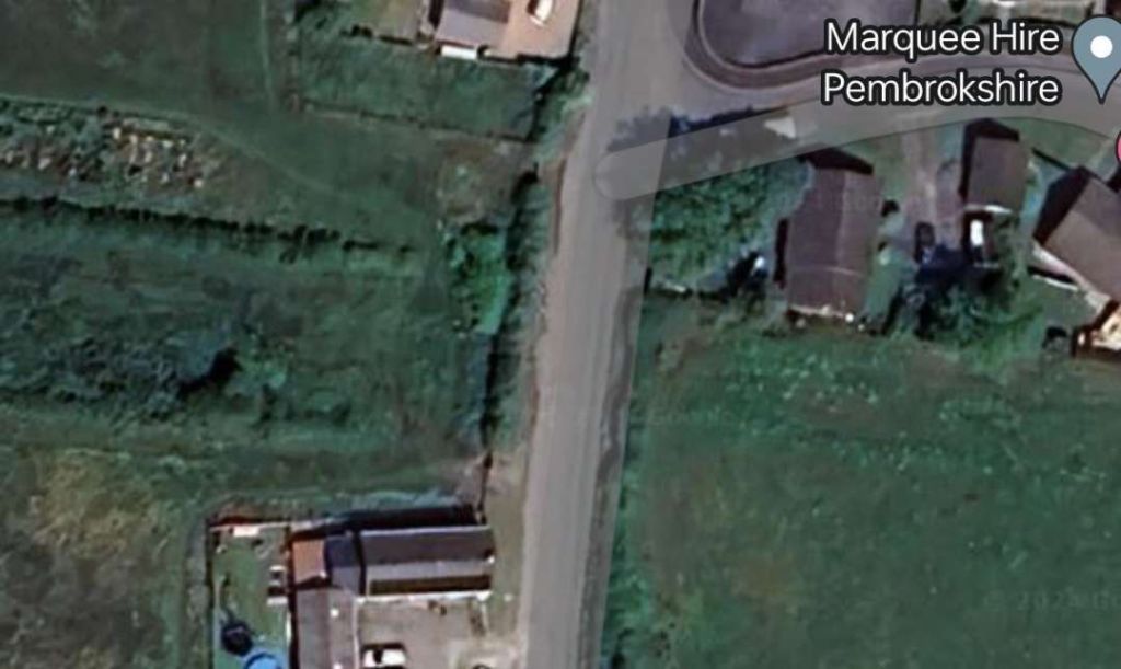
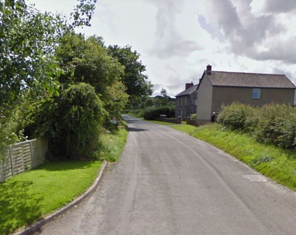
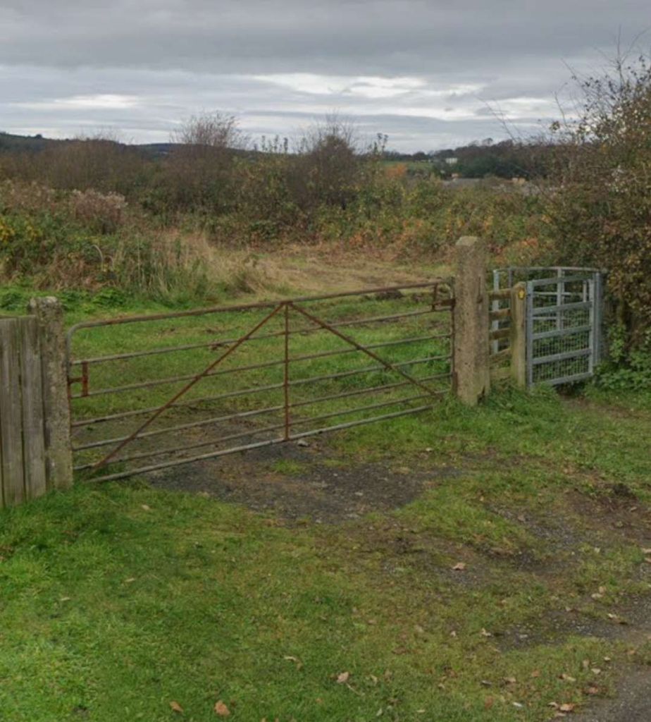
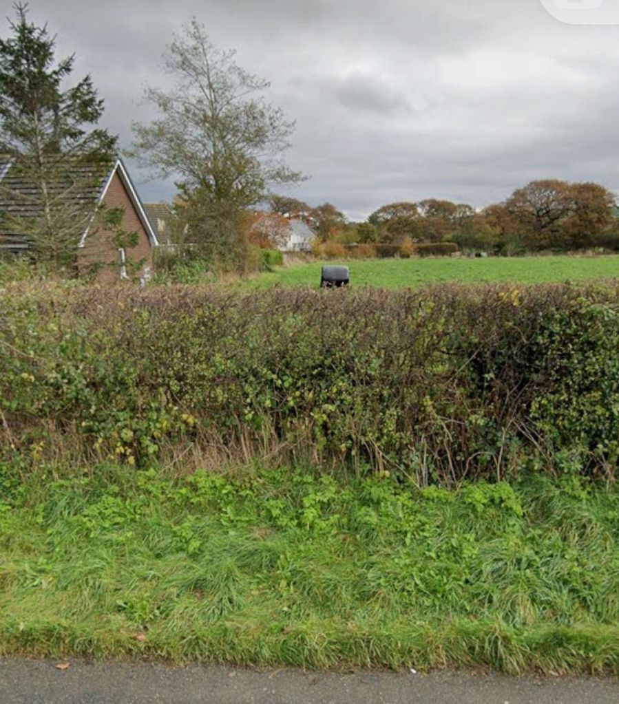
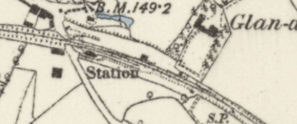
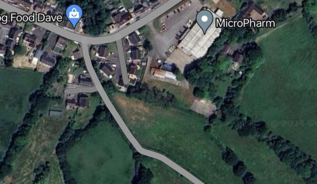
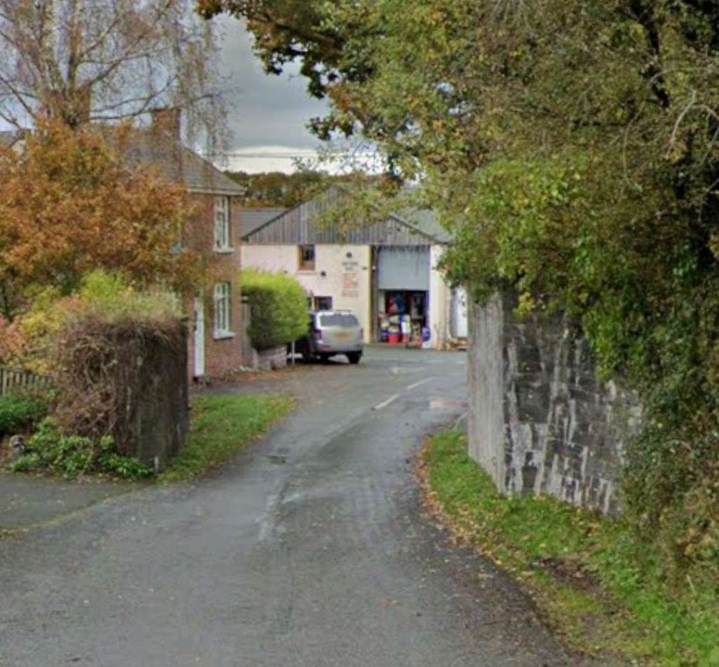
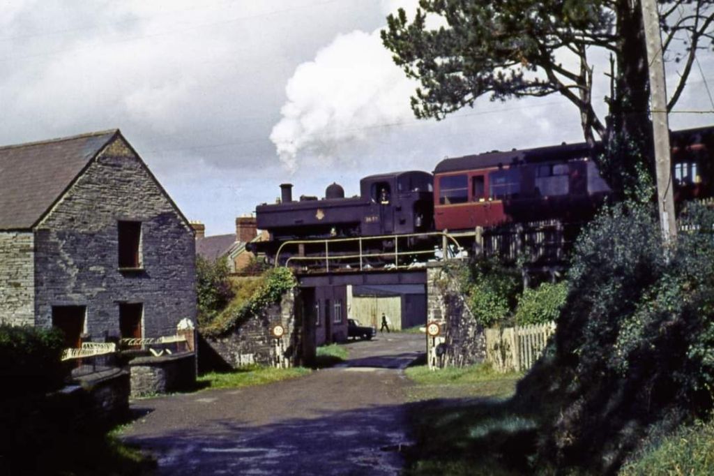
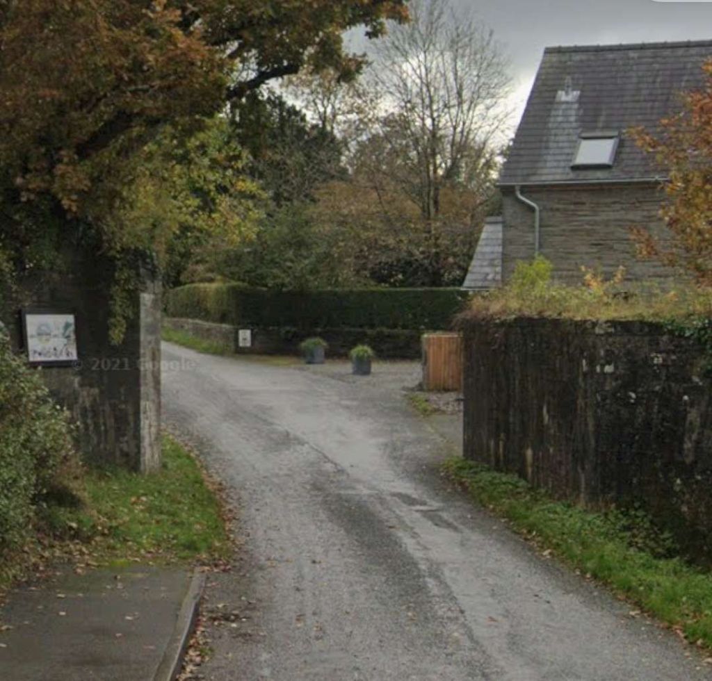
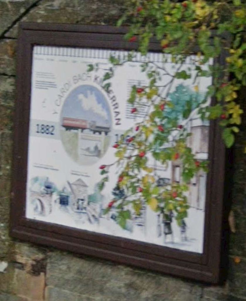
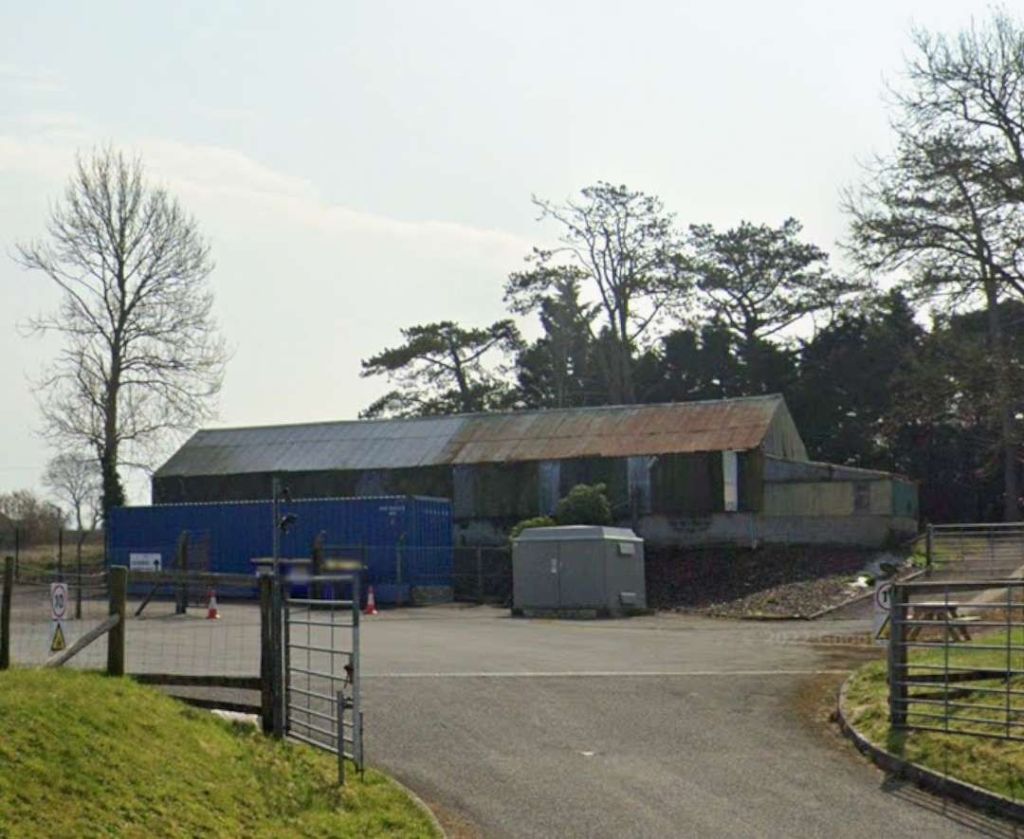
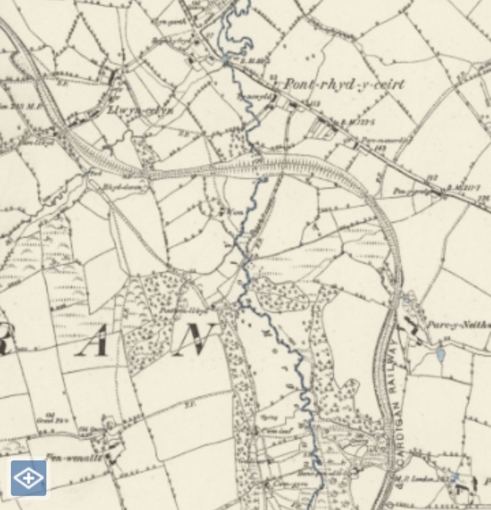
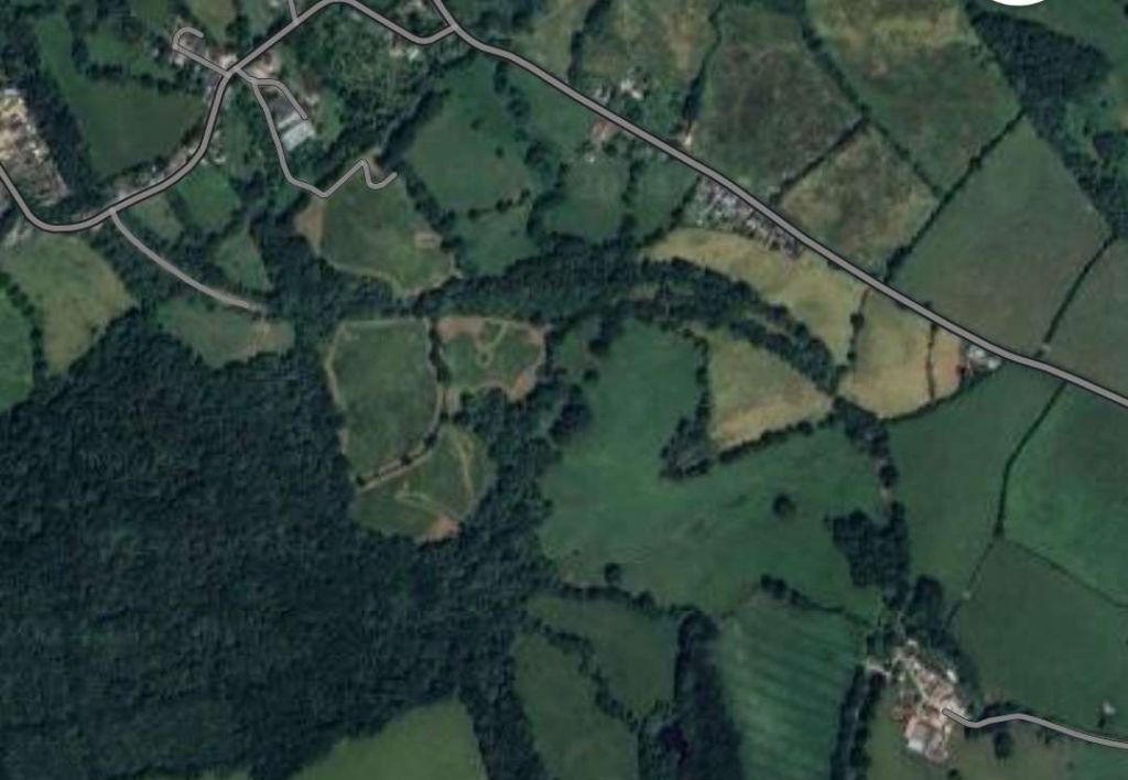
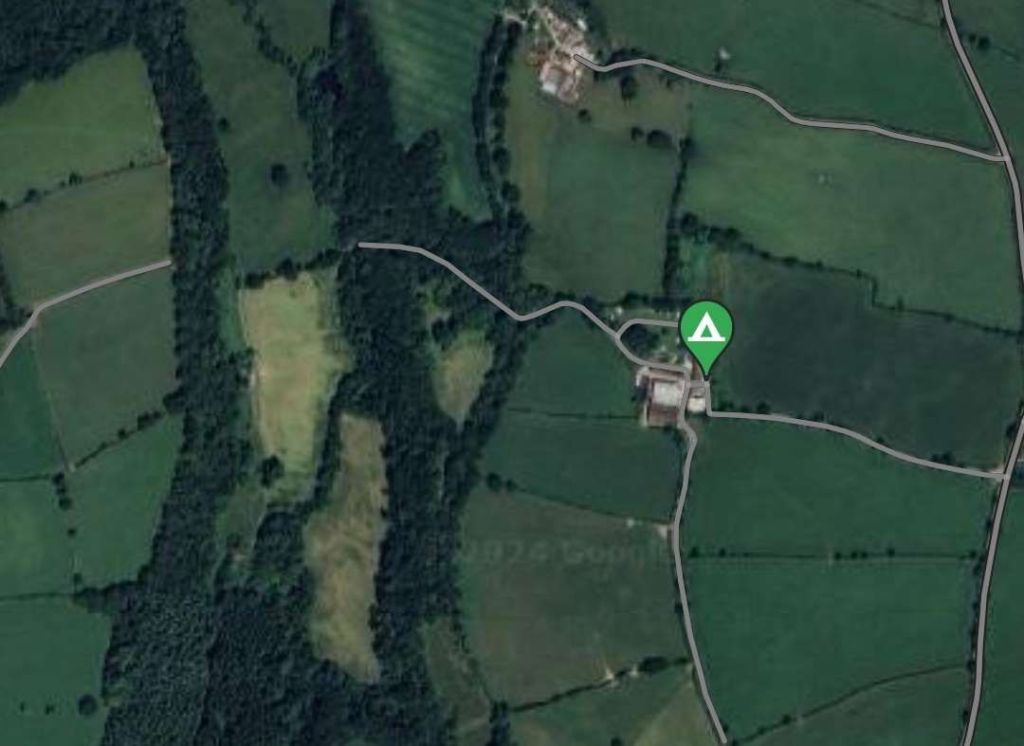
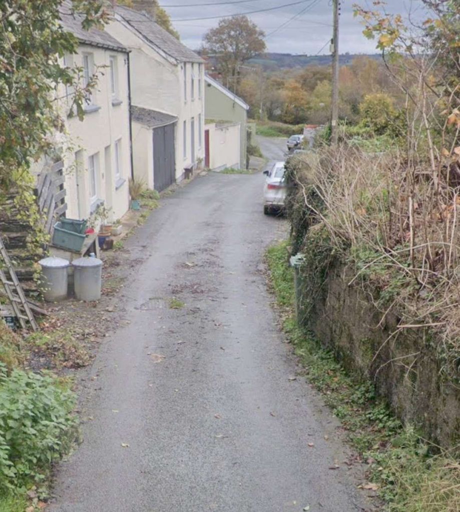
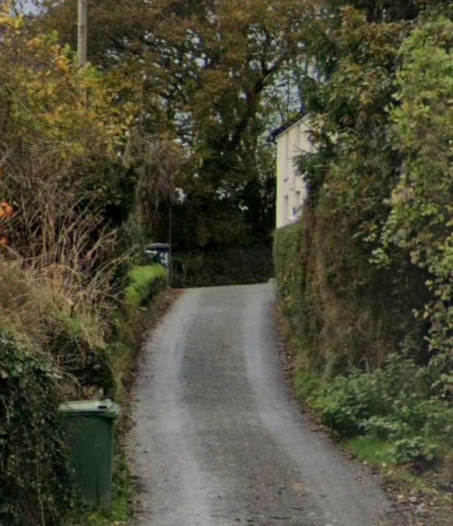
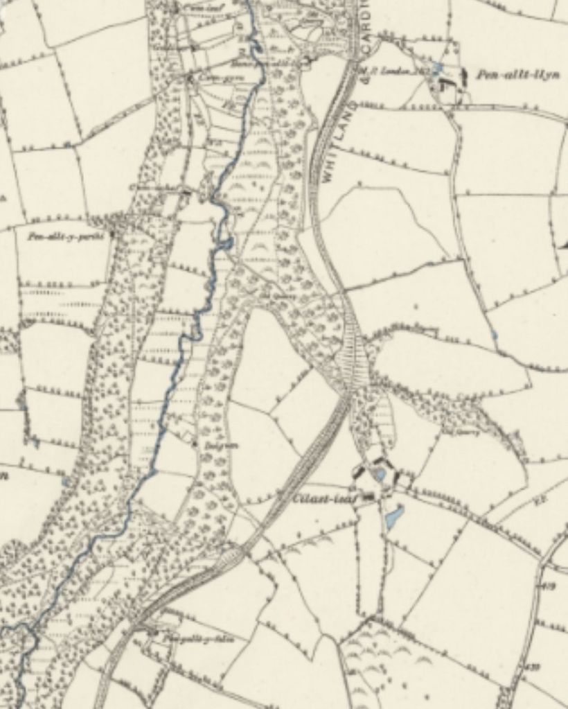
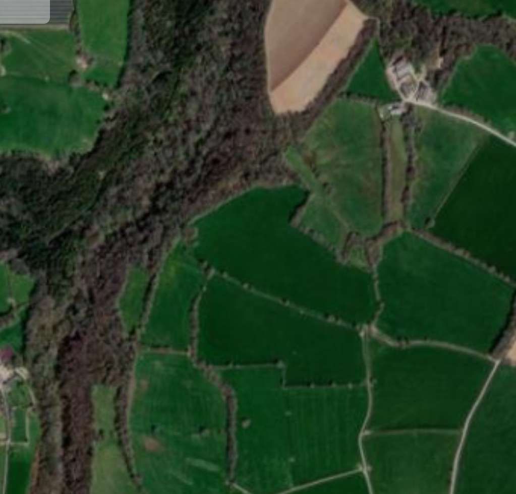
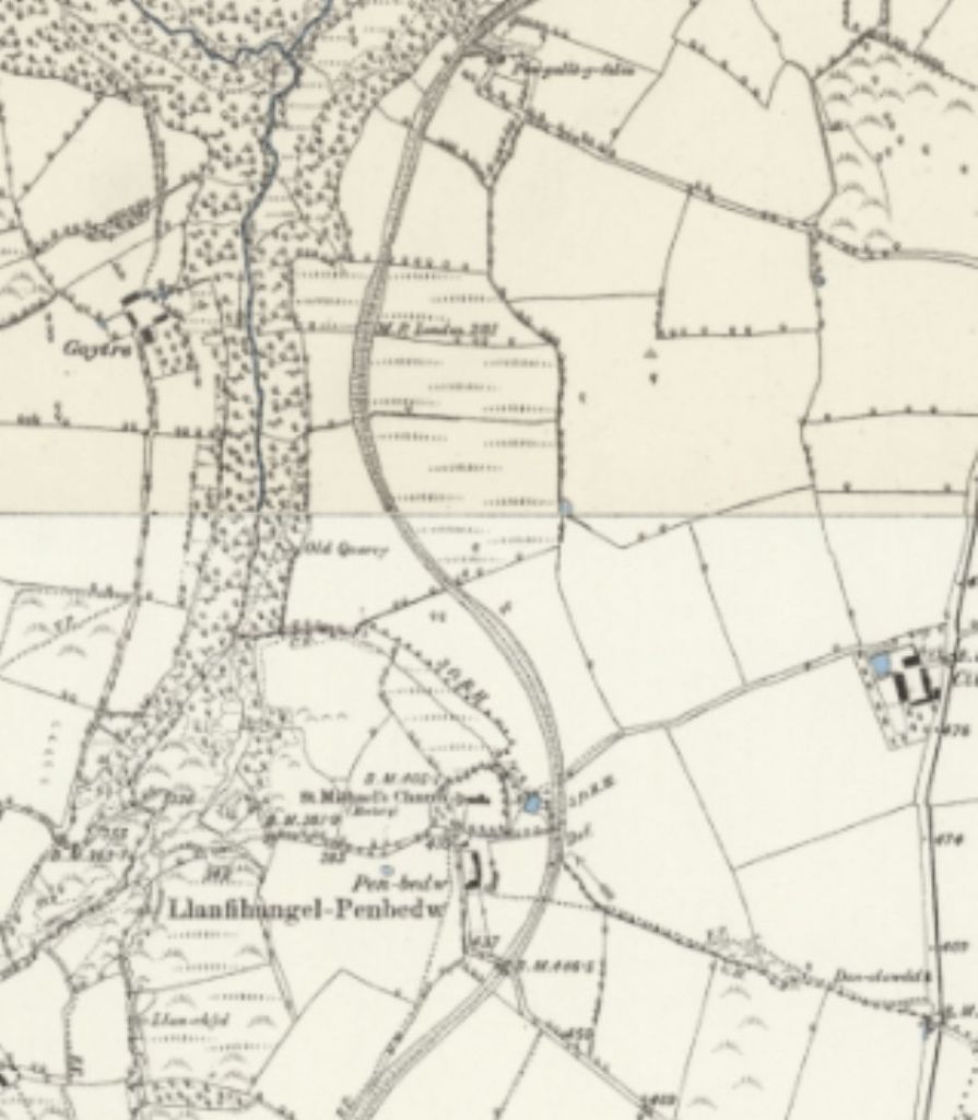
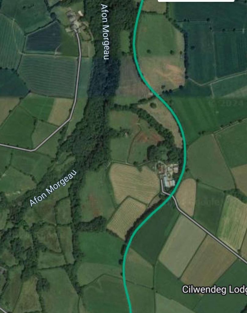
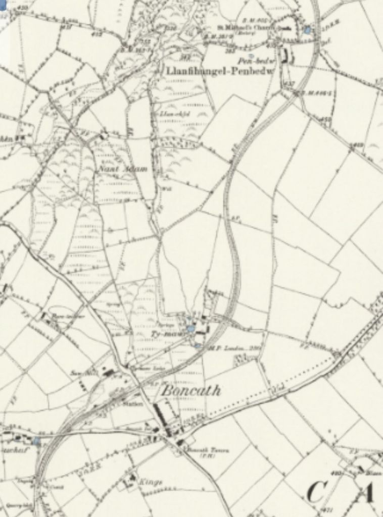
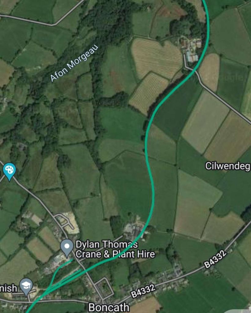
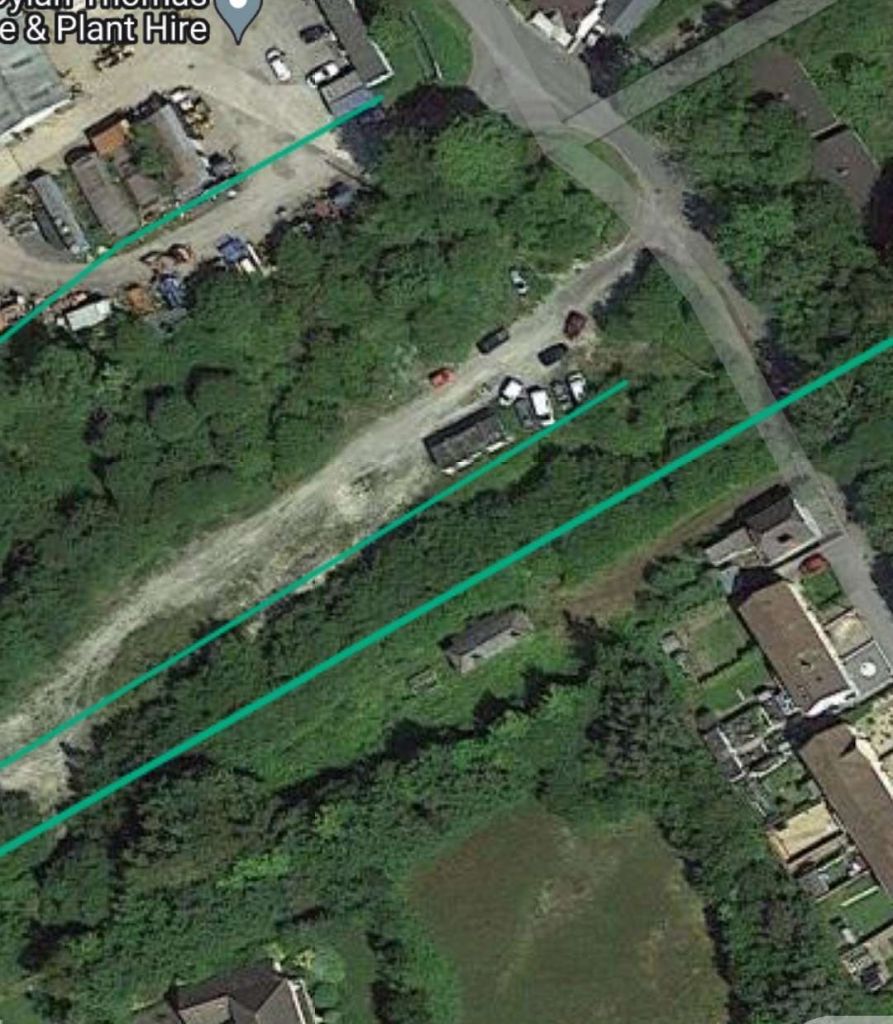
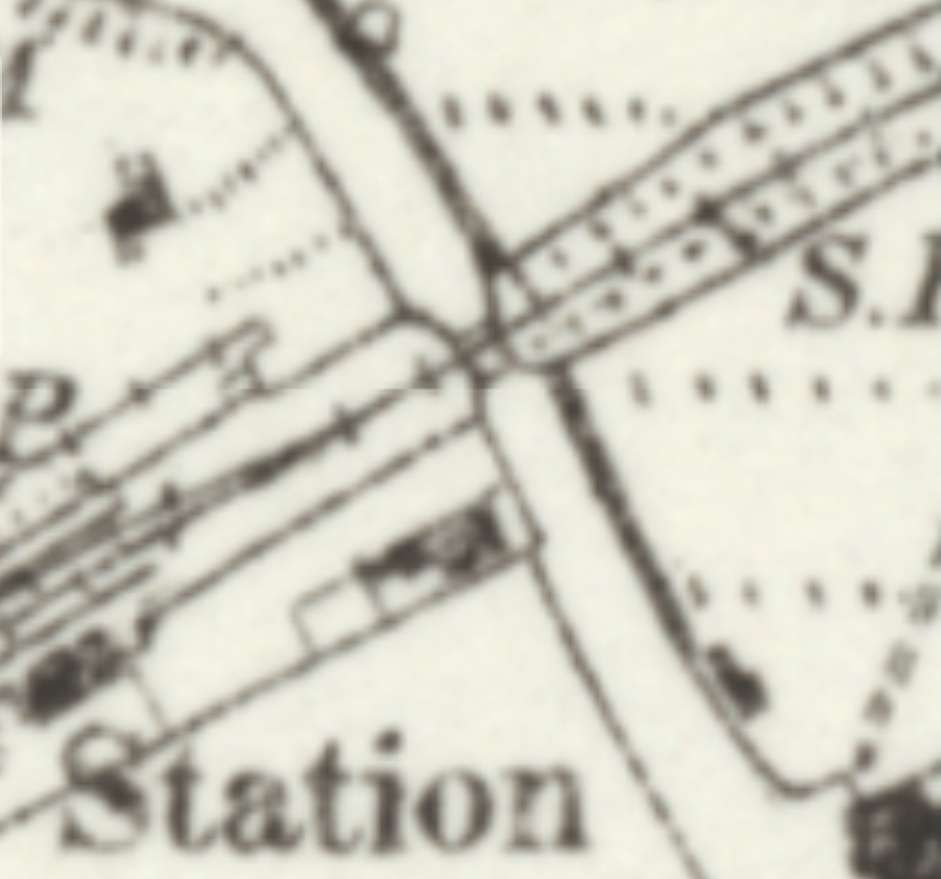
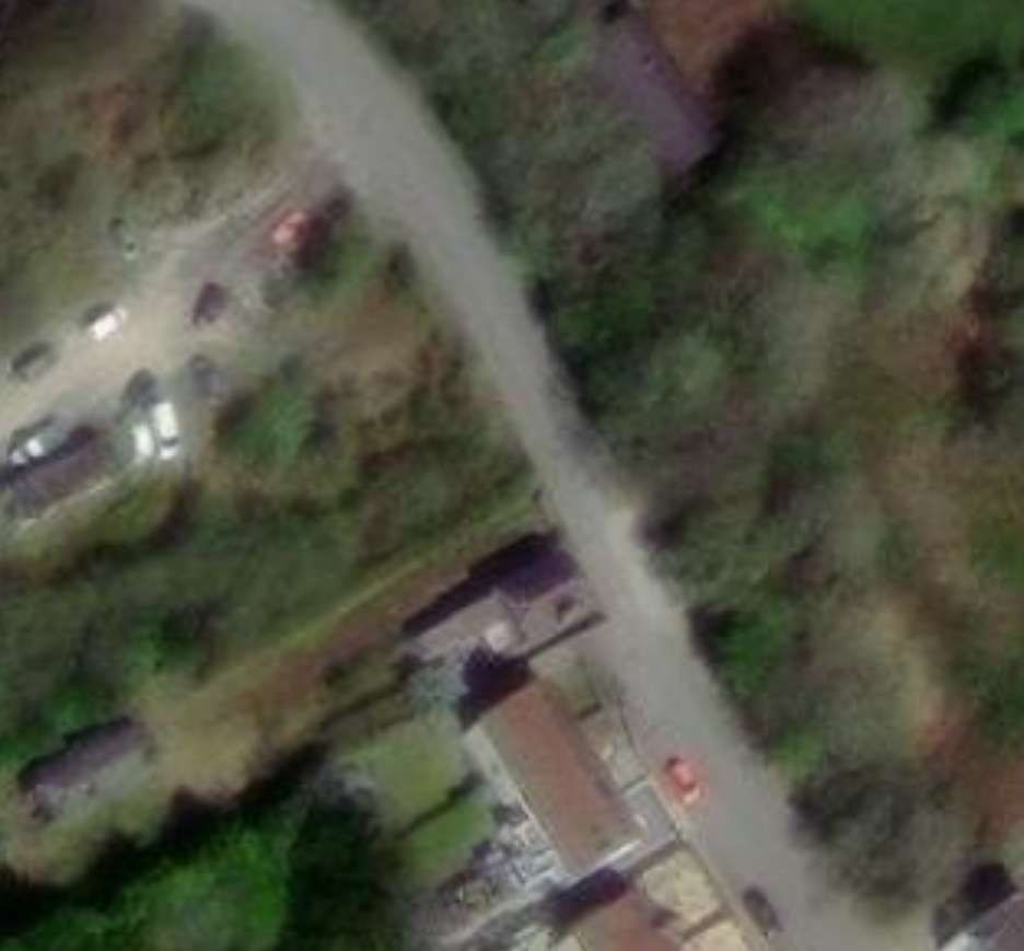
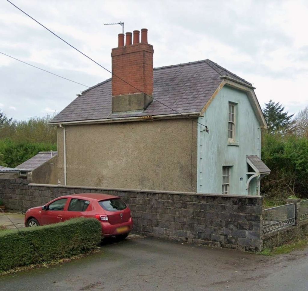
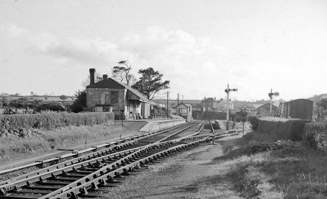
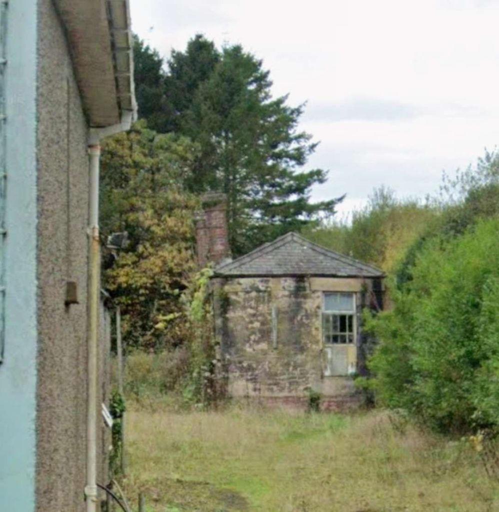
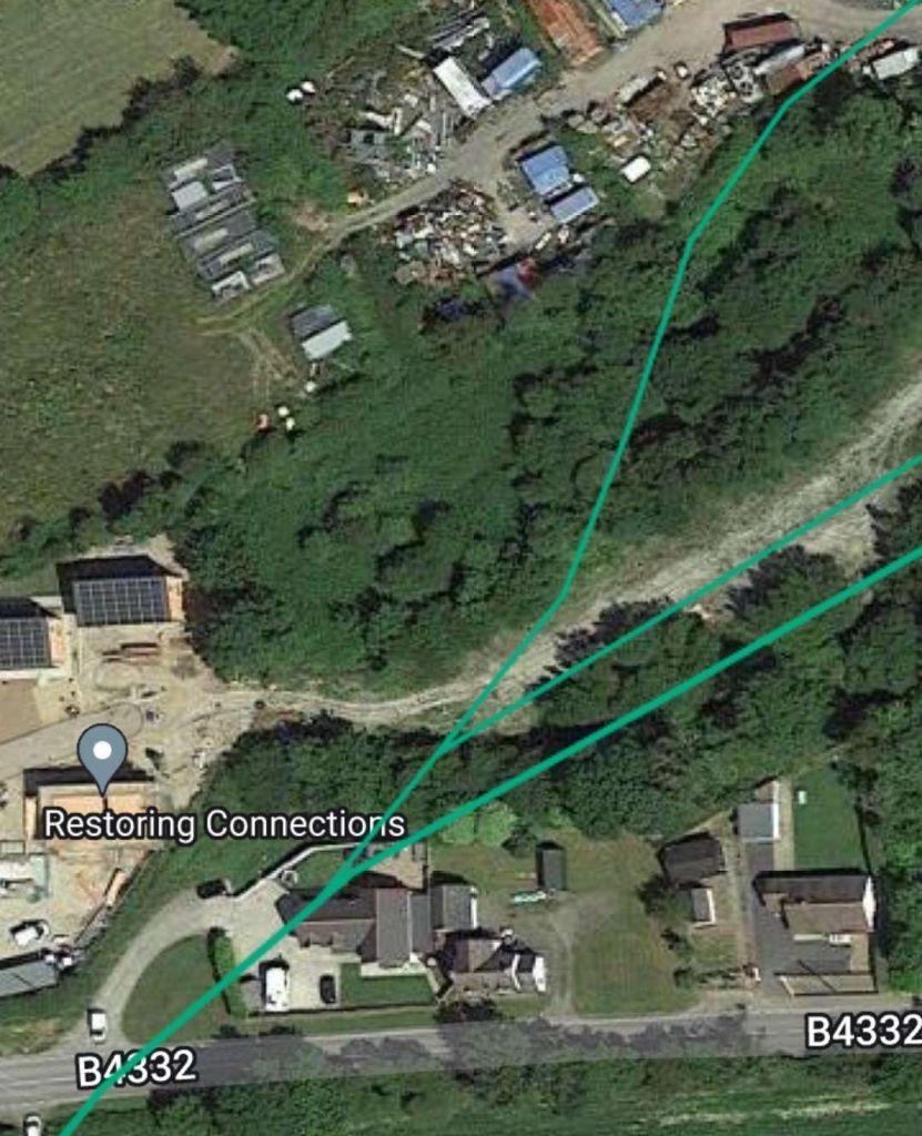
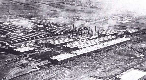
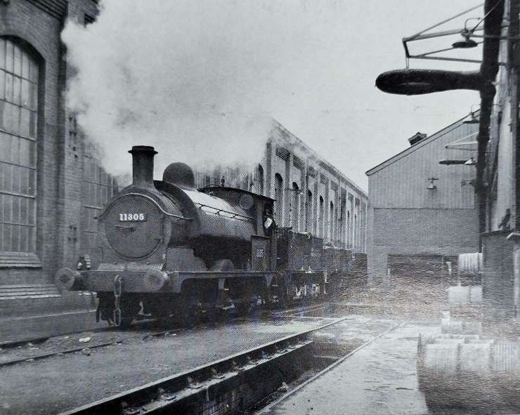
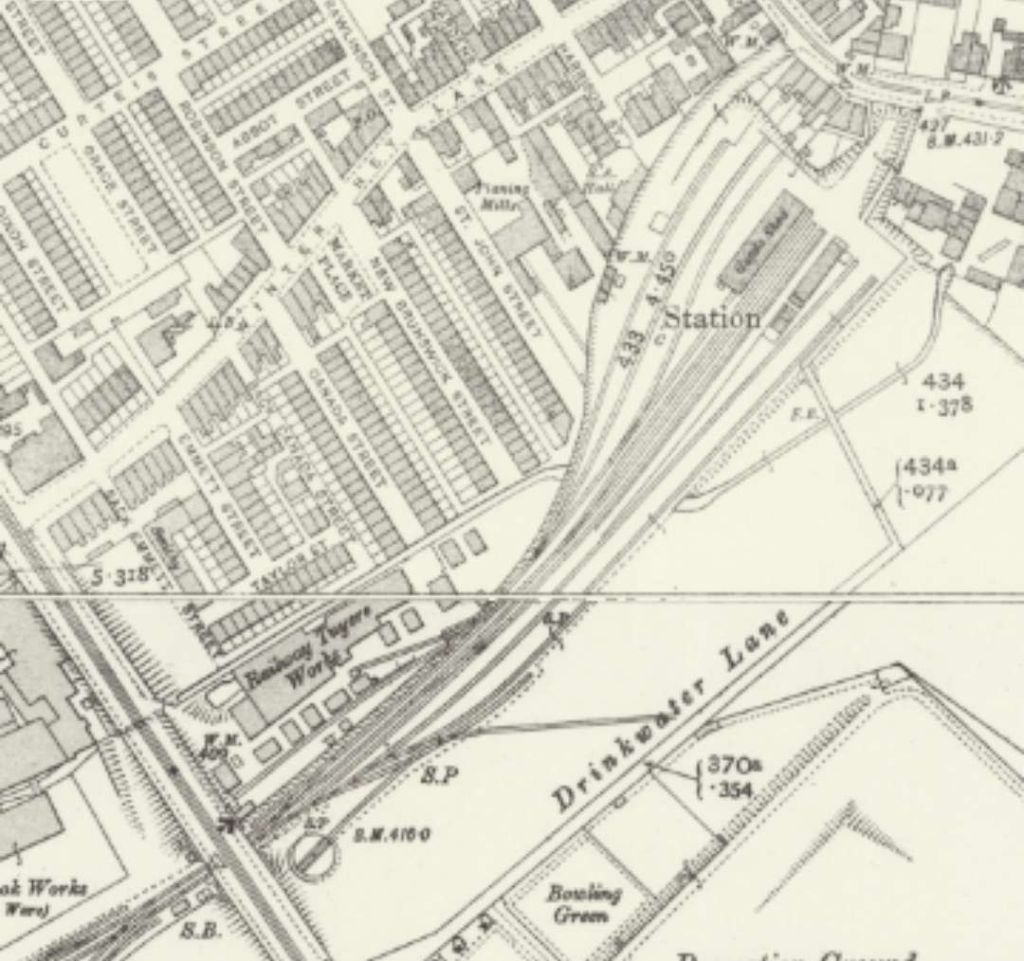
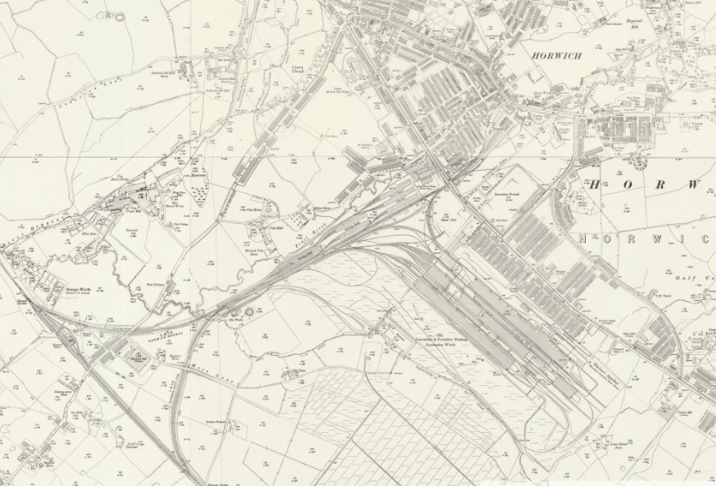
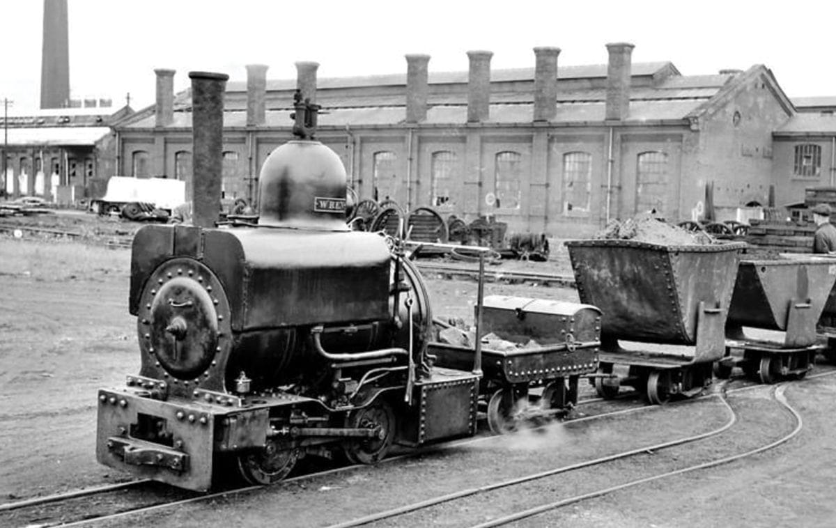
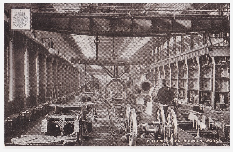
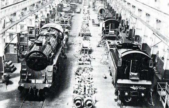
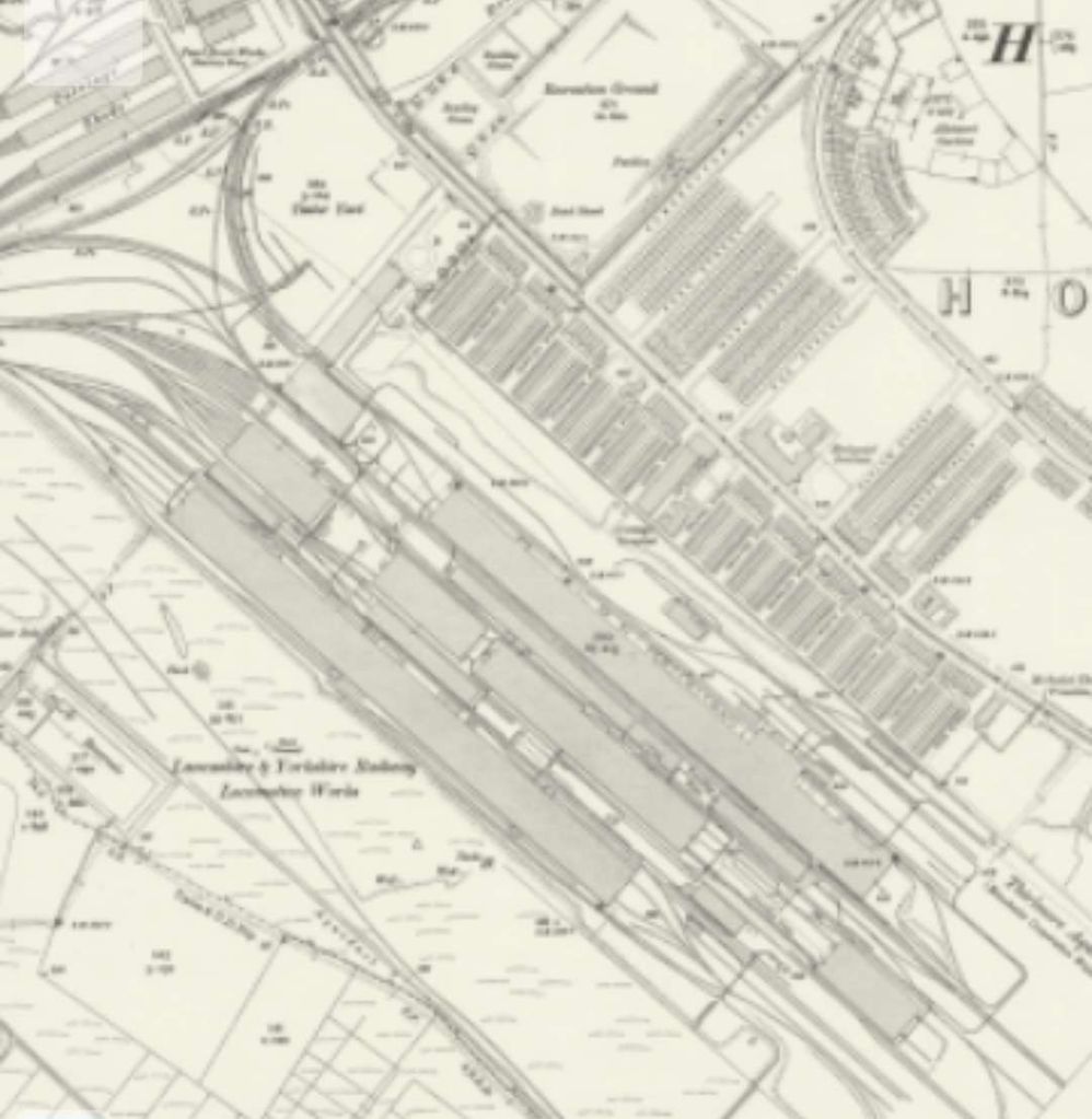
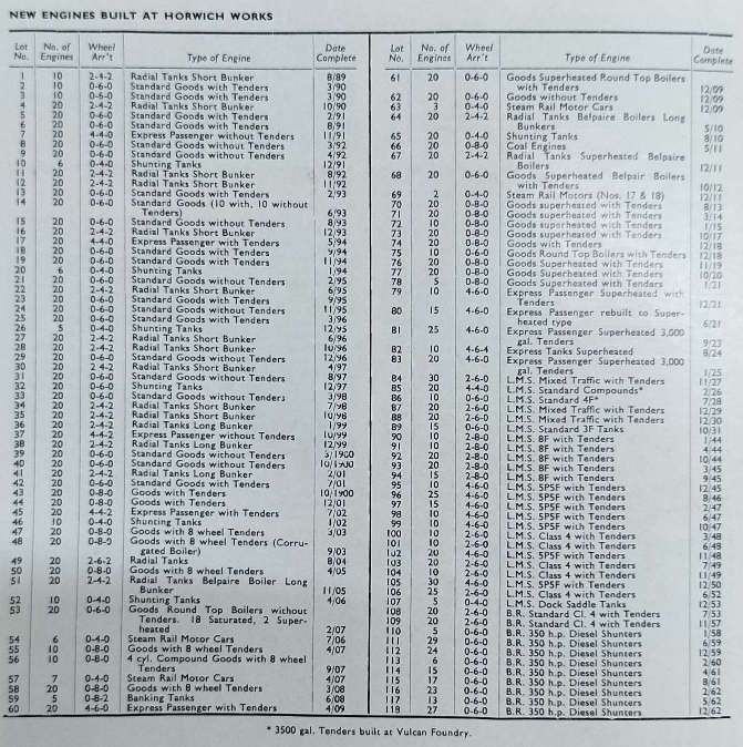
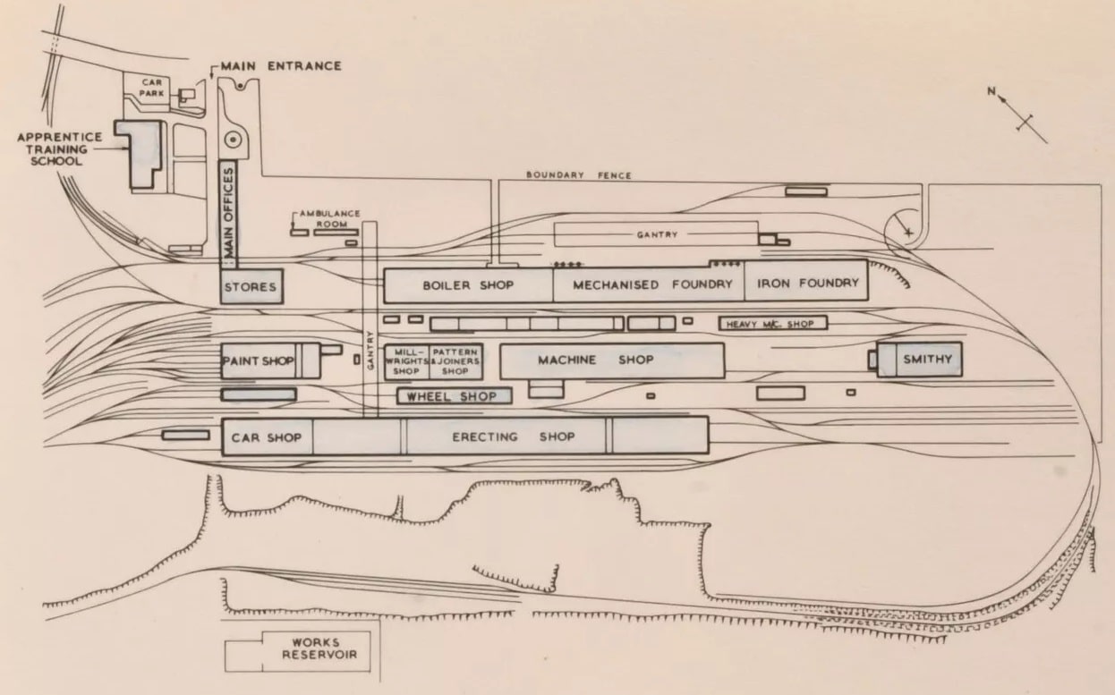
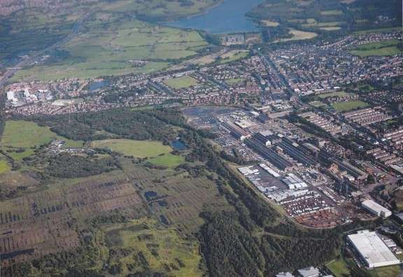
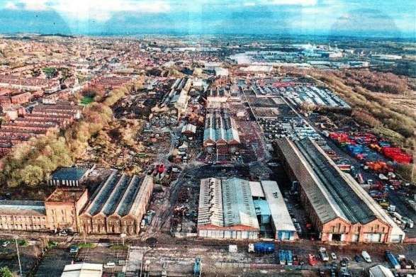
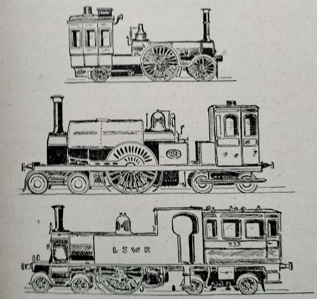
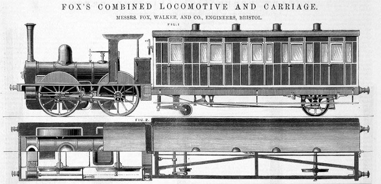
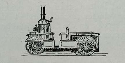
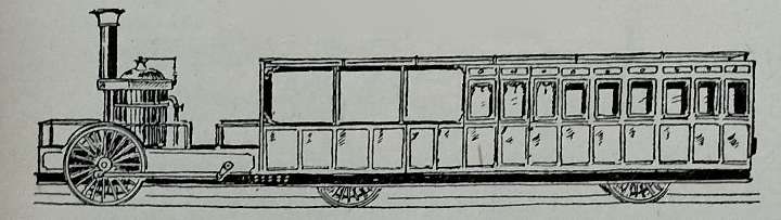
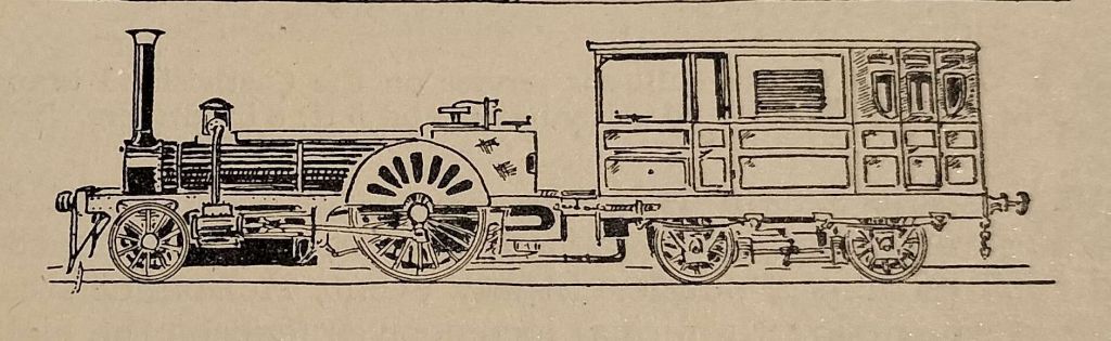
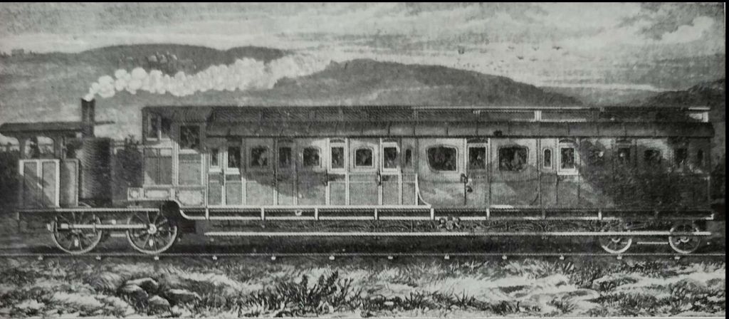


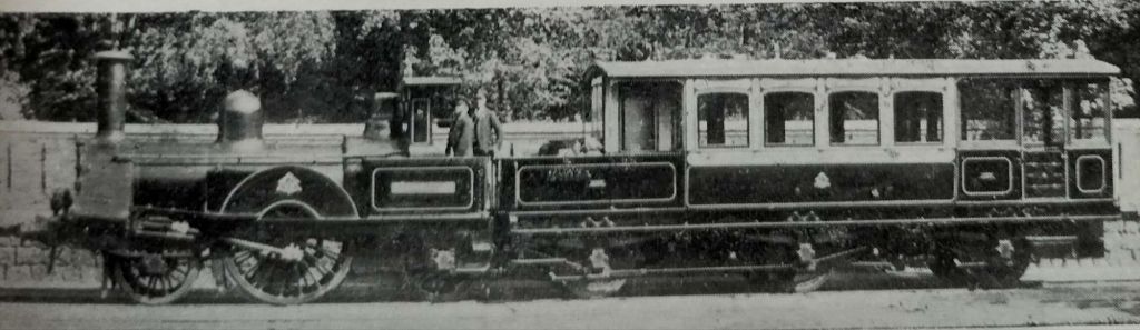
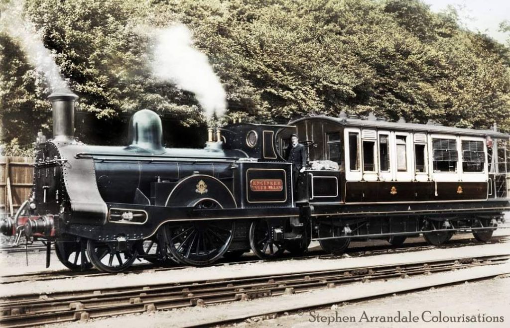
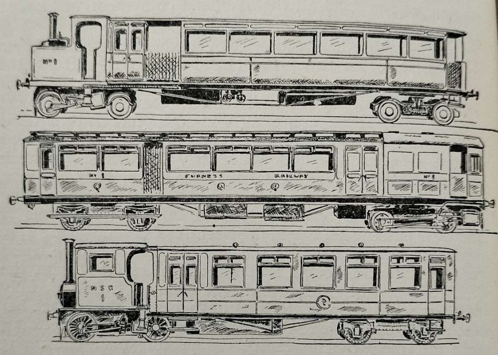
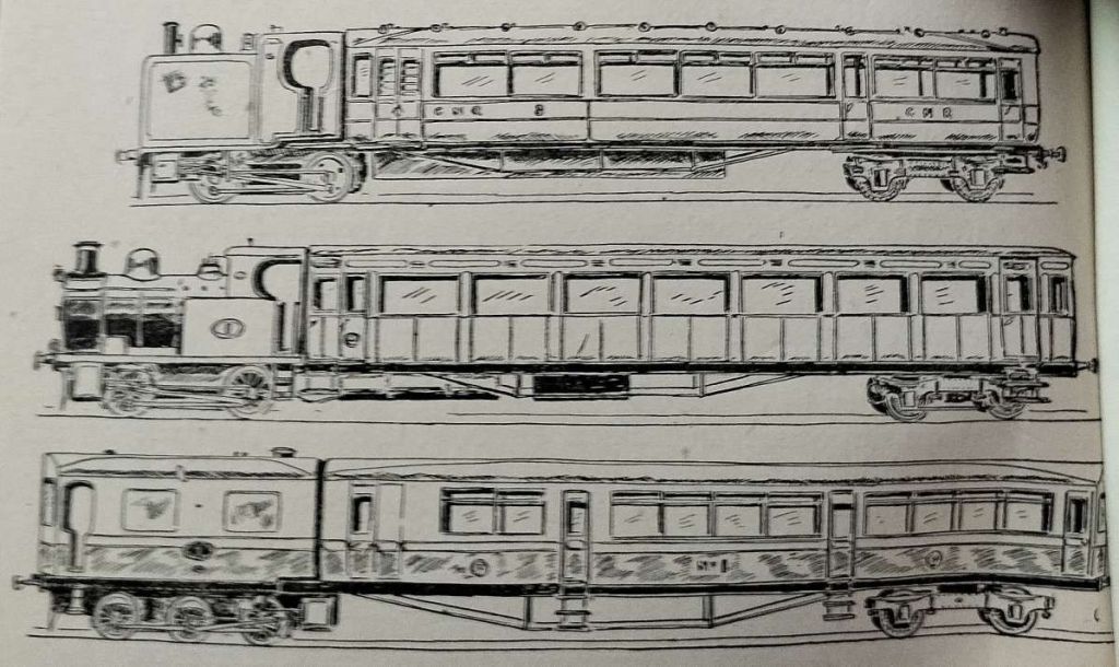
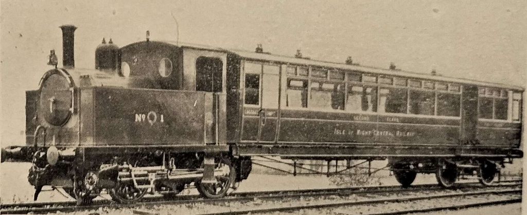
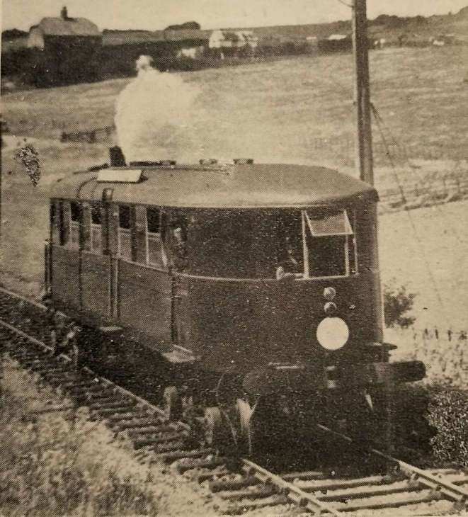


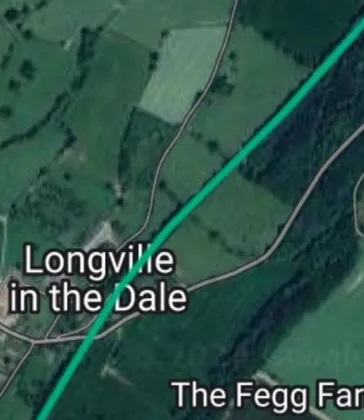
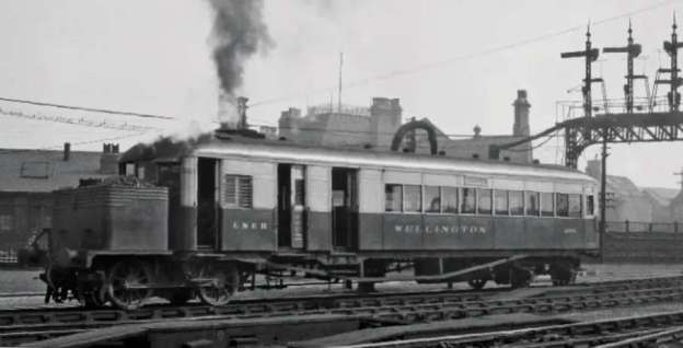
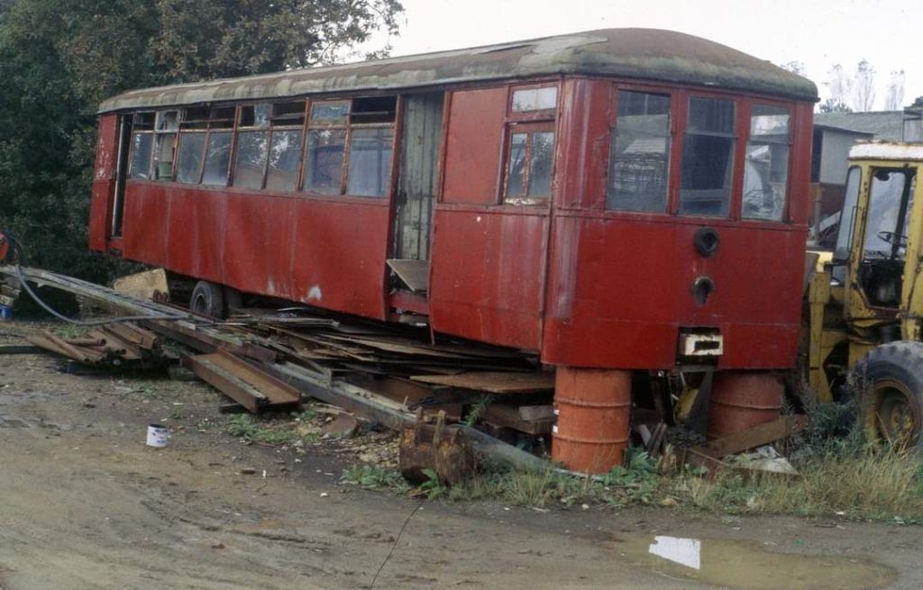
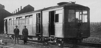
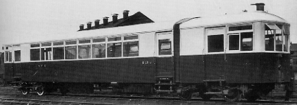
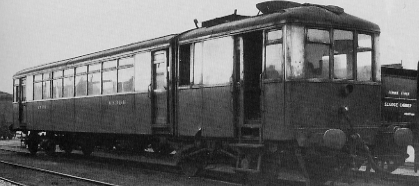
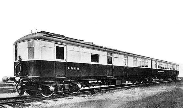
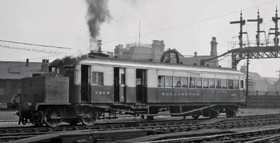
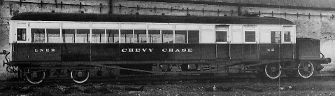
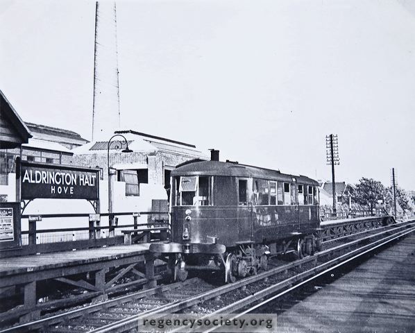


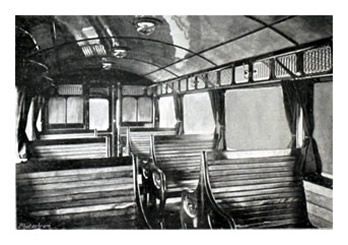


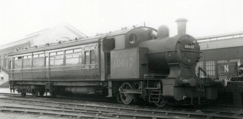
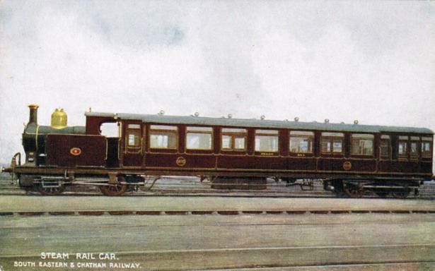
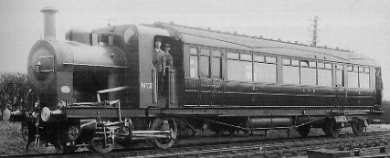

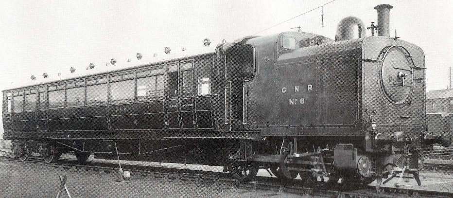


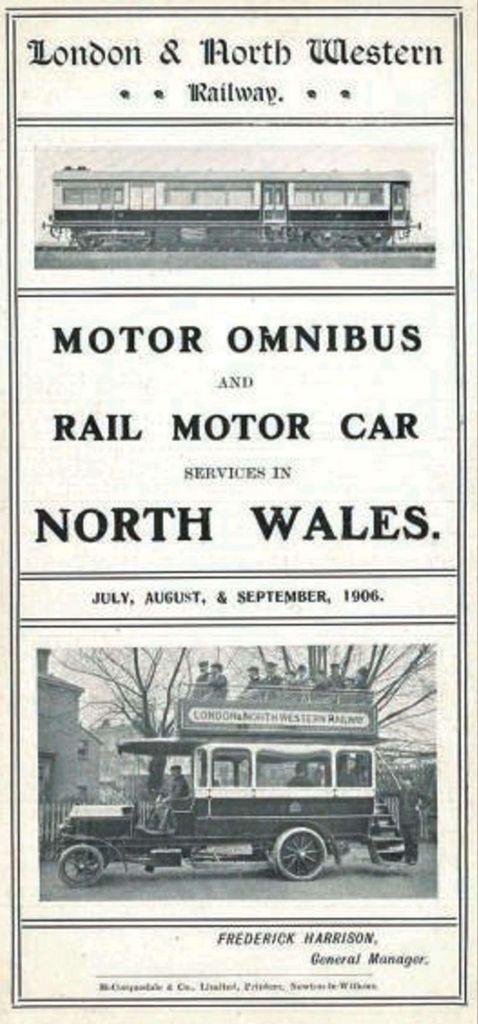
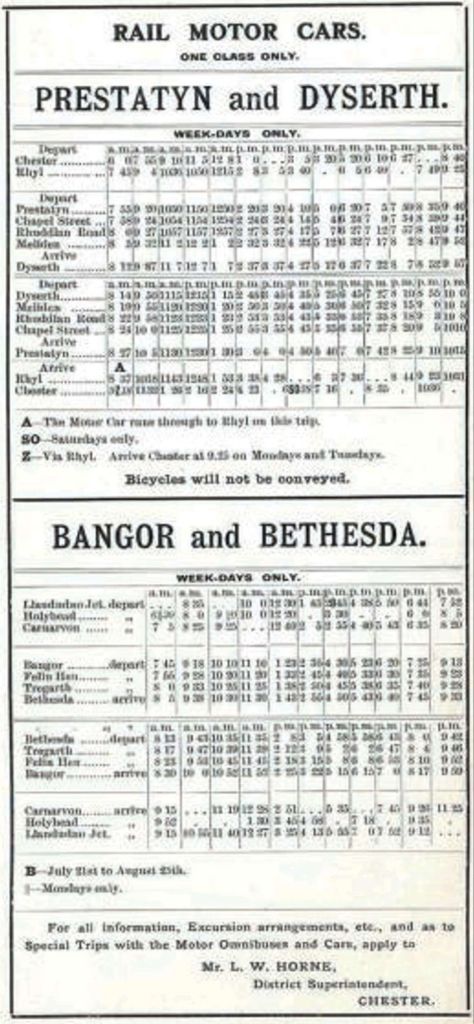
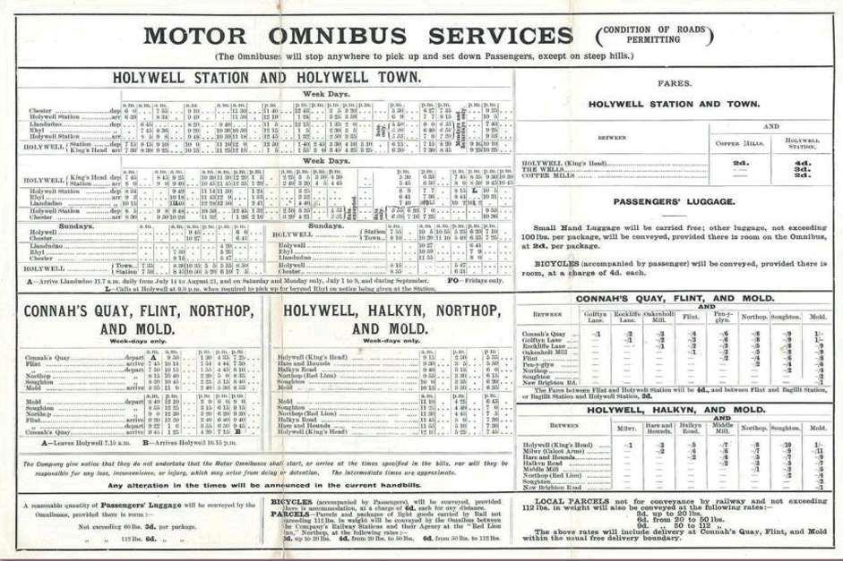

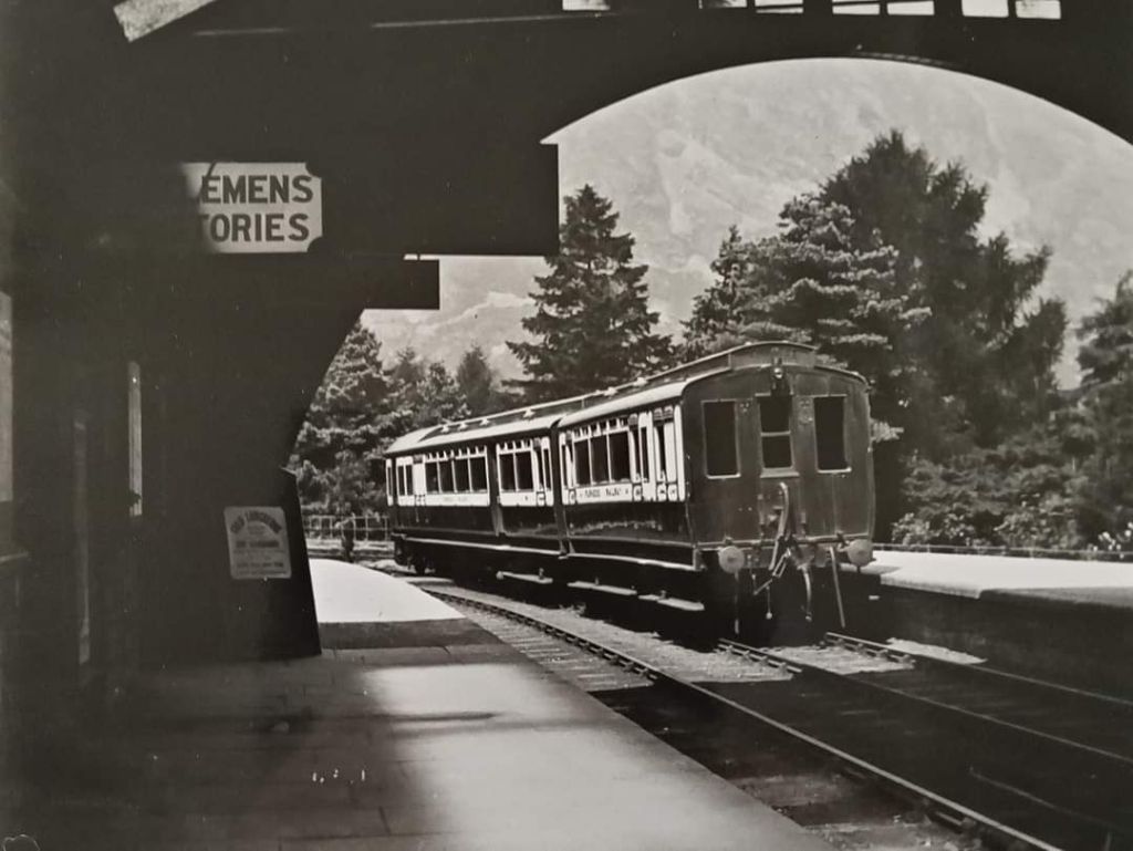

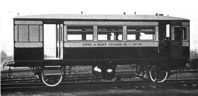


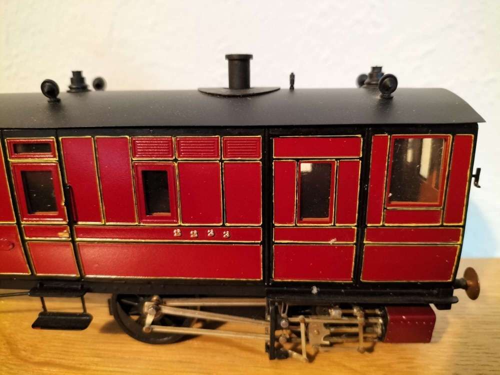
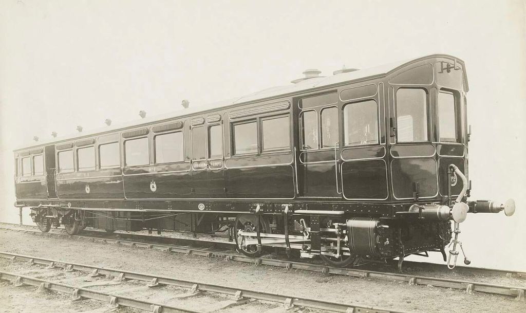
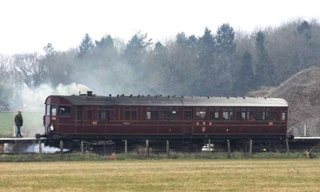
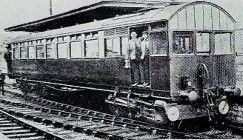
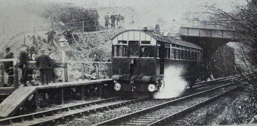

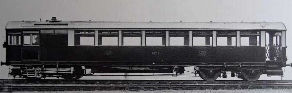

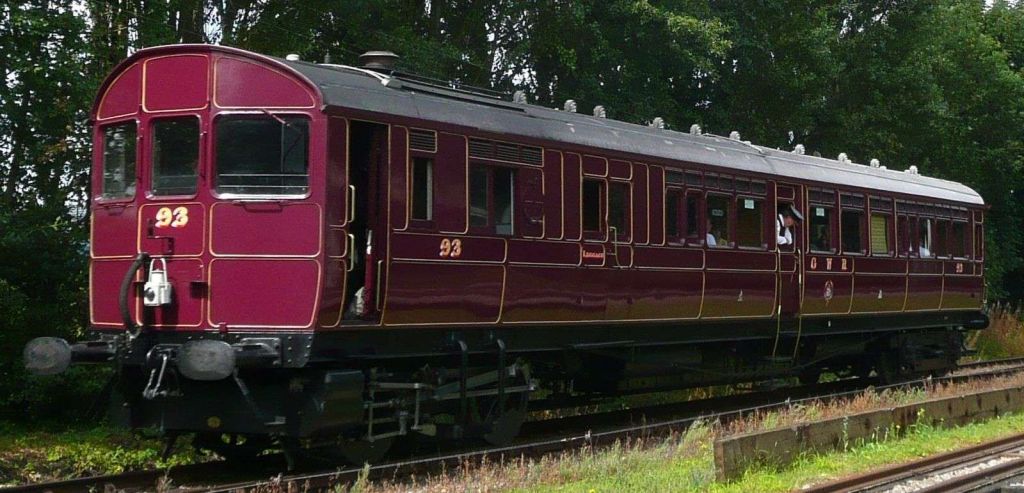


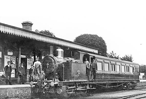
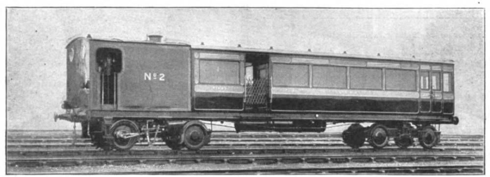


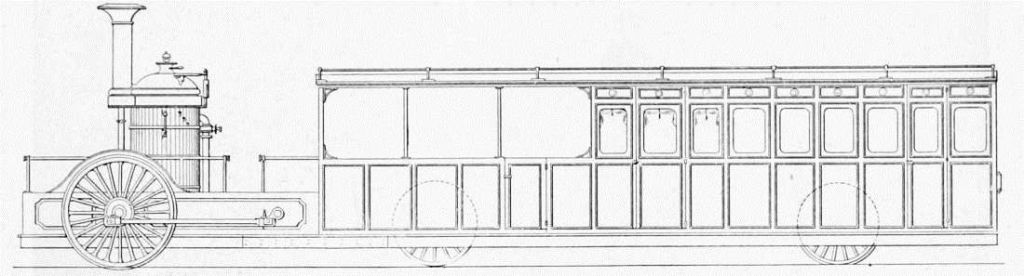


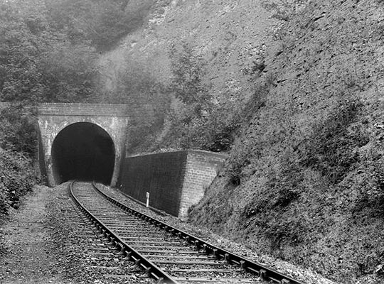
.jpg)
.jpg)