Looking through a number of 1964 Model Railway News magazines, I came across drawings of Sharp, Stewart & Co. 2-4-0, built in 1870 for the Furness Railway Co. and numbered 58 on their roster.
Side elevation and half plan of Locomotive No. 58 [1]Front elevation. [1]Tender, front and back half-elevations. [1]
Originally conceived as a mineral railway, the Furness Railway later played a major role in the development of the town of Barrow-in-Furness, and in the development of the Lake District Tourist industry. It was formed in 1846 and survived as an independent, viable concern until the Grouping of 1923. [4]
The Furness Railway contracted out the building of its locomotives until Pettigrew became Chief Locomotive Engineer in 1897. He put his first locomotive on the line in 1898.
2-4-0 Locomotive No. 58 had inside cylinders (16 in by 20 in), 5 ft 6 in diameter coupled wheels. It operated with a boiler pressure of 120 lb and weighed 30 tons 5 cwt. Its tender was 4-wheeled with a 1,200 gallon water capacity.
The locomotive, as designed, had no brake blocks, the only brake being a clasp type on the tender.
This relatively small locomotive was one of a series of 19 locos built to the same design. The class fulfilled the needs of the Furness Railway as passenger locomotives. The class was given the designation ‘E1’ by Bob Rush in his books about the Furness Railway. Rush’s classification was his own not that of the Furness Railway, but has become accepted generally. [2]
A photograph of one of this class can be found by clicking on the link immediately below. No. 44 was built in 1882 by Sharp Stewart & Co., Works No.3086. It was rebuilt in 1898, presumably in the Furness Railway works. Renumbered 44A in 1920, it became LMS No. 10002 – but was withdrawn in April 1925. [5]
Later, seven of the class were converted to J1-class 2-4-2 tank engines in 1891. [3]
References
T.A. Lindsay; Furness Railway Locomotive No. 58; in Model Railway News, Volume 40, No. 480, December 1964, p608-609. (Permission to copy granted for any non-commercial purpose.)
Significant elements of thisarticle depend on an article by David Bradshaw & Stanley C. Jenkins; Rails around Oakengates; in Steam Days, March 2013. [1] Their work is used here with the kind permission of David Bradshaw who is a native of Oakengates. In addition, I have gathered together everything that I have found which relates directly to the railways which passed through Oakengates. In March 2024, I gave a talk to the Oakengates History Group which was culled from what is included in this article.
The monochrome photographs included in this article were taken by a number of different photographers. Where possible, permission has been sought to include those photographs in this article. Particularly, there are a significant number of photographs taken by A.J.B. Dodd which appear here. These were first found on various Facebook Groups. A number were also supplied direct by Mike Dodd, A.J.B. Dodd’s son, who curates the photographs taken by his father. Particular thanks are expressed to Mike Dodd for entering into email correspondence about all of these photographs and for his generous permission to use them in this article. [174]
This article can be read here on this blog or can be downloaded as a .pdf file.
East Shropshire is well known as the ‘cradle of the Industrial Revolution’ with iron works, coal mines and furnaces all well established by 1760. Oakengates is a small town situated in the former Shropshire industrial area, and is roughly midway between Shrewsbury and Wolverhampton, which has now been subsumed into the new town of Telford. Prior to absorption into Telford, the town had a population of around 11,500, which made it the third largest settlement in the county after Shrewsbury and Wellington.
This extract from the Railway Clearing House Maps shows the immediate area around Oakengates prior to the Grouping in the 1920s. The red railways and London & Northwestern railways, the yellow are those controlled at that time by the Great Western Railway. Those dashed yellow and red are those which were in joint ownership. The Lilleshall Company network is not shown. This might help to understand the area covered by this article. We include the GWR mainline between Hollinswood Goods and Wellington, the Coalport Branch from Hadley to Malinslee, and the private railways of the Lilleshall Company. [1: p165]This extract from a drawing held on the Miners Way website may help in our understanding of the area covered. The Mineral Line used 200 mainline and 250 internal wagons. The company also bought some industrial locomotives from Barclay and Peckett. Through the years 22 locomotives were used on the line, 6 of these were built by The Lilleshall Company itself. The company also built a further 34 locomotives for their customers. [131]A little over three miles east of Wellington, and about 158½ miles from London (Paddington) via Oxford, former Great Western Railway ‘2800’ class 2-8-0 No 2897 climbs through Oakengates (West) station on a southbound (Up) freight, the gradient being 1 in 220 through the station, and this continues through the town’s nearby eponymous tunnel and nearly as far as Hollinswood sidings. The station here was opened in 1849 by the Shrewsbury & Birmingham Railway to serve Shropshire’s third largest town, a community that grew with the industrial revolution, the raw materials for the ironmasters of the late 18th century all being close at hand, and thus modern transportation was embraced at the earliest opportunity, significantly canals and then railways. A.J.B. Dodd/Colour-Rail.com [1: p165]
The transport of goods in the Oakengates area had been revolutionised by the construction of the Shropshire Canal, which was authorised in June 1788 and was completed throughout its 7.75 mile length by 1794. It ran virtually due south through Oakengates and connected with the earlier Donnington Wood, Ketley, and Wombridge canals to provide a link to and from the navigable River Severn, albeit 453ft of height had to be gained to achieve this.
The Shropshire Canal’s primary objective was the conveyance of coal, iron and lime from the Oakengates area to the River Severn at Coalport, and there was also a 2.75 mile canal branch that diverged south of Stirchley tunnel to serve Horsehay, and Coalbrookdale. This short, but quite busy extension to the local waterway system incorporated three tunnels, and there were four inclined planes (rather than flights of closely spaced locks), these being sited at Trench, Wrockwardine Wood, The Windmill and The Hay. There was a fifth inclined plane at Ketley, but this closed in 1816 when the ironworks to which it was connected was closed.
The GWR Shrewsbury to Birmingham Main Line
The Great Western Railway (GWR) took over the Shrewsbury & Birmingham Railway (S&BR) in 1854.
Apart from industrial tramways this was the first public railway to impinge on the Oakengates area. It was promoted during the ‘Railway Mania’ years of the mid-1840s as a line between Birmingham, Wolverhampton and Shrewsbury. The project was supported by the London & Birmingham Railway, which viewed the S&BR scheme as the first section of a much longer line to Liverpool and the north, in opposition to its bitter rival, the Grand Junction Railway (GJR).
The Shrewsbury & Birmingham scheme was rejected by Parliament in 1844, while in 1845 a substantially similar Bill failed to pass Standing Orders. Undeterred by these initial setbacks, the Shrewsbury promoters submitted a third Bill in November 1845, seeking Parliamentary consent for the making and maintenance of a railway commencing ‘at or near the Shrewsbury Canal Wharf, in the Parish of St. Mary, in the Borough of Shrewsbury, in the County of Salop, and terminating by a junction with the London & Birmingham Railway, near the Passenger Station of the said last-mentioned railway, in the township of Duddeston-cum-Nechells, in the Parish of Aston-juxta-Birmingham, in the County of Warwick’.
Meanwhile, the Grand Junction Railway had submitted an alternative scheme, known as ‘the Shrewsbury, Wolverhampton & South Staffordshire Junction Railway’, which would have followed more or less the same route as the Shrewsbury & Birmingham line. However, at that juncture, the London & Birmingham Railway agreed to join forces with the Grand Junction and the Manchester & Birmingham railways to form a new organisation known as ‘The London & North Western Railway’. This sudden and unexpected development had obvious ramifications for the Shrewsbury & Birmingham scheme, which was, in consequence, cut down to 29½ miles of line between Shrewsbury and Wolverhampton, access to Birmingham being obtained via the projected Stour Valley line.
The London & North Western Railway (LNWR) was formed by Act of Parliament on 16th July 1846 and, a little over two weeks later, on 3rd August 1849, the ‘Act for Making a Railway from Shrewsbury to Wolverhampton … to be called the Shrewsbury and Birmingham Railway’ received the Royal Assent. The resulting Act stipulated ten miles of line between Shrewsbury and Wellington would be shared with the Shropshire Union Railways & Canal Company, while the Shrewsbury & Birmingham Railway was granted running powers and a quarter share in the Stour Valley line. The S&BR was also permitted to construct a branch from Shifnal to the ironworks at Dawley.
The land required for the S&BR line between Shrewsbury and Wellington had been purchased by 19th September 1846, and the work of construction was soon underway, the Engineer being William Baker (1817-78). In engineering terms, there were few major obstacles, other than the two bridges across the River Severn and a 471-yard long tunnel at Oakengates.
The line running between Shrewsbury and Wellington was examined by the Board of Trade Inspector on 2nd May 1849, and he reported that ‘the railway is so far advanced that it can be used with safety by the public, but the stations will require a few days to complete’. Eastwards, a further four miles of line between Wellington and Oakengates required a second inspection, after delays in completing an overbridge at Wellington, but when this short section had been approved by the Board of Trade, the first portion of the S&BR line was opened on 1st June 1849, when trains began running between Shrewsbury, Wellington and Oakengates.
The initial timetable provided four trains each way, with Up services from Shrewsbury at 6.45am, 9.35am, 4.15pm and 6.45pm, and corresponding Down workings starting from Oakengates at 8.45am, 2.15pm, 5.15pm and 8.15pm. The first Up and last Down trains were first class only, whereas the remainder conveyed all classes. The Sunday service comprised just two trains each way.
Construction of the eastern section of line was delayed due to some difficulties involving Oakengates tunnel, while the work of the navvies had also been impeded by the abysmally wet summer of 1848. However, the railway was finally opened throughout on Monday, 12th November 1849, with the inaugural train of fifty carriages hauled by two locomotives, Wrekin and Salopian. Passengers wishing to reach Birmingham had to travel via Wednesfield Heath station and the former Grand Junction line as the Stour Valley route from Wolverhampton’s High Level station was as yet incomplete. The frequency of the service was increased to nine trains each way daily, but any access to the Stour Valley line was not granted until 4th February 1854.
The LNWR – a giant among railway companies and a huge undertaking by mid-Victorian standards – was able to exert unyielding commercial pressure on the Shrewsbury & Birmingham Railway and its ally, the Shrewsbury & Chester Railway with a view to eventual takeover. For example, although the Stour Valley line was opened on 1st July 1852, connections with Shrewsbury & Birmingham trains at Wolverhampton were arranged to be as inconvenient as possible, and the ‘North Western’ company refused to accept through bookings to and from the S&BR. However, the LNWR failed completely in its attempt to intimidate the Shrewsbury companies, and in 1854 the Shrewsbury & Birmingham and the Shrewsbury & Chester railways opted instead for an outright amalgamation with the Great Western Railway. Thus, on 1st September 1854, the line from Wolverhampton to Shrewsbury and thence to Chester became an integral part of the GWR system – albeit with a jointly owned section of line between Wellington and Shrewsbury.
In later years, the line through Oakengates became part of a much longer route extending from London (Paddington) to Birmingham (Snow Hill), Shrewsbury, Chester, and ultimately Birkenhead (Woodside) – the latter point becoming the northernmost extremity of the GWR main line passenger network.
In 1910, local services outlined in the April Bradshaw show fourteen trains to Wellington (and some beyond) stopping at Oakengates with nine in the opposite (Wolverhampton) direction. The Sunday services, as would be expected, were much more sparce, with three trains in the Wolverhampton direction and four to Wellington.
The British Railways (Western Region) timetable for Summer 1953 provides a post-Nationalisation but pre-dieselisation picture, with a frequent weekday (Monday to Saturday) service to both Wellington (Northbound/Down) and Wolverhampton (Southbound/Up), with some of these trains originating from Shrewsbury and Birmingham respectively, and two trains each way continuing on to London (Paddington) or working through to Chester (General). It is worth noting that between 18th June 1951 and 10th June 1956 the former GWR station in Oakengates was known as Oakengates (West), to differentiate it from Oakengates (Market Street) station on the former LNWR/LMS Coalport branch, and this is how it appears in timetables of the period.
At this time, the first Down train called at Oakengates (West) at 7.00am en route to Chester, although generally trains calling in this direction terminated at Wellington. Later trains called at 7.35am, 7.52am (ex-Birmingham, Snow Hill), 8.35am, 10.00am (Snow Hill to Chester), 12.01pm, 1.07pm, 1.54pm (ex-Snow Hill), 2.50pm, 3.57pm, 5.19pm, 6.10pm (to Shrewsbury), 7.11pm (Snow Hill to Shrewsbury), 9.04pm (to Shrewsbury), 10.25pm and 11.40pm.
The pattern of services for Up trains was broadly similar, with passenger trains generally terminating at Wolverhampton (Low Level). Calls at Oakengates (West) were at 6.50am and 7.13am (both to Snow Hill), then 7.52am (the 7.30am Shrewsbury-Paddington service), 8.38am, 9.31am, 10.16am, and 11.51am. Afternoon calls were at 1.39pm, 3.03pm, 3.58pm, 5.45pm (to Snow Hill), 7.15pm, 8.48pm and 10.47pm (the 10.15pm Shrewsbury to Paddington service that terminated in London at 5.05am on the following morning).
In early British Railways’ days, former GWR Churchward Mogul No 5381 heads a southbound passenger train past Hollinswood sidings, the massive yards established a little way from the southern portal of Oakengates tunnel to exchange traffic with the Lilleshall system. The distant chimneys and slag heaps are those of the Priorslee Furnaces, one of the principal Lilleshall Company establishments – and David Bradshaw says, these slag heaps proved to be great terrain for playing Cowboys & Indians in the early to mid-1950s. As an aside, the Wolverhampton-bound passenger train is effectively passing through the site of what is now Telford Central station, the impressive but arguably ugly industrial scene that I recall now landscaped to provide a modern road system serving the 1980s-built station and industrial estates, the area also being bridges by the M54. A.J.B. Dodd/Colour-Rail.com. [1: p167]
The summer of 1957 brought about the dieselisation of the stopping services at Oakengates as part of a Wellington to Lapworth service, Lapworth being the end of the four-track section of the former GWR main line south from Birmingham (Snow Hill), so it was a convenient terminating point. At the same time, Birmingham (Moor Street) to Leamington Spa services also went over to diesel-multiple-units. However, the dieselisation was not total, as some peak hour stopping services were still regularly steam-hauled through Oakengates, and it was status quo, unchallenged steam power, on stopping services between Wellington and Shrewsbury.
Between Wellington and Wolverhampton, however, steam locomotives were almost exclusively on goods and parcels duties as ‘Western’, ‘Warship’ and ‘Hymek’ diesel- hydraulics had taken over most of the expresses, and these thundered through Oakengates station. A particularly interesting working was the Bournemouth (West) to Birkenhead (Woodside) Inter-Regional duty and its corresponding Birkenhead to Bournemouth service, with Southern Region green-liveried coaches in use either on the northbound or southbound leg.
The BR (Western Region) public timetable for 12th September 1960 to 11th June 1961 lists the duty as ‘Week Days Only’, with the one train leaving Birkenhead at 9.20am, while that from Bournemouth departed at 9.30am, hence the need for two rakes, the two trains passing each other near Fenny Compton; Wellington was an 11.40am call on the Up duty, and 3.20pm on the Down service. However, the summer 1962 timetable saw the service cut-back to Wolverhampton (Low Level) on Mondays to Fridays, leaving the through service between Bournemouth and Birkenhead as a Saturdays- only option.
For many years the local services between Wolverhampton (Low Level) and Wellington were in the hands of Tyseley or Wellington-allocated Class ‘5101’ 2-6-2Ts on suburban stock, as illustrated by No. 4130 arriving from Wolverhampton at journey’s end. For the most part, passengers from Oakengates wishing to travel beyond Wellington would have to change trains here, and interestingly the local services between Wellington and Shrewsbury were actually Stafford line trains that worked through. However, these would never be dieselised. Instead the remaining intermediate stations between Stafford and Wellington, and onwards to Shrewsbury, would cease to be served from 7th September 1964. A.J.B. Dodd/Colour-Rail.com [1: p167]
The shake-up in Inter-Regional duties that was instigated with the introduction of the winter 1962/63 timetable, which significantly diverted the traditional Somerset & Dorset routed trains via Oxford, also brought about the end of the Bournemouth to Birkenhead duty, so Saturday, 9th September 1962 was the last day it ran. Interestingly, as part of the ongoing West Coast main line electrification, the Up and Down ‘Pines Express’ was also diverted away from Birmingham (New Street), so it now served Snow Hill, Wolverhampton (Low Level), and Wellington, then diverged to travel via Market Drayton to Crewe and Manchester. From an Oakengates perspective, this brought an English Electric ‘Type 4’ diesel through the station – the timetable ‘path’ for this train south of Wellington was that once used by the Birkenhead service.
At this stage, duties generally continued to operate to traditional timings, and a glance at the 1963 timetable provides an example. In the Down direction these were the 12.15am, 8.20am, 9.10am, 11.10am – ‘Cambrian Coast Express’, 12.10pm, 1.10pm, 2.10pm, 4.10pm, 6.10pm and 7.10pm from Paddington. The return journeys were at 6.30am, 7.40am, 8.55am, 11.40am, 2.45pm, 4.30pm and 8.55pm from Birkenhead, 2.30pm from Chester, and the 7.10am, 7.30am and 5.10pm from Shrewsbury.
There was a regional boundary change from 9th September 1963, with the Western Region retreating to Bromsgrove, but even with the new London Midland Region broom there were not yet enough diesels, locomotives or multiple-units, to exclude steam locomotive use on peak hour passenger duties, even into 1964. David Bradshaw remembers this well as in the 1963/64 period his girlfriend Margaret (now his wife), frequently caught the 5.10pm local service to Oakengates from the bay platform at Shrewsbury; it was generally hauled by a Shrewsbury-allocated ‘County’ or ‘Hall’, and the guard would always ensure that she caught it, often holding the train beyond its departure time. If she missed this, the next train was a Shrewsbury to Stafford service, with a change to a diesel-multiple-unit at Wellington.
Stafford Junction, just to the east of Wellington station, was the meeting point of the Shrewsbury & Birmingham Railway and Shropshire Union Railway & Canal Co, this opening on 1st June 1849, which was a pivotal day as inaugural S&BR services began between Shrewsbury and Oakengates and likewise the LNWR-operated Shrewsbury to Stafford services started, the latter diverging here; the junction was ‘Joint’ property, as was the line West from here to Shrewsbury. This view is looking east on 9th August 1932, the Stafford line branching left, while the line straight ahead is for Oakengates, although the next nearest railway infrastructure of note is Ketley Junction, just 52 chains away, where trains from Wellington for Much Wenlock diverged as they travelled ’round The Wrekin’. Mowat Collection.
The Shropshire Union Railways & Canal Co.
The Shropshire Union Railways & Canal Co. was created in 1846 as an amalgam of a number of canal and railway schemes. Railways were, at that time, starting to pose a serious threat to the local canal companies, and it was for this reason that the Shropshire Union company was formed, the idea being that a combined railway and waterway undertaking would be able to hold its own in competition with purely railway-orientated companies such as the London & North Western Railway.
The Shropshire Union worked a number of existing waterways, including the Ellesmere & Chester Canal (which had already absorbed the Birmingham & Liverpool Junction company), and it also obtained powers for a network of connecting railway lines, one of which would have run from Nantwich to Wolverhampton, while others would extend from Crewe to Newton and from Stafford to Shrewsbury. In total, it was envisaged that the Shropshire Union would encompass no less than 155 miles of railway, much of this system being converted from the Shropshire Union’s existing canals.
Having secured Parliamentary consent for their ambitious scheme, the Shropshire Union supporters looked forward to a prosperer future. However, their plans were perhaps far too ambitious, and the Shropshire Union company inevitably attracted the attention of rival railway companies, notably the rapidly expanding LNWR. In 1847, the Shropshire Union Railways & Canal Company was leased in perpetuity to the LNWR, and by this means the original Shropshire Union plans were effectively thwarted. The Nantwich to Wolverhampton and Crewe to Newton lines were abandoned, although, happily, the main canal routes remained in operation under London & North Western auspices.
It was also agreed that the proposed railway from Stafford to Shrewsbury would be constructed, with the proviso that the western section between Wellington and Shrewsbury would be vested jointly in the Shrewsbury & Birmingham and Shropshire Union companies. As we have seen, the line from Shrewsbury to Wellington was opened on 1st June 1849, and the connecting line between Stafford and Wellington was also opened on the same day, this eastern section being worked as a purely LNWR branch, whereas the Wellington to Shrewsbury line was jointly-owned with the S&BR. Trains worked on a Stafford to Shrewsbury axis, calling at Gnosall (64 miles), Newport (11½ miles), Hadley (17½ miles), Wellington (18¾ miles), and then intermediate stations to Shrewsbury (29¼ miles).
The LNWR Coalport Branch
Along with discussion of all the other railways in and around Oakengates (including the Lilleshall Co. private railways), David Bradshaw and Stanley C. Jenkins looked at the Wellington to Coalport Branch.
These paragraphs come first from the parts of the Steam Days article which relate to the Wellington to Coalport Branch, [1: p168-170, 175, 176-177] but are supplemented by my own research into the route of the line.
Wikipedia provides this schematic map of the Coalport Branch which highlights the key stations and sidings. [37]
The Great Western Railway had taken over the Shrewsbury & Birmingham Railway (S&BR) in 1854, and this may have prompted the LNWR to consider a scheme for converting the Shropshire Canal into a railway. This busy waterway was experiencing severe problems in terms of subsidence and water supply, and there was a major flooding incident in July 1855 when Snedshill tunnel collapsed. It was thought that the cost of repairs would probably exceed £30,000 and, faced with this heavy expenditure, the London & North Western Railway (LNWR) decided that the money would be better spent on the construction of a replacement railway from Hadley, near Wellington, to Coalport, which would utilise, as much as possible, parts of the troublesome canal.
It was then estimated that the proposed Coalport branch line would cost about £80,000, including £62,500 for the purchase of the waterway. Accordingly, in November 1856, notice was given that an application would be made to Parliament in the ensuing session for leave to bring in a Bill for the purchase and sale of the Shropshire Canal and the ‘Conversion of Portions thereof to Railway Purposes, and Construction of a Railway in connection therewith’.
The proposed line was described as a railway, with all proper stations, works, and conveniences connected therewith, commencing by a junction with the Shrewsbury and Stafford Railway of the Shropshire Union Company in the township of Hadley and parish of Wellington, in the county of Salop. at a point about two hundred yards westward of the mile post on the said railway denoting twelve miles from Shrewsbury’, and it terminated in the parish of Sutton Maddock, in the county of Salop, at a point ten chains or thereabouts to the east of the terminus of the Shropshire Canal at Coalport’.
The railway would pass through various specified parishes, townships, or other places, including Wellington, Hadley, Donnington Wood, Wrockwardine, Wombridge, Oakengates, Stirchley, Malins Lee, Dawley, Snedshill, Madeley, and Coalport, ‘occupying in the course thereof portions of the site of the Shropshire Canal’. Having passed through all stages of the complex Parliamentary process, the actual ‘Act for Authorising the Conversion of parts of the Shropshire Canal to Purposes of a Railway’ received the Royal Assent on 27th July 1857.
The canal was closed between Wrockwardine Wood and the bottom of the Windmill Hill inclined plane on 1st June 1858, although isolated sections of the waterway remained in use for many years thereafter. The work of conversion was soon underway, and on Thursday, 30th May 1861 The Birmingham Daily Post announced that the Coalport and Hadley line of railway would be opened on ‘Monday next’, implying that the first trains would run on 3rd May. In the event, this prediction was slightly optimistic, and on 12th June the same newspaper reported that, ‘in accordance with the arrangements arrested’. previously announced’, the Coalport branch had been opened for passenger traffic on Monday, 10th June 1861.
As usual in those days, Opening Day was treated as a public holiday, and a large number of spectators had assembled at Coalport station to witness this historic event. ‘At the appointed time, the first engine, and train of first, second and third class carriages, moved off from the station, having a respectable number of passengers’.
The newly opened railway commenced at Hadley Junction, on the Stafford to Wellington line, and it climbed south-eastwards on a ruling gradient of 1 in 50 towards Oakengates (3.25 miles from Wellington), which thereby acquired its second station. Beyond, the route continued southwards, with intermediate stations at Dawley (6 miles) and Madeley Market (7½ miles), to its terminus at Coalport, some 9½ miles from Wellington. The final two miles of line included a continuous 1 in 40 descent towards the River Severn. An additional station was opened to serve Malins Lee, between Oakengates and Dawley, on 7th July 1862.
Wellington Railway Station to Hadley Railway Station
Wellington Railway Station was the junction station for the Coalport Branch passenger services. The bay platform on the South side of the Wellington Station site was shared with the GWR Coalbrookdale line (Wellington & Severn Junction Railway). The station and the line to its East are covered in the link below:
Coalport East trains left the Shrewsbury to Birmingham line and for a short distance, to Hadley Junction, travelled along the line from Wellington to Stafford. After passing through Hadley Railway Station trains took to the Branch which curved away to the South of the main line.
Hadley Railway Station to Wombridge (Goods)
Experience shows that it is very difficult to plot a line on the ground when significant development has taken place. For the first section of this line the redevelopment from the 1960s into the 21st century has been very significant. In this article I have relied on modern satellite images provided by railmaponline.com. [4] As usual, historic mapping comes from the NLS (National Library of Scotland).
Hadley Railway Station appears on the left of this extract from the 25″ Ordnance Survey of 1901, published in 1902. The trackwork associated with the junction and with Castle Car Works can be seen at the top right of the extract. [12]The same area in the 21st century as shown on the ESRI satellite imagery provided by the NLS. [12]An enlarged extract from the 25″ Ordnance Survey which shows the area immediately around Hadley Station. [14]The same area on the modern satellite imagery of Google Maps. [15]Caren Craft shared the photograph of modern Hadley taking shape on the Hadley History Facebook Group on 26th June 2022. The photo was carried by the Shropshire Star on 15th August 2011. Both of the two railway bridges can be seen on the left of the image carrying the new single track railway line. [13]
Hadley Railway Station served the former Stafford to Shrewsbury Line and was the start of the branch to Coalport. The station was opened in 1849 and closed in 1964. The line through Hadley was closed from 1964, with the last remaining stretches of track being taken up in 1991. In the late 2000s a stretch of track was re-laid to the Telford International Railfreight Park for freight purposes only. [16]
Telford International Railfreight Park (known as TIRFP) is rail freight depot and construction development site located in Donnington to the north of Telford, on the former route of the Stafford to Shrewsbury Line. The terminal was opened in 2009. [17]
Wombridge Priory was a small Augustinian monastery established in the early 12th century, it was supported by a network of minor nobility and was never a large community. Despite generally good financial management, it fell within the scope of the Suppression of Religious Houses Act 1535 and was dissolved in the following year. [82]
The priory was dedicated to St Leonard. St Leonard was particularly popular in the 12th century following the release of Bohemond I of Antioch, a captured crusader – a circumstance which he seems to have attributed to the saint’s intercession. White Ladies Priory, another Shropshire Augustinian house, was also dedicated to St Leonard, as was the parish church at Bridgnorth, [82] and at a later date, Malinslee Parish Church. Remains of the priory buildings remained visible until the 19th century but are now hidden beneath the churchyard and other development. They were excavated in the 1930s and again in 2011 and 2012. [82]
The church was designated to St. Mary and St. Leonard and was built in 1869 by George Bidlake. It is the fourth church on the site of the Priory.
An aerial view of Wombridge Church with some of the remains of the Priory evident. This photograph was shared on the Telford – The Ultimate Guide Facebook Group by Steve Bowers on 27th February 2023. [47]
The bridge which carried the Coalport Branch over what was once Wombridge Road was demolished to make way for the A442 Queensway.
This photograph was taken during the demolition of the bridge. It is the only photo I have been able to find of the old railway bridge. It appears to have been taken from the South. Headroom would have been quite limited. The photograph was shared by Paul Wheeler on the Telford Memories Facebook Group on 23rd November 2017. [48]
We continue on our journey along the old Coalport Branch with a ground-level shot along the A442 showing the line of the old railway.
Looking Southeast along the A442, Queensway from the Northwest-bound off slip road. The A442 was built over the line of the Coalport branch which was curving along the length ahead towards the Southeast. [Google Streeetview, June 2022]The 25″ Ordnance Survey from the turn of the 20th century again. The important feature on this length of the Coalport Branch was the bridge which carried Stafford Road over the line. [49]Once again, this satellite image covers approximately the same area as that covered by the OS map extract above. The purple line is the route of the Coalport Branch as recorded on railmaponline.com. [33]An image from the Southbound carriageway of the A442 from a position at the top-left of the satellite image above. [Google Streetview, June 2022]From the same Southbound carriageway, the bridge which carries Stafford road over the A442 is visible in the distance. The Coalport Branch followed a tighter curve than the modern road, passing under Stafford Road to the South of the modern bridge over the A442. [Google Streetview, June 2022]A Brown’s Sentinel bus crosses the Stafford Road bridge in Oakengates in March 1963. For much of his married life, Ron Dean was in the driving seat. And his wife Greta was his conductor. The camera is pointing towards the South. [50]Stafford Road Bridge again, sometime in the 1960s before the A442, Queensway dual carriageway was built. This was probably taken at the time that a footbridge was being installed alongside the road bridge. The photo is taken facing South along the Brach line. It was shared on the Telford memories Facebook Group by Bear Yeomans on 7th February 2016. [51]Looking North from Stafford Road Bridge along the Coalport Branch towards Hadley Junction. This image was shared on the Oakengates History Facebook Group by Gwyn Thunderwing Hartley on 23rd May 2020. [52]Looking North under Stafford Road Bridge along the Coalport Branch. This image was shared on the Oakengates History Facebook Group by Gwyn Thunderwing Hartley on 30th July 2018. [53]This aerial photo of Oakengates was taken in November 1970. Just to the right of the top-centre of the image, Stafford Road bridge can be seen with the footbridge alongside it. The A442 is not evident, but the Coalport Branch cutting can be followed from the road bridge to the right. This image was shared on the Telford Memories Facebook Group by Marcus Keane on 22nd March 2022. [54]An enlarged extract from the picture immediately above showing Stafford Road bridge in the top-left. [54]This next length of the line takes us through Oakengates Market Street Railway Station and Goods yard. The 25″ Ordnance Survey of 1901, published in 1902 shows the station and goods yard to full advantage. [55]The railmaponline.com satellite image of the same area as in the map extract above. This begins to show how congested the area around Oakengates was with a variety of railway lines and sidings. [33]
The OS image above shows the length of the Coalport branch as it passes through Oakengates (Market) station and goods yard. We will return to look at the station later. Two images looking North through the station will suffice at this juncture.
Aview looking North from the boundary fence, through Oakemgates (Market) Station. The line was much less busy on this occasion. The image was shared on the Telford Memories Facebook Group by Paul Wheeler on 16th August 2017. An equivalent modern view from Canongate is not feasible because the industrial site is now screened by trees. [3]Looking North through the area that was Oakengates Market Street Station Goods yard from the Eastern end of Commercial Way. The purple line shows the approximate route of the Coalport Branch. The white building at the centre of this image is the old goods shed now put to a different use! [Google Streetview, June 2022]Looking Southeast from the same location. The mainline of the Coalport Branch would have run along the treeline behind the industrial units. [Google Streetview, June 2022]The view from the Southeast on Canongate. The purple line shows the approximate location of the Coalport Branch which passed under the road by means of a bridge. [Google Streetview, June 2022]Canongate Railway Bridge was a brick-arched structure. It is seen here infilled to support the road above. This image was posted by BruceS on Waymarking.com on 2nd June 2015. [60]Looking North under Canongate Bridge towards Oakengates Market Street Station. This picture was shared on the Oakengates History Facebook Group by Gwyn Thunderwing Hartley on 12th October 2017. [61]An aerial image looking North along the line of the Coalport Branch in 1948. Canongate bridge is in the centre of the image, the Station is towards the top of the image beyond the goods yard, (c) Historic England, Britain from Above (EAW013748). [62]An extract from the above image which shows Canongate, the Goods Yard and the Station in greater detail, (c) Historic England, Britain from Above (EAW013748). [62]The next length of the Coalport Branch took it passed Snedshill Iron Works and into a tight corridor which included the GWR Shrewsbury to Birmingham railway Line, the Coalport Branch and a Mineral Railway. This area is again shown on the 25″ Ordnance Survey of 1901, published in 1902. [63]Railmaponline.com’s satellite imagery shows the same area as in the OS map above as it appears in the 21st century. All the lines mentioned above are included in the overlay to the satellite imagery. [33]Another extract from the aerial image of 1948 which showed Canongate Bridge, this shows the area to the South of Canongate. Snedshill Iron Works are on the right of the image. In the centre of the image are John Maddock and Co.’s works for whom the aerial photographs were taken. Those works do not feature on either the 1901 Ordnance Survey or the modern satellite imagery. [62]Looking North from the A5 bridge over the Coalport branch. Snedshill Ironworks are on the right of the image. The bridge at the centre of the image is the same one that appears at the bottom of the aerial image immediately above. This photograph was shared on the Telford Memories Facebook Group by Paul Wheeler on 18th March 2018. [64]Almost extactly the same location, also looking North, the connection was one of the busier connections from the Coalport line. As we have noted, our vantage point is the Holyhead Road overbridge, the old A5 trunk road. This view shows the Coalport branch in the cutting on the left, while the lines on the right connect to the former Snedshill Iron Works; a Hawksworth ‘9400’ pannier tank is seen shunting the siding in the mid-1950s. This was initially one of the connections to the Lilleshall network but in about 1938 the Lilleshall Company sold the Snedshill Iron Works to John Maddock’s & Son, an Oakenshaw-based engineering firm that was outgrowing its premises near the GWR station. Subsequent development saw the distant building become one of the most modem casting foundries in Europe, and post-war, pipe fittings became the principal activity. (c) A.J.B. Dodd [1: p170]Looking Northwest along Reynolds Drive, Oakengates. The Coalport Branch was in cutting at this location. The purple line gives an idea of its Route. Its route crosses Hawkshaw Close a 100 yards or so to the left, as shown below. [Google Streetview, June 2022]Looking South along Hawkshaw Close, Oakengates with the line of the Coalport Branch shown. As noted above the line was in relatively deep cutting at this location. Google Streetview, June 2022]Looking North from Newlands Road, Oakengates, towards Oakengates Market Street Station. At this point on the line we are a little to the North of the accommodation bridge shown on the 1948 aerial image above. The approximate route of the line is again shown by the purple line. The line was, however, in deep cutting at this location. [Google Streetview, June 2022]Looking South from Newlands Road, Oakengates, along the line of the Coalport Branch which was in deep cutting at this location. The road to the right of this image is Station Road which once ran immediately alongside the old railway line a little further to the South.[Google Streetview, June 2022]Looking North along Station Road across the line of the old railway. Station Road was diverted when the new roundabout (immediately behind the camers) was constructed. The next two monochrome images focus on this location as it was in 1948. [Google Streetview, June 2022]The same length of line, but this time as shown in an aerial image from the Northwest, also taken in 1948. The image features John Maddock’s works with Snedshill Iron Works beyond, (c) Historic England, Britain from Above (EAW013752). [65]A closer view of the top-right of the above image with the Coalport branch heading away to the South. This area saw significant alterations in the later years of the 20th century. The significant bridge carries what is designated the B5061 in the 21st century, but was the A5 Trunk Road. The works immediately beyond the bridge and alongside the A5 are the Lilleshall Company’s Snedshill Brickworks, (c) Historic England, Britain from Above (EAW013752). [65]The 1″ OS Map of 1898, published 1899, shows the location of the bridge. The immediate area is now under the Greyhound Roundabout which sits alongside the A442. [66]Looking Southeast along the A5 towards the Lilleshall works at Priorslee. The dominant building with the curved roof on the left of this image is the Lilleshall Company’s Snedshill Brickworks. The Coalport Branch passed under the bridge at the centre of the image. This phot was shared on the Telford Memories Facebook Group on 23rd February 2014 by Vince Allen. [67]Looking down into the cutting of the Coalport Branch from the East in 1973. The road running across the image is the A5. The arch bridge is the Greyhound Bridge which is eventually replaced by the Greyhound Roundabout. The picture was shared on the Oakengates History Facebook Group by Gwyn Thunderwing Hartley on 14th May 2019. [68]A local collapse of parapet walling alongside the bridge occurred in 1966. The bridge is off to the left of the photograph, the running line of the Coalport Branch just below the image. This press cutting was shared on the Telford Memories Facebook Group by Paul Johnson on 1st March 2014. [69]In this postcard aerial view of Snedshill Brickworks from the West, the Mineral Railway adjacent to the Coalport Branch is visible, crossing the A5 at the bottom edge of the image. The Coalport Branch is just off the bottom of the picture. [70]Snedshill Brickworks again, this time in the 1950s and viewed from the East. The A5 runs away to the right of the image. The cutting of the Coalport Branch runs across from middle-right to middle-left. The A5 bridge over the line is hidden by the Works buildings. This picture was shared on the Telford Memories Facebook Group by Marcus Keane on 26th March 2014. [71]From a similar angle to the last picture but taken from the Lilleshall Brickworks buildings in 1974, this image was carried by the Shropshire Star at the time. The A5 runs diagonally across the shot with the dwarf wall above the arched Greyhound Bridge visible to its right. The cutting of the Coalport Branch runs left to right across the centre of the image. The picture was shared on the Oakengates History Facebook Group on 22nd October 2020 by Gwyn Thunderwing Hartley. [72]
This photo does not have the best of definition, but it is worth including as it shows the view South across the Brickworks before redevelopment work in the area. The Shrewsbury to Birmingham line curves away to the East. The A5 bridge over the Coalport Branch is visible at the bottom of the image. [33]
From this point South the A442 now occupies the space which once was used by the Coalport Branch. The Northbound slip road from the A442 can be seen following the line of the old railway on the Railmaponlin.com satellite image below.
The 25″ Ordance Survey of 1901, published 1902, shows the Coalport Branch passing over the GWR Shrewsbury to Birmingham main line. The GWR line passed under the area in a deep tunnel with the Coalport Branch above it also in a relative deep cutting. The two lines ran approximately parallel for a short distance. [74]Railmaponline.com shows the same area with the local lines overlaid on the satellite imagery from Google Maps. [33]The view North, back towards Oakengates from the northbound slip road of the A442. [Google Streetview, June 2022]The view South from the same location showing the approximate route of the Coalport Branch. [Google Streetview, June 2022]A little further South along the A442 with the approximate line of the Coalport Branch marked once again. [Google Streetview, June 2022]Further South again, this time the camera is on the southbound carriageway. The Coalport Branch ran approximately along the modern treeline. Beyond the horizon the A442 curves back over the formation of the old line. [Google Streetview, June 2022]Further South again the A442 crosses the line of the Coalport Branch. The next Railmaponline.com satellite image shows that the footbridge in this view is very close to the point where the A442 leaves the formation of the Coalport branch. [Google Streetview, June 2022]This next extract from the 25″ Ordnance Survey of 1902 shows the Shrewsbury to Birmingham line to the East of the Coalport branch and running parallel to it. Both pass under the road leading Northeast out of Hollinswood. The Coalport branch remains in cutting along much of its length on this map extract. [75]The same area on the satellite imagery provided by Railmaponline.com. The purple line shows the route of the Coalport Branch which, from close to the top-left of the image ran along a route immediately adjacent to the modern A442. Hollinswood Road has been replaced by a footbridge over the A442 and the Shrewsbury to Birmingham main line. It is further cut to the Southwest by the M54 and its junction arrangement, just off this image to the bottom-left. [33]Looking North towards Oakengates from the cycle track on the West side of the A442. The approximate route of the Coalport Brnach is indicated by the purple line. [My photograph, 13th March 2023]Looking Southeast from the cycleway alongside the A442. [My photograph, 13th March 2023]Another view looking North, but this time taken from the Footbridge/Cycleway bridge over the A442. [My photograph, 13th March 2023]Looking South from the same bridge with the route of the old railway indicated by the purple line. The bridge ahead carries the M54 over the A442. [My photograph, 13th March 2023]Looking South again, this time from the cycleway/footpath which runs under the M54 bridge over the A442. [My photograph, 13th March 2023]This is now the view South towards the Telford Station footbridge. My photograph, 13th March 2023]A few steps ahead and turning a half-circle, this is the view looking North under the M54 Bridge with the old railway route marked by the same purple line. [My photograph, 13th March 2023]The view South once more showing the line of the old railway. [My photograph, 13th March 2023]Looking North-northwest on Rampart Way under the footbridge leading to Telford Railway Station. The approximate line of the Coalport Branch is shown by the purple line. The M54 runs parallel to and beyond the purple line [Google Streetview, June 2022]Looking to the Southwest under the Station Footbridge with the line of the Old Coalport Branch shown in purple. [Google Streetview, June 2022]Old Dark Lane Colliery and Brickworks appear at the top of the next extract from the 25″ Ordnance Survey of 1901, published in 1902. Dark Lane Village is at the bottom of the image. Dark Lane village was lost as part of the development of Telford. The Branch has turned away from the Shrewsbury to Birmingham line towards the South. [76]The same area on the satellite imagery provided by Railmaponline.com. The route of the old line cuts across the West side of the A442 interchange and then South through housing and across Dale Acre Way. [33]Looking South across Hollinswood Interchange along the line of the Coalport Branch. [Google Streetview, June 2022]Looking East along the northern arm of Dunsheath. The line of the old railway crosses the housing development immediately this side of the black car and the van (approximately)! [Google Streetview, June 2022]Looking East along the southern arm of Dunsheath. The line of the old railway crosses the housing development as shown by the purple line. [Google Streetview, June 2022]
Old Darklane Colliery and Brickworks
The Colliery was opened in 1855 and closed finally in 1885. The owners were: Beriah Botfield (1855-1860]; Leighton and Grenfell (1869-1870); and Haybridge Iron Co. Ltd (1875-1885). [77]
Dark Lane Village
Dark Lane Village was lost in its entirety to the redevelopment which produced Telford. Dark Lane Row and the Methodist Chapel appear at the bottom of the OS map extract above. The remainder of the village features at the top of the OS Map extract below. Malins Lee Station was on the South side of the village. Little Dark Lane Colliery to the West. There were three long rows of cottages which were known locally as: Long Row (about 550ft long and containing 20 houses); Bottom Row (a little over 500ft long and containing 25 houses); and Short Row (nine houses built by the Botfield family in around 1825). A full description of the village and pictures of the buildings can be found on the Dawleyhistory.com website. [78]
The last extract on the Coalport Branch from the 1901 25″ Ordnance Survey shows Dark Lane village and Malins Lee Railway Station. [79]The same area on the satellite imagery provided by Railmaponline.com. After crossing Dale Acre Way, the route of the old line heads South-southwest across open ground and then over land used for housing development. [33]Looking West on Dale Acre Way. the approximate location of the old railway is shown by the purple line. [Google Streetview, June 2022]The view West in the 1960s along Dark Lane the GWR mineral railway was hidden in the dip. The road then rose relatively steeply to cross over the Coalport Branch. The bridge can be seen middle-left of this image. [80]This Streetview image is taken from approximately the same location as the picture immediately above. [Google Streetview, June 2022]This bucolic colour image shows the road featured in the image above but this time from a location adjacent to Bottoms Row, Dark Lane. The bridge over the Coalport Branch can be seen again on the horizon. This photo was shared on the Telford memories Facebook Group by Marcus Keane on 28th February 2023. It was colourised by Simon Alun Hark. [81]This image is taken from the same geographical location as the one immediately above, facing in the same direction. The light blue line indicates the alignment of the old Dark Lane. [Google Streetview, June 2022]This postcard view shows Bottom Row with the Methodist Chapel beyond. The bridge on the right of the image carried Dark Lane over the Coalport Branch. Malins Lee Station was beyond the bridge to the right of the image. A matching modern image is not practical as the camera location is now in the midst of a copse of trees close to the boundary of the exhibition centre car park. [82]
‘The Miner’s Walk‘ website provides more information about the area around Dark Lane village. [83] It includes a hand-drawn overlay of modern roads over the Ordnance Survey of the 1880s.
The hand drawn overlay showing modern roads as they relate to Dark Lane village and Malins Lee Railway Station. [83]Malins Lee Station as in appeared in 1932.The photograph seems to have been taken facing South from the bridge which carried Dark Lane over the line. The passenger facilities at the station seem to be a little different to others on the Coalport Branch. The station was closed for two years during WW1 as an economy measure and finally closed in 1952 with the line remaining open for goods traffic for more than a decade. Just to the South of the station was a single siding which served immediately local industries. This picture was shared by Lin Keska on the Telford Memories Facebook Group on 15th August 2018. [84]Marcus Keane shared this composite image on the Telford Memories Facebook Group on 20th July 2014 which shows the location of Malins Lee Station in relation to the modern blocks of flats in Hollinswood. [85]Malins Lee Station once again. This photo seems to have been taken from the filed opposite the station. The tall chimney behind the station was probably that of Dark Lane Foundry. This photograph was shared by Marcus Keane on the Telford memories Facebook Group on 24th January 2018, (c) Ray Farlow, circa 1907. [86]Malins Lee Station passenger facilities. The photograph was shared on Telford Memories Facebook Group by Marcus Keane on 20th September 2017. [87]Malins Lee Station had been closed to passengers for 12 years when this photograph was taken of a goods service on the Coalport Branch. The picture was shared on the Telford memories Facebook Group by Lin Keska on 15th August 2018. [88]
The Coalport branch line was, from its inception, geared towards freight traffic rather than passengers, and there were numerous private sidings linked to nearby factories within the Oakengates Urban District. One of these sidings, known as Wombridge Goods, served Wombridge Iron Works, which had a connection with a surviving section of the Shropshire Canal. There was also Wombridge ballast siding and Wombridge Old Quarry siding, while other sidings served the iron foundry of John Maddocks & Son, and also the Lilleshall Company’s steel works at Snedshill.
Successive editions of The Railway Clearing House Handbook of Stations reveal further private sidings on the Coalport branch, including, in 1938, the Exley & Son siding and the Nuway Manufacturing Co siding at Coalport, and at Madeley Market there was the Messrs Legge & Sons’ siding and the Madeley Wood Cold Blast Slag Co siding.
The original train service consisted of three passenger trains in each direction between Wellington and Coalport, with a similar number of goods workings. This modest service persisted for many years, although an additional Thursdays-only train was subsequently provided in response to the increased demand on Wellington market days. In 1888 the branch was served by four passenger trains each way, together with five Up and three Down goods workings. By the summer of 1922 there were five Up and five Down passenger trains, with an additional short-distance service from Wellington to Oakengates and return on Saturdays-only.
In the final years of passenger operation, the timetable comprised five trains each way. In July 1947, for example, there were Up services from Coalport at 6.22am, 8.50am, 11.57am, 4.40pm and 7.40pm, with corresponding Down workings from Wellington at 8.04am, 10.02am, 1.40pm, 6.30pm and 9.15pm; a slightly different service pertained on Thursdays and Saturdays. The final branch passenger service in 1952. consisted of four Up and four Down trains, increasing to five each way on Thursdays and six on Saturdays.
The Oakengates (West) Route
This excellent aerial image looking North shows Oakengates (West) Station on the left and Oakengates (Market) Station top-right. The image was shared by Darren Minshall on the Telford Memories Facebook Group on 26th February 2021. it allows to see just how close the two lines were South of the centre of Oakengates. [41]
In order to explain the layout of the railway system in and around Oakengates, it would be useful to visualise the route taken by the present-day trains on the Shrewsbury & Birmingham main line as they proceed north-westwards from Wolverhampton, via Bilbrook, Codsall, Albrighton, Cosford, and Shifnal. Beyond Shifnal, Madeley Junction – 156 miles 21 chains from Paddington via Oxford and Birmingham (Snow Hill) – is where the former Madeley branch diverges south for Lightmoor and continues as the Ketley branch to Coalbrookdale, this route was still used early in the 21st century to serve the Ironbridge power station. From Madeley Junction the main line turns on to a north-north-easterly heading, soon passing the once extensive sidings at Hollinswood (157 miles 25 chains). Here the Lilleshall system was accessed from the Great Western network on the Up side, while a little known line ran from Hollinswood Down sidings to Stirchley to serve a concentration of local industry. The 1¼ mile line was opened by the Great Western in 1908 and it closed in 1959 – in later days there were three workings a week.
This extract from the 25″ Ordnance Survey of 1901, published in 1902,shows Hollinswood Junction on the GWR/BR mainline between Shrewsbury and Wolverhampton. [91]This extract from the NLS provided ETSI satellite imagery shows the same are in the 21st century. The only thing which remains from 1901 is the double track mainline railway! The platforms of Telford Central Railway Station can be made out in the top-left corner of this image. [91]A view looking Southeast from Hollinswood Signal Box as Collett ‘Hall’ class 4-6-0 No. 5912 Queen’s Hall heads a Down passenger train towards Oakengates tunnel, its next likely stop being Wellington. Using GWR terminology, the line on the far right is the Stirchley branch, but it was also known as the Old Park branch or Botfields siding. Opened in 1908, despite its length of little more than a mile, over the years it served Grange Colliery, Wrekin Chemical Works, Old Park Iron Works, and Haybridge Colliery, among other locations, but officially the end of the line upon its 2nd February 1959 decommissioning was a Tarmac siding in Stirchley; sadly there is no date recorded for this view, so the link to Stirchley may already be out of use, the long term allocation of the passing ‘Hall’ to Tyseley shed giving no tangible clues. Of note is the massive water tank at the cutting to the east end of the sidings, an Up-facing freight is in the Down goods loop, and the LMS-pattern brake van on the far left is in the sidings from the former Lilleshall Company’s Priorslee site. A.J.B. Dodd/Colour-Rail.com [1: p171]Almost exactly the same view on Easter Monday 1948. This image was shared by Marcus Keane on the Telford Memories Facebook Group on 19th April 2020. [123]A view looking Northwest across Hollinswood sidings. David Bradshaw says that he used to play Cowboys and Indians on the steelworks slag heaps here. The locomotive is a Great Western Churchward 2-6-0 – mixed traffic (passenger and freight) built Swindon Works 14/6/1920 withdrawn from service 1/9/1959 having covered 1,266,196 miles – still with original design cylinders. This image was shared by David Bradshaw on the Oakengates History Group Facebook Group on 4th December 2016. [100] This image is also included in David Bradshaw and Stanley Jenkins article. In that article these notes are alongside the image: “In early British Railways’ days, former GWR Churchward Mogul No 5381 heads a southbound passenger train past Hollinswood sidings, the massive yards established a little way from the southern portal of Oakengates tunnel to exchange traffic with the Lilleshall system. The distant chimneys and slag heaps are those of the Priorslee Furnaces, one of the principal Lilleshall Company establishments – and David Bradshaw says, these slag heaps proved to be great terrain for playing Cowboys & Indians in the early to mid-1950s. As an aside, the Wolverhampton-bound passenger train is effectively passing through the site of what is now Telford Central station, the impressive but arguably ugly industrial scene that I recall now landscaped to provide a modern road system serving the 1980s-built station and industrial estates, the area also being bridges by the M54. A.J.B. Dodd.” [1: p167]Loco. No. 48516 heading through Hollinswood Junction with its train of coal wagons in 1965. This image was shared on the Telford Memories Facebook Group by Lin Keska on 4th April 2018. [114]This image was also shared on the Telford Memories Facebook Group by Lin Keska on 4th April 2018. [114]: The signal box diagram for Hollinswood shows the box sited at the end of the Stirchley branch, on the Down side of the main line with the signalman facing north as he works the frame, overlooking five through lines as well as other additional through sidings. This diagram is to an extent the tip of the iceberg, as it only shows equipment – signals, ground signals, points and related locking equipment – that is worked from the box itself, so clearly any hand-worked points at the extremities of the yards are not shown, so this explains the mysterious lines petering out from the Up yard into the Lilleshall network, which was of course the lifeblood of this location. Signalling Record Society. [1: p171]In this image Hollinswood sits beside the mainline as construction work for the new road interchange continues around it. This image was shared by Steve Bowers on the Oakengates History Group Facebook Group on 3rd July 2021. [113]
In modern times, a new station, Telford Central (157 miles 40 chains) has appeared between the site of the yards at Hollinswood and the 471-yard long Oakengates tunnel.
The modern M54 crosses the railway to the Northwest of Telford Central Station and the railway then is in steep cutting before plunging into Oakengates Tunnel.
This tunnel is the longest on the Shrewsbury to Wolverhampton line, as well as being the longest of three railway tunnels presently in use in Shropshire. The tunnel passed beneath the summit level of the Shropshire Canal, and it was the scene of a disaster in 1855, when a breach from the canal occurred. The entire summit level emptied into the tunnel, causing flooding in the town, although there were no reports of personal injuries. It is interesting to note that the S&BR Directors decided that the tunnel should be made wide enough to accommodate two broad gauge lines, although in actual fact the Shrewsbury & Birmingham Railway was constructed and opened as a standard gauge route.
Emerging into daylight once again, trains pass through a deep cutting before coming to rest in the still-extant station at Oakengates (158 miles 32 chains), which was of course known as Oakengates (West) for a while, its reversion to ‘Oakengates’ coming after the passenger closure of the Coalport line.
Up and Down platforms are provided at Oakengates, the main station building (now a dental practice) being on the Up (southbound) side. The Down platform was formerly equipped with a subsidiary waiting room, but just simple waiting shelters are now provided on both platforms at this unstaffed stopping place. The platforms are linked by a standard Great Western lattice girder footbridge, while a public footpath is carried across the line on a plate girder footbridge at the Hollinswood end of the station.
The main station building was designed by Edward Banks, one of Wolverhampton’s leading architects, who had been appointed to design and oversee the erection of the S&BR’s buildings. It was a typical Banks’ design, of red brick construction, in the Italianate style, with an open-fronted loggia for the benefit of waiting passengers. The latter has now been removed, but the main, two-storey hip-roofed building still remains intact.
An early photograph of the North end of the platforms at Oakengates Railway Station illustrating the proximity of the goods shed to the platforms. This image was shared on the Oakengates History Group Facebook Group by Gwyn Thunderwing Hartley on 29th February 2020. [99]This slightly wider view of the North end of Oakengate Station was shared by Gwyn Thunderwing Hartley on the Oakengate History Group Facebook Group on 23rd September 2023. [103]An early photograph of Oakengates Railway Station and footbridge. This image was shared on the Oakengates History Group Facebook Group by Gwyn Thunderwing Hartley on 29th February 2020. [99]
Prior to rationalisation, the station had been equipped with sidings on both sides of the running lines, the main goods yard, with half-a-dozen sidings, being to the north of the platforms on the Up side; one of these sidings crossed over Lion Street and ended a short distance from the LNWR ‘timber siding’. Two additional sidings were also available on the opposite side, and one of these served the cattle loading dock, where on dry days the local trainspotting fraternity would gather. The 1938 Handbook of Stations reveals that Oakengates was able to handle a full range of goods traffic, including coal, livestock, vehicles, horse boxes and general merchandise. There was a large, brick-built goods shed, and a six-ton yard crane. The station was signalled from a gable-roofed signal cabin that was sited near the entrance to the goods yard, on the Up side of the running lines.
While the image above clearly shows the relationship between the station building and the goods shed, this is a much better view of the main station building as it was in 1967. The image was shared on the Telford Memories Facebook Group by Nick Nandan on 14th April 2014. [5]A more distant view of the main station building as it was in April 1968. The image was shared on the Telford Memories Facebook Group by Marcus Keane on 20th February 2016. [11]The Station Building in the mid-1980s. This image was shared by Jeff Williams on the Telford Memories Facebook Group on 15th July 2014. [9]The Goodsyard adjacent to the passenger station building at Oakengates became the site of a Cement Silo belonging to Tunnel Cement. The passenger station building can be glimpsed behind the first coach on the train. The plant was at one time rail-served but this is no longer the case by the time this photograph was taken. The locomotive is a Class 47 diesel, I believe. This 1980s image was shared on the Oakengates History Group Facebook Group on 11th September 2016 by Stephen Tripp. [104]An earlier image of the same plant. This view was shared by Marcus Keane on the Telford Memories Facebook Group on 24th November 2017. [105]This photograph was taken by Richard Foxcroft and comes from his website about Telford’s railways. These are his comments: “There used to be extensive sidings (and a coal yard?) here, but now it is an unmanned station at which only the most-stopping trains call. The former station building has become a dental surgery. The fine bridge at the bottom or Market Street, Oakengates is an original Shrewsbury & Birmingham Railway bridge which bears a cast iron plate ‘Lilleshall Company Fect. 1848’. The goods yard in Oakengates had two sidings for Castle Cement until very recent years I can’t remember when they were closed but certainly they were still there when the ‘Donnington Farewell’ ran on 6.7.91.” [112]
Restarting from Oakengates (West) station, Bennetts or Padmores siding was sited on the Down side, and beyond Wombridge level crossing (159 miles 5 chains) was New Hadley Halt (159 miles 43 chains). This basic stopping place was opened on 3 November 1934.
Oakengates Railway Station as it appeared on the 25″ Ordnance Survey of 1901. At this time there was a significant goods yard which appears to have been kept relatively busy. In the top-left of this map extract the bridge over Bridge Street is visible. [106]In the 21st century the station platforms and the passenger station building remain. Substantial development has occurred around the vicinity of the station and the goods yard is long-gone. This is another extract from the ESRI satellite imagery provided by the NLS. [106]Looking through the Railway Bridge up Market Street, Oakengates, circa 1967. The Coffee Palace building to the left was demolished by Telford Development Corporation in 1975, This image was shared on the Oakengates History Group Facebook Group by Gwyn Thunderwing Hartley on 18th September 2020. [107]A, J.W Jones, of St Georges Bus at Bridge St. Oakengates in 1963. In view are the Coalport Tavern & Woods Grocery (now the Bridge Street Dentists) as well as the bridge carrying the GWR/BR mainline. (c) Roy Marshall. This image was shared on the Oakengates History Group Facebook Group by Gwyn Thunderwing Hartley on 31st March 2023. [110]Oakengates Railway bridge seen from the West with Market Street beyond. [Google Streetview, Jun 2022]This colourised postcard view shows the railway bridge from the opposite direction. This image was shared on the Oakengates History Group Facebook Group by David Lowe on 8th February 2014. [111]Oakengates Railway Bridge seen from the East. Market Street is behind the camera. [Google Streetview, May 2019]
Just a little further to the West the railway crossed/crosses Hadley Road.
the 1901 25″ Ordnance Survey shows the railway passing over Hadley Road. [115]The Railway Bridge over Hadley Road seen from the Southeast in June 2022. [Google Streetview, June 2022]
Proceeding in a westerly direction towards Wellington, there was a halt at New Hadley from 1934. Richard Foxcroft had a friend who remembered trains stopping at Hadley Halt as late as 1978-80, and Dave Cromarty was on the last train to stop there on 13th May, 1985 – despite which nothing remains of it. [112]
The southbound platform of New Hadley Halt, a basic timber-built structure on the western side of Oakengates. This mid-1960s scene shows the running-in board near the Up platform shelter, and the facilities on the Down platform were equally basic, a foot crossing at the Ketley Junction end of the halt being provided to cross the line. Opened in 1934, this stopping pace would go on to serve the people of Hadley for over fifty years. Tony Harden Collection. [200]
Beyond here, Ketley Junction (160 miles 22 chains) was where the Ketley branch trailed in on the Down side this was a through route that at its south end joined the Madeley branch at Lightmoor, its passenger duties generally starting at Wellington and working through Coalbrookdale and Buildwas to reach Much Wenlock.
Concluding our run along the Great Western Railway’s main line, Stafford Junction (160 miles 75 chains) was the meeting point of the LNWR/LMS-owned Shropshire Union line from Stafford, and Wellington station was sited 161 miles 27 chains from Paddington.
The Coalport line diverged from the Wellington to Stafford route at Hadley Junction, and ran south-eastwards via Wombridge goods station, at which point various private sidings branched out to serve Hadley Lodge Brickworks and other industrial concerns. We have followed the route through Oakengates already but we have not looked directly at the station. It seems right to preserve the structure of David Bradshaw & Stanley C. Jenkins’ article, and so we look at Oakengates (Market Street) Station here.
Oakengates, the largest station on the Coalport branch, was a short distance further on. The former LNWR and LMS station was renamed Oakengates (Market Street) on 18th June 1951, to prevent confusion with the nearby GWR station, which was thereafter known as Oakengates (West). The town’s Coalport line station was orientated on an approximate north-to-south alignment, and its layout included Up and Down platforms for passenger traffic, with a level crossing immediately to the north of the platform ramps.
The crossing adjacent to Oakengates (Market Street) Station on Station Hill. This image was shared on the Telford Memories Facebook Group by Paul Wheeler on 8th March 2018. [2]Looking South in 1963 across the level-crossing, the small signal cabin is on the left, the passenger facilities to the right and, it seems, a full goods yard beyond. Thus image was shared by Gwyn Thunderwing Hartley on the Oakengates History Group Facebook Group on 12th August 2020. [108]Taken from a point a little further up Station Hill, the station building can be seen with the enclosed loggia between the two single-storey flat-roofed brick-built rooms. The single-storey building, contained the booking office and waiting room facilities. The single-storey portion faced on to the platform, and it featured the two rectangular bays and a central loggia, which was fully enclosed by a wood and glass screen to form a covered waiting area. This image was shared on the Telford Memories Facebook Group by Paul Wheeler on 16th August 2017. [3]A view from almost exactly the same location in 2022. The police station site is on the left of the image, the modern railings in the same location as on the image above. The A442, Queensway, overbridge now dominates the scene. [Google Streetview, June 2022]
The main station building was on the Up (northbound) platform, while the diminutive signal box was situated on the Down platform, in convenient proximity to the level crossing. The cabin was a standard LNWR gable-roofed box, albeit of the smallest size.
Greetings from Oakengates. A commercial postcard, franked in October 1905, shows the station forecourt area of the LNWR station in Oakengates. The view is looking east up Station Hill, and the Methodist Chapel on the right was where David Bradshaw and his sister went to Sunday School in the late 1940s and early 1950s. Halfway up the hill, the Lilleshall Company main line crossed at road level and the disused canal passed under the road. The crossing featuring in the pictures above is on the left side of this image. David Bradshaw Collection. [1: p175]
This photograph is taken from a point just off the left of the above image and also looks East up Station Hill across the railway line, which was by the time the picture was taken, closed. The image was shared on the Telford memories Facebook Group by Marcus Keane on 13th November 2016. [56]
The main station building, which was similar to that at Coalport, was a typical LNWR design, incorporating a one-and-a-half-storey Stationmaster’s house at the rear, and an attached single-storey building, which contained the booking office and waiting room facilities. The single-storey portion faced on to the platform, and it featured two rectangular bays and a central loggia, which was fully enclosed by a wood and glass screen to form a covered waiting area. The residential block sported a steeply pitched slate-covered roof, whereas the booking office portion had a flat roof. The building was of local brick construction, with tall chimneys and slightly arched window apertures. This distinctive structure was erected, as were all the others on the line, by local builder Christopher Bugaley of Madeley. There was a detached gentlemens’ convenience on the Up platform, while facilities for waiting travellers on the Down platform comprised a small waiting room.
Looking West into Oakengates after the removal of the passenger facilities at Oakengates Market Street Station. Rails remain in the road. It is possible that this photograph was taken in the late 1950s or the very early 1960s. It was shared on the Oakengates History Facebook Group by Gwyn Thunderwing Hartley on 10th March 2017. [57]This little tableau of three images (one above and two below) were shared on the Oakengates History Facebook Group on 16th July 2019 by Gwyn Thunderwing Hartley. Two of the pictures show the work going on to deal with a derailment of a Pannier Tank. The photographs of the derailment were sent to the Group by John Wood (c) A.J.B. Dodd Dodd. Gwyn Thunderwing Hartley writes: A “derailment at Oakengates Crossing sometime before 1958. This is the LNWR LMS Rail line Market Street/Station Hill. Pic 3 shows where the then disused Line cuts across the Station Hill Road (the line ran between the Building and the Bus Stop traveling in the direction of Wellington), the building is the old Whitefoots Showroom, this was formerly a Pub, the building you can see the back of in the derailment pic is this same as in Pic 3. Much of this info is from John Wood.” The first picture shows the level crossing gates in the background and was taken looking Southeast with the Goods Yard and erstwhile Station Buildings beyond the Crossing gates to the South. The first of the two pictures below is taken looking North from the crossing gates. [58]Looking South from the level-crossing at the bottom of Station Hill and the top of Market Street. Oakengates (Market) Railway Station buildings were off the image on the right. The station platform edge can be seen through the crossing gates. The line curves round passed the Goods Yard, under Canongate Bridge and on towards the A5 at Greyhound Bridge. The photo was shared by Gwyn Thunderwing Hartley on the Oakengates History Facebook Group on 9th November 2019. [59]
Two dead-end goods sidings at Oakengates were provided on the Down side, while the Up side sported a sizeable goods yard and a substantial goods shed. There was also a timber yard siding and an additional goods shed that was used by Millington’s, a local company. The 1927 Ordnance Survey map suggests that the timber siding ran to within a few yards of the local (Oakengates & District) Co-operative Society Depot, and it was hardly a stone’s throw from a connection from the GWR station. For a time David Bradshaw attended the Sunday School at the Methodist Chapel halfway up Station Hill and was a regular at the classic Grosvenor Cinema, which was close to Market Street station. Halfway up Station Hill, the old canal and Lilleshall Company lines ran under and across the road respectively.
This photograph was taken in 1982 and shows the old goods facilities at Oakengates (Market) Railway Station. The view is taken looking North. By 1982, these buildings were in use by G.H.Ellam. This picture was shared by Gwyn Thunderwing Hartley on the Oakengates History Facebook Group on 18th May 2019. [109]
Motive Power on the Great Western Route
The Shrewsbury & Birmingham line was classified as a ‘Red’ route under the GWR system of locomotive weight restrictions and, as such, it was worked by a wide range of locomotive classes, including ‘Castle’, ‘Star’, Hall’, ‘Grange’, and ‘County’ class 4-6-0s. The impressive ‘4700’ class 2-8-0s were employed on overnight freights, while the ‘Kings’ made occasional appearances in the late 1950s on the ‘Cambrian Coast Express’. One London-bound express stopped at Oakengates, but passenger traffic was generally covered by Wellington to Wolverhampton local services.
In the 1950s, regular engines seen included the surviving ‘Star’ class 4-6-0s based at Wolverhampton or Shrewsbury, and Chester- allocated ‘Saints’. Wolverhampton was also home to the unique ‘Star/Castle’ conversion, No 4000 North Star, together with No 4079 Pendennis Castle and No 4061 Glastonbury Abbey – one of only three surviving ‘Stars’ at the time. Shrewsbury shed had Nos 5050 Earl of Saint Germans, 5073 Blenheim, and 5097 Sarum Castle. The ‘Stars’ were replaced at Wolverhampton, and later at Shrewsbury and Chester, by the Hawksworth ‘Counties’; the following ‘Counties’ were noted on the main line through Oakengates between 1953 and 1962 Nos 1000/03/08, 1013/16/17, and 1022/24/25/26. Shrewsbury shed obtained very good work from them, particularly in their modified form.
The prestige train on the route was the daily ‘Cambrian Coast Express’, and this train invariably had a recently overhauled Old Oak Common ‘Castle’ for its arduous out-and-home run – it was widely considered to be one of the London shed’s hardest footplate duties. Notable performers on this job were three veterans Nos 4090 Dorchester Castle, 5084 Reading Abbey and 7013 Bristol Castle – all built between 1922 and 1924 and recently rebuilt with double-chimneys and four-row superheaters, but standard ‘Castles’ such as No 5082 Gladiator were also employed. On Summer Saturdays, the ‘Cambrian Coast Express’ changed engines at Wolverhampton rather than at Shrewsbury, producing a mixture of ‘Manors’, ’43XX’ Moguls, ‘2251’ 0-6-0s, and ‘Dukedogs’ – very often double-headed. There was also the weekdays-only Bournemouth (West)-Birkenhead (Woodside) train with its alternate rakes of BR maroon or Southern Region green-liveried coaches, these duties being hauled by Oxford-allocated ‘Castles’ and ‘Modified Halls’, or by Chester ‘Counties’.
In 1958 Chester passed into London Midland Region control, and the Jubilee’ class 4-6-0s, including No 45632 Tonga, began appearing on express turns, in place of the ‘Castles’ and ‘Counties’. There were also irregular visits from engines that were running-in after overhaul at Wolverhampton Works. One of the two surviving ‘Bulldogs’, No 3454 Seagull in fact was noted on a Wolverhampton-bound freight shortly before its withdrawal in November 1951, while the BR Standard ‘Clan’ Pacific No 72006 Clan Mackenzie turned up one Sunday with a troop train.
Local passenger workings were generally handled by Wellington or Tyseley-allocated ‘5101’ class 2-6-2Ts until the appearance of diesel-multiple-units in 1957, although even then there was still some passenger work for the local tank engine fleet to cover. During 1958 BR Standard Class ‘3MT’ 2-6-2Ts first arrived at Wellington shed, and Nos 82004, 82006 and 82009 all saw service locally, although they were gone by February 1960. On rare occasions pannier tanks also saw use on these trains. Pannier tank No 7754, now preserved at Llangollen, was allocated to Wellington shed, and it was noted shunting in the yard at Oakengates.
There was always a significant amount of through freight traffic, and in this capacity a variety of locomotives appeared, including Grange’ and ‘Castle’ 4-6-0s, and Churchward 43XX class 2-6-0s, such as Nos 6346, 7313 and 9302. On a less regular basis, ‘Aberdare’ class 2-6-0s were sometimes recorded on freight duties, with occasional sightings of 56XX class 0-6-2Ts. Stanier ‘Black Five’ 4-6-0s became regular performers during the 1940s, together with the ROD Robinson-designed 04′ class (30XX) 2-8-0s, ’28XX’ class 2-8-0s and War Department ‘Austerity’ 2-8-0s, while in the late 1950s and early 1960s freight traffic was increasingly being handled by newly-built BR Standard ‘9F’ class 2-10-0s, and Stanier ‘8F’ class 2-8-0s.
Perhaps the most interesting heavy freight locomotives seen on the Wolverhampton to Shrewsbury route during the 1940s were the massive ’72XX’ class 2-8-2Ts, which had been introduced in 1934 as ‘stretched’ versions of the ’42XX’ class 2-8-0Ts. They were in many ways tank engine versions of the ’28XX’ class 2-8-0s, and they were used on similar heavy-duty freight work. Nos 7226 and 7227 were both stationed at Wolverhampton’s Oxley shed in 1938, but they were used on the S&BR line in much greater numbers after 1947, by which time Oxley’s allocation comprised Nos 7207, 7222, 7226, 7227, 7230, 7236, 7238, 7240, 7243 and 7248. Thereafter, these heavy freight tanks became familiar sights, their usual duties being the haulage of through goods workings to and from Wolverhampton. On occasions, the 2-8-2Ts were pressed into service on passenger workings. For example on 4th July 1947 No 7226 was noted at Wellington at the head of a local passenger train, following the failure of the diagrammed locomotive.
In earlier years, the GWR had employed large numbers of six-coupled saddle tanks for local freight and shunting work, the ‘1501’ class 0-6-0STs being produced in large numbers for use in the company’s Northern Division. These engines were associated with the Oakengates area for many years, together with the visually-similar ‘645’ and ‘655’ classes; in later years they were rebuilt with Belpaire boilers, and this led to the introduction of the pannier tanks to avoid the difficulty of fitting saddle tanks over the raised firebox casings.
The rebuilt 0-6-OPTs formed, in effect, a single class of large panniers, and numerous examples were allocated to Wellington shed at various times. Some typical examples during the 1930s include Nos 1527, 1536, 1554, 1706, 1748, 1758, 1787 and 1808, the last survivors being former ‘655’ class engine No 1748, and ‘1854’ series 0-6-0PT No 1706, both of which were still at Wellington in 1946. Another pannier tank class seen in and around Oakengates was the ’27XX’ series, which dated back to 1896, while there were also a number of ‘850’ class and ‘2021’ class small panniers for local shunting work.
The ubiquitous Great Western Collett ’57XX’ class 0-6-0PTs were introduced in 1929 as replacements for the earlier ‘1501’ and ’27XX’ classes. Several of the ’57XX’ class 0-6-0PTs were stationed at Wellington for local goods work, and No’s 3752, 3744, 3749, 3755, 5758, 7754, 9624, 9630 and 9639 all appeared on the S&BR line at different times.
Motive Power on the Coalport Branch
The Coalport branch was, typically, worked by Webb ‘Coal Tank’ 0-6-2Ts, together with Webb 2-4-2Ts and ‘Cauliflower’ 0-6-0s.
In earlier years the route had also been worked by LNWR 0-6-0 saddle tanks such as No 3093, which was recorded on the line in 1895. The London & North Western Railway ‘Coal Tanks’, which included the still-extant No 58926 (seen on the Coalport line as late as 21st October 1950), enjoyed a long association with the route, but at the end of the LMS era these veteran locomotives were replaced by Shrewsbury-allocated Fowler class ‘3MT’ 2-6-2Ts, such as Nos 40005, 40008, 40048 and 40058. The goods trains, meanwhile, were worked by a range of ex-LMS locomotive types, including Fowler Class ‘3F’ 0-6-0s, ‘4F’ 0-6-0s, and also the occasional ex-LNWR ‘Super D’ 0-8-0.
The passenger services, known locally as the ‘Coalport Dodger’ were poorly supported – except on market days in Oakengates and Wellington, and for the locally renowned Oakengates Wakes (Pat Collins Fair) – hence their early demise, particularly as the rival ex-GWR route to Wellington was more convenient. World War II staved-off closure for a few years, but in the early months of 1952 it was announced that passenger services would be withdrawn with effect from 2nd June 1952, and as this was a Monday the last trains ran on Saturday, 31st May. Fowler Class ‘3MT’ 2-6-2T No 40058 worked the final trains, its smokebox adorned with black flags, a wreath and the chalked letters ‘RIP’.
Motive power on the line after the cessation of passenger services was often provided by Hawksworth ’94XX’ class 0-6-0PTs, such as Nos 9470 and 9472 (complete with broken front numberplate), or less frequently, by ’57XX’ class 0-6-0PTs. There was an incident when a ’57XX’ was derailed on the catch points just outside Oakengates station, although details are elusive. Wellington shed’s sole ‘1600’ class 0-6-0PT, No 1663, shunted the GKN Sankey sidings near the junction of the Stafford and Coalport lines and it is believed to have ventured up the branch on occasion.
A goods working which appeared at Oakengates after mid-day invariably featured an LMS Burton-based Class ‘3F’ or ‘4F’ 0-6-0, although on one unforgettable occasion, on 14th August 1957, Bath (Green Park)-allocated Stanier ‘Black Five’ class 4-6-0 No 44917, in ex-Works condition, turned up on this humble working. This train had apparently started life as a light-engine working that had left Shrewsbury (Coleham) at 5.10am and, on then reaching Shrewsbury (Abbey Foregate) at 5.35am, it picked up a goods working and eventually arrived at Priors Lee sidings, just outside Oakengates, at 2.20pm.
In the period from July to the end of October 1957, the following locomotives appeared on what local trainspotters called ‘the mid-day goods’ (although it actually arrived in the early afternoon) – Class ‘3F’ 0-6-0s Nos 43709 and 43809, Class ‘4F’ 0-6-0s Nos 43948, 43976, 43986, 44124 and 44434, and of course ‘Black Five’ No 44917.
It is interesting to note that excursion trains continued to run from Coalport after the withdrawal of the regular passenger services. On one occasion, around 1956, there were two excursions to the North Wales Coast on the same day, both of which were hauled by Class ‘5MT’ 4-6-0s. Only one of these workings stopped to pick-up at Oakengates, as the other ran straight through Oakengates station – it must have been one of the few examples of a ‘non-stop’ passenger working in the life of the line? On 23rd April 1955 the Locomotive Club of Great Britain joined forces with the Manchester Locomotive Society to run a ‘Shropshire Rail Tour’, which left Shrewsbury at 2.30pm behind ‘Dean Goods’ 0-6-0 No 2516 on a tour of local branch lines, which included the Minsterley and Coalport routes, the fare for this interesting excursion being 15s 6d.
A year or two later, on 2nd September 1959, the Stephenson Locomotive Society arranged a further tour of West Midland branch lines, including the Womborne, Minsterley and Coalport routes, a Swindon three-car Cross Country diesel-multiple-unit being provided instead of a steam-hauled train, ostensibly to ‘improve timings’.
Another of David Bradshaw’s abiding memories is of an excursion, believed to have been arranged by the late Cyril Poole, a teacher from Madeley Modern School, which departed behind a Hughes/Fowler ‘Crab’ class 2-6-0 and returned in a tropical storm behind a ‘Super D’ 0-8-0, running tender-first. The train was made up to ten coaches and it took at least twenty minutes to surmount the 1 in 50 bank into Oakengates. Steaming was not an issue, but there were adhesion difficulties as the engine slithered and slipped up the bank – the noise level was something never to be forgotten!
The Lilleshall Company in Oakengates
The Lilleshall Company had a major presence in the Oakengates area, owning a significant number of brickworks, iron works, steel works, coke ovens, general engineering works, a concrete works, asphalt works, a coal distillation plant and at least twelve mines, which produced a mixture of coal, ironstone and fireclay. All but one of these locations appears to have been rail-connected, in some cases via tramways, and in others by a standard gauge railway system that connected with the LNWR/LMS system at Donnington exchange sidings (on the Wellington to Stafford line), at Oakengates on the Coalport branch, and at Hollinswood exchange sidings on the Great Western system. [1]
The Mineral Line used 200 mainline and 250 internal wagons. The company also bought some industrial locomotives from Barclay and Peckett. Through the years 22 locomotives were used on the line, 6 of these were built by The Lilleshall Company itself. The company also built a further 34 locomotives for their customers. [131]
Wikipedia tells us that the Lilleshall Company’s “origins date back to 1764 when Earl Gower formed a company to construct the Donnington Wood Canal on his estate. In 1802 the Lilleshall Company was founded by the Marquess of Stafford in partnership with four local capitalists. … In 1862 the company exhibited a 2-2-2 express passenger locomotive at the 1862 International Exhibition in London. In 1880 it became a Public company. In 1951 the Lilleshall Iron and Steel Co was nationalised under the Iron and Steel Act but then sold back to Lilleshall Co. under the provisions of the Iron and Steel Act 1953. The Lilleshall Company Railways closed in 1959. In 1961, the company were described as ‘structural and mechanical engineers, manufacturers of rolled steel products, glazed bricks, sanitaryware, Spectra-Glaze and concrete products’, with 750 employees. … The company began to decline during the 1960s. Many of its artefacts and archives are preserved by the Ironbridge Gorge Museum Trust.” [128]
Roger Brian, commenting on the Company’s railways, writes:
“I recall the Lilleshall railway which I explored in 1955-56. My uncle was at the time working for the company and rented a company house at Cappoquin Wrockwardine Wood. This was a very convenient base for exploration, as the railway ran past the garden gate and the engine shed was just opposite. I thinkI followed the entire railway to all its various branches. According to my cousin, who visited in recent years, the house is still there but a look at the latest OS Map suggests that the area has changed greatly.
Northwards, the line led to the junctions for Grange colliery and Granville colliery. At the Granville junction there was an engine shed for the NCB locos. I cannot say now whether this was of recent construction but it seems strange that there should be two old-established sheds so close together. I suspect this one was provided by the NCB on nationalisation. I would imagine that the coal required by the Lilleshall Company’s furnaces would have passed directly to them from Granville and Grange until then, but at the time I knew the line the practice was to bring the coal for the furnaces up to the loop that was clearly newly constructed about halfway between the NCB Engine shed and Cappoquin. The wagons would be left there for the Lilleshall Company’s engines to pick up.
Also in the area of the loop was a spur southwards to the Hoffman kiln which was still in existence at that time, but derelict. I think that the track had been lifted. Grange had also closed by that time and was rather derelict, but I cannot now recall whether the track was still in place. I think it had been removed. There were futher spurs to the north from the engine shed and these were used for NCB wagon storage though there were some dead Lilleshall ones there as well.
At that time Granville was still in operation, and the loaded wagons were brought down from there to the shed. Here a reversal took place and the wagons were then taken a line which ran northwards for about half a mile to where there had been another colliery long gone (?Waxhill Barracks?) Here there was another reversing station and from there the line descended to the Wellington-Stafford line at Donnington. This was the main outlet for the colliery.
The Lilleshall Company’s sheds were adjacent to their fabrication plant (St Georges?)and there were numerous overgrown sidings filled with abandoned wagons of the company. I recall a Peckett saddle tank in use and there was a large side tank as well, I think by Barclay, which I rode on.
There were further sidings about a mile further up the line beyond a level crossing and these were similarly occupied. It was possible from here to see the former LNWR line to Coalport. Beyond a further crossing (A5) was the company’s main site at Priorslee. Just beyond the crossing on the north side engines had been dumped, including Constance which the company had built themselves, and a sister engine of similar design.
The Priorslee operation was a pickle.I believe that at one time it had been integrated butsome of the processes had been discontinued. What was left were the blast furnaces producing pig iron in mediaeval conditions. I am not sure what happened to the pigs but the company did not then use them.
Adjacent to the blast furnaces were reheating furnaces for steel blooms produced elsewhere. Once heated these were transferred to the rolling mill and rolled to size suitable for use in the manufacture of prefabricated industrial buildings. These were then taken back to the fabrication plant, mostly by rail, but I suspect road was also used as well for the longer pieces.
Beyond the furnaces and the rolling mill was a small mountain of blast furnace slag with abandoned ladles – the whole area was extremely hazarous to walk on. Beyond that were further sidings, one of which led down to the GWR line.
The railway sytem continued to further collieries. I think that they were the Stafford and the Lawn. There were lots of overgrown sidings and abandoned wagons, and the whole of that part of the system was no longer in use. A further spur crossed the what was then the A464 again and continued to Woodhouse Colliery. This had been abandoned, but some of the buildings were still there.
I believe the railway system was run by a chap called Hughes but I never met him. I believe that it closed in 1959.
Sadly, summer 1956 was my last visit as my uncle left the company. This was probably just as well. My cousin told me recently that his father said that the directors were drunk most of the time, but I cannot vouch for this. So, a company and operations that had seen better days, but for me a new experience and a treasured memory.” [129]
The Lilleshall ‘main line’ ran south from Donnington through to Oakengates, where the links to the two main line railways were accessed from exchange sidings that acted as a hub for the nearby steel works at Snedshill, and for the facilities at Priors Lee (on the north side of the Hollinswood yards of the GWR/BR). Hollinswood exchange sidings was at the southern point of the same system, it being where the Lilleshall trains were handed over to GWR/BR locomotives – outgoing traffic from the system was in the form of pig-iron, bricks, concrete products and tiles, as well as coal.
Incoming traffic destined for the Priors Lee furnaces constituted coke and limestone, the latter being brought in from the Lilleshall Company’s quarries at Presthope on the Wellington to Craven Arms line.
Trains from Presthope for Hollinswood and the Lilleshall system appear to have followed different routes on occasion, with some travelling via Madeley Junction and some diverging at Lightmoor Junction for Ketley Junction (Wellington); Lightmoor was where the lines to Madeley Junction and Wellington diverged. Incidentally, Madeley’s GWR station opened on 2nd May 1859 as Madeley Court, and it was the only intermediate station between Lightmoor and Madeley Junction. Renamed Madeley (Salop) in June 1897, it was closed to passengers from 22nd March 1915, but briefly reopened to passengers from 13th July 1925 until 21st September 1915 – so the Madeley branch was virtually freight-only from 1915, and it was still part of the Network Rail system in the early 21st century. In addition, Lilleshall Co.-bound iron ore for smelting was brought in by rail. Iron ore arrived from Spain and Sierra Leone, with low grade domestic ironstone brought in from the Banbury area.
On careful inspection it can be seen that this 1953 Ordnance Survey map shows the Lilleshall system as a through route, albeit the line north from Granville to Donnington was by this time under NCB ownership. Dealing with public railways first, the ex-GWR main line passes from Wellington, through Oakengates and its tunnel, then Hollinswood, as it makes for Madeley Junction (bottom right) and Wolverhampton. The line heading north-east from the edge of Wellington is the former LMS route to Stafford, and off this is the by then freight-only Coalport branch, while north of Hadley Junction and Trench is Donnington exchange sidings, the northern outpost of the ex-Lilleshall system. The mineral line is in the shape of a reversed ‘S’, with Hollinswood’s BR connection to the south, Snedshill and The Nabb south of the curves near Wrockwardine Wood, and then there is a trailing spur south to the locomotive shed and engineering works. Thereafter, it is NCB territory, so after 1958 the coal traffic headed north for a convoluted journey via Donnington, Wellington (reverse), and Madeley Junction (reverse) to reach Ironbridge power station. Crown copyright. [1: p178]
Coal from the Lilleshall pits was despatched via Hollinswood to the Ironbridge power. station, which opened in 1932, and this traffic flow continued through to 1958, when the Lilleshall railway system was cut back. Coal was still being mined in the area under National Coal Board auspices, so with the former through route unavailable, the trains for Ironbridge power station were thereafter taken from Granville Colliery, by now combined with the Grange Colliery workings, to Donnington exchange sidings. From there they were hauled to Wellington, where a run-round and reversal was undertaken at the station. Unfortunately, the most direct route via Ketley to Ironbridge was not suitable for such heavy trains. Ketley Junction to Ketley would be taken out of use anyway in July 1962, so the route for the loaded coal trains was then from Wellington, through Oakengates station to reach Madeley Junction, where another reversal was necessary to access the line to the power station.
The dotted lines on this sketch map are private railways. The Lilleshall Company’s main line ran from The Humber Arm via Donnington Sidings (which are off the top of this map) via Granville and Grange Collieries in the top-right of the sketch map via Old Lodge Ironworks and Priorslee Furnaces down to Hollinswood. This sketch map was included on the Miner’s Walk website which provides information about the local area. [131]Bob Yate provides a sketch of the whole of the Lilleshall Company’s network of railways. This extract from the sketch map shows themost northerly length of their railways The locations shown are those from Tate’s sketch map and its key. Those on this extract are: 8. The Humber Arm Railway; 9. Lubstree Wharf; 10. The Donnington (LNWR) exchange sidings and the Midland Ironworks. [142: p38]
The most northerly point on the Lilleshall Company’s Railways/Tramways was the Wharf at the southern end of the Humber Arm. The 25″ Ordnance Survey map extract below shows the original tramway sidings at the transfer wharf. The Humber Arm was a short branch canal from the Shropshire Union Canal Newport Branch.
An extract from the 25″ Ordnance Survey of 1882 which shows the southern end of the Humber Arm and the tramway terminus along side the Canal. [132]
South of what is in the 21st century a Ministry of Defence site, the old tramway/railway encountered the LNWR route to Newport and beyond. Passing under the LNWR main line, the route of the Lilleshall Company’s tramway and the later standard gauge line diverged as shown on the map extract below.
This extract from the 1882 25″ Ordnance Survey shows the point at which the LNWR bridged the Lilleshall Company’s tramway/railway. It also shows the old tramway route continuing to the South-southeast and the laterstandard-gauge mineral railway curving round to the Northeast to run parallel to the LNWR main line.[133]This final RailMapOnline satellite image shows the features noted on map extract above and shows the dramatic changes which have occurred in the immediate vicinity of the old tramway. The tramway route is not followed by RailMapOnline South-southeast of Wellington Road. [134]
The tramway ran Southwest from this location finding its own way to Old Lodge Furnaces. The standard-gauge line turned to run parallel to the LNWR main line for a short distance before entering Donnington Wharf/Sidings.
The mineral railway curve round to run parallel to the LNWR mainline. [133]At a smaller scale here but still the 25″ Ordnance Survey of 1882, this map extract shows the length of the mineral railway as it curves away from the LNWR mainline. There were some exchange sidings at this location and lines which accessed a Timber Yard and the Midland Ironworks site, both on the East side of the LNWR mainline. This short length of the line appears at the Southeast corner of the relevant OS map sheet. [132]This RailMapOnline satellite image shows that the route of the old mineral railway ties in with the modern field boundary. [134]On the curve on Donnington Sidings looking East. This is the same train as shown on the next picture. This image was shared by Carole Anne Huselbee on the Telford Memories Facebook Group on 14th September 2014. [135]Donnington Sidings looking Northwest. A rake of empties setting off for Granville Colliery. Wellington Road Crossing is a short distance ahead of the locomotive. This photograph was shared by Carole Anne Huselbee on the Telford Memories Facebook Group on 5th October 2014. [136]Wellington Road Crossing. This picture was shared by Carole Anne Huselbee on the Telford Memories Facebook Group on 5th October 2014. [137]This next extract from the 25″Ordnance Survey of 1882 shows the mineral railway heading Southeast and crossing, first, what is now Wellington Road, and then running parallel to the modern Donnington Wood Way and crossing. [133]The route of the old mineral railway runs parallel to Donnington Wood Way, approximately on the line of the footpath shown on this Google Maps extract. The red flag marker highlights its route. The diversion of Wellington Road away to the North of the old level-crossing can be seen in the top-left of this image. [Google Maps, July 2023]
The old mineral railway route runs alongside the modern Donnington Wood Way. The red flag on the extract from Google Maps above marks the line of the modern footpath which follows the centre-line of the Lilleshall Company’s railway.
To the South of Waxhill Barracks Colliery the line passed the site of Barn Colliery before arriving at Old Lodge Furnaces.
Barn Colliery as shown on the 25″ Ordnance Survey of 1881/1882. [140]
Once the ‘by-pass’ line had been installed trains were able to run direct from Donnington to the Lodge Bank Sidings as shown below.
By 1970, this was the layout of the lines between the mainline at Donnington and the Colliery. This hand-drawn image appears in Bob Yate’s book. [142: p119]Granville Colliery’s Diesel Loco (NCB No. 2D?) en-route between Donnington Wharf/Sidings and Old Lodge and Granville Colliery in NCB days with a train of empty hopper wagons. This photo was shared on the Telford Memories Facebook Group by Carole Anne Huselbee on on 15th September 2014. [146]In earler NCB days, an 0-6-0ST locomotive pulls is train of hopper wagons up the more direct route from Coal Wharf (Donnington) to Granville Pit (not going via the location of Muxton Bridge Pit) .This image was shared on the Granville Colliery Facebook Group on 10th March 2020 by John Wood. [141]
Old Lodge Furnaces
These two extracts from the 1881/1882 25″ Ordnance Survey are, together, a plan of the Old Lodge Furnaces. Together, they give an excellent view of the area around the furnaces. In the lower of the two extracts the line running off the extract to the East heads towards Granville Colliery. The line running off the extract to the South runs to Dawes Bower and Grange Colliery. Of the lines exiting the extract to the West, one, running Northwest (at the top corner of the lower image) is the old tramway link to Lubstree Wharf. There are also two lines leaving the bottom-left corner of the lower image, the lower line runs towards collieries/shafts local to the furnaces and is probably a tramway at a higher level than the upper of the two lines which is in cutting and is the connection from Old Lodge Furnaces into the wider Mineral Railway network belonging to the Lilleshall Company to the South and West of this location. [143]Lodge Furnaces Donnington/Lilleshall Company 1882. The image was shared by Jeff Williams on the Telford Memories Facebook Group on 8th May 2017. [116]Lodge Furnaces Donnington/Lilleshall Company. The image was shared by Marcus Keane on the Telford Memories Facebook Group on 16th June 2022. Marcus Keane comments: “The Lodge Arm was built in 1822 to serve two Iron Smelters build by the mighty Lilleshall Company to supplement its works at Donnington Wood. This site was expanded in 1846 and again in 1859 till finally five furnaces were operating on the site, all fed by coal brought in on small tub boats. Of course, the site is on the original level of the canal, but we did have the last laugh. The furnaces were blown out in 1888 but the display board shows a cheerful picture of traditional canal boats “put, put, putting” in and out of the basin. This is wrong on so many levels: It was a tub boat canal so no full length boats could pass through the inclined planes, the locks and bridges were limited to 6ft 7inches which is narrower than normal craft and crucially, the furnaces closed at least 30 years before the first spluttering Bollinders were employed in commercial carrying. But not withstanding all that, its a nice scene and a watery oasis in a sea of industrial decay.” [126]A view of Old Lodge Furnaces from the East. (This image was first produced in the ‘London Trade Exchange’ of 2nd January 1875. Some of the tramways are visible, as are the coke ovens in the distance, and the engine house on the right, although the engraver has omitted the chimney beside the engine house.) [142: p11]
The Friends of Granville Country Park’s website provides a general introduction to the history of the Old Lodge Furnaces: … [144]
“In 1824 the [Lilleshall] Company brought into blast two new furnaces near the site of the Old Lodge. They were named the Old Lodge furnaces because of their proximity to the site of an old hunting lodge which was demolished in 1820. In March 1825 the Lilleshall Company paid the Coalbrookdale Company £2392 for (presumably) a Blast Engine. George Roden, a stonemason from the Nabb, was paid £425 in 1825 and £777 and 5 shillings in 1826 for erecting loading ramps and the retaining walls. In 1830 the Donnington Wood and the Old Lodge ironworks together produced 15,110 tons. A third furnace was added in 1846 and two more in 1859.
New blast beam engines, manufactured by the Lilleshall Company, were installed in 1862 and the height of the furnaces was increased from 50 to 71 feet at about the same time. Limestone came, via the canal, from the Lilleshall quarries and the coal (coke) and iron stone from the local pits via an extensive system of tramways, some of which, were later converted to standard gauge railways. The 1882 map show this series of transport plateways to transport the materials to the top of the furnace, and remove pig iron the furnace bottom.
The Old Lodge Furnaces produced cold-blast pig iron of the finest quality, but eventually it could not compete with cheaper iron made elsewhere and in 1888 the last of the Old Lodge furnaces was blown out 1888. The furnaces were demolished in 1905 by Thomas Molineaux Jnr, including a tall chimney 140 feet high by 13 feet diameter, known locally as “The Lodge Stack”. In 1956 the stone was reused for St Mathew’s Church. Thereafter the company concentrated all its iron and steel making at Priorslee.
All that remains of the furnace after extensive dismantling and site restoration involving raising of the ground levels, are parts of the brickwork of the first three furnaces. … The high walls behind the furnaces are the remains of the furnace loading ramps. On the right of the ramp walls hidden in the trees is a retaining wall in front which was the blowing house. Behind the loading ramps were calcining kilns which were added in 1870 to improve the quality of the iron ore” [144]
Dr. Mike Nevill in a relatively recent article entitled ‘Seasonal Archaeology: the Old Lodge Ironworks in the Snow‘ [145] highlights the remains of the Old Lodge Furnaces. They are a superb example of the way in which old industrial sites can become considerably more visible when the leaves are not on the trees. He writes:
“The large stone and brick ruins, in place 10m high, were the remains of the Old Lodge Furnaces on the north-eastern outskirts of modern Telford in Shropshire. These furnaces were built by the Lilleshall Company in 1825-8 and form part of a wider 18th and 19th century industrial landscape encompassing two collieries and accessed via a late 18th century canal. The complex now sits within Granville Country Park and is managed by the Shropshire Wildlife Trust. The park itself was designed as one of the green open spaces for the new town of Telford in the mid- to late 20th century. Now, this industrial landscape has reverted to semi-natural woodland and parkland, the industrial archaeology of the area appearing suddenly out of the overgrowth.” [145]
Nevill wrote this article on 19th December 2022. He goes on to say:
“In the 21st century, the circular brick bases of three of the five furnaces run in front of the high stone walls, this stone terracing, which formed the furnace loading ramps, framing these features. Standing within the ruins of a once hot and noisy furnace complex on one of the coldest mornings of the year had a certain irony. Instead of the sound of men working the furnaces and tapping the pig iron, sweating in the heat, there was only the chirp of robins defending their woodland territory and the crunch of frozen snow under foot.” [145]
These next few photos focus on the area that used to be occupied by Old Lodge Furnaces and which in the mid-20th century provided a marshalling yard for Granville Colliery.
In NCB days, Granville Colliery’s Diesel Loco (NCB No. 2D?) manoeuvring a rake of empty coal hopper wagons in the sidings to the West of the colliery, in the area which Old Lodge Furnaces used to occupy. This photo was shared on the Telford Memories Facebook Group by Carole Anne Huselbee on 5th October 2014. [147]This view from a location on the spoil heap to the South of the last image shows the later engine shed, built by the NCB, and two locomotives in steam marshalling wagons. The wagons closest to the camera appear to be empties which will probably be pushed towards the colliery screens which are a distance off to the right of this image. The photograph was shared on the Telford Memories Facebook Group by Paul Wheeler on 25th May 2018. [148]A view of the NCB-built engine shed built on the site of an earlier Lilleshall Company engine shed. After the NCB took over the collieries owned by the Company, Granville Colliery supplied coal to Buildwas Power Station and the coal trains were worked by a range of locos down the 1.5 miles to Donnington. Granville Colliery had a decent sized shed and in later years used Austerity 0-6-0 tanks but in Lilleshall Company days the bigger engines were the ex-TVR and Barry railway engines. This image and the accompanying text were shared by Marcus Keane on the Telford Memories Facebook Group on 15th September 2015. [119]Granville Colliery’s No 3 Holly Bank, Hunslet Engine Co Ltd 0-6-0ST Works No. 1451 of 1924, is at the head of a train of hopper wagons at the colliery on 14th October 1966. The wagons on the left are part of the, by now, National Coal Board-owned internal system, the former Lilleshall Co Ltd-owned collieries becoming national assets upon the creation of the NCB on New Year’s Day 1947. The engine shed seen above is just off the right of the photograph. This is probably not the best location to park a Vauxhall Victor ‘F’ series for its longevity, especially as they were somewhat vulnerable to the elements! W. Potter/Kidderminster Railway Museum. [1: p178]
Granville Colliery was close to, and to the East of the site of Old Lodge Furnaces. The extract from the 25″ Ordnance Survey of 1881/1882 below shows both the colliery site and the short line which served it.
This extract from the 25″ Ordnance Survey of 1881/1882 shows the full length of the Mineral Railway branch from the East side of the map extracts above (which show Old Lodge Furnaces). It is worth noting the loop which allowed locomotives to run round their trains just to the West of the Colliery site. [143]
Bob Yate tells us that the sinking of the main shaft at Granville Colliery started in 1860, to a depth of 409 yards. By 1950, this had reached 444 yards. It was linked to Grange Colliery underground in 1952 and finally closed in 1979. He continues: “The most prolific of the collieries, [Granville Colliery] supplied the LNWR, GWR and Cambrian Railways with locomotive coal, and latterly also to Ironbridge ‘B’ Power Station. In 1896, there were 177 underground and 67 surface workers. Later the pit had a fairly consistent workforce of around 300 men, but after the closure of the nearby Kemberton colliery in 1967, this grew to 900 men, but shrank again to around 600 in the early 1970s. Meanwhile, the annual output had grown from around 300-350,000 tons to 600,000 tons in the late 1960s.” [142: p16]
The Lilleshall Company Main Line South and West of Granville and Grange Collieries
The sketch map below is repeated to show the remainder of the Lilleshall Company network.
Continuing on from Granville Colliery, the network served Grange Colliery, Donnington Brick & Tile Works, New Yard Works, Snedshill Ironworks, Snedshill Brick & Tile Works, Priorslee Furnaces/Ironworks, Lawn Colliery, Dark Lane Colliery, Woodhouse Colliery, Stafford Colliery and Hollinswood Sidings. [131]This and the next extract from the 25″ Ordnance Survey of 1901 show the approach to and the area of Grange Colliery. This shows what appear to be the screens, or at least a loading point where output from Grange Colliery was loaded into Lilleshall Company wagons. The disconnect between the main network and the local lines can be seen at Dawes Bower. [151]Grange Colliery as it appears on the 25″ Ordnance Survey of 1901, published in 1902. The railway lines shown in the immediate area of the shafts and slag heaps were internal lines unconnected to the wider Lilleshall Company network. [150]The same area as shown on the OS map extract above. This image comes from the RailMapOnline.com website. What appears to be a caravan park on the site of the old colliery is Telford Naturist Club. The buildings to the top-right of the image are the Cottage Boarding Kennels and Cattery. [134]This extract from the 25″ Ordnance Survey of 1901 shows the point where the branch-line to Grange Colliery met the main Lilleshall line. The line from Grange Colliery enters bottom-right. At the top-right of this extract two sets of lines are shown. The upper lines run towards Donnington sidings, the lower lines connect to Granville Colliery. The lines leaving the top of the extract are local lines serving the area immediately around what were Old Lodge Furnaces. The line leaving the west (left) edge of the extract is the Lilleshall Company mainline to Priorslee and Hollinswood. As can be seen at the centre of the extract, a loco brining wagons from Grange Colliery would need to cross the mainline before reversing its wagons onto the mainline and, depending on its destination, then head for Donnington or Hollinswood. The sidings shown on this extract were also used for storing wagons before onward transit to their ultimate destination. [152]Again, a similar area to that shown on the OS map extract above. The purple lines are those provided by RailMapOnline.com. The Lilleshall Company Mainline curves from the top-right of this image to exit below the mid-point on the left side. [132]The next significant feature on the Lilleshall Company’s network was a triangular junction providing bi-directional access to Donnington Wood Brick & Tile Works [153]Again, a very similar area to that covered by the 25″ OS Map above. One arm of the triangular junction service Donnington Wood Brickworks can be seen on this image as providing the access route for vehicles to the old brickworks site. Redhill Way is the A4640 and it warrants a grade separated junction with the local roads. [132]Donnington Wood Brick & Tile Works were conveniently sited next to reserves of Clay. The Works had their own internal railway with a Self-acting Inclined Plane. [154]Donnington Wood Brick & Tile Works seen from the air, from the Northeast. This image was shared on the Telford Memories Facebook Group by Marcus Keane on 27th March 2019. [155]
The Lilleshall Company main line continued across Moss Road/Gower Street on a simply-supported girder bridge and then on past New Yard Engineering Works.
New Yard Engineering Works was situated on the West side of Gower Street.
The Lilleshall Company, New Yard, Engine Sheds, Gower Street, St Georges. … Urban Terrace can be seen in background. The line to the right of the image runs round behind the engine shed and workshop to serve the Works. This picture was taken by Frank Meeson and shared on the Oakengates History Group including surrounding areas Facebook Group on 15th June 2021 by Gwyn Thunderwing Hartley. [158]New Yard Engineering Works. Gower Street runs North-South on the right of the map extract New Works buildings faced East onto the road. The locomotive shed can be seen to the top-left of the image. The worskshops which stood alongside it were not built by the time of this Ordnance Survey (1901). The line to the left of the Engine Shed connected to the Lilleshall Company main line a little to the North of the map extract. [159]A postcard image of New Yard Engineering Works, this time the camera is to the Southeast of the Works and as a result shows, at the top-right, the Engine Shed and Workshop. Gower Street runs from the bottom edge of the image towards the centre-right. This image was shared on the Oakengates History Group Facebook Group by Gwyn Thunderwing Hartley on 17th February 2019. [160]The Lilleshall Company mainline curves to the South through the area known as ‘The Nabb’. Two bridges are shown. The one just visible top-right is the ‘Tin Bridge. Prior to the construction of the standard gauge mineral railway a horse-drawn tramway ran North-South through this location, running down the side of the terraced housing adjacent to the bridge. The second bridge appears bottom-left. It was a more substantial structure. [162]
This image covers the same area as the map extract and comes from railmaponline.com’s satellite imagery. Two bridges appear on the 25″ OS map extract above. That visible top-right on the map extract was adjacent to the set of terraced houses which appear at the top-tight of this image. Prior to the construction of the standard gauge mineral railway a horse-drawn tramway ran North-South through this location, it is flagged on this image and given the local name ‘pig-rails’. The location of the second bridge is centre-left on this image. [132]
The second bridge at the Nabb was just a couple of hundred metres to the Southwest.
This is the second of the two bridges which crossed the Lilleshall Main Line in ‘The Nabb’.The picture looks to the Southwest and comes from the Howard Williams Collection and was shared on the Oakengates History Group including surrounding areas Facebook Group on 27th February 2014 by Frank Meeson. The girder visible in the pictures above would have been the parapet girder on the far face of the bridge. [165]One of the bridge girders remains in the ground at this location. The mineral railway used to pass in cutting from left to right under the bridge. [My photograph, 4th January 2024]This close view of the information board at the site of the old bridge marks its location with a yellow triangle. The green area running Northeast, and marked with the number ‘3’, is the cutting of the old mineral railway. To the South of the yellow triangle, the route of old line ran behind the houses now on the East side of Willows Road. [My photograph, 11th December 2023]
The next significant feature on the Lilleshall Company main line was the level-crossing at Station Hill. While the railway crossed Station Hill on the level the earlier adjacent canal passed under the road. By the time of the 1901 Ordnance Survey that underbridge had been filled in.
The Lilleshall Company operated a number of steam engines which it picked up from various sources and some of which it built itself. The remainder of this article is no more than a glimpse of these locomotives on the Lilleshall Company’s network. The authoritative treatment of the motive power on the Lilleshall Company network is the book by Bob Yate, “The Railways and Locos of the Lilleshall Company.” [142]
Yate tells us that, because the Lilleshall Company’s network was extensive, it needed a considerable number of locomotives to operate it. He continues: “Much of the traffic was heavy, so it comes as no surprise to find that the company turned to acquiring former main line company locomotives for some of their more arduous duties. The total number of locomotives rose from four during the mid-1850s to eight by 1870, down to five by 1875, then six by 1886, increasing to nine in 1900 until 1920 when there were eleven. By the 1930s the number was back down to nine.” [142: p67] After WW2, numbers were reduced to five, and once closure was approaching all five were scrapped and two other locomotives were purchased.
It is interesting to note that the Lilleshall Company was itself a manufacturer of locomotives, and at least five of these were used within the home fleet. The company even designed and built a 2-2-2 express passenger locomotive in 1867 and exhibited it at the Paris Exhibition. It had 6ft 11in driving wheels and the locomotive was similar in appearance to James Stirling’s Great Northern Railway Single. Sadly, no buyer was found, and so it was rebuilt as an 0-6-0ST in 1873 and sold to Cannock & Rugeley Collieries, Rawnsley; it was finally withdrawn in 1962, after a life of 89 years!
The most modern Lilleshall-built engine used in the home fleet seems to have been No 2, an inside cylinder 0-6-0ST that is thought to have served between 1886 and around 1948. Over the years, 22 locomotives are known to have been used by the company, and at least four locomotives were active on the growing system by 1860. The fleet was made up of nine 0-4-0 tank engines, side and saddle tanks, one 0-4-4T, nine 0-6-0 side and saddle tanks, one 0-6-0PT, and three 0-6-2Ts. The makers represented included Andrew Barclay, Sons & Co Ltd, Manning, Wardle & Co Ltd, Neilson & Co Ltd, Peckett & Sons Ltd, Robert Stephenson & Co Ltd, and Hudswell, Clarke & Co Ltd.
There were, in addition, four ex-Great Western Railway engines that had been purchased over a number of years. No 1 – acquired by the Lilleshall Company in 1932 – was GWR No 581, a former Taff Vale Railway ‘O’ class 0-6-2T; No 3 – acquired in 1932 was GWR No 589, an ex-Taff Vale Railway ‘U’ class 0-6-2T; No 5 – acquired in July 1934 – was GWR No 251, an ex-Barry Railway ‘B1’ class 0-6-2T; and No 12 – acquired in 1949 – was Dean 0-6-0PT No 2794; it still carried its GWR number plate, and it was (by some way) the last survivor of its class. The main running shed was at the New Yard Works in Oakengates, where many of these locomotives were cut-up after withdrawal.
The line was closed in 1958, with the final rail tour taking place on 26th September, just before the end of the system. Had the line remained open for a few more years, the opportunity to preserve at least some of the more interesting engines would have presented itself. The final closure of the, by then truncated, Coalport Branch took place less than six years later, in July 1964, and much of this industrial infrastructure has since been swept away.
Modern Times
Today, the railway through Oakengates is a double-track main line without a single set of points. The 1960s ‘new town of Telford was finally provided with a station of its own upon the opening of Telford (Central) station on 12th May 1986, New Handle Halt being closed at the same time. Boasting ‘parkway’ facilities, passenger numbers at the modern station were 991,000 during 2010/2011, while ‘ Oakengates for Telford’, just 71 chains away on the other side of Oakengates tunnel was recorded as serving just 41,152 passengers in the same period. In 2013, services on the route were provided by London Midland and Arriva Trains Wales, although the latter company’s trains do not call at the unstaffed Oakengates station.
References
D. Bradshaw and S.C. Jenkins; Rails around Oakengates; in Steam Days No. 283, March 2013, p165-179.
B & R Video Productions produce a series of DVDs which have primarily been created by converting cine-film. One part of their library is the Jim Clemens Collection. These stills from the video are shared here with permission from Michael Clemens who holds the copyright on his father’s work. Michael is an author in his own right and maintains a website: https://www.michaelclemensrailways.co.uk. On that website there are details of all of the books he has published together with quite a bit of downloadable material including working timetables. His most relevant publication to this current article is: Michael Clemens; The Last Years of Steam in Shropshire and the Severn Valley; Fonthill Media Ltd, Stroud, Gloucestershire, 2017. That book contains two photographs which are similar to images shown above (p67).
Many of the photographs taken by A.J.B. Dodd which appear in this article were first found on various Facebook Groups. A number of others were supplied direct by Mike Dodd, A.J.B. Dodd’s son who curates the photographs taken by his father. Particular thanks are expressed to Mike Dodd for entering into email correspondence about all of these photographs and for his generous permission to use them in this article.
The featured image shows Presthope Station with the 18.00 hrs Craven Arms – Much Wenlock – Wellington train is leaving on 21st April 1951, heading for Much Wenlock. [30]
This article follows on from four other articles which covered the Wellington to Severn Junction Railway and this line from Buildwas to Much Wenlock. The first three articles can be found on these links:
From the commencement of the building of the line between Buildwas and Much Wenlock, the directors hoped that the line could be extended to Craven Arms via Presthope on Wenlock Edge (linking with the limestone quarries/works at that location).
The directors of the Wellington & Severn Junction Railway were, however, fully occupied with the line from Wellington to Buildwas. Another company was set up to build the ‘Wenlock & Craven Arms and Coalbrookdale Extension Railway‘. The bill went through the parliamentary process unopposed and authorised the ‘Wenlock Railway Company‘ to construct the line. Work started on 23rd October 1861.
By 5th December 1864, the line was open from Much Wenlock to Presthope. At this time, because it was a freight-only line, the Board of Trade saw no need for an inspection of the line. It had already been agreed at a meeting held on 4th December 1863 not to proceed with the line from Presthope to Craven Arms for the time being. It was to be three years after the line reached Presthope before the connection to the Shrewsbury & Hereford Railway close to Craven Arms was completed. It was finally opened on 16th December 1867.
Much Wenlock to Presthope
This article focusses on the length of the line which was completed in December 1864 – Much Wenlock to Presthope. Another article will follow the line to the West of Presthope.
Much Wenlock Railway Station had a single platform adjacent to the main running line. A passing loop was provided opposing the platform, and beyond it there was a rockery garden, “large limestone boulders [were] interspersed with shrubs and alpine plants flanked by a row of rhododendron bushes. In the centre of the rockery was a fountain.” [1: p97]
Trains leaving for Craven Arms crossed Sheinton Road/Street Bridge and passed the goods shed and yard on the left and then the engine shed. When the line terminated at Much Wenlock, the goods facilities used until the final closure of the line were the temporary railway station.
Trains began the climb towards Wenlock Edge. The pictures above show the climb had already begun alongside the goods yard. Neither the goods shed nor the engine shed remain in the 21st century.
That length is in private hands with a significant length in use as a paddock for horses and a small holding.
Westwood Halt in around 1960 – seen from the East. The single platform sat on the North side of the line immediately to the East of Westwood Crossing. It was not until 7th December 1935 that the Halt opened. It closed to passenger traffic on 31st December 1951. This picture was shared on the Much Wenlock Memories Facebook Group by Judith Goodman on 8th December 2020. The photographer is not known and the image is used under a Creative Commons Licence (CC BY-SA 4.0). [19]Google Maps image of the site of Westwood Halt. [Google Maps, 12th January 2024]Westwood Crossing seen from the North. The red line marks the approximate centre-line of the old railway. The Halt would have been off to the left of this image. [Google Streetview, 2009]Looking Northwest from Westwood Crossing towards the B4371. [My photograph, 12th January 2024]Looking Southeast from the location of Westwood Crossing. It is not possible to follow the route of the old railway to the West of this location as it is in private hands. To continue following the route requires a diversion along the footpath ahead, across one field to join another track and then heading back Northwest towards the olod line. [My photograph, 12th January 2024]The line leaving Westwood Crossing and heading towards Presthope. [My photograph, 12th January 2024]Westwood Crossing to the next overbridge, as shown on the 25″ Ordnance Survey of 1901. [22]Within a couple of hundred yards, trains passed Westwood Sidings. The sidings served Westwood Quarry. There were ground frames controlling access at each end of the siding. [23]
When the Wenlock Branch opened “limestone was being extracted [at Westwood Quarry] for use in the Madeley Wood Company’s furnaces. Horse-drawn tramways ran from the quarry on to a loading ramp above the sidings.” [1: p97]
The photographs of the pre-contract drawings for the line were taken by myself and show extracts from the construction plans held in the Shropshire Archive. There is a standard charge of £10 per visit for taking photographs of their records.
The dotted lines on this sketch map are private railways. The Lilleshall Company’s main line runs from Granville and Grange Collieries in the top-right of the sketch map via Old Lodge Ironworks and Priorslee Furnaces down to Hollinswood. This sketch map was included on the Miner’s Walk website which provides information about the local area. [4]
The monochrome photographs included in this article were taken by a number of different photographers. Where possible permission has been sought to include those photographs in this article. Particularly, there are a significant number of photographs taken by A.J.B. Dodd which appear here which were first found on various Facebook Groups. A number were supplied direct by Mike Dodd, A.J.B. Dodd’s son, who curates the photographs taken by his father. Particular thanks are expressed to Mike Dodd for entering into email correspondence about all of these photographs and for his generous permission to use them in this article. [72]
The remaining maps in this article follow the Lilleshall Company’s mainline as far as Hollinswood Sidings. Those sidings sat alongside the GWR mainline from Shrewsbury to Wolverhampton and Birmingham.
Another extract from the 1901 25″ Ordnance Survey. South of the A5 the Snedshill Ironworks sidings merge with the Coalport Branch although they do so after a line leaves heading away to the Southeast, passing to the East of the tunnel portal at the bottom of the map extract.. The Coalport Branch runs to the West of the tunnel portal of the GWR/BR mainline between Shrewsbury and Wolverhampton. The Lilleshall Company mainline curves round to run parallel to the spur closest to the tunnel portal. [21]The main line of the Lilleshall System continued in a South-southeast direction, curving gradually round towards the Southeast. [25]
Photographs taken while looking at the older tramway which predated the standard gauge network can be found in the later part of my article about the old tramway from Sutton Wharf to Oakengates. Those pictures illustrate the approximate route of the standard gauge line as well as the older tramway. To access that article, please click here (https://wordpress.com/post/rogerfarnworth.com/32520). That article also shows modern photographs of the area Southeast of this location on the Lilleshall Company’s network, including the area of Priorslee Furnaces and Hollingswood Sidings as it appears in the 21st century.
This extract is a little further to the Southeast. The Coalport Branch is on the left. The GWR mainline is in cutting running from the top-left of the image to the bottom-centre. The spur from the Snedshill Sidings meets the Lilleshall Company’s mainline just right of the centre point of the image. The line curving back towards the GWR mainline but terminating just above the bottom edge of the image, was originally a tramroad through Hollinswood to Malinslee. Links to articles about the tramroads in this area can be found below.[22]A similar area as covered by the 1901 25″ Ordnance Survey extract above. This extract from the Railmaponline.com satellite imagery shows the modern A442 following the route of the LNWR Coalport Branch with the GWR mainline to the East of it. The complex arrangement of the Lilleshall Company’s railways shows that we are close to what was Priorslee Furnaces. As noted above, the line which curves away to the South from the Company’s railways is a former tramroad which fed into a network of tramroads in the Hollinswood and Malinslee area of what is now Telford. Those tramroads are covered in the linked articles immediately below. [25]Priorslee Furnaces as shown on the 1882 25″ Ordnance Survey. [51]A very similar area to that shown in the extract above, this map extract comes from the 1901 25″ Ordnance Survey. There have been some significant changes to the buildings on the site in the period from 1882 to 1901. Alterations to the railway sidings on the site either accommodate the new structures or are relatively minor in nature. [52]This railmaponline satellite image covers much the same area as the two OS Map extracts above. The sidings shown on this image are indicative rather than definitive but do give a good idea of the area covered by Priorslee Furnaces. The road which runs down through the image is a diverted version of Hollinswood Road which then becomes a footpath. It crosses the GWR Mainline using a bridge which was built at the time the railway was constructed, and then a modern footbridge over the A442. [25]
Much of the area to the Southeast of Oakengates, including Priorslee is also covered in this article:
The tramroads in the Hollinswood/Malinslee area are covered in earlier articles about the Malinslee area (below) and are illustrated in the hand-drawn map from Savage and Smith’s research which appears below:
The Lilleshall Company operated a number of steam engines which it picked up from various sources and some of which it built itself. The remainder of this article is no more than a glimpse of these locomotives on the Lilleshall Company’s network. The authoritative treatment of the motive power on the Lilleshall Company network is the book by Bob Yate, “The Railways and Locos of the Lilleshall Company.” [59]
Yate tells us that, because the Lilleshall Company’s network was extensive, it needed a considerable number of locomotives to operate it. He continues: “Much of the traffic was heavy, so it comes as no surprise to find that the company turned to acquiring former main line company locomotives for some of their more arduous duties. The total number of locomotives rose from four during the mid-1850s to eight by 1870, down to five by 1875, then six by 1886, increasing to nine in 1900 until 1920 when there were eleven. By the 1930s the number was back down to nine.” [59: p67] After WW2, numbers were reduced to five, and once closure was approaching all five were scrapped and two other locomotives were purchased.
R.F. Savage & L.D.W. Smith; The Waggon-ways and Plateways of East Shropshire; Birmingham School of Architecture, 1965. Original document is held by the Archive Office of the Ironbridge Gorge Museum Trust.
Many of the photographs taken by A.J.B. Dodd which appear in this article were first found on various Facebook Groups. A number were supplied direct by Mike Dodd, A.J.B. Dodd’s son who curates the photographs taken by his father. Particular thanks are expressed to Mike Dodd for entering into email correspondence about all of these photographs and for his generous permission to use them in this article.
The featured image above is a picture of the Pilling Pig. It was shared by Mandy Sharpe on the Visions of Trains and Tracks of the North West of England Facebook Group on 19th August 2017. [6]
One of six postcards produced by Dalkeith. This card shows the full length of the line. [16]
In the past, I have written two articles about the Garstang to Knott End Railway, those articles can be found on these two links:
Reading some back copies of Railway Bylines, I came across an article in the March 2002 edition of the magazine about this short rural line. The article was written by R. Supwards with photographs by Douglas Robinson.
The line had a hesitant start and always struggled financially, but it remained independent until being taken over by the LMS at the Grouping but lost its passenger service in 1930. It was closed to goods traffic beyond Pilling at the end of 1950. In the summer of 1963, the line beyond Garstang Town was closed. The remainder of the branch did not last long. It was closed by the end of August 1965.
A ‘Cauliflower’ 0-6-0 locomotive in LMS colours sits at Knott End before setting off towards Pilling and Garstang. This image was shared by Steve Scott on the Visions of Trains and Tracks of the North West of England Facebook Group on 27th August 2017. Permission to use here has been applied for. [7]One of six postcards produced by Dalkeith. The station at Knott End is shown from two different angles on the right of the card. The station layout is shown on the left. [16]
Supwards’ article highlighted the different locomotives used on the line: “until about 1950 the engine was usually a ‘Cauliflower’ 0-6-0 from Preston.” [1: p196] These were followed by “Ivatt Class 2 2-6-0s, with the line being worked on the ‘one engine in steam’ principle. On weekdays the ‘Pilling Pig left Preston (North Union Yard) a little before midday and returned from Pilling at 3.10pm, whereas on Saturdays it left Preston at 7.37am and started back from Pilling at 10.17am. The return trips went to Farington Junction in Preston.” [1: p196]
By the mid-50s, the Ivatt locos were replaced by ex-L&YR 0-6-0s, which in turn were soon replaced by ex-LNWR 0-8-0 locomotives and then, by the late 1950s, Stanier Black 5 4-6-0s.
Supwards’ also records enthusiasts visits to the line. The first he records was on 1st May 1954 (when a joint Stephenson Locomotive Society/Manchester Locomotive Society tour visited Pilling as part of a tour of several ‘goods only’ lines in the area, hauled by 2-6-4T No.42316). [1: p196]
Another railtour took place on 29th May 1958 (a Manchester Locomotive Society brake van trip, which comprised a single brake van attached to the usual branch working in the care of an LMS Black 5 Class 4-6-0 locomotive, No. 45438). [1: p196] By that time Black 5s were the standard motive power on the line and remained so until its closure. [1: p196/198]
Various sites along the length of the branch line. This is another of the six postcards produced and sold by Dalkeith. [16]The Pilling Pig crossing the canal bridge at Nateby near Garstang in the mid-20th century. This image was shared on the Visions of the Trains and Tracks of the North West of England Facebook Group by Ian Gornall on 21st September 2021. It is used by kind permission from Ian Gornall. [3]
Supwards’ short article is supported by a series of photographs taken by Douglas Robinson which are not reproduced here for copyright reasons.
An excellent book about the line was written by Dave Richardson, published by the Cumbrian Railways Association. [4]
The Pilling Pig: A History of the Garstang & Knott End Railway. [4]
There is a superb set of photographs of the branch collated by Paul Johnson on smugmug.com. [5]
Locomotives
As promised in an earlier article about this line, here are some details of the locomotives that served the line in its early years before it was absorbed by the LMS. The basic details come from the Wikipedia article about the line: [8]
1870: Black, Hawthorn 0-4-2ST Hebe
“The line opened on December 5, 1870, running with a single locomotive, Black Hawthorn 0-4-2ST Hebe, passengers boarding any point along the line by request. … In 1872, Hebe broke down, with all services suspended, and soon the company was in rent arrears. The locomotive was repossessed, and for the next three years only occasional horse-drawn trains were run.” [9]
1874: Manning Wardle 0-4-0ST Union
“Services resumed in 1875 using a new locomotive, Manning Wardle 0-4-0ST Union.” [9]
In the late 1870s, Farmer’s Friend, was given the nickname ‘Pilling Pig’ “because of the squeal made by its whistle. This name became colloquially applied to all of the line’s locomotives and even the railway itself.” [9] This locomotive was operational until 1900. [11]
Hudswell Clarke 0-6-0ST ‘Farmer’s Friend’. This is an extract from one of six postcard images printed and sold by Dalkeith. [16]
1885: Hudswell Clarke 0-6-0ST Hope
This locomotive had larger cylinders than Farmer’s Friend (13×20 in rather than 11×17 in) but operated at the same boiler pressure (120 psi). [12]
1897: Hudswell Clarke 0-6-0ST Jubilee Queen
Hudswell Clarke 0-6-0ST ‘Jubilee Queen’. This is another extract from one of six postcard images printed and sold by Dalkeith. [16]
This locomotive had larger cylinders than Hope (15×20) and operated at a higher boiler pressure (140 psi). [12]
1900: Hudswell Clarke 0-6-0ST New Century
This is an enlarged extract from one of the six Dalkeith postcard images. It shows ‘New Century‘ at Garstang Engine Shed. [16]
This loco was a sister loco to Jubilee Queen, and is recorded by Wells [14] as having been purchased at the same time.
1908: Manning Wardle 0-6-0T Knott End
Hudswell Clarke 0-6-0ST ‘Knott End’. This is a third extract from one of six postcard images printed and sold by Dalkeith. [16]
This locomotive had 14×20 in cylinders and operated at 150 psi. [12]
1909: Manning Wardle 2-6-0T Blackpool
Manning Wardle 2-6-0T ‘Blackpool’. This is a fourth extract from one of six postcard images printed and sold by Dalkeith. [16]
This loco had 16×22 in cylinders, operated at 150 psi, and had larger diameter driving wheels (48 in). It was fitted with Isaacson’s patent valve gear. [12][13][14] It was Works No. 1747. Isaacson, together with Edwin Wardle and Charles Edward Charlesworth took out payments for the valve gear in 1907 (patents No’s. 17533 and 27899 of 1907). Atkins is quoted by steamindex.com as saying that “The 2-6-0T was rare on British standard gauge railways. The only other was on the Wrexham, Mold and Connahs Quay Railway – a rebuild from an 0-6-0.” [15]
Other Rolling Stock
Railmotor
In 1920, just a couple of years before the line was absorbed by the new LMS, a railmotor was hired by the G&KE from the LNWR. It was still running on the line in March 1930 when the passenger service ceased. [22: p22] It looked after the majority of passenger services on the line. “Seating 48 third class passengers, this vehicle originally operated in LNWR colours, but was later repainted in LMS red with the number 10698.” [22: p24-25] The last passenger service actually ran on Saturday 29th March, although the formal closure took effect before traffic started on Monday 31st March 1930. [22: p25]
Ex-LNWR Railmotor, LMS No. 10698, paused at Nateby whilst working a passenger service between Knott End and the main line at Garstang & Catterall. No. 10698 was renumbered as 29988 in 1933 and became the last of its type in service running through the war until withdrawal in 1948. (c) Knott End Collection. The photograph is used here by kind permission and can be accessed on the Railscot website, here. [23]
Coaches
The six postcards published by Dalkeith [16] include one showing coaching stock on the line. It is shown below:
Another of the Dalkeith postcards. as with the other postcard images, this appears to be a reproduction is of a Garstang & Knott End Railway poster from 1908. [16]
When the full line was completed to Knott End, eight bogie coaches were supplied by Birmingham Carriage and Wagon Co. Ltd. Since the bogie coaches had no guards compartment they originally worked with the goods brake vans, but in 1909 two new passenger brake vans were introduced.
After the removal.of passenger service from the Garstang to Knott End (G&KE) Railway, it seems that one or two items of rolling stock were transferred to the Wanlockhead branch of the Caledonian Railway in the 1930s. That line was originally the ‘Leadhills and Wanlockhead Light Railway’. [17] A thread on the Caledonian Railway Association Forum [18] explores what is known by members of that Forum.
Apparently, “In the early 1930s a composite coach with end roofed platforms was transferred from the Garstang and Knott End Railway to the Wanlockhead branch. Its LMS number was 17899.” [18]
It appears that “a G&KE 4 wheeled passenger brake van transferred at the same time.” [17]
It was scrapped at the same time as the bogie coach when the Wanlockhead line closed in 1939.[20]
There was an article about the construction, in 7mm/ft (O Gauge), of the two carriages in Model Railway News in October 1959. That article is produced in full below. [19]
A three-page article by N.S. Eagles in Model Railway News, October 1959 features his models of the two coaches. [19]3D images of the two coaches produced for 3D printing. [20]
Apparently, 6 of the 8 G&KE coaches “fetched up at the LMS Carriage depot at Slateford, where they were used as offices and stores until at least 1959.” [17]
Wagons
One of the postcards in the Dalkeith series shows wagons used on the line. One of these is covered above. There were two dedicated coaching brake wagons. In the image below the goods wagons are in grey and the coaching brake in deep red. [16]
The goods wagons on the line are featured on this last image, another of the Dalkeith postcard images. [16]
Drawings of G&KE Railway wagons can be found here. [21]
References
R. Supwards and Douglas Robinson; A Pig of a Job; in Railway Bylines; The Irwell Press, March 2002, p196-200.
Frank K. Walmesley; The Garstang & Knot-End Railway; in The Railway Magazine Volume 22, December 1959, p859–864
Jeffrey Wells; The Pig and Whistle railway: a Lancashire backwater; in BackTrack Volume 7, September 1993, p257–265; a summary is provided on steamindex.com: https://steamindex.com/backtrak/bt7.htm#1993-5, accessed on 9th December 2023.
Philip Atkins; Blackpool – Britain’s most obscure locomotive; in Backtrack Volume 10, January 1996, p40-42; a summary is provided on steamindex.com: https://steamindex.com/backtrak/bt10.htm#10-40 accessed on 9th December 2023.
This article follows on from three other articles which covered the Wellington to Severn Junction Railway and which reached as far along the line as Buildwas. Those articles can be found on these links:
In this article we follow the line from Buildwas to Much Wenlock which was initially the Much Wenlock and Severn Junction Railway, “established by the Much Wenlock and Severn Railway Company. The company itself was formed on 21 July 1859. The railway was later constructed between 1860 and 1862 forming part of the Wellington to Craven Arms Railway.” [1]
The Wellington to Craven Arms Railway was formed by a group of railway companies that eventually joined the Great Western Railway family, and connected Wellington and Shifnal with Coalbrookdale, Buildwas, Much Wenlock and a junction near Craven Arms on the route between Shrewsbury and Hereford. It’s purpose was particularly focussed on the iron, colliery and limestone industries around Coalbrookdale.
The line was built over a number of years by what started out as a number of different independent ventures:
the Wenlock Railway from Much Wenlock to Marsh Farm Junction, north of Craven Arms. [2]
“The Wenlock branch, with its four original constituent companies passed through areas as complex and diverse as its original organisation: from the slag tips and pennystone pit mounds of the East Shropshire coalfield to the wooded crest of Wenlock Edge and Ape Dale. The one central strand however on which the companies focused their attention was the ironworks nestling in the tree-lined Coalbrookdale valley, the success of their venture depending solely on the support which they would receive from the Coalbrookdale Company.” [61: p5]
The railways were opened to traffic between 1854 and 1867. The railways local to Coalbrookdale were heavily used by mineral traffic; the hoped-for trunk hauls to and from South Wales via Craven Arms were not realised. Passenger traffic was never heavy, and was sparse between Much Wenlock and Craven Arms. Passenger traffic closures took place from 1951 and ordinary goods traffic closed down in the 1960s. Ironbridge B Power Station generated significant volumes of merry-go-round coal traffic between 1967 and 2015. The line is now entirely closed to ordinary traffic, but the heritage Telford Steam Railway operates on a section between Lawley and Doseley. [2]
The immediate location of the railway station at Buildwas disappeared under the redevelopment of the power station.
These first few maps are taken from StreetMap.co.uk [17] and show the route of the railway South from Buildwas through Much Wenlock as it appears on 21st century Ordnance Survey mapping. …..
The footpath shown on the map extract above was accessible from the old station access road as far as the field boundary on the North side of railway land but not beyond that point. A public footpath runs East-West across the field shown to the West of the access road and to the South side of the old railway. In 2023, the field was in use to grow potatoes. Walking West along that path brings one to the first remaining significant structure on the line to Much Wenlock. The map extract below shows the line curving round to the South before crossing a farm access road.
A steep track alongside the underpass leads South-southwest alongside the old railway route to allow field access and it is possible, at the top of that access road, to step onto the old railway formation and follow it for a short distance to the Southwest through increasingly dense vegetation. Walking Northeast along the formation over the accommodation bridge was not feasible because vegetation obstructed the route over the bridge.
As the picture above shows, the trackbed from a point just to the West of the accommodation bridge is inaccessible. The next location where access is possible is at the next minor road on the East side of the A4169.
After clearing the bridge the old line was on embankment for a short distance with the minor road rising to the same height and continuing then on an upward grade. The next two pictures show the old railway formation at the point where the minor road and the old railway formation were at a similar height.
Farley Halt was opened in 1934 and closed in 1962. It had a short timber edged platform with a wooden shelter on the west side of the line behind the former Rock House Inn. The halt could be accessed by steps down from a road over bridge to the south. On the other side of the overbridge was an access siding to Bradley Rock Quarry. The halt has been demolished, but its nameboard can be found displayed 400 metres to the north of the site on a stone barn adjacent to the A4169 Much Wenlock Road. [28]
This next extract from the 1901/1902 Ordnance Survey takes the line as far as Farley Halt which was just on the North side of the road overbridge shown close to Rock House Inn. On the South side of the bridge were the sidings which served Bradley Rock Quarry. It is worth noting the tramways/tramroads associated with the Quarry and the incline and lime kilns to the East. Landowner Liquid Fertilisers now occupy the site of the sidings. [29]This map extract shows the full length of the sidings and most of the tramway/tramroad network on the East side of the old railway as surveyed in 1901. [30]This RailMapOnline extract covers the same length of line as the two map extracts above. [16]Farley Halt before the closure of the line to Much Wenlock. The access road bridge is visible beyond the locomotive. The shelter was made of timber, as can be seen, was the platform edge. [39]
Adrian Knowles
The building shown in this photograph used to Rock House Inn. The railway ran to the East of the Inn and Farley Halt was to the East of the Inn and to the North of the access road to Bradley Rock Quarry. Steps led down from that access road to the wooden-platformed halt. [Google Streetview, June 2022]The Northern Parapet of the bridge over the old railway at the entrance to what was Bradley Rock Quarry. Farley Halt was on the North side of the bridge. [Google Streetview, June 2022]Looking North over the Northern parapet of the bridge. Farley Halt’s platform was on the right-hand (West) side of the line. [My photograph, 19th August 2023]Looking South over the Southern parapet of the bridge towards Much Wenlock. The railway formation between here and the next minor road is overgrown. Bradley Rock Sidings were alongside the railway on this side of the bridge. [My photograph, 19th August 2023]
On the South side of the accommodation bridge were Bradley Rock Sidings. They can be seen clearly on the precontract plan below.
Bradley Rock Quarry appears to have been a relatively significant operation at the turn of 20th century. The Quarry is also known as Farley Quarry and it is under this name that more details can be found online. Much Wenlock is situated in the area of a Limestone outcrop. Kent Geologists Group comment on the Quarry: “The strata exposed in Farley Quarry consist mainly of Wenlock Reef Facies interbedded with nodular and tabular limestones of Silurian age and display clearly the particular feature known as “ball stones”. In the deeper parts of the quarry the strata gradually pass downwards into the Farley member. … The Wenlock Series was subdivided by Bassett et al (1974) into bio-zones based on graptolite fauna and the Farley Member is placed at the top of the Coalbrookdale Formation. Within the Coalbrookdale formation, the uppermost mudstones of the underlying Apedale strata grade upwards over some ten metres into an alternating sequence of grey, shaley mudstones and thin, nodular, buff to blue-grey limestones – the Farley Member.” [31]
It is worth pausing our journey along the Much Wenlock & Severn Junction Railway to wonder what might have been the way in which stone and lime from Bradley Rock Quarry was exported to the probable primary users along the River Severn and to its immediate North. There appears to be no evidence of a tramway along the line of the Much Wenlock & Severn Junction Railway. This suggests that transport from the quarry followed one of two possible routes. The first option was to use the old road from Much Wenlock to Buildwas, and that would have been the original route used. An alternative option was to gain access in some way to the Gleedon Hill Tramroad. John Wooldridge tells us about the tramways/tramroads which served this area. [34]
“In the early 18th century Abraham Darby brought Wenlock stone for iron smelting in Coalbrookdale. As the local iron industry expanded, quarries between Much Wenlock and the River Severn were acquired by ironmasters operating in the southern part of the East Shropshire coalfield. The Wenlock-Buildwas road (now A4169) led to a wharf on the River Severn downstream (East) of Buildwas bridge from where stone was carried downriver to the ironworks. In 1780 William Ferriday of Lightmoor leased stone quarries near Gleedon hill and the Coalbrookdale Company leased quarries nearby. In 1800 William Reynolds leased quarries at Tickwood and Wyke. In the early 19th century the Madeley Wood Company succeeded to the Wenlock quarries of Richard and William Reynolds (probably the quarries at Tickwood and Wyke) and also to the Coalbrookdale Company quarries (probably near Gleedon Hill). The late 19th-century decline of Shropshire’s iron industry curtailed demand for Wenlock stone and Gleedon Hill quarries closed between 1882 and 1901.
The first stone carrying railway may have been built some time after 1800 – the date when William Reynolds took a lease on quarries at Tickwood and Wyke – to transport stone north eastwards, probably to a Severnside wharf on the Buildwas-Benthall boundary (perhaps the area now occupied by Buildwas power station). This railway had gone by 1833 and I have found no other reference to it, nor indeed any trace of it on the ground. Between 1824 and 1833 the Madeley Wood Company built a railway north from Gleedon Hill to a Severnside wharf [a short distance] upstream (west) of Buildwas bridge. In 1862, mainly to improve the transport of limestone to the Severn, and of coal from there to the kilns at Much Wenlock, a steam railway was opened from Buildwas to Much Wenlock [35].” [34]
The railway built by the Madeley Wood Company between 1824 and 1833 was probably the route which was known as the Gleedon Hill Tramroad. This did not follow the valley in the way that the later railway did but ran South from wharves on the River Severn to the West of Buildwas. Bertram Baxter noted that this was about 1.75 miles in length. [34]
The route of the tramway can be followed on the 25″ Ordnance Survey of 1881/1882. Doing so, is beyond the scope of this article but one extract from the 1881/1882 Ordnance Survey will illustrate its relative proximity to the Bradley Rock Quarry.
It should be noted that, while there is clear evidence for the existence of the Gleedon Hill Tramroad and of the red line drawn onto this extract from the 25″ 1881/182 Ordnance Survey being correct, the suggested possible tramway routes are speculative. They do illustrate, however, that they were possibly used to access the Much Wenlock Road by the owners of Gleedon Hill Quarry before the construction of their tramroad. It is possible that they were also able, later, to take materiel from Bradley Rock Quarry to the Gleedon Hill Tramroad. To be able to firm up this possibility, further research would be required. [36]
Adrian Knowles, in his excellent book about the line, “The Wellington, Much Wenlock and Craven Arms Railway, that quarrying ceased at the Bradley Rock Quarry in 1927, “and this ended a quaint tradition. Each morning, just before 10.00am, the quarry timekeeper had stood at the connection to Bradley Sidings from where the crossing keeper’s cottage at Farley could just be seen down the line. The crossing keeper would stand at the door with his arm raised and at the instant he dropped his arm the quarry man would know that the Greenwich time signal had been relayed by telephone. Thus, for many years, railway time was quarry time.” [40: p105]
Apparently, “The redundant quarry buildings were later purchased by the Midland Counties Dairy for conversion to a creamery, mainly engaged in cheese production, which opened in April 1934 under the name ‘Dingle Dairy’. Bradley Sidings were left intact but were seldom used as the Midland Counties Dairy operated its own lorries to collect milk from surrounding farms and despatch the finished cheeses. Even the small tramway, which ran into the old quarry from Bradley Sidings, was left in place but was not used.” [40: p105]
The dairy was active until the mid-to late 1930s, but after its closure the newly formed Railway Executive Committee brought about an agreement for the Sidings to be taken over by the Air Ministry “which cleared most of the old buildings in 1938 and installed 16 large underground oil storage tanks. The original quarry tramway, which had been left in place while the dairy had occupied the site, was removed at this time, but the standard gauge siding and connection to the branch were retained. The establishment of the Air Ministry fuel depot was to have dramatic and exciting implications for the Much Wenlock branch and a hint of what was to come was given when strengthening work was undertaken on an occupation bridge near Farley.” [40: p115-116]
When, on 1st September 1939, the Railway Executive Committee took control of the railways, weight restriction on the Much Wenlock line were substantially lifted. “All ‘red’ engines (except ’47xx 2-8-0s and the ’60xx King’ Class) were now permitted to run from Madeley Junction and Ketley Junction to Builders and as far South as Much Wenlock, subject to a 20mph overall maximum speed limit.” [40: p116]
Local airfields were supplied by the oil stored at Bradley and regularly ’63xx’ Moguls and ’28xx’ heavy freight 2-8-0s were seen on the branch. There may even have been the occasional ‘USA’ 2-8-0 as well.
Since completing this article, I have been contacted by Eddie Challoner. His grandfather had time as the crossing-keeper at this location in the mid-1950s. This article brought back a series of memories for him and he very kindly provided two photographs from that time ….
The next few images were taken along the length of the line to the South of the cottage which is now a public footpath and part of the Jack Mytton Way.
The line runs South passed a lagoon to its right which was not present when the line was built.
Shadwell Rock Quarry was located at the South side of the modern lagoon. It grew significantly in size during the 20th century and its workings have now formed the lagoon which remains into the 21st century.
The various maps above and below show ‘Games Grounds’ or ‘Recreation Ground’. This were called Linden Field. This was the site of the very earliest revival of the World Olympic Movement. the field was immediately to the North of Much Wenlock Railway Station. The first Olympic games were held in 1850 on this field and continue to be held in the 21st century. The 130th games were held in July 2016.
Travelling Southwest from the passenger station, trains crossed Sheinton Street at high level and the either entered the goods yard or continued on towards Craven Arms rising up above the town and along the flanks of Wenlock Edge.
The station goods yard and engine shed were immediately to the Southwest of the railway bridge. We finish this part of our journey along the Wellington to Craven Arms railway in the goods yard at Much Wenlock.
Much Wenlock Engine Shed. This image was shared by Linda West on the Much Wenlock History Facebook Group on 13th March 2018. [54]The goods yard and engine shed at Much Wenlock. This image was shared on the Much Wenlock Memories Facebook Group by Shane Leavesley on 8th September 2014. The line towards Craven Arms runs behind the Engine Shed. [53]
These photographs were taken by myself and show extracts from the construction plans held in the Shropshire Archive. There is a standard charge of £10 per visit for taking photographs of their records.
A History of the County of Shropshire, Volume 10: Munslow Hundred (part), The Liberty and Borough of Wenlock, 1998, p339-477: http://www.british-history.ac.uk., accessed on 14th August 2023.
https:/https://www.geograph.org.uk/photo/3042155/maps.nls.uk/geo/explore/#zoom=17.0&lat=52.60637&lon=-2.54931&layers=168&b=1, accessed on 15th August 2023.
Reading the ‘Modern Tramway’ Journal of May 1983 in Autumn 2023, took me back to the time when I was working for Greater Manchester Council. The County Engineer was A.E. Naylor. I was working in the Engineer’s office in County Hall.
The ‘Modern Tramway’ carried an article by W.J. Wyse about the then recently released rail strategy for the conurbation. [1]
The report was released on 18th February 1983 and summarised the results of six months’ work by BR, the Greater Manchester Council (GMC) and the Greater Manchester PTE, assisted by consultants, ‘to develop an achievable long-term strategy for the maintenance and development of the local rail network, having regard to the likely development of the Intercity network’. It was a report which first made clear intentions for the building of a new ‘tram’-network for Greater Manchester.
Wyse writes:
“From the BR side, there was the important objective of improving Intercity services, so that these need no longer terminate at Manchester. An obvious example of such improvements would be to permit Anglo- Scottish expresses to run from London to Manchester on their way to Preston. The “Picc-Vic” scheme of the early 1970s had had to be abandoned because resources were not available. A later proposal for a low-cost Castlefield curve would have given only limited benefits in terms of improved central area access. Then, in 1980, BR published its proposals for the Windsor Link in Salford which, also using the link via Deansgate and Oxford Road, would enable through running between several interurban and local services. Coupled with the proposed Blackpool-Preston-Manchester electrification, this would also improve access to many Intercity services. Further improvements would follow from the Hazel Grove Chord, linking Hazel Grove with New Mills Central, to give better Intercity services to Sheffield.
The desire to improve the BR facilities in Manchester obviously brought up the possibility of electrifying the existing local rail system at 25 kV, coupling this with converting the 1500-volt lines to Hadfield and Glossop and the 1200-volt third-rail line to Bury all to 25 kV overhead supply. The problem here is that this would be a very expensive solution, so other strategies were considered and compared.
The current rail situation has five distinct areas which create problems that have to be solved in order to improve services. Some of these have already been mentioned, but setting them out in this way shows them in perspective.
1) Rolling stock obsolescence, especially of diesel railcar units.
2) Re-equipment of non-standard electric services now using de supply.
3) Renewal of obsolete signalling systems.
4) Separate north and south suburban railway networks, with lack of links and lack of penetration into and across central Manchester, making rail travel less attractive.
5) Two main Intercity stations, Piccadilly and Victoria, too far apart for easy interchange, and causing duplication of to be abandoned because resources were not facilities.
The GMC has committed itself to maintain the present basic pattern of rail services, and to improve the network to increase the use made of it. This includes better access to existing stations as well as possible new stations, and putting pressure on the government to authorise construction of new class-141 diesel railcar rolling stock.” [1: p146]
The Report proposed a number of alternative strategies.
BR’s intention to focus its Intercity services at Manchester Piccadilly retaining Victoria for provincial interurban and local services was made clear. This would mean a basic framework of Intercity services to Crewe, Macclesfield, Leeds, Preston and Liverpool, and beyond. Other interurban lines would serve Warrington, Chester and Bradford. These main programmes would then govern the re-equipment policies for the local services on these lines.
The rail strategy study concentrated on the lines which carry only local services, and indirect access into and across central Manchester.
The two main options were:
1) a comprehensive system of cross-city rail tunnels with electrification of the whole regional system to 25-kV mainline standards with ‘conventional’ rolling stock; or
2) non-conventional solutions using existing rail routes and a former rail route (to Charlton and Didsbury) with vehicles that could run on existing streets or in tunnels across the city centre to provide a comprehensive network that also would also allow for interchange with the Intercity network.
That second option was then further subdivided into two:
2a) a Light Rail Rapid Transit system using vehicle which were defined as “a cross between a rail vehicle and a tram”; and
2b) replacement of rail tracks by carriageways on which some form of express bus would run.
It was noted that (2b) might create problems for existing and proposed goods facilities.
Greater Manchester Rail Network with the Windsor Link and the Light Rail Transit System. It is interesting to see how much of this proposal has been implemented by 2023 and what additions have been made to the proposals as well. [1: p147]
The conventional rail solution would have meant a rail tunnel between Piccadilly and Victoria Stations with an intermediate stop at Piccadilly Gardens. Another tunnel would have run East-West, connecting the Altrincham line with the Piccadilly line with an intermediate station at Albert Square No reinstatement of the Chrolton-Didsbury line was included.
The non-conventional solutions would have to meet certain criteria:
“i) segregation from the conventional rail network except for grade crossings with limited movement of goods;
ii) routes compatible with development of the conventional rail network;
iii) existing or potential traffic must be sufficient; and
iv) the routes must make a logical network and, for the corridors they serve, give adequate interchange with the main BR network.
These criteria would be satisfied by the following lines; Bury, Rochdale via Oldham, Glossop/Hadfield, Marple/Rose Hill (assuming building of the Hazel Grove chord), Altrincham (with Chester services diverted via Stockport), and the former Midland line to Didsbury.
Interchange with conventional Intercity and local rail services would be given at Victoria, Piccadilly and Deansgate/Central stations. The cross-city routes would meet at Piccadilly Gardens with the equivalent of a triangular junction to provide good access to what they call “the core of the Regional Centre” by all permutations of through-running across the junction.
The routes for the surface link in the city centre [had] been worked out to minimise conflicts with general traffic; apart from the section between Piccadilly Gardens and High Street, the lines would not run through high pedestrian-activity areas. These routes, as shown in the map, have been worked out for a Light Rail solution, but the report indicates that they could be modified for a busway solution.
Alternatives to LRT that were considered include road-based systems (buses and trolleybuses) and dual-mode systems including busways on existing rail formations. The only systems they felt worth considering [were]: LRT, busways and guided buses. [1: p148]
The possible LRT system would require lower standards (in terms of alignment, stations, signalling and vehicle weight) than conventional rail systems. They would be able to run on streets and use existing rail routes at relatively minimal cost. This made them very attractive. Their capacity was stated as between 1,000 and 5,000 passengers per hour, with up to 10,000 in central areas. It was noted that phased development would be possible and that boarding and alighting might well be at close to normal pavement level.
Wyse continues:
“Changes would be needed to the proposed new layout of Piccadilly Gardens, and a number of changes to the road layout to accommodate LRT would have to balance the needs of LRT against other vehicles and pedestrians. An important change of attitude from the more usual approach is the opinion that installation of LRT need not lead to any significant decline in environmental standards, especially if overhead wires can be supported from wires attached to buildings rather than poles.
An LRT system could be extended on to other existing or former rail routes, or considered for other corridors where the roads are wide enough to allow construction. Indeed the wheel [had] now turned full circle, for the LRT could be extended “on-highway, right into the middle of major district centres”, in other words, as a conventional tramway. …
Both busway solutions [were] not … studied in the same detail as LRT solutions. They would require significantly higher capital expenditure for carriageways to replace existing rail tracks on some 90% of the proposed system, but only indicative costs [were] worked out for a carriageway width of 8 m with hard shoulders of 2.5 m. Whilst a guided busway would avoid the need for hard shoulders, there [were] issues of operational reliability and ‘on street’ use. A busway that [could] run on street without extra works or hardware could have advantages over LRT, and feeder services at the outer ends could also use existing roads. Further work would [have been] needed to establish whether capital costs could be reduced without sacrificing the operational and safety aspects. [1: p148-149]
A Comparison of Costs
This table gives an idea, at November 1982 prices, of the relative costs of the different options. The report’s authors noted that these figures do not include thing which were common to all the options, such as the Northwest electrification and the Windsor Link. [1: p149]
As can be seen in Table 1, LRT at surface level is the cheapest estimate by some margin. The report also considered what might be the costs of a first phase of work:
Re-electrifying the Bury line and constructing the Victoria-Piccadilly tunnel – £95 million;
LRT above ground – converting the Bury and Altrincham lines and building the complete city centre network – £38.5 million
LRT city centre network in tunnel, otherwise as the above ground scheme – £56.5 million.
Apparently, no work had yet been done “on assessing the operating costs of the alternative strategies, or on considering the effects of bus operating strategies. … While no assessment [had] been made of the benefits to passengers and the effects on other road users, all options [were] considered likely to give significant benefits compared with the ‘Do Nothing’ alternative.” [1: p149]
Cost comparisons were made with the Tyne & Wear and the London Docklands schemes with figures adjusted to November 1982 levels. Table 2 shows these prices.
This table shows just how significantly lower the estimated costs/mile of the Manchester LRT schemes were when compared with the Tyne & Wear Metro and the London Docklands schemes. The critical figures are in the right-hand column in the table. [1: p149]
Wyse commented that work so far undertaken indicated “that if the present rail network [was] to be retained, an LRT system using existing rail lines which do not carry BR interurban services would appear to offer a significantly cheaper solution than conventional heavy rail and ‘busway’ solutions.” [1: p150]
He also noted that, “Further work [was] needed to consider both the operating costs of the alternatives, with due allowance for revisions to bus services, and the likely order of benefits. … Aspects which need[ed] early consideration include[d]: confirmation of the feasibility of city centre LRT tunnels, the safeguarding of potential LRT and busway routes and facilities, the organisation and management of an LRT or busway system (a joint BR/PTE set up [was] suggested), and finally the opportunities to provide improved cross-conurbation services and connexions to Intercity services for major district centres such as Ashton-under-Lyne.” [1: p150]
Manchester’s Network in 2023
40 years on from thi9s report it is interesting to note how much of what was planned came to fruition. As we know the high cost solution of tunnelling under the city centre was not developed. A Light Rapid Transit solution was given the go-ahead and has met much of what was intended.
The first line constructed was the Altrincham to Bury line through Victoria Station and the centre of the city. A link to Piccadilly Station was also installed in the early years. The following history is gleaned from Wikipedia [3].
Phase I opened in 1992. The original Market Street tram stop handled trams to Bury, with High Street tram stop handling trams from Bury. When Market Street was pedestrianised, High Street stop was closed, and Market Street stop was rebuilt to handle trams in both directions, opening in its new form in 1998.
Shudehill Interchange opened between Victoria station and Market Street in April 2003. The bus station complementing it opened on 29 January 2006.
Phase 2 provided a link with Salford Quays with a line running to Eccles. Cornbrook tram stop was opened in 1995 on the Altrincham line to provide an interchange with the new line to Eccles. There was initially no public access from the street, but this changed on 3 September 2005 when the original fire exit was opened as a public access route.
Two of the original stops; Mosley Street, and Woodlands Road were closed in 2013. The latter being replaced by two new stops (Abraham Moss and Queens Road) opened nearby.
By the mid-2000s, most of the track on the Bury and Altrincham routes was 40+ years old and in need of replacement. In 2006 it was decided that a £107 million programme to replace this worn track would take place in 2007.
Phase 3 entailed a significant expansion of the network. It turned into a series of different phases as different funding arrangements had to be made:
Phase 3a – created four new lines along key transport corridors in Greater Manchester: the Oldham and Rochdale Line (routed northeast to Oldham and Rochdale), the East Manchester Line (routed east to East Manchester and eventually to Ashton-under-Lyne), the South Manchester Line (routed southeast to Chorlton-cum-Hardy and eventually to East Didsbury), and eventually the Airport Line (routed south to Wythenshawe and Manchester Airport). A spur was also added to the network to link from the Eccles line to Media City. The link to Media City was opened in 2010. The Line to Chorlton opened in 2011. The other lines opened gradually between 2011 and 2013.
Phase 3b – Three lines mentioned in the paragraph above were extended from initially shorter lines. The construction of the East Manchester line extension from Droylsden to Ashton-under-Lyne, the East Didsbury extension from Chorlton and the Airport line via Wythenshawe, commenced in 2011 and all was complete by the end of 2014.
The link to Manchester Airport. [5]
Phase 2CC – Second City Centre Crossing – was completed in 2017.
Trafford Park [4] – The Trafford Park line linked the Trafford Centre to the network and opened in 2020.
References
W.J. Wyse; A Rail Strategy for Greater Manchester; in Modern Tramway and Light Rail Transit, Volume 48 No. 545; Light Rail Transit Association and Ian Allan, Shepperton, London; May 1983, p146-150.
The first railways in the area were of wooden rails used during the construction of docks facilities. Some were in use in the Naval Dockyard in 1724, [2] and in 1756 John Smeaton laid some more to help move materials in his workyard on the mainland which was preparing stonework for the Eddystone Lighthouse. [4: p5-8] [1]
Smeaton’s Workyard near the location of Millbay Docks was used for a fastidious trial construction of the lighthouse to ensure that the massive stone blocks used in its construction would fit with each other before undertaking the work on site, 14 miles out to sea. To move these blocks around the Workyard, Smeaton made use of a ‘Rail Road’ which comprised of a four-wheel carriage running on a timber road. In Smeaton’s own words, stones were “delivered upon the four-wheel carriage that runs along the timber road, commonly called at the Collieries, where they are used, a Rail Road: and being landed upon the carriage, any stone can be delivered upon any of the Bankers in the line of the work-sheds on either side: or the carriage being turned a quarter round upon the Turnpike, or Turnrail, it can be carried along the road that goes up the middle of the yard, and be delivered upon any part of its area destined for their deposition; all the stones marked for the same course being deposited together; from which place they can be again taken up upon the carriage, run along the road, and be delivered upon any Banker in the line of sheds, or upon the Platform, and afterwards returned back to the same place of deposition, ready to be carried to sea in their proper order … A Banker in a mason’s yard is a square stone of a suitable size, made use of as a work-bench.” [4: p6-7]
In 1812, John Rennie laid a 3 ft 6 in (1.07 m) gauge metal tramway to help with the construction of the Plymouth Breakwater; rails were laid in the quarry at Oreston and on the breakwater, and loaded wagons were conveyed between the two on ships. [5][1]
Rennie’s use of a ‘Rail Road’ is recorded in three different contemporary accounts: “The first of these is ‘Two Excursions to the Ports of England, Scotland and Ireland in 1816, 1817 and 1818, with a description of the Breakwater at Plymouth and the Caledonian Canal‘ translated from the (French) original of Charles Dupin. The second book … [was]published by J. Johns of “Dock” (soon to become “Devonport”) in a booklet dated November 1820 entitled ‘Interesting Particulars Relative to the Great National Undertaking, the Breakwater now Constructing in Plymouth Sound.’ From these two books, a good picture of Rennie’s little railway can be formed, whilst the third book, Rennie’s own mammoth publication provides yet another set of carefully-scaled drawings, similar to Smeaton’s previous records.” [4: p9-10]
An engraving in Rennie’s book which shows the wagons used on his ‘railway’ [4: illustration between p8 & p9]
Rennie’s 3ft 6in gauge railway allowed horses to bring large stone blocks on flatbed wagons (or smaller stones in wagons fitted with sides), from his quarry at Oreston to a quay where the wagons were turned on a turntable and loaded onto vessels with iron rails in their holds and taken to the sites of the breakwater. On arrival a form of tippler appears to have been used to discharge the wagonloads onto the sides of the breakwater. [4: p10-11]
A second engraving from Rennie’s book which shows the wagons in place in the hold and on the deck of one of the wessels which transported stone from the quarry to the site of the breakwater [4: illustration between p8 & p9]
“The building of the breakwater extended over some thirty years, and in its final stages a railway was actually constructed on the surface of the “wall” enabling the ships to be unloaded in the reverse manner to that of the loading at Oreston, even down to the provision of turn-tables. … This … has given rise to the claim that this was the first rudimentary ‘train ferry’.” [4: p12]
A further engraving from Rennie’s book which shows the breakwater with the railway on its surface. [4: illustration between p8 & p9]
Kendall noted in 1968, that the quarry at Oreston still continued to supply stone for the maintenance of the breakwater. [4: p12]
On their journey around England in 1826 and 1827, Von Oeynhausen and Von Dechen visited the Plymouth Breakwater and the later Plymouth & Dartmoor Railway referred to below. [7: p51-55] Of the Breakwater Railway, they commented: “For the transport of the larger masses of stone, 10 ships of 80 tons burden have been built in the Royal Dockyard. These ships can carry 16 blocks, each of 5 tons weight, in two rows, each block resting on a wagon which runs on a railway. The two railways on the ships are extended to the breakwater by drawbridges; and then the wagons are drawn out of the ships by cranes and unloaded. In this manner, a ship of 80 tons can be unloaded in 40 or 50 minutes. The ships are brought to the place where the stones are required to be laid by the help of buoys.” [7: p55]
A more conventional tramway was opened on 26th September 1823. The 4 ft 6 in (1.37 m) Plymouth & Dartmoor Railway ran from Princetown to Sutton Harbour and the Cattewater. Branches were opened to Cann Quarry in 1829 and to Plympton in 1834, followed by the Lee Moor Tramway in 1854. Haulage on these lines in Plymouth was always by horses (although the Lee Moor Tramway did have two 0-4-0ST locomotives which spent most of their life at the Lee Moor end of the tramway). The Lee Moor line remained in use until 1960. [1][3][6: p9]
The Plymouth & Dartmoor Railway is covered in much greater detail in the article accessed via this link:
Paul Burkhalter; Devonport Dockyard Railway; Twelveheads Press, Truro, 1996.
Eric R. Shepherd; The Plymouth and Dartmoor Railway and the Lee Moor Tramway; ARK Publications (Railways), Newton Abbot, Devon, 1997.
H.G. Kendall; The Plymouth & Dartmoor Railway; The Oakwood Press, Lingfield, Surrey, 1968.
David St John Thomas; West Country Railway History; David & Charles, Newton Abbot, 1973.
Russell Leitch; Plymouth’s Railways in the 1930s including “The Gear’s Poor Relation”; Railway Correspondence & Travel Society, Peterborough, 2002.
C. Von Oeynhausen and H. Von Dechen; Railways in England 1826 and 1827; translated from the German by E.A. Forward and edited by Charles E. Lee and K.R. Gilbert; Newcomen Society, Cambridge, 1971.
I picked up a copy of this book in September 2023. It is large format Hardback book of 272 pages. The listed price is £30.00 but my copy cost me just over £10 plus postage and it is in an excellent pre-owned condition. I had anticipated a well-illustrated book which would be a relatively easy read. I was pleasantly surprised to find that while it was an excellent read, it was also a well-researched, scholarly work with: all maps and illustrations properly catalogued and sources noted; a significant bibliography of scholarly works; and a comprehensive index.
Hayes’ book brings together in one volume the history of waggonways, tramways and tramroads as well as early modern steam railways. It provides some superb copies of contemporary maps. Illustrations and text are exceptionally well laid out. I thoroughly enjoyed reading through some concise introductions to significant plateways and railways of the period.
Wooden Rails and Horse/Manpower
The book begins with a review of significant lines which were first constructed with wooden rails.
– Hayes tells us that, “The earliest definitively documented application of a cross-country railed way in Britain is that of entrepreneur Huntingdon Beaumont: his waggonway ran from Strelley to Wollaton, now in the West part of Nottingham. … Documents fix the date of this first waggonway at between October 1603 and October 1604.” [1: p14]
– Other early waggonways include: some close to Broseley, Shropshire, leading to wharves on the River Severn dated at around 1605; and several feeding to the River Tyne in the 1630s. Practice differed between these two areas. In Shropshire, wagons were usual relatively small on narrow-gauge tracks which fed straight into the mines they served. In the Northeast, wagons were larger and the gauge wider.
– In Wales, a Shropshire-type of waggonway was in use in Neath, Glamorgan before 1700. In Scotland, the first available records, from 1722, cover the Tranant to Cockenzie railway close to Edinburgh which was another Shropshire-style waggonway.
We have evidence that throughout the 1700s, wooden waggonways were in use. Examples include: the Alloa Waggonway (built in 1766); Ralph Allen’s wooden railway in Bath, Somerset (built in 1731); Whitehaven, Cumbria’s waggonways which converged on staiths in the harbour (1735); the Middleton Railway in Leeds (1758); Tyneside/Northumberland/Durham (1608 onwards, significant maps have been retrieved dated 1637, 1761 and 1788). Hayes draws attention to a number of Northeast waggonways: the Plessey Waggonway; the Killingworth Waggonway; waggonways associated with Dunstan Staiths (the last of which closed in 1990!); the Tanfield Waggonway (built between 1725 and 1738); the Beamish South Moor Waggonway (built around 1780); the Pelton Moor (built between 1746 and 1787) and Deanry Moor (built 1779) Waggonways. Hayes also mentions the replica wooden waggonway at Beamish Open-Air Museum. [1: p15-31]
This 1830 map of South Wales, part of the large ‘Map of the Inland Navigations, Canals and Rail Roads with the Situations of the various Mineral Productions throughout Great Britain’, of which many extracts are shown in Hayes’ book, shows a large number of railways despite being published the same year as the opening of the Liverpool Manchester Railway. The majority of the lines shown are plateways. After an early start with edge rails, most of the lines built after about 1800 were of the plateway type. Many of these railways are referred to in the book. [1: p66-67]
The book goes on to focus on the transition between wooden and iron rails, noting the practice of overlaying wooden rails with cast-iron plates, a system which was in use as early as 1767 in Coalbrookdale, Shropshire. [1: p36]
Cast and Wrought Iron
Hayes then looks at the introduction of Cast Iron and the later Wrought (or ‘maleable’) Iron. Again two different practices developed:
– L-shaped plateways with wheels without flanges were in use underground as early as 1787, these were then used above-ground in the Shropshire area, in the Forest of Dean, on a number of lines in South Wales, and by Benjamin Outram on the Butterley Gangroad, Little Eaton Gangway and the Peak Forest Tramway. Other examples include: the Lancatser Canal Tramroad; the Ticknall Tramway; the Caldon Low Tramway; the Surry Iron Railway, the Gloucester and Cheltenham Railway; the Middlebere Plateway, Dorset; the Silkstone Waggonway Near Barnsley; The Forest of Dean and Severn & Wye Railways; the Somerset Coal Canal Railway; the Kilmarnoch & Troon Railway; and the South Wales Railway and Canal Network (including the Hay Railroad between Brecon, Hay and Kington. A departure from the us of L-shaped Cast Iron plates was the use of granite for the Haytor Granite Railway which supplied granite from Dartmoor to wharves on the River Teign. [1: p38-71]
– Edge rails with flanged wheels saw greater early use in the Northeast and on a number of lines in South Wales, although many in South Wales were converted from edge-rails or round bars to plateways because of the influence of Benjamin Outram. Those lines remained as plateways until the 1830s. Wrought or ‘maleable’ iron was initially expensive as larger section rails were used. This changed when first ‘T- section’ and then ‘I-section’ rails were produced by a rolling process. Many early edge railways used short- sections of rail in a fish-belly shape. Hayes details some of the most significant very early iron edge railways: the Forest Line of the Leicester Navigation; the Lake Rock Rail Road; the Belvoir Castle Railway; the Mansfield & Pinxton Railway; the Plymouth & Dartmoor Railway; the Stratford & Moreton Railwaythe Monkland & Kirkintilloch Railway and its later siblings, the Garnkirk & Glasgow Railway, and the Ballochney Railway; the Slate Railways of North Wales, (including the Llandegai, Penrhyn, Nantile and Dinorwic Railways); and the Northeast Coalfield. [1: p72-93]
A short section [1: p94-99] covering inclined planes and stationary engines precedes Hayes coverage of the first ‘Travelling Engines’ and ‘Working Locomotives’ in the ear before Stephenson growing ascendancy. [1: p100-127]
Steam Power
Richard Trevithick was to be the person who solved the question of how to use steam-power on rails as a Travelling Engine. It required the use of high-pressure steam. …
The railway revolution came from a marriage of suitable iron track with a reliable source of mechanical power. Up to the end of the eighteenth century, steam power was in the form of low pressure, large machines, and the few that were mobile were slow and lumbering. The engineer and inventor Richard Trevithick would change everything. His answer was what he called ‘strong steam’ – high-pressure steam coupled with good enough quality of materials and construction to safely contain it. The first of Trevithick’s high-pressure engines was a stationary machine installed at Cook’s Kitchen Mine near Cambare, Cornwall, in 1800. It was reliable, for it was still running seventy years later. … In August 1802, Trevithick had been in Coalbrookdale, where, it seems, the Coalbrookdale Company, an ironworks, began making stationary propulsion engines based on his design. That month Trevithick wrote to a supporter in Cornwall, Davies Giddy, that “the Dale Co have begun a carrage at their own cost for the real-roads and is forceing it with all expedition.” This is significant in that it may be the first surviving reference anywhere to the idea of running a steam locomotive on rails. However, the possibility of a Coalbrookdale locomotive – which would have been the first in the world is a bit of an enigma, since there is no direct evidence of one being built beyond Trevithick’s letter. … When Trevithick’s Penydarren locomotive first ran in South Wales, it did so on a plateway and would have had wheels without flanges. [1: p100-101]
A good introduction to George Stephenson’s early activities [p128-133] is followed by a focus on the Hetton Colliery Railway which, after a competition between engineers, George Stephenson designed with three self-acting inclines and level sections worked by horses or by his locomotives. By the date of opening, Hetton Colliery Railway became the first to be designed specifically for locomotive use and featured three of Stephenson’s ‘patent travelling engines’. “Just over half the route was worked by locomotives. … The other five sections were all inclines. Three were worked on a self-acting basis and two … used engines. Despite being advised by Stephenson … to use maleable- or wrought-iron rails, the Hetton Colliery Railway used …cast-iron edge rails, each 3ft 9 ins long and laid on stone and wooden blocks. They gave the company a lot of trouble. … Despite considerable on-going modifications, … the railway proved conclusively the value of the locomotive engine and provided valuable experience for Stephenson. … [It] lasted for well over a century: the last section closed only in 1972, the result of the decline of the coal industry rather than issues with the railway.” [1: p134-139]
Most early railways were related to mineral interests and carried freight. The first passengers were carried, if at all, as an after thought. On the Swansea & Oystermouth Railway (later known as the Swansea & Mumbles Railway), which was built by 1806 to transport coal, iron ore, and limestone, Benjamin French offered the company £20/year in lieu of tolls “for permission to run a waggon or waggons on the Tram Road… for conveyance of passengers.” The proposal was accepted by the company, and French began his service with what was essentially a stagecoach with the wheels adapted to run on rails on 25 March 1807 – this is the world’s first documented regular rail passenger service. It seems to have been popular, for French’s permission was renewed the following year for £25. Ultimately mineral traffic on the line did not live up to expectation and passenger traffic became relatively more important. After a 9 year hiatus starting in 1855 both horse-power and steam competed for until 1898 when the companies involved merged. The line was by then essentially a tourist attraction, and a pier was built at the western end of the line to provide a destination. In 1929 the line was electrified and had 13 tramcars Popularity grew, and during the depression years of the 1930s 5 million passengers a year were being carried. But the popularity did not last, traffic declined, and the line closed in 1960.
These early railways were local affairs but there were visionaries who perceived that longer distances would soon become possible. Hayes points us to: Benjamin Outram, who proposed a double-track railway from London to Bath; Richard Lovell Edgeworth, who in 1802 published a paper entitled ‘On the Practicability and Advantage of a General System of Rail-roads‘; Thomas Telford, who surveyed a 125 mile route from Glasgow to Berwick in 1809-10, recommending the use of a railway rather than one of his favoured canals; John Stevens (in the US) who argued that railways would be better than canals over longer distances; William James, who in 1802 proposed railways from Bolton to Manchester and Liverpool, and who, in 1808, proposed a General Railroad Company to build a network of railways across Britain; Edward Pease, in 1821, imagined a London to Edinburgh railway; and Thomas Gray, who in 1820 was the first to proposed a detailed railway network covering all of the British Isles which could be used for poor-relief by creating massive levels of employment during its construction. [1: p140-143]
Detailed studies of the Stockton & Darlington Railway [1: p144-167]and the Canterbury & Whitstable Railway [1: p168-171] precede discussion of what Hayes calls ‘the First Modern Railway’, The Liverpool & Manchester Railway. Hayes provides a detailed and well-illustrated ‘chapter’ about that railway, including contemporary maps and images. [1: p172-193]
Another double-page spread from Hayes’ book. [1: p192-193]
Further short studies look at: Agenoria’s Railway and at the batch of locomotives, of which Agenoria was one, the other three being exported to the united States, one of which (the Stourbridge Lion) became the first steam locomotive to run in North America in August 1829; the Cromford & High Peak Railway; the Leicester & Swannington Railway; and the Stanhope & Tyne Railway. Honourable mentions include: the Bristol and Gloucestershire Railway; the Avon & Gloucestershire Railway; the Whitby & Pickering Railway; and the Bodmin & Wadebridge Railway.
Hayes then reflects on the gradual development of a national network of railways and a growing number of skilled railway engineers, [1: p206-225] before picking out one railway, the London & Greenwich Railway, which has a claim to have been the first commuter railway. [1: p226-229]. Hayes closes his book with a short look at the transfer of railway technology from the UK to the rest of the world. [1: p230-259].
Summary
In summary, Hayes book is, as the rear of the dust-jacket claims, “A highly illustrated and readable account of the earliest railways, from the first wooden-railed waggonways to the development of the railway network of the 1840s and beyond. During this period the modern railway engine was invented and refined; it rapidly outpaced the horse and developed into a swift and strong machine that changed the course of world history forever.” [1]
There are 700 maps and other illustrations and the story is brought to life by a lively narrative supported by well chosen photograph and railway ephemera.
The book is something of which its author can be justifiably proud. I thoroughly recommend it’s inclusion on the library of anyone interested in the development of the railways from their early beginnings. It is worth its cover price of £30.00, but if you can find it in good condition for around £10.00 second-hand, then jump at the opportunity to make a purchase!
References
Derek Hayes; The First Railways: Atlas of Early Railways; The Times, HarperCollins, Glasgow, 2017. [2]
On the road between Purton and Etloe on the Northwest side of the Severn Estuary there is a railway viaduct. Seemingly it sits remote from any former railway. Although you might just be forgiven for thinking that it is a remnant of the Forest of Dean Central Railway, or even associated with the Severn & Wye Railway which ran close to, but to the South of, the hamlet of Purton.
The Severn Bridge Railway Station sat just to the South of Purton on the West Bank of the River Severn. [9]Purton sits just to the North of the Severn Bridge Station on the Severn and Wye Railway. This map extract comes from the 25″ Ordnance Survey of 1901. [10]
It is, in fact, the main remnant of a planned railway/tramroad – the Purton Steam Carriage Road! It can be seen on the map extract below which shows the viaduct just to the North of the hamlet.
Purton Viaduct appears at the top-left corner of this map extract. The hamlet of Purton is bottom-left. Purton Pill is just below the centre of the extract. Historically, there was a ferry across the River Severn at this location. This map extract comes from the 1879 25″ Ordnance Survey. In 1879, a footpath can be seen following the approximate line of the proposed railway. [11]
The viaduct was built, circa. 1832, of red sandstone rubble with dressed voussoirs. It has 3 arches of diminishing heights, its main pier is wedge shaped, so that the viaduct is slightly angled. The tallest arch spans the road. The centre arch is damaged on the NE side. Its Southeast wall continues as retaining wall for some distance. Part of the parapet survives at the north west end.
The viaduct is of considerable historical and industrial archaeological interest: the Purton Steam Carriage Road was planned in 1830, just a few years after the Stockton and Darlington Railway first ran in 1825.
Sadly, it was never to carry the goods it was intended for, but it seems to have had considerable effect on local politics at the time, and on later railway enterprises in the area.
“The finance was to come from a prominent local Iron-master, Charles Mathias of Lamphey Court, Pembrokeshire. The viaduct is the most tangible surviving evidence for an industrial scheme which would have involved the first crossing of the Severn on a moveable bridge.” [1]
The Purton Steam Carriage Road Company predated the Forest of Dean Central Railway and intended to build a line, 8 miles or so long, from a purpose-built dock at Purton Pill to the then-new Foxes Bridge Colliery in the Forest of Dean.
A scheme drafted earlier in the century was revived in 1830 and supported by a number of Forest industrialists. As we have already noted, “The promoter of the Parliamentary Bill, presented to Parliament in 1832, was one Charles Mathias, who was so confident of the Bill’s success that he purchased the required land and began construction of the line. Unfortunately, the Bill met strong opposition from the Commissioners of Woods, failed to make its second reading and was withdrawn. Mathias’ premature and misplaced enthusiasm had led to the construction of various bits of railway infrastructure.” [3]
The structures completed included:
All or part of Nibley Hill Tunnel near Blakeney (the portals are each marked as “old quarry” on the 1892-1914 OS 25″ map);
Purton Viaduct is Grade II Listed by Historic England. It is recognised as being of “considerable historical and industrial archaeological interest”, but is suffering from the vegetation which has almost hidden it from view in places! [3]
The viaduct is noted in Neil Parkhouse’s, “Forest of Dean Lines and the Severn Bridge” which is the second volume in Lightmoor Press’, “British Railway History in Colour” series. [6]
North of the Viaduct, the line of the Purton Steam Carriage Road can be followed on older maps, as the map extract below shows.
Purton Viaduct appears in the bottom-right of this map extract and the route of the planned Purton Steam Carriage Road can be seen as the double-dotted track heading Northwest from the viaduct. This extract is from the 1879 25″ Ordnance Survey. [11]The line of the proposed Carriage Road runs from bottom-right to top-left on this extract from the 25″ 1878/1879 Ordnance Survey. [12]The line of the proposed Carriage Road runs from the bottom-right towards the top-left on this extract from the 25″ 1878/1879 Ordnance Survey. Approximately at the centre of the extract the Ordnance Survey chose to name the made-made defile at Lanesbrookgreen as an Old Quarry. It is in fact the location of what was to be the Southern mouth of Nibley Hill Tunnel. [12]This slightly out of focus extract from the 25″ Ordnance Survey of 1878/1879 shows both the North and South ends of Nibley Hill Tunnel marked as Old Quarries. The road running North-South adjacent to the line of the northerly length of Nibley Hill Tunnel and then crossing its line to the North of the proposed southern portal is now the A48. [12]This composite image overlays modern satellite imagery over the 25″ Ordnance Survey from the turn of the 20th century. The defiles marking the proposed tunnel entrances can be made out at the top and bottom of this image. The A48 is easily made out. [14]
Nibley Hill Tunnel would have been 600 yards in length and would have taken the Purton Steam Carriage Road into the Forest of Dean close to the village of Blakeney.
The Purton Steam Carriage Road was one of two early proposed Tramroads in the Forest of Dean which were close to the line of what became the Forest of Dean Central Railway.
To the North was the proposed Moseley Green and Tilting Mill Tramroad which was intended to link the valley of Blackpool Brook with the outside world by connecting mines in the Moseley Green area with the Bullo Pull Tramroad. It was not pursued. Instead, in 1832, the Purton Steam Carriage Road was devised to access the Blackpool Brook valley. [13]
Its route North of Nibley Hill Tunnel is difficult to identify on the Ordnance Survey mapping of the late-19th and early-20th centuries.

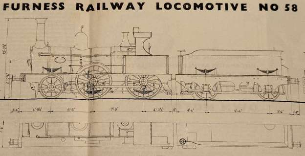
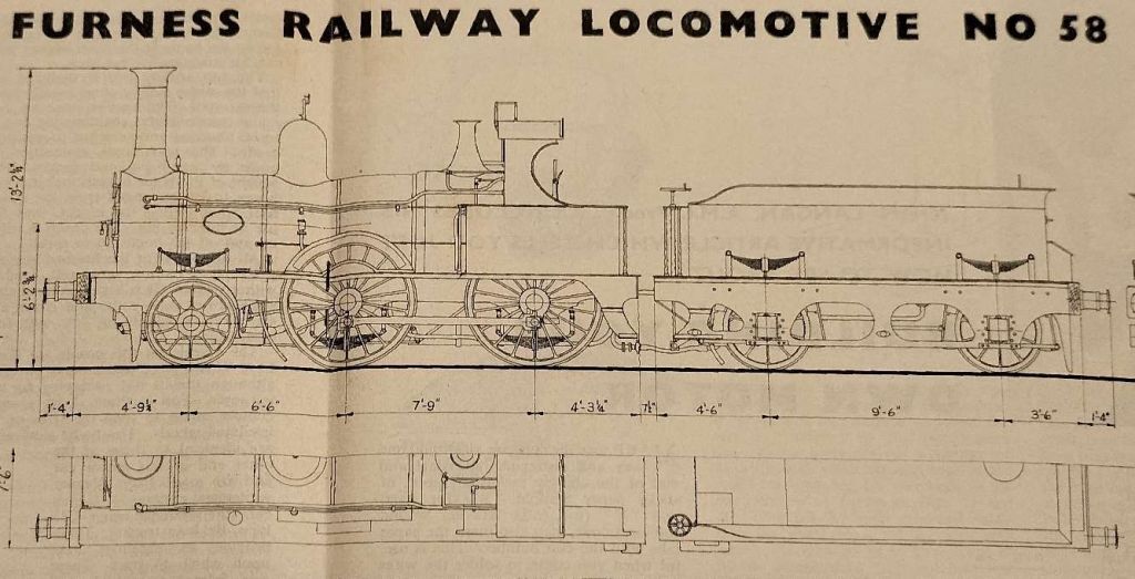
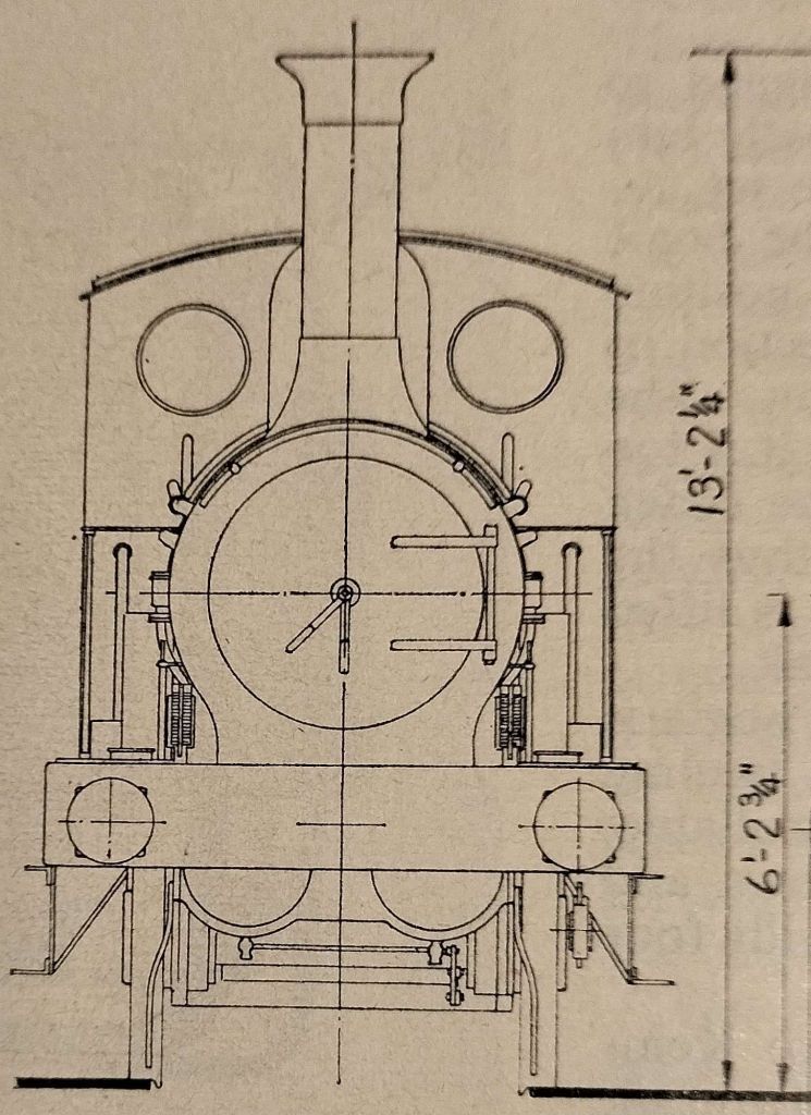
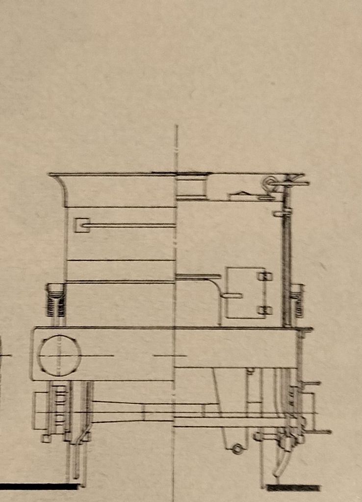
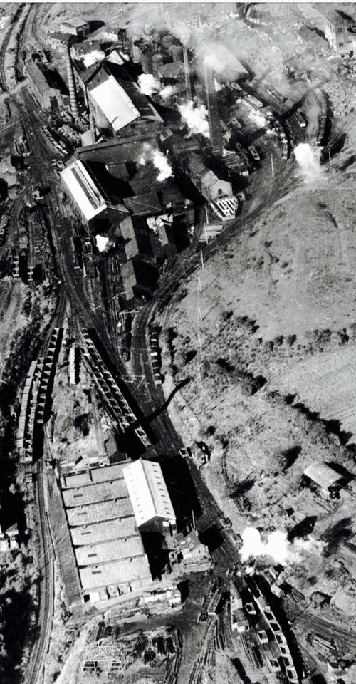


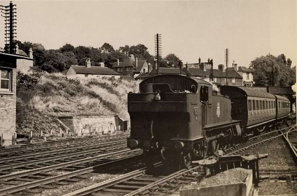
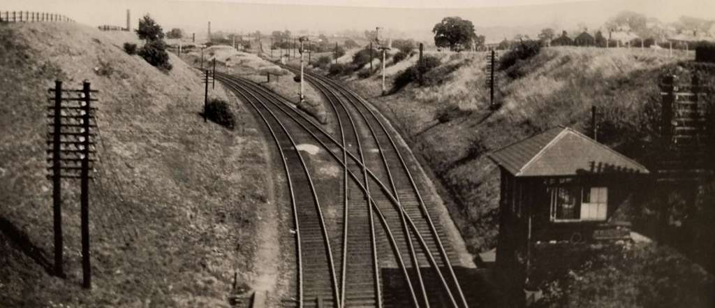

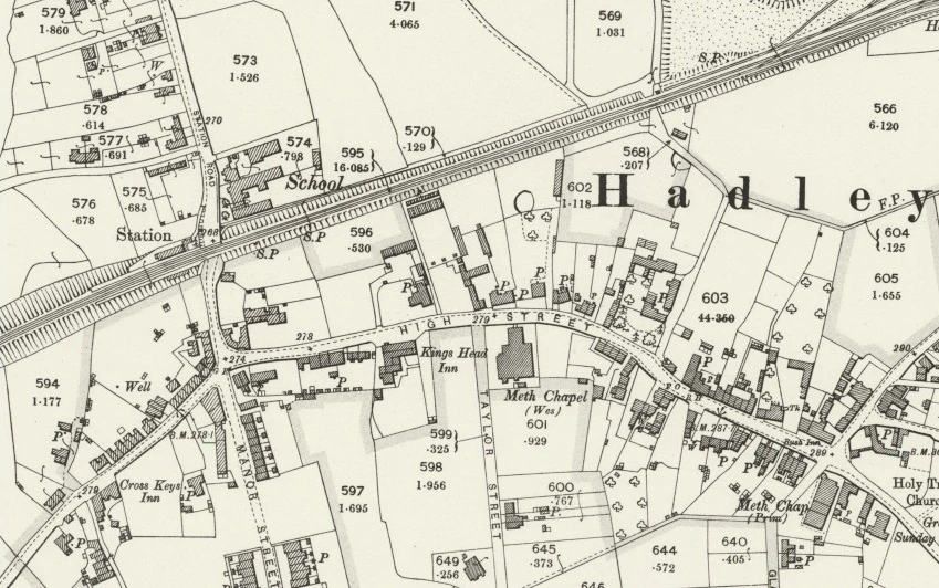


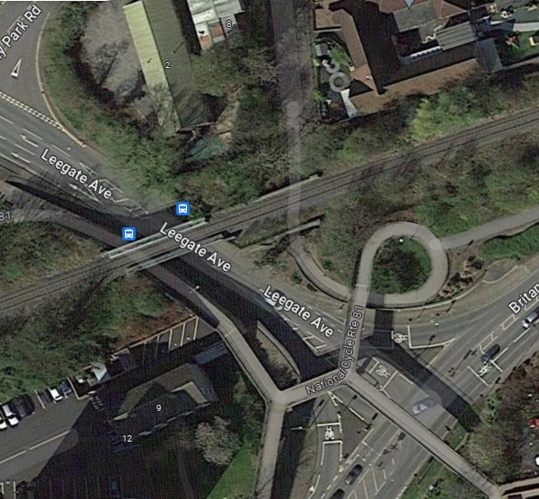
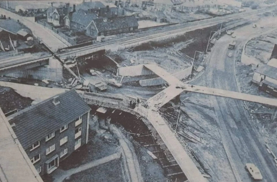
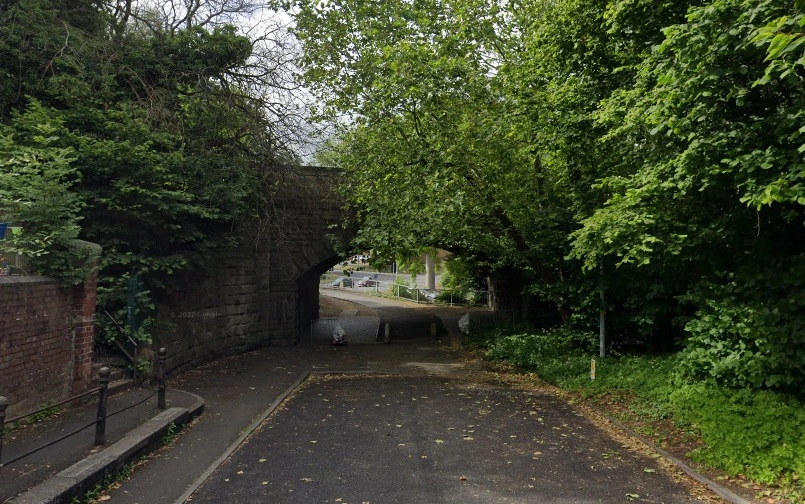

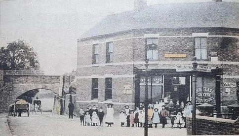

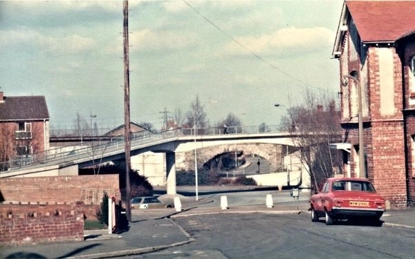
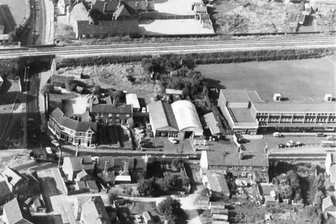
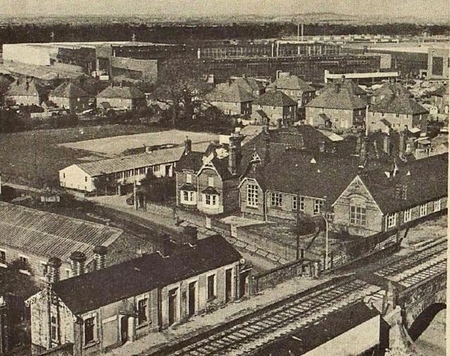

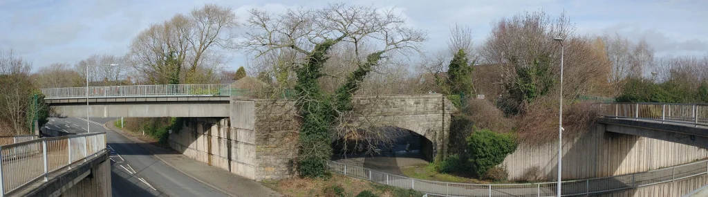
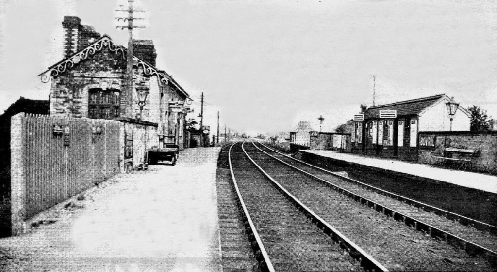
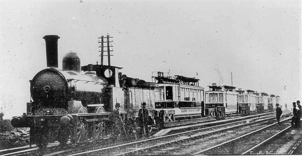
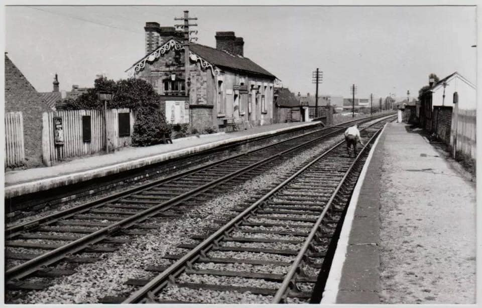

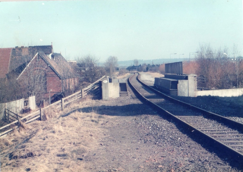


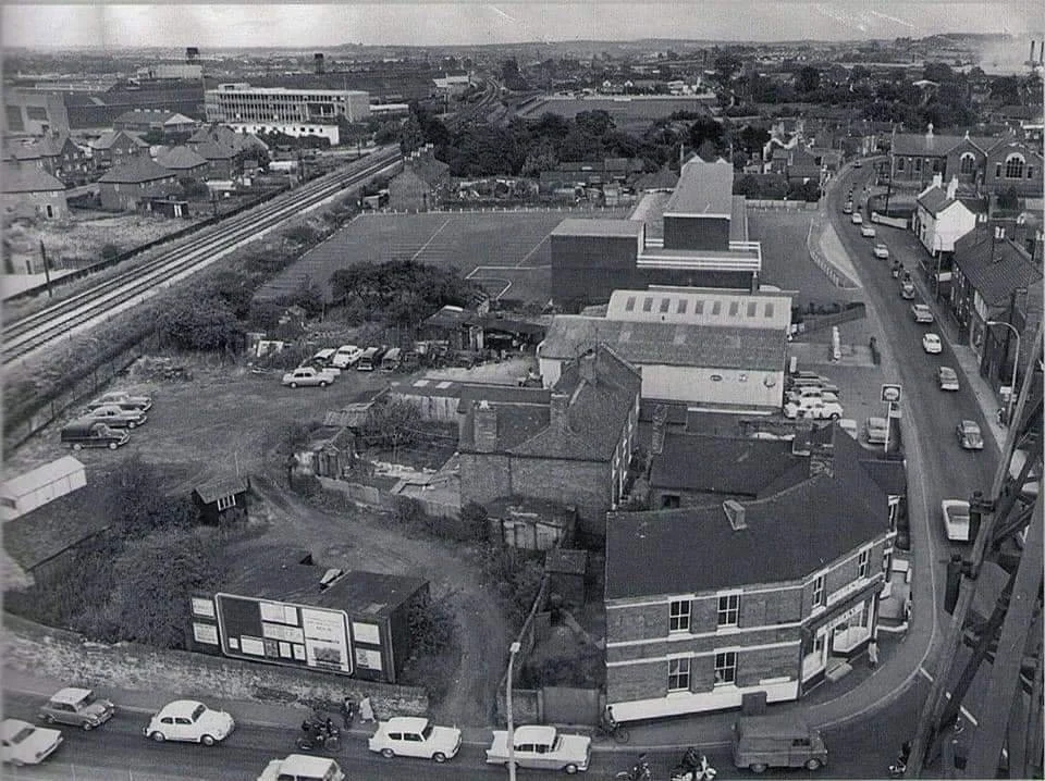


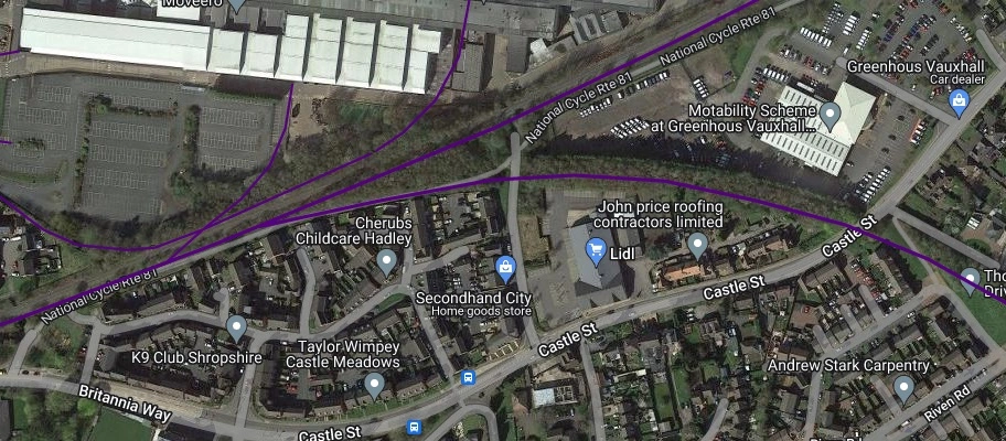
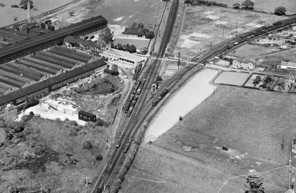
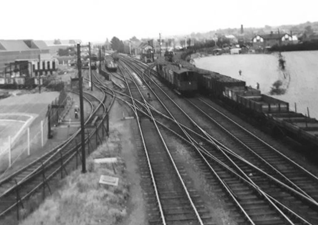
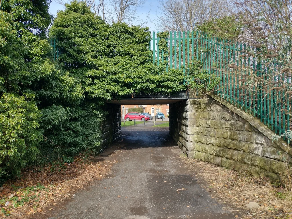

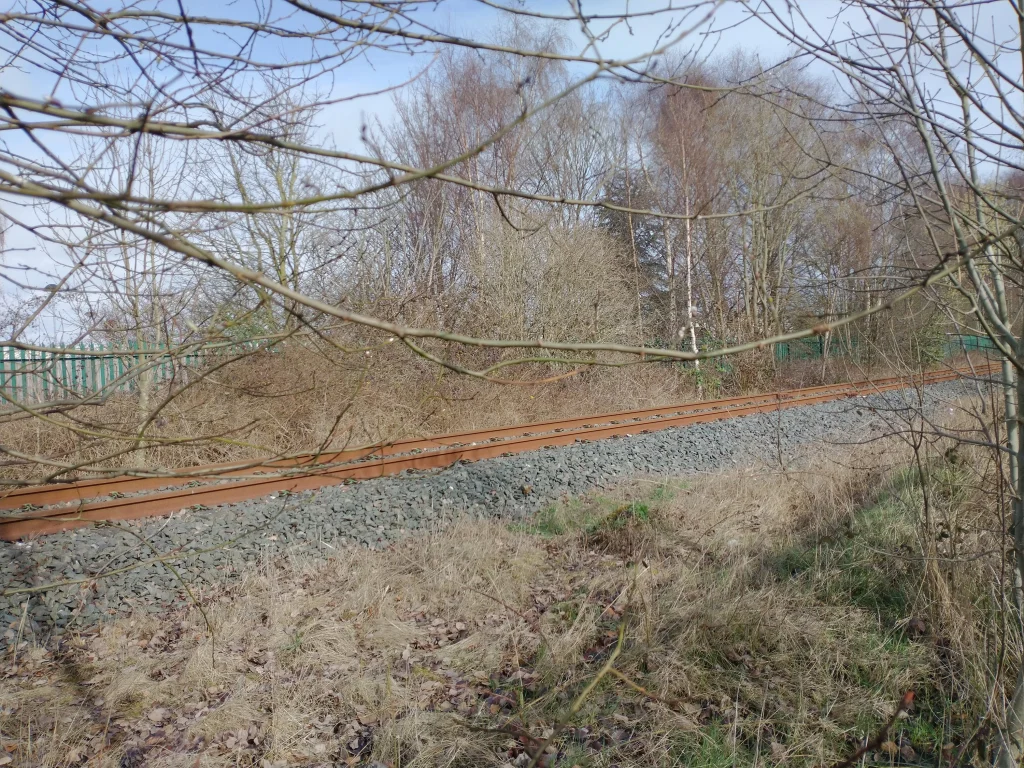
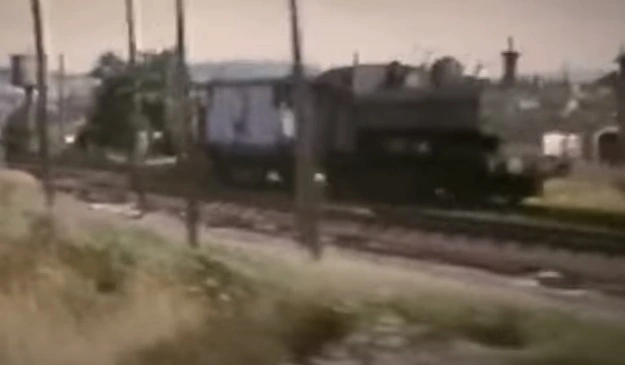
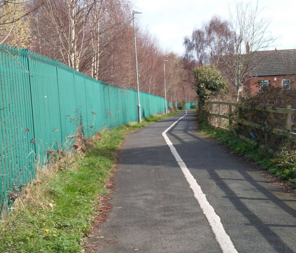
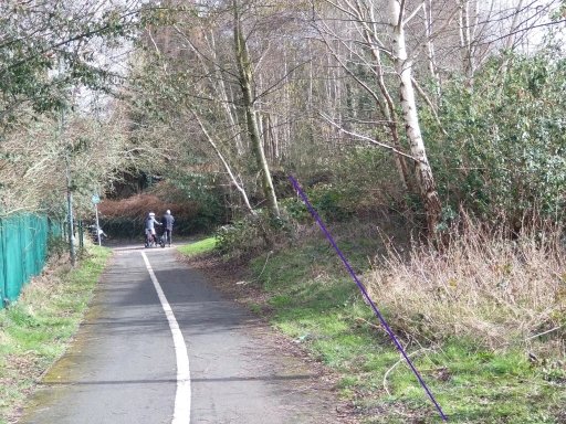
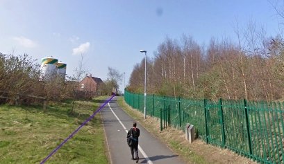
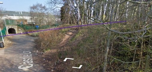
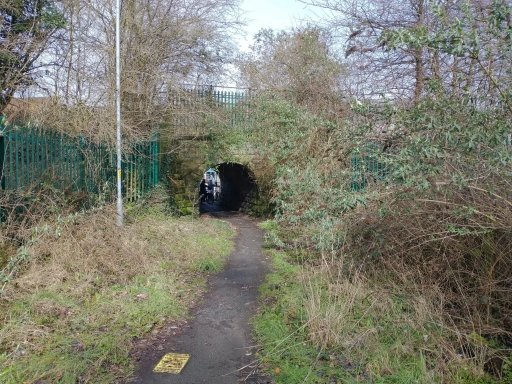

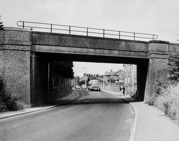
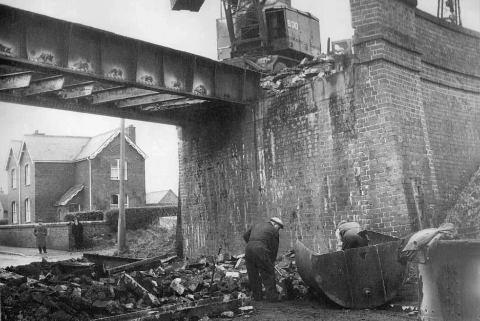
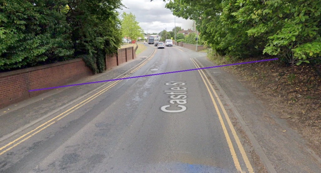
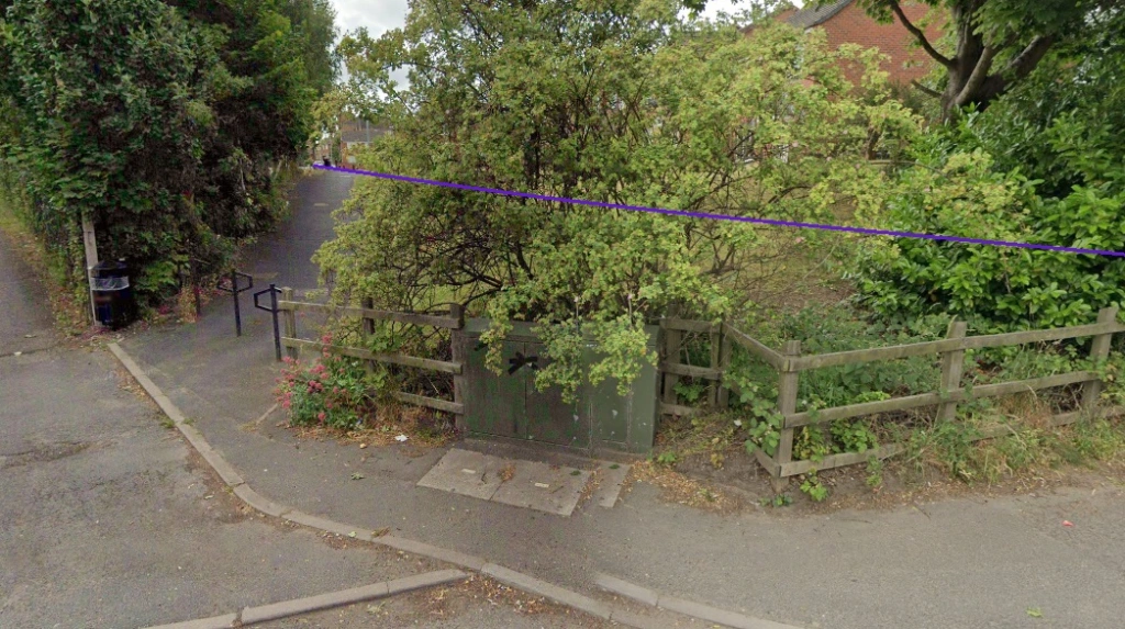
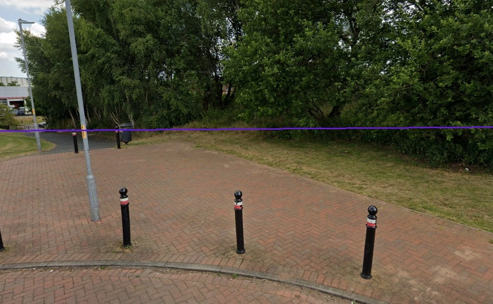
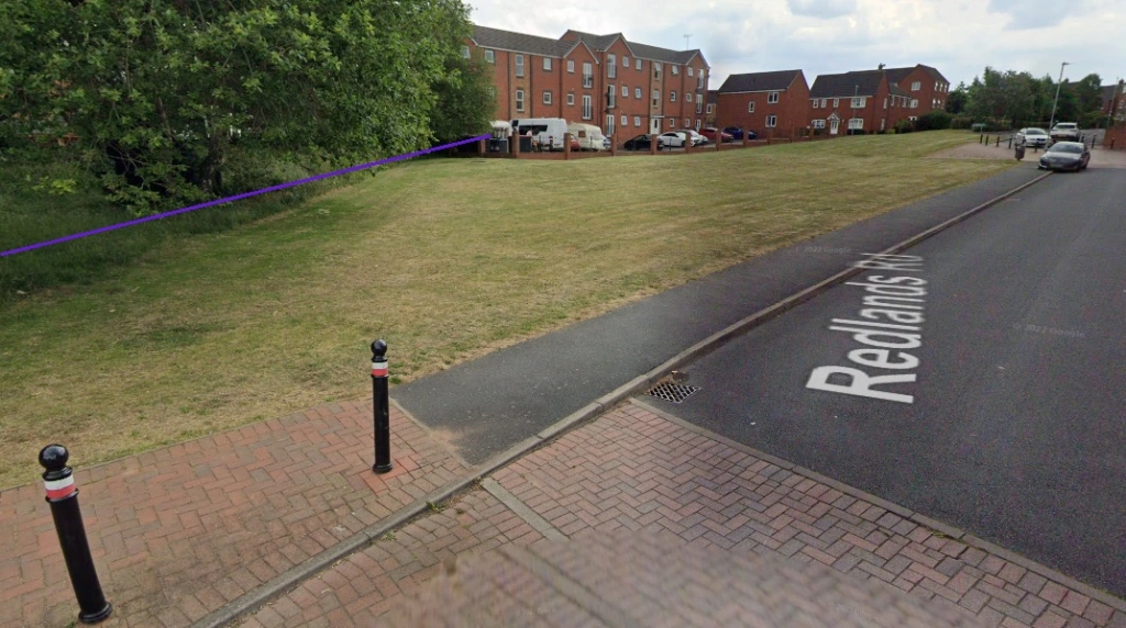

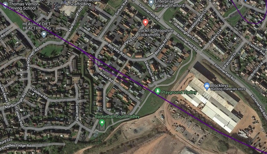
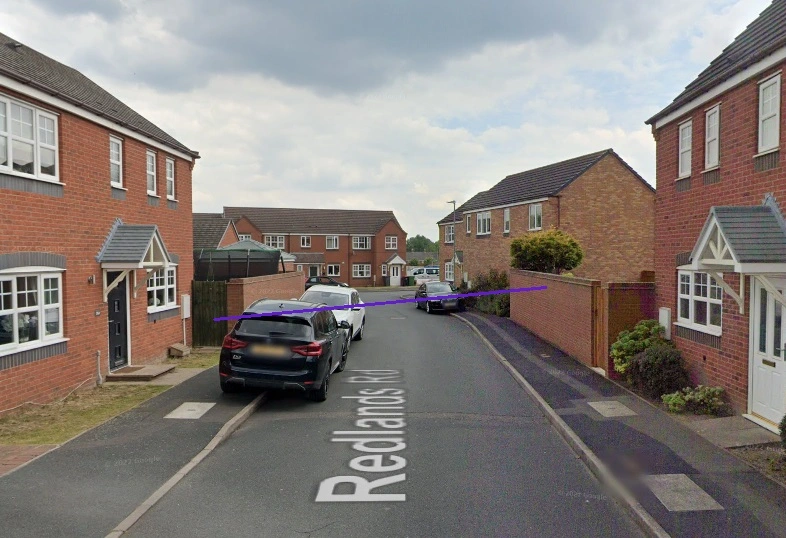

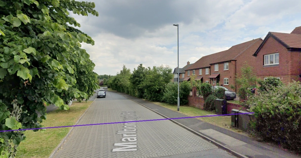

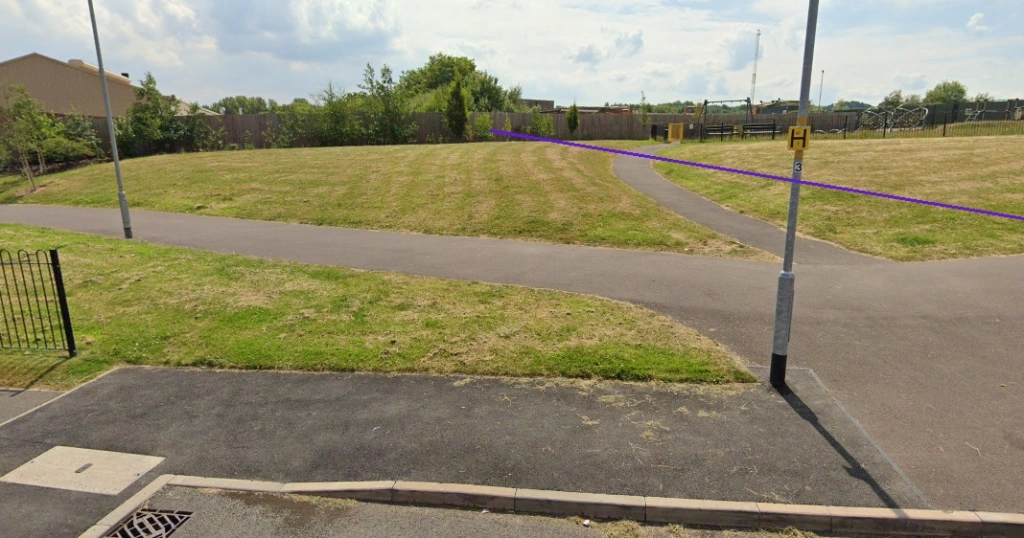
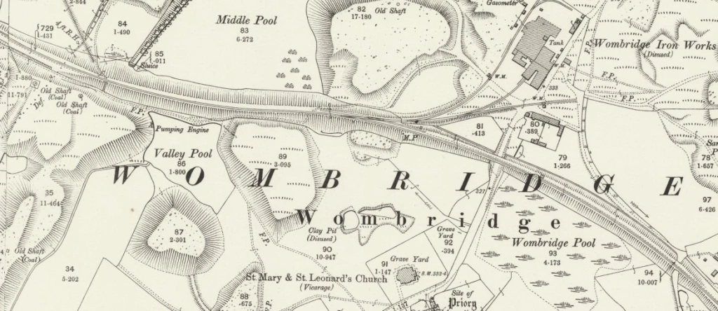
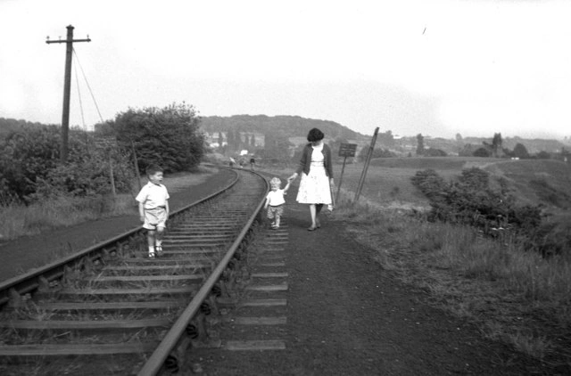

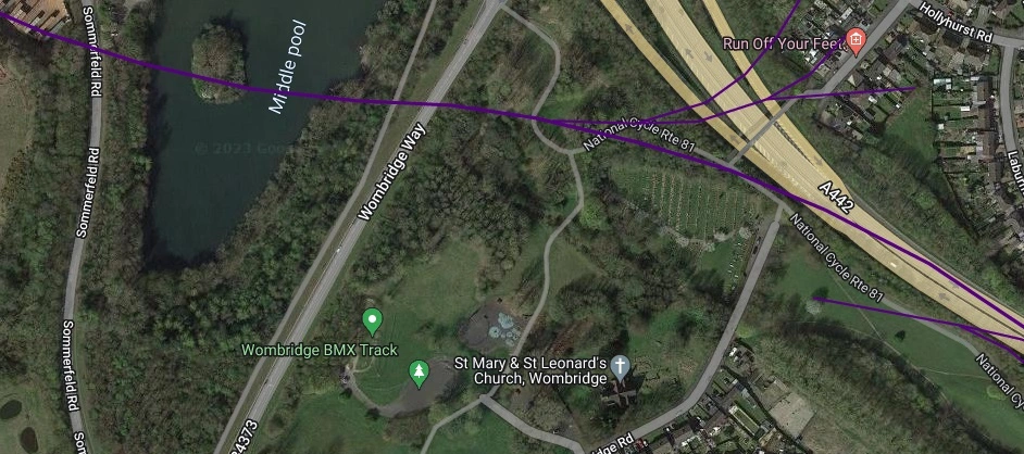
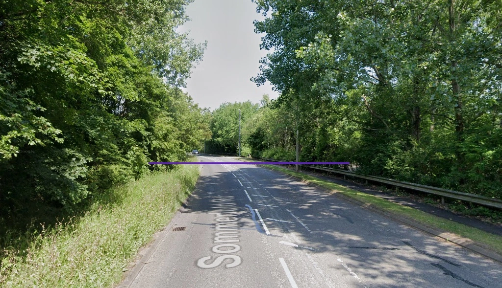
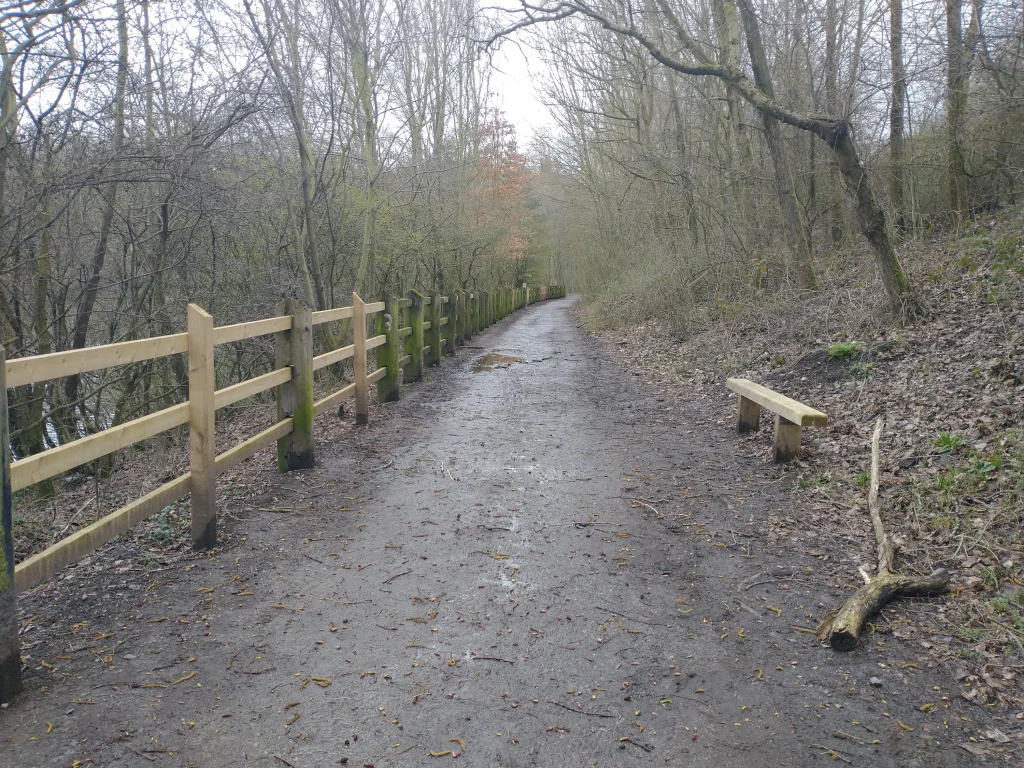
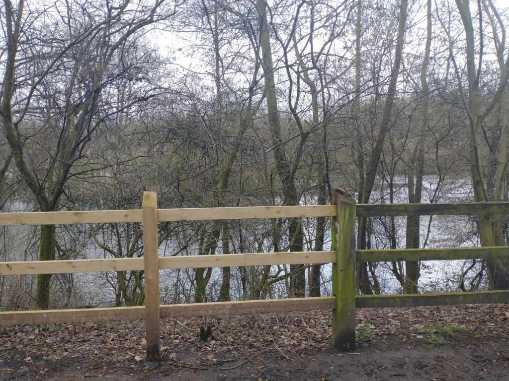


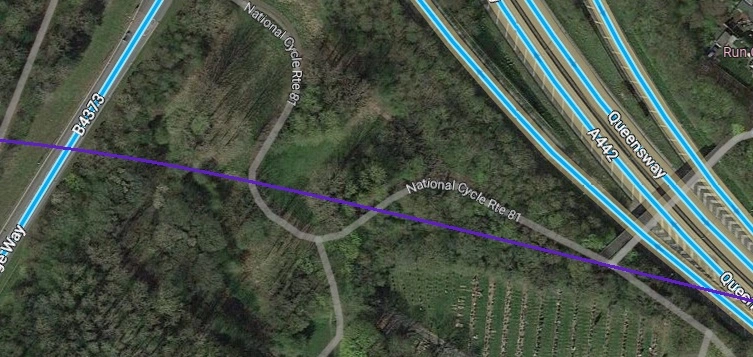
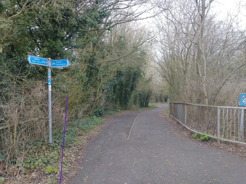
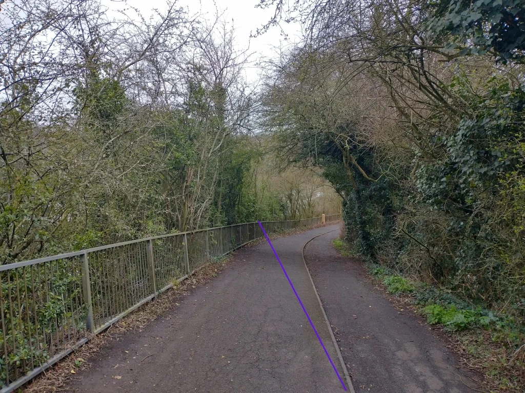
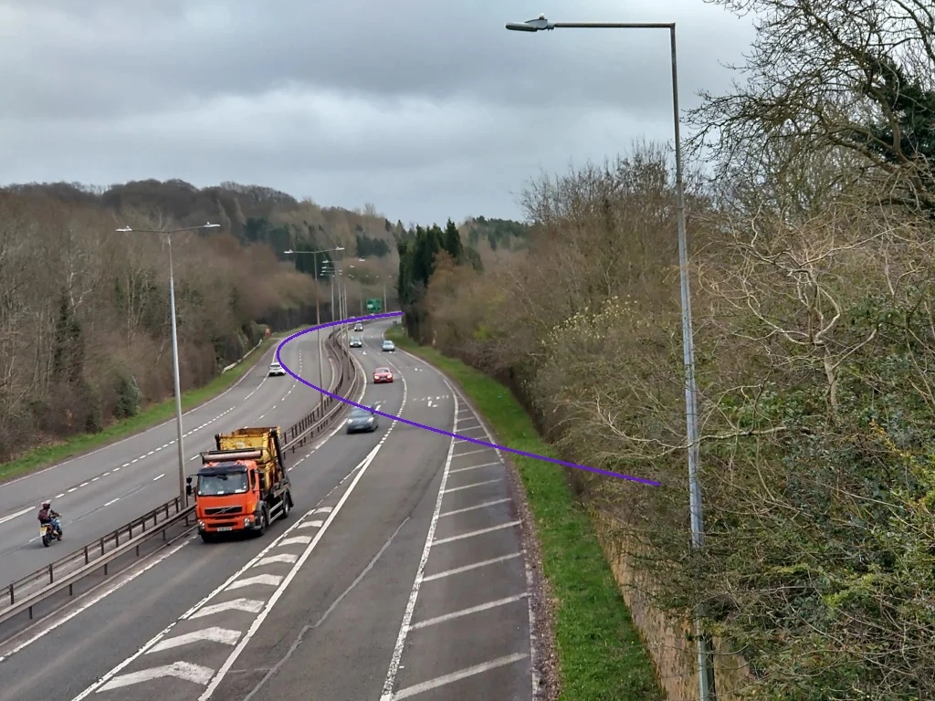
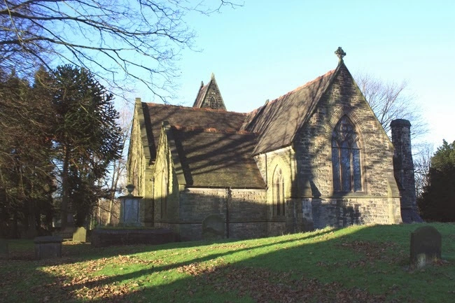
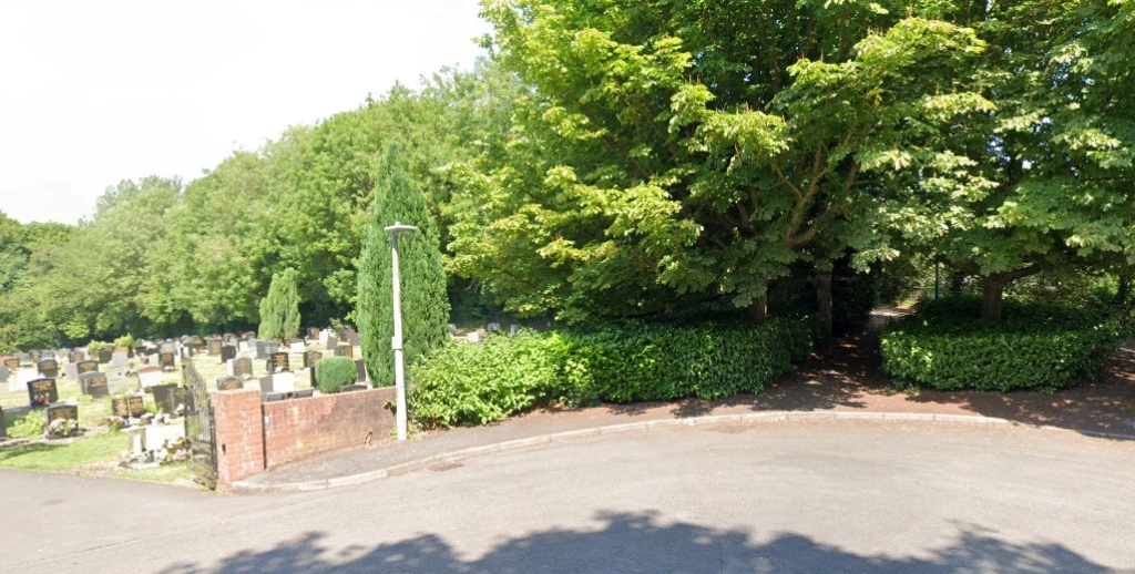


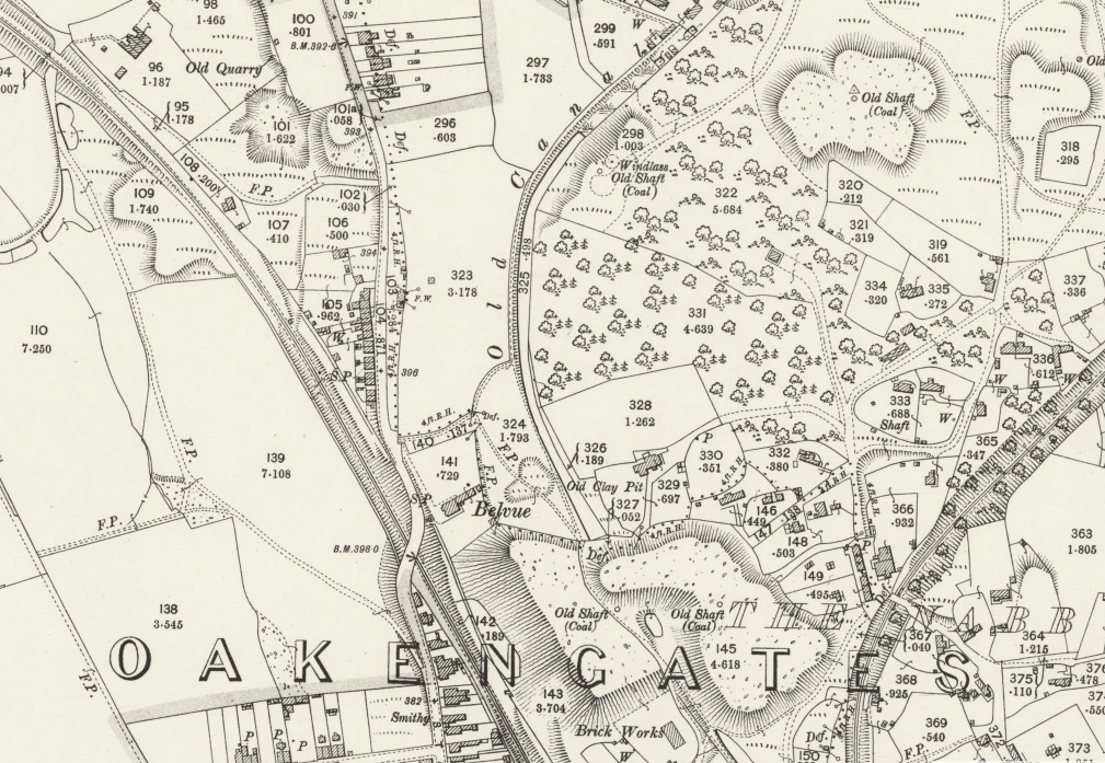
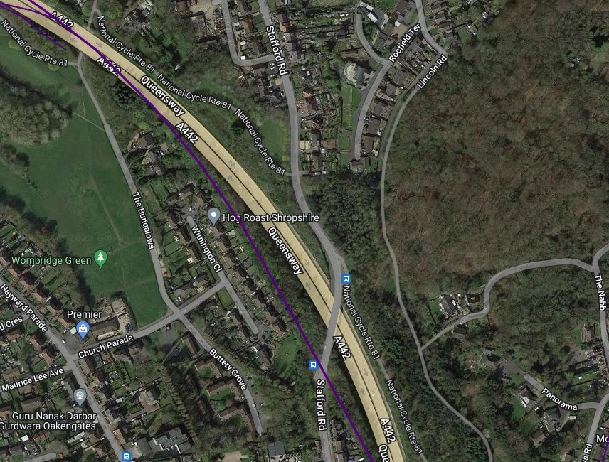

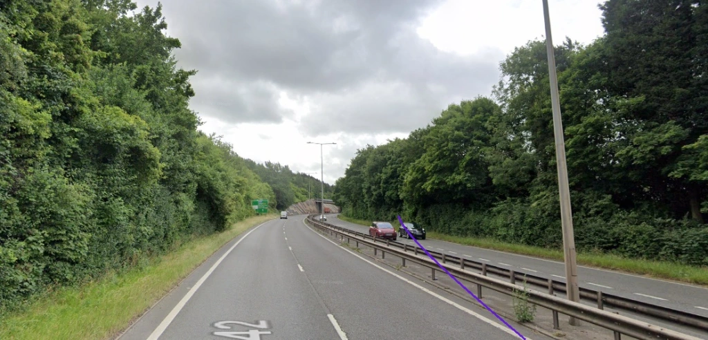
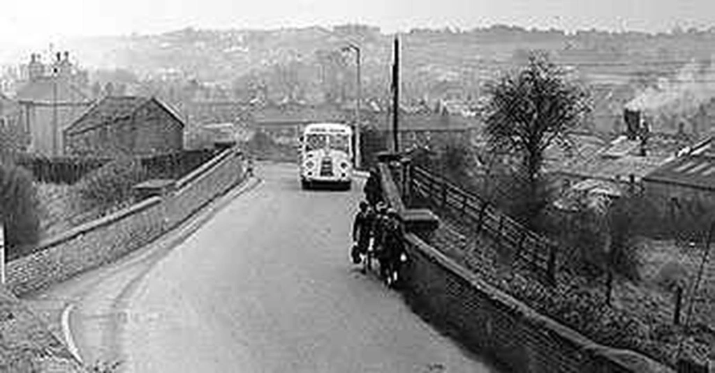
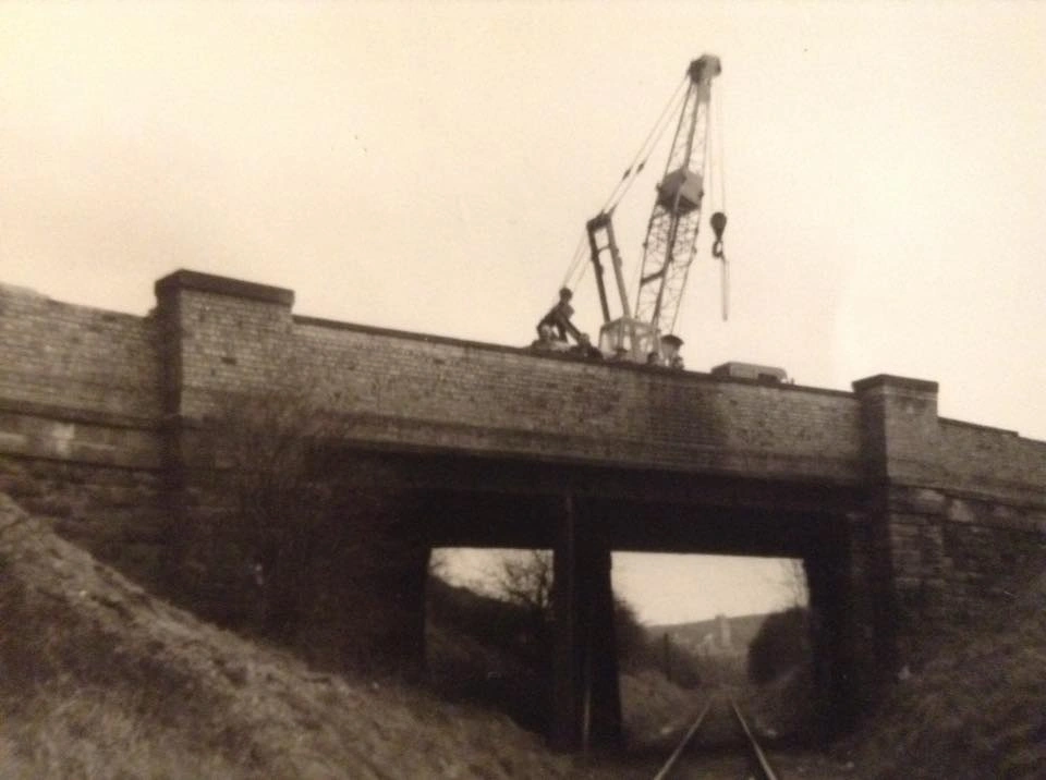
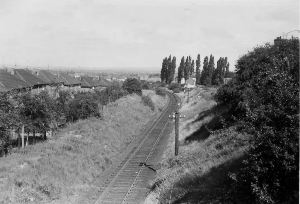

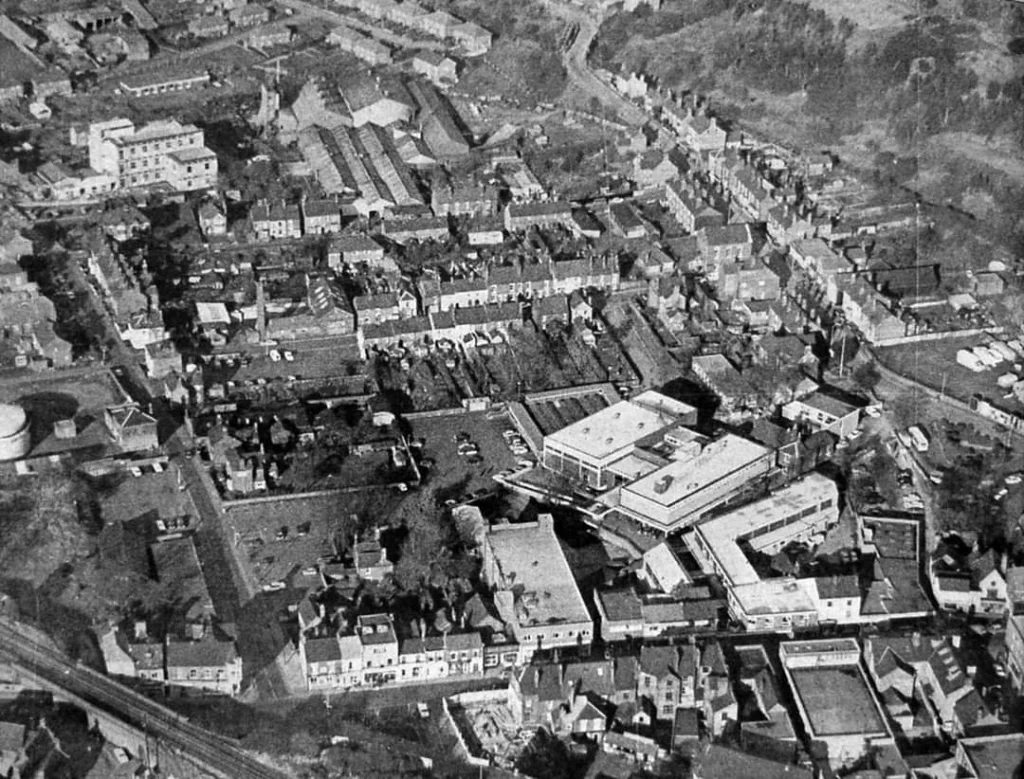
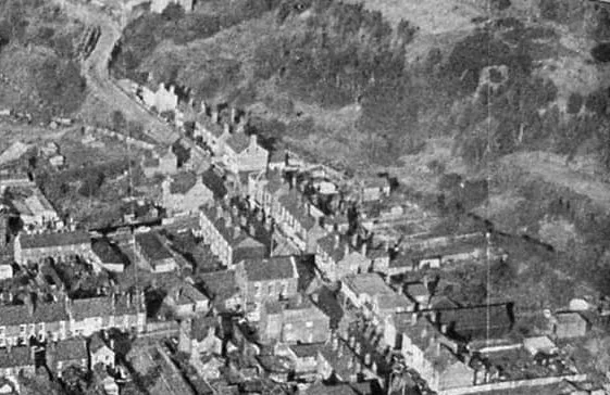
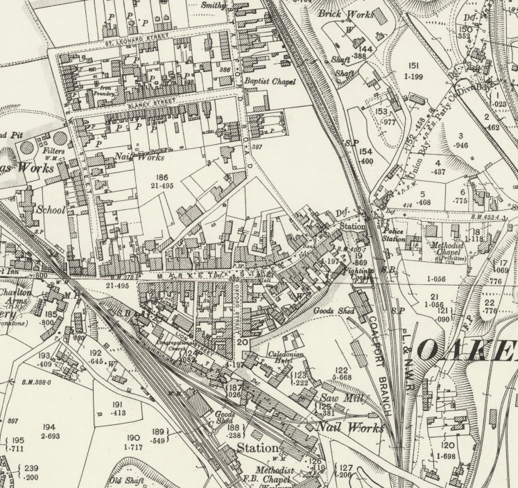
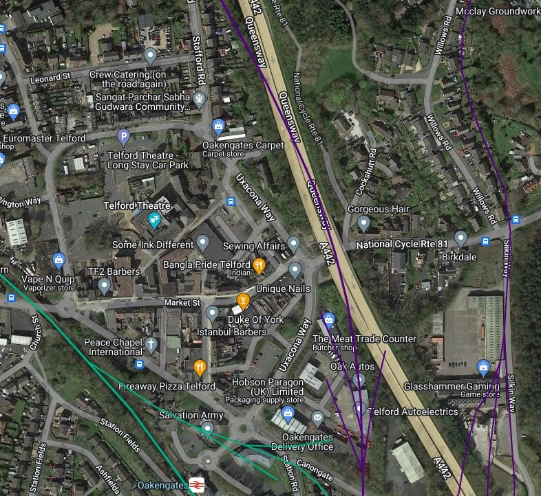
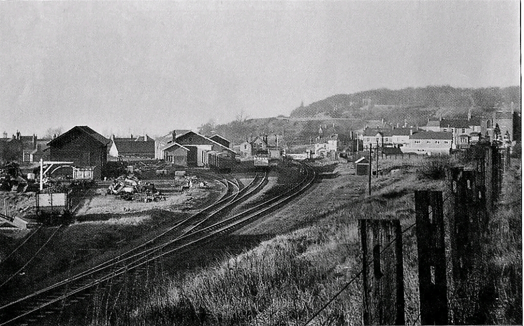
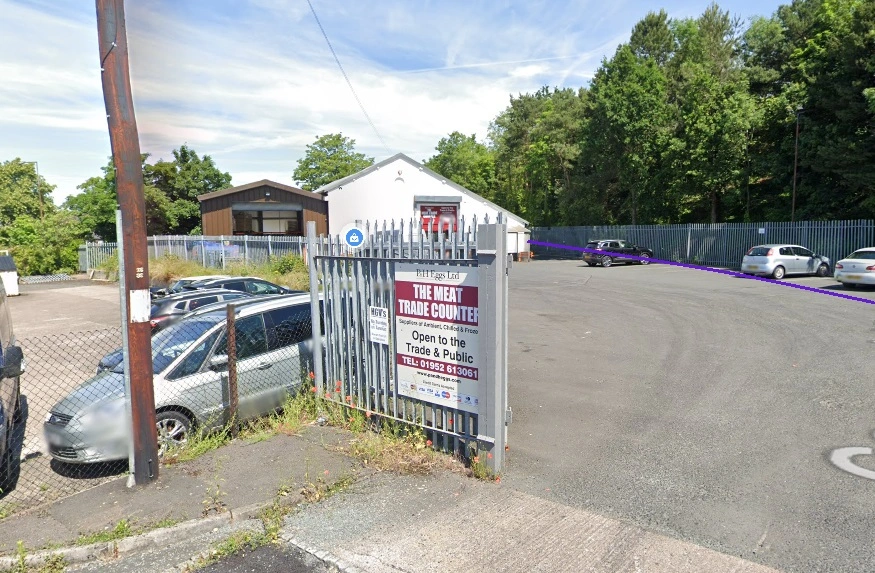
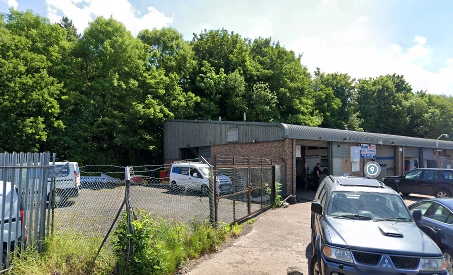
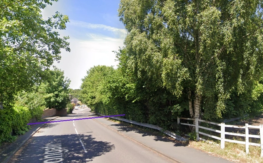


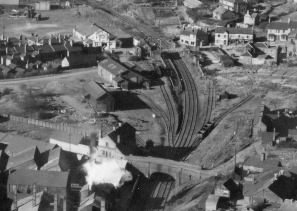
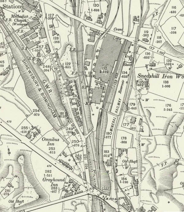

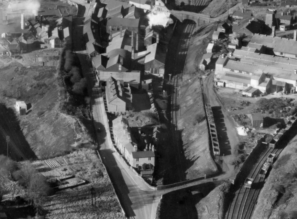
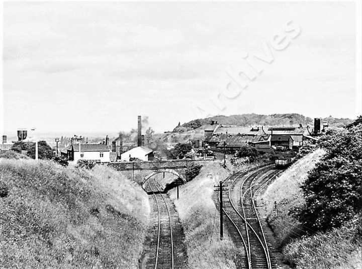

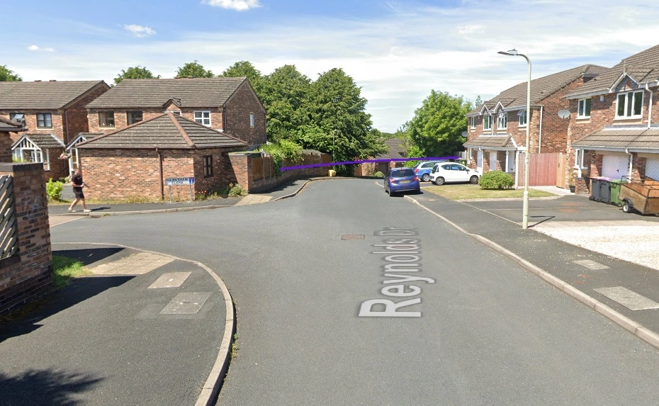
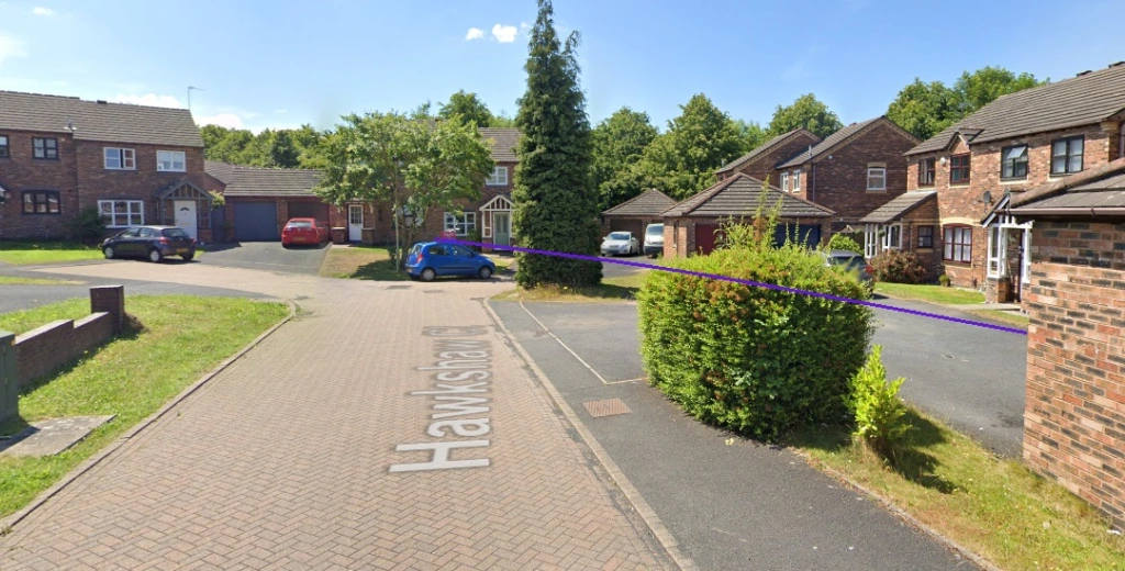
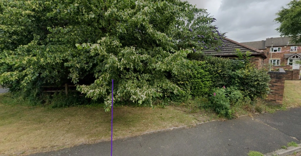
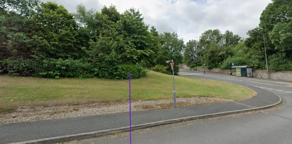
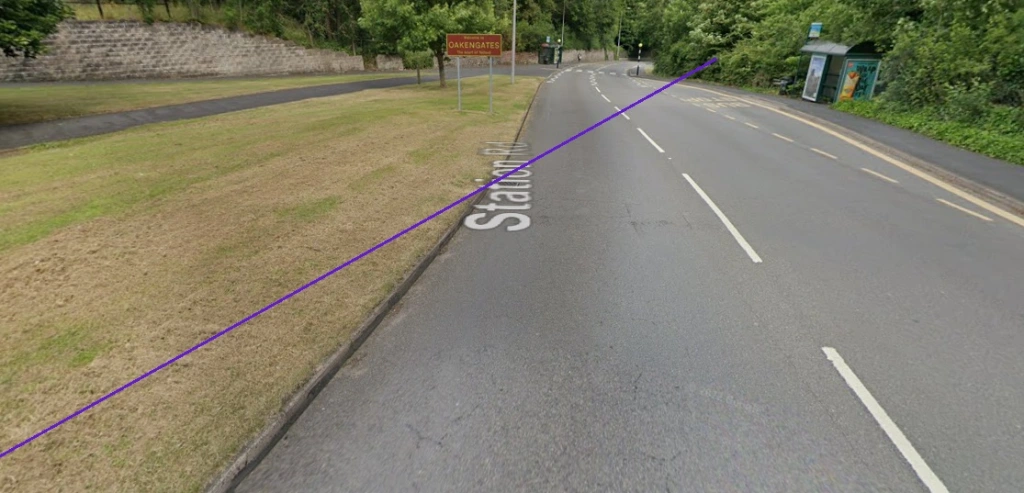
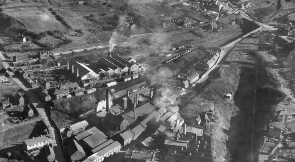
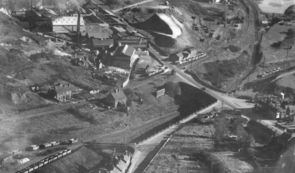


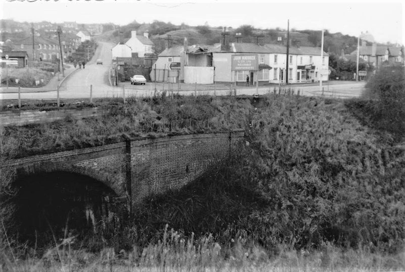


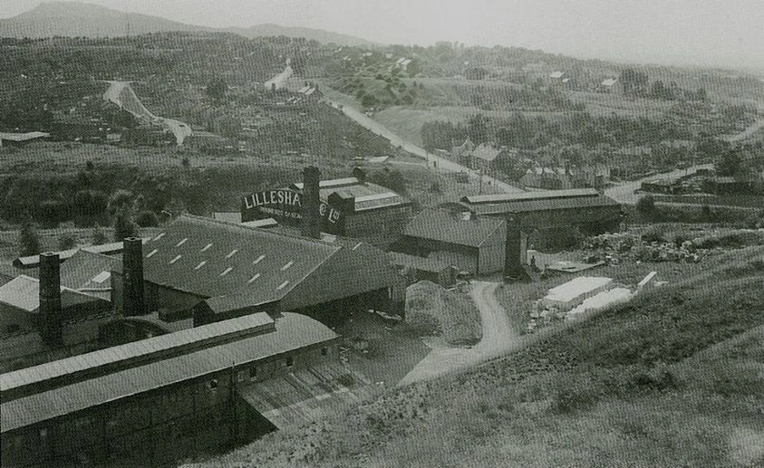


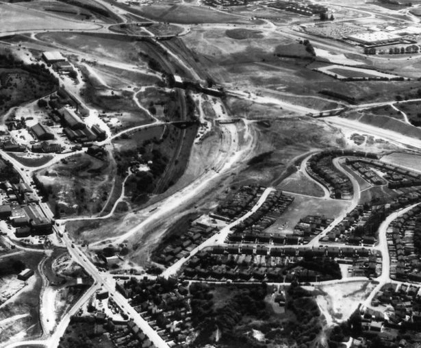


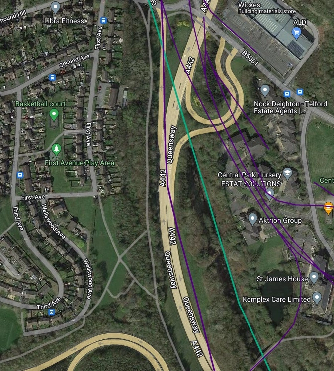
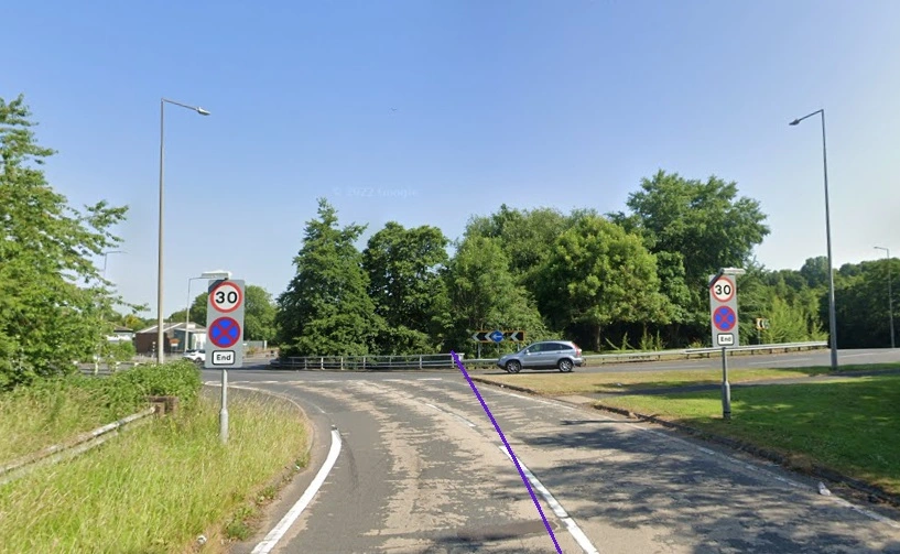
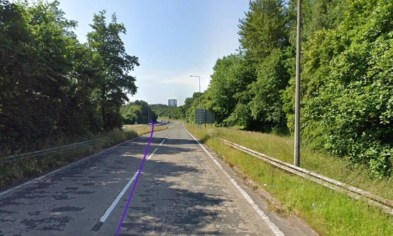
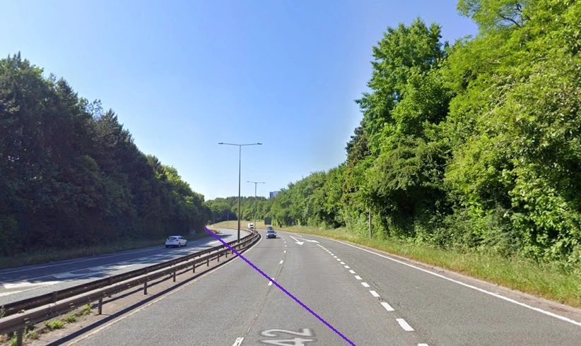
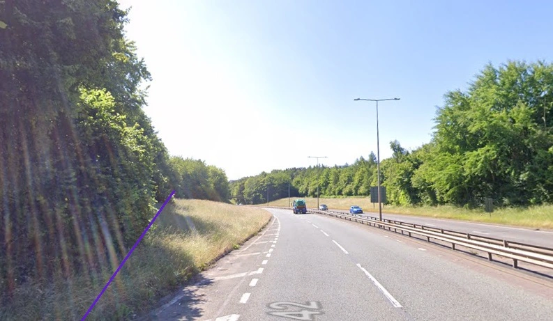
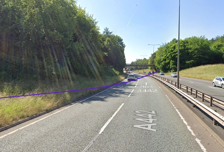
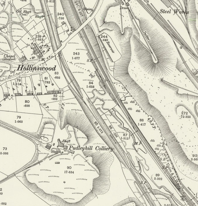

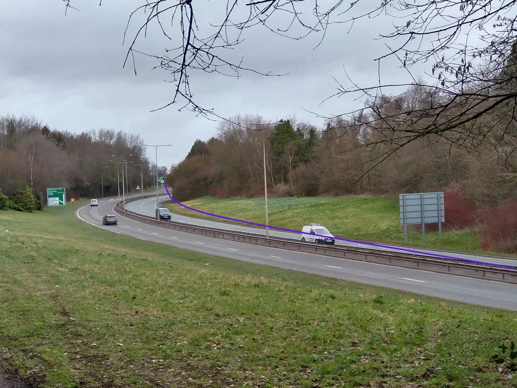
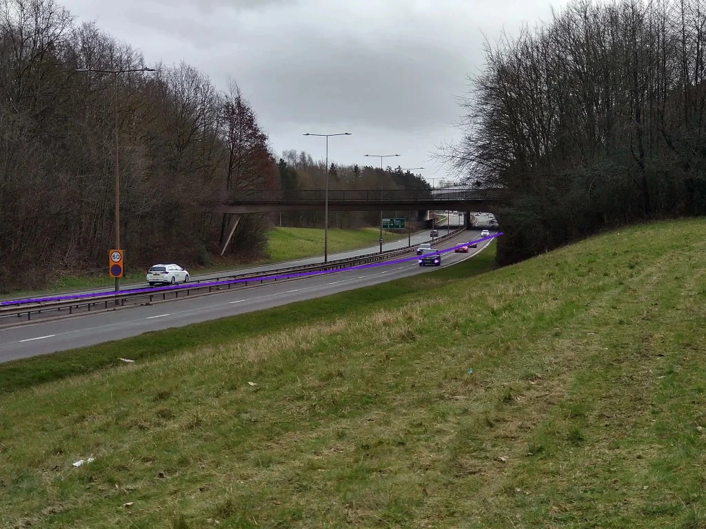
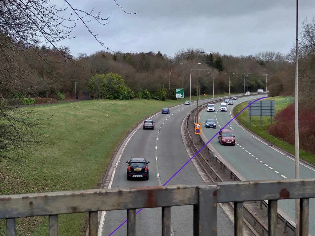

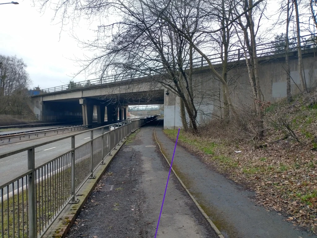

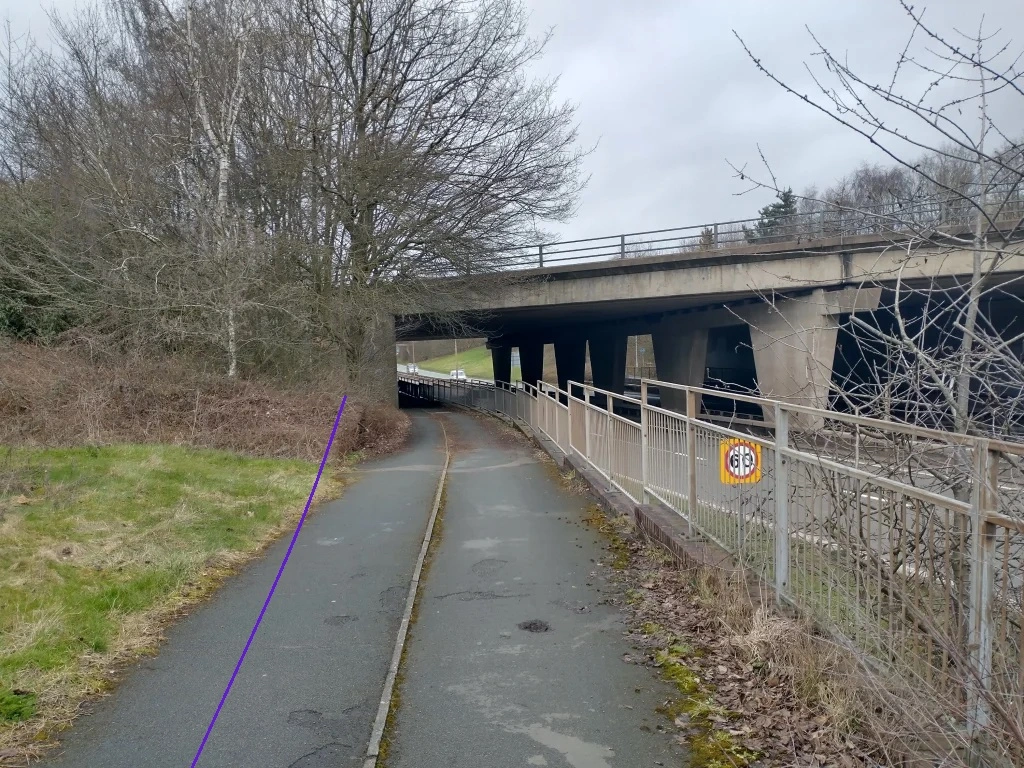
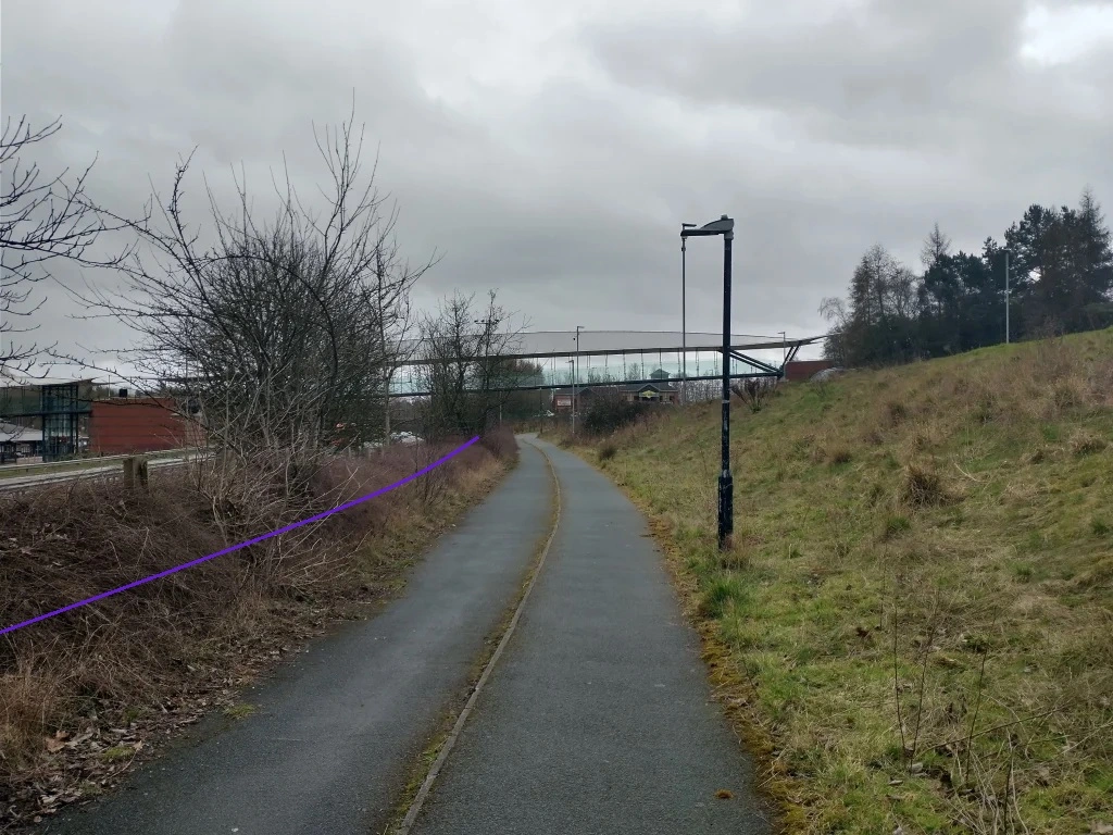

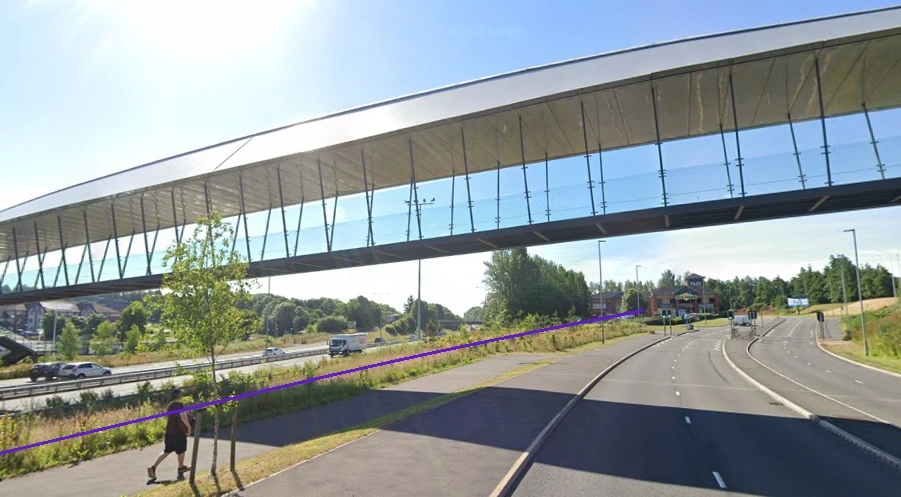

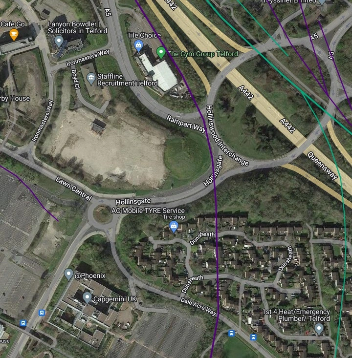
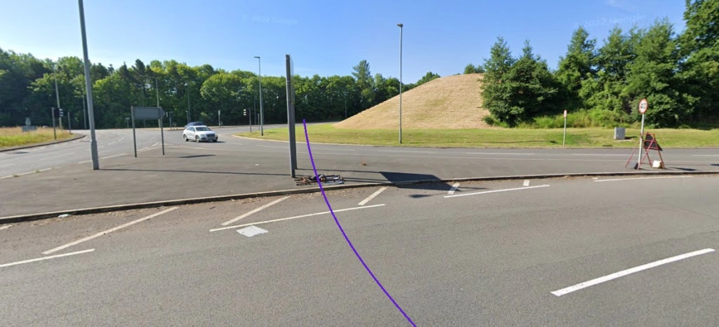
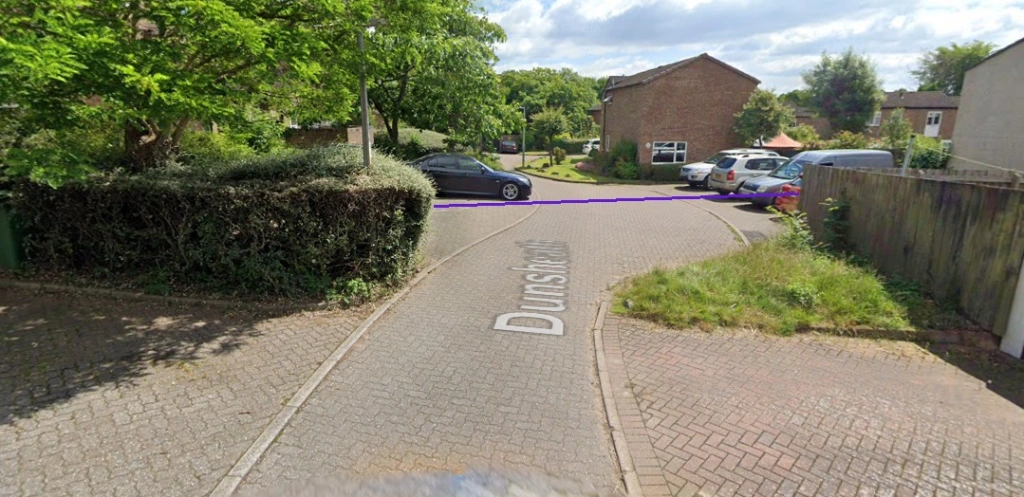
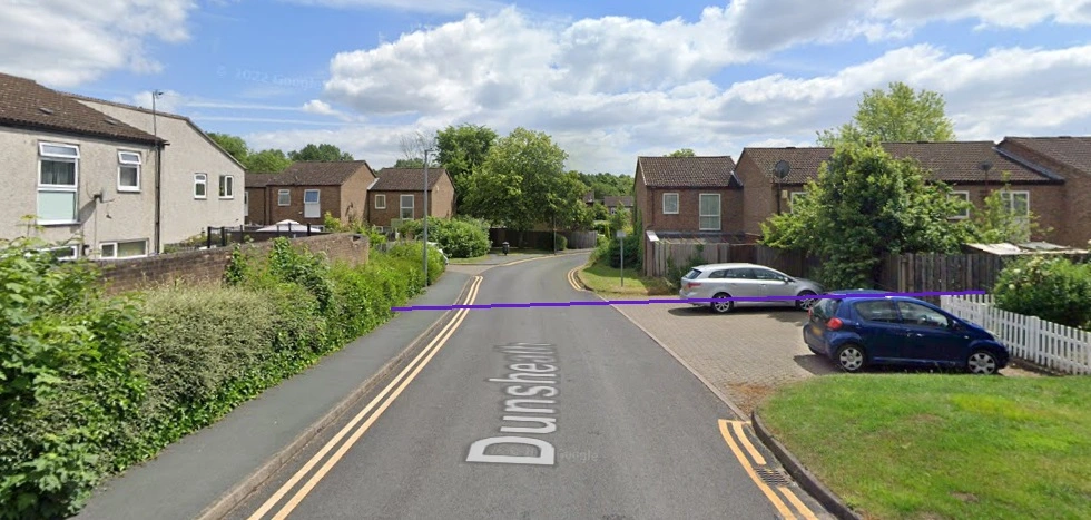
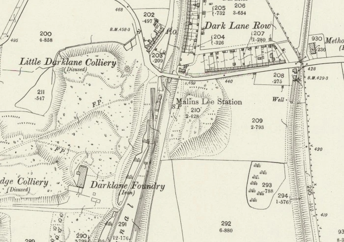
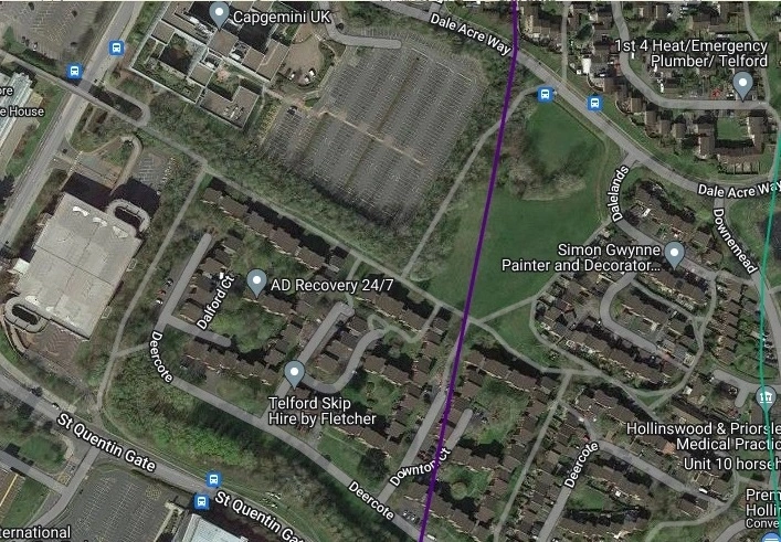
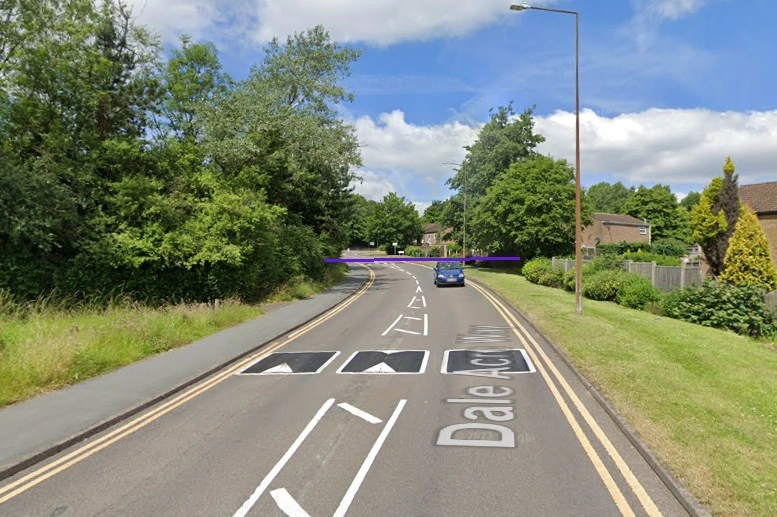
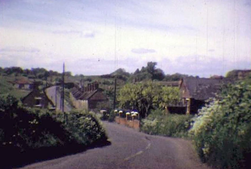
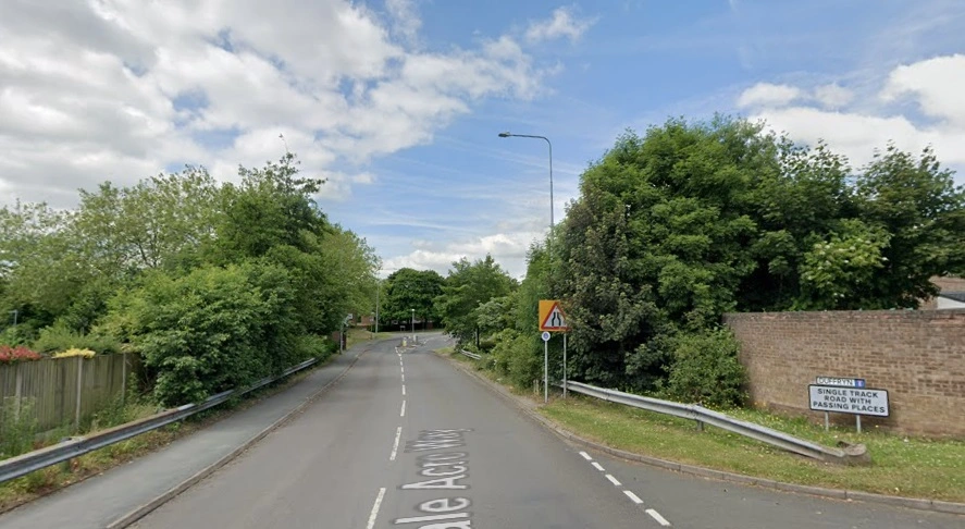

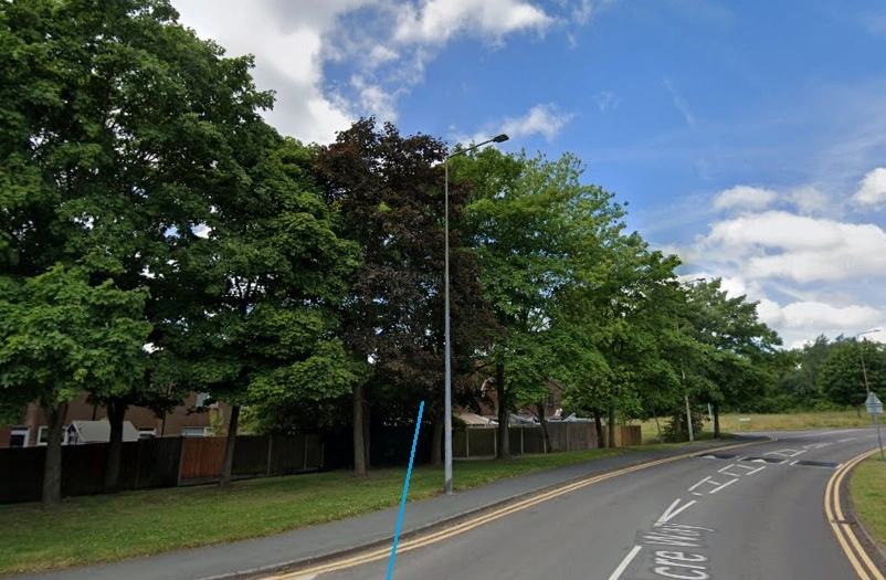
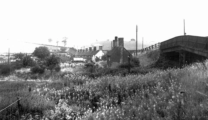

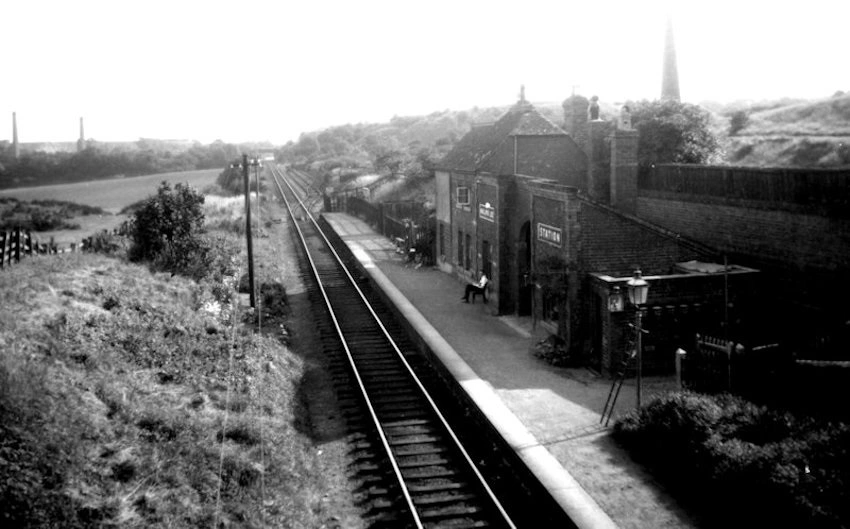
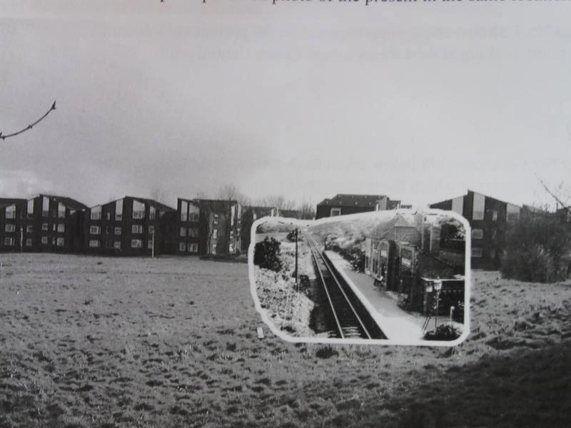
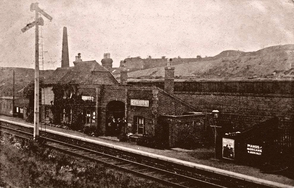
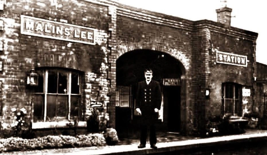


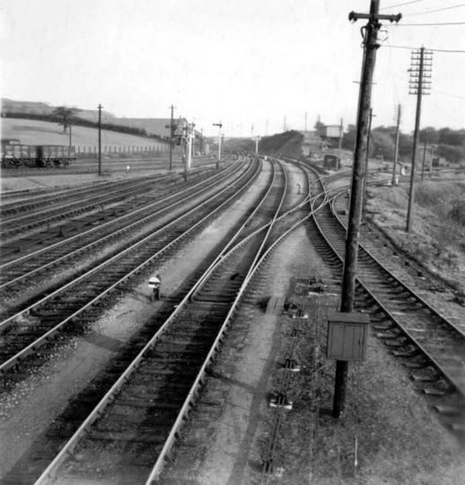
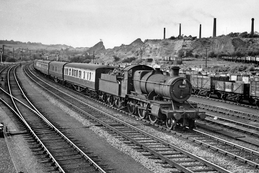
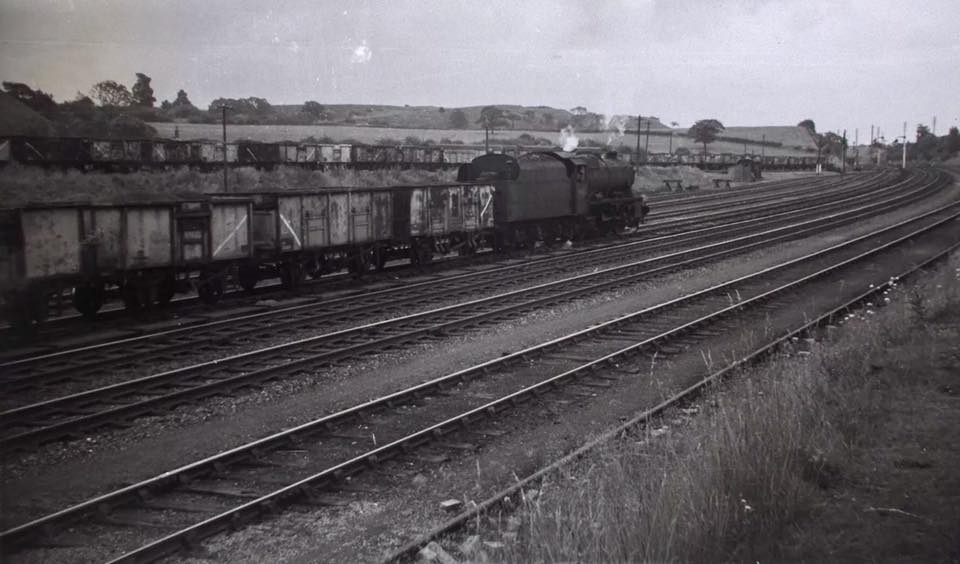
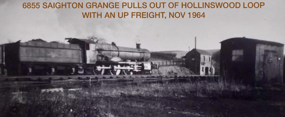
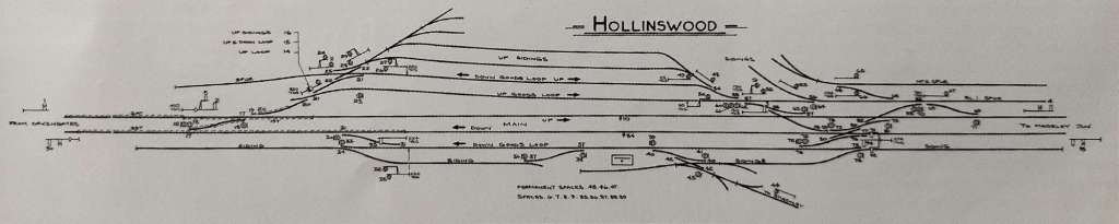


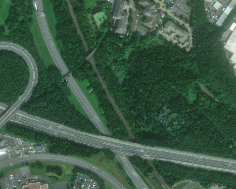
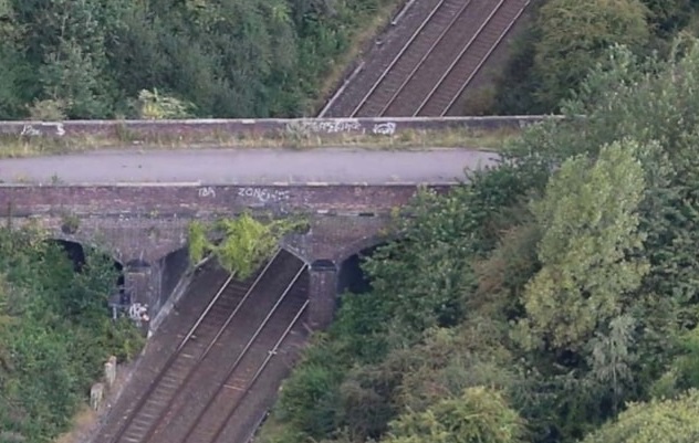
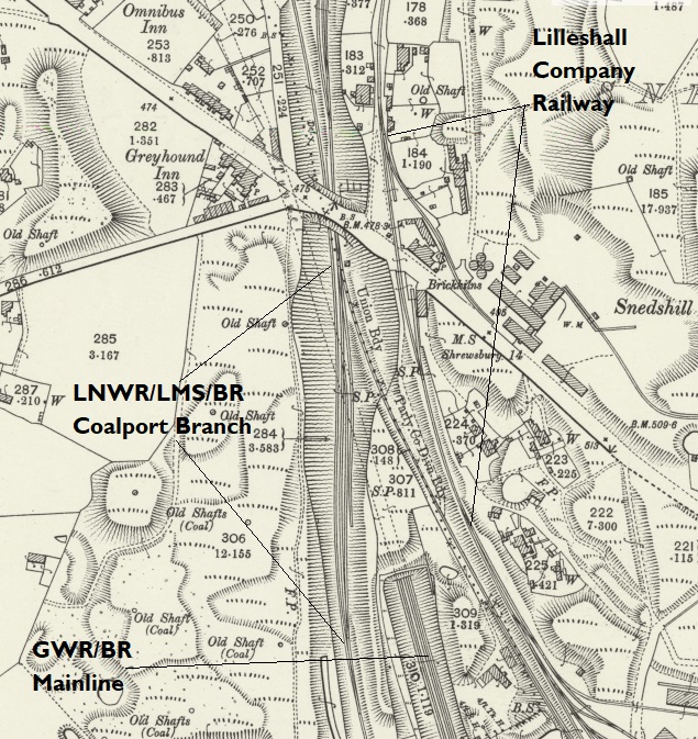

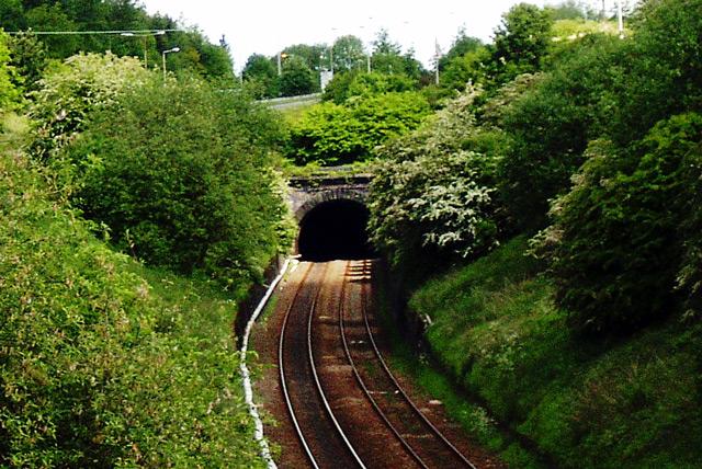
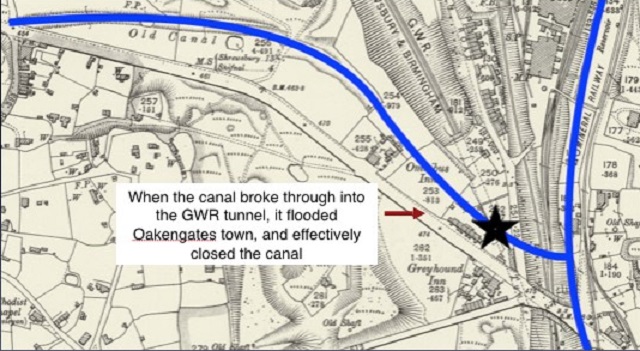
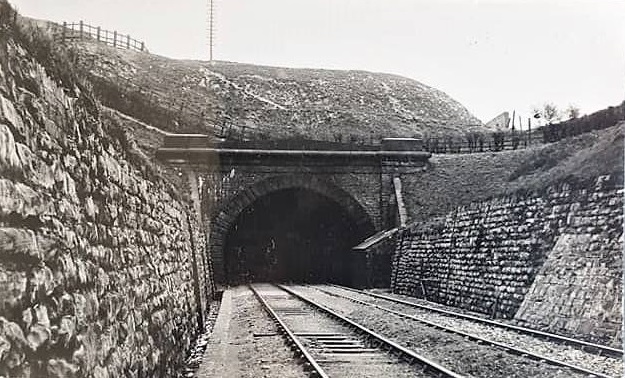
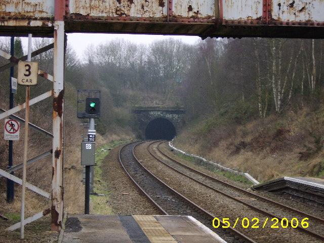
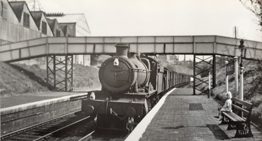
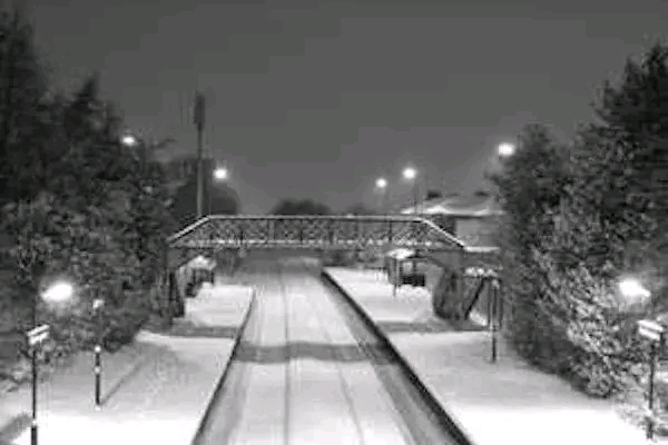
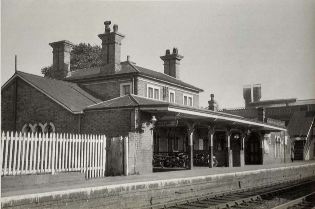

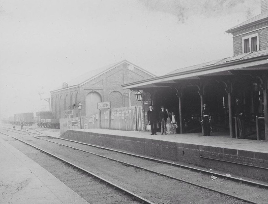
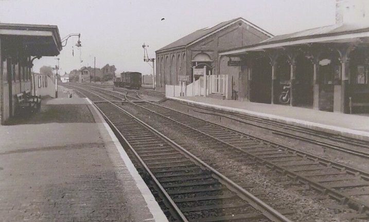
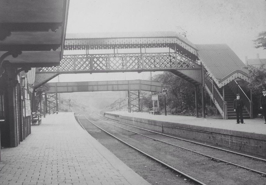
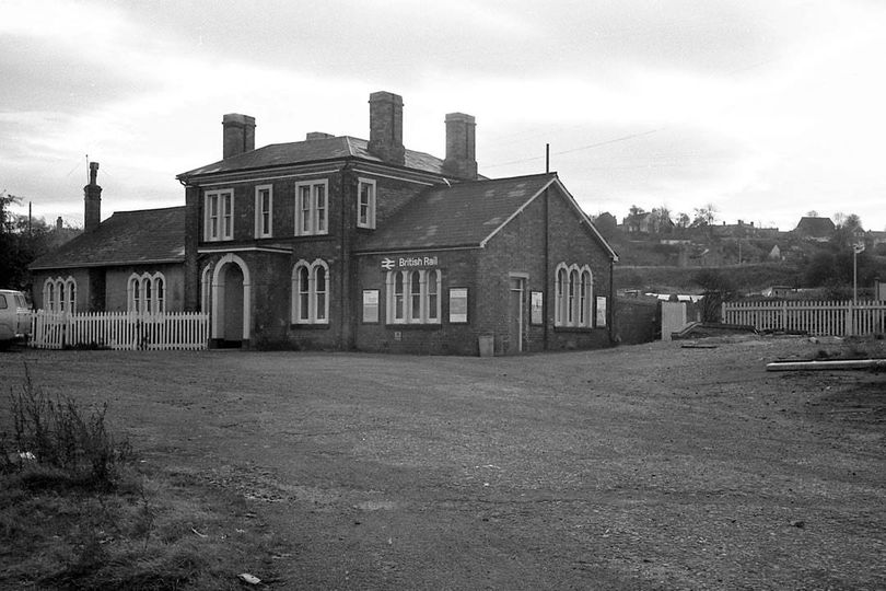
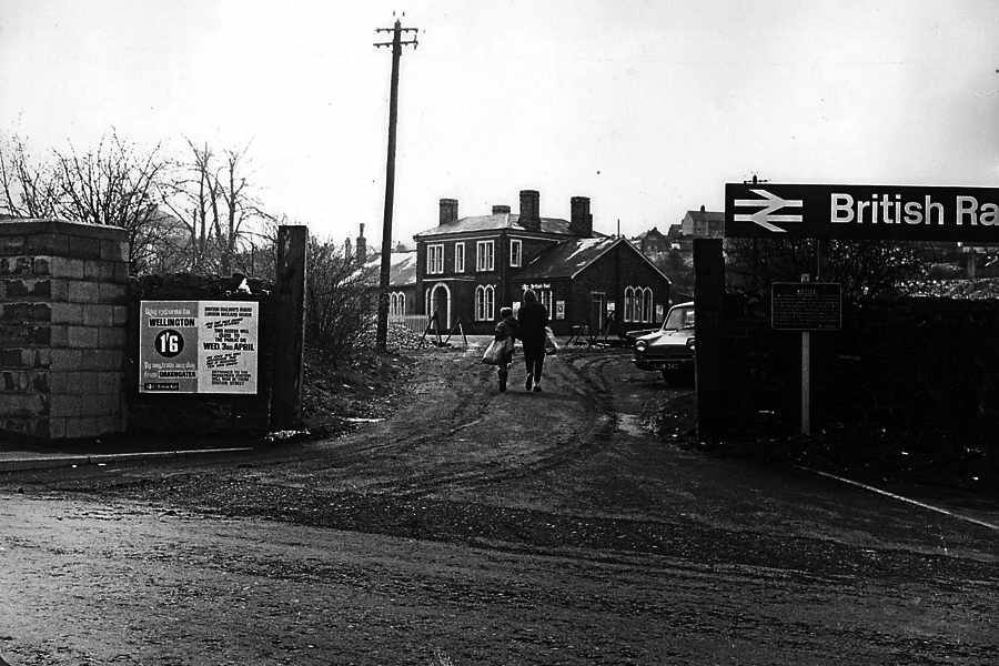
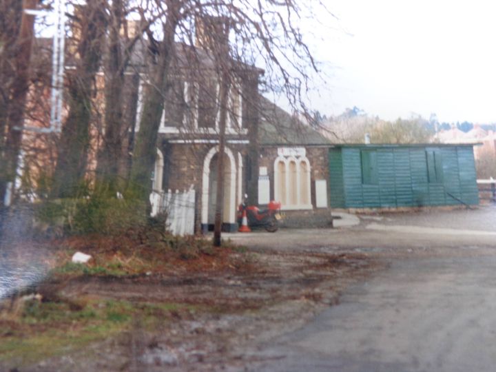

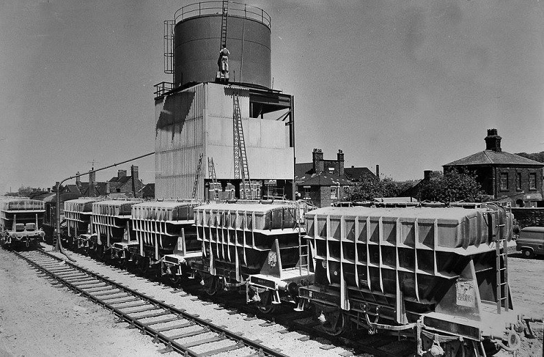
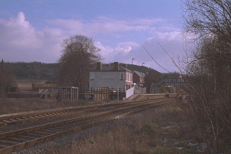
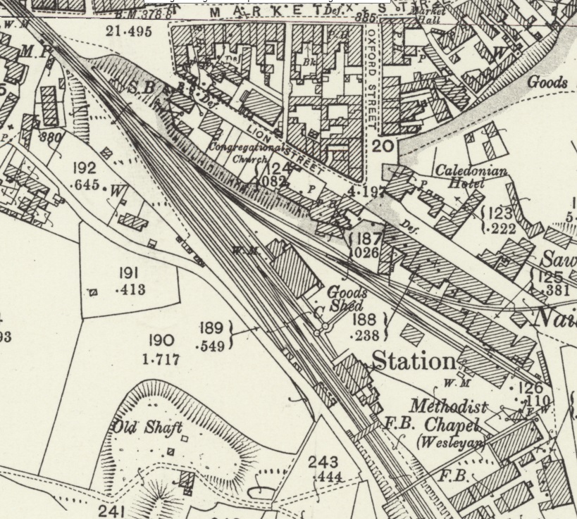


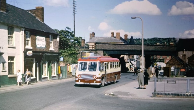
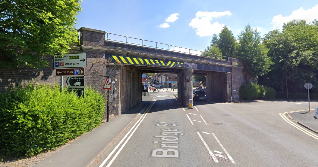
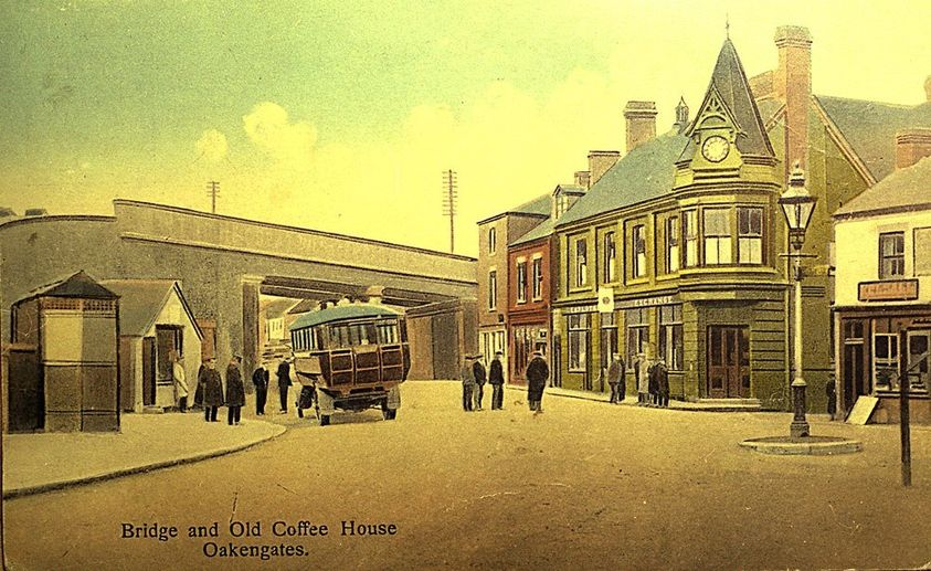

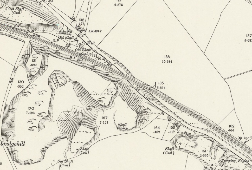

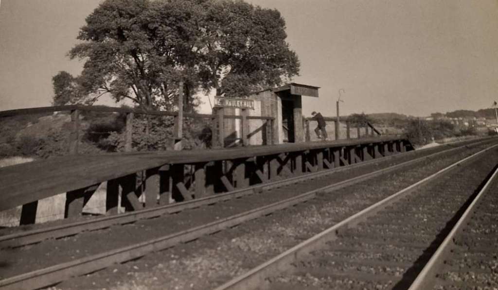


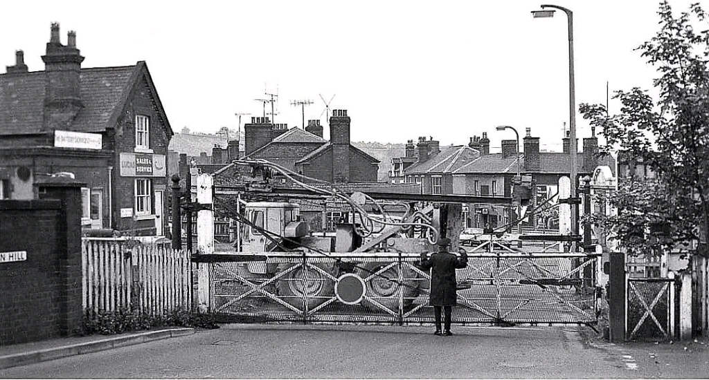
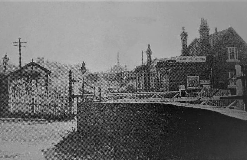


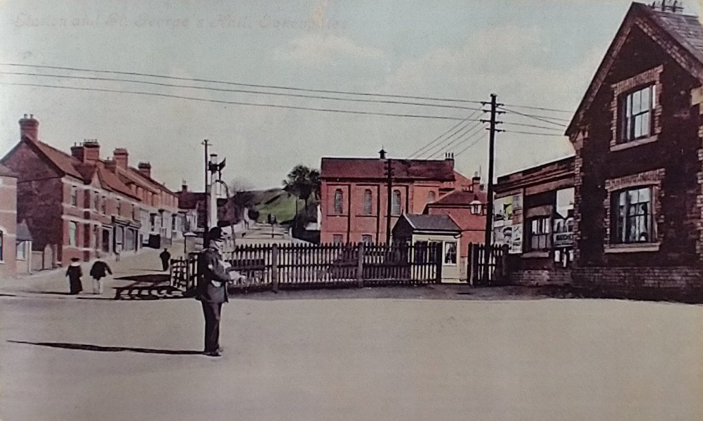
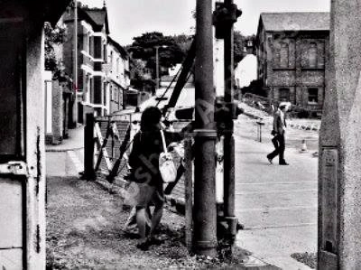
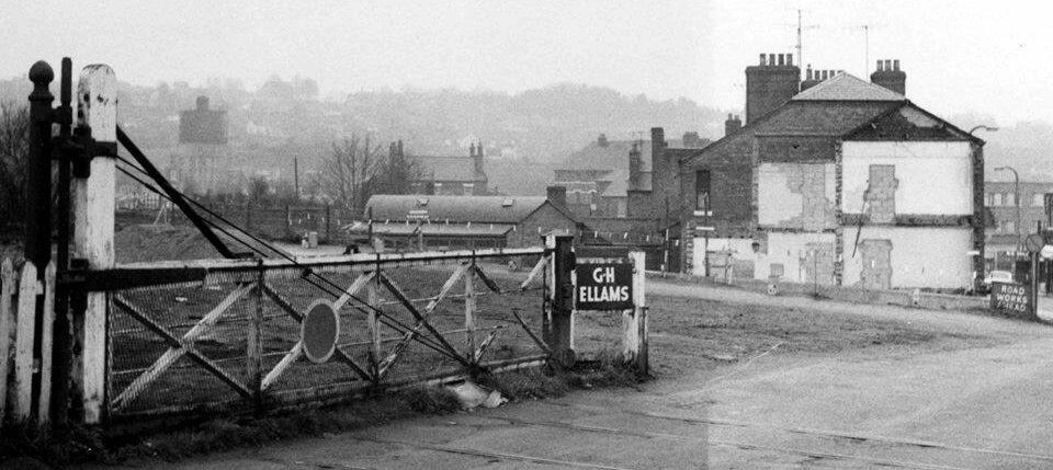

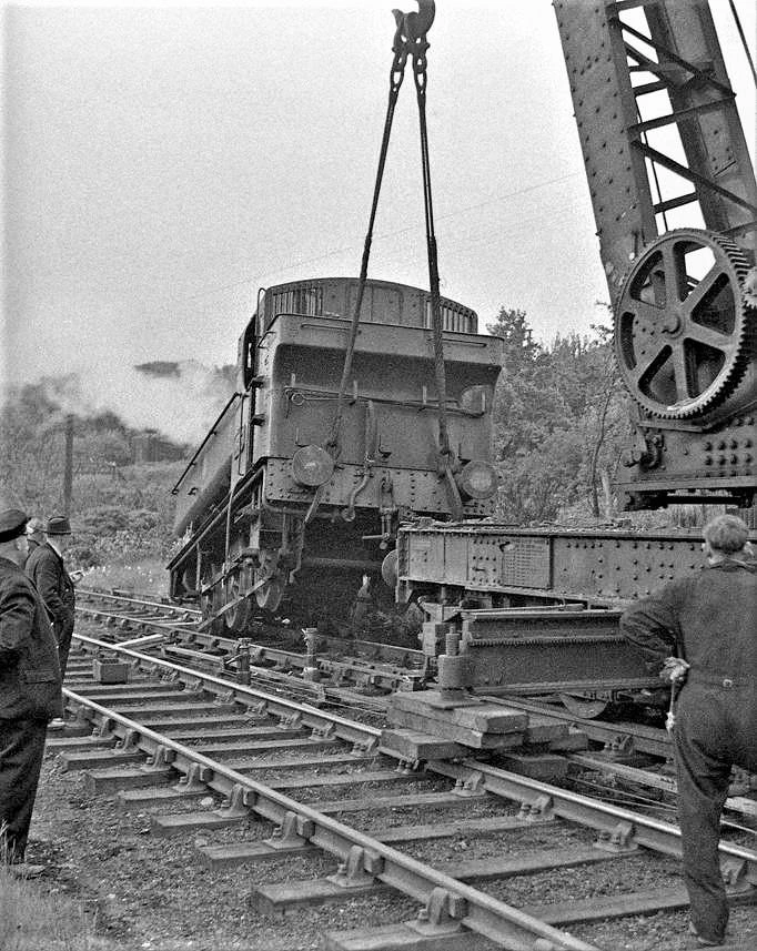

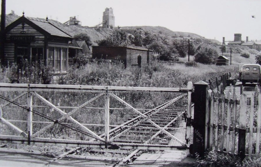
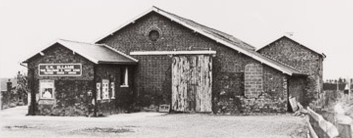
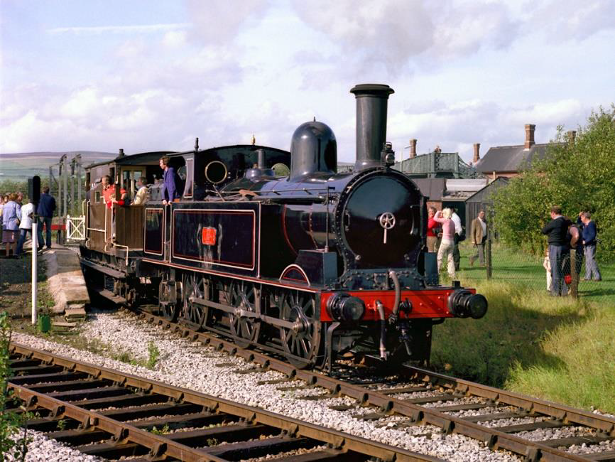
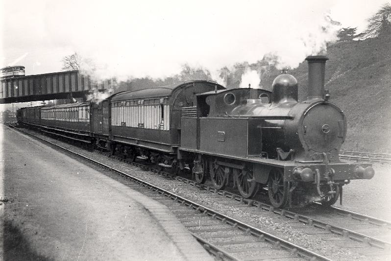


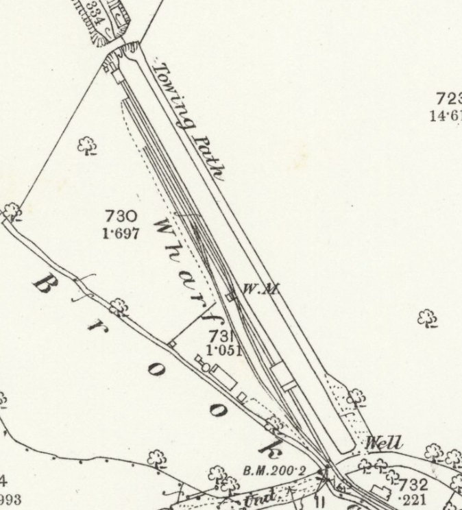
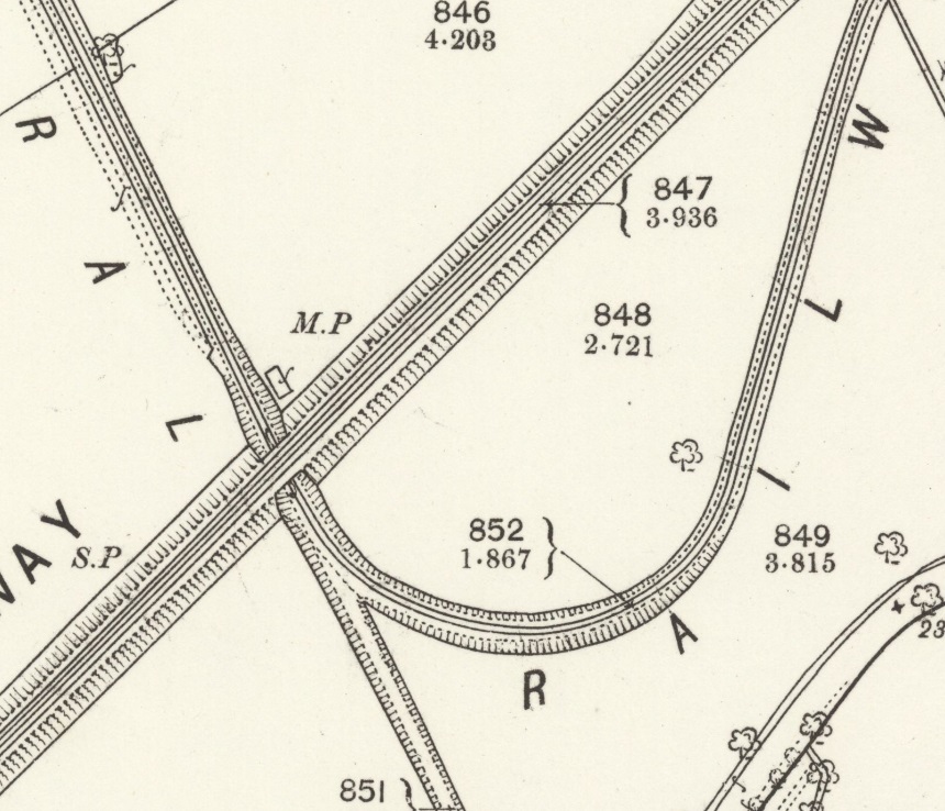
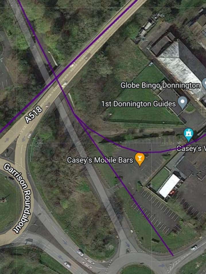
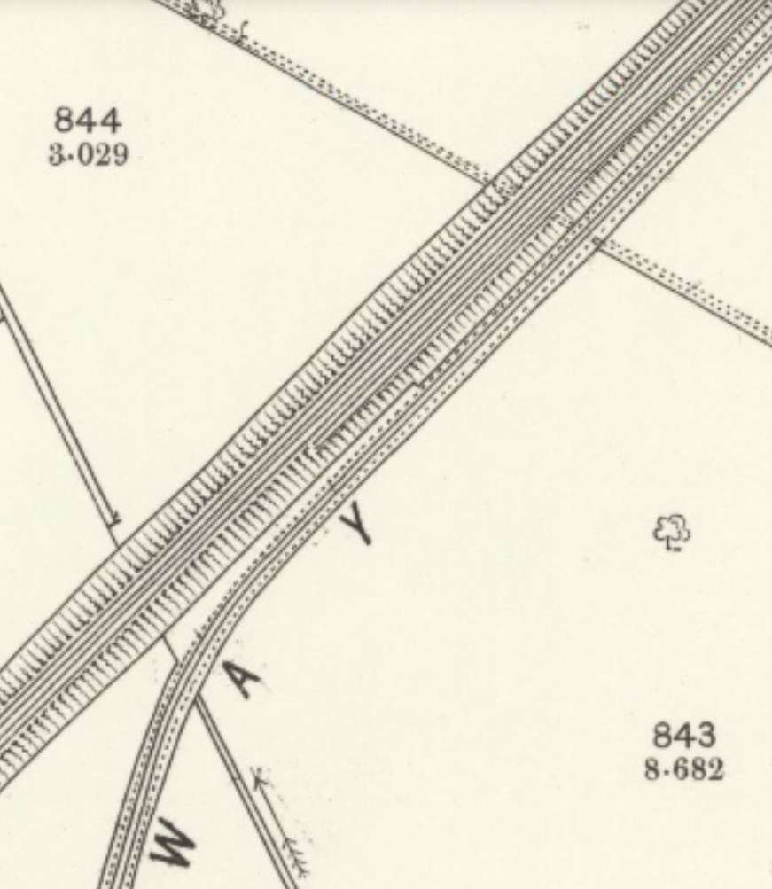

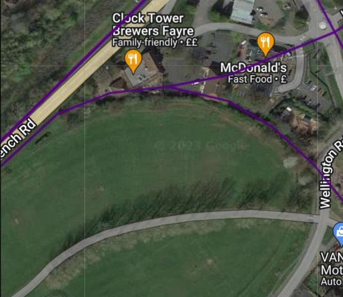

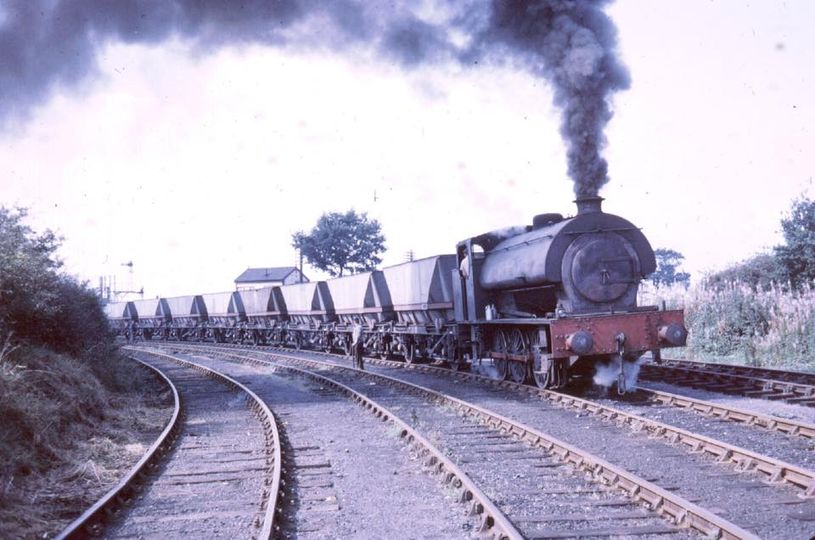
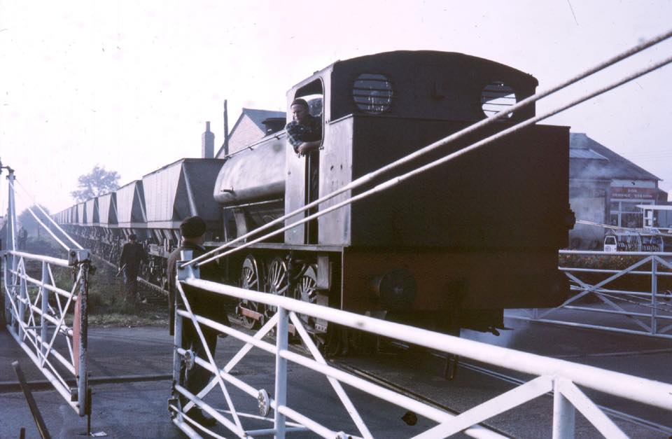
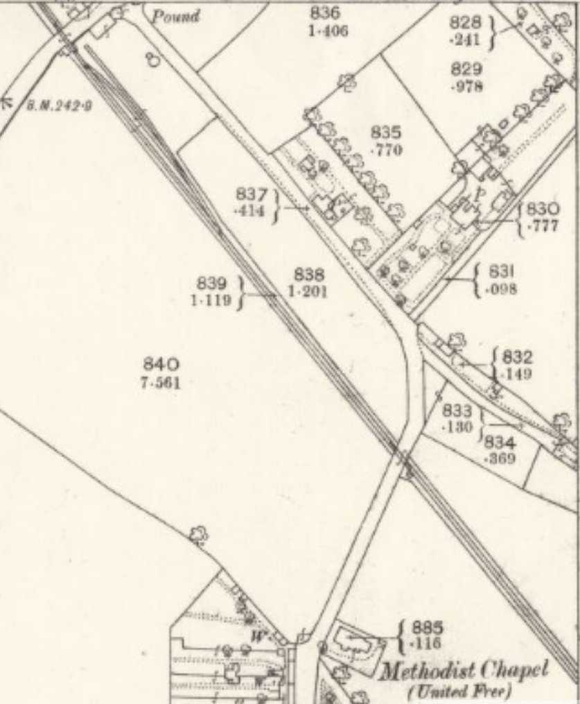
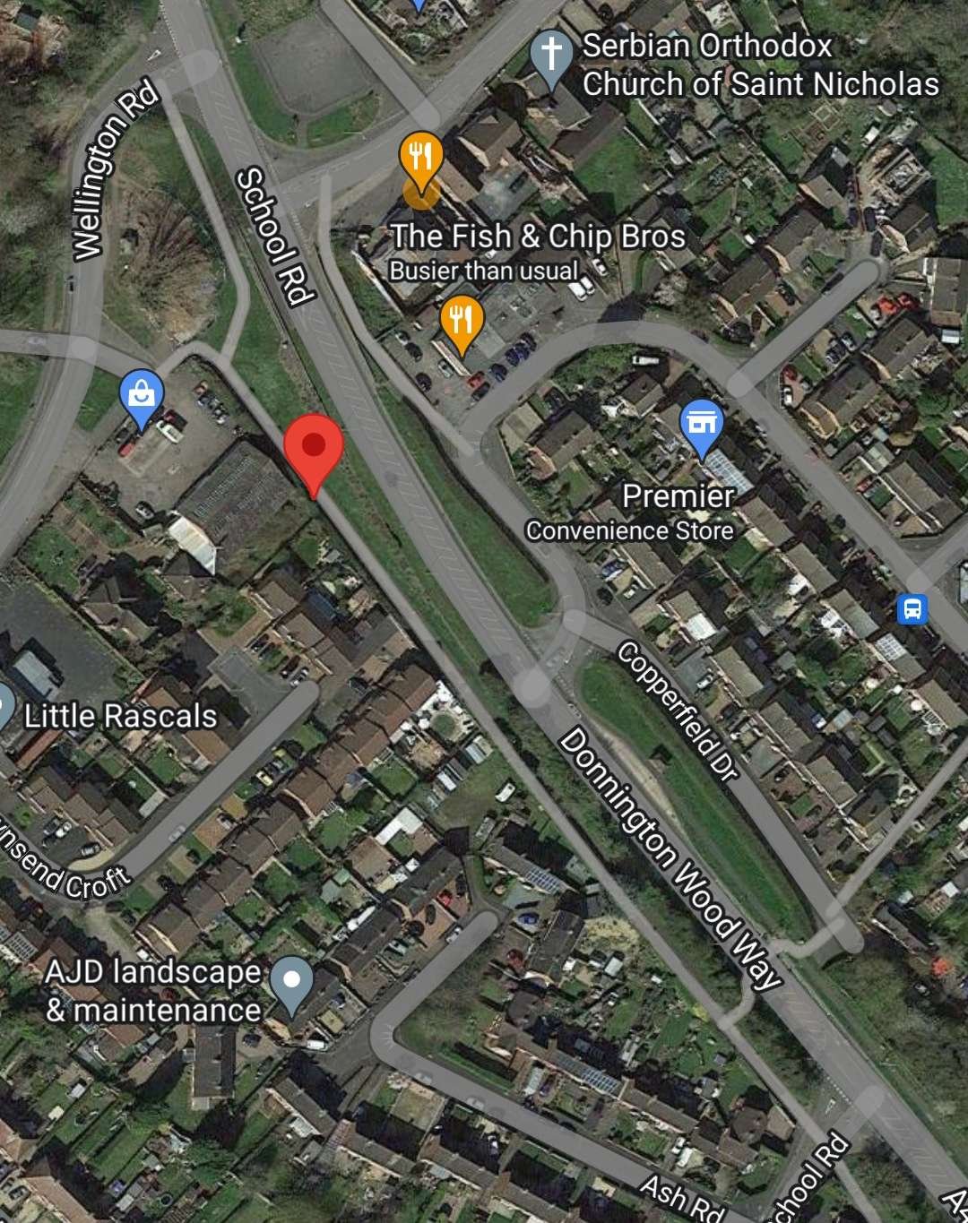
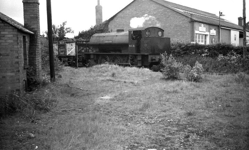


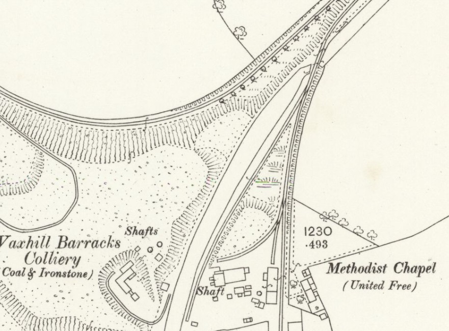
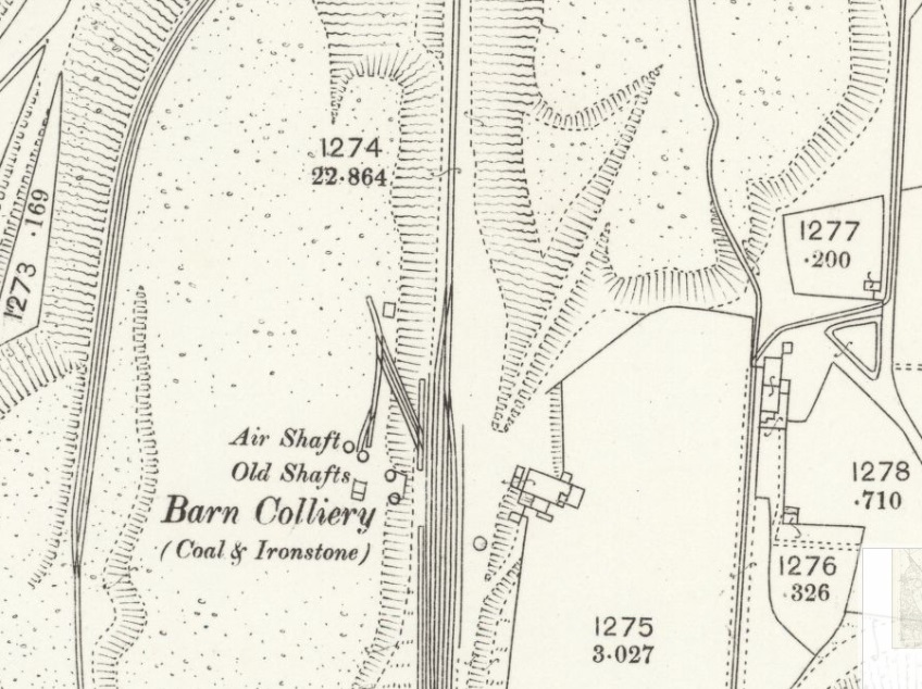

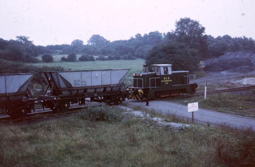

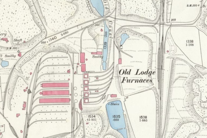
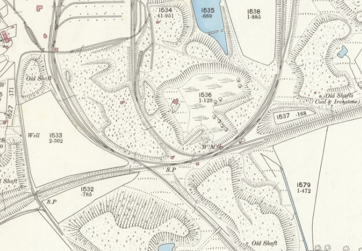
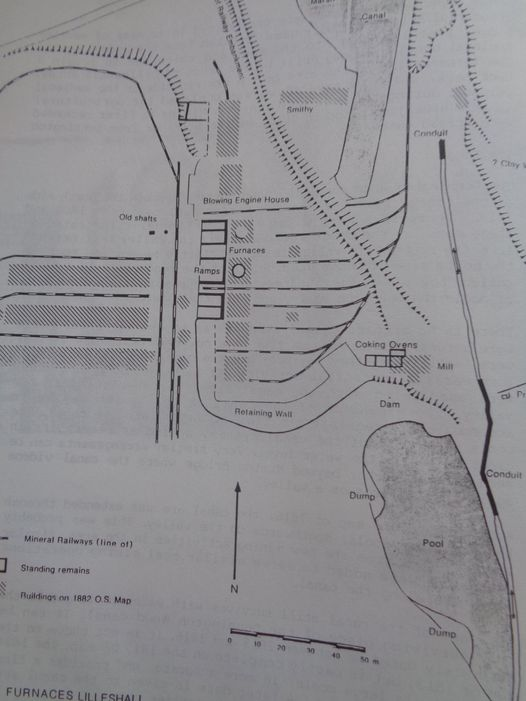
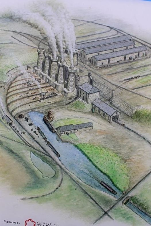
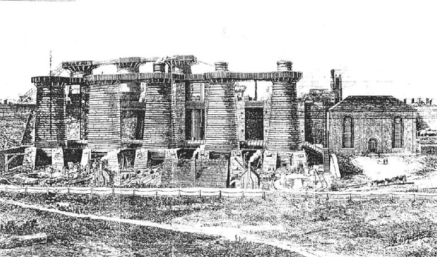
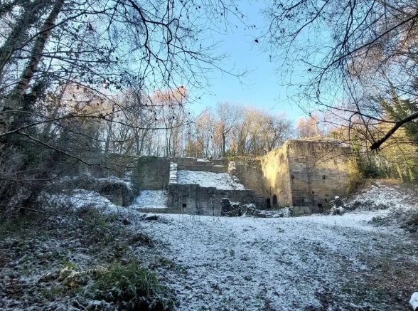
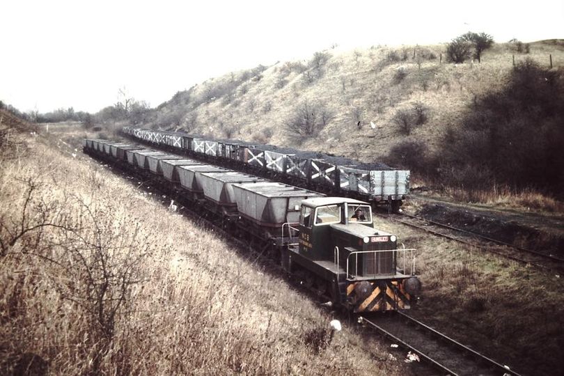
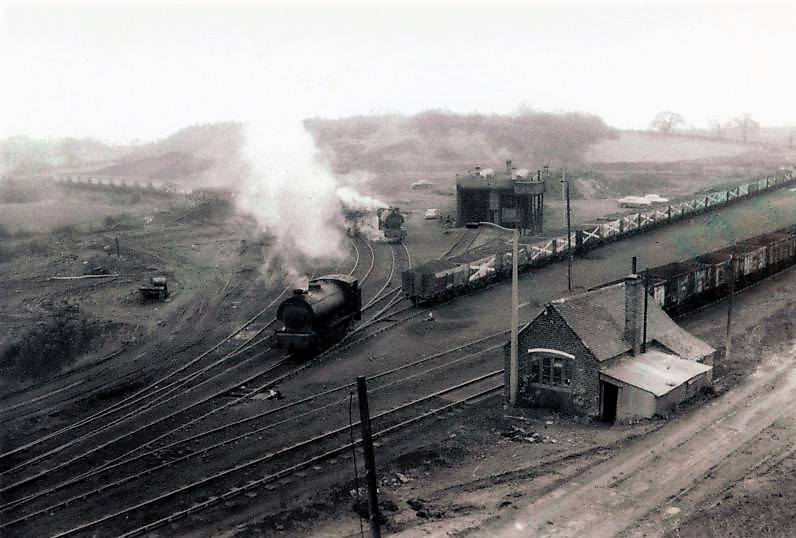

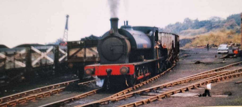
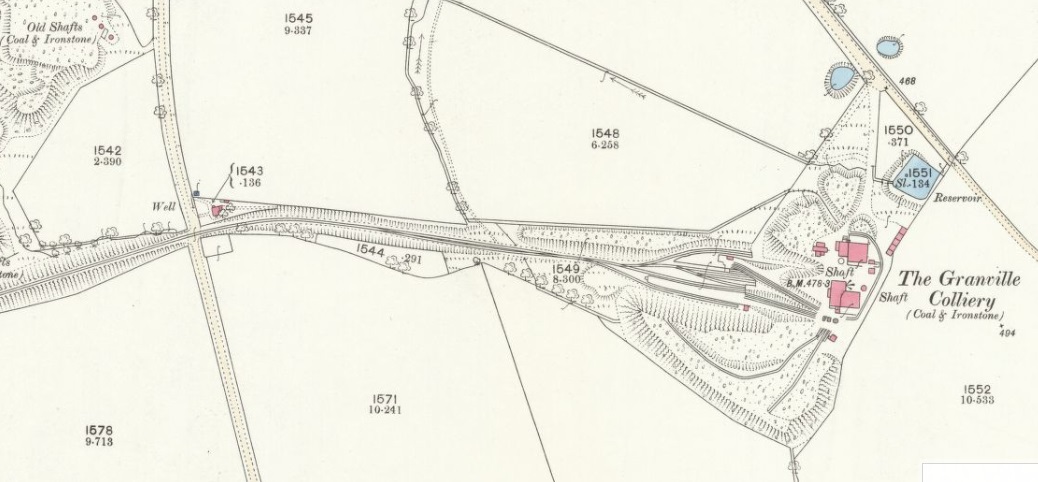
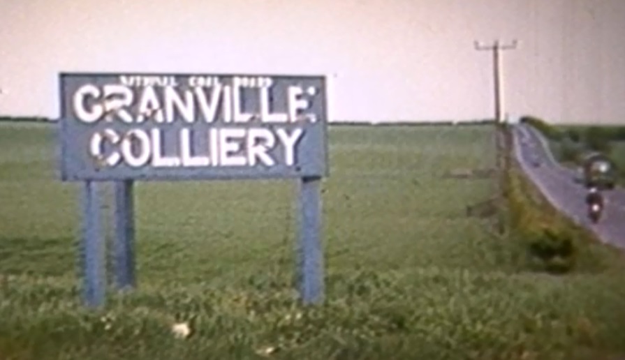
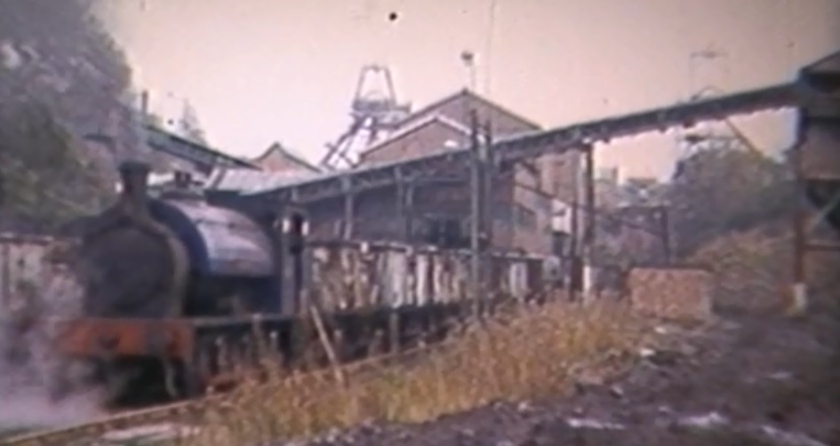
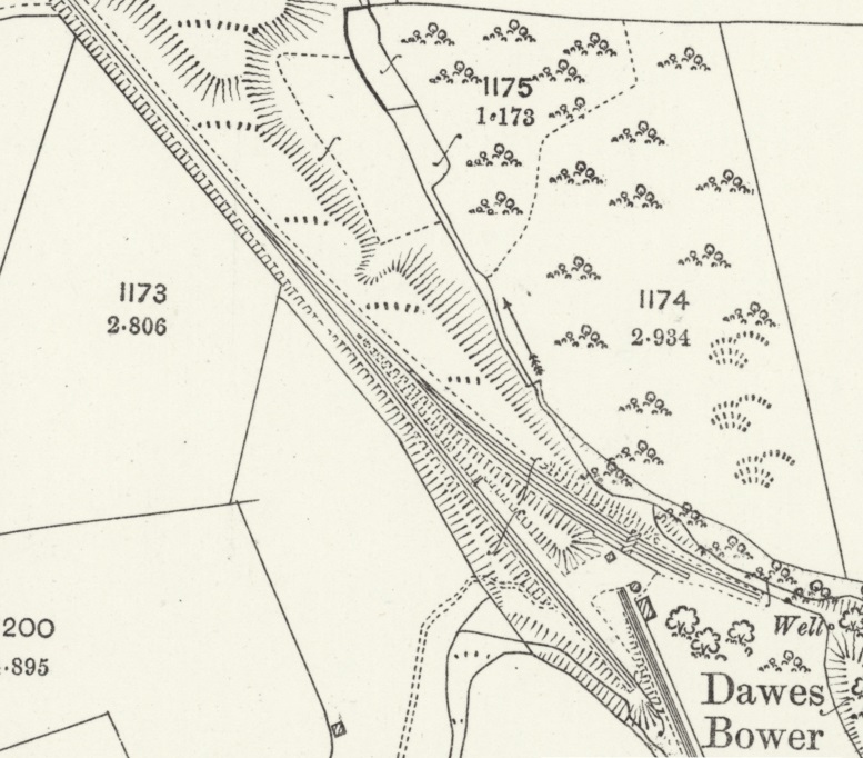
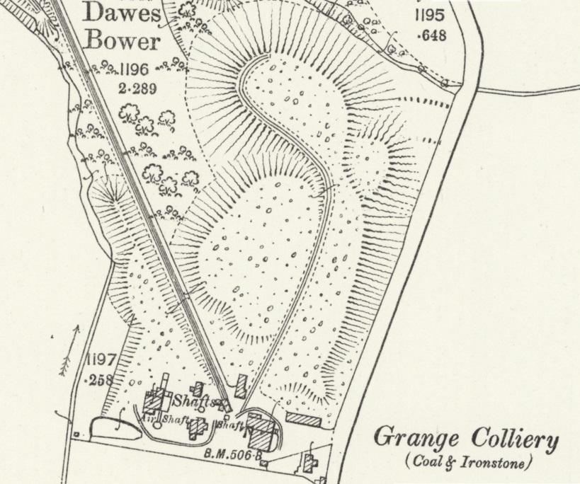


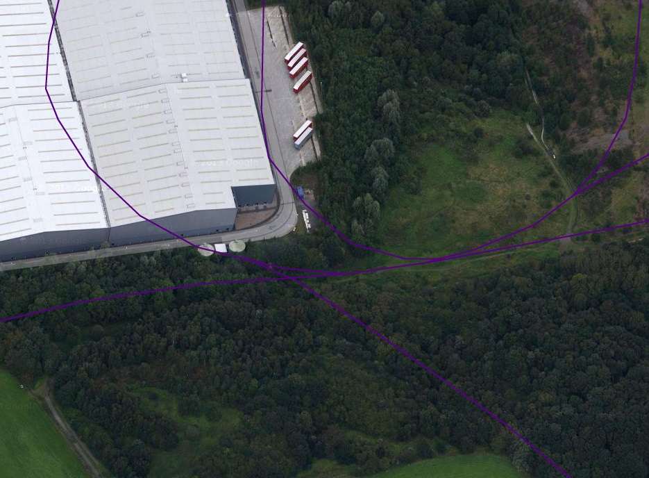


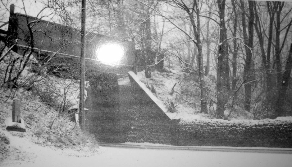
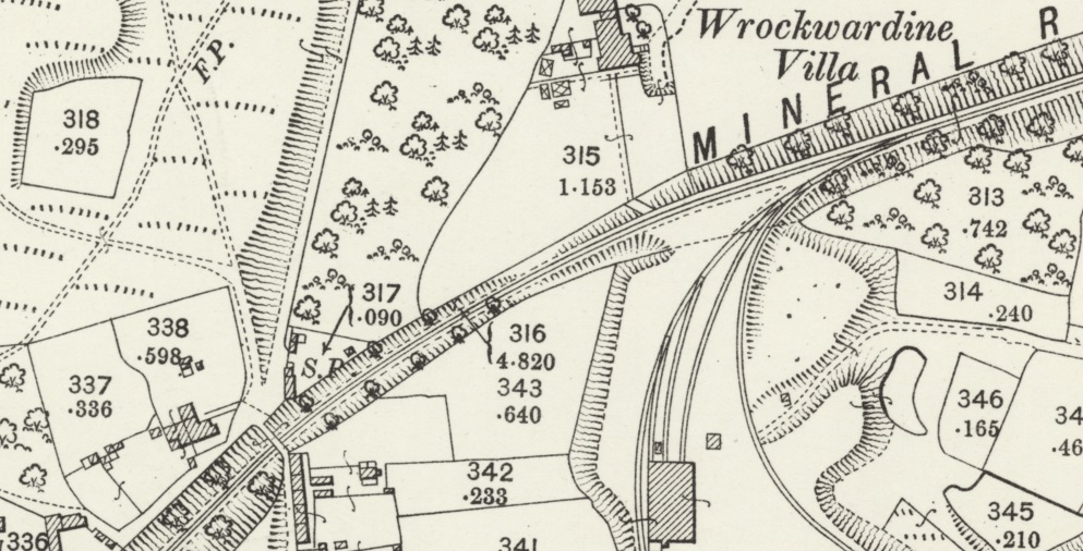
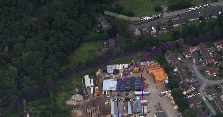
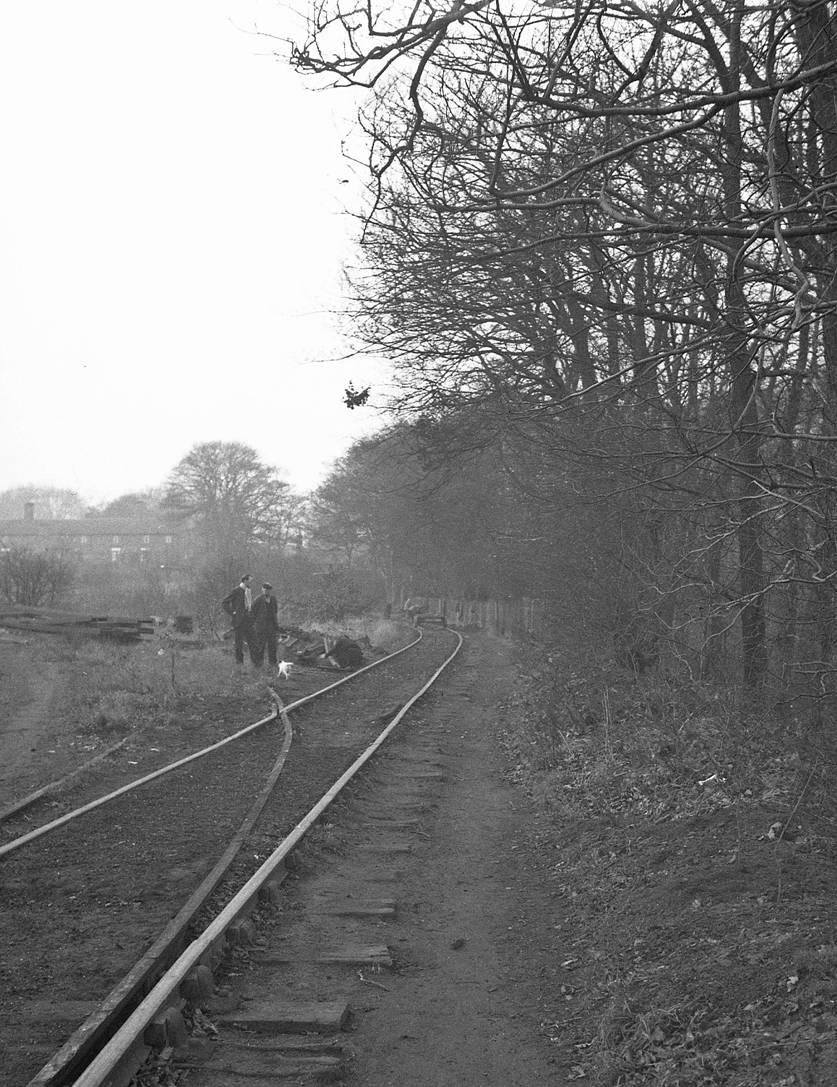

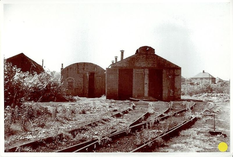
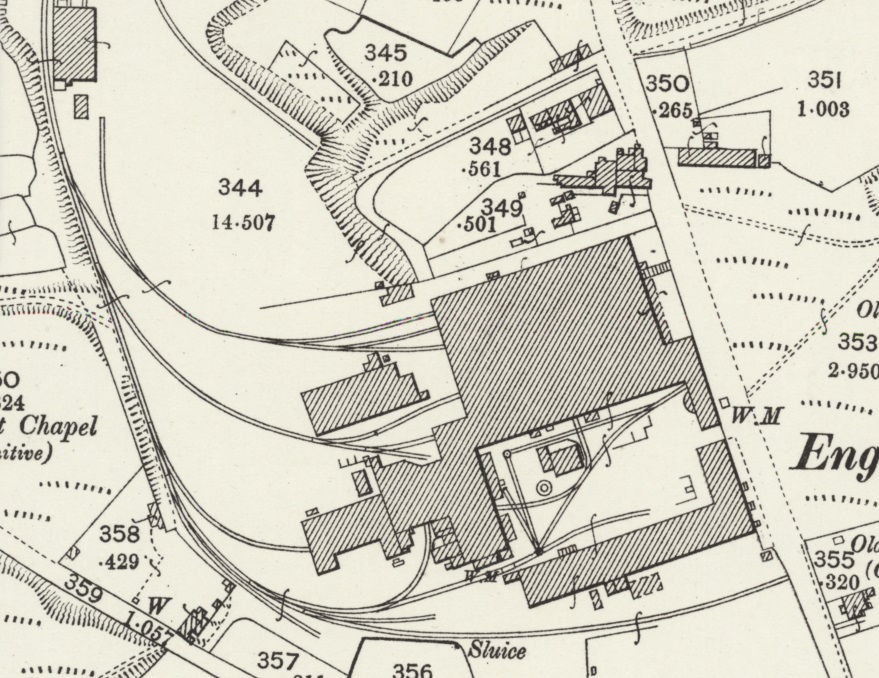
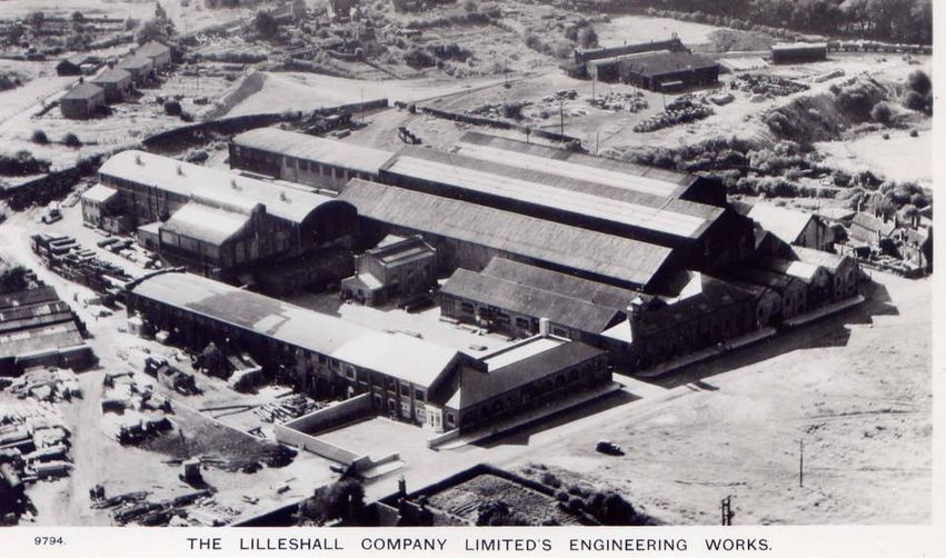
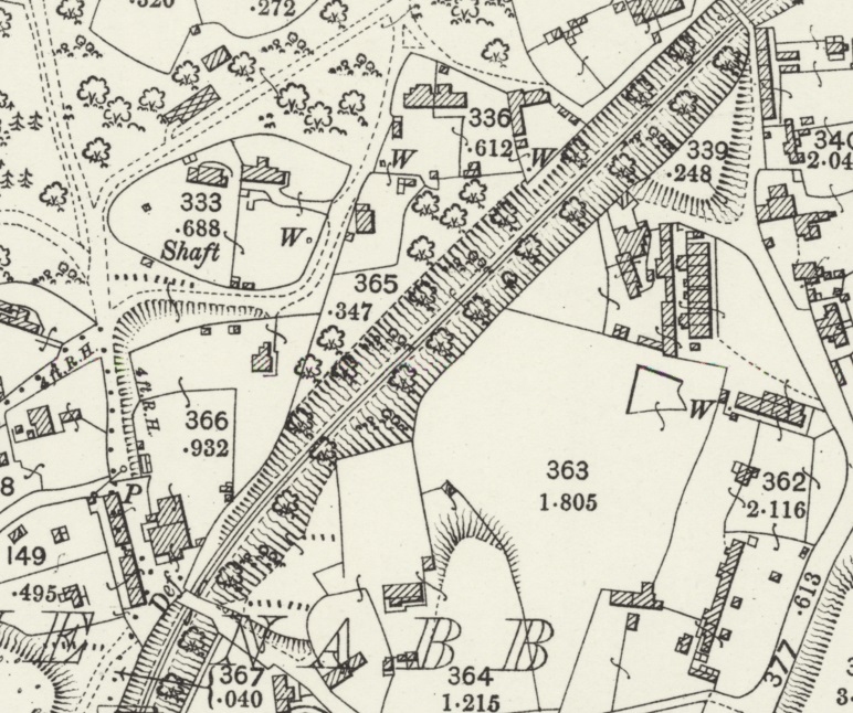

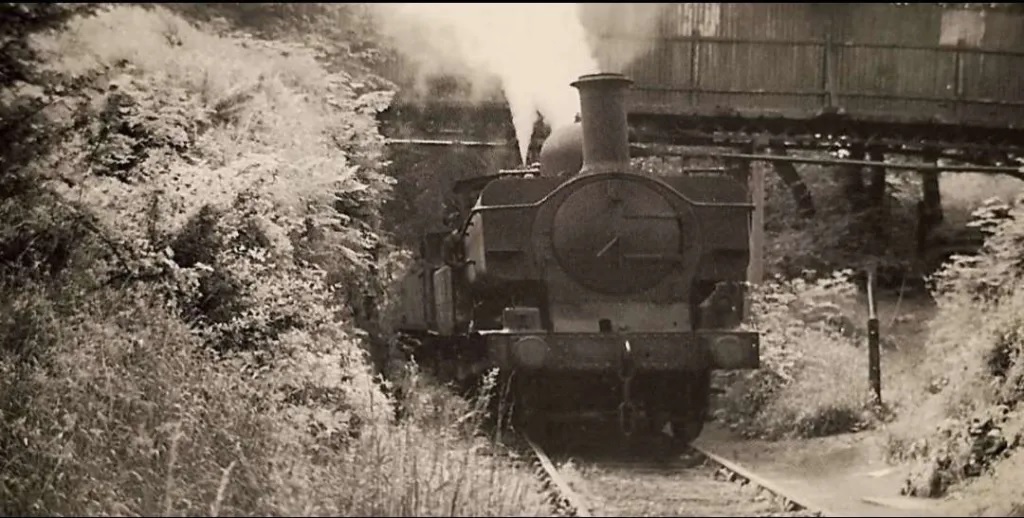
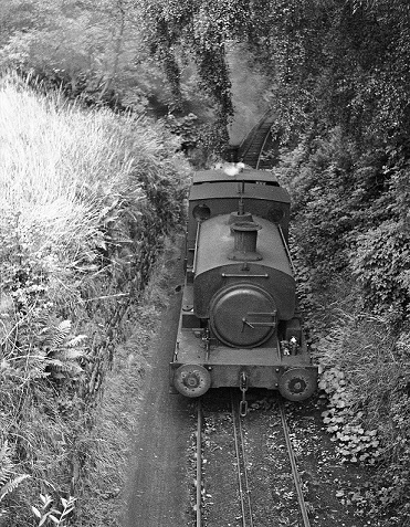
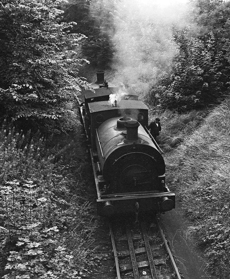
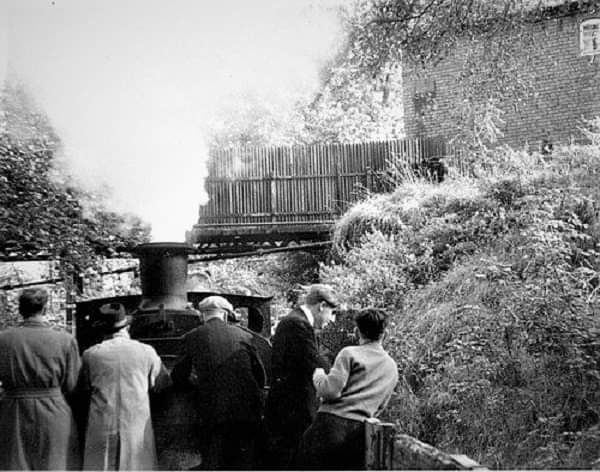

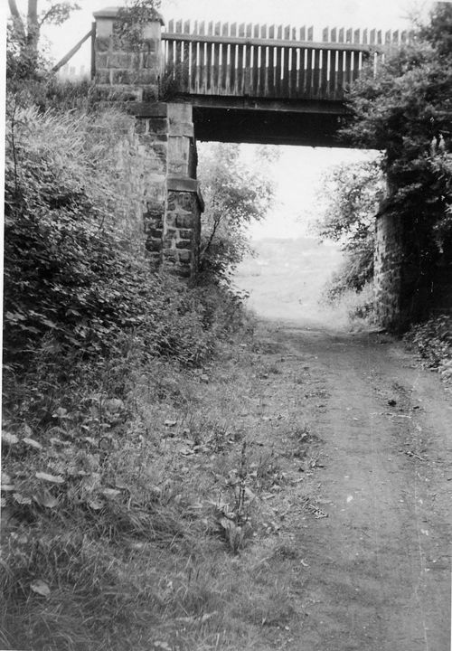

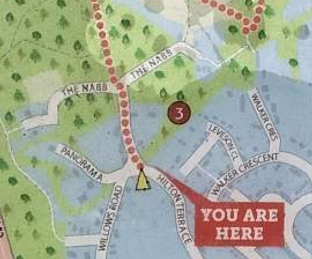
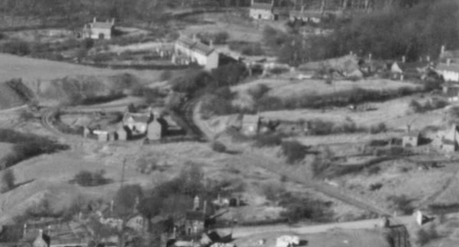


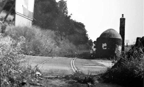
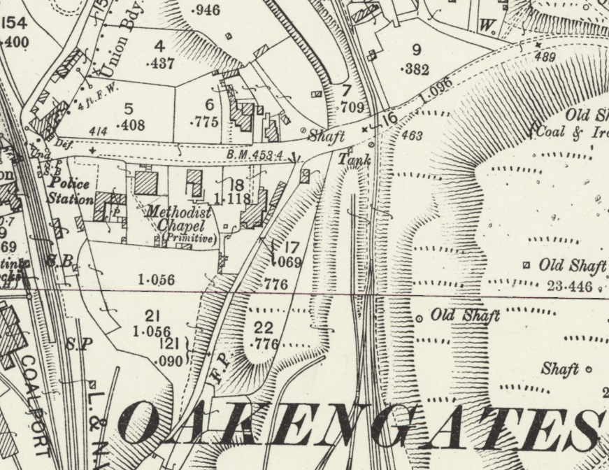
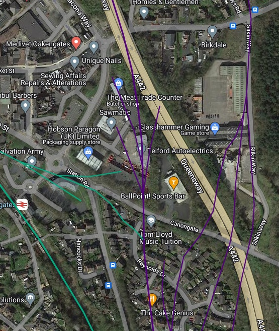

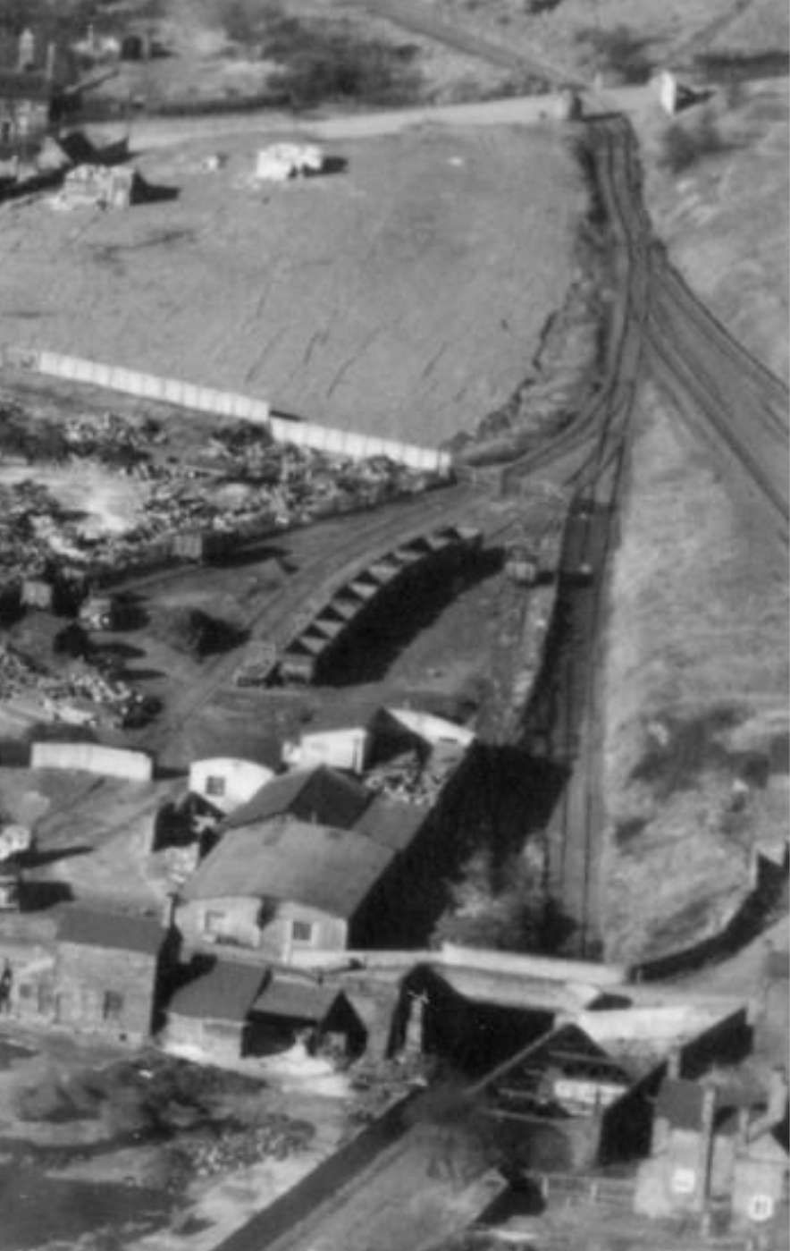
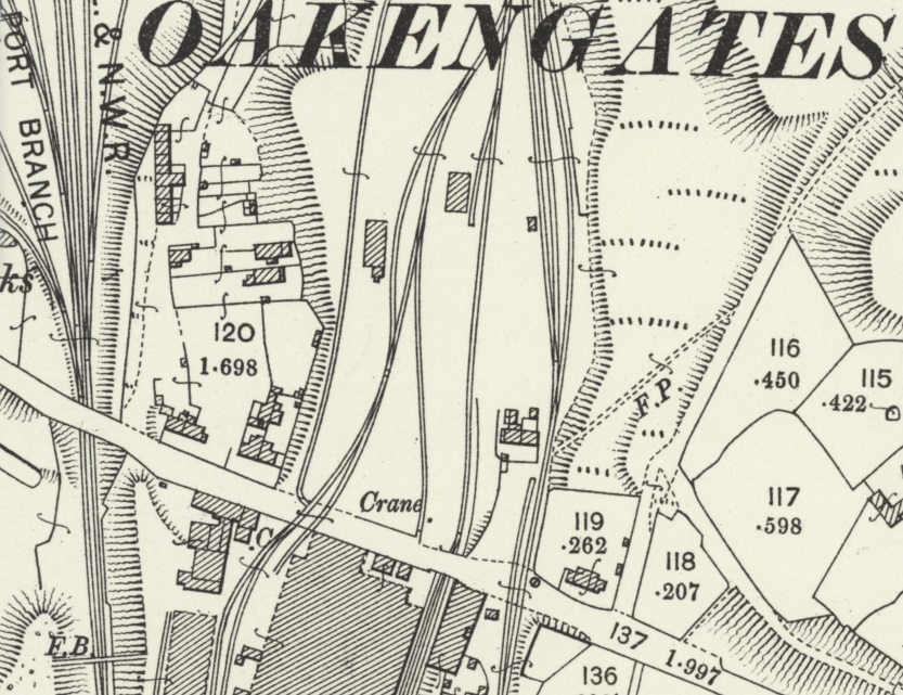
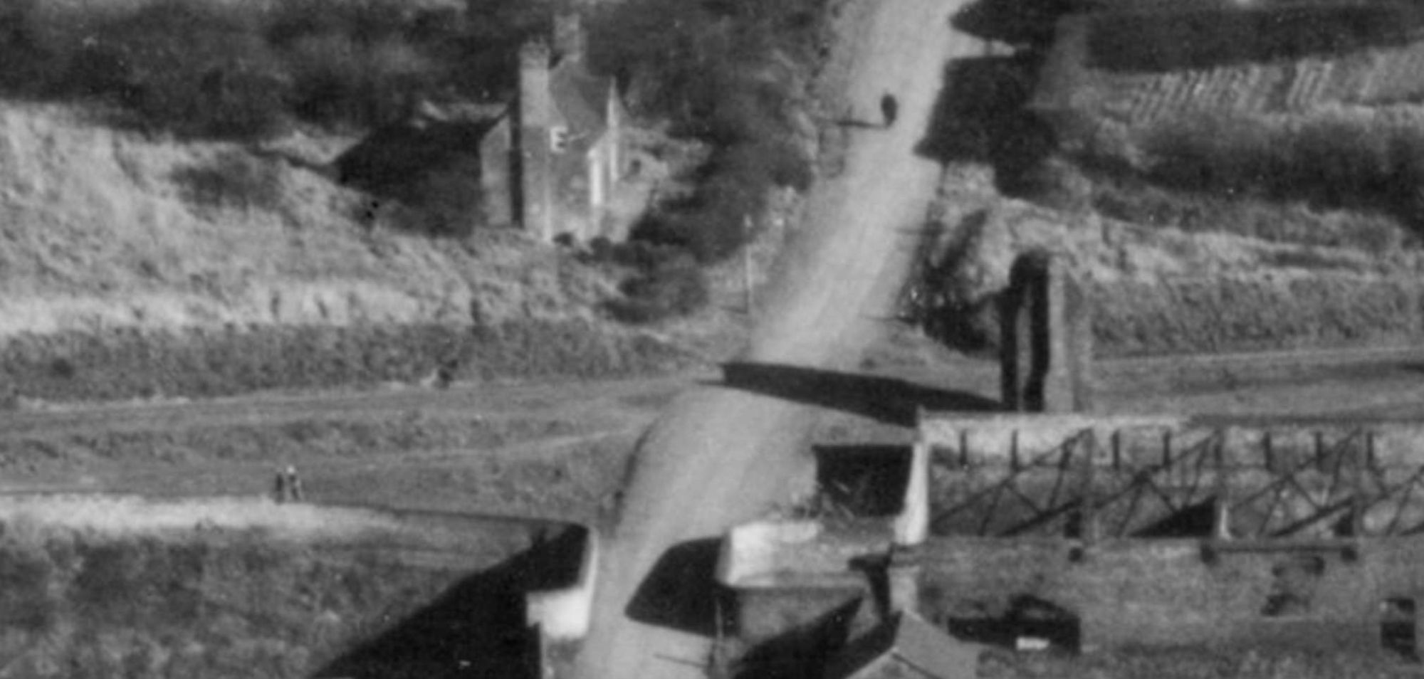

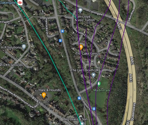

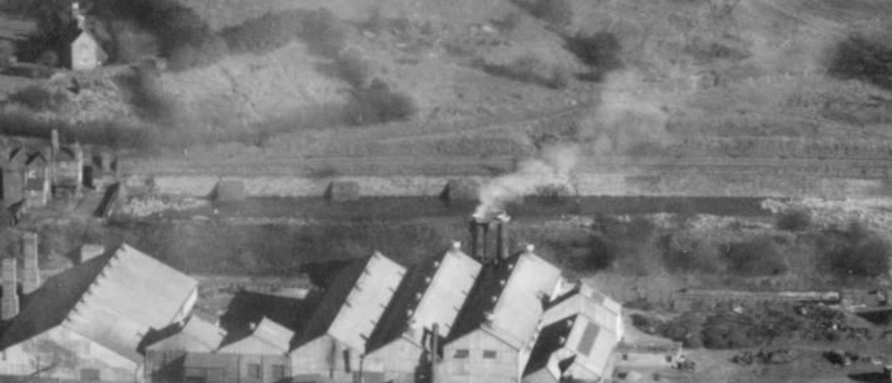


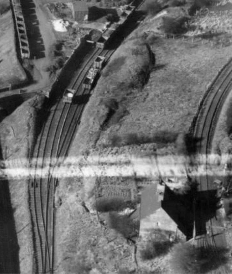

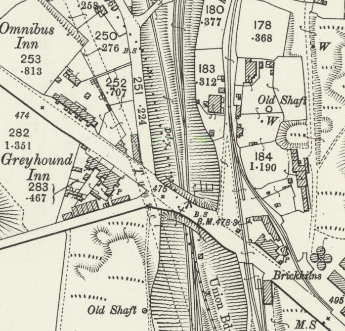
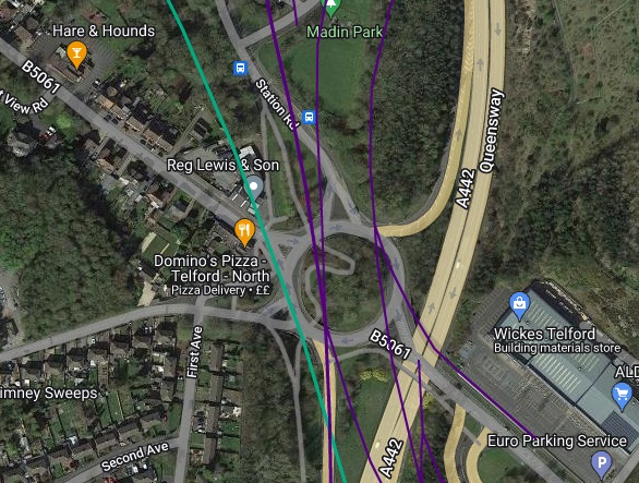

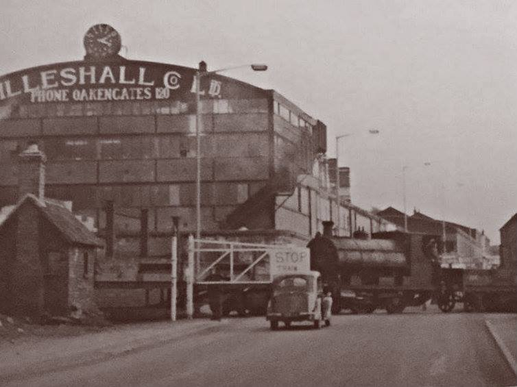
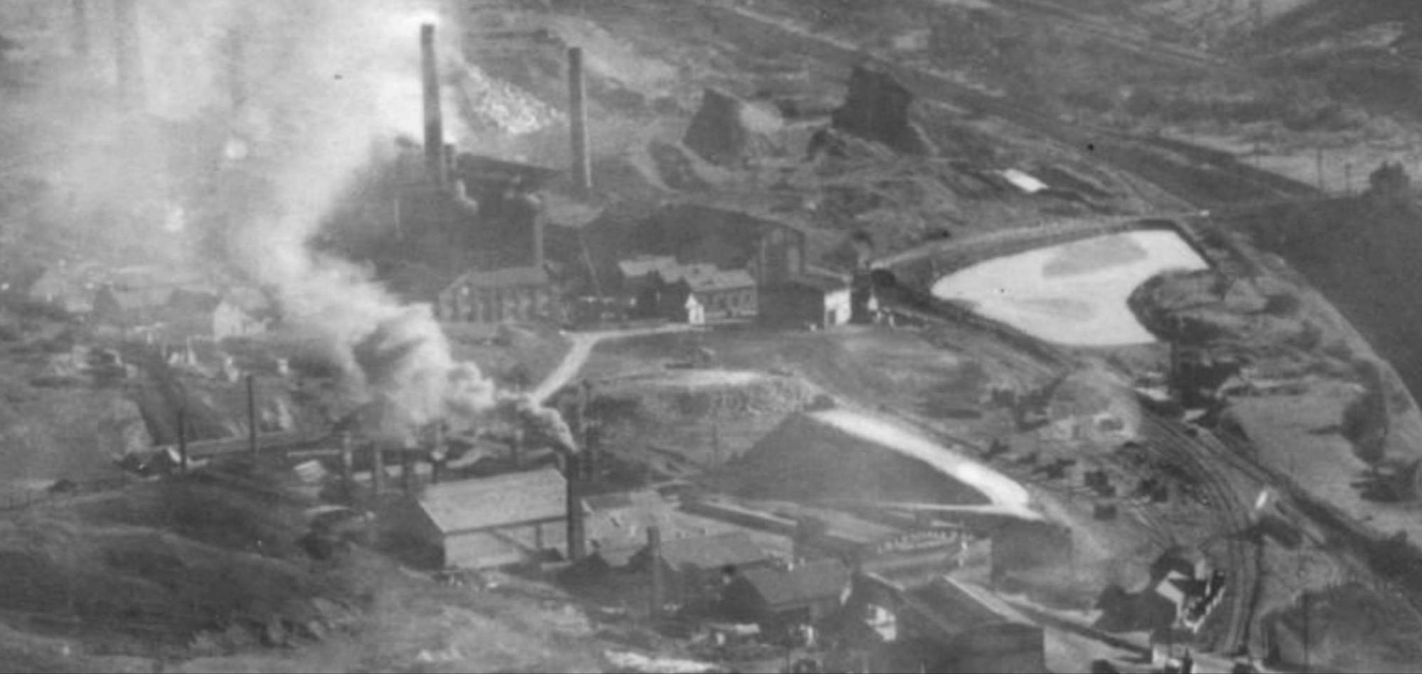


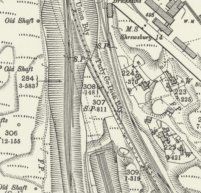

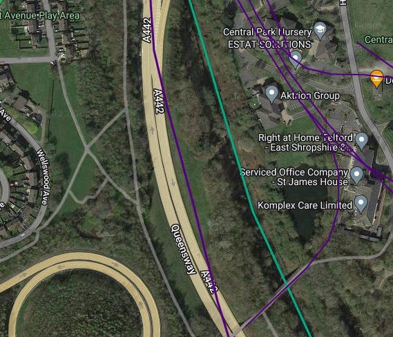
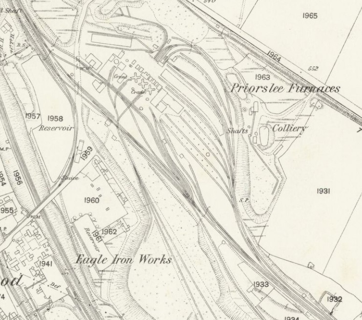


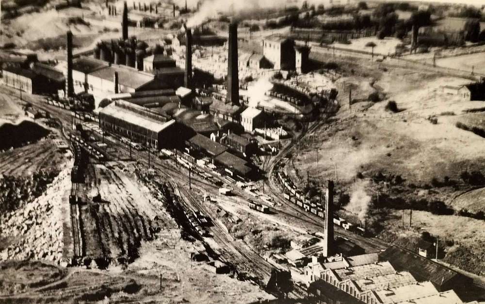

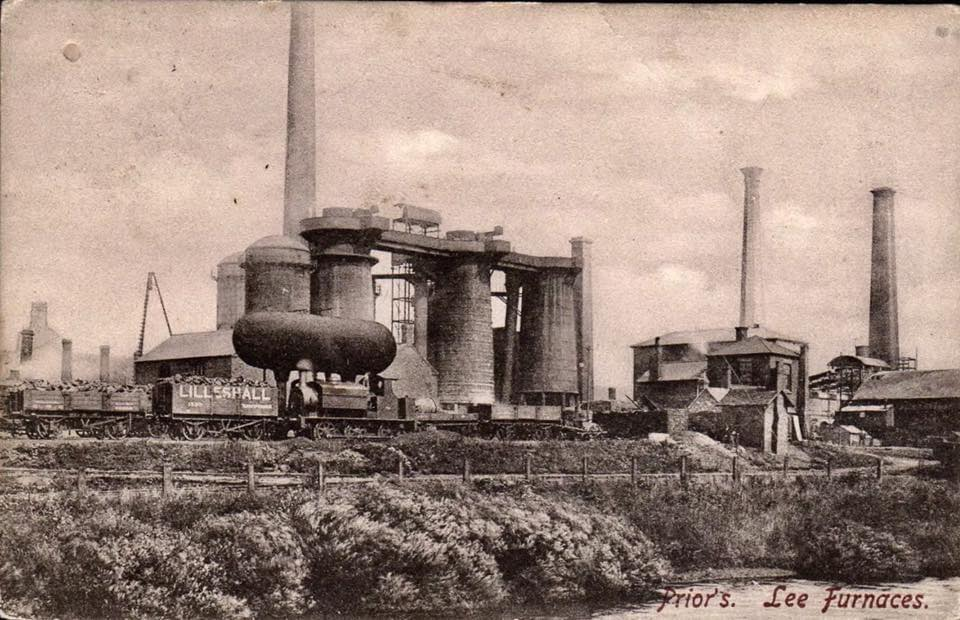
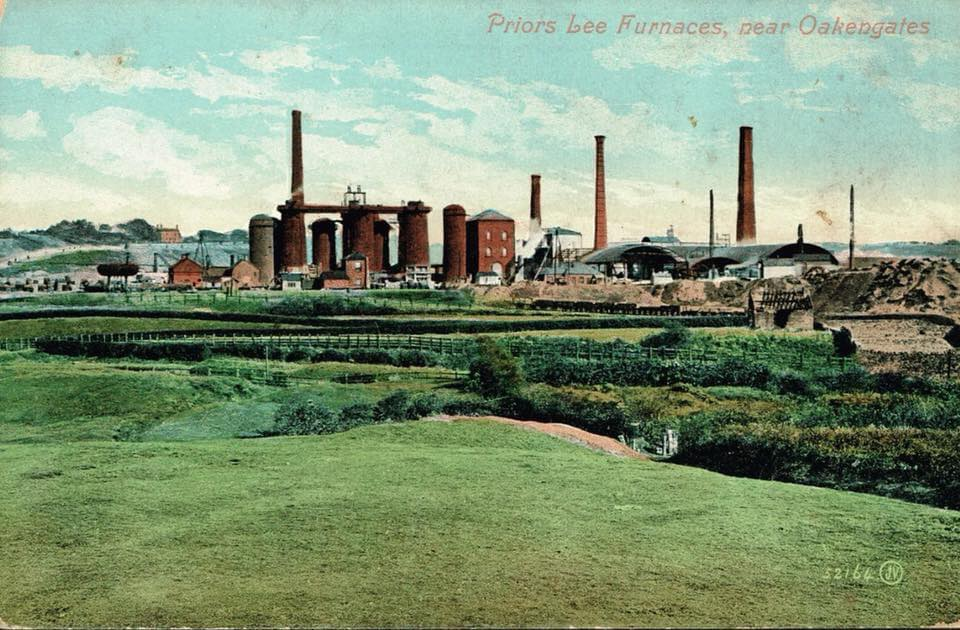
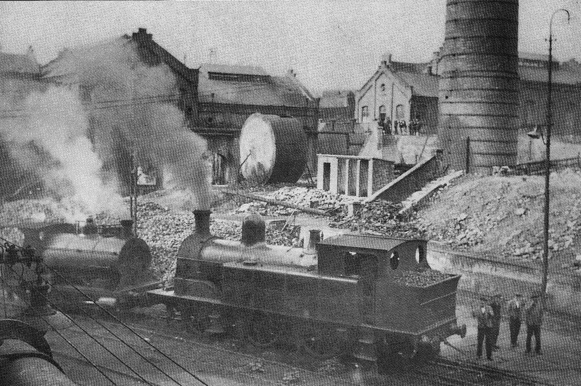
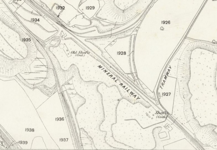
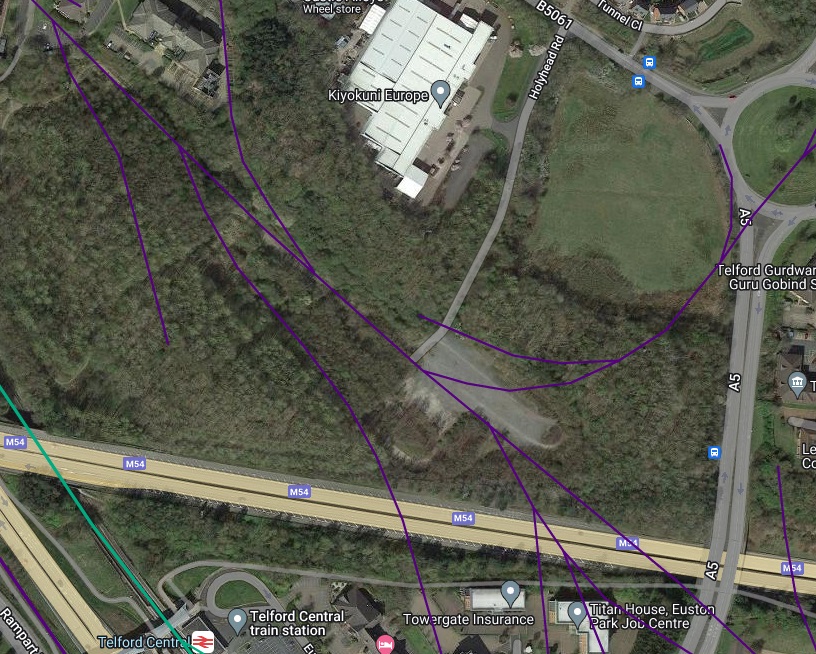
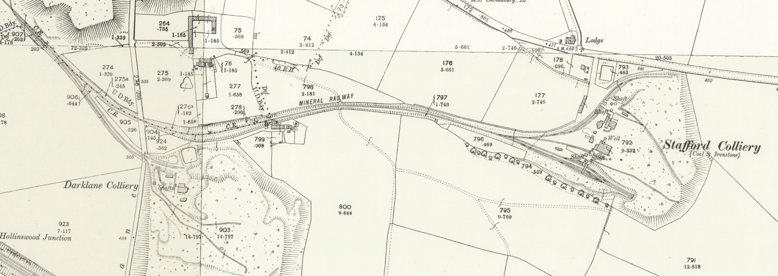
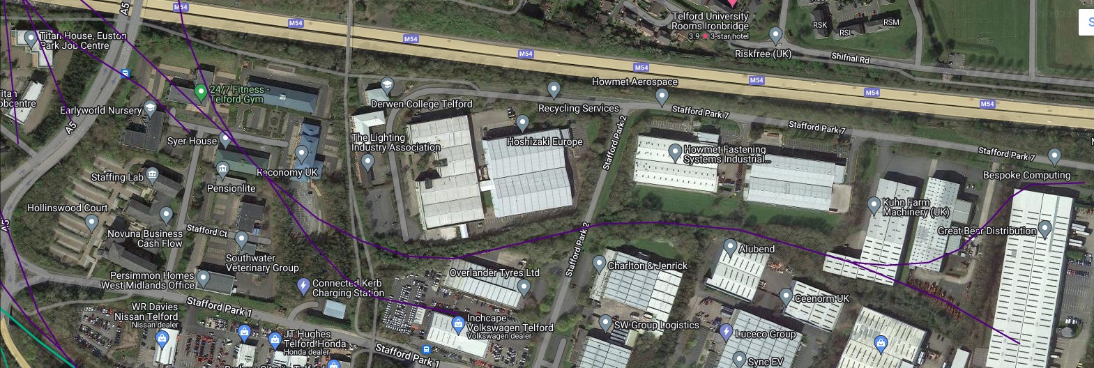

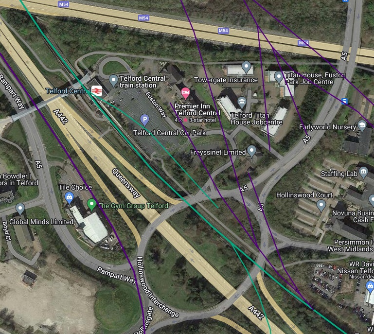


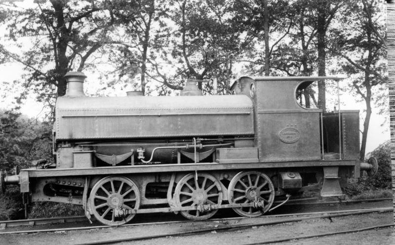
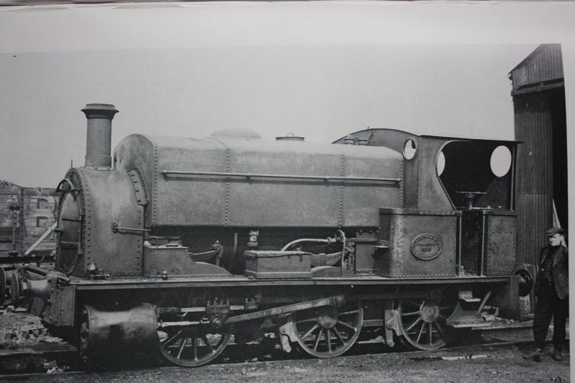

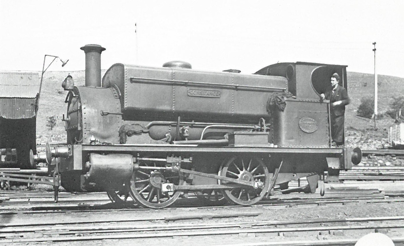
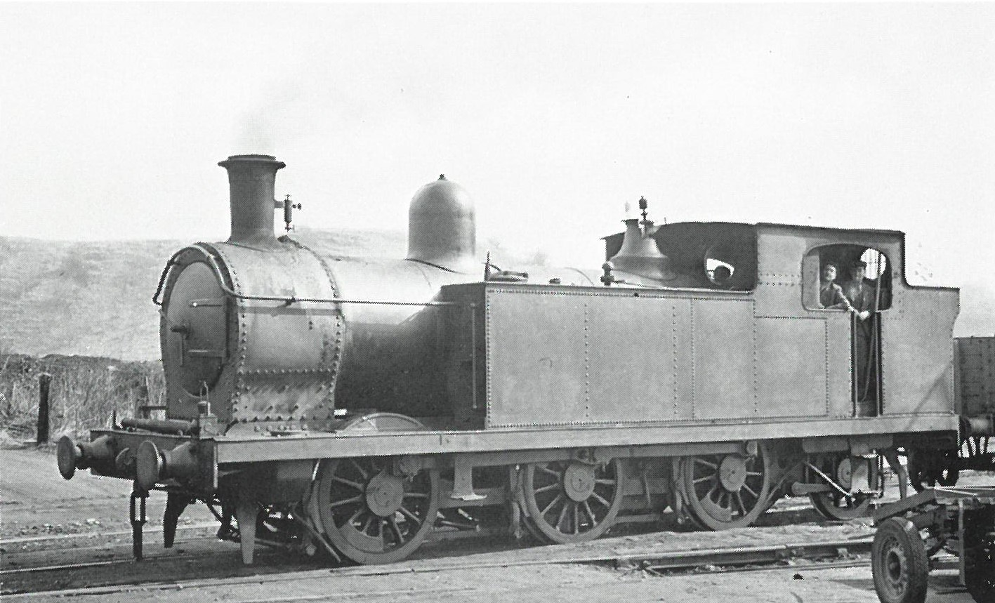

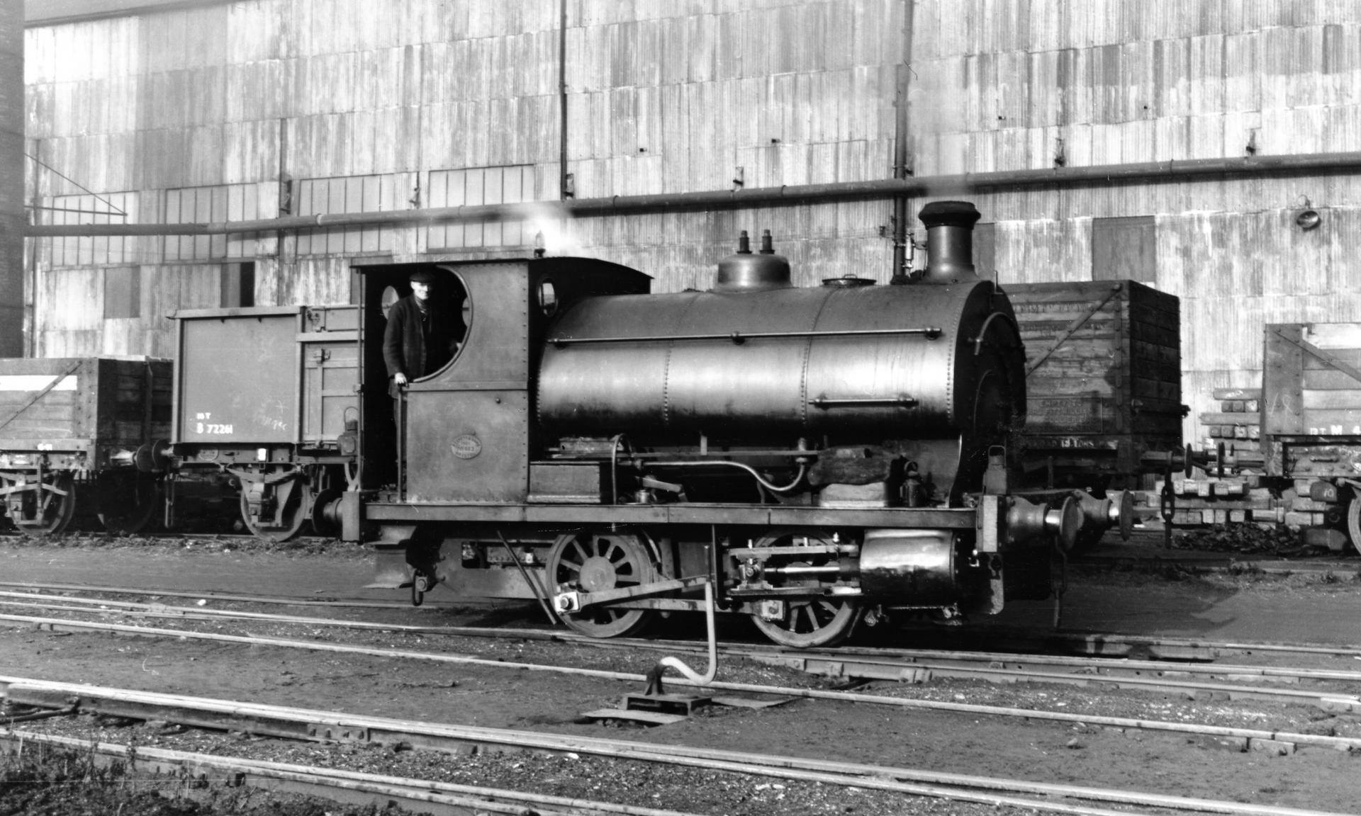
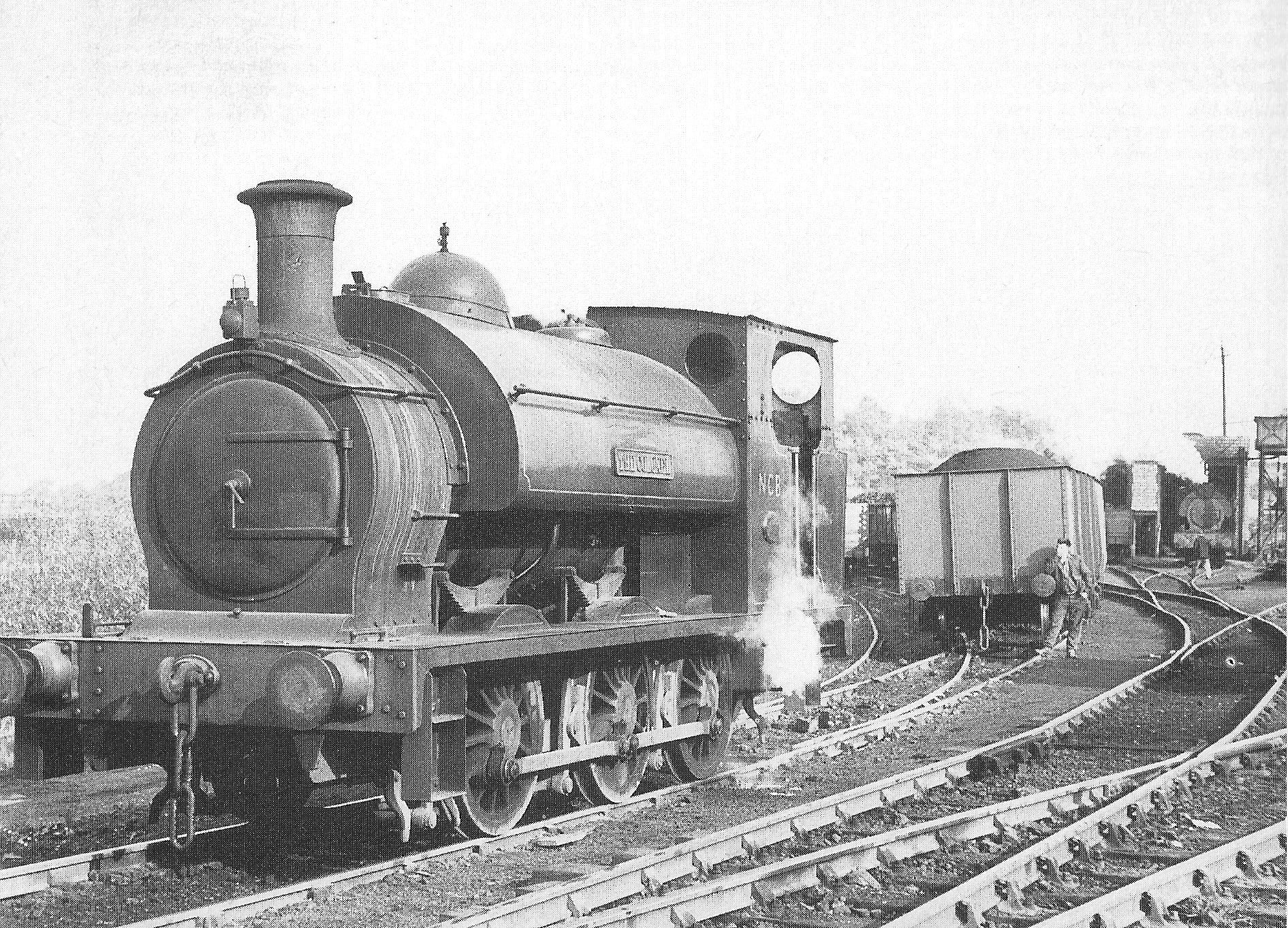
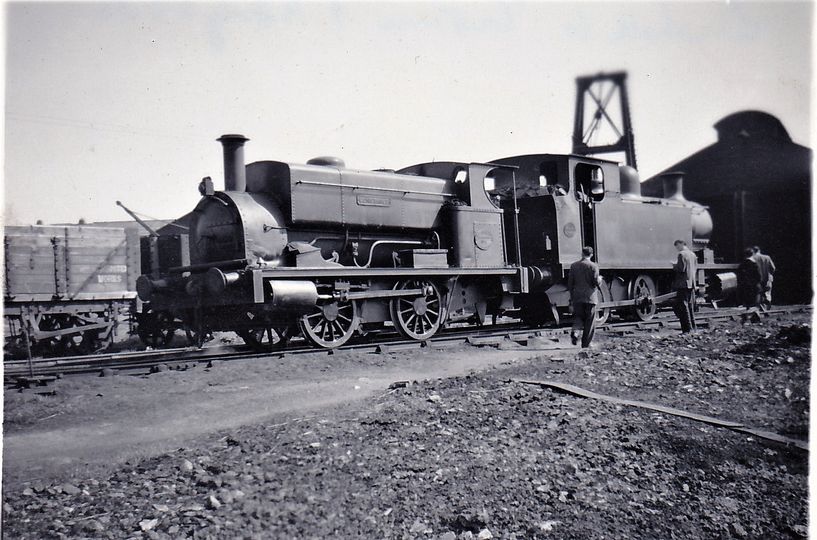

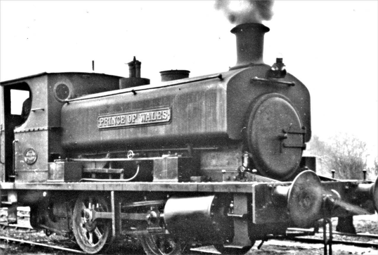


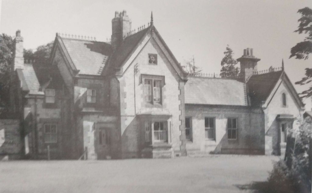
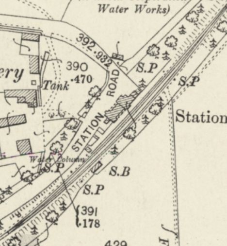
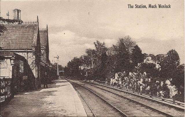
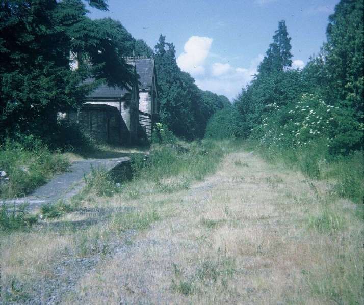


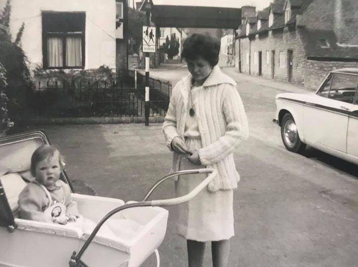
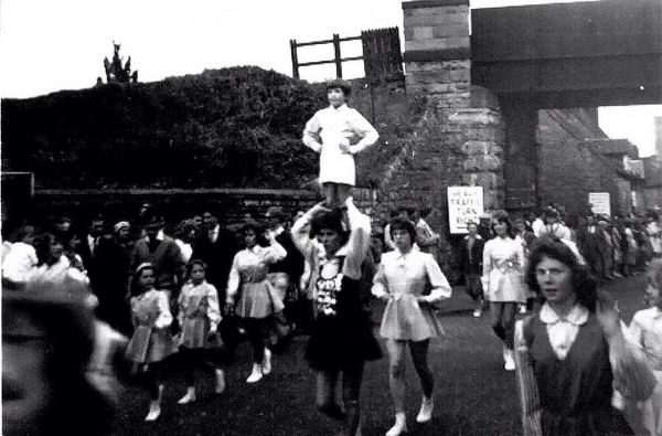
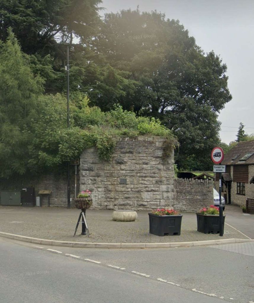
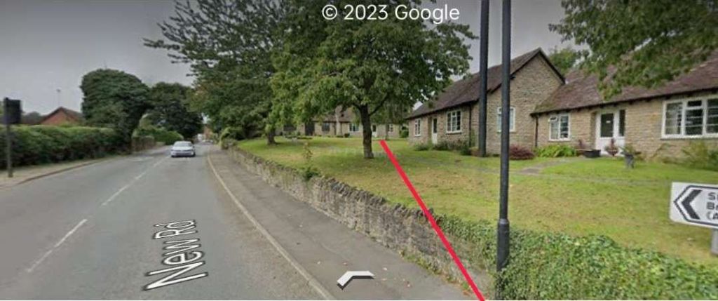
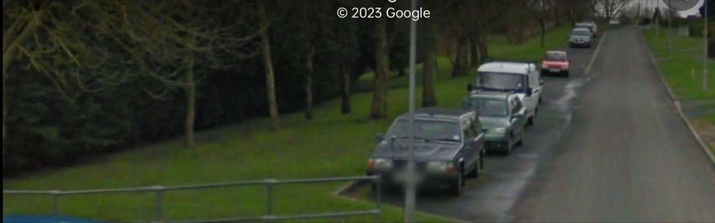
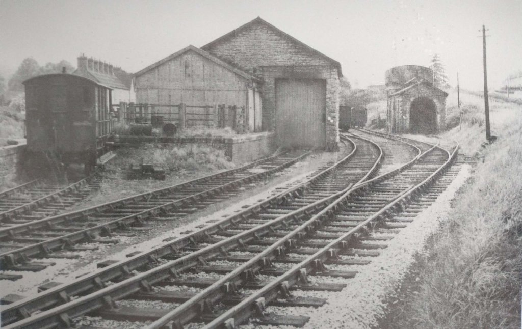
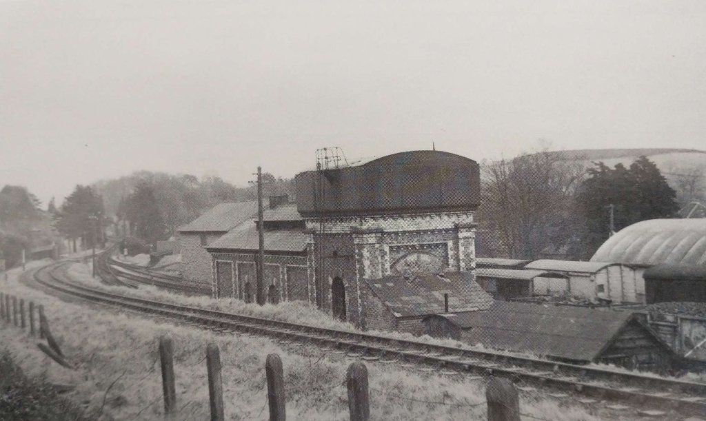
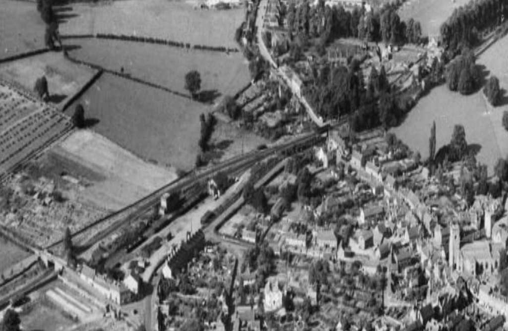
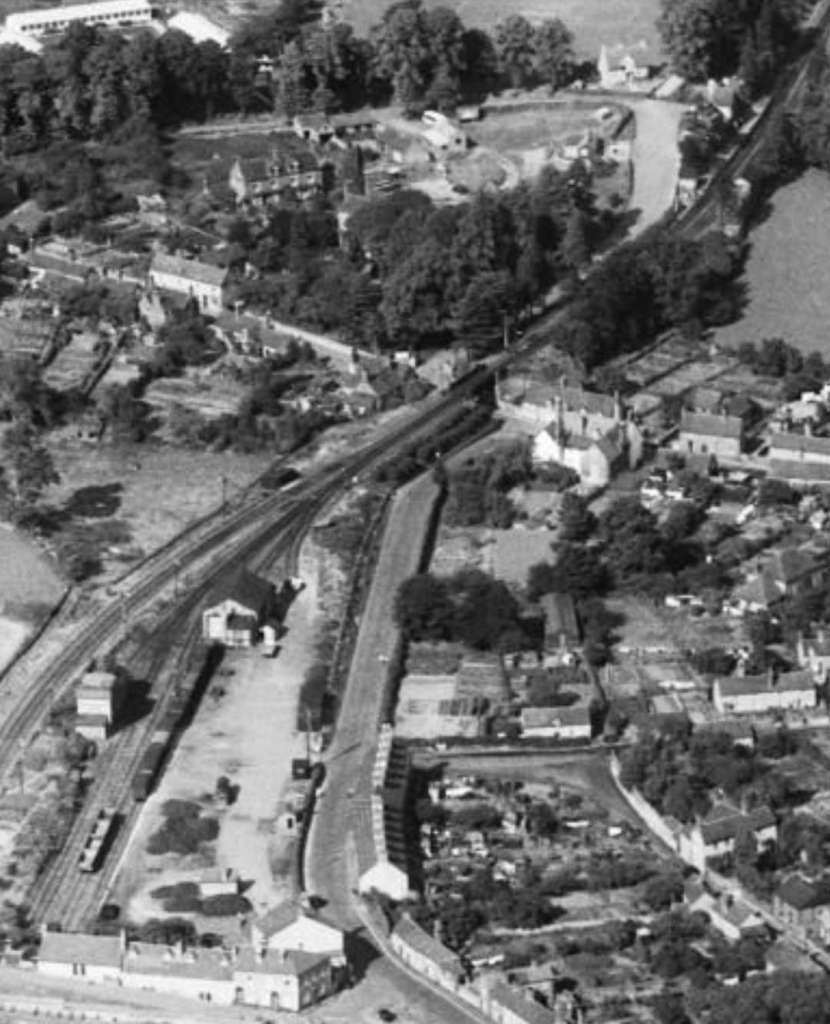
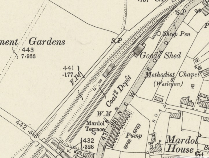
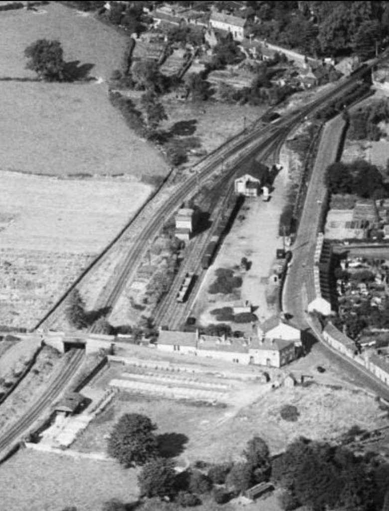
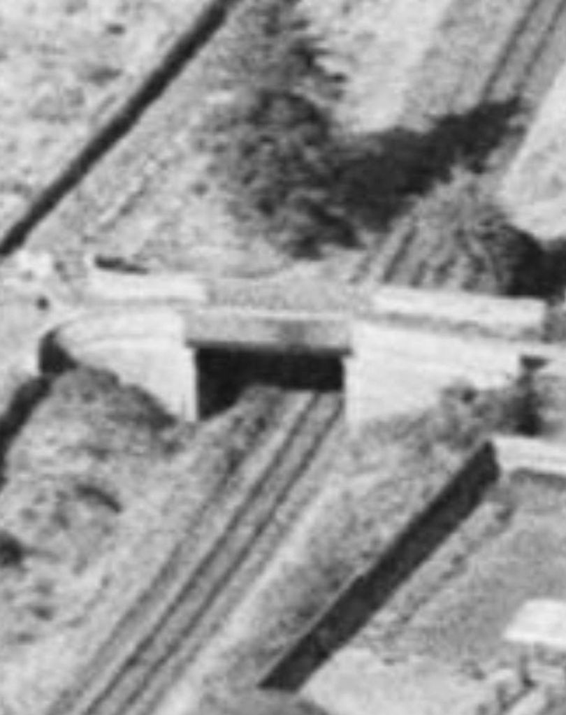
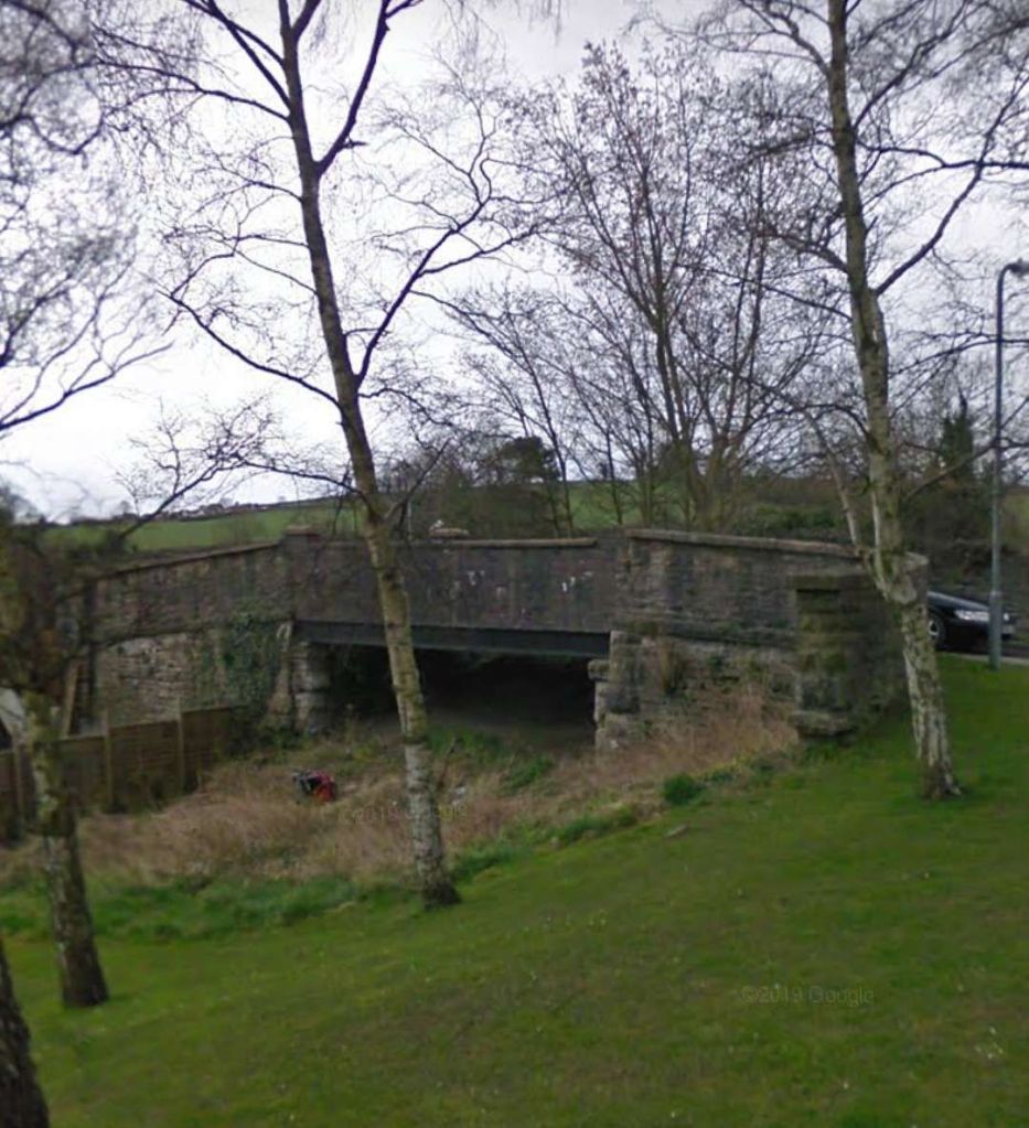
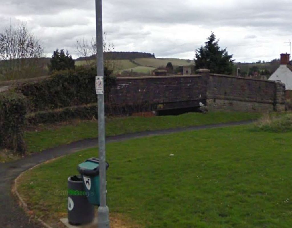
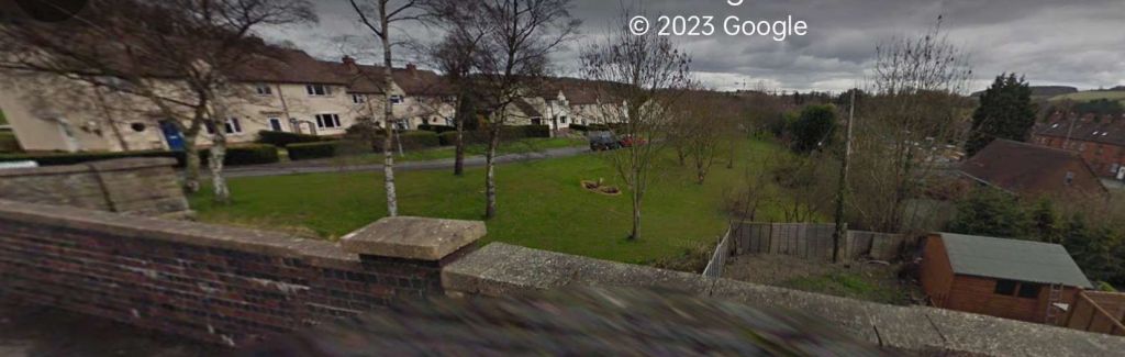
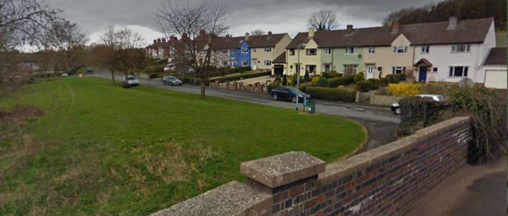
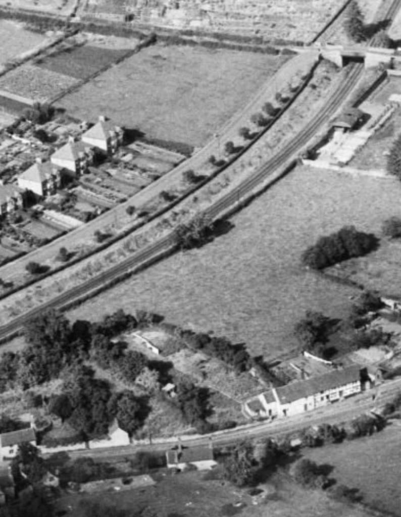
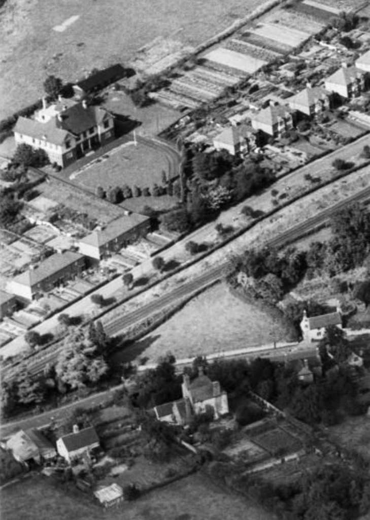
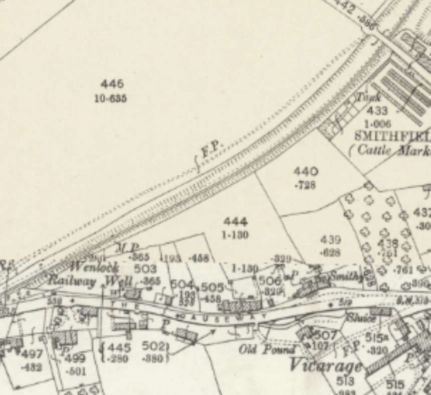
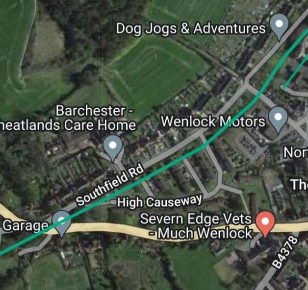
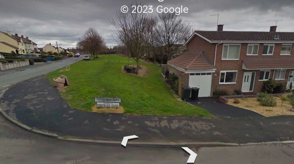
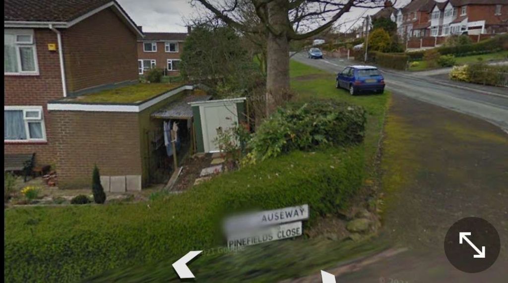

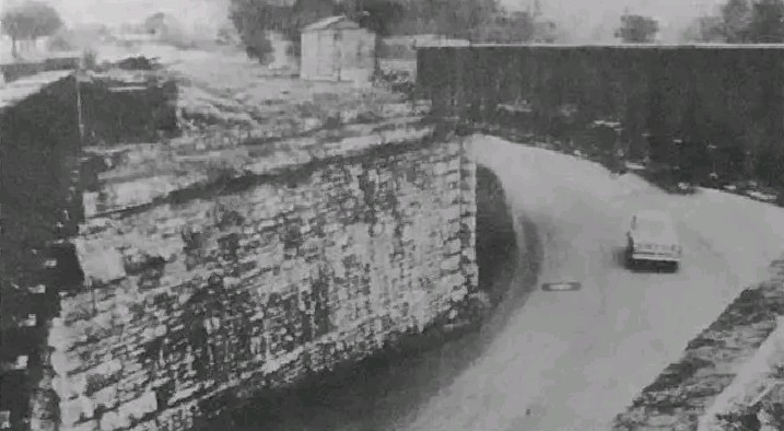
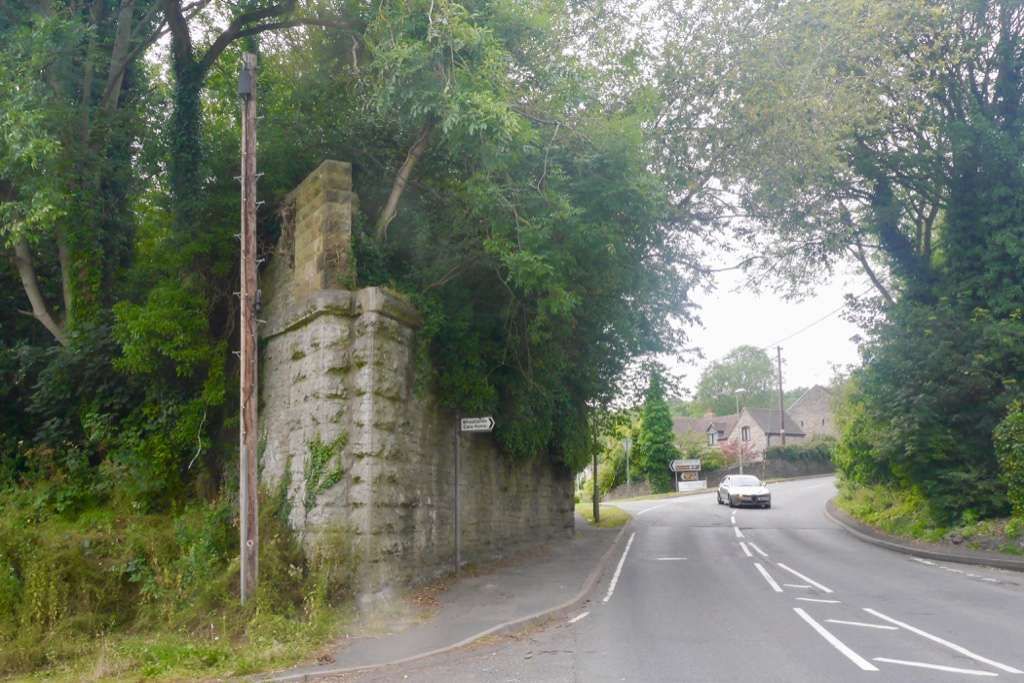
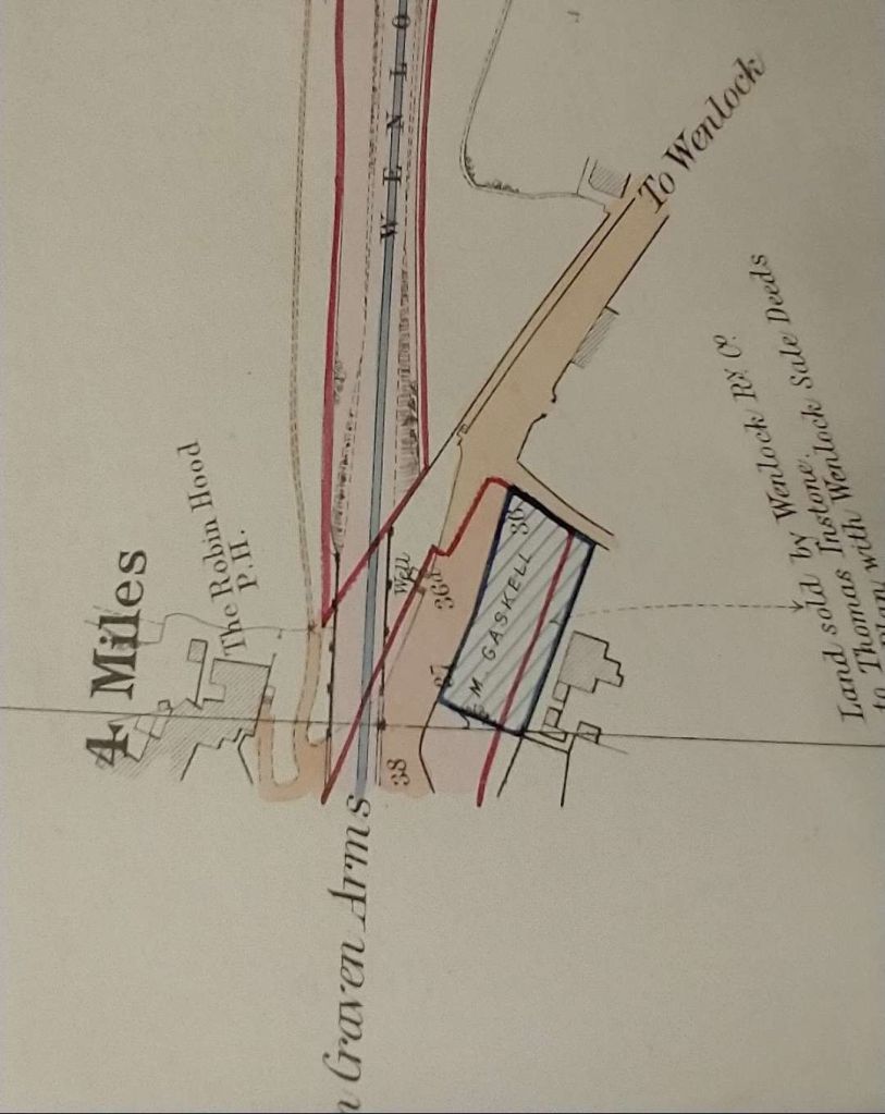
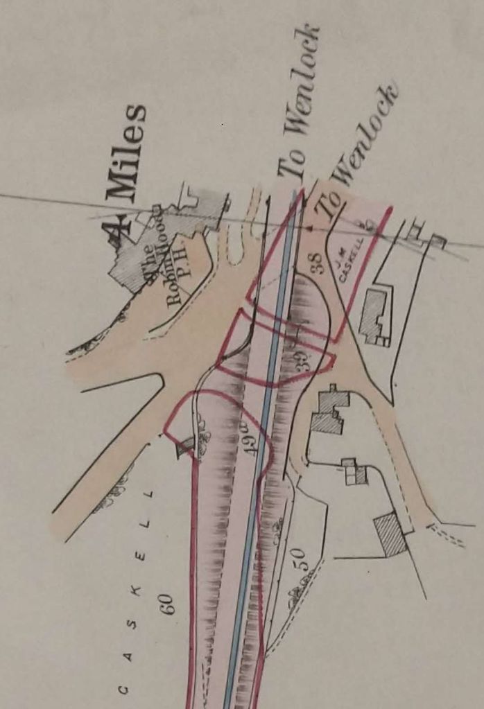
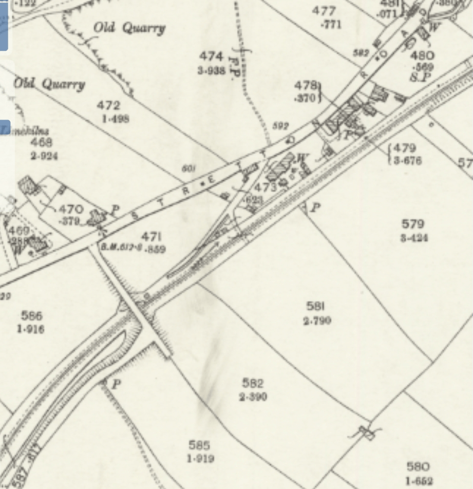
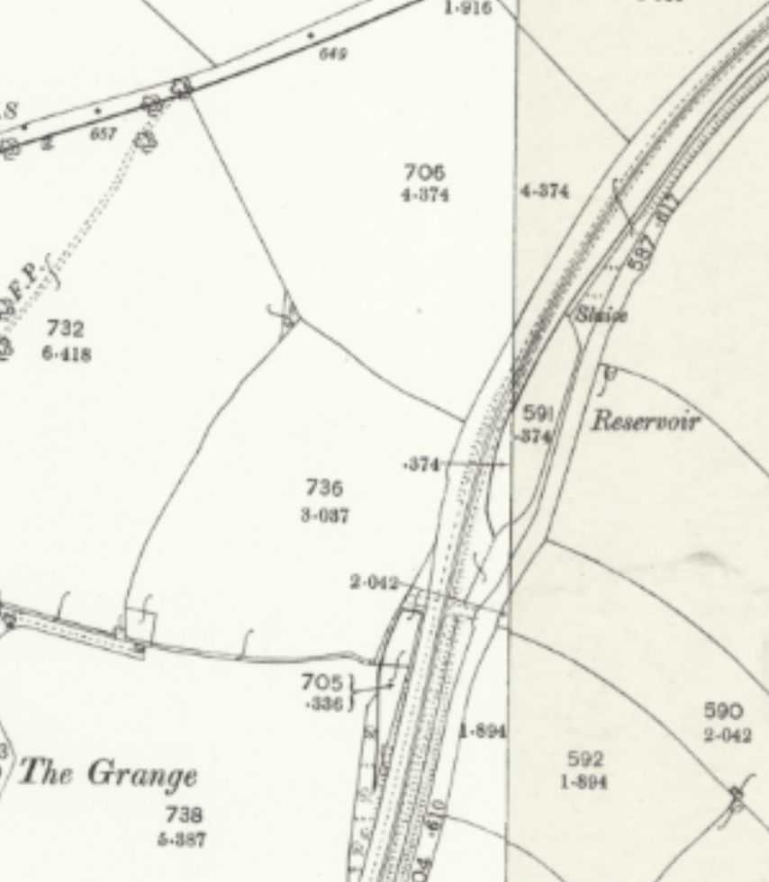
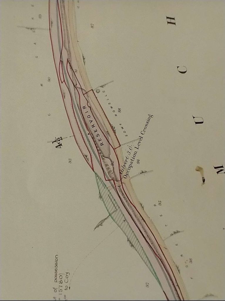
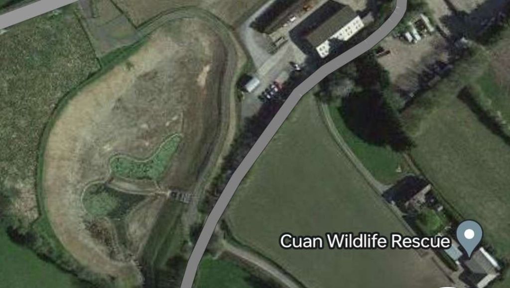
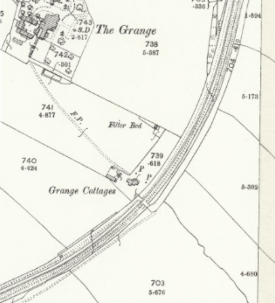
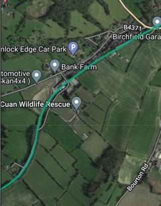
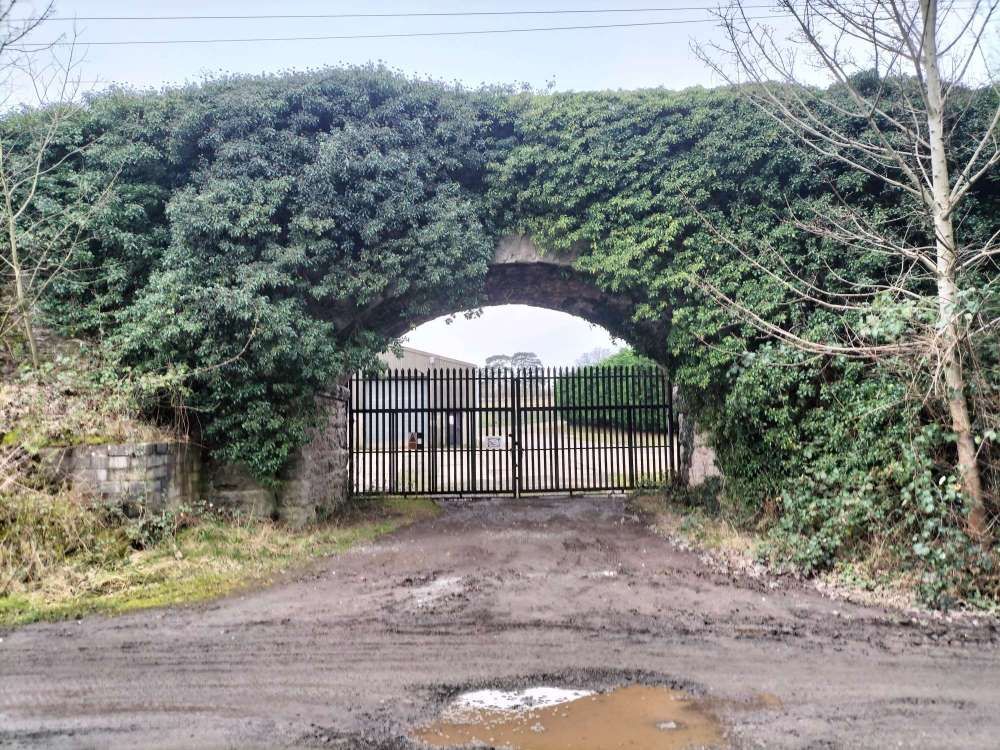
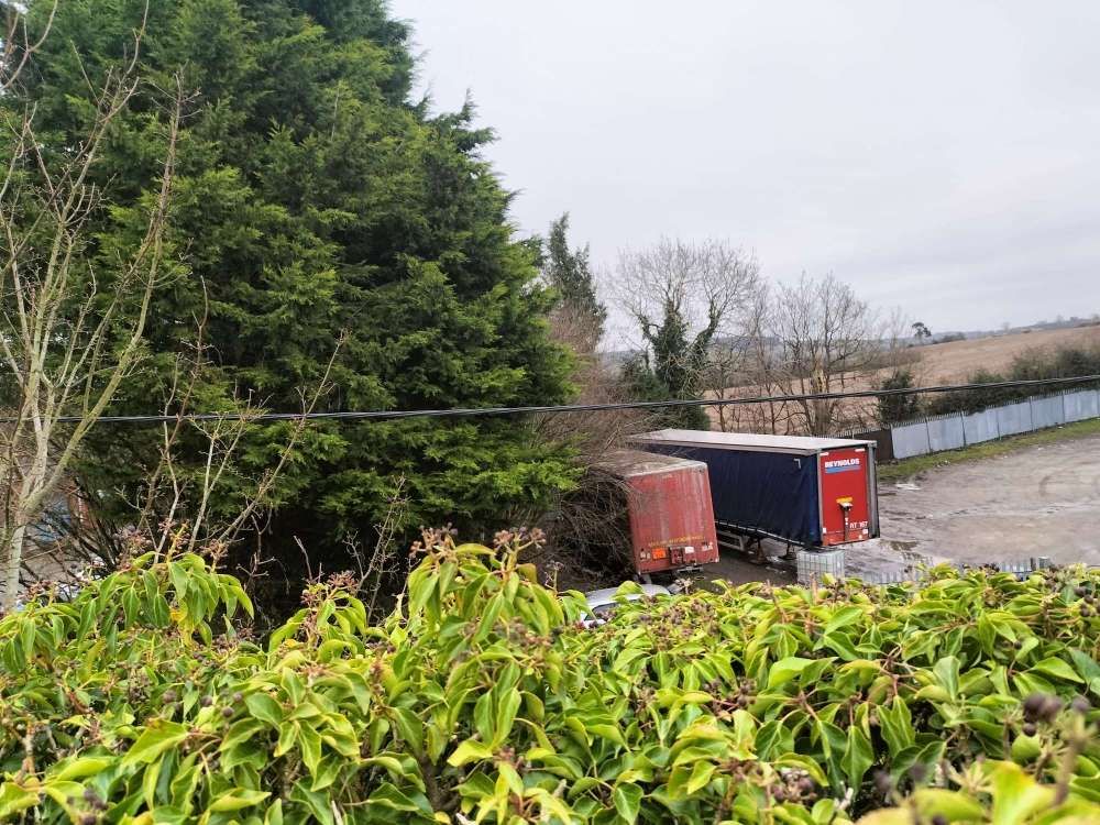
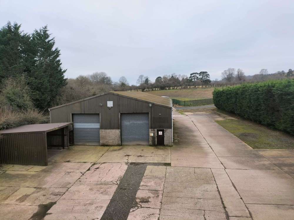
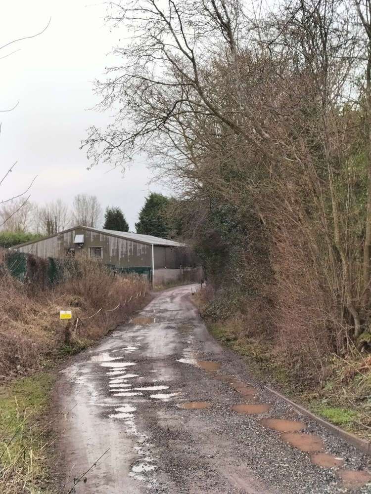
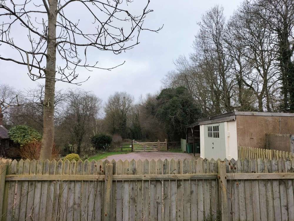

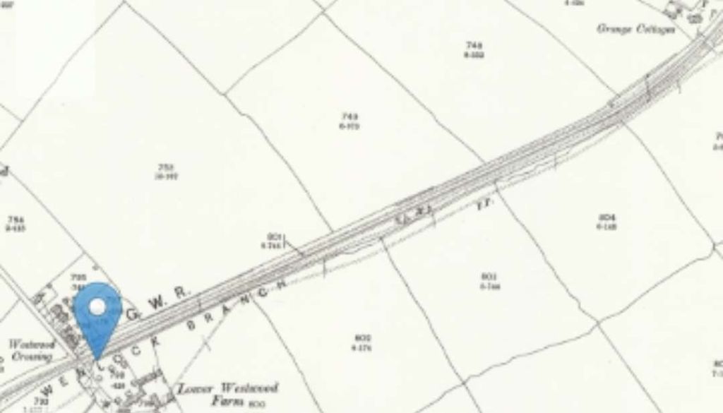
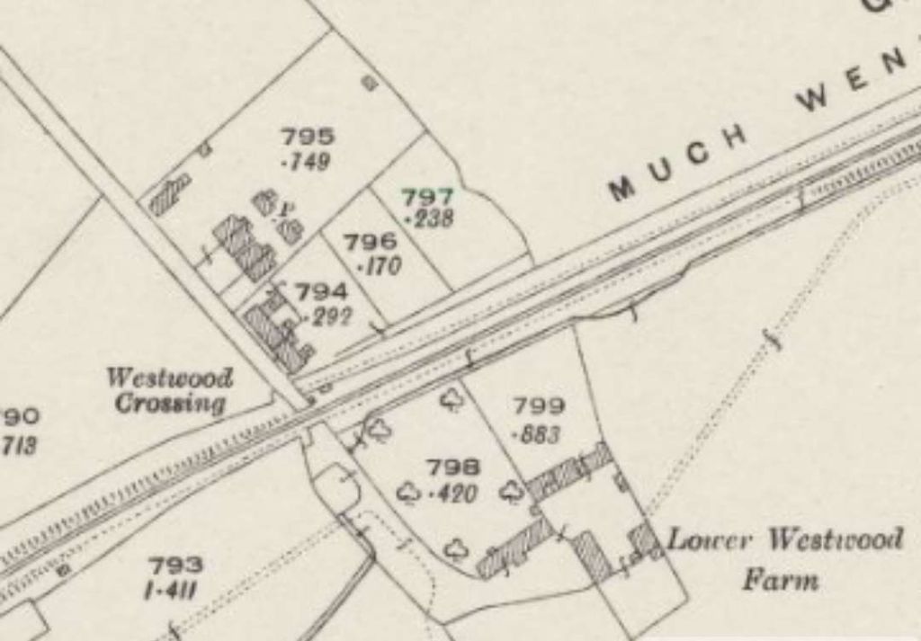
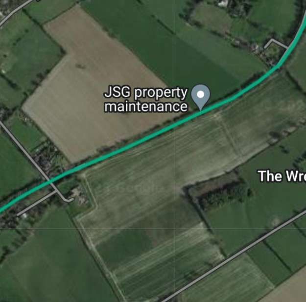
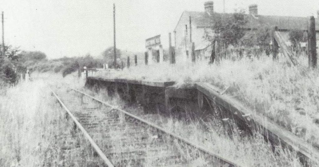
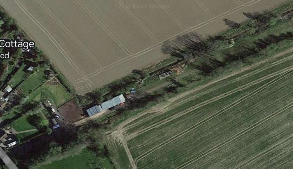
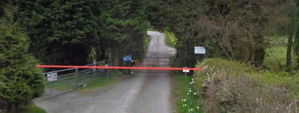
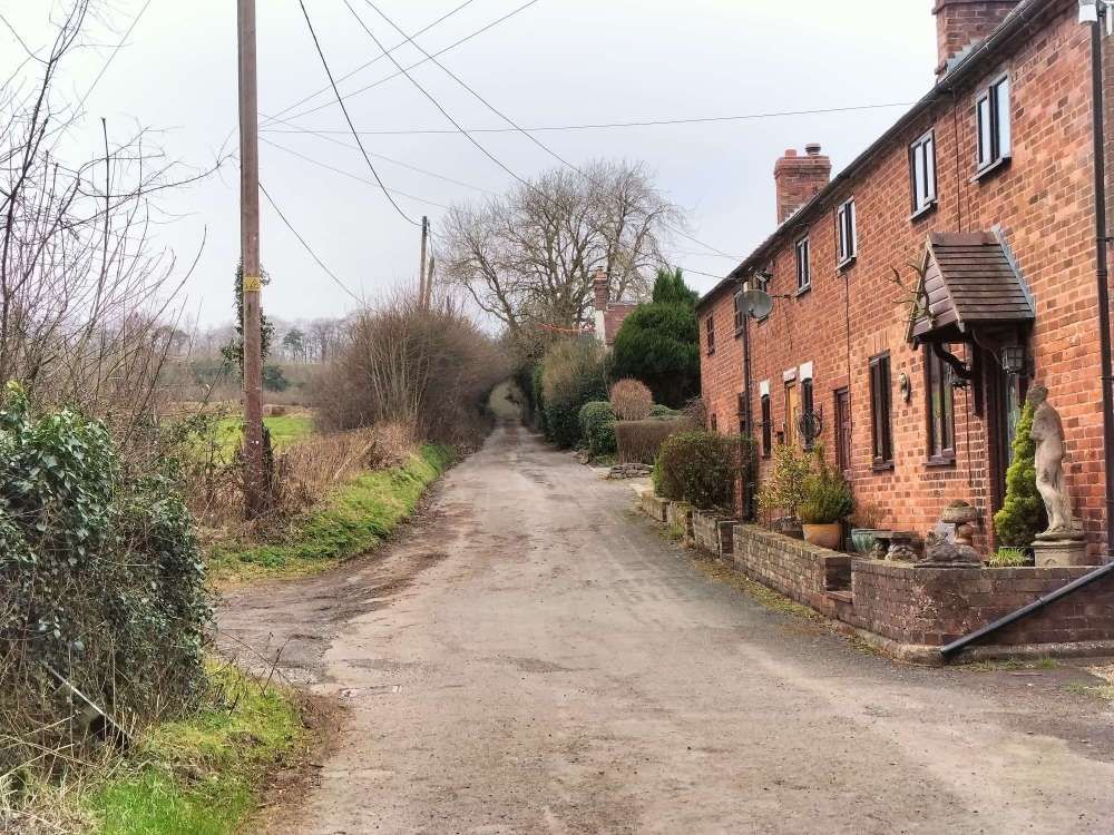
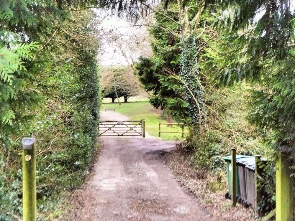
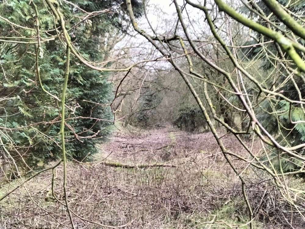
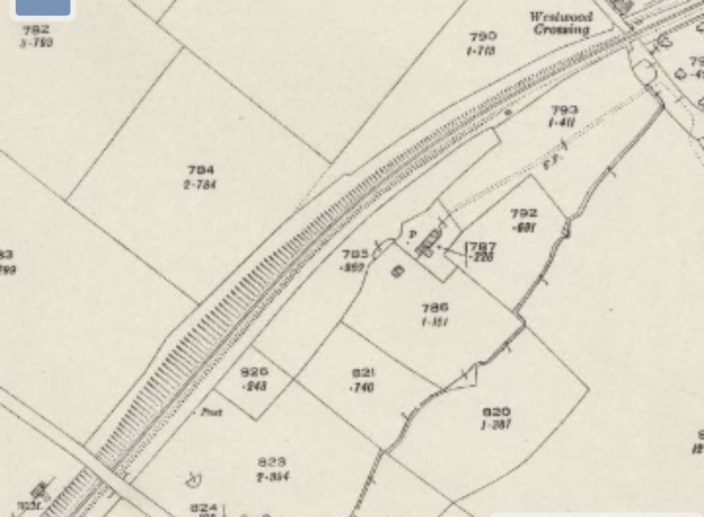
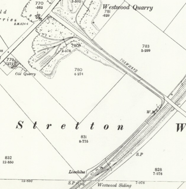
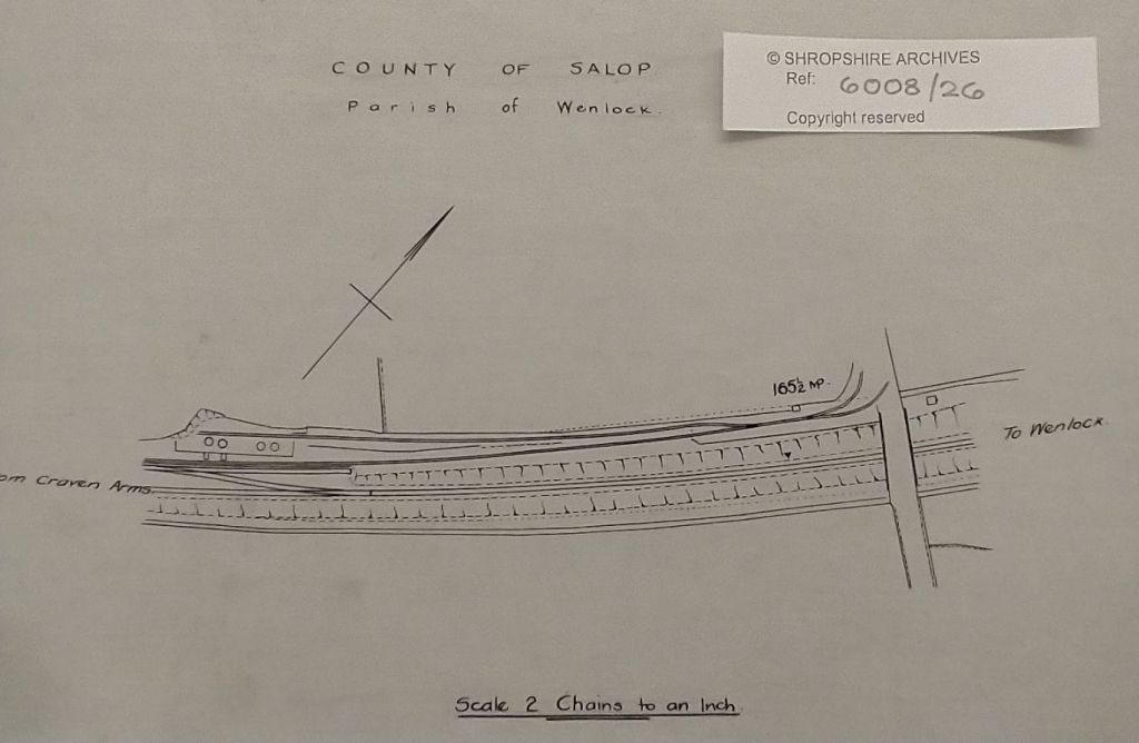
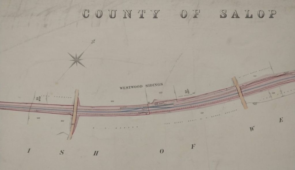
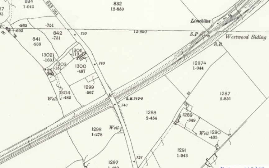
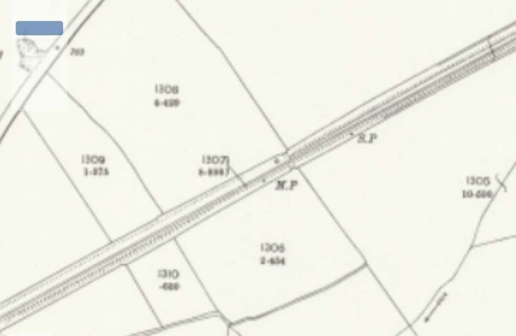
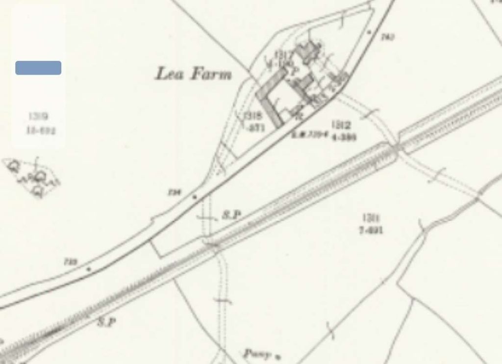
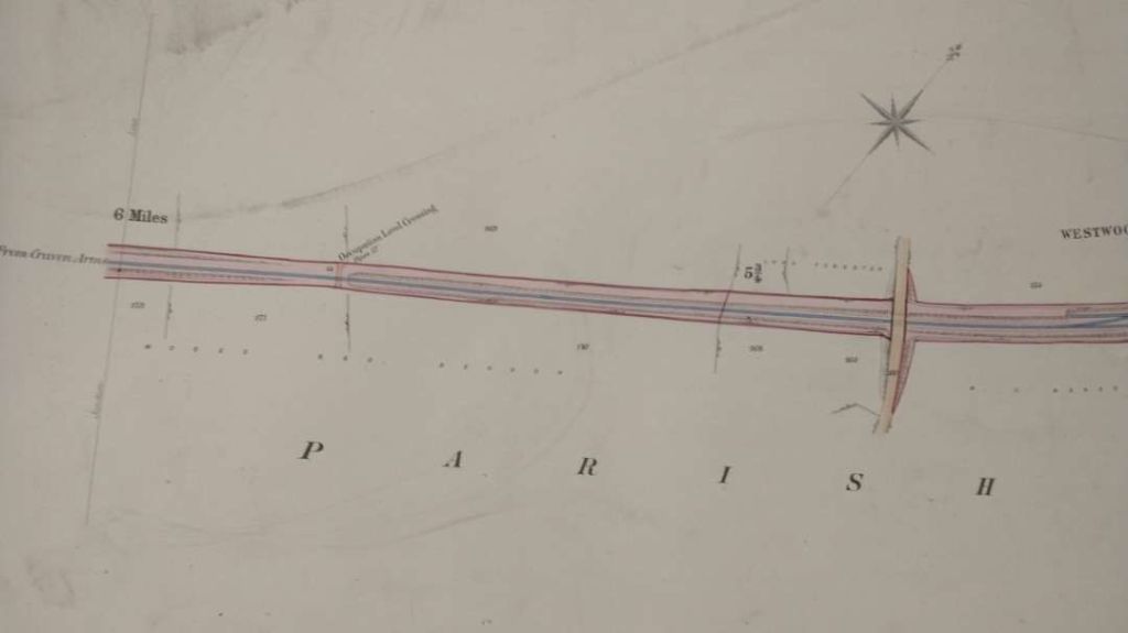
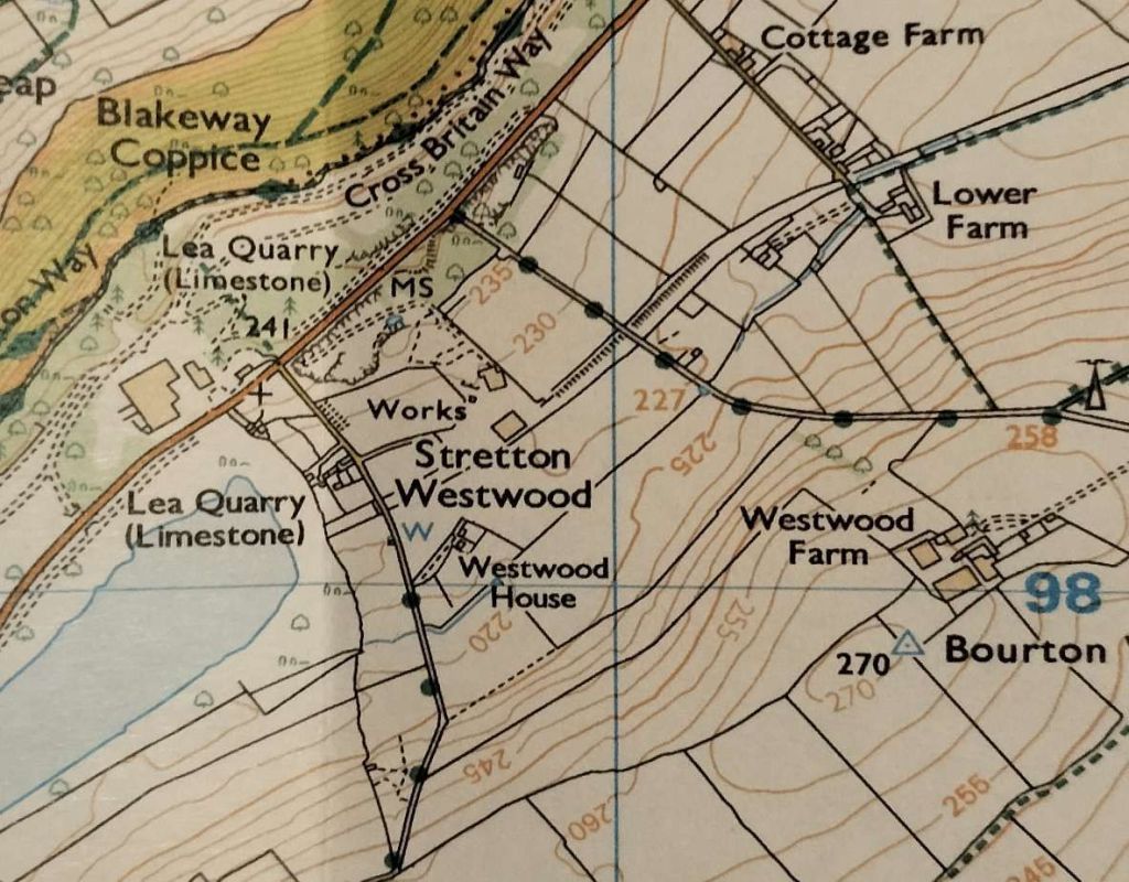
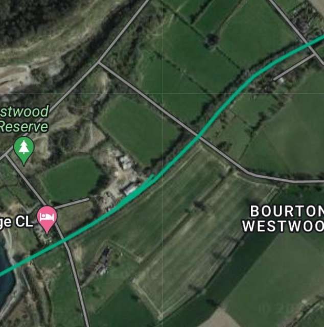
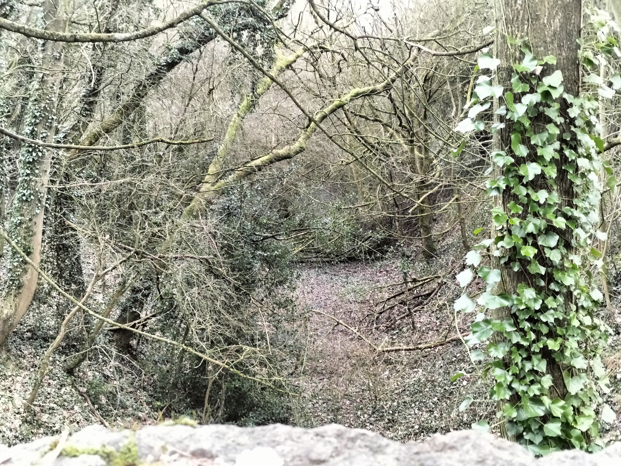
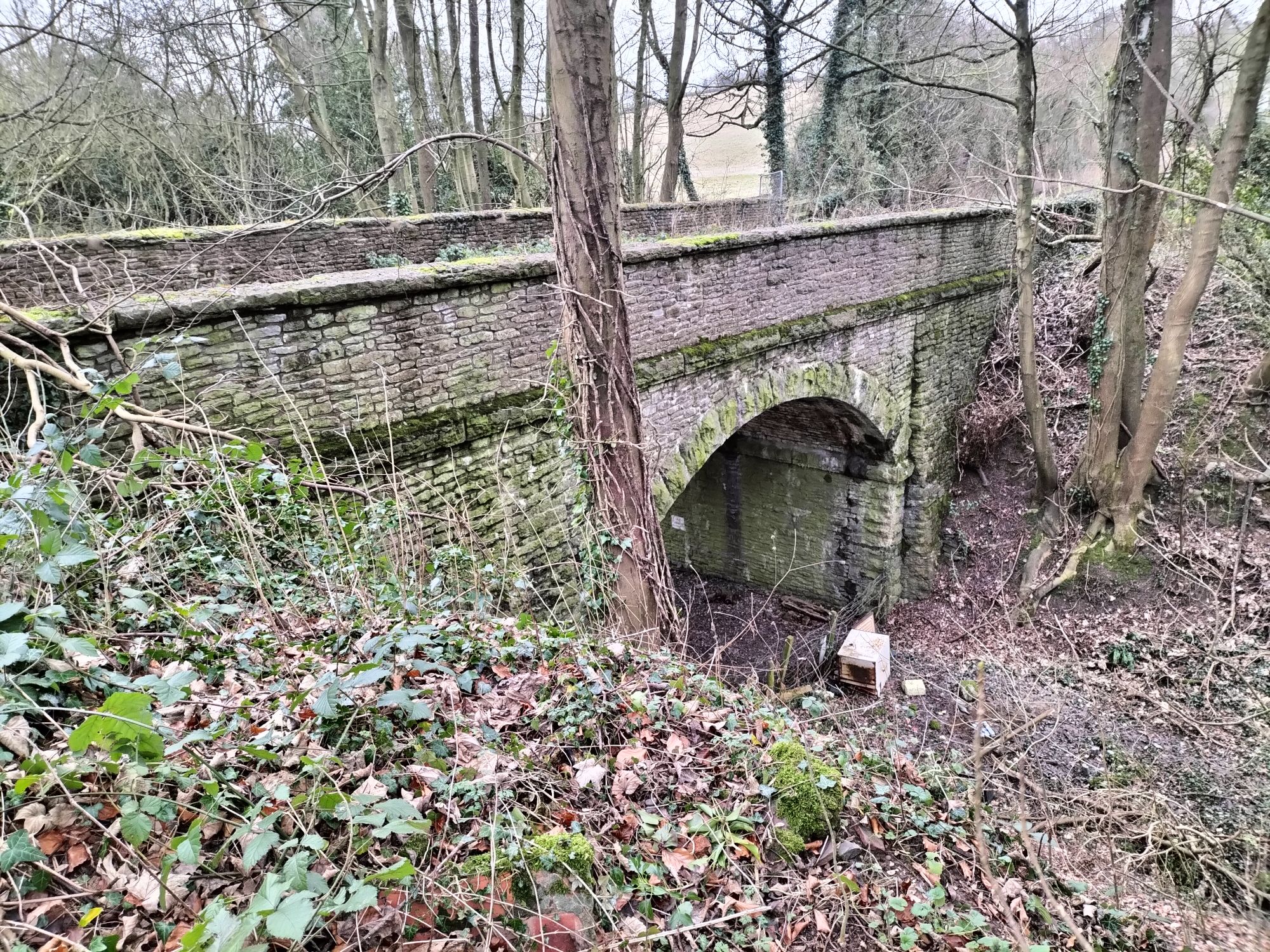
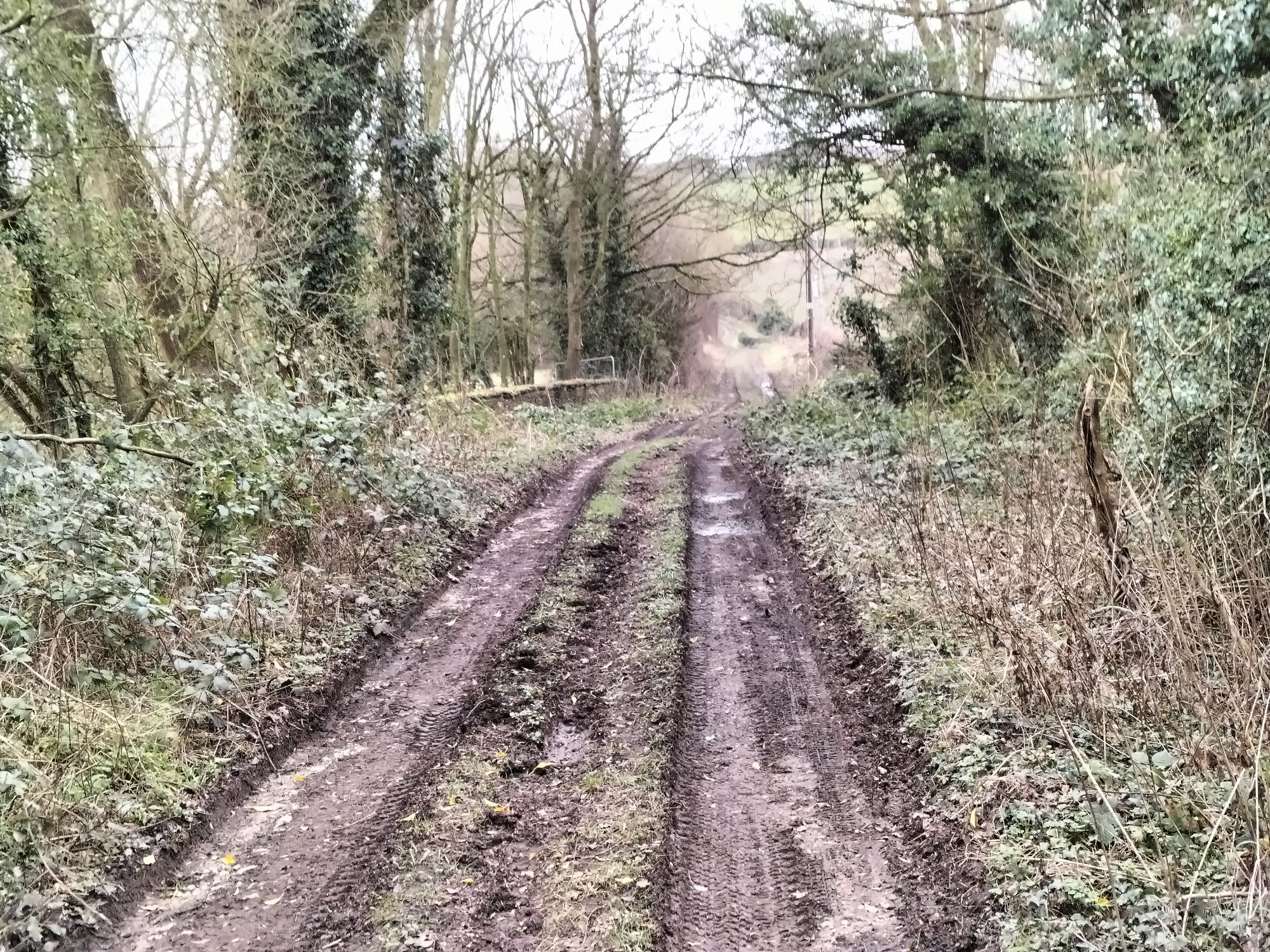
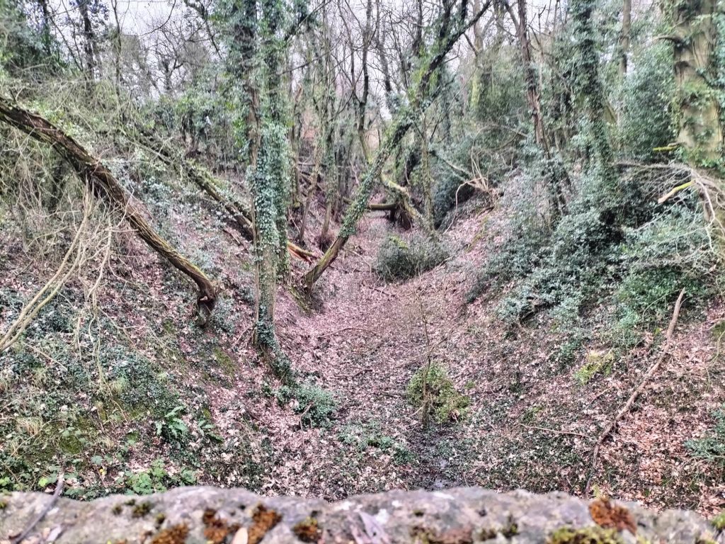
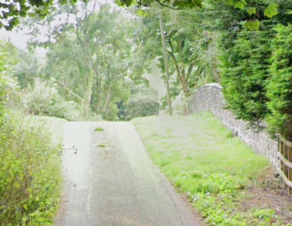
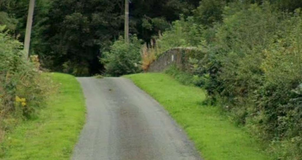
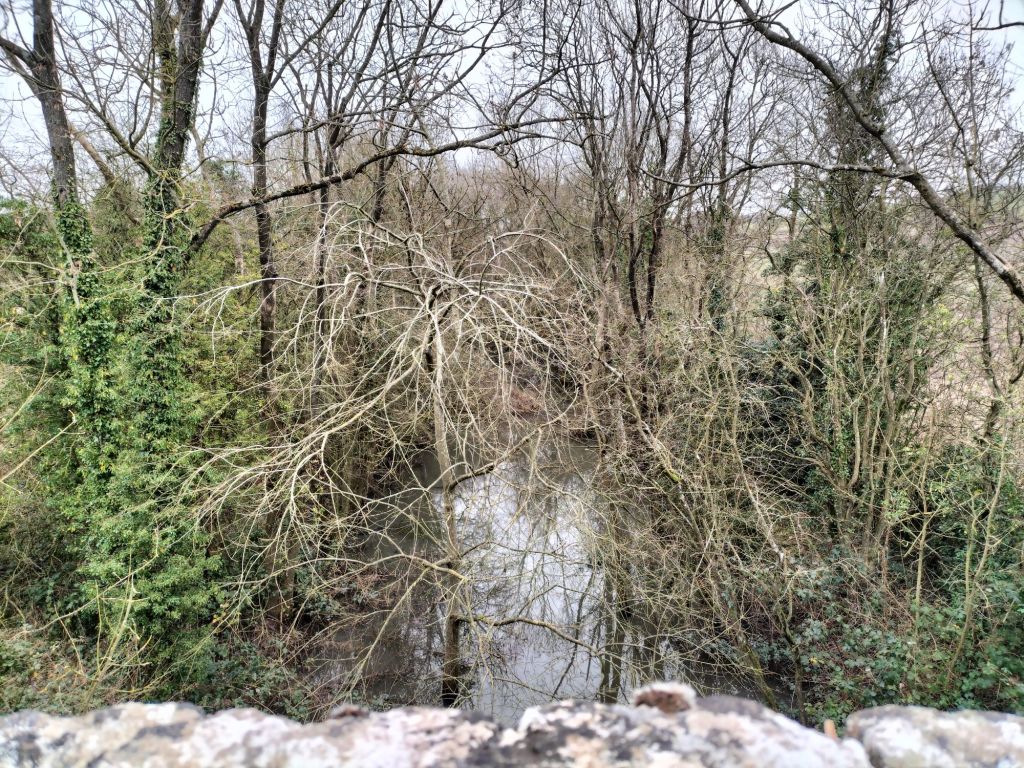
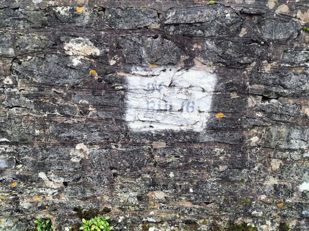
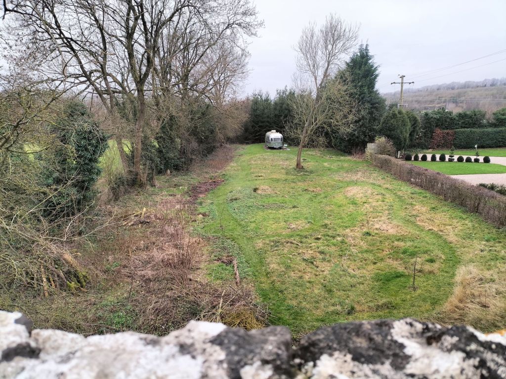
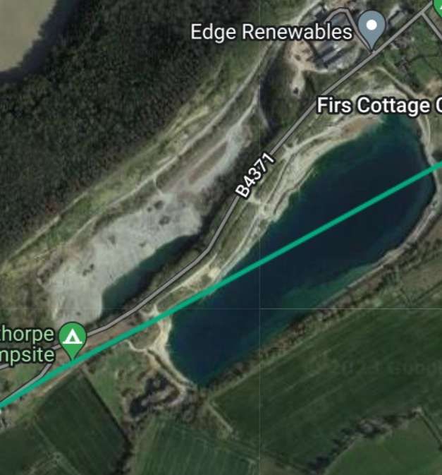


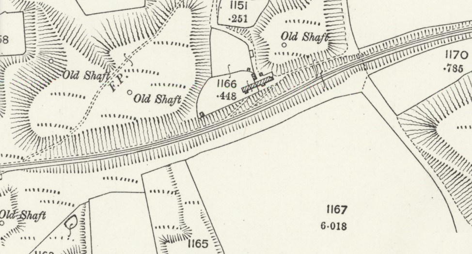
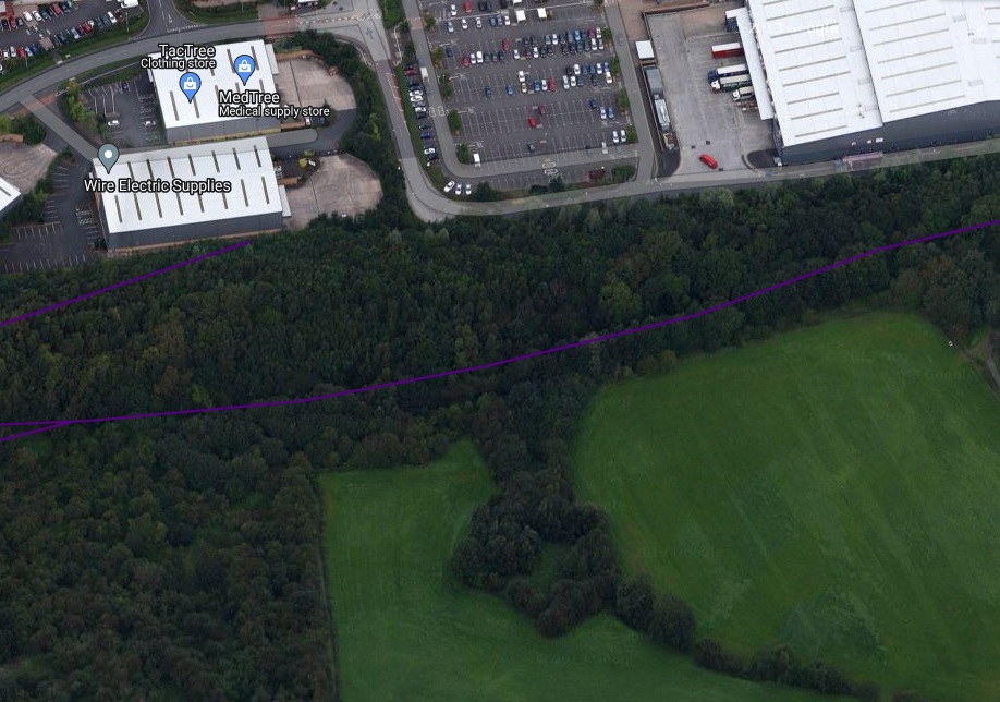
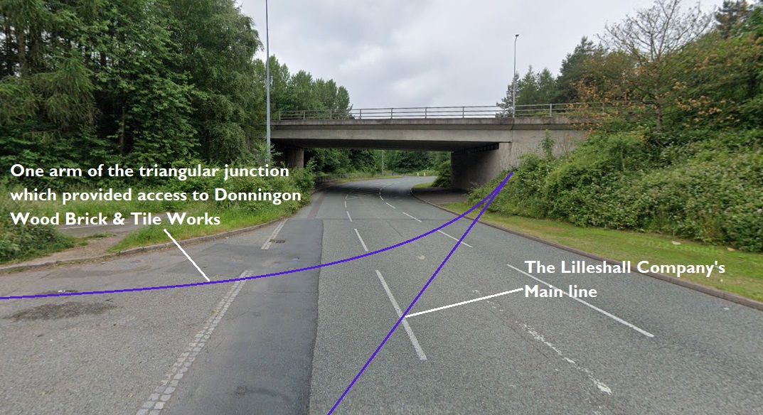
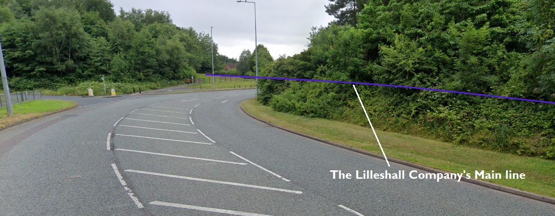
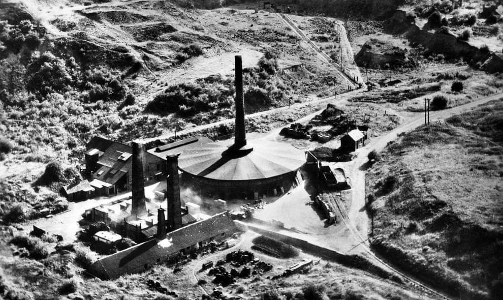


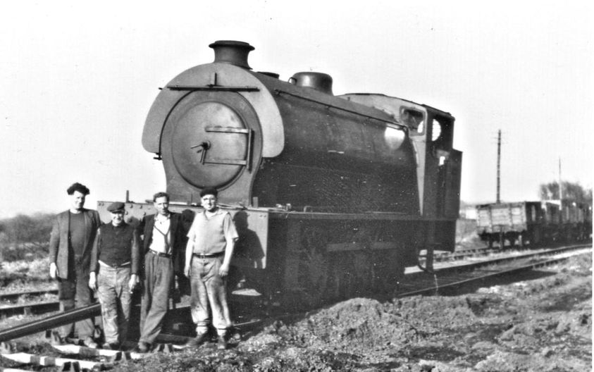

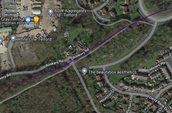
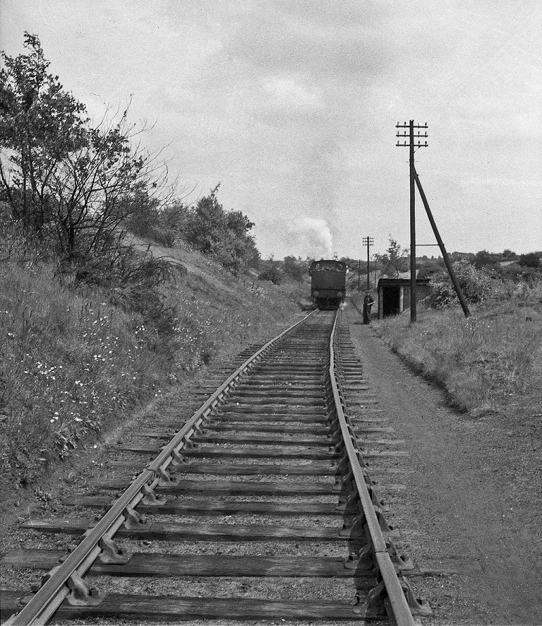

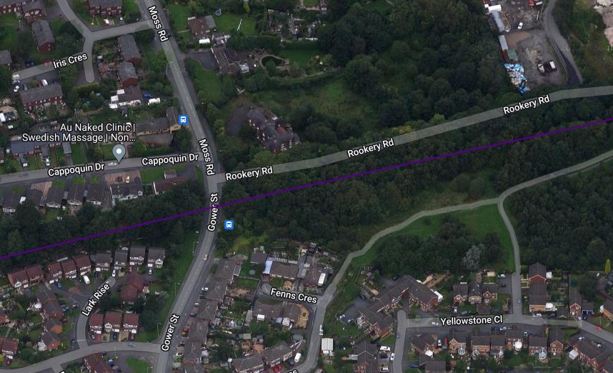
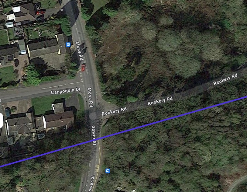
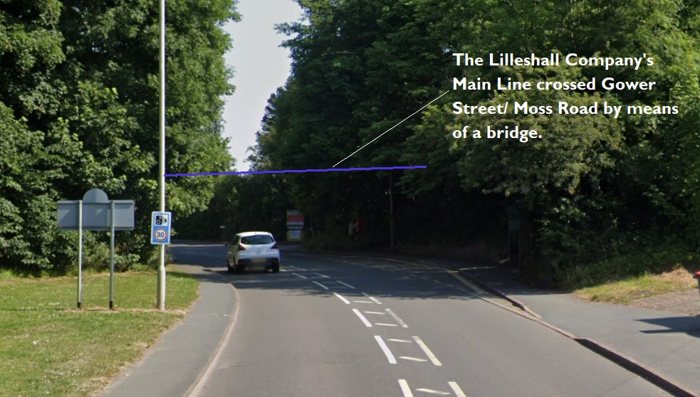
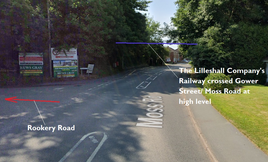


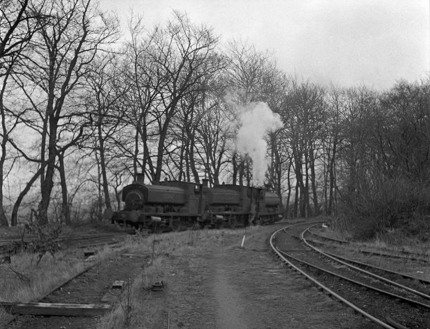
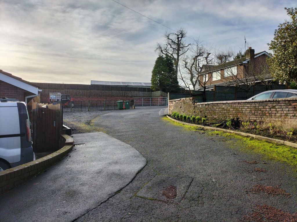

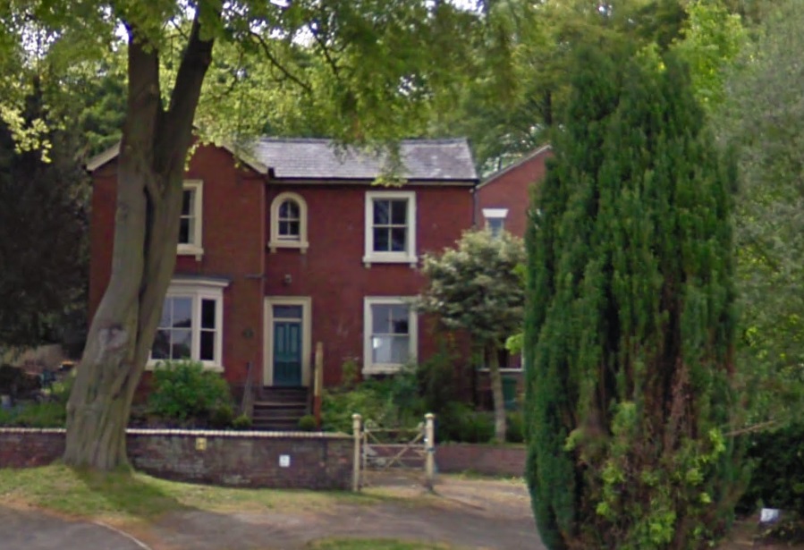
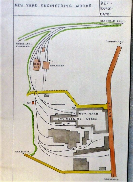

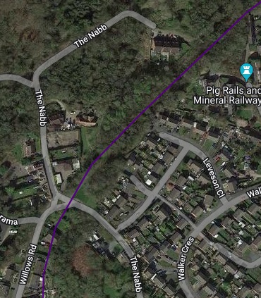


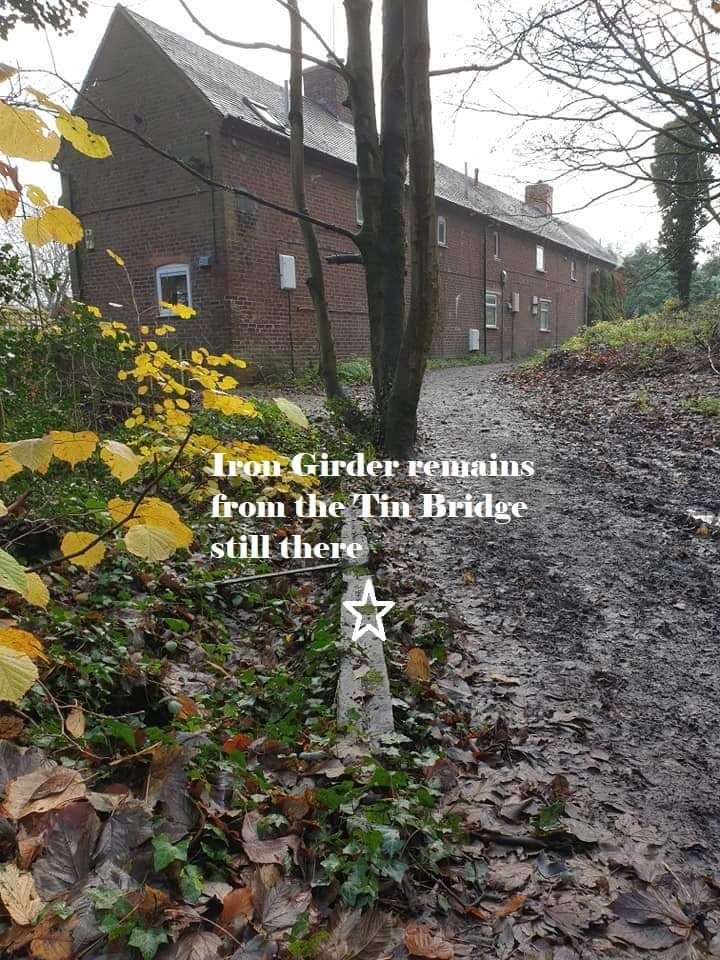

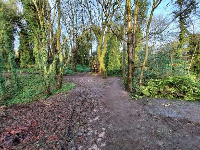
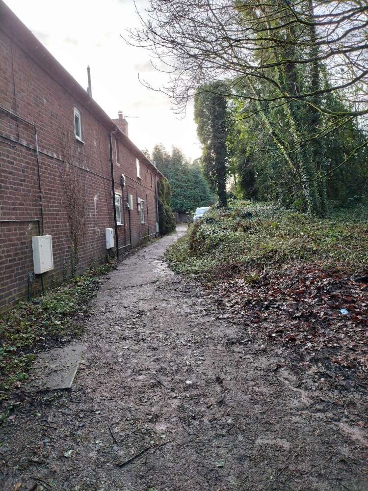


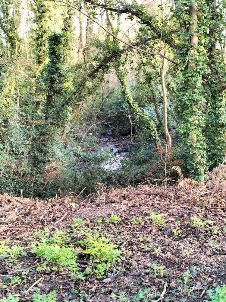

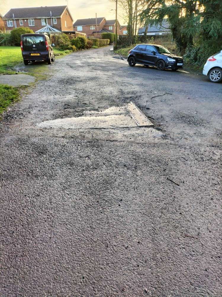
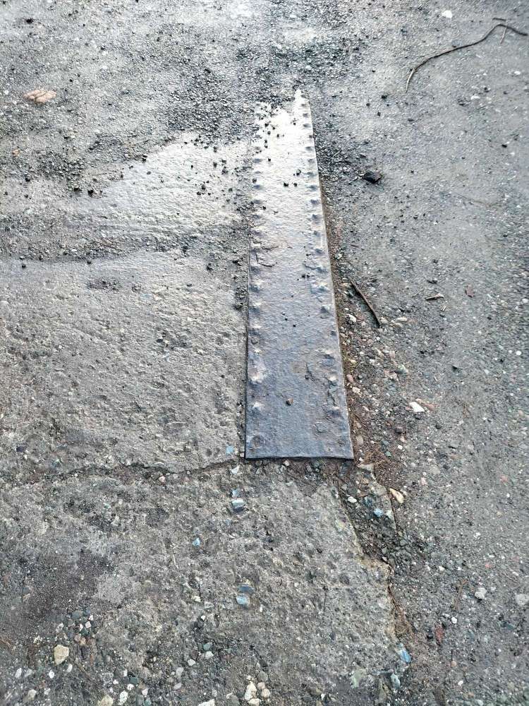
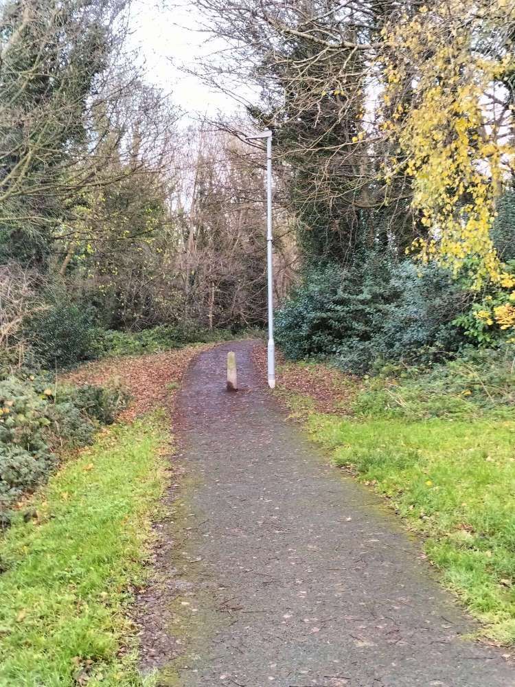
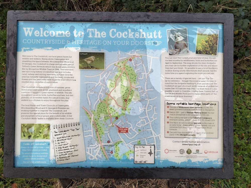

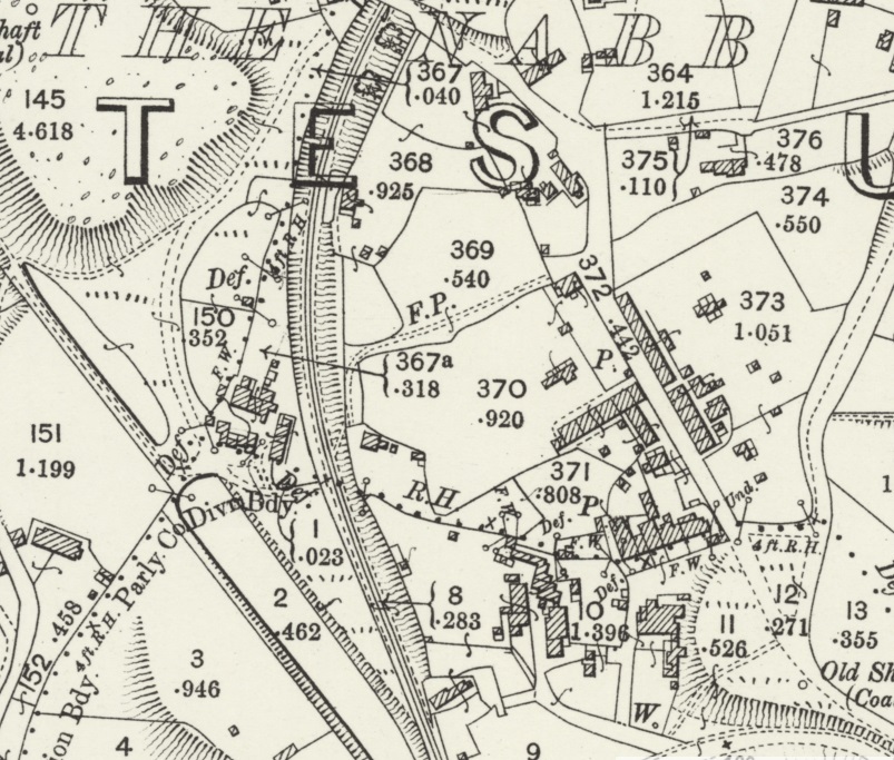
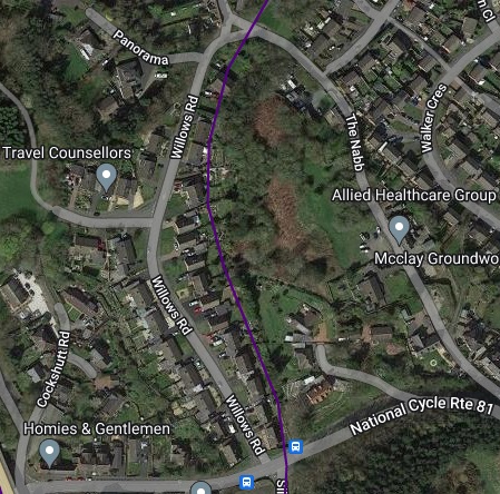


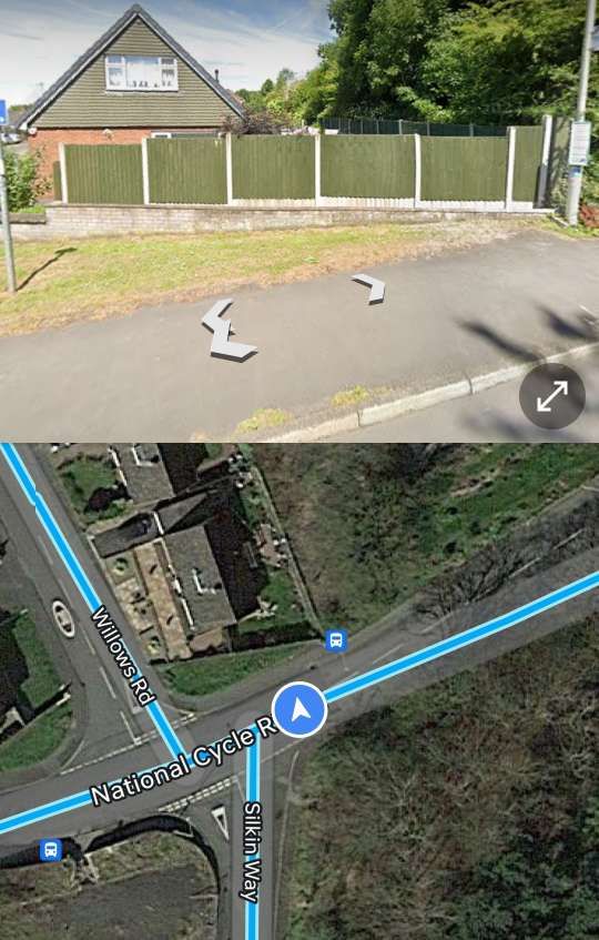

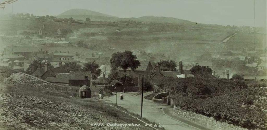


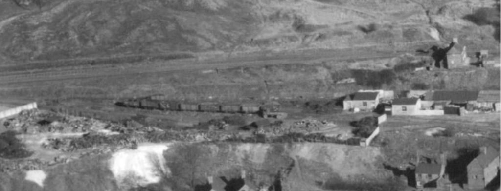
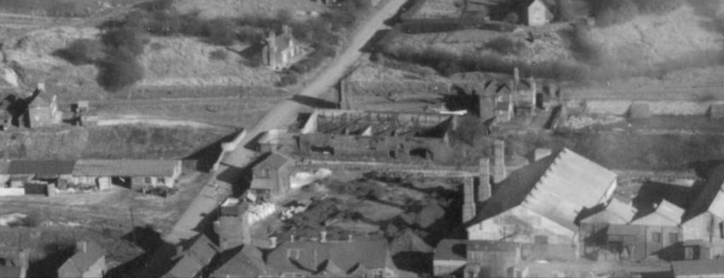


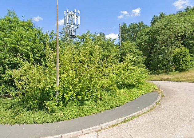

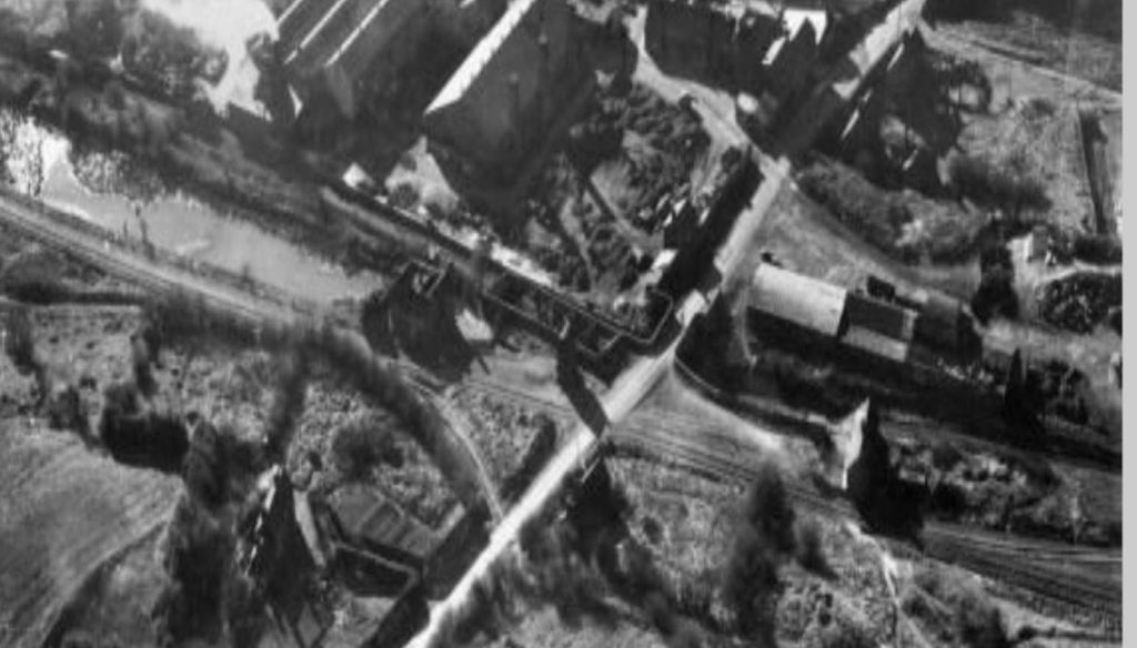

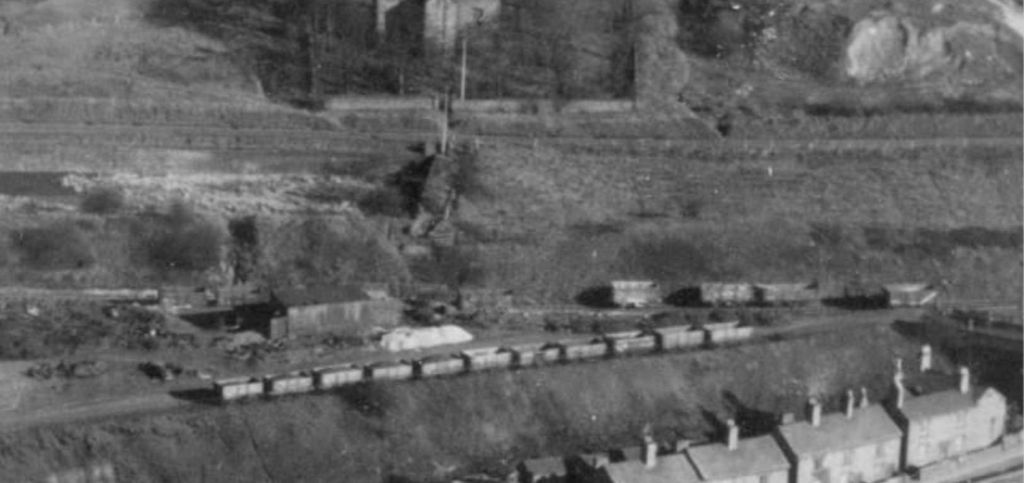
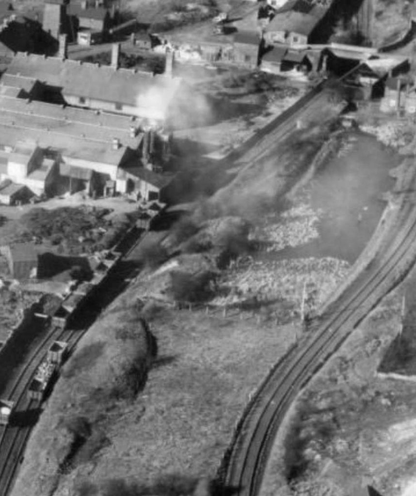


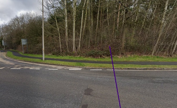
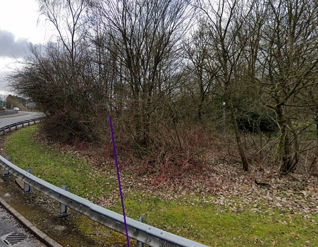


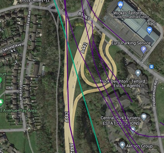
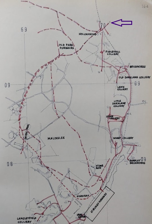

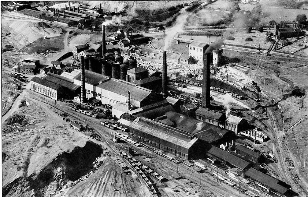
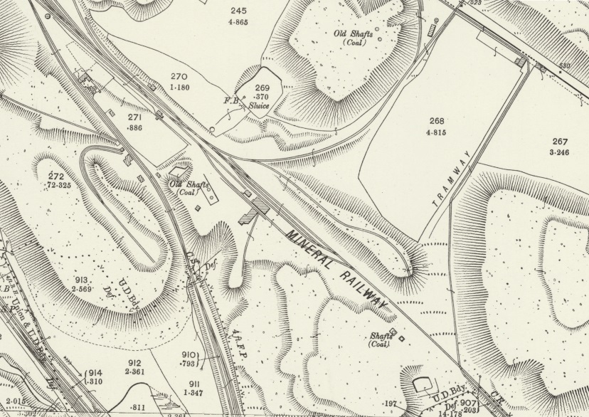

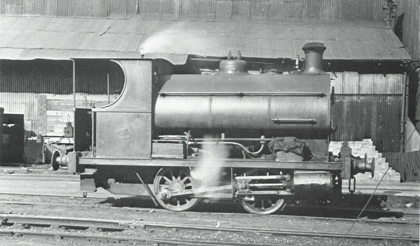

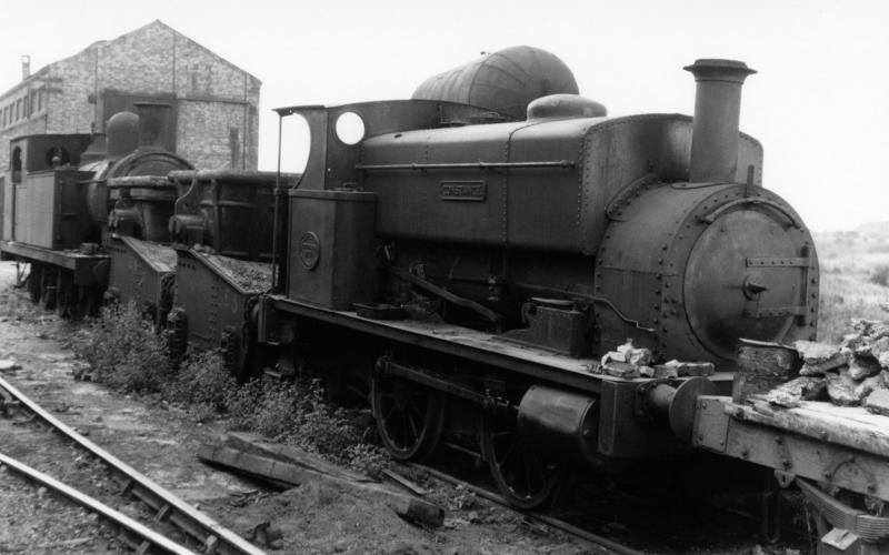
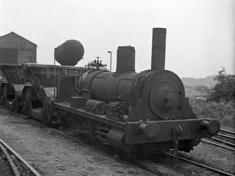
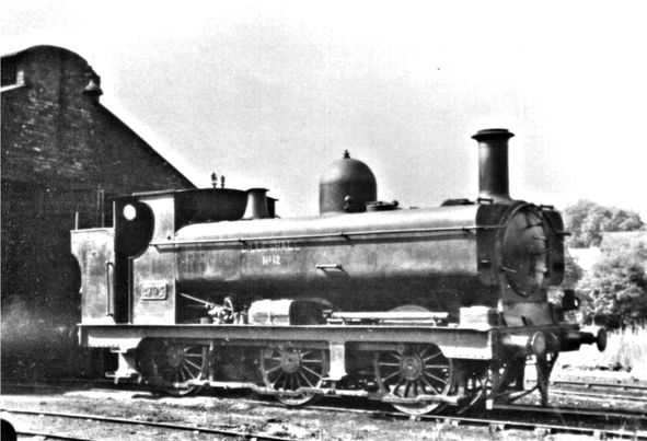
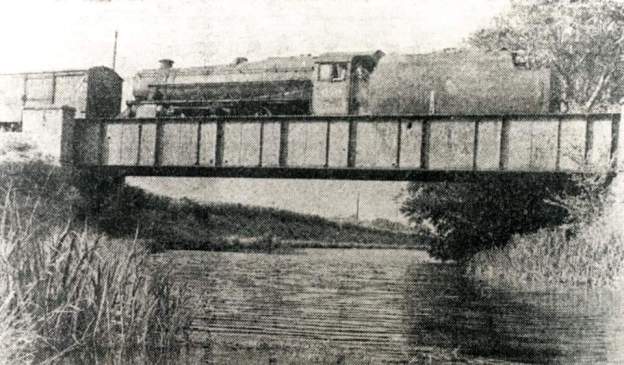

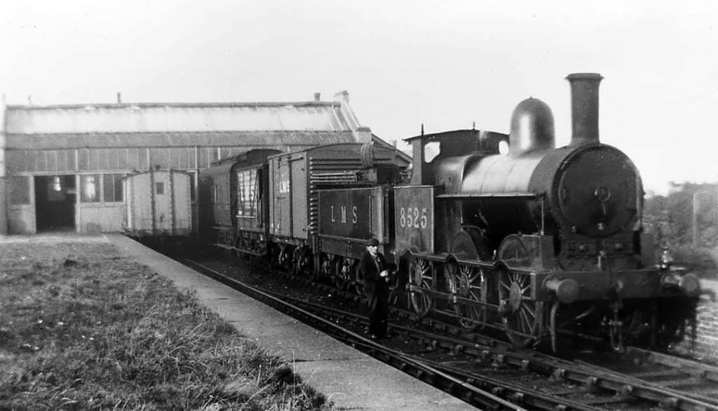
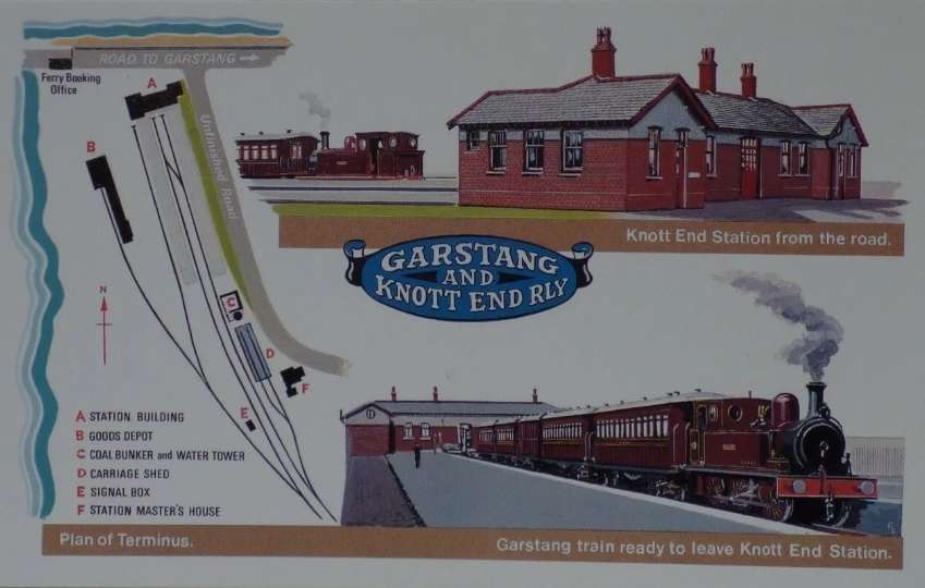
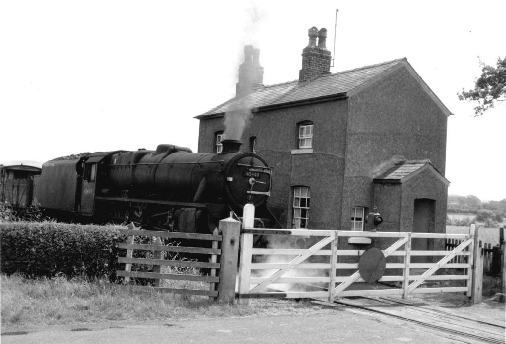
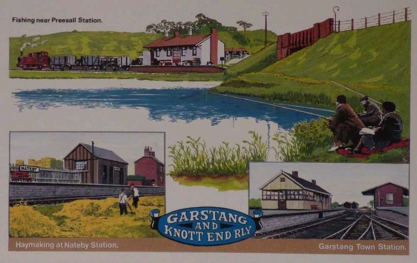
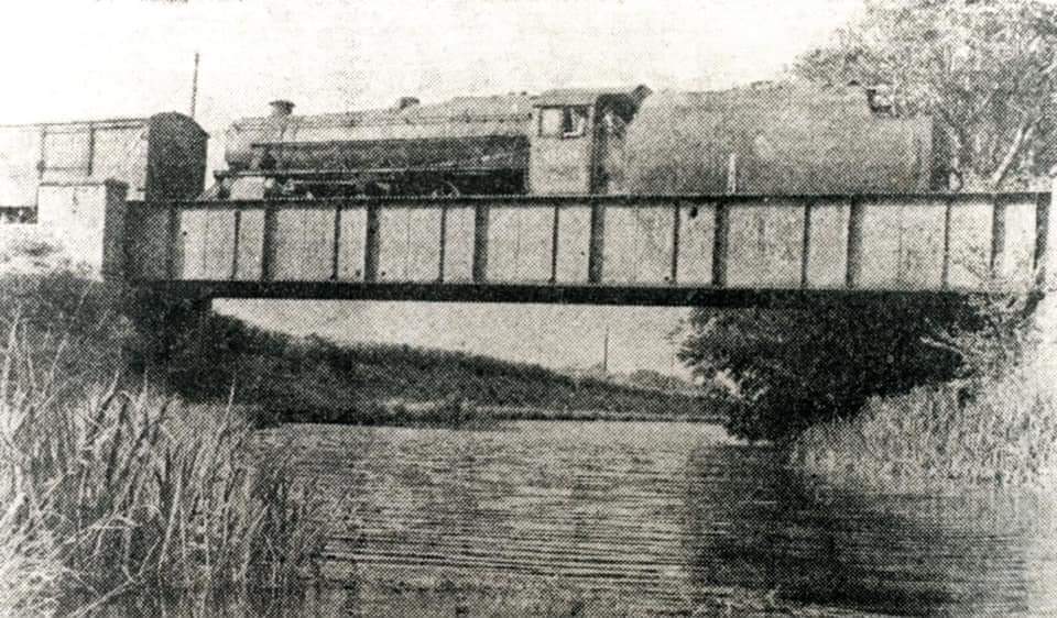
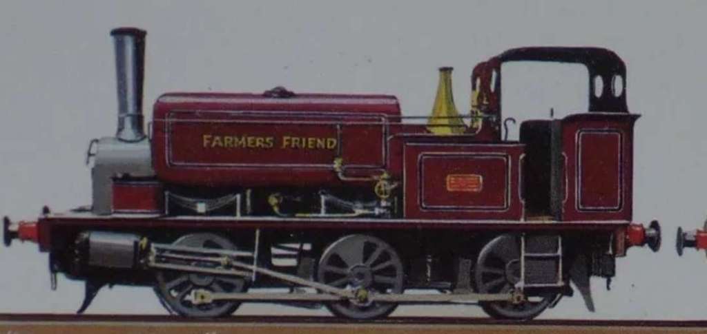
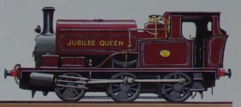
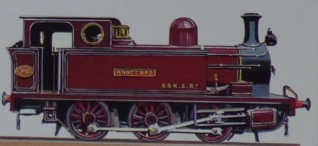
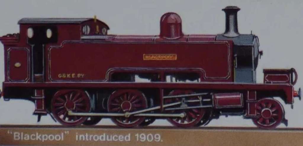
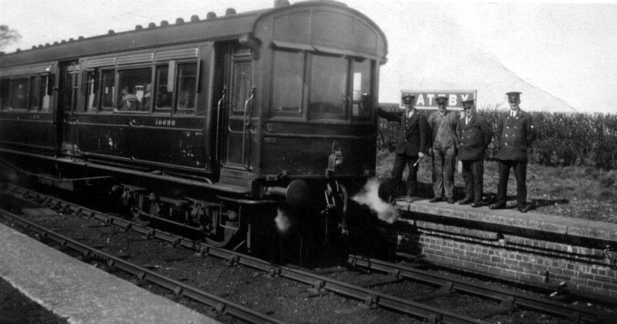
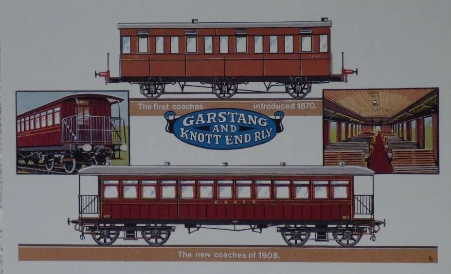
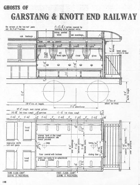
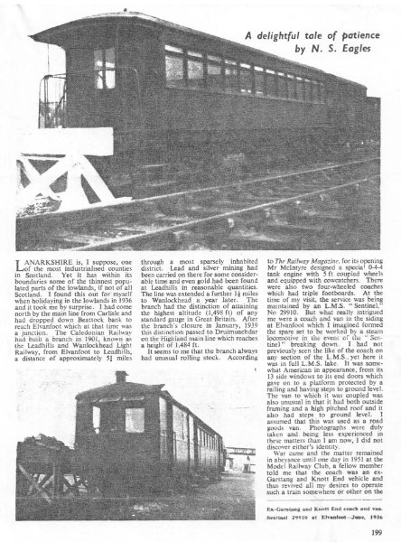
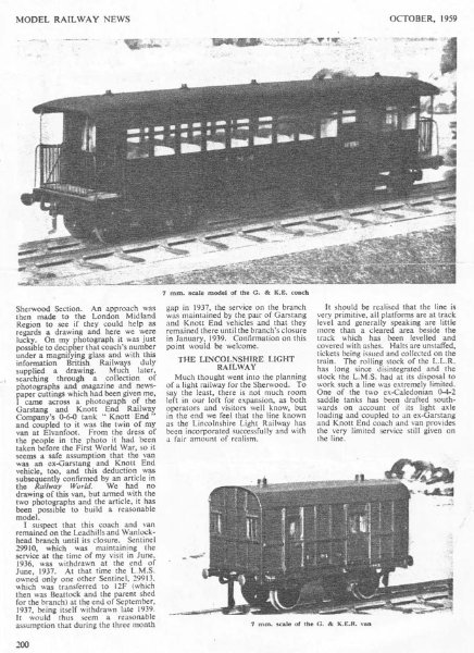
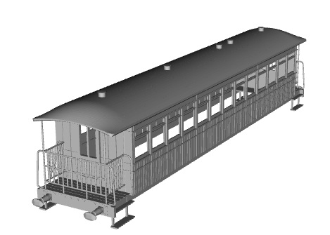
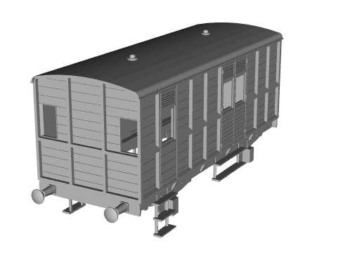
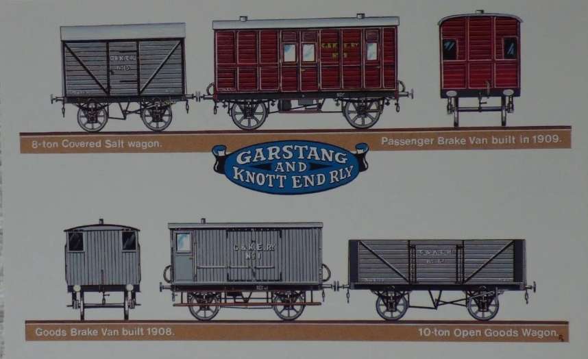
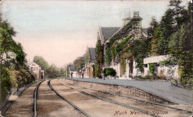
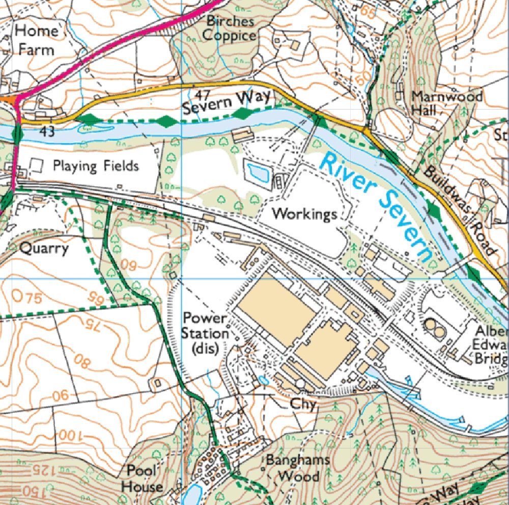
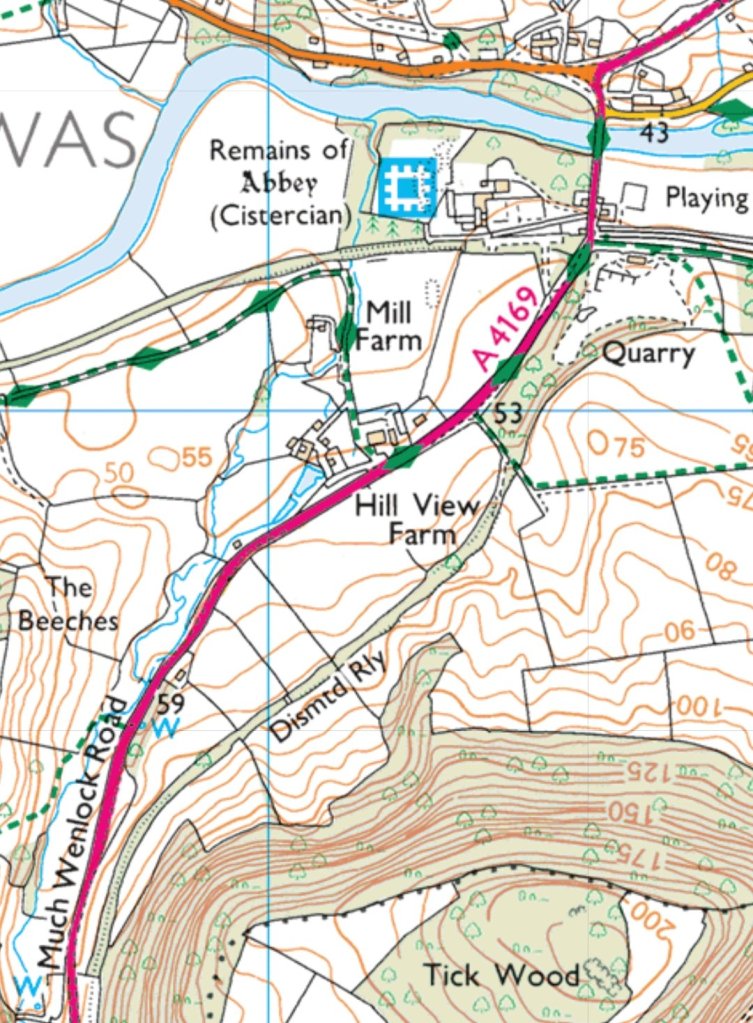
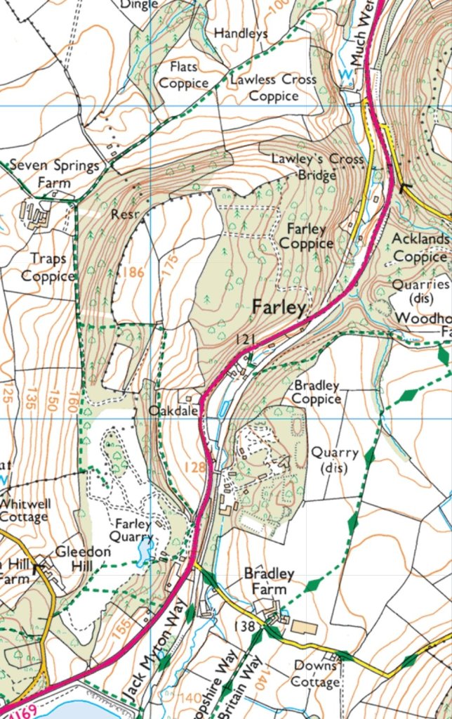


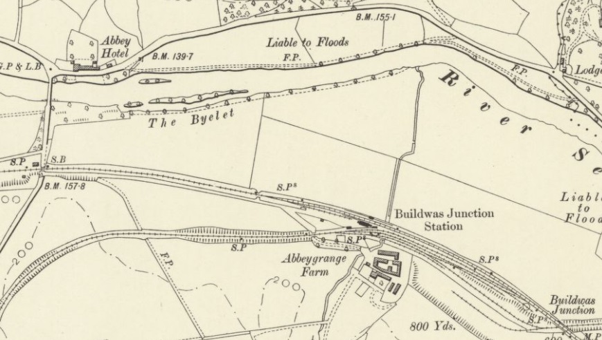
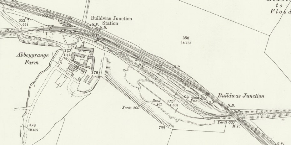
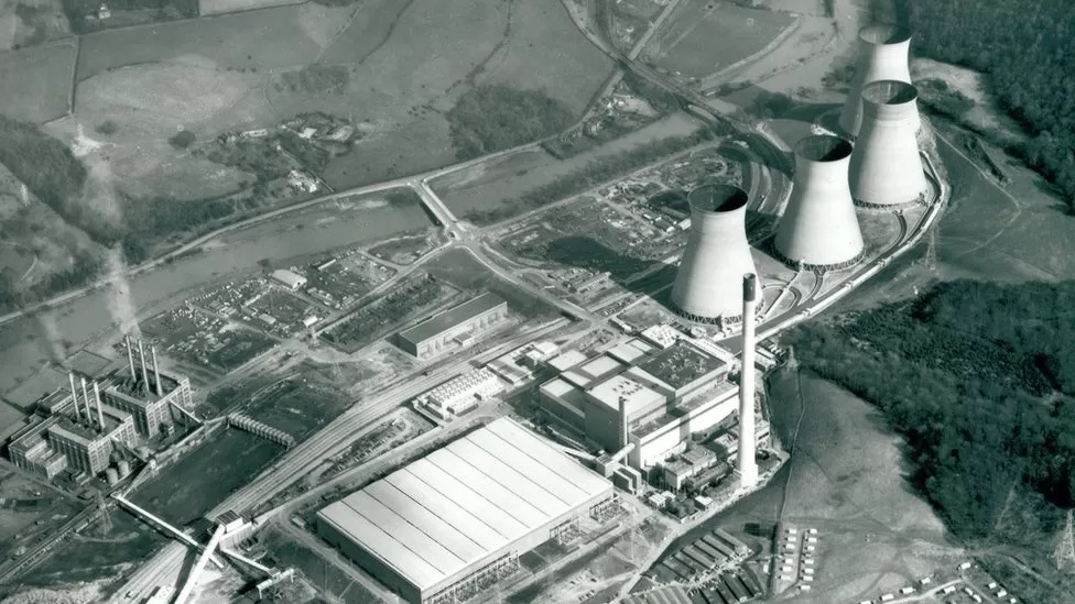
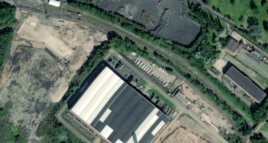
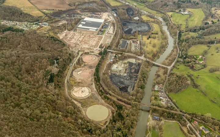
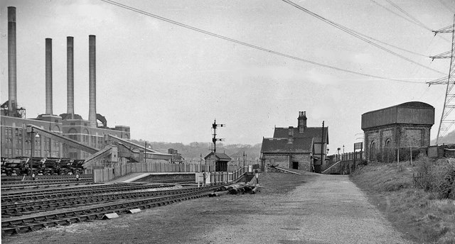
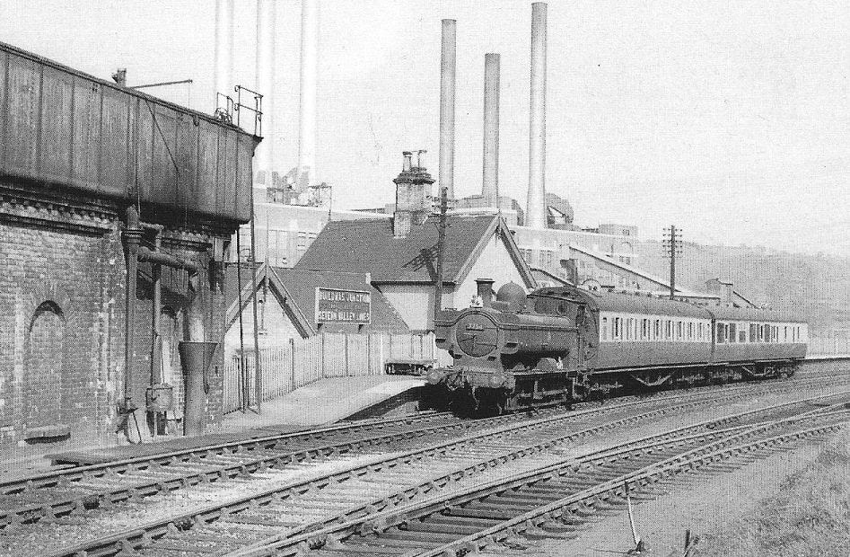
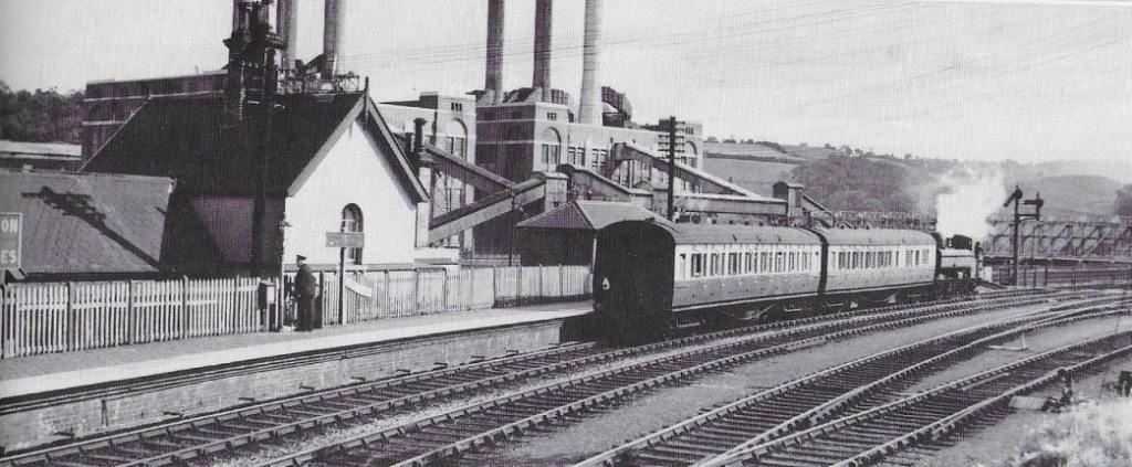
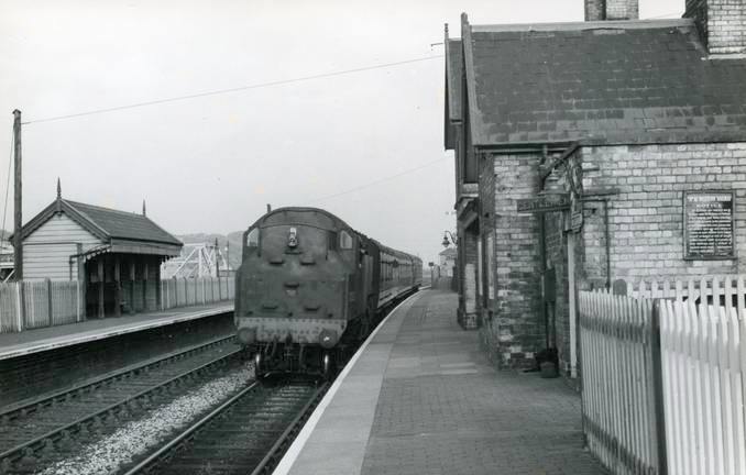
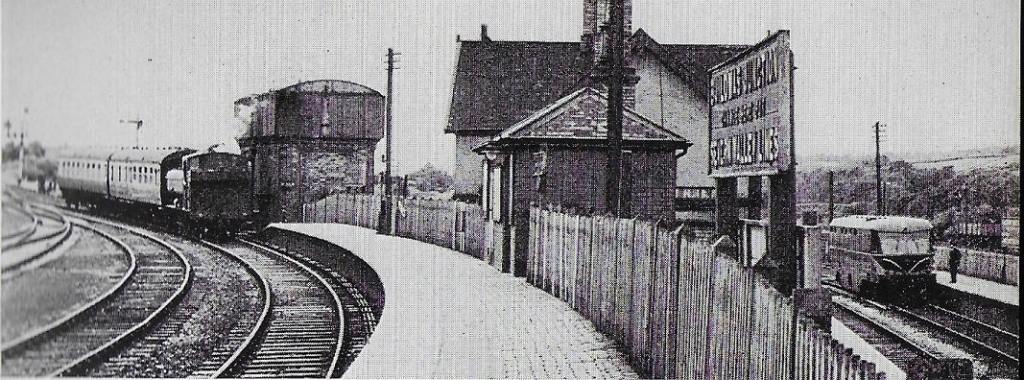
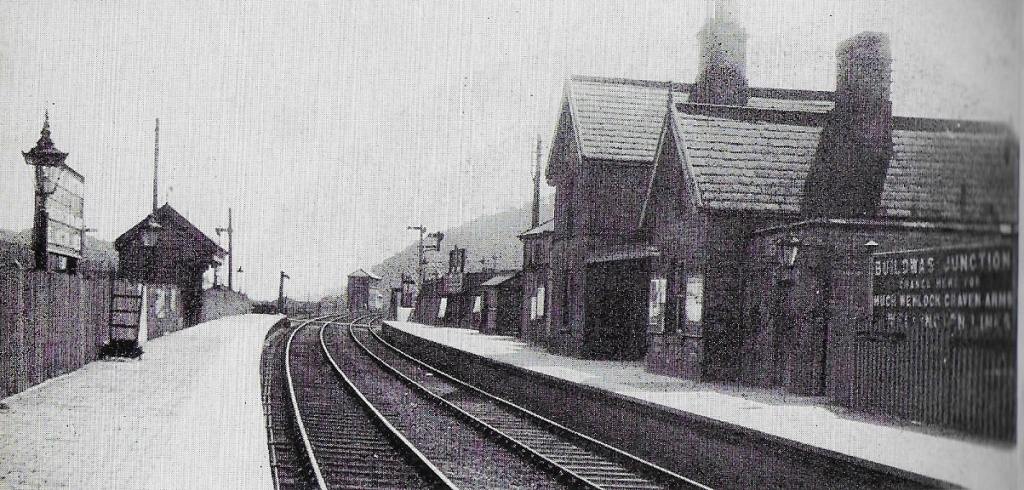


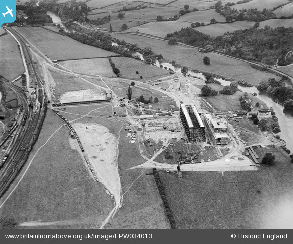
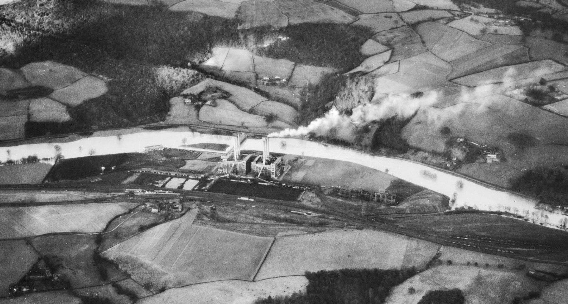
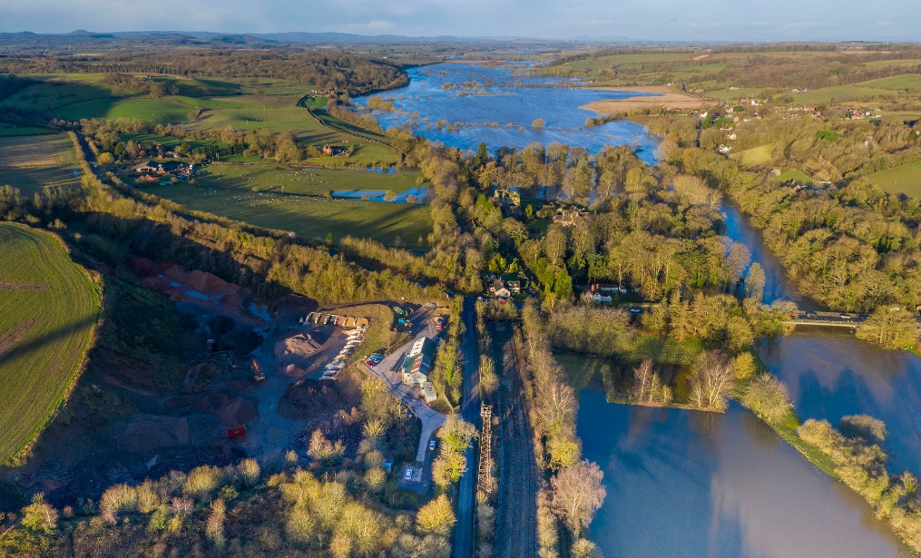
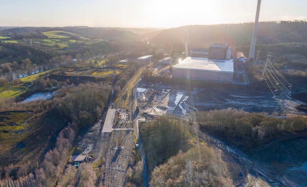
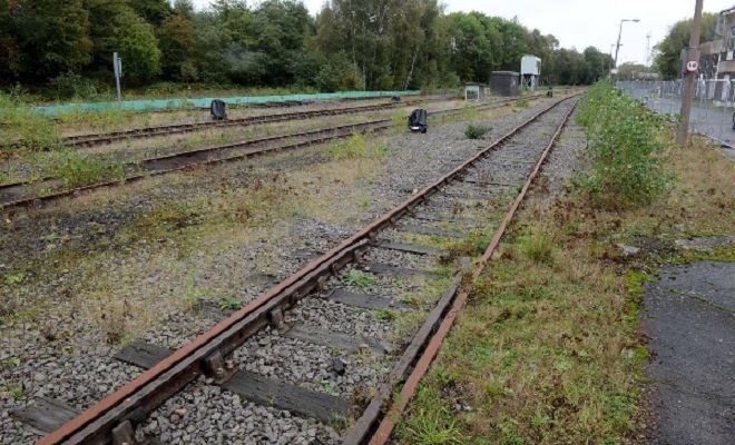
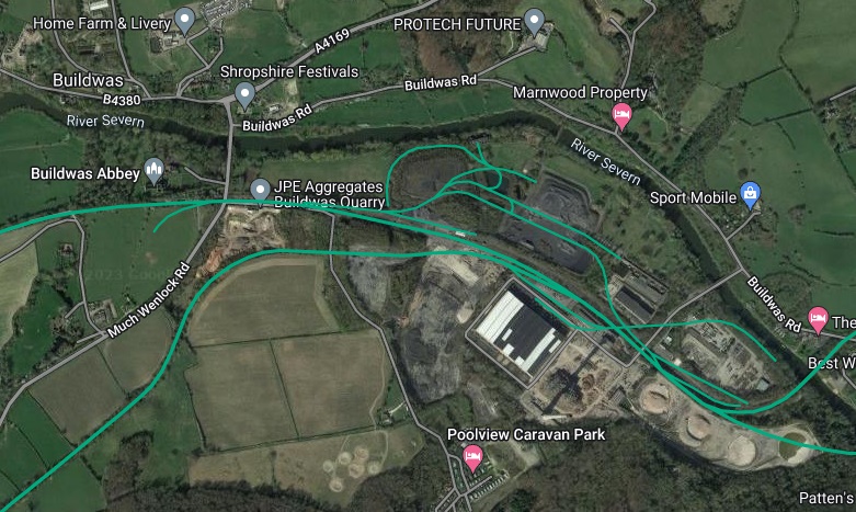
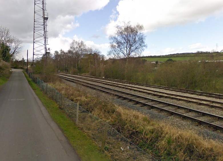
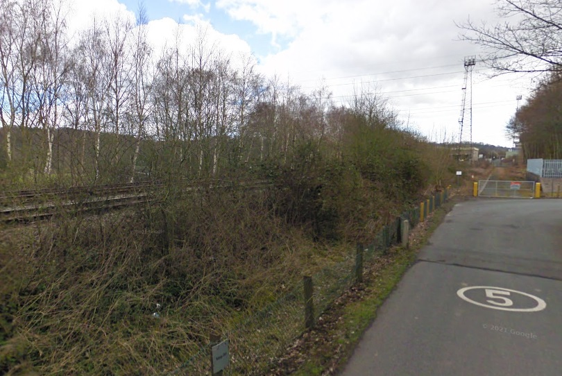


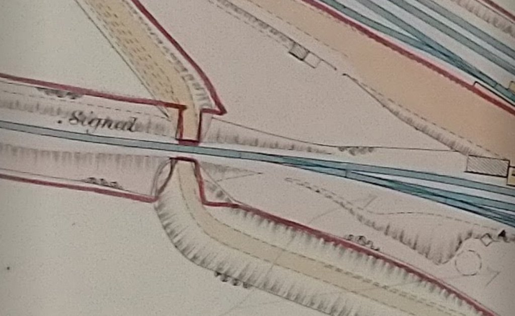


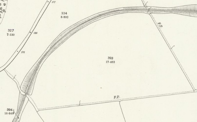
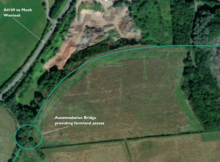

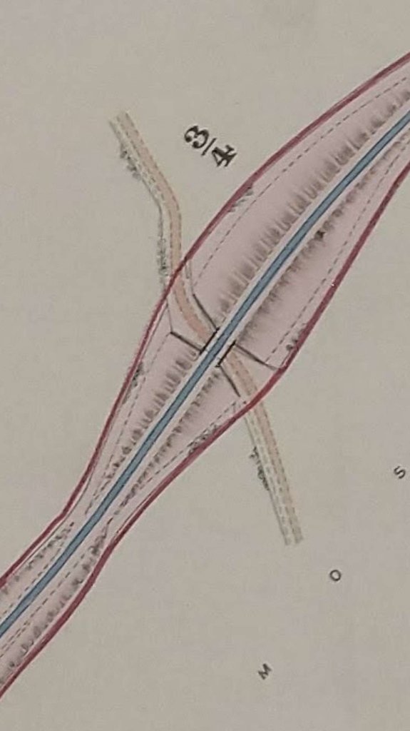
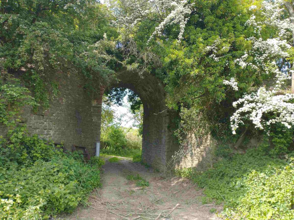
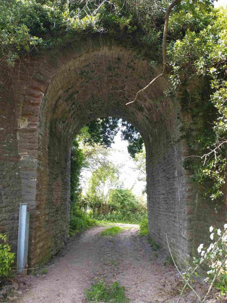

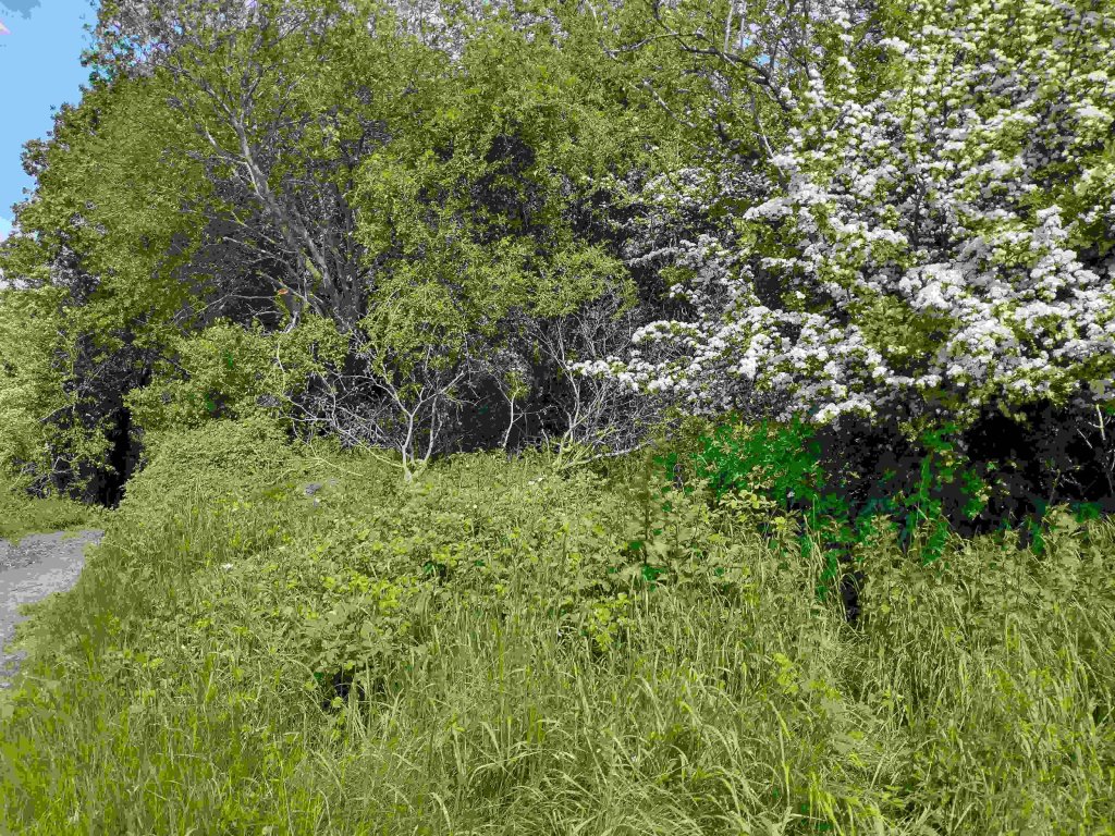
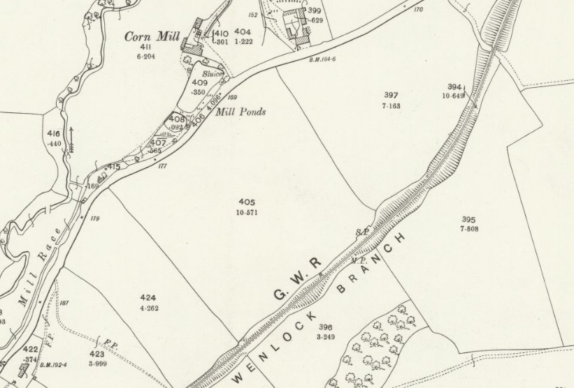
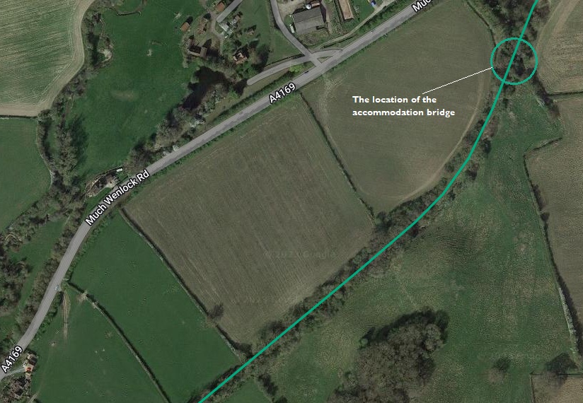
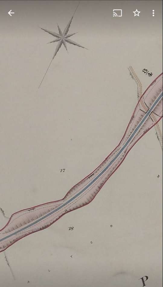

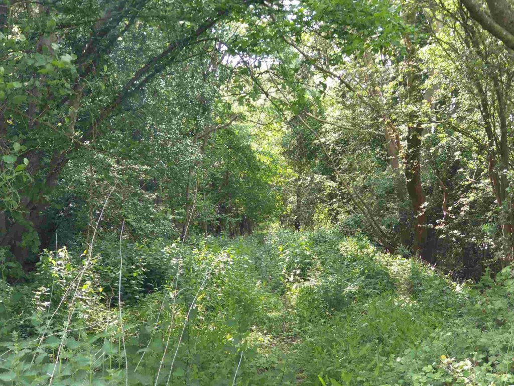
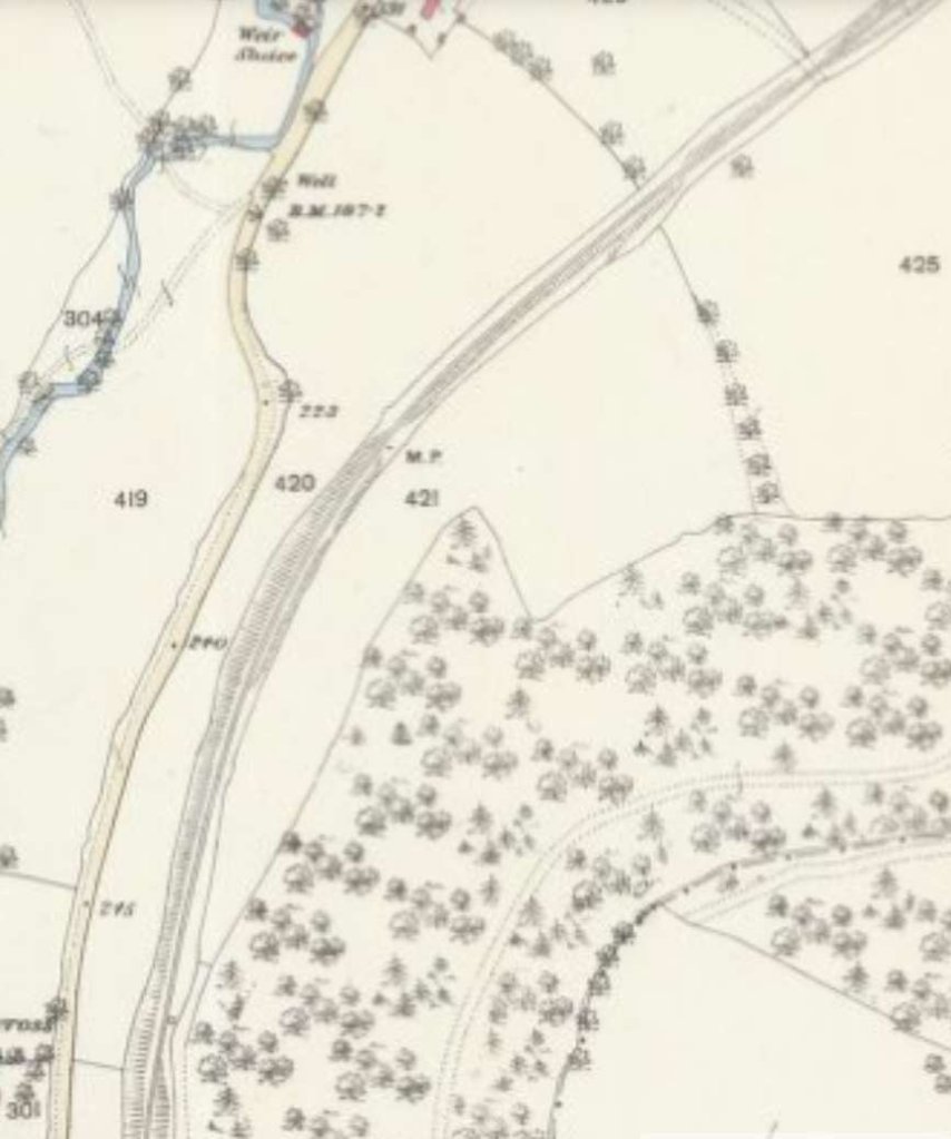
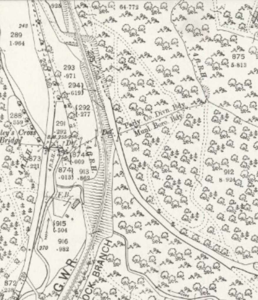
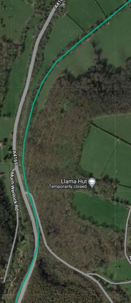
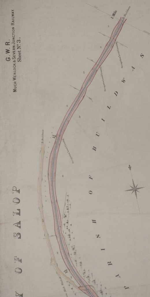

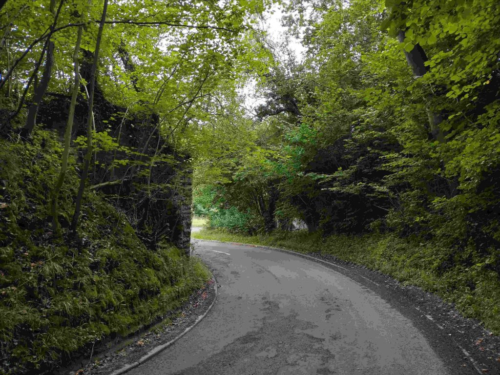
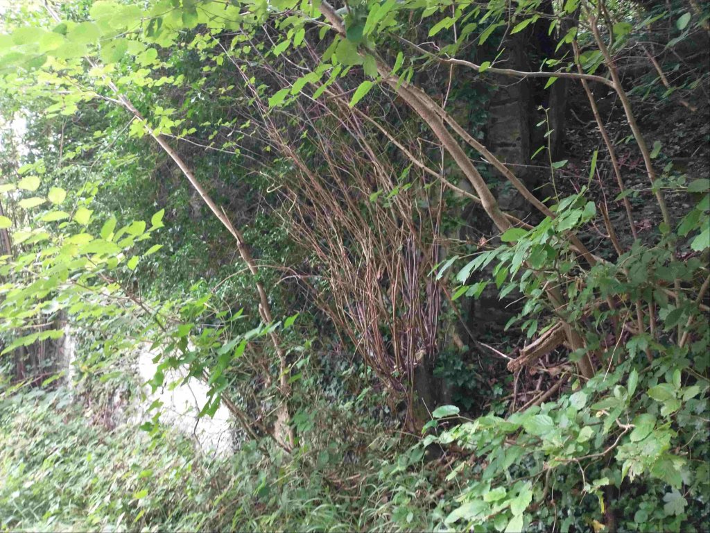
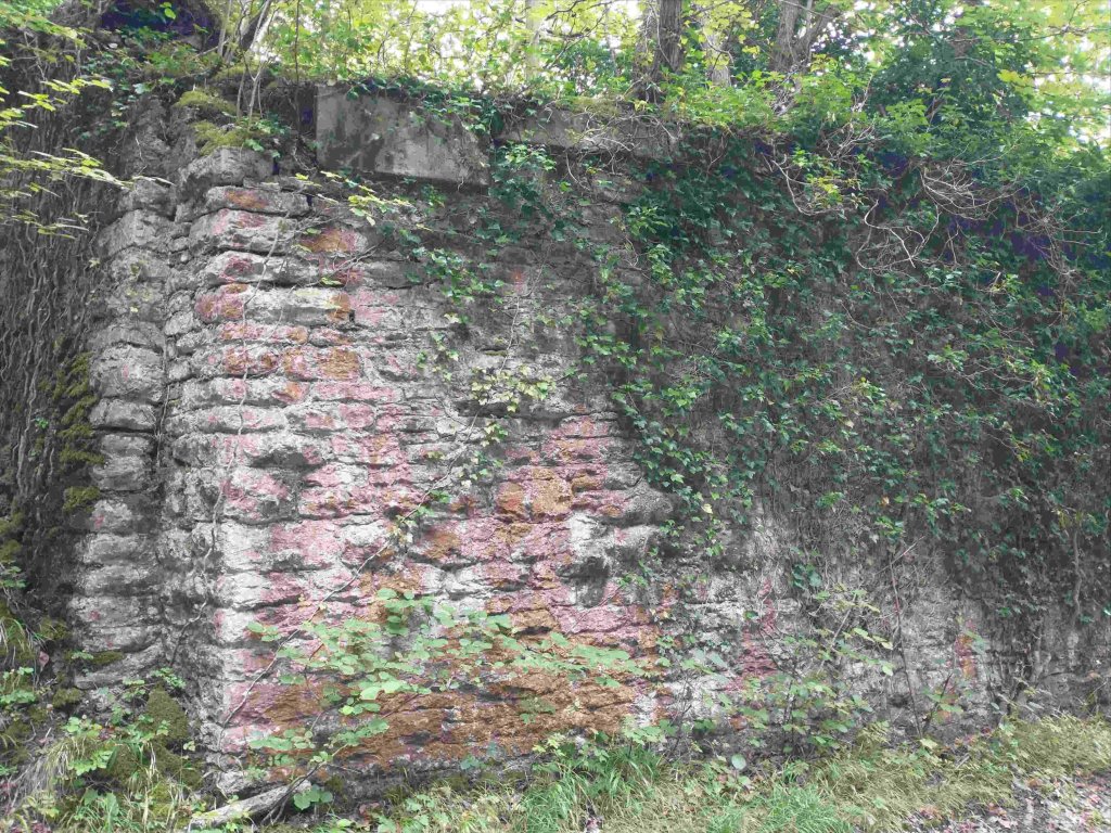

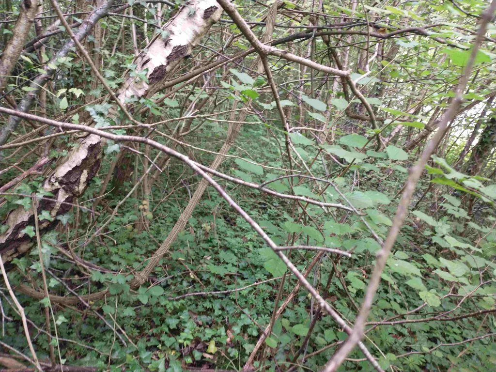


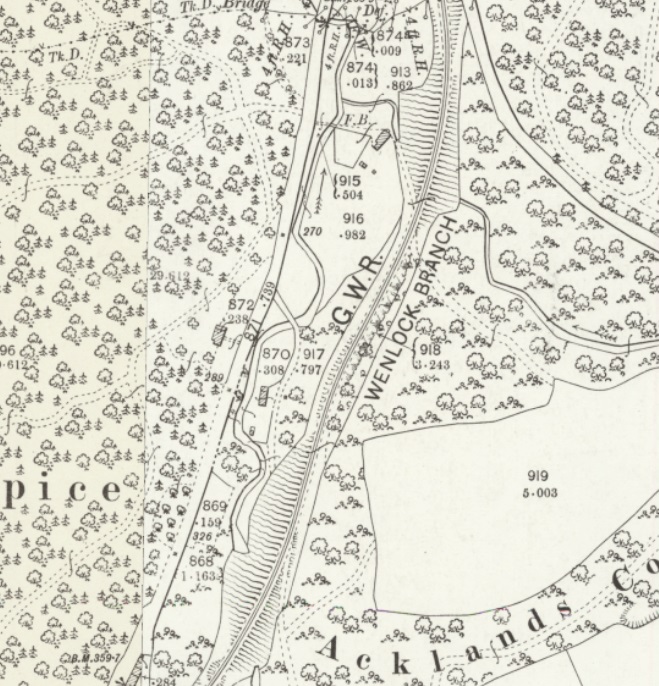

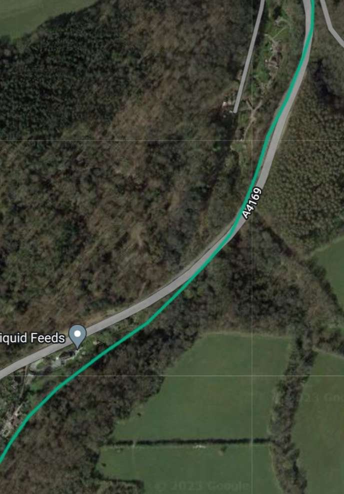
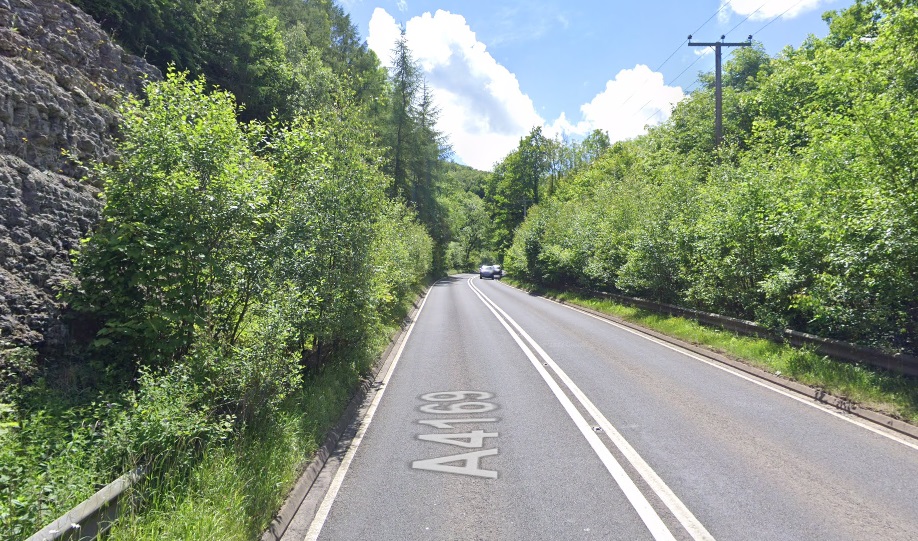
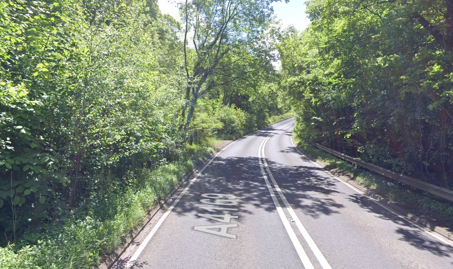

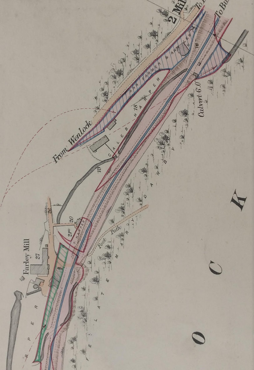


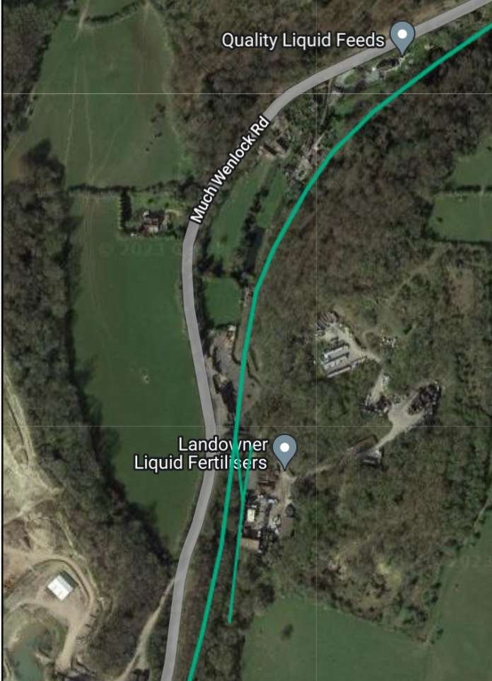
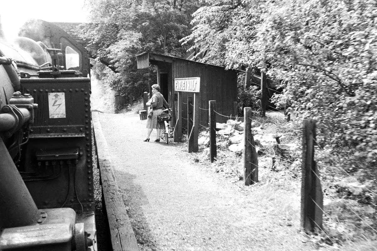
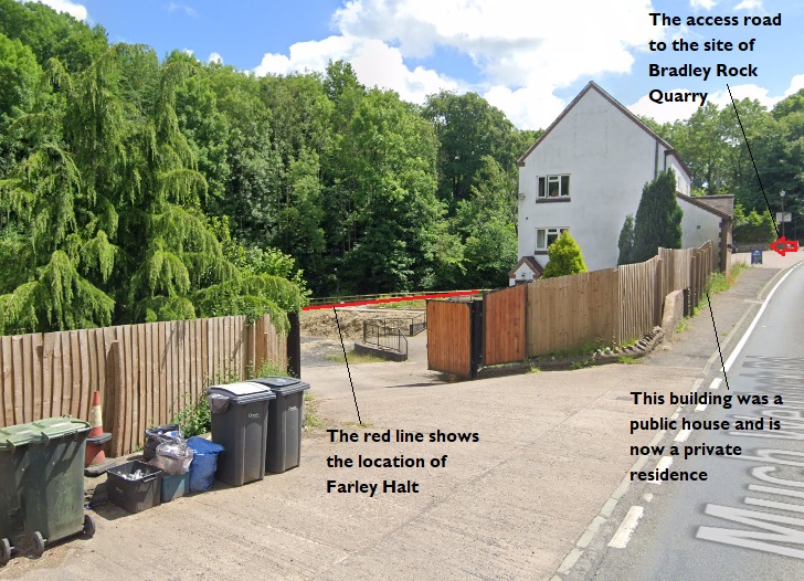
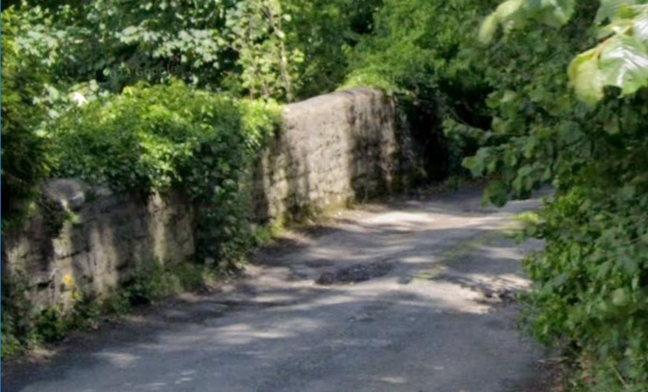
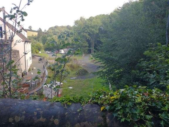

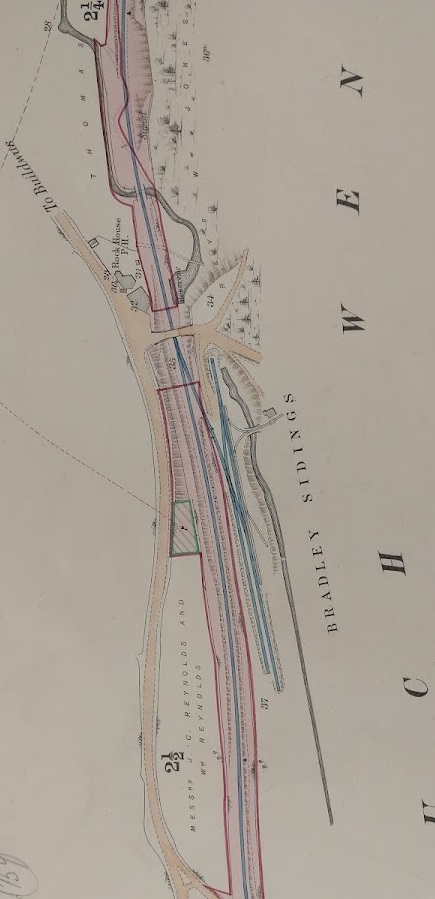
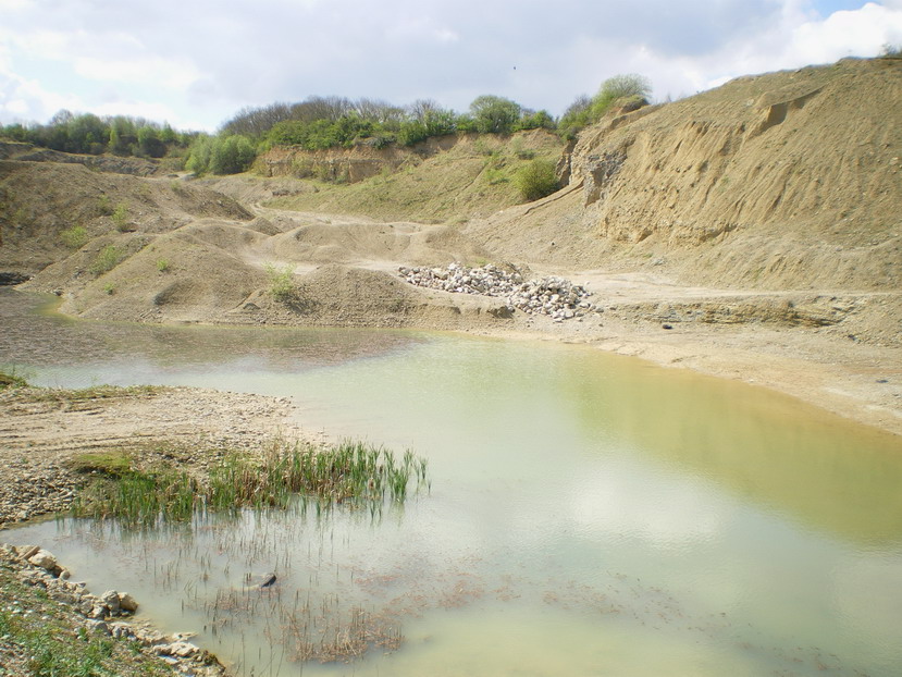

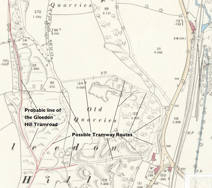
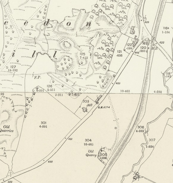


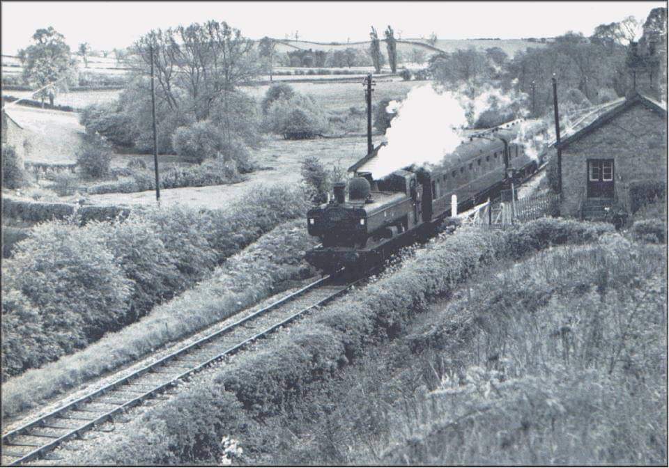
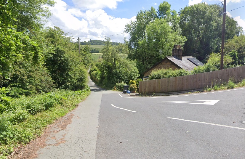

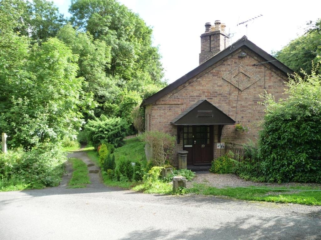
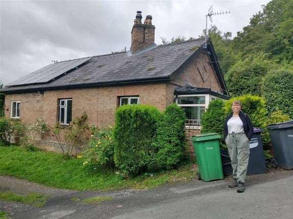


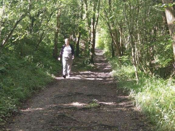


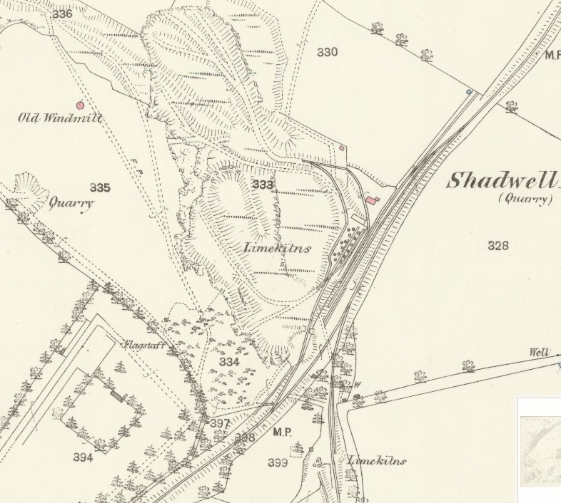
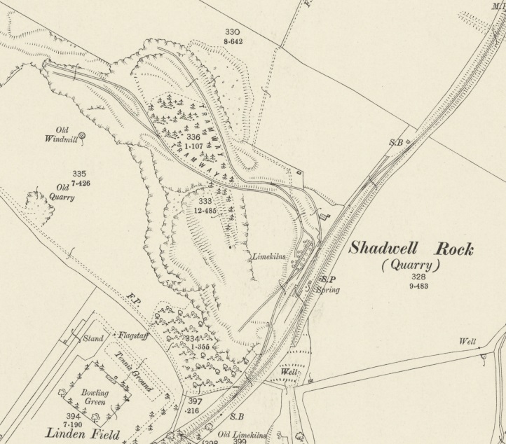

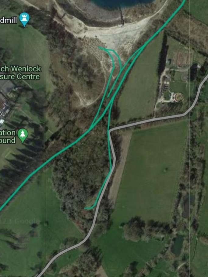
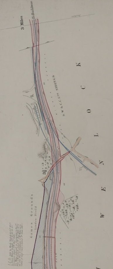

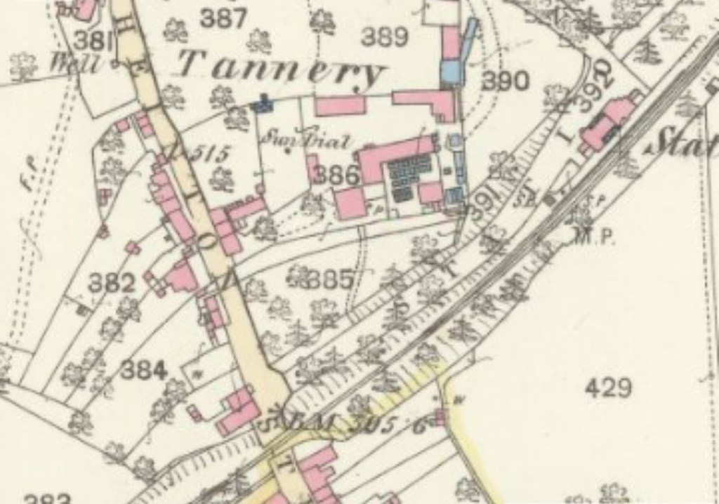

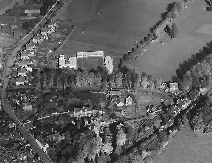
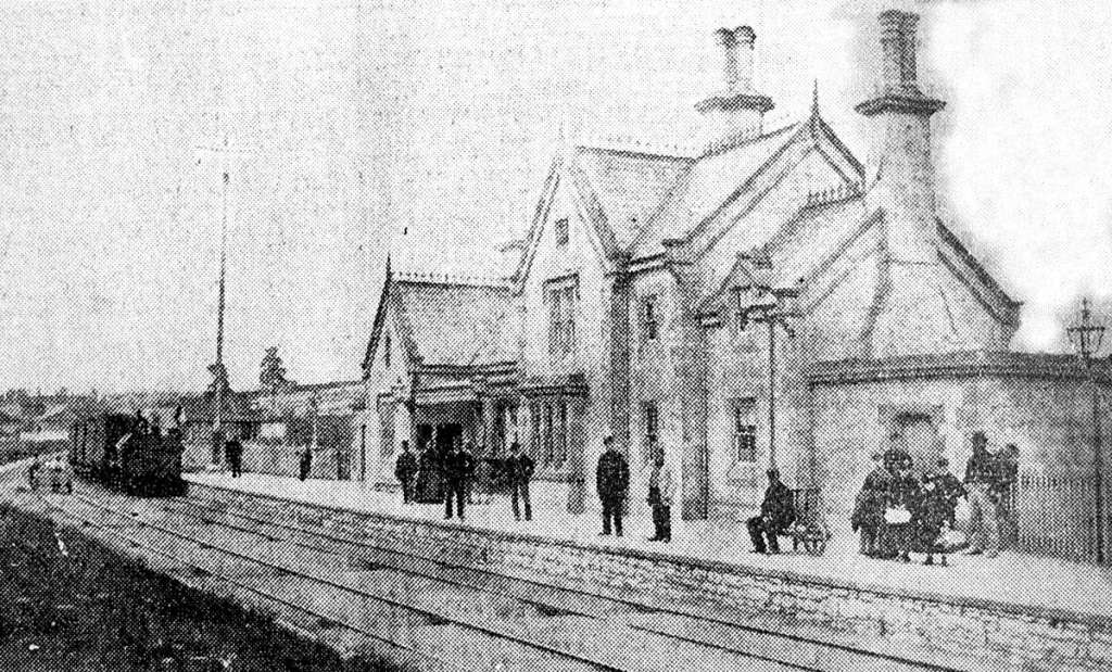

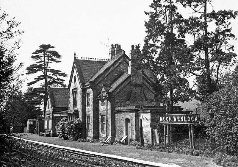


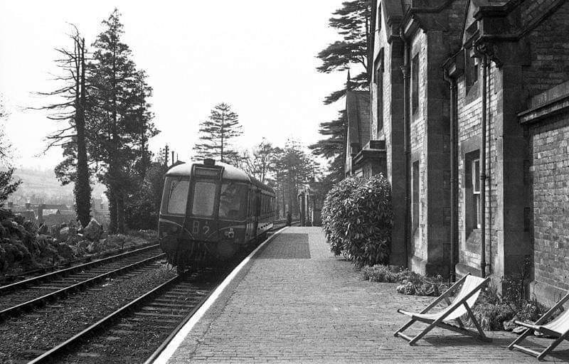


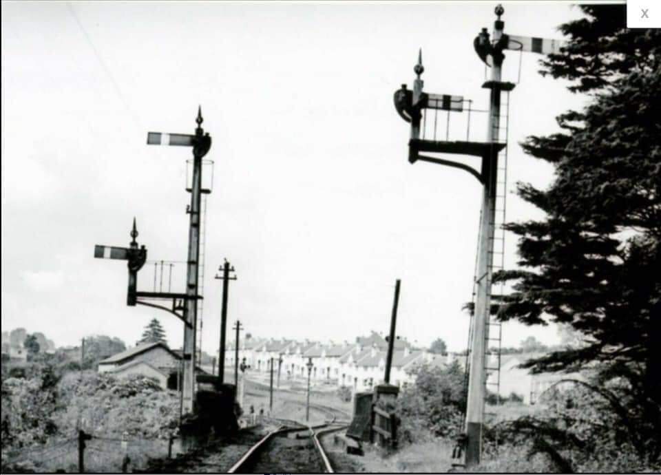


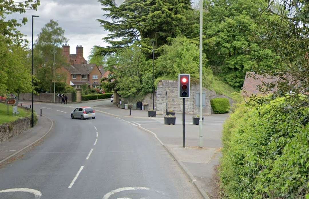

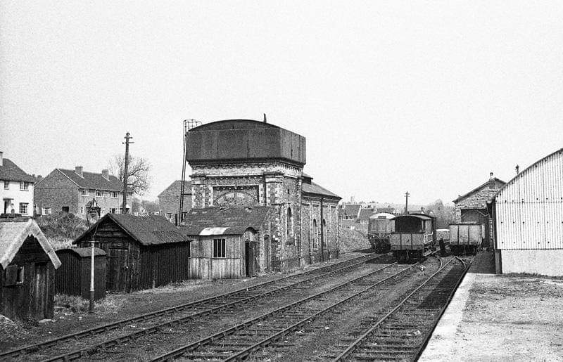
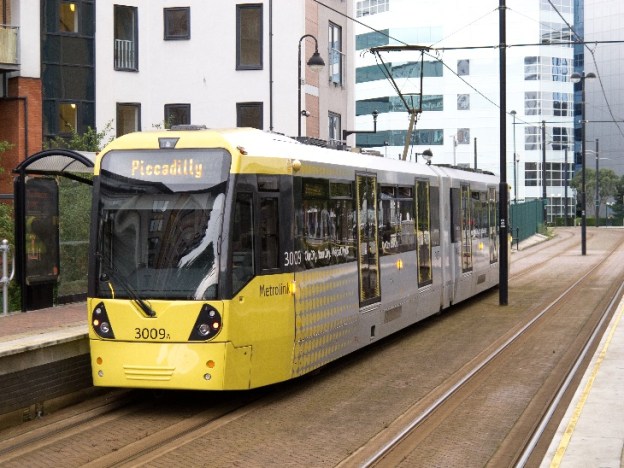
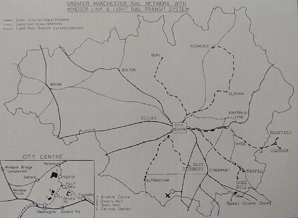
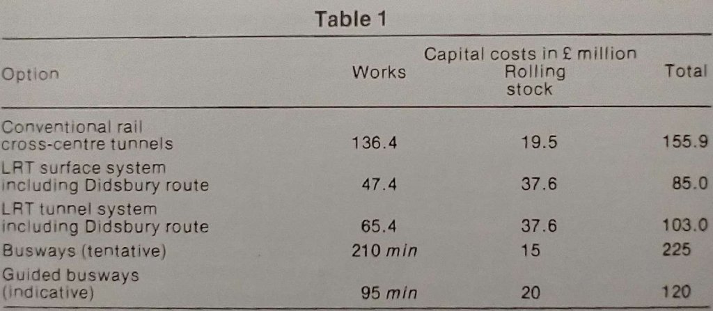
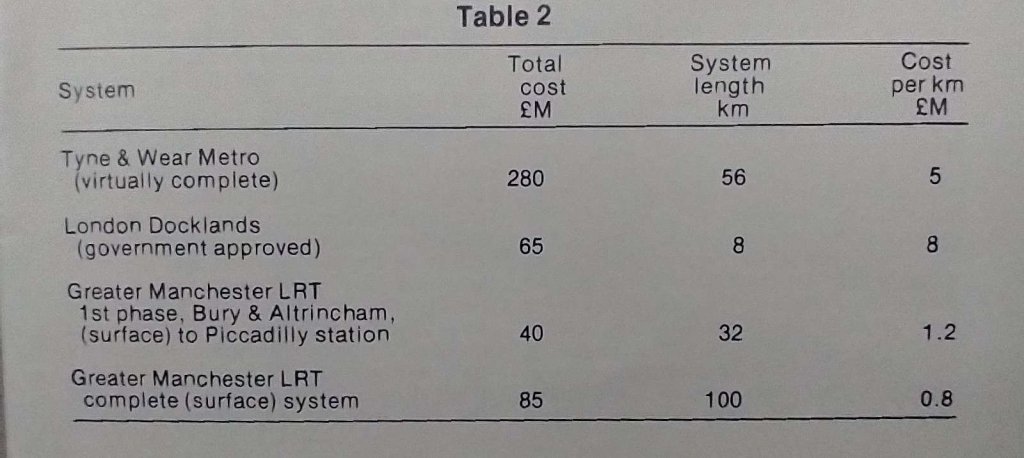
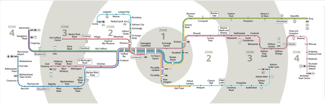
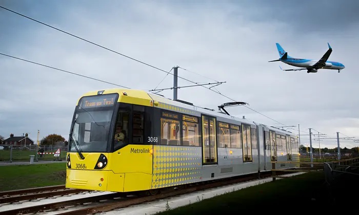
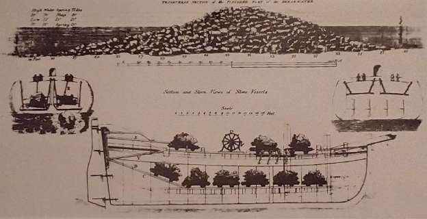
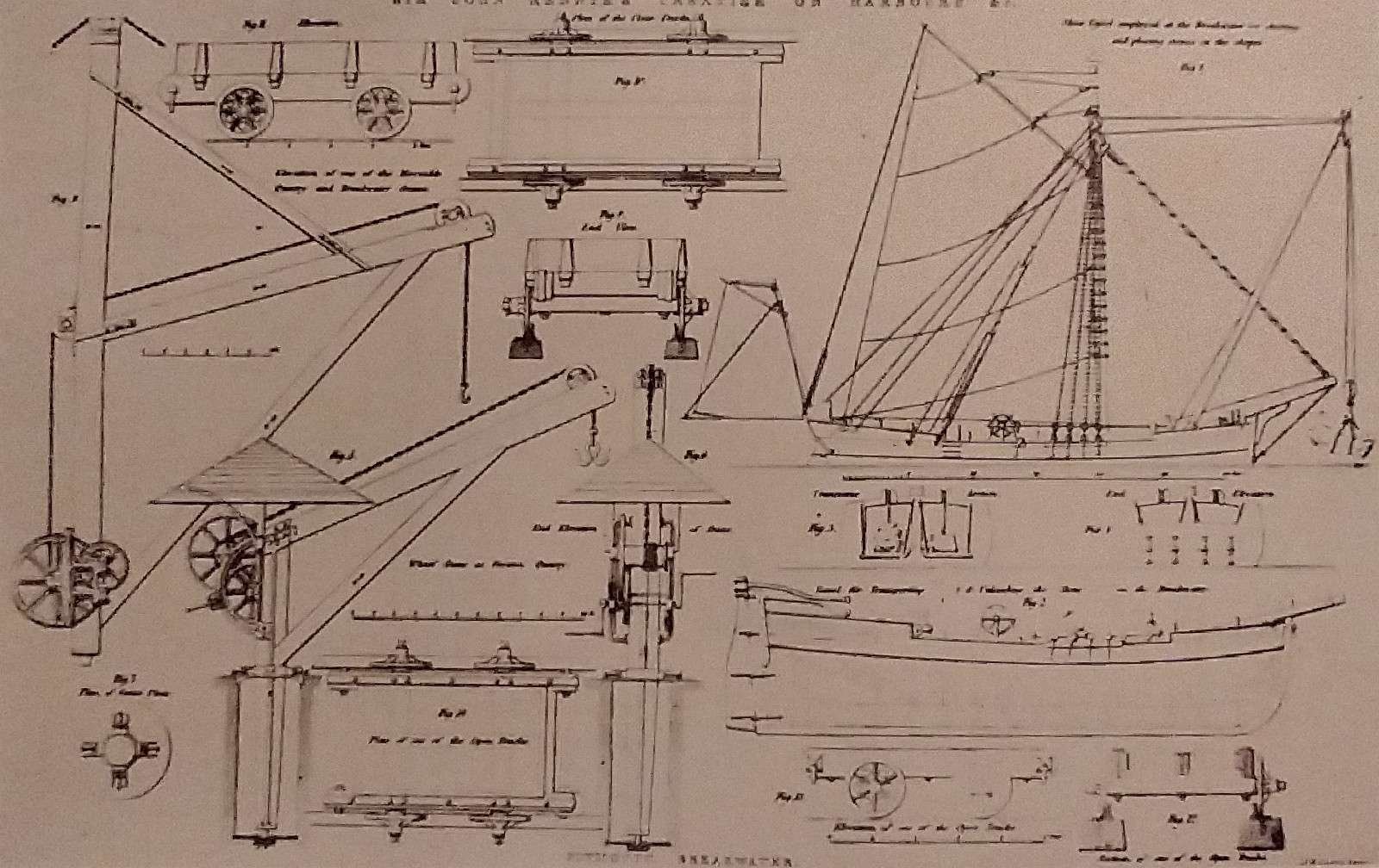
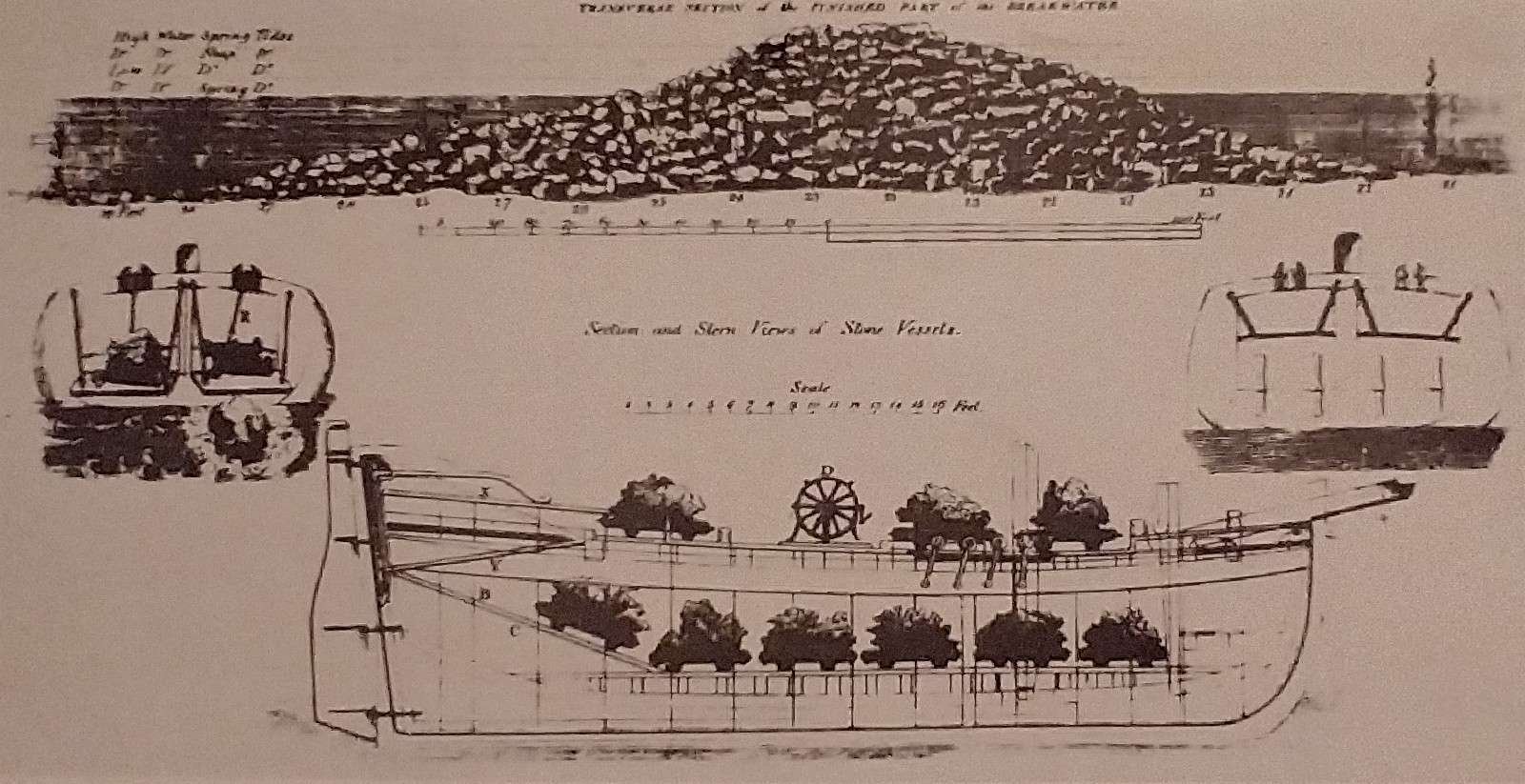
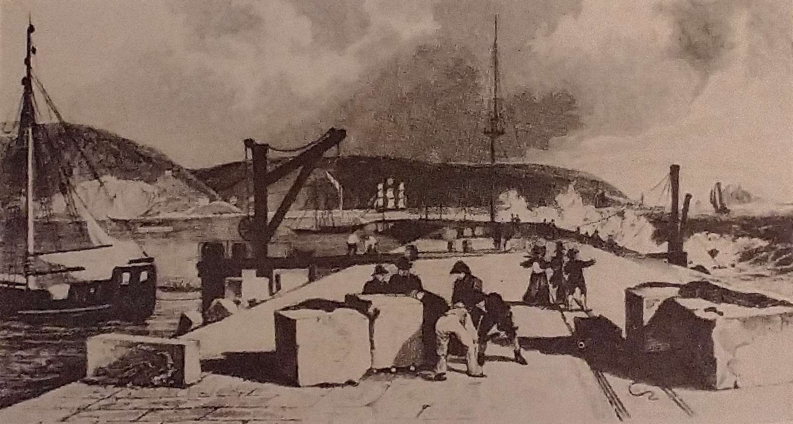

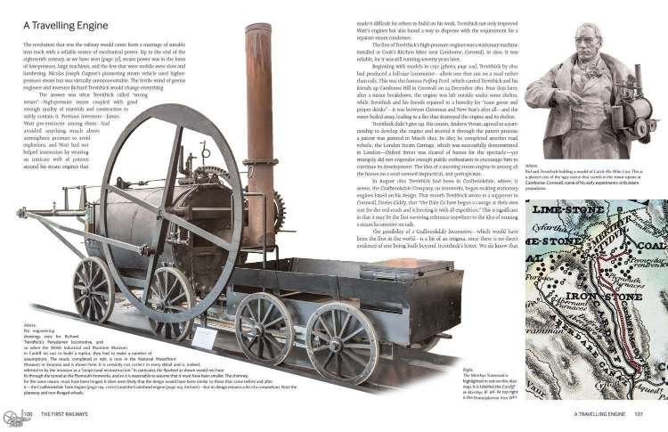

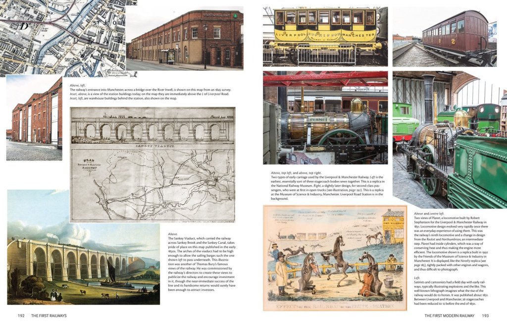
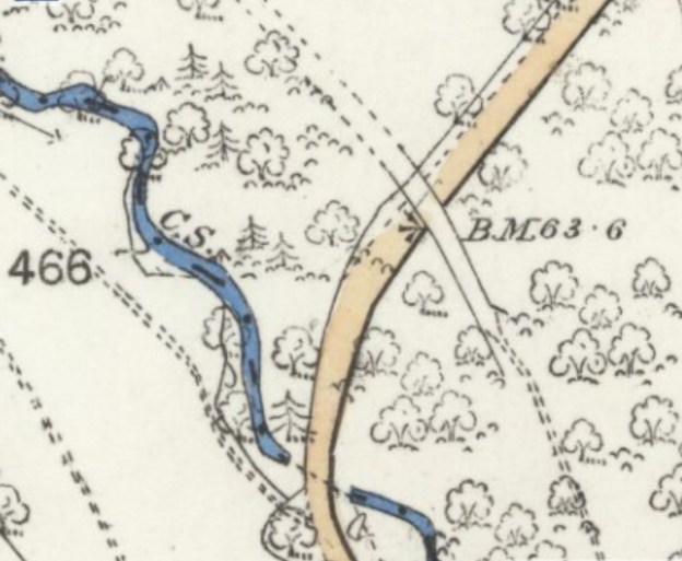
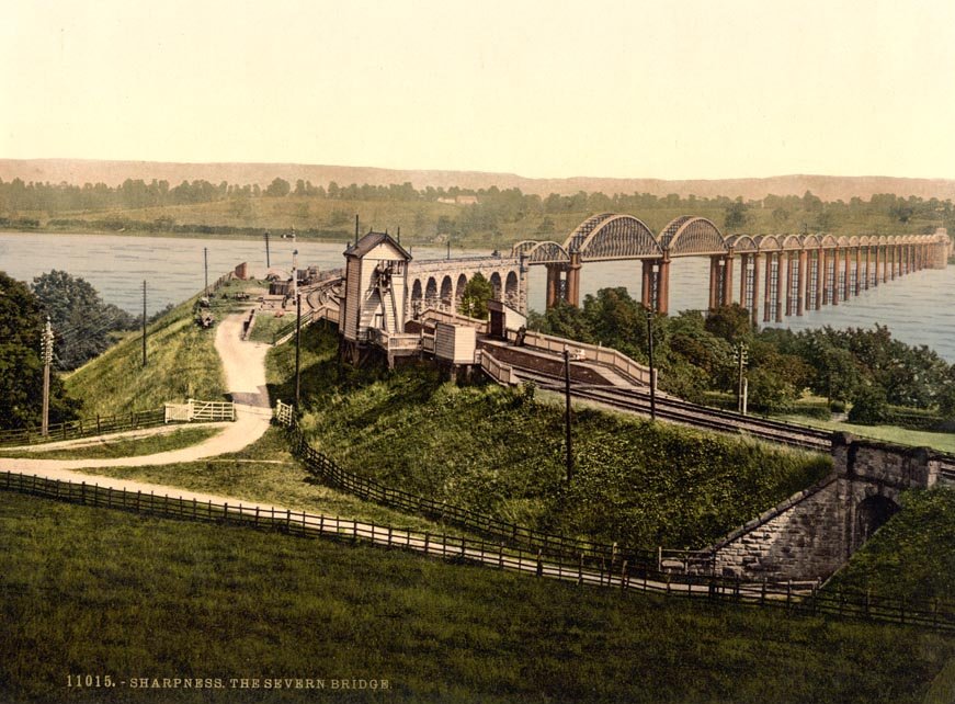
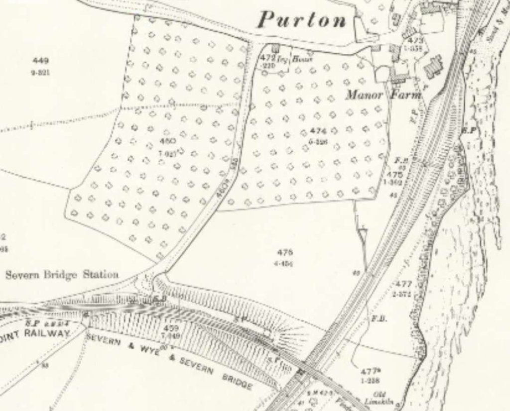
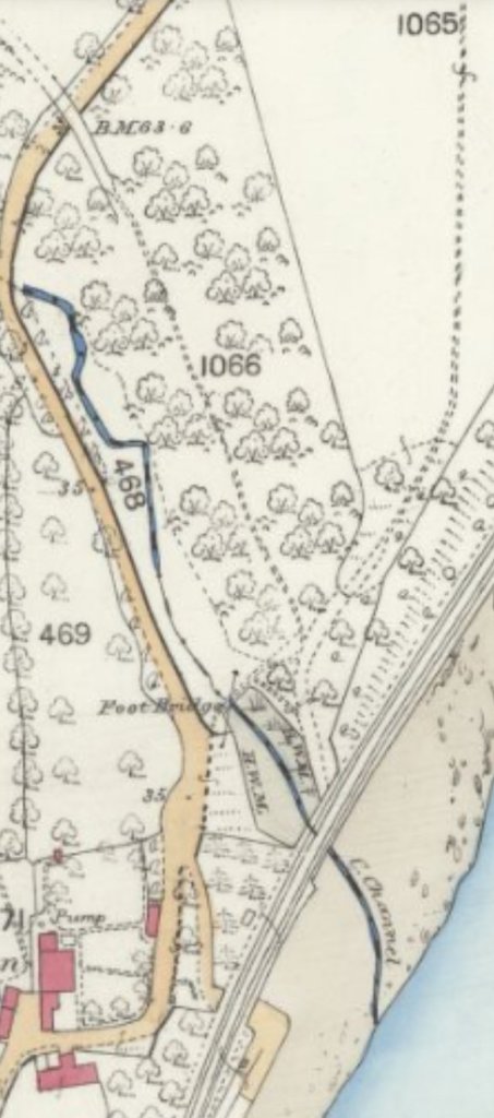
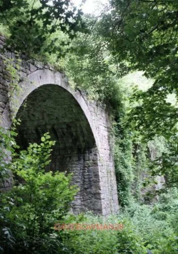
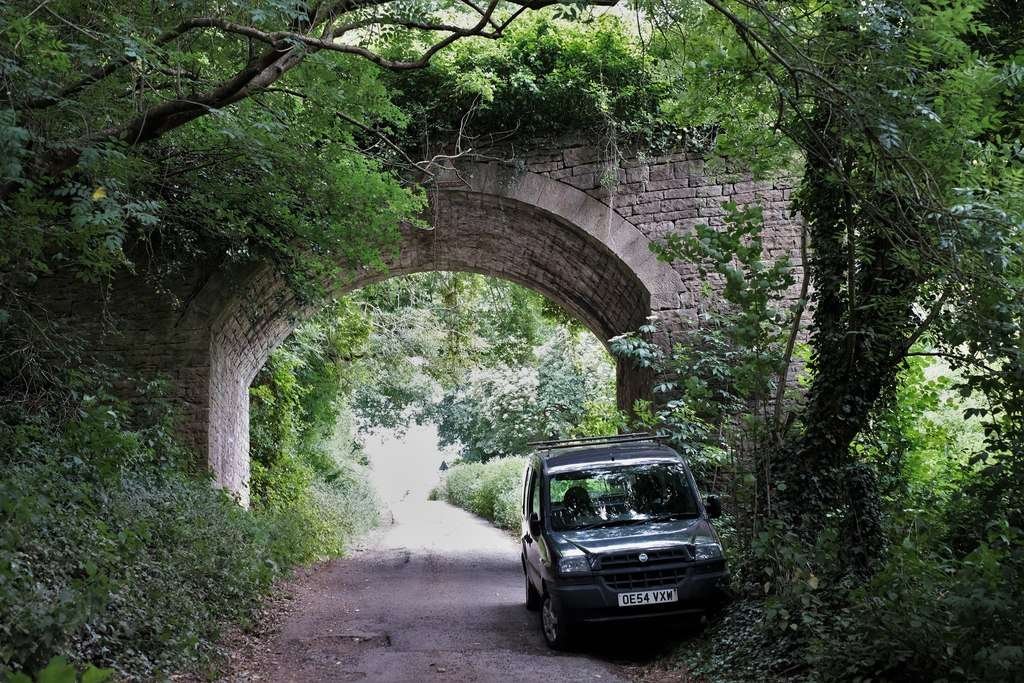
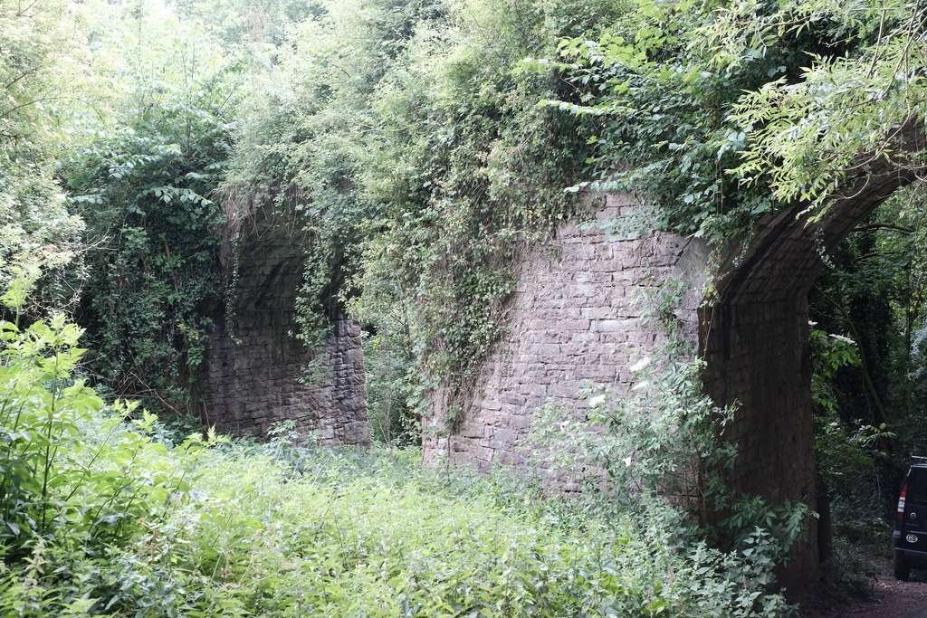
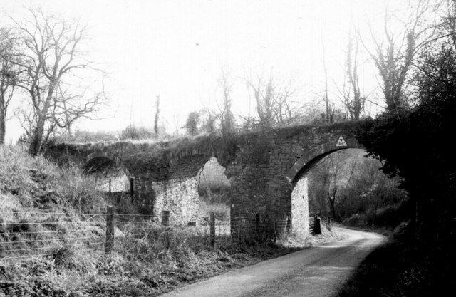
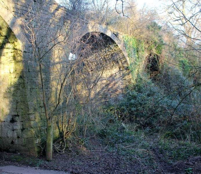
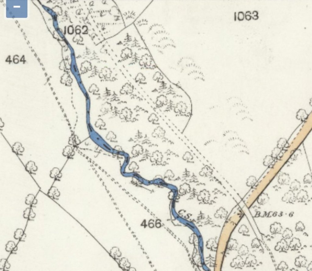
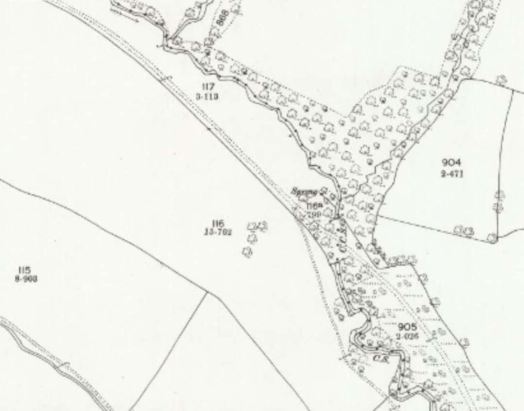
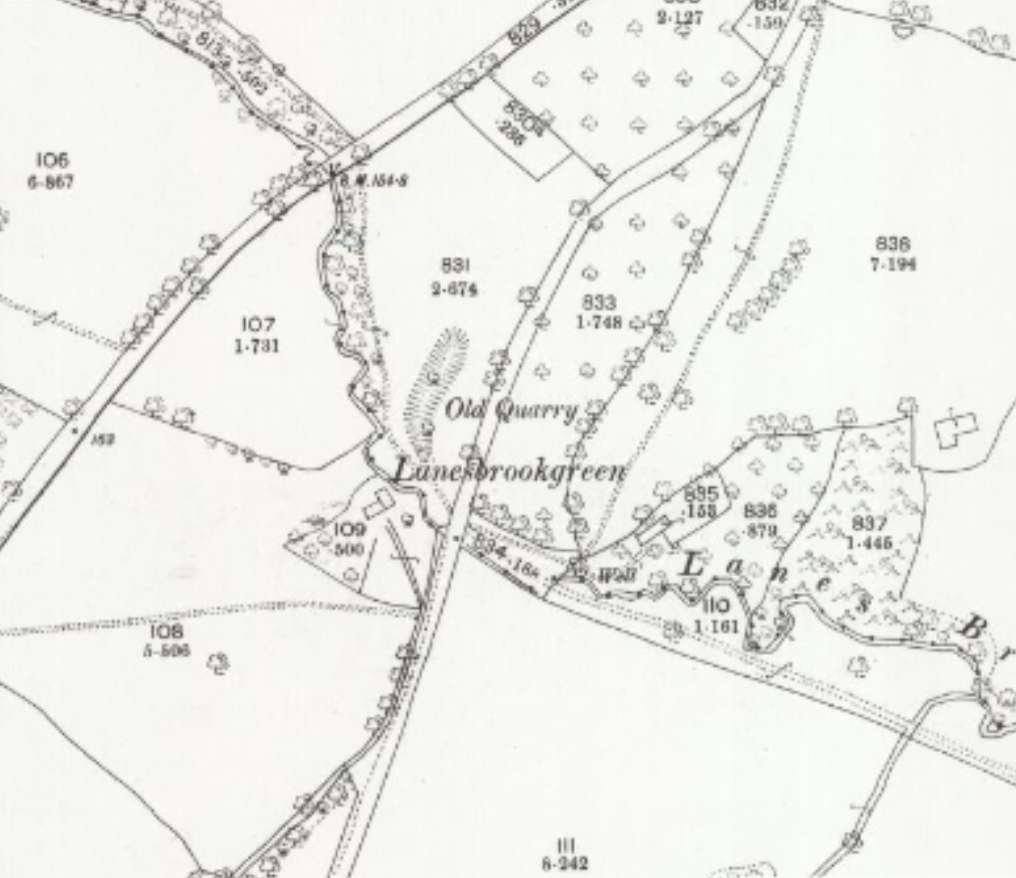
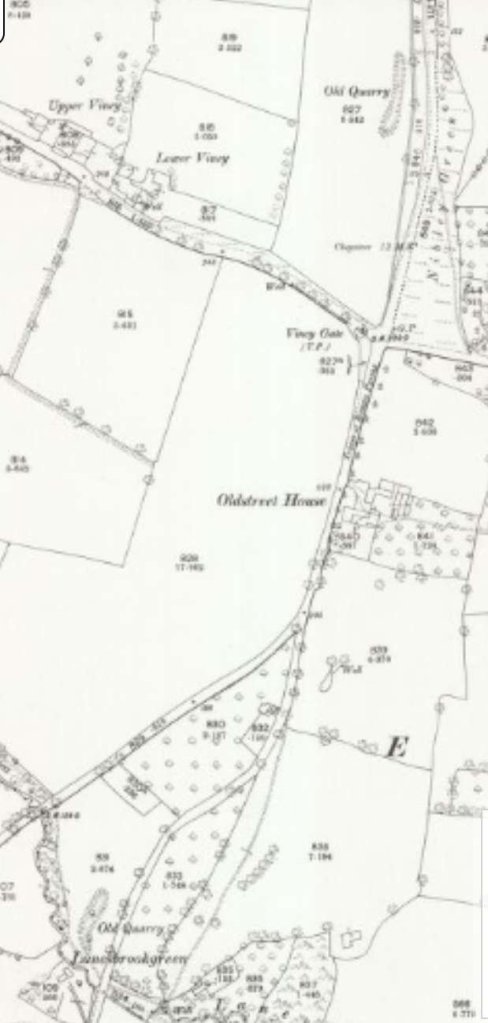
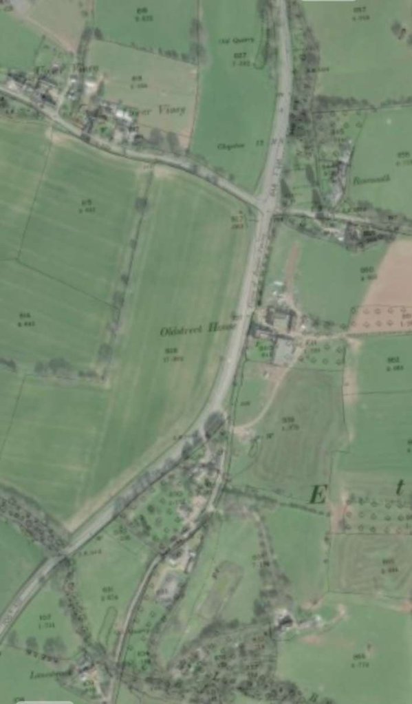

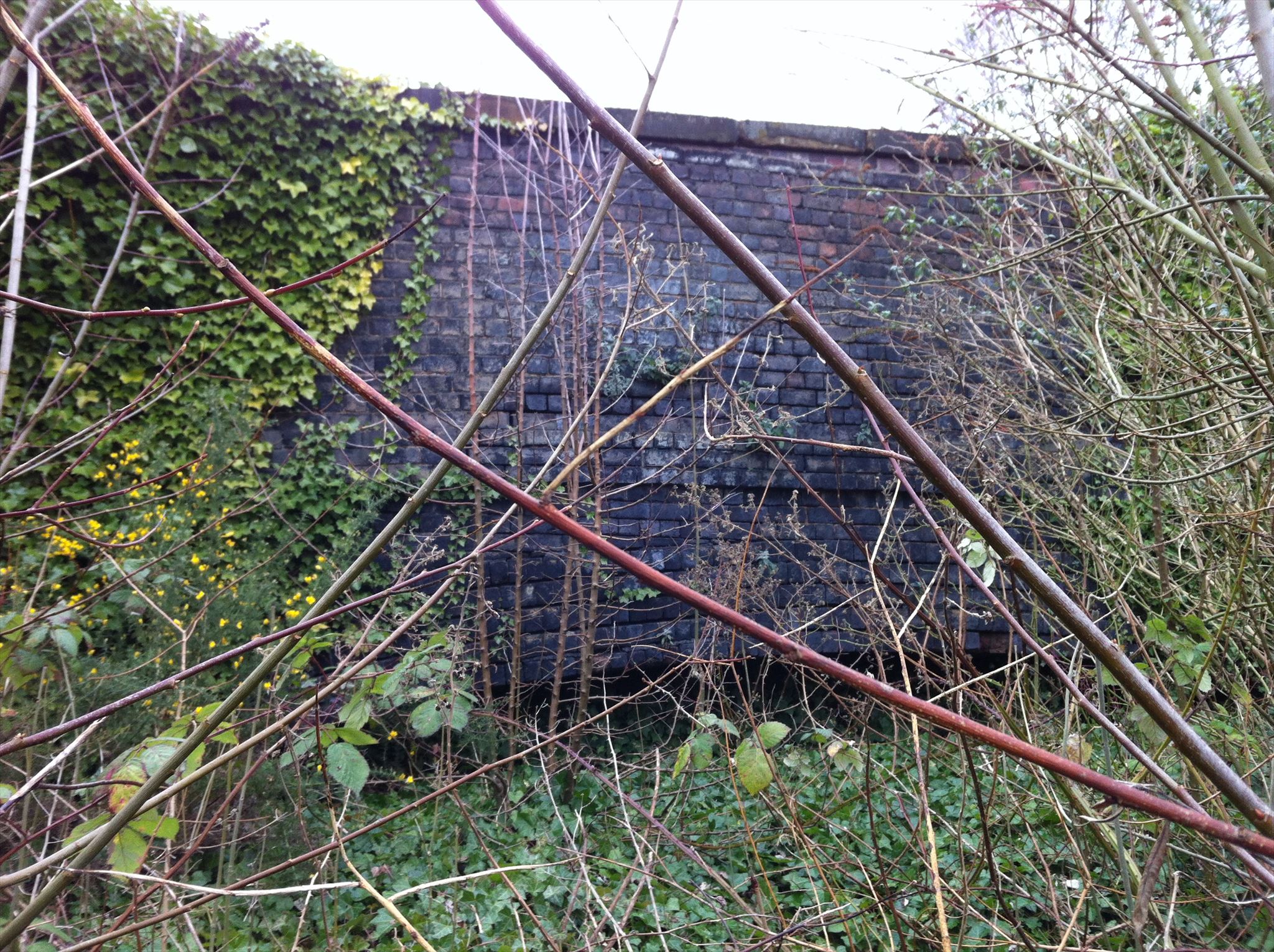