Category Archives: Railways and Tramways Blog

The Forest of Dean Central Railway

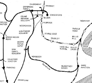
FDCR 1FDCR 2The Forest of Dean Central Railway

This short railway line was operated by the Great Western Railway (GWR) to serve collieries in the heart of the Forest of Dean in Gloucestershire. From its opening in 1868, the line was operated by the GWR and run by the Central Company until 1923. The GWR took over the line in 1923 and ran it until its closure in 1949. It ran from Awre Junction through Blakeney and on into the forest with the intention of reaching Foxes Bridge Colliery. In fact the line only travelled as far as the New Fancy colliery. It served several mines and quarries along its route as well as the corn mills in Blakeney.

Opening

Plans for a railway in the heart of the forest were first drawn up in 1826, but it took until 1868 for the Forest of Dean Central Line to open. A branch line to the New Fancy Colliery followed in 1869. A junction with the main Gloucester to Newport Line was formed at Awre, although the original plan was to open the line to a new dock at Brimspill on the River Severn. The railway never reached the river. It was built initially to serve the Howbeach Collieryt and then ultimately to reach the Foxes Bridge Colliery and in anticipation of its arrival,  the formation there was fenced and a bridge built for the Severn & Wye Railway’s Mineral Loop, but in the end, no track was laid north of the link to the New Fancy Colliery.

Decline and closure

The long delay from 1826 to 1868 was probably the ultimate cause of the railway’s failure to achieve success. The opening of the Severn & Wye Railway in the 1870s resulted in much of the coal traffic for which the Forest of Dean Central Railway was built being lost to the new company. By 1875 the section to the central mines and the New Fancy Colliery was first neglected and then abandoned. In 1921 virtually all of the traffic north of Blakeney ceased. Although for a time the GWR continued to run some services north of Blakeney, those ceased in 1932.

Today

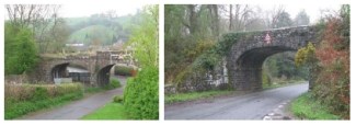
FDCR 3Some lengths of the formation remain, as do some of the structures. Part of the Blakeney Viaduct is still extant as is the Blackpool Bridge.


The Sheffield, Ashton-under-Lyne and Manchester Railway – 2

The following are links to information about the line which became part of the Manchester, Sheffield and Lincolnshire Railway in 1847:

http://en.wikipedia.org/wiki/Sheffield,_Ashton-under-Lyne_and_Manchester_Railway

http://www.railbrit.co.uk/Sheffield_Ashton-under-Lyne_and_Manchester_Railway/index.php


The Sheffield, Ashton-under-Lyne and Manchester Railway – 1

I am reading a book by Bill Laws: “Fifty Railways that Changed the Course of
History” published by David & Charles, Newton Abbot, UK, 2013 ISBN-13:978-1-4463-0290-3.

The Sheffield, Ashton-under-Lyne and Manchester Railway features as the 17th of these and particularly for the construction of the Woodhead Tunnel. This was a project that exposed one particular company’s shocking attitude to the safety of its workers and it provided some significant impetus to campaigns for better working conditions for navvies.

“When the early transport ships bearing British miscreants to New South Wales landed in Australia, hundreds had perished during the voyage. The prisoners, including a few of those disreputable railway labourers, notorious for their hard drinking and fighting, were so crammed into the ships’ holds that they died. The British government ordered that, in future, the charterers be held responsible for the convicts’ well-being. It produced immediate results. The transporters, paid a bonus for every prisoner safely landed, now took care of their cargo,” (p72).

However, this principle of responsibility for one’s workers was usually ignore by Victorian entrepreneurs and business leaders: “What use had a mill owner for some eight-year-old girl who, through her own carelessness, lost her hand in a machine? Why should a railway company be responsible for a navvy’s family, when the man died, dead drunk, in a tunnel collapse? And why should the shareholder, risking his capital on such a brave enterprise as the Sheffield, Ashton-under-Lyne and Manchester Railway Company’s plan to tunnel under the Pennines, have to mollycoddle workers who were being paid to do their job?” (p72/73).

Wellington Purdon, who was assistant engineer on the tunnel, was asked by a government enquiry if it was not wiser to use safety fuses while blasting rock He replied, “Perhaps it is: but it is attended with such a loss of time, and the difference is so very small, I would not recommend the loss of time for the sake of all the extra lives it would save, ” (p73).

Purdon’s comments revealed how little the railway companies valued their workers. The enquiry and Purdon’s comments should have changed the course of industrial history. Instead, Parliament shelved the enquiry’s report.

Edwin Chadwick

In 1845 the first train through the completed Woodhead Tunnel was met by a celebration. However, the social reformer Edwin Chadwick did not celebrate for he had calculated that the rate of attrition on the contract to build the tunnel was the equivalent of losses incurred in war. “With 32 killed and 140 injured, the casualty rate was higher than in the Battles of Waterloo” (p73).

The navvies on the Woodhead Tunnel paid to keep their own doctor on hand, Henry Pomfret. “The chief engineer, Wellington Purdon’s boss was Charles B. Vignoles who was also a share­holder in the railway company. When the contract ran over time and over budget, the job bankrupted him. The pioneering engineer Joseph Locke took over as more than a thousand labourers hewed away at the muck and mud from seven different shafts, one at each end and five vertical shafts from above, with pick, shovel and explosives. It was obvious to Locke that the only way to complete the project was to drive the men like animals and, if questioned, lie” (p73/74).

The job took six years to complete. When it came to an end Dr. Pomfret talked to his friend Dr. Roberton, who, inturn talked to Edwin Chadwick. “In January 1846 Chadwick delivered a paper to the Manchester Statistical Society: The Demoralization and Injuries Occasioned by Want of Proper Regulations of Labourers Engaged in the Construction and Works of Railways. Despite the exhausting title, the contents were as volatile as navvies’ explosives. They revealed how injured men were forced to fend for themselves, how most workers lived in homemade hovels (occasioning an outbreak of cholera) through the worst of the Pennine winters. Chadwick exposed the practice of not paying wages for several weeks and then paying them in public bars. The pubs encouraged the navvies to drink their wages, while delayed payments forced them onto the truck system, a version of the company store principle that kept the men and their families in hock to the railway company. (The truck was already outlawed in Britain, but the statute, laid down before the railway rush, had not specified railway workers.) Chadwick showed how the reputation of the average navvy as a feckless, reckless drunk was a direct result of the industry plying him with booze instead of provid­ing him with proper food and housing” (p75).

“The rail company and the engineers denied the charges against them. Nevertheless, the government inquiry in July 1846 recommended extending the Truck Act to the railways, making the companies responsible for the health, welfare and accommodation of their navvies and, most important of all, putting the liability for deaths or injuries on the company. The Members of Parliament also insisted that men should be paid weekly, and in cash, not in tokens for the truck. The inquiry report was never even debated” (p75).

However, “although no railway man was censured over the Wood-head Tunnel scandal, Chadwick’s efforts were not in vain. His correla­tion between losses on the battlefield and those on the railways caught the public imagination and in future, when navvies were killed, the press was quick to take up the story” (p75).

Woodhead Tunnel is infamous for the loss of life during its construction, but it is nothing compared to the massive loss of life associated with many colonial railways in Asia, Africa and South America.

Hereford – The Construction of Barrs Court Station 7

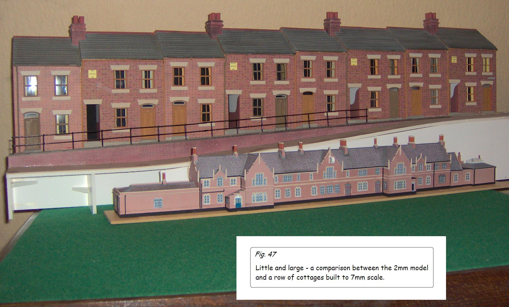
My father-in-law, David Cambridge, has been taking us on a tour of the work he did to produce an N Gauge model of Hereford Station for me. In this final post on this subject he makes some comments about the construction work and shows us a picture of a 7mm model alongside the 2 mm model of Hereford Barrs Court Station:

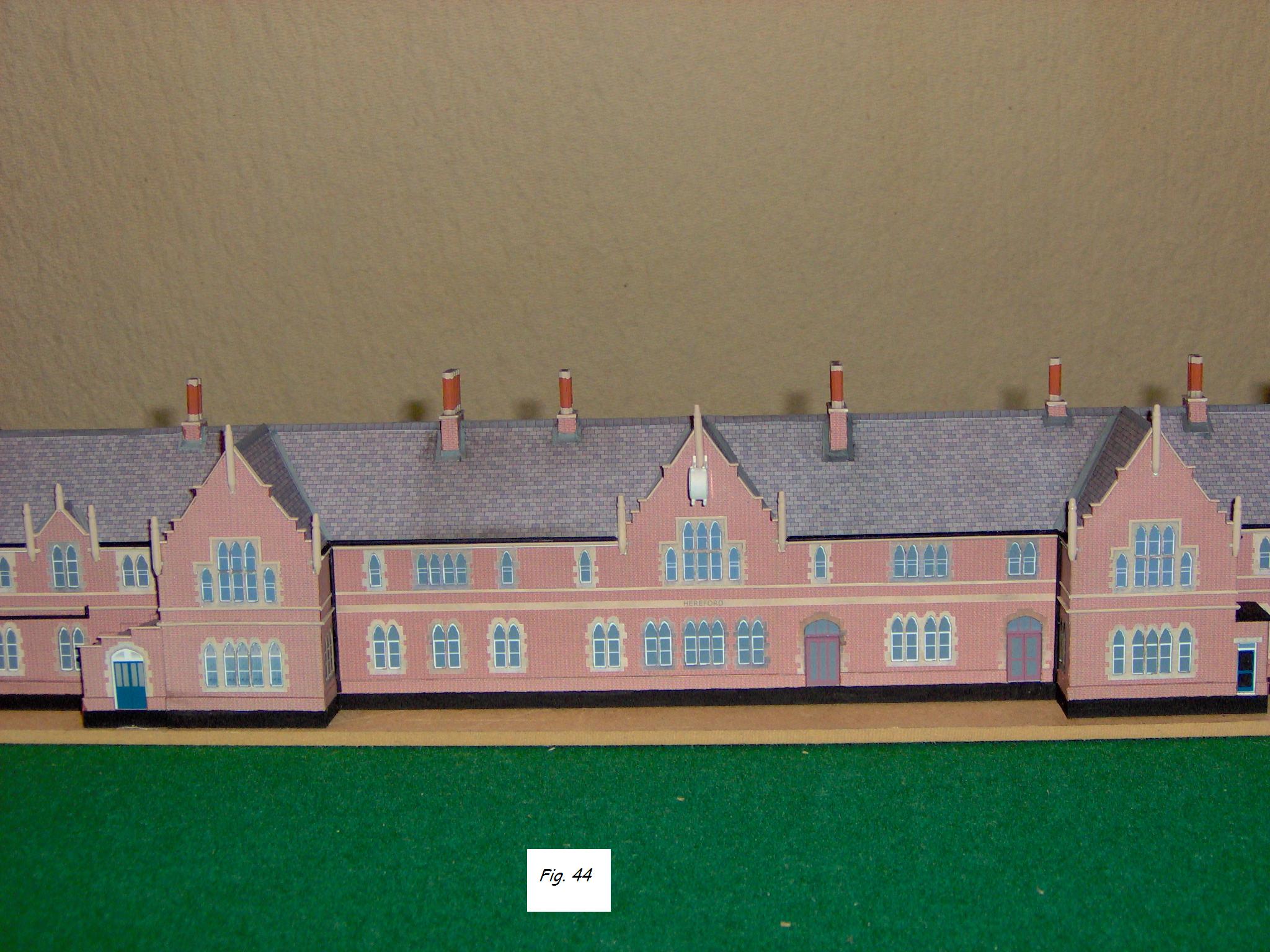
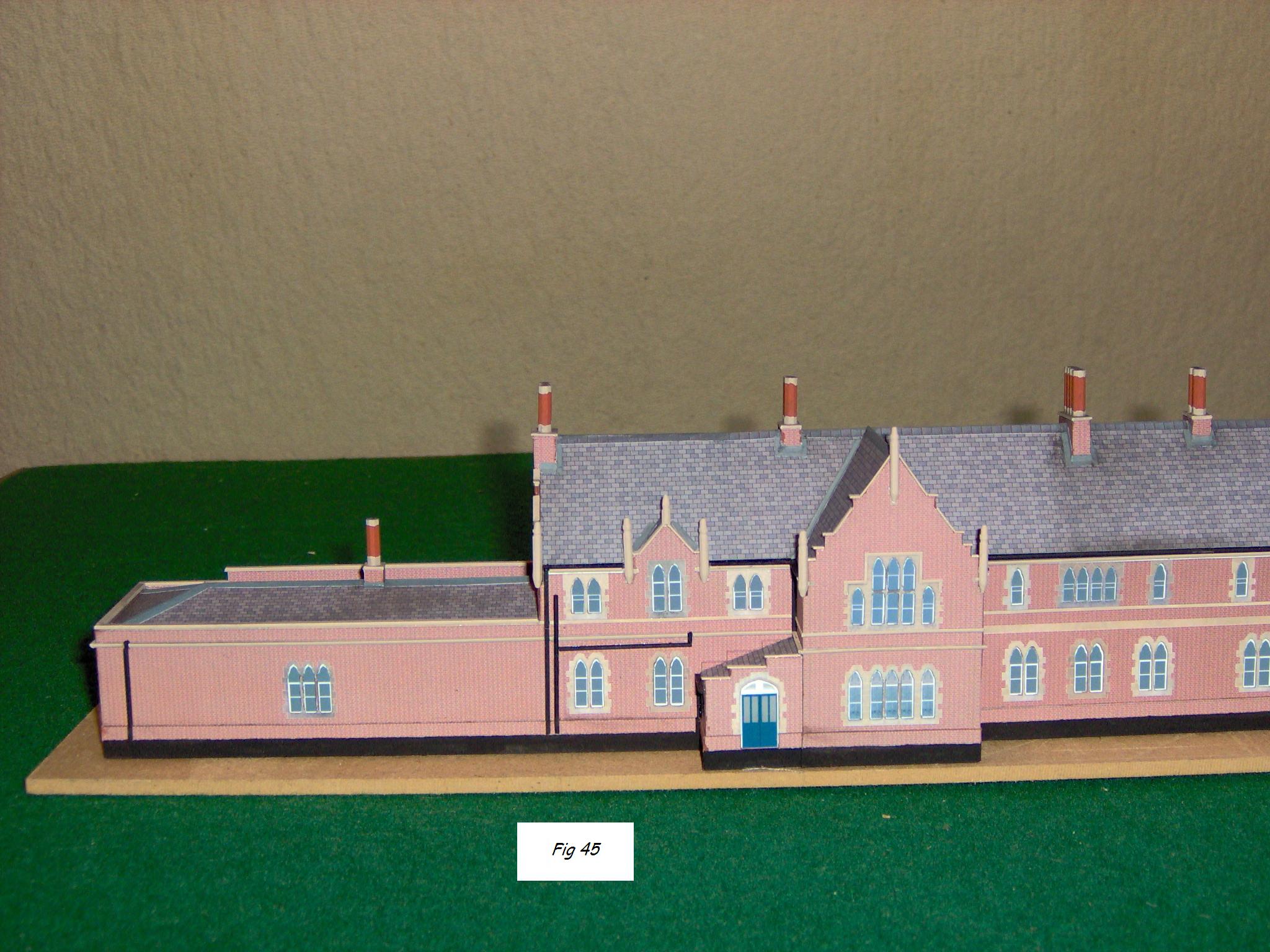
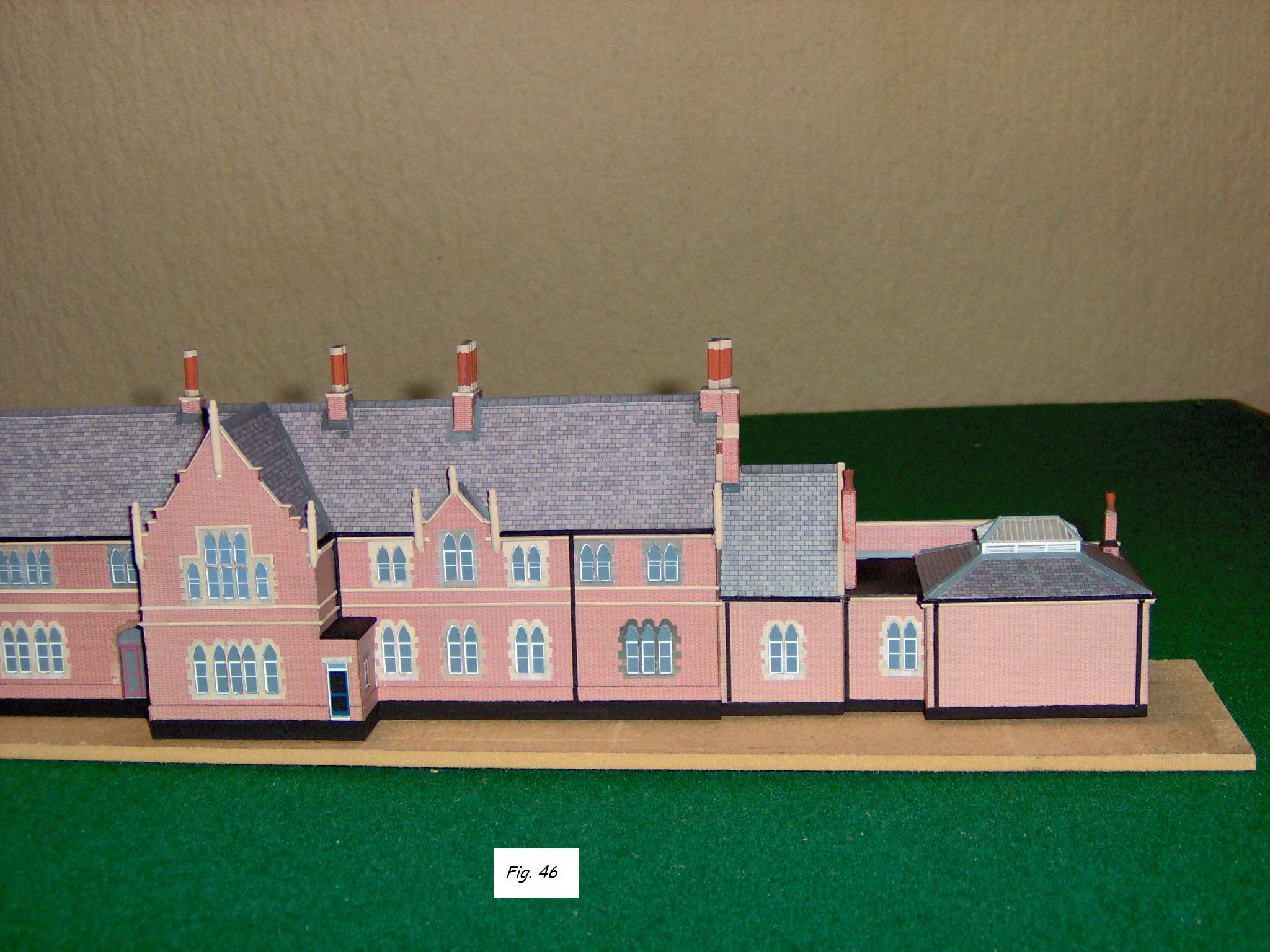
IM000074.JPGIn 7mm scale the usual rule of thumb for adding detail is that if you can’t see it on the model from a distance of two feet, omit or simplify it. Since the human eye looks for detail from about the same distance regardless of scale then much of the detail on a model of this size would have to be omitted. As I mentioned at the start, compromises would be necessary. For example, it proved impossible to find a solution to the brickwork and stonework on the octagonal chimney stacks. Application of brick paper would destroy the octagonal shape unless a separate piece was applied to each face. The solution was to paint them brick colour and apply a stone colour base and cap. I don’t feel that viewed from two feet away this is that noticeable. Other features over which compromise was necessary were the finials. These are quite a complex shape so a much simpler one was evolved as turning plastic on this scale was impracticable. I’m less happy about these, and probably the only real solution would be to turn one up from brass and have lost-wax castings made. This might also be a possible solution for the chimneys.

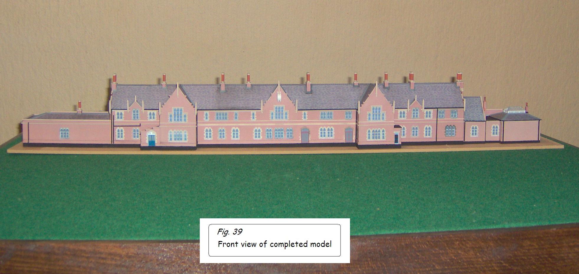
On the other hand, since the clock on the centre of the front elevation is such a noticeable feature it seemed worth making the effort to produce this in as much detail as possible. The iron tracery was obviously out of the question but a really detailed clock face was not, and this was computer produced and printed on glossy photo-paper, and I feel is quite effective.
The canopy over the central frontage has not yet been constructed. The only photograph so far traced does not yield sufficient information to make even an approximation so this is, one hopes, a temporary omission.

… and a final thought.

Having looked so long and hard at this station I have grown to appreciate and enjoy its overall design and though I have only seen it once in the flesh I feel as though I know it quite well.

My grandparents lived in Hereford and my father was born there; they must have travelled through this station a number of times.

The Victorian architects knew what they were doing in designing such an impressive station appropriate in size and style for a cathedral and county city. Detailed study of the exterior leads one to wonder what the interior must have been like. Many stations of the period had just as fine interiors as exteriors. I don’t know of any existing photographs of the inside, so this remains an intriguing and unanswered question.
David Cambridge

Hereford – The Construction of Barrs Court Station 5

David continues:

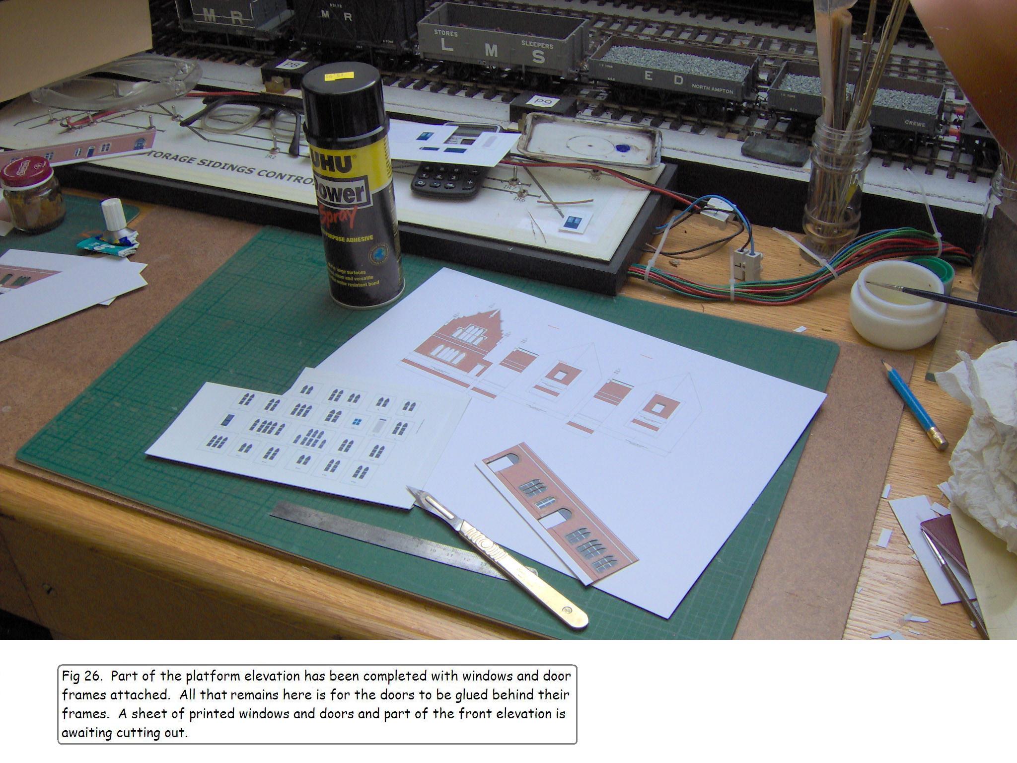
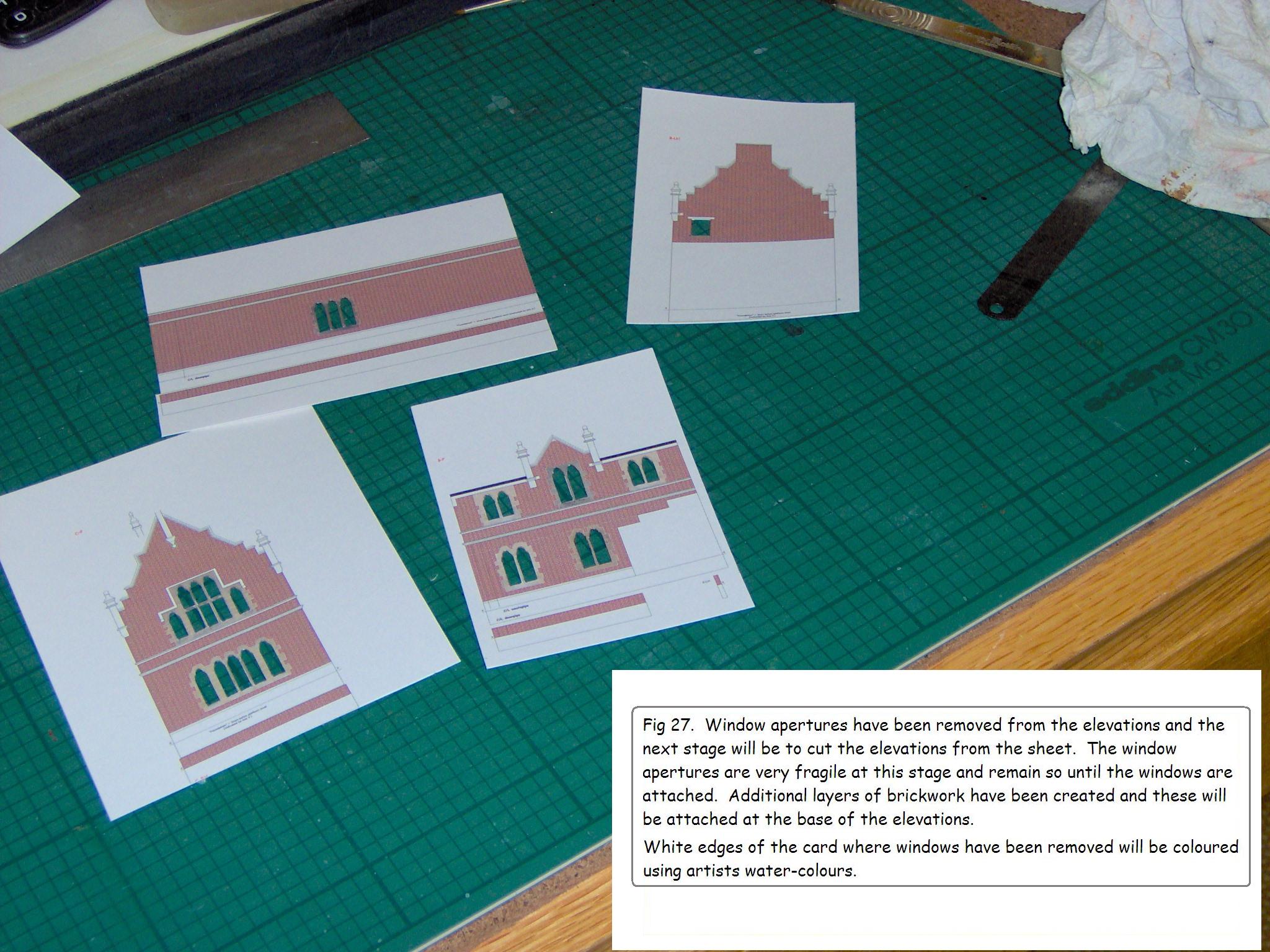
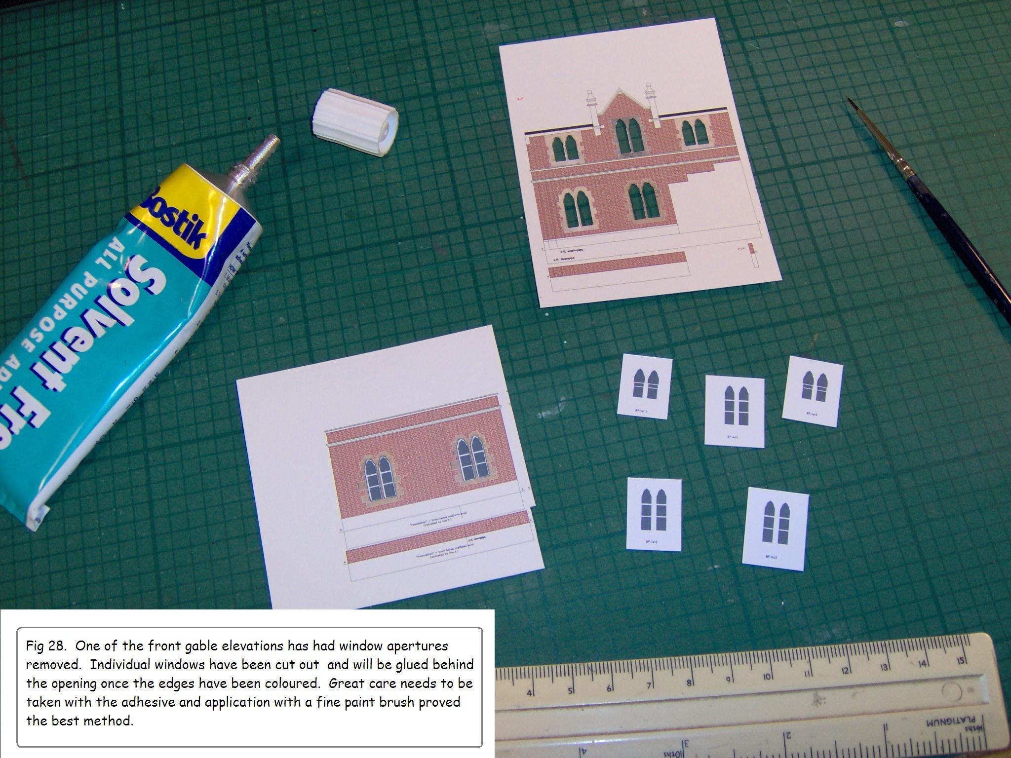
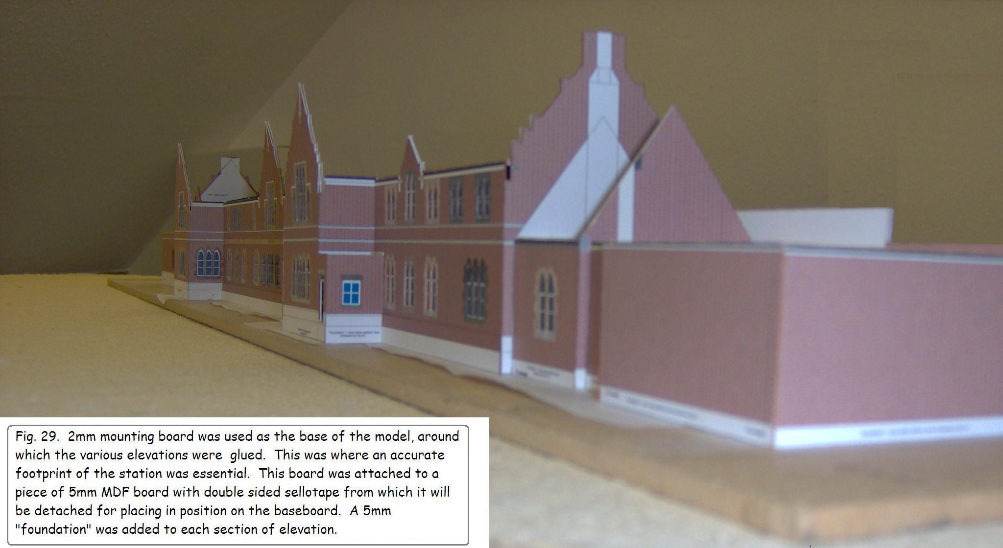
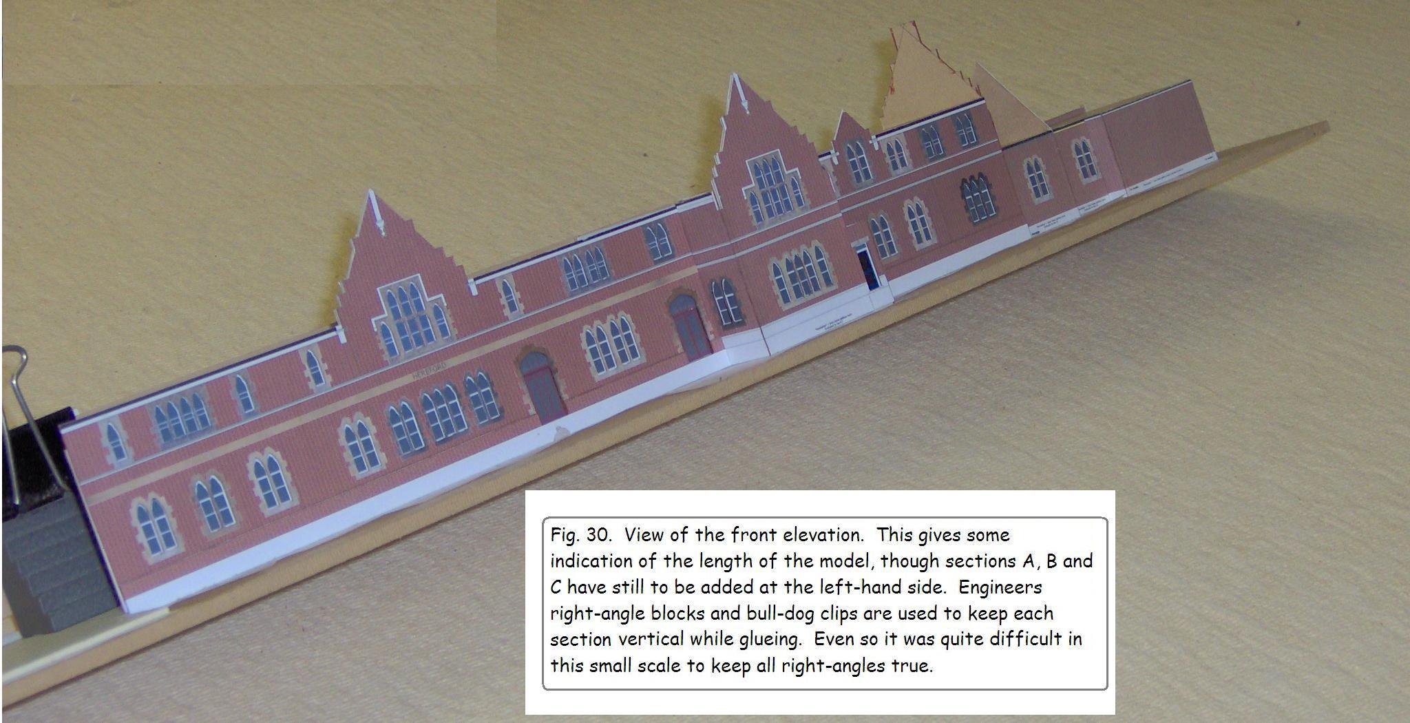
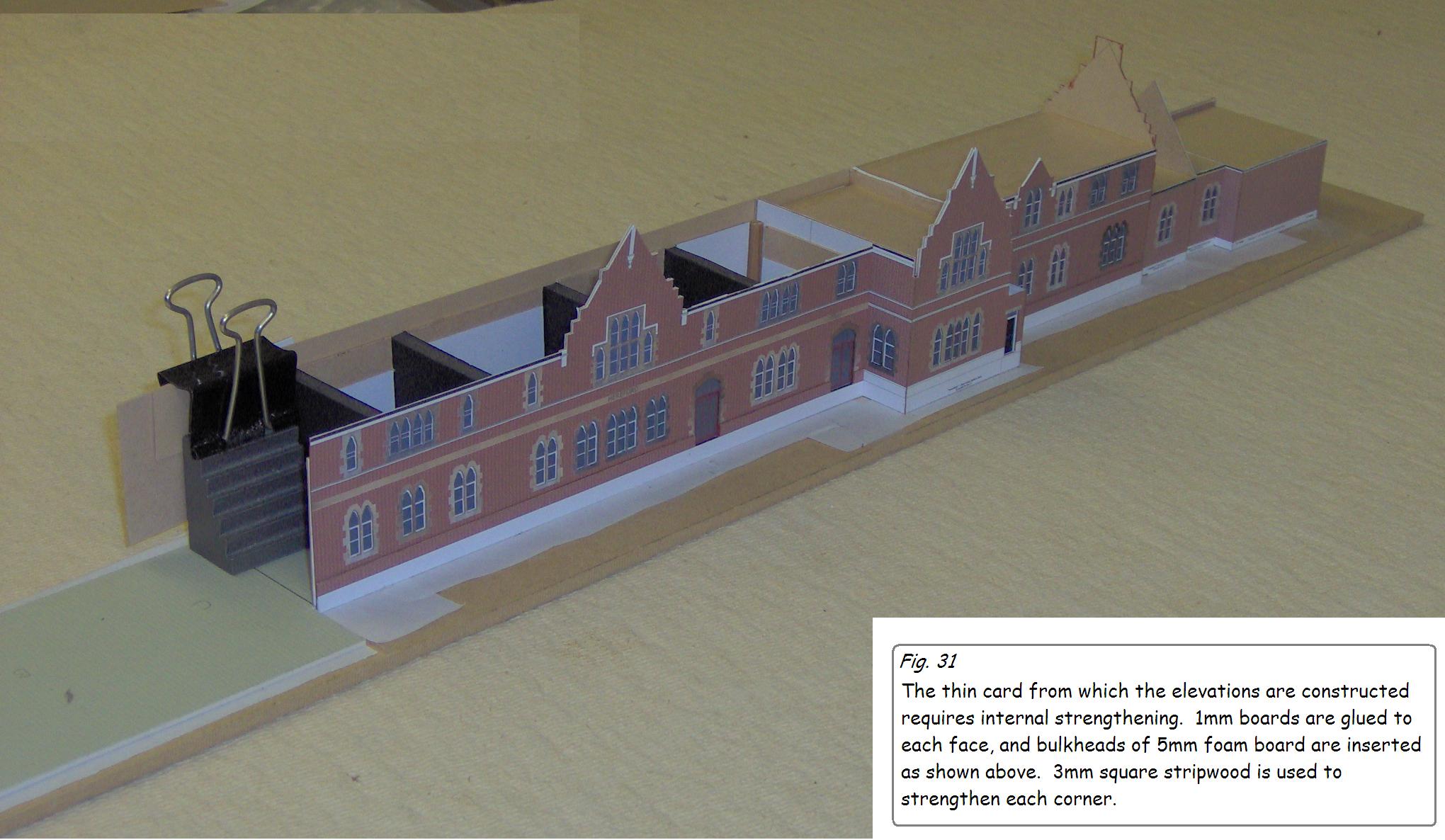
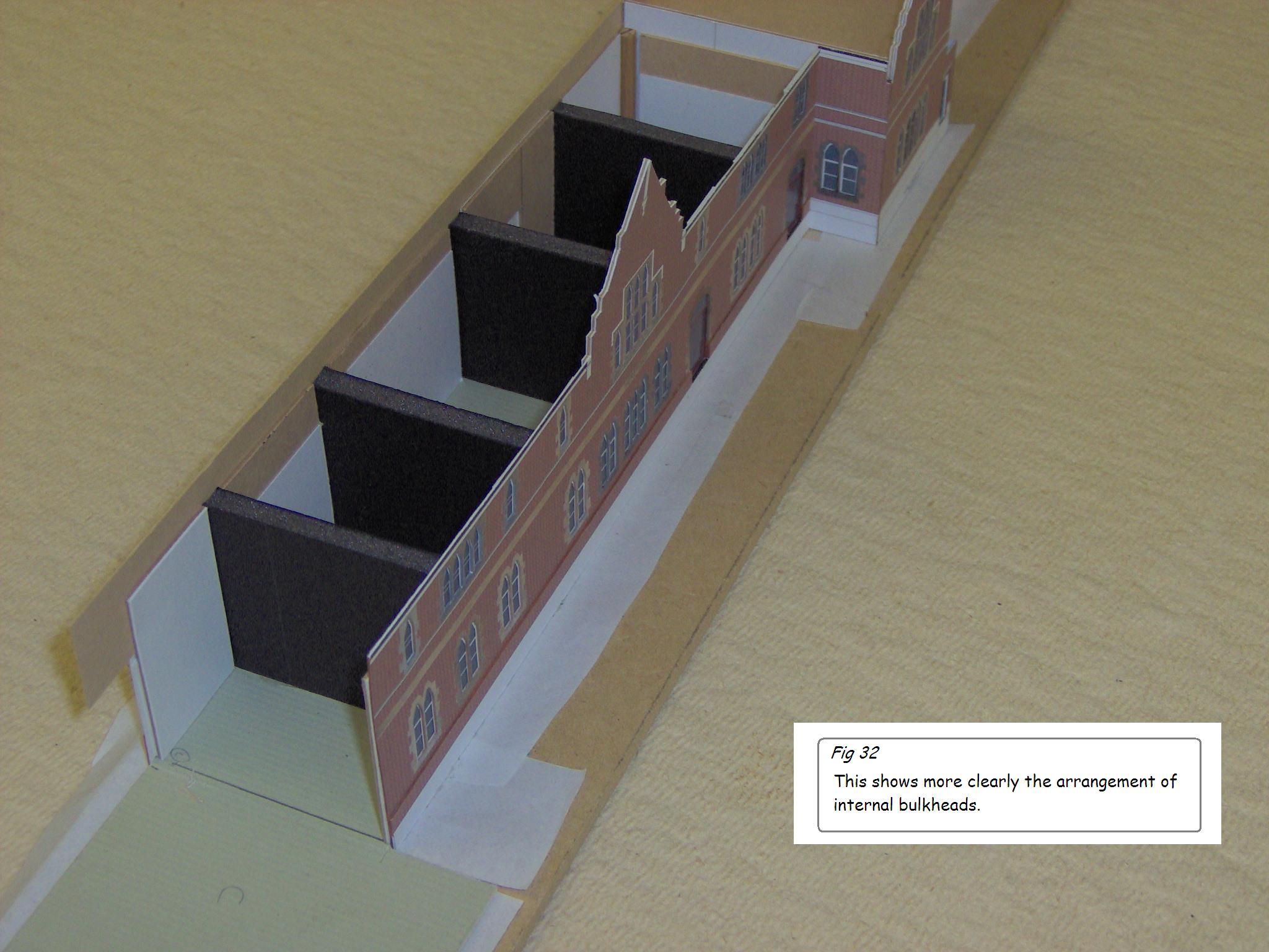
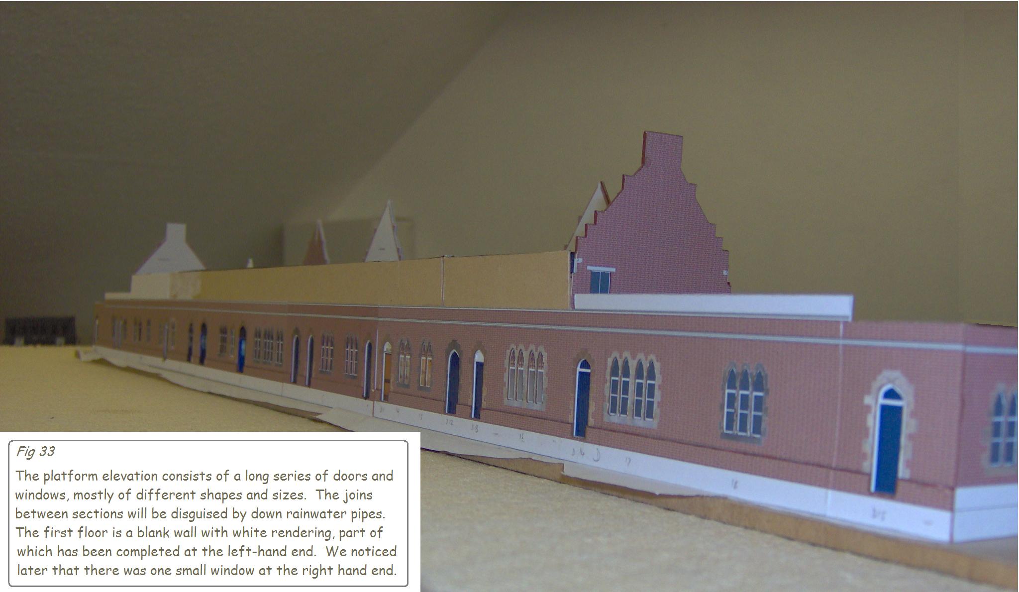
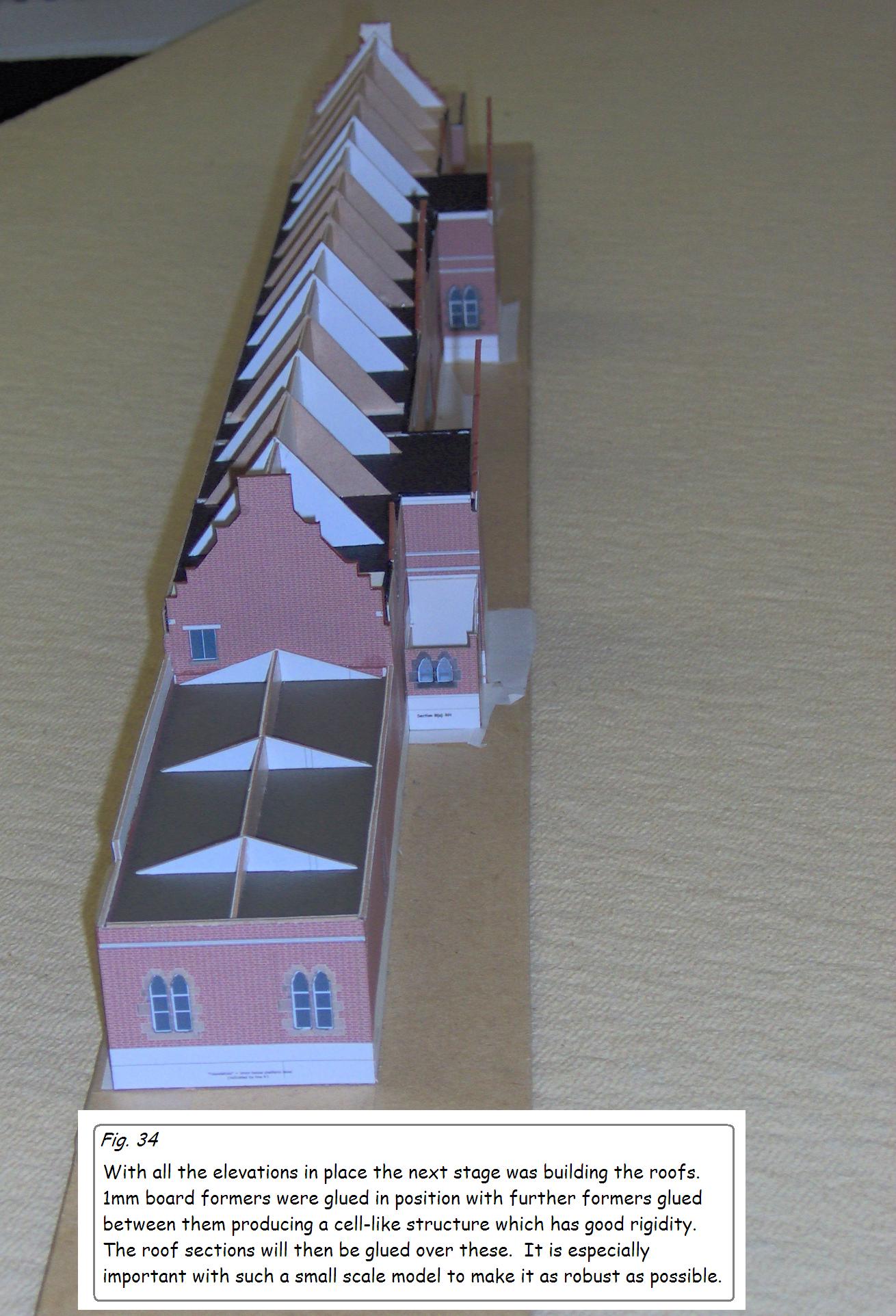
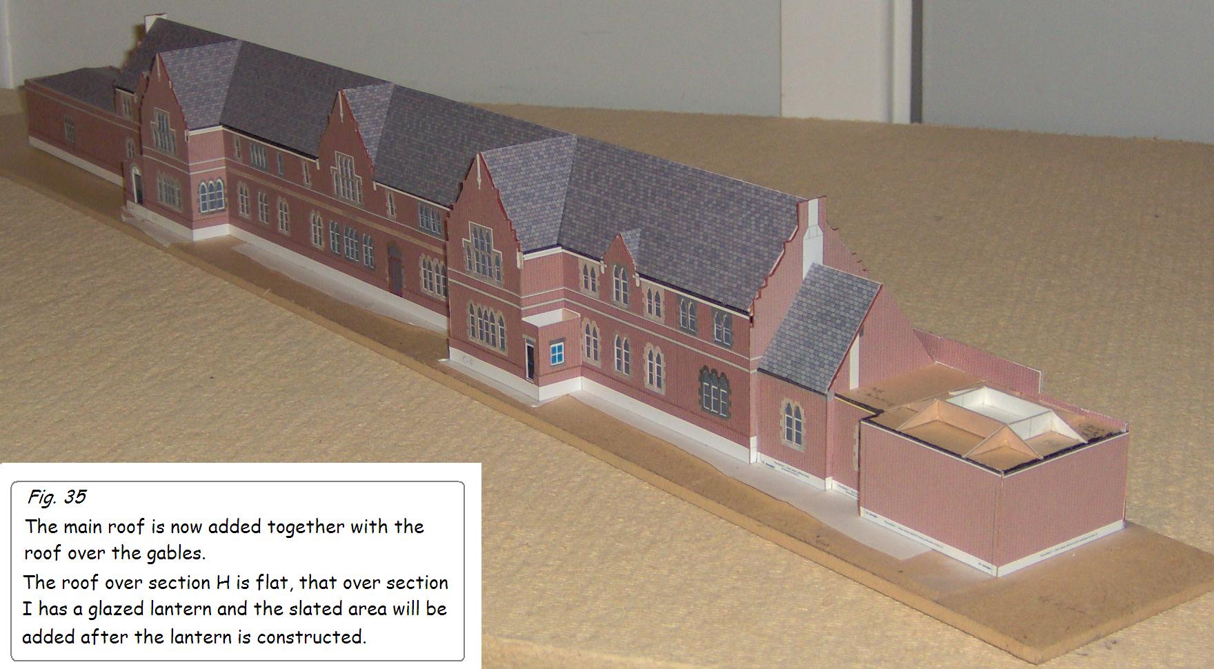
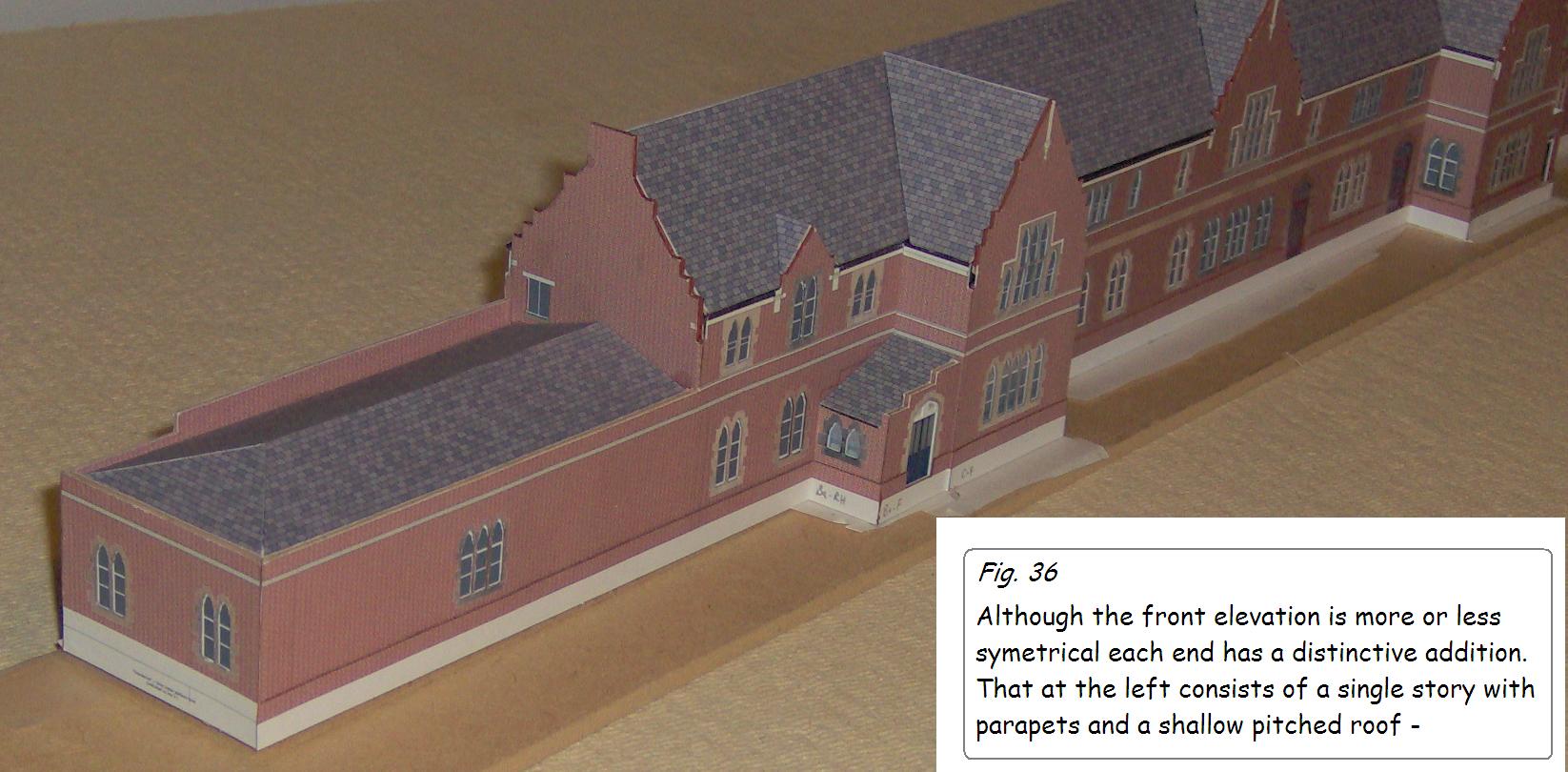
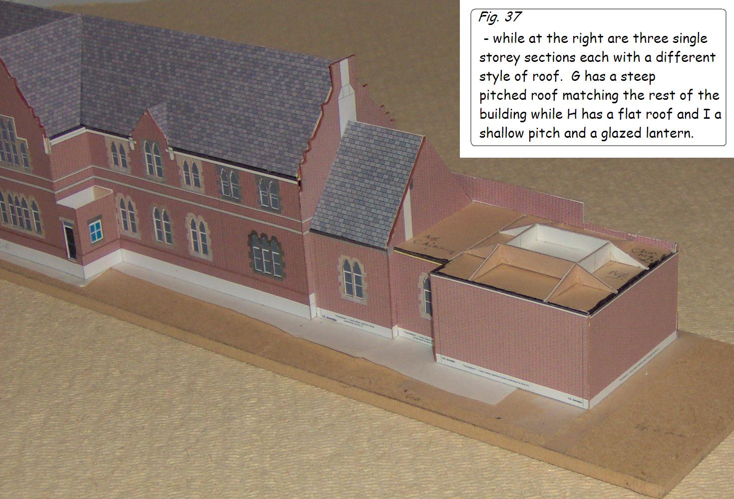
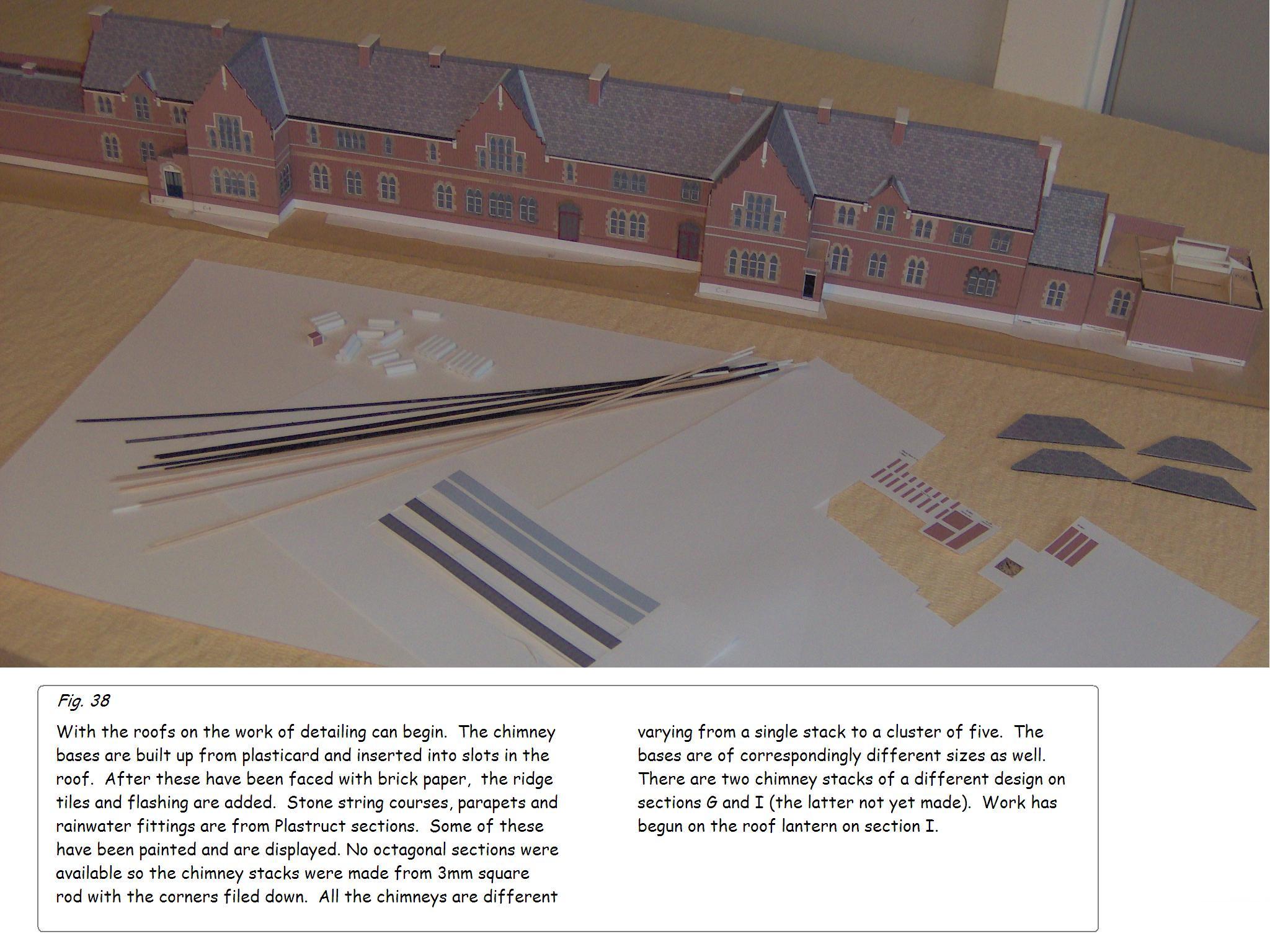
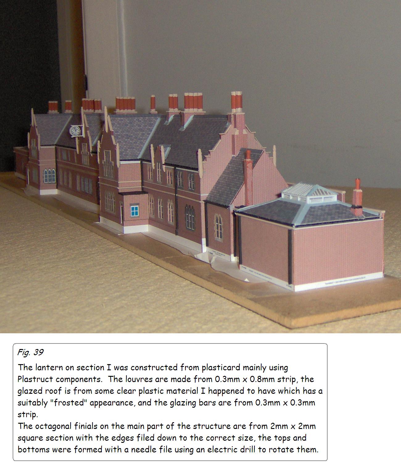
Once the fixative has dried the various door and window spaces can be carefully removed and the elevations cut out. This process and the various stages in construction are shown in figs. 26-39, below.
Doors and windows were printed onto glossy photo-paper, cut out and glued behind the appropriate apertures. It was not possible to produce transparent windows, so the glass was coloured navy-black, and in some cases, notably the platform and front elevations of the buffet where illuminated from within, these were copied straight from the photographs.

IM000009.JPG IM000015.JPG IM000016.JPG IM000019.JPG IM000013.JPG IM000012.JPG IM000014.JPG IM000020.JPG IM000024.JPG IM000034.JPG IM000032.JPG IM000033.JPG IM000036.JPG IM000044.JPG

Hereford – The Construction of Barrs Court Station 4

David goes on to describe the method of construction:

Method of Construction

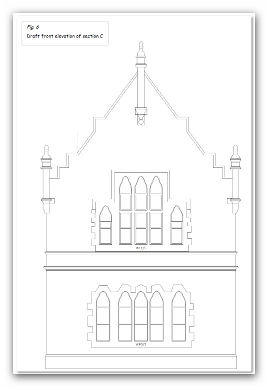
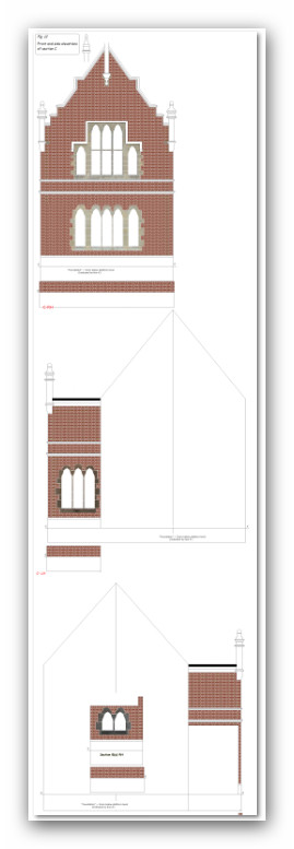
The first step was to make a line drawing of the front elevation of section C just to make sure that my estimated dimensions were on the right lines and that printing would be of the necessary accuracy (see fig. 6).Ashampoo_Snap_2014.01.26_14h58m37s_003

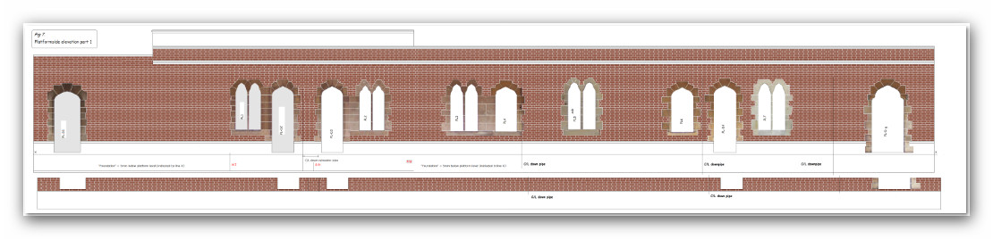
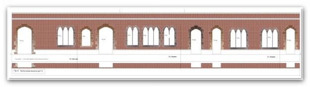
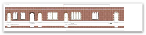
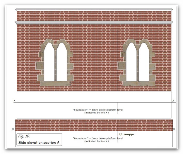
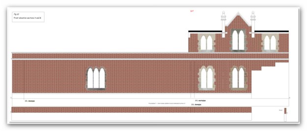
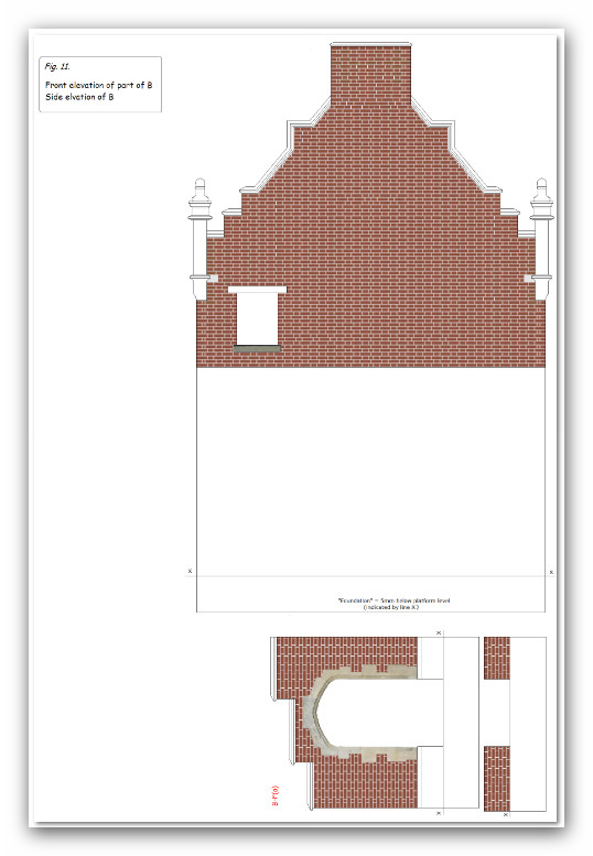
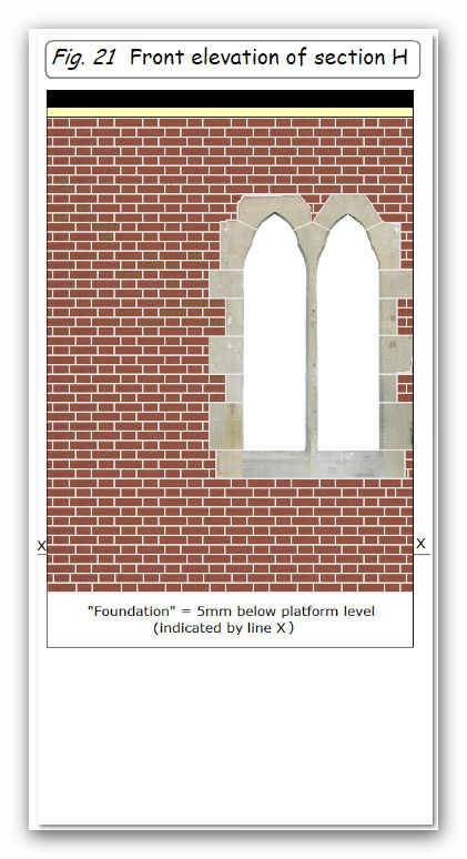
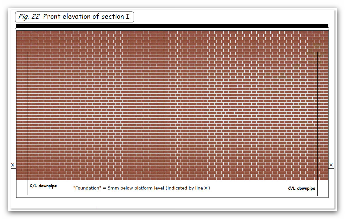
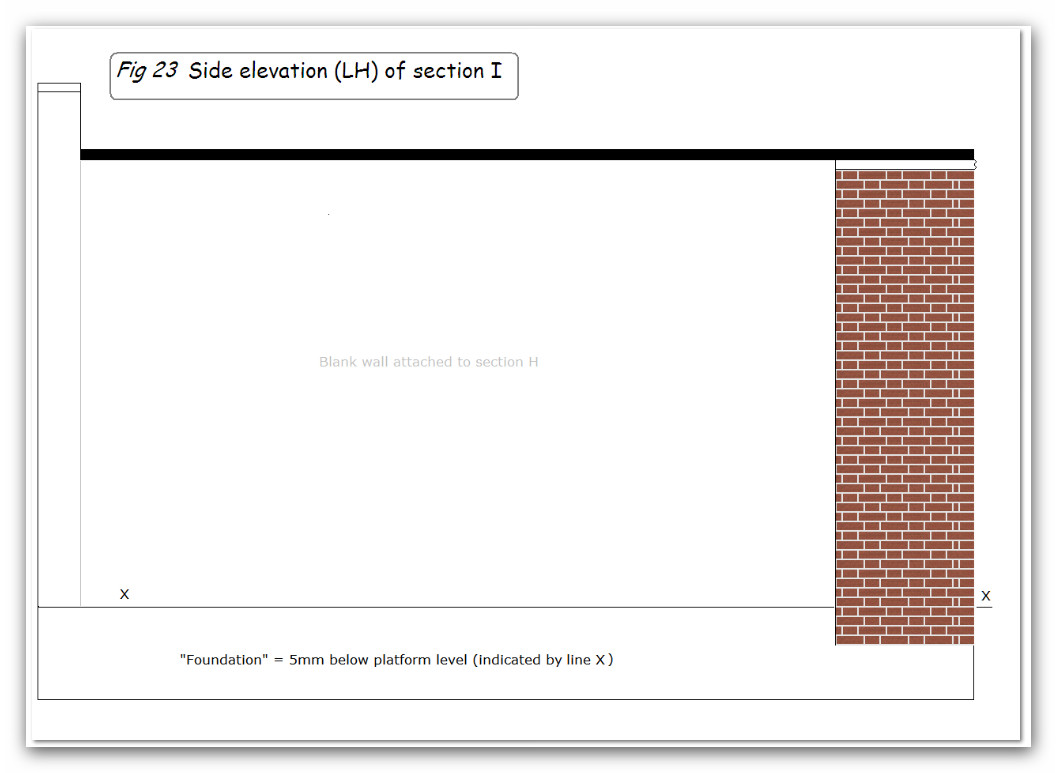
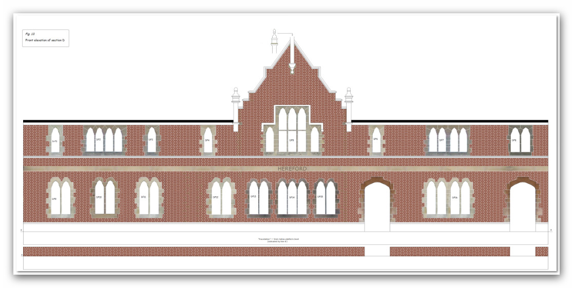
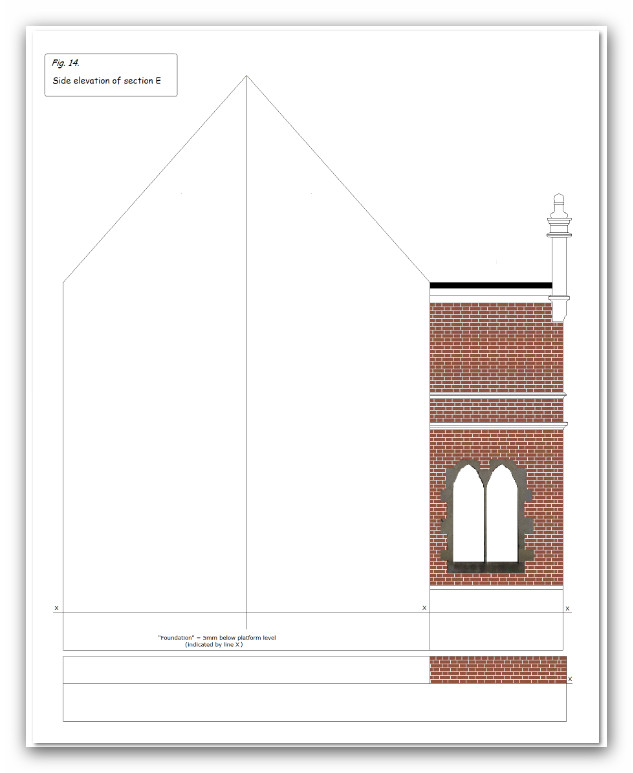
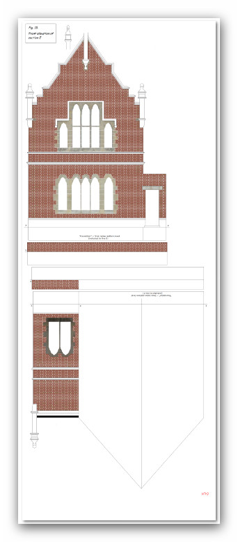
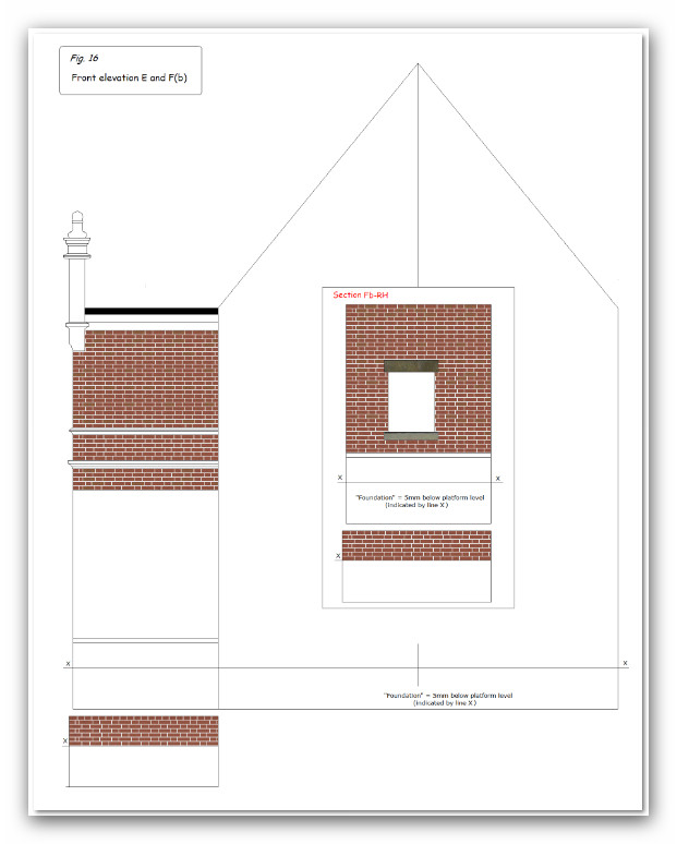
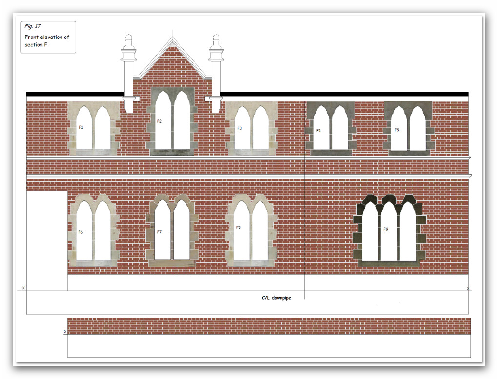
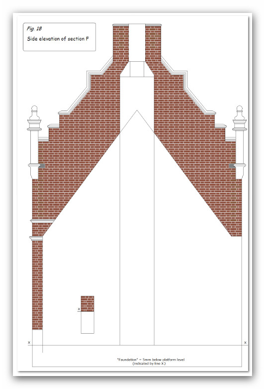
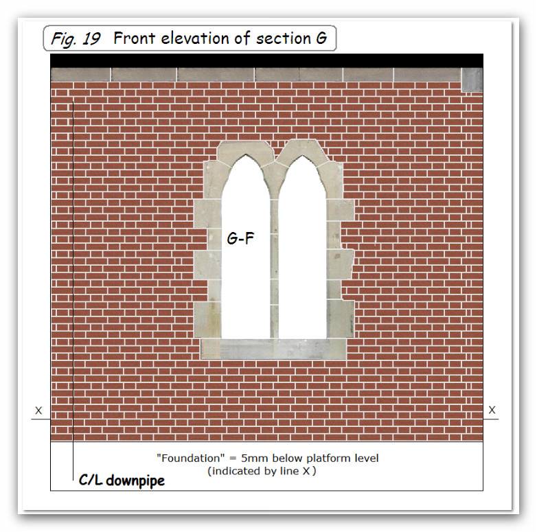
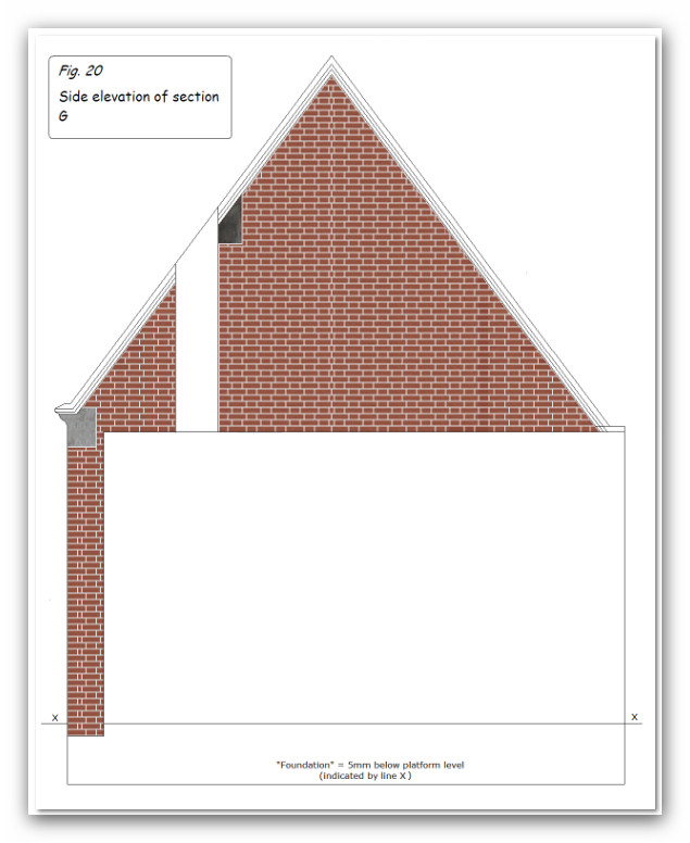
Next followed the detailed drawing of all the elevations -front, side and platform. Wherever possible, actual door and window surrounds were copied from the photographs and resized in situ (see figs. 7- 23, below).

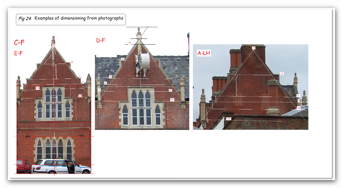
The process of determining dimensions was carried out from the photographs, and some examples of this are shown in fig. 24, below.

These images were then printed onto A4 sheets of white card. The ink used in inkjet printers appears to be soluble in water and white spirit so each sheet was sprayed with artist’s fixative. This seems to give some protection but care has to be taken to protect the parts from contact with these. I’m also not too sure about the colour permanence of the ink so it may be a good idea to shield models made this way from direct sunlight.

Ashampoo_Snap_2014.01.26_18h49m40s_004

Ashampoo_Snap_2014.01.26_18h50m47s_005

Ashampoo_Snap_2014.01.26_18h51m24s_006

Ashampoo_Snap_2014.01.26_18h52m21s_007

Ashampoo_Snap_2014.01.26_18h52m53s_008

Ashampoo_Snap_2014.01.26_18h52m53s_009

Ashampoo_Snap_2014.01.26_18h59m42s_010

Ashampoo_Snap_2014.01.26_18h59m42s_011Ashampoo_Snap_2014.01.26_19h03m35s_012Ashampoo_Snap_2014.01.26_19h05m48s_013

Ashampoo_Snap_2014.01.26_19h06m15s_014 Ashampoo_Snap_2014.01.26_19h06m45s_015 Ashampoo_Snap_2014.01.26_19h07m12s_016 Ashampoo_Snap_2014.01.26_19h07m38s_017 Ashampoo_Snap_2014.01.26_19h08m22s_018 Ashampoo_Snap_2014.01.26_19h08m46s_019 Ashampoo_Snap_2014.01.26_19h09m22s_020 Ashampoo_Snap_2014.01.26_19h09m50s_021 Ashampoo_Snap_2014.01.26_19h10m39s_022

Hereford – The Construction of Barrs Court Station 3

David continues:

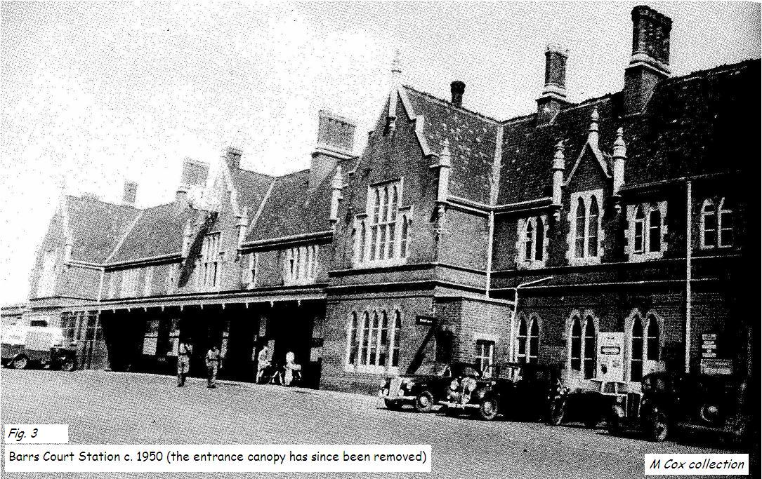
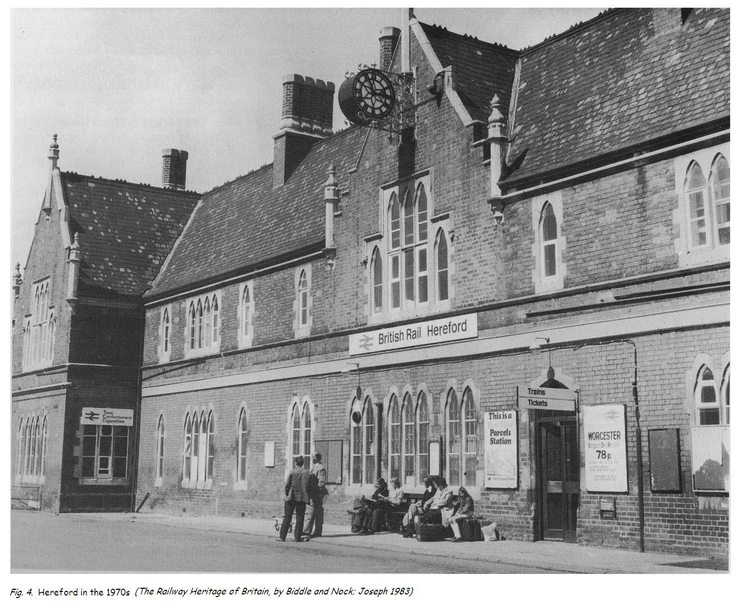
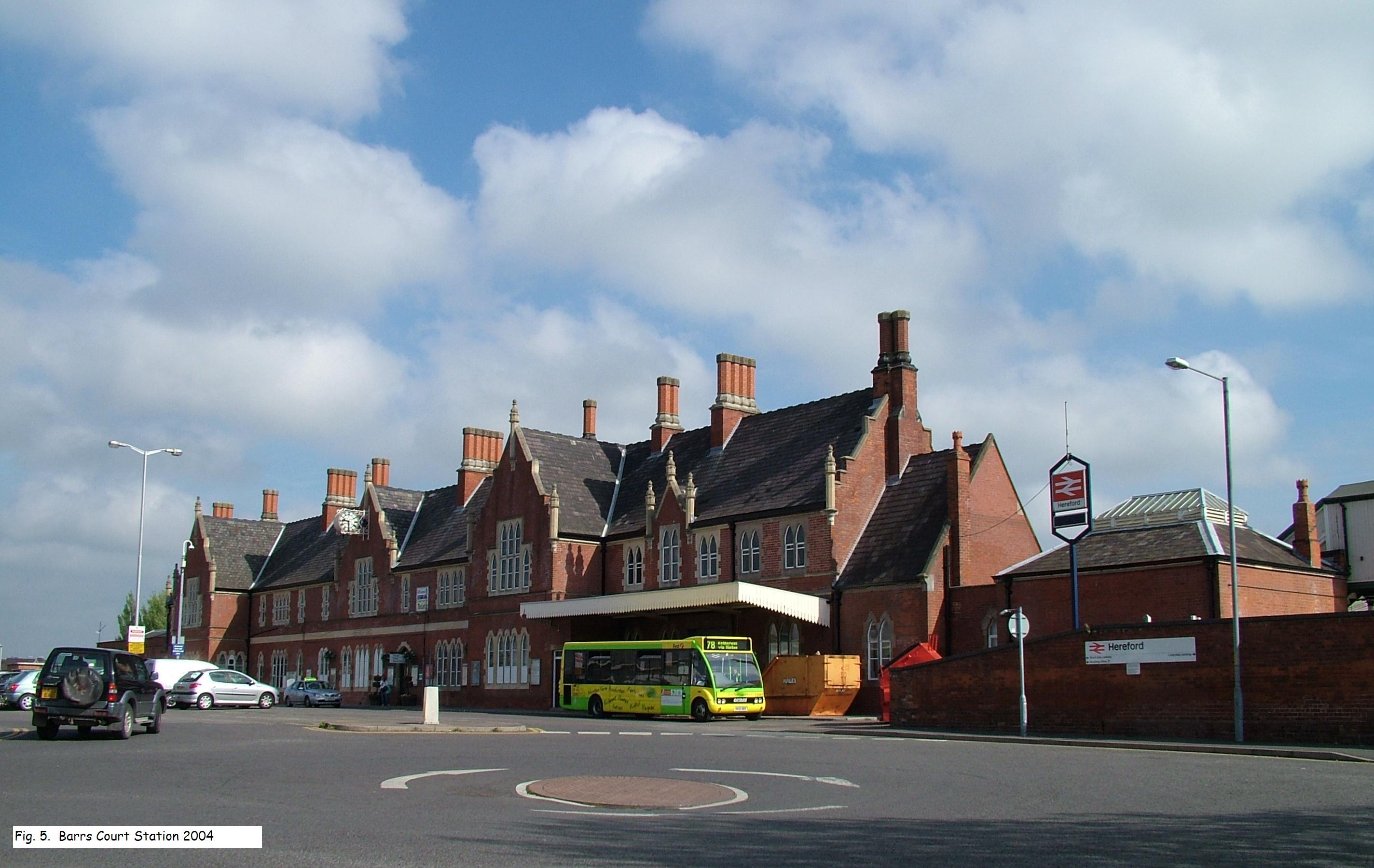
Roger’s layout is based in the 1950s – 1960s. One photograph has been traced for that period (see fig 3), and another from the 1970s (see fig 4) These show a number of differences from the 2004 view (see fig 5).

Barrs Court Station - Figure 3

The lack of any detailed images from the period required meant that some intelligent guesswork would be needed with particular regard to doors and windows. The main change from the present day would have to be the re-instatement of the canopy over the main frontage (section B).

page 8

The canopy over section F would need to be omitted, as would the industrial-type steel doors in this section and the corresponding section of the platform side. These were replaced by windows as it was presumed that the later canopy and doors were provided for parcels and mail access.

page 9


The two doors in section B are different to other doors, but they could be 1950s so have been left. The doors in section A and the side of section I look to be more recent and have been omitted.

Figure 5

Ashampoo_Snap_2014.01.25_11h25m13s_002

Hereford – The Construction of Barrs Court Station 2

David continues:

The first job was to create as accurate a plan of the building as possible. In doing this it soon became obvious that more photographs would be required, and it was necessary to obtain accurate dimensions for the bricks used, and if possible an accurate sizing of one of the bays for comparative purposes.

Fortunately through the auspices of the N gauge Society Roger was able to contact a colleague who carried out a survey and took more photographs.
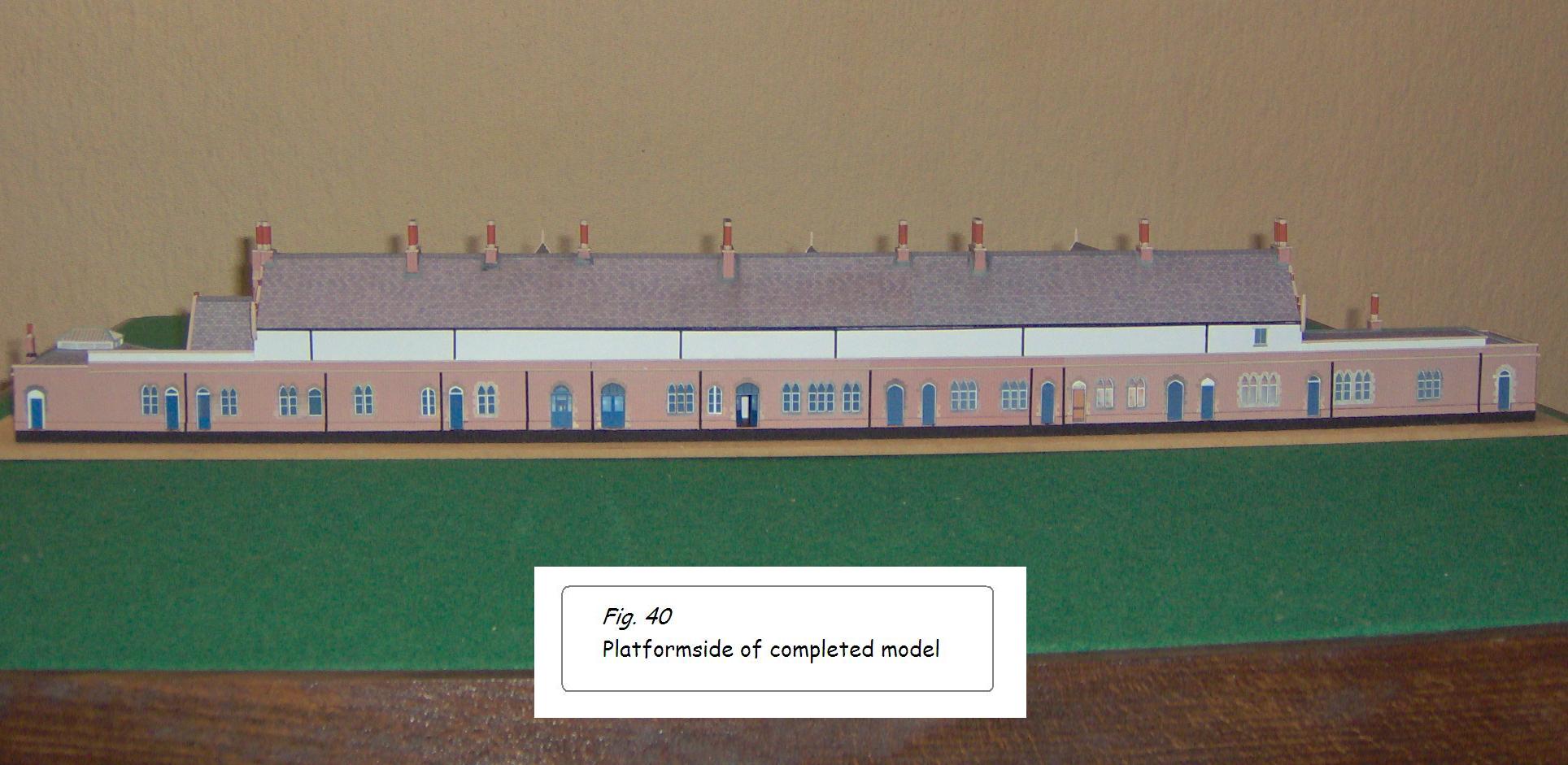
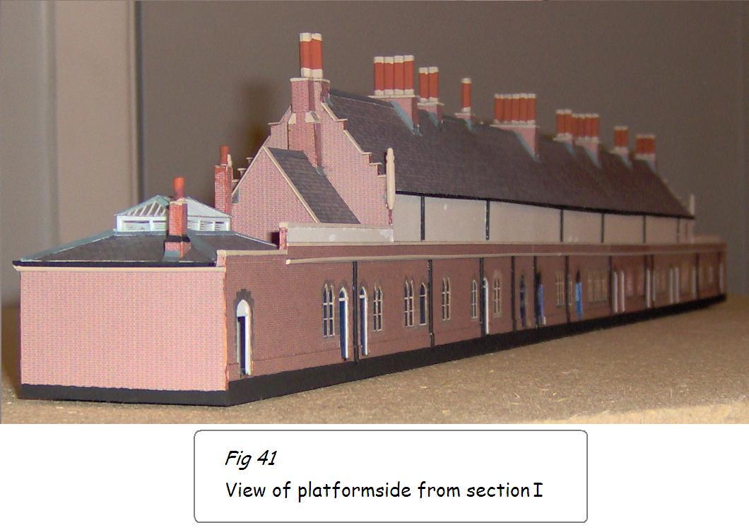
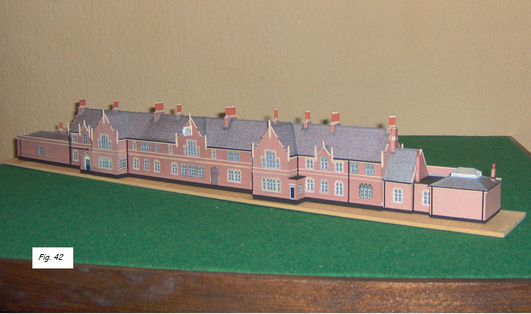
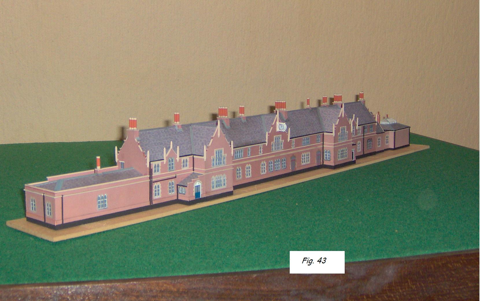
From these an approximate plan was drawn, from which it emerged that the building was about 330 feet in length which translates as 660mm in N gauge. There were 9 distinct blocks or sections of the building and these were labelled A-I to assist in identification as the various parts of the model were drawn and cut out. A final and accurate plan would not be possible until all the detailed elevations were created (see fig.2).

Ashampoo_Snap_2014.01.25_11h25m13s_002


Figure 2

Hereford – The Construction of Barrs Court Station 1

My father-in-law, David Cambridge became interested in the model of Hereford that I am building in N Gauge and undertook to build a card model of Barrs Court Station for the layout. I think the model is amazing. 

David did this work a few years ago. Sadly, since then, David has died.

The remainder of this post and those that follow under this heading are David’s own description of the work he did to build the model.

Barrs Court Station

This large two-storey railway station of red brick was built in 1853 for the Shrewsbury & Hereford Railway. The architect was R. E. Johnston and the building with its groups of lancet windows set in rusticated stone panels, its tall chimneys and gables, steep roofs and octagonal stone finials is listed Grade II.

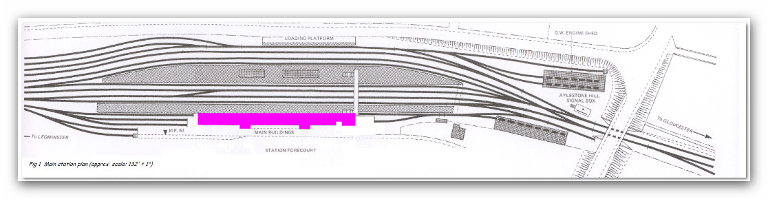
Roger’s N gauge scale model of Hereford railway station and its environs required a model of Barrs Court station. He had taken a large number of photographs of the station, but been unable to trace any drawings or plan of the building except for its footprint on an OS map (see fig. 1).
I had some experience of creating models, albeit in 7mm scale, by calculating dimensions from photographs and creating designs along the lines used by Metcalfe card model buildings. This was relatively straightforward using the MSPaint accessory in Microsoft Windows.

While I wanted the model to be as detailed as I could make it I soon realised that in this small scale certain compromises would be necessary. As regards the brick-work it would not be feasible to create separate bricks in relief, so I decided to draw the elevations in as large a pixel scale in MSPaint as was practicable and to draw in individual bricks.

I settled on a scale of 600 pixels per inch and a table was drawn up listing the number of pixels required for inches and feet in 2mm scale. This ensured dimensional accuracy when printing the designs for the various parts of the model.  The table is reproduced below.

Ashampoo_Snap_2014.01.25_10h27m06s_001


Fig. 1

Paint template for HEREFORD station @ 300 x 300 dpi

Prototype dim.      Dim @ 2mm scale                       Pixel equivalent

                                                                    400dpi             300dpi            600dpi

½ inch                         0.08 mm                      1                      1                      2

1 inch                          0.17 mm                      3                      2                      4

2 inches                       0.33 mm                      5                      4                      8

3 inches                       0.5   mm                      8                      6                      12

4 inches                       0.67 mm                      10                    8                      16

5 inches                       0.83 mm                      13                    10                    20

6 inches                       1.0   mm                      15                    12                    24

7 inches                       1.17 mm                      18                    13                    26

8 inches                       1.33 mm                      20                    15                    30

9 inches                       1.5   mm                      23                    17                    34

10 inches                     1.67 mm                      26                    19                    38

11 inches                     1.83 mm                      28                    21                    42

1 foot                          2.0   mm                      31                    23                     46

2 feet                           4.0   mm                      62                    47                    94

3 feet                           6.0   mm                      93                    70                    140

4 feet                           8.0   mm                      124                  94                    188

5 feet                           10.0 mm                      155                  118                  236

6 feet                           12.0 mm                      186                  141                  282

7 feet                           14.0 mm                      217                  165                  330

8 feet                           16.0 mm                      248                  188                  376

9 feet                           18.0 mm                      279                  212                  424

10 feet                         20.0 mm                      310                  236                  472

11 feet                         22.0 mm                      341                  259                  519

12 feet                         24.0 mm                      372                  283                  566