The Genova–Casella railway is a 24.3 km narrow gauge railway that connects Genoa to Casella, a village in the mountains inland from the city. [1] The stations on the line are shown in the graphic immediately below:
The Route of the Line. [1]
This article covers the history of the line and a journey along the southern half of the railway (Genoa to Sardorella). The second article covers the northern half of the railway and its rolling stock. That second article can be found here. [16]
When it is operating, “the line operates nine trains per day and it is used for both commuting and tourist purposes; it crosses three valleys and was opened in 1929. While it is owned by Liguria Region, it has been operated since 2010 by AMT Genova.” [1]
“At the end of the nineteenth century, a direct railway link between Genoa and Emilia Romagna was proposed, as an alternative to the Turin–Genoa railway. The railway had to start from the Port of Genoa and cross the Ligurian mountains to reach Piacenza railway station and Borgotaro. It was intended to be a fast, long-distance line primarily for goods.” [1]
“As a result, SAFEL (Società Anonima Ferrovie Elettrici Liguri) considered the construction of a local passenger line, complementary to the Genoa-Piacenza freight line. Its purpose was to connect the city centre to all the small municipalities and holiday resorts of the Ligurian hinterland … The first section of this network was the Genoa-Casella line.” [1]
“The original project was planned with a bifurcation to provide a branch towards Busalla and a line to Torriglia, which in a second phase would be extended to Piacenza.” [1]
These were just the first proposals from SAFEL. It considered a wide range of other schemes intended to follow on from their successful completion. A start was made when, in 1908, “SAFEL applied to the Ministry for a concession for the construction of the Genoa-Casella line. This concession was obtained on 17th June 1915. Like most of the local railways of the time, the line was almost entirely single-track and had a tortuous alignment (in order to follow the topography of the Ligurian mountains). Electrification was part of the original plans and the 950 mm track gauge was chosen to minimise infrastructure costs in accord with a directive from the Council of Public Works which recommended the adoption of an ‘Italian metric gauge’ (950 mm) for railways unlike the true metric gauge (1000 mm) adopted for tramways.” [1]
“To allow the construction of a connection at Manin with the Genoa tram network , the operating company presented a variation to the project, approved by the Higher Council of Public Works, which sanctioned the adoption of the 1000 mm gauge. This connection, however, although reported in the first design tables, was never built.” [12 – translated from Italian]
“The coming of the First World War imposed a long postponement to the construction of the railway line. It was not until 28th February 1921 that the final agreement between the Government and SAFEL was signed, which gave the permitted a start to construction work.” [1 – translated/adapted from Itailan] “On 26th June 1921 the first stone was laid. The construction of tunnels, bridges, and station buildings was entrusted to the ‘Consorzio Cooperative Liguri di Produzione e Lavoro tra Combattenti’, which gave work to thousands of former soldiers and workers who remained unemployed after the first world war. The construction was entirely financed with private funds.” [1]
“On 26th June 1921 the first stone was laid. The construction of tunnels, bridges, and station buildings was entrusted to the ‘Consorzio Cooperative Liguri di Produzione e Lavoro tra Combattenti’, which gave work to thousands of former soldiers and workers who remained unemployed after the first world war. The construction was entirely financed with private funds.” [1]
Construction work proved to be complex. The section from Genoa to Trensasco required steep gradients. To facilitate construction, “a 1.2 km-long cable car was installed in order to transport building materials from the Bisagno River valley. The cable car system lifted materials over a height of 450 m. Electric excavators and crushers (modern machinery at the time) were also adopted to produce the necessary sand and cement on site.” [1]
“In 1924 the S.E.N. (Società Elettrica Nazionale), a subsidiary of the Ernesto Breda industries, was awarded a contract for the laying of track, the construction of the overhead line, the construction of electrical substations, and for the supply of rolling stock.” [1]
“Meanwhile, resources were expended on pursuing a succession of extension projects, some of which were very unlikely. This resulted in ongoing financial instability and a slowing of the construction work already on site.” [1]
“The first tracks were laid in 1926 starting from Vicomorasso, with the help of a Mallet-type steam locomotive purchased by the Ferrovie dell’Appenno Centrale, but operations were interrupted due to lack of funds.” [1]
“Work resumed in 1927 thanks to a grant from the Municipality of Genoa and the National Bank. The Breda company was asked to complete the remaining civil engineering work in addition to the electrification of the line and the laying of the track (the bridge between the two Fontanassa tunnels, the Cicala and Puin viaducts).” [1]
“On 7th June 1928, the steam locomotive used in the construction of the line made an inspection trip to Casella pulling a passenger car with the Podestà of Genoa, Sant’Olcese, Serra Riccò and Casella on board. It was welcomed by the citizens in celebration along the way. Only on 2nd October 1928 was the first electric train – reserved for two hundred members of the Italian Electrotechnical Association which in those days held its annual congress in Genoa – able to travel the entire line.” [1]
“On 1st September 1929 the official inauguration took place. … Due to the lack of external funding, the ambitious projects planned for a Ligurian railway network were never fulfilled – Casella became the terminus.”[1][2]
The electric supply was originally 2400V DC. “The first electric locomotives were supplied by Breda, numbered 1 to 3. They were 360 horsepower Bo-Bo locomotives with an innovative Breda-Somarini energy recovery system, unique in Italy. In addition to the motive power, 4 third-class carriages (Nos. 50-53); 3 mixed first-third class carriages (Nos. 20-22) and 16 freight wagons of various types were delivered in 1926, well before the railway opened.” [1]
In 1930, “the Vittorio Veneto bridge over the River Scrivia [was constructed], but the railway was not immediately extended along the route.” [1][3]
“In 1933, even though the railway was operating at full capacity with a high numbers of passengers and freight, SAFEL was on the verge of bankruptcy. … The company had invested heavily in the extension projects without [paying] off outstanding debts with Breda and banca Nazionale del Lavoro, which had financed much of the construction of the line. … In 1934 SAFEL was declared bankrupt after a court trial, and the management of the railway was acquired by the Lazzi bus companies.” [1]
“On 23rd August 1937, two of the locomotives were destroyed in an accident near Vicomorasso. … Three [replacement A1-1A locos] were purchased, … built by MAN in 1913 for the Montebelluna – Asolo and Montebelluna – Valdobbiadene tramways [which] closed in 1931. … The machines entered service in 1939, … after conversion of the original power supply system from 975 V DC to 2400 V DC.” [1]
“During the Second World War the railway experienced its period of maximum use, since numerous families were evacuated to the area to the North of Genoa and the train operated both for passengers and for freight. … At the end of the conflict, both the infrastructure and the rolling stock were seriously damaged by intensive use and poor maintenance, so much so that use of the line was suspended and in 1949 it was placed under Government Commissioner Management.” [4: p16 – translated/adapted from Itailan]
“In 1953 the line was extended from the Casella depot to the town. … Since 1975, the railway has undergone complete … renovation, with the replacement of the rails, the electrical substation and the functional restructuring of the depots.” [4: p16 – translated/adapted from Itailan]
In 1956, a locomotive (No. 28) with a power of 355 kW with a maximum speed of 50 km/h was acquired from the Sangritana Railway; in 1960 another unit (No. 29) and spare parts were acquired. “The locomotives were part of a contract of fourteen four-axle locomotives built in 1924 with electrical equipment and bogies supplied by TIBB and case made by Carminati & Toselli. Originally narrow-gauge at 950 mm, they were converted to [metre-gauge].” [1]
“The ‘Casella train’ remains one of the few secondary Italian railways still in use because not only does it serve a route for which there is no alternative road network, but it also is a tourist attraction (the route intersects numerous hiking trails, including those to the Forts of Genoa and a stretch of the Alta Via dei Monti Liguri) and has low operating costs.” [4: p16 – translated/adapted from Itailan]
In the four-year period 1997-2000, the line was entrusted to the Italian State Railways to achieve a technical-economic recovery, and from 1 January 2001 it became the property of the Liguria Region.][4: p16 – translated/adapted from Itailan]
“Starting from the terminus at Manin, the route winds its way out of the city: running along a stretch of the Val Bisagno, it serves the localities of S. Pantaleo, Cappuccio, Campi, Pino Soprano, Torrazza, before passing through the Trensasco tunnel into Val Polcevera and reaching the terminus at Casella, in Valle Scrivia.” [4: p16 – translated/adapted from Itailan]
The Route
The terminus in Genoa is the Genova Manin railway station, located above the Piazza Manin and can be reached via a flight of steps or by bus No. 64.
In subsequent satellite images, red dots will only be used where the route of the railway is less clear than it might be. The next 5 satellite images take us as far as the Ex-Chiesa San Pantaleo where the Via San Pantaleo passes under the railway.
Close to Ex-Chiesa di San Pantaleo the Via San Pantaleo passes under the railway. Google Maps, November 2024]The stone-arched underpass which takes Via San Pantaleo under the railway, Luca Spinelli (2018). [Google Maps, November 2024]
The next sequence of 7 satellite images takes us to the San Antonino Halt.
Huddleston looks at a number of different sections of the network and after looking at what he has to say about each we will endeavour to follow those railway routes as they appear in the 21st century. We will go into quite a bit of detail on the journey along the Kalka to Shimla narrow-gauge line. The featured image at the head of this post was taken at Taradevi Railway Station on the Kalka to Shimla line, (c) GNU Free Documentation Licence Version 1.2. [29]
Shikohabad to Farrukhabad
This branch line had, in 1906, recently been opened. Huddleston describes it as being 65 miles in length, running through the district of Manipuri from Shekoabad [sic] to Farukhabad on the River Ganges. Until 1906, Farukhabad [sic] had “only been served by the metre gauge line which skirts the river to Cawnpore.There was lots of traffic in the district and both the broad and metre gauge lines completed for it, whilst the river and canals and camels compete with the railways.” [1: p40]
The journey from Shikohabad to Farrukhabad. Indian Railways spellings of the two locations differ from those used by Huddleston in 1906. [4]
We start this relatively short journey (of 63 miles) at Shikohabad Junction Railway Station. “The old name of Shikohabad was Mohammad Mah (the name still exists as Mohmmad mah near Tahsil and Kotwali). Shikohabad is named after Dara Shikoh, the eldest brother of Emperor Aurangzeb. In its present form, the town has hardly any recognisable evidence of that era. Shikohabad was ruled under the estate of Labhowa from 1794 to 1880.” [5] “Shikohabad Junction railway station is on the Kanpur-Delhi section of Howrah–Delhi main line and Howrah–Gaya–Delhi line. It is located in Firozabad district in the Indian state of Uttar Pradesh.” [6] The station opened in1866. “A branch line was opened from Shikohabad to Mainpuri in 1905 and extended to Farrukhabad in 1906.” [7]
Shikohabad Junction Railway Station, Uttar Pradesh. [Google Maps, October 2024]Shikohabad Junction Railway Station (c) Mohit Yadav. (2022)Shikohabad Junction Railway Station (c) Anshu Yadavv. (2021)
Trains from Shikohabad set off for Farrukhabad in a southeasterly direction alongside the Delhi to Kolkata main line. In a very short distance as the railway passed under a road flyover (Shikohabad Junction Flyover) the line to Farrukhabad moved away from the main line on its Northside.
The rail bridge carrying the Farrukhabad line over the Lower Ganga Canal seen from a point to the North alongside the canal. [Google Streetview, May 2023]Looking East-Northeast along the railway towards Farrukhabad from the AH1 Flyover. [Google Streetview, May 2023]Basdeomai, Uttar Pradesh. The covered way either side of the underpass is typical of many locations where local roads cross railways. This view looks Northwest across the railway. [Google Streetview, May 2023]looking Southwest along the railway. [Google Streetview, May 2023]Looking Northeast along the railway [Google Streetview, May 2023]
The first stopping point on the line is at Burha Bharthara. As can be seen immediately below, it is little more than a ‘bus-stop’ sign!
Burha Bharthara, (c) Dev Kumar. (2018)Burha Bharthara. [Google Maps, October 2024]
Very soon after Burha Bharthara, trains pull into Aroan Railway Station which is a little more substantial that Burha Bharthara having a single building with a ticket office.
Aroan Railway Station, (c) Rajput Boy. (2019]Aroan Railway Station. [Google Maps, October 2024]
Takha Railway Station is next along the line.
Takha Railway Station. [Google Maps, October 2024]The view East-northeast from Takha Railway Station, (c) Ketan Gupta. [October 2021 – Google Maps]
A couple of hundred meters short of Kosma Railway Station, the line crosses the Karhal to Ghiror Road at a level-crossing.
The level-crossing which takes the line across the Karhal to Ghiror Road, seen from the South. [Google Streeview, October 2023]Looking East from the level-crossing towards Kosma Railway Station. [Google Streetview, October 2023]
Kosma Railway Station provides a passing loop to allow trains travelling in opposite directions to cross.
Kosma Railway Station. [Google Maps, October 2024]Kosma Railway Station, (c) Rajat Singh, April 2023. [Google Maps, October 2024]The railway bridges an irrigation canal, (another arm of the Lower Ganga Canal (?)), a little to the East of Kosma Railway Station. [Google Maps, October 2024]
A short distance further to the East is Tindauli Railway Station, after which the line crosses another arm the Lower Ganga Canal.
Tindauli Railway Station. [Google Maps, October 2024]Another arm of the Lower Ganga Canal. [Google Maps, October 2024]
Further East the line crosses a number of roads, most now culverted under the line.
This is a view East from one of the more minor crossing points near Auden Padariya (not far West of the junction on the approach to Mainpuri) which has yet to have an underbridge constructed and still had its crossing gates in 2023. [Google Streetview, May 2023]Passing under the Auden Mandal- Kharpari Bypass, the line meets the line from Etawah before running into Mainpuri Junction Railway Station. [Google Maps, October 2024]Mainpuri Junction Railway Station. [Google Earth, October 2024]Mainpuri Junction Railway Station, (c) Surabhl Study. (2022)Mainpuri Junction Railway Station, (c) Narendra Singh Chauhan. (2023)Mainpuri Railway Station seen from the level-crossing on the Mainpuri-Kishni Road at the station limits. [Google Streetview, May 2023]
To the East of Mainpuri Railway Station, the next station is Mainpuri Kachehri Railway Station, just to the East of the Sugaon to Husenpur Road.
Mainpuri Kachehri Railway Station. [Google Maps, October 2024]Mainpuri Kachehri Railway Station, (c) Protkarsh Kumar – still from video (2022), [8]Mainpuri Kachehri Railway Station, (c) Protkarsh Kumar – still from video (2022), [8]
The next station was Bhongaon Railway Station which had a passing loop to allow trains to cross.
Looking East towards Bhongaon Railway Station from a couple of hundred metres to the West of the Station. [Google Streetview, May 2023]Bhongaon Railway Station. [Google Maps, October 2024]Bhongaon Railway Station. [9]Bhongaon Railway Station. [9]Just at the East end of the station site the Aligarh-Kanpur Road (Grand Trunk Road) crosses the line at level. This is the view from the level-crossing, East towards Farrukhabad. [Google Streetview, May 2023]A short distance further East the line passes under the newly constructed Bypass. This view looks back under the modern viaduct towards Bhongoan Railway Station. [Google Streetview, May 2023]
Continuing on towards Farrukhabad, it is only a matter of a few minutes before trains pass through Takhrau Railway Station, where facilities are basic, and Mota Railway Station where facilites are a little more substantive.
Takhrau Railway Station building. (c) Pankaj Kumar, August 2017. [Google Maps, October 2024]Mota Railway Station, (c) Vinod Kumar, May 2023. [Google Maps, October 2024]
The Railway then bridges the Kaali Nadi River and passes through Pakhna Railway Station.
The railway bridge over the (c) Shiv Shankar, January 2020. [Google Maps, October 2024]Pakhna Railway Station. [Google Maps, October 2024]Pakhna Railway Station, (c) Gaurav Singh. (2021)Pakhna Railway Station, (c) Gaurav Singh. (2021)
The next stop is at B L Daspuri (Babal Axmandaspuri) Station.
Babal Axmandaspuri Railway Station. [Google Maps, October 2024]Babal Axmandaspuri Railway Station, (c) Rajat Singh (September 2023). [Google Maps, October 2024]
Another short journey gets us to Nibkarori Railway Station.
Nibkarori Railway Station. [Google Maps, October 2024]Nibkarori Railway Station seen from the Northeast, (c) Rakesh Verma (July 2021). [Google maps, October 2024]
The next stop is at Ugarpur Railway Station.
Ugarpur Railway Station. [Google Maps. October 2024]Ugarpur Railway Station, (c) Desh Deepak Dixit (December 2017). [Google Maps. October 2024]
Not much further along the line we enter Shrimad Dwarakapuri Railway Station.
Shrimad Dwarakapuri Railway Station. [Google Maps, October 2024]
As the line reaches the town of Farrukhabad it turns sharply to the North.
On the South side of Farrukhabad the line turns to the Northwest. [Google Maps, October 2024]
It then enters Farrukhabad Junction Railway Station from the Southeast.
Farrukhabad Junction Railway Station. [Google Maps, October 2024]Farrukhabad Railway Station (c) Anil Yadav7883 (2022)Farrukhabad Railway Station (c) Qazim Khan (2022)Farrukhabad Railway Station (c) Provas Rautroy (2021)
Farrukhabad sits on the River Ganges. It is a historic city with a rich culture defined by the traditions of Ganga-Jamuni Tehzeeb (Ganges-Yamuna Culture), [10] which amalgamates aspects of Hindu and Muslim cultural practices, rituals, folk and linguistic traditions. [11] The city was begun in 1714, and Mohammad Khan Bangash (a commander in the successful army of Farrukhsiyar, one of the princely contenders for the Mughal throne, who led a coup which displaced the reigning emperor Jahandar Shah) named it after Farrukhsiyar. It soon became a flourishing centre of commerce and industry. [12]
Initially, under the colonial state of British India, Farrukhabad was a nodal centre of the riverine trade through the Ganges river system from North and North-West India towards the East. [12] Farrukhabad’s economic and political decline under British rule began with the closure of the Farrukhabad mint in 1824. [11]
Farrukhabad, according to the 2011 census had a population of 1,885,204. This was just under four times its size in 1901. Its population is predominantly Hindu. [13]
At the time of the 2011 Census of India, 94.96% of the population in the district spoke Hindi (or a related language) and 4.68% Urdu as their first language. [14]
Tundla to Agra
“From Shekoabad, it is only a matter of 22 miles to Tundla but very few people would ever hear about Tundla, if it was not for the fact that it is the junction for Agra. …Agra would have been on the main line if the East Indian Railway had the original intention been followed of taking the line across the Jumna river at Agra and then following its right bank into Delhi; but, instead of doing this, it was decided … to build only a branch to Agra, and to run the main line on the left side of the Jumna. … If we want to visit Agra, we must change at Tundla and go along the 14 mile of the branch line.” [1: p41]
Huddleston tells us that:
“Approaching Agra … from Tundla you see [the Taj Mahal] first on your left-hand side, wrapped in that peculiar atmospheric haze that adds charm to every distant object in the East, a charm even to that which needs no added charm, the marvellous and wonderful Taj Mehal [sic]. As you rapidly draw nearer it seems to rise before you in solitary dazzling grandeur, its every aspect changing as the remorseless train, which you cannot stop, dashes on. Once catch your first glimpse of the Taj and you have eyes for. nothing else, you feel that your very breath has gone, that you are in a dream. All the world seems unreal, and the beautiful construction before you more unreal than all. You only know it is like something you have heard of, something, perhaps, in a fairy tale, or something you have read of, possibly in allegory, and you have hardly time to materialise before the train rattles over the Jumna Bridge, and enters Agra Fort station.
There on one side are the great red walls of the fortress within a few feet of you, and there on the other side is the teeming native city, with its mosques and domes and minarets, its arches and columns and pillars. its thousand and one Oriental sights, just the reality of the East, but all quite different to everywhere else. … There are things to be seen in Agra that almost outrival the Taj itself, such, for instance, as the tomb of Ihtimad-ud-Daula, on the East bank of the river, with its perfection of marble carving, unequalled in delicacy by anything of the kind in the world. There are delightful places nearby of absorbing interest, as, for example, Fatehpur Sikri, and its abandoned city of palaces; there is enough in Agra and its vicinity to glut a glutton at sight seeing, but we must go back to the railway and its work. The Jumna Bridge, of which we have talked, belongs to the Rajputana Railway; the rails are so laid that both broad and metre gauge trains run over it, and above the track for trains there is a roadway.
But this is not sufficient for the needs of Agra, though supplemented by a pontoon bridge which crosses the river half a mile further up the stream. The trade of Agra first attracted the East Indian Railway, then came the Rajputana Malwa, and then the Great Indian Peninsular. Each of the latter two lines wanted a share, and the East Indian had to fight for its rights; to do its utmost to keep to the Port of Calcutta what the rival lines wanted to take to Bombay. Another railway bridge became a necessity, a bridge that would take the East Indian Railway line into the heart of the native city instead of leaving it on its outskirts, and the East Indian Railway began to construct it.” [1: p42-43]
In 1906 the new bridge over the River Jumna was under construction, due to be completed in early 1907. Huddleston describes the bridge under construction thus:
“The bridge will consist of nine soane of 150 ft., and there will be a roadway under the rails; the bridge is being built for a single line, and all the wells have been sunk to a depth of 60 ft , or more. The work … commenced in September [1905], and it is expected that the bridge will be completed in March 1907. It need only be added that the site selected for this new connection is between the existing railway bridge and the floating pontoon road bridge, and the chief point of the scheme is that, when carried out, the East Indian Railway will have a line through the city of Agra, and a terminus for its goods traffic in a most central position, instead of being handicapped, as it now is, by having its goods depôt on the wrong side of the river. Mr. A. H. Johnstone is the East Indian Railway engineer-in-charge of the work.” [1: p43]
We start the journey along this short branch in the 21st century at Tundla Junction Railway Station.
Tundla Railway Station. [Google Earth, October 2024]Tundla Railway Station (c) Amit Kumar (2023)Tundla Railway Station (c) Bikram Dhara (2022)
We head Northwest out of the station alongside the main line to Delhi.
Looking West towards Tundla Junction Railway Station from the South side of the lines. The closest rail line is the branch to Agra. [Google Streetview, July 2023]
The first station along the branch was Etmadpur Railway Station.
Etmadpur Railway Station. [Google Maps, October 2024]Etmadpur Railway Station, (c) Harkesh Yadav, March 2021. [Google Maps, October 2024]
The line to Agra next passes under the very modern loop line which allows trains to avoid Tundla Station.
Looking West, back towards Etmadpur Station under the modern relieving line bridge. [Google Streetview, June 2023]
The next photograph shows the older single track metal girder bridge a little further to the West of Etmadpur with the more modern second line carried by a reinforced concrete viaduct.
Seen from the North side of the line looking South, the older single track metal girder bridge with the more modern second line carried by a reinforced concrete viaduct. [Google Streetview, June 2023]
The line curves round from travelling in an West-northwest direction to a West-southwest alignment and then enters the next station on the line, Kuberpur Railway Station.
Kuberpur Railway Station. [Google Maps, October 2024]Kuberpur Railway Station seen from the approach road to the North. [Google Streetview, June 2023]Kuberpur Railway Station building seen from the platform, (c) sanjeev kumar, May 2018. [Google Maps, October 2024]A low definition view of the line heading West towards Agra as seen from the modern concrete viaduct carrying what I believe to be Agra’s Ring Road (a toll road). [Google Streetview, June 2023]
As we head into Agra, the next station is Chhalesar Railway Station.
Chhalesar Railway Station. [Google Maps, October 2024]Chhalesar Railway Station (c) Sabha Shankar, June 2018.Chhalesar Railway Station (c) Rohit Jaiswal, August 2023.
From Chhalesar Railway Station the line continues in a West-southwest direction towards the centre of Agra. The next station is Yamuna Bridge Railway Station.
Yamuna Bridge Railway Station Agra. [Google Maps, October 2024]Yamuna Bridge Railway Station, Agra, (c) Ashish Yadav, February 2022.Yamuna Bridge Railway Station, Agra, (c) Hasharema International Private Limited, September 2024.
South West of Yamuna Bridge Railway Station a series of bridges cross the River Yamuna.
Bridges across the River Yamuna. [Google Maps, October 2024]
The ‘Yamuna Railway Bridge’ crossing the River Jumna/Yamuna at Agra was opened in 1875, and connected ‘Agra East Bank Station’ to ‘Agra Fort Station’. The bridge carried the Bombay, Baroda and Central India Railway (BB&CIR) Metre Gauge ‘Agra-Bandikui Branch Line’, the East Indian Railway (EIR) and ‘Great Indian Peninsula Railway (GIPR) Broad Gauge lines. [18]
The first bridge over the Yamuna River at Agra. It is the more southerly of the two bridges shown on the 1972 map of Agra below. [17]A map of Agra in 1962 which shows the two Yamuna River Bridges in place by then. Some of the significant features of the city can be identified clearly on this map: Agra Fort and its adjacent railway station appear close to the first Yamuna Bridge; the Taj Mahal is to the South East of the bridge on the South bank of the river; the Tomb of Itmad-ud-Daulah can be seen to the East of the river just North of the Strachey Bridge; a number of railway stations can also be picked out around Agra City. [20]
The ‘Strachey Bridge’, to the North the older bridge at Agra, was opened in 1908. It was a combined Road and Railway bridge and constructed by the ‘East Indian Railway Company’ (EIR). The bridge was named after John Strachey who planned & designed the bridge. The 1,024 metres (3,360 ft) long bridge was completed in 1908, taking 10 years to complete since its construction commenced in 1898. The ‘Agra City Railway Station’ was thus connected by the bridge to the ‘Jumna Bridge Station’ on the East bank. This Broad Gauge line became the ‘EIR Agra Branch Line’. [18]
The Strachey Railway bridge over the Yamuna River, The two-tiered bridge facilitated simultaneous movement of road traffic at the bottom level and rail transport at the upper level. Though the bridge is still in use today, it’s closed for road traffic and is used only by railways. This bridge appears on the satellite image above, on the South side of the Ambedkar Road Bridge. [19]
Once the Strachey Bridge (this is the one about which Huddleston speaks at length above) was opened in 1908. The EIR had access to the heart of the city and particularly to Agra City Station. We will look at City Station a few paragraphs below. But it is worth completing a look at the bridges over the Yamuna River with the bridge which replaced the first Yamuna River railway bridge.
Huddleston comments: “Delhi is one of the most important junctions on the East Indian Railway. The Rajputana Malwa, the North Western, Southern Punjab, Oudh and Rohilkhand and Great Indian Peninsular Railways all run into Delhi. There is a regular network of lines in and around, and the main passenger station is that belonging to the East Indian Railway. All the railways run their passenger trains into the East Indian Railway station, and most of the goods traffic passes through it also. For some years past Delhi has been in a state of remodelling; the work is still going on, and it will be some time before it is completed.” [1: p43]
He continues: “When you alight on one of the numerous platforms at Delhi station, there is a feeling of elbow room; the whole station seems to have been laid out in a sensible way. You are able to move without fear of being jostled over the platform edge, everything looks capacious, and especially the two great waiting halls, which flank either side of the main station building. These are, perhaps, the two finest waiting halls in India; passengers congregate there, and find every convenience at hand, the booking office, where they take their tickets, vendors’ stalls, where they get various kinds of refreshments, a good supply of water, and, just outside, places in which to bathe; a bath to a native passenger is one of the greatest luxuries, and he never fails to take one when opportunity offers.” [1: p44]
Wikipedia tells us that “Delhi Junction railway station is the oldest railway station in Old Delhi. … It is one of the busiest railway stations in India in terms of frequency. Around 250 trains start, end, or pass through the station daily. It was established near Chandni Chowk in 1864 when trains from Howrah, Calcutta started operating up to Delhi. Its present building was constructed by the British Indian government in the style of the nearby Red Fort and opened in 1903. It has been an important railway station of the country and preceded the New Delhi by about 60 years. Chandni Chowk station of the Delhi Metro is located near it.” [21]
Delhi junction Railway Station was the main railway station in Delhi at the time that Huddleston was writing his articles.
Delhi Junction Railway Station. [Google Maps, October 2024]Delhi Junction Railway Station as it appears on OpenStreetMap. [21]Delhi Junction Railway Station. [22]The Red Fort, Delhi (c) M F Music. (2023)Jama Masjid, Delhi (c) Md Asif. (2022)New Delhi Railway Station is marked on this OpenStreetMap extract with a blue flag, it is just a short distance Southwest of Delhi Junction Railway Station which is marked by a grey train symbol to the top-right of the map extract and named ‘Old Delhi’. [23]
Delhi, Ambala (Umbala) and Kalka
The East Indian Railway proper terminated at Delhi Junction Railway Station but the railway company also operated the independently owned Delhi-Umabala-Kalka Railway.
“A railway line from Delhi to Kalka via Ambala was constructed by the Delhi Umbala Kalka Railway Company (DUK) during 1889 and 1890 and operations were commenced on March 1, 1891. The management of the line was entrusted to the East Indian Railway Company (EIR) who were able to register a net profit in the very first year of operation. The Government of India purchased the line in 1926 and transferred the management to the state controlled North Western Railway. After partition, this section became part of the newly formed East Punjab Railway and was amalgamated with the Northern Railway on 14th April 1952.” [3]
The terminus of this line is at Kalka, 162 miles from Delhi. Huddleston tells us that, “In the beginning of the hot weather, when the plains are becoming unbearable, Kalka station is thronged with those fortunates who are going to spend summer in the cool of the Himalayas, and, when the hot weather is over, Kalka is crowded with the same people returning to the delights of the cold season, very satisfied with themselves at having escaped a grilling in the plains. Therefore, nearly everyone who passes Kalka looks cheerful, but, of course, there is the usual exception to the rule; and in this case the exception is a marked one. All the year round there is to be seen at Kalka station a face or two looking quite the reverse of happy, and, if we search the cause, we find it soon enough. The sad faces belong to those who have reached Kalka on their way to the Pasteur Institute, at Kasauli; Kasauli is in the hills some ten miles from Kalka. It is at Kasauli that Lord Curzon, when Viceroy, established that incalculable boon to all the people of India, a Pasteur Institute. Formerly, when anyone was bitten by a mad dog, or by a mad jackal, and such animals are fairly common in the East, he had to fly to Paris, and spend anxious weeks before he could be treated-some, indeed, developed hydrophobia before they could get there, or got there too late to be treated with any hope of success. Now, instead of going to Paris, they go to Kasauli.” [1: p44-45]
The western approach to Deli Junction Railway Station. The station is on the right of this satellite image. The lines to the New Delhi Railway Station leave the image to the South, to the left of centre. The line to Kalka leaves the image towards the top-left. [Google Maps, October 2024]The view West from the bridge carrying Pul Mithai over the railway. The lines entering the photograph from the left are those from New Delhi Railway Station. Those ahead begin the journey to Kalka. [Google Streetview, February 2022]Looking West from Rani Jhansi Road/Flyover. It may be difficult to make out, but the line to Kalka curves away to the right. [Google Streetview, February 2022]
The first station beyond the junction shown in the photograph above is Sabzi Mandi Railway Station.
Heading North-northwest out of Delhi, trains pass through Delhi Azadpur Railway Station, under Mahatma Gandhi Road (the Ring Road), on through Adarsh Nagar Delhi Railway Station and under the Outer Ring Road.
Looking North-northwest from Mahata Gandhi Road. [Google Streetview, April 2022]Looking North-northwest from the Outer Ring Road. [Google Streetview, April 2022]
Outside of the Outer Ring Road the line passes through Samaypur Badli Railway Station which is an interchange station for the Metro; across a level-crossing on Sirsapur Metro Station Road; through Khera Kalan Railway Station and out of the Delhi conurbation.
Looking North-northwest from Sirsapur Metro Station Road Level-Crossing. [Google Streetview, April 2022]
The line runs on through a series of level-crossings and various stations (Holambi Kolan, Narela, Rathdhana, Harsana Kalan) and under and over modern highways before arriving at Sonipat Junction Railway Station.
A typical view from another level-crossing looking North-northwest along the line.[Google Streetview, April 2022]
Sonipat Junction Railway Station provides connections to Gohana, Jind and Palwal. [24]
(c) Mohit, March 2022. (c) Arvind, August 2021.(c) Rahul Singh, February 2019.
Northwest of Sonipat Railway Station a single-track line diverges to the West as we continue northwards through Sandal Kalan, Rajlu Garhi (North of which a line diverges to the East), Ganaur, Bhodwal Majri, Samalkha, Diwana Railway Stations before arriving at Panipat Junction Railway Station.
Panipat Junction Railway Station was opened in 1891. It has links to the Delhi–Kalka line, Delhi–Amritsar line, Delhi–Jammu line, Panipat–Jind line, Panipat–Rohtak line connected and upcoming purposed Panipat–Meerut line via Muzaffarnagar, Panipat–Haridwar line, Panipat-Rewari double line, via Asthal Bohar, Jhajjar or Bypass by the Rohtak Junction Panipat-Assoti Double line via Farukh Nagar, Patli, Manesar, Palwal. 118 trains halt here each day with a footfall of 40,000 persons per day. [25]
(c) Pintoo Yadav, May 2021.(c) Sunil j, January 2023.
Just to the North of Panipat Junction Railway Station a double-track line curves away to the West. Our journey continues due North parallel to the Jammu-Delhi Toll Road.
A view North along the line from one of the access roads to the Jammu-Delhi Toll Road. [Google Streetview, June 2023]
North of Panipat the line passed through Babarpur, Kohand, Gharaunda, Bazida Jatan Railway Stations while drifting gradually away from the Jammu-Delhi Toll Road.
Kohand Railway Station (c) Vikas Haryana (2012)Gharaunda Railway Station (c) Rohan Khodlyan (2021)
Beyond Bazida Jatan Station, the line turns from a northerly course to a more northwesterly direction before swinging back Northeast to a more northerly route. It then passes through Karnal Railway Station before once again swinging away to the Northwest and crossing a significant irrigation canal, passing through Bhaini Khurd, Nilokheri, Amin Railway Stations and then arrives at Kurukshetra Junction Railway Station.
North of Kurukshetra Junction the line passes through Dhoda Kheri, Dhirpur, Dhola Mazra, Shahbad Markanda (by this time running very close to the Jammu-Delhi Toll Road again), and Mohri Railway Stations before it bridges the Tangri River.
The Tangri River Railway Bridge seen from NH44, the Jammu-Delhi Road. The photograph is taking facing Northwest. [Google Streetview, June 2023]
Not too far North of the Tangri River the line enters Ambala City and arrives at Ambala Cantt Junction Railway Station.
Ambala Cantt Junction Railway Station. [Google Maps, October 2024]Ambala Cantt Junction Railway Station (c) Charan Singh (2021)Ambala Cantt Junction Railway Station (c) Ashish Jha (2022)
Ambala (known as Umbala in the past – this spelling was used by Rudyard Kipling in his 1901 novel Kim) is “located 200 km (124 mi) to the north of New Delhi, India’s capital, and has been identified as a counter-magnet city for the National Capital Region to develop as an alternative center of growth to Delhi.” [26] As of the 2011 India census, Ambala had a population of 207,934.
Travelling further North towards Kalka, trains start heading Northwest out of Ambala Cantt Railway Station. and pass through Dhulkot, Lalru, Dappar, Ghagghar Rauilway Stations before crossing the Ghaggar River and running on into Chandigarh.
The Ghaggar River Railway Bridge seen from the Ghaggar Causeway to the Northeast of the railway Bridge. [Google Streetview, June 2022]
Chandigarh Junction Railway Station sits between Chandigarh and Panchkula. it is illustrated below.
North of Chadigarh the flat plains of India give way to the first foothills of the Himalayas. What has up to this point been a line with very few curves, changes to follow a route which best copes with the contours of the land. Within the city limits of Chandigarh, the line curves sharply to the East, then to the Southeast as illustrated below.
The route of the railway between Chandigarh and Kalka to the immediate North of Chandigarh Railway Station. [Google Maps, October 2024]
The line then sweeps round to the Northeast.
The route of the line is again marked by the thick blue line on this next extract from Google’s satellite imagery. [Google Maps, October 2024]It is possible to glimpse the line from the Chandigarh-Kalka Road (NH5) at various points. This image looks from the road into Chandimandir Military Station. The bridge over the access road which can be seen above the gates carries the line to Kalka. [Google Streetview, June 2022]
The next railway station is that serving the military base, Chandi Mandir Railway Station. The line continues to the Northeast, then the North and then the Northwest before running into Surajpur Railway Station.
A glimpse of the railway North of Surajpur. The camera is facing West across the railway which is on a low metal viaduct. Kalka is some significant distance away off the right of this photograph. [Google Streetview, June 2023]
The line continues to sweep round to the Northeast before crossing the Jhajra Nadi River.
The Jhajra Nadi River Bridge seen from the Southeast on Jhajra Nadi Road. [Google Streetview, June 2023]
The line then runs parallel to the Jhajra Nadi River in a Northeasterly direction on its North bank before swinging round to the Northwest and entering Kalka Railway Station.
Kalka Station. [1: p40]An East Indian Railway Mail Train leaving Kalka. [1: p43]Kalka Railway Station. [Google Maps, October 2024]Kalka Railway Station as illustrated on the IndiaRailInfo.com website, (c) Shubh Mohan Singh. The train on the right is, I believe, the ‘Himalayan Queen’.Kalka Railway Station, (c) Saumen Pal (2022)The end of the broad gauge at Kalka Railway Station, (c) Janet Hartzenberg (2022)
The broad gauge terminates at Kalka and the journey on into the Himalayas is by narrow-gauge train.
Kalka to Shimla
Huddleston comments: “Simla [sic] is full of hill schools, and Kalka often sees parties of happy children returning to their homes; a common enough sight in London, perhaps, but in India quite the reverse. In India, European school children only come home for one vacation in the year, and that, of course, is in the cold season when they get all their holidays at a stretch. Many of them have to journey over a thousand miles between home and school. Needless to say, the railway is liberal in the concessions it grants, and does all it can to assist parents in sending their children away from the deadly climate of the plains. … At Kalka you change into a 2 ft. 6 in. hill railway, which takes you to Simla, the summer headquarters of Government, in seven hours. If you are going up in the summer, don’t forget to take thick clothes and wraps with you, for every mile carries you from the scorching heat of the plains into the delightful cool of the Himalayas, and you will surely need a change before you get to the end of your journey. … Kalka is 2,000 ft. above sea level, Simla more than 7,000 ft., therefore, the rise in the 59 miles of hill railway is over 5,000 ft., and the fall in the temperature probably 30 degrees Fahrenheit.” [1: p45]
Train of Bogie Coaches about to leave Kalka for Shimla. [1: p44]A portion of the sinuous course of the Kalka-Shimla line’s climb into the Himalayas. [1: p45]
The plan is to try to follow the line of the railway as it climbs away from Kalka Railway Station. First a quick look at the narrow gauge end of Kalka Railway Station.
The North end of Kalka Railway Station is devoted to the narrow-gauge line to Shimla. [Google Maps, October 2024]The narrow-gauge platforms at Kalka Railway Station seen from the Northwest. [Google Streetview, January 2018]The Kalka-Shimla Line. Kalka station throat looking Southeast into the station complex. [Google Streetview, January 2018]
The two views above were taken from the rear of a Shimla-bound train. This will be true of many subsequent photographs of the line.
Looking back towards Kalka Station from alongside the Diesel Shed. [Google Streetview, January 2018]The Kalka-Shimla line winds its way through Kalka. [Google Maps, October 2024]The line continues to switch back and forth on its way to the first station at Taksal. [Google Maps, October 2024]Taksal Railway Station. [Google Maps, October 2024]Taksal Railway Station looking West. [Google Streetview, November 2017]Taksal Railway Station looking East. [Google Streetview, November 2017]From Taksal Railway Station the line continues to wander around following the contours, gaining height as it does so. The route can relatively easily be picked out on this satellite image. One length of tunnel has been highlighted in red. [Google Maps, October 2024]The Western Portal of the tunnel marked above. [Google Streetview, January 2018]The Eastern Portal of the tunnel marked above. [Google Streetview, January 2018]The line continues towards Shimla following the contours and continuing to rise into the hills. Its course runs relatively close to National Highway No. 5 (NH5)
Koti Railway Station and tunnel portal just at the northern limits of the station. [Google Maps, October 2024]
Train arriving at Koti from Kalka (c) Meghamalhar Saha. (May 2024)The tunnel portal at Koti (c) Divyansh Sharma. (April 2021)
Koti Tunnel (Tunnel No. 10) is 750 metres in length. Trains for Shimla disappear into it at the station limits at Koti and emerge adjacent to the NH5 road as shown below.
Koti Tunnel (Tunnel No. 10). [Google Maps, October 2024]The Northeast portal of Tunnel No. 10(Koti Tunnel). [Google Streetview, January 2018]Leaving the tunnel the line runs on the West side of the Kalka-Shimla Road (NH5). It can be seen here a couploe of metres higher than the road. [Google Streetview, June 2023]
For some distance the line then runs relatively close to the NH5. on its Northwest side and increasingly higher than the road. The central image below shows road and rail relatively close to each other. The left image shows the structure highlighted in the central image as it appears from the South. The right-hand image shows the same structure from the North. The structure highlighted here is typical of a number along the route of the railway.
For a short distance the line has to deviate away from the road to maintain a steady grade as it crosses a side-valley.
The line runs away North of the NH5 to allow gradients to remain steady. Top0-left of this image is a wayside halt serving the communities in this vicinity and as the line turns to cross the valley and return towards the NH5, there is a bridge carrying the line over the valley floor. [Google Streetview, October 2024]
The Halt and bridge shown in the image above on an enlarged extract from the satellite imagery. [Google Maps, October 2024]
The Halt. [Google Streetview, January 2018]The stone-arched viaduct to the Northeast of the Halt, seen from the platform. [Google Streetview, January 2018]
Tunnel No. 12 is only a short tunnel relatively close to the NH5. This is the West portal. [Google Streetview, January 2018]The East Portal of Tunnel No. 12. [Google Streetview, January 2018]Tunnel No. 13. [Google Maps, October 2024]Tunnel No. 14. [Google Maps, October 2024]
The sort tunnels above are typical of a number along the line. Tunnel No. 16 takes the railway under the NH5.
The NH5 climbs alongside the railway line which can be seen on the left of this image. around 100 metres further along the line Tunnel No. 16 takes the railway under the road. [Google Streetview, August 2024]The line crosses under the NH5 at the bottom left of this satellite image and can be seen following the contours on the Southside of the road across the full width of the image, leaving the photo in the top-right corner. [Google Maps, October 2024]Looking back down the line towards Kalka through Sonwara Railway Station. [Google Streetview, January 2018]Again looking back towards Kalka the structure that the train has just crossed is given its own sign board. It appears to be a 4 span stone-arched viaduct. [Google Streetview, January 2018]
The next tunnel on the line (No. 18) is a semi-circular tunnel.
Tunnel No. 18The first portal , facing Southwest, encountered by Shimla-bound trains.The exit portal also facing Southwest.
Tunnels No. 21 and No. 22 are shown below. The first image in each of these cases is the line superimposed on Google Maps satellite imagery (October 2024). The other two images, in each case, are from Google Streetview, January 2018.
Immediately beyond the station the line is bridged by the NH5 and then enters another tunnel.
The short tunnel to the North of Dharampur Himachal Railway Station which perhaps carried the original road, (c) Balasubramaniam Janardhanan. (Video still, April 2022) {Google Maps, October 2024]The same bridge and short tunnel. [Google Streetview, January 2018]The line running North beyond the tunnel. [Google Streetview, January 2018]
After a deviation away to the North, the railway returns to the side of the NH5. Tunnels No. 27 and 28 take the line under small villages. Another tunnel (No. 29) sits just before Kumarhatti Dagshai Railway Station.
Kumarhatti Dagshai Railway Station. [Google Maps, November 2024]Kumarhatti Dagshai Railway Station, (c) Faizan Ahmed. (2020)Kumarhatti Dagshai Railway Station, (c) Bhushan Saini. (2023)Kumarhatti Dagshai Railway Station building. [Google Streetview, January 2018]
As trains leave Kumarhatti Dagshai Railway Station, heading for Shimla, they immediately enter Tunnel No. 30.
Tunnel No. 30 is a short straight tunnel which takes the railway under the village and NH5. [Google Streetview, January 2018]
Two short tunnels follow in quick succession, various tall retaining walls are passed as well before the line crosses a relatively shallow side-valley by means of a masonry arched viaduct.
A short viaduct to the East of Kumarhatti Dagshai Railway Station. [Google Streetview, January 2018]
Tunnel No. 33 (Barog Tunnel) is a longer tunnel which runs Southwest to Northeast and brings trains to Barog Railway Station.
Barog Tunnel, Southwest Portal. [Google Streetview, January 2018]Barog Tunnel Northeast portal opens out onto Barog Railway Station. [Google Streetview, January 2018]Barog Railway Station. [Google Streetview, January 2018]
Now back on the North side of the NH5, the line continues to rise gently as it follows the contours of the hillside. Five further short tunnels are encountered beyond Barog (Nos. 34, 35, 36, 37 and 38) before the line runs into Solan Railway Station.
Solan Railway Station. [Google Maps, November 2024]A railcar at Solan Station, (c) N Nozawa. (2023)Solan Railway Station, (c) Vikas Chauhan. (2021)
Immediately to the Eat of Solan Railway Station trains enter Tunnel No. 39 and soon thereafter Tunnels Nos. 40, 41 and 42 before crossing the NH5 at a level-crossing.
Level-crossing on the main Kalka-Shimla Road. [Google Streetview, January 2018]
Further tunnels follow on the way to Salogra Railway Station.
Salogra Railway Station was oriented North-South approximately.
Looking North through Salogra Railway Station. [Google Streetview, January 2018]Salogra Railway Station buildings seen from the South. [Google Streetview, January 2018]Salogra Railway Station sign, (c) Travel More. (2015)
A further series of relative short tunnels protects the line as it runs on the Kandaghat Railway Station.
Tunnel No. 51, typical of many short tunnels on the line. [Google Streetview, January 2018]Approaching Kandaghat Railway Station. [Google Streetview, January 2018]Kandaghat Railway Station. [Google Streetview, January 2018]The stone-arched viaduct carrying the line over the NH5 (Kalka-Shimla Road) at the North end of Kandaghat Railway Station. [Google Streetview, July 2024]
Tunnels Nos. 56 and 57 sit a short distance to the East of the viaduct above. the line now accompanies a different highway which turns off the NH5 close to the viaduct.
The next significant structure is the galleried arch bridge below.
More tunnels, Nos. 58 to 66 are passed before the line crosses another significant structure – Bridge No. 541 – and then runs through Kanoh Railway Station.
Bridge No. 541 seen from the aine approaching it from the South. [Google Streetview, January 2018]Bridge No. 541 seen from its West end. [Google Streetview, January 2018]Kanoh Railway Station. [Google Maps, November 2024]Kanoh Railway Station, (c) Saumen Pal. (April 2022). [Google Maps, November 2024]
After Kanoh Station the line passes through a further series of short tunnels (Nos. 67-75) before meeting its old friend the NH5 (the Kalka to Shimla Road) again.
The Kalka to Shimla Railway line viaduct seen from the Southwest on the adjacent NH5 (Kalka-Shimla Road). [Google Streetview, July 2024]
Beyond this point the line passed through Tunnels Nos. 76 and 77 before arriving at Kathleeghat Railway Station.
Kathleeghat Railway Station.
Kathleeghat Railway Station. [Google Streetview, January 2018]Kathleeghat Railway Station. [Google Streetview, January 2018]Kathleeghat Railway Station. [Google Streetview, January 2018]
Immediately the Northeast of Kathleeghat Station the line enters Tunnel No. 78 under the Kalka-Shima Road (NH5) and soon heads away from the road plotting its own course forward toward Shimla through Tunnels Nos. 79 and 80, before again passing under the NH5 (Tunnel No. 81). Tunnels Nos 82 to84 follow and the occasional overbridge before the next stop at Shoghi Railway Station.
Shoghi Railway Station. [Google Maps, November 2024]Shoghi Railway Station, (c) Muhammed Riyas. (2022)Shoghi Railway Station, (c) Abhishek Dhiman. (2020)
North East of Shoghi Station the line turns away from the NH5 and passing though a series of short Tunnels (Nos. 85-90) finds it own way higher into the hills before passing through Scout Halt and into a longer Tunnel (No. 91).
Tunnel No. 91, seen from the track alongside Scout Halt, (c) Iqbal Singh. (2019)Scout Halt, seen from the South Portal of Tunnel No. 91. [Google Streetview, January 2018]The North Portal of Tunnel No.91. [Google Streetview, December 2017]
North of Tunnel No. 91, the line enters Taradevi Railway Station which sits alongside the NH5.
Immediately North of the station the line passes under the NH5 in Tunnel No. 92 and then runs on the hillside to the West of the road. It turns West away from the road and passes through Tunnels 93 to 98 before entering Jutogh Railway Station.
Jutogh Railway Station. [Google Maps, November 2024]Jutogh Railway Station. [Google Streetview, January 2018]Jutogh Railway Station, (c). Manoj Rai. (2022)
Leaving Jutogh Railway Station, the line turns immediately through 180 degrees and runs along the North side of the ridge on which the town sits. Tunnel No. 98 is followed by a short viaduct.
This viaduct sits just east of Tunnel No. 98, above the Shima-Ghumarwin Road. Just a short distance towards Shima, the same road climbs steeply over the railway which passes under it in Tunnel No. 99. [Google Streetview, January 2018]
east of the road, Tunnel No. 100 is followed by a long run before an overbridge leads into Summer Hill Station.
Summer Hill Railway Station looking back towards Jutogh Station. [Google Streetvoew, December 2017]Summer Hill Railway Station looking towards Shimla. [Google Streetvoew, December 2017]
Beyond Summer Hill Station, the line immediately ducks into Tunnel No. 101 which takes it under the ridge on which Summer Hill sits and then returns almost parallel to the line whch approached Summer Hill Station but to the East of the ridge. It runs on through Tunnel No. 102 to Inverarm Tunnel (No. 103) which brings the line into Shimla.
Inverarm Tunnel (No. 103) Western Portal. [Google Streetview, January 2018]Inverarm Tunnel (No. 103) Sotheast Portal. [Google Streetview, January 2018]The incline on the approach to Shimla Station. [Google Streetview, January 2018]The incline on the approach to Shimla Station. [Google Streetview, January 2018]Shimla Railway Station. [Gpgle Streetview, January 2018]Shimla Railway Station. [Google Maps, November 2024]Shimla Railway Station, (c) Agrim Maurya. (2022)Shimla Railway Station, (c) Shishu Ranjan. (2022)
Shimla is the end of this journey on first the East Indian Railway and its branches and then the line to Kalka before we travelled the narrow gauge Kalka to Shimla Line.
Wikipedia tells us that “the Kalka–Shimla Railway is a 2 ft 6 in (762 mm) narrow-gauge railway. … It is known for dramatic views of the hills and surrounding villages. The railway was built under the direction of Herbert Septimus Harington between 1898 and 1903 to connect Shimla, the summer capital of India during the British Raj, with the rest of the Indian rail system. … Its early locomotives were manufactured by Sharp, Stewart and Company. Larger locomotives were introduced, which were manufactured by the Hunslet Engine Company. Diesel and diesel-hydraulic locomotives began operation in 1955 and 1970, respectively. On 8 July 2008, UNESCO added the Kalka–Shimla Railway to the mountain railways of India World Heritage Site.” [28]
References
G. Huddleston; The East Indian Railway; in The Railway Magazine, July 1906, p40-45.
An article by Seymour Glendenning in the July 1906 issue of The Railway Magazine focussed on the newly opened Burton & Ashby Light Railway. [1]
The light railway was a 3ft 6in gauge electric tram line supplied with electricity from a diesel generator plant near Swadlincote. [17] The power plant sat alongside the tram depot. [1: p56]
Glendenning explains that the rail network in the area between Burton and Ashby-de-la-Zouch was, of necessity design round the topography of South Derbyshire which resulted in the Midland Railway bypassing some significant industry and associated communities. A branch, built by the Midland Railway, off the main line penetrated the South Derbyshire Hills to serve Bretby Colliery. Another Midland Railway branch line described a rough horseshoe alignment, leaving the mainline not far from the Bretby Colliery line. This second branch served Newhall, Swadlincote and Woodville with a short branch designated as the Woodville Goods Branch.
This network of lines meant that the journey from Burton to Ashby was longer than the two towns might have hoped, and that transport to and from Ashby and Burton and the villages in the hills was much longer than it might be if an alternative could be designed which could cope with the steeper gradients necessary on a more direct route.
Initially local interests brought a bill before Parliament for the construction of a Light Railway. The Midland Railway opposed the bill which was then withdrawn with the Midland Railway agreeing to construct the line. Glendenning notes that it took only two years from the Midland’s agreement to carry out the project to its completion in 1906.
The Light Railways was “an electric railway, laid upon the public highway, with stopping places at all penny stages and intermediate points, while the various villages and towns through which it passes will practically serve as stations. … [Some] of the line … resembles that of a branch railway, fenced or hedged in on either side, this being necessary in consequence of short cuts across fields or garden plots. … The electric current is taken from an overhead cable, suspended from steel poles or standards, placed at frequent intervals along the line of route.” [1: p54]
Glendenning tells us that “the greater part of the track [was] laid singly and on one side of the public highway, a double road being laid at frequent intervals to serve as crossing places. An enormous expense, however, [was] incurred in widenings and clearance. For nearly half-a-mile in Newhall the street … had to be widened, involving the demolition of a number of houses and the clearing away of numerous front gardens. In Ashby itself, also, where the tram [had] to take some very abrupt curves on its tortuous way to the station, valuable property [was] cleared away in Bath Street and Market Street, in order to afford a safe route for the cars.” [1: p54]
The route of the line(s) is shown in black on the map extract below.
The line runs through 3 counties – Staffordshire, Derbyshire and Leicestershire. In 1906, Glendenning starts to describe the route:
“At the western extremity is Burton, with its huge breweries which supply a great part of the world’s beer. It was intended at first that, after crossing the Trent Bridge, the railway should leave Burton up a steep slope between the Winshill and Stapenhill roads, but eventually it was mutually agreed between the town and the railway that the Corporation track should be used as far as Winshill. The new line, therefore, begins at High Bank Road, with a very deep curved gradient up to Moat Bank, where a height of 250 ft. above Burton is reached. A fine stretch of hilly country then opens to view, with Brizlincote Hall on the right; next the line dips 60 ft. to cross a lateral valley. Then it rises again, and follows a number of switchback undulations until it enters Newhall, which is 400 ft. above ordnance survey datum line. Newhall furnishes a strong contrast to the fair country west of it. Collieries, brick yards, and pipe works abound. Newhall displays the characteristics of mining villages, i.e., it is dingy, squalid, and untidy. However, its teeming population will doubtless find the new line a very great convenience, both for business and pleasure purposes, and there seems little doubt but what the Midland Railway Company will reap a continued harvest of fares from the thousands of miners and their families. From Newhall, the level of the track gradually descends until it is below 200 ft., and then leaves the Ashby main road to take a right-angled turn into Swadlincote. Here the line, after going due south for a time, is carried over the old railway the single loop to Swadlincote and Woodville before mentioned on a long bridge of steel girders, resting on blue brick piers. The bridge [as can be seen below] has a switchback appearance, while the [second view below] taken from Swadlincote goods yard, shows a Midland Railway train passing under [the bridge there]. Shortly after crossing the bridge the track takes an abrupt turn to the left, in order to resume its eastward direction. At the same place, there is a branch about two miles long, going first south and then south-west to Gresley. The road towards Ashby rises continuously until it reaches a height of 569 ft. above sea level. It passes through the heart of the Derbyshire Potteries, where a great industry is carried on in the manufacture of furnace bricks, sanitary pipes, and common earthenware. Furnaces and kilns abound in Swadlincote, and the subsidiary industry of crate making is also much in evidence.” [1: p54-55]
Before continuing to follow Glendenning’s description of the line East from Swadlincote, it is worth looking at the first part of the line already described by Glendenning on contemporary mapping from the early 20th century, and as it appears in the 21st century.
The Burton terminus of the line was in Wellington Street, although as we have already noted the route within Burton ran not on Midland Railway metals but on those of the Corporation.
Burton-on-Trent’s tramway network opened on 3rd August 1903. “The system comprised four routes going out from Station Street to Horninglow, Branston Road, Stapenhill, and Winshill. The depot was in Horninglow Road. … The initial 20 tramcars were built by the Electric Railway & Tramway Carriage Works of Preston. A further four cars were obtained in 1919. … The system was closed on 31 December 1929.” [3]
The Burton-on-Trent tramway network. The terminus of the Burton and Ashby Light Railway was to the West of the railway station which sits, in the adjacent map extract, below the second ‘n’ of Burton-on-Trent. The terminus of the tramway was close to the Town Hall on Wellington Street, just beneath the second ‘o’ of Burton-on-Trent.
The terminus of the Burton and Ashby Light Railway was outside the post office on Wellington Street, just a stone’s throw from Burton Town Hall and the railway station just a short distance to the Southeast. The lilac line superimposed on the 1920 25″ OS map (published in 1922), shows the route of the line which ran along the town’s tramway network. [4]The same area in the 21st century. [Google Earth, October 2024]The railway station, seen from the Northwest in 1927. Burton-on-Trent Railway Station Passenger Facilities were at road level above the station platforms. Borough Road ran across the front of the station building, at the centre of this extract from Britain From Above aerial image No. EPW019724. The route followed by trams from the Burton and Ashby Light Railway started off the bottom of the image on Wellington Street and followed Borough Road. [11]The 1920 25″ OS mapping shows the route continuing along Station Street and turning up High Street. [5]Approximately the same area in the 21st century. [Google Earth, October 2024]Burton and Ashby Light Railway trams continued Northeast on High Street. [6]The Light Railway trams continued to follow the track of the Corporation Tramways across Trent Bridge. [7]The Light Railway’s trams continued to the East along Bearwood Hill Road. [7]Trent Bridge and Bearwood Hill Road to the East.
A series of images showing Trent Bridge in tramway days follows below.
After crossing the Midland Branch the Burton and Ashby Light Railway turned of the road that became the A511 (Burton Road) to the South and rather then following a highway picked its own route through the fields.
The Burton and Ashby Light Railway turned South off Burton Road (A511) to the East of what was the Stanhope Arms. [Google Streetview, August 2023]A tram on what appears to be the length of the line between the A511 and Sunnyside, (c) Public Domain. [9]The Burton and Ashby Light Railway followed its own fenced route South as Far as Sunnyside where it turned to the East. [16]The modern satellite image has the approximate route of the tramway superimposed in green. Before reaching Sunnyside, the railway followed what is now the line of ‘The Tramway’ a modern small estate road. It then turned towards the East running down Sunny side and across it junction with Bretby Road. [Google Maps, October 2024]Looking Northwest from Sunnyside, the green line shows the route of the old railway. [Google Streetview, March 2023]Looking Southeast along Sunnyside, the old railway ran down the centre of the road. There was a passing loop immediately in front of the camera. [Google Streetview, March 2023]A view looking Northwest on Sunnyside – on the right of this image a tram can be seen approaching Sunnyside from the North. This image was shared on the Newhall, Stanton & BretbyYesteryears Facebook Group by Keith Townsley on 5th December 2020, (c) Public Domain. [27]On this very similar image, a tram is turning onto Sunnyside. This image was shared on the Newhall, Stanton & Bretby Yesteryears Facebook Group by Marcus Payne on 10th September 2020, (c) Public Domain for the original image. [24]Looking Southeast along Sunnyside towards Bretby Road with the Light Railway rails in the road surface. This image was shared on the Newhall, Stanton & Bretby Yesteryears Facebook Group by Marcus Payne on 12th September 2020, (c) Public Domain for the original image. [24]Looking Southeast from Sunnyside across its junction with Bretby Road and along the line of the Light Railway which ran next to Matsyard Footpath. This image was shared on the Newhall, Stanton & Bretby Yesteryears Facebook Group by Julie Brown on 14th August 2022, (c) Public Domain [25]A similar view in 2024. The Light Railway ran along the line of the footpath. {Google Streetview, February 2023]The view towards Newhall from Bretby Road. This image was shared on the Newhall, Stanton & Bretby Yesteryears Facebook Group by Marcus Payne on 10th September 2020, (c) Simnett, Public Domain for the original. [24]This further extract from the 1920 25″ Ordnance Survey shows the line entering Newhall village alongside Matsyard Footpath and then running along the High Street. [16]Approximately the same area as it appears on Google Maps satellite imagery. The line entered at the top left corner of this image and then ran onto and along High Street (B5353). [Google Maps , October 2024]Looking Northwest from High Street, Newhall along Matsyard Footpath. The green line shows the approximate line of the old railway. [Google Streetview, February 2023]A tram approaching High Street, Newhall from the Northwest. This image was shared on the Newhall, Stanton & Bretby Yesteryears Facebook Group by Marcus Payne on 10th September 2020, (c) Public Domain for the original image. [24]Tram No. 13 entering Newhall at the same location as the Google Streetview image above, (c) Public Domain. [18]High Street, Newhall. This image was shared on the Newhall, Stanton & Bretby Yesteryears Facebook Group by Marcus Payne on 10th September 2020, (c) Public Domain for the original image. [24]A tram on Newhall High Street. This image was shared on the Newhall, Stanton & Bretby Yesteryears Facebook Group by Julie Brown on 16th January 2023, (c) Public Domain [26]The line ran on Southeast along High Street, Union Road and Newhall Road (B5353) passing St. Peter & St. Paul’s Catholic Church (which appears bottom-right on this map extract). [16]A tram on High Street/Union Street, Newhall. This image was shared on the Newhall, Stanton & Bretby Yesteryears Facebook Group by Julie Brown/Keith Townsley on 15th February 2023, (c) Public Domain. [24] Much the same location in the 21st century. [Google Streetview, August 2022]Approximately the same area as that shown on the extract from the 1920 25″ Ordnance Survey. [Google maps, October 2024]Looking Southeast along Newhall Road, B5353 with St. Peter and St. Paul Roman Catholic Church on the right of the image. The Button and Ashby Light Railway ran down Newhall Road towards Swadlincote. [Google Streetview, Aril 2019]
Another extract from the 1920 25″ Ordnance Survey. Trams from Burton-on Trent remained on Newhall Road for only a short distance, turning South along Midland Road. [16]
The same area in the 21st century, as shown by Google Maps satellite imagery. [Google Maps, October 2024]
This next extract from the 1920 25″ Ordnance Survey shows the Burton and Ashby Light Railway heading South towards Swadlincote Market Place along Midland Road. Sitting to the West of the Light Railway Bridge and at a lower level was Swadlincote Railway Station. To its North were some Sanitary Earthenware Works. [20]
The North end of the bridge on Midland Road, a tram is approaching from the North. Three trams are waiting to head out from the depot access road towards the Market Place. [29]
Glendenning provided a photograph of the bridge in this photograph under construction (see above). The bridge appears on the map extract immediately above and is seen here in use by the Burton and Ashby Light Tramway, (c) Public Domain. [19]The bridge over the Swadlincote and Woodville Branch seen from the East. A Midland Railway locomotive is about to depart the yard through Swadlincote Railway Station which is on the far side of the bridge. The station footbridge can be seen beneath the Light Railway Bridge. [1: p57]A similar view in the 21st century. [Google Streetview, August 2022]
The tram depot for the Burton and Ashby Light Railway was accessed at high level off the bridge shown above.
The tram depot off Midland Road, Swadlincote, seen from the West. The trams on the depot are (left to right) Nos. 18, 5, 14, 9 and 10. On the left of the depot is the horse-drawn trolley tower. The map extract immediately below shows the depot (top-left). [17]
We digress a little here to take a quick look at the Midland Railway’s Swadlincote and Woodville Branch which passes under the Light Railway in the image above.
This extract from the 1921 revision of the 252 Ordnance Survey shows the Swadlincote and Woodville Brach to the East of the Light Railway overbridge. Note the Mineral Railway leaving the Branch approximately at the centre of this extract. [21]
To the East of the overbridge a Mineral Railway left the Swadlincote & Woodville Branch in a southerly direction, it served a number of industrial concerns including: Anchor Glazed Brick and Sanitary Pipe Works (which sat to the Southwest of Swadlincote High Street and which were served by means of a bridge under High Street); Swadlincote Sanitary Pipe Works (on the East side of the High Street/Hill Street); Jack i th’ Holes Pottery (by means of a tunnel under Hill Street and Granville Colliery); Middle Sinks & Chimney Pots Works; and Hill Top Works (by means of a tunnel under Granville Colliery.
To the West of the overbridge sat Swadlincote Railway Station and the branch line headed away from Swadlincote to the West-southwest.
Swadlincote Railway Station sits on the West side of Midland Road close to the Light Railway Bridge. The map extract shows the Swadlincote and Woodville Brach heading away to the West-southwest. [20]
West of Swadlincote, the Swadlincote and Woodville branch served a number of industrial concerns, those closest to Swadlincote included: Swadlincote Old Colliery (and associated Brick & Pipe Works); Stanton Colliery (and Hawfields Brickworks); and Cadley Hill Colliery.
Cadley Hill Colliery. [20]Stanton Colliery. [20]Swadlincote Old Colliery. [20]
Returning to the Light Railway, we note that at Swadlincote Market Place a branch left the main line to Ashby-de-la-Zouch which ran South from Swadlincote to serve Castle Gresley.
The Castle Gresley Branch
The branch line to Castle Gresley first ran West-southwest along West Street and then, by means of a relatively wide arc (see the small image below), turned down Alexandra Road. Track was dualled along these two streets as far as a point a little to the South of the Public Library. [20]
The Light Railway turned South into Alexandra Road by means of a wide arc. The green line gives the approximate alignment of the double track tramway at this location. [Google Streetview, March 2023]
Tram No. 10 dropping down Alexandra Road towards Swadlincote Town Centre. Sharpe’s can be seen at the bottom of the hill. This image was shared by Keith Townsley on the New and Old of Swadlincote & Burton on Trent Facebook Group on 10th April 2021. [28]
The line ran South from Alexandra Road into Church Avenue. It then turned to the South-southeast along Wilmot Road before sweeping round to the West on York Road before turning sharply into Market Street. [20]
The Light Railway ran off Wilmot Street in a wide arc through what is now park land. [Google Streetview, March 2023]
The Burton and Ashby Light Railway (Gresley Branch) swept round from Market Street into Church Street. [20]
Trams swept round from Market Street into Church Street. [Google Streetview, April 2019.
The line continued in a generally westerly direction passing Church Sanitary Earthenware Works and Church Gresley Colliery. Sharp right and left curves took the railway through the square at the colliery gates and onto Castle Street. [22]The light Railway served the square outside Castle Gresley Colliery which is now a roundabout. It turned sharply towards the North and then back to wards the West as it left the square. [Google Streetview, March 2023]
A short distance along Castle Street took the line as far as Gresley Railway Station where the Gresley Branch terminated in front of the Station buildings.
The branch line terminated outside Gresley Railway Station buildings. [22]These two views shows the Gresley Station buildings before closure of the Station. Both show the platform elevation of the station, (c) Public Domian, found on the Burton-on-Trent Local History site maintained by Kevin Gallagher. [23]
Gresley Station is long-gone, the railway remains in place in the 21st century.
The location of Gresley Station seen from High Cross Bank Roundabout on the A444. [Google Streetview, March 2023]
References
Seymour Glendenning; The Burton and Ashby Light Railway; in The Railway Magazine, London, July 1906, p53-57.
Victoria’s and South Australia’s railways were 5ft 3in broad gauge. New South Wales’ railways were standard-gauge, Queensland’s were 3ft 6in gauge. And, as of 1899, the authorities were in no sense inclined to yield up their gauge to progress. [1: p417]
Perhaps we need a review of the historical context. Wikipedia provides a narrative which aids in understanding why Australia ended up with three different railway gauges.
“In 1845, a Royal Commission on Railway Gauges in the United Kingdom was formed to report on the desirability for a uniform gauge. As a result, the Regulating the Gauge of Railways Act 1846 was passed which prescribed the use of 4 ft 8 1⁄2 in (1,435 mm) in England, Scotland and Wales (with the exception of the Great Western Railway) and 5 ft 3 in (1,600 mm) in Ireland. … In 1846, Australian newspapers discussed the break of gauge problem in the United Kingdom, especially for defence [and] in 1847, South Australia adopted the 4 ft 8 1⁄2 in gauge as law.” [5]
“In 1848, the Governor of New South Wales, Charles Fitzroy, was advised by the Secretary of State for the Colonies in London, Earl Grey, that one uniform gauge should be adopted in Australia, this being the British standard 4 ft 8+1⁄2 in gauge. The recommendation was adopted by the then three colonies.[10][11][12] Grey notes in his letter that South Australia has already adopted this gauge.” [5] As at that time, Victoria and Queensland were part of New South Wales. It would seem as though this instruction should have settled the question of a suitable railway gauge for the Australian continent. However, communication with the UK took anything between 2 1⁄2 and 7 months before the installation of the Australian Overland Telegraph Line and under-sea cable communications in 1872 and debate over matters of consequence could be very protracted. In 1850, the NSW legislature sought a change of gauge to match the Irish standard gauge of 5 ft 3 in (1,600 mm). This was endorsed by the NSW Governor, and Colonial Secretary Earl Grey in London. That agreement was confirmed in 1851. In the meantime, a new engineer, James Wallace, was appointed by the railway company. He preferred the British standard gauge. “The government was persuaded to make the change back to 4 ft 8 1⁄2 in and in January 1853 they advised the company that the Act requiring 5ft 3in (1,600mm) would be repealed.” [5]
In February 1853, the other colonies (Victoria having separated from New South Wales in 1851) were sent a memorandum advising them of the pending change and it was recommended they likewise adopt 4 ft 8 1⁄2 in. IIn Victoria, the colonial government decided that it preferred the 5 ft 3 in (1,600 mm) gauge and an order for locomotives and rolling-stock was and placed.land communicated to suppliers in the UK.
“In July 1853, the Government of Victoria advised New South Wales that it would use the broader gauge and later appealed to the British Government to force a reversal of New South Wales’ decision. Subsequently, the Melbourne and Hobson’s Bay Railway Company opened the first railway in Australia in 1854, as a 5ft 3in (1600mm) a broad gauge line, and the South Australian Railways used the same gauge on its first steam-hauled railway in 1856.” [5]
Despite a request by the Secretary of State for the Colonies to reconsider the alteration to standard-gauge, in 1855, “the NSW Governor William Denison gave the go-ahead for the 4 ft 8 1⁄2 in Sydney to Parramatta railway, which opened in September of that year. … Concerns over the gauge difference began to be raised almost immediately. At a Select Committee called in Victoria in September 1853, a representative of the railway company which had not replied to Charles La Trobe’s earlier memorandum, reported a preference for 5 ft 3 in (1,600 mm), but when asked if Victoria should follow NSW he answered: ‘We must, I conclude of necessity, do so’. In 1857, the NSW railway engineer John Whitton suggested that the short length of railway then operating in New South Wales be altered from 4 ft 8 1⁄2 in gauge to 5 ft 3 in (1,600 mm) to conform with Victoria but, despite being supported by the NSW Railway Administration, he was ignored.” [5] At that time, there were only 23 miles (37 km) of track, four engines and assorted rolling-stock on the railway. “However, by 1889, New South Wales, under engineer Whitton, had built almost 1,950 miles (3,500 km) of standard gauge line.” [5][6: p186]
The problem was exacerbated when Queensland Railways opened their first line in 1865. They chose a narrow gauge, 3 ft 6 in (1,067 mm), on the supposition that it would be constructed more cheaply, faster and on tighter curves than the wider gauges. This line, between Ipswich and Grandchester, was the first narrow gauge main line in the world.
“South Australia first adopted this gauge in 1867 with its line from Port Wakefield to Hoyleton. The main reasons for choosing this were reduced cost, and the expectation that the narrow gauge would never connect to broad gauge lines. ‘Overbuilt’ English railways were criticised. The Wakefield line was also envisaged as a horse-drawn tramway. … Later narrow gauge lines went towards Broken Hill and to Oodnadatta and from Mount Gambier.” [5]
The Western Australian Government Railways adopted the narrow-gauge in 1879 for its first line from Geraldton to Northampton. [6: p186}]
“The Tasmanian Government Railways opened its first railway from Launceston to Deloraine in 1871 using 5 ft 3 in (1,600 mm) broad gauge, but converted to 3 ft 6 in (1,067 mm) narrow gauge in 1888.” [5][6: p186]
Queensland Railways train at Spring Bluff Station [1: p420]Spring Bluff Railway Station in 2024. Spring Bluff is best known for its heritage listed Railway Station, in the Spring Bluff valley tucked into the ranges north of Toowoomba. Spring Bluff Railway State is a favourite day trip for visitors, with the landscaped gardens and steam train rides attracting thousands for the spring exhibit during Toowoomba Carnival of Flowers. [14]
“South Australia first adopted this gauge in 1867 with its line from Port Wakefield to Hoyleton. The main reasons for choosing this were reduced cost, and the expectation that the narrow gauge would never connect to broad gauge lines. ‘Overbuilt’ English railways were criticised. The Wakefield line was also envisaged as a horse-drawn tramway. … Later narrow gauge lines went towards Broken Hill and to Oodnadatta and from Mount Gambier.” [5]
The Western Australian Government Railways adopted the narrow-gauge in 1879 for its first line from Geraldton to Northampton. [6: p186}]
“The Tasmanian Government Railways opened its first railway from Launceston to Deloraine in 1871 using 5 ft 3 in (1,600 mm) broad gauge, but converted to 3 ft 6 in (1,067 mm) narrow gauge in 1888.” [5][6: p186]
“Until the 1880s, the gauge issue was not a major problem, as there were no connections between the separate systems. The focus of railway traffic was movement from the hinterland to the ports and cities on the coast, so governments were not concerned about the future need for either inter-city passenger or freight services. It was not until 1883 when the broad and standard gauge lines from Melbourne and Sydney met at Albury, and in 1888, narrow and standard gauge from Brisbane and Sydney met at Wallangarra that the break of gauge became an issue.” [5]
“The issue of rail gauge was mentioned in an 1889 military defence report authored by British army officer Major General James Bevan Edwards, who said that the full benefit of the railways would not be attained until a uniform gauge was established. Until the turn of the 20th century, the benefits of a uniform gauge were not immediately apparent, since passengers had to pass through customs and immigration at the intercolonial border, meaning that all goods would have to be removed for customs inspection. It was only with [the anticipation of] Federation in 1901 and its introduction of free trade between the states that the impediment of different gauges became apparent.” [5]
The November 1899 edition of The Railway Magazine engaged in the discussion with the first of a series of three articles on the subject.
Indooroopilly Girder Bridge, Queensland Railway. [1: p417]The Indooroopilly Railway Bridge is still.in use in the 21st century. It now sits alongside a road toll-bridge. The railway bridge is undergoing refurbishment which started in 2022 and which is due to be completed by 2025. Eptec Services have been engaged to do the refurbishment work which will involve cleaning, sandblasting and repainting the bridge structure which is made up of steelwork fabricated in Italy. [15]
“All the aspirants for State rights and an Australian nationhood not unnaturally contend that the respective gauges now in use within their territorial boundaries are well adapted for their own requirements in the proposed Commonwealth.” [1: p417] So starts the first in a series of articles in The Railway Magazine (November 1899).
Despite the evidence tendered to those debating the formation of the new Commonwealth of Australia by accredited railway experts, the unification of railway gauges was “ultimately dropped as being beyond the grasp of Conventional solution.” [1: p418]
By 1897, the deliberations of the working group set up to address the difficulties brought about by the different gauges, resulted in a recommendation to their respective governments that the New South Wales standard-gauge be adopted at a probable cost of £2,400,000 to bring all of the colonies into line. (A better estimate of the cost, according to The Railway Magazine would be a minimum of £8,000,000). [1: p418]
Perhaps in the light of the expenditure involved in unifying the different gauges, the same working group met again in late 1898 to look at “several ingenious mechanical contrivances to overcome the break of gauge difficulties … [but these proposals] were deemed inadequate to the requirements of the proposed Commonwealth’s railway system.” [1: p418] The meeting endorsed the decision of 1897 with one dissenting voice, that of the Queensland representative, Mr R.J. Gray who reaffirmed his commitment to the 3ft 6in gauge.
In an article written in 1897, Gray’s deputy, Mr J.F. Thallon had indicated that no common gauge would, at that time, be agreed between the different jurisdictions. He proved “most clearly that the narrow gauge [had] been more cheaply constructed, worked and maintained than either the 4 ft. 8 1⁄2in. or 5 ft. 3 in., and that in Queensland, where the 3 it. 6 in. gauge [had] been adopted, the people [had] lower fares and freights than in New South Wales or Victoria; also, that the narrow gauge [was] capable of earning a revenue four times as great as the [then] present revenue of the Victorian railways and [was] therefore the best and cheapest gauge for a progressive Queensland.” [1: p418-419]
‘Rebus’ commented that “it will be readily admitted by all … that a uniform gauge throughout Australia would be a decided advantage. That need not be discussed, but a very pertinent question, if an alteration is to be made, is ‘Which is the best gauge for Australia?’ It is not the cost of conversion only we have to consider, but the extension of railways in the future, and the annual expenditure that will fall upon the generations yet to come. It is not a question of having one gauge from Brisbane to Sydney, or from Sydney to Melbourne, leaving the other lines in Queensland the same gauge as at present. Such a scheme would only perpetuate and intensify the evil, seeing that the traffic between Darling Downs and Gymple, Bundaberg, would all have to be transhipped in Brisbane. If a break of gauge is to remain anywhere, it could not be better placed than at Wallangarra, where there is little traffic. If a change of gauge is to be made it must … be complete, and include one and the same gauge for all Australia. Some have suggested a third rail between certain points, but the proposal cannot be treated seriously. To lay down a third rail in Queensland would cost more than to alter the gauge, and it would be much less satisfactory to all concerned.” [1: p419]
He continues: “The cost of converting the Australian railways to one uniform gauge, whichever be adopted, would be stupendous, involving, as it would, the absolute necessity of discarding and replacing enormous quantities. of rolling-stock, as well as the reconstruction of the permanent way of the converted lines. So far as mileage is concerned, the 3 ft. 6 in. gauge already almost equals (and adding extensions now in progress in Queensland and Western Australia, will quite equal) the other twoput together.” [1: p419-420]
By 1899, the lengths of each gauge open to public traffic were: 3ft 6in gauge, 5,280 miles; 5ft 3in gauge, 3,615 miles; and 4 f. 8 1⁄2in gauge, 2,531 miles. It was obvious to ‘Rebus’ that “to convert all lines to the 3 ft. 6 in. gauge would cost the community less in money, in time, and in public inconvenience than to adopt either of the other two. To alter the 4 ft. 8 1⁄2in. to 5 ft. 3 in. (which is the next important as regards mileage) would not be attended with insuperable difficulties, and it would have one substantial advantage, viz., that the rolling-stock of the 4 ft. 8 1⁄2in. gauge could be readily disposed of, whereas the 5 ft. 3 in. rolling-stock, if discarded would be a comparative drug on the market; but 5 ft. 3 in. as the uniform gauge would be decidedly objectionable, seeing it [was] all but obsolete. The question, so far as Australia [was] concerned, therefore reduces itself to 4 ft. 8 1⁄2in. or 3 ft. 6 in.” [1: p420]
‘Rebus’ goes on to review how the different gauges compared with each other in regard to cost of construction, revenue and expenditure, rates, fares, etc. He used the average expenditure of previous years to estimate the cost of construction and equipment: New South Wales had by that time spent £37 million on its railways, an average cost of £14,560/mile; Victoria had spent over £38 million on its railways, an average cost of £12,206/mile; Queensland had spent over £17 million on the miles of its network, £6,947/mile. He argued that it was vital to minimise cost of construction as the interest burden on each of the colonies was at about 50% of all expenditure!
Whilst, the cost burden of government borrowing was a significant argument. ‘Rebus’ seems to ignore the great advantages of increased speed and loading capacity available to networks of the wider gauges. Perhaps this was not so apparent at the end of the 19th century as it would become in later generations. It is clear that, in ‘Rebus” world, speed is of little value, cost is seemingly far more significant, perhaps this is indicative of the predominant concern being the transport of imperishable goods, rather than passengers or perishable goods.
‘Rebus’ goes on to argue that the cost per head of population was not particularly relevant but it was “very much the same in all three colonies, ranging from £29 in New South Wales to£36 in Queensland.” [1: p421-422] The length of railway per head of population was perhaps of greater significance – close to 28 ft in Queensland; 10 1⁄2ft in New South Wales; and 14 ft in Victoria! ‘Rebus’ argues that it was important to keep this disparity in mind when comparing the relative merits of different gauges, “because it is length of railway, not width, which is required to open up and develop the resources of Australia.” [1: p422]
He further argued that if the cost of servicing loans, the cost of maintenance and working expenses were aggregated, then “the New South Wales railways must earn a gross revenue of about £1,200 per mile in order to pay their way, Victoria £984, and Queensland £563. Taking the latest published returns, New South Wales earned £1,114 per mile, Victoria £769, and Queensland £483. In this respect,” he said, “the colonies of Australia [were] far behind other colonies where a uniform gauge of 3ft 6in is in operation.” [1: p422]
‘Rebus’ provides this table to allow a comparison of the percentage of net earnings to capital spent. [1: p422]
In the table above it can be seen that the return on investment in the two colonies in South Africa was significantly higher than all the networks in Australia and New Zealand. ‘Rebus’ pointed out that narrow-gauge lines could live with much lower traffic levels than the wider gauges of New South Wales and Victoria.
Of some interest may be the comparative figures ‘Rebus’ provides for revenue per head of population. The figures in Australia were:
New South Wales: £2 3s 10d
Victoria: £2 0s 10d
Queensland: £2 9s 4d
He compares this with revenue per head of population in the UK:
England & Wales: £1 18s 4d
Scotland: £1 16s 9d
He suggests that it would be unwise to assume an annual revenue higher than £2 10s per head of population.
He accepts that “gross receipts per mile of railway and per head of population may not prove a very reliable criterion of the practical advan-tage of one gauge over another, and it can without doubt be contended that the wider gauges, having more powerful locomotives and a larger population settled alongside, can carry at a much cheaper rate, and thus the residents of New South Wales and Victoria should gain indirectly a counterpoise to the very apparent disadvantage of the greatly increased initial cost in those colonies.” [1: p423]
He, therefore, compares a few rates and fares taken from the then latest published lists and in operation in 1899.
‘Rebus’ says that, “it will be observed that the ordinary fares in Queensland are very much lower per mile than in either of the other two colonies. In the case of holiday excursion fares the difference is even more favourable to Queensland, the figures being:” [1: p424]
Comparison of long-distance fares in Australia. [1: p424]
‘Rebus’ also provides a fare comparison for shorter distances based on the price of season tickets:
Monthly Season Ticket Comparison for 1899 in Australia shows that New South Wales prices are the highest. [1: p424]
‘Rebus’ continues to look at livestock transport costs and he demonstrates that the narrow-gauge of Queensland achieved cattle transport at about 75% of the cost in the other network areas. Sheep were again transported at lower rates/mile than on the other two networks. However, he seems to avoid drawing attention to the fact that cost per animal rather than per mile would not be as advantageous to his argument as the distances involved were much larger in Queensland.
This seems to be a weakness in each of the comparisons made by ‘Rebus’ for dairy products and grain as well.
Unfortunately, I don’t have access to the later articles which seek to put the case for the other two gauges. There are weaknesses in the arguments made by ‘Rebus’ and we have noted them in the text above. Possibly, however, as time went by and the 20th century unfolded, it increasingly became clear in many parts of the world that narrow gauge lines struggled with road competition and were handicapped by the longer transit times than possible on the larger gauges.
“With Federation in 1901 and the removal of trade barriers, the short sightedness of three gauges became apparent, [but] it would be 94 years before all mainland state capitals were joined by one standard gauge!” [2]
In those 94 years it became clear that the 3ft 6in gauge would, if chosen as the national gauge, have needed replacement with a wider gauge.
“At the time of Federation, standard gauge was used only in NSW, but was favoured for future construction. Work on gauge conversion was assisted by section 51 (xxxiii) of the Constitution of Australia, which made specific provisions for the Commonwealth Parliament to make laws with respect to railway acquisition and construction. An agreement was made with the South Australian and Western Australian state governments for the Trans-Australian Railway from Port Augusta to Kalgoorlie, with work started in 1911 and completed in 1917. However, with the different gauges, to transport goods from Queensland to Perth required four transshipments!” [2]
The Wikipedia article continues: “In October 1921, a royal commission into uniform rail gauge recommended gauge conversion of large areas of the country and that:
the gauge of 4 feet 8 1⁄2 inches be adopted as the standard
no mechanical, third rail, or other device would meet the situation
uniformity could be secured by one means only, viz., by conversion of the gauges other than 4 ft 8 1⁄2 in.” [5][7]
“The subject was discussed at a conference of the Prime Minister with the Premiers in November 1921, when it was decided to adopt 4 ft 8 1⁄2 in as the standard gauge for Australia and it was resolved that adoption of a uniform gauge was essential to the development and safety of the nation.” [5] [8]
“By the outbreak of World War II in 1939, there were still 14 break-of-gauge locations, with upwards of 1600 service personnel and many more civilians employed to transfer 1.8 million tons of freight during the conflict.” [5]
Strikingly, in 1922, 273 inventions to solve the break-of-gauge were proposed, and none adopted. [9]
In 1933, as many as 140 devices were proposed by inventors to solve the break-of-gauge problem, none of which was adopted. [10]
Even dual gauge with a third rail for combining Irish gauge and standard gauge was rejected as too reckless, as the gap between these gauges of 6.5 inches (165 mm) was considered to be too small. [11] Dual gauge combining Irish gauge and narrow gauge where the gap was 21 in (530 mm) was also rejected. [12]
“After the Second World War a report on uniformity of railway gauges was commissioned from former Victorian Railways Chief Commissioner Harold Clapp for the Commonwealth Land Transport Board. The report produced three main recommendations:
Gauge standardisation from Fremantle and Perth to Kalgoorlie, all of South Australian and Victorian broad gauge lines, all of the South Australian south east and Peterborough division narrow gauge lines, and acquisition and conversion of the Silverton Tramway. Costed at £44.3 million.
A new standard gauge “strategic and developmental railway” from Bourke, New South Wales to Townsville, Queensland and Dajarra (near Mount Isa) with new branch lines from Bourke via Barringun, Cunnamulla, Charleville, Blackall to Longreach. Existing narrow gauge lines in Queensland would be gauge converted, including Longreach – Linton – Hughenden – Townsville Dajarra and associated branches. Costed at £21.6 million.
A new standard gauge line to Darwin, including a new line from Dajarra, Queensland to Birdum, Northern Territory, and a gauge conversion of the Birdum to Darwin narrow gauge line. Costed at £10.9 million.
The report wrote that if only main trunk lines were converted, it would introduce a multitude of break of gauge terminals and result in greatly increased costs. It also recommended abandoning part of the existing Perth to Kalgoorlie narrow gauge line, and build a flatter and straighter route using third rail dual gauge, as modernisation was just as important as standardisation.” [5]
Wikipedia has reconstructed the railway network changes proposed by the Clapp Report. This file is made available under the Creative Commons CC0 1.0 Universal Public Domain Dedication [2]
None of the states in Australia were happy with the report. It seems to have been shelved, but “gauge conversion continued, with the South Australian Railways’ Mount Gambier line from Wolseley to Mount Gambier and associated branches converted to broad gauge in the 1950s, on the understanding it would change again to standard gauge at a later date, which would have made it the first and only railway in Australia to have successfully been converted to all three gauges.” [2] But it closed in 1995. Standard gauge lines were also built, with the line between Stirling North and Marree opened in July 1957. [2][6: p188]
“In 1956, a Government Members Rail Standardisation Committee was established, chaired by William Wentworth MP. It found that while there was still considerable doubt as to the justification for large scale gauge conversion, there was no doubt that work on some main trunk lines was long overdue. Both the committee and the government strongly supported three standardisation projects at a cost of £41.5 million:
Albury to Melbourne (priority 1)
Broken Hill to Adelaide via Port Pirie (priority 2, built third)
Kalgoorlie to Perth and Fremantle (priority 3, built second).” [2]
The Wikipedia article continues to describe individual projects in the 1960s, 1970s, 1980s, 1990s and on into the 21st century as late as 2018. [2]
As of 2022, there were 11,914 kilometres (7,403 miles) of narrow-gauge railways, 18,007 kilometres (11,189 miles) of standard gauge railways and 2,685 kilometres (1,668 miles) of broad gauge railways. [13]
References
‘Rebus’; Uniformity of Gauge in Australia – The Case for 3ft 6in Gauge; in The Railway Magazine, November 1899, London, 1899, p417-425.
“Standardisation of Railway Gauges“. Year Book Australia, 1967. Australian Bureau of Statistics. 25th January 1967, accessed on 9th September 2024.
“Break of Gauge“. The Daily News. Perth. 12th January 1922. p. 2. Retrieved 26th October 2013 – via National Library of Australia, accessed again, 9th September 2024.
“Break of Gauge”. The Brisbane Courier. Brisbane. 14th August 1933. p. 15. Retrieved 27th August 2011 – via National Library of Australia, accessed again, 9th September 2024.
“Great Western Railway”. The Argus. Melbourne. 11th March 1926. p. 7. Retrieved 26th August 2011 – via National Library of Australia, accessed again, 9th September 2024.
“Standard Gauge Plan Postponed”. The Argus. Melbourne. 17 February 1941. p. 5. Retrieved 26 August 2011 – via National Library of Australia, accessed again, 9th September 2024.
“Trainline 9” (PDF). Bureau of Infrastructure, Transport and Regional Economics. Department of Infrastructure, Transport, Regional Development and Communications. 26 May 2022. Retrieved 27 May 2022, accessed again on 9th September 2024.
A short history of the line is followed by some information about the locomotives used on the line. This first article then focusses primarily on the horse-powered tramroad which preceded the later Penrhyn Quarry Railway.
Penrhyn is the Welsh word for ‘promontory’.
“The history of Port Penrhyn can be traced back as early as 1713 when it was recorded that 14 shipments totalling 415,000 slates had been sent to Dublin. In 1720, another 8 shipments totalling 155,000 slates were sent to Dublin, two to Drogheda (20,000) and one to Belfast (35,000). Two years later, a shipment of 80,000 slates were sent to Dunkirk. After these few shipments only coastal traffic left from Aber-Cegin (Port Penrhyn) until Richard Pennant took over the ownership of Penrhyn Estates and appointed Benjamin Wyatt in 1786 as agent.” [23]
Porth Penrhyn in the mid- to late- 19th century. [23]
The Penrhyn Railway opened as a tramroad in 1801 which ran from quarries a few miles inland from Bangor in North Wales to the coast at Port Penrhyn. The gauge of the tramroad was 2ft 0.5in. It was constructed by Lord Penrhyn at a cost of around £175,000. [1][2] The alignment was as shown on the map immediately below.
The Penrhyn Railway 1801 to 1878: rendered with Maperitive, text and integration: Pechristener Wales in United Kingdom.svg: TUBS United Kingdom location map.svg: NordNordWest • CC BY 3.0. [1]
It was thought that there was an earlier line which ran between Port Penrhyn and Llandegai. That tramway, if it existed, was constructed in 1798. Its route paralleled that of the northern end of Lord Penrhyn’s tramroad. One theory is that this earlier tramway was operational until 1831. [1] There appear to have been two inclines on the Llandegai Tramway, one close to the port and the other directly adjacent to Llandegai Penlan Mill at Llandegai at the Southern end of that line. Both are shown on the image below.
The Llandegai Tramway: rendered with Maperitive, text and integration: Pechristener Wales in United Kingdom.svg: TUBS United Kingdom location map.svg: NordNordWest • CC BY 3.0. [1]
Research in 2021 suggests that the earlier tramway did not exist. [2]. If it did, it is likely that it was subsumed into the tramroad built by Lord Penrhyn. There is also research, undertaken in 2019, which suggests that a tramway was probably constructed in 1798 in connection with the Penrhyn Mills on the lower Ogwen. [35] My thanks to David Elis-Williams for providing a link to this research by Barrie Lill.
Lill comments that the Penrhyn Mills at Llandegai had a part in the development of the tramway/tramroad which eventually served the Penhryn Quarry: “The mill had what David Gwyn believes to be part of the first iron-railed overland edge railway of any length in the world, and the first iron edge railway built for the mass movement of stone. However, whereas James Boyd conjectures that originally the Penlan railway only extended from Port Penrhyn to the mill at Llandegai, pre-dated the Penrhyn Quarry Railway by three years, and was only later extended to the Quarry, [36] Gwyn does not agree. Instead he believes that the Penlan line merely was an off-shoot from the Quarry Railway. [37] At present there is no available evidence to confirm either theory, although there is a belief that prior to publishing his book on the Penrhyn Quarry Railways, Boyd had obtained supporting documents which no longer are publicly available. Irrespective of the above it seems unlikely that the mill would have opened without an adequate transportation system such as some simple form of tramway being in place, and in this scenario it is likely that the problems encountered with the working of this system are what prompted Wyatt to adapt the system and introduce the iron-railed edge railway to which David Gwyn refers.” [35]
Lord Penrhyn was persuaded by William Jessop to build the tramroad. “Jessop and his partner Benjamin Outram were then constructing the Little Eaton Gangway in Derbyshire. Samuel Wyatt was also involved in the construction of the gangway, and his brother Benjamin was the Penrhyn estate manager.” [1][2]
“Benjamin Wyatt was put in charge of building the tramway. Construction started on 2 September 1800, with the first slate train travelling on 25 June 1801. … The track used oval rails designed by Benjamin Wyatt, and their quoted gauge of 2 ft 1⁄2 in (622 mm) was measured between the centres of the rails. The railroad was operated by horse power along with gravity and three balanced inclines – “Port” (sometimes called “Marchogion”), “Dinas” north east of Tregarth and “Cilgeraint” a short distance north of Coed-y-Parc workshops in Bethesda. The longest was 220 yards (200 m).” [1]
Before the tramroad was constructed, slate was transported to the port by horses along mountain paths. After the tramroad was brought into service the local costs of transport fell from 4 shillings/ton to 1 shilling/ton. [1][4: p42-43]
In 1832, “Wyatt’s oval rails were replaced with more conventional … rails. The gauge of this new track was 1ft 10.3⁄4in (578 mm), measured between the inner edges of the rails – the conventional way of measuring track gauge.” [1][3]
In 1876 the tramroad was “rebuilt on a new course with steel rails laid on wooden sleepers. Steam locomotives were introduced, supplied by De Winton & Co. Engineers of Caernarvon.” [5]
Thomas Middlemass tells us that De Winton supplied ten locomotives to the line. “Seven were to be used at the quarries, three were to work the ‘main line’ to the coast, and all* were vertical-boilered 0-4-0 tanks.” [6: p16] They had two cylinders secured below the running plate with direct drive to one axle. The total weight varied between 4 and 5 tons. [7]
* … It appears that Middlemass has overlooked the fact that 3 of the 10 locomotives were fitted with horizontal boilers and were 0-4-0ST locos. They were named ‘Edward Sholto’, ‘Hilda’ and ‘Violet’, and were supplied in 1876, 1878 and 1879 respectively. [34]
Between 1882 and 1909 the Hunslet Engine Company of Leeds supplied sixteen four-wheeled locomotives for use in the quarry and on the line to Port Penrhyn.” [5]
One surviving Penrhyn locomotive is 0-4-0 vertical-boiler tank engine “George Henry,” which was built in 1877 and still looks good 140 years later at the Narrow Gauge Railway Museum in Tywyn, Wales.
The new route to suit steam-power obviated the need for the inclined planes, maintaining the easiest possible gradients. “Between coast and quarry it rose 550 feet, and, allowing for a stretch of 1/4 mile at 1 in 37 and 3 miles at 1 in 40, the average gradient emerged as 1 in 91. Flat bottomed rails were laid at first, but these were replaced in 1894 by the 50 lb bullhead variety.” [6: p15-16]
The new route of the Penrhyn Railway which opened in 1879: rendered with Maperitive, text and integration: Pechristener Wales in United Kingdom.svg: TUBS United Kingdom location map.svg: NordNordWest • CC BY 3.0. [1]
“The first locomotives used on the new railway were three De Winton’s. … Although successful, these locomotives were not powerful enough for the substantial traffic that passed down the line.” [1]
In 1882 the railway ordered ‘Charles’, a large 0-4-0ST from Hunslet. Charles proved very successful and was followed by ‘Blanche’ and ‘Linda’ in 1893 to the same basic design. These locomotives were the mainstay of the railway for the rest of its life.
In 1882 Penrhyn switched to more conventional locomotion, ordering “‘Charles’, a large 0-4-0ST from Hunslet. Charles proved very successful and was followed by ‘Blanche’ and ‘Linda’ in 1893 to the same basic design. These locomotives were the mainstay of the railway for the rest of its life.” [1]
“Between then and 1909 a positive spate of tank locos flowed, new, from Hunslet Engine Co. All were 0-4-0 saddle tanks, with weight and power variations introduced to meet specific Penrhyn requirements. Three were designed to work the ‘main line’, three were employed shunting at Port Penrhyn. Four of the smallest were confined to quarry work, and these were supplemented a few years later when six larger tanks arrived. As it happened, the latter were the last new purchases by Penrhyn.” [6: p16]
Among the Hunslet locomotives were the Penrhyn Port Class of three locomotives “built for the Penrhyn Quarry Railway (PQR). These locomotives were built by the Hunslet Engine Company between 1883 and 1885 and supplied specifically to work at Port Penrhyn near Bangor, North Wales. They were a variant of the standard Dinorwic Alice Class design.” [8]
“The Penrhyn Main Line class was a class of three narrow gauge steam locomotives built for the Penrhyn Quarry Railway (PQR). These locomotives were built by the Hunslet Engine Company between 1882 and 1893 and supplied specifically to work the railway that connected the Penrhyn Quarry near Bethesda in north Wales to Port Penrhyn on the Menai Strait.” [9]
“All three locomotives were preserved after the closure of the PQR. Charles was donated to the Penrhyn Castle Railway Museum. Linda was loaned to the nearby Ffestiniog Railway in July 1962. For the 1963 season the locomotive was re-gauged to the Ffestiniog’s 1 ft 11.5 in (597 mm) and purchased, along with Blanche at the end of the year. Both have since received extensive modifications including tenders, pony trucks and superheating.” [9]
The post-First World War years brought such economic instability that second-hand locos were not hard to find. Penrhyn bought 15 such from 1922 onwards. [5]
In 1923, three ex-US Army Baldwin 2-6-2Ts were also imported for ‘main line’ use, but, as happened elsewhere in Britain, they were never popular, and their working life was short.
The railway was private, providing no public service for either goods or passengers. Quarrymen’s trains were run, paid for by the quarrymen themselves.” [5]
“Today Porth Penrhyn in Bangor still serves the Penrhyn Quarry at Bethesda. Although today slate production and exports are not at 19th century levels it continues to be a key part of the business of slate. Exports of crushed slate (aggregate) by Penrhyn Quarry, through Porth Penrhyn currently to Rotterdam, or ports along the south coast of England, have grown to become a significant proportion of Welsh Slate sales in addition to several containers of roofing slates being shipped every month to Australia alone (taking approximately 45 days).” [23]
“Welsh slate is now covering the roofs of buildings as prestigious as the New South Wales Supreme Court and historic as Unwin’s Stores, both in Sydney Australia, as well as the Arts Centre in earthquake-hit Christchurch, New Zealand 2012. Europe also is a prime destination for Welsh slate with shipments of slate and decorative aggregate within Europe continuing to grow and evolve in particular.” [23]
All rail connections to the quarry disappeared in the mid-20th century under competition from road transport
The Post-1879 Route of the Railway
We start at the North end of the old railway at Porth Penrhyn. Porth Penrhyn) is a harbour located just east of Bangor in north Wales at the confluence of the River Cegin with the Menai Strait.
We follow the route on the Ordnance Survey 6″ Maps from around the turn of the 20th century as supplied by the National Library of Scotland (NLS). [10]
Before the future A5 was developed as a turnpike in 1820, the tramroad ran within the width of the old highway from this point for a few hundred yards. When the turnpike was created, the road level was lifted and the tramroad crossed beneath the renewed highway and ran along the Southwestern side. The sketch below shows this.
The old tramroad which was operational until 1879 was diverted to accommodate the construction of the turnpike. We start following the route of that old Tramroad. This sketch is based on a drawing in James Boyd’s book. [36: p11] He refers to the diversion in the text of the book as well.[36:p22]In this extract from the 6″ Ordnance Survey from around the turn of the 20th century, the short standard-gauge branch meets the mainline. The route of the old tramroad has now crossed the A5. The Penrhyn Quarry Railway only appears fleetingly in the top left corner if the map extract. [24]The same area as shown in the 6″ OS map above, as recorded on the ESRI satellite imagery provided by the NLS. The colour coding remains the same as in previous satellite images. [24]
A. The old tramroad
Beyond this point, we first follow the line of the old Tramroad to Penrhyn Quarries. …..
This next extract from the 6″ Ordnance Survey shows the route of the old tramway flanked by walls and passing in front of the Grand Lodge of Penrhyn Castle at Llandegai. [25]The same area now shown on the ESRI satellite imagery provided by the NLS. The lodge can be made out just to the Northeast of the red line which shows the approximate route of the old tramway crossing the roundabout on the A5 at Llandegai. [25]The approximate route of the old tramway is marked on this picture, as before, with a red line. The photograph is taken from the roundabout on the A5 at the entrance to Llandegai Industrial Estate which is in the top left of the satellite image above. The line ran just a few metres to the Southwest of what is now the A5. [Google Streetview]The approximate line of the old tramway runs across the next roundabout on the A5 before curving round to the South. [Google Streetview]Looking along the line of the old Tramroad from the modern roundabout, with the A5 heading South on the right. [Google Streetview]This is a repeat of the sketch shown earlier which is based on a drawing from James Boyd’s book. [36: p11] After being diverted from its original route, the tramroad ran on the Southern side of the highway before turning away to the South. The Smithy shown in the sketch appears on the 6″ map extract below. Just to the North of the Smithy there was a branch from the old tramroad which served the bottom of the Llandegai Incline which connected the Upper Penrhyn Mill to the tramroad. There were two level crossings at this location, one of which became an over ridge when the turnpike was built in 1820.The route of the old tramway continues on this next extract from the 6″ Ordnance Survey. At the top of the extract it is just to the left (West) of the Smithy. It crosses the standard-gauge line which is in tunnel at this point the Llandegai Tunnel). Further the south the formation, at the time of the survey was being used as an accommodation road to access ‘Bryn’ and then even further South, it was being used as a footpath. [26]This is an extract from ‘RailMapOnline’ which shows the route of the old railway plotted on modern satellite imagery. The purple line close to the top of the image is the line of the Llandegai Tunnel on the standard-gauge mainline. [27]Just to the South of the underground route of the standard-gauge mainline (Llandegai Tunnel), the old tramroad alignment crosses the access road to the A5 and runs South along the accommodation road visible to the left of the road in this image. [Google Streetview]The old tramroad route followed this lane South. [Google Streetview]At the end of the lane, a footpath can be seen running South. The hedge ahead in this image partially blocks the route but allows pedestrian access. [Google Streetview]The route of the old tramroad and the later footpath remain on the same alignment as far as the top corner of the woods shown in this map extract. From that point southwards the Tramroad route crossed the fields in a Southeasterly direction. [28]The same area as shown on the 6″ Ordnance Survey extract above. The North Wales Expressway is the notable modern addition to the image [27]The obvious features on this next extract from the 6″ Ordnance Survey which mark the line of the tramroad are the walls to the rear (West) of the cottages at Tyddyn-Iolyn. South of these properties the tramroad ran alongside the road for a very short distance. After which it curved away to the Southwest before curving back towards the Southeast to a point to the South of Llan-isaf Cottage. [29]The route described in the notes to the 6″ map extract immediately above are illustrated on this satellite image. [27]Facing South along the lane to the South of Tyddyn-Iolyn, showing the approximate line of the old tramroad in red. [Google Streetview]Looking back to the North along the lane to Tyddyn-Iolyn showing the point at which the old tramroad crossed the line of the lane. To the East of this point the Tramroad turned to the South and then to the West. [Google Streetview]The walled route of the Tramroad can still easily be picked out on the 6″ Ordnance Survey. After a short distance travelling in an West to East direction and before reaching the banks of the Afon Ogwen at a point to the North of Tyddyn-Dicwn it turned once again towards the South. [30]On the modern satellite imagery from RailMapOnline, the tramroad route appears to be within the width of the modern A5. There are signs that the actual formation of the old tramroad runs through the woodland to the South of the A5. Boyd shows this diversion on his map of the route. [36: p11] Its route can be picked out some metres to the South of the A5 but then rather than following a curving hedge line to the North and the East of Tyddyn-Dicwn at the bottom right of this satellite image. It continued towards the road junction, crossing the Southbound road just to the South of the junction. [27]The probable route of the old tramroad at the point where it crossed the road South towards Tregarth. From this point it travelled South between the road and the Afon Ogwen for a few hundred yards. [Google Streetview]The route of the old tramroad can again be picked out easily on the West Bank of the Ogwen passing an old quarry and then running immediately adjacent to Pen-isa’r-allt and on to meet Lon Ddinas. [31]RailMapOnline shows the tramroad crossing fields to the South of Lon Ddinas to join the route of the later Penrhyn Quarry Railway. This extract shows that route. Looking at the gradients involved and the 6″Ordnance Survey, it seems possible that this was the case only if an incline was used. There is no evidence of this on the ground. It seems more likely that Lon Ddinas runs along the line of the old Tramroad and may well, in times past have shared the same formation. The gradient along Lon Ddinas would have been much more suitable. However, records indicate that there was an incline at this location – known as the Ddinas Incline. [27]The lane which can easily be confused with the route of the old tramway is clearer on the 6″ Ordnance Survey. However, the Ddinas Incline followed the present field boundaries from close to Ddinas Farm up the relatively steep escarpment to meet the later Penrhyn Quarry Railway route. [32]
“The Ddinas Incline was one of three gravity-worked inclines on the original line of the Penrhyn Railway, built 1800-1801 to transport slate from the Penrhyn quarries to Port Penrhyn. … About half-way up the incline was an overbridge carrying a minor road, now widened and straightened at this point. To the north a cutting can still be seen, but the lower part of the incline has been destroyed by construction of a sewage works. To the south the line is visible as a terrace in the field. A ruined wall constructed of large roughly squared stone blocks near the top of the incline may be a surviving fragment of the winding house.” [33] W J Crompton, RCAHMW, 5 November 2009.
From this point on, the old Tramroad and Penrhyn Quarry Railway followed approximately the same route. The second article about these lines will follow the Penrhyn Quarry Railway to this point at Tregarth.
Dan Quine; The development of Port Penrhyn, Part One: 1760-1879; Archive. No. 110. Lightmoor Press, June 2021.
James I.C. Boyd; Narrow Gauge Railways in North Caernarvonshire, Volume 2 The Penrhyn Quarry Railways; The Oakwood Press, Usk, 1985. (The British Narrow Gauge Railway No. 5.)
Susan Turner; The Padarn and Penrhyn Railways; David & Charles; Newton Abbot, 1975.
This post is a short addendum to my post about the pre-railway age and the tramways of Pembrokeshire. In that post there was a section about the Porthgain to Abereiddi Tramway. In writing about that tramway, I failed to include details of the 3ft-gauge clifftop tramway which linked the slate quarry at Pen Clegyr Point with Porthgain.
I also failed to note the detail of the tramway tunnel between St. Bride’s Quarry and Porthgain Harbour. The original post can be found here:
Much of this current post about the Clifftop Tramway is summarised from a book by R.C. Jermy – “The Railways of Porthgain and Abereiddi,” which is an excellent study of the location. [2]
The 1906 6″ OS Map shows the clifftop tramway. [1]By the time the 1906 survey was undertaken the tramway tunnel and St. Bride’s Quarry were abandoned and the tramway rails through the tunnel had been lifted. The two short branches of the clifftop tramway can be seen to good effect on this map extract. [1]
By 1906, lines which linked St. Bride’s Quarry with the harbour via two inclines had been removed. The later tramway tunnel was also redundant and the tramway rails had been lifted. “Traces of the earthworks and inclines, including the lines to the spoil tips, are the only remains on the 1906 map. There remained on the clifftop just the lines of the horse-drawn tramway fetching stone from the quarries at Pen Clegyr Point. From loading sidings in the quarry the line entered a shallow cutting passing a small smithy on the right, after which maps indicate a short passing loop. The line then climbed upwards towards the summit close to Pentop Gate at which point it curved right, passing the weighing machine which measured the wagon weights. The line then forked into two, one track leading to each of the stone crushers located above the storage hoppers. Small passing loops were located on each of these tracks.” [2: p17]
There is, for me, an interesting connection between this area and the Forest of Dean. In 1900, the Forest of Dean Stone Firms were registered in Bristol.”This concern took over the harbour and mining interest at Porthgain but after November 1909, and until it was finally wound up in 1922, its interests were managed by United Stone Firms, another Bristol-registered Company. This firm raised a mortgage of £200,000 on the Dean Forest and Porthgain interests in 1910 and indeed this was the time when the crushed stone demand was reaching its peak. Sailing ships and powered vessels called regularly, the quarry and harbour railway systems were well developed and the Company ran its own fleet of steam coasters, each of about 350 tons.” [2: p10]
However, by 1913, despite the success of its Porthgain operations the parent company passed into the hands of the receiver. It remained so until 1926 “when it was reorganised and taken out of receivership by Walter Bryant of Coleford, Gloucestershire, who formed United Stone Forms (1926) Limited.” [2: p10]
However,by July 1931, that company became insolvent and was closed by 31st August 1931.
The 1948 revision of the 6″ Ordnance Survey was published in 1953. As far as the map extract is concerned all remnants of the clifftop railway have disappeared. This seems to be an over simplification of the situation as a number of remnants were still present even if not recorded. [5] The line of the track can still be traced as a levelled strip on the clifftop, adjacent to the path to Porthgain harbour. [4] R. C. Jermy includes a number of photographs, taken in 1951 by H. Townley, which show the engine shed (with ‘Newport’ gently rotting away on one of the roads) and the remains of two traction engines, ‘Daisy’ and ‘Dinah’. Dinah was sited at Pen Clegyr and was used as a winding engine. Daisy sat on the clifftop. [2: centre-pages]
Jermy notes that “by 1908 the demand for roadstone had increased and the Forest of Dean Stone Firms made the decision to invest in a steam locomotive for operating the clifftop system. … It was realised that with the arrival of a heavy locomotive complete relaying with heavier track would become a necessity. Accordingly 200 sleepers were ordered … and … between 20th and 22nd January, 1909 the tramway was [re-laid] with heavy rails and sleepers from Pentop Gate by the water tank to the winding engine house at the top of the incline leading from the lowest quarry levels. A new engine shed was constructed, the roof over the single road being completed just six days after the arrival of the first locomotive! An inspection pit was located between the rails in the shed. Later, in November 1909 a ten ton weighbridge was installed in a brick building close to the water tower.” [2: p18]
Later, two further locomotives arrived at Porthgain necessitating the addition of a second road to the engine shed.
Records appear to show that one of these locomotives, Singapore, was too heavy for the tramway rails in place when they arrived and as a result in some expenditure was necessary to upgrade the tramway. In fact, the prevailing weather conditions and the weight of the locomotives seem to have resulted in a significant regular maintenance programme being implemented.
Jermy shows two plans of the railway – the first shows it much as on the 1906 6″ Ordnance Survey. He dates his sketch plan to 1905. [2: p20]. The second is the result of a survey of the line by Jermy in the 1980s which seems to show the small network at its fullest extent in around 1925. [2: p21] This sketch plan shows the engine shed in its position on the Northeast side of the St. Bride’s Quarry, three roads serving the crushers and hoppers, a small Yard on the North side of St. Bride’s Quarry, a weighbridge and water tank to the Northwest of the Yard, a long straight length of line with two tracks, one known as ‘The Cutting’, the other as ‘Jerusalem Road’. These two line led to the Upper Level of Pen Clegyr Quarry and, via a cable-worked incline to the lower level of the quarry. [2: p21]
Locomotives
The first locomotive was named ‘Portgain‘. It was built in 1909 by Andrew Barclay in Kilmarnock. It was Works No. 1185. … No. 1185 was an 0-6-0T with 7″ x 13″ outside cylinders, 2ft 2½in wheels 3ft gauge. … Despatch Date: 26th July 1909. [2: p23][3] This locomotive was out of use by 1929 and was scrapped on site shortly after 1931. [4]
The second, ‘Charger‘ was built in 1891 by W.J. Bagnall in Stafford and had the Works No. 1381. It had a copper firebox, brass tubes and two 5½in x 10in outside cylinders. It passed through a number of ownerships before, in September 1912, it was moved to Porthgain. [2: p29-30] This locomotive was scrapped shortly after 1931. [4]
The third, ‘Singapore‘, was a 0-4-2 saddle tank built at the Kerr-Stuart works in Stoke-on-Trent and had Works No. 659. It had 9½in x 15in outside cylinders. It was built in 1899. It was first bought by the contractor G. Pauling and Co. It was shipped to Ireland and was used on the Burtonport Extension contract which Pauling’s were undertaking for the Londonderry and Lough Swilly Railway. Sold in 1903, it went to Scotland and remained there until 1912 when it was transferred to Porthgain. [2: p31-33] This locomotive was out of use by 1929 and was scrapped on site shortly after 1931. [4]
The fourth locomotive was ‘Newport‘, a 0-4-0T loco. It was built by Hudswell, Clarke and Company of Leeds. It was originally built as a 2ft 10in gauge loco with Works No. 311 in 1889. In 1900 it was owned by Kellett & Sons who worked on the Hagley to Frankley section of the Elan Valley Aqueduct. It went through a number of ownerships after this before entering service at Porthgain in May 1929 after an overhaul. [2: p33-36] This locomotive remained in the Porthgain Railway Locomotive Shed after closure until scrapped in 1953. [4]
This post includes a selection of news items about Kenya Railways in the period from 2018 to the Autumn of 2022. The items included are by no means exhaustive but they might be of interest! ……..
The Birth of a Nation: preserving records on the Kenya-Uganda railway line (EAP1143)
In 2018 the British Library funded a small pilot project undertaken in Nairobi Railway Museum’s archive. This was a low cost 6 month pilot which identified the condition of the archived documents and photographs and improved storage and access to them.
The photographs which were digitised all seem to predate the construction of the railway and document the life and times of people who lived on its route. [1]
The Standard-Gauge Line
In 2018, NPR reported that the “Standard Gauge Railway station in Nairobi is easily the most impressive public building in Kenya.” [8] The station is “adventurous. It’s all gray and modern. Geometric shapes form an abstract locomotive, and red neon announces the “Nairobi Terminus.”” [8]
The Standard-gauge Railway Station at Nairobi. [8]
NPR continues: “The train runs 293 miles from Kenya’s capital city to the port of Mombasa and back twice a day and represents the biggest infrastructure project since Kenya’s independence 54 years ago. The Chinese financed it; a Chinese company built it; and the Chinese will operate it for many years to come. … The project, which launched in the summer of 2017, has not only come to signify Kenya’s ambitions, but also China’s ambitions on the African continent. In the past decade, China has become the biggest lender to governments in Africa. The money has helped build ports, roads, bridges, airports and trains. But critics warn the loans are full of traps that could leave African countries in the lurch. Kenya alone owes $5.3 billion to China.” [8]
On 16th October 2019, VOA News reported that Kenya opened the second phase of the Standard Gauge Railway Project: “Kenya’s President Uhuru Kenyatta officially opened on Wednesday the second phase of his flagship infrastructure project: a Chinese-funded and built railway that will eventually link the port of Mombasa to Uganda. … The latest stretch of track cost $1.5 billion and runs from Nairobi to the Rift Valley town of Naivasha.” [9]
After the official opening, the president then joined the first ride along the line. … “The train stopped at every station, where a cheering crowd awaited the president. He promised them that the new railway will bring prosperity. … Kenyatta said that if the railway comes here, development also comes here.” [9]
The new track is 120 kilometers (75 miles) long and has 12 stations. Passengers can ride the trains, but the railway is mainly for cargo. The track will eventually lead to an inland container depot, (see below) from where containers will be distributed to Uganda and Rwanda, and to South Sudan. [9]
On 20th August 2021 the Ugandan newspaper, ‘The Independent’ reported that Kenya’s Standard-gauge railway line transported 2.31 million tons of cargo between January and the end of May that year: “an increase of about 45 percent from the similar period in 2020, according to data released on Thursday from the Kenya Railways Corporation.” [10]
“The rise in cargo volumes saw an increase in revenue generated during the months to 6.2 billion shillings (about 57 million U.S. dollars), up from 41.4 million dollars generated from January to May in 2020, it said. … The number of passengers using the train during the first five months of 2021 nearly doubled amid COVID-19 pandemic. … Some 601,201 passengers were ferried between the capital Nairobi and the coastal city of Mombasa during the period, up from 330,232 in 2020 when the country grappled with COVID-19 pandemic, the corporation said. … This generated revenue of 5.9 million dollars, up from 3.3 million dollars generated between January and May in 2020.” [10]
Refurbishment of Nairobi Central Station
Major renovations at Nairobi Central Station began on 27th July 2020. By January 2021, the work was well-advanced. Kenya Railways reported that the work would facilitate the use of the new DMUs due to arrive in the country.
Renovation work at Nairobi Central Station in January 2021. [5]
Kenya Railways stated on 13th January 2021 that, “as the rehabilitation works continue[d], stringent measures [were] put in place to safeguard daily commuters as they access[ed] the station.” [5]
Designated boarding points were set for various trains to facilitate safe movement of passengers within the Nairobi Central Station. For instance, Kikuyu and Ruiru trains, the boarding point was designated on the Western end of the Nairobi Central Station and it was to be accessed from Railways Police station. While passengers boarding Syokimau & SGR Link trains boarded the trains from the Eastern end of the station with the access point being adjacent to Guava restaurant.
Kenya Railways stated that, “The rehabilitation of Nairobi Central Station will not only give it a new face but also show KR is dedicated in making transportation better.” [5]
Plans for the full renewal of Nairobi Central Station were published in May 2022. The project has been sponsored by both the British and Kenyan Governments.
Design office view of the proposed renewed Central Station. [6]
THE British and Kenyan governments unveiled the final design of Nairobi’s new Central Railway Station and surrounding public area, which has been developed as part of the Nairobi Railway City redevelopment programme. [6]
The IRJ reported that, “The design was developed by SNC-Lavalin subsidiary Atkins and submitted to Kenya Railways and the Ministry of Transport. … The station is designed to accommodate up to 30,000 passengers per hour at peak periods, and will have 6000m2 of concourse space. The station will offer a new covered public space for the city with retail outlets and other amenities …. It features separate entrance and exit routes to avoid conflicting flows and ensure passengers can get to and from the platforms efficiently. … Three existing platforms will be joined by six additional passenger platforms, and four dedicated freight lines will be built. Two platform bridges will be built, with one for passengers entering the station and one for passengers exiting.” [6]
A few design office perspective views are shown below:
The SGR to MGR link at Naivasha
In July 2022, President Uhuru Kenyatta officially commissioned the Standard Gauge Railway – Metre Gauge Railway Passenger Rail Link at the Kenya Railways Mai Mahiu Station in Naivasha, Nakuru County. The ceremony took place on Tuesday, 26th July 2022.
The 5km link will enable passengers traveling to Western Kenya by train to switch from the standard-gauge service to that of the metre-gauge and vice versa. Kenya Railways reported that it would as a result be possible to travel exclusively by rail from Mombasa through Kilifi, Kwale, Taita Taveta, Makueni, Machakos, Kijiado and Nairobi onwards to Nakuru, Kisumu, Eldoret, Kitale, Nyahururu, Nanyuki, Malaba and Bungoma. [2]
Naivasha Inland Container Depot
On the same day (26th July 2022) the Naivasha Inland Container Depot (ICD) was officially opened by President Uhuru Kenyatta.
The Naivasha ICD facility which incorporates both the Standard Gauge Railway and the Metre Gauge Railway line will handle mainly transit cargo to the Great Lakes Region including Uganda, South Sudan, DR Congo, Northern Tanzania, Rwanda, and Burundi, which account for around 30% of imports and exports through the Port of Mombasa.
The SGR/MGR Link referred to above will greatly facilitate the transshipment process. All Transit cargo can now be delivered to the facility straight from the Port of Mombasa as either Through Bill of Lading (TBL) or merchant haulage (Non-TBL), while exports and empty containers can also be consolidated at the Naivasha ICD and railed to the Port of Mombasa for onward shipping.
Kenya Railways reported that, “The depot is linked to the Mombasa Port container terminal by a rail-tainer service on the Mombasa to Suswa Standard Gauge Railway line. It will serve to bring port services closer to customers and reduce congestion at the Port of Mombasa, Nairobi Inland Container Depot and on the roads. It is convenient for East African partner states who will not have to cover an entire 572 kilometres by road between Mombasa and Naivasha. From Naivasha ICD to Malaba Railway Yard, cargo will be transported over 36 hours and it will cost $860.”
Kenya Railways also affirmed that, “The Naivasha ICD includes a one-stop centre for ease of operations and efficient service delivery. The port houses all the Government agencies involved in handling of cargo namely Kenya Railways, Kenya Ports Authority, Kenya Revenue Authority, Kenya Bureau of Standards, Port Health (Public Health) and Revenue Authority officers from partner states of Uganda, Rwanda and Tanzania.” [3]
Nakuru Railway Station
President Uhuru Kenyatta officially commissioned the revitalized 217km Nakuru-Kisumu Metre-Gauge Railway (MGR) and the 465km Longonot–Malaba segment as well as the refurbished Nakuru Railway Station.
Kenya Railways reported on 28th July 2022 that the re-commissioning had taken place: “The iconic Nakuru Railway Station is a key transit station for cargo and passenger train services to and from Western Kenya, and is the aggregation hub for farm produce from the agriculturally rich Central Rift region for onward freight to the Coast for export.” [4]
“Nakuru town started as a railway station on Kenyan-Uganda railway line at the turn of 20th century. It was built in 1900 and later expanded in 1957. It sits on the east side of the centre of Nakuru. The town is part of the famous ‘White Highlands settlement’ areas established by the British during the colonial era. The areas surrounding Nakuru town are mainly known for their vast agricultural potential especially cash-crop farming i.e wheat, barley, pyrethrum, sisal, maize and beans. Nakuru Railway Station was built in order to serve the rapidly growing economy of the town.” [4]
Refurbished Nakuru Railway Station [7]
“Later branch lines were built to link the station to farming areas. Among these was the line linking the station to the sisal producing Solai area. Just 6.9 kilometres from Nakuru town lies Nakuru Junction station. This is the point at which the lines to Malaba and Kisumu diverge.” [4]
Suburban Services in Nairobi
Nairobi Commuter Rail Services now run regularly to Ruiru, Embakasi Village, Limuru, Syokimau and Lukenya in Kitengela. There is also a Madaraka Express Commuter Service that operates between Nairobi Terminus and Ngong station and a link service between Nairobi Central Station and the Standard-gauge Station runs at 0630hrs, 1200hrs and 2010hrs each day. [11]
A holiday in West Wales in the early Autumn of 2022 led to a little research on the railways in the area.
This is the sixth article about Pembrokeshire’s Railways. The first focussed on the pre-railway age, the second focussed on the mainline railways of the county. The third article focussed on the industrial railways in the vicinity of Milford Haven. The fourth and fifth on the Saundersfoot Railway in Pembrokeshire. The links to these posts are provided below. This article concentrates on the railways associated with RNAD Trecwn (the Royal Navy Armaments Depot at Trecwn).
TheRoyal Navy Armaments Depot at Trecwn (RNAD Trecwn)
RNAD Trecwn is, in the 21st century, a decommissioned Royal Navy Armaments Depot, south of Fishguard in the village of Trecwn, Pembrokeshire, West Wales.
It was built in 1938 to store and supply naval mines and munitions ordnance to the Royal Navy. The depot apparently came into its own during the cold war. During those times 400 permanent workers were employed at the site, housed in an MoD built small town. The site had an on-site, 2ft 6in (762mm) narrow gauge railway, built using copper to reduce sparks. Weapons were both delivered to the site and then distributed using standard gauge rail to Fishguard, Neyland for Milford Haven, and latterly Pembroke Dock. [56]
Trecwn as shown on the 1948 revision of the 6″ Ordnance Survey published in 1953. A series of three sidings are shown to the South of the main RNAD site. [57]
The Standard-gauge Branch Line and Sidings – Just south of the main entrance to RNAD Trecwm and the main security fence to the site was a single railway platform, for workers access to the depot. Within the security fence, a marshalling yard of 8 parallel loops existed, shunted by a dedicated MoD diesel hydraulic shunting locomotive. The line then extended on down the valley, through a gauge exchange shed for access to the narrow gauge network, and then provided direct access to the 58 cavern storage chambers via a series of herring-bone shaped sidings. [59]
Supply trains would run along the dedicated branch-line from the site: to Fishguard Harbour; to Neyland for Milford Haven; and Pembroke Dock. At Fishguard the line extended beyond the ferry terminal at Fishguard Harbour railway station, continuing along the breakwater to a single line spur, allowing for transfer of munitions to Royal Navy ships. [59]
These next few images show the Trecwn branch-line. The first shows its junction with what was the GWR line to Fishguard from which the branch runs Northeast towards Trecwn …
The Trecwn branch-line junction with the old GWR as shown on the 1951 1:25,000 Ordnance Survey. [60]The ESRI satellite image from the National Library of Scotland has the route of the Trecwn Branch-line imposed on it. [80]The view at the junction from a train window in 9th August 2007, (c) Ceridwen, authorised for use under a Creative Commons Licence (CC BY-SA 2.0). [238]A little to the South of the junction, a lane crosses the branch. This photograph looks along the line to the accommodation crossing on 5th May 2010, (c) Ceridwen, authorised for use under a Creative Commons Licence (CC BY-SA 2.0). [239]The view East along the line on 23rd July 2006. (c) Stephen McKay, authorised for use under a Creative Commons Licence (CC BY-SA 2.0). Stephen comments: “Taken from an accommodation level crossing looking along what was once a meandering branch to Clunderwen. [241] That route was abandoned in the 1940s, but a stub was retained to give access to the Royal Naval Armaments Depot at Trecwn.” [240]The view from the North along the A40 of the bridge carrying the branch over the road. [Google Streetview, March 2022]The view of the same bridge from the South [Google Streetview, March 2022]After a short distance running Northeast, the standard-gauge line runs adjacent to the main gates of Trecwm on an East-West axis before turning South and the East again. [60]
The depot was decommissioned in 1992. All 58 cavern storage bunkers and the extensive above ground network of storage sheds and other military buildings remain in place. Ownership of the site was transferred from the Ministry of Defence to Anglo-Irish consortium Omega Pacific in 1998, and then by court order to the Manhattan Loft Corporation in 2002. The site is being redeveloped as an industrial park. [56]
Dashed-red lines show the approximate route of the old standard-gauge line which was lifted in the early 21st century. [82]The remaining length of the Trecwm branch-line as shown on the 1951 1:25,000 Ordnance Survey. [60]The same area as shown in the OS Map above[230]Coflein provides this map of the main site in 2021. Careful inspection will show that the standard-gauge branch-line has been lifted by the date of this Ordnance Survey edition. [61]The 1906 6″ Ordnance Survey shows no sign of either the standard-gauge branch nor the infrastructure that made up RNAD Trecwn. [231]The same area on modern satellite imagery shows much of the infrastructure of the Depot remaining after closure. The standard-gauge sidings remain at the date this image was produced. [231]Just before reaching Trecwm, the line passed under the lane which can be seen at the left side of the satellite image above. The bridge parapets have been extended upwards for safety reasons using galvanised metal fencing. [Google Streetview, October 2021]The concrete bridge carrying the standard-gauge branch-line over a local road just prior to its entry into the Depot. [Google Streetview, March 2022]The same structure viewed from the North. [Google Streetview, October 2021]Google Maps in 2022 still shows the sidings in place in RNAD Trecwn. No doubt this will get updated in due course. [Google Maps, 29th September 2022]The site extends across the join between two OS Maps. This 1948 revision of the 6″ OS Mapping shows the West end of the Depot. The map was published in 1953. [232]At approximately the same scale, the next OS Sheet shows only the standard-gauge line and not the internal narrow-gauge lines. It is shown terminating at the same location as the mapping further above. [233]The fan of standard-gauge sidings just inside the Depot fencing, (c) Dave Mansell, taken in 2003. This image is used with the kind permission of the Subterranea Britannica website. [234]
Three aerial photographs are provided by the Fishguard and Goodwick Local History Society. Posted by Ian Evans, they are used here by kind permission.
The first one shows the main entrance to the depot at it’s southern end. It can be dated to the mid-1950’s. “At the bottom right of the image can be seen the main railway line into the valley, leading to the railway sidings. The buildings to both sides of the railway sidings included a number of specialist workshops and storage facilities, there were no live explosives handled in this area.” [247]
This aerial photograph looks from the West along the valley of the Afon Aer. To the right of centre, the fan of standard-gauge sidings can be made out. An enlarged image taken from this picture follows below. The picture was taken in 1955 and is used with the kind permission of Ian Evans and the Fishguard & Goodwick Local History Society. [247]An enlarged section of the photograph above which shows the bridge which carries the line over a minor road close to the Depot gates, in the bottom-right. The fan of sidings feature prominently towards the top of this extract. The branch beyond the sidings first curves away to the South [247]
The second “shows the workshops and stores buildings in more detail. The building at the bottom right with the tall chimneys was the southern boiler house which supplied steam to most of the buildings seen here. It was in this area that the narrow gauge railway system started, it extended right up the north end of the site.” [247]
Of interest, to me at least, is that when I load Google Earth onto my desktop I automatically get the railway tracks at Trecwn added. I am not sure how that happened, but it is useful for this article. ….
A Google Earth extract with the network of lines in the valley of the Aer shown in black. This is the first length inside the Depot. [Google Earth, 29th September 2022.The remaining length of the Depot in the Aer Valley. [Google Earth, 29th September 2022]
The third of three aerial images from the mid-1950s appears below. It “shows the red area where live explosives were handled and stored, everything from .303 Rifle bullets to 1 Thousand pound bombs were processed here and stored in 58 Magazines built into each side of the valley, If you zoom in you can see a number of the tunnel entrances quite clearly. A lot of the smaller buildings have blast walls surrounding them. The complex extended further north from this photo to the north end Boiler House and security gates.” [247]
The remaining length of the Depot taken from the air looking North along the valley of the Aer. Again, the picture was taken in 1955 and is used with the kind permission of Ian Evans and the Fishguard & Goodwick Local History Society. These images can be found at http://www.hanesabergwaun.org.uk/ [247]These two images are enlarged extracts from the last of the three aerial images above. It is possible to see something of the network of lines which existed in the valley. [247]
The OpenRailwayMap [235] is also of great help in establishing what railways existed inside the Depot. It is clear that the standard-gauge line extended much further to the Northeast along the valley of the Afon Aer than the Ordnance Survey mapping records.
To complete this section on the Standard-gauge line, I have included a series of screen-dumps from the OpenRailwayMap [235][236]. Having them at this point in the article should hopefully minimise scrolling when we look at the Narrow-Gauge network at the depot. The sequence of the map extracts runs from the Depot gates in the West, closest to the hamlet of Trecwn, eastwards to the point where the valley turns to the North and then follows the valley northwards.
This final image is the key/legend provided by the OpenRailwayMap [235][236] editors. The Trecwn branch as far as the depot gates is shown in yellow above. The standard-gauge lines within the Depot are deemed industrial lines and are therefore shown as thin brown lines. The length of these line inside the Depot is significantly longer that that shown on the Ordnance Survey maps. Abandoned standard gauge lines are shown as thick dashed brown lines (not grey as in the key).
The narrow gauge lines are shown as thin dashed brown lines. It is possible that by the time the mapping was undertaken these had been abandoned and are hence shown dashed. There are a very few lengths of narrow-gauge track shown solid brown.
The extent of the network of these lines is, for me, the most engaging element of this mapping. RNAD Trecwn had a very significant internal narrow-gauge network. …
The Narrow Gauge (2ft 6in) Lines – A 2ft 6in (762 mm) gauge network traverses the entire site, with direct access to the 58 cavern storage chambers. All rail infrastructure was built in copper to reduce the risk of sparks. Serviced via its own on-site locomotive shed and works, the line was equipped with a series of specially provided wooden enclosed wagons, with sliding roof covers. This allowed sea mines and other munitions to be directly placed within the wagons from overhead gantries, and transported over the entire site without access via any form of side door, hence enhancing safety. The narrow gauge line therefore became the main method of on-site distribution, with standard gauge rail or road the off site access method. [56]
The next few aerial images can be found on the Coflein website and show elements of the narrow-gauge system running along the site. In places the standard-gauge and narrow -gauge sit side-by-side.
This next aerial image comes from before the narrow-gauge tracks were lifted. The most obvious lines are standard-gauge lines but careful inspection will show the narrow-gauge network as well. This photograph was taken in 2006. [61]Turning through 180° this next aerial image from 2009 comes from the time when large parts of the narrow-gauge system had been lifted but before the narrow-gauge tracks at locations crossing site roads or standard-gauge lines were lifted. Careful inspection will identify a number of such locations. [61]View from the North in 2006 looking down on the upper area of the Depot with both standard-gauge and narrow-gauge lines visible. [61]Also taken in 2006 from the North, this view shows a number of the storage bunkers on site and the rail system. [61]Again taken in 2006, this photograph looks from the Southeast showing more of the bunkers in the northern length of the Depot. [61]
In 2003, David Mansell, writing about the site commented: “About a mile into the site the narrow gauge railway facilities commence with maintenance sheds and a covered transfer building. There are a total of 58 storage chambers, each extending into the hillside for 200 feet, arranged in a herringbone formation along both sides of the valley. Each one has alarmed steel doors with its own siding off the narrow gauge railway.” [234] … His opinion at the time, was that RNAD Trecwn was “a railway enthusiasts dream with both standard and narrow (2ft 6in) gauge lines. The depot has its own branch off the Fishguard to Carmarthen line and after a small platform area outside the depot for staff the line enters the site via lockable steel gates into the main marshalling yard where the line splits into 8 parallel loops. The standard gauge line then travels the entire length of the valley alongside the narrow-gauge line which has points for the siding to each storage chamber.” [234] …
The narrow gauge rolling stock then consisted of the “well known ‘Trecwn’ wooden wagons with sliding roofs to enable mines to be lowered in and flatbed trucks for other munitions. Some of the stock can now be seen on the Welsh Highland and [Welshpool and] Llanfair light railways.” [234]
At the time Dave Mansell was writing, there was still a substantial amount on site. Locomotives included small diesel shunters and battery units; some derelict examples of which were still on the site in 2003. Points on both gauges were manually operated and still well greased. [234]
The next few photographs were all taken early in 2003 by Dave Mansell and are shared with his kind permission and that of Subterranea Britannica…..
Locomotives – a series of narrow-gauge locomotives were employed at the site. These are surviving examples:
Ruston & Hornsby 187069 – was a Class 25/30hp locomotive with a Ruston 3VSO engine and weighing 3.25 tons. It left the works on 28th October 1937. “It was one of forty of that type working on the Nuttall-Pauling Consortium contract to build the … Depot at Trecwn. … Construction was complete by 1941 but this locomotive was evidently still in the West of Wales in 1950, because a spares order was placed by Pauling on 26th May 1950 to be sent to Geo Bros Ltd., East Burrows Yard, Swansea, which may have been repairing it. In 1951 it was noted at Pauling’s Park Royal plant depot, Middlesex, numbered P250 in the Pauling list. It was later sold or scrapped at an unknown date. [229: p1-2]
Baguley-Drewry Locomotives – Baguley-Drewry of Burton-on-Trent built a number of locomotives for this narrow gauge network.
The Talyllyn railway purchased two of Trecwn’s narrow-gauge locomotives …. Diesel No.11 “Trecwn” & No.12 “St Cadfan” were purchased by Talyllyn volunteers from RNAD Trecwn in 2008. The names were decided by ballot in 2014 by the group that originally purchased the locomotives for the Talyllyn. Both Locomotives were re-gauged from 2ft 6in to the Talyllyn’s 2ft 3in Gauge. Talyllyn members also purchased over a mile of track from RNAD Trecwn complete with rail, sleepers, spikes and fishplates in June 2008. [251]
The Talyllyn’s Facebook Page provided photographs of these locomotives. These two images were included. [251]
32. D S M Barrie, revised Peter Baughan; A Regional History of the Railways of Great Britain: volume 12: South Wales; David St John Thomas, Nairn, 1994.
36. Wing Commander Ken McKay; A Vision of Greatness: The History of Milford 1790-1990; Brace Harvatt Associates, 1989.
236. OpenRailwayMap (previously called “Bahnkarte”) is a detailed online map of the world’s railway infrastructure, built on OpenStreetMap data. It has been available since mid-2013 at openrailwaymap.org. This project was founded in December 2011 in order to create a world-wide, open, up-to-date and detailed map of the railway network, based on OpenStreetMap. The domain was registered on April 27th, 2013 and the corresponding website was launched in mid 2013. Since then it has received constant improvement. In February 2014 the project moved to a new server. In April 2014 a dedicated map for mobile phones was launched. [237]
The OpenRailwayMap includes all rail-mounted and automotive vehicles, e.g. railways, subways, trams, miniature railways and funiculars. The map does not include aerialways, monorails, and maglevs. The name OpenRailwayMap mostly refers to the online map, but the project also aims to support railroad-related data in OpenStreetMap. By developing a consistent data model, providing a mailing list for discussions, developing editor plugins, etc. the collection of these data is boosted and the data are made usable for other applications and developers. [237]
241. This statement needs a minot clarification. The Trecwn Branch used to leave the line between Fishguard and Clynderwen just South of where that line diverged from the route from Fishguard tthrough Clarbeston Road. The North Pembrokeshire line was lost many years before the Trecwn branch closed. The tracks visible in the image above led only to Trecwn.
This plan appears at the head of the article on the Disused Stations website about the Fishguard to Clynderwen route – a.k.a the North Pembroke shire and Fishguard Railway. it shows the Trecwn branch leaving this railway just South if its junction with the line through Clarbeston Road. [242]
The featured image above shows the Locomotive Bulldog which was used on the length of the line between the Inclined Plane and Reynalton Colliery.
This is a follow-up to the first article about the Saundersfoot Railway. The first article covered the history of the Railway and then went on to look at the route of the line from Saundersfoot Harbour via Wiseman’s Bridge to Stepaside. That is the arm of the Railway shown on the right-hand side of the image below.
The first article can be found by following this link:
These articles are part of a series looking at the railways of Pembrokeshire. Full details of that series can be found in the first article about the Saundersfoot Railway.
This map of the Saundersfoot Railway was shared on the Tenby and Saundersfoot Through Time Facebook Group by Mark Davies on 26th November 2015. [148]
This article follows the line running West from Saundersfoot Harbour under Saundersfoot Railway Station to Reynalton at the left side of the map above.
Saudersfoot Harbour to Reynalton Via Saundersfoot Tunnel (Kingsmoor Tunnel)
We start this journey with some of the pictures from the first article of Saundersfoot Harbour. We begin with two very early views of the harbour and its tramroad.
This picture showing coal being loaded onto a vessel at Saundersfoot Harbour was shared on the Saundersfoot & District Historical Society’s Facebook Group on 25th May 2020 by Gillian Hibberd.[141]
This picture showing Saundersfoot Harbour was shared on the Saundersfoot & District Historical Society’s Facebook Group by Gillian Hibberd on 24th May 2020. Note the railway tracks leading onto the North Harbour Wall. [225]A 1936 image of Saundersfoot Harbour looking Southeast from the North wall with the railway in the foreground. This image was shared by Gary Davies on 15th September 2019 on the Tenby and Saundersfoot Through Time Facebook Group. Gary Davies writes that there appears to only be “one coal wharf operating to fill the hold of this steamer the industrial era of the Harbour is coming to an end. As Bonvilles Court Colliery had closed in 1929 and the screens there were washing coal from Broom and Kilgetty Collieries. It wasn’t to long before the coal was sent out on the mainline branch of the GWR via the siding at Bonvilles Court Colliery. This would have been one of the last few coal steamers to come into the Harbour to load coal as by 1939/40 the export of coal from the Harbour had ceased.” [159]This image shows Rosalind heading away from the South quay at Saundersfoot Harbour. She is heading for Railway Street (The Strand) with the Miner’s Express. If she were to be travelling on Milford Street she would be turning left just behind where we are standing. [187]1906 6″ Ordnance Survey [199]Modern satellite imagery of the same area with the railway alignment shown as a red line. [199]Looking West along Milford Street, Saundersfoot in the 21st century. [Google Streetview, March 2022]Looking West along Milford Street, Saundersfoot in the 21st century. The railway ran approximately on the red line, heading off Milford Street (which turns to the right) down what is now called Brookland Place. [Google Streetview, March 2022]Looking back East along Milford Street from Brooklands Place. The railway ran approximately on the red line. [Google Streetview, August 2021]Looking West along Brookland Place. The road has been laid over the line of the old railway. [Google Streetview, August 2021]The view West from the end of Brookland Place looking along what is in the 21st century known as ‘The Incline’. The footpath follows the line of the old railway. [Google Streetview, August 2021]Looking back East along ‘The Incline’ towards Saudersfoot Harbour. [Google Earth, August 2021]Looking West along ‘The Incline’. The footpath continues to follow the line of the Saundersfoot Railway. [Google Streetview, August 2021]The route of the old railway crosses Westfield Road. [Google Streetview, August 2021]This enlarged view of the 6″ OS Map of 1906 shows the area around the bottom of the Inclined Plane. [199]The key buildings on the map above are highlighted on this NLS supplied satellite image of the same area. All of the buildings have been adapted for modern living. One, Incline Villa, is identified as a holiday let in the 21st century. [199]Incline Villa as advertised as a holiday let. The two storey element of the building has been expanded by the single storey extension. [205]The photograph was taken at approximately the point where the railway crossed what is now Westfield Road. It was shared on the Tenby and Saundersfoot Through Time Facebook Group by Mark Davies on 26th November 2015. [151]Beyond Westfield Road the footpath follows the line of the old railway. [Google Streetview, August 2021]Looking back towards Saundersfoot Harbour towards the line of the old railway from the East end of Incline Way. This footpath links to the line of the old railway. [Google Streetview, March 2022]The east end of Incline Way almost meets the line of the old railway which is shown in red and which continues to be a footpath in 21st century. At this point the incline is carrying the railway up onto the escarpment behind Saunderfoot. [199]Two pictures taken at different points along the Incline in November 2021 by Jonathan Kedward and shared by him on the Ancient Monuments UK’s website. [204]
This small extract from the 1906 6″ Ordnance Survey shows the same are as appears in the satellite imagery immediately above. As can be seen, very close to this location the three rails of the incline separated into four to allow wagons to pass. [199]
This extract from the 6″ Ordnance Survey shows the full length of the Incline. As can be seen there was a passing loop at half-height, referred to above, and a passing loop at the head of the incline. The building at the head of the incline shown below does not appear on the 1906 Survey, but does appear on the 1887 Map. [199]
The 1887 6″ Ordnance Survey shows the building at the head of the incline and a second loop closer to the highway which does not appear on the 1906 Survey. The existence of remains of the winding house in 2021 (see below) suggests that the building was missed off the 1906 survey. [201]
The photograph was shared on the Tenby and Saundersfoot Through Time Facebook Group by Mark Davies on 26th November 2015. It shows the passing loop at the head of the Incline. The photograph was taken facing Southeast towards Saundersfoot Harbour. [151]The remains of the winding house in November 2021. This photograph was taken by Jonathan Kedward and shared by him on the Ancient Monuments UK website. [204]The excellent information board at the Winding House pictured above. [206]The photograph was shared on the Tenby and Saundersfoot Through Time Facebook Group by Mark Davies on 26th November 2015. It shows the top of the Incline, facing Southeast, after closure and was probably taken from the location of the winding house shown in the picture above. [151]
Coflein records the Inclined Plane as follows: “The main line of the Saundersfoot Railway … opened in 1832 between Saundersfoot Harbour … and Thomas Chapel. It was built to a gauge of 4ft 0 3/8in and originally worked by horses. A self-acting incline, some 300m long and on a gradient of 1 in 5, lay about 800m west of the harbour. At the foot was a siding and hut whilst at the summit was a winding house. The track on the incline was double with a shared inner rail, widening to a loop midway allowing wagons to pass.” [203]
The incline was 363 metres long. Ancient Monuments UK’s website records the site as follows: “The monument consists of the remains of a complete tramroad incline formation from an important horse-drawn tramroad built in 1832, including a former counterbalance drum housing and marshalling areas at top and bottom. The monument is of national importance for its potential to enhance our knowledge of 18th and 19th century industrial and transportation practices. It retains significant archaeological potential, with a strong probability of the presence of associated archaeological features and deposits. The structure itself may be expected to contain archaeological information concerning chronology and building techniques. A drumhouse may be part of a larger cluster of monuments and their importance can further enhanced by their group value.” [204]
Looking back Southeast towards the Incline from ‘The Fan Road’, the modern road which follows the line of the old railway. Valley Road enters from the right in this image. [Google Streetview, March 2022]Looking Northwest, The Fan Road follows the line of the Saundersfoot Railway. [Google Streetview, March 2022]The Saundersfoot Railway’s branch into the Bonville’s Court Colliery. [Google Streetview, August 2018][201]The 1906 Ordnance Survey shows the branch-line from the Great Western Railway which was installed around the turn of the 20th century after a long campaign by Boneville’s Court Colliery’s owner. It finally superseded the Saundersfoot Railway and its access to the mainline at Saundersfoot Railway Station, see below. [202]The modern satellite image has the key features mark in red and ochre. [202]The Locomotive Bulldog sits taking water close to the entrance to the colliery. This image was shared by Gary Davies on the Saundersfoot and District Historical Society Facebook Group on 10th November 2018. [180]Bonvilles Court Colliery, which was active between 1842 and 1930; it was served first by the Saundersfoot Railway (and then from 1896 by a branch from the Pembroke & Tenby Railway (GWR). Following closure, part of the site was converted into a screening plant and storage yard. This picture was shared on the Tenby and Saundersfoot Through Time Facebook Group by Kenneth Townsend on 12th July 2019. [156]Two more photographs of the Colliery. [209][208]The photograph was shared on the Tenby and Saundersfoot Through Time Facebook Group by Mark Davies on 26th November 2015. [151]Looking North-northwest along The Fan Road, beyond Bonville’s Court Colliery, which follows the line of the old railway. [Google Streetview, March 2022]The 1906 6″ Survey shows the Saunders foot Railway snaking across the fields towards Saundersfoot Station. [200]Modern satellite imagery confirms that The Fan Road follows the alignment of the old railway to reach the B4316. The trees on the North side of the B-road hide the alignment of the old railway as it approached Saundersfoot Station along an alignment separate from but parallel to the B4316. [200]Saundersfoot Railway Station as shown on the 1906 6″ Ordnance Survey provided by the NLS. Both the transshipment siding and the line down to the tunnel have been added as red-lines. [210]The same area on the modern ESRI satellite imagery provided by the NLS. The area of the siding as theaccess to the tunnel are shown heavily wooded. In around 2018 the undergrowth was cutback to reveal the man-made embankment and rail routes. Please see the photograph below. [210]The same location on the 1887 6″ Ordnance Survey. By this time, the tunnel already appears dis-used. However, at a later date, 1915 or so, the line was opened up again and the locomotive Bulldog was purchased to supply the colliery at Reynalton. Sadly that period of operation is not picked up by the Ordnance Survey as the next revision took place in 1948 after closure of the line. [211]from the site of Saundersfoot Railway Station in 2018, this view shows the alignment of the Saundersfoot Railway. The B4316 is on the right of the image. This photograph was shared on the Tenby and Saundersfoot Through Time Facebook Group by Gary Davies on 15th April 2018. He commented at the time: “Now the trees have been cut its … possible to see the route of the Saundersfoot railway. On the left side is the route to the Kingsmoor tunnel and on the right is the embankment siding for discharging coal from the Saundersfoot railway onto coal wagons of the Main Pembroke Dock to Whitland Railway via the exchange siding which came in behind Saundersfoot Station.” [164]Saudersfoot Railway Station. This picture was shared on the Tenby and Saundersfoot Through Time Facebook Group by John Stoot on 16th December 2017. [162]Saundersfoot Railway Station in 1914. This photograph was shared on the Tenby and Saundersfoot Through Time Facebook Group by Penny Brace on 13th February 2020. [163]Saundersfoot Railway Station. This photograph was share by Sarah Whiddett on the Saundersfoot & District Historical Society’s Facebook Group on 3rd March 2020. [207]Saundersfoot Station Bridge. Mark Davies shared this image on the Tenby and Saundersfoot Through Time Facebook Group on 26th November 2015. [165]
The tunnel under Saundersfoot Railway Station was constricted in size and as a result dictated the size of any locomotive which could be used. Bulldog was purchased in 1915. Full details of the loco can be found on the first post about the Saundersfoot Railway. There is a picture of it above at the entrance to Bonville’s Court Colliery. [213]
Coflein records the tunnel as follows: “The main line of the Saundersfoot Railway opened in 1832 between Saundersfoot Harbour and Thomas Chapel. It was built to a gauge of 4ft 0 3/8in and originally worked by horses. King’s Moor Tunnel carried the line under rising ground below the hamlet of Hill and the site of the 1866 Saundersfoot Station on the Whitland extension of the former Pembroke & Tenby Railway. The tunnel is 450m long, 2.44m wide and approximately 2.6m high with a semi-circular arch.” [214] The route of the tunnel appears most clearly on the 1948 revision of the 6″ Ordnance Survey. …
28dayslater comments that the tunnel “is very wet and very muddy in places due to the years of neglect and non-use but is a very important part of Welsh industrial history.” [167]
To the North of the tunnel the line was in cutting for 200metres or so. It then traversed open country until passing on an embankment and bridge over New Road (it’s present name).
The 6″ 1906 Ordnance Survey shows the line continuing in a generally northwesterly direction [215]A thind red line shows the route of the old railway on this ESRI satellite image. Modern roads seem to make the most impact on the landscape although there is a caravan site sitting over the line of the railway in the bottom right quadrant of the satellite image (Kingsmoor Caravan Site). [215]Looking East along the A477 at the approximate location where the old railway route crosses the main road. It appears that it enters the caravan site (on the left) just at the Eastern edge of the entrance road. [Google Streetview, March 2022]As we have just noted, it appears that the route of the old railway enters the caravan site just at the Eastern edge of the entrance road and then runs roughly parallel to the road through the site but perhaps 50 to 100 metres to the Northeast. [Google Streetview, March 2022][215]The point at which the Saundersfoot railway crossed New Road, Begelly. Note the relatively large bungalow with its wall running parallel to the old railway. It would seem that the property boundary followed the line of the embankment![215]The location of the old railway in relation to New Road can be fixed by the bungalow shown to the left of this image, of which part seems to straddle the route of the old railway. [Google Streetview, March 2022]Begelly Railway Bridge over what is now New Road. This picture looks through the bridge to the West. The photograph was share on the Tenby and Saundersfoot Through Time Facebook Group by Ron Powell on 24th January 2017. [166]North of New Road a public footpath follows the old railway line as far as the West end of Parsonage Lane. [Google Streetview, March 2022]The route of the Miner’s Walk Path is shown here in mauve. It follows the old railway which is now a bridleway. [218]The path as it approaches Parsonage Lane, (c0 Two Dogs and an Awning. [217]The view West from the end of Parsonage Lane. The gated track is met by the old railway route coming in from the left and the track then follows the Saundersfoot Railway formation. [Google Streetview, March 2022]Bulldog at the head of a train of wagons North of Kingsmoor Tunnel. This picture was shared by Gavin Thomas on the Saundersfoot & District Historical Society Facebook Group on 17th October 2018. I am not sure of the location of this photograph but it is possible that is in the length that we are currently looking at. If so, Parsonage Lane runs just to the left and the buildings visible beyond the train are at Parsonage Green. [140]This extract from the 6″ OS Map published in 1889 is of what I consider to be the likely location of the photograph above. The rectangle shows the suggested location, with the train facing East towards the bridge at what is now called New Road. If I am right, the original building in the photograph no longer exists, it has been replaced by a bungalow. [219]
The line continued across the fields before it approached Thomas Chapel. We do know that there was a short branch to Broom Colliery. Its existence is recorded by Coflein: “An earthwork linear feature, probably a relict tramway, runs for c.400m NE-SW from SN11220814, at Broom Pit, … to SN10900788, where it effects an apparent junction with the Saundersfoot Railway . … It is not depicted as a railway on Ordnance Survey County series 25inch mapping of 1889 as it was disused by this time. … Broom Colliery was re-constructed and re-opened in 1933 and improvements included a 600-yard electrically-hauled narrow-gauge tramway to carry coal to the Saunderfoot Railway.” [228]
That statement from Coflein is supported on their website by an Ordnance Survey extract which is reproduced here and annotated with the key features. [228]
Thomas Chapel on the 62 Ordnance Survey of 1906. The Saundersfoot Railway can be seen approaching from the South. [220]Approximately the same are as on the map extract above. The red line on the satellite image shows the route of the old railway. [220]
The lane serving Honeywood Cottage and other deellings runs across the top-half of the map and satellite image above. Just left of, and above the centre of, the image it is crossed by the old railway. The location is marked with a red arrow. It is of interest because there appears to be a remnant of the Saudersfoot Railway just at this point. I am not entirely sure that this is the case. However, if it is then is fixes the route of the line beyond here to Reynalton. I’d be interested to know whether anyone can provide details of what it ia that appears in the photograph below.
The location of the Reynalton Cooliery and the New Reynalton Colliery as indicated by Coflein. [221]
Urbex tells us that the railway “was extended for about one and a half miles beyond Thomas Chapel to serve a new colliery at Reynalton. To avoid heavy expenditure on earthworks and bridges, the line followed a somewhat circuitous course through open country. The existing railway from Thomas Chapel to Saundersfoot was relaid.” Horse traction was finally abandoned, and all traffic between Reynalton and the head of the incline was worked by 0-4-0ST Bulldog. Bulldog was slightly larger than than Rosalind which worked the line between Stepaside and the harbour. “It had 9inch by 15inch outside cylinders, 2feet 6inch wheels, and weighed 12 and a half tons in working order. To enable it to pass through the tunnel under the Great Western Railway to Saundersfoot, the maximum height and width had to be restricted to six feet nine inches respectively.” [227]
Coflein comments that the colliery site at Reynalton was a former anthracite drift mine. “Reynalton Colliery was opened by 1906. It was rebuilt in 1914 under the New Reynolton Anthracite Colliery Co., and served by an extension of the Saundersfoot Railway. … The mine closed in 1921 and the site was cleared, the only survivors being a brick-built winding house, six houses in the village and some railway embankment. There are various shafts and pits shown on the 1948 OS 6inch map. A cinder and slag heap near the church was removed during the Second World War to assist with the construction of Templeton airfield, … 2km to the north. [217]
Reynalton Bridge Abutments. This photograph was taken and shared by Dewi H. Davies on 7th October 2015 (c) People’s Collection Wales and used here under the Creative Archive Licence. [222]View from the SouthView form the North[223]We know that the Reynalton extension was constructed with frugality in mind, that it sought to follow the contours as much as possible and avoided building embankments, cuttings or structures as much as possible. With these factors in mind the red line shown on this satellite image is an estimation of the likely route which roughly follows the contours of the land and picks up on features that exit in the 21st century. A solid red line has been used where I have reasonable confidence over the alignment of the railway, the red-dotted line where I have a greater uncertainty but feel that showing the probable line is warranted.
We have already identified the two bridge abutments alongside the road South of Reynalton and it is possible (see below) to pick out the line of the railway either side of that for a couple of hundred yards at most. Closer to the line to Thomas Chapel there is a linear section of woodland which is in the shape of an upturned ‘U’ which closely follows the contours of the land. Between these two lengths the presumed route does approximately follow the contours and existing features, specifically, a lane to the East of the modern tarmacked road running North-South at the centre of the picture and an obvious lane running to the West of that road which does not appear on any of the revisions of the OS mapping carried by the NLS.
This leaves us with a question about the line’s approach to Reynalton colliery. The blue flag on the Coflein map above locates the colliery with reasonable accuracy. That position is shown again below and is marked on this satellite image as an ochre-coloured circle. At the moment the line approaching the colliery is shown in ochre as well and dashed because I have little certainty over its exact line. I hope to be able to clarify this further as time goes by. [223]Coflein provides two aerial photographs looking from the North across Reynalton to the most visible remains of the Saundersfoot Railway extension to Reynalton Colliery. The remains can be picked out towards the top of this image. A tree-lined curve runs from the West to two bridge abutments and the line can then be seen as a straight line running East through the first two fields East of the highway. The photograph was taken taken on 11 January 2006 by Toby Driver. [224]The location of Reynalton Colliery. An enlarged version of the map as shown by Coflein. [221]
This last satellite image taken from Google Earth shows that my presumptions about the line of the railway close to the colliery may be right. The field which is centre-right on this image has an area of curved land which appears to have retained water differently to the rest of the field and which is as a result greener. [Google Maps, September 2022]
Writing about the Reynalton extension to the Saundersfoot Railway, Coflein says: “The main line was extended to serve Reynalton Colliery … in 1915. The colliery closed in 1921 and the extension was abandoned, the whole Saundersfoot Railway closing finally in 1939.” [226] Some detailed reasoning for my proposed alignment for the extension is given in the comments under the satellite image above. I am hoping that at some time I may be able to find further information on the alignments that I have shown and would be very happy for someone to correct my assumptions.
Making the assumption that I have the correct alignment a few more photos on the line of the old railway can be offered. …
A telephoto image looking along the line of the railway to the East from the lane at the centre of the satellite image above. [Google Streetview, August 2021]A wider view of the probable line of the old railway taken from the same lane, looking East. [Google Streetview, August 2021]This time looking ahead along the probable line of the Saundersfoot Railway Extension. [Google Streetview]
It goes without saying that if anyone has photographs from along the routes shown, and is prepared to share them, I would be delighted to include them properly referenced in this article.
One final note: OpenRailwayMap [235] is usually an excellent source for following rail lines throughout the UK and abroad. Sadly the only length of the Saundersfoot Railway covered is a short length either side of Saundersfoot Railway Station. That length include the tunnel under that station. [235]
Since posting about the Town Section of the Welshpool & Llanfair Light Railway I have received some pictures from people who visited the railway in the 1950s, 1960s and 1970s and I have identified a few other items worth including in this addendum.
The featured image above is one taken by K.H. Cribb and used by kind permission of his son Russ.
The original article about the W&LLR Town Section can be found here:
Most of the images included in this article are shared with the kind permission of the photographers. My thanks to all who have been willing to let me share their photographs. The author of an image is credited in the text under that image and, as appropriate, the source is provided in the ‘References’ at the end of the article. There are a number of images for which it has not been possible to determine or to contact the original photographer to seek permission to share the image. Any help in identifying a copyright holder, if one exists, would be appreciated.
1. A set of three photographs sent to me by Tony Jervis are included in the photographs below. All were taken in 1977. One shows the remaining dual-gauge track as it existed in 1977. Another shows the location of the Seven Stars Halt, the third shows the Bron-y-Buckley length of the line after the lifting of the track.
2. Three pictures were sent to me by Malcolm Peakman.
The first to mention was from the abandoned section of the narrow-gauge line in the town and particularly the dual-gauge track alongside the Smithfield livestock market and mirrors Tony Jervis’ photograph of the same location. This photo is included in the series of pictures following the route of the town section of the line below.
The other two are from further along the line and show some of the stock purchased by the preservation society when it took over the line. I have included these here for their historical interest, even though they do not relate directly to the Town Section of the line.
Malcolm Peakman also shared some memories of the early preservation period:
“As a volunteer on the W&L between 1962 to 1964 I travelled the town section many times, despite the failure to obtain long term permission we were allowed to use the line to recover spent ballast from BR to spread further up the line, so a typical weekend would see 2 or 3 trips with empty wagons down and loaded back up and then off loaded. As I was a teenage apprentice in a Locomotive Works I was a lot fitter than I am now and this part of the job certainly helped keep me in shape!
The worst part of the run was at Raven Square where we perforce ran wrong direction in the road due to the island. This caused several near misses where motorists ignored the red flags and tried to proceed in the face a steam loco. I only saw one collision, that was outside the Seven Stars where an irate local who had parked on the tracks despite knowing it would be used at the week end, chose to deliberately drive into the locomotive, he burst his radiator and scratched the paint on the loco. The police were not very sympathetic towards him.
I was there when the pannier tank and The Earl stood side by side.”
3. An image of the W&LLR is used by the Lightmoor Press on their website to advertise one of their publications, Michael Whitehouse’s, ‘Narrow Gauge Album 1950-1965 In Colour’. [1] The photograph was taken by Patrick Whitehouse and is covered by copyright so cannot be reproduced in this article. It can be seen by clicking here. [2]
The picture shows the view from the main W&LLR yard adjacent to Welshpool Railway Station towards the town centre. It shows No. 822 idling gently in the yard whilst the day’s goods train awaits its journey to Llanfair Caereinion having already been assembled. The passenger platform was behind the photographer to the left, behind the waiting goods train. Although no regular passenger services were offered at the time that Patrick Whitehouse took the photograph, having been withdrawn by the GER in the early 1930s. Beyond the engine to the right a second goods brake van can be seen. Behind that is the dual-gauge Smithfield Siding and the Smithfield livestock market. [2]
(On its webpage, Lightmoor Press writes: “Patrick Whitehouse (PBW)… travelled far and wide to photograph many … narrow gauge lines and systems before they were lost. In 1957, he compiled his seminal Narrow Gauge Album, which brought many of these wonderful but obscure railways to the attention of thousands of other enthusiasts, some of whom followed in his footsteps with their cameras. Now, PBW’s son Michael has delved in to the family and other archives to compile a similar album for the 21st century, accompanied by essays from a variety of well known names and sources.”) [2]
4. Then and Now Images. Tim Abbot has posted two images on Flickr with permission to use under a Creative Commons Licence. These are included in the series of photographs following the route of the line. Both appear early in that series of pictures as they show the length close to the mainline railway station.
5. Ken Cribb(K.H. Cribb) took around 1000 photographs of a series of different railways. All his photos come from the 1950s and 1960s. These photographs are very recently uncovered and mostly unseen by others. His son Russ is at present cataloguing those photographs and hopes one day that publication may be possible. Russ has very kindly allowed me to include a number of his dad’s photographs in this article.
Russ has been sharing a few of the photos on a number of Facebook Groups “to gain a bit more knowledge from people or railway groups that could help. This has been a bit of an eye opener as to some of the photos, not realising what historical importance some of them are.” [22]
He writes: “Dad was great friends with Richard Blenkinsop and many photographic locations were done together, Dick taking loads of notes and then publishing so many fantastic books over the years, with Dad showing up in a few. Sadly we lost dad in 1995 after Alzheimer’s set in very early at the age of 56, passing away at 64. There was never enough time to go through all the photos with him at the time as I had just started my own family and time was centred around the children. Then it was sadly too late and the recollection were very mixed and distorted so now left with the enormous task of trying to make as good a job as I can with the information available.” [22]
Russ would be delighted if there are people who might want to assist in understanding the pictures he has. He has kindly watermarked the photographs included here and would love to hear from anyone who can add to his knowledge. For the purposes of this blog, I have to remember to keep photograph file sizes relatively small, so please don’t judge the quality of the photographs on the basis of what appears here. In my view Ken Cribb’s photos are a great asset and they need to be shared more widely, If you have something significant to offer, please get in touch with me and I will pass your details on to Russ.
Ken Cribb took 26 photographs of the W&LLR, many on the last SLS special. Russ again: “His friend Pat Webber was with him that day, (who he cycled with for two weeks around Ireland and at Letterkenny) also sent one of his photos as a Christmas card. The photos are along the route, so he didn’t travel on the train on this occasion.” [22]
Russ continues: “Any publication is miles away yet, have to get the spreadsheet finished first and proper inventory of what photos there are before proper scanning. … [Dad] spent most of his spare weekends and holidays helping out on the Ffestiniog Railway and photographing Welsh narrow gauge along with the 1950’s steam on standard gauge across the UK and Ireland.” [22]
9 of Ken’s photographs are included below.
Photographs taken along the Town Section of the W&LLR
The photos which follow illustrate the Town Section of the line throughout its history. They begin close to the mainline station in Welshpool and end at Raven Square.
Welshpool now has a town trail which follows the line of the Town Section of the W&LLR. This is one of the information boards along the route. Each has a map which fills the centre of the board with illustrations and photographs surrounding the map. Text is in both Welsh and English. This is Board No. 2 which can be found the wall at the southwestern edge of the Tesco car park. The board explains: “Having crossed Smithfield Road the line entered the narrow gauge yard with the running line passing between a loop and warehouse siding. The warehouse, again a timber framed building, had a double pitch roof clad in corrugated iron sheets. Supported on pillars a canopy protected the rail-side entrance of the warehouse, whilst the yard-side entrance was protected by a canopy cantilevered out from the roof. … This area was an extremely busy one as not only did the standard and narrow gauge lines run side by side but also a busy cattle market was held adjacent. After the railway had closed the town section and the track removed the area was taken over and incorporated into the Smithfield until it moved to its present location on the outskirts of town in 2009.” [My photograph, 2nd September 2022]A plan of the yard at Welshpool which was shared by Rob Bishop on the Narrow Gauge Railway Enthusiast’s Facebook Group on 20th January 2017. It shows: the triangle formed by the dual-gauge length of line on the East side of the triangle, adjacent to the Smithfield market; the transshipment line extended across the bottom of the triangle; and the curving sidings of the goods yard. This image was shared by Rob Bishop on the Narrow Gauge Enthusiasts Facebook Group on 20th January 2017. [21]
The following photographs are, as far as possible, shown in sequence along the line through Welshpool starting at the mainline station and the W&LLR yard.
The first is a ‘then and now’ photograph created by Tim Abbot.
Tim Abbott comments: “The first train on the newly opened Welshpool & Llanfair Light Railway stands in the Smithfield Road outside the Cambrian Railway station in Welshpool on 4th April 1903. Where once stood the proud directors of the company, road improvements and a mini roundabout now lead intending passengers through Welshpool to the preserved railway’s new station on the western edge of the town.” (c) Tim Abbott, licenced for use under a Creative Commons Licence, Attribution-NonCommercial-NoDerivs 2.0 Generic (CC BY-NC-ND 2.0). [3]
The second shows the view from Smithfield Road in front of the mainline station car park in the year s after the W&LLR rails had been lifted.
The site of the terminus of the W&LLR on in front of Welshpool Railway Station on 14th July 1978. Smithfield Road is in the foreground and extends down the left side of this photograph. The passenger terminus was to the right of this image, the goods yard was off to the left. The transshipment facilities were through the gateway at the centre of the photograph. The image was taken by Keith Spencer and shared by him on the Disused Railway Lines of Britain Facebook Group on 30th December 2019. [17]
Tim Abbott comments: “Smithfield Road, then and now: The Welshpool and Llanfair Light Railway started from a siding beside the road outside the main line station. Trains, passenger up to 1931 and freight until closure in 1956, were made up here before departure for Llanfair. Road improvements have since wiped out all memory of the original line and the main line goods yard adjacent to it. (c) Tim Abbott, licenced for use under a Creative Commons Licence, Attribution-NonCommercial-NoDerivs 2.0 Generic (CC BY-NC-ND 2.0). [4]This is the first of 9 photographs taken by Ken Cribb which are included in this article. Chronologically, it is not the first, but it is correctly placed geographically for the purposes of this article. This is a SLS Special being readied for a trip on the W&LLR in November 1956. The headboard has yet to be put in place. The locomotive is No. 822, The Earl. The train is made up of brake vans and open wagons for what will inevitably be a steady run along the line to Llanfair, (c) Ken Cribb. [23]No. *22 The Earl again, just a little later in the morning. The Locomotive’s headboard has now been fixed and the crowd of enthusiats have arrived of the train in Welshpool Railway Station. It looks as though it will be quite a tight fit to get everyone on board, (c) Ken Cribb. [23]This is a photograph from an earlier visit to the W&LLR. Ken Cribbs visited the W&LLR twice in the 1950s. This is from the first visit in 1955 and shows No 823 Countess leaving the W&LLR platform on the forecourt of Welshpool Mainline Railway Station and taking the curve through the W&LLR goods yard in July 1955. The route appears on the picture below curving round to the left, (c) Copyright Ken Cribb. All of Ken’s photographs are used by kind permission of his son, Russ Cribb. [23]An extract from an aerial image showing a train of horseboxes sitting in the Smithfield siding in 1939. The cattle market is beyond and the W&LLR good yard is in front of the horseboxes, (c) Historic England and sources from the Britain from Above website, Image No. WPW061716, authorised for non-commercial use. [8]The third side of the triangle looking Northeast the narrow-gauge would have crossed the standard-gauge approximately where the cattle wagons stand in the distance beyond the shed. There was apparently a length of narrow gauge track which was placed across the standard-gauge when it was needed. The length of track concerned is shown dotted on the plan above. Again, the photographer is not known. The image was shared by Rob Bishop on the Narrow Gauge Enthusiasts Facebook Group on 20th January 2017. [21]This photograph shows the point close to the Cambrian Mainline where the narrow-gauge separated from the standard-gauge. The timber yard which it served was off to the left of the picture. The photographer’s identity is not known. The image was shared on the Narrow Gauge Enthusiasts Facebook Group on 20th January 2017 by Rob Bishop. [21]
The Smithfield Siding ran alongside the Smithfield livestock market and over part of its length was dual-gauge.
It is worth noting that the provision of the narrow gauge as part of this dual-gauge track was not to allow loading and unloading at the cattle dock but to provide access for W&LLR wagons to a sawmill farther down next to the standard gauge lines. The goods and cattle were unloaded from the narrow gauge in a different part of the yard. [11]
In 2003, Clwyd-Powys Archaeological Trust recorded the site of the dual-gauge siding on its website [5] in 2003 as follows: “PRN 85212 – Welshpool, Smithfield Road, railway transfer dock (multiple site) Scheduled Ancient Monument MG254(POW): NGR:- SJ22980734 (SJ20NW); Unitary authority:- Powys; Community:- Welshpool; Preferred site type:- 20th Century – Cattle docks (Multiple – Intact) … A rare surviving interchange facility between narrow and broad gauge railways. Built 1903 to provide a connection between the Welshpool and Llanfair Railway (narrow gauge) and the Cambrian Railways (later Great Western) (standard gauge), it remained in use until 1956. Three parallel rails in the transfer dock allowed access for both standard and narrow gauge rolling stock to the same platforms. The site is well documented in the papers of the Welshpool and Llanfair Railway in the National Library of Wales. A triangular island platform of stone, brick and concrete survives with mixed gauge track on both sides, laid into concrete without sleepers. The island platform has two rows of cattle pens with concrete and iron fencing and timber gates, and a single-storey brick office. Of national importance as a rare surviving railway transfer dock, believed to be the last surviving example in Wales, and possibly Britain (Cadw, 2003).” [5]
An interesting aside to the photograph above is the content of a short discussion on the Narrow Gauge Railways Facebook group. This discussion started with a comment from the photographer about the fact that the locomotive was facing towards Llanfair and a recollection that on another visit it was seen in the loco shed with its bunker facing towards Llanfair.
In response to Alfred Fisher, Tim Abbott commented that “Countess worked bunker first towards Llanfair in the 1920s. But your experience suggests this might not have been the only time. Until 1937 it was theoretically possible to turn locos on a triangle at Welshpool, but the connecting sidings were removed after this date.” [12]
The triangle Tim Abbot refers to was probably formed from the narrow gauge line which was part of the dual-gauge Smithfield Siding and a line which connected to the transshipment siding in the mainline goods yard at Welshpool.
A 21st century view along the route of the old railway looking towards the canal bridge and Welshpool town centre from the old W&LLR goods yard. This image was taken and then shared on the Narrow Gauge Railways Facebook group by David Knott on 28th May 2018. [13]The climb to the Canal bridge, also taken and shared by David Knott on 28th May 2018. [13]
These quotes come from private messages which Russ has sent me. He has kindly given permission for these to be shared here along with some of his father’s photographs.
All Ken Cribb’s photographs are included with permission from his son Russ. Rus would be interested in hearing from anyone with information to share about his father’s photographs. Please get in touch with me, if this is the case, and I will pass your details on to Russ.

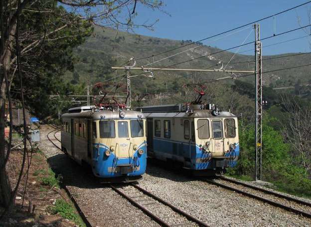
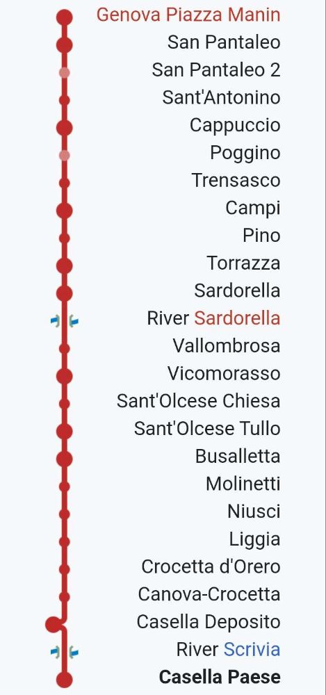
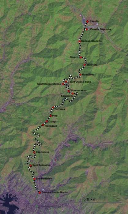
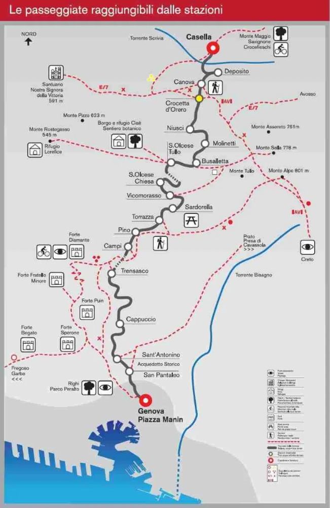
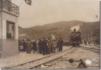
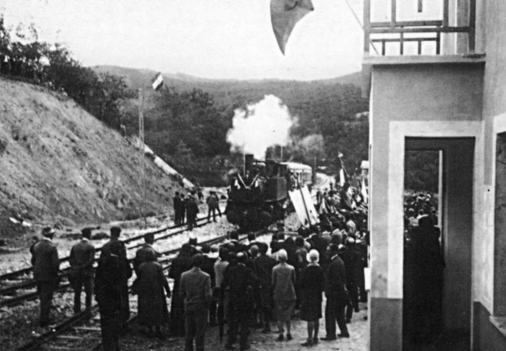
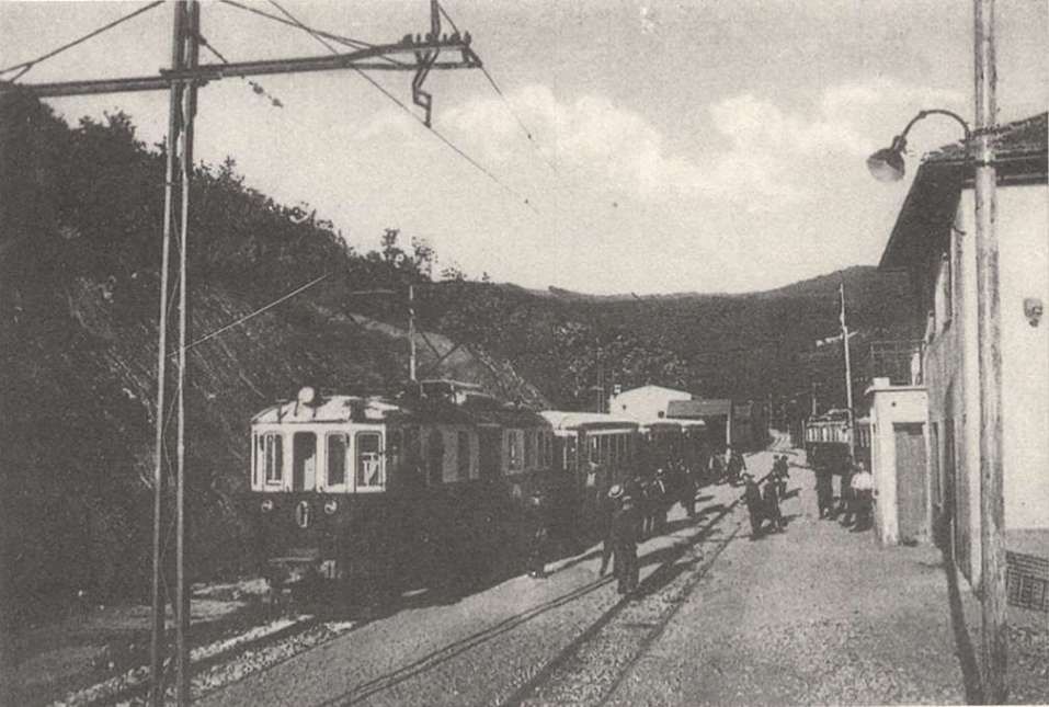
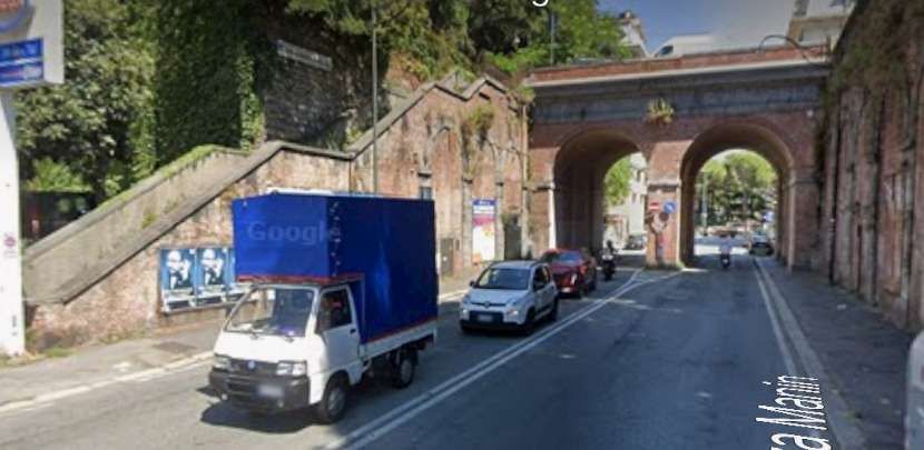
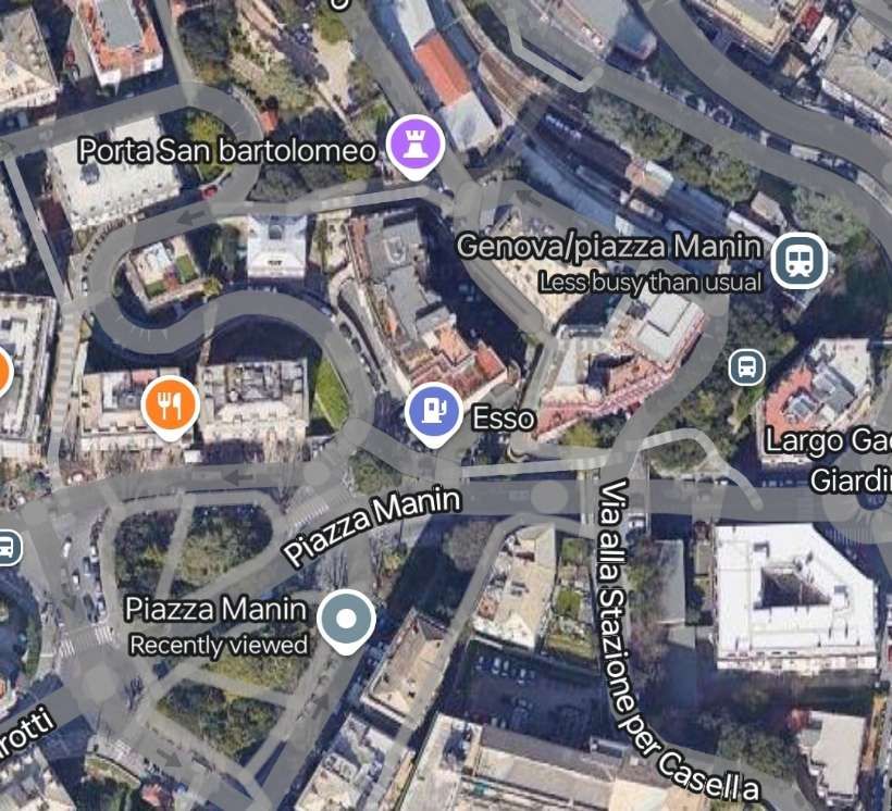
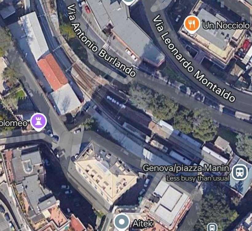
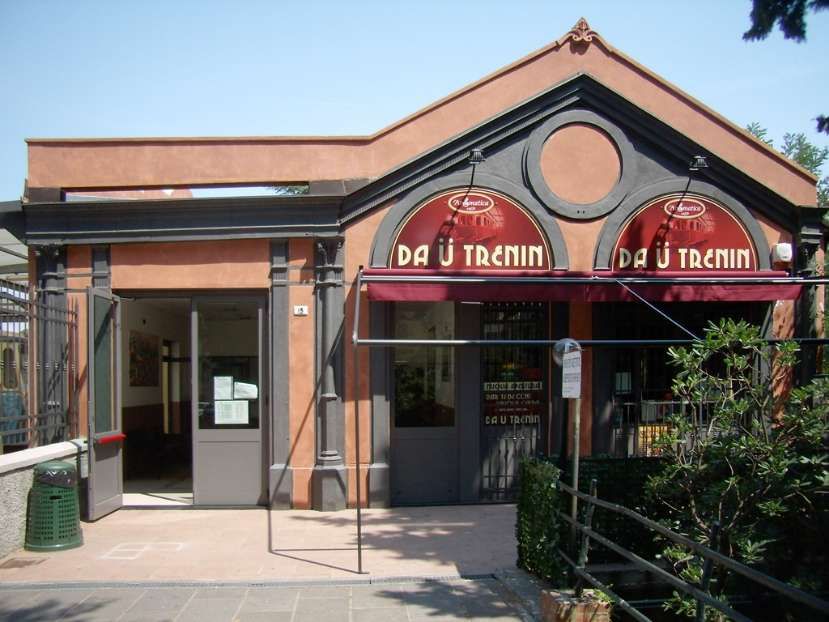
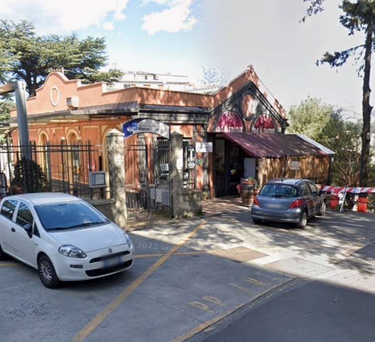
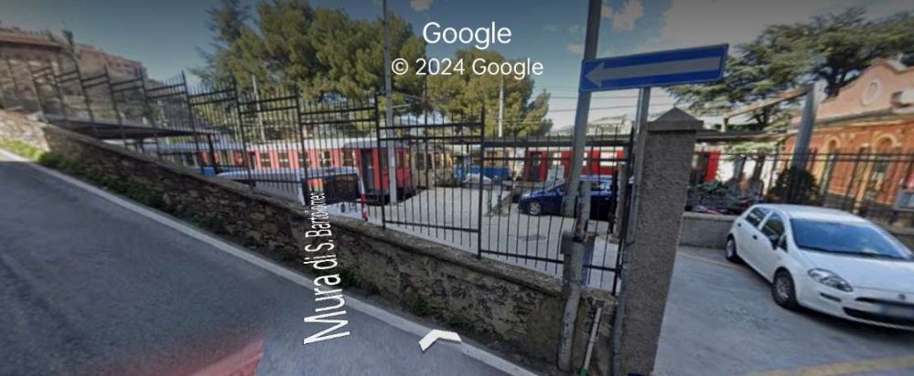
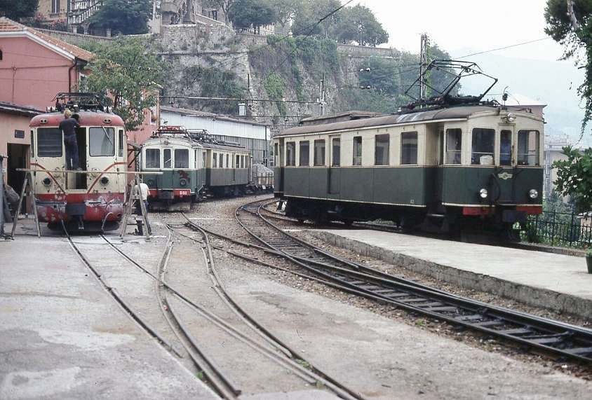
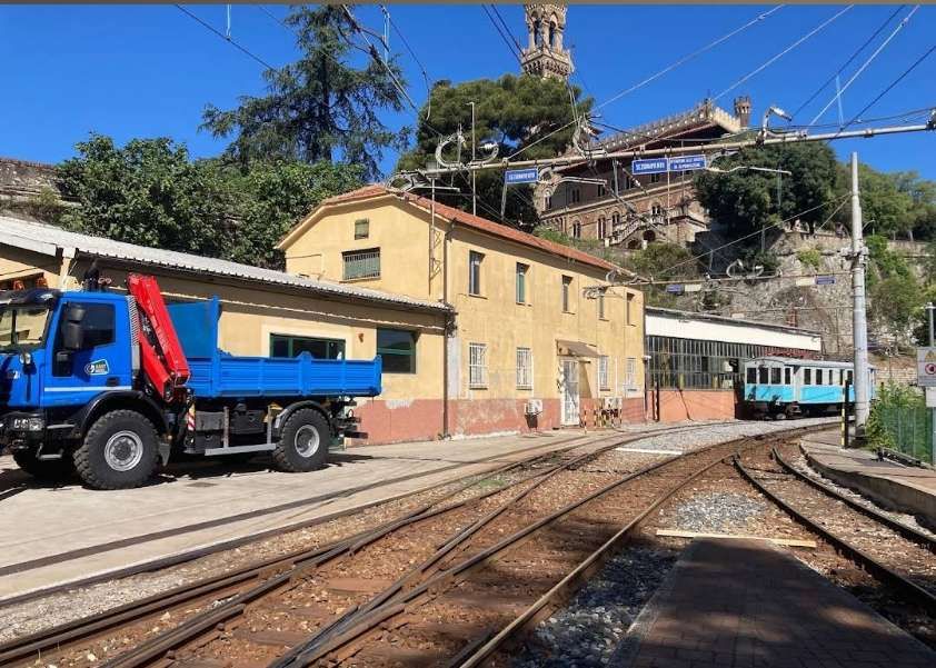
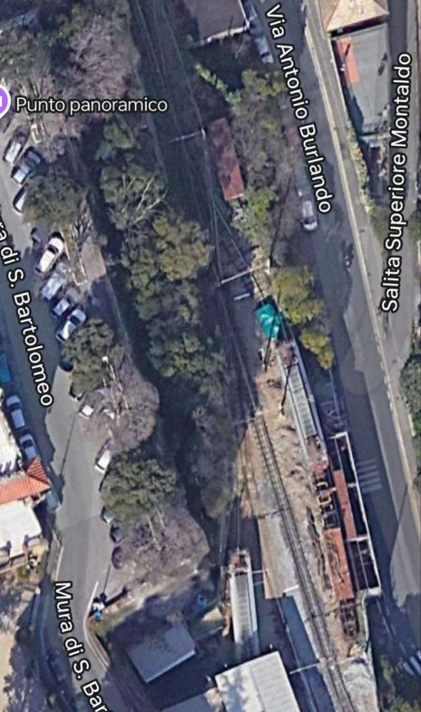
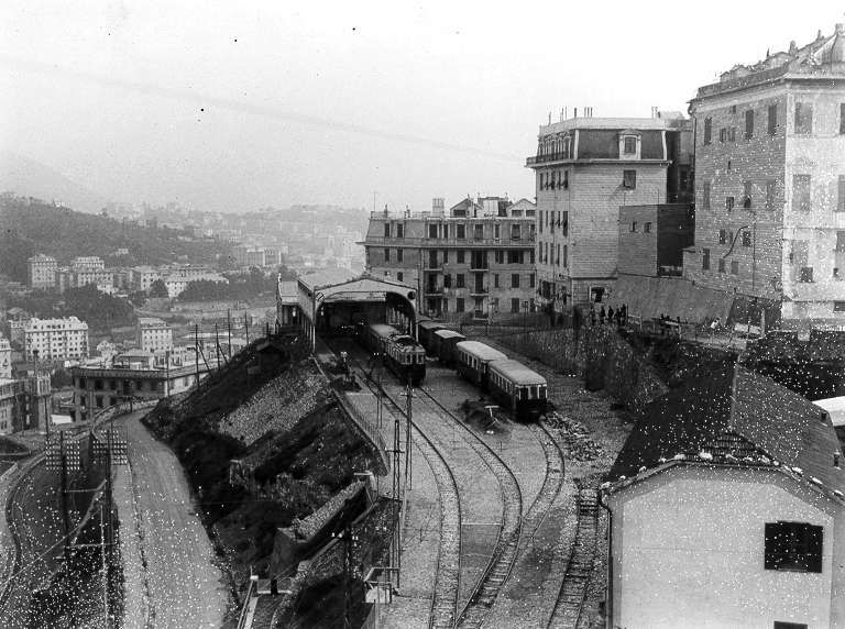
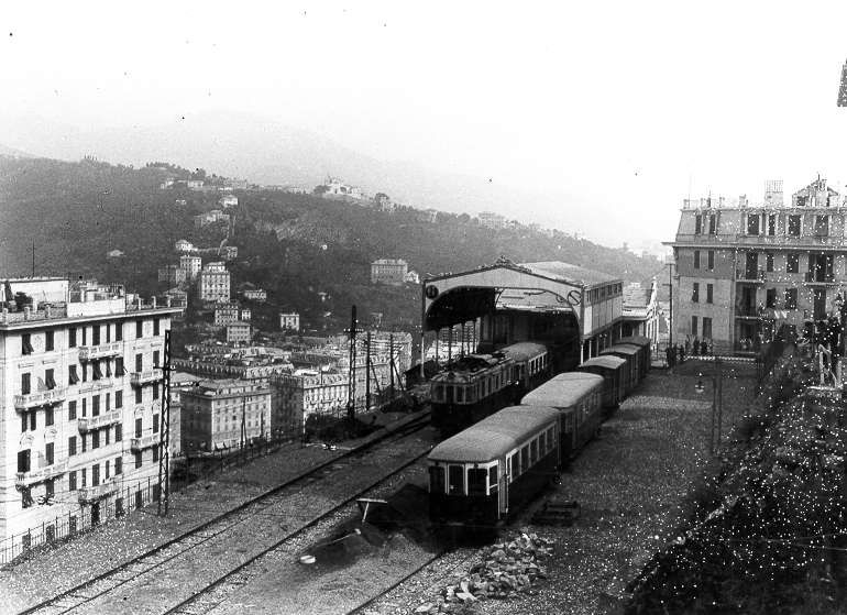
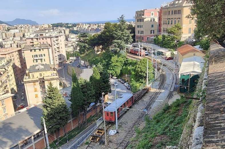
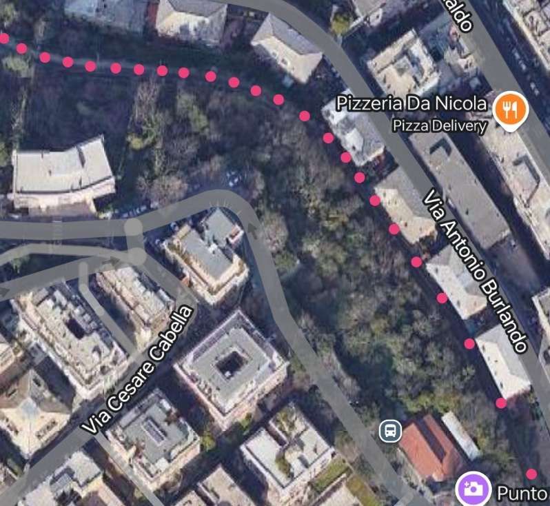
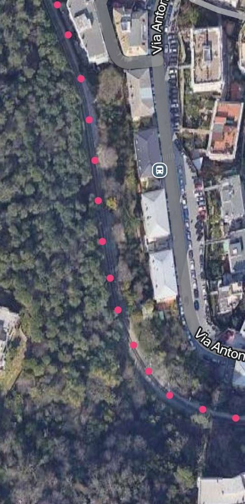
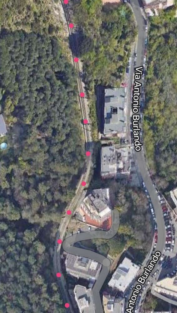
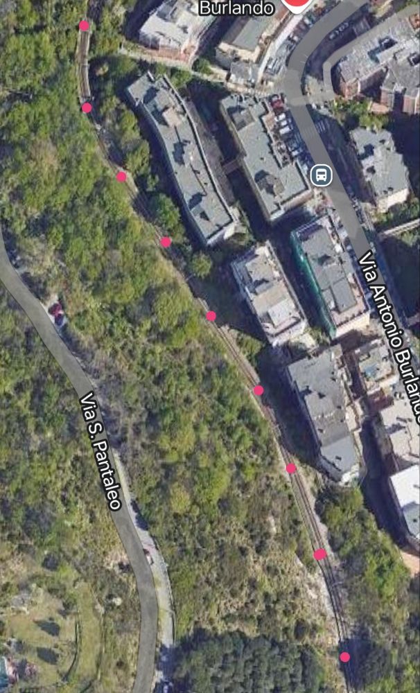
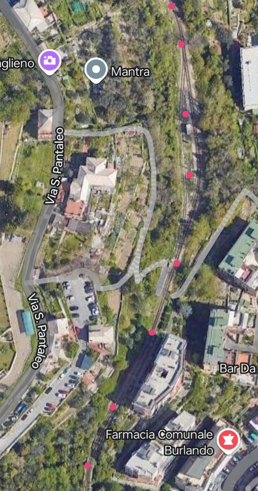
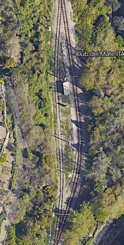
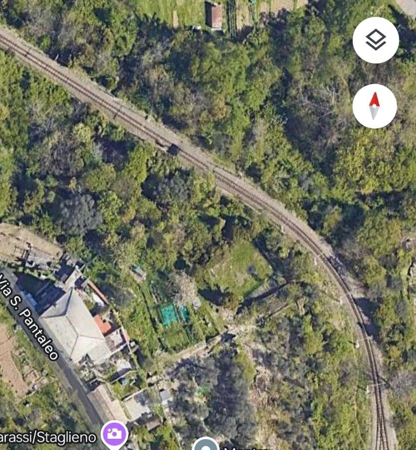
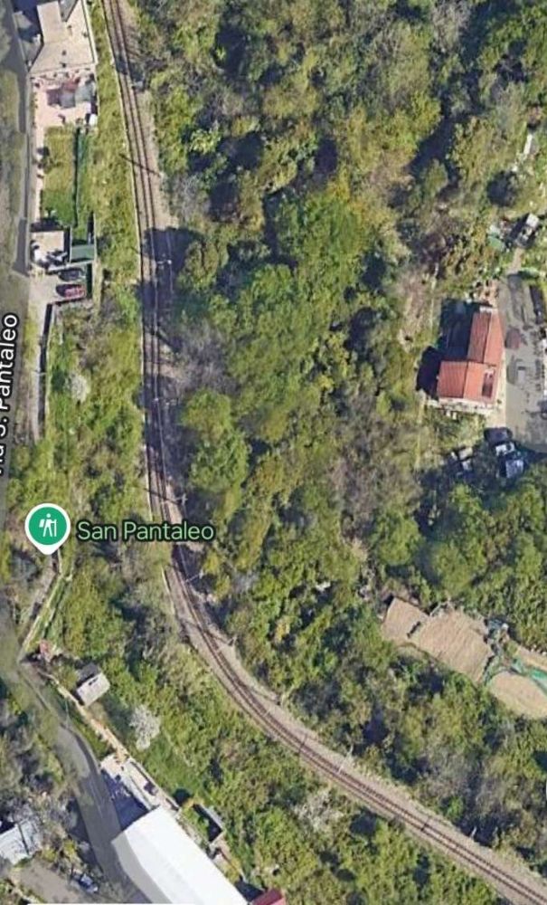
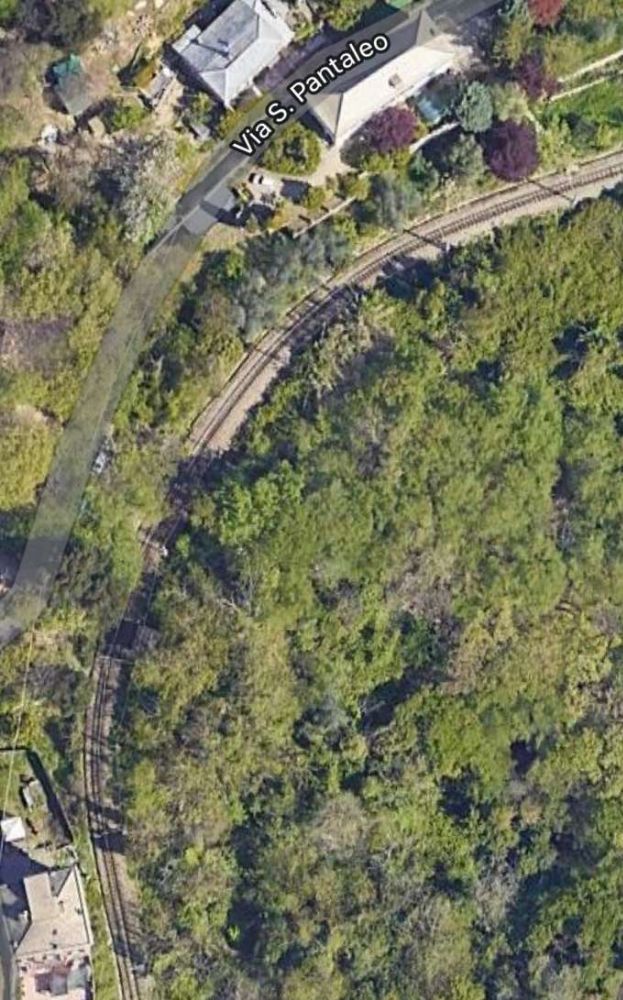
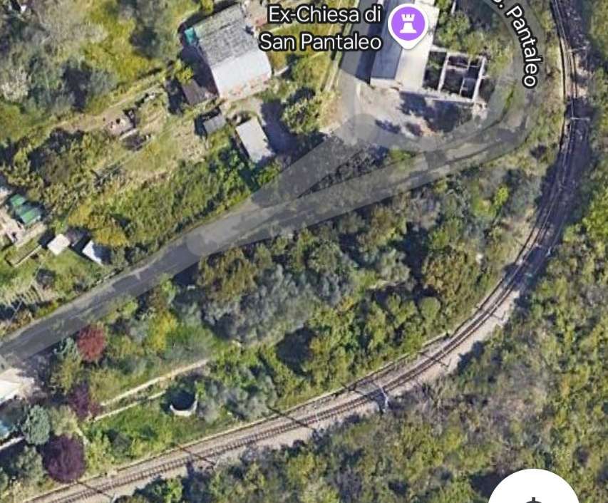
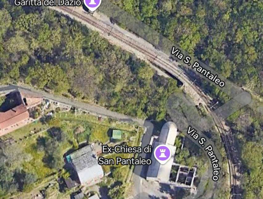
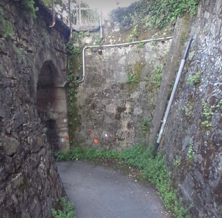
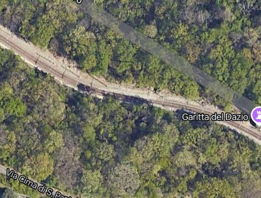

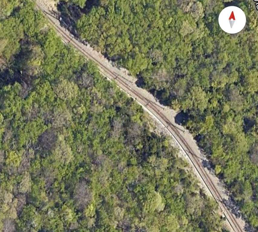
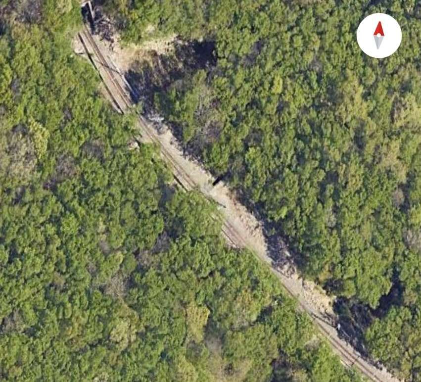
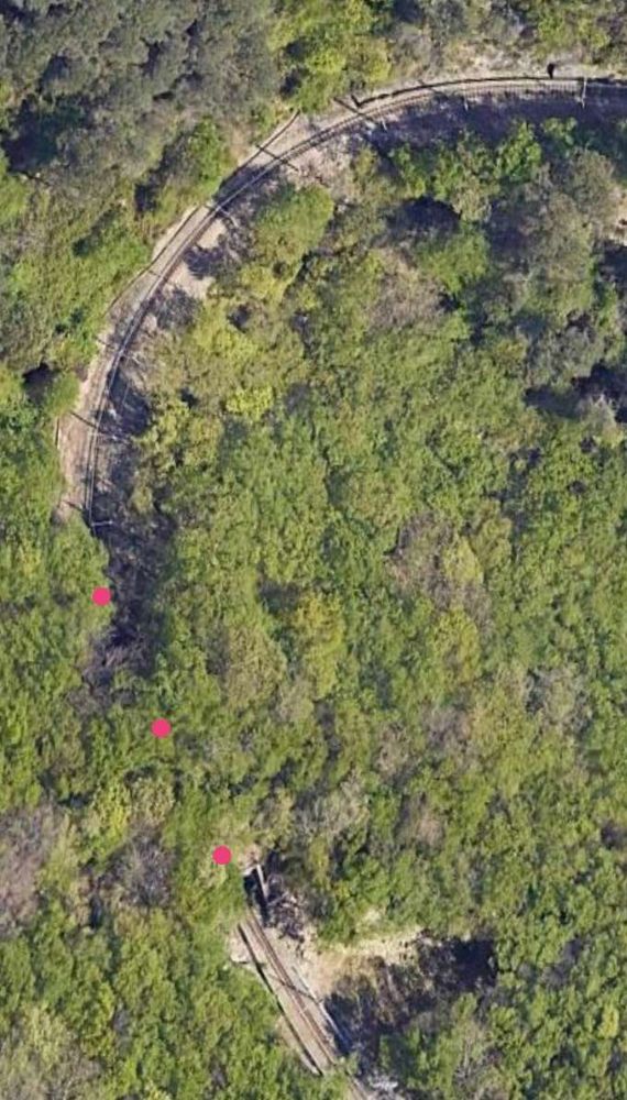
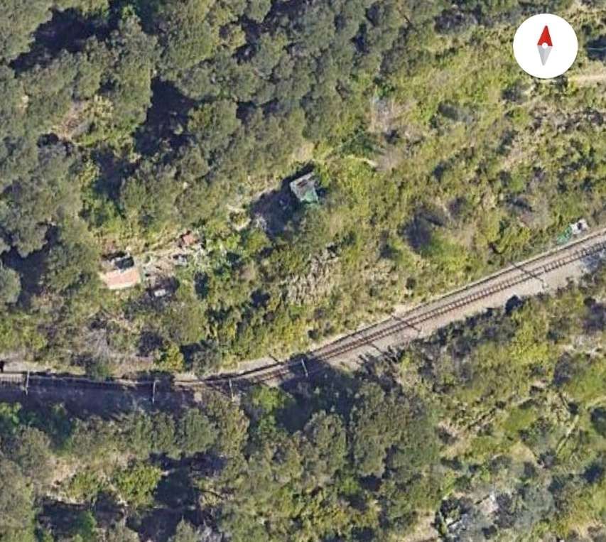
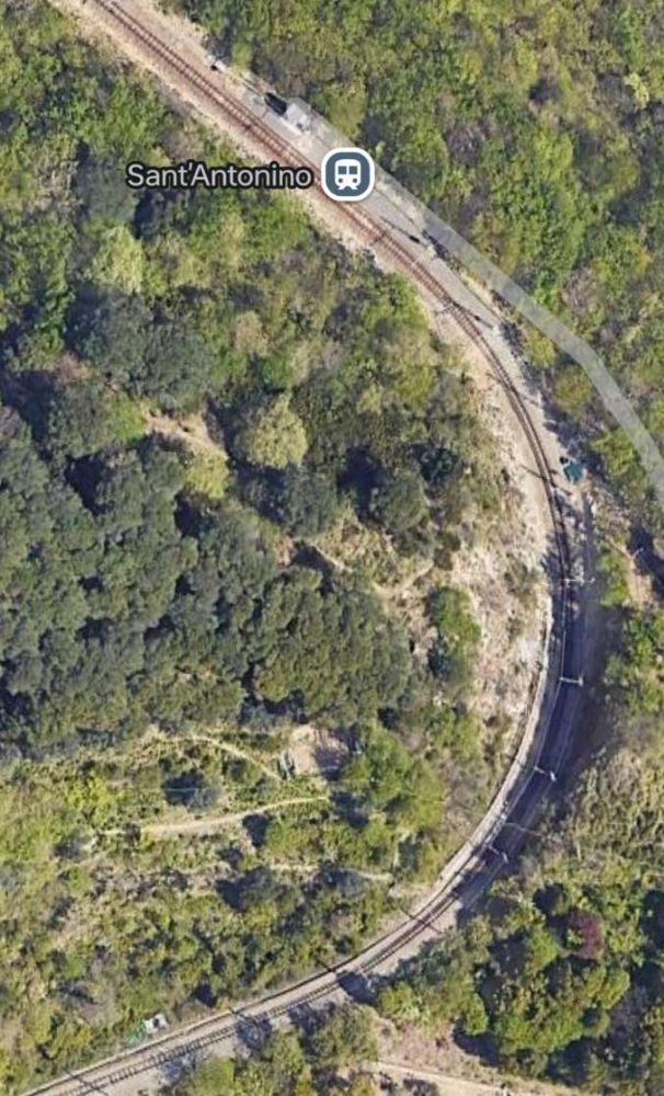
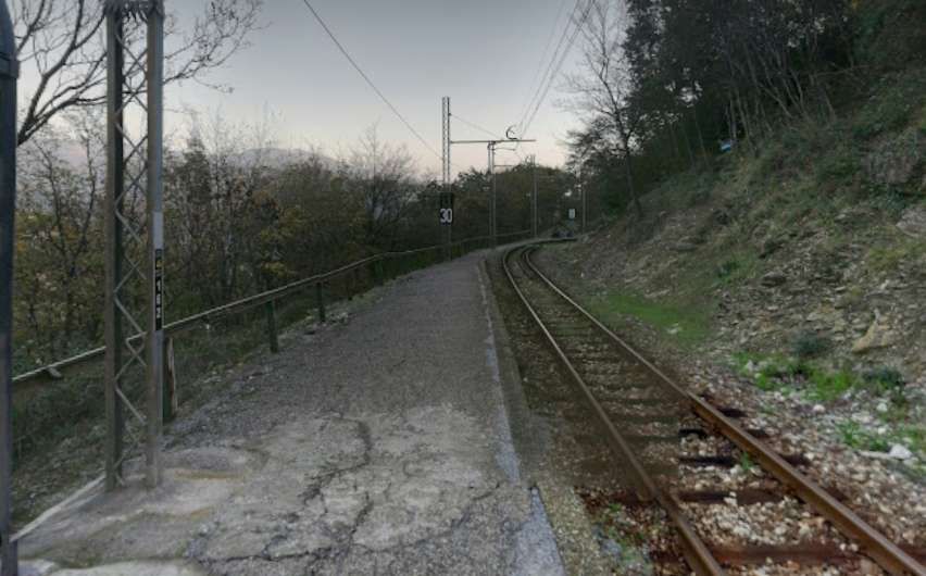
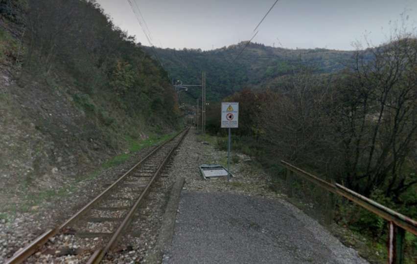
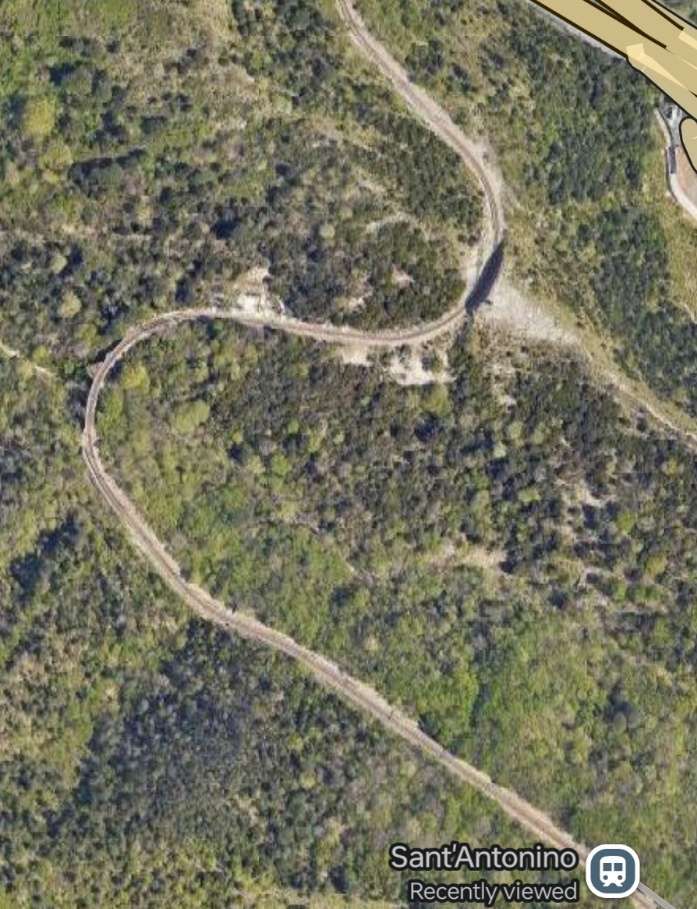
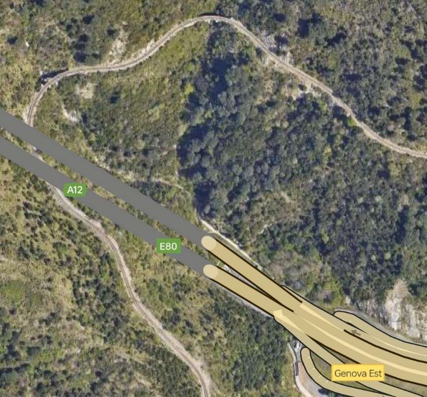
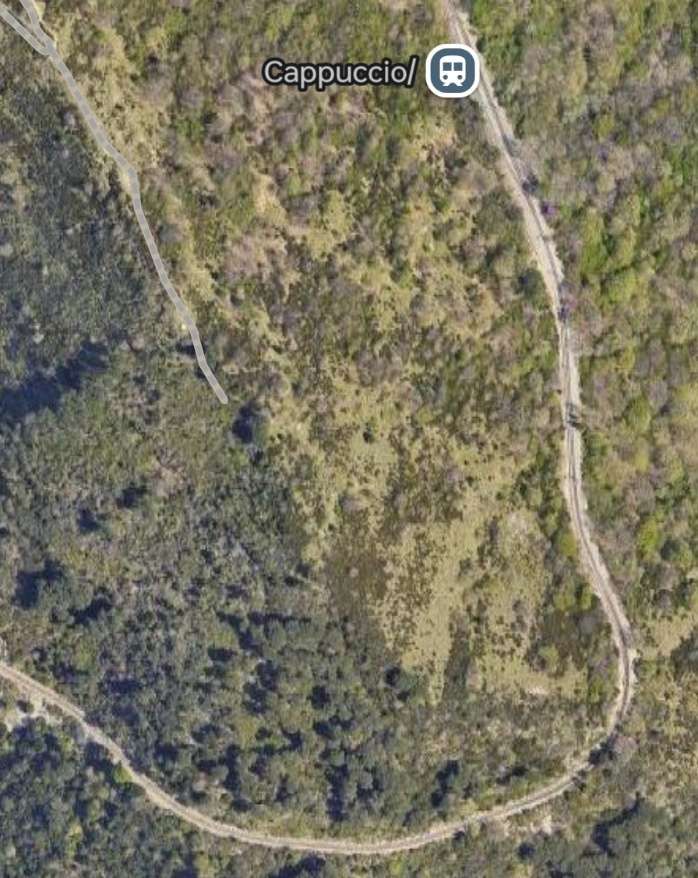
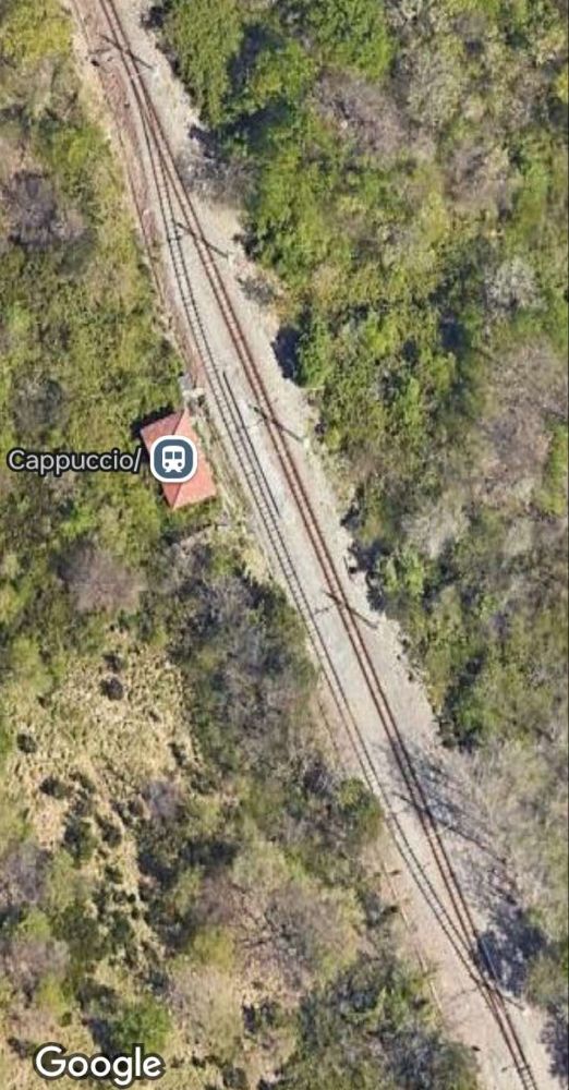
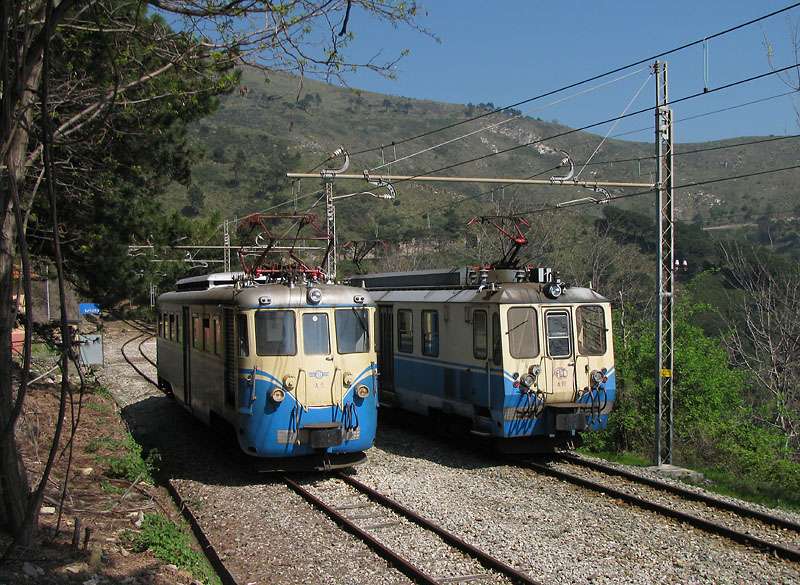
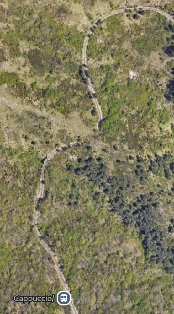
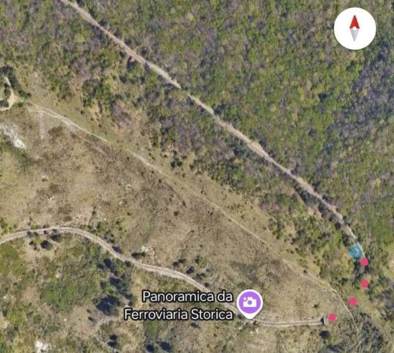
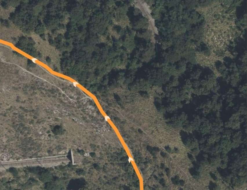
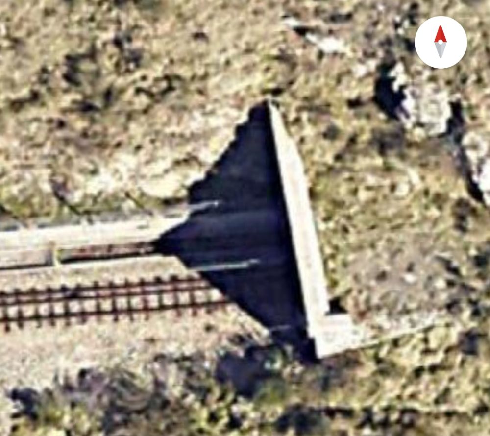
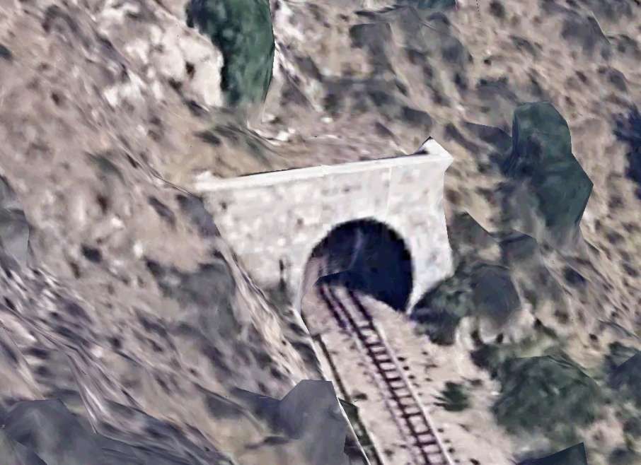
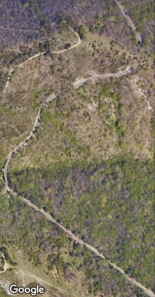
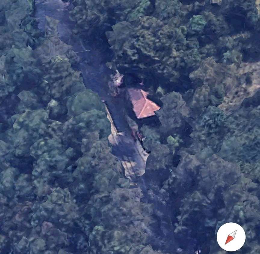
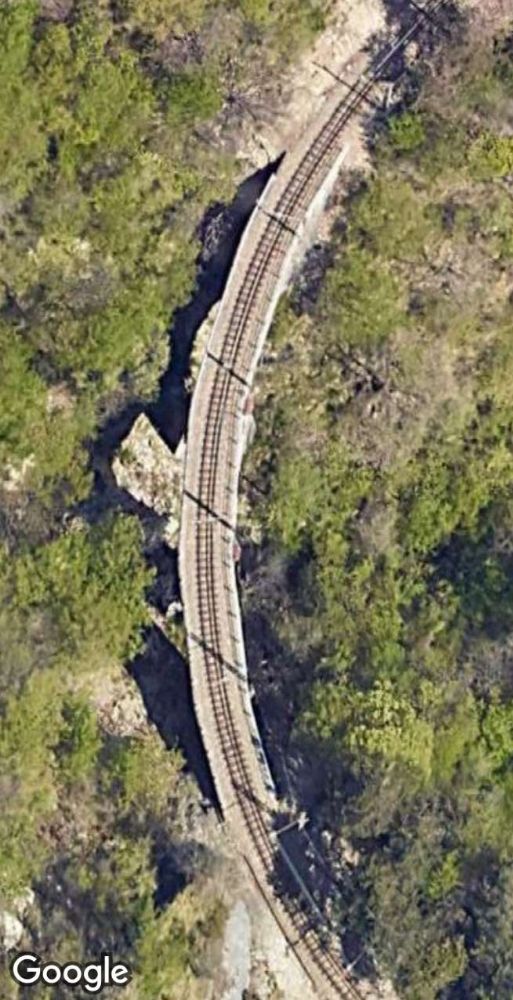
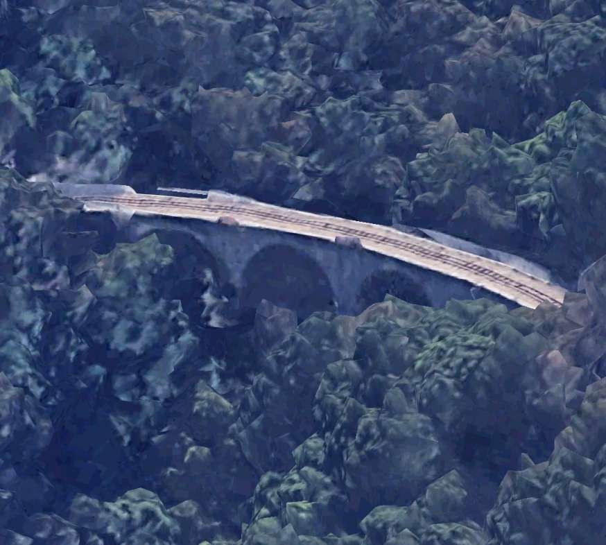
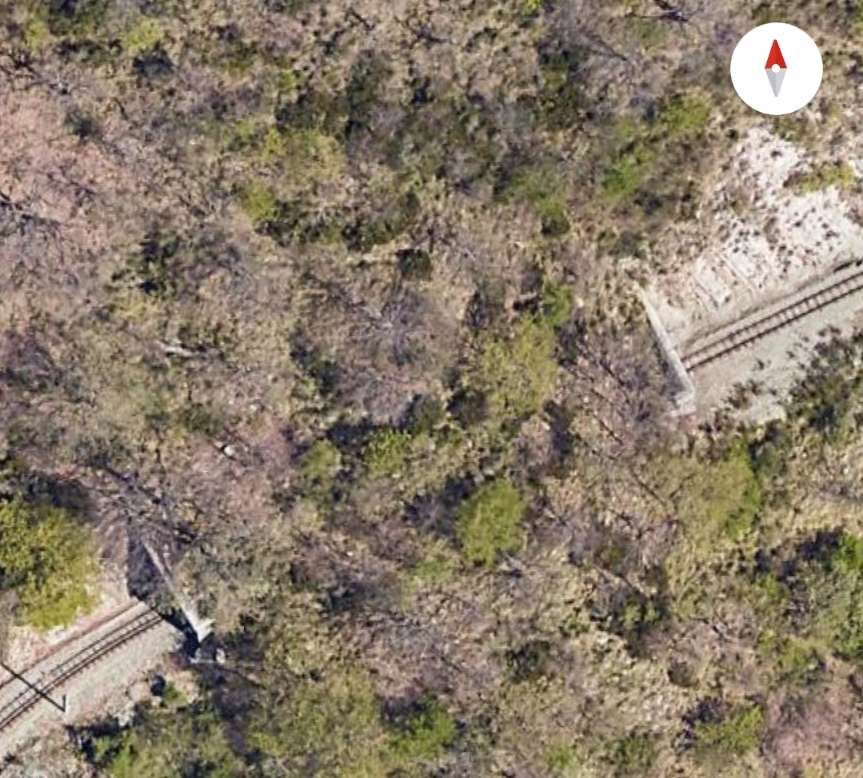
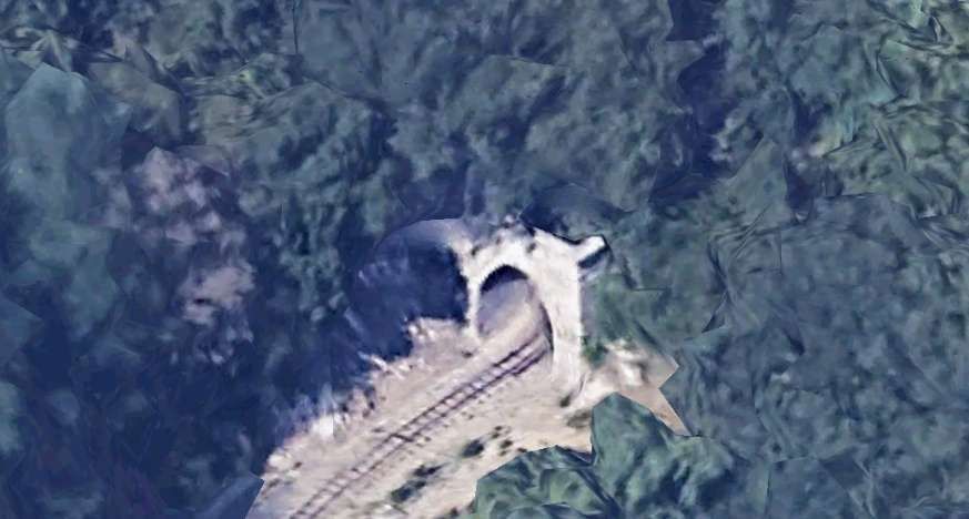
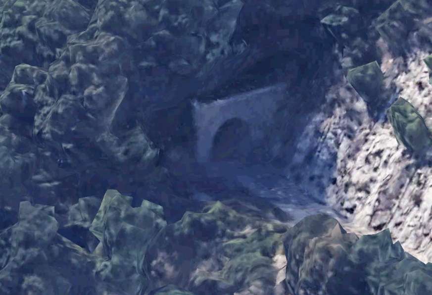

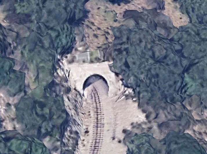
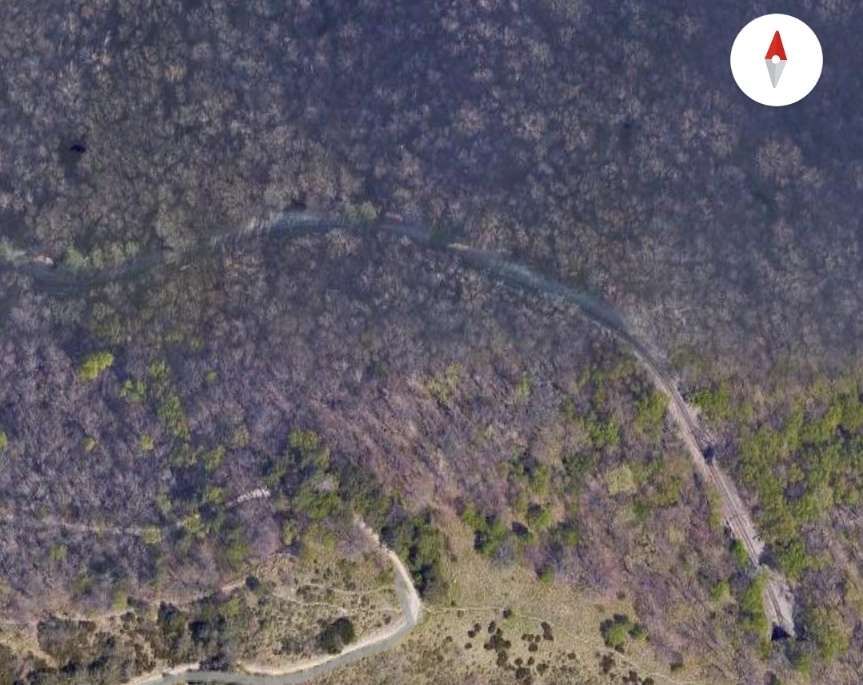
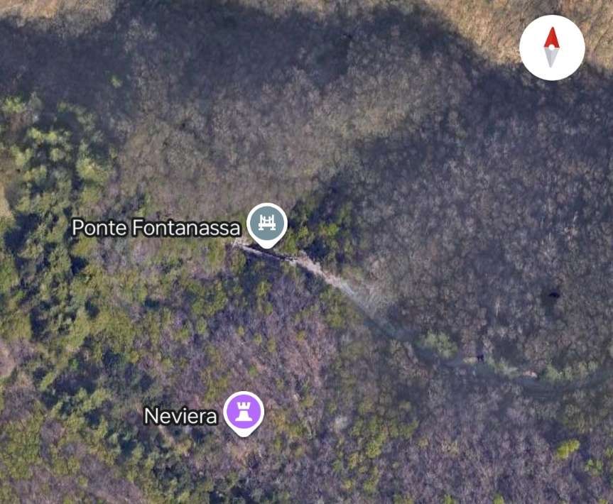
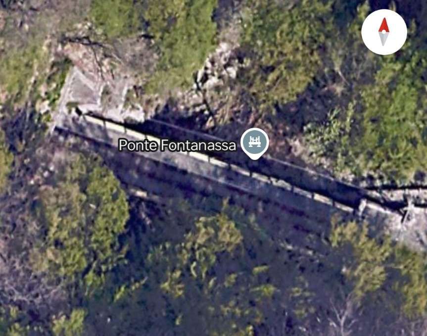
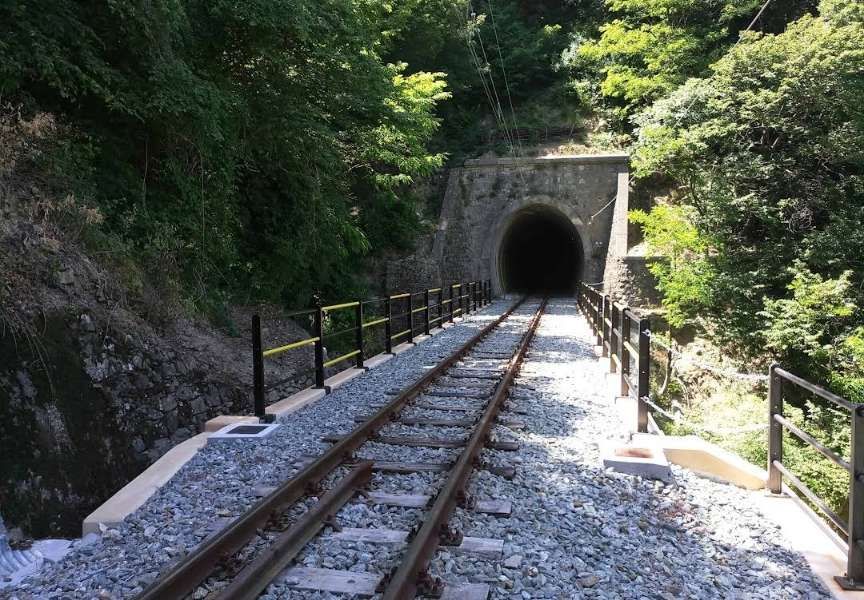
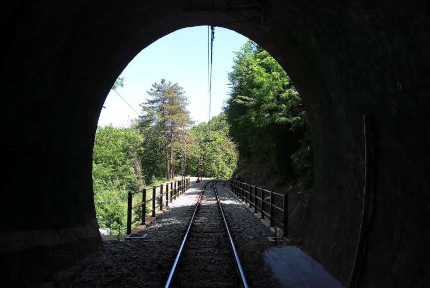
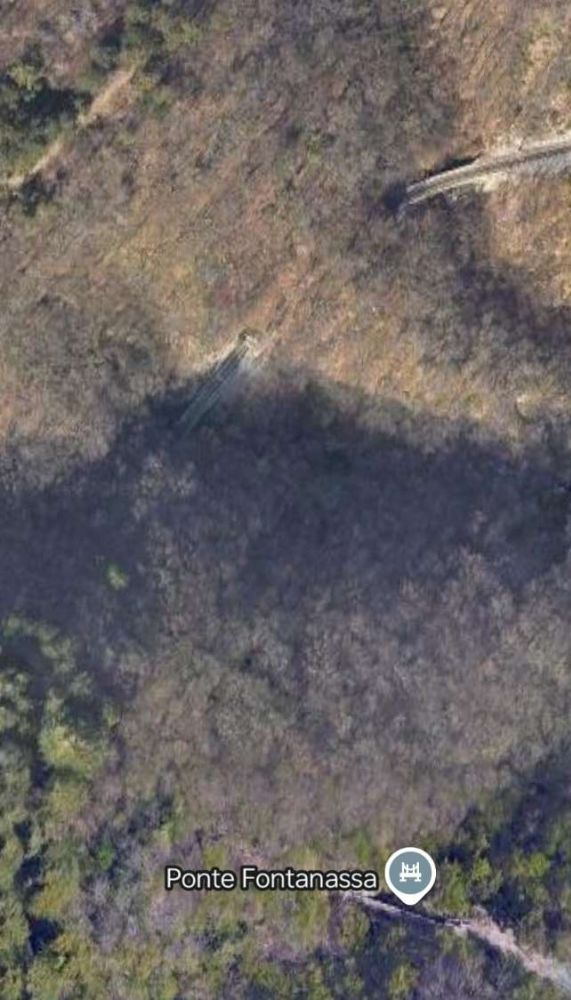
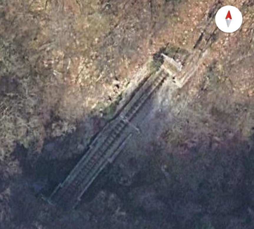
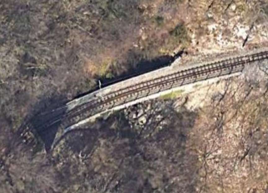
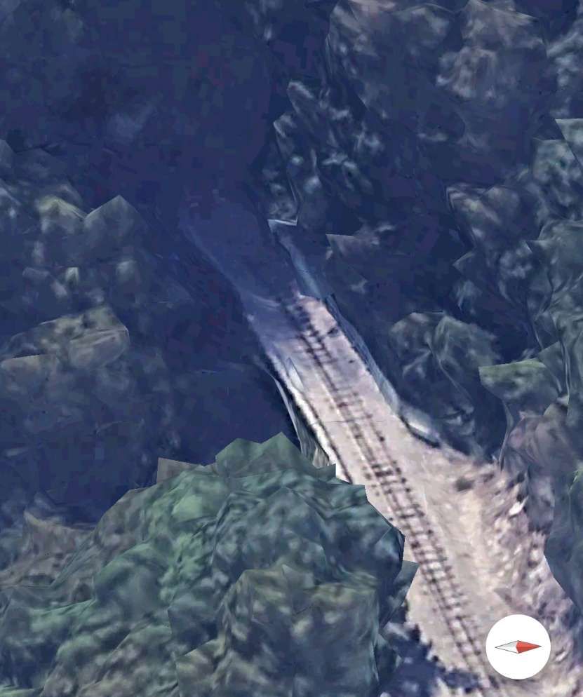
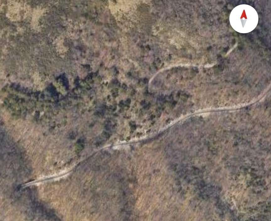
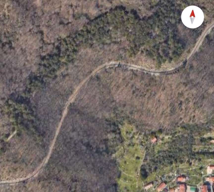
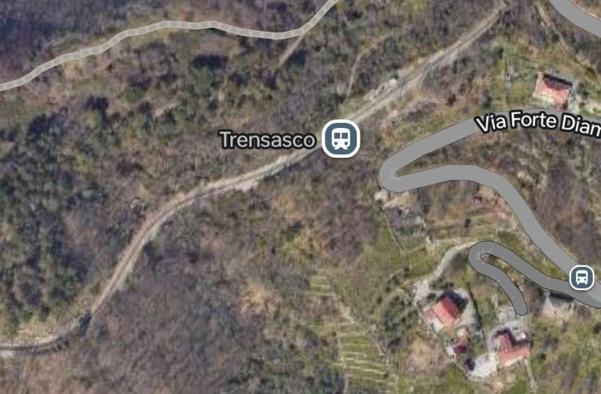

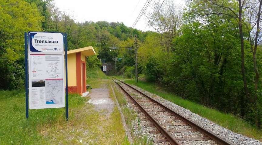

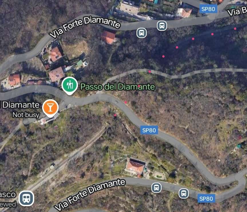
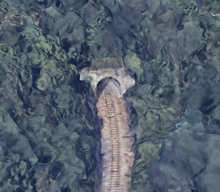
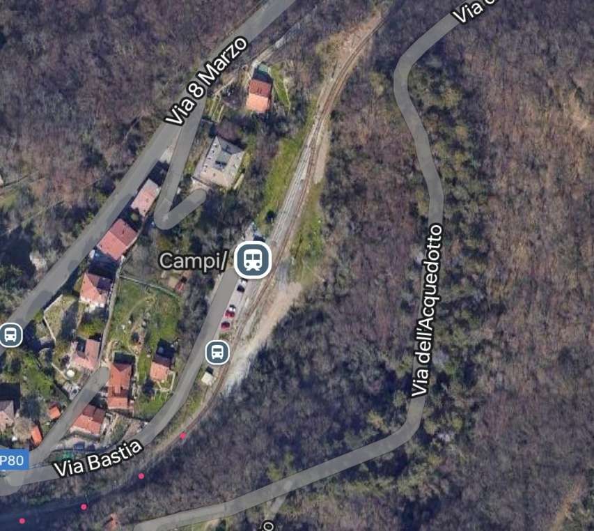
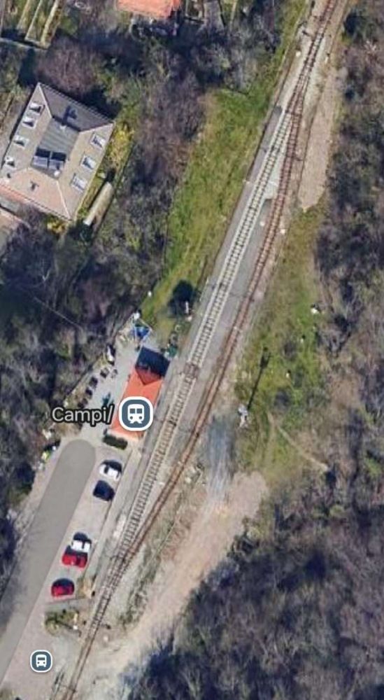
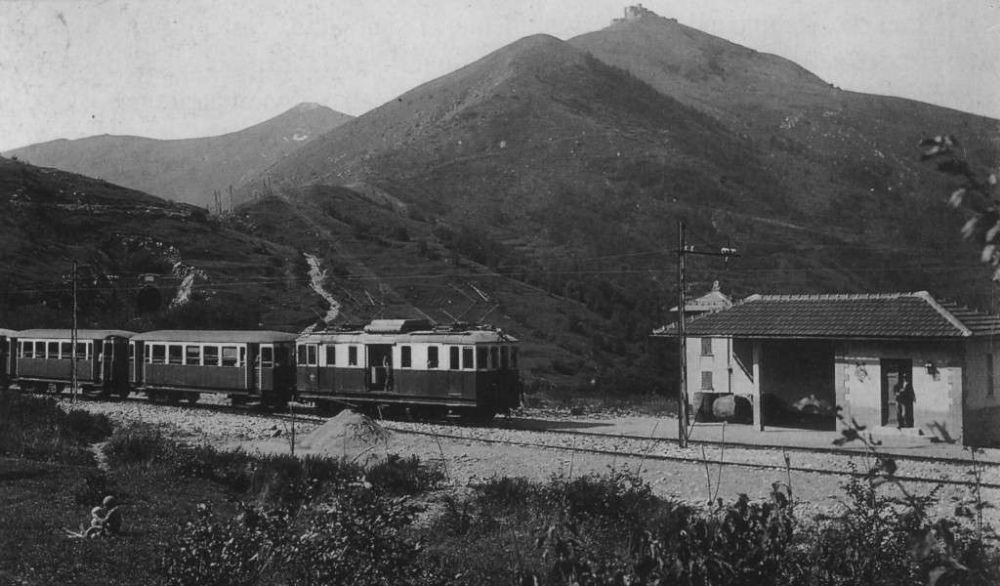
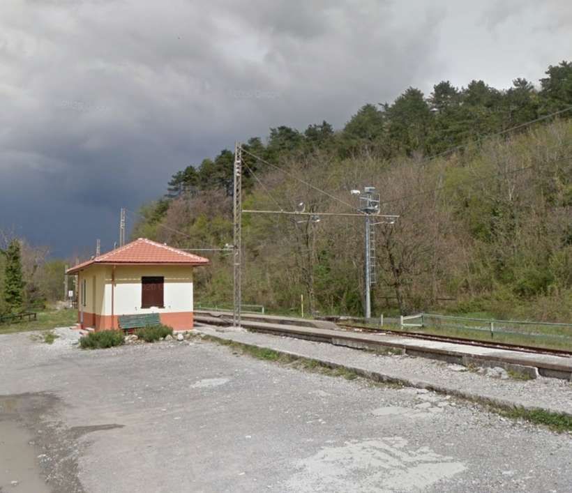
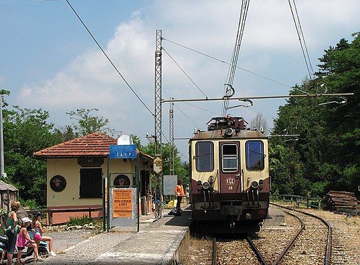
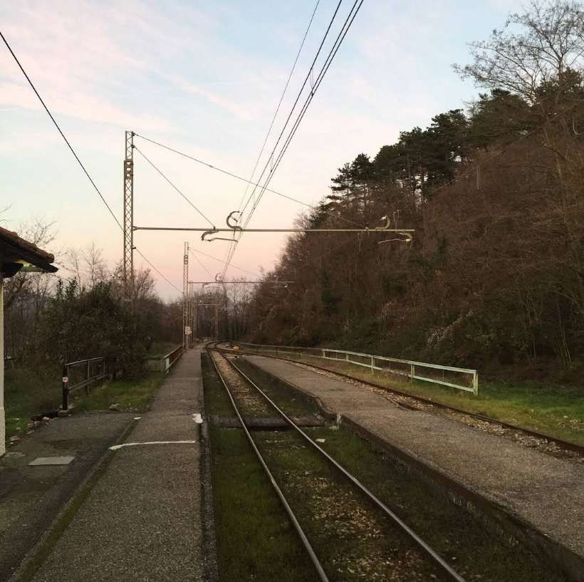
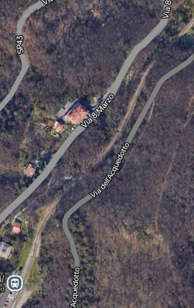
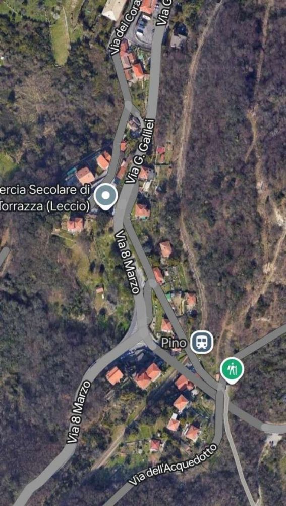
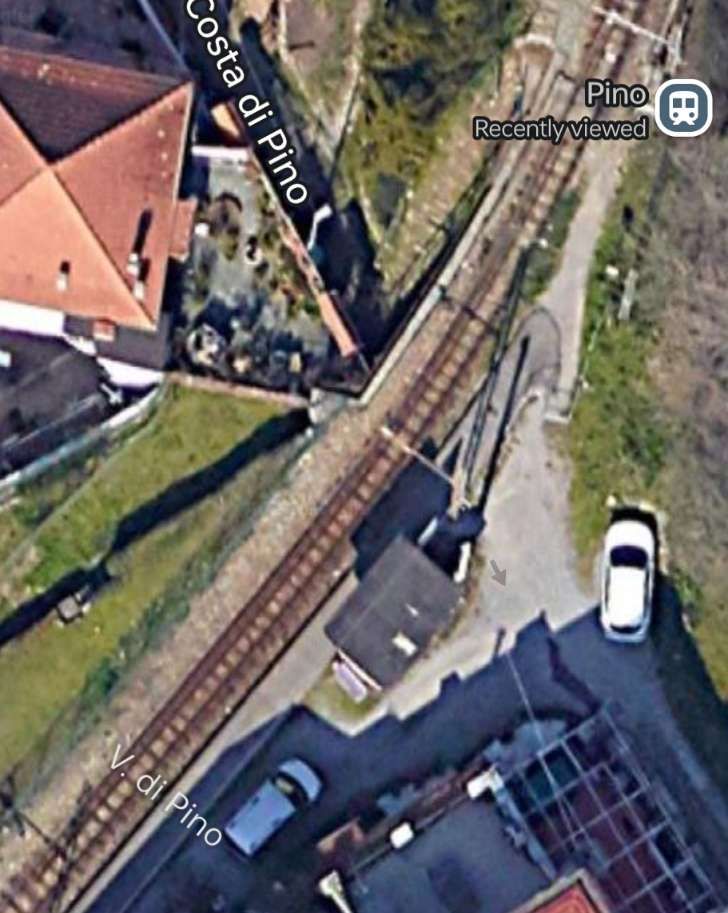
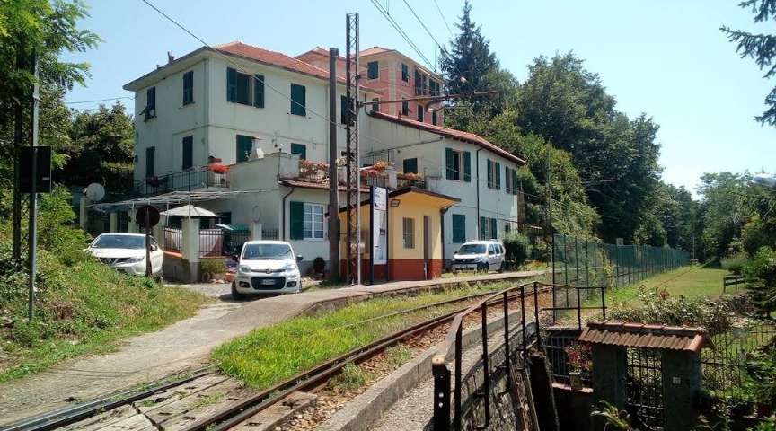
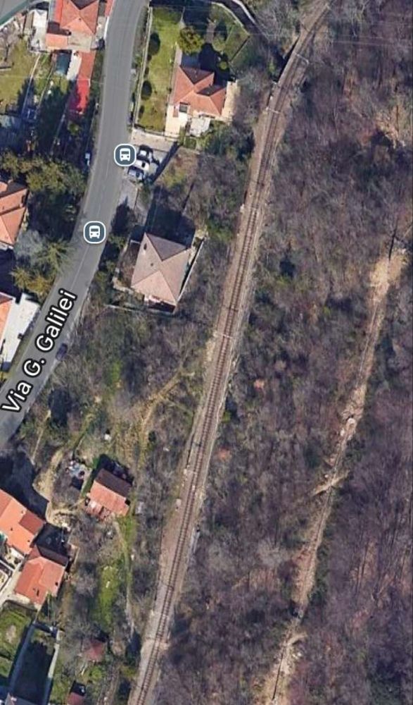

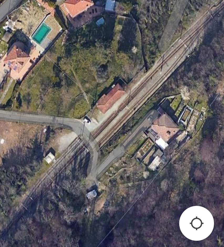
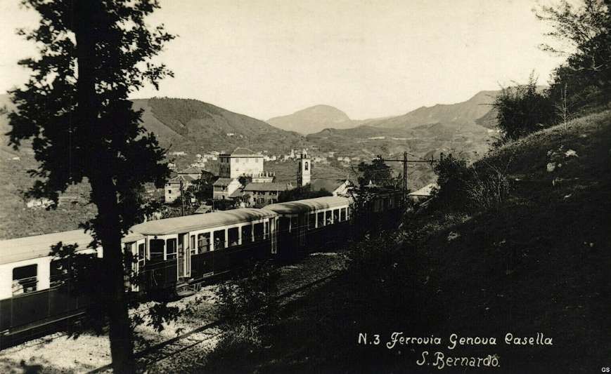
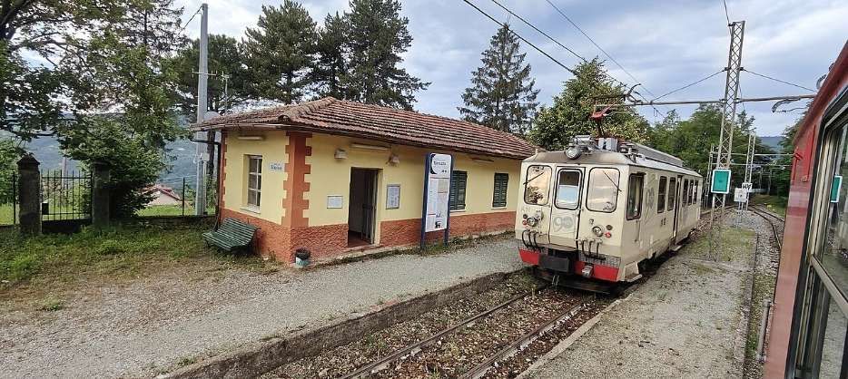
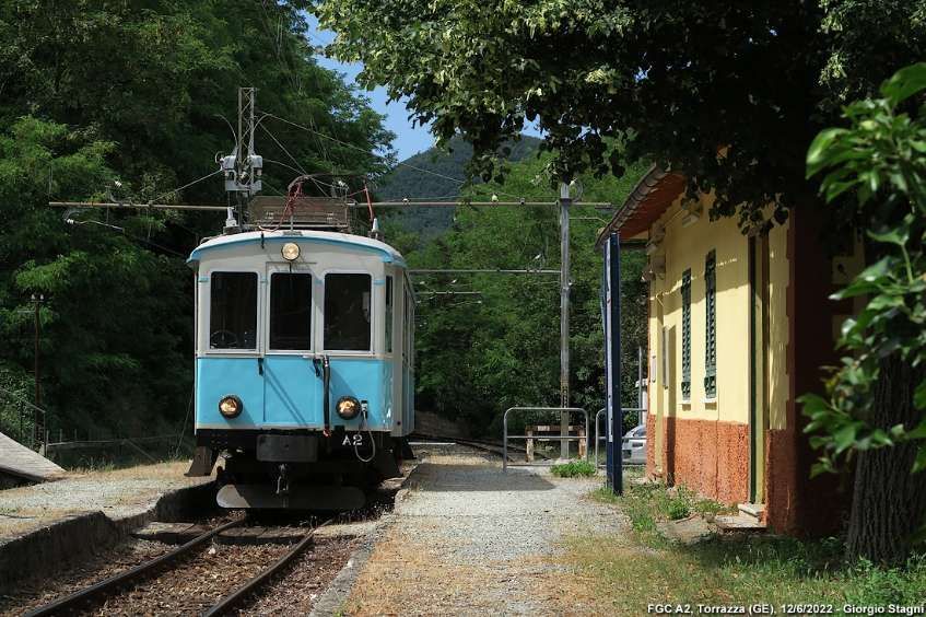
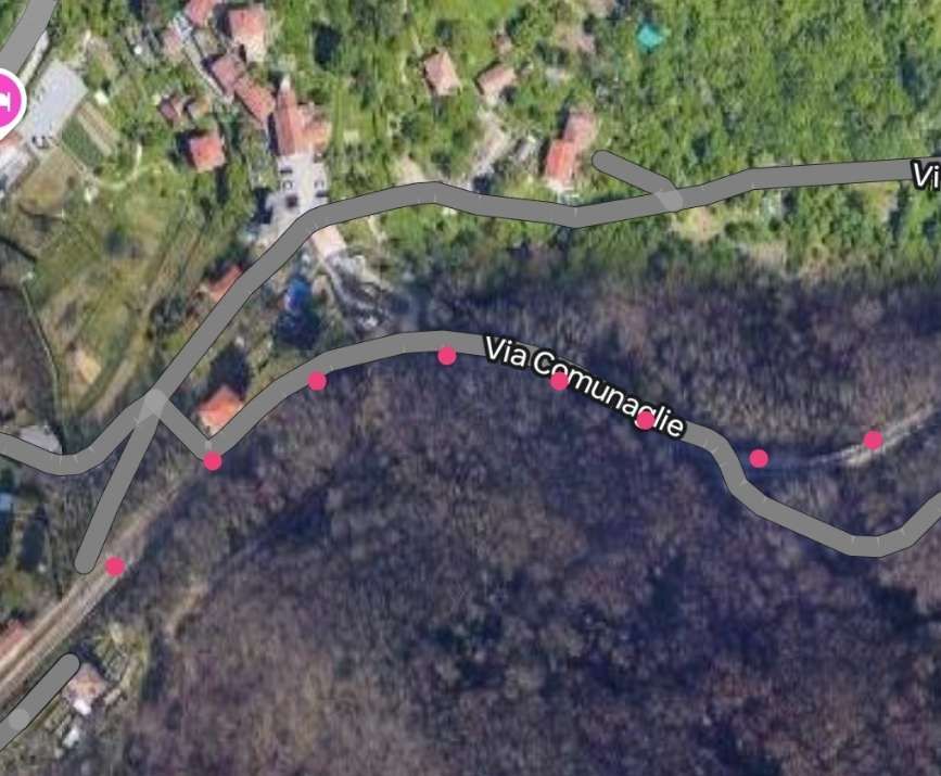
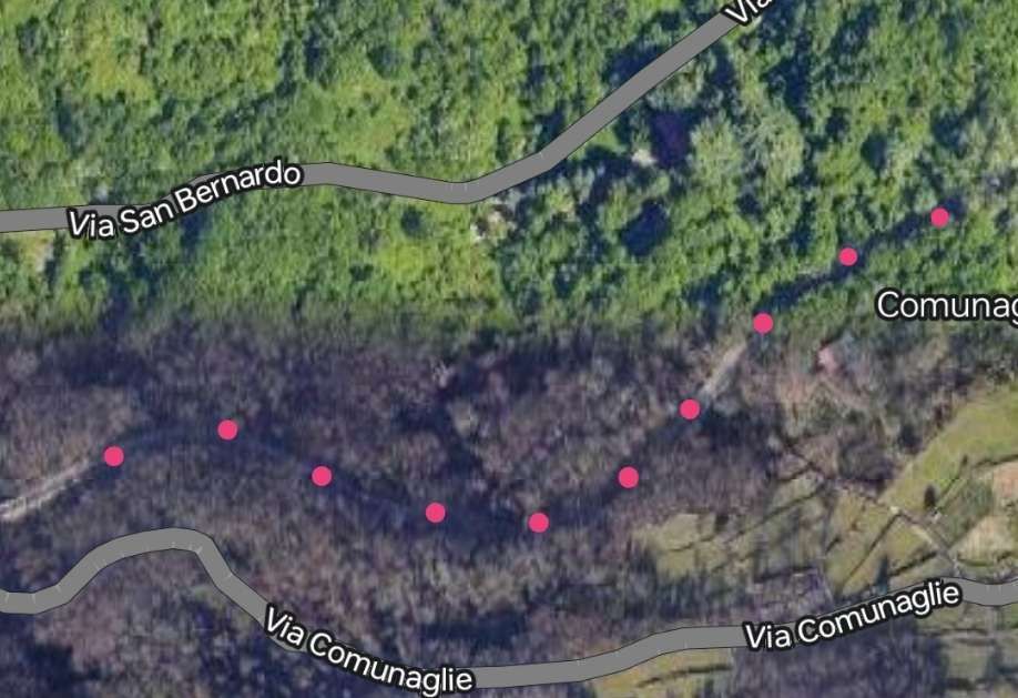
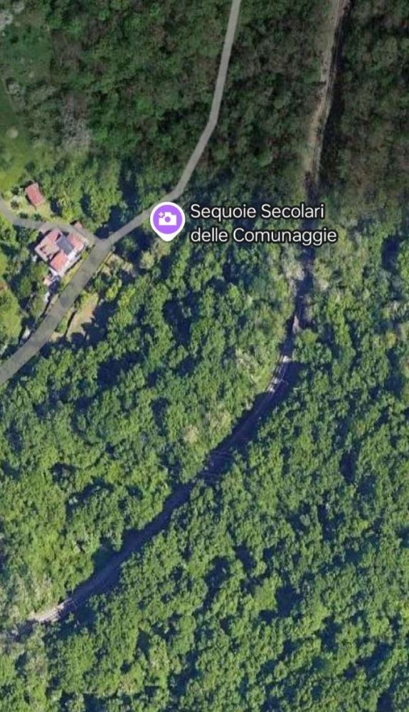
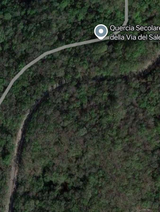
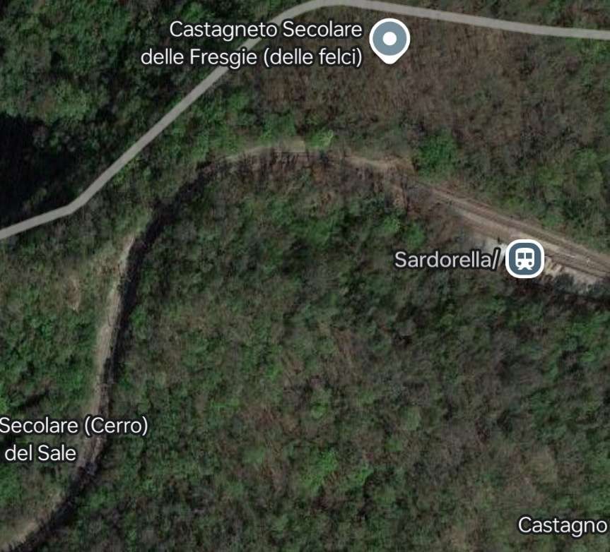
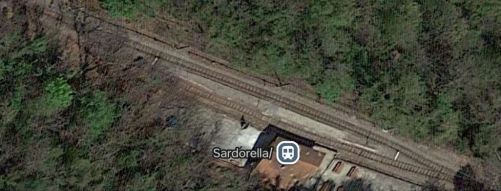
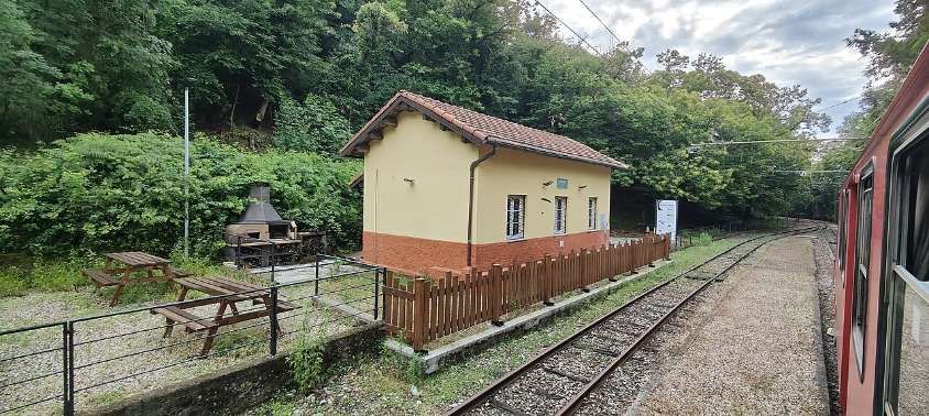
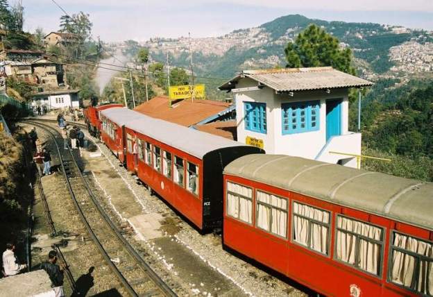
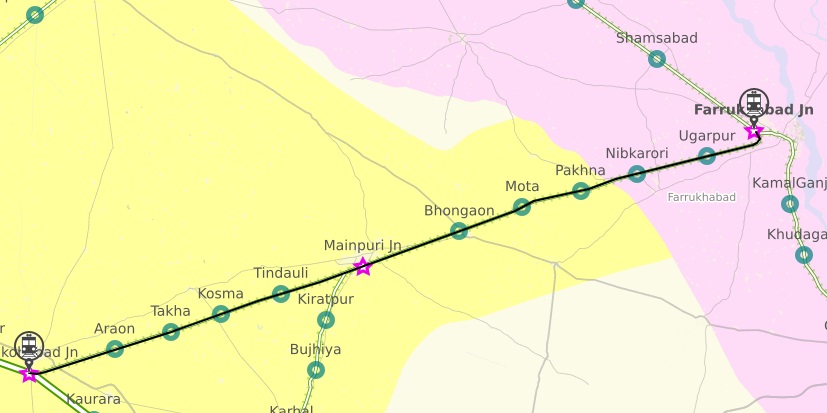
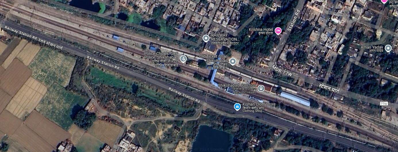
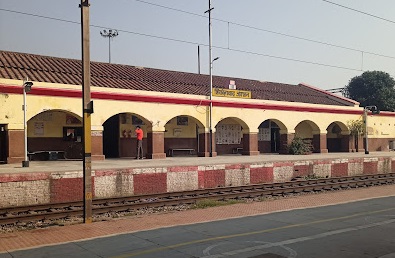
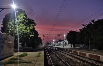
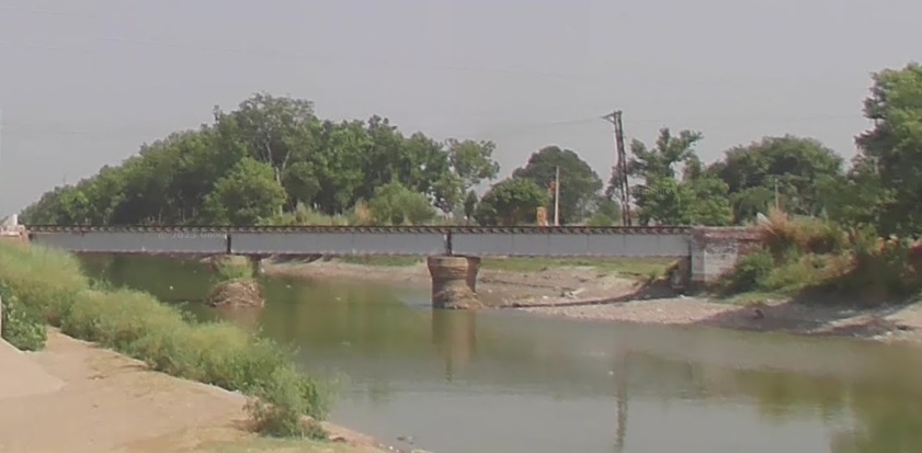
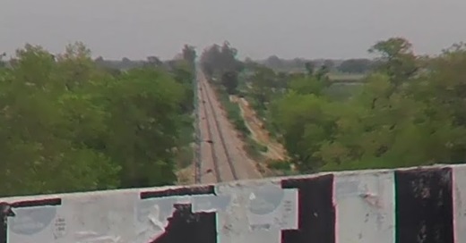
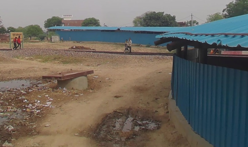
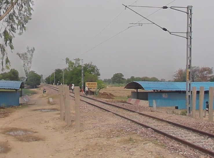
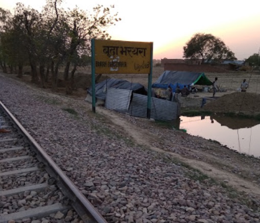
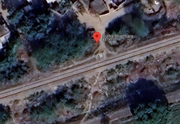
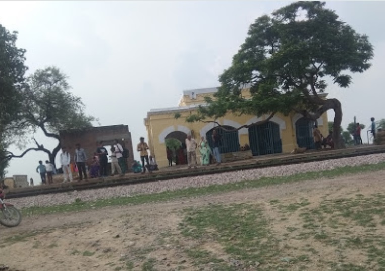
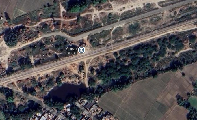
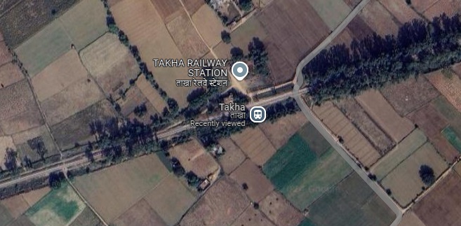
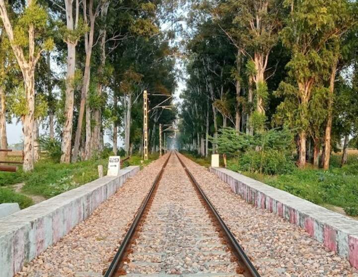
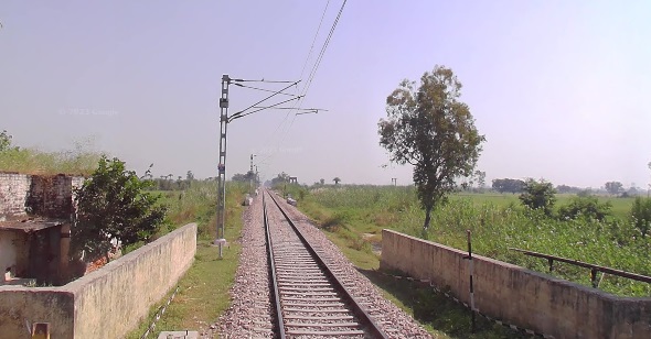
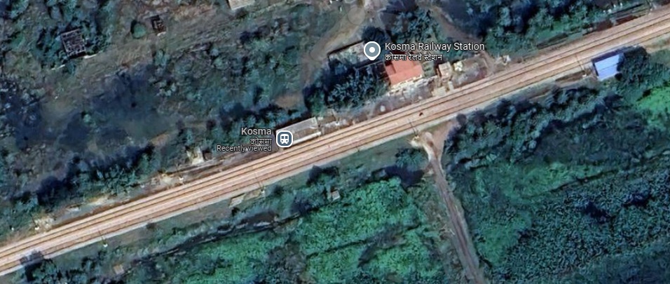
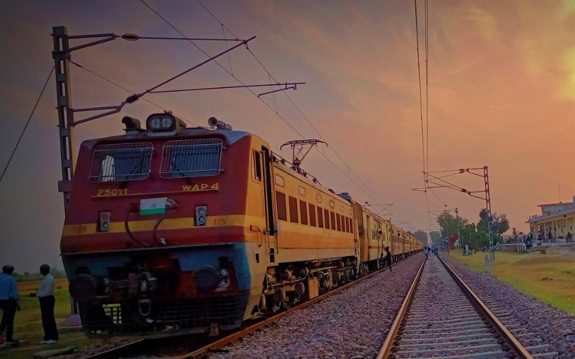
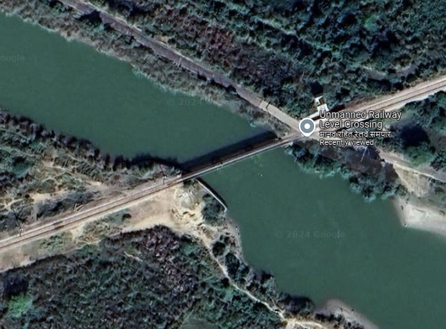
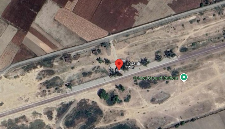

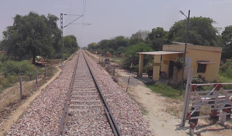
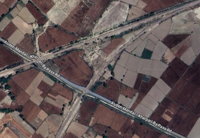
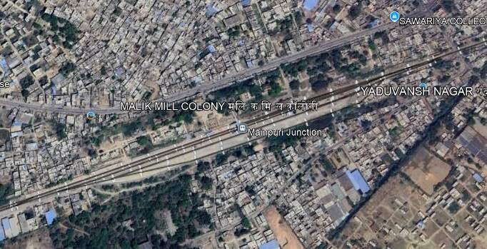
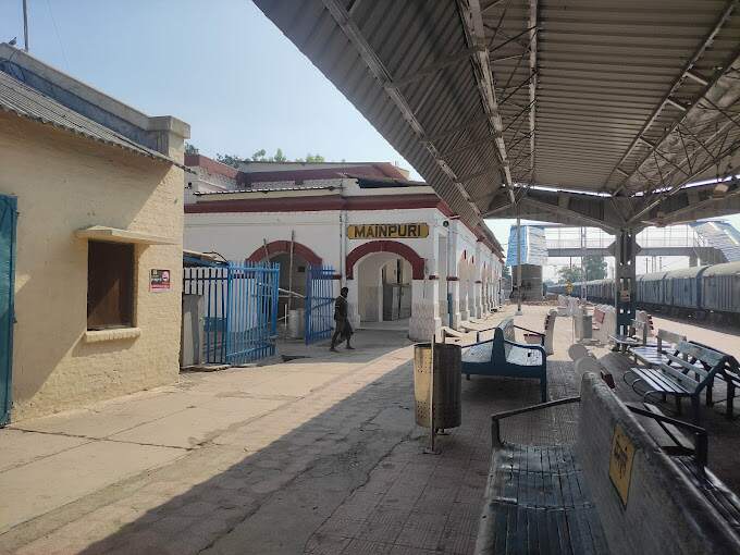
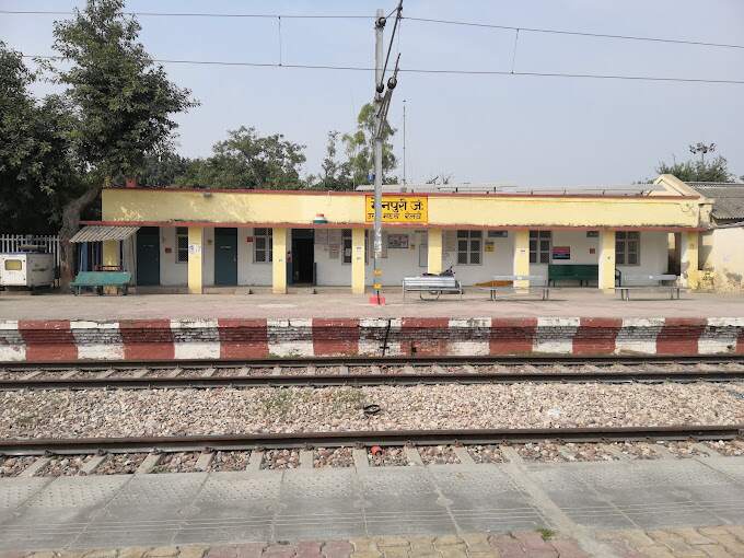
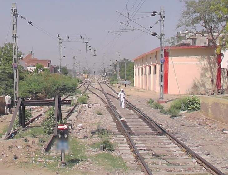
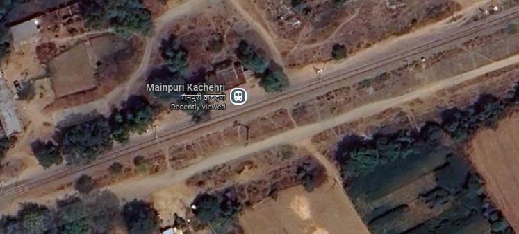
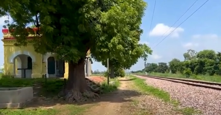

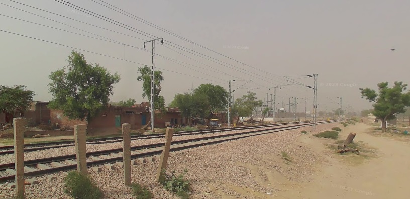
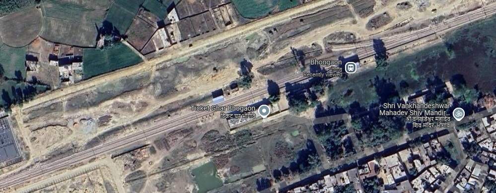
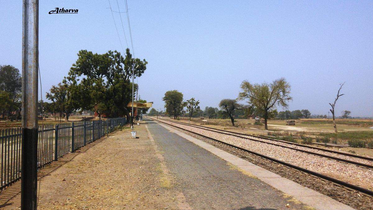
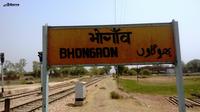
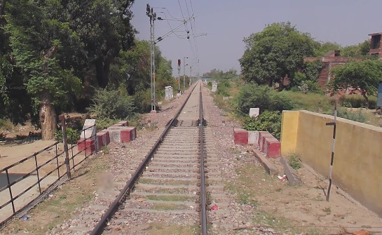
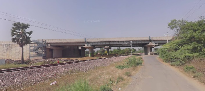
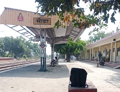

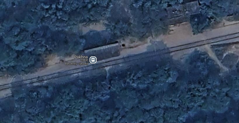
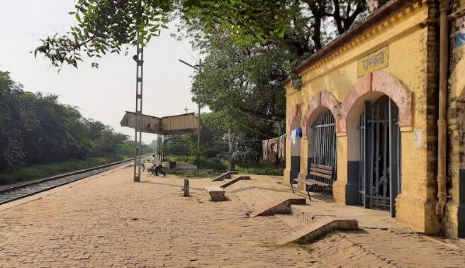
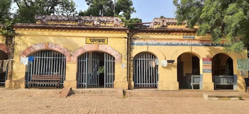
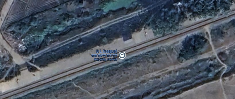
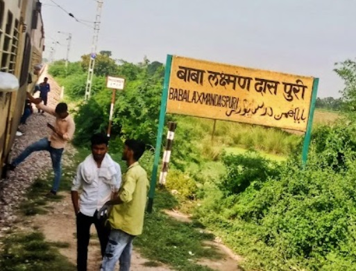
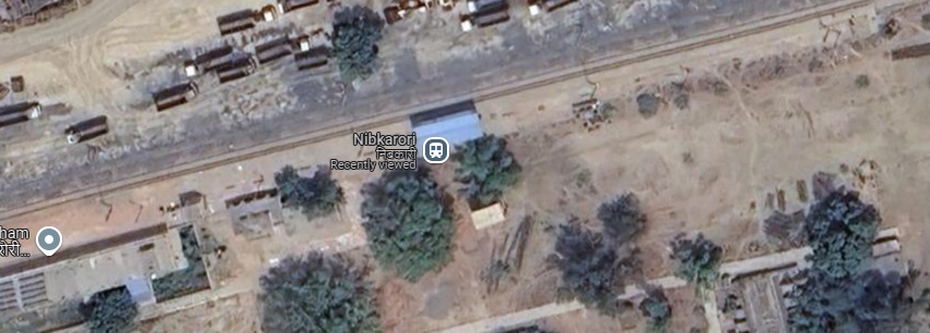
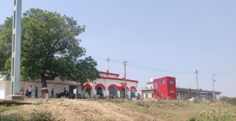
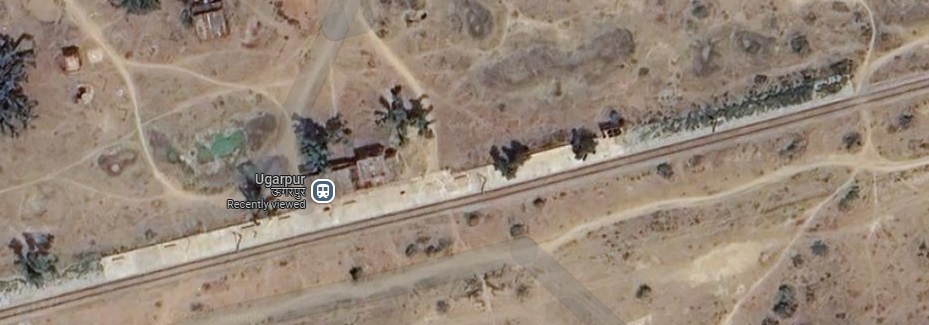
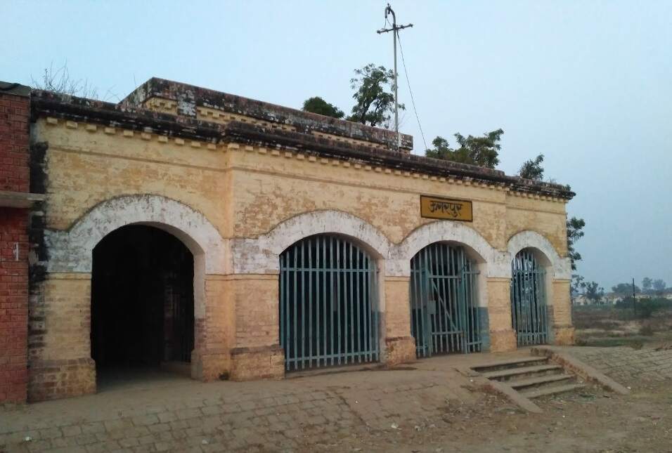
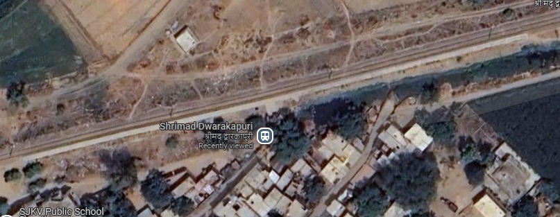
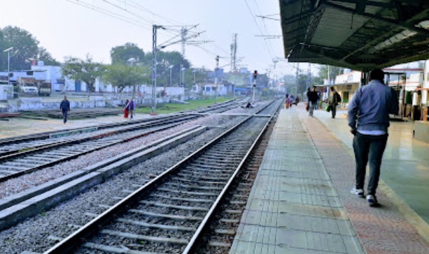
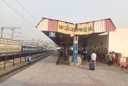
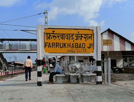
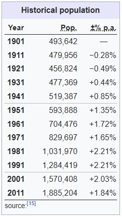
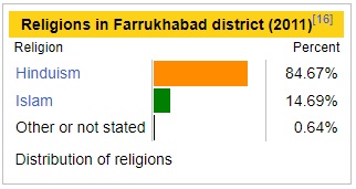
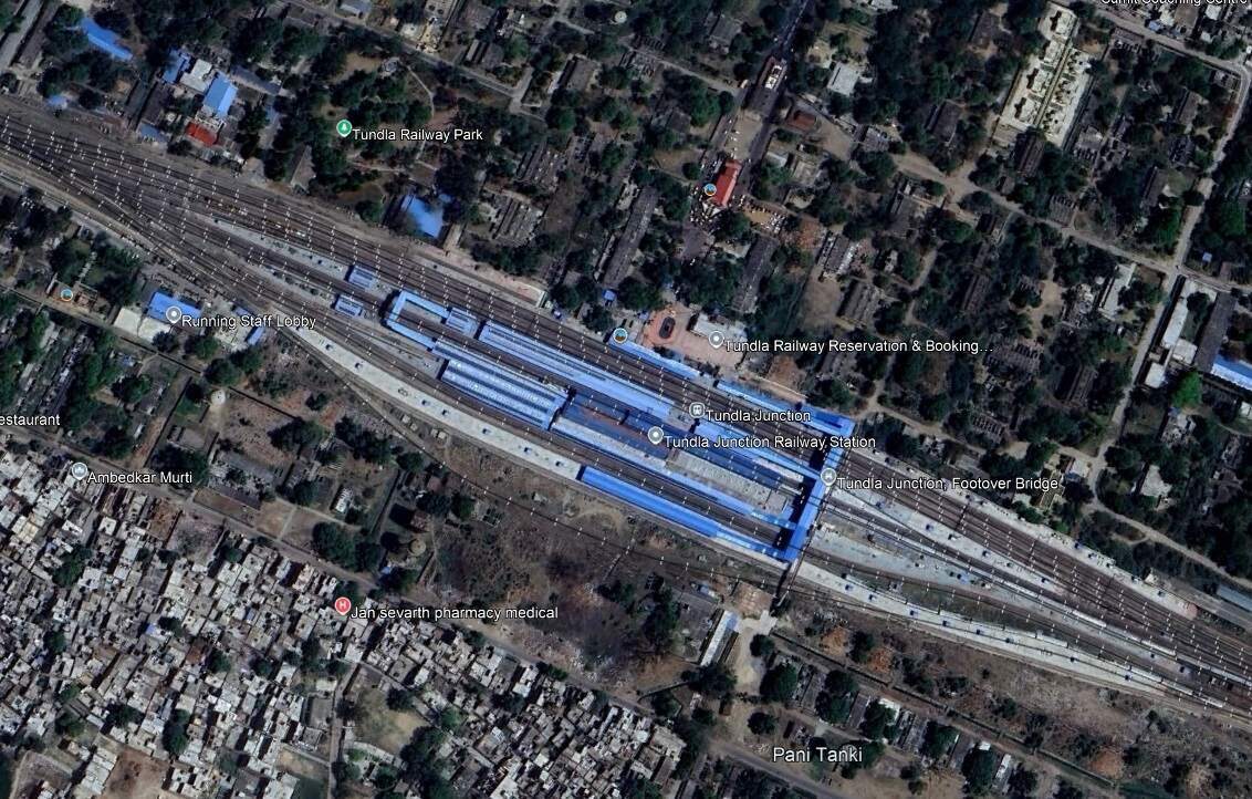
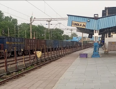
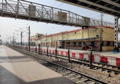
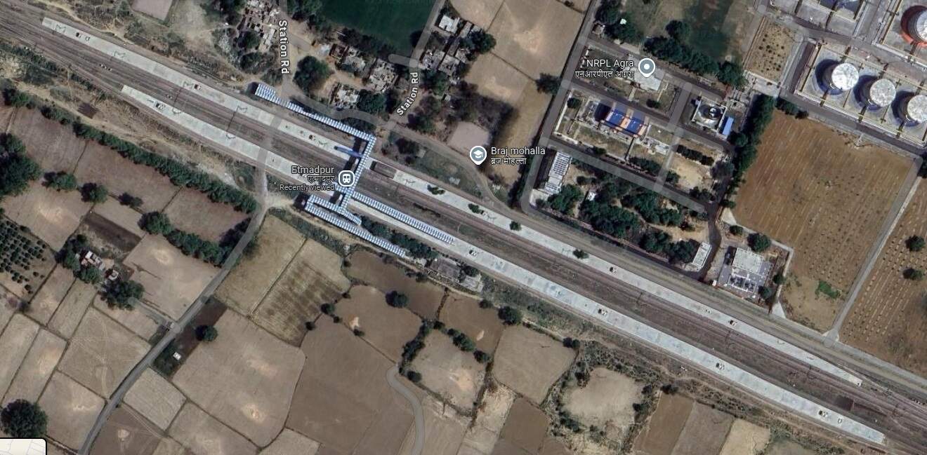
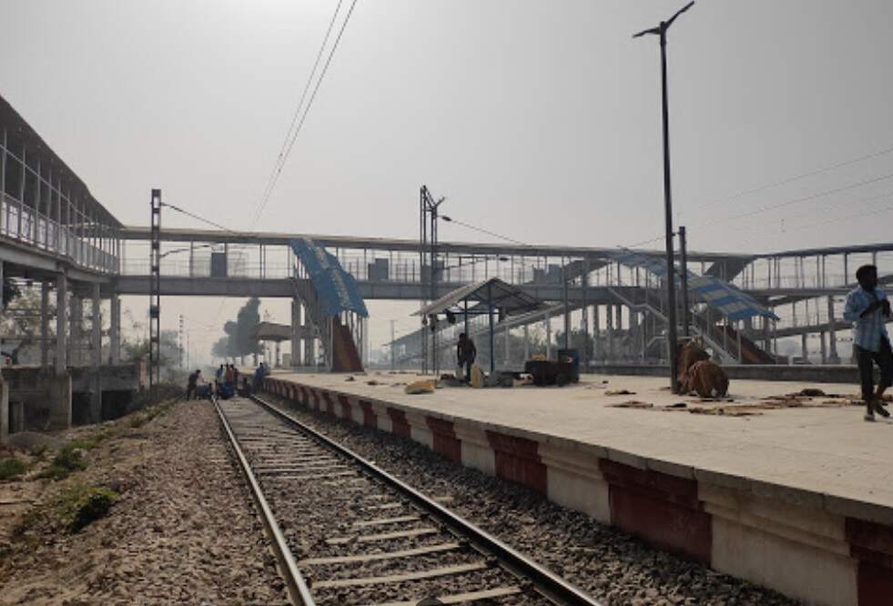
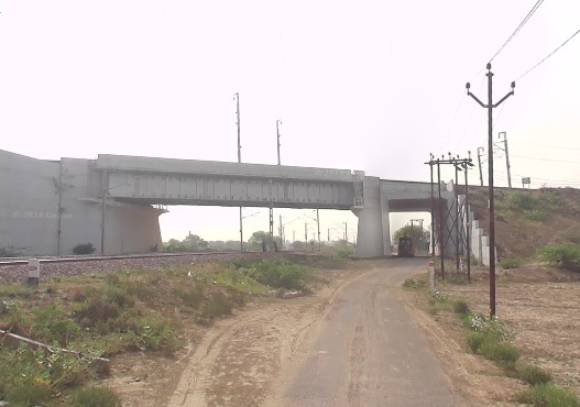
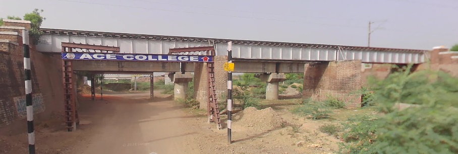
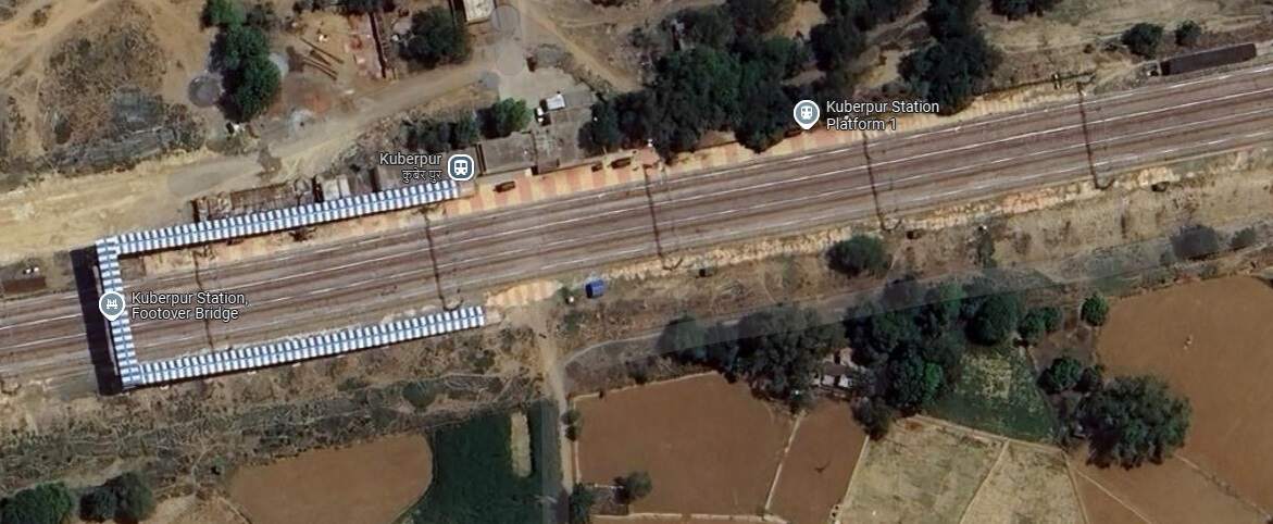

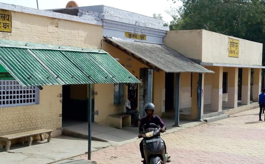
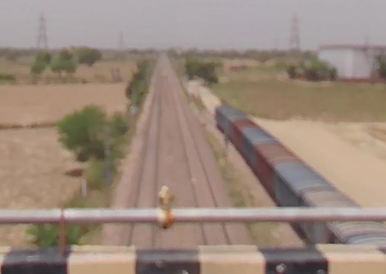
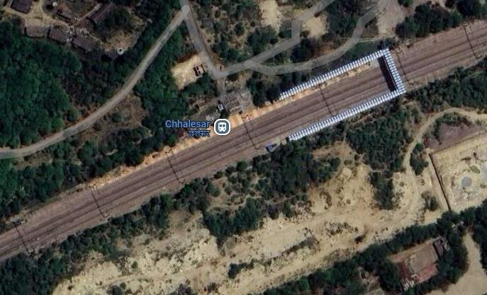
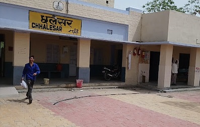
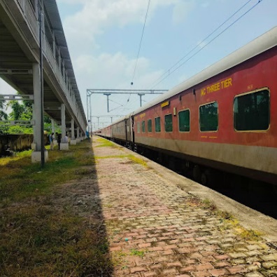
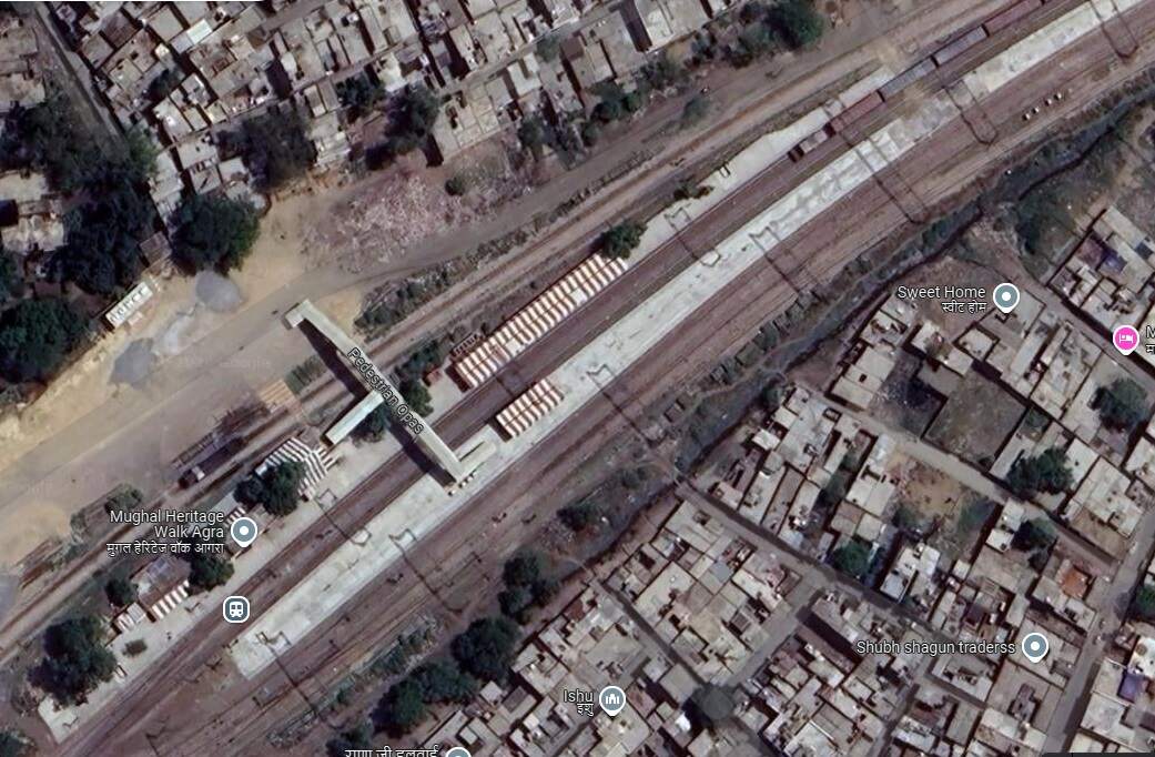
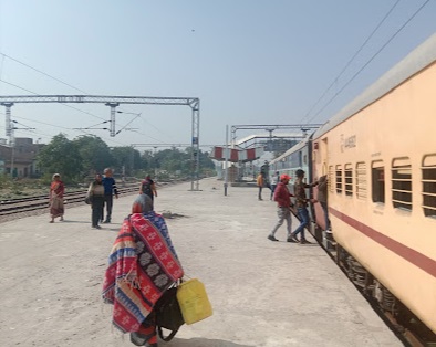
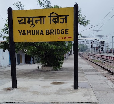
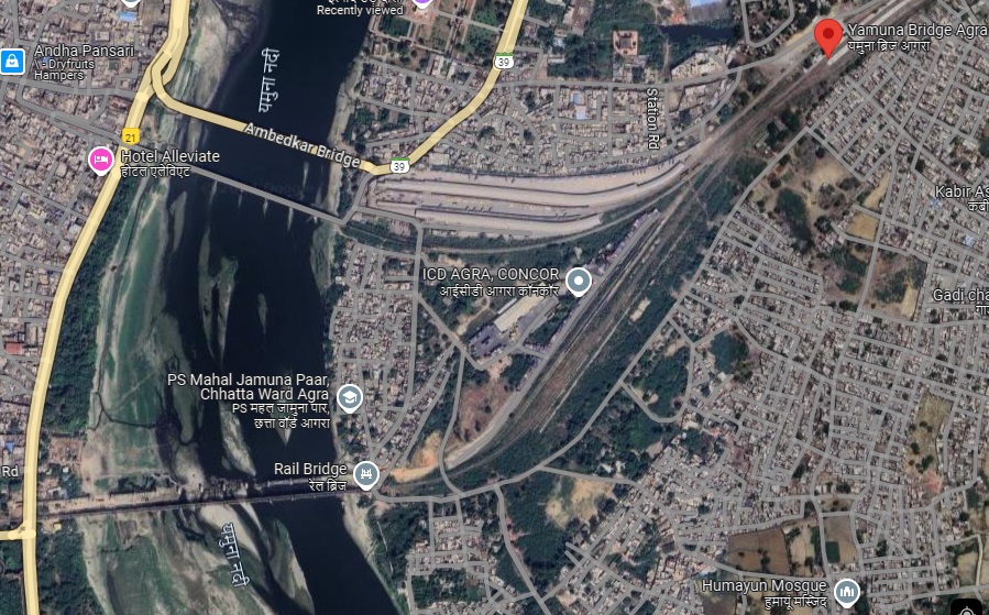
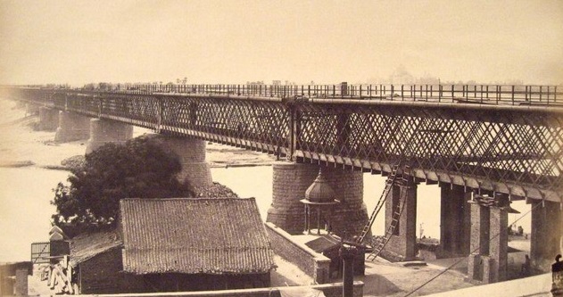
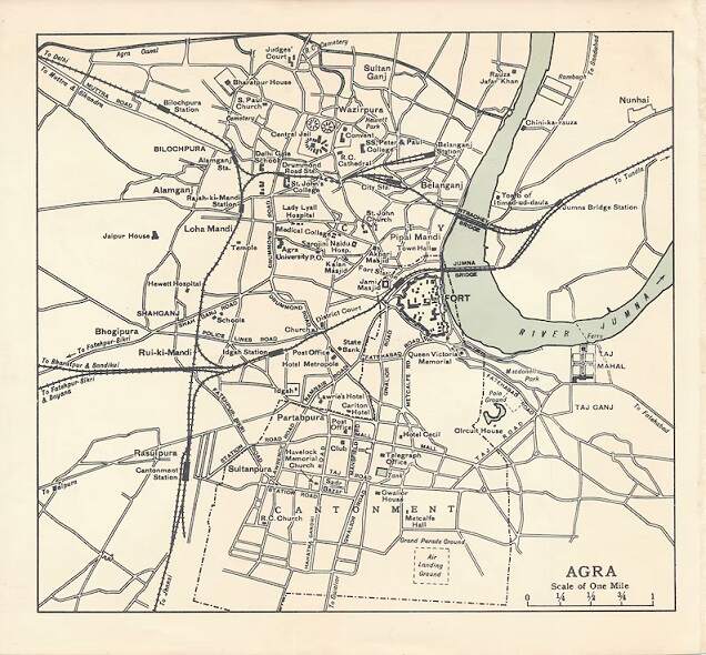
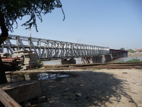
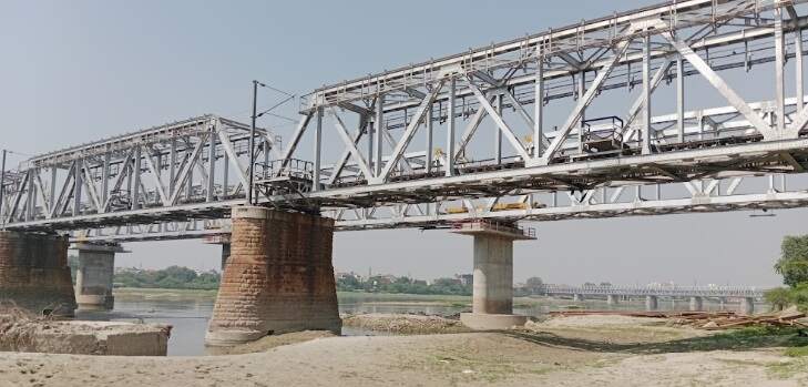
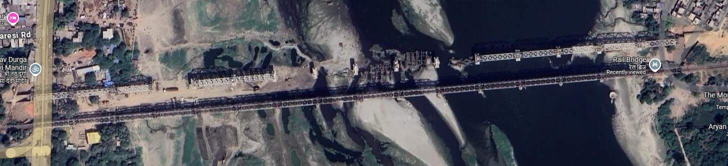
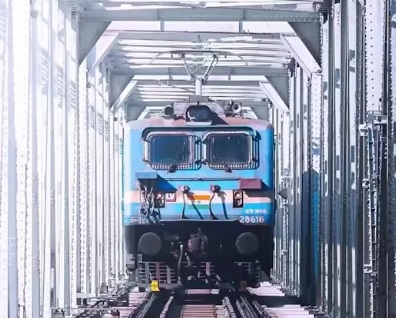

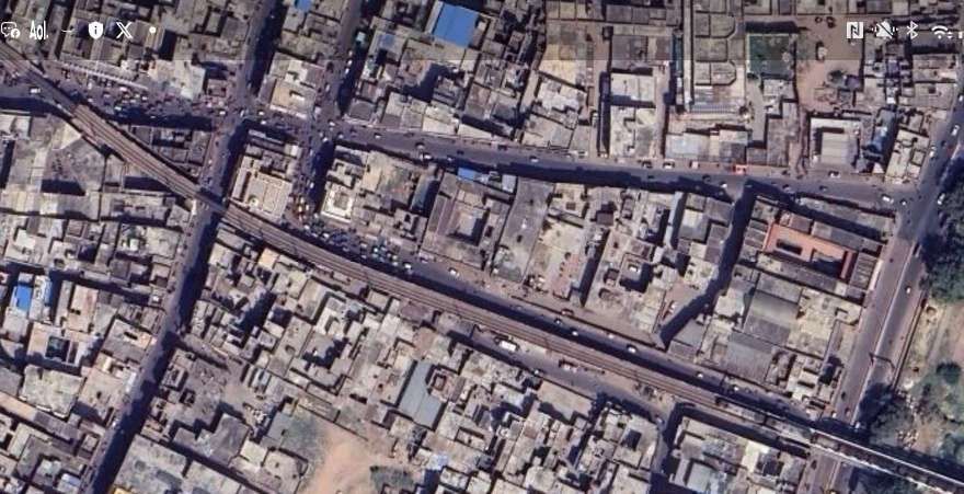
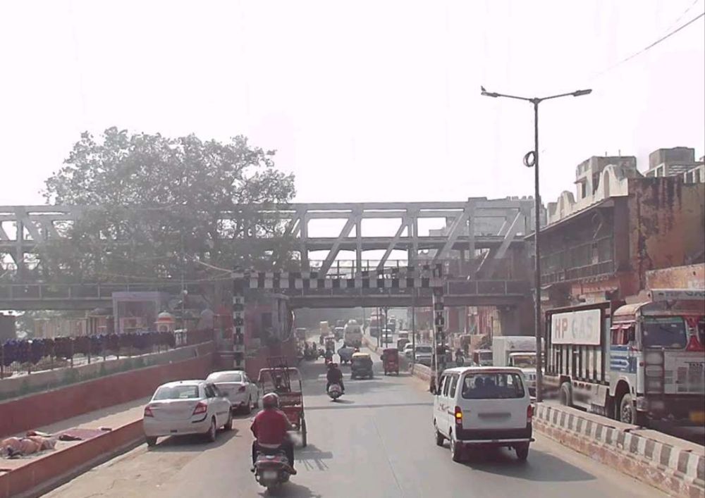

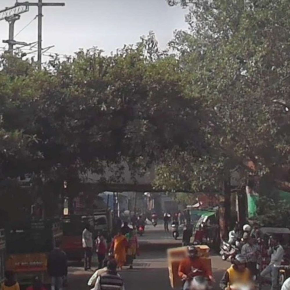
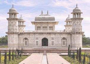

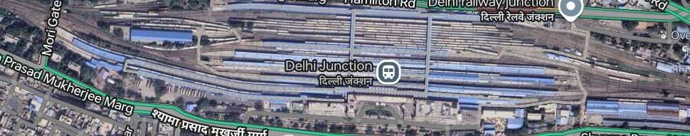
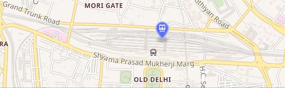
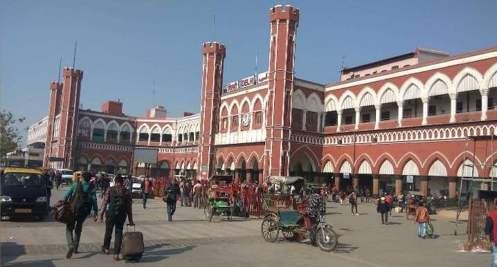


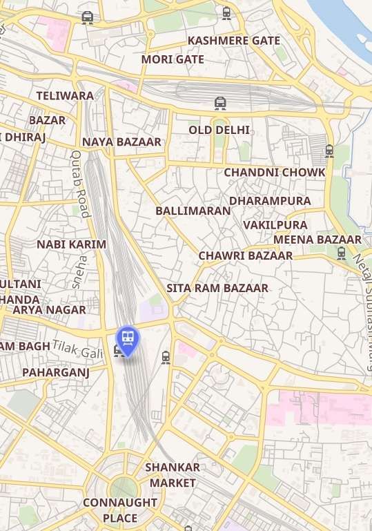
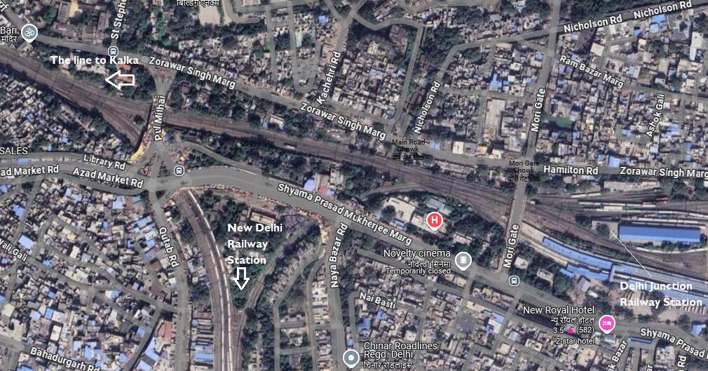
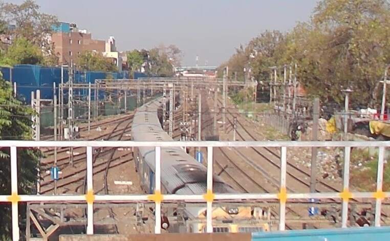
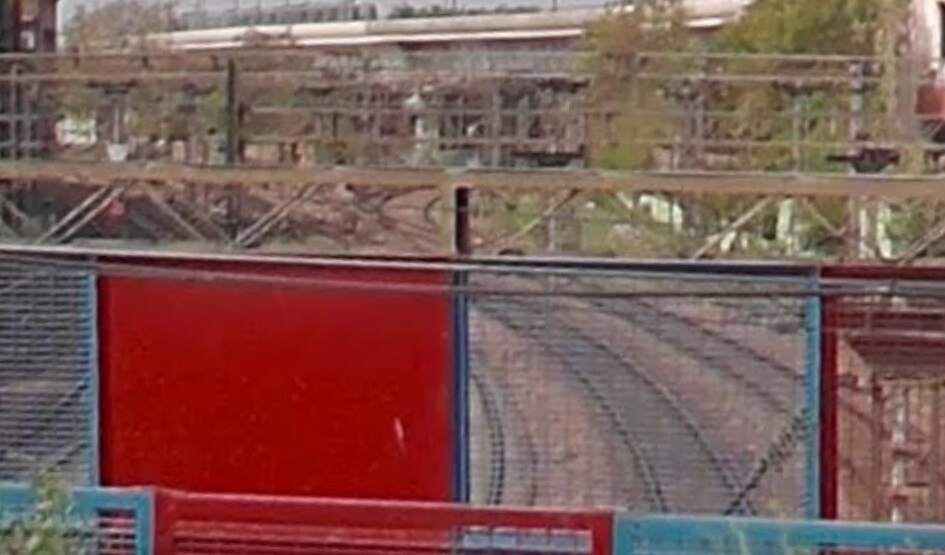
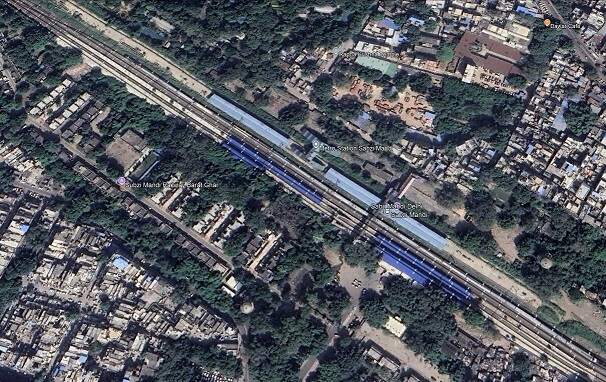
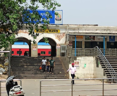
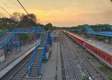
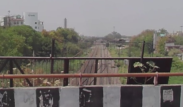
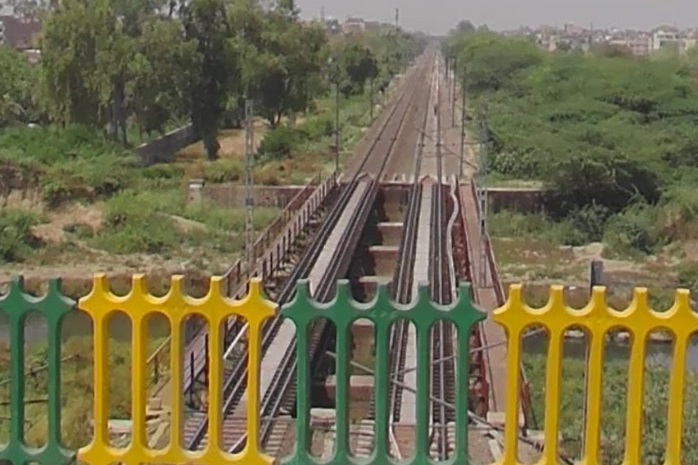

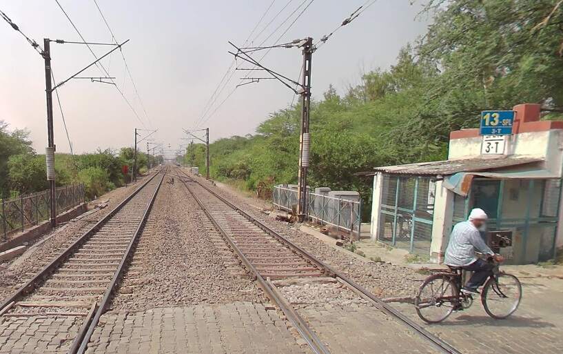
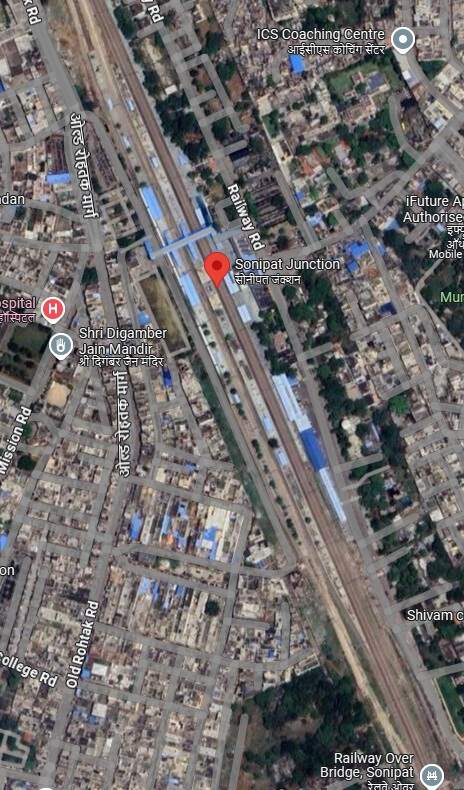
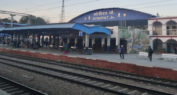
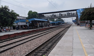
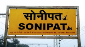
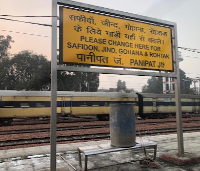
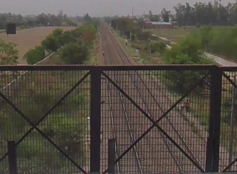
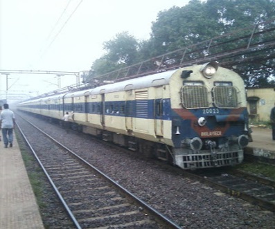
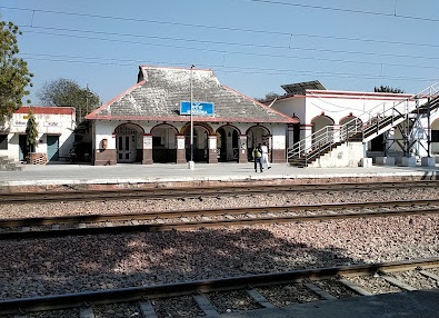
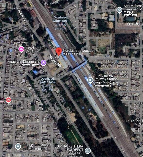
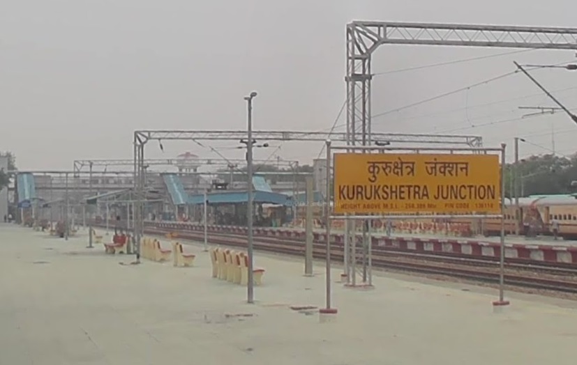
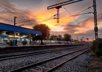
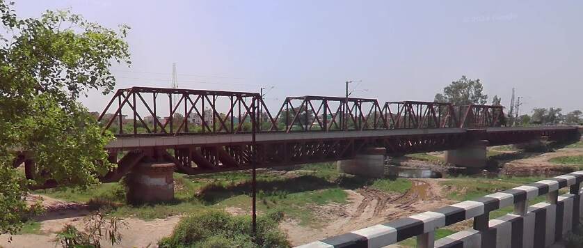
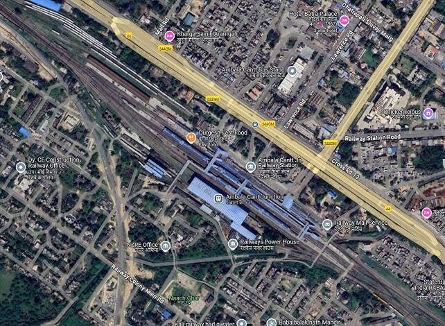
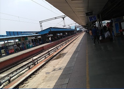

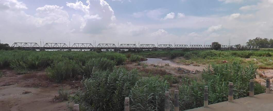
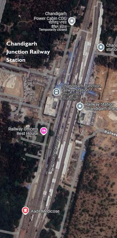
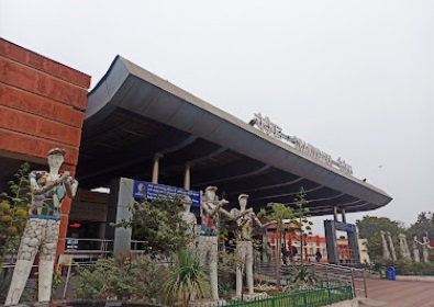
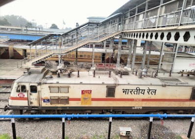
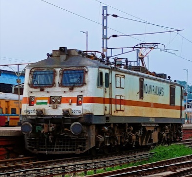
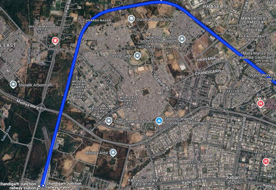
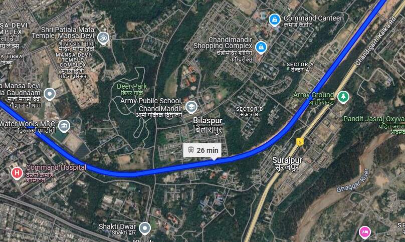
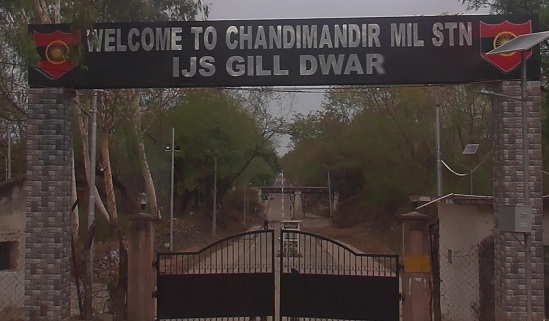
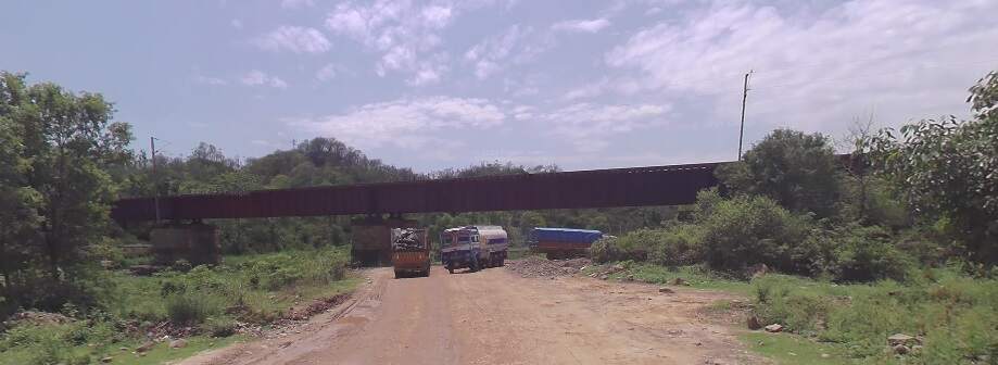
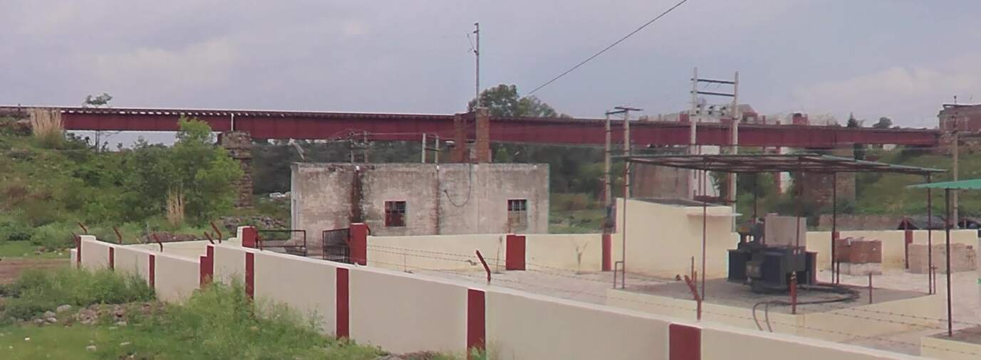
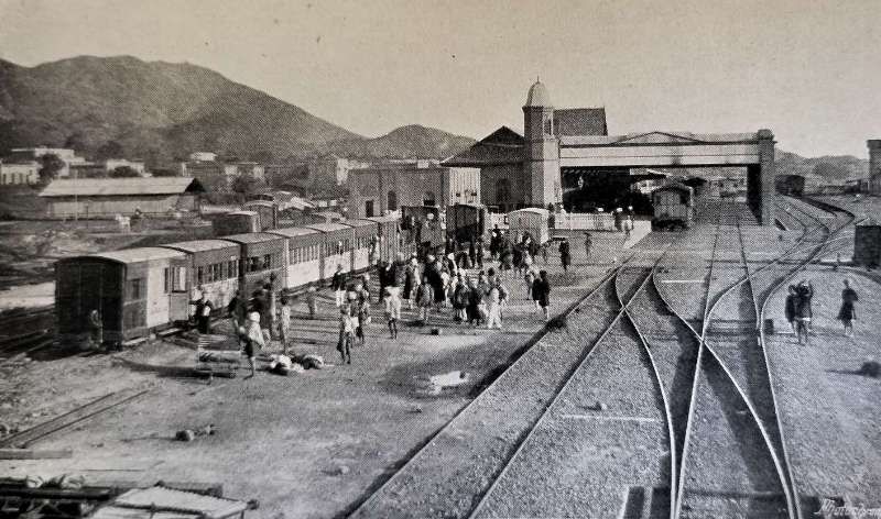

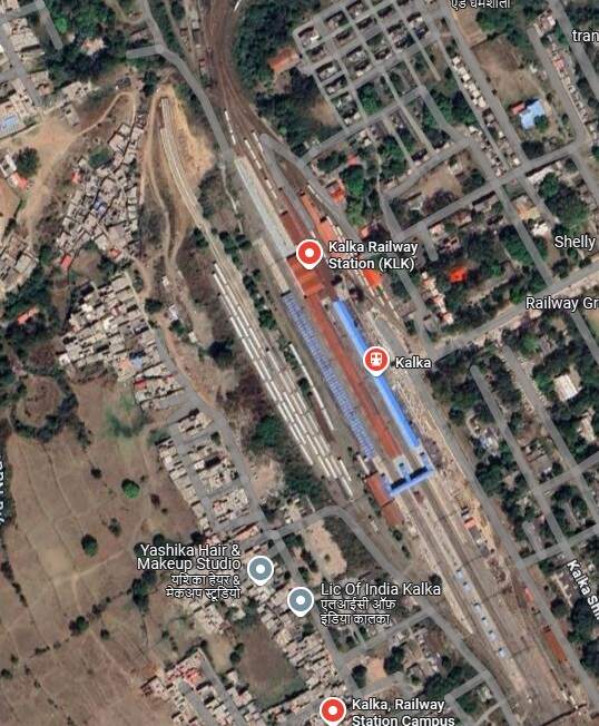
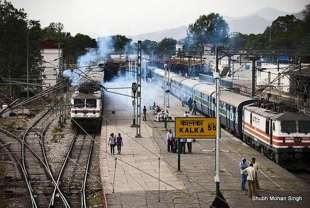
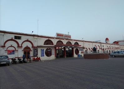
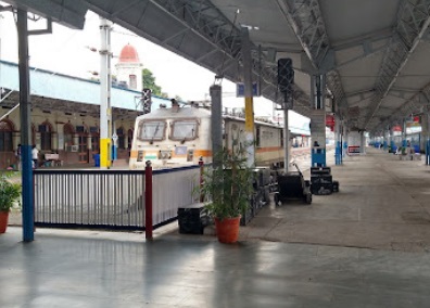
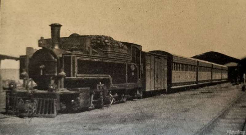
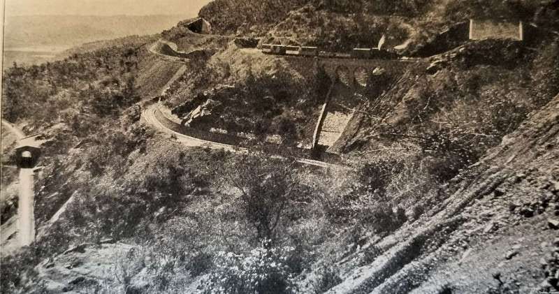
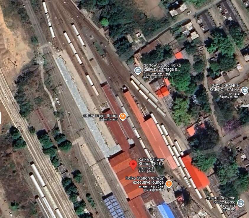
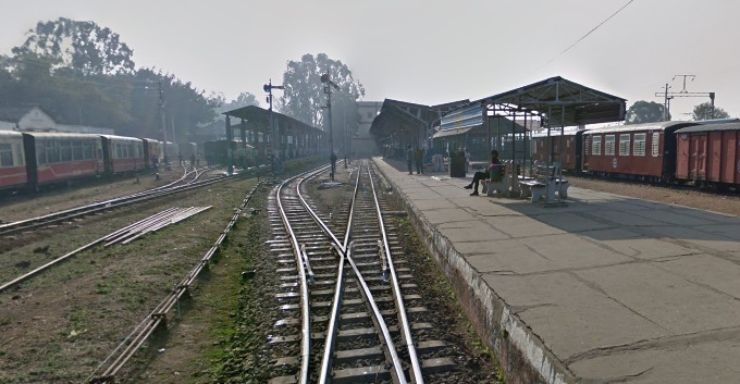
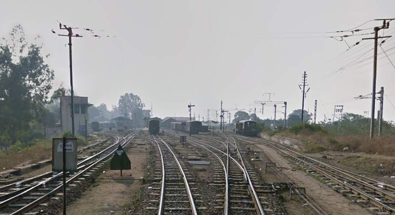
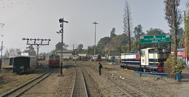
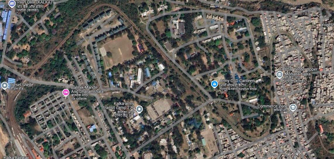
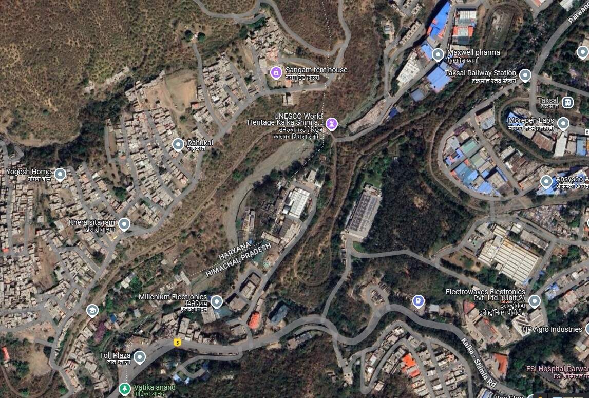
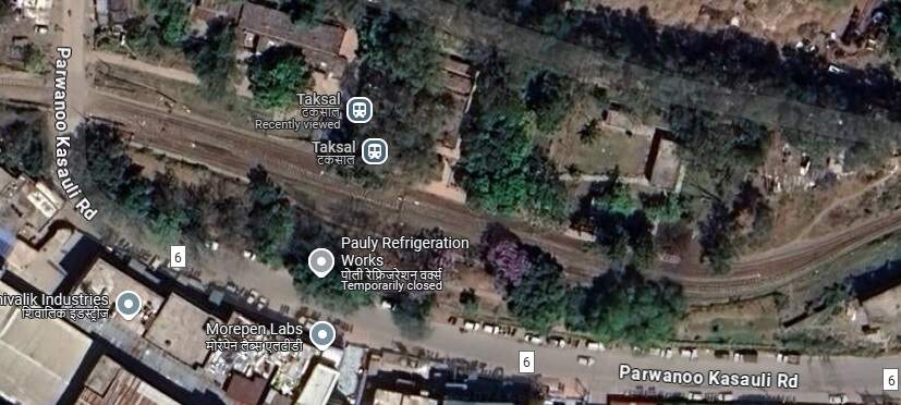
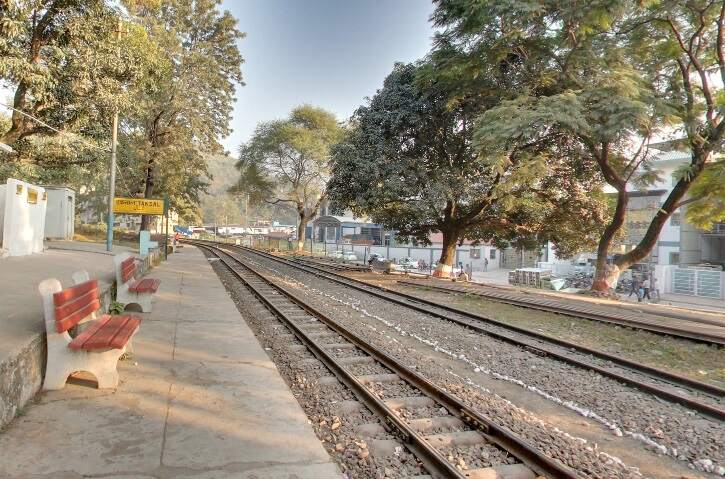
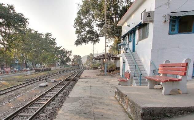
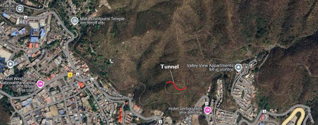
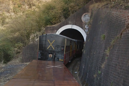
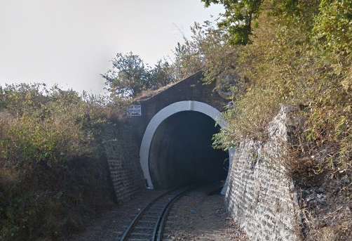
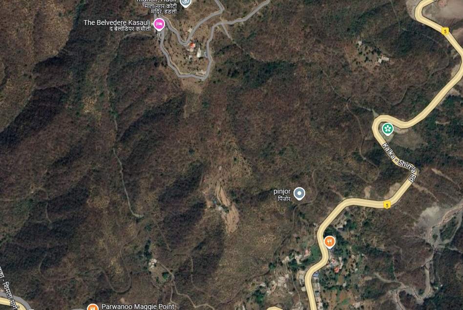
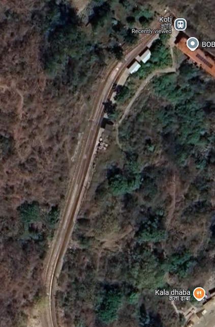
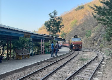
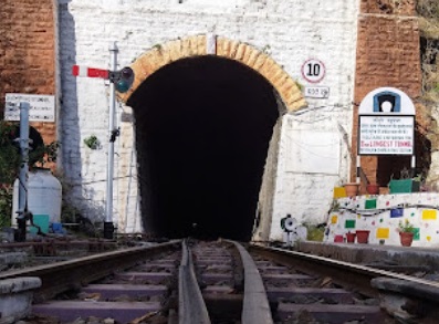
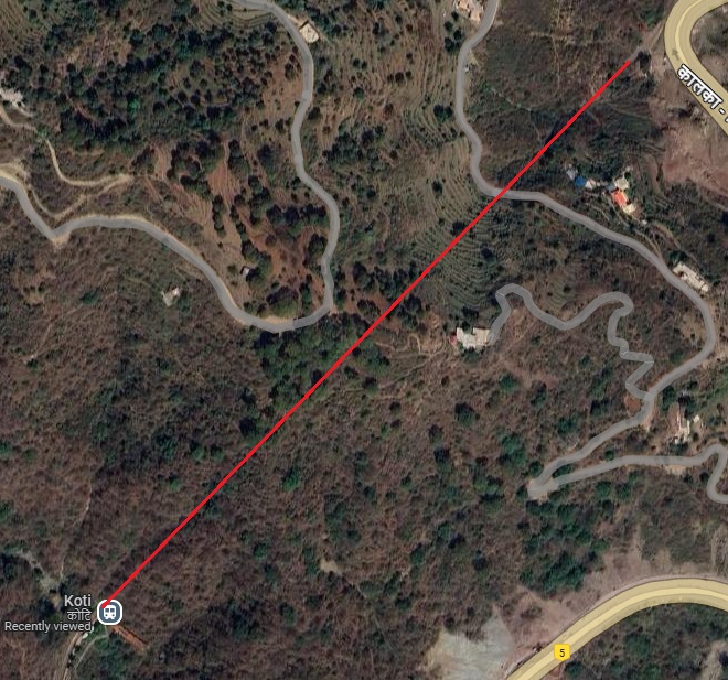
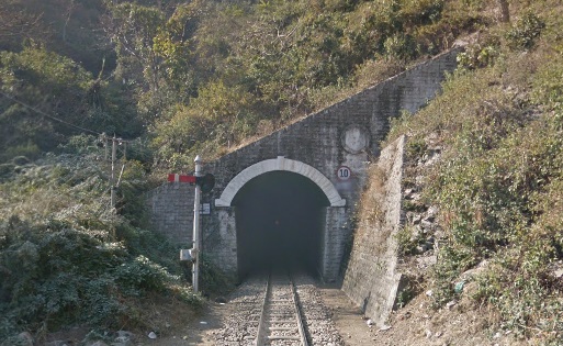
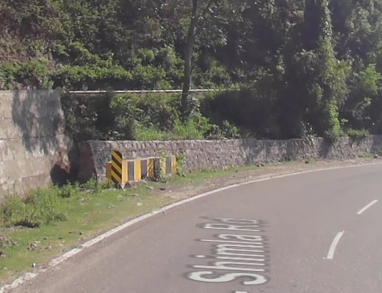
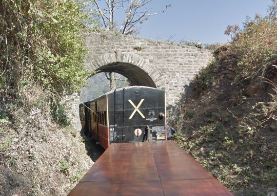
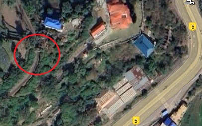
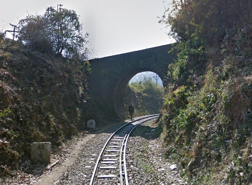
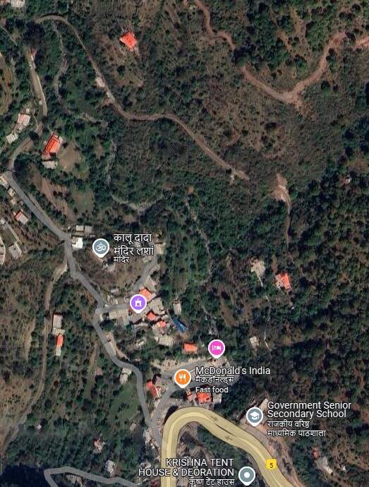
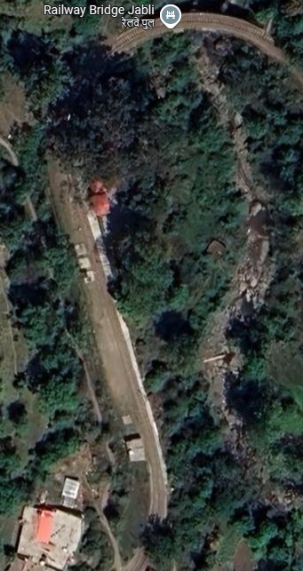
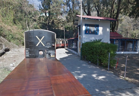
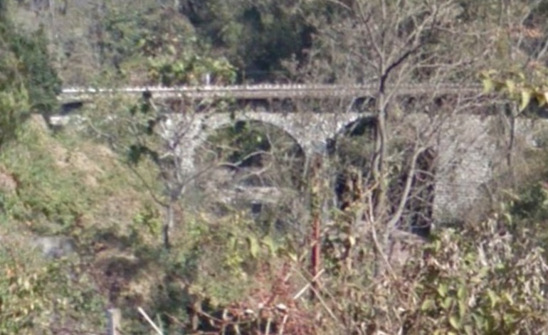
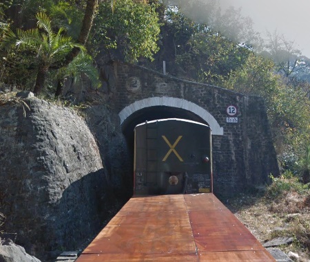
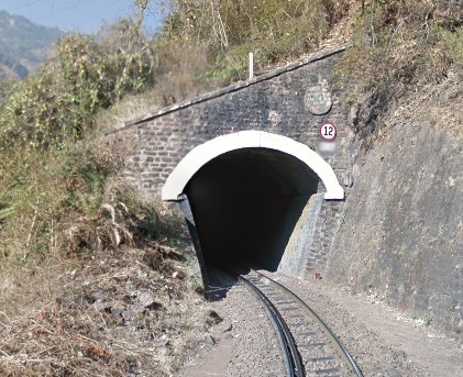
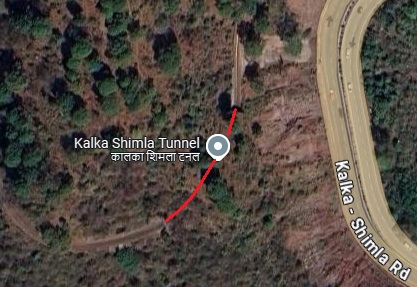
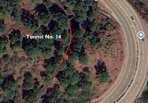

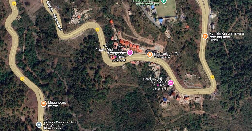
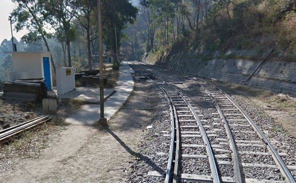
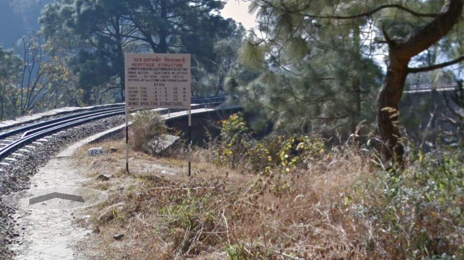
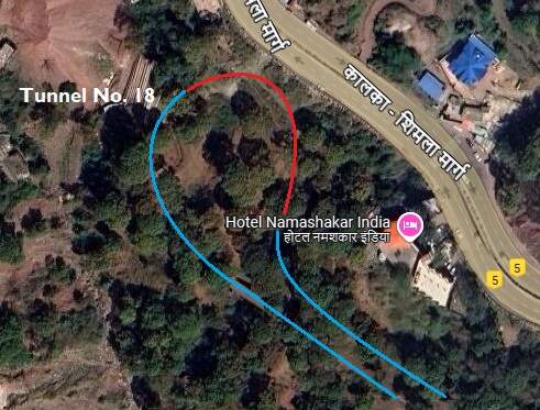
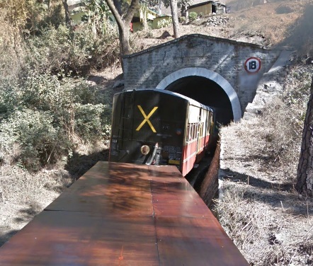
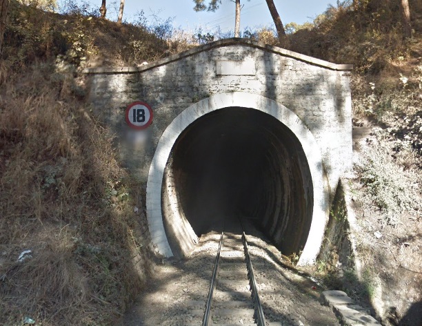
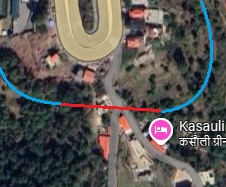
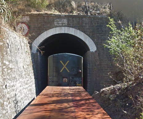
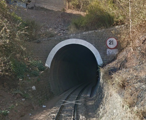

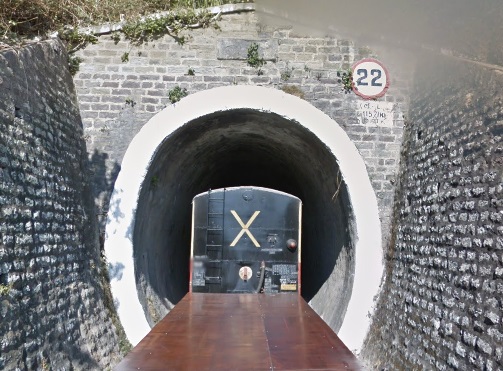
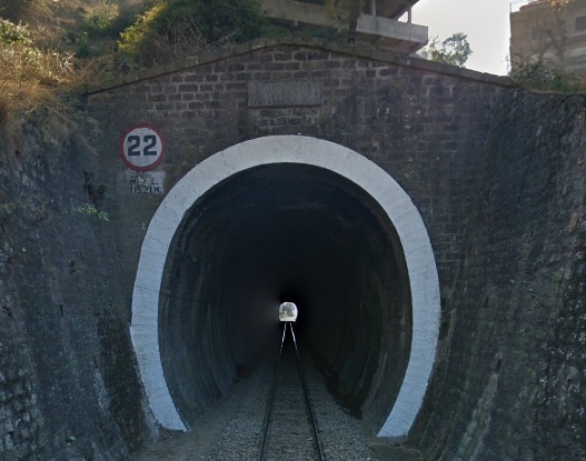
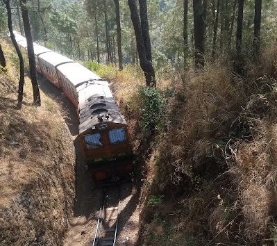
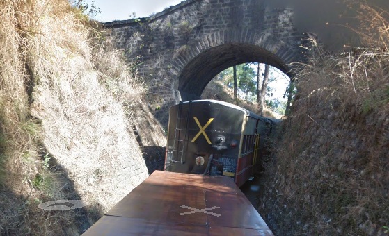
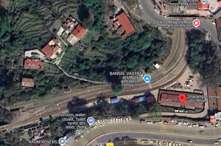
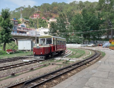
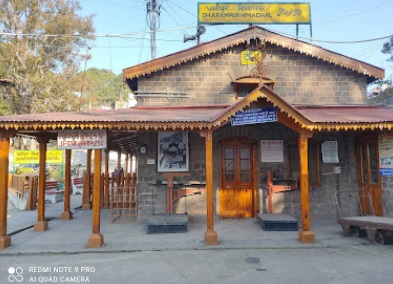
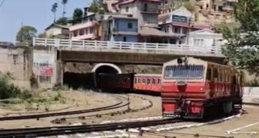
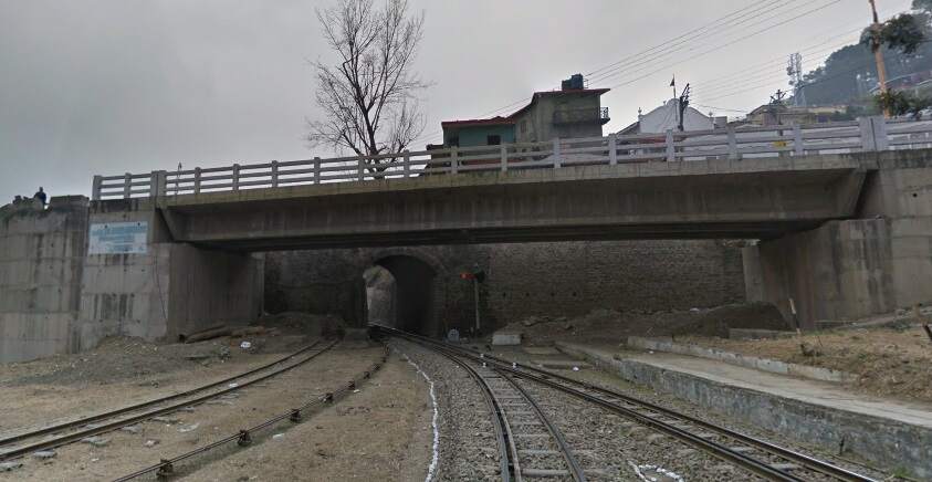
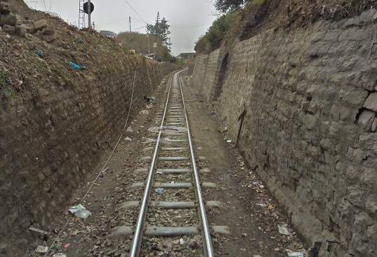
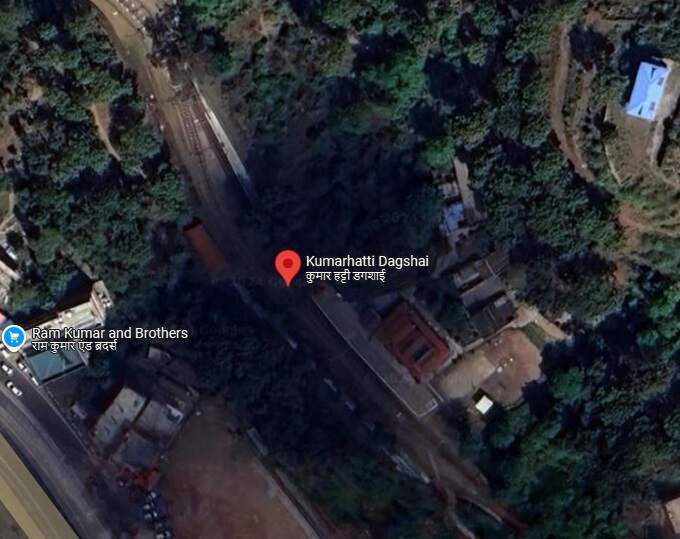
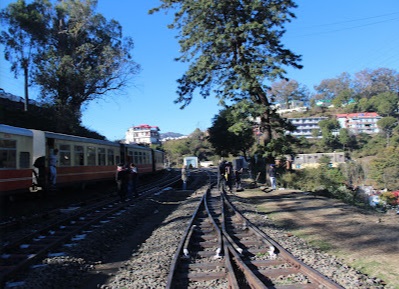
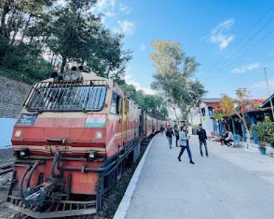
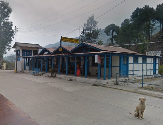
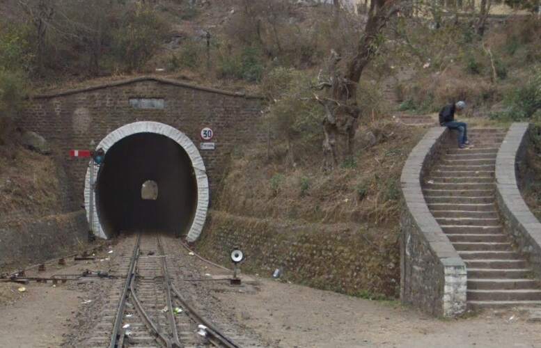
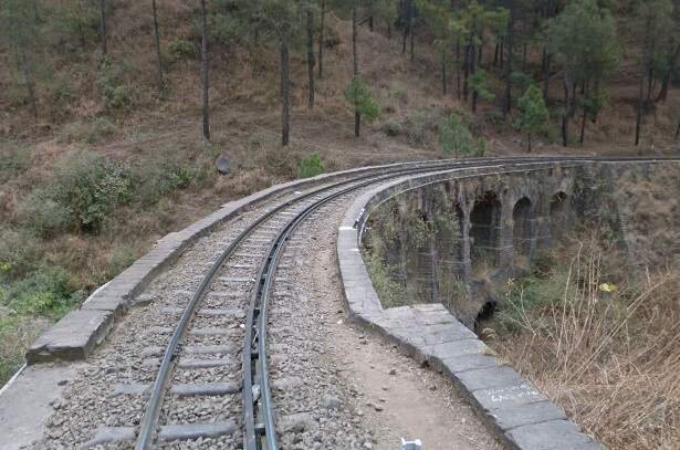

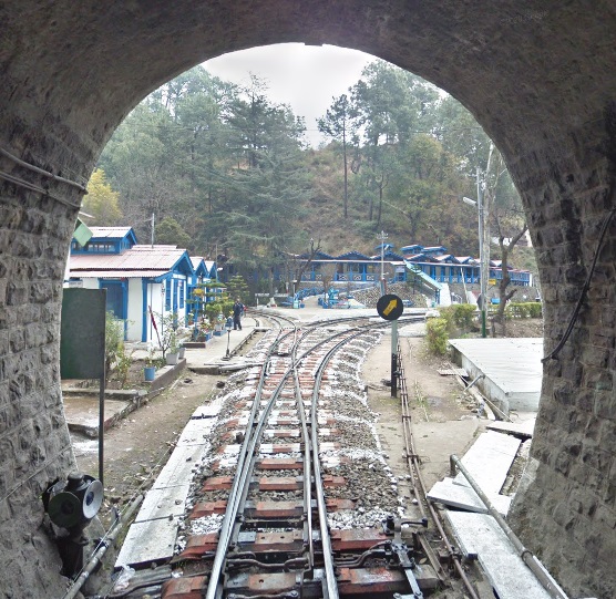
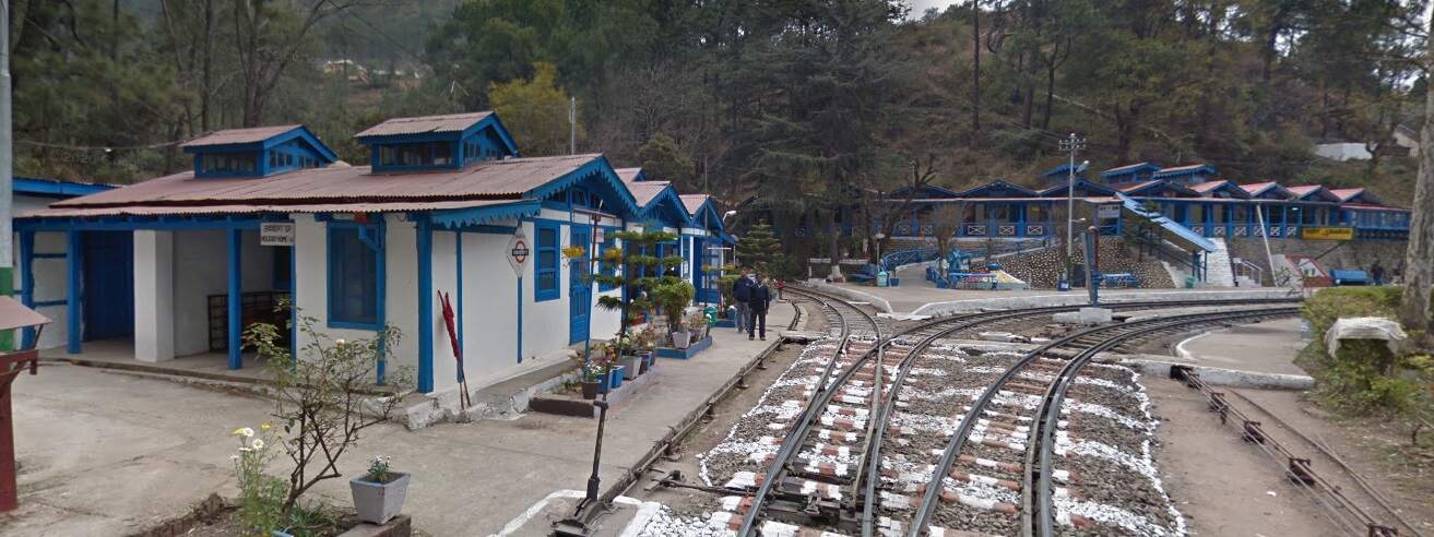
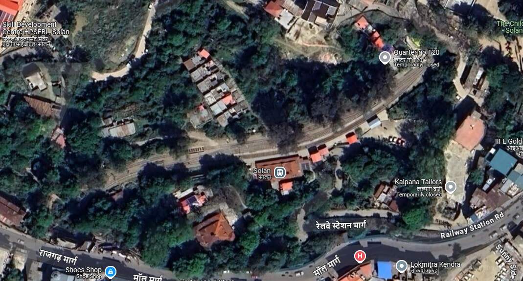
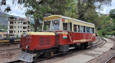
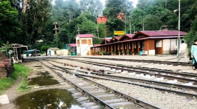
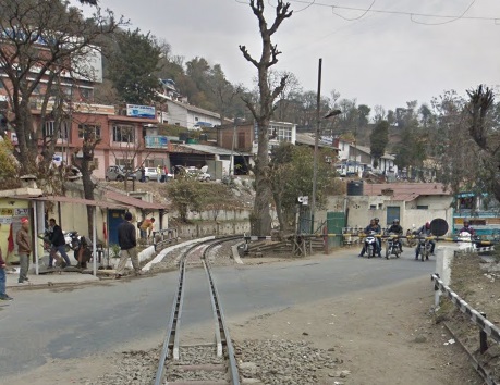
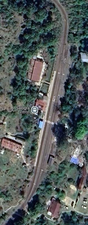
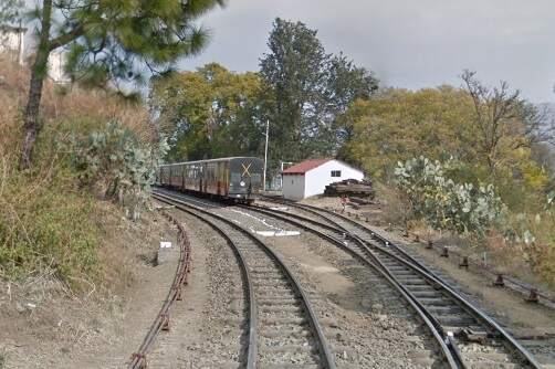
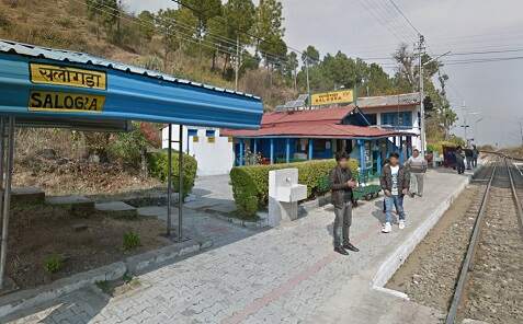
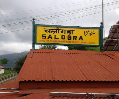
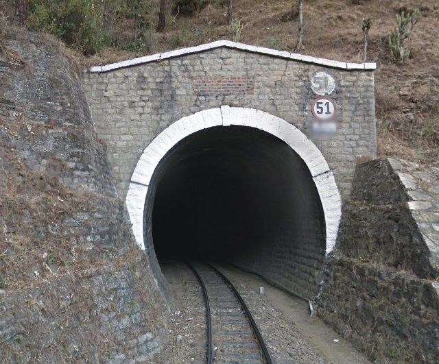
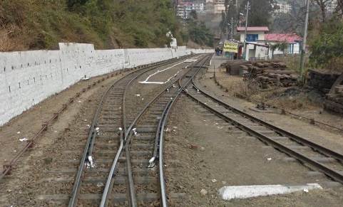
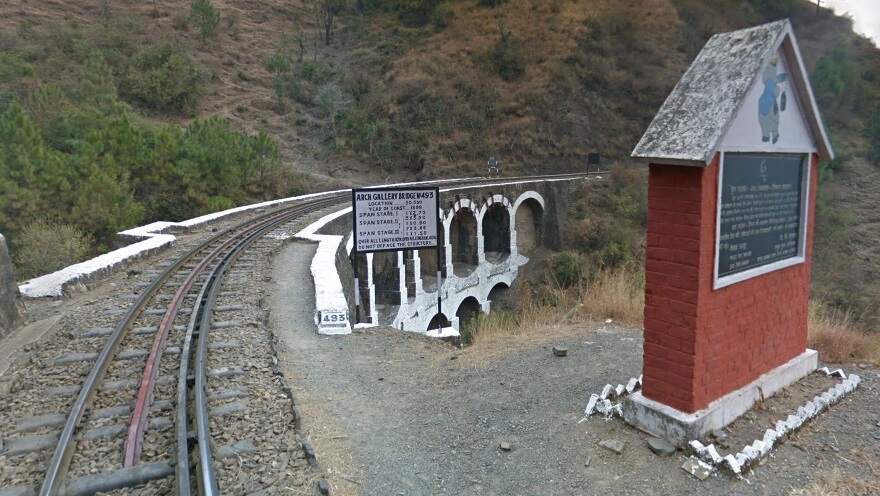
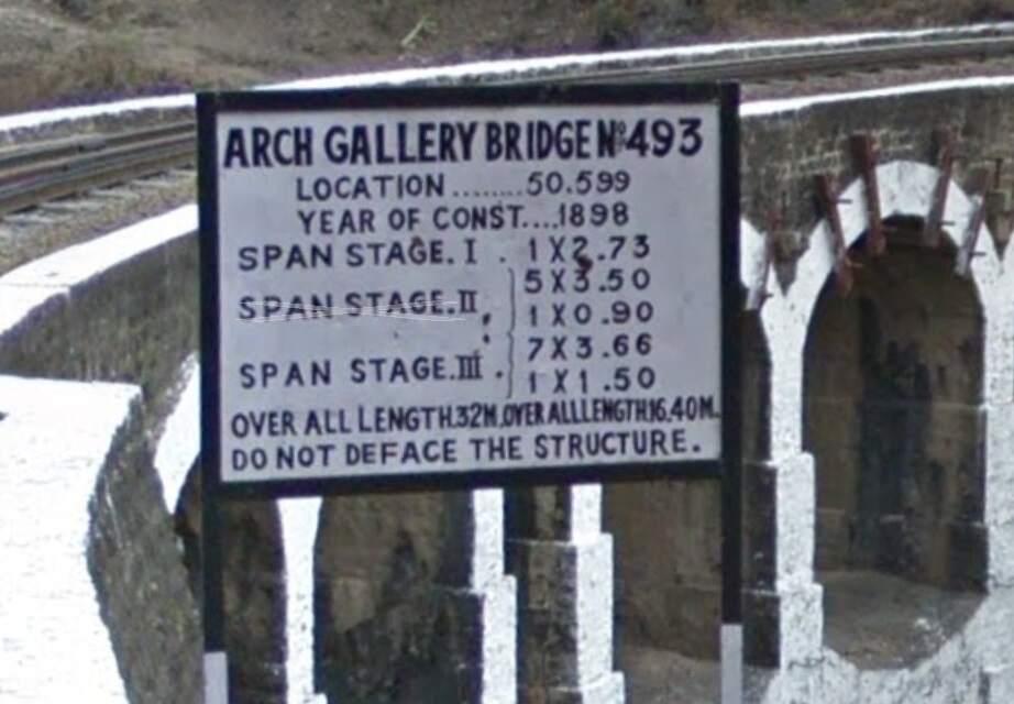
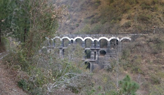
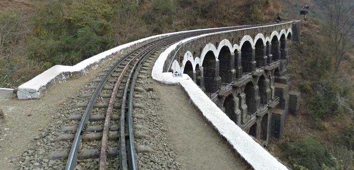
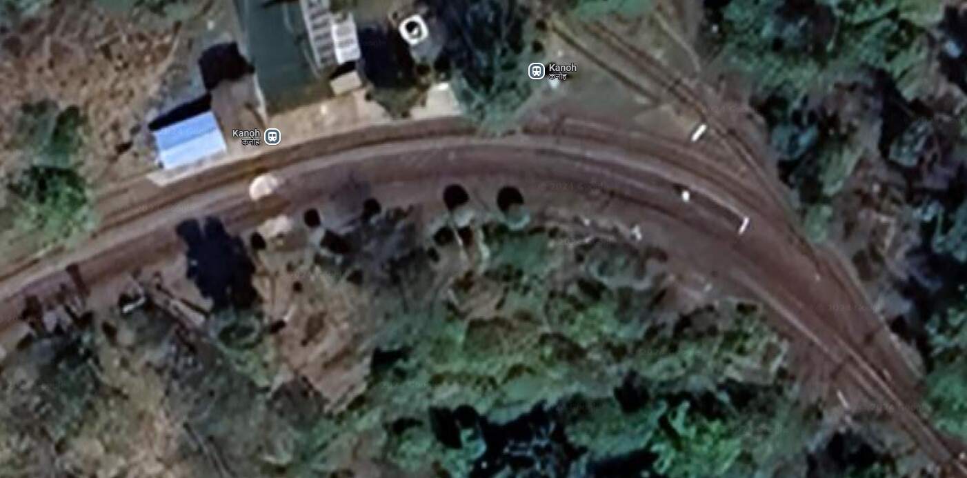
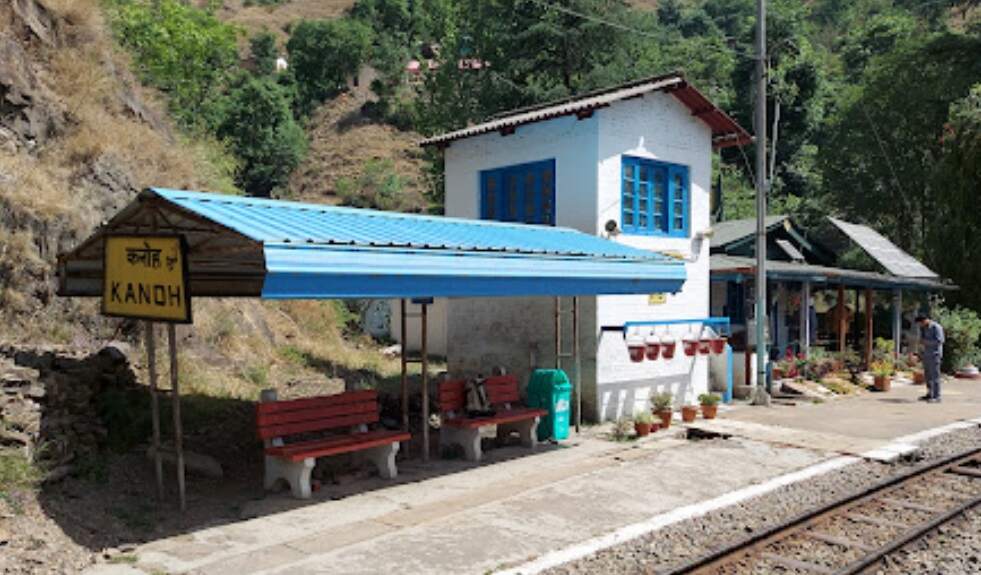
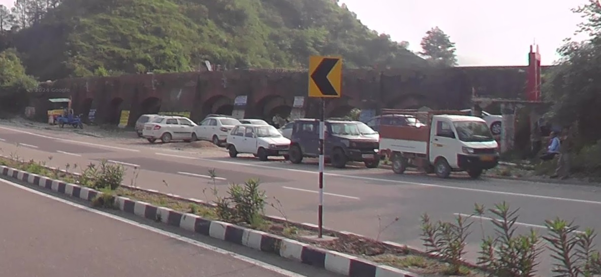
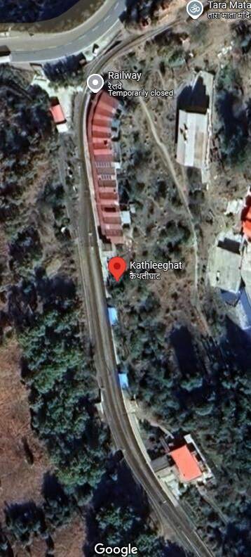
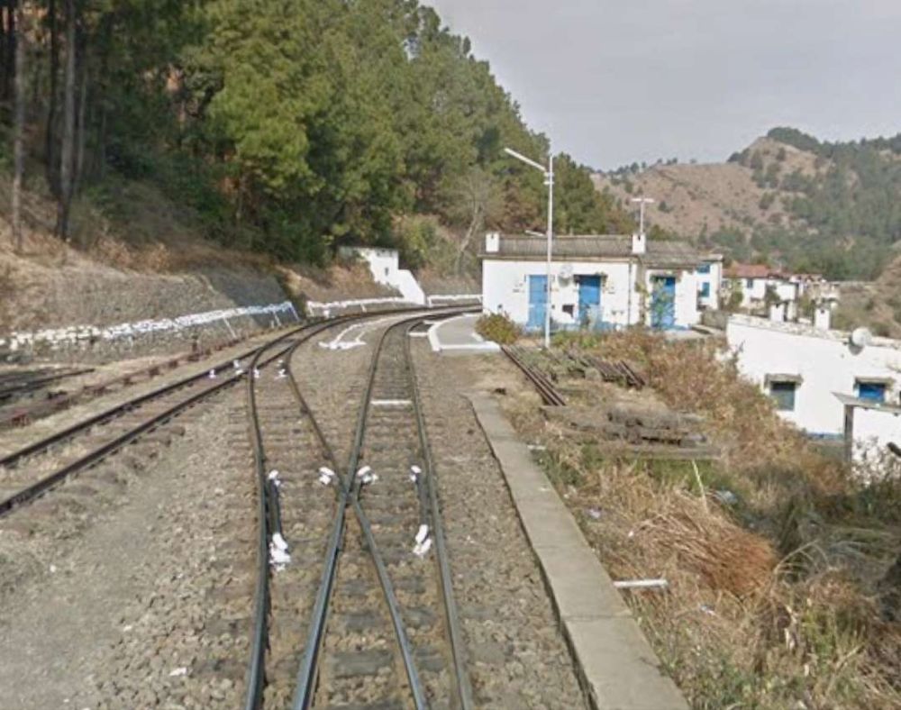
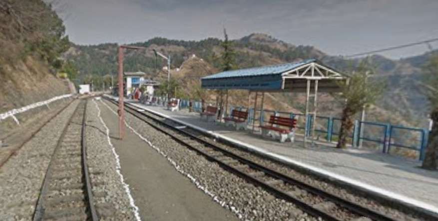
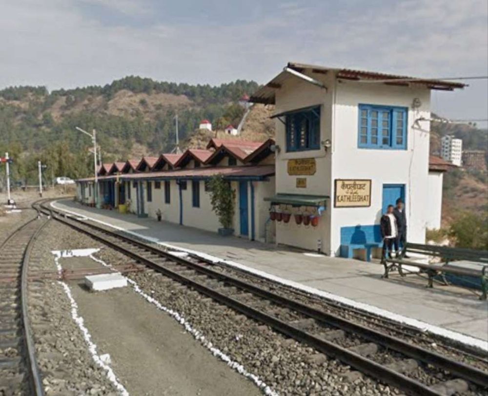
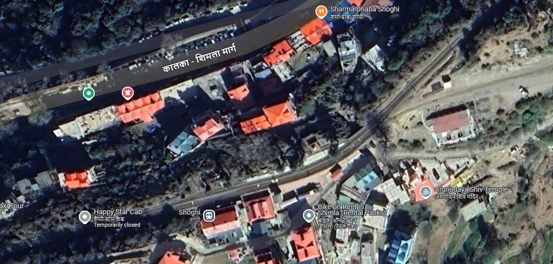
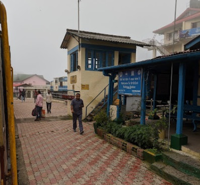
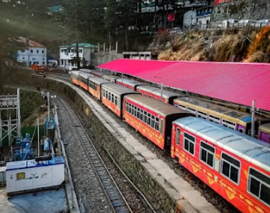
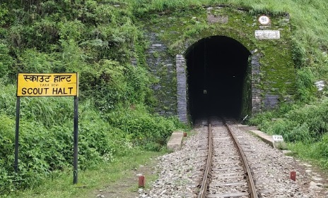
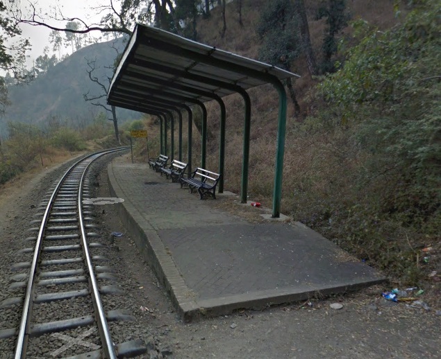
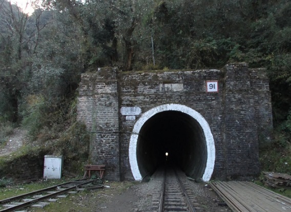
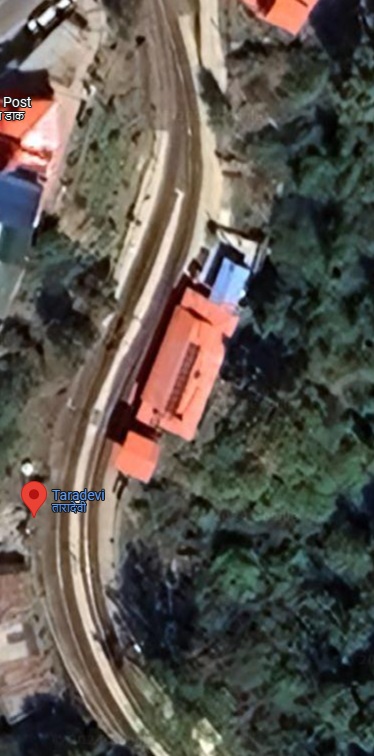
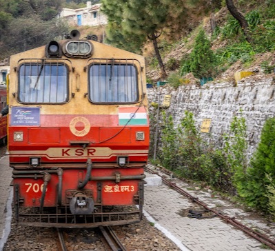
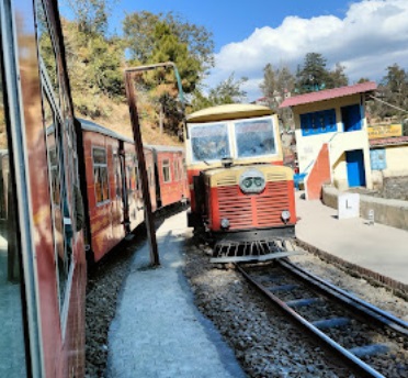
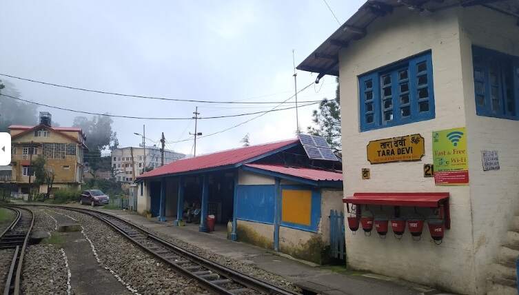
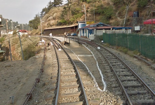
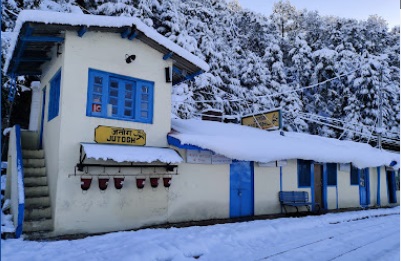
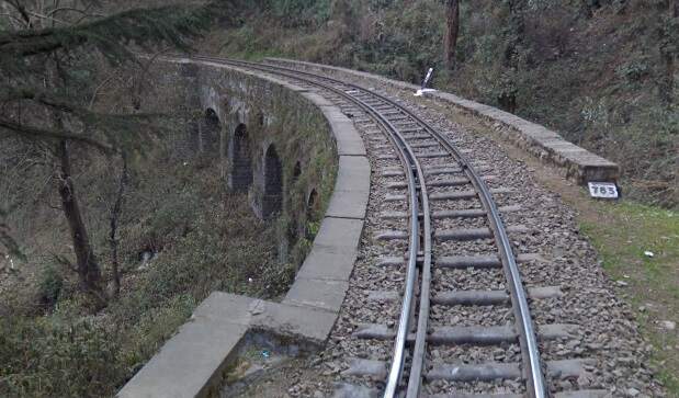
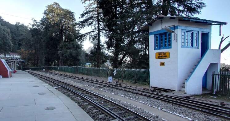
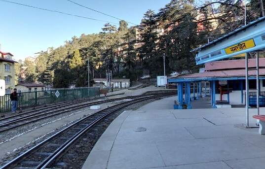
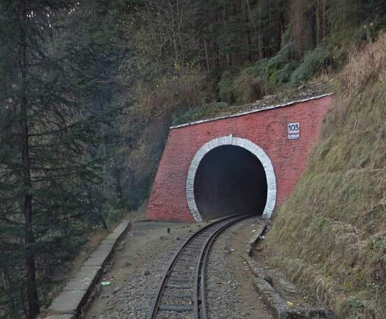
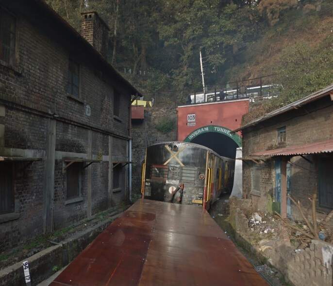
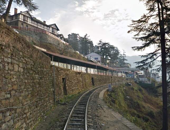
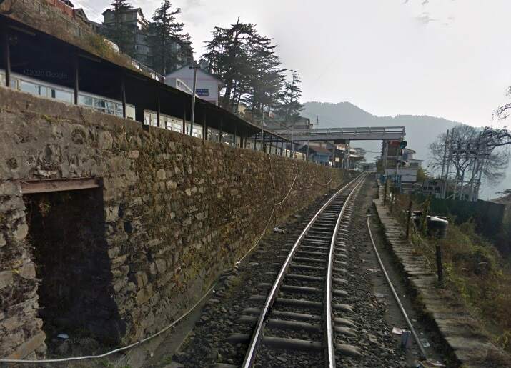
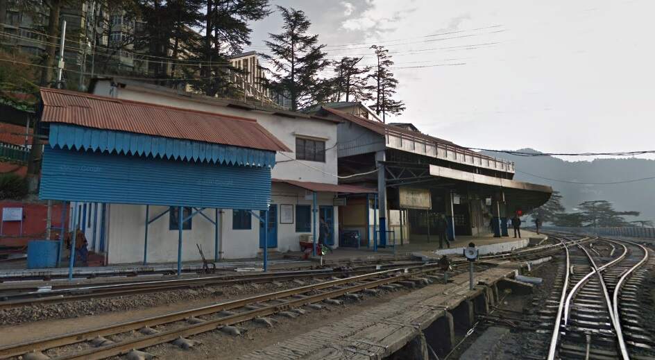
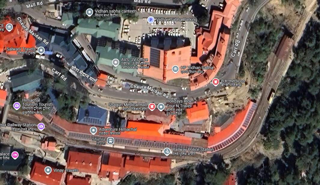
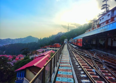
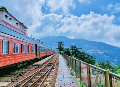
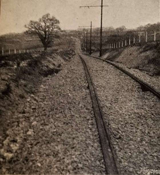
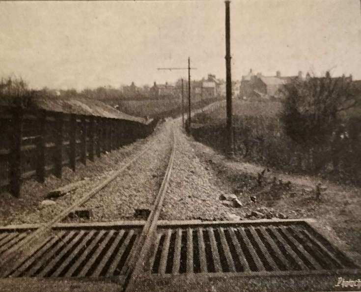

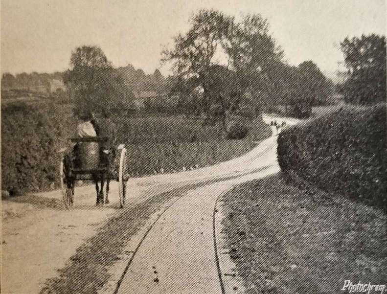
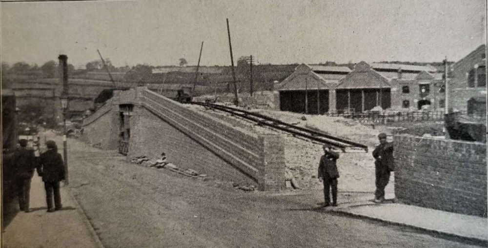
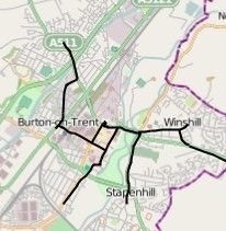
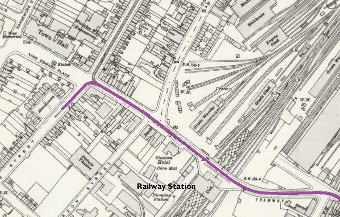
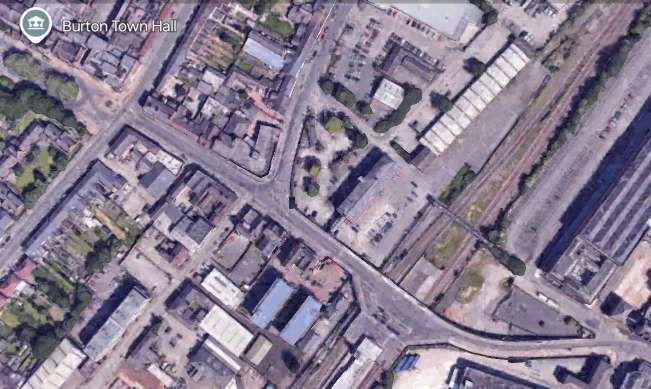
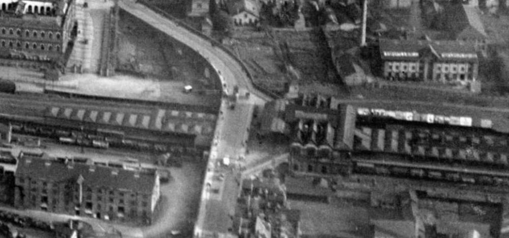
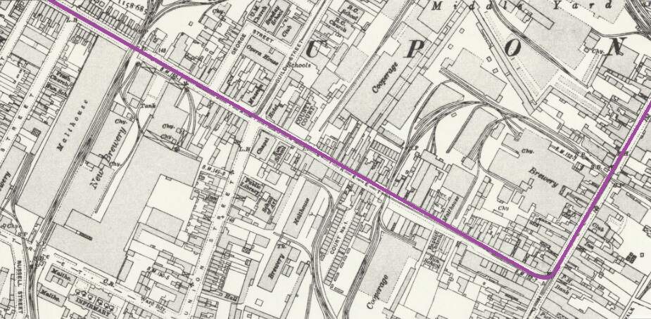
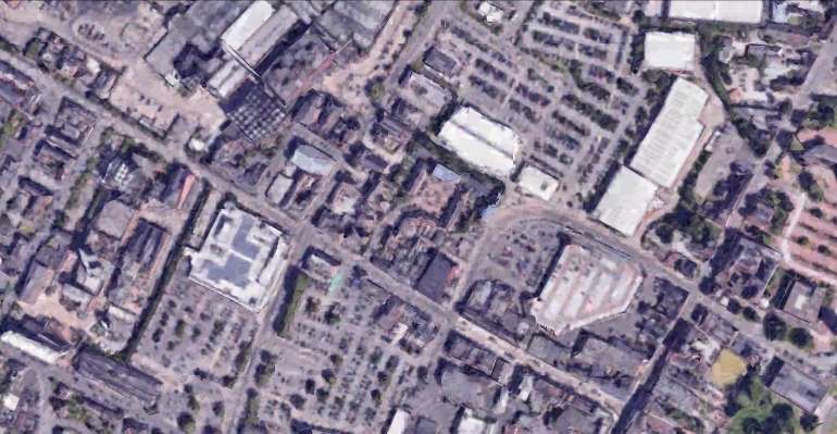
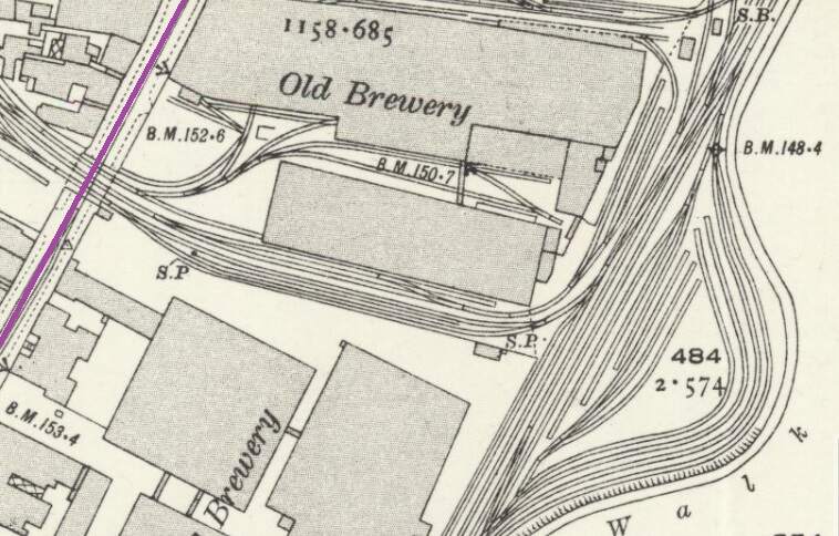
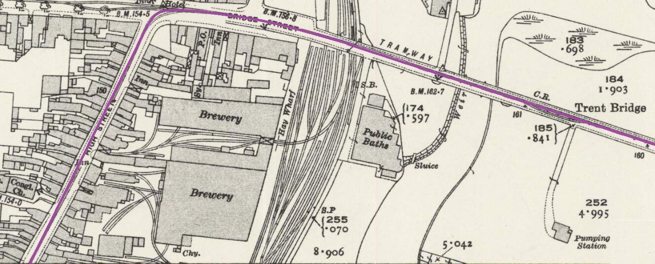
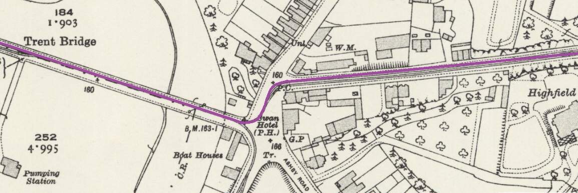
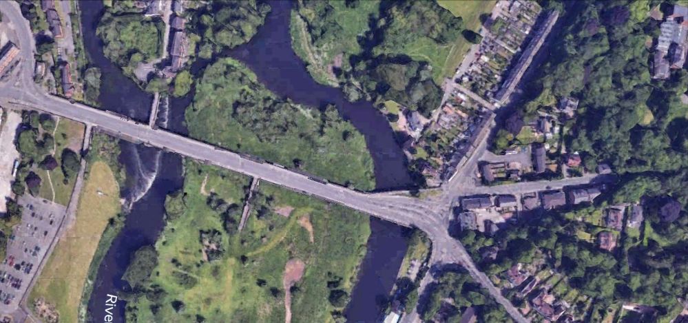
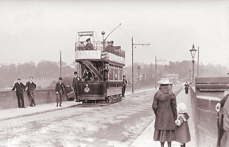
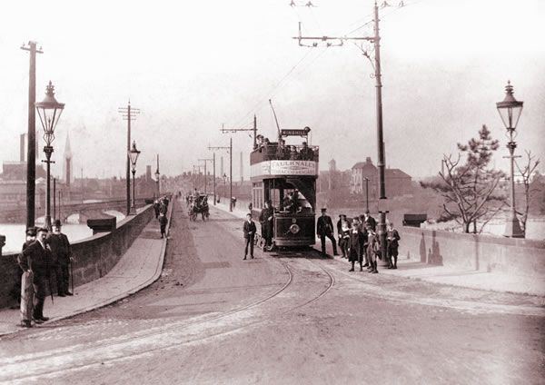
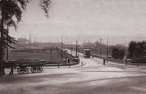
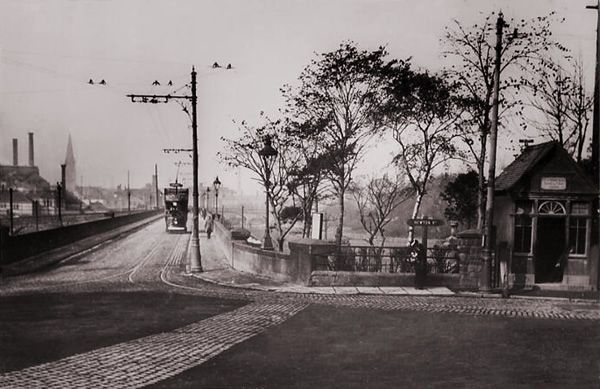
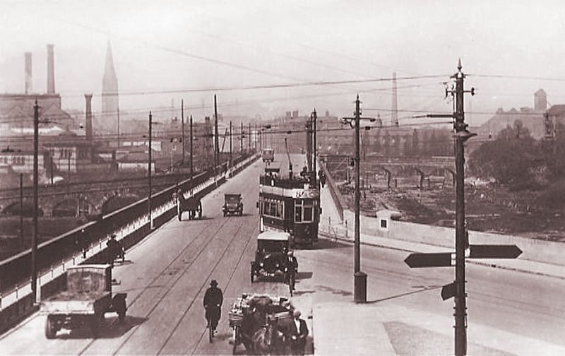
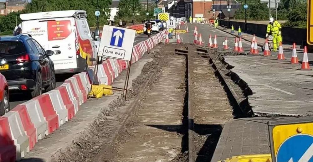
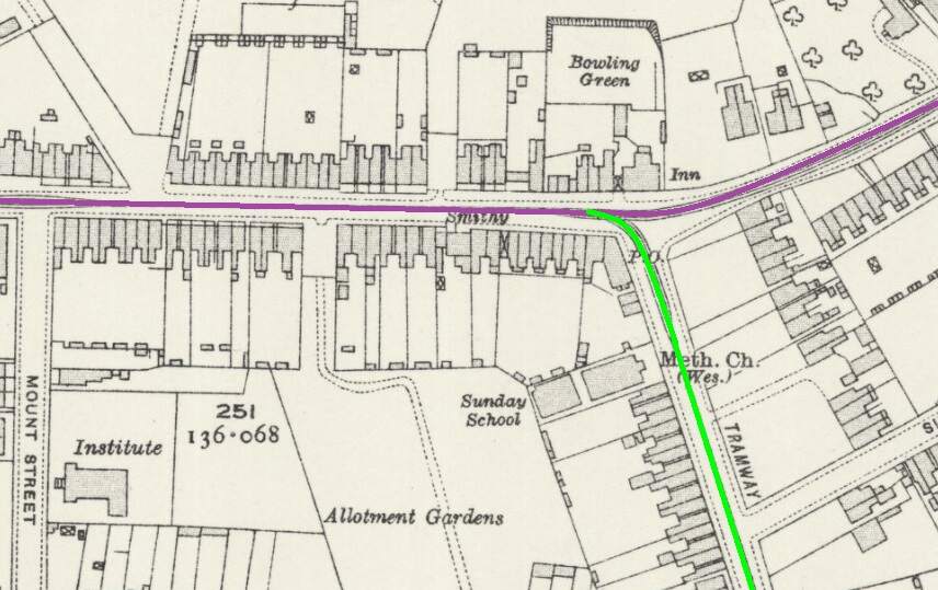
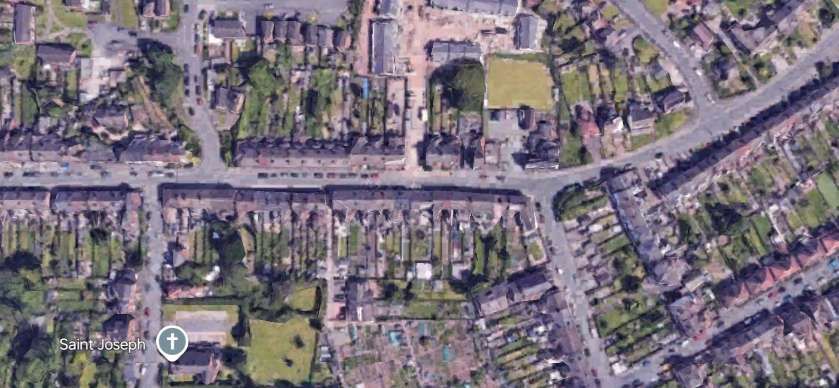
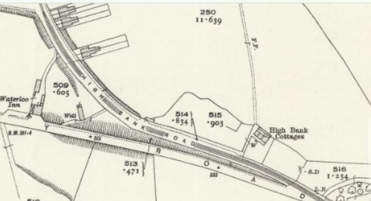
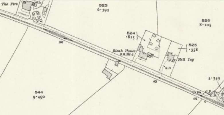
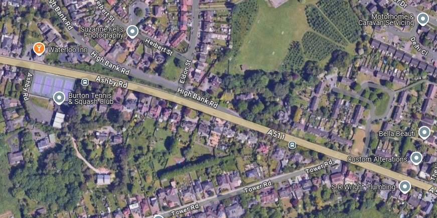
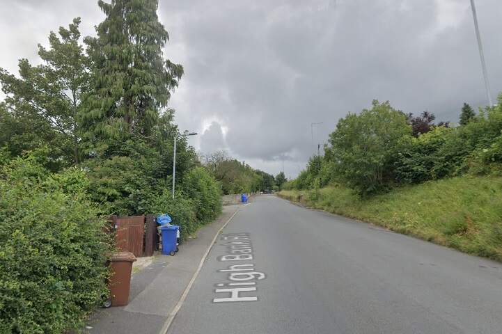
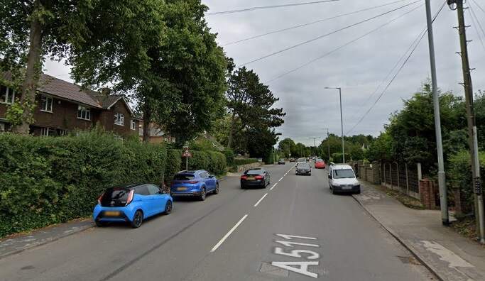
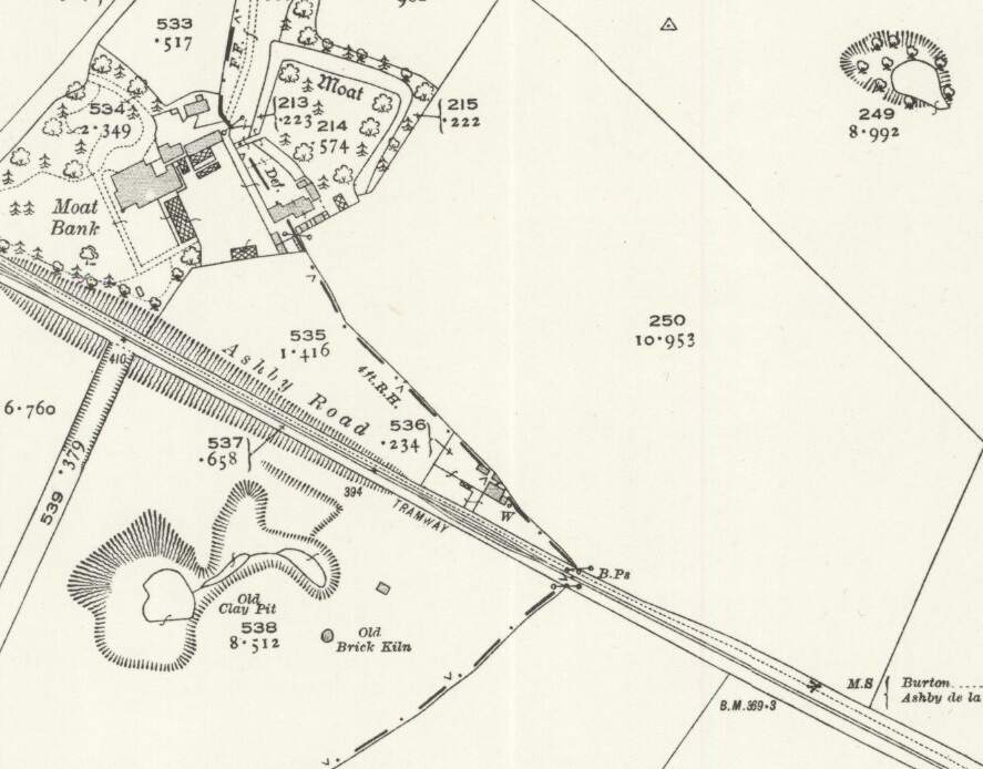
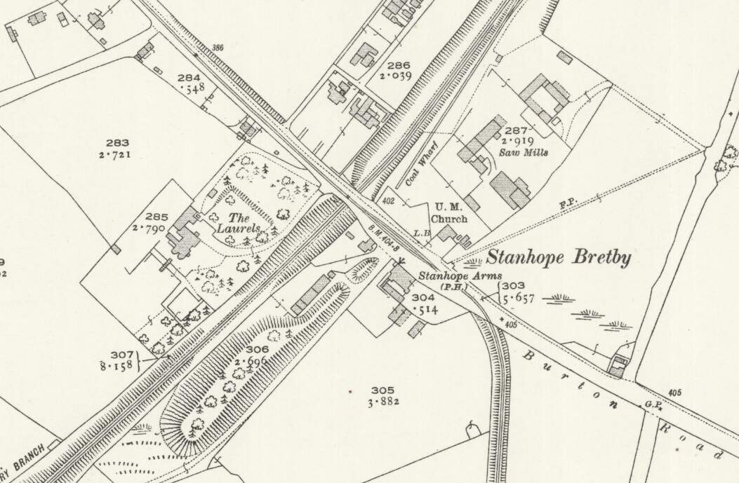
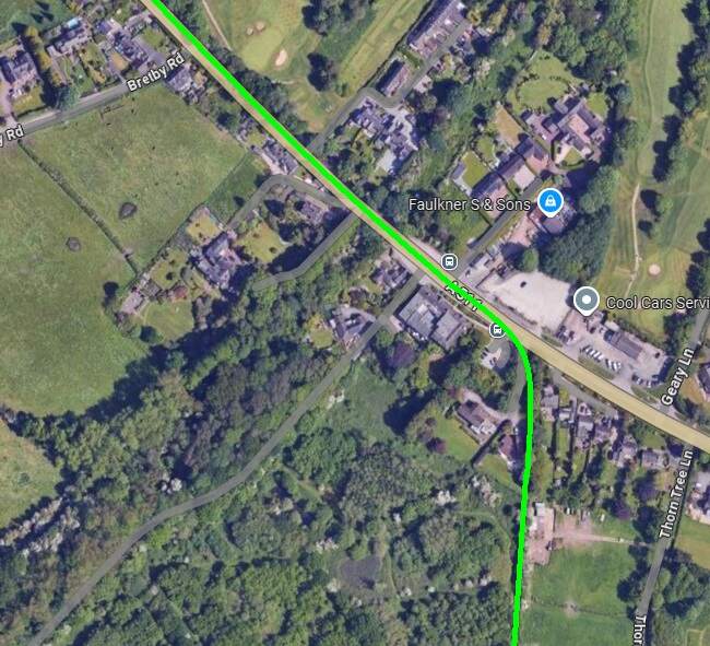
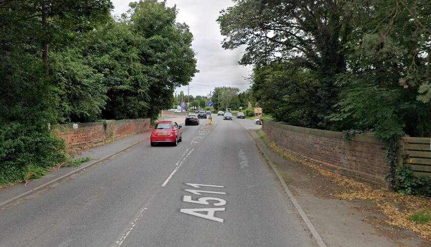
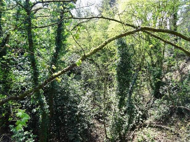
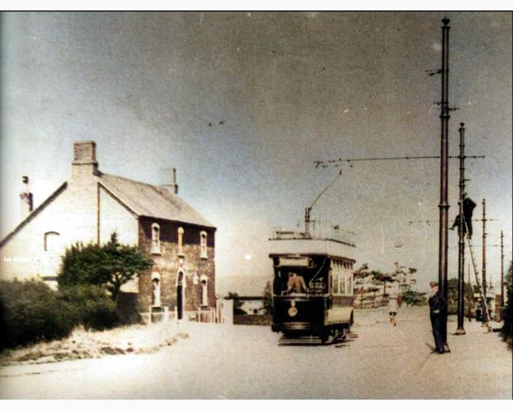
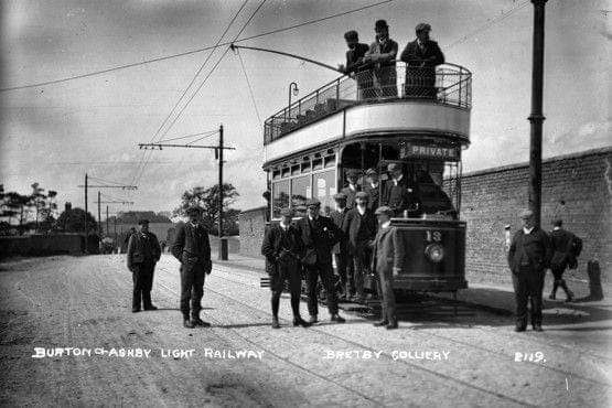
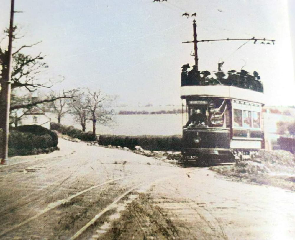
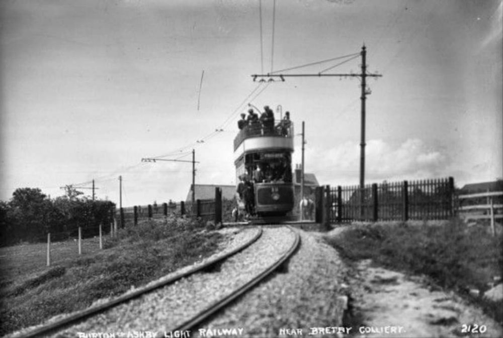
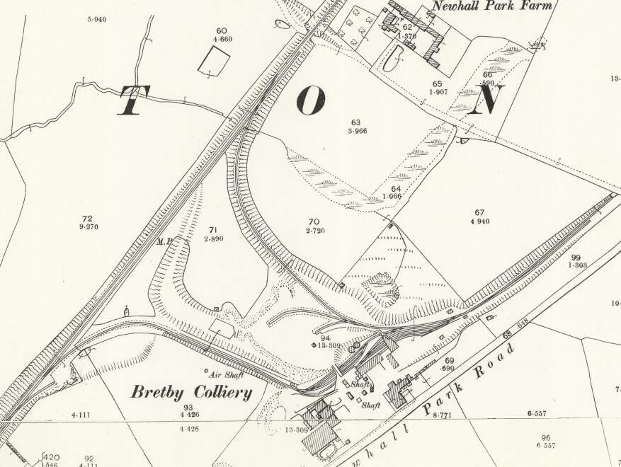
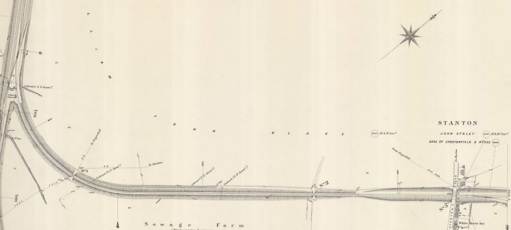
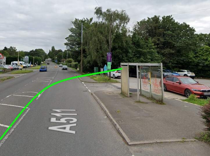
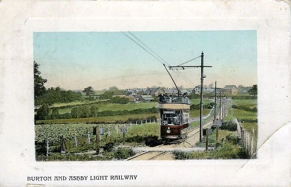
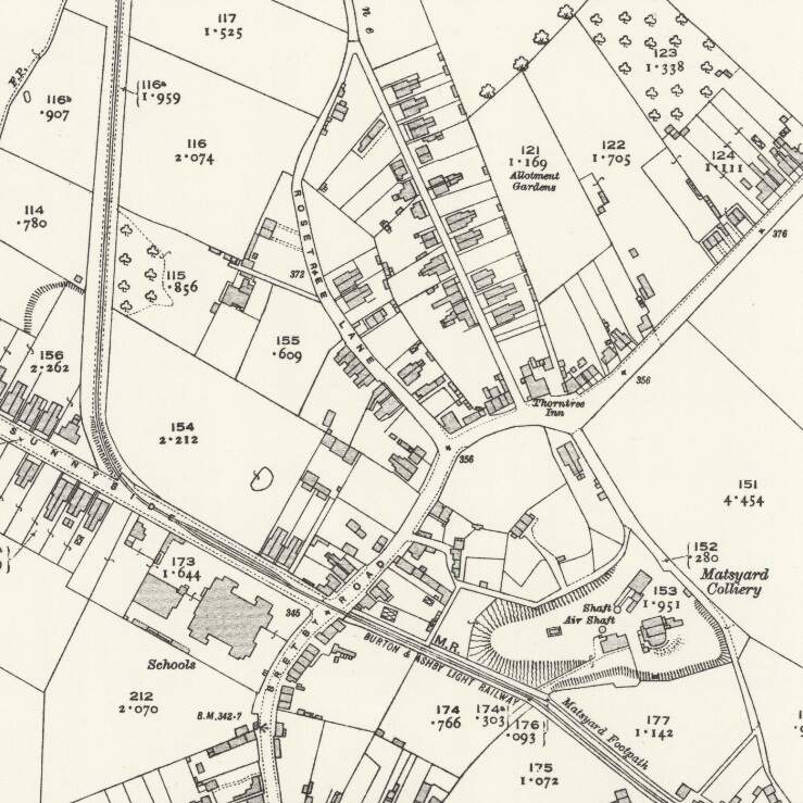
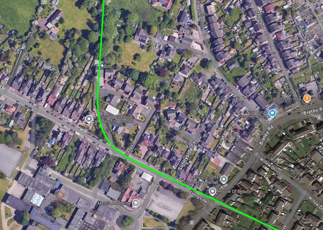
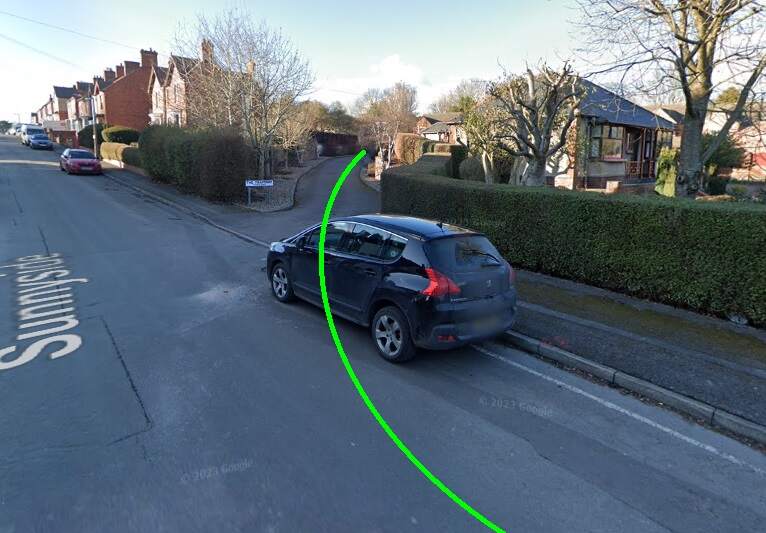
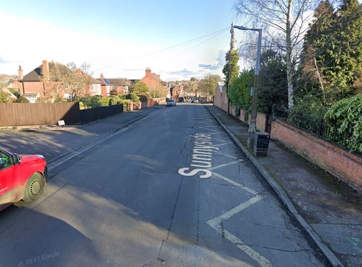
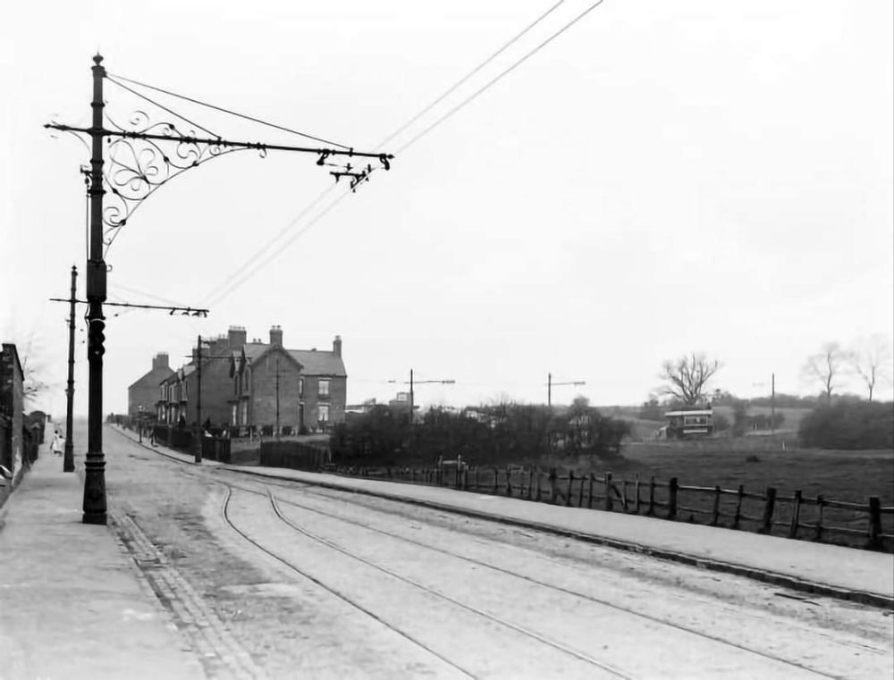
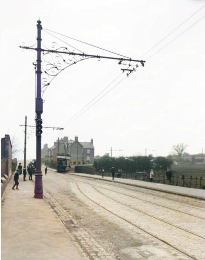
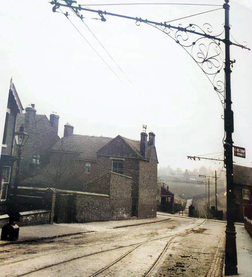
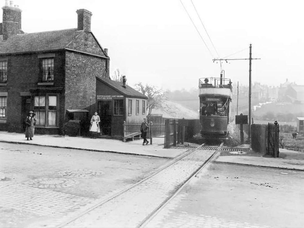
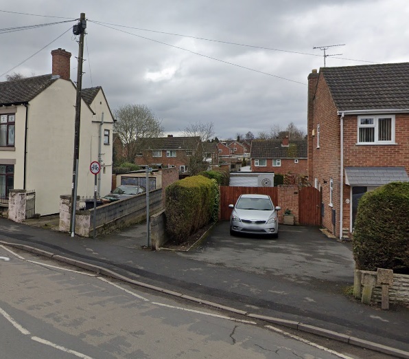
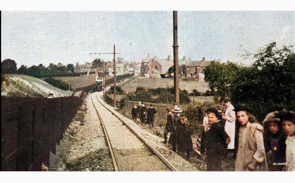
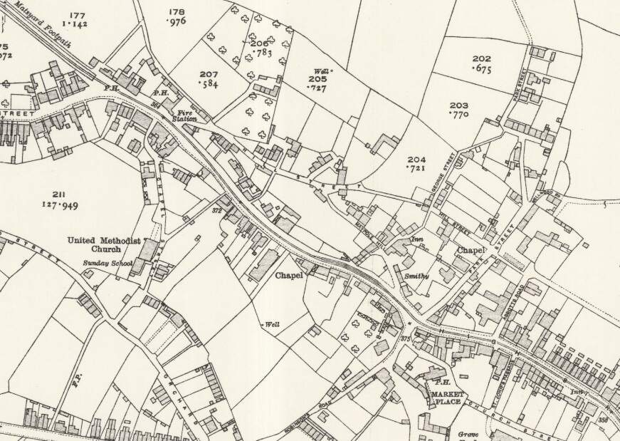
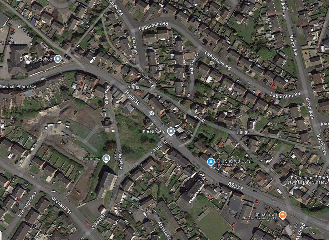
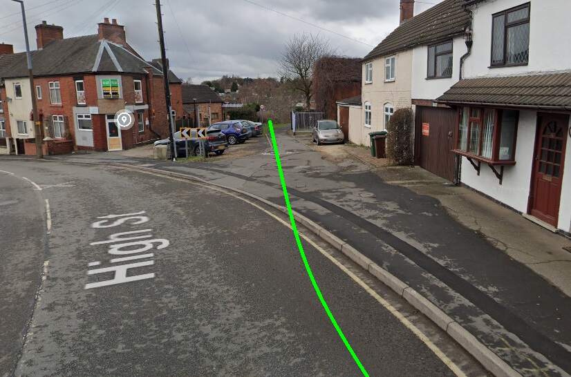
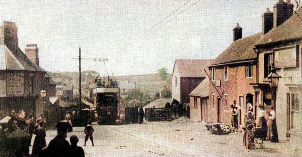
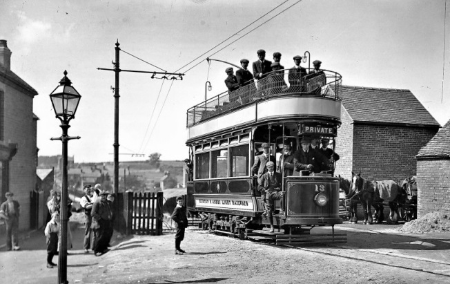
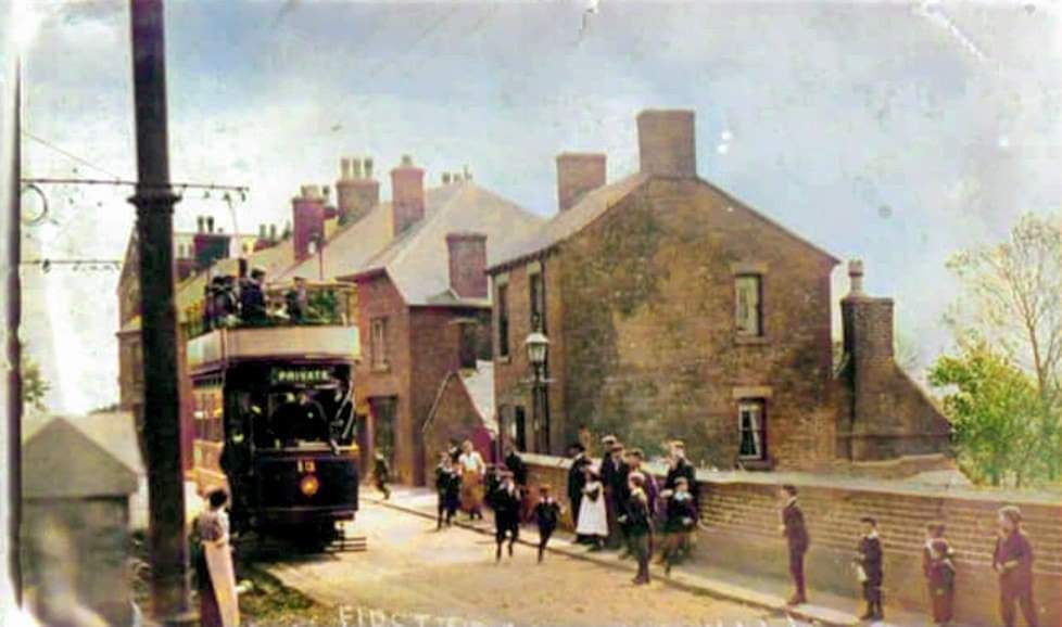

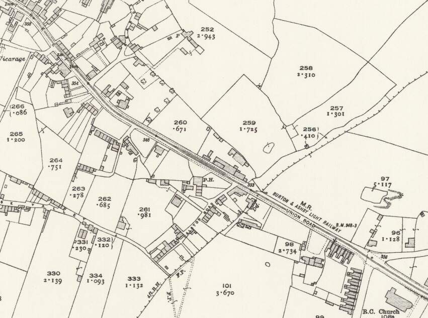
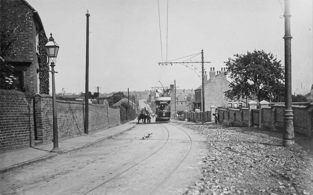
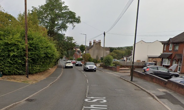
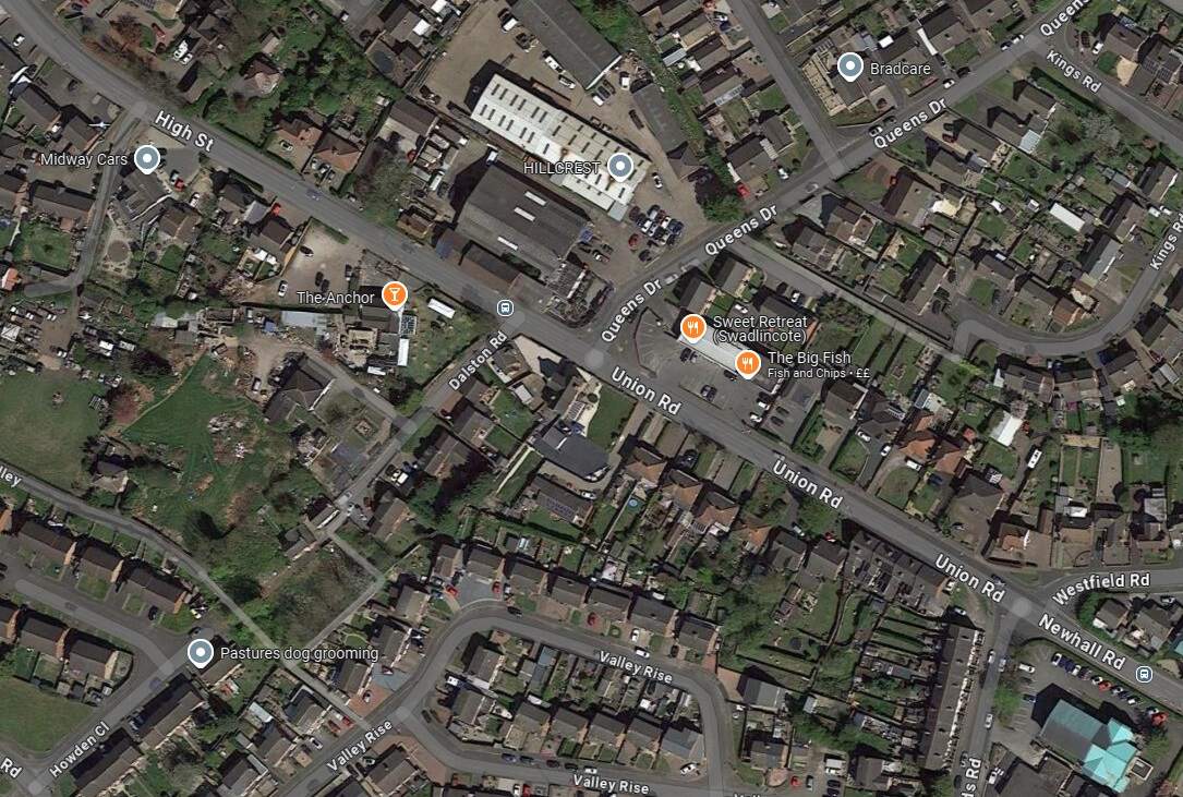
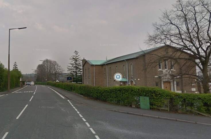
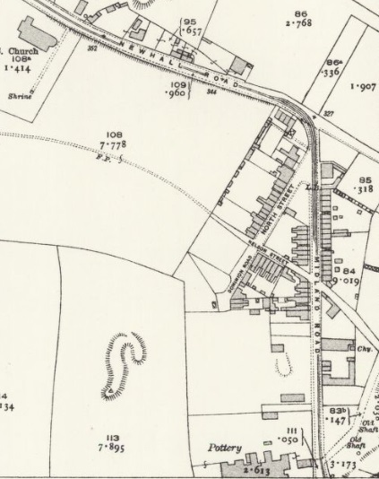
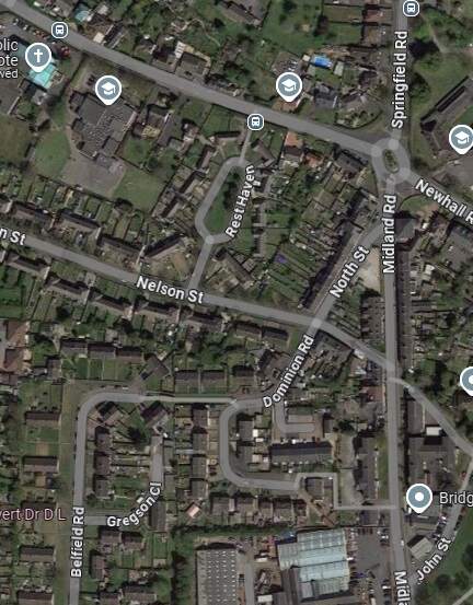
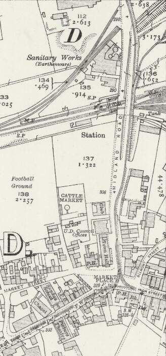
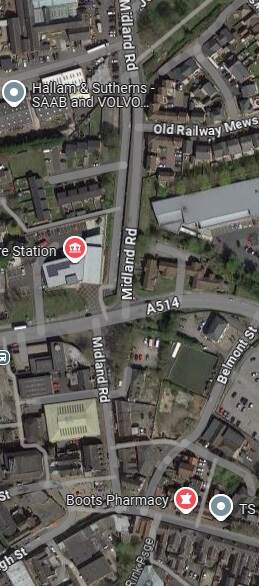
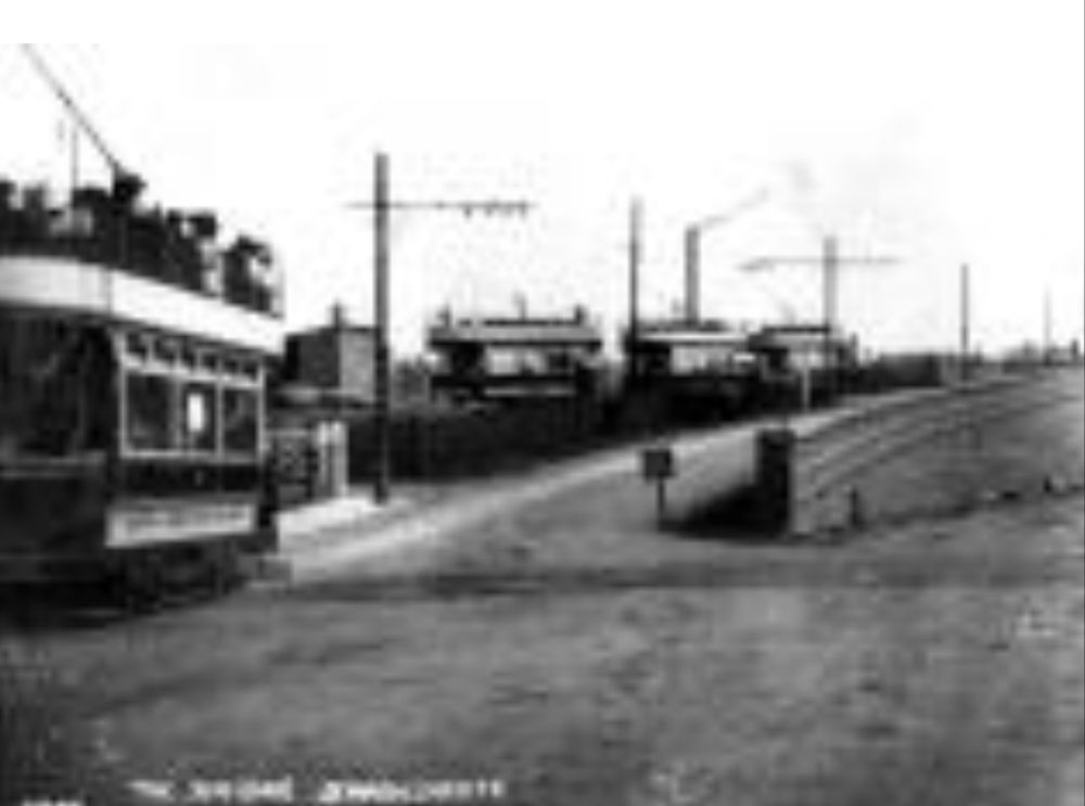
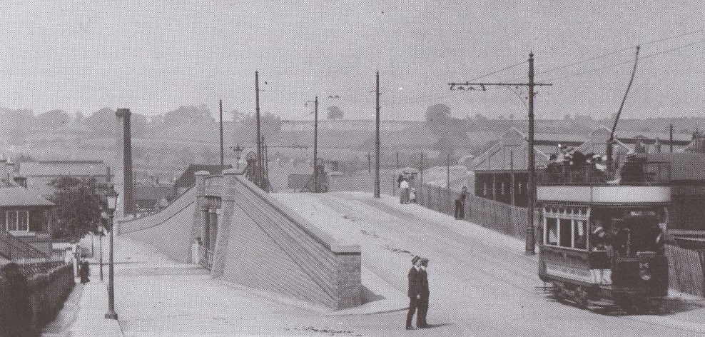
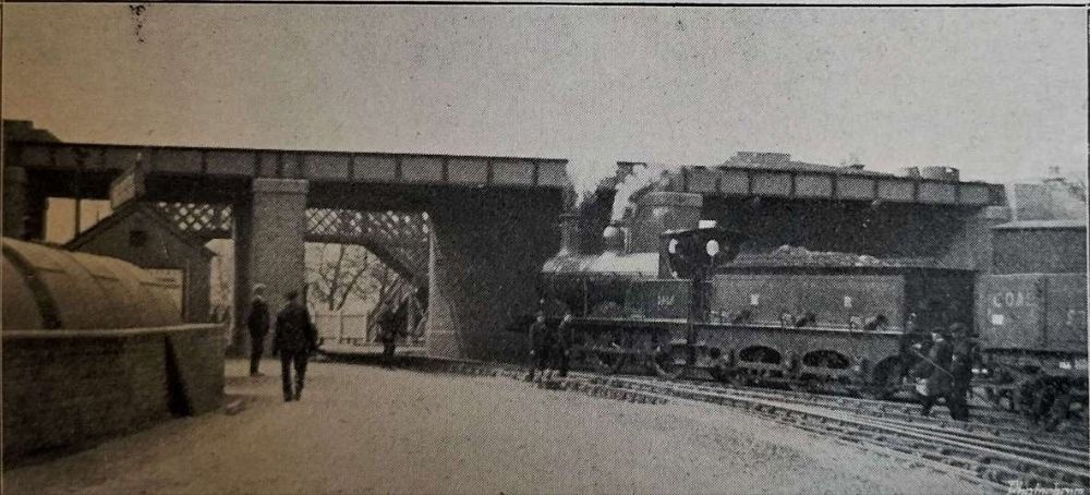
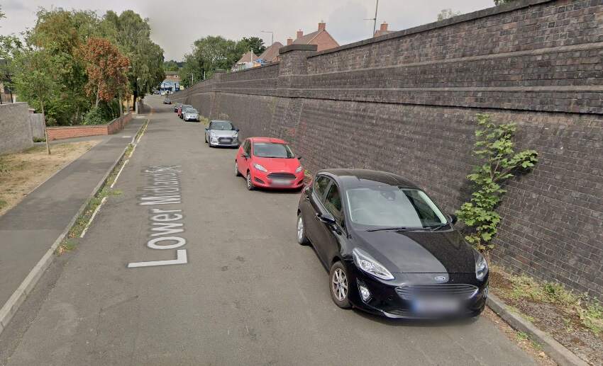
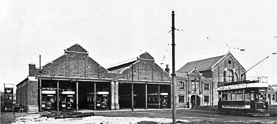
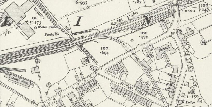
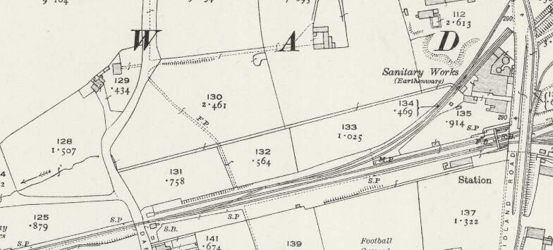
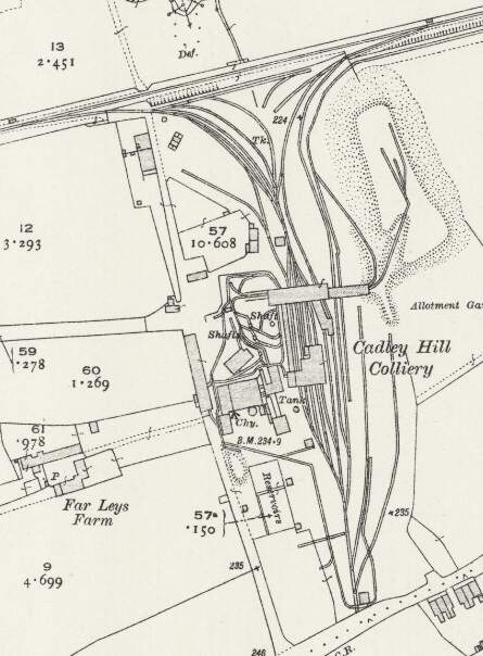
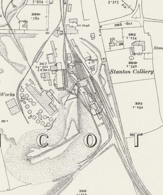
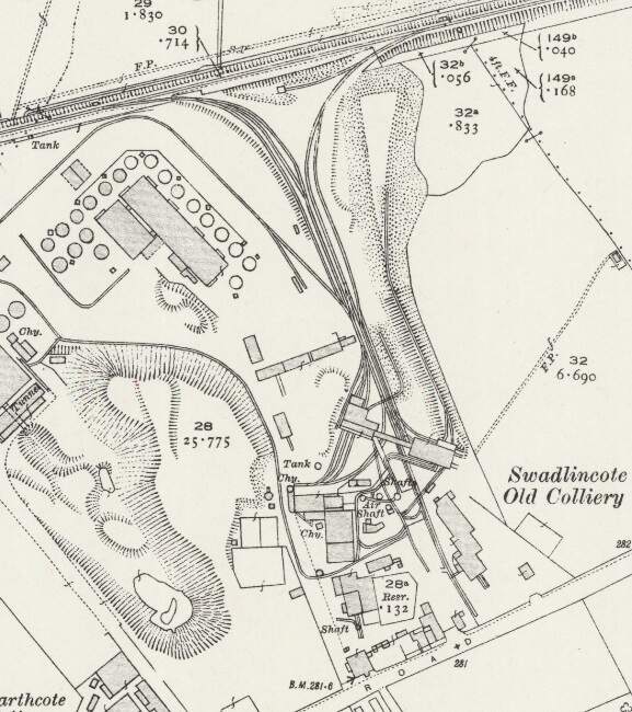
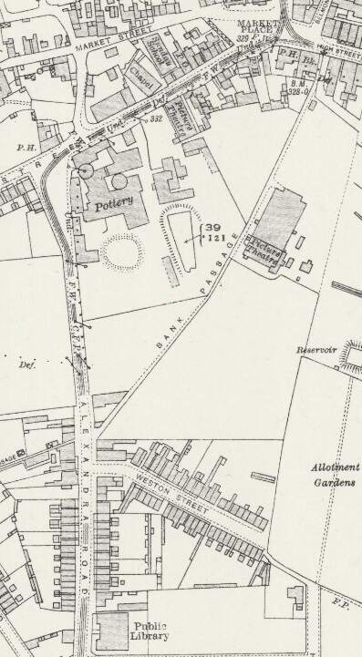
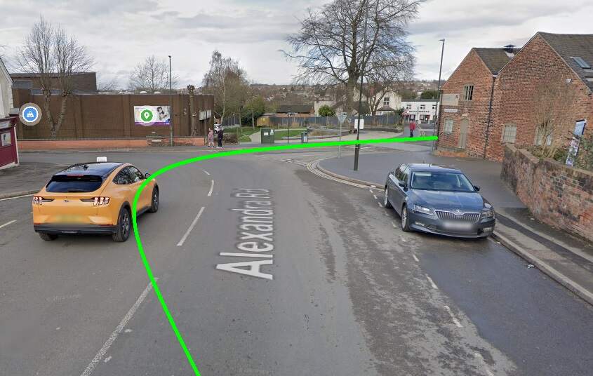
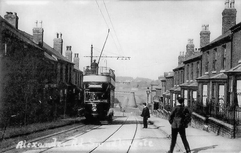
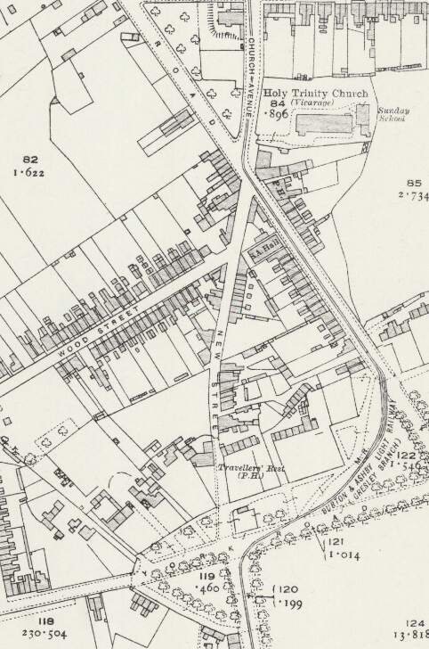
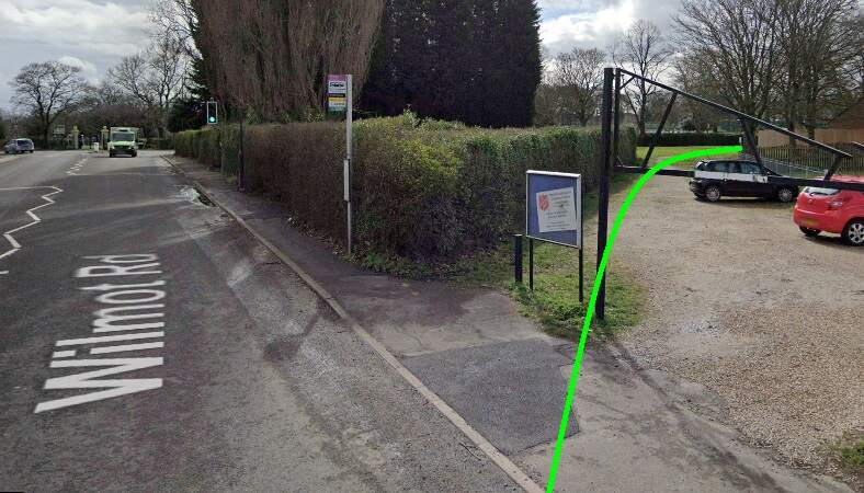
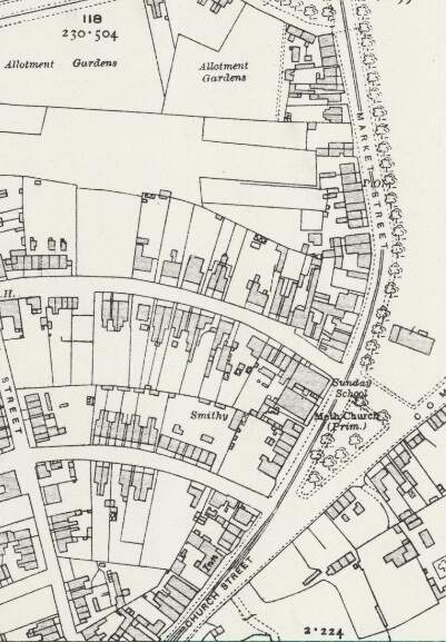
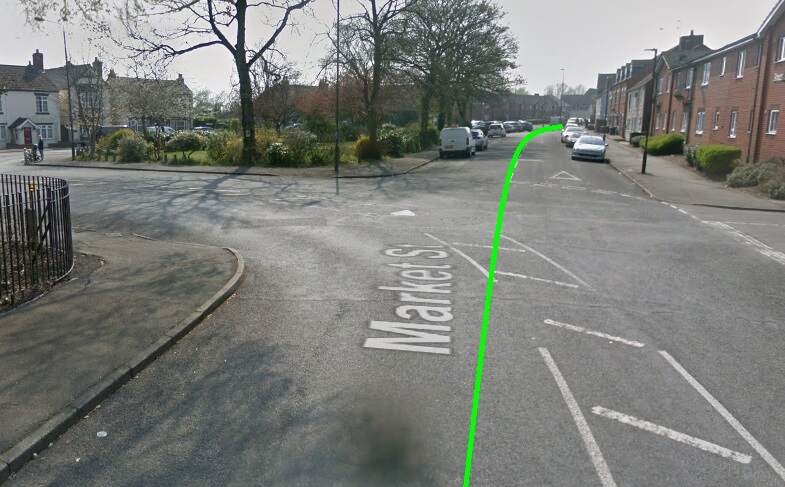
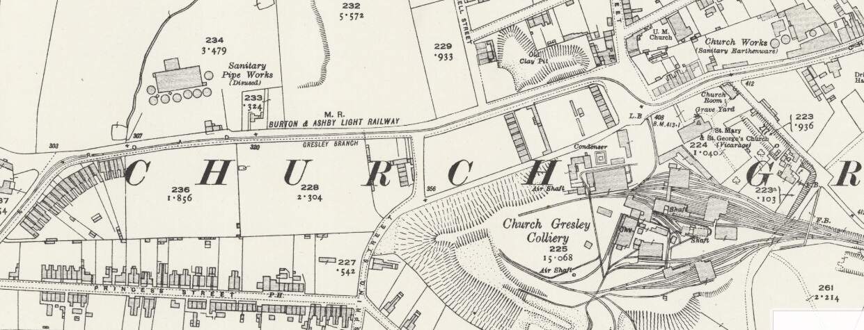
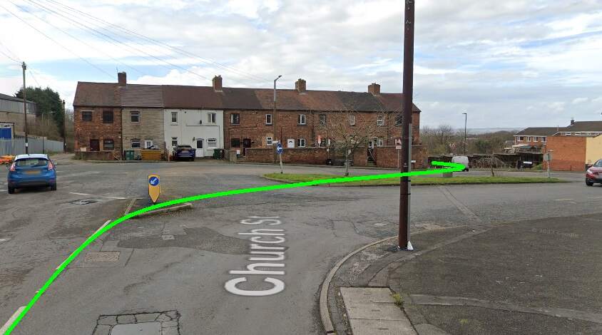
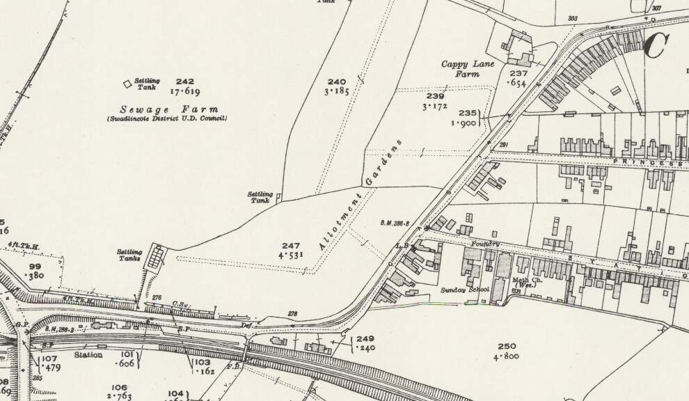
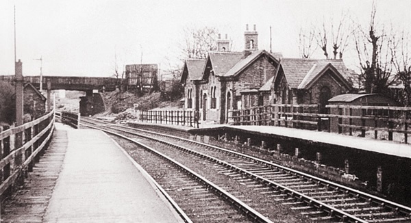
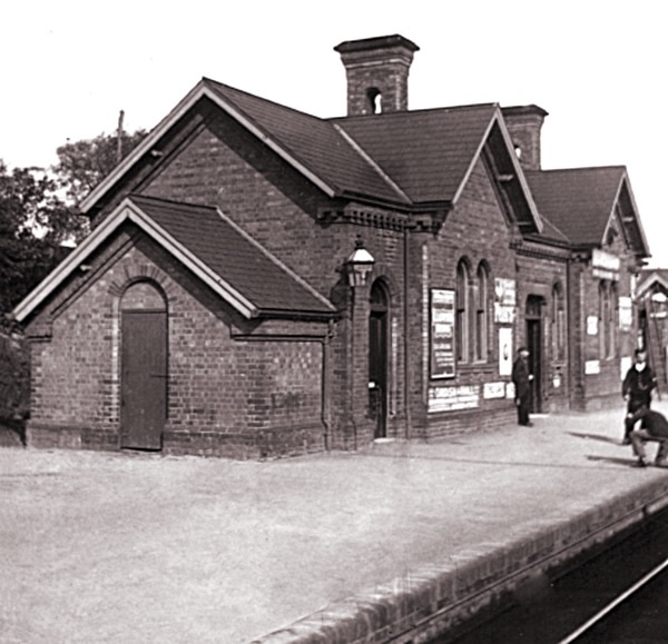

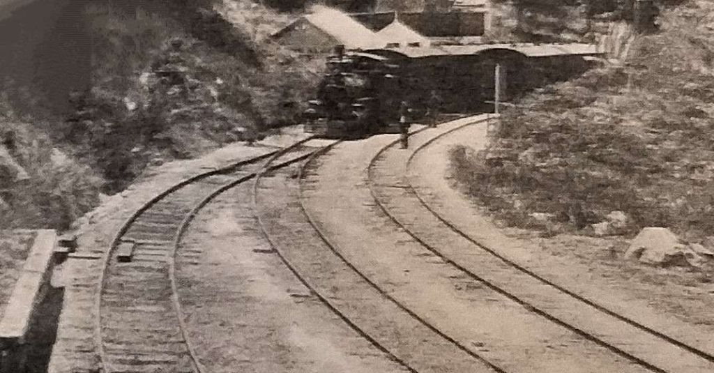
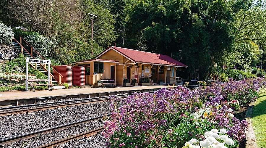
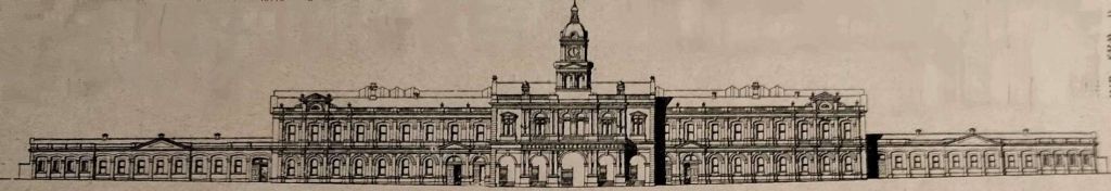
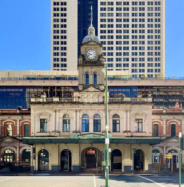
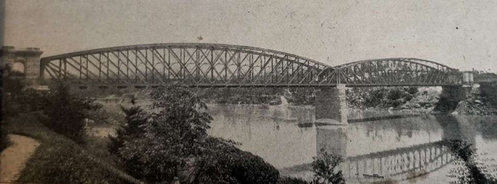
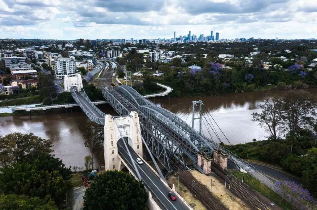
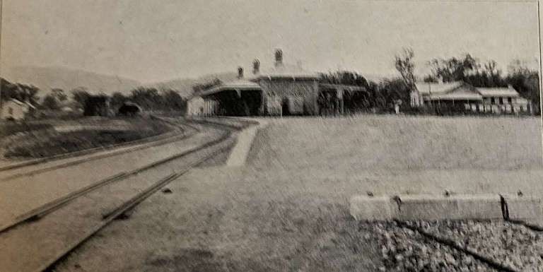
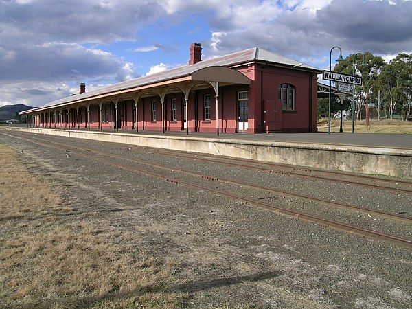
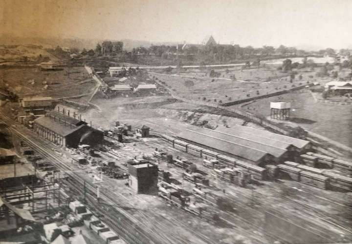
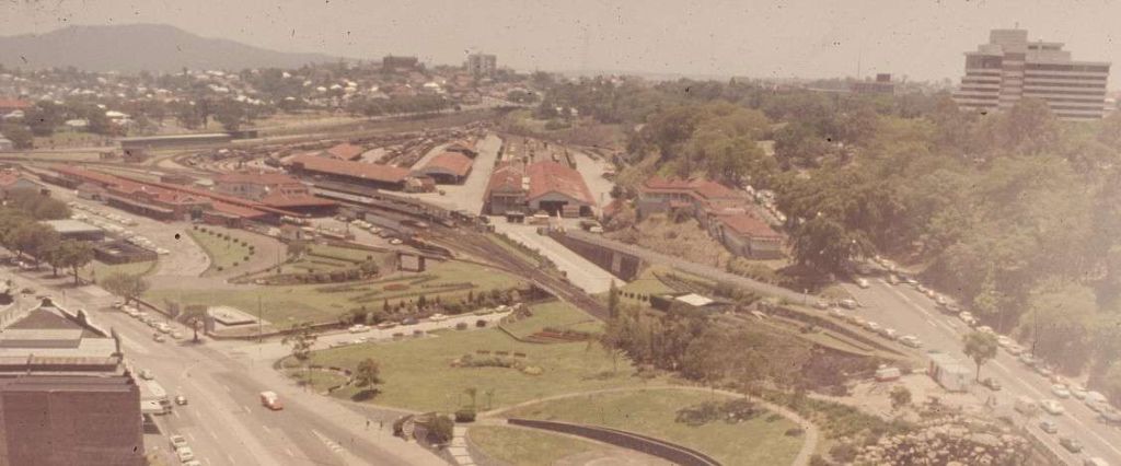
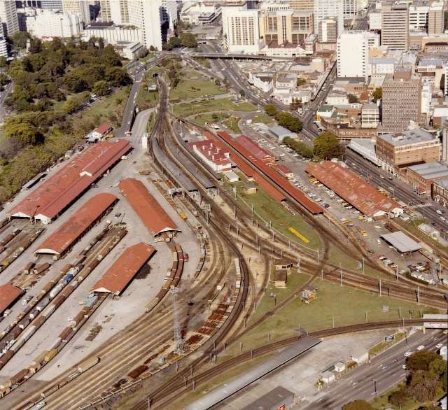

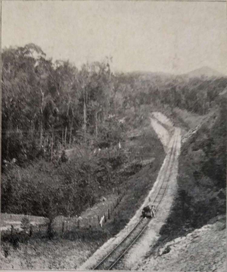
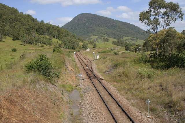
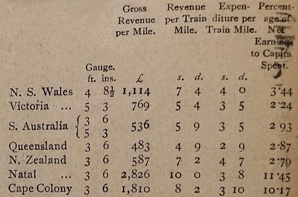
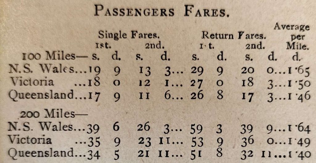
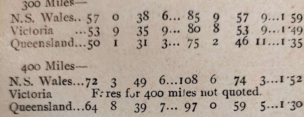
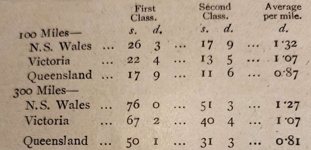
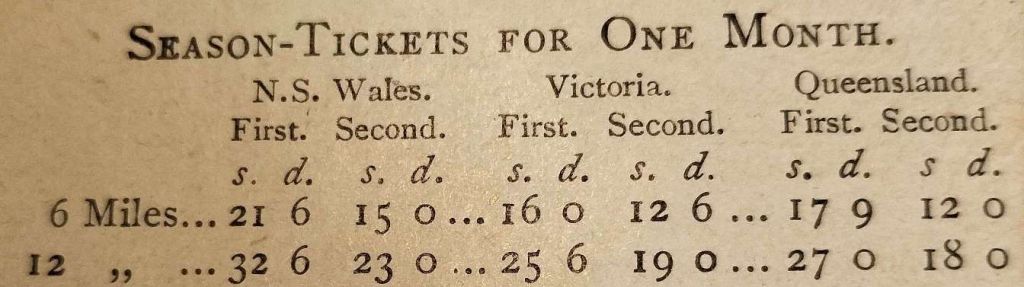
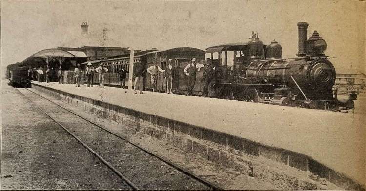
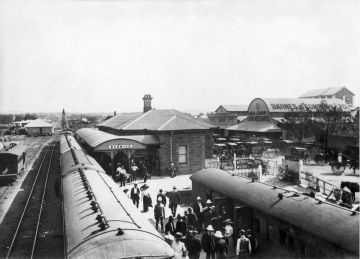
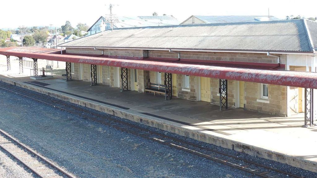
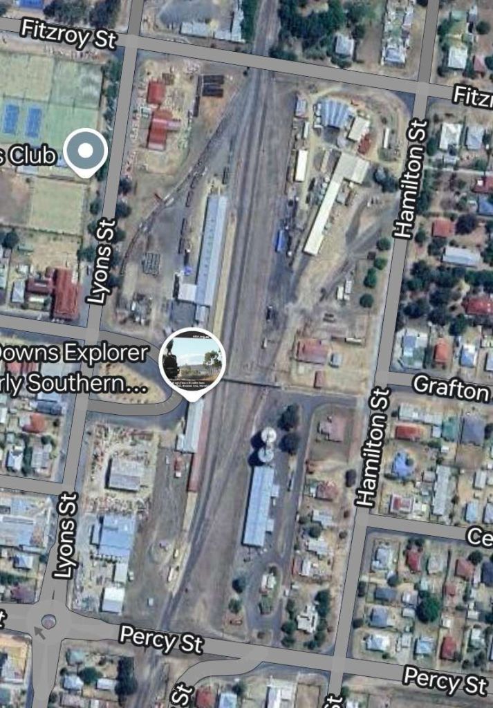
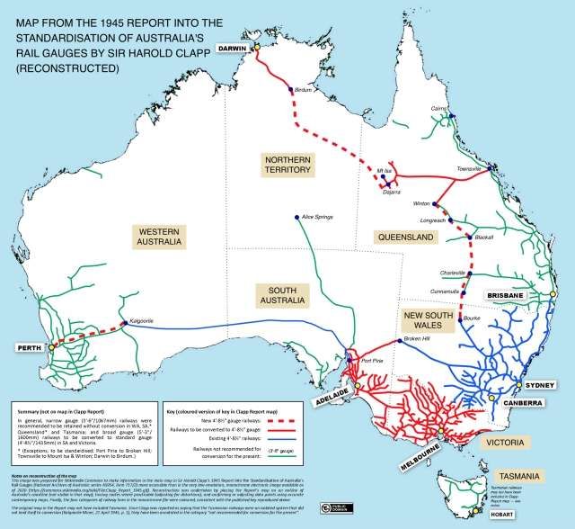


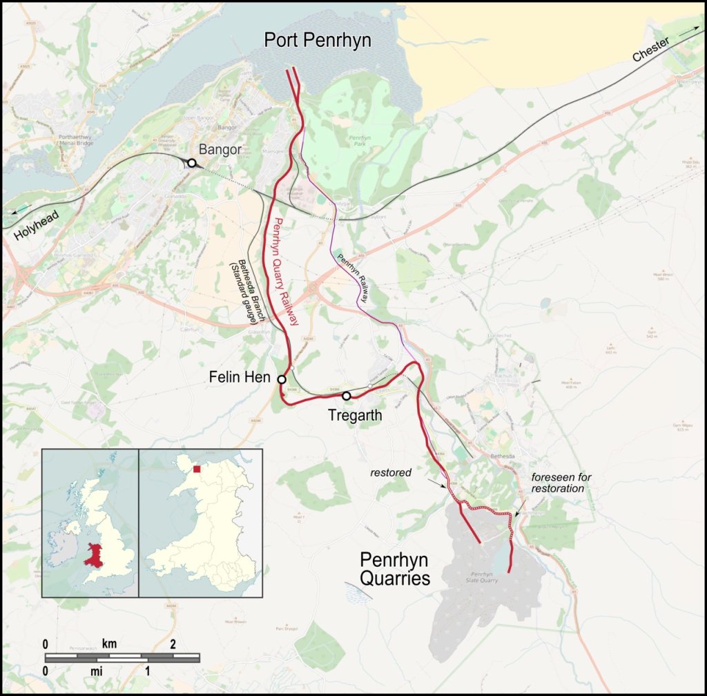

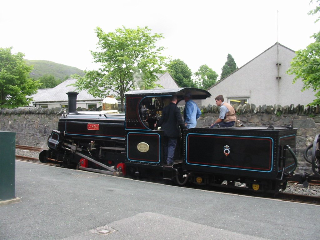
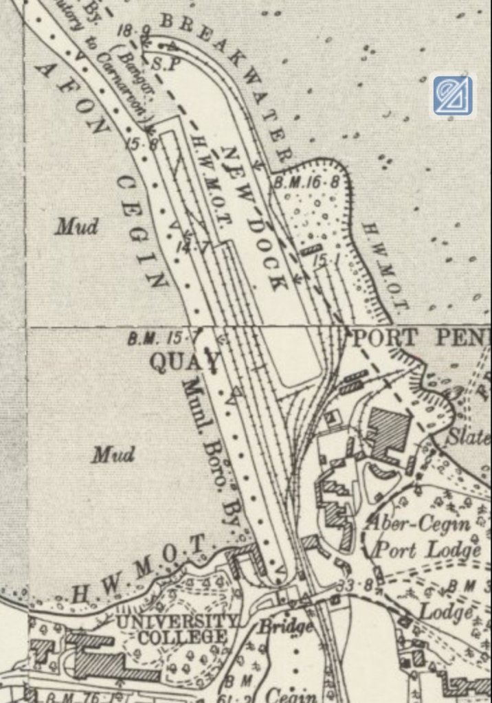
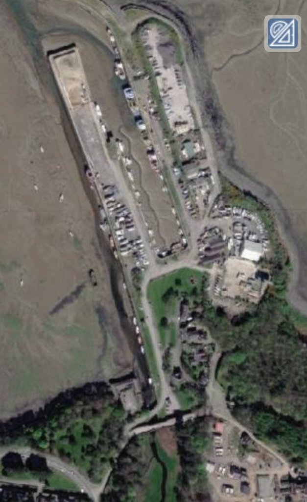


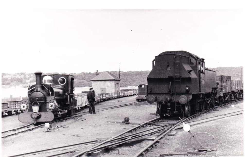
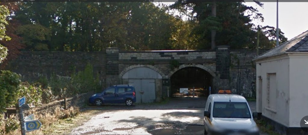

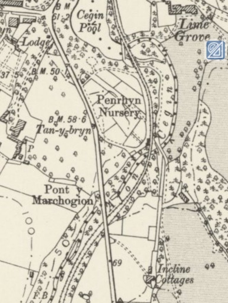


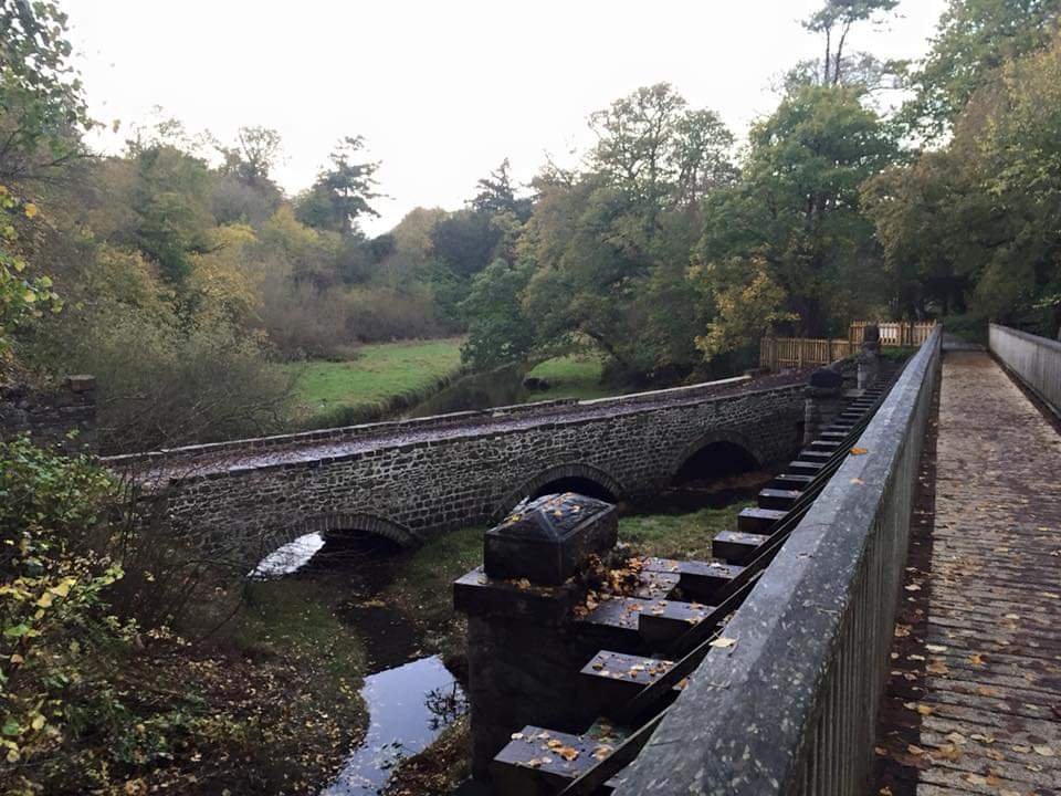
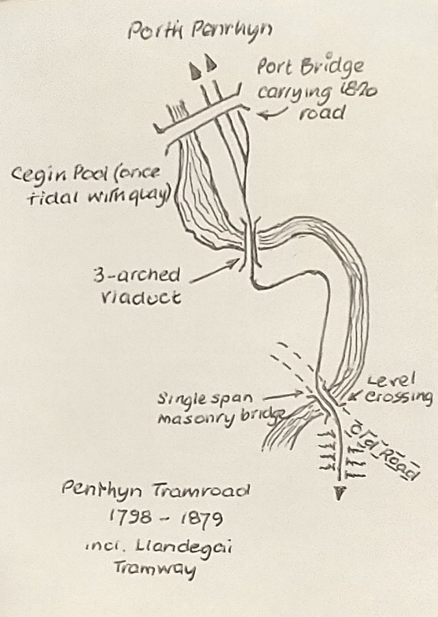
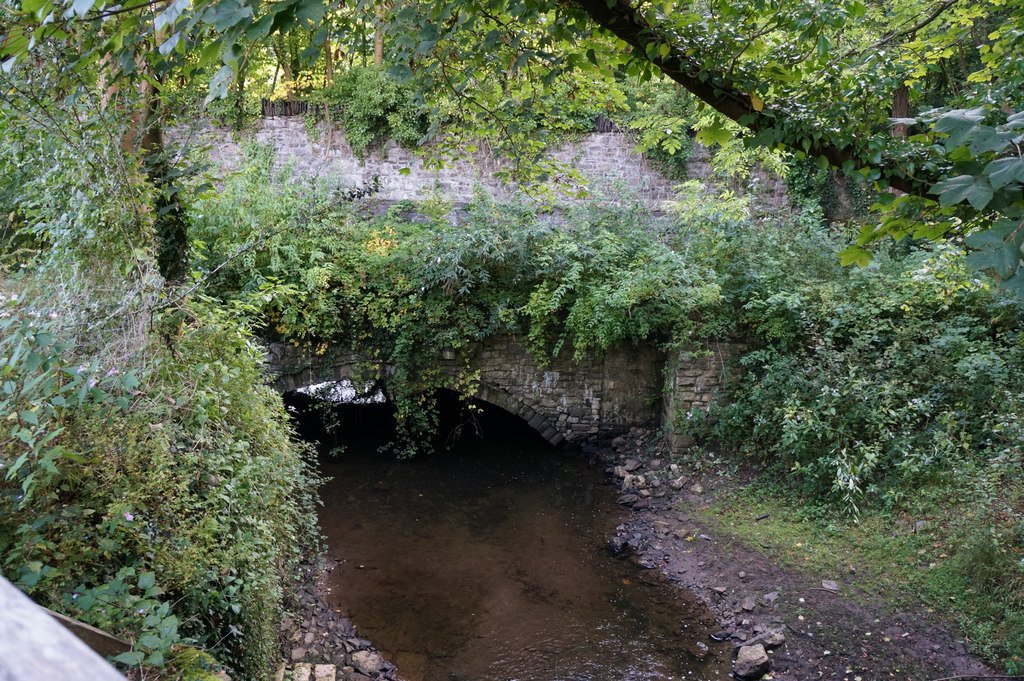

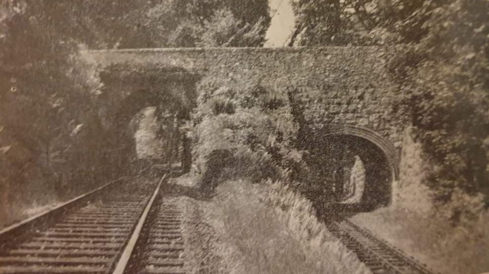
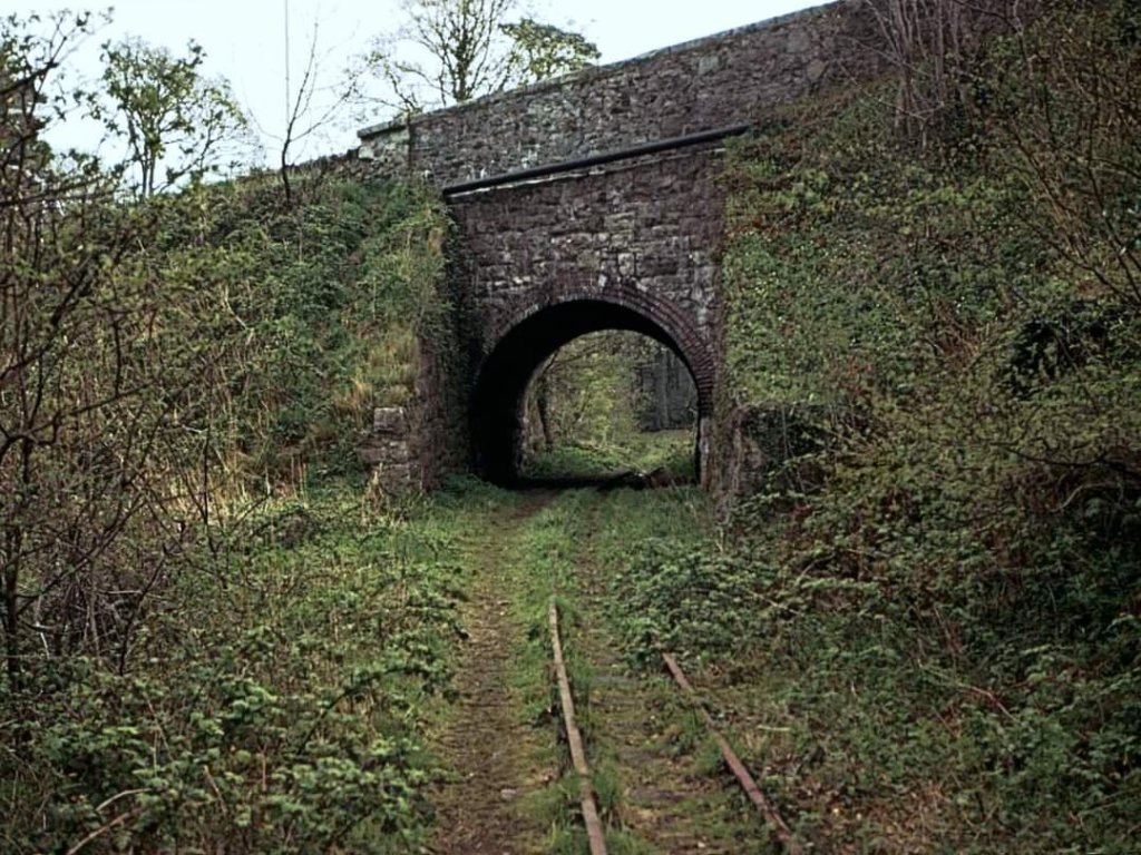
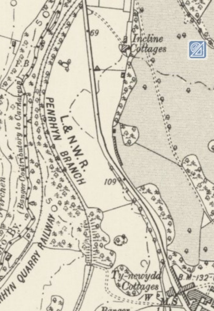

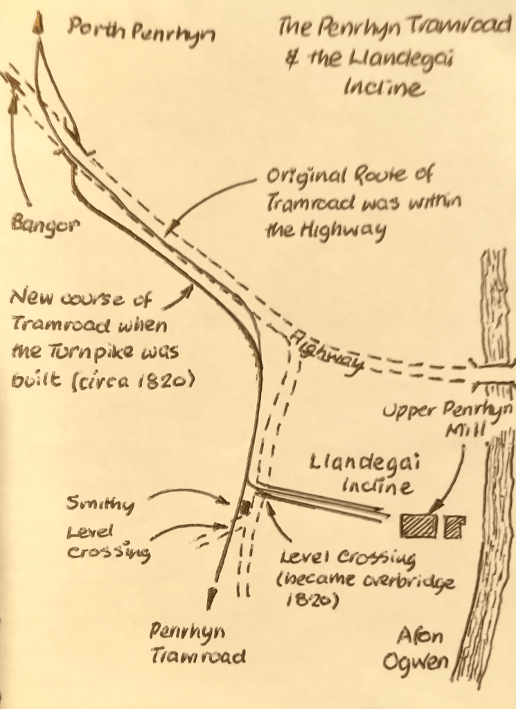
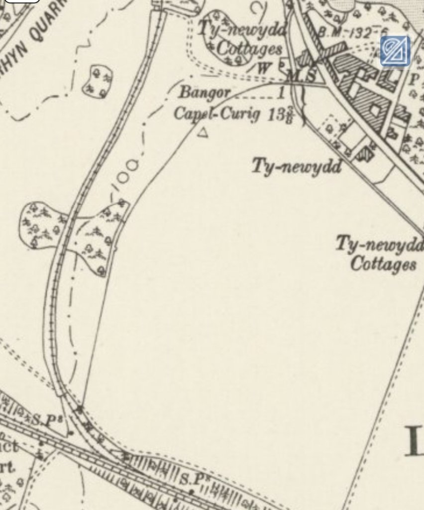
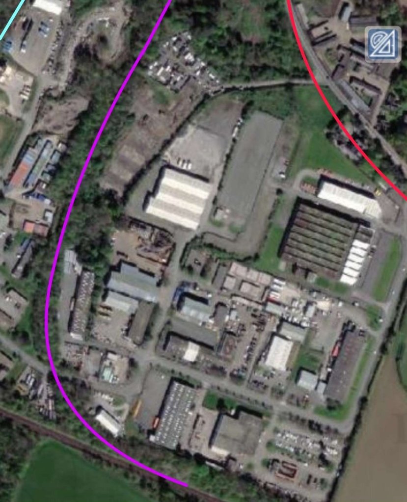
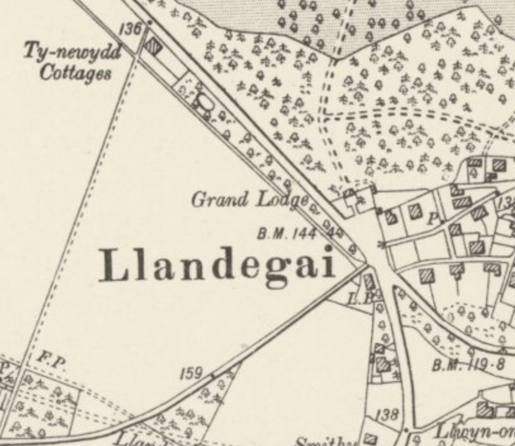

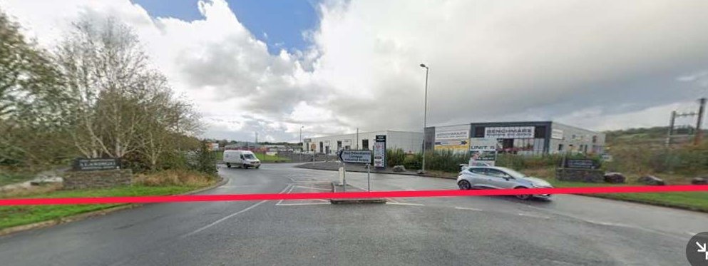
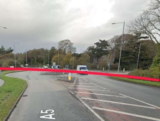
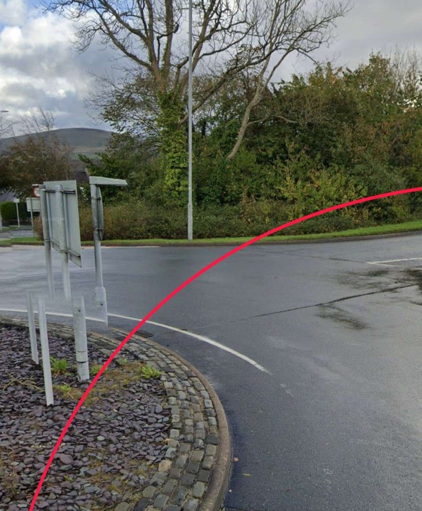

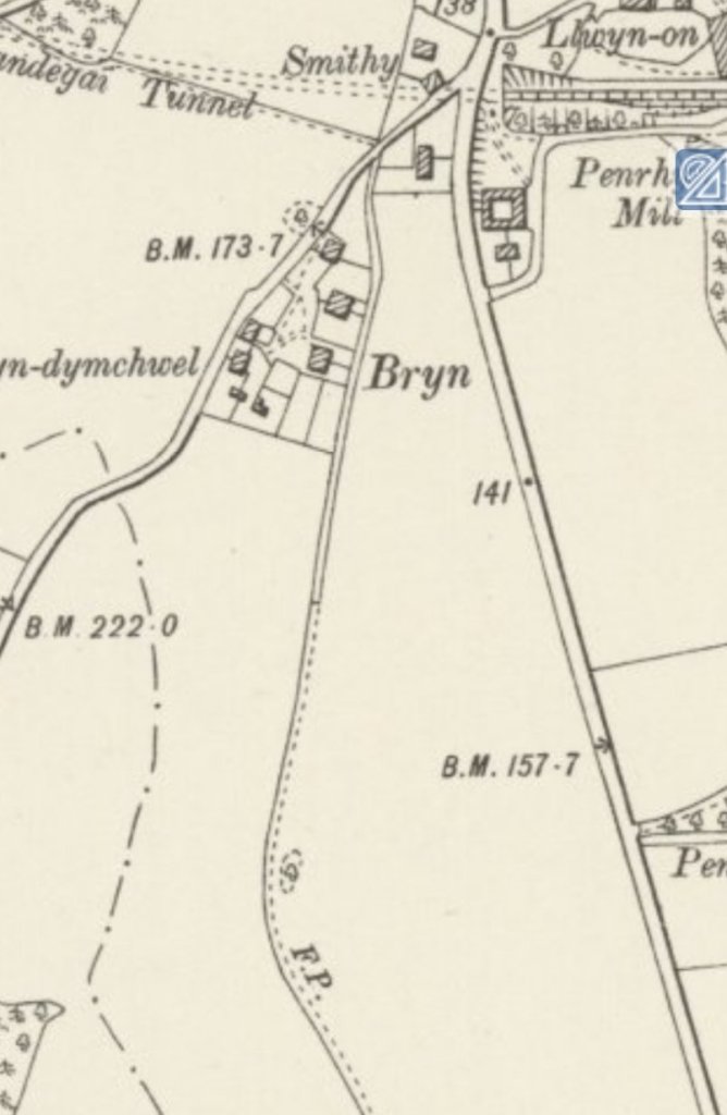
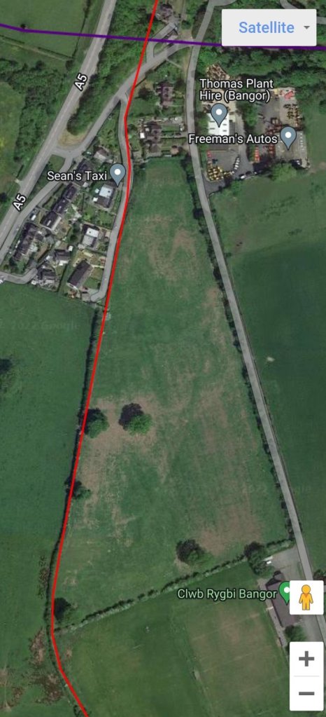

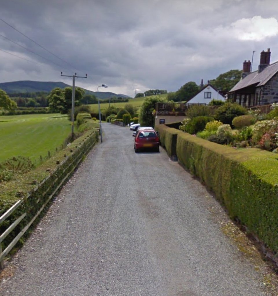
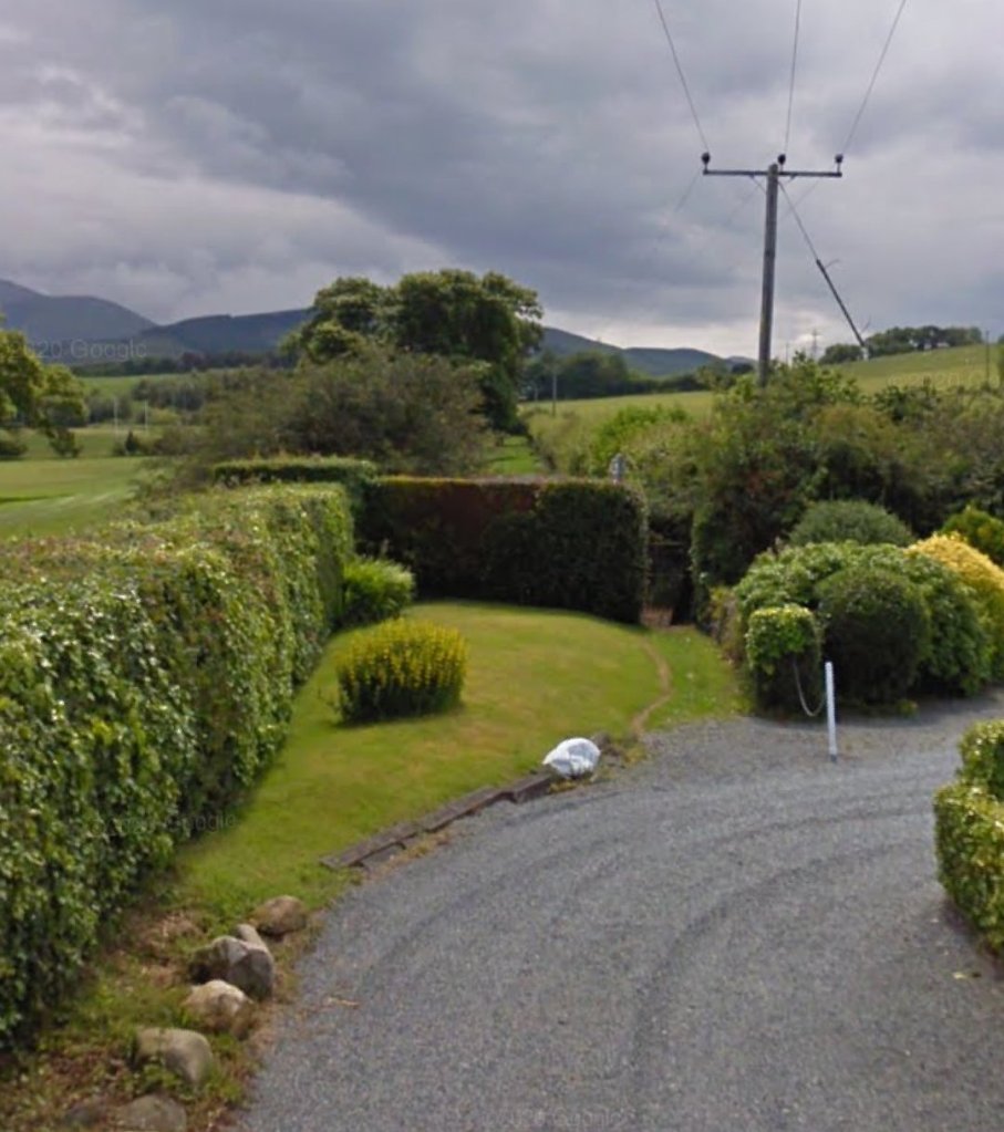
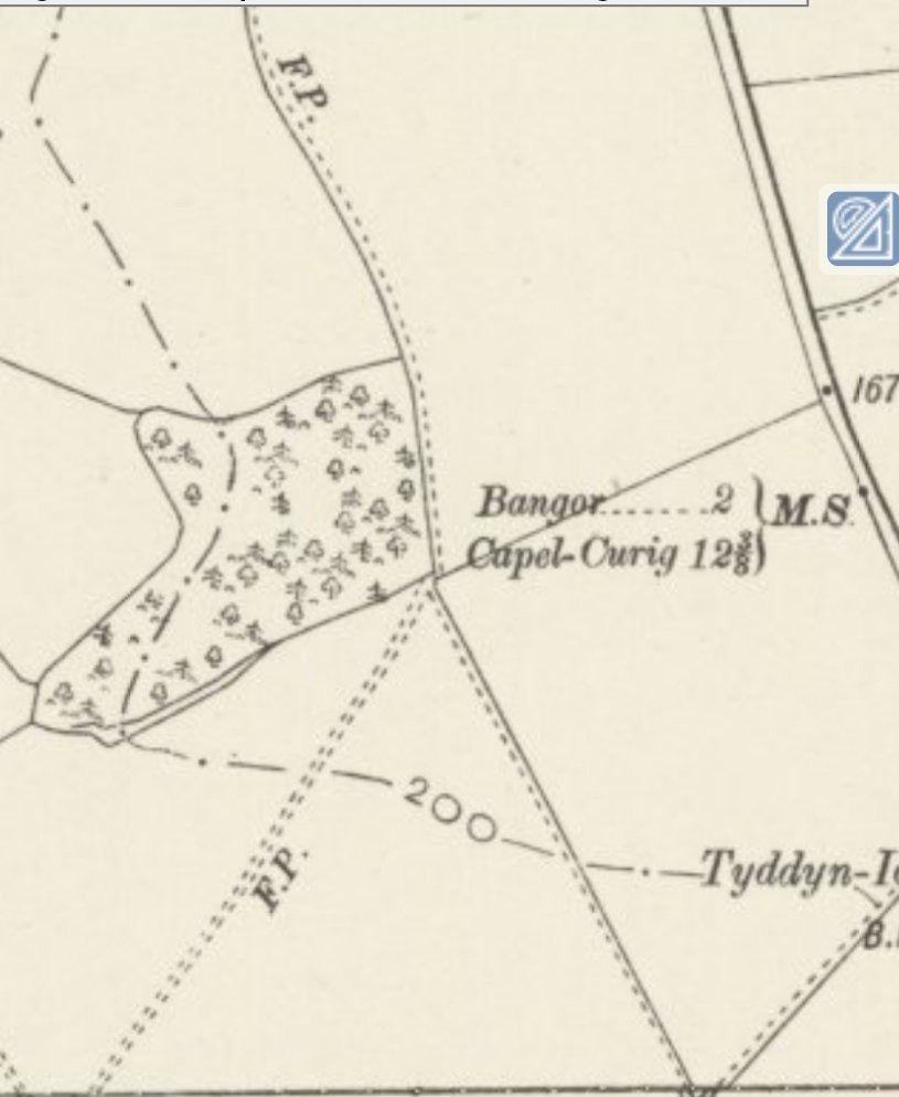
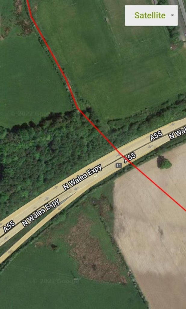
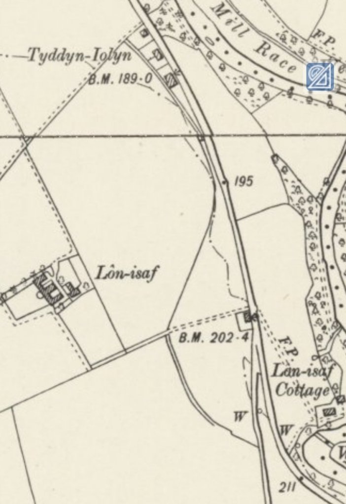

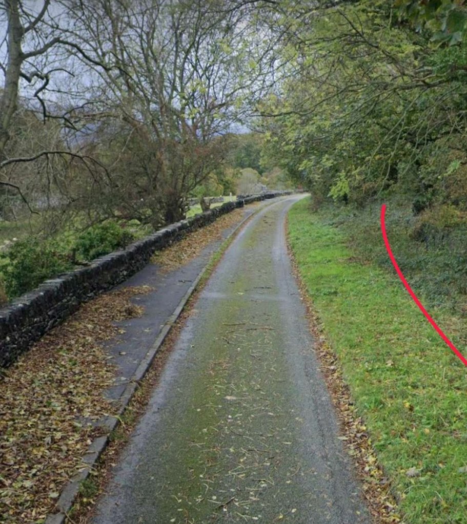

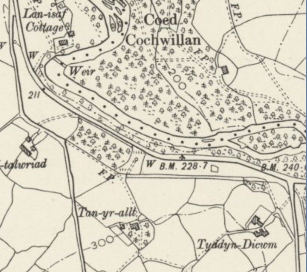
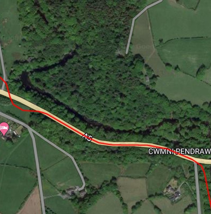
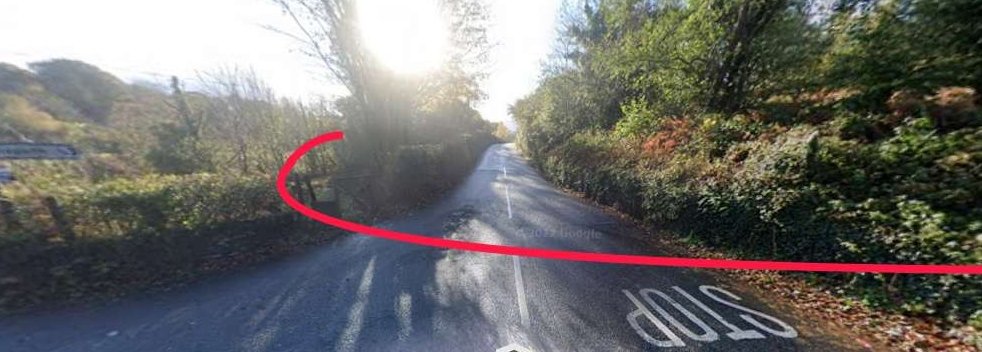
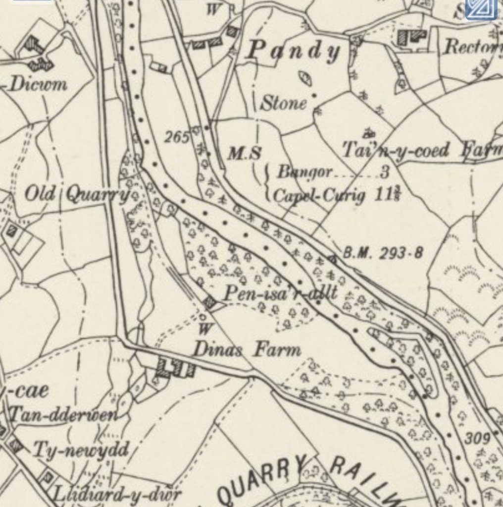
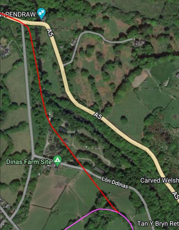

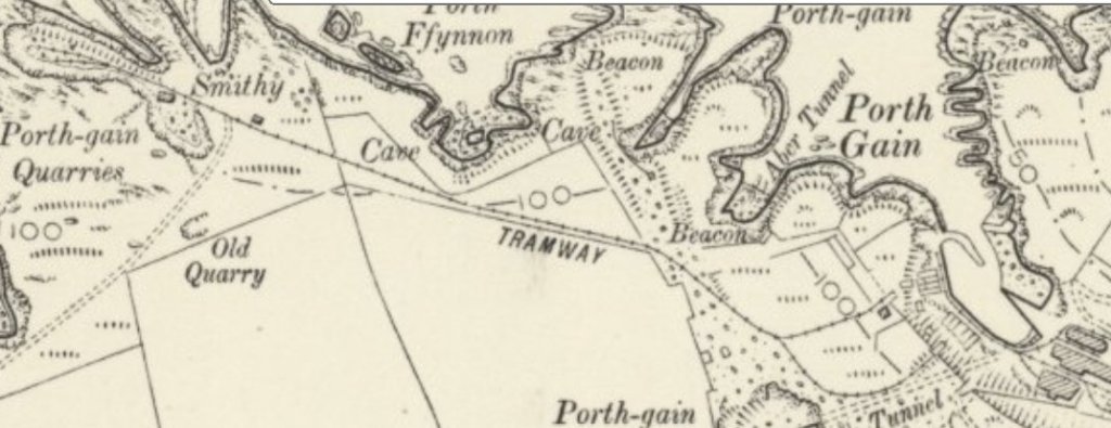

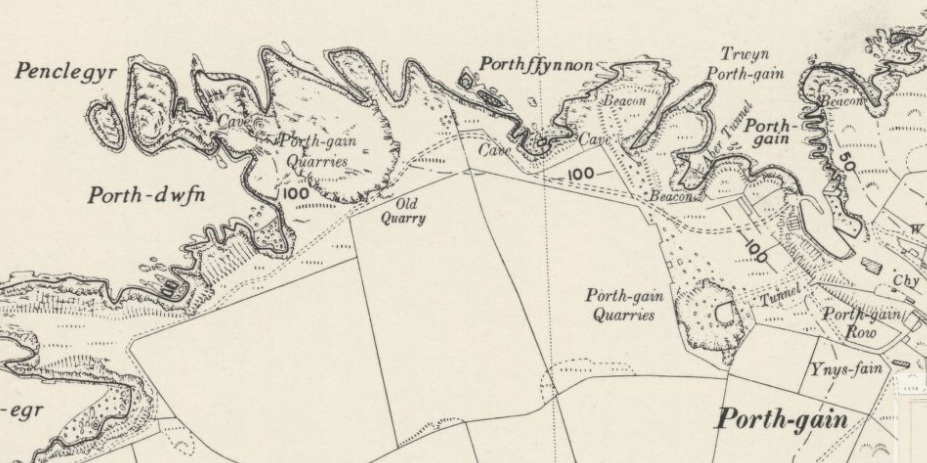
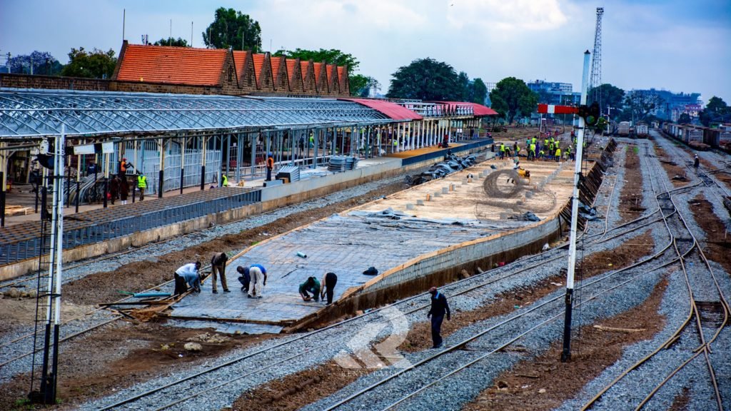


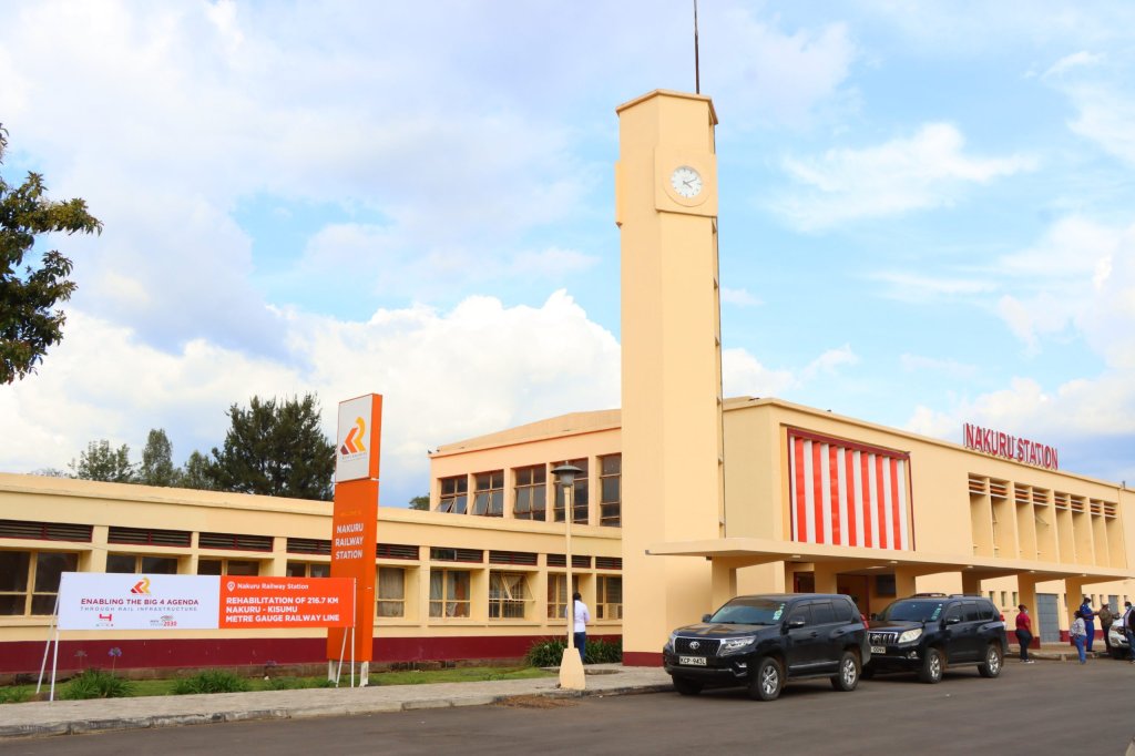
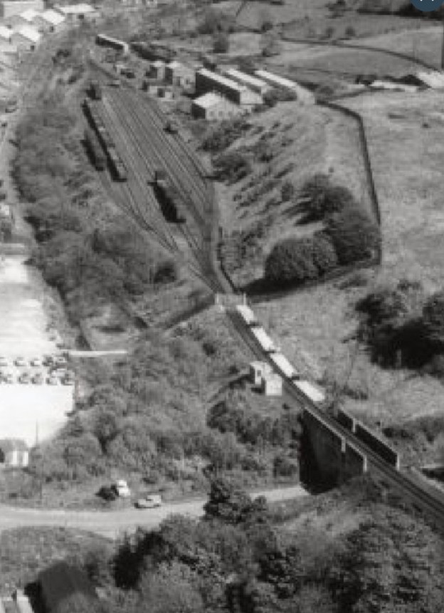
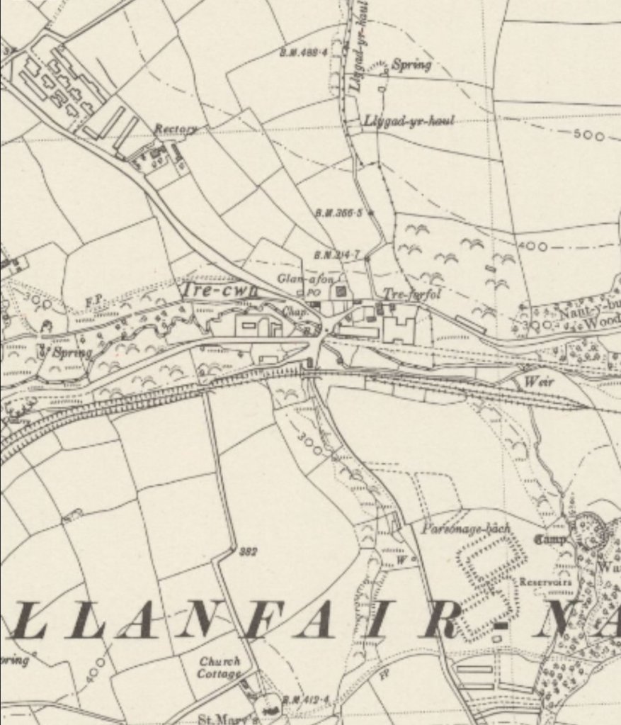
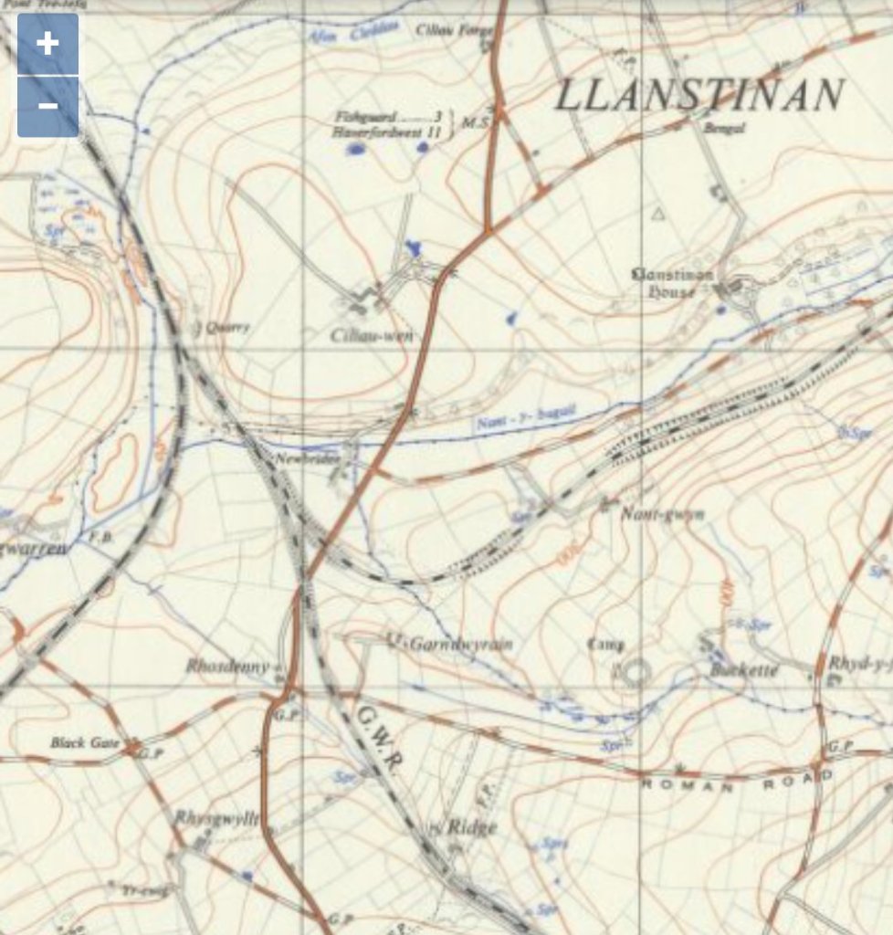


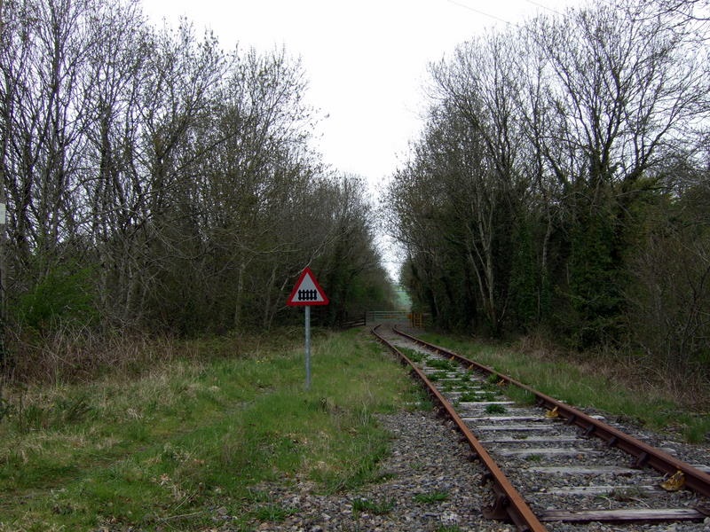
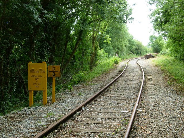


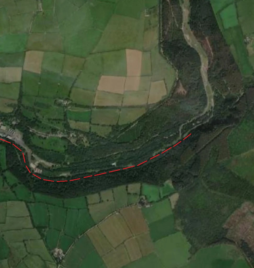
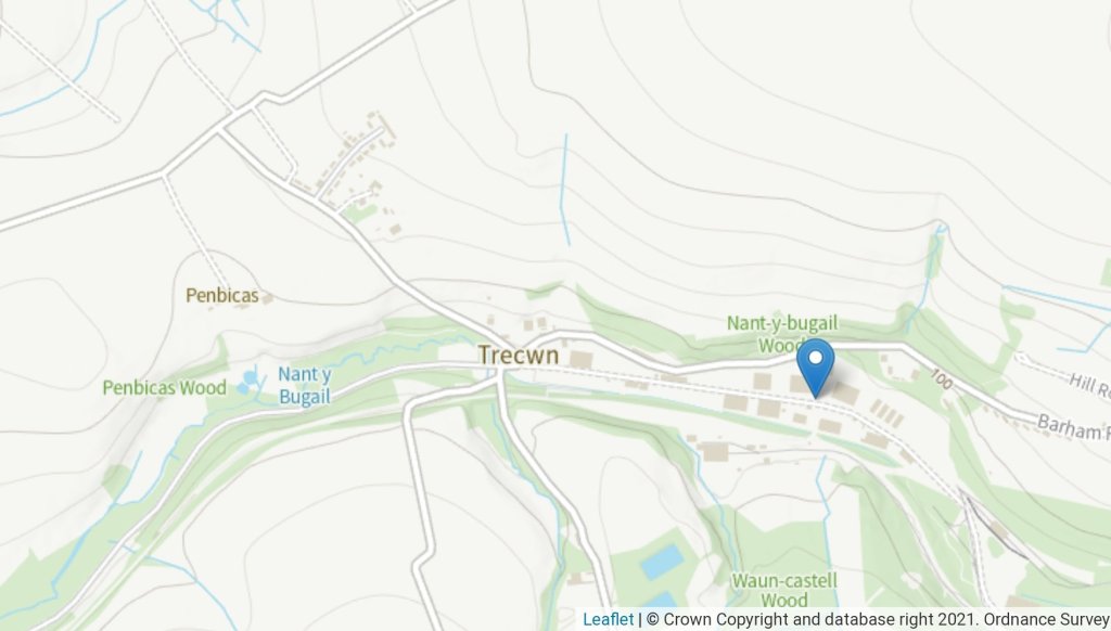


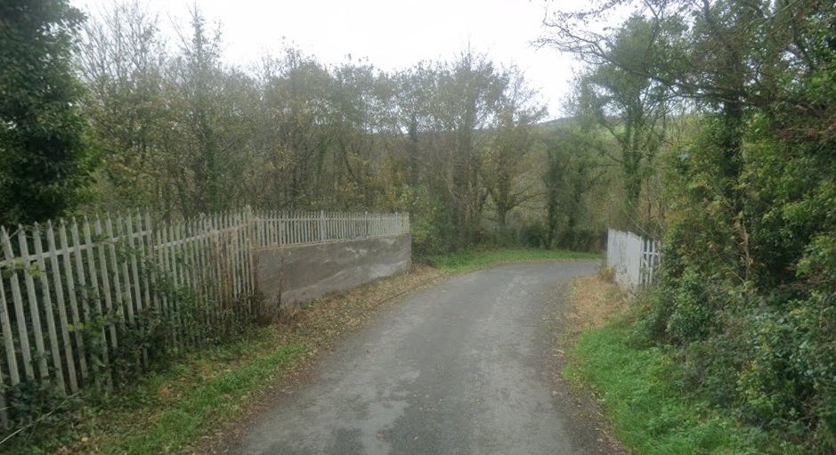
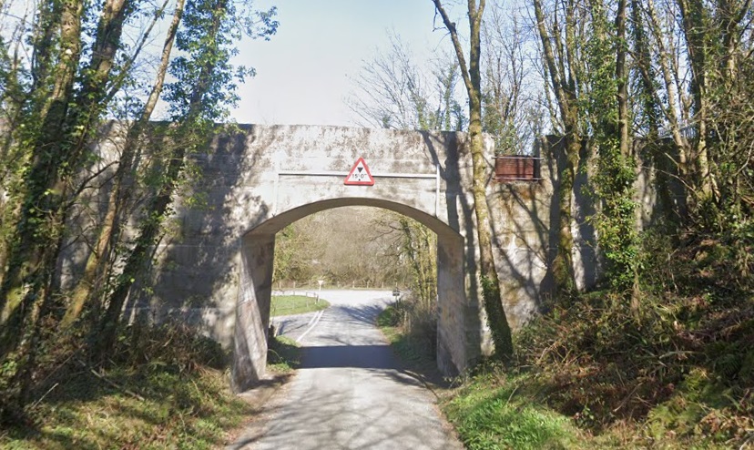
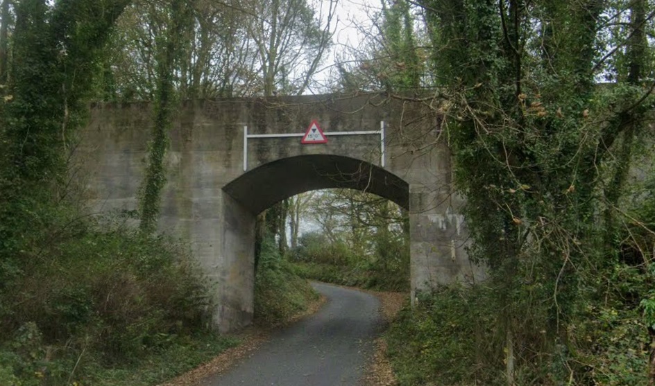


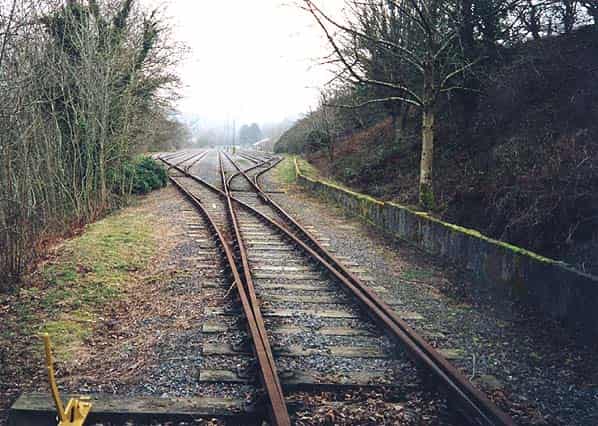
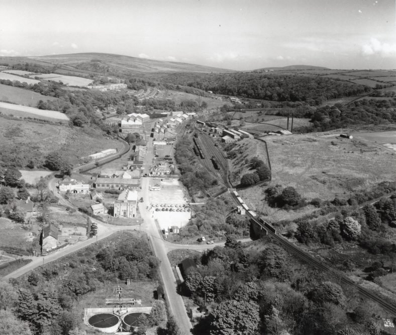


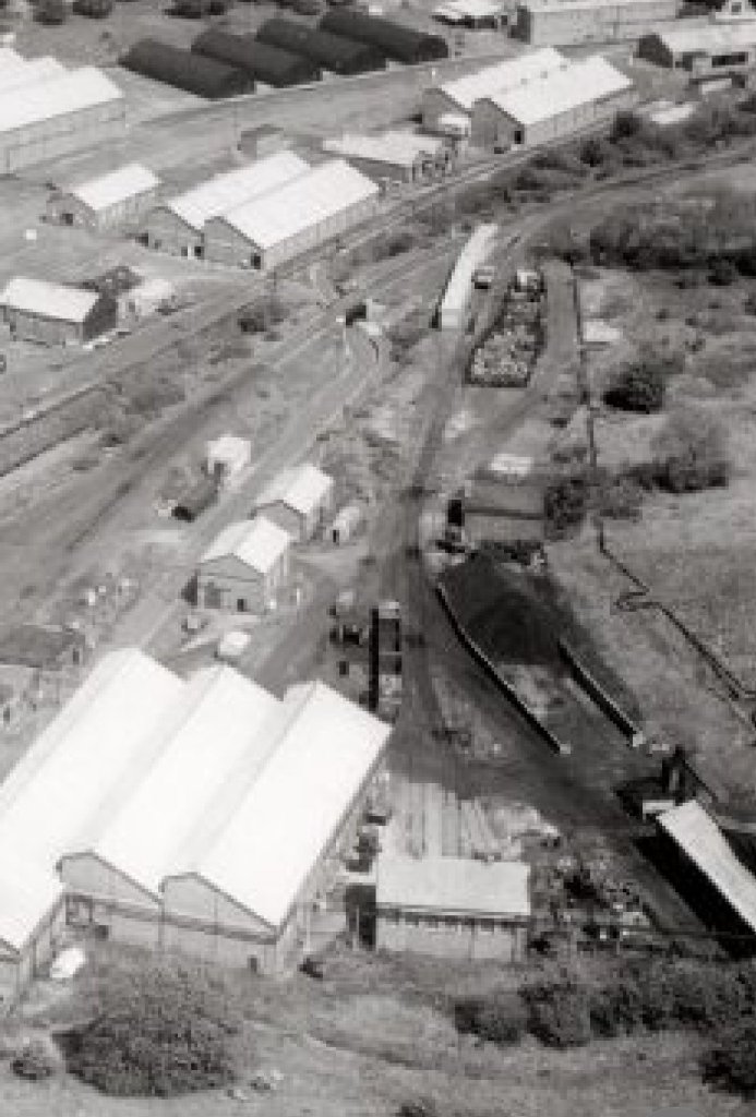
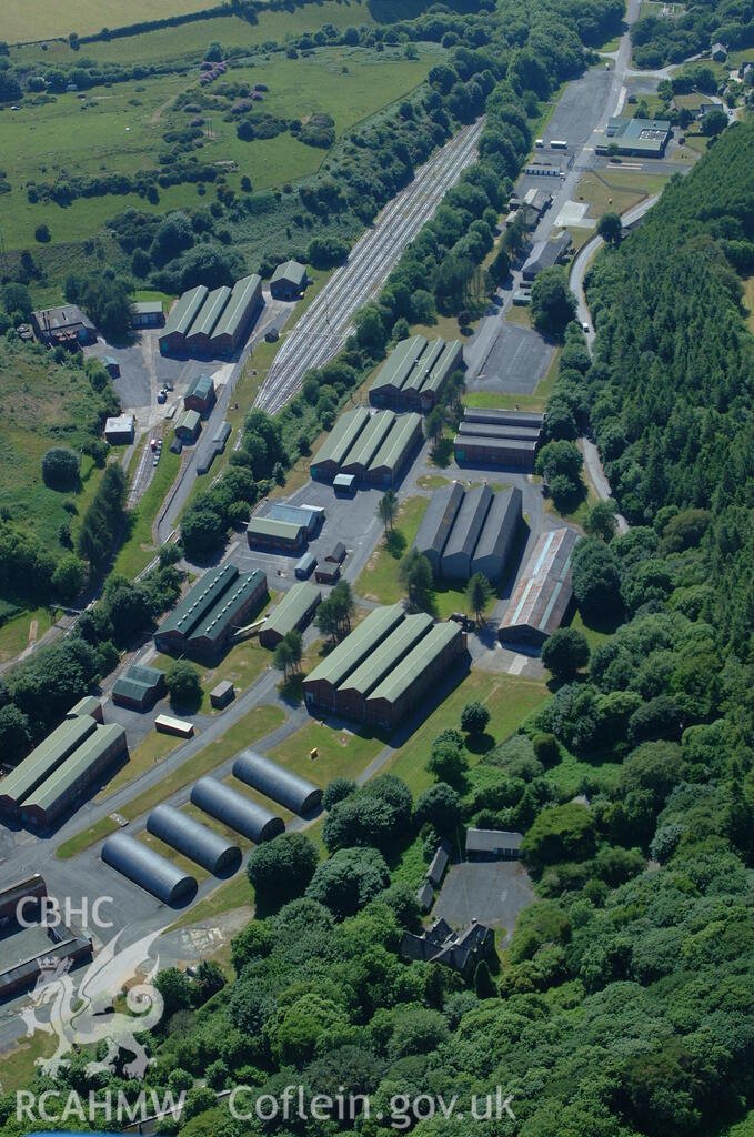


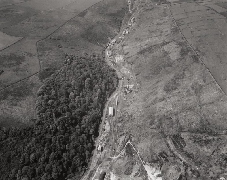

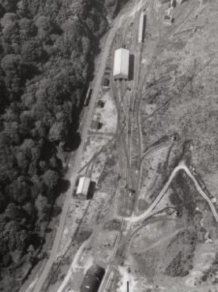
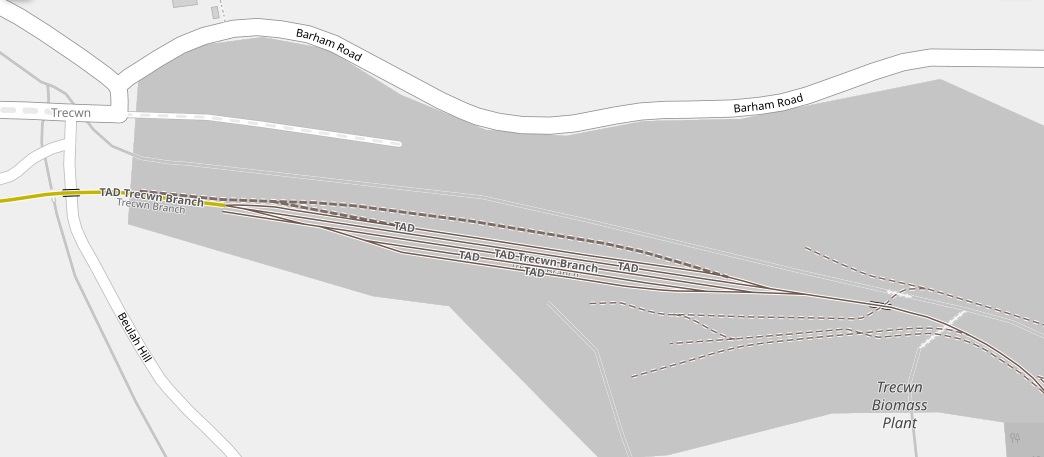

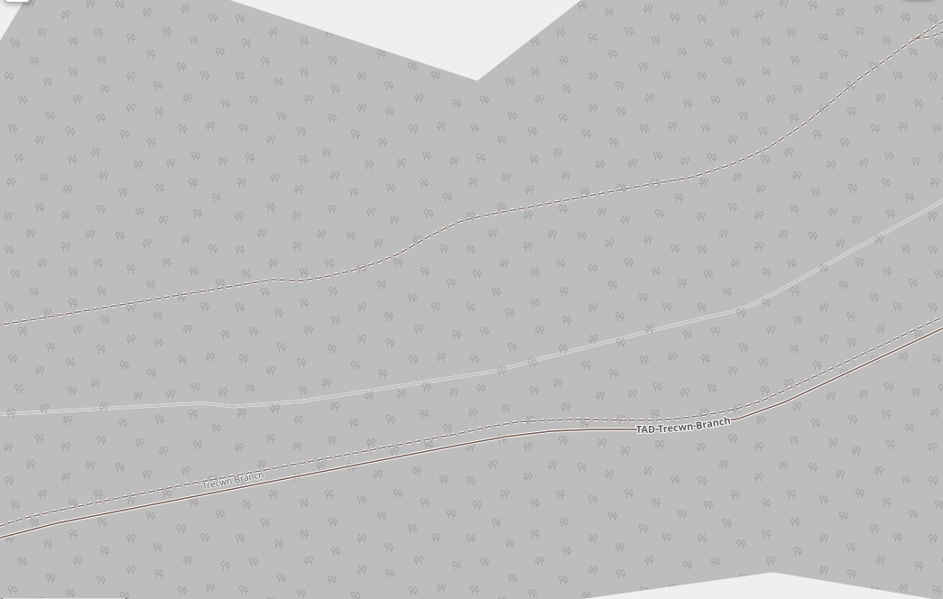


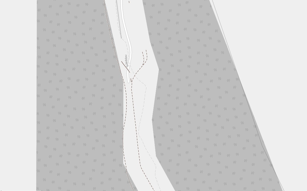
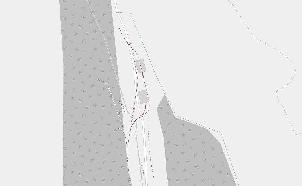
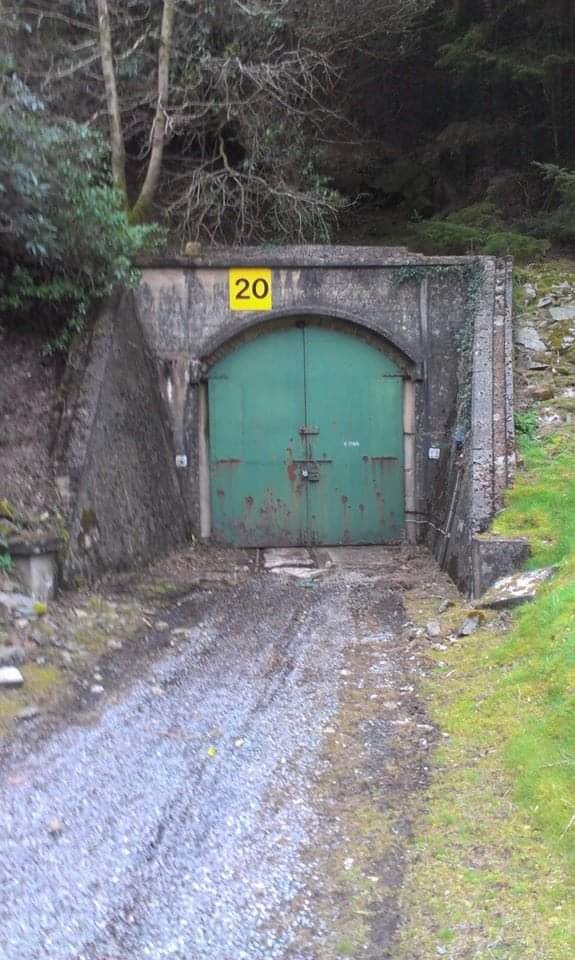

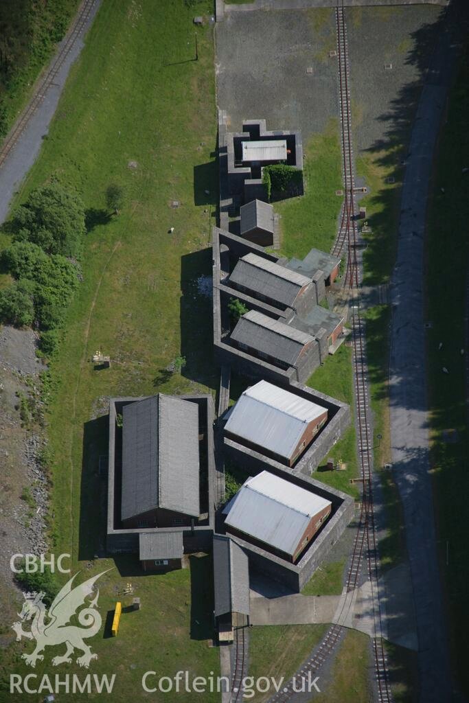

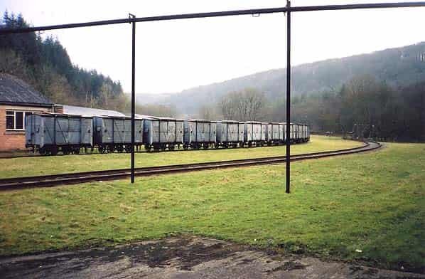
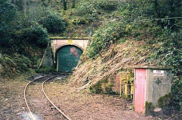
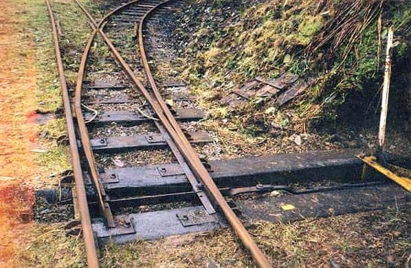
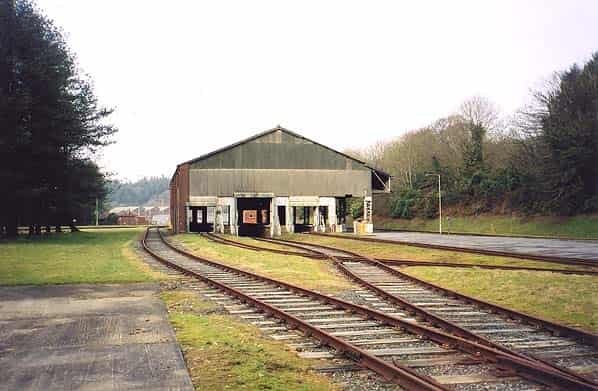
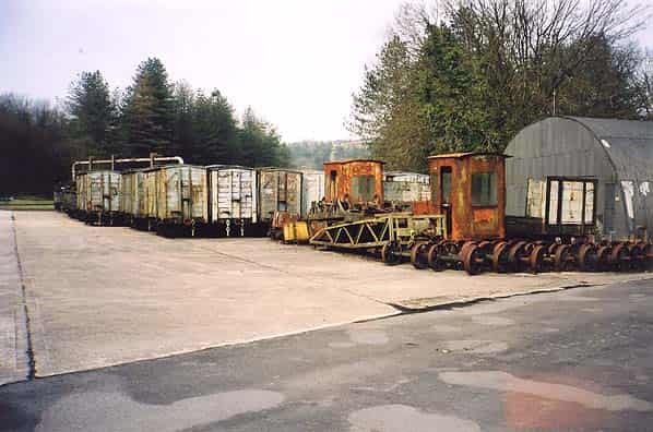

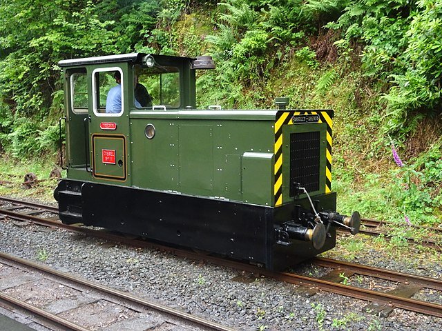

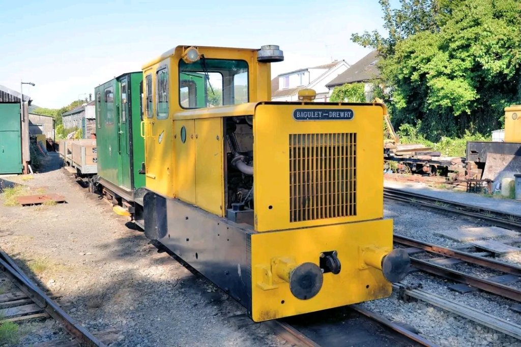


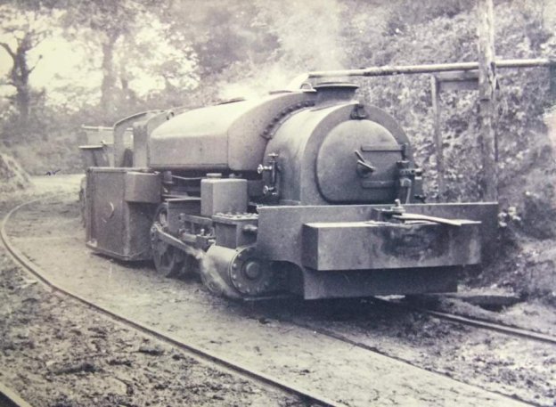


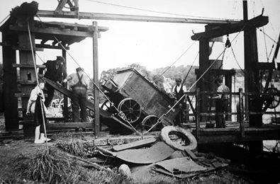
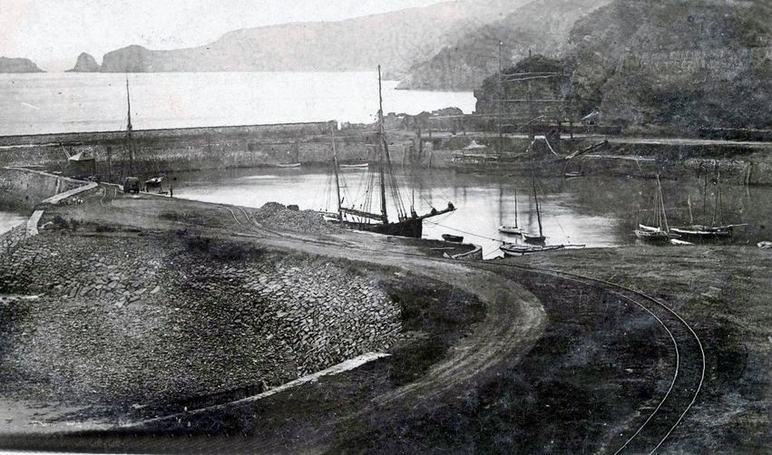

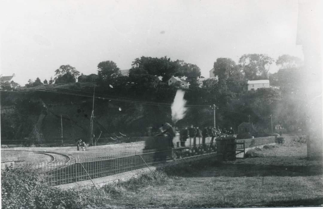

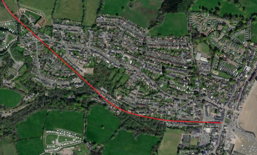


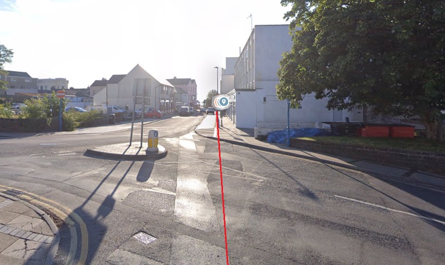
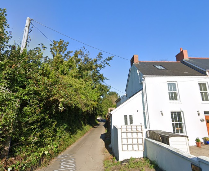
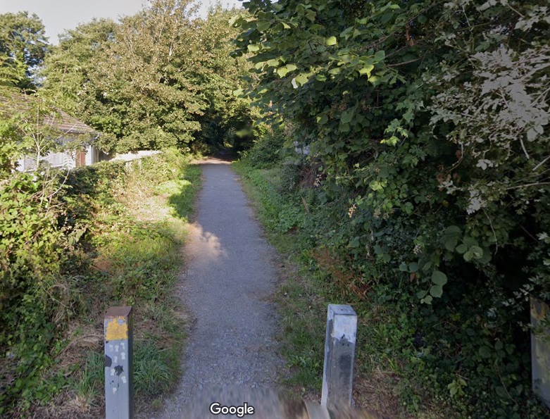

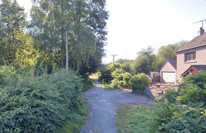
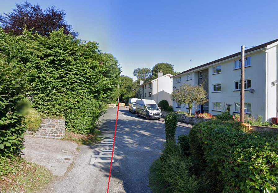

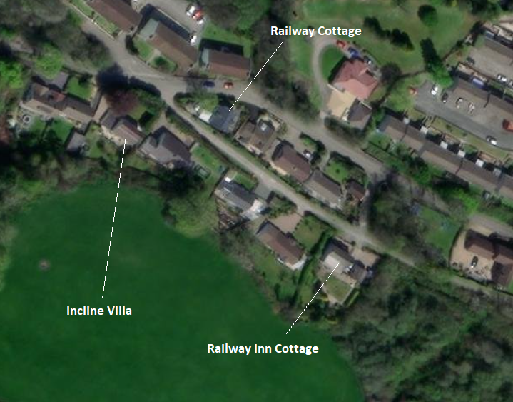

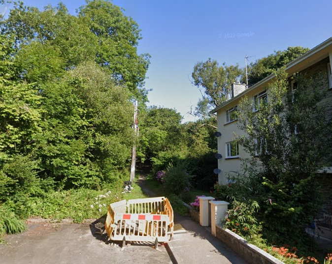


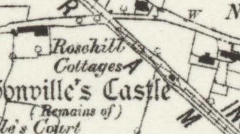
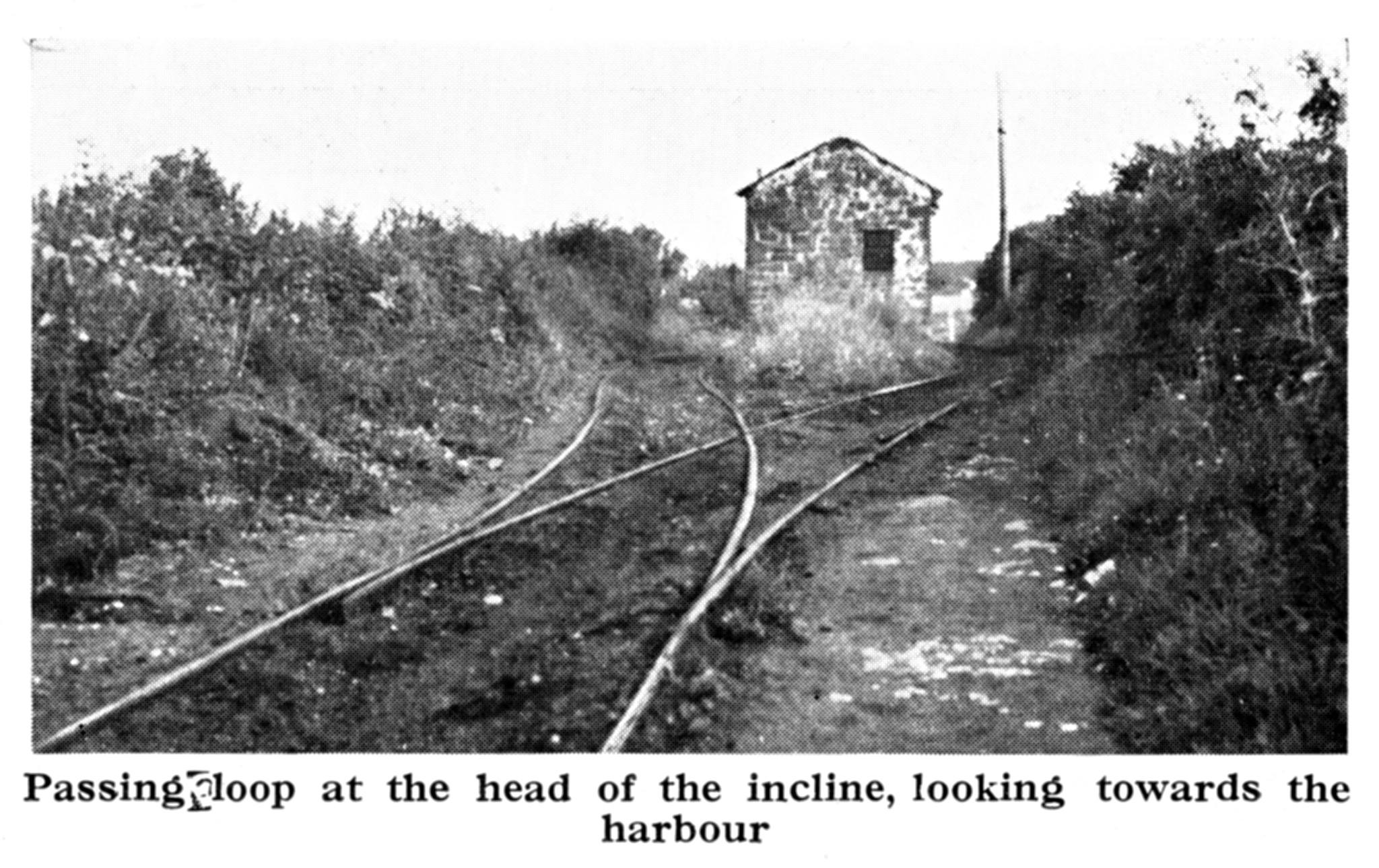
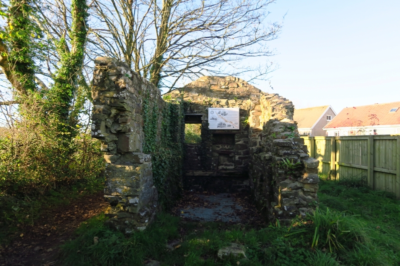
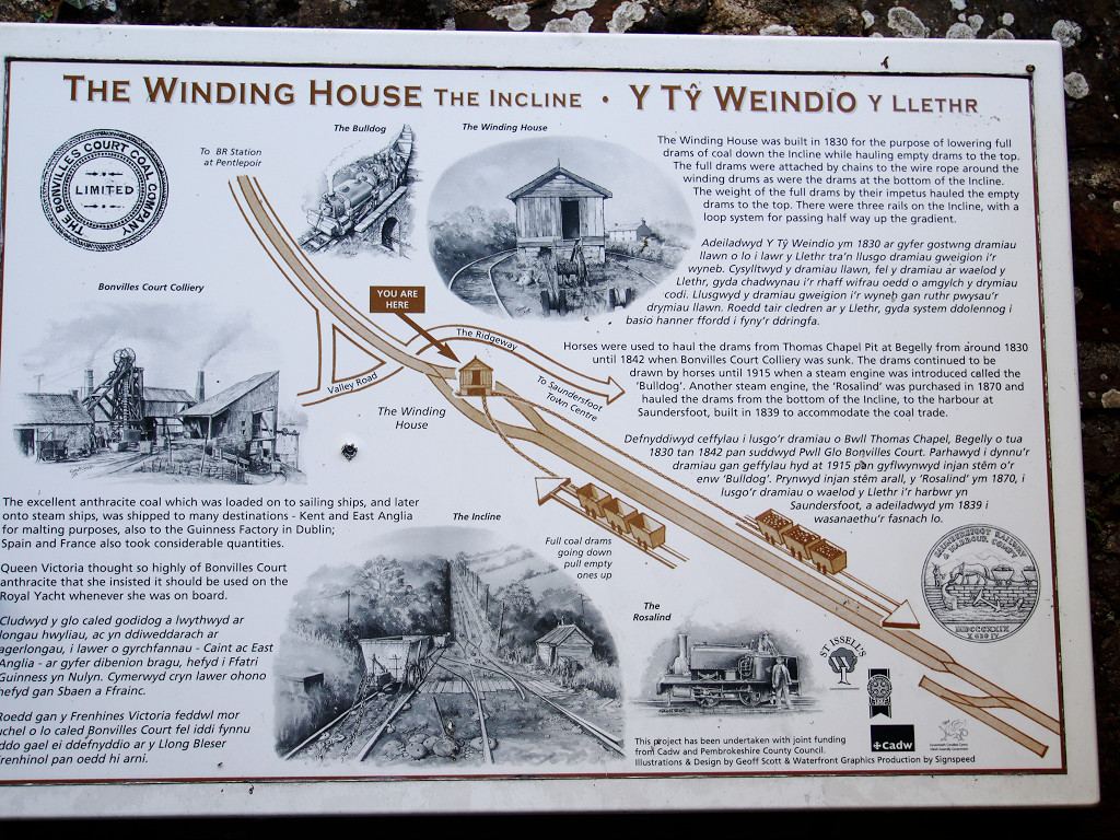

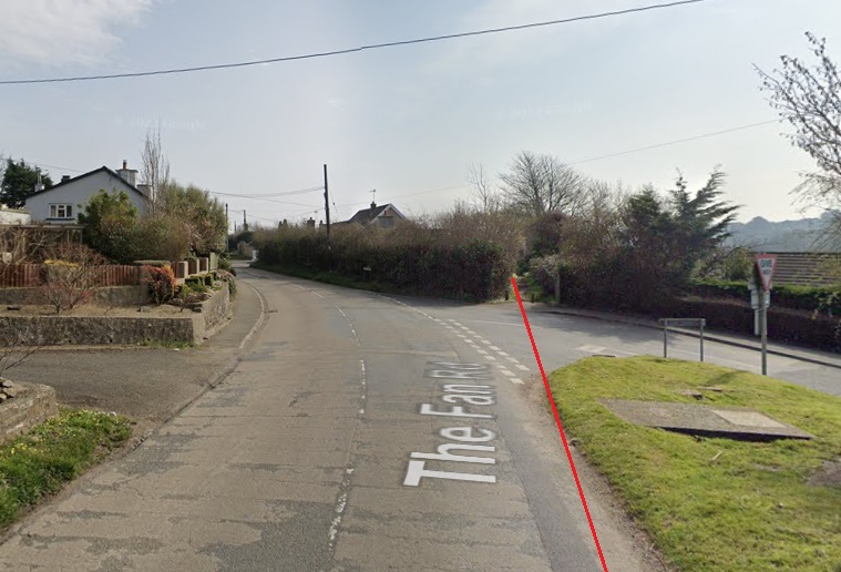

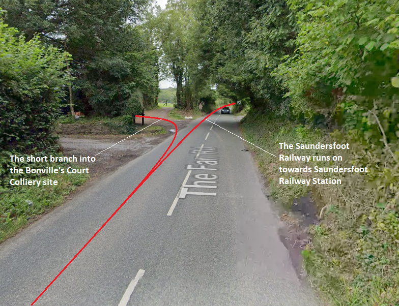

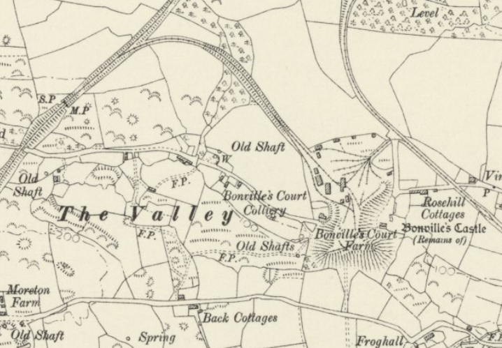
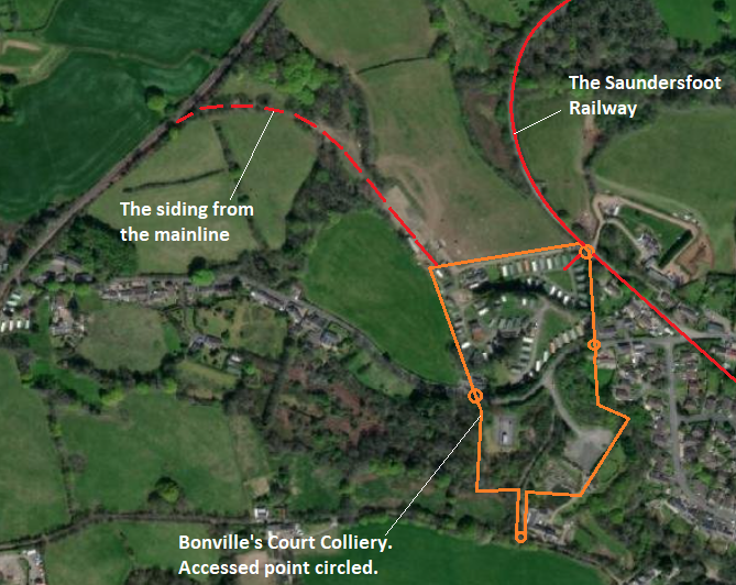
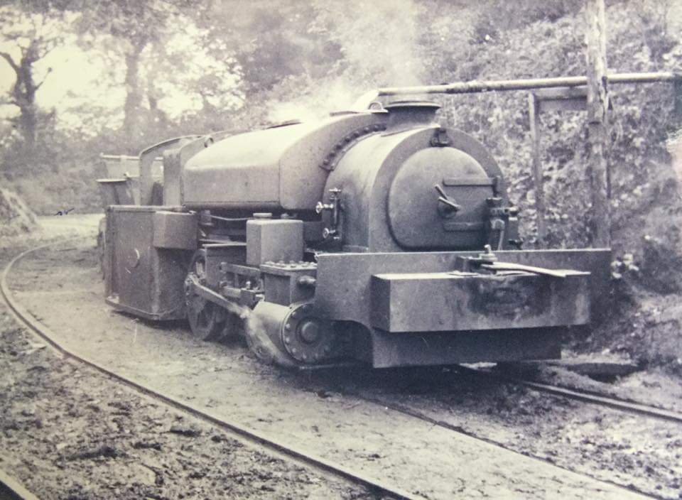


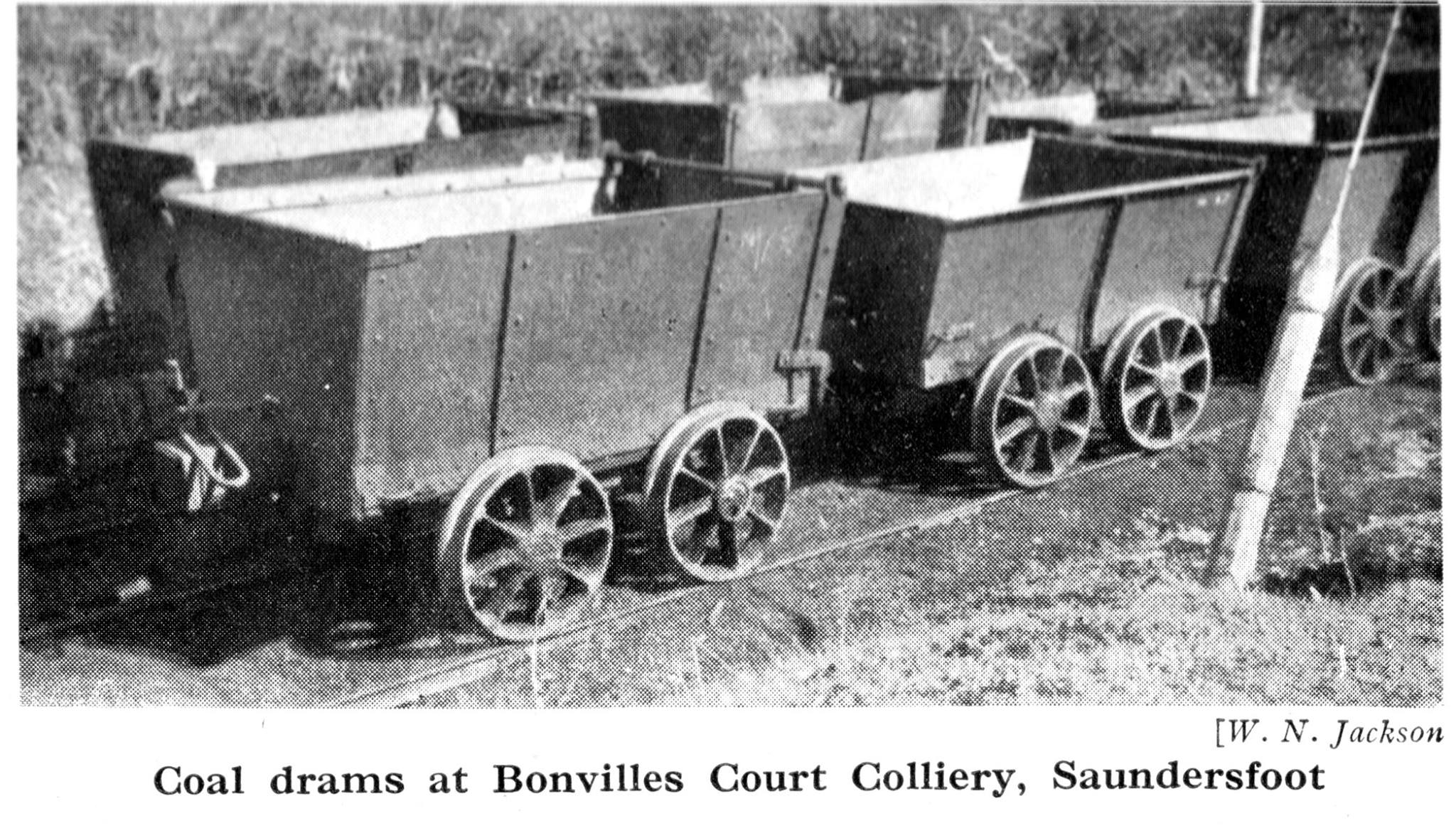


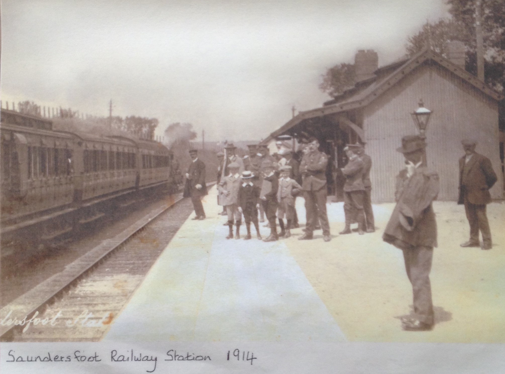
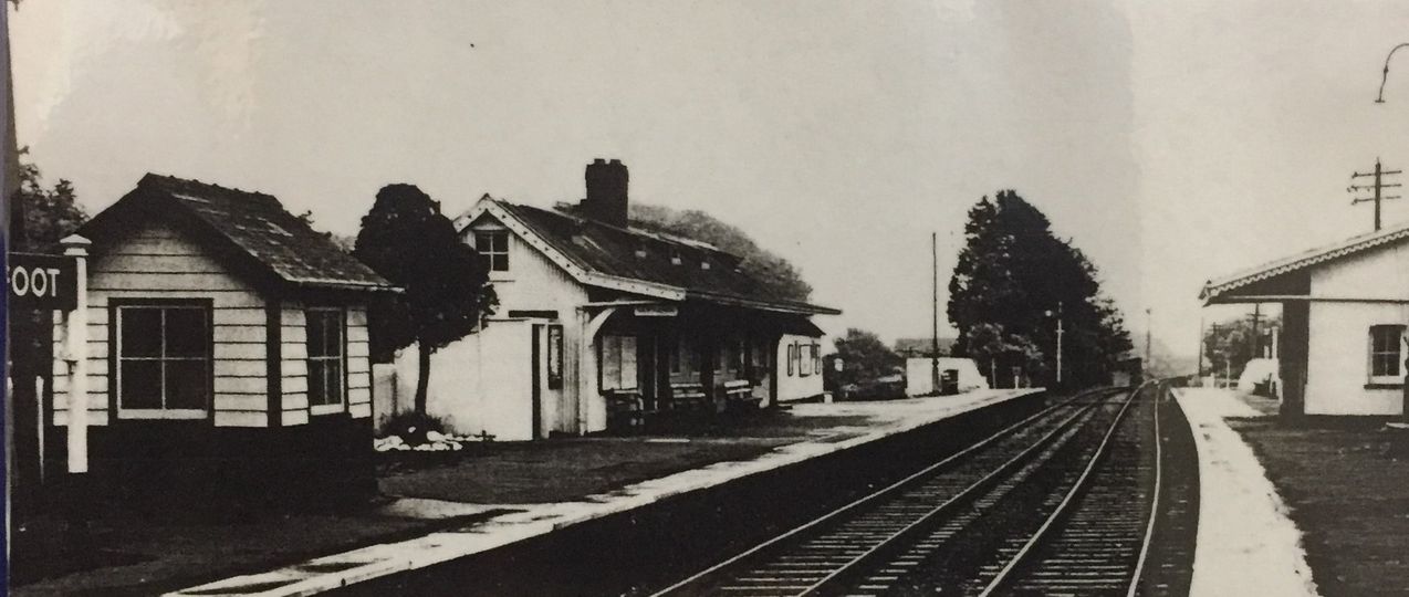
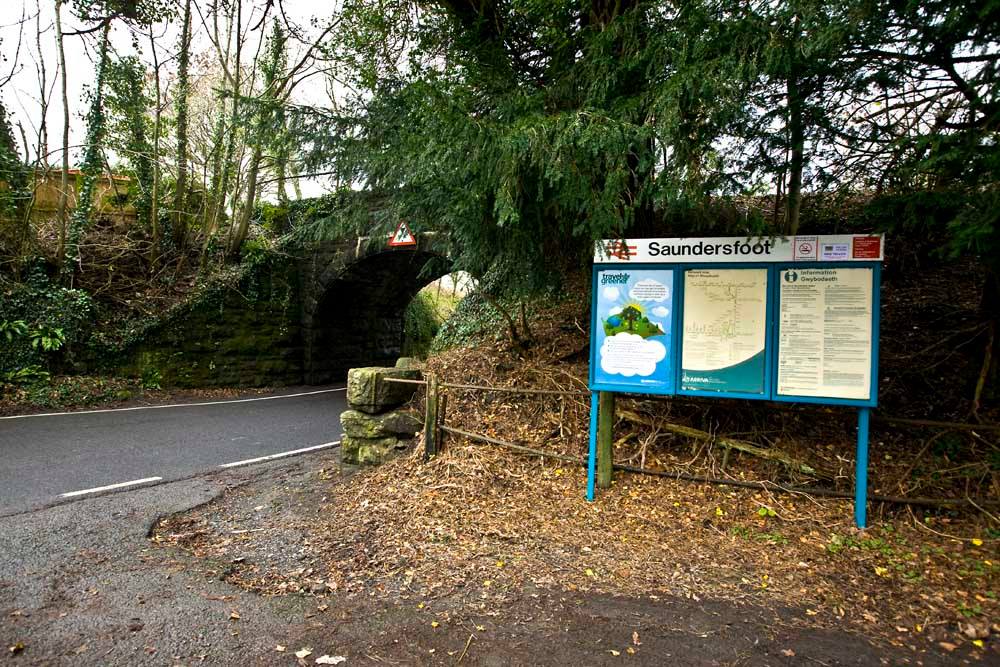
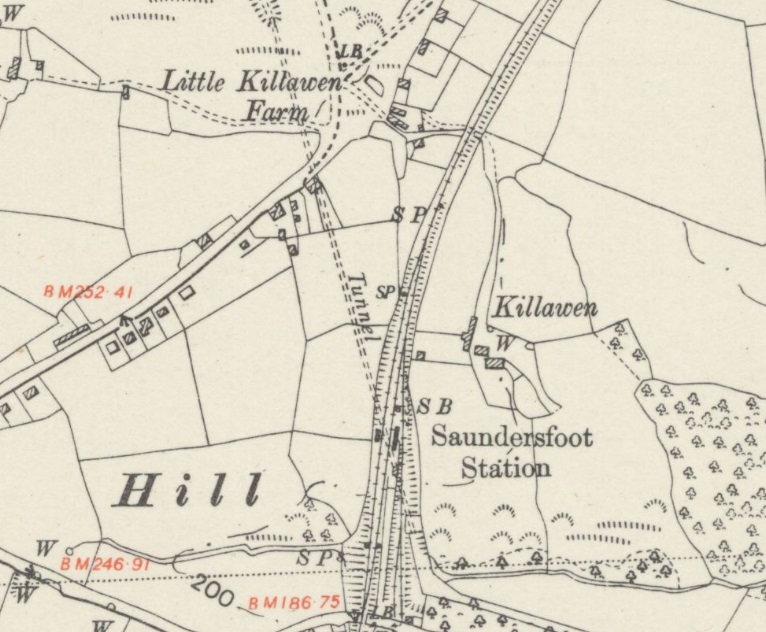
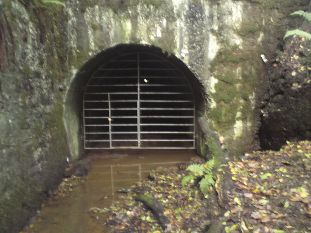

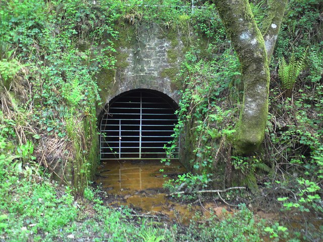

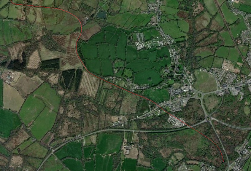


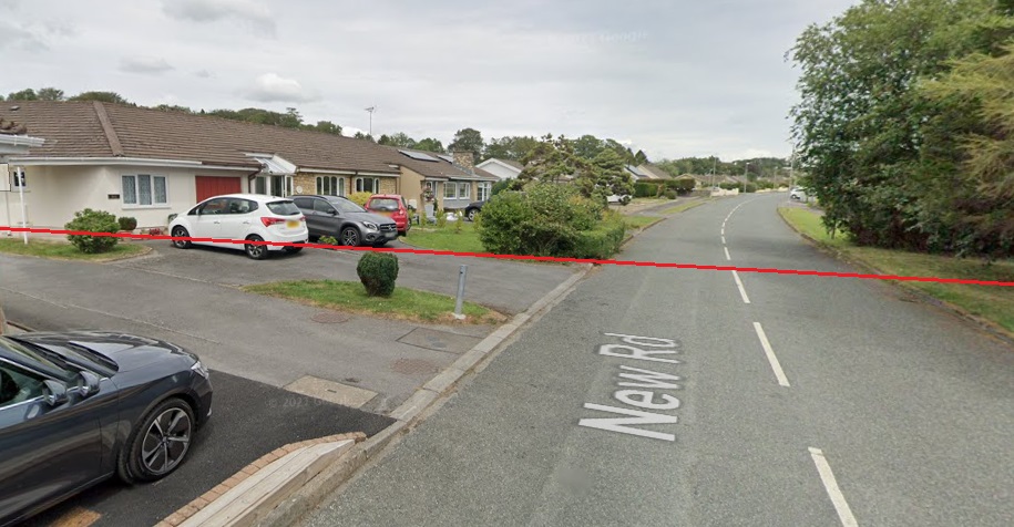

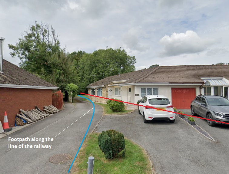
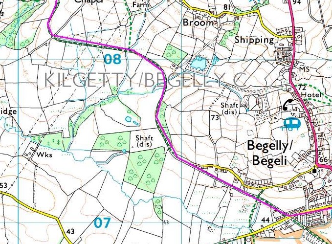
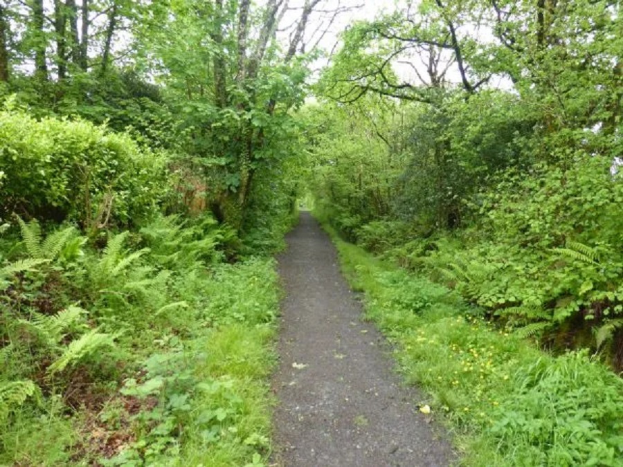
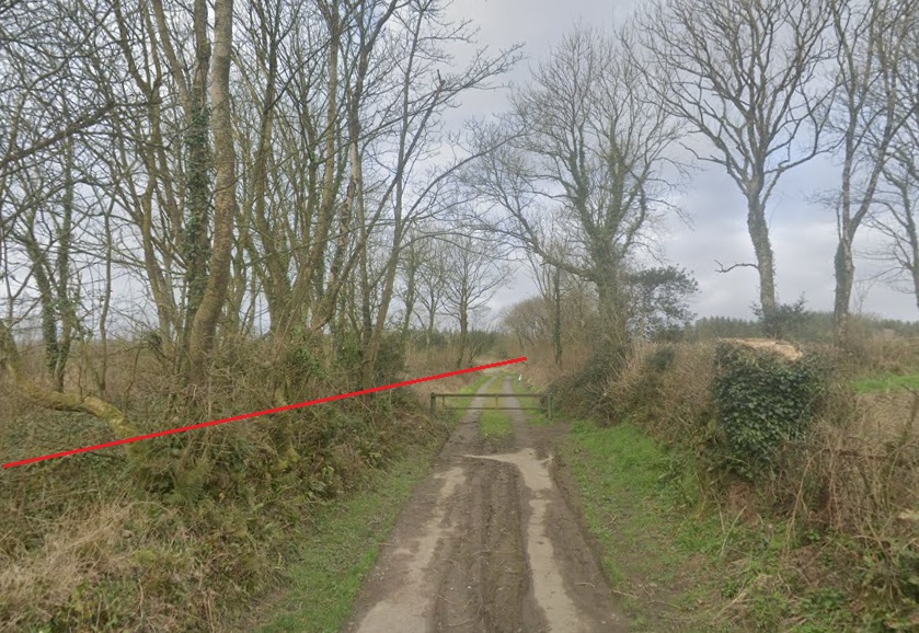
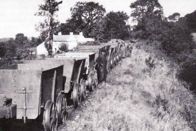
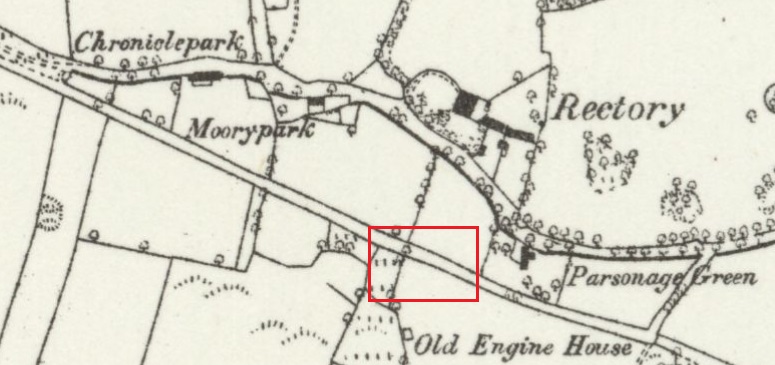


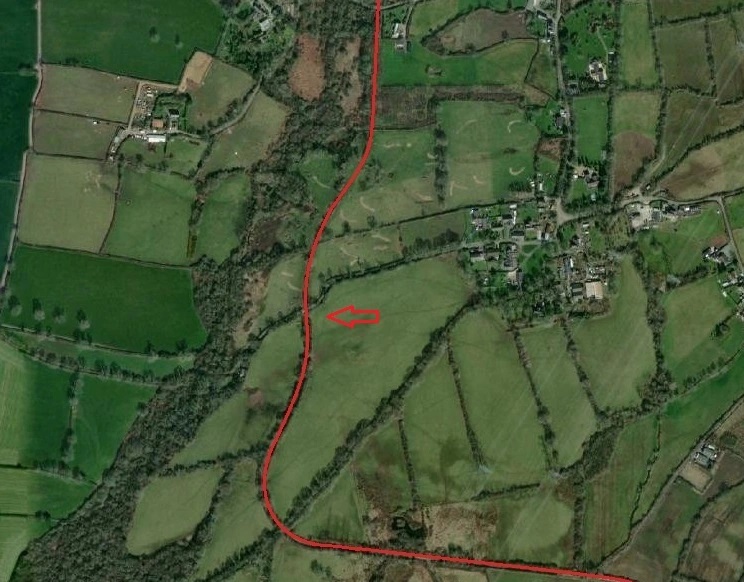
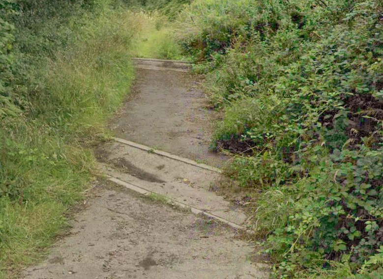


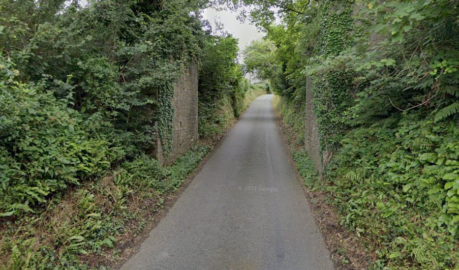
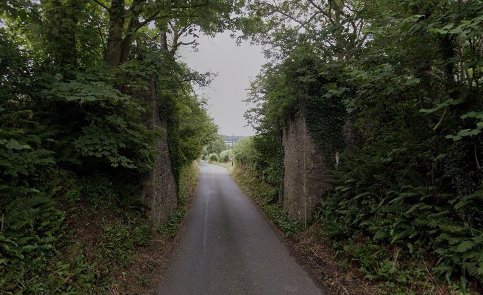


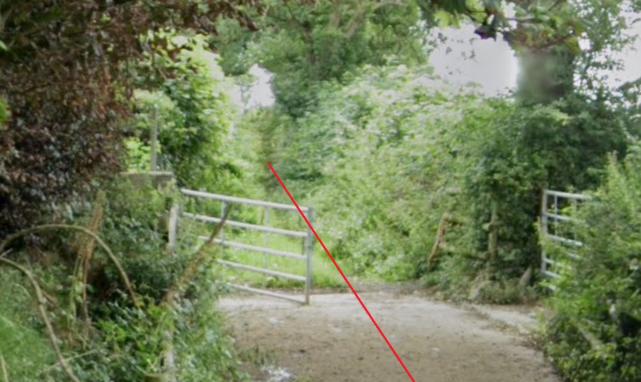


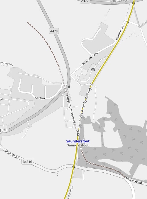
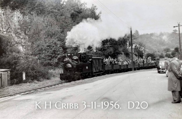
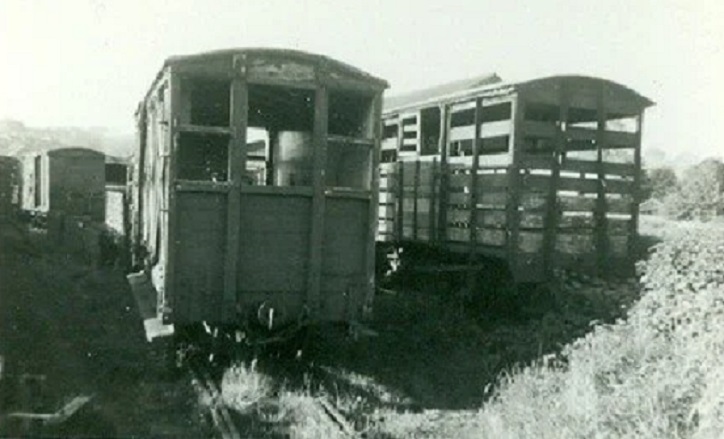


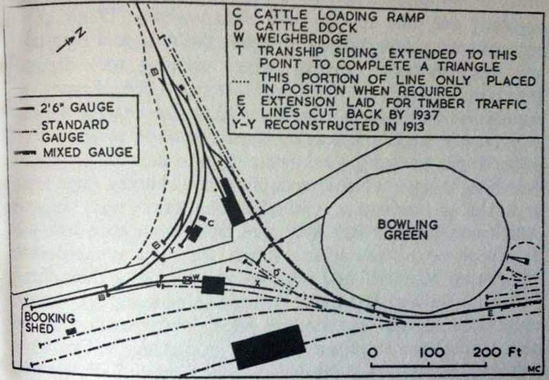


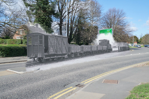

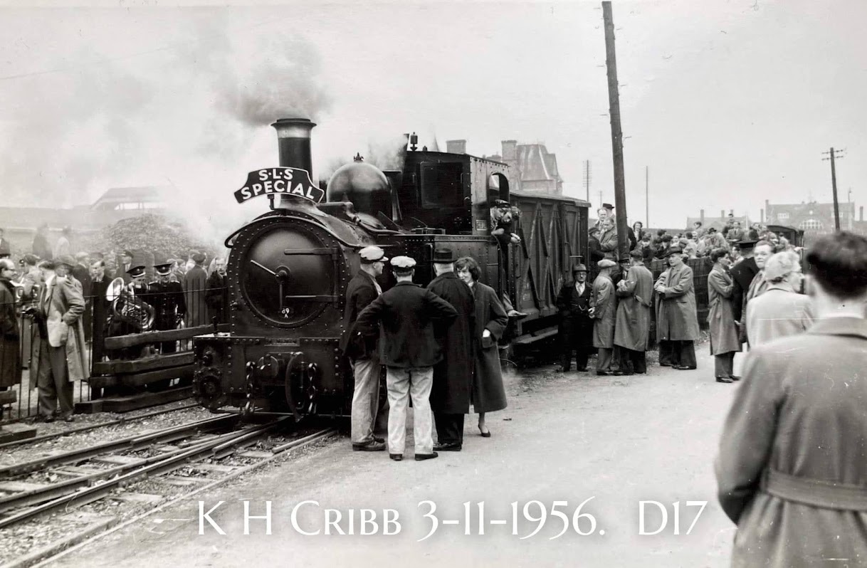
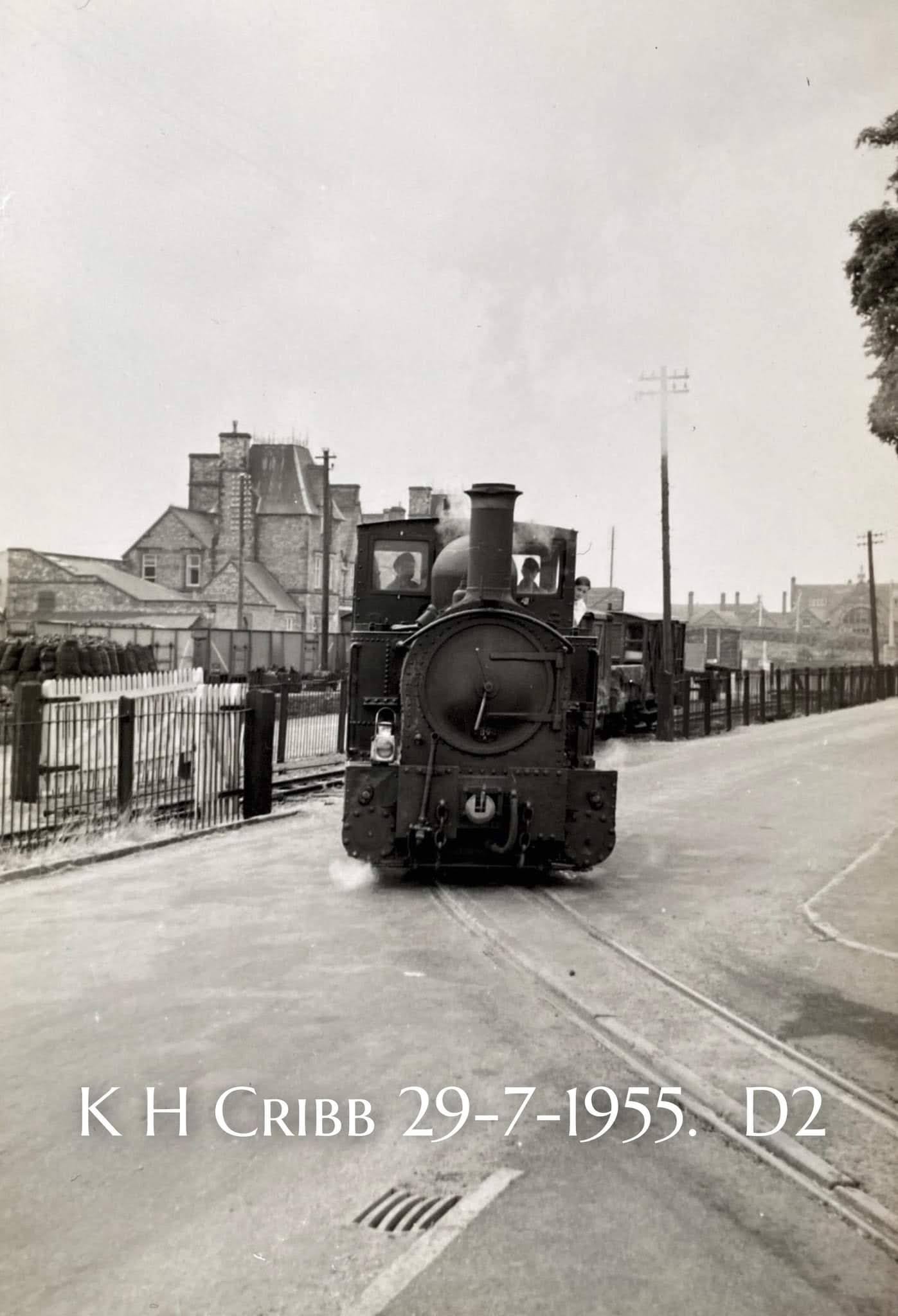
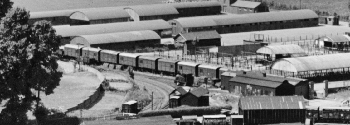


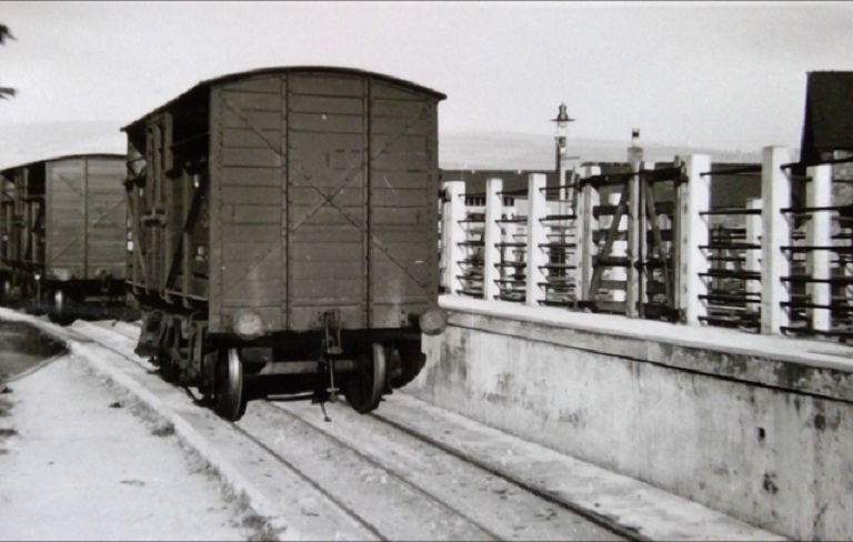
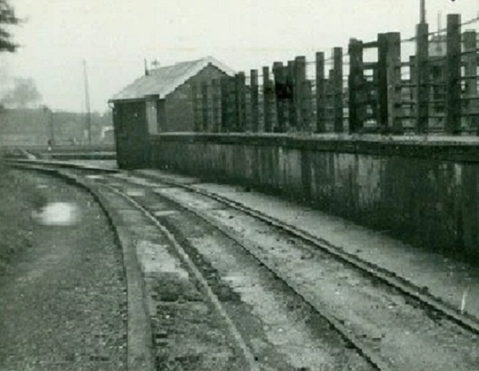
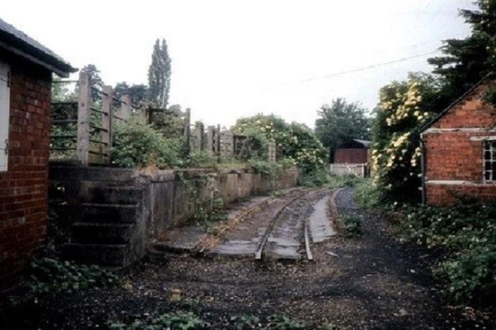
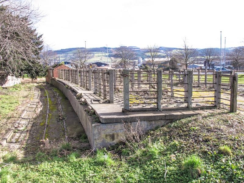
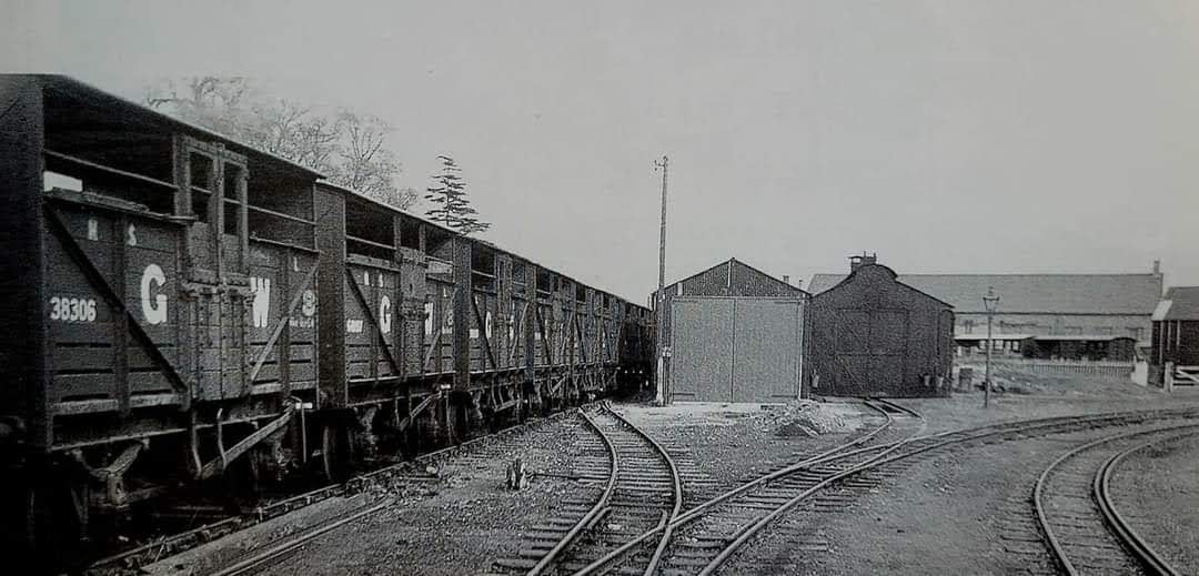

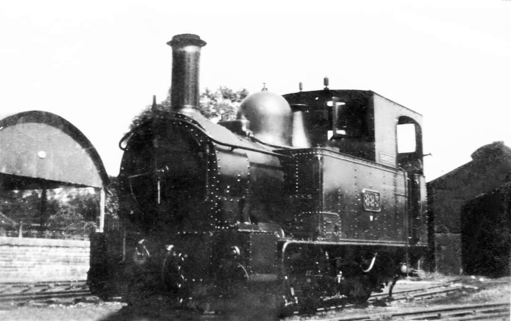

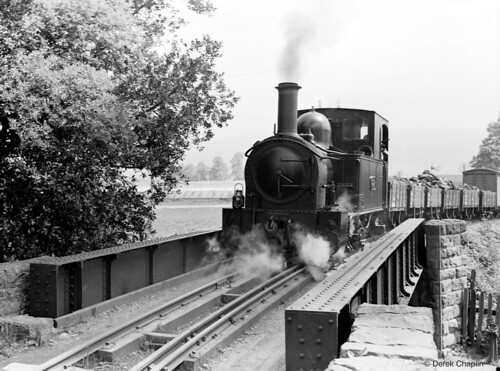
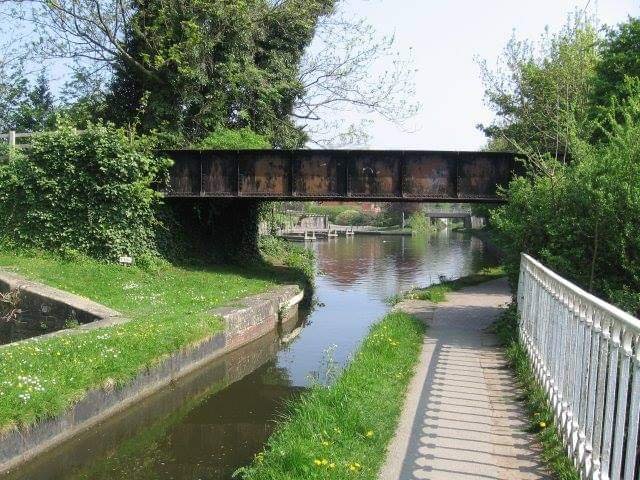

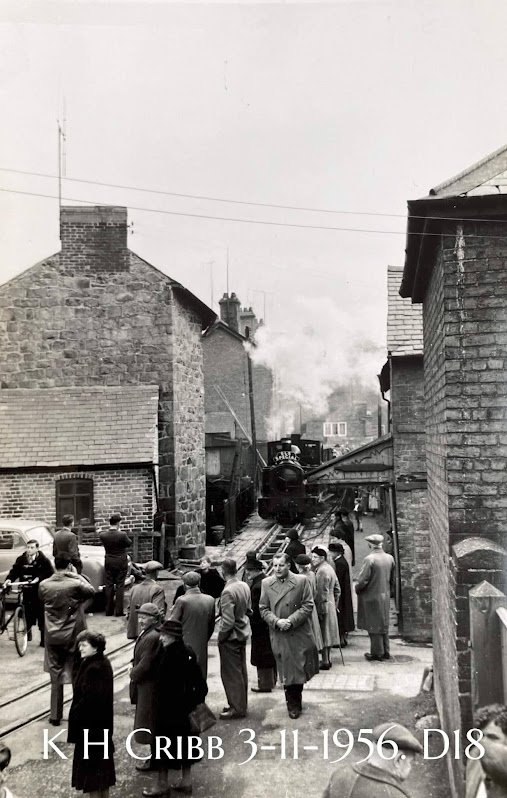
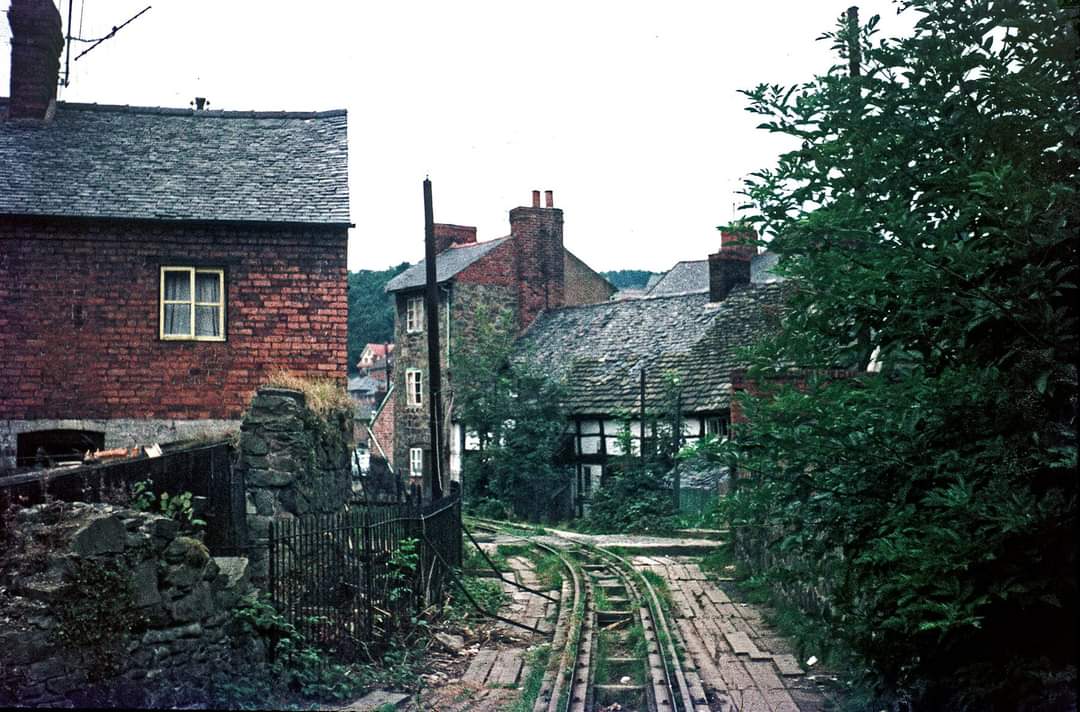

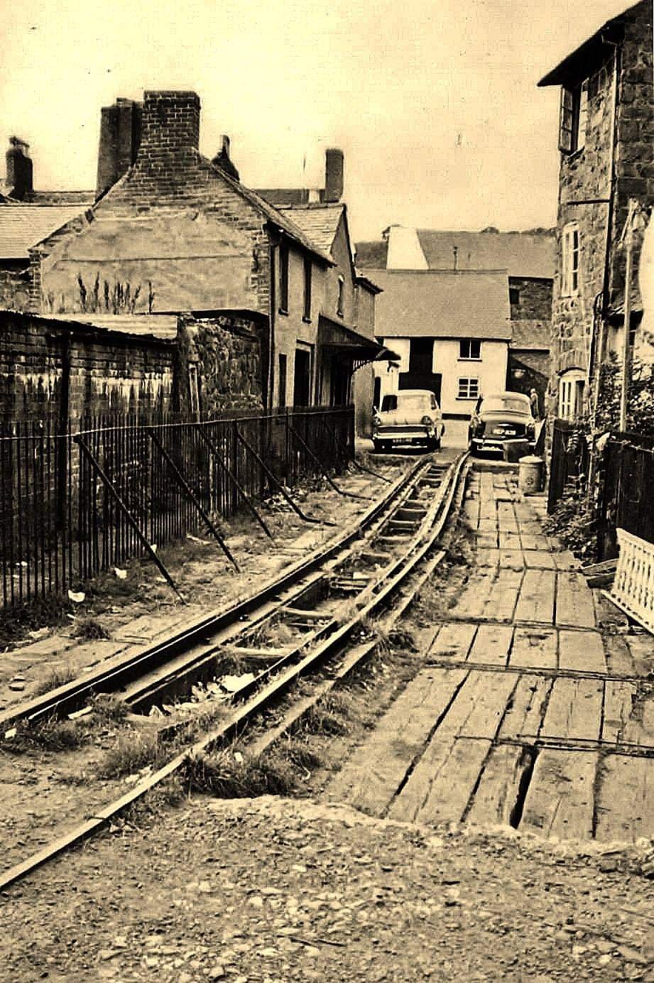
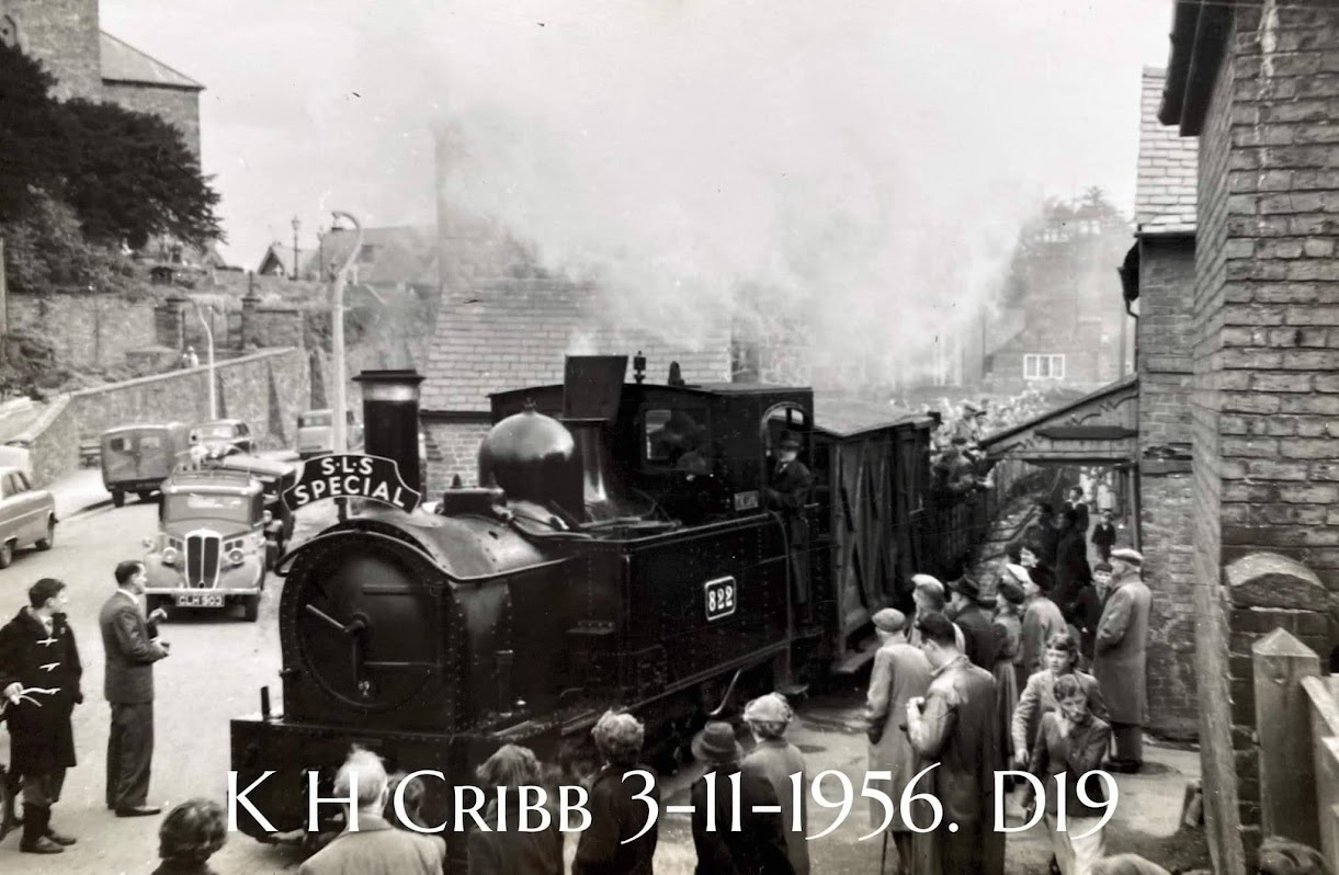


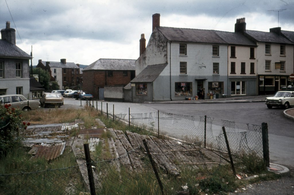
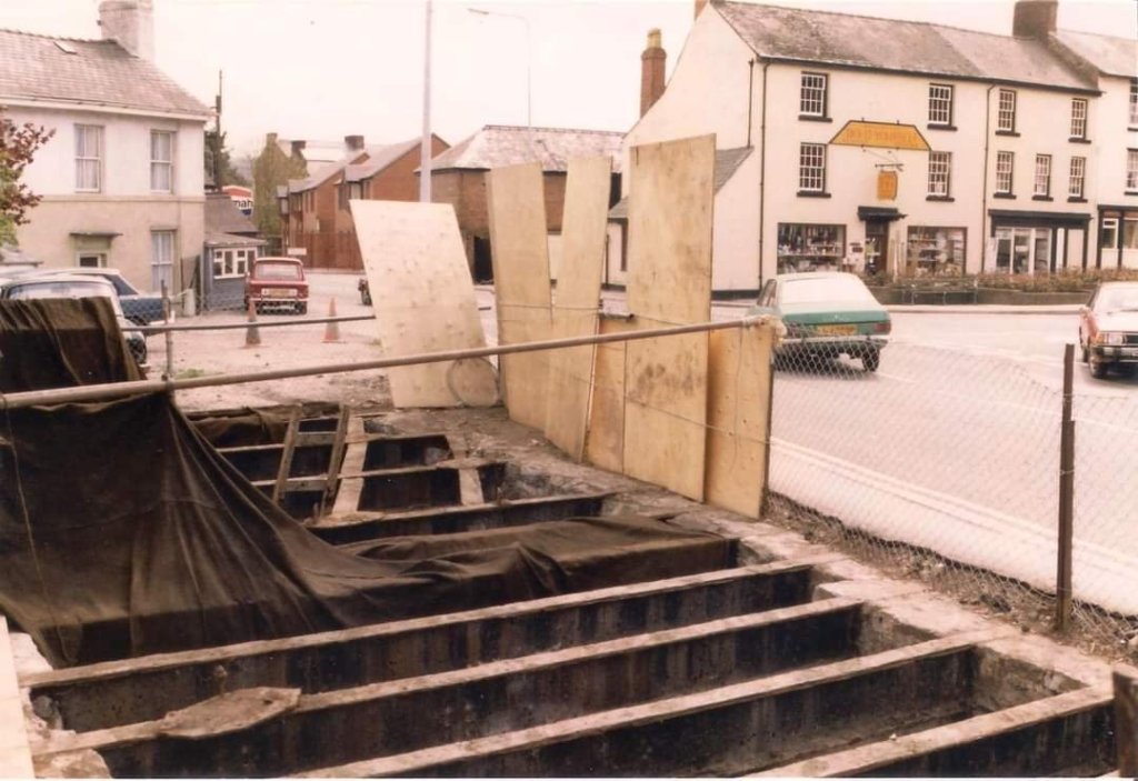


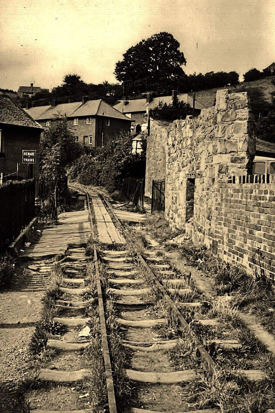
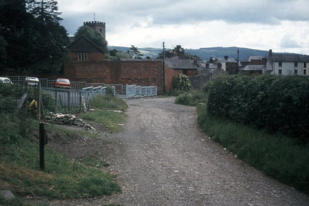
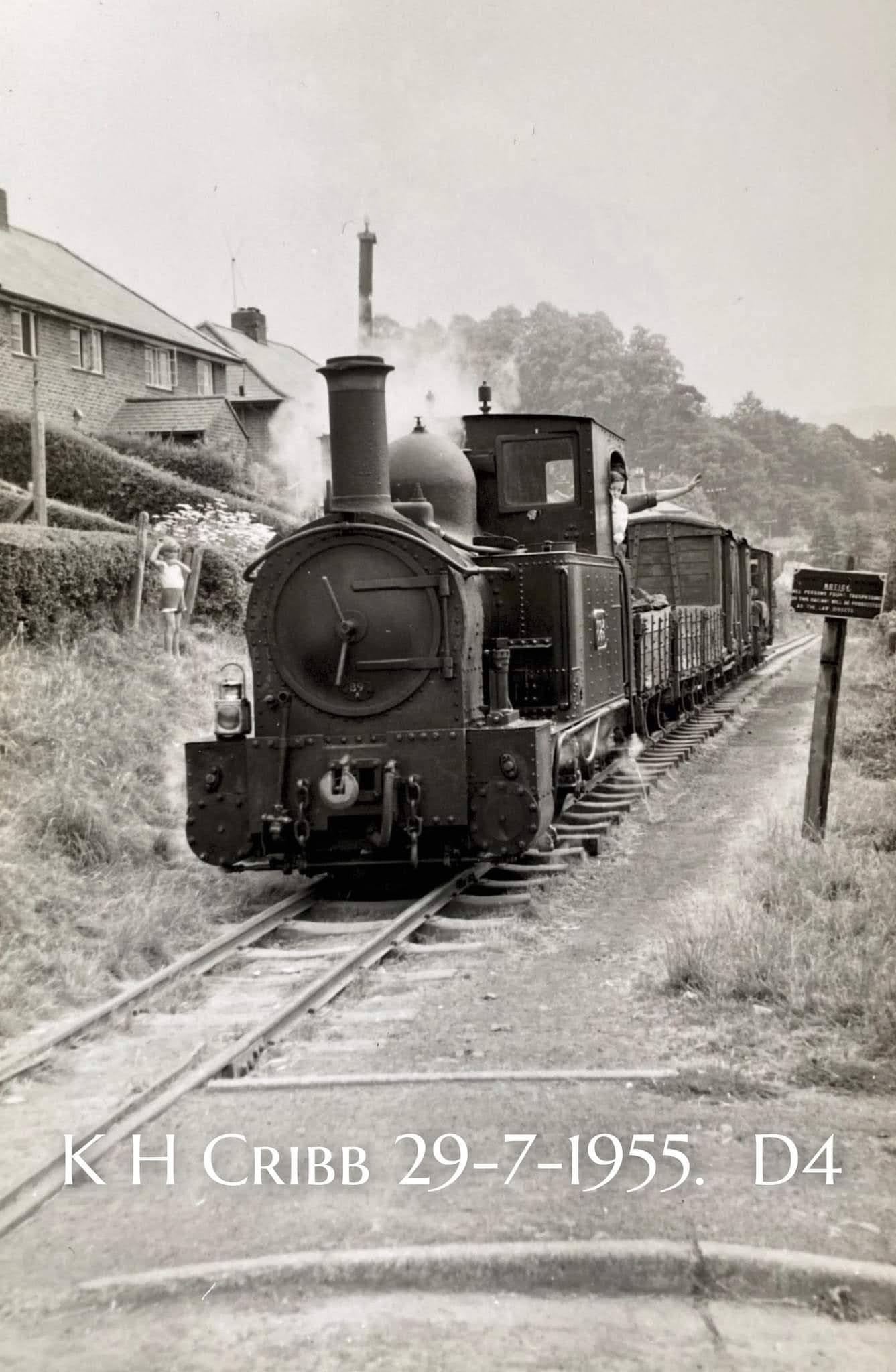


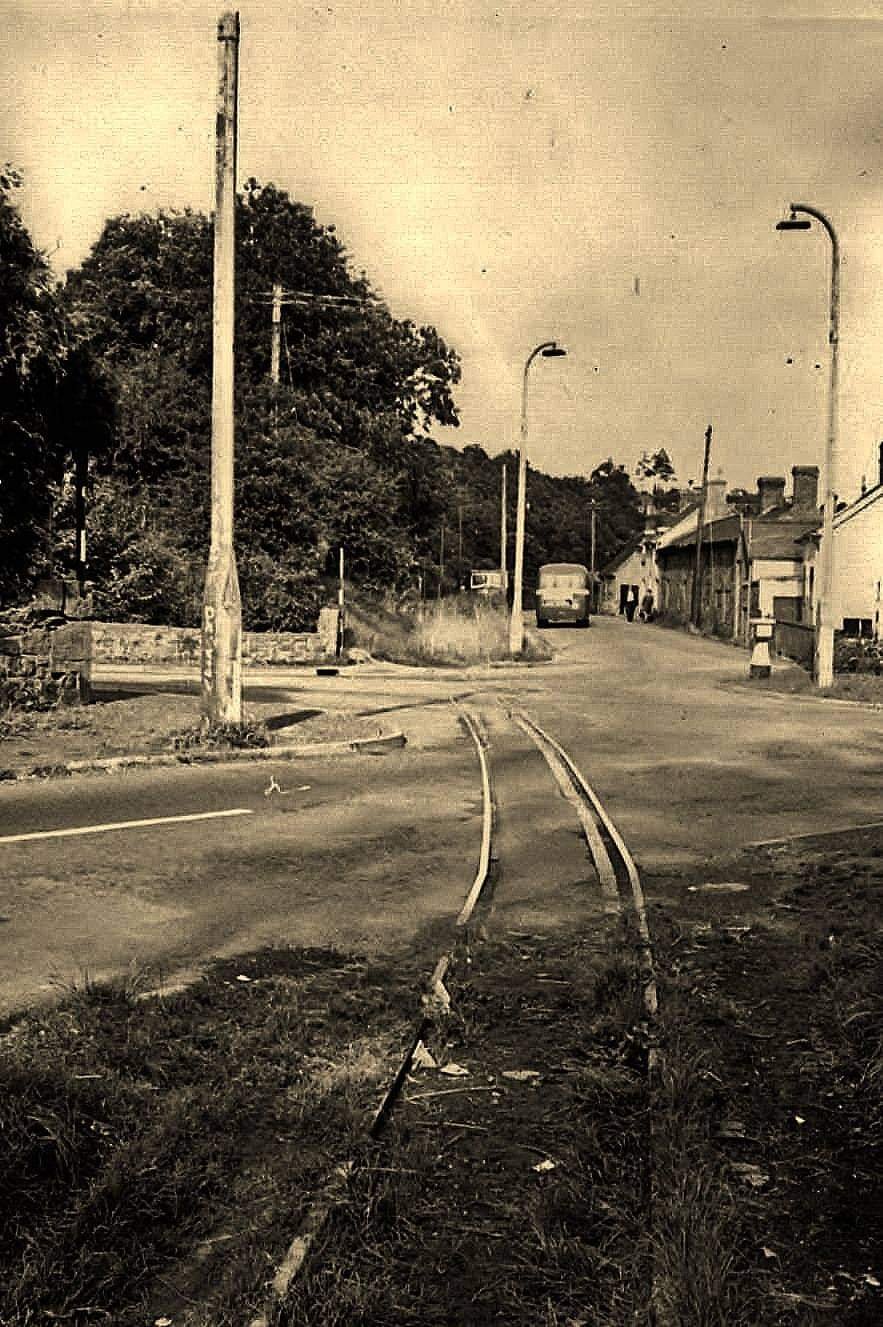


_a_Torrazza.jpg)
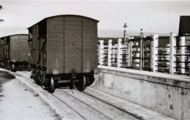