Tag Archives: narrow gauge

600 mm Narrow Gauge Lines used during World War 1 in East Africa – Predominantly in what is now Tanzania

600 mm gauge trolley lines (often known as Feldbahnen or “field railways”) played a crucial role in the East African Campaign of World War I, particularly in German East Africa (GEA) where they were used for both industrial and military logistics. These narrow-gauge systems were used to connect coastal areas, plantations, and interior supply depots to the main standard-gauge (1,000 mm) railways, or directly to the frontline.

Numerous privately owned 600 mm gauge Sisal Plantation Railways operated throughout the coastal and Tanga regions of German East Africa. These lines linked the plantations to factories and ultimately to the port at Tanga. During the first world war these were adapted for military use and transported troops, supplies and weapons.

In 1917, the Lukuledi Valley Line, a 600 mm trolley line in the Lukuledi Valley was extensively used to supply the German forces in the south of GEA and to evacuate their casualties to Lindi.

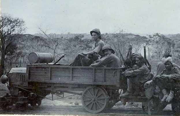
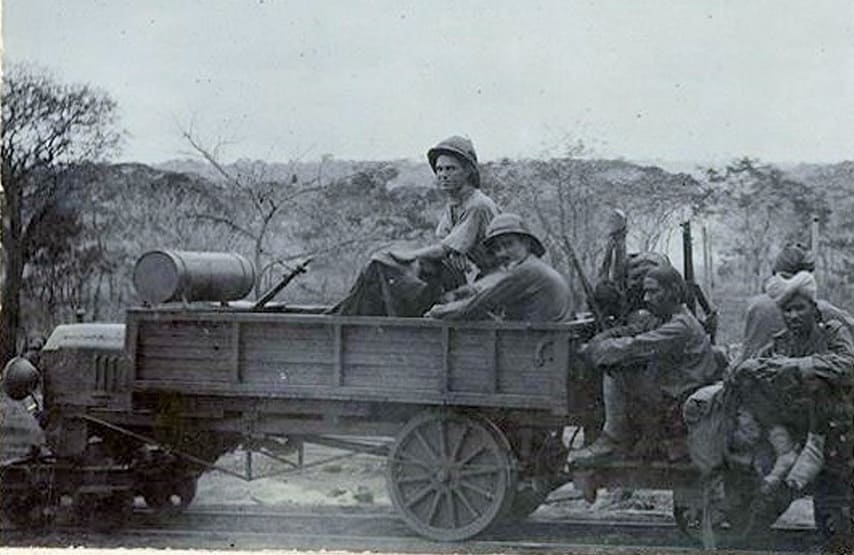
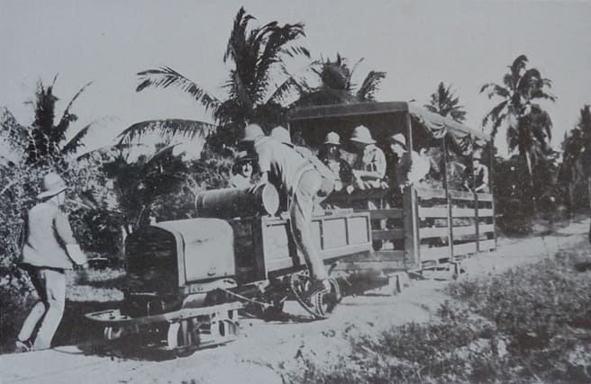
These light railways allowed the German Schutztruppe, led by Lieutenant Colonel von Lettow, to move heavy loads (such as artillery pieces from the sunken cruiser Königsberg) across difficult terrain without relying on limited road infrastructure. The lines often used prefabricated track segments. Trolleys were frequently moved by hand-pushing by local porters or workers, though sometimes small locomotives or tractors were used.

As British forces moved South into German East Africa from early 1916 onwards they were able to make extensive use of these 600mm lines, and built their own 600 mm light railways particularly in the later stages of the campaign as they pushed deeper inland where transport infrastructure was non-existent. The British made use of some small locomotives which had been in use on Sisal plantations before the war but also tractors designed for use on these lines.

A typical tractor in use on one of the 600 mm railways/trolley line. This one was in use on the line serving Handeni. [1: p9]

A number of these 600 mm lines are referred to by Harry Fecitt in an article entitled “The Indian Railway Corps East African Expeditionary Force, 1914-1919” the majority of which is is reproduced in Appendix A below.

Fecitt describes the work of the Indian Railway Corps as part of the advance Southwards into German East Africa by British forces. He notes that from Mombo station as far as Handeni the Germans had built a hand-powered field railway (trolley line) of 600 mm gauge to “Handeni, 65 kilometres to the south. The 25th Railway Company assisted the Royal Engineers in restoring this line as it had been partially destroyed, and on completion this trolley line was very useful for moving supplies in support of General Smuts’ advance to Morogoro.” [1: p8]

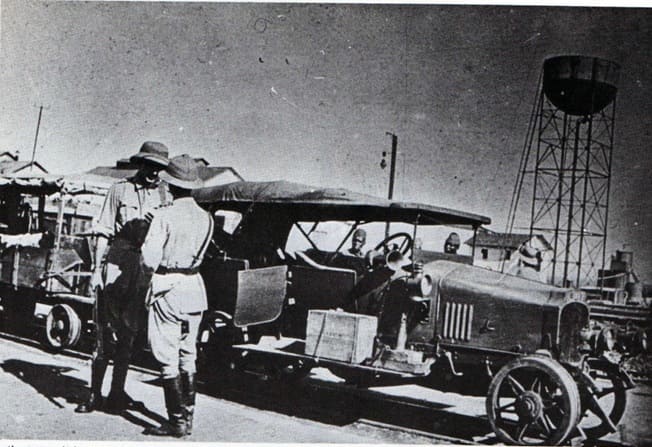
He notes also that a similar 600 mm gauge line had been constructed by the Germans from “Korogwe … towards Handeni. The materials for this line came from abandoned German farms and plantations and the locomotion came from adapted Ford cars used as tractors and operated by the East Africa Motor Transport Corps.” [1: p9]

A typical ‘train’ on a trolley line in what was once German East Africa but which by this time was terrritory occupied by the British. [21: p13]

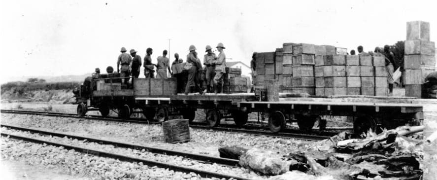
In British hands, these lines were very short-lived. Fecitt talks of the construction by the British of another 600 mm line as they moved South through German East Africa. The British “developed Kilwa Kisinjane as a port where men and supplies could be landed. Commencing in November 1916 a 600 mm tramway was built by the Corps from the ocean to Kilwa Kivinje, a distance of 26 kilometres, and then onwards for a further 24 kilometres. The construction material was produced by stripping the trolley lines previously built from Mombo and Korogwe. Motor tractors were again used and a driver company and a supporting maintenance company were formed from mechanical transport personnel; these companies became sub-units in the Railway Corps.” [1: p13]

Apparently, “the driving of tractors on railway lines, especially around curves, was not as easy as many potential drivers thought and de-railings with consequent damage were frequent. Sixty more tractors were ordered from India and 50 more from South Africa; these were all converted Ford cars with bogie trucks in place of the front axle and with heavier back axles and box bodies. The first 16 kilometres of track was duplicated but in broader gauge and steam trains ran along it, allowing swifter movement of men from the port to the first camp site where water was available. In July 1917 further construction was authorised at Kilwa and the 600 mm line was extended to Lungo, Mile 84, by November. On this line, which had a slight gradient, each box-body tractor pulled two trailers with a total load of up to 2.72 metric tonnes (3 tons).” [1: p13-14]

A typical Ford tractor in use on one of the trolley lines. [1: p15]

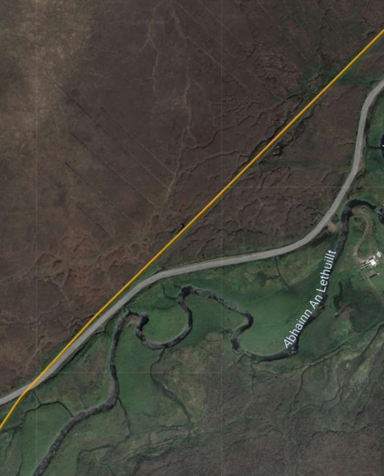
Further to the South, and inland from the port at Lindi which was 110 km South of Kilwa, there was an existing trolley line running from a jetty on the Lukuledi River which ran into Lindi Harbour, to former German plantations. The line had also been used by the German military. It was estimated that 30 kilometres of track could be recovered from the German line. A British line was then constructed heading inland from Lindi, using recovered materials where possible, by the 25th Railway Company. “On 27th August the line was open to Mtua and proved to be very useful in quickly evacuating wounded men as well as in carrying forward supplies. In this month, the 27th Railway Company arrived at Lindi, and support was provided by the South African Pioneers and the 61st (King George’s Own) Pioneers. Unskilled labour was badly needed and this problem had to be solved by moving down large labour gangs from the Usumbara and Central Railways. A few small steam engines were found on various plantations and put to use on the line. When the tractors from India arrived it was found that their axles had been made from inferior steel and they broke at the rate of two or three a day. This problem was compounded by severe rates of sickness that affected most of the Corps. At the beginning of November only 9 tractors out of 36 were working and only two mechanics were manning the workshops.” [1: p15]

Later in the month the Kilwa line was closed down and personnel were redeployed to Lindi where the Corps base was relocated, however the movement of badly needed materials and plant was delayed by shipping shortages. Railhead reached Ndanda, Mile 62, on 27th February 1918 and the decision was made to stop the line there.” [1: p15]

In November 1917, the Lindi line was still in use, with Army Service Corps men driving supplies from railhead into Portugese East Africa (PEA).

Much further North in Nairobi, a 13 km line was constructed from the town to the vast King’s African Rifles (KAR) Depot Camp at Mbagathi; the running of this line was handed over to the KAR.

In September 1918, “as the Germans in PEA were observed to be moving northwards, the Lindi line was ordered to be extended 30 kilometres to Massasi. The 28th Railway Company which was stood-by to sail for India quickly returned to Ndanda and started the work. Concurrently permission was obtained to raise an African Pioneer Company to replace the 28th Company. Suitable men were recruited from maintenance gangs on the Central Railway and from labour that had worked on the Mbagathi trolley line. The Lindi line reached Massasi in mid-November just as General von Lettow … still undefeated and then in Northern Rhodesia, now Zambia, accepted the Armistice terms decided in Europe and agreed to surrender. The 28th Railway Company sailed for India.” [1: p16]

References

  1. Harry Fecitt; The Indian Railway Corps East African Expeditionary Force, 1914-1919; via https://gweaa.com/wp-content/uploads/2012/02/The-Indian-Railway-Corps-East-African-Expeditionary-Force_1.pdf, 16th March 2026.

Appendix A – The Indian Railway Corps East African Expeditionary Force, 1914-1919

Introduction

In early August 1914 India was tasked with providing Indian Expeditionary Forces (IEFs) ‘B’ and ‘C’ for service in East Africa, and the provision of a Railway Corps was included in the organisation of IEF ‘B’ that was destined for German East Africa (GEA). The 25th and 26th Railway Companies, Sappers & Miners, under Majors C.F. Anderson and C.W. Wilkinson, both Royal Engineers, along with the Traffic and Locomotive Reserve of the two companies were mobilised at Sialkot and Quetta. Each company was around 300 men strong; an accompanying Coolie Corps of 300 men was raised mostly from the relatives of the company personnel. The officers were nearly all civilian railway officers of the Indian State Railways or Royal Engineer officers employed under the Indian Railway Board. The skills included survey, construction and operation. Major Anderson was medically repatriated soon after arrival and Lieutenant H.L. Woodhouse, Royal Engineers, then commanded the 25th Railway Company. Sir William Johns CIE was appointed Director of Railways.

The Indian Railway Board provided equipment sufficient for the repair and running of a section of the German East Africa railway. This equipment included 10 miles (16 kilometres) of 50-pound track, a large surplus of sleepers, 15 locomotives, nearly 200 trucks, a large number of pine baulks, a number of 20-foot and 40-foot bridge spans, cranes, pile drivers, machine tools, hand tools of all sorts, survey instruments, tents and office necessities. The companies brought out their own telegraph equipment but this was later handed over to the Indian Telegraph unit that carried out all the telegraph work of the railways and tramways.

Initial Employment in British East Africa

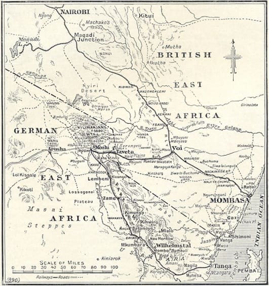
The Railway Corps arrived in two ships at Tanga in GEA where IEF ‘B’ was scheduled to land. Tanga was the Indian Ocean terminal of the German Usambara Railway that ran to Moshi near Mount Kilimanjaro; the British later named this line The Northern Railway. IEF ‘B’ failed to defeat the German force at Tanga and re-embarked; the Railway Corps stayed on its ships throughout the Tanga fight. IEF ‘B’ then steamed up to Kilindini, the port at Mombasa in British East Africa (BEA). Mombasa was the ocean terminal for the British Uganda Railway that ran up to Lake Victoria. IEF ‘B’ disembarked at Kilindini on 9th November 1914 and merged with IEF ‘C’ that had arrived in BEA in September.

A Railway Corps survey party commenced delineating a route for a military railway from Voi on the Uganda Railway westwards towards Moshi in GEA. The Railway Companies took over the defence of the Uganda Railway, sections of which were under threat from enemy raiding parties from GEA. Once all the stores had been landed it was decided to return most of the locomotive and traffic staff and the civilian officers to India, from where they could be easily recalled. In late December the two companies were moved from railway defence to construction work on the Kajiado to Longido road; better use was now made of their technical expertise and qualifications in the construction of roads, fortified posts and water supplies. The 25th Company went to Namanga and Longido and the 26th Company was based at Bissel.

Railway Construction

In February 1915 the decision was made to construct the first 40 miles (65 kilometres) of the one metre-guage military line from Voi towards Moshi in order to connect the military posts at Bura and Maktau. Twenty five miles of track were sent from India, 5 Miles were borrowed from the Uganda Railway, and the Corps already possessed 10 miles. The Railway Board in India continued its excellent support to the Corps by delivering to site the 25 miles of track only seven weeks after receiving the indent in India. The specialists were recalled from India and the companies were moved to Voi; material was moved up from Kilindini.

The construction method used was that one company laid track whilst the other worked ahead building the next bridge. Local labour for bush-cutting and earthworks was recruited from the Wataita tribe with the help of the District Commissioner and a missionary of the Church Missionary Society. The Wataita proved to be intelligent men who were quick learners. The 61st (King George’s Own) Pioneers had also landed with IEF ‘B’ and it had recently been employed in prolonging the Coonoor Railway to Ootacamund; when not tasked elsewhere the Pioneers provided useful support to the Corps. As the railhead advanced the Coolie Corps took over the maintenance of the track.

The Voi River was crossed and the first station opened at Mile 6.5 on 16th April. Heavy monsoon rains set in during May delaying the movement forward of supplies as the line needed constant repair and maintenance. On 31st May the bridge and station at Bura were opened at Mile 22. From now on the railway had to carry troops, supplies and water between Voi and Bura as well as construction material. The first section of the line was completed to Maktau on 23rd June. Whilst the railhead was advancing a big effort had been put into making Voi a suitable terminus for the military line. A workshop had been constructed, engines and rolling stock were brought up from Kilindini, a large store yard was established and an armoured train was built.

An unescorted Wataita earthwork gang was fired on by a German patrol and four men were wounded on 9th June; the Wataita were undeterred and asked if they could bring their bows and arrows to the worksite in future. The military line was blown up for the first time five days later, and after that the Germans blew the line every week, usually at around 2000 hours. This suited the repair gangs as they could make overnight repairs before the first morning train was run. The German demolitions were never very effective. On one occasion a train carrying the 130th (King George’s Own) Baluchis (Jacob’s Rifles) was pushing a truck loaded with sepoys’ kits ahead of it when an enemy mine detonated under the truck. A gap 0.75 metres in length was blown out of one of the rails but the complete train successfully passed over the gap and proceeded, with passenger and cargo damage being confined to some of the sepoys’ kits. The Germans had more success when attacking the Uganda Railway as that line often ran through desolate country and could be approached more easily.

A British attack at Mbuyuni, west of Maktau, failed on 14th July and that failure halted extension of the line. During this halt the companies constructed field works and defences and put in crossing stations and sidings on the Uganda Railway. A regular train service was introduced between Voi and Maktau and a Train Control System was installed. A second indent for 30 miles of track was sent to India and it arrived two months later. On November 13th 1915 the Director of Railways was placed in control of the Uganda Railway. This was done in order to ensure intimate cooperation between the Uganda Railway and the military line during the planned British offensive in early 1916. Officers and men of the Railway Corps were posted to the Uganda Railway whose operations were effectively militarised.

Platelaying began again in January 1916 and Mbuyuni, Mile 53.25, was reached on the 25th of that month, the Germans having withdrawn from the location two days earlier without fighting. Thousands of South African, British, Rhodesian, Indian and African troops were now being housed in camps along the military line and the supply of water in railway travelling tanks to these camps was a vital task for the Corps. Some relief was obtained when the engineers ran a pipeline from Bura, where the water was sourced, to Maktau. The British attacked Salaita Hill, west of Mbuyuni, on 12th February but the attack failed, the enemy counter-attacking to the railhead at Lanjoro, Mile 60.

This map illustrates the area of early operations in German East Africa. [21: p5]

Moving into German East Africa

The Germans withdrew from Salaita Hill and moved to defend the Latema-Reata hills just west of Taveta on the GEA and BEA border. The Corps pushed the military line westwards through dense bush, following up the advancing British troops. From drafts arriving from India and from within the existing Railway Companies the 27th Railway Company, Sappers & Miners, was formed; the Company Commander was Captain R.E. Gordon, Royal Engineers. This allowed the Corps to continue platelaying in dangerous territory whilst providing its own security. The Lumi River was crossed and Taveta reached, Mile 75, on 23rd March. After a tough fight the Germans had withdrawn from the Latema-Reata position on 12th March, allowing the Corps to lay track over a saddle between the two hills.

The enemy was demolishing the Usambara Railway line as he withdrew down it and once Moshi was in British hands a half-company of the Corps repaired the track from Moshi to the Ruvu River. Meanwhile the railhead was advanced over what was the toughest stretch on the entire military line. The monsoon rains again fell heavily but three rivers were crossed and a dense forest penetrated; the soil was black-cotton and quickly became marsh resulting in platelaying being achieved under water. A junction with the Usambara line was made 20 kilometres below Moshi and 40 kilometres from Taveta on 25th April. This was just in time for the British troops in Moshi who had lost their road from Taveta to the monsoon rains and floods, and who now relied upon supplies arriving by train.

The South African General J.L. Van Deventer was tasked by the British theatre commander, General J.C. Smuts, to advance south-westwards through Arusha and Kondoa Irangi to the German Central Railway line that ran from Dar Es Salaam on the Indian Ocean coast to Lake Tanganyika in the interior. To assist the supply columns supporting the South Africans in getting across a large number of bad drifts on the initial stage of the road the Railway Corps was tasked with pushing a line westwards from Moshi over the Garanga River to Sanja, Mile 21 on this new short line. Sanja was reached by the end of June. At this time the 28th Railway Company, Sappers & Miners, arrived from India commanded by Captain. E. St.G. Kirke, Royal Engineers, raising the establishment of the Railway Companies to that of a battalion. Lieutenant Colonel C.W. Wilkinson, Royal Engineers, was appointed Commandant of the Railway Battalion which became a unit in the Railway Corps.

Reconstructing the Usambara Railway

On 14th May reconstruction of the Usambara Railway south of Ruvu commenced; the Germans had demolished the Ruvu bridge but the Corps 7 erected an 18-metre girder bridge on 20th May. From then onwards on the 320 kilometres of track leading to Tanga every bridge had been destroyed. However the demolitions had been hasty and planned ineffectively and the Corps could quickly make track diversions or re-build bridges. In many places the track had been torn up and the fastenings thrown into the bush, in other places the fastenings only had been removed, and elsewhere each alternate rail joint had been blown up. The track was repaired through Lembeni, Same, Makania, Hedaru and ‘German Bridge’ stations, the latter being reached on 20th June. ‘German Bridge’ was the last suitable crossing point over the Pangani River until Maurui is reached 80 kilometres further on. The Germans had started building a bridge here and the British completed the construction.

Just beyond ‘German Bridge’ is Buiko, 180 kilometres from Tanga and the mid-point in the line. Mombo station, Mile 75, was opened on 29th June; from here the Germans had built a hand-powered field railway (trolley line) of 60 centimetres gauge to Handeni, 65 kilometres to the south. 25th Railway Company assisted the Royal Engineers in restoring this line as it also had been partially destroyed, and on completion this trolley line was very useful for moving supplies in support of General Smuts’ advance to Morogoro.

Fighting in the Infantry Role

On 4th July, railhead reached the Pangani River near Maurui and by the end of the month had reached Korogwe. However the German theatre commander, Colonel Paul von Lettow, had early in July tasked 500 or more of his troops as a ‘stay behind’ group to harass the British lines of communication in the area between Tanga, Maurui and Handeni. This enemy group successfully made a nuisance of itself by attacking convoys, mining roads, cutting telegraph and telephone lines and sniping from the bush. An attack by 170 German troops with a light gun had been repulsed at Zugunatto Bridge by the Jind Infantry on 13th July; the soldiers from the Princely State of Jind were amongst the best of the British troops. General Smuts ordered his Inspector General of Communications Brigadier General W.F.S. Edwards, a former BEA policeman, to resolve this problem. As Edwards had no spare infantry he decided to use the 25th and 26th Railway Companies, Indian Sappers and Miners, along with a few infantrymen, and reported this to General Smuts who made no comment. But Edwards did not confer with the Director of Railways who badly needed those two companies to stay on the job of railway restoration in order to alleviate supply problems. After dark on 13th July the two companies with 100 Jind Infantry, 50 British other ranks and 100 sepoys, moved out from Korogwe tasked with attacking Segera Hill and Mfumbile. Captain E. St.G. Kirke, Royal Engineers, commanded the companies and Lieutenant Colonel Wilkinson commanded the force.

The Railway Companies did well on Segera Hill, getting up to a machine gun, killing the German NCO in charge and capturing the gun in a bayonet assault. The German force withdrew hurriedly but counterattacked next day. The companies were up to their new task and broke the enemy assault. Lt Col Wilkinson now moved across country to deal with an enemy force at Hale, found that it had withdrawn to Kwa Mugwe, moved there and drove the enemy rear-guard away and then repelled another German counter-attack on 19th July. In these operations the machine guns of the accompanying Jind Infantry gave the Railway Companies the supporting firepower that they needed. The companies then returned to their railway duties, having taken a few casualties but doubtless with many war stories to tell. On 18th August Tanga was reached and the port and railway came into use for moving supplies from Kilindini to Korogwe where another 60-centimetre trolley line was constructed towards Handeni. The materials for this line came from abandoned German farms and plantations and the locomotion came from adapted Ford cars used as tractors and operated by the East Africa Motor Transport Corps.

The 600 mm trolley line serving Handeni. [21: p9]
Railway workshops in Nairobi converted many vehicles, including this Vauxhall, to carry supplies on the hastily rep lines in German East Africa. In three months over 300 miles of railway were repaired, enabling locomotives to take once more. [21: p10]

Incidents on the Central Railway

The Royal Navy along with infantry units advancing from Bagamoyo seized Dar Es Salaam, the GEA capital, on 4th September. A reconnaissance of the Central Railway between Morogoro and Dar Es Salaam showed that all bridges were down. Two Railway Companies were shipped to Dar Es Salaam to start repairing the track from that end and the other two were shipped to Bagamoyo; from Bagamoyo they moved overland to the dropped bridges over the Ruwu River which urgently needed reconstruction. The line was repaired for light use to Morogoro and mechanical transport units converted a selection of lorries to rail tractors, allowing the South African Pioneers to run a supply service westwards to Dodoma, 240 kilometres from Morogoro. Each tractor could pull 15 tons of trucks and freight. Further work was needed before the heavier steam trains could use the line but Dodoma was being supplied from Dar Es Salaam by steam trains on 1st January 1917. The South African Water Supply Corps gave constant support to the Railway Corps whenever a water supply point or a pumping station needed to be established, and large numbers of labourers from the South African Native Labour Corps were supplied to support the Corps; unfortunately many of these Africans succumbed to tropical diseases.

The Germans had destroyed many engines and trucks on the line but again their demolition work was unsatisfactory and did not greatly hinder the Corps. Troops from the Belgian Congo, now the Democratic Republic of the Congo, had crossed Lake Tanganyika and fought their way to Tabora, where 40 engines and 200 trucks were found basically undamaged. These were shared with the Belgians. The Railway Corps moved its base from BEA to Dar Es Salaam but immediately had to support the engineers restoring the docks there; Corps cranes were used to unload ships and the companies constructed jetties and slipways. In January 1917 Major L.N. Malan, Royal Engineers, took over command of the Railway Battalion from Colonel Wilkinson who became Deputy Director of the Railway Corps.

In April 1917 a branch line was constructed from Dodoma on the Central Railway southwards towards the Ruaha River. 26th, 27th and 28th Railway Companies were involved in the work which lasted until August, when railhead reached Matikira, Mile 28. The country was very difficult to cross and the lack of shipping to bring down sleepers from Kilindini caused delay. As soon as this short line was no longer needed the rails were recovered and used elsewhere.

A bad accident occurred on the Central Railway on 5th May when a re-built bridge at Mkata collapsed at night in heavy rain, due to an original German pier proving to have insufficient foundations. Sixteen gunners from 24th (Hazara) Mountain Battery (Frontier Force) and four Askari from the King’s African Rifles were drowned when their cattle trucks fell into the swollen river. Many other men were badly injured when they were flung against weapons and stores in the trucks. 26th Railway Company was deployed to restore the damaged line.

On 29th August 1917 the station at Kahe, where the military line from Voi joined the Usambara Railway from Moshi, was unexpectedly attacked by enemy troops, causing consternation amongst rear-echelon elements in Nairobi. An enemy raiding party had broken away from the German forces in southern GEA and had advanced northwards across the Central Railway, attacking British and Belgian locations; former German Askari enthusiastically joined the raiders. Elements of the party got up to Lake Victoria and one small group attacked Kahe. Two trains were captured as they approached the station, then looted and burned. Three British officers were taken prisoner, the Station Master was mortally wounded and a number of porters and labourers were killed. Before withdrawing the Germans started one of the two trains and let it run towards Taveta, but an Indian engine driver who had escaped into the bush jumped into one of the two engines on the train and brought it under control. When the train was at a safe distance from Kahe the driver disconnected the carriages and drove the engines to Taveta, where he was given a prompt military award.

A Trolley Line in the Kilwa Area

Moving south the British now developed Kilwa Kisinjane as a port where men and supplies could be landed. Commencing in November 1916 a 60centimetre tramway was built by the Corps from the ocean to Kilwa Kivinje, a distance of 26 kilometres, and then onwards for a further 24 kilometres. The construction material was produced by stripping the trolley lines previously built from Mombo and Korogwe. Motor tractors were again used and a driver company and a supporting maintenance company were formed from mechanical transport personnel; these companies became sub-units in the Railway Corps.

However tropical diseases and ailments such as malignant malaria were now affecting the Corps badly and often far more men of all trades were sick than were at work. Also the driving of tractors on railway lines, especially around curves, was not as easy as many potential drivers thought and de-railings with consequent damage were frequent. Sixty more tractors were ordered from India and 50 more from South Africa; these were all converted Ford cars with bogie trucks in place of the front axle and with heavier back axles and box bodies. The first 16 kilometres of track was duplicated but in broader guage and steam trains ran along it, allowing swifter movement of men from the port to the first camp site where water was available. In July 1917 further construction was authorised at Kilwa and the 60-centimetre line was extended to Lungo, Mile 84, by November. On this line, which had a slight gradient, each box-body tractor pulled two trailers with a total load of up to 2.72 metric tonnes (3 tons).

A typical ‘train’ on a trolley line in what was once German East Africa but which by this time was terrritory occupied by the British. [21: p13]
A typical Ford light railway tractor in use in the occupied German East Africa. [21: p15]

Construction activities at Lindi

A hundred and ten kilometres south of Kilwa more port facilities were developed at Lindi, which had a fine natural harbour. A British force was moving into the interior and needed a railway to follow it. Steam trains were ruled out because shipping was not available to move the necessary materials and rolling stock from Dar Es Salaam and Kilindini, so another 60-centimetre tractor line was started. This was helped by the fact that an existing trolley line led from several former German plantations to a jetty on the river running into Lindi Harbour; it was estimated that 30 kilometres of track could be recovered from the German line.

The 25th Railway Company deployed to Lindi in June and commenced work, following the British advance. Survey work on both the Lindi and Kilwa lines was sometimes interrupted the appearance of both lions, rhinoceros and elephants, and occasionally by the approach of enemy patrols who were engaged and driven off. On 27th August the line was open to Mtua and proved to be very useful in quickly evacuating wounded men as well as in carrying forward supplies. In this month the 27th Railway Company arrived at Lindi, and support was provided by the South African Pioneers and the 61st (King George’s Own) Pioneers. Unskilled labour was badly needed and this problem had to be solved by moving down large labour gangs from the Usumbara and Central Railways. A few small steam engines were found on various plantations and put to use on the line. When the tractors from India arrived it was found that their axles had been made from inferior steel and they broke at the rate of two or three a day. This problem was compounded by severe rates of sickness that affected most of the Corps. At the beginning of November only 9 tractors out of 36 were working and only two mechanics were manning the workshops.

Later in the month the Kilwa line was closed down and personnel were redeployed to Lindi where the Corps base was relocated, however the movement of badly needed materials and plant was delayed by shipping shortages. Railhead reached Ndanda, Mile 62, on 27th February 1918 and the decision was made to stop the line there. By then General, as he now was, von Lettow … and his slimmed-down German army were moving deeper into Portuguese East Africa (PEA), now Mozambique.

The Run-down of the Indian Railway Corps in East Africa

By November 1917 the 25th Railway Company was medically unfit for work with its strength at less than 40 fit men, and it was returned to India in March 1918. The 26th and 27th Railway Companies were in a similar condition and in May they also returned to India. 28th Railway Company remained in the field and all recent arrivals and returnees from leave were posted into that company. The Lindi line continued to be used and Army Service Corps men drove supplies from railhead into PEA; sadly many of these European drivers succumbed to tropical diseases and are buried in East Africa. As the East African Force was slimmed down Directorates were abolished and in March Sir William Johns left the theatre after handing over the Railway Corps to Colonel Wilkinson.

Up in Nairobi a tramway 13 kilometres long was constructed from the town to the vast King’s African Rifles (KAR) Depot Camp at Mbagathi; the running of this line was handed over to the KAR. The line from Voi to Tanga was practically on a peace footing and the Central Railway was being converted to commercial use. The arrival of 100 new tractors from South Africa, the increased use of steam traction, and a big improvement in the health of the personnel meant that soon the Lindi line was running very efficiently.

In September, as the Germans in PEA were observed to be moving northwards, the Lindi line was ordered to be extended 30 kilometres to Massasi. The 28th Railway Company which was stood-by to sail for India quickly returned to Ndanda and started the work. Concurrently permission was obtained to raise an African Pioneer Company to replace the 28th Company. Suitable men were recruited from maintenance gangs on the Central Railway and from labour that had worked on the Mbagathi trolley line. The Lindi line reached Massasi in mid-November just as General von Lettow-Vorbeck, still undefeated and then in Northern Rhodesia, now Zambia, accepted the Armistice terms decided in Europe and agreed to surrender. The 28th Railway Company sailed for India.

The Indian Railway Corps retained responsibility for railways in East Africa until January 1919, when civilian direction and personnel replaced it. The Corps had done an excellent job, tackling the diverse and serious challenges that East Africa presented in a most professional manner. Credit for the performance of the Corps must be attributed to the support provided by the Indian Railways Board and the Corps of Royal Engineers, but above all else to the skill, adaptability and perseverance of the men of the Railway Companies, Sappers & Miners. Shabash!

The Halton Light Railway

This short line originated from a proposal made by the stationmaster at Wendover. [1: p97]

The featured image for this short article is a photograph of a OO-Gauge model of Wendover Railway Station built by David Dan Givens and covered in the September 2018 edition of Hornby Magazine. The image shows the Northwest approach to Wendover Station. The branch line to RAF Halton leaves the main line just off camera to the left. [17]

The Halton Light Railway grew out of proposals made by the stationmaster at Wendover Station (bottom-left on this map extract). The line was less than 2 miles in length. It had a short 2ft-gauge extension across the Icknield Way into the beech woods on the slopes of the Chilterns. [1: p97]
A very similar area, on modern satellite imagery. [Google Maps, March 2026]

Wendover Railway Station serves the town of Wendover in Buckinghamshire, England, and villages including Ellesborough and Wendover Dean. It was opened by the Metropolitan Railway in 1892 and is on the London Marylebone to Aylesbury line and, in the 21st century, is served by Chiltern Railways trains. It sits between Great Missenden and Stoke Mandeville stations. [4]

The main line Northwest of Wendover in 1930, © Transport for London. [13]
The main line Southeast of Wendover in 1930, © Transport for London. [13]
Wendover Railway Station seen from the Southeast in 1944. The northbound platform is on the left and the southbound on the right. Both platforms have brick buildings and gabled canopies; the roofs of the canopies are part-glazed. A covered footbridge stands at the end of the buildings. A signal cabin [16] is located at the end of the northbound platform, with a goods shed on the opposite side of the tracks; wagons are stored on a track by the shed. Note the station name roundel on the southbound platform, with its accompanying oil lamp, © Transport for London. [11]
Wendover Station in the 21st century, also seen from the Southeast, © Mertbiol. This file is made available under the Creative Commons CC0 1.0 Universal Public Domain Dedication. [12]
Wendover Station seen from the railway bridge to the Southeast of the Station © H. Landon. This image was shared by Rod Bacon on the Wendover Memories Facebook Group on 19th December 2022. [20]
This postcard image of Wendover Station was shared by Rod Bacon on the Wendover Memories Facebook Group on 8th December 2020, © Public Domain. [20]

The Halton Light Railway was a spur line from Wendover Station to RAF Halton used to transport coal and other goods to and from RAF Halton.

Wendover Railway Station and the branch to Halton. The branch can be seen leaving the main line Northwest of the Station, close to the top of this extract from Britain from Above Image No. EPW036323 which is taken from the Southeast, © Historic England. [10]
The hedge line running left to right across this extract from Britain from Above Image No. EPW036323, marks the line of the branch, © Historic England. [10]

A narrow gauge railway link to Wendover station, which had been used to transport timber from beech woods on the Halton Estate in support of the [First World] war effort, was replaced in 1917 with a standard gauge branch line, to bring in coal and building materials to the RFC workshops. Timber from Halton Woods was used as trench props on the Western Front. [7]

Opened in 1917 after an eight-week construction period, the line ran for 1.75 miles (2.82 km) and was constructed by German prisoners of war during World War I. The railway was originally built, earlier in WW1 to carry timber from local beech woods to Wendover Station and building materials into the site of RAF Halton for construction of the workshops and other units. It also forwarded coal to the boilers on the camp. [7]

Wikipedia says that the line was originally built as a narrow gauge line and “was later converted from a narrow gauge of 1 ft 11 1⁄2 in (597 mm) to 4 ft 8 1⁄2 in (1,435 mm) standard gauge and was used to bring timber out of Halton woods.” [2]

The Railway has a Monument Record and appears on Buckinghamshire County Council’s Heritage Portal. It is Monument Record No. 0951006000. [7]

The Historic Monument Record says that the Railway is shown on historic mapping NG 6″ Provisional Edition 1955-62 and NG 10k Edition 1972-90. Labelled as ‘dismantled railway’ on 25k digital raster map. It appears to be disused even by 1955-62 edition. [7]

A railway dating from the 20th century is visible on historic aerial photographs and remote sensing data as extant structures, earthworks and levelled earthworks and was mapped as part of the Aylesbury Vale Aerial Investigation and Mapping project (EBC18604). Located on the north side of the town of Wendover and centred at SP 86991 08905. The railway line, originally built as a narrow-gauge line, was constructed to extract timber from the woods at Halton, felled by Canadian lumberjacks, for use in the trenches in World War I. [8: p81] Aerial photographs from 1961 appear to show the railway still present but it does not show on those from 1967. Images of the railway and the station at West Camp are on the ukairfields website for Halton. [7]

The conversion of boilers on the RAF station from coal fired to oil fired, allowed road-tankers to take over the inward flow of fuel and accelerated the demise of the railway and the last train ran on 29th March 1963 with closure following two days afterwards.[7]

The majority of the track has since been removed, including the original bridge over the Grand Union Canal which was replaced by a modern footbridge, however much of the line is designated a permissive footpath (rail trail).

The two images below are embedded in this article from ukairfields.org.uk and are © Richard E. Flagg. The first shows a remaining length of what appears to be 2ft-gauge track. The second shows what was the RAF Halton Railway Station.

A video covering this line can be found here. [5] This is one of a series of videos under the overall title of “Henry’s Adventures.”

The Route of the Line

Leaving Wendover heading Northwest, trains serving the Halton RAF Station ran alongside the main line before turning away to the Northeast.

The line crossed Aylesbury road at a level -crossing. …

Looking Northwest along Aylesbury Road, the crossing sat adjacent to Castle Park. This image was shared by Rod Bacon on the Wendover Memories Facebook Group on 28th March 2025. [18]
The crossing gates on the Southeast side of Aylesbury Road. This image was shared by Rod Bacon on the Wendover Memories Facebook Group on 4th April 2025. [19]
The line of the Light Railway is marked in this and later satellite images by a brown line superimposed on the image by RailMapOnline.com. [14]
Looking Southwest from Aylesbury Road. The hedge immediately in from of the camera masks the line of the old railway. [Google Streetview, September 2025]
Looking Northeast from Aylesbury Road, the track ahead of the camera and the hedge line to its left are on the line of the old railway. [Google Streetview, September 2025]

Further East the line crossed the Wendover Arm of the Grand Union Canal. …

The location of the railway bridge over the Wendover Arm of the Grand Union Canal. The rail line followed the field boundaries, running from the bottom-left corner of this image to the top-right. [Google Maps, March 2026]

The Footbridge (Oliver’s Bridge) replacing the original railway bridge over the Canal. As is obvious, the footbridge is narrow-gauge, unsuitable for access for all, © Chris Reynolds and licenced for reuse in under a Creative Commons licence (CC BY-SA 2.0). [15]

Beyond the Canal, the line turned Northeast before reaching RAF Halton where a station building and platform received and despatched trains. A fan of sidings sat to the right of the line.

The approach to RAF Halton showing the power house and workshop, © Public Domain. This image was shared by Rod Bacon on the Wendover Memories Facebook Group on 2nd October 2025. [22]

A short length of 2ft-gauge line remained in use until it was closed in 1941. It sat to the Northeast of the sidings and crossed Icknield Way before coming to its terminus.

RailMapOnlne.com records the railway lines in the immediate vicinity of RAF Halton in brown and orange, as shown here. The standard-gauge line (brown) is much as shown on the first plan/map above. The 2ft-gauge line is different to that shown on the map/plan near the head of this article. If we make the assumption that there would be a need to tranship timber from the 2ft line to the standard-gauge line, then the layout shown here is the more likely. The two maps have the crossing point over the Icknield Way (B4009) at approximately the same location. [14]
The crossing over the Icknield Way was at the approximate location shown by the orange line superimposed on the satellite imagery from RailMapOnline.com. [14]
Looking West from Icknield Way along the line of the old 2ft-gauge line. [Google Streetview, March 2025]
Looking East from Icknield Way along the line of the old 2ft-gauge line. [Google Streetview, March 2025]

Locomotives

I have not been able to establish a locomotive roster for the RAF lines at Halton. One locomotive in particular was identified by Frank Jones in the 1960s. ….

Manning Wardle 0−4−0 saddle tank R.A.F. No.2 was photographed by Frank Jones, presumably after the closure of the branch line and after she had been through the hands of John F. Wake’s Geneva Engineering Works in Darlington. Frank Jones submitted a photograph of No. 2 to the Industrial Railway Record in October 1968. It can be seen here. [6]

Modelling

Hornby Magazine covered an OO-Gauge Model of Wendover Railway Station which included the first few metres of the branch line. The layout featured in the September 2018 edition of the magazine. [17]

The RAF Halton Branch is represented by the line at the centre of this image which has a very short train heading away along the branch. [17]

This image shows the branch locomotive which was a Manning Wardle 0-4-0ST heading for RAF Halton. [17]

Wendover’s Goods Shed and Signal Box (shown here) sat immediately Southeast of the junction. [17]

References

  1. Clive Foxell; The Story of the Met & GC Joint Line; Clive Foxell, Chesham, Buckinghamshire, 2000.
  2. https://en.wikipedia.org/wiki/Halton_Railwayhttps://en.wikipedia.org/wiki/Halton_Railway, accessed on 13th March 2026.
  3. https://www.raf.mod.uk/our-organisation/stations/raf-halton, accessed on 13th March 2026.
  4. https://en.wikipedia.org/wiki/Wendover_railway_station, accessed on 13th March 2026.
  5. https://share.google/53r8ODIIX65bYAGnx, accessed on 13th March 2026.
  6. https://www.irsociety.co.uk/Archives/21/PP_21.htm, accessed on 13th March 2026.
  7. https://heritageportal.buckinghamshire.gov.uk/Monument/MBC24945, accessed on 13th March 2026.
  8. Andrew E. Adam; Beechwoods and Bayonets: The Book of Halton; Barracuda Books, 1983.
  9. http://www.ukairfields.org.uk/halton.html, accessed on 13th March 2026.
  10. https://www.britainfromabove.org.uk/en/image/EPW036323, accessed on 13th March 2026.
  11. https://www.ltmuseum.co.uk/collections/collections-online/photographs/item/1998-66276, accessed on 13th March 2026.
  12. https://commons.wikimedia.org/wiki/File:Wendover_railway_station_and_A413_road,_Wendover,_Buckinghamshire.jpg, accessed on 13th March 2026.
  13. https://www.ltmuseum.co.uk/collections/my-collections/simon-eccles/wendover-rail-collection, accessed on 13th March 2026.
  14. https://www.railmaponline.com/UKIEMap.php, accessed on 13th March 2026.
  15. https://www.geograph.org.uk/photo/1235766, accessed on 13th March 2026.
  16. https://signalbox.org/branch-lines/lets-wend-over-to-wendover, accessed on 14th March 2026.
  17. David Dan Givens; Wendover; Hornby Magazine, September 2018, via https://www.keymodelworld.com/article/wendover-oo-gauge-1930-lner-layout, accessed on 14th March 2026.
  18. https://www.facebook.com/share/p/1DXAafLM4i, accessed on 15th March 2026.
  19. https://www.facebook.com/share/p/1CAPnmd3ng, accessed on 15th March 2026.
  20. https://www.facebook.com/share/p/1DozKwvnab, accessed on 15th March 2026.
  21. https://www.facebook.com/share/p/18Ldav8tSn, accessed on 15th March 2026.
  22. https://www.facebook.com/share/p/1a586d1661, accessed on 15th March 2026.

The Railways of Skye and Adjacent Islands – Part 5 – The Quartzite (Silica) Quarry Tramway at Ord

There was a short tramway in the quartzite quarry close to Ord which was operational in the mid-20th century. …

The small village of Ord sits on the Northwest side of the Sleat Peninsula. [1]
The small building shown on this map near to Coille a’ Chuaraidh is the approximate location of the quarry. [6]
A road from the village runs Southeast across the Sleat Peninsula. The quartzite quarry was on the North side of the road at Coille a’ Chuaraidh. [1]

J.G. Stein & Co. of Bonnybridge commenced quarrying at Ord, Sleat Peninsula, Isle of Skye in 1944 and this continued until 1960. Silica was extracted from the quartzite ore and used as a heat resistant substance in industrial furnaces, fire bricks, cements, boilers etc. Only the explosives store and a storage building, now used as a bothy, survive. [1]

Ore was removed from the quarry in trucks that ran on a very short rail track to the road where it was loaded onto lorries and taken to the pier at Armadale. The ore was then loaded into a waiting puffer (coastal trading boat). [1]

The high cost of transport away from Skye meant that the quarry was uneconomic and it closed in 1960. [2]

The tramway/railway was very short – only 110 metres in length. [4]

The Ord Quartzite Quarry in 2024, © Copyright Richard Webb and licensed for reuse under a Creative Commons Licence (CC BY-SA 2.0). [7]
A stone shed at Ord Quarry which remained in use in 2010, although Ord Quartzite Quarry was disused, © John Allan and licensed for reuse under a Creative Commons Licence (CC BY-SA 2.0). [8]

Rolling Stock

The tramway was operated by manpower, no mechanical propulsion was employed. Rolling stock consisted of a number of wooden-framed tipper wagons, allegedly used on the Skye Marble Railway. [3]

This image is a postcard view of the Skye Marble Quarry.At the centre of the image is one of the tipper wagons used at Kilchrist and which may well have been bought for use at Ord Quarry. [5]

Until the 1970s, there were a number of these wagons gradually deteriorating on the beach at Ord, although there is no longer any sign of them. [4]

References

  1. https://her.highland.gov.uk/Monument/MHG55558, accessed on 3rd June 2025.
  2. http://www.sleatlocalhistorysociety.org.uk/index.php/township/36, accessed on 3rd June 2025.
  3. https://hlrco.wordpress.com/scottish-narrow-gauge/constructed-lines/skye-marble-railway, accessed on ,3rd June 2025.
  4. https://hlrco.wordpress.com/scottish-narrow-gauge/constructed-lines/ord-quarry-tramway, accessed on 3rd June 2025.
  5. https://www.facebook.com/share/1G4ECRkrPn, accessed on 1st June 2025.
  6. https://helpful-mammal.co.uk/2018/07/29/cxcv-armadale-to-isleornsay, accessed on 3rd June 2025
  7. https://www.geograph.org.uk/photo/7761899, accessed on 3rd June 2025.
  8. https://www.geograph.org.uk/photo/2102114, accessed on 3rd June 2025.

The Railways of Skye & Adjacent Islands – Part 4 – The Raasay Iron Mine Railway

There is an excellent book by Laurence & Pamela Draper, which they self-published in 1990, entitled “The Raasay Iron Mine: Where Enemies Became Friends.” I picked up a copy second-hand from an online sales site. That book covers the operation on Raasay in some detail. This article looks at the railways involved.

An extract from the Ordnance Survey 1″ Mapping of 1930 (Sheet 25) shows the line of the railway running North-northeast from the pier at Suisnish to Mine No. 1. A dotted line represents the line to Mine No. 2. [8]

Raasay Iron Mine

L. & P. Draper tell us that “Just before the First World War the Scottish coal and iron-ore mining, and iron-smelting, firm of William Baird and Company opened up an iron-ore mine on the Island of Raasay in the Inner Hebrides. … In association with the mine, Baird’s built several kilometres of narrow-gauge railway, a crusher, five calcining kilns, a huge ore hopper and a reinforced concrete pier. Many aspects of the installation, such as this pier, diesel-electric power generation and the provision of powerful external electric lighting, were very advanced for their time.” [1: pV][3: p146]

The BBC tells us that “William Baird and Co. Ltd … owned the Raasay estate and initiated the mine’s operations. The mine was developed just before the war and was crucial in providing iron ore for the British war effort, with the ore being transported to Ravenscraig for smelting.” [2]

Because most of the local men had been called up, Baird’s arranged for German Prisoners of War to work the installation from 1916 onwards. In permitting this, the British Government probably “contravened the Hague Convention which specifically banned the employment of Prisoners of War on munitions production; in 1920 the British Government attempted to destroy all relevant records, and was largely, but not entirely, successful. To enable prisoners to be used, the project was effectively nationalised (although that word was not actually used), with Baird’s operating it as agents for the Government; this was a standard system of management in the First World War. … Prisoners and local people worked in harmony together as colleagues, but relationships between Baird’s and the Ministry of Munitions were at times hostile. At the end of 1917 the local men, who were badly paid compared with men doing similar work elsewhere, went on strike, and there were allegations in Parliament that German Prisoners of War were being used as strike breakers, with a result that Winston Churchill himself made statements in response; these allegations were at best only half truths.” [1: pV][3: p146]

This map was reproduced in an article written by the Drapers for Der Anschnitt in 1999. It shows Baird’s initial plans for a railway were altered to move the kilns away from Suishnish House (modern spelling Suishnish). [1: p2]]3: p150]

A probable total of almost 200,000 tons of raw iron ore was produced over the life of the mines, which in the first instance ran until six months after the end of the First World War. “Everything was maintained in full working order, [but] almost the only further iron to be yielded, in the Second World War, came out as scrap from the dismantled installation itself.” [1: pV][3: p146]

L. & P. Draper tell us that, “After hostilities ceased on 11th November 1918 there was a rapid fall in demand for iron, and on 21st December 1918 the Government stated that it wished to terminate its agreement with Baird’s, asking: … do you want the prisoners after about the end of January 1919? … Baird’s said that it did, for a while, if the Ministry could take the output; otherwise the prisoners were not needed. … The Ministry was anxious that the whole installation should be shut down by 31st March 1919.” [1: p30]

It appears that there was probably no resolution between Baird’s and the government over ownership of remaining stocks of iron ore at the mine when it closed but L. & P. Draper note that in the years after the war, whenever a full load of coal was delivered to Raasay, the steamers involved left Raasay with a full hold of iron ore. [1: p31-32]

Soon after the war ended there was unrest on the island, partly because the fisheries had failed and partly because many of the veterans returned expecting that their interpretation of promises which had been made to them, that they would be re-located on more fertile ground, would be honoured. Following the example of many other Hebridean islanders since the latter years of the nineteenth century, they forcibly took over the south end of the island and some men served terms of imprisonment as a consequence. However, Baird’s sold the estate to the Scottish Board of Agriculture during the 1921-22 post-war crisis and many islanders were re-settled on land which they had coveted.” [3: p155-156]

ln the mid nineteen thirties, twenty years after its heyday, the installation was still in good working order as Baird’s had placed the works on a care and maintenance basis and employed a full-time 3-to-5 man crew … who kept the machinery in perfect working order. They painted the ironwork, including the large expanse of the end of the calcined-ore hopper, with red Iead, and ran the installation once each week. lt was capable of being started at relatively short notice at a time of national emergency. However, this was not to be, probably because of the cost of winning the relatively low grade ore, and after the onset of the Second World War the only iron to come from the site was the installation itself as scrap. lt is not clear whether the formal abandonment on 15th May 1941 was the beginning of dismantling, or just the date on which the
plan was drawn. … Three, if not all, of the kilns were taken to Lingdale, in Cleveland, Yorkshire where three were re-erected . They continued in intermittent production until about 1962. lt is not known which ones were rebuilt, but it seems likely that they were Nos 3, 4 and 5 which had been unused on Raasay.” [3: p156]

Raasay Iron Ore Mines Railways

No 1 Mine was connected to the pier at Suishnish by a virtually straight railway. A short steeply-inclined spur to the outcrop site left the main line at the entrance to No 1 Mine; No 2 Mine was connected by a spur from the main line. The railway led directly from the mines to the top of the crusher, on the hill overlooking the pier. Just below the crusher stood the kilns. An inclined railway connected the area just above the crusher down to the pier; this is also the route by which the coal was taken from the pier up to the crusher. Coal and iron ore were mixed in the crusher and taken by conveyor belt to charge the kilns. Below the kilns, more belts took the calcined ore to a hopper, from whence it was ultimately loaded onto ships at the seaward end of the pier.” [1: p33][3: p151]

Prior to the construction of the 4 ft. 6 in. railway the first output from the iron ore mine was transported by horse and cart down the narrow lane through Inverarish. [5: p78] But before the completion of the facilities near East Suishnish Pier, the incline was already bringing iron ore down from Mine No. 1 and the Outcrop Site.

We focus first on the railway infrastructure at the southern end of the line where the processing plant and pier were sited. The drawing below shows the layout of the site.

This hand-drawn map illustrated the arrangements at the Southern end of the operation on Raasay. It shows the layout of the various rail lines which served that part of the site. The main incline enters at the top of the sketch map. It brought the raw iron ore from the mine to the crushing plant. The crushed ore then was taken by an enclosed conveyor to the kilns where calcination took place. [4] It is of interest to note that the construction of the reinforced concrete pier was undertaken by Robert McAlpine and Sons, pioneers of the Glenfinnan and other concrete viaducts on the Mallaig railway line opened in 1901. [1: p33 and 35]
A first length of the line as shown on the satellite imagery provided by railmaponline.com. [10]
A second length of the line as shown on the satellite imagery from railmaponloline.com. [10]
Suisnish Pier appears at the bottom of this extract from Google Maps which allows us to see the line of the old railway without a superimposed purple line. As can be seen, the line of the old railway is still very evident in the landscape. The building shell to the West of the incline was a series of offices, from the Southeast these were a general office, a store (With a boiler underneath), a joiner’s workshop, a blacksmith’s workshop and an engineer’s workshop. To the right of the large hopper, the series of stone/brick structures are all that remains of the kilns. [Google Maps, May 2025]
East Suishnish (Suisnish) Pier in operation, note the wagons lined up on the pier. This T-shaped pier constructed of hand-mixed and reinforced concrete is 380 feet long and 25 feet wide. The pier frontage is 150 feet. The ore conveyor runs the length of the pier from the hopper to the 50 feet high ore conveyor loading-tower on the pierhead. The pier was designed by F.A. MacDonald and Partners, C.E. Glasgow and built by Robert McAlpine and Sons with teams of Irish labourers. [6][British Geological Survey: BGS C 2185]
Looking down from the former railway over the remains of the iron works and the pier from which the iron was shipped to Ravenscraig in Lanarkshire, © Anne Burgess and licensed for reuse under a Creative Commons Licence (CC BY-SA 2.0). [7]
This satellite image shows the area pictured in the photograph above. The pier extends from the bottom-left of the image towards its centre. The remains of the giant calcined-ore storage hopper are at the top of this image. At the top-right are some of the remains of the kilns. [Google Maps, May 2025]
Buildings adjacent to the incline, probably summer 1917; left to right: Ioads creeper hauler house (probably); pier incline hauler house; crusher (with circular oil storage tank); gantry; kilns; workshops and office. [3: p151][British Geological Survey: BGS C 2184]
The processing plant from the pier, probably in the summer of 1917. The giant calcined-ore storage hopper is just to the right of the centre of the image. It appears incongruous with its vertical iron face – looking much like a giant table-tennis bat! The concrete bases to the support gantries for the covered conveyor stand out to the left of the hopper, indicating that the plant was in a very new condition when the photograph was taken. [3: p151][British Geological Survey. BGS C 2183]

Two enlarged details from the image immediately above, show parts of the rail infrastructure on the site.

This first enlargement shows the steeply inclined line which ran down the side of the crusher to the pier. [3: p151][British Geological Survey: BGS C 2183]
This second enlarged extract shows the rail line running out onto the reinforced concrete pier. A short train of open wagons appears to be sitting on the rail line. [3: p151][British Geological Survey: BGS C 2183]

A third and a fourth extract, this time from photographs provided by the Munro Daughters for L. & P. Draper’s book, show the incline in use while the calcined-ore storage hopper was being constructed. …

This image is an enlarged extract from a photograph taken early during the construction of the calcined-ore storage hopper (1912?). The incline down towards the pier is already in use at this time and two short trains of wagons can be seen at the bottom. The line still.has to be extended out onto the pier, © Public Domain, courtesy of the Munro Daughters. [1: p35]
At a later date (1913/1914?), pier construction is well advanced by this time. Wagons can be seen again on the incline. This photograph shows the contractors railway lines running from close to the hopper to the end of the pier. There is an additional temporary line leaving that line and running towards the left side of the hopper, © Public Domain, courtesy of the Munro Daughters. [1: p38]

Perhaps it is worth noting here that the wagons used on the network were known as ‘hutches’. They were 5ft long overall, the body being 4ft long x 3ft wide and 2ft in height. Wheels were 1ft in diameter (1ft 2in over the flanges) and the axles were centred 1ft 6in apart. The overall height was 3ft 7in above rail height. [1: p65]

The hutches “were assembled from kits in the top of the crusher. They were pushed by hand initially, and were stiff until they were greased. …  4 wheels and 2 axles weighed 1 hundredweight 1 quarter 14 pounds (70kg). 200 sets were ordered on 28.4.13 and a further 100 on 5.6.14, so the mine must have had at least 300 hutches.” [1: p66]

Looking Southeast along the coast of Raasay at Suishnish showing the reinforced concrete pier with the hills of Skye and Scalpay, and perhaps the Scottish mainland beyond. [My photograph, 7th May 2025]
A view of Skye from the landward end of the Suisnish Pier. [Google Streetview, November 2021]
Looking North-northeast from the landward end of the pier. The large Calcined ore hopper remains are just to the right of centre. The offices and workshops are to the left of the image. Just above the hopper the line of kiln remains can be seen (camouflaged by the lie of the land. [Google Streetview 2021]
Looking North-northeast from the base of the incline, the route of which can clearly be made out, © Anne Burgess and licensed for reuse under a Creative Commons Licence (CC BY-SA 2.0). [9]
A view of the ironworks site and pier from the Northeast. [Google Streetview, June 2009]
A view across the reinforced concrete pier from the incline towards Skye. [My photograph, 7th May 2025]
The offices and workshops seen from the incline. From left to right these were: a general office; a store (With a boiler underneath); a joiner’s workshop; a blacksmith’s workshop; and an engineer’s workshop. [My photograph, 7th May 2025]
Looking Southeast from the incline, through the remaining bases of the kilns. [My photograph, 7th May 2025]
Just to the East of the incline looking North through the concrete foundations of the conveyor gantry. [My photograph, 7th May 2025]
From a point a little further North on the incline, the two concrete blocks in the foreground are two of the bases on which the enclosed gantry and conveyor were built. Beyond the blocks are the bases of the kilns. [My photograph, 7th May 2025]
At the North end of the series of concrete foundation blocks looking North, uphill into the remains of the crusher house. [My photograph, 7th May 2025]
The Hauler House at the top of the lower incline, seen from the incline, © John Alan and licensed for reuse under a Creative Commons Licence (CC BY-SA 2.0). [11]

The Pier Haulage Road was in 3 sections. The lower one, at a gradient of about 1 in 4.5, extended for 67 metres, the middle one at about 1 in 10 for 25 metres, and the upper one at about 1 in 4 for 83 metres. At the bottom of this incline the track was diverted around a huge L-shaped concrete block designed to catch runaways. … The hauler house … was used solely for haulage on the incline above the pier.” [1: p63]

The railway was, apart from the lower section, the Pier Haulage Road, largely double track. It was multi-level in the vicinity of the processing plant and the incline to the Outcrop Site was single track. Rails were 30lbs/yard, spiked into sleepers. Where there was traffic across the rails an inverted U-shaped bridging rail was used. [1: p65]

The track plan of the rails around the processing plant provided by the Drapers shows a complex arrangement with some very tight radius curves. It is not surprising that the ‘hutches’ needed to have a short wheelbase.

Track layout in the vicinity of the Crusher House. [1: p66-67]
The same building, the Hauler House, seen from further North on the second incline. The mountains of Skye sit beyond the Sound of Raasay. [My photograph, 7th May 2025]

L. & P. Draper tell us that the extensive system of narrow gauge lines were 2ft 3in gauge. The main line “extended in a straight line … from the pier root up an incline, the ‘Pier Haulage Road’, to a level ore storage area above the crusher and on to the No 1 Mine entrance at a distance of 2.6 kilometres. … At a distance of 1.4 kilometres from the pier a straight spur, 0.9 kilometre in length, left the main line … to No 2 Mine. … The junction layout is shown [below].” [1: p63]

The incline climbs to the North. [My photograph, 7th May 2025]
This telephoto shot shows the incline continuing to the North and shortens the distance to the mountain in the distance, which is Dunn Cana (Caan). [My photograph, 7th May 2025]
Looking back towards Skye from within the shallow cutting in the previous pictures. [My photograph, 7th May 2025]
Further North and looking North, the incline remains relatively clear of vegetation. [My photograph, 7th May 2025]
Railmaponline.com shows the line continuing North. [10]
Continuing North. [My photograph, 7th May 2025]
And again, further North and looking North. Dun Caan has dropped below the horizon as we continue the climb. [My photograph, 7th May 2025]
Railmaponline.com shows the location of the junction between the lines toMine No.1 to the North and Mine No. 2 to the Northwest. Just to the South of the junction, the remains of the Hauler House for the line to Mine No. 2 can be seen. [10]
Approaching the location of the junction from the South: the remains of the Hauler House sit close to the centre of the image. [My photograph, 7th May 2025]
The railway junction between the line to/from Mine No. 2 and the main line which ran between the pier and Mine No. 1. [1: p40]
Looking Southeast along the line of the railway built to serve Mine No. 2. The line passed under that serving Mine No. 1. The bridge was between the camera and the Hauler House. [My photograph, 7th May 2025]

Heading North from the junction, the route of line to Mine No. 1 now runs through a protected area where deciduous native trees have been planted among sparce examples of older trees.

The route of the incline is a waymarked path. For the most part it is a relatively easy walk. A section of the line crosses what is now a plantation protected from deer to allow newly planted native trees to mature. [My photograph, 7th May 2025]
The route of the old railway continues North through the plantation. [My photograph, 7th May 2025]
Railmaponline.com’s satellite imagery shows the line serving Mine No. 1 continuing North-northeast on the same alignment as the line South of the junction. The planted area can be made out at the bottom of this image. It is also possible to make out the line of the stream valley that the line had to cross. It runs diagonally from the bottom-centre of the image to the left side of the picture. [10]
The line continued North towards the location of the viaduct. [My photograph, 7th May 2025]
The remains of the viaduct come into view as the land begins to drop away. [My photograph, 7th May 2025]
The Southern abutment of the three span viaduct which carried the line to Mine No. 1 over the valley of a tributary of the Inverarish Burn.
A view North from the top of the Southern side of the valley. The two tall concrete columns remain in place but the bridge deck is long gone. Note the steep, stepped path on the North side of the valley. [My photograph, 7th May 2025]
The Northern abutment of the viaduct remains in place but it has lost the westernmost pilaster. [My photograph, 7th May 2025]

Apart from minor cuttings and embankments to maintain the design gradient on the incline and the structures immediately  around the junction, there were only two significant structures. Both were viaducts: that on the main line carried it over a ravine formed by a tributary of Inverarish Burn, that on the line to Mine No. 2 carried it over Inverarish Burn and Fearns Road. The Drapers tell us that these viaducts were “of iron girders with a decking of timbers measuring 12in x 6in in section. They had iron railings on each side, and the one to No. 2 Mine had steel-plate sides to prevent ore accidentally falling onto the road below.” [1: p65]

This photograph of the viaduct carrying the line to Mine No. 1 appears in L&P Draper’s book courtesy of John MacLeod. [1: p64]

North of the viaduct on the line serving Mine No. 1, the railway continued in a North-northwest direction towards the mine, continuing to climb towards the mine buildings.

North of the Viaduct the line continued in a North-northeast direction. Leaving the plantation area on its way North. [My photograph, 7th May 2025]
The old mine buildings can now ne made out ahead. A narrow lane converges on the line of the old railway, this is the road to Fearns. [My photograph, 7th May 2025]
Looking down to Raasay Sound from the upper reaches of the incline. The ferry can be seen on the right of the image. [My photograph, 7th May 2025]
Railmaponline.com’s satellite imagery shows the remaining mine buildings towards the top-right of this extract. The line heading Northeast from the remains of the mine buildings enters the mine. That running approximately East is a separate single-track incline which links the outcrop of the iron ore at the surface back to the mine buildings. [10]
The final approach to the mine buildings at Mine No. 1. The last length of the railway incline was in cutting. [My photograph, 7th May 2025]
The bridge carrying the narrow road to Fearns over the old railway. The entrance to the mine can just be made out to the immediate right of the bridge parapets. [My photograph, 7th May 2025]
The bridge carrying Fearns Road, seen this time from the North with the mine buildings on the right, © Richard Dorrell and licensed for reuse under a Creative Commons Licence (CC BY-SA 2.0). [13]

At the northern end of the railway incline, the line from the pier extended into the mine entrance of No. 1 Mine. It first passed under the road to Fearns before also passing under a separate incline which connected the facilities at the mine entrance to the surface workings where the iron bearing strata was exposed at ground level – the outcrop site. L. & P. Draper produced the drawing below which is based on the historic Ordnance Survey mapping.

Mine No. 1 and the Outcrop Site. [1: p46]
This extract from the railmaponline.com satellite imagery shows the full length of the single track incline notes above. [10]

The arrangement of the two rail lines is illustrated in the photograph below. …

The entrance to Mine No. 1. Two rail lines can be seen entering the mine. One of these lines has what appears to be a loaded wagon (hutch) sitting just outside the mine entrance. The bridge built to carry the incline serving the Outcrop Site can be seen in the foreground. The construction of that line has clearly only recently reached the tracklaying stage (the rails are incomplete). The diagonal line on the right of the image is a blemish/fold on the original. Towards the top of the fold it partially obscures the mine’s fan house. [1: p50][British Geological Survey: BGS C 2178]
Mine buildings: the two visible in this photograph are the checker’s office and the Compressor House. The road overbridge is just off the picture to the left. [My photograph, 7th May 2025]
Further mine buildings: on the left, the Checker’s Office; in the centre, the Weighbridge Office; and behind, the Hauler House [7th May 2025]
Mine No. 1’s fan house, high on the hill above the mine buildings and mine entrance, © Public Domain. [b3tarev3, 7th May 2012][12]
One of two information boards at Mine No. 1. [My photograph, 7th May 2025]
A closer view of the panel in the bottom-right of the above image. [My photograph, 7th May 2025]
The left side of the information board shows what is claimed on the board to be the world’s first caterpillar digger. This machinery was used at the Outcrop where minerals could be accessed from the surface without the need for a mining adit. This Bucyrus steam dragline was imported from the USA and arrived on Raasay in 1917. [My photograph, 7th May 2025]
The interior of Mine No. 1, © Public Domain. [b3tarev3, 6th May 2012][12]

Having covered the full length of the main line to Mine No. 1, we turn to the branch line serving Mine No. 2.

We did not walk the route of the line which served Mine No. 2: the first part of.  its route is shown on this extract from railmaponline.com’s satellite imagery. The purple line on this map extract stops short of Fearns Road and Inverarish Burn. The line continued North-northwest across the road and the burn on a three span viaduct. The abutment of the viaduct remains but the bridge decking was removed for scrap some decades back. The viaduct was of the same design as that on the line to Mine No. 1 with additional steel panels attached to the deck parapets over Fearns Road to prevent accidental spillage onto people using the road. [10]
This extract from railmaponline.com’s satellite imagery extends the lilac line across the valley of the Inverarish Burn to a terminus at the location of Mine No. 2. Fearns Road is shown running across the image with the Burn at its North. The Valley was crossed by a three-span viaduct to a very similar design to the viaduct on the line to Mine No. 1. Its location is marked by the three parallel lilac line. [10]

Only the abutments and piers of the viaduct carrying the line serving Mine No. 2 remain. The  four images below show this remains.

The southern abutment of the viaduct. [Google Streetview, November 2021]
The first pier to the North of Fearns Road. [Google Streetview, November 2021]
The second pier. [Google Streetview, November 2021]
The northern abutment, the camera lens has a drop of water just at the critical location! [Google Streetview, November 2021]
Another view of the piers of the viaduct on the line to Mine No. 2, © Public Domain. [b3tarev3, 7th May 2012][12]

Mine No. 2 only saw very limited use and closed relatively quickly after it opened.  L. & P. Draper are of the opinion that, “because of severe faulting there was virtually no production from No 2 Mine, which must have been an expensive white elephant considering the cost of constructing the high viaduct, hauler house and other mine-head buildings. However, it was not entirely unused, as Baird’s built a sawmill by No 2 Mine, and all timbers used in the mine, for pit props, railway sleepers, power poles and other purposes were sawn there and transported by rail.” [3: p153]

The two entrances to Mine No. 2, circa 1917, as sho0wn on the information board at the location of Mine No. 2, © Public Domain. [My photograph, 7th May 2025][British Geological Survey: BGS C 21…]
The interior of Mine No. 2, © Public Domain. [b3tarev3, 7th May 2012][12]
The fan house for Mine No. 2, © Public Domain. [b3tarev3, 7th May 2012][12]
Part of the public information board at Mine No. 2. [My photograph, 7th May 2025]
A closer shot of part of the information board. Mine No. 2 was the ‘mine that never was’: The infrastructure for Mine No. 2 was put in place but severe geological faults meant it could never be used. Only the railway viaduct, hauler house and giant fan house remain. Forestry workers later built a sawmill on the site in the 1950s. [My photograph, 7th May 2025]
The remains of the sawmill which was built at the location of Mine No. 2. [My photograph, an extract from the public information board. 7th May 2025]
The view into the site of Mine No. 2 from the public road. The information board can be made out near the centre of the image. [Google Streetview, November 2021]

References

  1. Laurence Draper & Pamela Draper; The Raasay Iron Mine: Where Enemies Became Friends; L. & P. Draper, Culbokie, Dingwall, Ross-shire, 1990.
  2. https://www.bbc.co.uk/programmes/p029zg20#:~:text=Listen%20now-,Isle%20of%20Raasay%2C%20Scotland:%20Raasay%20Iron%20Ore%20Mine,majority%20returned%20to%20their%20homeland, accessed on 7th May 2025.
  3. Laurence Draper & Pamela Draper; The Iron Ore Mine on the Hebridean Island of Raasay, North West Scotland: Where the labour force consisted largely of German prisoners
    of the First World War [PDF]; Der Anschnitt 51, 1999, H4, p146-156; via https://www.bergbaumuseum.de/fileadmin/forschung/zeitschriften/der-anschnitt/1999/1999-04/anschnitt-4-1999-laurence-draper-pamela-draper-the-iron-ore-mine-on-the-hebridean-island-of-raasay.pdf, accessed on 7th May 2025.
  4. Calcination is a process which involves a controlled burn of crushed ore mixed with imported coal. It is specifically designed to draw off water and unwanted minerals from the iron ore but without heating it to a temperature which would result in the production of metallic iron.
  5. Alexander Nicolson; Handbook to the Isle of Skye and Adjacent Islands; Archibald Sinclair, Celtic Press, Glasgow, 1936.
  6. https://geoscenic.bgs.ac.uk/asset-bank/action/browseItems?categoryId=1118&categoryTypeId=1, accessed on 13th April 2025.
  7. https://www.geograph.org.uk/photo/5761169, accessed on 13th April 2025.
  8. https://maps.nls.uk/view/74400582, accessed on 18th May 2025.
  9. https://www.geograph.org.uk/photo/5759597, accessed on 18th May 2025.
  10. https://www.railmaponline.com/UKIEMap.php, accessed on 19th May 2025.
  11. https://www.geograph.org.uk/photo/746790, accessed on 20th May 2025.
  12. https://www.flickr.com/photos/b3tarev3/albums/72157629614668258/with/7165934136, accessed on 27th May 2025.
  13. https://www.geograph.org.uk/photo/2097118, accessed on 27th May 2025.
  14. Not used.
  15. https://www.flickr.com/photos/b3tarev3/albums/72157629614668258/with/7165952142, accessed on 8th May 2025.

The Railways of Skye & Adjacent Islands – Part 1 – Loch Cuithir to Lealt

Derived from the remains of microscopic fossilized sea or freshwater algaes, diatomite is a naturally occurring, versatile mineral used in an array of applications from cosmetics to filtration. [4] It was harvested by drag line from Loch Cuithir in the late 19th century and the first half of the 20th century.

This unique form of silica has an elaborate honeycomb structure, peppered with thousands of tiny holes ranging from a few microns to submicron diameters. No other silica source, be it mined or artificially produced, presents such a structure. Some diatomite deposits are saltwater but most are from freshwater sources. … When ground, this profusion of shapes results in an extremely low-density powder known as ‘diatomaceous earth’ (DE) which has excellent absorption properties that are highly prized for filtration, agriculture, paints, plastics, cosmetics, and pharmaceuticals application.” [4]

Diatomite was also used in the production of dynamite. [2][3]

The route of the tramway/railway as recorded on railmaponline.com’s mapping. [5]
Sketch Map showing the extraction point at Loch Cuithir (on the left), the route of the tramway and the factory site (on the right). [6]
A closer view of loch Cuiithir, a drag-line was used here to extract diatomite. [6]
The tramway brought diatomite down to the processing plant on the seashore which is at the right of this expanded view. [6]
Loch Cuiithir seen from the West. Looking down from close to the summit of Flasvein onto the remnants of Loch Cuithir. From this high vantage point the outline of the original loch can be picked out. It was drained to these three shallow pools during the excavation of diatomite in three separate periods between the late 19th century and the 1960s. The deposits were up to 45ft deep and extended to over 20 acres, © John Allan and licensed for reuse under a Creative Commons Licence (CC BY-SA 2.0). [10]

Possibly as early as 1885 [1] but certainly by 1889, [2][3] work was underway at this site. A 2ft [2][3] or 2ft 6in [1] gauge tramway was being constructed in 1889 from the drag-line at Loch Cuithir to Lealt. The tramway followed the River Lealt down to its mouth at Invertote. When first opened the line was worked by gravity and manpower. Apparently, later in the life of the line a small steam locomotive was in use. [2][3]

At the “Western end of the line … at Loch Cuithir, … diatomite – known locally as Cailc (Scottish Gaelic for chalk) – was taken out from the loch bed and dried on wire nets. The seaward terminus had warehouses on the cliff-top at Invertote. At the base of the cliff was a factory where the diatomite was kiln dried, ground and calcined. [A] line … extended from the factory onto a pier into the Sound of Raasay.” [2][3]

Diatomite was also gotten from Loch Valerain and transported by aerial ropeway to Staffin Bay and on along the coast to Invertote Apparently, “during its existence, the Skye Diatomite Company extracted 2000 tons of diatomite. … From Invertote, the diatomite was transferred by skiff, onto puffer boats, waiting in the bay, and shipped across to the mainland. The diatomite was turned into kieselguhr which was mixed with nitroglycerine by Nobel Industries, at Ardeer, to make dynamite.” [2][3]

Stornoway Gazette described the operation as follows:

Over the years, the mine saw periods of inactivity, but when up and running operations made use of the large industrial works at the area – a large factory building, a railway with embankment cuttings, and a rolling stock traversing three miles of landscape, including an aerial ropeway. The light railway was used to transport the Loch Culthir Diatomite to the shores at Invertote for a final drying and grinding, and a large building containing a furnace, grinding machine and storage space was constructed there for this purpose. Such modernised business works were quite remarkable for this part of the world at the time. In those days there was no road between Staffin and Portree, so a puffer boat would anchor in the bay at Lealt, and local skiffs were used to transport the finished Diatomite from shore to boat, ready for shipping to the mainland. There were around 40 to 50 people steadily employed at Lealt, yet on days that the boat came in this total rose to as many as 80 workers.” [7]

Perhaps one of the most intriguing aspects of the mine’s history comes from the ownership of the drying factory at Invertote by Germans. Although closed during the period of the Great War, surprisingly the now enemy foreign residents were allowed to stay on. Shortly afterwards a rumour began to circulate that the area was haunted and that the ghost of a recent tragic death at the Lealt falls had appeared at the factory. As the local story goes, (the rumour was actually started by the Germans) with the intent of keeping locals away. It turned out that the resident Germans were spies and that, almost unbelievable to the community, the area was being used as a German base with submarines surfacing in the sea bay!” [7]

Moving on, the year 1950 saw the next development in the mining of Diatomite from Loch Cuithir. As the loch was one and a half miles up the moor, through peat bogs and rivers, the Department of Agriculture and Fisheries for Scotland (DAFS) decided that a road should be built, with the intention of extracting the Diatomite by digger, and then taking it to the Lealt road end above Invertote. The road took around a year and a half to build, during which the mine was put out of operation. Yet, when production started again, the new method of extraction did not reach the high standard of quality which was achieved when extracted manually by spades. The mechanical extraction resulted in the Diatomite being less pure, and full of unwanted dirt. Drying the substance is, in fact, the problem of the process, for it is obvious that in a damp climate like Skye, the diatomite does not lose its moisture quickly. The problems which began after the construction of the 1950s road were further highlighted and compounded six years later. A new factory was built at Uig (the site where the Cal Mac offices are now situated), far from the mining site at Loch Cuithir, and it may be said that this move was the ruining of the entire Diatomite industry upon Skye. As Diatomite was no longer dried at Invertote it now had to be transported by road, wet, for the much-needed drying process to Uig, 23 miles away. A vehicle may have left Loch Cuithir carrying five tonnes of Diatomite, yet only producing one tonne of the finished product after drying had taken place – a finished product which was also not as pure as it ought to be for the specialised work it had to do in various products. A lot of money was wasted on travelling, and within the factory itself, inefficiency was also present, with machinery often breaking down due to the damp state of the Diatomite. Outside the factory, the scenic communities of Trotternish also began to suffer. When the factory was working, it poured out a fine white dust which covered every house in the area. Grass became chalky in colour and after dry spells in the weather, the road-sides from Staffin to Uig would turn white with Diatomite – Uig was constantly under a cloud of dust. With complaints of insubstantial profits and bad management, the factory was finally closed to production for the last time in 1960. Yet, although the Diatomite mining industry on Skye came to an abrupt ending, it was still regarded by many locals as a blessing at the time. Following from World War One, the industrial works provided employment for many returning men who could not find work elsewhere in the island. And at peak production, around 1955/56, 50 to 60 men were paid good wages to work at the factory.” [7]

Bell & Harris tell us that “Loch Cuithir is located upon landslipped material, which overlies Upper Jurassic strata. Only parts of these diatomite workings remain. Some of the brick buildings, together with the line of the tramway used to transport the diatomite to the coast, are still obvious. The diatomite occurred as a 3–6m-thick horizon below a 1m covering of peat. The loch had an original area of 60 hectares (24 acres) and was drained in order to extract the diatomite. Ditches, around the perimeter of the loch, were excavated and the water was drained through a man-made outlet at the northern end of the loch, thus allowing removal of the peat and extraction of the diatomite. East of the drainage outlet are spoil-heaps, mostly of plateau lava boulders, presumably removed from the workings during excavation. The diatomite from this deposit was very pure, with little or no interlayered silt or mud. Macadam (1920) notes that the calcined (heat treated) diatomite contains over 96% [Silicon Dioxide](reported in Anderson and Dunham 1966), whilst Strahan et al. (1917) gave a value of 98.78%. According to Macadam (1920), the absorptive value of the material from Loch Cuithir was over 3.56 (a good diatomite would have an absorptive value in excess of 4.0).

Some excellent photographs of the derelict factory at Invertote can be seen here. [8]

The Route of the Tramway/Railway

From Loch Cuithir, the railway ran in a Southeasterly direction over boggy ground. Minimal earthworks were undertaken placing the railway at a level just above surrounding ground.

The orange line on this extract from railmaponline.com’s satellite imagery is the route of the old railway. The white line shows the route of the road built to provide access to Loch Cuithir from Lealt. [5]
Remnants of a brick structure close to Loch Cuithir. [My photograph, 30th April 2025]
The line of the old railway to the South of the access road. The abutments of a bridge over a stream mark its route. [My photograph 30th April 2025]
The location of another bridge with just the stone abutments remaining. This photograph was taken back in 2013, © Gordon Brown and licensed for reuse under a Creative Commons Licence (CC BY-SA 2.0). [11]
Looking back along the route of the old railway towards Loch Cuithir which some distance off to the right of this image. Running from the Loch, the line enters this image from the right and curves round towards the foreground. Its route is defined by the light green corridor through the heather. [My photograph, 30th April 2025]
Still looking approximately to the Southwest, this view shows the route of the railway as it approached the track to the loch. [My photograph, 30th April 2025]
Much closer now to the road crossing, this photograph was taken back in 2013, © Gordon Brown and licensed for reuse under a Creative Commons Licence (CC BY-SA 2.0). [12]
The next length of the line. At the bottom left, the point at which it crossed the line of the track can be seen. A long straight length running Northeast follows. [5]
Looking Northeast across the point at which the road crosses the line of the old railway. [My photograph, 30th April 2025]
Just beyond the crossing point and looking Northeast along the line of the railway. [My photograph, 30th April 2025]
The old railway route runs Northeast as the road turns East. [My photograph, 30th April 2025]
The railway ran on a relatively straight path while the road seeks to follow the contours alongside the River Lealt. [5]
The line continues in a Northeasterly direction. [5]
Further Northeast along the line of the railway. [My photograph, 30th April 2025]
While some distance from the road the railway formation turns to the East. [5]
Evidence of historic cultivation alongside the line can be seen South of the line. These were lazy beds, a method of arable cultivation where parallel banks of ridge and furrow were dug by spade. [5]
Continuing generally in an Easterly direct the route of line passes to the North of modern housing in Lealt. [5]
The line ran to the North (the right) of the building in this view. [My photograph 30th April 2025]
It ran Southeast towards Invertote. [5]
Across open moorland. [My photograph, 30th April 2025]
The road from Loch Cuithir is on the left the railway runs from the centre distance towards the camera. [My photograph, 30th April 2025]
The old railway alignment and the modern road converge as they head East. [5]
Looking West the old railway formation joins the modern road from the right. [My photograph, 30th April 2025]
The road sits on the old railway formation approaching the present A855. [My photograph, 30th April 2025]
The road drops off the old railway formation to run down to its junction with the A855. [My photograph, 30th April 2025]
The railway terminated at the cliff top. Loads may have been transported by aerial ropeway down to the factory which sat just above sea level. [5]
The remains of the Diatomite Factory can still be seen just above the beach at the mouth of the river. [5]

The Canmore National Record of the Historic Environment profiles these notes:

One of the greatest causes of interest in Skye Diatomite was its potential use as a substitute for Kieselghur by Alfred Nobel in the production of Dynamite in Nobel’s new Scottish factory at Ardeer in Ayrshire during the 1880s. Nobel eventually found a better source of material, but the Extraction of Diatomite nevertheless began in Skye at Loch Cuithir in 1886. The Diatomite was transported by tramway to be processed at Invertote, production continuing until 1913. The industry was briefly revived between 1950 and 1961, using road transport.” [13]

The principal remains of the Invertote works are a large, rubble-built, rectangular-plan roofless building (NG5201 6049). It has been entirely gutted, but fragmentary remains include a large cast-iron flywheel from a steam engine, and a cast-iron wall-mounted bearing box. The other surviving structure is a kiln (NG5201 6052), comprising a lower chanber or firebox built from Scottish firebricks (produced at the Star Works, Glenboig, Lanarkshire, and Etna Works, Armadale, West Lothian), onto which has been constructed a circular-section fireclay-brick column encased by an outer layer of sheet steel. The exact functions of the processing building and the kiln are uncertain, but it is likely that the latter was used for drying purposes.” [13]

References

  1. https://www.isbuc.co.uk/Sights/Rail.php, accessed on 13th April 2025.
  2. https://en.wikipedia.org/wiki/Lealt_Valley_Diatomite_Railway, accessed on 13th April 2025.
  3. https://web.archive.org/web/20080513044619/http://www.stornowaygazette.co.uk/back-in-the-day/SKYE-DIATOMITE-A-LOST-INDUSTRY.3847089.jp, accessed on 13th April 2025.
  4. https://www.imerys.com/minerals/diatomite, accessed on 1st May 2025.
  5. https://www.railmaponline.com/UKIEMap.php, accessed on 1st May 2025.
  6. https://canmore.org.uk/collection/1017056, accessed on 1st May 2025.
  7. Stornoway Gazette, 5th March 2008; via https://www.scottishbrickhistory.co.uk/diatomite-mines-isle-of-skye, accessed on 1st May 2025
  8. https://www.28dayslater.co.uk/threads/lealt-valley-diatomite-factory-skye-june-2021.129161, accessed on 1st May 2025.
  9. B. R. Bell & J.W. Harris; An excursion guide to the geology of the Isle of Skye; Geological Society of Glasgow, 1986; via https://earthwise.bgs.ac.uk/index.php/The_Loch_Cuithir_diatomite_deposits,_Skye_-_an_excursion, accessed on 1st May 2025.
  10. https://www.geograph.org.uk/photo/748488, accessed on 1st May 2025.
  11. https://www.geograph.org.uk/photo/3481387, accessed on 1st May 2025.
  12. https://www.geograph.org.uk/photo/3481377, accessed on 1st May 2025.
  13. https://canmore.org.uk/event/835753, accessed on 1st May 2025.

Genova (Genoa) Addendum – Light Rail & Modern Tramway, August, September & October 1995 – including La Guidovia del Santuario della Guardia

After completing a series of articles about Genova’s transport system at the end of 2024, beginning of 2025, I came across a series of three articles in the ‘Light Rail & Modern Tramway Journal’ dating from 1995. This article covers those three pieces. …

Written, 30 years ago, Barry Cross’ articles help us to engage with the changes to the transport systems in Genova over the decades.

Part 1: August 1995 – The Demise of the Old Tram Network and the Development of the Metro

Barry Cross says that “as far as tramway enthusiasts are concerned, the city lost most of its attractions in the 1960s, when the remaining interurban tram routes were abandoned, and public transport became synonymous with travelling by diesel bus. … Nevertheless, the curious topography of the city, which to all intents and purposes is built on a narrow coastal enclave, has meant that some rather curious forms of public transport have survived. Flying the tramway flag during the lean years has been the Granarolo rack tramway, whose two cars resemble both tramway and funicular vehicles. … Then there are the two conventional funiculars: the Sant’Anna and Zecca-Righi, which provide rapid access from the port to the residential districts in the hills above. Finally, the Genova-Casella electric light railway offers one of the most scenic and exhilarating rides to be found anywhere on the European continent.” [1: p251]

In the years prior to 1995, the municipality once again “decided to embrace tramway technology, in a desperate effort to improve public transport because of the severe deterioration in traffic conditions. The result [was] the construction of an entirely new light metro, recreating in part the coastal tramway abandoned in the 1960s. Despite only three stations having so far [in 1995] opened, patronage of the line already exceed[ed] expectations.” [1: p251]

In May and June 1964, Modern Tramway carried a two-part article on the tramways and light railways of Genova by Joachim von Rohr. Barry Cross attempts, in his articles, to show developments in the city up to 1995. This will provide an opportunity to compare the situation in the mid-1990s with that in 2024/2025.

In the 1960s, many Italian cities felt the urge to ‘modernise’ their public transport systems, a term which all too often meant the closure of efficient, if rather run-down tramway networks. Genova was no exception. Unusually, it was the urban routes that closed first, these being abandoned in the late 1950s, although the interurban routes continued to operate (and decline) well into the 1960s. … The interurban system essentially consisted of four metre-gauge routes emanating from the central Genova Caricamento terminus. Two of the routes ran along the coast, one west to Voltri (16.9 km) and the other east to Nervi (approximately 12 km), while the other two served inland destinations, along the Polcevera valley to Pontedecimo (15.1 km) and to Prato (13.6 km), situated in the Bisagno valley.” [1: p251]

Cross continues: “On 25th May 1964, the so-called ponente route to Voltri was abandoned to the west of Sampierdarena, involving the withdrawal of seven separate services. Worse still, tram tracks in Via Francia were also lifted to permit construction of a connection with the strade soprelevata (elevated roadway), in which the municipal authorities had placed so much faith as a means of decongesting the city’s narrow and winding streets. … As a direct result of this, route 7 had to be cut back from Caricamento to Sampierdarena and route 26 entirely abandoned on 27th June. Furthermore, the survival of the Pontedecimo route had become ever more precarious given that its only connection to the rest of the system was henceforth via the Certosa tram tunnel.” [1: p251]

The Pontedecimo route survived until 1st October 1964. On that day, “tramway operation through the Certosa tunnel ceased. All remaining routes were replaced by motor buses on 27th December 1966, the last tram to run in public service being car 935 on route 12 to Prato.” [1: p251]

By the 1960s, trams in the 700 and 800 series were the oldest on the network, dating from 1931 and 1934, both bogie cars. All were very much at the end of their working lives and were the first to be scrapped. Two of the 700 series trams are shown below. The first is No. 762, the second is No. 766. Trams No. 751-800 were bidirectional bogie-cars built in 1931. These were known as ‘long Casteggini’ type trams. [4][5]

The 800 series were numbered from 801 to 820 (UITE) were bidirectional bogie-cars built by Piaggio in 1932. These were known as ‘short Casteggini’ type trams. [4] Tram No. 821 is shown below at the tram terminus at Bratte in Bolzaneto. This image was shared on the Foto Genova Antica Facebook Group by Enrico Pinna on 14th October 2023. [6]

There were three types of articulated car on the network at that time. Cross says that “the most numerous of these were the 78 cars of the 1600 series, which were single-ended and the result of rebuilding from older stock, while the 15 cars of the 1700 were double-articulated vehicles ‘two-rooms-and-a-bath’ variety, also rebuilt from older cars in 1954-5, Maintenance of all of these cars was poor in their final years in service. … Genova’s most modern interurban cars were the six-axle 1100 series, built in 1942, of which there were only four examples, and the streamlined bogie cars of the 900 series. Both were bi-directional, with the articulated cars carrying two trolleys. The 900-series cars were the backbone of the interurban service and predominantly worked routes 10, 11, 16, 24 and 26. Both series were well maintained. with an eye to resale once the interurban network had been closed.” [1: p251]

Details of these four tram types can be found here. [7]

It was hoped that first, Beograd and then Zagreb might purchase the 900 series, even Madrid seems to have made enquiries, but “two and a half years after the Genova tramways closed, [the 900 series] cars were still to be found standing in their depots and were eventually broken up, with no buyer having been found.” [1: p251]

Cross recorded that “two cars, 962 and 973, were preserved, and in 1989 a scheme emerged to use them to provide passenger services on a metre-gauge heritage tramway, linking Piazza Caricamento and Piazza Ferrari along a pedestrianised Via San Lorenzo. However, in true Italian style, nothing [had] yet been decided.” [1: p252] I have not been able to find any evidence that the heritage service was brought into operation.

Cross goes on to say that “Articulated cars 1101-4 were sold to the Neuchâtel tramway (TN) in Switzerland, with car 1104 arriving on 29th March 1966 for a set of preliminary trials. These were so successful that TN bought all four and put them into service on route 5 in Autumn 1966. The Genova trolley poles were replaced by pantographs, and heating also had to be fitted, since this had been totally unnecessary in the balmy Mediterranean climate.” [1: p252]

Interurban trams were replaced by FS multiple-unit, rapid-transit trains along the coast between Nervi and Voltri or Pontedecimo in order to reach the centre of Genova. Withdrawal of the city centre trams “left Genova with 130 trolleybuses as its only means of electric urban public transport, but even these eventually succumbed to replacement by diesel bus. However, as time passed, it became ever more obvious that a huge mistake had been made in withdrawing the trams. … The elevated roadway did not prove the panacea that its planners had wished for, while motor buses did nothing to improve the traffic flow … their stops on Genova’s narrow, winding and steep roads effectively blocked the flow of all traffic!” [1: p252]

The municipality decided to reopen the Certosa tram tunnel for use by diesel buses. This required forced air ventilation to maintain reasonable air quality in the tunnel.  It “reopened for bus operation on 1st October 1967, although width restrictions made it impossible for two-way working. … Instead, a token block system had to be introduced, with buses passing through the tunnel in alternate directions at nine-minute intervals. This resulted in a serious capacity problem during the rush hour, which could be overcome only by sending convoys of three instead of single buses through the tunnel. … Unfortunately, the tunnel’s ventilation system simply could not cope with the upsurge in exhaust emissions. Indeed, the Il Lavoro’ newspaper shocked the general public when it featured a photograph of a bus on route 10 leaving the tunnel with its driver clearly seen wearing a gas mask!” [1: p252]

Other solutions had to be found. “In the 1920s, Genova had been tempted to undertake construction of a conventional heavy metro, influenced by the developing trend in some other European cities. However. successful implementation of the proper scheme had been undermined by its daunting cost.” [1: p252]

A study by the Marron Institute of Urban Management looking at possible urban transit solutions considered a number of Italian cities including Genova. It comments:  “Despite several attempts in the interwar period to develop metro rail networks in Rome, Milan, Genoa and Naples, the first proper metro line opened only in the mid-1950s. Metro construction finally gained momentum during the postwar years, characterized by fast urbanization and dramatic economic growth, but was hindered by the lack of a national transit policy, which finally emerged in the late 1980s, and by an essentially car-oriented transport policy.” [8: p15]

The idea of Metro for Genova was resurrected in 1972. “Trial borings were undertaken as a prelude to the construction of an 18-km two-line metro system. Ironically, the first line would run along the coast from Multedo in the west to Sturla in the east. duplicating in part the withdrawn coastal tramway! … The economics of building even a single cross-city line with, at most, two branches, proved beyond the financial capability of a city with a population of only 800,000. The decision not to proceed with the scheme was inevitable, leaving the city’s transport planners with little option but to continue with the status quo until a viable alternative could be found. … In the early 1970s, an alternative plan [was] put forward … to reuse old railway tunnels abandoned in the post-war period to provide a metro-style suburban rail service. The success of this scheme relied upon FS permitting metro cars to share tracks with conventional trains on the existing harbour line. But this it was not prepared to do. … After a change of political control in 1975, the Comunale di Genova set up a joint FS-AMT (Azienda Municipalizzata Trasporti) commission to examine the possibility of reusing previously-abandoned railway infrastructure to provide some sort of metro service. … A visit was paid to the Grazie tunnel, linking Brignole with Piazza Cavour, to assess its suitability, and also to the former Certosa tramway tunnel.” [1: p252]

Use of the Certosa tunnel by diesel buses had proved to be a failure. Instead of converting it for use by trolleybuses “it was proposed to build a Metropolitana Leggera (light metro) linking Rivarolo with Brignole by means of the tunnel. … Phase 1 would involve the construction of the Rivarolo Principe section. A reserved alignment would be built along Via Iori and Via Canepari, from where the trams would run through the tunnel to Dinegro. Here, traffic-light priority would allow the cars to cross Via Venezia and move to a further surface reservation along Via Buozzi. Finally, at Principe FS station, there would be a turning circle formed by Via Adua and Via San Benedetto. The Board of Directors of the AMT gave the project its full backing, with the Comunale following suit shortly afterwards. On 24th February 1981, the municipality, doubtless with an eye on the forthcoming June elections, approved an ITL 8000 M grant for the rehabilitation of the Certosa tunnel. although inflation eventually pushed this up to ITL 11 000 M. The central government also became involved, pledging investment worth ITL 165 000 M to build the entire 7.645-km Rivarolo-Brignole line. Ansaldo Trasporti was subsequently awarded a turnkey contract to both build and equip the line.” [1: p252-253]

Cross continues: “On 8th February 1982, the Certosa tunnel was closed to bus traffic for the last time. …  In all, 540 days were spent on rehabilitating the tunnel structure, although much more work was required before tram services could start. … In 1985, work on the project proceeded very slowly, while some drastic changes were made to the eventual alignment. In the revised plan, none of the surface sections of the line had survived. From Rivarolo to Brin, the line would be on an elevated alignment, crossing the double-track FS railway line via the Compasso park. Trams would then pass through the Certosa tunnel and cross under Via Venezia and Piazza Dinegro via a new 300-m cut-and-cover subway, continuing to Principe entirely in subway. The Principe-Brignole section would still run on the dock railway as planned, then via the Grazie tunnel to Brignole FS.” [1: p253]

The municipality set a “theoretical capacity of 36 000 passengers per hour and direction [for] the line, whose trains would draw current from a 750-volt de overhead contact wire. However, curves of 150-m radius would have to be negotiated, and rolling stock would have to be designed to operate on tunnel gradients as steep as 4%. The track design would require sleepers to be enclosed in rubber sleeves to absorb noise and vibration, following successful use of such a system in Wien (Vienna).” [1: p253]

This was a much heavier metro than had originally been planned, and would be both more expensive and slower to implement – the first phase costing ITL 1150,000 M and taking 9 years to build! It was hoped to start passenger services by the end of 1989, in the end it opened in June 1990. The first phase was 2.6 km in length and had cost ITL 100,000 M/km! The line proved to be very popular. “One and a half years later, 3.5 million passengers had used the line. … It had been hoped that the line would be extended from Dinegro to San Giorgio in 1992. However, more delays ensured that only the 900m Dinegro-Principe section would be ready in time. This was duly inaugurated on 27th July 1992, and was expected to increase substantially the initial line’s patronage, since Principe is Genova’s main long-distance railway terminus and a new suburban station, San Tomaso, was being built nearby. A further two ‘metro’ sets were put into service to cope with the expected increase in traffic.” [1: p253]

Cross was writing in 1995 and reported that work was ongoing on the next length of the Metro. In the end, work on that next section of the line to Caricamento was not completed until 2003. The next section to De Ferrari (underground station at Piazza De Ferrari) was completed in 2005, and that to Brignole in 2012. [9][10]

More about the Metro can be found here. [11]

Part 2: September 1995 – Casella Line Begins to Realise Tourist Potential

Cross notes the significant delays which affected the first scheme promoted by the ‘Societédi Ferrovie Elettriche Liguri‘ (SFEL) in 1915, which meant that It was not “until 1926 that construction was able to start on the metre-gauge line, which was to be electrified at 2.4 kV DC by the ‘Societé Ernesto Breda, which won contracts to supply the overhead and sub-stations, as well as the initial rolling stock.” [2: p295]

He also comments on the use of the contractor’s steam locomotive “to power the first train between Genova and Casella Deposito on 24th June 1929; then, on 31st August, the operating company laid on a special train for the Archbishop of Genova’s pastoral visit to Pino, with a regular passenger service starting the following day. However,” he says, “the line’s official inauguration had to wait until 28th October 1929.” [2: p295]

The line was notable for 60-metre radius curves and maximum gradients of 4.5%, imposed on engineers by the need to cross steep gradients between the Bisagno, Polcevera and Scrivia valleys. cross continues: “A non-counterweighted catenary was preferred over most of the line, although a simple transversal suspension overhead sufficed in stations, depot area and between the upper terminus and the depot. Very light 27 kg/m rail was standard throughout. The initial fleet of Breda vehicles operated by SFEL was:

  • 3 Bo-Bo motor baggage cars (001-003) rated at 270 kW, featuring the novel Breda-Somaini energy recuperation system;
  • 4 3rd-class bogie trailers (50-53);
  • 3 1st/3rd-class trailers (20-22);
  • 16 assorted goods wagons.

The Casella Deposito-Casella Paese section, originally planned in 1930, eventually opened in 1952, crossing the Scrivia river via a new combined road/rail bridge. Trains shared the road with cars, and the 1 km line terminated in mid-highway on the village outskirts.” [2: p295]

Cross comments that, throughout its life, the line made use, primarily, of second-hand rolling stock. “The first items acquired as early as 1935. In that year, three railcars came from the Montebelluna-Asolo and Montebelluna-Valdobbiadene lines operated by the former ‘Societé Veneta’, which ceased trading in 1931. These vehicles had been built at Padova by MAN in 1913 for operation at 975 V DC, but had to be modified at Genova. They had distinctive match-boarded sides, maximum-traction trucks, and retained original fleet numbers 054-056. With only two motors per car, they were rather slow, particularly with trailers.” [2: p295]

Cross notes that “World War II did little permanent damage, although rolling stock was worn out after almost continuous use evacuating families from Genova city while under bombardment. The Government Commission, which assumed managerial responsibility for the line in 1949, acquired supplementary stock from the 950-mm ‘Sangritana’ light railway (SFAA), almost totally destroyed in the war.” [2: p295] Of these, two electric locomotives were re-gauged, they were numbered 28 & 29, had 360-kW motors which “drew power via two pantograph-style bow collectors, one leading and one trailing, and could reach speeds of 50 km/h. They kept their original numbers when put on the Casella line in the 1950s and later acquired bus-type seats for 16 passengers.” [2: p295]

In January 1963, the line acquired significant amounts of stock and fixtures of the Ferrovia Elettrica Val de Fiemme (FEVF), which operated the Ora-Predazza metre-gauge line “three Bo-Bo baggage locomotives [B51-52, A2] driven by 310 kW motors and capable of a maximum speed of 60 km/h; three three-bogie rail cars … which drew power via a single rhomboidal pantograph to feed a 310 kW motor permitting speeds of 60 km/h; 36 bogie-trailers, of which C101-2 were long vehicles and C103-6 short; and … several goods wagons.” [2: p295] Of the fixtures, “the FEVF provided two static converters, replacing the FGC’s original generating equipment. These were installed at Vicomorasso and raised the line voltage from 2.4 kV DC to 2.6 kV. Unfortunately, this new equipment did not permit recuperation of energy and resulted in withdrawal of all earlier rolling stock, except that acquired from Sangritana lines.” [2: p295]

Furthermore, “in 1968, the recently-closed Spoleto-Norcia (SSIF) electric light railway yielded four 950-mm gauge railcars, built by Carminati & Toselli/TIBB in 1926 and later rebuilt by Casaltra/TIBB in 1957 with new electrical equipment, with 360-kW motors permitting maximum speeds of 60 km/h. They arrived at Genova in 1970 and entered revenue service a year later, the delay being for regauging. … Although originally numbered A1-4, they were altered to A4-7 to avoid conflict with earlier-acquired FEVF stock.” [2: p295]

Cross talks of the line struggling through the last 40 years of the 20th century. “When Joachim von Rohr visited the FGC in 1963, he noted Casella depot was particularly run down. Although renewal of the ballast was taking place, the use of short, not welded rails, plus a tendency to bend rail at joints, made for some eventful running. … On 17th January 1974, railcar A3 was derailed on poor track. On 31st October, a judge ordered closure on safety grounds, so urgent repairs were undertaken to permit a limited reopening between Genova and Sant’Antonino, and Campi SL and Casella in early 1975. Full operation resumed on 2nd March, with railcars now fitted with speedometers. … Money was not forthcoming to repair damaged A3, and the poor mechanical state of locomotive 28 also prompted its withdrawal. However money was made available to replace original rail with heavier 36-kg/m lengths, a task not completed until 1979. Maximum speeds were raised slightly, to reduce journey times from 1 hr to 55 min. In 1980-1, Casella Paese terminus was relocated from street to reserved track, and a new depot built at Vicomorasso. … In early 1990, Ansaldo Trasporti was awarded a contract to upgrade FGC installations. Overhead was replaced at a cost of ITL 5500 million, with original masts replaced by standard fitments. Voltage was raised to 3 kV DC, and a 1987 government grant allowed replacement of two sets of manual points in stations by electric ones.” [2: p295]

A gradual programme of rolling stock modernisation began in the early 1970s, “two-tone blue livery replaced the original red and cream, replaced in turn in 1980 by brown and cream. This new livery was to grace nine trailers rebodied by the Mantovana-based company ‘Gleismac’ in the early 1980s. However, C103-4 were not included, whilst C22 had already been rebuilt into a bar car at the end of the 1960s. Then, in 1985, damaged railcar A3 was completely rebuilt with a newly-designed body, chopper-controlled electronics from EEA of Genova, and two pantographs. At the same time, two Faiveley double-bracket pantographs were experimentally fitted to B51 and A4. … ‘Gleismac’ also supplied a BB diesel-hydraulic locomotive for works trains and insurance against power failure. Built by Gmeinder of West Germany in 1964, it was sold to ‘Gleismac’ from the ‘Sudwestdeutsche Eisenbahn Gesellschaft’ (SWEG) in 1986, and is now numbered D1. More recently, the bogies of disused locomotives B51-2 have been used by ‘Firema-Cittadella’ to build two new electric railcars, identical in appearance to existing railcar A3. The first, A8, was handed over to the FGC on 28th June 1993, with A9 following on 28th October. Unlike A3, both new cars can operate in multiple.” [2: p 295-296] Writing in 1995, Cross expressed the hope that if new bogies could be found, B51 might return to traffic. As far as I can tell, this did not occur. He also noted that Ferrocarril Genova Casella (FGC) was planning to buy two entirely new railcars similar to A3, A8 and A9 and three new trailers with a baggage compartment and a lift for the disabled. Two were built in 1998 (A11 and A12).

Cross also suggests that FGC planned “to rebuild railcar Al, with only A2 to be left in its original Carminati & Toselli 1920s condition. Both [were] reported fitted with modernised bogies. As for the four ex-Spoleto-Norcia railcars, at least one [was to] be de-motored to become a trailer. A4 [had] been given a new coat of cream and brown, and trailer C21, rebuilt by ‘Gleismac’ in the early 1980s, a curious livery of cream and blue.” [2: p296]

More information about railcars on the line can be found here. [12]


Looking forward from late-1995, Cross anticipated the purchase by the FGC of surviving rolling-stock from the closed Rimini-San Marino light railway. That line was operational for only twelve years between 1932 and 1944. “A significant engineering feat of its time, it included seventeen tunnels, three bridges, and three viaducts to negotiate the steep terrain. During the Second World War, the line was bombed and closed, after which its tunnels sheltered refugees during the Battles of Rimini and San Marino. After the war, the railway was abandoned in favour of the SS72 state road, San Marino Highway, and Funivia di San Marino. … In 2012, an 800-metre (1⁄2-mile) section was reopened as a heritage railway in San Marino, running between Piazzale della Stazione and near Via Napoleone.The restored section comprises the original railway’s final horseshoe turn through the 502-metre (1,647-foot) Montale tunnel.” [13] Cross anticipated that the FGC would buy the “four electric railcars, five trailers and 14 wagons, most for revenue service in Genova,” [2: p296] that were not required for the planned heritage line.

Cross comments that the distance of the Genova terminus at Piazza Manin from the central area of the city, means that the walk is quite daunting in summer months, but an extension into the heart of the city would be impractical because of the difference in height between the city centre and Piazza Manin. The terminus is situated high above the Bisagno valley which means that passengers see some fine views of the city soon after leaving the station. In describing the route, Cross speaks of a long viaduct “at Sant’Antonino which has four 10-metre arches. Departing services climb Sunday me 271 m in 9 km to reach Trensasco, located at 364 m above sea level. The line is cut into a ledge on the valley wall and near Cappuccio runs around the so-called ‘Colombo curve’ over the Viminate slope. The sharp bends give an exhilarating ride and are testament to the fact that the line engineers chose to bend with valley contours and even enter side valleys to avoid major tunnelling and expensive viaducts. … The line passes only through areas of sparse population, and former station buildings are so dilapidated it is often impossible to make out their names. Just before arriving at Campi (10 km), a small tunnel takes the line away from the main valley and shifts interest to the other side of the line. At Campi itself, up and down trains generally pass, and the guard of the ascending train has to advise control of his train’s arrival via a lineside telephone.” [2: p296]

Having arrived at 365 m above sea level, the line then descends towards Torrazza (11 km) and Vicomorasso (15 km), where the only sub-station is located and a spur line gives access to a small car shed. Withdrawn rolling stock has also been dumped here in recent years, while the station also provides passing facilities. Thereafter, the real assault begins and the line passes through some spectacular mountain scenery by means of loops and a spiral tunnel, climbing 100 m in a mere 2km before emerging into the Polcevera basin, with its notable chestnut and acacia woods. For one brief instant it is possible to see tracks below at three different levels! Another passing point is the small halt of Sant’Olcese Tullo.” [2: p296]

Cross continues his anecdotal account of a journey North along the line. He says that “the line continues to climb, although less dramatically in the mountainous terrain. There is one particularly dramatic hairpin bend near Sant Olcese, and near the following halt of Busalletta, fine views can be obtained of Monte Sella, 811 m. The railway summit is reached at Crocetta halt, 458 m above sea level and 22 km from Genova. It is possible to see the parallel road, which has done much to abstract traffic away from the line in recent years. There are also many small level crossings along the length of the line; the insignificant ones remain unprotected, while major crossing points are guarded by either automatic half-barriers and warning tones or simply flashing lights and audible tones.” [2: p296]

Casella Deposito (24 km) is just before the main depot site and has only an anonymous raised concrete platform to betray its whereabouts. The main line leads into a three track fan at the depot, where maintenance equipment is located and vehicle overhauls carried out. Nearby is the site of a quarry which supplied the FGC’s ballast. Appreciable goods traffic (now all lost), led to a ramp being built at Piazza Manin station to permit stone to be directly off-loaded from wagons into lorries in the street below.” [2: p296]

Trains must reverse to gain the Casella village line, sometimes achieved with a second railcar. On the last leg of the journey, the 1952-built combined road and rail bridge has the railway track on reserved and fenced aligament to one side. Thereafter, it is less than 1 km to the terminus, on the outskirts of the small village of Casella. Two-track Paese station is unmanned, although there is a small bar to welcome thirsty passengers. … The village has no special tourist attractions other than a few bars and restaurants, all mentioned in the FGC timetable. However, the cool mountain air makes a change from the oppressive heat of the coast, and an important magnet for day-trippers.” [2: p296]

Cross notes his sources for his article of which two are articles in the predecessor journal to the Light Railway and Modern TramwayModern Tramway. He quotes the news pages of that magazine from 1962 onwards and a specific article by Joachim von Rohr. [14] He also consulted an article in Mondo Ferrovario. [15]

As a separate note within his article, Cross comments on what he records as ‘The FGC’s First Serious Efforts to Attract New Traffic‘. …

At the start of the 1970s, the FGC began its first serious attempts to attract excursion traffic. While Genova municipal authorities were doing their best to dissuade unnecessary car journeys in the city, the light railway offered free parking at Genova Piazza Manin station to holders of return tickets. … This certainly offered scope for development, given the dramatic and beautiful countryside and ancient churches and forts within reasonable walking distance of stations.

This initiative has developed quite dramatically, and the policy of the FGC is now oriented towards the tourist market. It has put together a Belle Epoque train, formed of ‘heritage’ stock. The three-car train made its inaugural run on 5th November 1989 and is powered by the oldest surviving electric locomotive in Italy, No. 29 of the former Sangritana railway. … Passenger accommodation consists of ex-Val di Fiemme trailers C101 and C104, which retain original wooden furniture and bronze and brass fittings, accompanied by bar car No. C22. A major overhaul on No. C22 was undertaken in 1990, considerably upgrading its interior and also increasing capacity. … In expectation of an increase in visitors for the 1992 Columbus anniversary celebrations, the historic train had a regular Saturday working during June, July and August. The train has proved popular with both wedding and communion parties.

Near both Campi and Sardorella stations, the FGC has created playgrounds and picnic areas; the facilities at Sardorella can only be reached via the FGC. In 1990-1, the FGC began a bicycle transport service using a specially converted wagon; alternatively, customers can hire bicycles at cheap rates in Casella village.” [2: p296]

The images below show Locomotive D1 which operates the tourist train. …

Locomotive D1 responsible for a single coach. [18]

And here with two coaches. [18]

And here, escaping from a tunnel portal. [19]

Locomotive D1 was built in 1964 on behalf of the German railways by the manufacturer Gmeinder & Co. by adapting the MaK V100 standard-gauge locomotive to metre gauge, it was numbered V52 902 (later 252 902) and used on the 28 km long Mosbach-Mudau metre-gauge line. When it’s service on that line came to an end (2nd June 1973), it was first converted to standard-gauge by Gmeinder and used by Sudwestdeutsche Eisenbahngesellschaft (SWEG) which put it to work on the Breisach-Endingen-Riegel line (numbered VL46-01). In 1986, it was sold to the Gleismac company which converted it to metre-gauge and then sold it to the FGC. It was used to haul construction and passenger trains during the renovation of the overhead line. It was then set aside at Casella Deposito for over 10 years until in 2008 it was sent to Monopoli where it was rebuilt by 2014 and it returned to service on the line in November 2015.” [12][16][17]

Sadly, when we stayed in Genova in November 2024, the line was not operational and undergoing significant maintenance.

Part 3: October 1995 – Granarolo, Funiculars and the Guidovia

Cross’ third article about Genova begins by looking at the rack railway which ran from Piazza Principe, adjacent to Genova’s principal railway station to the small hilltop community of Granarolo. … Cross says: “The project was approved on 15th February 1896 and the line opened as an electric rack tramway on 1st January 1901, although the SGFM subsequently passed into liquidation on 2nd March 1902. Management of the line was then transferred to the Societé De Bernardi & Co (DBC), but this lasted only until 1907, when the concession passed to one Luigi Parodi, a former director of DBC. Upon his death in 1918, the municipality assumed control of the line, overhauled it and handed day-to-day management over to the Consorzio Nazionale Cooperative Combattenti, which stayed in control until 30th November 1934. On the following day, the Azienda Autonoma Autobus became the new owner of the line, this being then absorbed by the Unione Italiana Tranvie Elettriche! Despite the bewildering number of owners in the early years, the line has somehow managed to remain open ever since with no change in ownership.” [3: p333]

The 1.1-km tramway was built to the unusual gauge of 1200 mm, entirely on reservation. The lower station is at Salita di San Rocco (24 m above sea level) and the upper at Granarolo (220 m). The maximum gradient is about 23.5%. The Riggenbach rack system was chosen, with the rack at railhead level. Rail came from the Ilva company, 21 kg/m in 10.5 m lengths. … In 1950, the line was slightly extended at the upper station to permit a combined depot and workshop to be built. The lower station was also rebuilt, but still contains the inscription Ferrovia Principe Granarolo. The lower terminus is just to the west of Principe FS station and was built between two long tunnels. The lower part of the line runs through the city’s busy San Rocco district. At the passing loop, there is a station for ascending cars only. Beyond, the line has been laid directly on the slope of the Granarolo hill.” [3: p333]

Cross reports that: “The earliest recorded rolling stock was rebuilt in 1929 by Piaggio of Genova with CGE electrical equipment and two 38-kW Ansaldo traction motors. The bodies are unusual, with longitudinal seating, stepped floors and an inclined roof at the upper end, not unlike funicular cars. The two cars are 7.8 m long, 1.9 m wide and have four external doors, two per platform, and two interior doors. Service speed is 7 km/h, both ascending and descending, and capacity is 45 passengers. … The tramway uses a 550 V dc overhead contact wire, with current supplied from a sub-station which also supplied the urban trams. Each car has two trolleys, although during the day descending cars require no current, since the main braking system does not use the trolley; cars descending at night are obliged to raise one trolley to provide on-board illumination. … An interesting safety feature that persisted until recently was the fitting of two small wheels to the lower end of each car to extend the wheelbase and prevent their overturning in the event of an emergency stop. At the end of each journey, the driver wound up a counterweight, to activate an emergency braking system. This unusual device required the driver to keep his hand on a special wheel to hold off the brakes while the car was in motion. The cars had a conventional rheostatic brake which effectively operated on the cogwheel. Since there was no moveable paintwork, the cars were also fitted with double-flanged wheels on my new side and unplanned broad rollers on the other to permit negotiation over the midway passing place.” [3: p333]

Cross continues: “When both the urban and suburban tramways closed, the municipality had to make a decision on the rack line. Rather than scrap a substantial tourist asset, it was decided to undertake a major overhaul of the line and also rebuild the first of the two tramcar-type vehicles. From August 1975 to July 1976, services were suspended while all the rail was renewed and the two cars lost some of their idiosyncratic features. Two-tone green livery was replaced by orange. … In 1981, the service was modified to reflect completion of a parallel road, which at last made it possible for the AMT to put on a parallel bus service. The rack tram now [in 1995] runs every 30 minutes and its 15-minute journey time normally requires only one car, the other being stationed either at the upper terminus or near the Via Bari halt, where there is an inspection pit.” [3: p333]

Cross notes that “The Granarolo rack tramway has always suffered from a lack of traffic. In the early 1960s, it only carried 1000-1200 passengers per day and, today [in 1995] the situation is little changed. However, long-term plans for the line envisage its extension down to the coast and also further up into the mountain, where it will connect with the Genova-Casella light railway, rerouted to serve the planned upper terminus. … Older plans proposed converting the line into a funicular, reducing the current four staff to three, even two if the whole line were automated. However, in 1989, consultants MTC-Italia proposed upgrading the line whilst maintaining it as a rack tramway, suggesting replacement of the Riggenbach system by ‘something easier to maintain’ and widening the gauge to 1435mm.” [3: p333]

Cross reported that plans would have included “two new standard-gauge bogie cars, 24.5 m long and 2.2 m wide, with a maximum permitted axle load of 8 tonnes. Each car would accommodate 36 seated and 172 standing passengers. An acceleration of 1 m/s² was proposed, with a surprisingly high maximum speed of 75 km/h. The traction supply would have to be upgraded to 750 V DC. Although approved by the AMT in November 1990, no finance [had] yet been released to enable it to be implemented. In 1994, both cars were painted in red, bringing their livery into line with that [of] the two urban funiculars.” [3: p333]

Wikipedia notes that “In 2002, car 2 was sent away for an overhaul, but the bankruptcy of the original contractor and the involvement of a replacement in an alleged bribery scandal meant that the overhaul was not completed and the car returned to the line until March 2019. The overhaul included the replacement of the car floor, lighting, safety systems, electric drive, air conditioning and a new driver’s seat. Between 2002 and 2019, service was provided by car 1 operating alone. AMT now [2019] plans to use the rebuilt car to double the service frequency to every 15 minutes. ” [21]

Forward to 2024/2025 and our visit to Genova in November 2024. … When we were in Genova, we found this rack railway closed for maintenance work. Fabio Canessa reported in 20th May 2024 [20] on endless inconvenience for the inhabitants of Genova, with the line to Granarolo to be closed for major works for 2 years and the principality still waiting for news on an additional car for the line. [The notes from his report below have translated into English by Google Translate.]

Canessa noted that a series of interventions that would “force the closure of the system between the valley terminus and the stop on Via Bari for the entire duration of the construction site. …  It [would] involve replicating the same interventions carried out in 2012 on the upstream section. … The project, includes the consolidation of the historic walls, which are no longer up to standard, the creation of a lateral walkway to allow passengers to move away safely in the event of a breakdown, a sort of overflow pipe that runs parallel to the railway and discharges the water collected by the canal, the reconstruction of the pylons with the same look as the upper section and the reconstruction of the overhead line. …In addition, the stop on Via Centurione , which is currently unusable on the downstream side, will be fixed.” [20]

For the works, just over 2 million euros [were] allocated by the Region under an agreement with the Ministry of Infrastructure dating back three years. However, these resources are not yet available to AMT [on 20th May 2024], …the contract is being awarded, … but …. the works cannot be assigned until the Region … [provides] the money. The situation should be unblocked by June [2024] so that the construction site can be opened in the summer. In the meantime, the expropriations are being defined , which will concern small portions of private land necessary to move back the pylons and make room for the walkway.” [20]

The bottom line, for the residents of San Teodoro and Granarolo who often have no alternatives to the rack railway except walking, is that until 2026 the service will be limited to the via Bari-Granarolo section . Initially there was talk of 12-18 months, then the forecasts worsened. Unfortunately not all the work can be done at the same time, safety must be guaranteed.” [20]

The same section of the rack railway was closed for six months in 2021 to replace the tracks, sleepers, pylon plinths and also part of the contact line. The odyssey began in the early 2000s with the start of restyling work  on one of the two cars , a story that lasted almost twenty years. … Speaking of carriages, it is not yet certain what the timing will be for the third one: the Region had allocated 3.5 million euros for the construction.  … The contract was awarded to SVI of Lucignano (Arezzo) with a contractual expiry date set for September 2028. Even in this case, however, the Region must first unlock the necessary resources.” [20]

The Principe – Granarolo Rack Railway. [22]

The Zecca Righi Funicular

Cross tells us that plans to build “the Zecca Righi rack-braked funicular were first brought to the attention of the Genova public by a Mr Bucher on 30th June 1891. This was to start in Piazza della Zecca and proceed northwards in tunnel for 700 m. A station at Carnonara would have public access in an open shaft at 348 metres, while Montegalletto station was to be located at the upper entrance to the tunnel. Here, a transfer would be made to a second line, 820 m long and built entirely above ground. This would feature two intermediate stations, at Fossato and San Simone, with the upper terminus situated at the Chiappe wall on Righi mountain, from where tremendous views can be obtained of the Bisagno valley.” [3: p333]

Cross notes that Abt rack braking was preferred. ABT rack braking utilises two or even three different rack profiles, each half offset from each other. Trackopedia says that, “The tooth spacing is larger than with the other rack systems (120 mm). The advantage is that the profiles are always installed offset, so there are no full joints. Due to the low thickness of the profiles, they can be fitted or rotated much more easily by hand, which makes maintenance easier. In the curve, the outer profile should theoretically be longer. With short profiles, the difference in length is equalized at the joint.” [23]

Initially, a 900-mm track gauge was chosen for the line, “but this was later changed to metre gauge. The project was given the go-ahead and construction of what was classed as a secondary railway was begun. The upper line opened on 30th April 1895, while the steeper gradients encountered on the lower line delayed its opening until 13th February 1897.” [3: p333]

The two lines gave trouble-free operation for the next 70 years, but were rebuilt into a single funicular during a much-needed modernisation programme instigated by AMT, the new owner. Bell of Luzern undertook the conversion, with two high-capacity metal-bodied cars replacing the original wooden rolling stock. The new funicular cars had rigid suspension and driving gear consisted of 2 x 125-kW motors, permitting a speed of 4.4 m/s. Each car could accommodate 100 passengers, restricting the maximum one-way traffic flow to 400 passengers per hour, with a 15-minute journey time.” [3: p333-334]

Cross continues: “A second modernisation programme was announced in 1985. It was decided to introduce partial automation to reduce staff costs, with Ansaldo Trasporti and Nuova Agudio awarded the contract. The line was closed on 3rd August 1987 and replaced by substitute buses. The old track was replaced by heavier 50 kg/m rail mounted on rubber to reduce noise emission, while the winding motors, electrical equipment, telephone system and safety equipment were also replaced. The modern day line is 1.4 km long with a difference in height of 278 m between the two termini. Average gradient is 19.9%, with some sections as steep as 34%. … The new twin-car units, driven by 2 x 458-kW winding motors, and with sliding doors, have a speed of 6 m/s, cutting the journey time to 10 minutes and increasing the one-way passenger capacity to about 1800/hour, each train holding up to 156 passengers (16 seated) on seven stepped levels. Modern suspension has also greatly improved the ride quality, while electricity for car lighting is picked up by a mini-pantograph from a simple overhead.” [3: p334]

Cross concludes his notes about this funicular: “The two-car trains, which have been painted in a striking red livery with an orange zig-zag stripe outlined in white, can call at all seven stations, although the intermediate stops at Carbonara, Santa Nicola (urban bus connection), Madonnetta (religious shrine), Preve and San Simone are request stops signalled both by passengers waiting on station platforms and those inside the cars. The starting sequence is automatic, but cars are nevertheless, single-manned. No tickets are sold on any funicular premises, although ticket cancellers are provided on cars, and the tariff is that of the urban bus network.” [3: p334]

The Sant’ Anna Funicular

The Sant’ Anna Funicular on 18th May 2015 – Car No. 1 at the summit station, (c) Tiia Monto and licenced for reuse under a Creative Commons Licennce (CC BY-SA 3.0). [29]

Cross offers two short paragraphs about this line. …

There are not many rail lines offering an end-to-end journey time of around one minute, but this is all that is necessary to travel on the 353 metres between Piazza Portello and Corso Magenta on the Sant’ Anna funicular. So short is the line that it is possible to see both cars from either station. The present day installations were supplied by Agudio Poma of Torino and consist of two small red cars, driven by a 42-kW motor, with bodywork from Merighi, Neri & Roversi.” [3: p334]

Operation is automatic, although each car has a driving cab, and the 54-m height difference, starting at 20 m above sea level at Piazza Portello, is undertaken at a track speed of 4 m/s, with the passing place at a relatively flat location. Each car has eight seats on two stepped levels with a nominal total capacity of 30, giving a capacity of 180 passengers per direction per hour, with departures every ten minutes. Entry to the funicular is controlled by a turnstile, with boarding and alighting passengers segregated. The line is operated by AMT, so one day FS-AMT passes can be used.” [3: p334]

La Guidovia del Santuario della Guardia

In my survey of the different lines serving Genova, I missed this line completely. This is perhaps not surprising as it closed in October 1967!

A 1934 advertising poster for the line. [26]
The sanctuary of the Madonna della Guardia, on Mount Figogna, in the Polcevera Valley, is frequented by believers from all over Liguria. Around 1490 the apparition of the Virgin to a peasant gave rise first to a simple chapel and then, between 1528 and 1530, to a true sanctuary. In 1890 there was a further renovation with the construction of the current church. A hospice was built next to it and the complex covered the entire summit of the mountain. [27]
This map of the line can be found on the Marklinfan.com website and is embedded here The terminal at Serro can be seen in the bottom-right of the image. The shrine is towards the top-left of the sketch map. [26]
A watercolour sketch of one of the Cars used on the line. [27]

Cross says: “Some 250,000 visitors per year are attracted to the religious shrine on Monte Figogna, 817 m above sea level and from where spectacular views can be obtained over the Polcevera valley and the Mediterranean. The idea of providing a fixed link emerged in 1891, although a Belgian initiative dating from 1906 stalled for want of finance. It was not until 1926 that the Ferrovia Santuario della Guardia company was founded and subsequently undertook construction. … On 29th July 1929, the company inaugurated an initial 8.8-km section, linking the lower station of Serro di San Quirico, halfway between Bolzaneto and Pontedecimo and at 66 m above sea level, with a temporary upper terminus at Ca’Bianca (676 m). From Genova, it was possible to reach Serro, nestling between two steelworks and some oil refineries, via the UITE tramways. The remaining 1.7-km section was finally opened on 23rd June 1934. In all, there was a 130-m height difference between upper and lower termini with maximum gradients of 8.3% (the average was 6.5%) and minimum curve radius of 25 m. The line was single-track, with seven passing points and 10 Intermediate stations.” [3: p334]

Cross comments: “The Guidovia was highly unusual in that it featured petrol-engined solid-rubber-tyred vehicles which followed two parallel 200-mm wide concrete tracks. Inside these, conventional metre-gauge Vignole 9 kg/m rails acted as a guide path for flanges located on the inside of the wheels. … Iron tie-rods separated the rails at a fixed gauge, with conventional sleepers unnecessary since the weight of the vehicles was placed off the rails and on the concrete pathways. Known as the Laviosa guidance system, it was invented by the Corazza brothers, who owned the line. Rubber tyres were chosen because they gave twice the adhesion of steel wheels acting on steel rails, and made it possible for the vehicles to overcome the numerous steep gradients on the slopes of Monte Figogna.” [3: p334]

Annotated in Italian, this sketch shows the construction of the permanent way. [26]
Construction work showing the light Vignole rails and the ties which maintained the guage. This image is embedded from the marklinfan.com website. [26]
This image shows the size of the concrete bed on which the rubber-tyred wheels would run. [26]

This is probably the earliest form of guided bus technology used across the world and should be seen as the precursor of a number of other systems. [25]

Cross continues: “Both freight and passengers were carried, with passenger cars often hauling goods wagons. The journey was usually accomplished in 45 minutes at a speed of 12 km/h, although the cars had a theoretical maximum speed of 18 km/h. … The weekday timetable consisted of five return journeys, ten at weekends, although many other specials were put on for groups of visitors. Indeed, it was not unknown for the Guidovia to carry 3000 passengers in one day. In all, 30-35 staff operated the line, of which 11 were drivers, each responsible for the upkeep of his own vehicle. The depot and workshops were next to the lower terminus, which was equipped with a small turntable; others also at the upper terminus and at Gaiazza.” [3: p334]

The Cars were unidirectional and required turning at both terminii of the line. Staff called the turntables used ‘giostre‘ (carousels).

A Car being turned at the Serro terminus. [26]
A Car being turned at the upper terminus. [26]
A superb view of the Santuario della Guardia and the summit station of the Guidovia. [28]
This image shows both an unidentified Car and the Santuario della Guardia. It is embedded here from the stagniweb.it website. [28]

“The original fleet consisted of five bi-directional 90-hp petrol-engined cars (1-5), built by Officine Laviosa of Piacenza, with bodies made of waterproof oil-cloth. There were two Giardiniera trailers. In 1936, three single-cab cars (6-8) of slightly higher capacity were added. Changes were made to cars 1-5: their rear cabs were removed and a more powerful, 120-hp diesel engine fitted. In 1952, the two existing trailers were motored, using MAN diesel engines, to cater for rising patronage. An eleventh aluminium-bodied car also existed.” [3: p334] Cross was unable in his article to provide details of that aluminium-bodied car. More details have come to light since he wrote his article.

This picture of aluminium-bodied Car No. 11 is embedded from the marklinfan.com website. No. 11 was the last Car built for the line. Built in 1955 to cope with the increase in users, it was made of aluminum
and had different windows, double lights, and was equipped with automatic compressed air doors. It was built in the company’s Serro Workshops. [26]
Another photograph of Car No. 11 taken at the summit station. This image is displayed on one of the explanatory panels at the station. [28]
A drawing of one of the earlier Cars also from the display boards at the summit station. [28]

1:200,000 Touring Club Italiano map from 1964 shows the route of the line. The Guidovia is drawn from Madonna della Guardia to Bolzaneto. [28]

Cross says that at about the same time as Car No. 11 was built, Cars No. 2 and No. 4 underwent a complete revision, involving a livery change from light green to two-tone green. Ultimately, “the line closed in October 1967 with the expiry of the company’s concession. Track and superstructure had been allowed to deteriorate, and rolling stock was also life-expired. In the 1970s, the company laid on a bus service on a new road that had opened up the Santuario.” [3: p334]

A few pictures follow which have been embedded from the stagniweb.it website. They give a good idea of the condition of the line in the 21st century. …

The tie-bars and rails. [28]
The concrete platform. [28]
Approaching the summit. [28]
The display boards at the summit are housed in a shelter which simulates one of the old cars used on the line. [28]

Cross acknowledged the following sources for his notes on the rack railway, the funiculars and the Guidovia line;

Ferrovia Principe-Granarolo by A. Sasso & C. Serra (Mondo Ferroviario, October 1991).

The Tramways and Light Railways of Genova by J. von Rohr (Modern Tramway, June 1964)

Nuova Funicolare per Genova by Alessandro Sasso (Mondo Ferroviario, April 1990).

News pages of Modern Tramway 1962 et seq Guidovia della Guardia by A. Sasso & C. Serra Mondo Ferroviario, December 1990).

The Tramways and Light Railways of Genova byl von Rohr, (Modern Tramway, June 1964)

References for this full article

  1. Barry Cross; Genova: Back in the Tramway Business Part 1: The Interurbans and the ‘Light Metro’; in Light Rail & Modern Tramway, August 1995, p251-253.
  2. Barry Cross; The Tramways of Genova Part 2: Casella Line Begins to Realise Tourist Potential; in Light Rail & Modern Tramway, September 1995, p295-296.
  3. Barry Cross; The Tramways of Genova: Concluded: Granalaro, Funiculars and the Guidova; in Light Rail & Modern Tramway, October 1995, p333-334.
  4. Rete tranviaria di Genova; https://it.wikipedia.org/wiki/Rete_tranviaria_di_Genova, accessed on 26th November 2024.
  5. https://www.marklinfan.com/f/topic.asp?TOPIC_ID=4530&whichpage=2, accessed on 21st December 2024.
  6. https://www.facebook.com/share/p/4KDeRr6gMdLiv86E, accessed on 20th December 2024.
  7. https://rogerfarnworth.com/2024/12/21/genoas-early-tram-network-part-5-world-war-2-to-its-decline-and-closure-in-the-1960s-and-the-rolling-stock-used-on-the-network
  8. Marco Chitti, Eric Goldwyn, Elif Ensari and Alon Levy; Transit Costs Project: The Italian Vase Study Report; The New York University (NYU) Marron Institute of Urban Management, New York, via https://www.google.com/url?sa=t&source=web&rct=j&opi=89978449&url=https://transitcosts.com/wp-content/uploads/Italian_Case_Study.pdf, accessed on 23rd March 2025.
  9. HOME – Rete e orari – Metropolitana Azienda Mobilità e Trasporti S.p.A. (AMT). 2013, via https://www.amt.genova.it/amt, accessed on 23rd March 2025.
  10. Tramways & Urban Transit; Ian Allan Ltd/Light Rail Transit Association, April 2005, p149.
  11. https://rogerfarnworth.com/2024/11/26/genoas-metro
  12. https://rogerfarnworth.com/2024/11/25/genoa-casella-narrow-gauge-railway-part-2-sardorella-to-casella
  13. https://en.m.wikipedia.org/wiki/Rimini%E2%80%93San_Marino_railway, accessed on 24th March 2025.
  14. Joachim von Rohr; The Tramways & Light Railways of Genova; in Modern Tramway, June 1964.
  15. Roberto Cocchi & Alessandro Muratori; Ferrovia Genova-Casella; in Mondo Ferrovario, October 1993.
  16. Maria Vittoria Cascino; Il trenino di Casella arranca in ritardo tra guasti e amianto; on ilgiornale.it, 20th March 2008; accessed on 24th November 2024.
  17. Andrea Martinelli, La D1 è tornata!, in iTreni N° 388, January 2016, p24-26.
  18. https://www.ferroviagenovacasella.it/geca/la-seconda-guerra-mondiale, accessed on 19th November 2024
  19. https://www.mentelocale.it/genova/57212-ferrovia-genova-casella-dal-6-settembre-il-servizio-avverr-con-bus-sostitutivo.htm, accessed on 23rd November 2024
  20. Fabio Canessa; Granarolo Rack Railway, two years of stoppage coming for works between Principe and via Bari; in Genova24, 20th May 2024; via https://www.genova24.it/2024/05/cremagliera-di-granarolo-in-arrivo-due-anni-di-stop-per-lavori-tra-principe-e-via-bari-386640, accessed on 25th March 2025.
  21. https://en.wikipedia.org/wiki/Principe%E2%80%93Granarolo_rack_railway, accessed on 25th March 2025.
  22. https://www.reddit.com/r/InfrastructurePorn/comments/qg6cme/principegranarolo_rack_railway_genoa_italy, accessed on 25th March 2025.
  23. https://www.trackopedia.com/en/encyclopedia/infrastructure/superstructure/rack-railways, accessed on 25th March 2025.
  24. https://it.m.wikipedia.org/wiki/Autoguidovia_della_Madonna_della_Guardia, accessed on 25th March 2025.
  25. https://cs.m.wikipedia.org/wiki/Autobusov%C3%A1_dr%C3%A1ha, accessed on 25th March 2025.
  26. https://www.marklinfan.com/f/topic.asp?TOPIC_ID=4179, accessed on 25th March 2025.
  27. https://sentieridautore.it/2018/02/03/la-guidovia-della-guardia, accessed on 25th March 2025.
  28. https://www.stagniweb.it/mguardia.htm, accessed on 25th March 2025.

The Cavan and Leitrim Railway at Dromod again. …

It has taken me a while to get round to completing this article! ….

Saturday 6th May 2023 was the first time that I had been able to visit the Cavan & Leitrim at Dromod. A planned visit in 2020 was prevented by the COVID-19 pandemic and the associated lockdown which was enforced for our safety.

We were en-route, on 6th May, from Co. Donegal to Dublin after two great weeks following the route of the Burtonport Extension Railway between Burtonport and Letterkenny.

I had been intending to drop in to see the preservation society at Dromod either on the way to Co. Donegal or on the return journey. The second option worked in best with our travel arrangements.

My wife granted me an hour or so of freedom to explore the site at Dromod. Jo decided that she’d enjoy reading her novel more than traipsing around another railway related site. She had, after all, spent a good bit of her holiday walking along the track bed of abandoned railways.

My previous articles about Dromod and the first length of the Cavan & Leitrim Railway from Dromod to …. can be found on these links:

https://wordpress.com/post/rogerfarnworth.com/18449, and

https://wordpress.com/post/rogerfarnworth.com/19957.

The first image below shows the site of the two stations at Dromod as they appear on Google Earth’s satellite imagery.

Dromod’s railway stations as they appear on Google Earth. [Google Earth, 18th July 2023]

Drumod/Dromod on the 1″ OSi mapping of the mid-20th century. The Iarnrod Eireann Line runs from the centre-bottom of the image in a Northwest direction. The Cavan & Leitrim Railway curved away to the East from its terminus close to the mainline station.

Dromod Iarnrod Eireann Railway Station seen from the road-bridge over the approach to the station from the South. The Cavan & Leitrim Station building is hidden behind the mainline building. The Goods Shed associated with the mainline station can be seen beyond the footbridge sitting at the end of the platform. [Google Streetview, September 2019]
A platform level view of the Iarnrod Eireann Station looking North. The Cavan & Leitrim Railway Station sits behind the Station buildings in this view. Just visible above the train is the roofline of the mainline Goods Shed. [1]
The Station Approach seen from the East. The Cavan & Leitrim Railway terminus can be seen on the right of the picture, the Iarnrod Eireann Station building is on the left. [Google Streetview, May 2009]
The Cavan & Leitrim Railway terminus buildings at Dromod as seen from the Station Approach to the mainline station. The platform face was approximately on the line of the picket fence.[Goggle Streetview, May 2009]
The street side approach to the station building. The photograph is taken looking North. [My photograph, 6th May 2023]
The two stations as they appear on the 25″ OSi survey of the early 20th century. The northern approach to each station seems to have been guarded by an abattoir! [2]
Three enlarged extracts from the same mapping make it easier to pick out details at the two station sites. North of the mainline Goods Shed, there appears to have been a goods transfer platform with the 3ft gauge siding on its East side and an Irish standard-gauge line on its West side. These three map extract do not properly show the Cavan & Leitrim Railway carriage and engine shed. The next map extract shows both these buildings which were to the North of the passenger facilities. [2]
This map extract from the 25″ OSi survey shows the Cavan & Leitrim carriage shed, engine shed and turntable close to the centre of the image, the standard-gauge Goods Shed and the transfer platform are to the left of the image. [2]

The preservation line is only short in length and extends as far as the limits of the site permits towards Mohill. However, it is rightly proud of its work and continues to achieve much more than might be expected given the relatively small number of volunteers. You can visit its website by clicking here. [3]

Trains run on Saturdays, Sundays and Mondays. The group also has a transport museum, with narrow-gauge trains of every gauge, buses, planes, fire engines and artillery guns from WW1 and WW2.

‘Nancy’ sits alongside the Water Tower, outside the Engine Shed, at Dromod. She was not in steam on 6th May 2023. [My photograph, 6th May 2023]

‘Nancy’ was refurbished in the years prior to the pandemic. Work was finally completed in 2019. ‘The Railway Hub‘ reported the completion of the work on 22nd September 2019: “The restoration of the Cavan & Leitrim Railway’s Avonside 0-6-0T Nancy is officially complete after 22 years’ work and £160,000 investment. The former ironstone loco returned to steam at Alan Keef’s Ross-on-Wye workshops in March, but was delivered to Dromod without its brass dome cover as this was still being manufactured by ‘The Dorset Copperfish’. The new dome was finally delivered by Alan Keef on 27th July, and C&L volunteers wasted no time fitting it to Nancy as a final finishing touch.” [4]

The pictures taken at the preservation/museum site below are predominantly my own and were taken on 6th May 2023. By no means are these an exhaustive survey of the exhibits at Dromod.

We start with Michael Kennedy showing me Tralee and Dingle Railway Carriage No.10 (1891) which is stored in the carriage shed at Dromod awaiting restoration.

Tralee and Dingle Railway Carriage No.10T (1891) which is stored in the carriage shed at Dromod awaiting restoration. Michael is pointing to the faded CIE logo on the carriage side. It was in 1945 that Córas Iompair Éireann (CIÉ) was founded, uniting the Great Southern Railways with the Dublin United Tramway Company. The name means “Irish Transport Service” in the Irish language. CIÉ began its operations on 1st January 1945 as a private company with shares traded on the Dublin stock exchange. The Tralee & Dingle Railway became part of its empire! [My photograph, 6th May 2023]
An internal view of Tralee & Dingle Carriage No. 10T which sits under cover awaiting restoration. [My photograph, 6th May 2023]

Tralee & Dingle Railway Carriage No. 10T sits in the Carriage Shed at Dromod awaiting restoration. It is one of a pair of Tralee &Dingle carriages (7T and 10T). Its sister (7T) is currently in Cumbria. Both carriages were built by the Bristol Wagon and Carriage Works, 7T in 1890 and 10T in 1891. They served on the Tralee & Dingle until it closed to passenger traffic in 1939 and we’re then moved to the West Clare Railway.

They served on the West Clare until the West Clare section was dieselised in the 1950’s and the carriages became redundant, they were then sold off as bodies and used as holiday homes and huts. Number 7T and 10T became huts for drainage contractor Gerry Walsh. Micheal Kennedy recovered the carriages a number of years back. 7T is being restored in Cumbria, as of 2023, work is ongoing on the bogies and chassis.

To find out more about these carriages and about donations to the work being undertaken please follow this link. [5]

Also at Dromod is railcar trailer No. 47C of the CIE West Clare Section. Originally built in 1890 by the Bristol Carriage and Wagon Company for the Tralee & Dingle Railway as a wooden bodied 3rd Class 34 seat carriage, it carried the number 6 on the Tralee & Dingle. On one of its windows is a short history of carriage conversions undertaken to make railcar trailer No. 47C.

The information sheet on the side of Carriage No. 47c. [My photograph, 6th May 2023]
Carriage No. 47c alongside the platform at Dromod. This photograph was shared on The 3ft Gauge Enthusiasts Facebook Group by Philip Bedford on 2nd October 2021. [6]
The Cavan & Leitrim Railway logo on the side of Carriage No. 47c. [My photograph, 6th May 2023]
Ex-Bord Na Mona locos at Dromod on Saturday 22nd April 2023, © Gareth James and licensed for reuse under a Creative Commons Licence (CC BY-SA 2.0). [7]
More ex-Bord Na Mona at Dromod on 6th May 2023. [My photograph, 6th May 2023]
A Wickham Trolley in the shed at Dromod. This is number W6/11-4 (Works No. 9673). It was once based at Lochaber and was used for inspection duties on the 3ft gauge Lochaber system which included a section of railway going up Ben Nevis! It arrived at Dromod in the winter of 1996. [My photograph, 6th May 2023]
Affixed to the front window of the Wickham Trolley is a picture of it in use on Ben Nevis. [My photograph, 6th May 2023]

Wikipedia informs us that “the Lochaber Narrow Gauge Railway was a 3 ft (914 mm) narrow-gauge industrial railway. It was a relatively long line, built for the construction and subsequent maintenance of a 15-mile-long (24-kilometre) tunnel from Loch Treig to a factory near Fort William in Scotland.[1] The tunnel was excavated to carry water for the Lochaber hydroelectric scheme in connection with aluminium production by British Aluminium. The railway came to be known colloquially as the ‘Old Puggy Line’.” [7]

A proper look at the Lochaber Narrow Gauge Railway is for another time but it ran from Fort William to Loch Treig and on to the Laggan Dam on Loch Spean, as shown below.

Thes five extract from RailMapOnline taken together show the full length of the Lochaber Narrow Gauge Railway. Opened in 1925, the Lochaber Narrow Gauge Railway finally closed in 1977. [8]

Back to the Cavan and Leitrim at Dromod. The museum includes a series of different means of transportation. Just a few photos from my visit in 2023.

A Great Northern Railway Gardner bus sits in front of carriage 10T in the carriage shed. [My photograph, 6th May 2023]
One of the Bergbolagen Rail Tricycles restored by volunteers at the Cavan and Leitrim Railway. This tricycle was last in use by Bord na Mona on Clonsast Bog in County Kildare. [My photograph, 6th May 2023]

https://youtu.be/oxa_s5WfWn8 [11]

The Cavan and Leitrim Railway has restored two 3 foot gauge Bergbolagen Rail Tricycles, part of a batch purchased by Bord na Mona (The Irish Turf Board) in 1957 from the Bergbolagen Company in Stockholm, Sweden, the yellow one was used on Clonsast Bog in County Kildare, the green one (running second on the video) was used on Boora Bog in County Offaly. Andrew Wilson kindly donated the parts (rescued in the 1970s) from which both of these machines were restored. [9]

A replica 3 ft gauge rail inspection bicycle built by Cavan and Leitrim volunteers using the frames of 2 1920s “High Nelly’s” and original early 1900s american Teetor & Hartley wheels. [My photograph, 6th May 2023]
The Guinness Steam Loco (No. 22) at the Cavan & Leitrim at Dromod was 100 years old in 2012 which made it 111 years old in 2023. This is it, in storage at Dromod on 6th May 2023. Loco No. 22 was built in Spense’s foundry, Cork Street, Dublin in 1912.
It was part of an extensive network of locos in the Guinness brewery at St. James’s Gate in Dublin and continued in operations until 1957. In August 2003, No. 22 arrived in Dromod and since then, hard work began to restore it back to its former glory. So far the bodywork has been restored. No. 22 isn’t fully restored. Its Boiler is missing. The task of replacing it has proven challenging as it is designed to run on a 1ft 10in track, slightly narrower than the standard of 2ft. However that doesn’t mean it will never be restored. The Cavan & Leitrim continue in their search for the best replacement boiler and hope some day soon No. 22 will return to steam. [10]

Hidden amongst series of different important relics are two wagons. The first shown below comes from the West Clare Railway, the second

A chassis and frame from a 5 ton covered wagon from the West Clare Railway in storage at Dromod. [My photograph, 6th May 2023]
A 2-plank China Clay wagon from North Devon built by Marshalls in 1880 in store at the Cavan & Leitrim Railway at Dromod. [My photograph, 6th May 2023]
A restored two-plank wagon No.4318. [My photograph, 6th May 2023]

References

  1. https://www.irishrail.ie/Admin/IrishRail/media/Stations/dromod_pic.jpg, accessed on 18th July 2023.
  2. https://osi.maps.arcgis.com/apps/webappviewer/index.html?id=bc56a1cf08844a2aa2609aa92e89497e&extent=608964.6235%2C603547.0536%2C610175.0947%2C604299.7947%2C2157, accessed on 18th July 2023.
  3. https://www.cavanandleitrimrailway.com, accessed on 18th July 2023.
  4. https://www.therailwayhub.co.uk/7671/new-dome-completes-22-year-restoration-of-nancy-at-dromod, accessed on 18th July 2019.
  5. https://www.cavanandleitrimrailway.com/post/railbike, accessed on 19th July 2023.
  6. https://m.facebook.com/groups/1529628147328240/permalink/2815090888781953, accessed on 23rd July 2023.
  7. https://en.m.wikipedia.org/wiki/Lochaber_Narrow_Gauge_Railway, accessed on 3rd August 2023.
  8. https://www.railmaponline.com/UKIEMap.php, accessed on 5th August 2023.
  9. https://www.cavanandleitrimrailway.com/post/other-bike, accessed on 5th August 2023.
  10. http://thecavanandleitrimrailway.blogspot.com/2012/06/guinness-brewery-steam-loco-celebrates.html?m=1, accessed on 6th August 2023.
  11. https://youtu.be/oxa_s5WfWn8, accessed on 6th August 2023.

Two Highlights from the Mountain Railways of New Zealand’s North Island

Both the Rimutaka Incline and the Raurimu Sprial were highlighted by Will Lawson in an article in The Railway Magazine in 1909. [1]

The Rimutaka Incline

Will Lawson wrote about the mountain railways of New Zealand in the August 1909 issue of The Railway Magazine. [1] The two principal lines on the South Island were under construction at the time of his article. Those on the North Island were already in use. We look first at the Rimutaka Incline. …

A passenger train Scending the I in 15 Rimutaka Incline – Three locomotives manage the train, a conventional ‘Mallet’-type locomotives heads the train with two ‘Fell’ locomotives in a powerful supporting role, © Public Domain. [1: p121]

Will Lawson wrote:

It is raining at Cross Creek, that lonely railway outpost at the foot of the Rimutaka Incline. Heavy vapours cling to the mountain, and out across the valley only a cloak of mist is to be seen. In the winter twilight, the mail train from Napier arrives. The engine which has hauled it over the plains is uncoupled. With her big driving – wheels, she could hardly propel herself up the 1 in 15 grade which now confronts her, and she gives way to two black, squat-funnelled Fell engines, which already are moving out from the running-shed to be attached to the train. They are followed by No. 66, a huge freight engine, which rolls along with an air of supreme disgust, as though this business of climbing mountains was beneath her contempt. These grimy black monsters, with never a gleam of brass about them, take the mail to the summit-No. 66 in the lead, and the two Fell engines at convenient distances, sandwiched among the carriages, while three brake-vans bring up the rear. These have powerful brakes, which operate on a centre rail laid between the usual rails carrying the wheels. On this rail the Fell engines also grip with their bevel grip-wheels. The carriage lamps are lighted, and the Cyclopean eye of each steel Goliath gleams through the rain. It is 21 miles to the summit, on a greasy rail, up the side of a black, wet mountain. Yet a glance at the hissing, steaming engines now attached to the train gives reassurance. They have an air of irresistibility that is most convincing, and they apparently scorn the grade which rises abruptly outside the level station yard. The leading engine blows her whistle; the sound is echoed by the other two; white steam shoots skyward; and the train glides away from the lonely settlement.

Standing on the level, the water-gauges appear to be empty, but as the engine meets the hill and her bevel-wheels slide on to the centre rail to be firmly clutched thereon by a powerful lever, the water, owing to the tilt of the engine, rises in the glass to a normal level. One reason for not filling the boiler up when on the level is that if there is too much water in the boiler, the heavy blast of the exhaust steam causes ‘priming’. This, of course, is fatal to effective driving.

The bevel wheels on the Fell are driven by an engine distinct from that which drives the ordinary driving-wheels, and as both sets of wheels slip occasionally, the exhaust from the Fell engines occurs with some irregularity. The effect is peculiar, suggestive of an asthmatic Samson climbing a greasy pole. In contrast, the steady thrash! thrash! of No. 66 has dignity. The pace is the merest crawl, scarcely exceeding a walking pace, and the din from the three engines is deafening. This is due to the extremely high pressure at which the boilers are worked. The exhaust steam, mingled with smoke, shoots up for a distance of some 30 ft., and there swirls and hangs in a heavy cloud, which, dimly seen in the coming darkness, marks the progress of the train along the mountain side. The glare from the open fire-doors transforms the cloud of steam into a mass of wicked red vapours, which, with the black, foggy mountains and yawning ravines, makes the scene almost Mephistophelean in its luridness. The train of carriages appears as a procession of glow-worms crawling through a night of foggy density.

On the Incline the shovel is never idle, and in the half-hour occupied in making the ascent the fireman exerts enough energy to run her 20 miles or so on the level. Even on the ends of the hair of his head drops of perspiration cling. In the cab there is only that shielded lamp, so designed that it throws its light on the water-gauge and steam-gauge. The driver’s eyes are shielded from it, as they also are from the furnace glare. Drivers and firemen may elect to work on this section of line or not, as they choose. Extra pay is given them, and in the busy season a great deal of overtime is to be earned. There is one driver who has continued on this run for 20 years, and there are others who are content to stay, despite the, to the lay mind, severity of the ordeal to be gone through in each up-run, especially on thick, wet nights. On such occasions the engine eats coal – one may almost hear her chewing it, and the resulting smoke is suffocating in the tunnels of which there are three – two short ones on the way up and a long curving one at the summit. Best Coalbrookdale is burned – the hottest, cleanest coal obtainable.

Now, some distance up the track looms the first tunnel, piercing an outstanding spur. The engine whistles, there is a sound of slamming windows, with which the engines are fitted, and then such a pandemonium of sound as cannot be imagined. It is an inferno. The 30-foot column of expanding steam and smoke is confined by the tunnel’s arch about 2 ft. above the funnel, and there follows a terrific compression which forces the hot vapours into the engine-cab in spite of windows. Each thrash of the spouting funnel stuns like a blow, the sulphur suffocates, the heat scorches. And on top of all these the fireman opens the fire-door and tosses coal in. Then it seems that there is no air to breathe at all. The wet rail is making the pace slower than usual, though the leading engine, having a dry rail in the tunnel, is exerting herself to get out as quickly. as possible. Still the stuttering, thrashing exhaust thuds on the tunnel’s arch: the tiny lamp in the cab gleams faintly through the smoke; the wicked red shafts from the air-holes in the fire-door radiate their redness in the suffocating atmosphere. Then the clamour of the funnel quietens; the windows are shot open; driver and fireman lean out to breathe God’s air once more. The men in the second and third engines have a worse time than those in the leader, as the tunnel becomes hotter and more foul with the passage of each engine. Onward, upward, she goes – slipping and racing – sanding and swearing. When the wheels slip, sand is thrown upon the rail, but before this is done, steam is shut off. If the sand were thrown under the spinning wheels while steam is on, possibly every rod and crank would be broken owing to the sudden check to the revolving wheel jarring these parts and throwing undue strain upon them.

Another tunnel is passed through, after which the pace quickens. The ‘long straight’ is reached. Here the grade is easier, and the line is straight. So the engines quicken their stroke, and when the last tunnel appears, they are making better time. Into this horseshoe shaped hole in the mountain crest the one-eyed, black giant of steel thunders. She crashes and rumbles along, her crew coughing in the smoky atmosphere. Then clang-clang! clang-clang! A bell, swung at the side of the tunnel and rung by the wheels of each passing vehicle, cries weirdly, telling that the uphill fight is over, the level road is here at last. The engine’s beat becomes more rapid as each carriage tops the grade to the ringing of the bell. As the other engines reach level ground the pace becomes the normal pace of a train running into a station. Ding-dong! ding-dong! A deep-toned bell moans its message through the vaulted place. The grade is a down one now, into the Summit station. The centre grip-rail ends abruptly, and the train rolls into the Summit yard, where an engine of the usual tank type takes it over from the monsters of the mountains, and away down the 1 in 35 grades which lead to Wellington.” [1: p123-126]

A passenger train climbing the incline, date not known, © Public Domain. [2]

The Rimutaka Incline was built in the early 1870s and, as of 1909, was the steepest commercial railway in the world (the only railway on a grade of 1 in 15 on which ordinary rolling stock was used). “It [crossed] a spur of the Tararua Range at an elevation of 1,114 ft. above sea-level, and about a dozen trains [passed] over it in each direction daily.” [1: p121] It avoided what would have been a 25 mile (or more) deviation. Until the middle of the first decade of the 20th century, the line was worked by Fell locomotives alone, by 1909 a Mallet type of locomotive (designed and built in New Zealand specifically for work on the incline) was included in the roster.

Fell locomotives operate conventionally on regular gradients but are equipped with an extra four laterally-set wheels, which grip an additional centre-rail laid between the usual rails. The “lateral wheels are driven by a separate set of engines located under the smoke-box, and they are pressed to the rail by a lever which the fireman moves when the engine reaches the place where the centre-rail begins. Until that place is reached, progress is made by the usual driving wheels. The pressure exerted by the four grip wheels amounts to 70 tons, and, in addition, the engine has two powerful brakes, having jaws which grip the centre- rail in case of a stoppage and when descending the incline.” [1: p122]

The bottom end of the Rimutaka Incline, showing the beginning of the central grip rail, © Public Domain. [1: p123]

In 1909 the relatively new Mallet-type loco, No.66,  was proving to be highly effective. It was  “65 tons in weight, carried on 12 driving-wheels and two leading wheels, an articulated tank engine working at a pressure of 200 lbs. to the square inch. The driving-wheels [were] in two [six-coupled sets], each set being driven by compound engines, the exhaust from the rear cylinders occurring through a pipe on the top of the engine cab. On the incline this engine [could] pull a train weighing 110 tons, and to accomplish this she [burned] half a ton of coal. Usually, however, she [took] the train up the hill in conjunction with the Fell engines.” [1: p122]

No. 66, one of the E Class, Duplex ‘Mallet’-type Locomotives (2-6-0-0-6-0T) built specifically for use on the Rimutaka Incline (with no ‘Fell’-type grip-rail apparatus, © Public Domain. [1: p126]

The incline was on the line from Wellington to Napier with the steep upward grade being on the Napier to Wellington service.

Wikipedia tells us that the “Rimutaka Incline was a 3-mile-long (4.8 km), 3 ft 6 in (1,067 mm) gauge railway line on an average grade of 1-in-15 using the Fell system between Summit and Cross Creek stations on the Wairarapa side of the original Wairarapa Line in the Wairarapa district of New Zealand. …  The incline formation is now part of the Remutaka Rail Trail.” [2]

Wikipedia provides this schematic ‘map’ of the incline which lifted trains from 272 ft. above sea-level to 1,141 ft. above sea-level, © Public Domain. [2]

The background history of the Incline

These notes come from the Wikipedia entry about the incline. …

The construction of a railway from Wellington to Masterton was authorised in the Railways Act passed on 13th September 1871. Julius Vogel, Colonial Treasurer, travelled to England to raise finance for a major public works programme for railway construction. Vogel returned via the United States, where he studied rail systems.

After the Act was passed, a survey party  investigated four different routes. A commonality between all the proposals was the section from Upper Hutt to Kaitoki (later Kaitoke). Between Kaitoke and the Wairarapa, the four proposals were the Tauwharenikau Route, Mr Sinclair’s Route, a coastal route and the Pakuratahi Route.

While the government was conducting its surveys, Wellington Province Superintendent William Fitzherbert instructed his Provincial Engineer, Charles O’Neill, to investigate the possibility of a railway through the Rimutaka Valley (the route of the road between Featherston and Upper Hutt), with a tunnel through the dividing range. The survey was carried out between May andJuly 1871, and O’Neill reported that a tunnel 130 chains (2.6 km) long would be required, with the line rising at 1 in 60 from the Pakuratahi to the tunnel then descending at 1 in 40 to Featherston. This survey was forwarded to the Minister for Public Works.

In mid-1873 the route to Featherston was chosen after a final survey for the route from Upper Hutt to Summit.

For the line between Summit and the Wairarapa, several proposals were considered. The first, with gradients up to 1 in 30, was dismissed. It was found that to keep the gradient to no steeper than 1 in 40, curves of three chains (60 m) radius would be required. This would have required special rolling stock and heavy earthworks and was thus abandoned.

Another proposal was known as the Birch Spur Incline. This would have involved the line continuing from Summit to Birch Spur from where a rope-worked incline would convey traffic to the valley floor where the railway would continue through a narrow valley to the Wairarapa plains. The Public Works Department engineers investigating this proposal were unable to locate a suitable incline, so this proposal was also abandoned.

The last option was a three-mile (4.8 km) incline with gradients averaging 1 in 15 “to be worked by locomotives of an unusual nature”. This line was the most favourable from an engineer’s point of view, and required not unreasonable earthworks. The final decision was made by the head of the Public Works Department, John Carruthers. He determined that an incline worked by the Fell system would be suitable, and cited the Mont Cenis Pass Railway as an example. Though special locomotives would be required, factors in its favour were that ordinary rolling stock could be used and it was a proven system. It was to be the third and last Fell system employing the centre rail for both tractive power and braking, and the longest surviving. Though it was considered to be a “temporary” measure, it outlasted the second such system in Brazil by 72 years. [2]

Construction

Construction of the Rimutaka Incline was included in two contracts that were let for the building of the original Wairarapa Line. These contracts were known as the Summit contract and the Incline contract. [2]

The Summit Contract included the excavation of Summit station yard and related drainage, Summit tunnel, and formation work to a point 26 chains (523 m) beyond the tunnel. It was the shortest contract of those let for the line, it was finished by the original contractor, and it had the fewest alterations. Work was to start on 12th July 1874 and to be completed by 22nd July 1876, at which time the Pakuratahi contract was due to be completed. [2]

Summit yard was a large cut into the hillside, 120 feet (37 m) wide and 500 yards (460 m) long initially. Excavations removed material to a depth of 15–20 feet, with this fill being dumped on the opposite side of the yard to form level ground. On the hillside above the yard, further ground was levelled and houses erected thereon. [2]

After the yard had taken shape, work commenced on the tunnel. The approach to the tunnel was about 6 chains long and up to 60 feet (18 m) deep. The line entered the tunnel on a downward grade of 1 in 1,000, steepening to a grade of 1 in 15 at the eastern portal. At that end a small drainage tunnel had to be built to divert a stream that had flowed down a steep gully where the tunnel mouth was to be. The maximum height of the tunnel was 15 feet (4.6 m) above the floor: once rails were laid the maximum clearance was 13 feet 9 inches (4.19 m) The width of the tunnel varied from 10 feet 6 inches (3.20 m) at the floor to 12 feet (3.7 m) at 7 feet 6 inches (2.29 m) above the floor. Despite castigation from various parties, it was not until March 1877 that work on both ends of the tunnel met at the middle, having taken three and a half years to complete. [2]

The Public Works Department lined the tunnel after the rails had reached the site, enabling them to use work trains to bring materials and other supplies in. It was during this phase that the only fatality on this contract occurred: on 3rd May 1878, a sizeable portion of the lining collapsed on two men. One was killed outright, the other lost his eyesight due to severe head injuries. [2]

The Summit contract was completed on 10th December 1877, 17 months behind schedule. [2]

The Incline Contract was let on 5th October 1875 to Charles McKirdy for the sum of £49,029. The contract covered the formation only, with the Public Works Department responsible for track laying. [2]

Work on the contract began on 22nd October 1875. None of the major earthworks seem to have presented any great difficulties, save the lower tunnel, which was plagued by accidents and materials failures largely because of the unstable nature of the rock through which it passed. The tunnel was named Price’s after the manager McKirdy employed for this contract. On 2nd March 1876, two men died due to a cave-in of the tunnel roof. [2]

Between October 1877 and March 1878, platelaying was completed up to Summit. This enabled the use of work trains to haul up materials that were used to line Summit Tunnel. Track laying on the incline commenced in April 1878 and reached Cross Creek the following month. During this work, locomotive  H199 was stabled at Summit and used to haul work and ballast trains to the railhead. [2]

Initially, only simple arrangements were made for the station yard at Cross’s Creek, as it had yet to be decided the nature of operations on the Incline. It consisted of the main line, an engine siding of 10 chains, and the runaway siding. [2]

After formation work continued beyond Cross Creek, McKirdy ran out of time and money, with the remainder of his contract being picked up by his guarantors, T. W. Young and Robert Greenfield. They finished the formation to Featherston on 17th August 1878, with track laying finishing the following month. The contract was completed 13 months late. [2]

Operation – Initially, trains on the incline were limited to the weight that could be managed by a single locomotive. After complaints from management of the expense of running too many trains, two locomotives seem to have been used, both at the head of the train. From 1887 trains were worked with multiple locomotives, each at the head of its rated load. As the maximum weight of a train during this period was 150 tons, no more than three locomotives were used per train. Train operations continued to be modified until by 1908 the maximum load allowed per train had increased to 250 tons descending and 260 tons ascending. [2]

When the line opened, there were two Fell brake vans in service, each 12 ft 6 in (3.81 m) long and 5 ft 9 in (1.75 m) from floor to ceiling, with open platforms at either end. The wear on the brake blocks fitted to these vans was so severe that a set of blocks seldom lasted more than one trip down the incline. Like the positioning and loading of the locomotives, the arrangements for positioning of the Fell vans varied until they were largely standardised by 1897. For ascending trains, Fell vans were placed at the rear of the train. For descending trains, a Fell van was placed between the locomotives and the leading vehicle. If the gross weight of the train exceeded 120 tons or included more than 15 vehicles (excluding the locomotives in both cases) a second Fell van was attached to the rear of the train. These rules applied before the introduction of the Westinghouse continuous air brake. The Fell locomotives were never turned, running cab first on descending trains. [2]

As descending trains departed Summit the “through” guard applied the brakes on the leading vehicle, then moved through the train applying the brakes on the other vehicles until he reached the train van, which also had brakes that had to be applied. Each Fell van had its own guard to operate the two sets of brakes. [2]

After the introduction of the continuous brake system in 1903 it became possible to operate trains with five locomotives, and on descending passenger trains up to five Fell brake vans could be used – two next to the locomotives, one in the middle, and two at the rear. As each brake van had its own guard and the train had a train guard and locomotive crews, a train with five brake vans and four locomotives had a crew of 14, which added to the expense of the operation. Moreover, to reduce the strain on couplings, when several locomotives were used they would be distributed through the train, as can be seen from photos. This necessitated significant re-marshalling of the train at either end of the incline. [2]

Instructions issued in 1885 regarding the use of the safety siding required that the points for the incline be set to the safety siding. As descending trains approached the Cross Creek yard, the driver of the leading locomotive sounded a long whistle, which signalled that all was well. On hearing this signal the signalman would set the points for the arrival road. As far as is known no real emergency occurred. Cross Creek had an unusual six-lever partially-interlocked signalling installation and had no “distant” signals so had points indicators which applied to the “main” line (see Heine for station layout), while Summit had a fully interlocked 27-lever frame. [2][3]

Unusual traffic included four royal trains: for the Prince of Wales in 1921; the Duke (later King George VI) and Duchess of York in 1927; the Duke of Gloucester in 1935; and Queen Elizabeth II and the Duke of Edinburgh in 1954. Trains were diverted from the Manawatu line due to slips, floods or other mishaps. [2]

The original yards at Cross Creek and Summit were sufficient for the traffic levels of the time, but increasing traffic brought about incremental additions. The full extent of the Summit yard was reached in 1903, which coincided with the introduction of full signalling and interlocking, not introduced to Cross Creek until 1915. [2]

The Fell locomotives (H class) were not to be operated on any part of the railway other than the Incline, with the sole exception of conveying them to the Petone (and later Hutt) Workshops for maintenance. In the latter case, bunkers, water tanks and boilers were to be empty and the locomotives were to be towed at a speed not exceeding 10 miles per hour (16 km/h). These rules were relaxed to allow the locomotives to travel light engine to Petone and back under their own steam, subject to the same speed restrictions. In 1887 they were permitted to be operated between Cross Creek and Pigeon Bush, later extended to Featherston to enable them to be used for banking purposes. Running rights between Cross Creek and Featherston were revoked about 1943. [2]

Speed limits for trains on the Incline were changed several times. From 1884 to 1888 the limit was 6 mph (9.7 km/h) ascending and descending, except light passenger trains for which the limit was 8 mph (13 km/h). In 1888 these limits changed to 5 mph (8.0 km/h) up, 9 mph (14 km/h) down. The limits were finally 6 mph (9.7 km/h) up, 10 mph (16 km/h) down. [2]

Various classes of locomotives were deployed to supplement the H class when one or more was away for maintenance or repairs, including

  • W192 and 238 2-6-2T locomotives, built in 1889 and 1891 respectively, which spent most of their time on the Wellington to Summit section until their transfer in 1909;
  • 54-ton We 4-6-4T locomotives rebuilt from 4-8-0 B Class locomotives, rated to haul passenger trains up to 55 tons and goods trains up to 60 tons, until 1906, after which they were used mainly on the Upper Hutt to Summit section and rated to haul passenger trains up to 130 tons, mixed trains 150 tons and goods trains 155 tons, and were then later sent to work on the Rewanui Incline on the South Island;
  • 65-ton E 66, rated to haul 80 tons up the Incline, and nicknamed Pearson’s Dream. In 1910 it was transferred to banking duties on the Wellington to Johnsonville section, but it was never popular with crew. (This is interesting, given Lawson’s very positive description of the loco in use on the Incline);
  • Wg 480 4-6-4T locomotive, during the first World War.

After the Great War traffic was well within the capabilities of the six H class Fell locomotives. [2]

The mileages run by the H class locomotives show notable increases that correspond to economic and other major events, such as the opening of the Wairarapa Line as far as Masterton, completion of the line to Woodville, and the nationalisation of the Wellington and Manawatu Railway. With the opening of the railway to Masterton the annual mileage of the H class rose from less than 7,000 to more than 8,000, in 1883–1897 to 34,000, and to 42,000 when the line was opened to Woodville and began carrying traffic from the Hawke’s Bay. Mileage peaked at 64,123 in 1906–07, about 10,687 miles per locomotive or 1,780 return Incline trips. [2]

Wairarapa railcars

In 1936 seven lightweight Wairarapa railcars, RM 4–10, were introduced between Palmerston North, Masterton and Wellington. They were specifically designed for the Incline, and were built at the Hutt Workshops. They were named after historic Maori canoes: Maahunui, Mahuhu, Mamari, Matahourua, Mataatua, Arai-te-Uru and Arawa. Initially powered by 130 horsepower (97 kW) Leyland petrol engines, they were upgraded after several years to 120 horsepower (89 kW) diesel engines. They had a single rear driving axle with 38½” (978 mm) diameter wheels, necessitated by the need for the axle and final drive unit to have sufficient clearance above the Incline’s centre rail. Because of the large rear wheels the floor of the passenger compartment was 52½” (1334 mm) above rail level, more than 12 inches (300 mm) higher than normal. They were rated for a maximum speed of 60 mph (97 km/h) and expected to climb the Incline at 15-17 mph, but actually managed only 10–12 mph. Nevertheless, they greatly speeded up passenger trains on the route and immediately proved popular. They were withdrawn in 1955 when the Incline closed. [2]

Wairarapa Railcar RM4, ‘Maahunui’, on a trial run, © Albert Percy Godber, Public Domain. [4]

Closure

Several options for an alternative to the Incline were considered in the 20th century, but it was not until after WWII that a route through a tunnel between Maymorn and Lucena’s Creek was selected. Construction was started in 1948 by the Public Works Department and completed by a private contractor in 1955. The tunnel and deviation opened on 3rd November 1955, five days after this the Incline closed. [2][6]

Demolition was swift, with the removal of track between Cross Creek and Pigeon Bush largely completed by March 1956. H 199 was used to haul the work trains that removed the track between Cross Creek and Summit. The buildings were sold at auction, on site. Some of the rails were sent to the Rewanui Incline, as were a couple of the Fell brake vans. Five of the six H class locomotives were towed to the Hutt Workshops, later to Silverstream, to be scrapped. [2]

Today

A resurgence of public interest in the incline followed the publication of a book in 1976 and the opening of the Fell Engine Museum in the early 1980s, prompting the New Zealand Forest Service to re-establish access to Cross Creek in 1984. [5: p40] Interest increased following the publishing of an article in the NZ Runner magazine “Try this Run” in the November-December 1984 issue, which promoted this incline as a backcountry running opportunity [Issue No 35]. The official opening of a rail trail using the formation of the original railway line from Cross Creek to Kaitoke followed in 1987. [5: p41] It is today one of the more popular recreational facilities in the region and forms part of the Remutaka Forest Park. [5: p41]

The Raurimu Spiral

The Raurimu Spiral is a single-track railway spiral, starting with a horseshoe curve, overcoming a 139-metre (456 ft) height difference, in the central North Island of New Zealand, on the North Island Main Trunk railway (NIMT) between Wellington and Auckland. It is a notable feat of civil engineering, having been called an ‘engineering masterpiece’. [8] The Institute of Professional Engineers of New Zealand has designated the spiral as a significant engineering heritage site.” [7][9]

A bird’s eye view of the Raurimu Spiral, seen from the West and taken in November 2007, (c) Duane Wilkins and licenced for reuse under a Creatiev Commons Licence (CC BY-SA 2.0). [10]

During the construction of the central section of the NIMT, a major obstacle arose: how to cross the steep slopes between the North Island Volcanic Plateau to the east and the valleys and gorges of the Whanganui River to the west? … South of Taumarunui, the terrain is steep but not unmanageable, with the exception of the stretch between Raurimu and National Park, where the land rises too steeply for a direct rail route. A direct line between these two points would rise 200 metres (660 ft) in a distance of some 5 kilometres (3.1 mi), a gradient of 1 in 24. The area was thoroughly surveyed during the 1880s in an attempt to find a route with a lesser grade, but the only viable possibility seemed to require a 20-kilometre (12 mi) detour and nine massive viaducts. Even then, the gradient would have been steeper than 1 in 50.” [9]

The problem was solved in 1898 by a surveyor in the employ of Robert Holmes, Public Works Department engineer. He proposed a line that looped back upon itself and then spiralled around with the aid of tunnels and bridges, rising at a gradient of 1 in 52. Though costly and labour-intensive, the scheme was still cheaper than the previous plan by Browne and Turner which required 9 viaducts down the Piopiotea River.” [9]

Wikipedia tells us that the railway “forms an ascending spiral southwards, with two relatively short tunnels, a circle and three hairpin bends. From the north, trains pass Raurimu before going round a 200° bend to the left in a horseshoe curve, climbing above the track on which they have just travelled. Two sharp bends to the right follow, after which the line passes through two short tunnels, the Lower Spiral Tunnel (384 m) and the Upper Spiral Tunnel (96 m). Trains then complete a full circle, crossing over the Lower Spiral Tunnel through which they have just passed which is 23-metre (75 ft) below, before continuing towards Wellington. Two kilometres (1.2 mi) further on the line has two more sharp bends, to the right and then to the left. … After the second of these bends a train has risen 132 metres (433 ft) and travelled 6.8 kilometres (4.2 mi) from Raurimu– the straight-line distance is 2 kilometres (1.2 mi). Some of the sharp curves are only 7½ chains (150 m) radius. … A masterly feature of Holmes’ layout is the way in which it uses natural land contours so that no viaducts are needed, and only two short tunnels.” [9]

The Raurimu Spiral as show on OpenStreetMap, © OpenStreetMap contributors and licenced for reuse under a Creative Commons Licence (CC BY-SA 2.0). [11]

The line to Auckland was only completed in November 1908. The work on construction of the line across the feet of substantial mountains such as Mt. Ruapehu, Mt. Tongariro and Mt. Ngaruhoe (still an active volcano) proved arduous and held back the opening of the route. Overall, the “line rises to 3,000 ft. above sea-level. The maximum grade in the 90-mile mountain section is 1 in 50, and the sharpest curve has a radius of 7. 5 chains.” [1: p126]

At Raurimu, the railway rises 700 ft. in 7 miles, of which 4 miles constitutes the spiral. For the main lengths of the trunk route New Zealand Railways designed 72-ton four cylinder balanced compound Class ‘A’ locomotives. For the 90-mile mountain section a bigger beast of an engine was required! The Class ‘X’ “mountain engine [was] a monster weighing 92 tons. … The ‘A’ was probably the first narrow gauge locomotive, (3ft 6in gauge) in the world to be fitted with inside as well as outside cylinders, and the ‘X’ [was] similarly equipped. She [was] a four-cylinder engine, with eight-coupled 3ft. 9in. driving-wheels, which, carrying about 50 tons of her weight, [gave] her immense grip of the rail, her tractive force being 30,000 lbs. The ‘A’ (six- coupled 4ft. 6in. wheels) [had] a force of 17,000 lbs. So the ‘X’ [pulled] nearly double the load an ‘A’ [could] haul. A four-wheeled leading bogie and a two-wheel trailing truck [completed] her wheel arrangement. New Zealand, in the design and construction of this engine, [had] taken a stride which [brought] her narrow gauge on almost level terms with the standard one. The only fault which [could] possibly be found in the ‘X’ [was] in the width of the locomotive in the region of her fire-box. Her furnace and tubes [had] a heating surface of 2,000 square ft., and she [worked] at a pressure of 250 lbs. of steam to the square inch. Consequently, she [had] an enormous fire-box, which [overhung] at the sides. But, having length as well, she [had] symmetry and stability. At a high speed she [would have been] inclined to roll. Her speed, however, rarely [exceeded] 30 miles an hour, her business being to pull a heavy train up the hills at a fair pace.” [1: p126-127]

4-8-2 type, Class X, 4-cylinder balanced compound locomotive which was built for the purpose of working the 90-mile mountain section of the line between Wellington and Auckland, particularly for the Raurimu Incline and Spiral. It had 3ft. 9in. diameter coupled wheels, 13.5in. high-pressure cylinders, 22in. low pressure cylinders, a stroke length of 22in., steam pressure 250 lbs. per sq. in., and weighed 90 tons in working order, © Public Domain. [1: p127]

On the mountain section, the rails are 70 lbs., flat-footed (Vignoles) ones, spiked to sleepers and heavily ballasted. “The line [crossed] viaducts of great height, two of them curved ones, and it [pierced] many tunnels, one of which [had] an S-curve in its length. Altogether, the engineering conditions [were] severe, making the maintenance of a service of fast travel over this section a strenuous task.” [1: p127]

Train ascending the Raurimu Spiral in the early 1900s, (c) Frederick George Radcliffe/Auckland Libraries and authorised for reuse without restriction (Public Domain). [12]

Lawson goes on to describe a journey South over the spiral:

“There is bustle and babel on the railway platform at Taumarunui when the south-bound overland train is due. Her strident whistle sounds through the wintry morning air. A porter hurries along, his lantern gleaming in the dark, bidding all stand back, and he has hardly walked the length of the station when the express engine rushes past, bringing as her train six passenger cars, and the mail and baggage cars, three in number. She has come headlong from Te Kuiti, 50 miles away, through the long Poro-o-tarao tunnel and along the banks of the beautiful Ongaruhe River. But her ‘beat’ ends here. To fill her place comes a broad-backed monster whose bulging flanks overshadow her narrow wheel base. This is the ‘X’ engine, the monster of the mountains which will carry the mail, careering, where all Nature is, like herself, colossal. Her footplate is wide and her cab roomy and comfortable, after the American pattern. When her fire-door is opened it discloses an enormous cavern whence a stinging glare strikes out to the eyes. Beneath her tremendous energy one can almost feel the giant quiver. A shrill whistle is blown, and the fireman, watching for the guard’s starting signal, says, ‘Right away!’ There is a deep hoot from her whistle, and her throttle is opened slowly. So gently does she apply her strength, that the first sign of her moving is a gentle puff from her funnel 20 ft. away. Gathering way, she blows out a steady succession of muffled puffs, for there is nothing noisy about this locomotive until occasion in the shape of hard work demands it. Soon she is warming up and getting into her stride along the gently-rising track which leads to Piriaka. Originally it was intended that no grade on this line was to exceed 1 in 70, which, if not an easy one, is not unusual when cost of construction has to be studied, but the trend of the land towards the mountains compelled a maximum of 1 in 50, as already stated. Except on the Spiral, the maximum is 1 in 55. The big engine is making light work of her train of 9 heavy cars. Her fireman finds time to lean out and watch the carriage lights twinkling away in perspective. Past Kakahi and Owongo to Oio (surely the shortest railway name in the world!) and then the grades begin. Her furnace yawns for coal, her funnel’s roar rises in tone and intensity, her fireman mops his brow. Presently her hoarse, booming whistle hoots at the lights of Raurimu, the station at the foot of the Spiral. She steams into the station and makes her first stop after a 30-mile run. The engine is uncoupled, and runs along to a tank to water. This done, she returns to the train, and again her whistle blows for a starting signal. ‘X’, now thoroughly warmed to her work, makes haste to gather speed on the level stretch below the Spiral. It is a brave effort, and when she meets the rise she has attained some pace. Looking back, one may see where the grade begins. Some of the cars are still on the level. One by one they lift their noses to the grade until the whole train is hanging heavily on the engine’s draw-bar. Round to the left we sweep, and faintly can be heard the flange of a carriage wheel crying on the curve. Round and upwards for a mile.

Then nearly 100 ft. below, pale in the coming dawn, gleam the lights of Raurimu. One mile to gain a hundred ft. – that is, approximately, the achievement of Raurimu Spiral. Up we go: the engine blowing stentoriously, the fireman firing furiously, the carriages following unwillingly, and the speed a good 20 miles an hour. There is never a slip from the 8 driving-wheels, though there is a slight frost on the mountain side. The driver is watchful, and sands the line judiciously. A hoot from her whistle, and we are in the long 35-chain tunnel, and we feel it to be a relief when we are out in the pure mountain air once more.

Round and upwards, the big ‘X’ roars, steaming well. At last, the spiral motion ceases, and we rush out on to a length of straight line, which carries us over the long tunnel just passed through, which is 85 ft. beneath us. The mail rushes southward to the muffled measure of deep sound which her wheels toss out. Suddenly the thunder of our speed changes to an echoing, hollow-crashing sound. The earth which choked and deadened the uproar has dropped away, and a deep gorge, crossed by a towering entanglement of steel, echoes and re-echoes the sound. At either side of the engine, white handrails gleam. We are on Makatote Viaduct, the tallest in New Zealand, standing 260 ft. above the river-bed. Soon after, two curved viaducts are crossed: Toanui and Hapuawhenua. Then the train runs into Ohakune, which is half-way between Auckland and Wellington. After a short pause, we speed on across the Karioi Plains, and climb up to Waiouru, which is 2,659 ft. above the sea, and is the highest railway point in New Zealand. Snow-clad Ruapehu, the nearest and highest of the trio of mountains, shows bravely in the morning sunlight, and the wind that blows from the mountain is bitterly cold. So far, there has not been need for a snow-plough here, yet the possibility of one being required is always to be reckoned with. Last winter (1908), on the Central Otago Line, in the South Island, a snowstorm swept the high lands traversed by the railway, effectually blocking the line. One train was cut off from civilisation, and the engine belonging to it was set to the task of clearing the line. A snow-plough was devised by fastening a stout beam from the point of the cowcatcher to the top of the funnel, resting also against the smoke-box. Then all around were arranged timbers bound with iron. The engine, one of the “B” type of the New Zealand railways – 4-8-0, with 3ft. 6.25in. driving-wheels, weight 65 tons – patrolled the line, and finally succeeded in clearing the road again. Her enginemen had a cold time, working in a blizzard at 2,000 ft, above the sea. At one time it was freezing so hard, that icicles were formed on the engine. Whether such conditions will be met with on the North Island Trunk Line remains to be seen. Even the ‘X’ engines will find it hard work to climb the Raurimu Spiral if there are ‘ice-whiskers’ on the rails.” [1: p127-129]      

A Wf class tank engine climbing the Raurimu spiral in 1909 Original photographic prints and postcards from file print collection, Box 5. Ref: PAColl-5800-54. Alexander Turnbull Library, Wellington, New Zealand. (c) A. Williams/Alexander Turnbull Library and made available without restriction provided reproduced as taken with no alteration. [13]

References

  1. Will Lawson; New Zealand’s Mountain Railways; in The Railway Magazine, August 1909, p121-129.
  2. https://en.m.wikipedia.org/wiki/Rimutaka_Incline, accessed on 23rd December 2024.
  3. Richard Leitch, David; Scott, Brian (1995). Exploring New Zealand’s Ghost Railways (1998 ed.). Wellington: Grantham House.W. Heine; Semaphore to CTC: Signalling and train working in New Zealand, 1863-1993; New Zealand Railway and Locomotive Society, Wellington, 2000.
  4. https://en.m.wikipedia.org/wiki/NZR_RM_class_(Wairarapa), accessed on 24th December 2024.
  5. David Leitch & Brian Scott; Exploring New Zealand’s Ghost Railways (1998 ed.); Grantham House, Wellington, 1995.
  6. G. J. McClare & R. G. Thomson; New Zealand Railway and Locomotive Society, 1995.
  7. https://en.m.wikipedia.org/wiki/Raurimu_Spiral, accessed on 25th December 2024.
  8. Matthew Dearnaley; Steel backbone an economic lifeline;  The New Zealand Herald, 9th August 2008, via https://www.nzherald.co.nz/nz/steel-backbone-an-economic-lifeline/Y74XCJIOYIXRX2AG7UGB5C64M4/?c_id=97&objectid=10526022, accessed on 25th December 2024.
  9. https://www.engineeringnz.org/programmes/heritage/heritage-register/raurimu-spiral, accessed on 25th December 2024.
  10. https://commons.wikimedia.org/wiki/File:Raurimu_Railway_Spiral_from_Helicopter_-_panoramio.jpg, accessed on 27th December 2024.
  11. https://commons.wikimedia.org/wiki/File:Raurimu_Spiral_map.png, accessed on 27th December 2024.
  12. https://digitalnz.org/records/30057571, accessed on 27th December 2024.
  13. https://natlib.govt.nz/records/22513976, accessed on 27th December 2024.

Genoa’s Early Tram Network – Part 3 – The Remainder of the Eastern Network before the First World War.

A summary of what was covered in the first two articles

In the previous articles in this short series we looked at the history of trams in Genoa (Genova) – both horse trams and electric trams. In the first article, we covered the story as far as the beginning of the First World War. That article can be found here. [1]

In that article we looked at the tunnels which the city created in order to facilitate access to different parts of the tram network.

That article also covered the Western Network (which is marked in green on the map below).

In the second article we looked at a large part of the Eastern Tram Network. That article can be found here. [2]

We still have to look at the remainder of the network and the history of the network through to its final closure in the mid-1960s.

This map shows the three companies’ lines immediately prior to the date of unification under UITE. The Green lines were UITE (the former French Company). The Red lines were SFEF. The Blue lines were SATO, © Arbalete and authorised for reuse under a Creative Commons Licence (CC BY-SA 2.0). [19]

In this article we look at the services provided on the route from Piazza Corvetto to Prato (via Piazza Manin and Staglieno) which appears in red on the map above and the blue lines which ran out of Piazza Raffeale di Ferrari along Via XX Settembre to Staglieno, Foce, Thommaseo and Nervi. Firstly, looking as those provided before the First World War.

The Years Before World War One – The Eastern Network

Before the start of World War 1, the Eastern network provided these services: [19]

I. Eastern Network:

21 De Ferrari – Manin – Staglieno
22 De Ferrari – Manin
23 De Ferrari – Manin – Castelletto
24 De Ferrari – Manin – Castelletto – San Nicholo
25 Circuit in the hilly suburbs
26 Piazza Principe – Corso Ugo Bassi
27 De Ferrari – Zecca – Principe
28 Caricamento – De Ferrari – Galliera ‘Ospital
29 De Ferrari – Carignano
30 Circular Raibetta – Brignole – Corvetto – Raibetta
31 De Ferrari – Staglieno – Molassana – Prato
32 De Ferrari – Staglieno – Molassana
33 De Ferrari – Pila – Staglieno
34 Staglieno – Iassa
35 Pila – Staglieno
36 Pila – Staglieno – Molassana
37 De Ferrari – San Fruttuoso
38 De Ferrari – Foce
39 De Ferrari – San Francesco – Sturla – Priaruggia – Quinto – Nervi
40 De Ferrari – San Francesco – Sturla – Priaruggia – Quinto
41 De Ferrari – San Francesco – Sturla – Priaruggia
42 De Ferrari – San Francesco – Sturla
43 De Ferrari – Villa Raggio – Lido
44 De Ferrari – Tommaseo – San Martino – Borgoratti
45 De Ferrari – Tommaseo – San Martino – Sturla
46 De Ferrari – Tommaseo – San Martino
47 De Ferrari – Tommaseo
48 Raibetta – Pila

II. Municipal line:
De Ferrari – Quezzi

The Eastern network focussed on Piazza Raffeale de Ferrari. We looked at images from that piazza in the first article [1] about the trams of Genoa (Genova). At one time, Piazza de Ferrari was full of ‘circular tramlines’ and it was congested through much of the day.

Piazza Raffeale de Ferrari was the busy hub for the Eastern network, © Public Domain. [7]

Tram lines left Piazza Raffeale de Ferrari along Via Roma, to the Northeast and along Via XX Settembre. We covered most of those which radiated from the Northeast end of Via Roma (Piazza Corvetto) in the second article. [2]

This Article: The Rest of the Eastern Network

The line running from Piazza Corvetto to Prato will be covered in this article, along with those which ran out of Piazza Raffeale de Ferrari along Via XX Settembre.

Piazza Corvetto to Prato

Looking Northeast across Piazza Corvetto from close to Via Roma, circa 1900-1910. Via Asserotti leave the piazza at the mid point of the image. A tram can be seen leaving Via Asserotti in this image,, © Public Domain. [15]
A similar view from ground level in the 20th century, again Via Asserotti leaves the piazza at the centre of this image, [Google Streetview, August 2024]

As we have already noted in the second article in this short series, at Piazza Corvetto lines diverged to Piazza Carignano, Brignole, Manin and Acquaverde and Principe. The line to Prato ran Northeast from Piazza Corvetto through Piazza Manin.

Trams ran between Piazza Corvetto and Piazza Manin along Via Assarotti. [Google Maps, December 2024]
Looking Northeast along Via Asserotti in the 1940s. Traffic is now driving on the right. Genova had vehicles driving on the left until 1923 when the national government imposed a common practice across the country, (c) Public Domain. [5]
Later roadworks at the mouth of Via Asserotti on Piazza Corvetto. Behind the tram is Via Asserotti and to the right, Via S.S Giacomo e Filippo, (c) Public Domain. [3]
A postcard view from the 1970s along Via Asserotti from Piazza Corvetto. This is an extract from an image shared on the C’era una volta Genova Facebook Group by Paolo Nuzzo on 12th July 2019. [4]
Looking Southwest along Via Asserotti towards Piazza Corvetto, (c) Public Domain. [6]
A similar view Southwest along Via Asserotti in the 21st century. [Google Streetview, August 2024]
Piazza Manin, looking East towards the city walls. Via Asserotti is behind the camera to the right, (c) J. Neer, Public Domain. [8]
A similar view in the 2st century. [Google Streetview, August 2024]
Trams ran through the city walls under Ponte di Via alla Stazione per Casella. [Google Streetview, August 2024]
Looking West toward Piazza Manin from outside the city walls. (c) Public Domain. [10]
An earlier view looking West with a tram heading towards the camera, (c) Public Domain. [11]

Just East of Piazza Manin, trams passed through the old city walls & turned North following the contours of the side of the Bisagno Valley. This extract from the Baedeker 1906 map of Genova shows the route of the tramway as it heads North. The openstreetmap.org extract shows that the route is along Via Leonardo Montaldo. [13][14]

Trams ran North along Via Leonardo Montaldo. The road was built, initially through undeveloped land, to accommodate the tram service.

Piazza Manin is about 100 metres off to the left of this satellite image. Trams ran out from Piazza Manin to hed North up Via Leonardo Montaldo. [Google Maps, December 2024]
A tram heads away from Piazza Manin up Via Leonardo Montaldo from its southern end. It has just turned left at Largo Gaetano Giardino after passing under the city walls, © Public Domain. [26]
Via Leonardo Montaldo heading away to the North from Largo Gaetano Giardino. [Google Maps, December 2024]
Via Leonardo Montaldo follows the contours as it heads North, roughly parallel to Via Bobbio (SS45). [Google Maps, December 2024]
An early South facing view of a newly built Via Leonardo Montaldo, (c) Public Domian. [22]
Major changes have occurred in the area around Via Leonardo Montaldo. A relatively rural area in the early part of the 20th century is now well-developed. [Google Streetview, August 2024]
Looking North along Via Leonardo Montaldo, © Public Domain. [24]
The view North from a similar location in the 21st century. [Google Streetview, August 2024]
Looking North up the valley of the Bisagno with Via Leonardo Montaldo (not Via Canevari) on the left, © Public Domain. [9]
The view North from a similar location in the 21st century. [Google Streetview, August 2024]
Via Leonardo Montaldo joins Via Bobbio in Staglieno. [Google Maps, December 2024]
This panorama of the Bisagno Valley sows Via Leonardo Montaldo curving round towards the river in the middle distance. [28]
This closer view shows Via Leonardo Montaldo (on the left) curving round towards the river in the middle distance. [29]
Via Montaldo in the mid-20th century. This image was shared on the C’era una volta Genova Facebook Group by Christiano Burzi on 18th October 2016. [25]
The 21st century view looking North from a similar location. [Google Streetview, August 2024]
The final run down the hill to the valley floor in Staglieno. The building on the right is da Passano School, (c) Public Domain. [27]
A very similar view in the 21st century. [Google Streetview, August 2024]
A very early view of the UITE depot at the junction of Via Leonardo Montaldo and Via Bobbio in Staglieno, © Public Domain. [23]
The junction of Via Leonardo Montaldo with Via Bobbio in Staglieno. The buildings in the centre of the photograph belong to UITE, (c) Public Domain. [12]
The same view in the 21st century. Via Bobbio is on the left, Via Leonardo Montaldo is on the right. [Google Streetview, August 2024]

Trams from the centre of Genoa arrived at the junction shown above, both along Via Bobbio and Via Montaldo and then continued North and East up the valley of the Bisagno River, passing the Cemetery on the way.

Looking North along the right bank of the Bisagno River along Via Bobbio. Not too far ahead Via Bobbio becomes Via Piacenza. [Google Streetview, August 2024]
Staglieno Cemetery sits to the Northeast. Via Piacenza is on the right of this photo, the river just off the picture to the right. To the left of the prominent cemetery walls is Piazzale Giovanni Battista Resasco. The cemetery gates can be seen at the far end of the piazzale. [Google Streetview, August 2024]
1895: A tram at the end of Piazzale Resasco at the gates of Staglieno Cemetery, (c) Public Domain. [35]
The length of Via Piacenza approaching the gasworks at Gavette, (c) Public Domain. [34]
A tram passing the entrance to the gasworks. The line which runs from the camera into the works has been covered in another article on this website, © Public Domain. [43]

The line which served the Gavette works ran up the East side of the River Bisagno, crossing the river on its approach to the works. It was primarily used for bringing coal to the works in the days when it produced town gas. The article about that railway can be found here. [44]

A panorama of the Gavette gasworks . Trams ran along the road (Via Piacenza) between the works and the river. [c] Public Domain. [39]
The gasworks site is in the bottom-left of this extract from Google Maps satellite imagery. The tram line continued North along Via Piacenza on the West side of the River Bisagno. The main road (SS45) can be seen on the East side of the river. [Google Maps, December 2024]
Looking upstream along the right bank of the Bisagno river in San Bartolomeo. I have not been able to locate this view on Google Maps/Streetview, (c) Public Domain. [38]
Looking Southwest along Via Piacenza . The River Bisagno is off the left of the image, (c) Public Domain. [37]
The 21st century view, Southwest along Via Piacenza, from approximately the same location. [Google Streetview, August 2024]
Via Piacenza in San Goffardo looking back towards Stagieno, (c) Public Domain. [36]
It is difficult to be sure, but this is approximately the same location on Via Piacenza in San Goffardo. The church is behind the camera to the left. There has been a lot of development since the monochrome photograph above was taken. What seems like gardens to the left of the road in the image above have disappeared under more recent developments/buildings. Via Emilio is now between Via Piacenza and the river. [Google Streetview, August 2024]
This next extract from the satellite imagery shows Via Piacenza on the North side of the river as it heads away from San Goffredo and through Molassana. Trams continued to follow the right bank of the river through Molassana and on towards Struppa. [Google Maps, December 2024]
This final length of the tramway runs West to East through Doria to Prato. [Google Maps, December 2024]
A panoramic view from the Southwest of the hospital buildings in Doria (in the left and middle foreground) and the highway running through Prato (to the right side of the image) in Struppa, © Public Domain. [31]
The same buildings in the 21st century – Palazzo Della Salute, ASL3 Genovese  – seen from across the River Bisagno from approximately the same direction as the postcard image above[Google Streetview, August 2024]
The same buildings with a tram stopped outside in 1966. The notes with this photo say that the tram is sitting outside the Casa di Riposo. Line No. 12 was the last tramline to close, running until 27th December 1966, © Luciano Rosselli (La Valbisagno). [30]
Taken from the middle of the road in the 21st century. The tram stop outside of the hospital is now a bus stop! [Google Streetview, August 2024]

The terminus of the tramway is a little further East from the hospital/health buildings. These next few images take us to the end of the line in Prato.

Struppa – Prato – looking West on Via Nazionale (in the 21st century, Via Struppa), © Public Domain. [32]
Looking West again, at the same location on Via Struppa. [Google Streetview, July 2024]
In 1909 a tram sits at the terminus in Prato next to the recently completed tram company building, © Public Domain. [33]
A similar post card view, © Public Domain. [41]
Looking West along Via Struppa in Prato. The large tramway building that stood at the tramway terminus is still in use in the 21st century. [Google Streetview, July 2023]

Having arrived in Prato we have now covered all the ‘green lines’ and the ‘red lines’ on the network plan provided close to the start of this article. We still have to look at most of the ‘blue lines’. …..

We have previously looked at the blue line around the coast from Raibetta and that from Piazza Raffeale de Ferrari to Pila. The next line to look at is that from Pila North to Staglieno. We then complete looking at the routes by looking at the lines on the East side of the Bisagno valley, © Arbalete and authorised for reuse under a Creative Commons Licence (CC BY-SA 2.0. [19]

Pila to Staglieno

Trams following the route North alongside the River Bisagno started and ended their journeys at Piazza Raffeale de Ferrari and travelled along Via XX Settembre and Via Luigi Cadorna to the location of Ponte Pila. What was once a bridge over the Bisagno River is now part of the culverted length of the river.

Ponte Pila bridging the River Bisagno, © Public Domain. [45]
Looking East across Ponte Pila, © Public Domain. [42]
Looking West across what was Ponte Pila, from Corso Buenos Aires towards Via Luigi Cadorna. [Google Streetview, August 2024]
Looking East from the location of Ponte Pila along Corso Buenos Aires which was the route followed by all tram services to the East of the River Bisagno. [Google Streetview, August 2024]
Looking North in the 21st century from the location of Ponte Pila. [Google Streetview, August 2024]

In the 21st century, the road North from this location is Viale Emanuele Filiberto Duca d’ Aosta (SS1). Facing North from Ponte Pila the large Piazza Giuseppe Verdi was to the left of the road. This remains as a large garden area. Further ahead on the left is Brignole Railway Station.

Ponte Pila looking Northwest. Via Luigi Cadorna is ahead across the bridge on the left. Via Canevari runs North on the far side of the river, between the river and the public gardens which can be seen in front of the large building on the right half of the image, © Public Domain. [46]
Looking North up Via Canevari with the River Bisagno on the right. This image was shared on the Foto Genova Antica Facebook Group by Asinus Natator on 7th February 2022, (c) Public Domain. [47]

The next two images are difficult to location on the modern landscape as so much has change in the are around the River Bisagno. Most probably the building shown are on the line of the dual carriageway which sits over the culverted river.

Via Canevari in the 1920s. The prominent buildings behind the tram appear in the image above, © Public Domain. [54]
Via Canevari runs North and Via  Giovanni Tommaso Invrea runs East across the River Bisagno in the 1930s, © Public Domain. [49]
A view from the North of construction work on the underpass which takes Via Canevari under the railway tracks at Brignole Railway Station in 1940, © Public Domain. [53]
The same underpass seen from the North in the 21st century, now with the Metro Station above the road. [Google Streetview, June 2022]
The junction of Via Canevari and Corso Monte Grappa to the North of the Brignole Railway Station, © Public Domain. [52]
A similar 21st century view. [Google Streetview, March 2023]
Looking downstream on the River Bisagno with Via Canevari in the centre of the picture. The Bakery is behind the camera. The main tramway route to Stagieno leaves the image bottom-right. The tramline crossing the river on Ponte Castelfidardo is not shown on the tram map of the network in 1901 above. [57]

The junction shown in the image above appears left as a satellite image [Google Maps, December 2024] and below as a Streetview image [Google Streetview, April 2023]

Via Canevari in the 1920s, © Collezione Vito Elio Petrucci, Public Domain. [51]
A similar 21st century view. [Google Streetview, August 2024]
This is the municipal bakery in 1921. e year 1921. Via Canevari runs North to the left of the bakery. The building is now a Police Stationand Via Moresco. . Now is the Local Police station.
The smoking chimney is the one of the Genoa Electric Offices (OEG), which produced electricity for the city of Genoa and its trams. It used coal as fuel. The image was included in the Municipal bulletin in 1921, (c) Public Domain. [55]
The old bakery is, in the 21st century, a police station. [Google Streetview, August 2024]
The large electricity generation station for the tramway network sat alongside Via Canevari, between Via Canevari and the river. [48]
This extract from Google’s satellite imagery shows Via Canevari running one street back from the waterfront. The blue line highlights the tramway route to Staglieno. The bakery building (now a police station) is bottom-left. The electricity buildings stretch diagonally Northeast across the image from the bakery. [Google Maps, December 2024]
Further North and looking North on Via Canevari, (c) Public Domain. [56]
A similar 21st century view. [Google Streetview, August 2024]

The satellite image shows the remaining length of the route (in blue) as far as Staglieno where it joins the route from Via Lombardo Montaldo (in red). Two views typical of this length in the 21st century are shown below.

Ponte Castelfidardo to Piazza Terralba

We saw a picture of a tram on Ponte Castelfidardo above, on a section of tramway not recorded on the map of pre-1902 tramways of Genova, but Line No. 37 is recorded as running to the area of San Fruttuosa which is the area to the East of the River Bisagno through which this tram ran so was inaugurated between the turn of the century and the start of WW1. We will also see further below that a municipally owned line crossed the bridge and ran out to Quezzi. This line was also put in service before WW1.

This North-facing view of 1910 shows a tram on Ponte Castelfidardo with substantial municipal buildings on the East bank of the River Bisagno behind, © Public Domain. [62]
A later view of Ponte Castelfidardo seen from the Southeast, © Public Domain. [63]

To the East of Ponte Castelfidardo trams entered Piazza Manzoni.. Piazza Manzoni led East into Piazza Giusti. The industrial railway from Terralba to Gavette crossed Piazza Giusti. Information about that line can be found here. [64] The photograph below shows a train of covered wagons, probably from the fruit and vegetable market on Corso Sardegna, heading into the goods yard at Terralba. In the picture is the tramway crossing the line of the railway.

A train of covered wagons, probably from the fruit and vegetable market on Corso Sardegna, heads into the goods yard at Terralba. In the picture is a tramway crossing the line of the railway. By the time of this photo, the tramway appears disused as cars are parked across it. [65]

The route of this line beyond Piazza Giusti which circulated through Piazza Terralba. This is an extract from the 1956 tram map provided by Italian Wkipedia, © Arbalete and authorised for reuse under a Creative Commons Licence (CC BY-SA 2.0). [19]

The route can easily be made out on the modern satellite imagery from Google Maps. [Google Maps, December 2024]
An early 20th century photograph (facing East) of Via Paolo Giacometti.. The building in the distance was removed when the road was extended, © Public Domain. [66]
Via Paolo Giacometti facing East in the 21st century. The buildings at the far end of the street face out onto Piazza Giovanni Martinez. [Google Streetview, August 2024]
An early photograph of Piazza Martinez with railway sidings in place, © Public Domain. [79]
Piazza Martinez seen from the Southeast. Rail tracks can still be seen crossing the piazza on the diagonal from the bottom-left of this image, remnants of the standard-gauge sidings in the image above. © Public Domain. [67]
A similar view in the 21st century. [Google Streetview, August 2024]
By 1937, the year of this photograph, the tram tracks had been removed from Piazza Giovanni Martinez. This view looks South towards the FS standard-gauge railway lines. Trams running out from the city centre passed across the far side o, © Public Domain. [68]
Looking West across Piazza Terralba in 1940, © Public Domain. [78]
Piazza Terralba, © Public Domain. [80]

Lines East of the River Bisagno – Corso Buenos Aires

Corso Buenos Aires looking West, © Public Domain. [59]
Corso Buenos Aires looking West. [Google Streetview, August 2024]
Looking East along Corso Buenos Aires, © Public Domain. [61]
Corso Buenos Aires looking East. [Google Streetview, August 2024]
The view from Corso Buenos Aires into Piazza Thommaseo in 1922, © Public Domain. [58]
A similar view from Corso Buenos Aires into Piazza Thommaseo in the 21st century. [Google Streetview, August 2024]
This photograph shows how the city of Genoa went about regrading streets to meet their aspirations as a modern, cosmopolitan city. This is Corso Buenos Aires in 1896. It was being lowered to connect it with the road axis that ran through to Via XX Settembre. As a result, the basements became shops and the shops above apartments. On the right you can still see a door, now located on the first floor. Also of interest is the use of steam power and rails to remove excavated m© Public Domain. [60]
An early view West from Piazza Thommaseo along Corso Buenos Aires, © Public Domain. [69]
A view West across Piazza Thommaseo towards Corso Buenos Aires. [Google Streetview, August 2024]

Corso Buenos Aires to Foce and beyond

Partway along Corso Buenos Aires a branch tramway ran South down Corso Torino. This was pre-1902 Line No. 38.

The line South to Foce along Corso Torino, which terminated in Piazza del Popolo. This extract comes for the pre-1902 plan of the tramways of Genova provided by Italian Wikipedia. It does no shows developments which occurred after 1902 and before WW1, © Arbalete and authorised for reuse under a Creative Commons Licence (CC BY-SA 2.0). [19]

Facing North on Corso Torino, two trams pass, © Public Domain. [71]
Looking North on Corso Torino in the 21st century. [Google Streetview, August 2024]
It seems as though this photo was taken after 1923 when the national government enforced driving on the right. A tram heading South on Corso Torino close to the route terminus  which involved a loop in streets close to Piazza del Popolo (now Via Antonio Cecchi), which also host a local market, which was off to the right of the photograph, © Public Domain. [70]
A very similar view looking North on Corso Torino in the 21st century. [Google Streetview, August 2024]
Piazza del Popolo hosted a local market and was the effective terminus of the tram line to Foce. The red line marks the tram route which looped round the streets on the South side of the piazza. This is an extract from the Baedeker map of 1927, © Public Domain. [72]

Piazza del Popolo seen from the Southeast. [73]
Via Antonio Cecchi (previously Piazza del Popolo) in the 21st century. [Google Streetview, March 2023]

After 1901 and before WW1 a significant extension was made to the route to Foce which took trams South of Piazza del Popolo to the coast and along Corso Italia. That line is illustrated (dotted) on the map extract from the Markilnfan.com Forum below.

This map extract comes form a slightly larger one on the Marklin.com Forum. That new line connected in the East with a later line which ran along Via Barabino and through Galleria Marneli. Phots of the construction work on Corso Italia show it being built immediately after WW1, so it is not strictly relevant to the period we are looking at. [111]

Piazza Thommaseo to Nervi

There were two possible routes to Nervi. That shown blue on the image below was one of these.

The line to Nervi frpm Piazza Thommaseo, © Arbalete and authorised for reuse under a Creative Commons Licence (CC BY-SA 2.0). [19]

A second route can be seen on the map of tramlines in 1956 below. It is not clear when the alternative route began offering a service. We will look at this route later when we have followed the more northerly route as far as Piazza Sturla.

A later tramway map showing more of the route to Nervi. Note that on this later map an alternative route to that via San Martino marked as the terminus of Line 50 in 1956, was the route of Lines 51,52,53 in 1956, The two routes met at Piazza Sturla which is marked as the terminus of Lines 42 and 45 in 1956, © Arbalete and authorised for reuse under a Creative Commons Licence (CC BY-SA 2.0). [19]

The more northerly route left Piazza Thommaseo along Via Montevideo.

Looking Northeast across Piazza Thommaseo and along Via Montevideo in the 1920s, © Public Domain.  [74]
A similar view in the 21st century. [Google Streetview, August 2023]
At the Northeast end of Via Montevideo (off to the left of the picture), this mid-20th century view looks East on Via Tolemaide, © Public Domain. [75]
A similar view in the 21st century. [Google Streetview, August 2024]
Looking West along Corso Giulio Cesare (now Via Aldo Gastaldi) early in the 20th century, © Public Domain. [76]
Again looking West along Corso Giulio Cesare (now Via Aldo Gastaldi) in the mid-20th century, © Public Domain. [77]
Via Aldo Gastaldi (SS1) is highlighted in yellow on this satellite image. Trams left Via Aldo Gastaldi at the left of this image, travelling along Via San Marino which can be seen on the South side of the SS1. At the bottom-right of this image the road carrying the tramway becomes Via Sturla. [Google Maps, December 2024]
Looking East along what is now Via Aldo Gastaldi. Via San Martino bears off to the right. An earlier picture at this location can be seen below, © Public Domain. [94]
The tram in this East facing image from 1929 is travelling on Via San Martino. Construction work on the SS1 is underway. That road will open in 1933. Via Aldo Gastaldi was first known as Via Nuova San Martino, then as Corso Giulio Cesare and, after WW2, it was named after the partisan Aldo Gastald, © Public Domain. [82]
Looking East at the same location in the 21st century. On the left is the SS1 . Via San Martino runs up the centre of this image. [Google Streetview, August 2024]
Looking West along Via San Marino, © Public Domain. [95]
The samw vie, looking West, as in the monochrome image above, in the 21st century. [Google Streetview, August 2024]
The tram route along Via Sturla (c) unknown but most probably Public Domain. This image was shared on the Foto Genova Antic Facebook Group by Luciano Lully Lulli on 31st March 2020. [92]
Via Sturla, San Martino, (c) Public Domain. [93]
Via Sturla, San Martino, 1956. This image was shared on the C’era Una Volta Genova Facebook Group by Maurizio Maggiali on 22nd November 2020. It it taken at the same location as the monochrome imgae immediately above. [81]
The same location in the 21st century. [Google Streetview, August 2024]
Via Sturla winds its way Southeast through th Genoa’s suburbs. [Google Maps, December 2024]
Much closer to the coast now trams leave Via Sturla to run along Via Dei Mille. [Google Maps, December 2024]
In this photo, the line from San Martino is close to Piazza Sturla where it merged
with the shorter variant coming from Via Albaro (see below). The tram is heading for Quarto, Priaruggia, Quinto and Nervi. The image is later than 1915 as the new Sturla railway station is present, (c) Public Doamin. [102]
A similar location looking North on Via Sturla in the 21st century. [Google Streetview, August 2024]
This extract from a map of the East of Genova copnurbation shows the length of the tramway running along Via Sturla, Via dei Mille and Via V. Maggio, (c) unknown but most probably Public Domain. This image was shared on the Fotto Genova Antic Facebook Group by Luciano Lully Lulli on 2nd May 2023. [18]
Piazza Sturla with Via dei Mille running away from the camera. Vis Sturla enters the image on the left, (c) Public Domain. [96]
Via Sturla looking Northwest from adjacent to Via dei Mille, (c) Public Domain. [97]
Lookin Northwest, Piazza Sturla in the 21st century. [Google Streetview, August 2024]

Before heading on towards Nervi along Via dei Mille we need to look back at the alternative route to Piazza Sturla. Trams using this route left Piazza Thommaseo. It is not entirely clear when trams began serving this route. An early, probably pre-WW1 image, shows a tram on Via Albaro near the church of San Francesco.

This satellite image shows Piazza Thommaseo on the left. The blue line shows the tram route as far as the Church of San Francesco. The image below shows a tram using the route between Genova (Genoa) and Nervi. [Google Maps, December 2024]
A tram heading for Nervi is travelling along Via Albaro close to the church of San Francesco, (c) Public Domain. [85]
The same location in the 21st century, also looking East. [Google Streetview, August 2024]
Trams continued Southeast along Via Frederico Ricci and Via Paolo Boselli. [Google Maps, December 2024]
Continuing, East-southeast trams ran along Via Pisa and Via Caprera to Piazza Sturla. [Google Maps, December 2024]
Before the first world war, a tram heads for the city centre along Via Caprera over the old viaduct, (c) Public Domain. [84]
The same view towards the city centre in the 21st century. [Google Streetview, August 2024]

Two different routes to the West of Piazza Sturla have been covered. We now go on from Piazza Sturla to Nervi, setting off along Via dei Mille.

Via dei Mille becomes Via V. Maggio. [Google Maps, December 2024]
A view West on Via dei Mille towards Piazza Sturla, (c) Public Domain. [91]
The same view in the 21st century. [Google Streetview, August 2024]
Looking Northwest from Via V. Maggio along Via dei Mille, (c) Public Domain. [98]
A more modern postcard image looking Northwest from Via V. Maggio along Via dei Mille, (c) Unknown. This image was shared by Diego Ardenghi on the Foto Genova Antica Facebook Group on 20th January 2024. [99]
Via V. Maggio wanders along beside the Mediterranean. [Google Maps, December 2024]
Looking East on Via V. Maggio, (c) Public Domain. [90]
A similar location looking East on Via V. Maggio in the 21st century. [Google Streetview, August 2024]
Via V. Maggio looking West, (c) Public Domain. [100]
Via V. Maggio looking West, (c) Public Domain. [101]
A similar location on Via V. Maggio to the two monochrome images above. [Google Streetview, August 2024]
Via V. Maggio continues East along the coast. [Google Maps, December 2024]
Quarto dei Mille looking East from Via V. Maggio to Via Quarto, (c) Public Domain. [50]
The same location in the 21st century. Via V. Maggio is about to lead into Via Quarto
Via V. Maggio gives way to Via Quarto and then Via Quinto as trams run East. [Google Maps, December 2024]
Via Qunito gives way to Via Angelo Gianelli. [Google Maps, December 2024]
Via Proveinciale, Quinto, (now Via Angelo Gianelli, (c) Public Domain. [105]
The same location, looking East on Via Angelo Gianelli in the 21st century. [Google Streetview, August 2024]
Trams ran along Via Angelo Gianelli across the full width of this satellite image. [Google Maps, December 2024]
The final length of the tramway took it along Via Guglielmo Oberdan to Piazza Antonio Pittaluga (once Piazza Virrorio Emanuele). [Google Maps, December 2024]
Tram tracks on Via Guglielmo Oberdan in the 1950s, (c) Public Domain. With the SSi running through this part of Nervi, it is very difficult to find this location on Google Streetview. The arch bridge in the distance should be a helpful indicator but, as you will see below, the built environment is very different. I have also found it impossible to match the arch bridge and the steep hill side visible in this photograph. [86]
Possibly the same arch bridge as on that image above. If so, the immediate built environment has changed dramatically. [Google Streetview, August 2024]
Looking West on Via Guglielmo Oberdan, (c) Public Domain. [107]
The same location, looking West on Via Guglielmo Oberdan in the 21st century. [Google Streetview, June 2021]
Trams in Nervi – those on the left are heading towards the camera on Via Guglielmo Oberdan. The tram seen side-on is just turning out of Viale Goffredo Franchini after running round the loop from the terminus, © Public Domain. [83]
Looking West along Via Guglielmo Oberdan from the same location in the 21st century. [Google Streetview, June 2021]
The terminus loop to allow trams to be turned. This replaced a simple terminus in Piazza Vittorio Emanuele (now Piazza Antonio Pittaluga). [Google Maps, December 2024]

The tram terminus in Nervi was in Piazza Antonio Pittaluga (once Piazza Vittorio Emanuele) Early in the life of the network the terminus was in the piazza, later it was in Viale Goffredo Franchini on the North side of the piazza.

Piazza Vittorio Emanuele (later Piazza Antonio Pitta luga), Nervi, (c) Public Domain. [104]
The tram terminus in what is now Piazza Antonio Pittaluga, Nervi, (c) Public Domain. [106]
Piazza Antonio Pittaluga, Nervi, The terminus has, by the time of this photograph, been moved into Viale Goffredo Franchini on the North side of the piazza. (c) Public Domain. [88]
Piazza Antonio Pittaluga, Nerve. Although busses have replaced trams by the time of this 1960s photograph, the tram tracks remain in place. This image was shared on the Foto Genova Antica Facebook Group by Gianfranco Dell’Oro Bussetti on 14th November 2019, (c) Unknown Photographer. [103]
The tram terminus at Nervi in the mid-20th century. This image was shared on the Foto Genova Antica Facebook Group by Giovanna Levaggi on 13th May 2022, (c) Unknown Photographer. [87]
The same location in the 21st century. [Google Streetview, May 2022]

The Line to Quezzi

Partially in anticipation of taking control of the whole tram network before WW1, the municipality constructed its own line to Quezzi which used existing tram tracks as far as Ponte Castelfidardo. The transfer of the network to the municipality did not happen and this line, while remaining in the ownership of the city authorities was operated on their behalf by the tram company.

The municipally owned route to Quezzi – Ponte Castelfidardo is in the bottom left of this extract from the network map of 1956, © Arbalete and authorised for reuse under a Creative Commons Licence (CC BY-SA 2.0). [19]
The line to Quezzi followed the left (East) bank of the River Bisagno North from Ponte Castelfidardo along Corso Galliera before heading Northeast along Via Monticelli. [Google Maps, December 2024]
Via Monticelli facing Southwest, (c) Public Domain. [89]
The same location on Via Monticelli in the 21st century. [Google Streetview, August 2024]
The route continued to the Northeast along Via Ferreggiano. [Google Maps, December 2024]
The remaining length of the tramway. [Google Maps, December 2024]
A panorama of Quezzi in circa. 1935, with a tram close to the end of the line, (c) Public Domain. [108]
Piazza Foreggiano, Quezzi – the end of the line, (c) Public Domain. [109]
Another postcard view of Piazza Foreggiano. [110]
Quezzi – the end of the line as seen in the 21st century. [Google Streetview, September 2008]

Summary

The first three articles about the trams of Genoa cover the network up until the First World War. Future articles will go on to look at the later history of the network and the rolling stock used.

References

  1. https://rogerfarnworth.com/2024/12/03/genoas-early-tram-network-part-1-general-introduction-tunnels-the-years-before-world-war-one-and-the-early-western-network.
  2. https://rogerfarnworth.com/2024/12/08/genoas-early-tram-network-part-2-the-western-half-of-the-eastern-network/
  3. https://www.facebook.com/photo/?fbid=2545146392420285&set=gm.2936759829701615, accessed on 9th December 2024.
  4. https://www.facebook.com/photo/?fbid=10217441139974434&set=gm.2542054162505519, accessed on 9th December 2024.
  5. https://www.facebook.com/photo/?fbid=573155813058901&set=gm.1864386280272314, accessed on 9th December 2024.
  6. https://www.facebook.com/photo/?fbid=965102997232334&set=gm.3437059006393238, accessed on 9th December 2024.
  7. https://commons.wikimedia.org/wiki/File:Genova,_piazza_De_Ferrari_with_tram.jpg, accessed on 3rd December 2024.
  8. https://www.facebook.com/photo/?fbid=7096985957051867&set=gm.7429651220412431&idorvanity=903038299740455, accessed on 9th December 2024.
  9. https://www.genovacollezioni.it/Default.aspx?q=CARTOLINE%20PAESAGGISTICHE&t=VIA%20MONTALDO, accessed on 9th December 2024.
  10. https://www.facebook.com/photo/?fbid=10207100780029842&set=gm.1069967196380897, accessed on 9th December 2024.
  11. https://www.facebook.com/photo/?fbid=3855888057759977&set=gm.3510466582330934, accessed on 9th December 2024.
  12. https://www.facebook.com/photo/?fbid=2653365294930575&set=gm.3430201183690808, accessed on 9th December 2024.
  13. https://www.ebay.co.uk/itm/202978505253?mkrid=710-53481-19255-0&siteid=3&mkcid=1&campid=5337134778&toolid=11800&mkevt=1&customid=211123355, accessed on 9th December 2024.
  14. https://www.tuttocitta.it/mappa-search/Genova%20(GE)%20Via%20Leonardo%20Montaldo, accessed on 9th December 2024.
  15. https://www.ebay.co.uk/itm/152214705370?mkcid=16&mkevt=1&mkrid=711-127632-2357-0&ssspo=JNiy4OlNSAG&sssrc=4429486&ssuid=afQhrar7TGK&var=&widget_ver=artemis&media=COPY, accessed on 15th November 2024.
  16. https://en.m.wikipedia.org/wiki/AMT_Genova, accessed on 15th November 2024.
  17. Storia [History] (in Italian). AMT Genova; https://www.amt.genova.it/amt/amt-istituzionale/storia, accessed on 15th November 2024.
  18. https://www.facebook.com/photo/?fbid=10229785112963156&set=gm.5994591733973273&idorvanity=574539035978597, accessed on 14th December 2024.
  19. Rete tranviaria di Genova; https://it.wikipedia.org/wiki/Rete_tranviaria_di_Genova, accessed on 26th November 2024.
  20. AMT (ed.); History of public transport in Genoa; Genoa, SAGEP Editrice, 1980.
  21. Paolo Gassani; Photo history of the tramway in Genoa , Genoa, Nuova Editrice Genovese, 1982.
  22. https://www.facebook.com/photo/?fbid=755352478566422&set=gm.3020646531367823, accessed on 9th December 2024.
  23. https://www.facebook.com/share/p/HJc9iVmefjPnhGpJ, accessed on 9th December 2024.
  24. https://www.facebook.com/share/p/MpWZL2Xgd8rPHG2G, accessed on 9th December 2024.
  25. https://www.facebook.com/share/p/LY3C1m1gfTmGifja, accessed on 9th December 2024.
  26. https://www.facebook.com/share/p/uTT5SvihLiTAtJwV, accessed on 9th December 2024.
  27. https://www.facebook.com/photo/?fbid=10233032974313593&set=gm.7302826293149804&idorvanity=574539035978597, accessed on 10th December 2024.
  28. https://www.facebook.com/share/p/2vypu5hHje72PaXU, accessed on 9th December 2024.
  29. I have lost the link to this photograph. It is likely to be in the public domain. Please let me know if this is not the case.
  30. https://www.facebook.com/share/p/NSjuD7jr1jRvqFeq, accessed on 10th December 2024.
  31. https://www.facebook.com/share/p/uNKGpntDeuV3od7Q, accessed on 10th December 2024.
  32. https://www.facebook.com/share/p/eYCuJK5CHLD53gi1, accessed on 10th December 2024.
  33. https://www.facebook.com/share/p/zBqMBE1e2UWme6TR, accessed on 10th December 2024.
  34. https://www.facebook.com/photo/?fbid=150128121309176&set=gm.6294729730571258&idorvanity=903038299740455, accessed on 10th December 2024.
  35. https://www.facebook.com/photo/?fbid=10216638691114240&set=gm.3405748586190947, accessed on 10th December 2024.
  36. https://www.facebook.com/photo/?fbid=469395820062384&set=gm.1275670705865423, accessed on 10th December 2024.
  37. https://www.facebook.com/photo/?fbid=1677991308939616&set=gm.1396100543822438, accessed on 10th December 2024.
  38. https://www.facebook.com/photo/?fbid=10217419496272900&set=gm.2241116015987549, accessed on 10th December 2024.
  39. https://www.facebook.com/photo/?fbid=216418616833610&set=gm.3626517400780730, accessed on 10th December 2024.
  40. https://www.ebay.co.uk/itm/202978505253?, accessed on 5th December 2024.
  41. https://www.facebook.com/share/p/kuAkS8ufcnFCU2Dj, accessed on 10th December 2024.
  42. https://www.facebook.com/share/p/nJQXhcW3MqUM26Zz, accessed on 11th December 2024.
  43. https://www.ilmugugnogenovese.it/ferrovia-delle-gavette, accessed on 15th November 2024
  44. https://rogerfarnworth.com/2024/11/18/genoa-la-ferrovia-delle-gavette
  45. https://www.facebook.com/share/p/XfBaKjNUfwshrpN3, accessed on 11th December 2024.
  46. https://www.facebook.com/share/p/brJsfTBmchV1YXpy, accessed on 11th December 2024.
  47. https://www.facebook.com/photo/?fbid=1827047184155064&set=gm.4694766263955833&idorvanity=574539035978597, accessed on 1st December 2024.
  48. https://www.facebook.com/share/p/2wDz9QBSZGXU2XSX, accessed on 11th December 2024.
  49. https://www.facebook.com/share/p/ergRjUYdkJs65naj, accessed on 11th December 2024.
  50. https://www.guidadigenova.it/storia-genova/quarto, accessed on 14th December 2024.
  51. https://www.facebook.com/share/p/T3bExUHBYTuoZG6r, accessed on 11th December 2024.
  52. https://www.facebook.com/share/p/giyRFnSpqudeYqtQ, accessed on 11th December 2024.
  53. https://www.facebook.com/share/p/R4RXu7YUFKbjwRXD, accessed on 11th December 2024.
  54. https://www.facebook.com/share/p/c1JkABjHseSEcvi1, accessed on 11th December 2024.
  55. https://www.facebook.com/photo/?fbid=3141815219420063&set=pcb.4735444926554633, accessed on 11th December 2024.
  56. https://www.facebook.com/photo/?fbid=915418016933663&set=gm.7237966066302494&idorvanity=574539035978597, accessed on 11th December 2024.
  57. https://www.facebook.com/photo/?fbid=839038781238254&set=gm.6707808295984943&idorvanity=574539035978597, accessed on 11th December 2024.
  58. https://www.facebook.com/share/p/Gss7qM4tzS77QGDS, accessed on 11th December 2024.
  59. https://www.facebook.com/share/p/aYM6wPCPnB2ofKYF, accessed on 11th December 2024.
  60. https://www.facebook.com/share/p/H6iHSRihjQkKktmU, accessed on 11th December 2024.
  61. https://ceraunavoltagenova.blogspot.com/2013/09/piazza-tommaseo.html?fbclid=IwY2xjawHG6VBleHRuA2FlbQIxMQABHaSswouHm8qFk1i2LgaeWUrAFpnJGB_LkiaQsgJnV0dCeuaws4smMZNFJQ_aem_ZmFrZWR1bW15MTZieXRlcw&m=1, accessed on 11th December 2024.
  62. https://www.facebook.com/share/p/yQUBtrxc6mzukwyp, accessed on 12th December 2024.
  63. https://www.facebook.com/share/p/AwYCrepQZPwxvYK1, accessed on 12th December 2024.
  64. https://rogerfarnworth.com/2024/11/18/genoa-la-ferrovia-delle-gavette
  65. https://www.facebook.com/share/p/zHMhVzAzbf21SFJr, accessed on 12th December 2024.
  66. https://www.facebook.com/share/p/sv7t9EobPd6bUjXy, accessed on 12th December 2024.
  67. https://www.facebook.com/share/p/pRtppcDKy6JxSRzX, accessed on 12th December 2024.
  68. https://www.facebook.com/share/p/jyireLyczpUQ8ipY, accessed on 12th December 2024.
  69. https://www.facebook.com/share/p/Zx69u2D2BC9hmRo7, accessed on 12th December 2024.
  70. https://www.facebook.com/share/p/nHhryhRvYJF6sBU4, accessed on 12th December 2024.
  71. https://www.facebook.com/share/p/2JxyerNd7234HjT1, accessed on 12th December 2024.
  72. https://www.facebook.com/share/p/KoUfYx4zJCE4qi62, accessed on 12th December 2024.
  73. https://www.facebook.com/share/p/ZgYhb81EDaggRf1k, accessed on 13th December 2024.
  74. https://www.facebook.com/share/p/6sQxoJhBFrkmegiq, accessed on 13th December 2024.
  75. https://www.facebook.com/share/p/nLw68kMLxJbd3kfe, accessed on 13th December 2024.
  76. https://www.facebook.com/share/p/RrdJwTjcaQYs1dY9, accessed on 13th December 2024.
  77. https://www.facebook.com/share/p/tDtkkufAQe1hBpJG, accessed on 13th December 2024.
  78. https://www.facebook.com/share/p/e3UMaGmZC9uwpXJD, accessed on 13th December 2024.
  79. https://www.facebook.com/share/p/NTFSGBDbu7nESP7D, accessed on 13th December 2024
  80. https://www.facebook.com/share/p/ZbSYiLpi3bRp59kD, accessed on 13th December 2024.
  81. https://www.facebook.com/share/p/asbjVqqwSciYTYxo, accessed on 13th December 2024.
  82. https://www.facebook.com/photo/?fbid=10232503808884788&set=gm.6923456397753464&idorvanity=574539035978597, accessed on 13th December 2024.
  83. https://www.facebook.com/share/p/H5joMxafW9CcGB2M, accessed on 13th December 2024.
  84. https://www.facebook.com/photo/?fbid=830015374527522&set=pcb.3715897175176085, accessed on 14th December 2024.
  85. https://www.facebook.com/share/p/bE35E8u2tRThi7mo, accessed on 13th December 2024.
  86. https://www.facebook.com/photo/?fbid=1749021275539733&set=gm.6774155576016881&idorvanity=574539035978597, accessed on 15th December 2024.
  87. https://www.facebook.com/share/p/ARUTyhRnXRSKP29C, accessed on 13th December 2024.
  88. https://www.ebay.com.my/itm/360699660797, accessed on 13th December 2024.
  89. https://es.pinterest.com/pin/1070801248921208097, accessed on 13th December 2024.
  90. https://it.pinterest.com/pin/320459329748473144, accessed on 15th December 2024.
  91. https://www.facebook.com/photo/?fbid=1295163664942340&set=gm.8687040024728417&idorvanity=574539035978597, accessed on 14th December 2024.
  92. https://www.facebook.com/photo/?fbid=10221847299762787&set=gm.2756177604481385&locale=en_GB, accessed on 14th December 2024.
  93. I have not been able to identify the source of this image. It was sourced on line and is likely to no longer be within copyright. Please let me know if this is not the case.
  94. https://www.facebook.com/share/p/V6xTHbjjzwnQdhj5, accessed on 14th December 2024.
  95. https://www.facebook.com/share/p/F6Z2aQxpRfNiEx98, accessed on 14th December 2024.
  96. http://ceraunavoltagenova.blogspot.com/2017/04, accessed on 14th December 2024.
  97. https://www.facebook.com/photo?fbid=5183431385063284&set=gm.3693528314079638, accessed on 14th December 2024.
  98. https://www.facebook.com/photo/?fbid=10232245247706535&set=gm.9124273784283491&idorvanity=903038299740455, accessed on 14th December 2024.
  99. https://www.facebook.com/photo/?fbid=10228634444758874&set=gm.6928343290598108&idorvanity=574539035978597, accessed on 14th December 2024.
  100. https://picclick.it/Popular/tram-genova, accessed on 14th December 2024.
  101. https://www.facebook.com/photo?fbid=2435039796642329&set=gm.3959778180733103, accessed on 14th December 2024.
  102. https://www.marklinfan.com/f/topic.asp?TOPIC_ID=4530, accessed on 15th December 2024.
  103. https://www.facebook.com/photo/?fbid=3174148302658279&set=gm.2789467474430852, accessed on 15th December 2024.
  104. https://www.facebook.com/photo/?fbid=7219539698129825&set=gm.7554523737925178&idorvanity=903038299740455, accessed on 15th December 2024.
  105. https://www.facebook.com/photo/?fbid=625509079257893&set=gm.5470138519751933&idorvanity=574539035978597, accessed on 15th December.
  106. https://www.facebook.com/groups/574539035978597/search/?q=nervi%20capolinea%20del%20tram, accessed on 15th December 2024.
  107. https://www.facebook.com/photo/?fbid=980825313545627&set=gm.7671055249660238&idorvanity=574539035978597, accessed on 13th December 2024.
  108. https://www.facebook.com/photo/?fbid=1165459913948101&set=gm.4181704171928714, accessed on 15th December 2024.
  109. https://www.facebook.com/photo/?fbid=460732799068856&set=gm.4806745552757903&idorvanity=574539035978597, accessed on 15th December 2024.
  110. https://www.facebook.com/photo/?fbid=1611654688880626&set=pcb.1387312114701281, accessed on 15th December 2024.
  111. https://www.marklinfan.com/f/topic.asp?TOPIC_ID=4530&whichpage=2, accessed on 16th December 2024.

Genoa – Casella Narrow Gauge Railway Part 2 – Sardorella to Casella

This article covers the northern half of the line and has a quick look at the motive power and rolling-stock used.

Another article covers the history of the Line and the southern half of its route. It can be found here. [18]

This article covers the length of the line from Sardorella to Casella. [1]
A topographical map of the route. [1]
Perhaps a little clearer than the topographical map. [2]

We restart our journey from Genoa to Casella at Sardorella Halt. …

Sardorella Halt. [Google Maps, November 2024]
Sardorella Halt seen from a Genoa-bound train, © Al*from*Lig and authorised for reuse under a Creative Commons Licence (CC BY-SA 4.0). [3]
From Sardorella, the line drops South for a short distance before turning to the East. [Google Maps, November 2024]
It then heads Northeast towards Ponte Sul Sardorella. [Google Maps, November 2024]
At Ponte Sul Sardorella the line turns sharply round through 180° to run West. [Google Maps, November 2024]
The Ponte sul Sardorella (the bridge over the River Sardorella), authorised for reuse under a Creative Commons Licence (CC BY-SA 3.0). [4]
The line continues to the West beneath the village of Vicomorasso, before turning North into Vicomorasso Railway Station. [Google Maps, November 2024]

Vicomorasso Railway Station is a more substantial site than those already encountered since leaving Genoa.

Vicomorasso Railway Station, © Jeremy Segrott and licenced for reuse under a Creative Commons Licence (CC BY 2.0). [5]
Vicomorasso Railway Station, © AlfromLig and licenced for reuse under a Creative Commons Licence (CC BY-SA 4.0). [6]
An aerial view from the East across the village to Vicomorasso Railway Station. [Google Earth 3D, November 2024]
a1-1990vicomorasso
This image is embedded from Flickr and shows an A1 Class (ex FEVF) electric locomotive at Vicomorasso in 1990, © prazene, August 2010. [7]
A.2 in manovra a Vicomorasso.
This image is embedded from Flickr and shows an A2 Class electric locomotive of 1929, about to resume its journey towards Casella after a stop in Vicomorasso, © Andrea Catzeddu, June 2024. [11]
An aerial view from the Southwest of Vicomorasso Railway Station. [Google Earth, November 2024]
An aerial view of the railway immediately to the North of Vicomorasso Station. After a short length travelling North the line turns West, crossing Via Vicomorasso at level. [Google Earth 3D, November 2024]
Looking back towards Vicomorasso Railway Station from the junction of the Via Sant’Olcese (SP2) and Via Vicomorasso. [Google Streetview, December 2020]
Looking ahead from the junction of the SP2 and Via Vicomorasso, the line can be seen entering another tunnel. [Google Streetview, December 2020]
The tunnel at Vicomorasso. [Google Maps, November 2024]
The railway turns North and runs alongside the SP2 at a higher level than the road. [Google Maps, November 2024]
A tight S-bend takes the railway along the contours above the SP2 and to Sant’Olcese (Chiesa) Halt. [Google Maps, November 2024]
Sant’Olcese Halt. [Google Maps, November 2024]
Sant’Olcese Halt looking North. [9]
Looking Northeast this aerial view across Sant’Olcese (Chiesa) Halt shows the railway disappearing into a tunnel just to the Northeast of the Halt. [Google Earth 3D, November 2024]
The tunnel under Via A. de Gasperi in Sant’Olcese. The East portal of this tunnel is hidden by the tree canopy. [Google Maps, November 2024]

The railway is on three different levels on the hillside at Sant’Olcese. The first accommodates the Chiesa Halt, the tunnel above opens out onto the second level. The third level hosts the Tullo Halt.

Loco B52 in charge of a train heading towards Genova with the village of Sant’Olcese in the background. Something of the track arrangement here is visible. Another section of the line runs at a higher level off to the right of this image and runs into Sant’Olcese Tullo Halt, © Alberto Perego and authorised for reuse under a Creative Commons Licence (CC BY-SA 3.0). [30]
Both the lower level (adjacent to the SP2) and the middle level of track (which includes the tunnel marked by the red dots) can be seen in this satellite image. The North portal of this tunnel is hidden by the tree canopy. The South Portal is shown below. [Google Maps, November 2024]
The South Portal of the tunnel shown on the satellite image above. [Google Earth, November 2024]
Leaving the tunnel the line runs South for a short distance before swinging round through close to 270° before entering another tunnel and then heading North. [Google Maps, November 2024]
The East portal of the tunnel on the above satellite image is shrouded in the shadow of the adjacent tree. [Google Earth, November 2024]
The Northwest portal is a little clearer. [Google Earth, November 2024]
The line turns West again, crosses the SP2 by means of a level crossing and enters Sant’Olcese Tullo Halt which offers a loop for trains to pass. [Google Maps, November 2024]
Looking back East along the line from the level crossing on Via A. De Gasperi (SP2). [Google Streetview, May 2022]
Looking ahead into Sant’Olcese Tullo Halt from the level crossing on Via A. De Gasperi (SP2). [Google Streetview, May 2022]
Sant’Olcese Tullo Halt. [Google Maps, November 2024]
Sant’Olcese Tullo Halt. [Google Streetview, May 2022]
Sant’Olcese Tullo Halt, looking back towards Genoa, © Eugenio Merzagora. [13 – Structurae.net]
Sant’Olcese Tullo Halt, © Andrea Martinelli and licenced for reuse under a Creative Commons Licence (CC BY-SA 3.0). [12]
Leaving Sant’Olcese the line winds northwards following the contours, first alongside Via Rino and then switching over to the North side of Via Busalletta. [Google Maps, November 2024]
The railway alongside Via Ronco. [Google Streetview, May 2022]
The line runs alongside Via Busalletta at a lower level before rising to cross the road at a level crossing. The route of the line is obscured by the Google Maps superimposed line of the SP2. [Google Maps, November 2024]
The railway on the North side of Via Busalletta. [Google Streetview, May 2022]
The railway crosses Via Busalletta at a level crossing. [Google Streetview, May 2022]
The same crossing from above. [Google Earth, November 2024]
Looking back along the line towards Sant’Olcese from the level crossing on Via Busalletta. [Google Streetview, May 2022]
Looking forward from the level crossing towards Busalletta. [Google Streetview, May 2022]
Via Busalletta runs beside the railway towards Busalletta Halt. [Google Streetview, May 2022]
Looking back from Via Brigata Balilla at the South end of Busalletta Halt towards Sant’Olcese. [Google Streetview, May 2022]
Looking forward from Via Brigata Balilla at the South end of Busalletta Halt. [Google Streetview, May 2022]
A closer view of Busalletta Halt. [Google Maps, November 2024]
A wide angle view of Busalletta Halt from the South. [Google Streetview, May 2022]
Busalletta Halt from the South. [Google Streetview, May 2022]
Busalletta Halt from the Northwest. [Google Streetview, May 2022]
Busalletta Halt, © Al*from*Lig and licenced for reuse under a Creative Commons Licence (CC BY-SA 4.0). [14]
Busalletta Halt © Giorgio Stagni and licenced for reuse under a Creative Commons Licence (CC BY-SA 3.0). [14]
Busalletta Halt, © Giorgio Stagni and licenced for reuse under a Creative Commons Licence (CC BY-SA 3.0). [14]
Busalletta Halt, © Giorgio Stagni and licenced for reuse under a Creative Commons Licence (CC BY-SA 3.0). [14]
Busalletta to Molinetti Halt. [Google Maps, November 2024]
To the North of Busalletta Halt, the line runs on the East side of Via Molinetti. [Google Streetview, May 2022]
Further along the line towards Molinetti. [Google Streetview, May 2022]
And again, further still towards Molinetti Halt. [Google Streetview, May 2022]
Much closer now to Molinetti Halt. [Google Streetview, May 2022]
Heading North still and closing in on Molinetti Halt. [Google Streetview, May 2022]
Molinetti Halt seen from the South on Via Molinetti (SP2). [Google Streetview, May 2022]
Molinetti Halt. [Google Earth, November 2024]
Molinetti Halt to Niusci Halt. The line is further from the SP2 and at a higher level. [Google Maps, November 2024]
Niusci Halt seen from the East. [Google Earth, November 2024]
Niusci to Crocetta D’orero. Google Maps, November 2024]
West and North of Niusci Halt, the SP2 and the railway run in parallel. Initially the railway is too far from the road to be seen. Later the two run immediately adjacent to each other. [Google Streetview, May 2022]
The line crosses the road on the level. [Google Streetview, May 2022]
Looking back towards Niusci from the level crossing. [Google Streetview, January 2021]
Looking ahead towards Liggia Halt. [Google Streetview, May 2022]
Beyond the crossing, the SP2 begins to rise above the railway. [Google Streetview, May 2022]
Liggia Halt. [Google Streetview, May 2022]
Liggia Halt, looking North. [Google Earth, November 2024]
Crocetta D’orero Halt seen from the SP2 to the South of the Halt. [Google Streetview, May 2022]
Crocetta D’orero Halt seen from the South. [Google Earth, November 2024]
North of the Halt, the line tunnels under Crocetta D’orero village. The southern tunnel.mouth is towards the bottom of this image. [Google Earth, November 2024]
A better view of the tunnel entrance can be seen in this picture. [Google Earth 3D, November 2024]
The tunnel at Crocetta D’orero.[Google Earth, November 2024]
The North tunnel mouth in shadow. [Google Earth 3D, November 2024]
Canova Crocetta Halt sits immediately to the North of the tunnel under the village. [Google Maps, November 2024]
Canova Crocetta Halt. [Google Earth, November 2024]
Canova Crocetta Halt, seen from the South on the SP3. [Google Streetview, 2011]
North of Canova Crocetta Halt, the line headed North-northeast above Via Pianogrande. [Google Maps, November 2024]
The line continues into Casella Depositi Halt. [Google Maps, November 2024]
As the line curved into Casella Deposito it crossed this stone arched viaduct. The image is of quite poor quality. [Google Earth 3D, November 2024]
Casella Deposito and Halt. [Google Maps, November 2024]
An early view of the first station at Casella, now known as Casella Deposito. Steam was employed during construction. This view looks Northeast across the site of the station and across the River Scrivia. © Public Domain. [16]
Casella Station, now Casella Deposito, on the South bank of the River Scrivia. The town of Casella is on the North bank.  The bridge over the Scrivia is in the right background, © Public Domain. [8]
The final run into Casella requires trains to reverse at Casella Deposito Halt. The line curved round to the North, crossed the River Scrivia (Flume Scrivia) on a bridge shared with the SP3. [Google Maps, November 2024]
Looking East through the site of Casella Deposito. [Google Earth 3D, November 2024]
Looking West through the site of Casella Deposito. [Google Earth 3D, November 2024]
The line from Casella Deposito curves round towards Casella Paese. [Google Streetview, May 2022]
The curve from Casella Deposito to the bridge over the River Scrivia seen from the Southeast. [Google Earth 3D, November 2024]

A photograph of a later elettromotrice travelling on this curve can be found here. [17] In the linked image, unit A12 is shown on the curve from Casella Deposito to the Vittorio Veneto bridge (over the River Scrivia). It was shared by Gian-Paolo Codebo on the Sei de Casella se… Facebook Group on 7th May 2020.

The Vittorio Veneto bridge over the Flume Scrivia. [Google Earth 3D, November 2024]
The construction of the bridge over the River Scrivia at Casella © Public Domain. [15]
Looking North across the Ponte Vittorio Veneto. The railway runs along the East side of Via Ponte Vittorio Veneto over the bridge. [Google Streetview, May 2022]
Approaching the roundabout at the North end of the bridge. [Google Streetview, May 2022]
The railway crosses the SP226 immediately adjacent to the roundabout and then runs down the East side of Viale Europa. [Google Streetview, May 2022]
Looking back South over Ponte Vittorio Veneto. [Google Streetview, May 2022]
The railway heads Into the centre of Casella on the East side of Viale Europa. [Google Streetview, May 2022]
The line remains on the East side of Viale Europa right through to its terminus. [Google Streetview, May 2022]
The station throat, Casella Paese. [Google Streetview, May 2022]
The terminus at Casella Paese. [Google Earth 3D, November 2024]
The end of the line: Casella Paese Station seen from Via Aldo Moro to the North of the buffers. [Google Streetview, May 2022]

Locomotives and Rolling Stock

During Construction steam power was employed by the contractor and there are images around which show at least one excursion event that was steam hauled prior to the Line’s formal opening.

Two pictures can be found on the first article in this series, here. [18]

In that first article, we noted that the electric supply was originally 2400V DC. “The first electric locomotives were supplied by Breda, numbered 1 to 3. They were 360 horsepower Bo-Bo locomotives with an innovative Breda-Somarini energy recovery system, unique in Italy. In addition to the motive power, 4 third-class carriages (Nos. 50-53); 3 mixed first-third class carriages (Nos. 20-22) and 16 freight wagons of various types were delivered in 1926, well before the railway opened.” [1]

Unless noted otherwise, the paragraphs below are translated/paraphrased/amended from the Italian Wikipedia page about the Genoa (Genova) to Casella Railway. [21]

Locomotives

At the commencement of the service on the railway, the three locomotives mentioned above were supplied by Breda and numbered 1 to 3. [21]

The first electric train to arrive at Casella (now Casella Deposito). This image has already appeared in this article. It shows one of the first three locomotives supplied by Breda at the head of the train, © Public Domain. [21]
At the same location one of the three elettromotrices runs round its train of three coaches, © Public Domain. [21]

On 23rd August 1937, two of the locomotives were destroyed in an accident near Vicomorasso in which five people lost their lives. [22: p67] 

This accident meant that replacement locomotives were required. Three electric locomotives were purchased from the Società Veneta. They had been built by MAN in 1913 for the Montebelluna – Asolo and Montebelluna – Valdobbiadene tramways in Veneto which closed in 1931. [21]

One of the locomotives mentioned in the paragraph above at Stazione di Caerano sometime between 1913 and 1931 in Montebelluna, at  [23]

These locomotives entered service in 1939, initially maintaining the original numbering (053, renumbered 055 in 1943, 054 and 056), after conversion of the original power supply system from 975 V DC to 2400 V DC.” [1]

Locomotive 28 and 29 were built in 1924 for the Adriatic-Appennino Railway. The electrical equipment was supplied by TIBB of Vado Ligure; the body and bogies were made by Carminati & Toselli of Milan. Originally, they were part of a 1922 order for 14 locomotives of 950 mm gauge for the Sangritana Railway. Two (Nos. 28 and 29) were sold to Ferrovia Genova Casella (FGC) – No. 28 in 1956 and No. 29 in 1960. [22: p98 & 184] Conversion was necessary as the locomotives required a gauge change and modification from freight/baggage locomotives to passenger locomotives.

Locomotive No. 29 can be seen here. [24]

The two locomotives entered service in 1962. No. 29 is currently the oldest electric locomotive still in operation in Italy and is used in composition with three carriages (C22-C103-C104) as a historic train used on charters. No. 28 was placed in storage in 1975 and finally decommissioned and dismantled in 1998. [21][22: p184]

Electtromortices A1, A2 and A3 were built in 1929 for the Ferrovia della Val di Fiemme (Ora – Predazzo), similarly by TIBB and Carminati & Toselli. These were transferred on the closure of the Ora – Predazzo line in 1963 to the Ferrovie Genoa Casella. [21][1]

Elettromotrice A1 while employed by Ferrovia della Val di Fiemme (Ora – Predazzo) at Ora depot. [25]

A1 was painted blue/cream in 2011 with AMT logos. It was used for ordinary trains until 2019 and in 2022 it was set aside awaiting significant maintenance. [21]

A2 was reconditioned and returned to its 1929 condition. It re-entered service in June 2018.  In that December it was involved in an accident but emerged with little damage. In September 2019, further restoration work was completed and from February 2020 it was undertaking a regular historic train service, usually being timetabled for Saturday running. [21][26]

Elettromotrice A2, © Ale Sasso, June 2006. [20]
Elettromotrice A3 in charge of a Genoa-bound train at Ponte Rovena. [27]

A3 was built by Gleismac/EAA, after having suffered serious damage in an accident at Sardorella in 1974. It returned to service in 1983. It remained in service until 1999. After it was withdrawn, it doesn’t 12 years in storage before ultimately being dismantled in 2011. [21]

Elettromotrices, A1, A2 and A3 were part of a batch of about thirty electric locomotives which were built by Carminati and Toselli of Milan. Twenty-three of these were very similar to each other. being produced between 1924 and 1940. Three of this batch of locos (A1-A3) were deployed on the Ora-Predazzo line and on its closure came to the FGC. [21]

In addition, two 420 horsepower locomotives (max. speed 45 km/hr), B51 and B52 with Bo-Bo running gear were also transferred to the FGC in the early 1960s. [1]

Locomotive B52 at Niusci in the 1960s. The bogies of B51 and B52 were reused on the A8 and A9 elettromortrices of 1993, still in service. Locomotive B51 was restored/rebuilt and is preserved as a historic vehicle on the Trento-Malè Railway. That railway purchased it in 2008 and in 2009 the restored loco was in use pulling a single carriage on the Trento-Malè Railway, © Alberto Perego and licenced for reuse under a Creative Commons Licence (CC BY-SA 3.0). [30]

Also from Val di Fiemme came six bogie-carriages, two longer coaches numbered C101 and C102 and four of shorter carriages, numbered from C103 to C106. [1]

Elettromotrices A4-A7 were built in 1957 on the chassis and bogies of locos built by TIBB/Carminati & Toselli in 1926 for the Spoleto-Norcia railway. That reconstruction was undertaken by Casaralta-TIBB. It saw the application of new electrical equipment and the adoption of a new rounded body, typical of the mid-20th century. These elettromotrices transferred to Genoa in 1970 with the closure of Spoleto-Norcia line. They entered regular service, re-numbered A4-A7, between 1971 and 1973 after gauge-conversion from 950mm to metre-gauge. [21]

This monochrome image shows A4 climbing into Sant’Olcese Tullo Halt, © Georgio Stagni and licenced for reuse under a Creative Commons Licence (CC BY-SA 3.0). [28]
This image shows A4 in a later colour scheme at Torrazza, © Georgio Stagni and licenced for reuse under a Creative Commons Licence (CC BY-SA 3.0). [28]
A5 crossing Ponte Vittorio Veneto in the days prior to the railway being moved to the side of the road. In early days the railway ran along the road into Casella, © Georgio Stagni and licenced for reuse under a Creative Commons Licence (CC BY-SA 3.0). [28]
A5 leaving Casella and approaching Ponte Vittorio Veneto in a later guise, still in the days prior to the railway being moved to the side of the road, © Georgio Stagni and licenced for reuse under a Creative Commons Licence (CC BY-SA 3.0). [28]

Units A6 and A7 were visually the same as units A4 and A5.

Elettromotrice A6 at work on the line before it was set aside. [10]

Units A4 and A7 were scrapped (in 2014 and 2016 respectively), while A5 was restored to running order in February 2010, with the installation of fully electronic speed measuring devices and a dead man’s device, the application of a cream/blue anti-graffiti film and new AMT logos. It was taken away for restoration in 2022, and finally A6 has been shelved for over 10 years awaiting restoration. [21][22: p191]

Electric locomotives A8-A10 were built in 1993 by Firema-Officine di Cittadella at the request of Ferrovia Genova-Casella, they have identical bodies to the decommissioned A3. However, A8 uses the TIBB bogies from B51, the A9 those from B52 and the A10 those from A3. This last unit also has a body slightly different from the others due to the lower window line. [21]

This image shows A8 (on the left) and A12 (on the right) at Genova Manin Railway Station, © Al*from*Lig and licenced for reuse under a Creative Commons Licence (CC BY-SA 4.0). [21]
A9 in the snow at Crocetta, © Georgio Stagni and licenced for reuse under a Creative Commons Licence (CC BY-SA 3.0). [29]
We have seen this image before. Its value here is to allow Elettromotrice A10 on the right, to be compared to Elettromotrice A5 on the left, © Andrea Martinelli and licenced for reuse under a Creative Commons Licence (CC BY-SA 3.0). [1]

Elettromotrices A11-A12 were built in 1998 by FiReMa-Officine di Cittadella at the request of Ferrovia Genova-Casella. They have a body identical to the A10. A11 underwent a restyling in 2011 with the application of cream/blue anti-graffiti film and new AMT logos and is currently used in regular service. A12 is also back in service after an extraordinary overhaul of the bogies. [21][22: p198]

Elettromotrice A11 at Sant’Olcese Tullo, © Andrea Martinelli and licenced for reuse under a Creative Commons Licence (CC BY-SA 3.0). [31]

A12 can be seen on Flickr here. [32]

Locomotive D1 was built in 1964 on behalf of the German railways by the manufacturer Gmeinder & Co. by adapting the MaK V100 standard-gauge locomotive to metre gauge, it was numbered V52 902 (later 252 902) and used on the 28 km long Mosbach-Mudau metre-gauge line. When it’s service on that line came to an end (2nd June 1973), it was first converted to standard-gauge by Gmeinder and used by Sudwestdeutsche Eisenbahngesellschaft (SWEG) which put it to work on the Breisach-Endingen-Riegel line (numbered VL46-01). In 1986, it was sold to the Gleismac company which converted it to metre-gauge and then sold it to the FGC. It was used to haul construction and passenger trains during the renovation of the overhead line. It was then set aside at Casella Deposito for over 10 years until in 2008 it was sent to Monopoli where it was rebuilt by 2014 and it returned to service on the line in November 2015. [33][34]

Locomotive D1 responsible for a single coach. [9]
And here with two coaches. [9]
And here, escaping from a tunnel portal. [19]

Other Rolling Stock

We have already picked up some snippets of information about coaching stock and wagons. …

When the line opened there were “4 third-class carriages (Nos. 50-53); 3 mixed first-third class (Nos. 20-22) and 16 freight wagons of various types (delivered in 1926, well before the railway opened).” [1]

We also noted that, along with the B51 and B52 locos “from Val di Fiemme came six bogie-carriages, two longer coaches numbered C101 and C102 and four of shorter carriages, numbered from C103 to C106.” [1]

The following information is gleaned from H Rohrer’s detailed website about Italian railways. That website can be found here. [35]

Coaches C20-C22 were built by Breda and supplied in 1926, of which C22 was renovated by FGC in 1960 and C21 was renovated by Gleismac in 1979-1980. An image of Coach 22 can be found here. [36]

Coaches C50-C53 were built by Breda and supplied in 1926. An image of Coach C50 can be found here. [37] An image of refurbished Coach C53 can be seen here. [38]

Coaches C101-C102 were long-wheelbase bogie coaches, built by Carminati Toselli and supplied in 1929. These were later renovated by Gleismac between 1980 and 1983. An image of Coach 101 in original condition can be found here. [39] The renovated Coach 101 can be seen here. [40]

Coaches C103-C106 were short-wheelbase bogie coaches built by Conti (?) and supplied in 1929 (?). Of these C105 and C106 were later renovated by Gleismac between 1980 and 1983. The original Coach 104 can be seen here. [41] A refurbished Coach C106 can be seen here. [42]

Coaches C60-C62 were built by Citadella Firema and supplied in 1996/1997. An example can be seen here. [43]

References

  1. https://en.m.wikipedia.org/wiki/Genova%E2%80%93Casella_railway, accessed on 11th November 2024.
  2. https://www.bimbeinviaggio.com/en/italy/liguria-en/genoa/genoa-casella-train-route-timetable, accessed on 19th November 2024.
  3. https://it.m.wikipedia.org/wiki/Stazione_di_Sardorella#/media/File%3AStaz.Sardorella.jpg, accessed on 21st November 2024.
  4. https://www.stagniweb.it/foto6.asp?File=fgc19&Inizio=11&Righe=10&InizioI=1&RigheI=100&Col=5 , accessed on 21st November 2024.
  5. https://www.flickr.com/photos/126337928@N05/47033340152, accessed on 21st November 2024.
  6. https://commons.m.wikimedia.org/wiki/Category:Vicomorasso_train_station, accessed on 21st November 2024]
  7. https://www.flickr.com/photos/prazene/4889371810, accessed on 21st November 2024.
  8. https://www.ferroviagenovacasella.it/geca/il-primo-decennio, accessed on 19th November 2024.
  9. https://www.ferroviagenovacasella.it/geca/la-seconda-guerra-mondiale, accessed on 19th November 2024.
  10. https://www.ferroviagenovacasella.it/geca/dagli-anni-settanta-ad-oggi, accessed on 19th November 2024.
  11. https://www.flickr.com/photos/188768670@N06/53771228353, accessed on 21st November 2024.
  12. https://m.wikidata.org/wiki/Q56371269#/media/File%3AFCG_A11_Sant_Olcese_Tullo_20111228.jpg, accessed on 21st November 2024.
  13. https://structurae.net/en/structures/sant-olcese-tullo-station, accessed on 21st November 2024.
  14. https://commons.m.wikimedia.org/wiki/Category:Busalletta_train_station, accessed on 22nd November 2024.
  15. https://www.facebook.com/share/p/rHqZdscSXSdCuAKT, accessed on 22nd November 2024.
  16. https://www.facebook.com/share/p/hcrJ3NCNeUdQFZxX, accessed on 22nd November 2024.
  17. https://www.facebook.com/share/p/a1WSMYTtU7vbsyjT, accessed on ,22nd November 2024.
  18. https://rogerfarnworth.com/2024/11/21/genoa-casella-narrow-gauge-railway-part-1-genova-to-sardorella.
  19. https://www.mentelocale.it/genova/57212-ferrovia-genova-casella-dal-6-settembre-il-servizio-avverr-con-bus-sostitutivo.htm, accessed on 23rd November 2024.
  20. https://commons.m.wikimedia.org/wiki/File:Elettromotrice_A2_della_Ferrovia_Genova_Casella.JPG, accessed on 23rd November 2024.
  21. https://it.m.wikipedia.org/wiki/Ferrovia_Genova-Casella, accessed on 23rd November 2024.
  22. Corrado Bozzano, Roberto Pastore and Claudio Serra; Illustrated History of the Genoa-Casella Railway; Recco (GE), Il Geko Edizioni, 2016.
  23. https://commons.m.wikimedia.org/wiki/File:Caerano.jpg, accessed on 23rd November 2024.
  24. https://passionetrasporti.com/wp-content/uploads/2021/07/fgc-29-campi-2008-11-22-cerizzamatteo-1.jpg?w=1110&h=, accessed on 23rd November 2024.
  25. https://it.m.wikipedia.org/wiki/Ferrovia_della_Val_di_Fiemme, accessed on 23rd November 2024.
  26. https://www.ferroviagenovacasella.it/geca/wp-content/uploads/2020/02/VOLANTINO-viaggio-storica-AGGIORNATA-al-11.02.-2020.psd.pdf, accessed on 23rd November 2024.
  27. https://www.ebay.co.uk/itm/115360290908?mkcid=16&mkevt=1&mkrid=711-127632-2357-0&ssspo=Fbvtwm00Q0S&sssrc=4429486&ssuid=afQhrar7TGK&var=&widget_ver=artemis&media=COPY, accessed on 23rd November 2024.
  28. https://www.stagniweb.it/foto6.asp?File=casella2&Inizio=2&Righe=10&InizioI=1&RigheI=150&Col=5, accessed on 24th November 2024
  29. https://www.stagniweb.it/foto6.asp?File=fgc21&InizioI=1&RigheI=100&Col=5, accessed on 24th November 2024.
  30. https://www.stagniweb.it/foto6.asp?File=fgc19&Inizio=66&Righe=10&InizioI=1&RigheI=100&Col=5, accessed on 24th November 2024.
  31. https://commons.m.wikimedia.org/wiki/File:FCG_A11_Sant_Olcese_Tullo_20111228.jpg, accessed on 24th November 2024.
  32. https://api.flickr.com/photos/188768670@N06/50009526478, accessed on 24th November 2024.
  33. Maria Vittoria Cascino; Il trenino di Casella arranca in ritardo tra guasti e amianto; on ilgiornale.it, 20th March 2008; accessed on 24th November 2024.
  34. Andrea Martinelli, La D1 è tornata!, in iTreni N° 388, January 2016, p24-26.
  35. https://www.hrohrer.ch/railways/carrozze/cap19.htm, accessed on 24th November 2024.
  36. https://www.hrohrer.ch/railways/carrozze/f1904.jpg, accessed on 25th November 2024.
  37. https://www.hrohrer.ch/railways/carrozze/f1901.jpg, accessed on 25th November 2024.
  38. https://www.hrohrer.ch/railways/carrozze/f1905.jpg, accessed on 25th November 2024.
  39. https://www.hrohrer.ch/railways/carrozze/f1902.jpg, accessed on 25th November 2024.
  40. https://www.hrohrer.ch/railways/carrozze/f1906.jpg, accessed on 25th November 2024.
  41. https://www.hrohrer.ch/railways/carrozze/f1903.jpg, accessed on 25th November 2024.
  42. https://www.hrohrer.ch/railways/carrozze/f1907.jpg, accessed on 25th November 2024.
  43. https://www.hrohrer.ch/railways/carrozze/f1908.jpg, accessed on 25th November 2024.