Category Archives: Locomotives and Rolling Stock

Steam Railmotors – Part 3 – The Great Western Railway (GWR)

In addition to the references referred to in the text below, a significant study of the GWR Railmotors can be found in John Lewis’s book, “GWR Railmotors.” [13]

After borrowing a LSWR railmotor/railcar in the early years of the 20th century and running trials between Stroud, Chalford and Stonehouse on the ‘Golden Valley Line’, the GWR embraced this new technology. In fact, out of a total of 197 purpose-built steam railmotors/railcars built in the period from 1902 to 1911 across the UK, the GWR had 99 and was by far the largest user. [1: p9] These 99 units “represented the only truly serious attempt by a major British company to persevere with this particular solution to the fundamental operating problem.” [1: p13]

Talking of the Stroud Valley line M.G.D. Farr had a very short illustrated article about the GWR railmotors/auto-trains on that line carried by the Ian Allan journal, ‘Railway World‘ in January 1965. It followed the closure of the railcar/Railmotor/auto-train service in the valley on 31st October 1964. [14: p30]

GW steam railmotor No. 1 leaving Chalford in 1903. [14: p30]
GW steam railmotor No. 2 leaves Brimscombe Bridge Holt for Stonehouse in 1903. [14: p30]

The GWR separated its Railmotors into 2 different types: ‘Suburban’ and ‘Branch line’. The principal difference being the provision of a luggage compartment on those designed for branch line use which was not provided in those intended for suburban use. The first 16 units built did not have luggage space and were designated ‘suburban’. [6]

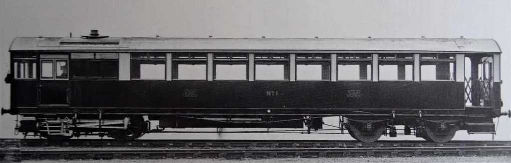
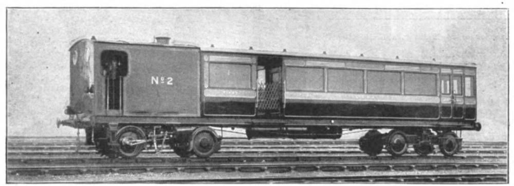
The majority of the GWR Railmotors were rigid framed with no articulation. Just two exceptions were articulated (No. 15 and No. 16). The remaining examples fell into two different variants. The first had an austere slab-sided appearance with matchboard side panels below the waist. They were flat-ended, as can be seen below. “Two ‘prototypes’ were built in 1903, followed by the main batch in 1904 (Nos. 3-14, 17-28).” [1: p13]

One of two ‘prototypes’, GWR Railmotor No. 1 at Stonehouse, © Public Domain. [7]
Manufacturers photograph of GWR Railmotor No. 1 © Public Domain, NRM Collection. [8]

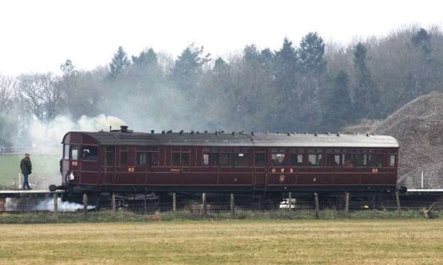
Later GWR Railmotors (Nos. 29-99) were built between 1905 and 1908, were bow-ended and were of a much more attractive design. They had higher waist-lines than contemporary locomotive-hauled coaching stock on the GWR and retained those lines when ultimately converted to auto-trailers. [1: p13]

Restored Great Western Railway steam railmotor No. 93 at Norton Fitzwarren during a visit to the West Somerset Railway, © Geof Sheppard and licenced for use here under a Creative Commons Attribution-Share Alike 4.0 International Licence (CC BY-SA 4.0), 25th March 2013. [6]
Another view of GWR Railmotor No. 93, this time at Didcot Railway Centre, © S P Smiler, cropped by Edgepedia and included here under a Creative Commons Licence (CC0 1.0 Universal Public Domain Dedication), 22nd August 2012. [10]

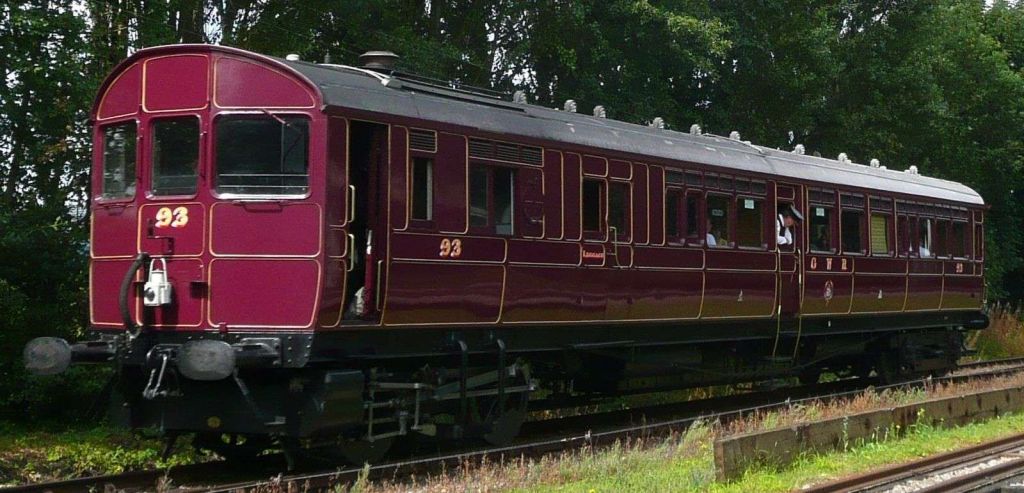
GWR Railcar No. 93 has been reproduced in model form by Kernow Model Railway Centre. Details can be found here. [12]

GWR Railmotor No.45 at Penzance in circa. 1915, © Public Domain. [6]

The GWR Railmotors were generally successful in developing patronage on the lines where they were used. Often generating sufficient traffic to warrant the provision of a passenger trailer car.

The first trailer built had the same flat-ended design as the early GWR Railmotors. The remaining trailers were built to the bow-ended format.

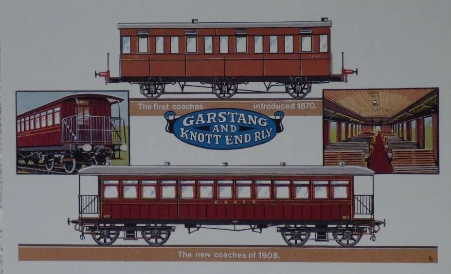
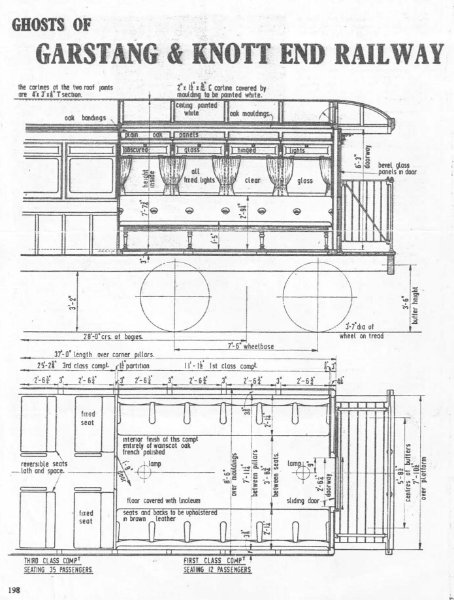
Gibbs tells us that “Such was the demand for trailers that in 1906 existing selected coaching stock was introduced to the conversion programme. Conversion was applied to six 1890s clerestory and two four-wheelers dating back to the 1870s, the 1870s-1900s supplying some of the first conversions, with demand increasing and later periods supplying more examples for conversion, each with varying seating patterns and internal format. Thus the two four-wheel, 28.5ft-long 1870 versions were running with the new 70ft latest additions to the fleet.” [9]

The design of the GWR Railmotors had not anticipated their success. While being adequately powered as single cars they were generally, particularly which had anything but shallow gradients, “incapable of pulling an extra trailer to carry the new customers which their success had generated.” [1: p13]

Inevitably, when passenger loads increased, alternatives to the Steam Railmotors had to be found. “The emerging ‘auto train’ was showing its usefulness and adaptability. Thus we find that, from 1915, the steam railmotors themselves were on the downward path to becoming trailers, and a serious conversion programme was initiated. These were dealt with year by year in varying sized batches, not strictly in order of age, but the match-boarded designs preceded those of wood-panel format, and it will be noted that conversions were not applied to all railmotors and nor were such activities an annual event.” [9]

Generally, the powered-bogie end of each unit was converted to a luggage compartment while the drivers position at the other end of the unit was retained “with controls for regulator and brakes connected through to the tank locomotive, suitably modified.” [9]

GWR Articulated Steam Railmotors

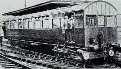
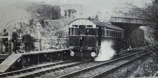
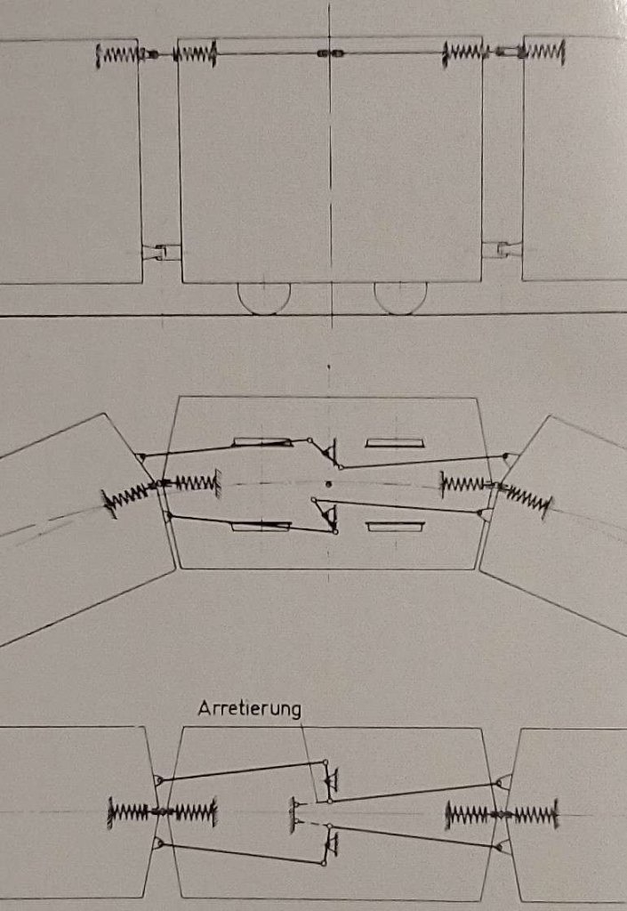
As we have already noted, the vast majority of GWR Steam Railmotors were rigid-bodied. Just two (GWR Nos 15 and 16) were articulated.

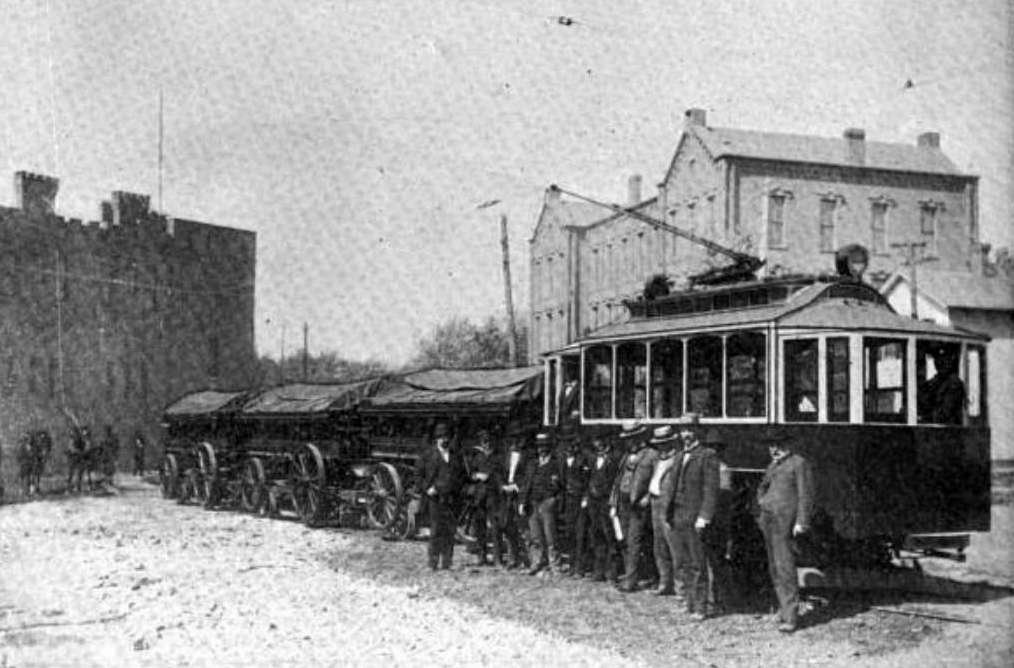
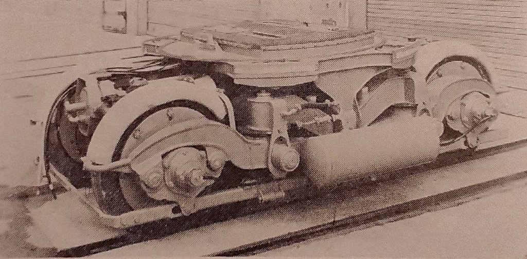
Articulated units had the advantage of being relatively easily separated for maintenance purposes and allowed for the possibility of providing more powerful locomotive sections. Throughout the UK, where articulated Railmotors were provided the locomotive section looked more like a small standard locomotive.

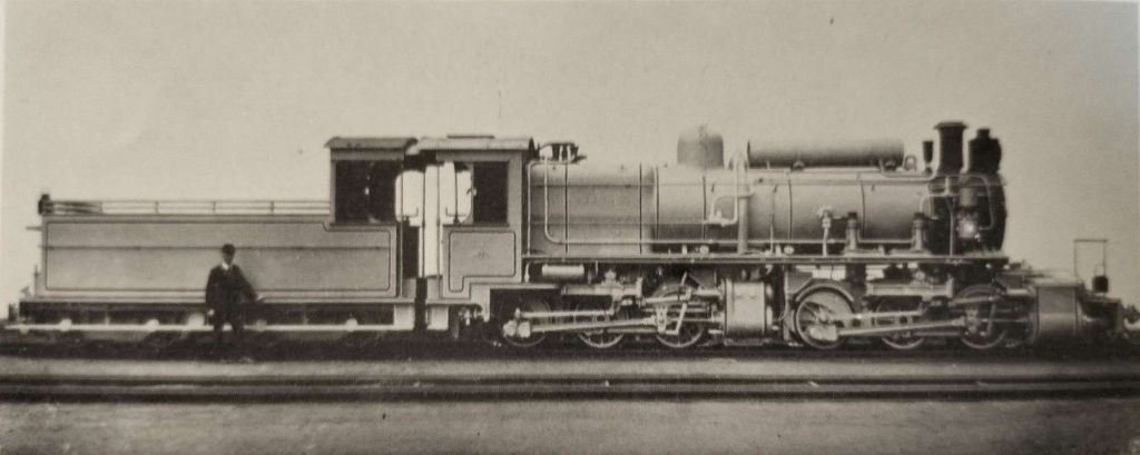
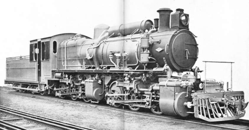
Often, additional power units were purchased to allow the immediate replacement of a unit in need of maintenance. An example of this practice was the deployment of articulated railmotors on the Taff Vale Railway. The Taff Vale railmotors were built between 1903 and 1905 “in the form of one prototype and three main batches. There were 18 engine units and 16 carriage portions, thus permitting stand-by power units to be available. …  The pioneer power unit came from the company’s own workshops (the last ‘locomotive’ to be built by the TVR in its shops at West Yard, Cardiff), followed by six each from Avonside and Kerr-Stuart and a final five from Manning Wardle.” [1: p21]

GWR Steam Railmotors No. 15 and 16 were ordered from Kerr Stuart. They were built in 1905 to Kerr Stuart’s design. Bristol Wagon and Carriage Company were subcontractors, providing the bodywork for each unit. [1: p32] There being only two units, exchangeable power sections was not an option fiscally.

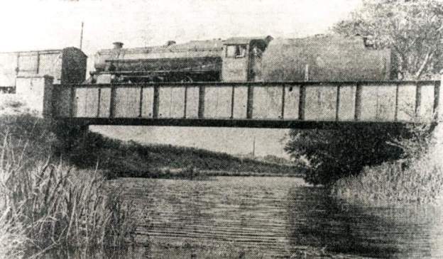
In 1920 No. 15 was sold by the GWR to J.F. Wake and sold on, in 1921, to the Nidd Valley Light Railway (NVLR). [1: p32]

Ex-GWR steam railmotor No. 15 was known as ‘Hill’ on the NVLR. This image shows the railmotor alongside the signal box at Pateley Bridge where the NVLR made connection to the NER branch from Harrogate via Ripley Junction. The NVLR was wholly owned by Bradford Corporation Waterworks and operated in connection with the construction of new reservoirs at the head of Nidderdale. The power unit on both GWR Nos. 15 and 16 had a transverse boiler. This feature was retained after transfer onto the NVLR. The sliding screens visible at the top of the driver’s access onto the footplate were a post-GWR alteration, © Public Domain. [11][1: p32]

References

  1. David Jenkinson & Barry C. Lane; British Railcars: 1900-1950; Pendragon Partnership and Atlantic Transport Publishers, Penryn, Cornwall, 1996.
  2. https://en.m.wikipedia.org/wiki/British_steam_railcars, accessed on 14th June 2024.
  3. R.M. Tufnell; The British Railcar: AEC to HST; David and Charles, 1984.
  4. R.W. Rush; British Steam Railcars; Oakwood Press, 1970.
  5. https://victorianweb.org/victorian/technology/railways/locomotives/27.html, accessed on 16th June 2024.
  6. https://en.m.wikipedia.org/wiki/GWR_steam_rail_motors, accessed on 17th June 2024.
  7. https://didcotrailwaycentre.org.uk/zrailmotor93/history/pictures/sub_gubbins.html, accessed on 17th June 2024.
  8. https://www.nrmfriends.org.uk/post/motoring-in-1903, accessed on 17th June 2024.
  9. Ken Gibbs; The Steam Railmotors of the Great Western Railway; The History Press, Cheltenham, 2015.
  10. https://commons.m.wikimedia.org/wiki/File:GWR_Steam_Railmotor_No_93_At_the_Didcot_Railway_Centre,_cropped.jpg, accessed on 17th June 2024.
  11. https://www.flickr.com/photos/29903115@N06/51337152220, accessed on 17th June 2024.
  12. https://www.kernowmodelrailcentre.com/pg/144/KMRC-Locomotive—GWR-Steam-Railmotor, accessed on 23rd June 2024.
  13. John Lewis; Great Western Steam Rail Motors and their services; Wild Swan Publications, Bath, 2004.
  14. M. G. D. Farr; Stroud Valley Railcars; in Railway World, January 1965, Ian Allan Publishing.

Steam Railmotors – Part 2 – Dugald Drummond (LSWR) and Harry Wainwright (SECR)

Drummond was born in Ardrossan, Ayrshire on 1st January 1840. His father was permanent way inspector for the Bowling Railway. Drummond was apprenticed to Forest & Barr of Glasgow gaining further experience on the Dumbartonshire and Caledonian Railways. He was in charge of the boiler shop at the Canada Works, Birkenhead of Thomas Brassey before moving to the Edinburgh and Glasgow Railway’s Cowlairs railway works in 1864 under Samuel Waite Johnson.” [3]

He became foreman erector at the Lochgorm Works, Inverness, of the Highland Railway under William Stroudley and followed Stroudley to the London Brighton and South Coast Railway’s Brighton Works in 1870. In 1875, he was appointed Locomotive Superintendent of the North British Railway.” [3]

In 1882 he moved to the Caledonian Railway. In April 1890, he emigrated to Australia, establishing the Australasian Locomotive Engine Works at Sydney, Australia. After only a short time he returned to the UK, founding the Glasgow Railway Engineering Company which was moderately successful, Drummond, “accepted the post as locomotive engineer of the London and South Western Railway [LSWR] in 1895, at a salary considerably less than that he had received on the Caledonian Railway. The title of his post was changed to Chief Mechanical Engineer in January 1905, [4] although his duties hardly changed. [5] He remained with the LSWR until his death” in 1912. [3]

He was a major locomotive designer and builder and many of his London and South Western Railway engines continued in main line service with the Southern Railway to enter British Railways service in 1947.” [3]

Harry Smith Wainwright was the “Locomotive, Carriage and Wagon Superintendent of the South Eastern and Chatham Railway from 1899 to 1913. He is best known for a series of simple but competent locomotives produced under his direction at the company’s Ashford railway works in the early years of the twentieth century.” [13]

Drummond and Wainwright experimented with steam railmotors/railcars in the early years of the 20th century.

The first of Drummond’s Steam Railmotors/Railcars, in its earliest incarnation, © Public Domain. [11]

In 1902, Dugald Drummond had two built for a branch line near Portsmouth. [6][7: p7] Intended to provide “an economic service on the LSWR and London, Brighton and South Coast Railway (LB&SCR) joint branch from Fratton to Southsea two steam railmotors were built by the LSWR in 1902, entering service in April 1903, and designated as K11 Class.” [6][8: p118, 123]

The 43-foot (13 m) long carriage-element seated thirty in third class and twelve in first class. The total length of the unit was 53 ft 5 in (16.28 m). The first of these railcars/railmotors to be built was lent to the Great Western Railway, returning with favourable reports. [8: p118] “However, when introduced in summer 1903 the units struggled with passengers on the gradients on the line and it was discovered that the GWR had trialed the unit on level track and without passengers. The units were rebuilt with a bigger firebox and boiler.” [6][8: p118-119][9: p22-25]

Rebuilt LSWR railmotor with a horizontal rather than vertical boiler. [10]

Wainwright  introduced similar steam railmotors on the SECR in 1904/5. He ordered 8 in total from Kitson of Leeds. The first two for use on the Sheppey Light Railway. Numbered 1 and 2 (WN 4292 and 4293, date 1904), “the engines were ordinary four-wheeled locomotives and could be detached from the car proper if necessary. They were fitted with the first Belpaire fireboxes on the [SECR]. Both engines and cars, were painted lake, the standard colour for the coaching stock on this line. There was accommodation for 56 passengers. all of one, class. ‘One of the cars had been running experimentally on the Deal branch.” [14] Wainwright’s railmotors, while superficially similar to the early Drummond Railmotors were actually articulated vehicles.

No. 3 is shown below on a public domain image found on the Westerham Heritage website. The same image appears on the dedicated webpage for Westerham Station on the Disused Stations website. [15] Disused Stations website tells us that the apparent side tanks on the locomotive portion of the unit “were actually coal bunkers, … with water carried in well tanks. The rail-motors were of the articulated type and the fairly conventional engine portions were built by Messrs Kitson. … Following eventual withdrawal the carriage portions were converted into four two-car hauled sets circa 1923, two of which were articulated twins while the other two were non-articulated push-and-pull sets.” [15]

SECR steam rail-motor No. 3 stands at Westerham in 1907. It was built by Kitson of Leeds was introduced to the Westerham branch of the SECR in April 1906. It was not popular and was withdrawn from the branch later in 1907. [12]

The coach portion of [SECR] No. 3 was paired with that of No. 8 to form an articulated twin set No.514. The other articulated twin became set No.513, formed from railmotors 1 and 2. Both articulated pairs, which were unique to the Southern Railway, are known to have survived until at least 1959.” [15]

After his experience with the LSWR Railmotors and after modifications had been made, Drummond ordered a further fifteen steam railmotors for the LSWR. These new railcars/railmotors were numbered 1 to 15. The earliest ‘experimental’ Railmotors were ignored in this new numbering system.

The first two were built in 1904 in two parts, “the engines at Nine Elms and the carriages at Eastleigh, and were designated H12 class. These were two feet (600 mm) shorter than the earlier cars, seated eight in first class and thirty-two in third.” [8: p119-120] Nos 1 & 2 “displayed a fully enclosed engine part, encased in a rather severe ‘tin tabernacle’.” [1: p14]

The second LSWR railmotor numbered No.2, © Public Domain. [10]

Thirteen more were built in 1905–6 to slightly different design, as class H13. [8: p120-122] These had the boiler pressure increased from 150 psi (1.0 MPa) to 175 psi (1.21 MPa). Engines and carriages were not detachable and these units were capable of towing an additional carriage. [9: p26,28] After the outbreak of World War I limited the work available for railmotors, the joint stock was taken out of service in 1914 and by 1916 only three units remained in service, to be withdrawn in 1919.” [6][9: p24,28] These units had “a very neatly enclosed locomotive portion embodying ‘coachbuilt’ styling.” [1: p14]

LSWR No.3,  the design is modified compared with No. 1 and No. 2. The leading dimensions are as follows; cylinders l0-in. by 14-in., boiler pressure 175 lbs. per sq. in.; heating surface: firebox 76 sq. ft., water tubes 119 sq.ft., flue tubes 152 sq.ft., total 347 sq. ft.; grate area 61 sq. ft.; capacity of tank 485 gallons and of bunker 1 ton, weight of coach complete 32 tons 6 cwt.; seating accommodation: 1st class 8, and 2nd class 32 passengers, total 40, © Public Domain. [16]

References

  1. David Jenkinson & Barry C. Lane; British Railcars: 1900-1950; Pendragon Partnership and Atlantic Transport Publishers, Penryn, Cornwall, 1996.
  2. https://en.m.wikipedia.org/wiki/British_steam_railcars, accessed on 11th June 2024.
  3. https://www.wikiwand.com/en/Dugald_Drummond, accessed on 11th June 2024.
  4. D. L. Bradley; Locomotives of the L.S.W.R. Part 2; Railway Correspondence and Travel Society, 1967, p2.
  5. J.E. Chacksfield; The Drummond Brothers: A Scottish Duo; Oakwood Press, Usk, 2005, p89.
  6. https://en.m.wikipedia.org/wiki/British_steam_railcars, accessed on 14th June 2024.
  7. R.M. Tufnell; The British Railcar: AEC to HST; David and Charles, 1984.
  8. D.L. Bradley; Locomotives of the London Brighton and South Coast Railway. Part 3; Railway Correspondence and Travel Society Press, London, 1974.
  9. R.W. Rush; British Steam Railcars; Oakwood Press, 1970.
  10. https://victorianweb.org/victorian/technology/railways/locomotives/27.html, accessed on 16th June 2024.
  11. https://www.flickr.com/photos/29903115@N06/48434232291, accessed on 15th June 2024.
  12. https://www.westerhamheritage.org.uk/condtent/catalogue_item/steam-railmotor-number-3, accessed on 15th June 2024.
  13. https://en.m.wikipedia.org/wiki/Harry_Wainwright, accessed on 15th June 2024.
  14. The Locomotive Magazine Volume 11 No. 150, February 1905, p20.
  15. Nick Catford; Westerham Station; http://www.disused-stations.org.uk/w/westerham/index1.shtml, accessed on 15th June 2024.
  16. The Locomotive Magazine Volume 12 No. 162, February 1906, p18; sourced as a .pdf file via:  https://www.oldminer.co.uk/pdf, accessed on 15th June 2024.

Steam Railmotors – Part 1 – Early Examples.

‘Lilliputian’ – An Experiment.

A small steam carriage was designed by James Samuel, the Eastern Counties Railway Locomotive Engineer, built by William Bridges Adams in 1847, and trialled between Shoreditch and Cambridge on 23rd October 1847. It was an experimental unit, 12 feet 6 inches (3.81 m) long with a small vertical boiler and passenger accommodation was a bench seat around a box at the back, although it was officially named ‘Lilliputian’ it was known as ‘Express’. [7][8: p16]

The Fairfield Steam Carriage

It seems that the earliest example of a steam railcar to enter service was another “experimental unit designed and built in 1847 by James Samuel and William Bridges Adams. In 1848, they made the Fairfield steam carriage that they sold to the Bristol and Exeter Railway, who used it for two years on a branch line.” [1] The Bristol & Exeter Railway was broad gauge.

The Fairfield Steam Carriage, © Unknown, Public Domain. [3][5]

The Fairfield Steam Carriage was built to the design of William Bridges Adams and James Samuel at “Fairfield Works in Bow, London. It was tested on the West London Railway late in 1848, although it was early in 1850 before modifications had been made that allowed Adams to demonstrate that it was working to the agreed standards. The design was not perpetuated by the Bristol and Exeter Railway, instead they purchased small 2-2-2T locomotives for working their branch lines.” [3]

Apparently, the unit worked on the Clevedon and Tiverton branches, and perhaps on the Weston branch too. [3]

The power unit had a single pair of driving wheels driven through a jackshaft by small 8-by-12-inch (203 mm × 305 mm) cylinders. Originally equipped with a vertical boiler 6 feet (1,800 mm) in height, 3 feet (910 mm) in diameter, this was replaced by a horizontal boiler length 7 feet 7 inches (2,310 mm), diameter 2 feet 6 inches (760 mm). The boiler was not covered by a cab or other bodywork; the two pairs of carrying wheels were beneath the carriage portion. It had seats for 16 first class and 32 second class passengers. It was once timed as running at 52 miles per hour (84 km/h).” [3][4]

The Fairfield Steam Carriage, © Unknown, Public Domain. [6]

Numbered No. 29 in the Bristol and Exeter Railway locomotive list, it was generally referred to as “the Fairfield locomotive”. It was not a great success, and although Samuel & Adams built another couple of steam railmotors at around the same time, the concept did not result in any further orders. [3]

Jenkinson & Lane dismiss this railcar as one of a few “rather weird and impracticable 19th Century ideas.” [2: p9] Nonetheless, it meets their criteria for a railcar. They state that a railcar should “contain within itself the means of propulsion as well as seats for the passengers, … the design should represent an ‘integrated concept’ … [in which] neither could function independently of the other.” [2: p5]

The ‘Enfield’ Steam Carriage

Built at about the same time as the Bristol & Exeter Steam Carriage was one which was purchased by the Eastern Counties Railway. …

The steam railcar ‘Enfield’
which was used by the ECR from 19th January 1849. [6]

Enfield‘ was larger than ‘Fairfield’. Built by Samuel and Adams this was used in regular service by the Eastern Counties Railway until the engine was converted into a 2-2-2 tank locomotive. [7][8: p18]

Another Early Example

More engine and carriage combinations to Samuel designs were built in the 1850s in the Eastern Counties railway works, and another by Kitson & Co. called Ariel’s Girdle. Later, in 1869, Samuel, Robert Fairlie and George England collaborated to build a prototype articulated steam railcar at England’s Hatcham Ironworks that was demonstrated in the works yard. However, England went out of business at about this time and nothing is known about the fate of this vehicle.” [7][8: p19]

References

  1. https://en.m.wikipedia.org/wiki/British_steam_railcars, accessed on 11th June 2024.
  2. David Jenkinson & Barry C. Lane; British Railcars: 1900-1950; Pendragon Partnership and Atlantic Transport Publishers, Penryn, Cornwall, 1996.
  3. https://en.m.wikipedia.org/wiki/Bristol_and_Exeter_Railway_Fairfield_steam_carriage, accessed on 11th June 2024.
  4. William Bridges Adams; “Road Progress, Or, Amalgamation of Railways and Highways for Agricultural Improvement, and Steam Farming, in Great Britain and the Colonies: Also Practical Economy in Fixed Plant and Rolling Stock for Passenger and Goods Trains; George Luxford, London, 1850, p15. George Luxford. p. 15.
  5. The Fair-Field Steam Carriage“. Illustrated London News. 1849.
  6. http://britbahn.wikidot.com/dampftriebwagen, accessed on 14th June 2024.
  7. https://en.m.wikipedia.org/wiki/British_steam_railcars, accessed on 14th June 2024.
  8. R.W. Rush; British Steam Railcars; Oakwood Press, 1970.

Great Northern Railway 0-4-2 Locomotive No. 551

The Great Northern Railway recognised the value of ‘mixed traffic’ locomotives in the 19th century. Lindsay says that seventy five locos of this class were built. One source says that a total of 117 Class 18 locos were built. [4] The Great Northern Railway Society says that 153 were built. [5] The different sources seem to agree that fifty of the class were out-sourced from locomotive builders, the remainder  were built in-house at the Great Northern’s Doncaster works. [1]

Side Elevation [1]
Front Elevation [1]
Tender – Front and Back Elevations [1]

The specification sent to outside loco constructors differed in at least one respect from that used in-house – the total heating surface of the outside builders locomotives was 543 sq. ft rather than 537.5 sq ft. [1]

Delivery of locomotives from outside firms was in the following order:

1875 – Nos. 551-556 from Sharp, Stewart & Co. (Works Nos. 2564-2569)

1876 – Nos. 557-580 from Sharp, Stewart & Co. (Works Nos. 2570-2575, 2585-2594, 2646-2653))

1876 – Nos. 581-600 from Kitson & Co. (Works Nos. 2059-2078)

It should be noted, however, that there was no direct correlation between the sequence of Works Nos. and the locomotive fleet numbers. “For instance,  engine Nos. 563 and 564 bear makers’ Nos. 2586 and 2585 respectively.” [1]

Messrs Sharp, Stewart & Co. locomotives were recorded as being  31 tons 13 cwt in weight. [1]

The Great Northern Railway (GNR) “was … By incorporated in 1846 with the object of building a line from London to York. It quickly saw that seizing control of territory was key to development, and it acquired, or took leases of, many local railways, whether actually built or not. In so doing, it overextended itself financially.” [2]

Nevertheless, it succeeded in reaching into the coalfields of Nottinghamshire, Derbyshire and Yorkshire, as well as establishing dominance in Lincolnshire and north London. Bringing coal south to London was dominant, but general agricultural business, and short- and long-distance passenger traffic, were important activities too. Its fast passenger express trains captured the public imagination, and its Chief Mechanical Engineer Nigel Gresley became a celebrity.” [2]

There was a significant amount of cross-country good traffic which saw these locomotives being well-used. I believe that they were designated ‘Class 18’ within the GNR’s fleet. They were “the first type of loco to actually be built at Doncaster, rather than by outside contractors … they were used on goods trains and certain secondary passenger trains,” [3] and at times were referred to as  ‘luggage engines’, because they were used  to bring a second train carrying  larger trunks and other passenger luggage in the day when carriages carried regular luggage on their roofs.[3].

References

  1. T.A.Lindsay; Great Northern Railway Engine No. 551; in Model Railway News Volume 40 No. 748, October 1964, p532-533. (Non-commercial use of drawings authorised.)
  2. https://en.m.wikipedia.org/wiki/Great_Northern_Railway_(Great_Britain), accessed on 29th March 2024.
  3. https://www.lner.info/forums/viewtopic.php?p=137505&sid=2418e9a33ffd0ca31a29be36138a3084#p137505, accessed on 29th March 2024.
  4. https://en.m.wikipedia.org/wiki/Locomotives_of_the_Great_Northern_Railway_(Great_Britain), accessed on 29th March 2024.
  5. https://www.gnrsociety.com/locomotive-class/18-series, accessed on 29th March 2024.

Furness Railway Locomotive No. 58

Looking through a number of 1964 Model Railway News magazines, I came across drawings of Sharp, Stewart & Co. 2-4-0, built in 1870 for the Furness Railway Co. and numbered 58 on their roster.

Side elevation and half plan of Locomotive No. 58 [1]
Front elevation. [1]
Tender, front and back half-elevations. [1]

Originally conceived as a mineral railway, the Furness Railway later played a major role in the development of the town of Barrow-in-Furness, and in the development of the Lake District Tourist industry. It was formed in 1846 and survived as an independent, viable concern until the Grouping of 1923. [4]

The Furness Railway contracted out the building of its locomotives until Pettigrew became Chief Locomotive Engineer in 1897. He put his first locomotive on the line in 1898.

2-4-0 Locomotive No. 58 had inside cylinders (16 in by 20 in), 5 ft 6 in diameter coupled wheels. It operated with a boiler pressure of 120 lb and weighed 30 tons 5 cwt. Its tender was 4-wheeled with a 1,200 gallon water capacity.

The locomotive, as designed, had no brake blocks, the only brake being a clasp type on the tender.

This relatively small locomotive was one of a series of 19 locos built to the same design. The class fulfilled the needs of the Furness Railway as passenger locomotives. The class was given the designation ‘E1’ by Bob Rush in his books about the Furness Railway. Rush’s classification was his own not that of the Furness Railway, but has become accepted generally. [2]

A photograph of one of this class can be found by clicking on the link immediately below. No. 44 was built in 1882 by Sharp Stewart & Co., Works No.3086. It was rebuilt in 1898, presumably in the Furness Railway works. Renumbered 44A in 1920, it became LMS No. 10002 – but was withdrawn in April 1925. [5]

https://transportsofdelight.smugmug.com/RAILWAYS/LOCOMOTIVES-OF-THE-LMS-CONSTITUENT-COMPANIES/LOCOMOTIVES-OF-THE-FURNESS-RAILWAY/i-742Bfsn/A

Later, seven of the class were converted to J1-class 2-4-2 tank engines in 1891. [3]

References

  1. T.A. Lindsay; Furness Railway Locomotive No. 58; in Model Railway News, Volume 40, No. 480, December 1964, p608-609. (Permission to copy granted for any non-commercial purpose.)
  2. https://en.m.wikipedia.org/wiki/Locomotives_of_the_Furness_Railway, accessed on 28th March 2024. (e.g. R.W. Rush; The Furness Railway, Oakwood Press No. 35)
  3. https://www.steamlocomotive.com/locobase.php?country=Great_Britain&wheel=2-4-0&railroad=furness, accessed on 28th March 2024.
  4. http://www.furnessrailwaytrust.org.uk, accessed on 29th March 2024.
  5. https://transportsofdelight.smugmug.com/RAILWAYS/LOCOMOTIVES-OF-THE-LMS-CONSTITUENT-COMPANIES/LOCOMOTIVES-OF-THE-FURNESS-RAILWAY/i-742Bfsn/A accessed on 28th March 2024.

The North British Locomotive Company J Class Locomotives on New Zealand’s 3ft 6in-Gauge Network

Towards the end of March 2024, I stumbled across a number of journals of the New Zealand Model Railway Guild. One of these, the March 2021 edition, included a pictorial article about J1211 North British 4-8-2 Locomotive No. 24534 of 1939. [6] The June 2021 issue included a history of the class [7: p13-15] and General Arrangement plans as originally carried in the Railway Gazette in 1940. [7: p22-24] Also in that journal are four photographs of J1211 in service between 1960 and 1970. [8]

40 No 4-8-2  locomotives which were built in 1939 by the North British Locomotive Company and became the New Zealand Railways (NZR) J class.

They were designed to provide a mixed traffic locomotive suitable for running on the lighter secondary lines of the NZR network, and for express passenger trains in major routes.

The J class incorporated roller bearing axles, hydrostatic lubrication and twin Westinghouse brake pumps. … They had bar frames instead of plate frames and were equipped with Baker Valve-gear.  The locomotives were attached to Vanderbilt tenders and were outshopped with distinctive bullet-nosed streamlining.” [1] The streamlining also encompassed the full length of the top of the boiler between the cab and the smoke box door and the area immediately beneath the smoke box door.

The J Class locos were out shopped with a distinctive streamlining from the cab to the top of the smoke box door and with a bullet-nosed smoke box door. [2]

New Zealand’s North Island benefitted from the first thirty of the class placed into service. The South Island hosted the remaining ten locomotives which apparently were used “The first 30 of the class in service were allocated to the North Island, with the remaining ten locomotives allocated to the South Island where they were used “on the hilly section between Dunedin and Oamaru. They were immediately placed into service on the main trunk routes in both islands in order to help move wartime traffic during the Second Word War. Although used on freight trains as well, the class was well suited to high-speed running on the passenger trains of the era.” [1]

Apparently, the streamlining became “burdensome for maintenance and the skyline casing, which was open at the top proved to be a trap for soot from the locomotive’s exhaust. After a time, the skyline casing started to be removed from some examples of the class leaving them with just the bullet nose.” [1]

Ultimately the bullet nose was also removed from the majority of these locomotives.

The locomotives of the class had their streamlining removed in the war years. [2]

Members of the class “were generally considered to be a very reliable engine and well suited to their task. … They were capable of speeds of over 60 mph with a 300-ton express train. …. However, today surviving engines being used to haul excursion trains are restricted to 80 kph. … On favourable grades a single J could move a 1000-ton train.” [7: p14]

The design was successful enough that NZR opted to build an improved variant  … in its own  Hillside workshops from 1946.” [1] These ‘Ja’ class locomotives were numbered 1240 to 1274 and became “the mainstay of the South Island rail services. Meanwhile North British were commissioned to build another 16, numbered from 1275 to 1290, also classified ‘Ja’, but they were oil fired and to be based in the North Island. … The sixteen ‘Ja’ from North British were the last steam locomotives to enter service with the NZR.” [7: p15]

Three J Class 4-8-2 are noted by Trainweb [2] as having been preserved:

J 1234, North British #24557/1939. For some time based at Glenbrook Vintage Railway, Auckland.. This locomotive is owned by Steam Incorporated of Paekakariki, and was leased to the Glenbrook Vintage Railway in 1998. The locomotive was returned to Paekakariki in June 2015.  [4] It is now in storage awaiting a 2nd restoration at Paekakariki. [5]

J 1211 “Gloria”, North British #24534/1939. Mainline Steam Heritage Trust, Auckland (Operational). [3]

J 1236,  North British #24559/1939. Mainline Steam Heritage Trust, Auckland (Being Restored). [2]

References

  1. https://preservedbritishsteamlocomotives.com/north-british-locomotive-comapany-works-no-24534-class-j-j-1211-gloria-4-8-2-new-zealand-railways, accessed on 26th March 2024.
  2. http://www.trainweb.org/nzsteam/j_4-8-2.html, accessed on 26th March 2024.
  3. https://www.mainlinesteam.co.nz/history, accessed on 26th March 2024.
  4. https://en.m.wikipedia.org/wiki/Glenbrook_Vintage_Railway, accessed on 26th March 2024.
  5. https://www.steaminc.org.nz/our-rail-fleet/steam-locomotives, accessed on 26th March 2024.
  6. 50’s Focus; NZ Model Railway Journal, Issue No. 413, March 2021, p14-15.
  7. North British 4-8-2 J Class Locomotive; NZ Railway Journal, Issue No. 414, June 2021.
  8. Sixties Style!; NZ Railway Journal, Issue No. 414, June 2021, p16-17.

Mallet Locomotives in East Africa

Ethiopia/Eritrea

The 950mm-gauge line from Massawa on the coast, inland to Agordot, was built during colonial occupation by the Italians with some steep gradients which meant that Mallets were considered to be suitable motive power.

The line should not be confused with the metre-gauge line running from Djibouti to Addis Ababa. A metre-gauge railway that was originally built by the French from 1894 to 1917 which has since been replaced by a Chinese built standard-gauge line. [5]

In 1907, Maffei built three 0-4-4-0T locomotives for the Massawa to Agerdot line.

Ansaldo the “supplied twenty five further engines of the same class between 1911 and 1915, and in 1931 and 1939 Asmara shops assembled a nominal three new engines from d components of earlier withdrawn engines. All these were standard European narrow-gauge Mallet tanks, saturated, slide-valved and with inside frames.” [1: p64]

In the mid-1930s, a series of fifteen larger 0-4-4-0T locomotives were built. These were “built to a superheated, simple expansion design, of which ten had piston valves and Walschearts gear and the other five, Caprotti poppet valves driven from outside cardan shafts.” [1: p65] A later series of “eight engines built by Analdo in 1938 reverted to compound expansion, retaining the superheater and piston valve features.” [1: p65]

The last of the Eritrean Mallets was built in their own shops in 1963, making it the last Mallet built in the world. [6]

The line closed in 1975. Eritrea was occupied by Ethiopia for many years. After gaining independence in 1993, some of the former railway staff started to rebuild their totally destroyed railway. Some of the Mallets, built by Ansaldo (Italy) in 1938, were brought back to life. Also one of the small Breda built shunters, two diesel locos and two diesel railcars (one from 1935) were put back into working order. [7]

A section of the line, between Massawa, on the coast, and Asmara, was reopened in 2003 and has offered an opportunity for Mallet locomotives to be seen in operation in East Africa. Indeed, an internet search using Google brings to light a list of videos of locomotives heading tourist trains in the Eritrean landscape.

Wikipedia notes that the line has a track-gauge of 950mm and that locomotives operate over a 118 km section of the old line. Italian law from 1879 officially determined track gauges, specifying the use of 1,500 mm (4 ft 11 1⁄16 in) and 1,000 mm (3 ft 3 3⁄8 in) gauge track measured from the centre of the rails, or 1,445 mm (4 ft 8 7⁄8 in) and 950 mm (3 ft 1 3⁄8 in), respectively, on the inside faces. [4]

Between Arbaroba and Asmara in November 2008, a single coach is headed by one of the surviving Mallet locomotives. This is an extract from an image on Wikimedia Commons (public domain). [13]

Steam operation on the line is over, no regular services are provided but occasional tours still take place with plenty of caveats about the availability of any form of propulsion. An example is a German-speaking tour planned (as of 24th March 2024) for November 2024. [8]

Tanzania (Tanganyika)

The metre-gauge line inland from Dar-es-Salaam was built by the Ost Afrika Eisenbahn Gesellschaft (East African Railway Co.). A.E. Durrant tells us that its first main line power “was a class of typical German lokalbahn 0-4-4-0T Mallets, built by Henschel in 1905-7. These were supplemented in 1908 by four larger 2-4-4-0Ts from the same builder, after which the railway turned to straight eight-coupled tank and tender engines.” [1: p67]

R. Ramaer notes that the first locomotives used by the Usambara Eissenbahn (UE) on the Tanga Line were five 0-4-2 locos which arrived on the line in 1893. Rising traffic loads led the UE “To look for something more substantial and in 1900, Jung supplied five compound Mallet 0-4-4-0T’s as numbers 1-5, later renumbered 6-10. … To provide enough space for the firebox and ashpan, the rigid high-pressure part, comprising the third and fourth axles, had outside frames, whereas the low-pressure part had inside frames.” [9: p19]

UE engine No. 1 (0-4-4-0T – supplied by Jung) with an early passenger train ready for departure at Tanga station in 1890. This image was posted on the Urithi Tanga Museum Facebook Page [10] and is also reproduced in R. Ramaer’s book. [9: p19]
UE Mallet 0-4-4-0T No. 8 heading a passenger train at Mombo. This image was shared in error on the Old Asmara Eritrea Facebook Page.  [11] It also appears in R. Ramaer’s book. [9: p20]

On the Central Line (Ost Afrikanische Eisenbahn Gesellschaft – or OAEG) which ran inland from Dar-es-Salaam, construction work started in 1905 and the first locomotives used by the OAEG were four 0-4-0T engines built by Henschel, a further four of these locomotives were supplied in 1909. These small engines had a surprisingly long life. Mallets were first supplied in 1905 by Henschel and were suitable for both coal and oil firing. These were 0-4-4-0T locos (four supplied in 1905 and one supplied in 1907). “The problem with this type of engine was the restricted tractive effort and running was not satisfactory because of the lack of a leading pony truck. … Therefore Henschel supplied a second batch of four locomotives in 1908 as 2-4-4-0Ts with larger boilers and cylinders. They also had a higher working pressure of 14 atmospheres (200lb/sq in) in comparison to 12 atmospheres (170lb/sq in)  for the earlier engines, while the bunker capacity had been increased from 1.2 to 2.2 tonnes of coal. (Oil fuel had been discarded).” [9: p21-23]

OAEG 2-4-4-0T No. 27, in the last Mallet class to be built for German East Africa. This locomotive appears in the Wikipedia list of Henschel steam locomotives. [12] It also appears in R. Ramaer’s book [9: p23] and A.E. Durrant’s book. [1: p66]

Kenya-Uganda

An ‘MT’ class locomotive in ex-Works condition at the Queen’s Park works of the North British Locomotive Co. [1: p66]

Mallets were the first articulated locomotives to operate in East Africa. Mallets were introduced on the Uganda Railway in 1913. A.E. Durrant notes that they consisted of “a batch of eighteen 0-6-6-0 compound Mallets to what was the North British Locomotive Co’s standard metre-gauge design, as supplied also to India, Burma, and Spain. They had wide Belpaire fireboxes, inside frames and piston valves for the high pressure cylinders only. Built at Queens Park works in 1912-1913, these locomotives entered service in 1913-14 and remained at work until 1929-30, when they were replaced by the EC2 and EC2 Garratts.” [1: p66]

North British Class ‘MT’ Mallets arrived in Kenya just before the start of WW1. [2]

These locomotives were given the classification ‘MT’ within the Uganda Railway fleet. Disappointing performance and high maintenance costs led to them being relegated to secondary duties and eventually being scrapped in the late 1920s as the Beyer Garratt locomotives began to arrive. [2] Their presence on the system was heralded by, “Railway Wonders of the World,” with the picture shown below. [3]

An ‘MT’ class Uganda Railway locomotive as illustrated in ‘Railway Wonders of the World’. [3]

References

  1. A.E. Durrant; The Mallet Locomotive; David & Charles, Newton Abbot, Devon, 1974.
  2. Kevin Patience; Steam in East Africa; Heinemann Educational Books (E.A.) Ltd., Nairobi, 1976.
  3. http://www.railwaywondersoftheworld.com/uganda_railway2.html, accessed on 1st June 2018.
  4. https://en.m.wikipedia.org/wiki/Eritrean_Railway, accessed on 22nd March 2024.
  5. https://en.m.wikipedia.org/wiki/Addis_Ababa%E2%80%93Djibouti_Railway, accessed on 22nd March 2024.
  6. https://en.m.wikipedia.org/wiki/0-4-4-0, accessed on 22nd March 2024.
  7. https://www.farrail.net/pages/touren-engl/eritrea-mallets-asmara-2010.php, accessed on 24th March 2024.
  8. https://ecc–studienreisen-de.translate.goog/historische-eisenbahn-und-strassenbahnreisen-mit-peter-1/8-tage-eritrea-mallets-in-den-bergen-afrikas?_x_tr_sl=de&_x_tr_tl=en&_x_tr_hl=en&_x_tr_pto=sc, accessed on 24th March 2024.
  9. R. Ramaer; Steam Locomotives of the East African Railways; David & Charles, Newton Abbot, 1974.
  10. https://www.facebook.com/urithitanga.museum/photos/pb.100063540805743.-2207520000/2336640756358366/?type=3, accessed on 24th March 2024.
  11. https://www.facebook.com/photo/?fbid=2169593963301193&set=pcb.2169594269967829, accessed on 24th March 2024.
  12. https://de.m.wikipedia.org/wiki/Liste_schmalspuriger_Lokomotiven_von_Henschel, accessed on 24th March 2024.
  13. https://commons.m.wikimedia.org/wiki/File:Eritrean_Railway_-_2008-11-04-edit1.jpg, accessed on 24th March 2024.

The Garstang to Knott End Railway again. …

The featured image above is a picture of the Pilling Pig. It was shared by Mandy Sharpe on the Visions of Trains and Tracks of the North West of England Facebook Group on 19th August 2017. Permission to include here applied for. [6]

One of six postcards produced by Dalkeith. This card shows the full length of the line. [16]

In the past, I have written two articles about the Garstang to Knott End Railway, those articles can be found on these two links:

The Garstang and Knott End Railway – Part 1

The Garstang and Knott End Railway – Part 2

Reading some back copies of Railway Bylines, I came across an article in the March 2002 edition of the magazine about this short rural line.  The article was written by R. Supwards with photographs by Douglas Robinson.

The line had a hesitant start and always struggled financially, but it remained independent until being taken over by the LMS at the Grouping but lost its passenger service in 1930. It was closed to goods traffic beyond Pilling at the end of 1950. In the summer of 1963, the line beyond Garstang Town was closed. The remainder of the branch did not last long. It was closed by the end of August 1965.

A ‘Cauliflower’ 0-6-0 locomotive in LMS colours sits at Knott End before setting off towards Pilling and Garstang. This image was shared by Steve Scott on the Visions of Trains and Tracks of the North West of England Facebook Group on 27th August 2017. Permission to use here has been applied for. [7]
One of six postcards produced by Dalkeith. The station at Knott End is shown from two different angles on the right of the card. The station layout is shown on the left. [16]

Supwards’ article highlighted the different locomotives used on the line: “until about 1950 the engine was usually a ‘Cauliflower’ 0-6-0 from Preston.” [1: p196] These were followed by “Ivatt Class 2 2-6-0s, with the line being worked on the ‘one engine in steam’ principle. On weekdays the ‘Pilling Pig left Preston (North Union Yard) a little before midday and returned from Pilling at 3.10pm, whereas on Saturdays it left Preston at 7.37am and started back from Pilling at 10.17am. The return trips went to Farington Junction in Preston.” [1: p196]

By the mid-50s, the Ivatt locos were replaced by ex-L&YR 0-6-0s, which in turn were soon replaced by ex-LNWR 0-8-0 locomotives and then, by the late 1950s, Stanier Black 5 4-6-0s.

A Black 5 heading the daily goods service on the line, possibly at Cogie Hill Crossing. This picture comes from an article in the North West Evening Mail, © North West Evening Mail. [2]

Supwards’ also records enthusiasts visits to the line. The first he records was on 1st May 1954 (when a joint Stephenson Locomotive Society/Manchester Locomotive Society tour visited Pilling as part of a tour of several ‘goods only’ lines in the area, hauled by 2-6-4T No.42316). [1: p196]

Another railtour took place on 29th May 1958 (a Manchester Locomotive Society brake van trip, which comprised a single brake van attached to the usual branch working in the care of an LMS Black 5 Class 4-6-0 locomotive, No. 45438). [1: p196] By that time Black 5s were the standard motive power on the line and remained so until its closure. [1: p196/198]

Various sites along the length of the branch line. This is another of the six postcards produced and sold by Dalkeith. [16]
The Pilling Pig crossing the canal bridge at Nateby near Garstang in the mid-20th century. This image was shared on the Visions of the Trains and Tracks of the North West of England Facebook Group by Ian Gornall on 21st September 2021. It is used by kind permission from Ian Gornall. [3]

Supwards’ short article is supported by a series of photographs taken by Douglas Robinson which are not reproduced here for copyright reasons.

An excellent book about the line was written by  Dave Richardson, published by the Cumbrian Railways Association. [4]

The Pilling Pig: A History of the Garstang & Knott End Railway. [4]

There is a superb set of photographs of the branch collated by Paul Johnson on smugmug.com. [5]

Locomotives

As promised in an earlier article about this line, here are some details of the locomotives that served the line in its early years before it was absorbed by the LMS. The basic details come from the Wikipedia article about the line: [8]

1870: Black, Hawthorn 0-4-2ST Hebe

The line opened on December 5, 1870, running with a single locomotive, Black Hawthorn 0-4-2ST Hebe, passengers boarding any point along the line by request. … In 1872, Hebe broke down, with all services suspended, and soon the company was in rent arrears. The locomotive was repossessed, and for the next three years only occasional horse-drawn trains were run.” [9]

1874: Manning Wardle 0-4-0ST Union

Services resumed in 1875 using a new locomotive, Manning Wardle 0-4-0ST Union.” [9]

1875: Hudswell Clarke 0-6-0ST Farmer’s Friend (alias “Pilling Pig”) [10: p73]

In the late 1870s, Farmer’s Friend, was given the nickname ‘Pilling Pig’ “because of the squeal made by its whistle. This name became colloquially applied to all of the line’s locomotives and even the railway itself.” [9] This locomotive was operational until 1900. [11]

Hudswell Clarke 0-6-0ST ‘Farmer’s Friend’. This is an extract from one of six postcard images printed and sold by Dalkeith. [16]

1885: Hudswell Clarke 0-6-0ST Hope

This locomotive had larger cylinders than Farmer’s Friend (13×20 in rather than 11×17 in) but operated at the same boiler pressure (120 psi). [12]

1897: Hudswell Clarke 0-6-0ST Jubilee Queen

Hudswell Clarke 0-6-0ST ‘Jubilee Queen’. This is another extract from one of six postcard images printed and sold by Dalkeith. [16]

This locomotive had larger cylinders than Hope (15×20) and operated at a higher boiler pressure (140 psi). [12]

1900: Hudswell Clarke 0-6-0ST New Century

This is an enlarged extract from one of the six Dalkeith postcard images. It shows ‘New Century‘ at Garstang Engine Shed. [16]

This loco was a sister loco to Jubilee Queen, and is recorded by Wells [14] as having been purchased at the same time.

1908: Manning Wardle 0-6-0T Knott End

Hudswell Clarke 0-6-0ST ‘Knott End’. This is a third extract from one of six postcard images printed and sold by Dalkeith. [16]

This locomotive had 14×20 in cylinders and operated at 150 psi. [12]

1909: Manning Wardle 2-6-0T Blackpool

Manning Wardle 2-6-0T ‘Blackpool’. This is a fourth extract from one of six postcard images printed and sold by Dalkeith. [16]

This loco had 16×22 in cylinders, operated at 150 psi, and had larger diameter driving wheels (48 in). It was fitted with Isaacson’s patent valve gear. [12][13][14] It was Works No. 1747. Isaacson, together with Edwin Wardle and Charles Edward Charlesworth took out payments for the valve gear in 1907 (patents No’s. 17533 and 27899 of 1907). Atkins is quoted by steamindex.com as saying that “The 2-6-0T was rare on British standard gauge railways. The only other was on the Wrexham, Mold and Connahs Quay Railway – a rebuild from an 0-6-0.” [15]

Other Rolling Stock

Railmotor

In 1920, just a couple of years before the line was absorbed by the new LMS, a railmotor was hired by the G&KE from the LNWR. It was still running on the line in March 1930 when the passenger service ceased. [22: p22] It looked after the majority of passenger services on the line. “Seating 48 third class passengers, this vehicle originally operated in LNWR colours, but was later repainted in LMS red with the number 10698.” [22: p24-25] The last passenger service actually ran on Saturday 29th March, although the formal closure took effect before traffic started on Monday 31st March 1930. [22: p25]

Ex-LNWR Railmotor, LMS No. 10698, paused at Nateby whilst working a passenger service between Knott End and the main line at Garstang & Catterall. No. 10698 was renumbered as 29988 in 1933 and became the last of its type in service running through the war until withdrawal in 1948. (c) Knott End Collection. The photograph is used here by kind permission and can be accessed on the Railscot website, here. [23]

Coaches

The six postcards published by Dalkeith [16] include one showing coaching stock on the line. It is shown below:

Another of the Dalkeith postcards. as with the other postcard images, this appears to be a reproduction is of a Garstang & Knott End Railway poster from 1908. [16]

When the full line was completed to Knott End, eight bogie coaches were supplied by Birmingham Carriage and Wagon Co. Ltd. Since the bogie coaches had no guards compartment they originally worked with the goods brake vans, but in 1909 two new passenger brake vans were introduced.

After the removal.of passenger service from the Garstang to Knott End (G&KE) Railway, it seems that one or two items of rolling stock were transferred to the Wanlockhead branch of the Caledonian Railway in the 1930s. That line was originally the ‘Leadhills and Wanlockhead Light Railway’. [17] A thread on the Caledonian Railway Association Forum [18] explores what is known by members of that Forum.

Apparently, “In the early 1930s a composite coach with end roofed platforms was transferred from the Garstang and Knott End Railway to the Wanlockhead branch. Its LMS number was 17899.” [18]

It appears that “a G&KE 4 wheeled passenger brake van transferred at the same time.” [17]

It was scrapped at the same time as the bogie coach when the Wanlockhead line closed in 1939.[20]

There was an article about the construction, in 7mm/ft (O Gauge), of the two carriages in Model Railway News in October 1959. That article is produced in full below. [19]

A three-page article by N.S. Eagles in Model Railway News, October 1959 features his models of the two coaches. [19]
3D images of the two coaches produced for 3D printing. [20]

Apparently, 6 of the 8 G&KE coaches  “fetched up at the LMS Carriage depot at Slateford, where they were used as offices and stores until at least 1959.” [17]

Wagons

One of the postcards in the Dalkeith series shows wagons used on the line. One of these is covered above. There were two dedicated coaching brake wagons. In the image below the goods wagons are in grey and the coaching brake in deep red. [16]

The goods wagons on the line are featured on this last image, another of the Dalkeith postcard images. [16]

Drawings of G&KE Railway wagons can be found here. [21]

References

  1. R. Supwards and Douglas Robinson; A Pig of a Job; in Railway Bylines; The Irwell Press, March 2002, p196-200.
  2. https://www.nwemail.co.uk/features/17492880.new-book-tells-story-garstangs-pilling-pig-railway, accessed on 7th December 2023.
  3. https://m.facebook.com/groups/428057400895737/permalink/1459373981097402, accessed on 7th December 2023.
  4. Dave Richardson; The Pilling Pig: A History of the Garstang & Knott End Railway; Cumbria Railways Association, 2019.
  5. https://transportsofdelight.smugmug.com/RAILWAYS/LOCOMOTIVES-OF-THE-LMS-CONSTITUENT-COMPANIES/GARSTANG-KNOTT-END-RAILWAY, accessed on 7th December 2023.
  6. https://m.facebook.com/groups/428057400895737/permalink/471089033259240, accessed on 7th December 2023.
  7. https://m.facebook.com/groups/428057400895737/permalink/474074486294028, accessed on 7th December 2023.
  8. https://en.m.wikipedia.org/wiki/Garstang_and_Knot-End_Railway, accessed on 9th December 2023.
  9. https://www.heritagerailway.co.uk/2796/group-embarks-on-garstang-knot-end-revival, accessed on 9th December 2023.
  10. T.R. Perkins; The Garstang & Knot-End Railway; in The Railway Magazine, January 1908, p72–77.
  11. https://www.steamlocomotive.com/locobase.php?country=Great_Britain&wheel=0-6-0&railroad=gke#20440, accessed on 9th December 2023.
  12. https://jdhsmith.math.iastate.edu/term/slgbgker.htm, accessed on 9th December 2023.
  13. Frank K. Walmesley; The Garstang & Knot-End Railway; in The Railway Magazine Volume 22, December 1959, p859–864
  14. Jeffrey Wells; The Pig and Whistle railway: a Lancashire backwater; in BackTrack Volume 7, September 1993, p257–265; a summary is provided on steamindex.com: https://steamindex.com/backtrak/bt7.htm#1993-5, accessed on 9th December 2023.
  15. Philip Atkins; Blackpool – Britain’s most obscure locomotive; in Backtrack Volume 10, January 1996, p40-42; a summary is provided on steamindex.com: https://steamindex.com/backtrak/bt10.htm#10-40 accessed on 9th December 2023.
  16. Dalkeith prodiced a series of 6 postcards. A set all 6 cards was for sale on eBay: https://www.ebay.co.uk/itm/195276709484?mkcid=16&mkevt=1&mkrid=711-127632-2357-0&ssspo=eqi-iQs2SYu&sssrc=4429486&ssuid=afQhrar7TGK&var=&widget_ver=artemis&media=COPY, accessed on 9th December 2023.
  17. Alastair Ireland; The Leadhills and Wanlockhead Light Railway; privately published in 1996.
  18. https://www.crassoc.org.uk/forum/viewtopic.php?t=1608, accessed on 9th December 2023.
  19. N.S. Eagles; Ghosts of Garstang & Knott End Railway; in Model Railway News, October 1959, p198-199.
  20. https://www.rue-d-etropal.com/3D-printing/passenger-stock-lt/3d_printed_light-railway-stock.htm#garstang,vaccessed on 9th December 2023.
  21. https://igg.org.uk/rail/00-app2/lms/gker.htm, accessed on 10th December 2023.
  22. W. Rush & M.R. Connor-Price; The Garstang & Knott End Railway; Oakwood Press, 1985.
  23. https://www.railscot.co.uk/img/60/981/, accessed on 11th December 2023.

Going “Piggy-Back” in 1899!

Modern Tramway Journal included a short article in October 1963 about developments in 1899 on the Isle of Man, and particularly about the use of ‘Bonner Wagons’ by the Isle of Man Tramways and Electric Power Company Limited. [1]

An item about ‘Bonner Wagons’ in the “American technical Press attracted the attention of Mr. Alexander Bruce, Chairman of the Isle of Man Tramways and Electric Power Company Limited, the predecessors of the Manx Electric Railway. Mr. Bruce was engaged in promoting and constructing a 10-mile extension of the coastal tramway from Laxey to Ramsey, and this line was intended to enter Ramsey along the seafront and possibly terminate at the pier, where freight could have been transhipped direct to and from cargo steamers without the expensive carriage necessary at Douglas. The new line also involved a rail-side steam power station at Ballaglass remote from road access. But the Ramsey Town Commissioners would not allow the sea-front route, and Mr. Bruce was forced to adopt instead the inland route and terminus which we know today. This line was opened to Ballure on 5th August, 1898, and into Ramsey on 24th July, 1899.” [1: p350-351]

Included in the tramway promotion was a granite quarry at the Dhoon, “purchased in 1895 and staffed partly by skilled Scottish sett-makers brought over from Dalbeattie, the centre of the Scottish granite industry. Setts from Dhoon Quarry were used for paving the Upper Douglas Cable Tramway, and setts and roadstone were produced both for the island’s roads and for export to the mainland. The export trade would provide an excellently balanced freight traffic on the electric line, the rail wagons taking the setts to Ramsey harbour and returning laden with coal for the power station at Ballaglass.” [1: p351]

After the Town Commissioners had prevented the extension of the tramway to Ramsey harbour, Mr. Bruce ordered several 3 ft. gauge ‘Bonner Wagons’ from the USA, which would “travel over the tramway to the outskirts of Ramsey, and could then be transferred to road by a removable ramp at one of the several level crossings. These wagons also came in very handy to counter a demand from the Ramsey Commissioners early in 1899 for 5 per cent of the gross receipts earned on the portion of the line in their area; Mr. Bruce threatened to turn the cars back at the town limits, and pointed out that by using the Bonner Wagons in the town the Company could carry on their freight traffic as they pleased. The Ramsey Commissioners soon gave way, and in return were treated on 9th June, 1899, to a special trip from Ballure to Snaefell Summit and back.” [1: p351-352]

Increasingly after the Second World War, the practice of hauling laden road trailers and semi-trailers on flat rail carsdeveloped in North America. “In this way, the railways of North America are attracting to that share of the long-distance freight that would normally move by road, quoting long-haul charges sufficiently low to represent to the haulier a clear saving over sending the load by road throughout, with its own tractive unit and crew.” [1: p350]

In the early years of railway travel “private carriages (with or without their occupants) were often conveyed on railway-wagons in the early years of railways, and in the days when motor-cars were less reliable than they are now they would quite often cover long distances in motor car vans attached to the train in which their owner travelled a forecast of today’s car-carrier trains. This method was also used for freight vehicles such as the pantechnicons of furniture-removal firms and (of course) by the circus, but the more usual method was for freight consignment to be bulked in railway wagons or vans, the railway company providing carriage services in the towns served, with transhipment in its own terminal warehouses.” [1: p350]

In competition with the mainline railways there were interurban services which predominantly carried passenger traffic but additionally sought freight traffic if it could be handled efficiently. Often such movement attracted significant transshipment costs. “In an effort to reduce these handling costs and quote competitive rates for collection-and-delivery traffic, a few American interurbans adopted a device known (after its inventor) as the Bonner Railwagon. The Bonner Wagon was in fact two separate vehicles which could be combined in one for the rail journey. The main portion was a substantial spring-axle high-sided cart of about four tons capacity, mounted on four spoked road wheels and designed to be drawn by horses when running on the streets; the second, smaller portion was a small axle-carrying truck on four flanged solid disc type wheels, on which the cart would ride for the rail journey, and which supported the cart’s axles at a height sufficient to bring the road wheels well clear of the tracks and pointwork.” [1: p350]

The first demonstration of the Bonner Railwagon system using horse-drawn wagons in Toledo in 1898. [4]

The mechanism was similar to the practice espoused by some European narrow-gauge railways where standard-gauge wagons could be carried over narrow-gauge lines. A typical example would be the practice as used on the Brünig Railway in Switzerland or on the Hartsfeldbahn in Bavaria which made use of Rollbocken in the mid-20th century.

The Rollbocke was an invention by Director Langbein of the Saronno branch of Maschinenfabrik Esslingen, which supplied many European narrow-gauge railways with it. The Härtsfeldbahn had up to 28 units, but then in connection with the expansion of the Rollbocke traffic to the Aalen-Ebnat section in 1950, 16 rental vehicles from the WEG-Bahn Amstetten-Laichingen were added. In 1960 another 16 units followed from the DB route Nagold-Altensteig. [2]

A typical Rollbocke (or dollie). [2]
A standard-gauge freight wagon on ‘dollies’ (rollbocken) at the ramp in Neresheim, around 1970. (Photo: Kurt Seidel Collection)[2]

The use of these Rollbocken was somewhat different in nature to the use of Bonner wagons as separate units were used for each axle of a larger-gauge wagon. Pits were provided to allow the Rollbocken to pass under the larger-gauge wagons.

Rollbock pit in Gbf Aalen in 1967. (Photo: Winkler / Härtsfeld Museumsbahn archive). [2]

The transfer of a Bonner Wagon between road and rail was done by means of a ramp at each side of the rails. In the USA, “the interurban car would shunt the wagon towards this ramp, the sides of which would offer support to the road wheels and as the move proceeded would cause the road wagon to rise clear of the rail vehicle; the latter would then be drawn out from underneath, after releasing appropriate locking devices, leaving the road wagon to be hauled by horses to its destination in the town.” [1: p350]

The transfer taking place in North America. Typically, Bonner wagons had wide-spaced wheels and no cross axles, and were parked astride the railway tracks on small ramps. A specially designed rail car was then run underneath them. Pneumatic jacks lifted the trailer wheels off the ramps slightly and clamped them securely in place. The transfer from road to rail could be accomplished in as little as four minutes. The system promised great efficiency and cost savings as high as 50% by eliminating the re-handling of freight between trucks and rail cars. Nor would cars have to sit idle waiting to be loaded or unloaded. [3]

Although the use of Bonner Wagons “was not widespread, even in America, the method sur- vived long enough to be used in the late 1920s in conjunction with motor tractors by the Lake Shore Electric Railway, with transfer ramps in the outskirts of Cleveland and Toledo at either end of an 85-mile main-line run. Bonner Wagons could be run in trains of any reasonable length, bar couplings being provided between the projecting ends of the rail units.” [1: p350]

An advert in North America from the Electric Railways Freight Company who were freight agents for the Lake Shore Electric Railway Company (1931). [3]

Returning to the Isle of Man, “when the line to Ramsey was fully operative, the Bonner Wagons settled down to a regular routine; granite setts from the Dhoon to Ramsey harbour, coal to Balla- glass power station, empty to Dhoon, and so on. The loading ramp was a removable installation, apparently used at Queens Drive crossing and not at the Ramsey Palace terminus, though even out at Queens Drive local residents often complained of the nocturnal noises caused by the shunting and transfers. It seems from this that the ramp could only be installed and used after the last passenger car had gone past at night, to be removed again before the first car in the morning. … Another ramp was installed at Derby Castle (Douglas) to perform the same rites as at Ramsey for journeys to and from Douglas harbour, and also for general freight traffic in the town.” [1: p352]

Transferring a Bonner Wagon from rail to road on the ‘Bonner siding’ at Derby Castle, Douglas, showing the ramps which supported the road wheels while the rail carrier was being moved. [1: p351]
A train of Bonner wagons hauled by a Manx Electric cross-bench car of the 14-18 series, at Laxey Station in 1899. The building on the right was later lost to fire. [1: p351]

So far as we know, the three Bonner Wagons on the Manx Electric Railway, survived for about 20 years. They were probably the only example of ‘Piggy-back’ vehicles on any British tramway or electric railway. Pearson & Price commented in 1963 that, at that time, the Bonner Wagon name “live[d] on … in an unexpected way, for the Derby Castle layout include[d] one siding that [ran] all alone behind the car shed nearest to the sea-front, and … that piece of track [was] known to the staff as the ‘Bonner siding’. The Dhoon granite quarry finally closed down in 1961, having belonged to the Highways Board for many years.” [1: p352]

References

  1. F.K. Pearson & J.H. Price; ‘Piggy-Back’ in 1899; in Modern Tramway and Light Railway Review, Volume 26 No. 2, Light Railway Transport League and Ian Allan, Hampton Court, Surrey, October 1963, p350-352.
  2. https://www.hmb-ev.de/fahrzeuge/rollbock-2, accessed on 24th August 2023.
  3. http://justacarguy.blogspot.com/2018/07/bonner-road-rail-wagons-something-ive.html?m=1, accessed on 24th August 2023.
  4. https://www.lakeshorerailmaps.com/clevelandfreight_3.html accessed on 24th August 2023.

Articulated Tramcars for Basel & Zurich – Modern Tramway, June 1962.

Modern Tramway and Light Railway Review, June 1962 carried an article based on notes by H.J. Bertschmann, G.A. Meier and M. Frei about then new articulated trams in these two Swiss cities. [1]

Both the Basler Verkehrs-Betriebe and the Verkehrsbetriebe der Stadt Zürich had taken delivery, in the months prior to the article being written, of the first prototypes of a new design of articulated tramcar. The design was a new departure, a double-articulated tram on three trucks. Earlier models of articulated cars had  two sections on two or three trucks, or three sections on two or four trucks, but never before three sections on three trucks.

“Wages costs represent a very high pro- portion of the total costs in the operation of public transport, and in both Basel and Zürich reach[ed] 80 per cent of the total expenditure. Economy in staff [was] therefore the only way in which undertakings [could] remain solvent, and the rapid increase in traffic oblige[d] transport undertakings to use high-capacity vehicles in order to minimise utilisation of the road surface. The development of bogie cars was the first step in this direction, and the delivery of the first articulated cars carries this a stage further.” [1: p19]

The interior of Zürich Tramcar No. 1801. Modern Tramway commented in 1962.”Its clean lines are very attractive, and the styling is in accord with the latest Swiss designs. The Basel cars differ only in minor details such as the arrangement of grab-rails and in the provision of upholstered seats. Even in 1962, Zürich trams have hard seats of moulded reinforced plastic; their riding is so smooth that upholstery is unnecessary! © Verkehrsbetriebe der Stadt Zürich. [1: p19]
Zurich Tram Car No. 1801 sits outside Irchel Depot © Ernst B. Leutwiler Verlag. Entrances to the tram were at either end. Egress was via the two central doors. Number 1801 was built in 1961 as a prototype for the large batch of, what Zurich would call, Mirages that came later in the 1960s. It was scrapped in December 1999. [3]

The very different technical requirements of the Swiss urban transport undertakings had often hindered the development of a Swiss standard tramcar, one of the difficulties was caused by differences in the topography of the towns.

“This … led to a unified effort by the Basel and Zürich undertakings, the two largest tram- ways in Switzerland, to design an articulated car whose basic design was suitable for both undertakings. Whilst a classical (by German standards) two-section single-articulated six-axle car was built for Zürich by SWS (Schlieren), the co-operation between the two systems to find the most advantageous design resulted in an order for three articulated cars, two for the BVB (Basel) and one for the VBZ (Zurich), being placed with SIG (Neuhausen). SIG conceived a new style of construction, departing from the customary articulation over the central bogie (known as a Jacobs bogie) in favour of a short middle section on a two-axle non-rigid truck with an articulation at each end.

There [we]re so many common features in the design for both BVB and VBZ that practically the only differences [we]re in the number of motors and their electrical connections. Basel cars [had] four motors totalling 264 kW, whilst Zürich cars [had] six motors rated at a total of 396 kW. Motor bogie wheels ha[d] a diameter of 720 mm against the 660 mm of the Basel middle bogie wheels. Whilst the Basel cars [would] normally each haul a bogie trailer and the Zürich prototype car will also do this, the production batch of Zürich cars [would] run in multiple-unit pairs, and … (like Basel) have only two power trucks. Zürich has still to decide whether the two leading trucks will be motored, as distinct from the end trucks as at Basel. By confining the differences to these features (apart from minor differences in interior styling), the cars [could] achieve the maximum economy whilst ensuring the best use of the adhesion weight. By means of special mechanisms, it was possible to arrange the axle loadings so that the load on the driving axles was the same in both the four-motor and six-motor cars. Variations in the axle-load on the middle truck induce[d] horizontal forces in the upper part of the articulations; these induce[d] turning movements in the vertical plane, with consequent transfer of load between the outer and inner trucks. As a result of this design, the car [was] better able to start from rest on hills. [1: p19-21]

The advantages of the new design were:

  • The middle truck is not under the articulation mechanisms – so maintenance is much easier.
  • Rotation over each of the two mechanisms is half of that for one mechanism.
  • The body did not obstruct the drivers view of the exit doors which are in the middle section of the tram.
  • Double articulation permits wider front and end designs which allows doors to be built in the parallel sides of the tram.
  • A minimising of internal obstructions for passengers was achieved by the lesser amount of articulation required.
These two diagrams enable a comparison to be made between the conventional articulated car (left) and the new Swiss double-articulated design. The left-hand diagram shows the extensive end-tapering necessary to prevent overhang, whilst the right-hand diagram shows how “squarer” ends are possible and that much less relative movement takes place at the articulations, © Der Stadtverkehr. [1: p188]
Plan and elevation of Basel  Tramcar No. 601. Apart from the livery, the external appearance of the Zürich car differs mainly in the addition of a front coupler, © Der Stadtverkehr. [1: p189]
Basel Articulated Tram No. 601 on Aeschenplatz in 1981, © Henrik Boye and used here by kind permission of the photographer. This tram survived in service until 1991. Its last journey in service was on 5th May 1991 and it was written off on 13th June 1991. [2][4]

Trams travelled at a maximum speed of 60km/h and had a capacity of 42 seated and 123 standing. The empty car weighed 28.3 tonnes. The significant dimensions of the tramcars were:

  • Overall length between couplings: 20.45m
  • Length of body: 19.7m
  • Height of roof over rails: 3.385m
  • Width: 2.2m
  • Distances between king-pins: 7.0m
  • Overhangs: 2.85m
  • Wheelbase of motorised truck: 1.86m
  • Wheelbase of non-motorised truck: 1.7m

The article describes the trucks, braking systems and control systems as follows:

“The motor trucks are swing-link trucks with outside frames and torsion-bar springing. The springing of the torsion bar and the swing-links is combined into a single springing system, and this contributes considerably to noise reduction, in conjunction with the resilient wheels. The longitudinally-mounted motors are held by a three-point suspension to the truck frames, using rubber inserts.

The braking system: … The service brake is rheostatic, augmented with an air-operated disc-brake. A Charmilles brake handle is fitted under the controller wheel (a Volkswagen steering-wheel), … the air brake automatically supplements the electrical brake as the regenerative current dies out, and excessive braking through combined electric and air braking applications is eliminated. In an emergency, the braking effort can be supplemented with magnetic brakes. The parking brake is a hydro-mechanical hand brake. An Electro-pneumatic valve proportions the application of air to the trailer and (on the Basel cars) to the un-motored truck.

The control system has 22 running notches, of which the last three are field-weakening notches; there are 23 notches for rheostatic braking and a 24th emergency notch for magnetic braking in addition. The motors are connected in series pairs, each motor operating at half-voltage, and every effort has been made to keep the number of power cables crossing an articulation to a minimum.” [1: p190-191]

The truck design adopted for the, then, new Basel and Zurich cars, © Der Stadtverkehr. [1: p190]
This schematic drawing illustrates the, then, ingenious link mechanisms at the articulations whereby the load was distributed in the most efficient manner. The upper diagram shows an elevation of the central section, and the two lower diagrams show plans of the car on a curve and on straight track, © Der Stadtverkehr. [1: p190]

The Modern Tramway Journal also reported on a number of other features:

“The exit doors incorporate a device similar to that on the Stuttgart articulated cars. They are operated by the passengers through a push-button, and the opening of a light inner door by the passenger in order to gain access to the step holds the main doors open. The other function of the inner door is to prevent the entry of passengers at the exit doors. In Zürich, passengers would press the push-button to signal to the conductor to open the doors, whilst Basel had intended that passengers should open the doors themselves. However, as Basel experienced some confusion with this arrangement, they changed over to the Zürich system.

Particularly interesting features of the new cars include a “Hesomat” indicator blind, driven by an electric motor. The driver merely presses a “tens” button and a “second digit” button for the code number of the desired destination, and this is automatically set-up. Another innovation is the point-changing button enabling the driver to simulate a “power” signal whilst coasting past the detector. To prevent the current taken by auxiliaries causing a false “power” signal, a push-button in the centre of the controller wheel can cut off all auxiliary power as the detector is passed.

The Zürich undertaking needs new cars urgently and it is hoped that the number of articulated cars will ultimately rise to 200; they are intended to be the basic unit for the planned Tiefbahn (subway) services. The Basel plans are less ambitious for the present, but they hope to operate route 6 entirely by these cars at some date in the future. This route, from Allschwil to the German border at Riehen, is one of the fastest urban routes in Switzerland, and these cars should be particularly suitable.” [1:p191]

In addition to the external jack-knife doors, the exits have a single leaf internal door. The action of the passenger in holding this open keeps the main doors open, and it also serves as a handrail. Its main purpose, however, is to deter passengers from entering by the exits, © Basler
Verkehrs-Betriebe.[1: p191]

Ultimately, tram No. 1801 was a success as a prototype in Zurich. A series of these vehicles were purchased later in the 1960s and were called ‘Mirages’. [4] An online acquaintance tells me that a number of these trams were later sold to the city of Vinnytsia in Ukraine. Details can be found here, [6] and in the YouTube video below. [7]

Ukraine passes trams to Vinnytsia. [7]

Tram No. 601 and its partner were less of a success in Basel. As a result, the two trams ordered by Basel were not followed by a larger order. They remained the only Basel trams of their specific type. [5] Basel did purchase further articulated trams but from different a different source.

References

  1. H.J. Bertschmann, G.A. Meier & M. Frei; New Articulated Tramcars for Basel and Zurich; in Modern Tramway, Light Railway Transport League and Ian Allan, Hampton Court, Surrey, June 2022, p187-191.
  2. https://en.sporvognsrejser.dk/foto/s/basel-articulated-tram-601-on-aeschenplatz-1981.jpg, accessed on 2nd August 2023.
  3. https://en.sporvognsrejser.dk/foto/postcard-zurich-articulated-tram-1801-at-the-depot-tramdepot-irchel-1975, accessed on 2nd August 2023.
  4. https://transphoto.org/vehicle/276178/?lang=et, accessed on 3rd August 2023.
  5. https://ba.e-pics.ethz.ch/catalog/ETHBIB.Bildarchiv/r/690998/viewmode=infoview, accessed on 3rd August 2023.
  6. https://en.m.wikipedia.org/wiki/Trams_in_Vinnytsia, accessed on 10th August 2023.
  7. https://www.youtube.com/watch?v=Gh7sMfSNK08, accessed on 10th August 2023.