
Why were railways created?
What were the circumstances which brought about their existence?
History does not make it easy to take out one example from a steady continuum of change. …
David Wilson writes: “There have been track or plateways since Roman times. You might say that these could be brought within the term railway and therefore the Romans invented the railway.” [1: p61]
Except there were railways of a sort, at least as far back at 600 BCE, possibly going back even further, maybe as far back as 1000 BCE. The clearest example being the Diolkos Trackway. [2] This was a paved trackway near Corinth in Ancient Greece which enabled boats to be moved overland across the Isthmus of Corinth.
David Wilson continues: “For most people, however, the railways began with the Stockton and Darlington (S&D), though I’m sure many people already appreciate that history is not always what it seems.” [1: p61]
David Wilson tells us that if one wished to take the view that the first ever railway was the first to have been authorised by Parliament, then the first railway was built in Leeds – The Middleton Railway. “The Middleton Railway was given Parliamentary Assent in 1758 and began using steam traction in 1812, two years before the advent of Mr Stephenson’s first locomotive, ‘Blucher’, and 13 years before the opening of the S&D.” [1: p61]
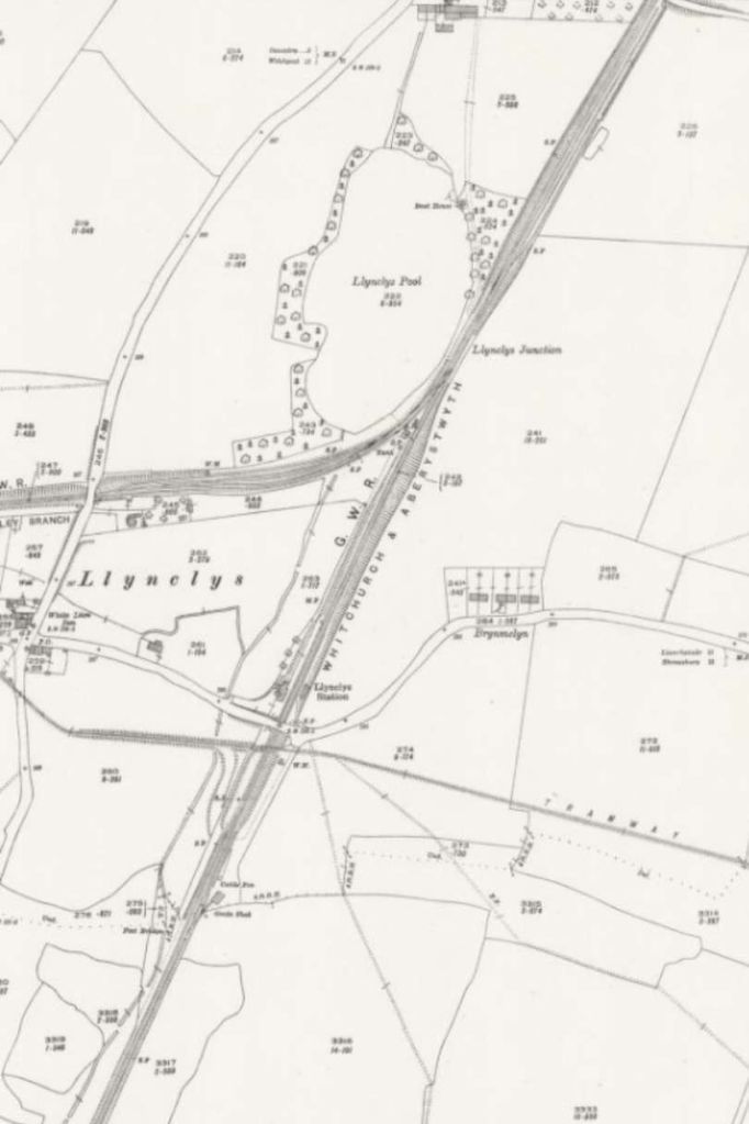
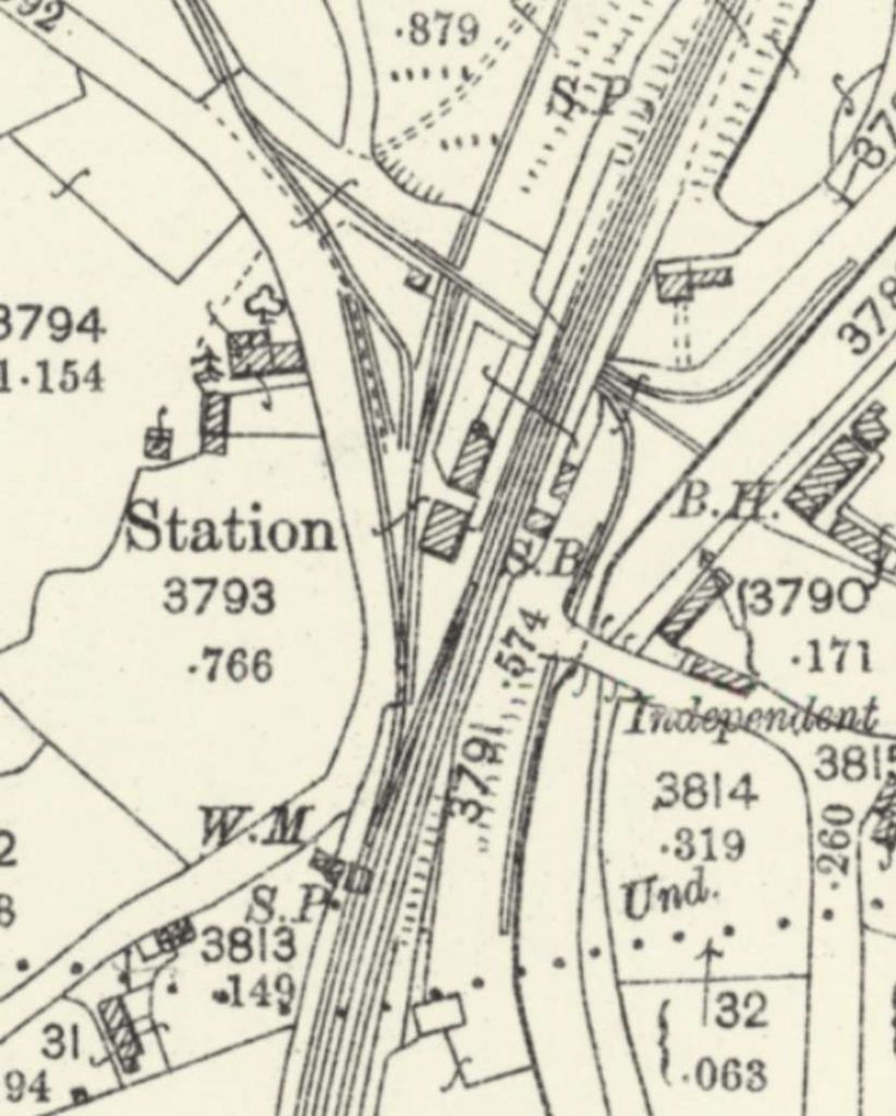
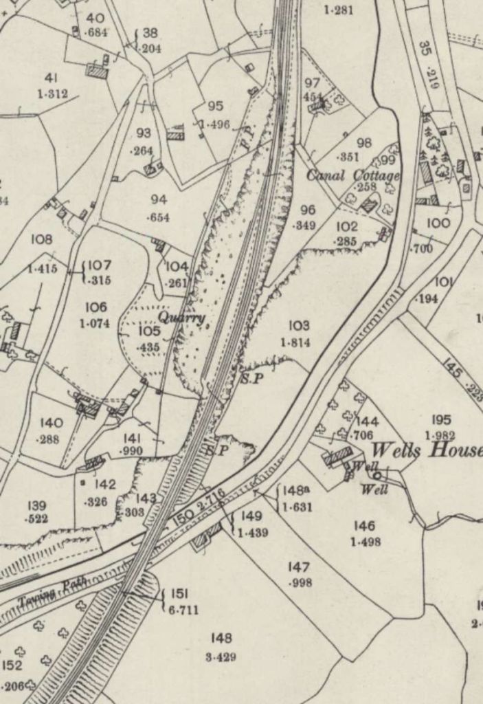
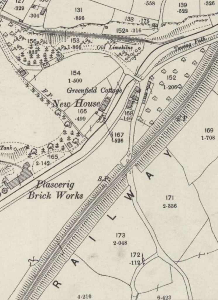
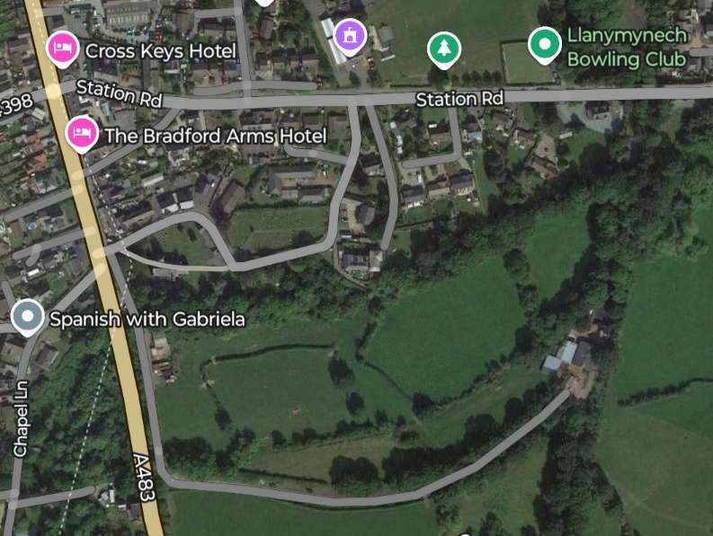
But there is more to consider. … The Lake Lock Rail Road opened in 1798 (arguably the world’s first public railway). It carried coal from the Outwood area to the Aire and Calder navigation canal at Lake Lock near Wakefield. [3][4] The Surrey Iron Railway was the first railway to be authorised by the UK Parliament (21st May 1801). It was a horse-drawn railway which ran between Wandsworth and Croydon. [5][6][7][8][9] It was followed by The Carmarthenshire Railway or Tramroad (authorised by Act pf Parliament on 3rd June 1802). It was a horse-drawn goods line, located in Southwest Wales, the first public railway first authorised by Act of Parliament in Wales.[3][10][11][12]
The Low Moor Furnace Waggonway was constructed in 1802. It connected Barnby Furnace Colliery to Barnby Basin on the Barnsley Canal. It was replaced in 1809 by The Silkstone Waggonway which operated until 1870. [19][20] The Merthyr Tramroad, between Merthyr Tydfil and Abercynon, also opened in 1802. [5][13][14][15][16][17][18] The Lancaster Canal Tramroad (also known as the Walton Summit Tramway or the Old Tram Road), was completed in 1803. It linked the north and south ends of the Lancaster Canal across the Ribble valley. [21][22]
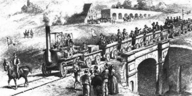
The first steam locomotive to pull a commercial load on rails was Penydarren (or Pen-y-Darren) was built by Richard Trevithick. It was used to haul iron from Merthyr Tydfil to Abercynon, Wales. The first train carried a load of 10 tons of iron. On one occasion it successfully hauled 25 tons. However, as the weight of the locomotive was about 5 tons the locomotive’s weight broke many of the cast iron plate rails. [5][13][14][15][16][17]
We could go on to mention:
- The Croydon, Merstham & Godstone Goods Railway opened in 1805; [23]
- The Sirhowy Tramroad opened in 1805; [24]
- The Ruabon Brook Tramway (also known as Jessop’s Tramway or the Shropshire Union Tramway) also opened in 1805; [25][26][27][28]
- The Middlebere Plateway (or Middlebere Tramway) opened on the Isle of Purbeck in 1806; [29][30][31][32]
- The Monmouthshire Canal Tramway, open by 1806; [33][34]
- The Oystermouth Railway, opened in 1806; [35][36] and
- The Doctor’s Tramroad, Treforest which opened in 1809. [37][38][39]
- The Monmouth Railway authorised by the UK Parliament in 1811. [5][72][73]
- The Kilmarnock & Troon Railway which opened in 1812. [5][74][75][76][77]
- The Killingworth Waggonway of which a first stretch opened in 1762 and which was extended in 1802, 1808 and 1820. [78][79][80][81][82][83]
- The Haytor Granite Railway of 1820 which not only transported granite from Dartmoor as freight but ran on granite rails. [84]
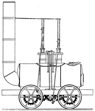
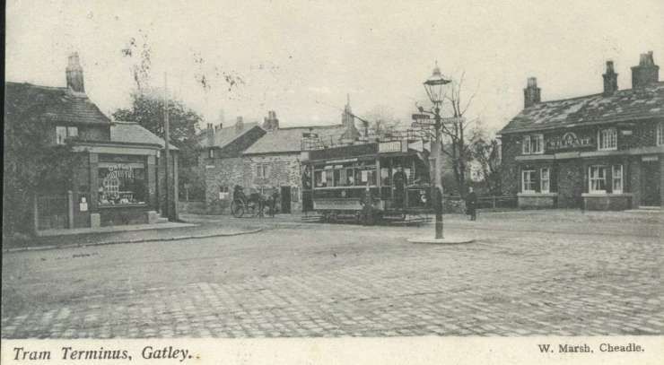
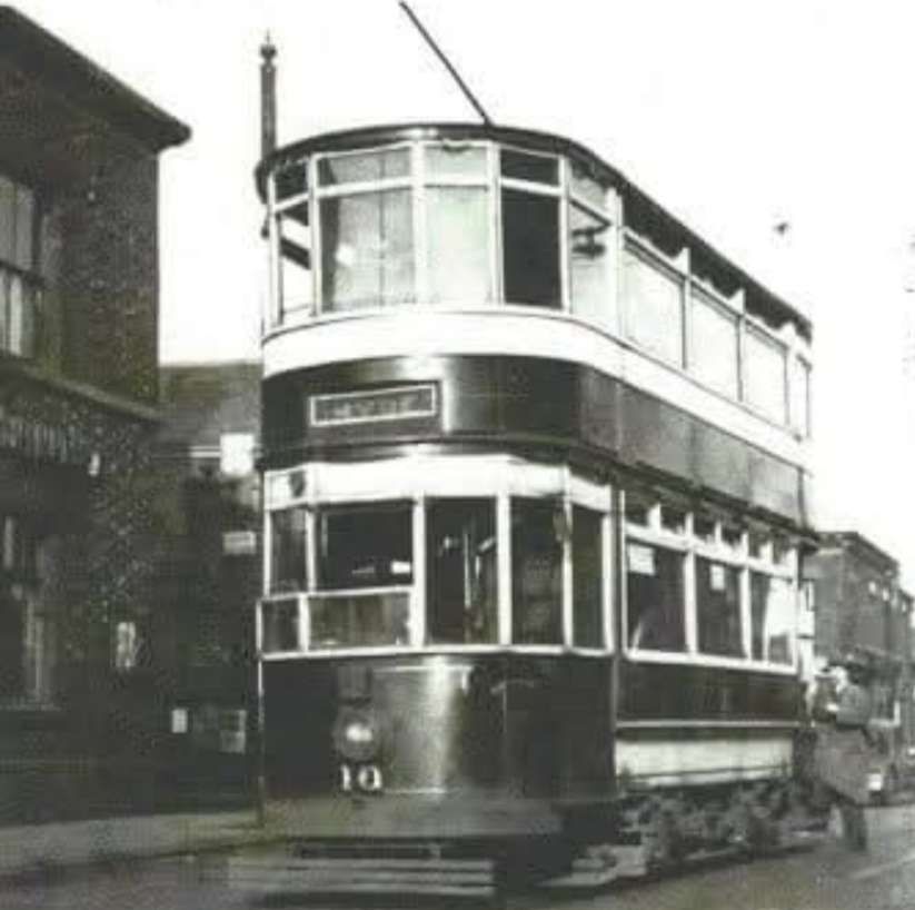
The drawing of the locomotive Blücher (below) was done by Clement E. Stretton, © Public Domain. Blücher was built by George Stephenson for the Killingworth Waggonway. It was the first of a series of locomotives which established his reputation as an engine designer and eventually “Father of the Railways”.
We could list other railways opening before the S&D in 1825. The use of steam power at The Merthyr Tramroad and The Middleton Railway preceded its use on the S&D. A very strong claim to be the most significant development in the early 1800s could be made on behalf of The Middleton Railway. But it is the Stockton & Darlington (S&D) Railway which has caught the imagination and it is the 200th anniversary of the S&D which is being celebrated in 2025 as the beginning of the railway age.
Why is this?
It is clear that the claim to fame of the Stockton and Darlington (S&D) is lessened, at least, by the prior claim of the Middleton Railway both as first to be sanctioned by Parliament and first to make commercial use of steam power. The claims associated with other railways which preceded the S&D also must be significant. However, there is one important and fundamental difference between it and them. David Wilson says that, unlike the Middleton Railway, “the S&D was constructed with a view to carrying other companies’ goods and, to a lesser extent, to carry people.” [1: p61]
In addition, he says, “Bear in mind the distinction between the carriage of goods and people, and between carrying one’s own goods and those of others. In many ways this type of division is what distinguishes the modern concept of the railway as a system for the transport of goods and passengers on a hire and reward basis from the early plateways and railways such as the Middleton, which were not essentially built to carry anything other than goods, typically coal, for their owners.” [1: p61]
Perhaps, though, there are more grounds for the place taken in history by the S&D. Rather than just running between a pithead and a coal wharf on a canal, river or road and serving specific industrial concerns, the S&D also was built by public subscription and linked one town to another.
David Wilson continues: “To arrive at a description of what constitutes a railway we have to enlarge our definition to include not only Parliamentary Sanction, the use of rails or tracks, and the carriage of goods, but also the carriage of the public, the carriage of public goods and that one settlement be joined to another by the laying of a line paid for through the issue of shares. Thus … a railway is a set of tracks laid between two centres of habitation, which carries goods or people for commercial reward and has been authorised by Act of Parliament. It will have been built through the raising of public funds, either through the sale of shares in it or via government spending from the public purse.” [1: p61]
Let’s return to the era before the existence of the steam locomotive, the era of that list of lines highlighted above (and many more).
David Wilson comments: “The growth of the coal mining industry in the later part of the 17th and early 18th century had led to a growth in the plateway systems used to move the coal from the pit head to [a road], canal or river for shipment to the growing cities and the newly built mills. By as early as 1645 there were wagonways taking coal from the Durham coalfields down to the Tyne. By 1800 there were more than 100 miles of these plateways in the Tyneside area alone.” [1: p61]
Similar developments were taking place elsewhere in the UK:
- The first overground railway line in England may have been a wooden-railed, horse-drawn tramroad which was built at Prescot, near Liverpool, around 1600 and possibly as early as 1594. Owned by Philip Layton, the line carried coal from a pit near Prescot Hall to a terminus about half a mile away. [40]
- The Wollaton Waggonway in Nottinghamshire was in use by 1604. [5]
- In East Shropshire and around the Severn Gorge; [41][42] A railway was made at Broseley in Shropshire some time before 1605 to carry coal for James Clifford from his mines down to the River Severn to be loaded onto barges and carried to riverside towns. It is possible that Clifford’s ‘railway’ was in use as early as 1570 and a similar line may well have been constructed by William Brooke near Madeley, again down to the River Severn. [43: p21] By 1775, there were a number of both short and long tramroads in the area around the Severn Gorge.
- The Tranent to Cockenzie Waggonway was built by the York Buildings Company of London, to transport coal from the Tranent pits to the salt pans at Cockenzie and the Harbour at Port Seton, in Haddingtonshire, now East Lothian. [5][44]
- The Alloa Wagon Way was constructed in 1768 by the Erskines of Mar in Alloa, to carry coal from the Clackmannanshire coalfields of central Scotland to the Port of Alloa. [45]
- The Halbeath Railway opened in 1783, from the colliery at Halbeath to the harbour at Inverkeithing. [46][47]
- The Charnwood Forest Canal, sometimes known as the ‘Forest Line of the Leicester Navigation’ was, under the guidance of William Jessop, using railways to supplement the canal between Nanpantan and Loughborough wharf, Leicestershire by 1789. [5][48]
- The Butterley Gangroad (or Crich Rail-way) was built by Benjamin Outram in 1793. [49][50][51][52][53][54][55][56][57]
- The Earl of Carlisle’s Waggonway opened in 1799 from coal pits owned by George Howard, 6th Earl of Carlisle around Lambley to Brampton, Cumbria. [51][58] There is some confusion over dates. The earliest opening date quoted is 1774, the latest 1799. [59] Dendy Marshall says that it was built in 1775. [60] C.E. Lee says it was constructed in 1798. [59][61]
It is perhaps easy to loose sight of the scale of these industrial undertakings. The rapid expansion of mining, plateways and railways “led to an increase in the numbers of horses in use … and a growth in the amount of horse feed needed. By 1727 The Tanfield Waggonway, in Co. Durham, carried 830 wagon loads of coal daily that’s a lot of horses.” [1: p61][5][62][63] “In 1804, the Middleton Colliery line was carrying 194 loads per day. Each wagon held about 2.5 tons and required the use of one horse and driver.” [1: p61]
A crisis in the use of horses and wagons occurred early in the 19th century with the advent of the Napoleonic Wars. The conflict became a significant drain on both horse and horse feed availability. The resulting inflation in the price of horses and feed lowered the profitability of each wagon load of coal. David Wilson says that, “The more visionary (or greedy, depending on your point of view) pit owners started to search for alternatives to the horse to move their goods to market. They provided their pit engineers with money and materials to experiment with steam power to replace horse power.” [1: p61]
Of course, steam power wasn’t new. Knowledge of the power of steam had been around since before the Common Era in Greek society [64][65][66] and the pits themselves had steam engines for pumping out the water and for lifting coal to the surface, or as winding engines on rope-worked inclines. [66][67] Newcomen’s first engine was installed for pumping in a mine in 1712 at Dudley Castle in Staffordshire. [66][68] What was new was first, the expiry of Boulton & Watt’s patent for a high-pressure steam engine, [5][69] and second, the idea of making the steam engine mobile, thus creating the steam locomotive. What eventually became even more revolutionary was the idea of creating a network of railways to serve the whole country. [1: p61]
We sometimes talk of a ‘perfect storm’ (a particularly violent storm arising from a rare combination of adverse meteorological factors), when we are talking about a series of adverse conditions occurring at the same time – a situation caused by a combination of unfavourable circumstances. The opposite of a ‘perfect storm’ is usually assumed to be a period of calm. However, the true opposite of a perfect storm is the occurrence (co-occurence) of a series of positive factors which combine to produce something significantly valuable. Wilson says that “as with almost anything man-made, there must be certain ingredients present. To bake a cake you need eggs, flour, milk etc. and in creating a railway you need, metalworking skills, engineering expertise, labour, capital and an incentive.” [1: 61]
The early years of the 19th century saw a timely co-incidence of these and other factors:
- growing shortages of horse and feed coupled to the rising prices of both;
- poor road conditions;
- a rapidly developing understanding of engineering – Wilson suggests that this was “as a consequence of the more theoretical works of philosophers such as Newton, Descartes and Leibniz. … Such men have a reputation as creators or exponents of the mechanistic world view. Prior to the works of these men many had thought, and indeed some still do think, that the earth was a living entity. However, the views espoused by Newton, Descartes and Leibniz came to be accepted, the world was made up of dead, lifeless and inert matter, here to benefit mankind;” [1: p62]
- the availability of skilled and unskilled labour – particularly the ‘navigators’ who were skilled in the techniques of earthworks, tunneling and bridge building – the men who had earlier built the canals. (“These men were to become the skilled labour of the railway construction industry and in turn they passed on their skills to the former farm labourers who were recruited to railway works as the lines progressed along their routes“); [1: p62]
- developing metalworking skills – “the Darby family, who set up the … Coalbrookdale foundry. had acquired new skills in metalworking from tinkers, in what is now the Netherlands;” [1: p62] After constructing Ironbridge, “the Coalbrookdale ironmasters began to widen their horizons. One of their number, John “Iron Mad” Wilkinson, constructed what was reputedly the first iron barge and, more importantly, … the smiths of Coalbrookdale collaborated with Richard Trevithick in the construction of his locomotive – they cast the cylinder block and the plates for the construction of the boiler;” [1: p62]
- the increasing availability of financial capital;
- the increasing birth rate and the better health of the work-force which provided the necessary labour while engineering work was still labour-intensive.
The Availability of Capital
Among the physical factors listed above is an interesting financial factor which will bear some scrutiny. Wilson tells us that “the capital to build the world’s first public railway came, not from the Government, but from the Society of Friends, the Quakers.” [1: p62] He notes too that the Darby family whose Coalbrookdale plant had such a formative influence in the early days of the industrial revolution, were also Quakers. Wilson explains that Quakers were isolated from much of society and public life because of a refusal to sign up to the articles of faith of the established church. However, the same religious views made them sympathetic to works performed for the public good. Various Quaker families began to take an interest in the developing railway sphere. The website quakersintheword.org [70] tells the story of the significant role played in financing railways played by the Quakers.
“In 1818 a small group of Quaker businessmen, including Edward Pease and his son Joseph from Darlington, Benjamin Flounders and the banker Jonathan Backhouse, met to discuss the possibility of building a railway from Darlington, passing several collieries, to the port of Stockton.” [70]
The Act of Parliament required for the work to take place faced significant delays in the parliamentary process. “The delay proved very significant, as in April 1821 Edward met George Stephenson and recruited him as an engineer for the railway. The original intention had been that the coaches would be horse drawn, just like all the others now in existence. However, George convinced Edward that steam engines were the future for railways, and that he could build them. The Pease family then put up much of the capital that enabled Stephenson to establish a company in Newcastle, where he built the locomotives.” [70]
After the opening of the Stockton & Darlington Railway, “the railway network grew under the guidance of Edward’s son Joseph, who opened the Stockton & Middlesbrough branch in 1828. … In 1833 Joseph became the first Quaker to enter Parliament and the railway interests passed to his brother Henry. In 1838, Henry opened the Bishop Auckland & Weardale line, followed by the Middlesbrough and Redcar line in 1846. Henry wanted to traverse the Pennines and in 1854 he started the Darlington & Barnard Castle line, which opened in 1856.” [70]
Quakers were often involved in railway developments in the 19th century, for instance, “in 1824, a group of merchants, including Quaker philanthropist and anti-slavery campaigner James Cropper, went to see the Stockton and Darlington railway. They soon began building the Liverpool and Manchester railway, which opened in 1830.” [70]
Incidentally, Quakers “were also responsible for two innovations that improved the way these new passenger railways worked – timetables and tickets. James Cropper produced a 12-page timetable for the Liverpool and Manchester railway, probably the first railway timetable ever. It was the forerunner of Quaker George Bradshaw’s Railway Companion, published in 1839. Bradshaw’s became a household name for anyone using the railways. … The second innovation was the railway ticket. In 1839 Thomas Edmundson, another Quaker, was appointed station master at Milton, on the Newcastle and Carlisle line. He was unhappy that customers paid their fares directly to him without receiving a receipt. Consequently he introduced the railway ticket, which came into general use with the creation of the Railway Clearing House in 1842.” [70]
The Birth Rate and Increasing Health of the UK Population
Wilson points us to one more significant factor in the development of railways in the early 19th century. “Seemingly disconnected and irrelevant factors were playing their part. During the period from the end of the civil war (1649) onwards there was a growing awareness of the value of the human being as resource, and a concerted effort was made to increase the birth rate and to cut the death rate. … This did not stem from any rise in humanitarianism but from a recognition that people were worth money. After all, in the 1640s and on into the 19th century, slavery was still common throughout the so-called civilised world, including Britain. Improvements in diet and sanitation increased life exресtancy. It is no coincidence that the first workhouses began to appear around the middle of the 17th century – a reasonably fit and healthy population produced more than a sickly and unfit one.” [1: p62]
“By the beginning of the 19th century, the conditions were in place for a major economic expansion. A growing empire and military strength ensured the supply of raw materials and provided a growing market place for the products made from them. An expanding population provided the physical means by which the empire might be held together. Technology provided the ability to carry out the grand design. The workhouses and other reforms had created a disciplined workforce.” [1: p62-63]
By 1850, a quarter of a million workers – a force bigger than the Army and Navy combined – had laid down 3,000 miles of railway line across Britain, connecting people like never before. [71]
And Finally …
Wilson suggests one other, less definable, reason for the dramatic welcome given to steam technology in particular. He suggests that there was a more visceral connection to steam power which predisposed humanity to embrace the technology.
No doubt, the S&D was at the forefront of engineering developments it was “the white heat of technology, the frontier of science.” [1: p63] Wilson asks us to consider that there was (and still is) a connection between “a piece of primitive industrial technology, the steam locomotive and its enduring popularity, and an ancient, and some might say mystical, view of the world.” [1: p63]
Wilson says: “Prior to the advent of the mechanistic world view in which cause and effect, hard science and hard facts are the order of the day, people held to a more animistic philosophy. Miners would pray to the earth before digging it up. … In this more mystic view of the world things were not made of chemicals and atoms, molecules and the force of gravity. They were composed of the four elements – earth, air, fire and water.” [1: p63] He asks us to consider whether “the reason so many people took to the steam engine and the railway when it began was that the steam locomotive has a unique blend of the four elements not only in its construction but in the very forces and requirements necessary for its movement. … [It] is made from the ores of the earth, heated by fire which needs air to burn. The metals from the forge are then tempered by water whilst being shaped on the anvil. In order to make the steam locomotive work, coal, or part of the earth, is consumed along with air in a fire which turns water into steam which in turn brings the locomotive to life.” [1: p63]
We all know that all men, are just little boys at heart. Increasingly women are involved in the preservation movement. There seems to be a deep emotional connection for many of us between the steam beasts of earth, wind, fire and water that reigned over the railway networks for the world for more than a century and a half and our own psyche, something deeply ‘elemental’!
Whatever the cause, the early 19th century saw humanity embrace steam-power and the benefits it brought with open arms and wallets.
References
- David Wilson; Mother of Inventions; in the Evening Mail Supplement, 1st June 1993, p61-63.
- https://en.m.wikipedia.org/wiki/Diolkos, accessed on 2nd March 2025.
- https://en.wikipedia.org/wiki/1790s_in_rail_transport, accessed on 20th February 2025.
- https://web.archive.org/web/20100604080339/http://www.stanleyhistoryonline.com/Lake-Lock-Rail-Road.html, accessed on 8th January 2025.
- https://en.wikipedia.org/wiki/Timeline_of_railway_history, accessed on 7th January 2025.
- https://web.archive.org/web/20070523122428/http://www.stephensonloco.fsbusiness.co.uk/surreyiron.htm, accessed on 9th January 2025.
- Dorian Gerhold; The Rise and Fall of the Surrey Iron Railway, 1802–46 (PDF); in Surrey Archaeological Collections, Vol. 95, 2010, p193–210; via https://archaeologydataservice.ac.uk/archiveDS/archiveDownload?t=arch-379-1/dissemination/pdf/vol_95/surreyac095_193-210_gerhold.pdf, accessed on 6th February 2025.
- https://en.wikipedia.org/wiki/1801_in_rail_transport, accessed on 20th February 2025.
- https://en.wikipedia.org/wiki/Surrey_Iron_Railway, accessed on 20th February 2025.
- https://coflein.gov.uk/en/site/275707, accessed on 8th January 2025.
- https://en.wikipedia.org/wiki/1802_in_rail_transport, accessed on 20th February 2025.
- M.R. Connop Price; The Llanelly & Mynydd Mawr Railway; Oakwood Press, Oxford, 1992.
- https://rogerfarnworth.com/2019/02/02/the-penydarren-tramroad-south-wales-part-1
- https://rogerfarnworth.com/2019/02/06/the-penydarren-tramroad-south-wales-part-2
- https://coflein.gov.uk/en/site/91513, accessed on 8th January 2025.
- https://www.irsociety.co.uk/Archives/59/Penydarren.htm, accessed on 8th January 2025.
- https://coflein.gov.uk/en/site/91513, accessed on 8th January 2025.
- https://en.wikipedia.org/wiki/Merthyr_Tramroad, accessed on 20th February 2025.
- https://en.wikipedia.org/wiki/Low_Moor_Ironworks, accessed on 20th February 2025.
- Silkstone Waggonway, South Yorkshire: Survey Report (PDF). Vol. 1; Yorkshire Archaeological Trust, August 2012; via https://web.archive.org/web/20160311113301/http://iadb.co.uk/epip/Silkstone%20Waggonway%20Vol%201%20text%20plates%20figures.pdf, accessed on 20th February 2025.
- https://en.wikipedia.org/wiki/Lancaster_Canal_Tramroad, accessed on 20th February 2025.
- S. Barritt; The Old Tramroad – Walton Summit to Preston Basin; Carnegie Publishing, Lancaster, 2000.
- Paul W. Sowan; The Croyden, Mertsham & Godstone Iron Railway: A Short Chapter in a Long Story; The Bourne Society (LHR45), Croydon, London, 2006, LHR45, p53-69; via https://bournesoc.org.uk/bslivewp/wp-content/uploads/CMG-Iron-Railway-SECURE.pdf, accessed on 9th January 2025.
- https://en.wikipedia.org/wiki/Sirhowy_Railway#Sirhowy_Tramroad, accessed on 20th February 2025.
- Alan Jowett; Jowett’s Railway Atlas; Patrick Stephens Limited, 1989, p57, 59.
- https://en.wikipedia.org/wiki/Ruabon_Brook_Tramway, accessed on 20th February 2025.
- Trefynant – Opening of Branch Railway at Trefynant Works; in Wrexham Advertiser, 6th January 1866, p8.
- Meeting of the Wrexham District Highways’ Board; in Wrexham Advertiser. 26th January 1867, p5.
- https://en.wikipedia.org/wiki/Middlebere_Plateway, accessed on 20th February 2025.
- R.W. Kidner; The Railways of Purbeck (Third ed.); Oakwood Press, 2000.
- Purbeck’s clay railways; in Dorset Life Magazine, January 2007; via https://web.archive.org/web/20070927150728/http://www.dorsetlife.co.uk/articles/ArticlesDetail.asp?ID=599, accessed on 20th February 2025.
- Middlebere Plateway; The Purbeck Mineral & Mining Museum; via https://web.archive.org/web/20070928063415/http://www.pmmmg.org/Middlebere.htm, accessed on 20th February 2025.
- https://en.wikipedia.org/wiki/Monmouthshire_and_Brecon_Canal#Monmouthshire_Canal_Tramway, accessed on 20th February 2025.
- https://coflein.gov.uk/en/site/308291, accessed on 20th February 2025.
- https://en.wikipedia.org/wiki/1807_in_rail_transport, accessed on 20th February 2025.
- https://en.wikipedia.org/wiki/Swansea_and_Mumbles_Railway, accessed on 9th January 2025.
- https://cof, lein.gov.uk/en/site/407018/?ref=goodoil.news, accessed on 20th February 2025.
- https://coflein.gov.uk/en/site/96185, accessed on 20th February 2025.
- https://britishlistedbuildings.co.uk/300024912-machine-bridge-also-known-as-pont-y-doctor-pontypridd/photos/147433, accessed on 20th February 2025.
- Mark Jones; Lancashire Railways – The History of Steam; Countryside Books, Newbury, 2012 p. 5.
- https://rogerfarnworth.com/2022/04/25/ancient-tramroads-near-telford-part-1-tramroads
- https://rogerfarnworth.com/2022/04/26/ancient-tramroads-near-telford-part-2-the-coalbrookdale-company-tramroads-shown-on-the-1882-83-6-os-maps-published-in-1887-and-later-surveys
- Peter King, The First Shropshire Railways in G. Boyes (ed.), in Early Railways 4: Papers from the 4th International Early Railways Conference 2008, Six Martlets, Sudbury, 2010, p70–84.
- https://en.wikipedia.org/wiki/Tranent_to_Cockenzie_Waggonway, accessed on 25th February 2025.
- An oblique aerial photograph taken facing north shows a general view in 1928 of Alloa, its Town Hall, Marshill and Church Street. The wagon road which was used to transport coal from the Holton area of Sauchie to Alloa harbour. Although the tracks are gone the road still exists from Station Hotel down to South School. https://www.britainfromabove.org.uk/image/SPW020247, accessed on 7th January 2025.
- https://en.wikipedia.org/wiki/1780s_in_rail_transport, accessed on 25th February 2025.
- Mark Poustie; Halbeath Railway; via https://www.railscot.co.uk/articles/Halbeath_Railway/#google_vignette, accessed on 25th February 2025.
- https://waterways.org.uk/waterways/discover-the-waterways/charnwood-forest-canal, accessed on 8th January 2025.
- Early Years; https://web.archive.org/web/20180120205818/http://www.butterleygangroad.co.uk/bgearlyyears.html, accessed on 8th January 2025.
- https://heritagecalling.com/2015/03/17/heritage-highlights-where-is-one-of-the-worlds-oldest-surviving-railway-tunnels, accessed on 8th January 2025.
- https://en.wikipedia.org/wiki/1790s_in_rail_transport, accessed on 20th February 2025.
- https://en.wikipedia.org/wiki/Butterley_Gangroad, accessed on 22nd February 2025.
- https://historicengland.org.uk/listing/the-list/list-entry/1422984?section=official-list-entry, accessed on 22nd February 2025.
- https://www.bbc.co.uk/news/uk-england-derbyshire-31951751, accessed on 22nd February 2025.
- P. Riden; Outram, Benjamin (bap. 1764, d. 1805); in the Oxford Dictionary of National Biography; Oxford University Press, Oxford, 2004; via, https://www.oxforddnb.com/display/10.1093/ref:odnb/9780198614128.001.0001/odnb-9780198614128-e-20959, accessed on 22nd February 2025.
- https://historicengland.org.uk/listing/the-list/list-entry/1109195?section=official-list-entry, accessed on 22nd February 2025.
- https://en.wikipedia.org/wiki/Steam_Horse_locomotive, accessed on 22nd February 2025.
- Brian Webb & David A. Gordon; Lord Carlisle’s Railways; Railway Correspondence & Travel Society, 1978.
- https://en.wikipedia.org/wiki/Brampton_Railway, accessed on 25th February 2025.
- C.F. Dendy Marshall; A History of British Railways Down to the Year 1830; Oxford University Press, London. 1938, 1971.
- C.E. Lee; The Brampton Railway; in The Railway Magazine, May and June 1942.
- https://en.wikipedia.org/wiki/Tanfield_Railway, accessed on 25th February 2025.
- Tanfield Railway; Wear – BBC Home; via https://www.bbc.co.uk/wear/content/articles/2008/05/20/tanfield_main_feature.shtml, accessed on 25th February 2025.
- Hero (Heron) of Alexandria, described in detail what is thought to be the first working steam engine. He called it an aeolipile (“wind ball”). His design was a sealed caldron of water was placed over a heat source. As the water boiled, steam rose into the pipes and into the hollow sphere. The steam escaped from two bent outlet tubes on the ball, resulting in rotation of the ball. The principle he used in his design is similar to that of today’s jet propulsion. Hero (Heron) did not consider this invention being useful for everyday applications: he considered his aeolipile invention as a novelty, a remarkable toy. https://www.smith.edu/hsc/museum/ancient_inventions/steamengine2.html, accessed on 3rd March 2025. The same device was also mentioned by Vitruvius in De Architectura about 100 years earlier. [66]
- https://blogs.bl.uk/digitisedmanuscripts/2020/12/ancient-steam-engines.html, accessed on 3rd March 2025.
- https://en.wikipedia.org/wiki/History_of_the_steam_engine, accessed on 3rd March 2025.
- In 1712, Thomas Newcomen’s atmospheric engine became the first commercially successful engine using the principle of the piston and cylinder, which was the fundamental type of steam engine used until the early 20th century. The steam engine was used to pump water out of coal mines. [66]
- Steven Johnson; The Invention of Air: A story of Science, Faith, Revolution and the Birth of America; Riverhood Books, New York, 2008.
- https://mises.org/mises-daily/james-watt-monopolist, accessed on 8th January 2025.
- https://www.quakersintheworld.org/quakers-in-action/286/Railways-in-Britain, accessed on 3rd March 2025.
- https://www.railwaymuseum.org.uk/objects-and-stories/navvies-workers-who-built-railways, accessed on 3rd March 2025.
- https://co-curate.ncl.ac.uk/wylam-wagonway, accessed on 15th January 2025.
- https://www.twsitelines.info/smr/1032, accessed on 15th January 2025.
- https://en.wikipedia.org/wiki/Kilmarnock_and_Troon_Railway, accessed on 20th February 2025.
- Campbell Highet; The Glasgow and South Western Railway; Oakwood Press, Lingfield, 1965.
- https://en.wikipedia.org/wiki/1812_in_rail_transport, accessed on 20th February 2025.
- C.J.A. Robertson; The Origins of the Scottish Railway System 1722–1844; John Donald Publishers, Edinburgh, 1983.
- https://my.northtyneside.gov.uk/sites/default/files/web-page-related-files/Killingworth%20Moor%20Archaeological%20Assessment.pdf, accessed on 3rd March 2025.
- https://co-curate.ncl.ac.uk/blucher, accessed on 15th January 2025.
- https://en.wikipedia.org/wiki/Killingworth_locomotives
- Clement E. Stretton; The Railway World, Volume VI; 1897.
- https://co-curate.ncl.ac.uk/killingworth-waggonway, accessed on 15th January 2025.
- https://www.northeastheritagelibrary.co.uk/coalsarchive/ww07/killingworth-waggonway, accessed on 15th January 2025.
- https://en.wikipedia.org/wiki/Haytor_Granite_Tramway, accessed on 27th April 2025


.JPG)