Stanley Jenkins tells us that “The opening of the Inverness & Rossshire Railway between Inverness and Dingwall on 11th June 1862 brought the benefits of rail transport to a prosperous farming area in Ross & Cromarty. The line was completed throughout to Invergordon on 25th March 1863, while a series of subsequent extensions eventually resulted in the creation of the Highland Railway’s ‘Far North’ line between Inverness and Wick. Inevitably the 161½ mile ‘Far North’ line omitted large numbers of places that would have benefited from direct rail links, and for this reason several branch-line schemes were put into effect during the latter part of the 19th century.” [1: p48]
“The Black Isle peninsula, between the Beauly and Cromarty Firths, became the focal point for two such schemes, only one of which was successful.” [1: p48]
Wikipedia tells us that “The Highland Railway was surprised when in 1889 the Great North of Scotland Railway (GNoSR) proposed the construction of a railway to Fortrose, … The GNoSR operated a network from Aberdeen and the nearest place to Inverness served by it was at Elgin, some distance away. The branch would have been detached from the owning railway, but running through the Black Isle it would have made a junction with the Highland Railway at Muir of Ord. A ferry operation from Fortrose to Ardersier, on the south side of the Moray, was included in the plans. Ardersier was then known as Campbelltown, and a railway branch to it was included. Two other schemes striking into Highland territory were proposed at the same time, elevating Highland Railway discomfort about its competitive position.” [2][3]
“The two companies had been adversaries for some time, and in 1883 and the following years there had been a state of continual warfare over junctions, frontiers and running powers. … The Highland saw at once that if this branch were built, it would be easy for the GNoSR to demand running powers into Inverness to reach its branch, and in that way the rival company would have gained access to the Highland’s stronghold.” [2]
After considerable ‘argument’ between the two companies, the GNoSR and the Highland Railway each submitted Bills to the UK Parliament for a line to Fortrose.
It was the Highland Railway’s scheme which received Parliamentary consent on 4th July 1890. Jenkins tells us that it was for a “16 mile branch line between Muir of Ord, on the ‘Far North’ line, and the fishing port of Rosemarkie. The gentle topography of the Black Isle ensured that the proposed line could be built with relative ease, and on 1st February 1894 a single line was opened as far as Fortrose a distance of 13 miles 45 chains. The final section between Fortrose and Rosemarkie was never built, the terminal station at Fortrose being deemed a suitable railhead for the surrounding district.” [1: p48]
“The Fortrose branch provided useful transport facilities … on the South side of the Black Isle, but it was felt that better facilities were needed on the North side of the peninsula. The 1896 Light Railways Act offered a solution to this local transport problem, and on 1st August 1902 a Light Railway Order was obtained for construction of a 19 mile line between Conon, on the ‘Far North’ line, and Cromarty. Work began at the Cromarty end, but subsequent progress was painfully slow, and extensions of Time Orders were obtained in 1907, and again in 1910. … About six miles of track was actually laid between Cromarty and Newhall, but all work was suspended in 1914 on the outbreak of World War I. At that time, construction work was in hand on a further two miles of line, but little had been done on the remaining eleven miles of line to Conon. The track was lifted around 1915 for use in the war effort, leaving the earthworks and other engineering features of the unfinished light railway in a derelict condition.” [1: p49]
“If the Cromarty & Dingwall Light Railway had been completed it would have had stations at Alcaig Ferry, Culbokie, Drumcudden, and Newhall. Other halts may have been opened once the line was in operation, while there were also suggestions that the route might be extended south-westwards from Cromarty to Rosemarkie and Fortrose, thereby creating a scenic ‘coastal’ route around the Black Isle that would have had considerable potential as a tourist attraction. Unfortunately the changed economic conditions after World War I meant that schemes of this kind were no longer viable, and the Fortrose branch was therefore left in splendid isolation as the only completed railway in the Black Isle area.” [1: p49]
“The Fortrose route was worked as a feeder branch for the ‘Far North’ line, and as such it was moderately-successful. Like other Highland Railway branch lines it was normally worked by small tank locomotives such as the Dübs 4-4-0Ts. Other engines seen on the line were Drummond’s well-known 0-4-4 branch-line tanks.” [1: p49]
The Route from Muir of Ord to Fortrose
The extracts below from the 25″ Ordnance Survey of 1904, published in 1906 cover the site of Muir of Ord Railway Station. [6] Jenkins tells us that “Muir of Ord – the junction station for branch services to Fortrose – was opened on 11th June 1862 when the initial section of the Highland ‘Far North’ line was brought into use between Inverness and Dingwall.” [1: p49]
“The station was orientated from North to South, with its main station building on the down, or northbound side. The track layout was relatively complex, with sidings on both sides of the running line and a lengthy crossing loop.The main goods yard, with accommodation for coal, livestock, furniture, machinery, and general-merchandise traffic, was situated to the south of the platforms on the down side. One of the yard sidings passed through a goods shed, while others were used mainly for coal or other forms of wagon-load traffic. Further sidings were available on the up side, and one of these gave access to a 50ft diameter locomotive turntable.” [1: p49]
Wikipedia tells us that “The station is 13 miles 4 chains (13.05 mi; 21.0 km) from Inverness, between Beauly and Conon Bridge, and is the location of the sole remaining passing loop on the single line between Dingwall and Inverness.” [5]
“The station building and platform canopy were erected in 1894, [5][7] 32 years after the station itself opened. [8] Passenger services on the branch ceased on 1 October 1951, but the branch remained open for freight until 13 June 1960. Muir of Ord station was closed on 13 June 1960 but reopened in 1976, on 4 October.” [5][8]
“After the railway bridge across the River Ness washed away in February 1989, isolating the entire network north of Inverness, Muir of Ord was chosen as the location for a temporary depot, from which the stranded rolling stock could operate the service to the highland communities which depended on the line.” [5][9]
“In November 2015, work commenced on a new A862 road bridge at the northern end of the station.” [5][10]
The project cost £3.7 million and was completed in the Summer of 2017. [11]
This ESRI satellite image supplied by the NLS shows the station site after the reconstruction of the raod bridge. [6]
Wikipedia tells us that “in the 21st century, both station platforms have modern waiting shelters and benches, with step-free access. There is a car park and bike racks adjacent to platform 1, along with a help point near to the entrance from the car park.” [5]
“As there are no facilities to purchase tickets, passengers must buy one in advance, or from the guard on the train.” [5]
“The station has a passing loop 32 chains (700 yd; 640 m) long, flanked by two platforms which can each accommodate a ten-coach train.” [5][12]
“On 11th June 1862 the Inverness and Ross-shire Railway opened their line between Inverness and Dingwall. It included a station at the village of Tarradale but the company decided to name it after the nearby cattle tryst (market), Muir of Ord. Eventually the name Muir of Ord was applied to the surrounding area.” [14]
“On leaving Muir of Ord, branch trains diverged eastwards, and having, executed a full 90 degree turn the route maintained its easterly heading for about two miles.” [1: p49]
A further extract from the 25″ Ordnance Survey of 1904, published in 1906. This extract shows the brach leaving the main line just North of the Station and heading East. [17]The same area as shown on ESRI satellite imagery provided by the NLS, in the 21st century. [17]As the line curved to the East it was crossed at level by a track. [17]
Additional sidings on the north side of the station provided locomotive facilities for the branch engine. The main engine siding gave access to a 50ft turntable, while a ‘kick-back’ spur ran into a single-road engine shed; another siding served as a coaling road. The station building was a typical Highland Railway timber-framed structure which was similar to its counterparts at Hopeman and Burghead, albeit with a second cross-wing at the left-hand end (when viewed from the platform). The resulting building was thus an ‘H-plan’ structure with a central block flanked by two cross-wings.” [1: p51]
In the 21st century, the track has been replaced by a modern estate road – Highfield Circle. The road entering bottom-centre is Fairmuir Road, that leaving top-right is part of Highfiels Curcle. These two roads approximately follow the line of the old railway. [17]A short distance to the East the line was in cutting and bridged by a minor road. [17]ESRI satellite imagery from the NLS shows the realigned road in the 21st century. The approximate line of the old road (blue) and railway (red) have been superimposed on the image. The modern road is named ‘Balvaird Road’. [17]A short distance further East the line was crossed by a farm access raod at a level-crossing. [18]The same location in the 21st century as shown on Google Maps satellite imagery. The lane is now named ‘Hawthorne Road’. [Google Maps, March 2025]Looking North along Hawthorne Road, across the line of the old railway (marked approximately by the red line). Google Streetview, September 2021]Looking West from Hawthorne Road along the line of the old railway towards Muir of Ord. The line of the railway is gated by the single-bar gate and it ran from there towars the distant trees. [Google Streetview, September 2021]A footpath follows the line of the old railway to the East of Hawthorne Road. [Google Streetview, September 2021]
From Hawthorne Road eastwards a public footpath follows the line of the old railway. There is a leaflet of walks for the area around Muir of Ord. One of the four walks included in the leaflet includes a length of the old railway. [19]
For a short length the old railway formation has been ploughed back into farmland. The next image looks back along the line of the old railway from a point further to the East.
After passing under the accommodation bridge, the old line ran east in cutting through what is now Spital Wood. Then, ” curving east-north-eastwards,” Jenkins tells us, “the railway continued to Redcastle (3 miles 58 chains), where the single-platform station was equipped with a full range of accommodation for goods, passengers, and livestock traffic.” [1: p49]
“Beyond [Redcastle], trains climbed towards the 250ft contour, the line’s modest summit of around 260ft above mean sea level being sited near the next station at Allangrange. Situated some 5 miles 39 chains from the junction, Allangrange was another fully-equipped station with provision for a range of goods traffic.” [1: p49]
The line continued in an East-northeast direction towards Allangrange Railway Station. [28]The same area as shown on the 21st century NLS ESRI satellite imagery. [28]Looking Southwest along the old railway towards Redcastle Station from the minor road towards the left of the satellite image above. [Google Streetview, April 2011]Looking Northeast along the old railway towards Fort from the minor road towards the left of the satellite image above. [Google Streetview, April 2011]Looking Southwest along the line of the old railway from the A832. [Google Streetview, March 2023]Looking Northeast along the line of the old railway from the A832. [Google Streetview, July 2008]Again, still heading East-northeast, trains drew closer to Allangrange Railway Station. [29]The same area in the 21st century. [29]
The line curved round from an East-northeast direction to and easterly alignment before entering Allangrange Railway Station.
From the point at which the old line crossed another lane, this is the view back towards Redcastle Station. The tree at the centre of the image on the horizon stand immediately adjacent to the line of the railway. [Little can be seen looking towards Allangrange Railway Station from the minor road as the rail alignment close to the road is overwhelmed by vegetation. [Google Streetview, September 2021]The line curved round to run in an easterly direction through Allangrange Railway Station which had a reasonable sized goods yard to the West of the passenger facilities. [30] The same location in the 21st century. The major road at the West end of the old station site is the modern A9 dual carriageway. [30]This is the view East along the line of the old railway from the A9 dual carriageway. [Google Streetview, March 2023]Noe looking East from the A9 through the trees and through the site of Allangrange Railway Station. [Google Streetview, March 2023]Looking West from the old A9 into Allangrange Station site. [Google Streetview, March 2023]Looking East from the old A9 towards Fortrose. [Google Streetview, March 2023]
Beyond Allangrange Station, and heading east-north-eastwards again, “the single-line railway descended towards Munlochy (8 miles 2 chains) which, like the other intermediate stations on the Fortrose branch, was fully-equipped for all forms of goods traffic.” [1: p49]
Three images of Munlochy Railway Station can be seen online at http://www.ambaile.co.ukhere, [53] here [54] and here. [55] Kind permission has been given to reproduce two of these images in this article.
Munlochy Railway Station looking Northeast. [53]Munlochy Railway Station, looking Southwest along the platform. [54]Looking Northeast through the station site from Cameron Crescent. [Google Streetview, September 2021]Again, looking NorthEast through the station site along Station Court. [Google Streetview, September 2021]Looking back Southwest from Millbank Road (B9161) through the station site. [Google Streetview, March 2023]Looking Northeast along the line of the old railway from Millbank Road (B9161) towards Fortrose. The A842 is just to the left. [Google Streetview, March 2023]
“From Munlochy the route passed over a small underline bridge, and with the A833 (later A832) road maintaining a parallel course to the left, Fortrose trains reached Avoch Station (11 miles 25 chains).” [1: p49]
“From Avoch, the line continued north-eastwards for a further … three miles to its terminus at Fortrose where, some 13 miles 45 chains from Muir of Ord, journeys came to an end in a surprisingly large station.” [1: p49-51]
“Fortrose had just one platform on the up side, with a run-round loop to the north and a four-siding goods yard to the south. One of the goods sidings passed through a goods shed, while another served a loading bank; a spur at the west end of the goods yard formed a short headshunt.” [1: p51]
Fortrose Railway passenger station building had “the booking hall and general waiting-room … in the centre part of the building, while the booking office and toilets were housed in the ends. The timber structure was clad in American-style vertical matchboarding, with thin cover strips affixed at each join to produce a ‘ribbed’ effect.” [1: p52] The centre block was recessed between the cross-wings to create a roofed waiting area at the front of the station.
Additional photographs of the Station can be found on the www.ambaile.co.uk website here, [73] here [74] and here. [75] Kind permission has been given to reproduce these photographs here.
Fortrose Railway Station from the end of the platform in 1912, showing the station building. A branch train is in the platform and a locomotive is on the turntable in the background. [73]Fortrose Railway Station seen from the Northeast (adjacent to the buffers). Llocomotive No. 57594 is described in the notes for the next image. Here it is about to be turned to take its train back to Muir of Ord. [74]Locomotive No. 57594 has just been turned and is being readied to haul the last train from Fortrose. The locomotive is an ex-Caledonian ‘812’ Class 0-6-0, built in August 1900 as CR No. 856, becoming LMS No. 17594 and finally BR No. 57594. It was withdrawn in December 1962. [75]
Decline and Closure
The Fortrose branch was relatively successful. Its passenger services were maintained throughout the LMS era. But the line “became increasingly vulnerable to road competition after World War II, and for this reason its passenger services were withdrawn with effect from 1st October 1951. Goods traffic lingered on for a few more years, but the end came in 1960, with the line being closed to all traffic from 13th June of that year.” [1: p52]
References
Stanley Jenkins; Highland Railway Minor Lines: 2; in Rex Kennedy (ed.); Steam Days; Red Gauntlet Publications, Bournemouth, Dorset, January 2002; p48-57.
After completing a series of articles about Genova’s transport system at the end of 2024, beginning of 2025, I came across a series of three articles in the ‘Light Rail & Modern Tramway Journal’ dating from 1995. This article covers those three pieces. …
Written, 30 years ago, Barry Cross’ articles help us to engage with the changes to the transport systems in Genova over the decades.
Part 1: August 1995 – The Demise of the Old Tram Network and the Development of the Metro
Barry Cross says that “as far as tramway enthusiasts are concerned, the city lost most of its attractions in the 1960s, when the remaining interurban tram routes were abandoned, and public transport became synonymous with travelling by diesel bus. … Nevertheless, the curious topography of the city, which to all intents and purposes is built on a narrow coastal enclave, has meant that some rather curious forms of public transport have survived. Flying the tramway flag during the lean years has been the Granarolo rack tramway, whose two cars resemble both tramway and funicular vehicles. … Then there are the two conventional funiculars: the Sant’Anna and Zecca-Righi, which provide rapid access from the port to the residential districts in the hills above. Finally, the Genova-Casella electric light railway offers one of the most scenic and exhilarating rides to be found anywhere on the European continent.” [1: p251]
In the years prior to 1995, the municipality once again “decided to embrace tramway technology, in a desperate effort to improve public transport because of the severe deterioration in traffic conditions. The result [was] the construction of an entirely new light metro, recreating in part the coastal tramway abandoned in the 1960s. Despite only three stations having so far [in 1995] opened, patronage of the line already exceed[ed] expectations.” [1: p251]
In May and June 1964, Modern Tramway carried a two-part article on the tramways and light railways of Genova by Joachim von Rohr. Barry Cross attempts, in his articles, to show developments in the city up to 1995. This will provide an opportunity to compare the situation in the mid-1990s with that in 2024/2025.
“In the 1960s, many Italian cities felt the urge to ‘modernise’ their public transport systems, a term which all too often meant the closure of efficient, if rather run-down tramway networks. Genova was no exception. Unusually, it was the urban routes that closed first, these being abandoned in the late 1950s, although the interurban routes continued to operate (and decline) well into the 1960s. … The interurban system essentially consisted of four metre-gauge routes emanating from the central Genova Caricamento terminus. Two of the routes ran along the coast, one west to Voltri (16.9 km) and the other east to Nervi (approximately 12 km), while the other two served inland destinations, along the Polcevera valley to Pontedecimo (15.1 km) and to Prato (13.6 km), situated in the Bisagno valley.” [1: p251]
Cross continues: “On 25th May 1964, the so-called ponente route to Voltri was abandoned to the west of Sampierdarena, involving the withdrawal of seven separate services. Worse still, tram tracks in Via Francia were also lifted to permit construction of a connection with the strade soprelevata (elevated roadway), in which the municipal authorities had placed so much faith as a means of decongesting the city’s narrow and winding streets. … As a direct result of this, route 7 had to be cut back from Caricamento to Sampierdarena and route 26 entirely abandoned on 27th June. Furthermore, the survival of the Pontedecimo route had become ever more precarious given that its only connection to the rest of the system was henceforth via the Certosa tram tunnel.” [1: p251]
The Pontedecimo route survived until 1st October 1964. On that day, “tramway operation through the Certosa tunnel ceased. All remaining routes were replaced by motor buses on 27th December 1966, the last tram to run in public service being car 935 on route 12 to Prato.” [1: p251]
By the 1960s, trams in the 700 and 800 series were the oldest on the network, dating from 1931 and 1934, both bogie cars. All were very much at the end of their working lives and were the first to be scrapped. Two of the 700 series trams are shown below. The first is No. 762, the second is No. 766. Trams No. 751-800 were bidirectional bogie-cars built in 1931. These were known as ‘long Casteggini’ type trams. [4][5]
The 800 series were numbered from 801 to 820 (UITE) were bidirectional bogie-cars built by Piaggio in 1932. These were known as ‘short Casteggini’ type trams. [4] Tram No. 821 is shown below at the tram terminus at Bratte in Bolzaneto. This image was shared on the Foto Genova Antica Facebook Group by Enrico Pinna on 14th October 2023. [6]
There were three types of articulated car on the network at that time. Cross says that “the most numerous of these were the 78 cars of the 1600 series, which were single-ended and the result of rebuilding from older stock, while the 15 cars of the 1700 were double-articulated vehicles ‘two-rooms-and-a-bath’ variety, also rebuilt from older cars in 1954-5, Maintenance of all of these cars was poor in their final years in service. … Genova’s most modern interurban cars were the six-axle 1100 series, built in 1942, of which there were only four examples, and the streamlined bogie cars of the 900 series. Both were bi-directional, with the articulated cars carrying two trolleys. The 900-series cars were the backbone of the interurban service and predominantly worked routes 10, 11, 16, 24 and 26. Both series were well maintained. with an eye to resale once the interurban network had been closed.” [1: p251]
Details of these four tram types can be found here. [7]
It was hoped that first, Beograd and then Zagreb might purchase the 900 series, even Madrid seems to have made enquiries, but “two and a half years after the Genova tramways closed, [the 900 series] cars were still to be found standing in their depots and were eventually broken up, with no buyer having been found.” [1: p251]
Cross recorded that “two cars, 962 and 973, were preserved, and in 1989 a scheme emerged to use them to provide passenger services on a metre-gauge heritage tramway, linking Piazza Caricamento and Piazza Ferrari along a pedestrianised Via San Lorenzo. However, in true Italian style, nothing [had] yet been decided.” [1: p252] I have not been able to find any evidence that the heritage service was brought into operation.
Cross goes on to say that “Articulated cars 1101-4 were sold to the Neuchâtel tramway (TN) in Switzerland, with car 1104 arriving on 29th March 1966 for a set of preliminary trials. These were so successful that TN bought all four and put them into service on route 5 in Autumn 1966. The Genova trolley poles were replaced by pantographs, and heating also had to be fitted, since this had been totally unnecessary in the balmy Mediterranean climate.” [1: p252]
Interurban trams were replaced by FS multiple-unit, rapid-transit trains along the coast between Nervi and Voltri or Pontedecimo in order to reach the centre of Genova. Withdrawal of the city centre trams “left Genova with 130 trolleybuses as its only means of electric urban public transport, but even these eventually succumbed to replacement by diesel bus. However, as time passed, it became ever more obvious that a huge mistake had been made in withdrawing the trams. … The elevated roadway did not prove the panacea that its planners had wished for, while motor buses did nothing to improve the traffic flow … their stops on Genova’s narrow, winding and steep roads effectively blocked the flow of all traffic!” [1: p252]
The municipality decided to reopen the Certosa tram tunnel for use by diesel buses. This required forced air ventilation to maintain reasonable air quality in the tunnel. It “reopened for bus operation on 1st October 1967, although width restrictions made it impossible for two-way working. … Instead, a token block system had to be introduced, with buses passing through the tunnel in alternate directions at nine-minute intervals. This resulted in a serious capacity problem during the rush hour, which could be overcome only by sending convoys of three instead of single buses through the tunnel. … Unfortunately, the tunnel’s ventilation system simply could not cope with the upsurge in exhaust emissions. Indeed, the Il Lavoro’ newspaper shocked the general public when it featured a photograph of a bus on route 10 leaving the tunnel with its driver clearly seen wearing a gas mask!” [1: p252]
Other solutions had to be found. “In the 1920s, Genova had been tempted to undertake construction of a conventional heavy metro, influenced by the developing trend in some other European cities. However. successful implementation of the proper scheme had been undermined by its daunting cost.” [1: p252]
A study by the Marron Institute of Urban Management looking at possible urban transit solutions considered a number of Italian cities including Genova. It comments: “Despite several attempts in the interwar period to develop metro rail networks in Rome, Milan, Genoa and Naples, the first proper metro line opened only in the mid-1950s. Metro construction finally gained momentum during the postwar years, characterized by fast urbanization and dramatic economic growth, but was hindered by the lack of a national transit policy, which finally emerged in the late 1980s, and by an essentially car-oriented transport policy.” [8: p15]
The idea of Metro for Genova was resurrected in 1972. “Trial borings were undertaken as a prelude to the construction of an 18-km two-line metro system. Ironically, the first line would run along the coast from Multedo in the west to Sturla in the east. duplicating in part the withdrawn coastal tramway! … The economics of building even a single cross-city line with, at most, two branches, proved beyond the financial capability of a city with a population of only 800,000. The decision not to proceed with the scheme was inevitable, leaving the city’s transport planners with little option but to continue with the status quo until a viable alternative could be found. … In the early 1970s, an alternative plan [was] put forward … to reuse old railway tunnels abandoned in the post-war period to provide a metro-style suburban rail service. The success of this scheme relied upon FS permitting metro cars to share tracks with conventional trains on the existing harbour line. But this it was not prepared to do. … After a change of political control in 1975, the Comunale di Genova set up a joint FS-AMT (Azienda Municipalizzata Trasporti) commission to examine the possibility of reusing previously-abandoned railway infrastructure to provide some sort of metro service. … A visit was paid to the Grazie tunnel, linking Brignole with Piazza Cavour, to assess its suitability, and also to the former Certosa tramway tunnel.” [1: p252]
Use of the Certosa tunnel by diesel buses had proved to be a failure. Instead of converting it for use by trolleybuses “it was proposed to build a Metropolitana Leggera (light metro) linking Rivarolo with Brignole by means of the tunnel. … Phase 1 would involve the construction of the Rivarolo Principe section. A reserved alignment would be built along Via Iori and Via Canepari, from where the trams would run through the tunnel to Dinegro. Here, traffic-light priority would allow the cars to cross Via Venezia and move to a further surface reservation along Via Buozzi. Finally, at Principe FS station, there would be a turning circle formed by Via Adua and Via San Benedetto. The Board of Directors of the AMT gave the project its full backing, with the Comunale following suit shortly afterwards. On 24th February 1981, the municipality, doubtless with an eye on the forthcoming June elections, approved an ITL 8000 M grant for the rehabilitation of the Certosa tunnel. although inflation eventually pushed this up to ITL 11 000 M. The central government also became involved, pledging investment worth ITL 165 000 M to build the entire 7.645-km Rivarolo-Brignole line. Ansaldo Trasporti was subsequently awarded a turnkey contract to both build and equip the line.” [1: p252-253]
Cross continues: “On 8th February 1982, the Certosa tunnel was closed to bus traffic for the last time. … In all, 540 days were spent on rehabilitating the tunnel structure, although much more work was required before tram services could start. … In 1985, work on the project proceeded very slowly, while some drastic changes were made to the eventual alignment. In the revised plan, none of the surface sections of the line had survived. From Rivarolo to Brin, the line would be on an elevated alignment, crossing the double-track FS railway line via the Compasso park. Trams would then pass through the Certosa tunnel and cross under Via Venezia and Piazza Dinegro via a new 300-m cut-and-cover subway, continuing to Principe entirely in subway. The Principe-Brignole section would still run on the dock railway as planned, then via the Grazie tunnel to Brignole FS.” [1: p253]
The municipality set a “theoretical capacity of 36 000 passengers per hour and direction [for] the line, whose trains would draw current from a 750-volt de overhead contact wire. However, curves of 150-m radius would have to be negotiated, and rolling stock would have to be designed to operate on tunnel gradients as steep as 4%. The track design would require sleepers to be enclosed in rubber sleeves to absorb noise and vibration, following successful use of such a system in Wien (Vienna).” [1: p253]
This was a much heavier metro than had originally been planned, and would be both more expensive and slower to implement – the first phase costing ITL 1150,000 M and taking 9 years to build! It was hoped to start passenger services by the end of 1989, in the end it opened in June 1990. The first phase was 2.6 km in length and had cost ITL 100,000 M/km! The line proved to be very popular. “One and a half years later, 3.5 million passengers had used the line. … It had been hoped that the line would be extended from Dinegro to San Giorgio in 1992. However, more delays ensured that only the 900m Dinegro-Principe section would be ready in time. This was duly inaugurated on 27th July 1992, and was expected to increase substantially the initial line’s patronage, since Principe is Genova’s main long-distance railway terminus and a new suburban station, San Tomaso, was being built nearby. A further two ‘metro’ sets were put into service to cope with the expected increase in traffic.” [1: p253]
Cross was writing in 1995 and reported that work was ongoing on the next length of the Metro. In the end, work on that next section of the line to Caricamento was not completed until 2003. The next section to De Ferrari (underground station at Piazza De Ferrari) was completed in 2005, and that to Brignole in 2012. [9][10]
Part 2: September 1995 – Casella Line Begins to Realise Tourist Potential
Cross notes the significant delays which affected the first scheme promoted by the ‘Societédi Ferrovie Elettriche Liguri‘ (SFEL) in 1915, which meant that It was not “until 1926 that construction was able to start on the metre-gauge line, which was to be electrified at 2.4 kV DC by the ‘Societé Ernesto Breda, which won contracts to supply the overhead and sub-stations, as well as the initial rolling stock.” [2: p295]
He also comments on the use of the contractor’s steam locomotive “to power the first train between Genova and Casella Deposito on 24th June 1929; then, on 31st August, the operating company laid on a special train for the Archbishop of Genova’s pastoral visit to Pino, with a regular passenger service starting the following day. However,” he says, “the line’s official inauguration had to wait until 28th October 1929.” [2: p295]
The line was notable for 60-metre radius curves and maximum gradients of 4.5%, imposed on engineers by the need to cross steep gradients between the Bisagno, Polcevera and Scrivia valleys. cross continues: “A non-counterweighted catenary was preferred over most of the line, although a simple transversal suspension overhead sufficed in stations, depot area and between the upper terminus and the depot. Very light 27 kg/m rail was standard throughout. The initial fleet of Breda vehicles operated by SFEL was:
3 Bo-Bo motor baggage cars (001-003) rated at 270 kW, featuring the novel Breda-Somaini energy recuperation system;
4 3rd-class bogie trailers (50-53);
3 1st/3rd-class trailers (20-22);
16 assorted goods wagons.
The Casella Deposito-Casella Paese section, originally planned in 1930, eventually opened in 1952, crossing the Scrivia river via a new combined road/rail bridge. Trains shared the road with cars, and the 1 km line terminated in mid-highway on the village outskirts.” [2: p295]
Cross comments that, throughout its life, the line made use, primarily, of second-hand rolling stock. “The first items acquired as early as 1935. In that year, three railcars came from the Montebelluna-Asolo and Montebelluna-Valdobbiadene lines operated by the former ‘Societé Veneta’, which ceased trading in 1931. These vehicles had been built at Padova by MAN in 1913 for operation at 975 V DC, but had to be modified at Genova. They had distinctive match-boarded sides, maximum-traction trucks, and retained original fleet numbers 054-056. With only two motors per car, they were rather slow, particularly with trailers.” [2: p295]
Cross notes that “World War II did little permanent damage, although rolling stock was worn out after almost continuous use evacuating families from Genova city while under bombardment. The Government Commission, which assumed managerial responsibility for the line in 1949, acquired supplementary stock from the 950-mm ‘Sangritana’ light railway (SFAA), almost totally destroyed in the war.” [2: p295] Of these, two electric locomotives were re-gauged, they were numbered 28 & 29, had 360-kW motors which “drew power via two pantograph-style bow collectors, one leading and one trailing, and could reach speeds of 50 km/h. They kept their original numbers when put on the Casella line in the 1950s and later acquired bus-type seats for 16 passengers.” [2: p295]
In January 1963, the line acquired significant amounts of stock and fixtures of the Ferrovia Elettrica Val de Fiemme (FEVF), which operated the Ora-Predazza metre-gauge line “three Bo-Bo baggage locomotives [B51-52, A2] driven by 310 kW motors and capable of a maximum speed of 60 km/h; three three-bogie rail cars … which drew power via a single rhomboidal pantograph to feed a 310 kW motor permitting speeds of 60 km/h; 36 bogie-trailers, of which C101-2 were long vehicles and C103-6 short; and … several goods wagons.” [2: p295] Of the fixtures, “the FEVF provided two static converters, replacing the FGC’s original generating equipment. These were installed at Vicomorasso and raised the line voltage from 2.4 kV DC to 2.6 kV. Unfortunately, this new equipment did not permit recuperation of energy and resulted in withdrawal of all earlier rolling stock, except that acquired from Sangritana lines.” [2: p295]
Furthermore, “in 1968, the recently-closed Spoleto-Norcia (SSIF) electric light railway yielded four 950-mm gauge railcars, built by Carminati & Toselli/TIBB in 1926 and later rebuilt by Casaltra/TIBB in 1957 with new electrical equipment, with 360-kW motors permitting maximum speeds of 60 km/h. They arrived at Genova in 1970 and entered revenue service a year later, the delay being for regauging. … Although originally numbered A1-4, they were altered to A4-7 to avoid conflict with earlier-acquired FEVF stock.” [2: p295]
Cross talks of the line struggling through the last 40 years of the 20th century. “When Joachim von Rohr visited the FGC in 1963, he noted Casella depot was particularly run down. Although renewal of the ballast was taking place, the use of short, not welded rails, plus a tendency to bend rail at joints, made for some eventful running. … On 17th January 1974, railcar A3 was derailed on poor track. On 31st October, a judge ordered closure on safety grounds, so urgent repairs were undertaken to permit a limited reopening between Genova and Sant’Antonino, and Campi SL and Casella in early 1975. Full operation resumed on 2nd March, with railcars now fitted with speedometers. … Money was not forthcoming to repair damaged A3, and the poor mechanical state of locomotive 28 also prompted its withdrawal. However money was made available to replace original rail with heavier 36-kg/m lengths, a task not completed until 1979. Maximum speeds were raised slightly, to reduce journey times from 1 hr to 55 min. In 1980-1, Casella Paese terminus was relocated from street to reserved track, and a new depot built at Vicomorasso. … In early 1990, Ansaldo Trasporti was awarded a contract to upgrade FGC installations. Overhead was replaced at a cost of ITL 5500 million, with original masts replaced by standard fitments. Voltage was raised to 3 kV DC, and a 1987 government grant allowed replacement of two sets of manual points in stations by electric ones.” [2: p295]
A gradual programme of rolling stock modernisation began in the early 1970s, “two-tone blue livery replaced the original red and cream, replaced in turn in 1980 by brown and cream. This new livery was to grace nine trailers rebodied by the Mantovana-based company ‘Gleismac’ in the early 1980s. However, C103-4 were not included, whilst C22 had already been rebuilt into a bar car at the end of the 1960s. Then, in 1985, damaged railcar A3 was completely rebuilt with a newly-designed body, chopper-controlled electronics from EEA of Genova, and two pantographs. At the same time, two Faiveley double-bracket pantographs were experimentally fitted to B51 and A4. … ‘Gleismac’ also supplied a BB diesel-hydraulic locomotive for works trains and insurance against power failure. Built by Gmeinder of West Germany in 1964, it was sold to ‘Gleismac’ from the ‘Sudwestdeutsche Eisenbahn Gesellschaft’ (SWEG) in 1986, and is now numbered D1. More recently, the bogies of disused locomotives B51-2 have been used by ‘Firema-Cittadella’ to build two new electric railcars, identical in appearance to existing railcar A3. The first, A8, was handed over to the FGC on 28th June 1993, with A9 following on 28th October. Unlike A3, both new cars can operate in multiple.” [2: p 295-296] Writing in 1995, Cross expressed the hope that if new bogies could be found, B51 might return to traffic. As far as I can tell, this did not occur. He also noted that Ferrocarril Genova Casella (FGC) was planning to buy two entirely new railcars similar to A3, A8 and A9 and three new trailers with a baggage compartment and a lift for the disabled. Two were built in 1998 (A11 and A12).
Cross also suggests that FGC planned “to rebuild railcar Al, with only A2 to be left in its original Carminati & Toselli 1920s condition. Both [were] reported fitted with modernised bogies. As for the four ex-Spoleto-Norcia railcars, at least one [was to] be de-motored to become a trailer. A4 [had] been given a new coat of cream and brown, and trailer C21, rebuilt by ‘Gleismac’ in the early 1980s, a curious livery of cream and blue.” [2: p296]
More information about railcars on the line can be found here. [12]
Looking forward from late-1995, Cross anticipated the purchase by the FGC of surviving rolling-stock from the closed Rimini-San Marino light railway. That line was operational for only twelve years between 1932 and 1944. “A significant engineering feat of its time, it included seventeen tunnels, three bridges, and three viaducts to negotiate the steep terrain. During the Second World War, the line was bombed and closed, after which its tunnels sheltered refugees during the Battles of Rimini and San Marino. After the war, the railway was abandoned in favour of the SS72 state road, San Marino Highway, and Funivia di San Marino. … In 2012, an 800-metre (1⁄2-mile) section was reopened as a heritage railway in San Marino, running between Piazzale della Stazione and near Via Napoleone.The restored section comprises the original railway’s final horseshoe turn through the 502-metre (1,647-foot) Montale tunnel.” [13] Cross anticipated that the FGC would buy the “four electric railcars, five trailers and 14 wagons, most for revenue service in Genova,” [2: p296] that were not required for the planned heritage line.
Cross comments that the distance of the Genova terminus at Piazza Manin from the central area of the city, means that the walk is quite daunting in summer months, but an extension into the heart of the city would be impractical because of the difference in height between the city centre and Piazza Manin. The terminus is situated high above the Bisagno valley which means that passengers see some fine views of the city soon after leaving the station. In describing the route, Cross speaks of a long viaduct “at Sant’Antonino which has four 10-metre arches. Departing services climb Sunday me 271 m in 9 km to reach Trensasco, located at 364 m above sea level. The line is cut into a ledge on the valley wall and near Cappuccio runs around the so-called ‘Colombo curve’ over the Viminate slope. The sharp bends give an exhilarating ride and are testament to the fact that the line engineers chose to bend with valley contours and even enter side valleys to avoid major tunnelling and expensive viaducts. … The line passes only through areas of sparse population, and former station buildings are so dilapidated it is often impossible to make out their names. Just before arriving at Campi (10 km), a small tunnel takes the line away from the main valley and shifts interest to the other side of the line. At Campi itself, up and down trains generally pass, and the guard of the ascending train has to advise control of his train’s arrival via a lineside telephone.” [2: p296]
“Having arrived at 365 m above sea level, the line then descends towards Torrazza (11 km) and Vicomorasso (15 km), where the only sub-station is located and a spur line gives access to a small car shed. Withdrawn rolling stock has also been dumped here in recent years, while the station also provides passing facilities. Thereafter, the real assault begins and the line passes through some spectacular mountain scenery by means of loops and a spiral tunnel, climbing 100 m in a mere 2km before emerging into the Polcevera basin, with its notable chestnut and acacia woods. For one brief instant it is possible to see tracks below at three different levels! Another passing point is the small halt of Sant’Olcese Tullo.” [2: p296]
Cross continues his anecdotal account of a journey North along the line. He says that “the line continues to climb, although less dramatically in the mountainous terrain. There is one particularly dramatic hairpin bend near Sant Olcese, and near the following halt of Busalletta, fine views can be obtained of Monte Sella, 811 m. The railway summit is reached at Crocetta halt, 458 m above sea level and 22 km from Genova. It is possible to see the parallel road, which has done much to abstract traffic away from the line in recent years. There are also many small level crossings along the length of the line; the insignificant ones remain unprotected, while major crossing points are guarded by either automatic half-barriers and warning tones or simply flashing lights and audible tones.” [2: p296]
“Casella Deposito (24 km) is just before the main depot site and has only an anonymous raised concrete platform to betray its whereabouts. The main line leads into a three track fan at the depot, where maintenance equipment is located and vehicle overhauls carried out. Nearby is the site of a quarry which supplied the FGC’s ballast. Appreciable goods traffic (now all lost), led to a ramp being built at Piazza Manin station to permit stone to be directly off-loaded from wagons into lorries in the street below.” [2: p296]
“Trains must reverse to gain the Casella village line, sometimes achieved with a second railcar. On the last leg of the journey, the 1952-built combined road and rail bridge has the railway track on reserved and fenced aligament to one side. Thereafter, it is less than 1 km to the terminus, on the outskirts of the small village of Casella. Two-track Paese station is unmanned, although there is a small bar to welcome thirsty passengers. … The village has no special tourist attractions other than a few bars and restaurants, all mentioned in the FGC timetable. However, the cool mountain air makes a change from the oppressive heat of the coast, and an important magnet for day-trippers.” [2: p296]
Cross notes his sources for his article of which two are articles in the predecessor journal to the Light Railway and Modern Tramway – Modern Tramway. He quotes the news pages of that magazine from 1962 onwards and a specific article by Joachim von Rohr. [14] He also consulted an article in Mondo Ferrovario. [15]
As a separate note within his article, Cross comments on what he records as ‘The FGC’s First Serious Efforts to Attract New Traffic‘. …
“At the start of the 1970s, the FGC began its first serious attempts to attract excursion traffic. While Genova municipal authorities were doing their best to dissuade unnecessary car journeys in the city, the light railway offered free parking at Genova Piazza Manin station to holders of return tickets. … This certainly offered scope for development, given the dramatic and beautiful countryside and ancient churches and forts within reasonable walking distance of stations.
This initiative has developed quite dramatically, and the policy of the FGC is now oriented towards the tourist market. It has put together a Belle Epoque train, formed of ‘heritage’ stock. The three-car train made its inaugural run on 5th November 1989 and is powered by the oldest surviving electric locomotive in Italy, No. 29 of the former Sangritana railway. … Passenger accommodation consists of ex-Val di Fiemme trailers C101 and C104, which retain original wooden furniture and bronze and brass fittings, accompanied by bar car No. C22. A major overhaul on No. C22 was undertaken in 1990, considerably upgrading its interior and also increasing capacity. … In expectation of an increase in visitors for the 1992 Columbus anniversary celebrations, the historic train had a regular Saturday working during June, July and August. The train has proved popular with both wedding and communion parties.
Near both Campi and Sardorella stations, the FGC has created playgrounds and picnic areas; the facilities at Sardorella can only be reached via the FGC. In 1990-1, the FGC began a bicycle transport service using a specially converted wagon; alternatively, customers can hire bicycles at cheap rates in Casella village.” [2: p296]
The images below show Locomotive D1 which operates the tourist train. …
Locomotive D1 responsible for a single coach. [18]
And here with two coaches. [18]
And here, escaping from a tunnel portal. [19]
“Locomotive D1 was built in 1964 on behalf of the German railways by the manufacturer Gmeinder & Co. by adapting the MaK V100 standard-gauge locomotive to metre gauge, it was numbered V52 902 (later 252 902) and used on the 28 km long Mosbach-Mudau metre-gauge line. When it’s service on that line came to an end (2nd June 1973), it was first converted to standard-gauge by Gmeinder and used by Sudwestdeutsche Eisenbahngesellschaft (SWEG) which put it to work on the Breisach-Endingen-Riegel line (numbered VL46-01). In 1986, it was sold to the Gleismac company which converted it to metre-gauge and then sold it to the FGC. It was used to haul construction and passenger trains during the renovation of the overhead line. It was then set aside at Casella Deposito for over 10 years until in 2008 it was sent to Monopoli where it was rebuilt by 2014 and it returned to service on the line in November 2015.” [12][16][17]
Sadly, when we stayed in Genova in November 2024, the line was not operational and undergoing significant maintenance.
Part 3: October 1995 – Granarolo, Funiculars and the Guidovia
Cross’ third article about Genova begins by looking at the rack railway which ran from Piazza Principe, adjacent to Genova’s principal railway station to the small hilltop community of Granarolo. … Cross says: “The project was approved on 15th February 1896 and the line opened as an electric rack tramway on 1st January 1901, although the SGFM subsequently passed into liquidation on 2nd March 1902. Management of the line was then transferred to the Societé De Bernardi & Co (DBC), but this lasted only until 1907, when the concession passed to one Luigi Parodi, a former director of DBC. Upon his death in 1918, the municipality assumed control of the line, overhauled it and handed day-to-day management over to the Consorzio Nazionale Cooperative Combattenti, which stayed in control until 30th November 1934. On the following day, the Azienda Autonoma Autobus became the new owner of the line, this being then absorbed by the Unione Italiana Tranvie Elettriche! Despite the bewildering number of owners in the early years, the line has somehow managed to remain open ever since with no change in ownership.” [3: p333]
“The 1.1-km tramway was built to the unusual gauge of 1200 mm, entirely on reservation. The lower station is at Salita di San Rocco (24 m above sea level) and the upper at Granarolo (220 m). The maximum gradient is about 23.5%. The Riggenbach rack system was chosen, with the rack at railhead level. Rail came from the Ilva company, 21 kg/m in 10.5 m lengths. … In 1950, the line was slightly extended at the upper station to permit a combined depot and workshop to be built. The lower station was also rebuilt, but still contains the inscription Ferrovia Principe Granarolo. The lower terminus is just to the west of Principe FS station and was built between two long tunnels. The lower part of the line runs through the city’s busy San Rocco district. At the passing loop, there is a station for ascending cars only. Beyond, the line has been laid directly on the slope of the Granarolo hill.” [3: p333]
Cross reports that: “The earliest recorded rolling stock was rebuilt in 1929 by Piaggio of Genova with CGE electrical equipment and two 38-kW Ansaldo traction motors. The bodies are unusual, with longitudinal seating, stepped floors and an inclined roof at the upper end, not unlike funicular cars. The two cars are 7.8 m long, 1.9 m wide and have four external doors, two per platform, and two interior doors. Service speed is 7 km/h, both ascending and descending, and capacity is 45 passengers. … The tramway uses a 550 V dc overhead contact wire, with current supplied from a sub-station which also supplied the urban trams. Each car has two trolleys, although during the day descending cars require no current, since the main braking system does not use the trolley; cars descending at night are obliged to raise one trolley to provide on-board illumination. … An interesting safety feature that persisted until recently was the fitting of two small wheels to the lower end of each car to extend the wheelbase and prevent their overturning in the event of an emergency stop. At the end of each journey, the driver wound up a counterweight, to activate an emergency braking system. This unusual device required the driver to keep his hand on a special wheel to hold off the brakes while the car was in motion. The cars had a conventional rheostatic brake which effectively operated on the cogwheel. Since there was no moveable paintwork, the cars were also fitted with double-flanged wheels on my new side and unplanned broad rollers on the other to permit negotiation over the midway passing place.” [3: p333]
Cross continues: “When both the urban and suburban tramways closed, the municipality had to make a decision on the rack line. Rather than scrap a substantial tourist asset, it was decided to undertake a major overhaul of the line and also rebuild the first of the two tramcar-type vehicles. From August 1975 to July 1976, services were suspended while all the rail was renewed and the two cars lost some of their idiosyncratic features. Two-tone green livery was replaced by orange. … In 1981, the service was modified to reflect completion of a parallel road, which at last made it possible for the AMT to put on a parallel bus service. The rack tram now [in 1995] runs every 30 minutes and its 15-minute journey time normally requires only one car, the other being stationed either at the upper terminus or near the Via Bari halt, where there is an inspection pit.” [3: p333]
Cross notes that “The Granarolo rack tramway has always suffered from a lack of traffic. In the early 1960s, it only carried 1000-1200 passengers per day and, today [in 1995] the situation is little changed. However, long-term plans for the line envisage its extension down to the coast and also further up into the mountain, where it will connect with the Genova-Casella light railway, rerouted to serve the planned upper terminus. … Older plans proposed converting the line into a funicular, reducing the current four staff to three, even two if the whole line were automated. However, in 1989, consultants MTC-Italia proposed upgrading the line whilst maintaining it as a rack tramway, suggesting replacement of the Riggenbach system by ‘something easier to maintain’ and widening the gauge to 1435mm.” [3: p333]
Cross reported that plans would have included “two new standard-gauge bogie cars, 24.5 m long and 2.2 m wide, with a maximum permitted axle load of 8 tonnes. Each car would accommodate 36 seated and 172 standing passengers. An acceleration of 1 m/s² was proposed, with a surprisingly high maximum speed of 75 km/h. The traction supply would have to be upgraded to 750 V DC. Although approved by the AMT in November 1990, no finance [had] yet been released to enable it to be implemented. In 1994, both cars were painted in red, bringing their livery into line with that [of] the two urban funiculars.” [3: p333]
Wikipedia notes that “In 2002, car 2 was sent away for an overhaul, but the bankruptcy of the original contractor and the involvement of a replacement in an alleged bribery scandal meant that the overhaul was not completed and the car returned to the line until March 2019. The overhaul included the replacement of the car floor, lighting, safety systems, electric drive, air conditioning and a new driver’s seat. Between 2002 and 2019, service was provided by car 1 operating alone. AMT now [2019] plans to use the rebuilt car to double the service frequency to every 15 minutes. ” [21]
Forward to 2024/2025 and our visit to Genova in November 2024. … When we were in Genova, we found this rack railway closed for maintenance work. Fabio Canessa reported in 20th May 2024 [20] on endless inconvenience for the inhabitants of Genova, with the line to Granarolo to be closed for major works for 2 years and the principality still waiting for news on an additional car for the line. [The notes from his report below have translated into English by Google Translate.]
Canessa noted that a series of interventions that would “force the closure of the system between the valley terminus and the stop on Via Bari for the entire duration of the construction site. … It [would] involve replicating the same interventions carried out in 2012 on the upstream section. … The project, includes the consolidation of the historic walls, which are no longer up to standard, the creation of a lateral walkway to allow passengers to move away safely in the event of a breakdown, a sort of overflow pipe that runs parallel to the railway and discharges the water collected by the canal, the reconstruction of the pylons with the same look as the upper section and the reconstruction of the overhead line. …In addition, the stop on Via Centurione , which is currently unusable on the downstream side, will be fixed.” [20]
“For the works, just over 2 million euros [were] allocated by the Region under an agreement with the Ministry of Infrastructure dating back three years. However, these resources are not yet available to AMT [on 20th May 2024], …the contract is being awarded, … but …. the works cannot be assigned until the Region … [provides] the money. The situation should be unblocked by June [2024] so that the construction site can be opened in the summer. In the meantime, the expropriations are being defined , which will concern small portions of private land necessary to move back the pylons and make room for the walkway.” [20]
“The bottom line, for the residents of San Teodoro and Granarolo who often have no alternatives to the rack railway except walking, is that until 2026 the service will be limited to the via Bari-Granarolo section . Initially there was talk of 12-18 months, then the forecasts worsened. Unfortunately not all the work can be done at the same time, safety must be guaranteed.” [20]
“The same section of the rack railway was closed for six months in 2021 to replace the tracks, sleepers, pylon plinths and also part of the contact line. The odyssey began in the early 2000s with the start of restyling work on one of the two cars , a story that lasted almost twenty years. … Speaking of carriages, it is not yet certain what the timing will be for the third one: the Region had allocated 3.5 million euros for the construction. … The contract was awarded to SVI of Lucignano (Arezzo) with a contractual expiry date set for September 2028. Even in this case, however, the Region must first unlock the necessary resources.” [20]
The Principe – Granarolo Rack Railway. [22]
The Zecca Righi Funicular
Cross tells us that plans to build “the Zecca Righi rack-braked funicular were first brought to the attention of the Genova public by a Mr Bucher on 30th June 1891. This was to start in Piazza della Zecca and proceed northwards in tunnel for 700 m. A station at Carnonara would have public access in an open shaft at 348 metres, while Montegalletto station was to be located at the upper entrance to the tunnel. Here, a transfer would be made to a second line, 820 m long and built entirely above ground. This would feature two intermediate stations, at Fossato and San Simone, with the upper terminus situated at the Chiappe wall on Righi mountain, from where tremendous views can be obtained of the Bisagno valley.” [3: p333]
Cross notes that Abt rack braking was preferred. ABT rack braking utilises two or even three different rack profiles, each half offset from each other. Trackopedia says that, “The tooth spacing is larger than with the other rack systems (120 mm). The advantage is that the profiles are always installed offset, so there are no full joints. Due to the low thickness of the profiles, they can be fitted or rotated much more easily by hand, which makes maintenance easier. In the curve, the outer profile should theoretically be longer. With short profiles, the difference in length is equalized at the joint.” [23]
Initially, a 900-mm track gauge was chosen for the line, “but this was later changed to metre gauge. The project was given the go-ahead and construction of what was classed as a secondary railway was begun. The upper line opened on 30th April 1895, while the steeper gradients encountered on the lower line delayed its opening until 13th February 1897.” [3: p333]
“The two lines gave trouble-free operation for the next 70 years, but were rebuilt into a single funicular during a much-needed modernisation programme instigated by AMT, the new owner. Bell of Luzern undertook the conversion, with two high-capacity metal-bodied cars replacing the original wooden rolling stock. The new funicular cars had rigid suspension and driving gear consisted of 2 x 125-kW motors, permitting a speed of 4.4 m/s. Each car could accommodate 100 passengers, restricting the maximum one-way traffic flow to 400 passengers per hour, with a 15-minute journey time.” [3: p333-334]
Cross continues: “A second modernisation programme was announced in 1985. It was decided to introduce partial automation to reduce staff costs, with Ansaldo Trasporti and Nuova Agudio awarded the contract. The line was closed on 3rd August 1987 and replaced by substitute buses. The old track was replaced by heavier 50 kg/m rail mounted on rubber to reduce noise emission, while the winding motors, electrical equipment, telephone system and safety equipment were also replaced. The modern day line is 1.4 km long with a difference in height of 278 m between the two termini. Average gradient is 19.9%, with some sections as steep as 34%. … The new twin-car units, driven by 2 x 458-kW winding motors, and with sliding doors, have a speed of 6 m/s, cutting the journey time to 10 minutes and increasing the one-way passenger capacity to about 1800/hour, each train holding up to 156 passengers (16 seated) on seven stepped levels. Modern suspension has also greatly improved the ride quality, while electricity for car lighting is picked up by a mini-pantograph from a simple overhead.” [3: p334]
Cross concludes his notes about this funicular: “The two-car trains, which have been painted in a striking red livery with an orange zig-zag stripe outlined in white, can call at all seven stations, although the intermediate stops at Carbonara, Santa Nicola (urban bus connection), Madonnetta (religious shrine), Preve and San Simone are request stops signalled both by passengers waiting on station platforms and those inside the cars. The starting sequence is automatic, but cars are nevertheless, single-manned. No tickets are sold on any funicular premises, although ticket cancellers are provided on cars, and the tariff is that of the urban bus network.” [3: p334]
The Sant’ Anna Funicular
The Sant’ Anna Funicular on 18th May 2015 – Car No. 1 at the summit station, (c) Tiia Monto and licenced for reuse under a Creative Commons Licennce (CC BY-SA 3.0). [29]
Cross offers two short paragraphs about this line. …
“There are not many rail lines offering an end-to-end journey time of around one minute, but this is all that is necessary to travel on the 353 metres between Piazza Portello and Corso Magenta on the Sant’ Anna funicular. So short is the line that it is possible to see both cars from either station. The present day installations were supplied by Agudio Poma of Torino and consist of two small red cars, driven by a 42-kW motor, with bodywork from Merighi, Neri & Roversi.” [3: p334]
“Operation is automatic, although each car has a driving cab, and the 54-m height difference, starting at 20 m above sea level at Piazza Portello, is undertaken at a track speed of 4 m/s, with the passing place at a relatively flat location. Each car has eight seats on two stepped levels with a nominal total capacity of 30, giving a capacity of 180 passengers per direction per hour, with departures every ten minutes. Entry to the funicular is controlled by a turnstile, with boarding and alighting passengers segregated. The line is operated by AMT, so one day FS-AMT passes can be used.” [3: p334]
La Guidovia del Santuario della Guardia
In my survey of the different lines serving Genova, I missed this line completely. This is perhaps not surprising as it closed in October 1967!
A 1934 advertising poster for the line. [26]The sanctuary of the Madonna della Guardia, on Mount Figogna, in the Polcevera Valley, is frequented by believers from all over Liguria. Around 1490 the apparition of the Virgin to a peasant gave rise first to a simple chapel and then, between 1528 and 1530, to a true sanctuary. In 1890 there was a further renovation with the construction of the current church. A hospice was built next to it and the complex covered the entire summit of the mountain. [27]
This map of the line can be found on the Marklinfan.com website and is embedded here The terminal at Serro can be seen in the bottom-right of the image. The shrine is towards the top-left of the sketch map. [26]A watercolour sketch of one of the Cars used on the line. [27]
Cross says: “Some 250,000 visitors per year are attracted to the religious shrine on Monte Figogna, 817 m above sea level and from where spectacular views can be obtained over the Polcevera valley and the Mediterranean. The idea of providing a fixed link emerged in 1891, although a Belgian initiative dating from 1906 stalled for want of finance. It was not until 1926 that the Ferrovia Santuario della Guardia company was founded and subsequently undertook construction. … On 29th July 1929, the company inaugurated an initial 8.8-km section, linking the lower station of Serro di San Quirico, halfway between Bolzaneto and Pontedecimo and at 66 m above sea level, with a temporary upper terminus at Ca’Bianca (676 m). From Genova, it was possible to reach Serro, nestling between two steelworks and some oil refineries, via the UITE tramways. The remaining 1.7-km section was finally opened on 23rd June 1934. In all, there was a 130-m height difference between upper and lower termini with maximum gradients of 8.3% (the average was 6.5%) and minimum curve radius of 25 m. The line was single-track, with seven passing points and 10 Intermediate stations.” [3: p334]
Cross comments: “The Guidovia was highly unusual in that it featured petrol-engined solid-rubber-tyred vehicles which followed two parallel 200-mm wide concrete tracks. Inside these, conventional metre-gauge Vignole 9 kg/m rails acted as a guide path for flanges located on the inside of the wheels. … Iron tie-rods separated the rails at a fixed gauge, with conventional sleepers unnecessary since the weight of the vehicles was placed off the rails and on the concrete pathways. Known as the Laviosa guidance system, it was invented by the Corazza brothers, who owned the line. Rubber tyres were chosen because they gave twice the adhesion of steel wheels acting on steel rails, and made it possible for the vehicles to overcome the numerous steep gradients on the slopes of Monte Figogna.” [3: p334]
Annotated in Italian, this sketch shows the construction of the permanent way. [26]
Construction work showing the light Vignole rails and the ties which maintained the guage. This image is embedded from the marklinfan.com website. [26]
This image shows the size of the concrete bed on which the rubber-tyred wheels would run. [26]
This is probably the earliest form of guided bus technology used across the world and should be seen as the precursor of a number of other systems. [25]
Cross continues: “Both freight and passengers were carried, with passenger cars often hauling goods wagons. The journey was usually accomplished in 45 minutes at a speed of 12 km/h, although the cars had a theoretical maximum speed of 18 km/h. … The weekday timetable consisted of five return journeys, ten at weekends, although many other specials were put on for groups of visitors. Indeed, it was not unknown for the Guidovia to carry 3000 passengers in one day. In all, 30-35 staff operated the line, of which 11 were drivers, each responsible for the upkeep of his own vehicle. The depot and workshops were next to the lower terminus, which was equipped with a small turntable; others also at the upper terminus and at Gaiazza.” [3: p334]
The Cars were unidirectional and required turning at both terminii of the line. Staff called the turntables used ‘giostre‘ (carousels).
A Car being turned at the Serro terminus. [26]
A Car being turned at the upper terminus. [26]
A superb view of the Santuario della Guardia and the summit station of the Guidovia. [28]
This image shows both an unidentified Car and the Santuario della Guardia. It is embedded here from the stagniweb.it website. [28]
“The original fleet consisted of five bi-directional 90-hp petrol-engined cars (1-5), built by Officine Laviosa of Piacenza, with bodies made of waterproof oil-cloth. There were two Giardiniera trailers. In 1936, three single-cab cars (6-8) of slightly higher capacity were added. Changes were made to cars 1-5: their rear cabs were removed and a more powerful, 120-hp diesel engine fitted. In 1952, the two existing trailers were motored, using MAN diesel engines, to cater for rising patronage. An eleventh aluminium-bodied car also existed.” [3: p334] Cross was unable in his article to provide details of that aluminium-bodied car. More details have come to light since he wrote his article.
This picture of aluminium-bodied Car No. 11 is embedded from the marklinfan.com website. No. 11 was the last Car built for the line. Built in 1955 to cope with the increase in users, it was made of aluminum and had different windows, double lights, and was equipped with automatic compressed air doors. It was built in the company’s Serro Workshops. [26]Another photograph of Car No. 11 taken at the summit station. This image is displayed on one of the explanatory panels at the station. [28]A drawing of one of the earlier Cars also from the display boards at the summit station. [28]
1:200,000 Touring Club Italiano map from 1964 shows the route of the line. The Guidovia is drawn from Madonna della Guardia to Bolzaneto. [28]
Cross says that at about the same time as Car No. 11 was built, Cars No. 2 and No. 4 underwent a complete revision, involving a livery change from light green to two-tone green. Ultimately, “the line closed in October 1967 with the expiry of the company’s concession. Track and superstructure had been allowed to deteriorate, and rolling stock was also life-expired. In the 1970s, the company laid on a bus service on a new road that had opened up the Santuario.” [3: p334]
A few pictures follow which have been embedded from the stagniweb.it website. They give a good idea of the condition of the line in the 21st century. …
The tie-bars and rails. [28]
The concrete platform. [28]
Approaching the summit. [28]
The display boards at the summit are housed in a shelter which simulates one of the old cars used on the line. [28]
Cross acknowledged the following sources for his notes on the rack railway, the funiculars and the Guidovia line;
Ferrovia Principe-Granarolo by A. Sasso & C. Serra (Mondo Ferroviario, October 1991).
The Tramways and Light Railways of Genova by J. von Rohr (Modern Tramway, June 1964)
Nuova Funicolare per Genova by Alessandro Sasso (Mondo Ferroviario, April 1990).
News pages of Modern Tramway 1962 et seq Guidovia della Guardia by A. Sasso & C. Serra Mondo Ferroviario, December 1990).
The Tramways and Light Railways of Genova byl von Rohr, (Modern Tramway, June 1964)
References for this full article
Barry Cross; Genova: Back in the Tramway Business Part 1: The Interurbans and the ‘Light Metro’; in Light Rail & Modern Tramway, August 1995, p251-253.
Barry Cross; The Tramways of Genova Part 2: Casella Line Begins to Realise Tourist Potential; in Light Rail & Modern Tramway, September 1995, p295-296.
Barry Cross; The Tramways of Genova: Concluded: Granalaro, Funiculars and the Guidova; in Light Rail & Modern Tramway, October 1995, p333-334.
Stanley Jenkins comments: “Situated at the head of a fertile valley some five miles inland from the Cromarty Firth, Strathpeffer was once famous as a health spa and fashionable holiday resort. Although the medicinal value of the local mineral springs had been known for many years, the village did not really develop until the Victorian era when the Countess of Cromartie was instrumental in creating a Central European-style spa in this remote part of Scotland.” [1: p53]
When the first section of the Dingwall & Skye Railway opened on 19th August 1870 the Strathpeffer area became much better connected. However, the new line ran well to the North of the village. The line had a station named ‘Strathpeffer’ but it was 2 miles from the spa and at a much higher level. The station ended up in that location because of the opposition of a local landowner to a far better route for the Dingwall & Skye line, which would have passed through the village. The result was a steeply inclined (1 in 50) line climbing to the summit at Raven Rock
The distant station meant that the increasingly popular spa had to provide a horse-drawn road service for increasing numbers of upper-middle class clients. Stanley Jenkins tells us that “It soon became clear … that a direct rail link was needed. Meanwhile, in 1880 the Dingwall & Skye Railway was merged with the Highland Railway, and following this development it was agreed that a short branch line would be built to Strathpeffer. The proposed line would follow a route similar to that suggested for the Dingwall & Skye Railway in the 1860s, albeit with a terminal station in Strathpeffer, rather than a through station as originally planned. Accordingly, on 28th July 1884 powers were obtained for the construction of a 2 mile 38 chain railway from Fodderty Junction, on the Dingwall & Skye Railway, to Strathpeffer. The authorised line ran west-south-westwards across easy terrain towards its destination, and with few physical obstacles to hinder the work of construction good progress was made. The single-track branch was opened on 3rd June 1885, the original Strathpeffer station on the Dingwall & Skye route having been renamed Achterneed just two days earlier.” [1: p53]
The line was single-track and had no intermediate stations. As there was no station at Fodderty Junction, trains ran to and from Dingwall. Jenkins comments that the railway terminated at Strathpeffer “in a spacious terminus, while at Dingwall the Highland Railway company provided a new junction station with much improved facilities.” [1: p53]
Jenkins notes that lines like that serving Strathpeffer “attracted a certain amount of excursion and leisure traffic during the Edwardian period. Indeed, the Strathpeffer branch was albeit briefly – served by a ‘named’ train. In 1911, the ‘Strathpeffer Spa Express’ was introduced as a special Tuesdays-only working that left Aviemore at 2.30pm and ran non-stop to Dingwall; the train then continued westwards to Strathpeffer, with an arrival time of 4.15pm. This prestigious service ran in conjunction with a train that left Perth at 11.50pm, the idea being that through travellers would be able to reach their hotels with time to wash and change before dinner. Curiously there was no corresponding up service, and one assumes that travellers were expected to return southwards on normal branch services. A similar through service was available on Saturdays during the Edwardian period; this working normally left Inverness at 3.00pm, and it called intermediately at Beauly, Muir of Ord, and Dingwall. In the up direction the balancing southbound service departed from Strathpeffer at around 8.15pm. These through workings catered primarily for visitors to the larger hotels in Strathpeffer, and in this context it is interesting to note that the Highland Railway opened its own hotel in 1911. The through services were withdrawn at the start of World War I, the ‘Strathpeffer Spa Express’ being deleted in 1915, while the Inverness through trains ran for the last time in 1914.” [1: p53]
The two extracts below from the 25″ Ordnance Survey of 1904 give an overview of Dingwall Railway Station and village. The full length of the station site and the junction of the line to Skye are included on this extract from the 25″ Ordnance Survey from the turn of the 20th century. [14]
Jenkins notes that “In its later years the route was treated as a minor branch line, with a service of around half a dozen trains each-way between Strathpeffer and the junction station at Dingwall. The latter station was opened on 11th June 1862 when the first section of the Inverness & Ross-shire Railway was brought into operation. In its early years the station was a very basic affair which hardly seemed appropriate for the county town of Ross & Cromarty. The station became a junction following the opening of the Dingwall & Skye Railway on 19th August 1870, but Dingwall did not reach its fully-developed form until the construction of the Strathpeffer line in the following decade.” [1: p55]
Jenkins tells us that “In view of the importance attached to the Strathpeffer scheme, it was decided that new and much-improved station buildings would be constructed, while a separate bay platform was installed at the north end of the station for use by terminating branch trains. The new station building was in effect a de-luxe version of the usual Highland Railway design, stone being utilised instead of the normal timber construction, while the building was given a substantial glass & iron platform canopy formed of seven transverse bays. The up and down platforms were linked by a lattice girder footbridge, and there was a small waiting-room block on the up side.” [1: p55]
“The track layout at Dingwall incorporated a number of loops and sidings, while the goods yard contained a range of facilities for all forms of traffic including coal, livestock, vehicles, and general merchandise; a 4ton yard crane was capable of dealing with timber or other large or heavy consignments. The station was signalled from two standard Highland Railway signal cabins known as Dingwall South and Dingwall North boxes.” [1: p55-56]
The junction between the line to Kyle of Lochalsh and the line North to Wick. The line to the North of the station, bridges the River Peffery (which is still tidal at this point) just to the South of the junction. Strathpeffer trains followed the Kyle of Lochalsh line to the West as far as Fodderty Junction. This is an extract from the ESRI satellite imagery provided by the NLS. [14]The road from Dingwall to Strathpeffer crossed the line at a level crossing. The crossing-keepers cottage can be seen on the South side of the railway line, to the East of the road. This is another extract from the 25″ Ordnance Survey from the early years of the 20th century. [19]The same area on the 21st century ESRI satellite imagery. [19]Looking North along the A834 through the level crossing with the Kyle of Lochalsh railway line. [Google Streetview, March 2023]Looking East from the A834 at the level crossing with the Kyle of Lochalsh railway line. [Google Streetview, March 2023]Looking West from the A834 at the same location. [Google Streetview, March 2023]
Jenkins tells us that, “On departure from Dingwall, branch trains proceeded westwards along the Kyle of Lochalsh line for a distance of 2 miles 22 chains. At Fodderty Junction the Strathpeffer route continued westwards, whereas the Kyle line turned sharply north-westwards on its way to Raven Rock Summit.” [1: p55-56]
Immediately to the North of Fodderty Junction, just off the top edge of the two images above, the Kyle of Lochalsh line crosses the modern A834 – the road from Dingwall to Strathpeffer.
“Until 1936, Fodderty Junction was worked from a small signalbox controlling home and distant signals in each direction, as well as the junction points. The junction was later operated by a hand generator from Dingwall North Box, with key-token operation on the ‘main-line’ section between Dingwall North and Achterneed, and one-engine-in-steam working for branch trains between Dingwall North and Strathpeffer. This mode of operation presented certain problems in that there had to be various ‘fail-safe’ arrangements between the two systems of single-line working. The Strathpeffer branch was therefore worked by a Tyer’s Occupation Key, which prevented conflicting movements on the main line between Dingwall North and Fodderty Junction, and ensured the safe operation of the one engine-in-steam section between Fodderty Junction and Strathpeffer.” [1: p56]
“Fodderty Junction Signal Box was reopened in June 1940 in connection with heavy wartime traffic on the Kyle of Lochalsh line. This situation pertained until August 1944, when the box was again closed. The box itself was a typical Highland Railway structure, while a small stone cottage was available nearby for the benefit of the signalman and his family.” [1: p56]
“Having gained their own line at Fodderty Junction, branch trains proceeded generally westwards along the south side of a fertile valley. The route was not quite straight, and as the railway approached its destination the single line was heading approximately west-south-westwards. Slowing for the final approach to the terminus, down trains passed a fixed distant signal, after which they came to rest in an attractive station, some 2 miles 38 chains from Fodderty Junction and 4 miles 60 chains from the start of the journey at Dingwall.” [1: p56]
Incidentally, for those who are unfamiliar with the full range of imperial units, a ‘chain’ is 22 yards in length (66 feet) and there are 80 chains to one mile. Initially the length of a chain varied between different jurisdictions but standardisation occurred in 1824 with the introduction of the imperial system of units. [2] A 66 ft. chain was made up of 100 links. [3]
The journey along the branch was relatively easy work for the locomotives employed. The approximately 2.5 miles to the terminus at Strathpeffer was on easy grades.
“Like other Highland Railway branch-line stations Strathpeffer was well laid-out, with a lengthy platform for passenger traffic on the up side and a small goods yard on the down side of the line. The platform line was flanked by an engine-release road, which was equipped with a short dead-end spur at its western end. Although only one platform was provided, there was sufficient space for a second platform on the down side if traffic requirements had ever justified such a facility. There was a short loading dock beside the spur at the end of the run-round loop, and this could, if necessary, have been extended eastwards to form a second full-length platform.” [1: p56]
“The station building was similar to those at other Highland branch-line terminals, albeit somewhat larger. This typical single-storey timber-framed structure was clad in the usual vertical weatherboarding, while its low-pitched slated roof was punctuated by an array of squat chimney stacks. As at Dingwall, an extensive ridge & furrow platform canopy was provided, eleven transverse bays being supported on a dozen vertical iron columns with ornate quatrefoil spandrels. The Highland Railway was not, by any definition, a rich company, and the provision of this lavishly-appointed station underlined the company’s commitment to the development of passenger traffic at Strathpeffer.” [1: p56]
https://canmore.org.uk/collection/44840 shows Stroudley 0-6-0 saddletank locomotive LMS 16118 (originally named ‘Balnain’ and later ‘Dornoch’) in Strathpeffer Station. [NB. This image can only be viewed on canmore.org.uk website as is not available for download.]
“The goods yard contained three dead-end sidings, one of which passed through a typical Highland Railway timber goods shed while another terminated alongside a raised loading bank. The yard was entered by means of a siding connection on the up side of the running line, the single turnout facing the direction of down trains. The main form of goods traffic handled here was domestic coal for consumption in the nearby hotels and guest houses, although it seems likely that a considerable amount of building material would have been handled at Strathpeffer during the Victorian period when many new buildings were being erected in the immediate vicinity.” [1: p56]
“The terminus was signalled from a small signal cabin on the down side of the run-round loop. The box contained an 11-lever frame with three spare levers. There was just one working signal, this being an up starting signal that was locked in the ‘danger’ position when the key token for the Dingwall North to Strathpeffer section was placed in the Strathpeffer key-token instrument. As a further safety measure a catch-point and sand-drag was provided beside the starting signal, and once set for the sand-drag the catch-point could not be reset until the key-token had been withdrawn from the Strathpeffer instrument.” [1: p57]
“Other features of interest at Strathpeffer station included a water tank and a well-built stone cottage for the stationmaster, both of these structures being situated to the south of the platform on the down side of the line. The station was well-sited in relation to the village (or ‘The Strath’, as it was known locally), and visitors arriving by train did not have far to walk in order to reach their hotels.” [1: p57]
“Strathpeffer was well-equipped with shops, golf courses, gardens and a pump room, all of these amenities being designed to cater for the needs of upper-middle class Victorian visitors.” [1: p57]
“Sadly, the heyday of Strathpeffer as a fashionable resort came to an end with the outbreak of war in August 1914, and in retrospect the LMS era was a period of slow but inexorable decline. Passenger services lingered on until the end of World War II, but the end came on 23rd February 1946 from which date the railway was closed to passenger traffic. Goods services continued until March 1951, after which the branch was closed in its entirety. Demolition was soon accomplished, but the once-elegant station building at Strathpeffer survived in a derelict condition.” [1: p57]
“In due course the delights of Strathpeffer were rediscovered by spa enthusiasts, conservationists, and students of Victorian architecture, and in recent years the Spa Pavilion and other buildings have been lovingly restored. Happily, the station building was sufficiently intact to attract funding for its restoration, and in 1980 this timber-framed Highland Railway structure was reopened as a craft centre and museum. In its new role, the restored station forms a fitting memorial, not only to the Strathpeffer line, but also to the other minor lines that once abounded in this corner of Scotland.” [1: p57]
Stanley Jenkins; Highland Railway Minor Lines: 2; in Rex Kennedy (ed.); Steam Days; Red Gauntlet Publications, Bournemouth, Dorset, January 2002; p48-57.
William John Macquorn Rankine; A Manual of Civil Engineering (2nd ed.); Griffin Bohn & Company, London, 1863, p3.
The first tramway in San Sebastian (Donostia in Basque), owned by La Compañía del Tranvía de San Sebastián (TSS), opened on 18th July 1887 as a metre-gauge horse-powered line. “It provided a service from the eastern suburb of Ategorrieta to and from the town centre and beach. The tramway was then extended beyond Ategorrieta to the town of Herrera, including 2.1 km of reserved track and a 100-metre tunnel, avoiding the severe gradients of the Miracruz hill. The single-track-and-loop line eventually reached Rentería in 1890.” [1: p185]
The Compañía del Tranvía de San Sebastián (CTSS) was founded on 28th August 1886 and is one of the oldest businesses in Gipuzkoa. At first, it provided Horse-powered services in the city. [2]
“The horse trams, known as ‘motor de sangre’ (literally blood engines), soon showed their limitations and for this reason the heads of the Company studied ways to modernise the transport system.” [2] It hoped to upgrade services by using steam trams but environmental concerns resulted in the local authority refusing the Company’s application. Instead, the Genèva-based Compagnie de l’Industrie Electrique et Mécanique was awarded the contract to build a line across the city. “A partial electric service was inaugurated on 22nd August 1887, and through running between San Sebastián and Rentería became a reality on 30th October. The rolling stock was built in Zaragoza using Thury (later Sécheron) electrical equipment, and consisted originally of motor trams 1-10 capable of hauling two trailers at 24 km/h. Several extensions were added to the tramway system until there were nine numbered services (1-9) all of which started from Alameda in the centre of San Sebastian.” [1: p185]
San Sebastian’s tramways were built to metre-gauge.
On 22nd August 1897, the first electric trams began to circulate between Rentería and Ategorrieta and the electrification of the city was completed on 22nd October of that same year. Donostia became the second city in Spain to have electrical trams (after Bilbao whose first line was up and running in 1896) and the first to electrify all its services (the Basque capital still had horse trams on some lines until 1909). [2]A tram at the Monte Ulia tramway terminus. [3]San Sebastian, Gros district and Mount Ulia, circa 1919. [3]
Barry Cross says: “Given the success of the urban tramways, it came as no surprise when the local entrepreneur, Vicente Machimbarena y Gorgoza, applied for the concession to build a 3.09-km ‘railway’ up the side of Monte Ulía, in 1893. The relevant legislation came into effect in 1895 and specified electric traction with overhead supply and the use of a rack to surmount a maximum gradient of 6%. However, when the engineer, Narciso Puig de la Bellacasa, was asked to undertake the initial surveys in 1896, they were for an adhesion line only. It was not until 1900 that sufficient money (ESP 530 000) had been raised to form the company, ‘Ferrocarril de Ulía’. Work on its construction began the same year, and the line opened on 9th July 1902. Although conceived as a railway, the completed metre-gauge line was merely an extension of the town tramways, with which it connected at Ategorrieta. As built, the continuous gradient varied between 4.5 and 5.5%, the only flat section being the mid-point passing loop.” [1: p185]
Cross continues: “The composition of the initial tramcar fleet accurately reflected the line’s tourist nature, since both the three two-axle motor trams and six trailers were of an open crossbench design known as ‘jardineras’. All cars were built in Zaragoza by Carde y Escoriaza, which equipped the motor cars with 2 x 52-kW motors and both rheostatic braking and electromagnetic track brakes. The early success of the line prompted the company to buy a further three motors and six trailers of the same design in 1907.” [1: p185]
The original tram service ran every 30 minutes. This was improved to 15 minutes from 1907. There were no intermediate stops on the climb up Monte Ulia. The tourist tram’s main purpose was to reach the summit.
Aerocar
The ‘Ferrocarril de Ulía’ Company, while paying a 2% dividend in 1904 also increased its capital to ESP 1 million with a view to building “something variously described as a ‘Tranvía Aereo’ and as a ‘Transbordador Funicular’. It opened on 30th September 1907 and proved to be one of the world’s first passenger suspension cableways, similar in concept although not in design to the aerial cableway across the Devil’s Dyke near Brighton, which had been built 13 years earlier. It began near the Monte Ulía tram terminus and rose gently just above the tree-tops to the Peña de las Aguilas, from where visitors could obtain impressive views along the Cantabrican coast.” [1: p186]
A close view of the fragile-looking passenger car of the Tranvia Aereo’. [4]
The next four images are postcard views of the Monte Ulia Aerocar. ….
“The world’s first aerial tram was probably the one built in 1644 by Adam Wiebe. It was used to move soil to build defences. Other mining systems were developed in the 1860s by Hodgson, and Andrew Smith Hallidie. Hallidie went on to perfect a line of mining and people tramways after 1867 in California and Nevada. Leonardo Torres Quevedo built his first aerial cableway in 1887. His first for passengers was this one at San Sebastian Donostia in 1907.” [3] Wikipedia’s Spanish site suggests that the cableway closed in 1912. [4] certainly, “Monte Ulia’s tramway and cableway were to be seriously threatened from 1912 onwards by the creation of rival attractions on Monte Igueldo, the mountain across the bay. Earlier but unrealised schemes had envisaged running a tramway around the base of this impressive mountain on a sort of Marine Drive, and taking it out to sea on a jetty to the island of Santa Clara, where a casino was to be built. However, so ambitious a project never materialised, and it was later decided to build a funicular instead. This would run from Ondarreta to the top of Monte Igueldo and be provided with a connecting tram service via a short branch line from the Venta-Berri Alameda tramway operated by the TSS.” [1: p186]
After 1912, the Monte Ulia line became progressively more unprofitable and closed down in 1916. However the ‘Aerocar’ story does not end in 1916 in San Sebastian. For a little more, please head through this article beyond the next section about a funicular railway. …
The Funicular de Igueldo
Cross tells us that “The main promoter of this new scheme was Emilio Huici, and the engineer in charge of the funicular project was Severiano Goni, who later built the Artxanda funicular in Bilbao. The Swiss firm of Von Roll supplied the electrical and mechanical equipment, leaving it to a local workshop to manufacture the funicular car bodies. Each car had five compartments with 30 seats and room for 20 standing. The line was 312 metres long and climbed 151 metres at gradients between 32 and 58%, making it the steepest of its kind in Spain.” [1: p186]
“The funicular opened for business on 25th August 1912, offering visitors to the summit the chance to dine at its restaurant until midnight, or to take “five o’clock tea” on a terrace overlooking San Sebastián. A return trip to the summit cost ESP 0.50, while from 5th September 1912 onwards the mountain enjoyed a through tram service from Alameda to the lower station of the funicular.” [1: p186]
The travelling distance of 320 metres connected Ondarreta Beach at the bottom, with the popular Monte Igueldo Amusement Park at the top, offering spectacular coastal views of La Concha Bay along the way. [3]
The next four images are postcard views of the funicular railway. …
The Spanish Aerocar in North America!
Cross points us to a similar but larger ‘Aerocar’ which was opened in 1915 in North America. It crossed the Whirlpool Rapids on the Canadian side of Niagara Falls. “It was built by the Spanish engineer, Leonardo Torres Quevedo, who, undaunted by the financial failure of his first cableway on Monte Ulía, had been persuaded to build a second. Its success can be measured by the fact that it survives to this very day.” [1: p186]The Canadian has been upgraded several times since 1916 (in 1961, 1967 and 1984).[1] The system uses one car that carries 35 standing passengers over a one-kilometre trip.[2]
The Canadian has been upgraded several times since 1916 (in 1961, 1967 and 1984). The system uses one car that carries 35 standing passengers over a one-kilometre trip. [5]
Three images of the Canadian ‘Spanish Aerocar’ follow below. …
Three images of the Aerocar’. [6]
The ride on the ‘Aerocar’ is featured on the Niagara Parks website. [7]
References
Barry Cross; The Spanish Aerocar; in Light Railway and Modern Tramway, July 1992, p185-186.
Flicking through a number of old magazines passed to me by a friend here in Telford, I came across a supplement published by The Railway Magazine in December 1990, “Eric Treacy: The Classic Years.” [1]
The Rt. Revd. Eric Treacy MBE, LLD, Lord Bishop of Wakefield from 1968 until 1976, died on Appleby Station on 13th May 1978. He left behind a large collection of railway photographs, taken over more than four decades.
In 1932, he was ordained deacon in the Church of England and priest a year later, serving as curate at Liverpool parish church from 1932 to 1934. [4] Wikipedia tells that “he took up railway photography, being inspired by visiting Liverpool Lime Street and getting to know his parishioners who worked on the railway. His photographic work appeared in various magazines during the 1930s.” [3]
His railway photography “was interrupted by the Second World War when he served as Military Chaplain. On 12th March 1940, he was commissioned as Chaplain to the Forces 4th Class (equivalent to captain). [5] On 10th May 1945, it was announced that Treacy had been Mentioned in Despatches ‘in recognition of gallant and distinguished services in North West Europe’. [6] He was promoted to a Chaplain to the Forces 3rd Class (equivalent to major). On 24th January 1946, he was appointed a Member of the Order of the British Empire (MBE).” [7][3]
In 1946 Treacy published his first book which contained images of L.M.S. locomotives. [8] On demobilisation he became Rector of Keighley and in 1949 was appointed Archdeacon of Halifax. [9] In 1961, he became Bishop of Pontefract [3] and in 1968, Treacy became Bishop of Wakefield. [1: p2]
The Railway Magazine Supplement comments that Treacy was “a devout man of the church as well as a talented lineside photographer (and frequent footplate passenger!) his atmospheric work never failed to portray his passionate love of railways, quickly establishing him as one of Britain’s foremost railway photographers.” [1: p2]
By 1935, “he was sending work regularly to The Railway Magazine signed ‘Rev E. Treacy, 2 Edge Lane, Liverpool’, showing London Midland & Scottish trains, many of them still worked by former London & North Western Railway locomotives, around that great city. Shap was an early discovery, and he spent many hours walking the fells and awaiting Anglo-Scottish expresses as they slogged their way to the summit. The zenith of his work undoubtedly came with the Stanier Pacifics, and to those who remember, it is virtually impossible to think of Eric Treacy without also the thunderous reminder of a ‘Princess Royal’ or ‘Coronation’ Pacific unleashing its full fury against that formidable climb with 15 bogies and more in tow.” [1: p2]
Lorna Hogger says that “Treacy befriended drivers and firemen in his congregation and often persuaded them to make smoke effects for his pictures. … He took time to plan his photographs days in advance, checking the weather and position of the sun at the time the train was due, and coming to know the locations well. Treacy rarely took unplanned shots, the equipment and large glass negatives being too expensive for acting on impulse.” [8]
Lorna Hogger also tells us that Treacy “joined the Railway Photographic Society in 1935, but unlike many of his peers he described his pictures as ‘emotional rather than technical’, enabling him to create stunning landscapes. This is evident in the photograph below which shows a goods train crossing the Ribblehead Viaduct.” [8]
The Railway Magazine Supplement continues: “No less atmospheric were his photographs of departures from major stations: think of Treacy, and sooty masterpieces of ‘Royal Scot’ or ‘Patriot’ 4-6-0s getting to grips with heavy trains at the foot of the deep rock cuttings out of Liverpool Lime Street come to mind, or perhaps an A4 Pacific trying to find its feet at the head of an Edinburgh-bound express at Kings Cross.” [1: p2]
The Railway Magazine Supplement concludes: “Throughout the transformation of the ‘Big Four’ to British Railways, and into modernisation when diesel locomotives began appearing on major routes, Treacy was there, and his legacy of ‘Deltics’ at Leeds or ‘Peaks’ on trans-Pennine services have all the richness and imagination of his steam photos.” [1: p2]
Photograph albums of Treacy’s work include:
Canon Eric Treacy; My Best Railway Photographs: No.1 L.M.S.; Ian Allan Ltd, London, 1946.
Eric Treacy; Roaming the Northern Rails; Ian Allan Ltd, London, 1976.
Eric Treacy; Roaming the East Coast Main Line; Ian Allan Ltd, London, 1977.
Eric Treacy; Lure of Steam; Ian Allan, London, 1969, 1980.
Eric Treacy; Glory of Steam; Ian Allan, London, 1981 (reprint?)
G. Freeman Allen; Great Railway Photographs by Eric Treacy; Peerage Books, London, 1982.
P.B. Whitehouse & G. Freeman Allen; Eric Treacy: Railway Photographer; David and Charles, Newton Abbott, 1983.
P.B. Whitehouse & J. Powell; Treacy’s Routes North; 1985.
P.B. Whitehouse & J. Powell; Treacy’s British Rail; 1990.
Eric Treacy; Portrait of Steam; 1991(reprint).
Eric Treacy; The Best of Eric Treacy; Atlantic Transport Publishers, 1994.
David Jenkinson & Patrick Whitehouse; Eric Treacy’s L.M.S.; Oxford Publishing Company, 1988.
References
Eric Treacy: The Classic Years; in The Railway Magazine (supplement), December 1990.
The featured image above shows a Caledonian Railway West Coast Dining Train hauled by Caledonian Railway 4–6–0 Locomotive No. 49.
Wikipedia tells us that “The Caledonian Railway (CR) was one of the two biggest of the five major Scottish railway companies prior to the 1923 Grouping. It was formed in 1845 with the objective of forming a link between English railways and Glasgow. It progressively extended its network and reached Edinburgh and Aberdeen, with a dense network of branch lines in the area surrounding Glasgow. It was absorbed* into the London, Midland and Scottish Railway in 1923. Many of its principal routes are still used, and the original main line between Carlisle and Glasgow is in use as part of the West Coast Main Line railway (with a modified entry into Glasgow itself).” [3]
* technically the Caley was not ‘absorbed’ but rather ‘amalgamated’ into the LMS.
Paul Drew says, “A little after eight o’clock on daylight weekday evenings in the years just before World War I, at Carlisle Citadel Station there was performed a colourful ceremony; it was the arrival from Euston of ‘The 2pm’ the West Coast Anglo-Scottish express par excellence and its making over by the London & North Western Railway (LNWR)to the Caledonian Railway (CR), with a change of engine. The occasion was impressive after sunset too, but the gaslight killed the colours of the locomotives and coaching stock; not only LNW and Caledonian were to be seen, but also Midland, North Eastern, Maryport & Carlisle, North British, and Glasgow & South Western. The seven railways and their several liveries made Carlisle Citadel the epitome of pre-1914 variety and splendour on Britain’s railways. The 2pm was sometimes called ‘The Corridor’ because in the 1890s it was the first West Coast train to include corridor stock.” [1: p4]
A Dunalastair II Locomotive, northbound with a mixture of the best Caledonian and West Coast joint stock. [86]
He continues: “In would come the 2pm behind an Experiment or, later, a Claughton 4-6-0 in LNWR blackberry black, austere perhaps, with a black tender devoid of identification for everybody should know an LNW engine. The coaches would be lettered WCJS (West Coast Joint Stock) but they would be the latest achievement of LNW design, specially built for the 2pm. The livery would be LNW-cream above the waistline and, below, that indescribable mixture of dark purple and brown; nearby, just for contrast, there might be some Caledonian main-line stock in cream and purple-lake, ruddier than the LNW lower panelling, and wearing the Caledonian coat of arms. (It was far more eloquent heraldry than the groups of shire and city arms favoured by most other companies, signifying among other things the Kingdom and Royal House of Scotland.) The 2pm consisted of seven, or sometimes up to nine, 12-wheel vehicles, with portions for Glasgow Central and Edinburgh Princes Street, which divided at Symington or Strawfrank Junction, or sometimes Carstairs.” [1: p4]
The Caledonian Railway Coat of Arms. [2]
Drew continues his evocative description of a late afternoon and early evening at Carlisle: “The North Western engine would run off into the yard and then would appear a massive eight-wheel Azure-Blue tender bearing on its side the Caledonian arms flanked by the initials CR. Beyond, there would loom into sight the great bulk of one of the Cardean class of inside-cylinder 4-6-0s, perhaps No 903 Cardean itself, a vision of Azure boiler, splashers and cab sides, purple-lake underframes, and scarlet buffer beam, and one of the most powerful and efficient inside-cylinder 4-6-0s, and indeed of any 4-6-0s, of a British railway.” [1: p4]
The CR was the first major railway to adopt a blue livery for its locomotives. The CR adopted the colour in the very early days of the company. Drew tells us that, “the CR’s ‘Azure Blue’ was achieved by mixing white paint at the company’s St Rollox (Glasgow) works with expensive darker blue, to economise; some CR engines painted in the Perth shops were finished in darker blue without the white admixture. Neither livery and especially the lighter has been surpassed by any of the blues essayed by other railways in the later years of steam.” [1: p4]
Caledonian Railway Class 60 4-6-0 steam locomotive, No 14652, banked by a Caledonian Railway 0-4-4T, No 15163 on the West Coast Main Line in 1935. Travelling into Scotland, the West Coast Main Line faces a formidable climb of ten miles at 1 in 100 from Beattock station to the summit. In steam days nearly all trains were assisted from the rear, as shown in this photograph. The train also appears to consist of ventilated vans and containers for meat traffic. [87]
Drew continues: “Cardean or a sister-engine would be coupled up and, after a blast of the Caley whistle, the miniature foghorn that contrasted so well with the shriller piping of other companies’ locomotives, the express pulled out on its 39.7-mile 44-minute run to Beattock at the foot of the 10-mile Beattock Bank. A stop of only two minutes was allowed at Beattock for buffering up the banking engine and ‘The Corridor’ was off on its next lap to Symington or other point of detachment of the Edinburgh vehicles. Overall timing allowed from Carlisle to Glasgow was 123 minutes, so that the train was due at Central at 22:16, eight hours 16 minutes after leaving Euston, and only one minute after the 84-hour Euston-Glasgow and Kings Cross-Edinburgh timings which the West and East Coast companies had agreed between themselves rather unprogressively after the second series of the so-called Races to the North of 1895.” [1: p4]
Close co-operation between the CR and the LNWR was the order of the day, as was a similar co-operation between The North British Railway and the North Eastern Railway on the east coast of the UK. But Carlisle was the frontier between the two and the Cr was independent of the LNWR in most things.
A general map of the Caledonian Railway network, Public Domain. [4]
In the 1830s and 1840s much thought was given to building a railway from central Scotland to join the growing English railway network. The hilly terrain and sparse population of the Southern Uplands made the choice of route contentious. [5]
Caledonian Railway 4-6-0 steam locomotive No. 910 on a heavy passenger duty! [90]
Drew tells us that “the Caledonian was conceived as a link between England and central Scotland and Glasgow before the most northerly component of the railways – the Lancaster & Carlisle Railway, eventually amalgamated into the LNWR – was projected. Alone of the four Anglo-Scottish trunk routes proposed in the late 1830s, the CR line from the south. from Carlisle via Annandale and Beattock, forking near Symington for Glasgow and Edinburgh, served both cities equally well. The Annandale route was chosen by that great engineer Joseph Locke. after some hesitation, in preference to the route via Dumfries. Nithsdale and Kilmarnock, which was more or less the alignment of the Glasgow & South Western and could not reach Edinburgh except through industrial Lanarkshire or by a detour through difficult terrain south of Glasgow.” [1: p5]
Wikipedia comments that, “the Caledonian Railway succeeded in opening its line by way of a summit at Beattock in 1847 and 1848. It connected Glasgow and Edinburgh with Carlisle, and there was a branch to connect with another railway to Perth. The approaches to Glasgow were over existing mineral lines, but a superior route was later built.” [5] The Carlisle-Glasgow main line was the Caledonian’s first trunk route. The Caledonian Railway Act received the Royal Assent on 31st July 1845, and the first section was opened from Carlisle to Beattock on 10th September 1847. The two cities of Edinburgh and Glasgow were reached by 15th February 1848. Drew tells us that, “the Glasgow terminus, Buchanan Street, was not opened until the following year. The station first used was Port Dundas, approached over the metals of the Glasgow, Garnkirk & Coatbridge [Railway], which the CR absorbed.” [1:p5]
Wikipedia comments: “Glasgow was reached over the Glasgow, Garnkirk and Coatbridge Railway (successor to the Garnkirk and Glasgow Railway), and the Wishaw and Coltness Railway, which the Caledonian had leased from 1st January 1847 and 1st January 1846 respectively. The Glasgow station was [initially] the Townhead terminus of the Glasgow, Garnkirk and Coatbridge Railway.” [3][8]
Wikipedia continues: “During the process of seeking Parliamentary authorisation, the Caledonian observed that the Clydesdale Junction Railway was being promoted. The Caledonian acquired that line during its construction, and it opened in 1849. It gave an alternative and shorter access to another Glasgow passenger terminal, named South Side, and to the Clyde quays at General Terminus (over the connected General Terminus and Glasgow Harbour Railway). The South Side station was already being used by the Glasgow, Barrhead and Neilston Direct Railway, worked by the Caledonian. One day, they hoped, they might extend that line into Ayrshire. Meanwhile, the line was leased (for 999 years) to the Caledonian in 1849.” [3][8][21][24]
“The Caledonian recognised that the Townhead terminus was unsatisfactory and constructed a deviation from Milton Junction to a new Glasgow terminus at Buchanan Street. It opened on 1st November 1849.” [3]
Glasgow Buchanan Street station buildings remained essentially unaltered over the years until their closure to passenger traffic in November 1966 when all remaining services transferred to Queen Street Railway Station.
Drew comments that the other two routes considered for trunk routes between the central belt of Scotland and the English network were one via the East Coast and the other inland from Newcastle via Hexham. He states that, “by the East Coast route of the North British from Berwick-on-Tweed there was no reasonable alternative to passing through Edinburgh (or through hilly country in its southern suburbs) to get to Glasgow. The fourth projected Anglo-Scottish route was from Newcastle to Edinburgh via Hexham and inland from the eventual East Coast main line; only disjointed branch lines, mostly closed, mark part of its course today.” [1: p5]
The Caledonian’s Edinburgh terminus was originally on Lothian Road. It opened in 1848 and had a single platform which served both arrivals and departures, and a two-road goods shed with a single loading platform. During 1865, the Caledonian was considering how to improve it, and considered making arrangements with the North British Railway to use Waverley Station. The local authority was anxious that there should be a single main station in the city. However the North British was hostile in principle, and the idea came to nothing. [7][8]
Major extension was essential, and “on 2nd May 1870 a new temporary station was opened adjacent to, and to the north of Lothian Road; it was named Princes Street. It was a wooden structure; the Caledonian was short of cash at this time and a more imposing terminal was not affordable. The passenger part of the station now had two platforms.” [7]
During 1890 the wooden terminus building at Princes Street was partly dismantled in preparation for improvement, “when on 16th June a fire broke out, substantially destroying much of the buildings. The new, spacious station accommodation was progressively brought into use in 1893 and 1894; it had nine platforms, and had cost over £250,000. Powers were obtained for building an adjacent hotel, but it was not opened, as the Caledonian Hotel, until December 1903.” [7][8]
The Caledonian Railway eventually served nearly all the economically important areas of the Lowlands other than the Fife coalfield. It was an outlet to the rest of the UK for trafic from the Northeast – particularly fish. It was in strident competition in and around Glasgow and throughout the central Lowlands with the NBR and GSWR. In Edinburgh, Perth, Dundee and along the coast to Aberdeen it was striving against the NBR, and at Ardrossan it battled against the GSWR. “It had to fight hard for most of its traffic, which comprised coal and other minerals, livestock, distillers’ grain and other agricultural produce; Glasgow and Edinburgh suburban commuters including train and steamer passengers ‘doon the water’ to and from the Clyde coast and islands; Glasgow-Edinburgh and Glasgow-Dundee inter-city passengers; and a high proportion of the Anglo-Scottish freight and passenger traffic because so much of England – for example, the West Riding and the Midlands could be reached equally well by Carlisle and by Berwick.” [1: p7]
Wikipedia comments that “as 1849 drew to a close, the Caledonian Railway had completed its first task: the railway was open from Glasgow and Edinburgh to Carlisle, with through trains running to and from London. Between Glasgow and Edinburgh a competitive service was run, although the Edinburgh and Glasgow Railway completed the journey faster. Carlisle Citadel station was in use, jointly owned with the London and North Western Railway. Through trains ran to Stirling and Perth over the Scottish Central Railway line from Greenhill.” [5]
The Caledonian’s trunk line progressed North towards Aberdeen from Peth and a branch was provided from Perth to Dundee. “Joseph Locke played the chief part in planning and co-ordinating the construction of a series of independent concerns which, after rather complex amalgamations, in 1866 took Caledonian trains into Aberdeen on CR tracks. Chief among them were the Scottish Central [Railway] and the Scottish North Eastern [Railway]. … The relatively low cost of construction through Strathmore and complications involving the North British [Railway] in Angus … influenced the main route eastwards from Perth via Glamis and Forfar to meet the North British at Kinnibar Junction. … Dundee was a CR terminus for most CR traffic. East of Dundee (and with a separate passenger terminus in that city) was the Dundee & Arbroath Joint line (CR and NBR). CR Aberdeen trains did not run via Dundee, as they do today after closure of the Strathmore line.” [1: p7]
The Caledonian Railway had intended to lease, or absorb, the Scottish Central Railway (SCR), which obtained its act of Parliament on the same day as the Caledonian. The SCR needed a partner railway to get access to Glasgow and Edinburgh, that was provided by the Edinburgh and Glasgow Railway (E&GR). The SCR opened from Greenhill Junction with the E&GR to Perth on 22 May 1848, and the Caledonian opened its branch to reach Greenhill Junction on 7 August 1848. The SCR remained independent for some time, building Perth General station. Because it provided access for a number of railways to Perth, the station was managed by a Joint Committee. The Perth General Station Joint Committee, later the Perth Joint Station Committee, was formed in 1859 to manage Perth railway station, initially consisting of the Scottish Central Railway, North British Railway, Scottish North Eastern Railway, and the Inverness and Perth Junction Railway, later including the Caledonian Railway, North British Railway and Highland Railway. [9][10]
The SCR itself managed to absorb some local railways; the Crieff Junction Railway had opened from Crieff to what later became Gleneagles station in 1856, and it was worked by the SCR and absorbed in 1865. [9]
In 1858 the Dunblane, Doune and Callander Railway was opened in 1858. It achieved considerable significance as the starting point for the Callander and Oban Railway. It was absorbed by the SCR in 1865 immediately before the SCR amalgamated with the Caledonian Railway on 1st August 1865, finally having gained Parliamentary approval to do so. [9]
The Scottish Midland Junction Railway (SMJR) “built a line from Perth to Forfar; at Perth it used the Scottish Central Railway joint station. The main line ran through the fertile area of Strathmore and the SMJR adopted two existing short lines that were on a suitable alignment. They were the Newtyle and Coupar Angus Railway and the Newtyle and Glammiss Railway. Both were unsuccessful adjuncts to the Dundee and Newtyle Railway, built using stone block sleepers and a track gauge of 4 ft 6+1⁄2 in (1,384 mm). The two short lines were modernised and altered to double track using standard gauge. At Forfar the SMJR joined the Arbroath and Forfar Railway, another earlier stone block railway, in this case using the track gauge of 5 ft 6 in (1,676 mm). The SMJR opened in 1848.” [3]
The NBR had, for many years, running powers over the CR, from Kinnaber to Aberdeen but was not competitive in the speed to the journey North until the 1890s, after completion of the Forth Bridge. Drew tells us that “railway strategy in Scotland was utterly changed by the failure of the Caledonian in the 1850s to amalgamate with the poverty-stricken 47-mile Edinburgh & Glasgow Railway. (The CR at that time had financial and administrative troubles of its own, which had led it in 1849 to propose operation of the CR system by the LNWR, which Euston turned down flat.) The CR continued to run its own Glasgow-Edinburgh trains over its own route, which remained circuitous at the western end until Glasgow Central was opened in 1879. The Edinburgh & Glasgow was absorbed into the NBR in 1865.” [1: p7] That take-over secured access for the NBR to Glasgow, the Firth of Clyde and much of the central Lowlands.
Drew comments: “The NBR improved the Glasgow Edinburgh passenger services and developed them as both inter-city and Anglo-Scottish trains. Only later did the CR begin to run rival, and in some ways better, Glasgow-Edinburgh expresses over its slightly shorter though more steeply graded line: it was spared, of course, the Cowlairs incline up from the North British Glasgow Queen Street terminus.” [1: p7]
The Aberdeen Railway was “to run north from Guthrie, a few miles northwest of Arbroath. Joining the Arbroath and Forfar Railway (A&FR) there, it obtained access to both termini of that line. It was authorised to lease the A&FR. The Aberdeen Railway may have underestimated the cost of upgrading the A&FR’s stone block track, and it ran out of money building its own main line; its construction was delayed and it encountered political difficulty in Aberdeen itself. It opened in 1850 to Ferryhill, on the southern margin of the city, extending to Guild Street station in 1854. There were branches to Brechin and Montrose.” [3]
From its inception, the Caledonian Railway saw itself as the creator of an extensive network in Scotland, and “it set about gaining control of as many other Scottish railways as possible. It did so not by purchasing them, but by leasing them. This had the advantage that no payment was required at first, only a periodical payment much later. The Caledonian negotiated with the SCR, the SMJR and the Aberdeen Railway and believed it had captured them, but the SCR had other ideas. Much later the Caledonian found that the periodical lease payments were unaffordable, and it was rescued by the legal opinion that the lease agreements had been ultra vires.” [3]
An important development in the history of Scottish railways was the “completion in 1863 of the Perth to Inverness via Forres route of what became soon afterwards the Highland Railway (HR). It gave much better access from the south to the central and northern Highlands and was just in time to enable the Caledonian to profit [from] the rapid growth of tourism in the Highlands. The CR was the chief source of HR passenger and freight traffic from and to the south. During the grouse-shooting and deer stalking seasons the trains between Euston and HR stations [via] the West Coast route, the CR and Perth included many horses and carriages.” [1: p7] These were only replaced by motor vehicles as the Edwardian era developed. The Caledonian encourged the upper class passtimes. “It was indulgent about attaching and detaching horseboxes, carriage flats and motorcar vans at its own stations … Many of the extra West Coast expresses during the season included such vehicles, which caused relatively minor marshalling problems south of Perth.” [1: p7]
At Perth, “long caravans of miscellaneous vehicles were made up and remarshalled. They included not only West and East Coast Joint Stock but also Midland & North British sleeping cars which ran between St Pancras and Inverness via Carlisle, Edinburgh and Perth.” [1: p7]
The Highland main line was mostly only a single track: there was often a motive-power shortage at peak periods, so that trains were often made over late to the CR at Perth. Northbound LNWR trains were often late at Carlisle, perhaps due to difficulties securing sufficient motive power. The LNWR had frequent recurse to double-heading until more powerful locomotives appeared in the early years of the 20th century. The Caledonian often found itself having to make up for the delayes caused by these other companies.
The Caledonian’s own mountainous route – the line from Dunblane via Callander and Crianlarich to Oban – is covered in a separate article which can be found here. [11] The punctuality record on that line was good, “partly because there was competition with the NBR West Highland line from 1898 onwards for traffic to the Western Isles.” [1: p8]
Drew tells us that, “a service which was more inter-city than its name implied, the ‘Grampian Corridor Express’ of 1905, from Glasgow and Edinburgh to Aberdeen, was selected for the allocation of new trainsets of magnificent 12-wheel vehicles. The Grampian ran from Buchanan Street to Perth, where it combined with an Edinburgh Princes Street portion that ran over part of the NBR Edinburgh-Glasgow main line from near Edinburgh to Larbert.” [1: p8] … He also notes the “CR’s regard for its Glasgow-Edinburgh expresses, for which some of the new coaches were 12-wheel non-bogie coaches with elliptical roofs.” [1: p8]
Drew draws attention to: the expansion of the Caledonian’s Clyde shipping services in the late 19th century, with new branches, stations and piers; and the construction of the Caledonian sub-surface lines under the centre of Glasgow (the Glasgow Central Railway. [1: p8]
The Glasgow Central Railway was built by the Caledonian Railway, running in tunnel east to west through the city centre. “It was opened in stages from 1894 and opened up new journey opportunities for passengers and enabled the Caledonian Railway to access docks and industrial locations on the north bank of the River Clyde. An intensive and popular train service was operated, but the long tunnel sections with frequent steam trains were smoky and heartily disliked.” [12] The CR’s line in the centre of the city “paralleled the North British Railway routes in the area, and after nationalisation of the railways the line declined and was closed in stages from 1959 to 1964.” [12]
Drew, writing in 1975, points forward to possible future uses of the closed tunnels [1: p8] and in 1979, “the central part of the route was reopened as an electrically operated passenger railway, the Argyle Line; this was greatly popular and enhanced connecting routes to west and east made this a valuable link through the city once more. The Argyle Line section is in heavy use today, but the other parts remain closed.” [12]
Wikipedia tells us that the Argyle Line “serves the commercial and shopping districts of Glasgow’s central area, and connects towns from West Dunbartonshire to South Lanarkshire. Named for Glasgow’s Argyle Street, the line uses the earlier cut-and-cover tunnel running beneath that thoroughfare. … The term ‘Argyle Line’ is commonly used to describe:the extensive urban passenger train service that connects the towns and suburbs of North Clyde with Motherwell, Larkhall, and Lanark, to the southeast. Of the 48 stations, 4 are in West Dunbartonshire, 4 in East Dunbartonshire, 17 in Glasgow City, 10 in North Lanarkshire, and 13 in South Lanarkshire; and thecentral portion of railway infrastructure encompassing less than 5 miles (8 km).” [12]
Drew continues: “Associated with the underground lines was the rebuilding and expansion of Glasgow Central passenger station including a low-level station on the CR underground; widening of the bridge over the Clyde to 20 tracks and creation of what for many years was, and in many ways still is, Britain’s most convenient major passenger terminus, in the heart of the city. Electrification and dieselisation have enabled Central to swallow the traffic (admittedly smaller than before as regards the number of trains) previously dealt with at St Enoch Station on closure by British Rail of the former GSWR terminus.” [1: p8]
The Caledonian Railway Bridge crosses the River Clyde at Broomielaw adjacent to Glasgow Central Station. The first structure built between 1876 and 1878 for the Caledonian Railway Company and opened on 1st August 1879, “was engineered by Blyth and Cunningham and built by Sir William Arrol & Co. It consisted of wrought iron lattice girders linked at the top by a light arched lattice girder, and carried on a cast iron arch over twin piers in the river. The piers are formed of cast iron cylinders sunk to bedrock and filled with concrete, and then extended above the river with Dalbeattie granite.” [14]
“The approach span over Clyde Place to the south was 60 feet (18 m) long and over Broomielaw to the north of the river was 90 feet (27 m) long. The navigation spans were 164 feet (50 m), 184 feet (56 m) and 152 feet (46 m) long. The bridge carried four tracks into the new Glasgow Central Station.” [15][18]
The second bridge was built between 1899–1905 during the expansion of Central Station, to a design by D. A. Matheson, chief engineer of the Caledonian Railway. Arrol and Co. was the contractor for this bridge as well. [17] “The foundations for the bridge are rectangular sunk caissons, sunk by the compressed air chamber method used on the Forth Bridge to a depth of up to 48 feet (15 m) below the river bed. The central span is 194 feet (59 m) long with Linville truss girders 15 feet 9 inches (4.80 m) deep. The parapet girders are around 10 feet (3.0 m) deep, and suspended on curved brackets. There are a minimum of eight parallel main girders in the width. The spans are of lengths 160 feet (49 m), 200 feet (61 m) and 178 feet (54 m), and the structure contains 11,000 tonnes (11,000 long tons; 12,000 short tons) of steel. [17] The total length of the bridge between the abutments is 702 feet 6 inches (214.12 m).” [18][19]
“The bridge varies in width from 35 to 62.5 metres (115 to 205 ft) and carries up to ten tracks. [17][18] It leads immediately into Glasgow Central Station on the north bank of the river. At the time of its opening, it was believed to be the widest railway bridge in existence.” [18][19]
A Caledonian Railway coke train, Plean, circa. 1910. [89]
The Caledonian’s goods operations were always commercially enterprising. The CR served all of Sctland’s main coalfields, with the exception of that in Fifeshire, and most of the heavy industry in the Glasgow area. “It was linked directly with the ports of Glasgow and its outposts on the Firth of Clyde with Leith (Edinburgh), Dundee and Aberdeen, and it virtually created Grangemouth. The Caledonian led the way in designing and providing for its customers’ new wagons, including high-capacity vehicles, for a variety of consignments. It was an early operator of fast freight trains. One of its major feats was co-operation with the English lines during World War I in moving vast tonnages of coal for warships in Scapa Flow in the Orkneys. The trains ran mostly from South Wales and the CR accepted them at Carlisle and made them over to the Highland at Perth. HR had the hardest task, of working heavy coal trains over its 300 miles of route from Perth via Inverness to Thurso, for shipment to Scapa.” [1: p9]
Although the CR was formed as an inter-city trunk line it coped manfully with other demands. “Local interests in Lanark promoted a branch line to their town, opening in 1855. Coal owners in South Lanarkshire [22] pressed for a railway connection, and the Lesmahagow Railway was formed by them, opening in 1856. It was later absorbed by the Caledonian, but other lines followed in the sparsely populated but mineral-rich area. As new coal mines opened, so new branches were needed, connecting Coalburn, Stonehouse, Strathaven, Muirkirk and Darvel and many other places, with new lines built right up until 1905. When the coal became exhausted in the second half of the 20th century, the railways were progressively closed; passenger traffic had always been light and it too disappeared. Only the passenger traffic to the Lanark and Larkhall branches remain in operation.” [3][8][21]
“In North Lanarkshire, the North British Railway was a keen competitor, having taken over the Monkland Railways. The area contained the rapidly-growing iron production area surrounding Coatbridge, and servicing that industry with coal and iron ore, and transport to local and more distant metal processing locations, dominated the Caledonian’s activity in the region. The Rutherglen and Coatbridge line, later linking Airdrie, and the Carfin to Midcalder line were routes with significant passenger traffic. Many lines to coal and iron ore pits further east were built, but serving remote areas the lines closed when the mineral extraction ceased.” [3][8][21]
Busby and East Kilbride: After rail connections became established at Barrhead (we noted above that the CR took a 999 year lease on the Glasgow, Barrhead and Neilston Direct Railway, the Glasgow & South Western Railway also built a branch to Barrhead. [26]) various interests in Bushby demanded a railway connection. This was opened by the CR in 1866. It was extended in 1868 to East Kilbride, although at that time the then small village did not generate much business for the railway. [3][8][21]
Branches South of Carstairs: When the main line was built, no branches were provided in the thinly populated terrain of the Southern Uplands. Subsequently, four independent companies made branches themselves, and the Caledonian built two. “The Symington, Biggar and Broughton Railway was opened in 1860, having been taken over by the Caledonian during construction. It was extended to Peebles in 1864.” [3][21]
The independent Dumfries, Lochmaben and Lockerbie Railway was opened in 1863. It “was encouraged by the Caledonian Railway, giving westward access into Dumfriesshire, and worked by it; the Caledonian acquired the line in 1865.” [3]
The Portpatrick Railwayopened “between Castle Douglas and Portpatrick in 1861–62 and the Caledonian Railway worked that railway; it obtained running powers over the G&SWR between Dumfries and Castle Douglas, and at a stroke the Caledonian had penetrated deep into the south-west, and to the ferry service to the north of Ireland, territory that the G&SWR had assumed was its own. The Portpatrick Railway later reformed with the Wigtownshire Railway as the Portpatrick and Wigtownshire Joint Railway; the Caledonian was a one-quarter owner.” [3][27][28]
Wikipedia continues: “The North British Railway opened its branch line to Dolphinton, east of Carstairs, and the Caledonian feared that the next step would be an incursion by the NBR into Caledonian territory, possibly seeking running powers on the main line. To head this off, the Caledonian built its own Dolphinton Branch from Carstairs; it opened in 1867. Dolphinton had a population of 260 and two railways, and traffic was correspondingly meagre, and the line closed in 1945 to passengers and in 1950 to goods.” [3][21]
“The independent Solway Junction Railway was opened in 1869, linking iron mines in Cumberland with the Caledonian Railway at Kirtlebridge, crossing the Solway Firth by a 1,940 yd (1,770 m) viaduct; the company worked the line itself. It considerably shortened the route to the Lanarkshire ironworks, and was heavily used at first, but the traffic was depleted by cheap imported iron ore within a decade. The Scottish part of the line was acquired by the Caledonian Railway in 1873, and the whole line in 1895. Serious ice damage and later heavy maintenance costs made the line seriously unprofitable and it was closed in 1921.” [3][29]
After 1880, the Caledonian’s network continued to expand. Wikipedia tells us that, “The Moffat Railway was opened from Beattock on 2nd April 1883. It was just over 1.5 miles (2.4 km) long. It was worked by the Caledonian and absorbed on 11th November 1889. The Caledonian Railway sought to develop both Moffat and Peebles as watering places, and ran The Tinto Express from both places, combining at Symington, to Edinburgh and Glasgow for several years.” [3][21]
The “Leadhills and Wanlockhead Branch was opened as a light railway from Elvanfoot in 1901–02. With challenging gradients to reach Scotland’s highest village in otherwise remote territory, the line scraped a bare living and closed in 1938.” [3][21]
In 1862, “the Greenock and Wemyss Bay Railway was authorised. It was an independent company intending to provide a fast connection from Rothesay on the Isle of Bute; it opened on 13th May 1865 and in August 1893 it amalgamated with the Caledonian Railway, having been operated by the Caledonian Railway since its opening.” [3][8][30: p78]
Wikipedia tells us that in 1889, the CR “opened an extension line from Greenock to Gourock, more conveniently situated than Greenock; this involved the expensive construction of Newton Street Tunnel, the longest in Scotland.” [3][31]
At this time after feeling frustrated with the performance of independent steamer operators, the CR sought powers to operate the vessels directly; this was refused by Parliament. So the company founded the nominally independent Caledonian Steam Packet Company (CSPC) in 1889. “The CSPC expanded its routes and services considerably; following nationalisation of the railways in 1948 it became owned by British Railways, but was divested in 1968 and later became a constituent of Caledonian MacBrayne (CalMac), which remains in state ownership.” [3][32]
Late in the 19th century, the CR began to focus on the development of suburban lines around Glasgow and Paisley. Wikipedia notes that “The Cathcart District Railway was promoted as an independent concern but heavily supported by the Caledonian. It opened in 1886 from Pollokshields to Mount Florida and Cathcart (the eastern arm of the present-day Cathcart Circle Line) in 1886, and was extended via Shawlands to form a loop in 1894. It was worked by the Caledonian, although the company retained its independence until 1923.” [3]
We have already noted the the Glasgow Central Railway which eventually became The ‘Argyle Line’. [3][25] “The Paisley and Barrhead District Railway was incorporated in 1897 and transferred to the Caledonian in 1902; it [linked] Paisley and Barrhead [to] enable a circular service from Glasgow. The line was substantially ready in 1902 but by now street tramways were electrically operated and eminently successful. It was plain that a passenger service would not be viable against tram competition and the intended passenger service was never started.” [3][30]
North of the River Clyde was both heavily populated and highly industrialised. Initiallt it was the preserve of the North British Railway and its satellites, but its importance encouraged the Caledonian to enter the area. “The Lanarkshire and Dumbartonshire Railway[33] was nominally independent, running from near Maryhill to Dumbarton, opening progressively between 1894 and 1896. In 1896 the Caledonian gained access to Loch Lomond with the opening of the Dumbarton and Balloch Joint Railway (originally built by the Caledonian and Dumbartonshire Junction Railway), built jointly with the NBR.” [3][33][36]
In 1888, the Lanarkshire and Ayrshire Railway opened a 6.5-mile (10.5 km) line “from Giffen on the Glasgow, Barrhead and Kilmarnock Joint Railway to Ardrossan. Its purpose was to shorten the route for Caledonian mineral traffic, and it was worked by the Caledonian. In 1903–04 it was extended eastwards to Cathcart and Newton, enabling the heavy mineral trains to avoid the Joint Line and the congested area around Gushetfaulds from the Lanarkshire coalfields to Ardrossan Harbour.” [3][21][34][35] Today, the only operational sections of the line are those between Newton and Neilston. Now two suburban branch lines (Newton to Glasgow Central via Kirkhill and Neilston to Glasgow Central via the Mount Florida side of the Cathcart Circle). Electrified in the early 1960s, these lines carry frequent suburban passenger trains. [35]
Around Edinburgh, an intersting development was the construction of theGranton Harbour Branch which opened in 1861, funded equally by the harbour authorities and the CR. Granton Harbour was a large industrial harbour built by lighthouse engineer, Robert Stevenson. [37]. In 1864, the Leith North Branch from the Granton line at Pilton to Leith was built, opening to passengers in 1879. [38] When, after 1900, “the port authorities built new modern docks to the east of the former Leith docks, and the Caledonian further extended its Leith line to reach the new facilities: the Leith New Lines opened in 1903. It had been planned to open a passenger service on the line, and passenger stations had been built, but tram competition made it clear that an inner suburban passenger railway was unviable and the passenger service was never inaugurated.” [3]
Wikipedia continues: “The Edinburgh main line passed close to numerous mineral workings, and several short branches and connections were made to collieries, iron workings and shale oil plants. The Wilsontown Branch from Auchengray, opened in 1860 was the most significant, and carried a passenger service.” [3] The Wilsontown Branch was a three and three-quarter mile long railway line that served the village of Wilsontown in Lanarkshire and several collieries, running from a bay platform at Auchengray Railway Station to Wilsontown Railway Station, which was the passenger terminus. [39]
The Wishaw and Coltness Railway, ran for approximately 11 miles from Chapel Colliery, at Newmains in North Lanarkshire … to the Monkland and Kirkintilloch Railway near Whifflet, giving a means of transport for minerals around Newmains to market in Glasgow and Edinburgh. built to 4ft 6 in gauge, it had several branches serving pits and ironworks. [40] The line was leased by the CR and re-gauged. In 1869, the line was extended from near Cleland Ironworks “to Midcalder Junction on the Edinburgh main line, passing through Shotts, Fauldhouse and Midcalder. This line connected to many further mines and industrial sites, and gave the Caledonian a passenger route between Glasgow and Edinburgh that competed with the North British Railway’s route through Falkirk.” [3]
The CR’s main line did not connect with a significant industiral area on the Water of Leith Southwest of Edinburgh. To address this, a branch line from Slateford to Balerno opened on 1st August 1874. [41] “The line was successful in encouraging residential building, especially at Colinton, and also leisure excursions: for a time it was known as ‘the picnic line’, but it too succumbed to more convenient transport facilities by road, and it closed to passengers in 1943.” [3]
Speculative residential development encouraged the construction of the Barnton Branch, Barnton was West of Edinburgh. “The branch line opened on 1st March 1894; the terminus was named Cramond Brig at first. The Caledonian intended to make the line into a loop, returning to the city by way of Corstorphine, but this idea was shelved.” [3][8][21]
The Callander & Oban Line was initially an independent company, it had been promised financial support by the Scottish Central Railway (SCR). The Caledonian absorbed the SCR in 1865 and the directors were dismayed at the level of commitment to a difficult construction scheme barely started. Construction took many years, reaching a station serving Killin in 1870 and Oban in 1880. The line ran on a shoestring – finances were always tight and the line was never profitable although it contributed greatly to the development of the town of Oban. A branch serving Killin was opened in 1886, [42] and another to serve Ballachulish, opened in 1903. [3][43] Articles about the Ballachulish Branch can be found here, [44] here, [45] and here. [46]
The western part of the line from Crianlarich to Oban remains open, connected to the ex-NBR West Highland Line, but the remainder has closed. [3][47][48] An article about the Callander & Oban Railway can be found here. [11]
The Strathearn Lines: “the Perth, Almond Valley and Methven Railway opened in 1858 to connect Methven to the SMJR network; it was extended to Crieff when the Crieff & Methven Railway opened in 1866.” [3][49] It eventually became part of the CR network through acquisitions and mergers.
“The upsurge in tourism in Strathearn encouraged many visitors, who used Crieff as a railhead and continued by road. In 1893 the Crieff and Comrie Railway made a short extension into Strathearn, and this encouraged ideas of completing a link right through to the Callander and Oban line. There were wild dreams of Irish cattle imports coming to Perth markets over the route. This became the Lochearnhead, St Fillans and Comrie Railway; due to serious problems raising capital, it took from 1901 to 1905 to open fully. The through traffic never developed and passenger connections at Balquhidder were poor, discouraging through travel.” [3][51]
The CR wanted the extension to Lochearnhead and the Callander and Oban line. “Moreover, it was concerned that the rival North British Railway would build such a line, abstracting much of its traffic in the area. When the Comrie company opened discussions with the Caledonian about selling their line, they found that the Caledonian was willing. In fact its offer was remarkably generous: they would repay the share capital in full, pay off the mortgage loan, and settle MacKay’s claim. This was put to a Special Shareholders’ Meeting on 9th February 1898. The shareholders agreed and the company was vested in the Caledonian Railway by Act of 1st August 1898.” [50][51]
Locomotives of the Caledonian Railway
The Caledonian Railway Locomotive Works were originally at Greenock but moved to St. Rollox, Glasgow, in 1856. Greenock Works and Shed opened in 1841 adjacent to the Greenock terminus of the Glasgow, Paisley & Greenock Railway (GP&GR). [53] The Caledonian Railway leased to GP&GR line in 1846 and at that time the Greenock Shed and Works wer enlarged to accommodate the CR’s needs. [53] The shed remained in use until 1885 when a railway extension from Greenock to Gourock required its removal and rellocation to Greenock Ladyburn Shed. [54]
“The class number used for Caledonian Railway engines was the stock number of the first member of the class to reach traffic. Hence earlier/lower numbered classes could well have appeared later in time. … Until the appointment of Dugald Drummond, unlike most other British railways, almost all engines had outside cylinders, and the 0-6-0 arrangement was quite rare, goods engines being of type 2-4-0 or 0-4-2. Passenger engines were normally 2-2-2.” [52][55]
Wikipedia tabulates all of the locomotives used by the Caledonian Railway under the names of the railway’s Chief Mechanical Engineers. The tables can be found here. [52]
Lightmoor Press published two excellent books about locomotives of the Caledonian Railway. The first by David Hamilton – Caledonian Railway Locomotives: The Formative Years – in 2019. [63] The second by H. J. C. Cornwell – Caledonian Railway Locomotives: The Classic Years – in 2020. [64]
The following series of images cover a range of examples of the Caledonian Railway’s motive power:
Drew comments that, “all Caledonian locomotives had to work hard. Every route, even Glasgow Central to Edinburgh, had its testing sections, and the Glasgow-Edinburgh expresses stopped relatively frequently to cater for outer-suburban passengers. Apart from the Glasgow-Carlisle main line, most Caledonian express passenger working involved getting away from the numerous stops necessitated by the sparse population. Some of the most exacting work was on the Clyde steamer boat trains, where every second counted in competition with the NBR and GSWR.” [1: p11]
Caledonian Railway Rolling Stock
Carriages: Lightmoor Press has released a book by Mike Williams which covers the passenger rolling-stock of the Caledonian Railway: Mike Williams; Caledonian Railway Carriages; Lightmoor Press, Lydney, 2015. [69] Mike Williams describes the carriages owned and operated by the Caledonian Railway from its opening until the 1923 Grouping, with 250 photographs and over 300 drawings. A well-produced and informative volume commensurate with the usual standard of Lightmoor Press publications.
Lightmoor Press describes the content: “The topics covered include the CR’s reaction to technological developments in railway passenger transport and the increasing attention paid to passenger comfort and convenience. The description of its carriage livery challenges some aspects of ‘received wisdom’ and deals with furnishing and internal décor. General service stock is reviewed to the end of McIntosh’s tenure in 1914, plus the carriages acquired from the West Coast Joint Stock fleet, the Pullman cars and the final designs in the Pickersgill regime. The CR Ambulance Train and other carriages in war-time service are described along with vehicles which were not part of general service stock. Saloons, Invalid carriages, Post Office vehicles, the Prison Van, Inchture horse bus and the Connel Ferry rail motor are all covered, along with some proposed designs that never saw service, including a steam rail motor. Appendices give information about the number of carriages in the fleet, their numbers, carriage orders and building dates and list the available drawings of carriages and components, with their location.” [70]
The Railway Wonders of the World article about the Caledonian Railway includes these paragraphs:
“The passenger work of the Caledonian is of high repute for speed and accommodation. As we have said enough of the West Coast service we will content ourselves here with the Grampian Corridor Express as an example. This train is made up of four varieties of coaches, composite, brake composite, brake third, and third. Each of these is 65 ft long in the body, and 68 ft 6-in over buffers, the width being 9 ft. The under-frames over headstocks are 64 ft 10-in, 44 ft between the bogie centres, and 7 ft 5-in over the sole bars, the wheel base being 56 ft.
In the composite the space between the partitions is 7 ft 4⅝-in in the first class, and 6 ft 4½-in in the third; in the brake composite it is 7 ft in the first class and 6 ft in the third, the brake compartment taking up 12 ft 2¾-in. In the brake third, in which the brake compartment occupies 27 ft 4½-in, it is 6 ft, and in the third it is 6 ft 2⅝-in. The composite seats 30 first-class passengers three aside and 24 third class four aside, the brake composite seats 18 first and 32 third, the brake third seats 40, and the third 72. The composite weighs 38 tons 4 cwt, the brake composite weighs 38 tons 11 cwt, the brake third weighs 35 tons 5 cwt, and the third 36 tons 10 cwt. These details are given to show, among other things, that appearances may be deceptive; in carriages seemingly alike there may be a difference in the knee-space making all the difference in the comfort, though in this case the smallest, 6 ft, is ample for any one of reasonable stature and attitude.
This heavy train – the Grampian – does 30 miles an hour up Dunblane bank, part of which is 1 in 73, for Beattock is not the stiffest gradient on the line, that being the 1 in 40 on the Bonnybridge branch. It is the 10 a.m. out of Buchanan Street and the 9.30 out of Edinburgh joining at Perth, where the restaurant car is put on; and the Glasgow portion weighs over 250 tons. It is not the fastest on the line, that being the 10.5 from Forfar to Perth, 321 miles in 33 minutes, the longest non-stop being the 2.17 a.m. from Carlisle to Perth, 150¾ miles in three hours; but with the exception of the Granite City Express, leaving Glasgow at 5 p.m, it is perhaps the best known.” [73]
Drawings of the Caledonian Railway Coaching Stock can be found on the Caley Coaches Ltd. website. [85] Caley Coaches Ltd. provides drawings and photographs to support its range of kits including for: 57′ Non-corridor coaches; 57′ Semi-corridor coaches; 57′ Corridor coaches; Grampian Stock; 65′ Slip Coaches; Edinburgh & Glasgow Stock; and 4 wheel “Balerno Branch” Coaches.
Wagons and Non-Passenger Coaching Stock: Lightmoor Press has also released a book by Mike Williams which covers the non-passenger rolling-stock of the Caledonian Railway: Mike Williams; Caledonian Railway Wagons and Non-Passenger Caoching Stock; Lightmoor Press, Lydney, 2013. [71]
Mike Williams details the history of the Caledonian Railways wagons from 1847 until the grouping in 1923 when the Company became part of the LMS.
Lightmoor Press says that research for the book is “based on Board minutes and other official sources, whilst over 250 official drawings have been examined. The introduction details the sources of information used and a chapter on the industrial development of Scotland outlines its influence on the size and diversity of the wagon fleet. The types of wagons and numbers in service are tabulated and the financial pressures which hamstrung the modernisation programme begun in the early 1900s are also described. An overview is offered of technical developments, which discusses how two Locomotive Superintendents transformed the wagon fleet. The liveries of wagons and Non-Passenger Coaching Stock are next described, supplemented in each case by the systems used by the Caledonian to allocate running numbers. Photographic evidence and drawings depict a far more complex picture than that presented previously. Eleven chapters then deal with different types of wagons, ranging from those built by the thousand, to small numbers of wagons for special traffic. Building dates are given for each design, whilst design developments are described and supported by photographs and works drawings. Sample running numbers are included for modellers. A further chapter describes the Caledonian’s relationship with the private traders who ran wagons over the system. Appendices list the construction orders undertaken by the company and outside contractors. The surviving works drawings are listed, with their archive references, and the photographs in an official album dating from 1900 are described. A final appendix gives information about drawings for the modeller, supported by specially commissioned drawings of details characteristic of Caledonian wagons. Produced in association with the Caledonian Railway Association.” [72]
These next few images show a few different Caledonian Railway good wagons:
Two Caledonian Railway bogie flat wagons loaded with a large steel column and base, in Glasgow, circa. 1910. [88]
To Conclude …
Paul Drew concludes his article with these words: “The Caledonian achieved its zenith in the years 1900-14. There was no activity in which it did not shine; passenger stations such as Glasgow Central, Edinburgh Princes Street, Stirling, Dundee West. and (with the Great North of Scotland) Aberdeen Joint; hotels; signalling, both semaphore and the pioneer electro-pneumatic installation at Glasgow Central; and Pullman cars, which it ran on the Oban line (as observation cars), the Glasgow-Edinburgh service and elsewhere. … [It] undoubtedly justified its claim to be the premier line of Scotland.” [1: p11]
References
Paul Drew; Caledonian Retrospect; in, Brian Stephenson (ed.), Trains Illustrated No. 14, Ian Allan, Walton-on-Thames, 1975, p4-11.
D. A. Matheson; The New Clyde Bridge of the Caledonian Railway at Glasgow. (Including Appendix and Plates); in The Institution of Civil Engineers, Minutes of the Proceedings, No. 182, (Paper No. 3764) 1910, p4–58; via https://www.icevirtuallibrary.com/doi/10.1680/imotp.1910.16924, accessed on 18th March 2025.
John Thomas revised J. S. Paterson; A Regional History of the Railways of Great Britain: Volume 6, Scotland, the Lowlands and the Borders; David and Charles, Newton Abbot, 1984.
John Thomas; The Callander and Oban Railway; David and Charles, Newton Abbot, 1966
John Thomas and David Turnock; A Regional History of the Railways of Great Britain: Volume 15: North of Scotland; David and Charles, Newton Abbot, 1989.
Charles Rous-Marten; British Locomotives in 1903; in the Bulletin of the International Railway Congress.
R. Essery & D. Jenkinson; An Illustrated History of L.M.S. Locomotives, Volume Three: Absorbed Pre-Group Classes, Northern Division; Oxford Publishing Company, 1986.
David Hamilton; Caledonian Railway Locomotives: The Formative Years; Lightmoor Press Lydney, 2019.
H. J. C. Cornwell; Caledonian Railway Locomotives: The Classic Years; Lightmoor Press, Lydney, 2020.
Images of animals are common in fables and fairy stories. They’re not so common in the New Testament. Sheep and Shepherd’s appear now and then, but in today’s Gospel we have two in the space of a few short verses. Two very contrasting images – Herod the fox and Jesus, the mother hen.
Fox and hen are ancient foes, as many a tale tells us.
They often start like this…. “Once upon a time there was a little Red Hen, who lived on a farm all by herself. An old Fox, crafty and sly, had a den in the rocks, on a hill near her house. …” – You may have told tha kind of story to your own children – certainly many parents have.
Are you familiar with the story? If not, there is a version of it at the end of this article…
Fox and hen – cunning evil fox, gentle little clever hen. That’s the pattern. It must ever have been so! For Luke cleverly juxtaposes the two images. Herod, the fox, the creature who eats chicken for supper. Jesus, the mother hen, who desperately loves her silly chicks and does everything she can to protect them.
First the fox: this Herod is not the same Herod who massacred the innocents. This Herod is his son. This Herod only makes a few short appearances in Luke’s gospel, yet he has a pivotal place in it. Luke’s purpose in writing his Gospel is to answer just one question. And it is Herod the fox who asks the question in Luke Chapter 9 – “Who is this man about whom I hear such things?” And, says Luke, … Herod tried to see Jesus.
Luke the evangelist reminds us of the aim and purpose of evangelism -to invite just that question and to encourage that quest.
And Herod is still wondering who Jesus is when towards the end of the Gospel of Luke, Jesus is brought before him at his trial.
We used to give our ancient Kings interesting and descriptive names Edward the Confessor, Ethelred the Unready. This Herod could be given a similar name. Herod the ambivalent, or Herod the undecided. For although he wanted to know more about Jesus he was never ready to act one way or the other. And in Luke 23, he sends Jesus back to Pilate for a final life or death decision.
Luke compares Herod, the cunning fox who stayed in power by careful political manoeuvring, with Jesus. Herod used Jerusalem as his power base, Jesus wept over Jerusalem. Jesus says that he longs for Jerusalem as a mother hen gathers her chicks under her wings in times of trouble.
This is not an image that we focus on so often…. Christ as lamb of God, or as the lion of Judah, resonate with our faith. Jesus the mother hen seems faintly ridiculous – why is that?
We know that God is neither masculine nor feminine – but God cannot be called “it” for the Bible reminds us time and again that God has a personality. Most often male imagery is used to speak about God, but by no means every time. … In our short Gospel reading, God is compared to a mother hen and the feminine image is important. God broods over Jerusalem with a depth of self-sacrificial love. He longs for their safety and eternal security and will do anything to give life to his children.
Perhaps this image of God, of Jesus, as the mother hen seems ridiculous because hens are seemingly brainless, clucking birds They are angular funny birds. It does seem … just ridiculous to compare God to a hen! But perhaps that is the point after all. For the hen destined for the pot is no more or no less helpless than the lamb led to slaughter.
The prophet Isaiah reminds us that the “man of sorrows” had no form or comeliness that we should admire him. Isaiah suggested that if we had seen him suffering we would have hid our faces in embarrassment – “we hid as it were our faces from him.”
Yes, hens are silly little things. But there is a story told of a fast moving grass fire and of a hen caught out in the open with her chicks. As the flames approached the hen could see that she and her brood would never out run the danger and so she gathered her chicks under her wings and settles down as tight to the ground as she can. The flames rapidly passed over the place where she sat and moved on across the grassland. As the ground cooled around her roasted body there was movement under her wings and the young chicks pushed their way out into the open and began to forage for scraps in the scarred landscape.
Luke compares Jesus, the mother hen who would die to protect her chicks, with the political authority of the day, Herod, the Fox, who held onto power by ruthless cunning.
We worship a God who describes himself to us in the person of Jesus, who broods over us, longing for good for us, longing for our security and peace. In our prayers, and as we say the creed together we express our confident trust in that ‘mother-hen’ kind of love that God has for us.
_____________________________________________
The Fox and the Little Red Hen
Once upon a time there was a little Red Hen, who lived on a farm all by herself. An old Fox, crafty and sly, had a den in the rocks, on a hill near her house. Many and many a night this old Fox used to lie awake and think to himself how good that little Red Hen would taste if he could once get her in his big kettle and boil her for dinner. But he couldn’t catch the little Red Hen, because she was too wise for him. Every time she went out to market she locked the door of the house behind her, and as soon as she came in again she locked the door behind her and put the key in her apron pocket, where she kept her scissors and a sugar cookie.
Once upon a time there was a little Red Hen, who lived on a farm all by herself. An old Fox, crafty and sly, had a den in the rocks, on a hill near her house. Many and many a night this old Fox used to lie awake and think to himself how good that little Red Hen would taste if he could once get her in his big kettle and boil her for dinner. But he couldn’t catch the little Red Hen, because she was too wise for him. Every time she went out to market she locked the door of the house behind her, and as soon as she came in again she locked the door behind her and put the key in her apron pocket, where she kept her scissors and a sugar cookie.
At last the old Fox thought up a way to catch the little Red Hen. Early in the morning he said to his old mother, “Have the kettle boiling when I come home tonight, for I’ll be bringing the little Red Hen for supper.” Then he took a big bag and slung it over his shoulder, and walked till he came to the little Red Hen’s house. The little Red Hen was just coming out of her door to pick up a few sticks for kindling wood. So the old Fox hid behind the wood-pile, and as soon as she bent down to get a stick, into the house he slipped, and scurried behind the door. In a minute the little Red Hen came quickly in, and shut the door and locked it. “I’m glad I’m safely in,” she said.
Just as she said it, she turned round, and there stood the ugly old Fox, with his big bag over his shoulder. Whiff! how scared the little Red Hen was! She dropped her apronful of sticks, and flew up to the big beam across the ceiling. There she perched, and she said to the old Fox, down below, “You may as well go home, for you can’t get me.”
“Can’t I, though!” said the Fox. And what do you think he did? He stood on the floor underneath the little Red Hen and twirled round in a circle after his own tail. And as he spun, and spun, and spun, faster, and faster, and faster, the poor little Red Hen got so dizzy watching him that she couldn’t hold on to the perch. She dropped off, and the old Fox picked her up and put her in his bag, slung the bag over his shoulder, and started for home, where the kettle was boiling.
He had a very long way to go, up hill, and the little Red Hen was still so dizzy that she didn’t know where she was. But when the dizziness began to go off, she whisked her little scissors out of her apron pocket, and snip! she cut a little hole in the bag; then she poked her head out and saw where she was, and as soon as they came to a good spot she cut the hole bigger and jumped out herself. There was a great big stone lying there, and the little Red Hen picked it up and put it in the bag as quick as a wink.
Then she ran as fast as she could till she came to her own little farm-house, and she went in and locked the door with the big key. The old Fox went on carrying the stone and never knew the difference. My, but it bumped him well! He was pretty tired when he got home. But he was so pleased to think of the supper he was going to have that he did not mind that at all. As soon as his mother opened the door he said, “Is the kettle boiling?”
“Yes,” said his mother; “have you got the little Red Hen?”
“I have,” said the old Fox. “When I open the bag you hold the cover off the kettle and I’ll shake the bag so that the Hen will fall in, and then you pop the cover on, before she can jump out.”
“All right,” said his mean old mother; and she stood close by the boiling kettle, ready to put the cover on.
The Fox lifted the big, heavy bag up till it was over the open kettle, and gave it a shake. Splash! thump! splash! In went the stone and out came the boiling water, all over the old Fox and the old Fox’s mother! And they were scalded to death. But the little Red Hen lived happily ever after, in her own little farmhouse.
In the first article [4] in this short series, we finished the first part of our journey from Oswestry along the Llanfyllin Branch just after passing through Carreghofa Halt with its adjacent combined canal aqueduct and road bridge. Just beyond the bridge we noted the Nantmawr Branch heading away to the North while trains for Llanfyllin ran round a short chord to meet what was the original alignment of the Llanfyllin Branch.
This photograph was taken from the road/canal bridge to the Northwest of Carreghofa Halt. Trains for Llanfyllin took the chord to the left. The Nantmawr Branch heads away to the North. [4]This extract from the 6″ Ordnance Survey of 1900, published in 1902, shows the relationship of the old and new routes taken by branch trains for and from Llanfyllin. The earlier alignment is shown as dismantled and runs to the North of the later alignment. The chord linking the two is on the left of this extract with the line to Llanfyllin leaving the left side of the extract. [5]This satellite image picks out the routes of the lines discussed as they appear in the 21st century. Just to the North of Llanymynech, the original line of the Llanfyllin Branch can be made out. A line of trees gives way travelling westwards to field boundaries that follow the route of the old line. To the South of Llanymynech, the more recent alignment is highlighted by field boundaries becoming tree lined as it approaches the location of Carreghofa Halt and then passes under the modern B4398 and the line of the canal. Immediately to the North of the Canal/Road Bridge the chord connecting the newer line to the older alignment of the Llanfyllin Branch is still described by a line of trees and then by field boundaries. [Google Earth, 28th February 2025]
After leaving the 26-chain chord trains headed due West for Llansantffraid across “a tract of pleasant agricultural countryside.” [3: p635] Within a short distance the Grove Viaduct was reached. It was a 90-yard long viaduct which sat about 7.7 miles from Oswestry.
This extract from the 6″ Ordnance Survey of 1900, published in 1903, shows the Llanfyllin Branch heading West over Grove Viaduct which is close to the centre of the image. The Afon Vyrnwy can be seen on the left side of the extract. [6]This satellite image covers approximately the same length of the Llanfyllin Branch as does the 6″ OS map extract above. [Google Earth, March 2025]
A minor road bridged the line to the East of Grove Viaduct. The railway cutting has been infilled but the bridge parapets and the deck under the road remain.
Looking North along the minor road in April 2024. [Google Streetview, April 2024]Looking East along the old railway from the bridge towards Llanymynech. [Google Streetview, April 2024]Looking West along the line of the old railway towards Grove Viaduct and Llansantffraid. [Google Streetview, April 2024]This is how the Grove Viaduct is shown on the 6″ OS map published in 1885 and surveyed during the years before that date. [9]The location of the Grove Viaduct over the Afon Tanat as it appears on modern satellite imagery. [Google Earth, March 2025]The line continues towards Llansantffraid. [6]A similar length of the line as it appears in Google Maps in March 2025. [Google Maps, March 2025]An aerial image looking Southeast showing Bryn Vyrnwy Holiday Park in the 21st Century. The access road running diagonally across the image follows the line of the old railway. [13]Looking West across Bryn Vyrnwy Holiday Park – the line of the old railway is paved, running between the two hedges. [13]Looking Southwest towards the hills the two hedge lines define the extent of the old railway land. [13]Llansantffraid-ym-Mechain Railway Station was the only passing place on the Branch. It is a large village about 7 miles (11 km) south-west of Oswestry (9.2 miles along the line) and 8 miles (13 km) north of Welshpool. It is at the confluence of the River Vyrnwy and the River Cain. The station can be seen just below the centre of this map extract. [6]
Llansantffraid-ym-Mechain
Jenkins tells us that Llansantffraid Railway Station was “the principal intermediate station on the branch. Its facilities included a single platform for passenger traffic on the up side of the line with a crossing loop immediately to the west, and a gated level-crossing to the east. The well-equipped goods yard included accommodation for coal, minerals, livestock, vehicles, and general merchandise traffic.” [4: p635]
The village of Llansantffraid-ym-Mechain as it appears in Powys Council’s local development plan. [12]A closer view of the railway on the OS map of 1885 where it crossed what is now the B4393 to the North of the river bridge. [6]The same location as it appears on the NLS ESRI satellite imagery in the 21st century. [14]Looking North from the river bridge towards the A495. The old railway crossed the road at the near side of the white walled property on the left of this image. [Google Streetview, April 2024]Looking East, the line of the old railway is marked by the driveway protected by the green gates. [Google Streetview, April 2024]Looking West, the old railway ran to the left of the buildings. [Google Streetview, April 2024]
Llansanffraid (Llansantffraid) means “Church of Saint Bride” in the Welsh language; ym-Mechain refers to its location in the medieval cantref of Mechain and distinguishes it from other places with the same or similar names. [7]
“The name is based on the story of St Bhrid, who is said to have floated across the Irish Sea on a sod of turf, or to have been carried to Scotland by two oystercatchers. The followers of St Bhrid possibly set up new settlements known by the Welsh as Llan Santes Ffraid, Church of (Lady) Saint Bhrid. In recent years the spelling of the village name, with or without a ‘t’, has been a contentious issue (as it has been at Llansantffraid Glyn Ceiriog).” [7]
Approaching the railway station, the old line crossed Lletty Lane on the level.
Looking East from Lletty Lane away from the site of the station. The level crossing location is off to the left of this image. [Google Streetview June 2021]
Jenkins continues: “Llansantffraid was the only crossing place between Llanymynech and Llanfyllin, although it was not [ideal] for passing two passenger trains because the loop was sited beyond the platform. It was nevertheless possible for one passenger train and one freight train to pass here, although the timetable in force in later GWR days ensured that this was not normally necessary. In the 1930s this only took place on Wednesdays when the 9.05 am (WO) passenger service from Llanfyllin to Oswestry passed the 9.12am (WO) light engine from Oswestry to Llanfyllin at 9.27 am.” [3: p635]
“The station building at Llansantffraid was a brick-built structure incorporating a two-storey residential portion for the stationmaster and his family. Although, like many Welsh stations, it was of comparatively plain appearance, the facade was enlivened by the provision of a bay window in the house portion, together with elaborate barge-boards and tall ‘ball & spear’ finials at the end of each gable. The stationmaster’s house was to the left (when viewed from the platform), while the booking office was to the right; the house was an L-plan structure with its gabled cross-wing facing the platform and a subsidiary wing that was parallel to the track.” [3: p636]
To the immediate West of the station building, a SPAR convenience store and a small industrial estate are built over the line of the old railway. A little further to the West, what is now the A495 turned South and bridged the line of the railway.
A closer view of the bridge at the West end of the village of Llansantffraid-ym-Mechain as shown on the 1885 6″ OS Map. [15]The same location in the early 21st century, as it appears on the NLS ESRI satellite imagery. The road (A495) has been widened, the bridge carrying the highway is long-gone. [15]This more recent satellite image shows a small new estate being built over the line of the old railway to the West of the A495. The route of the railway on the East side of the road is better defined in this image and the road Maes Y Cledrau sits on the line of the railway on the West side of the road. [Google Maps, March 2025]Looking East from the A495 along the line of the old railway. It passed to the left of the house visible on the right of the image. [Google Streetview, July 2024]Looking West from the A495 along Maes Y Cledrau. The old railway ran on the left side of the trees on the right of the image. In the distance, the newly built houses sit over the line of the railway. Closer to the camera it centre-line approximated to the kerb line of the road. [Google Streetview, July 2024]
The B4393 ran parallel to the line to the North. The line climbed towards Llanfechain on a gradient of 1 in 75.
The old railway closely followed what became the B4393. The road ran on the North side of the railway. [16]The same area as it appears on Google Earth satellite imagery in the 21st century. [Google Maps, March 2025]Looking West along the B4393 the line of the old railway can be identified, delineated by the two hedge lines on the left of this photograph. [Google Streetview, April 2024]The road and railway continued West immediately adjacent to each other. [17]The same area on 21st century satellite imagery. [Google Maps, March 2025]Again the old railway formation continues West alongside the B4393. [Google Streetview, April 2024]On this next extract from the 6″ Ordnance Survey a side road to the B4393 crosses the line of the railway. [18]The same area in the 21st century. [Google Maps, March 2025]Looking North across the bridge noted above. [Google Streetview, April 2024]Looking East along the old railway alignment from the road bridge. [Google Streetview, April 2024]Looking West along the old railway formation from the road bridge. [Google Streetview, April 2024]This next map extract shows Llanfechain Railway Station. [19]The same area in the 21st century. Note the way that the old railway turns away to the Southwest after passing through the station. [Google Maps, March 2025]The station at Llanfechain was a good walk from the centre of the village and not at the closest road crossing to the village. [21] The facilities at the station were limited, although the main station house was as substantial as that at Llansantffraid-ym-Mechain. The station site was framed by a road bridge. [21]
Llanfechain
Llanfechain was near to 11 miles from Oswestry. Jenkins tells us that “The layout at Llanfechain echoed that at neighbouring Llansantffraid in that there was just one platform on the up side. A small goods yard was able to deal with coal, livestock, and other forms of traffic. … The station building was of ‘Victorian house’ design incorporating residential quarters for the local stationmaster. The presence of a two-storey house portion made these stations appear much bigger than they actually were, the booking office and waiting-rooms being only one portion of the main structure.” [3: p636]
Leaving Llanfechain Railway Station “heading south-westwards, the single line climbed steadily through pastoral countryside towards the penultimate stopping place at Bryngwyn” [3: p636] which was a little over 12.5 miles from Oswestry.
Looking West-southwest along the line of the old railway in 2024. [Google Streetview, April 2024]The line headed Southwest as it left Llanfechain. Note the footbridge in the top-right of this map extract, the road bridge just below and to the left of the centre of the image and the accommodation bridge in the bottom-left. [20]The same area in the 21st century. At the top-right of this image what was once a footbridge over the old railway has been converted into an access road. On both this image and the map extract above another minor road can be seen bridging the line of the old railway just below the centre of the image. The line was in a cutting at this point. [Google Maps, March 2025]The road bridge seen from the Northwest. [Google Streetview, April 2024]Looking Northeast along the line of the old railway towards Llanfechain Railway Station. [Google Streetview, April 2024]Looking Southwest along the line of the old railway. [Google Streetview, April 2024]In this next 6″ map extract the accommodation bridge noted before, appears top-right and a further bridge bottom-left. The line remained in cutting along this length. [25]This extract from Google’s satellite imagery covers a similar area to the map extract above..It also shows the bridge noted above which carried another local access road over the old railway. [Google Maps, March 2025]On this next extract from the 6″ Ordnance Survey of 1880s the line begins to turn towards the West, from a southwesterly heading. What becomes the B4393 crosses the line at Bryngwyn Flag Station (a halt at which passengers had to signal the train to stop to collect them). The road curving round the bottom-left corner of the extract was to become the A490. [26]Much the same length of the line appears on this 21st century satellite image. The A490 can be seen on the bottom-left of this image. [Google Maps, March 2025]A closer view of the location of Bryngwyn Halt. The old railway can be seen bridging the old road which had to dog-leg to pass under the line. [26]Looking Northeast along the line of the old railway from the B4393. The bridge at this location was removed and the road was realigned after the closure of the railway. The level difference between the two is still evident. [Google Streetview, April 2024]Turning through 180°, looking Southwest along the line of the old railway. The realignment of the road required the removal of the bridge abutment and a short length of embankment which once also supported the Bryngwyn Halt. [Google Streetview, April 2024]
Bryngwyn Halt
Bryngwyn did not open with the line. Jenkins tells us that “having been opened by the Cambrian Railways as an unstaffed halt in the mid-1860s. The single platform was sited on the down side of the line with access from a nearby road. Interestingly, Bryngwyn was an early example of a ‘request stop’, a semaphore stop-signal being worked by intending travellers. The platform was originally of timber trestle construction with a small open-fronted waiting shelter, although a concrete platform and corrugated-iron shelter were later provided.” [3: p636]
“From Bryngwyn the route continued westwards for the final two miles to Llanfyllin. With the A490 road running parallel to the left, the line passed beneath a minor road bridge and, slowing for the final approach to their terminus, branch trains passed an array of parallel sidings before finally coming to rest beside a single-platform station some 8 miles 41 chains from Llanymynech, and 14 miles 48 chains from the start of the through journey from Oswestry.” [3: p636-637]
Over this next stretch of the old railway, the line continues to curve round towards the Northwest. The road that became the A490 runs parallel to the line but to its South. An access track Plas-ywen crossed the line at an un-manned crossing. A little further West the line was bridged by a lane running North from the main road. [27]Much the same area on modern satellite imagery. [Google Maps, March 2025]Looking North along the lane which crossed the old line. The railway was in cutting at this location so there are no significant gradients on the approaches to the bridge. The brick parapets of the bridge remain in place. [Google Streetview, Summer 2022]Looking East, the line of the old railway is camouflaged by tree growth. [Google Streetview, Summer 2022]Looking West, it is possible to see the old formation with the hedge following the old railway boundary. [Google Streetview, Summer 2022]The road and railway continued in parallel across this next extract from the 6″ Ordnance Survey. The River Cain runs just to the North. [28]The same area on modern satellite imagery. At the left of both these images a farm access track crosses the line of the old railway. [Google Maps, March 2025]The old line continued to curve towards the Northwest. [29]A very similar length of the old railway in the 21st century. The route of the railway can still be seen easily curving to the Northwest on the South side of the River Cain. [Google Maps, March 2025]The final length of the line which terminated to the Southeast of the centre of Llanfyllin. [30]The same area of Llanfyllin as it appears on satellite imagery in the 21st century. [Google Maps, March 2025]The centre of Llanfyllin in the 21st century. [Google Maps, March 2025]
Llanfyllin
Jenkins says that “Llanfyllin was a surprisingly spacious station, and although its track-plan was relatively simple, the goods yard and other facilities were laid out on a generous scale, the distance from the turnout at the eastern end of the run-round loop to the terminal buffer stops being around 34 chains, or slightly less than half a mile. The passenger platform was situated on the down side, and it had a length of around 385ft. The platform was flanked by two long parallel lines, one of which functioned as an engine release road while the other formed a lengthy goods reception line. These two lines were linked by intermediate cross-overs which allowed greater flexibility during shunting operations.” [3: p637]
The goods yard contained two goods sheds, one of these being situated on a loop siding that was laid on a parallel alignment to the passenger station. A long siding for “coal and other forms of wagon-load traffic extended along the rear edge of the goods yard; this siding branched into two shorter sidings at its western end, the second goods shed being served by one of these short spurs. The main goods sidings ended at loading docks at the western extremity of the station, while a further siding to the east of the platform on the down side served a cattle-loading dock. The latter siding was entered by means of headshunt from the engine shed siding, a reverse shunt being necessary before vehicles could be propelled into the cattle dock.” [3: p638]
Nearby the “engine shed was single-road structure with a length of about 50ft, … this normally accommodated just one locomotive. Water was supplied from a stilted metal tank beside the engine shed, this structure being fitted with flexible hoses through which the water could be delivered.” [3: p638]
The station throat at Llanfyllin Railway Station is framed by the road bridge carrying Derwlwyn Lane. This map extract comes from the 25″ Ordnance Survey of 1900, published in 1901. [33]
The image above is embedded from the Flickr site of Katerfelto, who comments: “Trains arriving at Llanfyllin passed a ground frame and then passed under a single-span iron bridge which carried Derwlwyn Lane over the line. From the south side could be seen the engine shed and water tower followed by some cattle pens and Llanfyllin signal box, before the single platform and its substantial station building announced the journey’s end.” [34]
Opposite the platform were the goods shed, a warehouse, several buildings and the run-round loop.
The terminal buffers were in a shallow cutting and short approach road led from the station building to the public road.
Jenkins continues: “Llanfyllin station building was similar to the other station buildings on the branch, being a typical ‘Victorian house’ design with a two-storey stationmaster’s house and attached single-storey booking-office wing. The window and door apertures were simple square-headed openings with large-paned window frames, but this otherwise plain brick building was enlivened by the provision of decorative barge-boards and elaborate pointed finials. The front of the booking office was slightly recessed to form a covered waiting area, and this feature contributed further visual interest to this former Oswestry & Newton Railway building.” [3: p638]
Llanfyllin had a population of around 2,000. Wikipedia tells us that “the community … population in 2021 was 1,586 and the town’s name means church or parish (Llan) of St Myllin (‘m’ frequently mutates to ‘f’ in Welsh).” [30]
I want to invite you to think back with me, first, to the years 2000 and 2005. Two significant events occurred in the life of two different sports people which hit the headlines.
25 years ago in April 2000, South Africans were stunned by allegations that Hansie Cronje, captain of the national cricket team, had taken bribes to fix matches. The very idea that this national hero and role model would contemplate doing something dishonest and corrupt seemed incomprehensible.
When some allegations were confirmed there was a real sense of national mourning. People asked: ‘If someone like Hansie Cronje can do this what hope is there for the rest of us?’ [1]
Cronje’s response on TV, when allegations were confirmed, was to blame the devil for making him accept bribes to fix results.
South Africans saw this as an attempt by Cronje to evade responsibility for his actions. And they were right.
To say, ‘The devil made me do it,’ is to attempt to avoid facing our own internal demons. We are responsible for our own actions … even if we feel that there might be mitigating circumstances.
Around 4 years later, in the winter of 2004/5, Ellen MacArthur came to prominence as one of our most outstanding sports-people. It surprised me, as I was thinking about this article, that it was as long ago as March 2005 that the TV programme about her was shown. Do you remember it? … It was the story of her amazing journey round the Antarctic as part of the Vendée Globe Race. [2]
It was filmed by her using just a few cameras on her yacht. I can still vividly remember my sense of disbelief at the stamina and commitment she showed, the difficulties that she faced and the obstacles that she overcame. You may well not remember the TV programme. … I was bowled over. I saw the speed of the yacht, the height of the waves. I saw her, in one sequence, hanging by one arm from the mast, 60 ft about the deck in the middle of a storm, trying to mend wind-measuring equipment. The camera showed just how much the yacht was rolling from side to side and at the top of the mast Ellen was alternatively far out over the swell on the port side of the yacht before being thrown across to the starboard side and again far out over the mountainous waves.
At one point in the programme, talking about her early life, Ellen said that she had a dream which she didn’t believe would ever become a reality. Yet, she said, with persistence she had realised that dream. For Ellen, the chance to pit herself against the ultimate sailing challenge was the dream.
Fulfilling the dream required wholehearted commitment to see it through, remaining true to herself and to the values she had embraced.
Martin Luther King Jr. is famous for his sermon on the 28th August 1963 from the steps of the Lincoln memorial in Washington DC. “I have a dream,” he said, “that my four little children will one day live in a nation where they will not be judged by the color of their skin but by the content of their character.” [3]
Just under 5 years later on 4th April 1968 he was assassinated in Memphis, Tennessee. Martin Luther King Jr. had a dream that became the focus of his whole life, and he was martyred for that dream.
Successful people the world-over will tell you that pursuing a dream, to be the best, requires commitment, application and stamina. They will tell you of the sheer slog of hard work involved, the guts and determination that it takes to be the best. And they will tell you too that the feeling which comes after success, like the joy of holding that gold medal, the status that they achieve – makes all the hard work worthwhile. Their dream, their mission achieved, they have every right to feel proud.
On the first Sunday in Lent, we remember that Jesus was tempted. In the Gospel stories, he is engaged in the sternest of tests of his commitment to his mission. The account in Mark is short. In Matthew and Luke we get a much fuller account of the battle he fought. Satan tries, and fails, to turn Jesus away from God’s plan. Satan offers Jesus the easy way out. Both Matthew and Luke talk of three different temptations.
Actually, it is effectively the same temptation in three different forms. … The temptation to set aside God’s plan for his life – to put the dream on hold. This was a temptation which Hansie Cronje could not handle, … it was a temptation that Ellen MacArthur faced and overcame.
Jesus is first tempted to put himself first – to change stones into bread. Then he is tempted to grasp power for himself rather than bring in God’s kingdom. And Satan also tempts Jesus to look for the easy route to draw people to himself, to seek fame rather than suffering and death. To look for the instant, short-term solution, rather than face real and necessary struggles ahead. All of these are temptations to destroy the dream, his mission. Temptations to turn aside from God’s plan.
In each case, it’s God’s plan that Jesus chooses to follow – a path of self-denial that will lead through the cross to eventual resurrection. God’s plan, God’s dream, is the defeat of the power of death and evil. Unlike Hansie Cronje, Jesus remains committed to the dream, no matter the cost. Much as Ellen MacArthur did, much at Martin Luther King Jr and many Christian martyrs did, Jesus remains focussed on the dream, on God’s dream, God’s plan.
So what is God’s dream? … What are we called to commit to wholeheartedly? … Perhaps the simplest expression of that dream is God’s desire to see the growth of the Kingdom of God on earth. Only you can answer the question about what part in God’s dream, God’s plan for the coming of God’s kingdom is for you. You might, though, have other people’s help in identifying your part in the plan in the coming of the Kingdom. But ultimately remaining true to God’s plan for you and refusing to be drawn away into other things, is what overcoming temptation is all about.
Here, though, are four clear challenges from Luke’s story of the temptations of Jesus. …………..
Priorities: Jesus was tempted to place physical need above spiritual, to live without trusting God, …… to turn stones into bread. ….… We so easily base our security in our jobs, our homes and families, and our money rather than in God. … We need to begin again to experience God’s provision for us, rather than just living off our own resources. … So, here’s a first challenge – to be prepared to make sacrifices in our lifestyle, to make serving God our priority. …. Perhaps as a sign of our commitment to God’s Kingdom this Lent, rather than giving up chocolate we could do something different? … Something positive? …
One option for families might be to use “Count Your Blessings,” a Lent initiative by Action for Children and Christian Aid [2] that encourages people to be grateful for what they have. Their websites have details. Or perhaps we could join with the Stewardship organisation in its 40 Acts of Kindness 2025, ‘Do Lent Generously’ [3] – a movement of thousands of people on a mission to impact their communities by creating moments of radical generosity.
Prayer and Worship: In being tempted to turn stones into bread, Jesus was tempted to turn away from his relationship with God and to become self-reliant. …. How can we together, begin to show our reliance on God? …. By praying and worshipping, together and alone, by expressing together, our need of God’s help. God can & does provide the resources we need to follow the dream. We need both to rely on God, & to be seen to do so. This is a challenge to spend more of ourselves in worship and prayer.
Persistence: In Satan’s encouragement to throw himself off the temple, Jesus was tempted to look for the instant, the short-term solution. To wow people into the kingdom, to impress with magic and illusion. … We can so easily fall into the trap of looking for the stop-gap solution, the one that will only require a little effort now, not a long-term commitment. The easy option. … God’s call is to persistence, to commitment, to seeing things through. This is exemplified in the bible’s word which we translate ‘faith’ – the Greek ‘pisteo’ and is derivatives is a word that means ‘faithfulness’ – it is a word about consistently being true to what we believe, no matter what happens. If we are not careful we read it as being something about screwing ourselves up to believe just a bit more. So we say to ourselves, ‘Strong faith now can move mountains’ when the perspective of the original Greek is that ‘ongoing faithful commitment will move mountains.’ Faithful persistent commitment to God’s call even when it is hard.
Place God’s kingdom above personal advancement: Satan tempted Jesus to worship him. To gain a position of power and influence. God wanted Jesus to walk the way of the cross. … It is so easy, isn’t it to want others to see our commitment, our diligence. To want others to praise us. To want to take the lead. Whereas God, in the example of Jesus, is calling us to a path of humility and possibly even suffering, and if we are to be leaders, then it will be a great cost to ourselves. …..
Ellen MacArthur had a dream – she gave it her wholehearted, persistent commitment, she risked everything to achieve it. Martin Luther King Jr. was faithful; to God’s call, working for racial justice in America. His commitment to God’s call led to his death. Jesus remained faithful in the midst of temptation. That faithful commitment, even unto death on a Cross, brought about salvation for us and for our world.
Hansie Cronje gave in to the temptations around him. The contrast could not be more sharp. …
We need a dream, God’s dream. We need to listen for his word, watch out for what God is doing and make that our dream. And if we really commit ourselves to that dream, we will grow closer to God, and the dream, through God’s power and strength, can become a reality.
How can we respond to the events which took place on Friday 28th February 2025 at the White House? How can we respond to the aggressive behaviour of Trump and Vance? It seems impossible to think of something we could do that will make any difference. Geopolitical events are so far beyond our control. It is so easy to feel depressed and powerless.
Perhaps we could donate to a charity working for the relief of suffering in Ukraine. Perhaps we could look for opportunities to support Ukrainians now living in our own areas. Perhaps there is something more we could do in our own relationships in response to what happened in the Oval Office.
First, let’s think about what happened in the White House on Friday 28th February 2025. …..
An intriguing analysis has been circulating online regarding the psychological aspects of Zelenskyy’s meeting with Trump and Vance. It seems that we witnessed a masterclass in gaslighting, manipulation, and coercion on the part of Trump and his entourage. This analysis was shared on Facebook by Yuliia Vyshnevska a Ukrainian lawyer living in Oxford (UK). [1]
These are the key points made by Yuliia:
Blaming the victim for their own situation – Trump explicitly tells Zelensky: “You have allowed yourself to be in a very bad position.” This is classic abuser rhetoric—blaming the victim for their suffering. The implication is that Ukraine itself is responsible for being occupied by Russia and for the deaths of its people.
Pressure and coercion into ‘gratitude’ – Vance demands that Zelensky say “thank you.” This is an extremely toxic tactic—forcing the victim to express gratitude for the help they desperately need, only to later accuse them of ingratitude if they attempt to assert their rights.
Manipulating the concept of ‘peace’ – Trump claims that Zelensky is “not ready for peace.” However, what he actually means is Ukraine’s capitulation. This is a classic manipulation technique—substituting the idea of a just peace with the notion of surrender.
Refusing to acknowledge the reality of war – Trump repeatedly insists that Zelensky has “no cards to play” and that “without us, you have nothing.” This is yet another abusive tactic—undermining the victim’s efforts by asserting that they are powerless without the mercy of their ‘saviour.’
Devaluing the victims of war – “If you get a ceasefire, you must accept it so that bullets stop flying and your people stop dying,” Trump says. Yet, he ignores the fact that a ceasefire without guarantees is merely an opportunity for Russia to regroup and strike again.
Dominance tactics – Trump constantly interrupts Zelensky, cutting him off: “No, no, you’ve already said enough,” and “You’re not in a position to dictate to us.” This is deliberate psychological pressure designed to establish a hierarchy in which Zelensky is the subordinate.
Forcing capitulation under the guise of ‘diplomacy’ – Vance asserts that “the path to peace lies through diplomacy.” This is a classic strategy where the aggressor is given the opportunity to continue their aggression unchallenged.
Projection and distortion of reality – Trump declares: “You are playing with the lives of millions of people.” Yet, in reality, it is he who is doing exactly that—shifting responsibility onto Zelensky.
Creating the illusion that Ukraine ‘owes’ the US – Yes, the US is assisting Ukraine, but presenting this aid as “you must obey, or you will receive nothing” is not a partnership—it is financial and military coercion.
Undermining Ukraine’s resistance – Trump states that “if it weren’t for our weapons, this war would have ended in two weeks.” This is an attempt to erase Ukraine’s achievements and portray its efforts as entirely dependent on US support.
Yuliia’sConclusion …. Trump and his team employed the full spectrum of abusive tactics: gaslighting, victim-blaming, coercion into gratitude, and manipulation of the concepts of peace and diplomacy. This was not a negotiation—it was an attempt to force Zelensky into accepting terms beneficial to the US but potentially fatal for Ukraine.
Our Response?
While we cannot influence relationships in international politics, however, we can choose our own actions and behaviours. Bullying and abusive behaviour can be part of many relationships. This has been brought into high relief by the events in the Oval Office, but we might recognise some of these behaviours either in ourselves or in others that we know. If so, we should seek help to change/overcome those behaviours.
There are already people working in our local communities supporting those suffering abuse or who support those who are regaining their dignity after experiencing shaming or abuse. Others are working to help abusers address their own behaviour. All these are worthy of our support. Some are shown below.
Support for charities working in Ukraine, and for Ukrainians in our local community is a priority. In itself, it is a firm and particular response to what we saw happening in the Oval Office. Some of these charities appear toward the end of this article.
Charities Seeking to End Abuse – Working with Abusers (to change behaviour) and with Those Who Have Been Abused
These charities include:
NAPAC: The National Association for People Abused in Childhood supports adults who have experienced childhood abuse;
Refuge: Supporting those who have experienced abuse;
Karma Nirvana: A specialist charity for victims and survivors of honour-based abuse;
Survivors UK: runs the National Male Survivors Online Helpline – a webchat and SMS service for men, boys and non-binary people who have experienced sexual abuse at any time in their lives;
NSPCC: has been protecting children for over 140 years;
Children 1st: offers a range of services for children, young people and their families who have been affected by physical, sexual or emotional abuse in Scotland. There is a network of local support groups across the country;
The Lucy Faithful Foundation: offers a number of programmes to help people move towards real change and understand their own, or their friend or family member’s, illegal behaviour.
And local charities, such as LEAP which works with Children and Families in the Tameside area of Greater Manchester.
Charities Proving Support to Ukraine and Ukrainians
Among others, these charities and other organisations include:
British Ukrainian Aid: A grassroots charity that believes in the power of civil society and volunteers united by a single goal: to see Ukrainians overcome the hardships of the war and live in dignity and prosperity in independent Ukraine;
United Help Ukraine: Provides humanitarian aid, including clothing, medical supplies, and rehabilitation for wounded soldiers;
UNICEF: Funds non-governmental and volunteer organizations that help civilians, including children, young people, and vulnerable people;
CARE International: Provides emergency food and water to Ukrainian refugees;
Sunflower of Peace: A non-profit organization that supports the people of Ukraine affected by the Russian military invasion;
Barnardo’s: Provides a free helpline to support Ukrainian families arriving in the UK;
British Red Cross: Provides practical and psychosocial support to people displaced from Ukraine who have arrived in the UK;
UNHCR (United Nations High Commissioner for Refugees): Works in Ukraine and neighbouring refugee-hosting countries, providing access to clean water, health care services, cash transfers and other critical support;
UN Central Emergency Response Fund (CERF): CERF enables humanitarian responders to deliver life-saving assistance whenever and wherever crises strike.
World Food Programme: The world’s largest humanitarian agency – provide life-saving support to the most vulnerable families;
PLAST — Donate to the Ukrainian scouts association to help provide humanitarian, medical and rehabilitation support to scouts and their families during Russia’s invasion;
for PEACE — The forPEACE Ukraine Relief Project works with Ukrainians to deliver targeted medical and humanitarian aid, connecting international financial support with Ukrainian networks, medical professionals, and trusted community organisers on the ground;
Voices of Children Charitable Foundation — since 2015, has provided free psychological assistance to children and their families affected by the war. From the full-scale invasion, the foundation has supported more than 64,000 children and adults. All donations go to individual and group, and online psychological sessions, activities (camps, art therapy, excursions), rehabilitation, and humanitarian aid for children and parents.
Leleka — focusing on the urgent supply of critical medical supplies and protective gear to Ukraine’s defenders and civilians
Rescue Now — this Ukrainian charity evacuates people from war zones and supports the elderly in eastern Ukraine. The Rescue Now team is supporting people in the Kherson region affected by mass flooding following Russia’s destruction of the Kakhovka dam.

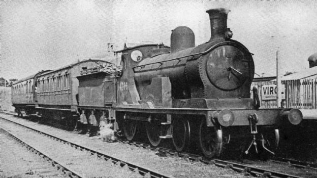
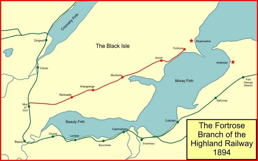
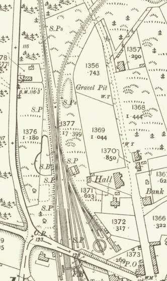
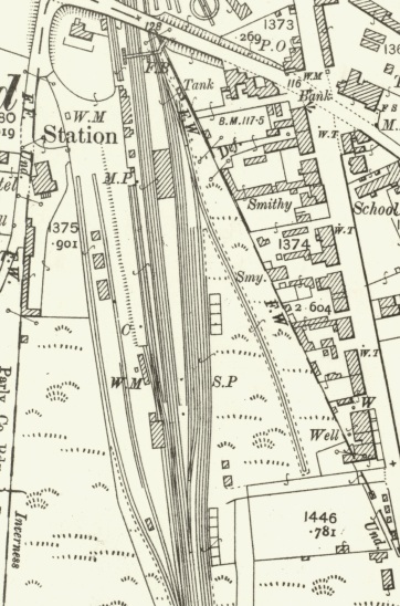
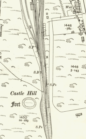
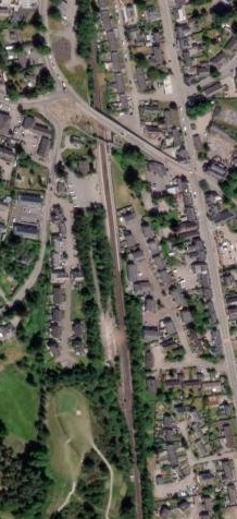
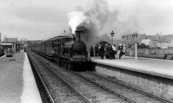
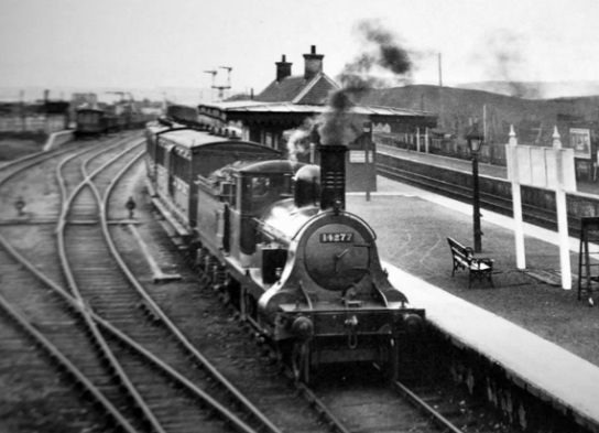
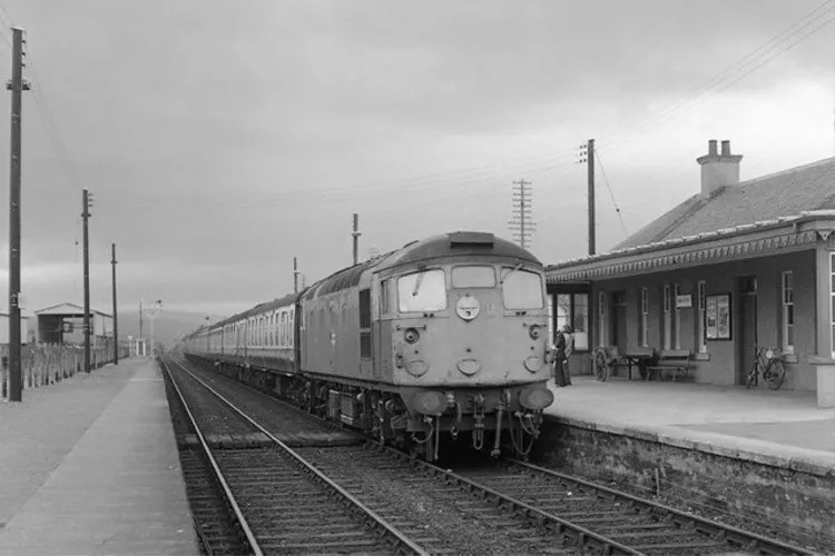
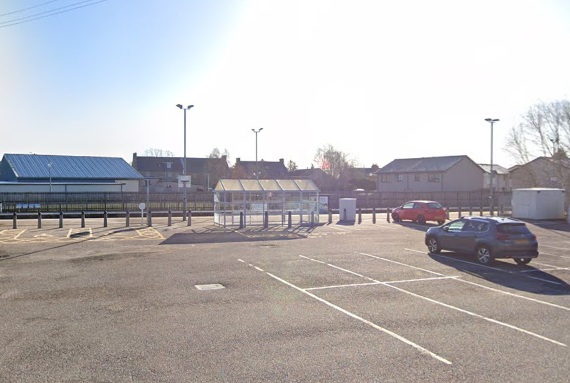
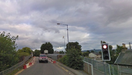
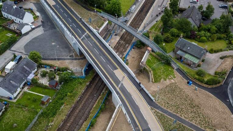
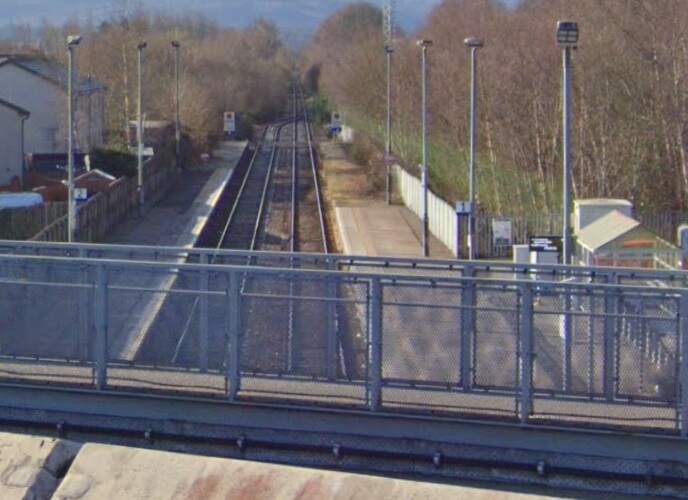
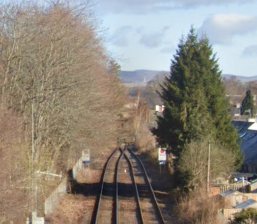
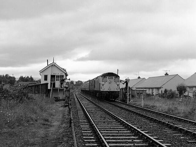
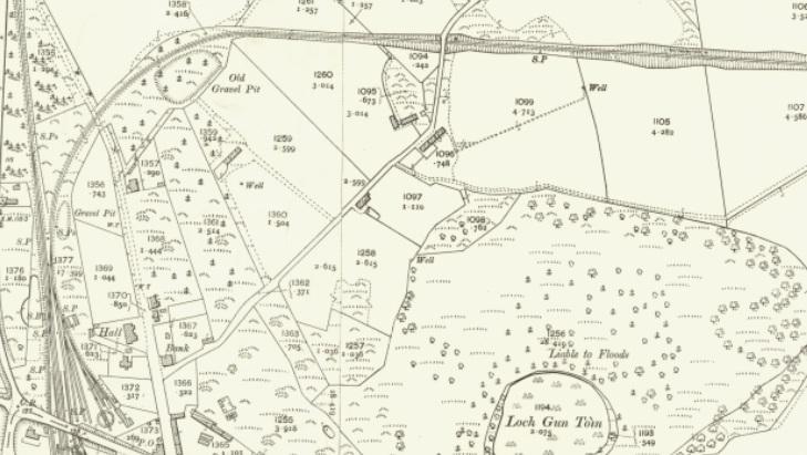
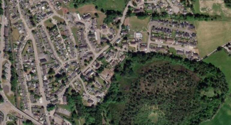
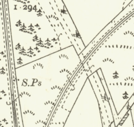
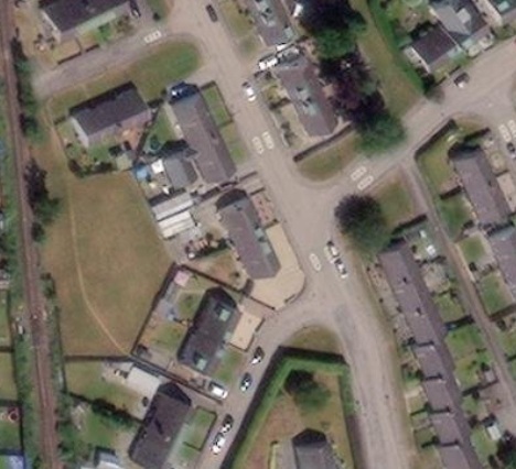
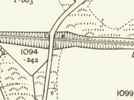
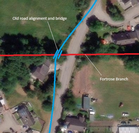
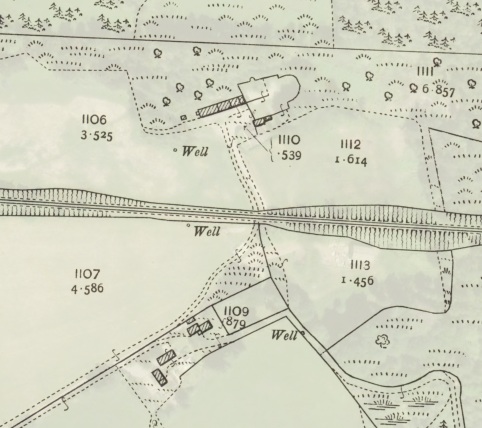
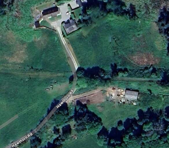
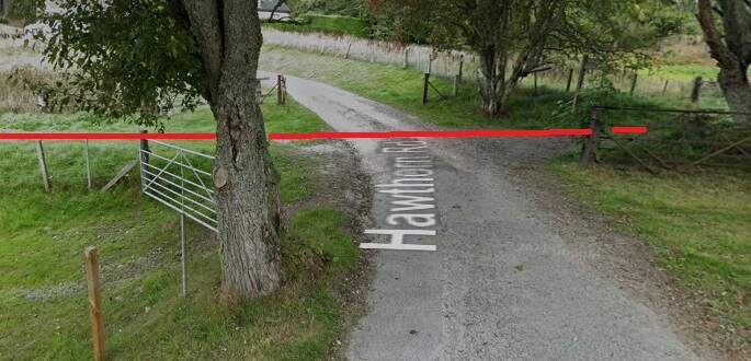
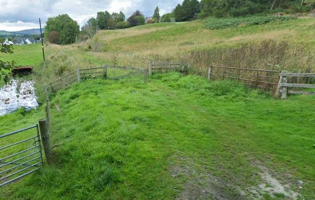
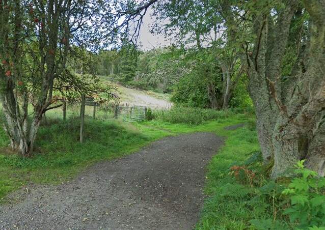
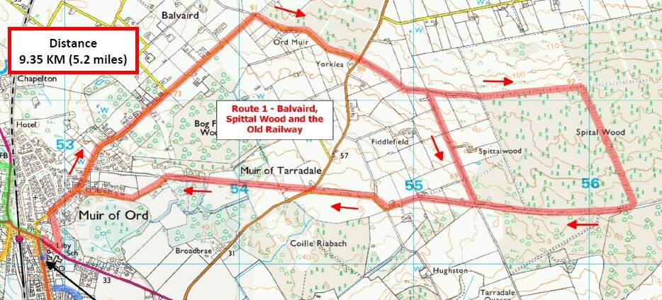
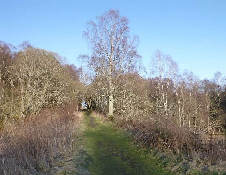
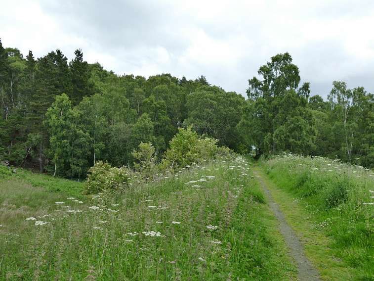
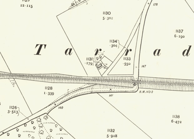
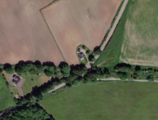
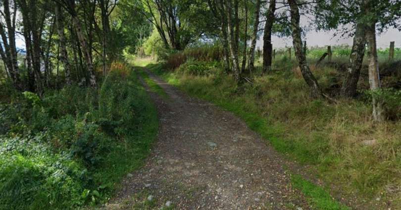
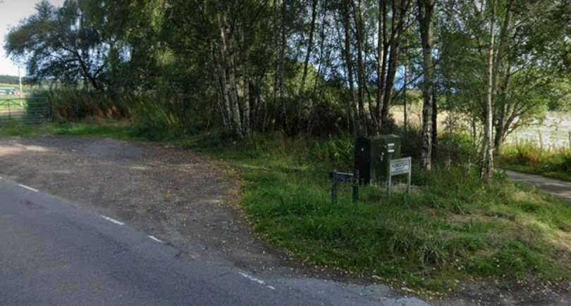
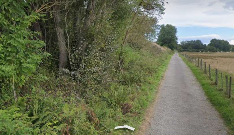
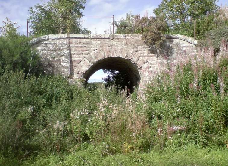
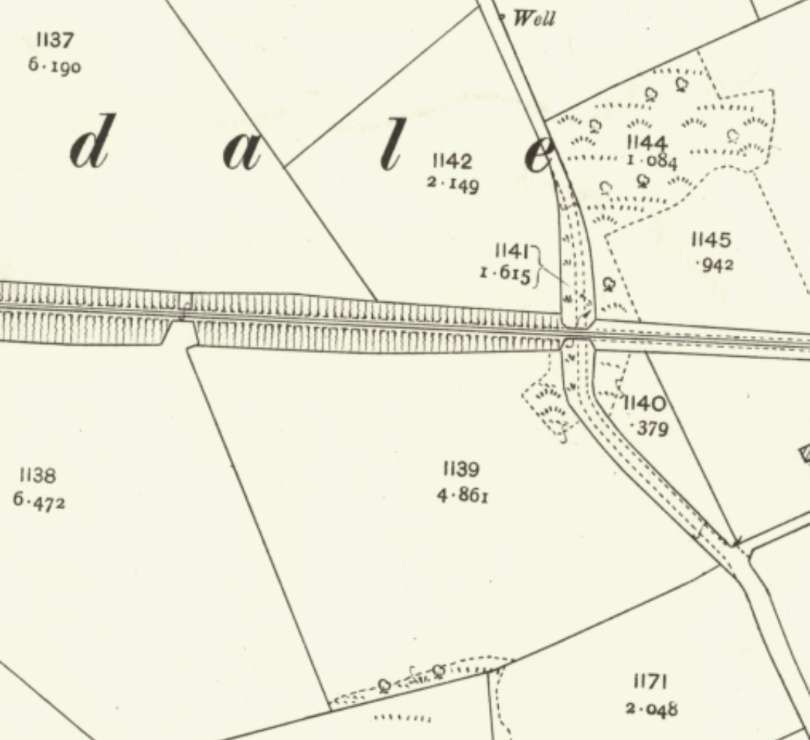
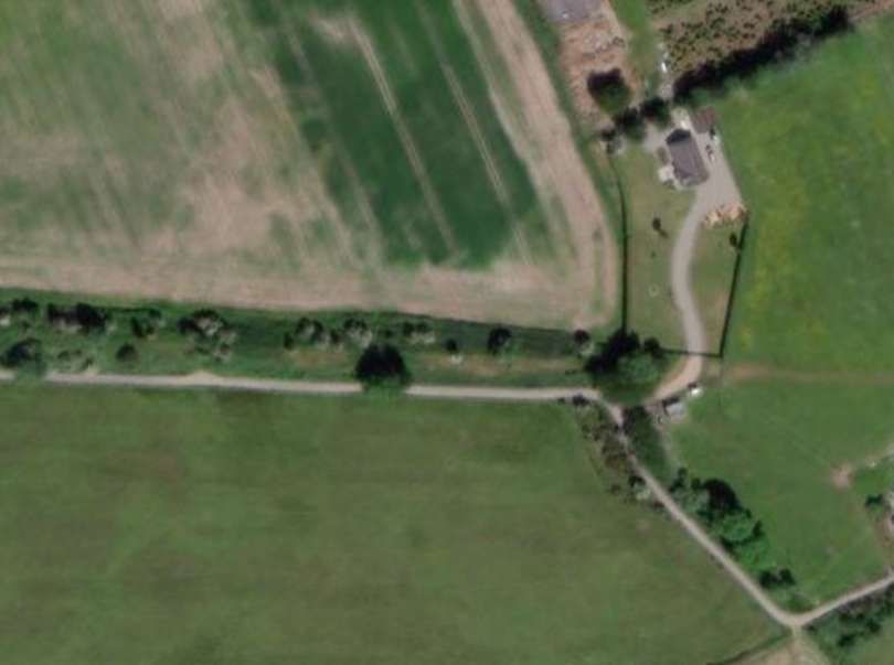
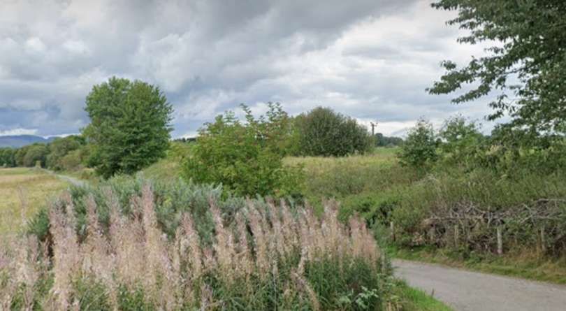
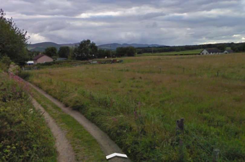
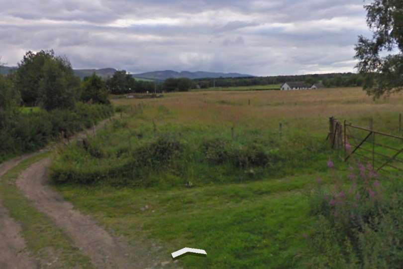
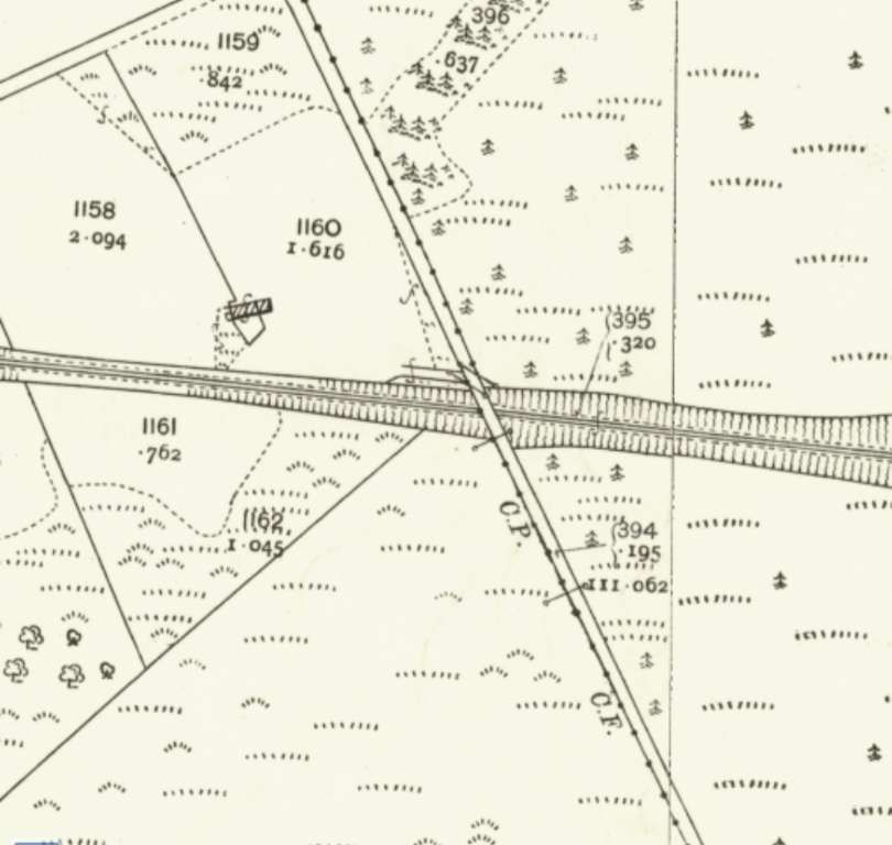
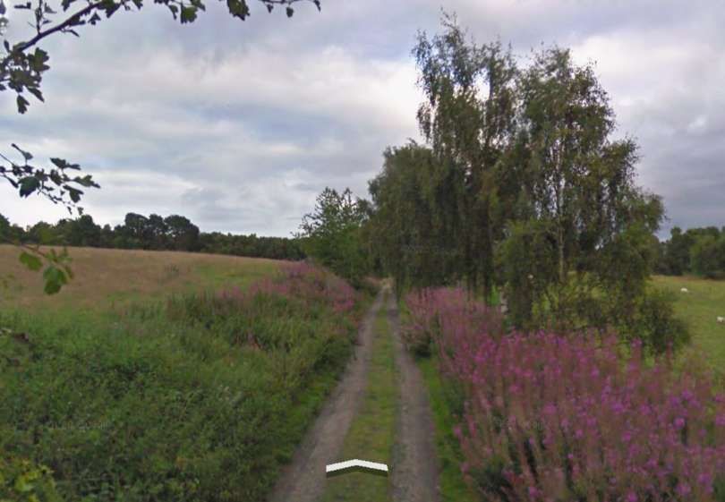
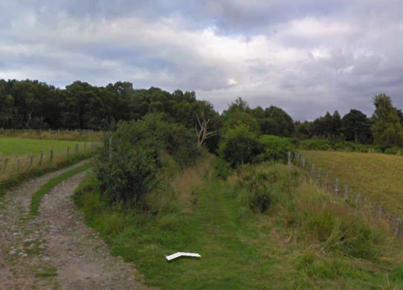
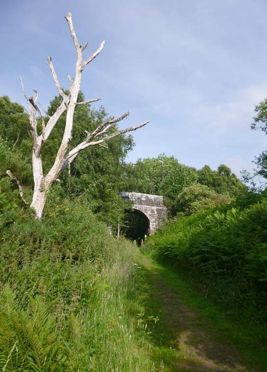
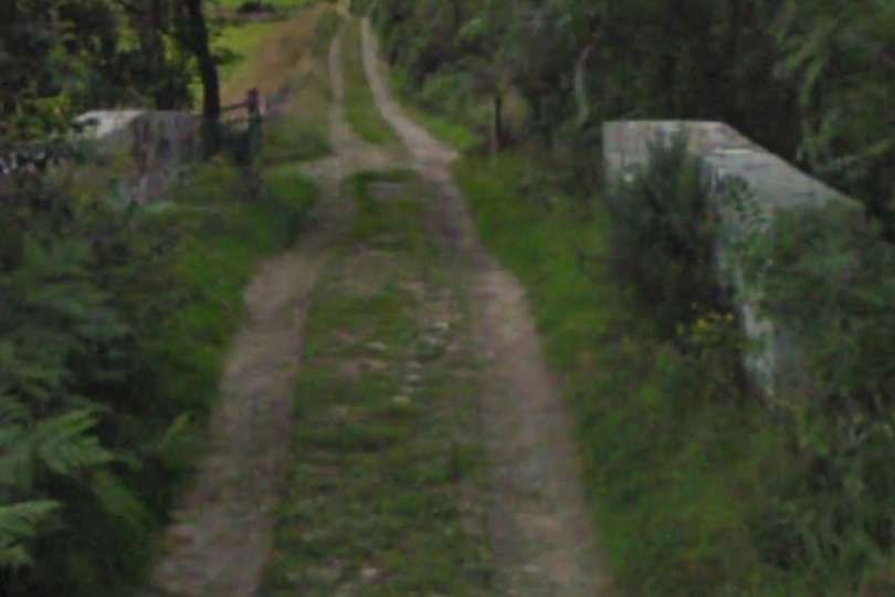
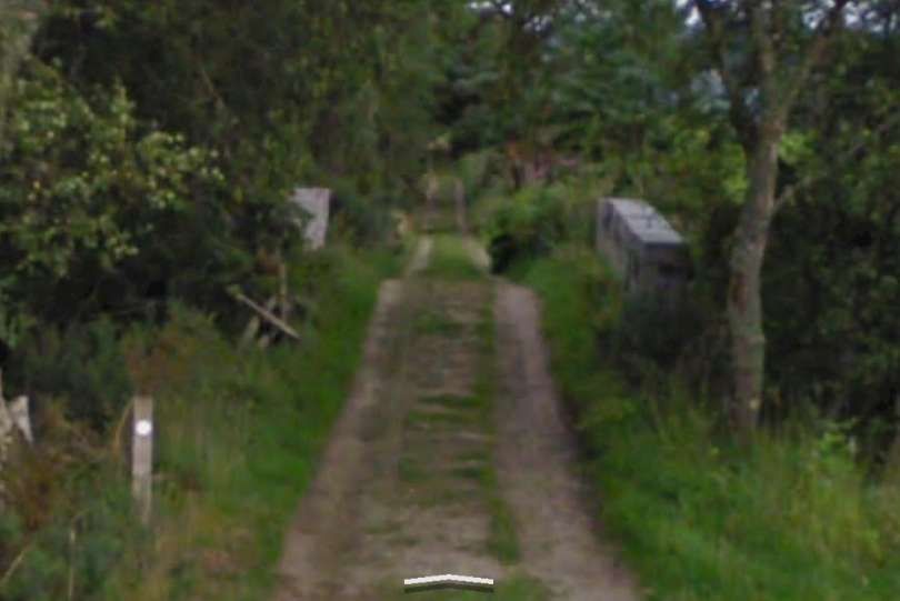
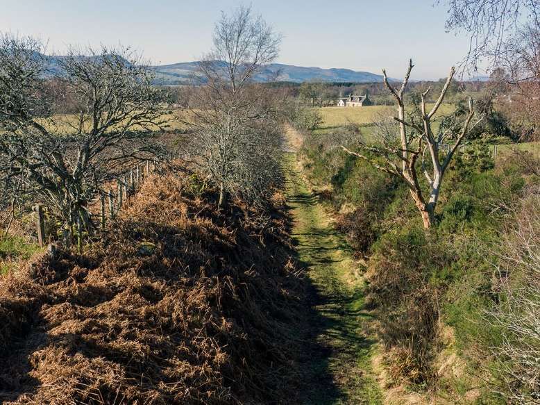
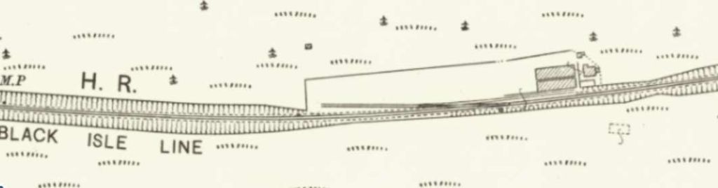
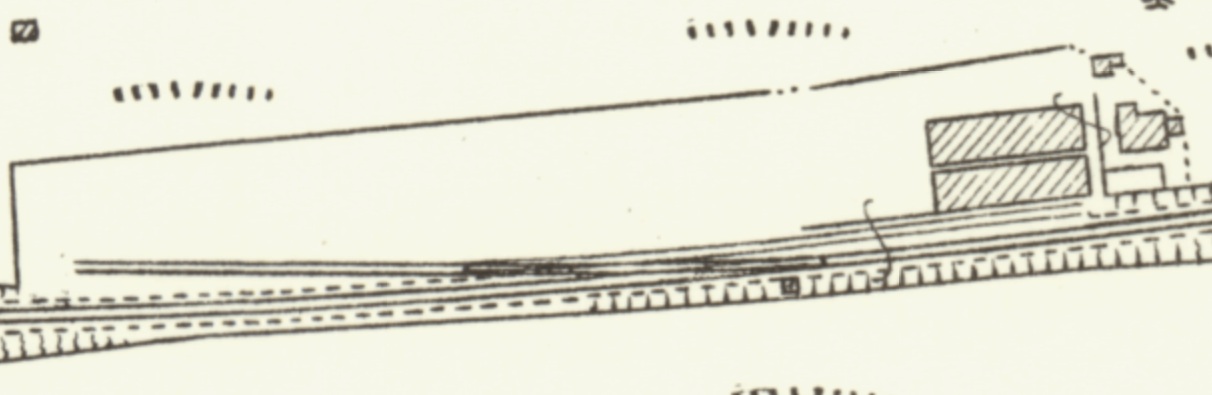
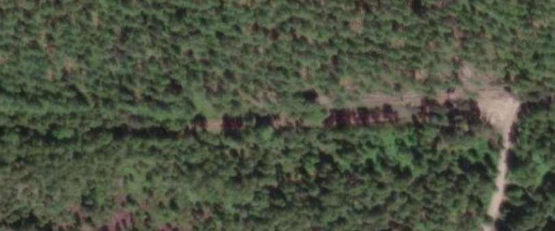
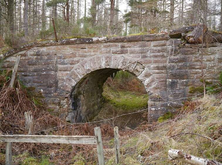

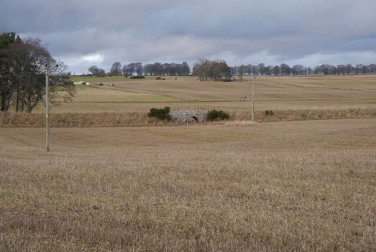
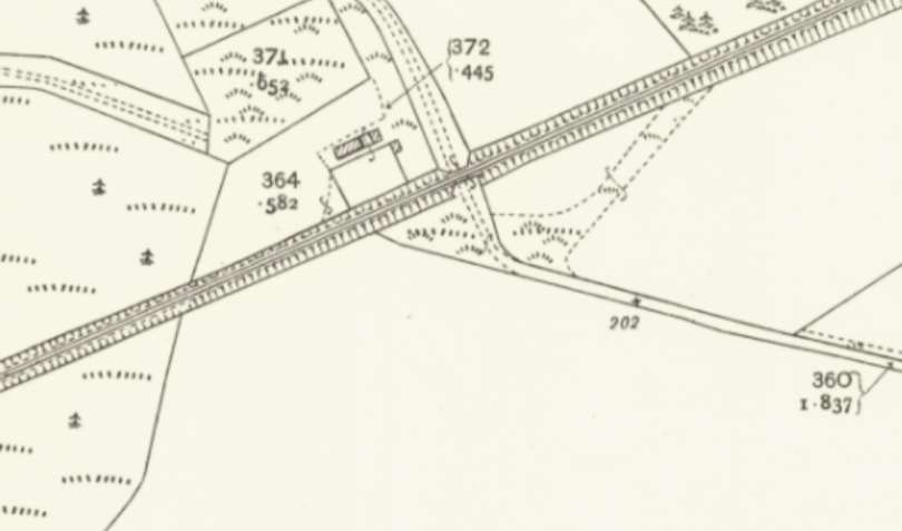
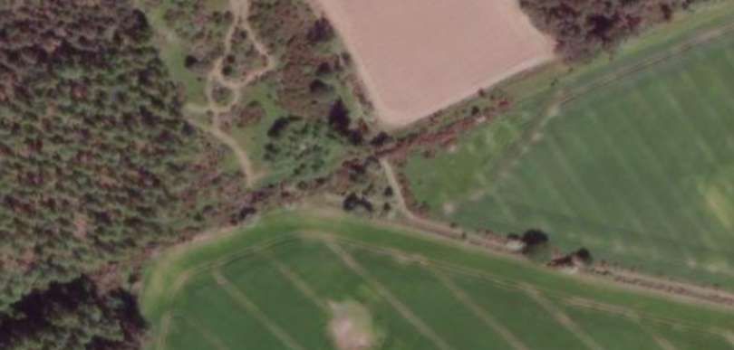
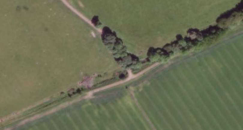
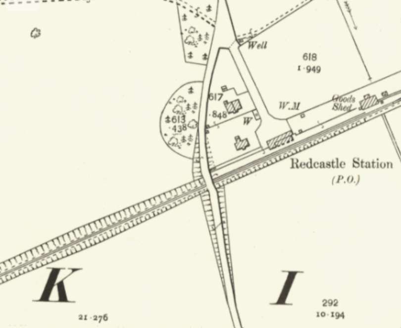
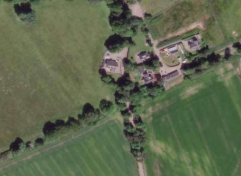
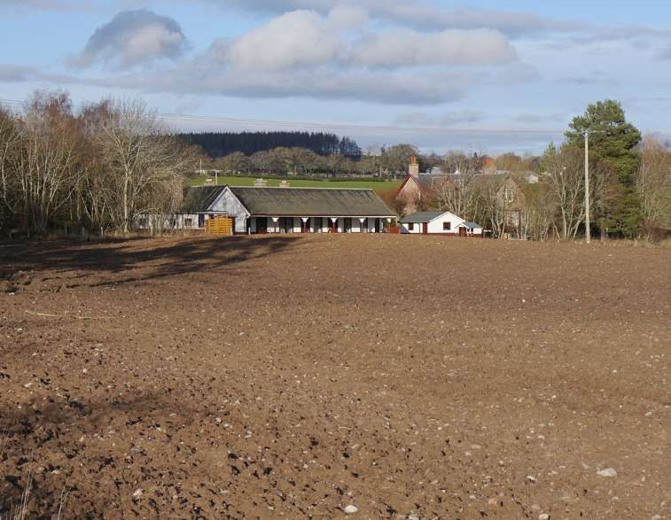
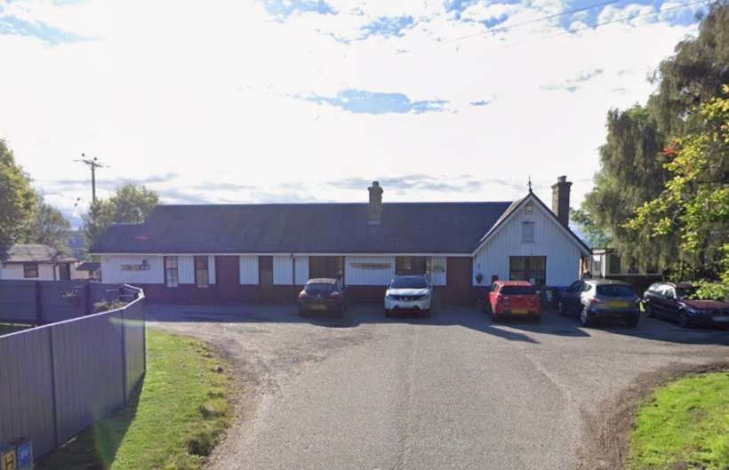
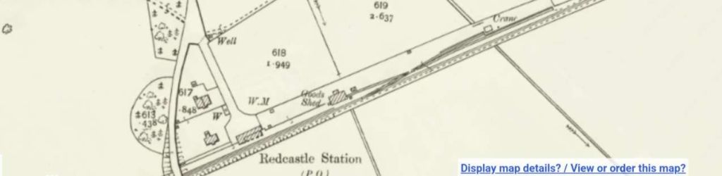
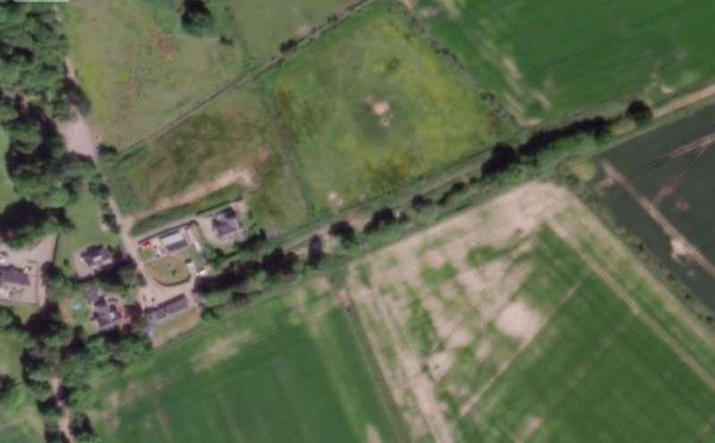
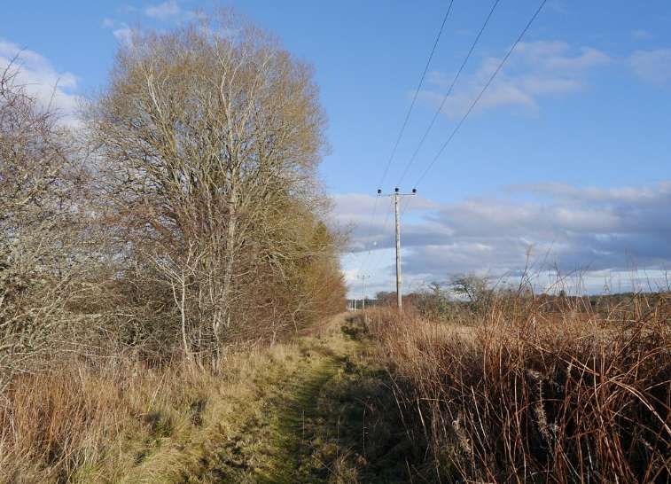
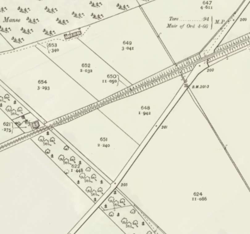
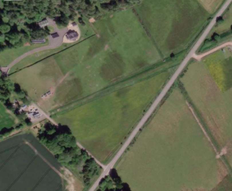
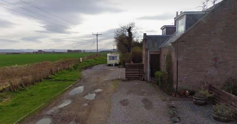
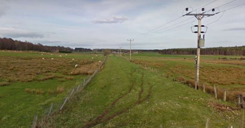
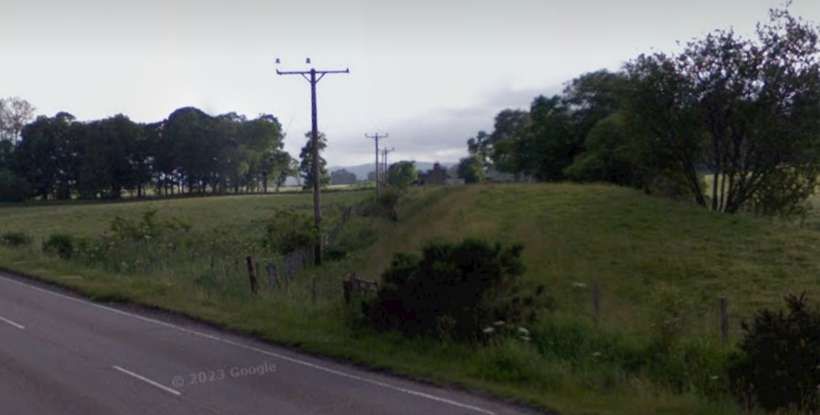
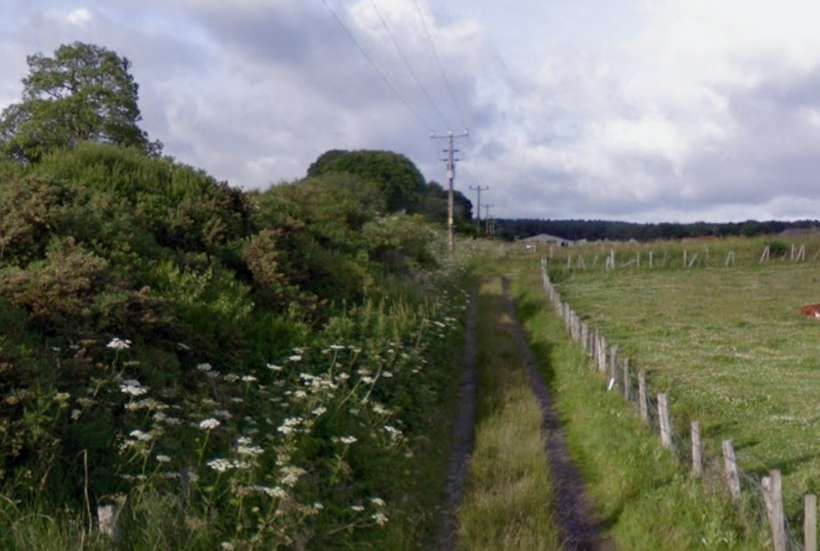
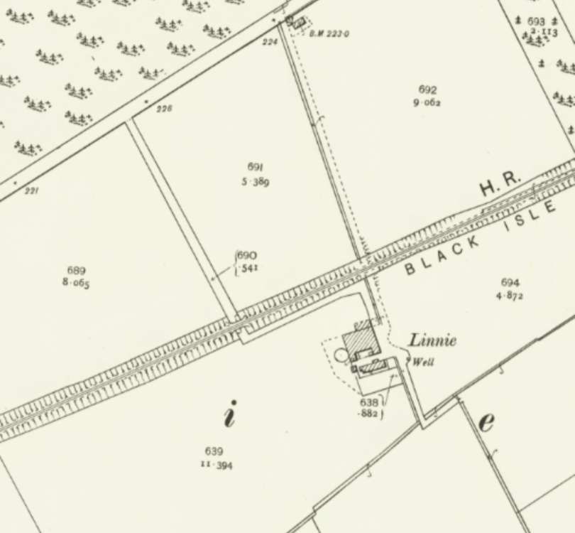
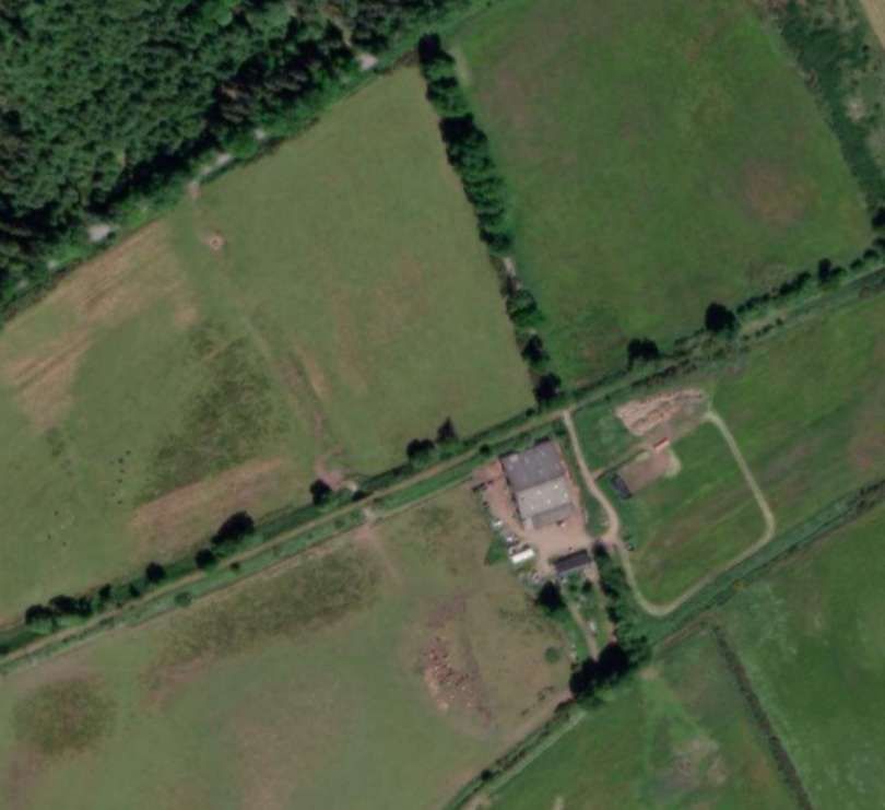
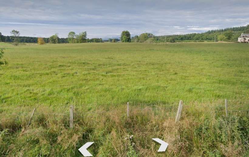

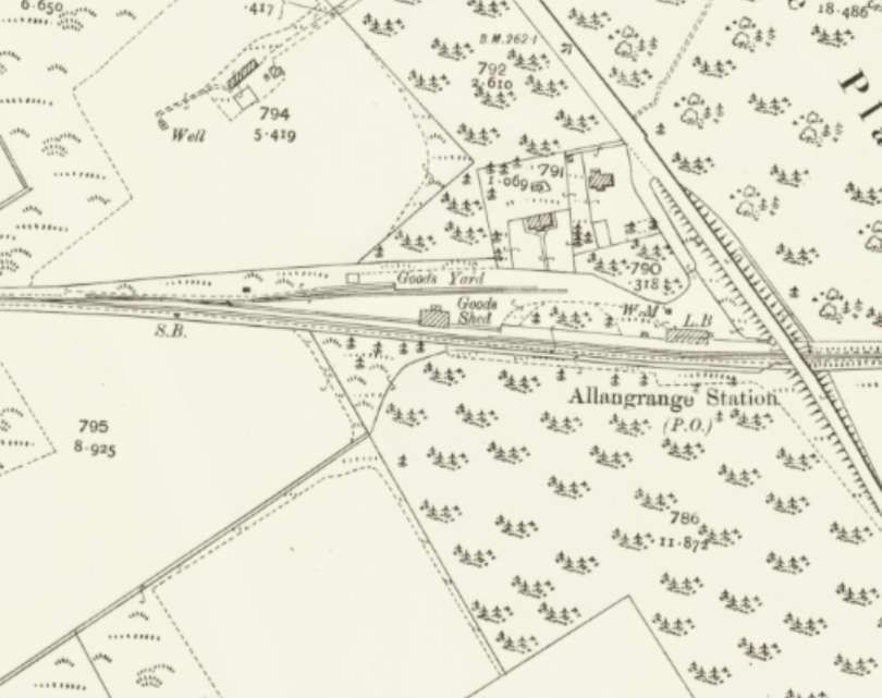
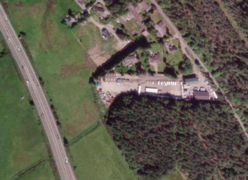
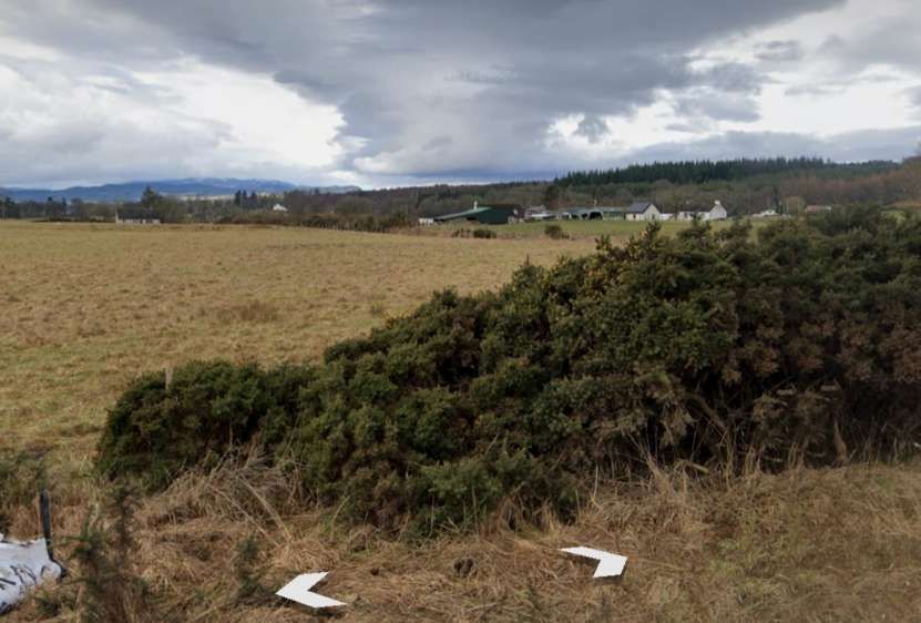
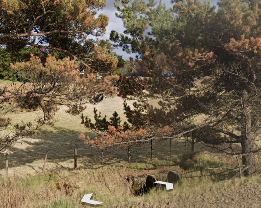
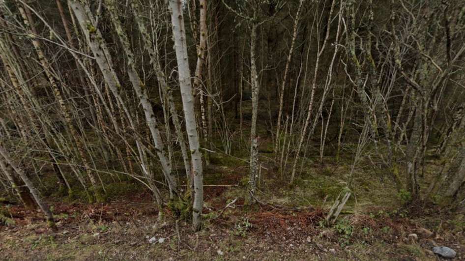
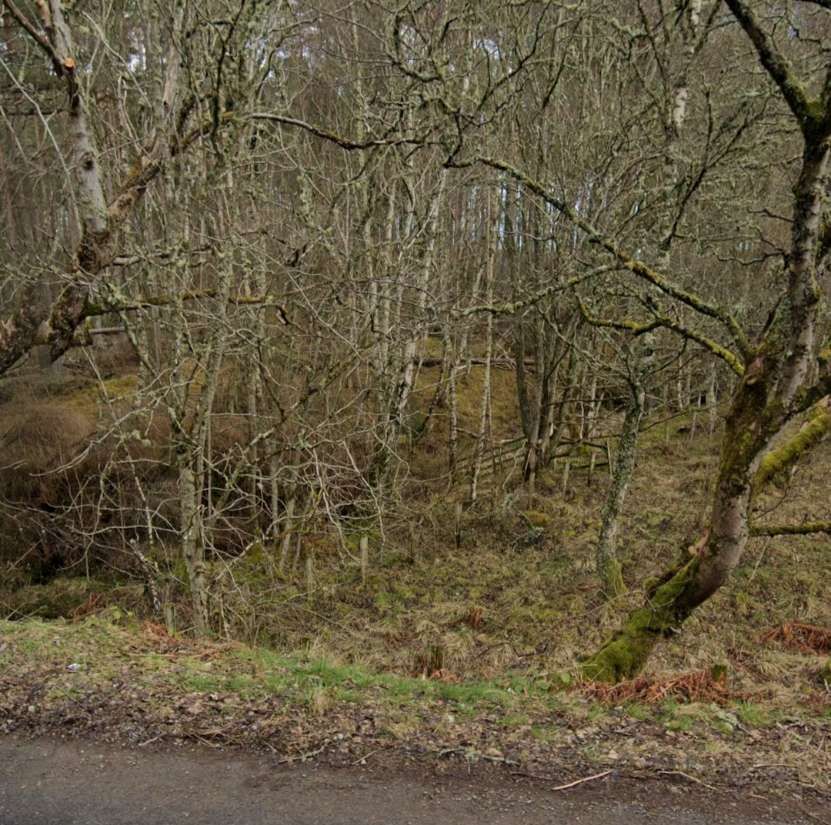
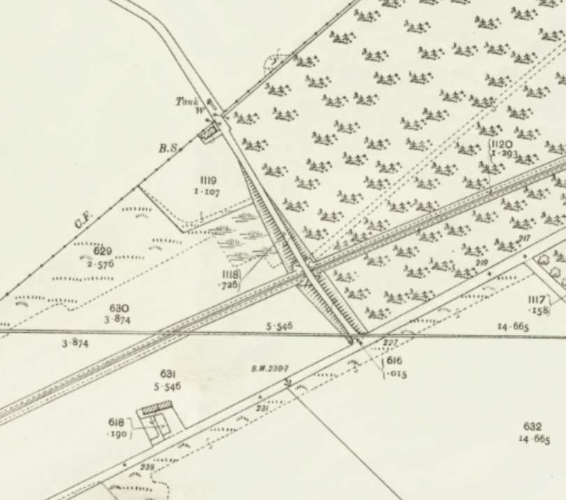
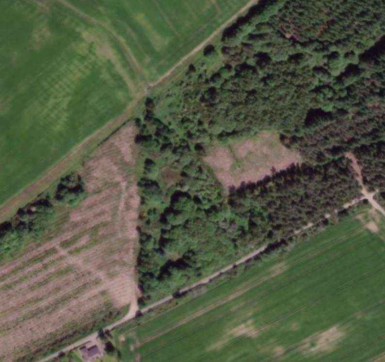
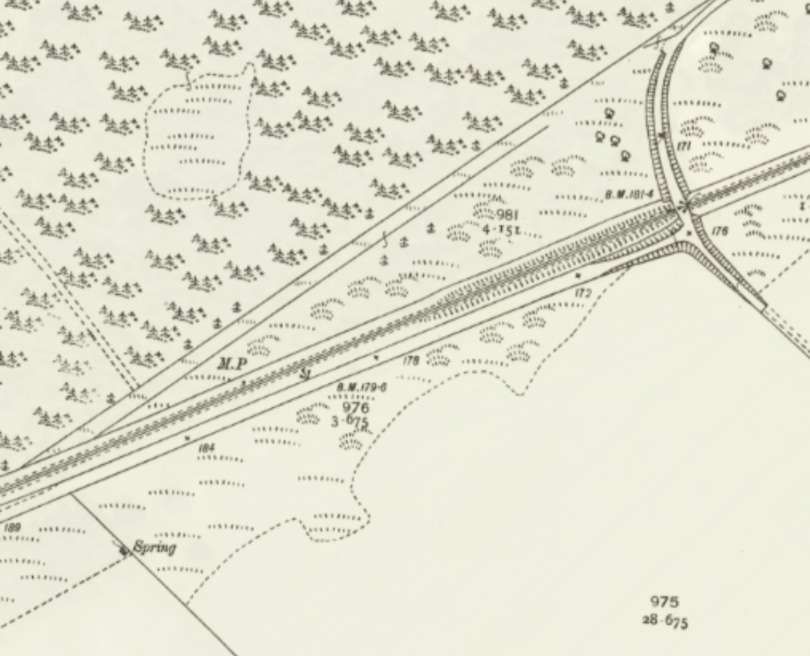
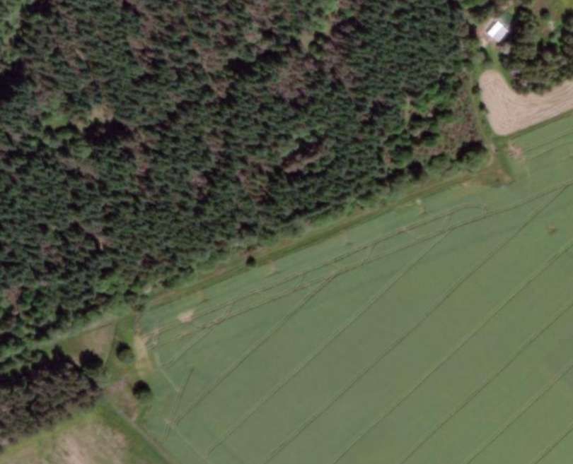
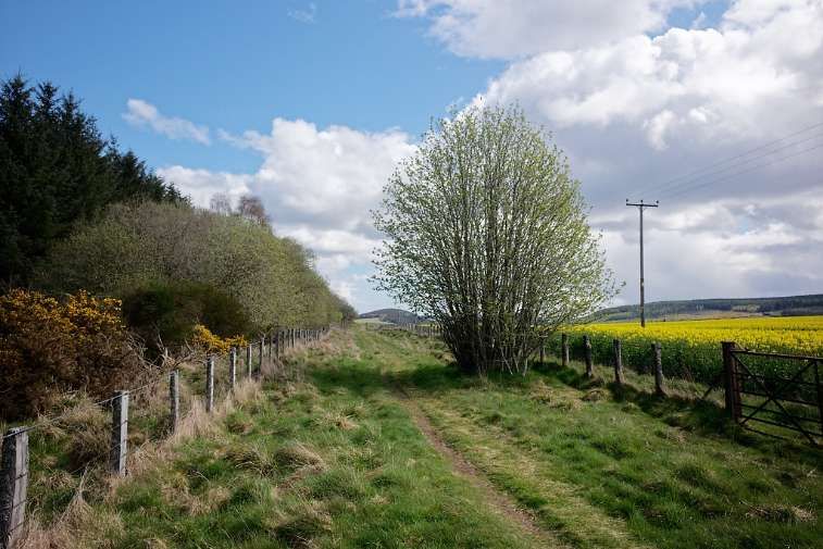
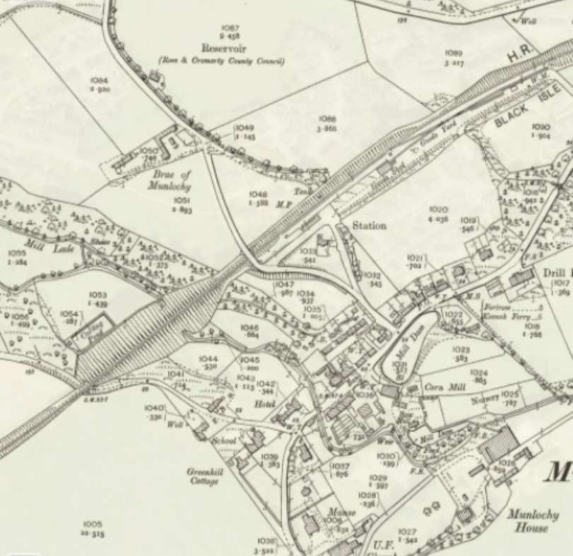
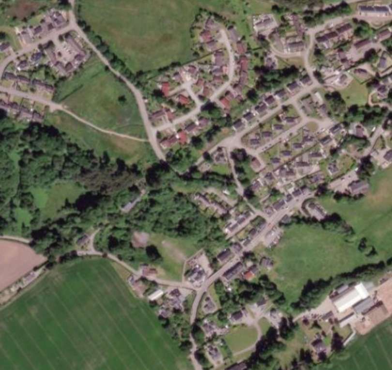
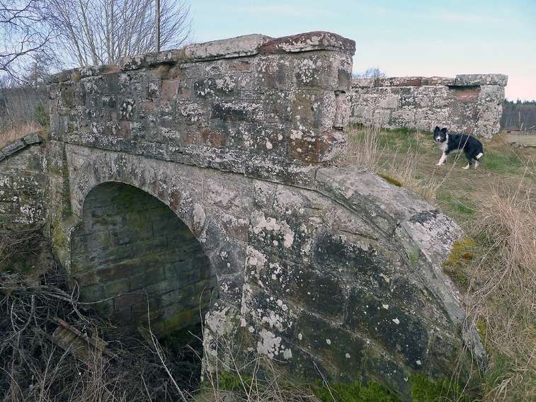
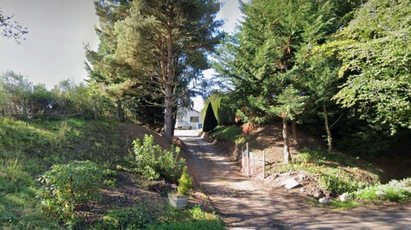
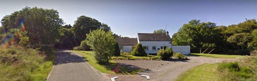
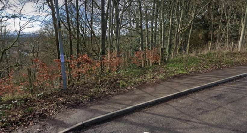
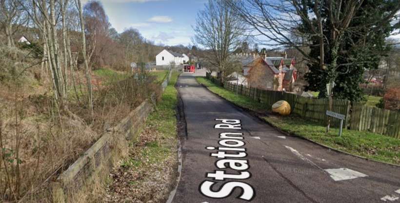
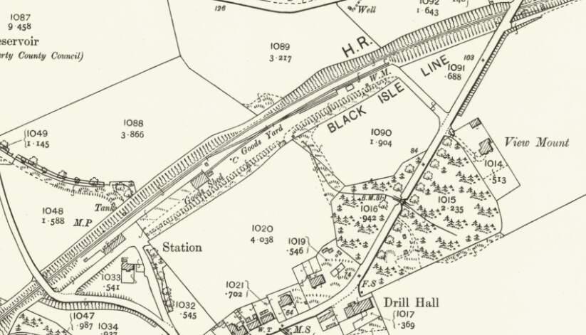
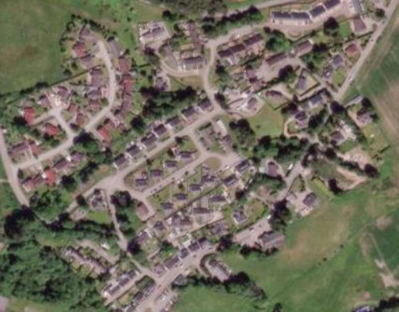
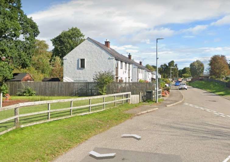
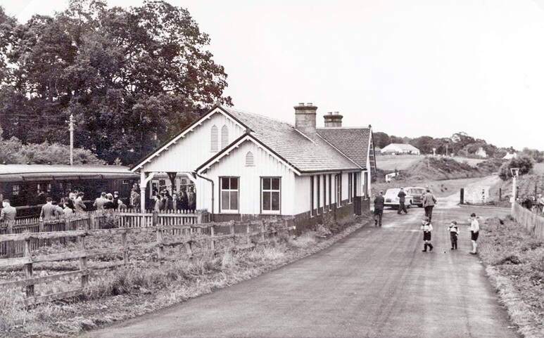
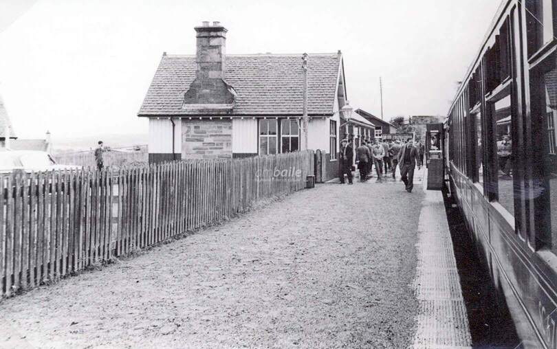
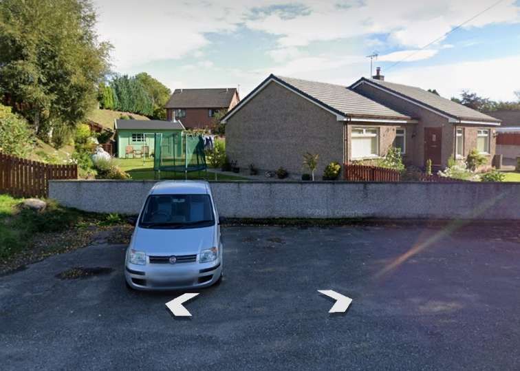
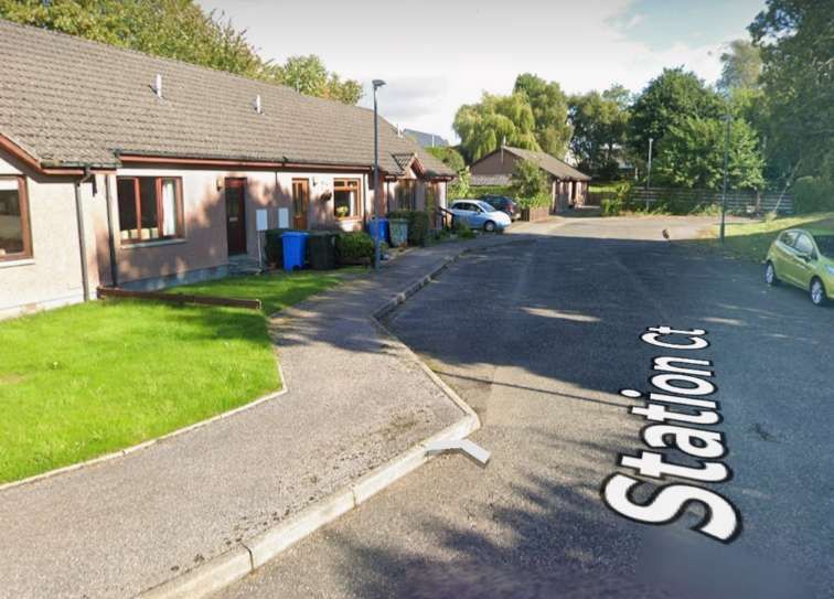
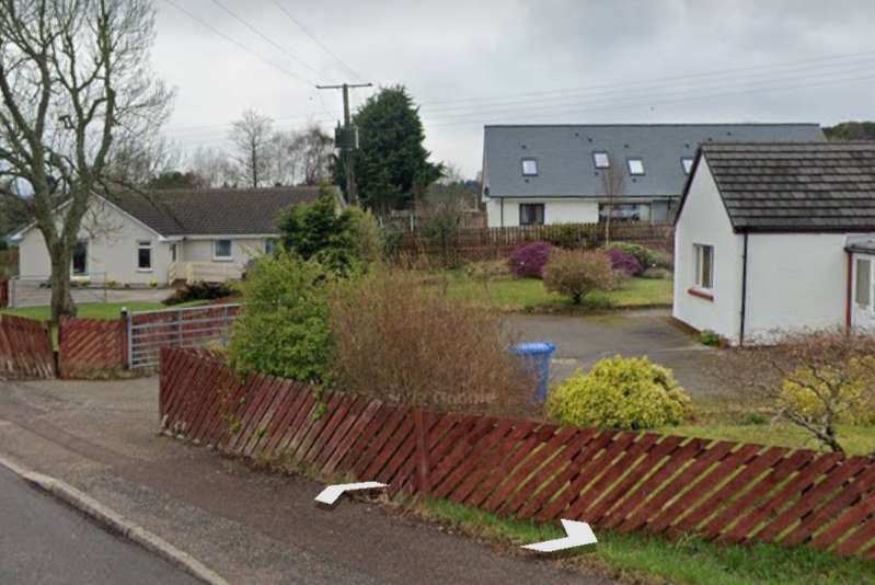
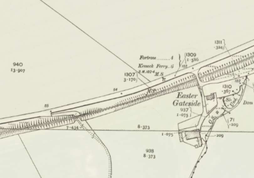
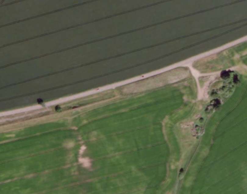
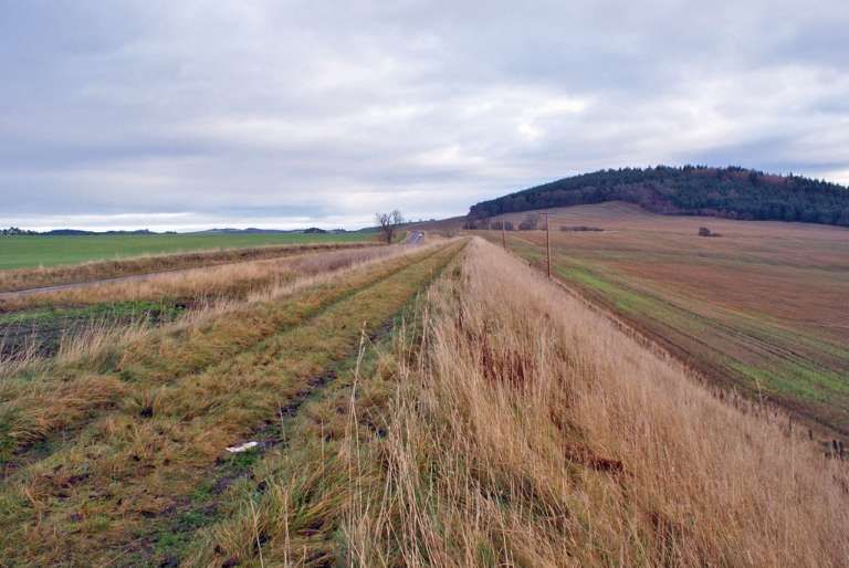
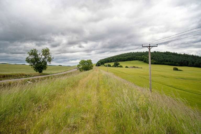
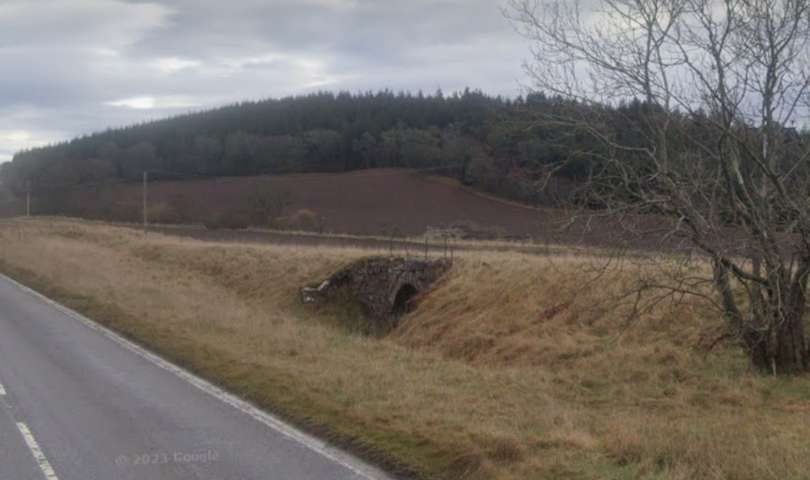
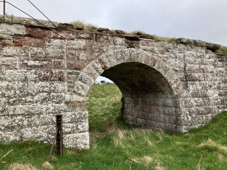
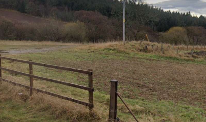
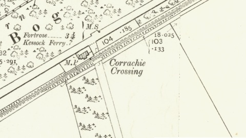
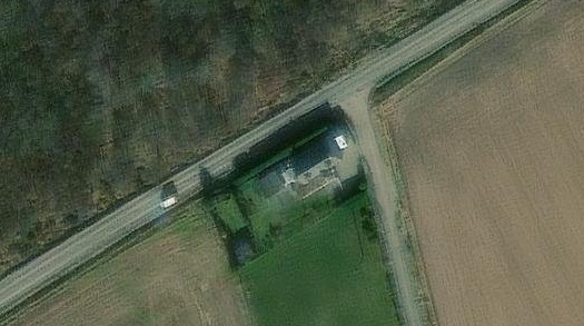
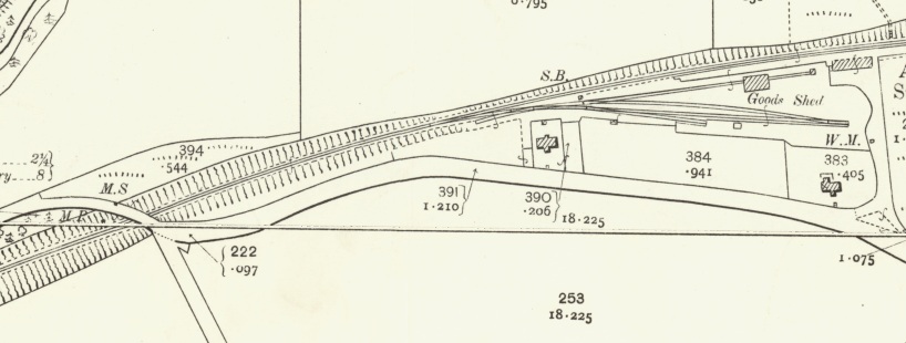
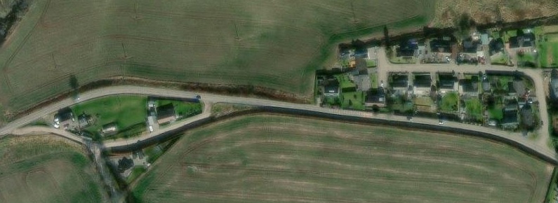
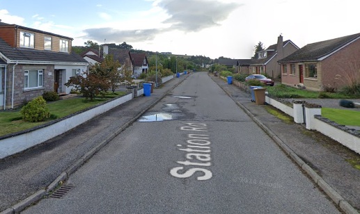
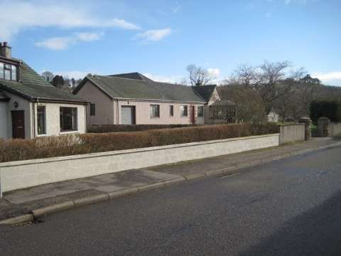
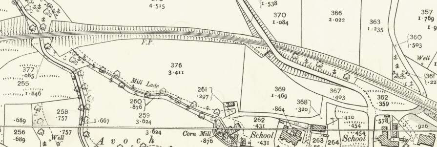
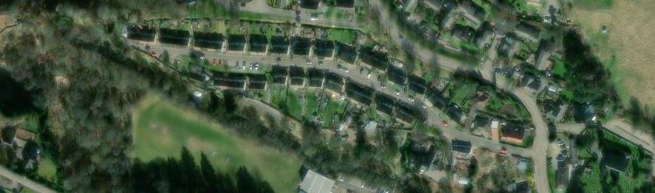
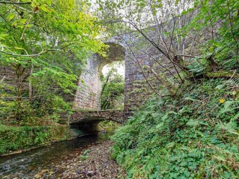
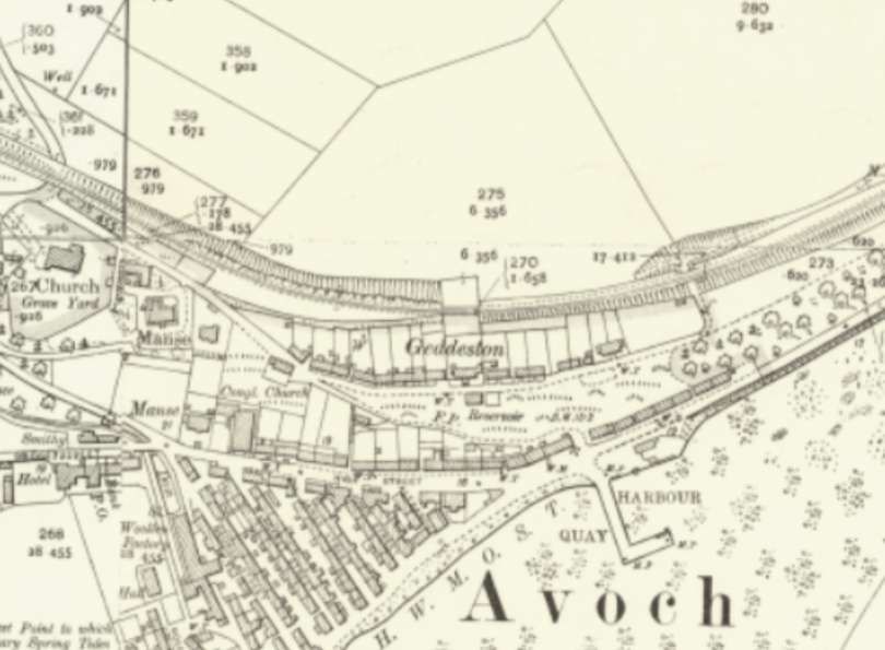
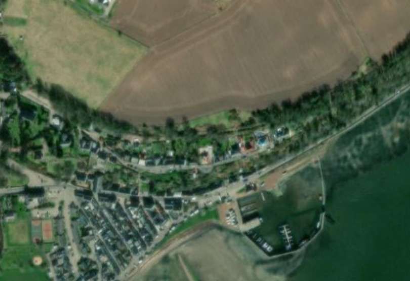
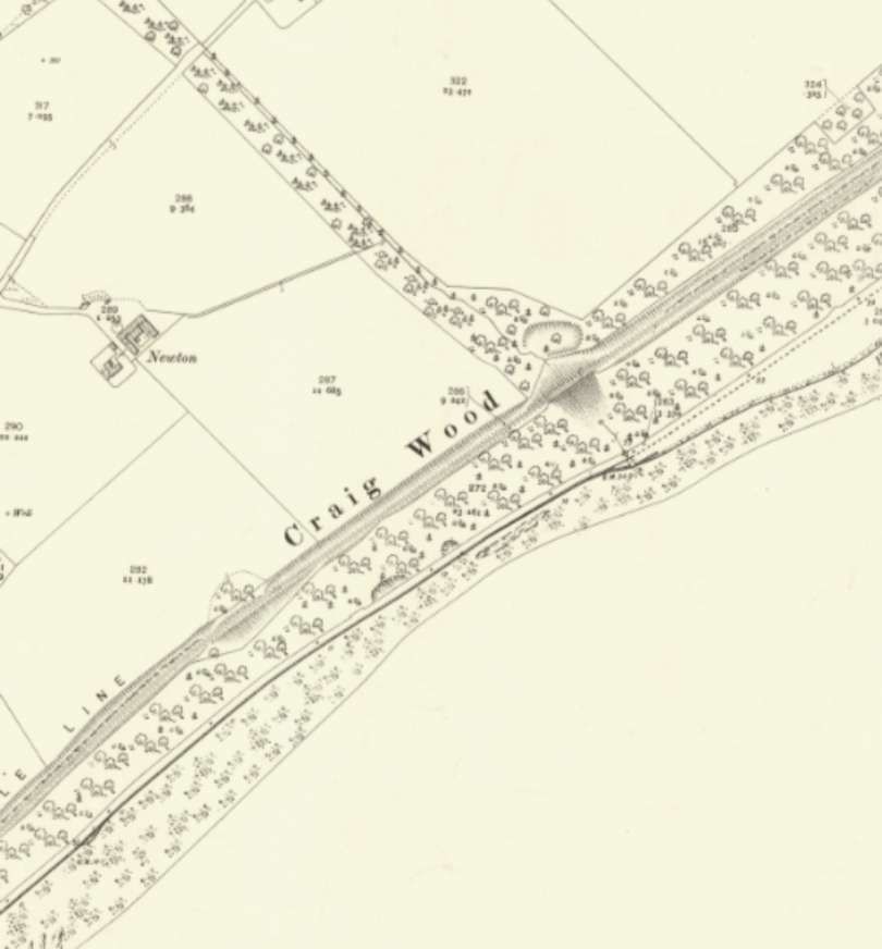
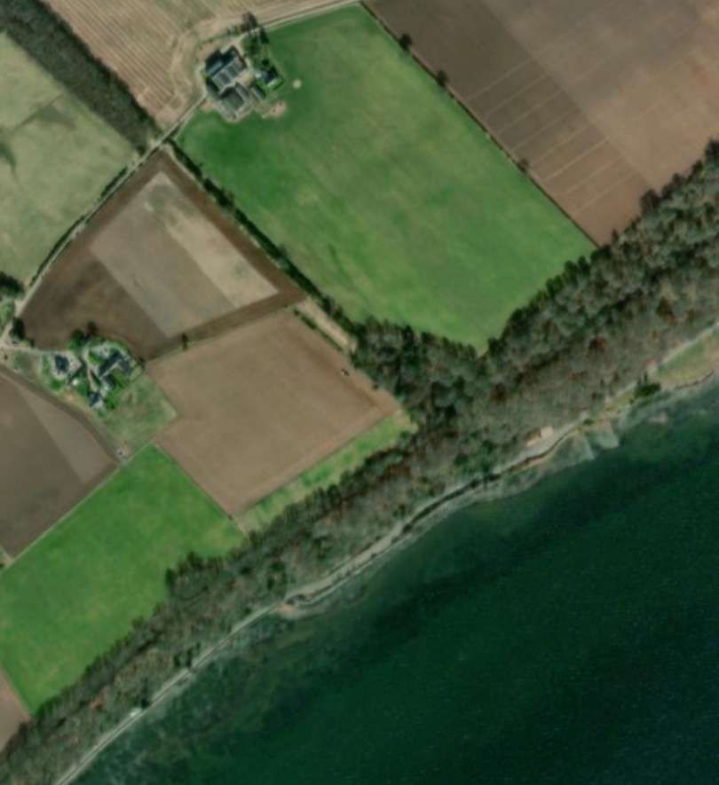
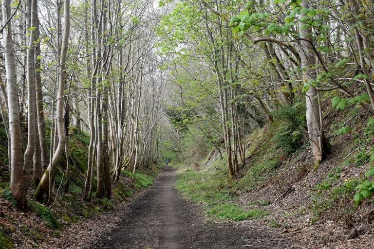
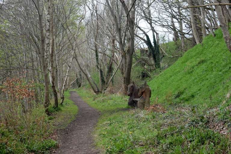
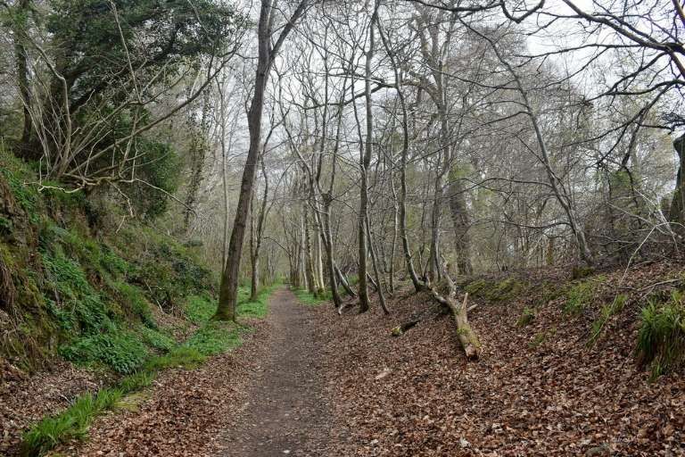
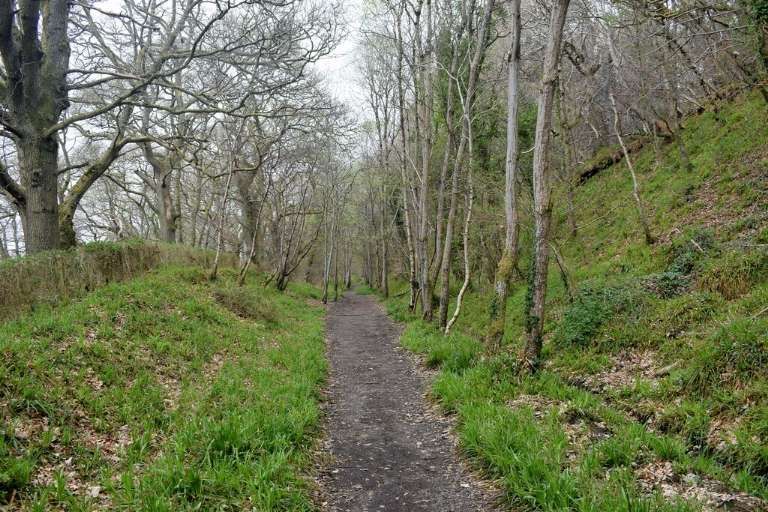
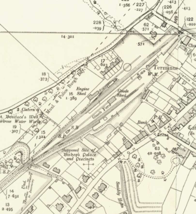
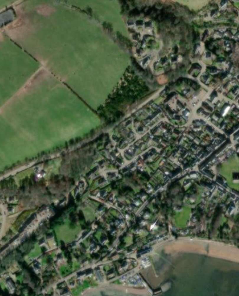
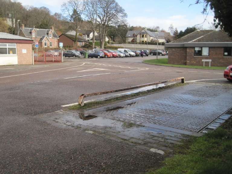
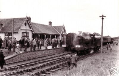
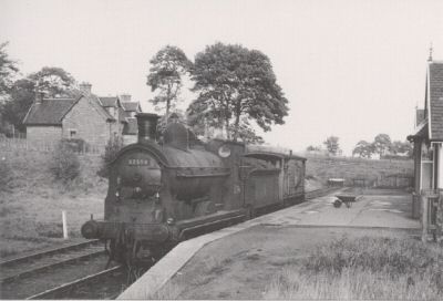

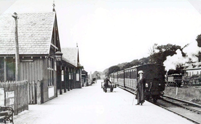
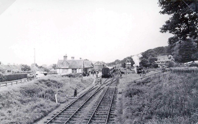
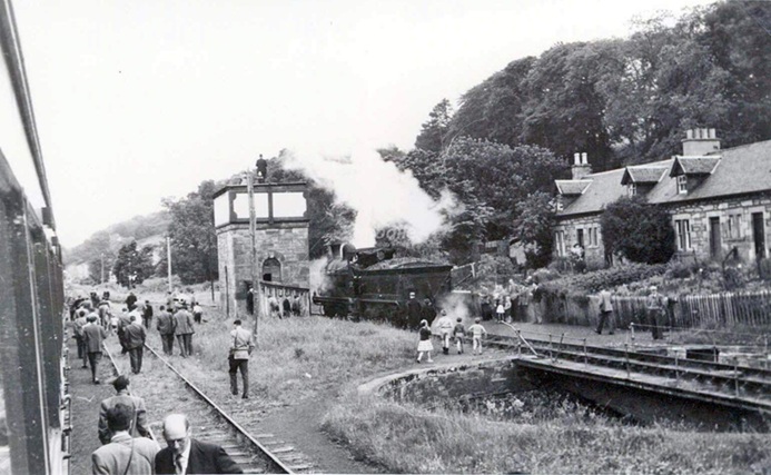

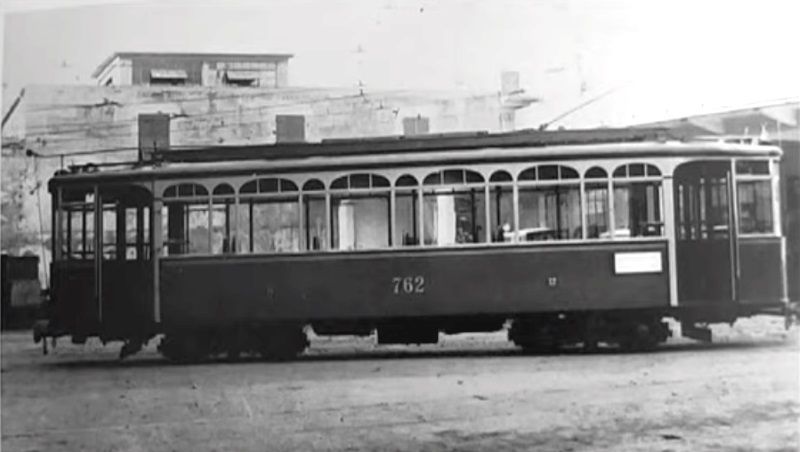
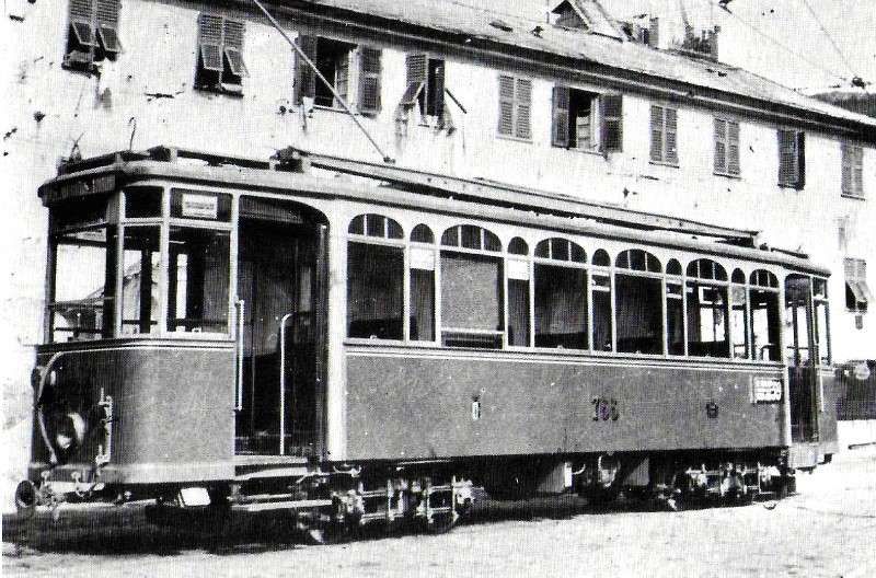
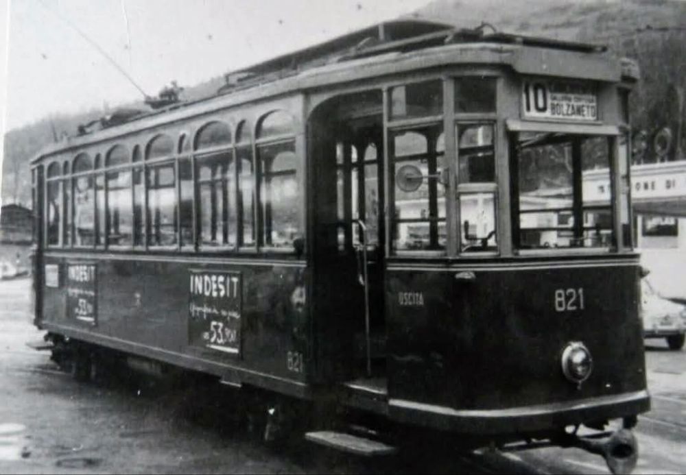
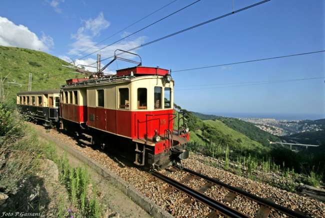
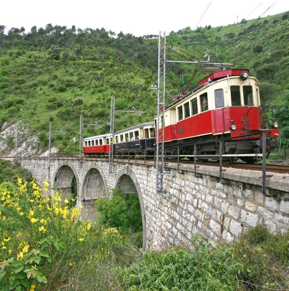
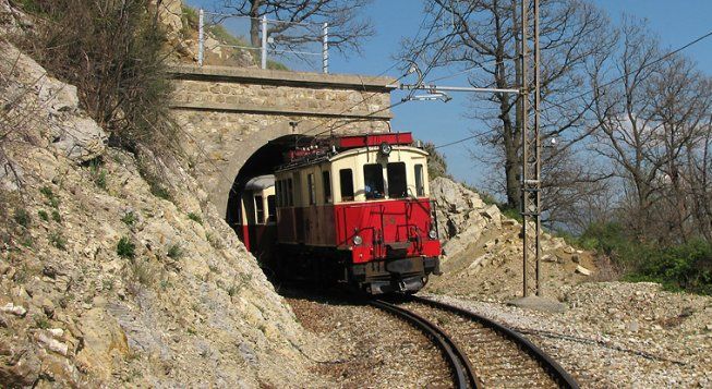
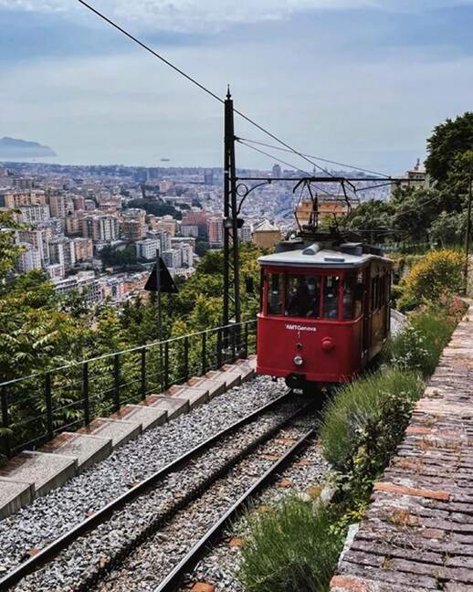
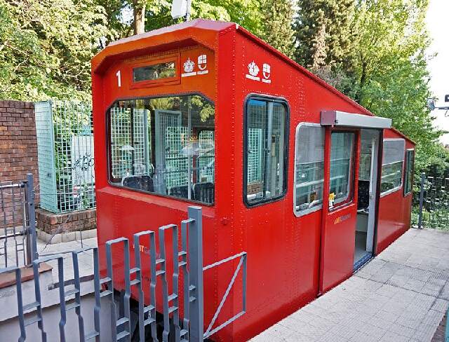
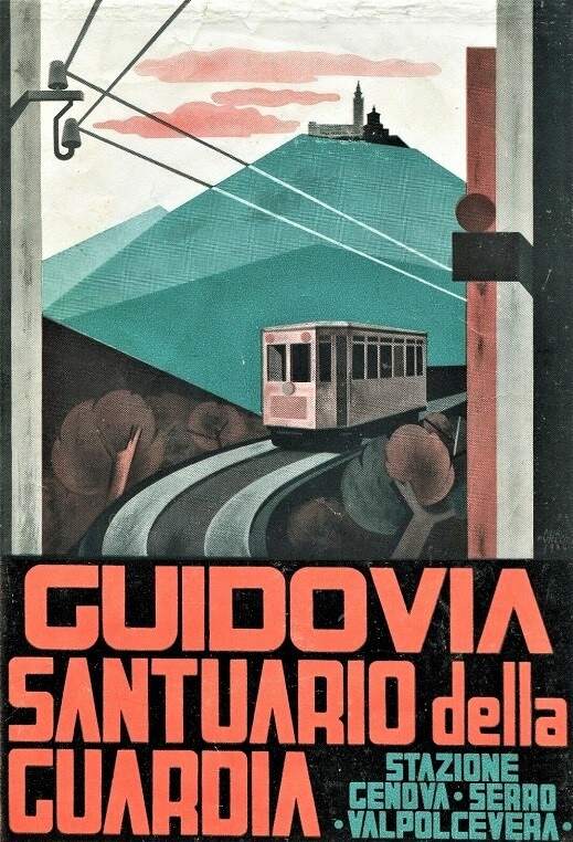
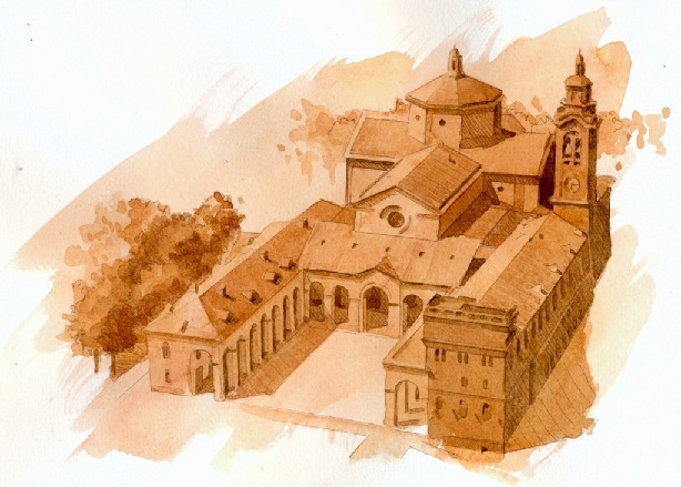
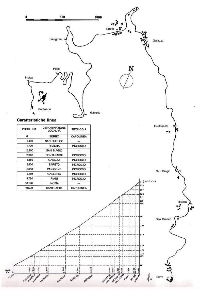
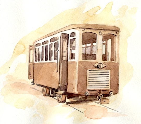
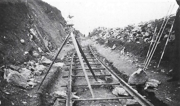
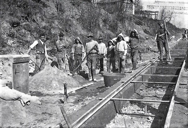
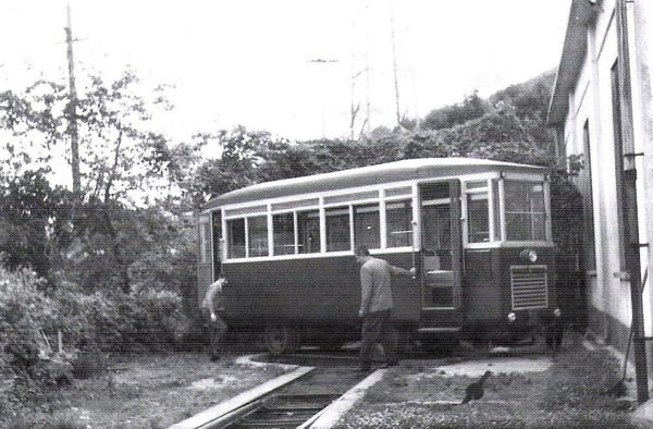
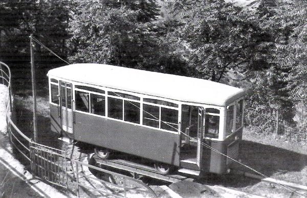
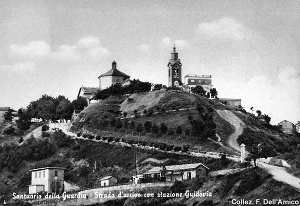
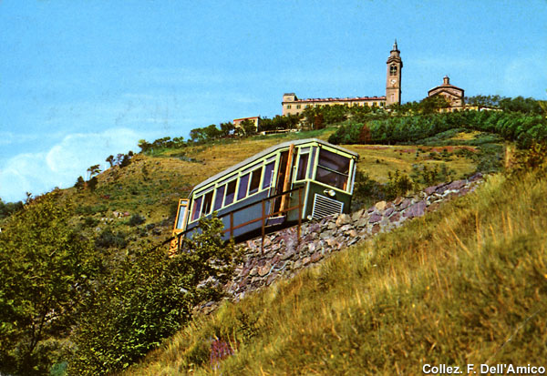
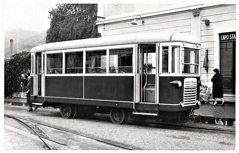
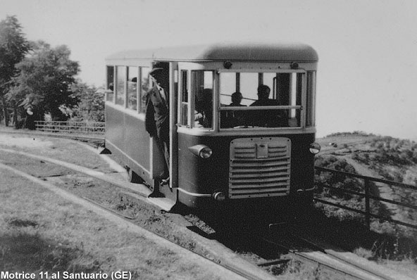
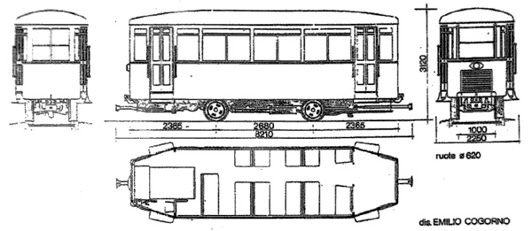
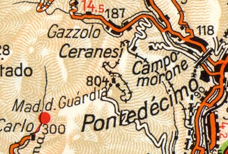
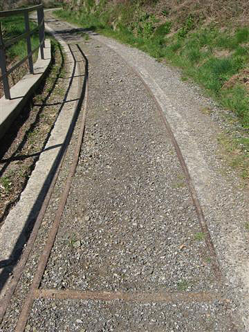
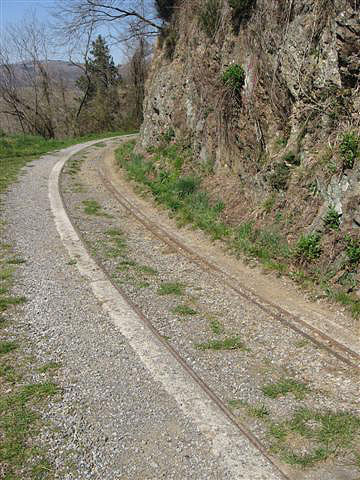
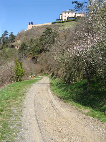
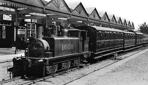
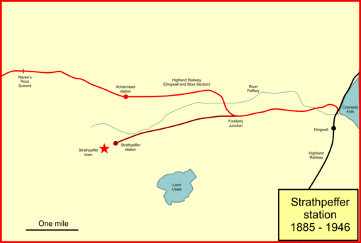
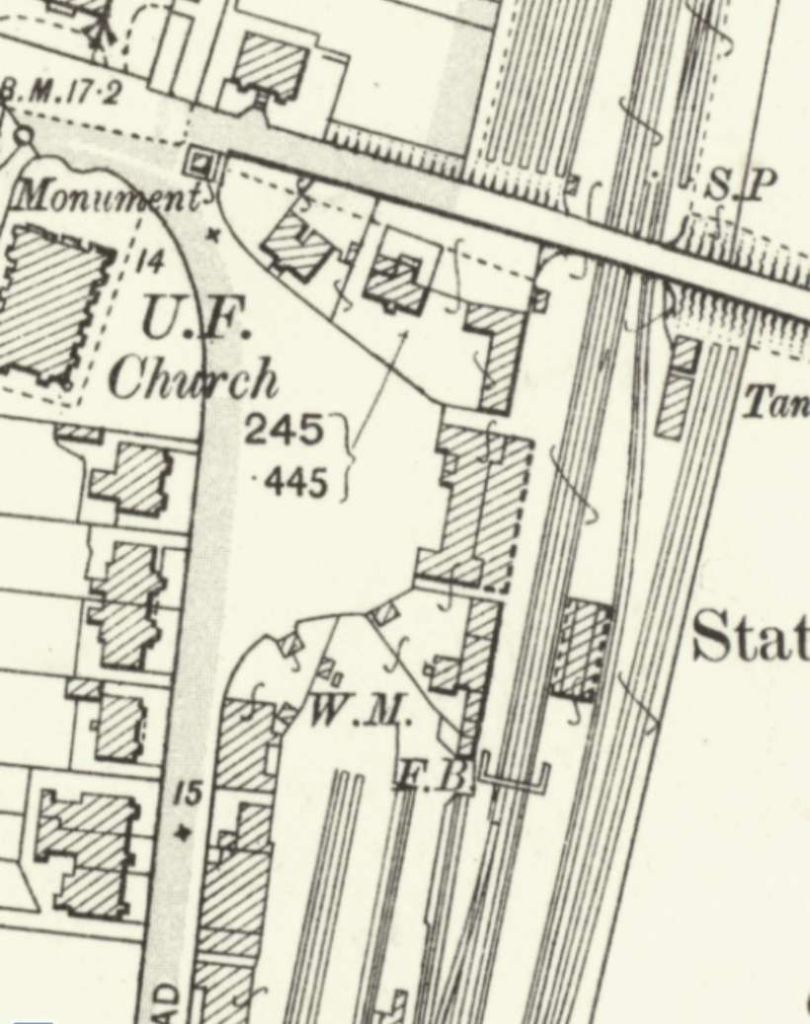
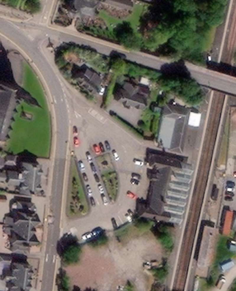
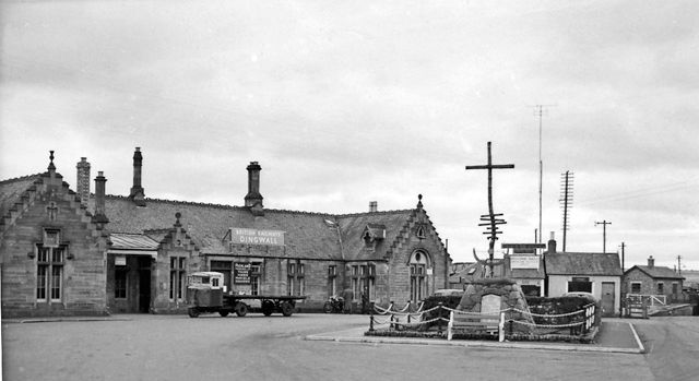
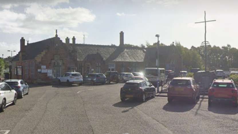
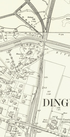
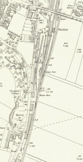
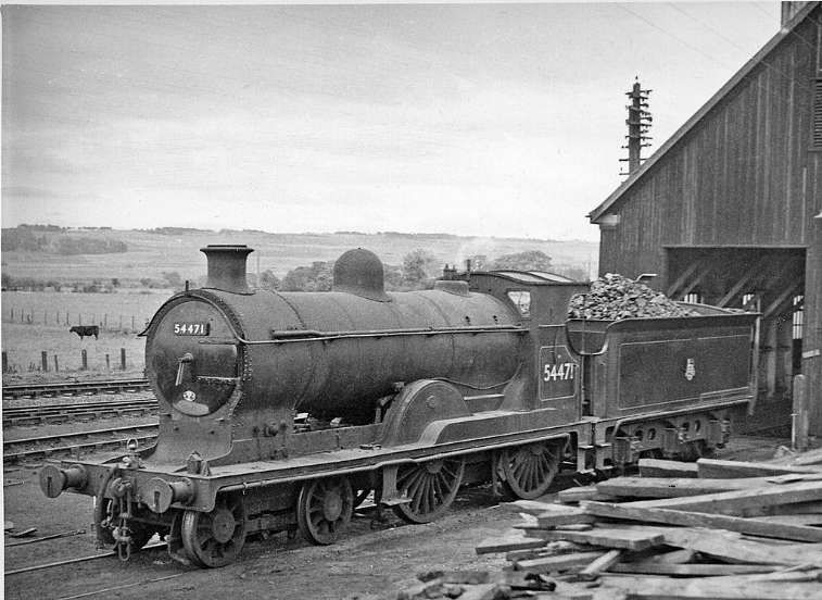

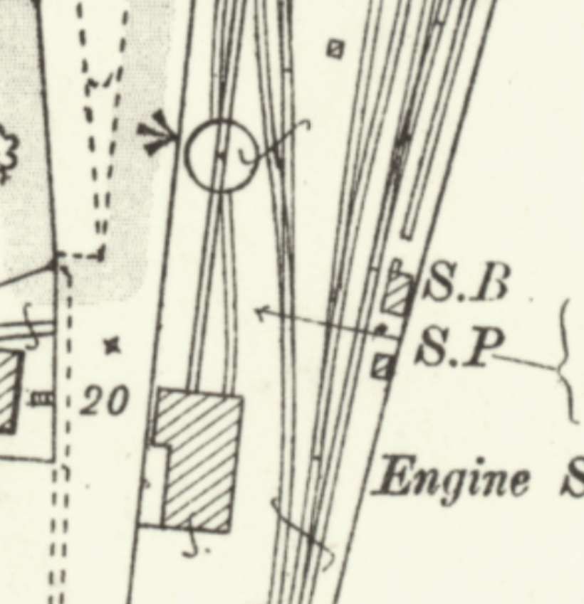
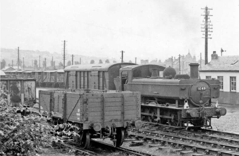
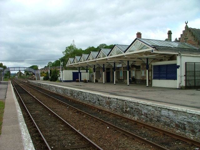
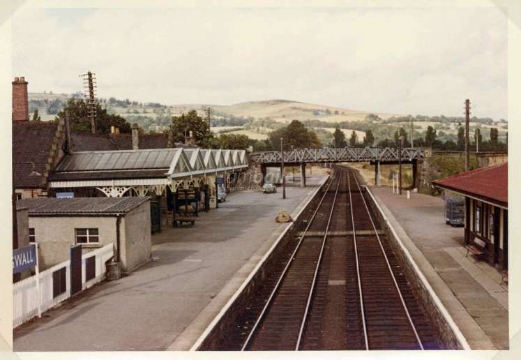
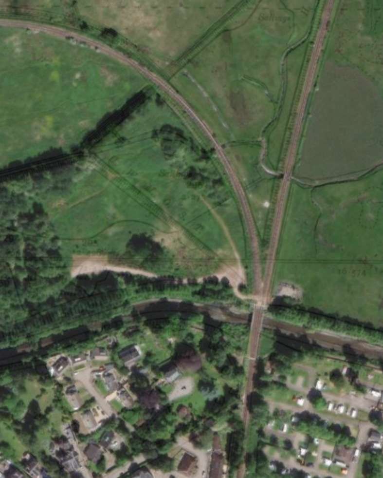
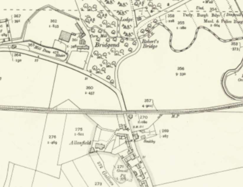
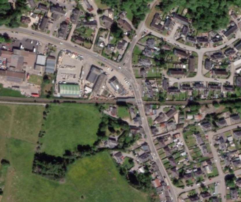
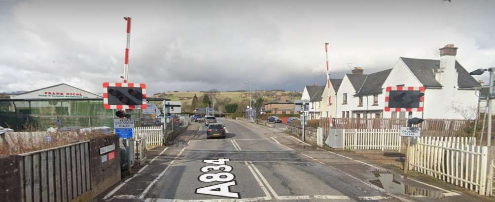
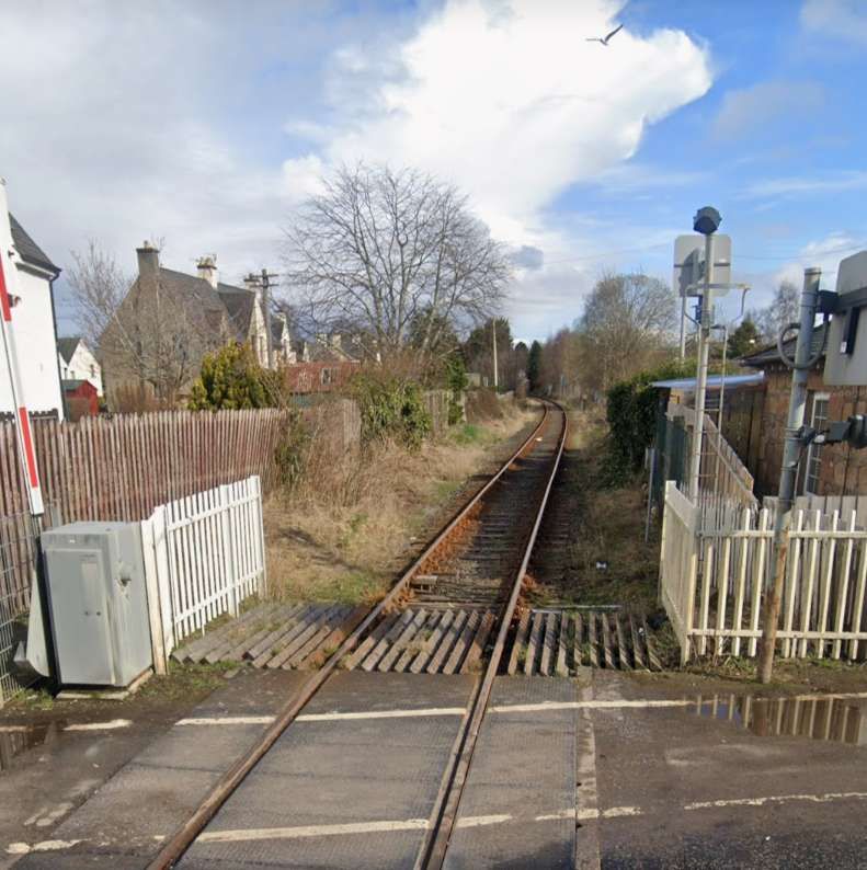
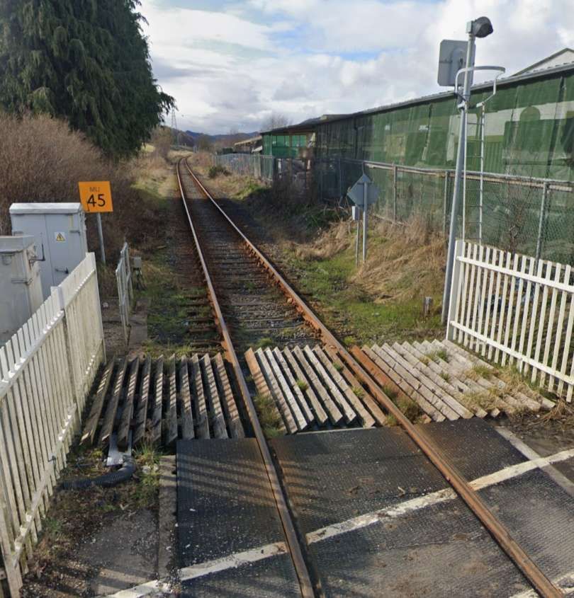
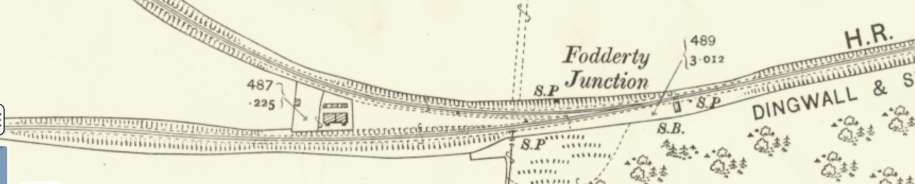
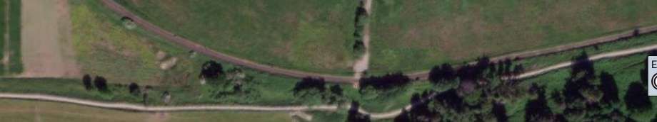
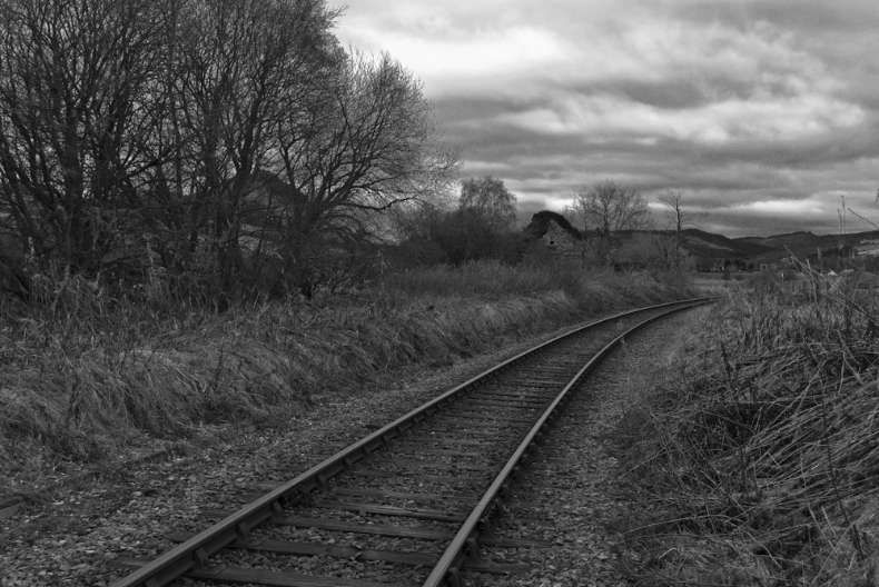
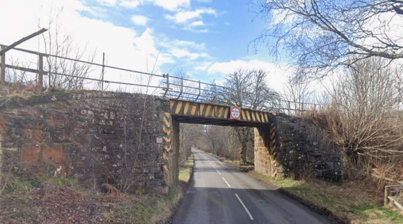
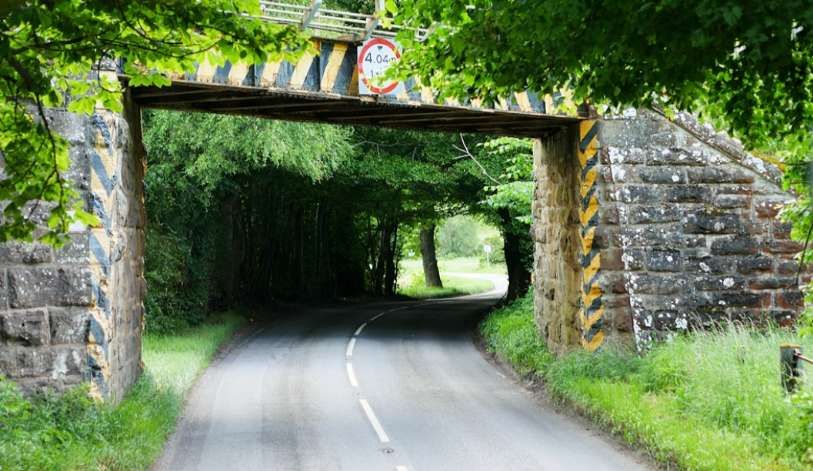
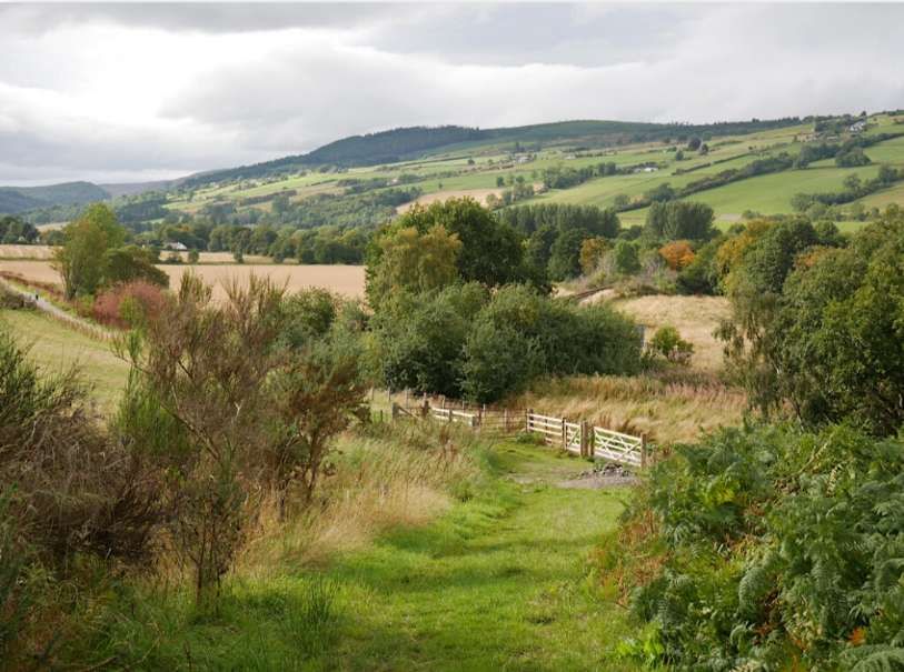
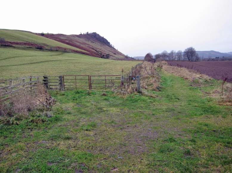
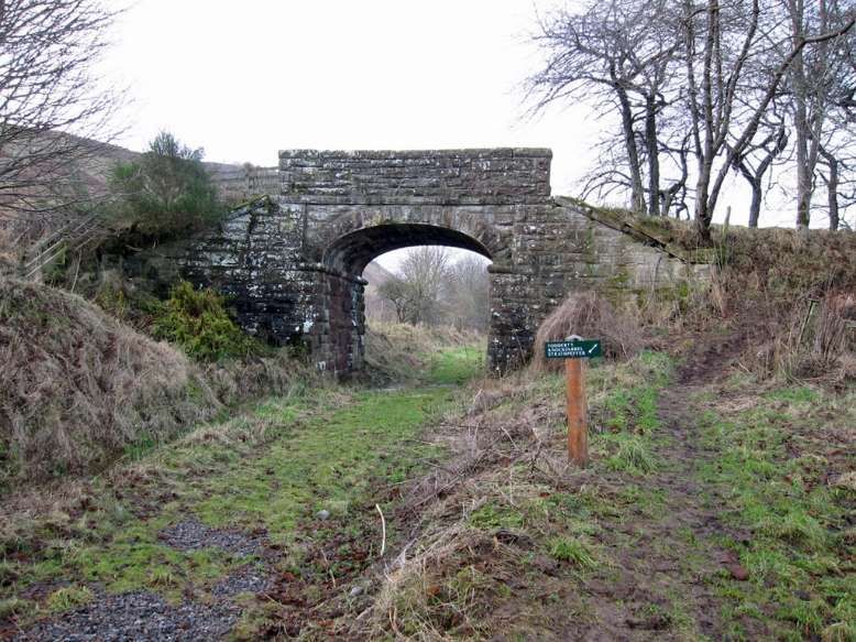
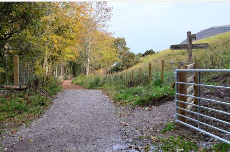
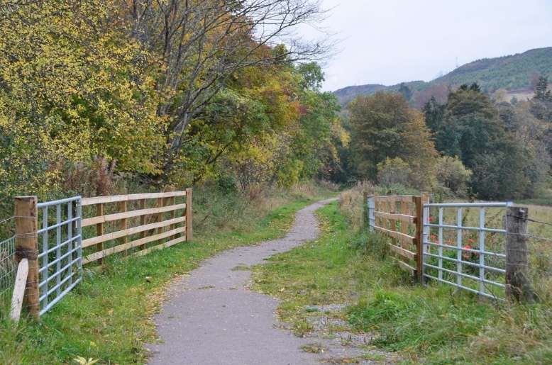
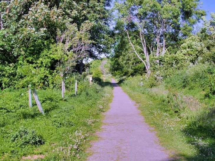
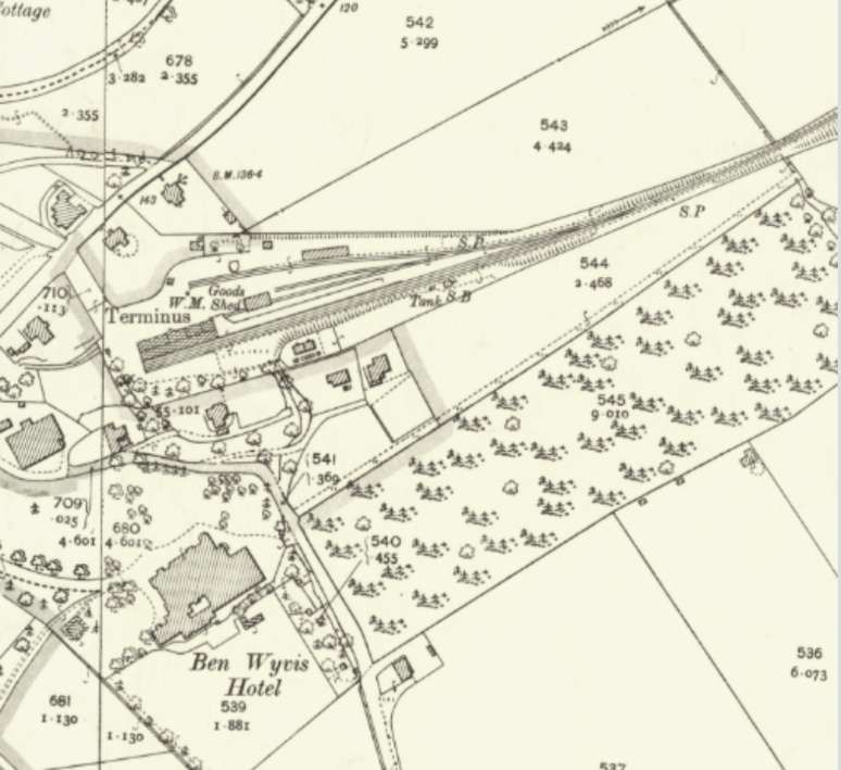
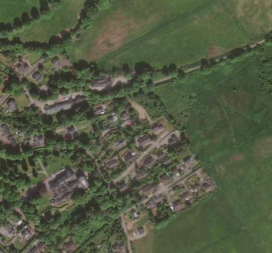
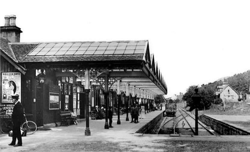
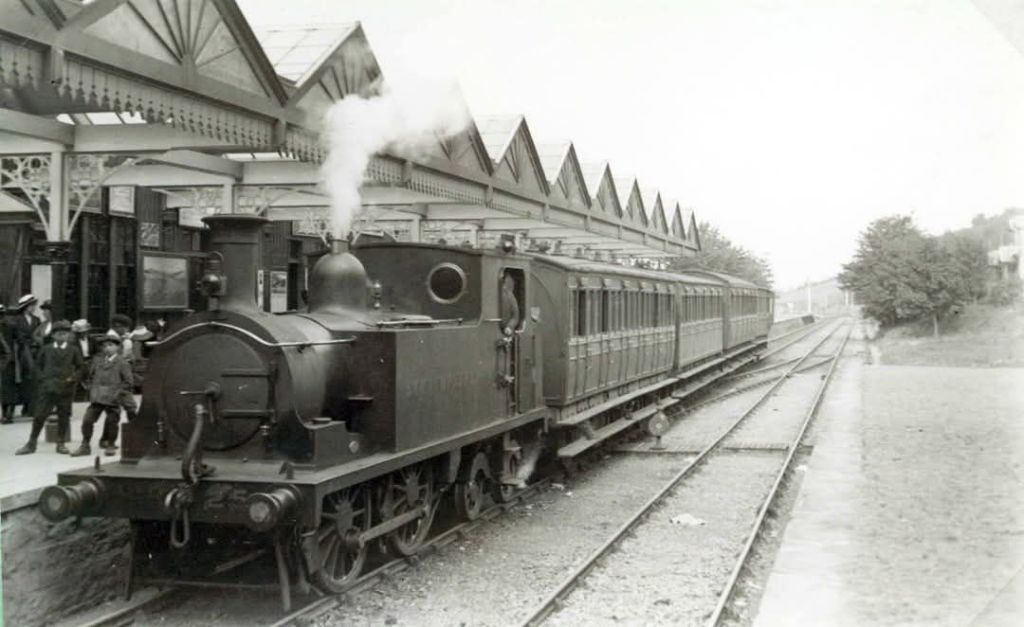
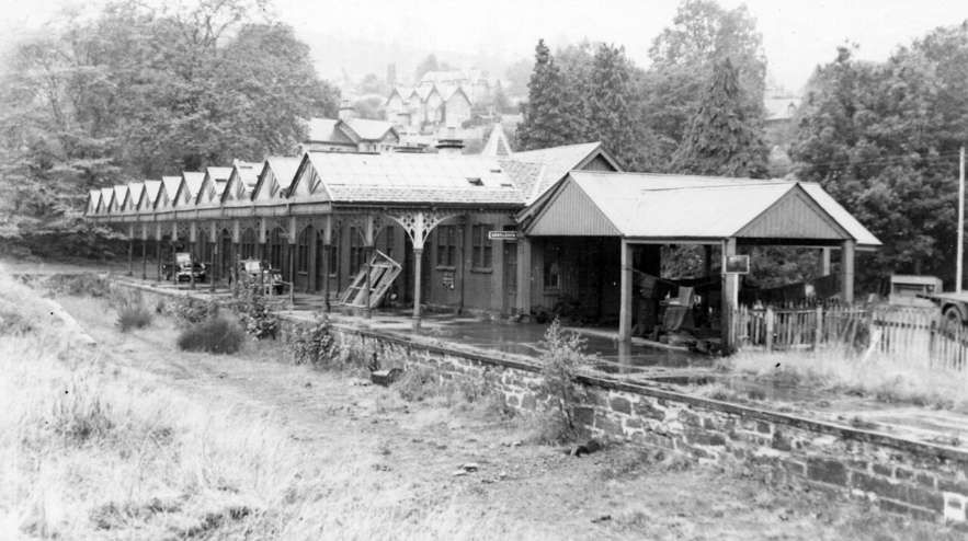
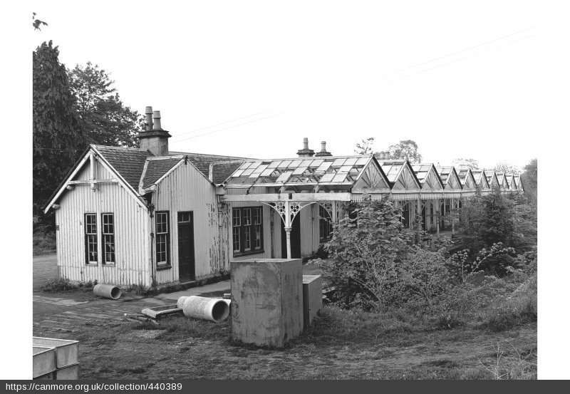
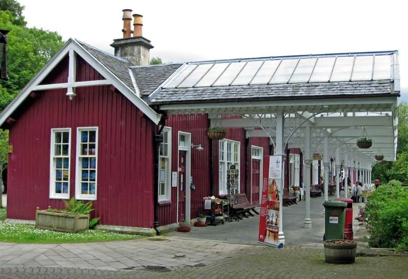
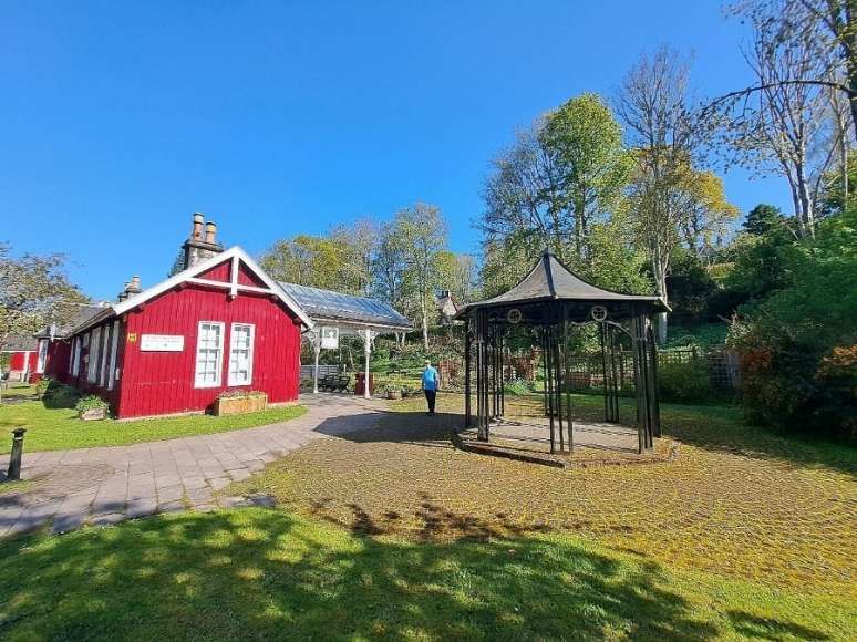
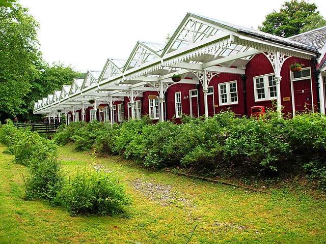
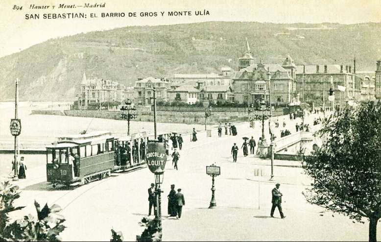
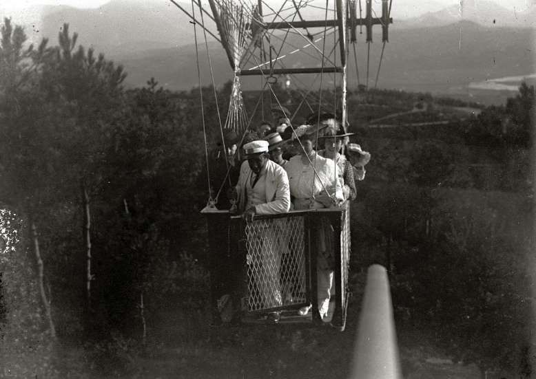
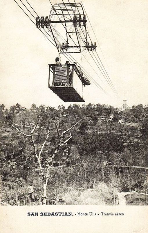
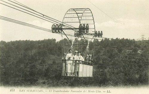
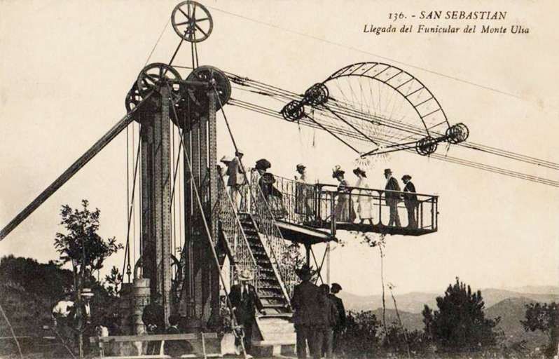
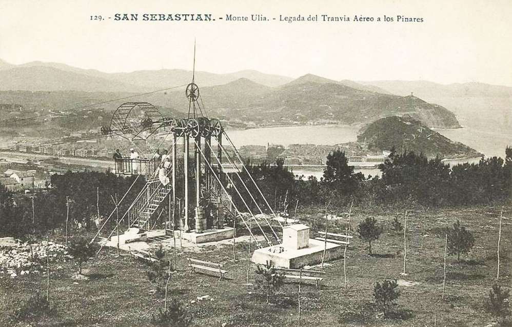
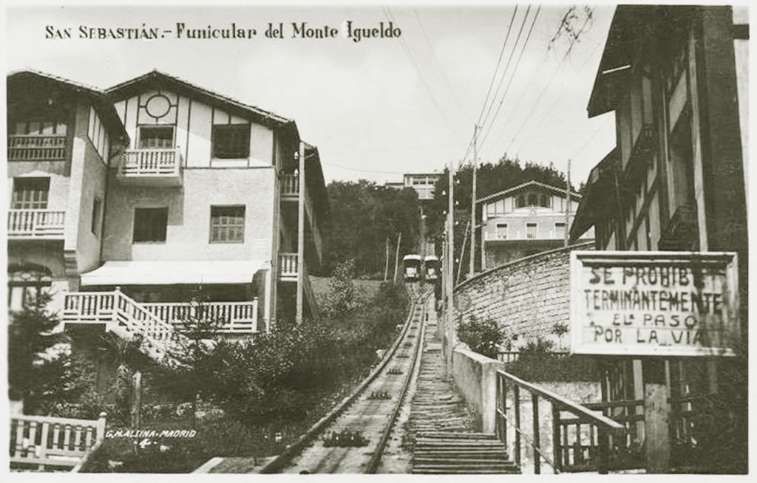
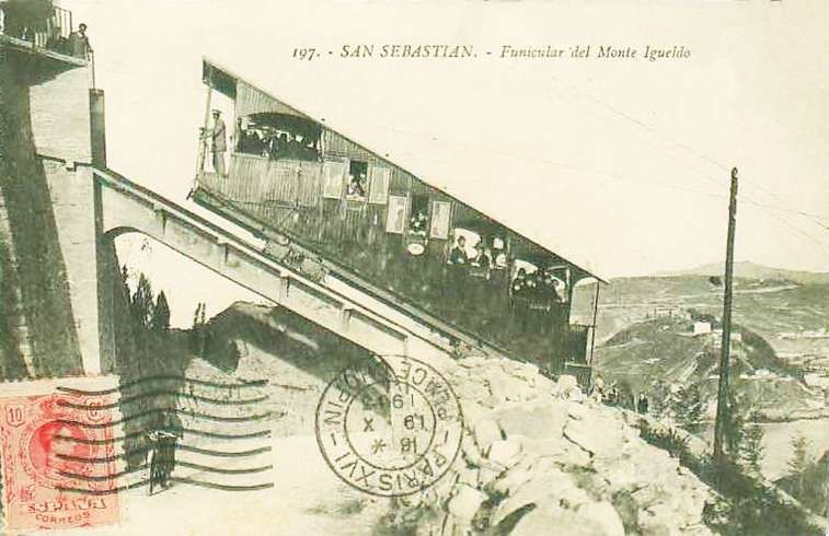
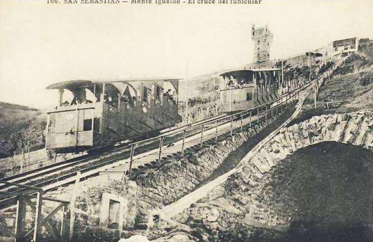
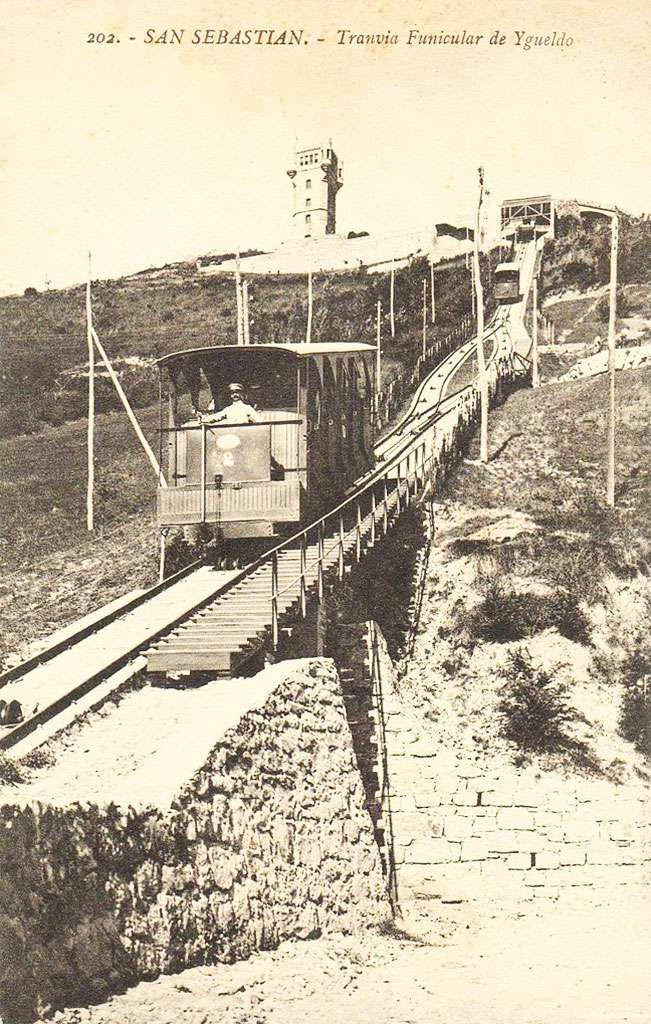
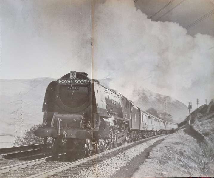
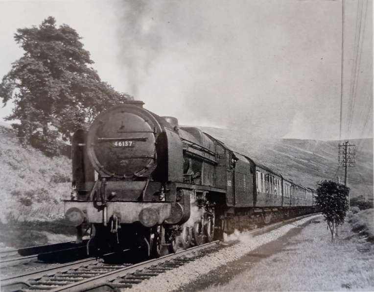
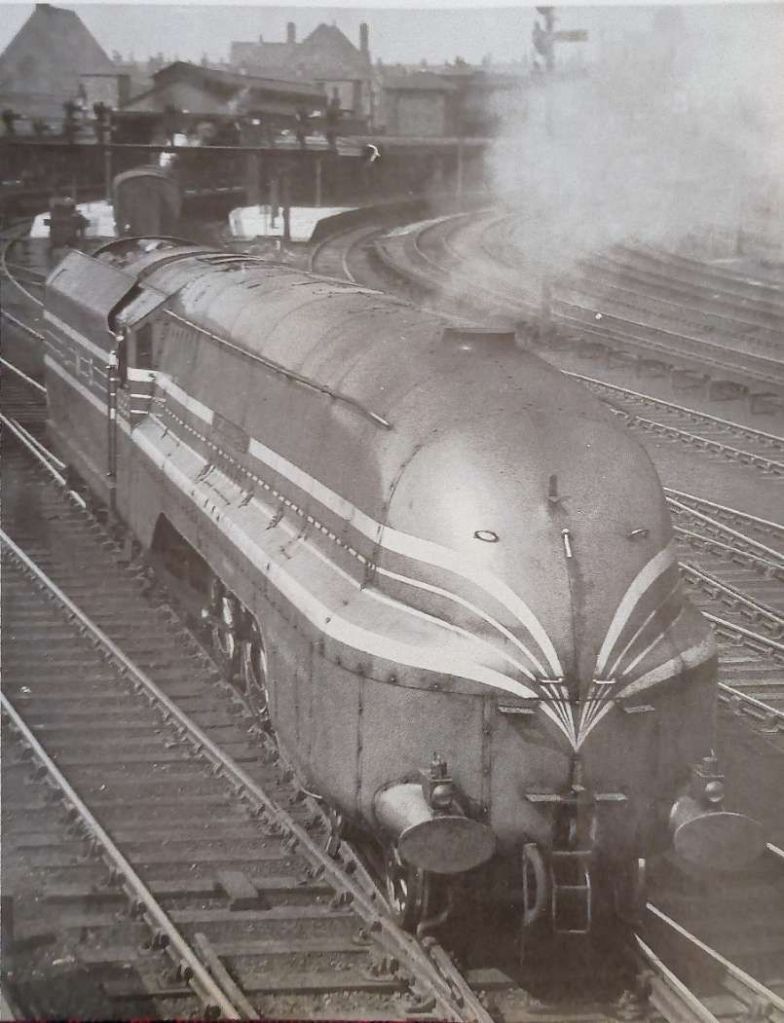
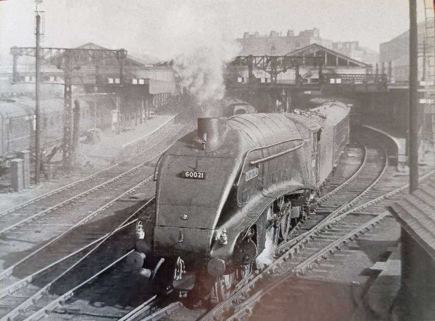
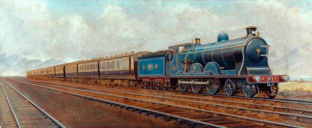
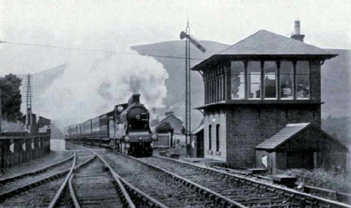
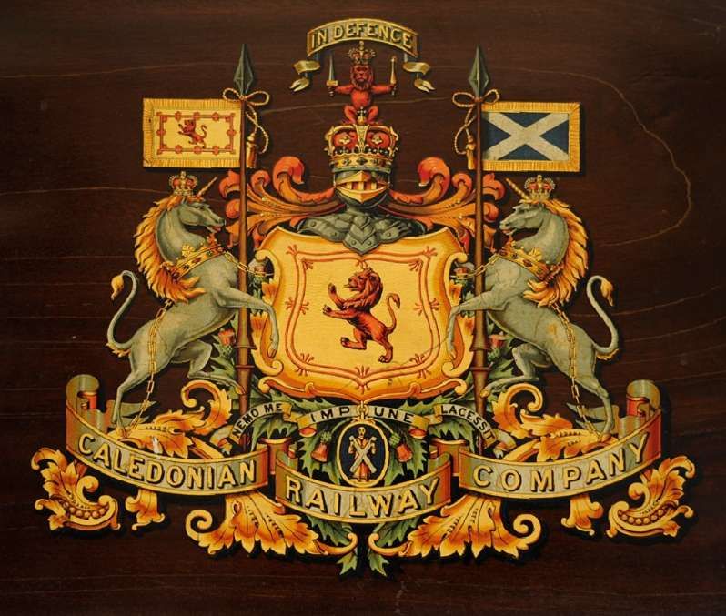
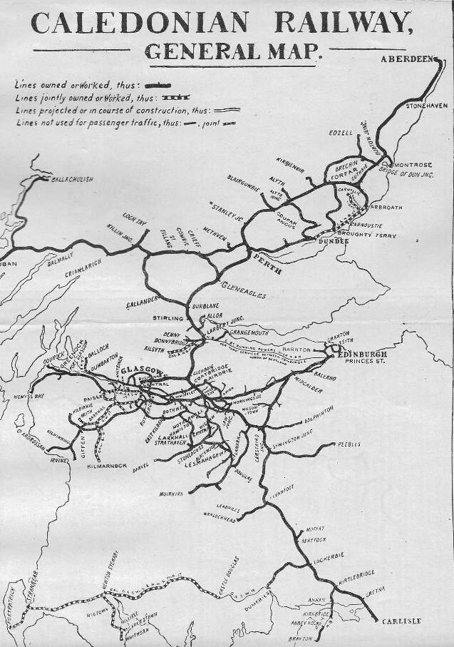
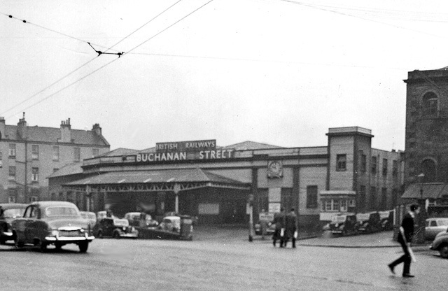
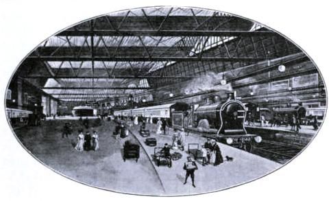
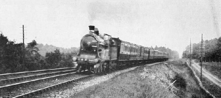
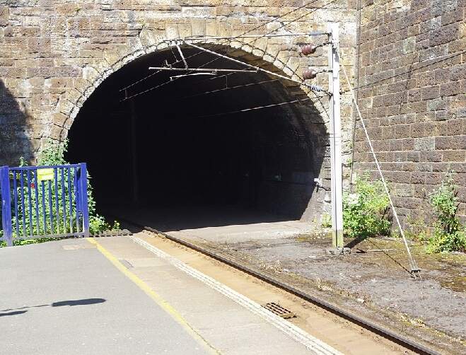
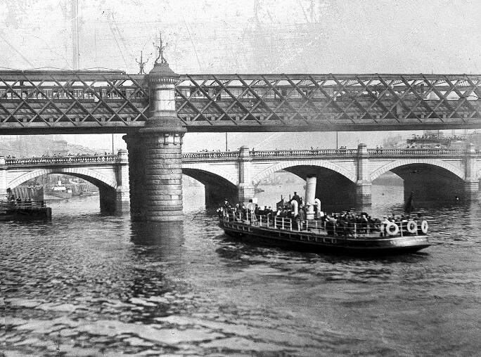
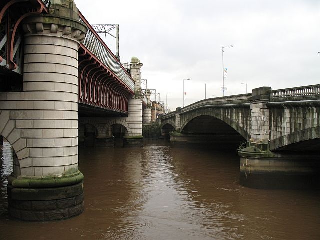
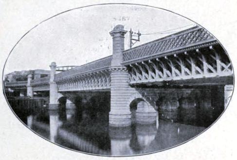
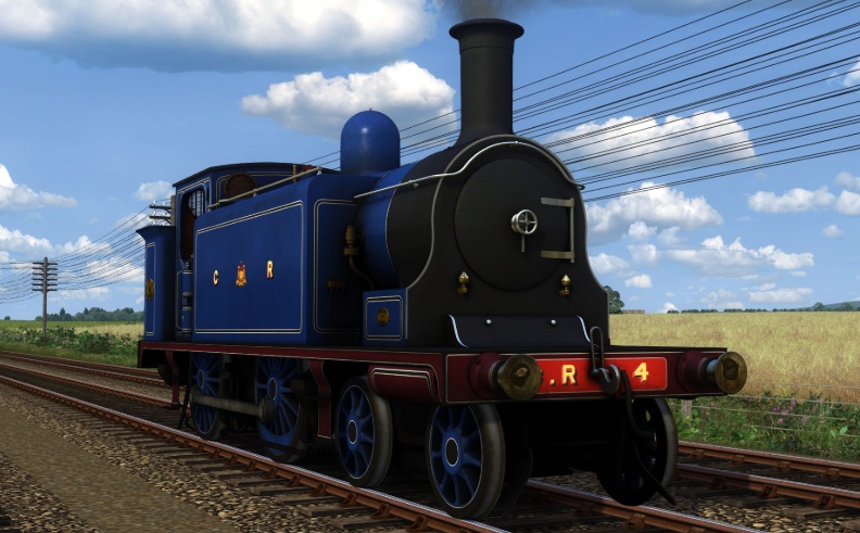
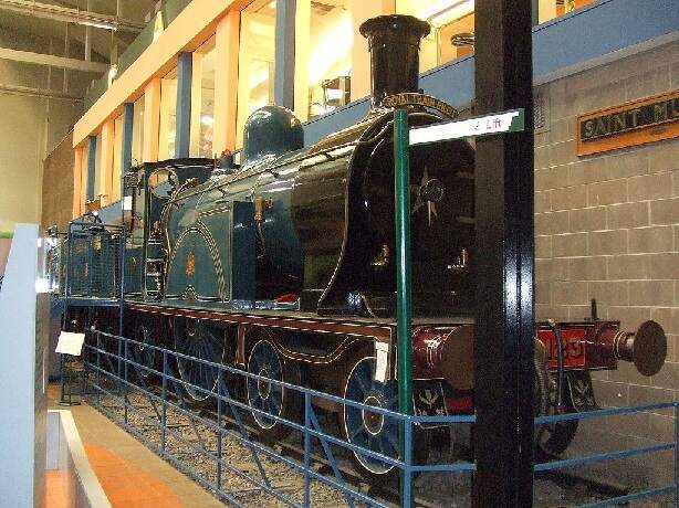
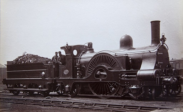
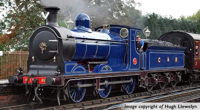
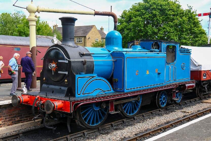
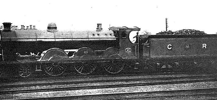
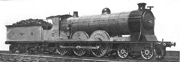
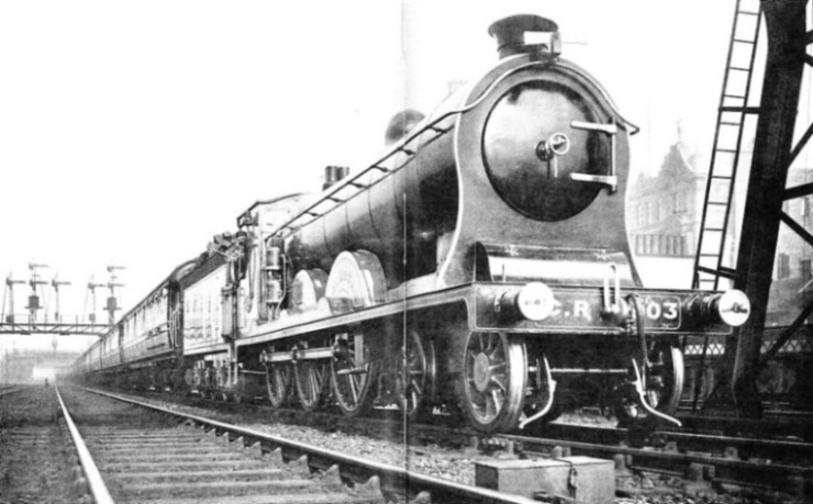
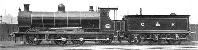
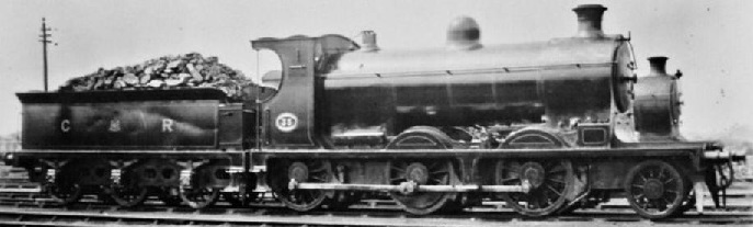
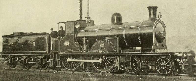
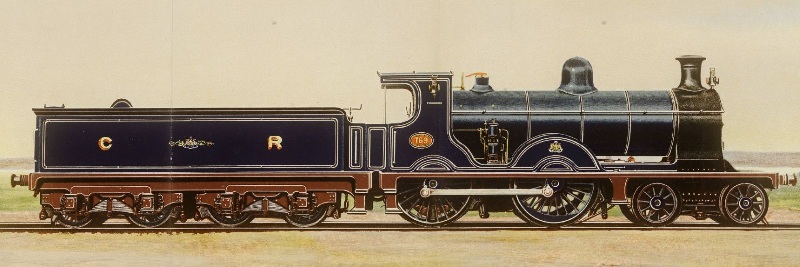
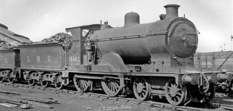
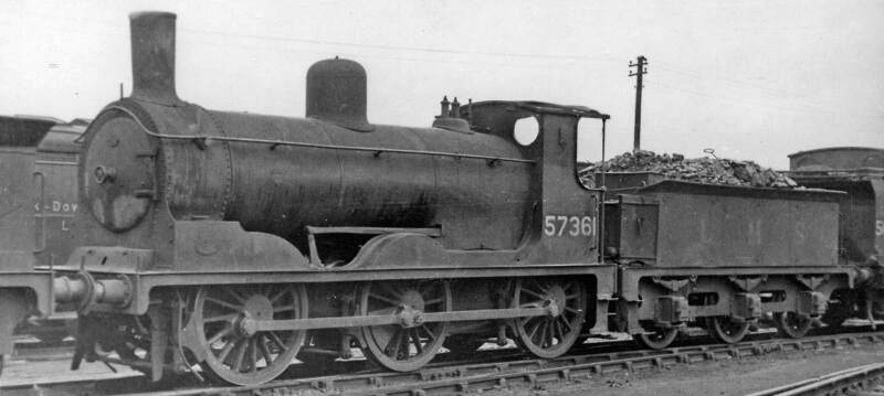
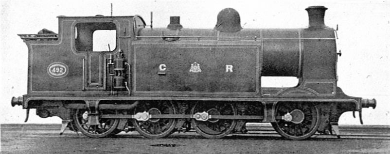
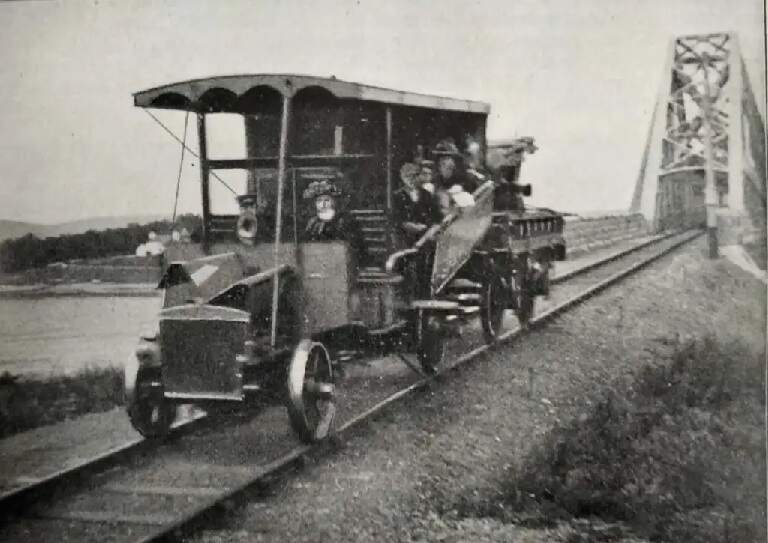
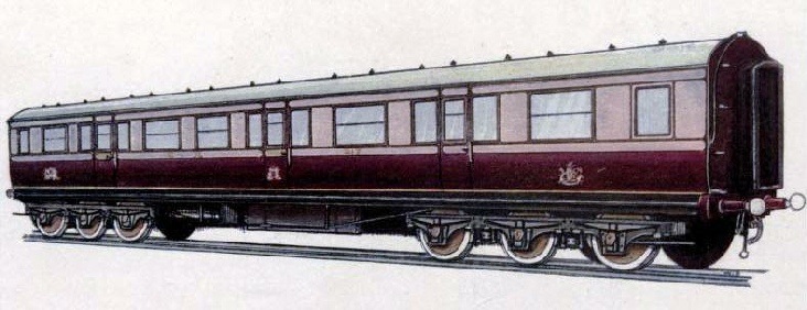
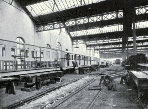
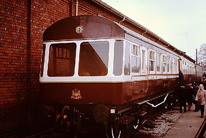
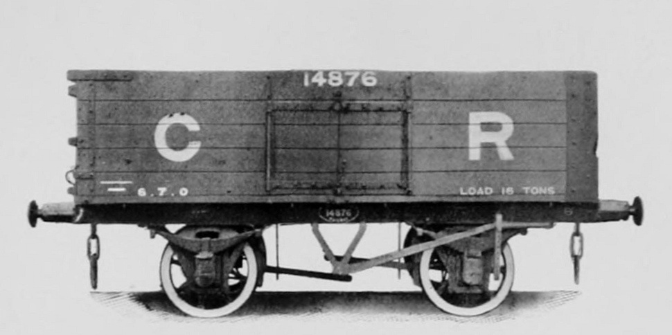
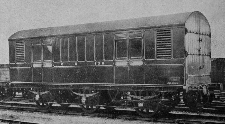
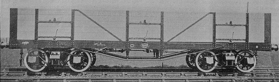
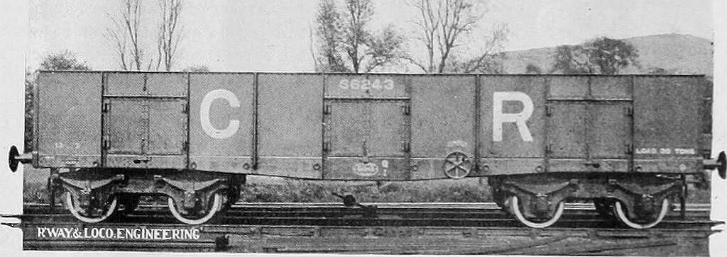
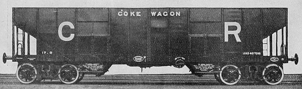


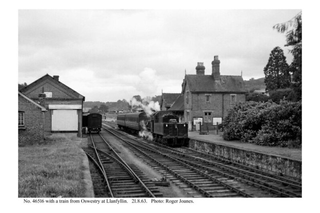
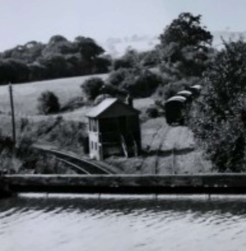
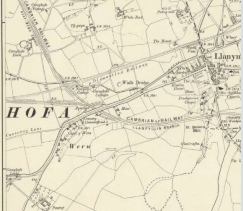
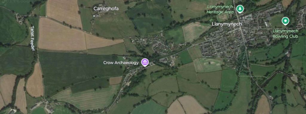
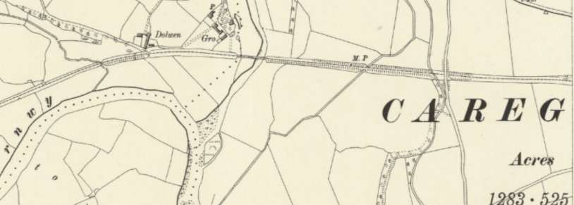
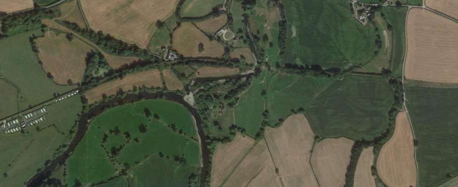
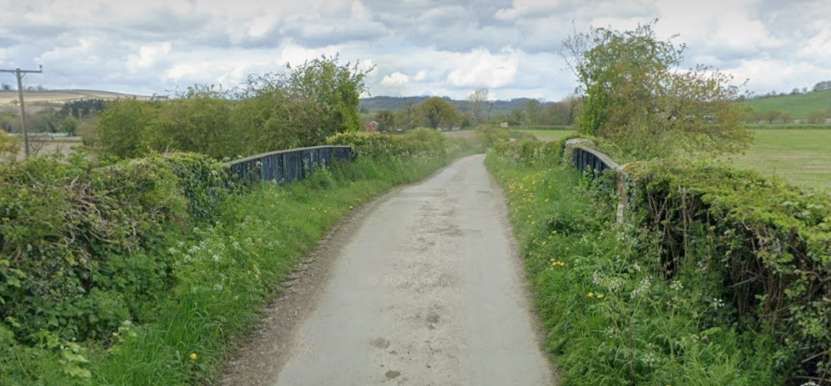
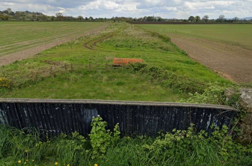
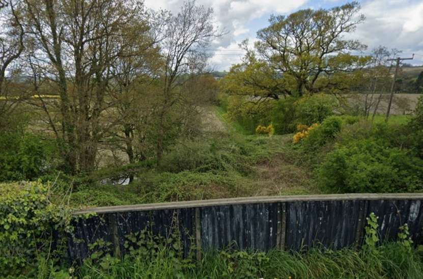
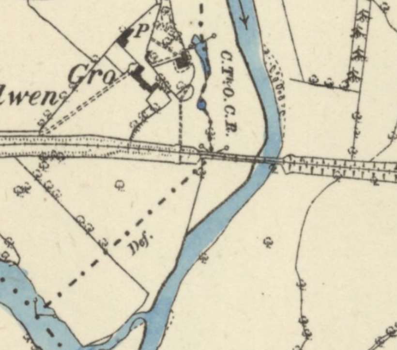
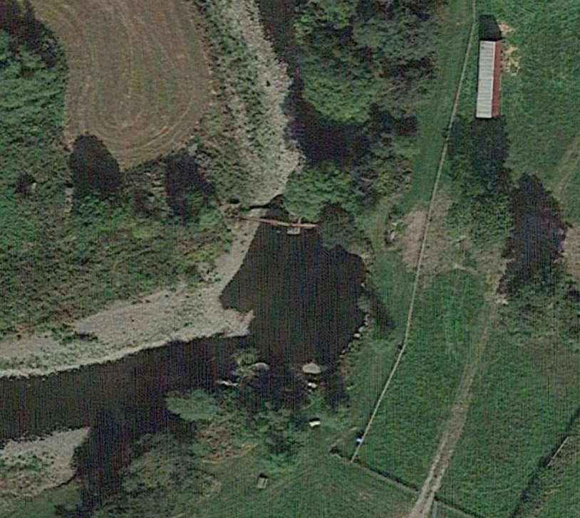
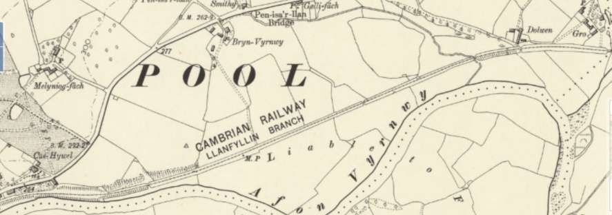
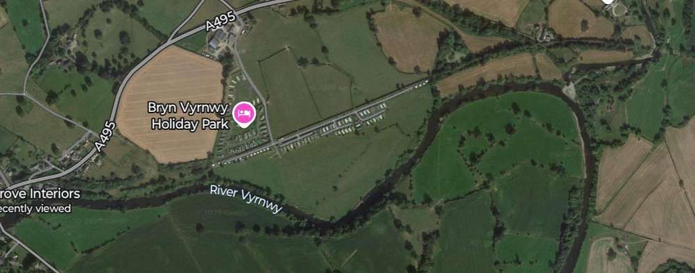
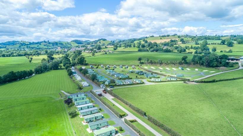
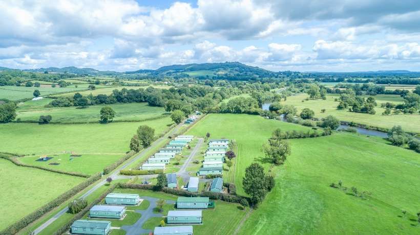

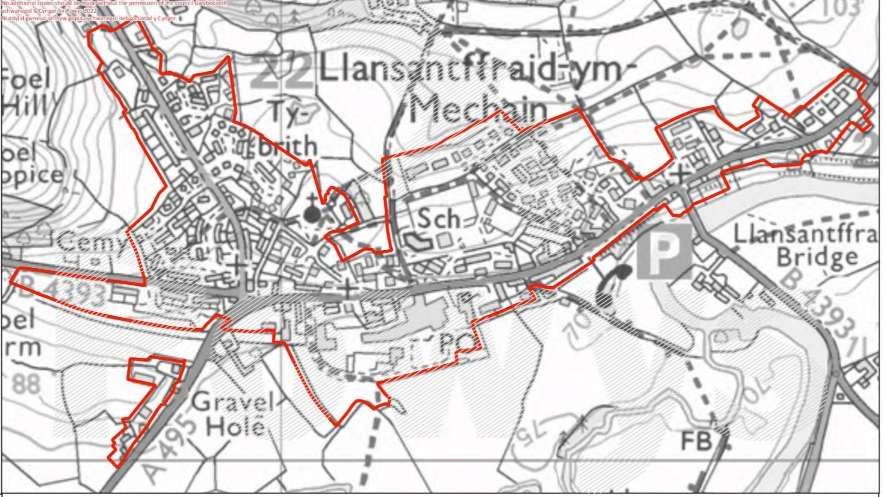

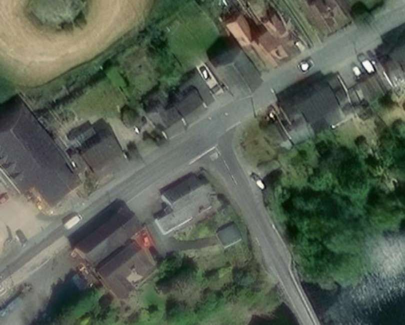
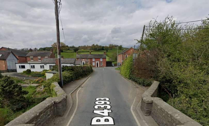
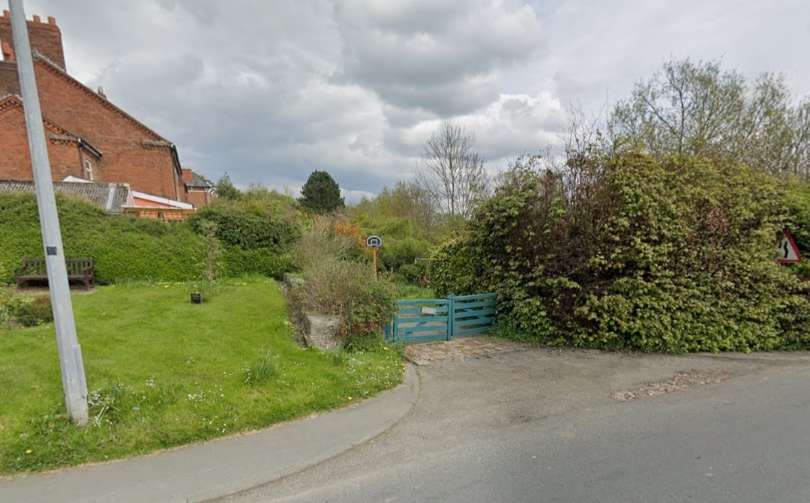
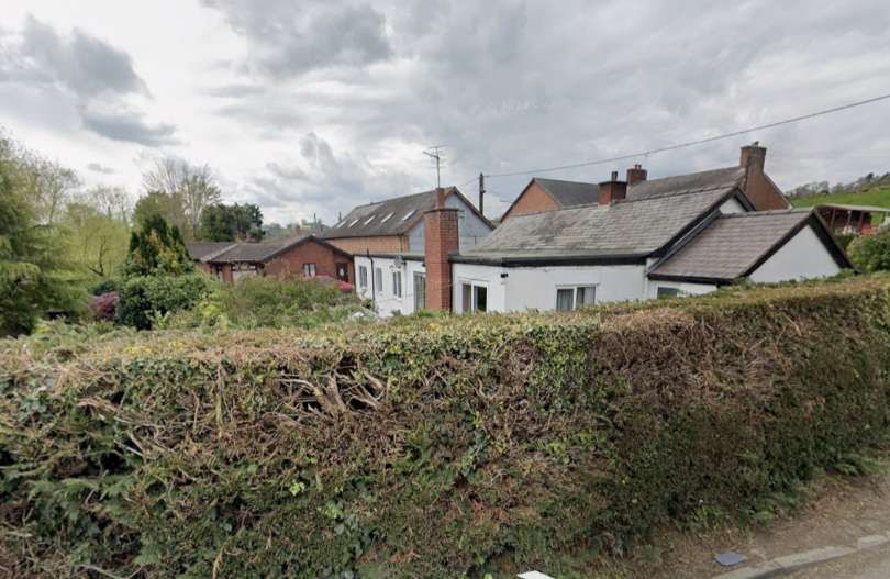
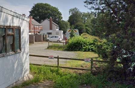
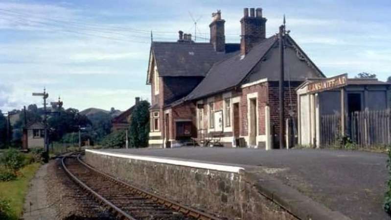
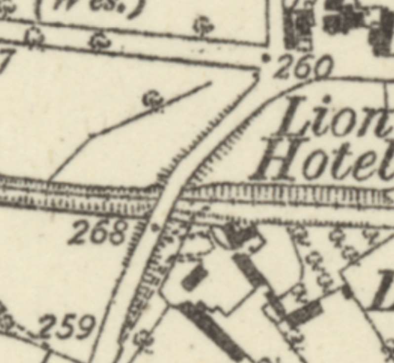

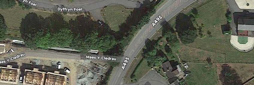
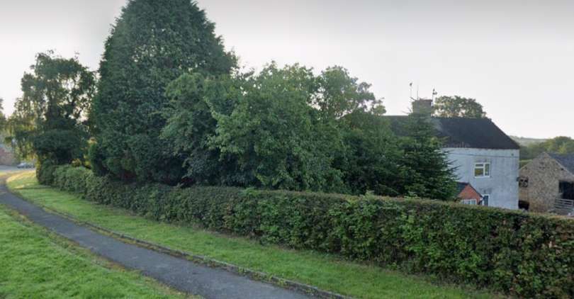
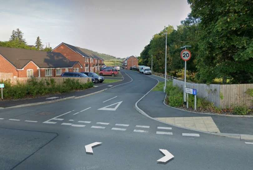
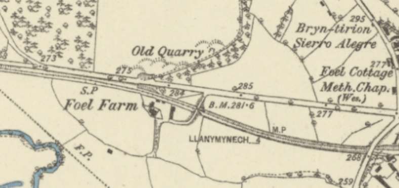

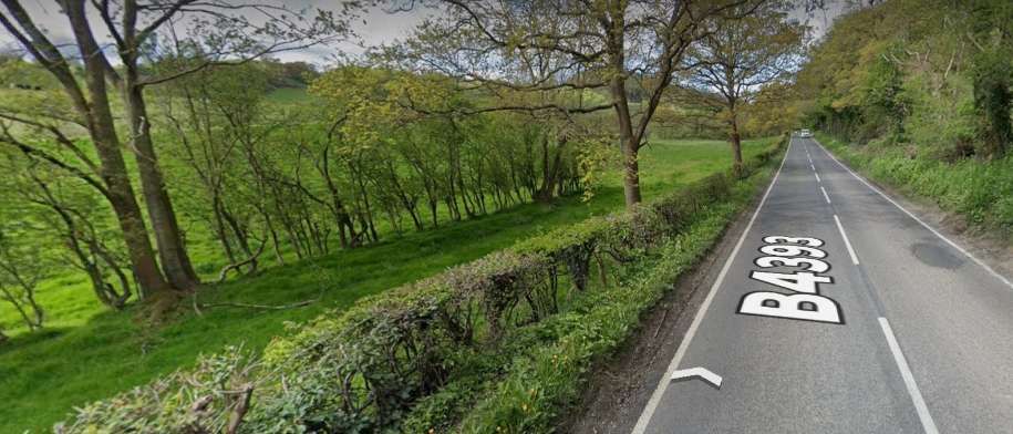
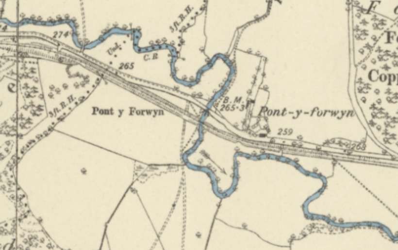
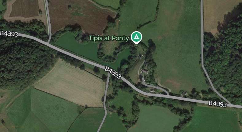
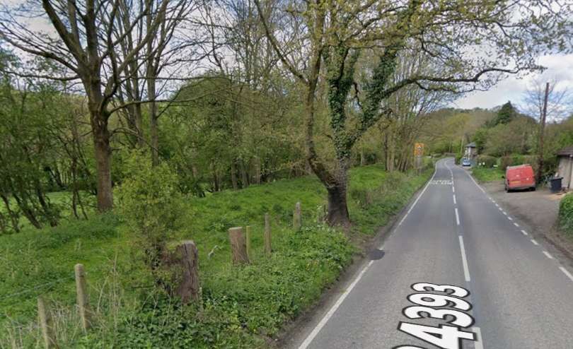
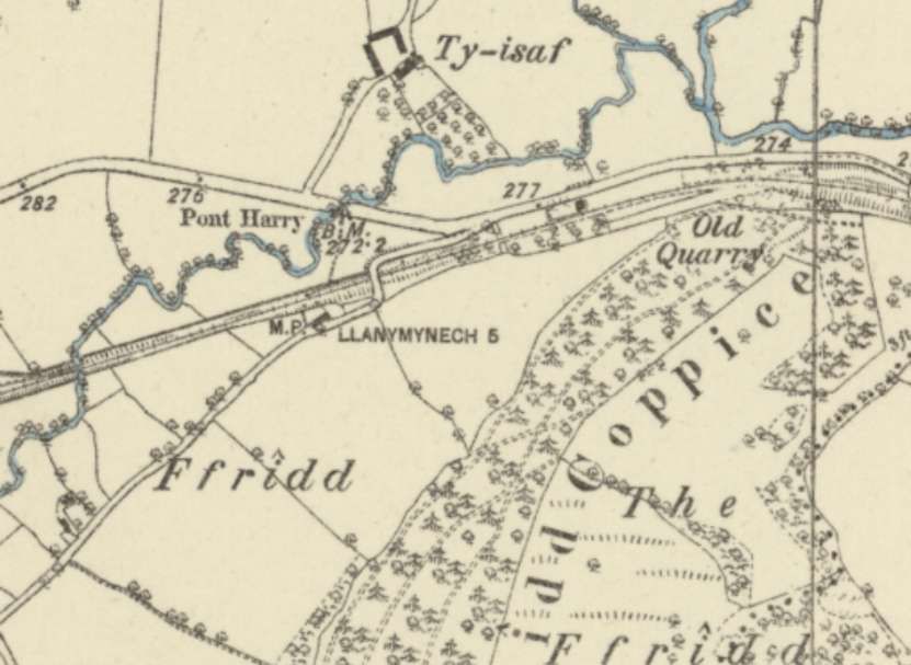
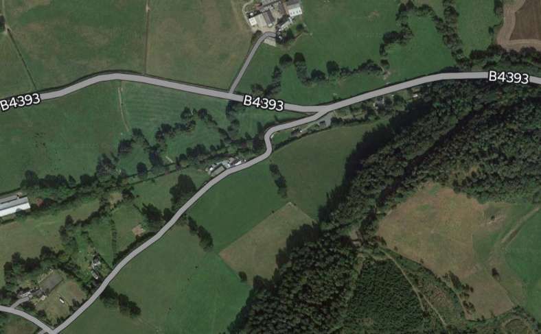
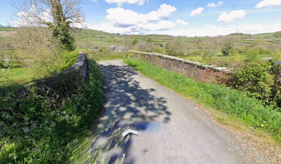
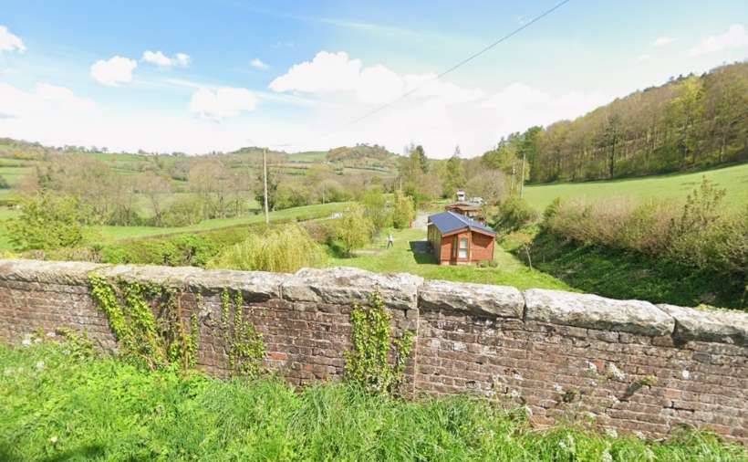
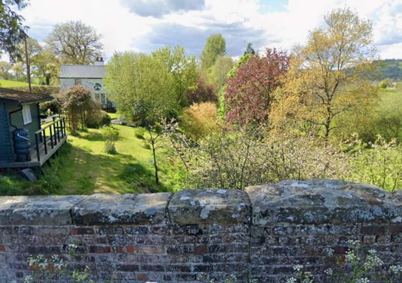
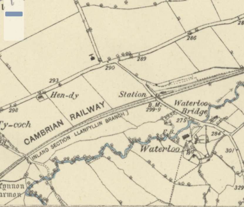
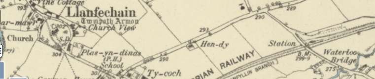
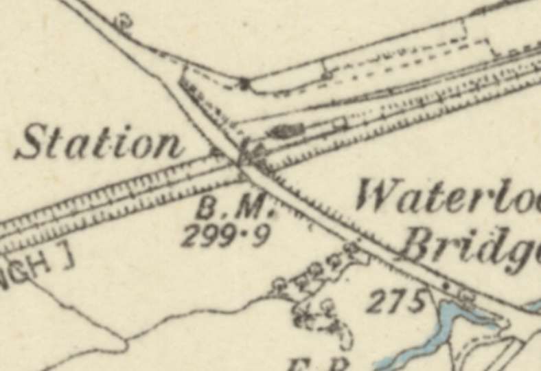
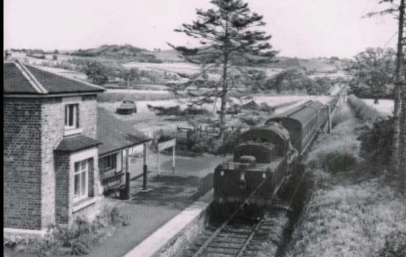
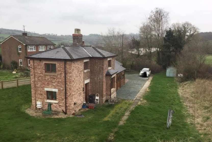
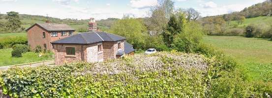
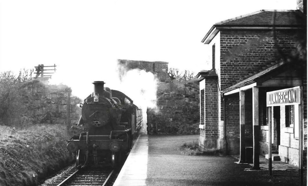

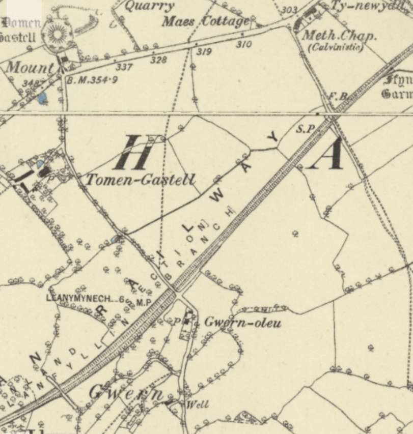
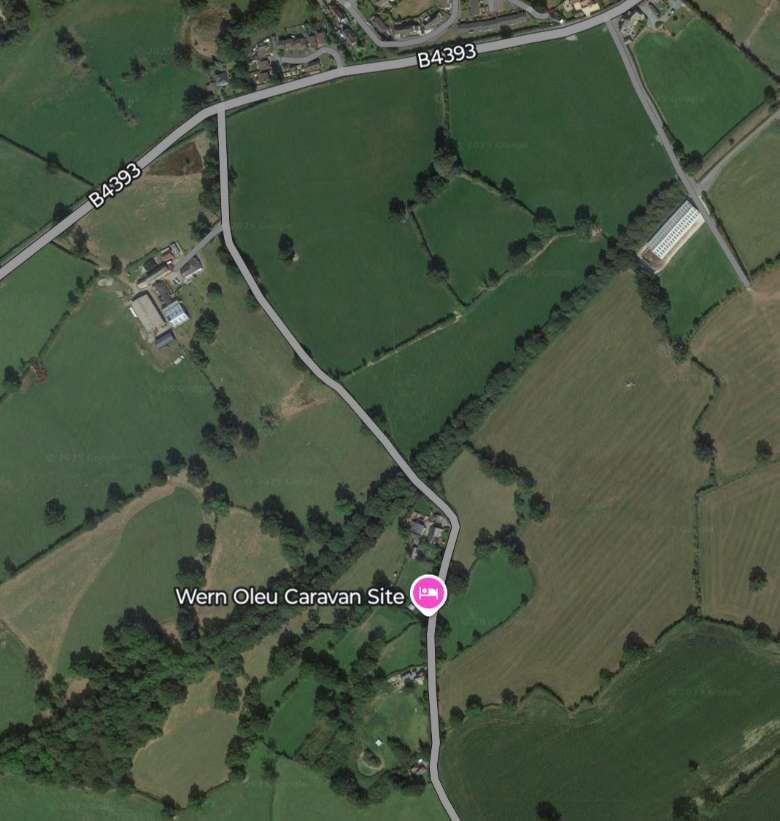
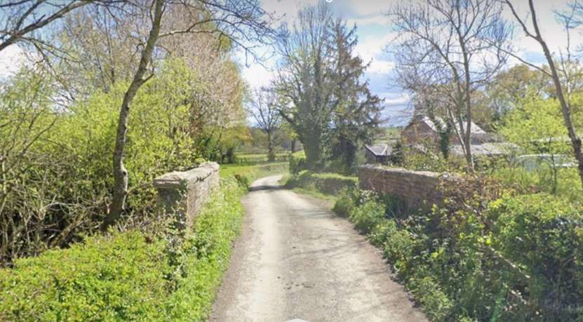
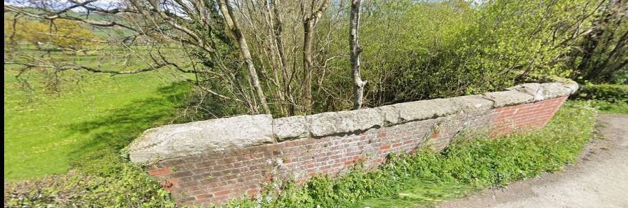
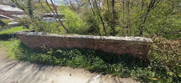
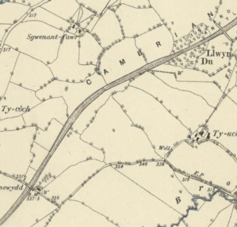
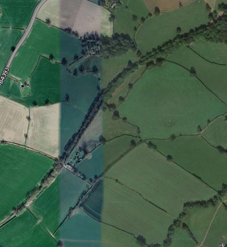
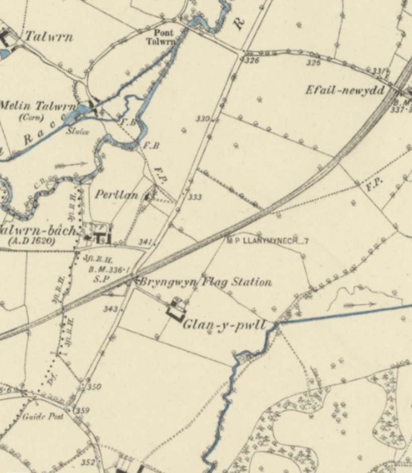
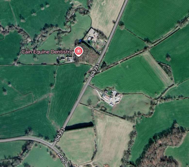
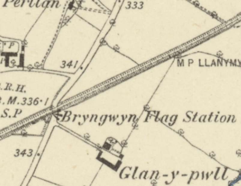
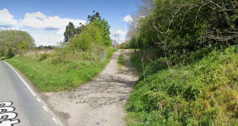
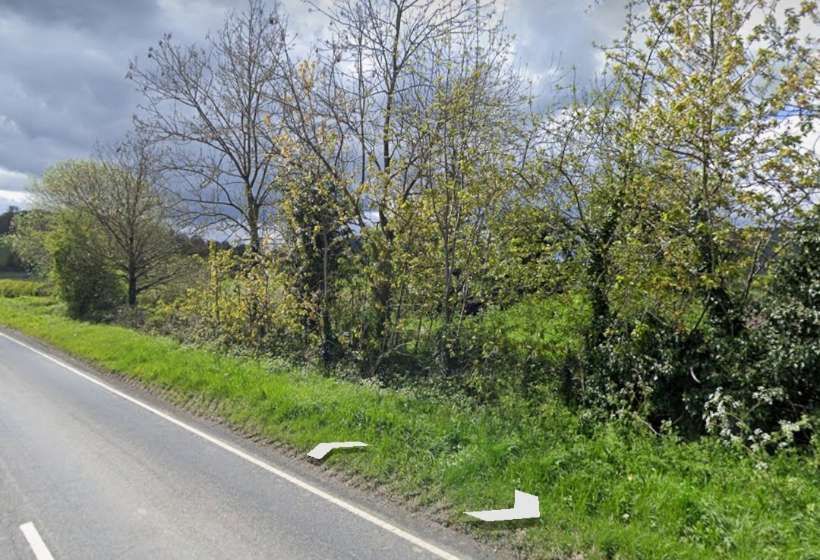
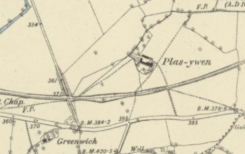
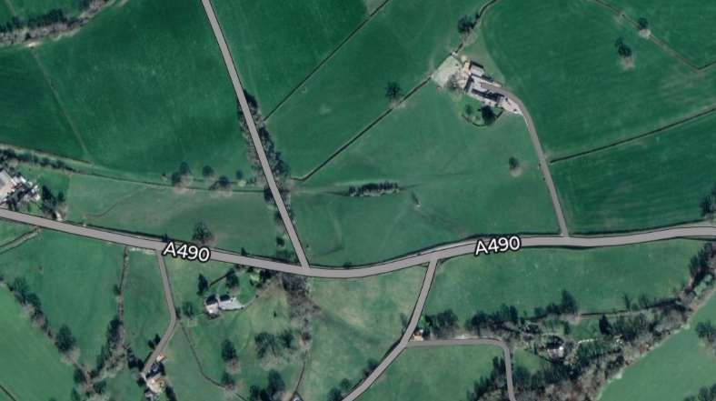
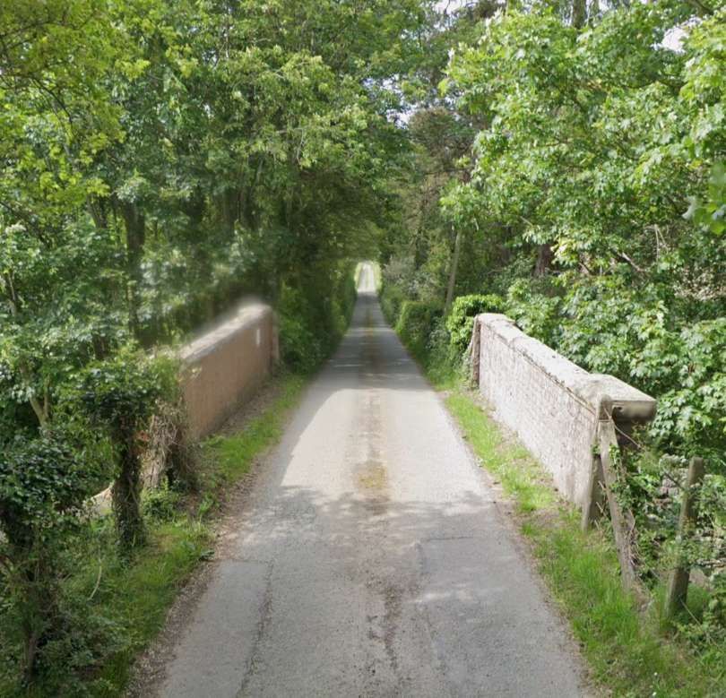
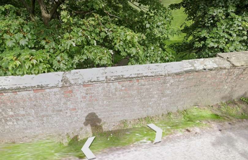
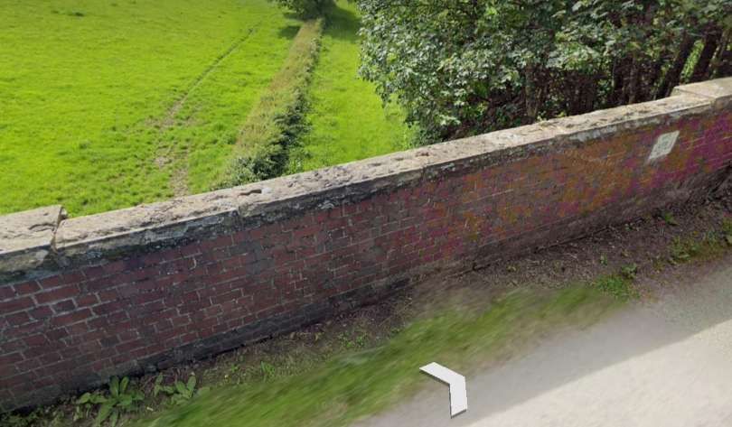
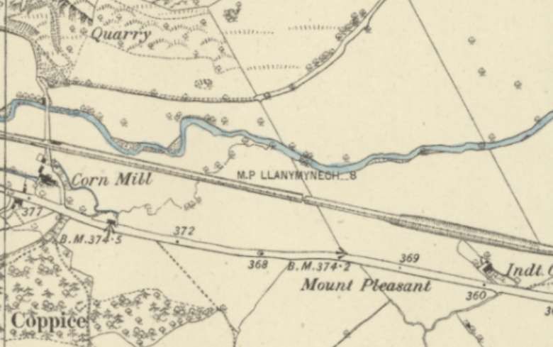
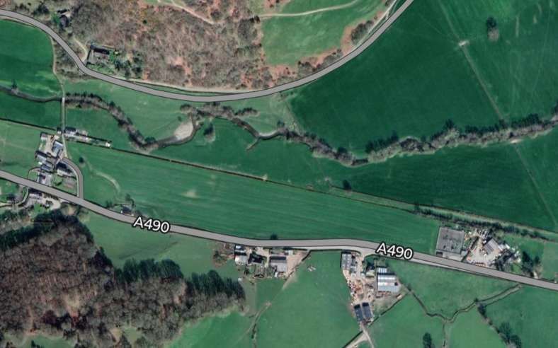
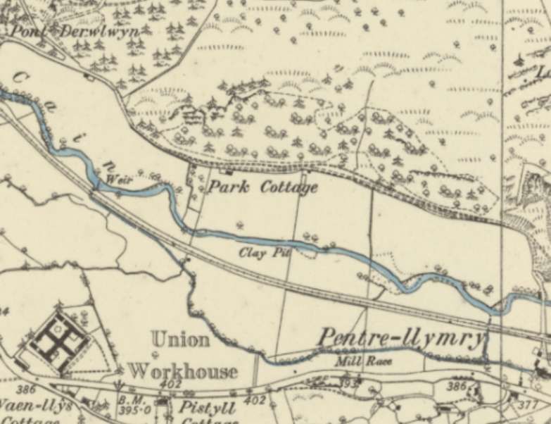
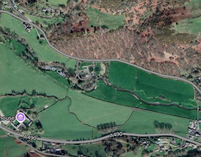
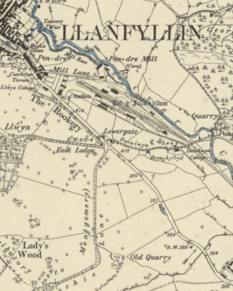
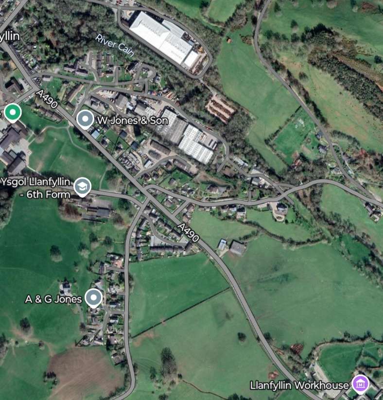
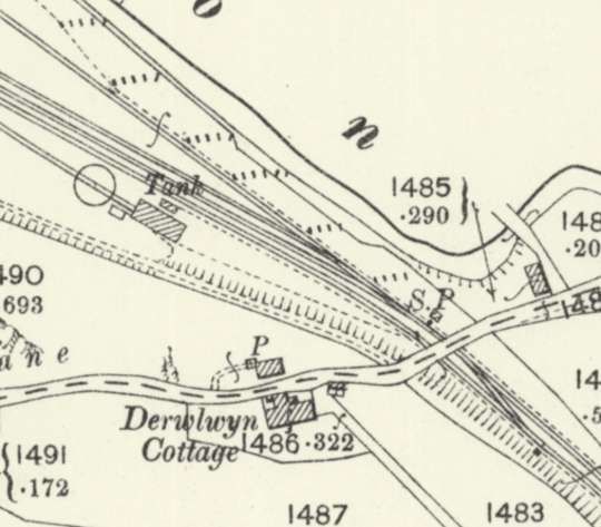

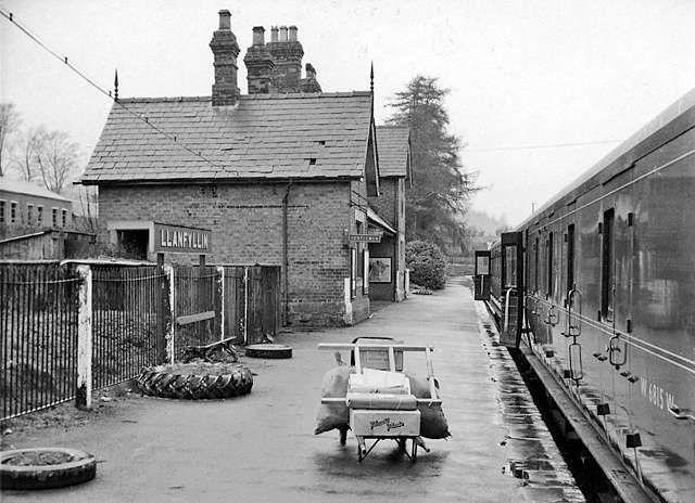
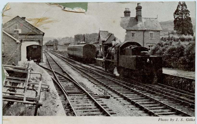
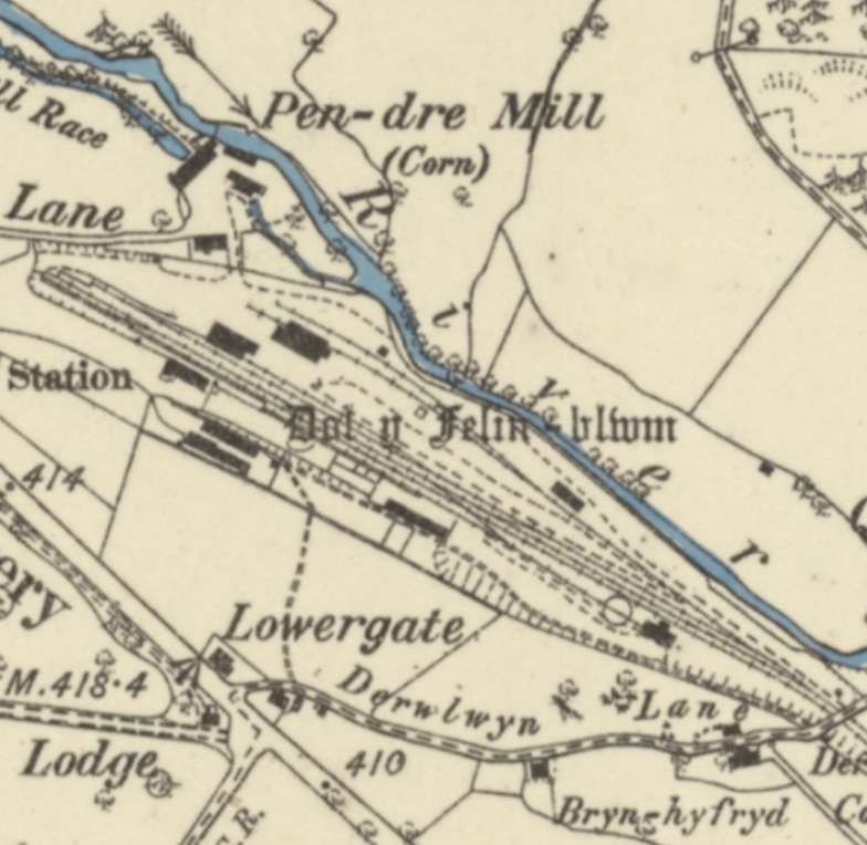
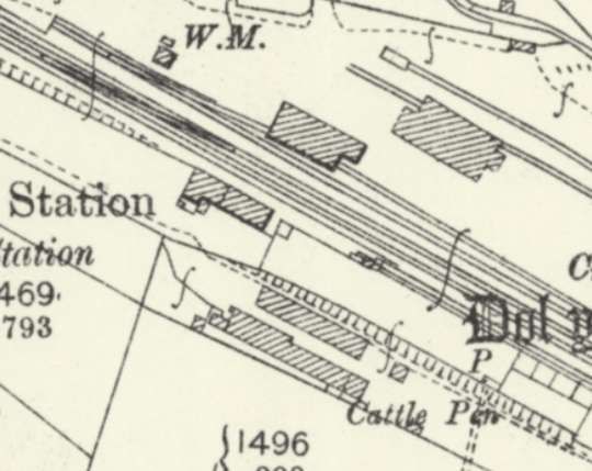

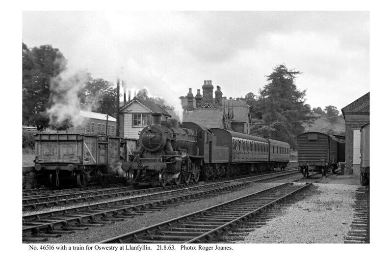


.jpg)
.jpg)