A. Uganda to begin construction of its Standard Gauge railway network in April 2026.
In August 2025, Rogers Atukunda wrote of the construction of Uganda’s Standard Gauge railway network commencing in April 2026. His article can be found here. [1]
B. Uganda is to use electric traction for the Kampala to Malaba Standard Gauge Railway Line.
Uganda has recently confirmed that its Standard Gauge line from Malaba/Tororo to Kampala will operate with electric traction to European standards rather than diesel traction to Chinese standards.
The planned regional standard-gauge network includes two lines separating inside the Eastern border of Uganda at Tororo. These then diverge further in the West (at Bihanga) and in the North (at Gulu). The total route length will be 1,724 kilometres subject to change due to design modifications and additional sidings and/or branch lines. [3]
Kabona Esiara of ‘The East African‘ explained in November 2025 that this required detailed negotiations between the railway authorities in Kenya and Uganda. These negotiations commenced in mid-November 2025. [2]
Uganda and Kenya were working on a raft of technical and policy measures to facilitate a seamless SGR system between the two countries as they work in the next few years on parallel finishing of their SGR lines.
Kenya says it will start constructing the Naivasha-Kisumu-Malaba line early in 2026 while construction of Uganda’s Kampala-Malaba should commence in the second quarter of 2026.
C. A series of mis-steps in the development of railways in Kenya and Uganda.
Mary Serumaga, in 2018, said that “the building of standard gauge (SGR) railways in both Uganda and Kenya and the predictable sagas that have ensued are reminiscent of the controversies surrounding the building of the Uganda and Rhodesian Railways in the late 19th and early 20th centuries. Both present a framework within which it is possible finally to understand the limited achievements in development in all sectors (and frankly, underdevelopment in many) and regression in Uganda’s primary education, copper mining and agricultural sectors. Both SGR projects are tainted with suspicion of shady procurement which, if taken together with the track records of the implementers, points to corruption. It would be irresponsible to say otherwise.” [4]
“The route, design, level of service and all other decisions of the Uganda Railway of 1990 were dictated by potential profits for foreign investors (both public and private) and their local agents, and not by notions of public service and the common good of those who would bear the ultimate cost. Return on investment is not a bad thing but the Imperial government also claimed to be acting in the interests of the indigenous populations. … The difference now is that there is no pretence about whether the railways are serving the interests of the general population. The different financial implications presented by the procurement process itself, the selection of routes and the relative cost of engineering in the different terrains, plus the cost of compensating displaced landowners, provide scope for long-running, energy-depleting corruption scandals. From the outset, there has been a lack of confidence that procurement processes for the necessary services would prioritise the interests of the public over the interests of the contractor and would actively exclude the personal interests of the public servants commissioning the works. This is what is triggering the anxiety surrounding the SGRs.” [4]
“Moreover, the choice over whether to upgrade the old railway or to start afresh was not adequately debated publicly. Ditto the options on financing. For the Kenyan SGR, the most costly of the potential routes were reportedly selectively chosen. Several cheaper routes on land allegedly already in possession of the government are said to have been rejected. … There are also questions surrounding passenger service. Do the railways only serve trade or are passengers entitled to this alternative to dangerous road transport?” [4]
“Uganda owns one half of the old East African Railway. Together with the Kenyan leg, it was put under a 25-year management contract. The new owners renamed their new toy Rift Valley Railways (RVR). In 2017, after only twelve years, the governments cancelled the contracts in a move the RVR called an illegal takeover. On the Ugandan end, there were allegations of asset-stripping by previous European concessionaires as well as unpaid concession fees and massive salary arrears caused by RVR. If RVR were to successfully sue the government for cancellation of the contract, their compensation would be the first budget overrun. … The government of Uganda then signed a Memorandum of Understanding in 2014 with the China Civil Engineering Construction Corporation (CCECC), which had submitted a study. It abandoned those negotiations in favour of a second Chinese entity, the China Harbour Engineering Company. In justifying its action, the government questioned the quality of the CCECC’s study, which it said was cut and pasted from pre-existing feasibility studies (something that could have been avoided by following proper procurement procedures). CCECC insists it was a pre-feasibility study requiring less detail than a full-blown feasibility study. Whatever the case, if CCECC had followed through with its suit for US$8 million in compensation, which would have been another massive blow to the budget at inception. Whatever compensation they have agreed to has not been made public but as matters stand, the budget for the eastern leg of the SGR has gone up from CCECC’s proposed US$4.2 billion to CHEC’s US$6.7 billion.” [4]
The remainder of Mary Serumaga’s article which looks back at colonial construction work and draws parallels with 21st century procurement and construction in East Africa can be found here. [4]
D. President Yoweri Museveni’s State of the Nation Address in June 2025.
In June 2025, President Museveni highlighted significant rail developments, advancing the Standard Gauge Railway (SGR) project to link with Kenya and the region, aiming to cut costs and boost trade, while discussing financing for the $2.8 billion Kampala-Malaba SGR and emphasizing participation in the development of the new rail infrastructure. In essence, the 2025 address signalled a push for comprehensive road and railway modernization and expansion, leveraging oil revenues and debt financing to build a robust network for economic transformation. [5] Museveni said, “we are soon finalizing the construction of the 1,443km East African Crude Oil Pipeline (EACOP) from Buliisa to Tanga in Tanzania. The construction of the SGR, which I launched last year, is soon starting,” [5] and “the NRM Government has prioritized infrastructure development especially roads, railways and electricity.” [5] In addition, the government will be focusing on revitalizing metre-gauge lines (like Tororo-Gulu, Kampala-Malaba).
E. Kenya – Additional Madaraka Express Trains for the Christmas period.
Kenya Railways announces additional Madaraka Express trains from 8th December 2025, to 5th January 2026, to meet increased festive season demand. The Nairobi-Mombasa train departs Nairobi at 9:40 AM, arriving in Mombasa at 3:35 PM, while the Mombasa-Nairobi train leaves at 4:30 PM, reaching Nairobi at 10:55 pm. [6]
“The railway operator said the move comes in response to increased demand during the holiday period, when thousands of Kenyans and tourists journey along the scenic Nairobi-Mombasa route. … ‘We are committed to providing a safe and convenient travel experience, and the additional services will help ease congestion while maintaining punctuality’ reads the notice dated 2nd December.” [7]
Transport for Greater Manchester (TfGM) has indicated that it is considering a plan to extending the already proposed East Didsbury to Stockport extension of the Metrolink tram network. The extension would utilise the underused railway line between Stockport and Denton.
Talk is of utilising tram-train technology on this possible new extension.
Should this proposal be approved it would link Stockport to Tameside and could also provide a link to Manchester Airport
The Mayor of Greater Manchester, Andy Burnham spoke of bold plans to deliver a decade of growth for Greater Manchester. He said that “developing the Bee Network and delivering better bus, tram and train connections will be fundamental to [that] growth story.” [2]
He continued: “For too long, Denton has been overlooked and by working up the tram-train option to connect Denton and the wider area to the Metrolink is a big step toward unlocking opportunities for local residents and businesses. … We’re committed to extending Metrolink to Stockport and beyond as part of our efforts to connect all our districts to the tram network and delivering a truly integrated transport network for everyone.” [2]
TfGM is already working with Stockport Council to develop a business case for bringing trams to Stockport. The Strategic Outline Case [4] – the first step in the process – is exploring a ‘core’ extension from the existing Metrolink stop at East Didsbury to Stockport town centre. The extension through Denton is not part of those ‘core’ proposals but, “as part of the work on the business case, TfGM is also considering how this may unlock future extensions. One option being worked up includes using tram-train technology – where services can run on both tram and train tracks – to run beyond Stockport town centre along the Denton rail line, connecting the area firmly into the wider Metrolink network including links to Tameside and Manchester Airport.” [2]
Good progress has been made on the first stage of the Stockport Metrolink extension business case, with TfGM now working to complete all required technical work ahead of submission to the Department for Transport in early 2026. Construction on the ‘core’ element of the project could begin by the end of the decade, if approvals and funding are acquired.
Andrew Gwynne, MP for Gorton & Denton, said: “For years I’ve campaigned, alongside the local community, for improved transport links to Denton and across the constituency. I’m delighted that as part of the Metrolink extension plans, TfGM are looking seriously at using the rail line as an option for tram-train services. … Improved connectivity is key to opening up opportunities for our people and communities, and supporting the growth ambitions across the city region.”
Navendu Mishra, MP for Stockport, said: “Since my election to the House of Commons in December 2019, I have been pushing the Government to fund the extension of Manchester’s Metrolink tram network into my constituency of Stockport, and I thank the Secretary of State for Transport, the Chancellor and Transport for Greater Manchester for backing the extension to our town centre. … This will be a significant boost for Stockport’s connectivity and local economy, helping people to get to work, school and healthcare appointments more easily and sustainably as well as unlocking new homes and jobs.” [2]
Leader of Tameside Council, Cllr Eleanor Wills, said: “The options being developed to utilise the Denton rail line to expand Metrolink and better connect Ashton to Manchester Airport via Stockport have the potential to be truly transformational. … The Ashton Mayoral Development Zone is an exciting and vital opportunity to unlock Ashton’s potential, providing new homes and quality jobs. With even better transport links we can set ourselves up to for good growth for many years to come.” [2]
Leader of Stockport Council, Cllr Mark Roberts, said: “I’ve always said when it comes to MetroLink that it should be ‘Next Stop Stockport not Last Stop Stockport’ to the help deliver the ambition we have -the delivery of Metrolink and improving public transport connectivity across the borough and Greater Manchester is something we can all get behind.” [2]
TfGM says: “With Greater Manchester embarking on a decade of good growth, the city region is committed through the Greater Manchester Strategy to developing a transport system for a global city region – with 90% of people within a five-minute walk of a bus or tram that comes at least every 30 minutes.” [2]
In June 2025, the government awarded Greater Manchester £2.5 billion through Transport for the City Regions funding for a pipeline of projects including a tram line to Stockport and tram-train services connecting Oldham, Rochdale, Heywood and Bury, new Metrolink stops and modern new interchanges. … The £2.5 billion is part of a package of investment Greater Manchester is seeking to deliver its growth ambitions in full – with the city region seeking to work collaboratively with Government on exploring new funding models for major transport and other infrastructure projects. [3] As of December 2025, Metrolink is the UK’s largest light rail network, with 99 stops connecting seven of the 10 boroughs of Greater Manchester. Record numbers of people are also getting onboard, with 45.6 million trips made in 2024 – up from 33.5m trips in 2022. [2]
The £2.5 billion investment for the Greater Manchester city-region is targetted at enabling the Bee network become fully-electric, zero-emission public transport system by 2030. Local rail lines will be brought into the Bee Network by 2030, fully integrated bike, bus, tram and train travel for the first time outside London. New electric buses, tram lines, tram stops and transport interchanges are among pipeline of projects which will deliver far-reaching benefits across Greater Manchester. Mayor Andy Burnham said that further progress on the next phase of the Bee Network will now be delivered at an unrelenting pace.
Greater Manchester will create an all-electric local public transport network:
Greater Manchester will bring rail into the Bee Network. “Local rail lines will be integrated with the Bee Network, … the move will see major improvements to stations, including making more fully accessible, as well as capped fares.” [3]
Greater Manchester will deliver major projects to drive green growth. “A pipeline of transport projects – including a tram line to Stockport and tram-train services connecting Oldham, Rochdale, Heywood and Bury, new Metrolink stops and modern new interchanges – will support the delivery of thousands of new homes, skilled jobs and green growth.” [3]
Greater Manchester’s current transport strategy is made up of a number of documents, including:
Greater Manchester Transport Strategy 2040.
A Five-Year Transport Delivery Plan 2021-2026 (including 10 local implementation plans).
Several supporting sub-strategies that all contribute to meeting regional transport ambitions and building the Bee Network.
In 2025, Greater Manchester are currently working on a new strategy – the Greater Manchester Transport Strategy 2050 – that will replace the current documents. [5]
You can find out more about the Greater Manchester Transport Strategy 2040 using these links:
The Greater Manchester Transport Strategy 2050 has been promoted by Mayor Andy Burnham. [8]
“Plans for a subway network in the city centre could become reality by 2050 if Greater Manchester makes good on ambitions set out within its latest rail strategy. … The 48-page strategy sets out a roadmap for the city region’s rail network, which needs to expand to keep pace with a growing population. … Among the highlights is the intention to develop an underground network by 2050.” [8]
“Starting at Piccadilly, where the city wishes to create a subterranean through-station as part of Northern Powerhouse Rail, the underground would provide increased network capacity without significant land take. … Taking Metrolink below ground [could] also minimise the disruption that would be caused if works were to take place at street level and push Manchester towards its target of doubling the number of intercity trips made by rail.” [8]
“The ripple effects of taking the network underground include easing the pressure on the Castlefield Corridor, ‘one of the most overburdened rail routes in the country’, according to the strategy.” [8]
The underground plan is just one part of the strategy for the city-region strategy that also includes upgrading stations, introducing tram-train technology on existing rail lines to widen the Metrolink’s reach, and delivering the Northern Arc – a new line between Manchester and Liverpool that would ultimately form part of Northern Powerhouse Rail. Land around rail hubs in the city region, including a huge development opportunity at Piccadilly similar in scale to that at Kings Cross, could support the delivery 75,000 new homes and unlock £90bn in economic uplift across the North West by 2050.
According to Andy Burnham, “Greater Manchester’s rail network plays a vital role in supporting [its] communities, powering [its] economy, and opening doors to opportunity – but for long has been held back from its true potential. … The way projects and services are planned and delivered is changing, with long needed reform giving the city-region a once-in-a-generation opportunity to reshape rail for Greater Manchester.” [8]
A year after the rail vision was unveiled a more simplified fare system on the Bee Network was announced. Andy Burnham said: “Simplifying rail fares is a key first step in making train travel easier and more accessible and the key to bringing local rail services into the Bee Network from December 2026. … Greater Manchester has a proud railway heritage, and our vision, developed with the industry, is about ensuring that everyone in our city-region can benefit from better connections, more reliable services, and a transport network that meets the needs of future generations.” [8]
Sitting beneath the city-region strategy is the more local SEMMMS (South-East Manchester Multi-Modal Strategy) which was settled in 2001 and the much later SEMMMS Refresh (2018) which identified measures required to meet future transportation needs in the Southeast of the city region centred on Stockport. These measures included: Metrolink/tram-train routes to Marple, Stockport town centre, the airport and Hazel Grove; segregated bus routes and bus priority schemes; improved rail services and new/ improved rail stations; new roads e.g. A6 to M60 Relief Road; new and improved walking and cycling routes and facilities on and off the highway; improved public realm in the district and local centres; creation of connected neighbourhoods that encourage the use of more sustainable forms of transport; the provision of transportation infrastructure needed to be supported by the introduction of smarter choices to encourage the use of sustainable transport. [9][10][11]
An extract from the TfGM plan for transport, looking forward towards 2040. It is intended that a tram-train service will run North from Stockport through Reddish, Denton and Guide Bridge to Ashton-under-Lyne. A similar service is planned to connect from Manchester Airport through Cheadle to Hazel Grove with a link North into Stockport to connect with the line through Denton. This schematic plan also shows the link from East Didsbury into Stockport. [12]
And finally …
Railway-News.com reported on 10th December 2025 that on 9th December 2025, TfGM Launched a Consultation on Future of Public Transport. The consultation invites people who live, work, travel, visit or study in Greater Manchester to help shape the future of the city region’s travel network by giving their views on the new GM Transport Strategy 2050, as well as the GM Transport Delivery Plan (2027-37). [13]
The proposed Plan will set out a framework “for how the Bee Network might be utilised to help Greater Manchester continue to become the growth capital of the UK through to 2050, whilst also addressing inequality and creating a greener city region.” [13]
The Consultation will run until 9th March 2026.
Backed by 2.5 billion GBP in government funding; TfGM’s plans “aim to deliver a number of transport projects through to the 2030s, resulting in what TfGM intends to be a world-class transport system. They will support both overall economic growth and the delivery of the new £1 billion Greater Manchester Good Growth Fund, which will in turn pump-prime a set of projects, drive growth and generation and ensure equal spending across the city region as a whole.” [13]
“The Bee Network is set to begin incorporating rail services by 2028, with TfGM aiming to provide 90% of the city region with five-minute access to a bus or tram that arrives at least every 30 minutes.” [13]
“GM transport strategy and delivery plans include keeping the local transport network safe and reliable via the renewal and maintenance of roads, Metrolink network and rail facilities; simplifying of fares, ticketing, bus services and introduction of new stops and services, as well as interchanges, Metrolink lines and expanded walking, wheeling and cycling networks; and the transformation of all local rail lines by incorporating them into the Bee Network.” [13]
“A detailed delivery programme listing schemes is set out in the GM Transport Delivery Plan 2027 – 2037, which is split into three phases, along with works in the regional centre and a wider ongoing set of works across the city region.” [13]
In addition to online feedback; a series of face-to-face drop-in sessions are planned to take place across Greater Manchester. The documents which are available to read online through clicking on these links:
For an overview of both documents, please click here. [16]
TfGM want to hear from anyone with an interest in the future of transport in Greater Manchester. They outline how you can respond here. [17] The deadline for participation is 9th March 2026.
Returning to where this article started, this is what the consultation draft of the Greater Manchester Transport Strategy 2050 document says about Stockport:
“Stockport town centre: Over the last decade, Stockport Council has spearheaded a £1bn transformation of its town centre. One of the UK’s largest town centre regeneration programmes, it has enabled the town to buck the trend of decline, with successful schemes across leisure, commercial and residential uses. Since 2019 Stockport Mayoral Development Corporation (MDC) has played a powerful role in accelerating this transformation, delivering a residential led masterplan for Stockport Town Centre West. The MDC is a radical new approach to tackling future housing need and the changing role of town centres, delivered through a unique collaboration between the GM Mayor and Stockport Council. It brings together powers devolved to the Greater Manchester Mayor, combined with strong local leadership from Stockport Council and the long-term commitment of the government’s housing agency, Homes England, to deliver an ambitious vision for the future of Stockport town centre. Over the past 6 years in collaboration with its many partner organisations the MDC moved from innovative concept to proven delivery vehicle, with over 170,000 sq. ft. new Grade A offices at Stockport Exchange, 1,200 new homes completed or on site and a state-of-the-art new transport Interchange with two-acre rooftop park. Reflecting this success and the Council’s continued growth ambitions, in 2025 the Council and GMCA agreed to expand the boundary of the MDC to cover the whole of the town centre and doubling its housing target to 8,000 homes by 2040.” [14]
A Strategic Outline Case (SOC) is the first part of developing a business case for major infrastructure projects. The two further stages are the Outline Business Case (OBC) followed by the Full Business Case (FBC). In the case of extending Metrolink to Stockport approval is required from the Department for Transport (DfT) to progress through each stage.
The featured image for this article, above is an FS Series 320 0-6-0 (030 in Italian notation) steam locomotive which was used in the early days of operation on the southern section of the Ventimiglia-Cuneo line, before the North and South sections could be linked. The locomotive depicted is FS3620 and carries a nameplate – ‘Terni’. 201 locomotives of this Class were built between 1904 and 1908. [8]
In the first four articles about the line from Cuneo to the sea we covered the length of the line from Cuneo to Breil-sur-Roya. These articles can be found here, [9] here [10] here, [11] and here. [12]
I also want to acknowledge the assistance given to me by David Sousa of the Rail Relaxation YouTube Channel https://www.youtube.com/@RailRelaxation/featured and https://www.railrelaxation.com and particularly his kind permission given to use still images from rail journeys that he has filmed on the Cuneo-Ventimiglia railway line. [35][55]
South of Breil-sur-Roya a junction allows direct access to Ventimiglia and to Nice. The map below shows the two routes as they existed prior to the alteration of the border between France and Italy after the Second World War.
The lines Nice to Tende and Ventimiglia to Tende in the period from 1928 to the Second World War, before the annexation, in 1947, of St-Dalmas de Tende and Piene to France. [40]
This article follows the line South from Breil-sur-Roya to Ventimiglia in two parts: the first as far as Airole and the second from Airole to Ventimiglia. ….
1. The Line South from Breil-sur Royato Airole
This drawing/map shows the two routes heading South from Breil-sur-Roya. [40]
As with the line immediately to the North of Breil-sur-Roya, the works to the South were constructed by the French. Both of the lines heading South from Breil-sur-Roya entered tunnels just a short distance South of Breil.
Breil-sur-Roya to Piene. [22]A colourised postcard view of Breil-Sur Roya Railway Station looking North through the station site in advance of the official opening in 1928. This colourised image was shared on the Stura-Cuneo Facebook Page on 20th February 2020, (c) Public Domain. [29]Breil-sur-Roya station during its very early operation (1928-35), before electrification, with numerous passenger carriages standing idle. The passenger building is in the background; in the foreground are the buildings on the second platform, the only ones today significantly reduced in height and length, publisher Frédéric Laugier, (c) Public Domain. [30]Breil-sur-Roya Railway Station at the height of its development, with electrification completed (1935), with the passenger building, the large freight yard filled with wagons, and the concrete sheds with arched vaults. Those in the background still exist but are used for non-railway purposes. The Breil Ecomuseum is now located on the north side, half-hidden by the foliage of the tree in the foreground. The photograph was taken from the hillside to the Northwest of the station site and faces Southeast, (c) Public Domain. [30]After the war, the line to Nice was reopened in 1947, but the station, reduced to the simple terminus of a secondary section, was greatly simplified, removing almost all the sidings (the long straight lines of which can still be made out). In the background, the line to Fontan still features the electrification poles (removed from the rest of the station), but it was naturally abandoned and remained there until its reconstruction in the 1970s. In the 21st century, platform 2, which had been removed at the time, has been restored, the buildings on the second platform have been scaled down, and the third platform has been eliminated. The turntable, which still exists, is part of the Ecomusée, publisher Lapie à Saint-Maur, 1955, (c) Public Domain.[31]Breil-sur-Roya Railway Station in 2013, (c) Gilles Tagadaand licenced for reuse under a Creative Commons Licence (CC BY-SA 3.0). [32]The southern end of the railway station site in Breil-sur-Roya. Two lines leave the station heading South-southwest. [Google Maps, August 2025]
South of the station adjacent parallel bridges cross the Voie de la Première Dfl and Vallon de la Lavina (the Lavina Bridge).
Looking East under the railway bridges (the Lavina Bridge) along Voie de la Première Dfl. [Google Streetview, October 2008]Looking West under the railway bridges (the Lavina Bridge)along Voie de la Première Dfl. [Google Streetview, October 2008]This extract from the OpenStreetMap mapping shows the close correlation of the two different routes over the first fe kilometres. The short red lines are the locations of tunnel mouths. [13]A short distance to the South the two lines can be seen to be separating both geographically and in level. This view looks Northeast with the station off to the left. [Google Streetview, October 2008]The view South from the cab of a Ventimiglia-bound train. Again, the separation in level is quite marked. [55]At the same location, this view looks Southeast. Both lines enter a tunnel just to the South. One tunnel mouth is visible on the left of the image at a lower level. The other tunnel mouth is behind the vegetation on the right of this image. [Google Streetview, October 2008]The two tunnel mouths. On the left, that of Gigne Tunnel, on the right, that of Caranca Tunnel. Left for Ventimiglia, right for Nice! [54]
The approach to the junction from Ventimiglia. The line from Nice is at the higher level on the left. [35]
The mouth of Gigne Tunnel (1188 metres in length), seen from the cab of the Ventimiglia-bound service. The tunnel is S-shaped. Trains heading South turn to the East within the tunnel and then, close to the East Portal, begin to turn to the South again. [55][1: p126]
The view North from the North Portal of Gigne Tunnel, seen from the cab of a Northbound train. [35]
The route of this tunnel crosses twice under the Caranca tunnel on the Nice line. [1: p126]
Just beyond the East Portal of Gigne Tunnel the line begins to curve South again. [55]
The East Portal of Gigne Tunnel, seen from the cab of a Northbound train. [35]
The North Portal of Sanfurian Tunnel (260 metres in length) was in deep shade when this image was taken from the cab of a Ventimiglia-bound train. [55]
The view Northwest from the same portal of Sanfurian Tunnel. [35]
The view South from the mouth of Sanfurian Tunnel. Note the high retaining walls to the right of the image. [55]
The South Portal of Sanfurian Tunnel, seen from the North end of Eboulis Viaduct. This viaduct has eight 18 metre stone arches and nine 7 metre stone arches. [35][1: p126]
The view from the North along the Route de Ventimiglia with the railway viaduct alongside the road. [Google Streetview, July 2014]
Eboulis Viaduct facing South. [55]
Eboulis Viaduct looking North, seen from the cab of a Northbound train. [35]
Eboulis Viaduct before the construction of the road between it and the River Roya. The quality of this image is not perfect but it is still possible to make out the South portal of Snfurian Tunnel towards the right of the image. [49]
The view along the E74/D6204 from the South with the viaduct to the left of the road and the river to the right below the road. [Google Streetview, July 2014]
Looking South over Bancao Viaduct. [55]
Looking North along Bancao Viaduct. [35]
Bancao Viaduct on the line from Breil-sur-Roya to Ventimiglia is close to the D6204 on this extract from OpenStreetMap. The line to the West is the line from Breil-sur-Roya to Nice which is at a much higher level. [14]
Looking West from the D6204/E74, a small culvert close to the road is dwarfed by the bridge carrying the line to Ventimiglia which in turn is dwarfed by the viaduct carrying the line to Nice. [Google Streetview, April 2008]
The bridge carrying the line to Ventimiglia is also known as the Bancao Ravine Bridge. [1: p126]
The length of the line South of Bancao Viaduct. The two rail line are still running in parallel, only beginning to separate significantly at the bottom of this extract from Open StreetMap. Cottalorda Tunnel begins towards the bottom of this map extract. [15]
The line can only be seen fleetingly from the road.
It runs in front of the terracotta-coloured building near the centre of this image. Railings at the edge of a retaining wall supporting the line can be seen to the right of the image. [Google Streetview, July 2014]
The North portal of Cottalorda Tunnel (297 metres long). [55]
Turning through 180°, this is the view North at the same location. [35]
Just a glimpse of the tunnel mouth and the associated retaining wall can be seen from the D6204/E74. [Google Streetview, July 2014]
The view South from the southern portal of Cottalorda Tunnel. [55]
The southern portal of Cottalorda Tunnel. [35]
Looking back towards Breil-sur-Roya and the mouth of Cottalorda Tunnel. Note the arcaded retaining wall on the left, typical of the retaining walls on this length of the line. The D6204 runs alongside and below the line to the right. [35]
This next length of the line from the South portal of Cottalorda Tunnel runs immediately adjacent to the E74/D6204. [16]
This smaller image, looks South along the D6204/E74. The railway can be seen adjacent to, but above the road. To the West side of the line, large retaining walls create space for the line on the steeply graded valley side. {Google Streetview, July 2014]
A little further South the Hydroelectric Plant is now visible. [Google Streetview, July 2014]
This View looks North. The building beyond the trees is Breil’s Hydroelectric Power Station (below). [35]
Now just beyond the Power Station , again looking South with a high retaining wall above the railway which sits a few metres above road level on the right. Three arcades carrying the line are followed by the three stone arches of the Riou Viaduct. [Google Streetview, July 2014]
Construction work on the Italian length of the line in the lower Roya (Roia) Valley began in Ventimiglia. Banaudo et al have chosen to follow the line from South to North to reflect the way this section of the line was constructed. We continue to follow the line from North to South.
The length of the line from the border at Piena (Piene) to Airole was completed before the first world war but traffic along this part of the line had to wait for completion of the length of the line in French territory. The Italian authorities decided that services would commence only between Ventimiglia and Airole. That length is covered later in this article.
The international border at the time of construction was just to the North of Piena (Piene). That border line remained the same through the interwar years. Services North from Airole via Piena to Breil-sur-Roya had to wait until 1928 and the opening of the full line.
The Riou Viaduct (three 6.25m masonry arches) was the location of the international boundary. Banaudo et all tell us that the point that the line crossed the boundary is marked by the letters I and F engraved in a stone on the deck of the structure. [1: p125]
The Riou Viaduct straddled the centuries old border between Genoa and Savoy which became the border between Italy and France. This view looking South along the D6204/E74 shows the arcade retaining wall (3 bays) followed by the three-arch viaduct. [Google Streetview, July 2014]This view looks North along the D6204/E74 towards Breil-sur-Roya. The three arches of the Riou Viaduct are on the left of the image. [Google Streetview, July 2014]
Immediately to the South of the Riou Viaduct, Piene (Piena) Station was built as a frontier station below the village of Piena-Alta which, Banaudo et al tell us, was for centuries the outpost of the Genoese republic and the border with the States of Savoy. [1: p125-126]
Close to the road border post at Piena-Bassa, the “Italian administration decided to establish a station intended for police and customs control operations. There were three platform faces, a two-story passenger building and a customs clearance hall of the same size for goods, comprising a warehouse, offices and two apartments on the upper floors. The site was hemmed in by the tunnel to the South, the French border to the North, the mountainside to the West, and the Roya River to the East, necessitating the construction of the station, cantilevered over a masonry gallery supported by seven arches, above the SS 20 roadway.” [1: p126]
This photograph was taken in 1925 facing upstream.. It shows Piene (Piena) Railway Station sitting at high level, above the Ventimiglia road, (Collection of J. L. Taylor) (c) Public Domain. [26]
Also facing up stream, this image shows the structures at this location in 2006, (c) Markus Schweiss and licenced for reuse under a Creative Commons Licence, (CC BY-SA 3.0). [33]
Since the photograph above was taken a netting protection has been applied to the principal buildings at rail level. This photograph taken in 2019 also faces upstream, (c) Eugenio Merzagora/Structurae and made available for reuse under their non-commercial licence. [34]
This view looks South along the D6204/E74. it is taken a couple of hundred metres South of the Riou Viaduct where the road passes what was Piene Railway Station building. The site was tight and in order to accommodate the necessary station buildings, they were built over the road. [Google Streetview, October 2008]
Piene Railway Station (closed) seen from the cab of a Southbound train. [55]
Piene Railway Station (closed) seen from the cab of a Northbound train. [35]
Writing about the length of the line between Ventimiglia and the border at Piena (Piene), Banaudo et al say: “In the lower Roya Valley, the seven tranches of the Ventimiglia – southern border section were successively awarded in 1908, 1910, 1911, 1912, and 1913. Despite the lower altitude, the route was as difficult as on the purely Alpine section of the line, with steep gorges and terrain that offered highly varied resistance to earthworks: unstable marly limestone, very hard black limestone, clayey marl, schist, sandstone, etc. Of the 17,260 m route, nearly half way to be in tunnels, with nineteen structures totaling 8,259 m, fifteen bridges and viaducts representing sixty-four masonry arches, as well as various secondary structures for crossing waterways and rural roads.” [1: p118]
Piene Railway Station to Airole Railway Station. [22]
South of Piene (Piena) a series of structures carry the line over or through the obstacles in its path:
• the Fromentino Tunnel, 645 m long; • a viaduct with three 10 m arches; • the Arme Tunnel, 333 m long; • a viaduct with four 10 m arches; • the Agrie Tunnel, 820 m long; • the Fanghetto tunnel, 419 m long, extended by a gallery (the post-WW2 border was established at the North end of this tunnel); • the Sardinesca Tunnel, 820 m long; • a single span arch bridge over the Tron valley.
These are all illustrated below.
The North Portal of Fromentino Tunnel (645 metres in length) in shade. [55]
The view from the North portal of Fromentino tunnel. [35]
It is just possible to see the tunnel mouth above, when looking up from the road. [Google Streetview, October 2008]
The view South from the D6204/E74 above the South portal of Fromentino Tunnel. Before reaching the Arme Tunnel, the line crosses a 3-viaduct of three 10 m span arches. The stone parapets of the viaduct can be seen below the top rail of the parapet immediately in front of the camera. [Google Streetview, September 2010]
The view South from the cab of a Ventimiglia-bound train at the southern portal of Fromentino Tunnel. The viaduct parapets are in the foreground. [55]
Turning round, this is the view of the South Portal of Fromentino Tunnel. [35]
Looking toward the northern portal of Arme Tunnel (333 metres long) which again is in shade. [55]
A view looking north along the railway from the road immediately above the North portal of Arme Tunnel. The parapets of the viaduct can again be seen between the two tunnel mouths. [Google Streetview, September 2010]
A similar view back towards Breil-sur-Roya from the cab of a Northbound service the mouth of Arme Tunnel. [35]
This next length of the line is heading South-southeast. Arme tunnel is at the top of this extract from OpenStreetMap. The line bridges (on a four-arch viaduct) a tributary of La Roya before being swallowed by Agrie Tunnel.
The view South from the mouth of Arme Tunnel. [55]
Turning through 180°, this is the South portal of the Arme Tunnel. [35]
The railway and the bridge are just visible over the edge of the road, looking East. The bridge is a viaduct of four 10 m spans. [Google Streetview, September 2010]
The northern portal of Agrie Tunnel (820 metres in length). [55]
The view from the cab of a Northbound service leaving Agrie Tunnel. [35]
A better view is obtained from the road above the North portal of Agrie Tunnel. This view shows the viaduct mentioned above. [Google Streetview, September 2010]
This is the view from the cab of a Southbound train at the South portal of Agrie Tunnel. The train is travelling at 68 km/hour and the still image from the video is much less distinct. [55]
A similar view but from the road. A metre high wall separates the road and the railway. [Google Streetview, July 2014]
Turning through 180°, we see the mouth of the Agrie Tunnel from the cab of the Northbound service. [35]
A similar view from the road. It is at this location that we cross into Italy! The border was adjusted as part of reparations after WW2. [Google Streetview, July 2014]
At high speed the video stills are less distinct. This is the northern mouth of the Fanghetto Tunnel which is in shade. This tunnel is 419 metres in length and trains cross the border between France and Italy as they enter it. [55]
A much more distinct view from the road of the mouth of Fanghetto Tunnel. [Google Streetview, July 2014]
Here, we are looking from Italy into France in this view back towards Breil-sur-Roya from the mouth of the Fanghetto Tunnel. [35]
The southern end of the Fanghetto Tunnel is galleried/arcaded with low level arches letting in light before the tunnel mouth is reached. [55]
The arcades close to the southern mouth of Fanghetto Tunnel seen from the East side of the valley. [Google Streetview, July 2021]
The view along the line from the southern portal of Fanghetto Tunnel. [55]
The southern portal of the Fanghetto Tunnel. [35]
With the Southbound train now travelling at 75 km/hr, small structures (like this accommodation bridge) whizz by and, certainly in this direction with the bridge face in shadow, it is impossible to make out any detail.. [55]
The structure is seen in better light, from the cab of the Northbound service. [35]
The northern mouth of Sardinesca Tunnel (820 metres long) again in shadow and indistinct because of the speed of the train. [55]
Looking back towards Breil-sur-Roya from the cab of a Northbound train at the mouth of the Sardinesca Tunnel. [35]
The view South beyond the southern portal of Sardinesca Tunnel. The parapets of a single span arch bridge are visible close to the camera. [55]
Turning through 180° we get a look at a footbridge over the line just outside Sardinesca Tunnel. [35]
The same footbridge seen from the SS20 road. the arch bridge over the Tron, a tributary of the Roya, can be seen on the left of the image. [Google Streetview, August 2021]
An extract from Google’s satellite imagery showing the same location. Note the tunnel mouth and adjacent footbridge in the top-left quadrant of the photograph. [Google Maps, August 2025]
Next comes the Olivetta-San-Michele Station and the San-Michele Tunnel (133 m long).
A very short distance South of the footbridge is Olivetta San Michele Railway Station. [Google Maps, August 2025]
Olivetta San Michele Station, seen from the cab of the Ventimiglia-bound service. [55]
A better railside view of the station building at Olivetta San Michele, this time from the cab of a Northbound train. [35]
The station building seen looking South from the SS20/E74 road. [Google Streetview, August 2021]
The station building seen from the East, (c) Pampuco and licenced for reuse under a Creative Commons Licence (CC BY-SA 4.0). [36]
The view ahead along the line towards Ventimiglia from the cab of the Southbound train as it pulls out of Olivetta San Michele Station. The tunnel ahead is San Michele Tunnel which is 126 metres in length. [55]
A view, looking South from the SS20, of the northern mouth of San Michele Tunnel with an Italian Locomotive heading into the tunnel (I may well need correcting on this) is shown in more detail below… It appears to be a Belgian locomotive (SNCB) No. 7336 with the name, ‘Mexico’. [Google Streetview, August 2021]
This picture it taken just a short distance to the South of the image above. It shows a side-on view of the same locomotive. I would not expect to see this locomotive at this location! [Google Streetview, August 2021]
This is SNCB 7304 – the image is provided by Wikipedia. The family resemblance with 7336 is manifest. The Class 73 locomotives formed the backbone of the SNCB/NMBS shunting locomotive fleet. [20]
Class 73 locomotives were built in three batches: 7301-7335 during 1965–1967, 7336-7375 during 1973-1974 and finally 7373–7395 in 1976–1977. [20]
This is the view North through the station site as seen from the cab of a Northbound service at the North postal of the San Michele Tunnel. [35]
Looking out from the Southeast portal of San Michele Tunnel, the line ahead crosses Roya IV Bridge which is 126 metres in length and then enters Mantici Tunnel which is 604 metres long. [55]
One hundred metres further South and turning through 180°, this is the view across Roya IV Bridge towards the San Michele Tunnel. Note that the road tunnel is just above the railway tunnel, although on a different line. [35]
The view from the road above the Southeast portal of San Michele Tunnel. The mouth of Mantigi Tunnel (604 metres long) can be seen at the end of the railway viaduct. [Google Streetview, August 2021]
A very short distance along the road a somewhat better view of the viaduct. [Google Streetview, August 2021] More views of the viaduct can be seen here, [17] here, [18] and here. [19]
Roya IV Bridge was also known as the San-Michele Viaduct. It was made up of five 15 metre arches. [1: p125]
The Mantigi tunnel has a short section where it is very close the the surface of the ground above, Banaudo et al, tell us that this allowed the provision of a vertical ventilation shaft. [1: p125]
Trains travelling South to Ventimiglia crossed the viaduct and ran on through Mantigi Tunnel. Airole Railway Station was originally on a large plateau beyond the Southeast portal of Mantigi Tunnel.
The original location of Airole Railway Station. The substantial passenger building remains. The walls of one other building can be seen to the Southeast of the passenger facilities. [Google Maps, August 2025]
Banaudo et al tell that “Airole station was located in an olive grove to the North of the village, in the only place where the shallower slope of the left bank of the Roya allowed the construction of a retaining wall to support all the railway infrastructure: the passenger building, three platform tracks and two freight tracks with a goods shed and high platform, as well as a water column for the locomotives.” [1: p121]
The station was built in 1914 and remained operational until, sadly, the station site was abandoned in the 1970s when it was replaced by a single platform halt in the centre of Airole. [25]
At the southern end of Mantigi Tunnel, trains enter a passing loop (Airole Loop), which is all that is left of the original railway station, before entering another tunnel! [55]
Looking back towards Breil-sur-Roya from within the passing loop. Immediately to the North of the loop, Northbound trains plunge into the Mantigi Tunnel. [35]
Looking North from the cab of a Northbound train approaching the old railway station building. It is evident from both these pictures that there were originally sidings at this location – confirmation that the station facilities at Airole were once quite significant. [35]
At the end of the passing loop trains enter Madonna Tunnel (249 metres long). [55]
Looking back towards Breil-sur-Roya from the portal of Madonna Tunnel. The passing loop is still provided at this location as there is no room at the present Airole Railway Station for more than a single track. [35]
Leaving Madonna Tunnel trains immediately pass under a local road bridge which appears as not much more than a silhouette as eyes get used to the light on leaving the tunnel. [55]
Airole Railway Station seen from the cab of a Ventimiglia-bound train passing under the accommodation bridge shown above. [55]
The view West from the bridge which carries Via Giacomo Matteotti over the line. [Google Streetview, August 2021]
Turning to face East, this is the present Airole Railway Station as seen from Via Giacomo Matteotti. [Google Streetview, August 2021]
A Northbound train is stationary at Airole Railway Station. This is the view ahead, West towards Olivette San Michele. The road over bridge sits a few metres closer to the station than the mouth of Madonna Tunnel. [35]
Airole Railway Station seen from the cab of a northbound service entering the station from the East. [35]
A similar view but this time the camera is on Via G. Biancheri which crosses the railway line above the West portal of Airole Tunnel (153 metres in length). [Google Streetview, August 2021]
This extract from Google’s satellite imagery shows the village of Airole which sits over the line. Airole Tunnel curves to the Northeast. Its West Portal is bottom-left in this image, its Northeast portal is top-right. [Google Maps, August 2025]
The view Southwest from the cab of a Ventimiglia-bound train at the Northeast portal of Airole Tunnel. [55]
The Southwest portal of Para Tunnel (754 metres long). [55]
Looking Southwest from Via Luigi Trucchi the Northeast portal of Airole Tunnel can be seen below the village of Airole. [Google Streetview, August 2021]
The view from Via Nazionale of the short bridge (Airole Bridge, one 10 metre arch) which sits to the Southwest of the mouth of Para Tunnel. The stonework of the tunnel portal can be seen above and to the right of the viaduct. Para Tunnel is over 747 metres long. [Google Streetview, August 2021]
This is the view back towards Airole Village and Railway Station from the mouth of Para Tunnel. White fencing sits on top of the parapet walls of Airole Bridge. [35]
Para Tunnel curves round to the Southeast. This is the view from the cab of the Southbound train as it exits Para Tunnel and crosses La Para II viaduct (four 10 metre arches). [55]
The viaduct mentioned above can be glimpsed from Via Natzionale. [Google Streetview, August 2021]
This is the view back into the mouth of Para Tunnel. [35]
The Northwest portal of Pian de Para Tunnel. The tunnel is 184 metres long. [55][1: p125]
A view of the Northwest portal of Pian de Para Tunnel from Via Nazionale. There is a single-span arch bridge carrying the line close to the tunnel mouth. [Google Streetview, August 2021]
The next length of the line as it appears on OpenStreetMap and annotated with the tunnel names. [21]
The Southeast portal of Pian de Para Tunnel seen from the cab of the Northbound train. [35]
Immediately to the Southeast of the tunnel portal Southbound trains cross La ParaI Viaduct. The Viaduct appears to have three 5 metre spans. This image looks Northeast from Via Nazionale. [1: p125]
The Southeast portal of Pian de Para Tunnel can be seen in the top-left of this image, looking North from a point a little further along Via Nazionale. [Google Streetview, August 2021]
The Southbound train is now travelling at over 80 km/hr. This is the portal of the next tunnel on the route – Gambetto Tunnel (173 metres in length. [55] [1: p125]
Turning through 180°, this is the view back towards Airole from the mouth of the Gambetto Tunnel. [35]
Gambetto Tunnel opens out onto the next bridge over La Roya – Roya No. III Bridge. [55] This structure is also known as the Lamberta Viaduct, it is made up of three 14 metre arches and two 10 metre arches. The gallery beyond the bridge is the route of the modern SS20. [1: p125]
Turning through 180°, this is the mouth of the Gambetto Tunnel from the cab of a Northbound service. [35]
With the railway running South-southeast towards Bevera and Ventimiglia, it alternates between tunnels and viaducts switching sides of La Roya (Roia) river. [23]
The Roya No. III bridge is also known as the Lamberta Viaduct. [1: p125]
The Roya No. II bridge is also known as the Colombo Viaduct. [1: p125]
A view of Roya No. III bridge from the bridge carrying Via Nazionale of the Roya to the West of the railway. [Google Streetview, August 2021]
The old road, Via Nazionale passes under the five stone arches of La Roya No. III bridge – three 14 metre arches and two 10 metre arches. The concrete gallery allows light into the tunnel carrying the modern SS20/E74. [Google Streetview, September 2011]
A view of La Roya No. III bridge from the Via Nazionala further to the East along the valley. [Google Streetview, September 2011]
Southbound trains then plunge into Lamberta Tunnel which is 750 metres in length. [55]
Turning through 180°, this is the view across Roya III bridge from the mouth of the Lamberta Tunnel. [35]
Leaving Lamberta Tunnel at its southern end, Southbound trains immediately crossed La Roya again on Roya No. II bridge. [55] The bridge is also known as the Colombo Viaduct. [1: p125]
Turning through 180° we see the Lamberta Tunnel Portal. [35]
Once across La Roya on No. II bridge trains ran on into Colombo Tunnel. [55]
Looking back across La Roya from the mouth of the Colombo Tunnel. [35]
Roia (Roya) No. II Bridge, seen from the viaduct carrying the SS20/E74 across the river. The old road down the valley (Via Nazionale) can be seen crossing the river at a lower level. The northern portal of Colombo Railway Tunnel can be seen on the left of this image. [Google Streetview, August 2021]A similar view, looking West from the Via Nazionale. [Google Streetview, September 2011]The view from the West of Roia No. II bridge, looking East. The tunnel mouth visible in this photograph is the southern portal of the Lamberta Tunnel. [Google Streetview, September 2011]
Looking South across Roia (Roya) No. 1 bridge (also known as the Bocche Viaduct) from the South portal of Colombo Tunnel. [55]
Roia No. I bridge, seen from the West on Via Nazionale. [Google Streetview, September 2011]Roia No. I bridge, seen from the East on Via Nazionale. The tunnel mouth visible on the left of the image is the northern portal of Delle Bocche Tunnel. [Google Streetview, September 2011]
The northern tunnel mouth of Delle Bocche Tunnel. [55]
Looking back from the Delle Bocche tunnel mouth across the Roia No. 1 bridge. [35]
Banaudo et al tell us that the length of the Roia (Roya) Valley that we have just traversed is known as the ‘Bocche’, “the wild gorges of the Roya which for a long time represented an abstacle to communications between the Ligurian lands of the Republic of Genova and the Piedmontese domain of the Kingdom of Sardinia. It was only in 1893that the … road from Ventimiglia to Breil was completed … after lengthy construction work hampered by the difficult terrain and the reluctance of the military authorities. The railway tamed this gorge through an uninterrupted succession of tunnels and viaducts.” [1: p121, 125]
Delle Bocche Tunnel (927 metres long) ends at the top of this OpenStreetMap extract. There is a short bridge which carries a length of the line before Southbound trains enter d’Allaveri Tunnel which, although it appears as one tunnel on the map extract is actually two tunnels with a very short open length in between. The Aqueduct illustrated on the map passes under the railway in that opening in pipes, (Pont sur les conduites forcées de la centrale hydroélectrique de Bevera). The first length of the tunnel is named d’Allaveri Tunnel (69 metres long), the second length is known as Serro Soprano Tunnel (245 metres long).
Once beyond these tunnels, Southbound trains have a clear run down to Bevera Railway Station. [24]
Looking South from the South portal of Delle Bocche Tunnel. [55]
Looking back to the North, this is the South portal of Delle Bocche Tunnel. [35]
A glimpse of the line from a local road (Localita Madonetta) at a point a couple of hundred metres South of the South portal of Dell Bocche Tunnel. The camera is facing Northeast. [Google Streetview, November 2011]
A short distance further South the line bridges a shallow valley and crosses a minor access road. This is the East elevation of the Varese Viaduct (three 8 metre arches) seen from Via Comunale di Varase. [Google Streetview, November 2011][1: p121]The western elevation of the same structure, seen from the Southwest. [Google Streetview, November 2011]
A little further Southwest the line is carried on a low bridge under another minor road. This view looks West from Via Comunale di Varase. [Google Streetview, November 2011]
The same structure seen from the West. [Google Streetview, November 2011]
Continuing South the line is carried alongside the River Roia (Roya) and above Via San Rocco on retaining walls and a series of nine 8 metre arches. The arches comprise one structure known as the Allaveri Viaduct. The North portal of d’Allaveri Tunnel can be glimpsed just to the right of centre in this photograph. [Google Streetview, November 2011]
The North portal of d’Allaveri Tunnel. This and the next tunnel are in the vicinity of the hamlet of Varese and the Bevera Hydroelectric Power Station. [55]
The view North from the cab of a Northbound train at the North portal of d’Allaveri Tunnel. [35]
This extract from Google’s satellite imagery shows the two tunnels at this location and Bevera’s Hydroelectric power plant which is immediately adjacent to the railway. It is the white-roofed building just above the centre of this image.
D’Allaveri Tunnel is the very short tunnel to the North of the Hydroelectric plant (71 metres in length). Serro Soprano Tunnel (244 metres long) extends South from the building to a point near to the bottom of this image.
The grey area at the bottom of the image (surrounding the tunnel mouth) is a series of greenhouses. As shown below.
[Google Streetview, July 2019]
An overexposed photograph showing the view South from the southern portal of d’Allaveri Tunnel. The Aqueduct which carries water under pressure to Bevera’s hydroelectric plant can be seen on the right. The line bridges the penstock on three 5 metre arches before southbound trains enter Serro Soprano Tunnel ahead. [55]
Another over-exposed view, this time facing North at the North portal of Serro Soprano Tunnel. The southern mouth of d’Allaveri Tunnel can be seen ahead.[35]
Looking South towards Bevera at the mouth of Serro Soprano Tunnel. [55]
The South portal of Serro Soprano Tunnel. [35]
An accommodation bridge North of Bevera Railway Station, seen from the cab of the Southbound service. [55]
The accommodation bridge, seen from above. [Google Maps, August 2025]
The same structure seen from the cab of the Northbound train. [35]
As we head South towards Bevera Railway Station, the valley of the Roia widens significantly and we enter the suburbs of Ventimiglia, of which Bevera is one part. Beverea Railway Station was built with a large “classically designed passenger building, two platform faces and and two freight tracks with a goods shed and loading platform.” [1: p121] In the 21st century Bevera is a single platform halt.
A Southbound train approaches Bevera Railway Station. [55]
Bevera Railway Station seen from above. [Google Maps, August 2025]
Bevera Railway Station building and forecourt seen from the Northwest. [Google Streetview, October 2010]Bevera Station building seen from the South adjacent to a low underpass under the railway. [Google Streetview, July 2019]A second underpass just a little further to the South. [Google Streetview, August 2021]
The Northbound service sits at Bevera Railway Station which is a single platform halt. [35]
The Southbound train, stationary at Bevera Railway Station. [55]
Bevera to Ventimiglia. [22]
Looking North into the Bevera Station site
South of Bevera Railway Station the railway bridges the Bevera River (Torrente).
The bridge over the Bevera Torrente. The river is quite a significant tributary to the Roia (Roya). [Google Maps, August 2025]The railway bridge over the Bevera, seen from the main road to the East. The viaduct has four16.35 metre arches and spans the Bevera close to its confluence with the Roia. [Google Streetview, August 2021][1: p119]
The same bridge, seen from the Northwest. [Google Streetview, August 2021]
The view North along the line from the cab of a Northbound train as it crosses the bridge over the Bevera River. [35]
The line runs on to the South on embankment through the suburbs of Ventimiglia.
The bridge over Via Madeira seen from the East. [Google Streetview, August 2021]
The same bridge seen from the West. [Google Streetview, August 2021]
Looking back along the line towards Bevera Railway Station from Pont Bevera (Viadotto Autoporto). [Google Streetview, August 2021]
Facing towards Ventimiglia this image taken from the cab of the Ventimiglia-bound service looks through Pont Bevera (Viadotto Autoporto). [55]
Facing North towards Bevera and looking under Pont Bevera (Viadotto Autoporto). [35]
Looking ahead along the line towards Ventimiglia Railway Station from Pont Bevera (Viadotto Autoporto). [Google Streetview, August 2021]
The North portal of Maneira Tunnel (171 metres in length) is in shadow and difficult to make out from the cab of the ventimiglia-bound train. [55][1: p119]
Turning through 180°, this is the view North from the cab of a Northbound service as it leaves the North portal of Madeira Tunnel. [35]
The view South from the South portal of Maneira Tunnel. [55]
Turning through 180°, this is the South portal seen fr
The line continues on embankment with low height underpasses to provide vehicular access under the line as shown below. [Google Streetview, August 2021]…
In between the second and third underpasses shown above the line passes through d’Isnardi Tunnel (168 metres in length). The North portal is so much in shade that the view from the cab of the Ventimiglia-bound service does not provide any detail. [55] That is the first image below…
The North portal of d’Isnardi Tunnel is so much in shade that no details can be made out from the cab of the Ventimiglia-bound service. [55]
Turning through 180° this is the view North from the North portal of the tunnel. [35]
The view South from the South portal of d’Isnardi Tunnel. [55]
Turning through 180° the South portal is seen from the cab of a Northbound service. [35]
The next few images come from above the level of the line further to the South – the first two from alongside to the West of the line and then from over bridges. ….
The first two of the images above look back along the line and then forward towards Ventimiglia Railway Station from Via Peglia. [Google Streetview, November 2011] The second pair of images look back and forward along the line from the bridge carrying Via Gallardi over the line. [Google Streetview, August 2021] The final par of images look back (across a curve in the line) and then forward along the line from the E80 (close to the toll booths). In the first of this pair of images the bridge carrying Via Gallardi over the line can be seen. [Google Streetview, July 2019]
The next two images show the bridge carrying Via Gallardi over the line. [55][35]…
This next pair of photos show the overbridge which carries the E80. [55][35] …
The next batch of photos continue towards Ventimiglia Railway Station. …
Two further underpasses are shown in the first two images above, the second pair of images are taken from the bridge carrying the SS20 over the line, the first looks back to the West towards the point where the double-track line from Nice begins to run alongside the single-track line from Cuneo. The second looks forward from the same bridge towards Ventimiglia Railway Station. The last two images are underpasses that the 3 lines cross on their way East. [Google Streetview, September 2024]
A cab level view of the diverging tracks seen in the third of the six views in the gallery above. The double-track line heading towards Nice diverges to the left. It is just approximately 6 kilometres to the international border. [35]
The next pair of images show the bridge carrying the SS20 as seen from cabs on services to and from Cuneo. [55][35] The first faces towards Ventimiglia, the second towards Bevera. …
The next three images show the final approach into Ventimiglia Railway Station. [55] …
The middle image above shows a shunter idling in a siding alongside the main running lines – TS D100 Shunter [Vossloh G1000 BB]. The Vossloh G1000 BB is a class of off-centre cab diesel-hydraulic B’B’ 4 axle locomotives built by Vossloh in Kiel since 2002. The class is based upon the standard Vossloh locomotives design, and they are a higher powered development of the Vossloh G800 BB which were produced mainly for the Austrian Federal Railways, with a 1.1 MW (1,500 hp) MTU engine replacing the 0.8 MW (1,100 hp) Caterpillar engine in the G800; as a result the front engine compartment is enlarged, whilst other features: bogie frame and overall dimensions remain the same. [27]
Another view of the TS D100 Shunter [Vossloh G1000 BB], this time from the cab of the Cuneo-bound service. [35]
Looking Northwest from the cab of a Cuneo-bound train about to depart from Ventimiglia Railway Station. [35]
Ventimiglia Railway Station is on a Northwest to Southeast axis. [Google Maps, August 2025]
A postcard view of Ventimiglia taken from the hillside to the Northeast of the Railway Station which features in the foreground of the image. [44]
Banaudo et al write that “the single track of the Col de Tende line runs alongside the Nice double track for a few hundred metres. [Initially] they crossed the Roya River together on a six-span metal viaduct, which was soon replaced by a new structure with eight 17-metre stone arches. Immediately beyond the bridge, the two routes separate and the Cuneo route climbs up the right bank of the river, at a gradient of 13 mm/m, the valley is still relatively wide. A bundle of three service tracks called Scalo Roia is located to the left of the main track. The Isnardi tunnel (168 m long) and Maneira tunnel (171 m long) precede a four-arch viaduct (with 6-metre arches).” [1: p119] This description assumes that the line is followed West out of Ventimiglia Railway Station.
Banaudo et al comment thatwhile construction was just beginning between“Breil and the southern border, the work begun in 1908 by the Italian companies from the coast was nearing completion. While awaiting the connection to France, the FS decided to operate the Ventimiglia-Airole section (11.970 km), which entered service on 16th May 1914. The service was provided by three round trips, including two local passenger trains and one mixed train, which covered the entire route in about thirty minutes uphill and twenty-five minutes downhill. Traction was provided by three-axle 030 locomotives with separate tenders, Group 320 (formerly the 3600 of the Rete Mediterranea), based to the newly created Savona depot.” [1: p142]
In France, WWI caused the cessation of all work on the line and in the aftermath of the conflict, “the resumption of construction proved very difficult. The PLM’s construction department received only meager allocations from the state, with priority funding being allocated to the recovery of the disaster-stricken regions of the northeast.” [1: p138]
On site, the years of inactivity had allowed serious deterioration, particularly of the tunnels on the unopened line. Following a three-day inspection tour of the entire line, the French decided to begin work once again.
The contractors made a significant investment in manpower and materials at the beginning of 1920 but discovered that rather than dealing with the PLM, the works would be directly funded by the government. The government determined that the budget for the work on French soil would be reduced from 104 to 75 million Francs and indicated that the maximum spend in 1920 would be 17 million Francs. This inevitably led to redundancies and to slower progress of the works. [1: p140]
When the authorities indicated in June 1920, that “only 700,000 Francs of credit remained to complete the year, … the elected officials of the Alpes-Maritimes immediately rushed to Paris to meet with representatives of the Ministry and the PLM management. Following discussions, a new budget was allocated by the State for railway construction. The PLM had a budget of 41 million Francs, 25 of which were allocated to the Nice-Cuneo line. Work could [continue], but the engineers and contractors in charge of it would have to take into account the irregular arrival of funds until the end when organizing their work.” [1: p140]
Work on the Nice to Breil-sur-Roya line and the remaining length of the line between Ventimiglia and Breil ran in parallel. The increased budget meant competition to attract staff was strong and people had to be hired from Italy, Spain, Portugal and Morocco. Stonemasons were in particularly short supply. We will probably see more about what this meant for the work when we follow the line from Breil-sur-Roya to Nice.
Banaudo et al note that in the early 1920s the line was opened between Ventimiglia and Airole for passengers and was used also to supply the French construction site on the length of the line between Breil-sur-Roya and Piena (Piene).
“From Breil to the southern border, the [railbed/formation]was passable by 1921 and the final track was immediately laid, while the FS did the same between Airole and Piena on the section removed during the war. On30thJanuary 1922, the Italian and French rails were finally connected on the Riou bridge, and the Borie company obtained from then on the authorization to directly route its materials from Nice to Breil by rail.” [1: p142]
Once the line opened fully between Ventimiglia and Cuneo, the line “retained the Ventimiglia-Airole service created before the war, while on the Cuneo San-Dalmazzo-di-Tenda line, the timetable included three daily three-class buses and a seasonal train running on public holidays from July to September. The 58 km journey took 2 hours 30 minutes in the north-south direction and 2 hours 10 to 15 in the opposite direction. This service included one less return journey than in 1915, because a fast Cuneo Nice bus connection was introduced in 1921 following an agreement between the FS and the Compagnia Generale dei Tramways Piemontesi (CGTP), to avoid the inconvenience of transhipment while waiting for the railway to be fully operational.” [1: p143-146]
In December 1923 it was agreed that on the length of line between the two borders, “all trains … would be hauled by the FS, including maintenance trains; in the event that they had to be exceptionally handled by a French locomotive, the latter would be accompanied by a pilot from the FS. The San-Dalmazzo Piena section would be equipped with Morse-type telegraph devices. The protection signals for Breil station on the Fontan-Saorge and Piène sides would be Italian, but the departure signals for all directions would be the PLM-type. The organization of customs controls between San-Dalmazzo, Fontan-Saorge, Breil and Piena was also [agreed].” [1: p146]
Banaudo et al provide a significant series of photographs of the construction work on the lines between Cuneo, Nice and Ventimiglia which takes up a large proportion of Volume 1 of Les Trains du Col de Tende. The photographs and drawings are predominantly from the French lengths of the line. [1: p152-311] It is a very significant collection of images which stand as a superb tribute to the amazing work of the various contractors employed on the line.
Opening of the line from Cuneo to Ventimiglia to passenger traffic had to wait for the completion of all of the French construction work. “Finally in October 1928 the lines were all completed – the celebrations must have been fantastic events. At last the small towns and villages along the route had access to jobs, schools and universities, cultural activities, hospitals … everything the cities had to offer.” [39]
The next article in this short series will look a the line heading out of Breil-sur-Roya towards Nice. It can be found here. [5]
References
Jose Banaudo, Michel Braun and Gerard de Santos; Les Trains du Col de Tende Volume 1: 1858-1928; FACS Patrimoine Ferroviaire, Les Editions du Cabri, 2018.
Jose Banaudo, Michel Braun and Gerard de Santos; Les Trains du Col de Tende Volume 2: 1929-1974; FACS Patrimoine Ferroviaire, Les Editions du Cabri, 2018.
Jose Banaudo, Michel Braun and Gerard de Santos; Les Trains du Col de Tende Volume 3: 1975-1986; FACS Patrimoine Ferroviaire, Les Editions du Cabri, 2018.
Franco Collidà, Max Gallo & Aldo A. Mola; CUNEO-NIZZA History of a Railway; Cassa di Risparmio di Cuneo, Cuneo (CN), July 1982.
Franco Collidà; 1845-1979: the Cuneo-Nice line year by year; in Rassegna – Quarterly magazine of the Cassa di Risparmio di Cuneo; No. 7, September 1979, pp. 12-18.
Stefano Garzaro & Nico Molino; THE TENDA RAILWAY From Cuneo to Nice, the last great Alpine crossing; Editrice di Storia dei Trasporti, Colleferro (RM), EST, July 1982.
SNCF Region de Marseille; Line: Coni – Breil sur Roya – Vintimille. Reconstruction et équipement de la section de ligne située en territoireFrançais; Imprimerie St-Victor, Marseille (F), 1980.
Ivan Kirillovich Elmanov (Russian: Иван Кириллович Эльманов) was a Russian inventor. During 1820, in Myachkovo, near Moscow, he built a type of monorail described as a road on pillars. [3] The single rail was made of timber balks resting above the pillars. The wheels were set on this wooden rail, while the horse-drawn carriage had a sled on its top. [3] This construction is considered to be the first known monorail in the world. [5][6] The horse-drawn carriages travelled on an elevated track. One project envisaged using them to transport salt on Crimea. [9]
Russia was a pioneer in the design and construction of monorails, from early horse-drawn models to later electrical and magnetic levitation systems. [2] Sadly, Elmanov could not find investors to fund for his project and stopped working on the monorail. In 1821, Henry Palmer patented his own (similar) monorail design in the UK. [2][3]
On Elmanov’s monorail railway, the wagon rolled on a special rail on wheels mounted on a frame, so the vehicles had no wheels but virtually contained the rail. [9]
Later examples of early (pre-1900) Russian monorail proposals include:
In 1836, Prince Beloselsky-Belozersky [8] proposed another monorail design which contained two rows of wheels on mounted on a pillar structure; [2][3]
In 1872, a monorail designed by Lyarsky was shown at the Polytechnic Exhibition in Moscow; [2][9] (This was 4 years before the construction of a steam-powered monorail for the United States Centennial Exposition in the USA); [3]
In 1874, Alexei Khludov [10] constructed a monorail for transporting wood; [2][9]
In late 1899, Russian engineer Ippolit Romanov built a prototype of an electric monorail in Odessa, modern-day Ukraine. “In 1897, he presented a functional model of his monorail at the meeting of Russian technological society. This idea was approved by the society, and an experimental electric monorail was built in 1899. In 1900, Empress Maria Fedorovna approved the building of an 0.2 kilometres (0.12 mi) long electric monorail in Gatchina. The monorail was tested on 25th June 1900. The monorail carriage … moved at a speed of 15 kilometres per hour (9.3 mph).” [2] “The cars weighing 1600 kg were made like the trams of that time and were suspended on a truss metal overpass at a height of at least 750 mm from the ground. Based on the published photographs, it can be assumed that the overpass was temporary and rested on long beams laid on the ground. … The car bogies were two-axle, with one running wheel with a diameter of 120 mm. Each bogie also had two pairs of horizontal guides and stabilizing wheels. Two motors with a capacity of 6 kW each operated on direct current with a voltage of 100 V. The electric drive control system provided for the possibility of regenerative braking. Power was supplied from a contact wire on the beam, the beam itself served as a second wire. … On 25th June 1900 (according to V. Nikolaev – 29th June), the monorail was tested. During the tests, the monorail moved with a load of up to 3200 kg (i.e. 2 times the tare weight of the carriage), with this load the speed was 15 km/h. It was noted that the carriage moved smoothly, without jerks and jolts. … According to the journal “Zheleznodorozhnoe Delo” No. 38,1900, the Romanov system … had advantages over foreign designs known at that time. The asymmetrical suspension scheme on an open beam, on the one hand, allowed this beam to be made fairly light and cheap, and on the other hand, allowed the bogies and drive to be made reliable and easy to maintain. … Romanov also put forward the idea of automatic driving of the monorail. In the magazine “Niva” No. 30, 1900 in an article about this monorail it was written: “Since the movement is produced by electrical energy transmitted along a copper wire along the entire route, then this same energy can be used to automatically divide the entire route into sections on which only one train can be at a time. Each train can approach the one in front no more than a certain distance, for example, about 1.5-2 miles. When the distance between trains decreases to this limit, then the train behind stops, although, of course, if necessary, a special device can bring the trains closer to each other to the desired distance. Acceleration or deceleration can be done automatically, so that the inattention or carelessness of the driver is corrected independently of him.” [3]
Oleg Izmerov; The Unknown Russian Monorail; via https://izmerov.narod.ru, accessed on 19th February 2025.
Oleg Izmerov; The death of sensations or strange episodes in domestic monorail history; via https://semafor.narod.ru/3_2001/monor.html, accessed on 19th February 2025. This article covers later developments in Monorail technology in Russia.
V. V. Chirkin, O. S. Petrenko, A. S. Mikhailov, Yu. M. Galonen; Passenger Monorails (in Russian); in Mashinostroenie (Mechanical Engineering), 1969, p240. [see [6] below]
“The source (book) provides basic information on the structure and operating features of monorails. It analyzes the most typical difficulties that arise when solving problems related to transport in modern large industrial centres, developing areas with unfavorable climatic conditions, and finding transport vehicles for direct communication between the centres of large cities, cities with airports, recreation areas, etc. It examines the selection of the main parameters and determination of the technical characteristics of the rolling stock and fixed devices of monorails. It analyzes the design features of the chassis, suspension systems, and stabilization of the rolling stock of existing and designed monorails. … A comparison is made of the technical and economic indicators of monorails and other types of transport, and recommendations are given for the selection of rational areas of application of monorail transport. … The book is intended for a wide range of engineering, technical and scientific workers in urban, industrial and other types of transport, as well as workers engaged in transport engineering.” (Translated from Russian) (https://www.logistics-gr.com/index.php?option=com_content&id=23626&c-72&Itemid=99)
I am indebted to ‘David’ for an update on the Plevin owned railway land in Mossley. …
It is a few years since I wrote a series of articles about the Micklehurst Loop which can be found on this blog. Circumstances have since changed at what was the Plevin site. Plevin’s relocated in 2024 to another site and their yard has been gradually deteriorating since then.
The original series of articles can be found here. [1] Following the link takes you to the latest blog post on the theme (which will be this one), scrolling down the webpage will bring you to the start of the series. My articles about the line follow the line from Stalybridge to Diggle. You will note that there are a number of addenda to the main series of articles.
When we walked the line as exercise during COVID it was not possible to gain access to Plevin’s site. Plevin’s property was covered in the second of four substantive articles about the line which can be found here. [2]
This coloured version of the 25″ Ordnance Survey of 1890/1891 was published in 1894. It shows Mossley’s stations on the Micklehurst Loop. At the top of the image the passenger station stands on embankment with the station building a little to the South on the East side of the line. The goods station which primarily consisted of the large goods shed is towards the bottom of the map extract. The railway and yard sit high above the Huddersfield Narrow Canal. [4]A closer satellite view of Plevin’s site in 2025 – this is the latest view of the site available on Google Maps. The lighter roof is that of the old goods shed the darker grey roofing is over later buildings built over the running lines of the Micklehurst Loop. [Google Maps, January 2025]The same buildings but this time as seen on Google Earth 3D imagery seen from the South. This is the current view on Google Earth at the beginning of 2025. [Google Earth 3D, January 2025]
‘David”s report on 28dayslater.co.uk is a comprehensive look at the site and its history. That report can be found here. [3] ‘David’ kindly sent through some of his photographs, of which a selection appear below.
‘David’ commented in January 2025 that the site is suffering some vandal damage now that no security is provided. A fuller impression of the site and its condition in 2025 can be gained by consulting David’s post on 28dayslater.co.uk.
‘Telfer’ or ‘Telfere elettrico’, was a monorail railway line built in Genoa in 1914, the first of its kind built in Italy. The name was derived from the English term ‘telpher’. [1]
In this case, the ‘Telfer’ was a monorail. Examples of telphers in the UK include one at Manchester Victoria Railway Station which is described here. [6]
The term has more normally been used for the moving element of a beam crane used in warehouses or other industrial settings. [6]
Given the Telfer’s link to the English word ‘Telpher’ then strictly speaking ‘Telfer’ should be assumed to apply to the moving element of this short term transport solution in Genoa which could itself, perhaps, be considered to be a monorail.
The Telfer was installed for the Italian Colonial International Exhibition of Marine and Marine Hygiene which opened in May 1914 and closed in November of the same year. [7]
In an historical period when European powers were involved in colonial expansion. The stated aim of the Exhibition was to show the developments in the sectors of hygiene and maritime trade, but ultimately it was an opportunity for Italy to celebrate its colonial conquests! [7]
The Telfer connected Piazza di Francia (the south-eastern part of the current Piazza della Vittoria) to the Giano pier of the port, near the new Harbour Master’s Office. It was managed by UITE (Società Unione Italiana Tramways Elettrici).
The Telfer was originally intended for Milan, to connect Milan with the residential area of Milanino, approximately 8 km from the city. That project never came to fruition.
Instead, a shorter version was built in just 100 days for the Exhibition in Genoa. The Telfer entered service on 18th June 1914 and served throughout the time of the exhibition. It was later modified for the transport of goods, in particular coal, from the port to the factories located along the Bisagno. It continued to function throughout the period of the First World War but was dismantled in 1918.
Italian patents for the system were held by BBB (the Badoni Bellani Benazzoli Company of Milan). [4]
The Italian Wikipedia tells us that “the line was traversed by a single, symmetrical train, which ran on its own track formed by a beam raised from the ground, with a running rail at the top and two lateral ones for support and guidance. For the support piers, reinforced concrete was used. … The monorail beams were of an inverted T section, 85 cm wide at the base and 190 cm in height, over which Vignoles 36 kg/m rail was fixed on oak stringers. … Along the lower edges of the inverted T beams, two guides for the horizontal wheels were provided, made from L-shaped bars. … The items of rolling-stock sat astride the beam and were supported by hooded double-edged central wheels. They had lateral appendages extended downwards for the guide rollers.” [1]
“Seats were arranged in four longitudinal rows, two on each side, stacked in steps, with the backrests on the inside. Each ‘carriage’ had 38 seats and 12 standing places, or with the seats folded down a standing capacity of 80 passengers could be achieved. There were three access doors on each side. … The ‘locomotive’ had four 700 mm wheels, all powered, each connected to an AEG Thomson-Houston 40 hp 500 V engine regulated by controller as used for electric trams. The brake was compressed air with a double shoe for each wheel.” [1]
“As the driver’s position in the train was at the centre of the convoy (the locomotive was at the centre of the train), automatic safety devices were placed to stop the train at the station. The entire convoy when fully loaded carried about 350 people and weighed 80 tons. All the rolling stock was built by Carminati & Toselli of Milan.” [1]
The Route of the Telfer Monorail
A map from around 1914 (shown in full above) shows the route of the line. Segments of the line follow together with appropriate supporting images.
The Telfer’s Northeast terminus was in the southern corner of Piazza d’Armi above the River (Torrent) Bisagno, close to the Bezzecca Bridge which at the time was the first structure spanning the river North of its outfall into the Mediterranean. Piazza d’Armi became Piazza di Francia and later Piazza Della Vittoria.
Piazza Della Vittoria with its triumphal arch is at the top of this extract from Google’s satellite imagery. [Google Maps, November 2024]
The route crossed the Corso Aurelio Saffi by means of a 26 metre span skew bowstring concrete arch bridge and ran straight down the West side of the river channel on the road known as Via del Feritore at that time. The line hugged the base of the high retaining wall and, in doing so, curved round to the West.
The Telfer passed through the Stella Batterie by means of widened windows. [1][3: p103]
The line then ran straight to the landward end of Pier Giano, cutting across the stretch of water in front of the Cava baths like a viaduct. A curve as tight as 50 metre radius took the Telpher onto the pier and the line continued for some 370 metres. [1]
The entire route was just over 2.2 km in length, with an average height above ground of 4 m. Except for the short stretch on the Giano pier, which was made of wood, the route was fabricated in reinforced concrete and was supported on a total of 72 piers. A third of the piers sat directly in the sea. [1]
The route was travelled at a speed of 20-30 km/h and was completed in about seven minutes. [3] The train ran every half hour from 9:00 to 24:00, A single ticket cost 1.00 lire (about 3.70 euros today), a return ticket 1.50 lire (about 5.50 euros today), there were concessions for shareholders, military personnel, children and groups. [1][3: p99]
http://www.uwrbancenter.comune.genova.it/sites/default/files/quaderno_arch_2011_03_21.pdf, accessed on 16th November 2024, p17. …..”The first monorail in Europe: On 14th June 1914, the first monorail built in Europe was inaugurated in Genoa. It was built for the International Exhibition that occupied the area of the current Piazza della Vittoria and Via Diaze hosted numerous exhibitions set up inside pavilions designed largely by the architect Coppedè. The “Telfer elettrico” (or “suspended or aerial railway”) connected the “aerial” station, located inside the Exhibition, to the port, at Molo Giano, where the exhibition pavilion of the Consorzio Autonomo del Porto was located. The Telfer was 2227 m long and followed, approximately, the route of the current Viale Brigate Partigiane and part of the current Aldo Moro flyover: to cross the final part of Corso Aurelio Saffi a parabolic bridge with a span of 28 m was built, a true “work of art”. The Telfer consisted of a monorail suspended on wooden or concrete beams resting on triangular-shaped supports and an electric traction train that moved in both directions, placed astride the beam and composed of a central locomotive that drove two or four carriages. The carriages had a capacity of 46 seats or, alternatively, 80 standing places. The Telfer reached a maximum speed of between 20 and 30 km/h and took eight minutes to complete the entire journey. It was built in one hundred and fifty days of actual work and had seen the employment of more than six hundred workers. It could have been used, after the closing of the exhibition, for the transport of people or goods, but unfortunately the war events imposed the dismantling of the monorail and the partial reuse of the materials.”
Bibliography
Enrico Pieri, Il “Telfer” di Genova, in Strade Ferrate , n. 16, ottobre 1983, pp. 22-27.
Marco Marchisio, Il Telfer di Genova, in Tutto treno & storia, n. 14, novembre 2005, pp. 30-43.
Lorenzo Bortolin, TELFER, la monorotaia di Genova, in I Treni Oggi, n. 16, gennaio 1982, pp. 20–21.
Cornolò Ogliari, Si viaggia anche … così, Milano, Arcipelago edizioni, 2002, ISBN88-7695-228-4.
Stefano Percivale (da un progetto di), Genova com’era Genova com’è, Genova, Fratelli Frilli Editori, 2008.
Franco Rebagliati, Franco Dell’Amico, Giovanni Gallotti e Magno Di Murro, Il Telfer, in In tram da Savona a Vado 1912-1948, L. Editrice, 2012, pp. 68–71, ISBN 978-88-95955-73-5.
Massimo Minella, Il Telfer, una monorotaia sull’acqua, in 1914 – L’Esposizione Internazionale di Genova, De Ferrari, Genova, 2014, pp. 99–111. ISBN 978-88-6405-564-0.
Just after I posted my first article about the Micklehurst Loop, I was sent a series of photographs by an online acquaintance, Tony Jervis. In February 1981, he visited the same length of the Micklehurst Loop as covered in that article. Tony’s pictures show the line before removal of the two viaducts but after the lifting of the length of line retained to serve the Staley and Millbrook Sidings opposite Hartshead Power Station.
Tony also pointed out a further YouTube video from Martin Zero which is embedded towards the end of this addendum. …..
My first article on the Micklehurst Loop can be found using this link:
At the time of Tony Jervis’ visit on 14th February 1981, only one section of the Spring-Grove Viaduct had been removed – a simply supported span which took the line over the Spring-Grove Mill. Toney was very happy for me to share these pictures as an addendum to my original article and he very kindly provided some notes to go with a number of the photographs. I have provided some annotated OS Maps to go with the pictures.
I have retained the reference numbers of the photographs used by Tony Jervis. I find the images fascinating. The first three photographs speak for themselves and are centred on Knowl Street Viaduct at the bottom end of the loop immediately adjacent to Stalybridge New Tunnel.
The 25″ OS Map showing the area to the East of Cocker Hill where the Micklehurst Loop broke out of Stalybridge New Tunnel and immediately spanned the River Tame. The locations of three of Tony’s photographs marked. [1]
Photograph 15, 1981, (c) Tony Jervis. [2]
Photograph 632-16, shows the length of the viaduct and is taken from above the Eastern Portal of Stalybridge New Tunnel, 1981, (c) Tony Jervis. [2]
Photograph 632-17,shows the skew span over the Huddersfield Narrow Canal looking towards the Centre of Stalybridge, 1981, (c) Tony Jervis. [2]
The next few pictures were taken in and around the Staley and Millbrook Station. The software I use allows me to add arrows which are vertical or horizontal but not at an angle, so the locations of the pictures shown on the OS Map immediately below are approximate.
25″ OS Map of Staley & Millbrook Station site at the turn of the 20th century. [1]
Photograph 632-18 shows Spring-Grove Mill was spanned by a simply-supported girder bridge which had already been removed when Tony Jervis visited in 1981, (c) Tony Jervis. [2]
Tony comments about the above image: this picture shows “the gap in the viaduct over the roof of Spring Grove Mill. I assume the gap was spanned by a horzontal girder bridge, which would have been easier to lift away for scrap than demolish a viaduct arch. In the background, the power station’s coal conveyor and bunkers are still intact, though the station had been closed about 18 months earlier. The goods shed … was still in the hands of Firth Hauliers.” [2]
The Goods shed and part of the conveyor are still in place. The viaduct, the mill chimney,the section of the mill visible to the extreme left of the image, the coal handling facilites are long-gone in the 21st century.
Photograph 632-19A, 1981, the portion of the mill on this (West) side of the viaduct and the mill chimney, still present in 1981, were demolished along with the viaduct in the later part of the 20th century (c) Tony Jervis. [2]
Tony Jervis, writing in 1981, comments: “the station platforms were up to the right at the top of the grassy bank but would not have been accessible for passengers from this side. Beyond the third arch was a span across the top of Spring-Grove Mill, which was presumably modified to allow the railway to be built. I assume the span was some sort of flat girder bridge which has since been craned away.” [2]
Photograph 632-20A, 1981, (c) Tony Jervis. [2]
He continues: “Passengers for the northbound platform would have climbed a covered passage from the booking office and come through this subway (picture 632-20A) whence another short covered ramp or steps would have led up to the platform waiting room. Note the glazed white tiles designed to slightly lighten the subway’s gloom. Since I appear not to have photographed them, I assume that the station platforms had long been swept away.
Photograph 632-21A, 1981, (c) Tony Jervis. [2]
Tony Jervis says: “Picture 632-21A (below) is taken from the middle of Grove Road east of the viaduct. The red brick wall would have been the end of the booking office; the station master’s house would have been out of shot to the left. In the distance is the entrance to the subway. There are marks of the platform retaining wall, which is partly of red brick at the bottom and blue engineering brick further up, that suggest a flight of stairs with an intermediate landing led up the southbound platform and that a lower ramp alongside followed the grass bank up to the subway. One might wonder, thinking of travel a century ago, whether there might have been a need for sack trucks or even a four-wheeled luggage trolley to reach the platforms. The white notice forbidding tipping and trespassing is not in the middle of the road but at the edge of the triangular station forecourt; it won’t show up on the posted picture but above the words is the BR “kinky arrow” symbol. Looking at the 25-inch OS plan, it is interesting to note that the formal entrance to nearby Staley Hall was from Millbrook village to the south but from the back of the building a footpath dropped down to Grove Road alongside the the stationmaster’s house, a tradesmen and servants’ entrance maybe?”
Tony has also provided photographs which were taken late in the evening on 14th 1981 of the Goods Yard across the river and canal from Hartshead Power Station. Their locations are again marked on the 25″ OS Map immediately below ……
25″ OS Map of the Staley & Millbrook Coal Sidings site. The extract does not show the full extent of the sidings which were in place in the mid-20th century..[1]
Photograph No. 632-21B 9-644 14 Feb 1981 SD 976000 S Former coal drops at Staley & Millbrook Goods Depot alongside Spring Grove Viaduct. The ruined structure on the horizon is Staley Hall. These drops were just to the North of Spring-Grove Viaduct, (c) Tony Jervis, 1981 – [Tony comments: The “B” suffix is because I managed to give two slides the same number when I numbered them back in 1981.] [2]
Tony Jervis comments: “These coal drops are near the end of the two sidings on the 25-inch OS map closest to the running lines. They are not marked on the map but the road approach for coal merchants’ lorries is clearly shown. I did wonder if the apparent tramway in Grove Road in one of [the photographs in the previous article] was a way of transferring coal from here round to the mill’s boiler house (below the chimney, one presumes) but I have seen no indication of it on any map. The viaduct over Spring Grove Mill starts by the rusty car. The building on the hill is Staley Hall and the “tradesmen’s” footpath I mentioned in a previous description can be seen descending the bank.” [2]
Photograph No. 632-22 9-646 14 Feb 1981 SD 976001 N Staley & Millbrook Goods Warehouse and the former Hartshead Power Station coal conveyor, (c) Tony Jervis, 1981. [2]
Tony comments: This picture shows “the goods shed when in use by Firth Transport. The cleaner ballast in the foreground was the southbound running line and the smoother patch to left of that is presumably where the walkway is today. In the background is the part of the coal conveyor that remains in situ today.” [2]
Photograph No. 632-23 9-645 14 Feb 1981 SD 977002 NW Hartshead Power Station Sidings and start of coal conveyor, Staley & Millbrook Goods Depot, (c) Tony Jervis, 1981. [2]
Tony comments: “One of the two towers on the edge of the power station coal sidings. I presume the “stepped” areas fenced in orange surrounded conveyor belts lifting the coal from siding level up to the high-level conveyor.” [2]
Photograph No. 632-24 9-647 14 Feb 1981 SD 977002 WNW Site of Hartshead Power Station Sidings and coal conveyor, Staley & Millbrook Goods Depot, (c) Tony Jervis, 1981. [2]
Tony comments: “Swinging left about 45 degrees from the previous photo, I’m not sure what purpose this building served. There is a capstan in front of it, suggesting that locomotives were not allowed to traverse the length of surviving track and wagons thereon were moved by cable. Could it have been an oil depot of some sort? The tall pipes at the far end could have been used to empty rail tank cars. Some power stations could burn oil as well as coal; was Hartshead one of them?” [2]
Photograph No. 632-25A 9-648 14 Feb 1981 SD 978002 WSW Staley & Millbrook Goods Warehouse; Hartshead Power Station beyond, (c) Tony Jervis, 1981 [2]
Tony comments: that it was really too dark by the time this picture was taken, none-the-less by screwing the contrast control to its maximum a grainy image of the shed and power station appears reasonably clear but very grainy. [2]
Flicking back and forth between this short article and the latter part of my first article about the Micklehurst Loop (https://rogerfarnworth.com/2021/01/31/the-micklehurst-loop-part-1), will allow a comparison with images of the Staley and Millbrook Station and Goods Depot Sites early in their life and in the 21st century.
To complete this short addendum to my first post here is another video from Martin Zero.
Tony Jervis comments: [4] “After watching the half-hour video, I read some of the comments by other viewers, some of whom had worked on the site. The tunnel turned out to be the power station’s engine shed and the steps led down to a conical underground coal hopper from which conveyor belts took the coal onwards or, perhaps, removed fly-ash.”
“Martin also found on the surface a length of surviving rail track with a lump of iron between the rails that might have been a “mule” or “beetle” for moving wagons slowly past an unloading point. It was mentioned by some people that there had also been an “oil conveyor” — surely a pipeline? — leading from the sidings owards the power station. That makes me wonder if my postulation that the low building in my “S & M Goods 4” posting (slide 632-24) may have been a tank wagon unloading station was in fact correct.”
“Martin did also show a circular object buried in the ground nearby which could perhaps have been the base of the capstan that appears in my photo. But the area is nowadays so afforested that it was impossible to work out accurately how the various items and buildings he found related to one another.”
I am indebted to Alan Young for a number of the images in this and the following articles about the Micklehurst Loop. This is his drawing of the Loop which appears at the head of his article about the Loop on the ‘Disused Stations‘ website. It is used with his kind permission, (c) Alan Young. [7]
During January 2021, my wife and I walked the majority of the length of the Micklehurst Loop from Stalybridge to Diggle. This was the goods relieving line for the main Stalybridge to Huddersfield railway line. It had been hoped to alleviate congestion by making the mainline into a 4-track railway but the geography mitigated against this and a route on the other side of the Tame Valley was chosen instead.
The maps used in this sequence of articles are predominantly 25″ OS Maps from 1896 through to 1922 and have been sourced from the National Library of Scotland. [1] There are a number of websites which focus on the Loop which are excellent. The sites concerned are noted immediately below and the relevant link can be found in the references section of this page or by clicking on the highlighted text here:
The most detailed treatment of the line and its stations can be found on the Disused Stations – Site Records website. The particular pages on that site which cover the Loop were provided by Alan Young. One page covers the route and pages covering each of the stations can be accessed from that page. [7]
Particularly good for old photographs of the Loop is the Table 38 webpage about the railway. [12]
Part 1 – Stalybridge to Staley & Millbrook Station and Goods Yard
This first map extract shows the Western end of the Micklehurst Loop. It left the mainline at Stalybridge Station which can be seen on the left side of the extract. Both the mainline and the loop entered tunnels under Stamford Street, Stalybridge. [1]This modern satellite image covers approximately the same area of Stalybridge as the map extract above. The route of the former Micklehurst Loop is highlighted by the red line.Looking west towards Stalybridge Station circa 1960 from Stamford Street BR standard Class 5 No.73162 takes the Micklehurst Loop as it pulls away from Stalybridge Station with a Huddersfield-bound freight and approaches Stalybridge New Tunnel. Photo by Peter Sunderland courtesy of Alan Young. [7]
The Western portal of Stalybridge New Tunnel sits just to the East of the Bridge that carries Stamford Street over the route of the Loop. It is difficult to photograph and access is not easy. While search for images of the line I came across a video on YouTube:
This video shows the Western end of the tunnel and then covers a walk through the full length of the tunnel and a glance out of the Eastern Portal. [8]
This next map extract shows the Micklehurt Loop emerging from the tunnel under Cocker Hill. The main line is in tunnel further North. Just South of the tunnel mouth Old St. George’s Church can be picked out, an octagonal church building which has now been replaced by St. George’s Church which is off the map extract to the North. Immediately to the East of the tunnel entrance, the Loop crossed the course of the River Tame and the Huddersfield Narrow Canal on a Viaduct.Much has changed in the satellite image above which covers approximately the same area. The canal basin can just be picked out, as can Knowl Street. The course of the River Tame is unchanged. Old St. George’s is long-gone. There is no evidence left of the Viaduct which carried the line.
Old St. George’s Church was located almost directly over the tunnel. It was an unusual church building and over its life was rebuilt twice on essentially the same plan. “The first was built in 1776. It was the first recorded church in Stalybridge and it did fall down shortly after it was built. The next church was demolished around a hundred years later because of structural problems and the last church was demolished in the 1960’s as it was no longer used.” [3]The last incarnation of Old St. George’s Church on Cocker Hill. This coloured monochrome image is held in the archives of Tameside MBC. The Micklehurst Loop can be seen exiting the tunnel below the church to the right and immediately crossing the River Tame on Knowl Street Viaduct. [4]This monochrome image is provided with permission, courtesy of Alan Young, once again. [7] He comments: “looking north up the River Tame the western end of Knowl Street Viaduct in Stalybridge is seen in this undated view. Having crossed this 16-arch viaduct the Micklehurst Loop promptly plunged into Stalybridge New Tunnel through Cocker Hill (left). This section of line ceased to handle traffic in 1972, when coal movements to Hartshead Power Station (near Staley & Millbrook) ceased, and the line was taken out of use in July 1976, but it was not until 1991 that the viaduct was demolished.” [7]
Knowl Street Viaduct carried the Loop over the River Tame, Knowl Street and the Huddersfield Narrow Canal and a series of arches in between. There were 16 arches in all.This photograph taken from the East alongside Knowl Street Viaduct is included with permission, courtesy of Alan Young. [7] Alan comments: “The Micklehurst Loop diverged from the original Huddersfield-Manchester line a short distance east of Stalybridge station, entered Stalybridge New Tunnel (about 300yd in length) then promptly crossed the broad valley of the River Tame on Bridge No.3 (also known as Knowl Street Viaduct). This impressive curving viaduct, in the blue engineering brick used by the LNWR on the Loop’s major structures, was 330yd in length with 16 arches. In addition to crossing the River Tame, the viaduct also strode across Huddersfield Narrow Canal and three roads. In this undated westward view, the viaduct and Stalybridge New Tunnel through Cocker Hill are shown. Coal trains that served Hartshead Power Station ceased to run over the viaduct in 1972, but it was not until July 1976 that the line was officially taken out of use. Fifteen years elapsed before the viaduct was demolished in 1991.” [7]A further image used with permission, courtesy of Alan Young. [7] Alan comments: “Looking north-east from a point close to the eastern portal of Stalybridge New Tunnel. The Knowl Street Viaduct, 330yd in length and with 16 arches, is seen crossing the River Tame then curving away towards the next station of Staley & Millbrook. The local passenger service on the Micklehurst Loop, on which this viaduct was located, ceased in 1917, but occasional passenger trains and many freight workings continued into the 1960s; coal traffic continued to pass over the viaduct until 1972 en route to Hartshead Power station near Staley & Millbrook station and the line was officially taken out of use in 1976. Nature is taking over the former trackbed as seen on this undated photograph. The viaduct was demolished in 1991.” [7]A modern view of Knowl Street taken from Google Streetview. Knowl Street Viaduct crossed Knowl Street at this location. The spandrel walls on the North side of the Viadct passed very close to the gable end of the terraced building to the East of Knowl Street, the righthand side in this view.
After crossing the Huddersfield Narrow Canal the Loop line regained the embankment shown on the next OS Map extract below. Just to the North of the point where the viaduct crossed the canal is a stone bridge carrying what is now (in the 21st century) the canal-side walk. That bridge is shown at the centre of the Google Streetview image below and at the bottom left of the OS Map extract. It is named Knowl Street Bridge and carries the number 97. [8]
After crossing the Canal the line was carried on embankment, passing to the West of Brookfield House and running North by Northeast parallel to the Canal with Huddersfield Road a distance away to the South. Across the valley of the River Tame to the West were Riverside Mills.The approximate line of the railway, shown in red, runs parallel to the canal. We parked in a small car park just off the south of this satellite image, as illustrated below. The image shows that the site of the Riverside Mills is now occupied by the premises of Smurfit Kappa, Stalybridge. [9]Stalybridge and the Southwest end of the Micklehurst Loop.
Brookfield House was “a large detached house built in the early 19th century for James Wilkinson, and shown on the 1850 Stayley Tithe Map. All that remains is the former mid-19th century lodge house at 93, Huddersfield Road, with the entrance to the former drive with stone gate piers on its south side. The grounds of Brookfield House are clearly shown on the 1898 OS Map, and included an oval lake and glasshouses, …. Brookfield House was demolished and the lake filled in between 1910-1933. The grounds are now overgrown with self-set woodland.” [2]This next OS Map extract illustrates, at the the top right, how tightly the river, railway and canal follow each other at times up the Tame Valley. The railway sits above the canal which in turn sits a little above the river. Also evident is the name used on this series of OS Maps for the Loop Line – the “Stalybridge and Saddleworth Loop Line.”
Alan Young explains: “Although described as both the ‘Stalybridge & Saddleworth Loop‘ and ‘Stalybridge & Diggle Loop‘ on Ordnance Survey maps, the line is more commonly known as the ‘Micklehurst Loop’.” [7]
River Meadow Cotton Mills were owned by Henry Bannerman who was a successful farmer in Perthshire, Scotland At the age of 55 in 1808 he “moved with his family to Manchester, determined to get involved in the burgeoning Lancashire cotton industry.” [10]
At one time the company had “four cotton mills in the Manchester area: Brunswick Mill in Ancoats, Old Hall Mill in Dukinfield and the North End Mill and River Meadow Mill, both in Stalybridge.” [10]
In 1929, the Lancashire Cotton Industry was struggling. It had not regained its markets after the First World War. In an attempt to save the industry, the Bank of England set up the ‘Lancashire Cotton Coroporation’. Bannermans’ mills were taken over a few years later. The mills were acquired by Courtaulds in 1964 and all production ceased in 1967.” [10] After closure the four-storey mill which was Grade II Listed “was used by Futura before they moved to Quarry Street and then S. A. Driver warp knitters, dyers , printers and finishers.” [11] As can be seen in the satellite image below, the Mill is now demolished.Souracre and River Meadow Cotton Mill and Souracre in the 21st century .
North of Souracre and visible at the bottom left of this next OS Map extract were Hartshead Calico Print Works East of Printworks Road and close by Heyrod Hall. Also visible on this map extract are Stayley Hall and the first Station on the Micklehurst Loop – Stayley and Millbrook Station.
Hartshead Print Works – is visible just below centre-left on the OS Map extract above. The works was listed in the Stalybridge Directory of 1891 as owned by John L. Kennedy &Co. Ltd, Calico Printers. lt was purchased in 1899 by the Calico Printers Association. [18]
Heyrod Hall – is shown on the top left of the OS Map extract above.
Stayley Hall – is a Grade II* Listed Building which dates back to at least the early 15th century.[14] The first records of the de Stavelegh family as Lords of the Manor of Staley date from the early 13th century. Stayley Hall was their residence. [15]
It came into the possession of the Assheton family through marriage and united the manors of Stayley and Ashton and thence into the family of Sir William Booth of Dunham Massey. In the middle of the 16th century. [15]
Stayley Hall 1795. [21]
In the middle of the 18th Century the Earldom of Warrington became extinct and the Hall, alonng with all the Booth’s estates passed to Harry Grey, 4th Earl of Stamford. Stayley Hall was owned by the Booth family until the death of Roger Grey, 10th Earl of Stamford in 1976. [15]
Wikipedia concludes its history of the Hall as follows: “In 2004 the Metropolitan Borough Council announced that they had granted permission to a developer to build 16 homes next to Stayley Hall. A condition of the planning consent was that the hall be restored.[3] The developer has converted the hall and outbuildings into houses and apartments, most of which are now occupied.” [15]
Early 25″ OS Map covering the length of the passenger facilities and most of the goods facilities at Staley & Millbrook Station. [1]
Staley and Millbrook Station – Alan Young’s on his webpage about the Station comments as follows: “Staley & Millbrook station stood on a steep slope immediately south of Spring Grove Viaduct. The two facing platforms were equipped with waiting rooms, most likely of timber construction, with glazed awnings, as is thought to have been the building style at all four of the Loop’s stations. The platforms, too, were most likely of timber construction as that material was used for the platforms at Micklehurst, where they were also on an embankment, and timber would be a much lighter load than masonry for an embankment to support. The stationmaster’s house and adjoining single-storey office range to its west faced Grove Road across a small, triangular forecourt. The station house was constructed of dark red brick with string courses of blue engineering brick and pale stone lintels.” [18]Staley & Millbrook Station building and the Sprong-grove Viaduct take from the East on Grove Road in the early 20th century. The picture shows a clean and relatively well maintained site, very different to what remains in the 21st century, please see the pictures below. [18]Staley and Millbrook Railway Station and Spring-grove Mill. [16]
Staley and Millbrook Station buildings have long-gone as has the Viaduct, the first arch of which spanned Grove Road and looked to be a graceful structure. Also of interest in the monochrome picture of the Station and Viaduct above is what appears at first sight to be evidence of a tramway or industrial railway in the cobbles of Grove Road. I have not as yet been able to find out anything about what this feature actually is. The feature is not marked on the map extract immediately above. Closer examination of the picture above suggests that rather than being part of a short industrial line the cobbles may have been laid to facilitate a particular movement around the Spring-grove Mill.
In the 21st century, this length of Grove Road has been tarmacked – a thin layer of tarmac covers the original sets. The next two pictures were taken on 30th January 2021 on a second visit to the site after walking the route of the Loop.
Taken from East of the route of the Micklehurst Loop, this photograph shows the location of the old station building. It sat facing the road on the left-hand side of the panorama. The Southern abutment of the viaduct sat adjacent to the station building, in the area of trees between the 5-bar field gate and the stone wall towards the right of the picture. The masonry wall is in the location of what were terraced houses between the canal and the railway viaduct. (My photograph, 30th January 2021)Another panorama, this time taken from the canal bridge to the West of the Loop. What is left of Spring-grove Mill can be seen on the left side of the image. Grove Road, heading towards Millbrook is central to the image. The masonry wall is the location of the terraced houses mentioned above. The first trees beyond it mark the line of the viaduct. The station building was sited beyond to the West. (My photograph, 30th January 2021)
Spring-grove Mill – As we have already noted, Spring-grove Mill is shown straddled by the viaduct on the OS Map extract above. When Staley & Millbrook station opened, “there was already some population and industry in the immediate neighbourhood. Spring Grove Cotton Mill faced the station across Grove Road, and map evidence suggests that the railway’s viaduct sliced through the existing mill building. A terrace of three cottages, also pre-dating the railway, stood immediately north of the platforms, and Stayley Hall was about 100yd south of the station. Millbrook village, with three cotton mills, was about ten minutes’ walk uphill east of the station.” [16] [18]The remaining buildings of Spring-grove Mill. The lighter (cream painted) brickwork is the part of the mill shown on the map extracts as being on the East side of the viaduct. The portion of the Mill to the West of the viaduct has been demolished. The red-brick portion of the remaining building would have been under the arches of the viaduct. The Western spandrels of the viaduct arches would have followed a line running from the intersecting kerb-stones in the right-foreground over the redbrick part of the present building. (My own photograph – 30th January 2021)
Spring Grove Mill was a cotton mill from 1818 to 1868 and then was a woollen mill for 100 years, it was the last steam-powered mill in the area. [17] The image of Hartshead Power station below, includes Spring-grove Mill in the bottom right-hand corner. By the time the aerial photograph was taken Grove Road appeared to extend across the Canal and the River Tame towards Heyrod.
Hartshead Power Station was also located North of Souracre to the West of the River Tame. It was a coal-fired station and was served by trains on the Micklehurst Loop up until the 1970s. The picture immediately below was posted by Tameside Council on their Facebook page in 2015.An aerial picture of Hartshead Power Station taken before the Second World War. It was opened by the Stalybridge, Hyde, Mossley and Dukinfield (SHMD) Joint Board in 1926 and the cooling towers were erected in the 1940s. The station closed in 1970 and was demolished in the 1980s. Although the Good Shed visible to the top right of the image still stands. The Micklehurst Loop curves from the bottom right to the top left of the picture. [13]This enlarged extract from the image above show the coal transfer facilities and railway sidings associated with the power station . [13] The resolution of the image is not wonderful but it does highlight the traffic which was brought to the site throughout the middle 50 years of the 20th Century.
OS 1:25,000 Map form the early- to mid-20th century, sourced from the National Library of Scotland – Hartshead Power Station. One of the two cooling towers is not shown in full as it crosses the map join. [14]
The full extent of the Hartshead Power Station site at Souracre can be seen on the adjacent OS Map extract from the middle of the 20th century, which also shows the location of Stayley Hall and the Stayley and Millbrook Station build just North-northwest of Stayley Hall.
Approximately the same area is shown below on a relatively recent extract from the ESRI World Image website which is the satellite mapping used by the National Library of Scotland. [13]
The Good Shed which is considered further below is visible on both the map extract and the satellite image and the extent of the railway sidings on the East side of the Loop line is evident.
The substantial Goods Shed was built at the same time as the Loop initially with two sidings to its East. These sidings were expanded with the advent of the power station in the early 20th century. The site is now overgrown and is returning to nature. The only exception being the Goods Shed itself. There is an excellent video showing its current condition on ‘Martin Zero’s’ YouTube Channel which is embedded below. My own pictures of the site also follow below.
The Goods shed at Stayley and Millbrook Station presided over a large expanse of sidings which served Hartshead Power Station on the opposite side of the Huddersfield Narrow Canal and the River Tame. [22]Looking South towards the location of the passenger facilities at Staley and Millbrook Station. The Goods shed is on the left (the East side of the Loop line). (My photograph, 18th January 2021).The Goods Shed taken from the same location as the last photograph – a substantial three-storey structure. (My photograph, 18th January 2021).
The next part of this walk following the line of the Micklehurst Loop sets off from this goods shed traveling North.

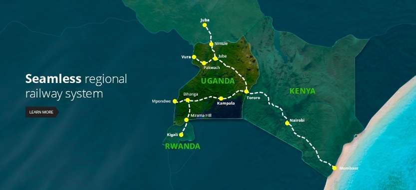

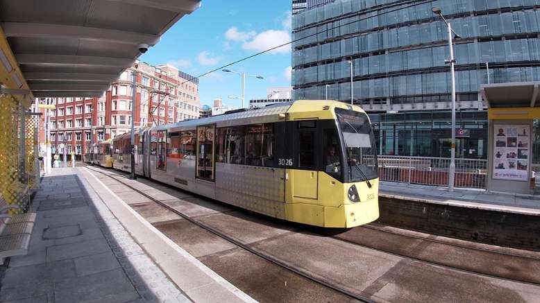

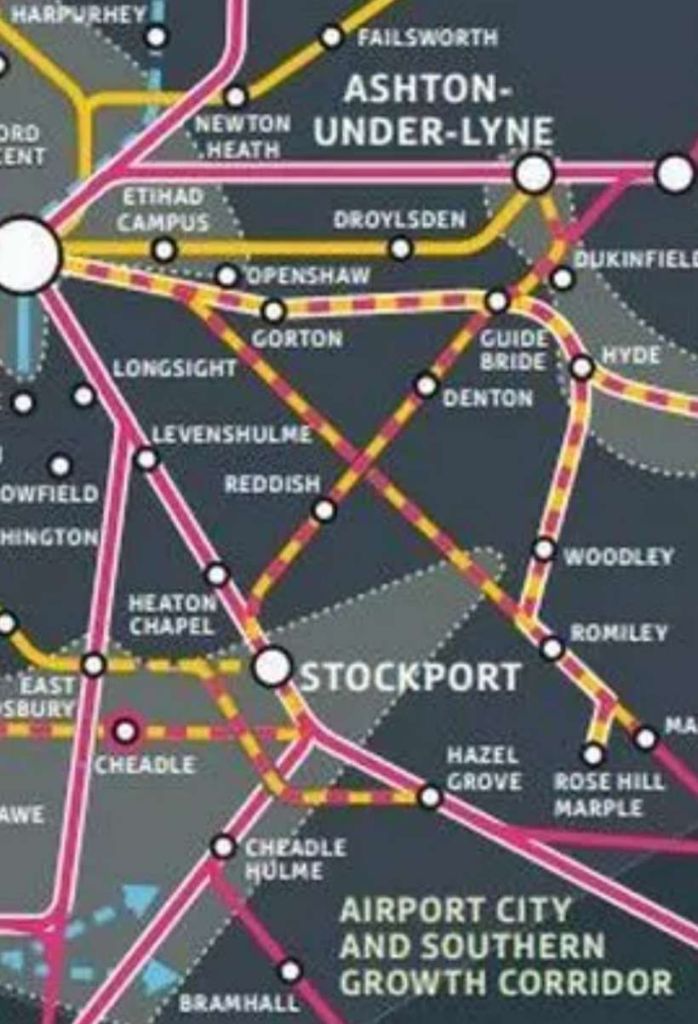
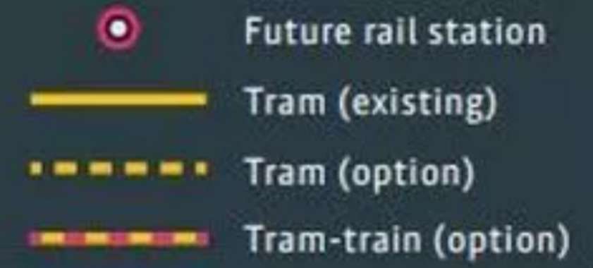
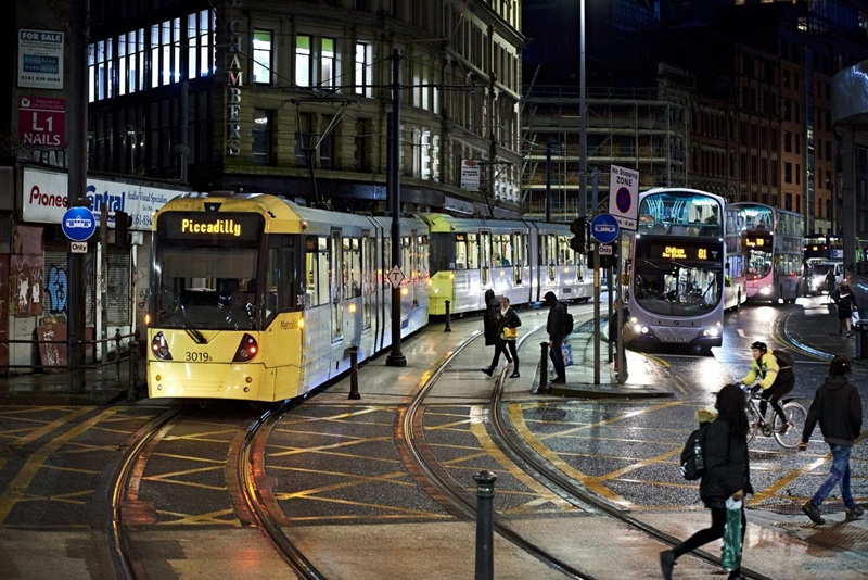
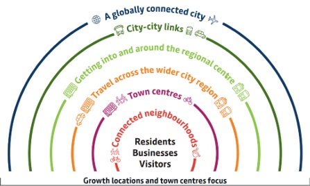
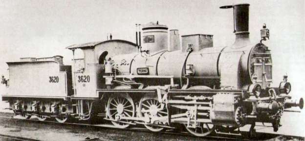
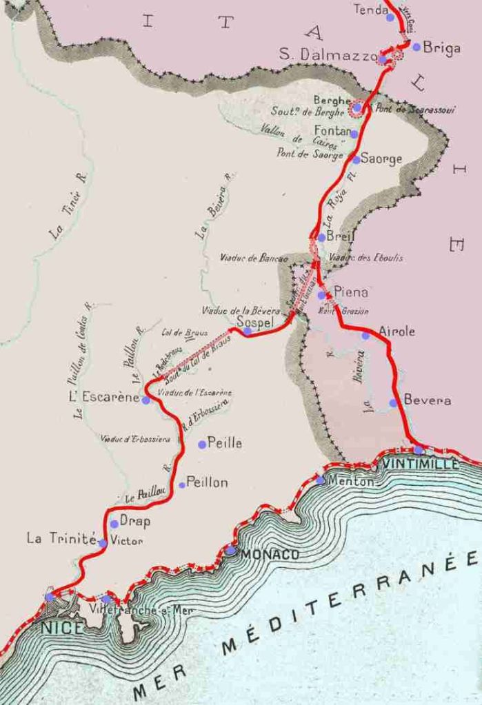
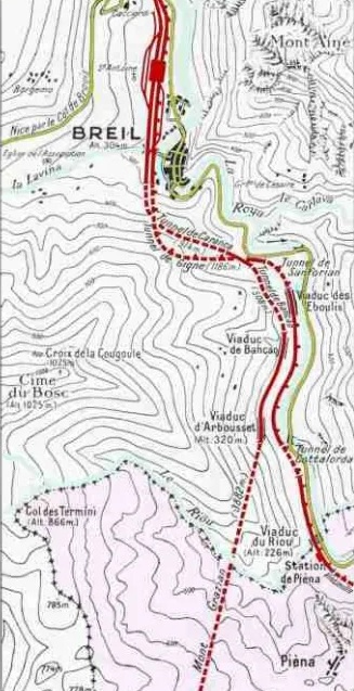
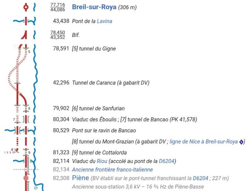
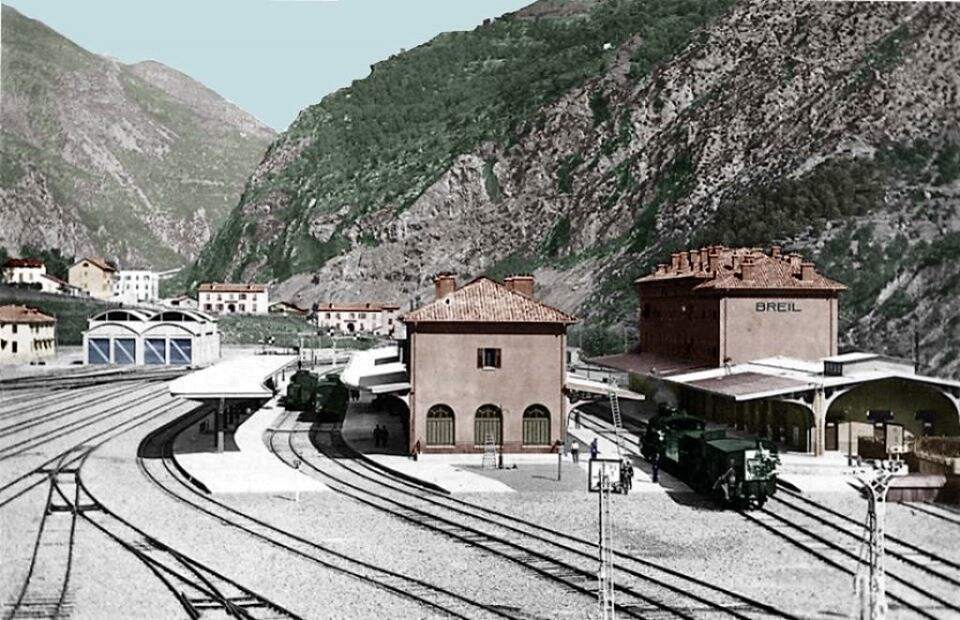
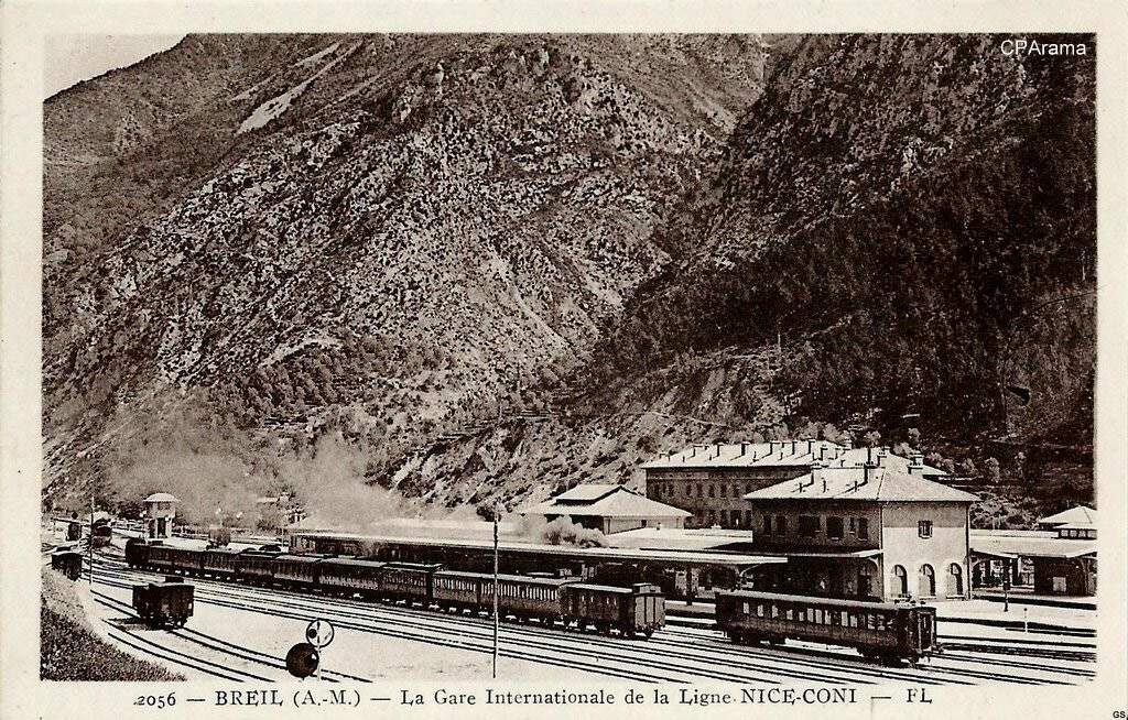
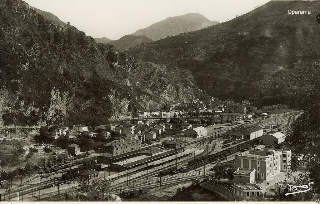
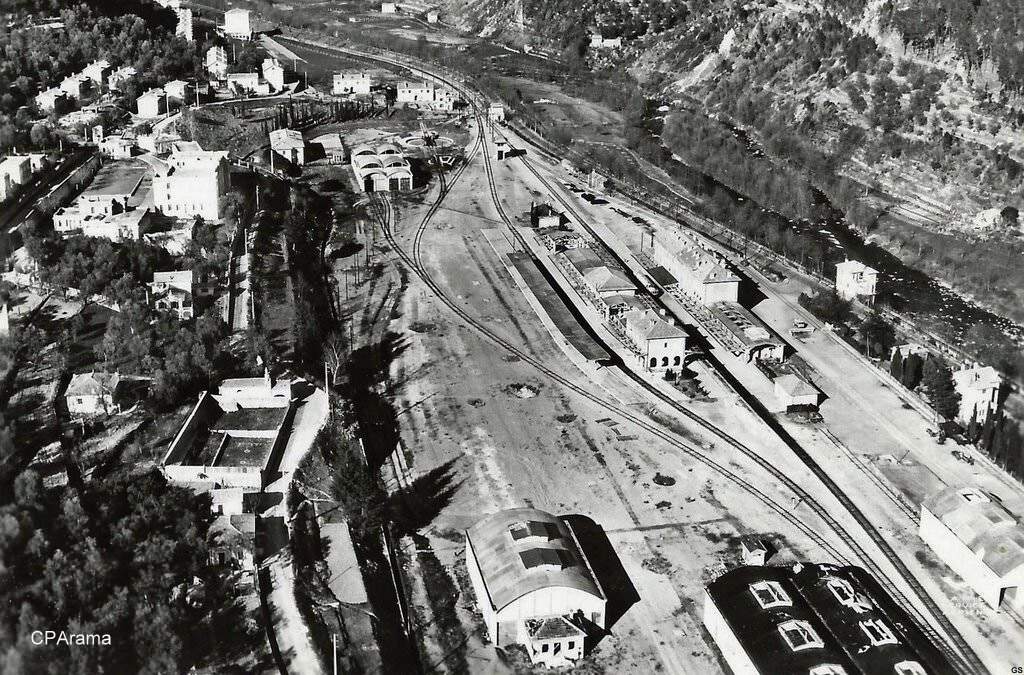
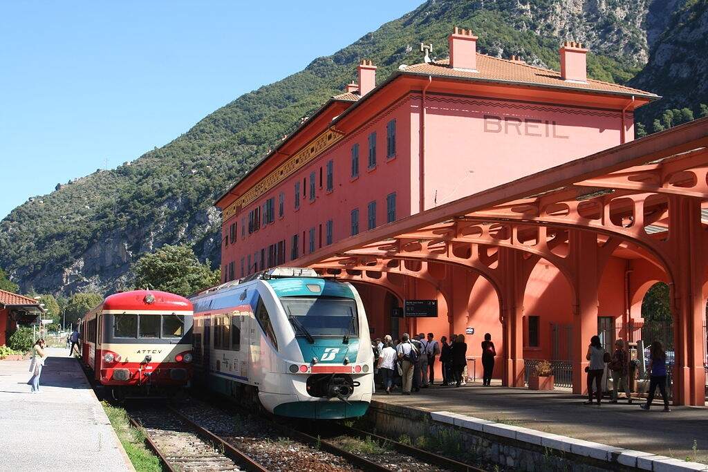
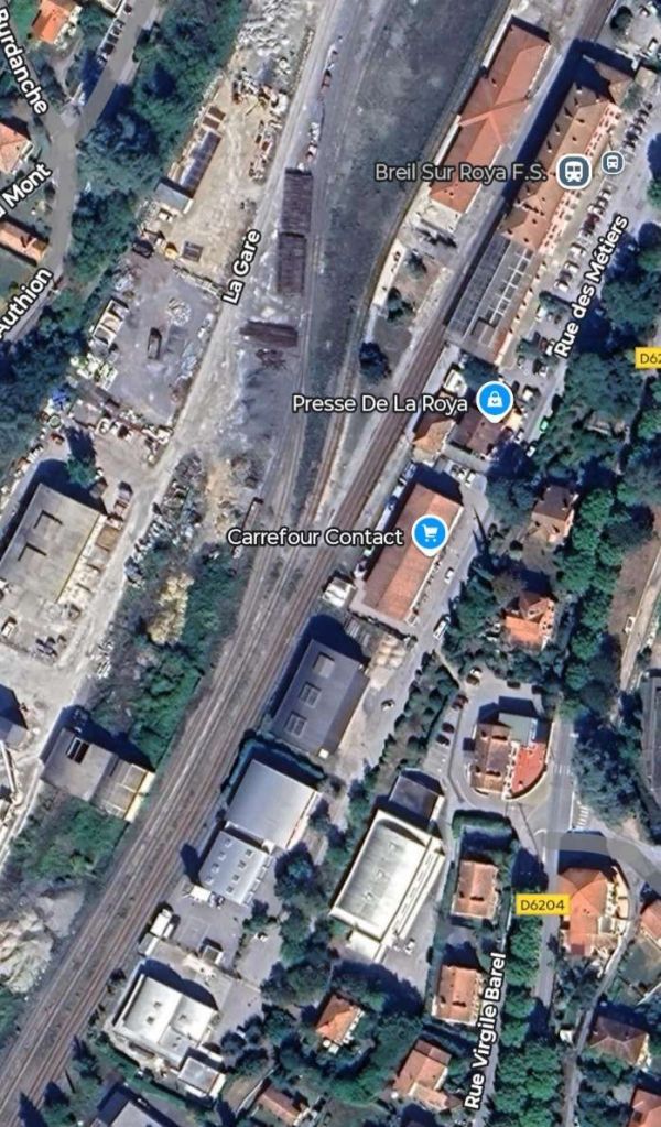
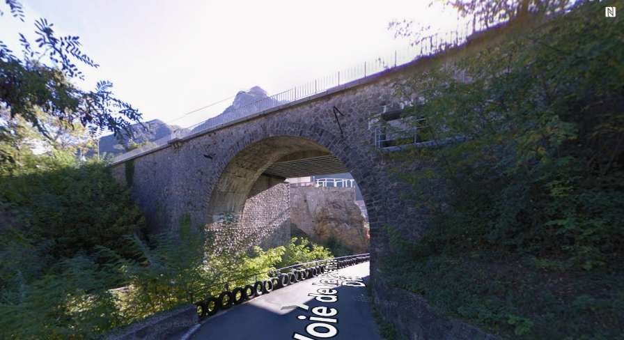
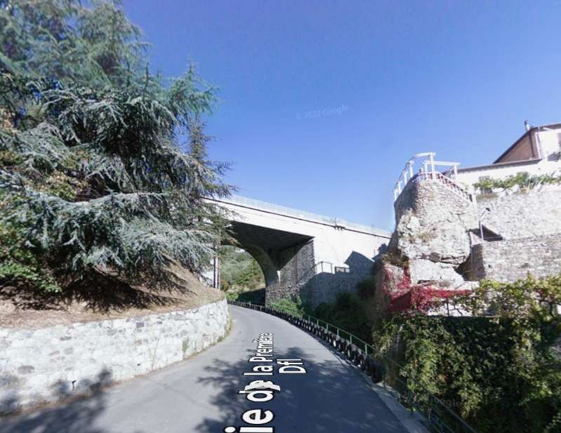
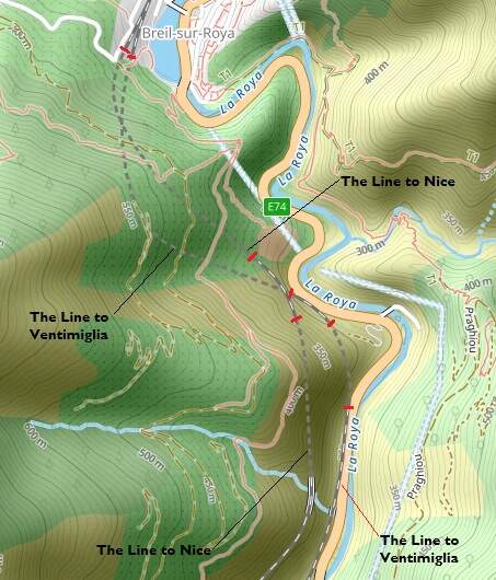
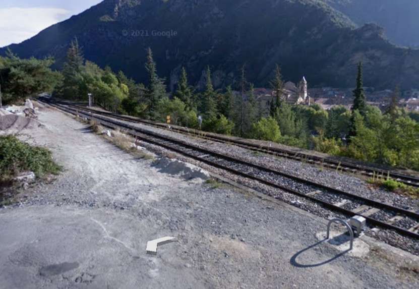
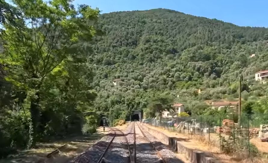
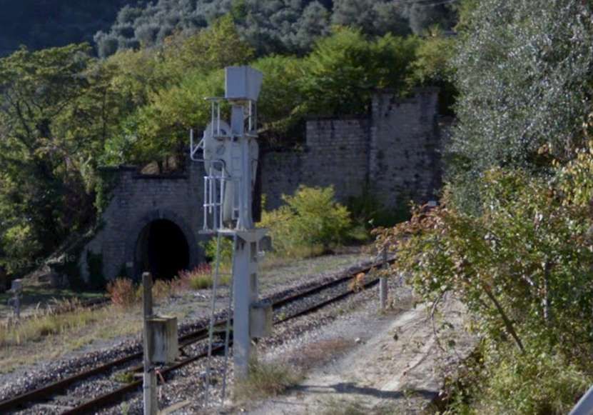
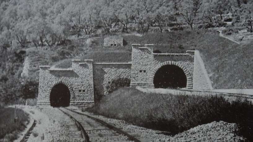
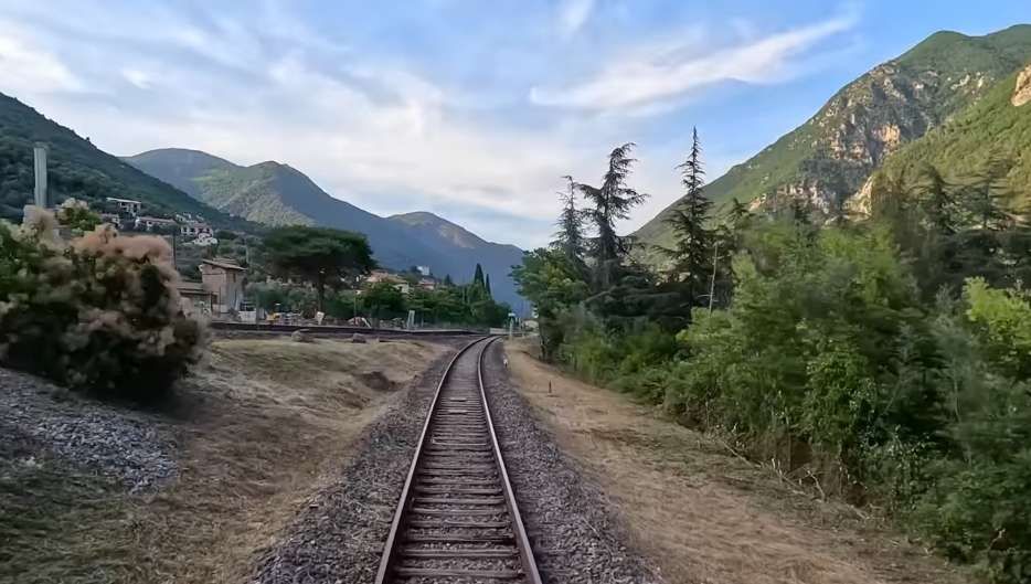
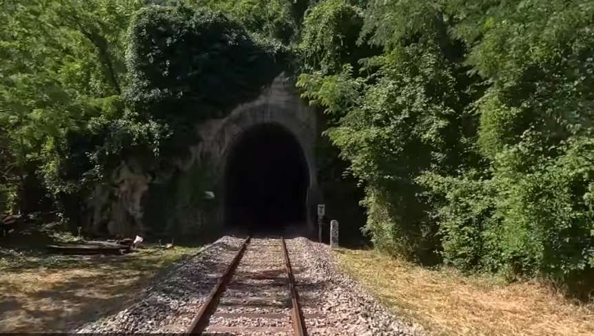
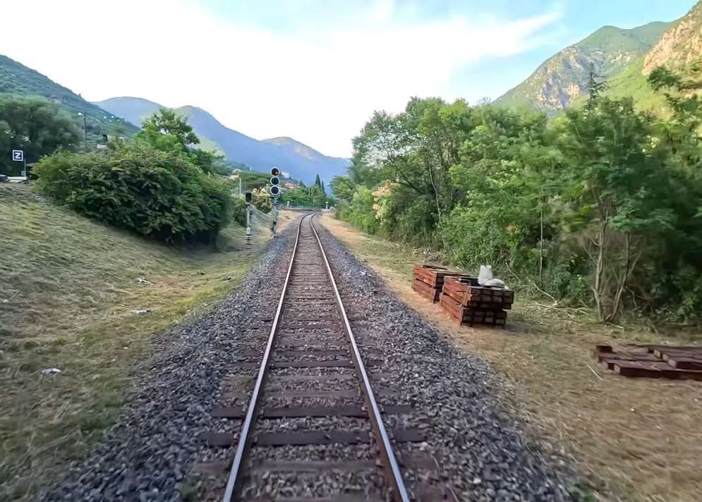
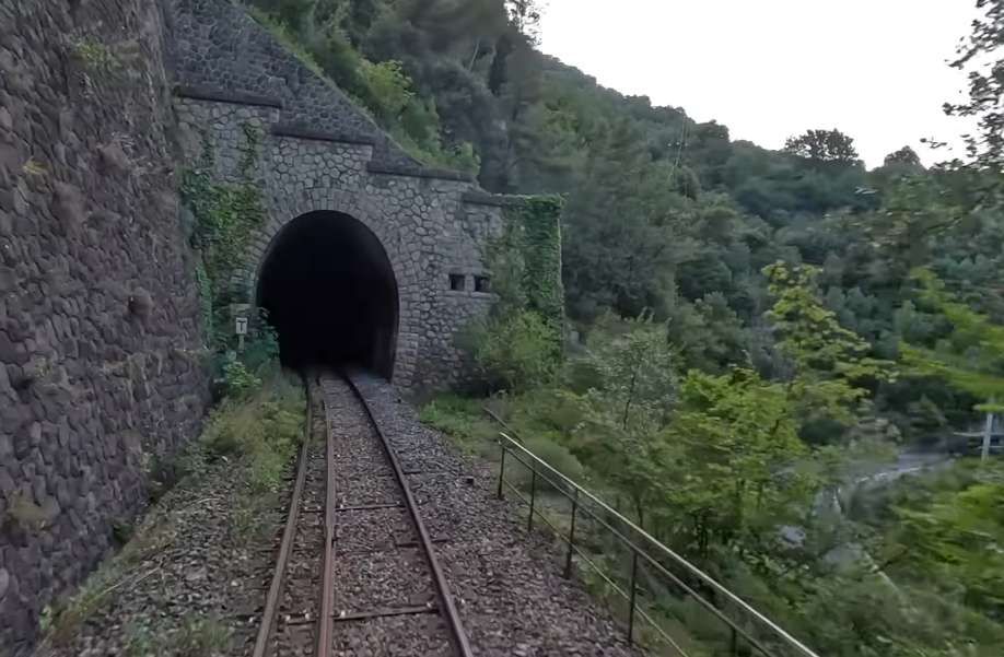
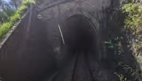

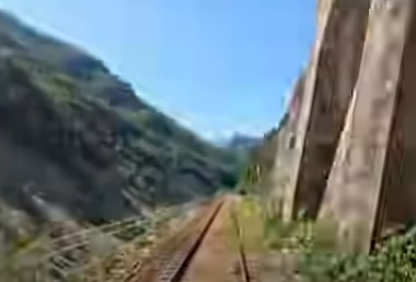
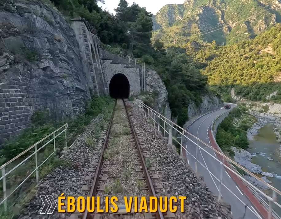
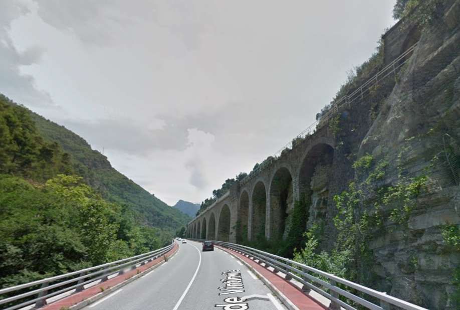
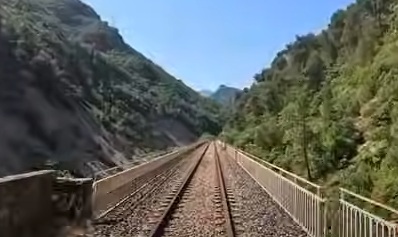
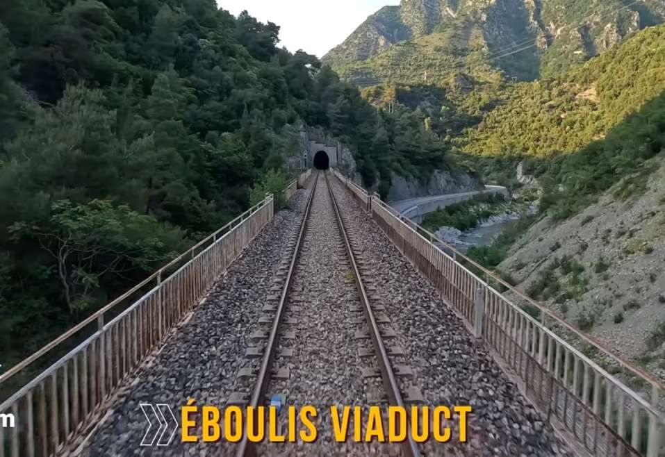

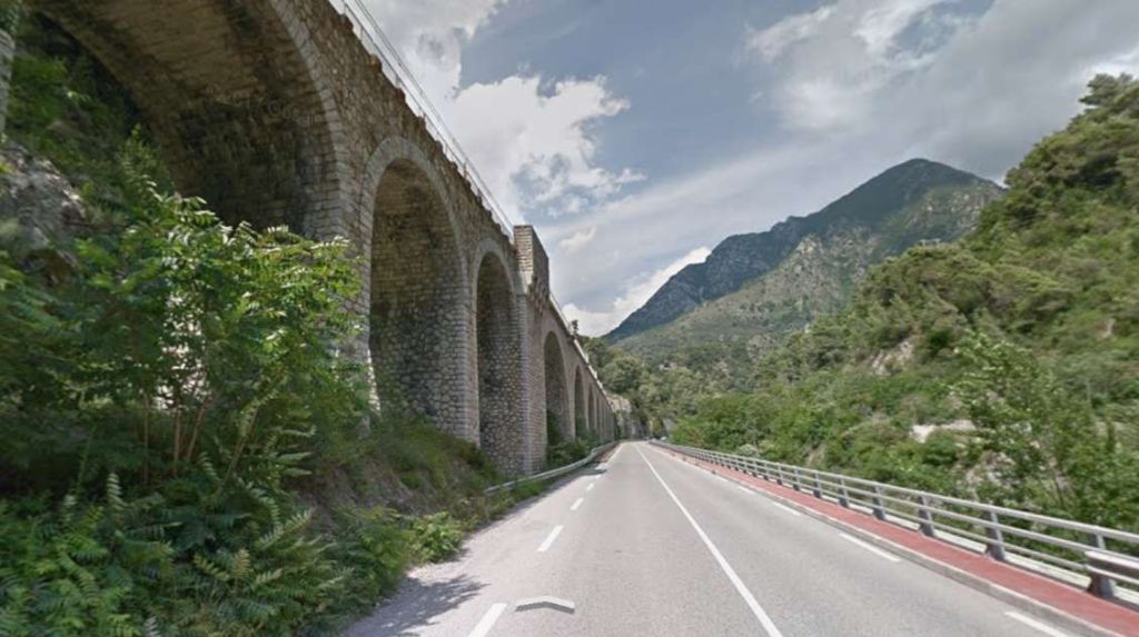
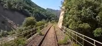
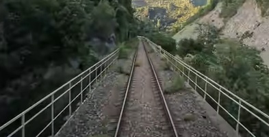
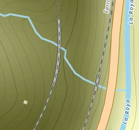
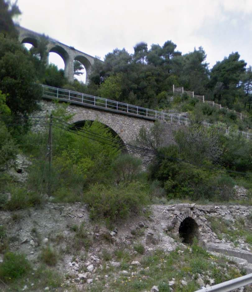

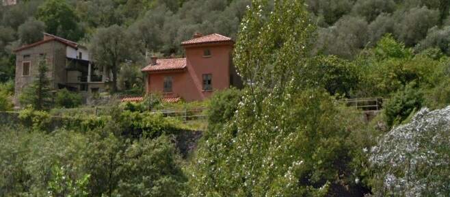
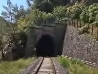
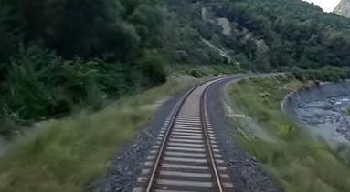
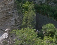
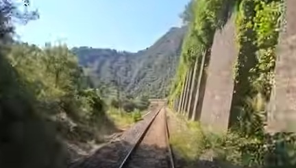
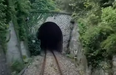
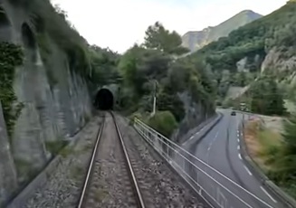
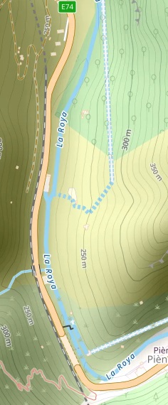
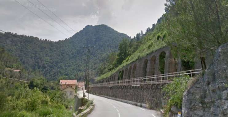
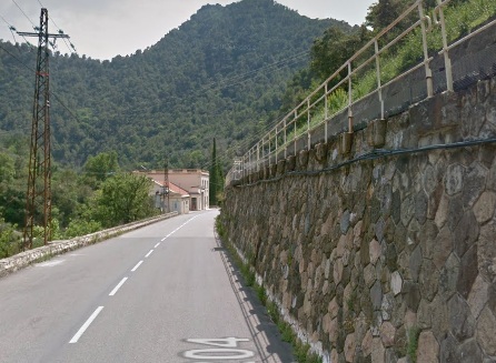
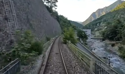
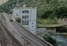
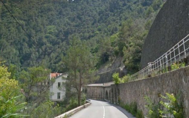

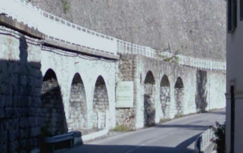
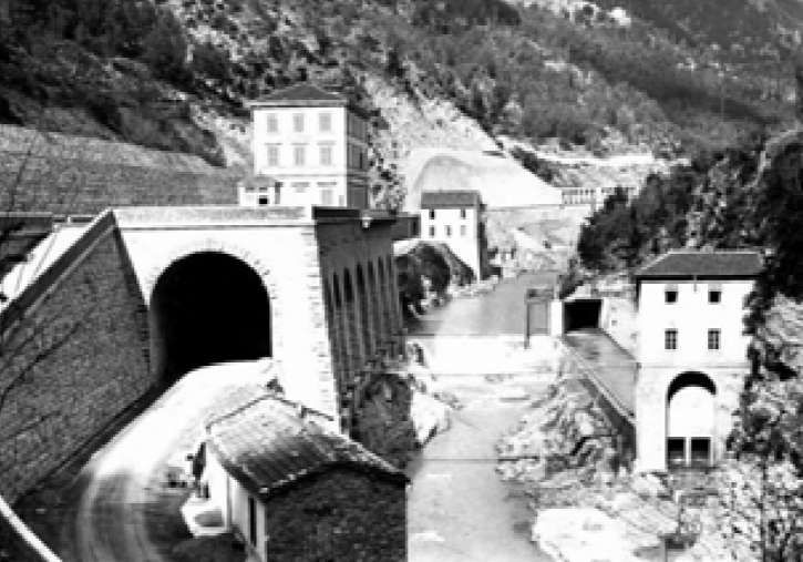
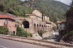
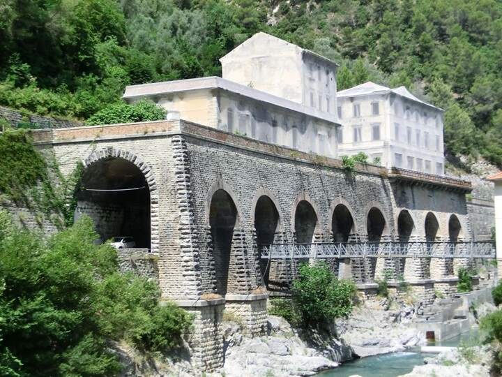
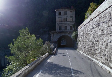
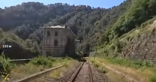
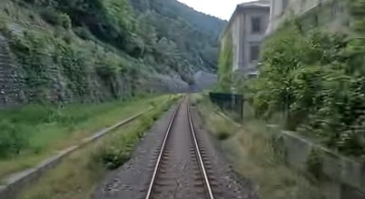
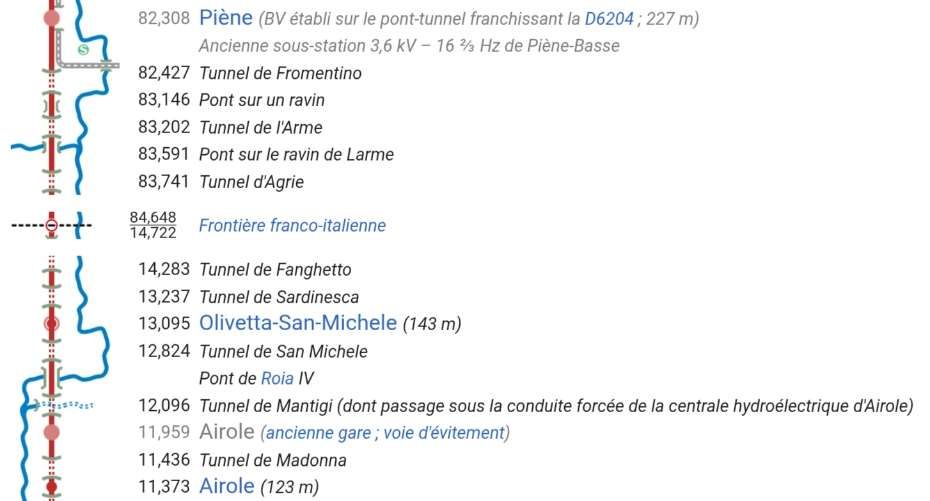
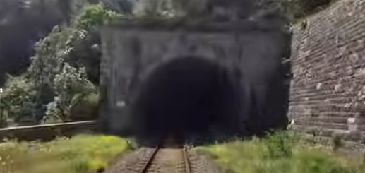
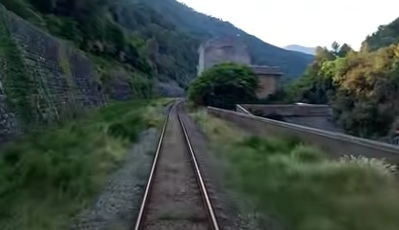
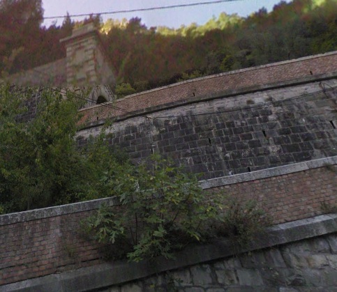
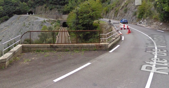
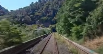
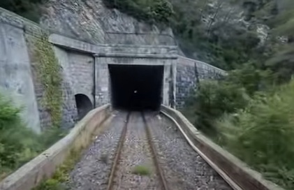
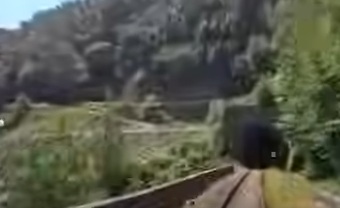
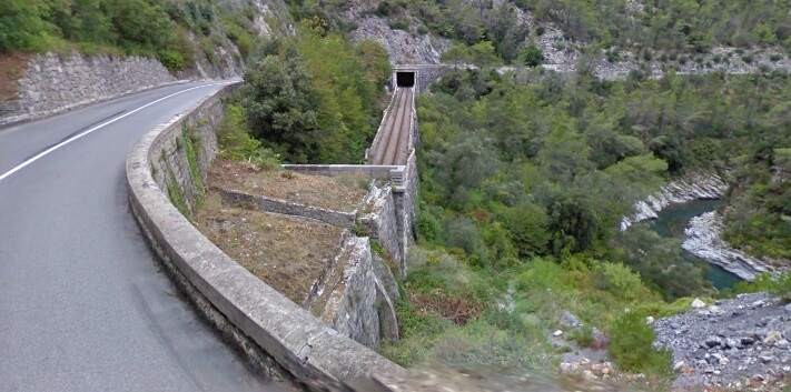
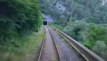
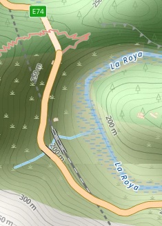
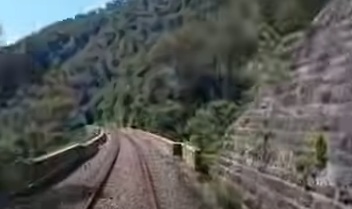
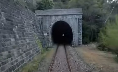
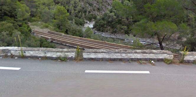
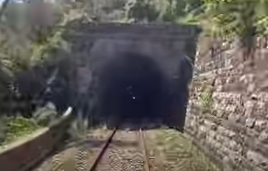
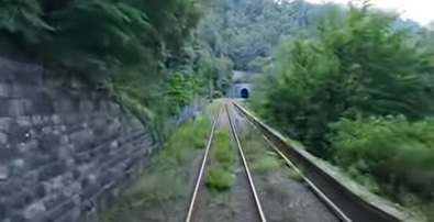
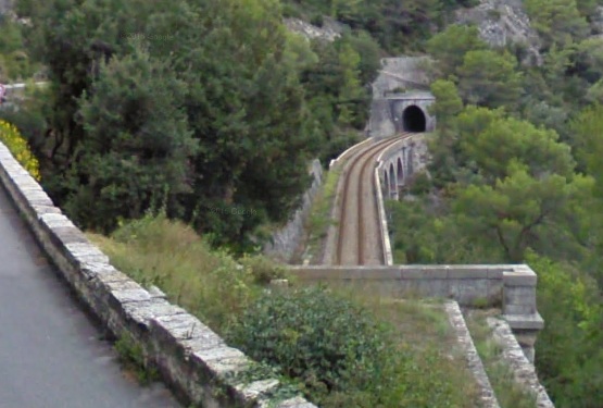
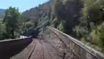
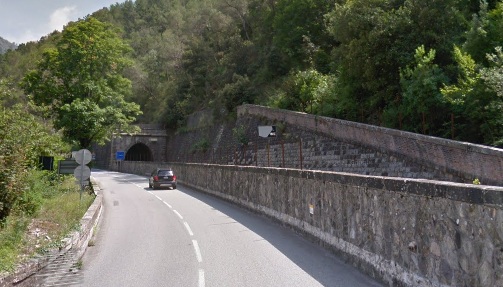
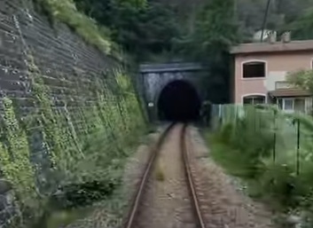
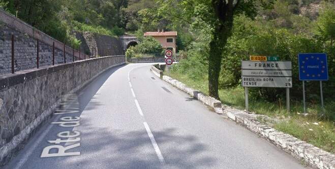
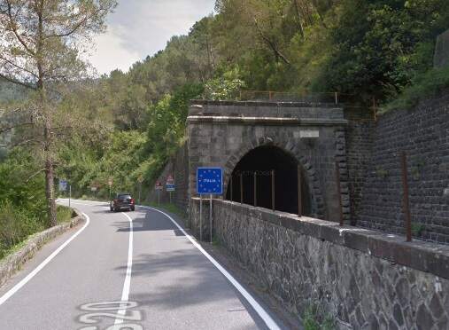
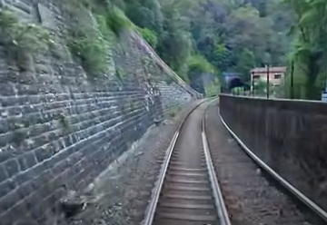
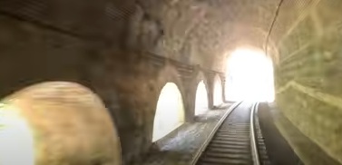
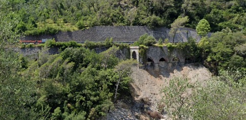
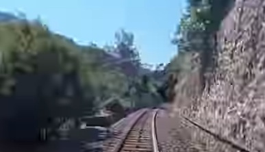
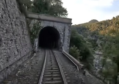
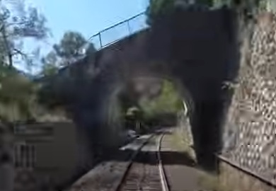
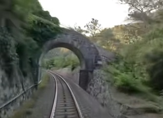
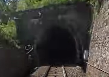
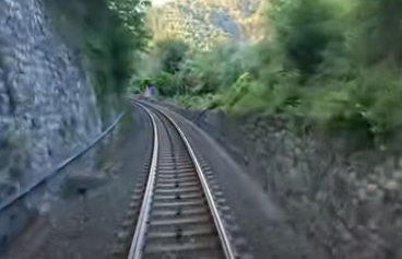
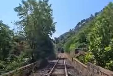
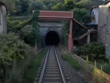
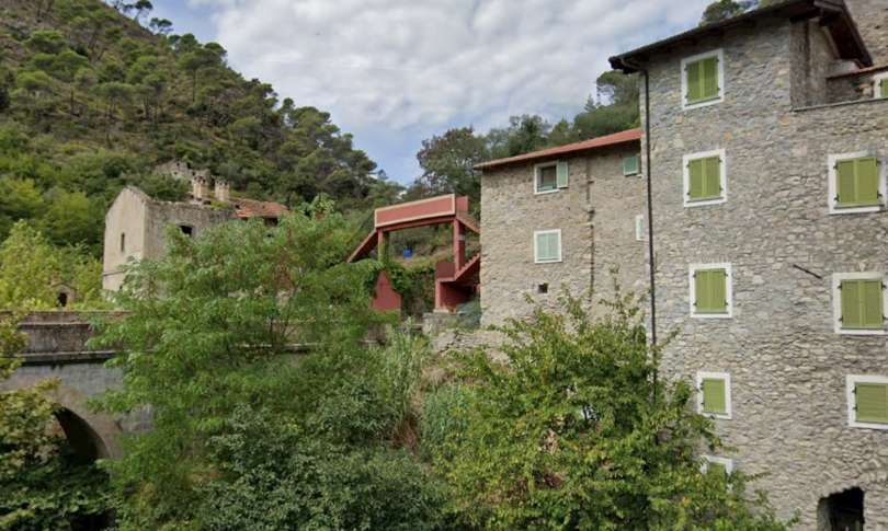
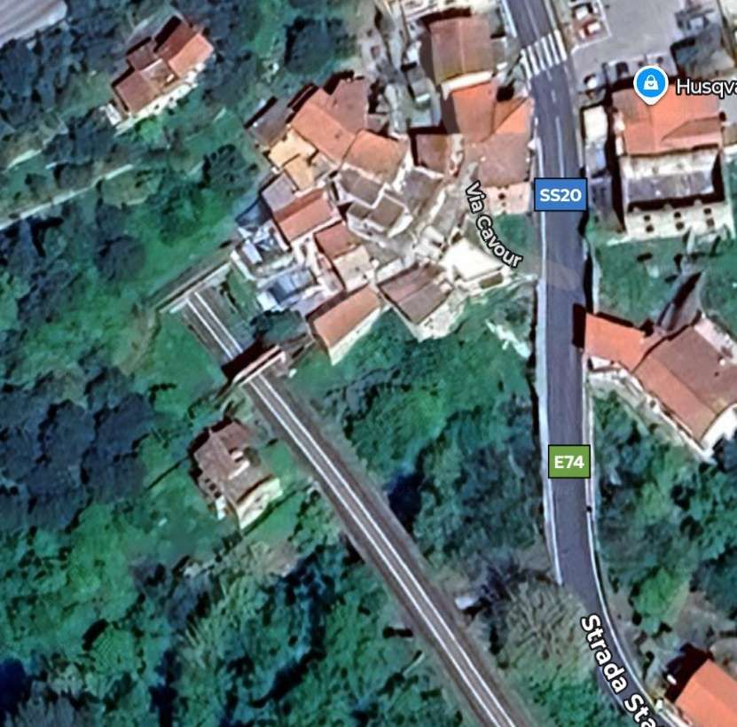
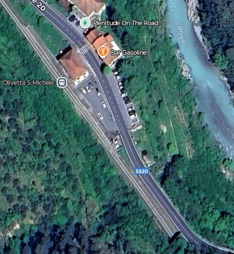
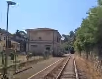
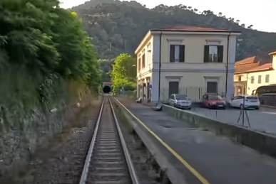
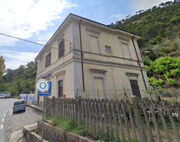
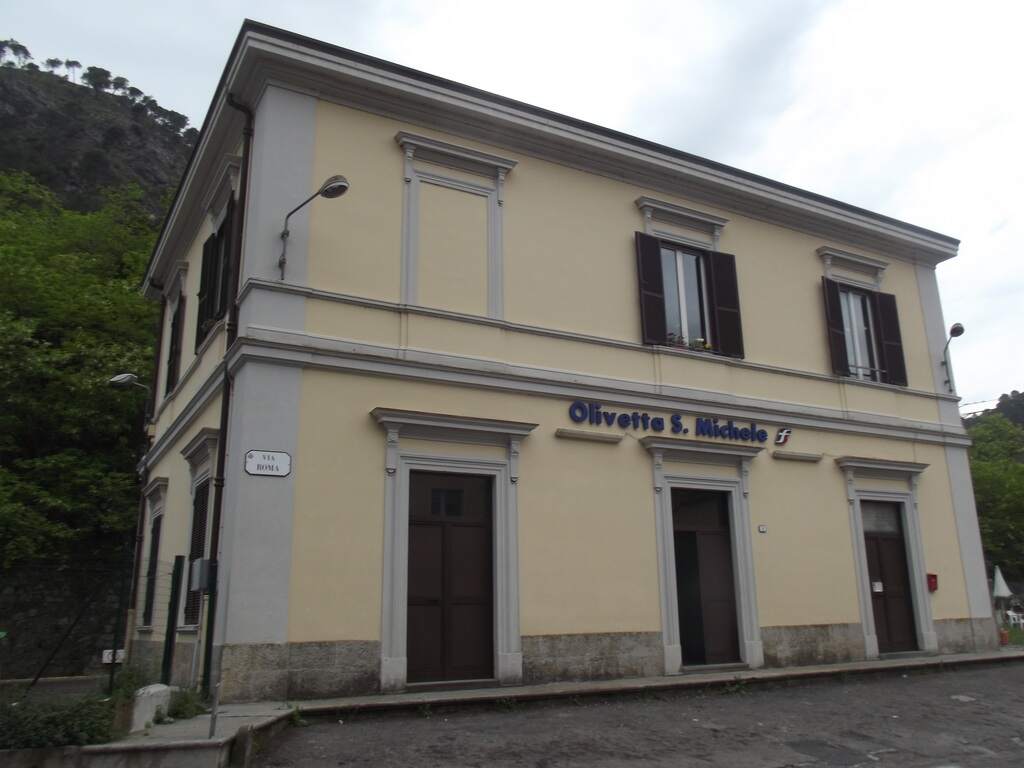
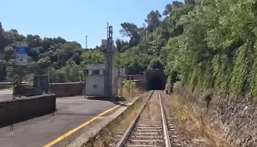
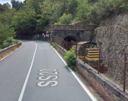
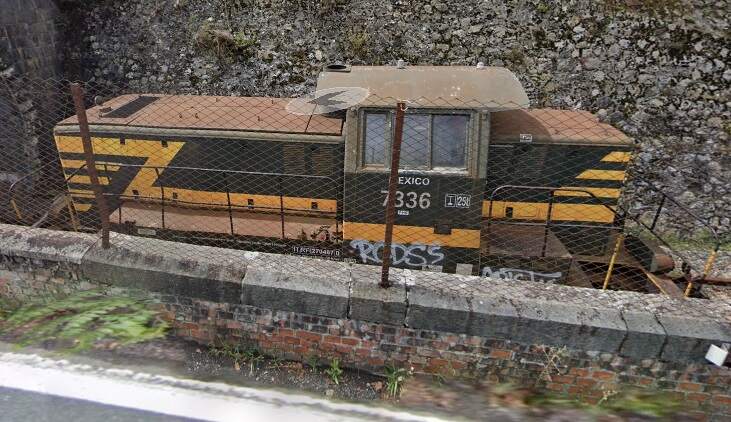
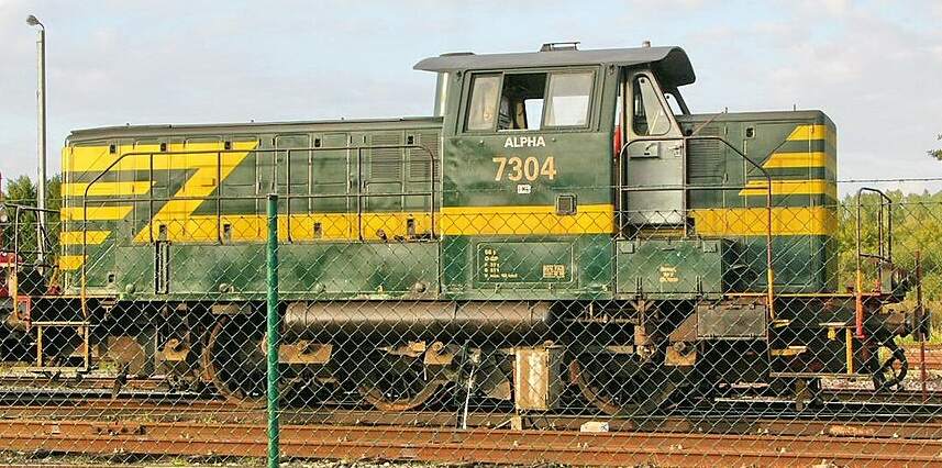
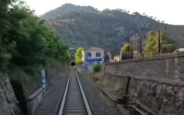
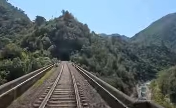
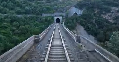
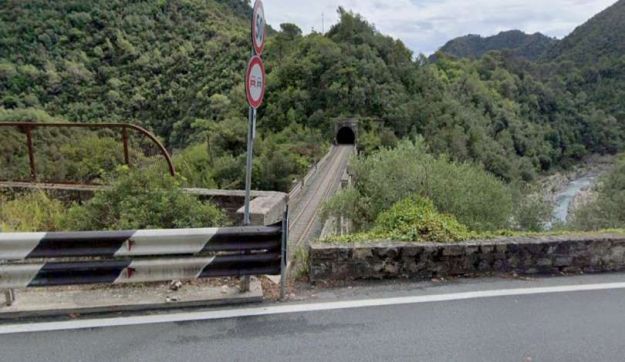
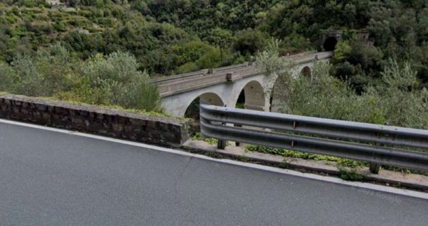
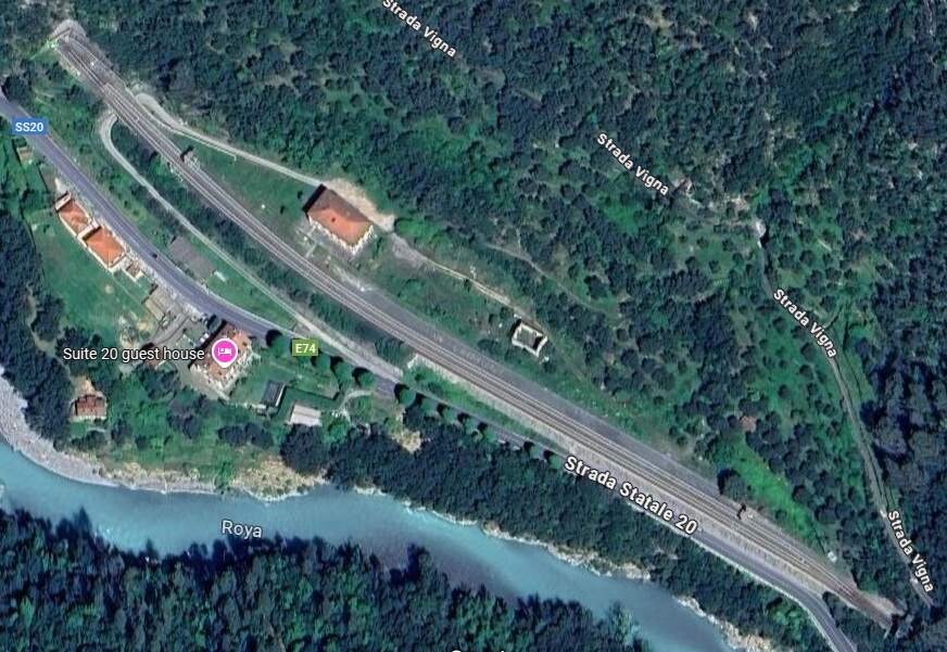
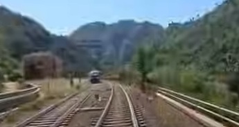
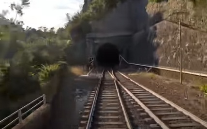
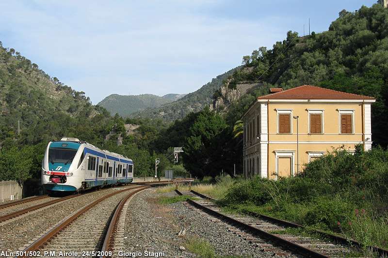
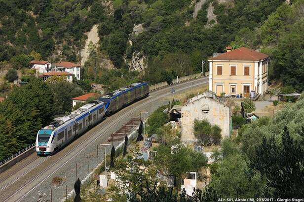
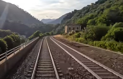
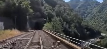
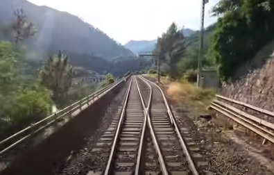
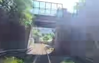
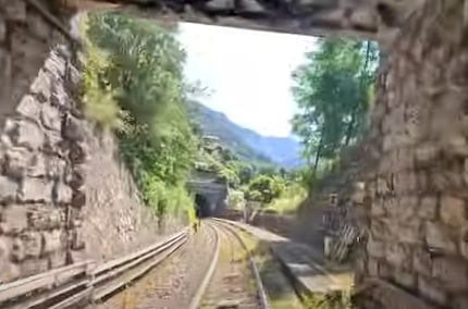
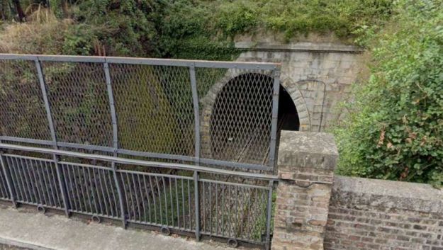
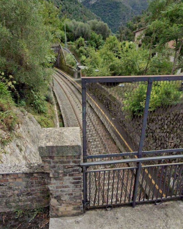
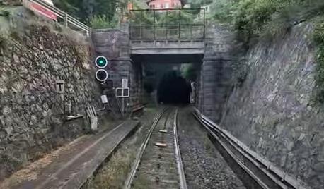
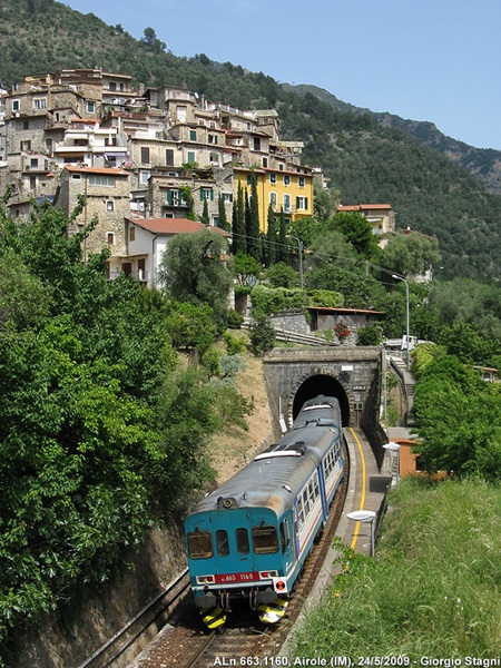
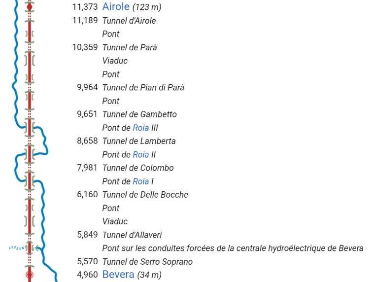
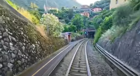
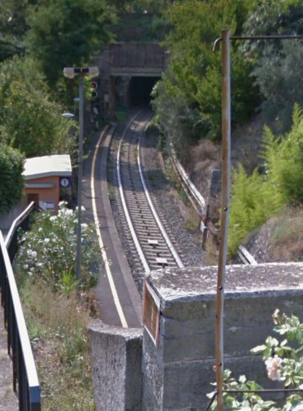
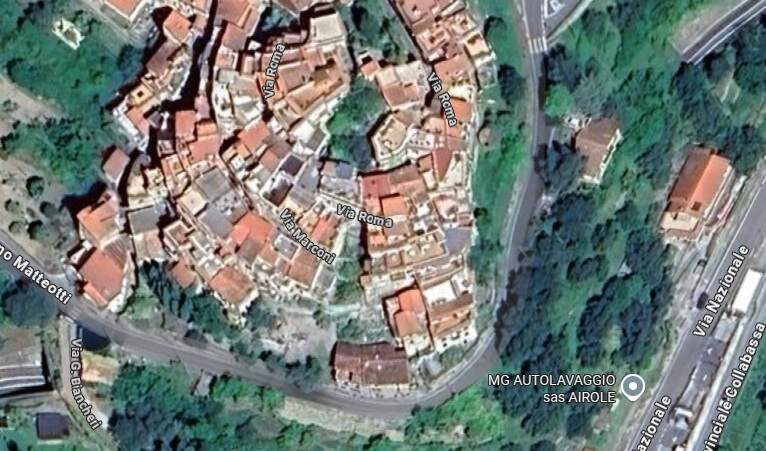
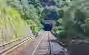
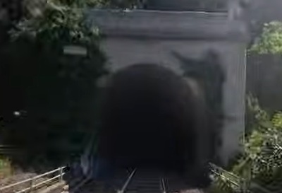
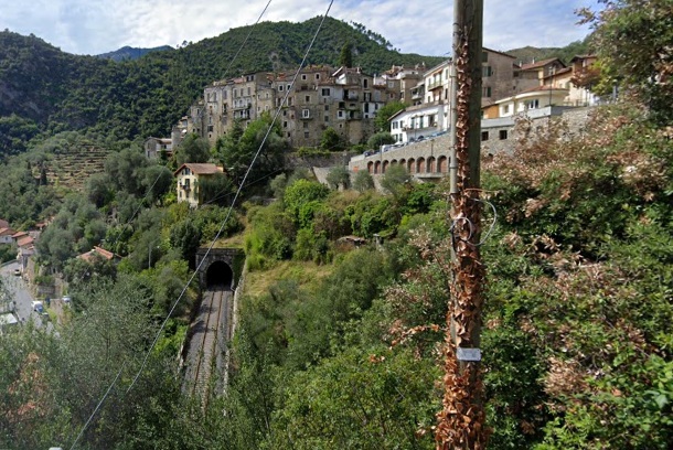
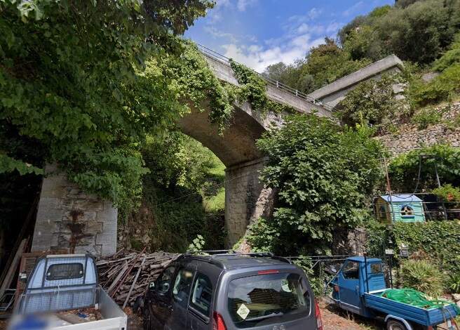
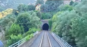
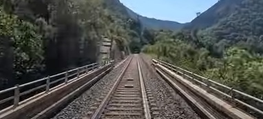
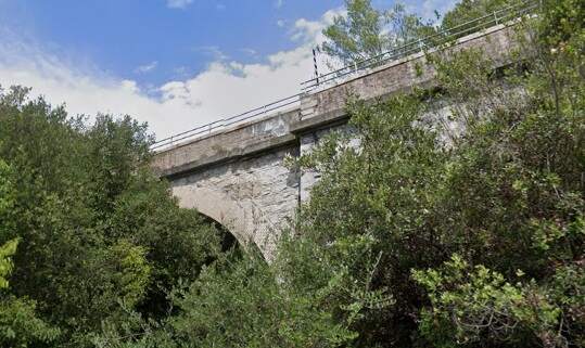
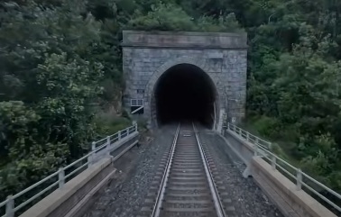
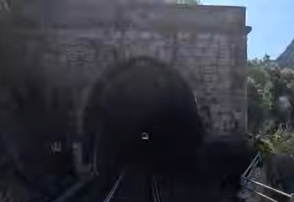
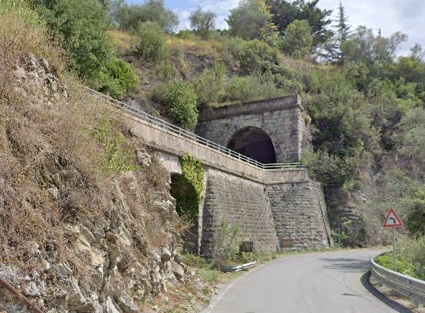

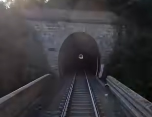
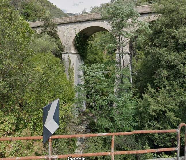
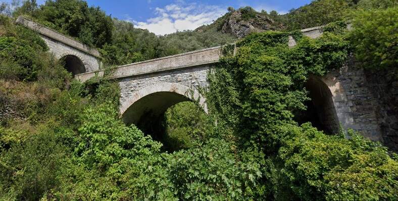
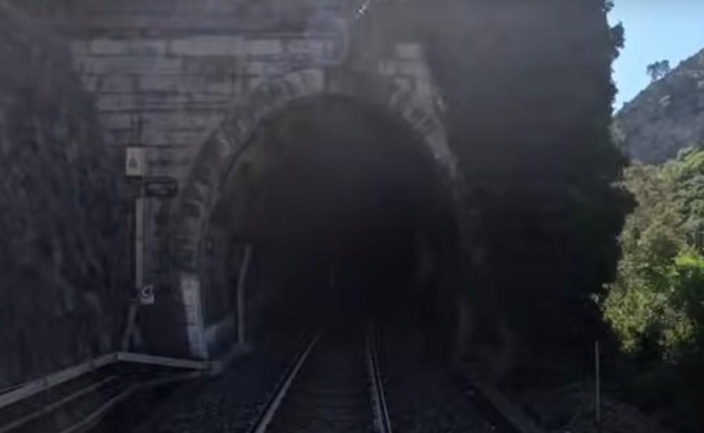

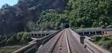
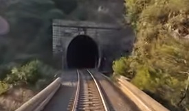
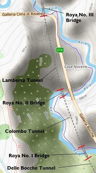
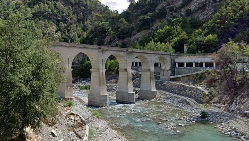
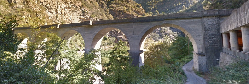
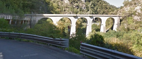
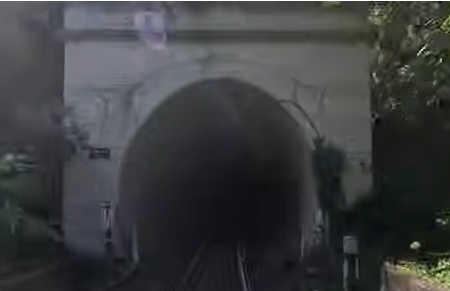
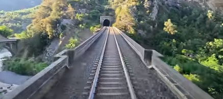
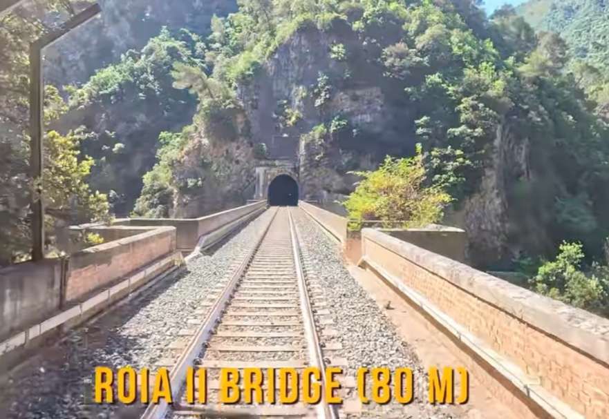
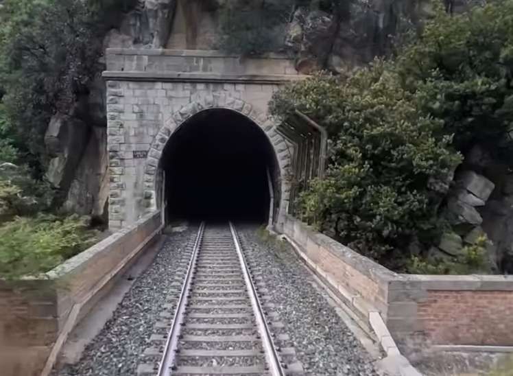
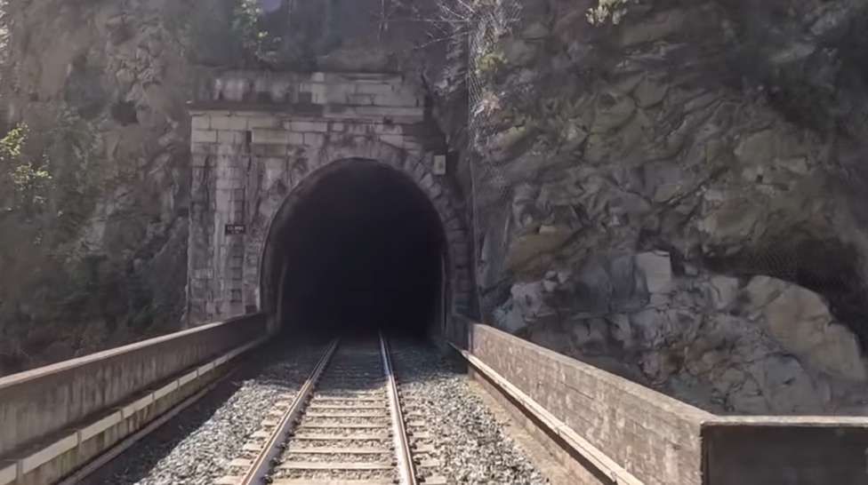
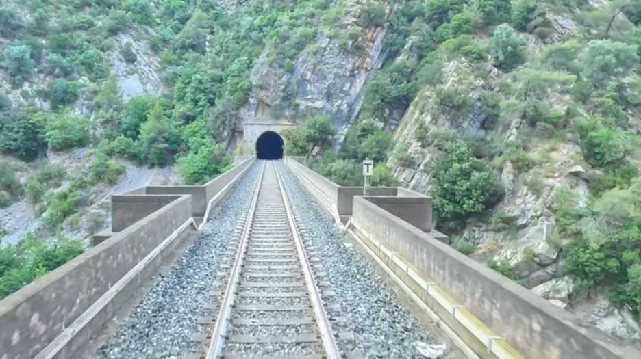
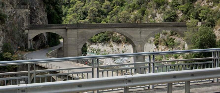
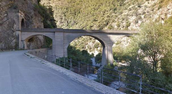
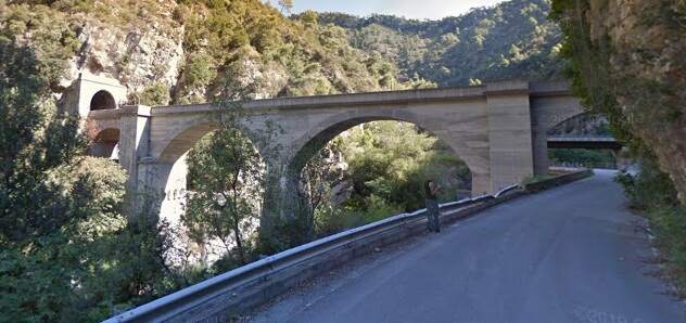
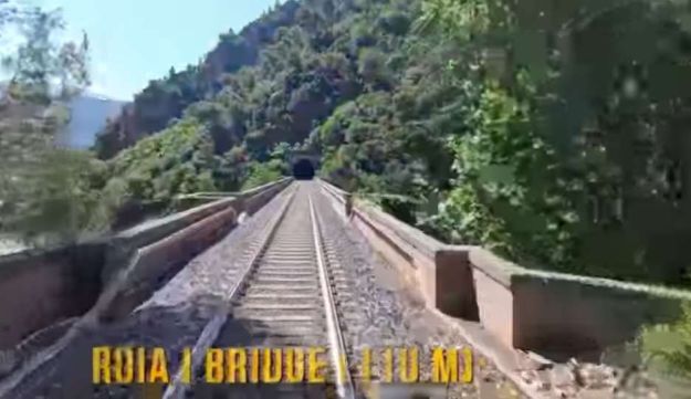
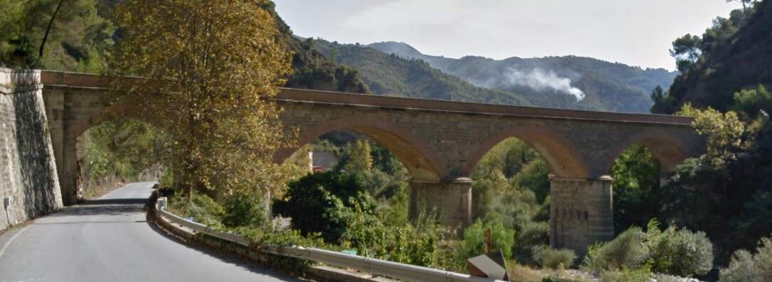
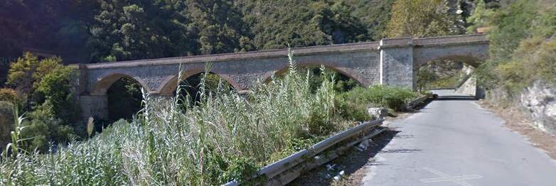
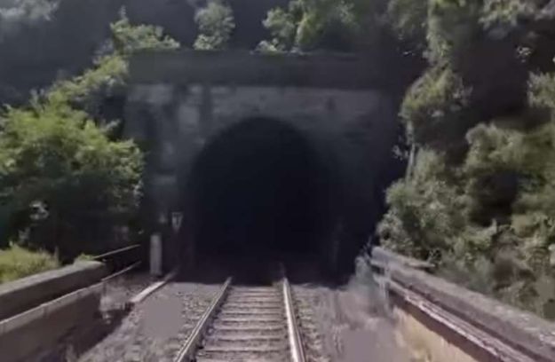
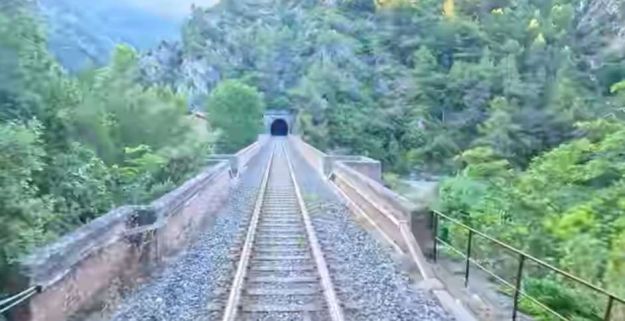
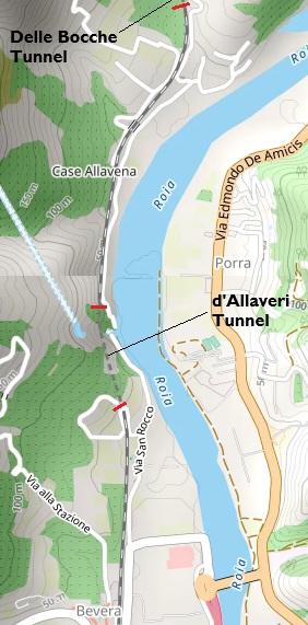
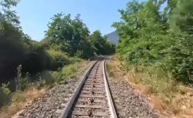
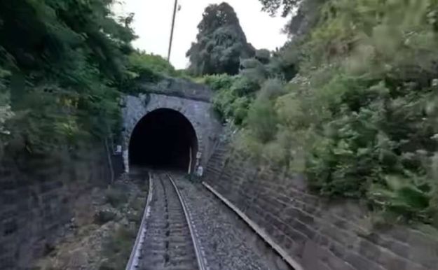
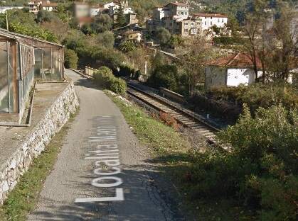
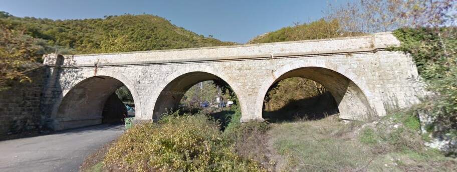
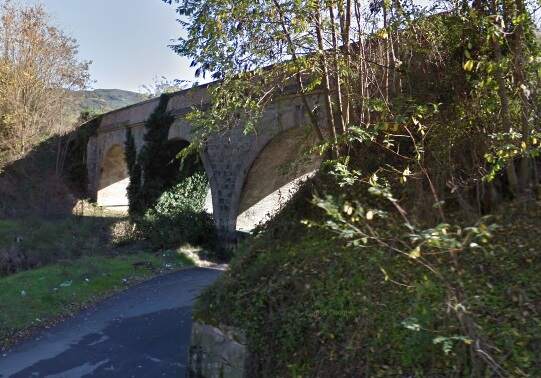
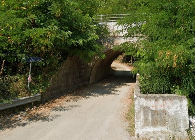
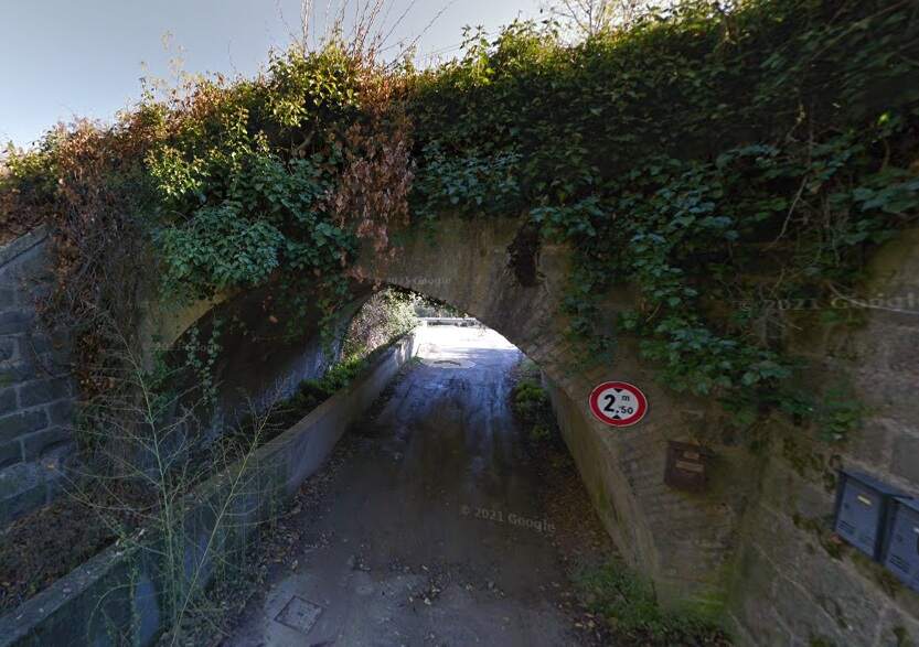

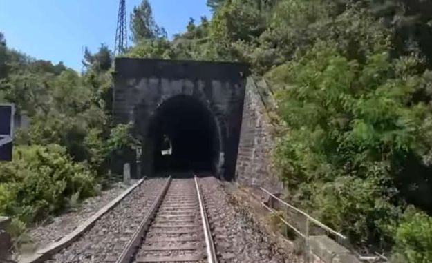
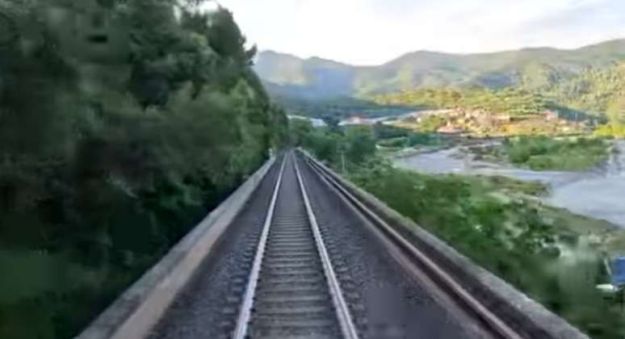
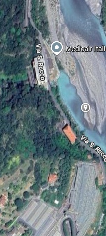
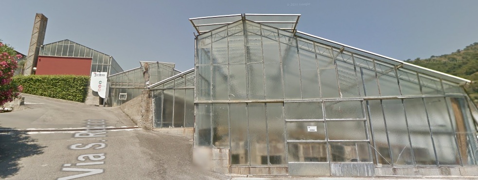
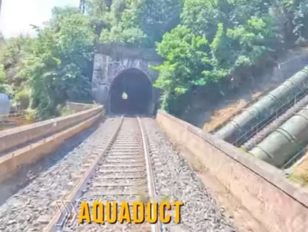
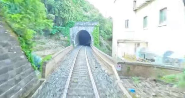
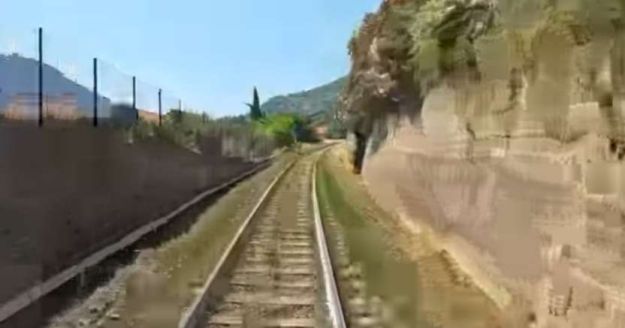
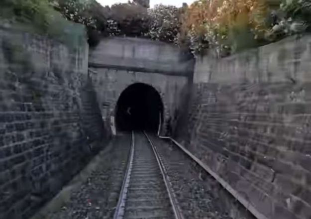
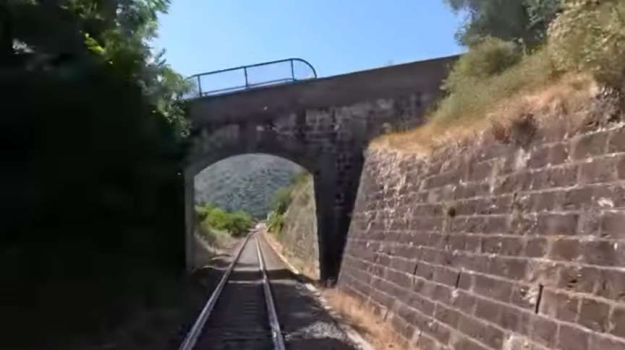
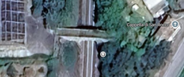
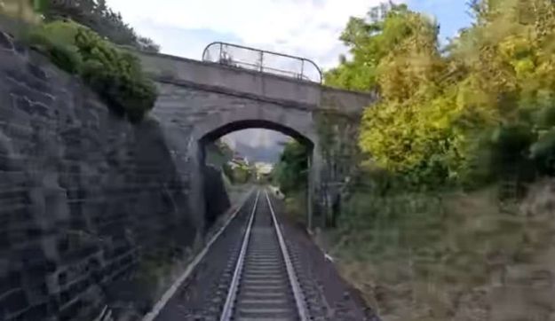
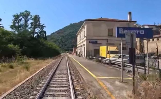
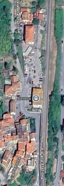
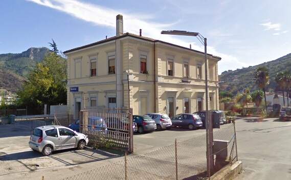
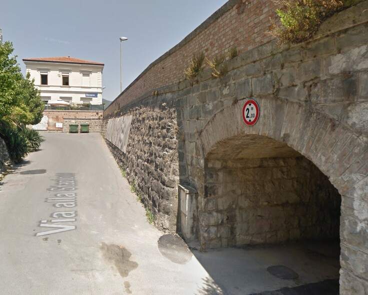
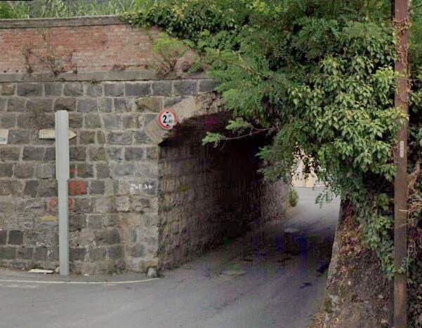
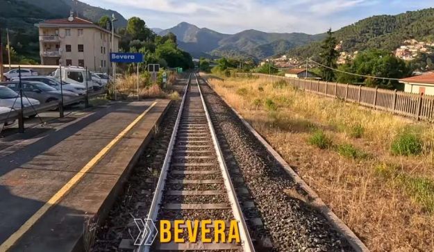
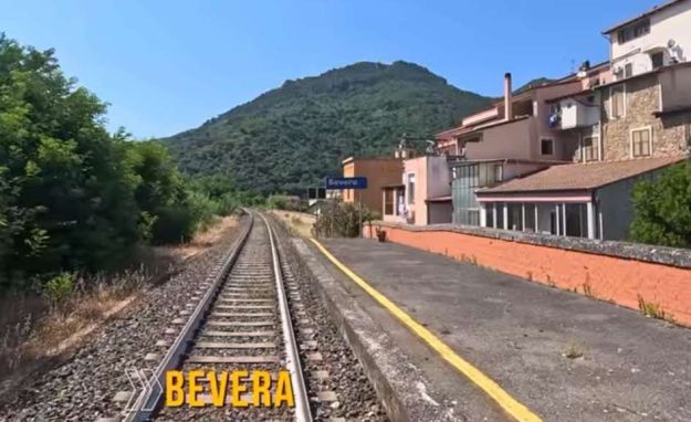
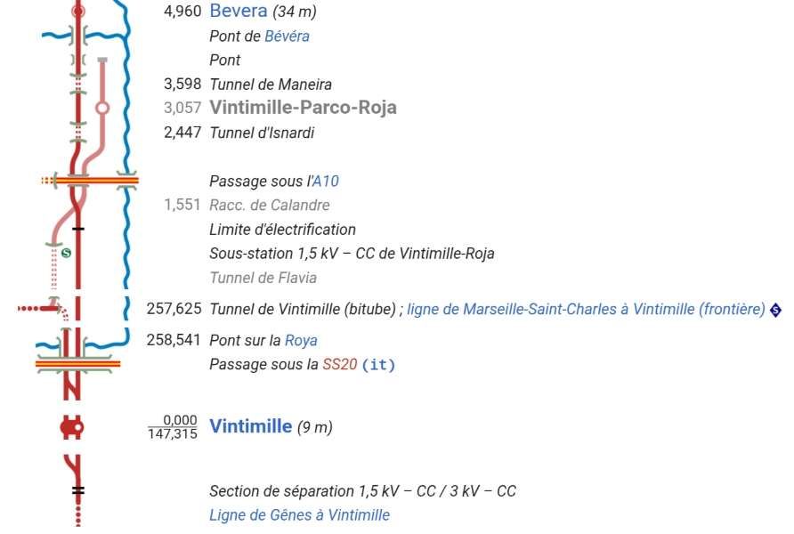
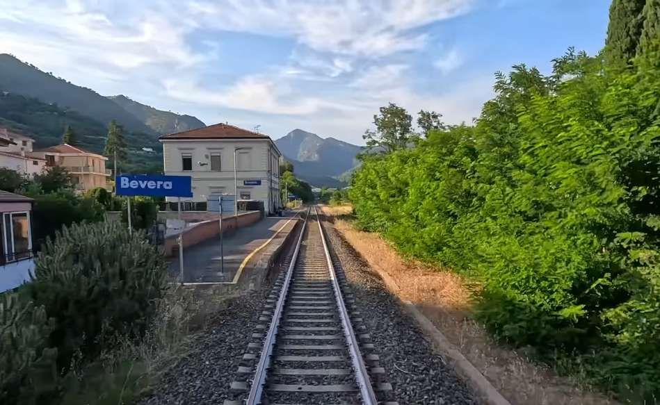
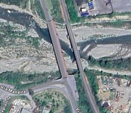
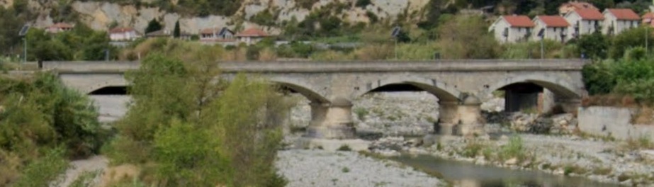
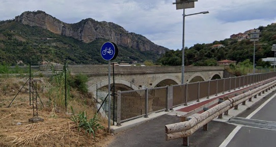
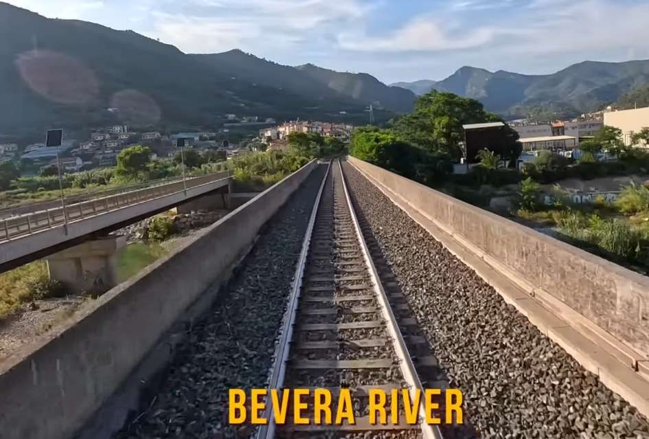
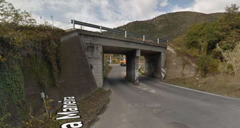
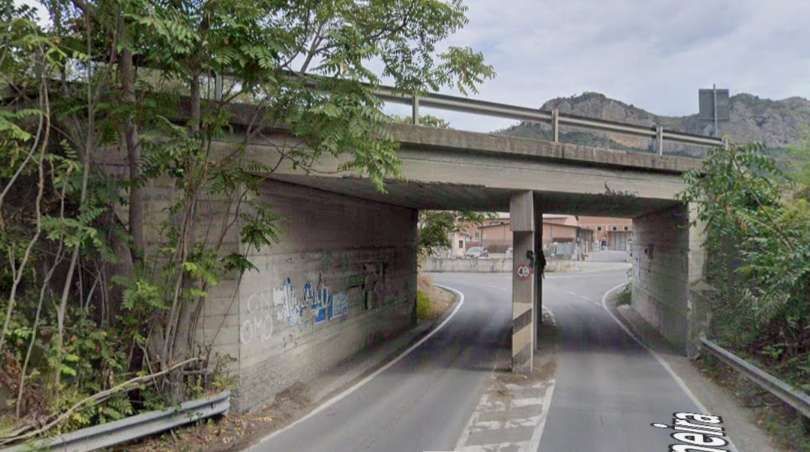
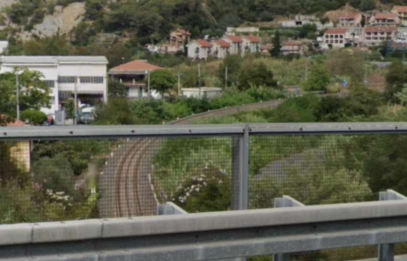
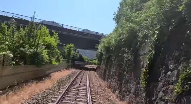
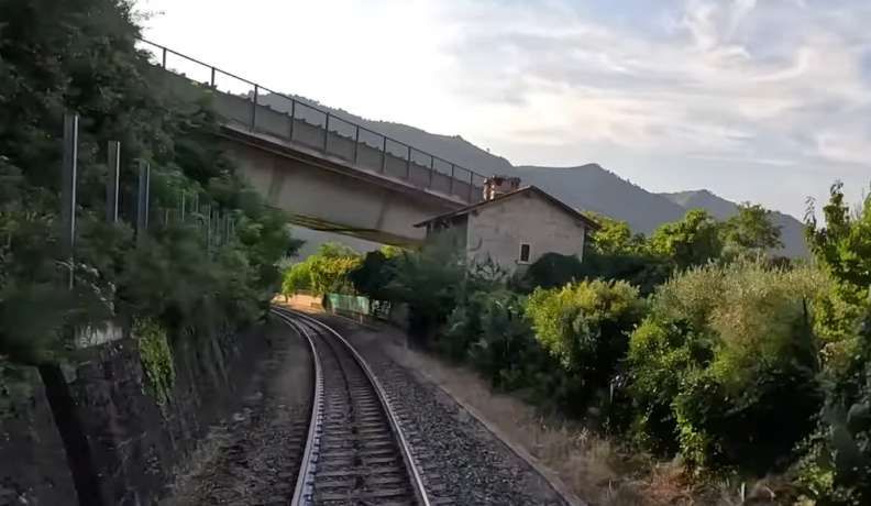
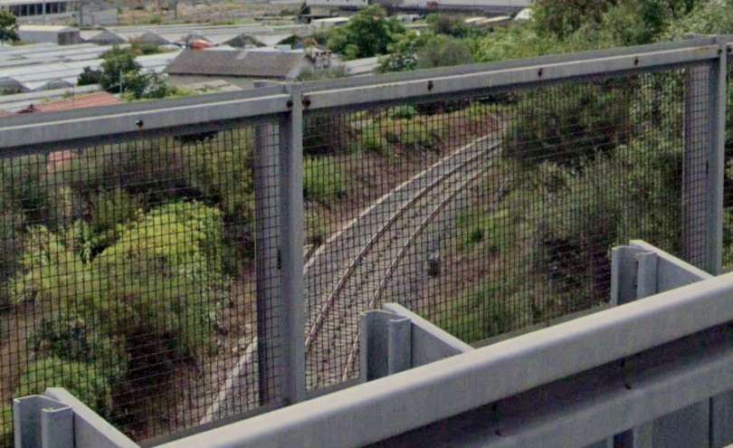
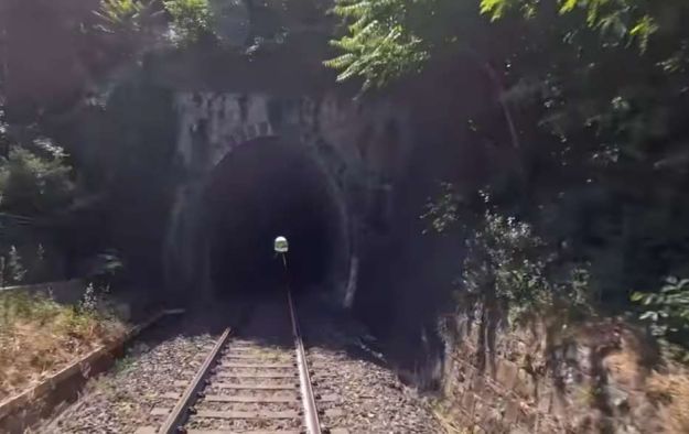
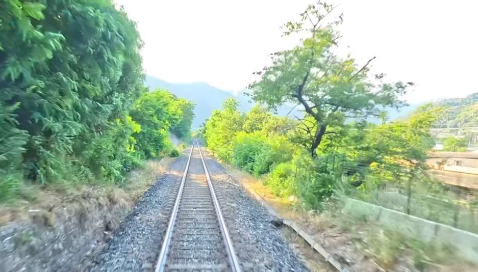
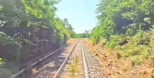
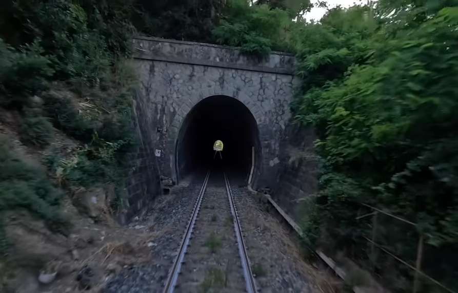
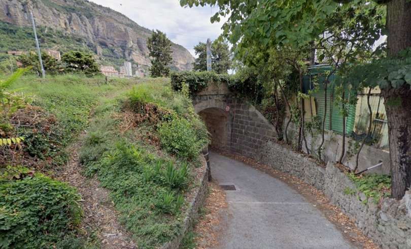
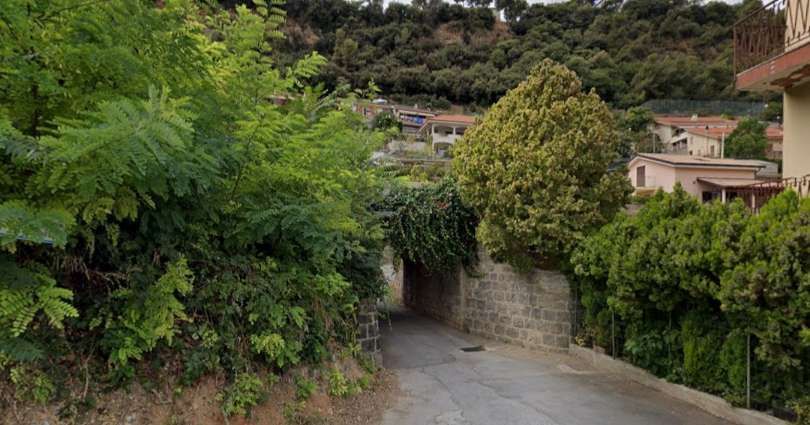
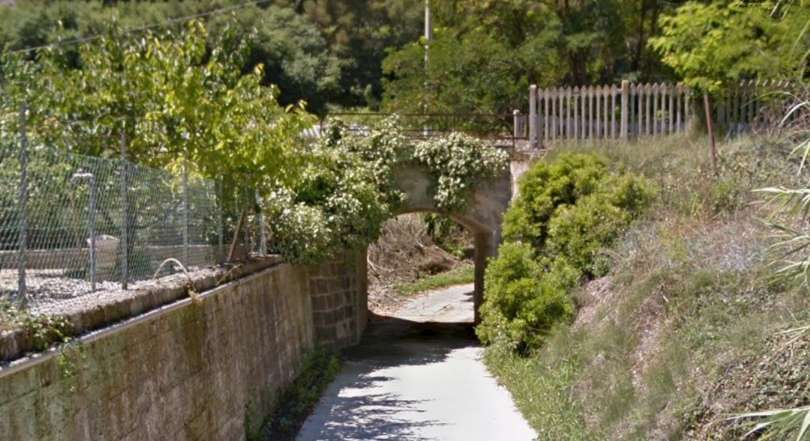
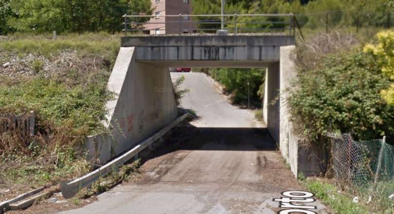
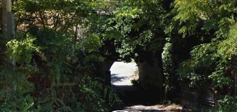
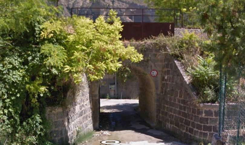
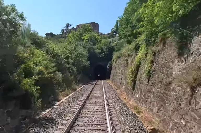
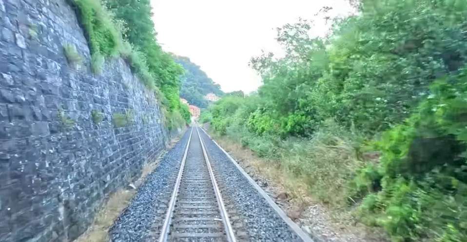
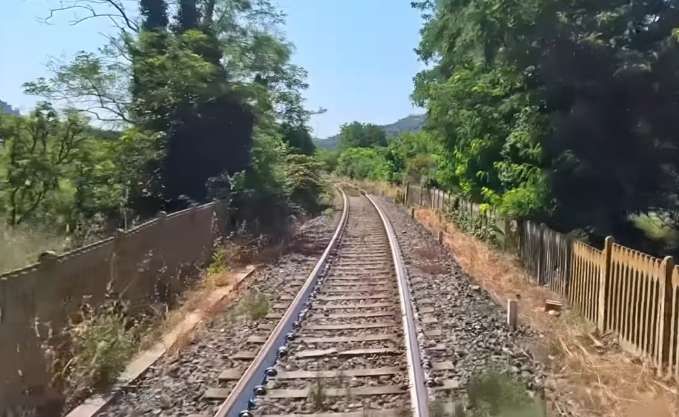
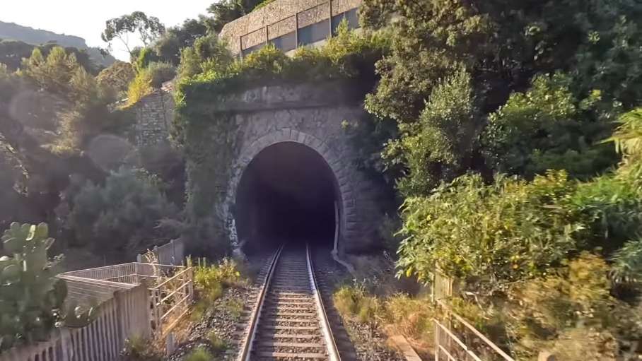
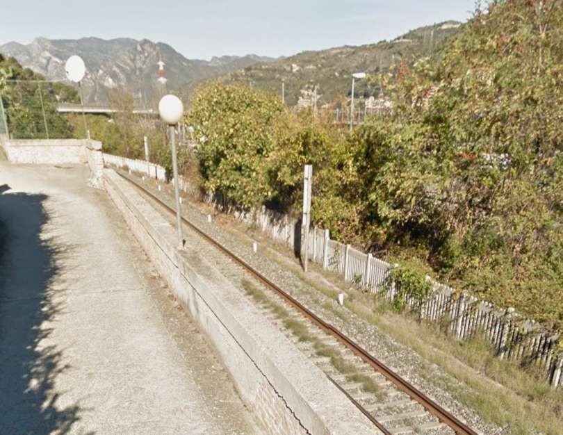
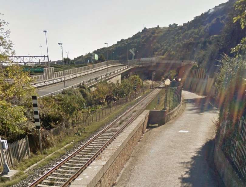
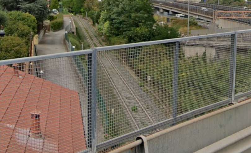
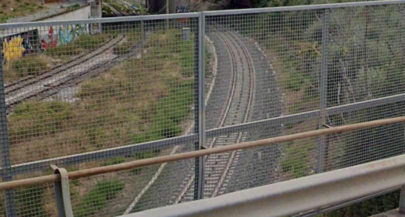
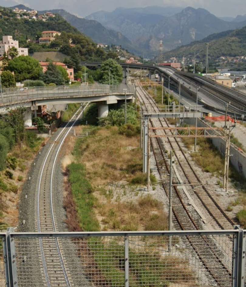
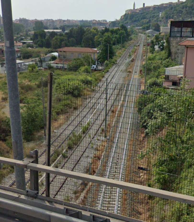
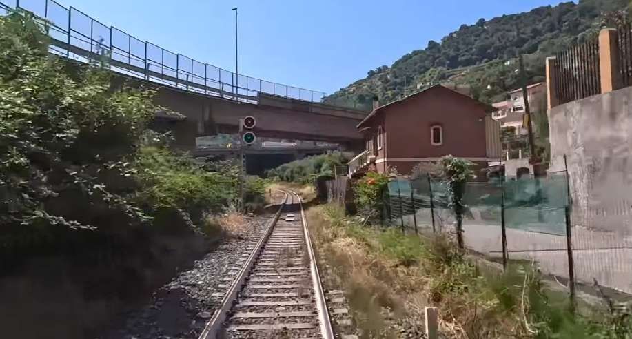

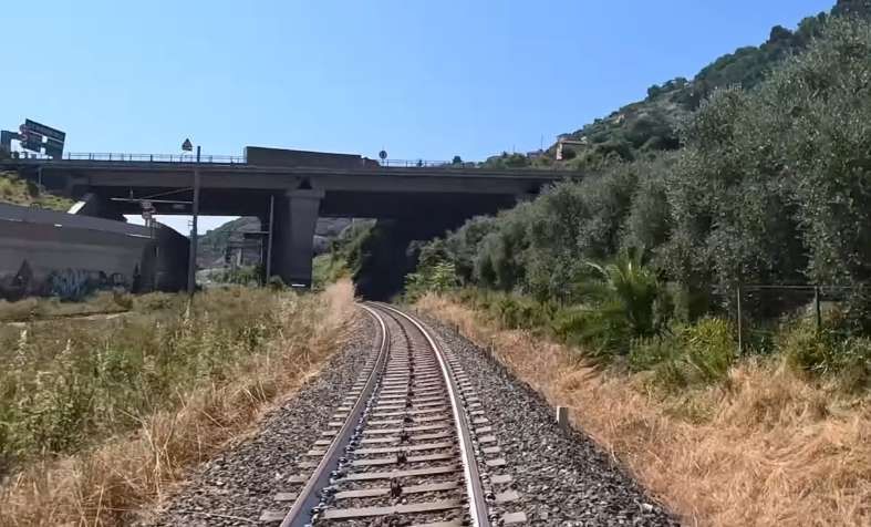
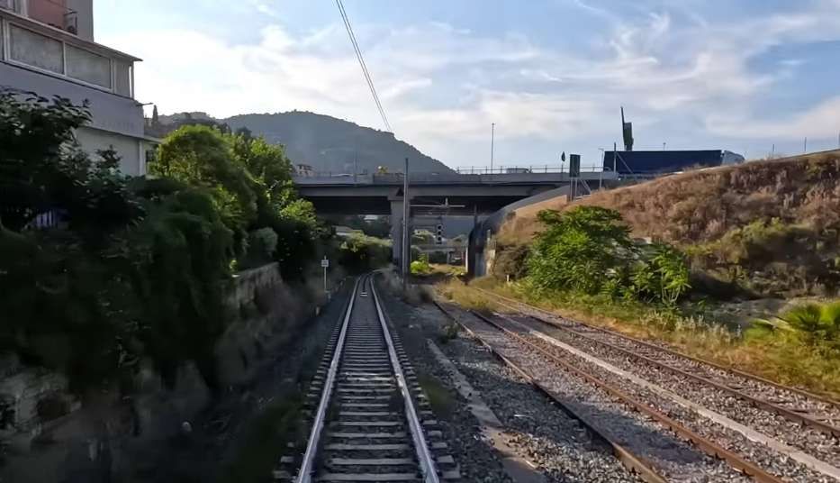
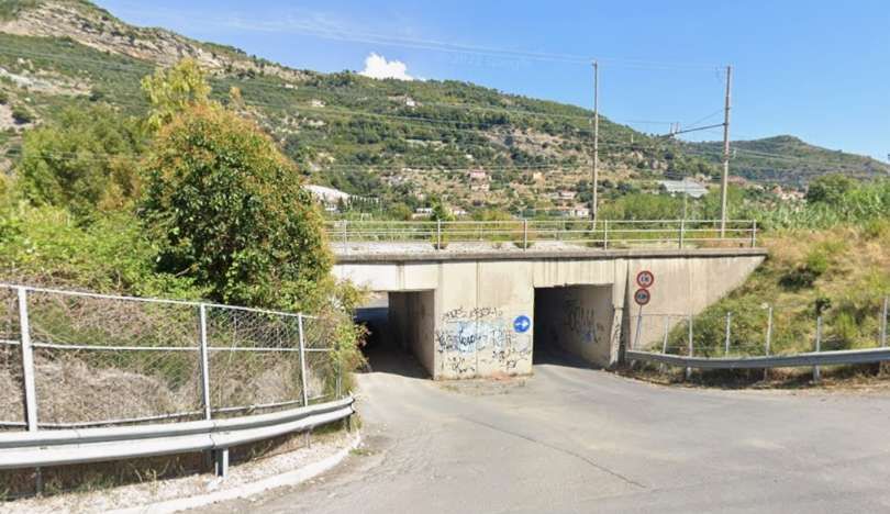
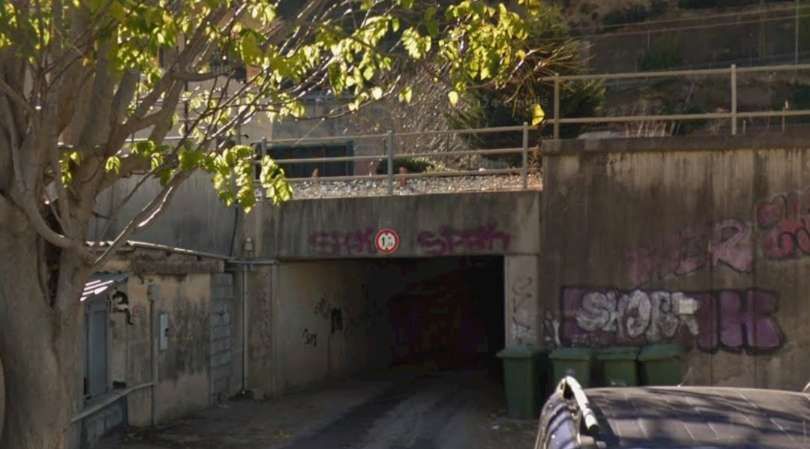
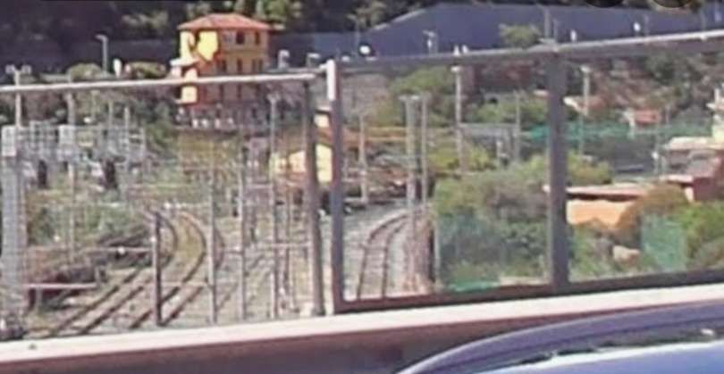
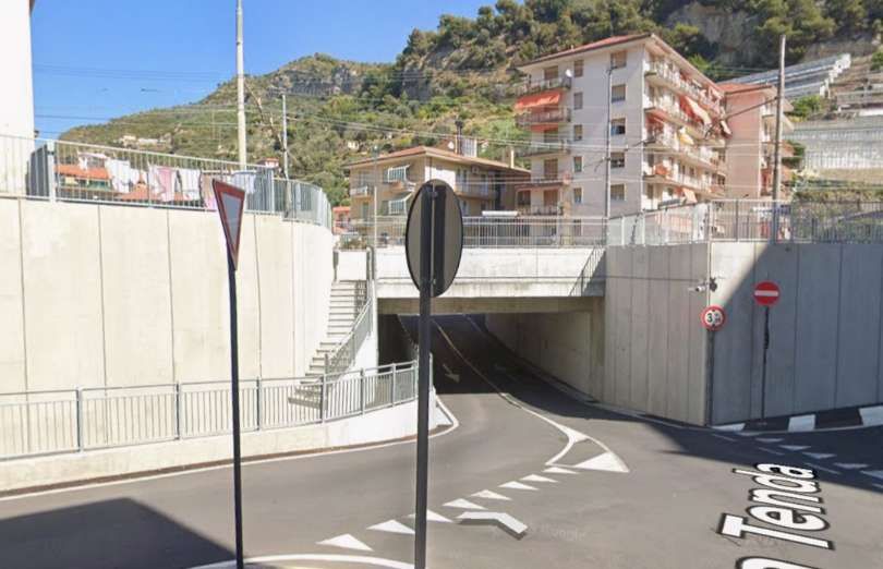
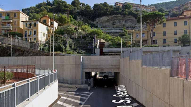


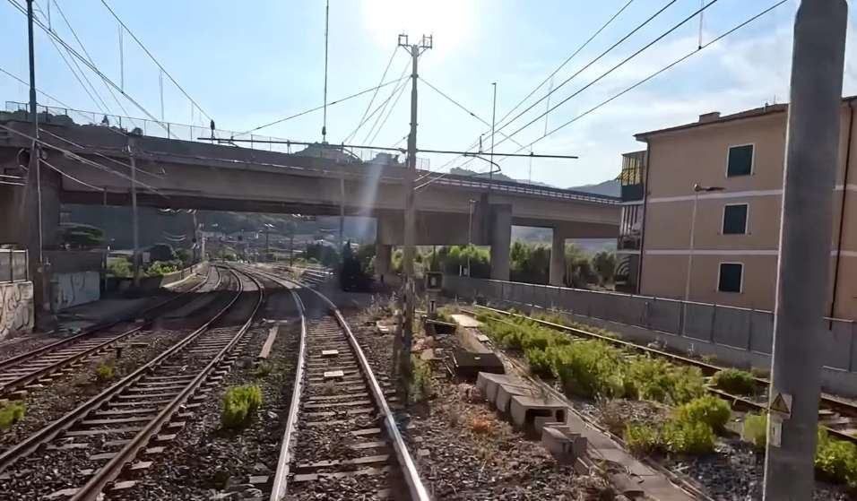
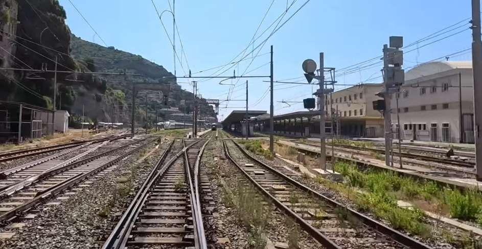
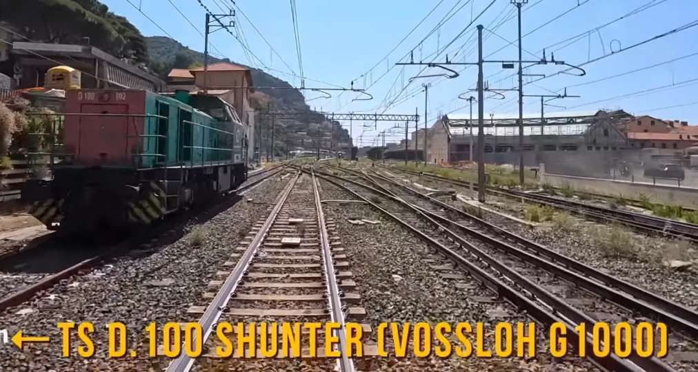
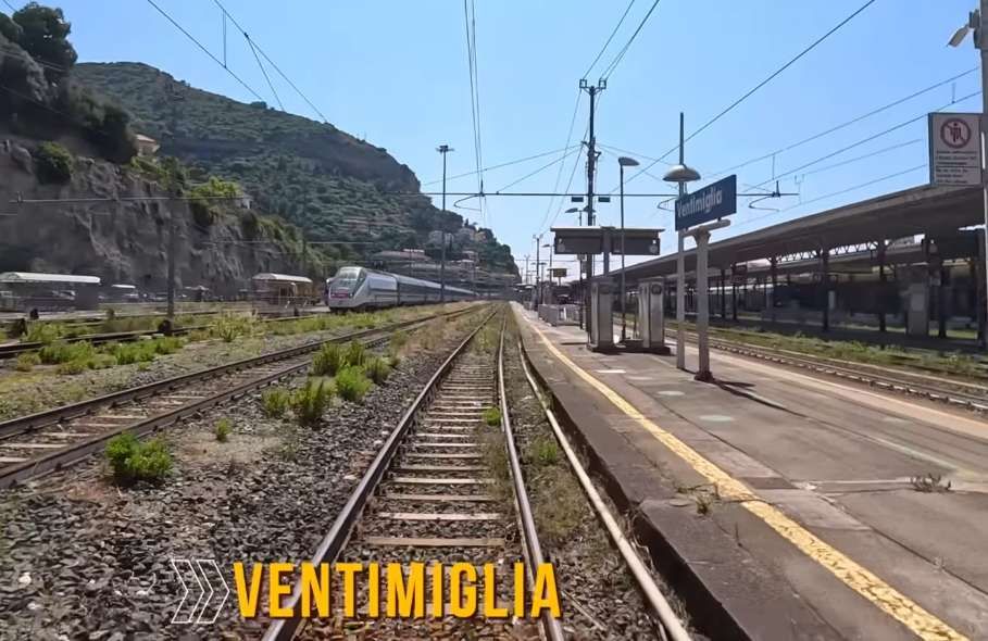
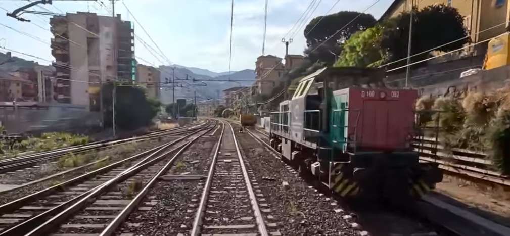
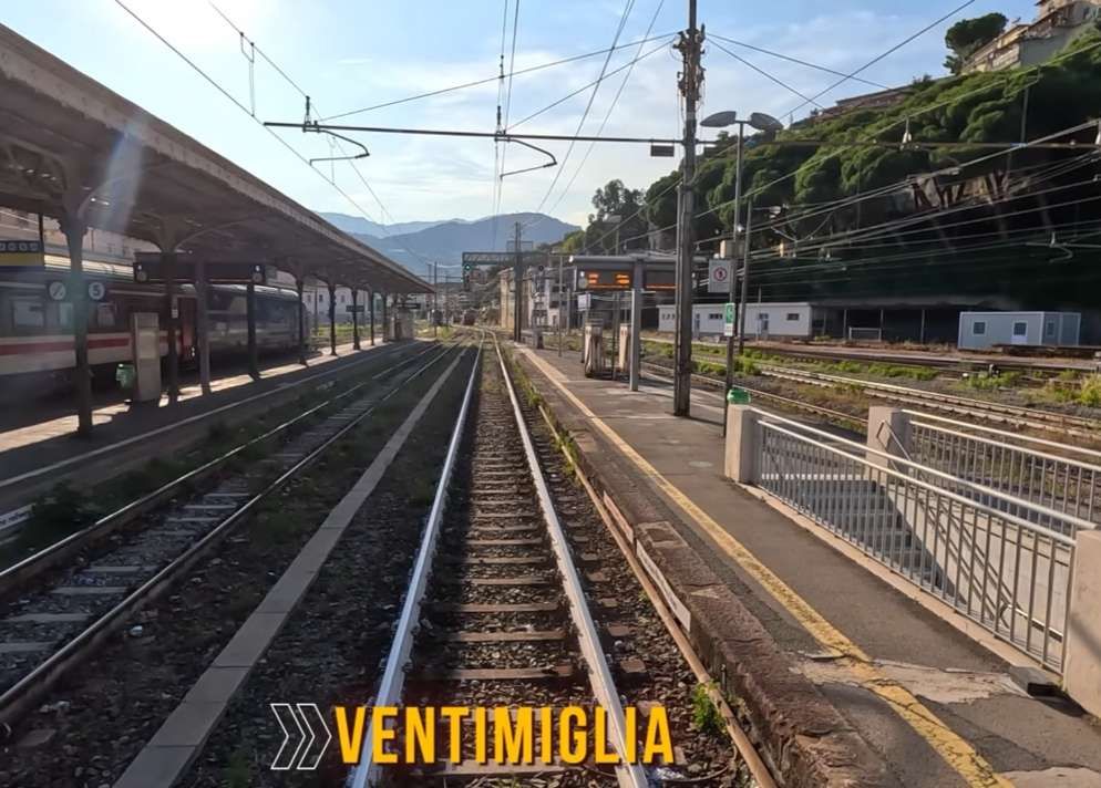
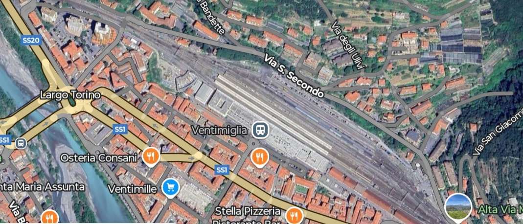
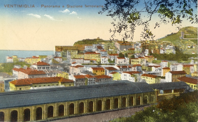
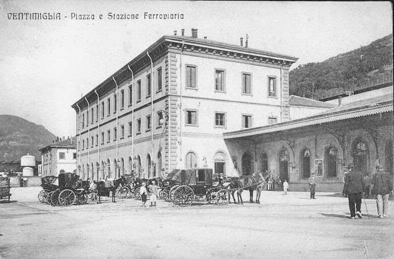
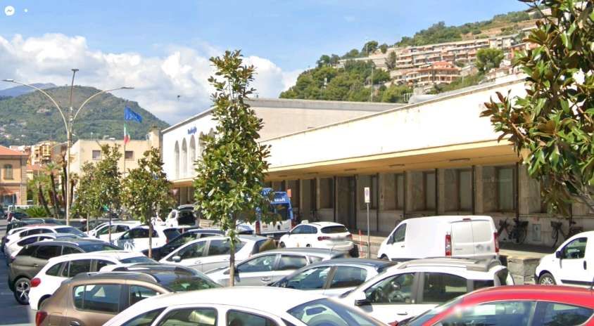
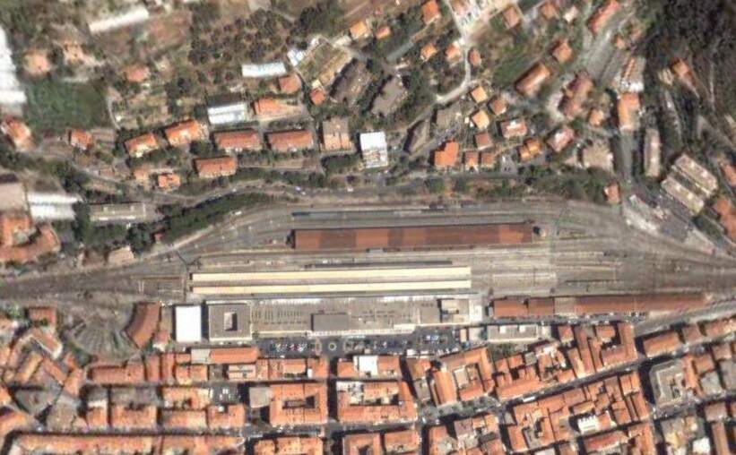
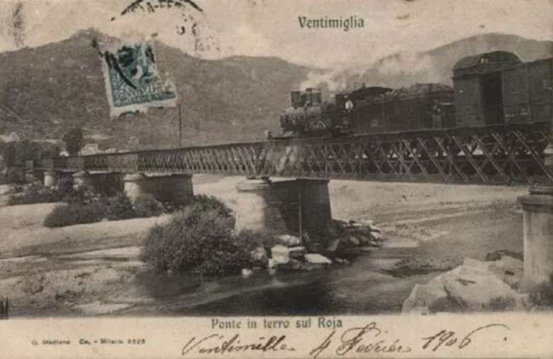

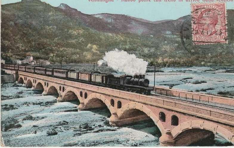
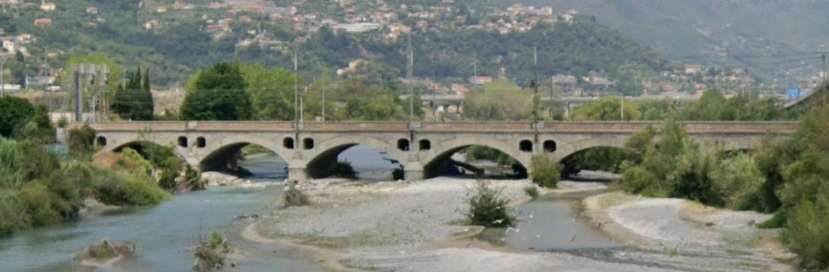
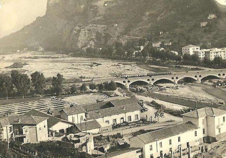
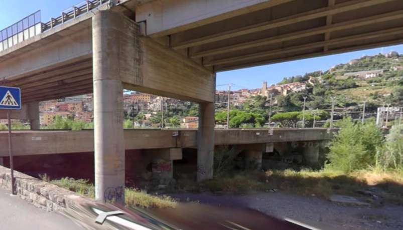
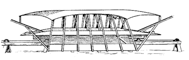

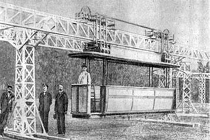
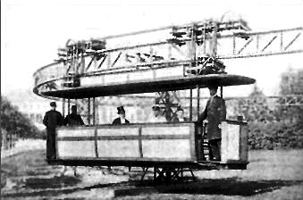
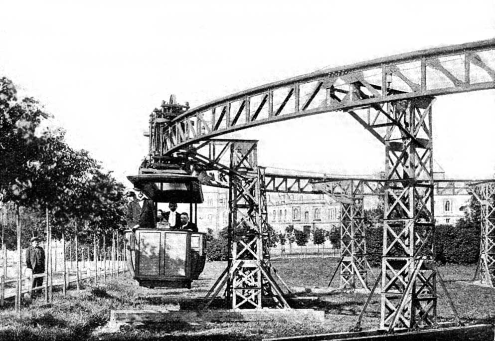
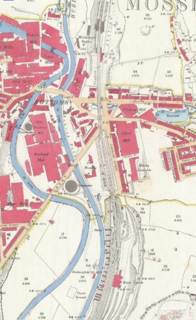


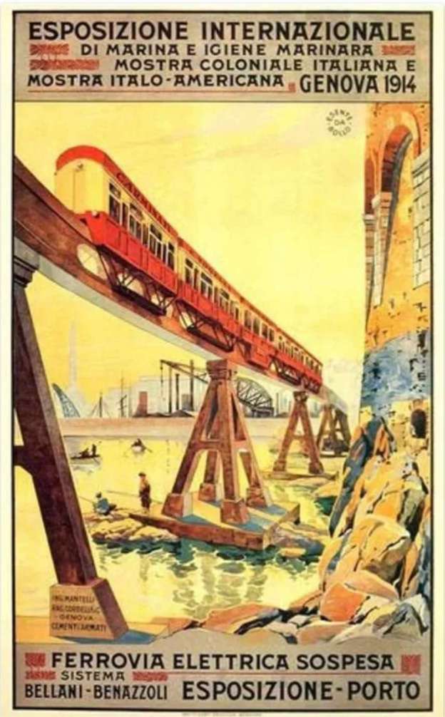
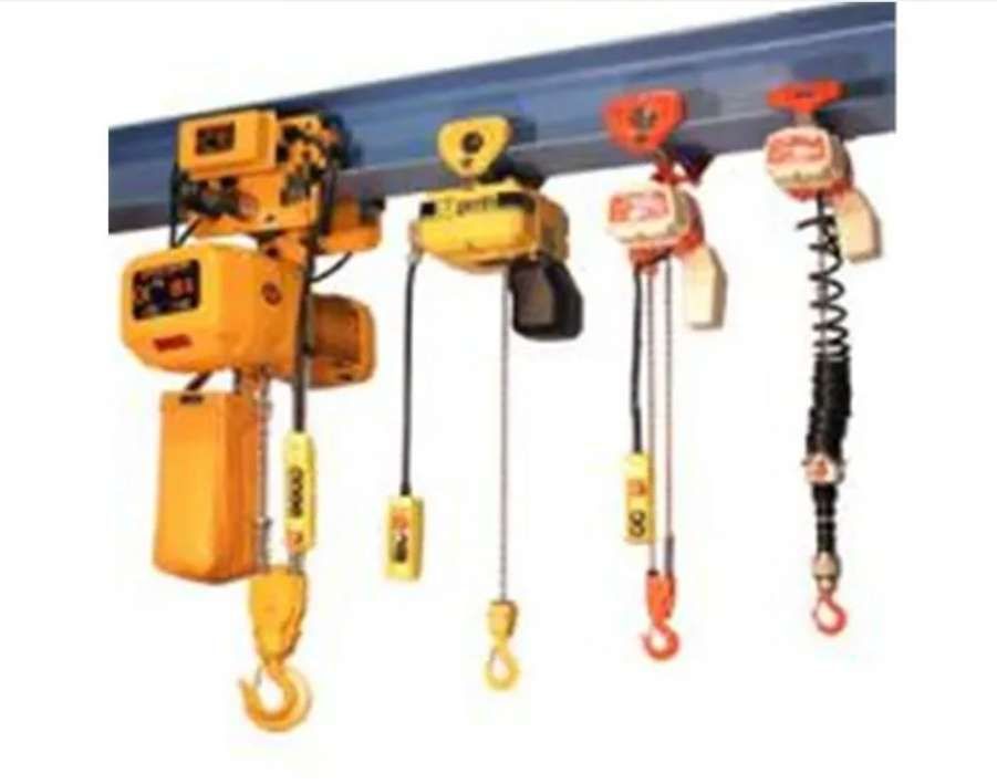
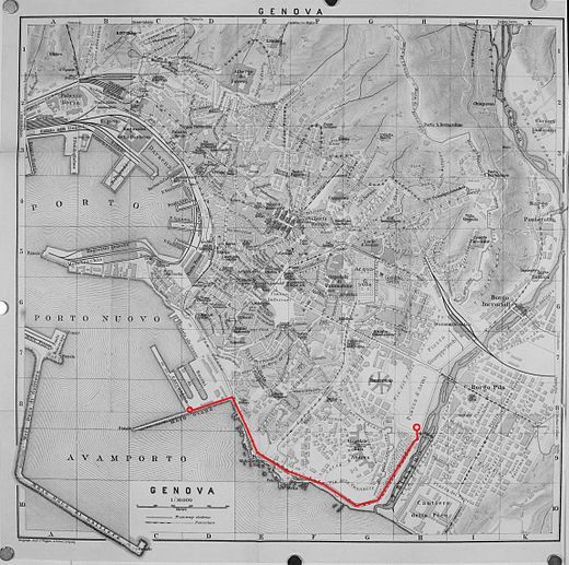
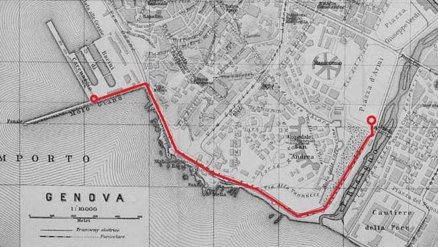
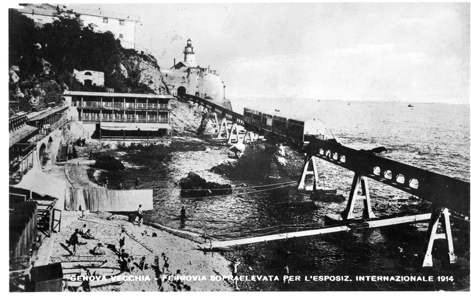
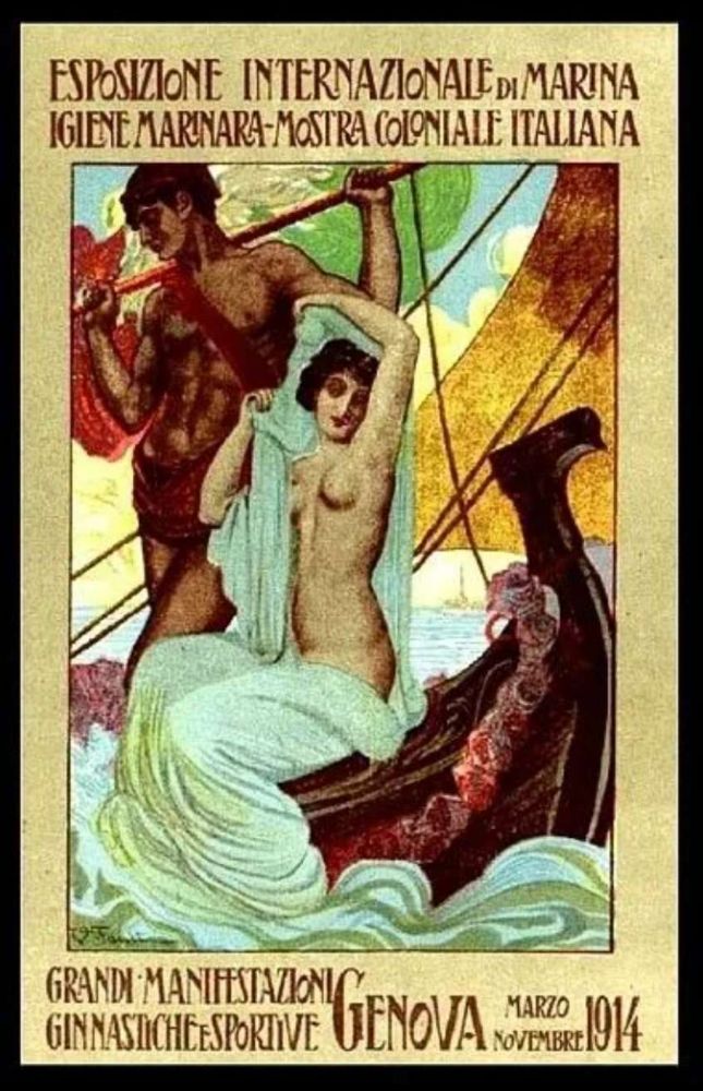

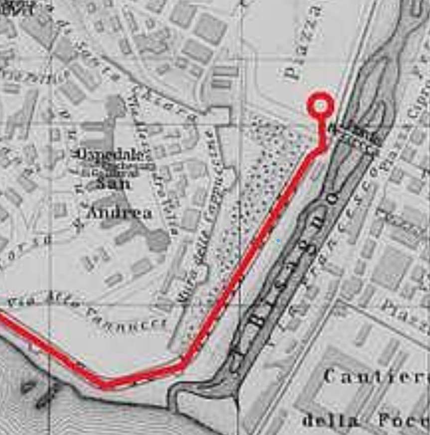
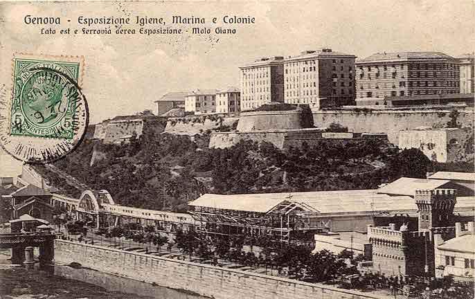
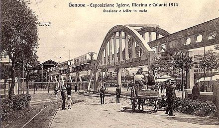
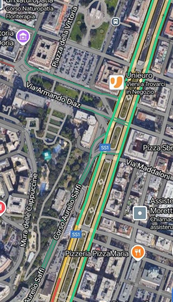
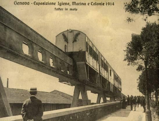
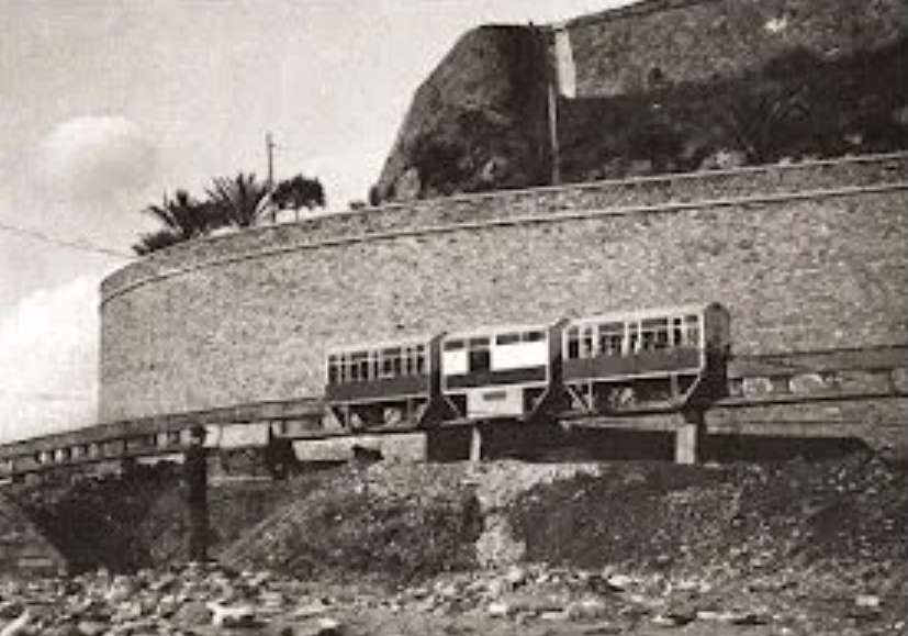

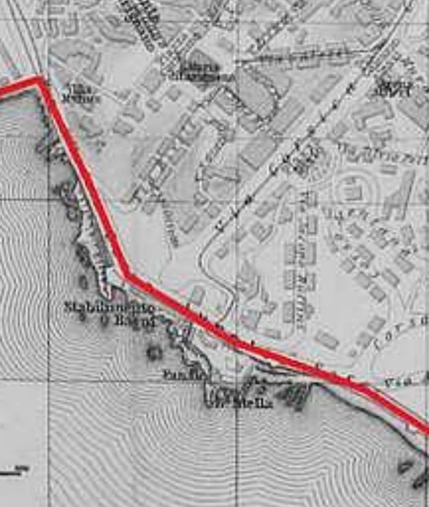
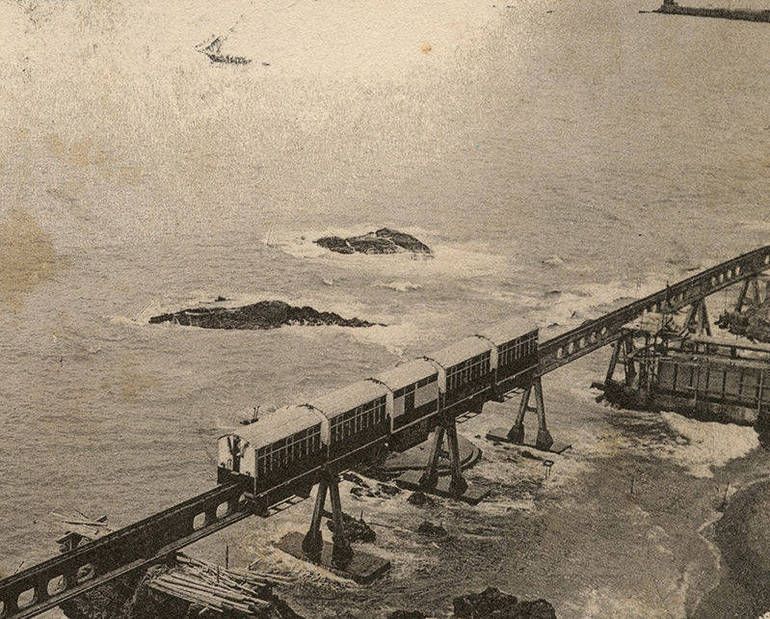
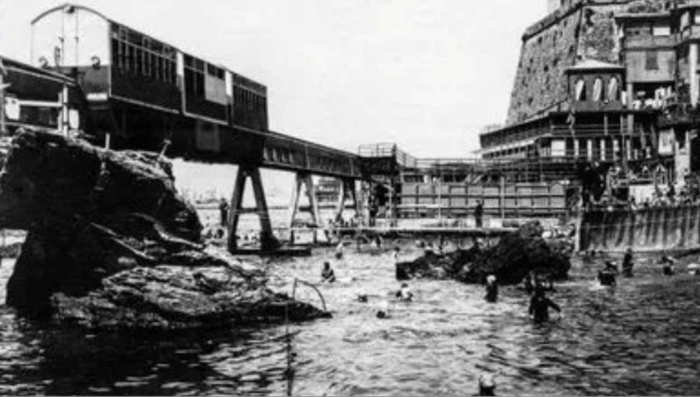
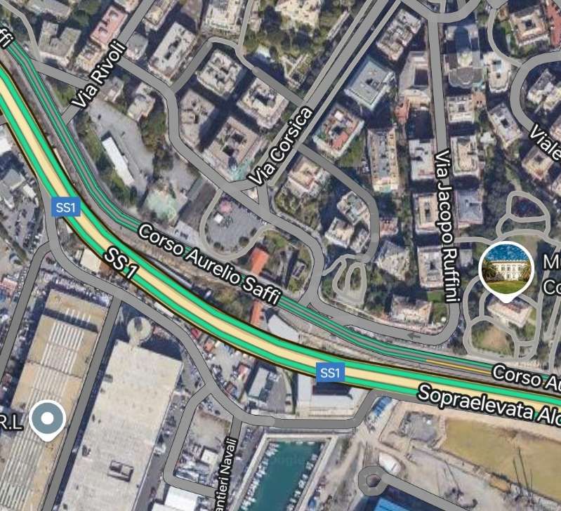
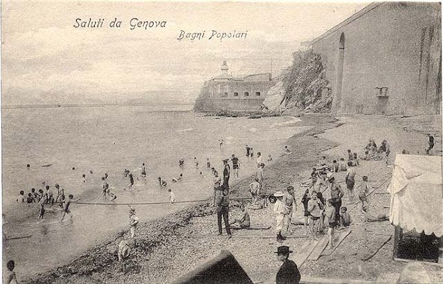
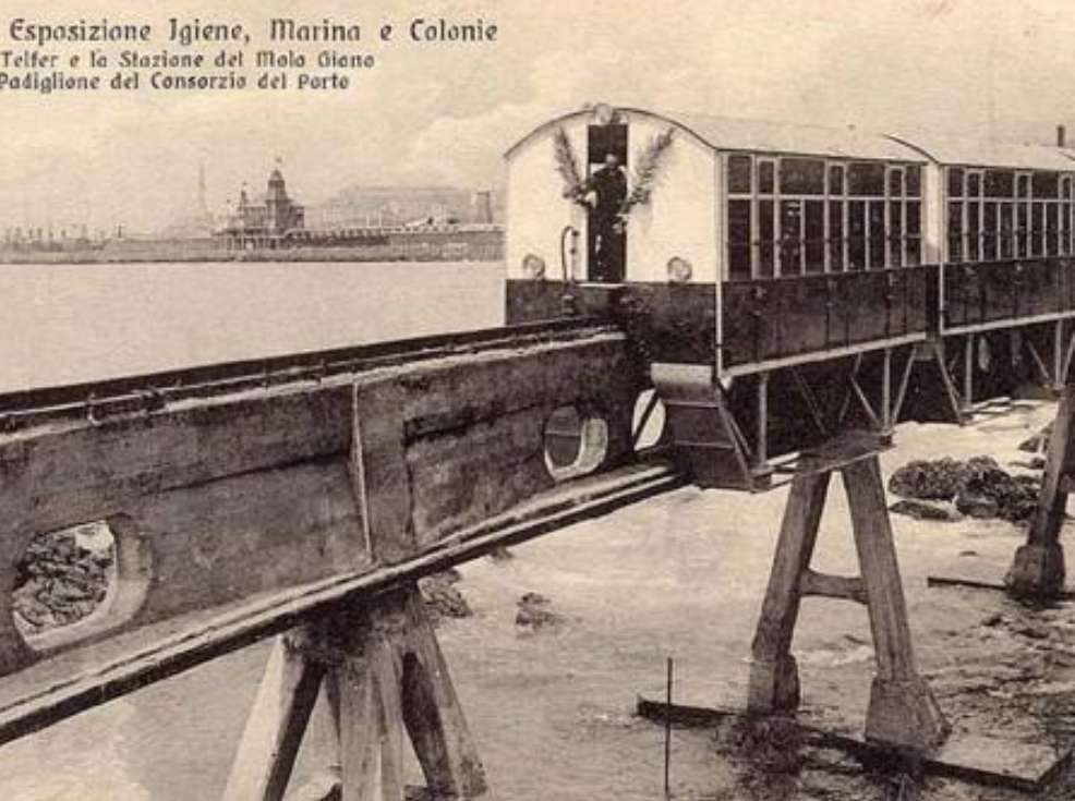

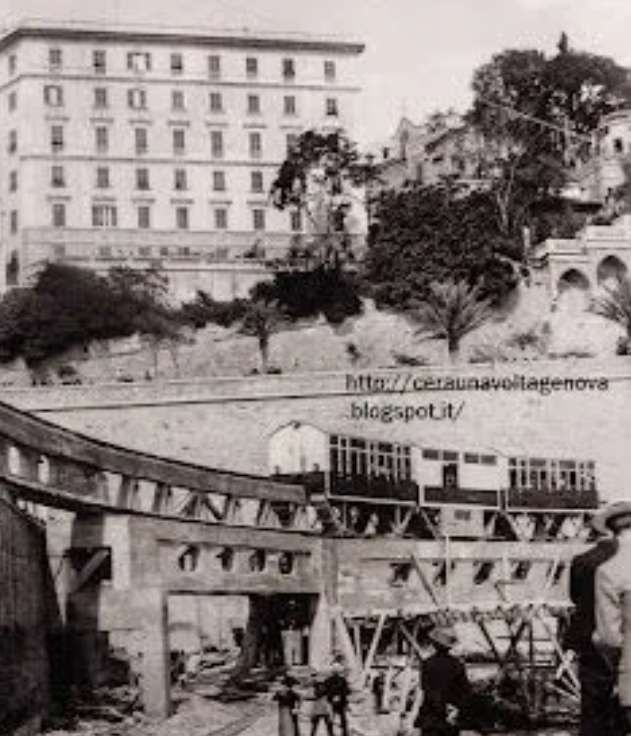

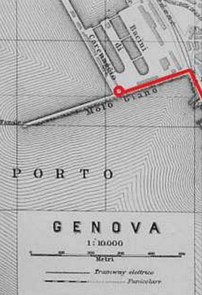
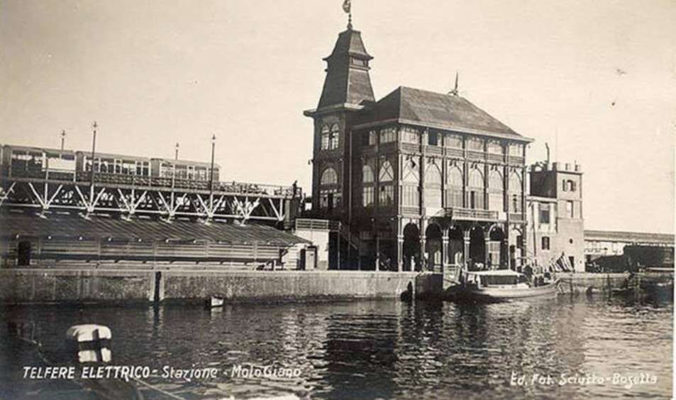
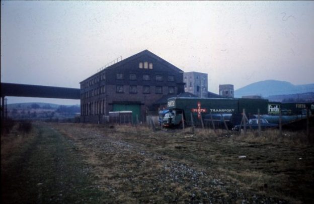
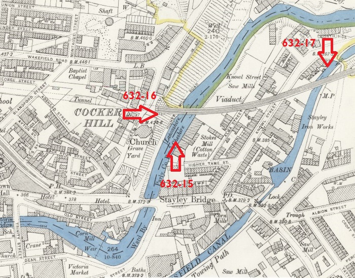
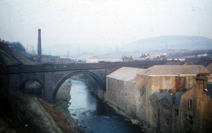
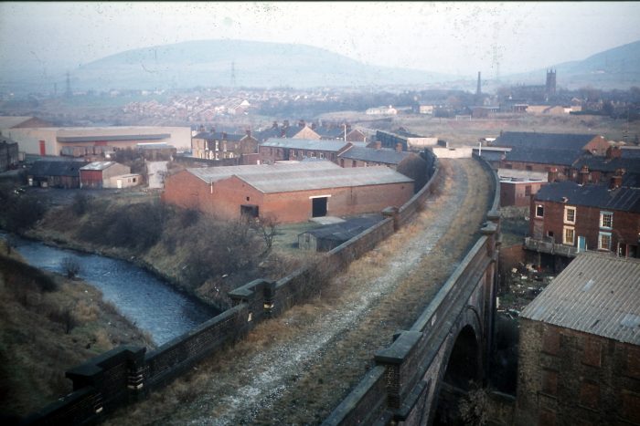
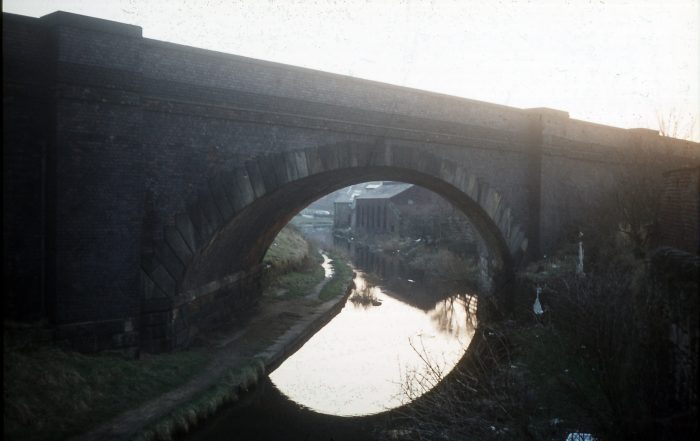
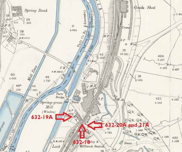
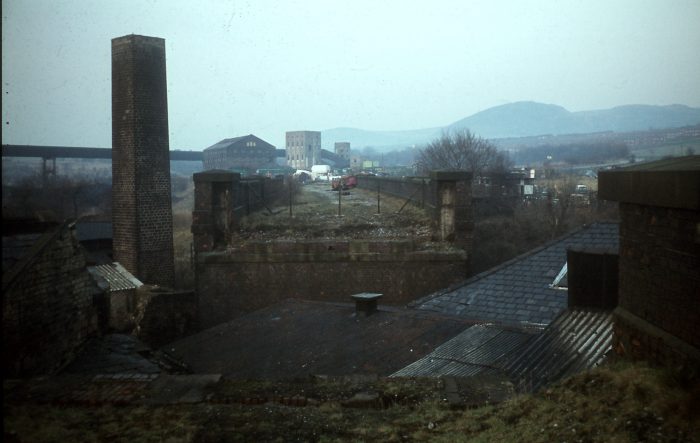
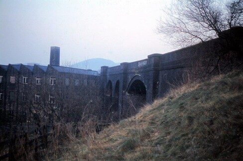
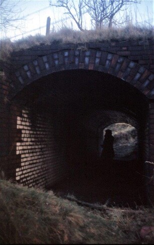
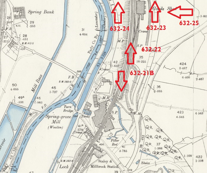
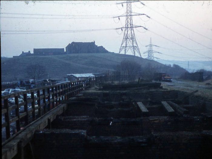

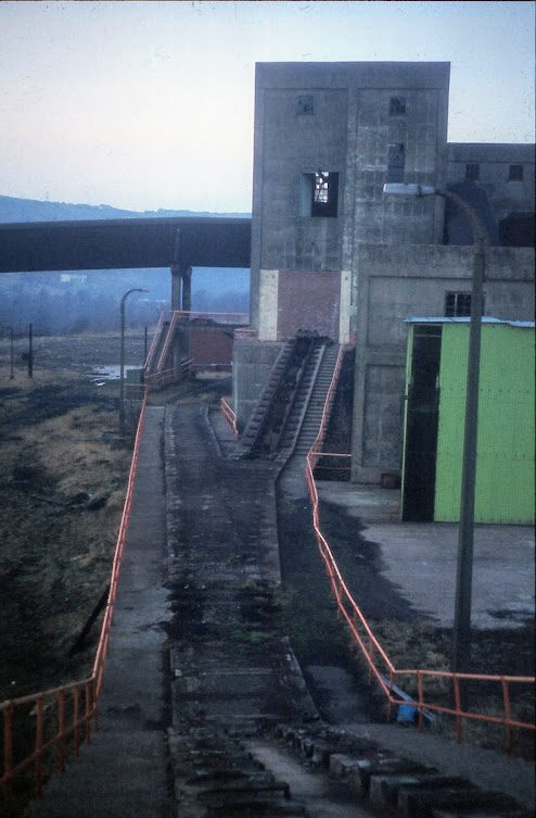
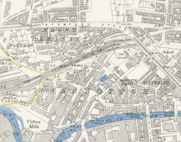
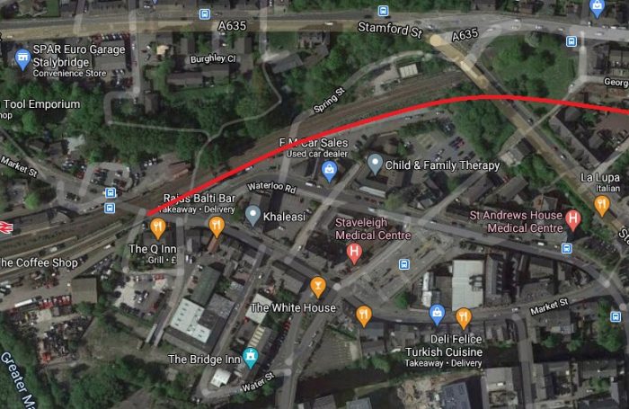

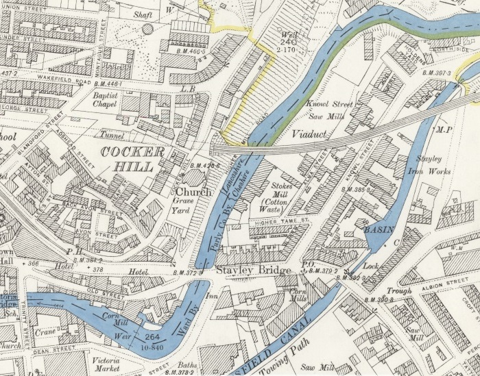
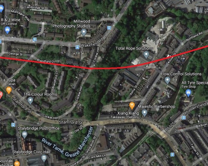
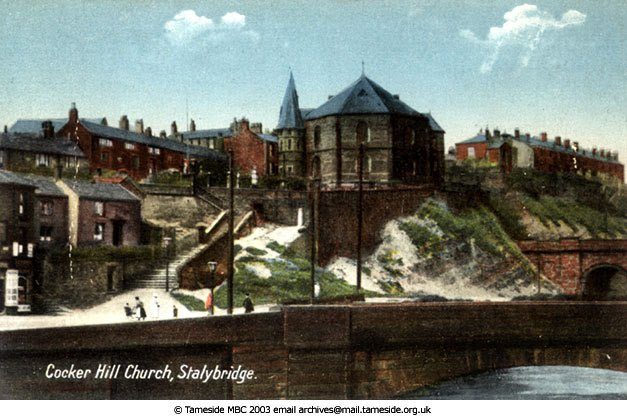
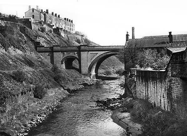
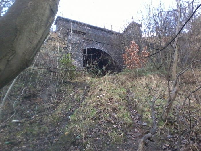
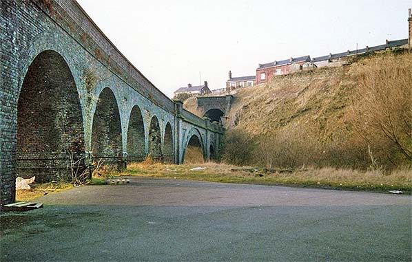
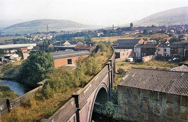
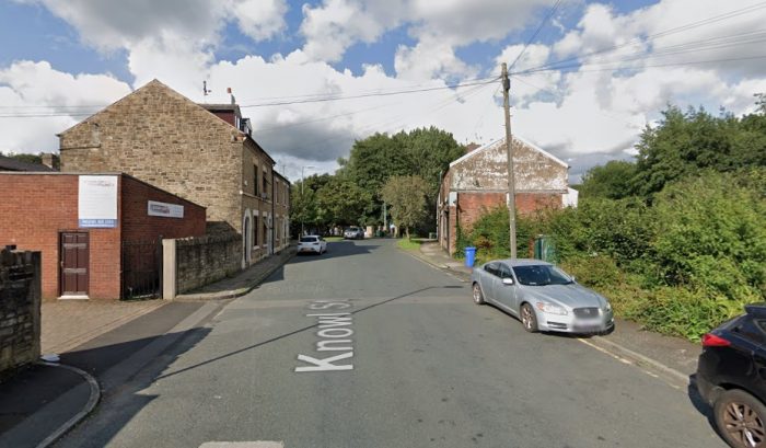
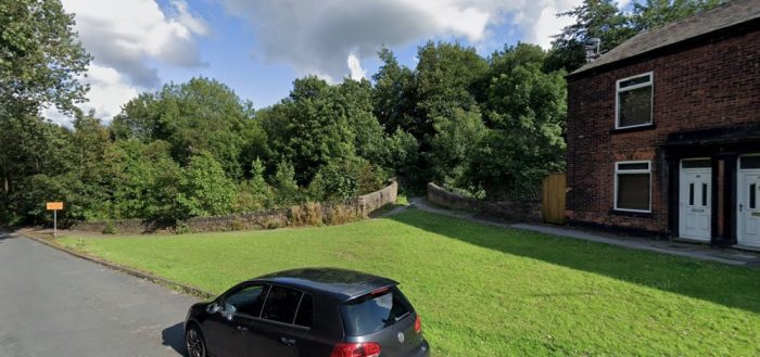
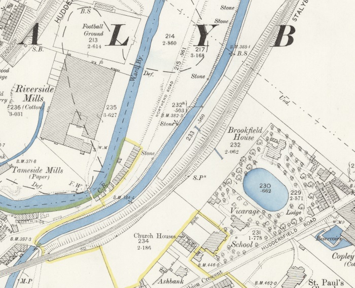
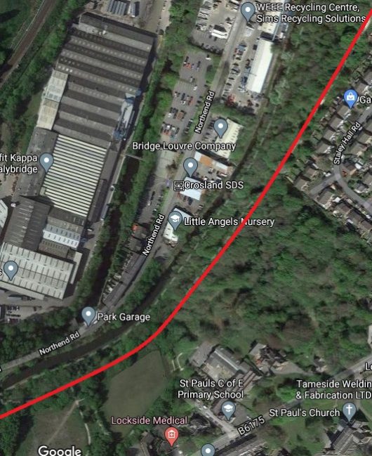
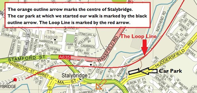
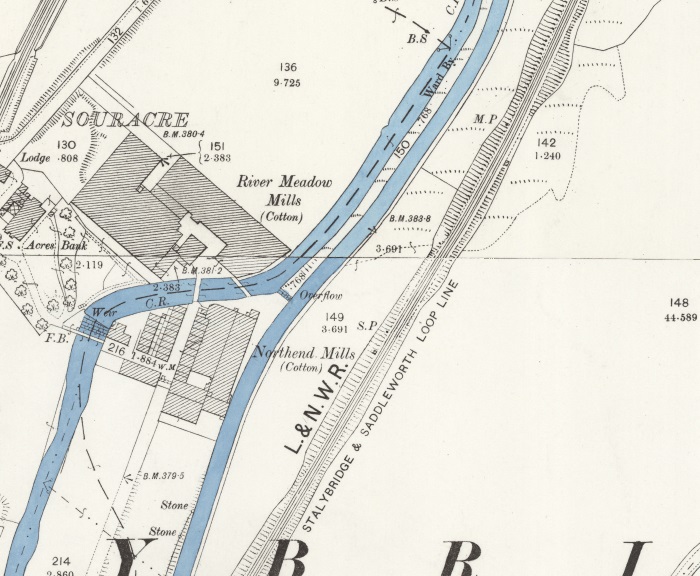
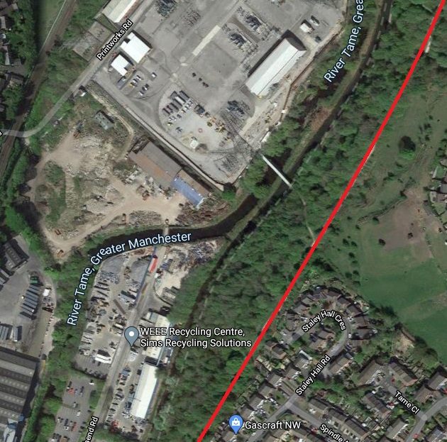
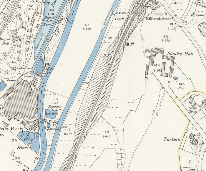
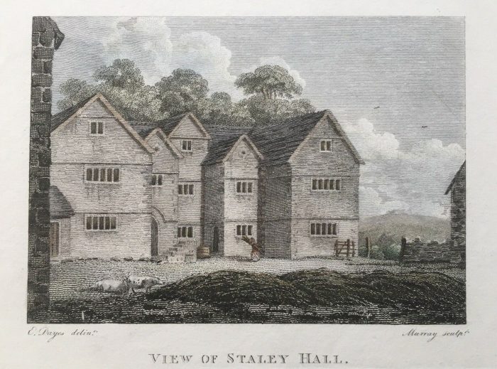
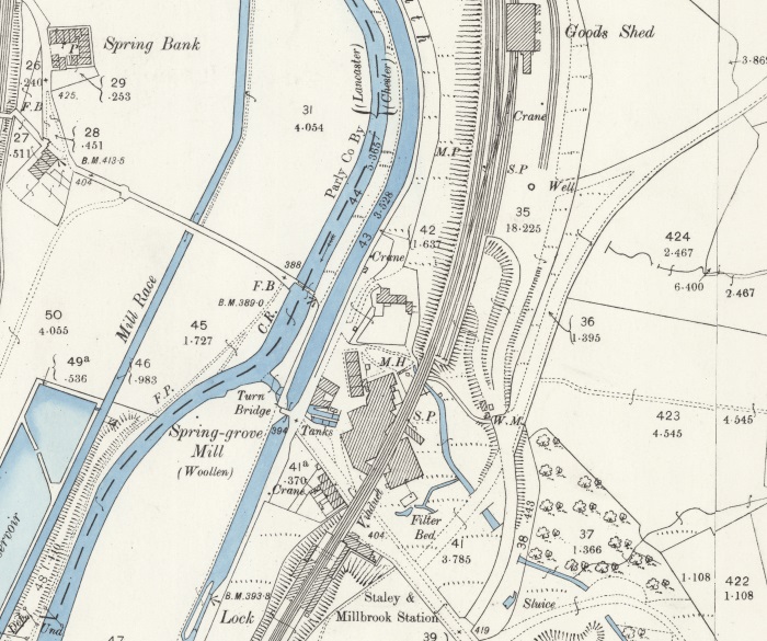
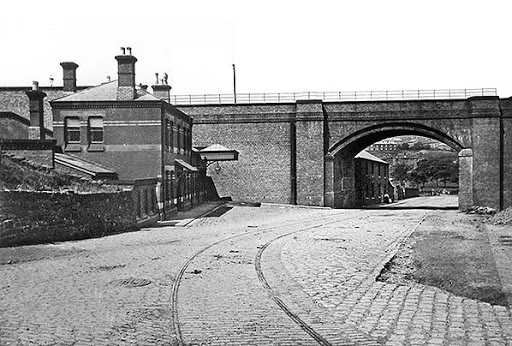
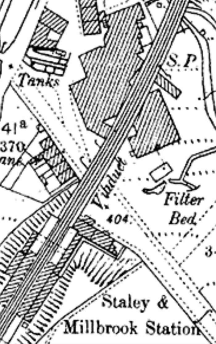

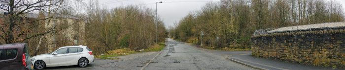
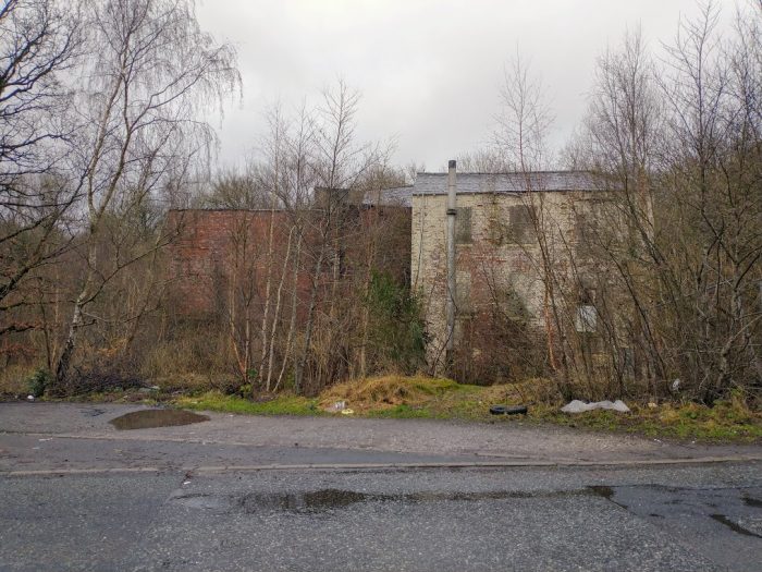
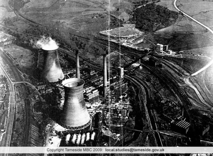
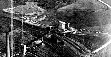
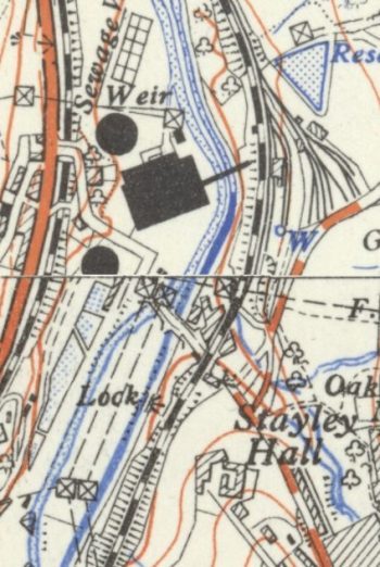
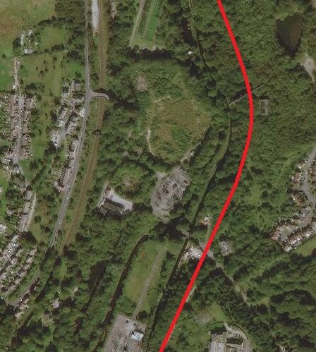
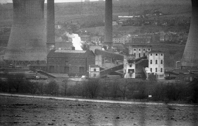

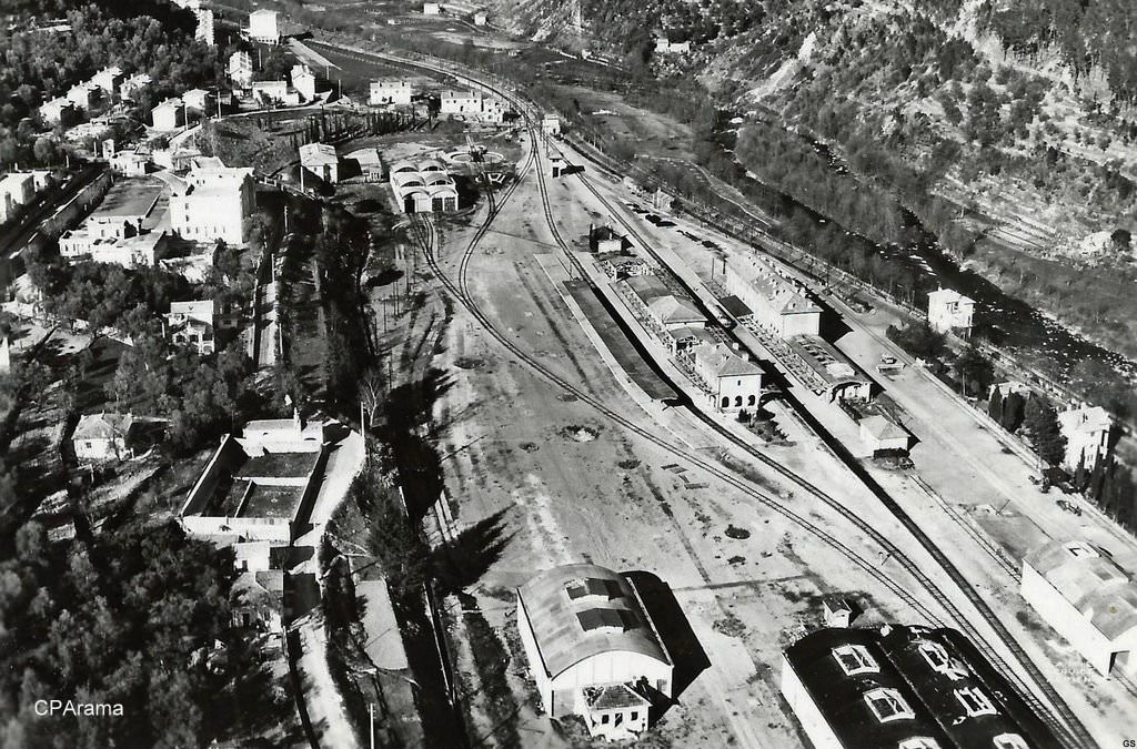