
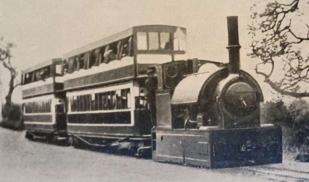
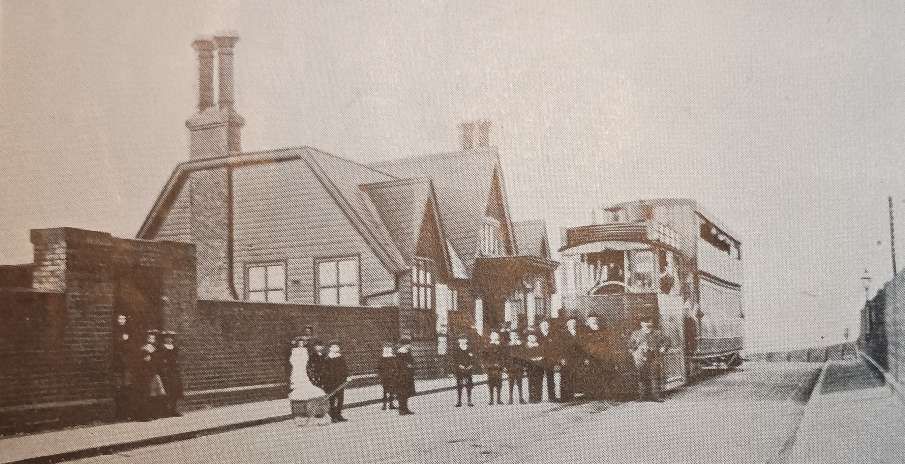
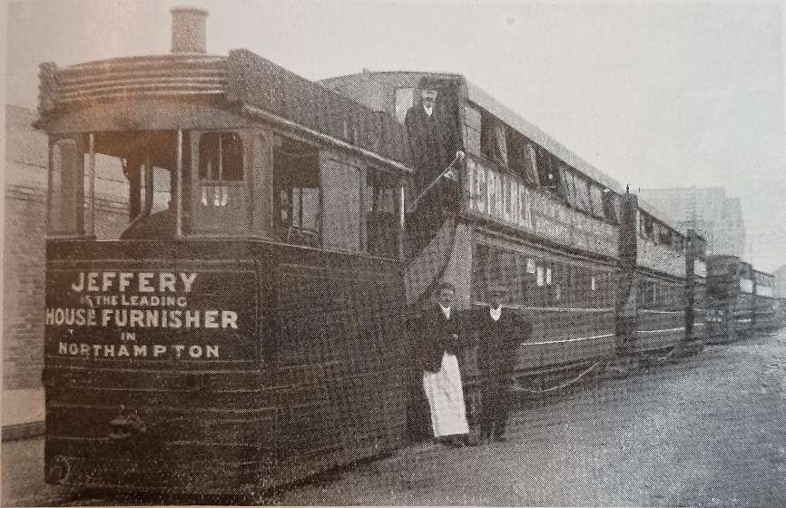
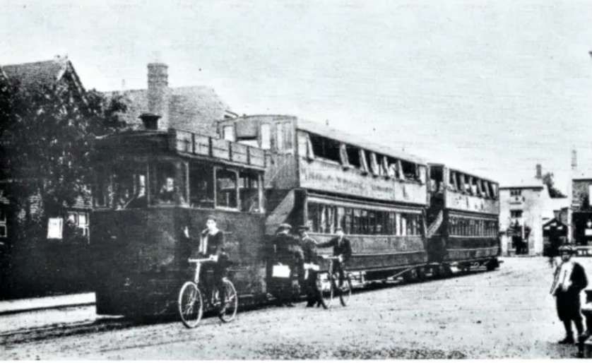
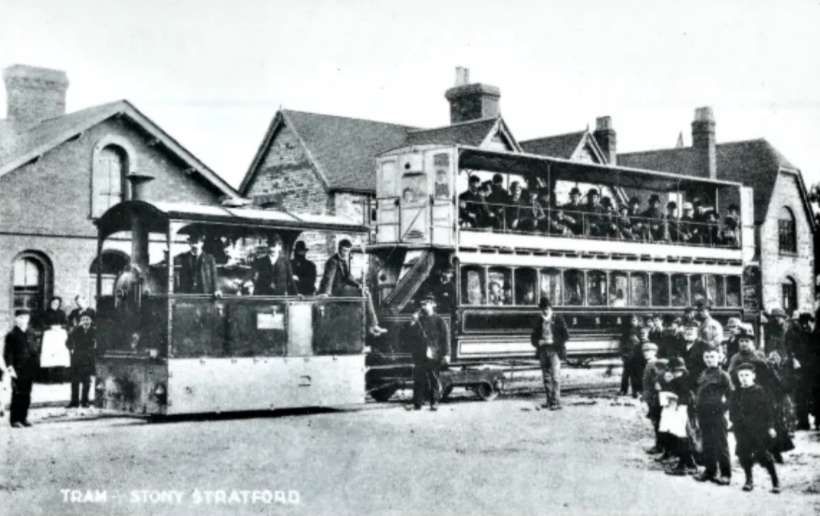
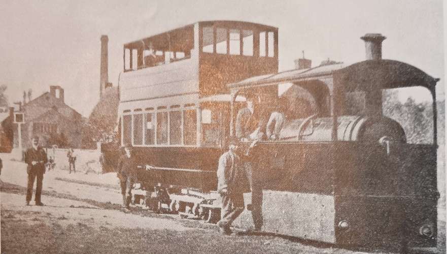
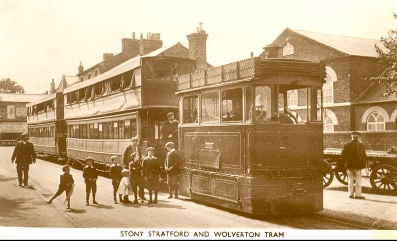
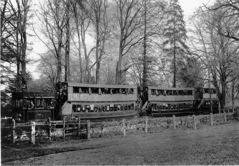
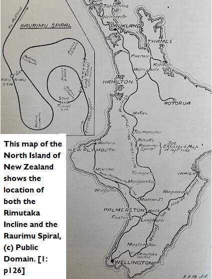
The featured image for this article shows a Bagnall saddle-tank engine and train of two 100-seat workmen’s cars in L.N.W.R. livery on the Wolverton and Stony Stratford Tramway.
Wolverton Works
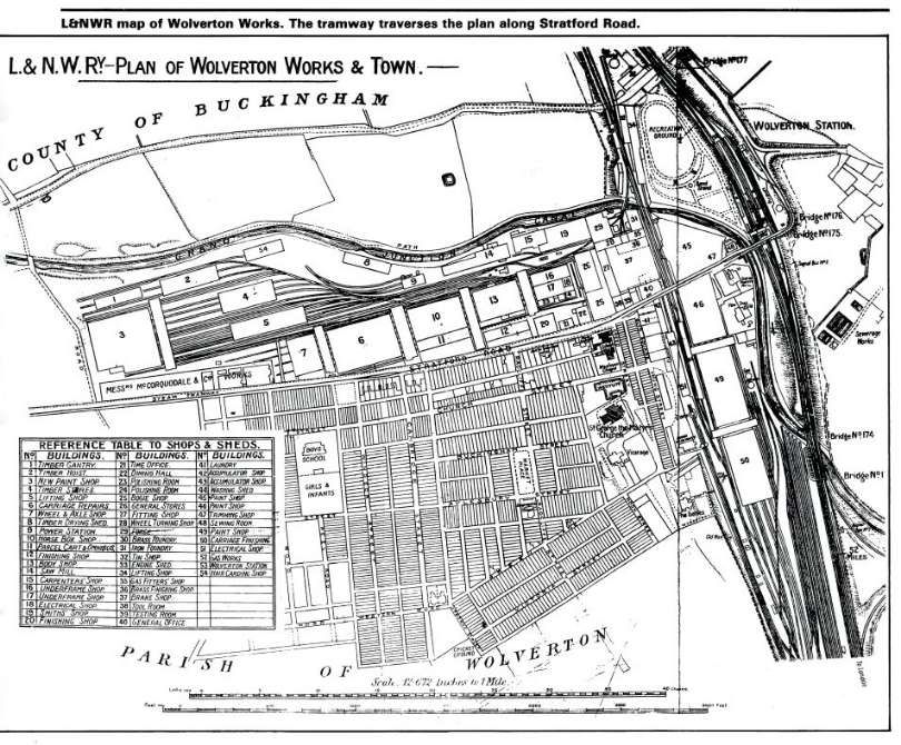
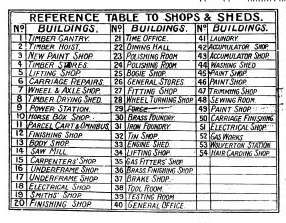
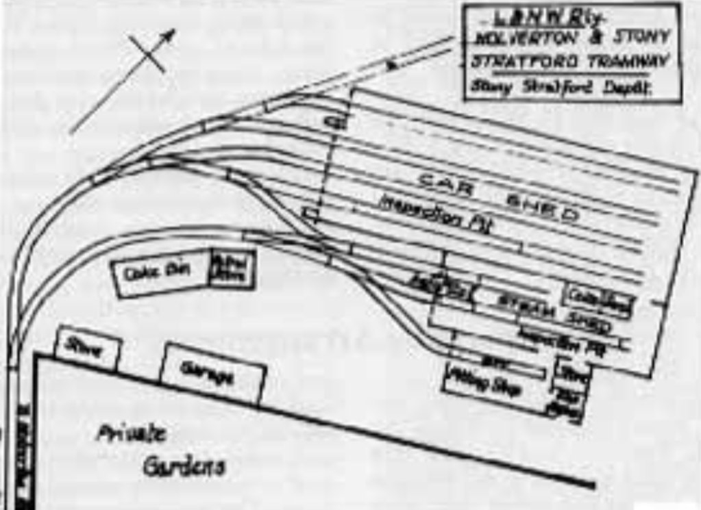
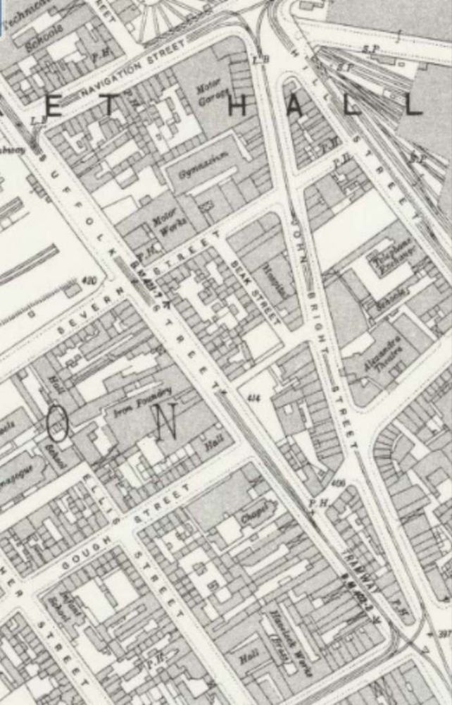
An enlarged key to the plan above which details the use of each building on the LNWR Site. [13: p19]
“Mainly by reason of the growth of the London North Western Railway works at Wolverton in the late 1870s, and the establishment of McCorquodale’s printing works alongside in 1878, a scheme to link the old market town of Stony Stratford, on Watling Street, with the London & North Western Western Railway station at Wolverton by means of a light railway began to take tangible form in 1882.” [1: p547]
Wolverton Railway Works was established in Wolverton, Buckinghamshire, by the London and Birmingham Railway Company in 1838 at the midpoint of the 112-mile-long (180-kilometre) route from London to Birmingham. The line was developed by Robert Stephenson following the great success of the Liverpool and Manchester Railway line. [2]
“The Victorian era new towns of Wolverton and New Bradwell were built to house the workers and service the works. The older towns of Stony Stratford and Newport Pagnell grew substantially too, being joined to it by the Wolverton and Stony Stratford Tramway and the Wolverton to Newport Pagnell Line (a branch line), respectively. The trams were … hauled by steam locomotives: the tram cars were certainly the largest ever in the UK and possibly the world.” [2]
After a survey of all possible sites for the London and Birmingham Railway works, “Wolverton was chosen due to its co-location alongside the wharfing facilities of the Grand Union Canal, thereby also enabling the railway company to gain an easy agreement to build a viaduct over the canal company’s land at this point.”
“In 1837, Edward Bury of Bury Curtis & Kennedy of Liverpool was appointed Locomotive Superintendent of the London to Birmingham railway with his headquarters at Wolverton. However, as Wolverton was simply considered to be a repair shop for the engines his Liverpool firm supplied to run on the line, he left the running of the Works to his Shop Foreman.” [3]
It became necessary for expansion to take place to accommodate, service and repair the increasing amount of rolling stock owned by the Company. “A large engine shed was built, said to be cathedral sized, together with all supporting facilities which also enabled the Works” [3] to produce, locomotives in house.
J E McConnell was appointed Superintendent in 1847. He built his first locomotive in 1849. This was “the prototype of the ‘Bloomer’ class (the wheels and works being more exposed the engines became know as Bloomers after Mrs Amelia Bloomer who was trying to reform ladies dress). During his time at Wolverton he made many innovations such as train heating, failsafe braking, hollow axles, boilers, fireboxes etc. Early in 1851, the first Bloomer engines were running.” [3]
Bloomer was a name used to refer to three similar classes of 2-2-2 express passenger locomotives designed by James McConnell. “A total of seventy-four were built between 1851 and 1862. The classes were similar in design and layout but differed in dimensions.” [4]
“In 1859, thirty four engines were transferred from Crewe to Wolverton which involved further expansion of the Works. Under McConnell the Works flourished but unfortunately for him Mr Richard Moon was appointed Chairman of the Company and there was a clash of personalities resulting in McConnell retiring. A year or two after his retirement the engineering works were transferred to Crewe. Before the transfer to Crewe, 165 engines had been built at Wolverton.” [3]
“Expansion of the Works again took place during 1864 when Wolverton became the Carriage Works for the LNWR and the manufacturing shops were converted to enable carriages to be built, painted and repaired. In 1869 two Royal Saloons for Queen Victoria were built at Wolverton. Sadly in 1872 the locomotive shop finally closed and Wolverton became exclusively a carriage works until in 1877 it was the largest in Britain.” [3]
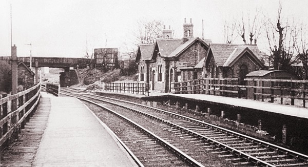
It seems that the original railway main line through Wolverton crossed land which was needed for the expansion of Wolverton Works. Two previous stations had been situated in the original route of the main line. “The first station was built for the opening of the London and Birmingham Railway on 17th September 1838, on the embankment just north of the canal above Wolverton Park. It proved to be temporary as the railway company purchased an additional 13.5 acres to the south, where they built a larger, more permanent station in 1840, at the east end of Church Street.” [8]
To avoid passing through the Wolverton Carriage Works, a railway main line deviation to the east was opened in August, 1881. The present Wolverton Station was built on the new line.
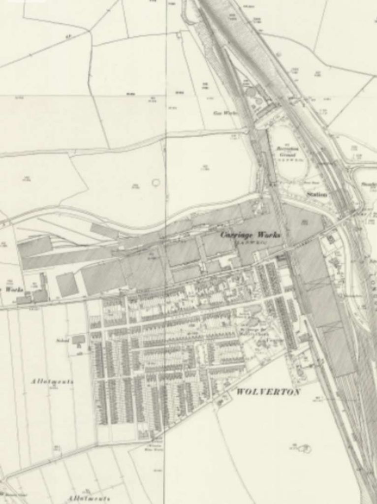
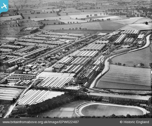
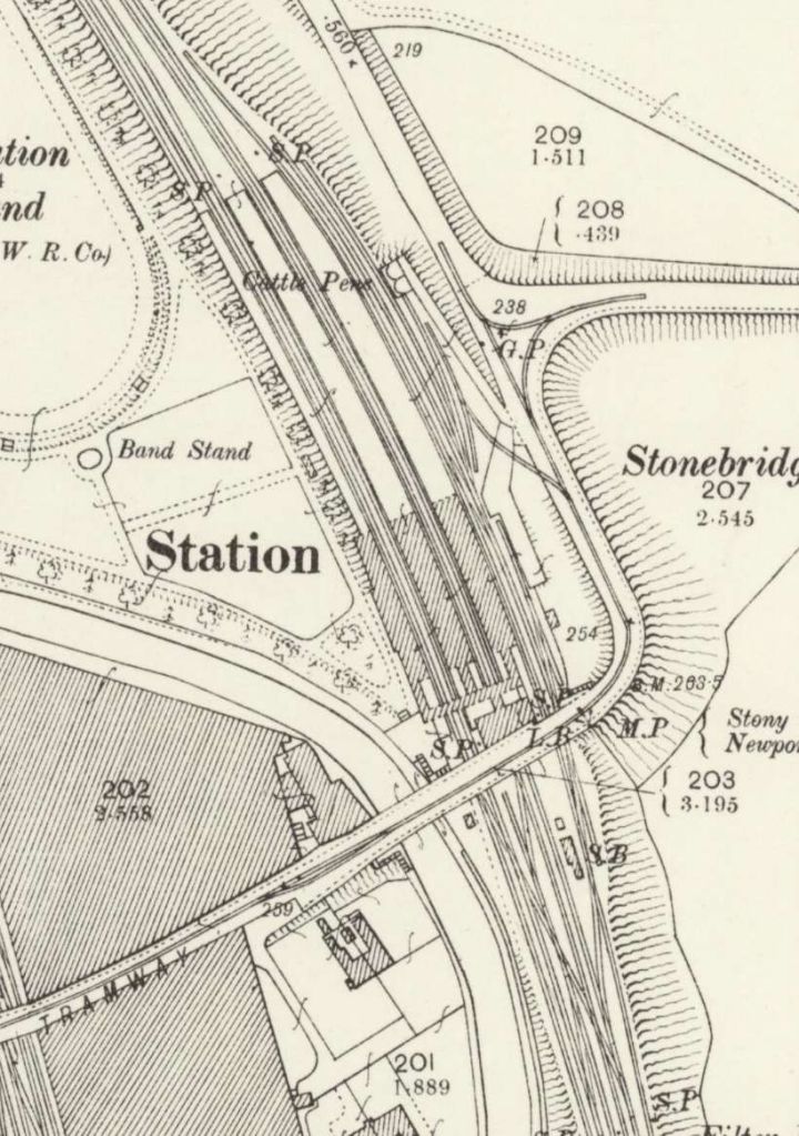
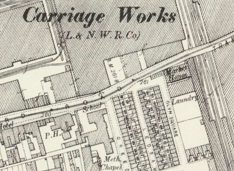
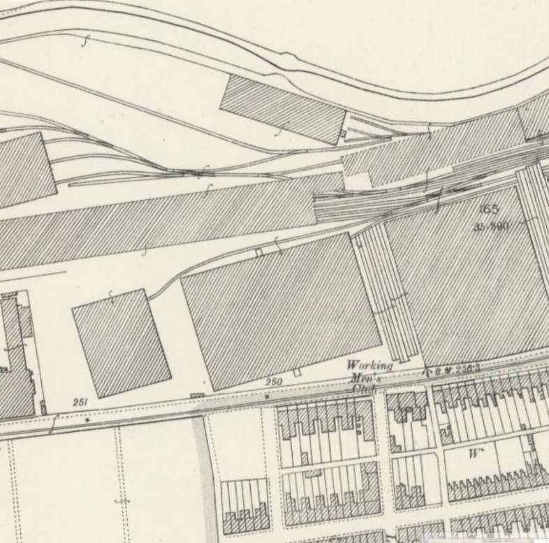
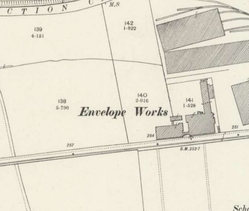
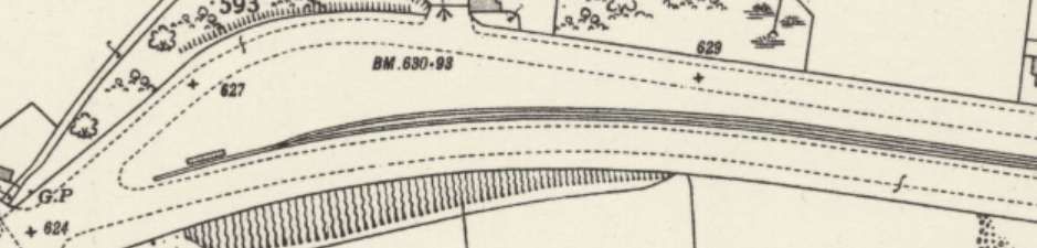
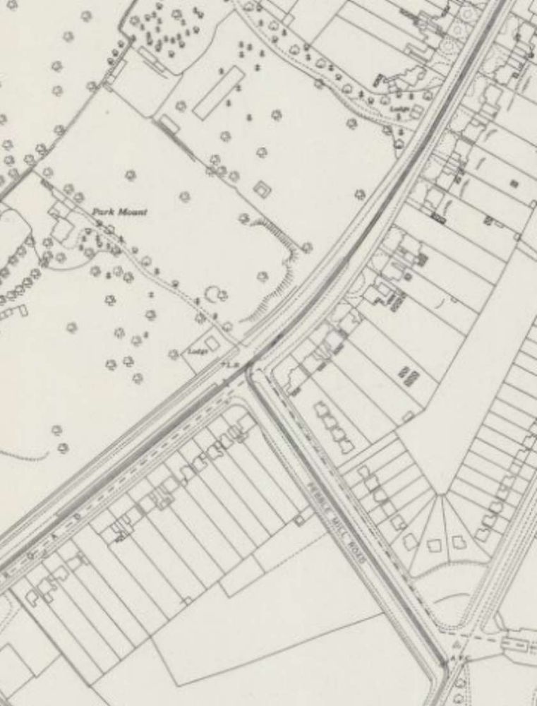
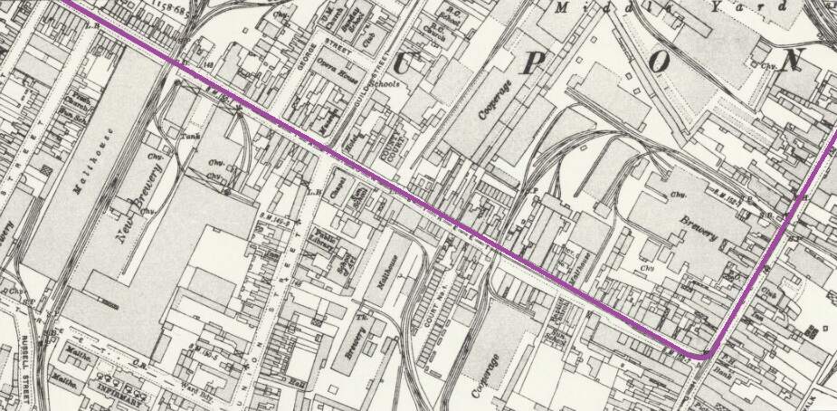
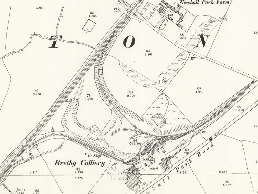
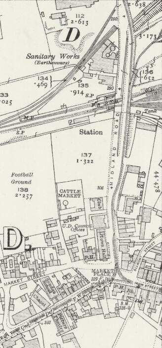
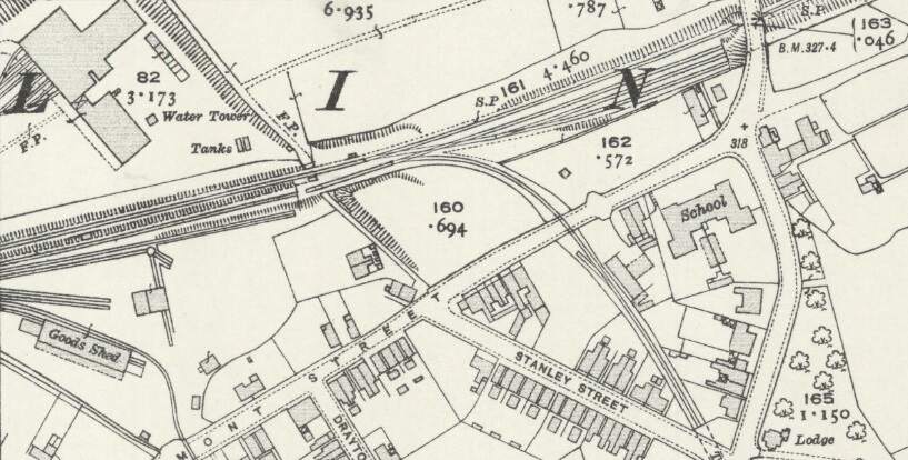
This rather fuzzy extract from the 25″ Ordnance Survey of 1898, published in 1900 shows the extent of the Railway Works at that time. To the West of the Railway Works was the site of McCorquodale’s Printing Works which can just be made out at the left edge of this map extract. The Grand Junction Canal sits between the Works and the Railway Station. [9]
McCorquodale’s Printing Works
McCorquodale’s Printing Works were one of a series of such establishments. McCorquodales built premises in Wolverton in 1878. The firm specialised in registered envelope manufacture, but undertook many other government and security printing contracts. The “history of the company commenced in 1841. George McCorquodale opened a stationers shop in Liverpool which became the Liverpool Printing and Stationery Company Ltd. The company prospered and five years later George opened the first McCorquodale printing works at Newton-le-Willows in Lancashire, specialising in providing a service to the ever expanding railway network.” [5]
Further factories were opened in Glasgow and London in the 1870s. In Wolverton, men were employed in the railway works but their daughters remained unemployed. “Sir Richard Moon, Chairman of the London & North Western Railway had an idea for solving the problem and contacted his friend George McCorquodale and suggested that he build a printing works in the town. George thought it an admirable suggestion and in 1878 he opened his registered envelope factory – success was immediate. The works rapidly increased in size and diversified into printing books, forms and commercial stationery.” [5]
“By 1886, McCorquodales of Wolverton was known as one of the finest printing factories in the country and employed 120 women and 20 men. Most of the girls started work at the age 13 or 14 and were normally employed until they married. Girls were encouraged to remain in the factory as long as possible and a £10 wedding grant was given to those who had completed 10 years service. Until 1909 staff worked a 54 hour week starting at 6am with a half day on Saturday. The company were also quick to provide the best welfare and working facilities in the area, and the staff were provided with dining, reading and recreation rooms. A Good Samaritan Society was started and pension funds paid for holidays and service bonuses.” [5]
The Tramway
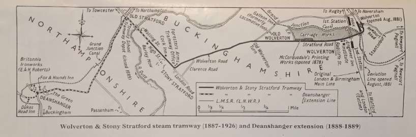
Lee tells us that in 1882 a special meeting of Stony Stratford ratepayers considered a proposal to apply to the Board of Trade for an Order to sanction a tramway between Wolverton and Stony Stratford. “The ratepayers approved, subject to the track nowhere exceeding 6 ft. in width. A company was formed, apparently by these local interests, and was incorporated on 4th November 1882, as the Wolverton & Stony Stratford Tramways Co. Ltd. The Chairman was Abraham Culverhouse, and the Secretary John George Ventris Field Johnson. The company failed to get under way, and was placed in voluntary liquidation on 3rd September 1883. One of its few corporate acts seems to have been the granting of consent, two days after it went into liquidation, to the registration of a new company with a similar (but not the same) name.” [1: p547]

“Meanwhile, a Tramways Order had been promoted by Frederick Charles Winby, a civil engineer and contractor, and this was granted on 16th July 1883. It authorised [a tramway] 2 miles 54 chains [in length], mainly of single line, 4 ft. gauge, from the new Wolverton Station (opened in August, 1881) to the northern end of High Street, Stony Stratford.” [1: p547]
Wolverton to Stony Stratford and beyond
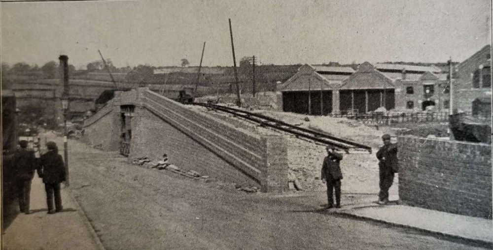
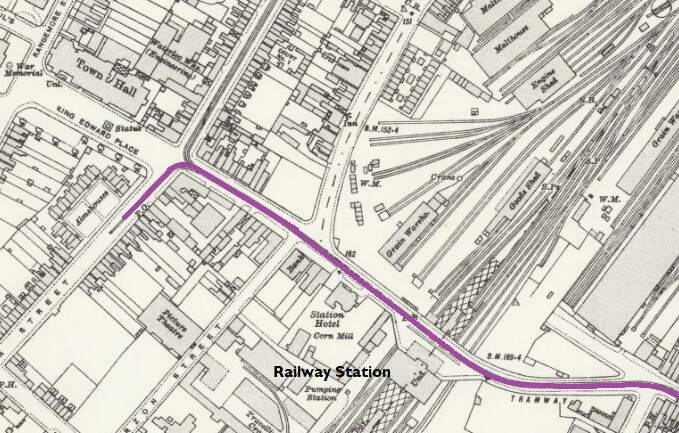
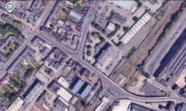
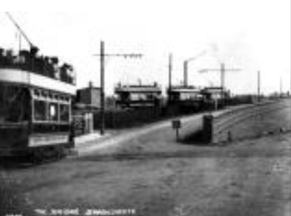
From the new station the tramway ran South along the road built to bridge the diversion line and the Canal at the South end of the site of Wolverton Railway Station. This road had once been a footpath.
The company promoted by Winby took the name, ‘The Wolverton & Stony Stratford & District Tramways Co. Ltd‘. It acquired all the rights and interests of Winby in the Tramways Order of 1883. Lee tells us that “It had an authorised capital of £20,000 in £1 shares, which was increased to £30,000 on 27th October 1883. The latter fact seems to have been forgotten, although it was duly registered and the requisite stamp duty paid. Indeed, the company had very little regard for the niceties of the Companies Acts, and actually varied its corporate name on the Memorandum and Articles of Association respectively. Thereafter, it could never remember the precise title shown on the certificate of registration, which is the one used above. Winby contracted to build the line, and to take part of the price in shares, but the whole arrangement fell through. The company was dormant until 1886, and only 34 shares were issued.” [1: p548]
C.H. Wikinson, a local contractor that promoted a number of schemes in the area (such as a link between Newport Pagnell and Olney), “entered into a contract with the company on 18th August 1886, to build the line for £13,325, and on 8th September 1886. agreed under an indenture to accept £2,000 in shares. The name of the company was changed on 5th October 1886, to the Wolverton, Stony Stratford & District Light Railways Co. Ltd., and its shares were offered for sale. They were taken up by a large number of local [people], and the work proceeded rapidly.” [1: p548]
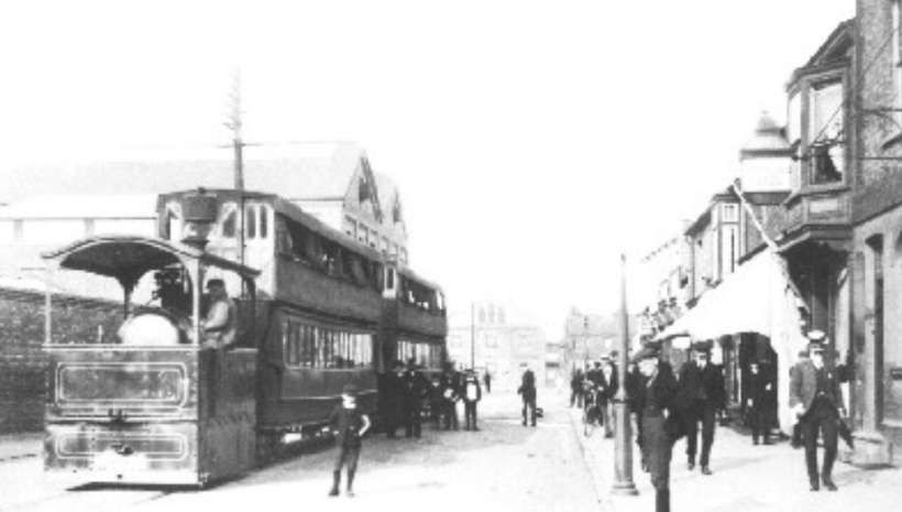
Lee continues: “The line as authorised in 1883 received Board of Trade sanction on 20th May 1887, in respect of 2 miles 15 chains single line and 40 chains double. It was built to the 3 ft. 6 in. gauge instead of the 4 ft. originally authorised. Public passenger traffic was begun on 27th May 1887, between the Barley Mow Inn, Stony Stratford, and Wolverton Station, with tramway-type steam locomotives hauling very large covered-top double-deck tramcars. The ordinary fare was 2d., with a special cheap rate for workmen, whereas the horse bus that had previously served the route charged 6d.” [1: p548]
Allan Edwards says: Wolverton “grew rapidly to an austere and symmetrical pattern, its housing owned by the railway company and leased to its employees; it seemed almost to be a northern industrial town misplaced in the agricultural heart of England. Stony Stratford meanwhile declined, becoming largely a dormitory town for its now larger neighbour. … By 1880, hundreds of workmen were walking daily to Wolverton from Stony Stratford and the surrounding villages. An alternative form of transport was a horse bus from Stony Stratford but the fare for this was 6d (22p) for a single journey, a price beyond the wage of the workmen of the now London & North Western Railway Co., or the new McCorquodale’s printing works whose average wage was only 30 shillings per week (£1.50).” [13: p15]
The old bus service did not run to a timetable, only travelling when there were sufficient passengers. “Average bus receipts were between £2 and £3 a week, but the tramway takings rapidly became £45 a week, largely by reason of the use of the line made by employees at the Wolverton carriage Works and at McCorquodale’s. Weekly tickets were issued to them at 1 shilling and entitled them to 4 journeys a day.” [1: p548]
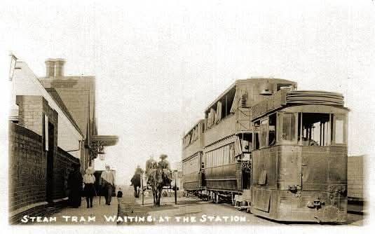
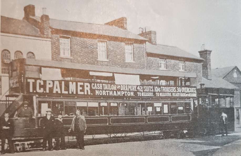
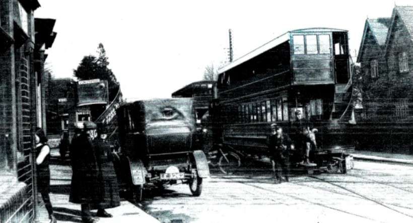
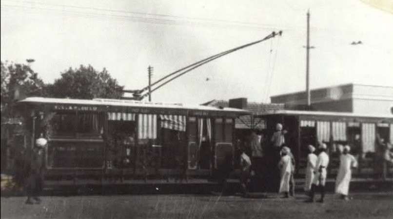
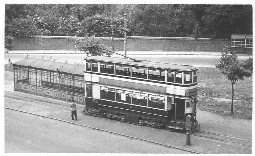
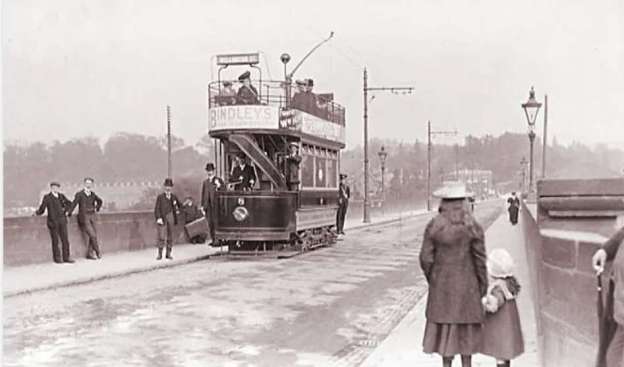
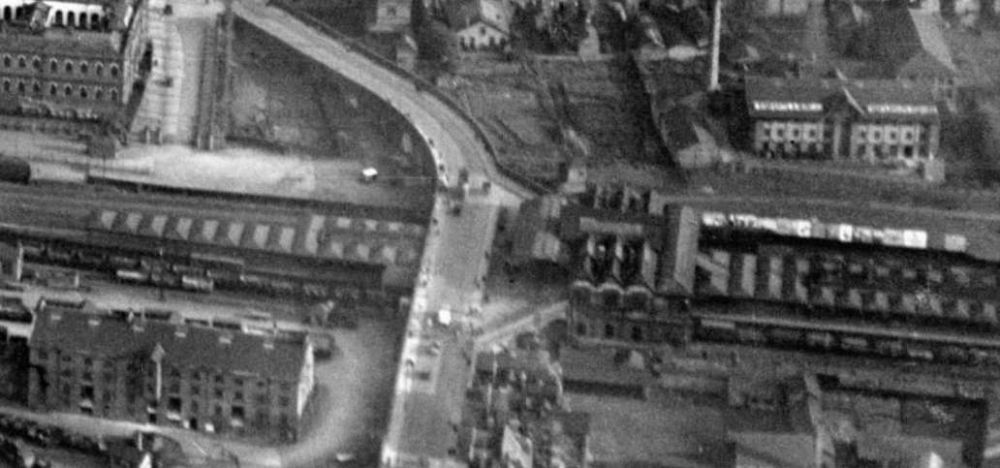
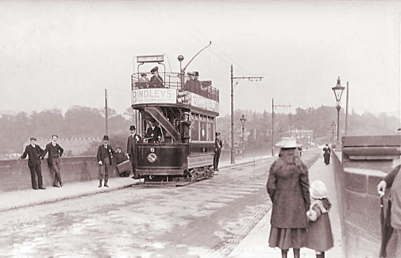
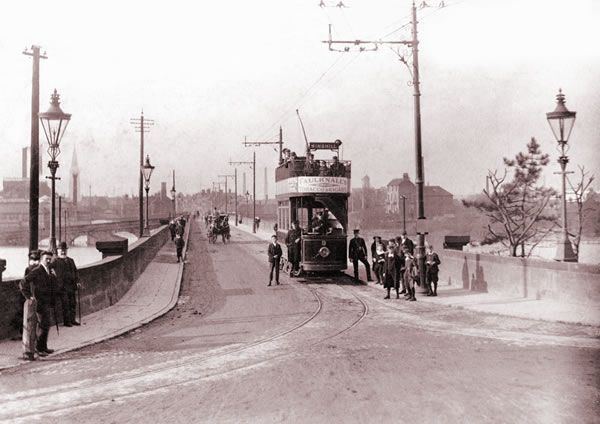
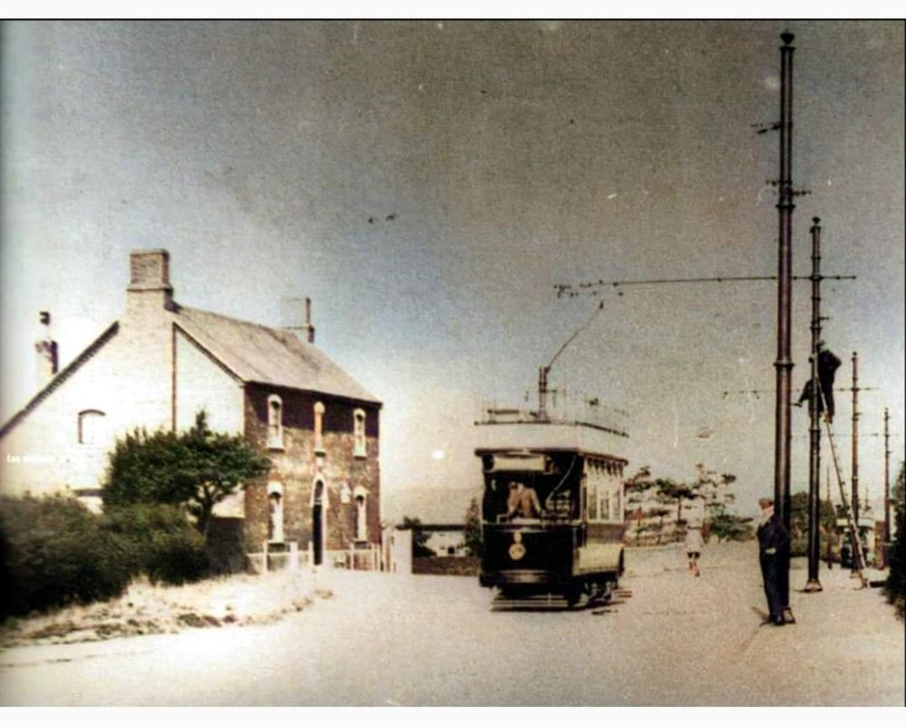
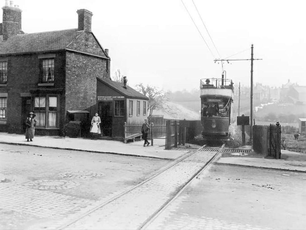
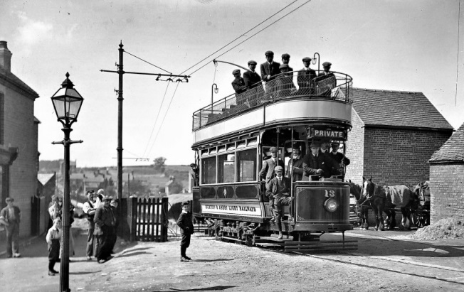
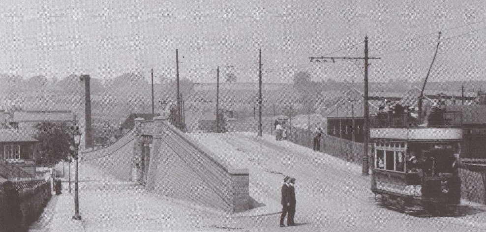
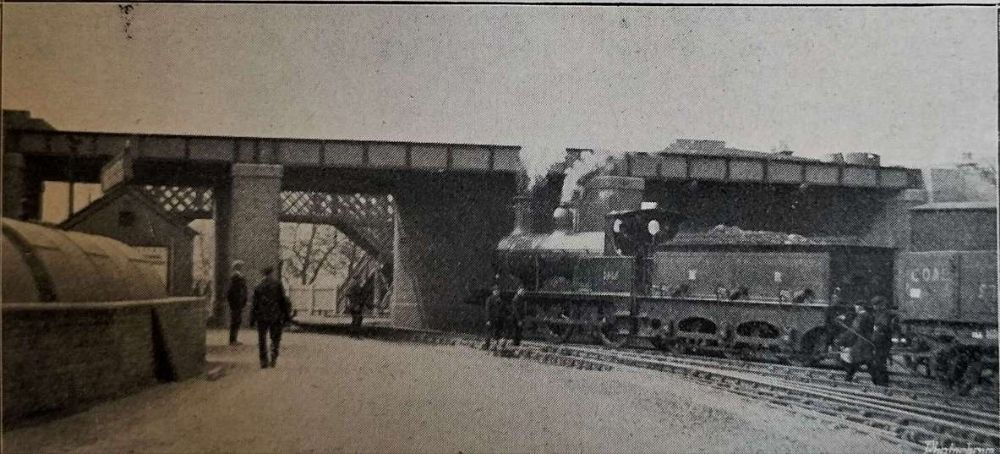
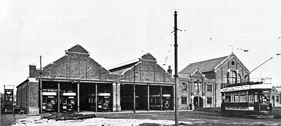
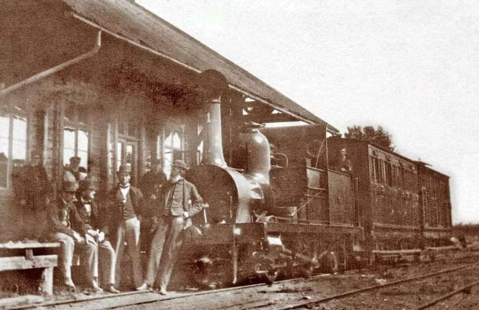
Another view of the steam tram waiting at Wolverton Railway Station. As these two images show, the passenger facilities were accessed at road level from the bridge over the main line railway, © Public Domain. [23]

Wolverton was a railway town built to accommodate the workers. It has since expanded significantly. Much of the old Works site and the railway ‘village’ of terraced housing form a Conservation Area in the 21st century.
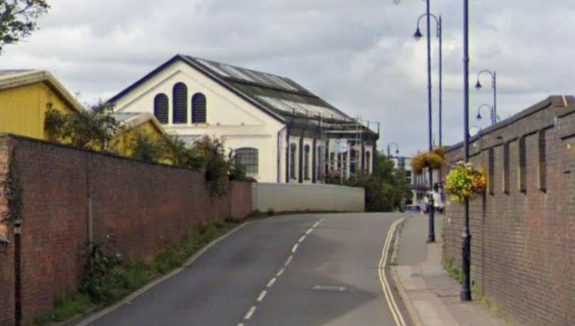
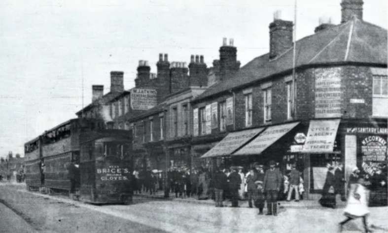
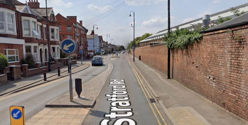
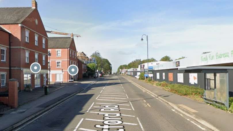
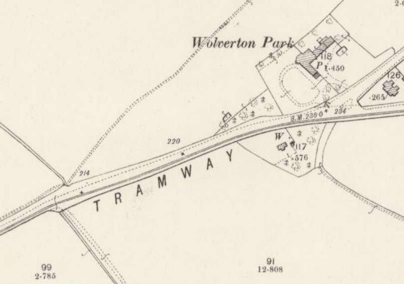
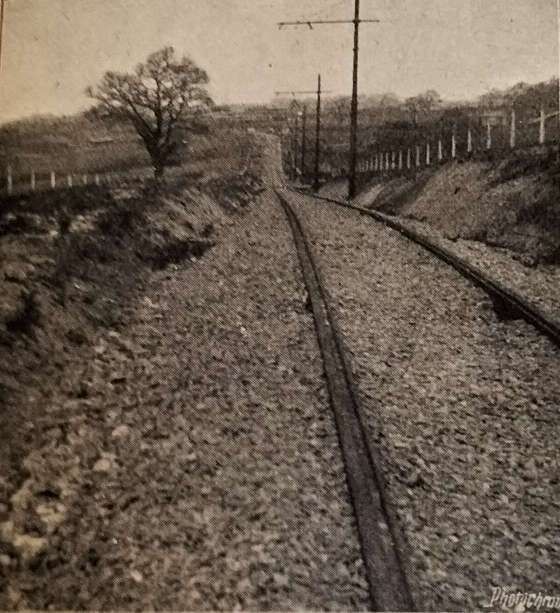
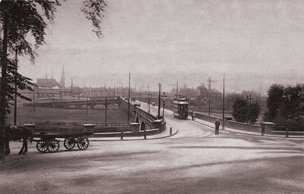
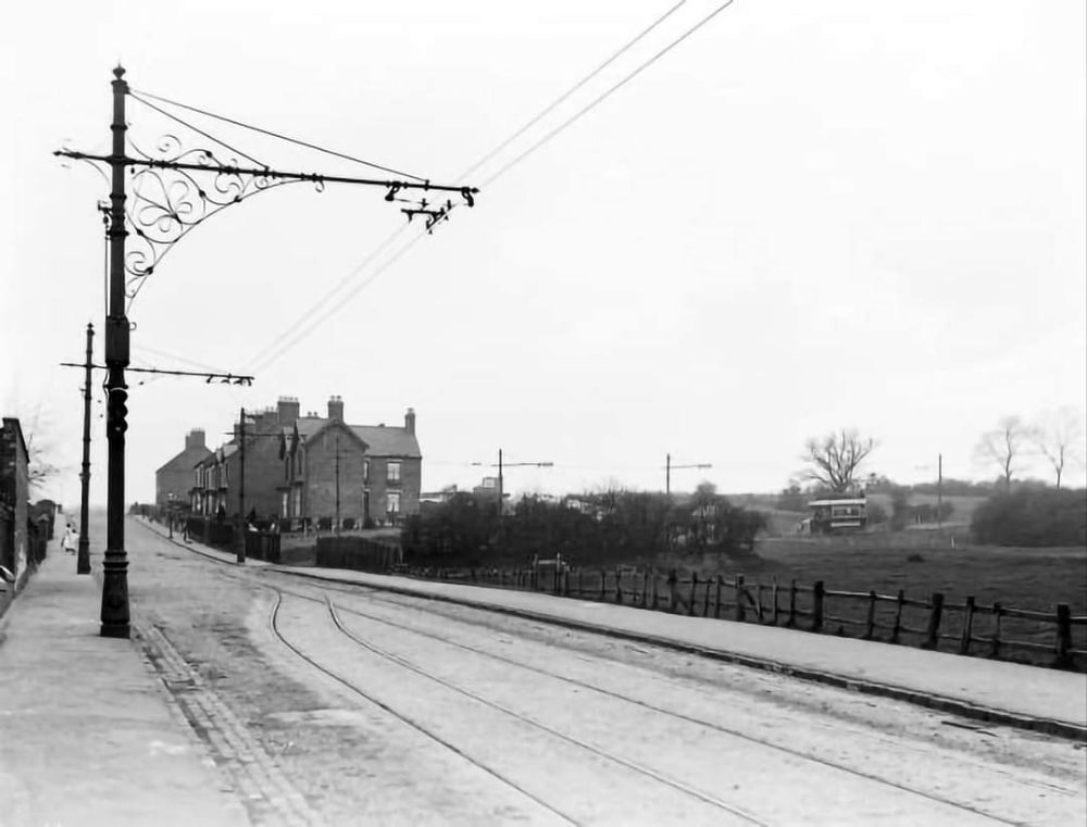
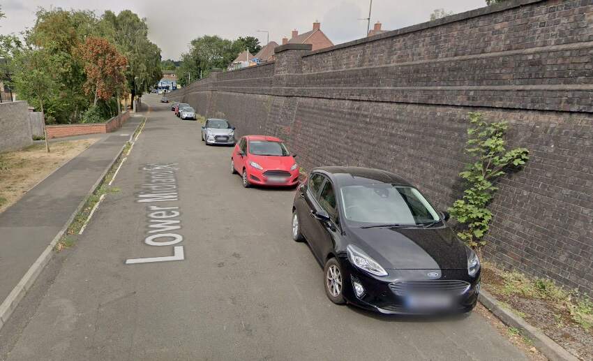
Allan Edwards describes the route of the tramway through Wolverton like this: Outside Wolverton Station goods yard there was a turning triangle on a steeply descending section of road and a link into the station goods yard. From this location, trams “climbed steeply on a right-hand curve to the road bridge over the 4-track railway line where tramway passengers could board outside the overline buildings of the LNWR station. The tramway then continued up and over the lines leading into the railway works. … With its track in the centre of the highway the tramway passed the railway workshops, the town of Wolverton being entirely on the left-hand side. Virtually continuous brick walls to the right sealed off first the LNWR works and then McCorquodale’s printing factory. It was nearly three quarters of a mile before the tramway line abruptly left the town behind, moving to the lefthand side of the road.” [13: p17]
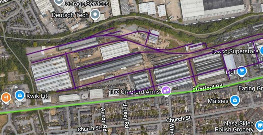
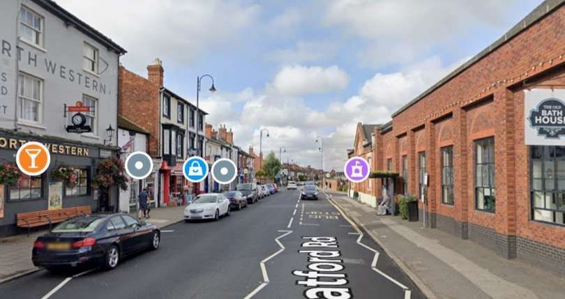
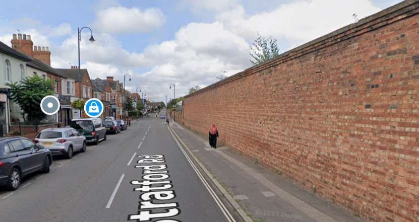
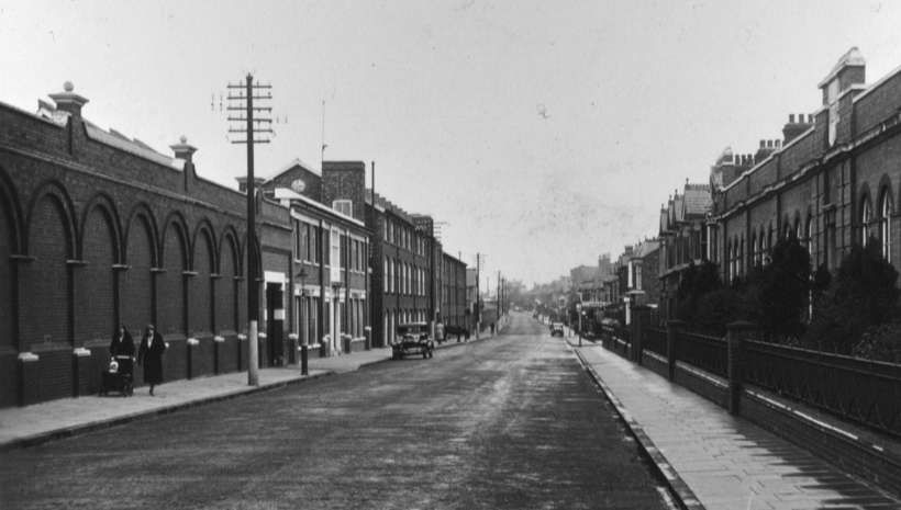
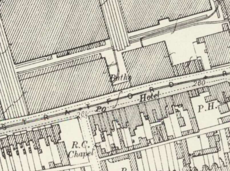
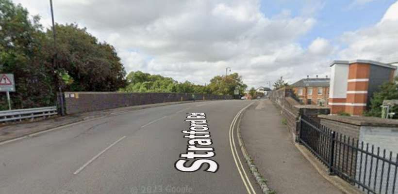
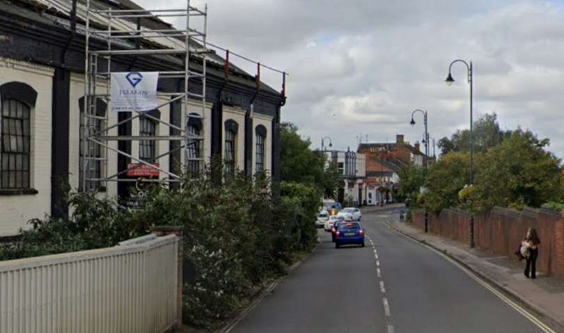
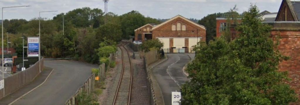
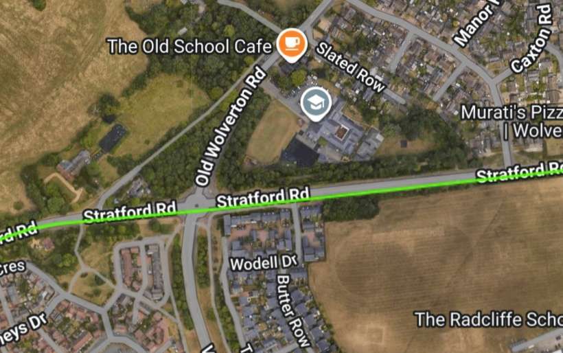
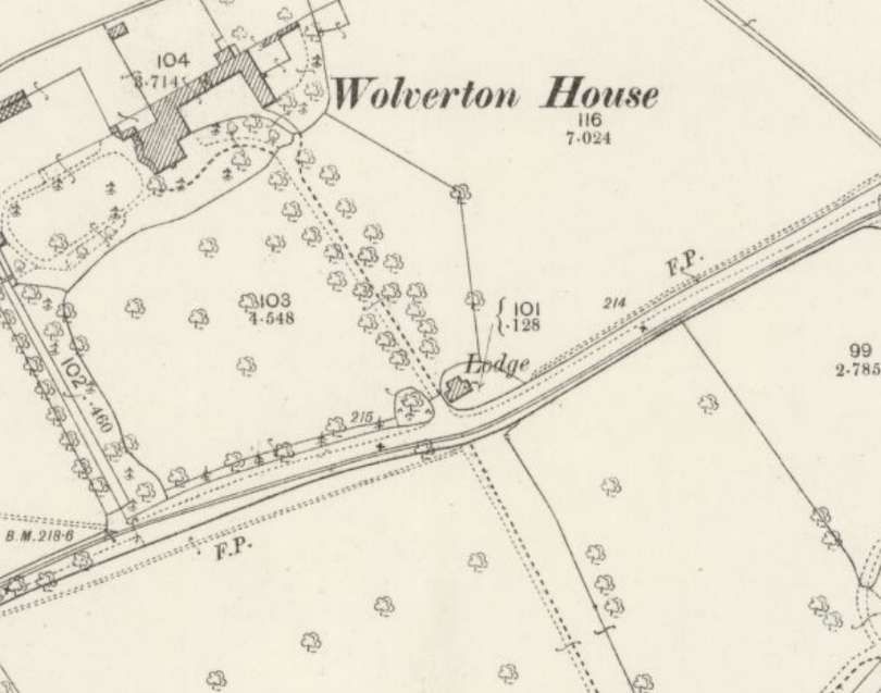
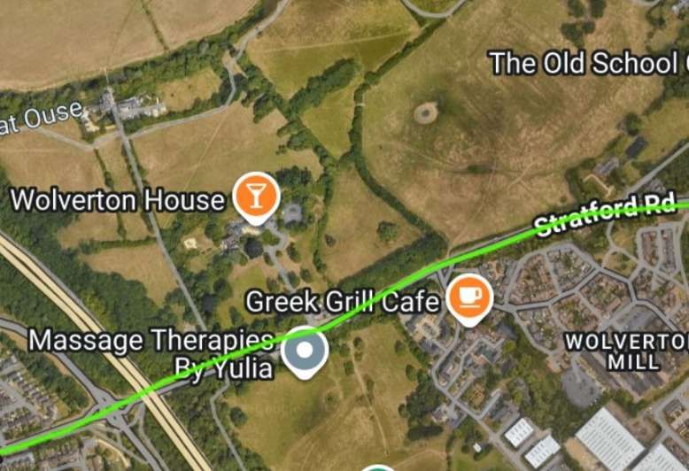
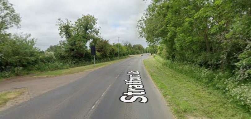
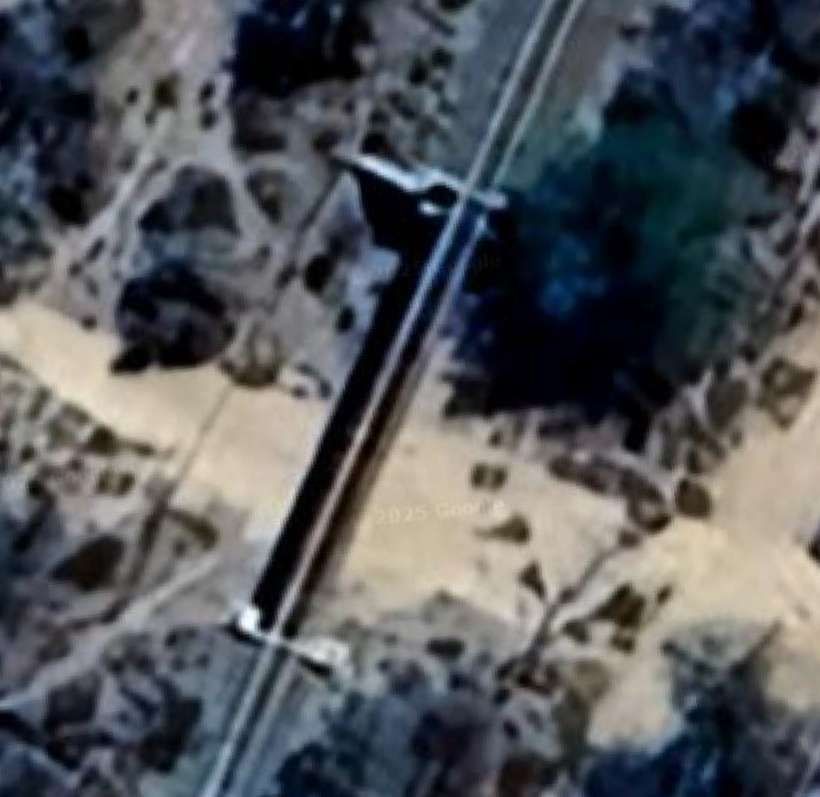
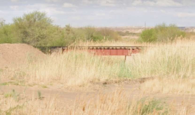
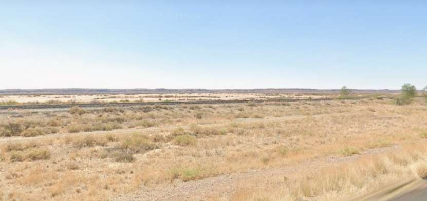
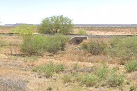
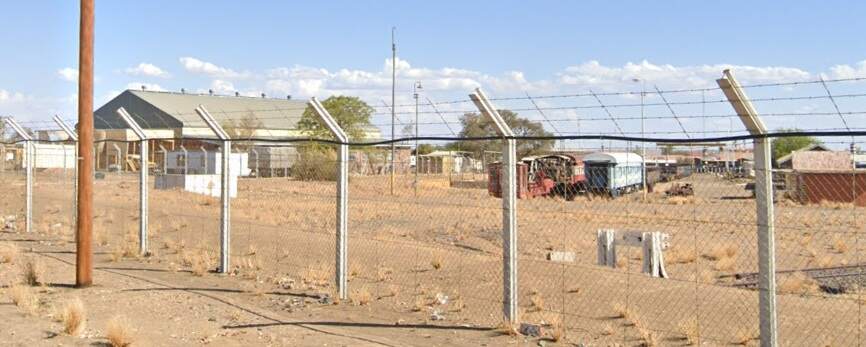
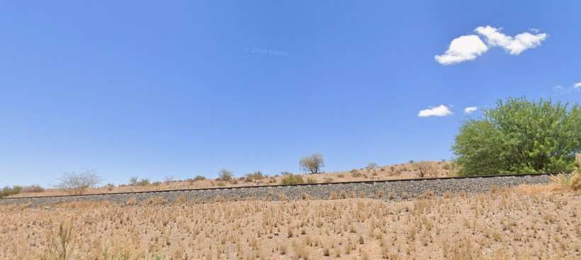
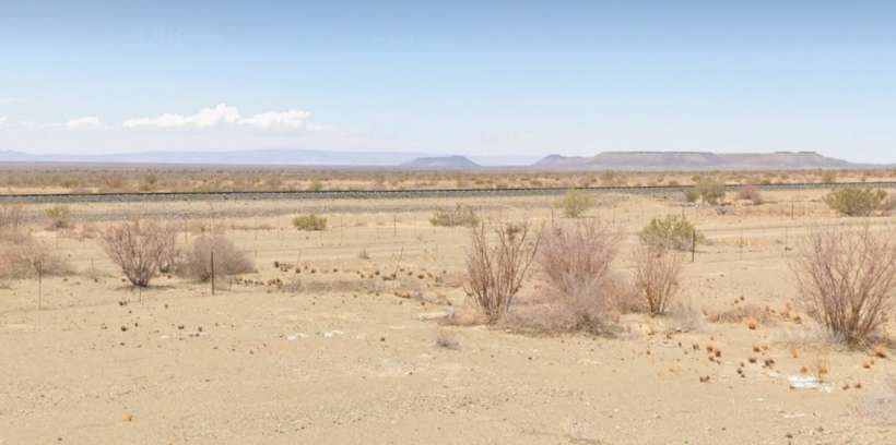
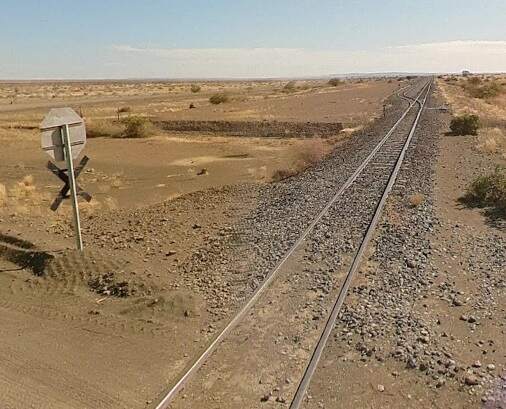
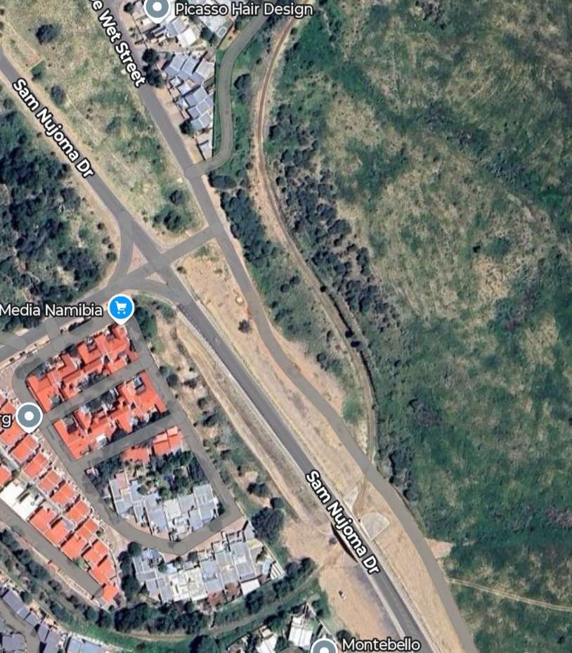
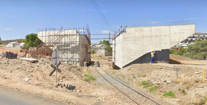
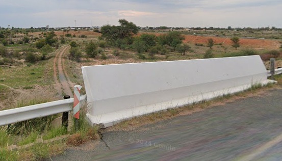
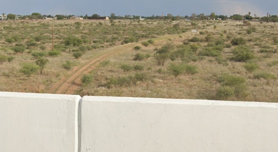
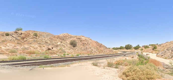
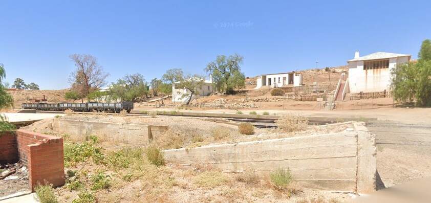
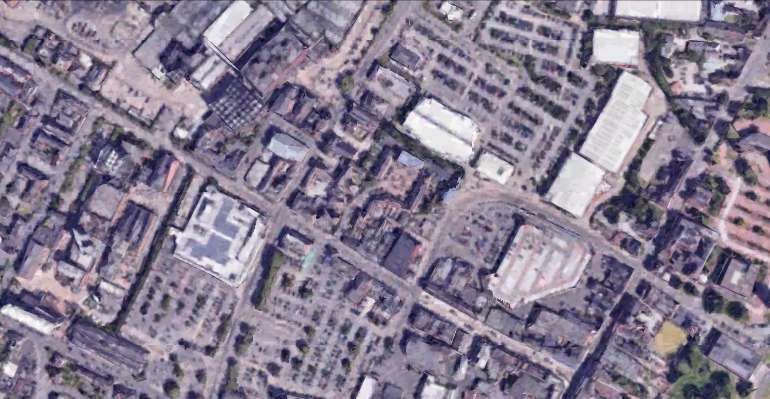
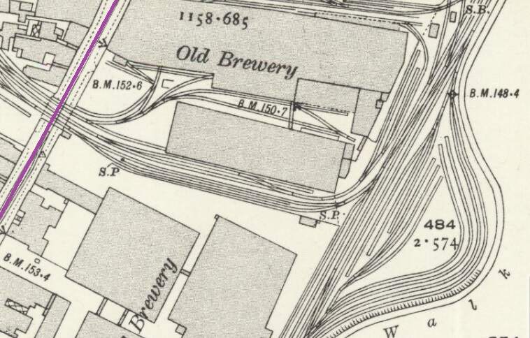
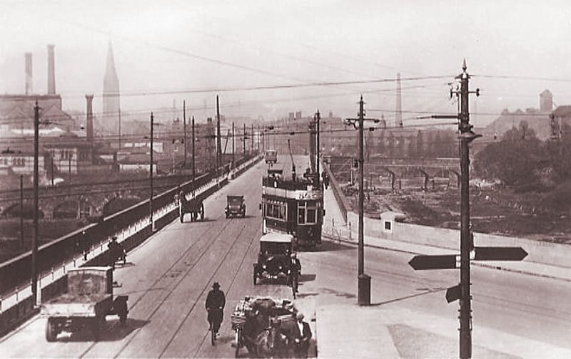
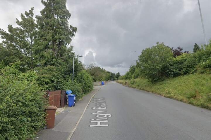
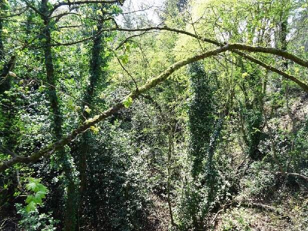
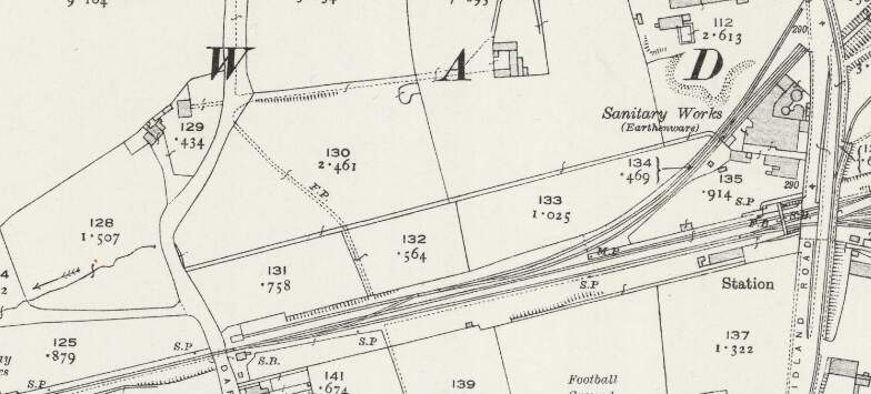
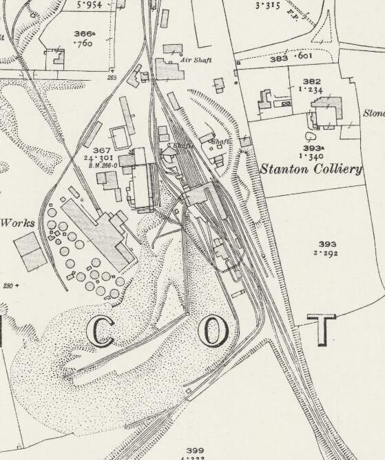
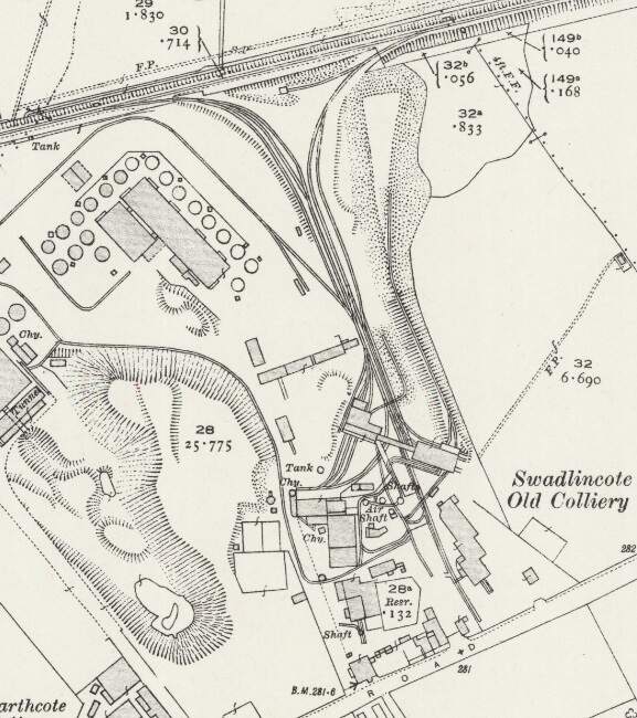
The next three images continue to show Stratford Road running along the South side of the site of Wolverton Works. …
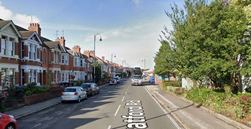
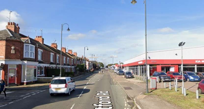
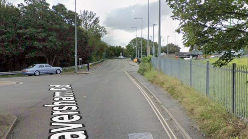
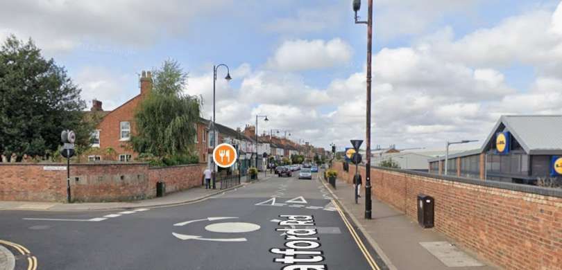
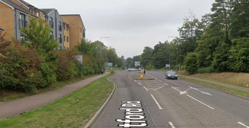
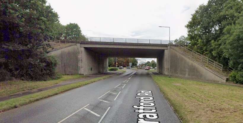
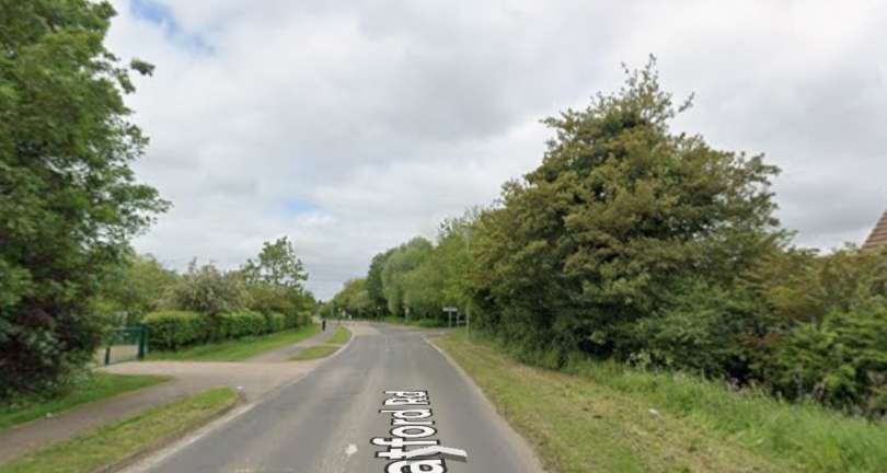
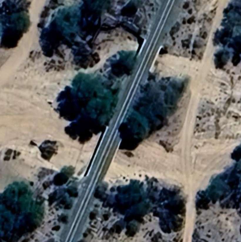
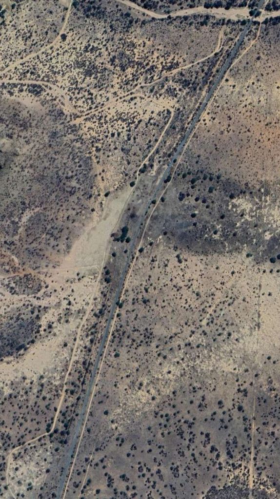
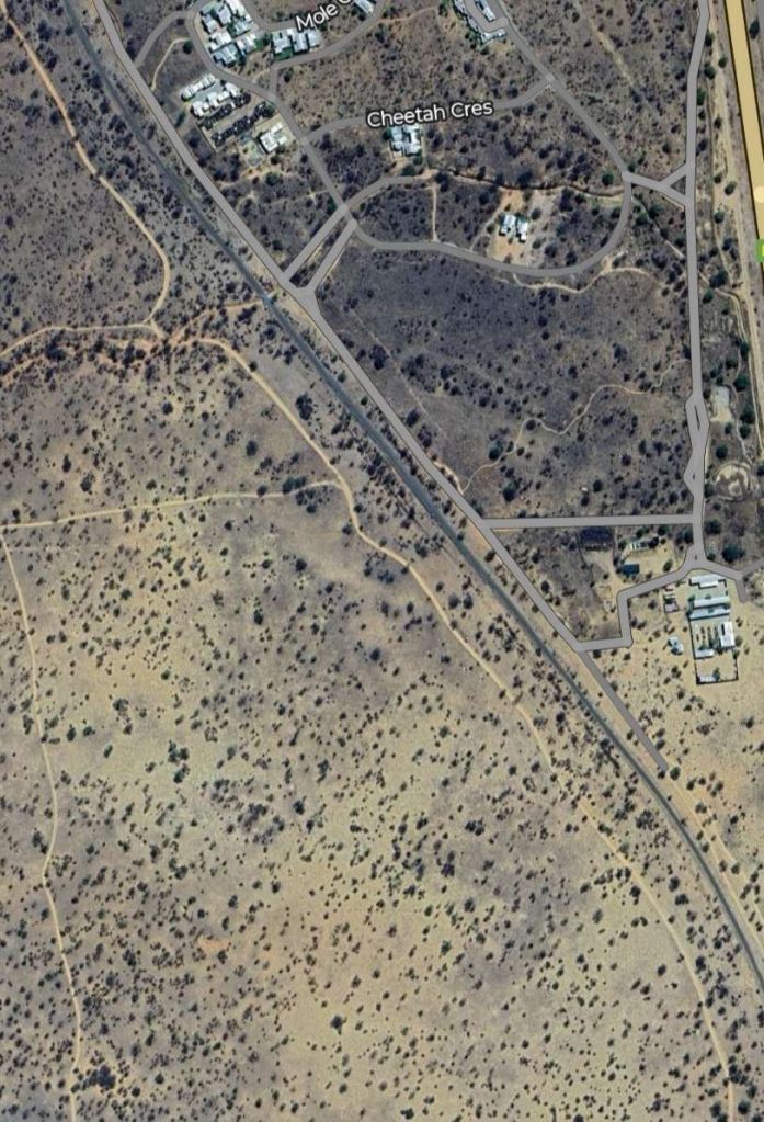
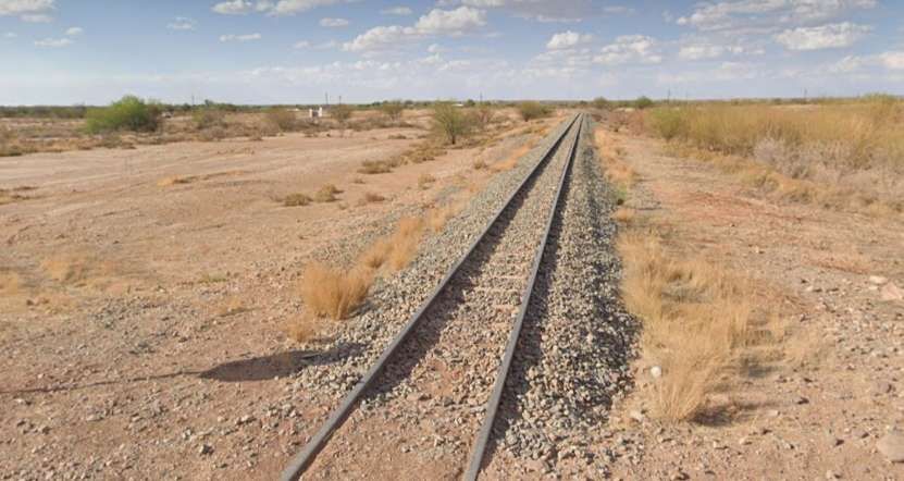
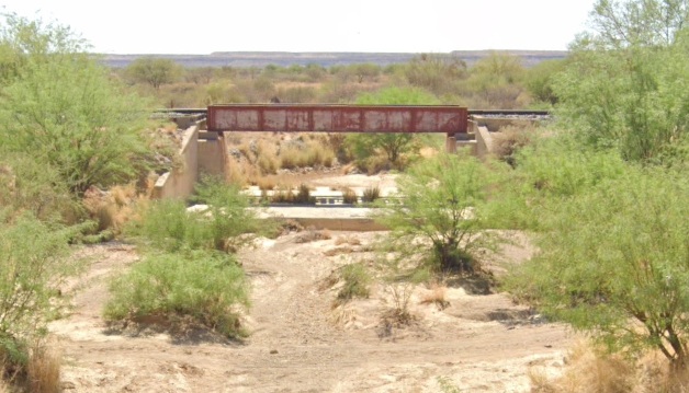
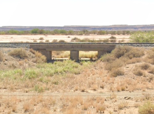
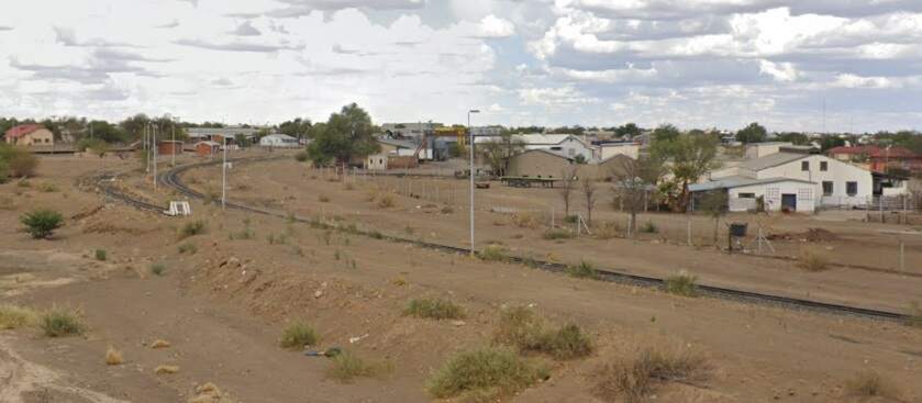
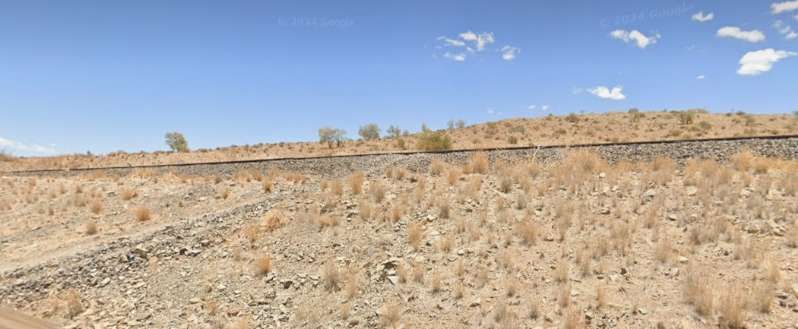
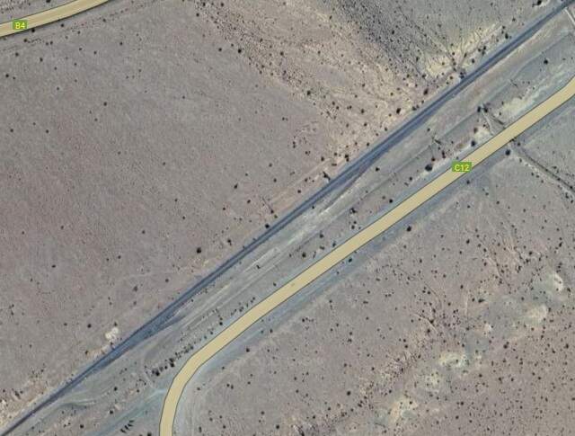
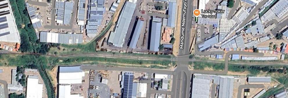
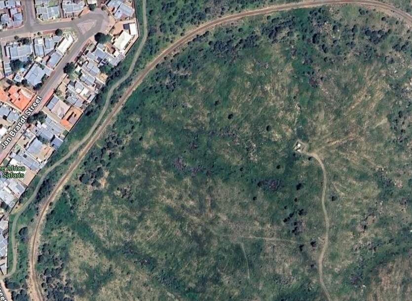
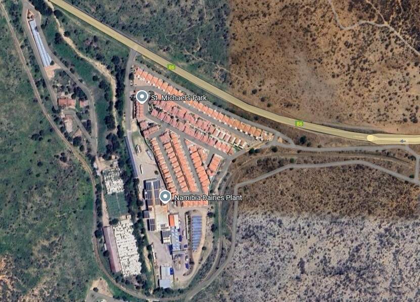
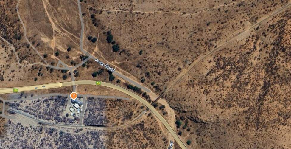
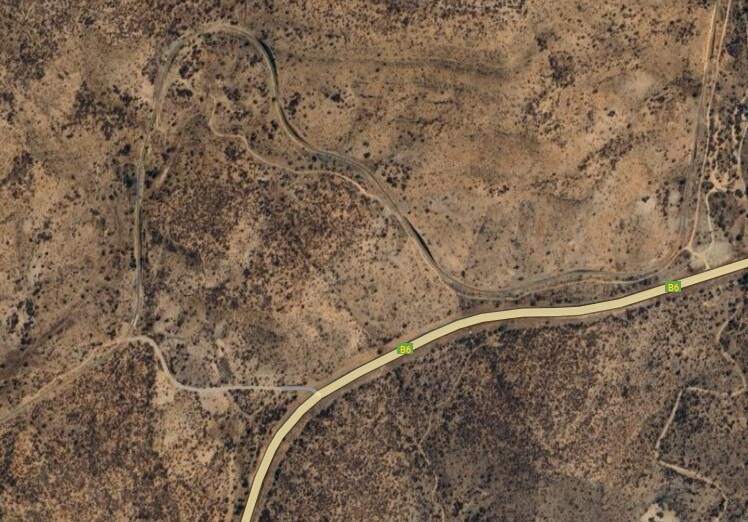
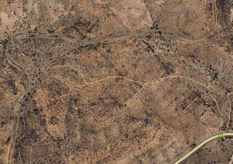
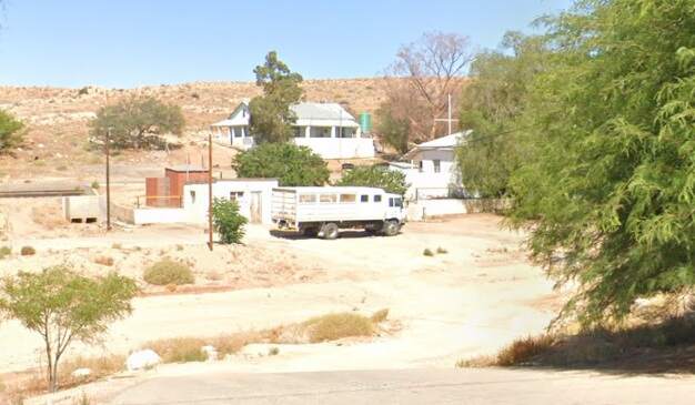
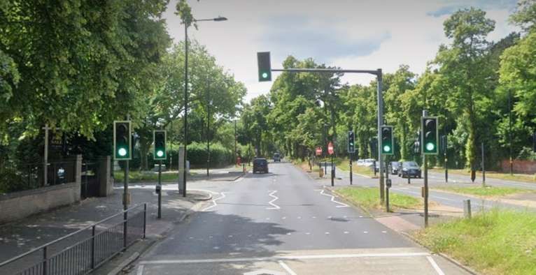
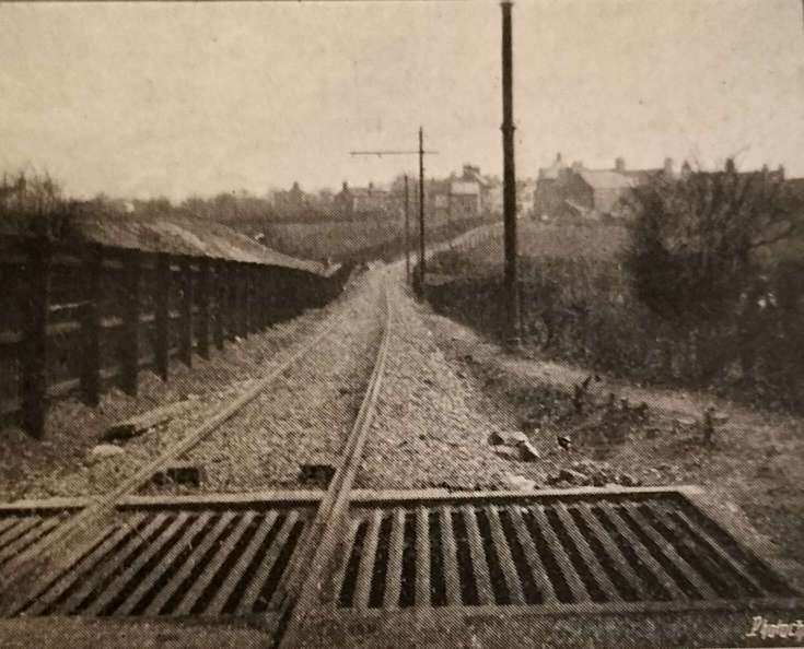
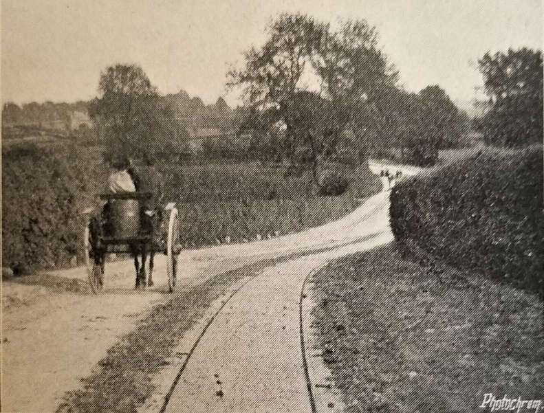
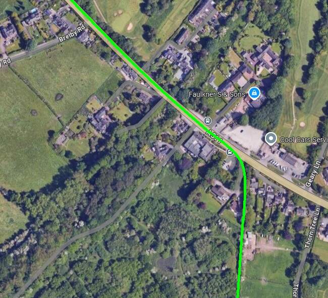
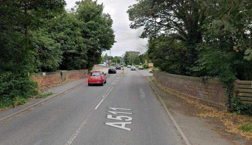
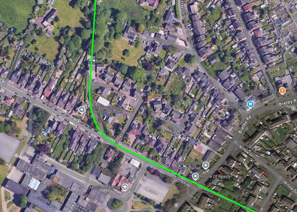
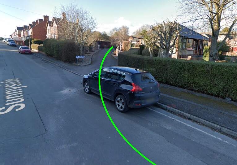
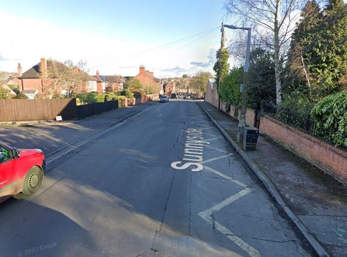
We are now beyond the West end of the Works site. The next three images show Stratford Road heading West towards a modern roundabout at Old Wolverton Road. …
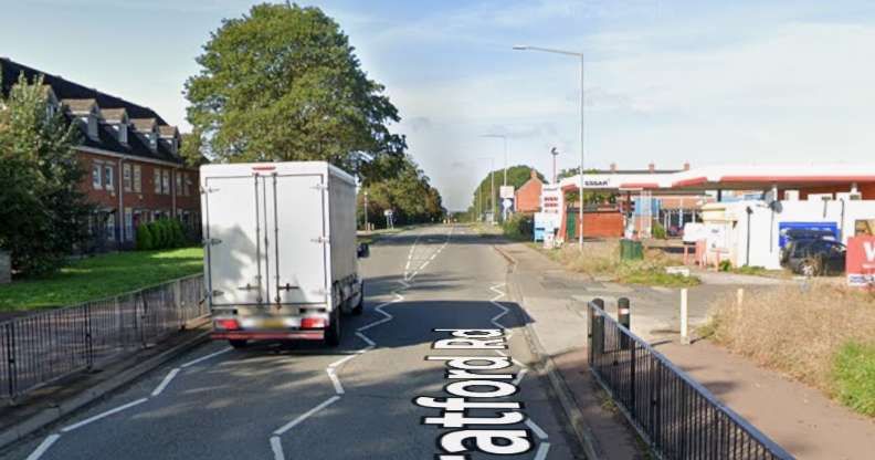
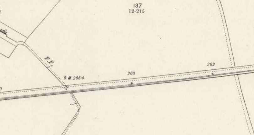
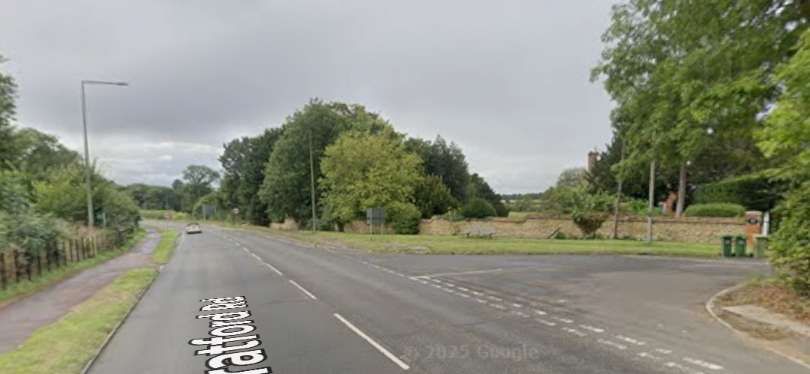
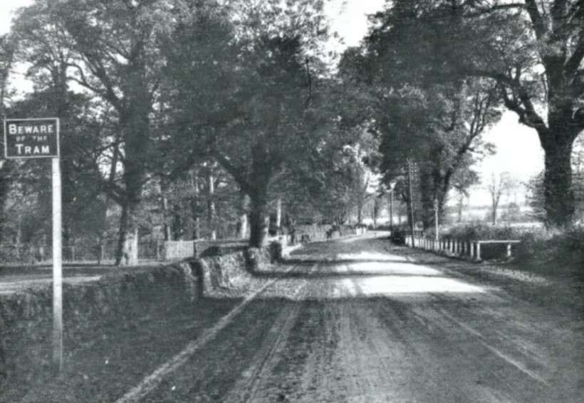
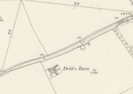
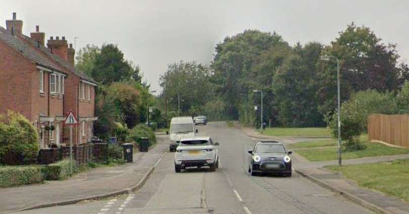
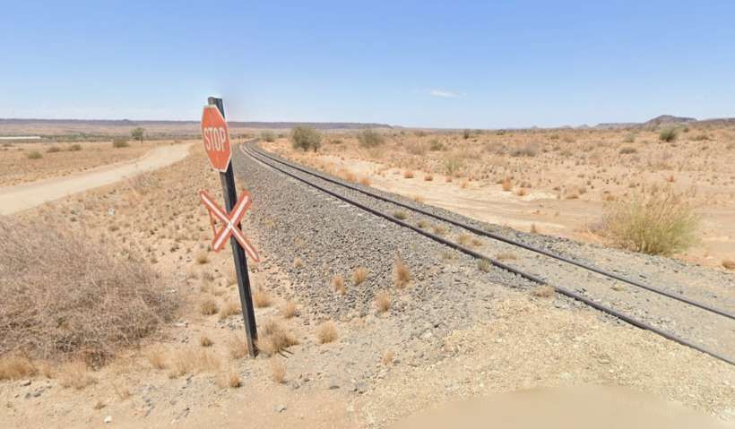
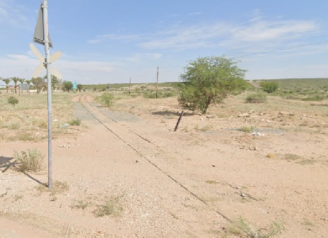
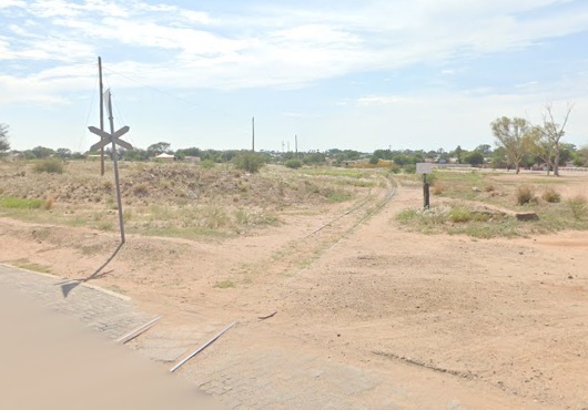
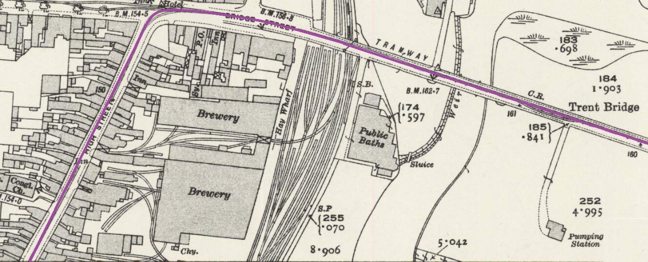
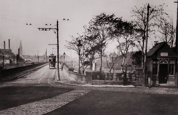
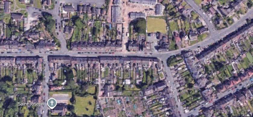
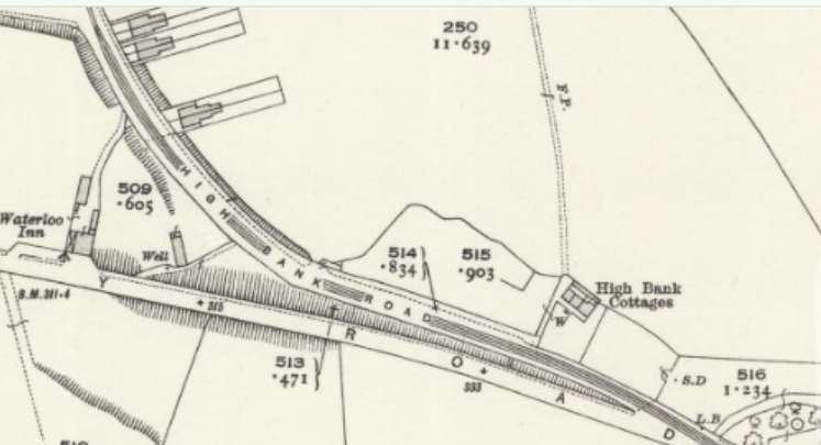
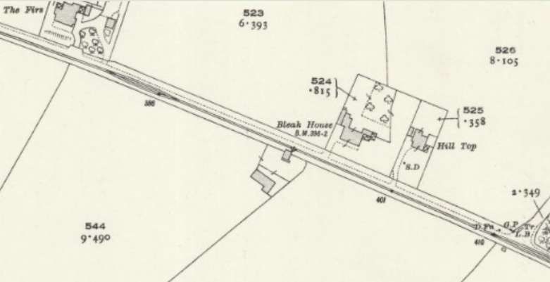
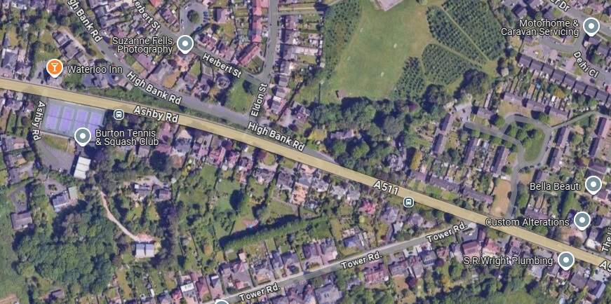
Edwards says that, “The route was almost straight but a fierce hill faced engines travelling towards Wolverton at almost the halfway point of the route where the old road to Wolverton (the remaining buildings of the original hamlet somewhat west of the new industrial town having by this time received the suffix ‘Old’) diverged from the newer, more direct course that the tramway traversed.” [13: p17]
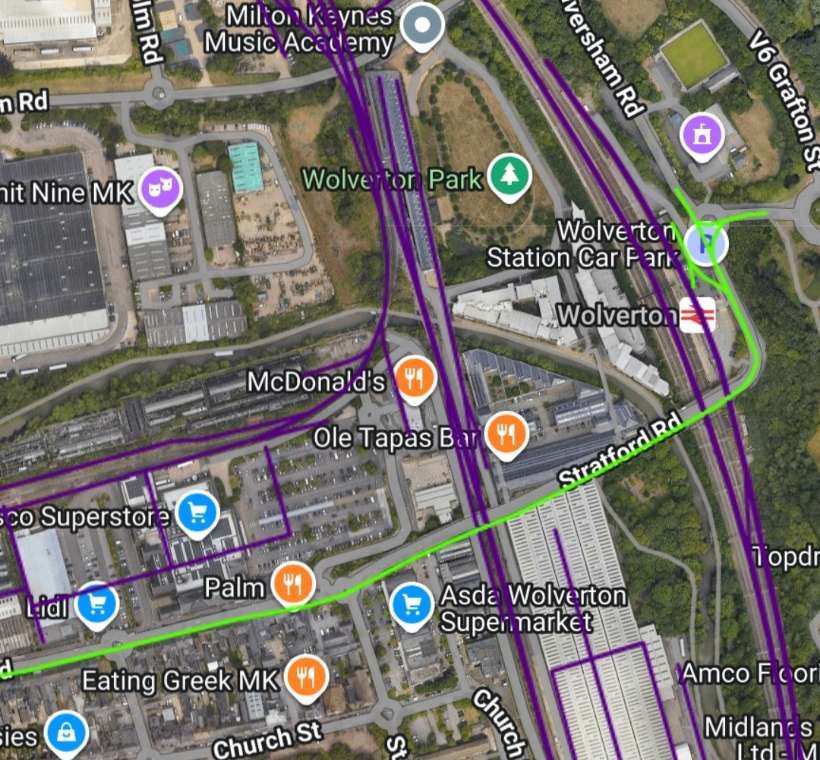
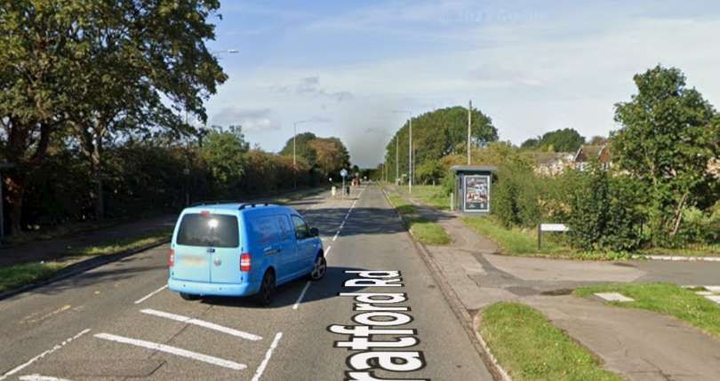
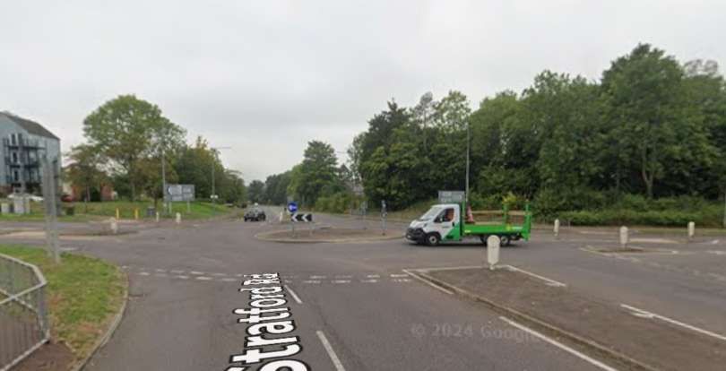
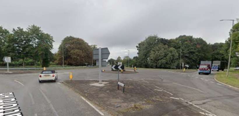
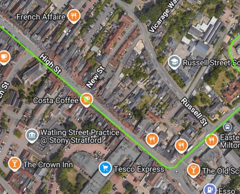
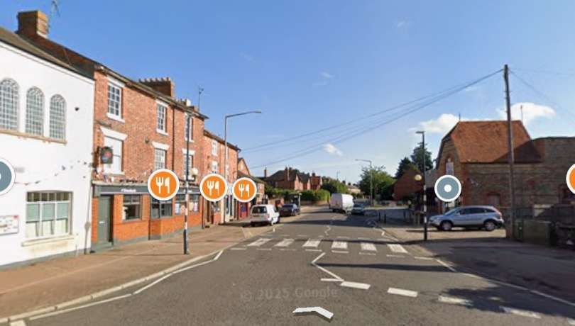
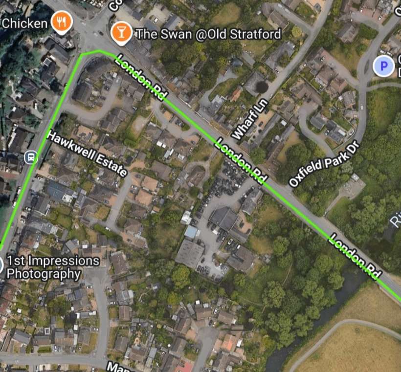
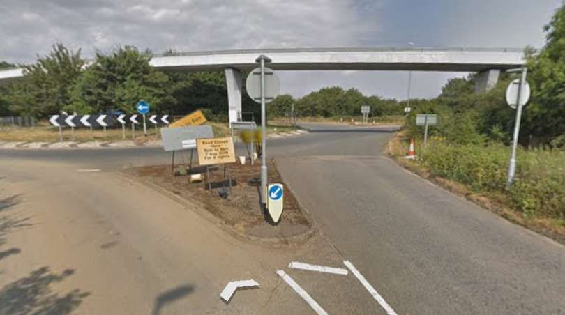
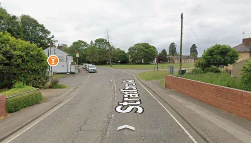
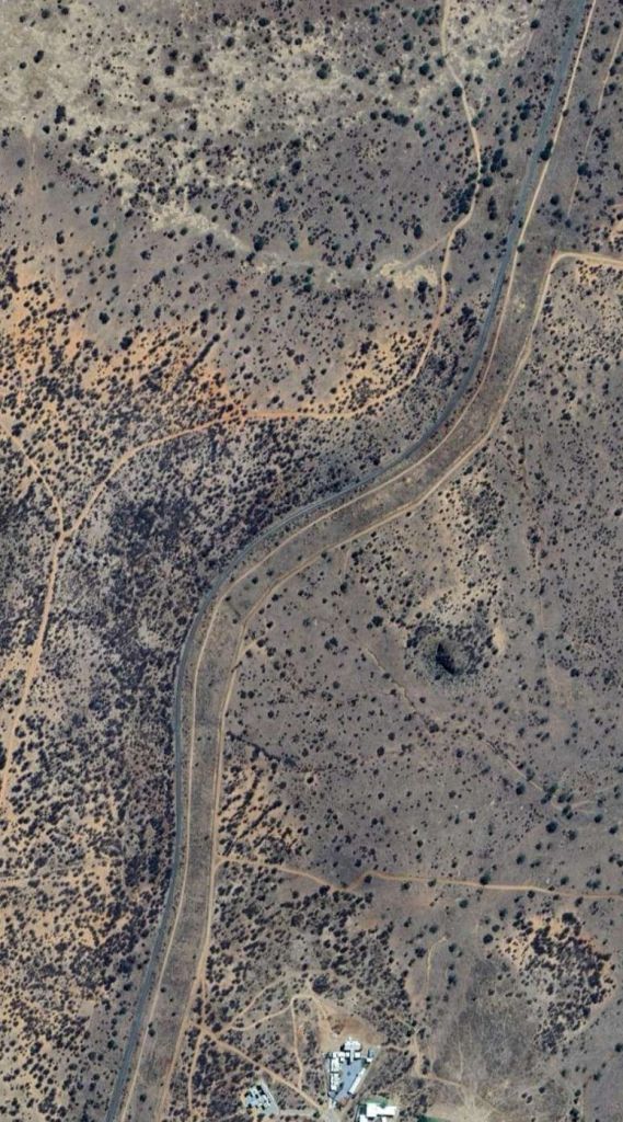
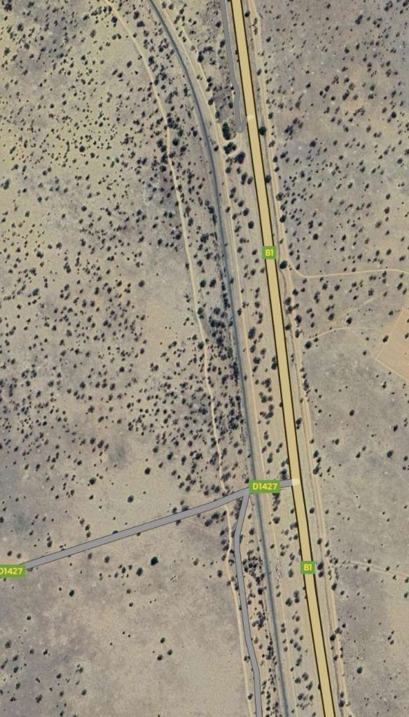
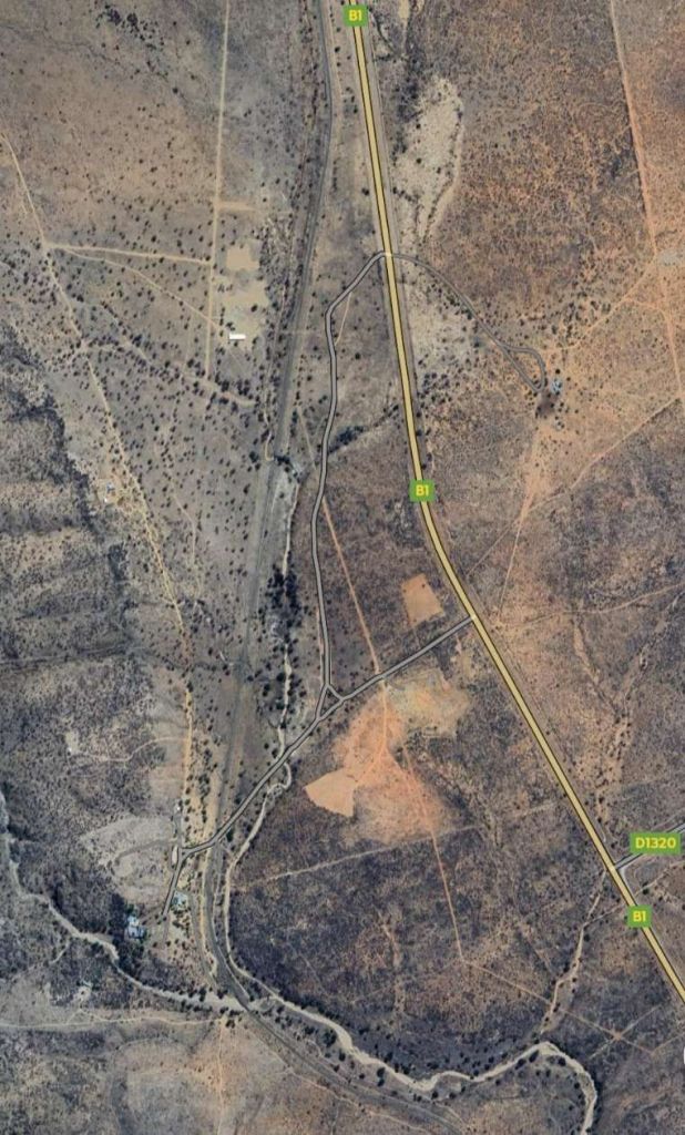
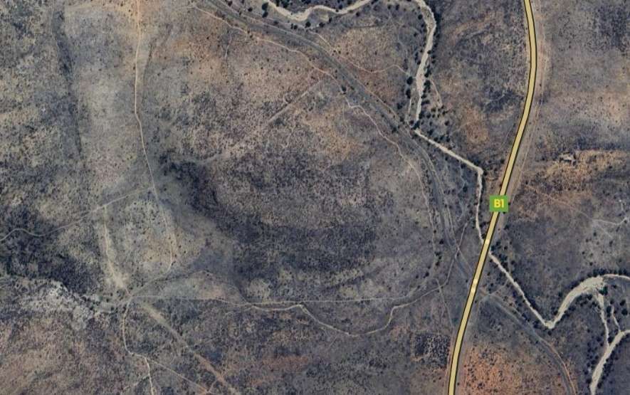
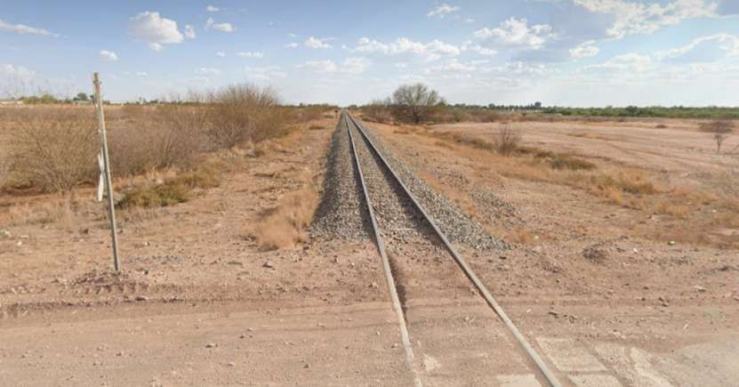
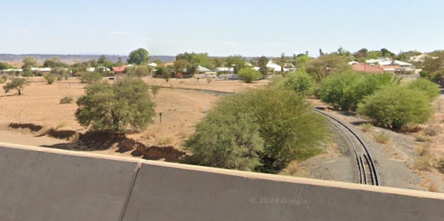
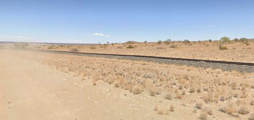
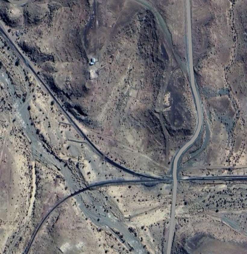
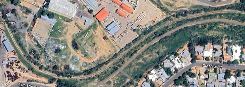
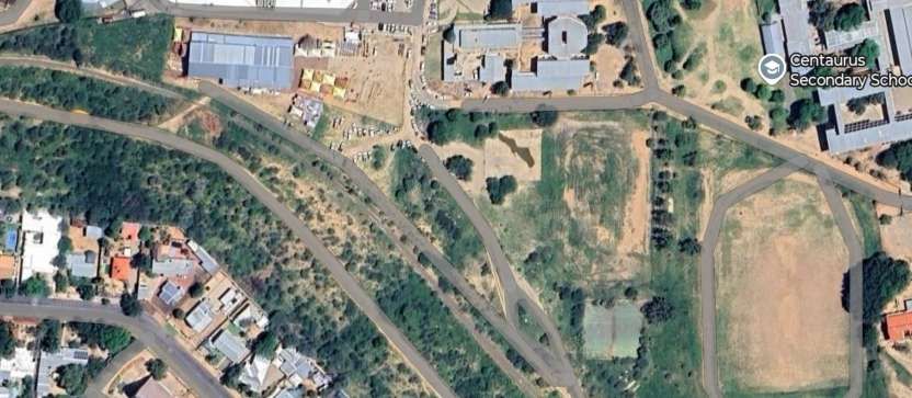
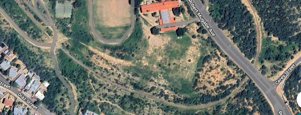
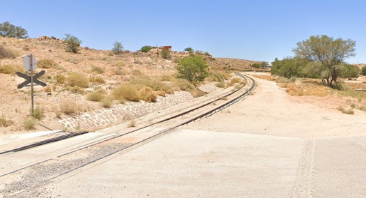
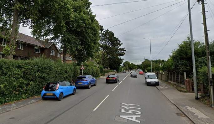
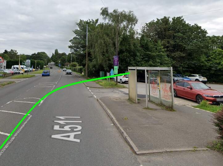
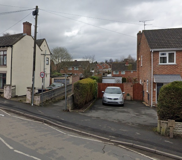
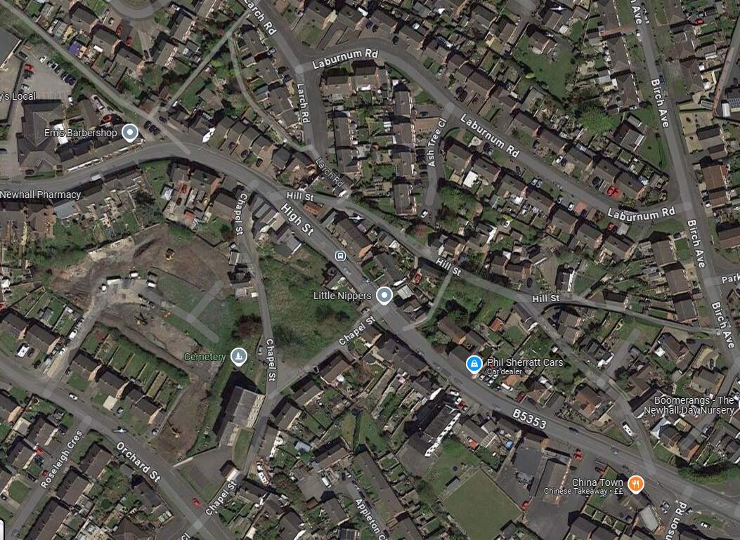
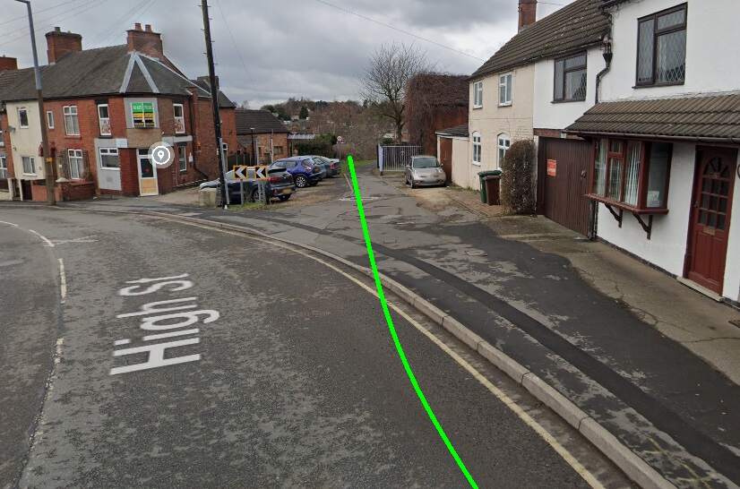
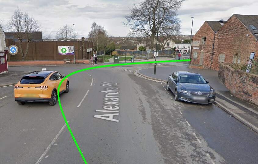
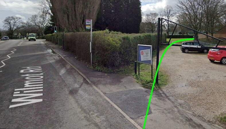
The next three Google Streetview images take the route of the tramway across the modern roundabout at the junction between Stratford Road and Old Wolverton Road to the original junction between the two roads. …
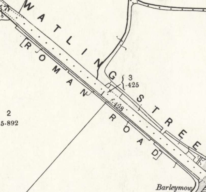
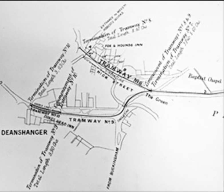
Lee provides just one paragraph which relates to the route travelled. He tells us that “In its maximum form, the undertaking began at the cattle sidings, Wolverton Station, and ran as a single line in the middle of the road through Wolverton. It then kept to its own track for about a mile, on the south side of the road to a point half a mile before the Wolverton Road joins the main Holyhead Road. The line there crossed over the Wolverton Road to its own track on the north side, but transferred once more to the middle of the public road through Stony Stratford. It thus traversed Wolverton Road to the junction, and turned sharply to the right (north west) along the Holyhead Road, here called High Street, and later Watling Street. At Old Stratford, the Deanshanger extension turned even more sharply to the left from Watling Street, and ran on its own track on the left-hand (south-east) side of the road.” [1: p549]
As we have already seen, Edwards description gives a little more detail: “Shortly before entering Stony Stratford the line abruptly cut across to the opposite side of the road. More than one pioneer motorist was apparently taken unawares by the sudden appearance of a steam tram engine and its trailers across his bows!” [13: p17]
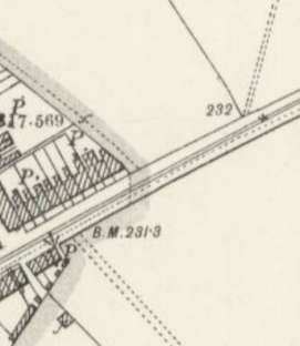
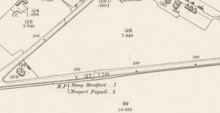
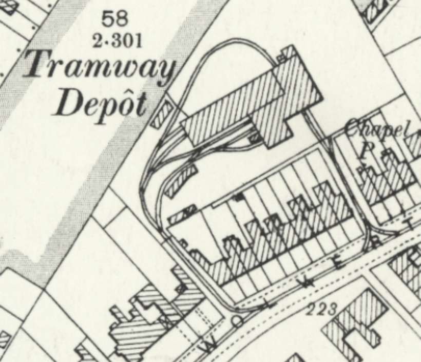
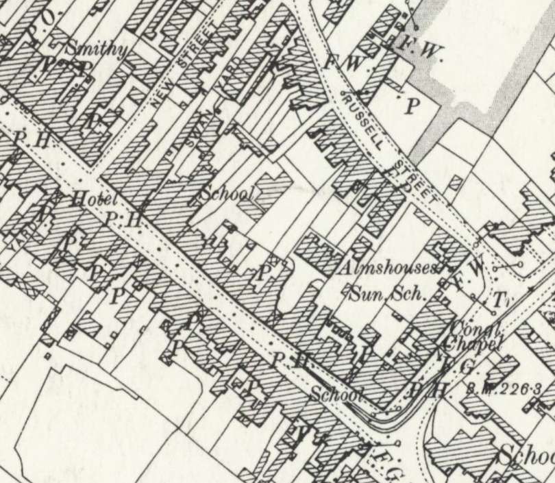
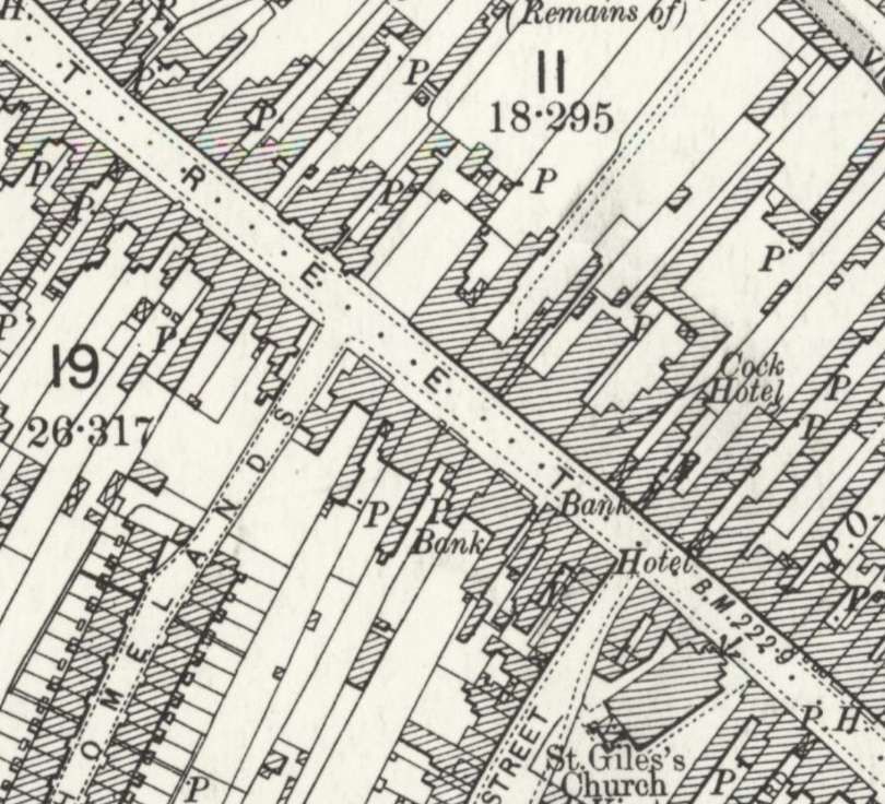
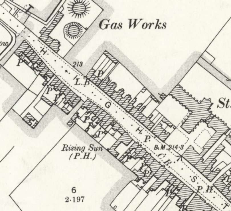
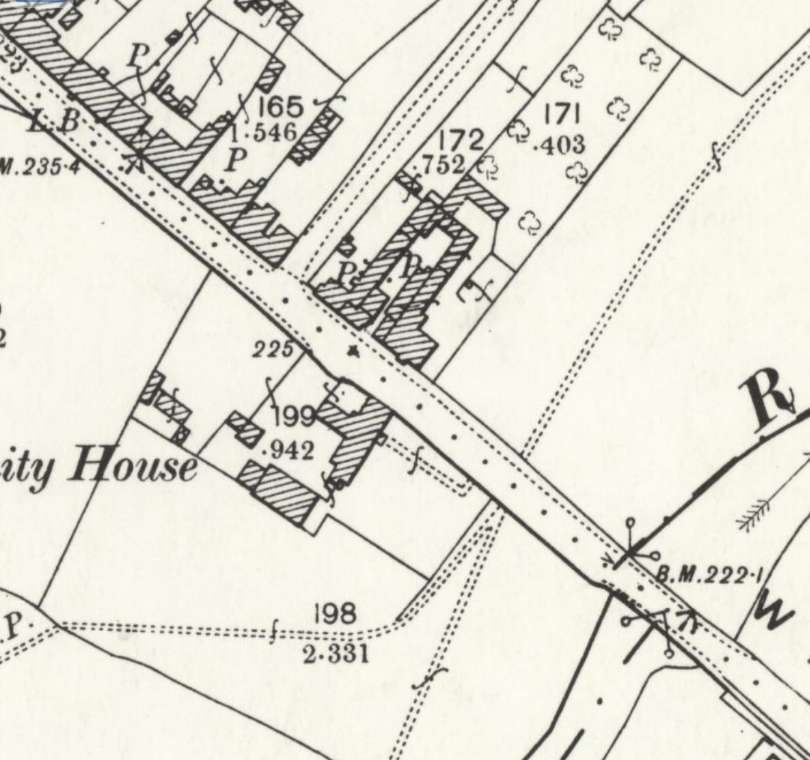
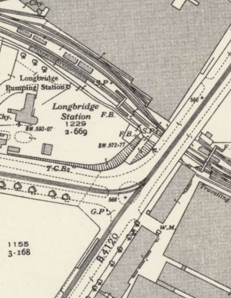
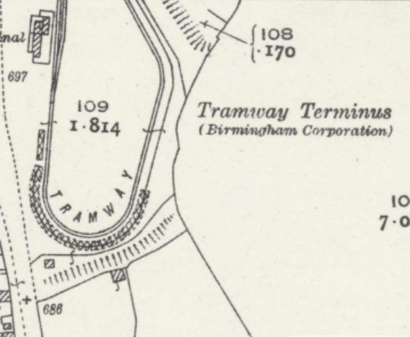
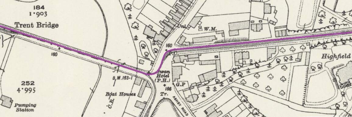
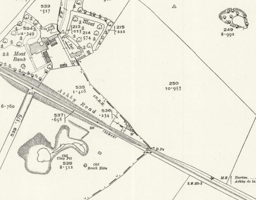
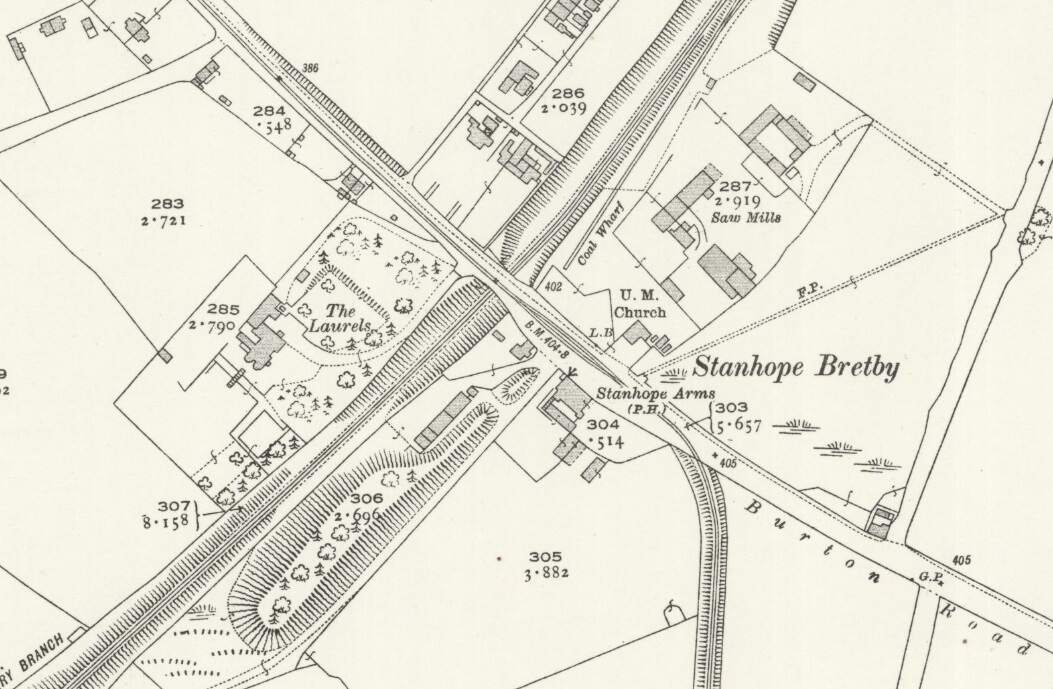
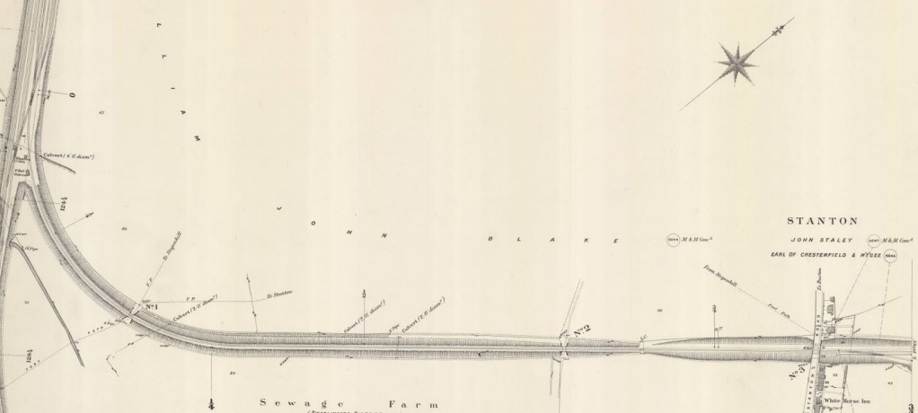
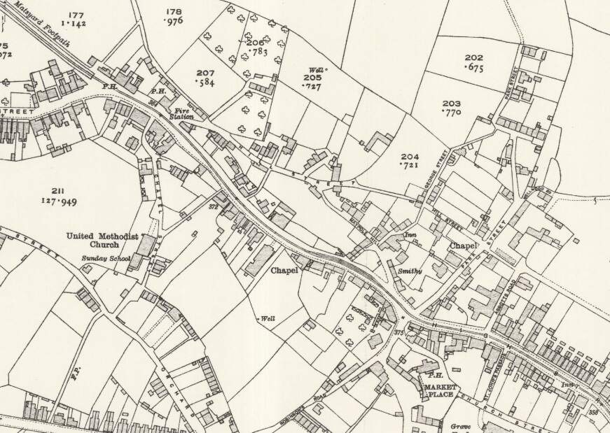
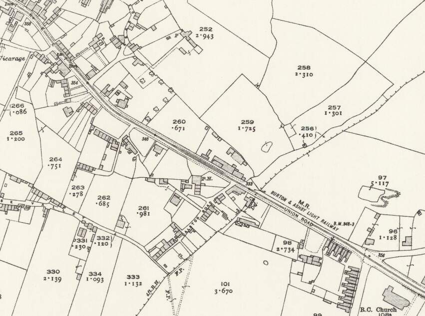
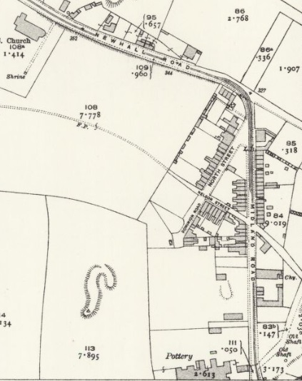
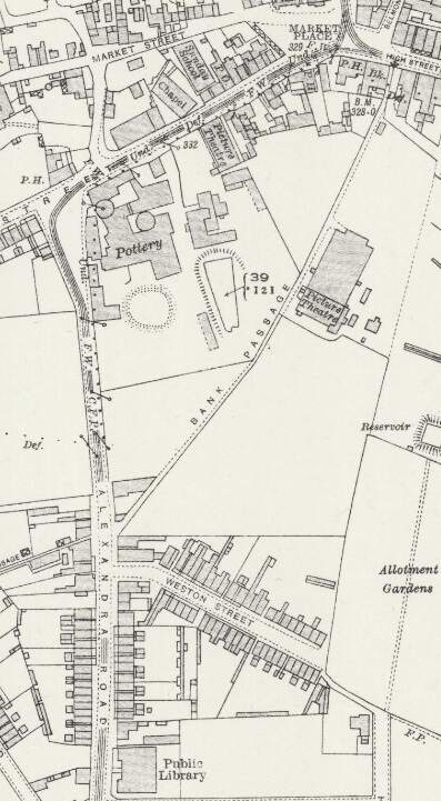
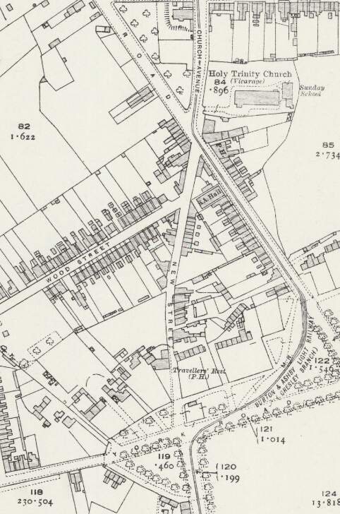
This next smaller map extract brings the line to the edge of the Ordnance Survey map sheet and shows the beginning of the housing at the eastern edge of Stony Stratford. [12]
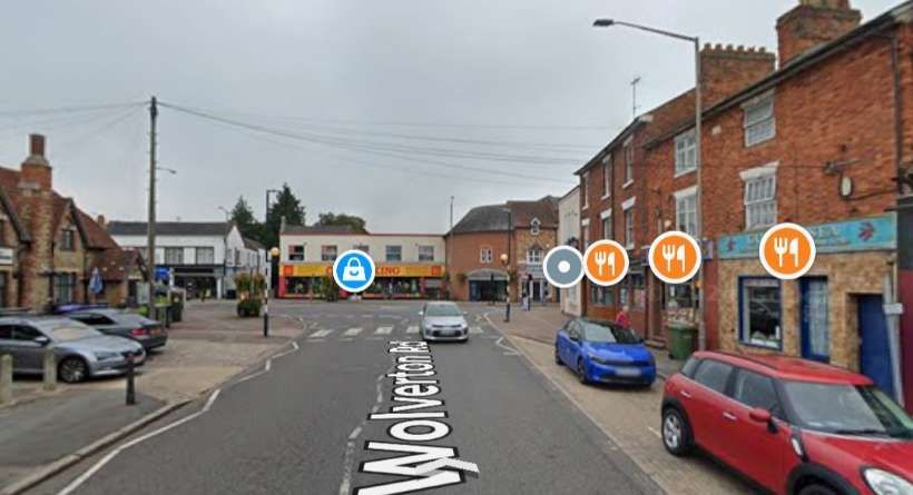
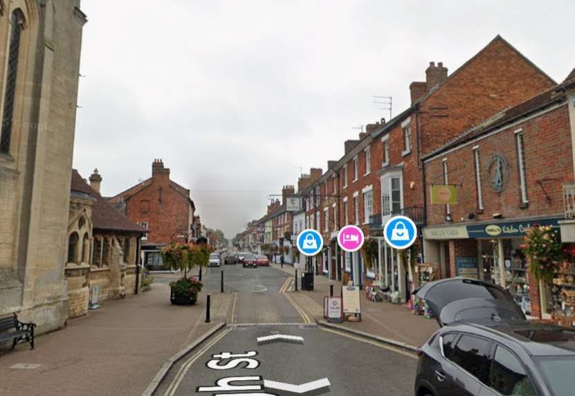
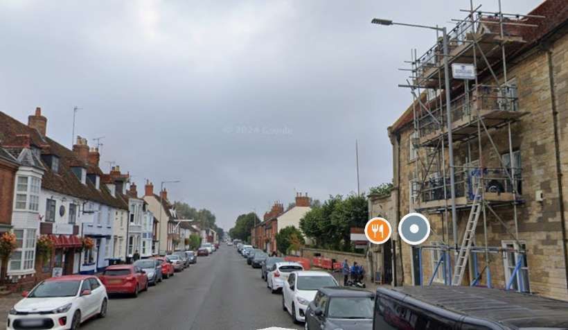
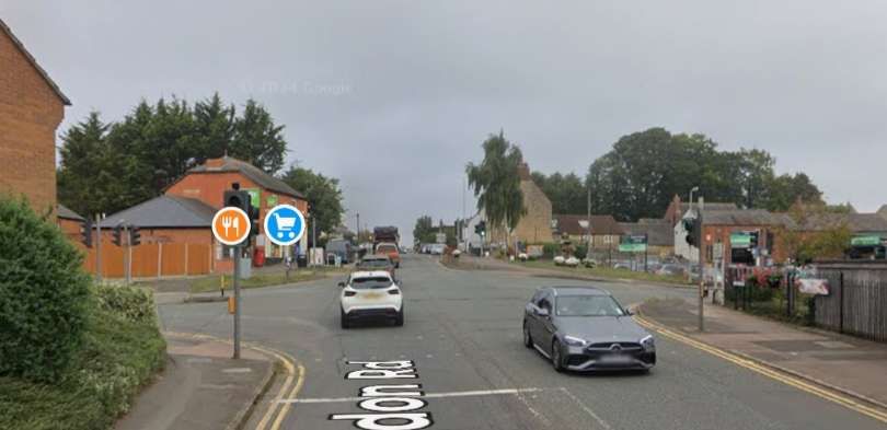
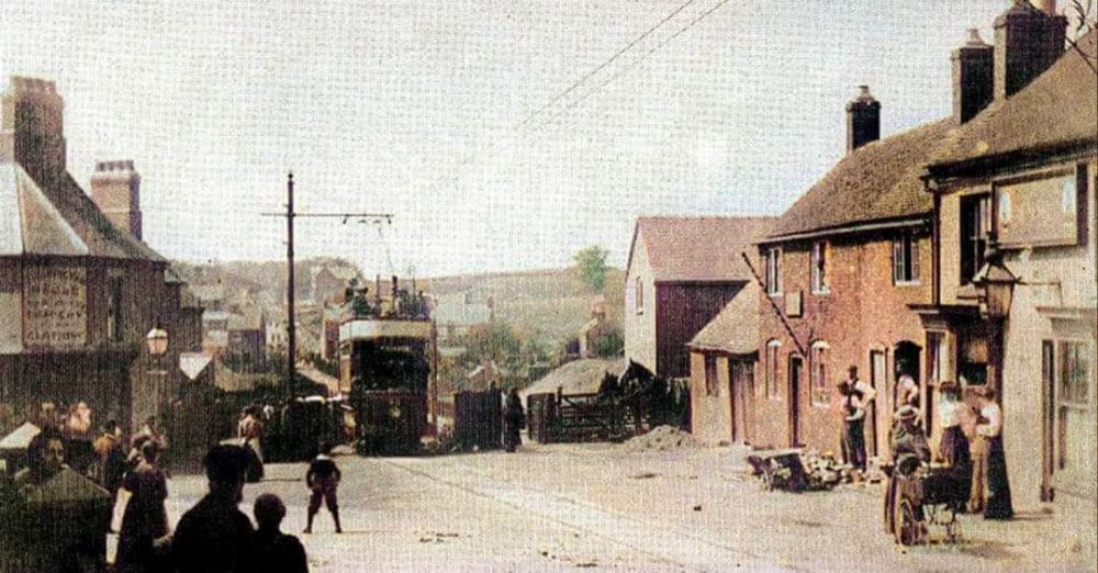
Edwards continues his description of the line: “Entering the town the line again took up position in the centre of the road. It had traversed just one mile from Wolverton. After a few hundred yards the road came to a T-junction with Watling Street outside The Forester’s Arms public house.” [13: p17]

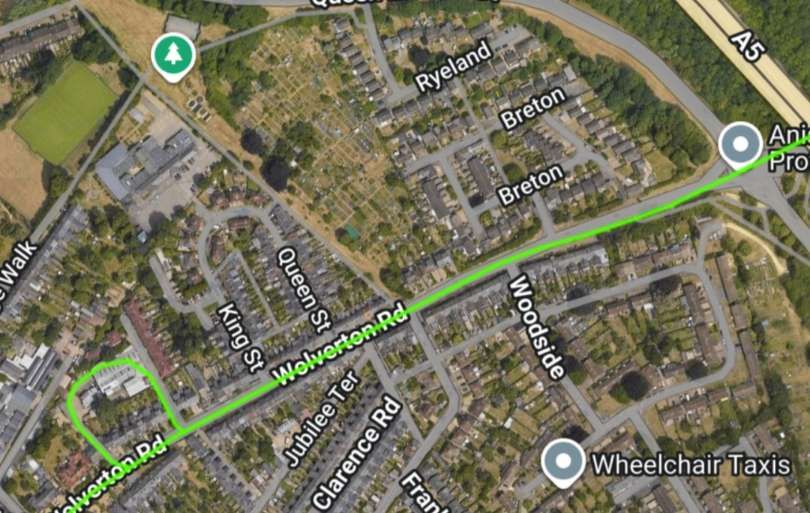

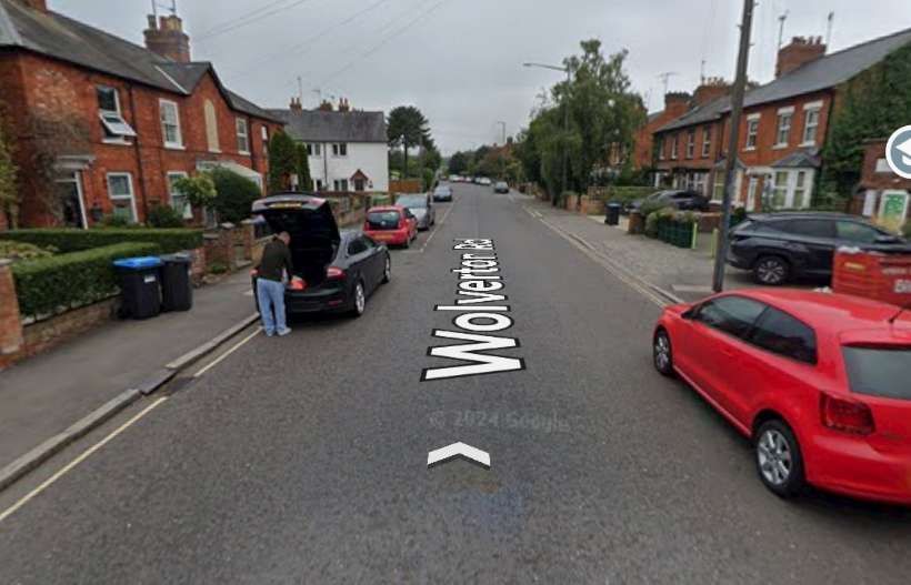
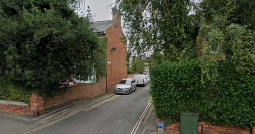
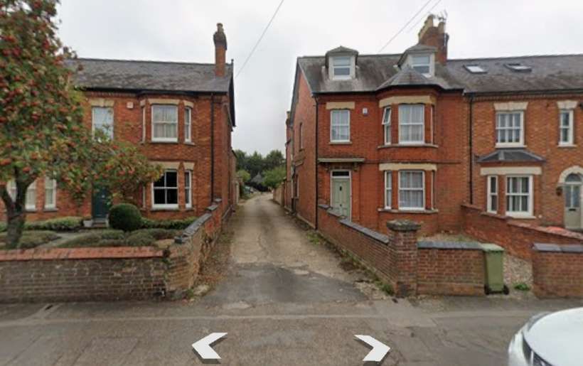
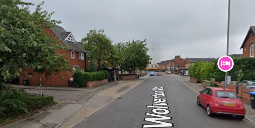
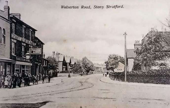
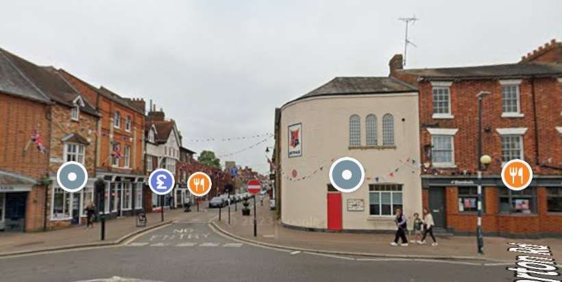
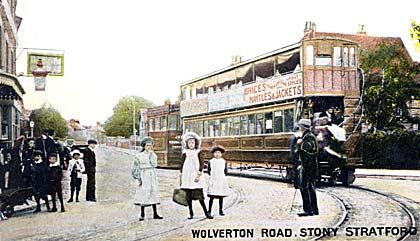
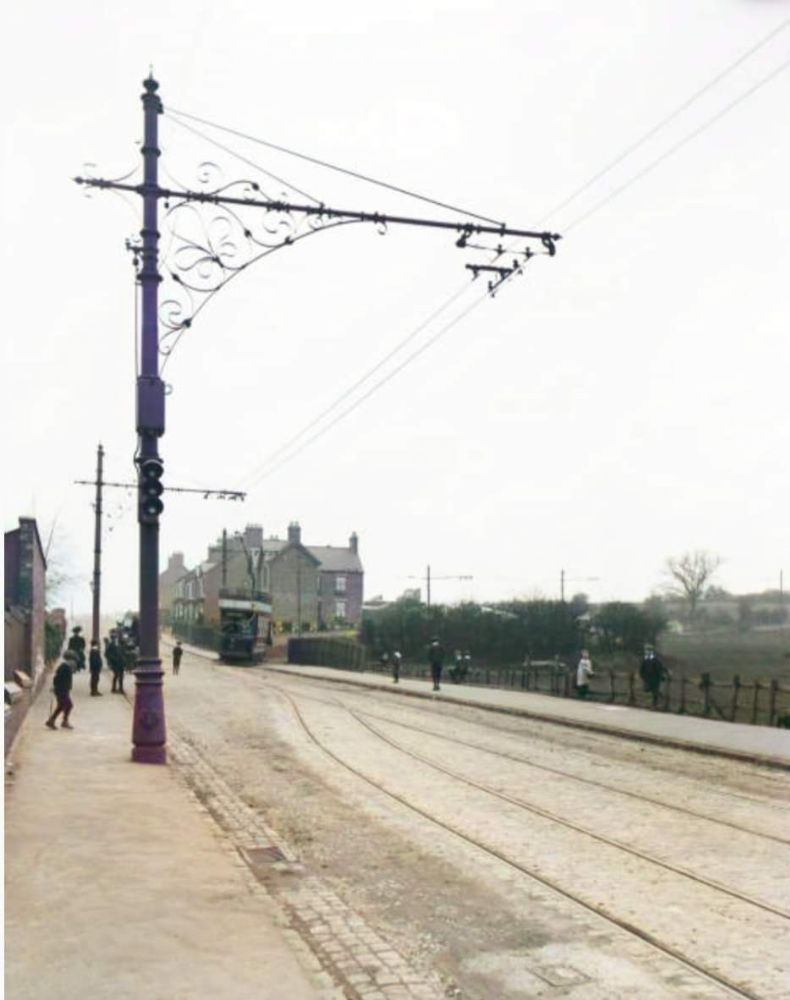
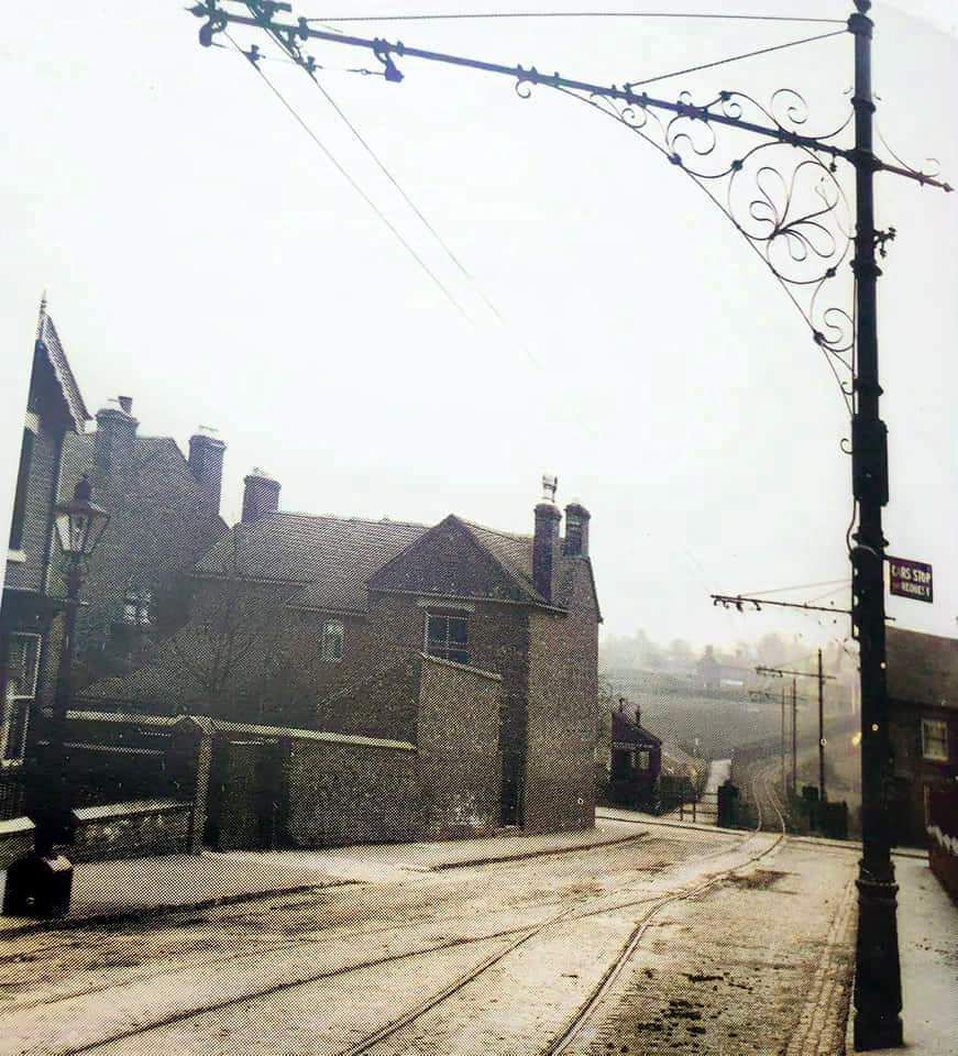
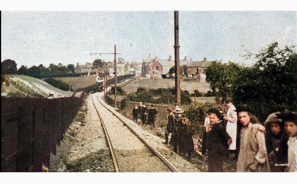
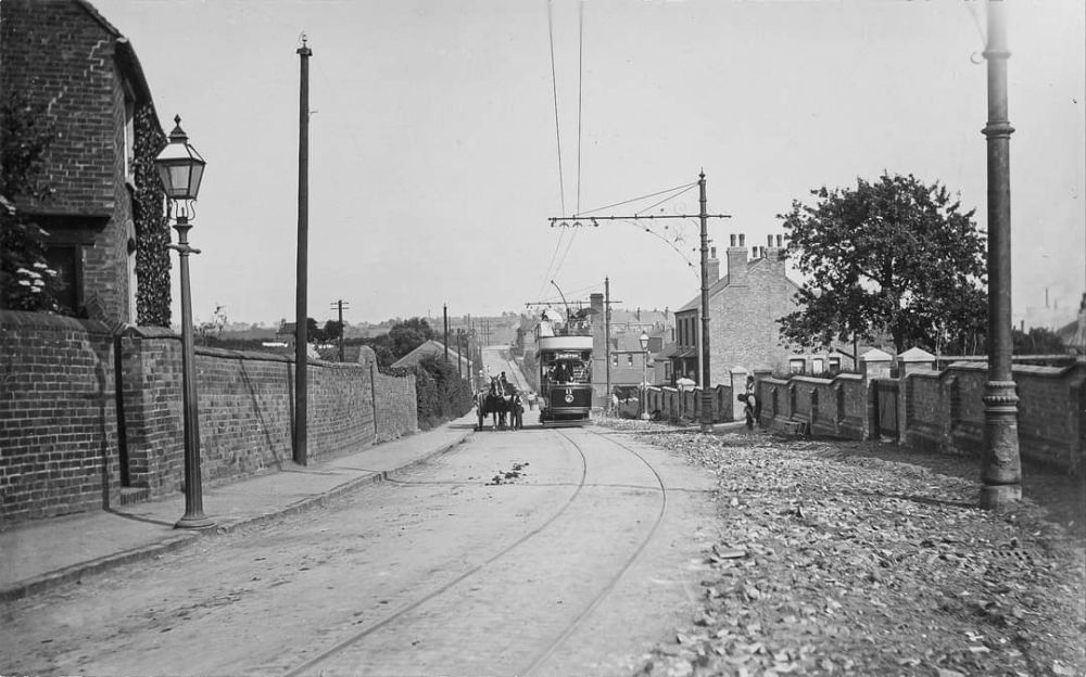
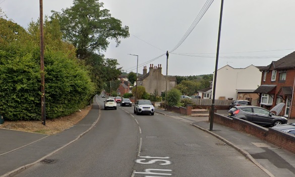
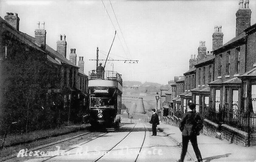
The view Northeast along Wolverton Road in Stony Stratford. The depot is behind the housing in the middle distance. To the left of the camera the tramway ran away to the Northwest. The Forresters Arms is on the left side of the photograph. This image was shared on the Stony Stratford Photos Facebook Group by Edward Corney on 20th November 2018. [22]
Edwards says that at the junction adjacent to the Forresters Arms, “The tramway turned right … to continue northwards beyond The Cock and The Bull hotels for another half mile to terminate outside The Barley Mow public house, the last building in the town.” [13: p17]

An extension, which opened fully in 1898, continued Northwest from the Barley Mow towards the River Ouse and the County border.
Lee tells us that from the outset, it had been intended to cater also for goods traffic: “this was not begun until March, 1888. A contract was made with the LNWR. to deliver its goods, which was stated to save the main-line railway £500 per annum. With an eye to goods traffic principally, Wilkinson promoted an extension from High Street, Stony Stratford, to Deanshanger, which was sanctioned by Order of 19th July 1887, authorising 2 miles 3 chains of 3 ft. 6 in. gauge. Deanshanger was the location of the Britannia Ironworks, the agricultural implement works of E. & H. Roberts, established in 1820.” [1: p548]
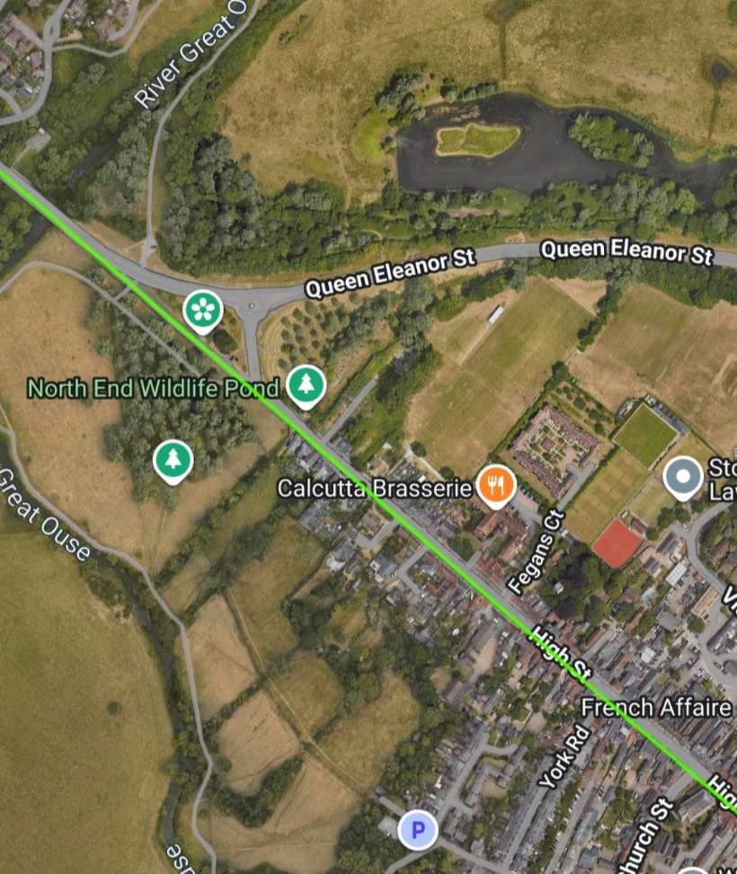
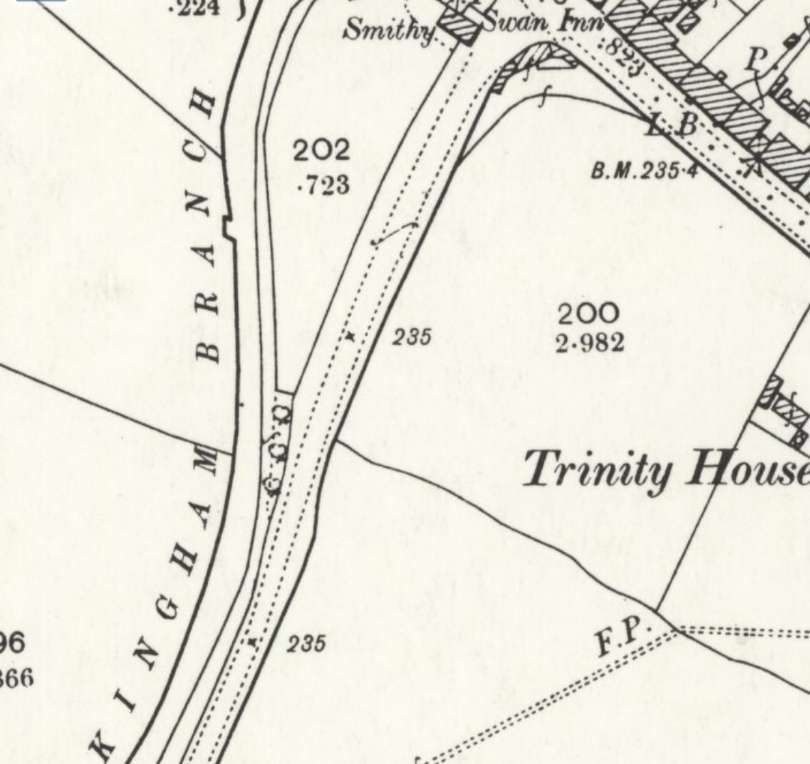
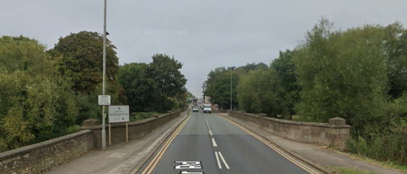
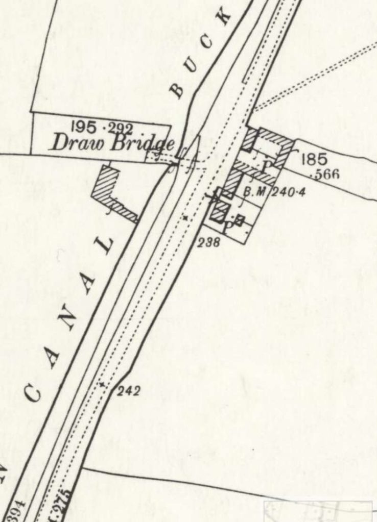
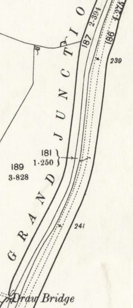
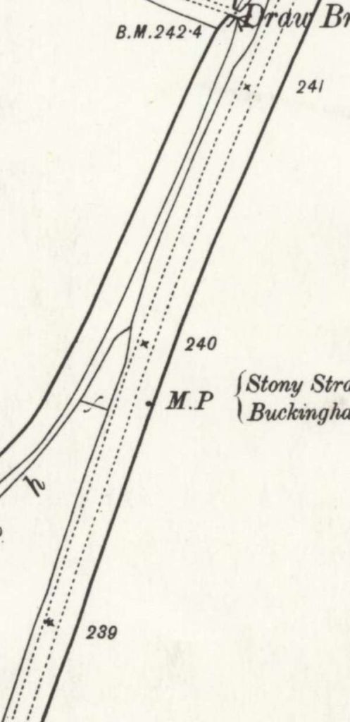
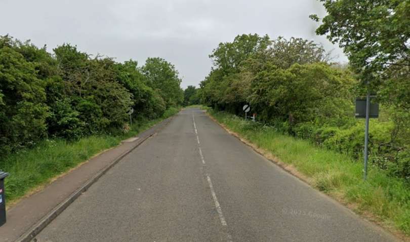
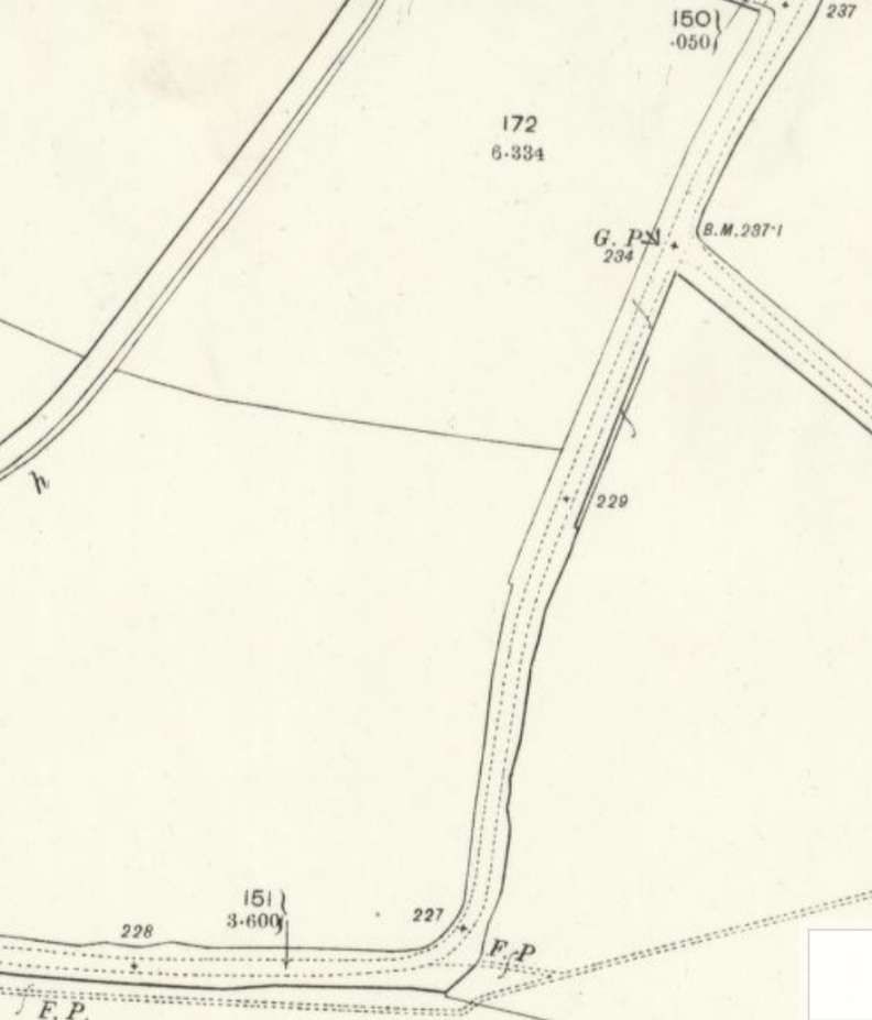
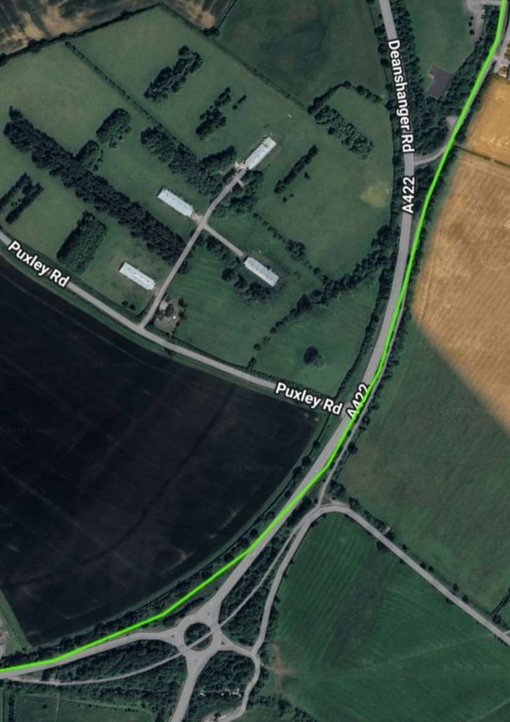
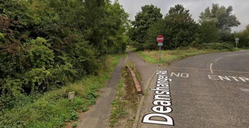
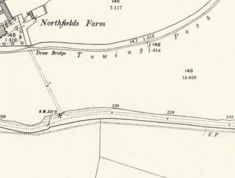
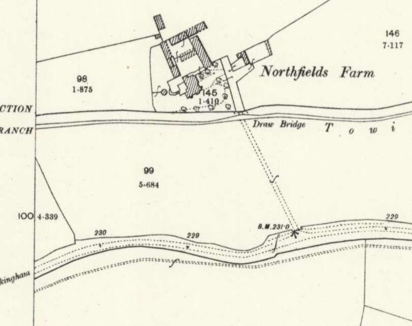
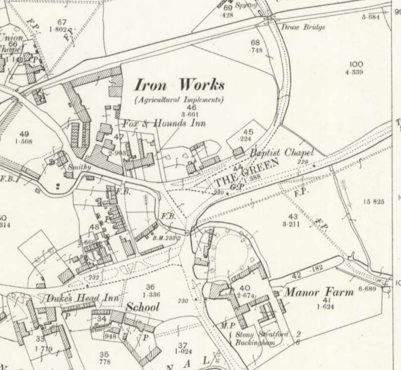
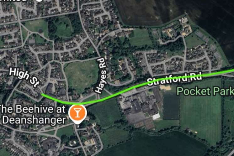
Allan Edwards tells us that, “Leaving The Barley Mow and taking its normal position in the middle of the road the extension travelled straight for almost three quarters of a mile over the embankment that carried the highway across the floodplain of the River Ouse. The river was the county border. Climbing very steeply into the Northamptonshire village of Old Stratford, the line then swung sharp left onto the Buckingham road. A separate depot and workshop for this section of line was established at this corner. … The line then ran parallel to the Buckingham arm of the Grand Junction canal to Deanshanger where it terminated on the village green outside The Fox & Hounds public house. This extension was sanctioned by the Board of Trade on 24th May 1888 and immediately came into public use.” [13: p18]
It seems that a section of 14 chains from the bottom of High Street, across the Great Ouse, to Old Stratford, was built quite quickly and opened later in 1887. “The major portion of the extension was complete at the time a visit to the undertaking was paid by the Civil & Mechanical Engineers Society on Saturday, 12th May 1888, and the party was given a run over the new line. Sanction of the Board of Trade was given on 24th May 1888, to 1 mile 56 chains single and 13 chains double of the Deanshanger extension, and this appears to have been brought into use for public passenger and goods traffic forthwith, extending from Old Stratford to The Green, Deanshanger, near the Fox & Hounds Inn. The intended extension to the Dukes Head Inn was never buiit. From Wolverton to Deanshanger, the through fare was 4d. This section seems to have remained Wilkinson’s property, and to have been leased to the company.” [1: p548]

Operation
Edwards tells us that “On Friday 17th May 1887 prior to the Whitsuntide holiday horses pulled the first tram from Wolverton station goods yard to Stony Stratford tram depot. On board were Charles Aveline (the Managing Director) and other officials of the tram company. For the return journey the horses were replaced by one of the two Krauss tram engines. Local school children were given free tickets.” [13: p17]
By 1st September 1887, Lee tells us, “the issued capital was no less than £20,000, which must be regarded as a gross over-capitalisation. Nevertheless, the nominal capital was increased on 21st June 1889, by £5,000, stated to be beyond £20,000, as the nominal increase of 1883 had been forgotten, and additional stamp duty was paid. A further change of name was also made at this period, and became effective on 26th July 1889, whereby the legal title became the ‘Wolverton, Stony Stratford & District Tramroads Co. Ltd.’ Shortly afterwards, the company declared itself insolvent, and went into voluntary liquidation on 4th September 1889. This was not acceptable to the creditors, and by Court Order of 26th October the winding up was made compulsory, and subject to the Court. The undertaking was placed in the hands of the official liquidator on 17th December, and the line was closed. Much of it was never reopened.” [1: p549]
The original portion, between Wolverton and Stony Stratford, was purchased by a syndicate of Bedford businessmen who reopened the Wolverton to Stony Stratford section in November 1891 and it was known as the ‘Wolverton, Stony Stratford District New Tramway’ and this was formally incorporated on 15th September 1893 with a capital of £5000 in £100 shares. The nominal capital was increased by £3000 (30 shares) at the end of January 1907. It ran until liquidation in 1919. The Deanshanger extension never re-opened. [16][1: p551]
Lee continues: “For many years the Stony Stratford terminus was at the Cock Hotel, but by 1910 the line was curtailed to a few yards in High Street, and in 1919 the terminus was at the Foresters Arms. After the first world war, the line was rapidly approaching derelict condition, and the company’s financial difficulties compelled it to go into liquidation on 17th July 1919; George Henry Margrave (then Secretary and Manager) was appointed liquidator. The local authorities refused to take over the line, and it seemed that the service would be finally abandoned, despite the fact that it had been conveying some 700 workmen daily, principally employees of the Wolverton Carriage Works and of the printing works of McCorquodale & Co. Ltd.” [1: p551]
Grace’s Guide continues: “In the early 1920s the line was taken over by the London and North Western Railway (LNWR) who purchased a new W. G. Bagnall tram locomotive. After the LNWR was merged into the London, Midland and Scottish Railway (LMS) the line was soon closed, in 1926.” [16]
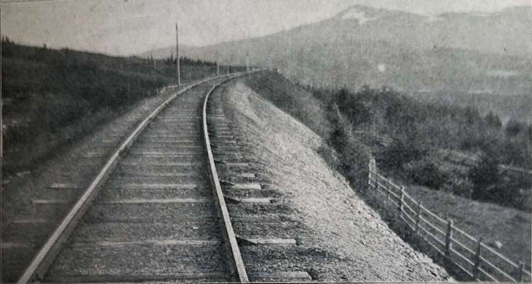
After purchase by the LNWR, the tramway was completely re-laid with concrete placed beneath the rails to strengthen them. Lee tells us that “under LNWR management the staff consisted of three drivers, three conductors, one fitter, one bricklayer and two labourers.” [1: p551]
Under LNWR management prior to the ‘grouping’, the surviving rolling stock “comprised three small four-wheel locomotives, five bogie double-deck cars, and two 10-ton coke trucks. The passengers continued to be principally Stony Stratford men employed at the Railway Works or at McCorquodale’s in Wolverton. They then numbered about 600 daily, of whom some 550 were weekly season-ticket holders. Although the number of men employed at the works increased as time went on, the working loss to the L.N.W.R. increased also, on account of the competition of motorbuses which gave a quicker service. In 1926, no fewer than 12 of these vehicles plied between Wolverton and Stony Stratford, and the trams, with their speed limit of 8 m.p.h. were almost deserted. Schemes of electrification were considered by the railway company (by now the L.M.S.R.), but they all proved too costly, and the climax came with the General Strike of that year, when on 4th May the service was suspended, never to be resumed. Latterly, the services (which, according to the railway company’s timetable, were run “subject to the condition of roads and other circumstances permitting”) had comprised about 14 trips each way, with one or two additional on Saturdays. There were three cars in each direction on Sundays. The journey time was 15 minutes. The official abandonment was announced on 19th May 1926, and it was stated that the company had been losing £2,000 a year on the service. Latterly the total takings were only about £30 a week. [1: p553]
The LMS negotiated with Buckinghamshire County Council (BCC) which took over the track in 1927 with the Ministry of Transport’s consent. BCC immediately began lifting the track and reconstructing the road surface. Work began in June 1927, by November 1927 the length between Watling Street and Clarence Road in Stony Stratford was completed. The section between Clarence Road and McCorquodale’s Printing Works was addressed between October 1933 and June 1934.
Rolling Stock – Locomotives
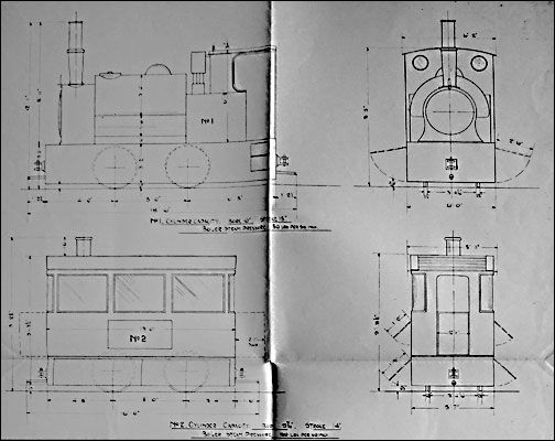
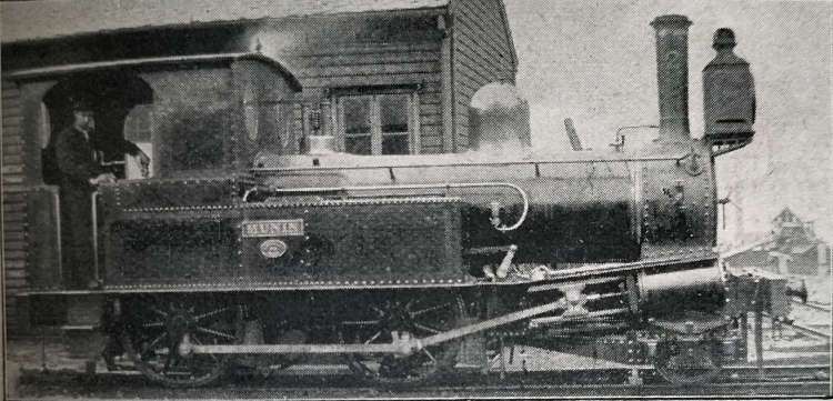
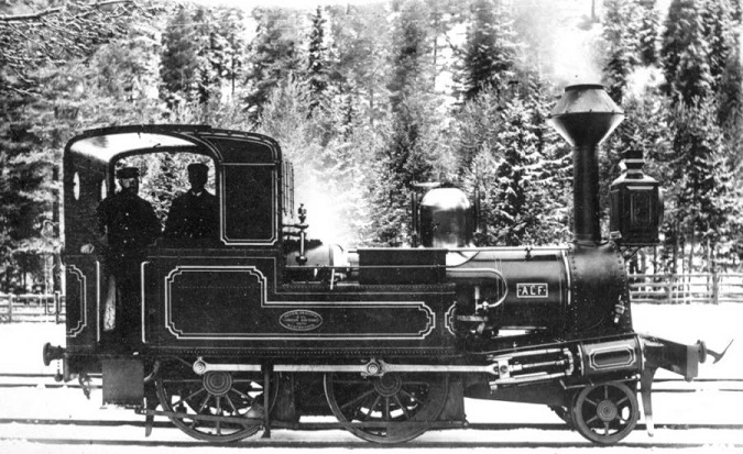
Lee tells us that, “the original locomotives consisted of two German engines supplied by Krauss & Company of Munich to a standard design then used in many continental cities for steam tramways. Some accounts of the line have stated that three, and even four, engines were provided at first, but the Board of Trade Returns to 30th June 1887, show only two, and others (if any) were presumably on loan. They had outside cylinders 8 in. in diameter by 12 in. stroke, wheels 2 ft. 6 in. in diameter, and a 5 ft. wheelbase. The working pressure was 175 lb. per sq. in. and they were non-condensing. Stephenson valve gear was used.” [1: p553]
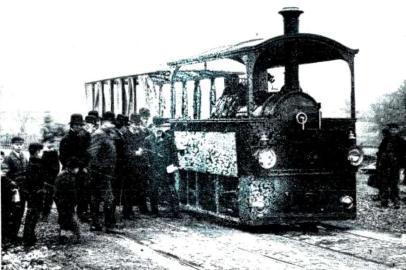
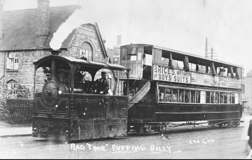
Edwards tells us that these Krauss locomotives, “with their distinctively European canopies and massive oil lights, soon earned the tramway the nickname ‘the little German‘.” [13: p17]
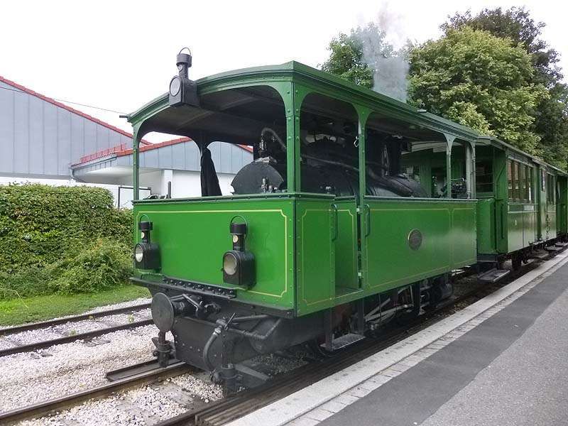
These Krauss locomotives were similar to tram locomotives sent to the Chiemseebahn in the same year, but smaller. They were rated at 40 hp and were governed to run no faster than 10 mph (16 km/h). Board of Trade regulations also required that the running gear had to be shrouded, steam exhaust had to be directed into condensers to avoid visible steam, smoke as well had to be invisible and had to be almost noiseless. [24]
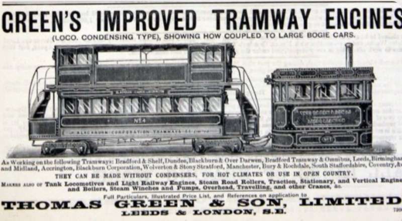
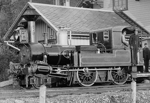
Sadly, unlike the locomotives sent to the Chiemseebahn, the Krauss locomotives supplied to the Wolverton & Stony Stratford Tramway “were found to be unable to handle the heavy passenger rolling stock, and two, more powerful, engines were supplied in 1887 by Thomas Green & Son of Leeds, designed to haul two large passenger cars fully loaded. These had 9 in. cylinders by 14 in. stroke, 2 ft. 6 in. wheels, and a 5 ft. wheelbase; the working pressure was 175 lb. These engines were of the tramway type with atmospheric condensers on the roof. The total loaded weight was 9-9.5 tons. A further locomotive was secured in 1900 from the Brush Electrical Engineering Co. Ltd., Falcon Works, Loughborough, which was generally similar to the Green engines, and had inside cylinders 7.5 in. in diameter by 12 in. stroke. This also worked at 175 lb. pressure and had an atmospheric condenser.” [1: p553]
Thomas Green commenced building tramway locomotives in 1882. [27] These locomotives were initially of the Wilkinson’s patent, built under licence. This design used a vertical boiler and a vertically mounted engine which drove one set of wheels through gears. The second pair of wheels was driven through coupling rods. The exhaust passed through a chamber in the firebox to provide reheat, which in principle would make the steam invisible. The speed governor was an “Allen” paddle type which acted on the reversing gear. [26]
Thirty-nine Wilkinson type trams were delivered before Green’s developed their own design using a horizontal boiler, inclined cylinders and Joy valve gear. These tram engines first appeared in August 1885. The machine quickly evolved such that Green’s tram engines became one of the market leaders. [26][27] It was Green’s own design of tram engine that was supplied to the Wolverton & Stony Stratford Tramway.
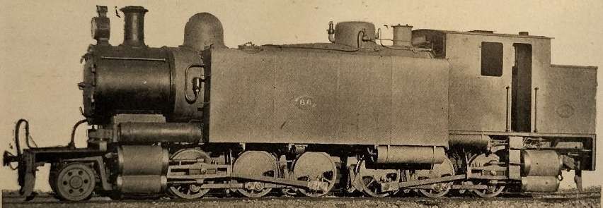
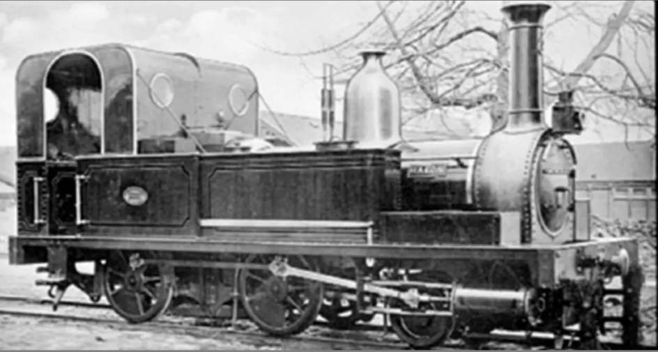
Lee continues: “After the acquisition of the line by the LNWR., a four-coupled saddle-tank engine was secured, in 1921, from W. G. Bagnall Limited of Stafford. Excepting that the motion was boxed in, this locomotive was of conventional railway design, without the tramway type casing over the upper works. Outside cylinders were 10 in. in diameter by 15 in. stroke the coupled wheels 2 ft. 9.25 in. in diameter, and the wheelbase 5 ft. The working pressure was only 150 lb. The saddle tank carried 300 gal. of water and the side bunkers had a capacity of 18 cu. ft. The total weight in working order was 16 tons. This engine was finished in standard LNWR. livery. As the standard chimney was found to be too short for the comfort of upper deck passengers, an ugly stove-pipe extension was added.” [1: p553]
Other Rolling Stock – Passenger Carriages
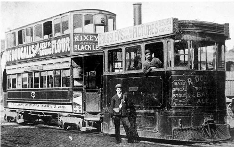
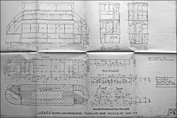
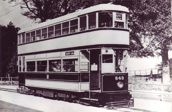
The passenger rolling stock consisted of large double-deck covered-top tramway cars which were mounted on bogies; “there were at first five in all, built by the Midland Carriage & Wagon Company, then of Shrewsbury, and these lasted throughout the life of the undertaking. The three of the largest type each seated 100 and were 44 ft. long and 5 ft. 9 in. wide; they were intended for the workmen and were said to be the largest tramway vehicles in the country. ” [1: p554]
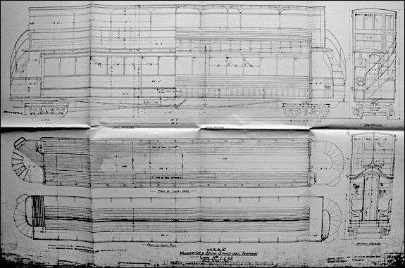
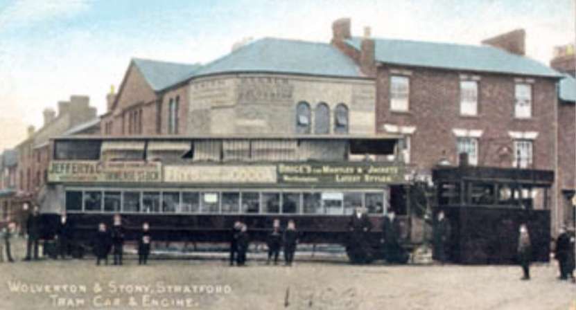
Edwards comments that the 44ft long 100-seat tramcars were the largest “to run in this country until the Swansea and Mumbles Railway built their gigantic electric cars many years later. The coaches had two inward-facing benches on the lower deck and a single continuous slatted bench on the upper deck where passengers faced outwards. The upper sides were open to the elements apart from waist-high decency boards above which were fitted canvas blinds.” [13: p18]
Edwards continues: “Capstan-operated brakes were fitted on each end platform, the locomotives also being equipped to operate the trailer braking by pull-rods and chains. The couplings of these cars were attached to the bogie centres. Originally the illumination was provided by oil lamps but acetylene lighting was later installed to be replaced again by conventional Pinsch gas lighting after the takeover of the line by the LNWR.” [13: p18]
Lees says that “Another car, upholstered, accommodated 80 passengers and was 38 ft. long and 6 ft. wide; and one [which] seated only 50 passengers, was 24 ft. 6 in. long, and 5 ft. 9 in. wide.” [1: p554]
Edwards mentions that the 80-seat tramcar had “neither decency boards or blinds on the upper deck as first built and, most unusually and inconveniently, internal landings to the staircases from the platforms. Decency boards and blinds were added later.” [13: p18]
The 50-seat tramcar “was the only one to be fitted with upholstered seating. One presumes that it was intended for use at times when the workmen would not be travelling. None of the tramcars carried external numbers and all of those mentioned were to last the lifetime of the undertaking.” [13: p18]
“A sixth car is shown in the Board of Trade Returns for the year ended 30th June 1888, and continued to feature until 1911. This was a small single-deck open-sided vehicle with curtains, seating 20 passengers, which does not appear to have been used after the closure of the line in 1889. For many years it remained in the depot at Stony Stratford.” [1: p554]
Other Rolling Stock – Goods
In its early years the undertaking had a number of parcel vans and small goods wagons, as well as 10-ton coal and coke trucks, 24 ft. long, also built by the Midland Carriage & Wagon Company. Eight goods trucks were shown in the return to the Board of Trade for 30th June 1888, at the time goods traffic was begun. It seems that goods traffic declined quite early in the history of the undertaking and all the parcel vans and most of the wagons were sold for scrap. Two of the wagons were of interest in having wheels with adjustable flanges so as to be capable of operating either on rail or road. The flanges were in sections and so arranged that they could be withdrawn inside the tread surface. When the train reached the Cock Hotel, they were, hauled off the line by horses to effect delivery at the door of the consignee. Two horses are shown in the company’s stock in 1888 and 1889. In its later years, the traffic was wholly passenger, apart from the carriage of mails.” [1: p554]
And finally
Grace’s Guide says that, “The line was unusual for a British street tramway being entirely worked by steam locomotives; indeed it was the last steam worked street tramway in the United Kingdom.” [16]
References
- Charles E. Lee; The Wolverton and Stony Stratford Tramway; in The Railway Magazine, Volume 98 No. 616; Tothill Press, London, August 1952, p547-554.
- https://en.wikipedia.org/wiki/Wolverton_railway_works, accessed on 17th January 2026.
- https://www.mkheritage.co.uk/mkm/wolvwork1.html, accessed on 17th January 2026.
- https://en.wikipedia.org/wiki/LNWR_Bloomer_Class, accessed on 17th January 2026.
- https://www.mkheritage.org.uk/archive/mkm/mccorq.html, accessed on 17th January 2026.
- https://wp.me/p178VP-fO, accessed on 17th January 2026.
- https://www.britainfromabove.org.uk/en/image/EPW022487, accessed on 17th January 2026.
- https://en.wikipedia.org/wiki/Wolverton_railway_station, accessed on 17th January 2026.
- https://maps.nls.uk/geo/explore/#zoom=15.1&lat=52.06498&lon=-0.81119&layers=168&b=ESRIWorld&o=100, accessed on 17th January 2026.
- https://maps.nls.uk/geo/explore/#zoom=17.5&lat=52.06314&lon=-0.81803&layers=168&b=ESRIWorld&o=100, accessed on 17th January 2026.
- https://maps.nls.uk/view/104180609, accessed on 18th January 2026.
- https://maps.nls.uk/view/114481013, accessed on 20th January 2026.
- Allan Edwards; The Stony Stratford Tramway; in BackTrack Magazine Volume 3 No. 1; Atlantic Publishers, Spring 1989, p,15-20; via https://quavid.wordpress.com/about/the-wolverton-stony-stratford-tranway-2, accessed on 21st January 2026.
- https://railmaponline.com/UKIEMap.php, accessed on 21st January 2026.
- https://maps.nls.uk/view/114481007, accessed on 23rd January 2026.
- https://www.gracesguide.co.uk/Wolverton_and_Stony_Stratford_Tramway, accessed on 23rd January 2026.
- https://www.mkheritage.org.uk/archive/mkm/workshop.html, accessed on 23rd January 2026.
- https://maps.nls.uk/view/114481031, accessed on 23rd January 2026.
- https://maps.nls.uk/view/114481019, accessed on 23rd January 2026.
- https://www.mkheritage.org.uk/os/doc/tran/tra.html, accessed on 23rd January 2026.
- https://maps.nls.uk/geo/explore/#zoom=18.1&lat=52.05759&lon=-0.84939&layers=168&b=ESRIWorld&o=100, accessed on 24th January 2026.
- https://www.facebook.com/share/p/17s7yE5aBp, accessed on 24th January 2026.
- https://www.livingarchive.org.uk/content/catalogue_item/the-sylvia-mead-collection/pq-views-of-new-old-bradwell/steam-tram-at-wolverton-station-with-goodmans-horse-drawn-cart-beside-it, accessed on 24th January 2026.
- https://www.steamlocomotive.com/locobase.php?country=Great_Britain&wheel=0-4-0&railroad=wsst, accessed on 26th January 2026.
- https://www.internationalsteam.co.uk/trams/steamtram05.htm#23, accessed on 26th January 2026.
- https://en.wikipedia.org/wiki/Thomas_Green_%26_Son, accessed on 26th January 2026.
- https://www.leedsengine.info/leeds/histtram.asp, accessed on 26th January 2026.
- https://www.lthlibrary.org.uk/library/PDF-217-2.pdf, accessed on 26th January 2026.
- https://www.mkheritage.org.uk/archive/mkm/rou05-works.html, accessed on 26th January 2026.
- https://www.mkheritage.org.uk/archive/mkm/history.html, accessed on 26th January 2026.
- https://ebay.us/m/dJ6aZw, accessed on 26th January 2026.
- https://www.mkheritage.org.uk/archive/mkm/stonystratford/docs/tram.html, accessed on 26th January 2026.
- https://wolvertonpast.blogspot.com/2017/03/the-wolverton-and-stony-stratford-tram.html?view=timeslide&m=1, accessed on 26th January 2026.
- https://www.mkheritage.org.uk/os/doc/tran/tra.html, accessed on 26th January 2026.


.jpg)
.jpg)
.jpg)
.jpg)