There was a 19th century proposal for a public railway to Dunvegan and Portree which never came to fruition. A later proposal was the Hebridean Light Railway which was promulgated by the Hebridean Light Railway Company. It intended to operate on the Scottish islands of Skye and Lewis. [8] The Skye line was to have connected the port of Isleornsay (for ferries from Mallaig on the Scottish mainland) and the port of Uig on the north-west coast of the island, from where ferries would have sailed to Stornoway on Lewis. Another line was then proposed to link Stornoway to Carloway, the second settlement of Lewis. Branch lines were also proposed to Breasclete [9] and Dunvegan. [10]
The line was proposed in 1898, but was never completed. Records of the proposals are held in the National Archives at Kew. [11]
Although these schemes never came to fruition, at least six industrial railways have existed on Skye and adjacent islands at one time or another. These include:
TheLoch Cuithir to LealtDiatomite Railway – Details of this line can be found here. [5]
The Talisker Distillery Tramway – This short 23″-gauge tramway opened in 1900 and closed in 1948. Details can be found here. [6]
The Skye Marble Railway – Soon after the turn of the 20th century a line was opened between the Kichrist Quarries in Strath Suardal and Broadford Pier/Quay. Different sources say that this was initially either and aerial ropeway or a horse-worked tramway. Whatever form the initial arrangements took, by the end of the first decade of the 20th century, it was operating as a steam-hauled 3ft-gauge railway which for a short while (certainly no more than 4 years) employed a Hunslet 0-4-0ST, originally built in 1892 and previously used on the construction of the County Donegal Railway and various other contractors projects. This line is covered in more detail in the article which can be found here. [7]
The Raasay Iron Ore Mines and Their Railway – the railway operated from 1913 to 1919. [1][2]
More can be discovered about Raasay’s railway here. [12]
The Quartzite Quarry at Ord (opened in 1945) was equipped with a 3ft-gauge railway along which wagons were pushed by hand to a loading embankment. A short article can be found here. [13]
Storr Lochs Hydroelectric Power Station (opened in 1952) which included a standard gauge electric cable railway which still routinely carries spares and supplies down a 1 in 2 gradient. Another short article can be found here. [14]
Other railways on Skye or on adjacent islands? One source commented that Skye had thirteen different railways/tramways open at one time or another. I have only been able, so far, to identify the ones listed here. Should others be aware of more historic rail sites on Skye, I would be interested to hear. Maybe that source intended their list to include the abortive schemes mentioned at the head of this article? One particular proposal, which never came to fruition, has imaginatively been taken as the basis for the story of the fictitious Highland Light Railway Company. [15]
The June 1950 issue of The Modern Tramway carried a report by A. A. Jackson on the tramways in the French port of Marseilles.
Marseilles sits in a natural basin facing West into the Mediterranean and surrounded by hills on three sides. Jackson’s article was based on personal observations in 1945 and later information provided by D. L. Sawyer and N.N. Forbes. He writes:
“The suburbs extend to the lower slopes of these surrounding hills and they are connected to the centre of the city by a tramway system that is now the largest in France. The original operator was the Compagnie Genérale Française des Tramways (Réseaux de Marseille) but the tramways have been under sequester since 1946. The route mileage at the present time is kilometres and the gauge is standard (i.e. 1.44 metres).
The important dates in the history of the system are:
1873: First horse tramway. (This date is questioned by other sources with 1876 being quoted for the first use of horse-drawn trams. The French Wikipedia entry talks of planned routes dating from 1873 but the concession only being awarded in 1876.) [2][3][16]
1876: C.G.F.T. acquired the tramways (excluding the Aix interurban).
1890: Electrification begun.
1904: C.G.F.T. acquired and electrified the steam railway, L’Est-Marseille.
1907: Allauch (12 km.) and La Bourdonnière (12 km.) routes opened.
1910: Electrification completed. Le Merlan route opened.
1922: First rolling stock modernisation began.” [1: p134]
These dates are not comprehensive. Jackson was writing at the end of the 1940s and could not be expected to cover later events. It is worth noting Wikipedia’s comment that, “Unlike most other French cities, trams continued to operate in Marseilles, even as through the 1950s and beyond trams disappeared from most cities around the world. The original tram system continued to operate until 2004, when the last line, Line 68, was closed. Trams remained out of operation for three years between 2004 and 2007, in advance of the effort to renovate the tram network to modern standards.” [2]
The Tramways of Marseilles in 1949. [1: p134]
Wikipedia says that “the network was modernised by the constant introduction of newer tramcars, to replace the older ones. In 1938, thirty-three trailers were recovered from Paris. These meant that reversible convoys could be operated. In 1939, the tramway company owned and operated 430 tramcars, 350 trailers and 71 lines.” [2]
A 1943 proposal would, if it had been realised, seen tunnels provided in the centre of Marseilles, the busiest lines would have been brought together in two tunnels. This project did not come to fruition.
Wikipedia continues: “In 1949 a further modernisation occurred. The first articulated tramcars was designed and built (Algiers tramway possessed articulated SATRAMO tramcars). These were created by joining two older tramcars. These tramcars remained unique [in France] until 1985 when Nantes tramway opened.” [2]
The city council did not want to keep its network of trams. The haphazard modernisation of tramcars was evidence of the council’s intentions. “The process of replacing tramways with trolleybuses and buses began after World War II in 1945 and accelerated from 1950. The first closures meant that Canebière was tramway-free from 1955. The last closure occurred on 21st January 1960.” [2] But not all lines closed. …
Line No. 68 opened in December 1893 and is the only tramway line to remain in service during the later part of the twentieth century. It “stretched from Noailles to Alhambra, serving La Plaine, the Boulevard Chave, the La Blancarde railway station and Saint-Pierre cemetery. The central terminus [was] situated in a tunnel. This tunnel, built in 1893, [was] unique in France and was built to give access to the city centre, avoiding the narrow streets of some of Marseille’s suburbs. Because of the problems involved in converting the line to bus use it was decided to keep the line operational.” [2]
Line 68 [was] 3 km (1.9 mi) long and was out of use for a few years. The decision to modernise it was taken in 1965 and the line had reopened by 1969 when twenty-one PCC tramcars were purchased and the whole track relaid. “The first of the PCC cars arrived on 26th December 1968 and the first tram went into service on 20th February 1969. The last of the old tramcars was withdrawn that spring. Modernisation resulted in an increase in passengers. Numbers increased from 4,917,000 passengers in 1968 to 5,239,000 in 1973.” [2]
The PCC cars were later modernised in 1984. Three new cars were delivered and all cars made into double cars. The line operated successfully until 2004 when it closed for reconstruction. After refurbishment, “the short section between La Blancarde and Saint Pierre was reopened as part of a new network on 30th June 2007. The section along Boulevard Chave to Eugène Pierre [reopened later the same year] … the tunnel to Noailles was … [reopened in] …summer 2008.” [2]
Returning to Jackson’s article of 1949/50, he continues:
“The longest route is that to the industrial town of Aubagne, 17 km. inland (service 40) and this is further extended 14 km. eastwards by an original trolley-bus route (to Gémenos and Cuges). The Aubagne tram line, which also carries the associated service 12 to Camoins les Bains (12 km.) and a short working to St. Pierre (service 68), begins at the Gare Noailles, a sub-surface tramway station in the centre of the city and the trams leave this station in tunnel, proceeding thus for 1 km. with no intermediate stop, to emerge on a quiet, broad boulevard before branching, (service 12 to Camoins, 40 to Aubagne). After the junction, each of these two lines continues outwards on roadside reserved track for most of its length. The origin of these important suburban arteries was the steam railway L’Est Marseille which was constructed in 1892 from the Gare Noailles to St. Pierre, and converted to an electric tramway by the C.G.F.T. in 1904. Bogie cars and trailers provide a fast service on these routes and the local services to St. Pierre are worked by single-truck cars, One so often hears aesthetic criticism of tramways that it is interesting to note that a well-known League member once explored the Marseilles system and left the city, blissfully unaware of the existence of this interesting sub-surface terminus.” [1: p134-135]
“The other City termini are in side streets off the main thoroughfare La Canebiere (Boulevard Garibaldi, Alliées Leon Gambetta, Cours Belsunce, Cours Joseph Thierry) also opposite the Préfecture, and on the two main streets leading north out of the city (Place Jules Guesde and Place Sadi-Carnot). To cross the city involves a change of cars in all but one instance, the sole remaining cross-city service being No. 41, Chartreux St Giniez. Coastal lines extended to L’Estaque in the north-west and to La Madrague in the south, the latter serving the popular beach and pleasure resort La Plage du Prado (rather similar to Sunderland’s Sear burn route). Other lengthy routes (mostly with rural termini) are: Chateau Gom bert (5), La Bourdonnière (1) Allauch (11), Les trois lucs (7), Le Redon (24) and Mazargues (22 and 23). The circular service, No. 82, serves the residential and coastal areas to the south of the city and enjoys wide roads and unrestricted run ning over most of its length; it traverses the scenic Corniche for part of its run. This is one of the few routes on which cars may be seen running without the almost inevitable trailer. In the older parts of the city many of the streets are narrow, but the greater part of Marseilles is planned on the usual French pattern and therefore possesses wide streets and boulevards well suited to tramway operation. As in Italy, the track in the boulevards is often placed against either curb, well away from the main traffic stream, and in such places the parking of cars is strictly controlled to ensure that tramway operation is unrestricted. At boulevard intersections such as the Rond Point du Prado there are well planned circular layouts joining all tracks. Four-wheeled trolleybuses of standard design and small oil buses have replaced the trams on a number of strictly urban routes unsuitable for tramway operation (the oil bus substitutions are presumably an intermediate stage with the eventual intention that they be replaced by trolleybuses). These trolleybus and oil bus substitutions retain the old tramway services numbers although in certain cases the original tramway route has been extended or slightly modified. Mr. D. L. Sawyer, who was in Marseilles recently, reports that the trolleybuses are not unaffected by the daily shaking up they receive from the rough, uneven street surfaces which gives one cause to reflect that an effective trolleybus installation in many European cities would prove to be a very expensive business as the traditional street surfaces would need to be completely replaced with a surface rather more kind to the not-so-sturdy trolleybus. The tram tracks, which suffered badly from war time neglect, were very noisy in 1945, but they have now been put in excellent condition.” [1: p135-136]
The “Régie Départmentale des Chemins de Fer et Tramways des Bouches du Fer et Tramways des Bouches du Rhône formerly operated a reserved-track roadside electric tramway from Marseilles to the university and cathedral city of Aix en Provence, 29 km to the north. This line was physically connected, by end-on junction, with the Marseilles system, and its Marseilles terminus was at the Place du Change, by the Vieux Port. The dark blue and silver bogie cars, towing one or more heavy bogie trailers, operated an hourly service with a journey time of just under 90 minutes. The Aix terminus was at the extreme end of the main street, the Cours Mirabeau, at the Place Forbin, and the depot and works were situated at the Pont de l’Arc, Aix. This line was converted to trolleybus operation during the winter of 1948-49 and the main trunk road has thus been burdened with additional vehicles. Mr. Sawyer states that the trolleybuses have reduced the journey time considerably; this is hardly surprising as the trams they have replaced were not modern and the number of stops on the tram route was unnecessarily large. New tramcars and a certain amount of track re-alignment would probably have produced an even greater improvement than the trolleybuses it is certain that they would have been a better investment.” [1: p136]
Jackson reports on the rolling-stock in use on the network:
“The rolling stock of the Marseilles system is an interesting mixture of semi-modern and modernised cars, painted blue and cream and mostly of single-truck design. The trailers approximately equal the motor cars in number and are of even greater variety; one type, a covered toastrack, is known locally as ‘Buffalo’ and is very popular during the hot Mediterranean summer. Extensive use is made of twin-units in Marseilles thus obviating the necessity of shunting at termini. The cars are fitted with deep throated hooters and the sound of these, together with the clanging of the bells that announces the changing of the traffic lights is a characteristic of the city. The rolling stock is housed in five depots, all marked on the map, viz., Arenc, Les Catalans, Les Chartreux, La Capelette and St. Pierre. The repair and construction workshops are at Les Chartreux. The high price of materials and the financial situation forbid the purchase of new trams under present conditions and the current programme is therefore concerned with the rehabilitation of existing equipment. A fine and bold beginning has been made in car No. 1301, placed in service in the summer of 1949. This is an articulated car, built from two of the more modern motor cars and the result is a vehicle of pleasing and efficient appearance, 21 metres in length with a passenger capacity of 175 (35 seats) and a maximum speed of 50 km. per hour. One driver and one conductor only are needed (a saving of 35 per cent on personnel against the motor car and trailer type of unit); loading is through the front entrance, unloading through centre and rear exits. The car is double-ended and the doors are pneumatically controlled, one by the driver and the other two by the conductor. The tram cannot start until the central door is closed.
The tickets are issued on the usual carnet system and the books of tickets can be purchased at a reduced price at kiosks and tobacco shops, a book of twenty 5-franc tickets costing 85 francs. Two tickets are taken by the conductor for one section, three for two sections, and four for three sections or over. After 9 p.m. and on Sundays the rate is increased by one ticket and on special journeys to the Sports Stadium and Race Course, a minimum of five tickets is taken. The length of the sections is short and it is only on the longer suburban routes that the all-over fare becomes cheaper. Many cars are equipped for “pay as you enter” (although to use the word “pay” is not entirely accurate as the carnet system means that the conductor rarely handles money). On the Aubagne route (No. 40) a special fare tariff is in force; the complete journey requires five tickets costing eight francs each. Transfer tickets are not used as they have been declared unsuitable for Marseilles.” [1: p136-137]
The French Wikipedia entry for the trams of Marseilles gives some significant detail relating to the trams used on the network. The original, early, rolling-stock delivered between 1891 and 1925 was “cream-coloured, the colour adopted by the CGFT on all the company’s networks. All the motor cars had open platforms and could be transformed in summer, with the glass frames on the side walls being replaced by curtains. The numbers were painted in large figures on the four sides of the vehicles.” [16]
Two axle trams: [17]
No. 501 to 524, “Saint Louis” motor car, 1891-95, power: 2 × 12 hp , empty weight 6.7 tonnes, ex No. 201 to 224 before 1900; (Drawings can be found here. [18])
No. 525, prototype “K” engine, 1891-95, power: 2 × 27 hp, ex No. 301 before 1900;
No. 526-530, “P”, 1898, power: 2 × 27 hp, ex No. 1 to 5 Marseille Tramways Company
From 1925, the engine bodies were modernized. They were rebuilt with closed platforms and their capacity was increased. The trucks (chassis) remained original, but the electrical equipment was reinforced to gain power. This fleet was completed by two series of new engines. All modifications were made according to the criteria of the “Standard” type, a standard defined for vehicles to use the future tunnel network. [17][24]
Bogie trams: [17]
1200, prototype of a closed platform tram;
1201-1231, 1924, transformation of the “C” trams, 1002-1033, power: 4 × 32 hp, empty weight 16.4 tons;
2001-2004, 1929, known as “Pullmann”, delivered new, power: 4 × 42 hp, empty weight: 21.5 tonnes.
Trailers
The number of trailers varied between 400 and 500 depending on the period. The majority of trailers had 2 axles and were numbered in the series 1 to 500. These included: open trailers called “Badeuse” with side access to the rows of transverse benches; and closed trailers with access via end platforms. [17]
In addition there were a number of bogie trailers:
138-153, 1899, transformed into tram cars;
2051-2054, 1928, accompanying the “Pullmann” engines 2001-2004;
2201-2233, 1937, purchased from the STCRP (Parisian network) and coupled to the 1200 locomotives;
2551-2572, 1944, of the “Standard” type, coupled to the 1200 motor cars. [17]
Jackson continues:
“In 1945, overcrowding of trams had reached a peak as there then existed no other means of public transport and the number of cars in service had been reduced by the shortage of electricity and lubricants and the ravages of war-time lack of maintenance. Passengers were then to be seen riding on the steps, on the bumpers, on the roofs and even standing tightly jammed between the trailer and the motor car, precariously balanced on the couplings; indeed it was often difficult to see the cars for the passengers. This is only mentioned as a tribute to the sturdiness and reliability of electric tramways which here, as in many other cities all over the world, continued to operate and bear the brunt of all the city’s passenger traffic long after war conditions had forced other means of transport out of service.” [1: p137]
“With regard to the future, it is encouraging to know that the main tramway routes will be retained and modernised and that modern tramway equipment and reserved track routes of the electric light railway type will be a feature of the Marseilles of the future-a fine tribute to the planners of the original tramway system. It is officially recognised that trolleybuses would be unable alone to cope with the heavy traffic of this great French port, and only a small number of tram routes remain to be converted to trolleybus operation. Further tramway subways, including one under the Canebière, were proposed some years ago and it may be that these will, after all, be built as they would be considerably less expensive than the tiny network of underground railways that is part of the current plans.” [1: p138]
It is worth a quick look at the development of Marseille Metro further below.
Jackson also provides details of the different services in place in 1949 (his list was correct as at May 1949, but omitted some all-night services and short workings):
Line 23, Tram No. …34 (first digit not visible) in Place Castellane. This image is made available under a Creative Commons Licence (CC BY-NC-SA 2.0). [30]
The 21st Century
Marseilles modern tram network was inaugurated on 30th June 2007. The first phase of the new Marseille tram network opened on that date. It consists of one line linking Euroméditerranée in the northwest with Les Caillols in the east. Between Blancarde Chave and Saint-Pierre stations, it runs on part of the former Line 68.
“In November 2007, the portion of the old Line 68 between Blancarde Chave. and E-Pierre (near the entrance to the tunnel) reopened, and two lines were created. Line 1 links E-Pierre and Les Caillols, and Line 2 runs from Euroméditerranée to La Blancarde, where a transfer between the two lines was created. La Blancarde train station is a transit hub: a station on Line 1 of the Marseille Metro opened in 2010, and it has long been served by TER regional trains to and from Toulon.” [2]
“In September 2008, Line 1 was extended to Noailles via the tunnel formerly used by line 68. This tunnel now carries a single track since the new trams are wider than the [PCC trams]. In March 2010, Line 2 was extended 700 metres North from Euroméditerranée-Gantes to Arenc.” [2]
“In May 2015, the 3.8 km (2.4 mi) Line 3 was inaugurated. It shares Line 2 tracks between Arenc and la Canebière where Line 2 turns west. Line 3 continues South on new track through Rue de Rome to Place Castellane. Line 3 extensions south, 4.2 km (2.6 mi) to Dromel and la Gaye, and 2 km north to Gèze are planned. Tram Line 3 will therefore continue to run parallel to the Dromel-Castellane-Gèze Metro Line 2, which may limit its ridership.” [2]
Rolling-stock: “Customized Bombardier Flexity Outlook trams are used on the new tram line[s]. Composed of five articulated sections, they were 32.5 m (106 ft 8 in) long and 2.4 m (7 ft 10 in) wide. Twenty-six were delivered in 2007.[2][3] They were extended by 10 m (32 ft 10 in) by adding two additional articulated sections in 2012. [6] In 2013, six new Flexity were ordered for the T3 line.” [2]
“Their exterior and interior appearance was designed by MBD Design. [6] The exterior resembles the hull of a ship, and the driver’s cabin resembles the bow. A lighted circle displays the colour of the line the tram is on. Inside the tram, the floor, walls, and ceiling are coloured blue, and seats and shutters are made of wood.” [2]
“The tram network is run by Le Tram, a consortium of Régie des transports de Marseille and Veolia Transport. The proposal to privatize the operation of public transit was unpopular, and resulted in a 46-day transit strike.” [7]
Marseilles Metro
The Marseilles Metro is independent of the tram network. It consists of two different lines, partly underground, serving 31 stations, with an overall route length of 22.7 kilometers (14.1 mi). [10] Line 1 opened in 1977, followed by Line 2 in 1984. Two stations, Saint-Charles and Castellane , each provide interchange between lines. [11]
Modern Tramway talks, in 1949, of the Shaker Heights Rapid Transit (SHRT) Lines as “A high speed electric light railway entirely on reserved track, connecting a beautiful high class residential district with the centre of a large city. affording such speedy and efficient service that the car-owning suburban residents prefer to use it and park their cars on land provided by the line; a system which makes a handsome profit and has recently taken delivery of 25 of the most modern type of electric rail units in the world [which] are only some of the outstanding facts about Shaker Heights Rapid Transit.” [1: p101]
Two images from Modern Tramway which show: first , a station in Shaker Heights which shows the central reservation and a car of standard type; second, a PCC car equipped for multiple-unit operation, one of a fleet of 25 delivered in 1948. [1: p112]
The network was created by the Van Sweringen brothers and purchased after their bankruptcy, and a period of 9 years in receivership, by Cleveland City Council in 1944. [2]
The official ownership details down the years are:
“1913–1920: Cleveland & Youngstown Railroad 1920–1930: Cleveland Interurban Railroad 1930–1935: Metropolitan Utilities 1935–1944: Union Properties (47%), Guardian Savings and Trust (33%) and Cleveland Trust (20%) 1944–1975: City of Shaker Heights 1975–present: Greater Cleveland Regional Transit Authority.” [4]
The SHRT connected the city of Cleveland, Ohio, with the largest residential area known as Shaker Heights, six miles East.
The Van Sweringen brothers planned the line “in the early 1900’s as part of a land development scheme, … to serve the district that would grow up on the Heights and beyond, and the charter was obtained in 1907. The land development was planned around the line, and the engineers allowed for a railway area 90 feet wide through the property with 50 feet of open space each side of the tracks (room for four tracks and a grass verge on each side). Building was delayed by the First World War and the line was not opened until 11th April, 1920.” [1: p101]
On 20th July 1930, Shaker Rapid Transit cars began using the Cleveland Union Terminal (CUT), after the Terminal Tower opened. [12]
Before this, on 17th December 1913, trams began operating on the first 1.6-mile segment in the median of what would become Shaker Boulevard, from Coventry Road east to Fontenay Road. [12] The line was grandly named ‘The Cleveland & Youngstown Railway’.
In 1915, the tram service was extended to Courtland Boulevard. In 1920 it became apparent that the plan to link Cleveland to Youngstown would not succeed and the line was renamed as ‘The Cleveland Interurban Railway’ (CIRR). In April of that year, the Van Sweringen brothers opened a segregated (trams separate from other rail and road traffic) line from East 34th Street to Shaker Heights with their trams using the urban tram (streetcar) network to reach the city centre. [12]
“In 1923, the Standard Oil Company built the Coventry Road Station for $17,500. … In 1924, the Shaker trains were referred to as ‘the private right-of-way rapid transit line’, but calling it ‘the rapid’ probably dates back further than that.” [12]
The historic station at Tower City (1927 onwards) was the early terminus of the Shaker Heights Rapid Transit Lines which were extended along the Cleveland Waterfront.
The modern Tower City Station is the central station of the Cleveland, Ohio RTA Rapid Transit system, served by all lines: Blue, Green, Red and Waterfront. The station is located directly beneath Prospect Avenue in the middle of the Avenue shopping mall. The station is only accessible through the Tower City Center shopping complex. [13]
The first cars were ordinary tramcars from the Cleveland City system, specially refitted for fast service. “In July, 1930, the SHRT (which had formerly entered the city over street tracks) was brought into the main line railway terminus over existing railway tracks. By this time the line extended for 9.5 miles from the Union Terminal Building in Cleveland to Green Road, at the far end of Shaker Heights; in addition, there was a branch line to Moreland.” [1: p101]
The two lines in the suburbs were extended. The Moreland line in 1929, eastward from Lynnfield (its original terminus) to Warrensville Center Rd. The Shaker line, in 1937, was extended from Warrensville Center Rd. to a new loop at Green Rd. [2]
“Under the main floor of the Union Terminal Building, the SHRT tracks are adjacent to the main line railway platforms. The six miles out to Shaker Square are on an ascending grade along the valley of the Cuyahoga river, and are entirely on private right-of-way; from Shaker Square onwards, the line runs through a grass reservation in the centre of Shaker Boulevard as far as Green Road Terminal.” [1: p101]
“The branch to Moreland, a suburb of smaller type property, diverges about 500 feet east of Shaker Square station, running in a south-easterly direction; at this terminus are storage yards with car parking facilities inside a U track formation.” [1: p101]
“The overhead is compound catenary out to East 55th Street, Cleveland, and normal trolley-wire elsewhere; the line is signalled throughout and road crossings are well spaced.” [1: p101]
The journey from Green Road outer terminus to the Union Terminal Building in downtown Cleveland “is covered in 22 minutes including 16 stops en route. The six miles from Shaker Square down into Cleveland (which include four curves with speed restriction) are covered in 8-9 minutes by non-stop cars. The up-grade increases the express timing on the outward journey to Shaker Square to 12 minutes.” [1:p101]
“When the City Council bought the line in 1944, the Director of Transportation, Mr. Paul K. Jones, began to modernise the existing fleet and to look around for new cars. He chose PCC cars with multiple unit equipment, and after trial runs in 1946 with a PCC-MU car ordered for Boston’s tramways, he ordered 25, to be modified to suit the SHRT’s demands and these were delivered towards the end of [1948]. They have Sprague Multiple Unit Control and are equipped for MU operation in trains of up to six cars. Other details are: Seating capacity. 62; overall length, 52ft. 7in.; overall height, 10ft. 4in.; width, 9ft.; truck wheel base, 6ft. 10in.; livery, canary yellow.” [1: p101]
A new $60,000 sub-station was built by 1949 in Shaker Heights which ensured adequate power for the PCC cars. Other improvements undertaken were “the doubling of car parking space at stations and an increase in service frequency.” [1: p101]
Extensions of the SHRT were, in 1949, considered likely; at that time, the line had been graded beyond Green Road as far as Gates Mills and steel poles had been erected part of the way. (This extension never occurred even though the preparatory work had been undertaken.) [7]
The Moreland Branch had been graded south to the Thistledown Race Track beyond Warrensville and there was little doubt, at that time that this extension would be completed. It turns out that this extension also never came to fruition.
“In Cleveland itself, the City Council … asked for 31 million dollars for the purpose of financing extensions of its city lines east and west of the city. The East Side line was laid out and partly graded by the original builders of the SHRT; it left the Heights line at East 60th Street and needed, at the time of writing of the article in Modern Tramway, only a few months’ work to complete.” [1: p101]
“Snow [had] no effect on the operation of the SHRT and the line [carried] on when local bus and trolley bus lines [had] ceased … in the severe winter of 1947-8; and all the year round, as mentioned before, the owners of the $75,000 homes of Shaker Heights [left] their cars behind and [travelled] into town by the faster and more reliable means so amply provided.” [1: p102]
“In 1955 the Cleveland Transit System (which was formed in 1942 when the City of Cleveland took over the Cleveland Railway Company) opened the first section of the city’s new rapid transit line, now known as the Red Line. It used much of the right-of-way and some of the catenary poles from the Van Sweringen’s planned east-west interurban line adjacent to the NYC&StL tracks. The first section of the CTS rapid transit east from Cleveland Union Terminal included 2.6 miles (4.2 km) and two stations shared with the Shaker Heights Rapid Transit line, necessitating split platforms with low-level sections (for Shaker Heights rapid transit cars) and high-level sections (for CTS rapid transit cars).” [4]
In the 21st century, the Red Line (formerly and internally known as Route 66, also known as the Airport–Windermere Line) is now “a rapid transit line of the RTA Rapid Transit system in Cleveland, Ohio, running from Cleveland Hopkins International Airport northeast to Tower City in downtown Cleveland, then east and northeast to Windermere. 2.6 miles (4.2 km) of track, including two stations (Tri-C–Campus District and East 55th), are shared with the light rail Blue and Green Lines; the stations have high platforms for the Red Line and low platforms for the Blue and Green Lines. The whole Red Line is built next to former freight railroads. It follows former intercity passenger rail as well, using the pre-1930 right-of-way of the New York Central from Brookpark to West 117th, the Nickel Plate from West 98th to West 65th, and the post-1930 NYC right-of-way from West 25th to Windermere.” [5]
The Red Line is shown on the four extracts from OpenStreetMap below. [5]
These four map extracts show the full length of the Red Line from the airport in the West to East Cleveland. [5]
In the 21st century the two original Shaker Heights routes form the Blue Line and the Green Line as part of Cleveland, Ohio’s Rapid Transit System.
“The Blue Line (formerly known as the Moreland Line and the Van Aken Line, and internally as Route 67) is a light rail line of the RTA Rapid Transit system in Cleveland and Shaker Heights, Ohio, running from Tower City Center downtown, then east and southeast to Warrensville Center Blvd near Chagrin Blvd. 2.6 miles (4.2 km) of track, including two stations (Tri-C–Campus District and East 55th), are shared with the rapid transit Red Line, the stations have low platforms for the Blue Line and high platforms for the Red Line. The Blue Line shares the right-of-way with the Green Line in Cleveland, and splits off after passing through Shaker Square.” [3]
The Blue Line from Cleveland to Shaker Heights shown on OpenStreetMap. [3]
“The Green Line (formerly known as the Shaker Line) is a light rail line of the RTA Rapid Transit system in Cleveland and Shaker Heights, Ohio, running from Tower City Center downtown, then east to Green Road near Beachwood. 2.6 miles (4.2 km) of track, including two stations (Tri-C–Campus District and East 55th), are shared with the rapid transit Red Line; the stations have low platforms for the Green Line and high platforms for the Red Line. The Green Line shares the right-of-way with the Blue Line in Cleveland, and splits off after passing through Shaker Square.” [4]
Tram cars used on the Shaker Heights lines since 1920 include: the 1100-series and 1200-series centre-entrance fleet; the colourful PCC cars; and the current fleet of Breda LRVs which have operated the line since 1982. [15]
Cleveland’s 1100-series and 1200-series center-door cars were built in the mid-1910s. “Not only were these cars distinctive and immediately identifiable as Cleveland cars, but many of them outlasted the Cleveland street railway itself. This was because the suburban streetcar route to Shaker Heights, barely on the drawing board when the center-door cars were built, bought a handful of 1200-series cars to hold down service when it was new. For years these cars were the backbone of service to Shaker Heights until the last of them were finally retired in favor of PCC cars in 1960.” [16]
Cleveland’s PCC Trams began arriving in the late 1940s, as we have already noted. PCC (Presidents’ Conference Committee) trams were streetcars of a design that was first “built in the United States in the 1930s. The design proved successful domestically, and after World War II it was licensed for use elsewhere in the world where PCC based cars were made. The PCC car has proved to be a long-lasting icon of streetcar design, and many remain in service around the world.” [17]
The Shaker Heights Rapid Transit network purchased 25 new PCC cars and 43 second-hand cars. A total of 68: the original 25 Pullman cars were extra-wide and had left-side doors. The second-hand cars were: 20 cars purchased from Twin Cities Rapid Transit in 1953; 10 cars purchased from St. Louis in 1959; 2 former Illinois Terminal cars leased from museums in 1975; 2 cars purchased from NJ Transit in 1977; 9 ex-Cleveland cars purchased from Toronto in 1978. PCCs were used until 1981. [17]
The Cleveland Transit System had 50 PCCs purchased new and 25 second-hand. The second-hand cars purchased from Louisville in 1946. All Cleveland’s cars were sold to Toronto in 1952. Of these, nine cars were (noted above) sent to Shaker Heights in 1978. [17]
Pullman Standard PCCs “were initially built in the United States by the St Louis Car Company (SLCCo) and Pullman Standard. … The last PCC streetcars built for any North American system were a batch of 25 for the San Francisco Municipal Railway, manufactured by St. Louis and delivered in 1951–2. … A total of 4,586 PCC cars were purchased by United States transit companies: 1,057 by Pullman Standard and 3,534 by St. Louis. Most transit companies purchased one type, but Chicago, Baltimore, Cleveland, and Shaker Heights ordered from both. The Baltimore Transit Co. (BTC) considered the Pullman cars of superior construction and easier to work on. The St. Louis cars had a more aesthetically pleasing design with a more rounded front and rear, compound-curved skirt cut-outs, and other design frills.” [17]
“Both the Cities of Cleveland & Shaker Heights purchased PCC trolleys after WWII. Cleveland operated theirs from 1946 to 1953 before they sold them to the City of Toronto. Shaker Heights operated their PCCs for a much longer period – i.e. from 1947 up until the early 1980s.” [18]
Cleveland’s Breda LRVs are a fleet of 34 vehicles operating on the Blue, Green and Waterfront lines. One is shown below on the Blue Line and one on the Green Line. [19]
The LRVs were purchased from the Italian firm, Breda Costruzioni Ferroviarie, to replace the aging PCC cars. They were dedicated on 30th October 1981. [3]
The cars consist of two half bodies joined by an articulation section with three bogies. The two end bogies are powered, and the central bogie under the articulation section is unpowered. “The car is slightly more than 24 m (79 ft 10 in) long, is rated AW2 (84 seated passengers and 40 standing), and can travel at a maximum speed of 90 km/hr (55 mph). This speed can be reached in less than 35 sec from a standing start.” [20]
Overall length: 79ft 11in.
Width: 9ft 3in
Tare weight: 84,000lb
Acceleration: 3mph/sec.
Service braking: 4mph/sec.
Emergency braking: 6mph/sec.
Each LRV “is bidirectional with an operator’s cab at either end and three doors per side. The passenger door near the operator’s cab is arranged to allow the operator to control fare collection. The 84 seats are arranged in compliance with the specification requirements. Half the seats face one direction and half the other. Each end of the car is equipped with … an automatic coupler with mechanical, electrical, and pneumatic functions so that the cars can operate in trains of up to four vehicles.” [20]
In 2024, the Greater Cleveland Regional Transit Authority board approved “the selection of Siemens Mobility for a contract to replace the Breda light rail vehicle fleet. … The planned framework contract with Siemens Mobility would cover up to 60 Type S200 LRVs, with a firm order for an initial 24. … The high-floor LRVs will be similar to cars currently used by Calgary Transit, with doors at two heights for high and low level platforms, an infotainment system, ice cutter pantographs, 52 seats, four wheelchair areas and two bicycle racks. … The fleet replacement programme currently has a budget of $393m, including rolling stock, infrastructure modifications, testing, training, field support, spare parts and tools. This is being funded by the Federal Transportation Administration, Ohio Department of Transportation, Northeast Ohio Areawide Co-ordinating Agency and Greater Cleveland RTA.” [21]
References
Shaker Heights Rapid Transit Lines; in Modern Tramway Vol. 12, No 137, May, 1949, p101,102,112.
The first three articles in this series covered the network as it was established by the beginning of the First World War. These articles can be found here, [1] here [2] and here. [3]
We have already noted that there were changes to the network above which occurred before WW1, particularly the second line to Piazza Sturla in the East, the additional line to Sampierdarena in the West and the Municipal line to Quezzi in the Northeast.
In this article we look at the network from World War 1 to the beginning of World War 2.
After WW1 and into early WW2
In 1923, driving on the right was imposed on roads throughout the country (until then, individual cities had discretion over the matter). Genoa complied on 31st August 1924. The change did not cause major upheavals in the tram service as it had always been undertaken by bidirectional carriages with doors on both sides. [19][21: p56]
In the mid 20s the autonomous municipalities between Nervi and Voltri along the coast, up to Pontedecimo in Val Polcevera and up to Prato in Val Bisagno, were annexed to the capital and a ‘Greater Genoa’ was formed. The entire tram network fell within the new municipal area. [19]
During this time UITE remained as a private company but the City acquired a majority of shares. [19][20: p223] and began to direct the development of the company and the network. [19][21: p62]
In 1934, major reform of the network took place. Trams ceased to use Via Roma, Via XX Settembre, and Piazza de Ferrari. The piazza saw major change – the lifting of the ‘tramway ring’ allowed, first, the planting of a large flower bed, and later (in 1936) the construction of a large fountain designed by Giuseppe Crosa di Vergagni. The trams were diverted through Piazza Dante and Galleria Colombo which was newly opened. [20: p224] At the same time new lines crossing the city were activated, with the aim of better distributing passengers in the central areas. [19][21: p62] The following year the trams also abandoned Corso Italia, in favour of a new route further inland which also included the new Galleria Mameli. [19][21: p125]
The modernization of the network included renewal of the fleet of trams. That renewal commenced in 1927 with the introduction of ‘Casteggini’ (trolley/bogie trams – named after the UITE engineer who designed them). These were followed in 1939 by modern ‘Genoa type’ trams, [20: p657] built first as single units and then, from 1942, in an articulated version. [19][20: p660]
In 1935, the large Littorio depot near Ponte Carrega (Val Bisagno) came into operation. In 1940, workshop facilities were opened at the depot. [20: p237-238]
Italian Wikipedia tells us that after the changes made in 1934, the following list covers the tram routes on the network: [19][21: p125]
1 Banco San Giorgio – Voltri 2 Banco San Giorgio – Pegli 3 Banco San Giorgio – Sestri 4 Banco San Giorgio – Sampierdarena 5 Banco San Giorgio – Sampierdarena – Rivarolo 6 Banco San Giorgio – Sampierdarena – Bolzaneto 7 Banco San Giorgio – Sampierdarena – Pontedecimo 8 Banco San Giorgio – Sampierdarena – Campasso 9 Banco San Giorgio – Galleria Certosa – Rivarolo 10 Banco San Giorgio – Galleria Certosa – Bolzaneto 11 Banco San Giorgio – Galleria Certosa – Pontedecimo 12 Banco San Giorgio – Galleria Certosa – Certosa – Sampierdarena – Banco San Giorgio 13 The reverse of Line 12 14 Banco San Giorgio – Cornigliano 15 Banco San Giorgio – Pra 16 Brignole – Corvetto – Pegli 18 Marassi – Bolzaneto 21 Dinegro – Manin – Staglieno 22 Manin – Corvetto – Piazza Santa Sabina 23 De Ferrari – Marassi – Quezzi 24 Corso Dogali – Manin – Corvetto – Principe – Corso Dogali (circulating clockwise through the hills) 25 The reverse of Line 24 (circulating anti-clockwise through the hills) 26 Dinegro – Principe – via Napoli 27 Corso Dogali – Manin – Corvetto – Tommaseo 28 Principe – Corvetto – Via Atto Vannucci – Banco San Giorgio 30 De Ferrari – Foce 31 Banco San Giorgio – Staglieno – Prato 32 Banco San Giorgio – Molassana – Giro del Fullo
33 De Ferrari – Piazza Verdi – Staglieno 34 Piazza della Vittoria – Staglieno – San Gottardo – Doria 35 Piazza della Vittoria – Staglieno 36 Piazza della Vittoria – Ponte Carrega 37 De Ferrari – Piazza Verdi – San Fruttuoso 38 De Ferrari – Via Barabino – Boccadasse 39 De Ferrari – Sturla – Nervi 40 Banco San Giorgio – De Ferrari – Albaro – Quinto 41 Piazza Cavour – Via Barabino – Corso Italia – Priaruggia 42 De Ferrari – San Francesco d’Albaro – Sturla 43 De Ferrari – San Francesco d’Albaro – Lido 44 Banco San Giorgio – De Ferrari – Borgoratti 45 De Ferrari – San Martino – Sturla 46 De Ferrari – Tommaseo – San Martino 47 De Ferrari – San Francesco d’Albaro – Villa Raggio 48 Piazza Cavour – Piazza della Vittoria – San Fruttuoso 49 De Ferrari – Tommaseo – ‘Ospedale San Martino 50 San Martino – Brignole – Corvetto – Sampierdarena – Campasso 51 Quezzi – Brignole – Principe – Galleria Certosa – Rivarolo 52 San Giuliano – Brignole – Principe – Dinegro 53 Tommaseo – Brignole – Principe – Sampierdarena – Campasso 54 Sturla – Albaro – De Ferrari – Banco San Giorgio – Dinegro 55 Foce – Brignole – Principe – Dinegro 56 Marassi – Brignole – Principe – Dinegro
The lines marked with a red ‘X’ are those which closed in the city centre with the reorganisation of 1934, (c) Paolo Gassani. [8]
After 1934, Piazza Banco di San Georgio became the centre of the altered network (it was referred to originally as Piazza Caricamento). This was facilitated by earlier alterations to the network which included:
Piazza Railbetta, Piazza di San Georgio, Via San Lorenzo and Piazza Umberto 1
These earlier alterations included a very short line, shown on the Baedecker 1916 map of Genova, connecting Piazza Banco di San Georgio and Piazza Raibetta. In addition, a line along Via San Lorenzo and Piazza Umberto 1 made a connection from that short line to Piazza Raffaele de Ferrari which at the time was at the heart of Genova’s tram network. This three-way length of connecting tramways opened up the possibility of the significant revisions to the network which occurred in 1934. The 1916 Baedeker map is the first I have found which shows these links, early Baedeker maps available online do not show these lines. There is photographic evidence of these lines being in use by 1906.
An additional short line was provided from Piazza Galeazzo Alessi at the top of Via Corsica along Mura Sant Chiara, Mura del Prato, Viale Milazzzo and Via Alessandra Volta, as shown below.
Corso Italia was built between 1909 and 1915 [6] and the tram line to Foce was extended along Corso Italia sometime in the early 1920s. The tram line can be seen (dotted) on the map extract below.
Other links were added such as a line between Piazza Brignole and Piazza Giuseppi Verdi (outside Brignole Station). With the culverting of the Bisagno River in 1930/31, a link along Via Tolemaide from Piazza Verdi to meet the existing tramway which ran Northeast/Southwest on Via Montevideo and continued East towards San Martino, became possible.
Piazza Raffeale de Ferrari, Piazza Dante and routes East
We have already noted that Piazza Raffaele de Ferrari ceased to be the main focus of the network in 1934 and that trams were removed from Via XX Settembre and Via Roma at the time. What remained in the vicinity of Piazza de Ferrari was a single loop line were 11 lines from the East and Valbisagno terminated. The terminus was on Via Petrarca with a return loop through Via Porta Soprana and Via Antonio Meucci to Piazza Dante and then on to their destinations. The first image below shows the revised arrangements on the South corner of Piazza Raffaele de Ferrari.
Trams which originally entered Piazza Raffaele de Ferrari from the north along Via Roma were diverted from Piazza Corvetto along Via Serra toward Piazza Brignole. More about this further down this article.
A 600 series tram in Via Meucci on the return loop. The tram is approaching Via Dante where it will turn right to head East out of the centre of Genova, (c) Public Domain. [13]
Trams travelled up and down Via Dante and through Galleria Cristoforo Colombo to serve the East of the city and the coast.
When trams were diverted away from Piazza De Ferrari, those which used to travel down Via Roma were diverted along Via Serra and Piazza Brignole. A new length of tramway was built along Via Edmondo de Amicis to link Piazza Brignole with Piazza Verdi and Brignole Railway Station.
The station forecourt of Brignole Railway Station and the North side of Piazza Giuseppe Verdi became a significant hub within the new network inaugurated in 1934.
Looking East across the face of Brignole Railway Station in the 1960s with the tram station in the centre of the view. This image was shared by Gianfranco Curatolo on the C’era Una Volta Genova Facebook group on 20th August 2016. [29]Piazza Giuseppe Verdi and Brignole Railway Station in the 21st century. [Google Maps, December 2024]
East from Piazza Verdi (Via Tolemaide)
Major work was undertaken in the 1930s along the length of the River Bisagno from the railway to the sea shore. That full length of the river was converted and a broad boulevard was created.
Piazza Verdi (Brignole Railway Station), Viale Brigata Partigiane/Viale Brigata Bisagno, Via Barabino, Galleria Mameli, Via Carlo e Nello Rosselli and further East
The construction of Galleria Principe di Piemonte (later Galleria Mameli) allowed a further route East from the city centre to be exploited.
We begin this article with a look at maps of the Piazza Raffeale de Ferrari and its immediate environs over the years around the turn of the 20th century. The Piazza became one of two focal points for tramways in the city (the other was Caricamento).
I found the series of maps interesting and they provoked a desire to find out more about the network of horse-drawn and later electric trams and tramways of Genoa. ….
Italian Wikipedia informs us that: “The first public transport in Genoa was provided by a horse bus service linking the city centre and Sampierdarena, that started in 1873. In 1878, the French company Compagnia Generale Francese de Tramways (CGFT, French General Company of Tramways) began to build a horse tram system.” [16][17]
Towards the end of the century, the new urban plan led to the construction of new roads with wider carriageways, principal among these were:
Via Assarotti connecting Piazza Corvetto to Piazza Manin;
Via XX Settembre, built between 1892 and 1899, widening Strada Giulia and connecting the Palazzo Ducale (Piazza de Ferrari) with Porta Pila and the banks of the River Bisagno (once the eastern boundary of the city);
Corso Buenos Aires, once outside the city walls, was lowered to the level of Ponte Pila and the new Via XX Settembre, to form a single artery that would connect the centre with the Albaro district;
Corso Torino, perpendicular to Corso Buenos Aires.
After this work was done, the city began to look more modern and the widened streets made room for tramways in the centre and East of the city. The municipal administration began to plan new lines, both towards the eastern suburbs and in the central districts of the city. [19]
The city welcomed competition and set up a series of concessions which were given to different groups: the French Company kept the Western concession; Val Bisagno and the hilly areas to two Swiss businessman (Bucher & Durrer); and the east of the city was granted to a group of local businessmen. [19][20: p66]
The two parties, other than the French, formed companies: Bucher created the Società di Ferrovie Elettriche e Funicolari (SFEF) in 1891. [20: p85] The Genoese entrepreneurs founded the Società Anonima Tramways Orientali (SATO) in 1894. [20: p120] The two companies took on the two concessions which envisaged electric traction on metre-gauge lines to accommodate running on the narrow winding streets of the city centre. [19]
“By 1894, SFEF had achieved no more than a single short electric tram line between Piazza Manin and Piazza Corvetto, whilst SATO had not progressed beyond the planning stage. The CGFT system had extended through the city and the Val Polcevera, but was still horse operated.” [16][17]
“In 1894, the German company Allgemeine Elektrizitäts Gesellschaft (AEG) … bought both the SFEF and SATO companies. The following year AEG created the company Officine Electrical Genovesi (OEG), … which took over the city’s existing electricity supply company, and the Società Unione Italiana Tramways Elettrici (UITE), … which purchased the CGFT’s concession. By the end of 1895, AEG had a monopoly of both electricity supply and public transport provision in the city.” [16][17] Under AEG’s “ownership, SFEF and SATO developed a tram network of more than 53 km (33 mi) reaching Nervi and Prato, whilst UITE electrified their lines to Voltri and Pontedecimo.” [16][17]
As we have already noted, the first electric traction line connected Piazza Corvetto to Piazza Manin, running along Via Assarotti. [20: p92] It was activated by SFEF on 14th May 1893 [20: p96] The single-track line was 800 metres long and ran on a constant gradient of 7% [20: p95]; the tickets cost 10 cents. The electrification (600 V DC) was via an overhead cable and was carried out by AEG of Berlin, which, as we have already seen, later acquired a significant shareholding in the company. [19][20: p86-87]
In subsequent years the SFEF network expanded rapidly; in 1895-96 the Monte line to the North of the city centre entered into service, including the Sant’Ugo spiral tunnel; in 1896 the line from Piazza Principe to Piazza Brignole was born. It included two tunnels in the Castelletto area. [21: p20] , In 1897, the Val Bisagno line up to Prato began operation. [19][21: p26]
The first SATO line entered into service on 26th July 1897, connecting Piazza Raibetta to Staglieno through the Circonvallazione a Mare, [20: p122] followed two years later by the long coastal line to Nervi. [20: p127] In 1900 the eastern trams reached the central Piazza de Ferrari, travelling along the new Via XX Settembre which was formed through widening of the old Via Giulia. [19][21: p53]
The two networks, SFEF and SATO, were technically compatible and the two companies, both controlled by AEG, soon unified the two networks. [20: p142]
“Finally in December 1901, AEG merged SFEF and SATO into an enlarged UITE.” [16][17]
The enlarged UITE found itself managing 70 km of network, divided between the 30 km of the ‘Western network’: (formerly the French Company) and the 40 km of the ‘Eastern network’ (formerly SFEF and SATO). [20: p170-171] The unification of the network led to an increase in overall traffic, symbolised by the creation of the vast ring terminus in Piazza de Ferrari in 1906. [20: p129]
This seems the right time to look again at the ‘ring terminus’ in Piazza de Raffeale Ferrari. ….
In 1908, after three years of construction work, Galleria Certosa (Certosa Tunnel) was put into use. It facilitated tram journeys to and from the Polcevera valley, avoiding the crossing of San Pier d’Arena. [19][21: p38] The tunnel connected Piazza Dinegro, in the port area, to the Rivarolo district in Val Polcevera. It was 1.76 km long. [22]
In 1934, Galleria Certosa was used every day by five lines: Tram No. 9 (San Giorgio-Rivarolo), tram No. 10 (San Giorgio-Bolzaneto), tram No. 11 (San Giorgio-Pontedecimo) and the two circular lines between San Giorgio and Sampierdarena. [22]
Having noted the construction of Galleria Certosa in the early years of the 20th century (above), it is worth looking at some other tunnels which were built to facilitate the movement of trams.
Galleria Vittorio Emanuele III (renamed Galleria Giuseppe Garibaldi on 27th November 1943)
There seems to be quite a story to the life of this tunnel! The first two photographs show the first tunnel. They focus on the portal in Piazza Della Zeccan.
These next two photographs show the tunnel as it was first widened in the form which preceded the Galleria Vittorio Emanuele III which had a much smaller bore.
Named after Christopher Columbus, whose house was nearby, the gallery was opened to the public in the 1930s and was hailed as the city’s gateway to the sea. It connected Piazza de Ferrari and Piazza della Vittoria.
Now long gone, there was a tram tunnel on Via Milano to the Southwest of the city centre. It took the tramway (and roadway) under San Benigno Hill. It was.built in 1878 by the Compagnia Generale Francese dei Tramways for its horse-drawn trams. Its Southwest portal was in Largo Laterna. Its Northeast portal is shown in the first image below.
In the early years of the 20th century, the municipal administration began to consider the idea of taking control of the tram service. In anticipation of this, in 1913, it built its own line from Marassi to Quezzi, known as Municipal Line A, it was operated by UITE on behalf of the Municipality. [19][21: p44]
Before the start of World War 1, the tram network provided these services: [19]
21 De Ferrari – Manin – Staglieno 22 De Ferrari – Manin 23 De Ferrari – Manin – Castelletto 24 De Ferrari – Manin – Castelletto – San Nicholo 25 Circuit in the hilly suburbs 26 Piazza Principe – Corso Ugo Bassi 27 De Ferrari – Zecca – Principe 28 Caricamento – De Ferrari – Galliera ‘Ospital 29 De Ferrari – Carignano 30 Circular Raibetta – Brignole – Corvetto – Raibetta 31 De Ferrari – Staglieno – Molassana – Prato 32 De Ferrari – Staglieno – Molassana 33 De Ferrari – Pila – Staglieno 34 Staglieno – Iassa 35 Pila – Staglieno 36 Pila – Staglieno – Molassana 37 De Ferrari – San Fruttuoso 38 De Ferrari – Foce 39 De Ferrari – San Francesco – Sturla – Priaruggia – Quinto – Nervi 40 De Ferrari – San Francesco – Sturla – Priaruggia – Quinto 41 De Ferrari – San Francesco – Sturla – Priaruggia 42 De Ferrari – San Francesco – Sturla 43 De Ferrari – Villa Raggio – Lido 44 De Ferrari – Tommaseo – San Martino – Borgoratti 45 De Ferrari – Tommaseo – San Martino – Sturla 46 De Ferrari – Tommaseo – San Martino 47 De Ferrari – Tommaseo 48 Raibetta – Pila
III. Municipal line:
A De Ferrari – Quezzi
The Western Network, particularly before World War One
Lines 1 to 11 constituted the Western Network. All of these lines had their city centre terminus at Piazza Caricamento. The Piazza is shown on the adjacent 1916 map.
The map shows part of the Port area of Genoa (Genova) in 1916 with a significant series of standard-gauge railway sidings in evidence (black lines) and some red lines which indicate the metre-gauge tram routes. Piazza Caricamento is close to the water halfway down the map extract. [31]
There were three main routes out of Piazza Caricamento, one of which followed the coast round to meet the lines on the East of the city. The other two shared the bulk of the services leaving the piazza. One of these two routes ran West through San Pier d’Arena (Sampierdarena), the other ran through Galleria Certosa.
The route to San Pier d’Arena (Sampierdarena) closely follows the coast and ran through the Galleria on Via Milano before the San Benigno Hill was raised to the ground.
Pictures of the Galleria can be seen earlier in this article.
West of the Galleria, the original tramway ran along what is now Via Giacomo Buranello (what was Via Vittorio Emanuele) to Sampierdarena. This route appears to the North of the SS1 on the satellite image below.
Before looking at line further West from Sampierdarena we need to note a line which was added to the network before WW1.
A second tramway was built which ran alongside the railway sidings on what is now the SS1, it was then Via Milano, towards Sampierdarena. The route is illustrated by the mid-20th century view below.
That route along Via Sampierdarena (Via Milano and Via Colombo) and then Via Pacinotti is illustrated at the bottom of the map below. After running along the centre of Via Sampierdarena, trams turned inland, heading Northwest to join the earlier route, West of Piazza Vittorio Veneto on Via Pacinotti.
A map provided by the Marklinfan.com Forum which shows the new coastal tram route mentioned above. [92]
The Western Network’s Coastal Line(s)
At Sampierdarena the original lines of the Western network separated. Some lines continuing along the coast and others turning inland. The lines diverged at the West end of Piazza Vittorio Veneto. The coastal line ran along what is today Via Frederico Avio, then turned onto what is now Via Antonio Pacinotti, before turning West on what is now Via Raffaele Pieragostini, crossing the River Polcevera at Ponte di Cornigliano, running along Via Giovanni Ansaldo before joining Via Cornigliano at Piazza Andrea Massena.
We have followed the Western Network as far as we can along the coast. We now need to look at the line(s) of the Western network which ran up the valley of the River Polcevera from Sampierdarena.
To do this we need to return to Piazza Vittorio Veneto in Sampierdarena.
The Western Network and Val Polcevera (the Valley of the River Polcevera)
The lines to the North left Piazza Vittorio Veneto at its Western end, passing immediately through an underpass under the FS Standard Gauge railway.
In the 19th century the route was known as ‘Via Vittorio Emanuele’. In the early years of the 20th century the road was renamed ‘Via Umberto 1’. In 1935, the city gave the road the name ‘Via Milite Ignoto’ (the Unknown Soldier). This decision appears to have been short-live as very soon the road was divided into two lengths, the more southerly length becoming ‘Via Martiri Fascisti’, the remaining length, ‘Via delle Corporazioni’. After the end of Word War Two renaming again occurred. In 1945 the names which continue to be used in the 21st century were chosen – ‘Via Paolo Reti’ and ‘Via Walter Fillak ‘. Fillak and Reti were partisans in WW2. [59][66]
A view from above … This is Piazza (Via) Vittorio Emanuele seen from the West. The tram tracks can be seen heading away through the underpass in the foreground. [75]
The route of this part of the old tramway network begins at this rail underpass (where the street is now named, ‘Piazza Nicolo Montano’, having once been Via Nino Bixio), [65] before running along Via Paolo Reti and then Via Walter Fillak. Just beyond the underpass the railway station access left the road on the left. The first old postcard views below show this location.
Two pixelated, low definition images showing the bottom end of what was Via Umberto 1. One the left in both images is the incline leading to the Sampierdarena Railway Station forecourt. [59]A tram sits at a stop at Piazza Montano. This image was shared on the Foto Genova Antica Facebook Group by Annamaria Patti on 22nd May 2022. [3]Three further postcard views, of better quality, of the bottom end of Via Umberto 1, (c) Public Domain. [59][62][63]The view to the Northeast from the rail underpass in 2024. The station approach is on the left. The old tramway curved round to the left below the station approach’s retaining wall. [Google Streetview, August 2024]Just a little further along the old tram route. The retaining wall on the left supports the station approach road. The tramway ran on along what is now Via Paolo Reti. For some distance the road was flanked by a retaining wall supporting the FS standard-gauge railway. [Google Streetview, August 2024]
The adjacent Google satellite image shows roads over which the old tramway ran. In the bottom right is Piazza Nicolo Montano. It is also possible to make out the station approach ramp which has a number of cars parked on it. In the immediate vicinity of the passenger railway station, railway buildings can be seen separating Via Paolo Reti from the railway but very soon the road and the railway run side-by-side with the railway perhaps 2 to 3 metres above the road. Via Eustachio Degola passes under the railway just to the North of the station buildings. Towards the top of the satellite image, Via Paolo Reti can be seen turning away from the railway wall. [Google Maps, December 2024]
Via Paolo Reti (the former Via Umberto 1) turns away from the railway wall which is now much lower than it was near the station buildings. [Google Streetview, August 2024]Via Umberto 1, looking North from the bend visible in the photograph above where the road leaves the side of the railway, (c) Public Domain. [68]Via Paolo Reti (once Via Umberto 1) at the same location as the monochrome image above. [Google Streetview, August 2024]
The monochrome image below purports to show Piazza San Marino. As far as I can work out the piazza was historically, ‘Piazza Vittorio Emanuele III’ and later renamed for another partisan from World War 2 – ‘Piazza Ricardo Masnata’.
A relatively low quality image of Piazza San Marino and Via Umberto 1. The piazza later became Piazza Ricardo Masnata. This view looks North with a tram visible on the left, (c) Public Domain. [64]Piazza Ricardo Masnata, looking North. There is little to link this image from 2024 with the monochrome image above, other than the alignment of the roads and the shape of the piazza. However, at the centre of this image is a lower building which also appears in the monochrome image. [Google Streetview, August 2024]Via Umberto 1 looking North from what became Piazza Ricardo Masnata, (c) Public Domain. [67]The same location in the 21st century. [GVia Umberto 1, now Via Walter Fillak with a tram heading towards Genoa. [69]The same location on Via Walter Fillak in the 21st century. [Google Streetview, August 2024]
The line from Sampierdarena ran towards Certosa where, once Galleria Certosa was completed, it met the line through the tunnel.
The tramway followed Via Celesia through Rivarolo (Superior). Rivarolo and Via Celesia can be seen at the bottom of this extract from openstreetmap.org. [79]
This image from the early 20th century looks North along Via Celesia. Space on the street was clearly at a premium! [80]Via Celesia in the 21st century. [Google Streetview, August 2024]
North of Via Celesia, the tramway ran along Via Rivarolo.
This postcard shows the junction at the North end of Via Celesia, circa. 1920s. Via Rivarolo is ahead. This image was shared on the C’era una volta Genova Facebook Group by Mario Vanni on 18th August 2019, (c) Public Domain. [82]The smae location in the 21st century. [Google Streeetview, August 2024]This next extract from openstreetmap.org shows Via Rivarolo entering bottom-left. Trams ran on into Teglia on Via Teglia and continued on to Bolzaneto (in the top-right of this extract) along Via Constantino Reta. [79]This postcard view looks South along what is now Via Teglia (then Via Regina Margherita. This image was shared on the C’era una volta Genova Facebook Group by Elio Berneri on 19th October 2020, (c) Public Domain. [83]A very similar view at the same location in the 21st century. [Google Streetview, August 2024]Car 906 in service on line 7 Caricamento – Pontedecimo, one of the longest of the UITE, is seen here running in Bolzaneto. The photograph was taken facing North. In the background you can see another Tramcar, as well as a third on the track in the opposite direction, (c) Public Domain. [84]A similar North facing view in Bolzaneto in the 21st century. [Google Streetview, August 2024]A tram waits at Piazza del Municipio in Bolzaneto. This image was shared by Mario Vanni on the C’era una volta Genova Facebook Group on 8th July 2021, (c) Public Domain. [85]A very similat view of the same location in the 21st century. The road on which the bus is standing is now known as Via Pasquale Pastorino. [Google Streetview, August 2024]A few hundred metres to the Northeast is the area known as ‘Bratte’. A tram waits in the mid-20th century to set off for Caricamento. This image was shared on the C’era una volta Genova Facebook Group by Roberto Della Rocca on 12th December 2020. [86]A similar view at the same location in the 21st century. [Google Streetview, August 2024]
North of Bratte, Trams crossed the River Secca, a tributary of the Polcevera, following Via Ferriere Bruzzo and then continued North alongside the River Polcevera on Via San Quirico.
Tram No 79 leads a trailer car South on Via San Quirico in the first decades of the 20th century. It seems as though Ponte Tullio Barbieri can be seen behind the tram. This image was shared by Sergio De Nicolai on the C’era una volta Genova Facebook Group on 21st October 2018. [88]A similar location on Via San Quirico in the 21st century. [Google Streetview, July 2022]
Trams passed under the FS Standard-gauge lines close to Ponte Tullio Barbieri. [Google Streetview, June 2022]Trams ran on through the centre on San Quirico on Via San Quirico.Before returning to the side of the river, passing under the railway again. [Google Streetview, July 2022]
The next length of the journey is the last. Trams terminated at Pontedecimo. [79]
A tram and trailercar on Lungo Polcevera in Pontedecimo close to Pontedecimo Railway Station, This image was taken looking South along the river bank and was shared by Giorgio Gioli on the C’era una volta Genova Facebook Group on 4th November 2020. [89]This view looks South along the bank of the River Polcevera at a location similar to that in the image above. [Googler Streetview, January 2021]
The central piazza in Pontedecimo. The terminus of the tram service. This image was shared on the C’era una volta Genova Facebook Group by Roberto Cito on 29th October 2023. [87]Trams terminated in Pontedecimo. [Google Streetview, July 2022]The tram depot at Pontedecimo. This image was shared on the C’era una volta Genova Facebook Group by Alessandro Lombardo on 30th October 2019. [90]
This article looks at two tramway routes which were built. The first ran from Nice to Bendejun via Pont de Peille and Contes. The second branched of the first at Pont de Peille and ran to along the valley of the Paillon de Peille to La Grave de Peille. It also covers a proposed tramway to l’Escarene which was not constructed.
Nice to Contes and Bendejun
This line was approximately 18.6 km long. The first part of the route (from Nice Place Garibaldi as far as La Trinite Victor) ran along the same rails as the urban service – a length of around 6.5km.Just over 9 km of line (which was deemed to be part of the coastal (littoral) network) brought trams to Contes. The final length of the line was regarded as part of the TNLs ‘departemental’ network and took trams to the terminus at Bendejun.
Only approximately 0.5 km of the line and (as far as Contes) was on the level. The remainder of the line was set at varying gradients with the steepest being 55mm/m. The line rose from 12 metres above sea-level at Place Garibaldi to 189 metres above sea-level at Contes, and 260 metres above sea-level at Bendejun.
The following notes on the significant dates associated with the line are gleaned from Jose Banaudo’s book. [1: p70] …
The line from Garibaldi to Abbatoirs opened to the public on 21st February 1900. On 2nd June of the same year, the line opened from Abbatoirs to Contes. Goods were carried on this section of the line from 1st October 1900.
It was not until 1st February 1909 that passengers could travel between Contes and Bendejun and no goods were carried along that length of the line until 1st January 1911.
After just over a year, in February 1912, subsidence closed the length of the line between Contes and Bendejun. The line opened again in March. During the winter of 1916-1917, the line was closed by snow and landslides.
On 1st January 1923 tram services were given new numbers: Nice to La Trinite or Drap became No. 26; Nice to Contes or Bendejun, No. 27.
Sadly, after further problems with landslides, the line between Contes and Bendejun was permanently closed from 18th November 1926.
On 8th October 1934 renumbering led to the line to La Trinite being numbered 36 and the Nice to Contes service, 37.
A landslide affected the line between the cement works and Contes. It was closed from November 1934 to March 1935.
Late in 1935, the Nice terminus of these services was moved from Place Garibaldi to Rue Geoffredo.
After damage to the electricity substation adjacent to Pont-de-Peille on 12th February 1938, the passenger service from Drap to Contes was curtailed and the No. 37 service was replaced by buses.
There was opposition to the bus service being provided by a single company. This saw a reopening of the tram service on Ligne 37 on 15th March 1938. There followed a period between 3rd August 1938 and December 1944 when tramway services were interrupted relatively frequently for a variety of reasons which included damage during WW2.
On 23rd December 1944 the tram service resumed from Nice to Pont-de-Peille with a bus service covering the remainder of the route to the North.
On 17th January 1945, goods transport between Contes and Nice resumed and, on 20th January 1945, passenger trams returned to Contes.
In the winter of 1948-1949 bad weather saw the interruption of services North of La Pointe de Contes.
January 1950 saw the closure of the line to passenger services with buses used to replace that service on a permanent basis. In May 1950, the goods service was also closed permanently.
The line to Bendejun followed the left bank of the River Paillon between the centre of Nice and its terminus in Bendejun. Its terminus in Nice was at the Northwest corner of Place Garibaldi, where a wooden kiosk served as its station building. It used the same tracks as the urban services through Abattoirs to La Trinité-Victor.
For a short distance trams ran on the verge of Route Nationale No. 204. Stops at Roma and Random (which had a passing loop) were followed by the stop in the village of Drap which was adjacent to the bridge to Cantaron.
The Route Nationale in Drap. Tram tracks can be seen in the centre of the road. This old postcard view was shared on the Comte de Nice et son Histoire Facebook Group by Alain Nissim on 18th May 2022. [4]Drap again, this image shows La Place des Ecoles and the Route Nationale. A tram can be seen on the road at the extreme right of the picture. This old postcard view was shared on the Comte de Nice et son Histoire Facebook Group by Alain Nissim on 18th May 2022. [4]La Place des Ecoles viewed from almost the same location as in the monochrome postcard image above. In the 21st century the Plane trees have gone and cars have taken over from the park that made up much of the square. [Google Streetview, November 2022]Turning just a little to the right and wandering a little further along the Route Nationale, this image shows the passing loop at the tram stop in Drap. It was shared on the Comte de Nice et son Histoire Facebook Group by Jean-Paul Bascoul on 22nd February 2019, and comes from his private collection. [5] The same photograph appears in José Banaudo’s book. [1: p68]Approximately the same location as seen in the 21st century. The school on the left has seen its roof raised by the addition of another floor. [Google Streetview, November 2022]
It appears that as late as 1955, the tram track was visible in the road surface in the centre of Drap. The two parallel images from the IGN website show it present on Avenue de General de Gaulle when the map on the left was surveyed in 1955.
The Place des Ecoles in the centre of Drap. The ‘cross’ on the older map on the left is superimposed over the line of the tramway which was in the centre of the road. [11]A little further North the tramway can be seen leaving the centre of the road in the 1955 map extract. Presumably it ran along the verge between the road and the River Paillon. It might already have been lifted by 1955. The map is of little help with establishing its presence immediately North of this location. [12]
Leaving the centre of Drap, trams then passed under the PLM line between Nice and Cuneo for the third time at Pont des Vernes which also spanned the River Paillon. Trams ran between the river and the road.
Pont des Vernes in the 21st century. What was the old Route Nationale still passes under the most Easterly span of the truss girder viaduct which also spans the River Paillon. [Google Streetview, 2011]
The confluence of two arms of the River Paillon lay shortly beyond the railway bridge (Paillon de Contes and Paillon de L’Escarène). The Paillon de L’Escarène flowed in from the Southeast from the heights of Peillon, L’Escarène and Lucéram. It was spanned by a five-arched viaduct, some 140 metres in length which carried both the Route Nationale and the tramway. The construction of the bridge was started in the last years of the 18th century. While the bridge may well have been completed within a few years, the construction of the road of which it was a part, between Turin and Nice, was interrupted by conflict and was not completed until 1838. [1: p67]
A postcard view from the Southwest looking towards Pont de Peillon. The old road bridge (and its five arches) sits at the centre of the view. [7]A modern view looking Northeast along the D2204 where it crosses the Paillon de L’Escarene. [Google Streetview, April 2023]The same bridge, viewed from Chemin du Fontanil de Croves to the Southeast of the bridge. [Google Streetview, May 2019]This next extract from the parallel imagery provided by the IGN shows the tramway returning to the centre of the Route National as it crossed the bridge in 1955. It might be inferred from this that from Drap to this point it was still present on the West side of the highway. Again, however, the map extracts cannot be seen as conclusive proof of this. At the centre-top of the 1955 map extract the tramway appears to leave the road carriageway for a short distance for a tram stop and passing loop, which is mentioned in the text below. However Jose Banaudo has a photograph of the location in his book which seems to show the tramway remaining in the carriageway with an electricity substation just beyond it. [1: p69] There is now a roundabout at the junction between the road to Contes/Bendejun and the road East to La-Grave-de-Peille. [13]
Trams faced gradients on either side of the central arch of the bridge – 41mm/m and 34mm/m. Very soon after crossing the bridge in a northbound direction, trams encountered the stop at Pont-de-Peille, “where an electrical substation was located and from which the La-Grave-de-Peille line branched off to the east.” [1: p67]
A 21st century view North from the bridge. [Google Streetview, April 2023]The hamlet of La Pointe-de-Contes was beyond the North end of the bridge over the Paillon de L’Escarene. [3]
Beyond the hamlet of La Pointe-de-Contes, the line crossed the Ruisseau de la Garde (a tributary to Le Paillon de Contes) on a single-span bridge.
This next extract from the parallel mapping of the IGN shows the highway bridge over the Ruisseau de la Garde. The bridge sits in the bottom half of the two map extracts. The 1955 mapping appears to show tram tracks over the bridge at the centre line of the road. To the South of the bridge, it seems that the tramway was on the West verge of the road. North of the bridge it appears to switch to the East side verge of the carriageway. Only a short distance further North the tramway appears to cross back to the West side of the road. Road realignments in this area have resulted in a roundabout at the location of the old bridge. [14]The bridge over the Ruisseau de la Garde at La Pointe de Contes in 1953. The image was shared by Pierre Richert in the Comte de Nice et son Histoire Facebook Group on 31st October 2017 [15]A similar view in the 21st century. [Google Streetview, April 2023.
Banaudo says that the road junction adjacent to the bridge was the point at which the L’Escarene tram line would have branched off the line to Contes. Work on that line wasn’t completed. [1: p67]
From this bridge, the line to Contes and Bendejun followed RN15 (now D15) North past the Lafarge lime and cement factory. “This, which was the main reason for the line’s existence, was served by two branches allowing the reception of fuel and the shipment of its products to Nice and its port.” [1: p67]
The location of the Lafarge factory. The 1955 map seems to show the tramway on the West side of the road. There also appear to be at least two sidings on the East side of the road. [15]An aerial image of the Lafarge Cement Works at Contes. The River Paillon de Contes is in the background. [10]
About a kilometre further North, the Contes station was located in the La Grave district adjacent to the footbridge leading to Châteauneuf.
Another extract from the parallel imagery provided by the IGN. The tramway can be seen, in the 1955 map extract on the left, following the verge of the road and immediately adjacent to the river channel. The bridge shown crossing The river at this point provided access to Chateauneuf which sat above the valley to the West. The tram stop was close to the bridge and a little to the Northwest of it. [17]
At Contes, the tramway had a small building and a siding by the river beneath the perched village.
Contes Gendarmerie and tram stop. This image was shared by Pierre Richert on the Comte de Nice et son Histoire Facebook Group on 30th October 2017 as part of an extensive album of postcard views of Contes. [3]A view from a similar position in the 21st century. The construction site is on the land once occupied by the Gendarmerie. [Google Streetview, April 2023]This image from the Jean-Henri Manara collection was colourised and shared by Demian West on the Comte de Nice et son Histoire Facebook Group on 13th December 2022. This original image was included in the comments attached to the colourised image on the Facebook group by Demian West. [16]A similar view in the 21st century. [Google Streetview, April 2023]The tram terminus at Contes. This postcard view was shared by Jean-Paul Bascoul on the Comte de Nice et son Histoire Facebook Group on 21st January 2017. It comes from the private collection of Jean-Paul Bascoul. [9]
From there, the line continued up the left bank of the Paillon. Banaudo tells us that there was only one further passing-loop which was in the district of Roccaya, near the Rémaurian footbridge. “The Bendéjun terminus was in the Moulins district, in a steep site where the road crosses the Paillon and definitively leaves the bottom of the valley to rise in bends towards this village and that of Coaraze.” [1: p67]
The Bendejun terminus of the tramway was in the valley floor close to the mills and alongside the river. There was a bridge just beyond the tram terminus which took the road over the Paillon de Contes and a series of hairpin bends lifted the road quickly up the valley side. This is another extract from the IGN parallel mapping. The map on the left was published in 1955. [18]The tram terminus at Bendejun, beyond this point the road turns sharply to the left to cross the river and then climbs through a series of hairpin bends to Bendejun and on to Coaraze. This image was shared on the Comte de Nice et son Histoire Facebook Group by Roland Coccoli on 30th May 2023. [19]A view from a little further South in the 21st century. The properties on either side of the road both remain. That on the East of the road now appears to be rendered. Of interest in this view are what appear to be tram rails in the right foreground. [Google Streetview, April 2023]
We have already noted that the tramway service North of Pont-de-Peille was frequently interrupted by landslides, subsidence and weather events. Banaudo also writes of significant problems with the trailers used for goods services which were often in poor condition or overloaded and as a result caused damage to the relatively light-weight rails of the tramway. [1: p71]
Pont de Peille to La Grave de Peille
Two branch-lines from the tramway to Contes were planned, the first was a line to La Grave de Peille. When built it had a total length of just short of 6.6 km. Its maximum gradient was 39 mm/m and only 360m of the route was on the level. The line ran from 112 m above sea-level to 195 m above sea-level at La Grave de Peille.
The concession for the operation of the line to La Grave de Peille was given to the TNL in June 1904. The line opened to passengers and freight on 12th June 1911. The route was numbered 28 on 1st January 1923 and saw construction traffic for the Nice-Cuneo Railway between 1923 and 1928. The cement works at La Grave was established in 1924.
At the end of 1926 the service was interrupted by a landslide. Work was undertaken between 1926 and 1927 to improve the electrical supply and September 1928 saw the official inauguration of the freight service associated with the cement works.
The Bridges and Roads Authority undertook paving work along the line in the winter of 1928-29. In August 1929, a landslide disrupted the service once again and a deviation was put in place.
On 8th October 1934, the line was renumbered, Ligne 38. The service was interrupted, once again, in November 1934. This time it was by a landslide at Châteauvieux.
The terminus in Nice was moved, along with that of the line to Contes and Bendejun, from Place Garibaldi to Rue Geoffredo in November 1935 and another landslide interrupted the service at Ste. Thecla between December 1935 and December 1936.
This tale of woe continued throughout the next decade with closures due to landslides, floods, the failure of bridges, or deterioration of trackwork. Banaudo provides a full list of these events. [1: p75]Such an unreliable service maintained at significant cost was of little use to users (passengers and goods). Closure became inevitable and it occurred on 1st April 1947.
The route started immediately to the North of the Pont de Peille stop on the line to Contes. Banaudo describes this connection as “une aiguille en rebroussement” (literally, ‘a turning needle’). [1: p72] In context, this appears to be a point which allowed access to the branch-line from the North. Trams from Nice would stop at Pont de Peille and then execute a reversal just to the North of the stop to gain access to the branch. This presumably involved a powered car running round its trailer at the tram stop and then reversing towards Contes. Banaudo provides one photograph of the manoeuvre taking place. [1: p72]
Such an unreliable service maintained at significant cost was of little use to users (passengers and goods). Closure became inevitable and it occurred on 1st April 1947.
The route between Pont de Peille and La Grave de Peille started immediately to the North of the Pont de Peille stop on the line to Contes. Banaudo describes this connection as “une aiguille en rebroussement” (literally, ‘a turning needle’). [1: p72] In context, this appears to be a point which allowed access to the branch-line from the North. Trams from Nice would stop at Pont de Peille and then execute a reversal just to the North of the stop to gain access to the branch. This presumably involved a powered car running round its trailer at the tram stop and then reversing towards Contes. Banaudo provides one photograph of the manoeuvre taking place. [1: p72]
The junction of the D21 and the D15 is shown on the right of these two parallel IGN images. The reverse curve, mentioned in the text about the tramway above, appears to be shown on the image on the left. The cross marks its location. The tramway appears to have run on the South side of the road.[20]The road to La-Grave-de-Peille and L’Escarene. Tge tramway ran along the verge of the old road or within the width of the carriageway over much of the journey to La-Grave-de-Peille. [Google Streetview, April 2023]
The branch-line followed the valley of the River Paillon de L’Escarène valley, a route also used by the PLM Nice-Cuneo line. Banaudo tells us that “the tram first took the right bank, sometimes on the shoulder and sometimes on the roadway of Route Nationale No. 21 (now departemental road No. 21). It passed through the hamlet of Borghéas, then entered the Châteauvieux gorge where a three-arch bridge brought the road and the track over to the left bank. After passing the pumping station of a spring which supplied part of the city of Nice with drinking water, trams reached the hamlet of Ste. Thecla.” [1: p72]
The location of the three-arched bridge which is mentioned by Banaudo in the quoted text above. [21]The same location as seen on Google Earth in 21st century. [Google Earth, 18th October 2022]A 21st century view, looking Northeast across the bridge carrying the D21 over the Paillon de L’Escarene. [Google Streetview, March 2023]The village of Ste. Thecle sits in the valley floor adjacent to the Paillon de l’Escarene. It hosts a railway station which is named Peillon-Ste. Thecle which serves the two villages. Paillon is high above, and to the East of the village of Thecle. [22]A view of Sainte Thecle, the mills and Peillon which shows the tramway alongside the road. The view looks Eastnortheast towards Paeillon. Note the kerb marking the limits of the highway. Peillon can be seen high above Ste. Thecle in this photograph. The River Paillon de l’Escarene is below the road and tramway to the left. This old postcard image was shared by Jean-Paul Bascoul on the Comte de Nice et son Histoire Facebook Group on 5th October 2023 and comes from the private collection of Jean-Paul Bascoul. The location of this photograph is difficult to confirm in 21st century. The relative positions of Peillon and the rock outcrops behind make it clear that the location is in Ste. Thecle but changes in the buildings in Ste.Thecle make ascertaining the location difficult. No doubt someone with local knowledge might be able to firm up the position of the camera! [6]The tram stop at Les Moulins de Peillon seems to be marked on the 1955 map extract on the left. However, it is worth noting Banaudo’s comments below which seem to suggest that the tramway was on the East side of the road. The tramway is perhaps marked by the single line on the East side of the road. The location is named on the modern map extract to the right. The valley has, by this time, turned to the North. Access to the village of Peillon is via the steep road with hairpin bends in the top right of each map extract. [23]The village of Peillon sits high above the valley floor. It is a car free mediaeval perched village. [24]
The next stop was in the valley closer to Peillon and set among the mills. This stop provided a passing loop, the only one on the line. Banaudo continues: “On the right, the picturesque village of Peillon stands at 376 m at the top of a rocky spur in a site worthy of a postcard. Immediately afterwards, the valley narrows once again and forms the narrow Bausset gorge where the tramway line was established over 567 m on its own site overlooking the road, finding it again to cross the Paillon on a single-arch bridge.” [1: p72]
These comments from Banaudo suggest that the line was on the East side of the road, perhaps indicated by the single black line on the 1955 map extract above which crosses the side road to Peillon only a few meters to the East of the main road. It seems that North of this point the tramway was very close to the road but held above it by a retaining wall. Road and tramway came together again at the next bridge over the Paillon de l’Escarene. That bridge is marked on both of the map extracts (1955 and 2023) above. The bridge used by the old road and tramway is marked in grey on the modern map.
Looking East off the modern road bridge, the single masonry arch of the old bridge can be seen in a collapsed state. A modern road realignment at this location removed some dangerous bends and improved traffic flow. [Google Streetview, April 2023]
Beyond this point, with the tramway and the D21 now on the West bank of the river, the valley opens out and the route of the old tramway passes through Novaines before reaching the location of its terminus at La Grave-de-Peille.
The tramway ran along the old Route Nationale No. 21 to La Grave de Peille. As the road turned to re-cross the River Paillon de L’Escarene, the tramway continued for only a short distance to serve a cement works on the West bank of the river. [25]The terminus of the passenger service at La Grave de Peille. This image was shared on the Comte de Nice et son Histoire Facebook Group by Roland Coccoli on 2nd December 2018. [8]
The terminus of the route was sited at the meeting point of the boundaries of three communes, Peillon, Peille and Blausasc, adjacent to a cement works which was operating from the mid-1920s and had its own branch-line from the tramway. The cement works became particularly significant in the life of the branch-line once the PLM opened its line between Nice and Cuneo in the late-1920s. Passengers deserted the trams as a much quicker journey to and from Nice was offered by the PLM from its two stations, Peillon-Ste. Thecle and Peille.
The railway station at Peille with the cement works visible in the distance on the right side of the image. This colourised monochrome postcard image was taken with the camera facing towards the Southwest. Trams ran along the valley from/to the lefthand edge of this image as far as the cement works. [26]
Banaudo highlights a particular problem with the line to La Grave de Peille. [1: p74] The tramway was built with minimal investment – just enough to reach its terminus. Rails were the lightest possible; the TNL used existing bridges not designed for the loads imposed by trams and trailers; road carriageway widths were decreased to provide space for the trams, (ather than setting the rails in the roads).
Local protests began as early as 1908, but issues becameore acute after the Great War because of the increased traffic on both the road and the tramway resulting from the construction of the Nice-Cuneo railway and the opening of the cement plant at La Grave. “Neither the road nor the railway were able to withstand this additional load. On 21st November 1928, the municipal council of Peillon reported that the Bausset bridge was in a lamentable state and, for lack of urgent measures, serious misfortunes occurred during the winter of 1928-29. Despite the protests of the TNL company which rightly feared for the sustainability of its rails, the Bridges and Roads Authority covered the rails with macadam to widen the roadway accessible to cars. What was predictable happened: insufficiently drained under this coating and tired by high tonnages, the rails were too weak and the already tired sleepers soon began to disintegrate.” [1: p74]
In 1937 proper maintenance was undertaken between Borghéas and Châteauvieux, “but the alarming state of the track, the insufficient electricity supply and the shortage of wagons led the TNL to provide its passenger service by bus” [1: p74] The cement factory also began to use road vehicles.
WW2 resulted in traffic (both goods and passengers) returning to the rails in the summer of 1940, but by the beginning of 1941 the track had deteriorated to such an extent that all tramway traffic had to be suspended.
Sufficient maintenance was undertaken to allow goods services to resume within a few weeks but the condition of the bridge at Bausset meant that the line North of the bridge could not be used by trams. Lime and cement, “went down by truck to the Peillon stop (Les Moulins), where it was transhipped on a train of two wagons limited to 6 km/h to Pont-de-Peille… The end-to-end service resumed on 7th July 1941, but it was again interrupted in September 1943 by the destruction of the Pont de Peille then at the end of August 1944 by that of the Pont de Bausset bridge.” [1: p74]
A temporary structure of steel beams and a wooden deck was quickly provided but “the track formed such tight curves on either side of the structure that derailments were not rare.” [1: p74]
Early 1945 saw the reintroduction of passenger and freight services but the following winter saw heavy flooding which destabilised the temporary bridge at Bausset and the line was again closed, this time for two and a half months. Ultimately the increasingly erratic service on the line resulted in its final closure in the spring of 1947.
La Pointe de Contes to l’Escarene
Sadly, this line was never used in earnest. Much was done to create the line but circumstances combined to mean the work done did not come to fruition. Initially, l’Escarene was chosen as the final destination for the tramway from Pont de Peille via La Grave de Peille in 1904. The concession for the line between La Grave and L’Escarene was awarded on 26th June 1904, but it was rescinded early in 1906.
Banaudo tells us that, “after several decades of procrastination, the construction of a Nice-Cuneo railway line had been approved by an international convention, granted to the PLM and made public. As the route of this line was established by the Paillon de L’Escarène valley which the tramway should have taken.” [1: p76]
The result of that decision was the truncation of the route from Pont de Peille to La Grave de Peille and L’Escarène at La Grave.
Banaudo goes on to explain that “the idea of connecting L’Escarène to the tram network was not abandoned, especially since some were still considering extending a line as far as Luceram and even Peirs Cava, at an altitude of 1400 m.” [1: p76]
In 1910 the Bridges and Roads Authority commenced discussions with the TNL. The steep Gradients likely to be required saw the TNL propose an option of a rack system.
It was not until 1913 that the route from La Pointe de Contes was confirmed. Work began in January 1914. The Great War saw work come to a standstill.
It was 1919, before rearranged contracts saw work recommence on the line. Ok about was in short supply and priority was given to the construction of the PLM line between Nice and Cuneo. In the end, the Departement suspended work on the line in 1926 because costs of materials had risen dramatically.
In 1928, Banaudo tells us, “at the request of the municipality of Blausan, the general council took the decision to develop the length of the tramway formation which was remote from the existing road, from Fuont-de-Jarrier to the Col de Nice which became the departmental road 321.” [1: p76] The planned tramway to L’Escarène was finally abandoned/decommissioned on 29th June 1933.
Had it been built, the total length of the tramway would have been just under 7.6 km with a maximum gradient of 55mm/m. It would have risen from a height of 131m above sea-level at La Pointe de Contes to around 410 m above sea-level at the Col de Nice.
The route was to have been served entirely by a single-track tramway leaving the line to Contes at La Pointe de Contes.
The red line shown on these map extracts provided by the IGN shows the route of the planned tramway as it left the route to Contes and Bendejun. A road now follows that line and appears on the modern mapping on the right. The road is named ‘Chemin du Tram’. The main road towards L’ Escarène leaves both extracts at the top right. [27]Looking North along the main road towards Contes. Behind the camera the road to L’Escarène heads away to the East. The tram stop for La Pointe de Contes was along this length of road. Just to the North of the tram stop was the point where the tramway to L’Escarène would have set off to the East. [Google Streetview, March 2023]The tramway to Contes and Bendejun ran ahead along what is now the D15. The route to L’Escarène would have run off to the right at what is now a road junction. [Google Streetview, March 2023]The route of the planned tramway followed what is now called ‘Chemin du Tram’ which runs directly ahead of the camera. It is the road to the left of the trees at the centre of this image. [Google Streetview, March 2023]A little further East along what would have been the route of the tramway. [Google Streetview, March 2023]The planned route ran to the right of the retaining wall before joining the D2204. [Google Streetview, March 2023]Looking back towards the D15 from the D2204. The tram route followed the retaining wall running away from the camera on the right side of the photograph, and then curved round between the two buildings seen beyond the parked vehicles. [Google Streetview, April 2023]
Initially, it would have followed the Route Nationale No. 204 (now the D2204) up the valley of the Ruisseau de la Garde.
Parallel map extracts, once again, provided by the IGN. The main features, which can be seen on both the 1955 extract and the 21st century extract, are the bridges which carried the road over the Ruisseau de la Garde. [28]The location of the first of the two bridges. There is little at road level to indicate that it is crossing the stream which passes some metres below the road. [Google Streetview, April 2023]The location of the second bridge is easier to make out. The modern road has been straightened and a new bridge constructed. The old road which would have been followed by the tramway bears away to the left with the new bridge directly ahead. [Google Streetview, April 2023]The view from the new bridge across the Ruisseau de la Garde of the old road. [Google Streetview, April 2023]The view Southwest along the D2204 in the 21st century. The old road can be seen on the right of the picture. [Google Streetview, April 2023]Further Northeast on the D2204 the verge of which would have carried the proposed tramway. [Google Streetview, April 2023]Again, further Northeast on the D2204 the verge of which would have carried the proposed tramway. [Google Streetview, April 2023]
At the hamlet of La Fuont-de-Jarrier, the tramway left the road and the valley to embark on a dedicated length of almost 4 km. Banaudo tells us that the route ran through “a landscape of arid hills where only pines managed to grow on ridges of gray marl. The only locality encountered was the village of Blausasc, below which a stopping point was to be established. The line continued northwards, passing through a small tunnel at a place called La Blancarde, to join the road approaching the Col de Nice.” [1: p76]
La Fuont-de-Jarrier was the point at which the proposed tramway diverted from the highway. The formation intended for the tramway became the base for the new CD 321. The new road is that shown leaving the established road to the right on the 1955 IGN map extract. [29]The junction between the D2204 and the CD321 in the 21st century. The CD321 follows the formation of the intended tramway to L’Escarène. [Google Streetview, April 2023]The next length of the CD321. [30]Over the first few kilometres, the carriageway was wide enough for two full lanes of traffic. [Google Streetview, March 2023]A further length of the CD321 with Blausasc above the road to the East. [31]The CD321 continues to follow the planned route of the tramway. This rock cutting was cut for the tramway. The location is at the bottom of the twin maps above. [Google Streetview, March 2023]The tramway route (CD321) runs ahead and bears to the right. The road which crosses the route at this location is the D221. [Google Streetview, March 2023]The red line marks the route of the CD321 which is built on the formation of the proposed tramway. The road crossing it at the staggered junction seen here is the D221 which linked Blausasc to the Route de la Col de Nice. [Google Earth, December 2023]Looking North-northwest along the CD321 towards the top of the twin map extracts above. [Google Streetview, March 2023]This next set of two parallel map extracts from the IGN show the Route de la Col de Nice marked by two heavy bold lines and the CD321 above it to the East. [32]
This next sequence of photographs show the road (CD321) running from the bottom of the twin extracts above towards the tunnel which can just about be picked out on the modern map extract above.
This sequence of four images shows the CD321 in the 21st century. Over this length, no attempt to widen the formation built for the intended tramway has been made. Retaining walls, where they exist, will most probably be those constructed by the contractors developing the tramway route. [Google Streetview, March 2023]An enlarged dual map extract of the area at the top-left of the last twin map extracts from the IGN. Both this, and the last pair of extracts show, on the right-hand, modern extract, the tunnel bored for, but never used by, the planned tramway which is, however, now used by the CD 321 in the 21st century. [34]
This next sequence of three photographs show the CD321 in the vicinity of the tunnel built for the planned tramway.
These three photographs show the Route de Blausasc (the CD321) passing through the old tramway tunnel. [Google Streetview, March 2023]Another set of twin map extracts from 1955 and the 21st century provided by the IGN. This pair of images provides the reason for the separation of the planned tramway route from the older Route de la Col de Nice. The hairpin-bends shown centre left on each of the images meant that the road would have been completely unsuitable for use by trams. Track curvature and gradient would have been insurmountable obstacles. To the North of the hairpin-bends, both routes converge. [33]The Col de Nice was the high point in the proposed tramway. The Route de la Col de Nice and the planned tramway met just to the South of the Col de Nice. [35]
North of the tramway tunnel, the last kilometre or so of the CD321 and hence the last length of the independent tramway formation required the construction of a series of retaining walls. These next few photographs illustrate the size of the task undertaken by the contractors in the early 20th century. The four photos follow the Route de Blausasc North towards its junction with the Route de la Col de Nice.
These four photos follow the CD321 North, each shows the size of the retaining structures built for the tramway. [Google Streetview, April 2023]
A few hundred metres before its junction with the D2204, the CD321 runs parallel to it with the two roads gradually reaching the same height above sea level.
The D2204 and the CD321 run parallel with no more than a few metres height difference. [Google Streetview, April 2023]The planned tramway, now the Route de Blausasc (CD321) meets the D2204 just short of the Col de Nice. [Google Streetview, April 2023]The Col de Nice in the 21st century. [Google Streetview, April 2023]
Banaudo talks of the tramway running in a cutting below and to the right of the road and then reaching L’Escarène at the end of a steep descent. [1: p76]
This final example of the parallel imagery provided by the IGN shows the D2204 (Rue de Chateau) running down into L’Escarène.
In the first instance, the tramway would have been within the width of the modern highway, but as shown below it did run below and to the right of the road on its way down into L’Escarène.
The view along Rue du Chateau, L’Escarène from the Col de Nice. The tramway formation ran on the right side of the road. [Google Streetview, April 2023]Heading down into L’Escarène evidence can be seen of the prepared tramway route to the right of, and just below, the highway. [Google Streetview, March 2023]The separated tramway route, metalled, runs to the right of, and below, the Rue du Chateau much of the way down into the centre of L’Escarène. [Google Streetview, March 2023]Closing in on the centre of L’Escarène, the proper tramway would have been within the width of the modern highway. [Google Streetview, March 2023]
I have not been able to establish the location in L’Escarène planned for the terminus of the tramway.
This article completes a series of articles about the early 20th century metre-gauge tramways and railways of Nice and its hinterland. Perhaps the next series of articles centred on Nice will look at the standard-gauge line between Nice and Cuneo? ……
References
Jose Banaudo; Nice au fil du Tram: Volume 2: Les Hommes et Les Techniques; Les Editions du Cabri, 2005.
Reading the ‘Modern Tramway’ Journal of May 1983 in Autumn 2023, took me back to the time when I was working for Greater Manchester Council. The County Engineer was A.E. Naylor. I was working in the Engineer’s office in County Hall.
The ‘Modern Tramway’ carried an article by W.J. Wyse about the then recently released rail strategy for the conurbation. [1]
The report was released on 18th February 1983 and summarised the results of six months’ work by BR, the Greater Manchester Council (GMC) and the Greater Manchester PTE, assisted by consultants, ‘to develop an achievable long-term strategy for the maintenance and development of the local rail network, having regard to the likely development of the Intercity network’. It was a report which first made clear intentions for the building of a new ‘tram’-network for Greater Manchester.
Wyse writes:
“From the BR side, there was the important objective of improving Intercity services, so that these need no longer terminate at Manchester. An obvious example of such improvements would be to permit Anglo- Scottish expresses to run from London to Manchester on their way to Preston. The “Picc-Vic” scheme of the early 1970s had had to be abandoned because resources were not available. A later proposal for a low-cost Castlefield curve would have given only limited benefits in terms of improved central area access. Then, in 1980, BR published its proposals for the Windsor Link in Salford which, also using the link via Deansgate and Oxford Road, would enable through running between several interurban and local services. Coupled with the proposed Blackpool-Preston-Manchester electrification, this would also improve access to many Intercity services. Further improvements would follow from the Hazel Grove Chord, linking Hazel Grove with New Mills Central, to give better Intercity services to Sheffield.
The desire to improve the BR facilities in Manchester obviously brought up the possibility of electrifying the existing local rail system at 25 kV, coupling this with converting the 1500-volt lines to Hadfield and Glossop and the 1200-volt third-rail line to Bury all to 25 kV overhead supply. The problem here is that this would be a very expensive solution, so other strategies were considered and compared.
The current rail situation has five distinct areas which create problems that have to be solved in order to improve services. Some of these have already been mentioned, but setting them out in this way shows them in perspective.
1) Rolling stock obsolescence, especially of diesel railcar units.
2) Re-equipment of non-standard electric services now using de supply.
3) Renewal of obsolete signalling systems.
4) Separate north and south suburban railway networks, with lack of links and lack of penetration into and across central Manchester, making rail travel less attractive.
5) Two main Intercity stations, Piccadilly and Victoria, too far apart for easy interchange, and causing duplication of to be abandoned because resources were not facilities.
The GMC has committed itself to maintain the present basic pattern of rail services, and to improve the network to increase the use made of it. This includes better access to existing stations as well as possible new stations, and putting pressure on the government to authorise construction of new class-141 diesel railcar rolling stock.” [1: p146]
The Report proposed a number of alternative strategies.
BR’s intention to focus its Intercity services at Manchester Piccadilly retaining Victoria for provincial interurban and local services was made clear. This would mean a basic framework of Intercity services to Crewe, Macclesfield, Leeds, Preston and Liverpool, and beyond. Other interurban lines would serve Warrington, Chester and Bradford. These main programmes would then govern the re-equipment policies for the local services on these lines.
The rail strategy study concentrated on the lines which carry only local services, and indirect access into and across central Manchester.
The two main options were:
1) a comprehensive system of cross-city rail tunnels with electrification of the whole regional system to 25-kV mainline standards with ‘conventional’ rolling stock; or
2) non-conventional solutions using existing rail routes and a former rail route (to Charlton and Didsbury) with vehicles that could run on existing streets or in tunnels across the city centre to provide a comprehensive network that also would also allow for interchange with the Intercity network.
That second option was then further subdivided into two:
2a) a Light Rail Rapid Transit system using vehicle which were defined as “a cross between a rail vehicle and a tram”; and
2b) replacement of rail tracks by carriageways on which some form of express bus would run.
It was noted that (2b) might create problems for existing and proposed goods facilities.
Greater Manchester Rail Network with the Windsor Link and the Light Rail Transit System. It is interesting to see how much of this proposal has been implemented by 2023 and what additions have been made to the proposals as well. [1: p147]
The conventional rail solution would have meant a rail tunnel between Piccadilly and Victoria Stations with an intermediate stop at Piccadilly Gardens. Another tunnel would have run East-West, connecting the Altrincham line with the Piccadilly line with an intermediate station at Albert Square No reinstatement of the Chrolton-Didsbury line was included.
The non-conventional solutions would have to meet certain criteria:
“i) segregation from the conventional rail network except for grade crossings with limited movement of goods;
ii) routes compatible with development of the conventional rail network;
iii) existing or potential traffic must be sufficient; and
iv) the routes must make a logical network and, for the corridors they serve, give adequate interchange with the main BR network.
These criteria would be satisfied by the following lines; Bury, Rochdale via Oldham, Glossop/Hadfield, Marple/Rose Hill (assuming building of the Hazel Grove chord), Altrincham (with Chester services diverted via Stockport), and the former Midland line to Didsbury.
Interchange with conventional Intercity and local rail services would be given at Victoria, Piccadilly and Deansgate/Central stations. The cross-city routes would meet at Piccadilly Gardens with the equivalent of a triangular junction to provide good access to what they call “the core of the Regional Centre” by all permutations of through-running across the junction.
The routes for the surface link in the city centre [had] been worked out to minimise conflicts with general traffic; apart from the section between Piccadilly Gardens and High Street, the lines would not run through high pedestrian-activity areas. These routes, as shown in the map, have been worked out for a Light Rail solution, but the report indicates that they could be modified for a busway solution.
Alternatives to LRT that were considered include road-based systems (buses and trolleybuses) and dual-mode systems including busways on existing rail formations. The only systems they felt worth considering [were]: LRT, busways and guided buses. [1: p148]
The possible LRT system would require lower standards (in terms of alignment, stations, signalling and vehicle weight) than conventional rail systems. They would be able to run on streets and use existing rail routes at relatively minimal cost. This made them very attractive. Their capacity was stated as between 1,000 and 5,000 passengers per hour, with up to 10,000 in central areas. It was noted that phased development would be possible and that boarding and alighting might well be at close to normal pavement level.
Wyse continues:
“Changes would be needed to the proposed new layout of Piccadilly Gardens, and a number of changes to the road layout to accommodate LRT would have to balance the needs of LRT against other vehicles and pedestrians. An important change of attitude from the more usual approach is the opinion that installation of LRT need not lead to any significant decline in environmental standards, especially if overhead wires can be supported from wires attached to buildings rather than poles.
An LRT system could be extended on to other existing or former rail routes, or considered for other corridors where the roads are wide enough to allow construction. Indeed the wheel [had] now turned full circle, for the LRT could be extended “on-highway, right into the middle of major district centres”, in other words, as a conventional tramway. …
Both busway solutions [were] not … studied in the same detail as LRT solutions. They would require significantly higher capital expenditure for carriageways to replace existing rail tracks on some 90% of the proposed system, but only indicative costs [were] worked out for a carriageway width of 8 m with hard shoulders of 2.5 m. Whilst a guided busway would avoid the need for hard shoulders, there [were] issues of operational reliability and ‘on street’ use. A busway that [could] run on street without extra works or hardware could have advantages over LRT, and feeder services at the outer ends could also use existing roads. Further work would [have been] needed to establish whether capital costs could be reduced without sacrificing the operational and safety aspects. [1: p148-149]
A Comparison of Costs
This table gives an idea, at November 1982 prices, of the relative costs of the different options. The report’s authors noted that these figures do not include thing which were common to all the options, such as the Northwest electrification and the Windsor Link. [1: p149]
As can be seen in Table 1, LRT at surface level is the cheapest estimate by some margin. The report also considered what might be the costs of a first phase of work:
Re-electrifying the Bury line and constructing the Victoria-Piccadilly tunnel – £95 million;
LRT above ground – converting the Bury and Altrincham lines and building the complete city centre network – £38.5 million
LRT city centre network in tunnel, otherwise as the above ground scheme – £56.5 million.
Apparently, no work had yet been done “on assessing the operating costs of the alternative strategies, or on considering the effects of bus operating strategies. … While no assessment [had] been made of the benefits to passengers and the effects on other road users, all options [were] considered likely to give significant benefits compared with the ‘Do Nothing’ alternative.” [1: p149]
Cost comparisons were made with the Tyne & Wear and the London Docklands schemes with figures adjusted to November 1982 levels. Table 2 shows these prices.
This table shows just how significantly lower the estimated costs/mile of the Manchester LRT schemes were when compared with the Tyne & Wear Metro and the London Docklands schemes. The critical figures are in the right-hand column in the table. [1: p149]
Wyse commented that work so far undertaken indicated “that if the present rail network [was] to be retained, an LRT system using existing rail lines which do not carry BR interurban services would appear to offer a significantly cheaper solution than conventional heavy rail and ‘busway’ solutions.” [1: p150]
He also noted that, “Further work [was] needed to consider both the operating costs of the alternatives, with due allowance for revisions to bus services, and the likely order of benefits. … Aspects which need[ed] early consideration include[d]: confirmation of the feasibility of city centre LRT tunnels, the safeguarding of potential LRT and busway routes and facilities, the organisation and management of an LRT or busway system (a joint BR/PTE set up [was] suggested), and finally the opportunities to provide improved cross-conurbation services and connexions to Intercity services for major district centres such as Ashton-under-Lyne.” [1: p150]
Manchester’s Network in 2023
40 years on from thi9s report it is interesting to note how much of what was planned came to fruition. As we know the high cost solution of tunnelling under the city centre was not developed. A Light Rapid Transit solution was given the go-ahead and has met much of what was intended.
The first line constructed was the Altrincham to Bury line through Victoria Station and the centre of the city. A link to Piccadilly Station was also installed in the early years. The following history is gleaned from Wikipedia [3].
Phase I opened in 1992. The original Market Street tram stop handled trams to Bury, with High Street tram stop handling trams from Bury. When Market Street was pedestrianised, High Street stop was closed, and Market Street stop was rebuilt to handle trams in both directions, opening in its new form in 1998.
Shudehill Interchange opened between Victoria station and Market Street in April 2003. The bus station complementing it opened on 29 January 2006.
Phase 2 provided a link with Salford Quays with a line running to Eccles. Cornbrook tram stop was opened in 1995 on the Altrincham line to provide an interchange with the new line to Eccles. There was initially no public access from the street, but this changed on 3 September 2005 when the original fire exit was opened as a public access route.
Two of the original stops; Mosley Street, and Woodlands Road were closed in 2013. The latter being replaced by two new stops (Abraham Moss and Queens Road) opened nearby.
By the mid-2000s, most of the track on the Bury and Altrincham routes was 40+ years old and in need of replacement. In 2006 it was decided that a £107 million programme to replace this worn track would take place in 2007.
Phase 3 entailed a significant expansion of the network. It turned into a series of different phases as different funding arrangements had to be made:
Phase 3a – created four new lines along key transport corridors in Greater Manchester: the Oldham and Rochdale Line (routed northeast to Oldham and Rochdale), the East Manchester Line (routed east to East Manchester and eventually to Ashton-under-Lyne), the South Manchester Line (routed southeast to Chorlton-cum-Hardy and eventually to East Didsbury), and eventually the Airport Line (routed south to Wythenshawe and Manchester Airport). A spur was also added to the network to link from the Eccles line to Media City. The link to Media City was opened in 2010. The Line to Chorlton opened in 2011. The other lines opened gradually between 2011 and 2013.
Phase 3b – Three lines mentioned in the paragraph above were extended from initially shorter lines. The construction of the East Manchester line extension from Droylsden to Ashton-under-Lyne, the East Didsbury extension from Chorlton and the Airport line via Wythenshawe, commenced in 2011 and all was complete by the end of 2014.
The link to Manchester Airport. [5]
Phase 2CC – Second City Centre Crossing – was completed in 2017.
Trafford Park [4] – The Trafford Park line linked the Trafford Centre to the network and opened in 2020.
References
W.J. Wyse; A Rail Strategy for Greater Manchester; in Modern Tramway and Light Rail Transit, Volume 48 No. 545; Light Rail Transit Association and Ian Allan, Shepperton, London; May 1983, p146-150.
I picked up a copy of this book in September 2023. It is large format Hardback book of 272 pages. The listed price is £30.00 but my copy cost me just over £10 plus postage and it is in an excellent pre-owned condition. I had anticipated a well-illustrated book which would be a relatively easy read. I was pleasantly surprised to find that while it was an excellent read, it was also a well-researched, scholarly work with: all maps and illustrations properly catalogued and sources noted; a significant bibliography of scholarly works; and a comprehensive index.
Hayes’ book brings together in one volume the history of waggonways, tramways and tramroads as well as early modern steam railways. It provides some superb copies of contemporary maps. Illustrations and text are exceptionally well laid out. I thoroughly enjoyed reading through some concise introductions to significant plateways and railways of the period.
Wooden Rails and Horse/Manpower
The book begins with a review of significant lines which were first constructed with wooden rails.
– Hayes tells us that, “The earliest definitively documented application of a cross-country railed way in Britain is that of entrepreneur Huntingdon Beaumont: his waggonway ran from Strelley to Wollaton, now in the West part of Nottingham. … Documents fix the date of this first waggonway at between October 1603 and October 1604.” [1: p14]
– Other early waggonways include: some close to Broseley, Shropshire, leading to wharves on the River Severn dated at around 1605; and several feeding to the River Tyne in the 1630s. Practice differed between these two areas. In Shropshire, wagons were usual relatively small on narrow-gauge tracks which fed straight into the mines they served. In the Northeast, wagons were larger and the gauge wider.
– In Wales, a Shropshire-type of waggonway was in use in Neath, Glamorgan before 1700. In Scotland, the first available records, from 1722, cover the Tranant to Cockenzie railway close to Edinburgh which was another Shropshire-style waggonway.
We have evidence that throughout the 1700s, wooden waggonways were in use. Examples include: the Alloa Waggonway (built in 1766); Ralph Allen’s wooden railway in Bath, Somerset (built in 1731); Whitehaven, Cumbria’s waggonways which converged on staiths in the harbour (1735); the Middleton Railway in Leeds (1758); Tyneside/Northumberland/Durham (1608 onwards, significant maps have been retrieved dated 1637, 1761 and 1788). Hayes draws attention to a number of Northeast waggonways: the Plessey Waggonway; the Killingworth Waggonway; waggonways associated with Dunstan Staiths (the last of which closed in 1990!); the Tanfield Waggonway (built between 1725 and 1738); the Beamish South Moor Waggonway (built around 1780); the Pelton Moor (built between 1746 and 1787) and Deanry Moor (built 1779) Waggonways. Hayes also mentions the replica wooden waggonway at Beamish Open-Air Museum. [1: p15-31]
This 1830 map of South Wales, part of the large ‘Map of the Inland Navigations, Canals and Rail Roads with the Situations of the various Mineral Productions throughout Great Britain’, of which many extracts are shown in Hayes’ book, shows a large number of railways despite being published the same year as the opening of the Liverpool Manchester Railway. The majority of the lines shown are plateways. After an early start with edge rails, most of the lines built after about 1800 were of the plateway type. Many of these railways are referred to in the book. [1: p66-67]
The book goes on to focus on the transition between wooden and iron rails, noting the practice of overlaying wooden rails with cast-iron plates, a system which was in use as early as 1767 in Coalbrookdale, Shropshire. [1: p36]
Cast and Wrought Iron
Hayes then looks at the introduction of Cast Iron and the later Wrought (or ‘maleable’) Iron. Again two different practices developed:
– L-shaped plateways with wheels without flanges were in use underground as early as 1787, these were then used above-ground in the Shropshire area, in the Forest of Dean, on a number of lines in South Wales, and by Benjamin Outram on the Butterley Gangroad, Little Eaton Gangway and the Peak Forest Tramway. Other examples include: the Lancatser Canal Tramroad; the Ticknall Tramway; the Caldon Low Tramway; the Surry Iron Railway, the Gloucester and Cheltenham Railway; the Middlebere Plateway, Dorset; the Silkstone Waggonway Near Barnsley; The Forest of Dean and Severn & Wye Railways; the Somerset Coal Canal Railway; the Kilmarnoch & Troon Railway; and the South Wales Railway and Canal Network (including the Hay Railroad between Brecon, Hay and Kington. A departure from the us of L-shaped Cast Iron plates was the use of granite for the Haytor Granite Railway which supplied granite from Dartmoor to wharves on the River Teign. [1: p38-71]
– Edge rails with flanged wheels saw greater early use in the Northeast and on a number of lines in South Wales, although many in South Wales were converted from edge-rails or round bars to plateways because of the influence of Benjamin Outram. Those lines remained as plateways until the 1830s. Wrought or ‘maleable’ iron was initially expensive as larger section rails were used. This changed when first ‘T- section’ and then ‘I-section’ rails were produced by a rolling process. Many early edge railways used short- sections of rail in a fish-belly shape. Hayes details some of the most significant very early iron edge railways: the Forest Line of the Leicester Navigation; the Lake Rock Rail Road; the Belvoir Castle Railway; the Mansfield & Pinxton Railway; the Plymouth & Dartmoor Railway; the Stratford & Moreton Railwaythe Monkland & Kirkintilloch Railway and its later siblings, the Garnkirk & Glasgow Railway, and the Ballochney Railway; the Slate Railways of North Wales, (including the Llandegai, Penrhyn, Nantile and Dinorwic Railways); and the Northeast Coalfield. [1: p72-93]
A short section [1: p94-99] covering inclined planes and stationary engines precedes Hayes coverage of the first ‘Travelling Engines’ and ‘Working Locomotives’ in the ear before Stephenson growing ascendancy. [1: p100-127]
Steam Power
Richard Trevithick was to be the person who solved the question of how to use steam-power on rails as a Travelling Engine. It required the use of high-pressure steam. …
The railway revolution came from a marriage of suitable iron track with a reliable source of mechanical power. Up to the end of the eighteenth century, steam power was in the form of low pressure, large machines, and the few that were mobile were slow and lumbering. The engineer and inventor Richard Trevithick would change everything. His answer was what he called ‘strong steam’ – high-pressure steam coupled with good enough quality of materials and construction to safely contain it. The first of Trevithick’s high-pressure engines was a stationary machine installed at Cook’s Kitchen Mine near Cambare, Cornwall, in 1800. It was reliable, for it was still running seventy years later. … In August 1802, Trevithick had been in Coalbrookdale, where, it seems, the Coalbrookdale Company, an ironworks, began making stationary propulsion engines based on his design. That month Trevithick wrote to a supporter in Cornwall, Davies Giddy, that “the Dale Co have begun a carrage at their own cost for the real-roads and is forceing it with all expedition.” This is significant in that it may be the first surviving reference anywhere to the idea of running a steam locomotive on rails. However, the possibility of a Coalbrookdale locomotive – which would have been the first in the world is a bit of an enigma, since there is no direct evidence of one being built beyond Trevithick’s letter. … When Trevithick’s Penydarren locomotive first ran in South Wales, it did so on a plateway and would have had wheels without flanges. [1: p100-101]
A good introduction to George Stephenson’s early activities [p128-133] is followed by a focus on the Hetton Colliery Railway which, after a competition between engineers, George Stephenson designed with three self-acting inclines and level sections worked by horses or by his locomotives. By the date of opening, Hetton Colliery Railway became the first to be designed specifically for locomotive use and featured three of Stephenson’s ‘patent travelling engines’. “Just over half the route was worked by locomotives. … The other five sections were all inclines. Three were worked on a self-acting basis and two … used engines. Despite being advised by Stephenson … to use maleable- or wrought-iron rails, the Hetton Colliery Railway used …cast-iron edge rails, each 3ft 9 ins long and laid on stone and wooden blocks. They gave the company a lot of trouble. … Despite considerable on-going modifications, … the railway proved conclusively the value of the locomotive engine and provided valuable experience for Stephenson. … [It] lasted for well over a century: the last section closed only in 1972, the result of the decline of the coal industry rather than issues with the railway.” [1: p134-139]
Most early railways were related to mineral interests and carried freight. The first passengers were carried, if at all, as an after thought. On the Swansea & Oystermouth Railway (later known as the Swansea & Mumbles Railway), which was built by 1806 to transport coal, iron ore, and limestone, Benjamin French offered the company £20/year in lieu of tolls “for permission to run a waggon or waggons on the Tram Road… for conveyance of passengers.” The proposal was accepted by the company, and French began his service with what was essentially a stagecoach with the wheels adapted to run on rails on 25 March 1807 – this is the world’s first documented regular rail passenger service. It seems to have been popular, for French’s permission was renewed the following year for £25. Ultimately mineral traffic on the line did not live up to expectation and passenger traffic became relatively more important. After a 9 year hiatus starting in 1855 both horse-power and steam competed for until 1898 when the companies involved merged. The line was by then essentially a tourist attraction, and a pier was built at the western end of the line to provide a destination. In 1929 the line was electrified and had 13 tramcars Popularity grew, and during the depression years of the 1930s 5 million passengers a year were being carried. But the popularity did not last, traffic declined, and the line closed in 1960.
These early railways were local affairs but there were visionaries who perceived that longer distances would soon become possible. Hayes points us to: Benjamin Outram, who proposed a double-track railway from London to Bath; Richard Lovell Edgeworth, who in 1802 published a paper entitled ‘On the Practicability and Advantage of a General System of Rail-roads‘; Thomas Telford, who surveyed a 125 mile route from Glasgow to Berwick in 1809-10, recommending the use of a railway rather than one of his favoured canals; John Stevens (in the US) who argued that railways would be better than canals over longer distances; William James, who in 1802 proposed railways from Bolton to Manchester and Liverpool, and who, in 1808, proposed a General Railroad Company to build a network of railways across Britain; Edward Pease, in 1821, imagined a London to Edinburgh railway; and Thomas Gray, who in 1820 was the first to proposed a detailed railway network covering all of the British Isles which could be used for poor-relief by creating massive levels of employment during its construction. [1: p140-143]
Detailed studies of the Stockton & Darlington Railway [1: p144-167]and the Canterbury & Whitstable Railway [1: p168-171] precede discussion of what Hayes calls ‘the First Modern Railway’, The Liverpool & Manchester Railway. Hayes provides a detailed and well-illustrated ‘chapter’ about that railway, including contemporary maps and images. [1: p172-193]
Another double-page spread from Hayes’ book. [1: p192-193]
Further short studies look at: Agenoria’s Railway and at the batch of locomotives, of which Agenoria was one, the other three being exported to the united States, one of which (the Stourbridge Lion) became the first steam locomotive to run in North America in August 1829; the Cromford & High Peak Railway; the Leicester & Swannington Railway; and the Stanhope & Tyne Railway. Honourable mentions include: the Bristol and Gloucestershire Railway; the Avon & Gloucestershire Railway; the Whitby & Pickering Railway; and the Bodmin & Wadebridge Railway.
Hayes then reflects on the gradual development of a national network of railways and a growing number of skilled railway engineers, [1: p206-225] before picking out one railway, the London & Greenwich Railway, which has a claim to have been the first commuter railway. [1: p226-229]. Hayes closes his book with a short look at the transfer of railway technology from the UK to the rest of the world. [1: p230-259].
Summary
In summary, Hayes book is, as the rear of the dust-jacket claims, “A highly illustrated and readable account of the earliest railways, from the first wooden-railed waggonways to the development of the railway network of the 1840s and beyond. During this period the modern railway engine was invented and refined; it rapidly outpaced the horse and developed into a swift and strong machine that changed the course of world history forever.” [1]
There are 700 maps and other illustrations and the story is brought to life by a lively narrative supported by well chosen photograph and railway ephemera.
The book is something of which its author can be justifiably proud. I thoroughly recommend it’s inclusion on the library of anyone interested in the development of the railways from their early beginnings. It is worth its cover price of £30.00, but if you can find it in good condition for around £10.00 second-hand, then jump at the opportunity to make a purchase!
References
Derek Hayes; The First Railways: Atlas of Early Railways; The Times, HarperCollins, Glasgow, 2017. [2]
The area covered by this article is the area on the East side of Savage & Smith’s tracing [1: p164] and is as shown in the adjacent extract.
They included the line of the Coalport Branch on their plan (the continuous thin black line with circular dots). The Stirchley Branch was a little to the East of the Coalport Branch. It ran down past the Randlay Brickworks towards Old Park Ironworks which were South of the bottom end of Randlay Pool. Savage & Smith grouped the two ironworks in the vicinity under one title of ‘Stirchley Furnaces’.
It should be noted that the Shropshire Canal pre-dated the Coalport Branch but was on very much the same line as the railway. Small deviations in the alignment remain visible in the 21st century, particularly the length close to Hinkshay Pools and that close to Wharf and Lodge Collieries.
Tramroads on the remainder of the tracing [1:p164] are covered in previous articles, particularly those noted below.
This is the full page referred to. [1: p164]
Earlier articles about the tramways covered on this map can be found at:
The tramways alongside first the old Shropshire Canal and the later LNWR Coalport Branch were not all operational at the same time. However, Savage and Smith were highly confident of the routes of most of these tramways. Only a few lengths are shown as dotted on these plans. The solid red lines are those which they could locate relatively precisely.
As can be seen on these drawings, the lines associated with the Shropshire Canal Coalport Branch and the later LNWR Coalport Branch railway are shown as solid red. The lines shown with the longer red dashes are translated from the 1836 Shropshire Railway Map. The scale of that map is relatively small – just ½” to a mile. The shorter red dashes denote lines as drawn on the 1833 1” Ordnance Survey. Enlarging from both of these maps leaves room for discrepancies to be introduced.
Savage and Smith highlight many of these lines on a 1″ to the mile map representing tramway additions between 1851 – 1860. During that decade their 1″ plan shows the Shropshire Canal as active to the North of Stirchley but without a northern outlet to the wider canal network. At the southern end of the active canal, the Lightmoor branch to the South of Dawley Magna suggests that much of the movement of goods on the canal was related to the Lightmoor Ironworks and the Lightmoor Brick and Tile Works. Unless there was only local movements during this period, perhaps associated with the Priorslee Furnaces and any other works in that immediate area.
Tramway/Tramroad changes in the 1850s. [1: p95]An enlarged extract from Savage & Smith’s 1″ to a mile plan of the Malinslee area (1851-1860), showing some of the tramroad routes alongside the Shropshire Canal. [1: p95]The Ordnance Survey of 1881/1882 published in 1888. The lettered locations match those on the Savage & Smith extract above. Further details are provided below. [2]
Savage & Smith provide notes about the Tramways/Tramroads close to the line of the LNWR Coalport Branch (and the Shropshire Canal Coalport Branch). They comment: “By 1856, there is a considerable amount of industry along the canal from Hinkshay to Shedshill. The upper reservoir at Hinkshay had appeared before 1833, but the site of the lower reservoir was in 1856 just a small canal basin with a line running to it probably from Langleyfield Colliery. A line from Jerry Furnaces to the ironworks at the rear of New Row crosses it at right angles and a common type and gauge of rail cannot be assumed. This second railway from Jerry Furnaces reverses and continues in to Stirchley Furnaces. … To the north of Stirchley Furnaces the line runs on the west side of the canal on the towpath. There is a branch near Stone Row, perhaps to pits; to Randley Brickworks and perhaps to pits to the north of the brick- works; to Wharf Colliery and Lodge Colliery; past Dark Lane Foundry; to old Darklane Colliery and Lawn Colliery with a branch to old Darklane Brickworks. After a reverse the line carries on to Dudleyhill Colliery and Hollinswood Ironworks ” [6: p166]
The tramroads marked are:
A: Tramroads in the immediate area of Stirchley Ironworks.
B: A line to the North of Stirchley Ironworks on the West side of the Canal, on or alongside the towpath.
C: a branch near Stone Row which probably extended further than shown by Savage & Smith to Wood Colliery to the Northwest of Stone Row.
D: a looped branch probably serving Wharf Colliery, Darklane Foundry, Lodge Colliery, Little Darklane Colliery and Lawn Colliery.
E: a short branch to pit heads to the Southwest of Randlay Brickworks, perhaps also serving the Brickworks.
F: Tramways around Old Darklane Colliery.
G: a short branch serving the Brickworks at Hollinswood.
Another enlarged extract from Savage & Smith’s 1″ to a mile plan of the Malinslee area (1851-1860), showing their remaining tramroad routes close to the Shropshire Canal. The red letters match those on the 6″ Ordnance Survey plan immediately below [1: p95]An extract from the 1881/1882 Ordnance Survey published in 1888. The redlines drawn on the extract match those drawn by Savage & Smith on their plan above. In the period from 1855 through to 1880 the profile of theland in this vicinity was markedly altered by the construction of the railways shown on the map. Lines to A, B, C and D have all gone by 1881. The line to E connects with the line running East-southeast from Priorslee Furnaces and shown on plans below. [2]
By the 1860s, Savage & Smith show that the Shropshire Canal was no longer in use. Between the 1870s and the turn of the 20th century, some further minor additions to the network in the immediate are of Stirchley and just to the South of Oakengates associated with the Priorslee furnaces can be seen on their 1″ to the mile
Tramway/Tramroad changes between 1876 and 1900. [1: p99]
The later changes to the tramroad/tramway network relate partly to the coming, in 1861, of the Standard-Gauge LNWR railway branch to Coalport. Stirchley and Jerry Furnaces – on the 1876-1900 map, have tramroad links to the railway.
The tramroad/tramway network changes to permit access to the LNWR line close to Stirchley. The locations marked with red letters match those on the OS map extract below. [1: p99]The Ordnance Survey of 1881/1882 published in 1888. The lettered locations match those on the Savage & Smith extract above. [2]
A: Langley Fields Brickworks, at on e time this line extended Northwest towards St. Leonard’s, Malinslee to serve Little Eyton Colliery.
B: Langleyfield Colliery.
C: Jerry Ironworks – serve by two different lengths of tramroad, one at high level and one at low level.
D: A connection which crossed the old Shropshire Canal to a wharf running alongside the LNWR Branch.
E: a line connecting Stirchley and Oldpark Ironworks to the network and so providing access to the wharf at D.
F: access to an ironworks to the Northwest of Hinkshay Row.
G: A line which curved round the West side of Hinkshay Pools to provide access to another length of wharf alongside the LNWR branch close to Dawley & Stirchley Railway Station. This is not shown on the plan drawn by Savage & Smith.
The other changes between 1876 and 1900 relate to Priorslee, where tramroads are shown to the Southeast of Priorslee Furnaces. The 6” Ordnance Survey of 1903 shows the bottom arm at this location linking Darklane Colliery to the Furnaces. The upper arm is shown on the 6” Ordnance Survey of 1885 as serving a colliery adjacent to the Lion Inn. The tramroad link to the colliery is not shown on the later survey.
The tramroad/tramway network changes associated with Priorslee Furnaces. The locations marked with red letters match those on the Ordnance Survey extract below. [1: p99]The 1880/1882 Ordnance Survey published in 1885 showing the Oakengates/Priorslee area. The locations marked by red letters match those highlighted on the Savage & Smith extract above. [3]
A: Priorslee Furnaces.
B: Darklane Colliery.
C & D: tramroads serving a colliery adjacent to the Lion Inn..
E: the tramroad access from Priorslee Furnaces.
Telford in the 21st century
The area covered by these maps has been dramatically altered by the construction of Telford Town Centre. The centre of Telford sits directly over the area covered by this article. This is demonstrated by the side-by-side image provided below. 21st century satellite imagery is set alongside the 1901 Ordnance Survey.
The National Library of Scotland provides a version of its mapping software that allows two different images to be placed side by side and geographically related to each other. The image on the right covers the same area as that on the left. [4]
The area around Priorslee Furnaces in 1901 and in the 21st century. By 1901 the Furnaces made use of the Mineral railway to their Southside rather than access to the tramroad along Holyhead Road. On the 1901 mapping the tramroad link into the works ahs been cut. This suggests that the line along Holyhead Road was probably no longer active by 1901. [5]Facing Northwest along Holyhead Road in June 2022. The access road from the A442 Queensway is ahead on the left. The old tramroad would have run roughly where the footpath is on the left. [Google Streetview]Turning through 180 degrees and now looking Southeast, the tramroad was on the south side of the road. [Google Streetview, June 2022]A little further to the Southeast and the tramroad was still alongside Holyhead Road (B5061). [Google Streetview, June 2022]we are now running alongside the site of what were Priorslee Furnaces. There was a tramroad access from the site to the tramroad running alongside Holyhead Road. [Google Streetview, June 2022]Further Southeast the tramroad continued to follow the verge of Holyhead Road. [Google Streetview, June 2022]East of Priorslee Furnaces the tramroad ran on the South side of Holyhead Road. A branch headed South towards Darklane Colliery. The ‘mainline’ only contiued a short distance further East. [6]Further Southeast and now approaching the modern roundabout shown on the side-by-side image from the NLS above. [Google Streetview, June 2022]Looking Southeast across the roundabout towards Shiffnal Road. The tramroad alignment remains on the south side of the road. [Google Streetview, June 2022]On the other side of the roundabout and now on Shiffnal Road. The tramroad ‘mainline continues Southeast toward Stafford Colliery, the branch heads towards Darklane Colliery and, as it is under modern buildings cannot be followed on the North side of theM54. Photos of the area it travelled on the South side of the M% can be found further below [Google Streetview, June 2022]Both the Darklane branch and the ‘Mainline’ terminate in these images. The DarkLane route cannot easily be found on site, apart from the approximate location of what would have been its at-level crossing of what was once a road and is now a footpath. That to the Stafford Colliery near the Red Lion Pub can still be followed! [7]For a short distance further the tramroad remained alongside the old road before turning sharply to the South along what is now a footpath and cycleway. [Google Streetview, June 2022]Looking South from Shiffnal Road along the footpath/cycleway which follows the route of the old tramroad to Stafford Colliery. [Google Streetview, June 2022]Looking South from a point 100 metres or so along the footpath/cycleway which follows the route of the old tramroad to Stafford Colliery. [My photograph, 2nd February 2023]The approximate limit of the tramroad heading South. [My photograph, 2nd February 2023]This view from the Eastbound carriageway of the M54 shows the footbridge which carries the path that followed the line of tramroad. The Stafford Colliery was on the North side of what is now the motorway. Somewhere close to the top of the motorway cutting is the location of two tramroad arms which ran approximately East-West serving the Stafford Colliery site. [Google Streetview, November 2022]Looking North along the line of the footbridge which crosses the M54. Shiffnal Road is ahead beyond the site of the old Stafford Colliery. The redlines are indicative of the tramroads serving the colliery. [Google Streetview, March 2021]
The tramway/tramroad route which led to Darklane Colliery crossed the line of the M54 a short distance to the West of the modern footbridge.
Looking North across the M54, on the approximate line of the old tramroad/tramway. [My photograph, 2nd February 2023]Looking approximately in a northerly direction. The old tramway ran approximately as shown by the red line. [My photograph, 2nd February 2023]Turning through around135 degrees to the East this is the view along the line of the tramway/tramroad. The alignment is roughly as shown by the red line. [My photograph, 2nd February 2023]The tramroad ran on a line which now runs from the rear of Syer House towards the Volkswagen dealership on Stafford Park 1. It would have passed the spoil heaps from Darklane Colliery as it did so. Darklane Colliery straddled the line of Stafford Park 1.Sketch of the old tramroad route on the modern ‘Street Map’ of the immediate area. [8]The footbridge over Stafford Park 1 sits over the site of Darklane Colliery. [My photograph, 2nd February 2023]Looking East along Stafford Park 1 which is spanned by a modern footbridge. The photograph is taken from within the site of Darklane Colliery. [My photo, 2nd February 2023]Two views looking South over the site of Darklane Colliery from the footbridge spanning Stafford Park 1. [My photo, 2nd February 2023]This final photograph looks North along the footpath/cycleway and shows the approximate route of the tramway/tramroad which terminated a short distance to the East of the modern footpath. [My photograph, 2nd February 2023]
References
R.F. Savage & L.D.W. Smith; The Waggon-ways and Plateways of East Shropshire; Birmingham School of Architecture, 1965. Original document is held by the Archive Office of the Ironbridge Gorge Museum Trust.

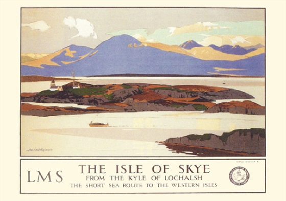
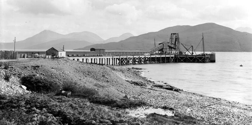
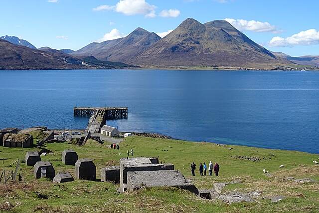
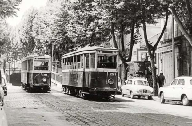
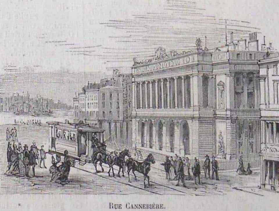
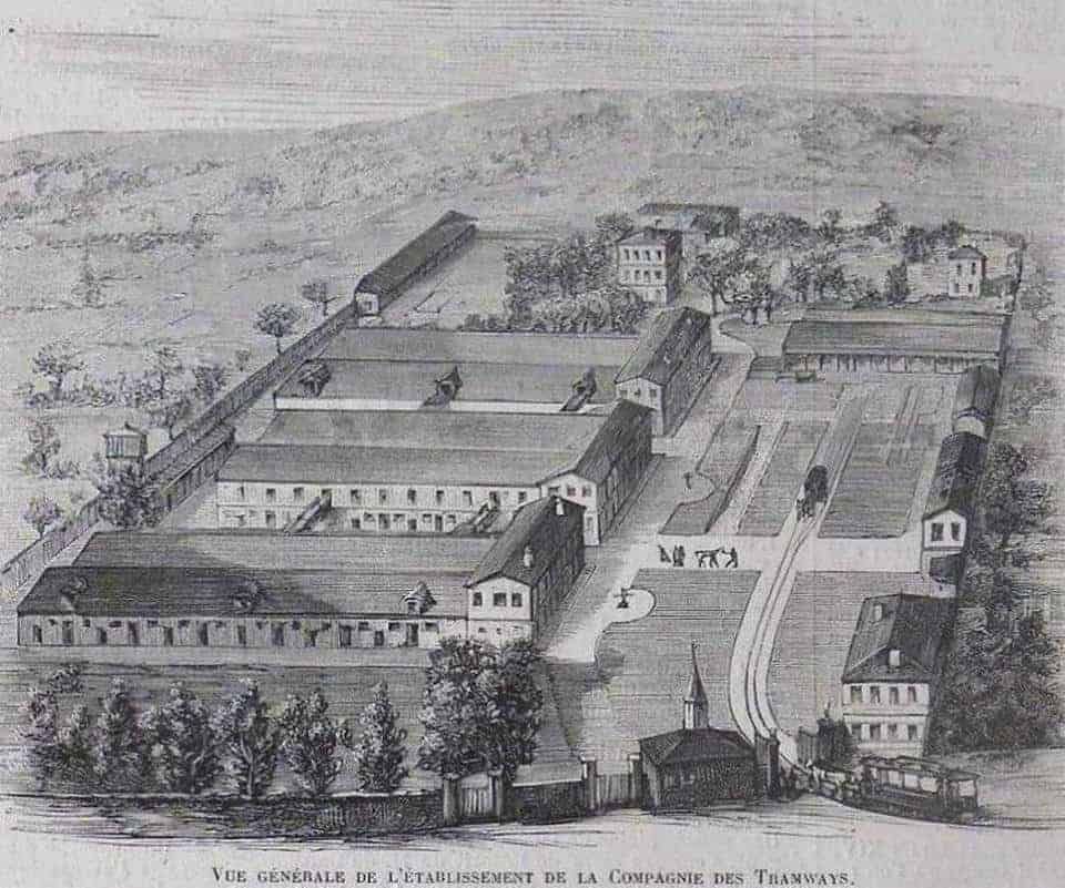
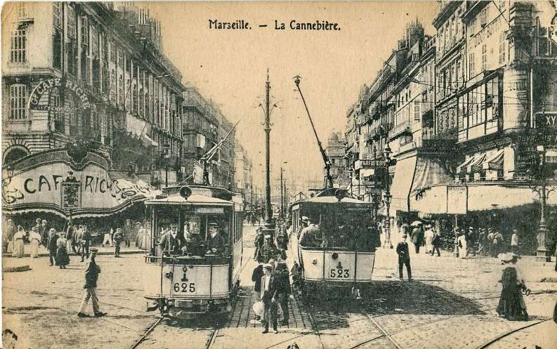
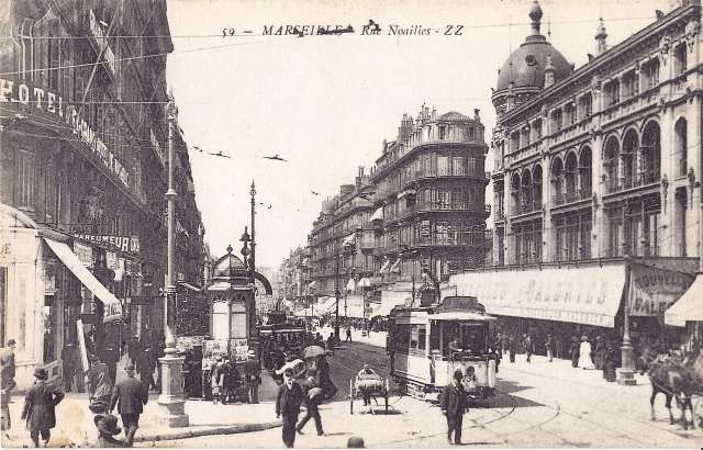
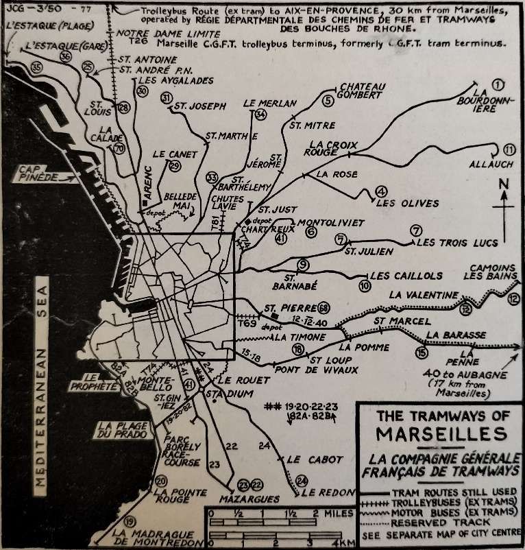
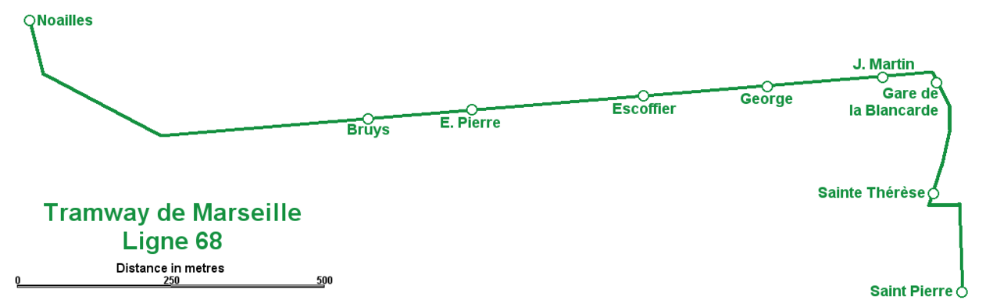
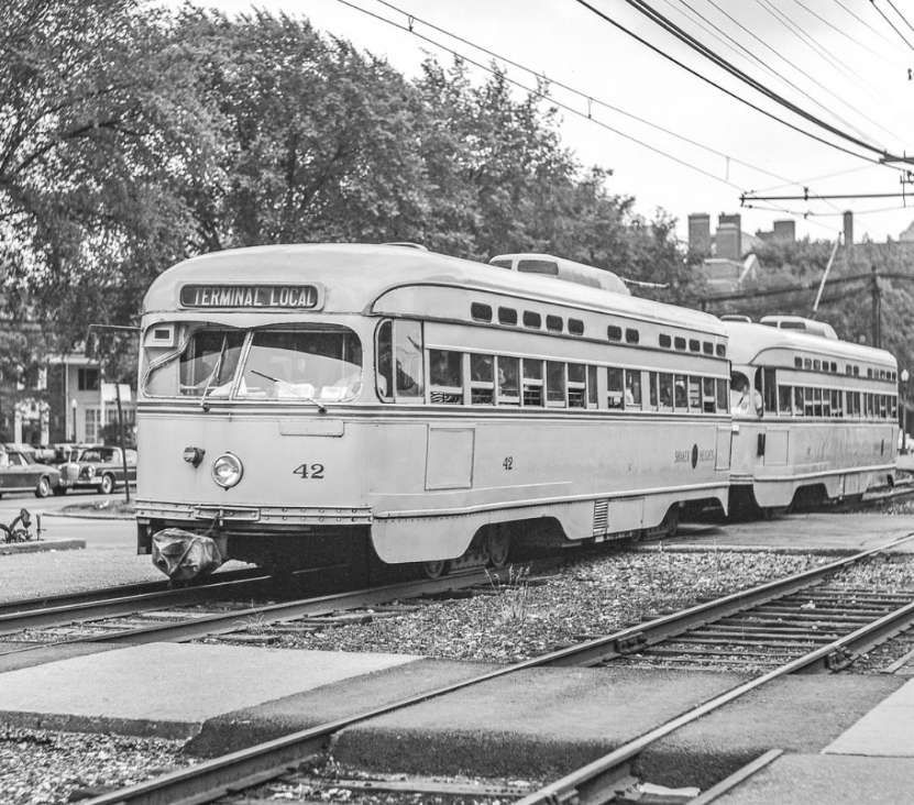
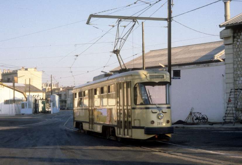
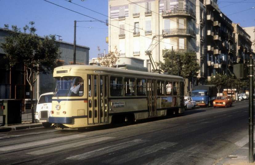
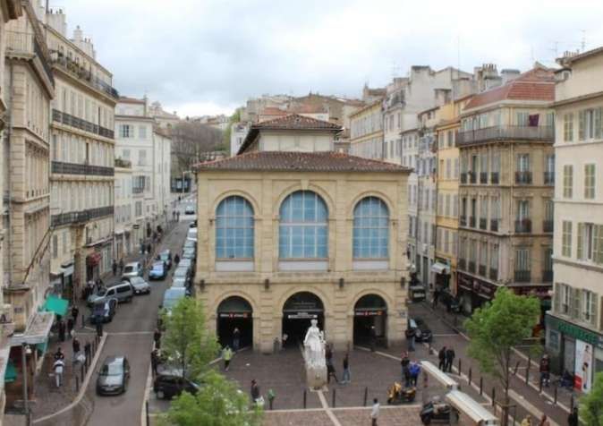
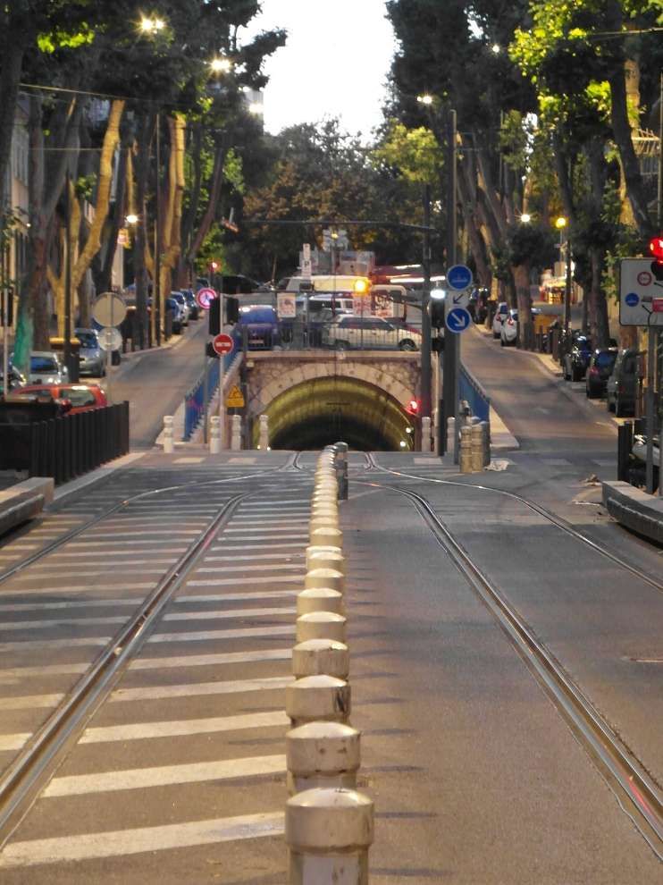
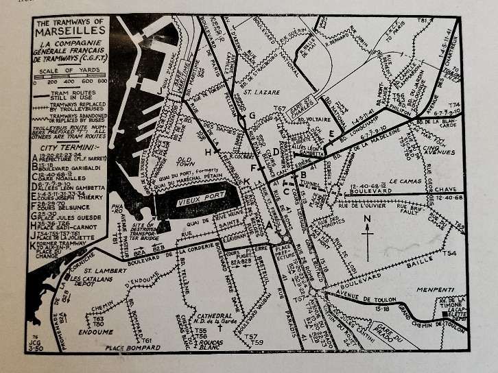
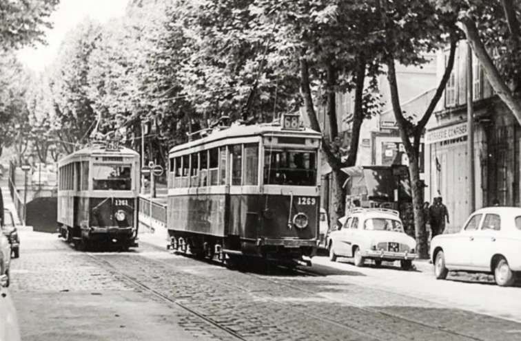
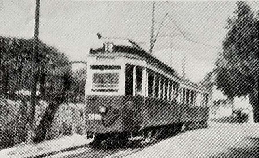
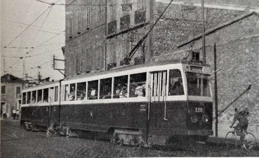
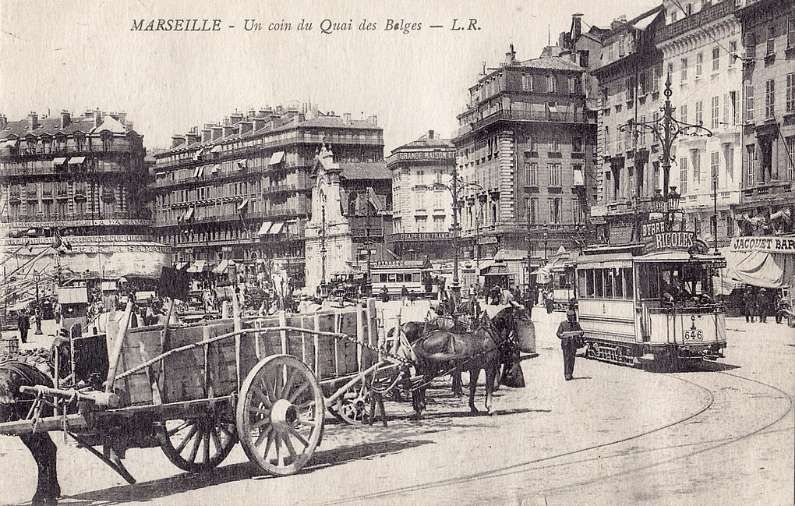
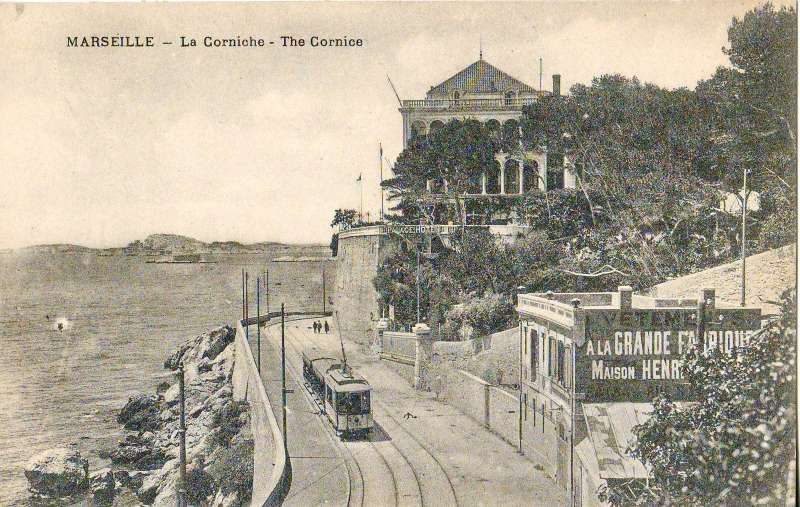
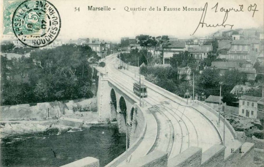
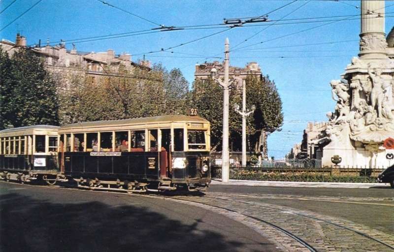
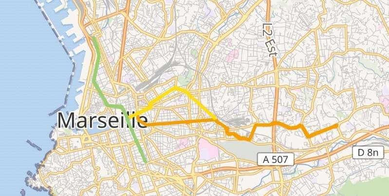
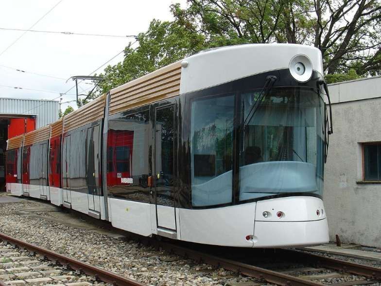
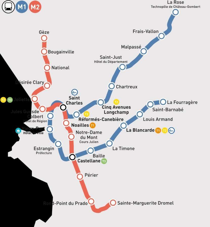
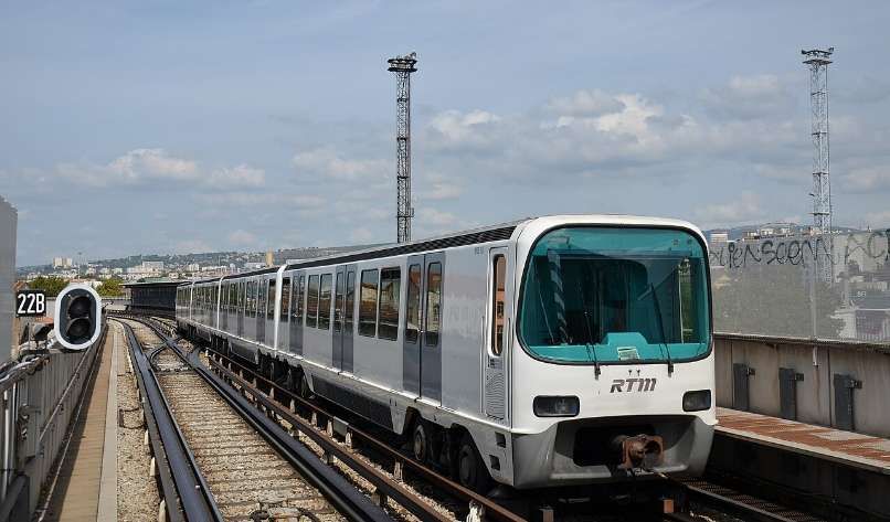
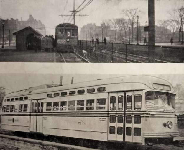
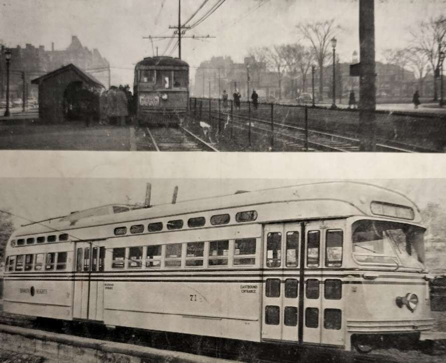
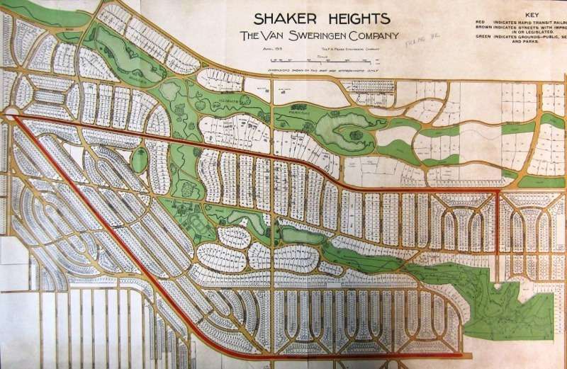
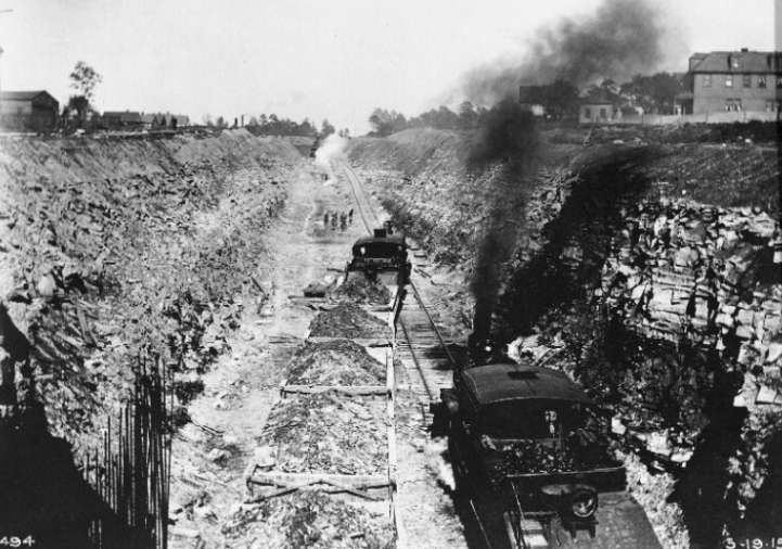
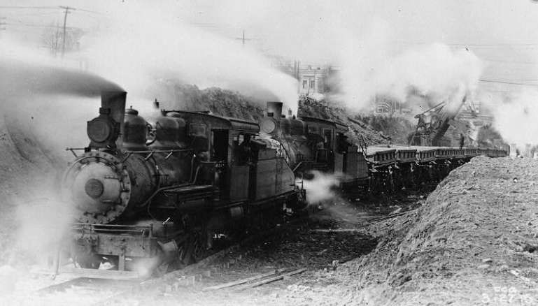
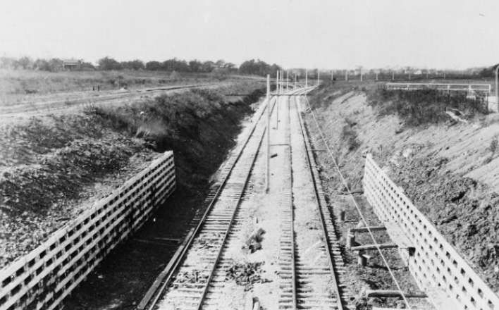
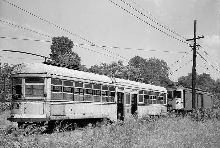
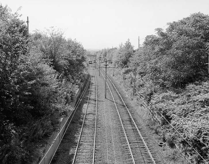
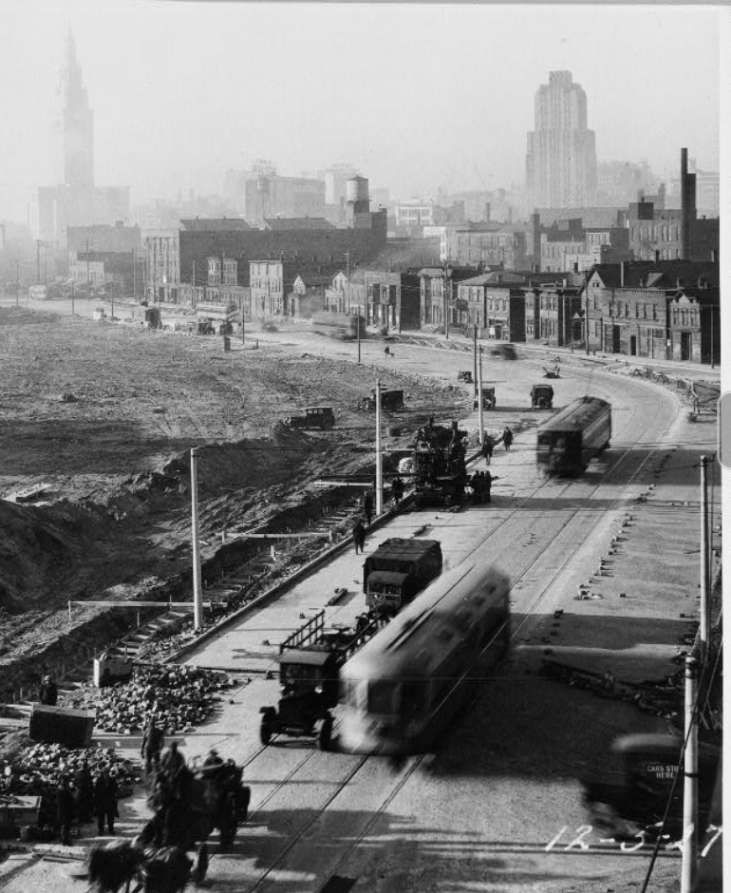
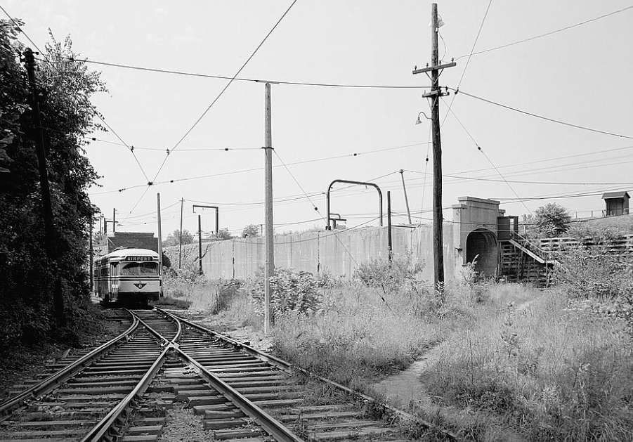
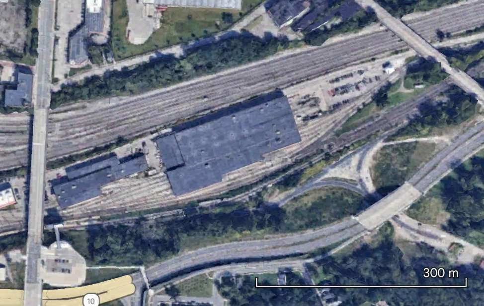
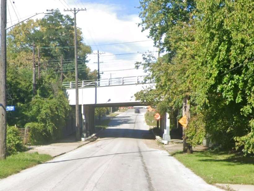
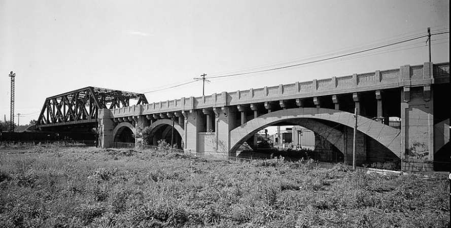
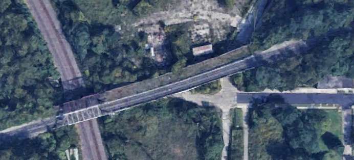
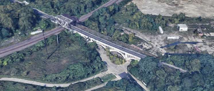
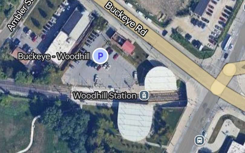
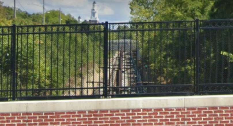
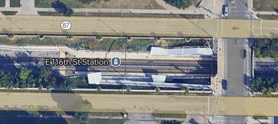
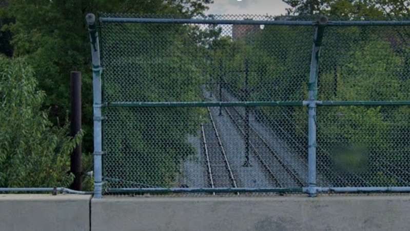
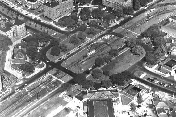

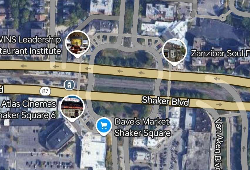
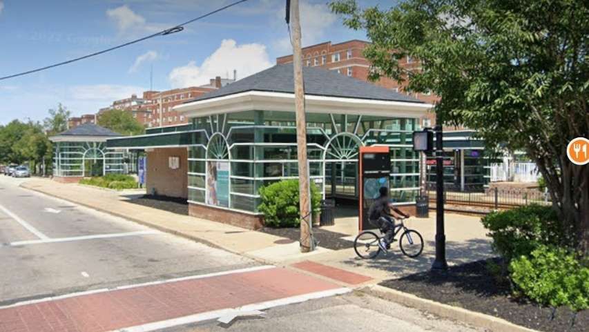
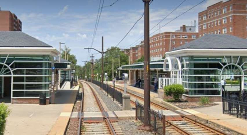
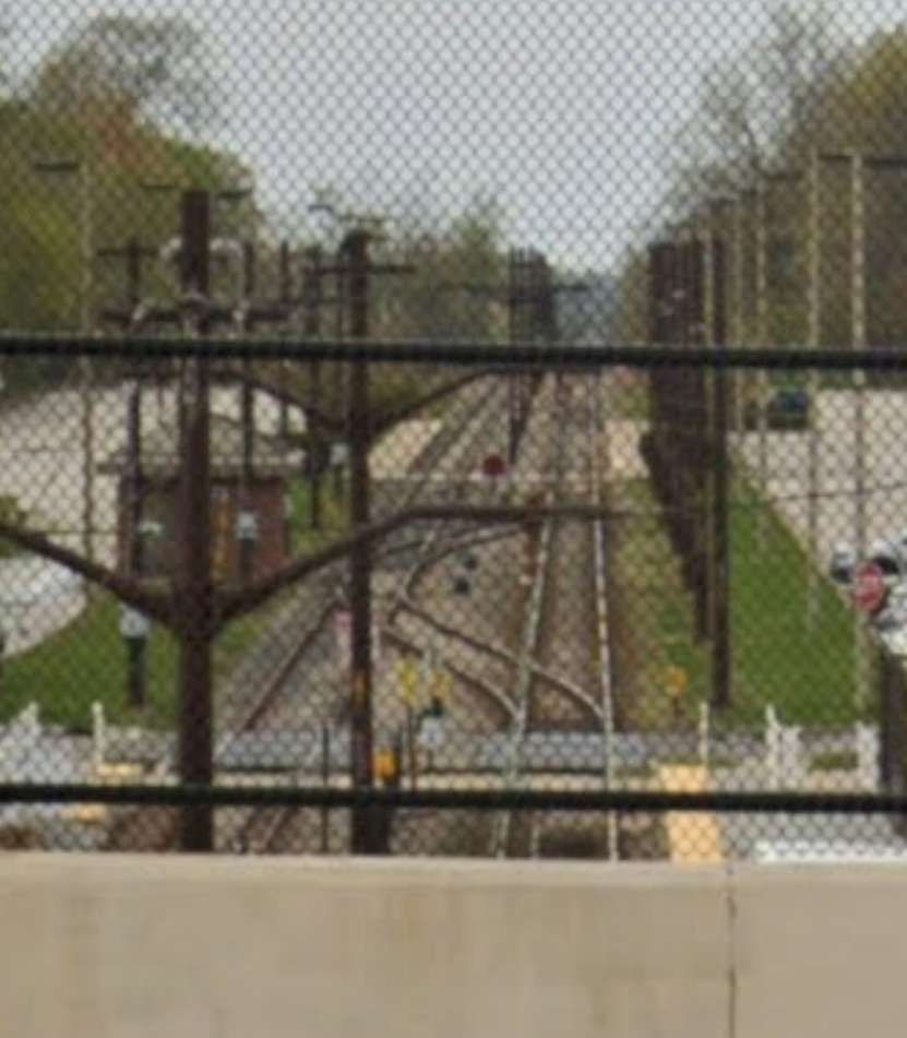
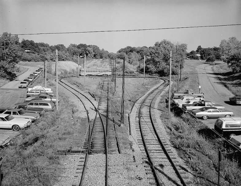
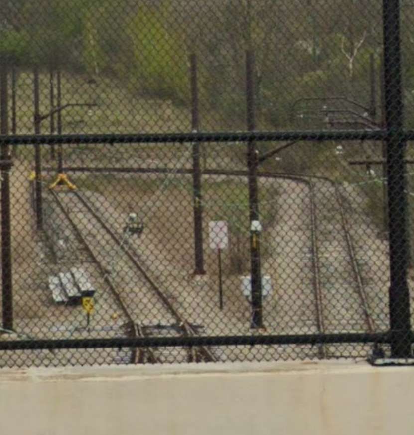
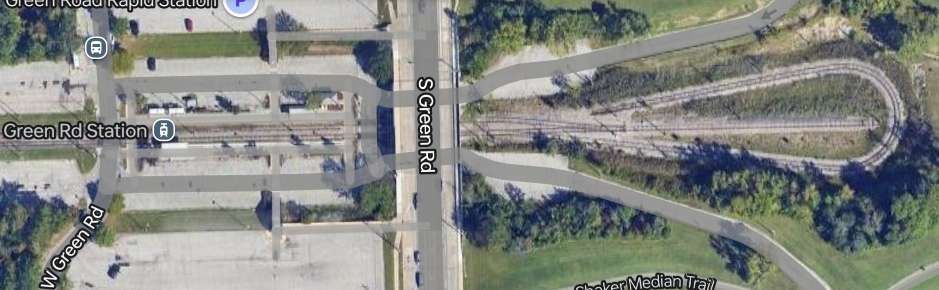
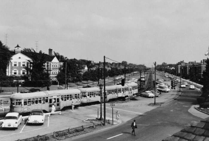
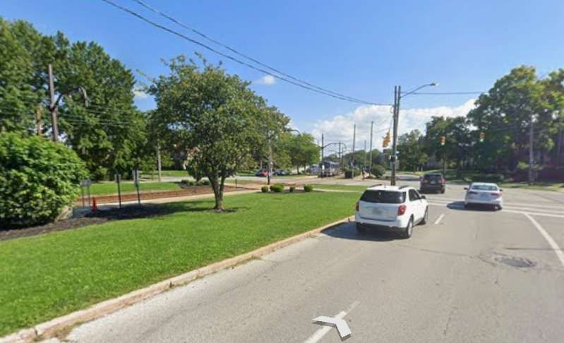
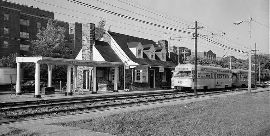
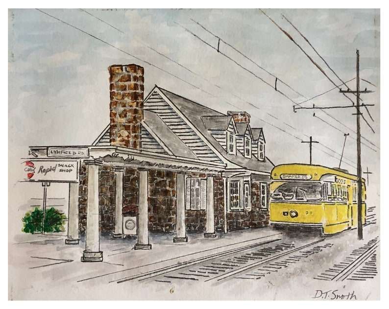
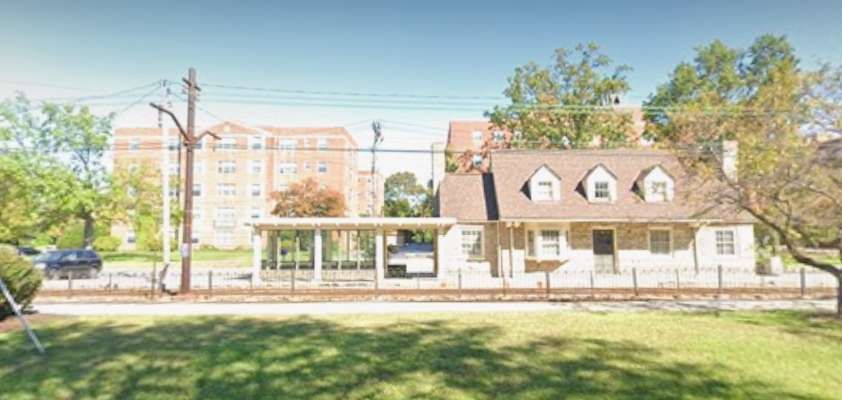
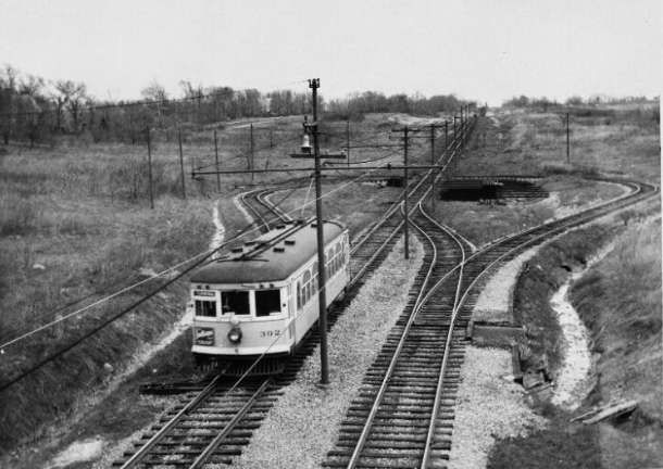
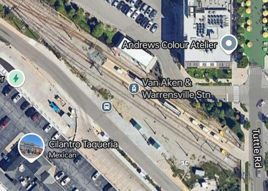
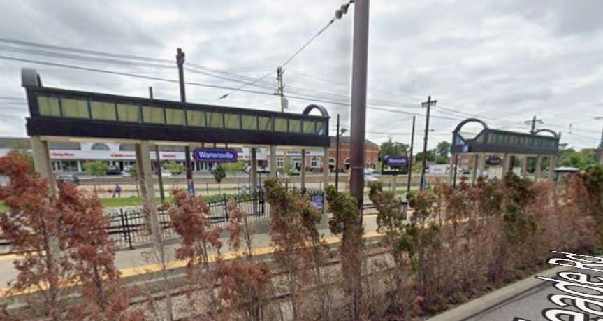
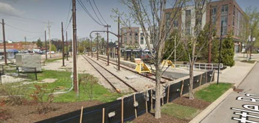
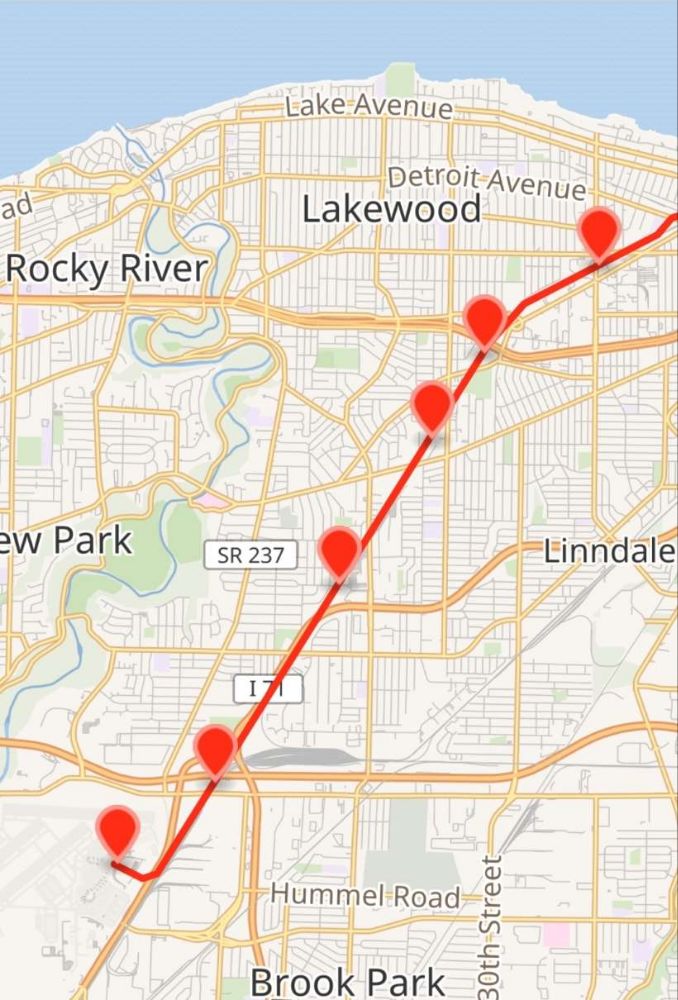
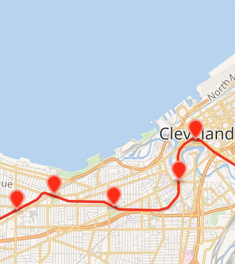
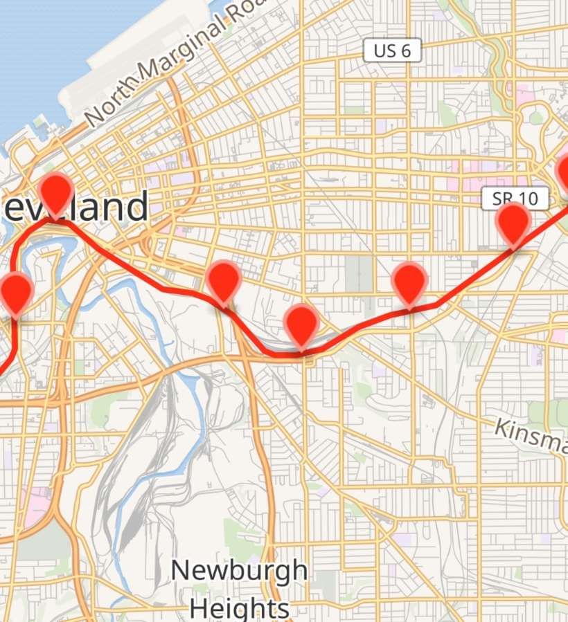
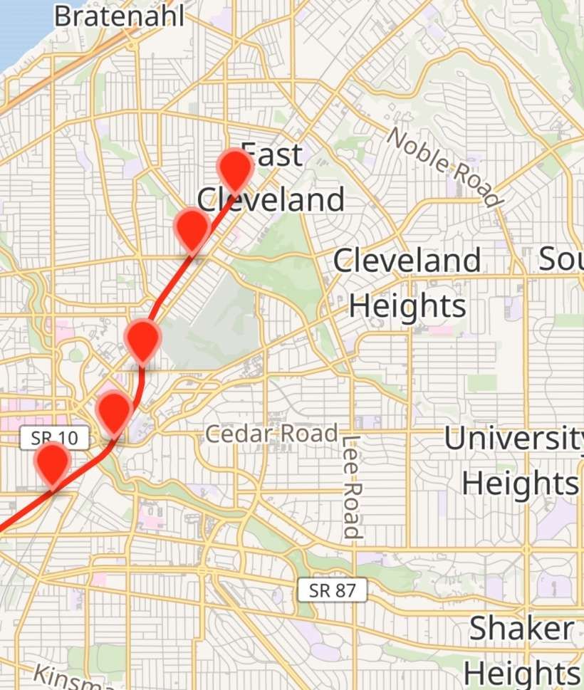
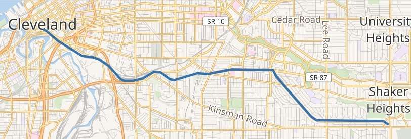
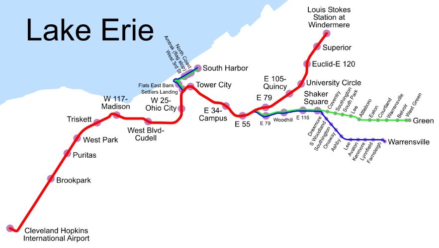
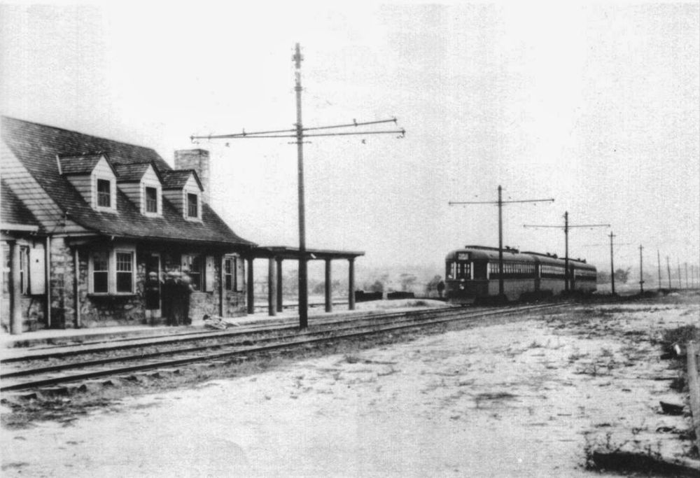
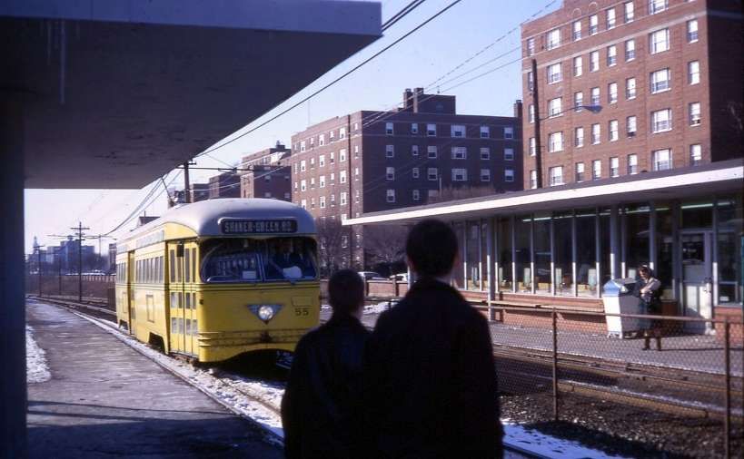
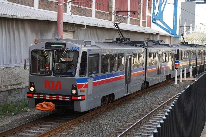

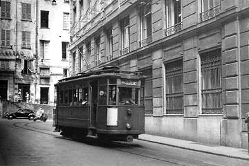
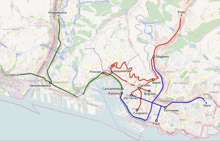
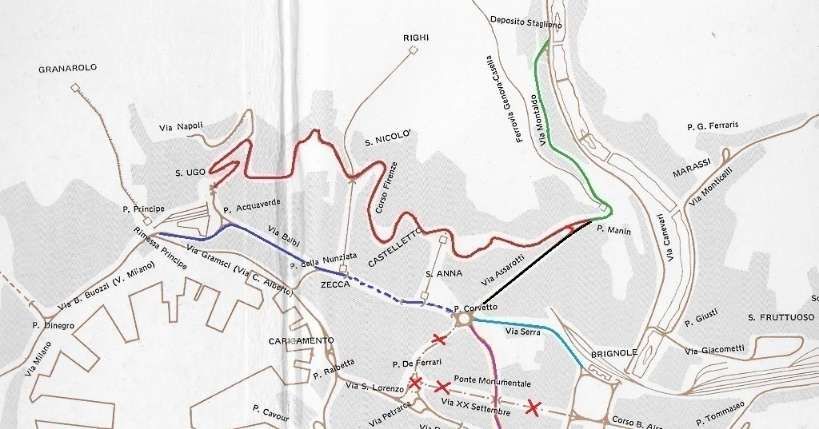
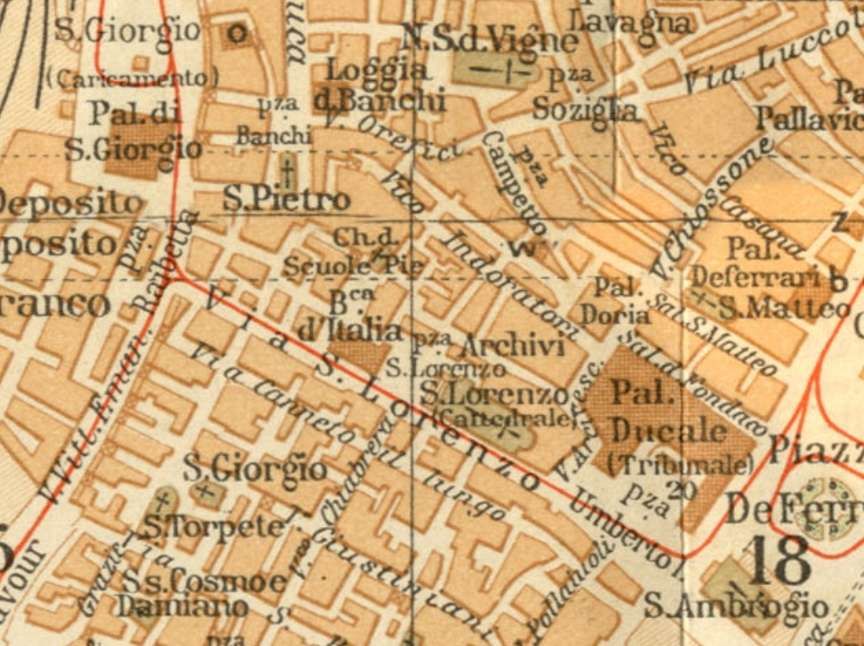
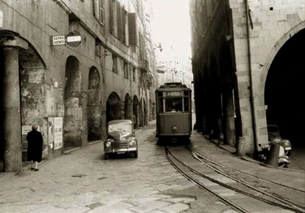
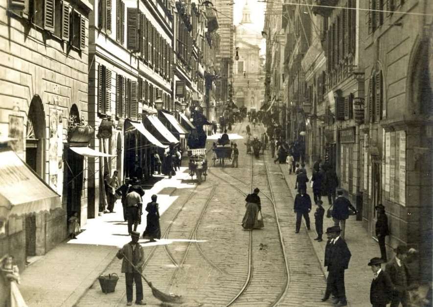
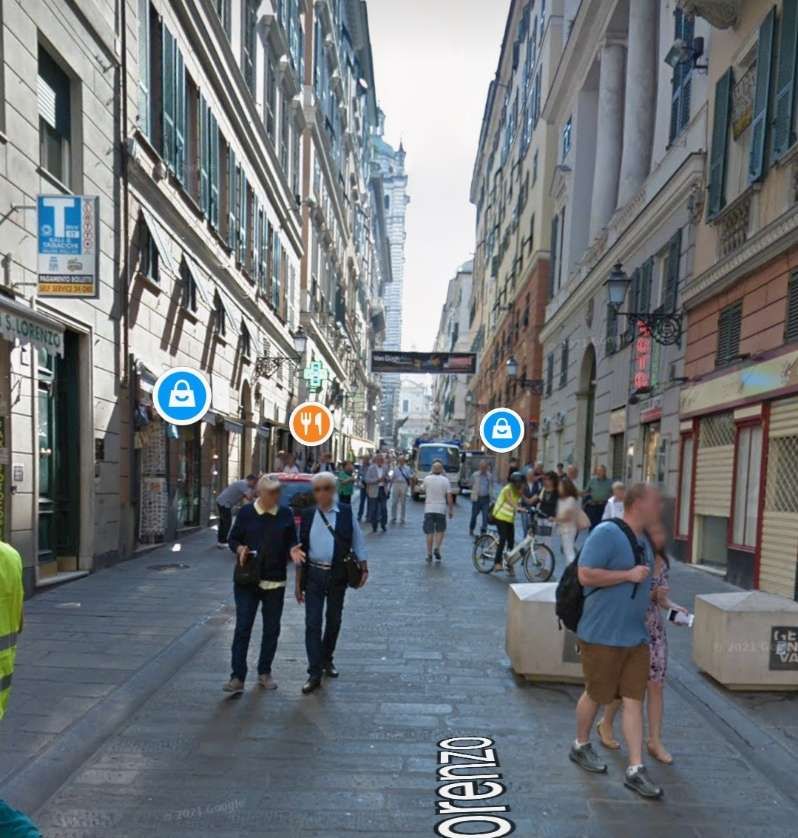
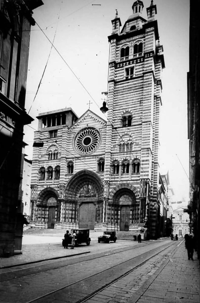
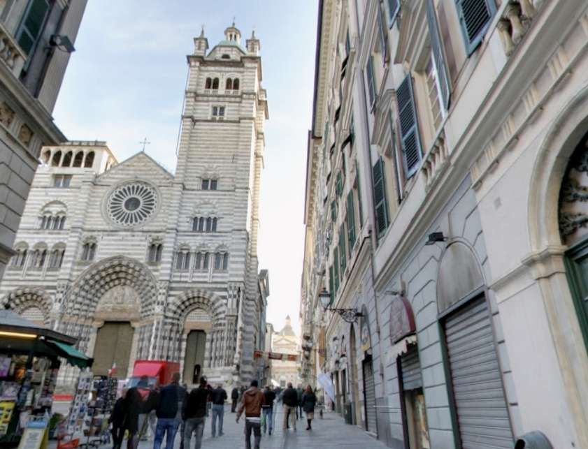
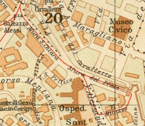
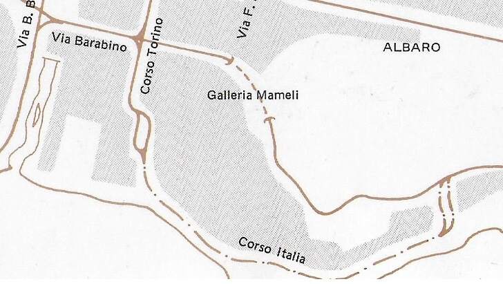
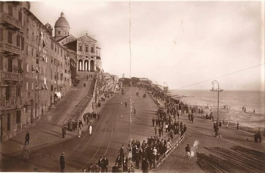
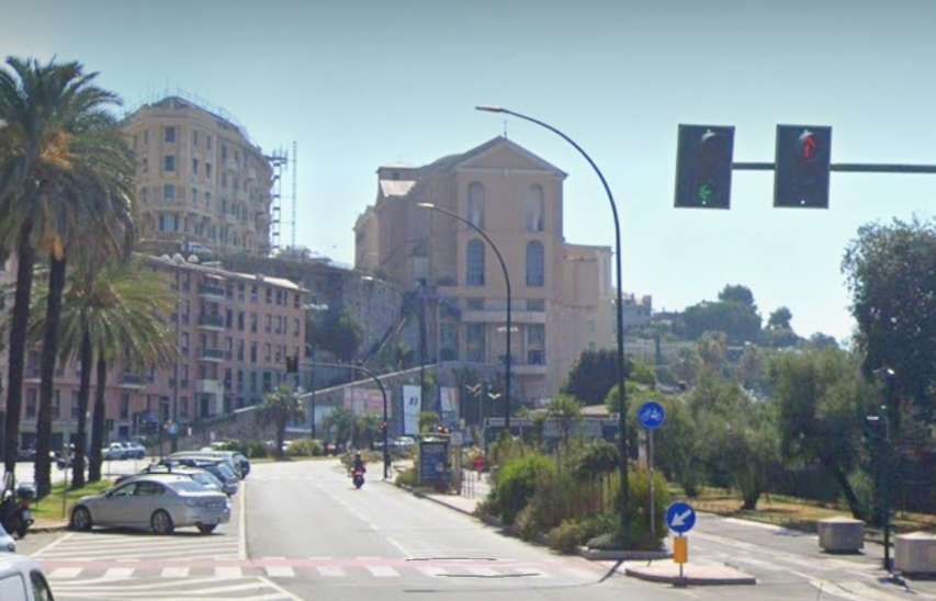
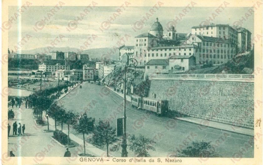
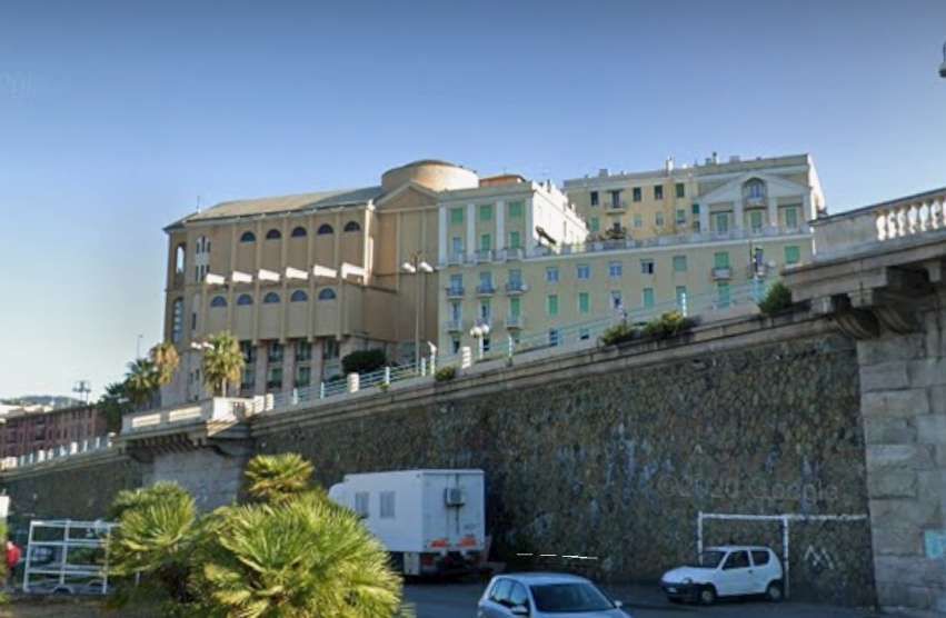
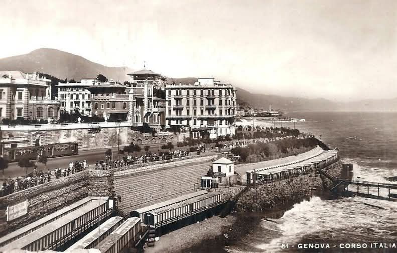
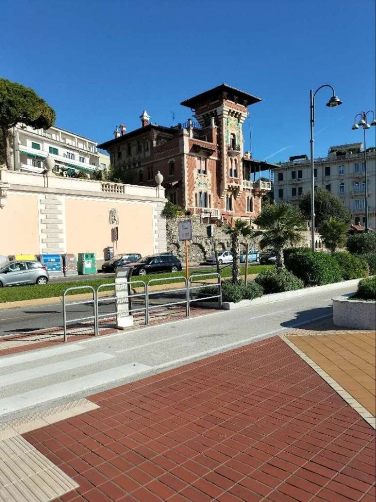
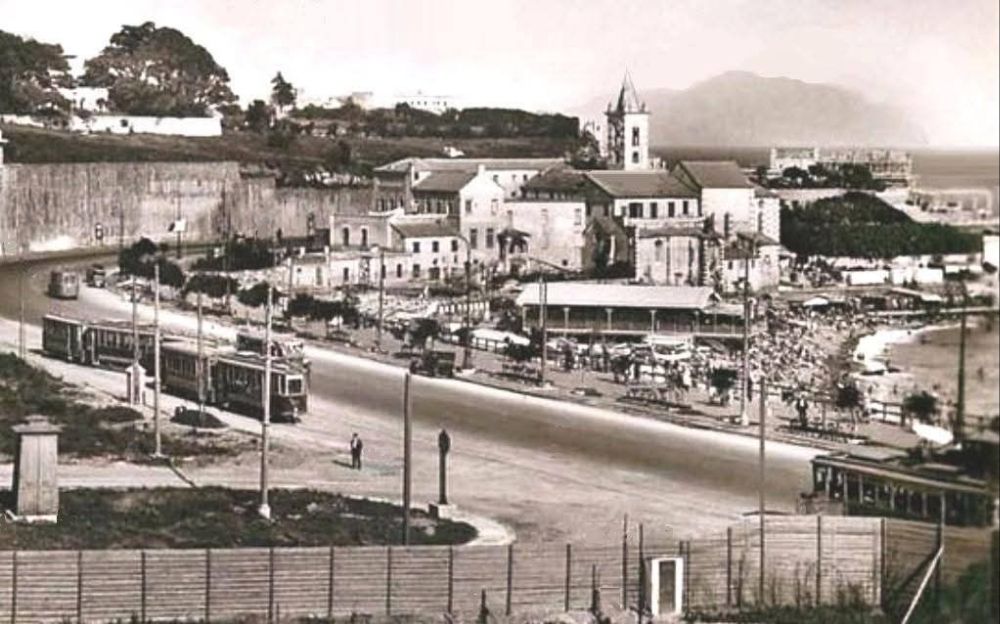

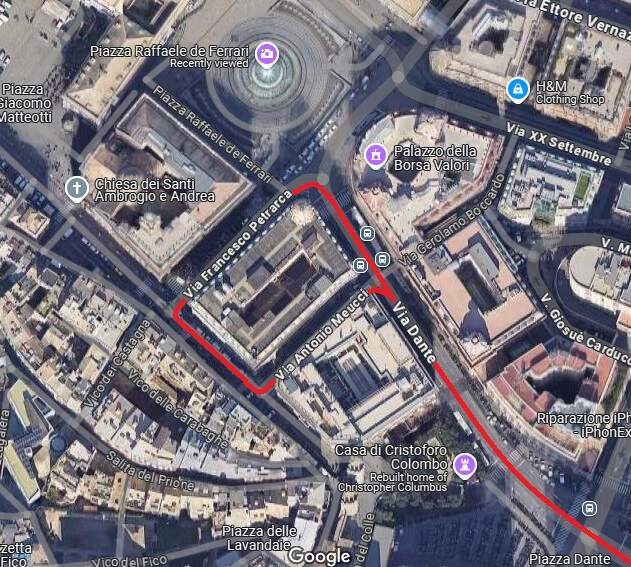
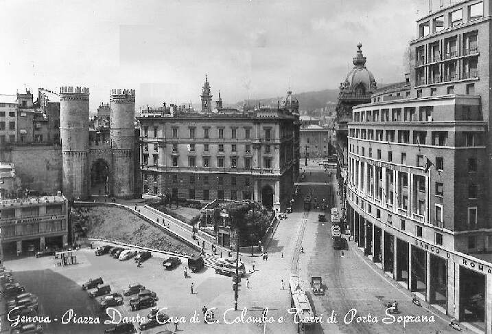
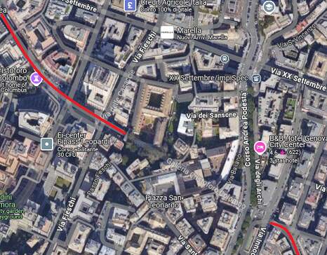
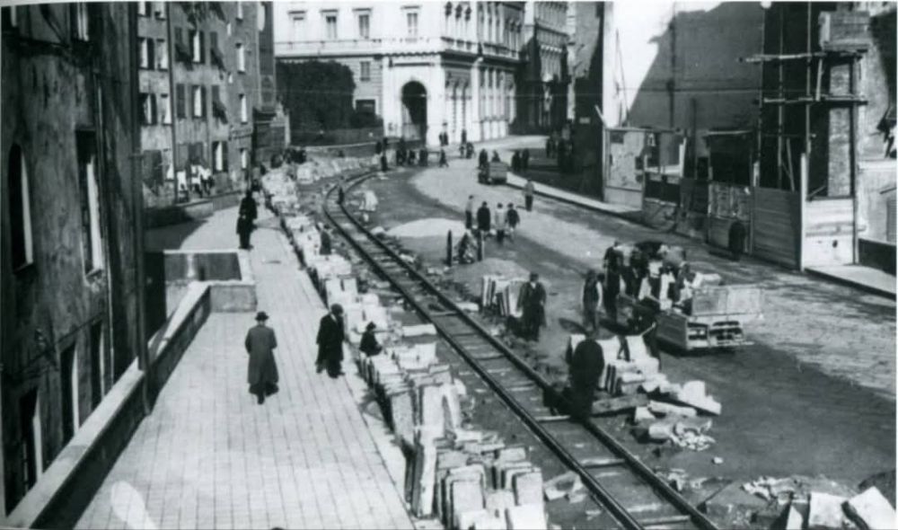
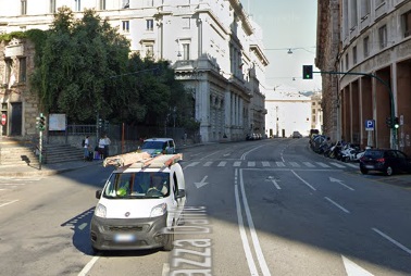
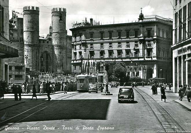
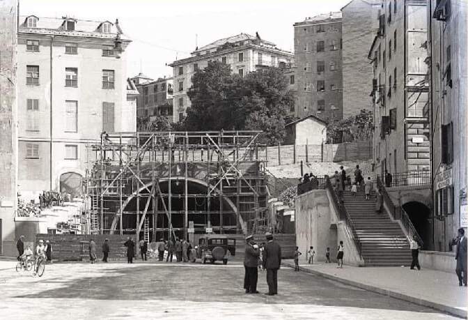
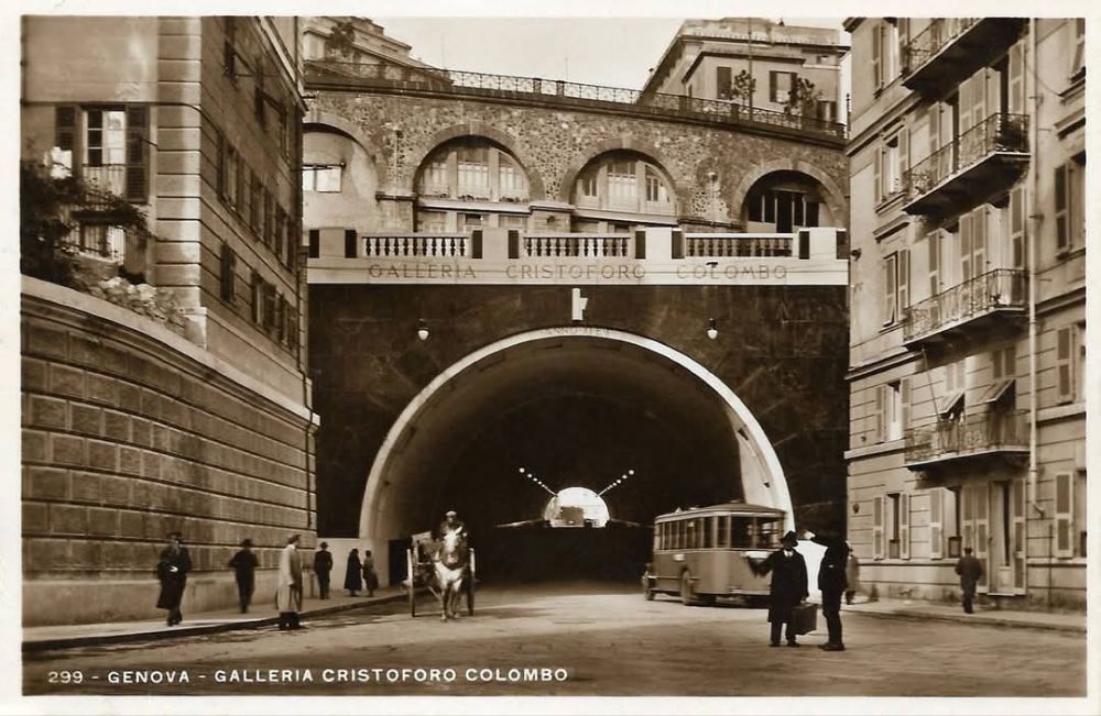
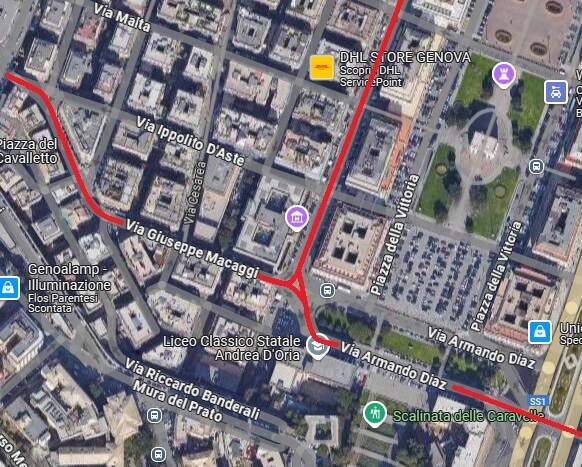
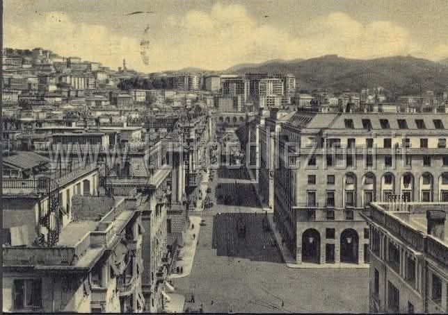
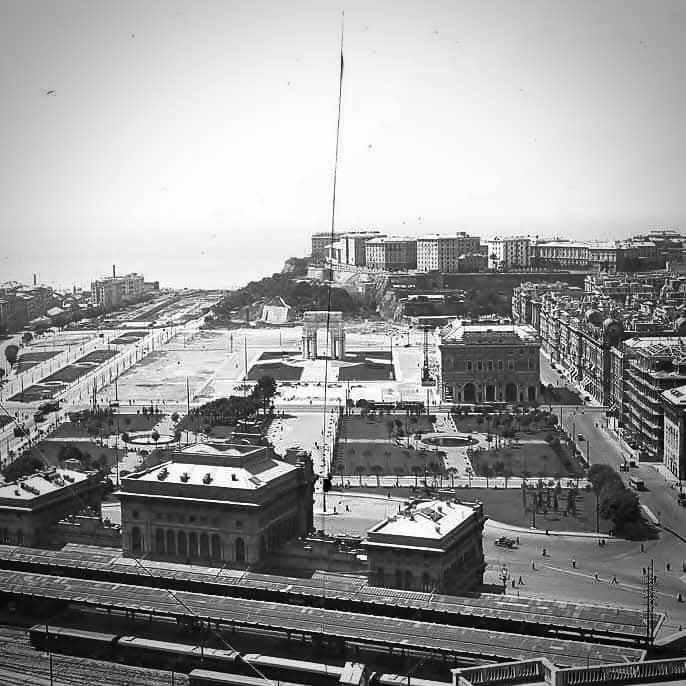
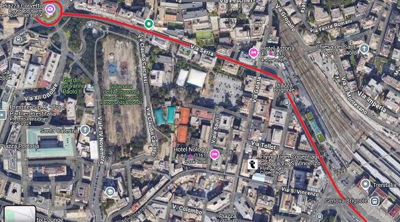
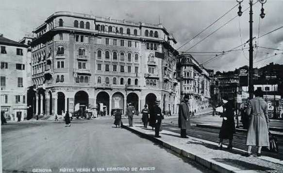
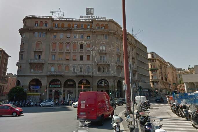
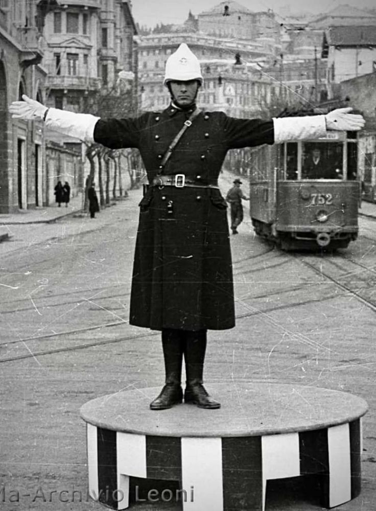
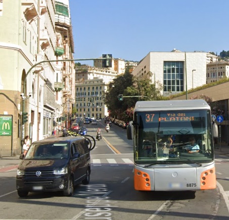
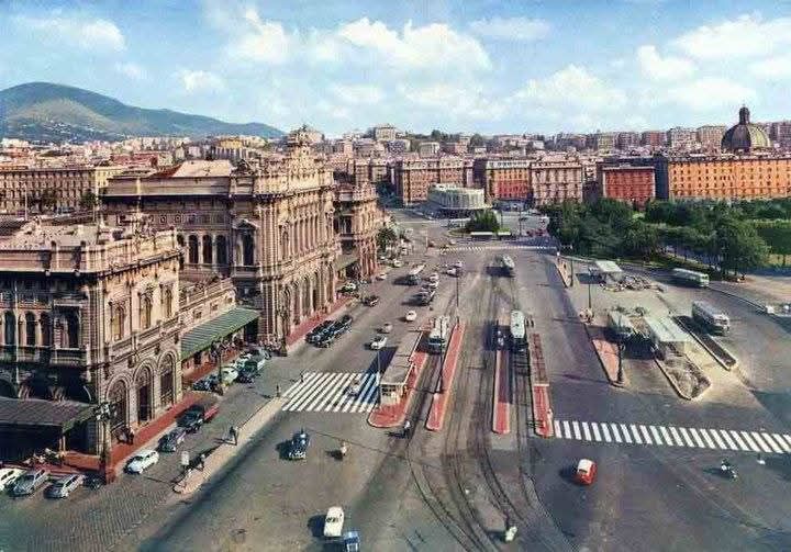
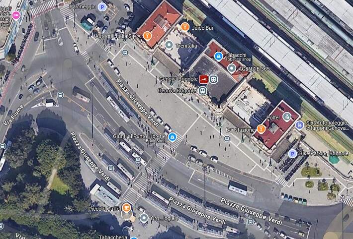
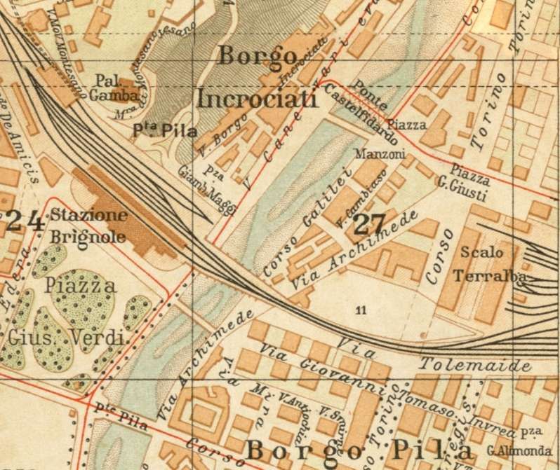
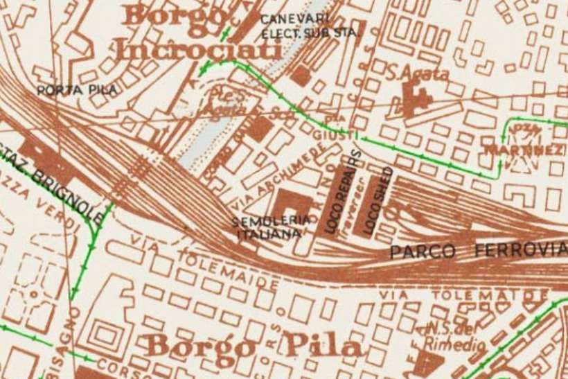
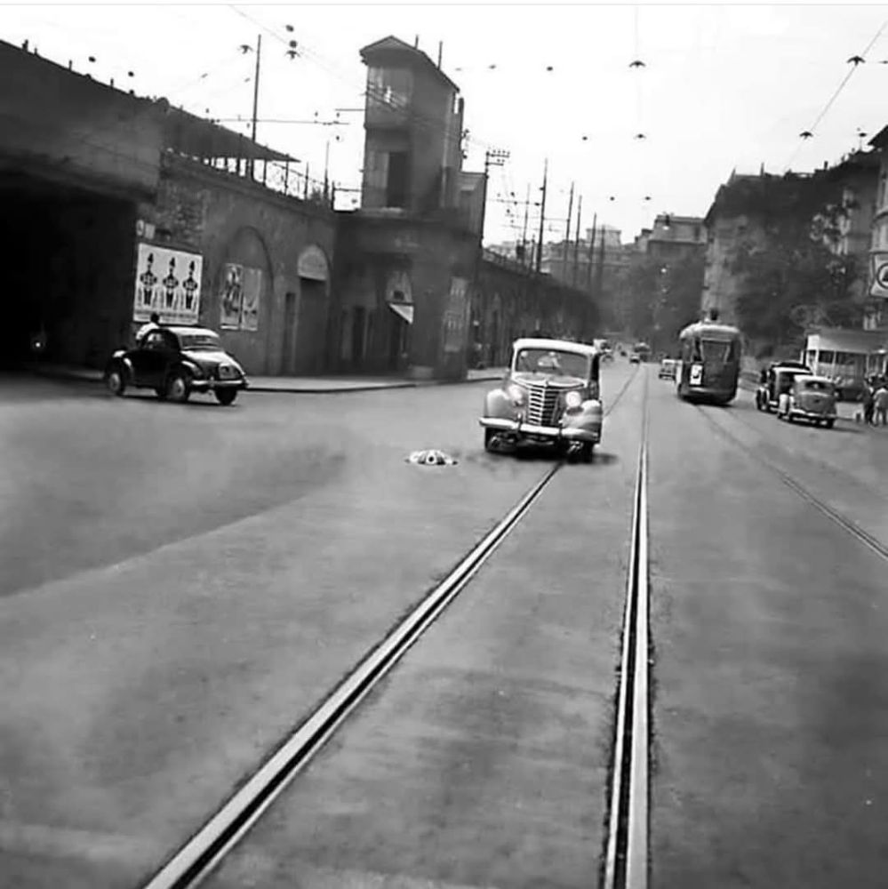
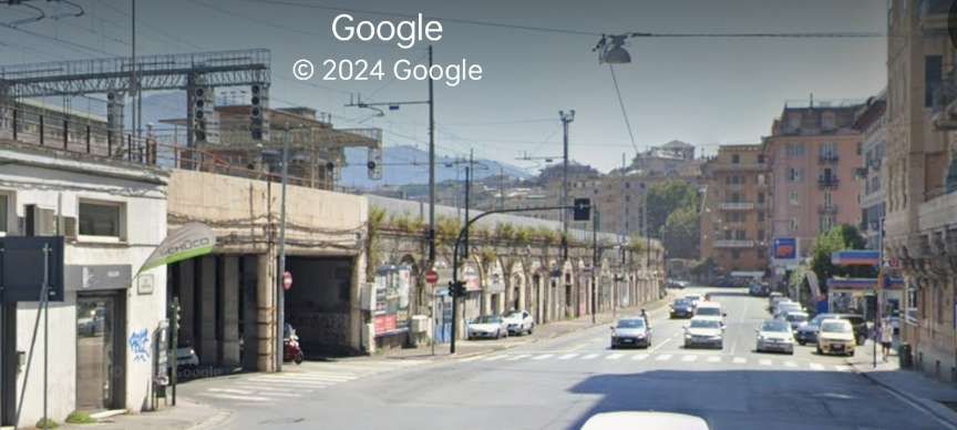
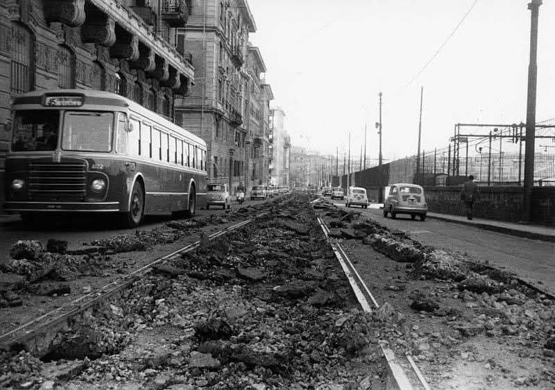
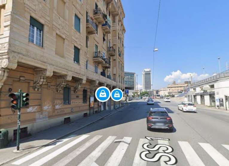
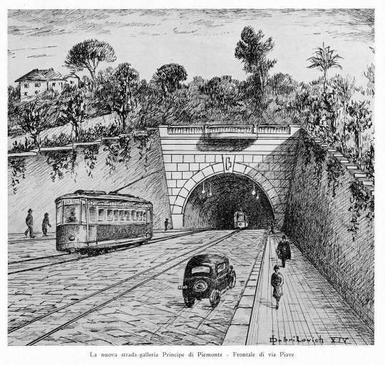
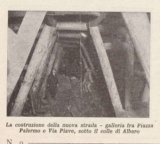
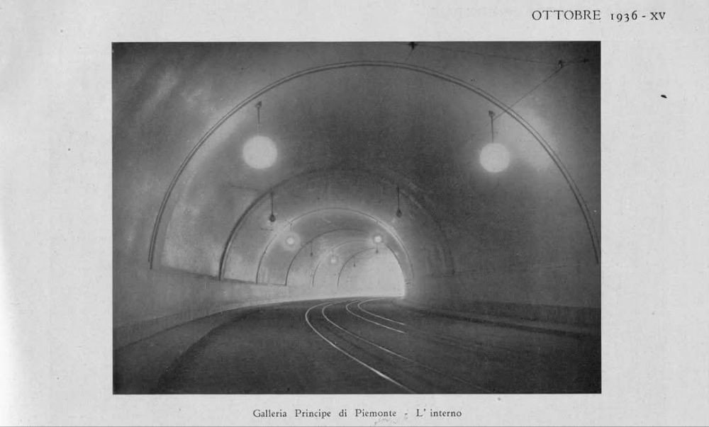
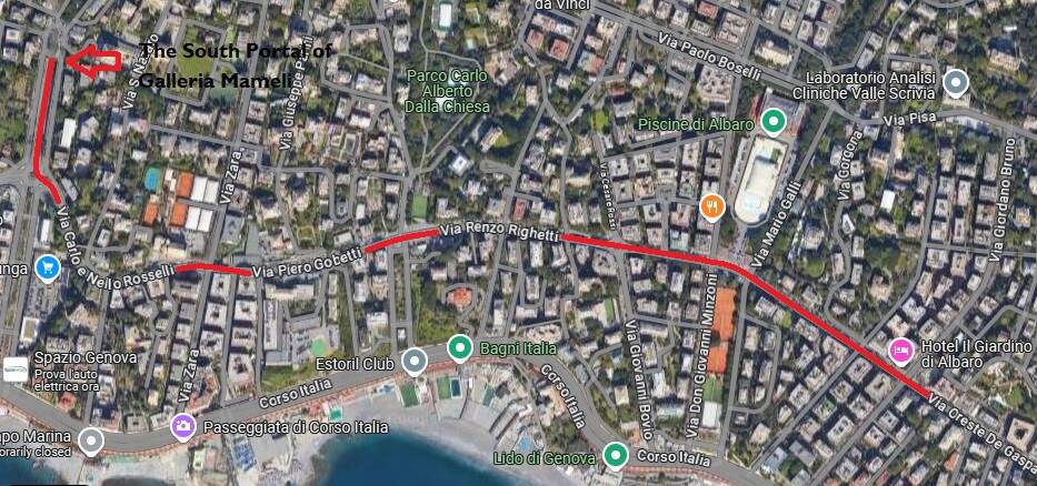
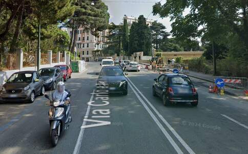
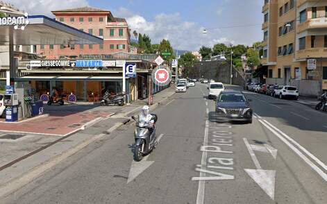
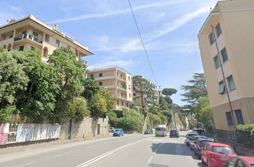

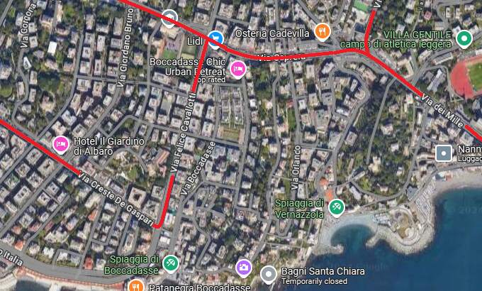
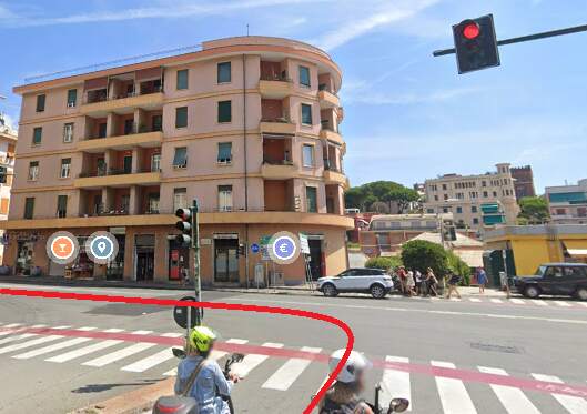
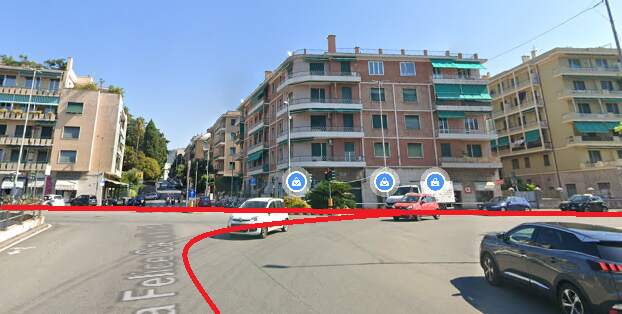
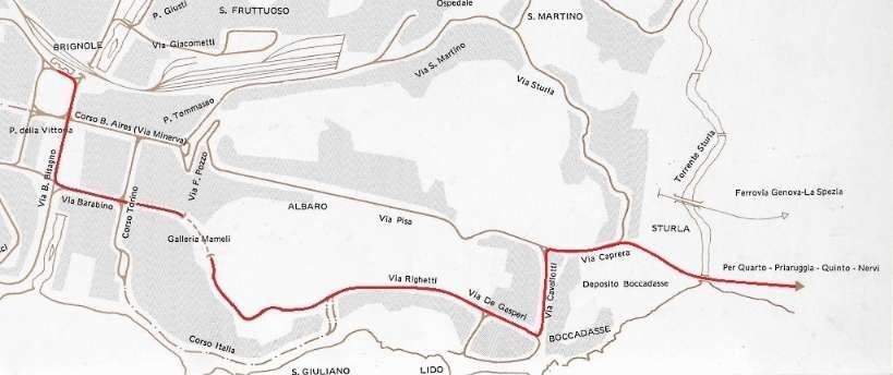

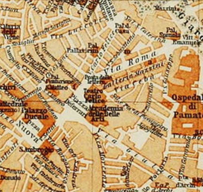
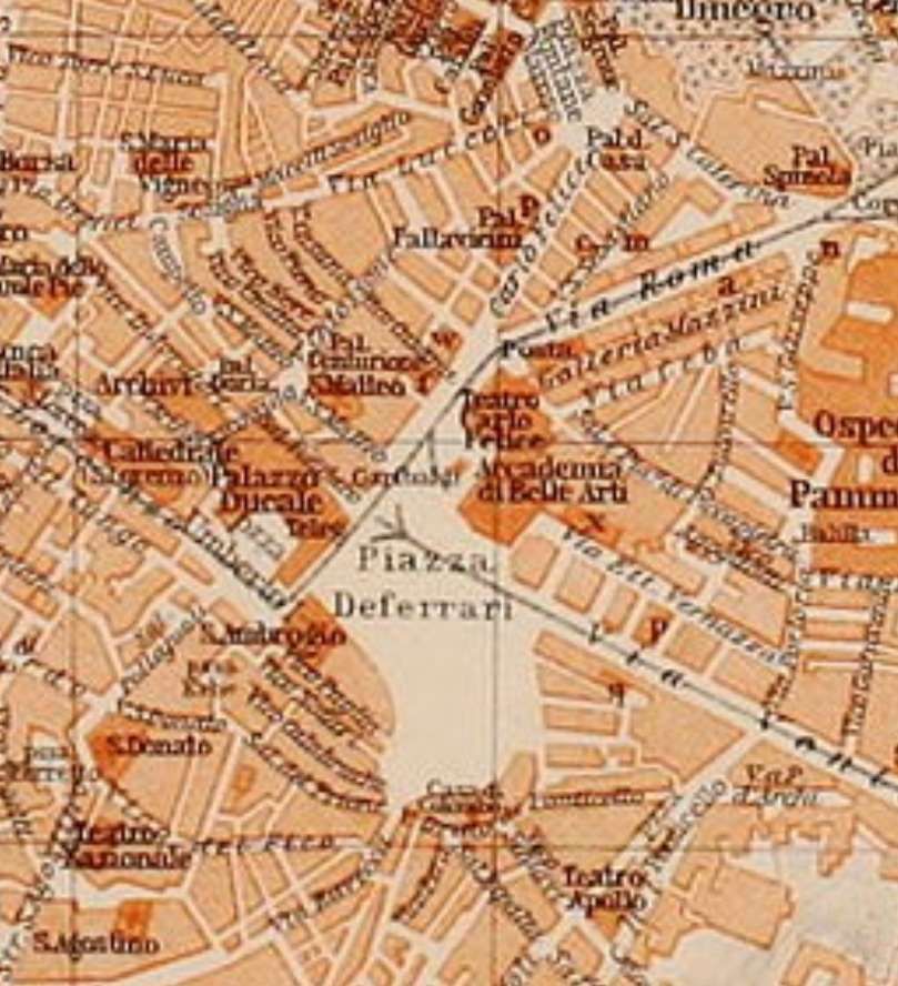

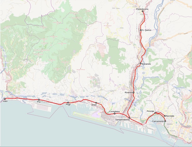
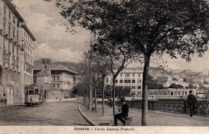
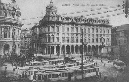
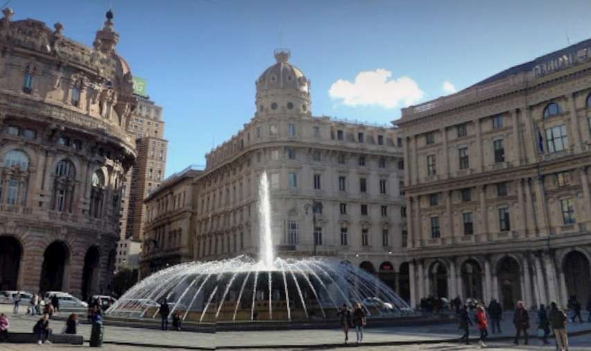
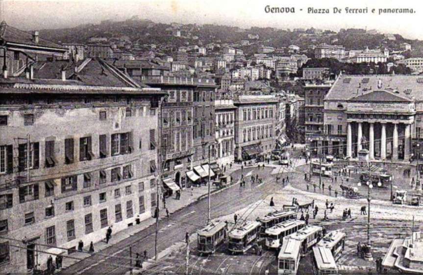
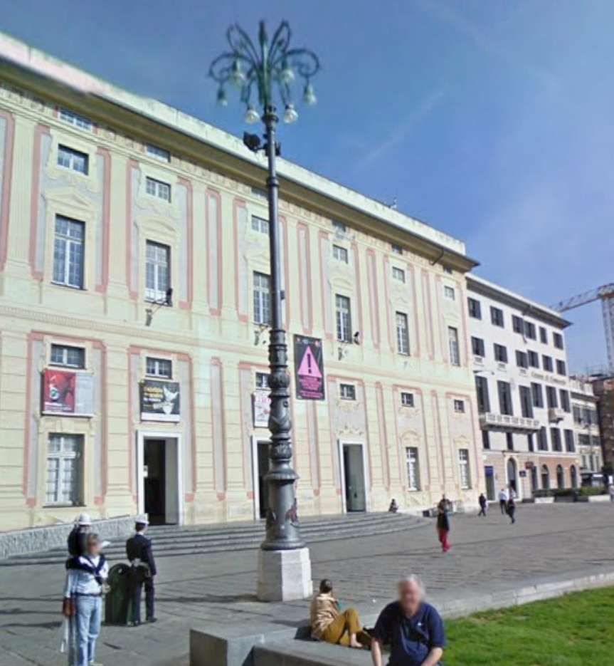
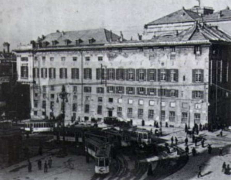

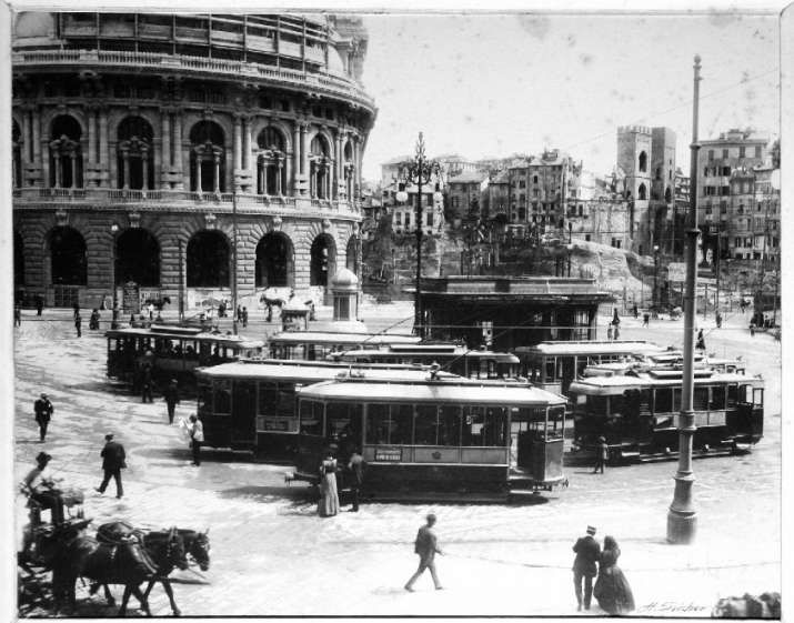
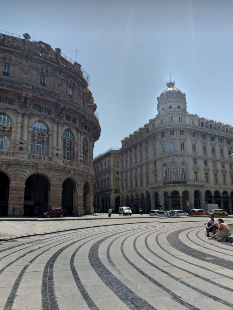
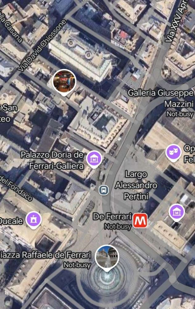

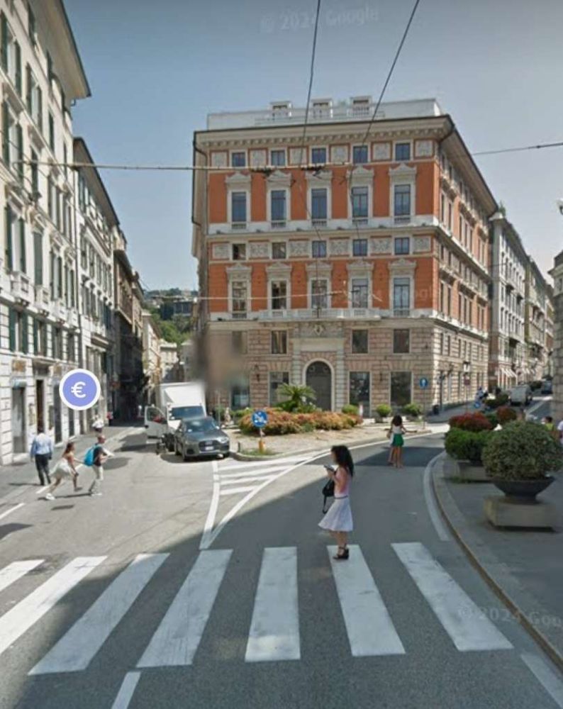
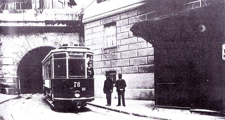
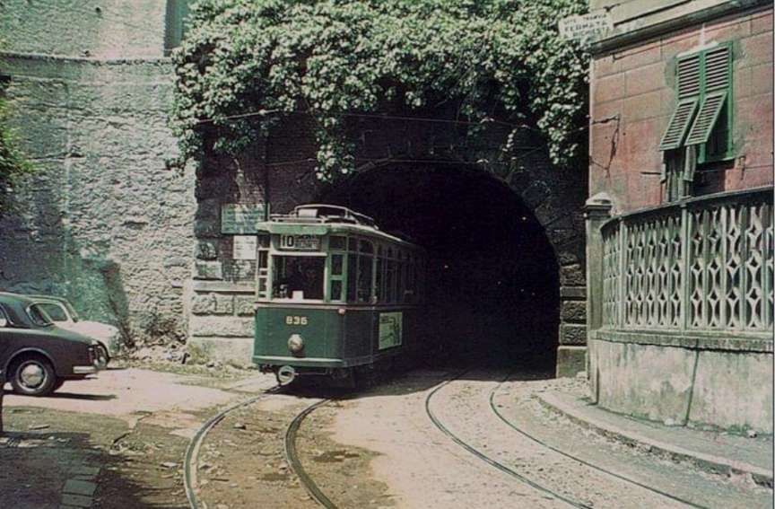
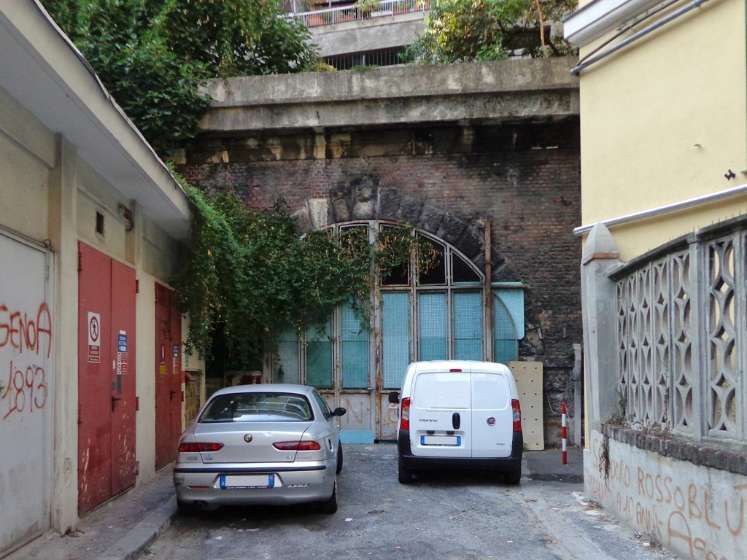
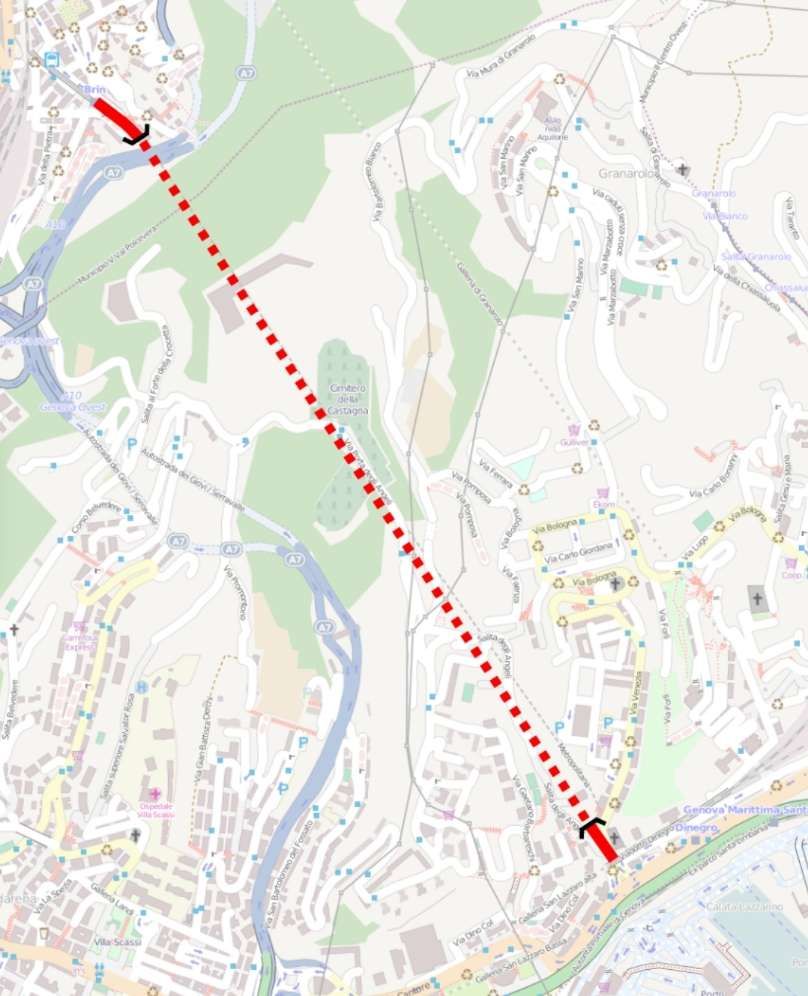
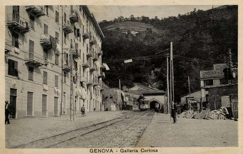
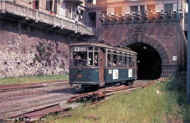
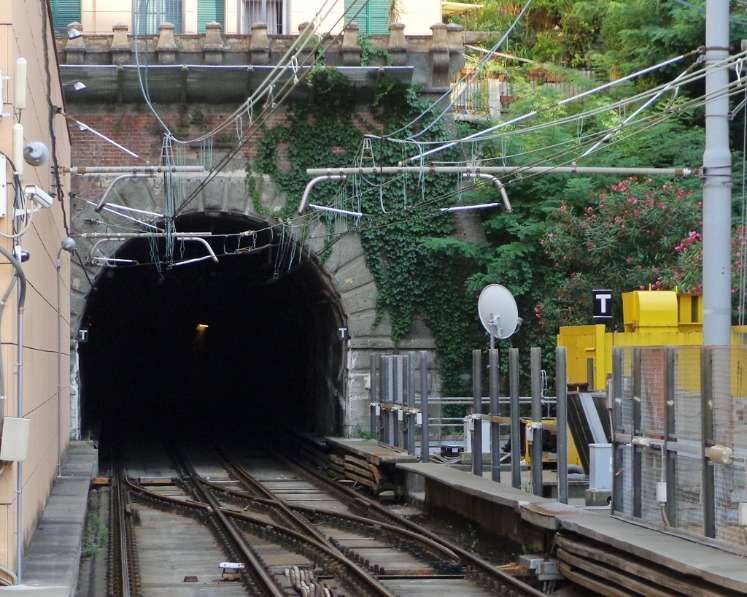
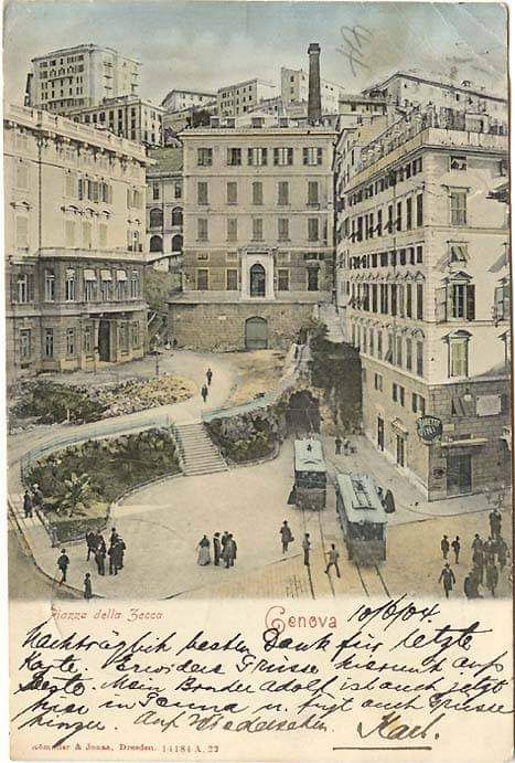
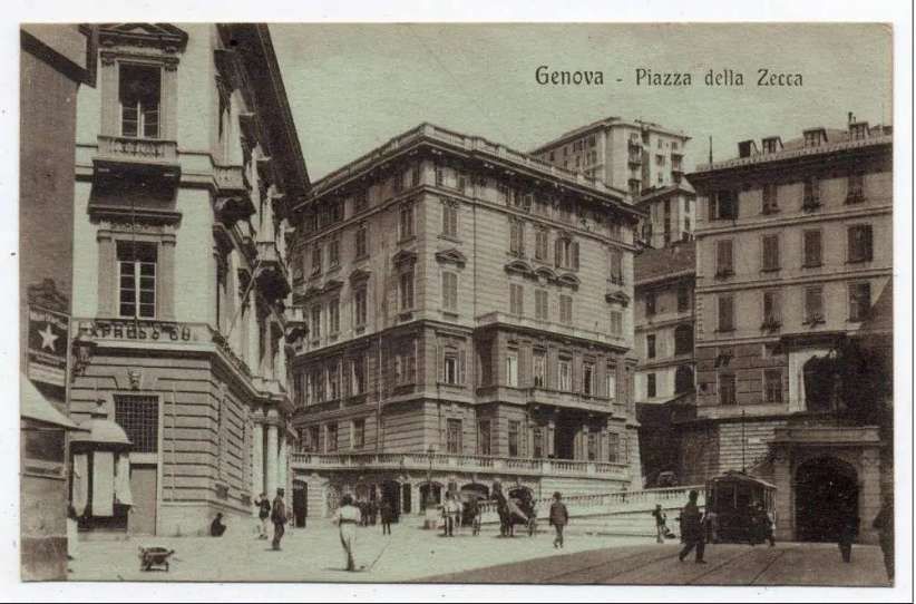
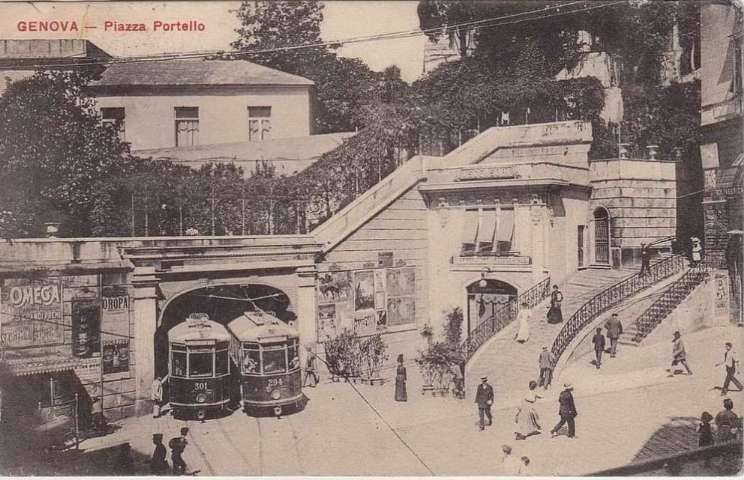
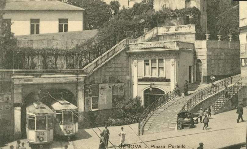
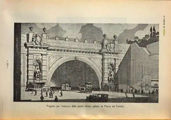
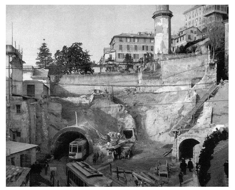
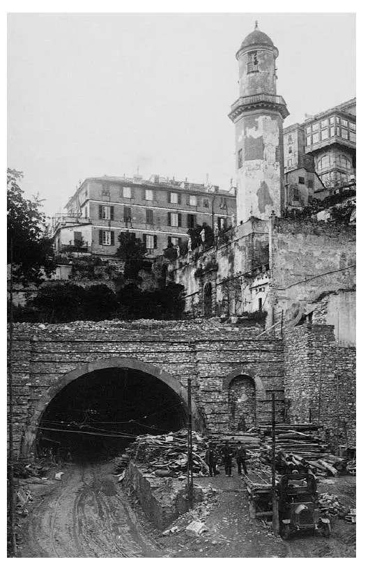
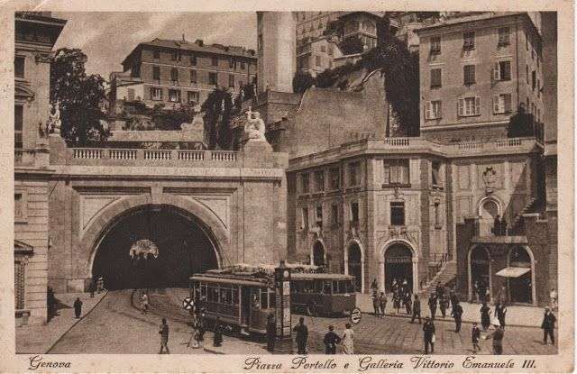
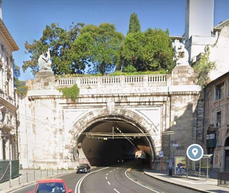
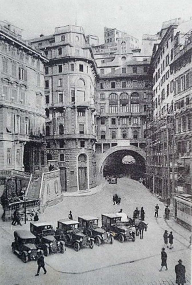
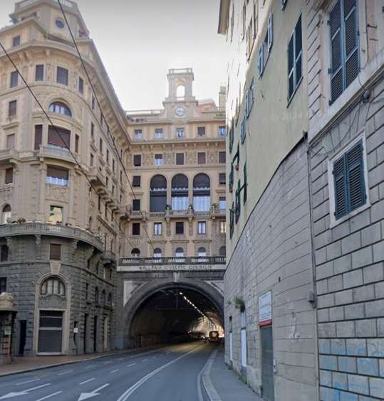
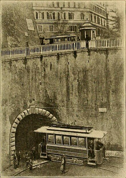
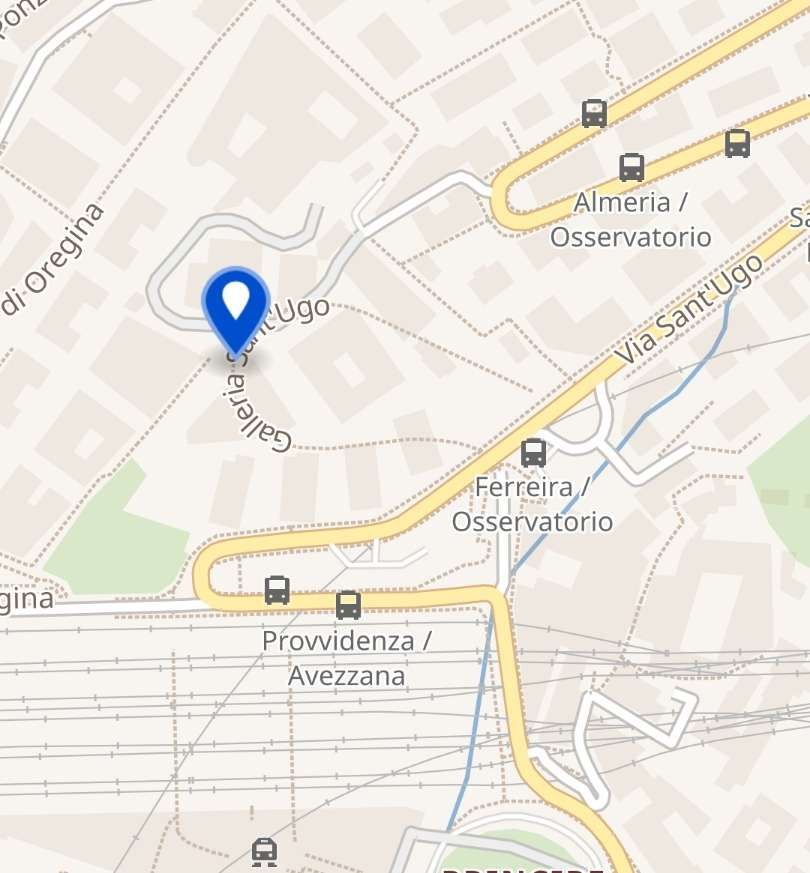
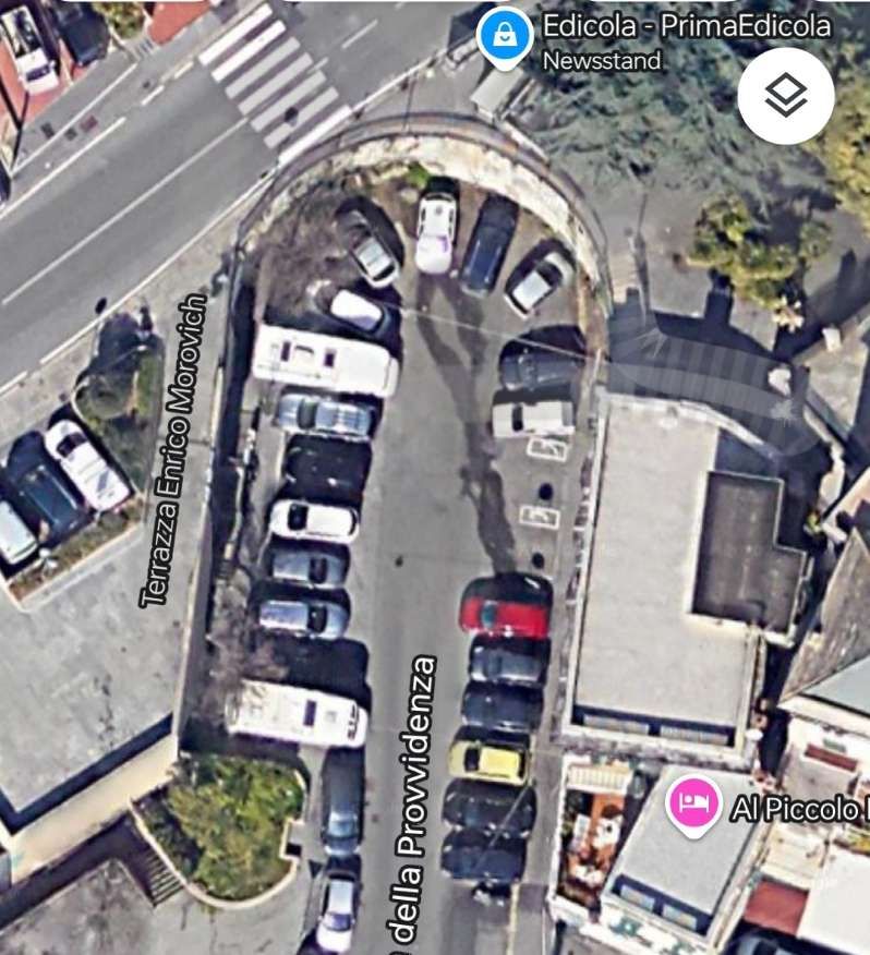
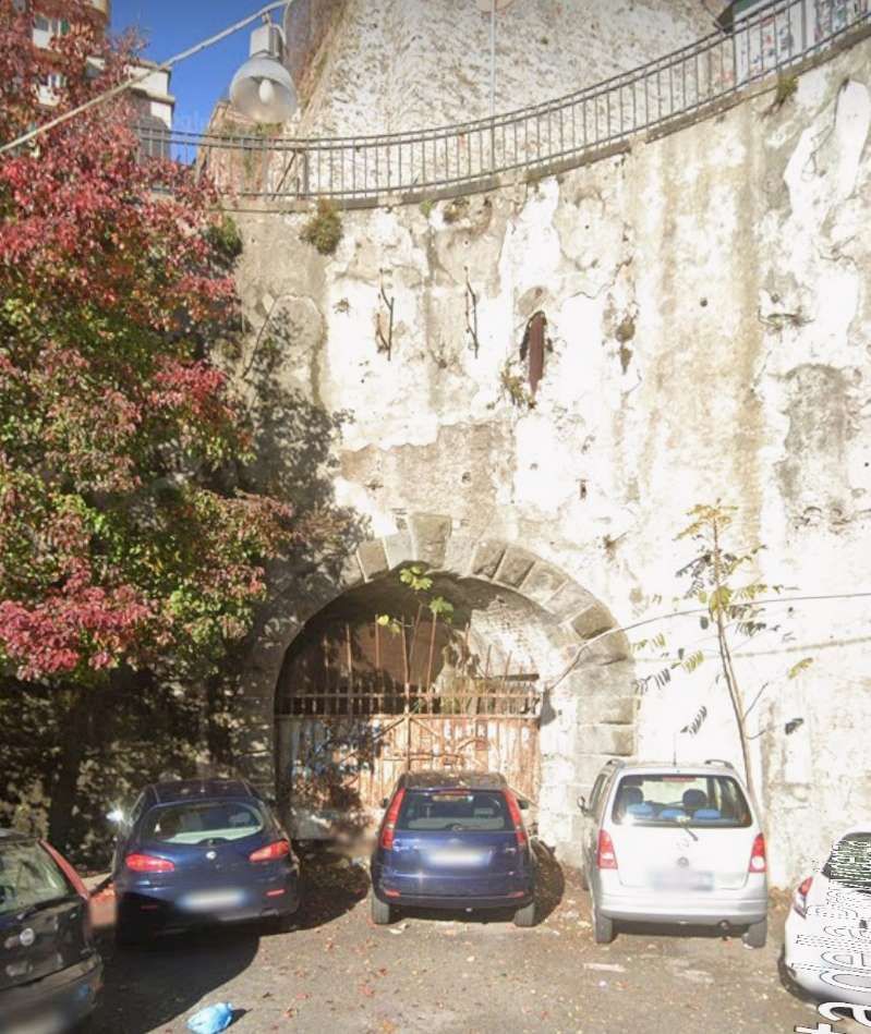
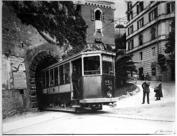
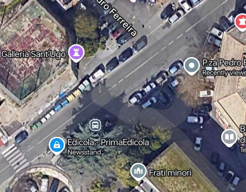
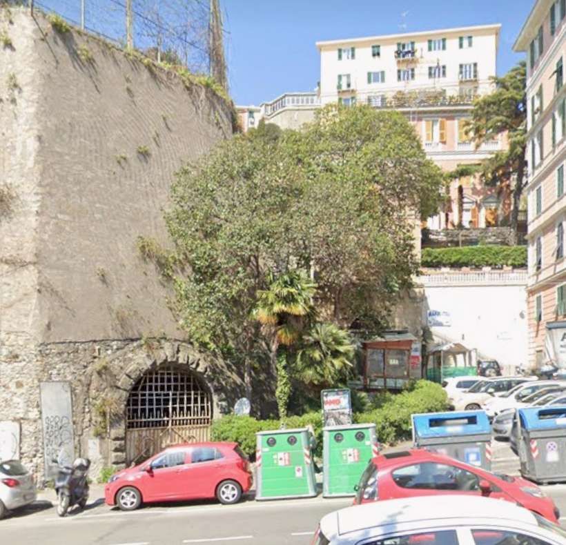
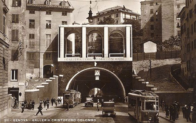
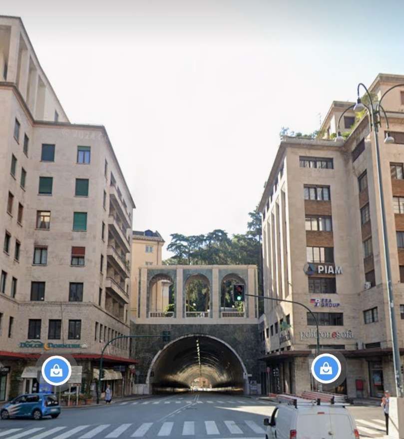

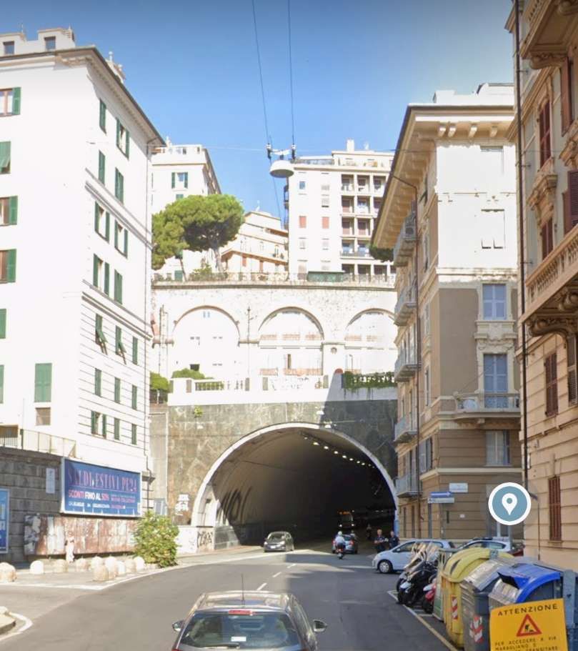

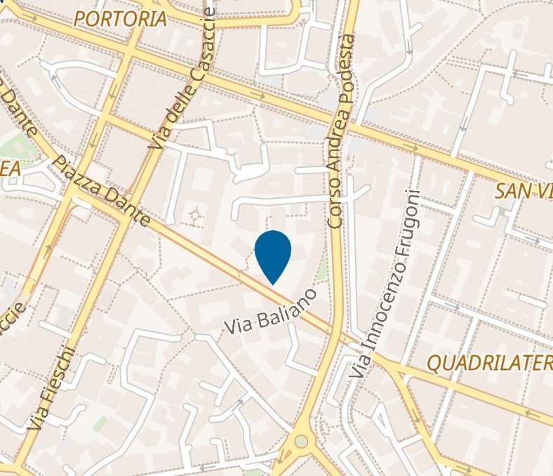
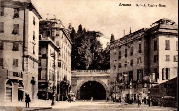
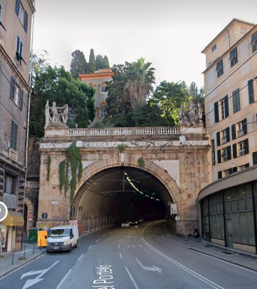
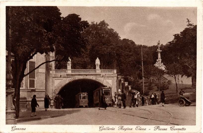
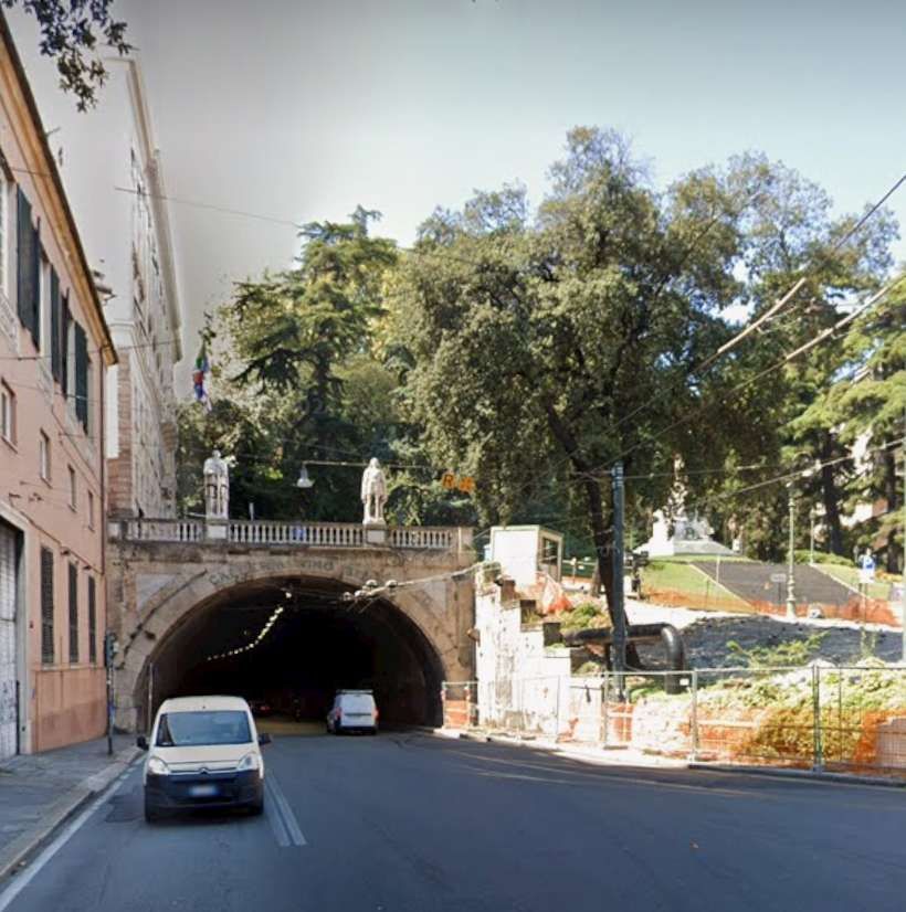
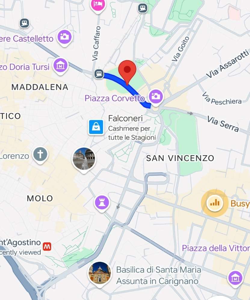
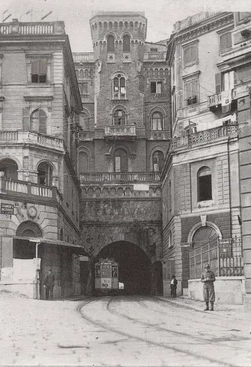
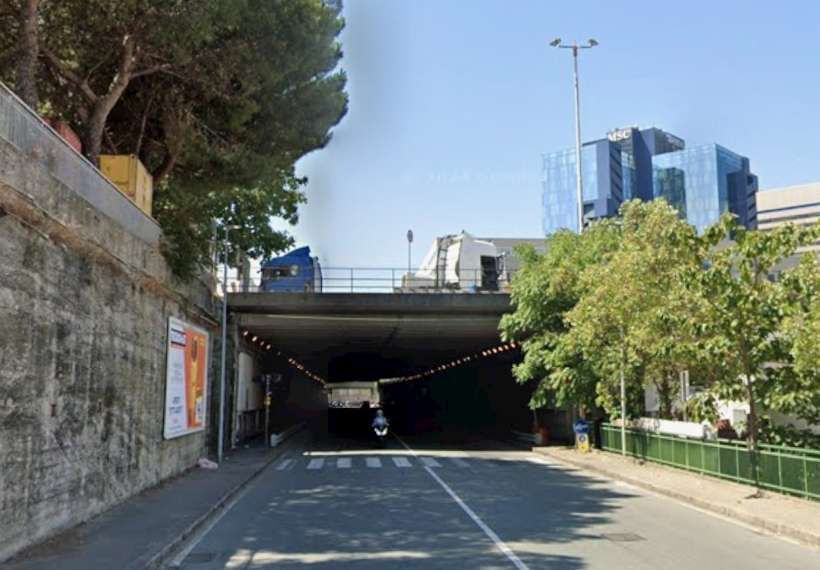
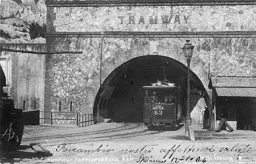
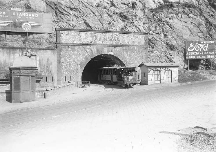
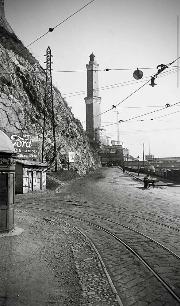
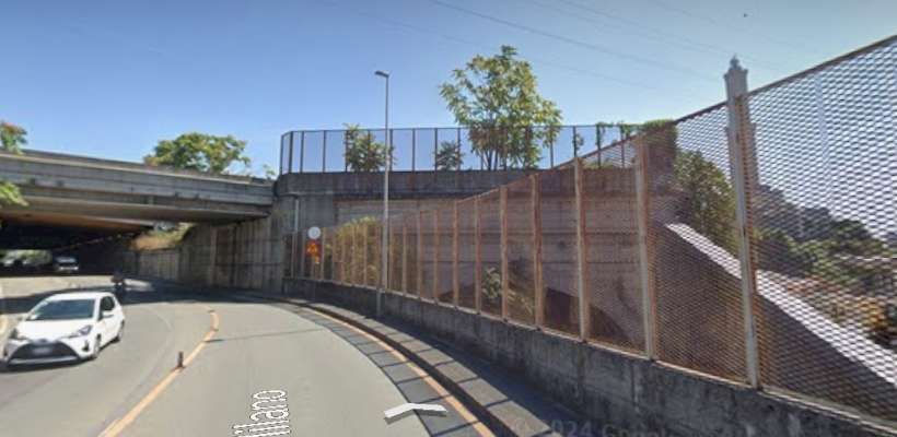
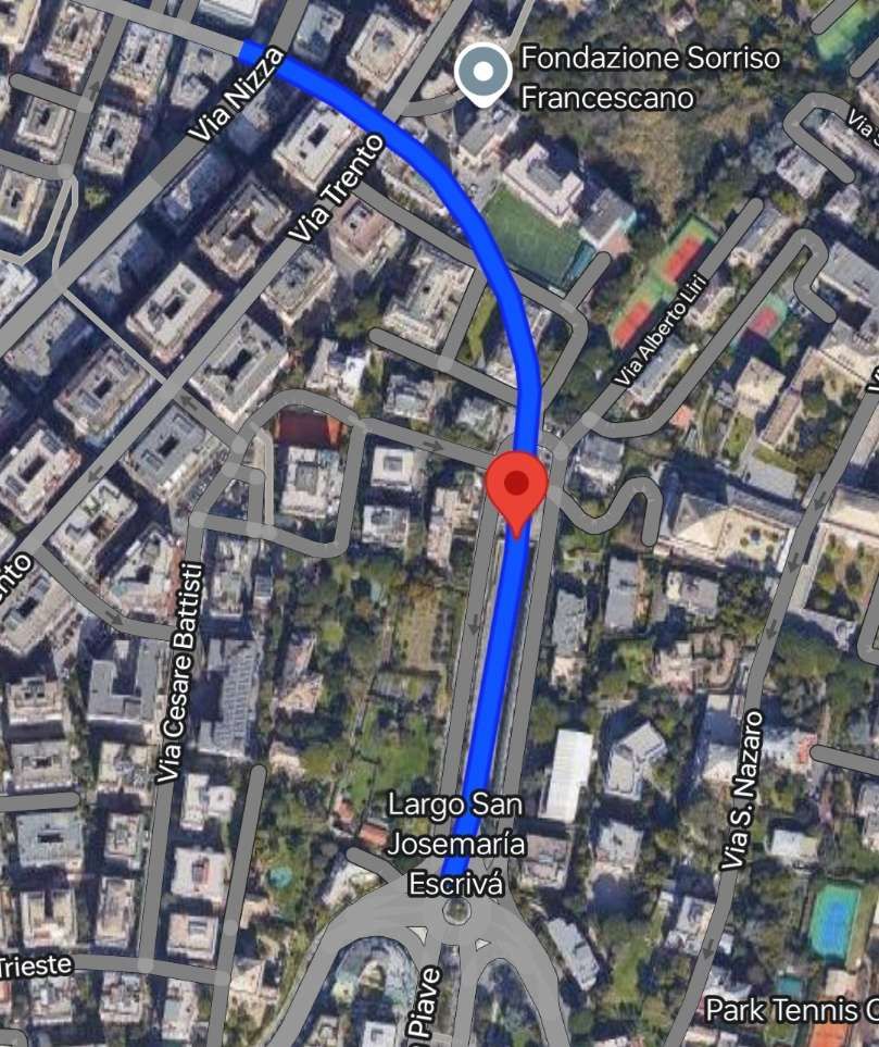
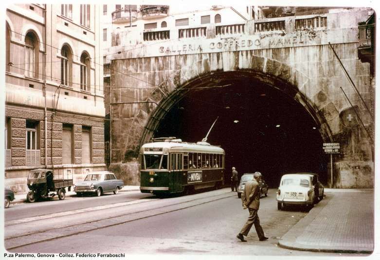
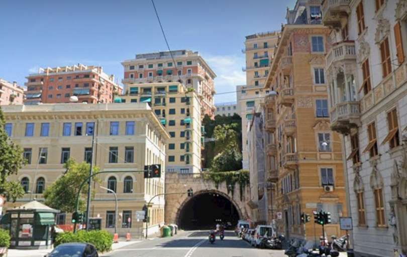
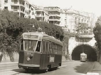
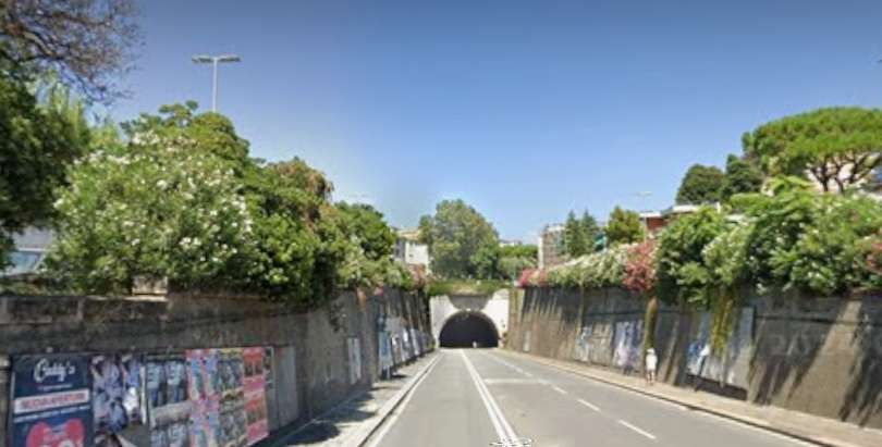
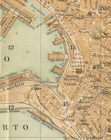
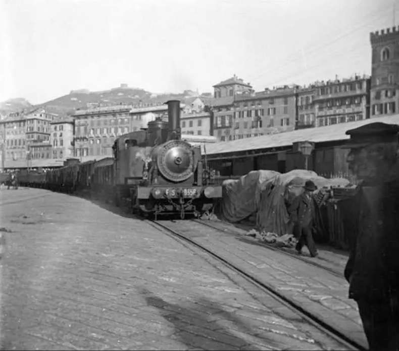

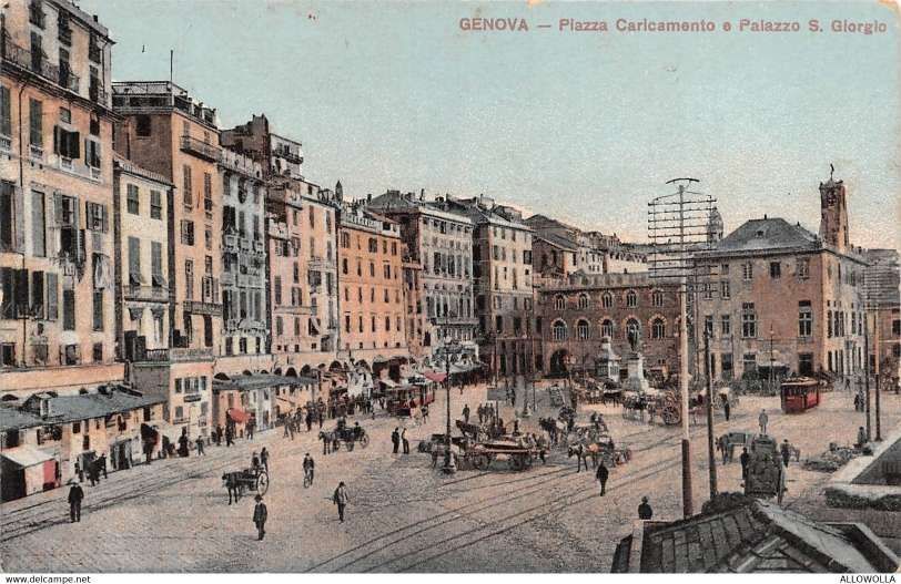
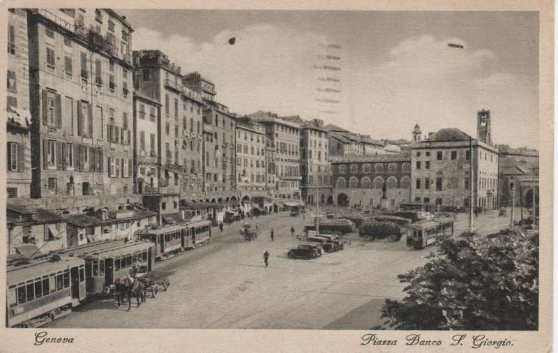
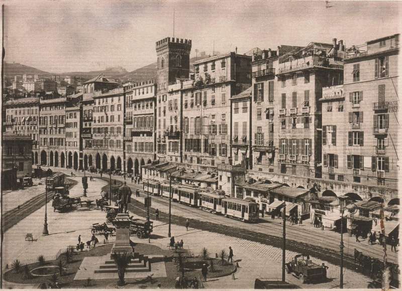
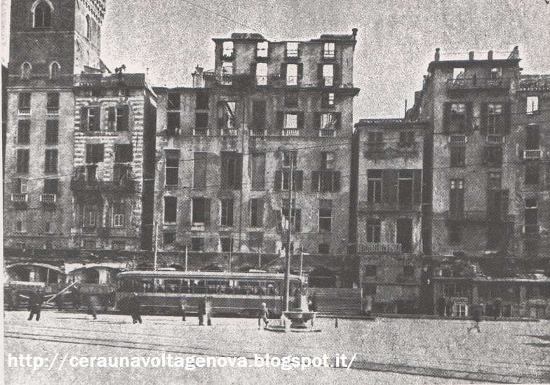

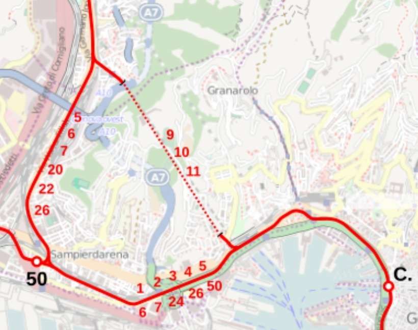
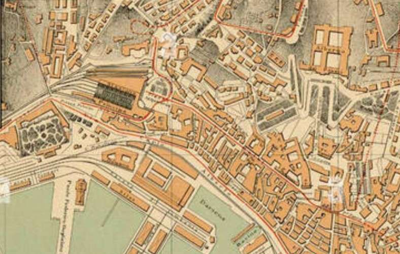

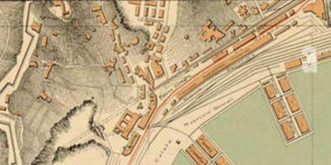
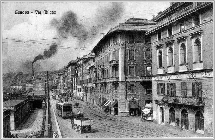
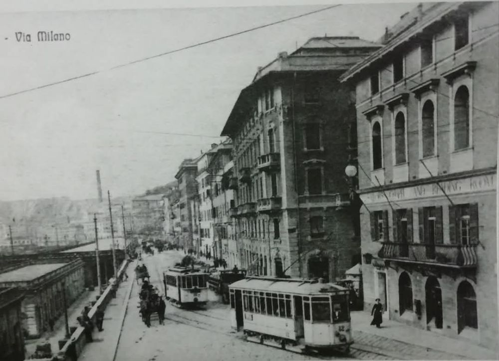
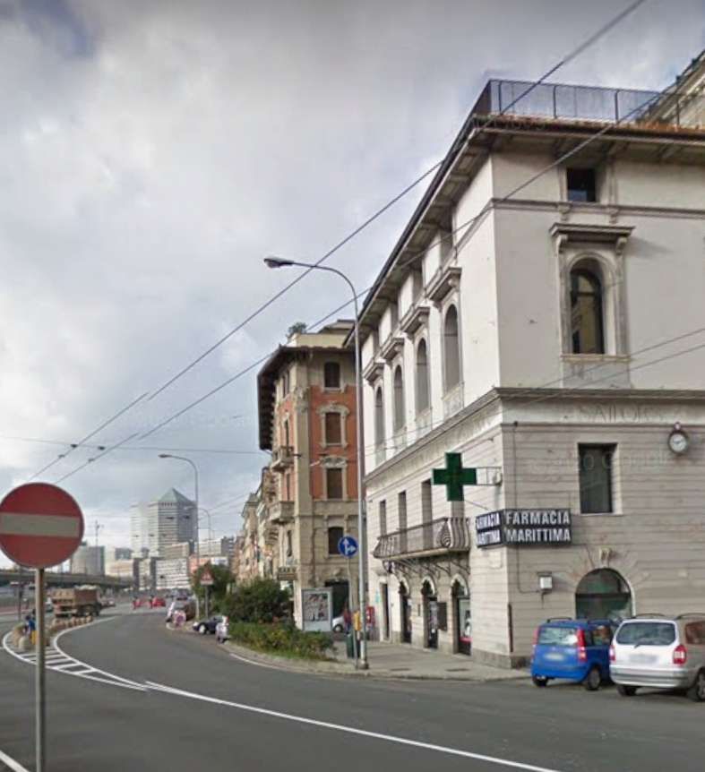
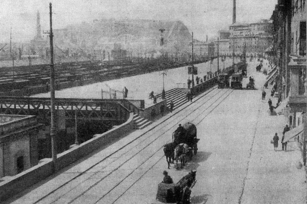
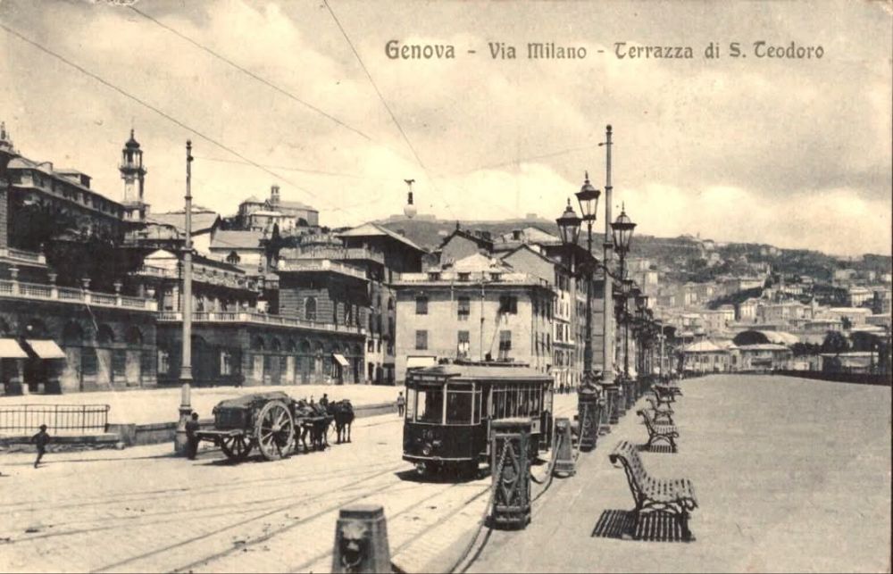
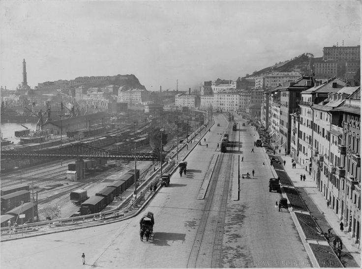
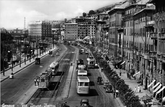

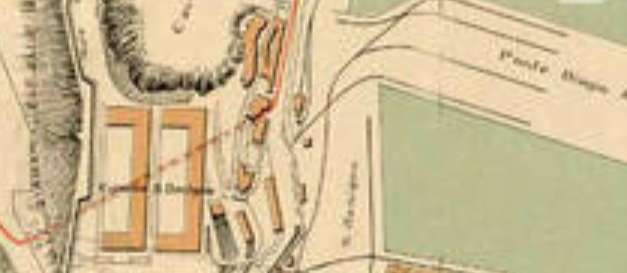
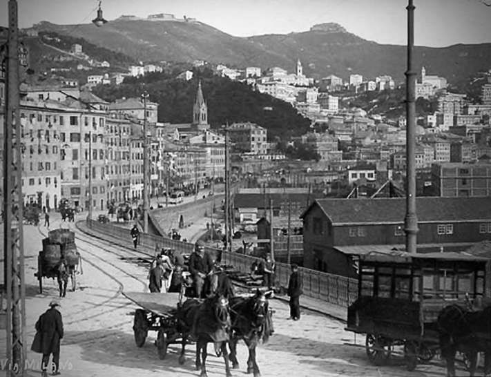
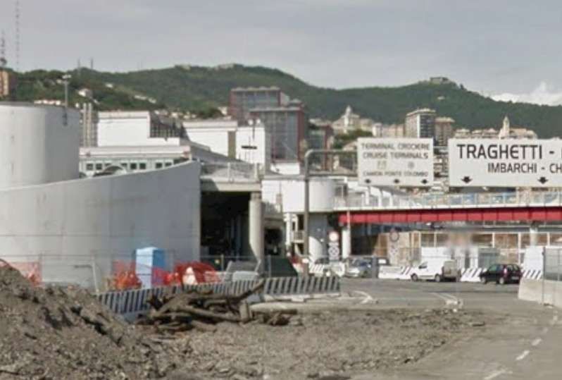
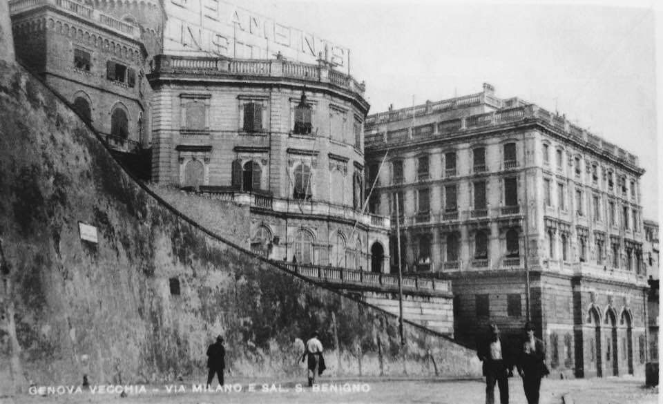
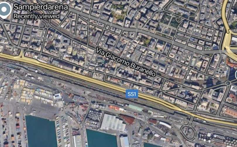
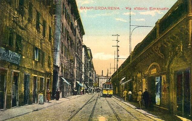
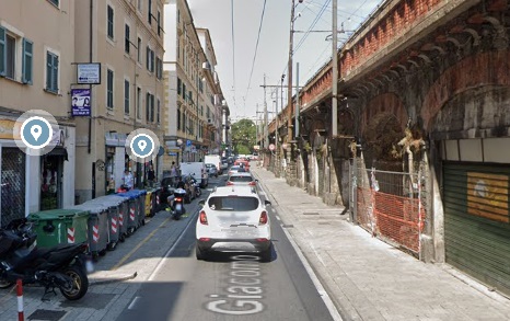
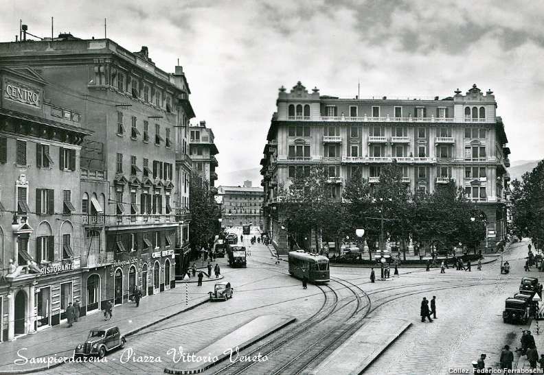
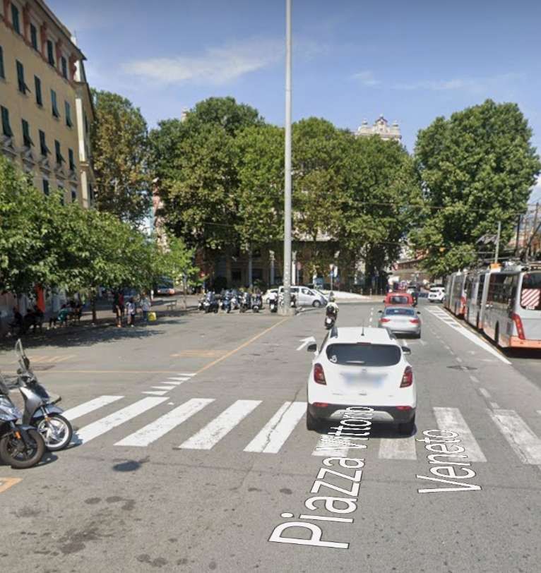
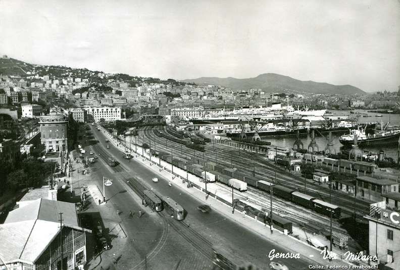
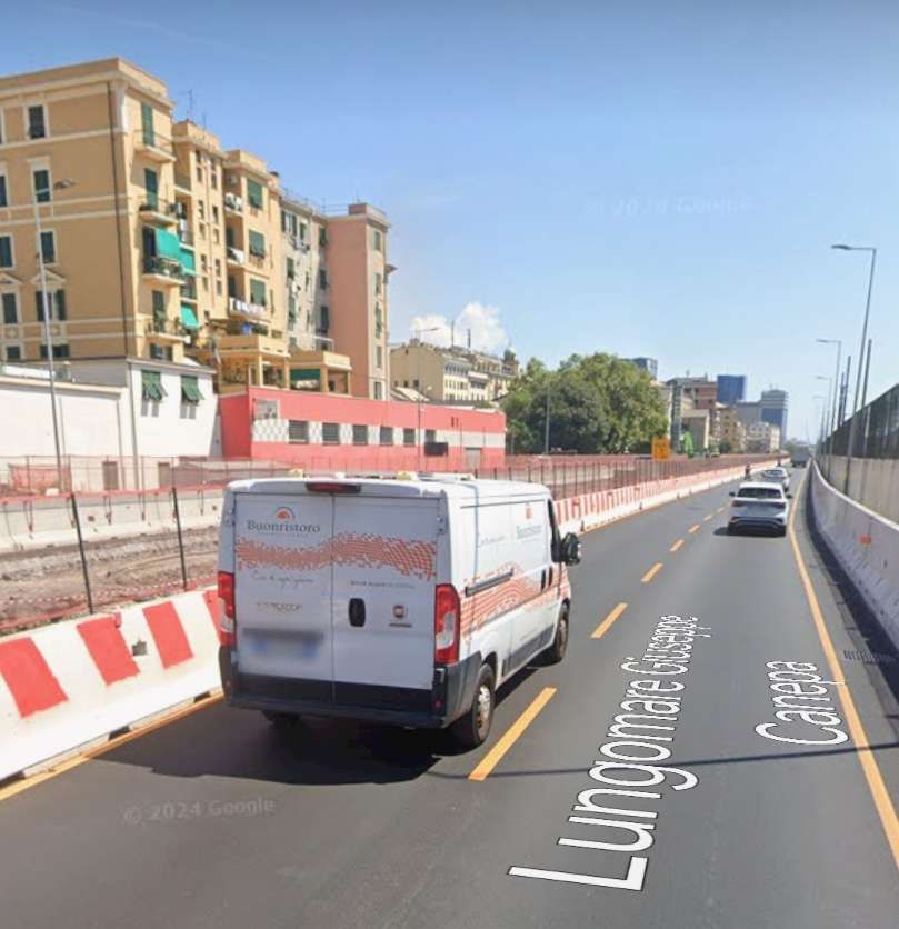
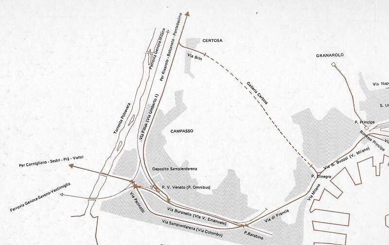
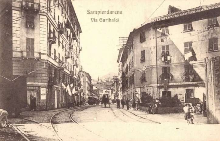
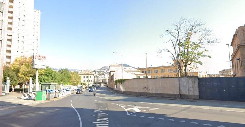
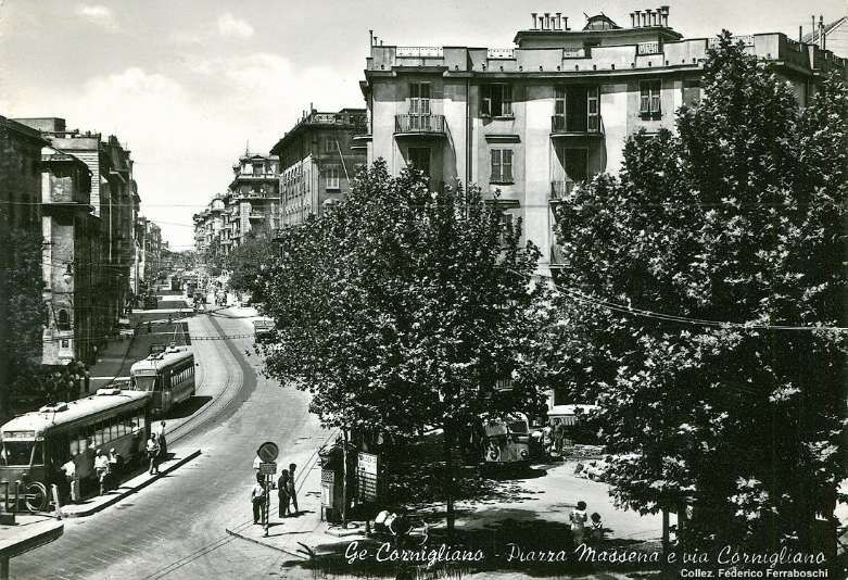
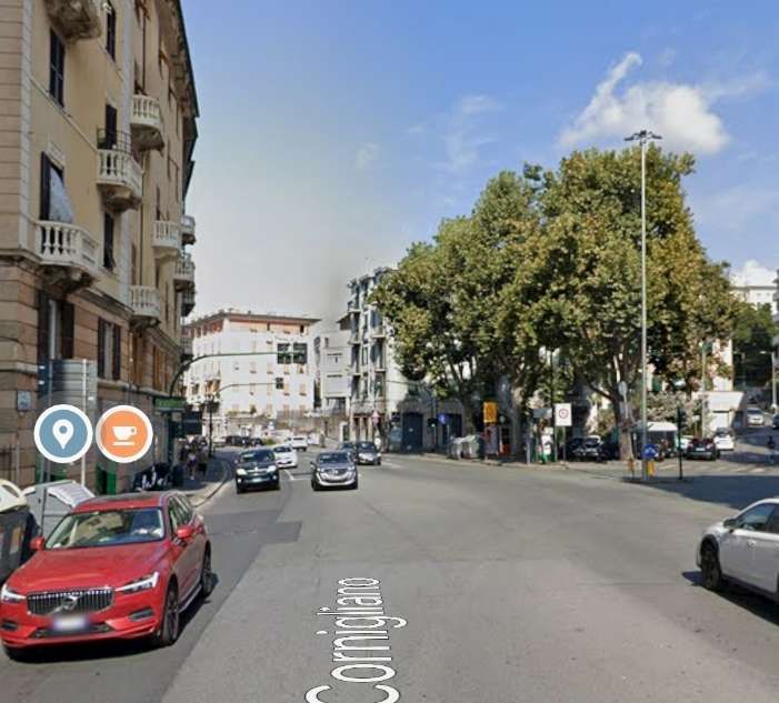
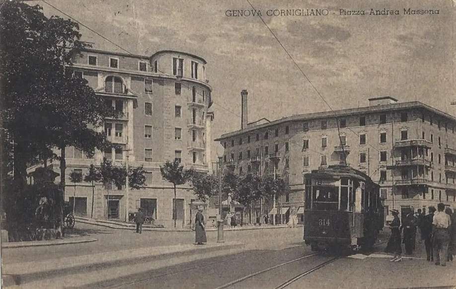

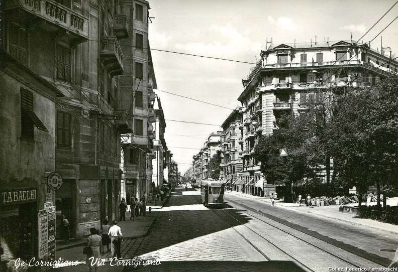
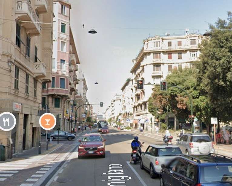
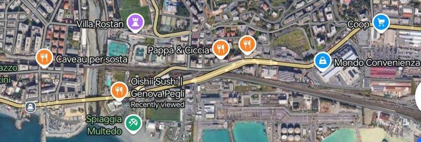
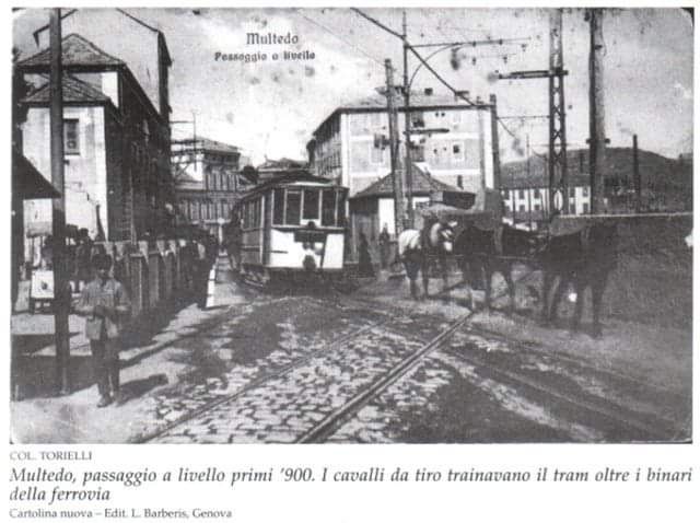
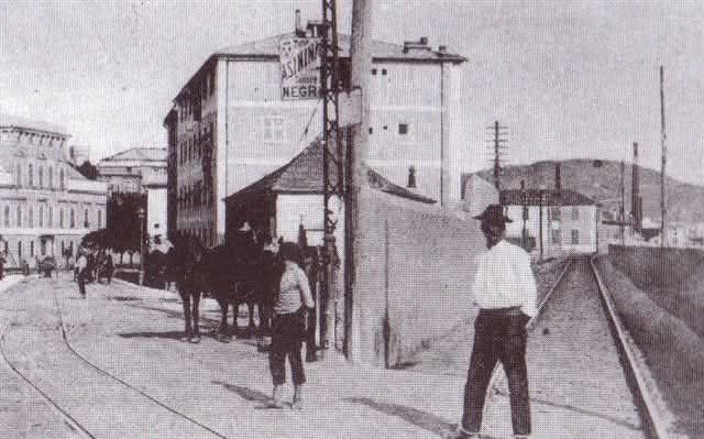
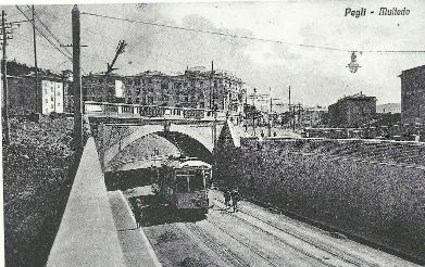

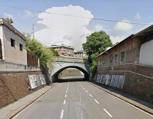
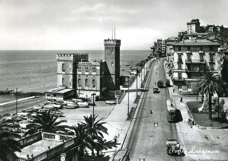
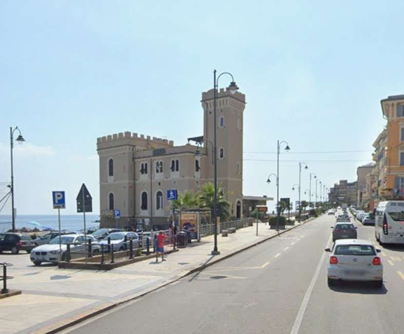
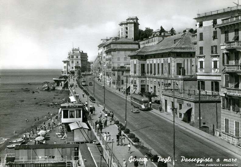
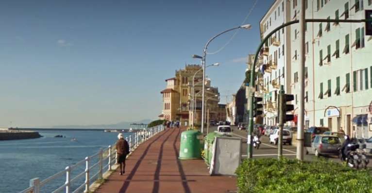
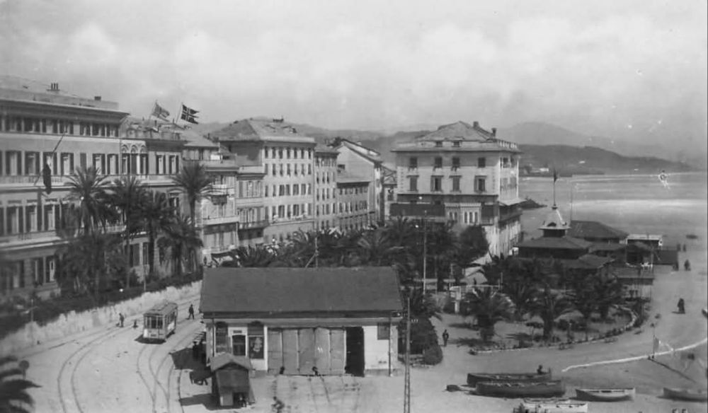
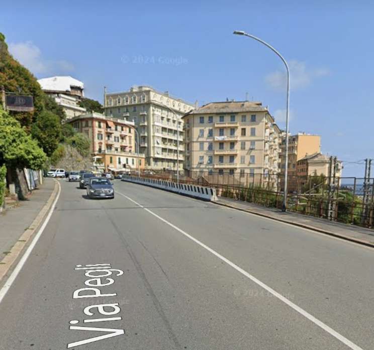
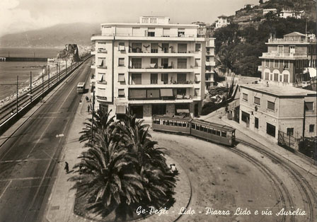
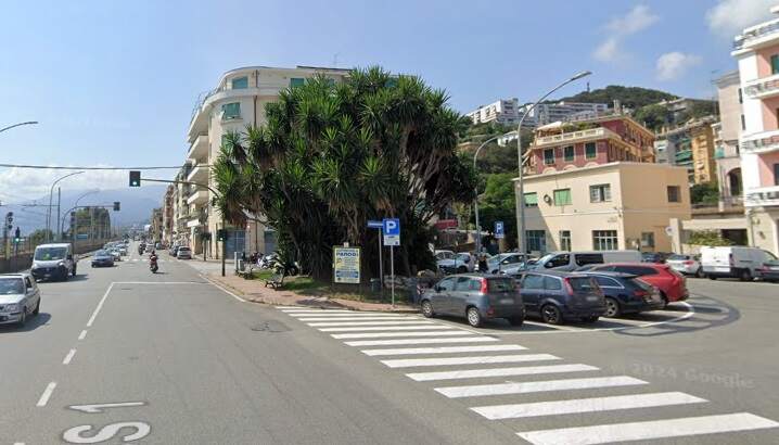
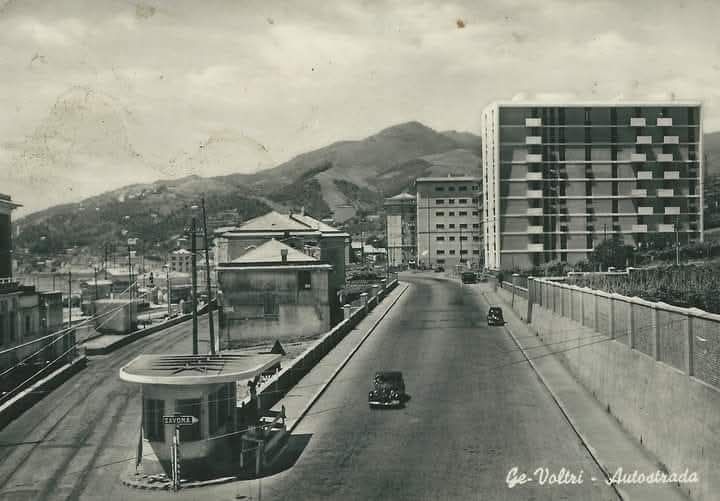

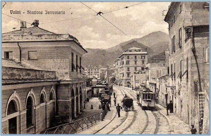
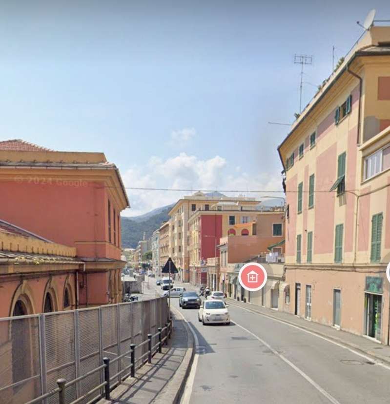
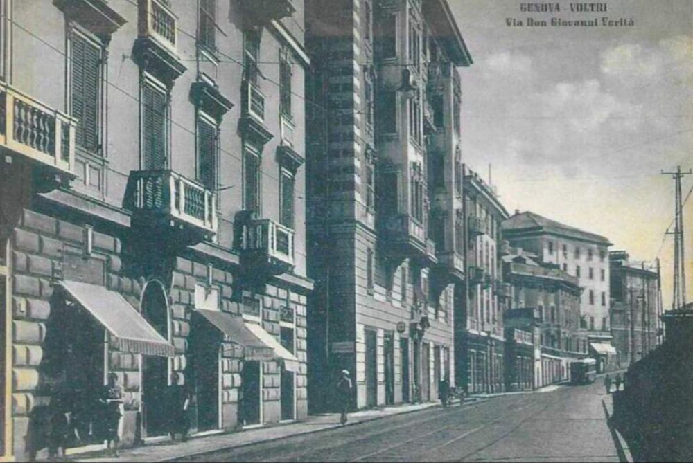
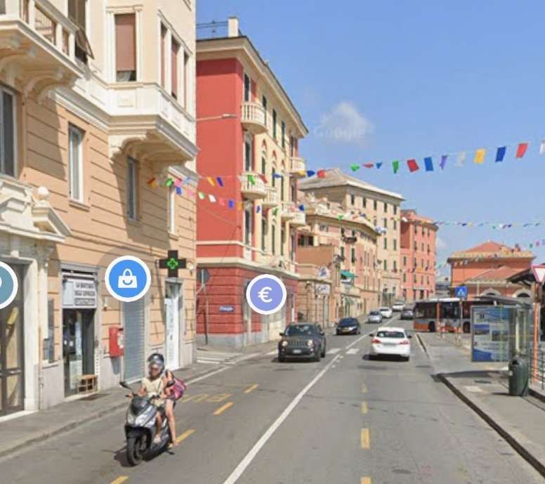
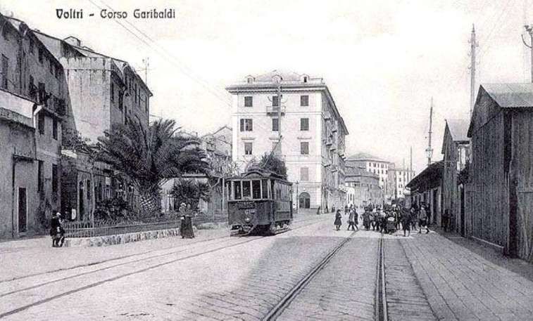
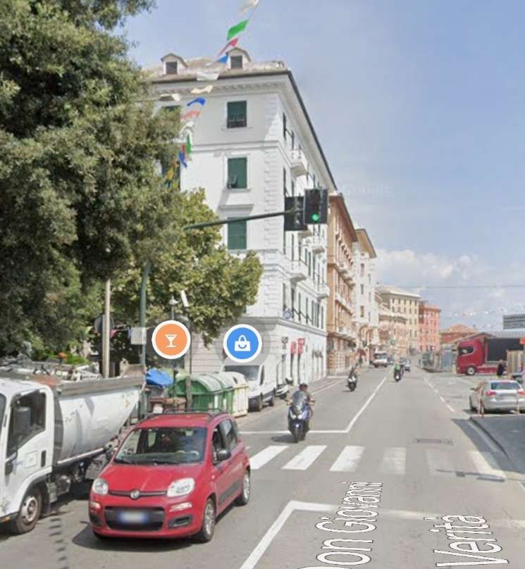

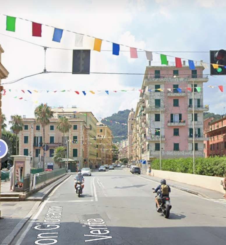
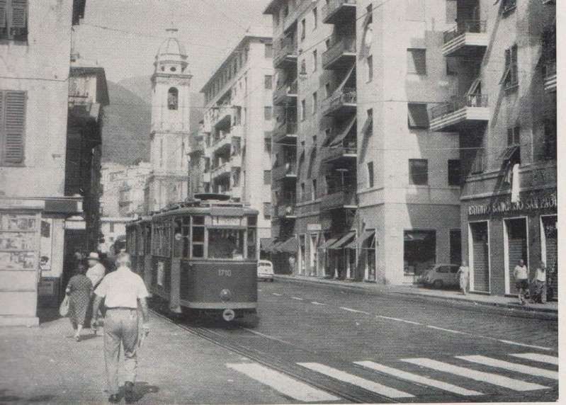
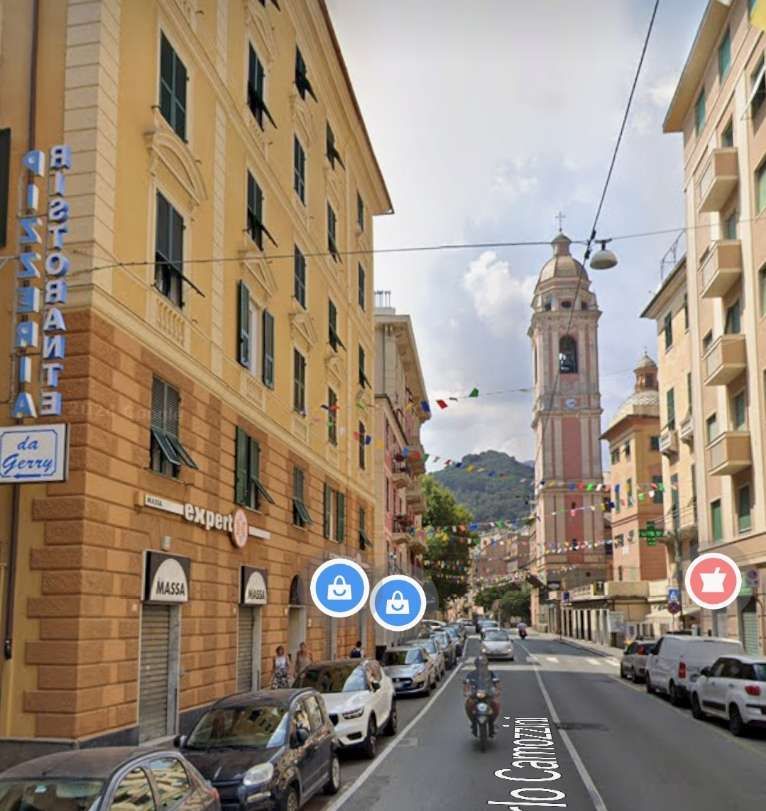
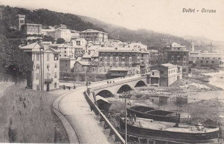
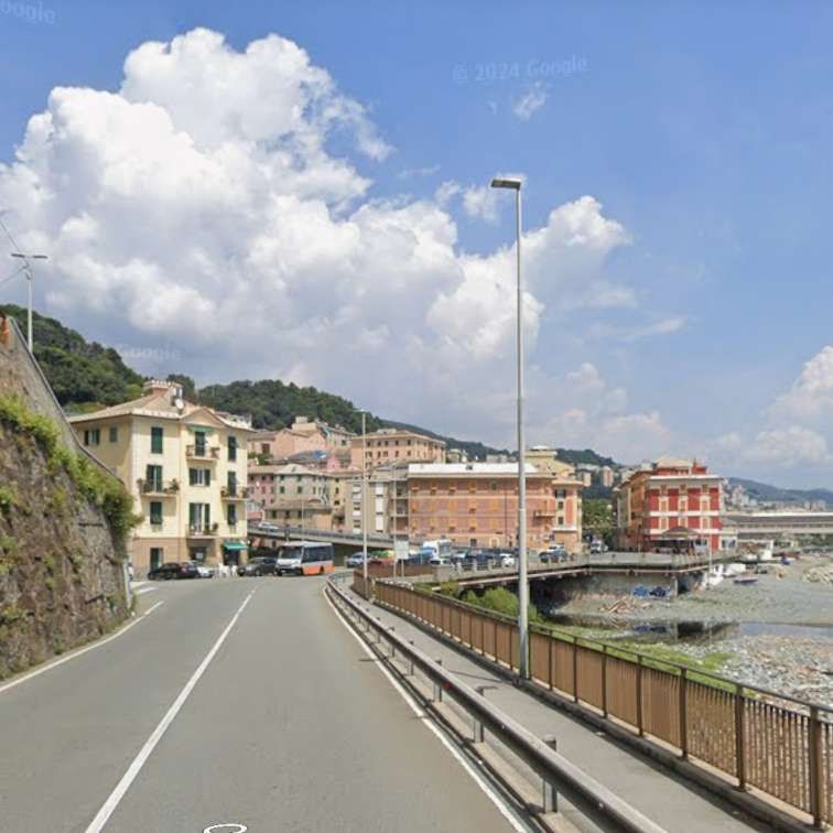
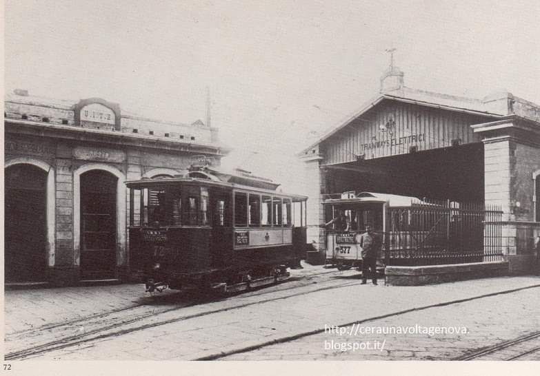
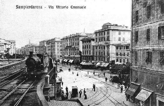
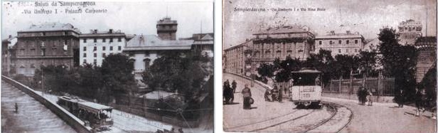
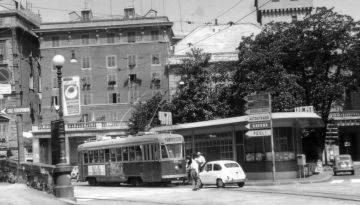
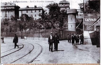
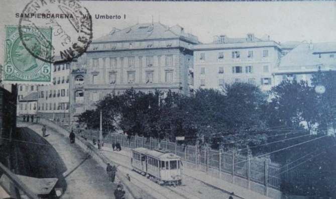
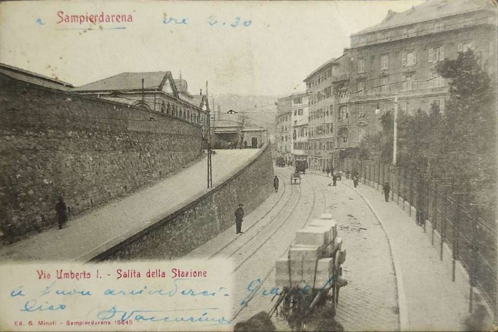
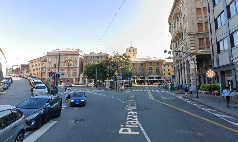
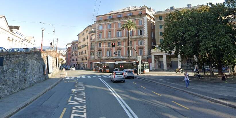
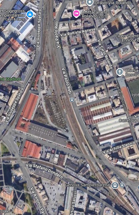
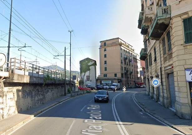
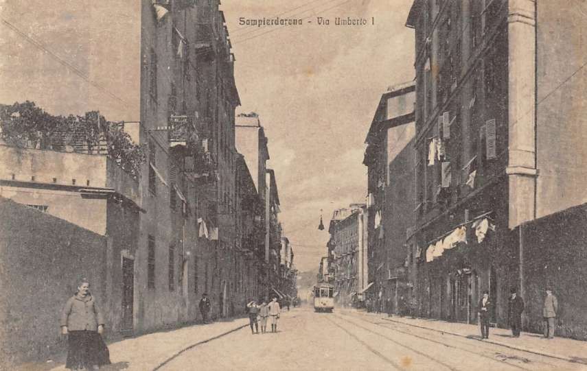
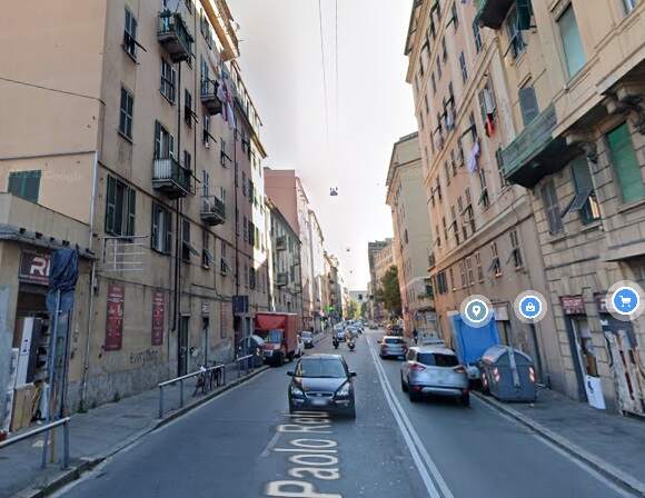
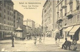
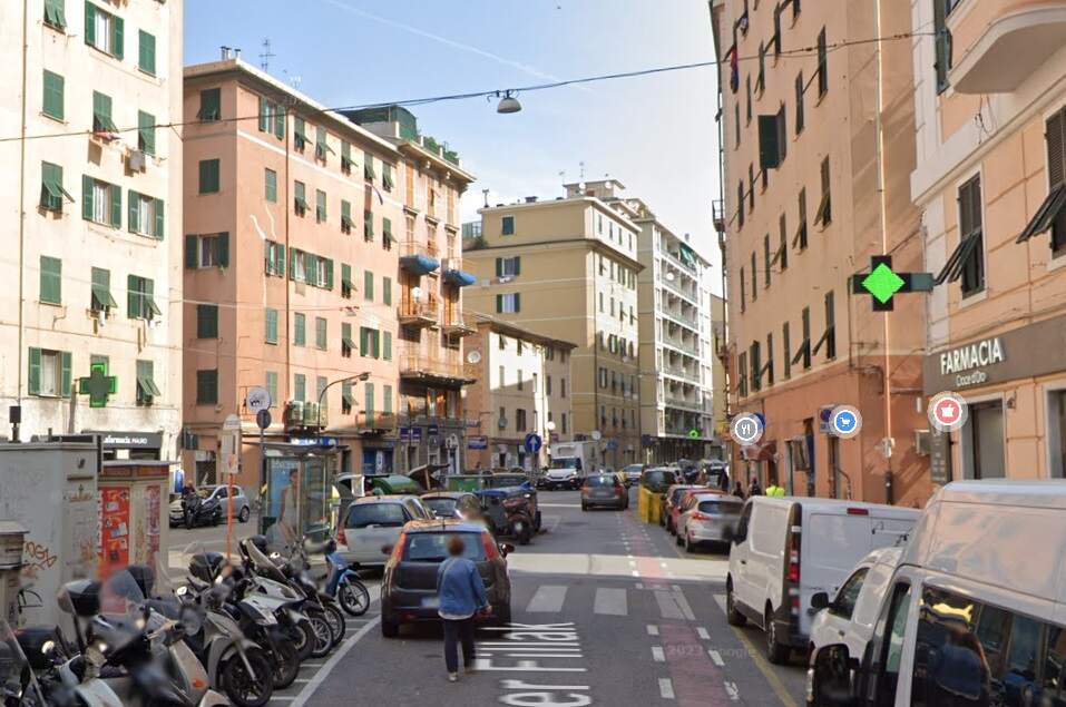
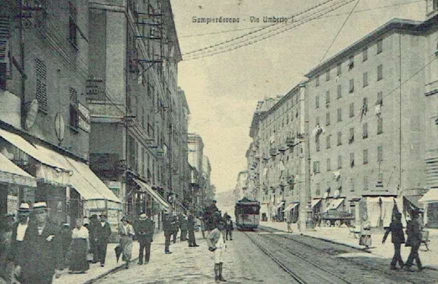
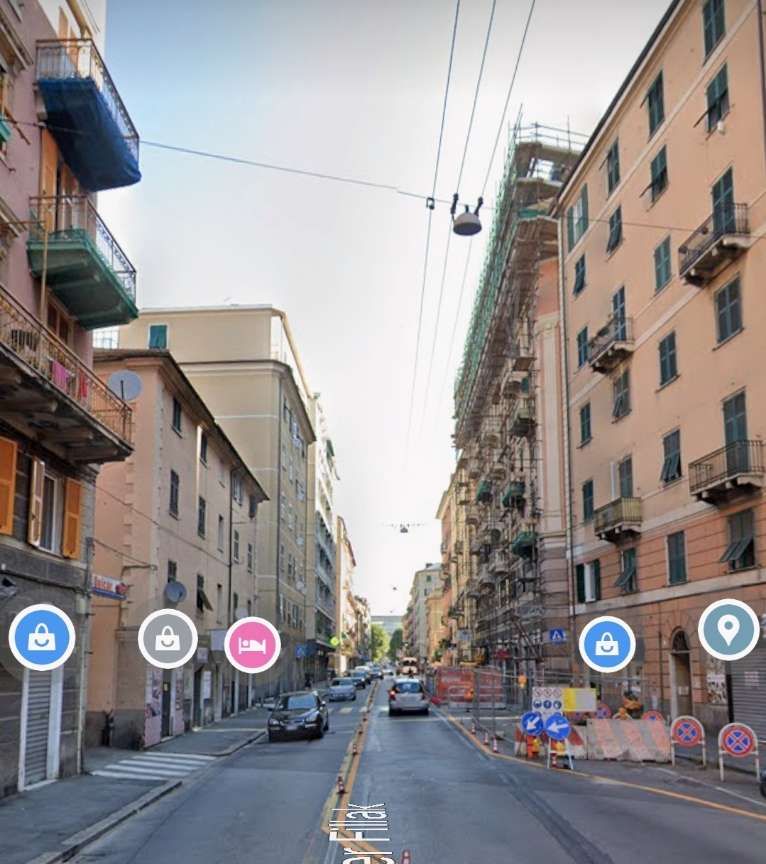
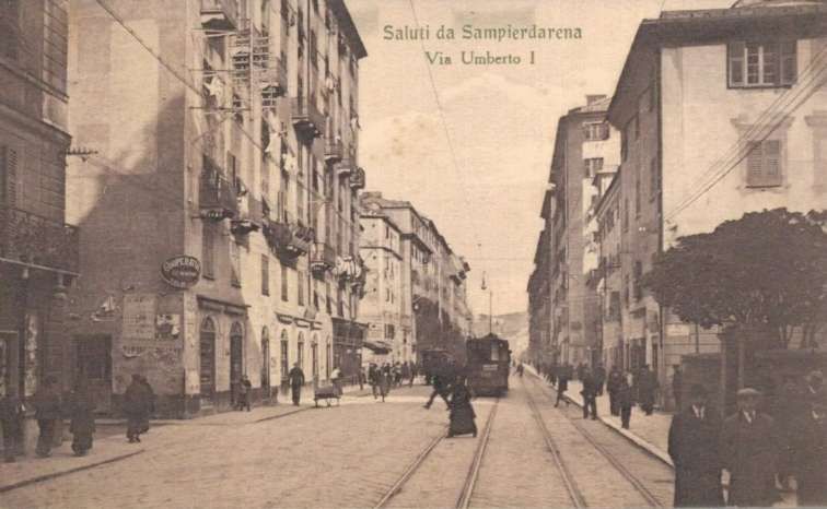
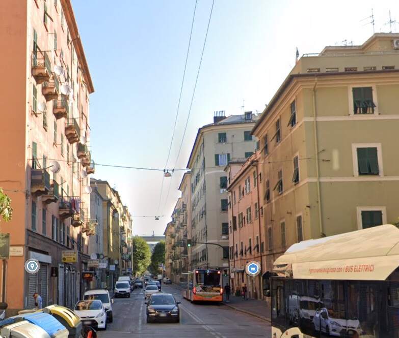
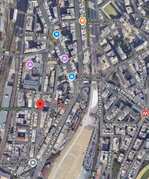
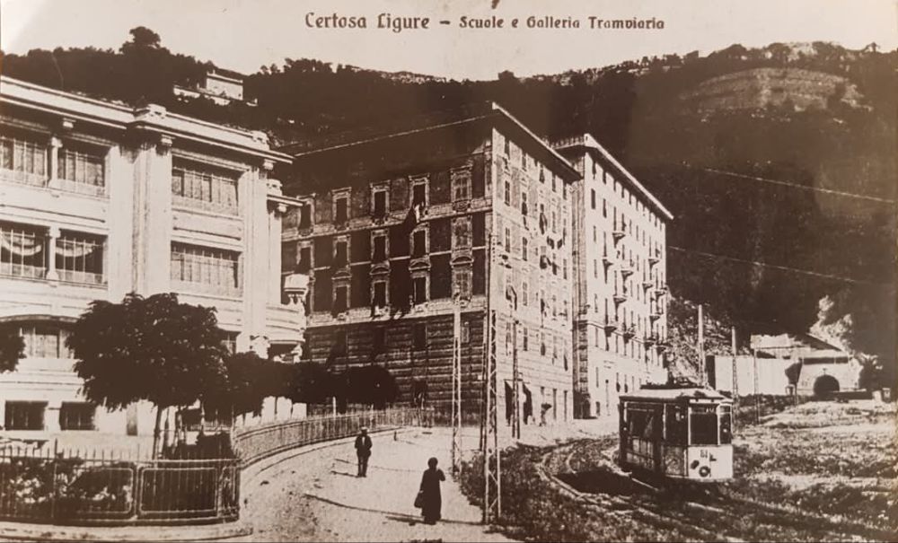
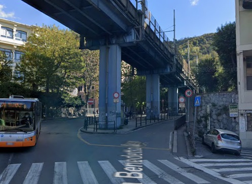
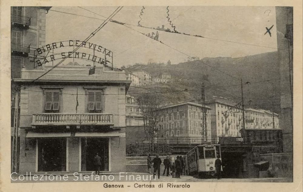
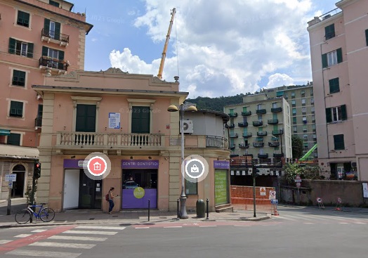
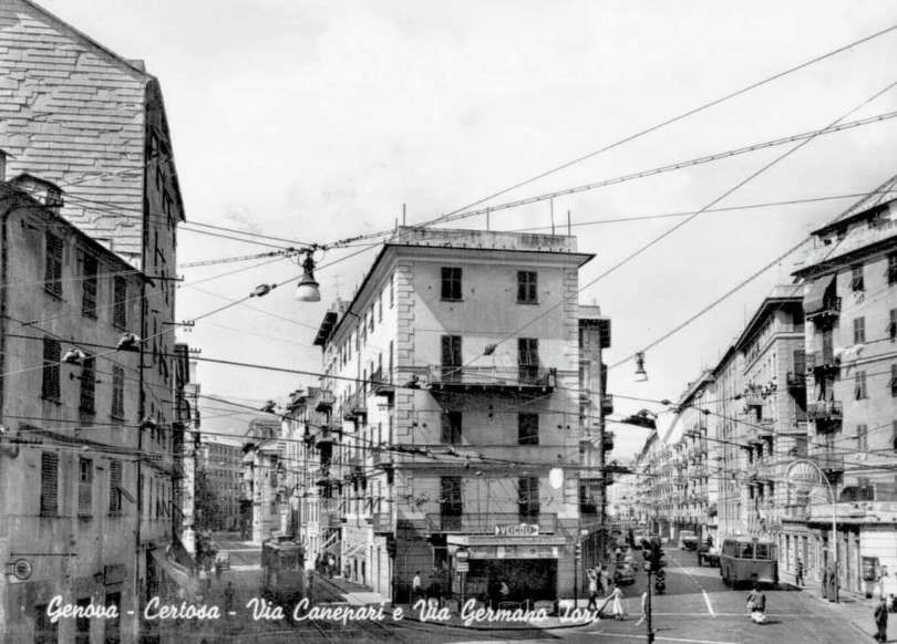
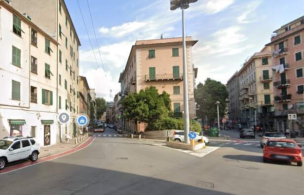
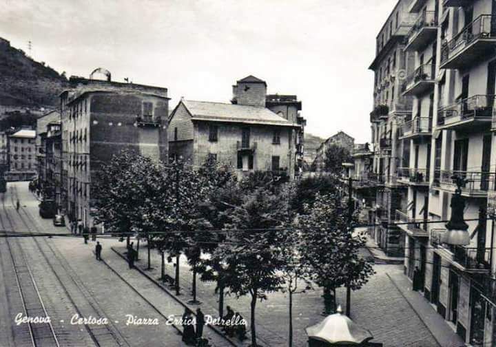
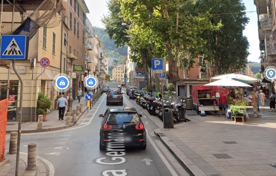
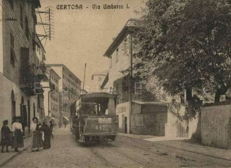
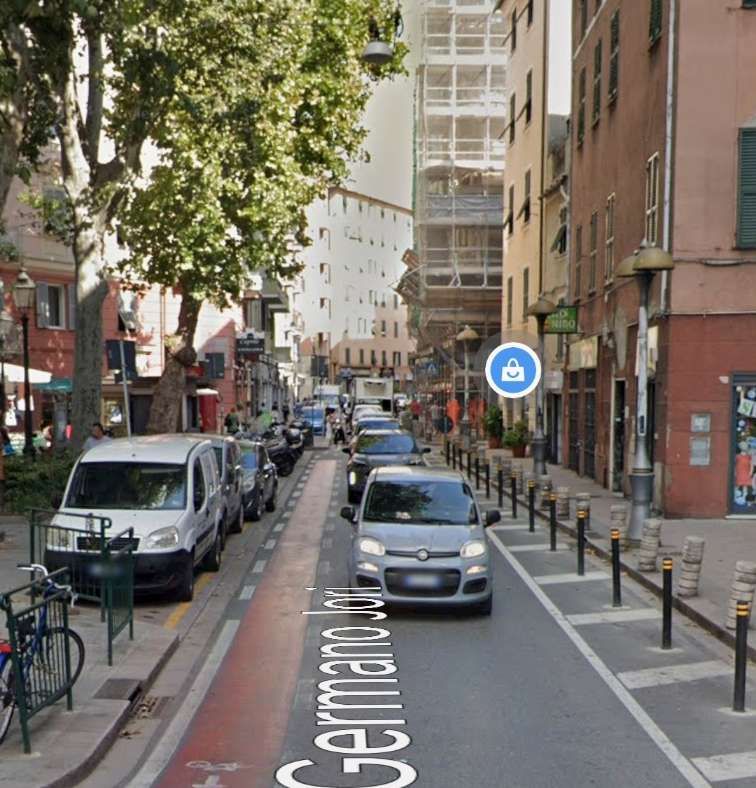
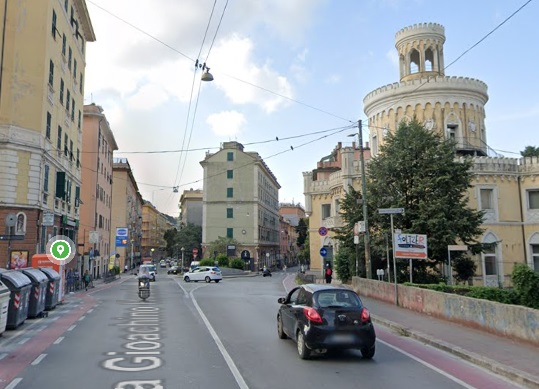
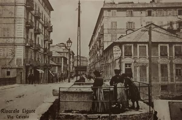
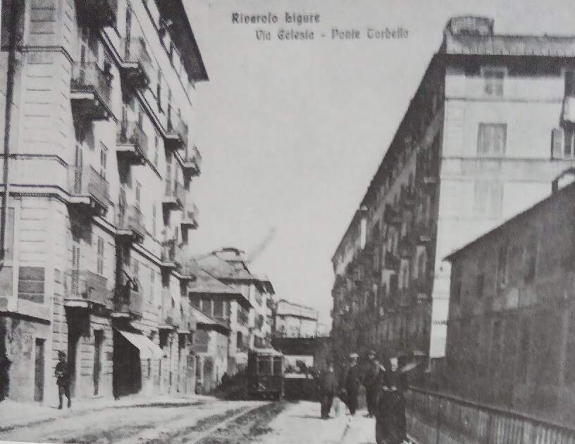
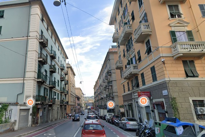
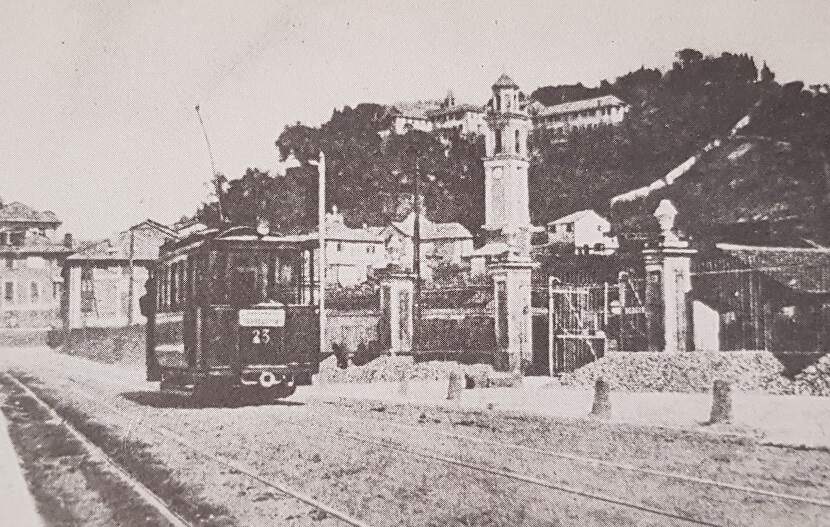
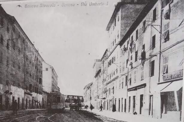
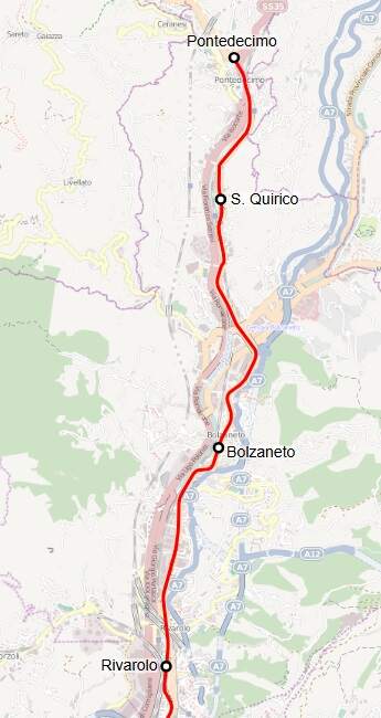
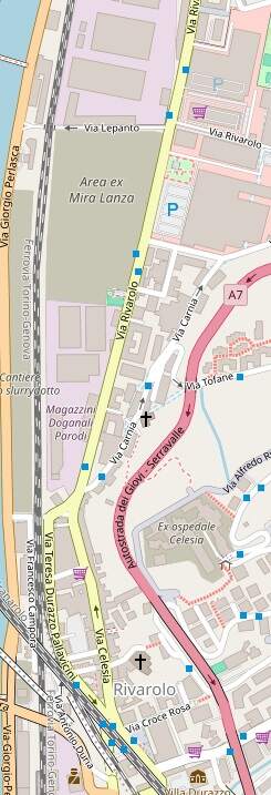
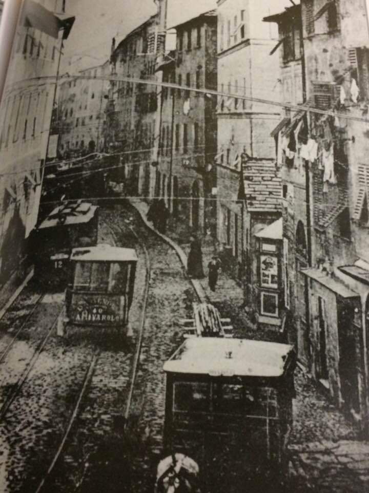
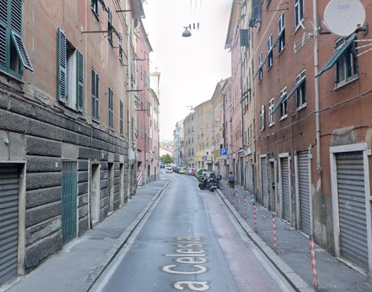
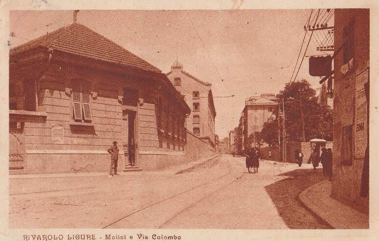
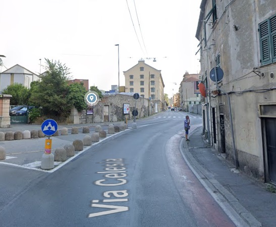
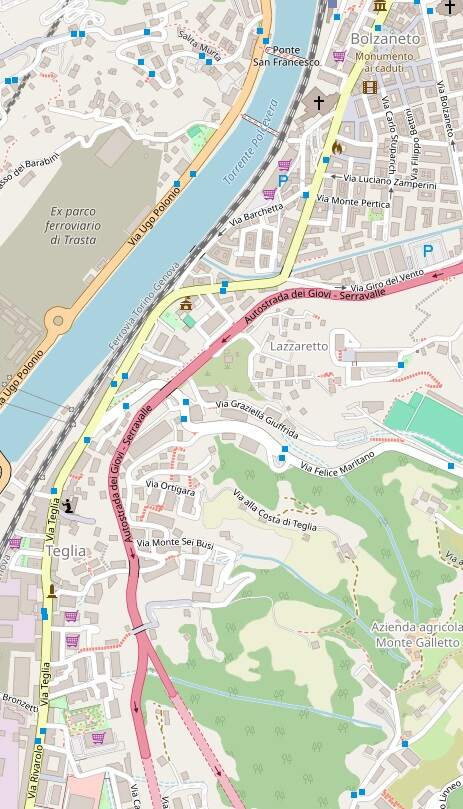
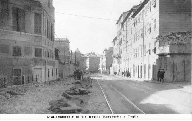
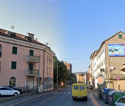
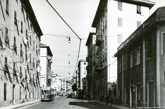
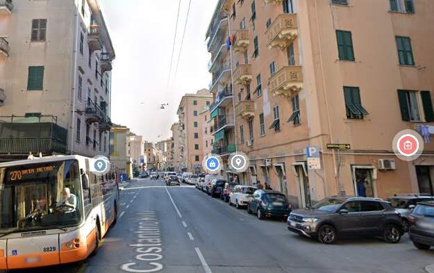
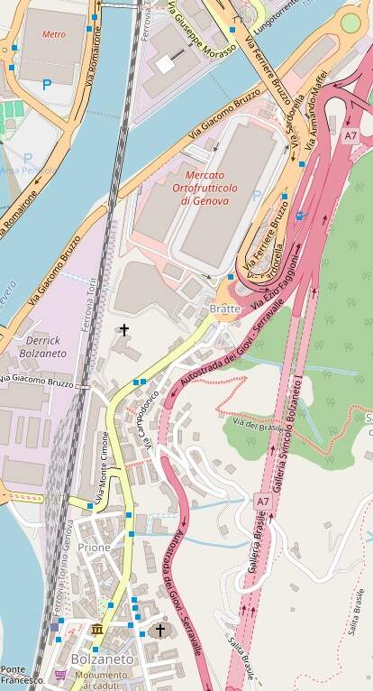
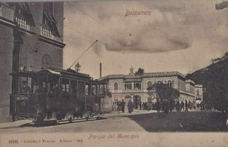
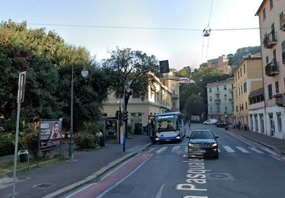
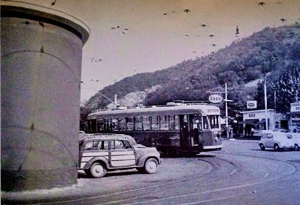
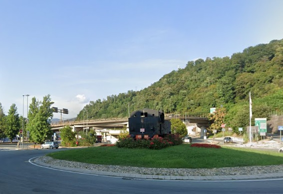
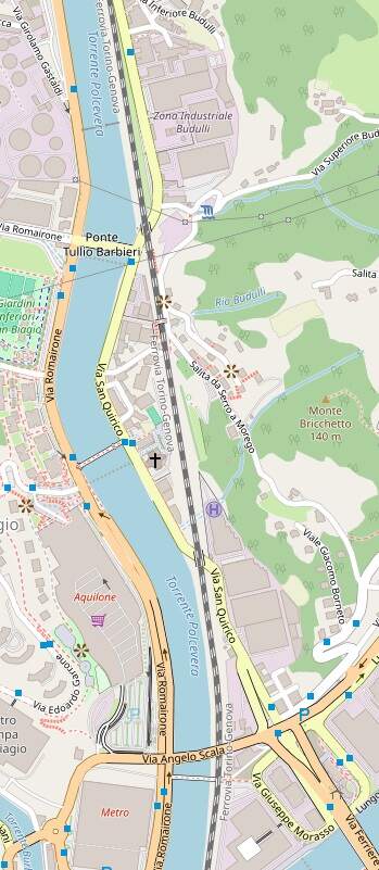
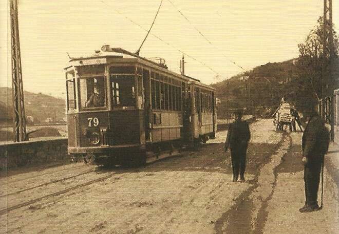
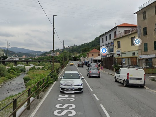
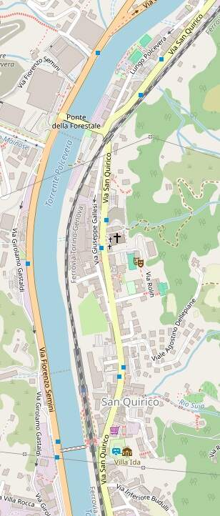
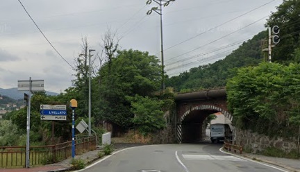
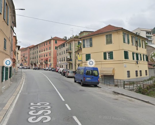
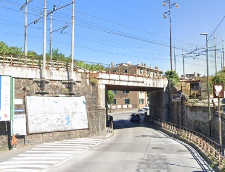
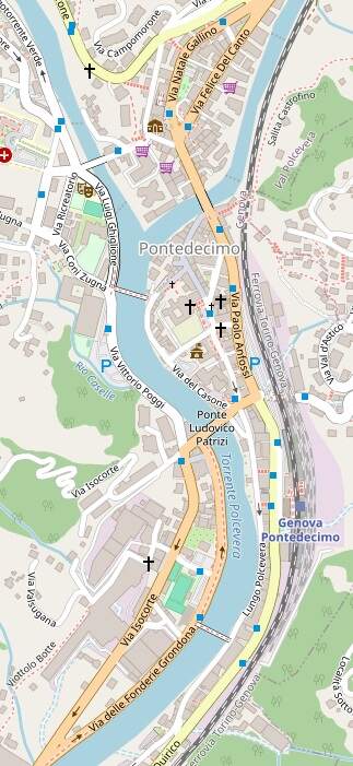
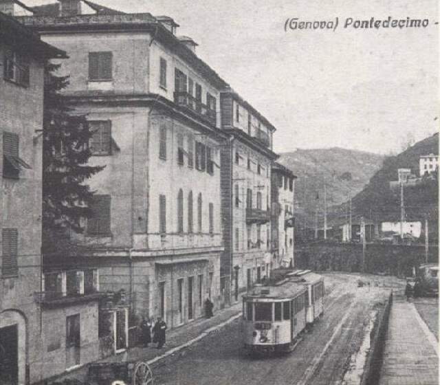
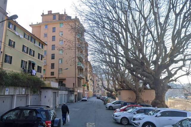
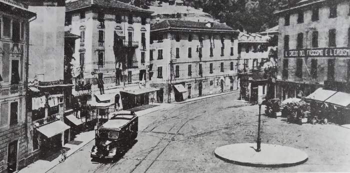
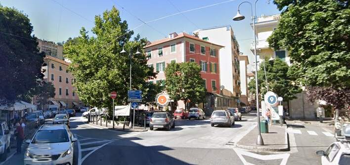
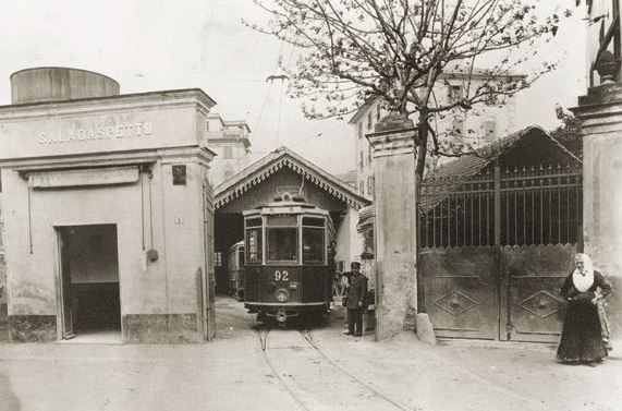
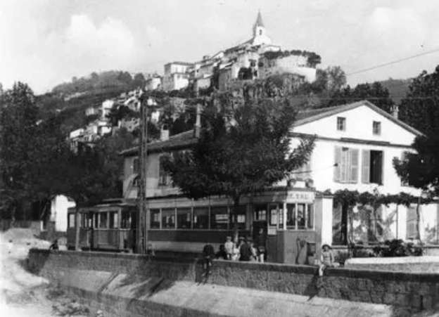
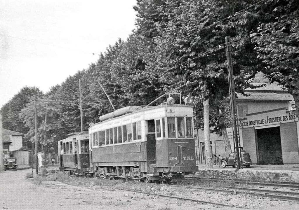
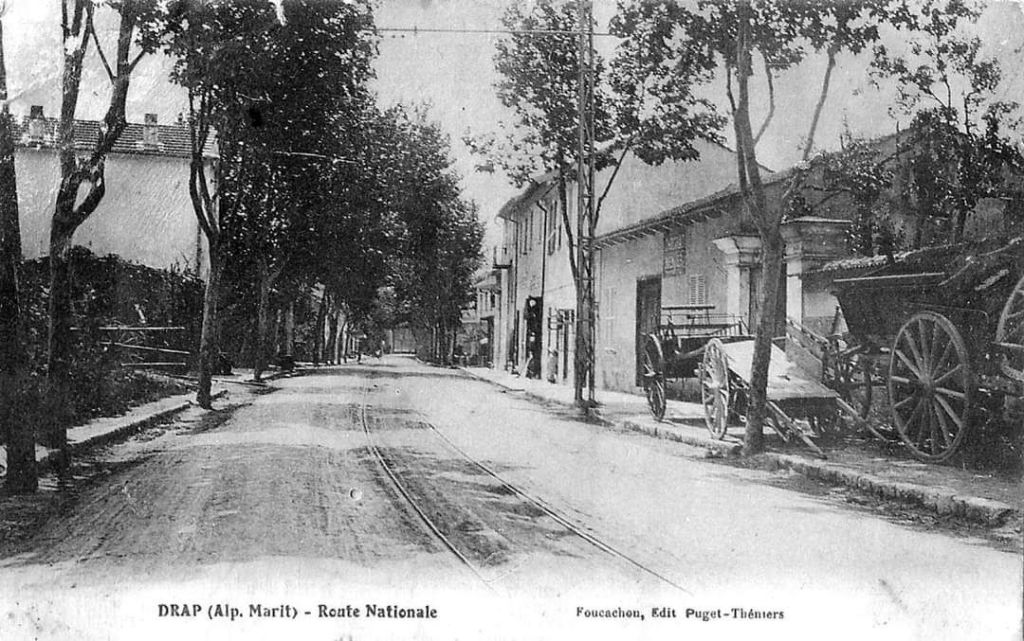
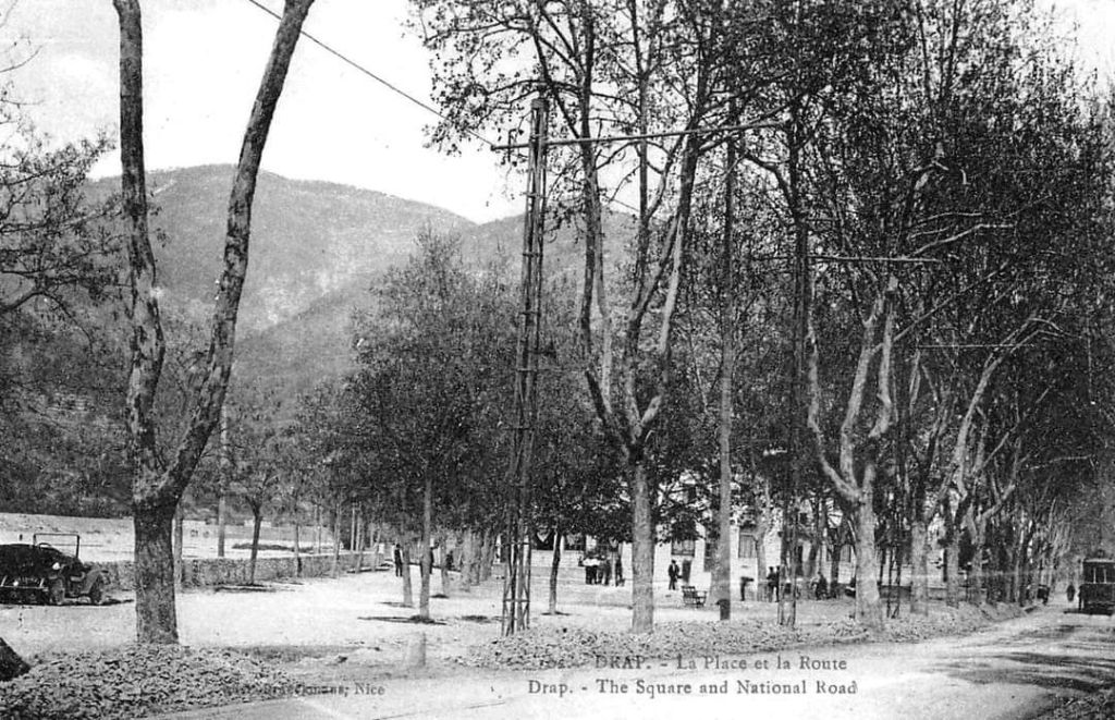
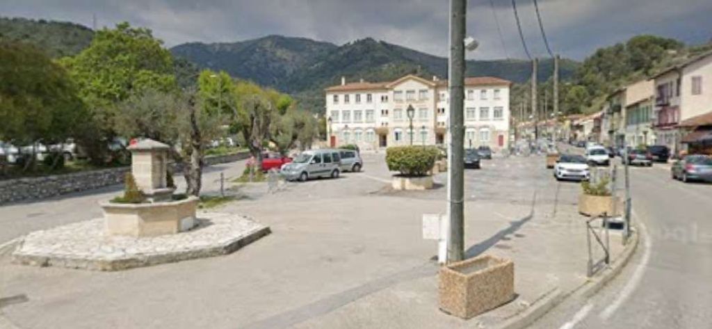
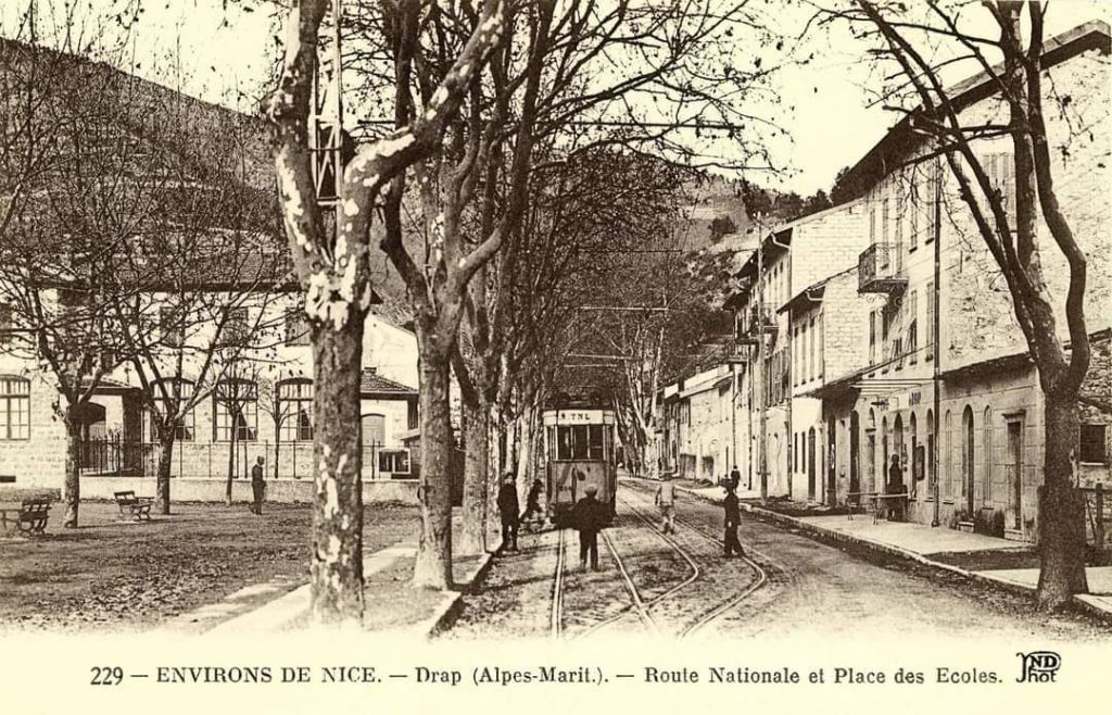
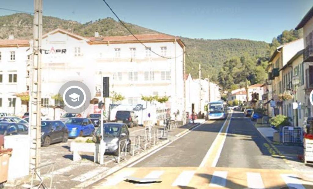
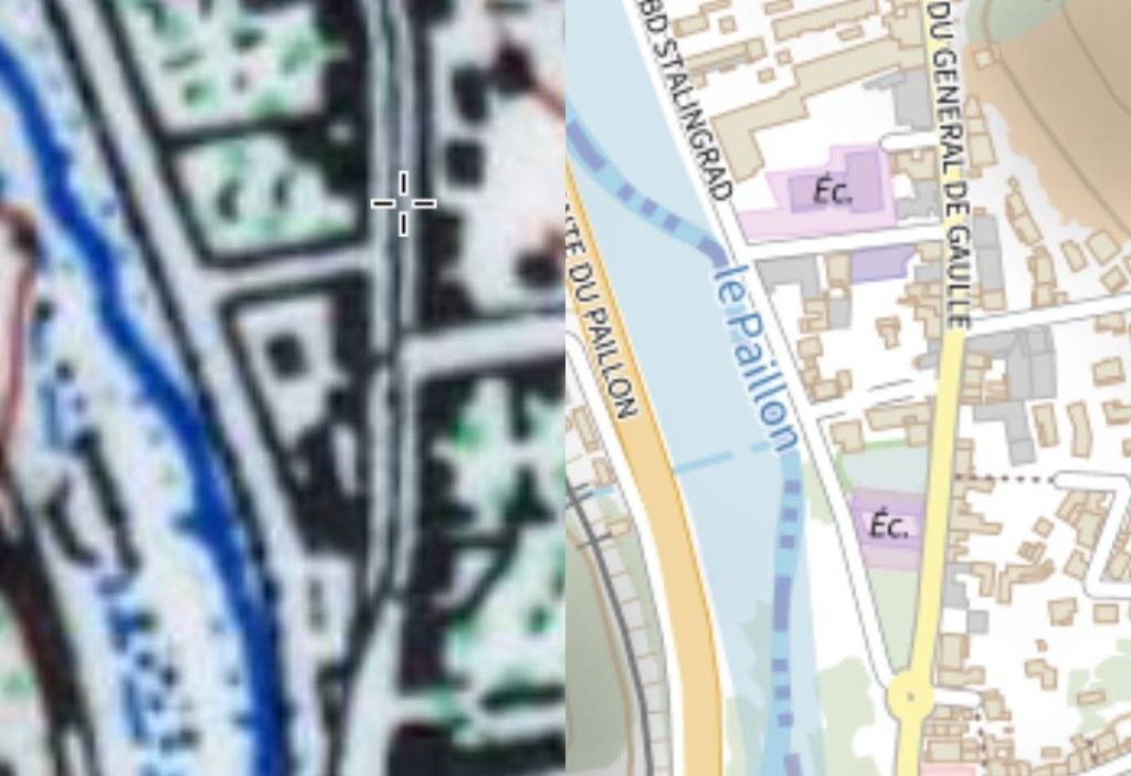
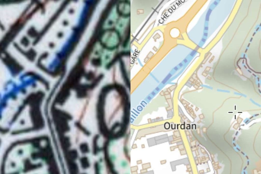
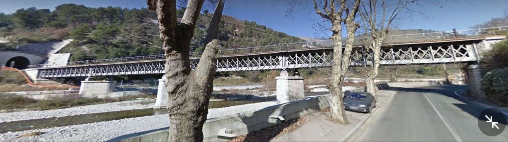
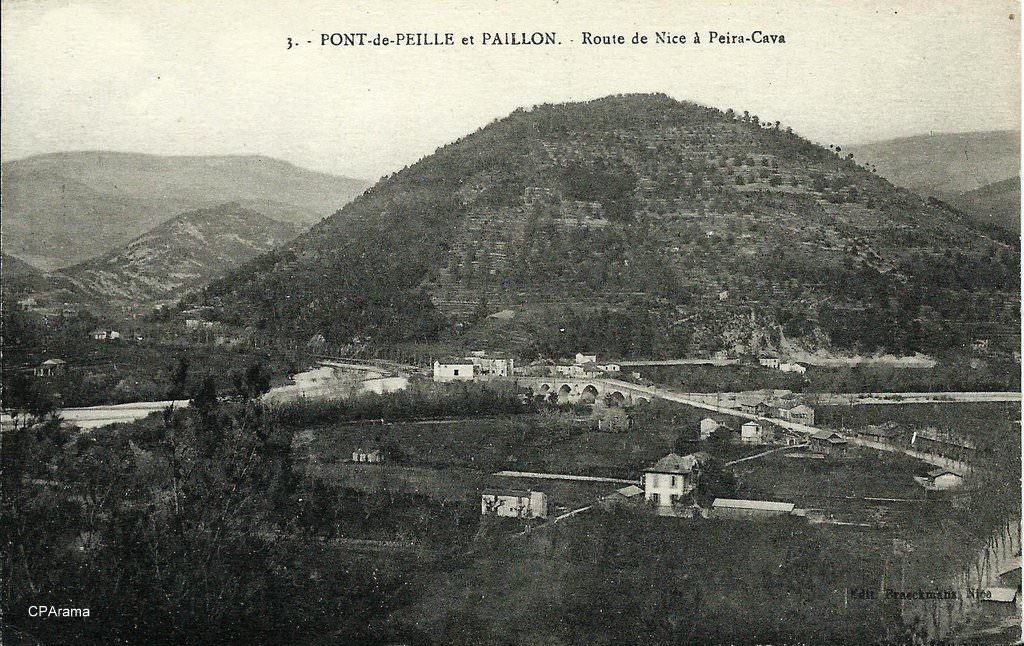
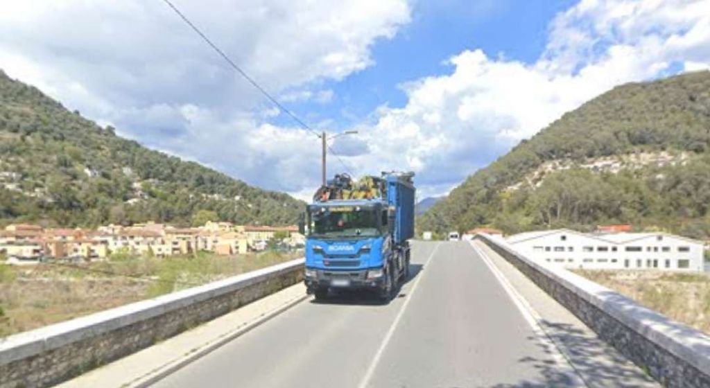
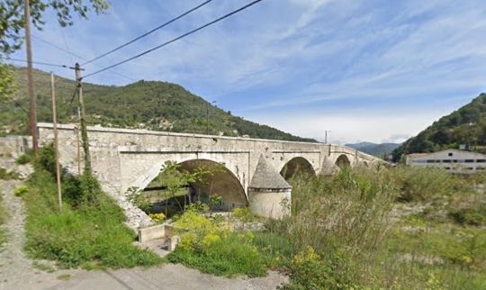
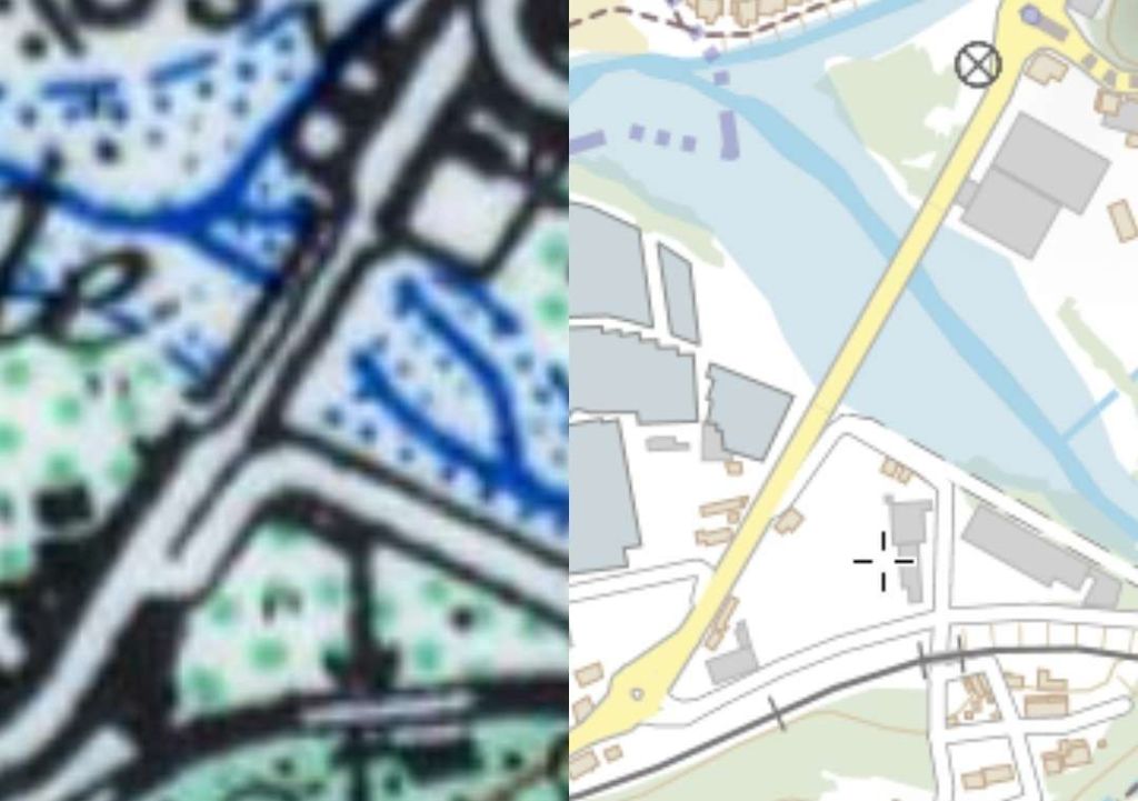
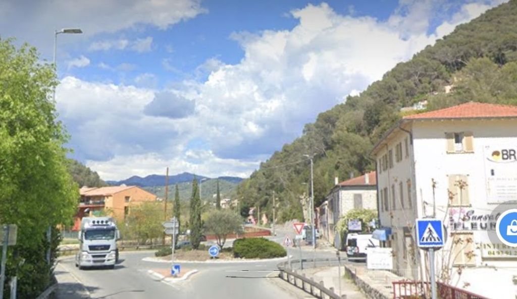
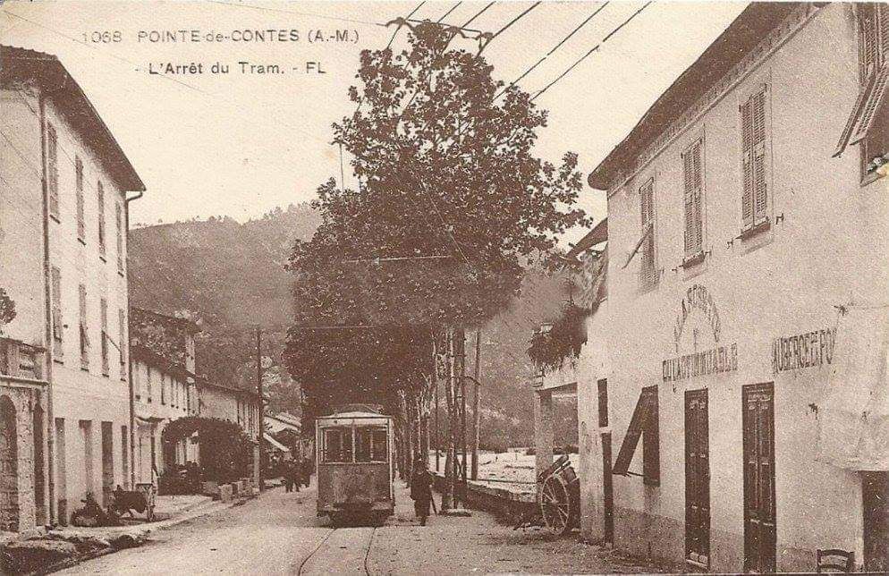
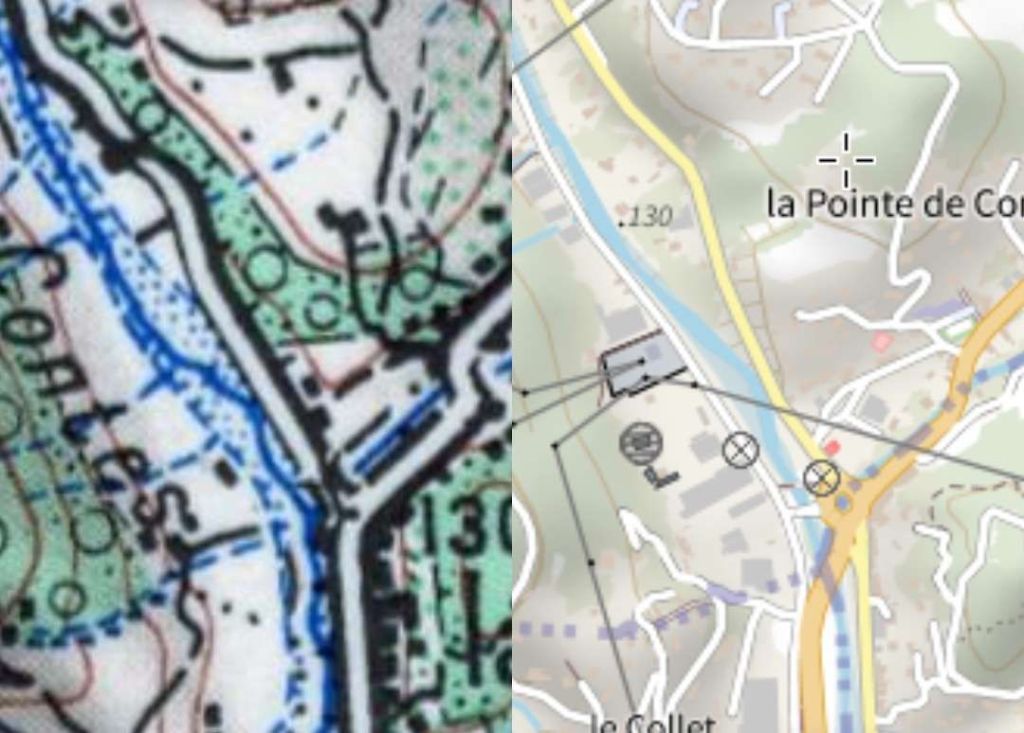
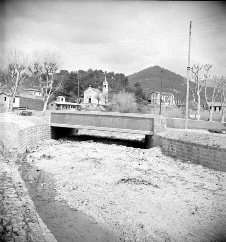
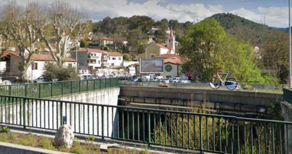
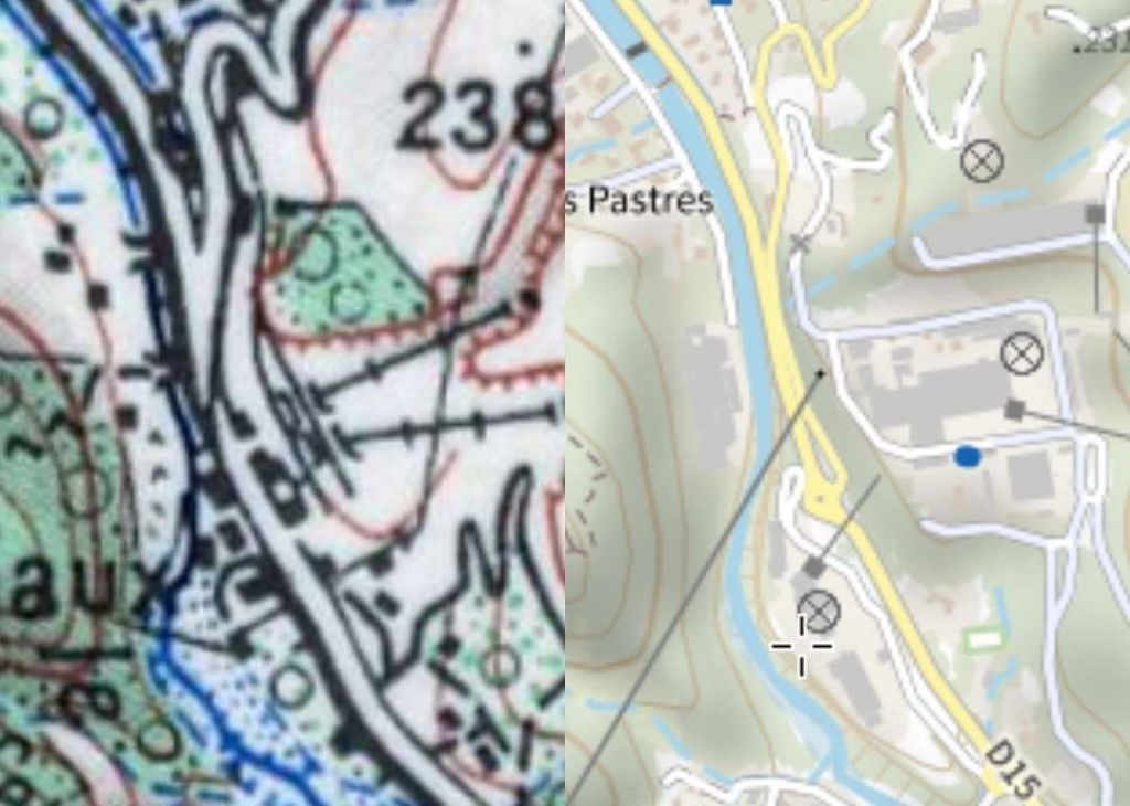
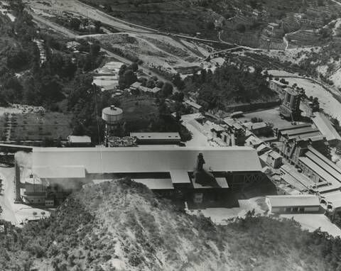
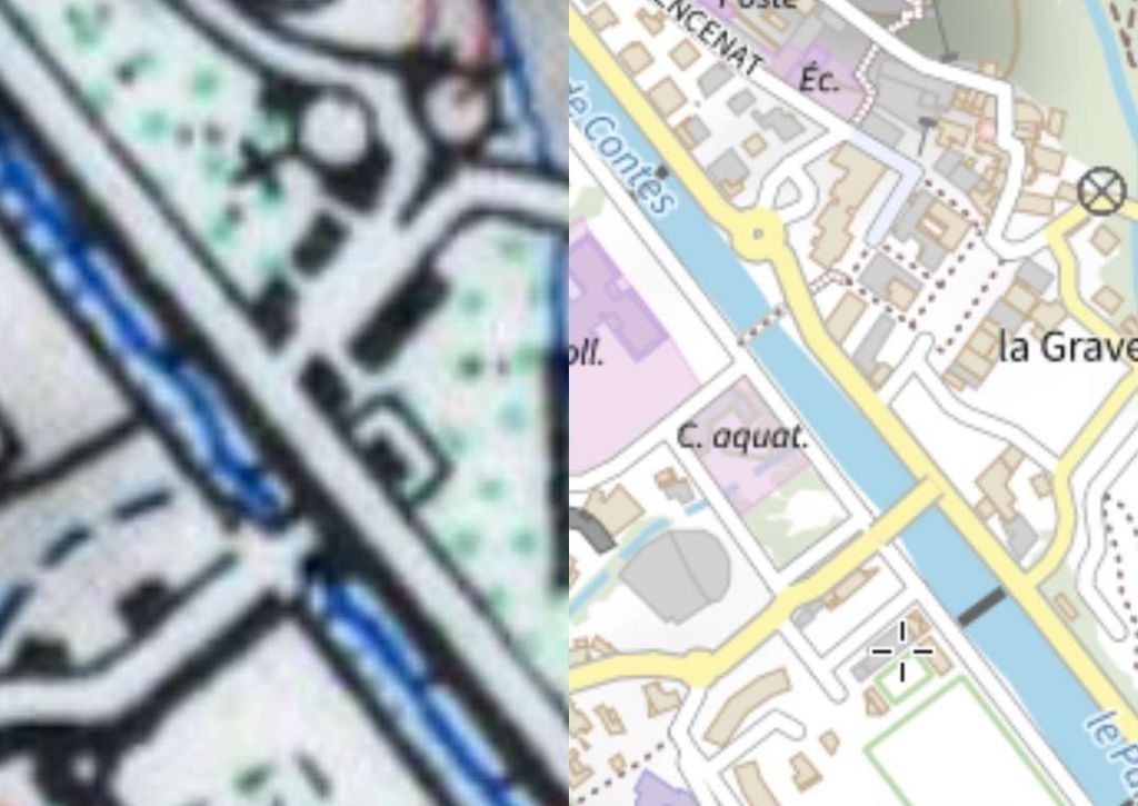
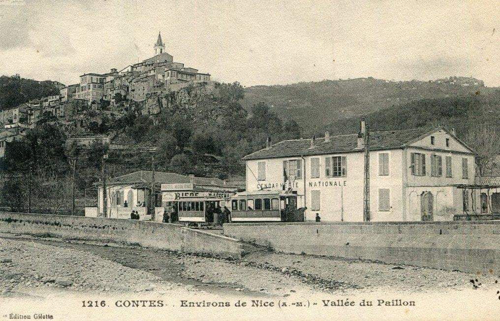
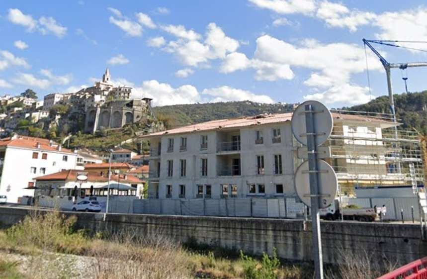

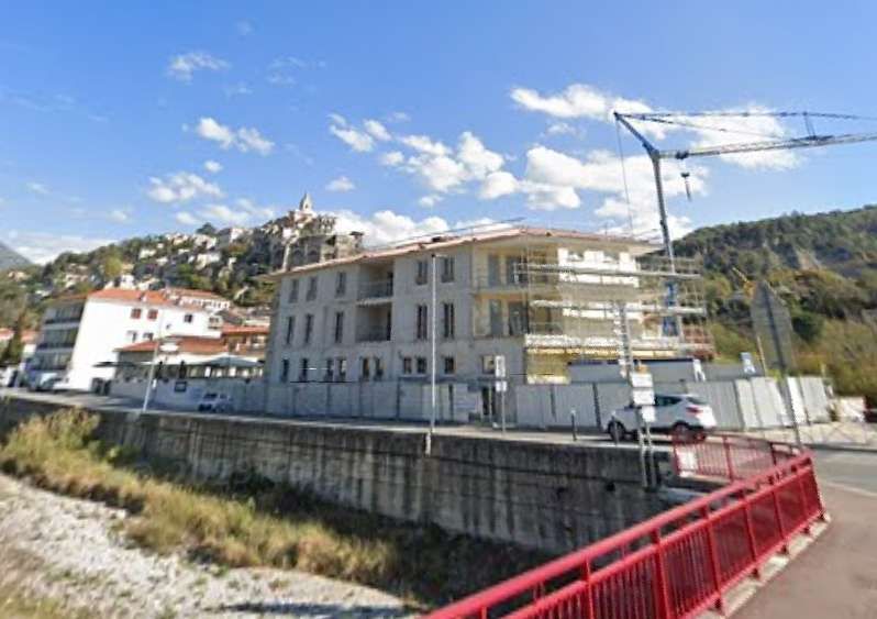
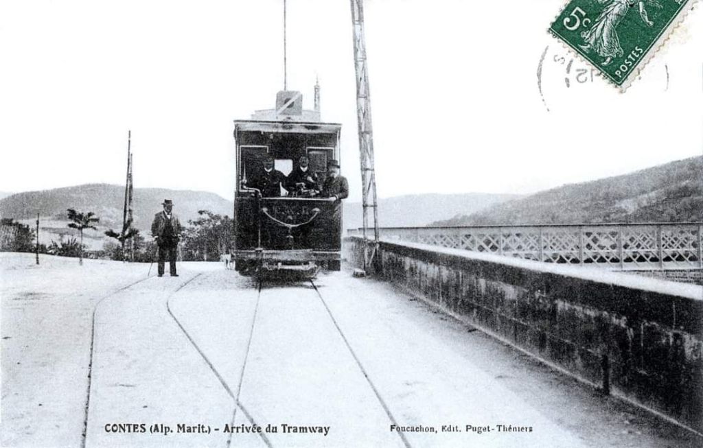
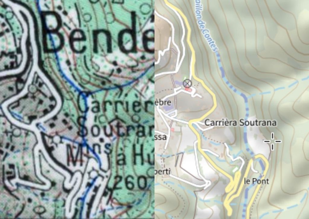
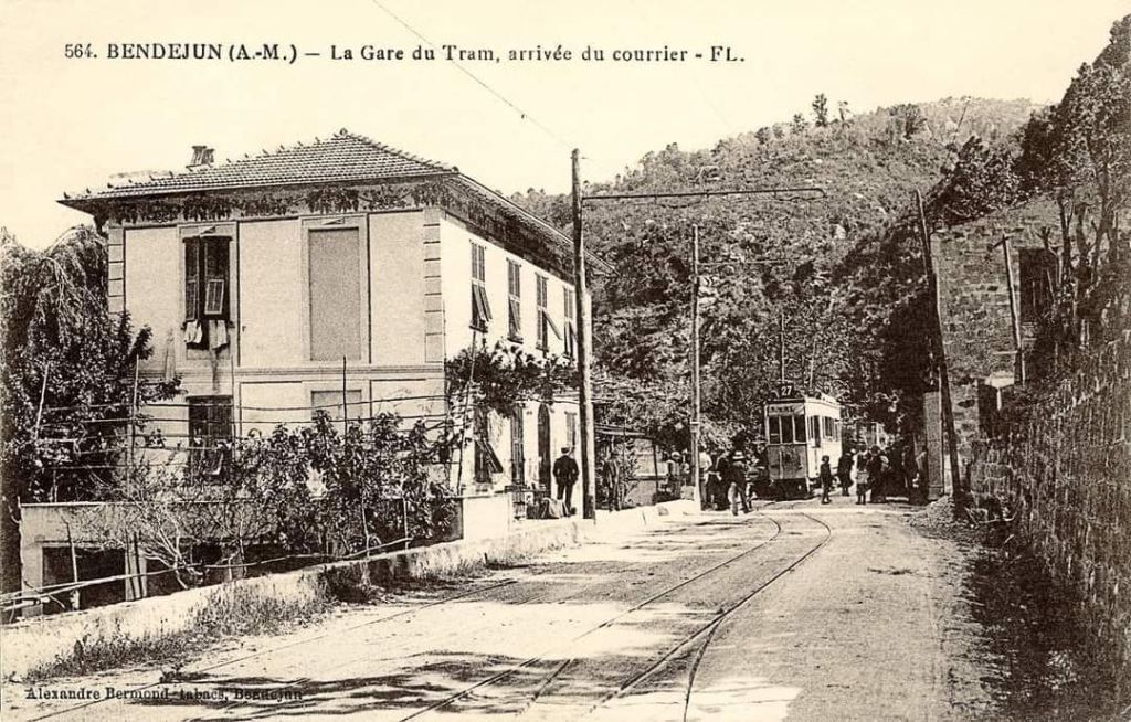
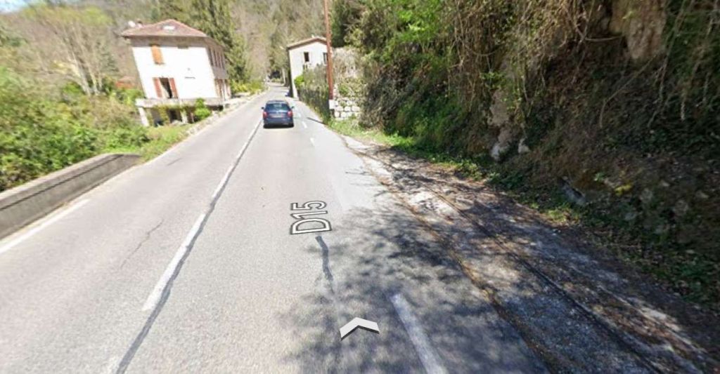
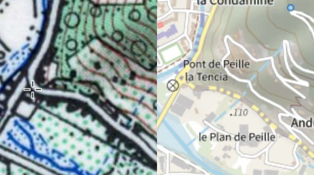
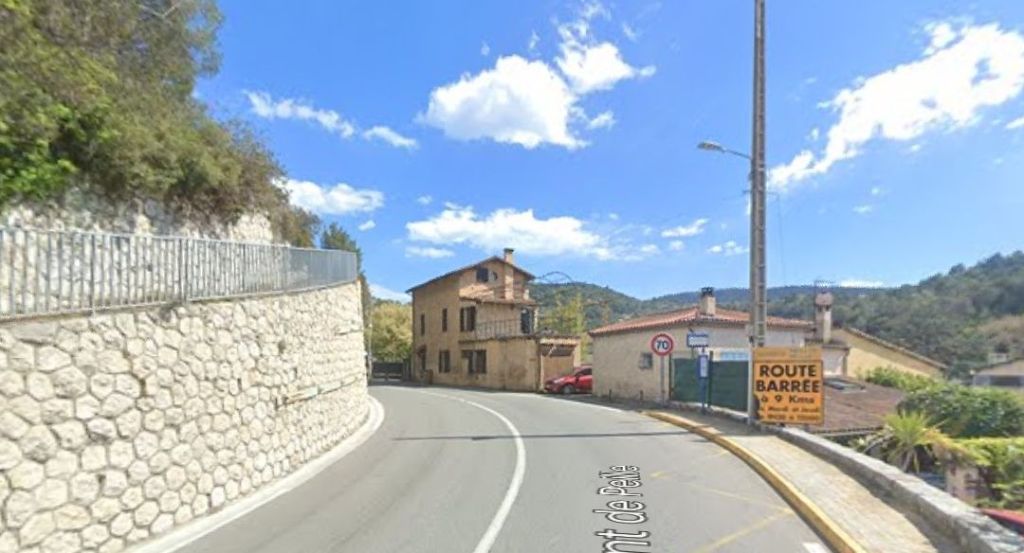

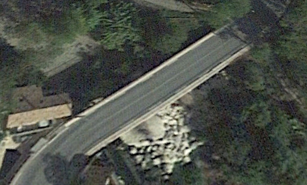

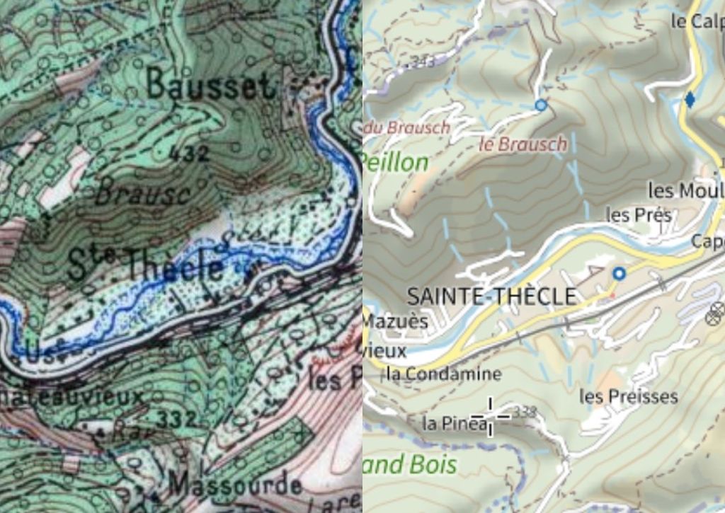
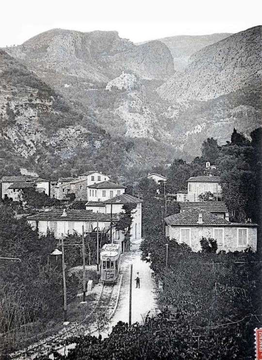
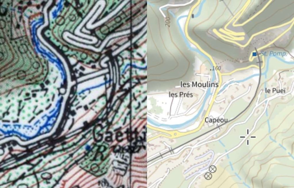
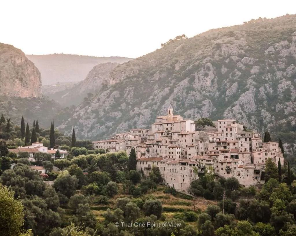
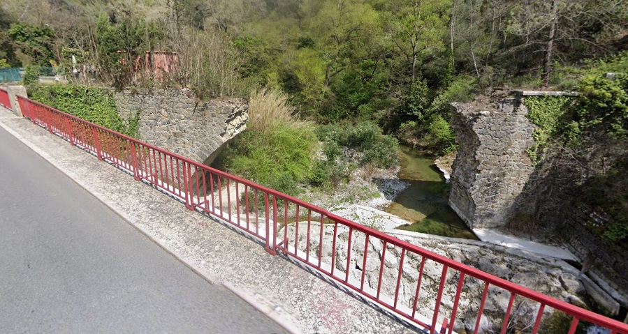
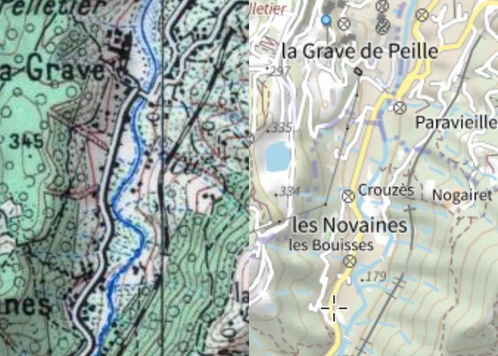
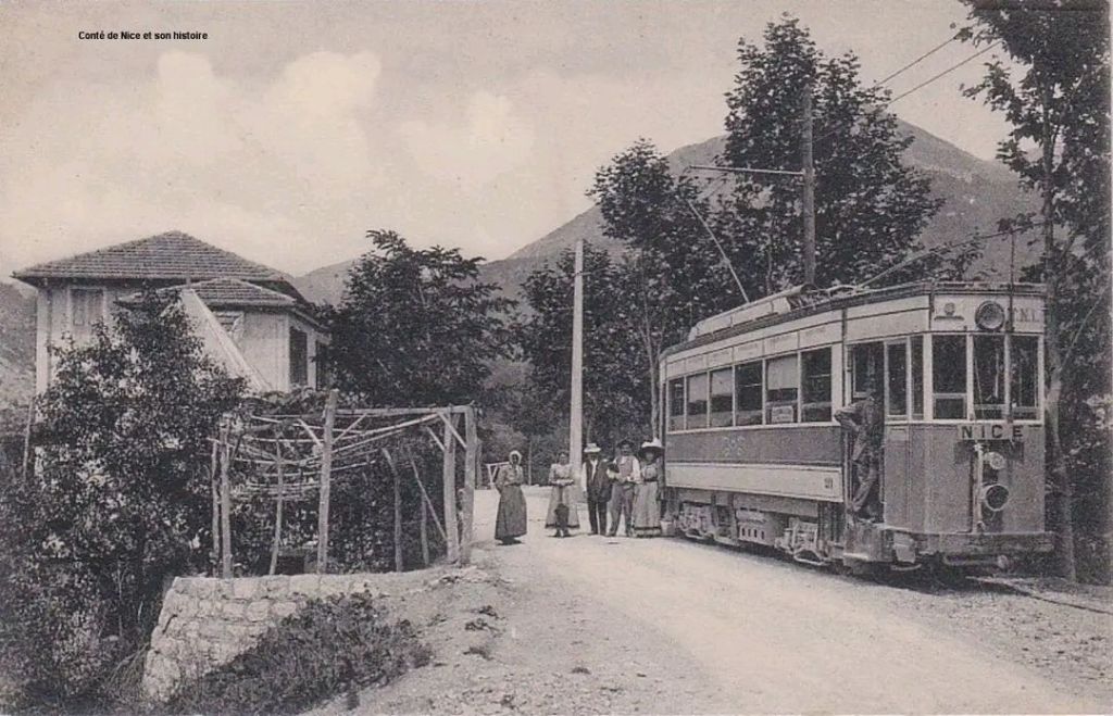
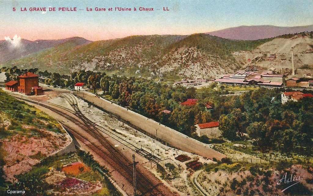
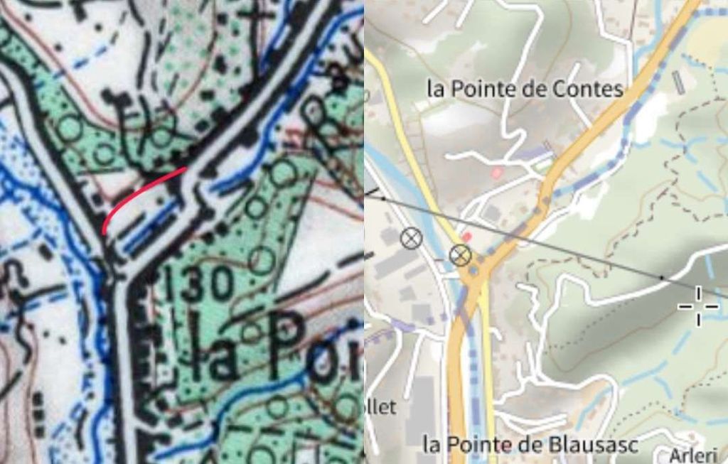
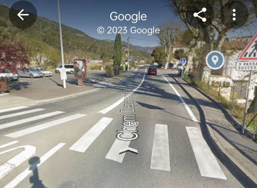


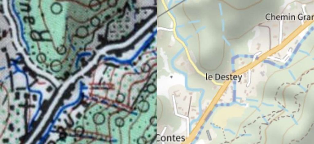
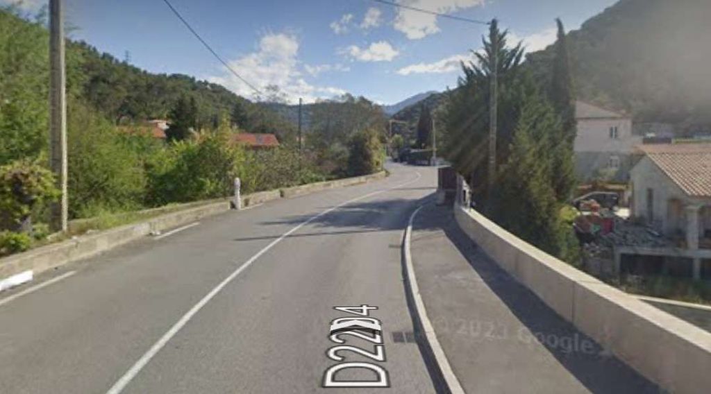
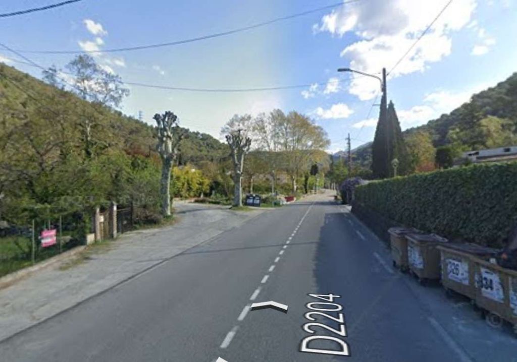
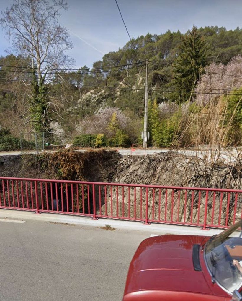
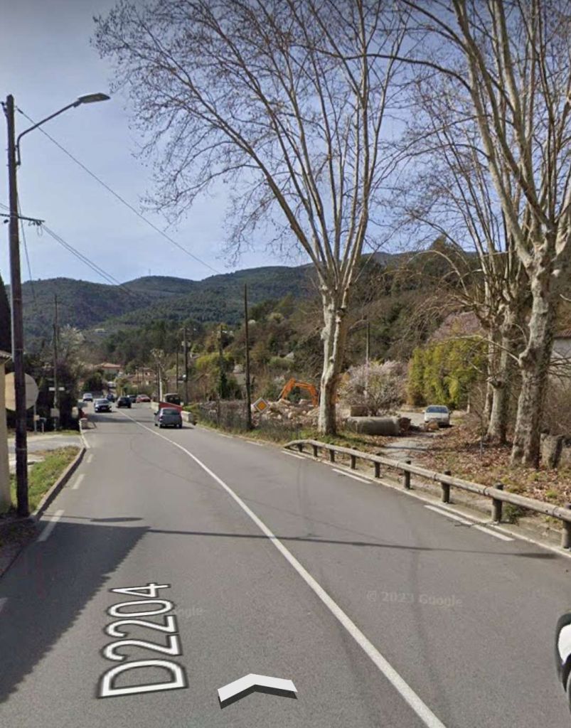
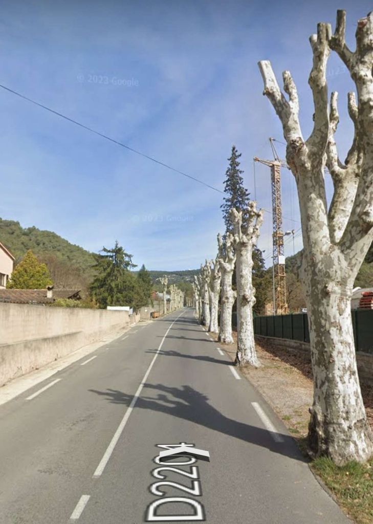
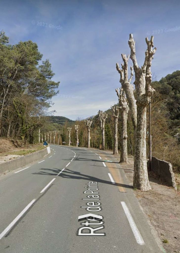
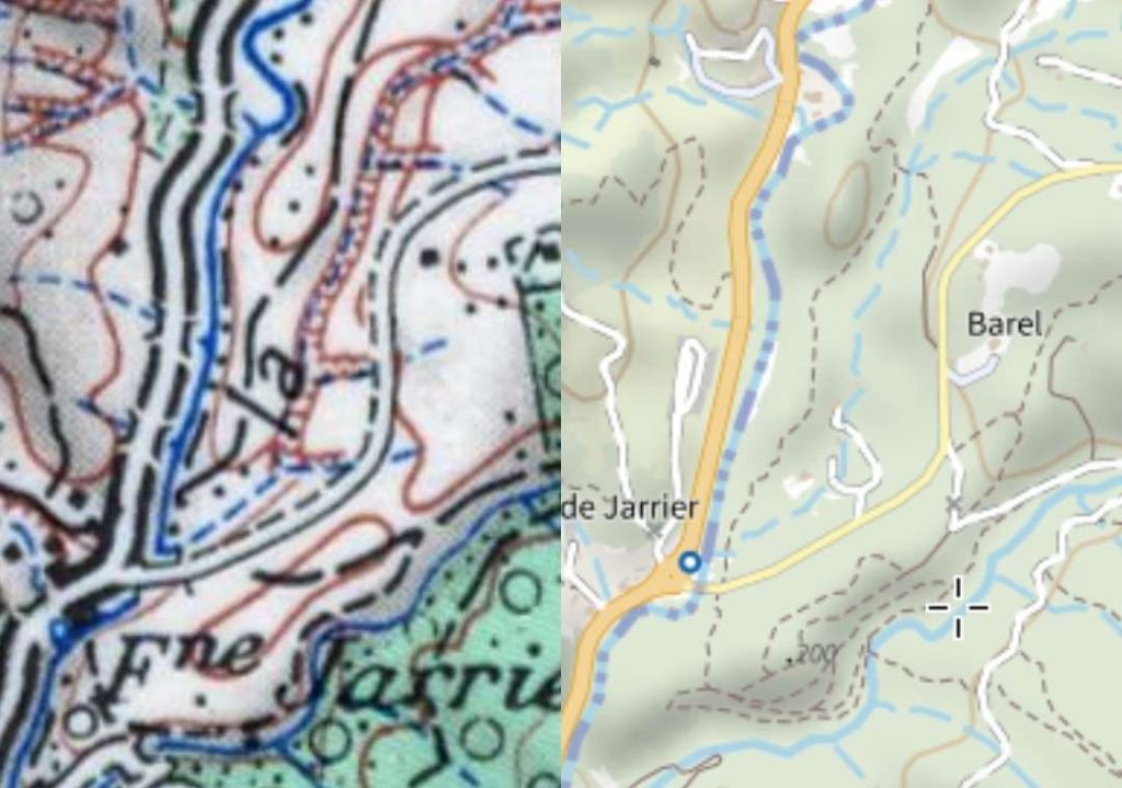
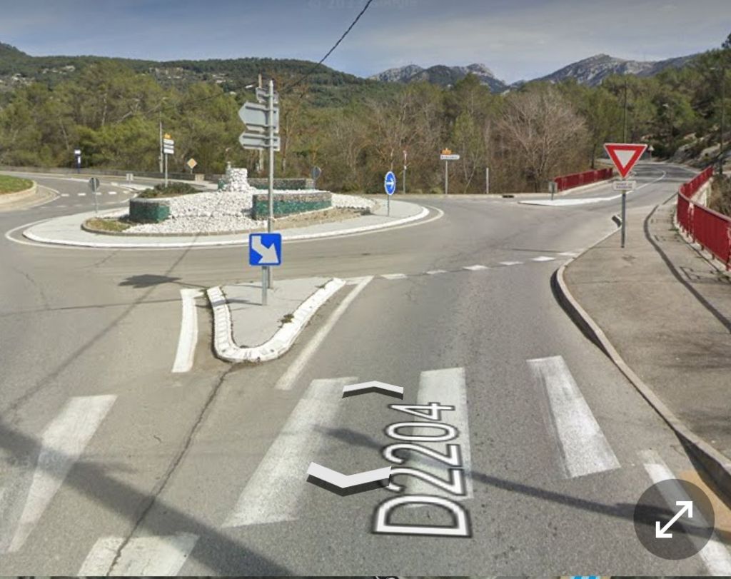
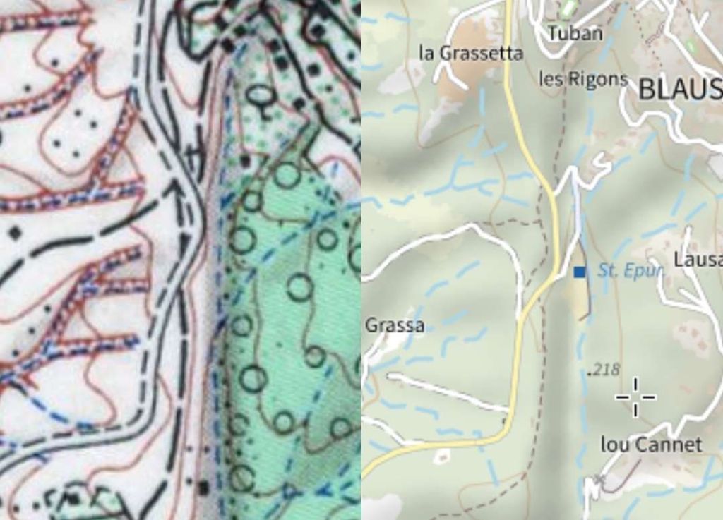
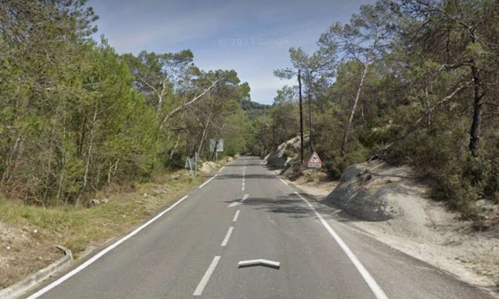
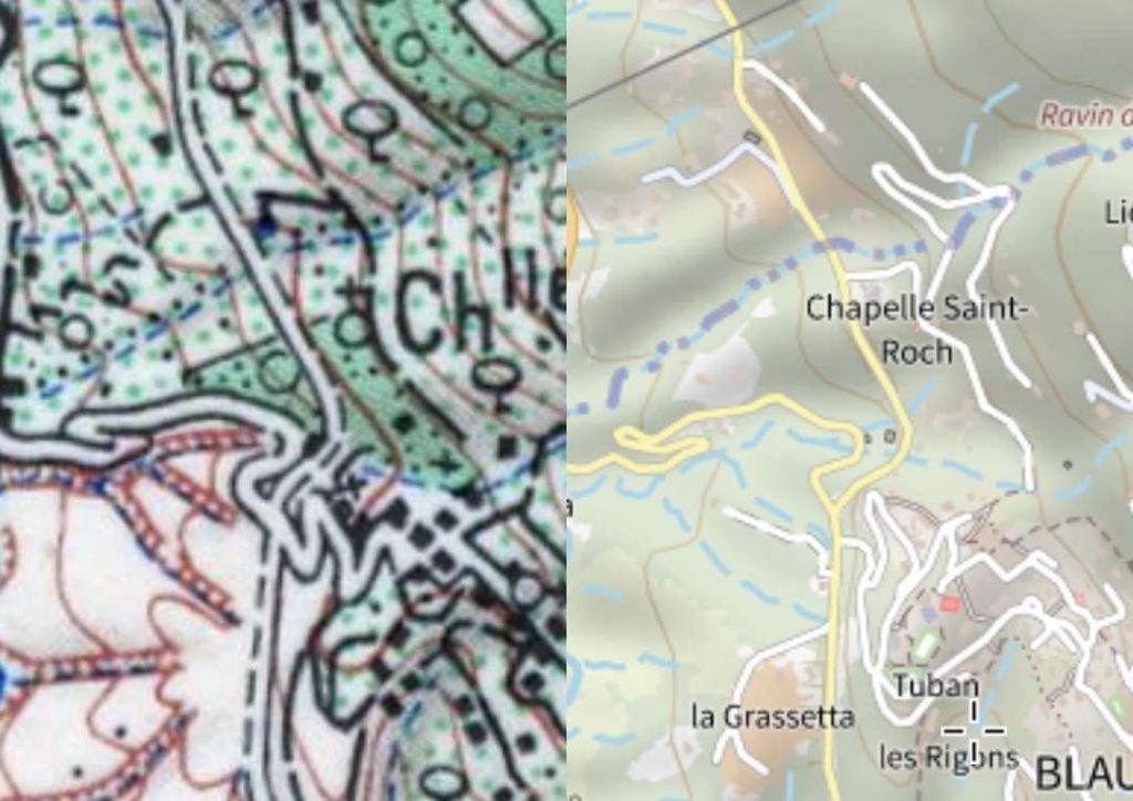
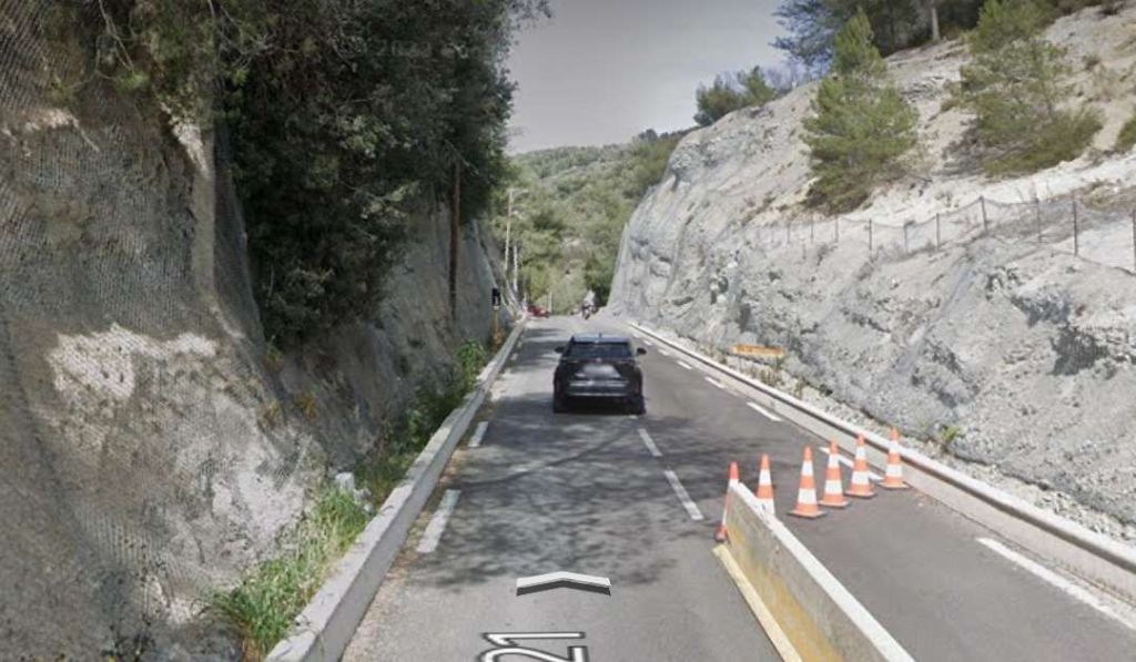
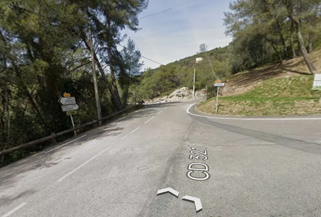
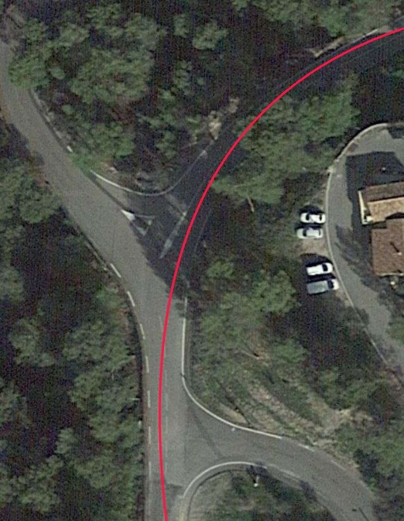
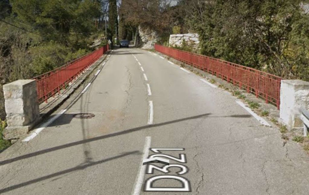
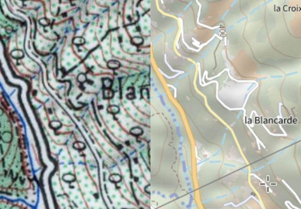
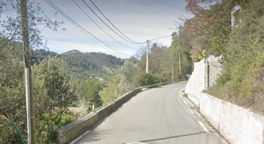

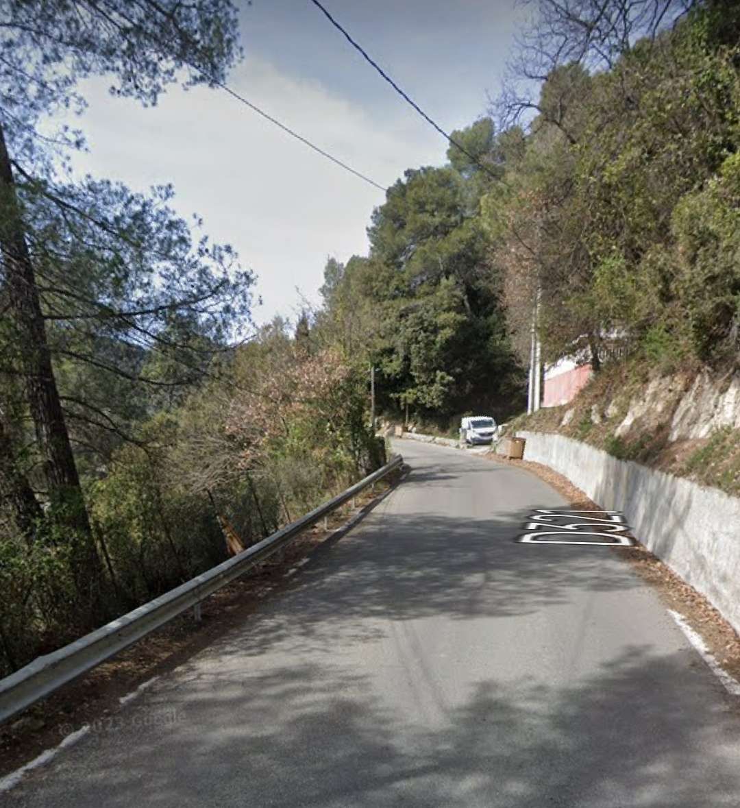
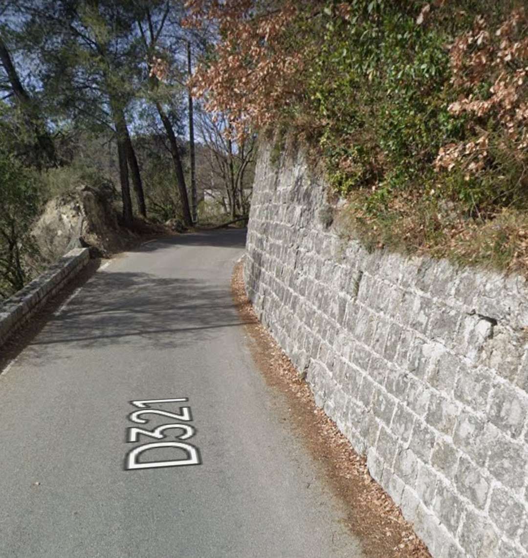
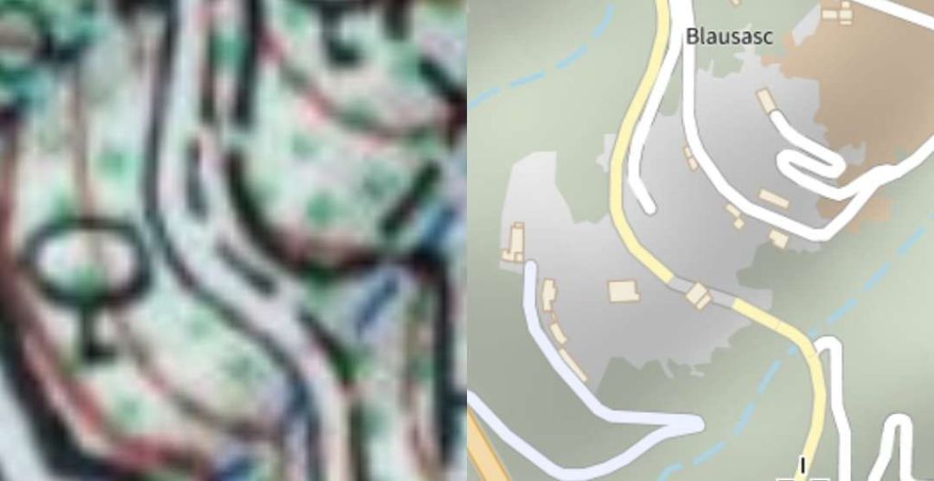
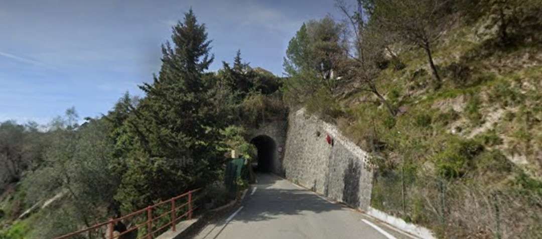
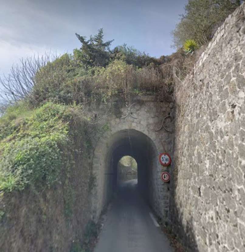
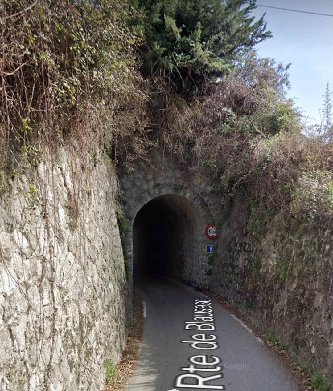
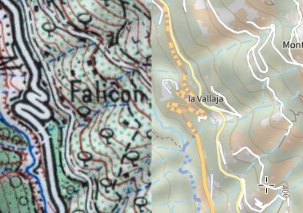
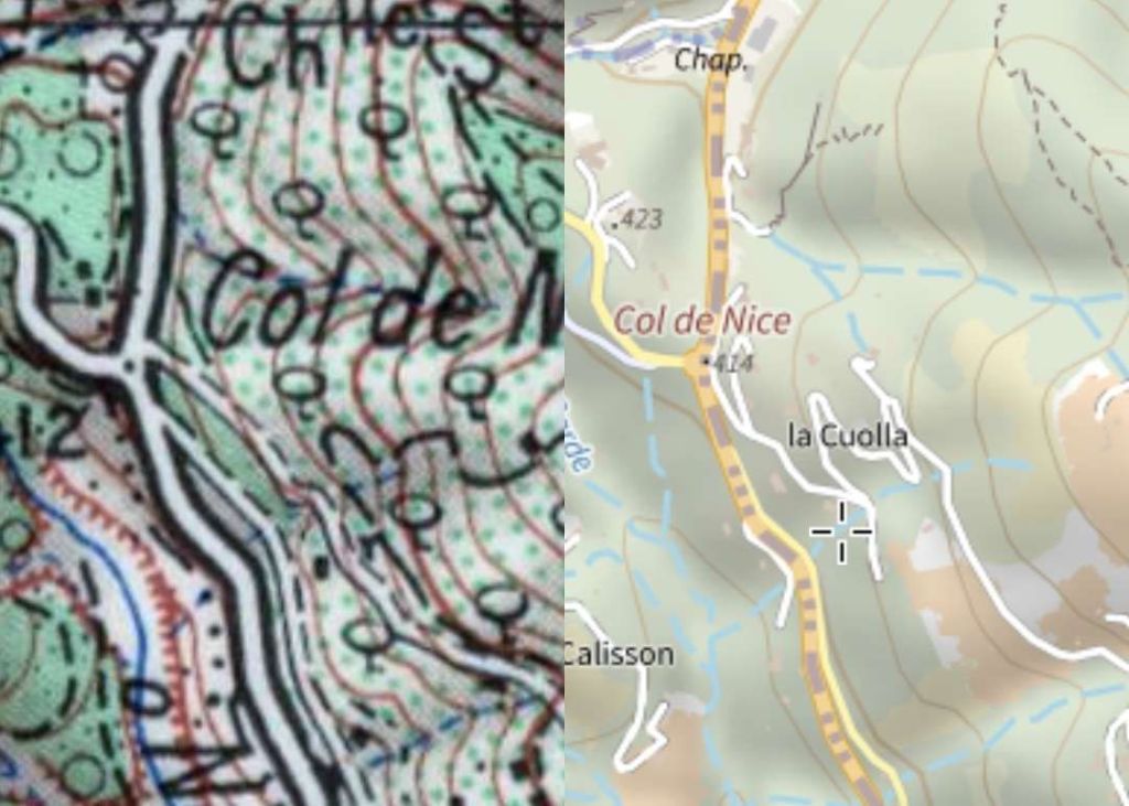
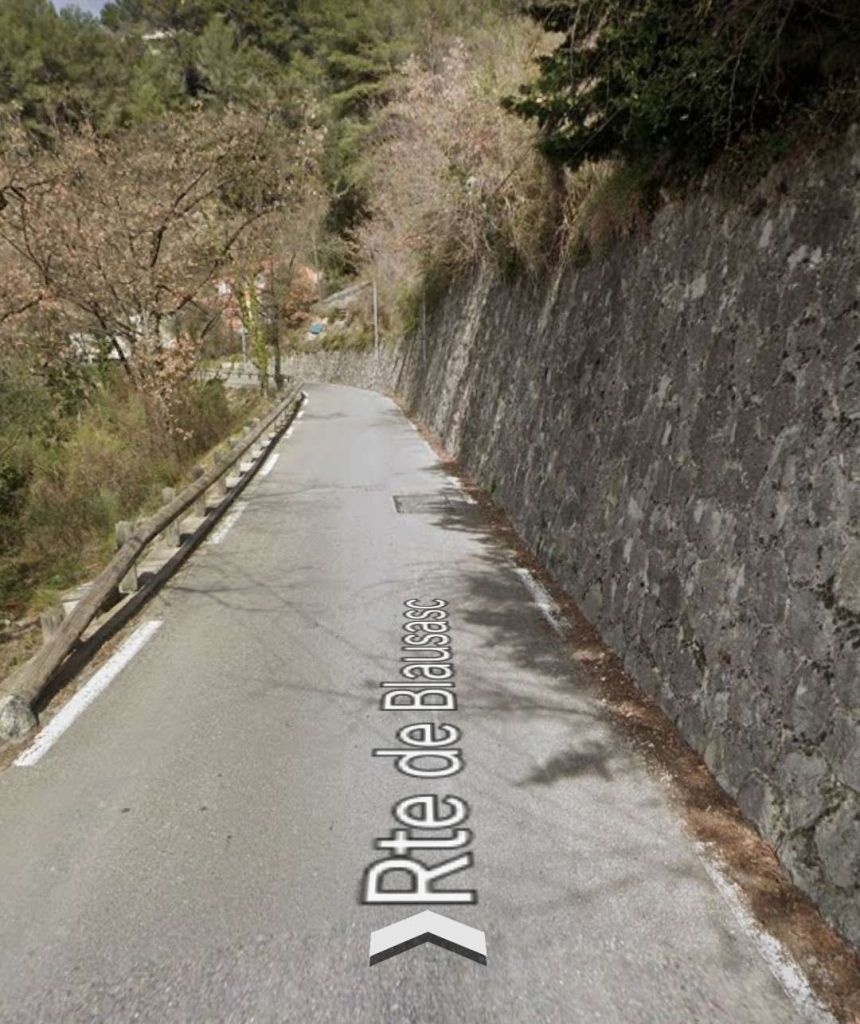
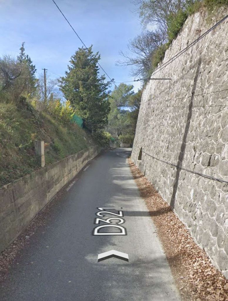
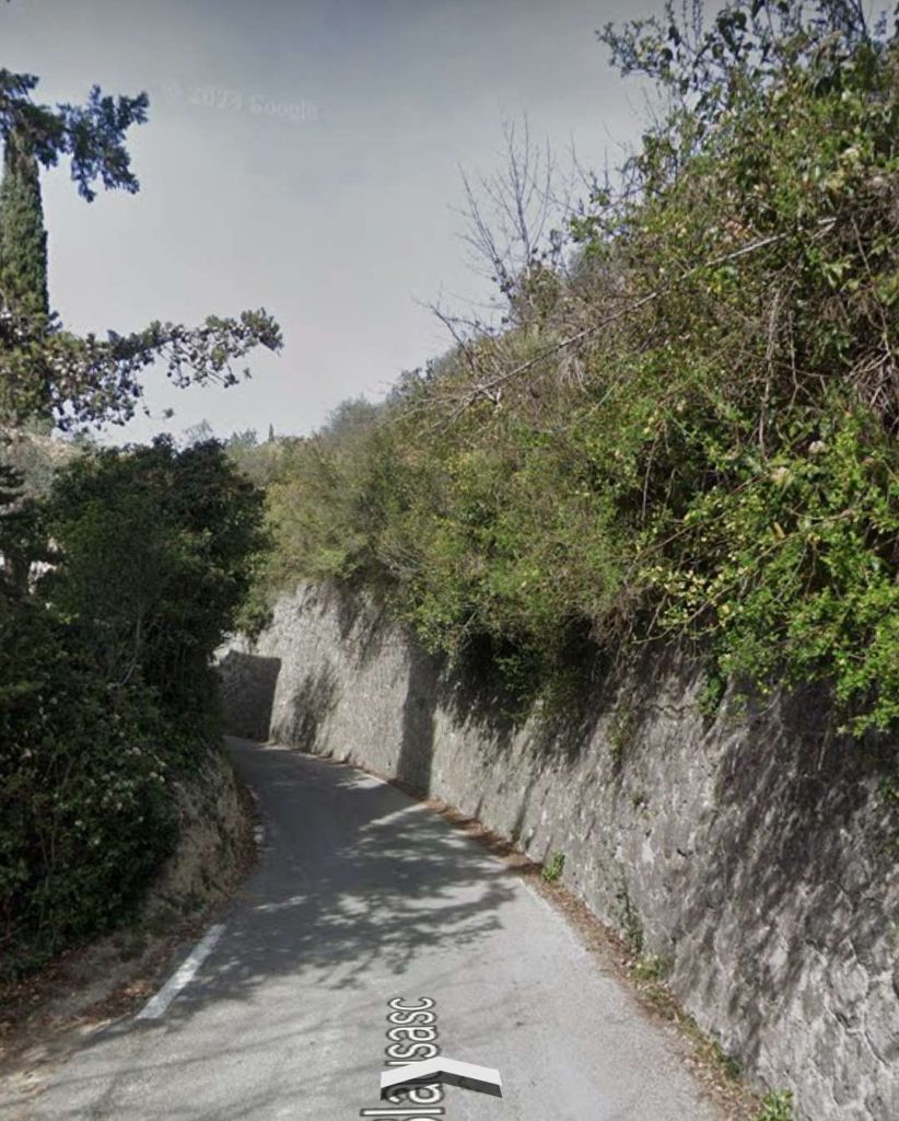
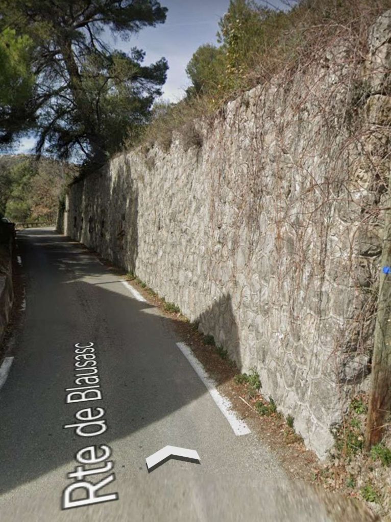

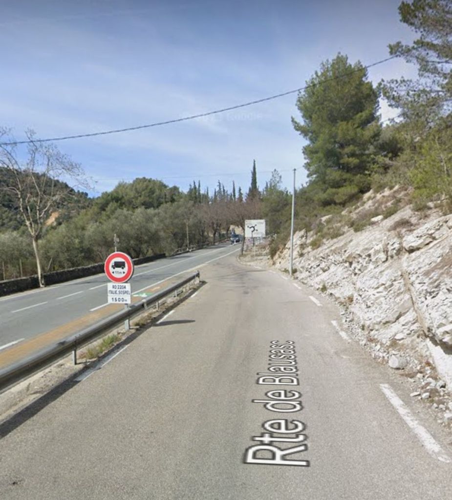
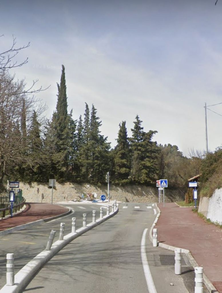
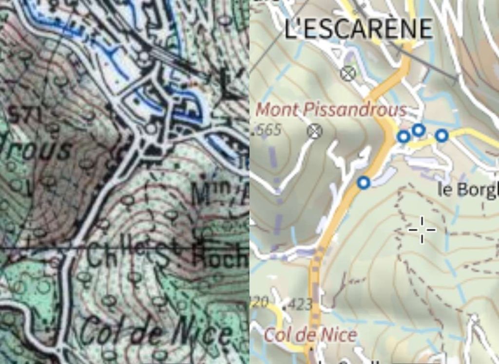
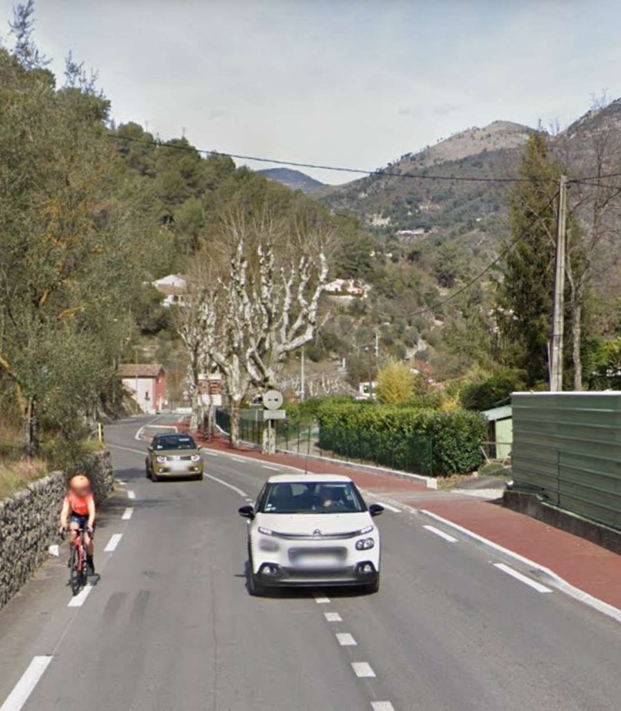
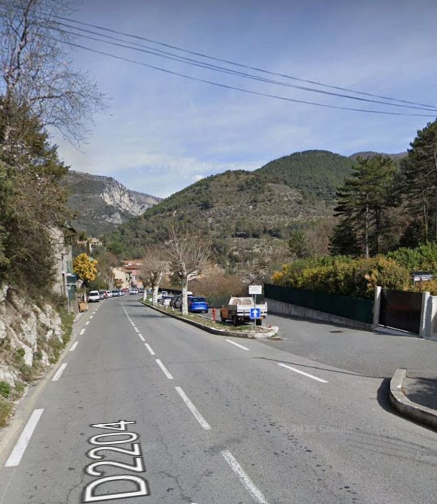
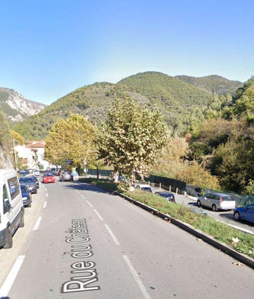
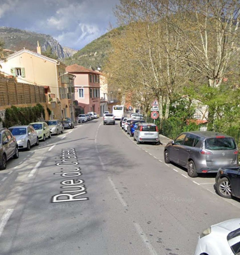
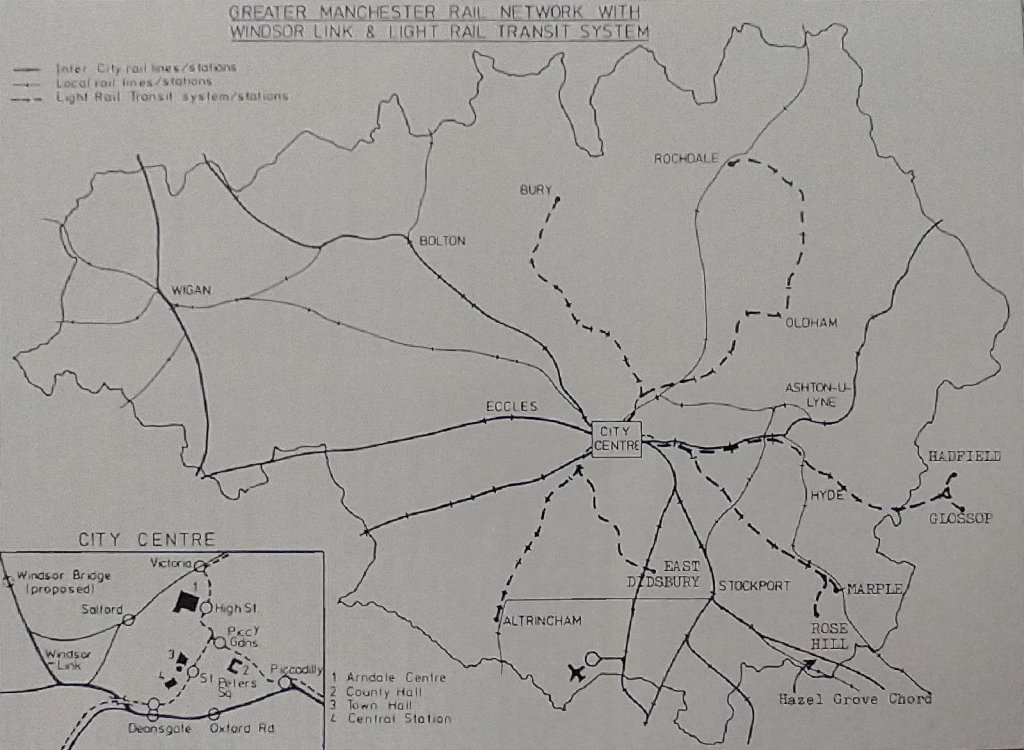
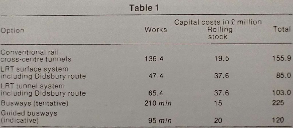
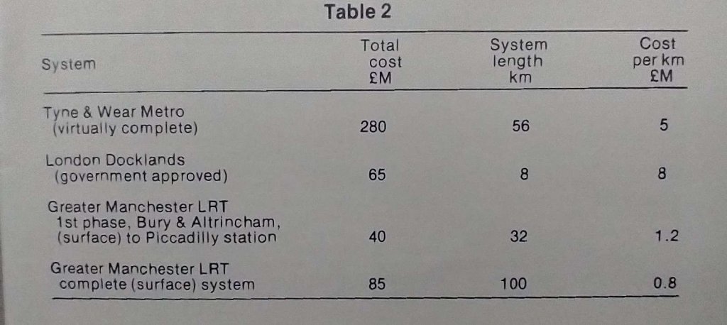
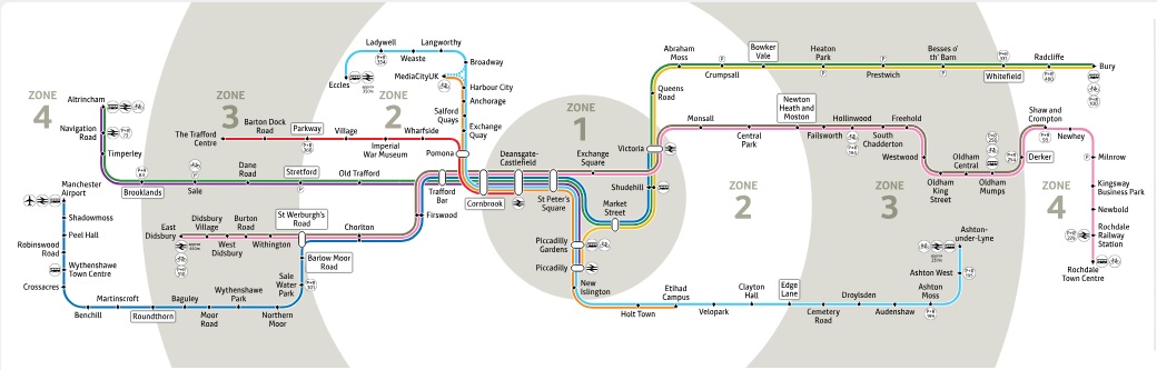
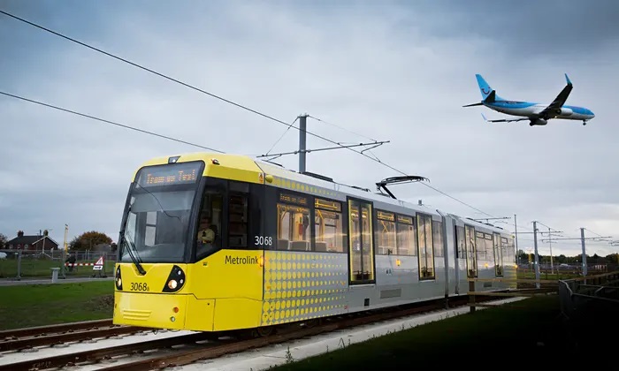
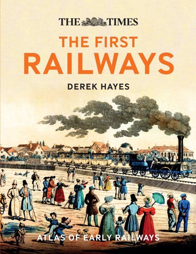

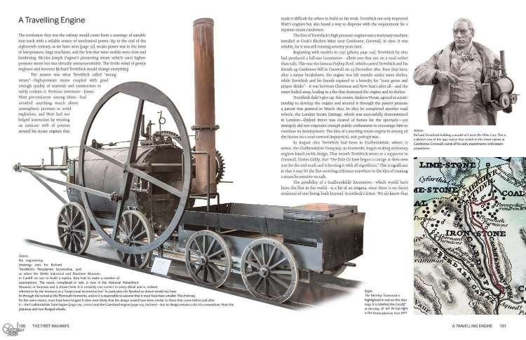

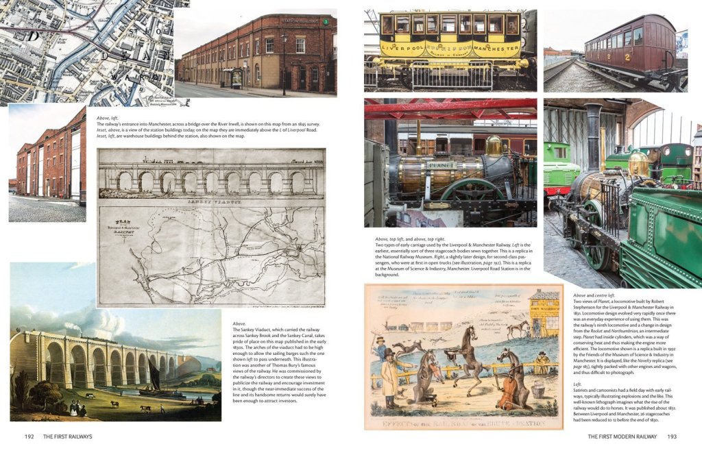
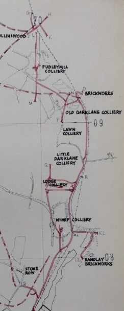
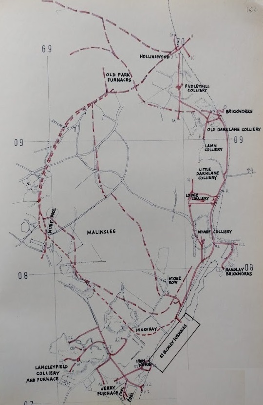
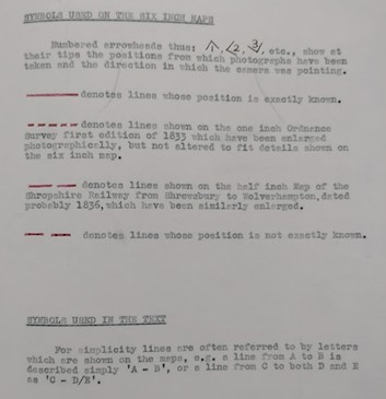
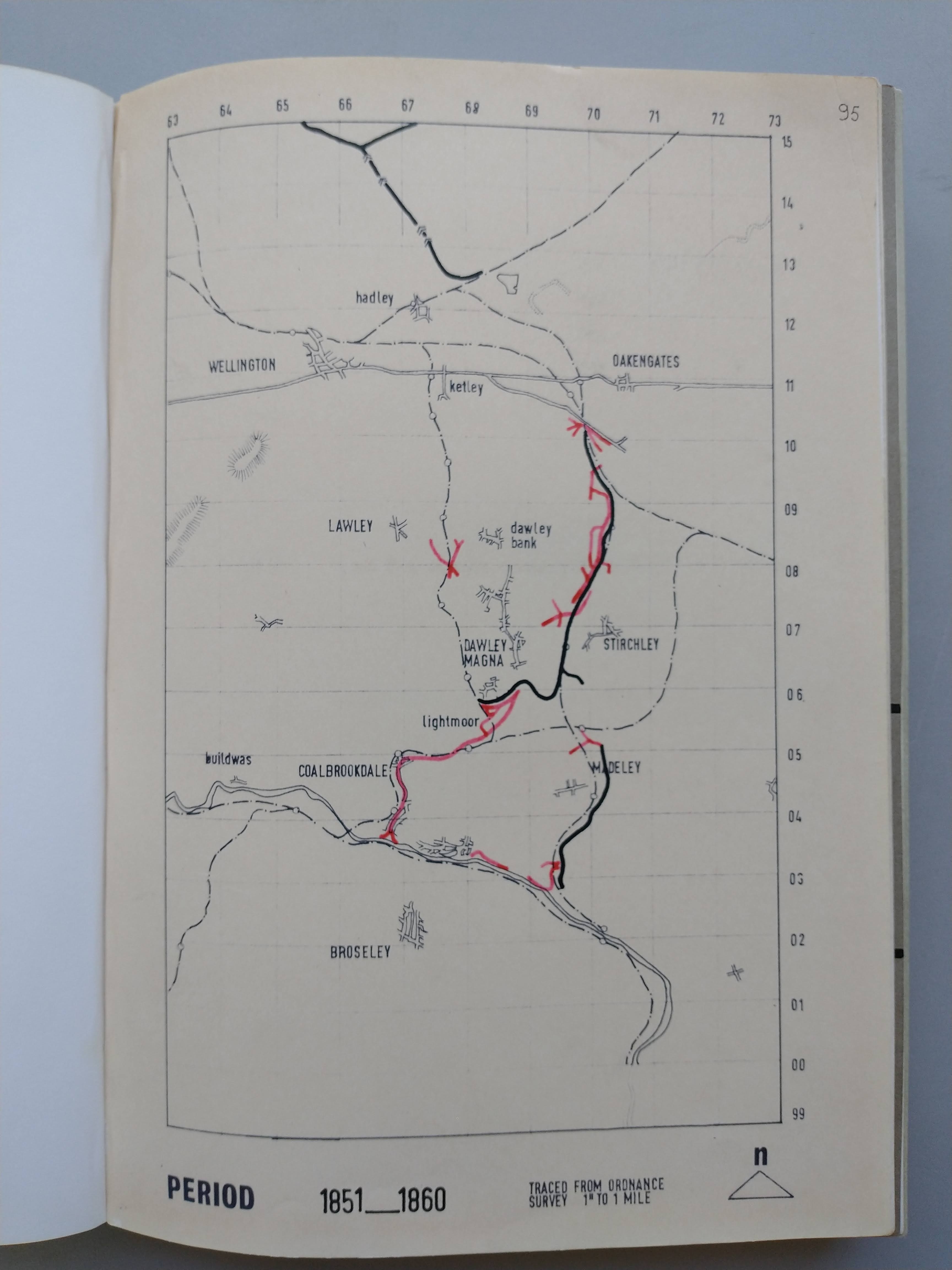
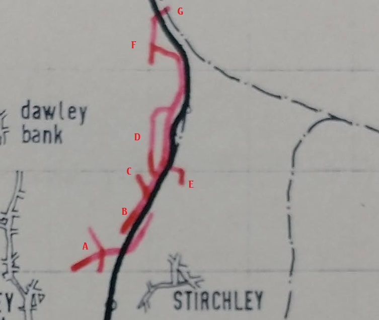
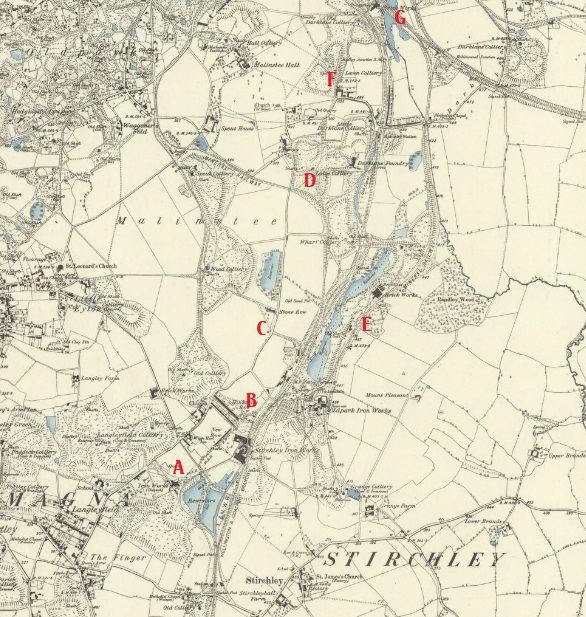
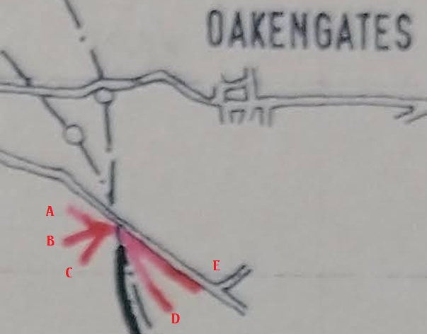
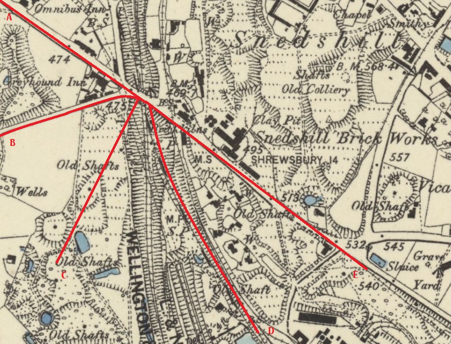
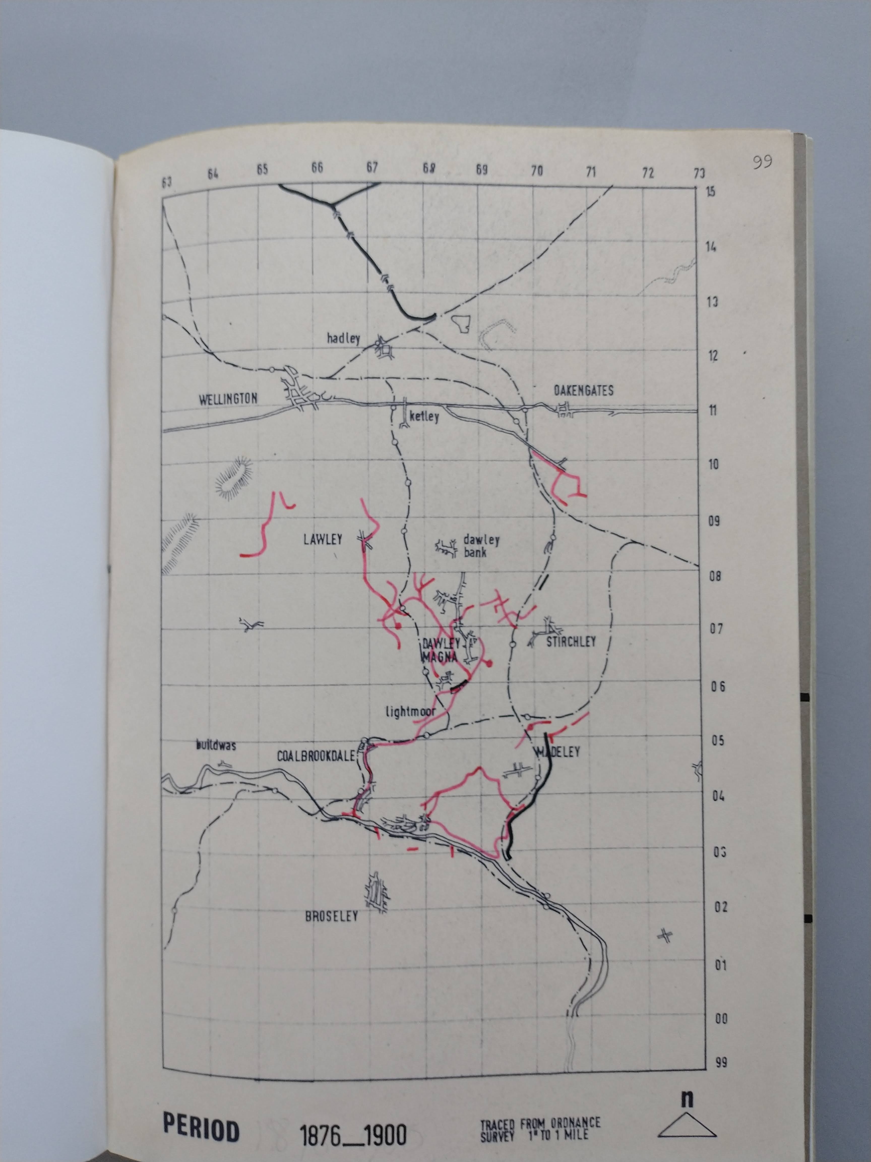
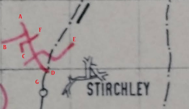
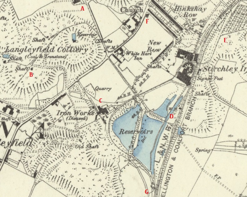
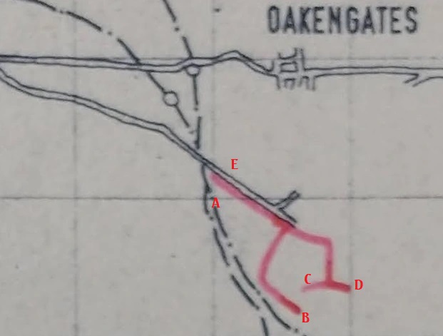
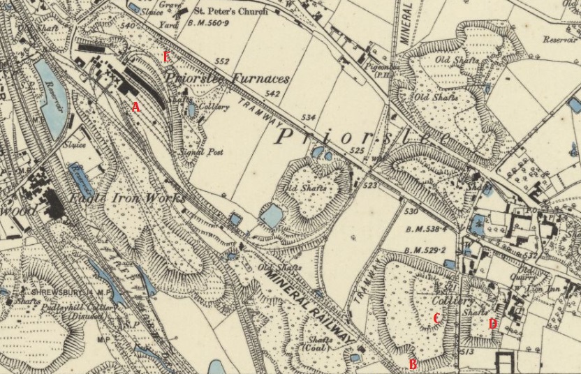
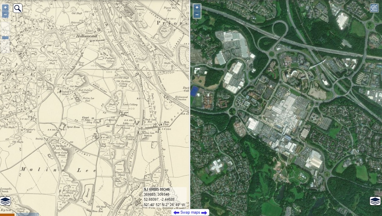

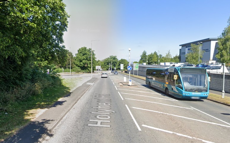

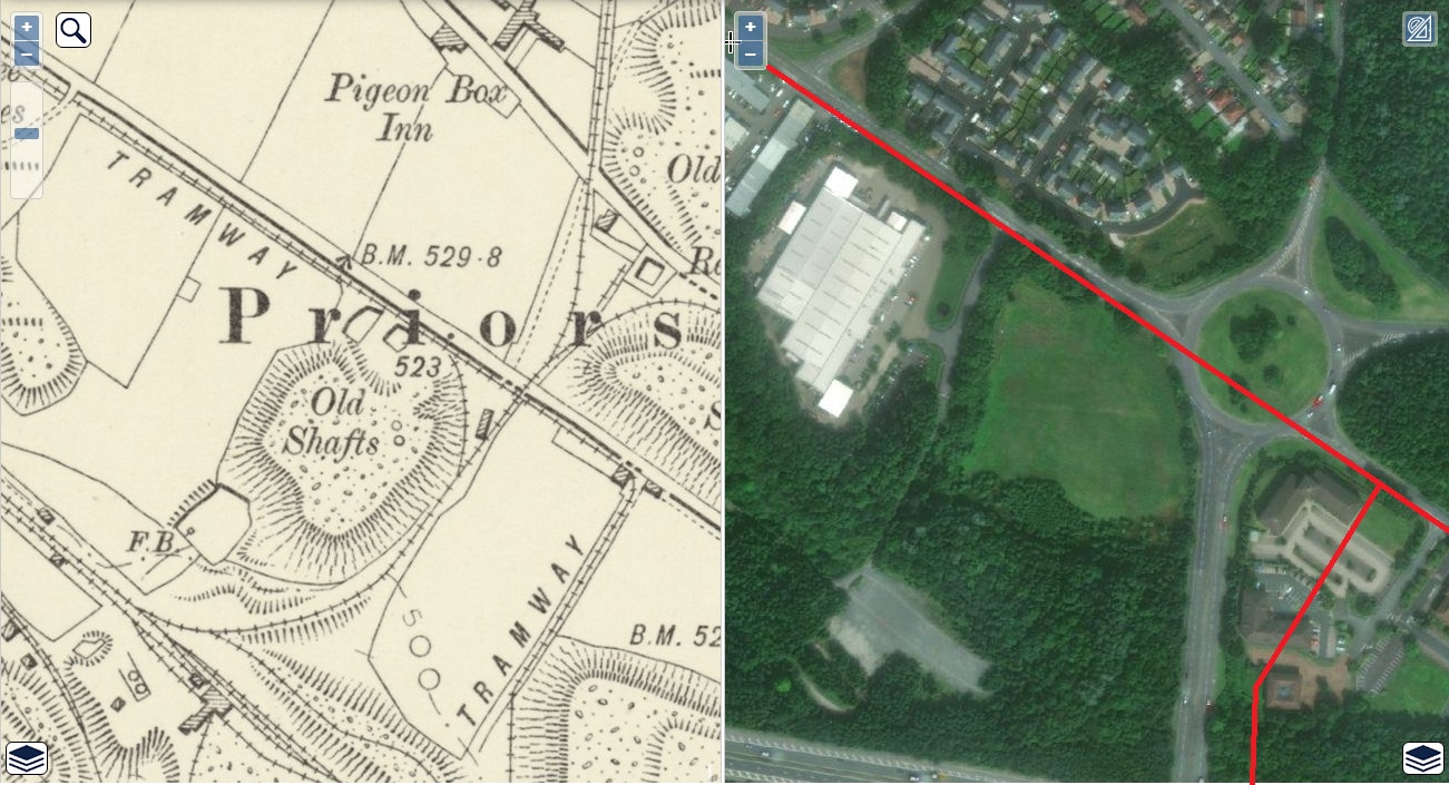
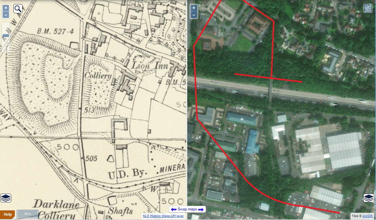
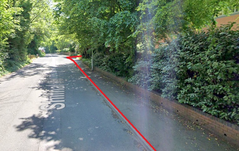
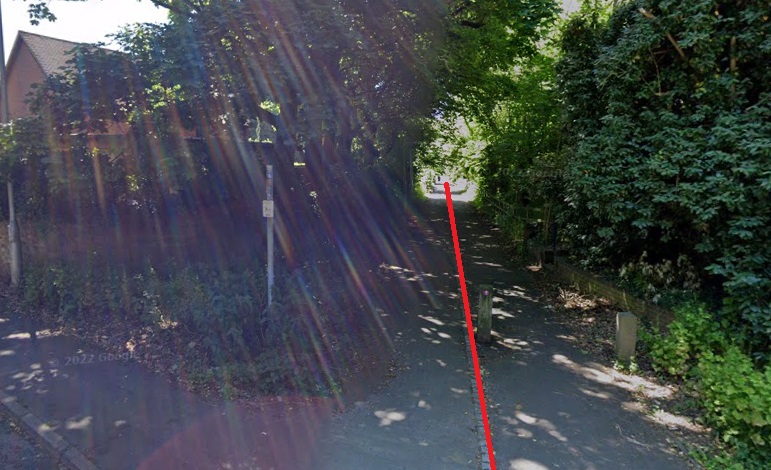
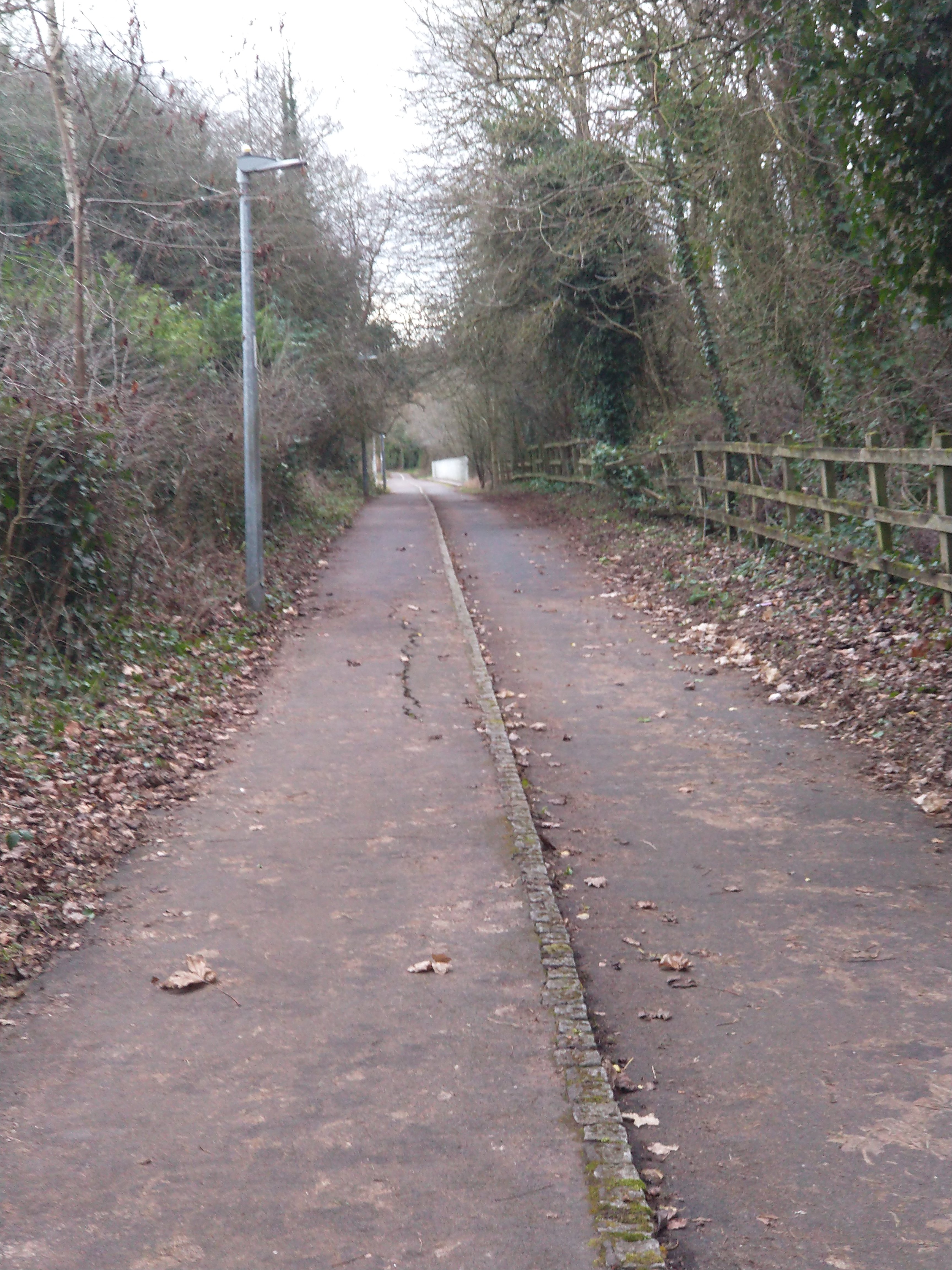
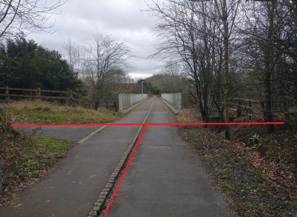
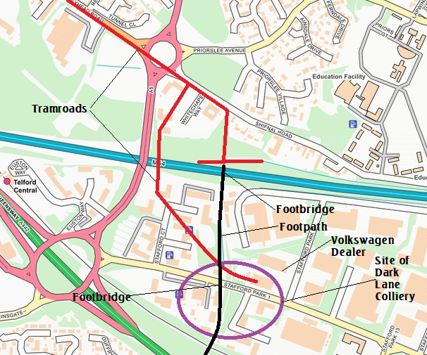
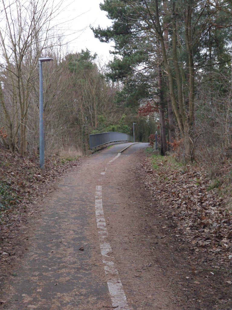

.jpg)
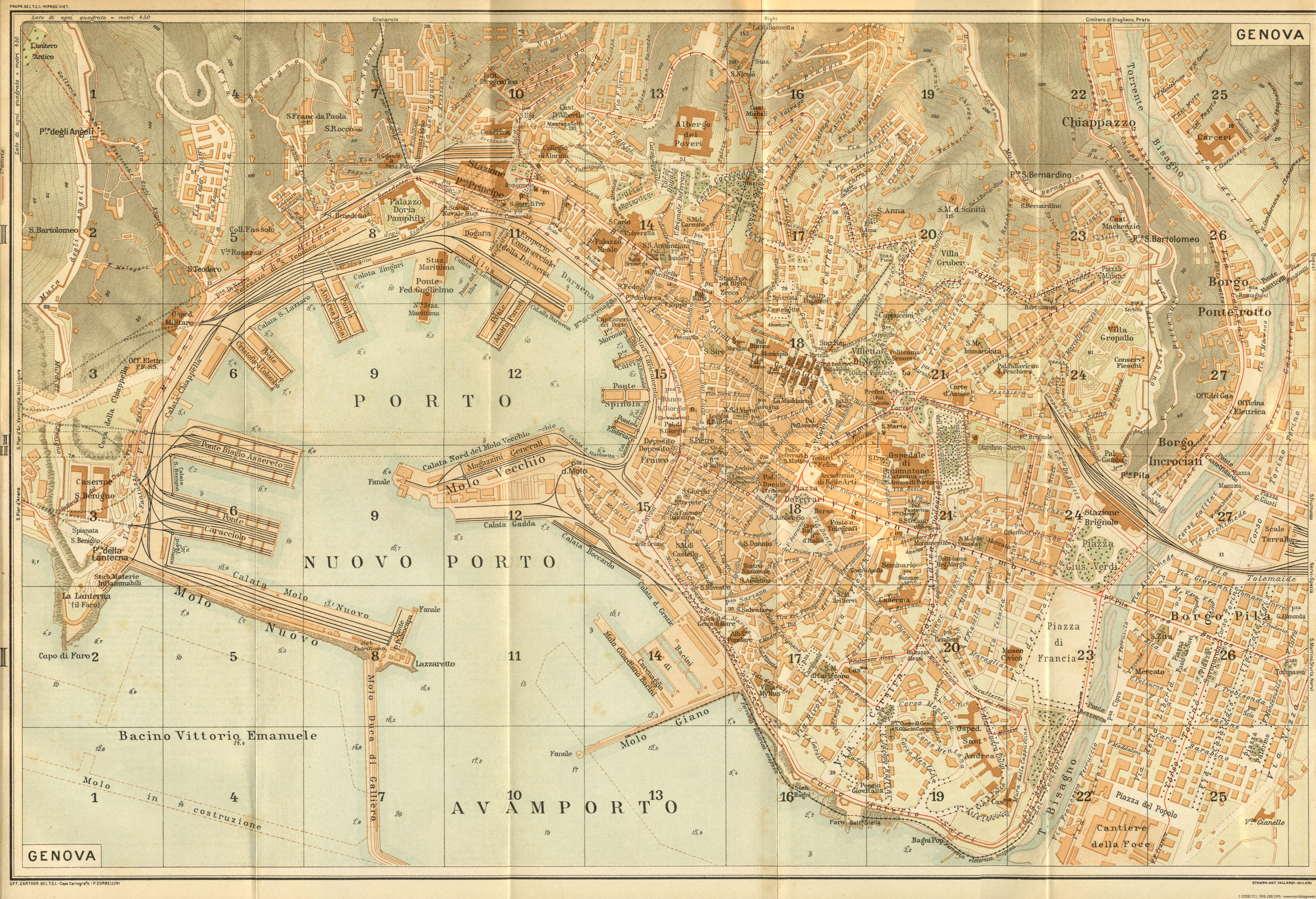