The Railway Magazine of November 1954 reported that East African Railways & Harbours had begun to name its new ’60’ Class Beyer- Garratt locomotives. They chose to name them after past and present Governors. The ’60’ Class were then the most powerful Beyer-Garratt locomotives to be delivered to East Africa. Twenty-seven (29? [1]) had been ordered, and by the Autumn of 1954, twenty-five had been delivered, with 20 already in service.
“Sir Edward Twining, Governor of Tanganyika, named one of the class after himself at a ceremony at Dar es Salaam on 18th September; on 25th September 25, Sir Andrew Cohen, Governor of Uganda, named another locomotive at Kampala; and Sir Evelyn Baring, Governor of Kenya, named a third of the class at Nakuru on 29th September. With the subsequent naming of the other locomotives after past Governors, the ’60’ Class [would] become known as the ‘Governor’ Class.” [2: p804]
“The first 12 of them were built by sub-contractors Société Franco-Belge in Raismes (Valenciennes), France, and the rest were built by Beyer, Peacock in Gorton, Manchester, England. The class entered service in 1953-54.” [1][3: p77-78]
“They were 1,000 mm (3 ft 3 3⁄8 in) gauge 4-8-2+2-8-4 Garratt-type articulated steam locomotives built for the East African Railways as a development of the EAR’s existing ’56’ Class.” [3: p77]
Initially, all members of the class carried the name of a Governor (or equivalent) of Kenya, Tanganyika or Uganda, but later all of the Governor nameplates were removed. [3: p77-78]
The Railway Magazine also noted that, “The policy of naming locomotives [was] to continue and it [had] been suggested that the ’59’ Class Beyer-Garratt locomotives, delivery of which [was] expected to begin in 1955, should become the ‘Tribal’ Class.” [2: p804]
The table below (in 4 parts) comes directly from the Wikipedia article about the ’60’ Class locomotives. The information included in the table is taken from two important texts,, both published by David & Charles, one by Ramaer, [3: p91] the other by Durrant. [4: p190]
4 sections of a single table included in the Wikipedia article about the ’60’ Class locomotives. [1]
’59’ Class
The ’59’ Class Beyer-Garratt locomotives entered service in 1955–56, and were the largest, heaviest and most powerful steam locomotives to operate on any metre-gauge railway in the world. [3: p72-73] In the end, the 34 locos of the Class were named not after Tribes but after Mountains. [5]
“The locomotives had a 4-8-2+2-8-4 wheel arrangement, weighed 252 t (248 long tons; 278 short tons), and delivered a tractive effort of 83,350 lbf (370.76 kN). They were designed to haul 1,200-ton trains on 1.5% gradients and were the mainstay of freight services on the 330 mi (530 km) run from Mombasa to Nairobi until the late 1970s.
“During normal service, the locomotives were attended to by two regular crews on a ‘caboose’ basis, one working and one resting in a van with sleeping accommodation, changing over at eight-hour intervals.
“The engines, many with Sikh drivers, were kept very clean and well maintained. The most famous of the 59 class was 5918 Mount Gelai with a devoted crew known as the ‘Magnificent Foursome’ who worked on it for 16 years. The two drivers, Kirpal Singh and Walter Pinto, simply went on holiday when the locomotive went into Nairobi works for scheduled maintenance.
“According to railway photographer Colin Garratt (in 1975), ‘the overall condition of Mount Gelai is possibly unrivalled anywhere in the world today. Her cab interior is more akin to a Sikh temple than a locomotive footplate for its boiler face abounds in polished brasswork, embellished with mirrors, clocks, silver buckets and a linoleum floor’. [6]
“Withdrawals started in 1973, with the last locomotive (Mount Gelai) removed from service in April 1980 when it was driven by its long time driver, Kirpal Singh directly to the Nairobi Railway Museum; Mr. Singh retired from railway service the same day. Together with Mount Gelai, Mount Shengena was also saved from scrap and both are now preserved by the Nairobi Railway Museum.
In August 2001, Mount Gelai was transferred from the Nairobi Railway Museum to the Kenya Railways’ main works for an overhaul to working order. Between November 2001 and September 2005 the locomotive made three round trips to Mombasa hauling excursion trains. It was also used on at least one occasion to haul a freight train to Nairobi due to a shortage of diesel locomotives. However, it has not operated outside of Nairobi since 2005 and is unlikely to do so again due to operational restrictions and the partial regauging of Kenya’s metre-gauge.” [5]
600 mm gauge trolley lines (often known as Feldbahnen or “field railways”) played a crucial role in the East African Campaign of World War I, particularly in German East Africa (GEA) where they were used for both industrial and military logistics. These narrow-gauge systems were used to connect coastal areas, plantations, and interior supply depots to the main standard-gauge (1,000 mm) railways, or directly to the frontline.
Numerous privately owned 600 mm gauge Sisal Plantation Railways operated throughout the coastal and Tanga regions of German East Africa. These lines linked the plantations to factories and ultimately to the port at Tanga. During the first world war these were adapted for military use and transported troops, supplies and weapons.
In 1917, the Lukuledi Valley Line, a 600 mm trolley line in the Lukuledi Valley was extensively used to supply the German forces in the south of GEA and to evacuate their casualties to Lindi.
These light railways allowed the German Schutztruppe, led by Lieutenant Colonel von Lettow, to move heavy loads (such as artillery pieces from the sunken cruiser Königsberg) across difficult terrain without relying on limited road infrastructure. The lines often used prefabricated track segments. Trolleys were frequently moved by hand-pushing by local porters or workers, though sometimes small locomotives or tractors were used.
As British forces moved South into German East Africa from early 1916 onwards they were able to make extensive use of these 600mm lines, and built their own 600 mm light railways particularly in the later stages of the campaign as they pushed deeper inland where transport infrastructure was non-existent. The British made use of some small locomotives which had been in use on Sisal plantations before the war but also tractors designed for use on these lines.
A typical tractor in use on one of the 600 mm railways/trolley line. This one was in use on the line serving Handeni. [1: p9]
A number of these 600 mm lines are referred to by Harry Fecitt in an article entitled “The Indian Railway Corps East African Expeditionary Force, 1914-1919” the majority of which is is reproduced in Appendix A below.
Fecitt describes the work of the Indian Railway Corps as part of the advance Southwards into German East Africa by British forces. He notes that from Mombo station as far as Handeni the Germans had built a hand-powered field railway (trolley line) of 600 mm gauge to “Handeni, 65 kilometres to the south. The 25th Railway Company assisted the Royal Engineers in restoring this line as it had been partially destroyed, and on completion this trolley line was very useful for moving supplies in support of General Smuts’ advance to Morogoro.” [1: p8]
He notes also that a similar 600 mm gauge line had been constructed by the Germans from “Korogwe … towards Handeni. The materials for this line came from abandoned German farms and plantations and the locomotion came from adapted Ford cars used as tractors and operated by the East Africa Motor Transport Corps.” [1: p9]
A typical ‘train’ on a trolley line in what was once German East Africa but which by this time was terrritory occupied by the British. [21: p13]
In British hands, these lines were very short-lived. Fecitt talks of the construction by the British of another 600 mm line as they moved South through German East Africa. The British “developed Kilwa Kisinjane as a port where men and supplies could be landed. Commencing in November 1916 a 600 mm tramway was built by the Corps from the ocean to Kilwa Kivinje, a distance of 26 kilometres, and then onwards for a further 24 kilometres. The construction material was produced by stripping the trolley lines previously built from Mombo and Korogwe. Motor tractors were again used and a driver company and a supporting maintenance company were formed from mechanical transport personnel; these companies became sub-units in the Railway Corps.” [1: p13]
Apparently, “the driving of tractors on railway lines, especially around curves, was not as easy as many potential drivers thought and de-railings with consequent damage were frequent. Sixty more tractors were ordered from India and 50 more from South Africa; these were all converted Ford cars with bogie trucks in place of the front axle and with heavier back axles and box bodies. The first 16 kilometres of track was duplicated but in broader gauge and steam trains ran along it, allowing swifter movement of men from the port to the first camp site where water was available. In July 1917 further construction was authorised at Kilwa and the 600 mm line was extended to Lungo, Mile 84, by November. On this line, which had a slight gradient, each box-body tractor pulled two trailers with a total load of up to 2.72 metric tonnes (3 tons).” [1: p13-14]
A typical Ford tractor in use on one of the trolley lines. [1: p15]
Further to the South, and inland from the port at Lindi which was 110 km South of Kilwa, there was an existing trolley line running from a jetty on the Lukuledi River which ran into Lindi Harbour, to former German plantations. The line had also been used by the German military. It was estimated that 30 kilometres of track could be recovered from the German line. A British line was then constructed heading inland from Lindi, using recovered materials where possible, by the 25th Railway Company. “On 27th August the line was open to Mtua and proved to be very useful in quickly evacuating wounded men as well as in carrying forward supplies. In this month, the 27th Railway Company arrived at Lindi, and support was provided by the South African Pioneers and the 61st (King George’s Own) Pioneers. Unskilled labour was badly needed and this problem had to be solved by moving down large labour gangs from the Usumbara and Central Railways. A few small steam engines were found on various plantations and put to use on the line. When the tractors from India arrived it was found that their axles had been made from inferior steel and they broke at the rate of two or three a day. This problem was compounded by severe rates of sickness that affected most of the Corps. At the beginning of November only 9 tractors out of 36 were working and only two mechanics were manning the workshops.” [1: p15]
“Later in the month the Kilwa line was closed down and personnel were redeployed to Lindi where the Corps base was relocated, however the movement of badly needed materials and plant was delayed by shipping shortages. Railhead reached Ndanda, Mile 62, on 27th February 1918 and the decision was made to stop the line there.” [1: p15]
In November 1917, the Lindi line was still in use, with Army Service Corps men driving supplies from railhead into Portugese East Africa (PEA).
Much further North in Nairobi, a 13 km line was constructed from the town to the vast King’s African Rifles (KAR) Depot Camp at Mbagathi; the running of this line was handed over to the KAR.
In September 1918, “as the Germans in PEA were observed to be moving northwards, the Lindi line was ordered to be extended 30 kilometres to Massasi. The 28th Railway Company which was stood-by to sail for India quickly returned to Ndanda and started the work. Concurrently permission was obtained to raise an African Pioneer Company to replace the 28th Company. Suitable men were recruited from maintenance gangs on the Central Railway and from labour that had worked on the Mbagathi trolley line. The Lindi line reached Massasi in mid-November just as General von Lettow … still undefeated and then in Northern Rhodesia, now Zambia, accepted the Armistice terms decided in Europe and agreed to surrender. The 28th Railway Company sailed for India.” [1: p16]
Appendix A – The Indian Railway Corps East African Expeditionary Force, 1914-1919
Introduction
In early August 1914 India was tasked with providing Indian Expeditionary Forces (IEFs) ‘B’ and ‘C’ for service in East Africa, and the provision of a Railway Corps was included in the organisation of IEF ‘B’ that was destined for German East Africa (GEA). The 25th and 26th Railway Companies, Sappers & Miners, under Majors C.F. Anderson and C.W. Wilkinson, both Royal Engineers, along with the Traffic and Locomotive Reserve of the two companies were mobilised at Sialkot and Quetta. Each company was around 300 men strong; an accompanying Coolie Corps of 300 men was raised mostly from the relatives of the company personnel. The officers were nearly all civilian railway officers of the Indian State Railways or Royal Engineer officers employed under the Indian Railway Board. The skills included survey, construction and operation. Major Anderson was medically repatriated soon after arrival and Lieutenant H.L. Woodhouse, Royal Engineers, then commanded the 25th Railway Company. Sir William Johns CIE was appointed Director of Railways.
The Indian Railway Board provided equipment sufficient for the repair and running of a section of the German East Africa railway. This equipment included 10 miles (16 kilometres) of 50-pound track, a large surplus of sleepers, 15 locomotives, nearly 200 trucks, a large number of pine baulks, a number of 20-foot and 40-foot bridge spans, cranes, pile drivers, machine tools, hand tools of all sorts, survey instruments, tents and office necessities. The companies brought out their own telegraph equipment but this was later handed over to the Indian Telegraph unit that carried out all the telegraph work of the railways and tramways.
Initial Employment in British East Africa
The Railway Corps arrived in two ships at Tanga in GEA where IEF ‘B’ was scheduled to land. Tanga was the Indian Ocean terminal of the German Usambara Railway that ran to Moshi near Mount Kilimanjaro; the British later named this line The Northern Railway. IEF ‘B’ failed to defeat the German force at Tanga and re-embarked; the Railway Corps stayed on its ships throughout the Tanga fight. IEF ‘B’ then steamed up to Kilindini, the port at Mombasa in British East Africa (BEA). Mombasa was the ocean terminal for the British Uganda Railway that ran up to Lake Victoria. IEF ‘B’ disembarked at Kilindini on 9th November 1914 and merged with IEF ‘C’ that had arrived in BEA in September.
A Railway Corps survey party commenced delineating a route for a military railway from Voi on the Uganda Railway westwards towards Moshi in GEA. The Railway Companies took over the defence of the Uganda Railway, sections of which were under threat from enemy raiding parties from GEA. Once all the stores had been landed it was decided to return most of the locomotive and traffic staff and the civilian officers to India, from where they could be easily recalled. In late December the two companies were moved from railway defence to construction work on the Kajiado to Longido road; better use was now made of their technical expertise and qualifications in the construction of roads, fortified posts and water supplies. The 25th Company went to Namanga and Longido and the 26th Company was based at Bissel.
Railway Construction
In February 1915 the decision was made to construct the first 40 miles (65 kilometres) of the one metre-guage military line from Voi towards Moshi in order to connect the military posts at Bura and Maktau. Twenty five miles of track were sent from India, 5 Miles were borrowed from the Uganda Railway, and the Corps already possessed 10 miles. The Railway Board in India continued its excellent support to the Corps by delivering to site the 25 miles of track only seven weeks after receiving the indent in India. The specialists were recalled from India and the companies were moved to Voi; material was moved up from Kilindini.
The construction method used was that one company laid track whilst the other worked ahead building the next bridge. Local labour for bush-cutting and earthworks was recruited from the Wataita tribe with the help of the District Commissioner and a missionary of the Church Missionary Society. The Wataita proved to be intelligent men who were quick learners. The 61st (King George’s Own) Pioneers had also landed with IEF ‘B’ and it had recently been employed in prolonging the Coonoor Railway to Ootacamund; when not tasked elsewhere the Pioneers provided useful support to the Corps. As the railhead advanced the Coolie Corps took over the maintenance of the track.
The Voi River was crossed and the first station opened at Mile 6.5 on 16th April. Heavy monsoon rains set in during May delaying the movement forward of supplies as the line needed constant repair and maintenance. On 31st May the bridge and station at Bura were opened at Mile 22. From now on the railway had to carry troops, supplies and water between Voi and Bura as well as construction material. The first section of the line was completed to Maktau on 23rd June. Whilst the railhead was advancing a big effort had been put into making Voi a suitable terminus for the military line. A workshop had been constructed, engines and rolling stock were brought up from Kilindini, a large store yard was established and an armoured train was built.
An unescorted Wataita earthwork gang was fired on by a German patrol and four men were wounded on 9th June; the Wataita were undeterred and asked if they could bring their bows and arrows to the worksite in future. The military line was blown up for the first time five days later, and after that the Germans blew the line every week, usually at around 2000 hours. This suited the repair gangs as they could make overnight repairs before the first morning train was run. The German demolitions were never very effective. On one occasion a train carrying the 130th (King George’s Own) Baluchis (Jacob’s Rifles) was pushing a truck loaded with sepoys’ kits ahead of it when an enemy mine detonated under the truck. A gap 0.75 metres in length was blown out of one of the rails but the complete train successfully passed over the gap and proceeded, with passenger and cargo damage being confined to some of the sepoys’ kits. The Germans had more success when attacking the Uganda Railway as that line often ran through desolate country and could be approached more easily.
A British attack at Mbuyuni, west of Maktau, failed on 14th July and that failure halted extension of the line. During this halt the companies constructed field works and defences and put in crossing stations and sidings on the Uganda Railway. A regular train service was introduced between Voi and Maktau and a Train Control System was installed. A second indent for 30 miles of track was sent to India and it arrived two months later. On November 13th 1915 the Director of Railways was placed in control of the Uganda Railway. This was done in order to ensure intimate cooperation between the Uganda Railway and the military line during the planned British offensive in early 1916. Officers and men of the Railway Corps were posted to the Uganda Railway whose operations were effectively militarised.
Platelaying began again in January 1916 and Mbuyuni, Mile 53.25, was reached on the 25th of that month, the Germans having withdrawn from the location two days earlier without fighting. Thousands of South African, British, Rhodesian, Indian and African troops were now being housed in camps along the military line and the supply of water in railway travelling tanks to these camps was a vital task for the Corps. Some relief was obtained when the engineers ran a pipeline from Bura, where the water was sourced, to Maktau. The British attacked Salaita Hill, west of Mbuyuni, on 12th February but the attack failed, the enemy counter-attacking to the railhead at Lanjoro, Mile 60.
This map illustrates the area of early operations in German East Africa. [21: p5]
Moving into German East Africa
The Germans withdrew from Salaita Hill and moved to defend the Latema-Reata hills just west of Taveta on the GEA and BEA border. The Corps pushed the military line westwards through dense bush, following up the advancing British troops. From drafts arriving from India and from within the existing Railway Companies the 27th Railway Company, Sappers & Miners, was formed; the Company Commander was Captain R.E. Gordon, Royal Engineers. This allowed the Corps to continue platelaying in dangerous territory whilst providing its own security. The Lumi River was crossed and Taveta reached, Mile 75, on 23rd March. After a tough fight the Germans had withdrawn from the Latema-Reata position on 12th March, allowing the Corps to lay track over a saddle between the two hills.
The enemy was demolishing the Usambara Railway line as he withdrew down it and once Moshi was in British hands a half-company of the Corps repaired the track from Moshi to the Ruvu River. Meanwhile the railhead was advanced over what was the toughest stretch on the entire military line. The monsoon rains again fell heavily but three rivers were crossed and a dense forest penetrated; the soil was black-cotton and quickly became marsh resulting in platelaying being achieved under water. A junction with the Usambara line was made 20 kilometres below Moshi and 40 kilometres from Taveta on 25th April. This was just in time for the British troops in Moshi who had lost their road from Taveta to the monsoon rains and floods, and who now relied upon supplies arriving by train.
The South African General J.L. Van Deventer was tasked by the British theatre commander, General J.C. Smuts, to advance south-westwards through Arusha and Kondoa Irangi to the German Central Railway line that ran from Dar Es Salaam on the Indian Ocean coast to Lake Tanganyika in the interior. To assist the supply columns supporting the South Africans in getting across a large number of bad drifts on the initial stage of the road the Railway Corps was tasked with pushing a line westwards from Moshi over the Garanga River to Sanja, Mile 21 on this new short line. Sanja was reached by the end of June. At this time the 28th Railway Company, Sappers & Miners, arrived from India commanded by Captain. E. St.G. Kirke, Royal Engineers, raising the establishment of the Railway Companies to that of a battalion. Lieutenant Colonel C.W. Wilkinson, Royal Engineers, was appointed Commandant of the Railway Battalion which became a unit in the Railway Corps.
Reconstructing the Usambara Railway
On 14th May reconstruction of the Usambara Railway south of Ruvu commenced; the Germans had demolished the Ruvu bridge but the Corps 7 erected an 18-metre girder bridge on 20th May. From then onwards on the 320 kilometres of track leading to Tanga every bridge had been destroyed. However the demolitions had been hasty and planned ineffectively and the Corps could quickly make track diversions or re-build bridges. In many places the track had been torn up and the fastenings thrown into the bush, in other places the fastenings only had been removed, and elsewhere each alternate rail joint had been blown up. The track was repaired through Lembeni, Same, Makania, Hedaru and ‘German Bridge’ stations, the latter being reached on 20th June. ‘German Bridge’ was the last suitable crossing point over the Pangani River until Maurui is reached 80 kilometres further on. The Germans had started building a bridge here and the British completed the construction.
Just beyond ‘German Bridge’ is Buiko, 180 kilometres from Tanga and the mid-point in the line. Mombo station, Mile 75, was opened on 29th June; from here the Germans had built a hand-powered field railway (trolley line) of 60 centimetres gauge to Handeni, 65 kilometres to the south. 25th Railway Company assisted the Royal Engineers in restoring this line as it also had been partially destroyed, and on completion this trolley line was very useful for moving supplies in support of General Smuts’ advance to Morogoro.
Fighting in the Infantry Role
On 4th July, railhead reached the Pangani River near Maurui and by the end of the month had reached Korogwe. However the German theatre commander, Colonel Paul von Lettow, had early in July tasked 500 or more of his troops as a ‘stay behind’ group to harass the British lines of communication in the area between Tanga, Maurui and Handeni. This enemy group successfully made a nuisance of itself by attacking convoys, mining roads, cutting telegraph and telephone lines and sniping from the bush. An attack by 170 German troops with a light gun had been repulsed at Zugunatto Bridge by the Jind Infantry on 13th July; the soldiers from the Princely State of Jind were amongst the best of the British troops. General Smuts ordered his Inspector General of Communications Brigadier General W.F.S. Edwards, a former BEA policeman, to resolve this problem. As Edwards had no spare infantry he decided to use the 25th and 26th Railway Companies, Indian Sappers and Miners, along with a few infantrymen, and reported this to General Smuts who made no comment. But Edwards did not confer with the Director of Railways who badly needed those two companies to stay on the job of railway restoration in order to alleviate supply problems. After dark on 13th July the two companies with 100 Jind Infantry, 50 British other ranks and 100 sepoys, moved out from Korogwe tasked with attacking Segera Hill and Mfumbile. Captain E. St.G. Kirke, Royal Engineers, commanded the companies and Lieutenant Colonel Wilkinson commanded the force.
The Railway Companies did well on Segera Hill, getting up to a machine gun, killing the German NCO in charge and capturing the gun in a bayonet assault. The German force withdrew hurriedly but counterattacked next day. The companies were up to their new task and broke the enemy assault. Lt Col Wilkinson now moved across country to deal with an enemy force at Hale, found that it had withdrawn to Kwa Mugwe, moved there and drove the enemy rear-guard away and then repelled another German counter-attack on 19th July. In these operations the machine guns of the accompanying Jind Infantry gave the Railway Companies the supporting firepower that they needed. The companies then returned to their railway duties, having taken a few casualties but doubtless with many war stories to tell. On 18th August Tanga was reached and the port and railway came into use for moving supplies from Kilindini to Korogwe where another 60-centimetre trolley line was constructed towards Handeni. The materials for this line came from abandoned German farms and plantations and the locomotion came from adapted Ford cars used as tractors and operated by the East Africa Motor Transport Corps.
The 600 mm trolley line serving Handeni. [21: p9]Railway workshops in Nairobi converted many vehicles, including this Vauxhall, to carry supplies on the hastily rep lines in German East Africa. In three months over 300 miles of railway were repaired, enabling locomotives to take once more. [21: p10]
Incidents on the Central Railway
The Royal Navy along with infantry units advancing from Bagamoyo seized Dar Es Salaam, the GEA capital, on 4th September. A reconnaissance of the Central Railway between Morogoro and Dar Es Salaam showed that all bridges were down. Two Railway Companies were shipped to Dar Es Salaam to start repairing the track from that end and the other two were shipped to Bagamoyo; from Bagamoyo they moved overland to the dropped bridges over the Ruwu River which urgently needed reconstruction. The line was repaired for light use to Morogoro and mechanical transport units converted a selection of lorries to rail tractors, allowing the South African Pioneers to run a supply service westwards to Dodoma, 240 kilometres from Morogoro. Each tractor could pull 15 tons of trucks and freight. Further work was needed before the heavier steam trains could use the line but Dodoma was being supplied from Dar Es Salaam by steam trains on 1st January 1917. The South African Water Supply Corps gave constant support to the Railway Corps whenever a water supply point or a pumping station needed to be established, and large numbers of labourers from the South African Native Labour Corps were supplied to support the Corps; unfortunately many of these Africans succumbed to tropical diseases.
The Germans had destroyed many engines and trucks on the line but again their demolition work was unsatisfactory and did not greatly hinder the Corps. Troops from the Belgian Congo, now the Democratic Republic of the Congo, had crossed Lake Tanganyika and fought their way to Tabora, where 40 engines and 200 trucks were found basically undamaged. These were shared with the Belgians. The Railway Corps moved its base from BEA to Dar Es Salaam but immediately had to support the engineers restoring the docks there; Corps cranes were used to unload ships and the companies constructed jetties and slipways. In January 1917 Major L.N. Malan, Royal Engineers, took over command of the Railway Battalion from Colonel Wilkinson who became Deputy Director of the Railway Corps.
In April 1917 a branch line was constructed from Dodoma on the Central Railway southwards towards the Ruaha River. 26th, 27th and 28th Railway Companies were involved in the work which lasted until August, when railhead reached Matikira, Mile 28. The country was very difficult to cross and the lack of shipping to bring down sleepers from Kilindini caused delay. As soon as this short line was no longer needed the rails were recovered and used elsewhere.
A bad accident occurred on the Central Railway on 5th May when a re-built bridge at Mkata collapsed at night in heavy rain, due to an original German pier proving to have insufficient foundations. Sixteen gunners from 24th (Hazara) Mountain Battery (Frontier Force) and four Askari from the King’s African Rifles were drowned when their cattle trucks fell into the swollen river. Many other men were badly injured when they were flung against weapons and stores in the trucks. 26th Railway Company was deployed to restore the damaged line.
On 29th August 1917 the station at Kahe, where the military line from Voi joined the Usambara Railway from Moshi, was unexpectedly attacked by enemy troops, causing consternation amongst rear-echelon elements in Nairobi. An enemy raiding party had broken away from the German forces in southern GEA and had advanced northwards across the Central Railway, attacking British and Belgian locations; former German Askari enthusiastically joined the raiders. Elements of the party got up to Lake Victoria and one small group attacked Kahe. Two trains were captured as they approached the station, then looted and burned. Three British officers were taken prisoner, the Station Master was mortally wounded and a number of porters and labourers were killed. Before withdrawing the Germans started one of the two trains and let it run towards Taveta, but an Indian engine driver who had escaped into the bush jumped into one of the two engines on the train and brought it under control. When the train was at a safe distance from Kahe the driver disconnected the carriages and drove the engines to Taveta, where he was given a prompt military award.
A Trolley Line in the Kilwa Area
Moving south the British now developed Kilwa Kisinjane as a port where men and supplies could be landed. Commencing in November 1916 a 60centimetre tramway was built by the Corps from the ocean to Kilwa Kivinje, a distance of 26 kilometres, and then onwards for a further 24 kilometres. The construction material was produced by stripping the trolley lines previously built from Mombo and Korogwe. Motor tractors were again used and a driver company and a supporting maintenance company were formed from mechanical transport personnel; these companies became sub-units in the Railway Corps.
However tropical diseases and ailments such as malignant malaria were now affecting the Corps badly and often far more men of all trades were sick than were at work. Also the driving of tractors on railway lines, especially around curves, was not as easy as many potential drivers thought and de-railings with consequent damage were frequent. Sixty more tractors were ordered from India and 50 more from South Africa; these were all converted Ford cars with bogie trucks in place of the front axle and with heavier back axles and box bodies. The first 16 kilometres of track was duplicated but in broader guage and steam trains ran along it, allowing swifter movement of men from the port to the first camp site where water was available. In July 1917 further construction was authorised at Kilwa and the 60-centimetre line was extended to Lungo, Mile 84, by November. On this line, which had a slight gradient, each box-body tractor pulled two trailers with a total load of up to 2.72 metric tonnes (3 tons).
A typical ‘train’ on a trolley line in what was once German East Africa but which by this time was terrritory occupied by the British. [21: p13]A typical Ford light railway tractor in use in the occupied German East Africa. [21: p15]
Construction activities at Lindi
A hundred and ten kilometres south of Kilwa more port facilities were developed at Lindi, which had a fine natural harbour. A British force was moving into the interior and needed a railway to follow it. Steam trains were ruled out because shipping was not available to move the necessary materials and rolling stock from Dar Es Salaam and Kilindini, so another 60-centimetre tractor line was started. This was helped by the fact that an existing trolley line led from several former German plantations to a jetty on the river running into Lindi Harbour; it was estimated that 30 kilometres of track could be recovered from the German line.
The 25th Railway Company deployed to Lindi in June and commenced work, following the British advance. Survey work on both the Lindi and Kilwa lines was sometimes interrupted the appearance of both lions, rhinoceros and elephants, and occasionally by the approach of enemy patrols who were engaged and driven off. On 27th August the line was open to Mtua and proved to be very useful in quickly evacuating wounded men as well as in carrying forward supplies. In this month the 27th Railway Company arrived at Lindi, and support was provided by the South African Pioneers and the 61st (King George’s Own) Pioneers. Unskilled labour was badly needed and this problem had to be solved by moving down large labour gangs from the Usumbara and Central Railways. A few small steam engines were found on various plantations and put to use on the line. When the tractors from India arrived it was found that their axles had been made from inferior steel and they broke at the rate of two or three a day. This problem was compounded by severe rates of sickness that affected most of the Corps. At the beginning of November only 9 tractors out of 36 were working and only two mechanics were manning the workshops.
Later in the month the Kilwa line was closed down and personnel were redeployed to Lindi where the Corps base was relocated, however the movement of badly needed materials and plant was delayed by shipping shortages. Railhead reached Ndanda, Mile 62, on 27th February 1918 and the decision was made to stop the line there. By then General, as he now was, von Lettow … and his slimmed-down German army were moving deeper into Portuguese East Africa (PEA), now Mozambique.
The Run-down of the Indian Railway Corps in East Africa
By November 1917 the 25th Railway Company was medically unfit for work with its strength at less than 40 fit men, and it was returned to India in March 1918. The 26th and 27th Railway Companies were in a similar condition and in May they also returned to India. 28th Railway Company remained in the field and all recent arrivals and returnees from leave were posted into that company. The Lindi line continued to be used and Army Service Corps men drove supplies from railhead into PEA; sadly many of these European drivers succumbed to tropical diseases and are buried in East Africa. As the East African Force was slimmed down Directorates were abolished and in March Sir William Johns left the theatre after handing over the Railway Corps to Colonel Wilkinson.
Up in Nairobi a tramway 13 kilometres long was constructed from the town to the vast King’s African Rifles (KAR) Depot Camp at Mbagathi; the running of this line was handed over to the KAR. The line from Voi to Tanga was practically on a peace footing and the Central Railway was being converted to commercial use. The arrival of 100 new tractors from South Africa, the increased use of steam traction, and a big improvement in the health of the personnel meant that soon the Lindi line was running very efficiently.
In September, as the Germans in PEA were observed to be moving northwards, the Lindi line was ordered to be extended 30 kilometres to Massasi. The 28th Railway Company which was stood-by to sail for India quickly returned to Ndanda and started the work. Concurrently permission was obtained to raise an African Pioneer Company to replace the 28th Company. Suitable men were recruited from maintenance gangs on the Central Railway and from labour that had worked on the Mbagathi trolley line. The Lindi line reached Massasi in mid-November just as General von Lettow-Vorbeck, still undefeated and then in Northern Rhodesia, now Zambia, accepted the Armistice terms decided in Europe and agreed to surrender. The 28th Railway Company sailed for India.
The Indian Railway Corps retained responsibility for railways in East Africa until January 1919, when civilian direction and personnel replaced it. The Corps had done an excellent job, tackling the diverse and serious challenges that East Africa presented in a most professional manner. Credit for the performance of the Corps must be attributed to the support provided by the Indian Railways Board and the Corps of Royal Engineers, but above all else to the skill, adaptability and perseverance of the men of the Railway Companies, Sappers & Miners. Shabash!
Over recent years, I have reported events relating to the railways of Kenya and Uganda but have singularly failed to do so in relation to the railway network in Tanzania. This has probably been because of an abiding interest in the railways associated with what is now referred to as the Northern Corridor (when referring to the Standard Gauge Railway network).
It is time to rectify this situation. …
First, a look at the history of the various lines in Tanzania.
This article focusses on the history of the Usambara Railway (Usambarabahn) in the north of Tanzania.
Apart from two tramways in Zanzibar, [2] Tanzania’s railway history began when the country was known as German East Africa with German colonial lines being developed not long after the first tramway in Zanzibar was built. [1]
There were also a number of primarily plantation or industrial lines in Tanganyika/Tanzania and one in what is now Burundi. More about these lines can be found here. [7]
During World War 1, the German authorities and then the invading British military made significant use of 600 mm gauge lines to support their supply lines. An article focussing on these lines can be found here. [28]
Late in the 19th century, Germany was eager to expand influence and coffee exports, and it planned a railway from the port of Tanga to Lake Tanganyika. [3]
The featured image at the top of this article is a photograph of Njussi Railway Station on the Usambarabahn. It will be beyond copyright now and therefore in the Public Domain. It was shared on the German Colonial Empire Facebook Page on 2nd March 2026. [18]
The Metre-Gauge Usambara Railway
The Eisenbahngesellschaft für Deutsch-Ostafrika (Railway Company for German East Africa) was established in 1891. “Its main line from Tanga into the hinterland was known as the Usambara Railway. For that, and subsequent, main lines in the German colony, the gauge selected was 1,000 mm (3 ft 3 3⁄8 in) metre-gauge. In addition, light railways were developed for individual Tanganyikan sisal plantations in narrower gauges, usually 600 mm (1 ft 11 5⁄8 in) gauge.” [1]
The name ‘Usambara’ comes from the mountains through which the railway travelled from the coast. The Usambara Mountains in northeastern Tanzania are a scenic, biodiverse range close to Tanga.
A Map of the Usambara Railway and the plantation areas in Usambaraland as far West as Kürchhoff. [9: p3]
A series of early photographs associated with the Usambarabahn are held on the Getty Images website and can be found here. [31]
M.F. Hill, in his comprehensive history of Tanganyika’s Railways covers the building of the main network in ‘Part II: German Rule and the Building of the Railways: 1891-1914‘ [8: p55-105]
The first plan was for a railway from Dar-es-Salaam to Morogoro, Tabora and Ujiji. A surveyor was commissioned to undertake a preliminary reconnaissance. An Arab revolt put that endeavour on hold. In 1891, a line from Dar-es Salaam to Bagamoyo was surveyed, but nothing came of the planned line. Also in 1891, a meeting of famous African explorers recommended the construction of two lines: considered the most important, was a line from Dar-es-Salaam to Lakes Victoria and Tanganyika; of secondary importance, a line from Tanga to Kilimanjaro. In the end the decision was probably influenced by the fact that the German East Africa Company has acquired vast tracts of land in the Usambaras and started a number of plantations. It seemed that the northern line would be the easiest to build. [8: p61]cf. [11][12]
Tanga Railway Station with a 0-4-4-0 mallet type steam locomotive and passenger train departing inland. The locomotive is a Jung compound mallet steam locomotive of the early 1900s. It has the extended cab. The cowcatchers have been left on. These were later removed but surprisingly, this was not done when they extended the cab. The railway company owned five mallet-type 0-4-4-0 steam locomotives, built in Germany by Arnold Jung in 1900. Additional UE steam locomotives were delivered in 1893 by Vulkan (Stettin) and in 1908-12 by Orenstein & Koppel of Berlin, (c) Public Domain. [21: p8]0-4-4-0 mallet type steam locomotive (Arnold Jung 414-418/1900) and mixed train at Tanga. This image was shared on the German Colonial Empire Facebook Page on 10th March 2026, (c) Public Domain. [25]
“The construction of the Usambara Railway, from Tanga to the hinterland, began in 1893. However, the company building that railway went into bankruptcy after two years. At that stage, only 40 km (25 mi) of track had been completed, as far as Korogwe. The treasury of the colony then took over the project in 1899. Four years later, in 1903, it issued an Order for further construction.” [1] cf. [11][12]
Hill comments: “In the August of 1891 preparatory work for the building of the line started at Tanga under the direction of Engineer Hermes. He was soon succeeded by Herr Mittelstaedt, who in turn handed over the job to Herr Wunder. All three men were forced by ill-health to leave East Africa after short spells of duty. The incidence of malaria was very high and the frequent illness of European staff, particularly amongst the surveyors, was a serious drag on the progress of construction. The record of the early years of the railway is a poor tribute to German abilities. Admittedly the difficulties were very great, but they were made all the greater by inefficiency, by bad organisation, by inexperienced staff, by an almost complete absence of medical services until 1899, by inadequate personal and general discipline, by a low standard of technical skill and by a lack of plain common-sense.” [8: p62-63] cf. [11][12]
Hill continues: “On 30th May 1893, Chief Engineer Bernhardt arrived at Tanga and laying of the track started, nearly two years after the arrival of the first group of engineers. A year later the line between the port and the railway station was completed and by the end of 1895 railhead was at Muhesa, 40 kilometres from the coast. The official opening of the Tanga-Muhesa section was held on 1st April 1896, although only half of the line was properly ballasted. … The alignment was indifferent, particularly near Ngomeni, where Bernhardt decided on a double switchback to overcome an apparently difficult gradient. This expedient was a great obstacle to the smooth and economic running of traffic for many years. In fact it was entirely unnecessary, and a classic example of the drawbacks of the location method of survey, particularly when employed by surveyors who lacked the perseverance to undertake a reasonably wide reconnaissance. The cost of the line had greatly exceeded the estimate and von Soden’s prediction that the Railway Company would be bankrupt “in the shortest time” unless it were supported by Imperial finance was soon proved to be correct. By the middle of 1895 the Railway Company’s capital was exhausted and construction of the line stopped for a time at Ngomeni (Km. 28). From there to Muhesa the work was financed by advances from the parent company, the Deutsch Ost Afrikanische Gesellschaft, and the Railway Company’s report for 1895 referred to the line as “our creation universally recognised and fully appreciated in the colony as the first great cultural deed.” Unfortunately the Railway Company could raise no more money. It could not even maintain the line already built and there was no prospect of extending it from Muhesa towards Korogwe. On 26th June 1896, the District Commissioner of Tanga, von St. Paul, wrote a depressing report to the acting Governor, von Bennigsen.” [8: p63-64] cf. [11][12]
The line was in a parlous state of repair, the jetty at Tanga had collapsed and no effort had been made to repair it. Repair costs were estimated at 300,000 marks (£15,000 = over £1.7 million in 2026). The rail used was too light for the loads to be carried (31 lb/yard). It was estimated that the completion of the line to Korogwe would cost 2.2 million marks (£110,000 = £12.5 million in 2026).
Finance was eventually forthcoming (1st April 1899), six days later the line was acquired by the German government. Stuttering attempts were made on completing the railway to Korogwe. Thoughts turned to extending the line beyond Korogwe. The Reichstag agreed to the signing of a construction contract for 2,600,000 marks for the line between Korogwe and Mombo.
So, Muhesa had been reached in 1896, Korogwe saw construction recommence in 1903. Progress was made through challenging terrain including dense forests, steep hills, and rivers, employing African laborers under German oversight. “The construction of the railway now went ahead more rapidly as a consequence of employing a firm of contractors with adequate financial and technical resources. The bridge over the Pangani river at Maurui was completed on 11th August 1904, and the Korogwe-Maurui sector was opened to traffic in December. On 17th February 1905, the extension to Mombo was formally opened by Geheimrat Stuhlmann in the presence of Prince Adalbert of Prussia. Thirty-six kilometres of line had been built in a year, an improvement on the very slow progress of previous years but by no means a remarkable achievement. So far it had taken twelve years to build 129 kilometres, whereas construction of the Uganda Railway started in the December of 1895 and the first locomotive ran through to Kisumu, 572 miles from Mombasa, on 20th December 1901.” [8: p72-73] The contractor was Lenz & Co. an established German railway contractor. [11][12]
It seems that at this time (1905) plans to extend the line to Lake Victoria were set aside. Although in November 1913 two plans were promulgated which would, if built, given access to Lake Victoria. Neither came to fruition.
The Usambara Railway (Usambarabahn) in the era of German control. The location is not know, (c) Public Domain. [24]
4-coupled steam locomotive (2-8-0) with separate 4-axle tender in 1000 mm gauge delivered for the Usambara Railway – Orenstein & Koppel Works No. 2701 of May 1908, 300 hp, 1000 mm, 1D, Usambara N° 11. The image comes from a Company advertisement placed in 1911. [30]
With the line reaching Mombo in 1905, an agreement between the Imperial German Government and the contractor Lenz & Co. led to the formation of the ‘Deutsche Kolonial Eisenbahn Bau- und Betriebs Gesselschaft’ (The German Colonial Railway Construction and Administration Company – the DKEBBG) with an initial capital of 4,000,000 marks (£200,000 = in 2026, to over £31 million). This company assumed responsibility for the operation of the Tanga line, paying an annual rent of 152,000 marks, 20,000 marks more than the net profit on the line in 1904. cf. [11][12]
Hill tells us that “an inspection of the Usambara Line during 1907 revealed a number of defects and made it very clear that the rolling stock was not being kept in good repair. … Engine No. 1 which had undergone a major repair in 1906 was again in a very bad state. Engine No. 2 was in the workshops for heavy repairs. The axles of Engine No. 3 were worn out. Engine No. 4 was in fair state, having just come out of the workshops. Engine No. 5 was in urgent need of repairs. Engine No. 6, the ‘Deutschland,’ in spite of recent repairs, again needed attention. Engine No. 7, the ‘Preussen,’ could not be used on the line, but supplied steam for the machines in the workshop. Out of seven engines only two were railworthy, and their excessive use was doing them no good. When the writer of this report travelled from Tanga to Mombo behind Engine No. 1, it had to be repaired at every station and twice had to stop for running repairs between stations.” [8: p73]
That report also stated that “many rails were badly aligned and that Africans were not sufficiently skilled or responsible for this work without European supervision. European trackmen would not give satisfactory service so long as they were allowed to own plantations along the line or to work for plantation owners as well as for the railway. There was no European lavatory at Mombo station and the engine shed at Mombo had been burnt down. In view of ‘the enormous amount of traffic being dealt with at this railhead’, a European station-master should be appointed at Mombo. ‘The Goan at present in charge,’ the report stated, ‘is unsatisfactory because Europeans do not respect his authority. It is said that at Mombo station, when a train arrived, bedlam prevails and only the strongest get any attention.” [8: p73-74]
Construction of an extension, 45 km in length, to Buiko started in July 1907 and was completed in two years at a cost of 4,200,000 marks. By 1910, the annual rent was increased to 246,000 marks. cf. [11][12]
In 1908, it was recommended that the line should be extended to Moshi and that improvements should be made to the harbour at Tanga. A formal contract between the German authorities and the DKEBBG was drawn up. A sum of 12,250,000 marks was made available for the extension, and 1,500,000 marks for the harbour improvements. It was also agreed that the annual rent for the line should be increased to 760,000 marks once the line reached Moshi. [8: p74] cf. [11][12]
Despite construction difficulties, the railhead reached Same by 1st October 1910, and Moshi on 29th September 1911. The 178 km from Buiko to Moshi was built in rather more than 2 years. Hill comments: “The annual rate of construction, 84 kilometres, was by far the highest rate achieved during the slow creep of the line from Tanga. Since Lenz & Co. had been responsible, the standard both of alignment and construction was greatly superior to the section between Tanga and Korogwe. The extension to Moshi was formally opened on 7th February 1912, with an impressive display of pomp and ceremony and a remarkable consumption of wine. About the same time the name of the line was changed from Usambara Bahn to Ost Afrikanische Nordbahn.” [8: p74] cf. [11][12]
The line featured engineering feats such as double hairpin curves between Ngommi and Pongwe, a 23.3-kilometre branch from Tengeni to Sigi with four switchbacks (in 2ft 6in-gauge), while a cable spur linked it to sawmills in 1910, underscoring its role in supporting timber and agricultural exports like coffee, sisal, and rubber from plantations in the Kilimanjaro and Meru regions. [1]
It was not until May 1914 that funds were approved for an extension to Arusha. The Reichstag voted 9,400,000 marks for expenditure during 1914 and 1915 on the extension to Arusha and for further improvements to the harbour at Tanga. Hill says that “the contracts had been signed when the outbreak of war between Germany and Great Britain put an end to the extension of the Nordbahn by the Germans. A contract was also signed for a line from Ngomeni to Bwiti, at the north-east end of the Usambaras, and thence back to the main line at Korogwe. Construction of this line had just started when war broke out.” [8: p75]
“Around 1914, one train traveled daily to and from Tanga and Buiko, with a second train running to Moshi and back on two days a week. It took 14 hours and 40 minutes to travel the full distance.” [4]
“For a brief period between 4th June 1912 and 12th May 1913, the Usambara Railway was called Nordbahn (Northern Railway). The expansion to Arusha had already been planned and funded, but due to the outbreak of WW I, it was never completed.” [4]
Wettich writing in German in 1910/1911 says: “This, in brief, is the story of the Northern Railway, whose construction delays severely hampered the development of the north. Although no significant difficulties or major engineering structures were required, apart from the jetty in Tanga. The Tanga-Buiko section, a full 174 km long, took 17.5 years to complete, while the British completed their rival project, the much more challenging Uganda Railway, a 940 km long line, from August 1896 to December 1901, that is completed in 5.5 years!” [9: p4]
He goes on to talk of the “connection between the development of Usambara and the advancing railway construction is of particular interest, because in close connection with the railway plans, which were taking on a firmer form, new plantations and new settlements arose. The publications of the Reich Colonial Office are of little help with establishing the position at the time Wettich was preparing his paper. The situation at the time that paper was written is shown in the hand-drawn map entitled “A Map of the Usambara Railway and the plantation areas in Usambaraland as far West as Kürchhoff. [9: p3]” which can be found towards the top of this article. The present situation is essentially shown on the map Fig. 2, whereby reference should be made in particular Wettich draws attention to the plantations of Ambangulu and Korogwe and the Schummewald timber concession of the Wilkens & Wiese company, and that of the timber company for German East Africa which he goes into some detail about later in his paper.” [9: p4]
Between 1912 and 1914 some of the worst effects of poor workmanship on the “Tanga-Korogwe section were remedied, the money being provided from savings on the Buiko-Moshi section. The switchback at Ngomeni was eliminated by means of a comparatively simple realignment. Since 1893 plantations had replaced forest and thick bush and the lie of the land was easy to see. The correct alignment and the folly of the switchback were obvious.” [8: p75]
Hill notes that, “since 1911 the railway administration had been responsible for the 750 mm. Sigi line, (details of which can be found here) [7] and negotiations for its purchase from the Sigi Export Company were in-train when war broke out.” [8: p75]
Other ways of bringing traffic to the railway were developed. A ropeway, 9 kilometres long, ran from Mkumbara to Neu Hornow and climbed the precipitous cliffs and spanned the gorges of the western Usambaras. This ropeway was owned by the firm of Wilkins and Wiese, and designed to carry cedar from the Shume plateau to the railway, an enterprise that was never an economic success. The longest span of the ropeway, 907 metres, was said to be the longest in the world when it was built in the years 1910-1911. This ropeway is covered in another article which can be found here. [9][13]
A road suitable for animal-drawn transport ran from Korogwe to the sanatorium built at Vugiri in the central Usambaras. From Mombo, the first road in German East Africa designed to carry motor traffic ran to Wilhelmstal (Lushoto) and served the plantations established in the central and western Usambaras. This metalled road, built at the remarkably low cost of £700 a kilometre, was an outstanding example of the skill of the German surveyors and engineers and in striking contrast with much indifferent work on the Tanga railway. In 1914 a scheme was under discussion for the Railways Administration to take over motor transport between Mombo and Wilhelmstal. Another road was built to serve eastern Pare, and in the mid-20th century it was still part of the main road from Tanga to Moshi. [8: p75-76]
The route of the railway from Buiko to Same seems strange to Hill. He says: “There is no existing record of the reasons which persuaded the designers of the railway from Buiko to Same to take it along the western rather than the eastern skirt of the Pare mountains. One of the arguments for the extension of the railway beyond Buiko from the eastern side and the climate there is much pleasanter than in the dry country to the west. Maybe the German authorities deemed it advisable to keep the Pare mountains as a barrier between the railway and the frontier of British East Africa. There seems to be no other logical explanation.” [8: p76]
“In1913, the railway employed 562 workers (including 35 Europeans) and operated with 18 locomotives, 31 passenger carriages, and 199 goods [wagons], underscoring its scale as German East Africa’s primary northern artery before wartime disruptions.” [6]
The paper written by Hans Wettich in 1910/11 includes a wealth of information about German East Africa and the Usambarabahn in particular. Before going on to focus on what happened to the line in the First World War and its aftermath it is worth some time spent on looking at what Wettich had to say in his paper.
Developments in the German Protectorate in the areas around the Usambara Railway
Wettich provides us with an interesting digression in the story of the Usambara Railway, examining the performance of a variety of crops introduced into plantations around the line of the railway. Plantation managers first turned to tobacco but discovered quickly that the African soil was light on the necessary nutrients to support more than minor local production. Plantation managers then turned to Coffee which also failed. [9: p4] Wettich goes on to describe a whole series of different cultivation options. The translated text of this part of Wettich’s paper is included at Appendix A to this article. He also provides a couple of paragraphs about industry in the vicinity of the line which are included here in translation in Appendix B.
The Lack of Transport Routes: the Necessity of Private Branch Lines
Wettich considered that the development of the Usambara region was held back by poor transport links: “The greatest difficulty for the development of Usambara is the lack of traffic routes, since apart from the Usambara Railway there are hardly any roads and the timber has to be brought to the Usambara Railway on private branch tracks. However, the rugged mountain slope of West Usambara almost excludes access roads. On the plateau it is possible, though with difficulty, to work on prepared paths with cumbersome Cape wagons or the newer single-axle log wagons, which require 10 to 20 men for harnessing, but here the light railway, the so-called forest railway, will soon be used to an extensive extent to harvest timber, all the more so as the highlands are often flat. Some have proposed that timber should be transported down from the high plateau by means of wooden or stone flumes or by the use of the forest streams allied with dams and rafting according to Alpine and Scandinavian practice. These proposals are not feasible in the vast majority of cases. The route down is too long for flumes (7 to 9 km), and because the massif rises directly from the plain in rugged, steep walls with almost vertical drops up to 1500 m in height!” [9: p13]
The Sigi Railway (Sigibahn)
Writing about the Sigibahn, Wettich says: “The conditions are somewhat more favourable in East Usambara with its gentler mountain slopes, where the Sigi Export Corporation, which is controlled by the German Timber Company for East Africa, succeeded in finding a reasonably favourable route on which it was able to lay a small railway to its concession in East Usambara, The railway is of great interest alongside the Mkumhara-Neu-Hornow branch line.” [9: p13] (see a separate article here [13]), This was because “it shows how a narrow-gauge mountain railway overcomes the great difficulties of the terrain. It has a length of 23.7 km and connects meets the Usambara Railway at Tengeni station. The Company built the line over a length of 17.6 km before the use of switchbacks became necessary.” [9: p13-14] A further switchback was required close to the top of the line. The Sigibahn is covered in more detail in a separate article here. [7] It is perhaps just worth noting here that the cost of the construction work was higher than estimated partly because the actual path of the railway was over 2 kilometres longer than originally surveyed. [9: p15-16]
Wettich mentioned two other branch lines: [9: p16]
a 20 km line serving the sawmill in Ambangulu – this appears to be the cable way referred to above between Neu-Hornow and Mkumbara. [13]
a planned branch line from Njussi Railway Station – I have not been able to find evidence that this line was built.
The Significance of the Sigibahn
Writing in 1910/11 Wettich said: “Of these railways, the Sigi Railway in particular will be of great importance, because it not only serves to transport timber, but also handles other freight traffic and passenger traffic between the Usambara Railway and East Usambara. In its lower part it cuts through the fertile Bondeiland, in which local cultures of all kinds thrive excellently. Furthermore, it allows the plantations in East Usambara to transport their products, which until now had to be brought to the Usambara Railway on the heads of the natives. In addition, the Sigibahn makes it much easier to visit the extensive cultural facilities of the Imperial Biological-Agricultural Institute in Amani, which can be reached from Sigi station in just under an hour.” [9: p16]
He also noted: “The timetable of the railway is adapted to that of the Usambara Railway and is regulated in such a way that every Tuesday, Thursday and Saturday scheduled trains run from Sigi to Tengeni and back. In each direction, the journey time is 2 hours 20 minutes. The railway transports letter and parcel post.” [9: p16]
Both Hill and Wettich provide some statistical information about the value and performance of the Usambarabahn. First, information provided by Wettich. …..
The Operating Results of the Usambara Railway before the First World War.
Results up to 1910
Wettich obtained figures from the German Colonial Railway Construction and Operating Company specifically for the period during which the railway was leased to this company, i.e., for the years 1905 to 1910. The figures are more detailed than those contained in the official memorandum but only cover the period prior to the writing of his paper in 1910/11. The statistics are illustrated in the graphs provided in his paper, below. …
This first graph shows the growth in passenger transport on the Usambara Railway between 1905 and 1910. The three passenger classes are shown, two different vertical scales are used. The first shows the millions of passenger kilometres travelled, which rose from just over 4 million in 1905/6 to close to 9 million in 1909/10. The second shows the number of passengers in each of the three passenger classes. The total number of passengers increased from about 110,000 in 1905/6 to close to 220,000 in 1909/10. [9: p37]
Wettich commented in 1910/11: “As can be seen, passenger traffic has almost doubled since the opening year, but shows only a slight increase for the last three years. The lines for revenue from passenger traffic and for passenger-kilometres travelled correspond to the representation of passenger transport. It is interesting to note that the Usambara Railway charges fees for passenger luggage in the first class, insofar as it exceeds 30 kg. This helps to curb smuggling of rubber bales by first class passengers!” [9: p38]
This second graph shows revenue from passenger and passenger baggage transport between 1905 and 1910 in Rupees. By far the larger proportion of income on the Usambara Railway came from passenger transport, although goods traffic was gradually increasing in absolute terms, if not as a percentage of income. [9: p37]
By 1909/10, freight traffic had increased fourfold compared to the first year of operation. It should be noted that, despite the loss of construction material freight for the new Mombo-Buiko railway line following its opening in the reporting year 1908/09, tonnage traffic only declined slightly. Unfortunately, the various goods are not itemized in the statistics, so the development of individual plantation sectors is difficult to ascertain from the available information. [9: p38]
This third graph shows the quantities of goods carried on the Usambara Railway by three different measures: the value in hundreds of thousands of rupees; the tonne kilometres; and the actual tonnage carried. [9: p37]
This further graph shows the amount of livestock transported on the line by two measures: the income from this traffic in thousands of rupees; and the numbers of livestock, large cattle at the bottom of the graph, small livestock above. [9: p37]
The statistics only listed livestock traffic separately, which, due to local disturbances such as epidemics, feed shortages, drought, etc., showed fluctuating figures, although a steady increase can be observed in the latest two years for which figures were available. The majority of livestock traffic consisted of small livestock, including numerous Maasai sheep in the north of the colony bred for their wool.
This graph shows the overall income for the Usambara Railway between 1905 and 1910. Despite fluctuations in different income streams which can be seen in the graphs above, a pleasing picture of a steady increase in income is evident. [9: p38]
Later Statistical Information
Hill has the benefit of being able to look back from the mid-1950s and after the events of two world wars. He was also able to draw on reports written in the years after Wettich’s paper was written.
In June 1914, Hill tells us, Herr E. Kuhlwein, the Traffic Manager of the Usambarabahn wrote a report to the Imperial Government at Dar es Salaam. He said:
“Disregarding the initial years, traffic and income have shown a steady increase from year to year. In the early years traffic conditions were primitive and our capital extremely limited. Today, however, we have a well-regulated enterprise serving the traffic requirements of the country adequately. It is only natural that settlements and plantations in the north of our colony are developing at the same rate as the railway. Shortly beyond Tanga European-owned plantations are found and one follows [another] all the way to Mkumbara (Km. 148). Adjoining this area lies bush country, which offers a great deal of interest to the traveller – wild life, the Usambara mountains and the Pare range. Long before his arrival at Moshi the traveller espies the snow-covered peaks of Kilimanjaro (Kibo m. 6,010 and Mawenzi m. 5,355) in their majestic greatness.” [8: p76]
Herr Kuhlwein continued: “Today the railway boasts, apart from essential installations and official buildings, pleasant houses for its staff, well constructed and suitably equipped for life in the tropics; its own water supply, and a convalescent home situated in beautiful Wilhelmstal. … The rolling stock consists of 18 engines; 25 passenger coaches (the latest type of first-class coach provides all modern comforts) and 205 goods trucks, including mail and luggage vans with a carrying capacity of from 7 to 12 tons. … One passenger and one goods train run on the Tanga-Buiko sector daily in each direction, while a train twice weekly in each direction is still sufficient for the traffic of the Buiko-Moshi sector.” [8: p77]
“Traffic staff at present consists of: 36 European officials; 17 Goan officials and artisans; 25 Indian officials and artisans; 46 Native officials and artisans; 400 Native workmen. Construction staff, inclusive of staff employed by the Construction Company itself, consists of: 50 Europeans and 4,000 Native labourers.” [8: p77]
Herr Kuhlwein then quoted the following statistics for the year 1913: [8: p77]
The gross revenue came from: Passenger Traffic, 392,761 marks; Up goods traffic, 458,320 marks; Down goods traffic, 225,958 marks; Livestock, 25,162 marks; and Sundries, 80,000 marks.
The most important items in the goods traffic heading inland were: Piece Goods: 8,656 tons; Indian Rice: 2,400 tons; Sleepers and Rails: 2,000 tons; Firewood: 1,000 tons; Cement: 800 tons; Petrol: 700 tons; Machinery & Parts: 350 tons; Sisal Plants: 260 tons; Honey & Syrup: 230 tons; Imported Timber: 200 tons; Corrugated Iron: 175 tons; Tar: 175 tons; Flour: 100 tons; Sundries: 2,350 tons.
The most important items in the goods traffic heading for the coast were: Sisal: 8,000 tons; Piece Goods: 4,000 tons; Local timber: 1,500 tons; Coffee: 1,000 tons; Rubber: 400 tons; Fruit: 330 tons; Stone: 330 tons; Beans: 270 tons; Hides; 130 tons; Sisal Plants: 120 tons.
Hill points out that traffic heading to the coast involved a large redistribution trade in piece goods and that sisal plants appear to have been moved up and down the line. [8: p78]
Tanga
Hill assessed work undertaken at Tanga Harbour before 1914 and he is not kind in his assessment of work undertaken there: “The new installations at Tanga harbour, for which 1,500,000 marks were voted in 1909, were completed on 15th April 1914, but a design for a new quay wall was an ignominious failure. It was, indeed, a strange and complex design. In 1913 the shore at Tanga was littered with thousands of tons of reinforced concrete piles cast at Mannheim on the Rhine. They had been carried by river barges to Rotterdam and thence shipped to Tanga. The available records provide no answer to the question why these concrete works were not cast at Tanga. Soon after completion, part of the quay wall collapsed, another example of bad design, bad work and a lack of common-sense.” [8: p75]
Wettich noted that Tanga’s importance as a port for the Usambara area grew significantly from 1906. By 1910/11, the turnover at the port had “almost tripled since 1906. Even in 1900, when the Northern Railway was only about 100 km long, a critical report mention[ed] an increase in plantation activity in the northern districts, which led to an increase in the number of workers and a rise in wages. This, however, opened up the possibility of profitable trade extending far into the interior.” [9: p39]
Incidentally he explained that “it should not be forgotten that a strong impetus to establish Tanga as an independent city also stemmed from the plague quarantine of 1906, which closed the coast to trade with Zanzibar and permitted only Tanga to operate as a port for Zanzibar dhows. This virtually eliminated Zanzibar’s transshipment traffic, which had driven up the price of all goods.” [9: p39]
At Tanga, a change in circumstances occurred with steamer connections and shipping infrastructure being improved by Germany, allowing even large ships to call at the port. Wettich reported that “the largest cargo [up to the date of his paper] was taken on by the steamer ‘König‘ of the German East Africa Line in Tanga on 12th July 1910, consisting of 3,000 bales of sisal hemp, 147 sacks of coffee, 266 bales of rubber, and 90 different items of merchandise totalling about 3000 cubic metres.” [9: p39]
In 1910/11, Wettich reported that “The trade statistics in the official memorandum for 1908/09 show that Tanga is … the most important port in the protectorate. While Dar es Salaam recorded total trade valued at 11,818,000 marks in 1908/09, Tanga’s trade value was 10,180,000 marks. However, if one disregards the imports of both cities, which reached an unusually high level in this reporting year due to the import of railway construction materials via Dar es Salaam, while exports reached unusually high levels, Tanga’s exports, valued at 3.5 million Marks, surpassed those of Dar es Salaam, which had a value of 1,150,000 Marks. Compared to the previous year, Tanga’s exports increased by 880,000 Marks, while Dar es Salaam’s decreased by 500,000 Marks. The highest value products exported via Tanga in 1908 were sisal hemp (1.75 million marks), coffee (approximately 800,000 Marks), and synthetic rubber and gutta-percha (420,000 Marks).” [9: p39]
Hill noted in the mid-1950s that “from 1891 to 1914, the capital investment in harbour works at Tanga and on the Nordbahn from Tanga to Moshi was approximately 25,000,000 Marks (£1,125,000), most of which was converted to a 4% loan.” [8: p78]
The Viability of the Usambarabahn before the First World War
Hill then considers the viability of the Usambarabahn in the period prior to the first world war: “Interest charges [on the 4% loan] were about one million Marks a year. During 1913, the gross revenue was 1,182,321 Marks, but running costs were 883,000 Marks, a considerable increase over Herr Kuhlwein’s estimate of 700,000 Marks. On this basis, the excess of revenue over running costs was nearly 300,000 Marks, a great deal less than the rent of 760,000 Marks payable by the Deutsche Kolonial Eisenbahn Bau- und Betriebs Gesellschaft. In turn, the rent was considerably less than the annual charge for interest. Moreover, the running costs made no provision for amortisation and depreciation and there was no Betterment Fund. There was very little justification for the optimism expressed in the Railway Administration Company’s last published report. Of itself, the Nordbahn was never an economic proposition and the capital invested in it could only be justified by the economic development of the countryside which it made possible.” [8: p78]
“In the March of 1913 the manager of the Nordbahn was asked to provide an estimate of the future revenue of the line. He pointed out that it depended on the development of the European plantations which provided by far the greater part of the revenue. Increased European settlement was essential if the railway’s finances were ever to be placed on a sound basis. The natives only grew enough for their own needs and there was no prospect of a surplus of native-grown crops for export. The manager suggested that the Governor should remove all native cultivations from alongside the line and that the native lands should not come nearer than 5 kilometres to the railway. ‘Were this land to be cultivated by Europeans,’ he wrote, ‘it would also give passengers a better impression than they gain at present‘.” [8: p78]
Hill commented further that “there [was] doubt that the Nordbahn was an effective stimulant of the development of plantations. The first choice of crops was unfortunate. The Germans never made a success of coffee, and although ceara rubber grew quite well the trees produced a latex which was very low in dry rubber content and could not compete with the hevea plantations of the Far East. During the years of German rule large plantations of ceara rubber were established throughout the length of the coastal belt. Most of these rubber plantations were eventually abandoned and in several instances they were replanted with sisal. For a brief period during the Second World War, when the hevea plantations of the Far East were in enemy hands, it was possible to operate the Tanganyika rubber estates on an economic basis. There [were] still some small plantings of hevea in the Tanga province, but only a very small area of the country [was] climatically suited to rubber.” [8: p78-79]
Hill continues: “After the boom year of 1910 and the subsequent collapse of prices, sisal replaced rubber as the main economic crop along the Nordbahn. Sisal plantations were also established along the Central Railway – the Mittelland Bahn – in the Lindi district and elsewhere along the coast. Tanga has always been the main centre of sisal production. By 1911 there were fifty-four sisal estates in German East Africa, in all 47,625 acres of sisal, of which 19,140 were in bearing. In that year 10,989 tons of fibre, valued at £226,612, were exported. By 1913 the acreage of sisal was 61,878, of which 35,898 acres were in bearing. In 1912, exports of sisal amounted to 16,738 tons valued at £367,961 and in 1913 to 20,835 tons valued at £535.579.” [8: p79]
The Necessity of Rapid Continuation of Construction of the Northern Railway Line
In 1910/11, Wettich was expecting that the Usambarabahn would be extended beyond Moshi towards Lake Victoria. He wrote: “The importance of Tanga and the development of its hinterland will be significantly boosted once the northern railway reaches Lake Victoria at the burgeoning port city of Muansa, as planned. The area to be opened up by this railway is already one of the richest and most densely populated in the colony. The railway would initially cut through the Moshi district, which is already served by the Kilimanjaro road. On Kilimanjaro, coffee of excellent quality and high yield is cultivated on large plantations, and according to the official memorandum, its production value is constantly increasing. Rubber and maize are also grown here. On Mount Meru, livestock farming flourishes, particularly under the management of 37 Boer settlers, who have taken up sheep farming and are now also raising ostriches.” [9: p39-40]
Wettich continued: “The Muansa district is today primarily a major production area, especially for peanuts and small varieties of coffee. The rice production of the districts around Lake Victoria is particularly noteworthy. The official annual report for 1909/10 states: ‘With the expansion of rice cultivation in the regions bordering Lake Victoria, the prospects for an increase in exports are justified; however, it is questionable whether the Uganda Railway can carry enough freight to successfully compete with Indian rice on the coast’. These regions therefore desperately need a new transport route with cheaper freight. This is the Usambara Railway, extended to Lake Victoria, which is significantly shorter than the Uganda Railway and will be able to transport freight from Lake Victoria to the coast much more cheaply. Furthermore, this railway would increase production of cotton, beans, and wild silk. It should also be noted that gold has been discovered in the river sand on the southern shore of Lake Victoria.” [9: p40]
He continued: “If the development of these promising areas is to be pursued, then at the same time emphasis must be placed on reinforcing the superstructure of the initial section of the Usambara Railway, because it currently consists of field railway ballast, 9 m long rails weighing 15.5 kg per linear meter, allowing only 3.3 tons of wheel load. … Competition from the English Uganda Railway absolutely compels the construction of the Northern Railway as quickly as possible. Moreover, it is an undeniable fact that with the commissioning of the Uganda Railway, the English would immediately seize all traffic from the northwest of the German protectorate. As early as 1906, an official report stated that not only the north and northwest, but also the southwest of the German colony were exporting produce via the Uganda Railway, and that this had, in a very short time, brought about an unprecedented development of trade throughout the entire northwest, down to Tabora, The Uganda Railway has seen trade develop where little was envisaged and has also attracted goods previously transported to the coast via Bag-mojo. As recently as1902, Muansa, Bukoba, and Shirati were small inland trading centres whose statistics were not worth recording. In 1906, their turnover is greater than that of Ranga after 20 years of German rule. Trade at Muansa was the largest in the entire protectorate. Although Tanga has now far surpassed Muansa, according to official trade statistics, the flow of trade from the Uganda Railway to the north of the protectorate is still quite significant, as total trade across the inland border amounted to over 4 million Marks in the year 1908/09 for the districts of Moschi, Schirati, Muansa and Bukoba, of which Muansa alone accounted for over 3 million Marks.” [9: p40]
Wettich continued: “The Uganda Railway’s area of influence has expanded even further. It primarily carries mail for eastern Congo and will, once the Cape-Cairo Railway is completed (which already reaches as far as Elizabethville in Katanga, north of Broken Hill in Rhodesia), further expand its reach.” [9: p40-41]
It seems that the German authorities were anticipating the completion of Cecil Rhodes Cape to Cairo railway and a link from it to the Uganda Railway. Had the Cape to Cairo Railway become a reality, the British would have had access to the Katanga Mines, unless the Usambara Railway was to be extended to Lake Victoria in the meantime! Or the German East Africa’s Central Railway has reached Lake Tanganyika. Wettich quoted British reports that not only was the Central Railway about to embark on an extension to Tabora, but that preliminary work on the Tabora-Tanganyika section of the Central Railway has already begun with Holtzmann as the construction company in conjunction with the Regierung project. [9: p41] Regierung projects were large scale German state-contracted (“Regierung” or government-related) infrastructure projects such as the construction of the Reichstag building in Berlin. [10]
Wettich continues: “Possible terminus points for [the Central Railway] are Udjidji, Kigoma, or Kirando. Private proposals favour the Mpapua or Kilimatinde-southern tip of Lake Tanganyika route, but these have less prospects than the Rabora-Kirando line. [The Central Railway] would offer significant advantages over the Cape-Cairo and Uganda railways, particularly with regard to ore transport to the mines in the Katanga region. However, the possible more southerly line would be even more advantageous, especially since it also intersects the coalfields of East Africa and would thus enable the processing of Katanga tin and copper ores between Nyasa and Tanganyika.” [9: p41]
The Current Counteracting Effect (in 1910/11) of the Usambara Railway Against the Influence of the Uganda Railway
Wettich saw a future in which the Usambarabahn would challenge to Uganda Railway in significance. The Uganda Railway had demonstrated the extent to which a railway projected according to commercial principles could boost trade, agriculture, and industry over a wide area, including in Uganda itself, the Uganda Railway resulted in lively development in all areas. [9: p41]
Wettich argued that the completion of the Usambarabahn (Nordbahn) to Lake Victoria would undoubtedly bring similar successes. He demonstrated in his paper the influence of the existing Usambara Railway on the development of the land. He noted that some time after the extension of the Usambara Railway from Mombo to Buiko and after the start of construction work on the new Buiko-Same line, export traffic on the Usambara Railway had increased by approximately 75%. He notes too, in 1910/11, that a shift in traffic across the border from the Uganda Railway in favour of the Usambara Railway had already begun. [9: p41]
He pointed also to the beneficial effects of railway construction on the terrain alongside the railway through private branch lines, and how engineering could overcome even difficult terrain conditions with railway lines featuring switchbacks and even the 1500 m high slopes of the Usambara massif by means of a cableway. [9: p41]
Wettich concluded his paper by saying: “It is undeniable that the activities of the German Colonial Railway Construction and Operating Company in the north of [German East Africa] are already of the greatest benefit, and that with regard to the Usambara Mountains, the German Timber Company for East Africa has created an excellent transport route with the Sigibahn railway, and furthermore, the firm Adolf Bleichert & Co. in Leipzig, with the Neu-Hornow-Mkumbara cableway, is undoubtedly an engineering work of the first rank, while the company Wilkens & Wiese, with the same project, has created a cultural work of the highest importance. On the one hand, the cableway and the rich timber resources of the Usambara Massif allowed the highlands to be used profitably, but on the other hand farms undertaking agriculture and animal husbandry, supplied the needs of the plantation-growing plain.” [9: p41-42]
As we have already seen, Wettich’s relatively positive assessment of the Usambarabahn was contradicted by Hill who saw, with the benefit of hindsight, a future of increased indebtedness ahead of the railway company as the first world war loomed.
In ‘Permanent Way Volume II‘ Hill went on to describe some of the factors which contributed to the relatively poor performance of the Usambarabahn: “Apart from the more serious mistakes and setbacks, the construction and operation of the Nordbahn produced the comedy of errors that is part and parcel of any pioneer enterprise in Africa.” [8: p79]
He pointed to: intermittent friction between the German administration and the railway authorities with trivial incidents becoming major issues; times when German thoroughness lost a sense of proportion; loss of tax revenue on ivory; petty disputes over the rights of Lenz & Co. to import materials for railway construction without facing customs duty; an inordinate number of minor matters being referred to the Colonial Office in Berlin; minor battles over the duties and capability of Goan engine-drivers and a further possibility of training African staff as engine drivers; poor relations with the Usambara Post; and excessive parsimony which included a failure to ensure that clocks were synchronised and a reluctance to provide effectively lighting for the nighttime use of passenger stock and platforms at stations. [8: p79-83]
The First World War and its Aftermath
The Usambarabahn was a critical asset in German East Africa during World War I. It served as a vital logistical link for German Schutztruppe forces before being captured by British forces in 1916.
Initially British forces sought to take Tanga from the sea. An expeditionary force (Indian Expeditionary Force B) made up, primarily, of Punjabl soldiers under the leadership of General Michael Tighe left Bombay and travelled to Mombasa. The journey took over two weeks. The Punjabi troops had not been to sea before and suffered miserably from sea-sickness. “To a man, they were dispirited, discouraged and wretched.” [19]
It was decided that “the British East Africa force under Brigadier Stewart was to attack at Longido, a post on a mountain north-west of Kilimanjaro, to coincide with the attack on Tanga. The little information that was available about the German troops indicated that the main German Force was at Moshi at the northern end of the Moshi to Tanga railway line. Tanga was thought to be unoccupied by troops. The fact that German troops could be quickly rushed down the railway if Tanga was attacked was largely ignored.” [19]
C. J. Thornhill describes the battle: “On arriving at the German port of Tanga the troopships and HMS Fox anchored outside the harbour and a message was sent to the enemy to the effect that the British meant to bombard the town; but a generous period was given to get the women and children out of danger. This prolonged period of grace proved the undoing of the British and resulted in the cruel butchery in cold blood of many of our men. The German Commander, Von Lettow, took full advantage of every hour. He had only a few men at the time to defend Tanga, but at once set his railway running day and night at high pressure, sending almost every man in the country who could fire a gun to Tanga. … Fortifications and earthworks were thrown up around Tanga and the country mapped out until the defence of the place, where our forces were about to attack, was fully prepared. When the time was up, our men landed in open boats and barges. The Naval Officers and Blue Jackets with their great guns were itching to bombard the place where our men were to land, thus rendering it safe; but not a shot was fired. The troops were massed on the foreshore. They started to advance towards the town and the waiting and entrenched Germans opened fire with machine guns on our men, who calmly returned fire in spite of being mown down like ripe corn. The Germans held their positions, our men were exposed and at a disadvantage; and with heavy losses slowly retired to their boats.” [20] [19: p 13] No supporting fire from HMS Fox was possible as the depth of penetration of British forces was not know. Additionally, “a regiment of Indian troops fled from the battlefield. They had never before faced machine gun fire and were further panicked by swarms of bees from their nests in the trees, who, frightened by the gun fire, indiscriminately attacked the troops both Indian and German. Some men received more than a hundred stings and at a decisive moment even the machine guns of one of von Lettow’s companies were put out of action. The bulk of our forces embarked in the boats and got safely away, but there were not enough vessels to take everybody, as some of the boats were still away bringing in equipment. The poor fellows who had to remain behind desperately kept back the enemy while embarkation slowly took place, but they became weaker and weaker and at last were forced right back to the water and seeing there was no cover, had to surrender. But the blood-thirsty enemy Askaris, finding them helpless, rushed down and butchered them.” [20][19: p13]
After their victory at Tanga, von Lettow’s tactics were to change. “Tanga was one of the very few ‘conventional’ confrontations between the Allies and the Germans. Most of the four year campaign was a prolonged chase of the German troops through some of the most inhospitable country in Africa. The German policy was usually to avoid confrontation and tie up as many allied troops and resources as possible.” [19: p13]
The confrontation at Longido, ultimately, went little better for British forces: “The Germans initially thought that the Allies planned to invade German East Africa from Longido in the north. Many of the German troops were at Longido rather than Tanga. Due to a breakdown in communications these troops had not received the orders to proceed to Tanga, and were strongly positioned on a ridge halfway up a mountain. The British column approached the German lines by night but found itself in a thick mist 1,500 feet above the plain. When the mist lifted a strong German force attacked and was only beaten off after a fierce counter attack by the Punjabis. Unfortunately, however, the firing had stampeded the mule train, which careered back down the slopes leaving the Punjabis without water. Isolated, without prospect of support and with no water under the hot sun the Punjabis decided to withdraw under cover of darkness.” [19: p14]
Initially, after the Battle of Tanga, von Lettow “assembled his men and their scant supplies to attack the Uganda railway in British East Africa (Kenya). Apparently these attacks and the much later ones on Northern Rhodesia were the only times in the First World War that British administered territory was occupied by German troops.” [19: p14] “The story of the failure at Tanga was cabled by General Aitken to London on 5 November 1914. It was a bitter shock to the British Government who until then had displayed little interest in the East African campaign.” [19: p16]
The failure of British amphibious assault at Tanga in November 1914 brought about a change in British tactics. They built a new railway line from Voi (on the Uganda Railway) to Maktau (and later extended it to Kahe) to disrupt the Usambara line’s supply chain and ultimately to support their own offensive.
From December 1914 to February 1916, the British campaign in East Africa was “almost entirely on the defensive against an enemy who was unable to launch a large scale offensive. For 15 months von Lettow … was able to perfect his little army which eventually consisted of some 14,000 soldiers, most of them well trained and well disciplined. Von Lettow was fluent in the Swahili language which earned him the respect and admiration of the Askaris. He appointed black officers and said, and believed, “we are all Africans here”. In one historian’s opinion no other white commander of the era had so keen an appreciation of the black African’s worth not only as a fighting man but as a man. During this 15 month lull in military activity von Lettow had to consider ways and means of maintaining his blockaded economy. Von Lettow was not only an excellent administrator and a talented commander; he was also a brilliant improviser which meant that he was able to rally the people of German East Africa to supply him with all the much needed medicines including quinine which was produced from wood bark by a Biological Institute at Usambara.” [19: p17]
A map of the area of the East Africa Campaign in the First World War. [19: p22]
The British offensive in East Africa took place in February and March 1916.
In November 1915, the British War Cabinet approved the plan of sending South Africans to East Africa to bolster forces there. By early 1916 the situation in East Africa was worsening for the Germans. The Schutztruppe was now reaching its peak strength, 2,712 Europeans, 11,637 Askaris and 2,591 auxiliaries. The bulk of these were placed in the Kilimanjaro area. The South African Lieutenant-General Jan C. Smuts was appointed to take command in British East Africa. The staff found that they might be replaced by Smuts’s henchmen, all “amateur” soldiers. Smuts’ appointment considerably helped recruitment in South Africa. For the Allies, January 1916 marked the arrival of the first South African reinforcements and two Indian battalions from the Western Front. On 19th February 1916, Tighe, was at the quayside in Mombasa to welcome Smuts and within days, confidence had returned to British East Africa. [19: p19]
“Smuts, like his opponent von Lettow, was anxious at that time to avoid a stand up fight. He was determined to out manoeuvre von Lettow from every position as quickly and painlessly as possible, without actually defeating him openly in the field. Many of the British officers thought Smuts wrong; they thought that von Lettow should be conquered there and then in one blow, no matter what the cost while the South Africans were still eager and fresh.” [19: p21]
The British first secured Moshi and having done so, General Smuts discovered that the bulk of the Schutztruppe had not moved west but had withdrawn down the Usambara Railway. Smuts ordered an advance through thick bush towards Kahe station, south of Moshi. Although Kahe was von Lettow’s headquarters, when the British arrived there, they found it abandoned. The northern end of the Usambarabahn had been captured and essentially British East Africa was now safe from invasion.
“The pattern for the future of the campaign had been set. Von Lettow would slowly retreat, fighting just enough to weary and tax the British, never too much to suffer too many casualties himself, taking every advantage of natural cover, using every ounce of guile and wit that he possessed to keep as large a force of Allied forces in East Africa as possible. Already von Lettow’s 6,000 troops in the northern area had caused a good deal of trouble to the invading force of about 45,000 men.” [19: p29]
In May 1916, British forces under Brigadier-General J.A. Hannyngton pursued von Lettow’s small force down the Usambarabahn towards Tanga. “The railway, had been destroyed by the Germans as they retired, and behind Hannyngton’s column came three hard worked companies of engineers who restored the line as they went. The railway line was re-laid at about two miles a day, a remarkable rate in the circumstances.” [19: p35]
A diversion bridge under construction by the 25th Railway Company: Sappers and Miners 9th July 2016 on the Usambarabahn in German East Africa. The location is not known, (c) Public Domain. [21: p13]
Harry Fecitt comments: “On 14th May reconstruction of the Usambara Railway south of Ruvu commenced; the Germans had demolished the Ruvu bridge but the Corps 7 erected an 18-metre girder bridge on 20th May. From then onwards on the 320 kilometres of track leading to Tanga every bridge had been destroyed. However the demolitions had been hasty and planned ineffectively and the Corps could quickly make track diversions or re-build bridges. In many places the track had been torn up and the fastenings thrown into the bush, in other places the fastenings only had been removed, and elsewhere each alternate rail joint had been blown up. The track was repaired through Lembeni, Same, Makania, Hedaru and ‘German Bridge’ stations, the latter being reached on 20th June. ‘German Bridge’ was the last suitable crossing point over the Pangani River until Maurui is reached 80 kilometres further on. The Germans had started building a bridge here and the British completed the construction.” [21: p6-7 – for the full text of Fecitt’s article , please see Appendix C below]
By September 1916, British and Indian forces had fully captured the Usambarabahn. The Indian Railway Corps worked rapidly to repair the damage, erecting diversions and rebuilding bridges like the one at the Ruvu River to restore functionality for Allied logistics. The line was quickly operational and now connected to the Uganda Railway via the link between Voi and Moshi/Kahe.
The Usambara Railway after the First World War and on into the 21st century
Under the British mandate after World War I, “the railway was integrated into the East African Railways system, with an 86-kilometre extension from Moshi to Arusha completed and opened to traffic on 13th December 1929, enhancing connectivity to Kenya’s Uganda Railway via a link at Voi and boosting trade revenues from £108,000 in 1920 to £704,000 by 1929.” [3][4][5]
The adjacent route map highlights all the significant locations on the Usambara Railway. In the next article in this series we will look at what can be seen of the line in the 21st century.
Following Germany’s defeat in WWI, Britain took control of Tanganyika and the railway, officially managing it under the Tanganyika Railways and Port Services.
We have already noted the connection to Kenya which improved regional logistics. Between the two world wars, the Usambara Railway served as the primary transport corridor for the agricultural and mineral outputs of the Kilimanjaro and Arusha regions, connecting them to the coastal port of Tanga.
The brochure for the opening of the railway to Arusha [22] commented that, “There [were] … areas open to settlers in the ‘Ufiome Triangle’ and Mbulu, and these areas [were] fast becoming settled. There is little doubt that at no distant future these districts will be served by a railway connecting Arusha with the Central Line.” [22: p19]
The bridge over the Tengeru River on the line between Moshi and Arusha. [23]
The brochure goes on to say that Arusha would not remain the railhead for any great period. The Tanganyika Government had “in view a connection with the Central Line, but whether this projected line [would] run via Mbugwe, Kondoa, Irangi and Dodoma or via Mbugwe, Singida and Manyoni, [was] at present not decided. … Gen. Hammond and the General Manager of the Tanganyika Railways recently discussed the projected line with local public bodies who were in favour of the latter route.” [22: p19]
“In either case the projected line [would] tap the rich ‘Ufiome Triangle’ and the highlands West of the Rift Valley escarpment. Fifty to Sixty farms [had] been taken up in recent years in the sub-district of Mbulu, both above and below the escarpment.” [22: p19]
“There [was] also under consideration a branch from the Moshi-Arusha line to Engare Nairobi on the western slopes of Mount Kilimanjaro, and such line it [was] hoped, [would] later be joined with the Kenya and Uganda Railway near Kajiado, thus shortening the north and South route considerably and making direct communication with the Kenya capital.” [22: p19]
Needless to say, neither of these development were ultimately pursued.
Throughout the 1920s and 1930s, the line was primarily used to move agricultural produce (such as sisal and coffee) from the Usambara Mountains and Moshi area to the port of Tanga. During this period, the line shifted from a primarily military-geopolitical tool designed for German “Cape-to-Cairo” ambitions into an economic engine for the British colonial administration, particularly linking the Highlands to the coast. Passenger Service during the interwar years was sometimes handled by diesel multiple units (DMUs), a modernization compared to the purely steam-driven German era. The railway also facilitated the arrival and settlement of merchant families, particularly Asian merchants, who consolidates trade in the interior, establishing themselves at various stations along the line. [23]
After the second world war, the Usambarabahn (Tanga line) in Tanganyika was integrated into the East African Railways (EAR) system. It played a key role in regional commerce, facilitating growth in towns like Arusha by the late 1940s.
In 1964,the line was linked to the Central Line via the Ruvu-Mruazi Link. This connected Tanga to Dar es Salaam facilitating better communication and trade in Tanzania. After the 1977 dissolution of the EAR, line became part of the Tanzania Railways Corporation.
The lines shown in red on this map of Tanzania are the metre-gauge lines of the Tanzania Railways Corporation. The railway shown by an orange line is the 3ft 6in-gauge Tazara Express line connecting Dar es Salaam with Zambia, (c) Jkan997 and licenced for reuse under a Creative Commons Licence (CC BY 3.0). [26]
In the 21st century, trains no longer travel as far as Arusha, although the railway company maintains a station in Arusha and still employs a station master there. Perhaps a hope remains that regular services might resume! [27]
References
The references appear immediately after the Appendices (A, B and C) below.
Appendix A:Developments in Farming and Land use in the German Protectorate in the areas around the Usambara Railway
These notes are a partial translation of a section of a paper presented to the German Association for the Promotion of Industryby Hans Wettich in 1911, written, probably, in 1910. [9]
Wettich provides an interesting interlude in the story of the Usambara Railway by examining the performance of a variety of crops introduced into plantations around the line of the railway. Plantation managers first turned to tobacco but discovered quickly that the African soil was light on the necessary nutrients to support more than minor local production. Plantation managers then turned to Coffee which also failed. [9: p4]
Wilkens & Wiese was formed in Tanga on 21st February 1898 with the acquisition of 3000 hectares to be used for a Coffee plantation in Ambangulu in the mountain triangle bordered by Luengera, Pangani and Mkomasi in western Usambara. clearance of the virgin forest commenced but with the intention of keeping as much of the cleared timber as possible for useful projects to limit the capital outlay on the project.
It turned out that, while the Javanese coffee seed developed well, the yield was poor, even with efforts made to improve soils quality. The company survived off the income of the sawmill that it set up to make the best use of cleared timber. The company decided that the plantation, dependent on coffee alone, could not get by. The expenses of the company amounted to 60000 Marks per year, which at a price of 60 Marks/hundredweight of coffee required a minimum harvest of 1000 hundredweight of Coffee. Only in 1907, however, was the harvest more, namely 1350 hundredweight. In 1908, only 350 hundredweight was produced. This improved in 1909 to about 800 hundredweight. It was therefore necessary to look for other more profitable plantation plants and the company gradually reduced the coffee stock from 700,000 trees/bushes to 300,000. [9: p4-5]
The other plantations in the North, with the exception of those in the Kilimanjaro area, also continued coffee cultivation only to a limited extent. Namely only in wind-protected and low-lying locations that allow intensive cultivation through fertilization and the necessary shading. On average, from 1903 to 1907, coffee worth 420,000 to 525,000 Marks was exported annually (330,000 to 500,000 kg per year). Only in 1908/09 was it possible to produce 650,000 kg with a value of 800,000 Marks due to a favorable harvest and good prices. [9: p5]
To increase the profitability of the plantation in Ambangulu, initial trials were conducted with quinine, but these were soon abandoned because the quinine trees suffered from vandalism during the dry season. Then, the Gerber Acacia [14] was cultivated, its bark contains 45% tannins and it allows for practical and inexpensive cultivation, as the tree, coppiced every 6-8 years, resprouts from the root. All areas in Ambangulu unsuitable for coffee cultivation were planted with Gerber Acacia. An additional benefit with these trees was that they provided the necessary wind protection for the coffee plants. On this plantation, 20 hectares were planted with Gerber Acacia, while in the Wilhelmsthal district, a total of 36 hectares were planted on 15 plantations, and 74 hectares were planted on 20 plantations. Wettich commented that, as of 1910, it was still questionable as to whether the Gerber Acacia would prove successful. [9: p5]
Meanwhile, trials conducted by the Imperial Biological-Agricultural Institute in Amani, in East Usambara, had shown that the rubber tree (Manioc Glasiovii) and the Sisal Agave would provide usable plantation plants for Usambara. However, Ambangulu, at an altitude of 1200 m, was too high for rubber cultivation, and the soil was too undulating for the cultivation of sisal agave, as its cultivation is only recommended in the lowlands, since harvesting is difficult due to the spines on the leaves, whose significant weight also necessitates extensive transport equipment. [9: p5]
In order to put their planting company on a more reliable footing, Wilkens & Wiese decided to acquire land in the plain for planting Manioc and Sisal. Therefore, in 1906, the Kosalowe sisal plantation in the Pangani plain, which was in the process of being built, was purchased. It sat a 5 hour journey from Ambangulu.. There, 1,300,000 agaves were planted in three years, which yielded the first harvest as early as 1909. [9: p6]
The importance of Sisal cultivation in German East Africa can be seen in the official memorandum of 1908/09. The value of the hemp export from the Protectorate rose from a little more than 300,000 Marks in 1903 to almost 3 million marks in 1908, despite the fact that the prices in Manila fell from 900 marks per ton in 1907 to 520 marks in 1908 and fell to 480 marks in 1909. [9: p6]
The total export for 1909/10 showed a decrease in value compared to the previous year of about 500,000 marks, but an increase in exports of approximately 1400 tons. The Usambara region exported 2730 tons of hemp in 1907/08, 3873 tons in 1908/09, 5394 tons in 1909/I0. Cost price per ton was at most 300 marks. Even including shipment costs there remained a worthwhile profit of at least 180 marks per ton, even with the low hemp price in 1910. [9: p6]
It is therefore understandable that the sisal cultivation, which in 1906/07 covered 10,553 ha with 31 million heads, grew in 1908/09 to 14,316 ha with 40 million heads, and in 1909/10 to 17,141 ha with 45.25 million heads. Usambara and the district of Wilhelmsthal were part of this effort with their sisal plantations increasing from 2 million agaves and 650 ha in 1907 to 4.75 million agaves and 1490 ha in 1908/09. [9: p6]
In view of this great growth, the management of the Usambara Railway decided to run special Sisal wagons on the line, of which 3 were ordered in 1910. These wagons can be opened and closed in the middle of the roof by a horizontally movable ceiling, so that the wagon compartment can be completely filled with a load. [6]
Other crops were, in 1910, at least for Usambara, still under experimantation. [9: p6]
Cotton, on which great hopes were placed, is worth mentioning, but its cultivation in Usamhara does not seem to have been particularly successful. While its cultivation was spreading as an indigenous crop in the centre and south of the country, it was planted almost exclusively as an intermediate crop between annual Sisal Agaves in the Tanga and Wilhelmsthal districts. This probably explains the decline in crops reported for 1908/09 in the district of Wilhelmsthal, where only 1076 ha were planted in the previous year, while for 1909/10 an increase was recorded in the northern districts. However, the yield was affected by excessively wet weather in 1910/11. [9: p6-7]
Sugar cane wass planted in the Pangani Plain by Indians and Arabs, and it was not until 1909/10 that a European settler began cultivation of sugar cane in the Pangani area. While in 1907/08 exports were as high as 170,000 kg of sugar, in 1909 they fell to 10,000 kg. The official report for 1908/09 attributes this to the fact that the local sugar is being used up by the needs of the plantations in the Usambara region itself, and this decline is therefore a sign of the strong development of this region after the northern railway opened the way to the sea. [7]
With the exception of the north-west districts, rice had only found local importance, as had bananas. Beans, which are grown with great success in southern Uganda,were less important for Usambara. On the other hand, it seemed that the rubber plantations will be destined for greater success, in spite of the fact that the demand for labourers is about twice as great as for a Sisal plantation of the same size. The former reluctance of the planters, especially in the north-eastern districts, has subsided as a result of increased prices on the world market. [9: p7]
Coconut also found its way into the Usambara region. In 1908/09, 26 hectares were already planted with 2580 young coconut palms in the district of Wilhelmsthal. [9: p7]
Woodlands
In addition to the plantation economy, the mountains have gained in importance for Usambara. In a report in the “Deutsche Kolonialzeitung”, the Imperial Chief Forester Eckert estimates the usable areas aroud the Usambara Railway and its extension at about 125,000 ha. There are, however, significantl;y larger forest areas accessible
In any case, significantly larger forest areas were accessible via branch lines. On 1st April 1910, the authorities owned about 382,056 hectares of forest reserves in the entire Protectorate, of which 62,965 hectares were in the Wilhelmsthal-Tanga-Pangani forest district alone. About 39,000 ha of forest reserves were in preparation in these districts in 1910. However, the government only exploited the forests if there were no perceived difficulties such as the Mangrove forests in the Rufidji Delta. Otherwise, the use of forests was leased. The size of the leased fiscal forests in the entire protected area in 1908/09 was 16,000 ha, in which 4480 cubic metres of timber were felled with a levy to the tax authorities of 46,300 Rupees. The government’s own felling, on the other hand, amounted to only 6665 cubic metres. For 1909/10 the leased fiscal forest area was 21200 ha, which produced a levy of 9184 Rupees for the tax authorities. [9: p7]
The Composition of the Holdings
As far as the forests of Usambara were concerned, the trees were of mixed quality. There were are hardwoods, some of which were difficult to use because of their hardness. Easily splitable wood species were already in use by natives, but according to a report by Chief Forestry Officer Dr. Haug, Stuttgart, there are only 2 varieties of industrially viaable coniferous woods. Uniform stands of the same wood species are hardly found. Unusable woods, such as the poisonous Kandela Acacia, often swamp other varieties. [9: p8]
There are some of the hardwoods that can be used for construction in spite of their hardness and are increasingly being sold in the country itself. There are also some woods that are excellently suited for the furniture industry and joinery, including mahogany. This type of wood is planted out in suitable places during reforestation. Planting experiments have also been made in quarries with various types of teak wood, which show favourable success in humid locations, so that it is to be expected that the forests of Usambara will increase in value quite significantly through afforestation with these precious woods. However, teak cultivation in quarries will be abandoned, as most of it is on dry soil and tends to be covered by the existing canopy and so very dry. [9: p8]
For the lowlands, the characteristic wood species is the Mangrove, which is felled because of the rich tannin content of its bark. In 1909/10, for example, the bark harvested by private individuals in the entire Protectorate was 3,506,480 kg! [9: p8]
In the primeval forests found at around 1200 m above sea-level there were some isolated extraordinarily mighty trunks. Also there was Mkweo wood (which grows in long, bright trunks of good strength and it has properties equivalent to American walnut wood), after being taken to the sawmill of Messrs. Wilkens & Wiese in Ambangulu, wood was carried on a 20 km long light railway to the Usambara Railway and via Tanga to Hamburg, where it was sold by a trader in overseas woods, Janson & Pielstick. It had by 1910/11 proved itself excellent for telephone boxes and was used for the interior of the D-train cars, and the cabins and salons of the large ships. Wettich sited work ongoing on a Reichspost steamer and a large steamer of the Hamburg-America Line, currently under construction.
Mkweo was also used in parquet flooring and was exhibited in this form in Brussels. It was noted as having a calm, distinguished tone, Its wood had not, in 1910/11, yet been used for furniture although Mkweo was much cheaper than American walnut. Wettich anticipated that the furniture industry would soon adopt the wood, as its use for railway, ship and telephone purposes guarantees its good properties. The sawmill in Ambangulu, which also cuts the camphor-like smelling yellowish Mkeneneholz, which shows hardly any tendency to crack and is available in dense and large blocks, currently also supplies other timber for private and state institutes and enterprises, furthermore it also supplied Mareka, a magnificent, heavy and hard wood with a very beautiful grain, which Wettich was sure would soon be in use for interior design and as a veneer for furniture. [9: p8-9]
It is worth noting that Mkweo timber (also known as Mbane in Nguru), hard and yellow, was much used locally and exported to Germany where it was used for wagons and shipbuilding, including luxury panelling etc. Supplies were about exhausted by 1945 and it is presumably very scarce now. [15] I have not been able to find further references to Mkeneneholz timber.
The German Timber Company for East Africa of Berlin, harvested at approximately the same altitudes on the banks of the Sigi River, wood of yellow to dark brown colour, which resembled teak but was considerably lighter, hard and strong in colour. The wood was gladly bought by the wagon and shipbuilding industries at a price of 145 marks per cubic metre. The company also supplied grey, occasionally yellowish, single-grained Matamba wood which was used in-country for handicrafts, and the oak-like Kengeholz (yellowish brown) wood. These woods from the Sigi River area were very light and easy to work with with great hardness and strength. [9: p9]
In spite of the country’s own abundance of wood, it had not been possible in the Protectorate (by 1910/11) to completely displace the Nordic pine and spruce wood, which had the advantage of cheapness. On the coast in 1907 a cubic metre cost 64 marks. At that price, even the company Wilkens & Wiese still had to use Norwegian wood for its roof construction work. [9: p9-10]
Significantly more valuable than the stands of the plain and the middle altitudes were the forests of the Usambara plateau, which are located at an altitude of about 2000 m. Here were the Schagai Forest, the Magamba Forest and especially the Schummewald. In these primeval forests there are often scattered numerous cedars, whose trunks sometimes reach a height of 40 to 50 metres and have diameters of up to 2 metres or more. [] The wood is comparatively soft, so that it can be used as pencil wood, all the more so as the American cedar is becoming rarer and of a lower quality according to the trade. Brush handles, long pipe stems and camera bodies for the tropics are further products from it. The most beautifully coloured blocks of the yellow to intense red and polishable, mahagony-like wood would also be adopted by the furniture industry for luxury furniture. To have recognized the value of these forests is the merit of Hermann von Wissmann, who drew Mr. Wiese’s attention to them early on. Today, the government has concluded a number of lease agreements for the use of wood in Usambara, and according to the official report for I909/10 from the Schummewald, about 1240 cubic meters of cedar wood have been used this year. Experimental plantings with the cigar box wood cedar of the Cedrala odorata have also been successfully carried out in Amani, so that the production of this wood for Usambara is also secured. [9: p10-11]
Another precious wood of the Schummewald, which could be used primarily for the furniture industry and handicrafts, was the white, slightly grained Podocarpus wood, [9: p11][17]
Appendix B: The Industrial development of northern German East Africa under the influence of the Usambara Railway, its branch lines and road extensions
These notes are a partial translation of a section of a paper presented to the German Association for the Promotion of Industryby Hans Wettich in 1911, written, probably, in 1910. [9]
As significant progress in the construction of the Usambara Railway occurred, parallel developments prospered. This was particularly noticeable in the area of Kilimanjaro and Mount Meru, where the first section of the Kilimanjaro Road, extending from the railway line for a distance of 134 km, was completed in 1909. Another road ran from Same, an intermediate station on the new Usambara Railway line (350 km), via Moshi to Arusha, which opened up the southwestern slopes of the Pare Mountains and connected to individual settlement areas via access roads. In addition to settler plantations, along these transport routes, native settlements and cultivation occurred. A road from Mombo to Wilhelmsthal and from there on to the Kwai Domain, Mount Magamba, and the Schumme Forest was also constructed. [9: p36]
Furthermore, agricultural and mining enterprises in the area of the northern valley were on the rise. Trade and commerce had experienced a significant increase, which was reflected in strong attendances at markets. The upswing was also characterized by the increase in timber harvesting concessions, which in 1909/10 amounted to slightly over 5000 hectares in the three forest districts of Tanga, Panguni, and Wilhelmsthal.
Industrially, the Mukomassi-Wasser-development company was at work. It intended to construct a power plant in the valley of the upper Mukomassi on the Usambara railway. This would, when open, process the rich clay deposits located there into aluminum using electrical means.
In 1908/09, the latest year for which information was available to Wettich, only mining operations existed, such as in the district of Wilhelmsthal for precious minerals and shared prospecting fields. Mica mining fields were put into operation in West Usambara in 1909/10.
Appendix C: The Indian Railway Corps East African Expeditionary Force, 1914-1919
Introduction
In early August 1914 India was tasked with providing Indian Expeditionary Forces (IEFs) ‘B’ and ‘C’ for service in East Africa, and the provision of a Railway Corps was included in the organisation of IEF ‘B’ that was destined for German East Africa (GEA). The 25th and 26th Railway Companies, Sappers & Miners, under Majors C.F. Anderson and C.W. Wilkinson, both Royal Engineers, along with the Traffic and Locomotive Reserve of the two companies were mobilised at Sialkot and Quetta. Each company was around 300 men strong; an accompanying Coolie Corps of 300 men was raised mostly from the relatives of the company personnel. The officers were nearly all civilian railway officers of the Indian State Railways or Royal Engineer officers employed under the Indian Railway Board. The skills included survey, construction and operation. Major Anderson was medically repatriated soon after arrival and Lieutenant H.L. Woodhouse, Royal Engineers, then commanded the 25th Railway Company. Sir William Johns CIE was appointed Director of Railways.
The Indian Railway Board provided equipment sufficient for the repair and running of a section of the German East Africa railway. This equipment included 10 miles (16 kilometres) of 50-pound track, a large surplus of sleepers, 15 locomotives, nearly 200 trucks, a large number of pine baulks, a number of 20-foot and 40-foot bridge spans, cranes, pile drivers, machine tools, hand tools of all sorts, survey instruments, tents and office necessities. The companies brought out their own telegraph equipment but this was later handed over to the Indian Telegraph unit that carried out all the telegraph work of the railways and tramways.
Initial Employment in British East Africa
The Railway Corps arrived in two ships at Tanga in GEA where IEF ‘B’ was scheduled to land. Tanga was the Indian Ocean terminal of the German Usambara Railway that ran to Moshi near Mount Kilimanjaro; the British later named this line The Northern Railway. IEF ‘B’ failed to defeat the German force at Tanga and re-embarked; the Railway Corps stayed on its ships throughout the Tanga fight. IEF ‘B’ then steamed up to Kilindini, the port at Mombasa in British East Africa (BEA). Mombasa was the ocean terminal for the British Uganda Railway that ran up to Lake Victoria. IEF ‘B’ disembarked at Kilindini on 9th November 1914 and merged with IEF ‘C’ that had arrived in BEA in September.
A Railway Corps survey party commenced delineating a route for a military railway from Voi on the Uganda Railway westwards towards Moshi in GEA. The Railway Companies took over the defence of the Uganda Railway, sections of which were under threat from enemy raiding parties from GEA. Once all the stores had been landed it was decided to return most of the locomotive and traffic staff and the civilian officers to India, from where they could be easily recalled. In late December the two companies were moved from railway defence to construction work on the Kajiado to Longido road; better use was now made of their technical expertise and qualifications in the construction of roads, fortified posts and water supplies. The 25th Company went to Namanga and Longido and the 26th Company was based at Bissel.
Railway Construction
In February 1915 the decision was made to construct the first 40 miles (65 kilometres) of the one metre-guage military line from Voi towards Moshi in order to connect the military posts at Bura and Maktau. Twenty five miles of track were sent from India, 5 Miles were borrowed from the Uganda Railway, and the Corps already possessed 10 miles. The Railway Board in India continued its excellent support to the Corps by delivering to site the 25 miles of track only seven weeks after receiving the indent in India. The specialists were recalled from India and the companies were moved to Voi; material was moved up from Kilindini.
The construction method used was that one company laid track whilst the other worked ahead building the next bridge. Local labour for bush-cutting and earthworks was recruited from the Wataita tribe with the help of the District Commissioner and a missionary of the Church Missionary Society. The Wataita proved to be intelligent men who were quick learners. The 61st (King George’s Own) Pioneers had also landed with IEF ‘B’ and it had recently been employed in prolonging the Coonoor Railway to Ootacamund; when not tasked elsewhere the Pioneers provided useful support to the Corps. As the railhead advanced the Coolie Corps took over the maintenance of the track.
The Voi River was crossed and the first station opened at Mile 6.5 on 16th April. Heavy monsoon rains set in during May delaying the movement forward of supplies as the line needed constant repair and maintenance. On 31st May the bridge and station at Bura were opened at Mile 22. From now on the railway had to carry troops, supplies and water between Voi and Bura as well as construction material. The first section of the line was completed to Maktau on 23rd June. Whilst the railhead was advancing a big effort had been put into making Voi a suitable terminus for the military line. A workshop had been constructed, engines and rolling stock were brought up from Kilindini, a large store yard was established and an armoured train was built.
The armoured train, ‘Simba’, was built in the railway workshops in Nairobi to help counteract German mounted patrols that carried out nuisance raids on the railway between Mackinnon Road and Sultan Hamud, (c) Public Domain. [21: p2]
An unescorted Wataita earthwork gang was fired on by a German patrol and four men were wounded on 9th June; the Wataita were undeterred and asked if they could bring their bows and arrows to the worksite in future. The military line was blown up for the first time five days later, and after that the Germans blew the line every week, usually at around 2000 hours. This suited the repair gangs as they could make overnight repairs before the first morning train was run. The German demolitions were never very effective. On one occasion a train carrying the 130th (King George’s Own) Baluchis (Jacob’s Rifles) was pushing a truck loaded with sepoys’ kits ahead of it when an enemy mine detonated under the truck. A gap 0.75 metres in length was blown out of one of the rails but the complete train successfully passed over the gap and proceeded, with passenger and cargo damage being confined to some of the sepoys’ kits. The Germans had more success when attacking the Uganda Railway as that line often ran through desolate country and could be approached more easily.
A British attack at Mbuyuni, west of Maktau, failed on 14th July and that failure halted extension of the line. During this halt the companies constructed field works and defences and put in crossing stations and sidings on the Uganda Railway. A regular train service was introduced between Voi and Maktau and a Train Control System was installed. A second indent for 30 miles of track was sent to India and it arrived two months later. On November 13th 1915 the Director of Railways was placed in control of the Uganda Railway. This was done in order to ensure intimate cooperation between the Uganda Railway and the military line during the planned British offensive in early 1916. Officers and men of the Railway Corps were posted to the Uganda Railway whose operations were effectively militarised.
Platelaying began again in January 1916 and Mbuyuni, Mile 53.25, was reached on the 25th of that month, the Germans having withdrawn from the location two days earlier without fighting. Thousands of South African, British, Rhodesian, Indian and African troops were now being housed in camps along the military line and the supply of water in railway travelling tanks to these camps was a vital task for the Corps. Some relief was obtained when the engineers ran a pipeline from Bura, where the water was sourced, to Maktau. The British attacked Salaita Hill, west of Mbuyuni, on 12th February but the attack failed, the enemy counter-attacking to the railhead at Lanjoro, Mile 60.
This map illustrates the area of early operations in German East Africa. [21: p5]
Moving into German East Africa
The Germans withdrew from Salaita Hill and moved to defend the Latema-Reata hills just west of Taveta on the GEA and BEA border. The Corps pushed the military line westwards through dense bush, following up the advancing British troops. From drafts arriving from India and from within the existing Railway Companies the 27th Railway Company, Sappers & Miners, was formed; the Company Commander was Captain R.E. Gordon, Royal Engineers. This allowed the Corps to continue platelaying in dangerous territory whilst providing its own security. The Lumi River was crossed and Taveta reached, Mile 75, on 23rd March. After a tough fight the Germans had withdrawn from the Latema-Reata position on 12th March, allowing the Corps to lay track over a saddle between the two hills.
The enemy was demolishing the Usambara Railway line as he withdrew down it and once Moshi was in British hands a half-company of the Corps repaired the track from Moshi to the Ruvu River. Meanwhile the railhead was advanced over what was the toughest stretch on the entire military line. The monsoon rains again fell heavily but three rivers were crossed and a dense forest penetrated; the soil was black-cotton and quickly became marsh resulting in platelaying being achieved under water. A junction with the Usambara line was made 20 kilometres below Moshi and 40 kilometres from Taveta on 25th April. This was just in time for the British troops in Moshi who had lost their road from Taveta to the monsoon rains and floods, and who now relied upon supplies arriving by train.
The South African General J.L. Van Deventer was tasked by the British theatre commander, General J.C. Smuts, to advance south-westwards through Arusha and Kondoa Irangi to the German Central Railway line that ran from Dar Es Salaam on the Indian Ocean coast to Lake Tanganyika in the interior. To assist the supply columns supporting the South Africans in getting across a large number of bad drifts on the initial stage of the road the Railway Corps was tasked with pushing a line westwards from Moshi over the Garanga River to Sanja, Mile 21 on this new short line. Sanja was reached by the end of June. At this time the 28th Railway Company, Sappers & Miners, arrived from India commanded by Captain. E. St.G. Kirke, Royal Engineers, raising the establishment of the Railway Companies to that of a battalion. Lieutenant Colonel C.W. Wilkinson, Royal Engineers, was appointed Commandant of the Railway Battalion which became a unit in the Railway Corps.
Reconstructing the Usambara Railway
On 14th May reconstruction of the Usambara Railway south of Ruvu commenced; the Germans had demolished the Ruvu bridge but the Corps 7 erected an 18-metre girder bridge on 20th May. From then onwards on the 320 kilometres of track leading to Tanga every bridge had been destroyed. However the demolitions had been hasty and planned ineffectively and the Corps could quickly make track diversions or re-build bridges. In many places the track had been torn up and the fastenings thrown into the bush, in other places the fastenings only had been removed, and elsewhere each alternate rail joint had been blown up. The track was repaired through Lembeni, Same, Makania, Hedaru and ‘German Bridge’ stations, the latter being reached on 20th June. ‘German Bridge’ was the last suitable crossing point over the Pangani River until Maurui is reached 80 kilometres further on. The Germans had started building a bridge here and the British completed the construction.
Just beyond ‘German Bridge’ is Buiko, 180 kilometres from Tanga and the mid-point in the line. Mombo station, Mile 75, was opened on 29th June; from here the Germans had built a hand-powered field railway (trolley line) of 60 centimetres gauge to Handeni, 65 kilometres to the south. 25th Railway Company assisted the Royal Engineers in restoring this line as it also had been partially destroyed, and on completion this trolley line was very useful for moving supplies in support of General Smuts’ advance to Morogoro.
Fighting in the Infantry Role
On 4th July, railhead reached the Pangani River near Maurui and by the end of the month had reached Korogwe. However the German theatre commander, Colonel Paul von Lettow, had early in July tasked 500 or more of his troops as a ‘stay behind’ group to harass the British lines of communication in the area between Tanga, Maurui and Handeni. This enemy group successfully made a nuisance of itself by attacking convoys, mining roads, cutting telegraph and telephone lines and sniping from the bush. An attack by 170 German troops with a light gun had been repulsed at Zugunatto Bridge by the Jind Infantry on 13th July; the soldiers from the Princely State of Jind were amongst the best of the British troops. General Smuts ordered his Inspector General of Communications Brigadier General W.F.S. Edwards, a former BEA policeman, to resolve this problem. As Edwards had no spare infantry he decided to use the 25th and 26th Railway Companies, Indian Sappers and Miners, along with a few infantrymen, and reported this to General Smuts who made no comment. But Edwards did not confer with the Director of Railways who badly needed those two companies to stay on the job of railway restoration in order to alleviate supply problems. After dark on 13th July the two companies with 100 Jind Infantry, 50 British other ranks and 100 sepoys, moved out from Korogwe tasked with attacking Segera Hill and Mfumbile. Captain E. St.G. Kirke, Royal Engineers, commanded the companies and Lieutenant Colonel Wilkinson commanded the force.
The Railway Companies did well on Segera Hill, getting up to a machine gun, killing the German NCO in charge and capturing the gun in a bayonet assault. The German force withdrew hurriedly but counterattacked next day. The companies were up to their new task and broke the enemy assault. Lt Col Wilkinson now moved across country to deal with an enemy force at Hale, found that it had withdrawn to Kwa Mugwe, moved there and drove the enemy rear-guard away and then repelled another German counter-attack on 19th July. In these operations the machine guns of the accompanying Jind Infantry gave the Railway Companies the supporting firepower that they needed. The companies then returned to their railway duties, having taken a few casualties but doubtless with many war stories to tell. On 18th August Tanga was reached and the port and railway came into use for moving supplies from Kilindini to Korogwe where another 60-centimetre trolley line was constructed towards Handeni. The materials for this line came from abandoned German farms and plantations and the locomotion came from adapted Ford cars used as tractors and operated by the East Africa Motor Transport Corps.
The 600 mm trolley line serving Handeni. [21: p9]Railway workshops in Nairobi converted many vehicles, including this Vauxhall, to carry supplies on the hastily rep lines in German East Africa. In three months over 300 miles of railway were repaired, enabling locomotives to take once more. [21: p10]
Incidents on the Central Railway
The Royal Navy along with infantry units advancing from Bagamoyo seized Dar Es Salaam, the GEA capital, on 4th September. A reconnaissance of the Central Railway between Morogoro and Dar Es Salaam showed that all bridges were down. Two Railway Companies were shipped to Dar Es Salaam to start repairing the track from that end and the other two were shipped to Bagamoyo; from Bagamoyo they moved overland to the dropped bridges over the Ruwu River which urgently needed reconstruction. The line was repaired for light use to Morogoro and mechanical transport units converted a selection of lorries to rail tractors, allowing the South African Pioneers to run a supply service westwards to Dodoma, 240 kilometres from Morogoro. Each tractor could pull 15 tons of trucks and freight. Further work was needed before the heavier steam trains could use the line but Dodoma was being supplied from Dar Es Salaam by steam trains on 1st January 1917. The South African Water Supply Corps gave constant support to the Railway Corps whenever a water supply point or a pumping station needed to be established, and large numbers of labourers from the South African Native Labour Corps were supplied to support the Corps; unfortunately many of these Africans succumbed to tropical diseases.
The Germans had destroyed many engines and trucks on the line but again their demolition work was unsatisfactory and did not greatly hinder the Corps. Troops from the Belgian Congo, now the Democratic Republic of the Congo, had crossed Lake Tanganyika and fought their way to Tabora, where 40 engines and 200 trucks were found basically undamaged. These were shared with the Belgians. The Railway Corps moved its base from BEA to Dar Es Salaam but immediately had to support the engineers restoring the docks there; Corps cranes were used to unload ships and the companies constructed jetties and slipways. In January 1917 Major L.N. Malan, Royal Engineers, took over command of the Railway Battalion from Colonel Wilkinson who became Deputy Director of the Railway Corps.
In April 1917 a branch line was constructed from Dodoma on the Central Railway southwards towards the Ruaha River. 26th, 27th and 28th Railway Companies were involved in the work which lasted until August, when railhead reached Matikira, Mile 28. The country was very difficult to cross and the lack of shipping to bring down sleepers from Kilindini caused delay. As soon as this short line was no longer needed the rails were recovered and used elsewhere.
A bad accident occurred on the Central Railway on 5th May when a re-built bridge at Mkata collapsed at night in heavy rain, due to an original German pier proving to have insufficient foundations. Sixteen gunners from 24th (Hazara) Mountain Battery (Frontier Force) and four Askari from the King’s African Rifles were drowned when their cattle trucks fell into the swollen river. Many other men were badly injured when they were flung against weapons and stores in the trucks. 26th Railway Company was deployed to restore the damaged line.
On 29th August 1917 the station at Kahe, where the military line from Voi joined the Usambara Railway from Moshi, was unexpectedly attacked by enemy troops, causing consternation amongst rear-echelon elements in Nairobi. An enemy raiding party had broken away from the German forces in southern GEA and had advanced northwards across the Central Railway, attacking British and Belgian locations; former German Askari enthusiastically joined the raiders. Elements of the party got up to Lake Victoria and one small group attacked Kahe. Two trains were captured as they approached the station, then looted and burned. Three British officers were taken prisoner, the Station Master was mortally wounded and a number of porters and labourers were killed. Before withdrawing the Germans started one of the two trains and let it run towards Taveta, but an Indian engine driver who had escaped into the bush jumped into one of the two engines on the train and brought it under control. When the train was at a safe distance from Kahe the driver disconnected the carriages and drove the engines to Taveta, where he was given a prompt military award.
A Trolley Line in the Kilwa Area
Moving south the British now developed Kilwa Kisinjane as a port where men and supplies could be landed. Commencing in November 1916 a 60centimetre tramway was built by the Corps from the ocean to Kilwa Kivinje, a distance of 26 kilometres, and then onwards for a further 24 kilometres. The construction material was produced by stripping the trolley lines previously built from Mombo and Korogwe. Motor tractors were again used and a driver company and a supporting maintenance company were formed from mechanical transport personnel; these companies became sub-units in the Railway Corps.
However tropical diseases and ailments such as malignant malaria were now affecting the Corps badly and often far more men of all trades were sick than were at work. Also the driving of tractors on railway lines, especially around curves, was not as easy as many potential drivers thought and de-railings with consequent damage were frequent. Sixty more tractors were ordered from India and 50 more from South Africa; these were all converted Ford cars with bogie trucks in place of the front axle and with heavier back axles and box bodies. The first 16 kilometres of track was duplicated but in broader guage and steam trains ran along it, allowing swifter movement of men from the port to the first camp site where water was available. In July 1917 further construction was authorised at Kilwa and the 60-centimetre line was extended to Lungo, Mile 84, by November. On this line, which had a slight gradient, each box-body tractor pulled two trailers with a total load of up to 2.72 metric tonnes (3 tons).
A typical ‘train’ on a trolley line in what was once German East Africa but which by this time was terrritory occupied by the British. [21: p13]A typical Ford light railway tractor in use in the occupied German East Africa. [21: p15]
Construction activities at Lindi
A hundred and ten kilometres south of Kilwa more port facilities were developed at Lindi, which had a fine natural harbour. A British force was moving into the interior and needed a railway to follow it. Steam trains were ruled out because shipping was not available to move the necessary materials and rolling stock from Dar Es Salaam and Kilindini, so another 60-centimetre tractor line was started. This was helped by the fact that an existing trolley line led from several former German plantations to a jetty on the river running into Lindi Harbour; it was estimated that 30 kilometres of track could be recovered from the German line.
The 25th Railway Company deployed to Lindi in June and commenced work, following the British advance. Survey work on both the Lindi and Kilwa lines was sometimes interrupted the appearance of both lions, rhinoceros and elephants, and occasionally by the approach of enemy patrols who were engaged and driven off. On 27th August the line was open to Mtua and proved to be very useful in quickly evacuating wounded men as well as in carrying forward supplies. In this month the 27th Railway Company arrived at Lindi, and support was provided by the South African Pioneers and the 61st (King George’s Own) Pioneers. Unskilled labour was badly needed and this problem had to be solved by moving down large labour gangs from the Usumbara and Central Railways. A few small steam engines were found on various plantations and put to use on the line. When the tractors from India arrived it was found that their axles had been made from inferior steel and they broke at the rate of two or three a day. This problem was compounded by severe rates of sickness that affected most of the Corps. At the beginning of November only 9 tractors out of 36 were working and only two mechanics were manning the workshops.
Later in the month the Kilwa line was closed down and personnel were redeployed to Lindi where the Corps base was relocated, however the movement of badly needed materials and plant was delayed by shipping shortages. Railhead reached Ndanda, Mile 62, on 27th February 1918 and the decision was made to stop the line there. By then General, as he now was, von Lettow … and his slimmed-down German army were moving deeper into Portuguese East Africa (PEA), now Mozambique.
The Run-down of the Indian Railway Corps in East Africa
By November 1917 the 25th Railway Company was medically unfit for work with its strength at less than 40 fit men, and it was returned to India in March 1918. The 26th and 27th Railway Companies were in a similar condition and in May they also returned to India. 28th Railway Company remained in the field and all recent arrivals and returnees from leave were posted into that company. The Lindi line continued to be used and Army Service Corps men drove supplies from railhead into PEA; sadly many of these European drivers succumbed to tropical diseases and are buried in East Africa. As the East African Force was slimmed down Directorates were abolished and in March Sir William Johns left the theatre after handing over the Railway Corps to Colonel Wilkinson.
Up in Nairobi a tramway 13 kilometres long was constructed from the town to the vast King’s African Rifles (KAR) Depot Camp at Mbagathi; the running of this line was handed over to the KAR. The line from Voi to Tanga was practically on a peace footing and the Central Railway was being converted to commercial use. The arrival of 100 new tractors from South Africa, the increased use of steam traction, and a big improvement in the health of the personnel meant that soon the Lindi line was running very efficiently.
In September, as the Germans in PEA were observed to be moving northwards, the Lindi line was ordered to be extended 30 kilometres to Massasi. The 28th Railway Company which was stood-by to sail for India quickly returned to Ndanda and started the work. Concurrently permission was obtained to raise an African Pioneer Company to replace the 28th Company. Suitable men were recruited from maintenance gangs on the Central Railway and from labour that had worked on the Mbagathi trolley line. The Lindi line reached Massasi in mid-November just as General von Lettow-Vorbeck, still undefeated and then in Northern Rhodesia, now Zambia, accepted the Armistice terms decided in Europe and agreed to surrender. The 28th Railway Company sailed for India.
The Indian Railway Corps retained responsibility for railways in East Africa until January 1919, when civilian direction and personnel replaced it. The Corps had done an excellent job, tackling the diverse and serious challenges that East Africa presented in a most professional manner. Credit for the performance of the Corps must be attributed to the support provided by the Indian Railways Board and the Corps of Royal Engineers, but above all else to the skill, adaptability and perseverance of the men of the Railway Companies, Sappers & Miners. Shabash!
M.F. Hill; Permanent Way Volume II: The Story of the Tanganyika Railways; East African Railways and Habours, Nairobi, Kenya; Watson & Viney, Aylesbury & Slough, 1957.
Hans Wettich; The development of Usambara under the influence of the East African Northern Railway and its private branch lines, with special consideration of the Mkumbara-Neu-Hornow cableway; Simion, Berlin 1911. Reprint from: Proceedings of the Association for the Promotion of Industry 90 (1911), Issue 6; via https://publikationen.ub.uni-frankfurt.de/frontdoor/index/index/docId/11924, accessed on 24th February 2026.
This and the next few references hold a translation of the first four pages of Hans Wettich’s paper (Reference 9 above). it parallels the account in the main text of the article above: “With the advance of the Usambara Railway, the north of the colony of German East Africa has undergone a development that must be of particular interest not only to the engineer, for here the interaction between the natural riches of the country and the engineering art used for development is vividly demonstrated and, on the other hand, between the engineering works carried out and the economic development of the country. “If a picture of this development is to be unrolled here from a technical point of view, taking into account at the same time the means of transport used to open up Usambara, it is first necessary to name the sources from which the sources were drawn. These are notes and information from literature, daily newspapers and African periodicals, official records and reports, but preferably reports and reports originating from the companies and companies involved. Commissioned by the plantation company Wilkins & Wiese, Tanga; the Deutsche Holzgesellschaft für OstaJrika in Berlin, the Deutsche Kolonial-Eisenbahn-Bau- lind Betriebsgesellschaft, Berlin; of the cable car factory of Adolf Bleichert & Co., Leipzig and the timber import company, Ja,l1son & Pielstick, Hamburg, the author had extensive information at his disposal. In addition, there are personal reports from engineers and fitters who were involved in the construction of railways in Usambara, and from officials of some of the companies mentioned who travelled through these regions. … It is a well-known fact that rich colonies are to a certain extent self-determining. Plantations, agriculture or mining enterprises penetrate into the area of political occupation and make do with the most primitive means of transport, for the high-value products of the country also permit high transport costs. Transport routes follow the advancing demands, and the procurement of the capital required for railways and roads presents no difficulty. … Less rich colonies, or those whose wealth cannot be readily recognized, want to be seized first, they want to get roads and railways before plantations can spread on a larger scale, before the exploitation of the country’s treasures can take place. In such cases, the raising of capital for the transport route also entails some difficulties, and the help of the government and the help of the mother country cannot be dispensed with.” [p1-2] “If we look at the development of German East Africa from this point of view, it must be conceded that from the time of the acquisition of the protected area, the government and private entrepreneurs, but unfortunately not the Reichstag, have really taken stock of the situation. If a few slightly enthusiastic circles were able to tell of the fabulous riches of the country, they were generally sober about everything. and initially demanded transport routes that were to be joined by plantations and mining ventures in a colonizing manner.” [p2]
The translation of Hans Wettich’s paper continues by focussing on the Usambara Railway: “Although in the centre and south of the country there was an established relatively large overland traffic between Zanzibar and the great lakes, the North seemed to be the most suitable for the beginning of the colony, because here, only a short distance from the coast and the port of Tanga, was the Usambara region, whose fertility was known and whose high altitude climate seemed to permit the settlement of Europeans. Of course, the government preferred the centrally located Dar es Salaam more as a counterweight to Zanzibar, which had become English, and in order to strengthen Dar es Salaam, settled on a project to construct a Central Railway on the old caravan route via Tabora to Lake Tanganjika. Private capital, however, turned to the North, where a whole number of plantations were established in a short time. This resulted in a project to create a branch line from the coast to the caravan site of Korogwe, being aired before 1888. In 1893, the construction of this first German colonial railway was started by the Eisenbahngesellshaft für Ostafrika (Railway Company of East Africa) under the support of the Ostafrikanischen Gesellschaft (East African Society), and on 1st April 1896 the line from Tanga to Muhesa was opened. Construction had to be stopped at Muhesa due to a lack of further funds. In 1897, the Ostafrikanischen Gesellschaft declared itself unable to continue to support the Eisenbahngesellshaft für Ostafrika in the loss-making operation of the railway, and the government had to step in with a monthly allowance of 6000 Marks and finally take over the railway for the price of 1,300,000 Marks. It is obvious that the operation of the line to Muhesa could not be economical, since no major production area had yet been reached at that point, and that it was necessary to extend the line at least to Korogwe and thus connect it to the busy Usambaraland. Ln 1901, the Reichstag approved the funds for this length of the line, but twice refused the means to continue to Mombo. It was not until 1903 that a budget was set aside for this purpose. The construction of the Korogwe-Mombo railway line was transferred to the company Lenz & Co., of Berlin. As a result of the construction work the railway’s profitability grew, and the government, leased the further construction of the railway and its operation to the German Kolonial-Eisenbahnbau-und Betriebsgesellschaft of Berlin in 1905. From then on, railway construction made stronger progress. In 1910, Buiko was reached with 174 km, and today work is being done on the continuation to Moschi (350 km), whereby already in the 3rd quarter of 1910, according to newspaper reports, a total length of 254 km has been reached.” [p2-4]
Gerber Acacia (Senegalia catechu) – The Gerber Acacia is a deciduous tree that reaches heights of 6 to 10 metres. Its bark is fissured and cracks into wide strips. The twigs have a downy bark and often bear a few hook-shaped thorns formed from the stipules. … The seeds contain a water-soluble mucilage with a high protein content, which is edible for humans. The leaves are considered good fodder and are primarily fed to goats. The wood makes good firewood and is also used for charcoal production . It is also well-suited as construction timber. The resin is used in tanning and dyeing . Gum arabic can be extracted from the bark. … Some constituents of the Gerber Acacia have astringent properties, so the crystallized resin Khersal is used in Ayurveda for chronic diarrhoea , dysentery , colitis , and leukorrhea , and as a mouthwash for stomatitis (inflammation of the oral mucosa), gingivitis (inflammation of the gums), pharyngitis (inflammation of the throat), and laryngitis (inflammation of the larynx). For this purpose, the heartwood should be dried. For more information see: https://de.wikipedia.org/wiki/Gerber-Akazie, accessed on 11th March 2026.
Juniperus procera (known by the common English names African juniper, African pencil-cedar, East African juniper, East African-cedar, and Kenya-cedar) is a coniferous tree native to mountainous areas in Africa and the Arabian Peninsula. It is a characteristic tree of the Afromontane flora. It is a medium-sized tree reaching 20–25 metres (66–82 feet) (rarely 40 m or 130 ft) tall, with a trunk up to 1.5–2 m (5–6+1⁄2 ft) diameter and a broadly conical to rounded or irregular crown. For more information, see the relevant Wikipedia article: https://en.wikipedia.org/wiki/Juniperus_procera, accessed on 14th March 2026.
Podocarpus wood is commonly traded as podo or yellowwood, it is a versatile, light-to-medium-weight softwood derived from various species within the Podocarpaceae family, such as Podocarpus neriifolius and Afrocarpus falcatus. Despite being classified botanically as a softwood, it often behaves like hardwood, prized for its fine texture, straight grain, and yellowish-brown colour. For more information, see the relevant Wikipedia article: https://en.wikipedia.org/wiki/Afrocarpus_falcatus, accessed on 14th March 2026.
The western Usambara Hills were characterised by precipitous cliffs and deep gorges. The provision of a rail link between Mkumbara and Neu Hornow was not considered practical.
A 9 km long ropeway was constructed, under the ownership of “the firm of Wilkens and Wiese, and designed to carry cedar from the Shume plateau to the railway, an enterprise that was never an economic success. The longest span of the ropeway, 907 metres, was said to be the longest in the world when it was built in the years 1910-1911.” [1: p75] Wood was transported via the Goatal/Ngoha Valley in the Schumewald/Shume Forest. [2]
The ropeway was constructed by Adolf Bleichert & Co. a German company primarily active in cableway construction . It was founded in 1876 by Adolf Bleichert and was headquartered in Leipzig – Gohlis from 1881. [2] More information about Adolf Bleichert & Co. can be found here. [3]
What follows here is a translation of a German language text with the associated images. [4]
Wilkens & Wiese were aware, when negotiating with the German authorities for a concession to harvest timber saplings in the western Usambara hills and particularly the Schumewald forest, of the difficulty of connecting the steep high plateau with the railway in the plain. A railway or road would have been completely out of the question due to the sharp, steep, and heavily forested slopes of the hills. The only option available to them was a cableway to connect the high plateau with the then-planned station of Mkumbara on the Usambara Railway. In anticipation of the expected difficulties, the cableway was ordered from Adolf Bleichert & Co. in Leipzig-Gohlis andwork commenced in the spring of 1910. The location of the cable car and the timber concession of Wilkins & Wiese are shown below: [4: p17]
Site plan of the enterprises of the plantation company Wilkins and Wiese in Vestusambara. [4: p17]
The undertaking faced enormous difficulties due to the steep mountain slope. Furthermore, the rock was crumbly and easily weathered, so landslides often disrupted the work. A shortage of workers, the construction of new roads to transport building materials, and last but not least, Sandfly and Mosquitoes tormented workers and hindered completion throughout. Only through sheer energy and great sacrifice was it possible to complete the work. [4: p17-18]
By 1911, the system shown below was fully operational and transported sawn timber, beams, and logs from the sawmill located on the high plateau at 2000 m above sea level to the Mkumbara railway station on a regular schedule. Its horizontal length is 9.0 km, with a height difference of 1435m between the terminal stations. The greatest difference in elevation of the cableway is 1523 m, as shown in the longitudinal profile below. Due to the extremely unfavourable conditions, the line had to be divided into three sections, the uppermost of which first has to overcome a climb of about 90 metres. Therefore, a traction system had to be provided for all eventualities, which would assist if the gradient became too heavily congested with wagons. The cableway’s capacity was designed for ten tons per hour downhill and one tonne per hour uphill. [4: p18]
A longitudinal profile of the Mkumbara tto Neu Horow Cableway. [4: p18]
The line began at the loading station near the Neu-Hornow Sawmill at an altitude of approximately 2000 m above sea level. At about 1.2 km from the sawmill, it crosses the edge of the plateau. It then descends quite steeply to an altitude of 1290 m, where it turned through a 45° angle. From here, the cableway had to be routed to a breakpoint, where it turned once again seeking suitable locations for the support towers. The line then continued with two spans of more than 300 metres each to another breakpoint, the junction station at an altitude of 770 metres. Then the cableway heads for Mkumbara, crossing the uniquely beautiful Ngoha Valley with a free span of 100 metres. Prior to reaching the bottom station at an altitude of 68 metres, the railway has a tensioning and anchoring station at 660 metres and a double tensioning station at 170 metres. The journey of a load takes about one hour.
The Neu-Hornow sawmill has several standard frame saws on which logs can be cut into beams and processed into lumber. The loading station, shown below, is equipped with fixed hanging rails. In addition to the necessary guide rails for operation, it also has a storage area for empty hangers.
The cableway loading station at the sawmill. [4: p19]
The points at which hangers attach and detach from the cable/rope are visible on the right of the drawing. These points allow the incoming cars to detach automatically from the haul rope, while the outgoing cars automatically reconnect to the haul rope. Patented Bleichert apparatus is used as the attaching device. [4: p19]
The end guide pulley was equipped with two hand brakes, each with a disc diameter of approximately 2 metres, capable of braking 50 horsepower, with one serving as a safety brake. The brakes were only applied when the train was stationary. During operation, an automatic brake regulator controlled the train speed. This regulator (a hydraulic brake), along with the cableway’s drive system, was housed in a separate engine room next to the loading station. There was a 1.6 m³ reservoir on the roof of the loading station and two concrete tanks in front of the engine house, in which water supplies for the summer were collected. [4: p19]
The cableway needed both effective braking and a good quality drive system. Sometimes heavy loads had to climb the first length from the loading station without sufficient weight on the longer descent to balance the load. A higher capacity engine was required so that the cableway would also be used to generate electricity to power the sawmill. so a 50 PS electric motor was installed and performed well. [4: p19-20]
The hydraulic regulator consisted mainly of a capsule structure with a relieved throttle valve, which was driven by a belt from the cableway countershaft. The mechanism drew water from a reservoir and pushed it back into the box through slots of the regulating slide. The regulating slide is fully actuated by a centrifugal force governor, which may also be driven by the drive shaft of the track via a belt. As soon as the revolutions per minute of the countershaft begin to increase, the centrifugal force governor moves the regulating slide into action. [4: p20]
A General view of the Neu-Hornow sawmill. On the left in the foreground is the first support pillar of the cableway; in the middle is the loading station with the building for the drive and brake regulator. To the right of that is the sawmill with a grey timber drying shed. [4: p20]
The frame saw is driven by a Lanz Lokomobile/traction engine. (A Lokomobile was a portable, self-propelled, or towable steam-powered (or sometimes internal combustion) engine used historically to provide power to machinery like threshing machines or sawmills. Mounted on wheels or skids, these versatile, mobile power units were commonly used in agriculture and industry, frequently featuring a steam boiler and a single-cylinder engine.) [5]
Given the extremely difficult road conditions on the mountain, the firm Wilkins & Wiese undoubtedly acted uneconomically in choosing a locomobile as the drive system, because it was foreseeable that it would cause enormous difficulties to transport this large and heavy 10 hp machine up the mountain, and that the profit from saving on assembly costs compared to a stationary engine and boiler system to be transported disassembled would be far outweighed by the extraordinarily high transport costs of the fully assembled locomobile. [4: p21]
The locomobile/traction engine had to be transported 60 km from Mombo, the then terminus of the Usambara Railway, via Wilhelmsthal to Neu-Hornow. Two to three Europeans and 100 labourers worked continuously on the transportation of the traction engine for about seven months. The boiler was mounted on a railway wagon frame, which was then moved forward on a track. The track was then removed behind the wagon and reattached at the front. Depending on the difficulty of the route, distances of 100 to 1000 metres were covered daily.
This image shows the lengths that Wilkins & Weise had to go to, in order to get the locomobile/traction engine into position at Neu Hornow. [4: p21]
This required building roads and bridges, widening and reinforcing existing paths, and blasting rocks. Often the machine hovered over the abyss, in danger of plunging down and destroying months of expensive work. Using animals for transport was impossible because the tsetse fly was native to this area. Since the traction engine also had to provide the power for the initial commissioning of the cableway, the transport of the locomobile to Neu Hornow was a major contributor to delays in commissioning the cableway. [4: p21]
A glimpse into the loading station of the cableway at Neu Hornow. The station, except for the roof, was constructed entirely of iron to protect it from termites. The coupling points for Bleichert’s automatic clamping device, the “Automat,” are clearly visible at the front. This device was operated by the weight of the sling and the load. At the coupling points, the weights were supported during entry and exit by laterally arranged auxiliary rails, on which they ran with small rollers. Depending on whether the coupling rails rise or fall, the weight of the vehicles was raised or lowered, thus opening or closing the clamp. The haul rope was guided in such a way that it was gripped by the smooth coupling mechanism with a sling swivel. The process of coupling and uncoupling is therefore relatively simple: incoming cars require no operation at all, outgoing cars were pushed out of the station by hand and coupled themselves automatically to the haul rope. The coupling and uncoupling process was absolutely safe, and lifting the car’s weight by the auxiliary rails posed no risk of derailment, as the coupling rollers were only lifted by a very small amount and were also guided laterally, while the running gear did not lift off the track. [4: p22]
From the loading station, the track gradually ascended to its highest point. The log wagons, illustrated in the image below, which transported logs up to 14 m long and weighing up to 1000 kg, consisted of two carriages connected by the haulage rope. To increase the clamping force of the lead-weighted coupling mechanism on these steep inclines, stops were provided to the right and left of the suspension of the carriage, against which the suspension bracket was applied to inclines. Under the influence of a load, it acts like a lever on the pull piece of the clamp, thereby achieving a correspondingly increased clamping force, which ceases immediately when the incline decreases, so that the positive characteristics of the automatic coupling device reappear. Among these, the great protection afforded to the haul rope is particularly noteworthy, as the clamping force was not greater than absolutely necessary. The slings were designed with a lightweight construction, yet possessed the required stability during idling and when entering stations due to the use of a counterweight. [4: p22-23]
Timber-wagons on the cableway. [4: p23]
Platform wagons were used for transporting sawn timber down the valley and for transporting various goods up the mountain. These wagons were also used for passenger transport. [4: p23]
The highest point of the line was at 2011 m above sea level, 1591.2 m above the survey base, was reached 1.2 km from Neu-Hornow, 1523 m above the unloading station. To obtain the most favorable line alignment, a simple cut had to be made at the crossing over the edge of the plateau (shown in the image below). This presented no difficulties due to the firm clay layer, but in light of the heavy tropical downpours, special safety measures for the support foundations were required. For this purpose, the line was laid at an angle and equipped with a lateral drainage ditch. Sloping ditches were also dug in front of the supports to divert the water. The slope of the ground followed the profile of the cableway and accordingly had a gradient of 1:2. [4: p24]
The summit of the line seen approaching from the loading station at Neu Hornow. [4: p24]
Ahead down the line was a gorge-like valley which the cableway panned on its way to the first ‘angle-station’, making use of a 30 metre high support stanchion.
The first angle-station (winkelstation) son the side of a promontory of rock above the gorge mentioned in the last paragraph. In order to accommodate the ‘winkelstation’, excavation was necessary at the top of the promontory. This cause difficulties as the ground proved friable and the easily crumbling and weathering rock fractured in two directions. Repeated collapses significantly delayed the completion of the cableway. Stability was finally achieved by building a significant retaining wall and by concreting the rock fissures. [4: p24-25]
This photograph was taken during construction of the first ‘winkelstation’. the cableway flanked the side of the promontory. ‘The ‘winkelstation’ is under construction to the right of this image. [4: p25]
The ‘winkelstation’ sat immediately above/behind the retaining wall and required some excavation of the rock to create a plateau. A sketch diagram appears below:
Winkelststaion No. 1. The cables of the first length line were tensioned by weights: the fully loaded cable, with 1 ton, the slack cable with 13 tons. The tension weights consisted of iron frames filled with concrete cubes. The cables of second length of the cableway were anchored in the winkelstation. The haul rope of the first line passed over the second line and was guided by deflection and guide rollers in the station. The station does not operate automatically. Automatic operation was omitted to keep costs as low as possible. Accordingly, each rope section had a coupling and attachment cleat, these operated in the same manner as at the loading station. A photograph pf this winkelstation appears below. [4: p26]A photograph of Winkelstation No. 1. [4: p27]
Beyond Winkelstation No. 1, the railway crosses a short rocky ridge, then continues supported in the middle of two spans of approximately 300 metres each, across several hundred metres of steep gullies to the Willkelstation No. 2, located on the side of another rocky ridge and accessible only via difficult paths. Given the exceptionally unfavorable terrain, the central support between winkelstations I and II had to be maintained at a height of approximately 33 metres.
The section between the two Winkelstations is of particular interest because at the time of construction it was the steepest continuously operating cableway in the world. The location is shown in the image immediately below. Here, the gradient was 41° = 1 in 1.15 or 86 %). However, such inclined lifts with shuttle operation are not uncommon. The Bleichert company stated that this gradient was only surpassed by a few cable cars in the canton of Salzburg and the Wetterhorn lift near Grindelwald. The steepest gradient at the Wetterhorn lift, reaching up to 200%, corresponding to approximately 87°!
The steepest section of the cableway, shortly below Willkelstation No. 1 [4: p28]
Even funicular railways lag behind the Neu-Hornow cableway. The maximum gradient on a funicular railway is 70% on the Virgelbahn near Bolzano, which operates with a reciprocal carriage system. The photograph below shows just how steep this section of the cableway is.
Over the longer spans, the haul rope had to be guided as far away as possible from the track rope to prevent entanglement in the track rope. Based on these considerations, a support design generally emerged that deviated from the normal design due to the large distance between the haul rope guide and the support shoe.
The steepest section of the cableway: 8 metre-long cedar beams are being transported down the gradient. Despite the gradient, the Bleichert coupling mechanism “Automat” holds the haul rope securely. Therefore, no safety or multi-coupling devices are required. [4: p29]The abnormal stanchion at the bottom of the steepest section of the cableway. [4: p30]
In Winkelstation No. 2 (shown diagrammatically below), the track cables of the second section are tensioned by counterweights. To gain the necessary space for the counterweights, a pit had to be blasted. The haul rope from Neu-Hornow terminates at this station. However, it is inextricably linked to the haul rope for the final section to Mkumbara, so that the speed of both ropes is the same.
Winkelstation No. 2. [4: p30]
Handbrake operation for the further descent did not seem reliable enough. It was much more practical to also apply the brake regulator installed in Neu-Hornow to the last section of the cableway. Furthermore, for this last section, with its relatively gentle gradient compared to the higher sections, there was a risk that the haul rope would stop if there was a large uphill load and a poorly occupied downhill section. Therefore, at Winkelstation No. 2, the traction cable of the upper two sections is guided around a pulley on the end guide shaft of the lower traction cable run, thus achieving the necessary positive connection. The traction cable of the upper section then passes over an end guide pulley mounted in a tensioning frame and is tensioned by tightening the tensioning lever due to weight distribution. In this station as well, the wagons are manually guided onto the following sections for the reason already mentioned. Winkelstation No. 2 is shown in the photograph immediately below. The coupling points are visible at the entry and exit points. To find space and support points for the installation, costly blasting and foundation work was also necessary here. [4: p28-29]
Winkelstation No. 2 [4: p31]This photograph shows, dramatically, the length between Winkelstation No. 2 and Winkelstation No. 1 in the far distance. The longest span between support stanchions on the cableway was 900 metres which was the length closest to Winkelstation No. 2. It appears to good effect in this image! [4: p32]
As far as the terrain allowed, naturally existing support points were utilized. For example, just below Willkelstation No. 2, a support could be erected just before the drop into the Ngoha valley; however, beyond this point, no support was possible before the opposite valley edge, which was 210 m lower and 100 m away.
This photograph looks down the line of the cableway to Mkumbara in the valley bottom. In the foreground, the first and second 300-meter spans between suspension stations I and II are visible. On the left side of the image, the Winkel station II with its white roofs can be seen. From here, the large span across the Ngoha Valley begins, behind which the first tensioning and anchoring station for section III is located. The line then descends further to the plain, intersecting the banks of the hills in front of the Usambara massif twice more, between which the second suspension station, Pangalliebeno, is located on the northern slope. [4: p33]
The railway descends from the first suspension station shown in the above photograph at a gradient of 1 in 3. Cuts had to be made in the affected ridges, the first of which, at support No. 59 (shown below), was particularly troublesome. Supports had to be spaced 10 m apart, and an allowance had to be made for very unstable ground where the substrata was highly fissured and where rockfalls were frequent. Due to the continued disruption, more than 6000 cubic metres of rock had to be moved,
Planed timber planks being carried past the site of the landslide shortly before dropping down the cableway onto the plain. This image gives a good idea of the terrain that the cableway travelled over/through. [4: p34]The supports/stanchions, as the pictures show, are largely identical. This gave the advantage for the cableway that the individual elements could be interchanged as required. [4: p34]
About 100 metres before the lower terminal station there was a double tensioning station where the suspension cables leading to the lower station were tensioned because the lower terminal station did not offer enough space for the weights. It was necessary to create pits for the tensioning weights. [4:p31]
From the tensioning station the cableway crossed level ground to reach the terminus in Mkumbara. [4: p32]
The terminal station (shown in plan and section below) was angled, due to the direction of the connecting track to the Usambara railway. The ground below the station was piled shaped to create a loading ramp from which the logs could be easily rolled into the railway wagons on the metre-gauge siding. The unloading of the cableway was carried out in the same way as the loading, using a mobile ‘table’ that was moved under the arriving logs and raised by a simple winch. The sling chains were then released. The table was then tilted towards the ramp, whereupon the logs rolled off in the desired direction. Sawn timber was unloaded by hand. To prevent any delays in railway operations, a siding was provided alongside the main line. [4: p32-33]
The lower terminal station of the cableway at Mkumbara. [4: p35]
Perhaps of interest is the fact that permission to operate the railway telephone was granted only after great difficulties and subject to revocation, because telephone lines longer than 500 m, even if they ran entirely on the owner’s land, were within the protected area of the Tanganyika postal monopoly. [4: p33]
All the railway structures were made of iron to protect against termites, and the telephone poles were made of Mannesmann tubing. [6] This increased the construction costs. Freight costs for shipping and rail transport were within the normal limits appropriate to the size of the project. [4: p33]
In contrast, the costs of transporting the components to the construction site from the then-terminus of the Usambara Railway at Mombo, the execution of the foundation work, and the procurement of cement, water, etc., required considerable expenditure, especially since, neither the cattle-herding Maasai from the surrounding areas were available to work, nor could draft or pack animals be kept due to the tsetse fly. Roads also had to be built almost everywhere for transporting the materials, along which the supports, station components, and building materials were hauled individually by porters, during which many a sack of cement and many a barrel of water leaked quite by accident along the way, thus becoming lighter. The wages were relatively low, amounting to 45 heller or 60 pfennigs per day with free board including rice. The workers’ housing was also inexpensive to build. They consisted of reed sheds or reed huts, which, at best, were covered with clay. [4: p33-34]
Taking into account all the factors that delayed and complicated construction, it is understandable, despite the low wages paid to the workers, that the total construction costs exceeded those of the actual delivery of mechanical parts for the cableway many times over, and it does not seem implausible that the construction as a whole cost between 1.75 and 2 million marks according to one account, and between 2 and 2.5 million marks according to another. [34]
Writing in the early 20th century, Hand Wettich said, “The question must now be raised whether these considerable costs for a private branch line of 9 km in length will also achieve the desired success, but it can be stated that the system is already well on its way to doing so. In 1909/10, as already mentioned, 1240 cubic metres of cedar wood were exported from Neu-Hornow, and exports are constantly increasing.” [4: p34]
The influence of the timber transport cableway on plantation farming.
The company (Wilkens & Worse), which, like so many others, was only brought into being by the construction of the Usambara Railway, developed in a direction that was hardly expected beforehand. …. For logging, the construction of roads, field railways, and houses, the company Wilkens & Wiese needed to keep a large number of native workers and hauling the timber required the keeping of cattle. As an alternative, earlier in the 20th century, two stallions and ten Norman mares were purchased in Marseille and transported to Africa. Despite the contaminated coastal areas, they arrived safely in the mountains at that time. Initially, some animals died, but the majority began to acclimatize, as evidenced by a number of foals. The success of the stud farm was limited, although the animals were at least protected from the tsetse fly on the heights of western Usambara and otherwise found favourable conditions. The number of horses was insufficient for the needs of the sawmill. Therefore, oxen, the humped cattle of the country, were also raised. [4: p35]
Keeping people and animals forced the plantation society to engage in agriculture on the Usambara plateau. On the protected clearings, maize, turnips, and oats were cultivated. Barley, in particular, yielded exceptionally good harvests, albeit in a small area. Barley was preferable to oats as it was less susceptible to damage from the numerous buffalo and wild boar of the Schummewald forest, which caused considerable damage to the oat fields. Potatoes yielded up to 100 hundredweight per acre, but the potato harvests were threatened by severe night frosts, which at the time of writing of Wettich’s article had destroyed almost the entire year’s crop. [4: p35-36]
These developments, which came about almost accidentally, provided the possibility that both arable and livestock farming on the plateau could meet needs across German East Africa. In addition, non-food crops might be able to be cultivated – hemp, rubber, tannins, coffee, quinine , cotton, etc. – all these could be transported to the plains via the cableway. Neu Hornow and its cableway seemed to have a very bright future.
The scale that Wilkens & Wiese’s plantation business had reached was demonstrated by the company’s development, which began 13 years before with two Europeans and 100 native-born workers and by 1907 employed 10 to 12 Europeans and about 2,500 native-born workers. The company was started with a maximum capital of 500,000 marks, which gradually grew to 3,500,000 marks (as of 1907). [4: p36]
Just as the firm Wilkens & Wiese secured its business by expanding from timber harvesting, so too other timber companies established or acquired plantations for the same reason. For example, Elie Deutsche Holz-Gesellschaft für Ostafrika (Elie German Timber Company for East Africa) took over the rubber plantation of 3,000 Manihot Glaziovii trees [7] established directly at Sigi by the former Sigi Export Company. The three- to four-year-old trunks were tapped for the first time in 1910. Wettich was unable to comment on the quality of the rubber harvest because it was only at the time en route to Hamburg; however, the company was convinced of a good future for its plantation. [4: p36]
References
M.F. Hill; Permanent Way Volume II: The Story of the Tanganyika Railways; East African Railways and Harbours, Nairobi, Kenya; Watson & Viney, Aylesbury & Slough, 1957.
Hans Wettich; The development of Usambara under the influence of the East African Northern Railway and its private branch lines, with special consideration of the Mkumbara-Neu-Hornow cable car; Simion, Berlin 1911. Reprint from: Proceedings of the Association for the Promotion of Industry 90 (1911), Issue 6; via https://publikationen.ub.uni-frankfurt.de/frontdoor/index/index/docId/11924, accessed on 24th February 2026.
Mannesmann tubing refers to high-quality, specialized steel tubes produced by Mannesmann Precision Tubes GmbH and Mannesmann Line Pipe GmbH, which are subsidiaries of the Salzgitter Group. The brand is known for pioneering the “Mannesmann process” for creating seamless steel tubes. Products are characterized by high dimensional accuracy, tight wall thickness tolerances, and minimal eccentricity. For more information see: https://en.wikipedia.org/wiki/Mannesmann and https://www.mannesmann-precision-tubes.com, accessed on 8th March 2026.
Manihot Glaziovii is also known as Tree Cassava or Ceara Rubber Tree. It is a species of deciduous flowering plant in the spurge family, Euphorbiaceae, that is native to eastern Brazil. The tree cassava was used as a source of rubber, instead of Hevea brasiliensis throughout the world. The plant is introduced largely in the world, but now it is classified as one of the most highly invasive plants in the world. See: https://en.wikipedia.org/wiki/Manihot_carthaginensis_subsp._glaziovii, accessed on 8th March 2026.
The featured image for this article shows a train on the Kihuhui Bridge on the Sigi Railway in Tanganyika. [3]
Tanganyika (now part of Tanzania) possessed a dense network of industrial narrow-gauge railways, primarily developed during the German colonial era (German East Africa) in the late 19th and early 20th centuries to support plantation agriculture and forestry. While the main lines (Central Line and Usambara Railway) were built to 1,000 mm (metre) gauge, industrial, plantation, and forestry lines often used 600 mm (1 ft 11 5⁄8 in) or 750 mm (2 ft 5 1⁄2 in) gauge. [1]
Following World War I, the British administration deemed many of the 600 mm “light railways” to be economically inefficient compared to the, at the time, more efficient 1,000 mm metre-gauge lines, leading to a shift away from developing these smaller lines. [1]
Early Industrial Narrow Gauge lines included:
1. The Sigi Railway
The Sigi Railway (Sigi-Bahn) was a 23.5 km long, 750 mm gauge line opened in 1911 to transport timber from forests in the Usambara Mountains to the Tanga or Usambara Railway. It featured significant engineering challenges, including four switchbacks to handle steep terrain. [2]
Tanga and the Usambara Hills showing the metre-gauge line. [7: p2]A closer view with a North point just to the West of North. The metre-gauge line runs diagonally across the map extract. The Sigi-bahn is represented by the dashed line leading to the centre of the hatched area. [7: p3]A sketch map of the full length of the Sigi-bahn with Tengeni to the left and Sigi to the right. Beneath the German text in this extract, the gradient profile of the line is shown. [7: p15]These three images divide the length of the Sigi-bahn shown above into three. [7: p15]A train on the Kihuhui Bridge on the Sigi Railway in Tanganyika. [3]
The line ran from Tengeni station (185.9 m above sea level) near Muhesa (now Muheza), located on the Usambara railway, to Sigi (438 m above sea level) in the heavily forested eastern Usambara Mountains, which, until the railway’s construction, were rugged and difficult terrain. The area could only be reached by caravans via forest and mountain trails. This severely limited the transport of goods and merchandise. [3]
A travel group at Tengeni railway station in the Usambara Mountains, with trains of the Sigi Railway and the Usambara Railway in the background. [3]
Tengeni Railway Station. [10]
The Sigi Railway Management Concession of 29th April 1910, was a necessary precondition to the exploitation of the forestry concession held by the Deutsche-Holz-Gesellschaft fuer Ostafrika. The 23.5 km. railway’s operation was bound to the sawmills that provided the bulk of the traffic. [2]
Work began in 1904. The Sigi Export Company, during its ownership, constructed 17.6 km of track. Due to financial difficulties, work had to be interrupted repeatedly. After the German Timber Company for East Africa took over the logging rights to 12,000 hectares, the sawmill, and the railway, it completed the latter. The railway went into full operation on 1st September 1910. [3][4: p96]
The line had gradients of up to 40%, minimum radii of 40 m, and, as already noted, four switchbacks. It climbed 252 metres to the Sigi terminus. [4: p96] The switchbacks enabled a relatively uniform gradient to be achieved. The section of track near Sigi was particularly interesting. Here, the railway described almost complete circles to wind its way up the mountain slopes and featured three of its four switchbacks in a length of less than one kilometre. Where possible, engineering structures were avoided. Nevertheless, numerous smaller bridges had to be built over mountain streams, blasting operations carried out, and dams constructed, particularly along the upper section. The construction of a large steel girder bridge over the Kihuhui River gorge was unavoidable; this bridge had two masonry piers between its abutments. [3]
Between Tengeni and Fanussi, rails weighing only 10 kg/m and measuring 7 metres in length were used. The lower section of the line was ballasted only where absolutely necessary for structural or operational reasons, such as on the curves. In contrast, the upper section was fully ballasted and fitted with rails weighing 15 kg/m. Ballasting the entire line was planned but was not completed before the First World War. The rails rested on iron sleepers with shims. The sleeper design on the lower section was chosen to allow for the replacement of the existing rails with the new, heavier rail profile. The flat fishplates used in the first construction phase were reinforced by the addition of angle fishplates. [3]
The line originated at Tengeni station, 44km from Tanga on the Usambara Railway. The Tengeni station grounds belonged to the state and were leased to the German Colonial Railway Construction and Operating Company. With government approval, this company subleased the land for 30 years, first to the Sigi Export Company Ltd. and later to the German Timber Company for East Africa. The site included several buildings constructed by the Sigi Export Company, the railway’s administration building, a warehouse and goods shed, the engine shed, a carriage shed, and a water tower for supplying locomotives. There were also three houses for European employees, one of whom was a locomotive driver. The sawmill was located directly next to the station. The station building had a tiled roof. It contained a waiting room, an office for the local freight clerk, and a room rented by the Usambara Railway as a ticket office . A larger residential building with a corrugated iron roof served as overnight accommodation for travelers.
Apart from the two termini, there were no train stations or stops. Trains would stop on the open track if necessary. The entire route was equipped with a telephone line for train safety. [3]
In the German era, the operation of the Sigi-bahn was the responsibility of the German Colonial Railway Construction and Operating Company (DKEBBG), which had also been operating the Usambara Railway since 1905. The DKEBBG was a subsidiary of Lenz & Co. in Berlin, which built and operated numerous narrow-gauge railways of various track gauges throughout the German Empire. [5]
The choice of a narrower gauge compared to the Usambara Railway meant that all goods had to be transshipped at the connecting station of Tengeni for onward transport. [4: p96] In addition to freight traffic, there was also public passenger traffic, as roads were scarce in the area around Sigi and Amani. Thus, from the beginning, the terminus at Sigi also served the Imperial Biological-Agricultural Institute in Amani. [4: p96]
Given the route, the average travel speed was only about 10 km/h, so a train needed 2 hours and 20 minutes for the entire journey. Trains were usually mixed passenger/goods services , with connections in Tengeni to and from trains on the Usambara Railway. Pure freight trains were also used when needed. The scheduled trains also carried mail and parcels to and from Sigi. Due to their more pleasant climate compared to the lowlands and coastal region, the Usambara Mountains were a popular destination for Europeans living in the colony. Their abundance of game also made them a popular destination for hunters. Therefore, the DKEBBG even offered special trains for tour groups from Tanga to Tengeni with a connection to Sigi. The DKEBBG advertised the journeys on the Sigi Railway:
“A special trip to Tengeni for the purpose of touring the Sigi Railway and visiting the Agricultural Institute in Amani would cost 100 Rp. On the Sigi Railway, scheduled trains should be used at the regular fares. (One way 3.50 Rp.). … A trip on the Sigi Railway, with its magnificent views of wild gorges, lush valleys, and dense primeval forests, is one of the most beautiful excursions in German East Africa.” [6]
In passenger transport there was a so-called “European class” (1st class, fare 15 Heller per tariff kilometre = 3.50 Rupees/total distance) and a so-called “native class” (3rd class, fare 2.5 Heller per tariff kilometer = 0.60 Rupees/total distance). With the full commissioning of the line, great expectations were placed on its role in opening up the entire East Usambara region. [7]
The sawmill at the top of the Sigibahn was located directly on the Sigi River, by whose water power it operated. The Sigi River was dammed by a 36 m long dam. The water was channelled via a 150 m long water channel to a water wheel with a double ratio, which drove the various sawing machines. Bringing the wood from the storage area to the saws is done by a trolley. [7: p16]
The up and downs of the Sigi railway after World War I were due to differing opinions with regard to the economics of the line. Operational experience in the 1920s ultimately served to convince the Government of Tanganyika that there could be no place in the Territory’s pattern of communications for the operations of light railways. [2]
Locomotives in Older Literature
According to the few available sources, the Sigi Railway had two wood-fired tank locomotives of different power levels at its disposal for operating the line . The existence of at least one six-coupled locomotive is confirmed by the photograph of a train on the Kihuhui Bridge which is included in this article. [3]
Details regarding the locomotives vary depending on the source.
The locomotives were reportedly built by Orenstein & Koppel in 1904. [5: p6][8: p26] According to another source, the locomotives were built in 1910. [9] The more powerful of the two locomotives had an output of 50 hp, weighed 10.7 ton, had a driving wheel diameter of 580 mm, and a wheelbase of only 1,400 mm. The less powerful locomotive was said to have produced only 40 hp, with otherwise similar dimensions. The 40 hp locomotive could only haul a load of 13–14 t on the inclines. This meant that it was not even capable of pulling the regular, relatively light trains on the line alone, without the assistance of the second locomotive. [3]
According to a third source, the locomotive fleet consisted of one 45 hp and one 60 hp triple-coupled tender locomotive. [3][7: p15]
Locomotives in More Recent Evidence
The more powerful of the two locomotives, however, was clearly a Mallet locomotive of the B’Bn4vt type. A photograph in the collection of the colonial image archive of the University of Frankfurt/Main confirms the error in older literature. The locomotive pictured, with its Kobel chimney and the tender box for timber “attached” to the cab, is unequivocally a Mallet locomotive and not a six-coupled locomotive with a rigid chassis. The photograph is captioned ‘Train of the Sigibahn’. [3]
Between 1902 and 1912, the Orenstein & Koppel company built a large number of Mallets for plantation and narrow-gauge railways worldwide. At least visually, the Sigibahn locomotive is very similar to locomotive number 13 of the Frankfurt Feldbahn Museum (Orenstein & Koppel , B’Bn4vt, 1909/3902, 30 hp, 600 mm gauge, ex. locomotive 4 of the Gending/Java sugar factory, 600 mm gauge) and to the locomotive of the Statfold Barn Railway /England (Orenstein & Koppel, B’Bn4vt, 1905/1473, 60 hp, 762 mm gauge, ex. locomotive 5 of the Pakis Baru/Java sugar factory, 750 mm gauge). [3]
A Mallet locomotive was better suited to the railway’s needs than a six-coupled engine, as it could be fitted with a significantly larger boiler and four cylinders instead of two for increased power. The articulated design of the running gear resulted in good running characteristics, even on the tight curves of the track. [3]
Questions regarding the Sigibahn locomotives remain unanswered. However, it is established that the locomotives bore the operating numbers No. 1 and No. 2. The original bronze number plate of locomotive No. 2, bearing the inscription “Deutsche Holzgesellschaft für Ostafrika No. 2” (German Timber Company for East Africa No. 2) , has been preserved, is part of the collection of the German Historical Museum in Berlin, and is displayed there in the permanent exhibition. [3]
The rolling stock was modest. It consisted of only two-axle, semi-open passenger cars [5: p6-7] , two covered and two open two-axle goods wagons, six four-axle stake wagons for timber transport, two firewood wagons, and three track maintenance cars. When there was a large influx of passengers, they were occasionally transported in the two-axle open and covered freight cars. [3]
Despite the steep gradients, all the Sigi-bahn carriages were equipped only with hand brakes. This necessitated the presence of brakemen on the trains . The manufacturers of the carriages and wagons are not known. [3]
And Finally ….
In searching for more information about the Sigi-bahn I have discovered a forum link to a walk along the length of the Sigi-bahn which can be found here. [11]
.
2. Sisal Plantation Railways
Numerous privately owned, 600 mm gauge light railways operated throughout the coastal and Tanga regions, linking sisal estates to factories and main-line stations.
Sisal plantation railways were a crucial component of the German colonial agricultural economy in the late 19th and early 20th centuries. These networks, often referred to as ‘light railways’, were used to transport harvested sisal leaves from the fields to processing factories and eventually to the Tanga port for export.
Sisal cultivation and associated small-gauge rail systems were introduced in the 1890s, with a significant boost in the very early 20th century. The plantation lines typically branched off from the main Usambara Railway.
The Tanga sisal plantations contributed to over 60% of the country’s GDP at their peak. The history of these railways is deeply linked to the development of the Tanga port and the early industrialization of the region.
An illustration of one of these lines in use in the 1960s can be seen here. [12]
“Sisal production in the country peaked in 1964 with around 250,000 tonnes in production from regions from all over the country such as Tanga, Morogoro, Arusha, Mwanza and Shinyanga. In 1967 following the Arusha Declaration most of the sisal estates were nationalized by the government. This began the downfall of the sisal industry as bureaucracy, over-centralization and lack of experience caused the production to fall rapidly. Furthermore, with the increasing popularity of Synthetic Nylon fibers, drove the world price for sisal down resulting in the foreclosure of many sisal factories. By the end of Ujamaa and President Nyerere’s rule, sisal production had fallen from 235,000 tonnes in 1964 to 32,000 in 1985, less than 15% of the country’s peak.” [14]
Remnants of the 600mm-gauge lines appear in different places in the sisal fields of Tanzania. Two examples can be found on these links – here [13] and here. [15]
.
3. Later Industrial Lines
Later Industrial Narrow Gauge Lines included:
A. The Southern Province Railway
The Southern Province Railway was a short-lived, metre-gauge railway constructed by the Overseas Food Corporation to support the “Groundnut Scheme.” It ran for 212 km from the port of Mtwara to Nachingwea, and including various branch lines was a network of about 275 km of railway, all told. It was abandoned in 1963.
An extract from a photograph of a map of Tanzania’s railways taken by Kiplimo Koech. This photograph was shared by Kiplimo Koech on Facebook on 12th February 2026. [23]
When the British Government “decided to press on with the Groundnuts Scheme in the Southern Province, the railways were faced with the problem of transport to and from the areas of cultivation which were then only vaguely defined. As soon as more was known about the approximate location of the areas to be cultivated around Nachingwea, and the estimated tonnages to be moved between there and the coast, the railways undertook a study of the best way of meeting the requirements at the lowest transport cost. There were three possible sites for port works – Lindi creek, Mikindani and the Mtwara creek which forms part of the port of Mikindani. Reasonably reliable information was available about the route along the Lukuledi valley between the areas to be cultivated and Lindi creek, but very little was known of the topography and soil conditions over about so miles at the coastal end of the most likely route to Mikindani and Mtwara. No sort of survey was practicable at the time, as all routes were impassable due to the rains. Such information as was available indicated that this section would not be easy to build. The limitations of Lindi as a port were fully recognised, but the Administration of the Railways recommended the use of Lindi in the early years of the scheme, leaving the route to Mikindani and Mtwara and the possible sites for port works to be surveyed later when more precise information would be available regarding costs and tonnages to be carried. However, the Ministry of Food decided to send out im-mediately its own mission to consider the site of the port works. The mission, which arrived in the February of 1947, consisted solely of specialists in port operation and construction. They recommended that the port works be in Mtwara creek on the grounds that it offered the best harbour facilities. Little or no account was taken of the extra cost of railway construction, the possible difficulties of the route and the extra time which would be needed for construction. The Ministry of Food, which was solely responsible for financing the new port and railways, accepted the advice of the mission.” [22: p268-269]
“The Railways’ Administration had meantime accepted responsibility for the survey and construction of the railway on behalf of the Managing Agents. In view of the importance attached to the Groundnuts Scheme, the Administration decided that the quickest way of providing a route of adequate capacity from the sea was to proceed from Mkwaya at the head of Lindi creek through Ruo – 20 kilometres from Mkwaya – to Nachingwea. The survey began in May, and the first contracts for earthworks were placed before the end of the year. The survey of the line from Mtwara to Ruo was entrusted to Messrs. Paulings, who were later awarded the contract for the construction. The Mkwaya-Ruo-Nachingwea route was opened to traffic on 25th October 1949. Due to physical difficulties, work on the Mtwara-Ruo section proceeded slowly, and due to financial difficulties Messrs. Paulings were released from the contract in the September of 1950. The Mtwara-Ruo section was finally opened on 17th January 1954.” [22: p269]
“In addition to the needs of the Groundnuts Scheme, the railways were also concerned with the provision of transport for minerals. In 1947, a siding, about nine miles long, was built from the Mwanza branch to serve the Mwadui mine of Williamson’s Diamonds Limited. The Company met the cost of bridging and earthworks. … In the Mpanda district of the Western Province, a large lead-silver-copper-gold ore body was found, and Uruwira Minerals Ltd. undertook the development of a lead mine. It was decided, in 1946, to investigate the possibility of a branch line from Kaliua on the Central line to Mpanda. After a preliminary survey it was decided to build the line, about 131 miles long. By the end of 1947, 70 miles of the location survey had been completed, and contracts for the earthworks of the first 40 miles had been placed with three local contractors. This line was opened to traffic in the August of 1950.” [22: p269]
“In 1947, the goods stock on the Central and Tanga lines was in a normal state of repair and overhauls were up to schedule. Like all other railways, the Tanganyika Railways suffered at the time from a shortage of tyres, springs, couplers and brake spares, but the percentage of wagons withdrawn from service due to this shortage was not abnormal. As soon as a preliminary estimate of the tonnage to be moved in connection with the Groundnuts Scheme was available, it was clear that the factor restricting the Railways’ capacity would be the supply of wagons. Orders were placed immediately in the United Kingdom but, in spite of the priorities obtained, deliveries could not be expected for two to three years. A world-wide search was made for metre-gauge stock to meet the demand during the intervening period – and to some extent as part of the permanent equipment. As a result wagons belonging to the War Office were found at Shaiba, near Basra, and at El Shatt, near Suez. A technical officer was sent to select suitable wagons, and those chosen were shipped as soon as possible. Because of exposure to the weather and pilfering they needed a fair amount of rehabilitation. By concentrating the resources of the Dar es Salaam workshops on the shipments as they arrived, the wagons were quickly put into service. In all, 430 four-wheeled wagons were obtained from Shaiba and El Shatt towards the end of 1947 and early in 1948. Later the purchase of these wagons was criticised as an unnecessarily expensive and unsatisfactory way of meeting a very urgent need. An effective answer is that 414 of the wagons were still giving good service in 1957.” [22: p269-270]
“Moreover, these wagons arrived in Dar es Salaam at a most opportune moment. They enabled the ordinary traffic offered, the extraordinary traffic of the Groundnuts Scheme and construction materials to be carried during the very difficult time until the new wagons on order arrived in 1949 and 1950. The strain imposed on the capacity of the port and the Central line was exacerbated by the fact that the import of materials and equipment for the Groundnuts Scheme far exceeded the original estimates.” [22: p270]
As it turned out, the Southern Province Railway was an overambitious scheme. Construction took place between 1948 and 1954 to facilitate the export of groundnuts under the British Overseas Food Corporation’s ambitious post-World War II agricultural initiative. The scheme was intended to produce up to 600,000 tons of peanuts annually on cleared bushland to address food shortages and generate revenue, the project exemplified colonial-era top-down development but collapsed amid unsuitable clay-heavy soils, erratic rainfall, mechanical breakdowns, and overestimation of yields, resulting in total losses of £36 million by 1951. Despite the scheme’s abandonment, the single-track railway—built with 60-lb rails on untreated wooden sleepers—was completed and opened for limited traffic in January 1954, initially subsidized through joint guarantees by the Overseas Food Corporation and the Tanganyika government against predictable operating deficits. Its brief operation underscored the perils of ignoring local ecological realities in favour of imported heavy machinery and rapid mechanized clearing, leaving behind underutilized infrastructure that highlighted systemic flaws in mid-20th century imperial planning rather than delivering sustained economic benefits. [16]
The failure of the Groundnut Scheme should probably have resulted in a decision to abandon the construction of the railway, but the thinking at the time was that the line would promote significant growth in southern Tanganyika. After completion of the line and its branches it was placed under the same management as all the other metre-gauge lines in East Africa, with the East African Railways (EAR). [16]
Rather than being designed with longevity in mind. The network, focused on freight haulage with minimal passenger elements. It spanned key agricultural zones but was engineered for temporary use (for instance, using untreated timber for sleepers rather than steel), reflecting the scheme’s optimistic projections for short-term financial gain, rather than long-term viability! [16]
Initially the railway was steam-powered (series RV/21and NZ/22) but under EAR diesel-power was introduced (series 80 and 81).
It is at least possible that the prior existence of the Lindi tramway which at one time extended from Lindi to Masasi (in the latter year of WW1 and in the aftermath of the conflict) influenced, even if only subconsciously, the choice of this route and the inland areas it served for the groundnut project it was intended to serve. More information about this earlier trolley line which was powered by Ford tractors can be found elsewhere in this series of articles about the railways of Tanganyika/Tanzania.
The Route of the Southern Province Railway
This schematic route plan is provided by Wikipedia. It shows the main line from Mtwara Harbour to Nachingwea and notes two link lines to the Sisal Plantations at Muta-Narunyu and Karimjee. Two branch lines, one to Masasi, the other to Lindi Creek are also shown. The second of which also provided a link to Lindi Sisal Plantation. [17]
Two bridges over the River Lukuledi are also shown.
Mtwara Port was deepened by the British in 1948-1954. It was functional but underutilized for many years due to poor transport infrastructure. However, in 2010-2011 the increased activity in oil and natural gas exploration caused a surge in activity. It has recently seen major upgrades. The port has a special economic zone attached to it and In December 2015 Alistair Freeports Limited injected $700,000 to upgrade the Export processing zone around the port area. [18]
Mtwara City, Port and Gas Plant. [Google Maps, February 2026]
As we noted earlier, the Port at Mtwara was built towards the end of the construction period as an extension to the original length of line which ran to a port at Lindi. The extension to Mtwara came off the line to Lindi about 27 km from Lindi and ran for about 106 km serving Mikindani and Mtwara.
There is little that I have been able to find online which can be used to confirm the route of the railway. Some assumptions on the alignment of the railway can be made, whether they are warranted or not I cannot tell.
Should further information come to light the remaining paragraphs and images about this line will need to be revised. I can see two possibilities for the route of the old line:
1. The first possibility depends on an assumption that the railway will have been built with an access road alongside it. That access road is likely to have survived and become part of the lasting road network of the Southern Province of Tanzania.
Determining, conclusively, the route of the line would have been helped by the availability of Google Streetview images in the Southern Province of Tanzania. However Google Streetview imagery in Tanzania is primarily focused on key tourist locations and specific, curated, or partnered locations rather than comprehensive nationwide road mapping. Major coverage areas include Gombe National Park, parts of Zanzibar, and the Ngorongoro Crater rim.
The next three images show a possible route of the line between Mtwara and Nachingwea the grey lines are roads T6 running West from Mtwara, the T7 in the East serving Lindi, the T6 from Mingoyo to Nangana and the Nachingwea Road, West of Nangana.
In the West there was a branch line serving Lukuledi and Masasi, the route of which is much less clear.
These three map extracts come from Kartaview. They show the full length of the presumed route of the line from Mtwara to Nachingwea. The branch line to Lindi is also shown. The branch line to Masasi ran through Lukuledi, but its likely route is less easy to establish. [24]
My presumptions about the possible route of the line are called into question by the schematic route plan above which places the junction between the line serving Lindi at a place called Ruo. We will come back to this below.
In the East, close to Mtwara Port the alignment of the railway is very difficult to determine as it has probably been built over.
It is probable that the line from Mtwara Port followed the line of the T6 Northwest along the coast before turning inland adjacent to or on the line of the T6 which runs in a straight line South-southwest as far as its junction with Tanu Avenue. Here the road runs through reverse curves before continuing South-southwest. [24]As we have already noted, a most likely alignment for the old railway follows the T6 as it travels West, through Mikindani and on towards a junction at Mingoyo. [24]
Assuming that my assumptions are correct, at Mingoyo the line from Mtwara appears to have met the line to/from Lindi. It appears that trains to Lindi would have progressed without reversing. Trains to Nachingwea would have required the locomotive to run-round its train.
The remainder of the route West to Nachingwea would follow the line suggested, along the T6 and the Nachingwea Road.
2. Given the complications associated with a junction at Mingoyo and the fact that the Wikipedia schematic route diagram indicates that the junction between the Lindi line and the Mtwara line was 14 km further South at Ruo, it is possible that the line from Lindi followed the T7 to Mingoyo and the the T6 to Mkwaya. However, following this route takes the line in the wrong direction to access a junction at Ruo which is some distance away to the Southwest. No bridge is shown over the Lukuledi river on the Lindi branch on the schematic route plan above. However, neither is a bridge shown on the line to/from Mtwara.
If, Ruo was the location of the junction at least one bridge over the Lukuledi would have been necessary, most probably on the line from Lindi.
As is painfully obvious from the paragraphs above, without significantly more information we can only speculate on the actual route of the old line.
.
B. Port of Bujumbura Railway: While operating within the neighbouring territory of Burundi, a 600 mm gauge industrial railway ran from 1947 to 1982 within the port area, servicing Lake Tanganyika traffic. Its operator was Office Congolais des Chemins des fer des Grands Lacs (CFL). [26] At the time of its construction, Bujumbura was known as Usumbura. [27]
Franz Baltzer; The Colonial Railways with Special Consideration of Africa; Berlin 1916. Reprint, Leipzig 2008.
Helmut Schroeter; The Railways of the Former German Protectorates of Africa and Their Vehicles = The Vehicles of the German Railways, Volume 7; Frankfurt 1961.
German Colonial Railway Construction and Operating Company (ed.): German East Africa – from the coast to Kilimanjaro with the Usambara Railway; Heinicke, Berlin, 1914.
Hans Wettich; The development of Usambara under the influence of the East African Northern Railway and its private branch lines, with special consideration of the Mkumbara-Neu-Hornow cable car; Simion, Berlin 1911. Reprint from: Proceedings of the Association for the Promotion of Industry 90 (1911), Issue 6; via https://publikationen.ub.uni-frankfurt.de/frontdoor/index/index/docId/11924, accessed on 24th February 2026.
Helmut Schroeter and Roel Ramaer; The railways in the former German protectorates then and now; Krefeld, 1993.
Roel Ramaer; Gari la Moshi – Steam Locomotives of the East African Railways; Malmo 2009.
M.F. Hill; Permanent Way – Volume II – The Story of Tanganyika Railways; East African Railways and Habours, Nairobi, Kenya; Watson & Viney, Aylesbury & Slough, 1957, p268-272.
The 950mm-gauge line from Massawa on the coast, inland to Agordot, was built during colonial occupation by the Italians with some steep gradients which meant that Mallets were considered to be suitable motive power.
The line should not be confused with the metre-gauge line running from Djibouti to Addis Ababa. A metre-gauge railway that was originally built by the French from 1894 to 1917 which has since been replaced by a Chinese built standard-gauge line. [5]
In 1907, Maffei built three 0-4-4-0T locomotives for the Massawa to Agerdot line.
Ansaldo the “supplied twenty five further engines of the same class between 1911 and 1915, and in 1931 and 1939 Asmara shops assembled a nominal three new engines from d components of earlier withdrawn engines. All these were standard European narrow-gauge Mallet tanks, saturated, slide-valved and with inside frames.” [1: p64]
In the mid-1930s, a series of fifteen larger 0-4-4-0T locomotives were built. These were “built to a superheated, simple expansion design, of which ten had piston valves and Walschearts gear and the other five, Caprotti poppet valves driven from outside cardan shafts.” [1: p65] A later series of “eight engines built by Analdo in 1938 reverted to compound expansion, retaining the superheater and piston valve features.” [1: p65]
The last of the Eritrean Mallets was built in their own shops in 1963, making it the last Mallet built in the world. [6]
The line closed in 1975. Eritrea was occupied by Ethiopia for many years. After gaining independence in 1993, some of the former railway staff started to rebuild their totally destroyed railway. Some of the Mallets, built by Ansaldo (Italy) in 1938, were brought back to life. Also one of the small Breda built shunters, two diesel locos and two diesel railcars (one from 1935) were put back into working order. [7]
A section of the line, between Massawa, on the coast, and Asmara, was reopened in 2003 and has offered an opportunity for Mallet locomotives to be seen in operation in East Africa. Indeed, an internet search using Google brings to light a list of videos of locomotives heading tourist trains in the Eritrean landscape.
Wikipedia notes that the line has a track-gauge of 950mm and that locomotives operate over a 118 km section of the old line. Italian law from 1879 officially determined track gauges, specifying the use of 1,500 mm (4 ft 11 1⁄16 in) and 1,000 mm (3 ft 3 3⁄8 in) gauge track measured from the centre of the rails, or 1,445 mm (4 ft 8 7⁄8 in) and 950 mm (3 ft 1 3⁄8 in), respectively, on the inside faces. [4]
Between Arbaroba and Asmara in November 2008, a single coach is headed by one of the surviving Mallet locomotives. This is an extract from an image on Wikimedia Commons (public domain). [13]
Steam operation on the line is over, no regular services are provided but occasional tours still take place with plenty of caveats about the availability of any form of propulsion. An example is a German-speaking tour planned (as of 24th March 2024) for November 2024. [8]
Tanzania (Tanganyika)
The metre-gauge line inland from Dar-es-Salaam was built by the Ost Afrika Eisenbahn Gesellschaft (East African Railway Co.). A.E. Durrant tells us that its first main line power “was a class of typical German lokalbahn 0-4-4-0T Mallets, built by Henschel in 1905-7. These were supplemented in 1908 by four larger 2-4-4-0Ts from the same builder, after which the railway turned to straight eight-coupled tank and tender engines.” [1: p67]
R. Ramaer notes that the first locomotives used by the Usambara Eissenbahn (UE) on the Tanga Line were five 0-4-2 locos which arrived on the line in 1893. Rising traffic loads led the UE “To look for something more substantial and in 1900, Jung supplied five compound Mallet 0-4-4-0T’s as numbers 1-5, later renumbered 6-10. … To provide enough space for the firebox and ashpan, the rigid high-pressure part, comprising the third and fourth axles, had outside frames, whereas the low-pressure part had inside frames.” [9: p19]
UE engine No. 1 (0-4-4-0T – supplied by Jung) with an early passenger train ready for departure at Tanga station in 1890. This image was posted on the Urithi Tanga Museum Facebook Page [10] and is also reproduced in R. Ramaer’s book. [9: p19]UE Mallet 0-4-4-0T No. 8 heading a passenger train at Mombo. This image was shared in error on the Old Asmara Eritrea Facebook Page. [11] It also appears in R. Ramaer’s book. [9: p20]
On the Central Line (Ost Afrikanische Eisenbahn Gesellschaft – or OAEG) which ran inland from Dar-es-Salaam, construction work started in 1905 and the first locomotives used by the OAEG were four 0-4-0T engines built by Henschel, a further four of these locomotives were supplied in 1909. These small engines had a surprisingly long life. Mallets were first supplied in 1905 by Henschel and were suitable for both coal and oil firing. These were 0-4-4-0T locos (four supplied in 1905 and one supplied in 1907). “The problem with this type of engine was the restricted tractive effort and running was not satisfactory because of the lack of a leading pony truck. … Therefore Henschel supplied a second batch of four locomotives in 1908 as 2-4-4-0Ts with larger boilers and cylinders. They also had a higher working pressure of 14 atmospheres (200lb/sq in) in comparison to 12 atmospheres (170lb/sq in) for the earlier engines, while the bunker capacity had been increased from 1.2 to 2.2 tonnes of coal. (Oil fuel had been discarded).” [9: p21-23]
OAEG 2-4-4-0T No. 27, in the last Mallet class to be built for German East Africa. This locomotive appears in the Wikipedia list of Henschel steam locomotives. [12] It also appears in R. Ramaer’s book [9: p23] and A.E. Durrant’s book. [1: p66]
Kenya-Uganda
An ‘MT’ class locomotive in ex-Works condition at the Queen’s Park works of the North British Locomotive Co. [1: p66]
Mallets were the first articulated locomotives to operate in East Africa. Mallets were introduced on the Uganda Railway in 1913. A.E. Durrant notes that they consisted of “a batch of eighteen 0-6-6-0 compound Mallets to what was the North British Locomotive Co’s standard metre-gauge design, as supplied also to India, Burma, and Spain. They had wide Belpaire fireboxes, inside frames and piston valves for the high pressure cylinders only. Built at Queens Park works in 1912-1913, these locomotives entered service in 1913-14 and remained at work until 1929-30, when they were replaced by the EC2 and EC2 Garratts.” [1: p66]
North British Class ‘MT’ Mallets arrived in Kenya just before the start of WW1. [2]
These locomotives were given the classification ‘MT’ within the Uganda Railway fleet. Disappointing performance and high maintenance costs led to them being relegated to secondary duties and eventually being scrapped in the late 1920s as the Beyer Garratt locomotives began to arrive. [2] Their presence on the system was heralded by, “Railway Wonders of the World,” with the picture shown below. [3]
An ‘MT’ class Uganda Railway locomotive as illustrated in ‘Railway Wonders of the World’. [3]
References
A.E. Durrant; The Mallet Locomotive; David & Charles, Newton Abbot, Devon, 1974.
Kevin Patience; Steam in East Africa; Heinemann Educational Books (E.A.) Ltd., Nairobi, 1976.

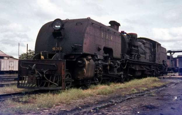
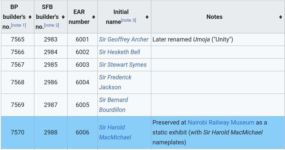
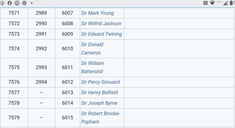
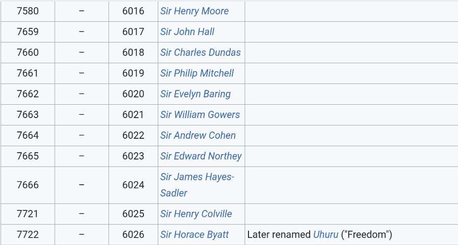
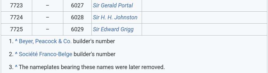
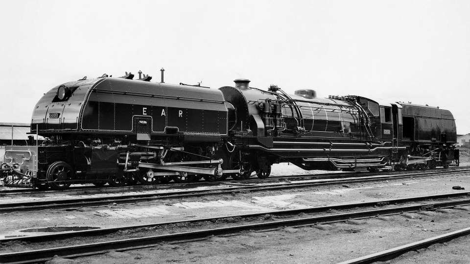
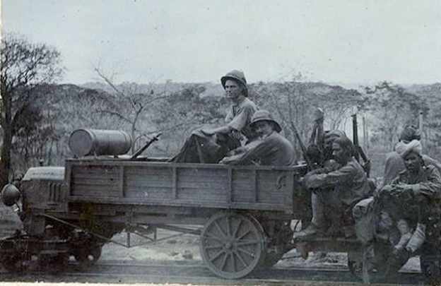
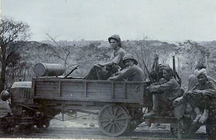
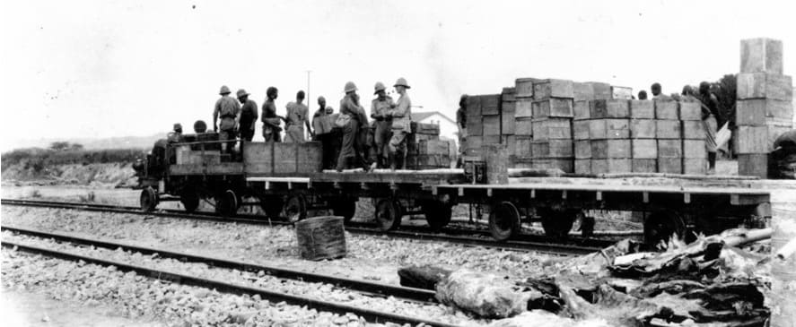
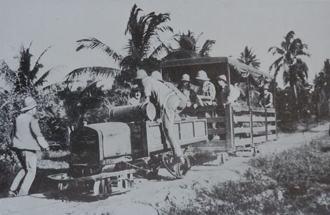
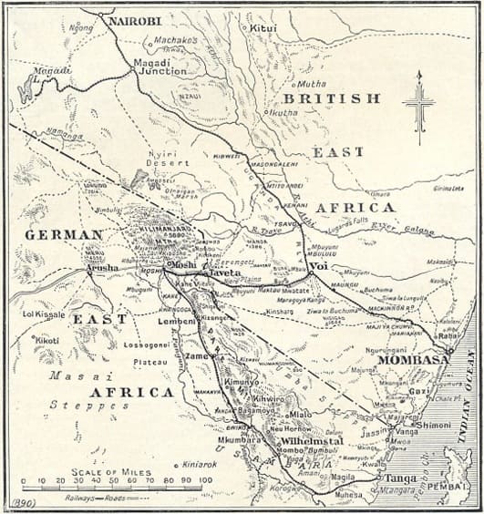
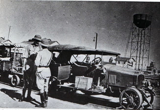
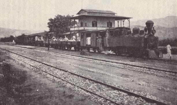
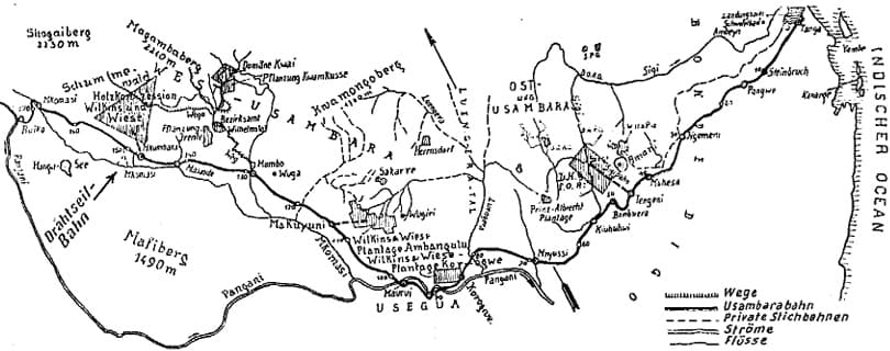
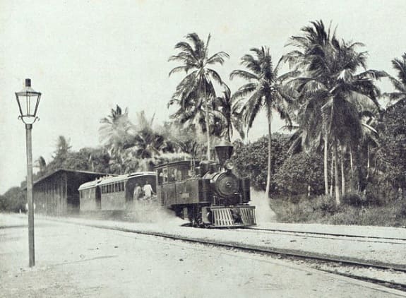
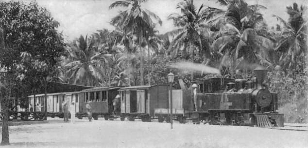
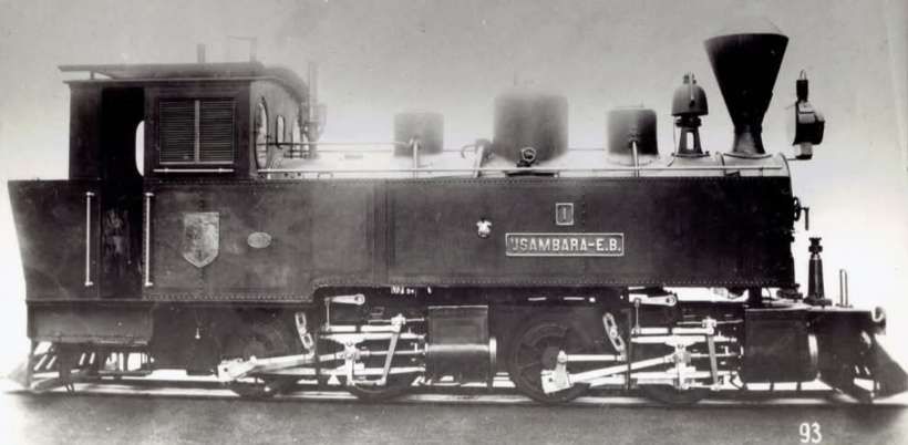
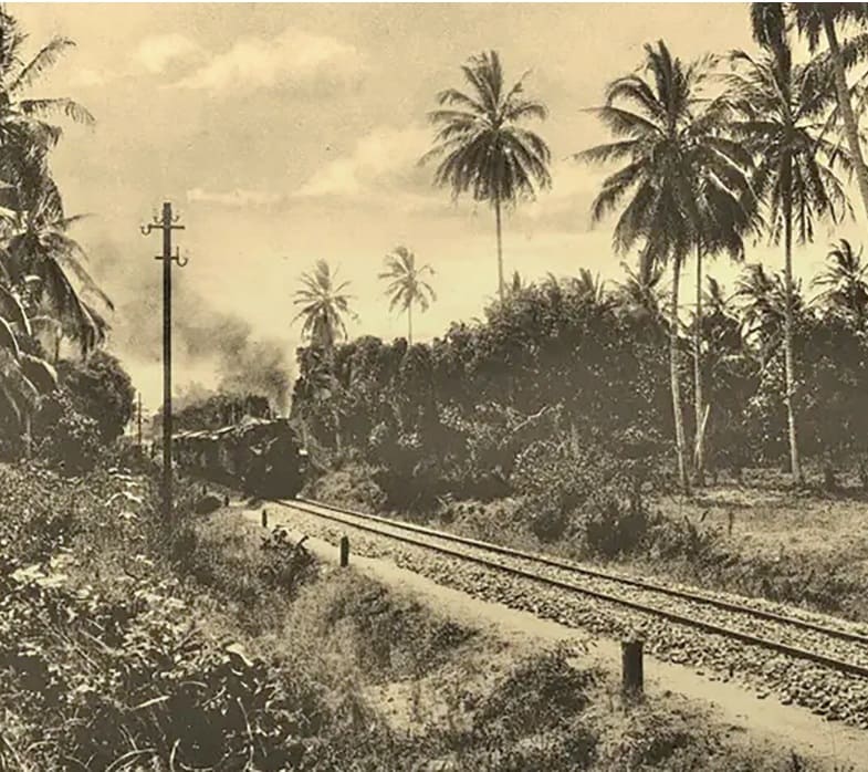
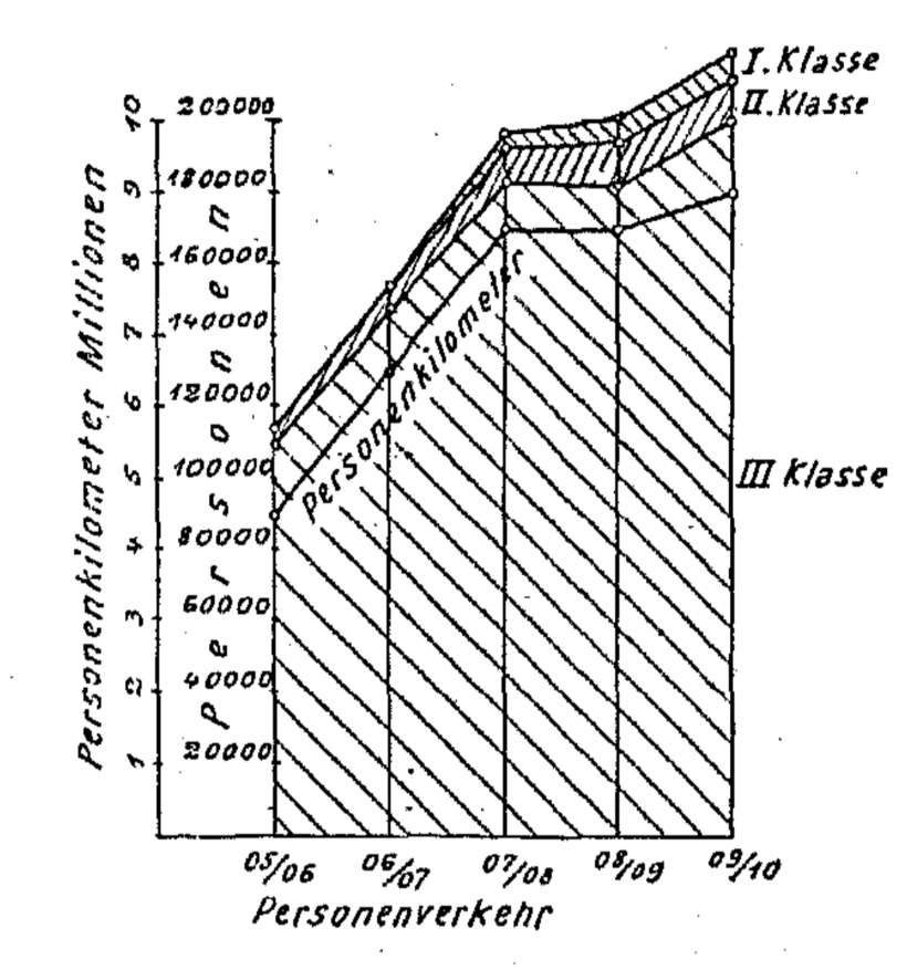
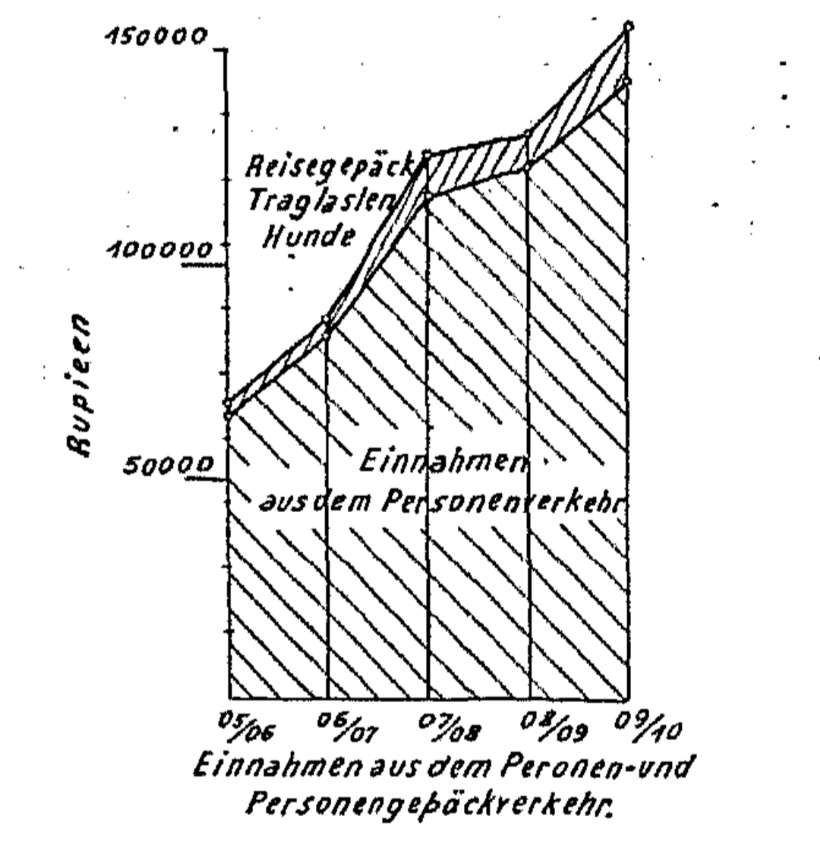
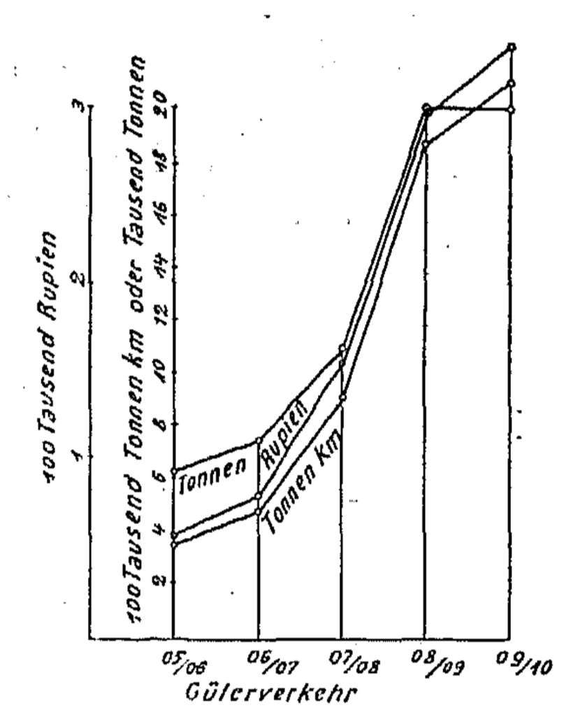
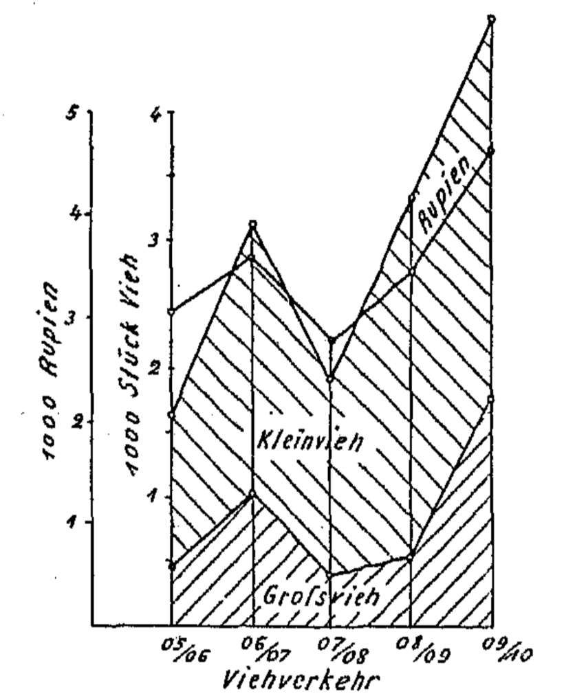
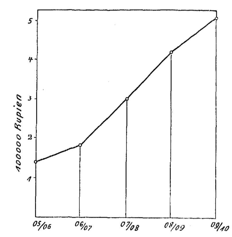
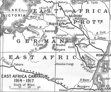
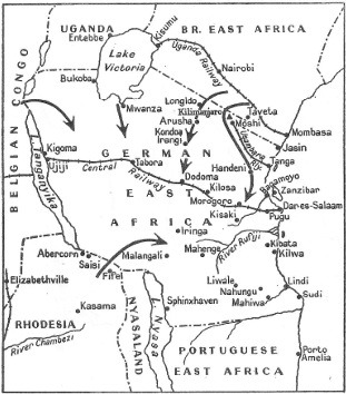
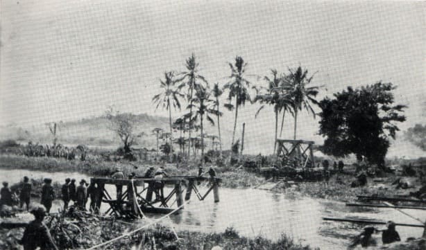
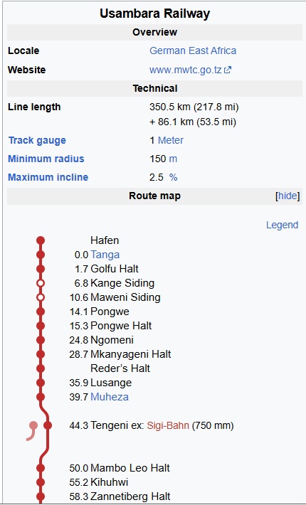
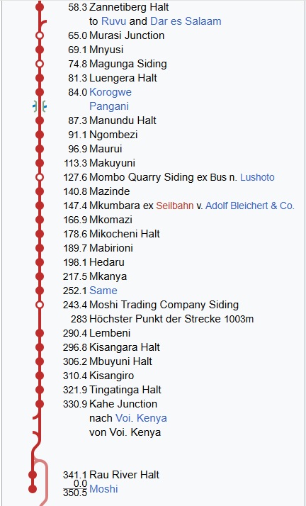
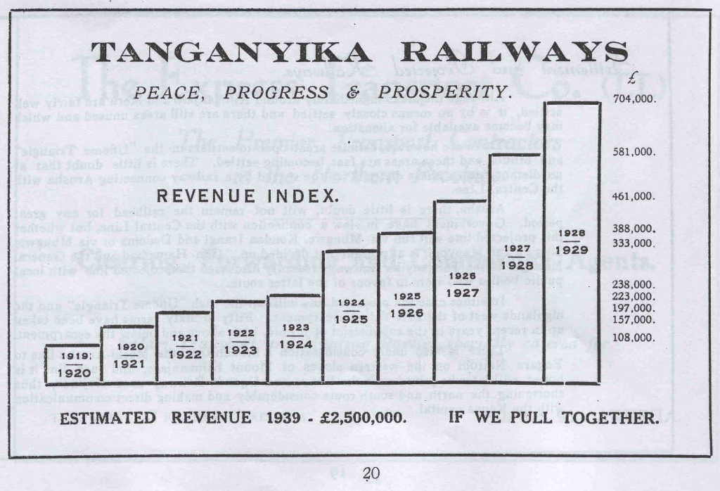
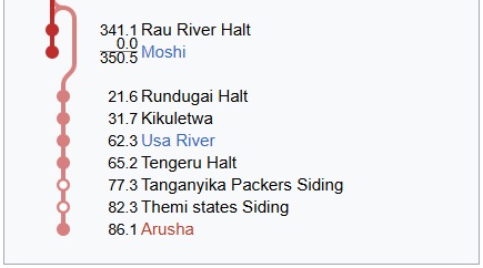
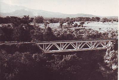
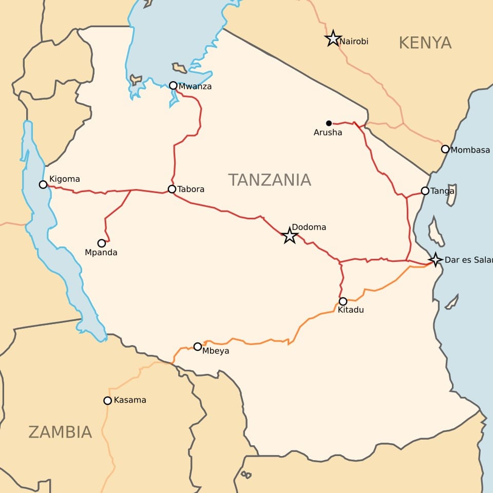
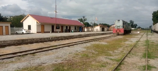
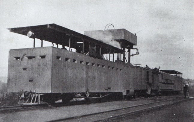
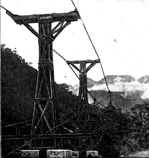
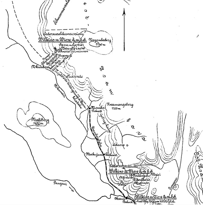
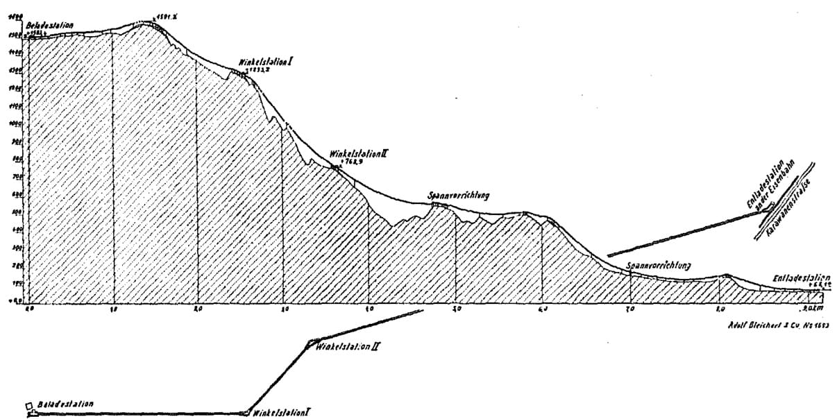
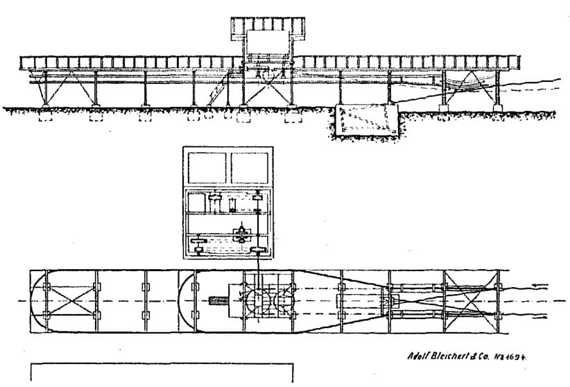
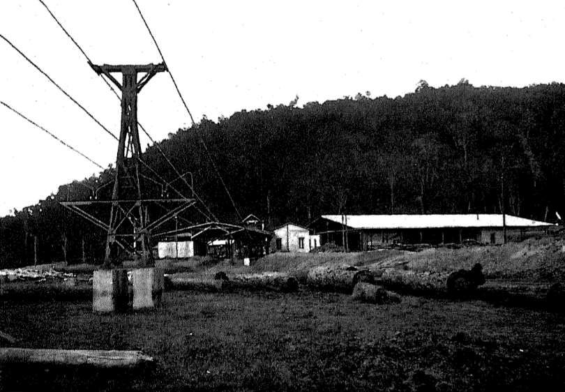
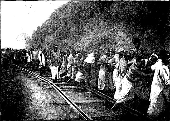
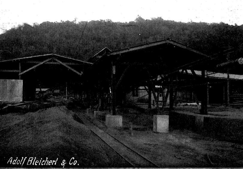
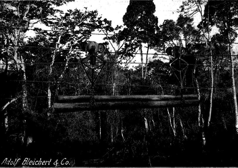
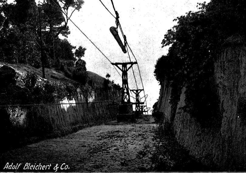
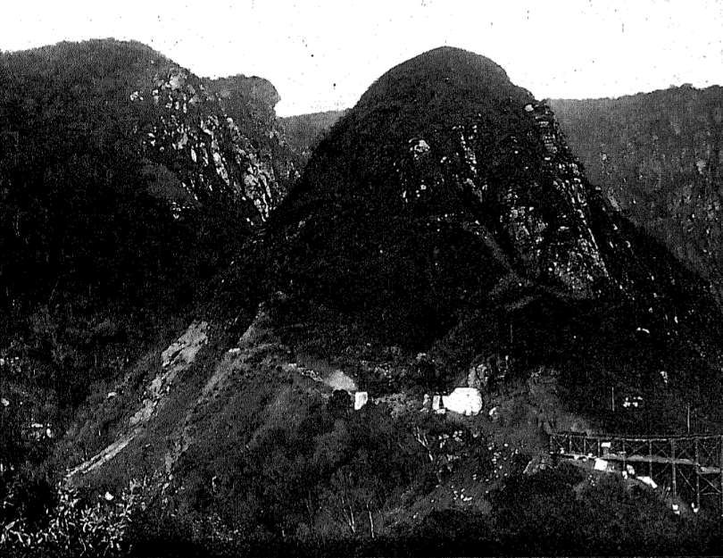
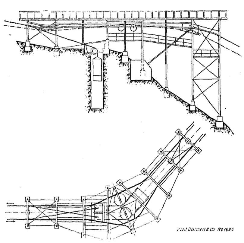
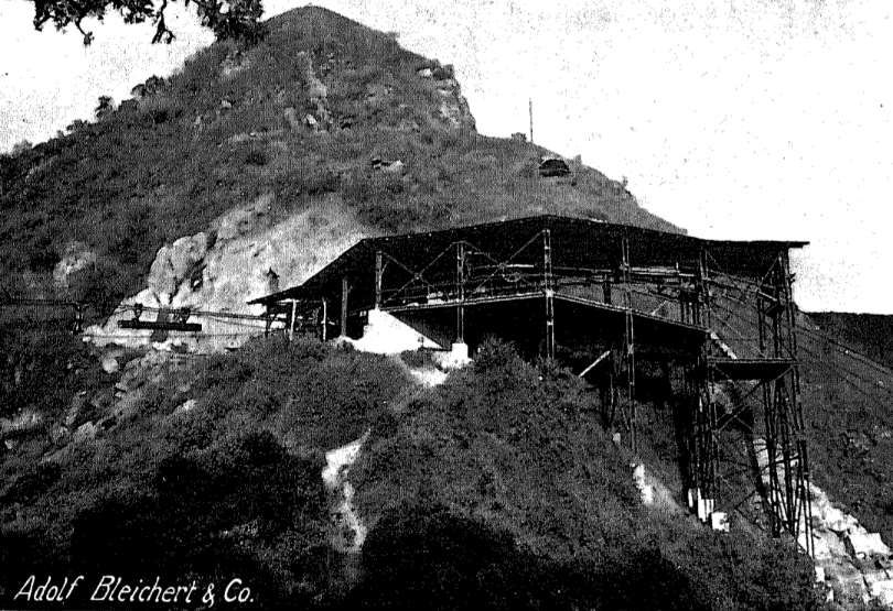
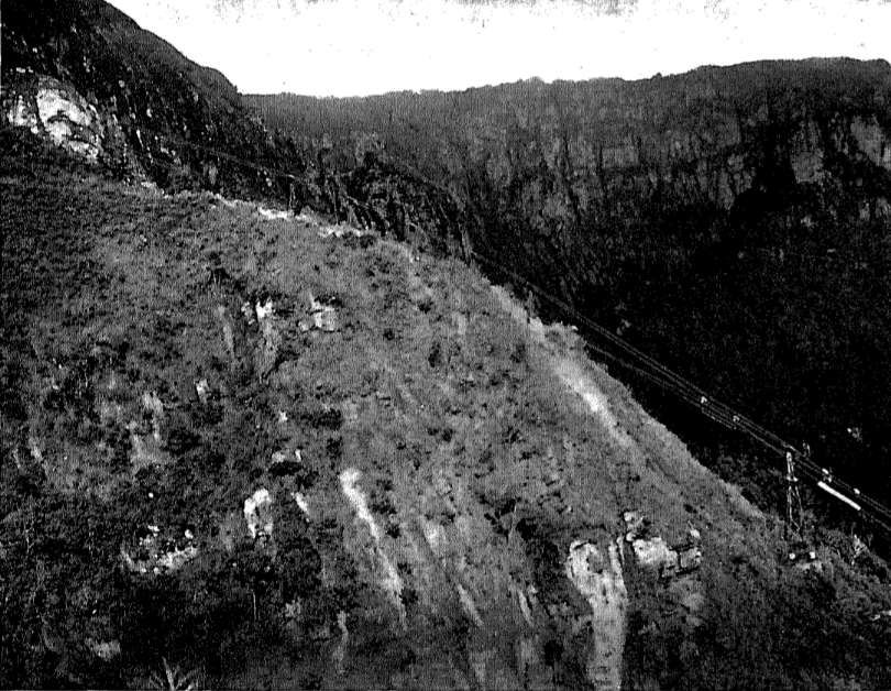
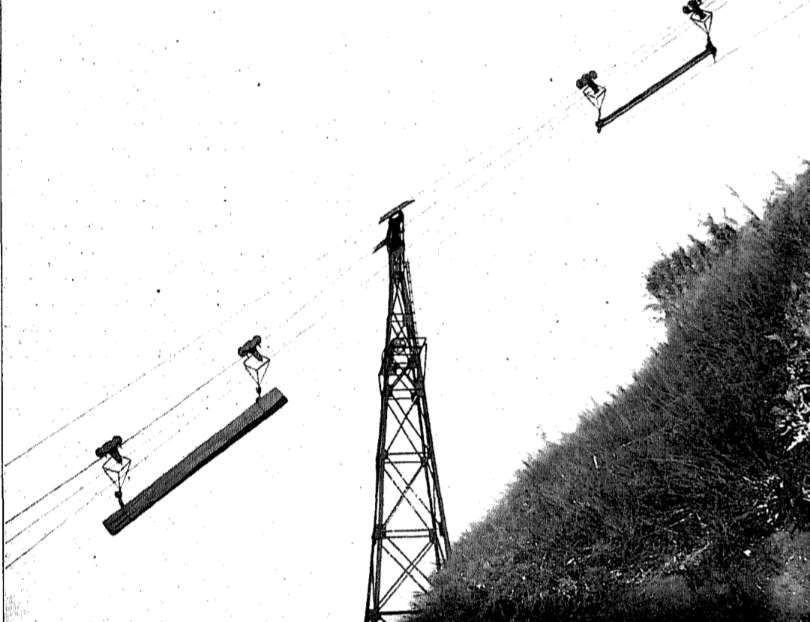
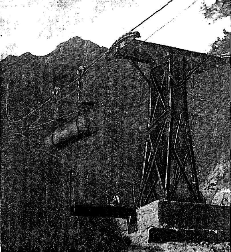
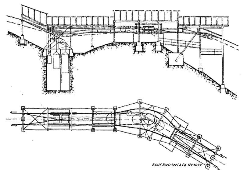
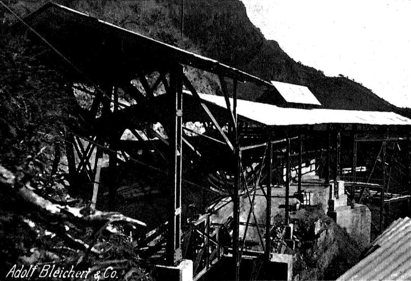
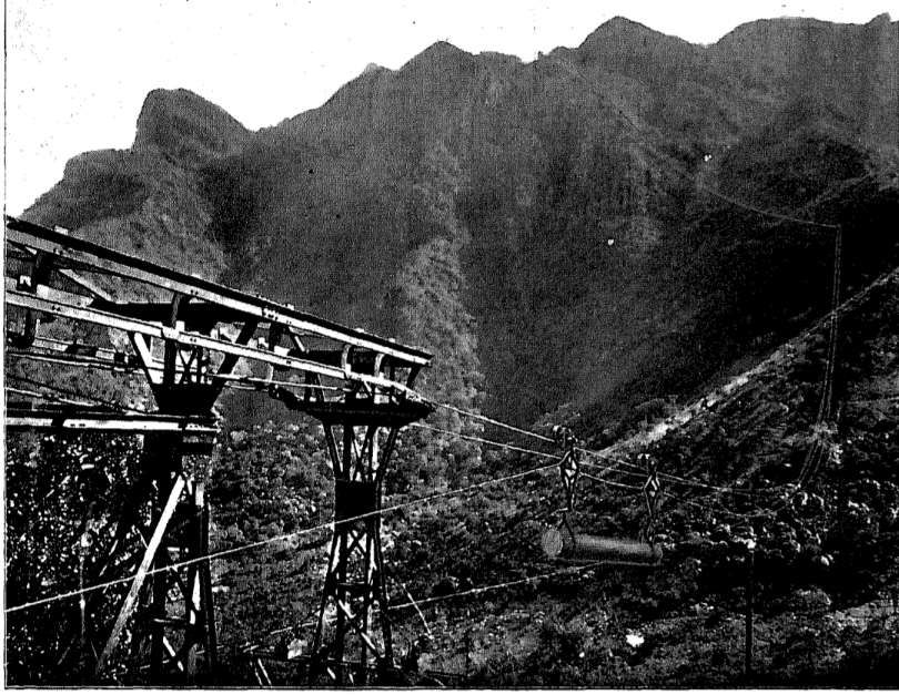
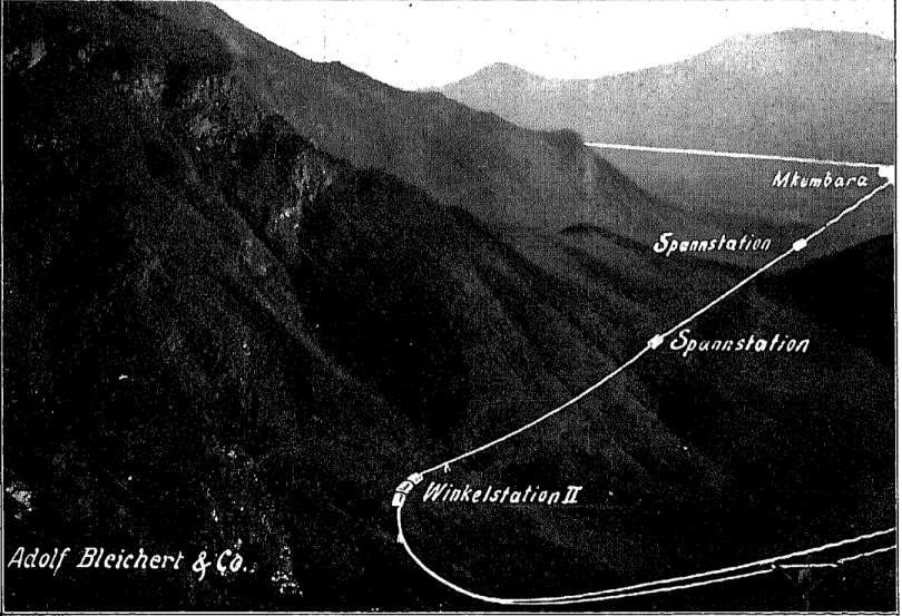
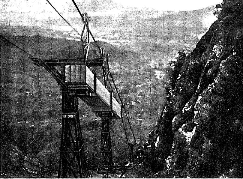
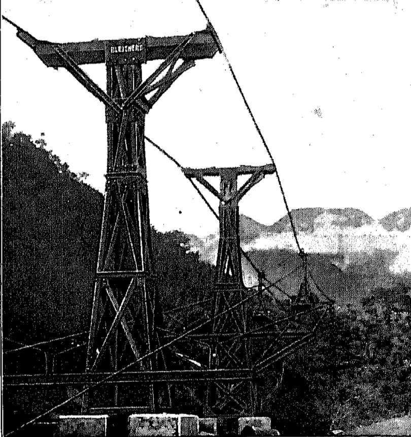
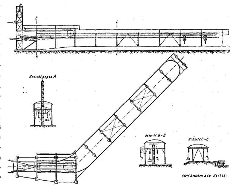

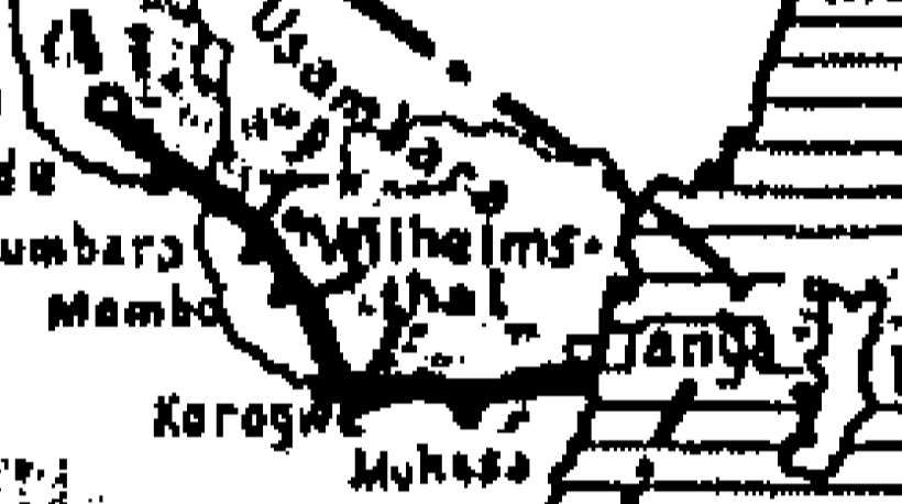
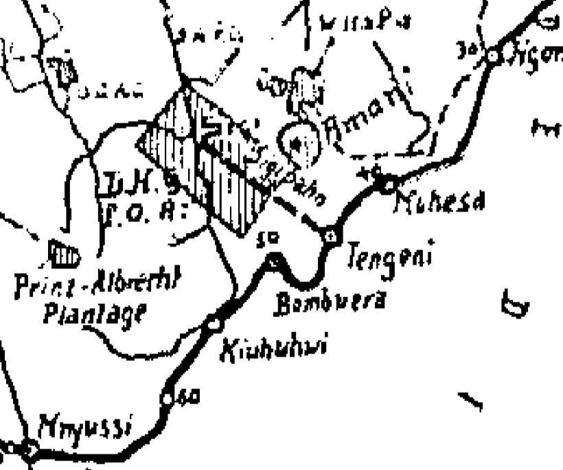
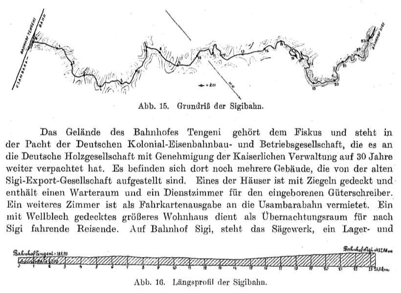
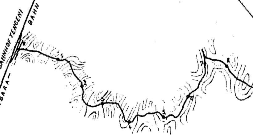
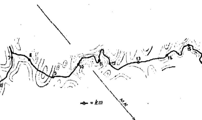
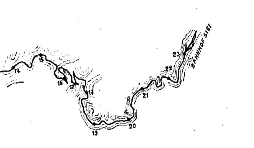
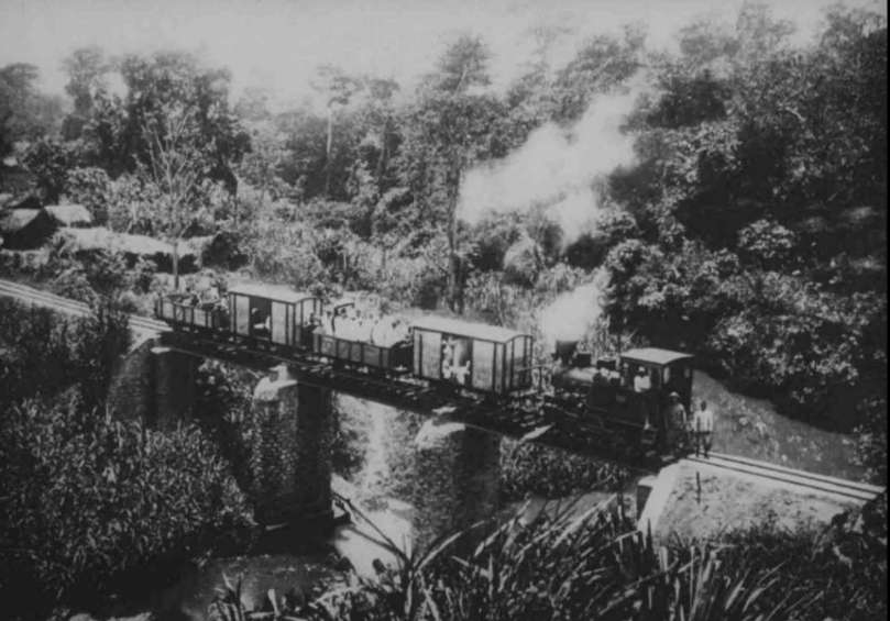
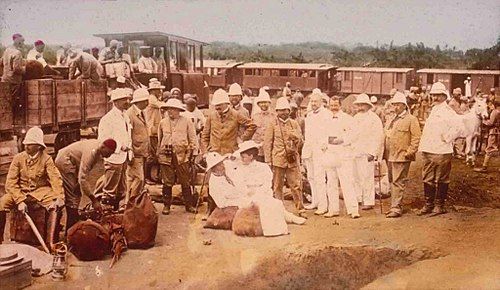
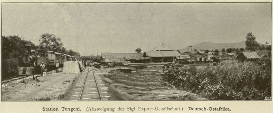
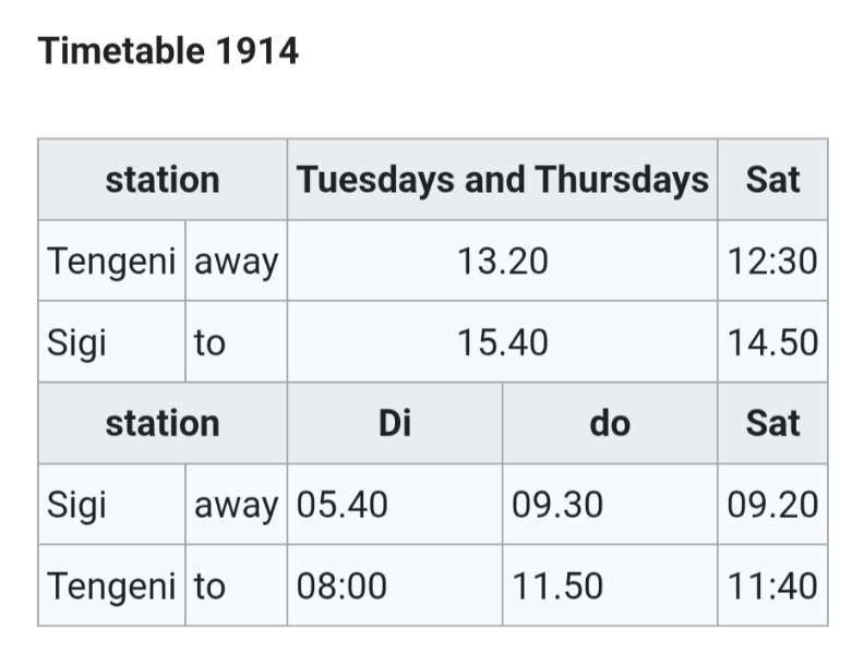
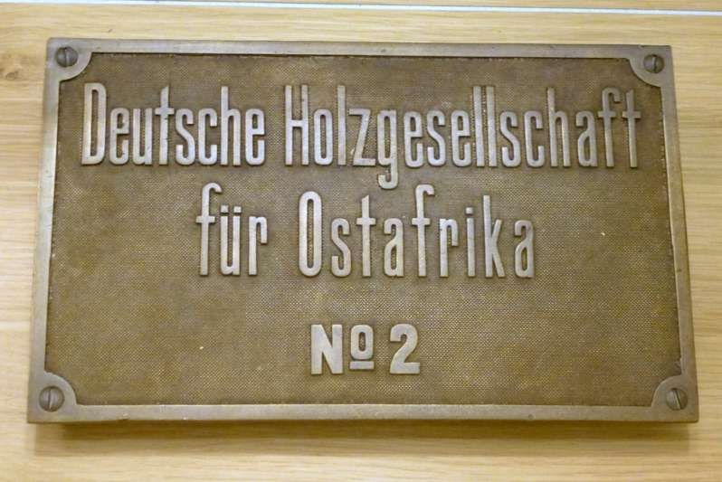
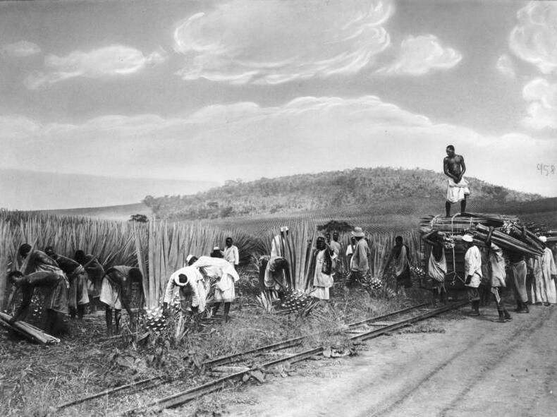
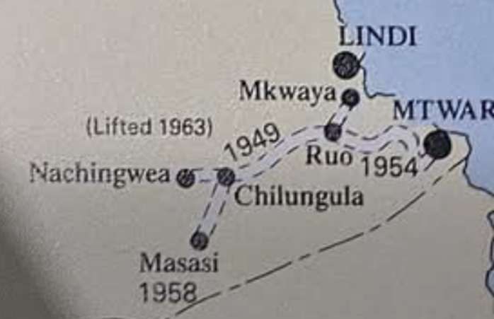
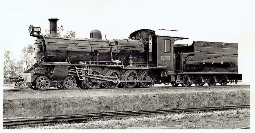
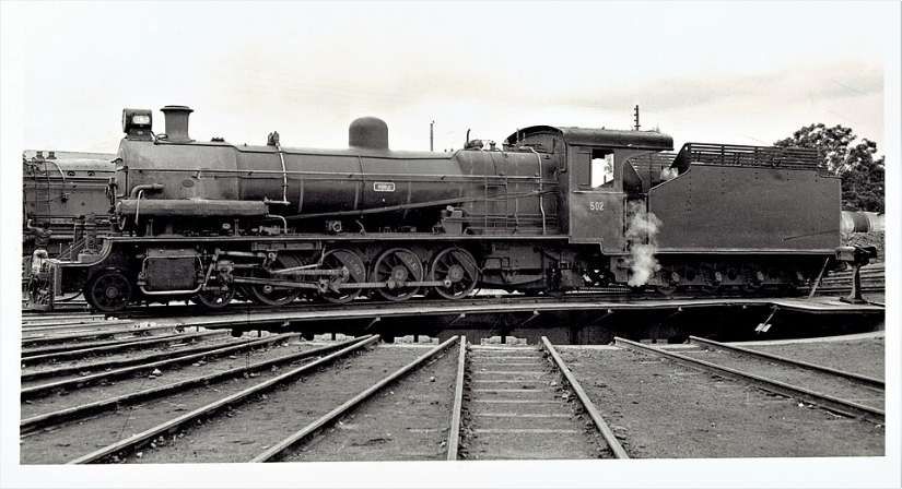
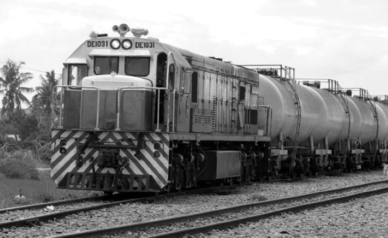
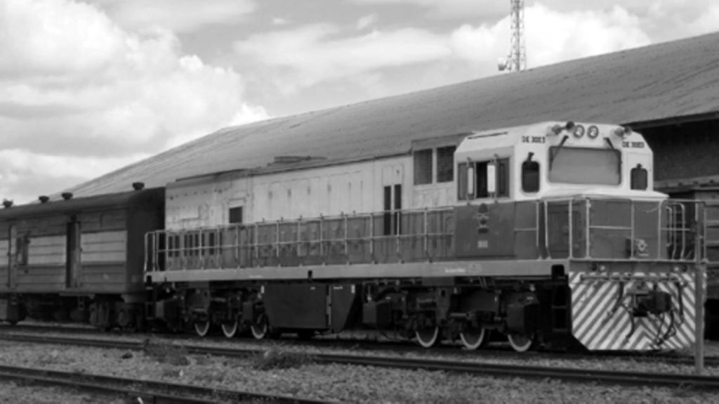
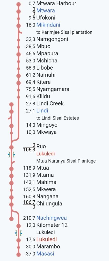
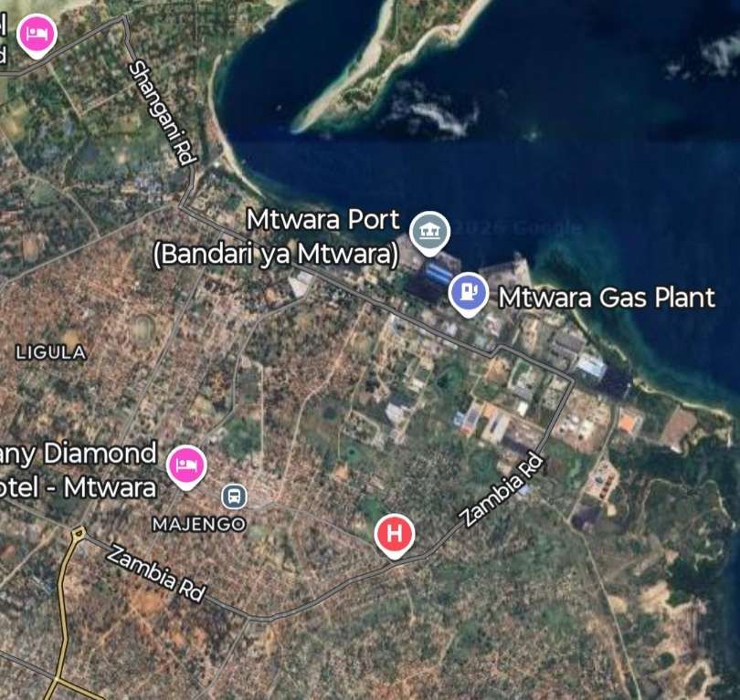
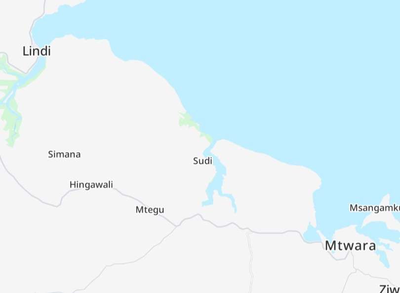
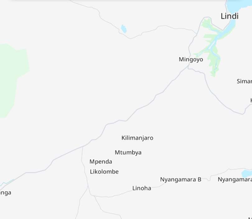
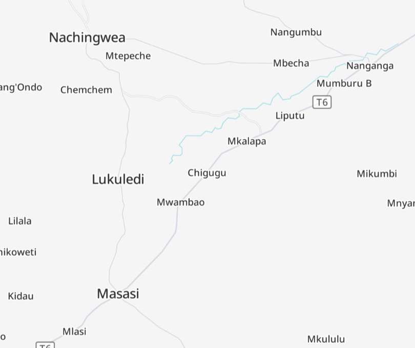
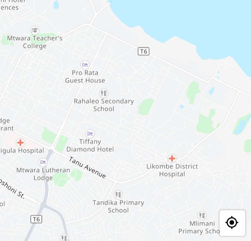
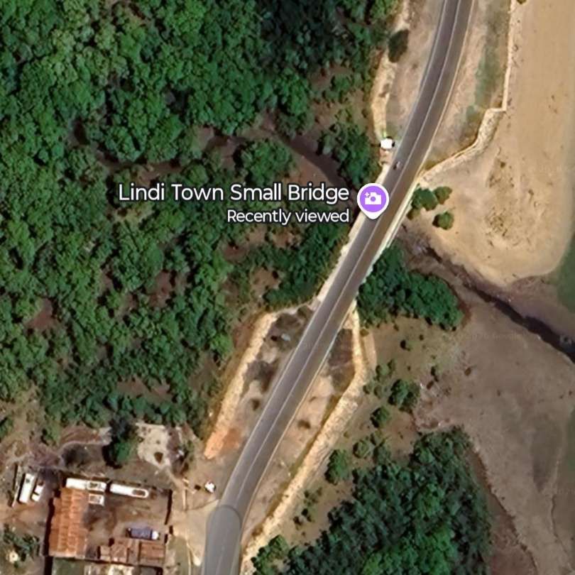
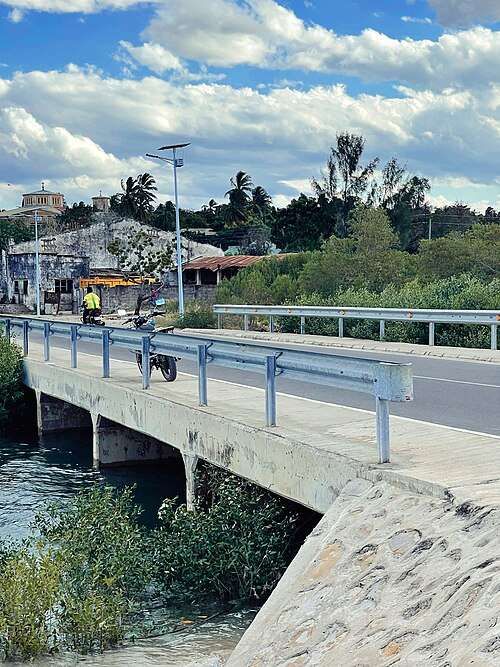

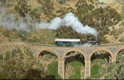

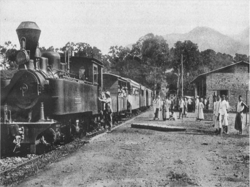

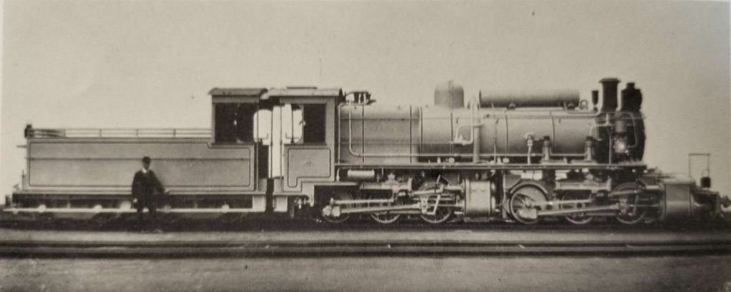

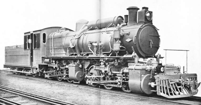
