Manchester Mayfield 3rd September 1955. Longsight’s Stanier 2-6-0 42960 is ready to depart with a suburban service. Photo H C Casserley.
A short note about extensive alterations at Manchester London Road Station appeared in the December 1958 issue of The Railway Magazine. The major alterations were designed to accommodate the electrification of the line between Manchester and Crewe. [1]
The Railway Magazine reported that “The improvements include[d] the construction of three new platforms, the lengthening of the existing platforms, to accommodate 16-coach electric trains, and the widening of the concourse. The station [would] thus have 14 platforms, of which ten [would be devoted to main-line and local traffic on the former London & North Western line, and the remainder to trains on the Great Central route. When the alterations [were] completed, the adjoining terminus at Mayfield [would] cease to deal with passenger traffic. A new power signalbox [would] control the area extending to East Didsbury and Heaton Chapel, and will replace 13 manual boxes. Electric trains [would] not be an innovation at London Road, because the Altrincham line was electrified in 1931, and the Sheffield line in 1954.” [1]
The text in bold highlights the closure of Mayfield Station to passenger traffic. This article focuses on Mayfield Railway Station. ….
Mayfield Station had only ever been something of which I was vaguely aware despite having lived in the Manchester area for large parts of my life.
Manchester Mayfield Station was, “on the south side of Fairfield Street next to Manchester Piccadilly station, [Manchester London Road station, as it was in 1958]. Opened in 1910, Mayfield was constructed as a four-platform relief station adjacent to Piccadilly to alleviate overcrowding. In 1960, the station was closed to passengers and, in 1986, it was permanently closed to all services having seen further use as a parcels depot.” [2]
“Opened on 8th August 1910 by the London and North Western Railway, Manchester Mayfield was built alongside Manchester London Road station (later Piccadilly) to handle the increased number of trains and passengers following the opening of the Styal Line in 1909. [4][5: p7] The LNWR had considered constructing a new platform at London Road between the [Manchester, South Junction and Altrincham Railway’s] MSJAR’s platforms 1 and 2, which were renumbered 1 and 3 in anticipation, but this was abandoned in favour of the construction of Mayfield; the platforms nevertheless remained renumbered. [6: p167] Four platforms were provided and passengers could reach London Road via a high-level footbridge. [6: p167][7: p43] Mayfield suffered the effects of bombing during World War II, when it was hit by a parachute mine on 22nd December 1940.” [8: illustration 40] [2]
Manchester Mayfield Railway Station as it appears on the 25″ Ordnance Survey of 1914. [21]
Mayfield was a relief station, mainly used by extra trains and suburban services to the south of Manchester [6: p167] – places such as Cheadle Hulme, Buxton, Alderley Edge, Chelford and Stockport. [9: table 97] “In the London Midland timetable of September 1951, the Pines Express from Bournemouth West is shown as arriving at Mayfield at 4.30pm (16.30) on Mondays to Fridays. On Saturdays, this train used Piccadilly station, then known as London Road. [10: table 17] In the 1957-8 timetable, the Pines Express still arrived at Mayfield on Mondays to Fridays, now at the time of 4.45pm (16.45).” [11: table 21][2]
For a brief period during the electrification and modernisation of London Road station, Mayfield Station was the Manchester terminus for many diverted services. [12: p86-87] It was closed to passengers on 28th August 1960 with the completion of the electrification and modernisation works at Manchester London Road station. [13: p92]
“The site was converted into a parcels depot, which opened on 6th July 1970. [4] Royal Mail constructed a sorting office on the opposite side of the main line and connected it to Mayfield with an overhead conveyor bridge, which crossed the throat of Piccadilly station.” [2]
The depot closed in 1986, following the decision by Parcelforce, Royal Mail’s parcels division, to abandon rail transport in favour of road haulage. The tracks into Mayfield were removed in 1989, as part of the remodelling of the Piccadilly station layout. The parcels conveyor bridge was removed in 2003 with the Sorting Office being rebuilt as the Square One development, prestige offices used by Network Rail. [2]
The site of Mayfield station is the property of London and Continental Railways. [2] The interior of the station was used in Prime Suspect as a drug dealer’s haunt. [4] It was also used as a double for Sheffield railway station in The Last Train. The roadside building was gutted by a fire in 2005. [4]
There are, or have been, various plans for the use of the site of Mayfield station. These include:
Reopening as a station
“A study was carried out by Mott MacDonald in 2000, which looked at possibilities of increasing capacity at the Piccadilly station. One solution put forward would see the track quadrupled between Slade Lane Junction and Piccadilly, with a pair of through platforms in the Mayfield goods yard to the south of Piccadilly’s platforms 13 and 14 linked to additional running lines to Ashburys station. This proposal was supported by the Greater Manchester Passenger Transport Executive as it would increase usable train paths through Piccadilly by between 33% and 50%; the extra track would, however, require an expensive extension to the Piccadilly – Deansgate viaduct carrying the track from Slade Lane. The location of the proposed platforms was also criticised, as it would entail ‘a long walk for passengers wishing to interchange with other terminating rail services at Manchester Piccadilly or access the city centre’.” [2]
Other options would have the station used again as a terminus, providing a rail link to Manchester Airport or, alternatively, the lines might be extended through Mayfield and connected to the existing line to Manchester Oxford Road railway station. [2][4]
“Further proposals were put forward in 2009 by the Greater Manchester Integrated Transport Authority for reinstating Mayfield as an operational station, to alleviate capacity problems at Piccadilly Station. [14] However, as part of the Northern Hub railway development scheme across Northern England, Network Rail now plans to increase capacity on the existing Oxford Road-Piccadilly route by widening the viaducts and adding two additional platforms (15 and 16) to the south side of Piccadilly station. [15] There are no plans to re-open Mayfield station for public transport.” [2]
Commercial redevelopment –
In 2008, an alternative scheme involving Manchester Mayfield was put forward. This proposal would see the station as part of a new 30-acre (120,000 m2) city centre district immediately adjacent to Piccadilly Station. That project would have created more than 6,000,000 square feet (560,000 m2) of offices contained in office blocks up to 12 storeys high, and would be completed over a period of 15 years. The scheme was led by “Mayfield Manchester”, a joint venture company between Ringset, part of the Wrather Group, and Panamint; the company owns around 90% of the land around the station as of 2008, but do not own the station itself. In April 2008,Manchester Mayfield were said in talks with its owners of the station site, BRB Residuary. [2]
Other schemes were also under consideration:
Conversion into a Coach station by National Express to replace their Charlton Street facility [2]
Government Offices – in May 2009, the site was earmarked for a development which would have housed 5,000 civil servants. It would have required the demolition of Mayfield station. This did not go ahead at the time but the idea was revived in 2015 as one of a number options for the site. [16] one of those options was for a very significant redevelopment of the area around Piccadilly station and the Mayfield area, involving the demolition of both Mayfield station and Gateway House. [28][29] However the status of this is now unknown due to the cancellation of the HS2 Manchester leg. [2]
Entertainment Venue – in 2019, some of the site was converted into Depot Mayfield, a 10,000 capacity venue for culture located at Manchester’s historic former railway Mayfield as part of a £1 billion regeneration project. [17] It regularly hosts The Warehouse Project, a series of club nights. [2]
There is continued interest in the site as an urban regeneration area and it is proposed to replace the station with offices, residential developments and a significant urban green space.
The new green space, ‘Mayfield Park’ opened in 2022. [18]
Manchester Mayfield Redevelopment and ‘Mayfield Park’. [19]
“Mayfield will facilitate transformational change at the eastern gateway of the city centre close to Piccadilly Station. The 20 acre site provides the opportunity to create a distinctive and unique city centre district. The vision for Mayfield is for a distinctive, world class development delivering significant new commercial space, and up to 1500 new homes alongside a mix of retail and leisure facilities all centred on a new 6.5 acre city centre park.” [19]
C.R. Clinker; LNWR Chronology 1900-1960; David and Charles, Newton Abbot, 1961.
Sydney Richards; Manchester and its Railways; in Railways: The Pictorial Railway Journal, Volume 8No. 91, Railway World Ltd., London, November 1947.
S. Hall; Rail Centres: Manchester; Ian Allan Publishing, 1995.
E. M. Johnson; Scenes from the Past: No. 3, Manchester Railway Termini; Foxline, 1987.
British Railways London Midland Region Passenger Services Timetable 16th September 1957 to 8th June 1958.
British Railways London Midland Region Passenger Services Timetable, September 10th 1951 until further notice.
British Railways London Midland Region Passenger Services Timetable 16th September 1957 to 8th June 1958.
Oswald S. Nock; Britain’s New Railway; Ian Allan Publishing, 1966.
C. R. Clinker; Clinker’s Register of Closed Passenger Stations and Goods Depots in England, Scotland and Wales 1830–1977; Avon-AngliA Publications & Services, Bristol, October 1978.
The December 1958 issue of The Railway Magazine featured three photographs of Beyer Garrett locomotives at work in East Africa. These were giants of the metre-gauge that grappled with long loads on steep inclines and at times sharply curved track radii. [1]
1. EARClass ’55’ Garratt No. 5504 at Diva River
Class ’55’ Garratt No. 5504 on the up mixed train at Dura River. [1: p849]
The KUR EC5 class was a class of 1,000 mm (3 ft 3 3⁄8 in) gauge 4-8-2+2-8-4 Garratt-type articulated steam locomotives built during the latter stages of World War II by Beyer, Peacock & Co. in Gorton, Manchester for the War Department of the United Kingdom. The two members of the class entered service on the Kenya-Uganda Railway (KUR) in 1945. They were part of a batch of 20 locomotives, the rest of which were sent to either India or Burma. [2: p64]
The following year, 1946, four locomotives from that batch were acquired by the Tanganyika Railway (TR) from Burma. They entered service on the TR as the TR GB class. [2: p64]
In 1949, upon the merger of the KUR and the TR to form the East African Railways (EAR), the EC5 and GB classes were combined as the EAR 55 class. In 1952, the EAR acquired five more of the War Department batch of 20 from Burma, where they had been Burma Railways class GD; these five locomotives were then added to the EAR 55 class, bringing the total number of that class to 11 units. [2: p64]
This locomotive was Works No. 7151, War Department No. 74235, War Department India No. 423. It was one of the two that went to Burma Railways (their No. 852) from where it was purchased by Tanganyika Railways in 1946 and became their No. 751. It came to the EAR in 1949 and received the No. 5504. [3]
Sister locomotives in Class 55 can be seen here [7] and here. [8]
Dura River was the last station on the Western Extension before the end of the line at Kasese, Uganda. The River flowed North to South towards Lake George and was crossed by the railway at the Eastern edge of the Queen Elizabeth National Park. Mapping and satellite imagery in the area are not highly detailed – the following images are the best I can provide. …
The EAR 58 class was a class of 1,000 mm (3 ft 3 3⁄8 in) gauge, 4-8-4+4-8-4 Garratt-type articulated steam locomotives built by Beyer, Peacock & Co. in Manchester, England, in 1949. [9]
The eighteen members of the class were ordered by the Kenya-Uganda Railway (KUR) immediately after World War II, and were a slightly modified, oil-burning version of the KUR’s existing coal-fired EC3 class. By the time the new locomotives were built and entered service, the KUR had been succeeded by the East African Railways (EAR), which designated the coal-fired EC3s as its 57 class, and the new, oil-burning EC3s as its 58 class. [2: p66][9]
No. 5804 was built in 1949 (Works No. 7293) and originally given the KUR No. 92. Its sister locomotive No. 5808 (Works No. 7297, given KUR No. 96 but never carried that number) was the first to enter service with the EAR. [9]
EAR ‘Class 58’ Locomotive No. 5803 (a sister to 5804) is seen here at Changamwe, Kenya, with the Mombasa–Kampala mail train, circa 1950-51. [9]
Other locomotives in the class can be seen here, [11] here, [12] and here. [13]
Kikuyu Station is 20 kilometres or so from Nairobi, during construction of the railway, railway officers established a temporary base in Kikuyu while they supervised work on the laying of the track down at the rift valley escarpment.
Daily mixed train, headed by class ’60’ Beyer-Garratt locomotive No. 6021, Sir William Gowers,” about to leave Kasese, terminus of the East African Railways & Harbours Western Extension in Uganda. [1: p849]
The EAR 60 class, also known as the Governor class, was a 1,000 mm (3 ft 3 3⁄8 in) gauge 4-8-2+2-8-4 Garratt-type articulated steam locomotives built for the East African Railways as a development of the EAR’s existing 56 class. [2: p77]
The 29 members of the 60 class were ordered by the EAR from Beyer, Peacock & Co. The first 12 of them were built by sub-contractors Société Franco-Belge in Raismes (Valenciennes), France, and the rest were built by Beyer, Peacock in Gorton. The class entered service in 1953-54. [2: p77]
Initially, all members of the class carried the name of a Governor (or equivalent) of Kenya, Tanganyika or Uganda, but later all of the Governor nameplates were removed. [2: p77]
No. 6021 was built by Beyer Peacock (Works No. 7663). It was not one of the class built by sub-contractors Société Franco-Belge. It was given the name ‘Sir William Gowers’ when first put into service, losing the name along with other members of the class in the 1960s after independence. …
Other members of the class can be seen here, [17] here, [18] and here. [19]
Kasese Station only became part of the rail network in Uganda in 1956. The construction costs of the whole line from Kampala were very greatly affected by the difficult nature of the country in the final forty miles before Kasese. Severe problems were presented by the descent of the escarpment, which involves a spiral at one point, while from the foot there is an 18-mile crossing of papyrus swamp through which a causeway had to be built, entailing a vast amount of labour. The extension to Kasese was built primarily to serve the Kilembe copper mines. Construction of the line from Kampala to Kasese took approximately five years. [21]
The Railway Magazine of February 1952 carried an article by Charles E. Lee about railways in what was German South West Africa. This encouraged me to have a look at the history of Namibia’s railways and their condition and extent in the 21st century. The 1952 article also caught my attention because Manchester Diocese (I was a priest in Manchester Diocese before retirement) is linked with the Diocese of Namibia.
The territory was formally colonized by Germany between 1884-1890. It covered an area of 835,100 sq. km. It was a settler colony and had attracted around 3,000 German settlers by 1903, who primarily settled in the central high grounds. [2]
German South West Africa, now known as Namibia, was a German colony from 1884 to 1915. It was not a province within the German Empire but a separate colonial territory. From 1891, the capital was Windhoek, which also serves as the capital of modern-day Namibia. [2]
The arrival of German settlers disrupted the existing socioeconomic balance and led to conflicts, particularly with the Herero and Nama people.
“In 1883 Franz Adolf Lüderitz, a merchant from Bremen, Germany, established a trading post in southwest Africa at Angra Pequena, which he renamed Lüderitzbucht. He also acquired the adjacent coastal area, which he named Lüderitzland. These areas were constituted the first German colony under German protection on April 24, 1884. The German occupation subsequently extended inland. By the latter 1880s the German Colonial Company for the South realized that it was incapable of administering the territory, and the German government immediately took over the colony’s administration. As a result of the Zanzibar Treaty (1890) between Germany and Great Britain, German South West Africa acquired the Caprivi Strip (named after the German chancellor Graf Leo von Caprivi), a tract of land 280 miles (450 km) long in the extreme northeast of the territory; the colony thus gained access to the Zambezi River.” [3]
German colonial rule was harsh, leading to insurrections and resistance. “Major Theodor Leutwein, governor of the colony in 1894–1904, suppressed insurrections of the Khoekhoe (1894) and of the Hereros (1896). In 1904, however, the Hereros fomented a far more dangerous rebellion. The German force, at first only 750 strong and supported only by one artillery battery, had to face an army of some 8,000 men equipped with modern weapons. Reinforcements increased the German force, ultimately under the command of General Lothar von Trotha, and resulted in a decisive German victory on the Waterberg River. Further Khoekhoe rebellions were put down in 1904–07.” [3]
German South West Africa was occupied by the South African Union Defence Force in 1915 during World War I, and Germany formally ceded the territory under the Treaty of Versailles in 1919. Its administration was taken over by the Union of South Africa (part of the British Empire) and the territory was administered as South West Africa under a League of Nations mandate. It became independent as Namibia on 21st March 1990. [2]
The Railways
The railways in German South West Africa played a crucial role in the colonial administration and the First World War campaign. The German colonial authorities built a railway network between 1897 and 1914 to enable colonial territorialization and facilitate the extraction of resources. [4]
Charles E. Lee tells that “under the German regime, the first railway in South West Africa was the Northern State Railway (NSR), as it was then called, built to a gauge of 60 cm. (1 ft. 11 in.) between Swakopmund and Windhoek, via Jackalswater and Karibib, a distance of 238 miles. This line was begun in 1897 and was built by a German Military Brigade from Europe. It was first intended to be worked by animal power – Argentine mules or Cape donkeys – but steam traction was soon adopted. The first section (15 miles) was opened to traffic from Swakopmund in January 1898. By the end of that year 68 miles were ballasted and 54 open. In July 1900, the line was opened to Karibib, 121 miles, and the whole railway completed to Windhoek, a further 117 miles, in June, 1902. The curves and gradients were very severe, the gradient out of the Khan River gorge, for instance, being 1 in 19 with curves of 180 ft. radius. The rails weighed about 19 lb. a yard and were laid on iron sleepers. There were iron girder bridges at Khan River, Dorst River, and Kubas. The only good and plentiful water supplies were at Swakopmund and Karibib.” [1: p121]
Wikipedia tells us that there was actually an earlier line than the one Lee talks about. It was a small mining rail line at Cape Cross in 1895. [5] “Soon afterwards, the ox-cart transport system totally collapsed, in the wake of a rinderpest epidemic in 1897. As it was necessary to react quickly to the now extremely precarious transport situation, decisions were made: to build a railway line from the German port of Swakopmund to Windhoek (the Staatsbahn); to use existing, 600 mm (1 ft 11 5⁄8 in) gauge military Feldbahn material; and to entrust a railway brigade with the construction work, which began in September 1897.” [5]
Wikipedia continues: “Construction of the railways connecting with the Staatsbahn was aimed partly at military strategic objectives following the uprising of the Herero and Nama, and partly at economic requirements. … By World War I, the following lines had been developed (listed by the first year of full operation):” [5]
1902: Swakopmund–Windhoek line, 600 mm (1 ft 11 5⁄8 in) gauge, Karibib–Windhoek section re-gauged in 1911 to 3 ft 6 in (1,067 mm) gauge. [5]
1906: Otavibahn, 600 mm gauge. [5]
1905: Onguati–Karibib branch. [5]
1908: Otavi–Grootfontein branch. [5]
1907: Lüderitzbahn, 3 ft 6 in (1,067 mm). [5]
1909: Seeheim–Kalkfontein branch. [5]
ca 1911: Kolmannskuppe–Elisabethbucht–Bogenfels, industrial railway of the diamond fields. This 600mm gauge railway was electrified from 1911 (the only electric railway in Namibia’s history). Diamond mining in the region gradually moved south. The northern part of the line as far as Pomona was abandoned in 1931, and some of its materials were used for the extension of the railway towards Oranjemund. The southern section was operated with diesel traction. This line no longer exists. [5]
1912: Windhoek–Keetmanshoop railway, 3 ft 6 in (1,067 mm) gauge. [5]
1912: Rehoboth shuttle, 600 mm (1 ft 11 5⁄8 in) gauge (questionable). [6][7][2][5]
1914: Otjiwarongo–Outjo–Okahakana, 600 mm gauge (project started, but not completed due to the war). [5]
Lee talks of the formation, by the Otavi Mining & Railway Company, an Anglo-German syndicate owning the copper mines at Otavi and Tsumeb, of a railway: “This company was formed in Berlin in 1900, in accordance with an arrangement between the South-West Afrika Company, the Disconto-Gesellschaft of Berlin, and the Exploration Company. The first intention was to build a 3 ft. 6 in. gauge railway from Port Alexander in Portuguese West Africa to run in a south-easterly direction up the Muende River Valley and via Etosha Pan to the Tsumeb Copper Mines, and later to extend this line to Rhodesia to form a trans-African railway. Eventually it was decided to form a 60 cm. gauge line entirely in German territory connecting Swakopmund with Tsumeb, a distance of 351 miles. Construction was undertaken by Arthur Koppel & Co. and was begun in November 1903, but was delayed by the Herero War, and the work completed on 25th August 1906. This undertaking, called the Otavi Railway, had the distinction of being the longest narrow-gauge railway in the world. Branches were laid subsequently from Otavi to Grootfontein (56 miles) and from Onguati to Karibib on the State Railway (9 miles). The cost is stated to have been about £2,400 a mile, or roundly £1,000,000 in total. The railway was bought by the German Imperial Government in 1910 for £1,250,000, but the management was left in the hands of the company under a 30-year lease, terminable after 10 years.” [1: p121]
This line was well constructed, and well ballasted. It had a ruling gradient of 1 in 66 and minimum curvature of 150 metres. The permanent way consisted of steel rails in 30-ft. lengths, 30 lb. a yard, laid on steel sleepers weighing about 26 lb. each. “From Swakopmund, for a distance of 68 miles, the line rises steadily on a grade of 1 in 66 to Ebony Station, where it reaches an altitude of 3,500 ft. (On the down journey, the last 40 miles into Swakop-mund can be run by gravity.) From Ebony there is a regular fall to Usakos, which is 2,640 ft. above sea level. From Usakos it climbs 690 ft. in 13 miles to Onguati, and continues to rise until it attains its greatest elevation near Kalk-feld, where the summit is 5,200 ft.” [1: p121]
“The Otavi Railway, like the State Railway, was built to the 2 ft-gauge, though a difference of 1 centimetre in the wheel gauges is stated to have prevented the free interchange of rolling-stock. The widening to 3 ft. 6 in. of the gauge between Swakopmund and Omaruru had been voted by the German Railway Board, but the work had not been put in hand by the outbreak of the 1914 war. A new branch projected at the same period was the Ovamboland Line, the first aim of which was to provide Ovambo labour for the South. The Landesrat in November 1913, approved a line of 2 ft-gauge, but on earthworks and bridges wide enough for a 3ft. 6in. gauge track, to run from Otjiwarongo (on the Otavi Railways) to Outjo and Okahakana.” [1: p121]
Railways in South West Africa from Swakopmund, mainly German- built, included the 361 miles to Tsumeb, opened in 1906, and the longest narrow-gauge railway in the world. The gauge at the Southern end was widened in 1915. [1: p122]
A sum of £450,000 was allowed for the line from Otjiwarongo to Outjo and Okahakana “in the German Loan Estimates for 1914-15. The first section, including the 55 miles from Otjiwarongo to Amiab Poort, was to cost £250,000. Construction was begun, and the line was laid for 22 miles before the outbreak of hostilities in the first world war.” [1: p123]
“Railway developments south of Windhoek, on the 3 ft. 6 in. gauge, made it desirable to convert the earlier 2ft. lines. During 1911, the section from Karibib to Windhoek was converted to 3 ft. 6 in. gauge at a cost of £550,000, with the Bechstein-Koppel Gesellschaft as contractor. The ruling gradient [was] 1 in 66 with a minimum curvature of 656 ft. This work was completed during 1913. The Swakop River at Okahandja [was] spanned by a bridge 350 ft. long, and there [was] a smaller bridge at Otjihavera. About the same time, the coastward section from Karibib to Swakopmund was practically abandoned in favour of the alternative route provided by the Otavi Railway. In fact, the settlers in the Swakop Valley, who asked for a short railway to link them with Swakopmund, were promised in November 1913, that the material from the disused 92 miles of the State line between Swakopmund and Kubas would be used for this purpose, but it was not done.” [1: p123]
An image showing an armoured train in South West Africa during World War I, 1914-1918, can be found here [29] The South African army invaded the German colony of South West Africa in March 1915 overrunning the much smaller German forces.
Wikipedia tells us that, “With the outbreak of World War I, the German Schutztruppe military unit retreated from the coast, and withdrew into the inland. In the process, the Schutztruppe destroyed the Otavibahn, and the old Staatsbahn towards Karibib, as far as Rössing.” [5]
The Staatsbahn was abandoned but this was not the case with the Otavibahn. In 1914, “British troops … moved forward from the British enclave of Walvis Bay, and by the end of 1914 they had built a 37 km (23 mi) long 3 ft 6 in (1,067 mm) railway to Swakopmund. The Otavibahn was also reconstructed in 3 ft 6 in (1,067 mm) as far as Usakos, and the section between Usakos and Karibib was realigned. The network north of Usakos remained in 600 mm (1 ft 11 5⁄8 in) gauge; the workshop for both gauges was consolidated in Usakos, and the one in Karibib was closed.” [5]
Lee tells us that by 1917 the Staatsbahn line from Karibib to the coast had ceased to exist. “the line between Karibib and Rossing (95 miles), the 10-mile branch from Jakalswater (built to carry water from the Swakop River at Riet), and the Kubas military line (4.5 miles), were lifted and removed to provide material for Tanganyika and the Union of South Africa.” [1: p123]
Lee goes on to confirm that the Union forces, in the course of their invasion of German South West Africa, “laid a 3 ft. 6 in. line for 100 miles inland from Swakopmund to Kranzberg along the original track of the Otavi line, which the Germans had wrecked in their retreat. This was completed in August, 1915. The construction of a new 12.5-mile section, of the same gauge, from Kranzberg to Karibib, was completed in July 1915, and again connected the Otavi Railway with the [NSR]. Thus, in August 1915, there was continuous communication of uniform gauge for the first time from Swakopmund to points south of Windhoek. As strategic railways had meanwhile linked the Union Railways with those of South-West Africa on 25th June 1915, a through railway of 1,635 miles was provided between Walvis Bay and Cape Town.” [1: p123]
Also during the first world war, a new railway from South Africa was constructed – “as an extension of the De Aar-Prieska Railway – to achieve a secure supply route for … South African troops. In 1916, the line was connected to the German network at Kalkfontein (now Karasburg).” [5]
“With the linking of the Kranzberg-Tsumeb 2ft-gauge line to the workshops at Usakos by means of a third rail between Usakos and Kranzberg on the 3-ft. 6-in. gauge track of improved location, the 9-mile section from Karibib to Onguati was no longer of value, and it was uplifted in 1924.” [1: p123]
“The former Otavi Railway system [was] therefore represented [in 1952] by about 100 miles of 3 ft. 6 in. line on the coastward section, part of the main railway system of South-West Africa, and 307 miles of 2ft-gauge farther inland. [In 1952, there were] also various private branch lines (some disused) connected with the 2ft section. [In 1952], the present main line of this gauge [was] from Kranzberg to Tsumeb, some 251 miles, on which one train in each direction [was] run two days a week.” [1: p123]
Wikipedia continues: Under South African/British occupation, the following lines were established (listed by first year of full operation): [5][10]
1914: Walvis Bay–Swakopmund in 3 ft 6 in (1,067 mm). [5]
1915: Swakopmund–Karibib: Reconstruction in 3 ft 6 in (1,067 mm). [5]
1915/1916: (De Aar)–Nakop (border)–Kalkfontein in 3 ft 6 in (1,067 mm). [5]
1921: Otjiwaronge–Outjo 600mm gauge (based on German preparations). [5]
1929: Windhoek–Gobabis railway in 3 ft 6 in (1,067 mm). [5]
From 1958: the Otavibahn north of Usakos was gradually regauged to 3 ft 6 in (1,067 mm), with the new line being laid parallel to the existing line, but largely on new foundations; the new line was in operation from 1961. [5]
“From August 1915 the Namibian railway network was operated de facto by South African Railways, and this arrangement became official in 1922. … From 1959, steam locomotives were gradually replaced by diesel locomotives, for which an engine-house was built in Windhoek. This made operations very much easier, because water is in short supply in Namibia, and the coal needed to heat the water in the steam locomotives also had to be procured from the Transvaal.” [5]
The Namibian Network in the 21st century
In the 21st century, the rail network of Namibia is operated by TransNamib. As of 2017, the Namibian rail network consisted of 2,687 km of tracks. [11]
The railway line from Windhoek to Kranzberg is 210 kilometres (130 miles) long and was completed in 1902. [10]
Windhoek (capital – junction)
Okahandja
Karibib (proposed cement works)
Kranzberg (junction Tsumeb v Windhoek)
After the aerial image immediately below, the next three images form a kind of ‘tryptic’ which shows the TransNamib train yard and station at Windhoek. Taken together they show the full site. …
Wikipedia tells us that “the station was built in a Cape Dutch-style and is located on Bahnhof Street. An additional northern wing was constructed by South African Railways in 1929 to match the existing style of the building. … The station also houses the small Trans-Namib Railroad Museum which outlines Namibian transport history, particularly that of the railway. Opened on 1st July 1993, the exhibition consists of a wide range of railway equipment, maps and related items which date back to German colonial times. Another part of the exhibition is dedicated to Namibian Airways history and Namibian Maritime history. … Across from the entrance [to the station] stands the German locomotive ‘Poor Ole Joe’, one half of a South West African Zwillinge, No 154A, the sole surviving specimen of this type of steam locomotive. It was originally shipped to Swakopmund in 1899 and reassembled for the run to Windhoek” [23][24]
Namibia Scientific Society posted the following on Facebook on 9th June 2020: Poor Ole Joe is a 600mm-gauge steam locomotive “and was manufactured in 1900 by Henschel & Sohn GmbH, Kassel, Germany, under the serial number 5376. It was put into operation in 1904 and operated on the Swakopmund – Windhoek route. The steam locomotive was taken out of service in 1939 after traveling approximately 371,000 miles.” [25]
There is some uncertainty over the date of fabrication of the locomotive. Perhaps the two years mentioned relate to a date when the locomotive was shipped from the factory and the date of completion of the reassembly in Swakopmund?
The railway line from Kranzberg to Walvis Bay is 201 kilometres (125 miles) long. The section between Kranzberg and Swakopmund was completed in 1902. In 1914, an extension to Walvis Bay was commissioned; the rails were laid close to the shore of the Atlantic Ocean. In 1980, this extension was replaced by an alternative route behind the dunes that allowed for higher axle load. [10]
Kranzberg (junction Tsumeb v Windhoek)
Usakos
Arandis (crossing loop)
Swakopmund
Walvis Bay (port)
Looking back Northeast towards Kranzberg Railway Station from the B2. [Google Streetview, 2024]Looking Southwest along the railway towards Usakos’, Arandis and Swakopmund. [Google Streetview, 2024]
Key locations along the line to Swakopmund are illustrated below: …
Before having a look at the Rossing Uranium Mine, it is worth a quick diversion Northwest of the station and marshalling yard shown above. The Namibia Institute of Mining & Technology is host to a plinthed display of a locomotive and carriages from the old 2ft-gauge railways of Namibia.
This image shows a complete (but short) 2ft-gauge train at the Namibia Institute of Mining and Technology. [Google Streetview, 2024],
This train was once on display in Windhoek. It was moved to the Namibia Institute of Mining Technology (NIMT) outside Arandis. and restored with the help of Wesbank Transport and AWH Engineering, Rigging and Rentals. The locomotive, is a Henschel Hb 56. The locomotive and its wagons were in use between Usakos and Tsumeb between 1906 and 1959. The South African Railways then donated it to the National Museum in Windhoek and in 1964 it was placed in front of the Alte Feste, but it was too close to the Reiterdenkmal and was moved in 1974 to the southern side. The train consists of the locomotive, a coal wagon, a closed goods wagon, a passenger coach for first and second class and a wagon in which the conductor travelled with the mailbags, milk and cream cans that were picked up along the route. The passenger coach could transport 16 passengers. The first-class passengers could sit on upholstered seats while the second-class passengers sat on plain wooden benches. The two classes were divided by a small washroom. The conductor’s wagon was destroyed in 2007 when it was set alight by a homeless person who slept in the train and made a fire. The boilermaker and carpentry students at NIMT renovated the train. [35]
“The locomotive is from the class Hb 0-6-2T. Of the 15 locomotives built by Henschel for the Otavi line between 1905 and 1908, six were absorbed into the SAR. The engines had Allan valve gear and often ran with an auxiliary tender attached which contained both coal and water.” [36]
Walvis Bay was a British enclave in German South West Africa. The first narrow gauge railway in the British ruled Cape Colony was in Walvis Bay. Initially projected merely to connect the jetty with the town, the Walvis Bay Railway was opened in 1899 and ran for twelve miles up north to the German border at Plum. [17]
“On 6th March 1899 the Agent General for the Cape of Good Hope ordered a “Sirdar” class locomotive named ‘Hope’ which was almost as long in transit to Walvis Bay – where it arrived on 22nd August 1899 on board the British barque Primera – as it had been in the building. Because of the extremely light nature of the track (12 lb. rail with sleepers spaced three feet apart) HOPE was provided with an additional pair of carrying wheels at both ends. Thus the standard 0-4-0T type was converted to a 2-4-2T type. Even so the maximum axle load of ‘Hope’ in working order would be about 1¾ tons, which is considerably more than today’s suggested figure for this category of track of 1 ton 4 cwt. Within six years the railway was virtually moribund and by 1915, ‘Hope’ had been laid aside and forgotten. That was because the Germans preferred to use their own harbour in Swakopmund.” [17][18]
Two works photographs of ‘Hope’: in the one with the valance (wheel cover) raised, one of the smaller carrying wheels can just be made out on the left of the picture. [17][18]
Kranzberg-Otavi
The railway line from Kranzberg to Otavi is 328 kilometres (204 miles) long and was completed in 1906. [10]
Kranzberg (junction Tsumeb v Windhoek)
Omaruru
Kalkfeld (short siding)
Otjiwarongo (junction for Outjo)
Otavi
Kranzberg Railway Station has already been featured above. The next images show the line from there to Otavi. …
Kranzberg Railway Station. [Google Streetview, June 2025]
The loop allows trains from Windhoek to access the route to Otavi without reversing. That line running towards Otavi sets off from Kranzberg in a Northeasterly direction crossing a series of dry watercourses and gradually taking a more northerly course before encountering the D2315 (a dirt road).
From Kalkfeld the line heads in a generally Northeasterly direction towards Otjiwarongo.
As on the earlier length of the line, we see it crossing a number of dry river beds. [Google Maps , June 2025]
The next five images are a sequence which shows a long passing loop, perhaps halfway towards Otjiwarongo.
A sequence of five images shows a passing loop. The sequence has the Northeast end of the loop in the first of the five images and the Southwest end of the loop in the fifth image, immediately above. [Google Maps, June 2025]
The next five images show a sequence of structures over dry river beds
Five bridges spanning dry watercourses. [Google Maps, June 2025]This photograph is taken from the C33 which has followed the railway Northeast towards Otjiwarongo. [Google Streetview, 2024]Approaching Otjiwarongo, this photograph faces East-northeast from alongside an ungated crossing around 50 metres Southeast of the C33. [Google Streetview, 2024]This photograph faces East-northeast along the approach to Otjiwarongo Railway Station. The road from which it is taken is the C38. [Google Streetview, 2024]Otjiwarongo Railway Station is a junction station with line onward to Otavi and Outjo. [Google Maps, June 2025]Otjiwarongo Railway Station building. [Google Streetview, 2024]Otjiwarongo Goods Shed. [Google Streetview, 2024]In 1912, Henschel built three 2-8-2 tender engines No. 40, No. 41 and No. 42 for the Otavi line for use on the Swakopmund-Karabib section. No. 41 is plinthed outside Otjiwarongo Railway Station. Like many other SWA locos they had dust covers to protect the motion. The carrying wheels were arranged as radial axles. As there were no separate bogie truck, the axle boxes were guided in such a way that the wheels could move radially with respect to the frame. At that time the railway was a 2ft-gauge line [Google Streetview, 2024] More information can be found here. [39]
The line to Otavi continues heading Northeast. …
The line to the Northeast of Otjiwarongo Railway Station. [Google Maps, June 2025]At the bottom-left of the image above the line crosses the C33 at an ungated crossing. [Google Streetview, 2024]A closer satellite view of the length of the line to the Northeast of the C33. A few sidings serve industries to the South of the line. The road at the centre of the image running North-South is Industria Street. [Google Maps, June 2024]Looking West from Industria Street. [Google Streetview, 2024]Looking Northeast from Industria Street. [Google Streetview, 2024]The B1 to the Northeast of Otjiwarongo bridges the line. This view looks Southwest towards the railway station. [Google StrLooking Northeast towards Otavi from the B1. [Google Streetview, 2024]The line runs parallel to the B1 heading Northeast. [Google Streetview, July 2024]Looking Northeast along the line from an ungated crossing at the D2430. The B1 can just be seen on the left of this image. [Google Streetview, July 2024]A little further Northeast this photograph, taken from the B1, shows a minor road crossing the railway at an ungated crossing. [Google Streetview, July 2024]As we travel Northeast, the landscape becomes greener. This another view looking East from the B1 and shows another ungated crossing of a minor road. [Google Streetview, July 2024]The line passing under the B1. The landscape has changed. The line is running through dense shrubs and small trees. [Google Streetview, 2024]In Otavi, this is Phyllis Street. It crosses the line at the Southwest end of the station site. [Google Streetview, 2024]Otavi Railway Station and turning triangle. [Google Maps, June 2025]Otavi Railway Station building. [Google Streetview, 2024]
It is worth noting here that the original gauge of the line from the coast to Otavi and Tsumeb was originally built to 2ft-gauge. Later it was converted to 3ft 6in gauge. The line was built for the Otavi Mining and Railway Company (Otavi Minen- und Eisenbahn-Gesellschaft or OMEG). The company was founded was a railway and mining company in German Son 6th April 1900 in Berlin with the Disconto-Gesellschaft and the South West Africa Company as major shareholders. [41]
The first locomotives designed for regular service were fifteen 22-tonne 0-6-2T locos built by Arn. Jung. [41][42: p45] Henschel & Sohn built twelve locomotives similar to the Jung design and three 0-6-0T locos. [41][42: p45] Twenty 8-wheel auxiliary tenders carrying 8 cubic metres of water and 3.5 tonnes of coal were built to enable these tank locomotives to complete longer runs. [41][42: p45][43: p65] Henschel & Sohn built three HD class 2-8-2 in 1912 with separate 8-wheel tenders for long-distance running. [42: p47] These locomotives weighed 59 tonnes (including the 26-tonne tender) and remained in service for 50 years as the 2-8-2 type became standard for the railway. [41]
By 1913, train service included 4 express trains, 14 mixed trains, and 29 freight trains each week. [42: p39] Express and mixed trains included a baggage car, a car for African passengers, and a coach for first and second class passengers. [42: p39] The passenger coaches carried concrete ballast in a depressed center section to minimize the possibility of wind tipping a lightly loaded car off the rails. [43] Express trains stopped only at designated stations, but other trains would stop at intermediate points when transport was required. [42: p39] Equipment included: 96 low-side ore gondolas; 55 high-side gondolas; 20 limestone gondolas; 20 boxcars; 12 tank cars; 4 stock cars; 3 passenger coaches; and an executive business car with a kitchen, a bathroom, and an office convertible to a bedroom at night. [41][42: p42][43: p65]
There were also some self-powered steam rail cars with a coal bunker, a mail compartment, 2 compartments for Europeans, and 4 for Africans. [41][42: p36]
Otavi-Grootfontein
The railway line from Otavi to Grootfontein is 91 kilometres (57 miles) long and was completed in 1908. [10]
Otavi (junction for Grootfontein)
Grootfontein (branch terminus)
Otavi Railway Station, seen from the C39 at the Northeast end of the station site. [Google Streetview, 2024]From the same location on the C39 a wider view shows the sidings at Otavi Railway Station [Google Streetview, 2024]Turning through approximately 180° and looking Northeast, the line to Tsumeb runs towards the hills at the left of the image. The line to Grootfontein curves away to the right. [Google Streetview, 2024]Looking back towards Otavi Railway Station from the ungated crossing on Josef Buchholz Avenue. [Google Streetview, 2024]Turning through 180°, this is the view Sputheast from Josef Buchholz Avenue towards Grootfontein. [Google Streetview, 2024]Heading Southeast out of Otavi the line to Grootfontein passes under the B1. This is the view along the line from the road and bridge. [Google Streetview, 2024]Out of Otavi, the line soon starts to accompany the B8 in its journey East. This photograph is taken from the B8 and shows an ungated crossing on a minor road. [Google Streetview, 2024]An ungated crossing provides access from the B8 into Kombat. The road is the D2863. This is the view East at the crossing. [Google Streetview, 2024]
The line turns away from the B8, to the North. As it does so it crosses the D2860 at an ungated crossing.
The line to Grootfontein crosses the D2860 at an ungated crossing. [Google Streetview, 2024]
The line follows the D2860 and then the D2905 before passing under the B8, as it heads for Grootfontein.
An ungated crossing to the South of the D2905. [Google Streetview, 2024]The view ahead along the line towards Grootfontein from the B8. [Google Streetview, 2024]The view towards Grootfontein from a minor road ungated crossing. [Google Streetview, 2024]Much closer to Grootfontein, another view East along the railway. [Google Streetview, 2024]The fuel depot at Grootfontein. [Google Maps, June 2025]Grootfontein Railway Station. [Google Maps, June 2025]Grootfontein Railway Station in 2007. This image was shared on the African Railway Station Stopping Places Facebook Page In 2012. [46]Grootfontein Railway Station goods depot in 2007. This image was shared on the African Railway Station Stopping Places Facebook Page In 2012. [47]
Grootfontein railway station is being converted into a logistics hub for business with the DRC and Zambia.
At the moment, trucks from the DRC, Zambia or Namibia travel about 2,500 kilometres from Walvis Bay harbour to Lubumbashi. With the introduction of the Grootfontein hub, these trucks will travel a distance of about 1,400 kilometres. TransNamib is prepared to dedicate four trains a week for this business idea. [44]
Immediately to the East of the railway station the line turns to the South and is clearly not well used and significantly overgrown in places. [Google Maps, June 2025]After a few hundred metres the line turns to the East. It can clearly be made out towards the bottom of this satellite image. [Google Maps, June 2025]The line continues East and passes under the D2830. [Google Maps, June 2025]Looking West from the D2830, a short length of the line can be seen just to the right of the centre of this image. [Google Streetview, 2024]To the East of the D2380 a series of sidings still exist. [Google Maps, June 2025]It is harder to make out the sidings in this view. The photograph looks East from the D2380. [Google Streetview, 2024]These last two satellite images show the extent of the tracks in the industrial area to the East of the D2380. [Google Maps, June 2025]
Otjiwarongo-Outjo
Otjiwarongo (junction for Outjo)
Outjo (railhead)
Otjiwarongo Railway Station is illustrated above. The railway line from Otjiwarongo to Outjo is 69 kilometres (43 mi) long. The first 26 kilometres (16 mi) were completed under the German colonial administration in 1914/1915; the railway line was named Amboland Railway in reference to the territory of the Ovambo people. The link to Outjo was completed in 1921 under South African rule. [10]
The branch line to Outjo can be seen turning away North from the line to Otavi. [Google Maps, June 2025]The branch line crossed the C33 at an ungated crossing. This photograph looks South from the C33 towards Otjiwarongo Railway Station. [Google Streetview, 2024]Turning through 120°, or perhaps more, standing on the C33, the rails of the line to Outjo disappear into the vegetation. The line has clearly not been used for some time. However, we will see that much of the line to Outjo remains in place and perhaps could be renovated should the need arise. [Google Streetview, 2024]The line curves round towards the West. On the way it appears often out of the undergrowth. Here, this minor road crosses the old railway and the signs still stand proudly either side of the line, either side of the railway. [Google Streetview, 2924]The road shown above appears bottom-right of this image. [Google Maps, June 2025]The line then heads Southwest for a while before gradually turning through the West to the Northwest. [Google Maps, June 2025]The line appears out of the brush quite often and sometimes for significant distances, as these two. [Google Maps, June 2025]These two images are typical of what can be seen on satellite imagery. The line appears out of the brush quite often and sometimes for significant distances. [Google Maps, June 2025]The line turns through West to Northwest. [Google Maps, June 2025]It continues, Northwest. [Google Maps, June 2025]One passing loop appears out of the undergrowth. [Google Maps, June 2025]Here it can be seen crossing another minor road. [Google Maps, June 2025]And then a tarmac road. All crossings are ungated. [Google Maps, June 2025]
The next series of six photographs show sidings parallel to the running line. This location is more than just a passing loop but I have not been able to establish whether a specific local industry was the reason for the sidings. The photographs run in sequence Southeast to Northwest. …
The last of six photographs of sidings adjacent to the line to Outjo. [Google Maps, June 2025]
The next sequence of four photographs shows a passing loop on the line. In sequence, these photographs run from the Southeast to the Northwest. …
In 2005, a new 89 km section of Northern Railway from Tsumeb to Oshivelo was opened by President Sam Nujoma, as part of the “Northern Extension” of the railway link from Kranzberg to Otavi. Construction on the project’s second phase, a 59 km stretch from Ondangwa to Oshikango on the Angolan border at a cost of about N$329m, was scheduled to be completed by December 2007. Ondangwa Station opened in 2006 for freight.
In phase 3, a 58 km branch from Ondangwa to Oshakati was constructed at an estimated cost of N$220m, for completion in December 2008. For the future a connection from Oshikango to a point near Cassinga is planned on Angola’s southern railway system. [11][13][14]
The Ondangwa-Oshikango line was officially opened by President Hifikepunye Pohamba in July 2012. In order to keep the system operational and safe, provincial governor Usko Nghaamwa implored local residents to stop stealing railroad ties and sections of the wire fence. [11][15]
Otavi (junction for Grootfontein)
Tsumeb
Ondangwa (junction)
Oniipa (road bridge)
Onjdiva [11][14]
Namacunde [11][16]
Oshakati
Oshikango (Angolan border)
The C39 crossed the railway immediately to the North of Otavi Railway Station. as we have already noted, this view from the ungated crossing shows the branch to Grootfontein heading away to the right and the line North-northeast to Tsumeb heading for the distant hills. [Google Streetview, 2024]
The journey towards Tsumeb runs uneventfully over flat ground surrounded by shrub and small trees, heading North-northeast, until it reaches Ohorongo Cement Works.
An aerial view of the works can be found here. [48] That view looks North across the Works and shows the railway and a dedicated branch to the Works in the background.
Ohorongo Cement Works. [Google Maps, June 2025]The passing loop and access to the cement works’ private sidings. [Google Maps, June 2025]The dedicated siding can be seen leaving the main line at the Southwest end of the passing loop. [Google Maps, June 2025]The siding curves round along the Northeast side of the Works. [Google Maps, June 2025]The siding ends towards the Northeast corner of thecsite
The railway continues Northeast over largely unremarkable flat terrain, before turning East, encountering one arm of the B1 and then a triangular junction.
Encyclopedia Britannica tells us that “In 1851 Sir Francis Galton, a British explorer, made note of copper ore deposits in the vicinity of what later became the town of Tsumeb. An Anglo-German company acquired mining rights for the Tsumeb area in 1903. Southwest of Tsumeb is the site of the final German troop surrender to South African forces in World War I. The town remained a small copper-mining centre until the Tsumeb mine was purchased in 1947 by a largely U.S.-based corporation. It has since been developed as a planned company town (although ownership of the mine has changed hands several times), exploiting mineral deposits that include significant amounts of lead and copper as well as zinc, cadmium, silver, and germanium (a metalloid element used as a semiconductor). An integrated copper and lead smelter treats concentrates from Tsumeb and other mines. Owambo labourers are the chief contract workers.” [50]
The mine, owned by Dundee Precious Metals sits to the East of the B1.
The line to the North of Tsumeb left the triangular junction to the West of the town heading first to the West and then to the Northwest and then directly North alongside the D3007, before turning West-northwest again.
Looking Southeast from the B1 towards Tsumeb. [Google Streetview, 2022]Looking Northwest from the B1 along the line towards Omuthiya. [Google Streetview, 2022]The ungated crossing at the D3007. [Google Maps, June 2025]
After a few kilometres on a West-northwest heading, the line then turns to the North-northwest and runs parallel to the B1 for some considerable distance.
The B1 and the railway converge and head North-northwest. [Google Maps, June 2025]The line seen from the B1. [Google Streetview, 2022]The ungated crossing on the D3004. [Google Streetview, 2022]The view North-northwest along the line from the ungated crossing on the D3001. [Google Streetview, 2022]The line diverges from the B1 just to the South of the River Owambo. Both the railway and the road cross the river in this satellite image. [Google Maps, June 2025]Triangle on the South side of the D3610 at Oshivelo. [Google Maps, June 2025]Oshivelo Railway Station on the North side of the D3610. [Google Maps, June 2025]Looking South East from an ungated crossing just to the Southeast of Omuthiya Railway Station. [Google Streetview, 2022]Looking Northwest from the same ungated crossing into the site of Omuthiya Railway Station. [Google Streetview, 2022]Omuthiya Railway Station. [Google Maps, June 2025]The line to the Northwest of the station, seen from the South. [Google Streetview, 2024]A short distance further up the line looking back towards Omuthiya. [Google Streetview, 2024]A little further Northwest again, this time looking North towards Ondangwa. [Google Streetview, 2024]Looking back towards Omuthiya from the ungated crossing on the D3603. [Google Streetview, 2024]At the same ungated crossing, this photograph is taken looking forward towards Ondangwa. [Google Streetview, 2024]Two culverts then take the line over the dry channel of the River Gwashigam. [Google Maps, June 2025]Looking back Southeast from the bridge carrying the D3622 over the line on the approach to 0ndangwa. [Google Streetview, 2024]Looking Northwest from the same bridge towards Ondangwa. [Google Streetview, June 2025]Looking South-southeast from an ungated minor dirt road crossing closer to Ondangwa Railway Station. [Google Streetview, 2024]Looking West-northwest towards Ondangwa. [Google Streetview, 2024]Ondangwa Railway Station and turning triangle. [Google Maps, June 2025]Looking South East from the B1 overbridge into the site of Ondangwa Railway Station. [Google Streetview, 2024]The view West from the same bridge across the turning triangle, the arm on the right leads to the line heading North towards the Angolan border. [Google Maps, June 2025]Fuel depots sit alongside the line as it heads North. [Google Maps, June 2025]Looking North from the bridge carrying the C45 over the railway which is now closing in on the railhead on the Angolan border. [Google Streetview, 2024]
The next three images are a sequence of North-facing photogra
The last photograph on the northern line is a satellite image showing the railhead
The railhead in Oshikango at the Namibia/Angola border. [Google Maps, June 2025]
References
Charles E. Lee; The Longest Narrow-Gauge Railway; in The Railway Magazine, February 1952, Tothill Press, Westminster, London, p121-123.
Helmut Schroeter; Die Eisenbahnen der ehemaligen deutschen Schutzgebiete Afrikas und ihre Fahrzeuge = Die Fahrzeuge der deutschen Eisenbahnen 7 [The Railways of the former German Protectorates in Africa and their Rolling Stock = the Rolling Stock of the German Railways 7]. (in German); Verkehrswissenschaftliche Lehrmittelgesellschaft, Frankfurt am Main, 1961.
Helmut Schroeter and Roel Ramaer; Die Eisenbahnen in den einst deutschen Schutzgebieten: Ostafrika, Südwestafrika, Kamerun, Togo und die Schantung-Eisenbahn: damals und heute [German colonial railways: East Africa, Southwest Africa, Cameroon, Togo and the Shantung Railway: then and now] (in German and in English); Röhr-Verlag, Krefeld, 1993.
Brenda Bravenboer and Walter Rusch; The First 100 Years of State Railways in Namibia; TransNamib Museum, Windhoek, 1997.
According to Schroeter; Bravenboer does not mention this line.
Frederic J. Shaw; Little Railways of the World; Howell-North, Berkeley, California, 1958.
Dick Andrews; Extra Narrow Gauge Junction: Otavi Ry., State Northern Ry. in South Africa [sic]; in Narrow Gauge and Short Line Gazette, Volume 16 No. 1, 1991, p63–66.
In January 1950, G. Charles published a short (2 page) article about the Duke of Sutherland’s railway interests. [1]
It was only the nationalisation of the British railways which brought to an end the Duke of Sutherland’s hobby of owning and running his own train with running powers over LMS lines.
Charles noted in 1950, that the Duke of Sutherland was the only individual owner of a private railway carriage in the UK. He notes that wealthy men in the USA owned private carriages until the 1930s.
We perhaps ought to remind ourselves that the royal family had access to a number of sets of rolling stock on different railway company lines. A tradition which remained in place once the UK railways were nationalised.
We should perhaps also note that the Duke of Sutherland was not alone in owning his own locomotive which ventured onto the main line railways of the UK. The story of the diminutive ‘Gazelle’ includes its first ownership by a wealthy businessman who took it out onto the main line. Its story can be found here. [2]
Since Charles article of 1950, we have become used to private owners being able to run stock (locomotives, carriages and wagons) on lines which belong to the nation in some guise or other. Indeed, the whole railway network began to operate in this way with privatisation in the 1990s.
Charles continues to tell the story of the Duke of Sutherland’s railway involvement. … “The railway through Sutherland, from Golspie to Helmsdale (17.25 miles), was projected by the third Duke, and built at his own expense, after a local undertaking, the Sutherland Railway, had succeeded only in completing its line from Bonar Bridge to Golspie, 6 miles short of Brora, the intended terminus. The line was authorised on 20th June 1870, but construction already had been begun, and the railway was completed on 19th June 1871. A private station was provided, 2 miles north of Golspie, to serve Dunrobin Castle, the seat of the Duke. The railway from Golspie to Helmsdale was worked by the Highland Railway, but it was not until 28th July 1884, that the Duke sold his undertaking to that company, of which he was already a director. He was also a director of the London & North Western Railway.” [1: p9] Some notes about the Sutherland Railway are included below.
“To enable his railway to be opened before the connection with the Sutherland Railway, at Golspie, was completed, the Duke had purchased a locomotive and some coaches. After the Highland Railway took over the working of the line, the engine was used to haul the Duke’s private saloon between Inverness and Dunrobin, but south of Inverness, the saloon was attached to main-line trains. These arrangements were continued after the railways north of Inverness were amalgamated with the Highland Railway, and persisted after the grouping, in 1923.” [1: p9]
“The locomotive was a small 2-4-0 tank engine, built by Kitson & Company Leeds, and named Dunrobin. It had outside cylinders 10 in. diameter x 18 in. stroke, and coupled wheels 4 ft. diameter. The weight in working order was 21 tons.” [1: p9]
The first ‘Dunrobin‘ was a small 2-4-0 tank engine, built by Kitson & Company, Leeds. It was used to pull the two daily passenger trains on the line. When the Duke of Sutherland’s Railway reached Golspie in June 1871, the railway operations were transferred to the Highland Railway and the locomotive was used exclusively for the Duke of Sutherland’s private train. [4: p35-36] Dunrobin was sold to the Highland Railway in 1895. It was rebuilt in 1896 with a larger boiler and cylinders. The Highland Railway numbered it 118 and named it Gordon Castle for use on the Fochabers branch. Later it was renamed Invergordon and used as a shunter in that town, where it survived until just after the Grouping. [14]
“The original Dunrobin was acquired by the Highland Railway, and rebuilt at the Atlas Works, with a larger boiler, and new cylinders. It was numbered 118, named Gordon Castle, and put to work on the branch from Orbliston Junction to Fochabers. Some years later, it was renamed Invergordon, and used for shunting at Invergordon Harbour. During the first world war, it was loaned to the Great North of Scotland Railway, and was scrapped in 1923. The second Dunrobin performed shunting duties at Invergordon, and at Rosyth, during the [second world] war.” [1: p9]
The Duke of Sutherland’s locomotive Dunrobin designed by David Jones and built in 1892. [1: p18]
The second Dunrobin survived into preservation. Along with the four-wheel saloon it was sold to Captain Howey and initially preserved as static exhibits at New Romney on the Romney, Hythe and Dymchurch Railway in Kent.
Dunrobin and its carriage at New Romney. [19]
Following Howey’s death in 1963, the locomotive and carriage were sold to Harold Foster, who had them transported to Canada. Foster was declared bankrupt in 1965, [15] and the locomotive and carriage were bought for $15,000 by the Government of British Columbia. Dunrobin was then overhauled at the British Columbia Hydro workshops, to enable it to take part in the Canadian railway centennial celebrations in 1966. [20] Dunrobin and its carriage (58A) became exhibits at Fort Steele heritage village, where Dunrobin was steamed occasionally. It was last steamed at Fort Steele in 2005. [16]
This image is embedded from the Beamish Museum website. It shows Dunrobin and 58A being tested on 27th June 1966, on the BC Hydro sidings at New Westminster, British Colombia. This photo is one of an extensive set (plus a scrapbook) recording Dunrobin’s life in British Columbia. [20][21]
In 2010, both were declared surplus to requirements [15] and in January 2011, Beamish Museum announced that it had purchased both the locomotive and carriage which arrived back in the UK in May 2011. Dunrobin was taken to Bridgnorth on the Severn Valley Railway, where restoration work was undertaken. [17] Progress on restoration was slow as the condition of the locomotive was worse than had been anticipated. By 2020 work had made good progress but was halted by the pandemic. In 2021, Beamish Museum, received a grant of £150,000 to allow work to be completed. At that time, the Museum was anticipating that the project would be completed within 2 or 3 years. [20]
Heritage Railway Magazine No. 181 contains a feature article on Dunrobin which can be found here. [18] At present Beamish Museum is still expecting Dunrobin to be in steam at the Museum in 2025. [22]
The Two Carriages
“In 1899, a large saloon was built for the Duke at Wolverton Carriage Works, London & North Western Railway. It was designed by Mr. C. A. Park, Carriage & Wagon Superintendent, L.N.W.R., who used it as the prototype for the royal train built in 1903 for King Edward VII and Queen Alexandra, an example of railway coachbuilding, decoration, and furnishing unequalled during the [first half of the 20th century]. This train was used subsequently by King George V and Queen Mary, and George VI and Queen Elizabeth, until 1941. King Edward VIII never used it, as he preferred the late Lord Stamp’s “President’s Car,” which also [was] used by the Princess Elizabeth and Princess Margaret.” [1: p9-10]
“After the death of the third Duke, in 1892, his son decided to have a more powerful engine, and David Jones, Locomotive Superintendent, Highland Railway, designed a 0-4-4 side tank engine, with 13 in. x 18 in. inside cylinders, and a boiler carrying a working pressure of 120 lb. per sq. in. The diameter of the coupled wheels was 4 ft. 6 in., and of the trailing wheels 2 ft. 6 in. This engine was built at the Atlas Works, Glasgow, in 1895. Like its predecessor, it was named Dunrobin, and was painted dark green, with black bands, and yellow lining. A seat with leather cushions, extending the full width of the cab, was provided over the coal bunker for passengers riding on the footplate. The front weather board was autographed by several illustrious travellers, who inspected the engine while they were guests of the Duke.” [1: p9][14]
The large saloon in the paint shop at Wolverton in June 1949. [1: p19]
“In February, 1949, the Duke of Sutherland advertised his saloon for sale, for conversion into a bungalow; but a Lincolnshire firm of coachbuilders recognised the vehicle from its description, and purchased it. The new owner, the Lincolnshire Trailer Company, Scunthorpe, intend[ed] to preserve the saloon as an example of the finest British coach work in existence. It … also acquired the Duke’s locomotive and smaller saloon, Arrangements [were] made with Capt. J. E. P. Howey, Chairman of the Romney, Hythe & Dymchurch Railway, for the engine and the saloons to be exhibited at New Romney.” [1: p10]
“The large saloon [was] 57 ft. long over headstocks, and 61 ft. over the buffers. The width [was] 8 ft. 6 in., and height from rail level to the top of the roof 12 ft. 7 in., and to the side cornices 10 ft. 9.5 in. The saloon [was] carried on four-wheel bogies with a wheelbase of 8 ft., and spaced at 39 ft. centres. It [was] fitted with the vacuum and Westinghouse brakes. …. The saloon [was] divided into a large lounge (13 ft. 10 in. long, and extending over the full width of the vehicle), a smoking room (7 ft. long) three single berth sleeping compartments, a pantry, and a luggage and attendant’s compartment. Two of the sleeping berths [had] separate toilets, and a third toilet adjoin[ed] the smoking room. The lounge [was] furnished with two movable settees, a round table, and four dining chairs; and the smoking room [had] four fixed armchair seats, convertible into two beds, and two folding tables. The vestibules at each end of the saloon [had] end observation windows, but no gangways to connect with other vehicles on the train. Complete privacy for the occupants [was] thus assured.” [1: p10]
The smoking compartment of the Duke of Sutherland’s large Saloon. [1: p19]
“Stone’s system of electric lighting [was] installed, and there [were] electric bells to the attendant’s compartment, and electric fans for ventilation in hot weather. The fittings of the pantry include[ed] an oil cooker, a sink and a dresser. Steam heating apparatus, and a self-contained high-pressure hot-water system, [were] provided for warming the vehicle. … The interior decorations of the saloons and berths [were] of Spanish mahogany, white enamelled, and picked out in gold leaf, with solid silver lighting fittings. The ceilings [were] in figured lincrusta, finished in white and gold leaf. The couches and easy chairs [were] upholstered in green figured tapestry, with loose chintz covers, and the pelmets and curtains [were] of green silk and chintz to match. Turkey carpets [were] laid in the lounge and the smoking room, but elsewhere, Wilton pile carpets, underlaid with thick grey felt, [were] used. The external finishings of the saloon [were] dark Sutherland green, on the lower panels, and white, picked out with gold leaf, on the upper panels. The roof and the tyres [were] painted white.” [1: p10]
The bogie saloon is now part of the National Railway Museum’s collection. As of January 2011 it was under the care of the Scottish Railway Preservation Society at the Bo’ness and Kinneil Railway. [14] It remains on display in Museum Hall No. 2 in the Museum of Scottish Railways at the Bo’ness and Kinneil Railway. Further details can be found here. [23]
This photograph of the bogie saloon (57A) is embedded here from the Museum of Scottish Railways website. Please click on the image to go to their website. [23]
“The smaller saloon [ran] on four wheels, and [was] 25 ft. long and 8 ft. 6 in. wide. It [was] divided into a saloon, 14 ft. 3 in, long, with side and end windows, and a brake van, 10 ft. long. The saloon [was] furnished with six armchairs and a table, and there [were] three fixed seats in the brake van. The interior decorations [were] of mahogany and maple, and the external finish resemble[d] that of the larger saloon. When the Duke was travelling by special train, north of Inverness, the large saloon was steadied by having the smaller vehicle attached behind it.” [1: p10]
The Duke of Sutherland’s small four-wheel saloon, used for local journeys, and for steadying the large saloon. [1: p18]
The smaller saloon is now at Beamish Museum. It travelled there in 2011 and underwent limited refurbishment to allow it to be placed in service at the Museum. In 2018 it saw its first use at the Museum. [20]
This photograph of coach 58A is embedded her from Heritage Railways Magazine’s website from 2018. Please click on the image to be taken to the report on their website. [24] Should image-link fail, please click here. [25]
The Sutherland Railway and the 3rd Duke of Sutherland
“The Sutherland Railway had opened in 1868, terminating at Golspie. The Duke continued the line to Helmsdale from his own resources. It opened from a Dunrobin Castle station to West Helmsdale in 1870, and for some months the Duke had it operated as a private railway. In 1871 the line was completed from Golspie to Helmsdale, and operated as a part of the Highland Railway. … It was absorbed into the Highland Railway in 1884 and continues in use today as part of the Far North Line.” [3]
Various interests in Inverness and in Sutherland sought to extend railways to the North of Inverness. The first step in this was the Inverness and Ross-shire Railway which opened as far as a Bonar Bridge station on 1st October 1864. [4: p30]
“Next came the Sutherland Railway which obtained Parliamentary powers to build a line from Bonar Bridge to Brora in 1865. [5] This was assisted by the commercial drive and financial resources of The Duke of Sutherland.” [3]
The Sutherland Railway ran out of money when it reached Golspie. It was “unable to continue to Brora as authorised. By now the Inverness and Ross-shire Railway had been absorbed into the Inverness and Aberdeen Junction Railway, and it was only by the negotiating pressure of the Duke of Sutherland that the line reached Golspie. The Duke of Sutherland had a seat at Dunrobin Castle, which would have been on the Brora line, but was now not railway connected. … The Duke of Sutherland decided to build a line himself, and this became the Duke of Sutherland’s Railway. It obtained its authorising act of Parliament, the Duke of Sutherland’s Railway Act 1870 … on 20th June 1870. [4: p33-36] The act authorised a 17-mile line along the coast from Golspie to Helmsdale, on the borders of Caithness, taking over the Golspie to Brora powers of the Sutherland Railway.” [3][5]
“Engineering difficulties at both ends of the line delayed the completion of the line throughout, but the section from Dunrobin to a point just short of Helmsdale was finished by the autumn of 1870. The Duke decided that the railway should be opened forthwith, and a temporary station, known as West Helmsdale, was built at Gartymore. An engine and some coaches were purchased for working the line, but since there was as yet no physical connection with the Sutherland Railway at Golspie, the stock had to be placed on wagons and hauled along the road by a traction engine.” [3][4: p33-36]
“The opening ceremony was performed on 17th September 1870 by Princess Christian of Schleswig-Holstein. … From the date of the opening ceremony, the railway was privately operated, but after a Board of Trade inspection it was opened to the public on 1st November 1870.” [3][7]
“After the public opening, a service of two trains a day in each direction was run. On 19th June 1871 the works were completed and the railway was opened throughout, and the Highland Railway took over the working. [4: p33-36] The temporary terminus at Dunrobin became a private station serving the castle, at which trains called by request to pick up or set down passengers. In 1902 the buildings were reconstructed to the designs of the estate architect.” [3]
On 28th July 1884 the Duke of Sutherland’s Railway was absorbed into the Highland Railway. [3][4: p40]
It is worth noting that the Duke of Sutherland made a significant loss in undertaking all this work. He later commented in 1870 that it might have been possible to have turned a small profit if he had chosen to undertake the work as a narrow gauge line. …
“The Duke of Sutherland said he wished he had known more of the Festiniog Railway six years ago. ‘I have expended’, said His Grace, ‘about £200,000 in promoting and making railways in the North. Had these lines been constructed on the narrow gauge, and had they in consequence cost only two-thirds of the sum that has been expended on them, I should have obtained a direct return on this large sum which I have laid out for the benefit of my estates and of the people in those remote districts. As it is I shall suffer considerable loss.” [8]
The expenditure in the 1860s of £200,000 is the equivalent of close to £31,077,000 in 2025! [9] It is astounding that the Duke’s holdings meant that expenditure of that sum of money did not bring about bankruptcy. “The pound had an average inflation rate of 3.11% per year between 1860 and 2025, producing a cumulative price increase of 15,438.46%! … A pound today only buys 0.644% of what it could buy back then.” [9]
George Granville William Sutherland-Leveson-Gower, 3rd Duke of Sutherland (1828-1882) had interests around the country but of particular interest to me is his involvement with developments in East Shropshire which became the Lilleshall Company. He also held shares in other industrial ventures, including coal and ironstone mines.
The 3rd Duke of Sutherland inherited significant wealth and estates, including those in West Midlands, which included the estate of Lilleshall. He was also known for his interest in industrial projects, like the Shelton Iron & Steel Co. where he was a principal shareholder. The Duke’s involvement with the Lilleshall estate and his other industrial interests demonstrate a broader pattern of wealth accumulation and investment within his family. The family’s influence extended beyond the specific “Lilleshall” company to include other industrial and land ownership ventures, particularly within the West Midlands region. [10][11][12]
In 1892, the 3rd Duke of Sutherland’s obituary included these words: “…The late Duke was keenly devoted to science as employed for the promotion of the prosperity and material comfort of the tenants on his vast estates. He did more than, perhaps, any other man in the world to utilise cultivation by steam, and at one period he used all the resources and talent of the firm of John Fowler and Co., of Leeds, in this direction. He constructed at his own expense a railway in Sutherlandshire. It is said that an admiring navvy, seeing him start from Dunrobin Station one day, exclaimed to his mate, ‘There, that’s what I calls a real Dook. Why? There he is a driving of his own engine on his own railroad and burning of his own blessed coals!’ One who knew him well has said of him: ‘He was ever ready to assist in the development of ingenious ideas in machinery, mechanical appliances, and the like’...” [12][13]
References
G. Charles; The Duke of Sutherland’s Saloons and Locomotives; in The Railway Magazine, January 1950, Volume 96, No. 585, Transport (1910) Ltd., Westminster, London, p9-10.
Tony Streeter; Dunrobin: Overlooked, outcast and unwanted – until now!; in Steam Railway No. 384; Bauer Media, Peterborough, (7 January – 3 February 2011), p7–8.
Robin Jones; Steam comes home… twice; in Heritage Railway No. 151; Mortons Media Ltd., Horncastle, p24–25.
Will Marsh; Steam Locomotive Notes; in Severn Valley Railway News. No. 220; Winter 2022, p18.
“At first glance appearing to be no more than an offshoot of the picturesque and spectacular Callander & Oban Railway, the Killin Railway was a wholly independent company in its own right for the first 37 years of its working life. The Killin Railway Company endured for almost all of its independent years under the patronage of one of Scotland’s wealthiest men. The local people promoted the village railway company in 1881 and the line was run under their management from its official opening on 13th March 1886 until its independence was reluctantly conceded to the LMS from 1st June 1923. In absorbing the Killin Railway Company the LMS accepted some £12,000 of debt accumulated over the years of its independence and paid the remaining shareholders just 8% of the face value of their original investment, in full settlement of the enforced transaction. During the years of independence and before they were absorbed into the LMS, the train services of both the Killin and the adjacent Callander & Oban Companies were worked by the Caledonian Railway Company as integral parts of its system.” [1: p624-625]
Gavin Campbell, the Marquis of Breadalbane & Holland held 438,558 acres of land in his estates in Argyllshire and Perthshire, spread across much of central Scotland. He was the prime mover in the development of the branch line to Killin Village.
Wikipedia tells us that “On 1st June 1870, the Callander and Oban Railway opened the first portion of its line. Shortage of cash meant that the original intention of linking Oban to the railway network was to be deferred for now. The line opened from the former Dunblane, Doune and Callander Railway at Callander to a station named Killin, but it was at Glenoglehead, high above the town and three miles (5 km) distant down a steep and rugged track.” [2][3]
“The difficult local terrain prevented any question of the line to Oban passing through Killin, and local people were for the time being happy enough that they had a railway connection of a sort; indeed tourist trade was brought into the town. The Callander and Oban Railway had in fact been absorbed by the Caledonian Railway but continued to be managed semi-autonomously. The Caledonian was a far larger concern that had money problems, and priorities, elsewhere. Nevertheless, as time went on, extension of the first line to Oban was resumed in stages, and finally completed on 30th June 1880.” [2]
Elton tells us that, “At the time that the story of the village railway began, Killin was a remote rural community that had for many years relied for its prosperity on providing a market place for the produce of the Highland farmers from the surrounding lands. Those farmers were largely tenants of the Marquis and although there is no doubt that he had their well-being in mind as well as that of the villagers of Killin, the commercial possibilities were also under his consideration when he moved the promotion of the village railway and concurrently founded the Loch Tay Steamboat Company. The village of Killin also served as a convenient overnight stop for animal drovers and their herds consisting predominantly of sheep. Situated near the lower, western, end of Loch Tay, a number of ancient overland paths met naturally near the village.” [1: p625-626]
“The traditional commerce of Killin had been seriously eroded when, in 1870, the Callander & Oban Railway had reached the head of Glen Ogle. … The C&O was able to offer to the traditional customers of Killin a more direct access to the great livestock markets of southern Scotland. The station at the head of Glen Ogle, given the name Killin, was the northern terminal of the C&O from 1st June 1870 until August 1873. On that date the line was extended for seventeen miles to a temporary terminal at Tyndrum. From Tyndrum the C&O line eventually reached Oban, being ceremonially opened to that place on 30th June 1880. Prior to that, the Highland Railway Company had built a branch line, from its Perth-Inverness main line at Ballinuig, to Aberfeldy and this line also attracted livestock trade away from Killin. It was at one time believed locally that the branch line would be extended from Aberfeldy to Kenmore and perhaps on to Killin itself but this was never seriously considered by the Highland Company. Nevertheless, as built, the branch line gave better and cheaper access to the immense markets of Perth and Edinburgh and attracted traffic from the C&O terminal at Glenlochhead.” [1: p626]
“The people of Killin petitioned the Callander and Oban company for a branch line, but this was refused, and when the Caledonian Railway itself was persuaded to obtain Parliamentary authority to build the branch, the Bill failed in Parliament.” [2]
Under the leadership of the Marquis of Breadalbane, the people of Killin decided to build a railway themselves. “The first meeting of the local railway took place on 19th August 1882, in Killin. Making a branch to join the Callander and Oban [Railway (C&O)] at its “Killin” station would involve an impossibly steep gradient, but a line was planned to meet the C&O further west and at a lower altitude. Even so, the branch would be four miles (6.4 km) long with a gradient of 1 in 50. It could be built for about £18,000. At the Killin end, the line would be extended to a pier on Loch Tay, serving the steamer excursion traffic on the loch.” [2][4][5]
Elton tells us that before the 19th August 1882 meeting took place, the Marquis of Breadalbane “sought the advice of civil engineer John Strain. In 1877 Strain had successfully undertaken to survey and engineer the last section of the C&O. This 24 miles of railway, from Dalmally to Oban, had presented him with many difficulties. Following Strain’s recommendation Breadalbane explained to the villagers at the meeting that the proposed new line would branch from a junction on the C&O some 2½ miles down the line from the existing Killin station at the head of Glen Ogle. A new station would be placed within the village itself and the line would be extended 1 miles to a station on the shore of Loch Tay. A pier for berthing the steamships plying the loch was to be built with facilities for handling passengers, live-stock and general cargo, adjacent to the Loch Tay station. The Marquis had formed the Loch Tay Steamboat Company, whose steamships and those of succeeding companies would serve on the loch until 1939.”
The ruling gradient of the proposed new line would be a demanding 1 in 50. John Strain had estimated the cost of building the line at £18,000 (£3,428 per mile). Detailed forecasts of the potential traffic indicated that only a modest income could be expected for distribution to shareholders (£365 per annum). The Marquis “invited those attending the meeting to invest in the railway, adding that he would match pound for pound the money raised. … In the three weeks after the initial meeting no more than £370 was subscribed to the funds of the new company. Mr. A. R. Robertson, who had been appointed Company Secretary, estimated that the total potential investment from the area was unlikely to exceed £4,000. This figure assumed the most strenuous of canvassing and included the promise of £1,000 from Sir Donald Currie, a resident of Aberfeldy. Mr. Robertson, as the manager of the Killin branch of the Bank of Scotland, was in a unique position to assess the probable local investment.” [1: 627]
There was a clear local determination to bring the scheme to fruition. In kind commitments were made locally in exchange for shares in the new line. The Marquis “donated all of the required land and sleepers for the track whilst the Caledonian and C&O Companies supplied the rails, all in return for shares in the village company. The C&O Company itself bought 1,200 shares and that encouraged many smaller investors. The Caledonian Railway arranged to work the line for the first three years for 55% of the receipts but stipulated that the annual turnover should not be less than £2,377. There was not one objector to the scheme and the potentially ruinous promotion of a Parliamentary Bill was thus avoided. Instead, only a Board of Trade Certificate for the construction was required and that was received on 8th August 1883. Prior to that the embryonic Killin Railway Company had already sought tenders to construct the line. The board of directors consisting of Lord Breadalbane himself, Charles Stewart, Sir Donald Currie, John Willison and Col. John Sutherland obtained nine quotations in all. These ranged from the highest at £22,442 6s 3d down to one of £13,783 8s Od, quoted by Messrs. Α.& K. MacDonald of Skye. The company secretary, who had no profound knowledge of railways, calculated that if the directors accepted the lowest tender, the total cost of getting the line into full working condition would be £28,552. The total assets available to the company at that point in time, having exhausted all sources and allowing for borrowings of £5,200, had reached an impressive £20,801. John Strain was again consulted and advised that the line could not be built for anything like the price of the lowest tender. Nevertheless, the temptation of saving such capital was too great and the MacDonalds’ tender was accepted by the village board.” [1: p627]
Inevitably, work on the project gradually fell behind and ultimately the MacDonald’s contract had to be terminated. The work was passed to John Best, of Glasgow. “Towards the end of February 1885, Strain reported that 73% of the earthworks and 84% of the culverts, creeps and bridgework had been completed.” [1: p628] The Board of Trade inspection eventually took place in early 1886 and the ceremonial opening took place on 13th March 1886. Public services on the line commenced on 1st April 1886.
The junction station on the C&O was half-a-mile from the nearest road and was far more complex than required. The station was of substantial proportions. “A single and an island platform provided three faces, two of which served the up and down lines of the C&O respectively. The remaining face … was kept exclusively for the use of the village line train. Two sidings and a crossover system were installed on the village line side. A passenger overbridge was built in 1908, while two cottages for station staff and a goods shed completed the facilities. The station complex was controlled by two signal boxes containing a total of 48 levers, 22 in the West box and 26 in the East. The junction station was set on a gradient of 1 in 138, at an elevation of about 800ft above sea level.” [1: p630]
Elton’s date for the construction of the footbridge is called into question by the OS Map extract below which was surveyed in 1899 and shows a foot bridge already in place at that time.
In 1935, the West Signal Box at Killin Junction was closed and the East Signal Box took control of the whole station layout. On Saturday 22nd October 1938, “Lt. Col. Wilson (Ministry of Transport) reported that the West Junction box had been closed and the facing points at the southern end of the main crossing loop were now motor operated by primary battery from the East Junction box, with an auxiliary tablet instrument for the section to Luib provided on the Down platform. To provide connections at the south end of the station Branch platform, a new 9-lever ground frame was provided, electrically controlled from the East Junction box, and which also slotted the running signals which applied to movements into and out of the Branch platform at its south end. Such moves were relatively infrequent, although the Branch Platform line formed a convenient third loop for trains crossing. The platform was mainly used for the shuttle service on the Killin Branch, which was worked by a train staff and one engine in steam. On account of the long and steep downward gradient towards Killin, interlaced lines named “live” and “dead” roads were formerly provided, with facing points at both ends. Ascending trains used the left-hand interlaced line, in which there were self-acting catch points. These “live” and “dead” roads had now been removed. Shunting was prohibited along the branch unless the engine was at the lower end. A similar prohibition applied to the single line towards Luib, where the gradient also fell steeply. The signal arrangements were as on the plan, with three new track circuits, separately indicated in the East Junction box, which had a frame of 28 levers, all in use with correct locking and control.” [66]
More photographs of the station can be found on Ernie’s Railway Archive on Flickr …. here, [10] here, [11] here, [12] here, [13] here, [14] here, [15] here, [16] and here. [17]
In the image above, the Callander and Oban Railway is on the right of the signal box, the Killin Branch is to the left of the box. The line down to Killin was steeply graded (1 in 50) down to the village.
The two lines ran in parallel for a short distance but increasingly at different altitudes. [19]The same are as shown on the 21st century ESRI satellite imagery provided by the NLS. [19]
The branch continued heading Northeast towards Killin, passing to the North of Wester Lix and bridging a minor tributary of the River Dochart.
To the Northeast of the main road the railway remained predominantly on embankment. A cattle creep sat a few hundred metres Northeast of the road bridge. It can be seen in the top right of the last OS Map extract. The next significant structure carried the line over the Allt Lairig Cheile, another tributary of the River Dochart.
This next extract from the 25″ Ordnance Survey of 1899, published in 1900 includes the over the bridge over Allt Lairig Cheile, bottom left, and above it a small infectious diseases hospital. In the top-right corner of this extract was the next significant structure on the branch line which spanned Allt na Lice another tributary of the River Dochart. [23]A very similar area in the 21st century, as it appears on the ESRI satellite imagery from the NLS. [23]
The large building which appears on the satellite image above is Acharn Biomass.
This picture of Acharn Biomass’ site was taken by Coconut Island Drones in November 2024. [24]
Acharn Biomass Plant is an electricity production plant owned by Northern Energy Developments. It has a 5.6 MW capacity. [25]
A short distance Northeast along the line, a pair of sidings were provided at Acharn. This Acharn is not to be confused with a hamlet of the same name on the south shore of Loch Tay towards its East end. That Acharn is a hamlet in the Kenmore parish of the Scottish council area of Perth and Kinross. It is situated on the south shore of Loch Tay close to its eastern end. The hamlet was built in the early 19th century to house workers from the surrounding estates. [27]
This Acharn is adjacent to Acharn Forest. Most of the forest is a mixed conifer plantation with pockets of broad-leaved woodland and open moorland. [28] The sidings at Acharn served the farm and were situated on the north side of the single line, they opened with the Killin Railway in 1886. The sidings ground frame was released by the branch train staff. Owing to the gradient, the sidings were only worked by Down direction trains. They were removed in 1964. Colonel Marindin (Board of Trade – 12th February 1886) noted in his inspection of the Killin Branch, that there were no main line signals at the location of the Sidings. [30]
Elton describes the station at Killin: “three sidings were provided for the expected livestock and freight traffic and we’re controlled by a ground frame. The station buildings were of a simple nature (as they were at Loch Tay) and the station itself was set on a gradient of 1 in 317. Two cottages were provided in the village for railway staff.” [1: p630]
A camping coach was positioned here by the Scottish Region from 1961 to 1963. [64]
Elton continues: “The line extended a further 1.25 miles to a single platform at Loch Tay. A branch a little before Loch Tay station extended on a sharp curve along the pier that served the steamers.” [1: p630]
Again, Elton continues: “At Loch Tay was a small engine shed, with water and fuel facilities for the locomotive working the branch. Considering that one of the objectives in building the line was to recapture the lost livestock traffic, nothing was done to provide learage accommodation for farm animals at either the village or the junction stations. Naturally, this discomfited passengers using the line but in any case the way to the big livestock markets was many miles further over the C&O than from Aberfeldy and the animal traffic was never recovered to any great extent.” [1: p630]
Looking Southwest along pier Road, the railway formation is on the left. [Google Streetview, March 2010]Looking Northeast on Pier Road with the railway formation on the right. [Google Streetview, March 2010]Loch Tay Railway Station as shown on the 1899 25″ Ordnance Survey, published in 1900. This map extract shows the station, the sharply curved line extending out onto Killin Pier, the sawmill/timber yard, and, to the Northeast of the station, the engine shed which was kept open through to the closure of the branch in the 1960s. [59]The same area in the 21st century with the pier line and the station line superimposed as black lines. [59]A very early view over Loch Tay Railway Station, looking towards Killin. Rolling stock sits at the station platform while one of the two ‘Pus’ allocated to the line by the Caledonian Railway shunts Killin Pier, (c) Public Domain. [63]The Station building at Loch Tay (c) Unknown. [60]A low resolution copy of a drawing of Loch Tay Railway Station building, (c) Unknown. [60]This image shows BR 2-6-4T Locomotive No. 80093 in steam at Loch Tay Engine Shed, (c) Unknown. [61]
The Callander Heritage Centre writes of the locomotive above: “In 1885, Caley locomotive designer and engineer, Dugald Drummond, was commissioned to build a special small tank engine which could be used on the Killin branch. After much research into the line, its gradients, curves and so on he decided upon an 0-4-2 saddle tank type locomotive. The design was based on the popular 0-4-0 “Pug” tanks which were widely used for dockside and colliery work. Once the plans were prepared two such locomotives were built at the Caledonian Railways St Rollox locomotive works in Glasgow before being sent up to the branch. … With its tall, straight stovepipe chimney the little engine soon became known as the coffee pot amongst the local villagers who would often gather on the station platforms when the train was due just to marvel at its sheer size and power. It may have only been a small engine by comparison to the larger mainline giants, but to the people of Killin nothing could have beaten their blue pug.” [55]
Elton tells us that the original intention had been for 0-4-0ST locos to provide the motive power but Drummond quickly became convinced that 0-4-0 wheel arrangement would be inadequate. “The heavy grading of the line, together with the severe curve weight distribution essential on the Loch Tay pier, resulted in the two locomotives being given an 0-4-2ST wheel arrangement. The water and fuel capacities on the engines were increased to assist adhesion on the 1 in 50 ruling gradient and they were fitted with a Westinghouse braking system as an additional safety feature. Built at the Caley’s St. Rollox works, the engines carrying the numbers 262 and 263 – were of distinctive appearance and, in their Caley blue livery, became popular with the Killin villagers. They were known as the ‘Killin Pugs’ but were soon found to be unsuitable for working the village line, both being withdrawn from it as early as 1889. They were found work elsewhere on the Caley system, surviving the groupings and remaining in service almost into nationalisation.” [1: p631]
Thanks to Ben Alder for pointing me to The Model Railway News which carried an article about one of these locomotives written by J. N. Maskelyne in its July 1938 edition. The article was a result of a request made to the LMS for design details of the locomotives. The request resulted in delivery of four large blue prints and a copy of the small official weight-diagram, together with a letter in which regret was expressed that no general arrangement drawing of the engine could be found. The prints showed, respectively, the frames, the cab, the smokebox, and the saddle-tank: on carefully scrutinising these prints, Maskelyne concluded that “in all probability, no general arrangement drawing was ever made. [His conclusion was that] except for the items mentioned above, all the details on this engine were standard, or, at least, common to other types of engines and that the order for her construction was accompanied by a set of blue prints, similar to that which I had received, and a ‘Material List’, setting out all the details required, and referring to drawings already issued to the works.” [58: p184]
With the aid of the four blue prints, and a photograph, taken by Mr. J. E. Kite, Maskelyne produced general arrangement drawings for the locomotives.
Front Elevation of Ex-Caledonian LMS 0-4-2ST Locomotive, original number 253, LMS No. 15001. In 1938 the locomotive was stationed at Inverness for shunting duties.In Killin Branch days the locomotive was painted in the standard blue passenger locomotive colours of the Caledonian Railway. In 1938, the locomotive was painted in unlined black with LMS on the saddle tank and number ‘15001’ on the bunker sides. [58]Elevation of the same locomotive. [58: p182]
Maskelyne notes that “the dimensions of this engine [were] very small; her coupled wheels [were] 3 ft. 8 in., and the trailing wheels, which [were] of “disc” type, [were] 3 ft. diameter. The boiler barrel [was] 10 ft. 9 in. long, and ha[d] a mean diameter of 3 ft. 8 in. it contain[ed] 138 tubes of 14 in. diameter, and [was] pitched with its centre-line 5 ft. 41 in. above rail level.” [1: p183]
“The firebox inner shell [was] 3 ft. 6 in. square, and the grate area [was] 10.23 sq. ft. The heating surface of the tubes [was] 632 sq. ft., and that of the firebox [was] 52 sq. ft., making a total of 684 sq. ft. The working pressure [was] 140 lb. per sq. in. The cylinders ha[d] a diameter of 14 in. and a stroke of 20 in., and the tractive force [was] 10,600 lb. The saddle-tank [held] 800 gallons of water, the bunker 2.25 tons of coal. In working order, the weight [was] 31 tons 4 cwt. 2 qr., with 25 tons 17 cwt. available for adhesion, and the engine [would] take a minimum curve of 41 chains radius. The height of the top of the chimney [was] 10 ft. 10½ in. above rail level.” [58: p183-184]
It became necessary, after just a few months of operation to review the basis on which the C&O provided services on the line. It was abundantly clear after that time that the agreed minimum level of receipts (£2,377 per annum) would not be met. “A new working agreement with the Caledonian came into operation on 1st April 1888. The Caley undertook to work the Killin line at cost initially for a period of five years. Additionally, it agreed to contribute £525 pa towards the general running cost of the village line. In practice the Caledonian deducted the operating costs at source and sent the balance on to the Killin company.” [1: p631]
Late in the 1880s, “the ‘Pugs’ were replaced by altogether more powerful tank engines of 0-4-4T wheel configuration, again designed under Dugald Drummond. … Two were allocated for use on the Killin line and locomotives of this type and their subsequent developments provided most of the motive power on the village line until the 1950s.” [1: p631]
In the 1950s, under BR ownership, the Caledonian 0-4-4Ts were replaced by a variety of different locomotives. Ultimately the standard service on the line was provided by standard BR 2-6-4T 4MT locomotives. This was possible because of the earlier closure of the line Northeast of Killin and there being no need to accept the limitations on weight and wheelbase demanded by the Loch Tay pier. Passenger accommodation on train services was provided by a single four compartment brake coach and services often ran as a mixed train with goods wagons attached to the single passenger-carrying vehicle.
The sponsorship of the short Killin Branch by The Marquis of Breadalbane protected the little line from the worst of the political winds affecting the railway world. He became ill while travelling to a Caledonian Railway board meeting. Elton tells us that he “died at the Central Hotel, Glasgow on 19th October 1922, at the age of 71. His nephew, Mr Iain Campbell, who succeeded to the title, was not disposed to regard the Killin village line as anything other than a financial liability. … The death of the Marquis left the management of the village company in the hands of the two remaining local directors, Messrs. Campbell Willison and Alan Cameron. They were fiercely determined to retain control of their line in the face of what they at first believed was a move to absorb the Killin village line by the Caledonian Company. Ultimately, they received the approach from an organisation, quite unknown to them, calling itself the London, Midland & Scottish Railway. They immediately adopted a defensive position, rejecting an offer which accepted all the accumulated debt of the village company and offered £1 in cash for every £100 of Killin Company stock. The audacity of this rejection, from such a minor outpost of its ‘shotgun’ empire, came as something of a surprise to the LMSR authorities. The villagers did not at first comprehend that an Act of Central Government would ultimately give them no choice in the matter. Nevertheless, after some negotiation the offer to the villagers was eventually raised to £8 per £100 of stock as well as taking on the £12,000 of debt. The Killin Railway Company ended as it had begun with a meeting in the Village Hall. This was held on 19th March 1923 and the takeover was enacted on the following 1st July, on which date the Caledonian and C&O Companies also came under the wing of the LMSR.” [1: p632]
Elton continues: “Under the regime of the LMS the Killin branch, as it now became, changed very little. However, in September 1939, immediately after the outbreak of World War II, the line between Killin Village and Loch Tay was closed to both passenger and freight traffic. The Loch Tay pier was dismantled and the remaining steamships were withdrawn at the same time. The line to Loch Tay remained in place as the engine shed and refuelling facility were used until the line closed. The Loch Tay section did enjoy a brief renaissance in 1950. A hydro-electric scheme was installed near to the site of the former Loch Tay station and the branch was heavily engaged in transporting the necessary materials to the development site.”
It is remarkable that the line, taken over a such a high cost by the LMS in 1923, was to provide its service to the village for a further 42 years in the face of improving roads and the rapid development of the motor vehicle. It’s fate was intimately tied to that of the line between Dunblane and Crianlarich Lower Railway Station. The closure of the main line was included in the ‘Beeching Plan’ published on 25th March 1963. Elton tells us that “The freight service between Killin Junction and the village station was withdrawn on 7th November 1964 in anticipation of the closure which was finally scheduled for 1st November 1965. It was perhaps an irony that an ‘Act of God’ preempted the plans of man. On 25th September 1965, an apparently minor rock fall occurred in Glen Ogle, blocking the ex-C&O main line. This resulted in the immediate cessation of all services on the route. On examination of the fall BR engineers found that it was of a much more serious nature than it had at first appeared. The estimated cost of repair was £30,000 and … was not considered a viable proposition.” [1: p632]
The last train on the Killin Branch ran on 27th September 1965. “The locomotive, BR 2-6-4T No.80093, gathered together the varied collection of rolling stock that had accumulated at the lower end of the line over the years. The massive locomotive needed two journeys from the village to Killin Junction to clear the stock, a motley collection consisting of three assorted passenger coaches and thirteen goods wagons. The conditions on the 1 in 50 climb out of the village were wet and greasy. Perhaps the miserable weather reflected the mood of the villagers on that now far-off day when they were deprived of the little railway that their forebears had fought so hard to win and retain over a period of 82 years.” [1: p632]
References
Michael S. Elton; Killin Village Railway; in BackTrack Volume 14 No. 11, November 2000, p624-632.
David Ross; The Caledonian: Scotland’s Imperial Railway: A History; Stenlake Publishing Limited, Catrine, 2014.
John Thomas; The Callander and Oban Railway; David & Charles, Newton Abbot, 1966.
John Thomas and David Turnock; A Regional History of the Railways of Great Britain: Volume 15: North of Scotland; David & Charles (Publishers), Newton Abbot, 1989.
This image was kindly shared with me by Ben Alder on 10th April 2025.
This image was kindly shared with me by Ben Alder on 10th April 2025.
Andrew McRae; British Railways Camping Coach Holidays: A Tour of Britain in the 1950s and 1960s; Scenes from the Past: No. 30 (Part Two), Foxline, 1998.
In June 1990, The Railway Magazine issued a supplement entitled ‘King’s Cross Renaissance: The History, Development and Future of Two Great Stations’ by P. W. B. Semmens MA, CChem, FRSC, MBCS, MCIT.
Semmens introduces the supplement by highlighting first the 1846 ‘Royal Commission on Railway Termini Within or in the Immediate Vicinity of the Metropolis’ which recommended that “surface railways should remain towards the outskirts, and fixed a ring of roads around the city, beyond which they should not penetrate.” [1: p3]
The Midland Goods Sheds, Midland Road, St. Pancras & King’s Cross Passenger Stations as shown on the 25″ Ordnance Survey of 1914, published 1916. [2]The same area as it appears on the modern ESRI satellite imagery in March 2025. [2]Camden/St. Pancras/King’s Cross as shown on ESRI World Topography provided by the National Library of Scotland (NLS). [3]
The next few images show these buildings from the air. …
By 1990, the main line railway still barely penetrated the central core of London “and only Thameslink crossed the built up area to provide a through route.” [1: p3] The impact of the Royal Commission was most obvious “in the North of the city, where five of our main line termini … situated in a virtually straight line along one major road, stretching from Paddington in the West to the twin stations of St. Pancras and King’s Cross five miles away to the East.” [1: p3] As a result passengers heading into the centre of London still have to change to other forms of transport even if limited subsurface onwards extensions were provided by three of the termini.
In the latter half of the 20th century, developments in service industries and improved electronic communication systems have allowed companies, which originally needed to be closely situated in the centre of the city, to look for alternative, better locations. “The railway termini, with their built-in transport facilities for staff, thus provide excellent sites at which to build new offices, and BR [was] extensively involved in many such developments, after its initial office plans for the new Euston had been thwarted by the government of the day. Some of the London termini, however, are of such outstanding architectural merit that it is not acceptable for them to be swept away and replaced by office blocks on top of improved station facilities for trains and customers. Notable among these are St. Pancras and King’s Cross, both Grade I listed buildings, whose proximity to each other makes them unique in London. (Broad Street was never really a main-line terminus, as its services were virtually all of a suburban nature.)” [1: p3]
In addition, “Extensive goods activities were also developed by the railways close to many of their London main-line termini. This was particularly apparent in the vicinity of King’s Cross and St. Pancras, where there were vast areas devoted to the vital job of keeping the country’s capital provisioned, fuelled, and even ‘mucked out’, as arrangements had to be made for the removal of refuse by rail.” [1: p3]
The Great Northern Railway’s “Goods Yard complex, designed by Lewis Cubitt, was completed in 1852. The complex comprised the Granary Building, the Train Assembly Shed, and the Eastern and Western Transit Sheds. The buildings were aligned to the axis of the Copenhagen tunnel through which the trains arrived from the north. … The Granary building was mainly used to store Lincolnshire wheat for London’s bakers, while the sheds were used to transfer freight from or to the rail carts. Off-loading from the rail carriages was made easier by cranes and turntables powered by horses and, from the 1840s, hydraulic power. … Loaded and unloaded carts were moved into the Train Assembly Shed and formed into trains for departure northwards. Stables were located under the loading platforms – some of these remain in the Western Transit Shed. … In the 1860s, offices were added on either side of the Granary to provide more clerical workspace. Dumb waiters were used to transport papers up and down and windows between the offices and sheds allowed traffic to be monitored.” [6]
The Midland Railway’s Somers Town Depot sat adjacent to St. Pancras Station on the West side of Midland Road. The next two images give an idea of the detailed brickwork used on the boundary walls of the depot.
Detail of the wrought iron railings and brickwork in the vast Somers Town Goods Yard walls. [12]
Somers Town Depot was an ambitious two-deck goods yard that differed from neighbouring King’s Cross to the east in that the tracks and platforms were raised. “This enabled the tracks to traverse above the Regents Canal to the north and arrive at their terminus before the Euston Road at that high level (conversely, the Great Northern Railway tracks to Kings Cross passenger station tunnelled underneath the canal and stayed low). Beneath, loading bays were envisioned – a logistics hub for triage, trade and distribution on to the horse-drawn road network. With its own independent hydraulic system, 20ton loaded railway wagons could be dropped to the lower level on lifts for unloading.” [12]
The technical design was accompanied by carefully developed aesthetical design work in order to – to compliment Sir George Gilbert Scott’s passenger terminus next door. “A vast decorative screen wall would contain and secure the goods depot – necessarily tall to both encompass the raised sidings within, and the perimeter access roadway around them, but essentially horizontal in format – emphasising the soaring vertical spires of The Midland Grand Hotel beyond.” [12]
The screen wall was 3250 feet or about three-quarters of a mile in length, 30 feet high and nearly 3 feet thick and surrounded the whole site. It required “about 8,000,000 bricks of a peculiarly small size, rising only 11 inches in four courses, which greatly improved the appearance of the work. It [was] faced with Leicestershire red brick, the inner portion being entirely of Staffordshire blue bricks, set in cement, no lime having been used in this or any other work on the depot. … The elevation on the Euston Road [was] tastefully ornamented with Mansfield stone, whilst the large arched openings, left in the wall to assist in lighting the roadway which runs around the enclosure, [were] protected by hammered iron screens, 11 feet by 8 feet, and weighing about 12 cwt. Each, of beautiful workmanship.” [12][13]
“While the Midland [Railway] developed some of its goods facilities alongside the passenger station, the Great Northern [Railway] adopted a different strategy. Its corresponding activities were carried out to the north of King’s Cross terminus, in an area lying mainly to the west of the main lines, although some of them were actually situated above the tracks through Gas Works Tunnel. Much of this land [in 1990] is now derelict or only partially used, and the idea of making use of it has been carefully studied during recent years. The first intention was just to make better use of the area for housing, offices and leisure, but the upsurge in rail travel during the last few years, plus the building of the Channel Tunnel, has provided the incentive to include additional and better facilities for those who travel to and from the two main-line stations by train.” [1: p3]
However, the major switch from rail to road transport in the later half of the 20th century saw a steady decline in the need for such significant goods handling facilities. And as the end of the century approached these areas were repurposed to help regenerate inner city areas and improve transport infrastructure.
Writing in 1990, Semmens tells us that “A large proportion of the Midland’s goods activities used to be carried out in its Somers Town Depot, situated immediately to the west of the passenger station, on the other side of Midland Road. The need for this from the railway’s operational point of view ceased many years ago, and after the site had been cleared, it was used for the new British Library. After years of work, which started at a great depth below street level, the £450 million building is now well on the way to completion. It is expected to be fully in use by 1996, although the first public access to the new facilities will be three years earlier.” [1: p3]
The British Library was created on 1st July 1973 as a result of the British Library Act 1972. [7] Prior to this, the national library was part of the British Museum, which provided the bulk of the holdings of the new library, alongside smaller organisations which were folded in (such as the National Central Library,[13] the National Lending Library for Science and Technology and the British National Bibliography). [7]. In 1974 functions previously exercised by the Office for Scientific and Technical Information were taken over; in 1982 the India Office Library and Records and the HMSO Binderies became British Library responsibilities. In 1983, the Library absorbed the National Sound Archive, which holds many sound and video recordings, with over a million discs and thousands of tapes. [8]
For many years the British Library’s collections were dispersed in various buildings around central London, in places such as Bloomsbury (within the British Museum), Chancery Lane, Bayswater, and Holborn, with an interlibrary lending centre at Boston Spa, 2.5 miles (4 km) east of Wetherby in West Yorkshire (situated on Thorp Arch Trading Estate), and the newspaper library at Colindale, north-west London. [7][8]
The St Pancras building was officially opened by Her Majesty the Queen on 25th June 1998. [10]
Library stock began to be moved into the new building on 25th October 1997 By the end of 1997, the first of eleven new reading rooms had opened and the moving of stock was continuing. [8] The library continued to expand, from 1997 to 2009 the main collection was housed in the new building and the collection of British and overseas newspapers was housed at Colindale. In July 2008 the Library announced that it would be moving low-use items to a new storage facility in Boston Spa in Yorkshire and that it planned to close the newspaper library at Colindale, ahead of a later move to a similar facility on the same site. [9] From January 2009 to April 2012 over 200 km of material was moved to the Additional Storage Building and is now delivered to British Library Reading Rooms in London on request by a daily shuttle service. Construction work on the Additional Storage Building was completed in 2013 and the newspaper library at Colindale closed on 8th November 2013. The collection has now been split between the St Pancras and Boston Spa sites. The Library previously had a book storage depot in Woolwich, south-east London, which is no longer in use. [8]
But, in looking at the British Library in the 21st century, we are getting ahead of ourselves! …
1: Two Great Stations and their Goods and Locomotive facilities
A: King’s Cross Station to 1990
The earliest of the two stations was the Great Northern Railway’s King’s Cross. It was shared with the Midland Railway for 20 years while St. Pancras Station was being built. The building which appears on the aerial images near the head of this article was completed in 1852. It was preceded by a temporary GNR building situated between Copenhagen Tunnel and Gas Works Tunnel.
King’s Cross Railway Station in 1852 as it appeared in the Illustrated London News in 1852. [14]The twin train sheds, seen from the Northeast. [15]King’s Cross Railway Station Structure Plan 1852. [15]
Semmens tells us that “The 1852 station was a striking building, designed by Lewis Cubitt, with twin train-sheds linked at the South end by a brick façade. It was surmounted by a tower in Italianate style, complete with a clock, which had been on show at the Great Exhibition, and a bell. When built it was the largest station in Britain, and this moved certain shareholders to complain of extravagance. The building was, however, a fairly simple one, with only two platforms being provided originally, one for arrivals and the other for departures, set against the two outer walls. Between them were no fewer than 14 carriage roads, inter-connected by turntables and cross-tracks, as the four-wheeled vehicles of those days were small enough to be shunted like this, even by manpower, from one place to another within the confines of the station.” [1: p4]
Semmens continues: “Many changes took place during the station’s first half-century of operation, and its layout had altered considerably by 1905, when it featured in a series on signalling in The Railway Magazine.” [1: p4]
This diagram of King’s Cross station layout was provided in the March 1905 issue of The Railway Magazine. It shows the platform arrangements at that time as well as the signalling. The original double-track Gas Works Tunnel had by then been joined by two similar parallel bores, while there were connections on both sides of the ‘throat’ to the Inner Circle, complete with platforms for the through trains to and from the City. Although other additional platforms had been provided, many of them had been constructed outside the train-sheds. As the era of bogie coaches had begun by then, the turntables and cross-tracks had gone, but there were still four carriage sidings alongside the main departure platform (now No. 8). This feature was to continue into the days of the Grouping. Two of the arrival platforms (Nos 3 and 4) were only half-length ones, and this unusual arrangement did not disappear until 1934. [1: p4][16]
The Great Northern Railway opened its connection to the Inner Circle of the Metropolitan Line in 1863. In 1865, the York Road Platform was constructed to allow trains bound for the City to stop before heading into the tunnel which took them down to the Inner Circle. “Northbound trains were not provided with a similar platform on the down side until 1878, even though what was to become the semi-detached Suburban station had come into use three years earlier. The use of these curves at King’s Cross was considerably extended after 1866 when the Snow Hill connection was completed between Farringdon and Holborn Viaduct, as it became possible to run through trains from the Great Northern to destinations south of the Thames. Considerable amounts of freight were also worked this way, and the provision of a banker to help loose-coupled trains up the steep incline from Farringdon lasted until after nationalisation. The passenger trains, however, were withdrawn before the first world war, as travellers had opted to use the better connections then being provided by the Underground.” [1: p5]
Semmens notes that, “Gradients on Hotel Curve, as the line up from the Metropolitan was called, were as steep as I in 35, and the station stop at the top caused endless difficulties with the operation of these through services.” [1: p5]
He continues, “It will be seen from the 1905 diagram that at that time there was a small locomotive yard, complete with turntable, between the suburban and main-line stations. In 1923 this was moved to its better-known position on the west side of the lines where they entered Gas Works Tunnel. The railway had purchased some of the land formerly used by this utility, and installed a 70ft turntable there to cope with the new Pacifics which were starting to emerge from Doncaster. Although the main locomotive activities at King’s Cross were centred on Top Shed, situated further to the north in the middle of the Goods Yard, there were obvious advantages in providing facilities closer at hand for turning and refuelling incoming locomo-tives before they took up their return workings. The end of the main departure platform (for many years No. 10, but now No.8) provided generations of enthusiasts with a grandstand view of these activities, which continued through the diesel era until the East Coast workings became monopolised by the HSTs.” [1: p5-6]
As well as a cramped layout and the proximity of the tunnels to the station throat, there were two overbridges. One served the Gas Works and was removed in 1912, the other was removed in 1921 when an alternative access route, ‘Goods Way’ was built South of Regents Canal over the mouth of the tunnels. Sightlines from the signal cabins were poor. As a result rudimentary track circuits were installed as early as 1894. [1: p6]
Semmens reported in 1990 that, “Since 1905 there [had] been three major changes in the signalling for the King’s Cross area. The first took place just before the Grouping, when a number of three-position upper-quadrant semaphores were installed, with roller-blind route indicators. In 1932 there was a much bigger change in the station area, with colour lights replacing the semaphores, and the points being worked electrically. The distinctive roller-blind route indicators were to remain until 1977, which saw the commissioning of the modern power box, situated on the up side immediately south of Gas Works Tunnel, While the previous all-electric box had just controlled the approach lines and those in the station itself, the present panel interface[d] with the Peterborough one at Sandy, 44 miles away. For good measure it also control[ed] the Hitchin-Cambridge line as far as Royston. … This latest change was part of two major developments on the East Coast Main Line in the 1970s, the Great Northern suburban electrification and the introduction of the Intercity 125s.The first of these resulted in an appreciable reduction of movements in the terminus, as the inner suburban services, worked by the dual-voltage class 313 units, were mainly diverted from Finsbury Park to Moorgate through the large-bore tunnels which were built in 1904 as the Great Northern & City Railway. From this there is now an excellent cross-platform interchange at Highbury & Islington with London Transport’s Victoria Line, giving frequent connections to and from King’s Cross Underground. They supplement those at Finsbury Park off the outer-area EMUs operating from King’s Cross suburban station, which has recently had a fourth platform added. Under the refurbished roofs of the train-sheds there [was] a straight-forward eight-platform layout for main-line trains, but the connections to the Inner Circle [were] severed, as the new inner-suburban trains now reach[ed] the City directly from Finsbury Park.” [1: p7]
Semmens also comments: “As part of this electrification scheme, the old freight flyover north of Copenhagen Tunnel was rebuilt to take passenger trains, and rails were removed from the most easterly bores of Gas Works and Copenhagen Tunnels. All this resulted in a much simpler layout at King’s Cross, and it was possible to improve the speed restrictions, which increased the station’s capacity, as well as reducing journey times. The 25 kV overhead catenary was put up [and] provide[d] power for the electric Intercity services which [were] already running as far as Leeds and York, and [would] be extended to Edinburgh and Glasgow in May 1991. … At the opposite end of the station, a considerable improvement in the passenger amenities was introduced in the early 1970s. When King’s Cross was built, the south end of the train sheds lay alongside St. Pancras Old Road, but the changes that followed the building of the Midland station produced a triangle of spare land between the station and Euston Road. Over the years this became cluttered with an assortment of completely uncoordinated buildings, known as the ‘Indian Village’. In 1973 the last of these was swept away, and the present [in 1990] single-storey concourse built in their place. It include[d] the BR ticket office and travel centre, which had previously been situated, somewhat inconveniently, halfway along No. 8 Platform. The new concourse also provide[d] other amenities, but even the vastly increased space often [became] crowded as a result from f the greater numbers [by 1990, travelling] on the frequent Intercity services.” [1: p8]
Finally in respect of King’s Cross station, Semmens notes that planning permission for the single story concourse was only granted on a temporary basis and was due to expire in 1996.
B: St. Pancras Station to 1990
At first, the Midland Railway reached London over the Great Northern Railway’s tracks from Hitchin. “Its services by this route began in 1858, but the minimal facilities at King’s Cross made it difficult to accommodate the increasing number of trains being operated by the two companies. Not surprisingly, the Great Northern gave its own trains priority, and the Midland became increasingly frustrated, with no fewer than 3,400 of its services being delayed in 1862 when the Great International Exhibition at South Kensington attracted a lot of special workings. Many of the trains off the Midland were made to use King’s Cross goods yard, and then, in the middle of the summer, the [Great Northern] moved some of the Midland’s wagons out of the way after the latter had been slow to commission their own coal yard. As a result the Midland decided it had had enough, and there was nothing for it but to build its own extension from Bedford into London.” [1: p9]
In the few years that had elapsed since the Great Northern had built its line into King’s Cross urban sprawl had magnified, and the Midland was presented with the immense task of finding a route for its own tracks. “To accommodate its proposed facilities, the Midland was able to buy a large area of land from Lord Somers on the north side of Euston Road, and a suitable reorganisation of the roads in the area could be made to accommodate its new terminus close to King’s Cross. The company was actually able to site it right on the other side of the new Pancras Road, with only the Great Northern Hotel in between.” [1: p9]
The Midland coped with the barrier presented by the Regent’s Canal by crossing it at high level and maintaining that high level through to the station buffers. This created space under the platforms to store goods brought to London by the railway. Semmens says that “there was one commodity … which had its own special containers, and these formed the new unit of measurement which was adopted for this part of the station. The platforms and tracks were thus supported on a two-dimensional grid of columns, sited 29ft 4in apart, which was chosen because it maximised the storage capacity for barrels of Burton beer.” [1: p9]
“To get the beer into the cellars, beer-laden wagons were pulled into the station, then reversed onto a hydraulic lift just outside the trainshed that took them down. Below, two railway lines ran the length of the stores and there were three wagon turntables, so that wagons could be manoeuvred throughout.” [17]
“St. Pancras has had a long and close relationship with the brewing industry and beer consumption in London. Throughout the nineteenth and first half of the twentieth century, beer came from all over the country, and particularly from Burton-on-Trent, to supply thirsty Londoners. A major arrival point was St Pancras where beer was stored in a massive warehouse and in the vaults under the passenger station.” [17]
“Burton’s high-quality attractive pale ales – a contrast to the darker porter beers drunk in London – were well-renowned in the 1820s and 1830s, but getting them to London was very costly and could take three weeks. The railway’s arrival in Burton in 1839 changed that and soon Burton brewers opened rail-supplied agencies nationwide and their trade expanded rapidly. Bass, a major Burton brewer, output rose from just over 30,800 barrels in 1839 to 850,000 in 1879, its biggest market being London where its beers grew in popularity.” [17]
“Before the late 1860s, Burton brewers supplied London by sending their beer via the Midland Railway’s competitors. However, when the Midland planned its main line to London in the early 1860s, Bass agreed to send all their beer with the company as a far as possible, for a fixed price. In return the Midland would provide “Ale Stores and Offices sufficient for the business” at St Pancras. The railway built a dedicated warehouse adjacent to the Regent’s Canal which was connected to St Pancras’s northern goods yard. This held 120,000 barrels and employed 120 men. Bass subsequently became the world’s largest railway customer, and in 1874 it sent 292,300 barrels of beer to London, 36% of its total output.” [17]
Network Rail says that, “In 1865, a competition was held to design the front façade of the station including a new hotel. George Gilbert Scott, the most celebrated gothic architect of his day, won the competition even though his design was larger than the rules allowed. Construction of the hotel started in 1868 however the economic downturn of the late 1860s meant that the hotel, named the Midland Grand, was only completed in 1876. Striking and self confident, the station and hotel completely dominated its Great Northern neighbours.” [19]
The location chosen for the station was known as Agar Town. It was an area of slum dwellings. The powers-that-be saw an opportunity to clear the area. Semmens tells us that, “several thousand homes of one sort or another were demolished, which resulted in the eviction of an estimated 10,000 people, while hundreds of cats took to the wild, marking out their own new territories in the railway works. There were still more complications, as the Fleet River ran through the site by then little more than a sewer, so it was enclosed in a pipe-while corpses had to be cleared from part of the burial ground for the old St. Pancras church. Another church, St. Luke’s King’s Cross, had to be demolished, and a replacement was built at the Midland’s expense in Kentish Town. Provision was also made for a connection to the Metropolitan Railway, to permit through services to the city. This diverges from the eastern side of the main lines at Dock Junction (originally St Paul’s Junction), nearly three-quarters of a mile from the buffer-stops. It then swings to the west before passing diagonally beneath the terminus on its way to join the Metropolitan at Midland Junction, roughly in line with the end of King’s Cross.” [1: p9]
It is difficult to imagine the upheaval caused to many of the poorest residents of London by the clearance of the slums.
When it was built, St. Pancras Station had “five platforms with a further six carriage roads, which put it ahead of what King’s Cross had at the time. In 1892 the layout was modified when some of the carriage roads were replaced by two more full-length platforms, making the total up to eight, plus the shorter one on the down side. Further changes took place in the early years of nationalisation, and from 1968 there were just six full-length ones, plus the bay.” [1: p10]
The track diagram for St. Pancras in 1905, published in The Railway Magazine, November 1905. [1: p11][21]Details of the signal gantry at the station throat, published in The Railway Magazine, November 1905. [1: p11][21]
“In 1923 St Pancras was transferred to the management of the London Midland & Scottish Railway; the LMS focused its activities on Euston, and so began the decline of St Pancras over the next 60 years. In 1935 the Midland Grand was closed as a hotel due to falling bookings and profit, blamed on the lack of en suite facilities in the bedrooms. It was used instead as office accommodation for railway staff and renamed St Pancras Chambers.” [19]
During WWII, the station played an important role for troops departing for war and children being evacuated from London. Although the station was hit hard during the blitz, there was only superficial damage and the station was quickly up and running. [19]
Throughout the 1950s and 1960s, BR allowed the condition of St. Pancras Station to deteriorate and then sought to close and demolish it. “John Betjeman spearheaded a campaign to save the station and hotel, and in November 1967 was successful in getting the buildings declared Grade 1 listed just days before demolition was due to begin.” [19]
Although the buildings were saved, their decline was allowed to continue; the hotel building was mothballed in 1985 and the train shed roof fell into a state of serious disrepair. [19]
Semmens tells us that, “Under the BR Modernisation Plan, diesels took over the main-line and suburban services out of St. Pancras. For many years the former were in the hands of the ‘Peaks (class 45s), hauling rakes of air-conditioned Mark II coaches, but in the autumn of 1982 the first Intercity 125s were drafted to the line. This was slightly earlier than had been envisaged in the original BR plans of 1973, but those arrangements had been based on the Bristol and South Wales sets being cascaded to the Midland after the arrival of APTs on the Western. After the protracted development of the light-weight tilting trains, the position changed, and there were no plans for HSTs on the Midland, but this altered as BR sought to maximise the revenue from its high-speed diesels.” [1: p10]
Writing in 1990, he continues: “Since 1982 the number of these units deployed on the Midland main line has increased, the latest unit having been drafted in after the arrival of the first Intercity 225 set for the ‘Yorkshire Pullman’ on the East Coast Route in October last year. It is of interest that the Eastern Region provides the HST sets for the Midland main line, some from Bounds Green and the others from Neville Hill.” [1: p10]
“For the suburban services out of St. Pancras a special type of diesel multiple-unit was provided. These four-car seats, later to become Class 127, were introduced in 1959, and had Rolls-Royce engines with hydraulic torque converters. They improved the frequency of services on the line, as well as the overall speeds, but by the end of their working lives they had become rather unreliable. They had to continue in passenger operation somewhat longer than intended, because the introduction of their electric successors was held up by the protracted dispute over Driver-Only Operation. The new Class 317 EMUs finally went into service in the summer of 1983, the overhead wires having already been installed into St. Pancras for some considerable time.” [1: p11]
These new EMUs lasted only 5 years in service before being replaced by Class 319 units which were able to operateboth from the 25kV North of St. Pancras and the Southern region’s third rail, to offer a cross-river Thameslink service which was inaugrated by Princess Anne in May 1988. The Thameslink service led to the majority of trains from the North not entering St. Pancras Station. St. Pancras lost most of its suburban services, and by 1990, was primarily an Intercity station. Semmens notes that under the regeneration proposals current in 1990, that role would partly reverse again. [1: p11]
C: Goods & Locomotive Facilites
Semmens notes in 1990 that much of the planned regeneration would be concerned with “the future use of the land that was once occupied by former goods yards and locomotive sheds.” [1: p12] We have already noted these facilities:
The Somer Town Goods Station of the Midland Railway and its facilities further to the North would not be part of planned regeneration work as they were set aside for the British Library development which we have highlighted above.
The one-time Great Northern Goods Yard – would become the core of planned regenertion activites – an 85-acre “area situated between the Great Northern and Midland main lines, … bounded on the North by the electrified North London Line and by Regent’s Canal on the South.” [1: p12]
King’s Cross Top Shed – sat in a small area at the heart of the Great Northern Railway’s goods facilities. It closed in June 1963.
Semmens goes on to describe the area: “potato market occupied much of the east and south-east sides of the yard. It consisted of 40 covered ‘runs’, set at right angles to the main sidings, and each of them could accommodate three or four wagons while they were unloaded by the various merchants. Standage elsewhere in the yards would be required for up to 400 additional loaded wagons awaiting their turn to be shunted into place, and each of these movements would require the use of capstan and turntables, in addition to the yard pilot. Lying to the west of this area were the dispatch roads where wagons and vans could be positioned under cover while being loaded by traders. One of the tracks led down a steep incline to the underground area, which was used for ‘vulnerable’ traffic. Nearby was a building known as the Midland Shed, being. a relic from the time between 1858 and 1867 when that company’s trains reached London over the Great Northern from Hitchin. More tracks served the one-time Grain Warehouse, although it had lost its canal connections” [1: p12] which are shown in the NRM images above.
Semmens continues his description: “Continuing clockwise, the coal area was reached, which had two lines of drops inside the confines of the yard. From one of these, a pair of tracks crossed Regent’s Canal to serve Camley Street Coal Yard, where over 200 wagons could be positioned for unloading using the electric transporter. Earlier still, when the gas works alongside King’s Cross passenger station was operating, that had its own connection across the canal for the delivery of coal straight into the retort-house. Along much of the western boundary of the yard, after the canal has passed under the Midland [Railway], the property of the two railway companies came [1: p12] together. The tracks in the King’s Cross yards finished at right-angles to the lines out of St. Pancras, and were separated only by a wall and the width of the perimeter road. It was here in 1980 that the NRM’s replica of Rocket was transferred from road to rail when it worked the last steam train into St. Pancras, to publicise the Post Office’s commemorative stamps that year.” [1: p12-13]
“Between Top Shed and the North London Line were more sidings, some of which were under cover and handled Sundries, while bricks from the numerous works at Fletton, alongside the East Coast Route near Peterborough, were dealt with in the open. Hereabouts too was the smelly part of the yards, where manure from the railway’s own cartage stables was loaded for dispatch, in addition to some of London’s refuse. Even in 1965 some 40 wagons a day of rubbish from the Chapel and Hoxton Markets were being moved from here to Holwell Sidings on the branch from Hatfield to St. Albans.” [1: p13]
Semmens appears to have the wrong location for Holwell Sidings. Rather than being on the Hatfield to St. Alban’s, they were, in fact in Leicestershire. [50]
Additionally, a single-track line climbed steeply from these yards “to a dead-end parallel to Copenhagen Tunnel, from where there was a trailing connection across all the tunnels to serve the Caledonian Road goods yard away to the east.” [1: p14] While this short branch was still in use in 1965, another facility, which disappeared much earlier, was Cemetery Station, “the remains of which could be seen until the mid-1950s. Like the better-known facilities at Waterloo, this formed the starting point for funeral trains. Those in North London used to run to the graveyard on the east side of the East Coast Main Line, just north of New Southgate, the junction there being controlled by Cemetery Signalbox, now demolished. The final traces of the station opposite King’s Cross Goods Yard were swept away during the construction work that went on here for the Victoria Line.” [1: p14]
In 1965, King’s Cross Goods Yard still employed more than 1,000 men. The main terminal close in 1974 and by 1990 much of the yard’s activities had ceased. Semmens noted in 1990 that, “Freightliners ha[d] come and gone, but three separate aggregate/concrete facilities still operate[d] in the area to the north of the Top Shed. They [were] served by regular Railfreight workings, usually hauled by a pair of class 31s. There [were] also sufficient other operations to justify the presence of an unofficial caravan close to the Grain Warehouse providing food and drinks for those who work[ed] in the area. The various listed buildings and structures remain[ed], but many of the others ha[d] deteriorated since closure.” [1: p14]
2: Regeneration: First Thoughts
Back in Victorian times St. Pancras Station was built alongside King’s Cross because of the commercial competition between two different railway companies. This position was not changed by the Grouping, as, in 1923, their ownership passed to the LMS and LNER respectively, which were still rivals, particularly for the Anglo-Scottish business. Semmens notes that in 1990, the two stations were still operated by two different regions, but their common ownership during since 1948 had nevertheless provided opportunities for rationalisation and cooperation. [1: p15]
“In 1966, the year after Lord Beeching had returned to ICI, proposals for combining King’s Cross and St. Pancras were first aired, with the latter being closed. Its suburban services would have worked through the tunnels to the City, while the main-line trains were to have been diverted into King’s Cross, where one scheme envisaged a heliport on the roof. A two-storey concourse building was to have been constructed across the front of King’s Cross, while a new 300ft tower to the north-west of the station would have become the new BR headquarters. The St. Pancras hotel would have been demolished and replaced with a new office block.” [1: p16]
These early plans were stymied when St. Pancras Station and the Hotel were ‘listed’ in 1967. Suggestions that it should be a sports centre or a transport museum with trains diverted elsewhere, came to nothing in 1968 when rationalisation of railway facilities was abadoned.
Semmens says that, “a decade and a half later, other, much more friendly, proposals were to materialise for the two stations, which would enable them to become the nucleus for the regeneration of the whole area. … It was in the latter half of the 1980s that British Rail offered potential developers the opportunity to submit ideas on how to revitalise the whole 130 acres of their land around King’s Cross. … The developer’s brief was the regeneration of the land North of the two stations, which was to be fully co-ordinated with new station facilities and railway works. In particular, provision was to be made for a sub-surface station below the existing platforms at King’s Cross, which would ultimately benefit the Thameslink services due to be inaugurated in May 1988.” [1: p17]
Two consortia were invited by British Railways to submit plans which the public could study at an exhibition held in the St. Pancras Undercroft at the beginning of 1988. They were:
1. Speyhawk, working in conjunction with Sir Robert McAlpine & Sons (Speyhawk/McAlpine).
2. London Regeneration Consortium (LRC), working with two separate groups of architects, Foster Associates, and Skidmore, Owings & Merrill.
Semmens notes that “although only open for a relatively short time, the exhibition drew the public’s attention to the plans, and created considerable interest in architectural circles. In addition to the displays, which included models of the main proposals, both consortia produced some effective printed material which enables us to recall what was being planned at this stage of the project.” [1: p17]
Semmens says that “the individual styles of the two Victorian stations made it difficult to link them together architecturally, and three very different proposals for the new concourse resulted, as shown in the illustrations. Speyhawk/McAlpine, who were already involved with BR in the redevelopment of the hotel at St. Pancras, went for a ‘solid’ design. with a classical, stone-built, rotunda serving as the main public entrance. On the other hand, the LRC’s two architectural partners both came up with proposals that included much more glass in their construction. Foster Associates proposed a huge glazed vault, filling the whole gap between the two stations, while Skidmore, Owings & Merrill’s plans were for a much smaller, fan-shaped, structure with an unusual roof profile.” [1: p17]
These were only outline schemes, but suggested very different ways in which the area around and to the North of the two stations could be developed. “All three schemes involved covering in the railway tracks out of King’s Cross, between the twin train-sheds and Gas Works Tunnel, which would have meant that trains would have first emerged into daylight at the north end of this tunnel. Speyhawk/McAlpine also proposed building over the Midland’s tracks for some distance alongside Pancras Road, and included a monorail link from their proposed concourse to a new Maiden Lane station on the North London Line.” [1: p17]
The proposals submitted by the London Regeneration Consortium were preferred by British Rail, and they became the designated developers. However, the brief that they began working to was altered significantly as the 1980s gave way to the 1990s because of a significant “upsurge in railway travel … sweeping across Europe in response to modern attitudes to mobility and the environment. In particular the significance of the Channel Tunnel began to be perceived, and the need for a second London terminal/interchange to serve those parts of the country north of the Thames emerged.” [1: p17]
Semmens supplement to The Railway Magazine was effectively a position statement, outlining the state of play at the beginning of the 1990s. New proposals were before Parliament, designed to enhance the railway facilities of the UK considerably, in addition to creating a whole new urban area out of the wastelands of the former goods yard at King’s Cross. [1: p17] That redevelopment was given greater significance by the need to accommodate the Channel Tunnel Rail Link (HS1), which would bring high-speed rail services to London. [31]
In 1990, the UK Parliament considered and approved the British Rail development plans, including the merging of the stations and the creation of a new low-level station. [32] The Select Committee drew attention to the financial links between the proposed office and commercial developments on the railway lands behind King’s Cross and St. Pancras stations and the proposal for the new station to go ahead. [33]
In 1991, 1992 and 1993, the King’s Cross Railways Bill was debated in the House of Commons and the House of Lords [34] but development did not take place at that time. In 1996, the decision was taken to locate the HS1 terminal at St. Pancras (a change from the original intention for it to be at Waterloo Station).
3: The SchemeCurrent in 1990
Semmens tells us that in November 1988, the British Railways Board and London Underground Limited lodged their private ‘King’s Cross Railways’ Bill with Parliament, seeking authority “to construct works and to purchase or use land at King’s Cross in the London boroughs of Camden and Islington; to confer further powers on the Board and the Company; and for other and related purposes”. While this may sound quite modest, its passing will set in operation the second most important railway project in Britain this century, and encourage urban redevelopment of 134 acres, worth some £3 billion, as well as providing 1,800 new homes and creating the potential for up to 30,000 jobs. Remarkably little detail of how this will be achieved emerges from the four parts, 31 sections and five schedules of the Bill itself, but this was supplemented by 35 days of evidence presented by BR to the MPs considering it at the start of its committee stage.” [1: p17]
“King’s Cross, St. Pancras, Thameslink and the London Underground interchange connected with these stations are currently used by some 270,000 passengers every weekday. Many of these travel by the BR Intercity services using both the main line stations, with Anglo-Scottish trains arriving and departing every half hour for considerable periods of the day. The popularity of the East Coast Route … increase[d] still further with the travelling public after the full electric services [came] into operation in May 1991, when many of the trains [began to] run through to Glasgow.” [1: p17-18]
Long-distance passengers were “supplemented by those using the Network SouthEast suburban trains, including the Thameslink services running right across the heart of London. From King’s Cross Underground it is possible to travel to more than 60 per cent of the Underground stations without changing trains, and all the other BR main-line termini can be reached direct, except Waterloo, which requires one change. All five London airports [were soon to] be within one hour’s journey by train from King’s Cross, either direct or with easy changes, and the rail link right into Stansted [was due to] begin operations in March 1991. … The King’s Cross area [also] serve[d] as a significant bus interchange.” [1: p18] Towards the end of the 1980s, there had been a steady increase in the number of passengers using all these services.
In 1993, “the biggest step-change in British and European-transport history [was due to] take place when the Channel Tunnel open[ed] that June, following on the heels of the start of the Single European Market six months earlier. When first thoughts were being given to the King’s Cross regeneration project, predictions about the impact of both these factors suggested that provision should be made eventually for additional facilities to be developed at King’s Cross. The need for them was not expected to arise, however, until into the 21st Century. The position was changing rapidly, though, and in July 1988, British Rail published its report on the long-term route and terminal capacity for its Channel Tunnel train services. which indicated that both could become congested appreciably before the year 2000.” [1: p18]
“This radically changed the emphasis on the ideas for the new railway facilities required at King’s Cross, which became the obvious location for the second terminal for the through trains to Europe. Unlike the first terminal, to be opened at Waterloo in 1993, it would provide direct interchange with domestic Intercity trains serving the whole of the northern half of Britain … and could also be made to facilitate the workings of the through trains to and from the Continent. Any such scheme for a new major set of platforms would be extremely expensive, but an additional advantage of the King’s Cross site is that the regeneration possibilities could provide welcome finance.” [1: p18]
This diagram shows the changes to the railway connections envisaged as part of the King’s Cross proposals current in 1990. ][1: p17]A plan of the land affected by the King’s Cross proposals of 1988/1990. [1: p18]
“The … proposals … included in the 1988 Bill, provide[d] for eight new sub-surface platforms, set diagonally below the main station at King’s Cross, four of which would be for the Channel Tunnel services. To reach these from the north, a new connection [would be] required, swinging westwards in a wide curve from Belle Isle, at the south end of Copenhagen Tunnel, as it descends. Just north of the point at which it passes under Regent’s Canal, it is joined by a connection off the Midland main line, so trains from both routes can use the new platforms. At present the sharp curves through the tunnel under St. Pancras impose major restrictions on the type of rolling stock that can use the Thameslink route, and the new arrangements will remove these.” [1: p18]
In addition, “this curve [would] enable Thameslink services off the Great Northern suburban lines which [could not then be operated]. Even if the York Road and Hotel Curves were to be reopened at King’s Cross, the tight clearances caused by the tunnels and curvature would necessitate the provision of even smaller rolling stock than the [then] present class 319s. BR also ha[d] a Bill going through Parliament for the construction of a new chord at West Hampstead, which [would] provide a connection between the lines out of St. Pancras and the West Coast Route, enabling Thameslink services to be extended that way too if required. The through Channel Tunnel trains serving the northern part of Britain [would] also be able to use these links to reach the East and West Coast Main Lines. At the south-east end of the new King’s Cross sub-surface station, the platform roads [would]. converge into the two tracks which form the present Thameslink route.” [1: p18]
Realignment work then underway in “the Ludgate Hill area [would] remove the existing clearance restrictions at that end of the link, and only minimal widening work [would be] necessary between King’s Cross and Farringdon to enable the passage of the largest coaches on BR. The present King’s Cross (Thameslink) station [would] disappear, and passengers using it [would] also benefit from the change. The main entrance to this [was] situated a considerable distance away along Pentonville Road, and require[d] a long walk to reach it, either through underground passageways or across busy roads. Although the passenger facilities there [had been] recently improved, the platforms [were] short and comparatively narrow, and there [was] no room for them to be extended in any direction. A sub-surface ticket hall for the new Thameslink platforms [would] be built on the corner of York Way and Pentonville Road, beneath the Bravington block of shops, right opposite the south-east corner of the main station at King’s Cross.” [1: p19]
“Commuter traffic on the Great Northern lines [was] also expected to continue to grow. The [then] present suburban platforms [would] not accommodate 12-coach trains, and already in peak periods outer suburban sets [could] be found competing with Intercity trains for platform space in the main station. To deal with this problem, it [was] planned to switch all the Network SouthEast trains into St. Pancras by a new surface connection which [would] run across King’s Cross Goods Yard, and join the Midland’s tracks just behind the site of Top Shed. To accommodate these extra workings in St. Pancras, the number of platforms [would] be increased to ten, a task that [would be] comparatively straightforward, thanks to the method of construction adopted back in the 1860s. Bridge No. 1, immediately outside the station, [would] have to be widened, and as this [was] situated over what amounts to a six-road intersection, it [would] involve some clever engineering.” [1: p19]
The existing platforms at King’s Cross would need to be lengthened to accommodate the longer East Coast Route trains needed to meet demand. At King’s Cross, as at St. Pancras the station layout would need improvement to allow higher arrival and departure speeds to be achieved. Track would need to be relaid through Copenhagen and Gas Works tunnels.
“New platforms and tracks are of little use unless better facilities are also provided for the passengers, and considerable thought [had] been given to this aspect of the proposals as well. The idea for the new concourse beside King’s Cross Station [had] been developed, and a new design for it [had] been produced by Richard Paul of Norman Foster Associates. Like the earlier London Regeneration Consortium proposals, it [would] be clad in glass, and the triangular roof, covering 8,300 square metres, [would] be supported by just nine columns, all except one of them situated along the walls. People entering the station from the street [would] approach the concourse down a wide semi-circular ramp from the south-east. Escalators [would] connect with the improved interchange arrangements for the London Underground’s five lines, which [would] be constructed to take into account the long-term recommendations of the Fennell Report on the 1987 escalator fire. Passengers arriving by car or taxi [would] use a special area to the north of the new concourse, … equipped to deal with the different types of flow involved.” [1: p19]
Great care had been taken to ensure that the concourse was user-friendly; due allowance being made for ‘meeters and greeters’ and the dwell-times that will result. As shown in one of the illustrations, the ticket office and travel centre would be set across the wide north end, “with the main catering facilities at mezzanine level above them. The usual forecourt retailing activities [would] be located along the walls, and kept low so that views of the two main station buildings through the glass walls [were] not obscured. The floor of the concourse [would] be below street level, to facilitate the connections required to the various platforms.” [1: p20]
“Four of the new sub-surface platforms [would] be dedicated for use by the international services to and from the Continent, and they [would] have their own inward and outward Customs and immigration facilities, although these activities [were expected to] take place on the trains in the case of the through services between the Continent and the northern parts of the country. When the Channel Tunnel open[ed] in June 1993, the schedule from Edinburgh to Paris [was expected to] be approximately eight hours. To reach the West London Line through Olympia, these services [would] use either the ‘King’s Cross Link’ with the North London Line … or the Harringay curve. After the new low-level station [had] been completed at King’s Cross, which would be in 1996 at the earliest, half an hour would be cut from the timings of all the through international trains using the East Coast Route.” [1: p20]
“The international trains would then still be using the existing lines through Kent, but the completion of the European Rail Link, after 1998, [would] enable an additional 30-minute cut in timings to be made, to the great advantage of the millions of international passengers who [would] use the route each year thereafter. Its opening [would] bring Edinburgh within seven hours of Paris, and 6 hours from Brussels, the former being only an hour longer than the ‘Coronation’s’ London-Edinburgh timing, which was the fastest ever scheduled in the days of steam. From 1996, it [was] expected that there [would] be one international train an hour in each direction from Waterloo and the same number from King’s Cross, but this represents only about a quarter of the long-term capacity of both terminals. From King’s Cross, St. Pancras and Euston stations up to ten Intercity trains an hour [in 1990 departed] for the Midlands, Northern England and Scotland.” [1: p20]
“The completion of the Channel Tunnel Rail Link [would] signal the start of the high-speed domestic services from King’s Cross to the towns and cities in Kent. With the eight-coach Class 342 ‘Kent Express’ units running at up to 125 mph, the journey to Dover could take as little as 60 minutes. … Cross-London Intercity trains [might also run] this way, although they might presumably have [had] to be hauled by dual-voltage electric locomotives, as it is unlikely that the diesel fumes from the shortened Cross-country HSTs would be welcome in King’s Cross Low Level.”
Provisions were made within the Bill for the purchase of land outside British Rail’s ownership. Some temporary road diversions were envisaged as was the need to remove and later replace the listed lock-keeper’s cottage alongside the canal. A ‘listed’ gas-holder would need to be dismantled and rebuilt. A nature reserve would need to be removed and replaced by a larger one. semmens noted that only 29 homes would be demolished and the development would provide 1800 new dwellings. He noted too that a period on at least 20 years would be likely to relapse from the Act receiving Royal Assent before the scheme would be completed.
British Rail was given the green light by MPs to carry out a multi-million pound redevelopment of King’s Cross and St Pancras stations and as the 1990s unfolded, the UK Government established the King’s Cross Partnership to fund regeneration projects in the area. London and Continental Railways (LCR) was formed to construct the railway and received ownership of land at King’s Cross and St Pancras stations in 1996. After the millennium, work on High Speed 1 (HS1) began, providing a major impetus for other projects in the area.
4: St. Pancras Midland Grand Hotel
St. Pancras Renaissance Hotel in the 21st century. [35]
Before going on to consider developments after Semmens was writing in 1990, it would be good to hear what Semmens had to say about the hotel which fronts Barlow’s trainshed. Designed by Gilbert Scott, the hotel was no more than a series of foundations when the station opened in 1868. Five years would elapse before the building was complete.
The Midland Railway over stretched its finances in building its extension into London. It downsized the design of the hotel, removing an eighth floor which would have housed the headquarters of the railway company after an intended move from Derby. The project programme was allowed to drift to aid the company’s cashflow. Semmens describes the hotel as “the finest example of non-religious Victorian Gothic in Britain, … much of the detail was adapted from the architect’s plans for offices in Whitehall which never materialised.” [1: p22]
Construction of the Midland Grand Hotel took place between 1868 and 1876 and was completed in various stages with the East Wing opening on 5th May 1873 and the rest followed in Spring 1876. Altogether, the hotel fabric had cost £304,335, decoration and fittings £49,000 furnishings £84,000, adding up to a not-inconsiderable £437,335. [37]
The completed building had used 60 million bricks and 9,000 tons of ironwork including polished columns of fourteen different British granites and limestones.
Midland Grand Hotel Advertisement of 1885, Public Domain [36]The Midland Grand Hotel in 1873
Despite all its magnificence, “the building had a number of serious drawbacks, which in time were to prove its downfall as a hotel. Although it was equipped with hydraulic lifts-receiving their power from the high-pressure water mains that used to run below the main highways in London and the first revolving door in the capital, an examination of the ridge of the Mansard roof above the dormer windows will reveal rows of chimneys. These came from the open fires in the various rooms, private as well as public, which were neither easy to service nor particularly efficient as sources of heat. … Only 12 years after the Midland Grand Hotel had been completed, work started on a rival hotel in another part of London which was to eclipse it in comfort and appointments. Funded in part from the profits of the theatre of the same name, the Savoy Hotel in the Strand was completed in 1889. During its construction, the builder asked whether, in the light of the number of bathrooms being installed, the management were expecting to entertain amphibians. While not all the bedrooms originally had their own bathroom, no fewer than 67 were provided initially. … The Midland [Grand] did not have bathrooms on anything like this scale, and not many decades were to pass before those who used hotels of this standing expected such facilities in every room. In the same way as the Midland Grand Hotel could not install central heating at an economic price, they were unable to provide all their bedrooms with baths ‘en-suite’.” [1: p22]
The Midland Grand was taken over by the London, Midland and Scottish Railway in 1922, its facilities were already outdated and it had become too expensive to run and refurbish. the demand for high-class hotel accommodation in the King’s Cross/St. Pancras area declined in the 1930s and the hotel closed in 1935. [1: p23][37]
Now renamed St Pancras Chambers, the premises settled down to a somewhat less glamourous existence as railway offices. It retained this role until 1983. [1: p23][37]
The building survived the bombing raids of the Second World War but found itself threatened with complete demolition in the 1960s. As we have already noted, in 1967 it was awarded Grade 1 listed status in recognition of its importance as an example of high Victorian Gothic architecture. [37]
In 1983, the building failed its fire certificate and was closed down, remaining empty for many years.
Semmens continues: “the Speyhawk/McAlpine development proposals for the St. Pancras Grand Hotel, as it [was to] be titled, predated the main King’s Cross Regeneration Project. They [involved] the original hotel buildings … [and] the undercroft.” [1: p23] No Act of Parliament was required but by 1990 the plans had already received outline planning permission from the local authority. “Their implementation, however, depend[ed] closely on the larger BR scheme, not only because of the general upgrading of the area that will then result, but because the links from the new concourse to the two main-line stations will require ‘corridors: through the undercroft.” [1: p23]I
Included in the Speyhawk/McAlpine scheme, and sited in the undercroft were:
a leisure centre;
a shopping precinct (St. Pancras Plaza);
a cat park; and
a multi-screen cinema.
Above ground the scheme allowed for:
the conversion of the station booking hall into a hotel brasserie or coffee shop;
the conversion of the original hotel entrance into a night club;
the meeting of fire regulations by isolating the grand staircase to make it a self-contained area;
the installation of a modern central heating system; and
the provision of en-suite bathroom facilities (a challenge in a listed building).
These developments had to be set alongside significant work to the fabric of the building. [1: p23]
Planning permission was granted in 2004 for the building to be redeveloped into a new hotel. [38]
The main public rooms of the old Midland Grand were restored, along with some of the bedrooms. The former driveway for taxis entering St. Pancras station, passing under the main tower of the building, was converted into the hotel’s lobby. In order to cater for the more modern expectations of guests, a new bedroom wing was constructed on the western side of the Barlow train shed. [38][39]
As redeveloped the hotel contains 244 bedrooms, two restaurants, two bars, a health and leisure centre, a ballroom, and 20 meeting and function rooms. [37][38] The architects for the redevelopment were Aedas RHWL. At the same time, the upper floors of the original building were redeveloped as 68 apartments by the Manhattan Loft Corporation. [38][40]
The St. Pancras Renaissance Hotel opened on 14 March 2011 to guests; however, the formal Grand Opening was on 5 May – exactly 138 years after its original opening in 1873.[38][41]
The building as a whole including the apartments is still known as St Pancras Chambers. [38] Its clock tower stands at 76 m (249 ft) tall, with more than half its height usable. [38][42]
5: Bringing Things Up-to-date (2025)
By 2025, the redevelopment of the King’s Cross area has been completed. The final form of the development and of the railway provision is somewhat different from that described by Semmens.
Two street maps of London illustrate the changes to the site between the late 1980s and 2025. [30]
King’s Cross before regeneration. [30]King’s Cross after regeneration. [30]
Particularly different from earlier plans, is the way in which the international high-speed and Channel Tunnel railway traffic has been accommodated within the overall project and we will come back to those changes later in this article.
It is first worth noting that King’s Cross has undergone a substantial renaissance, one that has been described as “one of the most exciting and vibrant urban regeneration schemes in Europe.” [25]
King’s Cross Central has evolved from an idea on paper to one of the most sought after places in London. The routes and spaces within the development provided a flexible framework for sequential development on the site, and have successfully created a sense of place during each phase of the development. Significantly, those routes and spaces link the railway stations to the former derelict Granary Building and beyond. [30]
The site as redeveloped with significant open spaces and carefully planned cycle and pedestrian routes. [26]
The plan above shows the revised concourse design which was finally adopted. It is attached to King’s Cross Station building and not to St. Pancras Station building. Redevelopment of King’s Cross Station commenced in 2008, the contract duration was 42 months with completion in 2012. The contract cost £550 million. [23]
The contract involved: constructing a 1,700 tonne geodesic steel and glass dome over the top of the London Underground ticket hall; reconstruction of platforms 1 and 8 and shortening of platforms 5 to 8 to enlarge the concourse; a new glass footbridge and escalators serving platforms 1 to 8; a new 12 car platform (300m); 4,000 m² of refurbished office space; 20,000 m² of renewed main shed roof; and 2,500m² of photovoltaic panels to generate 10% of the station’s power needs. All of which was undertaken without impacting normal station operations. [23] The main objective of the project was to provide station capacity to handle projected peak hour passenger demand within a more attractive retail and transport interchange environment.
The new concourse alongside King’s Cross Station. [23]A second view of the same roof structure. [24]
The main outputs were: a new western concourse, four times the size of the existing one (from 2,000m² to 8,000m²); a wider range and quality of commercial outlets; better interchange with London Underground and St Pancras International Station; renewed main shed roof to provide better lighting. [23] “The historically accurate restorations and modern architectural and servicing interventions won 35 international design awards, including the coveted Europa Nostra prize for cultural heritage. Internationally, the station is widely regarded as one of the most successful large-scale historic building transformations of recent times, and is a fitting gateway to the 35ha regeneration scheme immediately to the north.” [24]
Islington Gazette comments: King’s Cross is now ‘vital piece’ of London economy after regeneration. [27] The area North of the two railway stations is now “a haven for offices, chain shops and restaurants.” [27] A study, by Regeneris, “was commissioned by Argent, one of the two companies behind the redevelopment. Regeneris said the project has helped create 10,000 jobs and £600million for the economy per year.” [27]
King’s Cross is the largest mixed-use development in single ownership to be developed in central London for over 150 years. The 67-acre site has a rich history and a unique setting – and it is adjacent to the best-connected transport hub in London. Post World War II the area declined from being an industrial and distribution services district to a rundown post-industrial area. What is emerging at King’s Cross is a vibrant new city quarter of offices, homes, community facilities, schools, a world-renowned university in Central Saint Martins as well as a host of shops, restaurants, bars and cultural venues. When complete, there will be 50 new and refurbished buildings set in an exciting and inspiring network of new streets, squares, parks and public space. 2,000 new homes, 3 million square feet of offices and hundreds of new shops are being delivered as part of the scheme. Universal Music Group, Google, YouTube, and Facebook are some of the high-profile tenants that will have offices and buildings in the area. The development is circa 85% complete with an estimated completion date of around 2025. … Coal Drops Yard is a spectacular reinvention of Victorian industrial railway sheds creating a unique public and retail destination within Kings Cross’s heart. This was a highly complex and challenging project because of its unique “kissing roof” and its Victorian heritage; data capture was difficult but this challenge was overcome. “BAM’s innovative use of digital was instrumental in the delivery of the scheme allowing us to improve the accuracy of repairs; map survey images to elevations and schedule the works required to give a clear scope of works and cost. In addition, our use of 3D Rhino software allowed BAM Design, Heatherwick Studio and Arup to refine the complex roof form and structure.” Coal Drops Yard is an amazing structure; there are many other architecturally impressive buildings on the site. [29]A ‘fish-eye’ lens aerial view of the site from the West. [28]Aerial views over the King’s Cross site in 2004, left, and 2022 right. [28]
Rowan Moore comments that, “The two-decade transformation of the industrial site north of King’s Cross station in London, once notorious, now a pleasant enclave of offices, homes, shops, bars and boulevards, is essentially complete. It’s a huge success. … The near quarter-century, kilometre-long, 67-acre project to redevelop King’s Cross in London is a monument of its age. It is the urban embodiment of the Blair era in which it was conceived, of the third way, of the idea that market forces, wisely guided by light-touch government, can be a power for good. It will get into the history books about cities (if such things are written in the future), representing its time in the same way that John Nash’s Regent’s Park represents the Regency and the Barbican represents the 1960s.” [28]
“The development runs from the terminuses of St Pancras and King’s Cross through a central open space called Granary Square, to a dense cluster of blocks and towers at its northern end, formed around a long oblong lawn with [Alison] Brooks’s building at its head, which includes most of the most recent additions. It is phenomenally successful, both commercially and at achieving its stated aims. Its developers, Argent (selected in 2001), set out to achieve somewhere like the sort of cities where you might want to go on holiday, with open spaces that one of its architects calls “incredibly pleasant”, and – contemplating children from surrounding areas playing in its fountains, or office workers and art students lounging in its open spaces – it has certainly done that. It has created, in its 50 new and restored buildings, about 1,700 homes, more than 40% of them affordable, 30 bars and restaurants, 10 new public parks and squares, 4.25m sq ft of offices and capacity for 30,000 office jobs.” [28]
6. St. Pancras Internationaland Rail Decisions& Developments
This drawing illustrated the high concentration of vital rail infrastructure in or under the King’s Cross development area. [43: p21]
The strategic decision was taken to focus international and domestic high-speed services at St. Pancras. The decision to have St Pancras as the terminus for the CTRL was heavily driven by the ambition to regenerate East London.
HS1 (previously the Channel Tunnel Rail Link, or CTRL) is a high-speed line which connects the Channel Tunnel with London, via Stratford, Ebbsfleet and Ashford in Kent. Eurostar services began serving St. Pancras on opening. Prior to the opening of the high-speed line, Eurostar services operated from Waterloo International. Domestic high-speed services between St. Pancras and Kent were introduced in December 2009.
HS1 was initially planned to tunnel through south-east London to an underground King’s Cross international station much as discussed by Semmens. However, in 1994 this plan was rejected, and the decision was taken to approach London from the east, terminating at St. Pancras. [43: p21-22]
In 1994, St. Pancras station was seen as not realising its full potential as a station. The original route involved expensive tunnelling under listed buildings, a medieval hospital and the King’s Cross gasworks, while the route into St. Pancras could follow the existing North London Line. [43: Appendix B]
“As a result of the decision to locate HS1 at St. Pancras, the station was extended to hold extra platforms and extend existing platforms to the required length for Eurostar. On completion there were 13 platforms: 4 for Midland Main Line services on the western side, 6 for international services in the central train shed, and 3 for HS1 domestic services to Kent on the eastern side. On opening, HS1 could carry up to 8 Eurostar services per hour as well as up to 8 domestic high-speed services per hour, along with two open access paths. … Once St. Pancras opened to international services in 2007, Eurostar moved their operations to St. Pancras and stopped serving Waterloo. Domestic HS1 services launched in 2009 using new Class 395 ‘Javelin’ trains, as part of a major revision of the Southeastern timetable in December 2009.” [43: p22]
“As a result of the work to bring HS1 to St. Pancras and the increased services this would bring to the area, the King’s Cross Thameslink station and King’s Cross St. Pancras underground station needed to be expanded to handle the additional passenger traffic. The decision to relocate the King’s Cross Thameslink station to St. Pancras was originally intended to accommodate the Thameslink Programme, which would introduce additional and longer trains connecting North and South London through the Snow Hill tunnel. … When the new Thameslink station was constructed, it was driven by three purposes: to accommodate the expanded Thameslink network, to improve safety and passenger experience at the station, and to serve the new Eurostar/HS1 terminal at St. Pancras. The new St. Pancras Thameslink station opened in December 2007, separately from and in advance of the wider Thameslink Programme. … Regarding the Underground station, a key recommendation of the Fennell report following the 1987 King’s Cross Fire was taking action to improve passenger flow, ease congestion and improve safety at the King’s Cross St. Pancras Underground station. In response, the London Underground (King’s Cross) Act was passed in 1993. Two new ticket halls were constructed: the western ticket hall and northern ticket hall. The western ticket hall was opened in 2006, doubling the station capacity at the time to serve HS1, Thameslink and visitors to the 2012 Olympics. The northern ticket hall opened in 2009, further doubling station capacity and reducing congestion. It also allowed step-free access to the Underground platforms and was described as essential to effectively managing future passenger numbers. This ticket hall also connects directly to the HS1 domestic station via a direct subway link.” [43: p22-23]
The interior of the redeveloped St. Pancras trainshed looking North from the back of the hotel. [47]A view, looking South through the refurbished St. Pancras trainshed towards the hotel. [47]
Refurbishment of St. Pancras to receive Eurostar services required a highly complex programme of expansion, modernisation and restoration. St. Pancras Interational Station became a key urban hub leading to the redevelopment of the surrounding area through added retail and hospitality. The project included the full restoration of the existing Grade I listed station, incorporating the technical requirements of a transport interchange fit for the 21st century.
Throughout construction and restoration of this complicated scheme, London Midland connections were kept almost entirely operational with minimal inconvenience to both staff and passengers throughout the design. The result is a thoroughly modern transport interchange with over 45 million passengers passing through the zone every year. [48]
Rail services operate at the high level under the trainshed roof with retail sited in the undercroft. [49]
Shops and cafés occupy what was formerly a Victorian store for beer brewed in the Burton-on-Trent breweries. Within the Grade 1 listed building, The design of the undercroft exposed the original brick arches to the former beer vaults within new fully glazed shop fronts. Opening up the platform level to expose the undercroft revealed a naturally lit main concourse that acts as the main thoroughfare connecting different parts of the complex. The designers say that “the cafés and bars on the main concourse connect via escalators and lifts to the hotel and restaurants at the platform level, providing intuitive connectivity throughout the public areas.” [49]
Developments after the completion of HS1 and St. Pancras International illustrate just how rapid change has been over the years. They have included:
A. The East Coast Main Line Upgrade which began in 2019 and which includes:
the construction of a new platform and track at Stevenage – which encompassed a 126 metre-long platform (featuring amenities like a passenger lift and ticket vending machines), and 2 km of new track, permitting more frequent services between Hertford and Stevenage North and which opened in August 2020;
work at Werrington (North of Peterborough) to improve capacity and reliability of passenger services – a new two track line and tunnel separating freight and passenger movements and eliminating the delay caused by freight trains crossing the East Coast Main line;
improvements to power supply infrastructure to enable the use of electric trains; and
King’s Cross Expansion – renewing and expanding tracks, signalling and overhead equipment serving King’s Cross Station, particularly the reopening of the third tunnel (‘King’s Uncrossed’ – December 2020 – June 2021) enabling increased service frequency.
For the sake of completeness, Wikipedia also lists further major works to improve services on the East Coast Main Line which include: [44]
Power supply enhancement on the diversionary Hertford Loop route;
Re-quadrupling of the route between Huntingdon and Woodwalton (HW4T), which was rationalised in the 1980s during electrification (part of the ECML Connectivity programme);
Enhanced passenger access to the platforms at Peterborough and Stevenage;
Replacement of the flat crossing at Newark with a flyover;
Upgrading of the Down Fast line at Shaftholme Junction from 100 mph to 125 mph and higher-speed associated crossovers (part of the ECML Connectivity programme);
Modified north throat at York station to reduce congestion for services calling at platforms 9 – 11 (part of the ECML Connectivity programme);
Freight loops between York and Darlington (part of the ECML Connectivity programme);
Darlington station up fast line platform and future station remodelling as part of HS2;
Fitment of TASS balises and gauging/structure works proposed by the open-access operator GNER (Alliance Rail) to enable tilt operation of Pendolino trains north of Darlington station, supporting its aspirations for express 3 hr 43 min London to Edinburgh services;
Power supply upgrades (PSU) between Wood Green and Bawtry (Phase 1 – completed in September 2017) and Bawtry to Edinburgh (Phase 2), including installation of static frequency converter (Frequency changer) technology at Hambleton Junction and Marshall Meadows Bay area.
Level-crossing closures between King’s Cross and Doncaster: As of July 2015 this will no longer be conducted as a single closure of 73 level crossings but will be conducted on a case-by case basis (for example, Abbots Ripton Level Crossing will close as part of the HW4T scheme)
Increasing maximum speeds on the fast lines between Woolmer Green and Dalton-on-Tees up to 140 mph (225 km/h) in conjunction with the introduction of the InterCity Express Programme, level-crossing closures, ERTMS fitments, some overhead line ewuipment (OLE) rewiring and the OLE PSU – estimated to cost £1.3 billion (2014). This project is referred to as “L2E4” or London to Edinburgh (in) 4 Hours. L2E4 examined the operation of the IEP at 140 mph on the ECML and the sections of track which can be upgraded to permit this, together with the engineering and operational costs.
In June 2020 it was reported that the UK government would provide £350 million to fund the UK’s first digital signalling system on a long-distance rail route. The signalling is to be fitted on a 100-mile (161 km) section of the East Coast Main Line between King’s Cross, London, and Lincolnshire, which will allow trains to run closer together and increase service frequency, speed and reliability. The first trains are expected to operate on the East Coast Main Line using this digital signalling technology by the end of 2025, with all improvements scheduled for completion by 2030. [45]
B. Upgrades to the Midland Main Line into St Pancras which were first proposed in 2012 as part of the High Level Output Specification for Control Period 5, to include electrification of the line between London and Sheffield, but paused in 2015 along with the rest of the HLOS plans in order to carry out a review. Work was restarted later in 2015, then cancelled again in 2017, and were finally re-announced in 2021 as part of the Integrated Rail Plan. [43: p24][46]
C. Rail and Tube service changes since 2000: various changes to the Rail and Tube services which call at King’s Cross and St Pancras over the past quarter century. As of November 2022, these changes included:
Eurostar – 2007 – Services moved from Waterloo to St Pancras; 2015 – Introduced direct London-Lyon/Avignon/Marseille service in summer season; 2018 – 2 train per day London-Amsterdam service introduced; 2019 – Third daily service to Amsterdam introduced; 2020 – Direct Amsterdam-London services introduced;
Southeastern High Speed – 2009 – Domestic HS1 services began; 2012 – Operated high speed ‘Javelin’ services between St Pancras and Stratford during London Olympics;
East Midlands Railway – 2003 – 1 train/hour (tph) St Pancras-Manchester ‘Project Rio’ service introduced while WCML underwent engineering work (ended 2004); 2007 – East Midlands Trains franchise created, merging Midland Mainline and Central Trains; 2008 – 1 tph introduced to Corby; 2009 – 2 tph introduced to Sheffield by extending 1 tph London-Derby; 2019 – Franchise awarded to EMR;
Thameslink – 2007 – Thameslink platforms open at St Pancras; 2009 – 15 tph peak hour service introduced on core section; 2018 – A large timetable change in May reintroduced cross-London services via London Bridge and many new services; 2019 – Cambridge-Brighton service doubled to 2 tph in each direction;
London North Eastern Railway – Early 2000s – Increased Leeds services from 37 trains/day (tpd) to 53 tpd as Class 373s were moved to GNER; 2011 – ‘Eureka’ timetable change simplified stopping patterns and introduced 1 tpd London-Lincoln service; 2015 – VTEC awarded franchise; introduced daily services to Stirling and Sunderland; 2016 – Newcastle services extended to Edinburgh; 2018 – Franchise awarded to London North Eastern Railway (LNER); 2019 – ‘Azuma’ trains enter service; expanded service to Lincoln and Harrogate by extending existing services every other hour;
Great Northern/Thameslink – 2007 – King’s Cross Thameslink station closes with through services moved to St Pancras; 2018 – Great Northern route connected to Thameslink, resulting in several services moving to St Pancras and continuing through London;
Grand Central – 2007 – Services begin with 1 tpd London-Sunderland; 2008 – Introduced a 3 tpd service to Sunderland; 2009 – Introduced a 4th daily service to Sunderland; 2010 – Introduced 3 tpd between London and Bradford; 2012 – Added a 5th Sunderland service; 2013 – Added a 4th Bradford service;
Hull Trains – 2000 – Services begin with 3 tpd London-Hull: 2002 – 4th daily service to Hull; 2004 – 5th daily service to Hull; 2005 – 6th daily service to Hull; 2006 – 7th daily service to Hull; 2015 – 1 tpd extended to Beverley; 2019 – 2nd daily service extended to Beverley;
Lumo – 2021 – Service commenced;
Tube – Circle – 2009 – Broke the ‘circle’ with extension to Hammersmith; 2014 – New S Stock trains;
Tube – Hammersmith & City – 2012 – New S Stock trains
Tube – Metropolitan – 2010 – New S Stock trains;
Tube – Northern (Bank branch) – Automatic Train Operation (ATO) introduced, permitting up to 26 tph (up from 20 tph);
Tube – Piccadilly – 2008 – Heathrow T5 extension opened; 2016 – Night Tube begins (6 tph); and
Tube – Victoria – 2009 – New rolling stock; 2013 – New signalling permitting 33 tph (up from 27 tph); 2016 – Night Tube begins (6 tph); 2017 – New timetable of 36 tph. [43: Appendix C]
References
P. W. B. Semmens; King’s Cross Renaissance: The History, Development and Future of Two Great Stations; in The Railway Magazine (Supplement); London, June 1990.
Gerard Peet; The Origin of the Skyscraper (PDF); Council on Tall Buildings and Urban Habitat Journal No. 1, 2011, p18–23. via JSTOR, http://www.jstor.org/stable/24193146; accessed 3rd April 2025.
In 1850, the Edge Hill yards occupied 40 acres, with room for 1,782 wagons. By 1873, the yards spread over 104 acres and could accommodate 3,215 wagons. In 1894, they were 200 acres in size, with 60 miles of lines with a capacity of 6,828 wagons. At the turn of the 20th century there was still space on the site for further expansion, if required.
The gradient across the site meant that wagons moved around the site under their own weight. To prevent dangerous runaways a system of hooks attached to heavy chains was employed at key locations across the site. These are marked on the diagram above by the letter ‘A’.
A sketch showing the chain-drag and hook used throughout the LNWR’s yard to arrest runaway wagons. [1: p234]
“For ‘arresting’ runaway wagons, a heavy cable was set in a wrought iron tank between and below the level of the rails. A steel hook lay in a loose socket at the height of a wagon axle, nine inches inside one rail: the cable was connected to the hook and the weight of the former, when dragged over the soft ballast, stopped the runaways. The hook socket and hook were lowered by a lever when a train passed over it, the lever working a signal arm at the same time. When the hook was – raised the signal stood at ‘danger‘.” [1: p235]
The LNWR recorded the use of the ‘Chain Drag’ – “There is no doubt … that this simple safeguard was an important factor, affording as it did a security against possible runaways which enables the whole scheme of shunting by gravitation to be carried out and worked with the greatest despatch.” [1: p235] Considerable damage and inconvenience, and maybe a major disaster, had been avoided through its use.
Contemporary LNWR records from June 1875 to June 1895 illustrate the value of these chain drags. They record the cause of each deployment of a chain drag: [2: p235]
Defective wagon brakes … 28
Wagons not sufficiently secured by shunters … 37
Failure to lower the hook to allow the passage of a train … 32
Hook raised too soon before the last vehicle had passed … 9
Defects in signals, couplings, etc. … 10
Carelessness (generally the responsibility of shunters … 52
Drawn out by loose chains hanging from wagons … 2
Hook lever slipped from shunter’s hand … 2
Misunderstanding between shunters … 9
Unknown causes … 25
“During the above period the ‘chain drag’ was required on 206 occasions and it did not once fail to stop the runaways without, moreover, any ‘injury to them or their loads’. Six ‘chain drags’ were in use, varying from 86 cwt to 109 cwt of stud cable in each drag.” [1: p238]
These ‘chain drags’ are one instance of the retarders needed in marshalling yards. The ‘chain drag’ is, however, purely a means of stopping runaway wagons rather than a mechanism to control the speed of wagons descending through a yard. Retarders, generally, are some form of mechanical brakes, often pneumatic, hydraulic, or spring-driven, which are strategically placed to control the speed of rolling wagons as they descend through a yard. They help prevent collisions by allowing operators to adjust the speed of cars to the distance they are to roll, avoiding violent impacts. Among others, these include:
Clasp Retarders – large, air or hydraulically powered beams that squeeze the wheels at rail level; and
Piston Retarders – which extract energy from the railcar as it rolls over them, offering a quieter alternative to clasp retarders.
Clasp Retarders
Typical Clasp Retarders, these were photographed at the LNER’s Whitemoor Marshalling Yards. [3]
The LNER’s marshalling yard at Whitemoor was separated into an ‘up’ yard and a ‘down’ yard. “Both yards are equipped with retarders, or rail brakes, the up yard having four hydraulic brakes and the down yard two eddy current brakes. The retarders are placed at the foot of the hump on the first four – or in the down yard the first two – leads after the king points. Their purpose is to slow down the railway trucks which are travelling at too high a speed and to keep a suitable spacing between successive wagons.” [3]
“It is necessary to brake the wagons as they run off the hump, to prevent them from colliding with the vehicles already in the sidings, and so causing damage both to the wagons and their loads. The purpose of these rail-brakes is to do away with the braking by hand required in an ordinary hump yard, where a large staff is needed. This hand-braking always involves risk. Further, the steepening of the hump gradients at Whitemoor, to accelerate the sorting, causes the wagons to run down at greater speed, and makes a powerful system, of braking the more essential. The intensity of the braking force, with these rail-brakes, can be adjusted according to whether the siding into which the wagon is about to run is full or empty; in the latter instance a longer run is needed, and the brakes will be applied with less severity.” [3]
“The brakes consist of four longitudinal brake beams, one on either side of both running rails. Two of these beams are fixed and the others are pivoted. … These beams are carried on a table or platform which, in turn, is mounted on the pistons of a number of hydraulic cylinders. Thus when water at pressure is admitted to the cylinders the whole table moves upwards, so that the “feet” of the brake beams engage with the flanges of the wheels and results in the squeezing of the wheels between the brake beams. If the pressure in the cylinders is increased sufficiently the wagon will be lifted off the running rails and will ride on the feet of the pivoted beams.” [3]
Cross-sections through the hydraulic retarders in the ‘up’ yard at Whitemoor showing them at rest and in active braking mode. [3]
“In the construction of the eddy current brake, as used in the ‘ down’ yard, there are four brake beams, two for each rail. These beams form the north and south poles of a large electromagnet and are mounted on packets of loose plates which in turn rest on massive iron ‘cores’.” [3]
The action of electric brakes working on the eddy-current principle is illustrated in this diagram. Mounted on movable plates, brake beams pull inwards on being energized by the electro-magnet. The main braking effect is due to eddy-currents set up, in the wheels, and this action is assisted by the friction of the beams which grip the wagon wheels. These electric brakes are used in the down yard at Whitemoor. [3]
“The cores shown in the diagram above are spaced about 7 ft apart throughout the length of the brake, and round each is a coil which is supplied with direct current. Thus when the coils are electrically energized the whole brake becomes a large electro-magnet, with the brake beams as its poles. As these poles arc mounted on loose plates, they pull inwards on to the wagon wheels. As the wagon passes through the brake the wheels rotate in a strong magnetic flux and eddy currents are set up in the wheel tyres, thus retarding the wagon. … This effect can be reproduced simply by rotating a disk of any electrically conductive material between the poles of a horse-shoe magnet. While a certain amount of friction must necessarily be present owing to the fact that the beams are actually in contact with the wheel tyres, the main braking effect is obtained by eddy currents, and it is this fact that distinguishes the action of this brake from that of the hydraulic brake, which relies entirely upon friction.” [3] Springs are provided at intervals along the brakes in order to pull the beams apart when the brake is switched off.
Piston Retarders
Piston retarders can operate either by compressed air or by hydraulics. Those shown in the image below are paired Dowty Retarder/Booster units. A full discussion of these units and their development over time can be found here. [2]
Hydraulic booster/retarders at Tinsley yard near Sheffield [2: p22]Typical Piston Boosters/Retarders. These are compressed air booster/retarder units in pairs. [2: p26]
“Joule Piston Retarders are self-contained, hydraulically operated devices installed on railway tracks to control the speed of rolling stock. These retarders require no external power source, making them efficient and reliable tools for managing train speeds in marshaling yards. … They are effective speed retarders. After being plunged by a rail [wagon], they immediately pop up with higher resistance to being pressed in again, so if the next wheel comes by too soon it applies more resistance against it.” [4] They appear to be used, primarily, in North America.
Joule Piston Retarders at Balmer Yard, Seattle, USA. [5]
An excellent video of retarders at work can be seen here. [9]
Other instances of retarders
In Chippenham, Wiltshire, UK a series of tests were undertaken with different retarders. A series of photos can be seen here. [6]
Sorting Goods Wagons: The Fascinating Story of Whitemoor Marshalling Yards, where Goods Wagons are Swiftly and Automatically made up into New Trains; in Railway Wonders of the World, https://www.railwaywondersoftheworld.com/sorting-goods.html, accessed on 5th April 2025.
Flicking through a number of old magazines passed to me by a friend here in Telford, I came across a supplement published by The Railway Magazine in December 1990, “Eric Treacy: The Classic Years.” [1]
The Rt. Revd. Eric Treacy MBE, LLD, Lord Bishop of Wakefield from 1968 until 1976, died on Appleby Station on 13th May 1978. He left behind a large collection of railway photographs, taken over more than four decades.
In 1932, he was ordained deacon in the Church of England and priest a year later, serving as curate at Liverpool parish church from 1932 to 1934. [4] Wikipedia tells that “he took up railway photography, being inspired by visiting Liverpool Lime Street and getting to know his parishioners who worked on the railway. His photographic work appeared in various magazines during the 1930s.” [3]
His railway photography “was interrupted by the Second World War when he served as Military Chaplain. On 12th March 1940, he was commissioned as Chaplain to the Forces 4th Class (equivalent to captain). [5] On 10th May 1945, it was announced that Treacy had been Mentioned in Despatches ‘in recognition of gallant and distinguished services in North West Europe’. [6] He was promoted to a Chaplain to the Forces 3rd Class (equivalent to major). On 24th January 1946, he was appointed a Member of the Order of the British Empire (MBE).” [7][3]
In 1946 Treacy published his first book which contained images of L.M.S. locomotives. [8] On demobilisation he became Rector of Keighley and in 1949 was appointed Archdeacon of Halifax. [9] In 1961, he became Bishop of Pontefract [3] and in 1968, Treacy became Bishop of Wakefield. [1: p2]
The Railway Magazine Supplement comments that Treacy was “a devout man of the church as well as a talented lineside photographer (and frequent footplate passenger!) his atmospheric work never failed to portray his passionate love of railways, quickly establishing him as one of Britain’s foremost railway photographers.” [1: p2]
By 1935, “he was sending work regularly to The Railway Magazine signed ‘Rev E. Treacy, 2 Edge Lane, Liverpool’, showing London Midland & Scottish trains, many of them still worked by former London & North Western Railway locomotives, around that great city. Shap was an early discovery, and he spent many hours walking the fells and awaiting Anglo-Scottish expresses as they slogged their way to the summit. The zenith of his work undoubtedly came with the Stanier Pacifics, and to those who remember, it is virtually impossible to think of Eric Treacy without also the thunderous reminder of a ‘Princess Royal’ or ‘Coronation’ Pacific unleashing its full fury against that formidable climb with 15 bogies and more in tow.” [1: p2]
Lorna Hogger says that “Treacy befriended drivers and firemen in his congregation and often persuaded them to make smoke effects for his pictures. … He took time to plan his photographs days in advance, checking the weather and position of the sun at the time the train was due, and coming to know the locations well. Treacy rarely took unplanned shots, the equipment and large glass negatives being too expensive for acting on impulse.” [8]
Lorna Hogger also tells us that Treacy “joined the Railway Photographic Society in 1935, but unlike many of his peers he described his pictures as ‘emotional rather than technical’, enabling him to create stunning landscapes. This is evident in the photograph below which shows a goods train crossing the Ribblehead Viaduct.” [8]
The Railway Magazine Supplement continues: “No less atmospheric were his photographs of departures from major stations: think of Treacy, and sooty masterpieces of ‘Royal Scot’ or ‘Patriot’ 4-6-0s getting to grips with heavy trains at the foot of the deep rock cuttings out of Liverpool Lime Street come to mind, or perhaps an A4 Pacific trying to find its feet at the head of an Edinburgh-bound express at Kings Cross.” [1: p2]
The Railway Magazine Supplement concludes: “Throughout the transformation of the ‘Big Four’ to British Railways, and into modernisation when diesel locomotives began appearing on major routes, Treacy was there, and his legacy of ‘Deltics’ at Leeds or ‘Peaks’ on trans-Pennine services have all the richness and imagination of his steam photos.” [1: p2]
Photograph albums of Treacy’s work include:
Canon Eric Treacy; My Best Railway Photographs: No.1 L.M.S.; Ian Allan Ltd, London, 1946.
Eric Treacy; Roaming the Northern Rails; Ian Allan Ltd, London, 1976.
Eric Treacy; Roaming the East Coast Main Line; Ian Allan Ltd, London, 1977.
Eric Treacy; Lure of Steam; Ian Allan, London, 1969, 1980.
Eric Treacy; Glory of Steam; Ian Allan, London, 1981 (reprint?)
G. Freeman Allen; Great Railway Photographs by Eric Treacy; Peerage Books, London, 1982.
P.B. Whitehouse & G. Freeman Allen; Eric Treacy: Railway Photographer; David and Charles, Newton Abbott, 1983.
P.B. Whitehouse & J. Powell; Treacy’s Routes North; 1985.
P.B. Whitehouse & J. Powell; Treacy’s British Rail; 1990.
Eric Treacy; Portrait of Steam; 1991(reprint).
Eric Treacy; The Best of Eric Treacy; Atlantic Transport Publishers, 1994.
David Jenkinson & Patrick Whitehouse; Eric Treacy’s L.M.S.; Oxford Publishing Company, 1988.
References
Eric Treacy: The Classic Years; in The Railway Magazine (supplement), December 1990.
P.W. Gentry wrote about Stockport’s trams in the July 1949 issue of Modern Tramway.
He says: “Besides possessing several interesting features of its own, the Stockport system today commands added attention as the last last surviving member of that once network of standard gauge undertakings encircling Manchester. It is an unusually pleasing system by virtue of its compact and simple arrangement, its focal point being Mersey Square.” [1: p123]
The article in Modern Tramway caught my attention because for about 9 years I worked in Stockport as a highway engineer.
This is a second article looking at Stockport Corporations Tramways. The first article which looked at the history of the network and followed one axis of that network can be found here. [2]
Mersey Square was the main hub of Stockport’s tramway network and appeared as a schematic plan in Gentry’s article in The Modern Tramway. …
Before looking at the remaining tram routes operated by Stockport Corporation it is worth noting the trams which Stockport Corporation used to operate the network. P.W. Gentry listed these as follows:
This table is taken from Gentry’s article. [1: p126]
Edgeley to Mersey Square and Mersey Square to Reddish andGorton
This first axis of the network was covered in my first article about Stockport Corporation Trams, here. [2] Two further axes are worth our attention: the first, below, that between Gatley and Bredbury; the second that between Manchester and Hazel Grove.
Gatley to Mersey Square and Mersey Square towards Bredbury
Tram services entered Mersey Square and crossed the Mersey. Services to the West of the town commenced here and ran along Princes Street to Bridge Street. That length of the network is covered in an earlier article which can be found here. [2]
We resume this article at the Northeast end of Princes Street and its junction with Bridge Street and then follow the route to Hyde.
This completes the length of the tramway from Stockport to Hyde. The next article in this short series will cover the line from Manchester to Hazel Gri
References
P.W. Gentry; Stockport Corporation Tramway; Modern Tramway, Vol. 12 No. 138, June 1949, p123-126.
Harry Postlethwaite, John Senior & Bob Rowe; Super Prestige No. 14, Stockport Corporation; Venture Publications, Glossop, Derbyshire, 2008. This document is made freely available by MDS Books as a .pdf: https://www.mdsbooks.co.uk/media/wysiwyg/Stockport_Download_1.pdf, accessed on 14th January 2025.
The Modern Tramway reported in December 1950 on the purchase by the Sudan Light & Power Company of the new 4-motor bogie tramcars. The bogies and equipment were being “supplied by the English Electric Company and the underframes and bodies by Charles Roberts and Company Ltd., under sub-contract to the English Electric Company. All motor tramcars and trailers [were to] be fitted with air brakes. As will be seen from the drawing reproduced, the body design [was] a pleasing example of modern British practice. The trailer cars [were] of similar outline.” [1: p270]
I published an article about the railways/tramways of Sudan in May 2022. That article can be found here. [7] This present article should be seen as an addendum to that article.
The image is embedded from Getty Images. It is a high-angle view of pedestrians, cars and an EEC tram &n trailer at the tram terminus in Omdurman, Sudan, circa 1955. The tramline connects Omdurman, on the west bank of the River Nile, with Khartoum. (Photo by Three Lions/Hulton Archive/Getty Images). [4]
The Modern Tramway continues:
“Electric tramway operation in Khartoum began on 16th January, 1928 when the line from Khartoum North to Omdurman via Khartoum and the White Nile Bridge was opened. The Khartoum Tramways were the first electric tramways in the Sudan and transport in the city and outskirts had been previously provided by two steam tramway lines, which were closed on the opening of the electric line.” [1: p270]
The Modern Tramway describes the electric tramway which replaced the steam-powered trams:
“The present rolling stock of the 3ft. 6 n. gauge Khartoum tramways consists of 16 single-truck motor trams, 15 4-wheel trailers, one 4-wheel electric locomotive and 30 goods trucks. All the stock was built by the English Electric Company Ltd. Four passenger services are operated, viz:
Khartoum Central Station Omdurman Central Station (5 miles).
Khartoum Central Station Khartoum North (3) miles).
Omdurman Central Station Abu Rouf (14 miles).
Circle (12 miles).” [1: p270]
“Headways are 18, 20, 20 and 30 minutes respectively. In addition a freight service is operated between Khartoum railway station and Omdurman. The main Iine begins at Khartoum North (where it made end on junction with a steam tramway to Shabat Reach, a service now operated by motor buses) and shortly turns south to cross the Blue Nile; on gaining the other bank, the line turns east, passing through the main part of Khartoum and running parallel to the Blue Nile. On this section there is the main depot and a large loop which runs round to the Central Station and the back of the city before turning north to rejoin the main line. At Mogren Point, the main line crosses the White Nile and immediately turns north towards Omdurman; this city stretches for 6 miles along the river and during the régime of the Mahdi it became the capital of his empire. The city is memorable for the battle fought outside its walls in 1898 between the followers of the Mahdi and the British. Some distance after turning north, there is another depot at Zaptia, on the western side of the line. At Omdurman Central Station the tramway turns east, back towards the river Nile, which it reaches at Abu Rouf, the final terminus. From this point, there is a ferry service to the terminus of the former steam tramway at Shabat Reach on the other side of the Nile. The tramways are all single-line-and-loop and there are several goods sidings. In 1948, 8,883,851 passengers were carried, whilst goods traffic averages 12,000 tons yearly.” [1: p270-271]
“At the time of the inauguration of the electric tramways it was thought that due to the very dry nature of the ground in Khartoum, satisfactory earth points could not be obtained for earthing the track for a track return system. It has since been established that it is possible to provide earth points, and the new trams will operate on the normal single overhead and track return system.” [1: p271]
The Modern Tramway acknowledged the help of the Sudan Light and Power Company Ltd., who provided the information on which these notes are based.
References
Modern British Tramcars for Khartoum; in The Modern Tramway Vol. 13 No. 156, London, December 1950, p270.

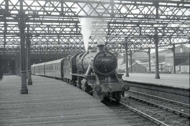
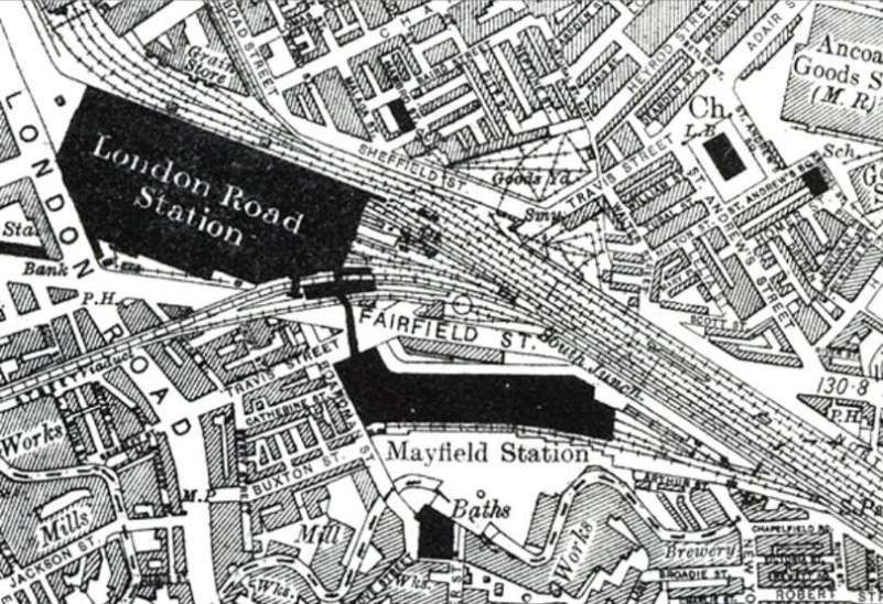
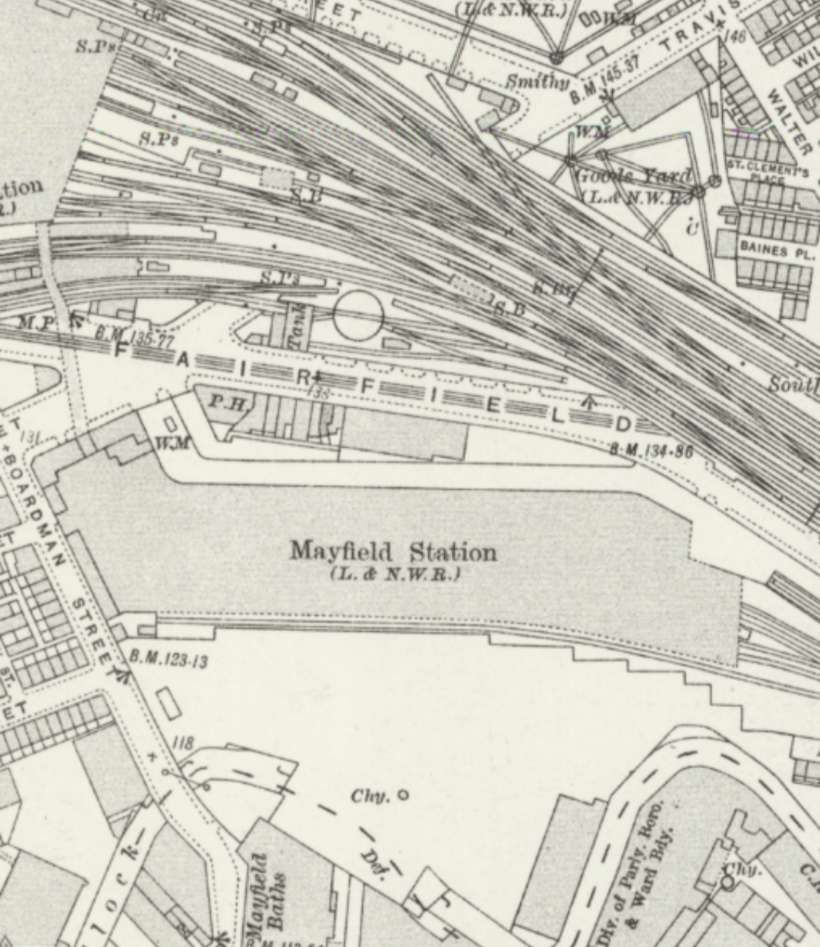
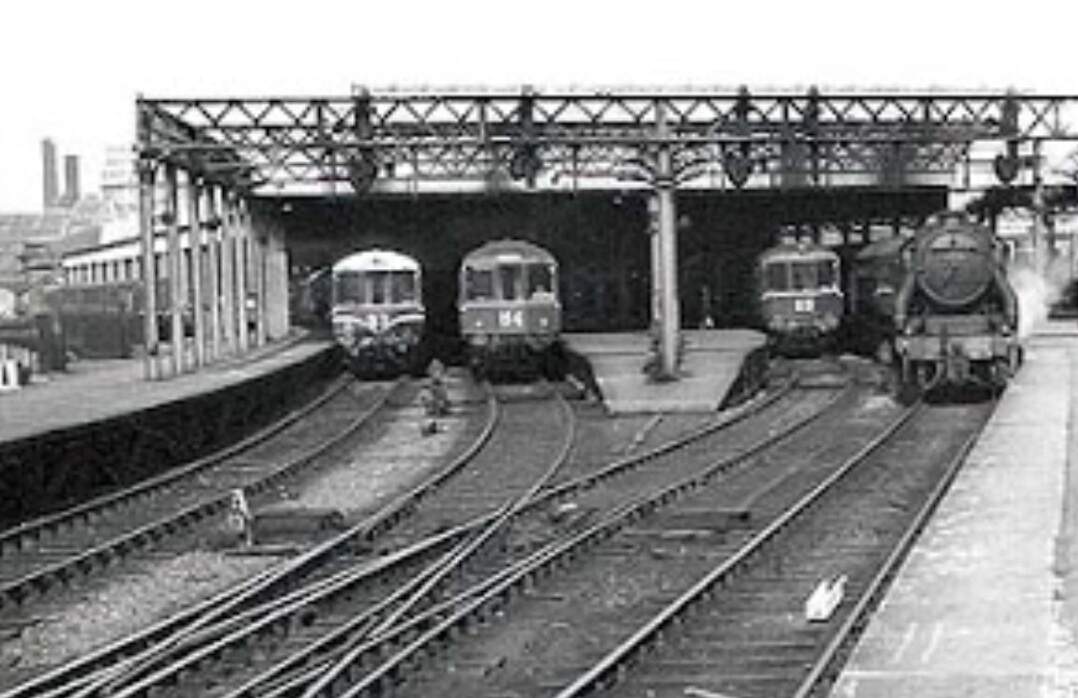
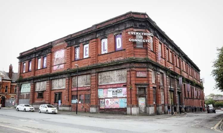
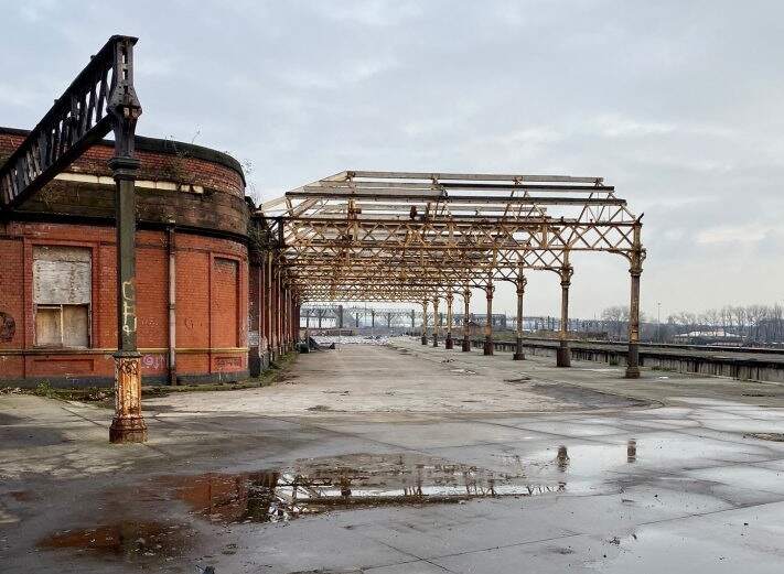
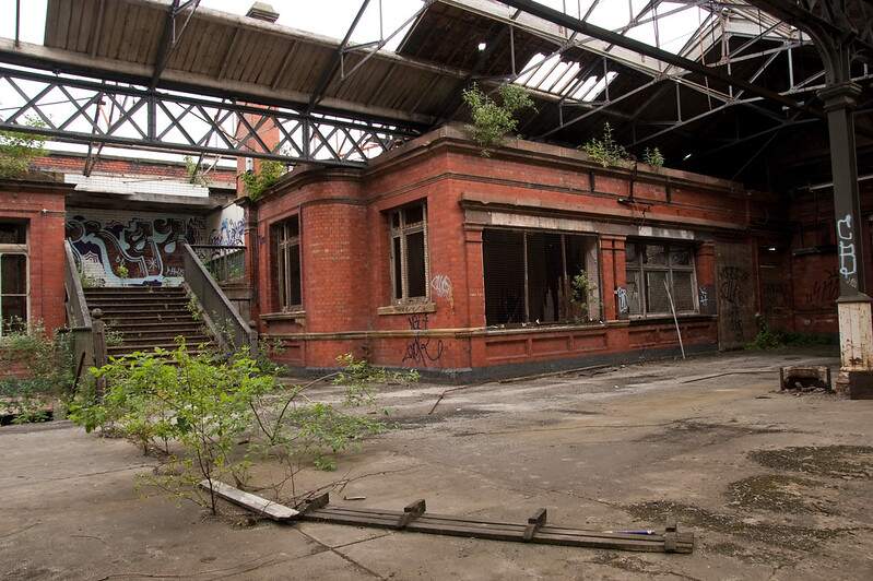
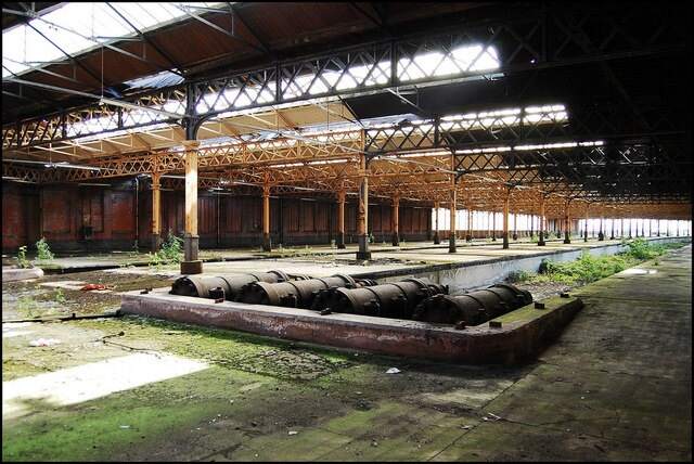
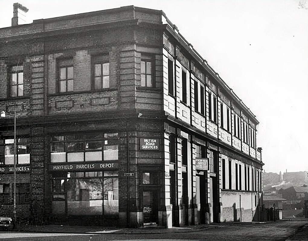
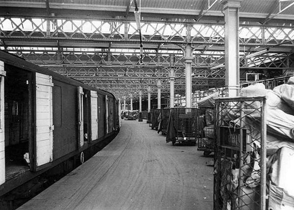

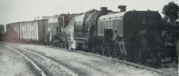
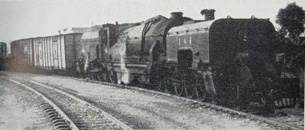
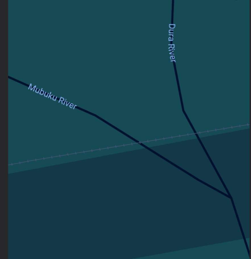
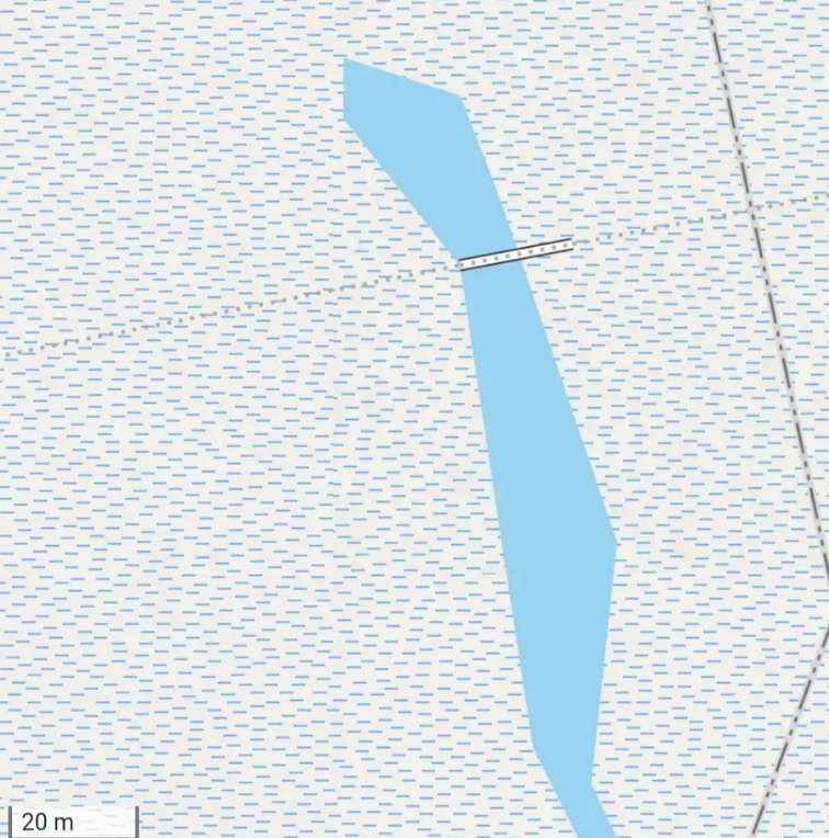

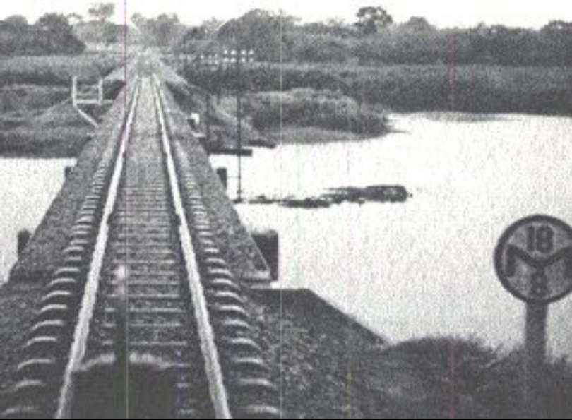
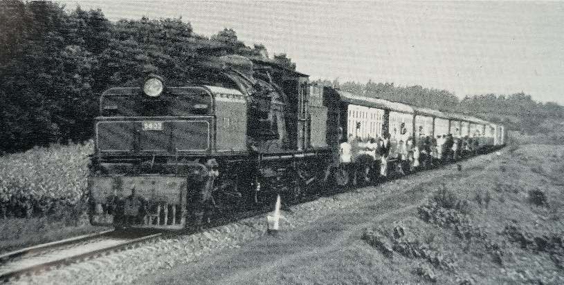
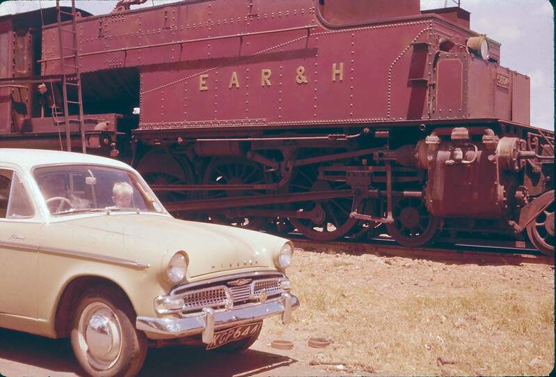
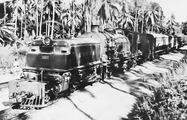
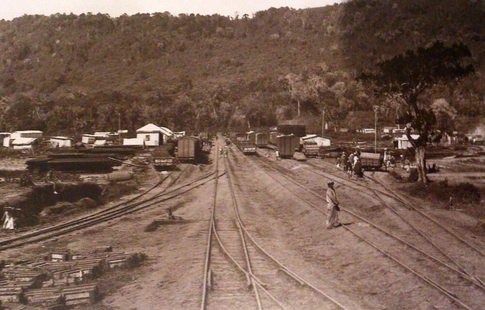
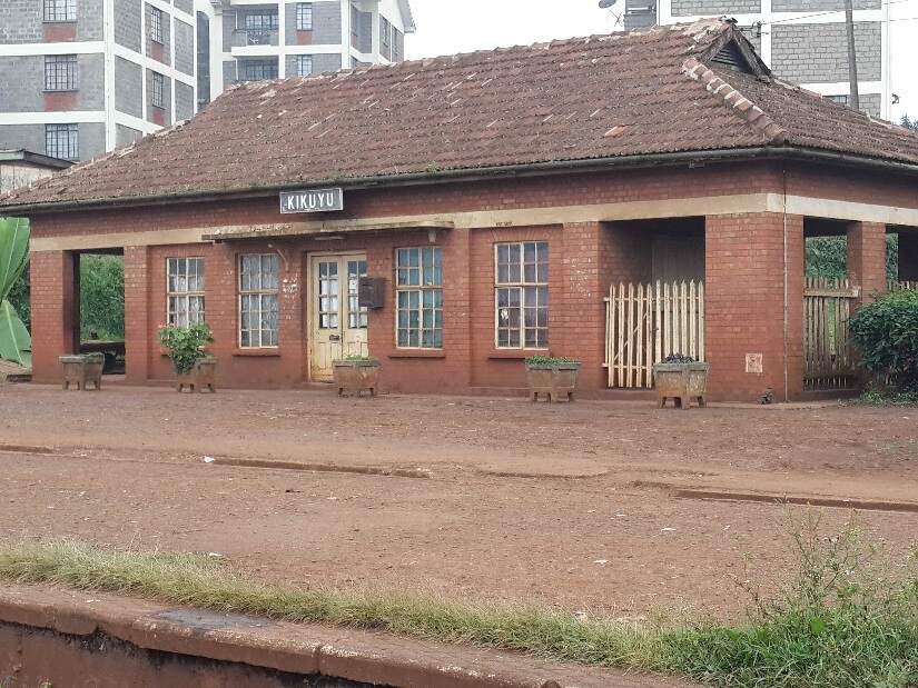
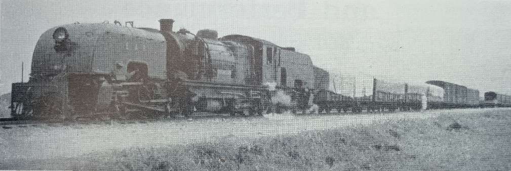
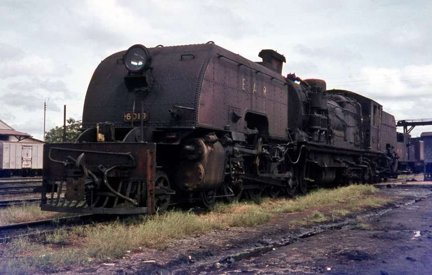
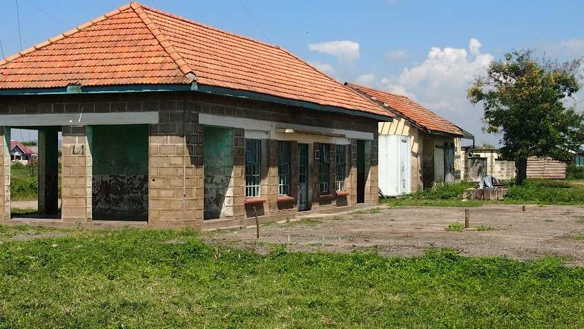
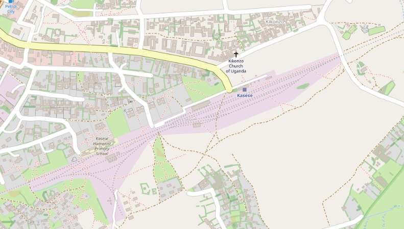
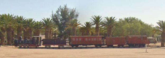
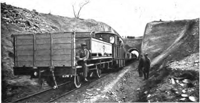

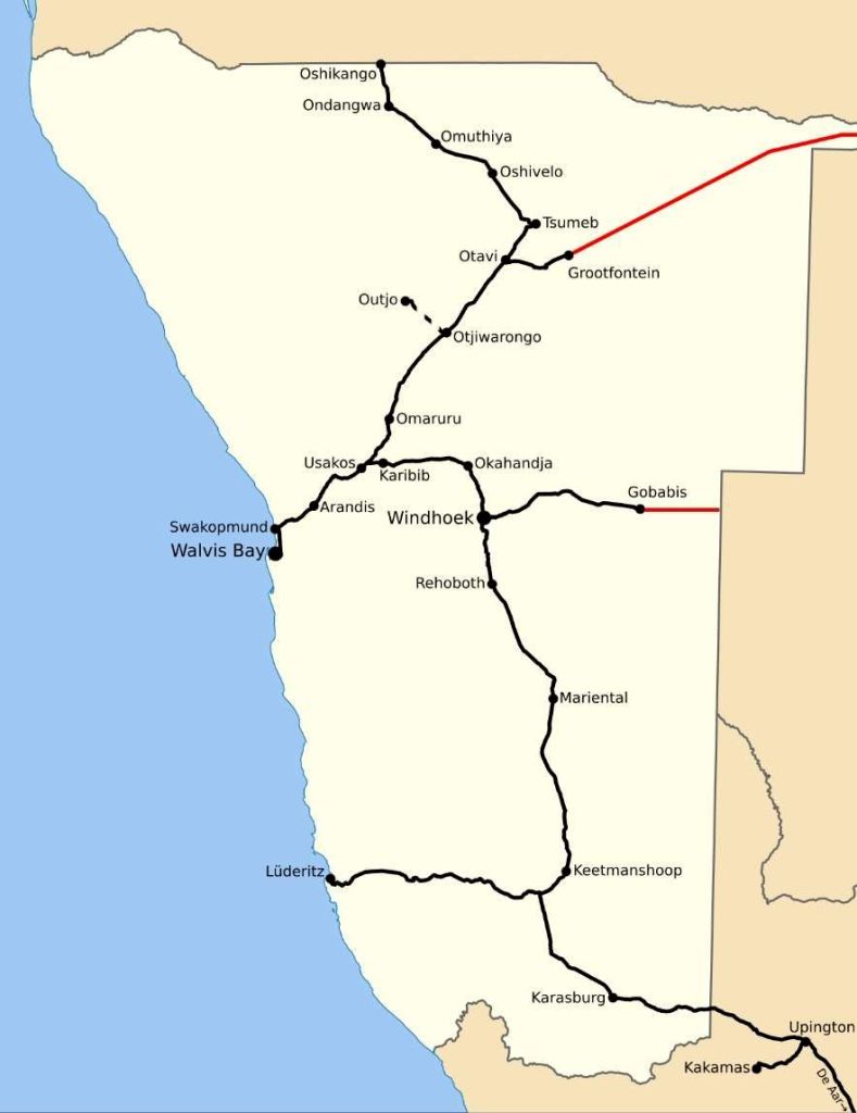
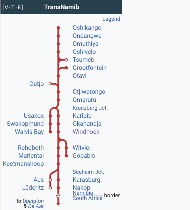
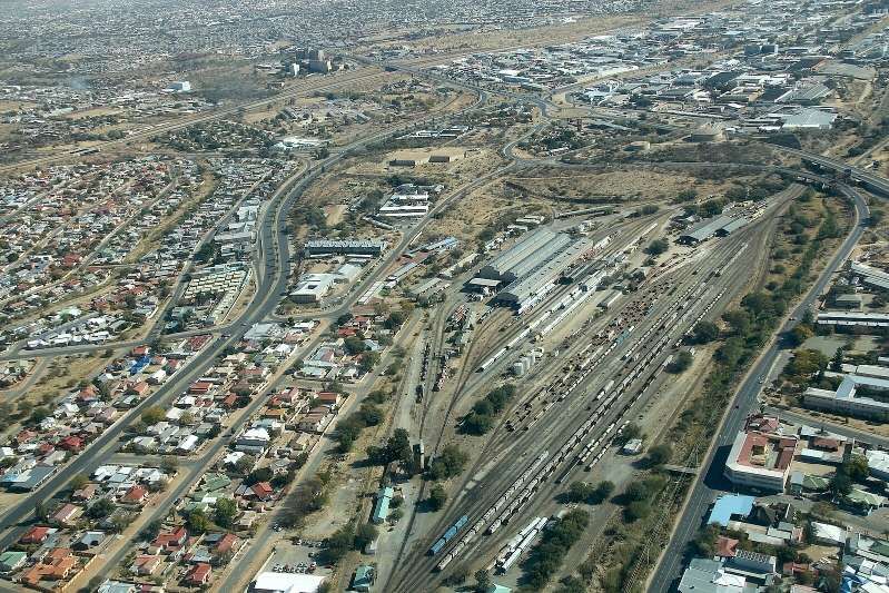
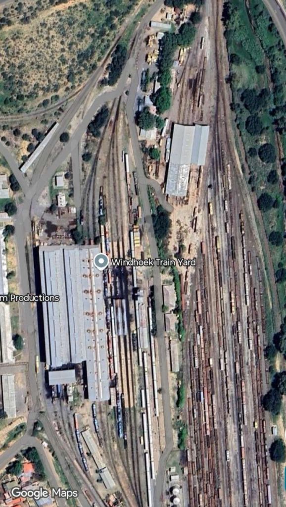
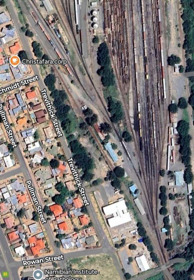
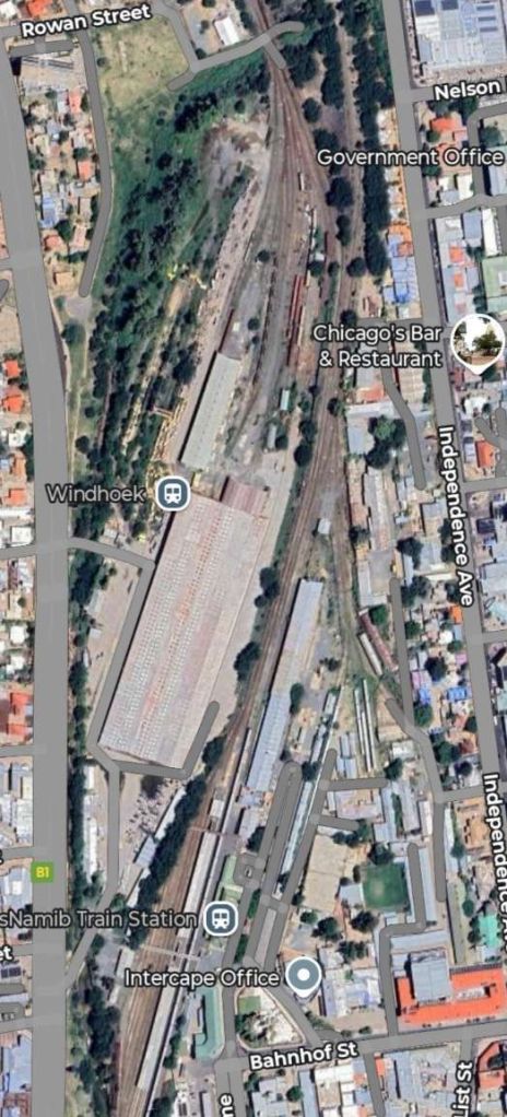
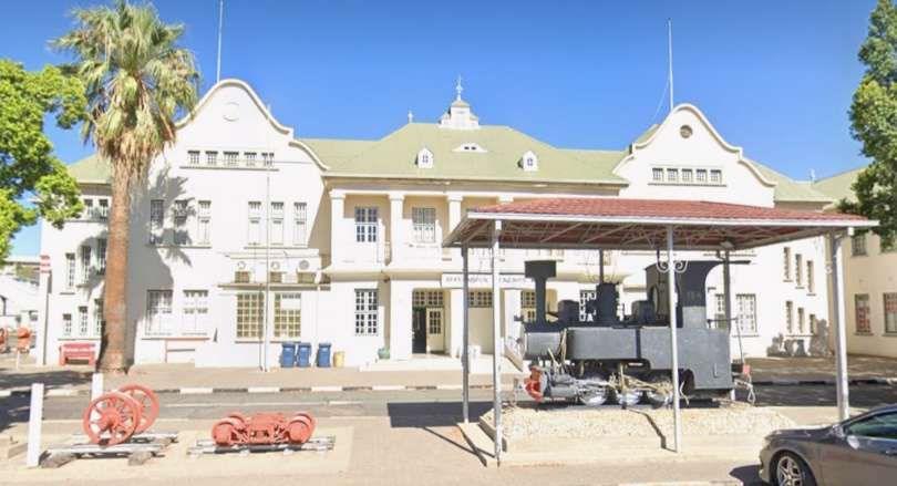
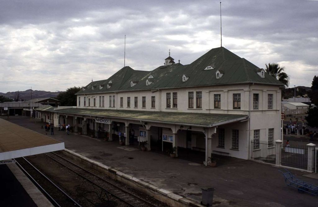

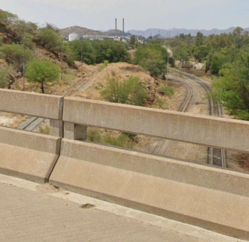
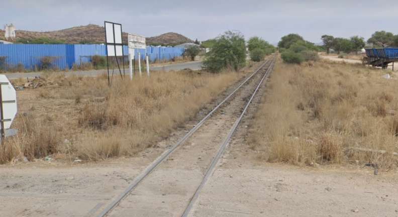
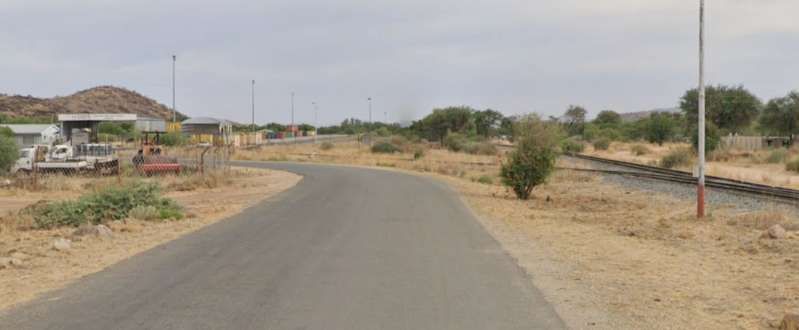
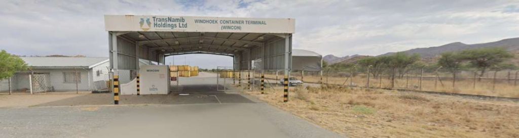
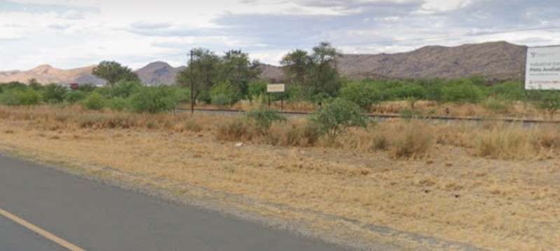
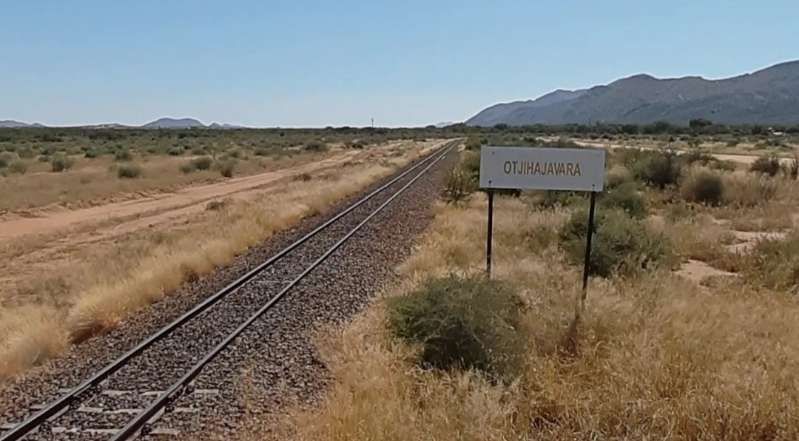
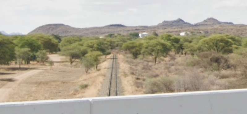
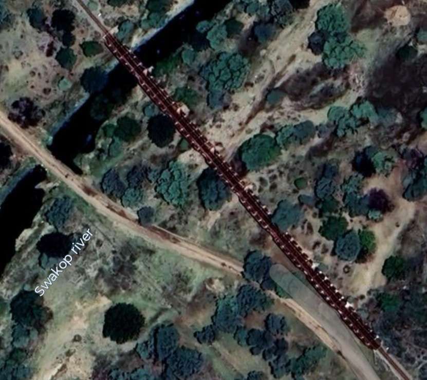
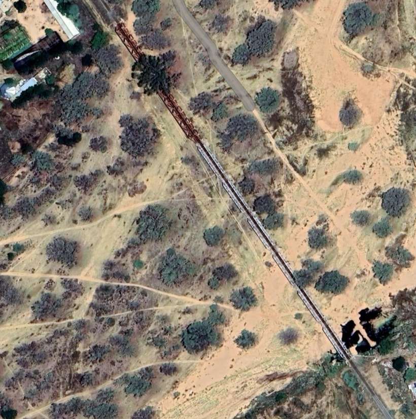
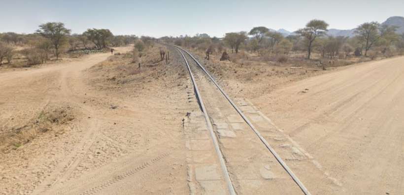
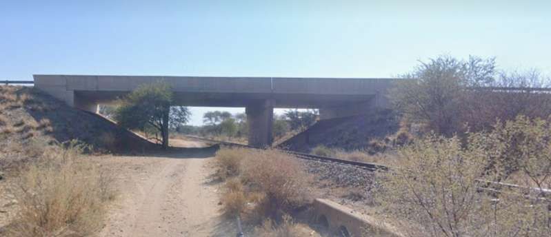
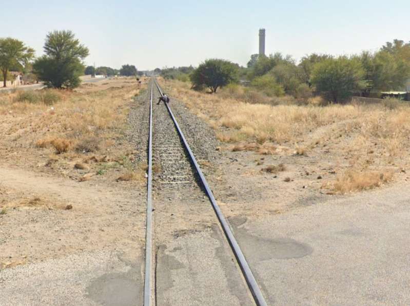
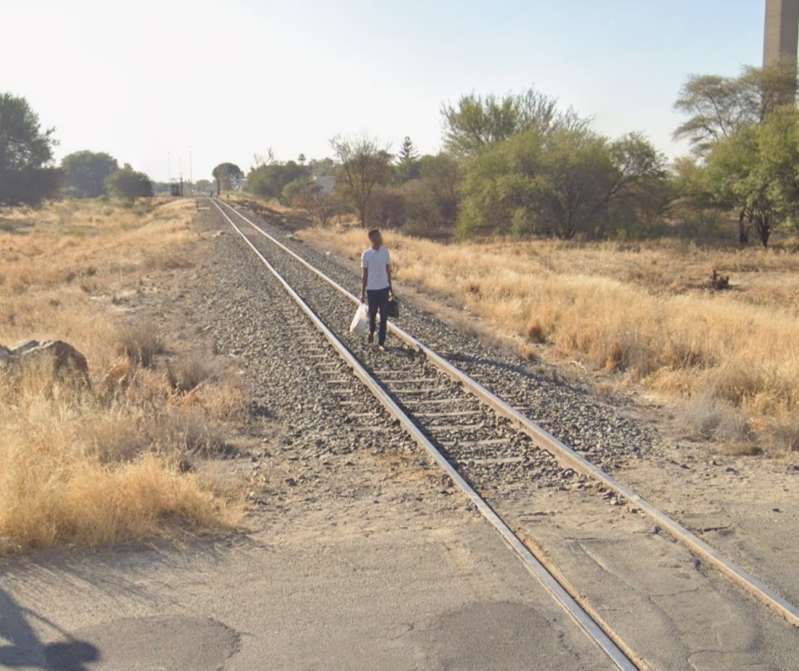
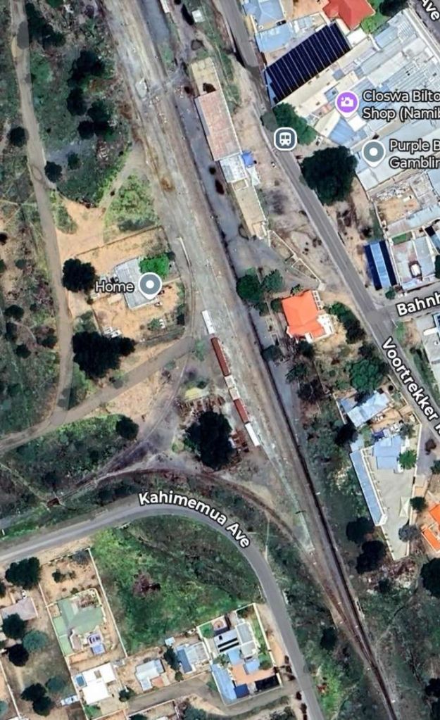
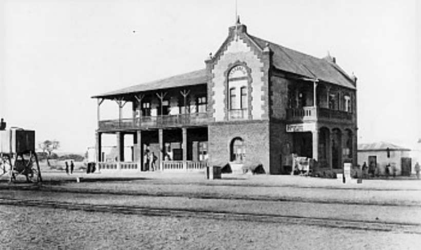
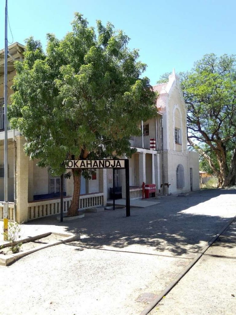
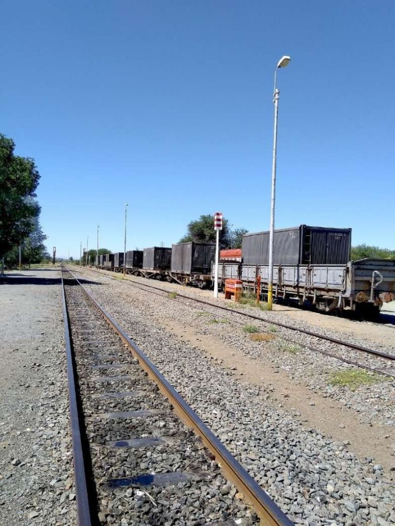
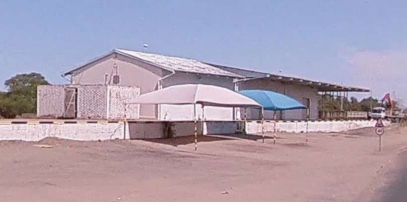
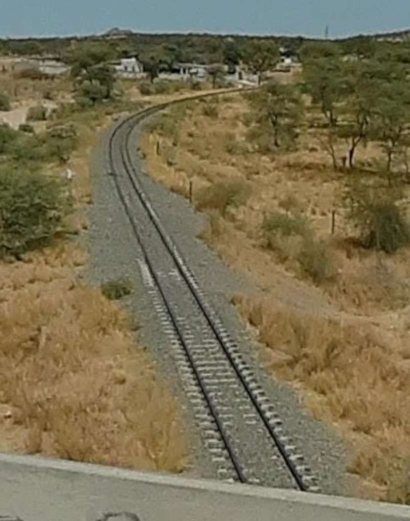
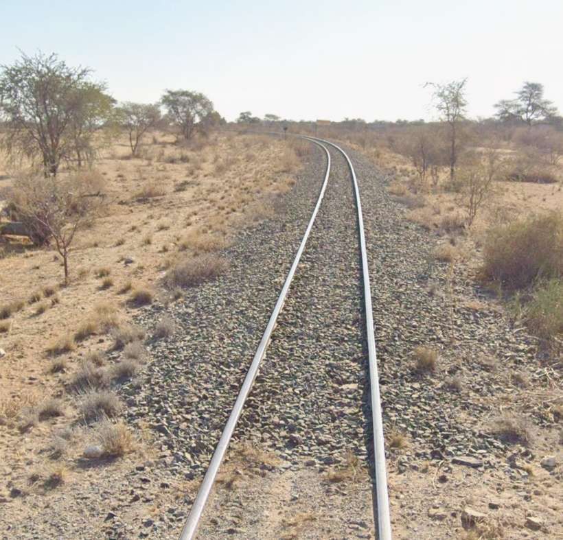
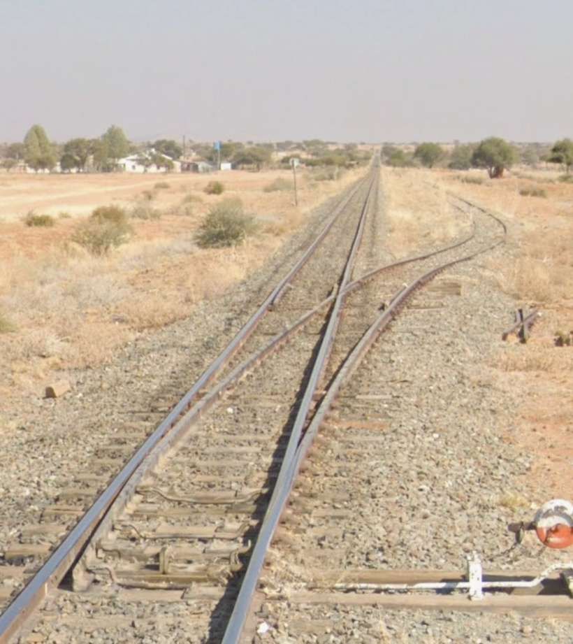
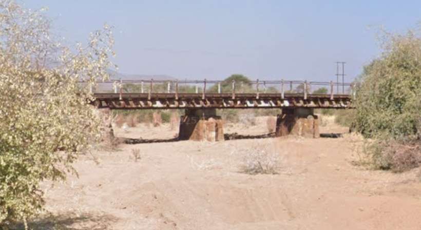
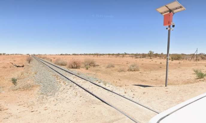
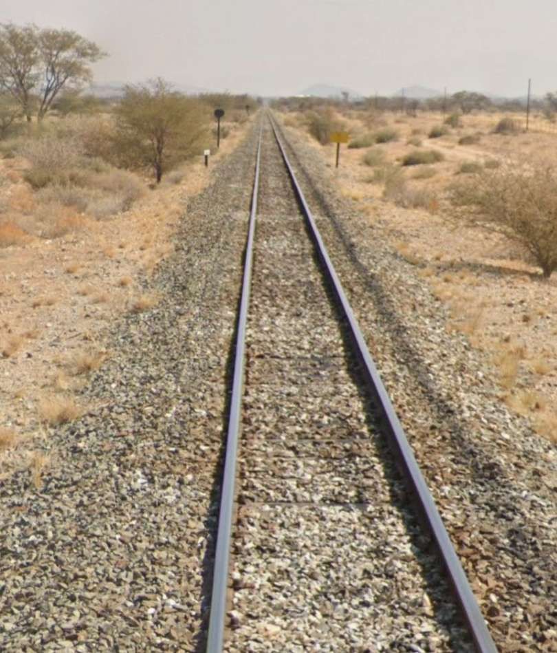

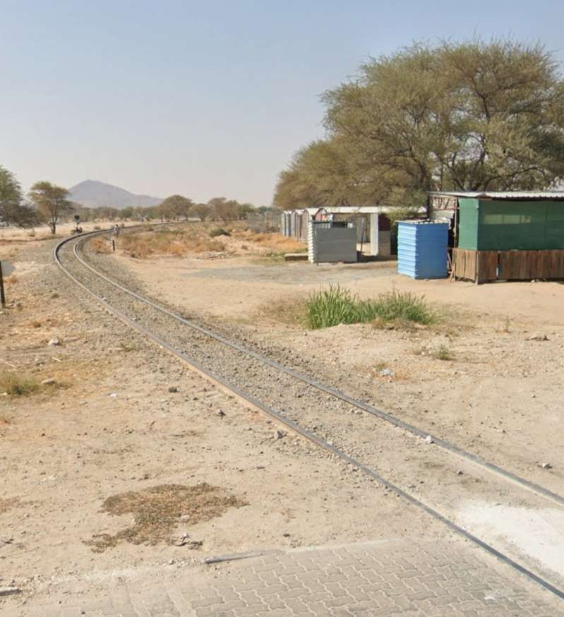
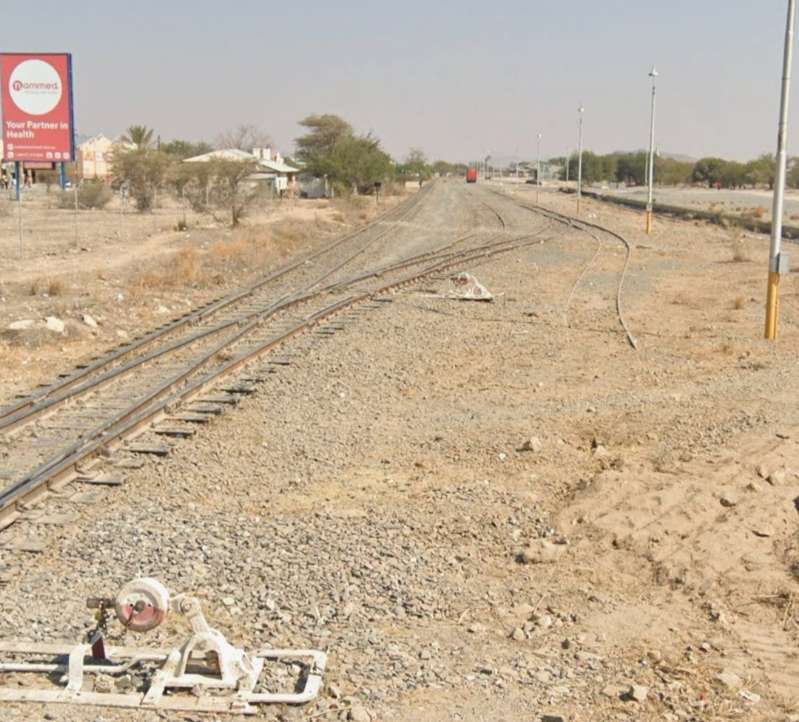
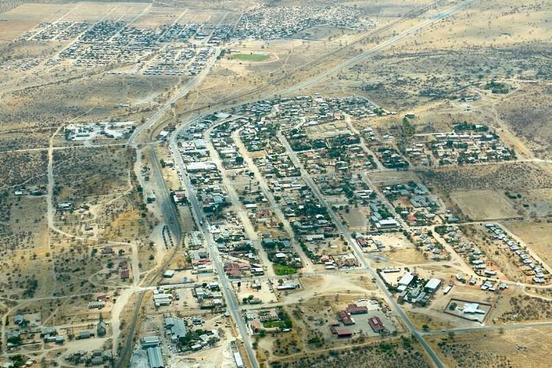

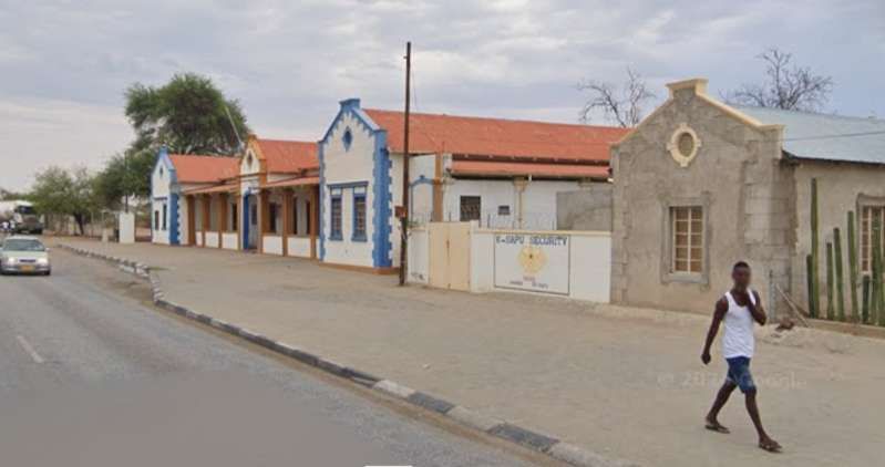
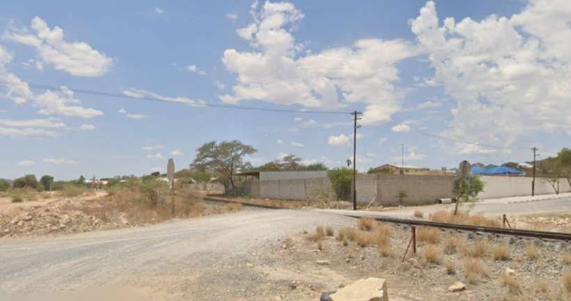
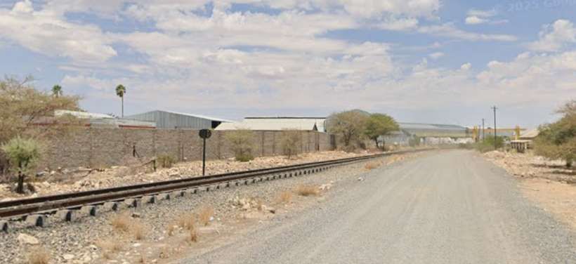
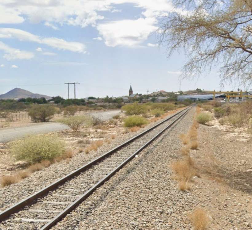
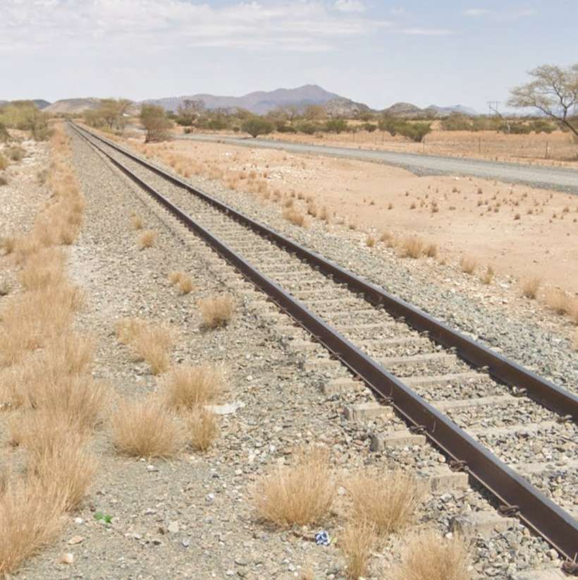
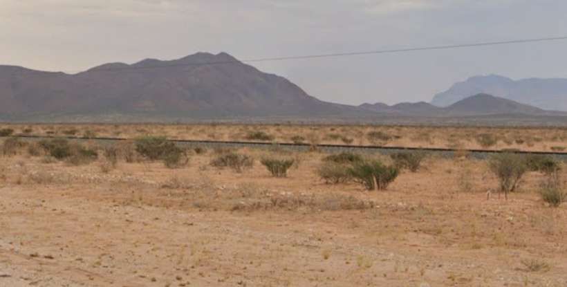
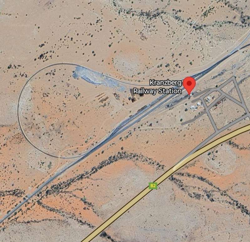
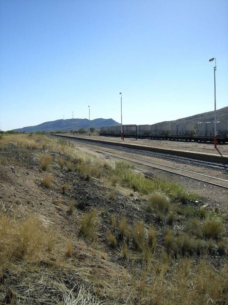
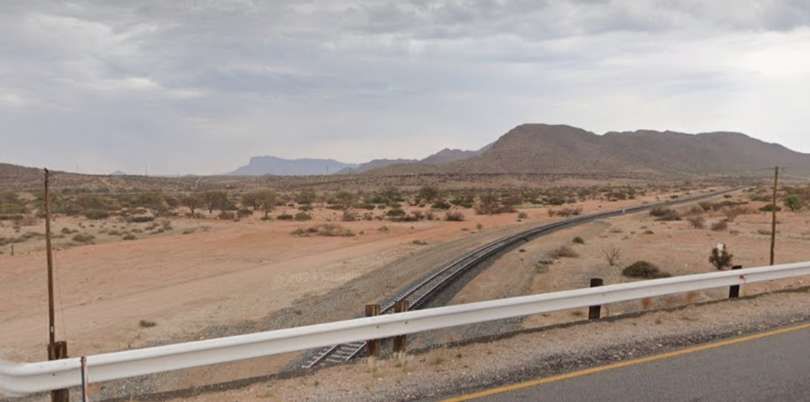
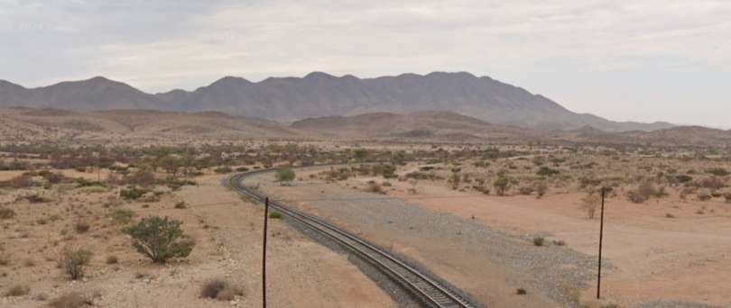
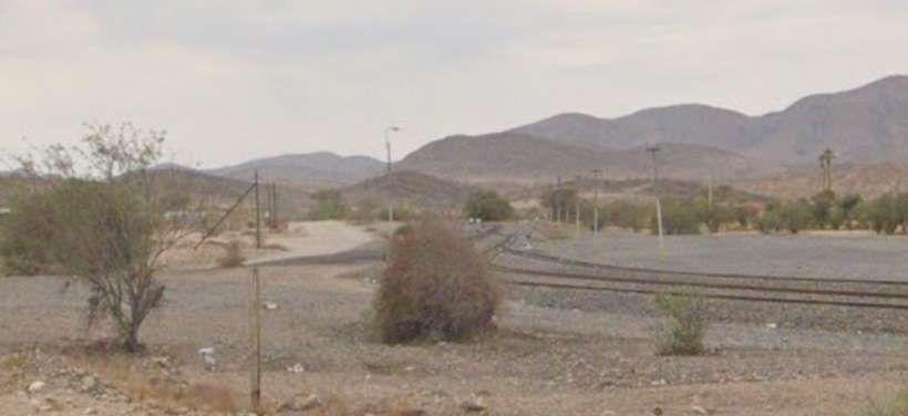
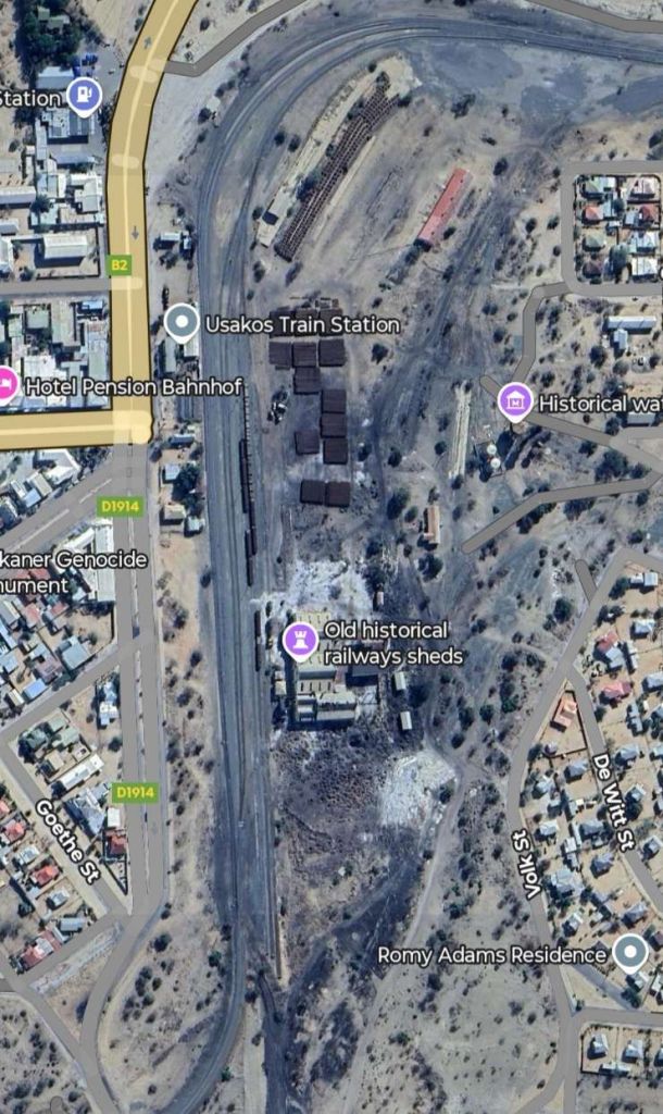
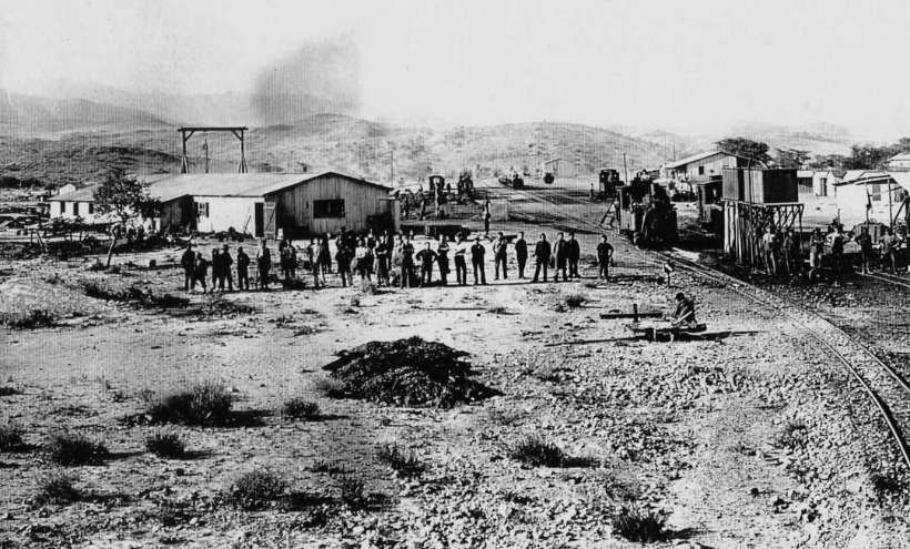
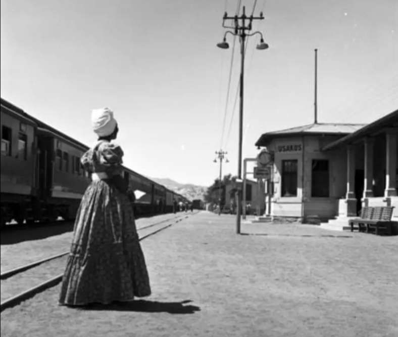
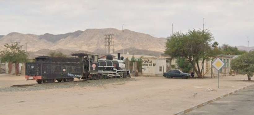
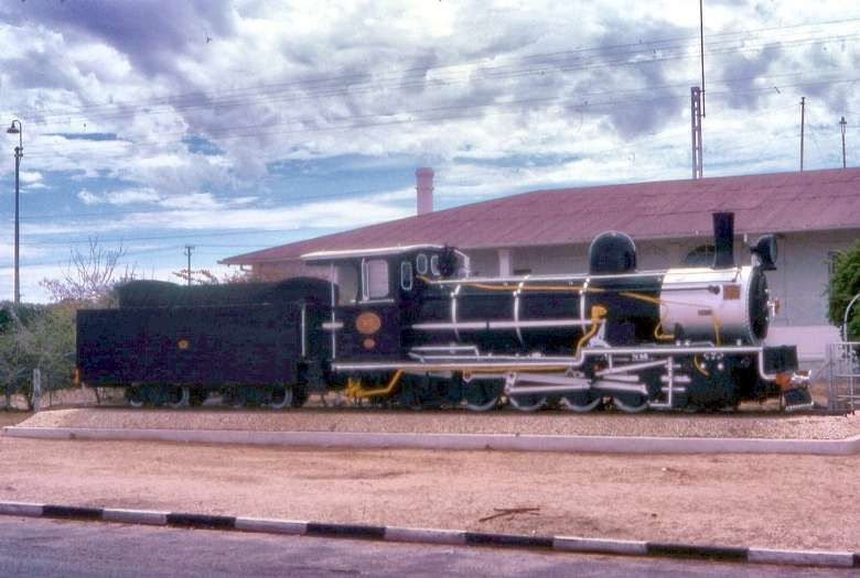
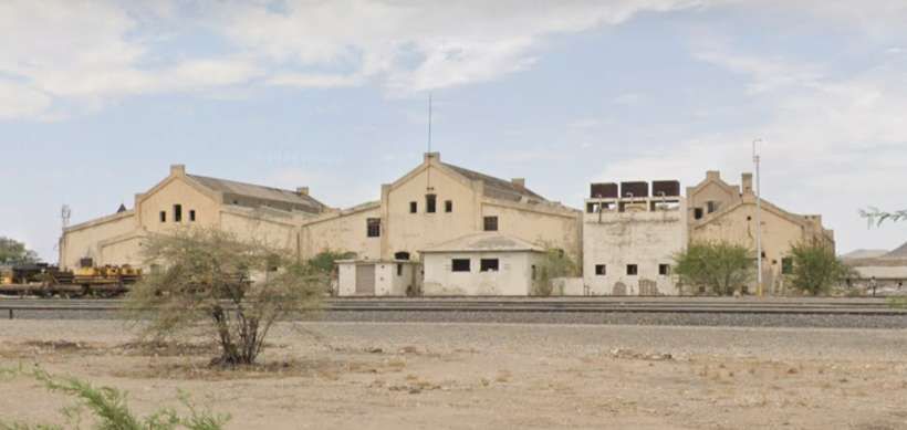

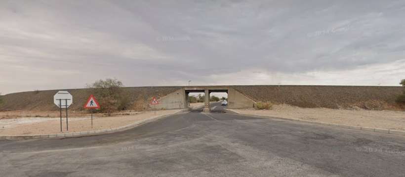
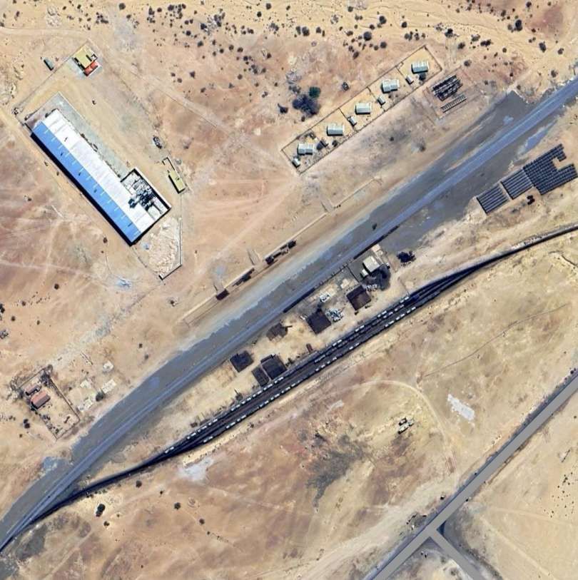
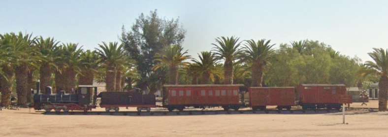

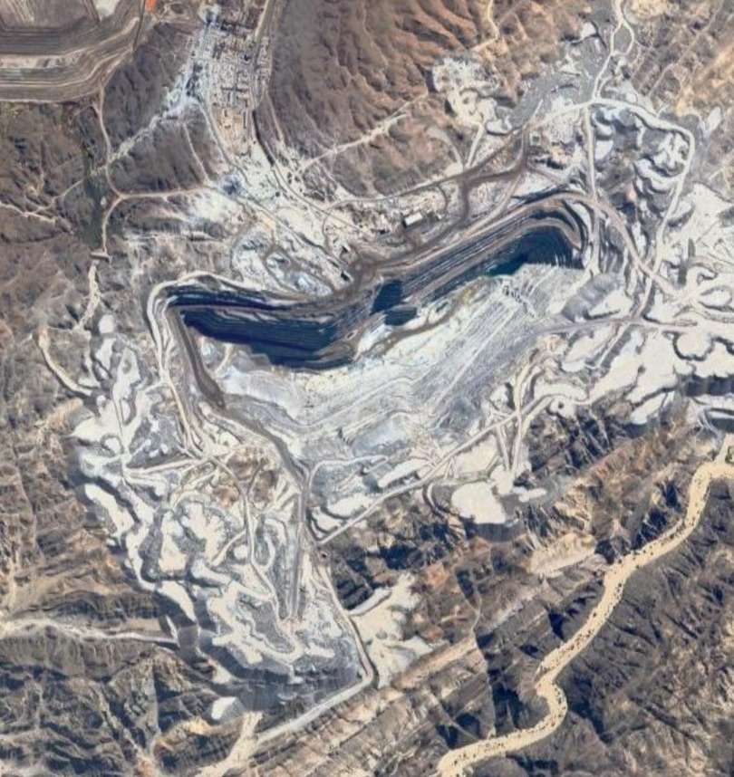
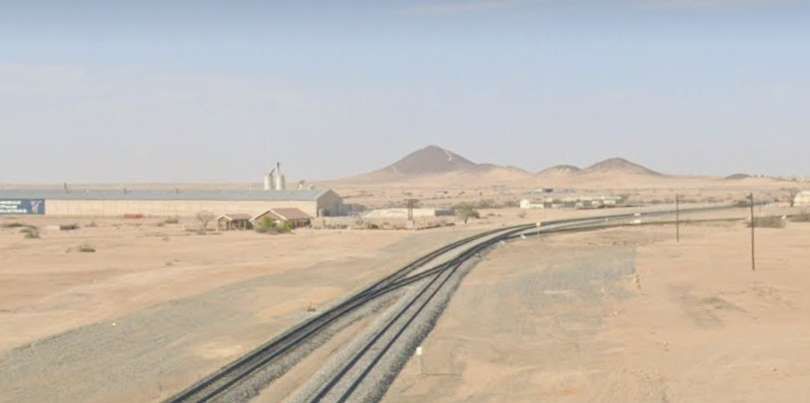
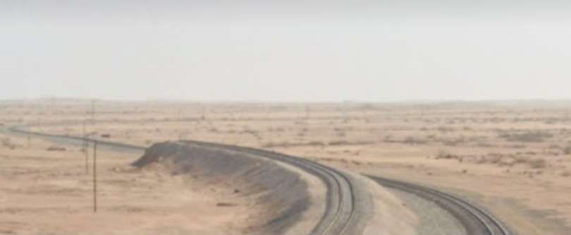
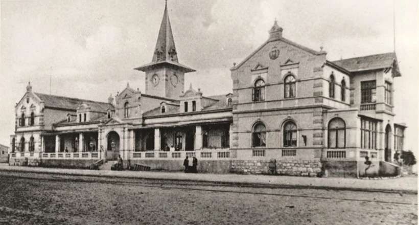
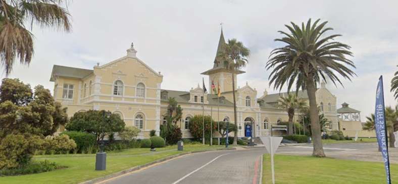
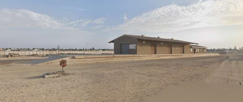

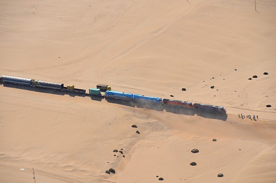
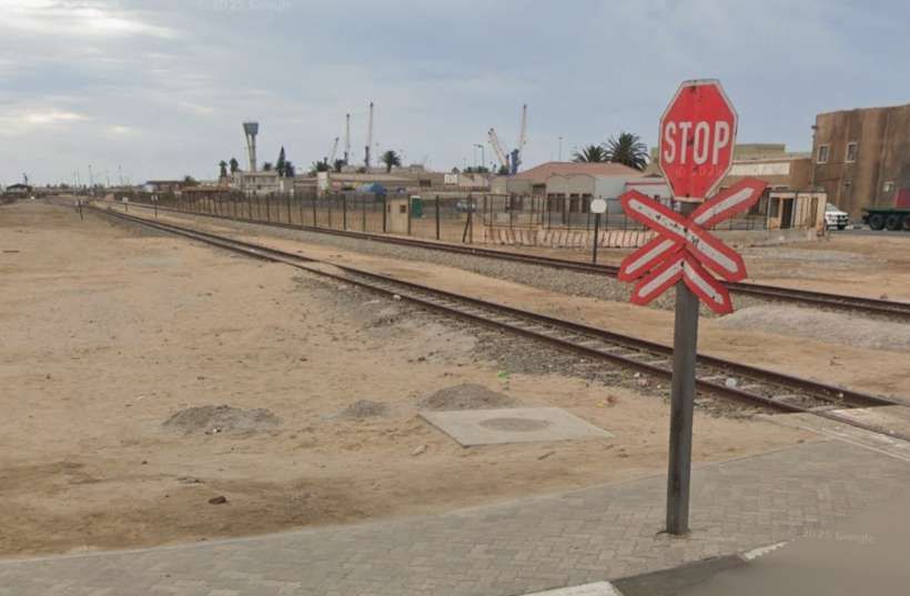
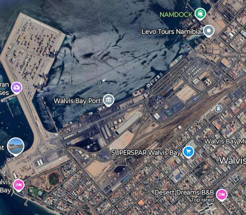
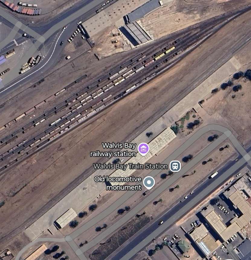
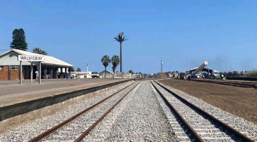
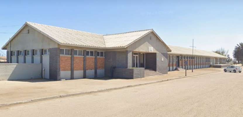
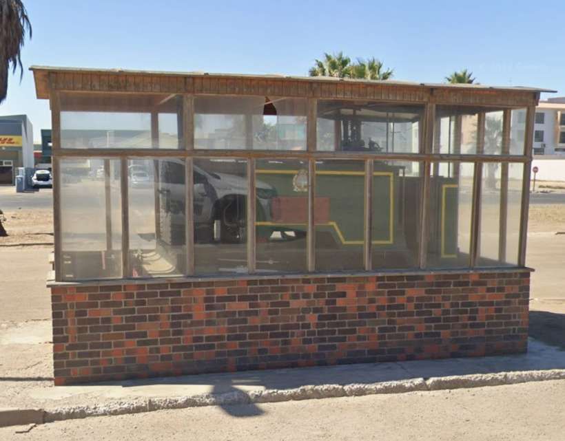
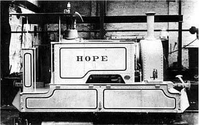

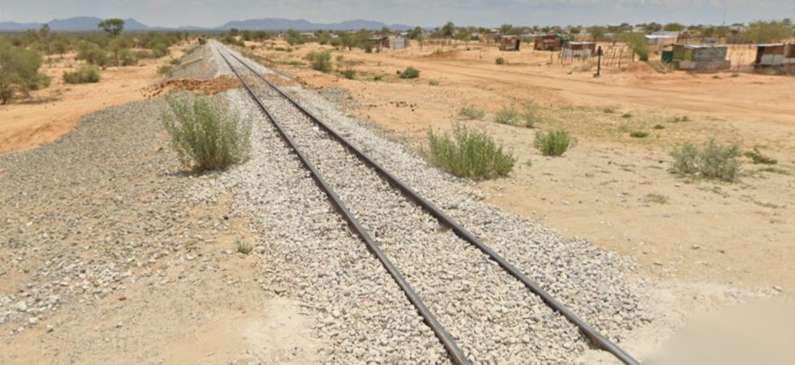
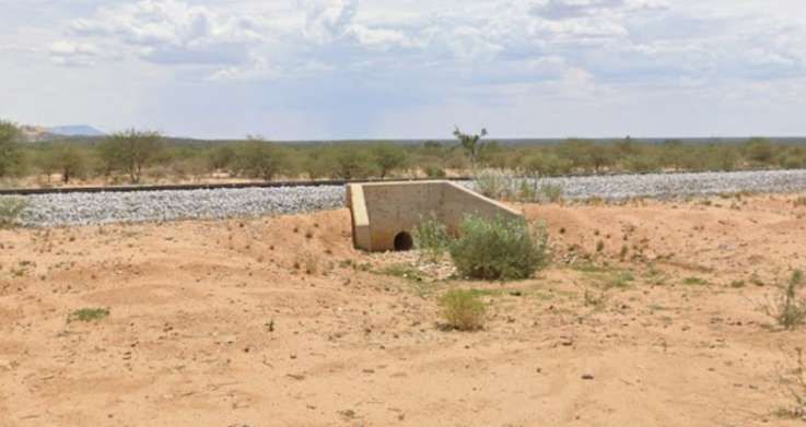

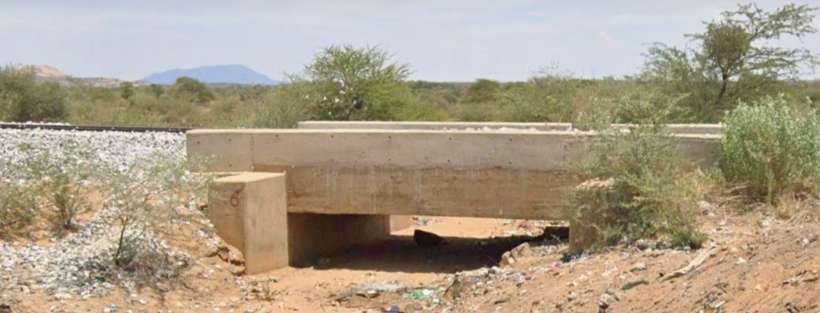
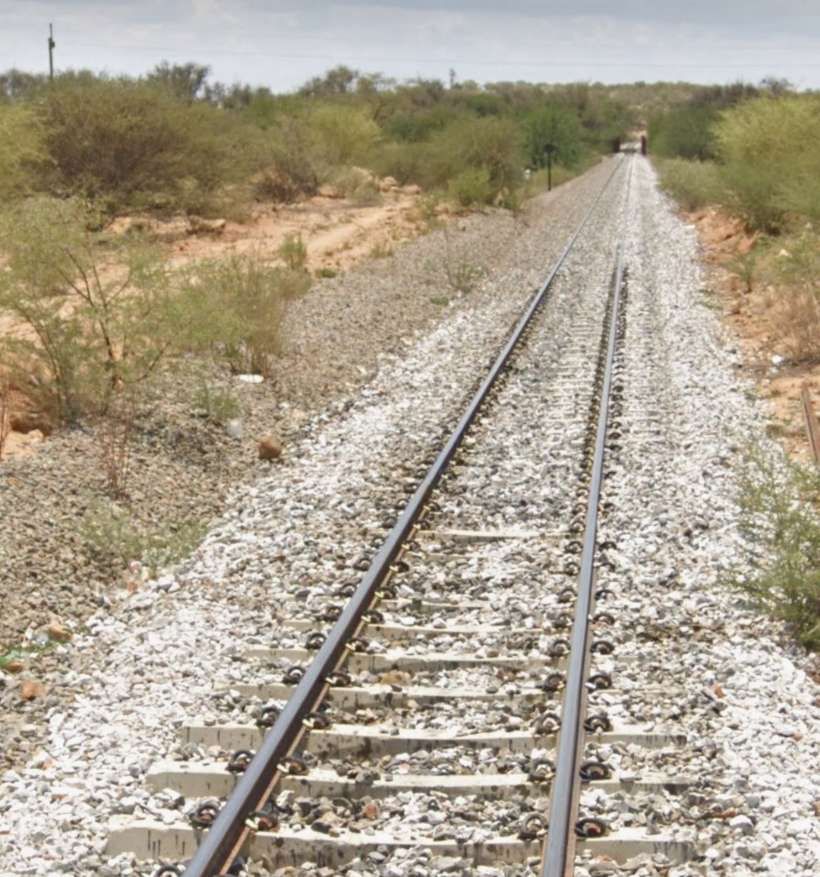
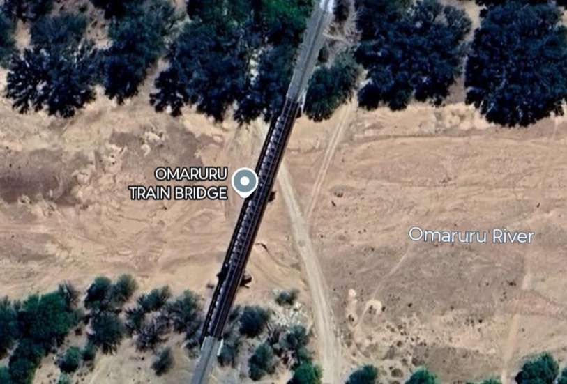
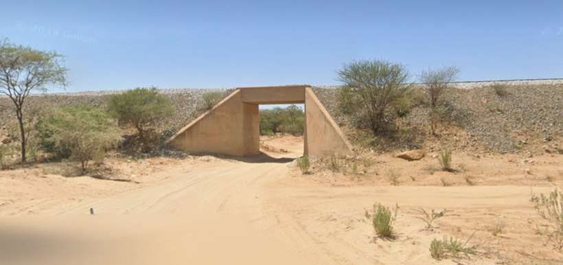
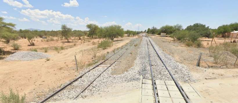
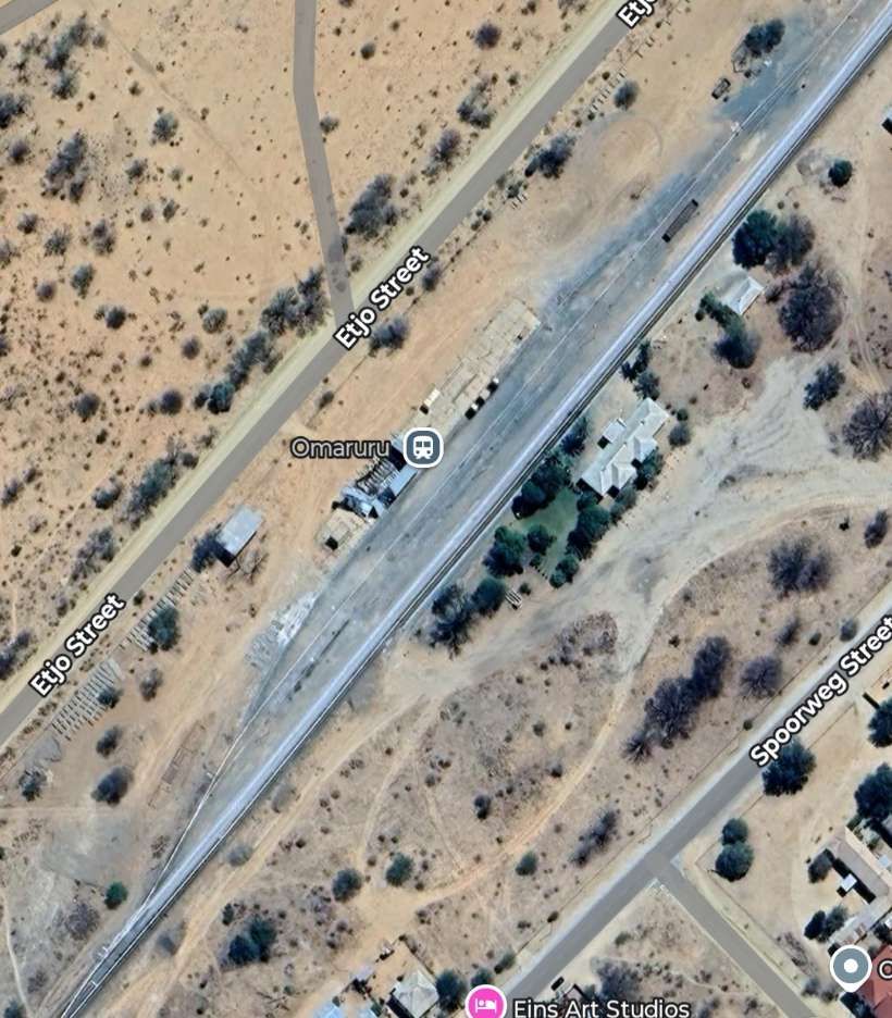
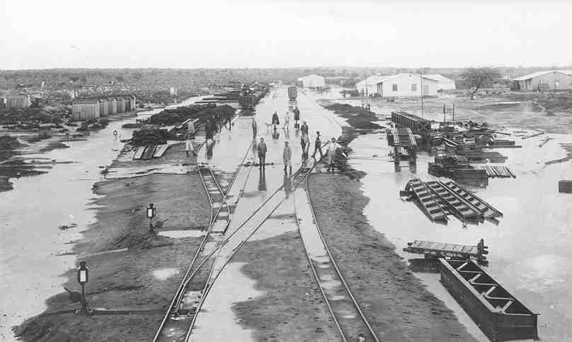
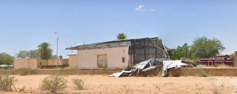
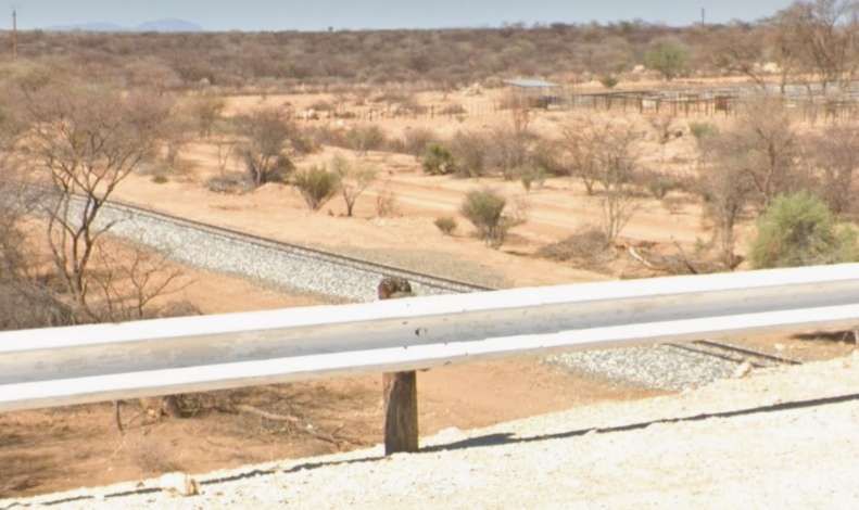
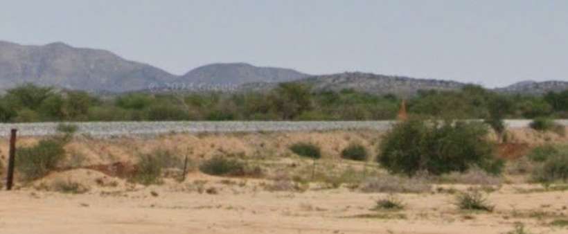
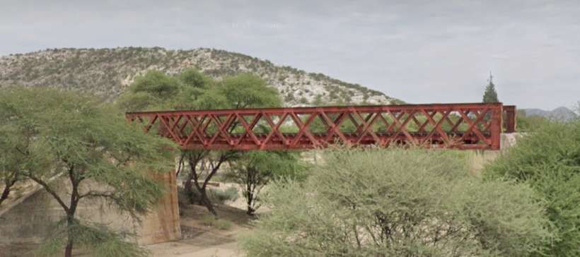
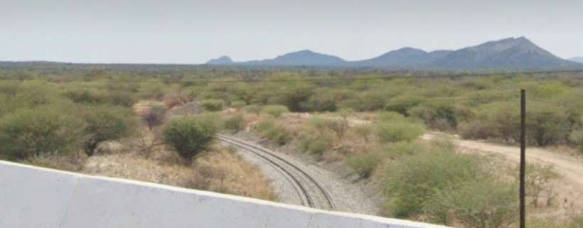
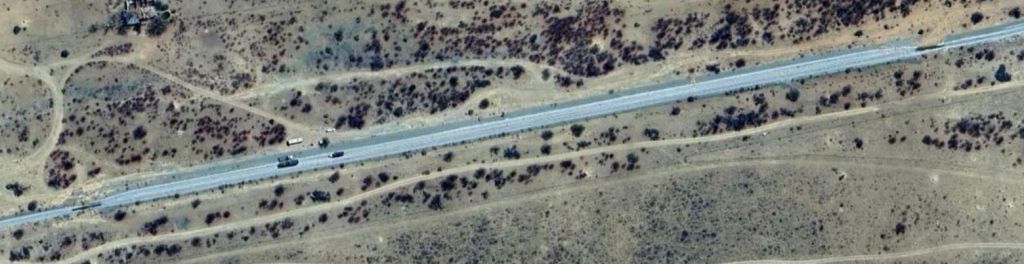
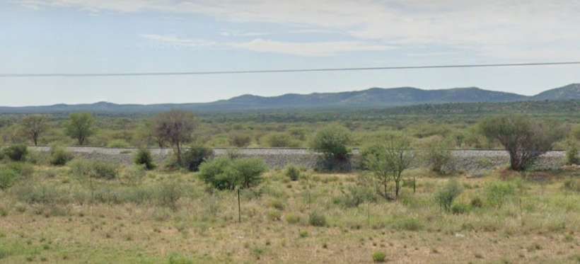
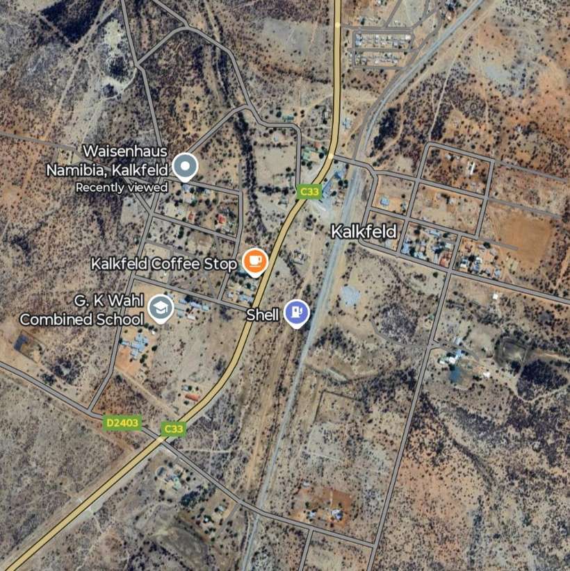
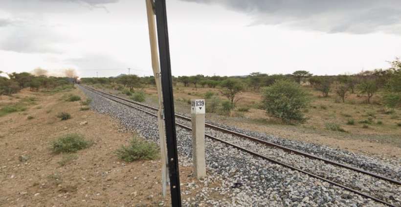
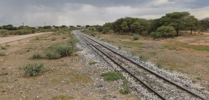
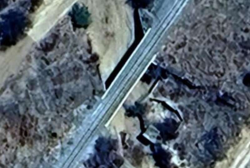
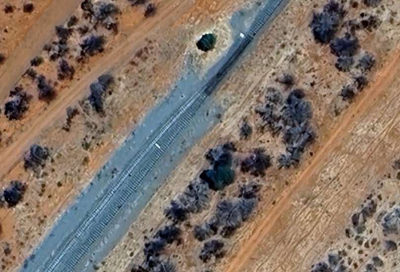
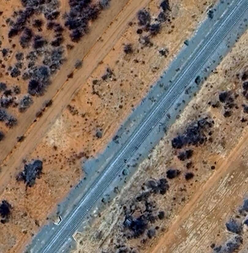
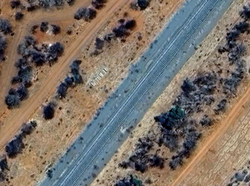
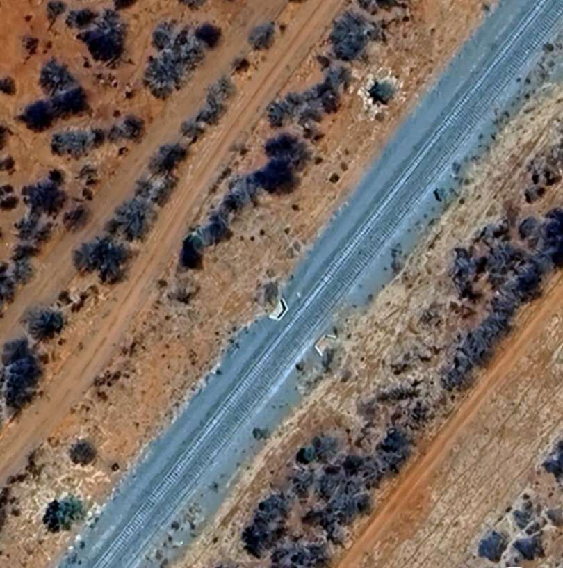
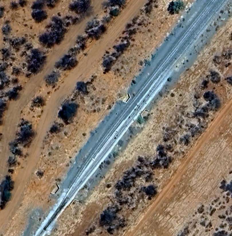
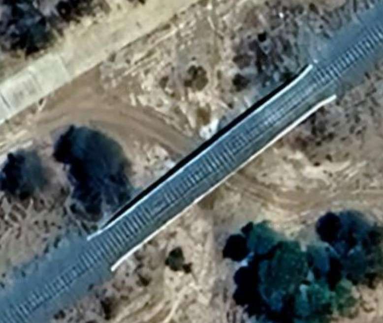
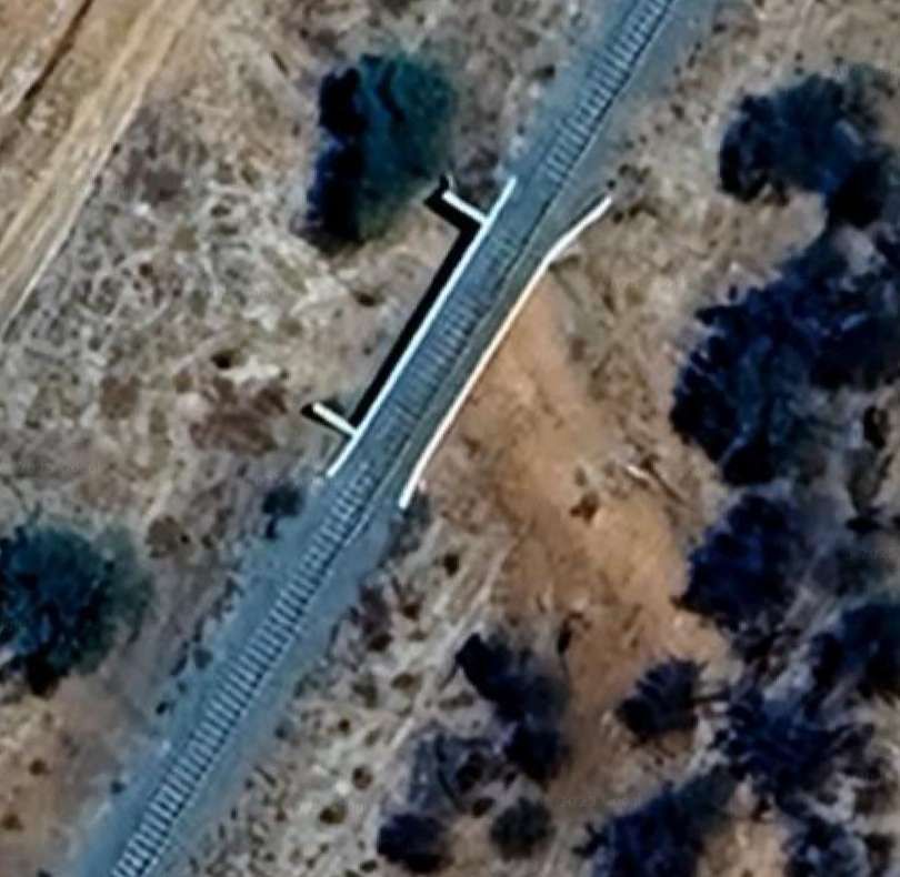
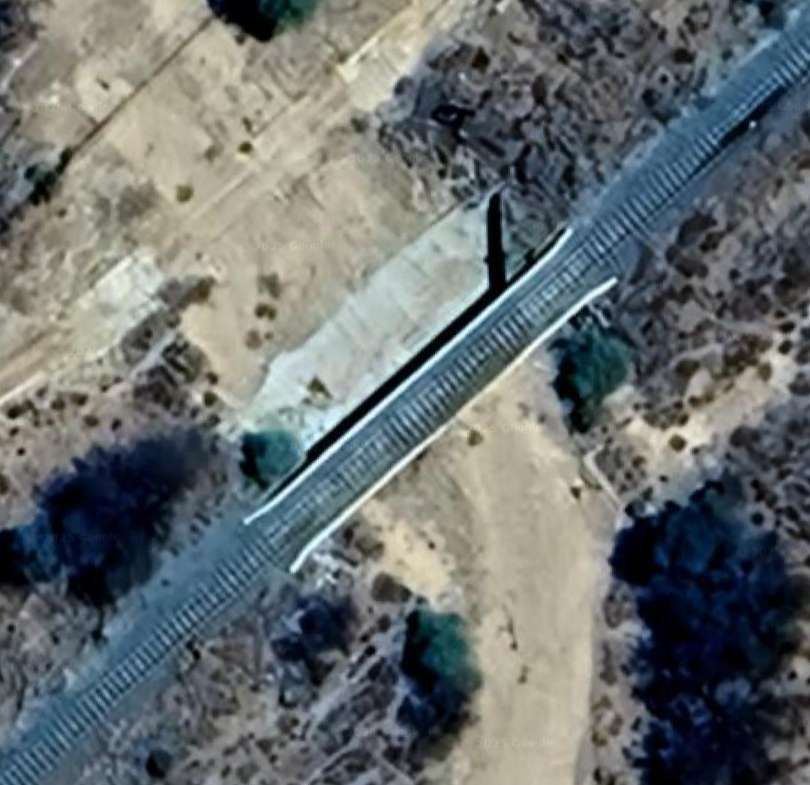
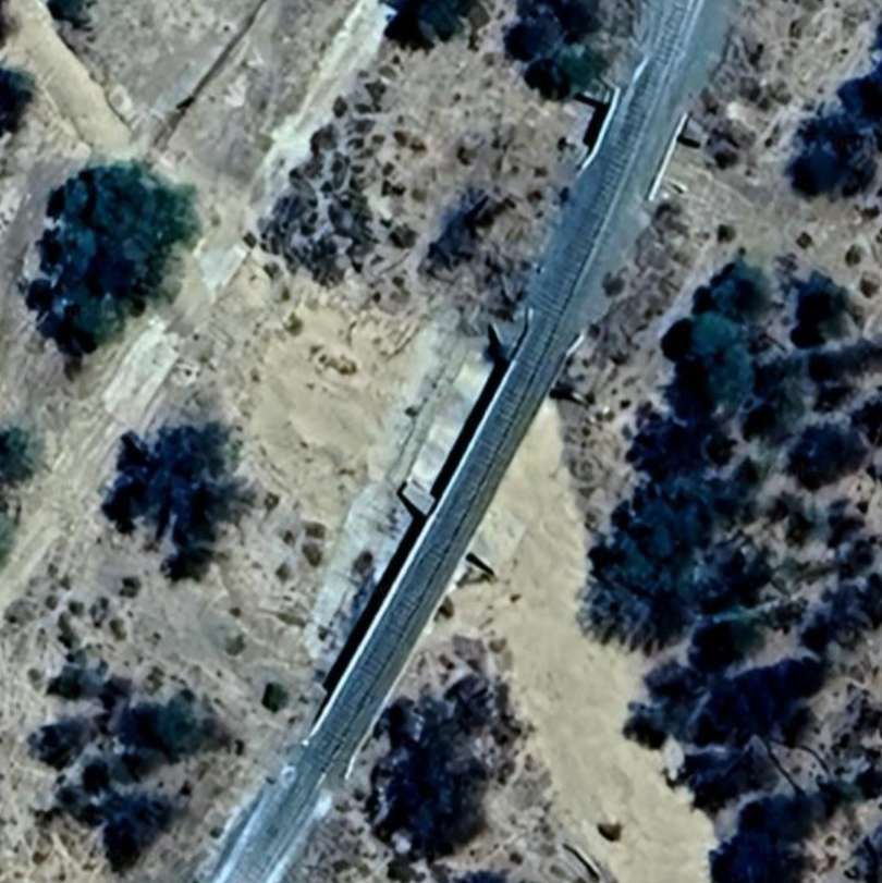
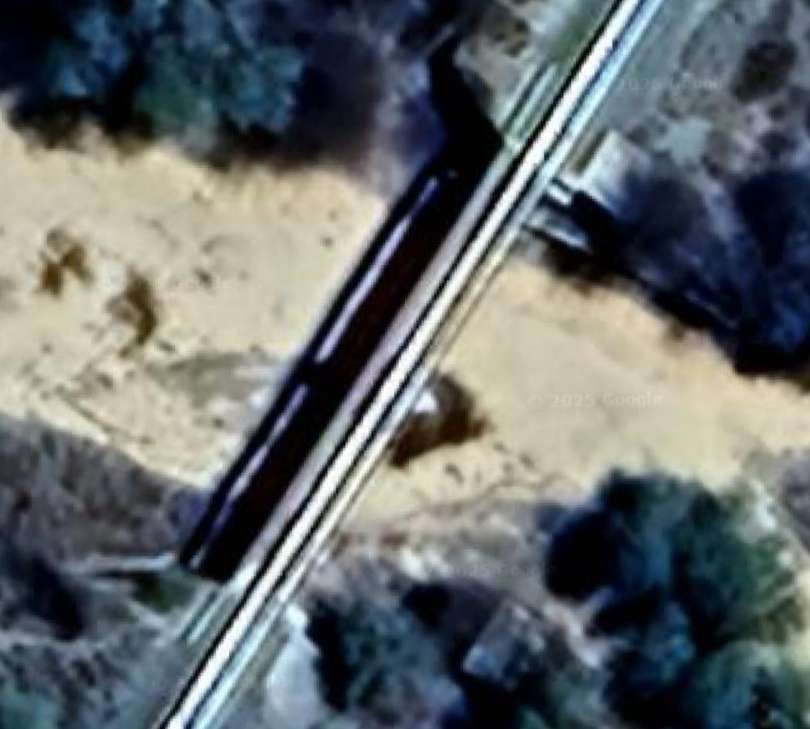
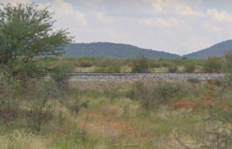
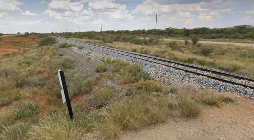
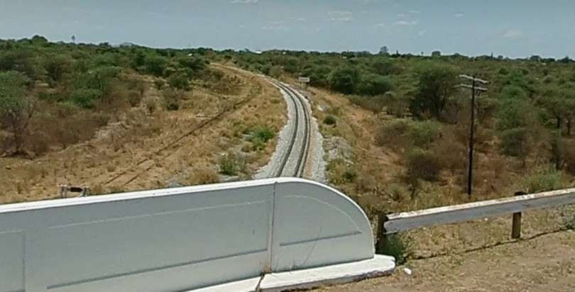
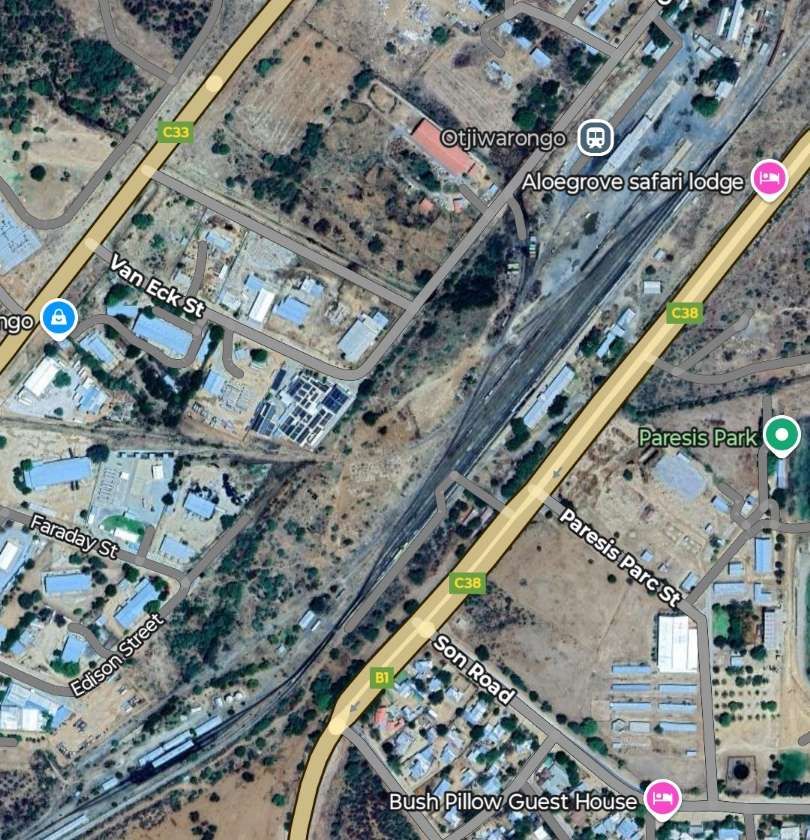
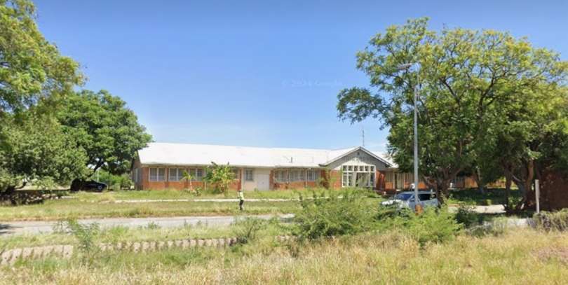
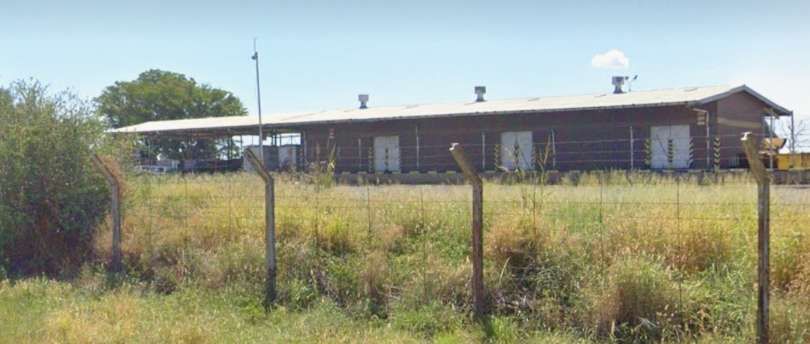
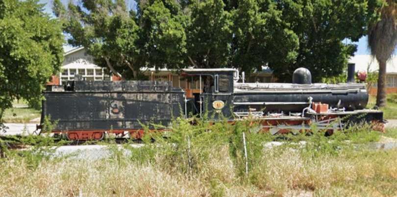
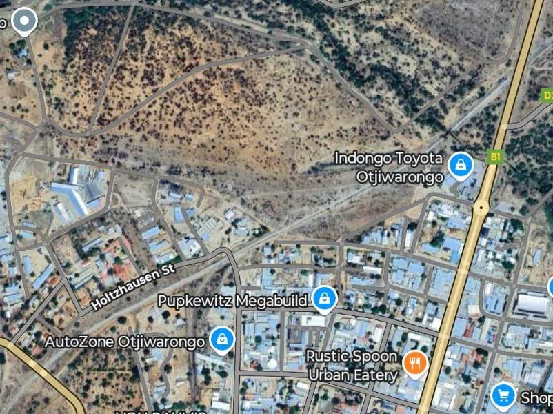
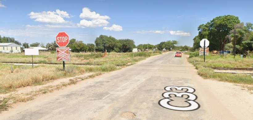
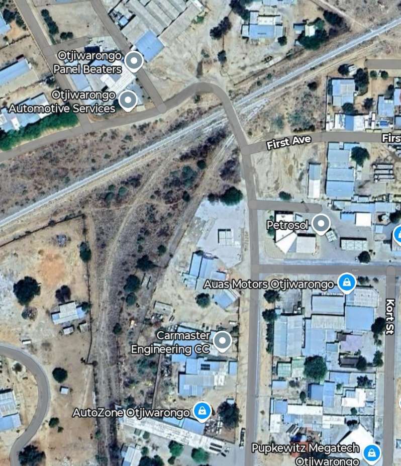
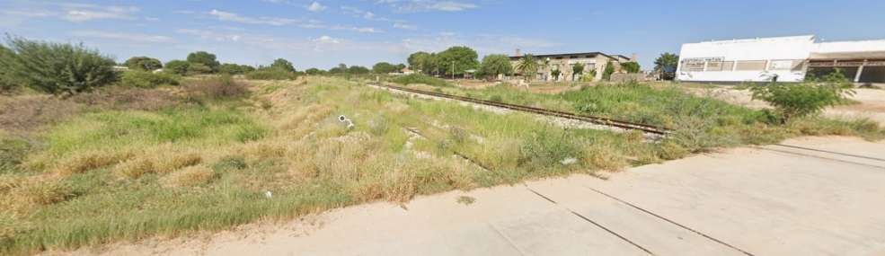
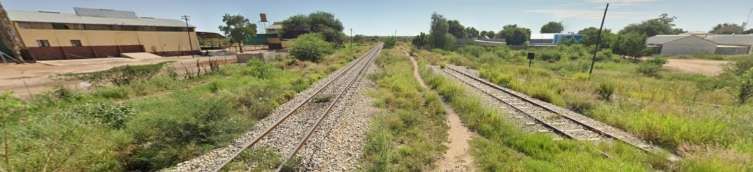
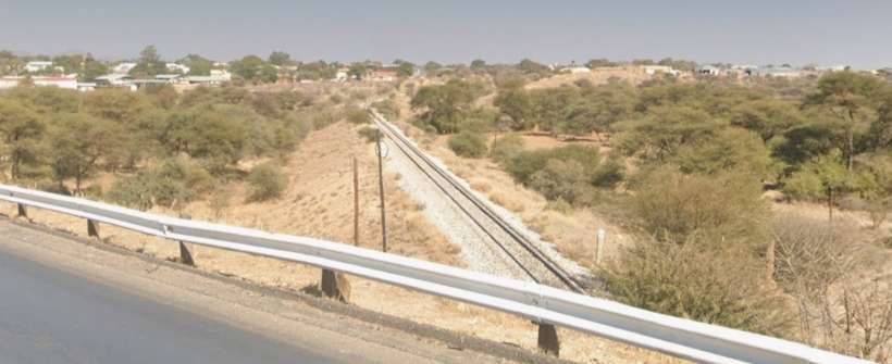
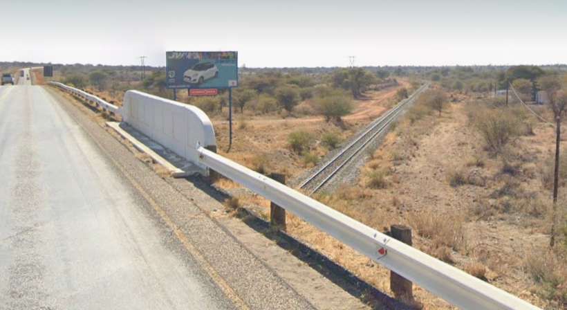
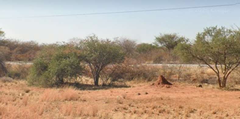
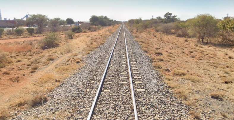
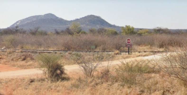
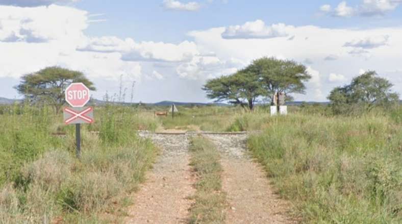
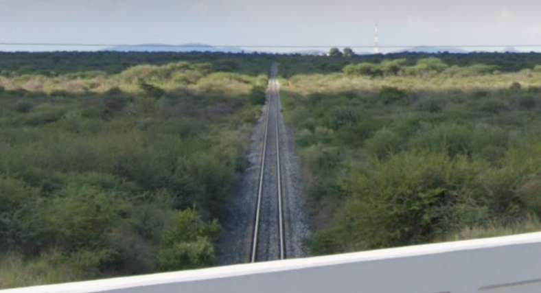
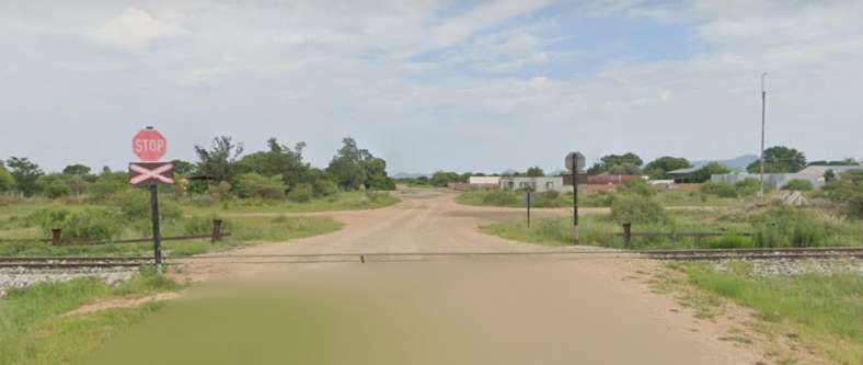
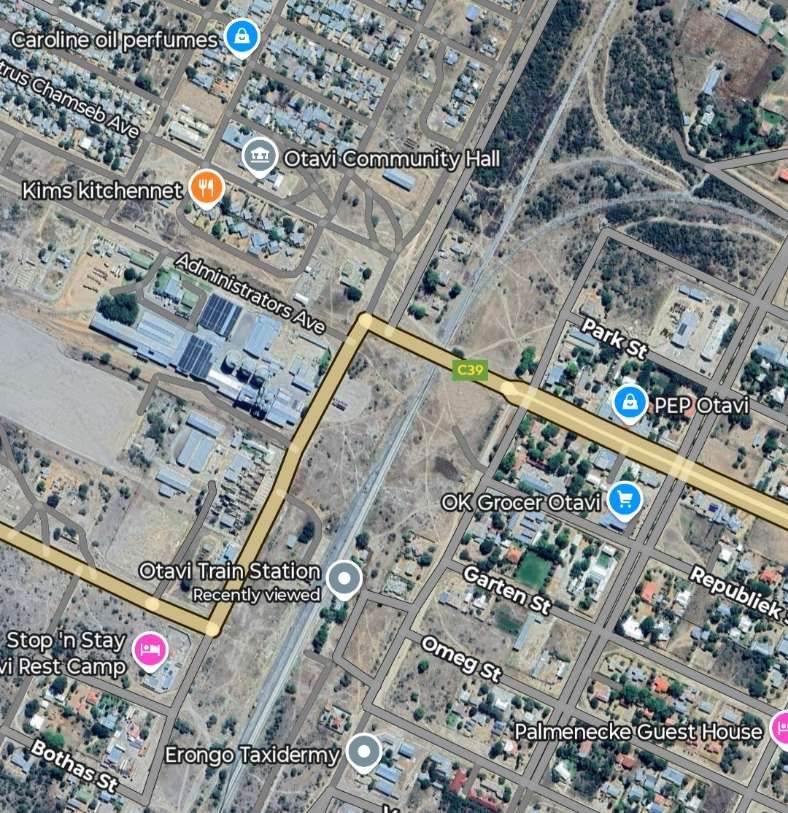
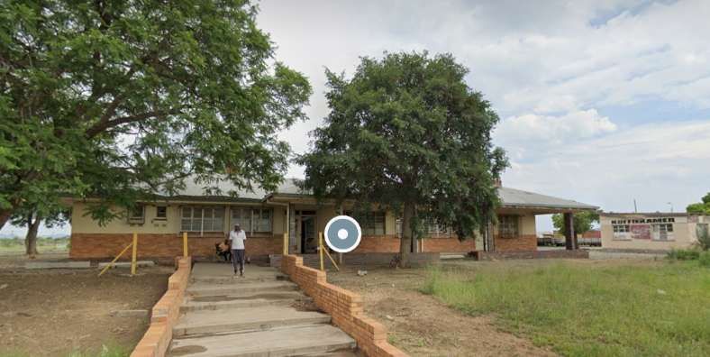
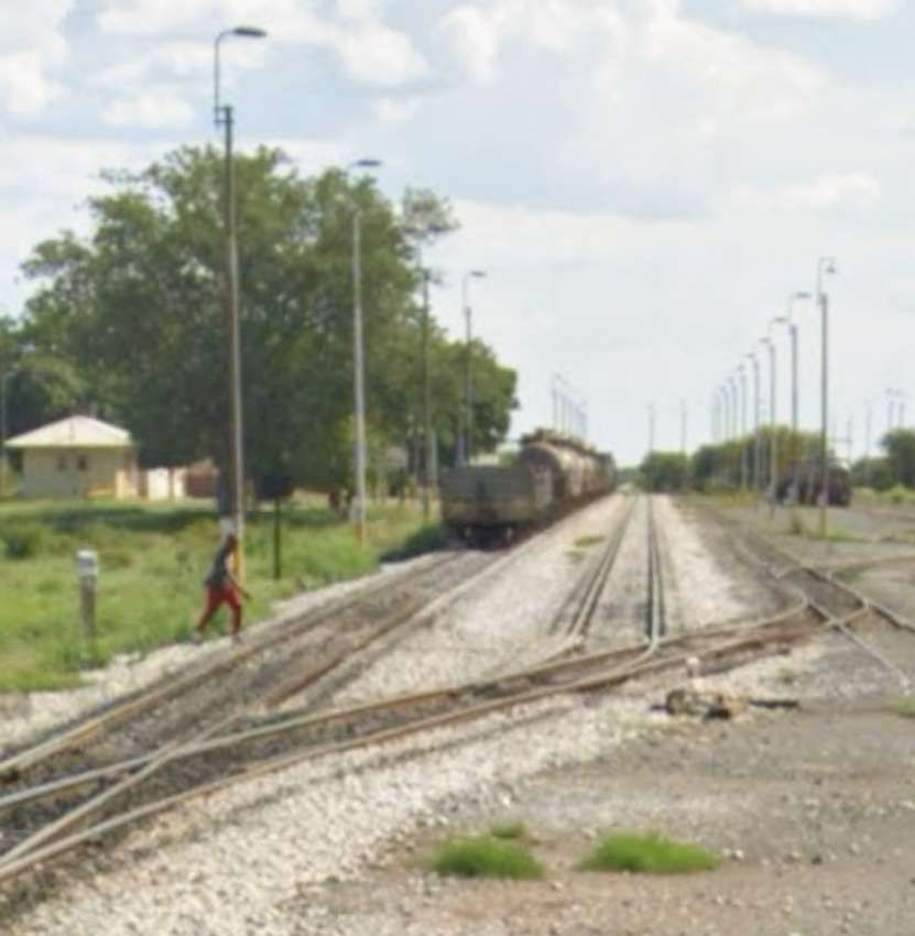
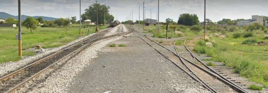
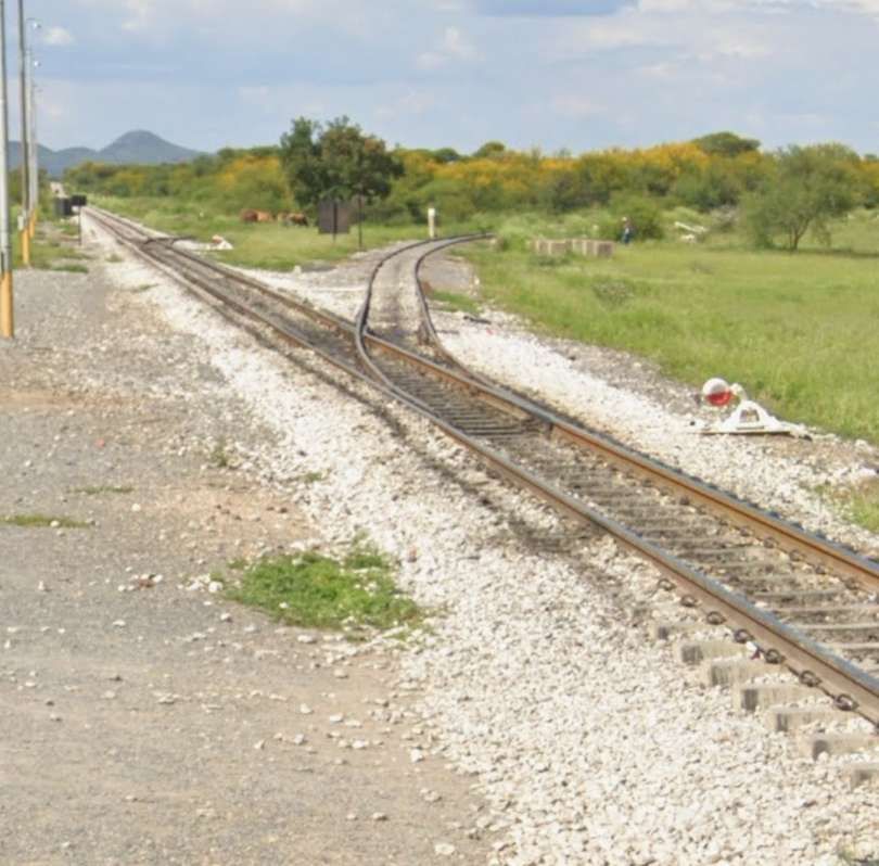
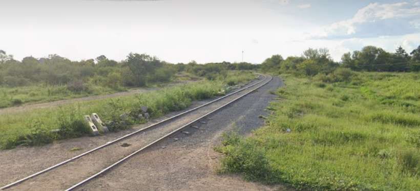
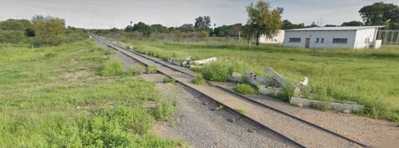
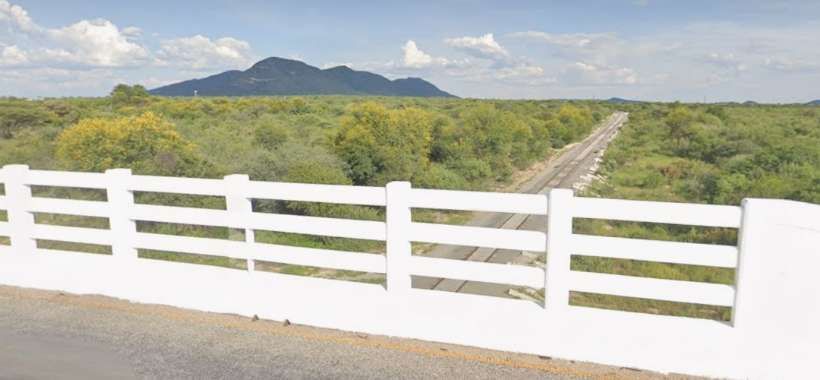

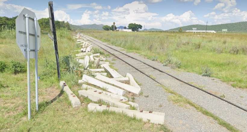
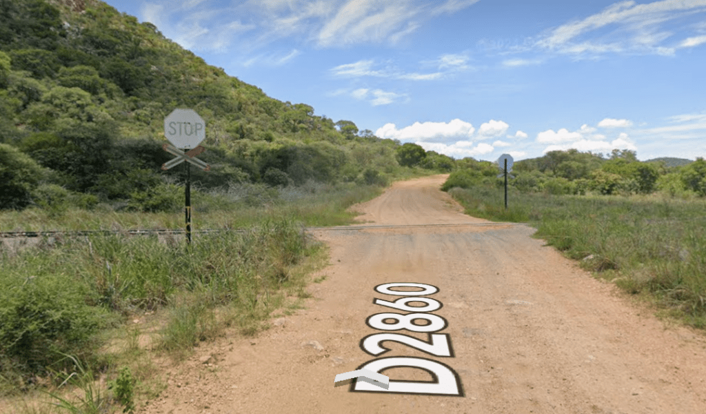
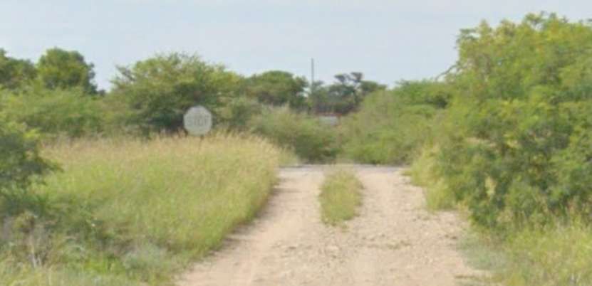
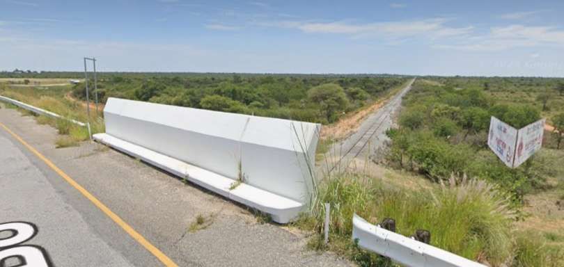
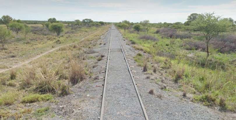
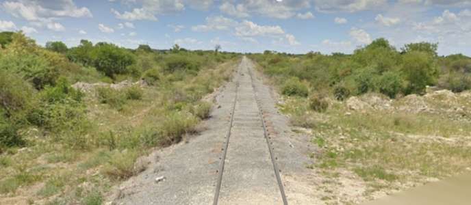
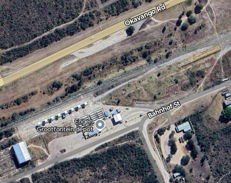
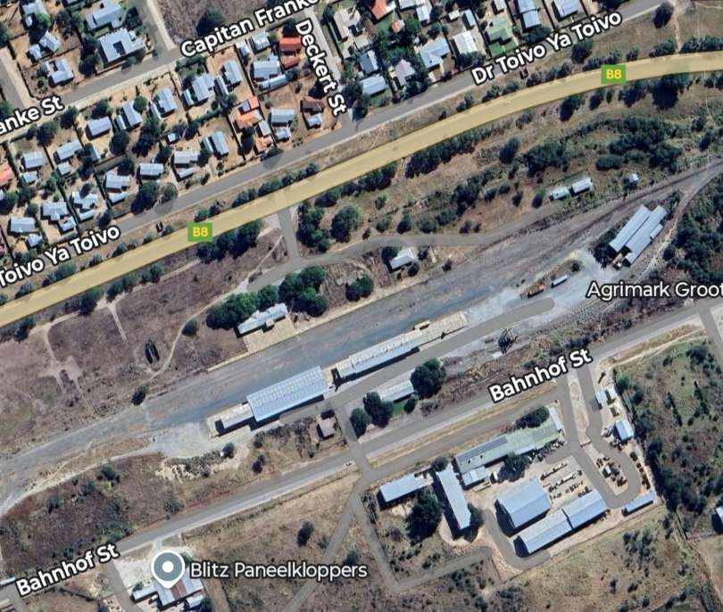
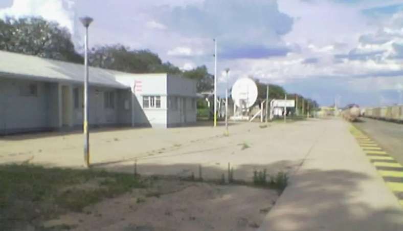
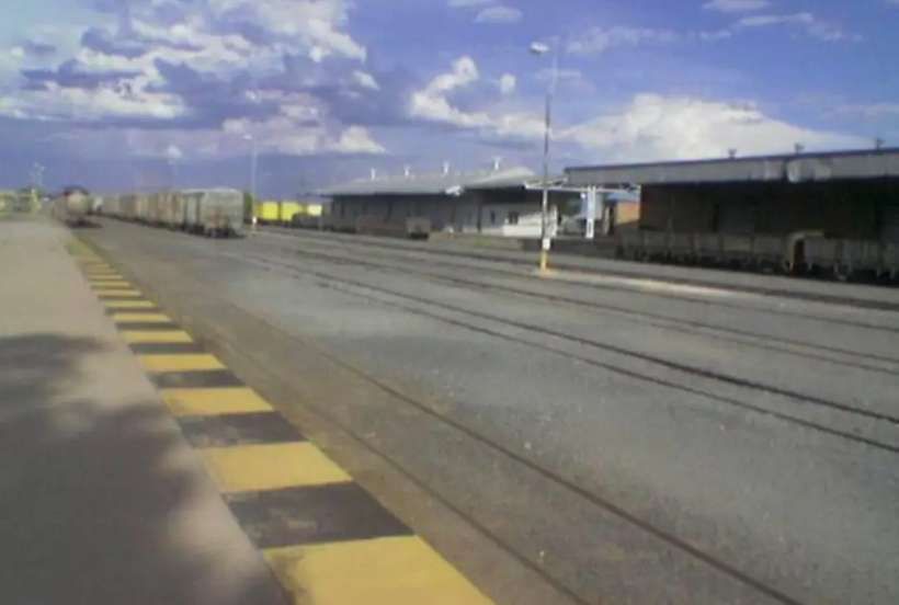
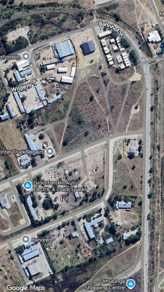
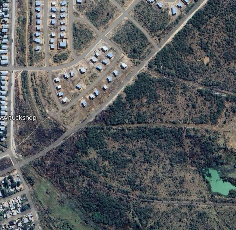
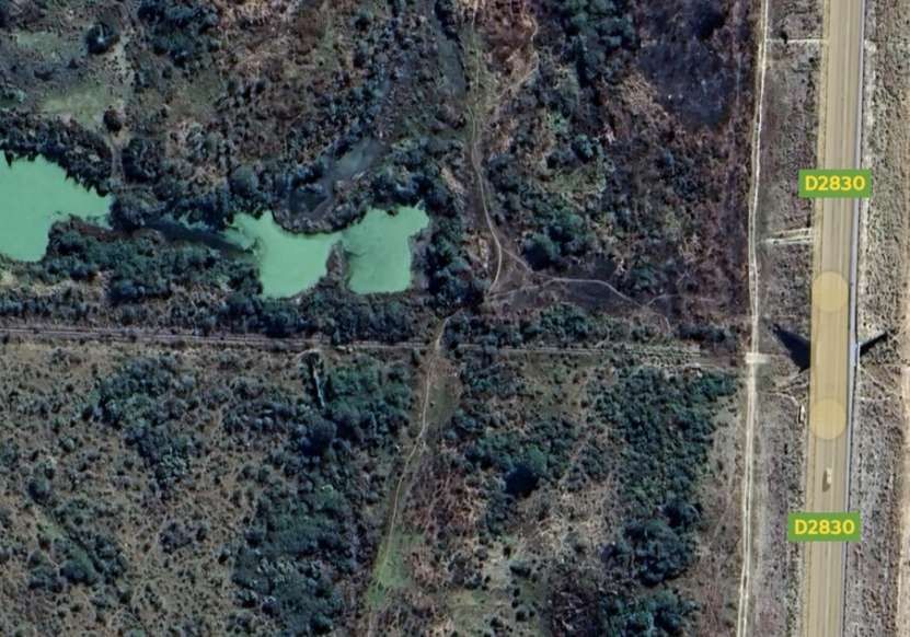
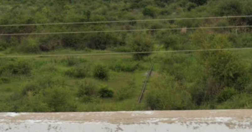
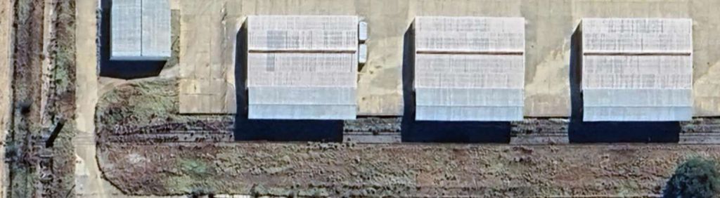
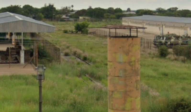
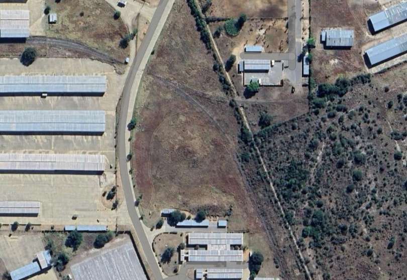
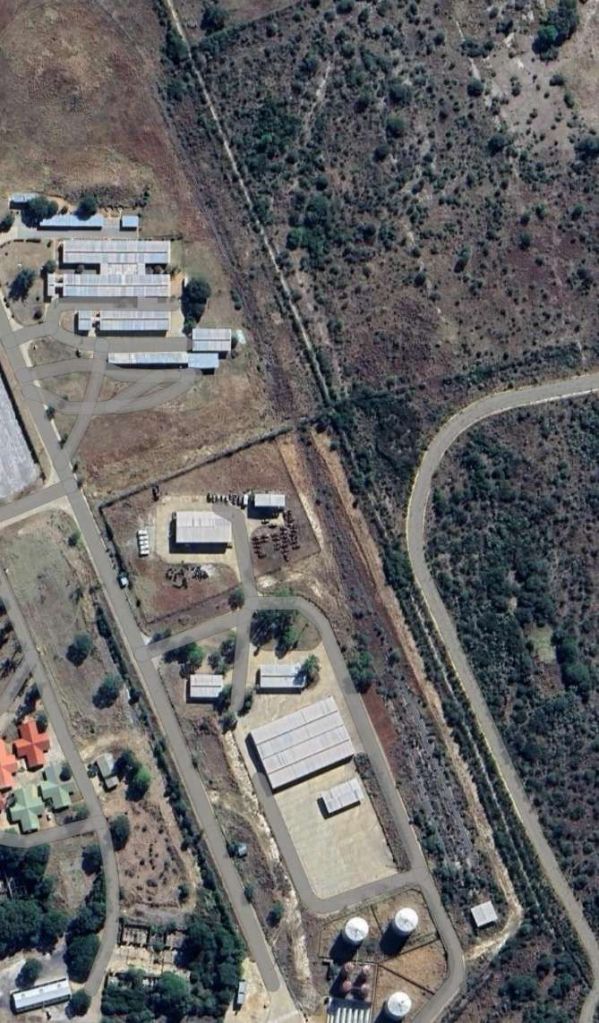
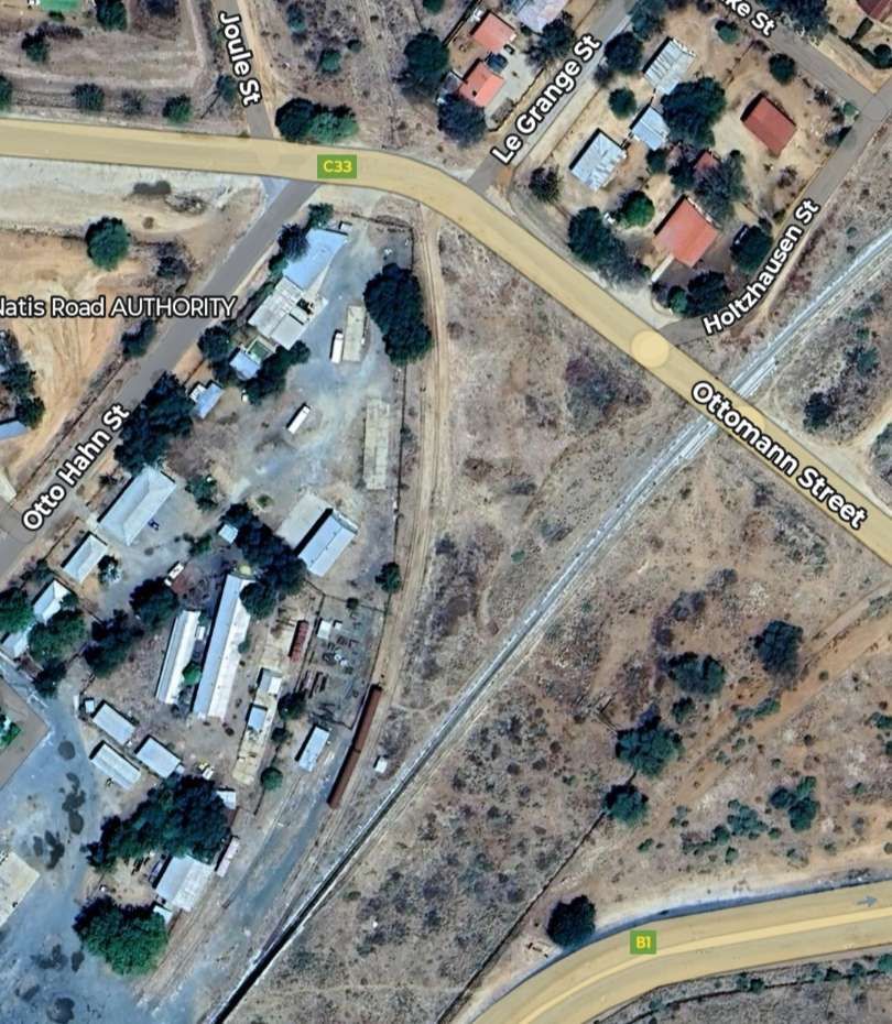
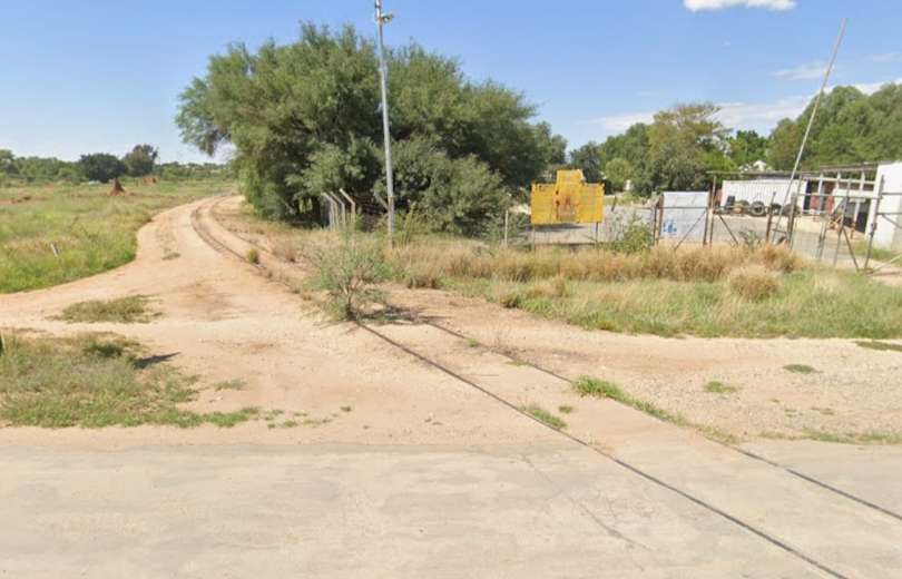
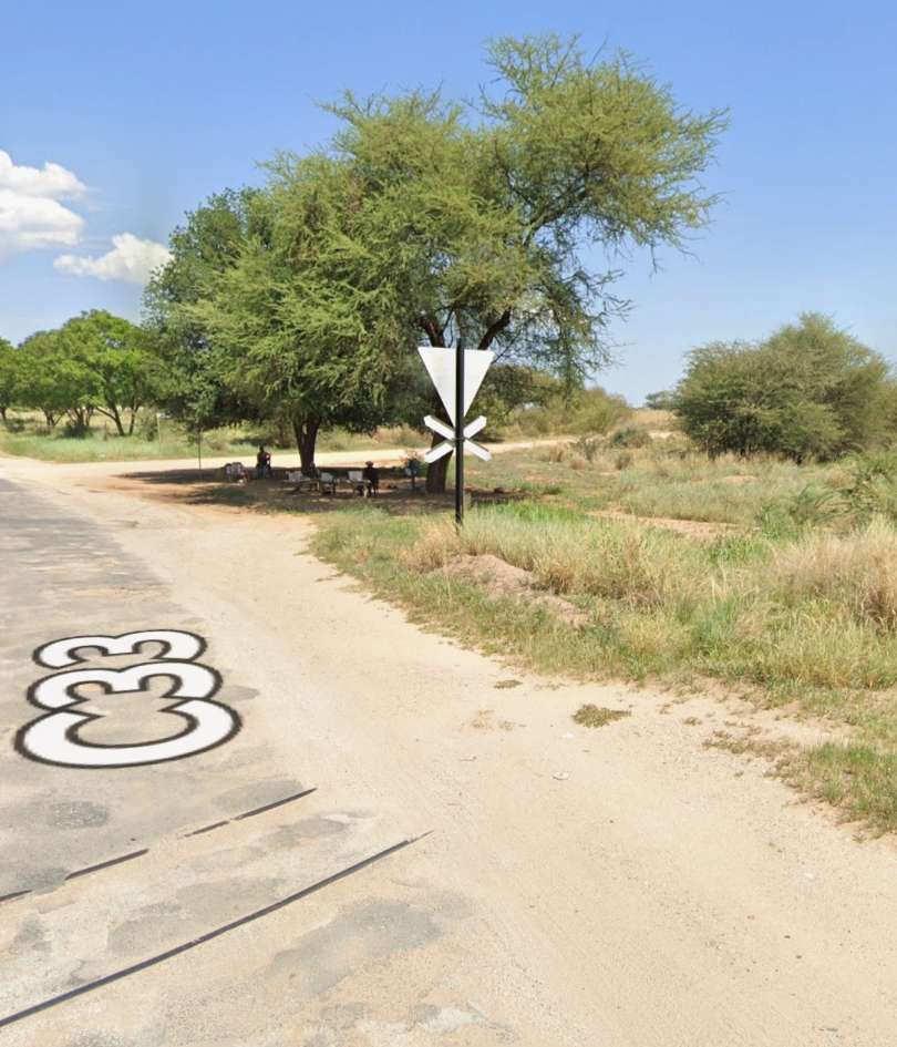
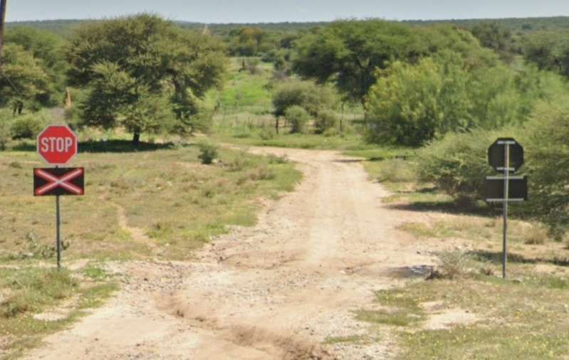
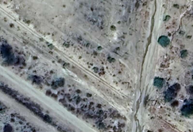
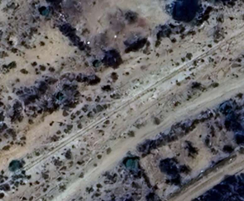
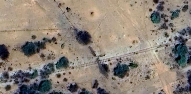
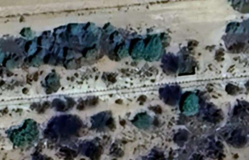
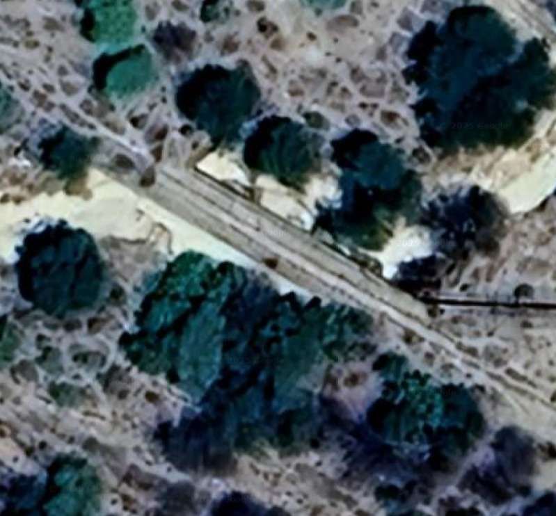
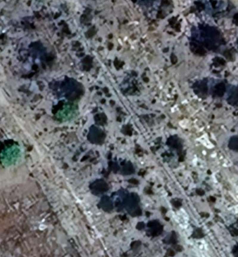
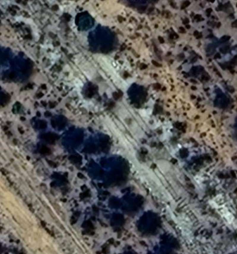

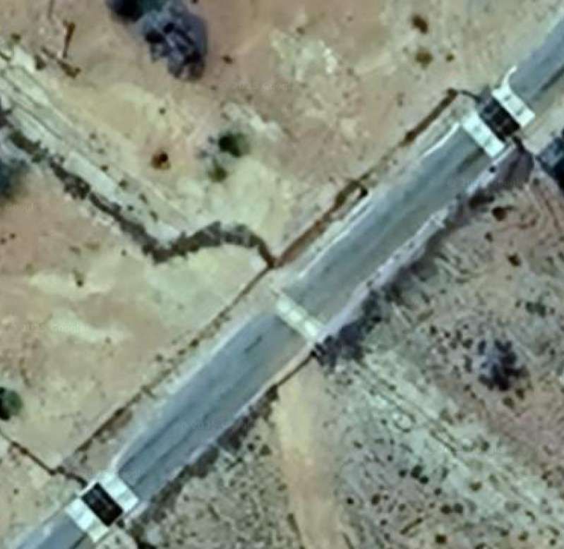
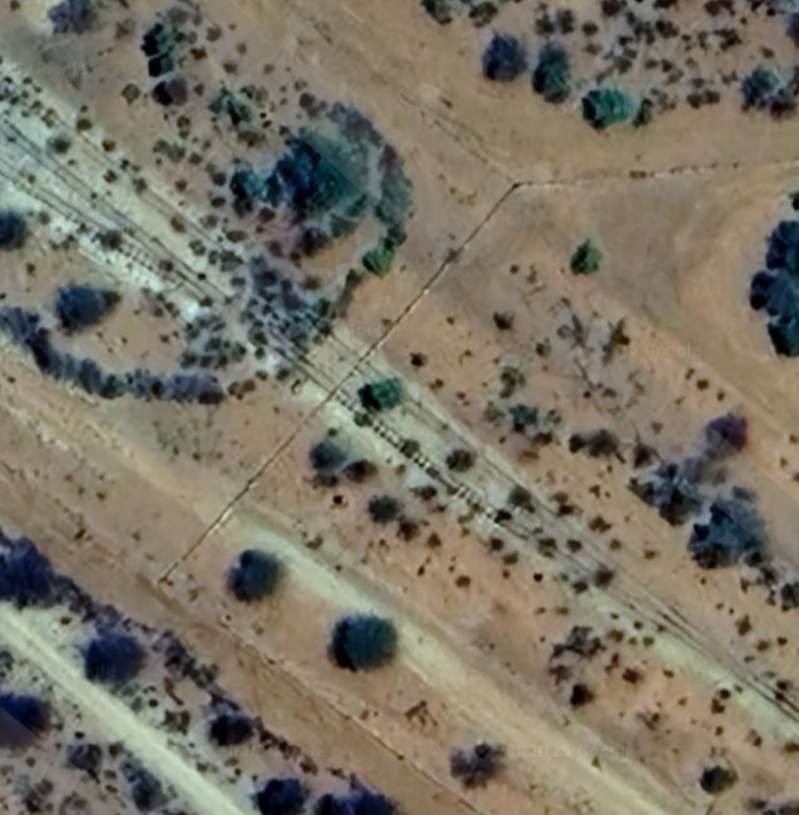
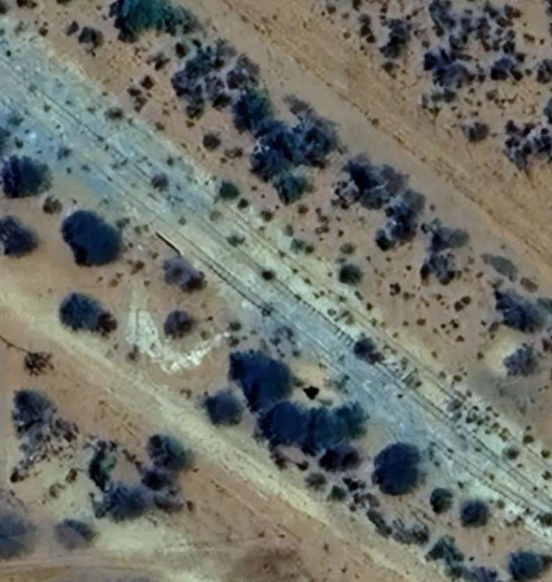
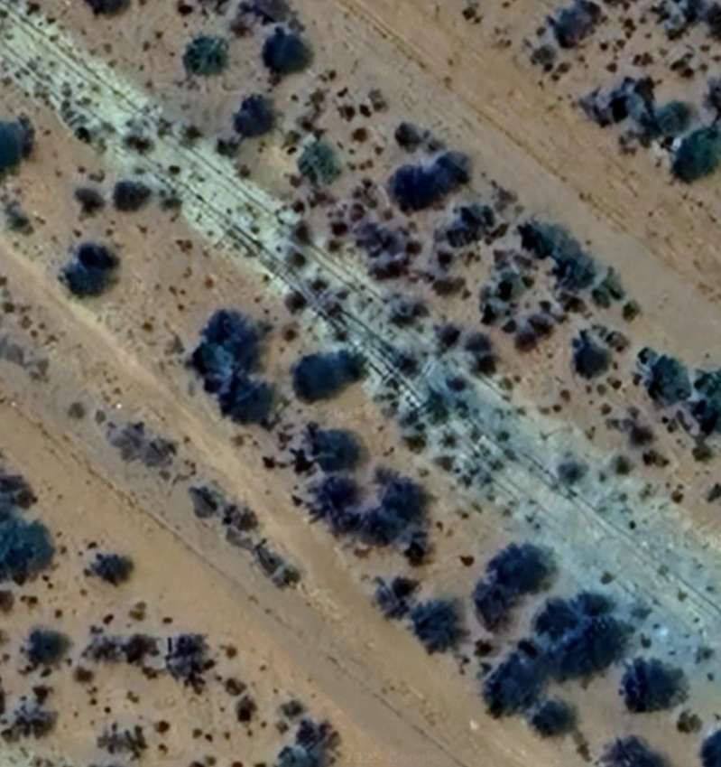
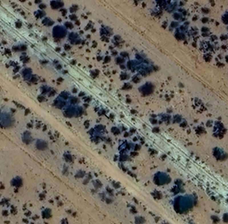
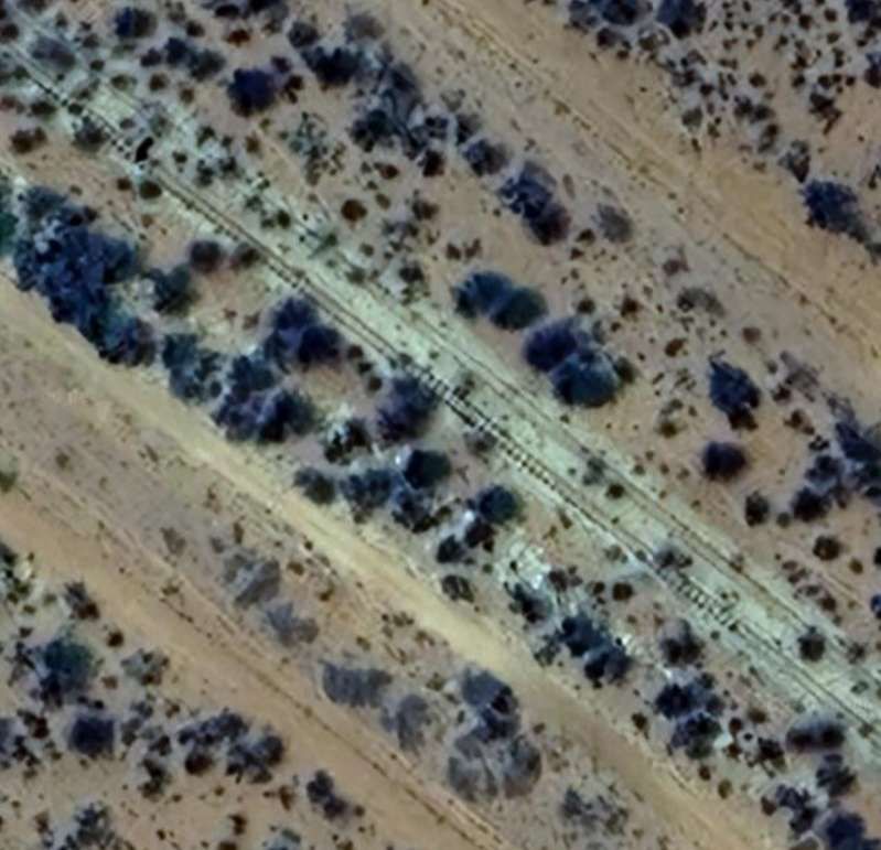
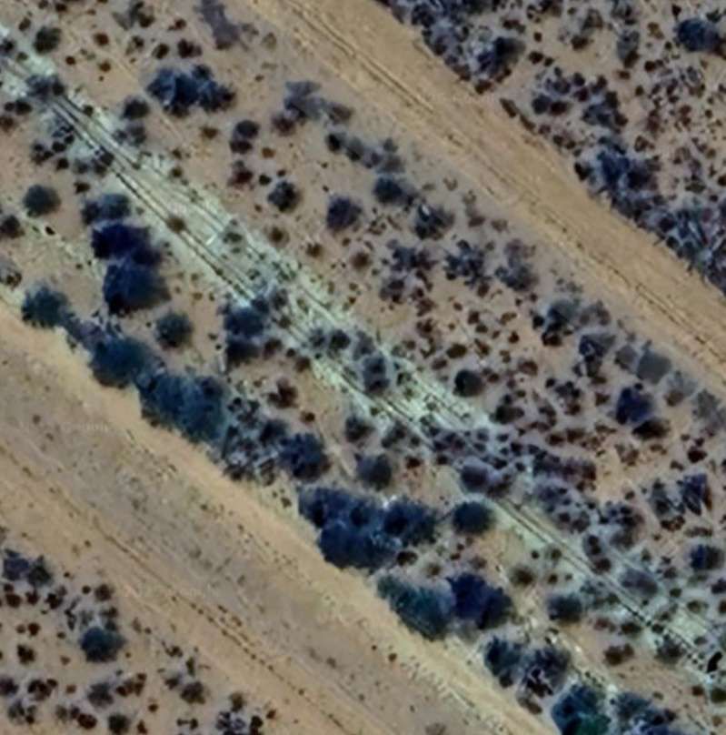
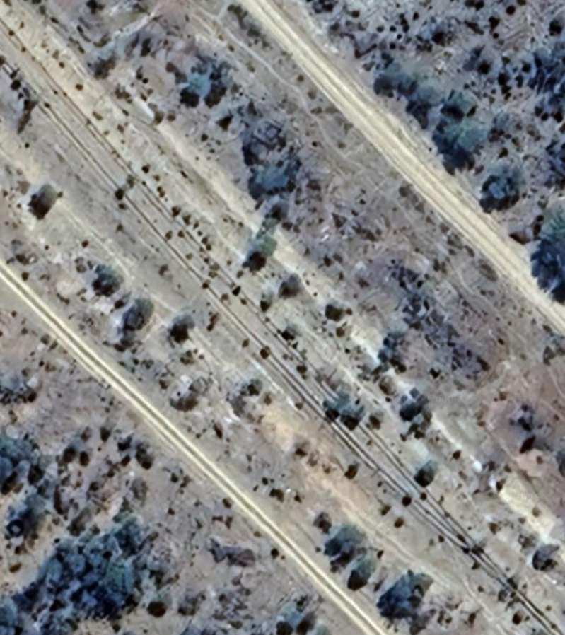
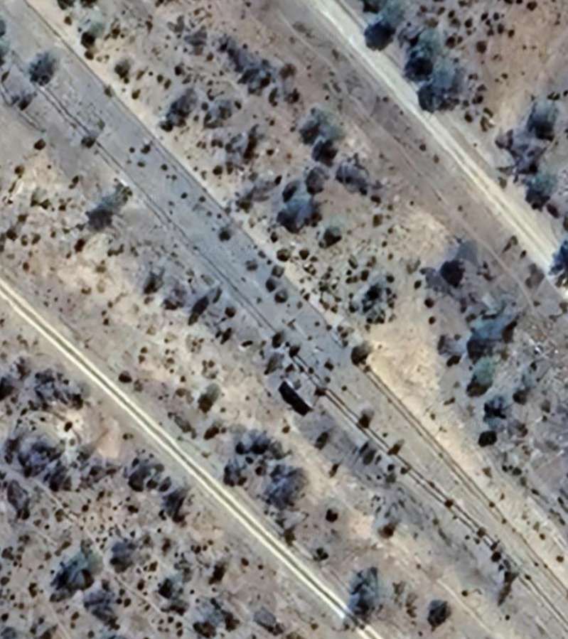
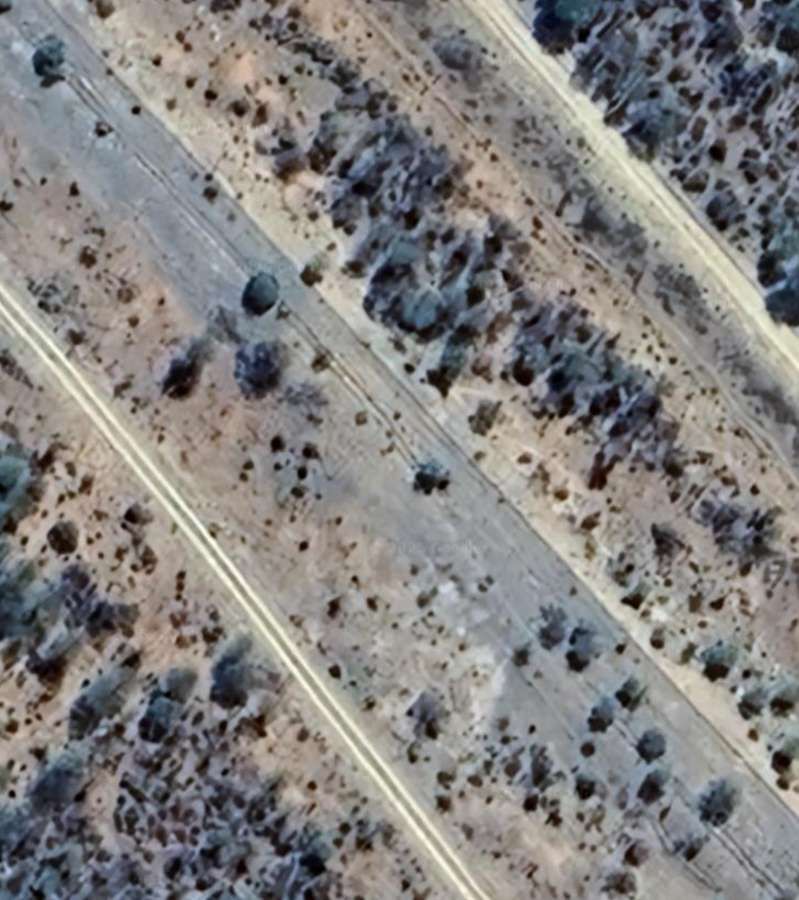
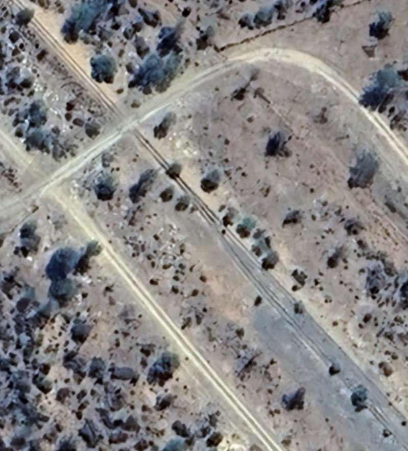
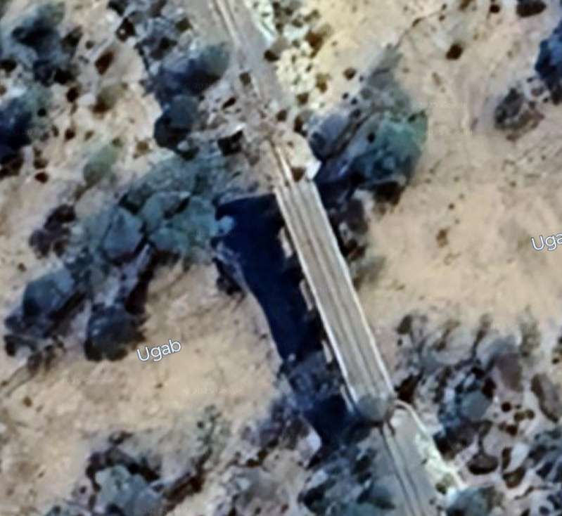
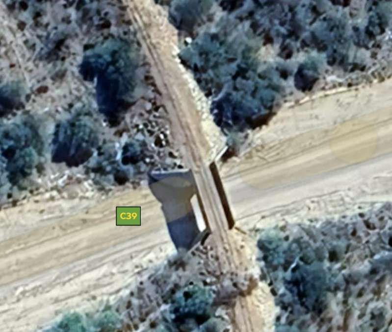

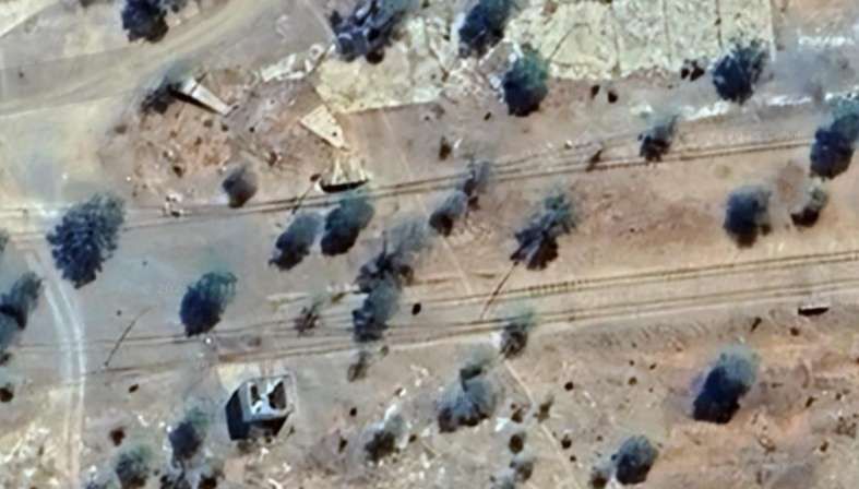
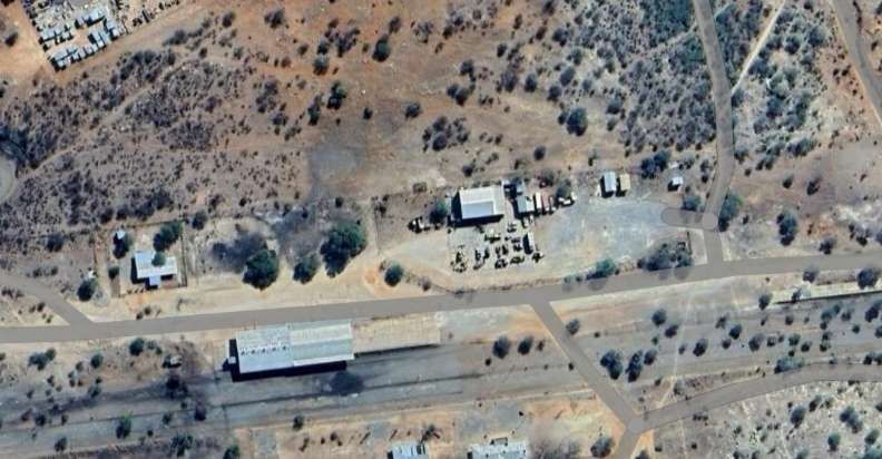
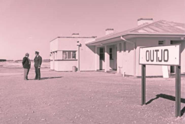
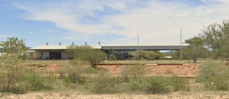
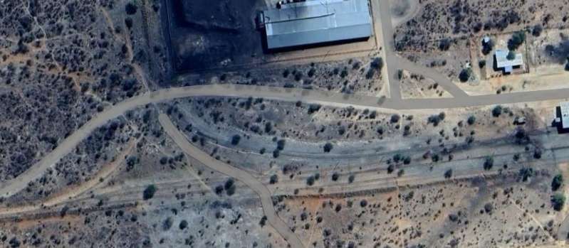
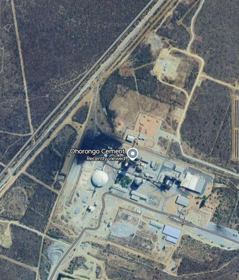
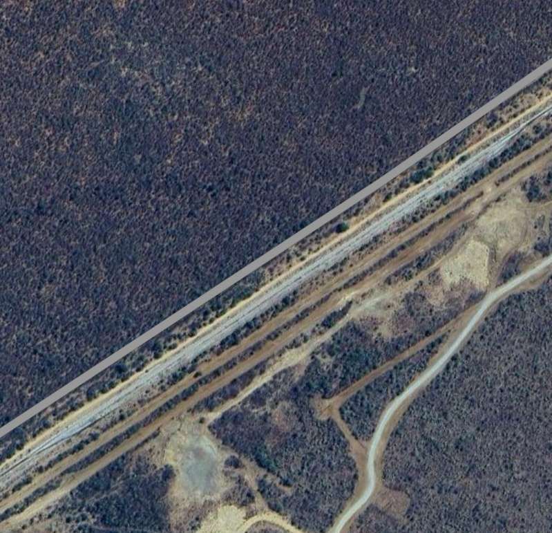
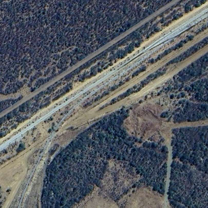
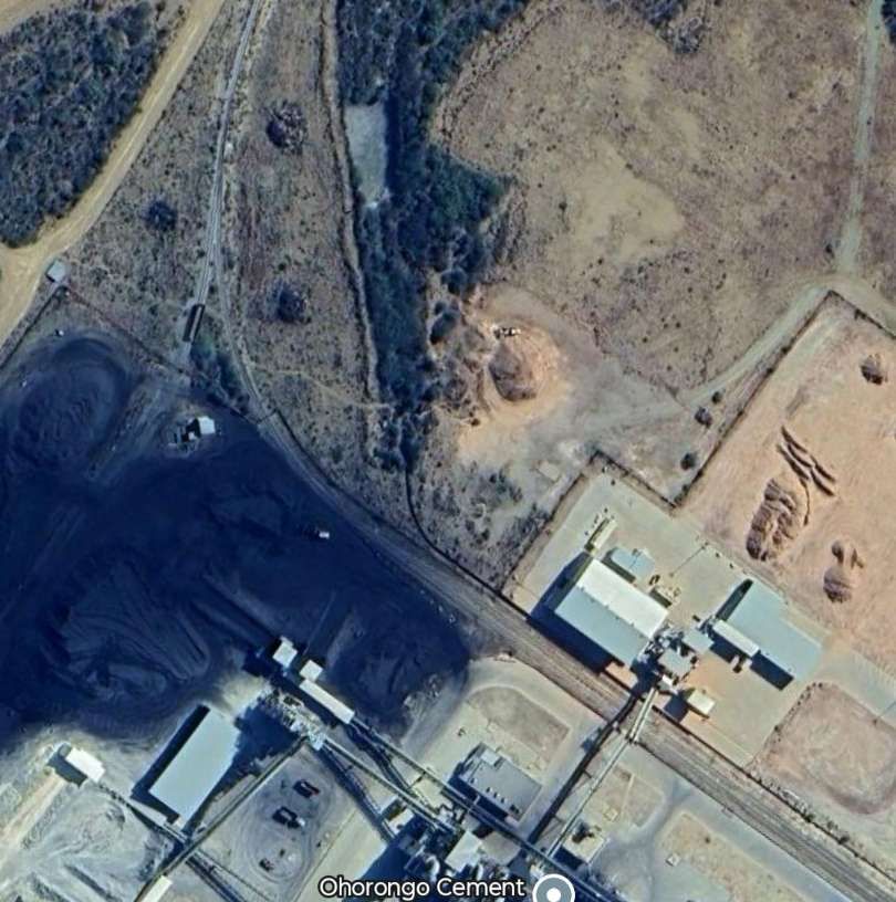
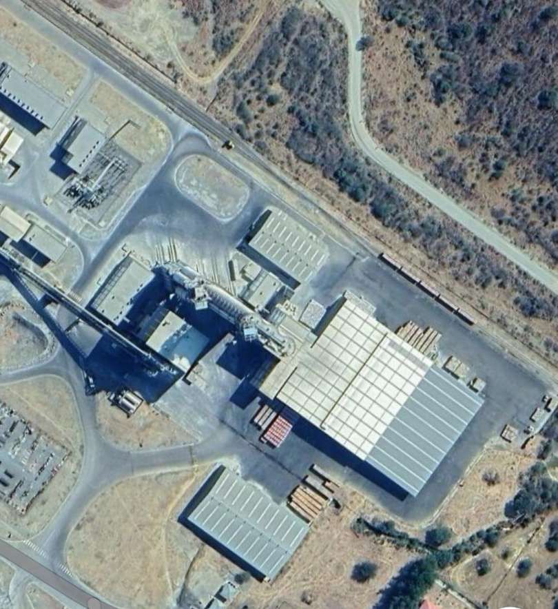
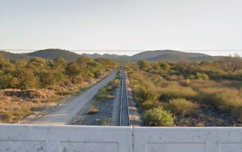
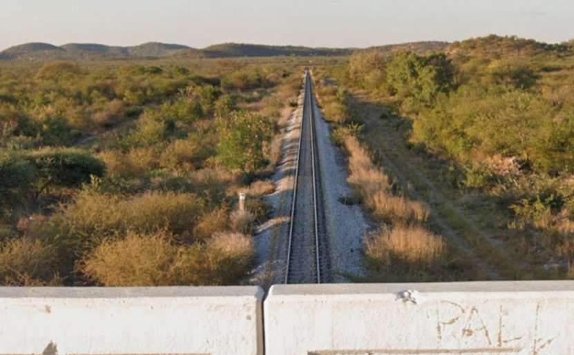
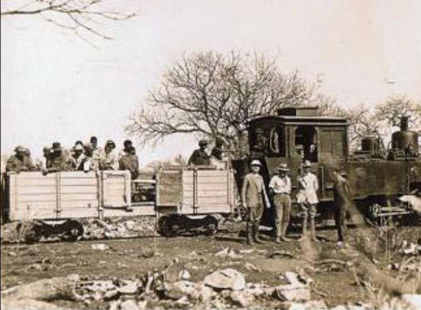
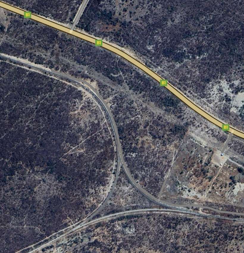
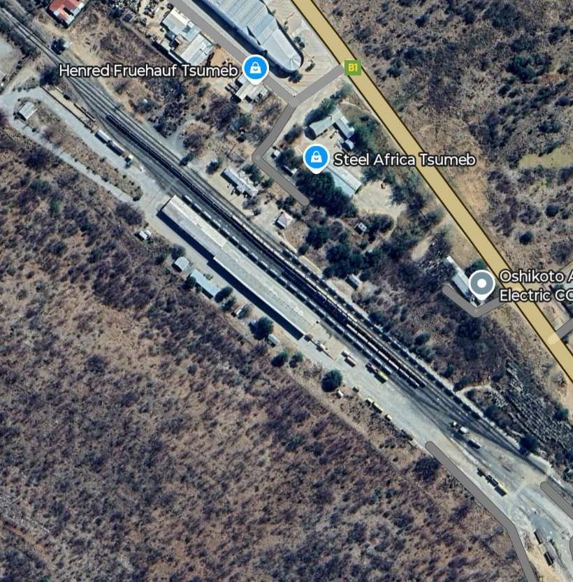
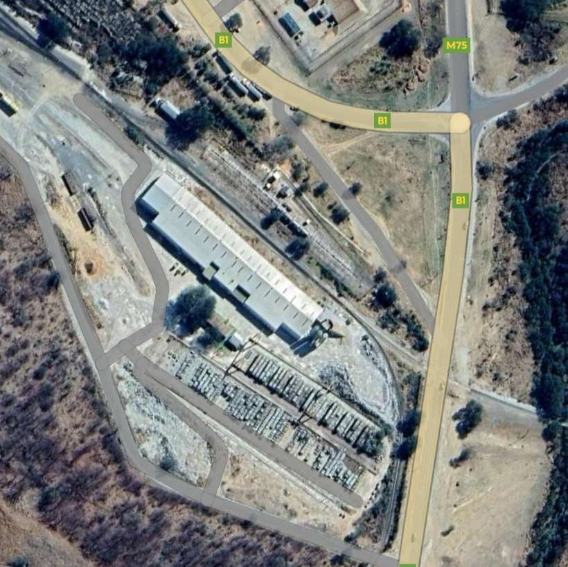
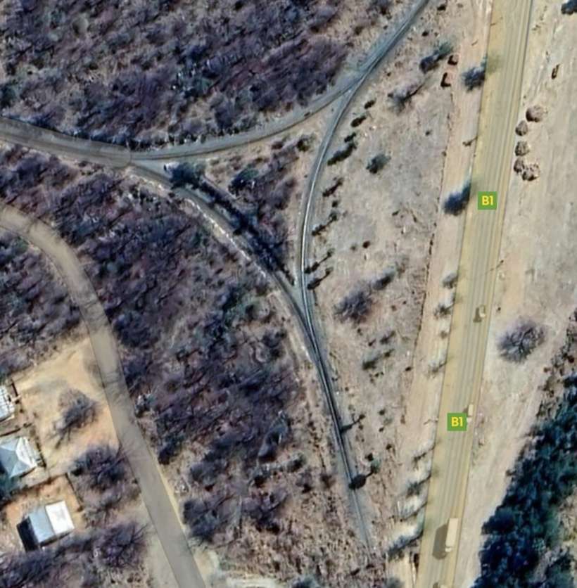
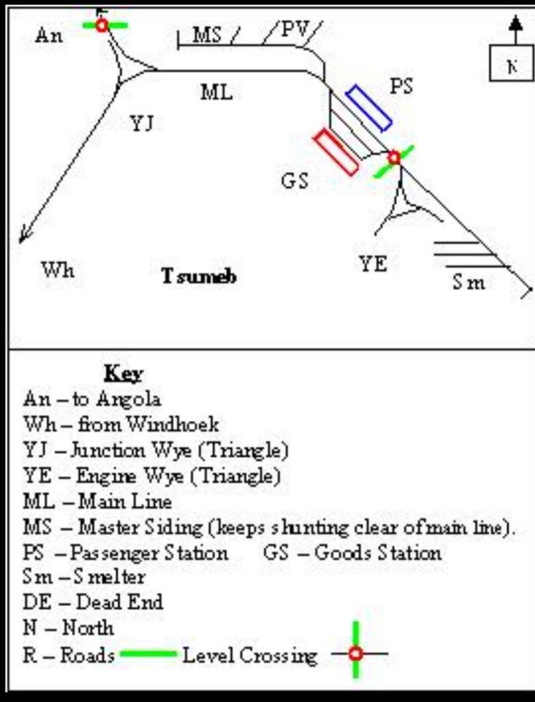
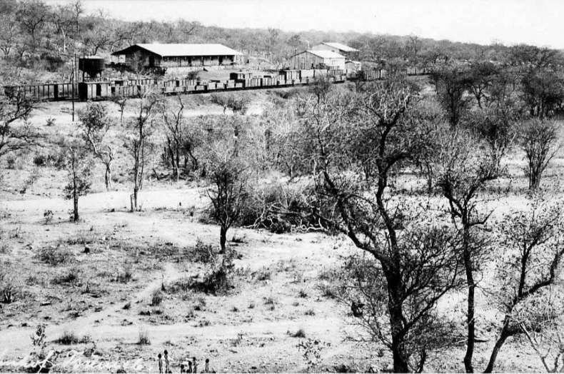
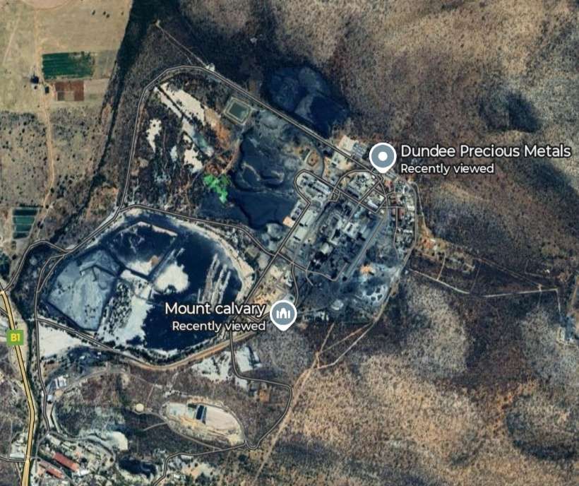
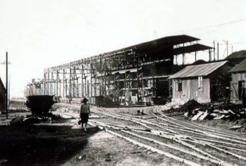
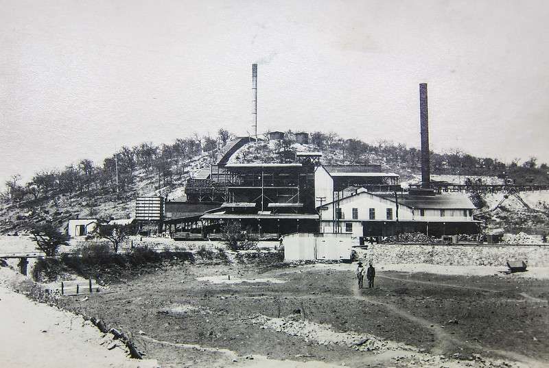
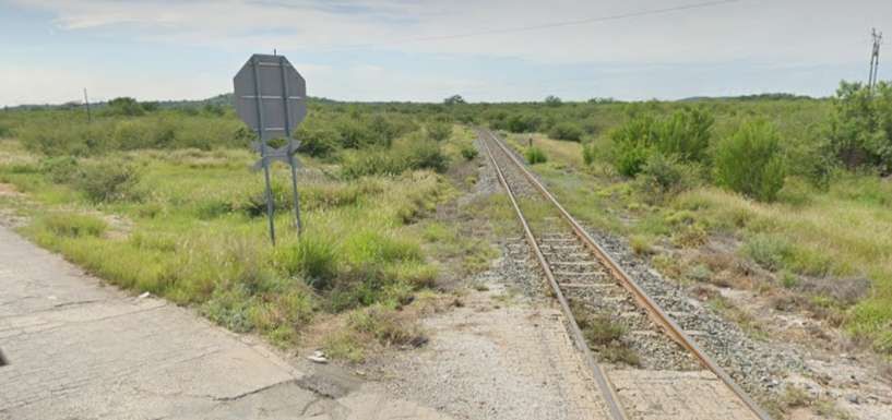
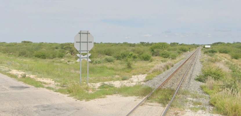
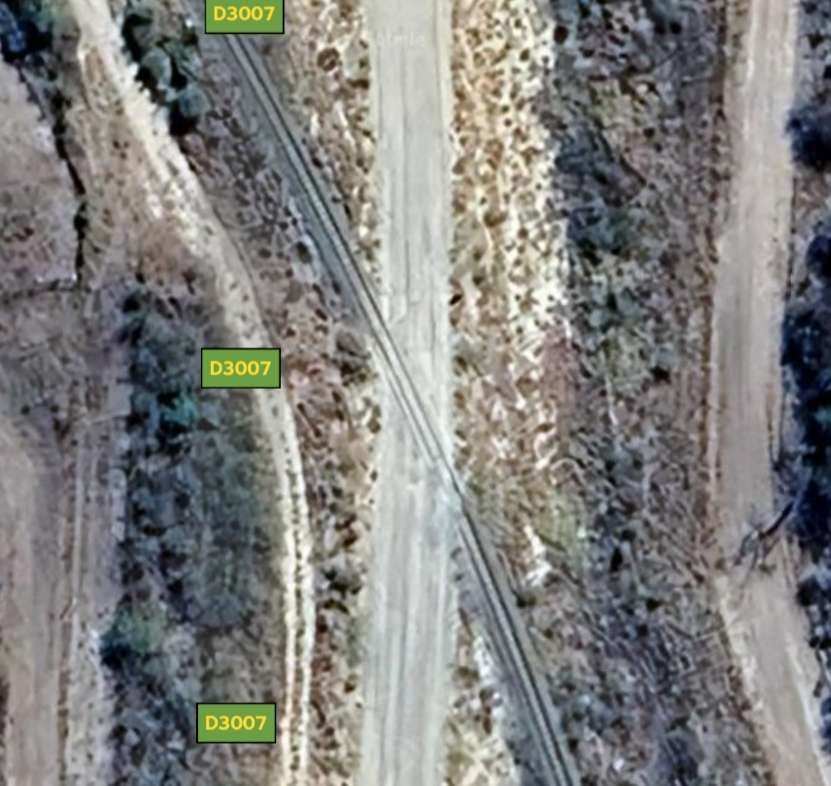
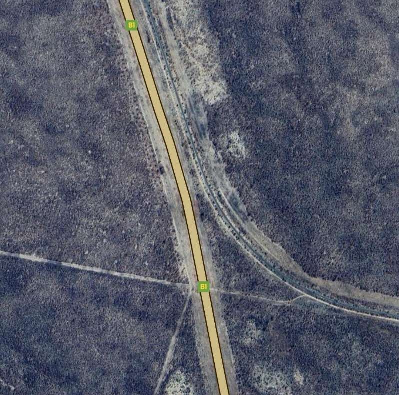
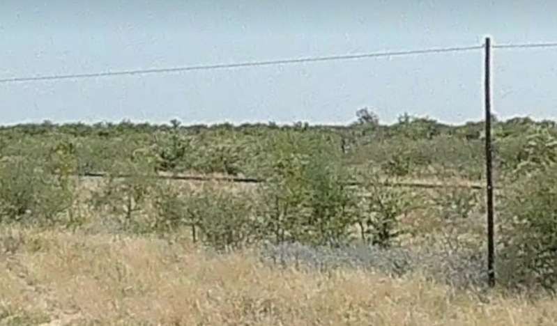
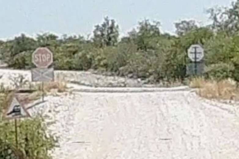
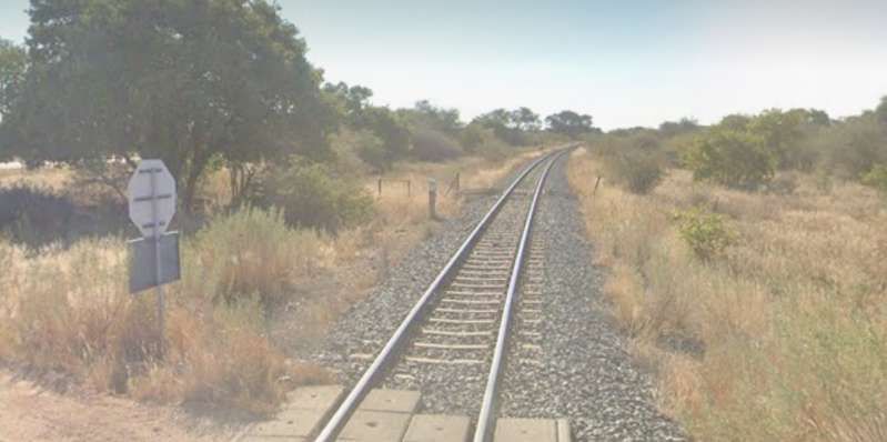
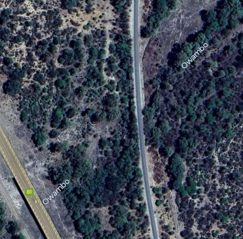
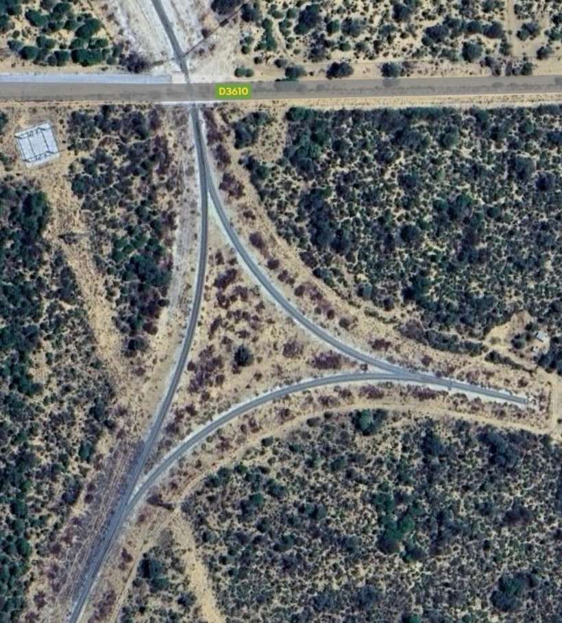
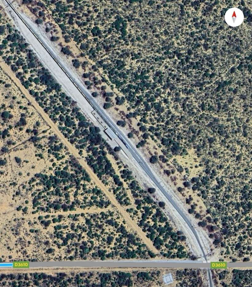
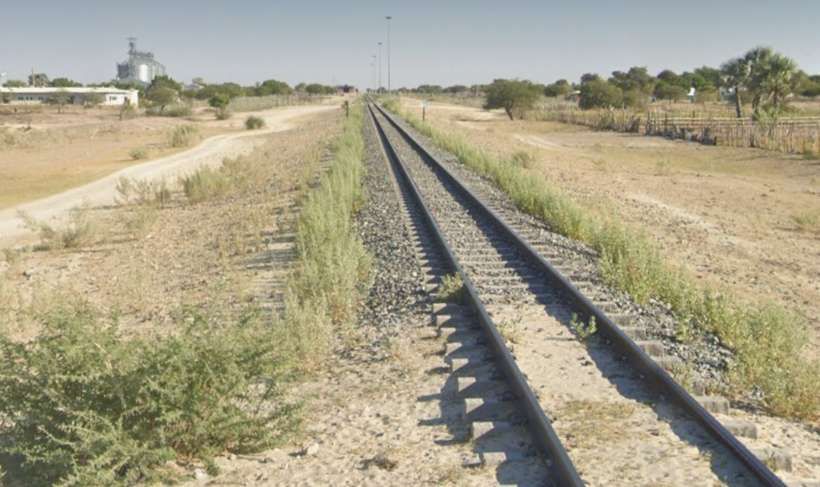
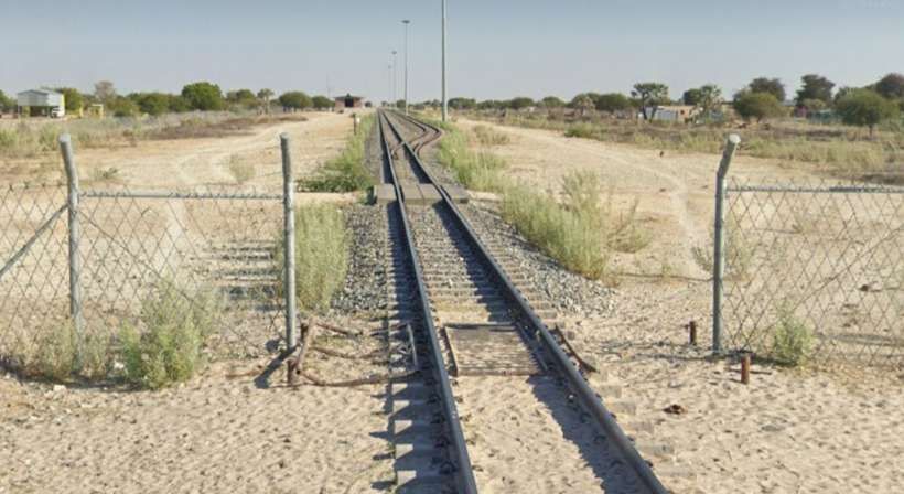
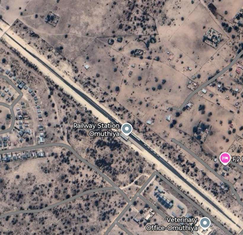
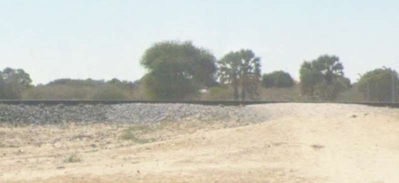
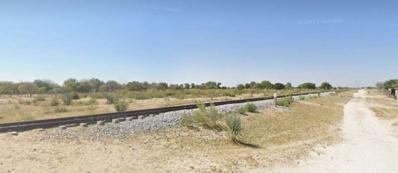
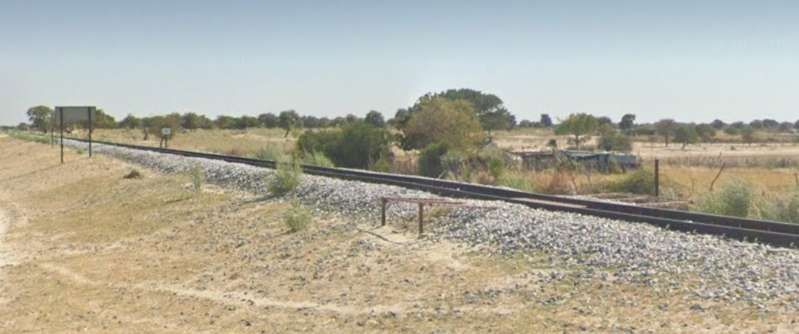
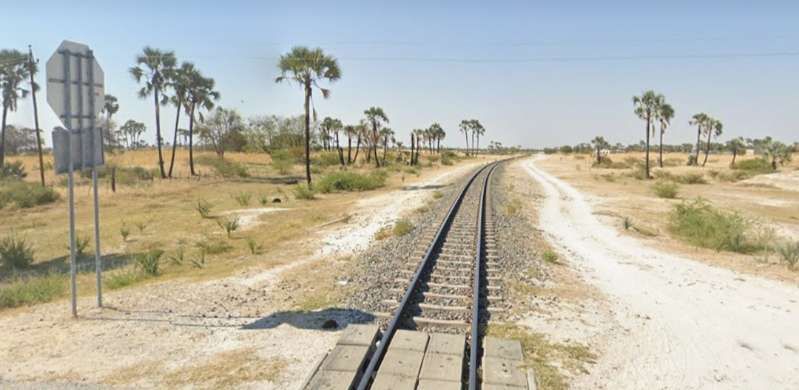
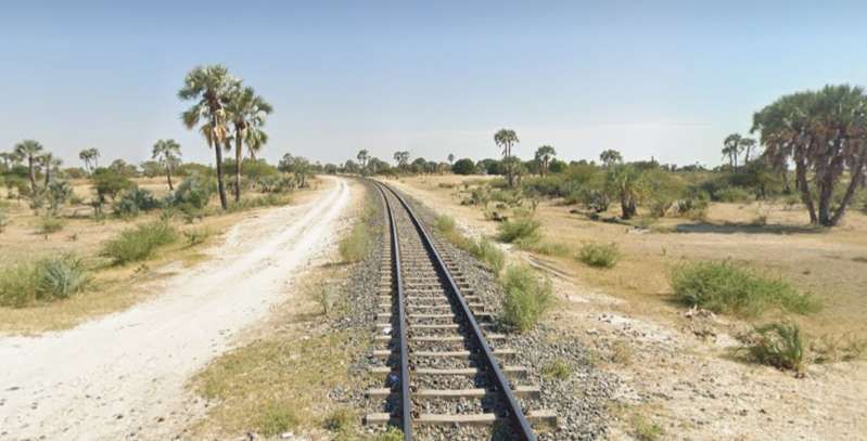

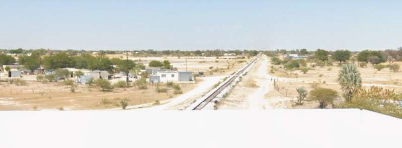
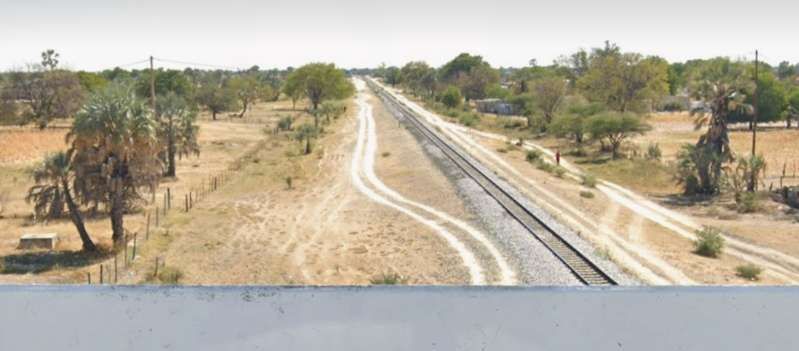
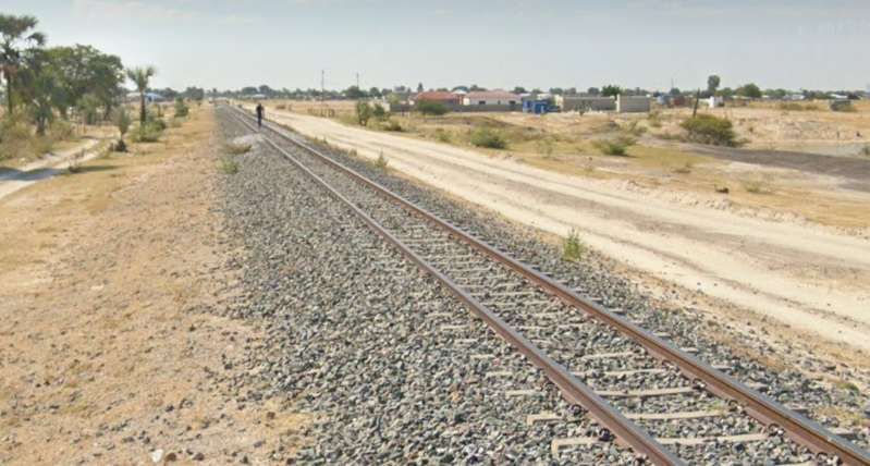
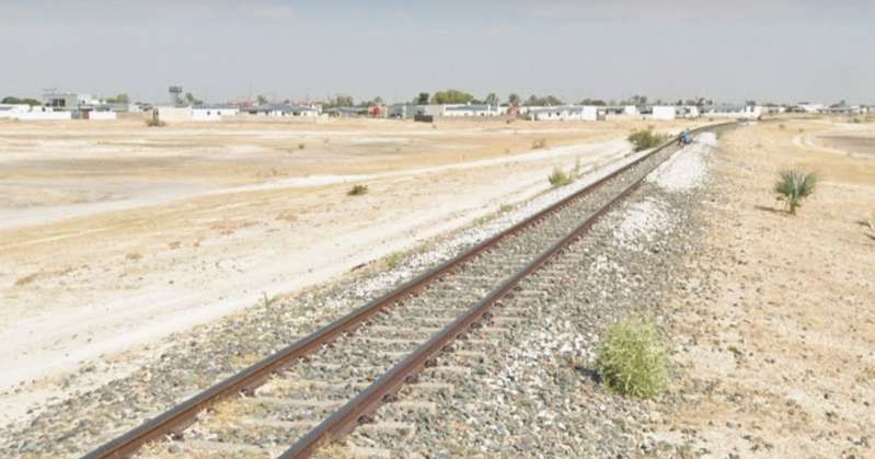
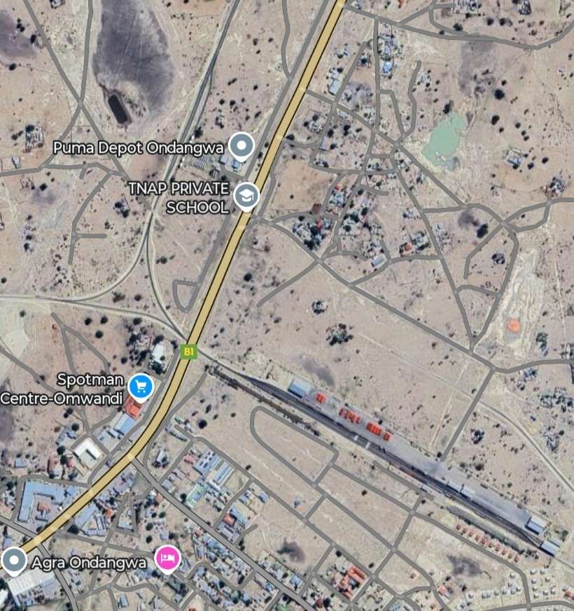
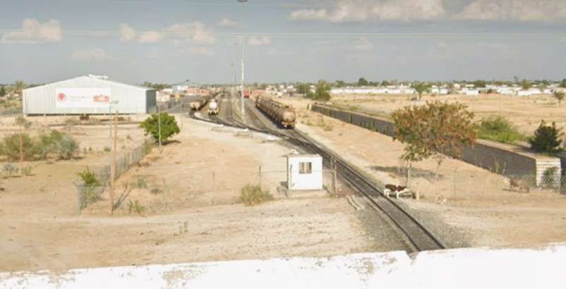
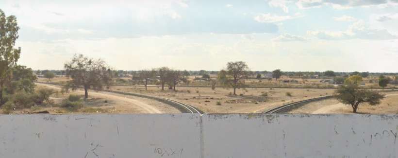
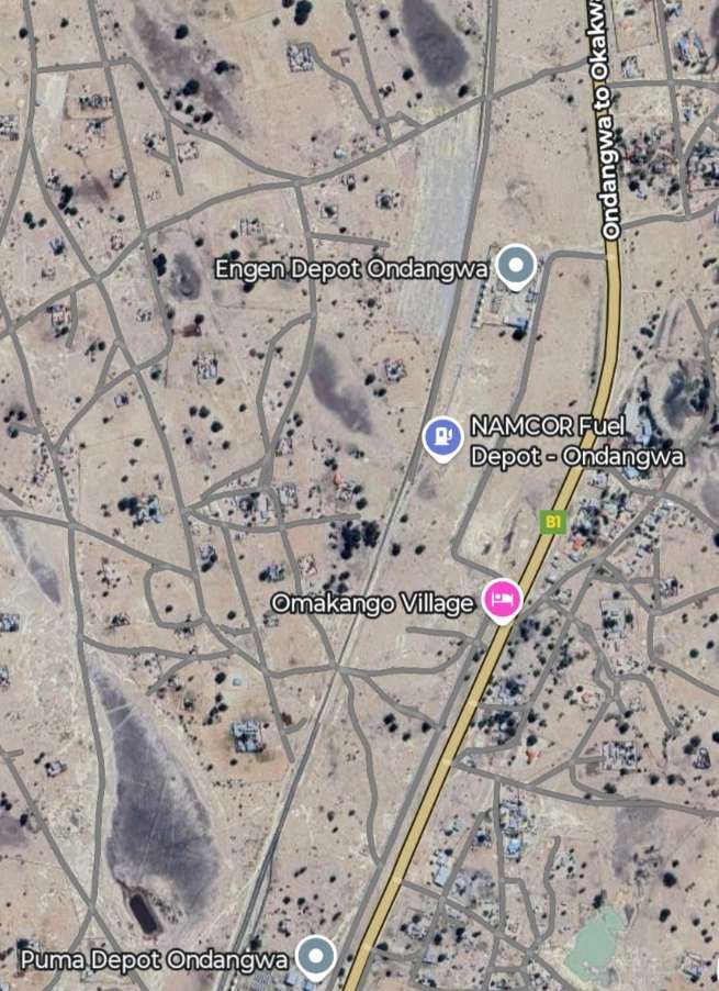
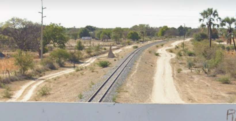
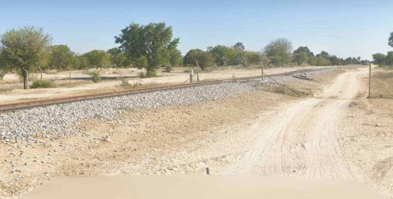
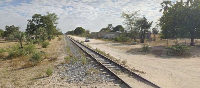
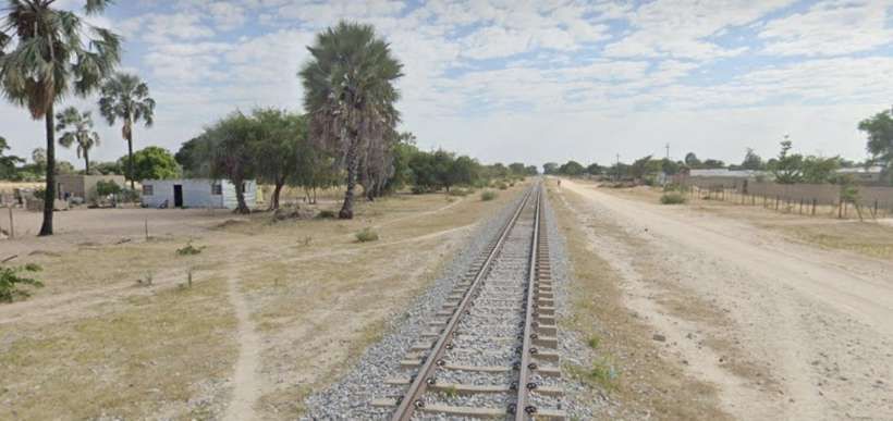
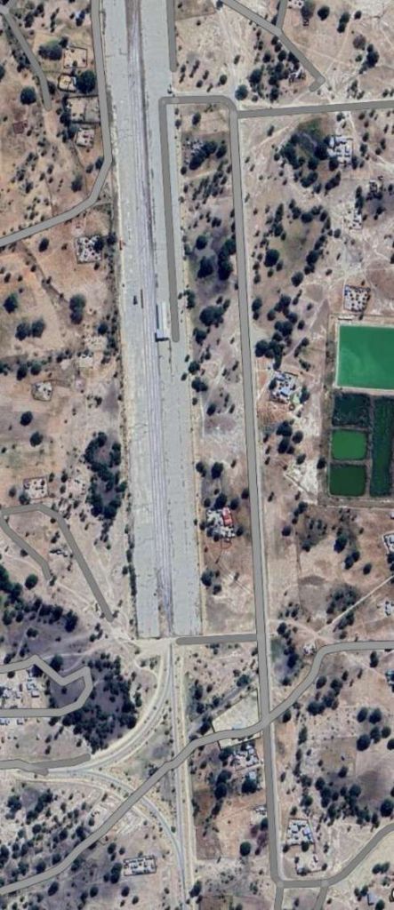


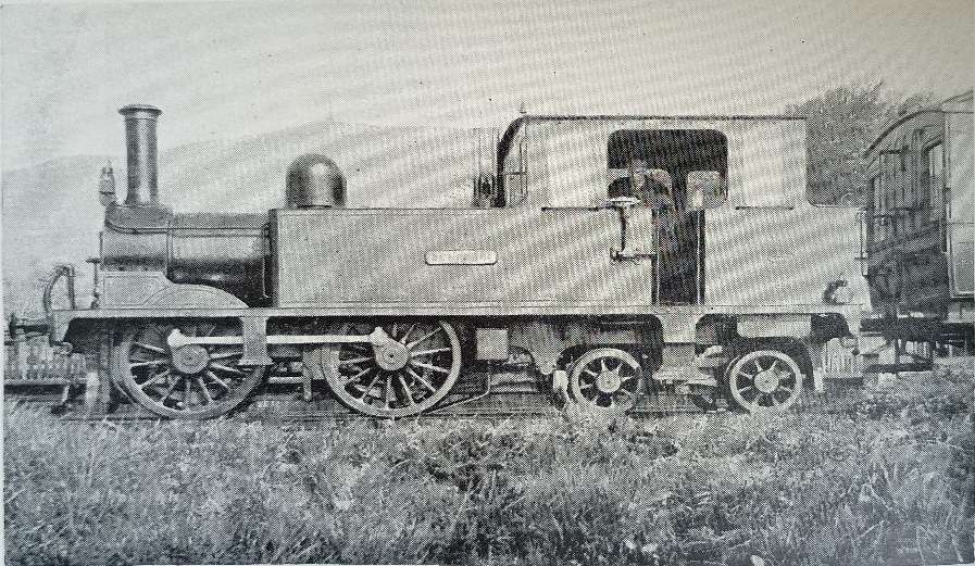


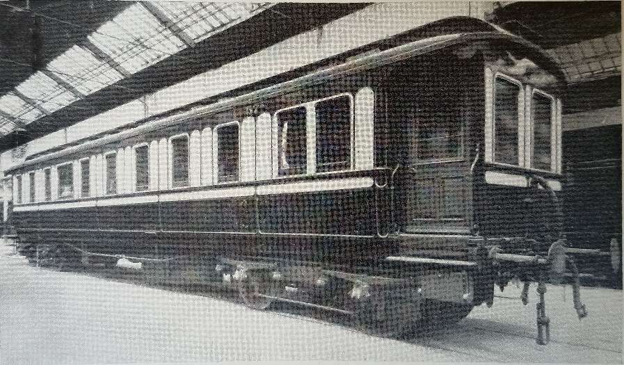


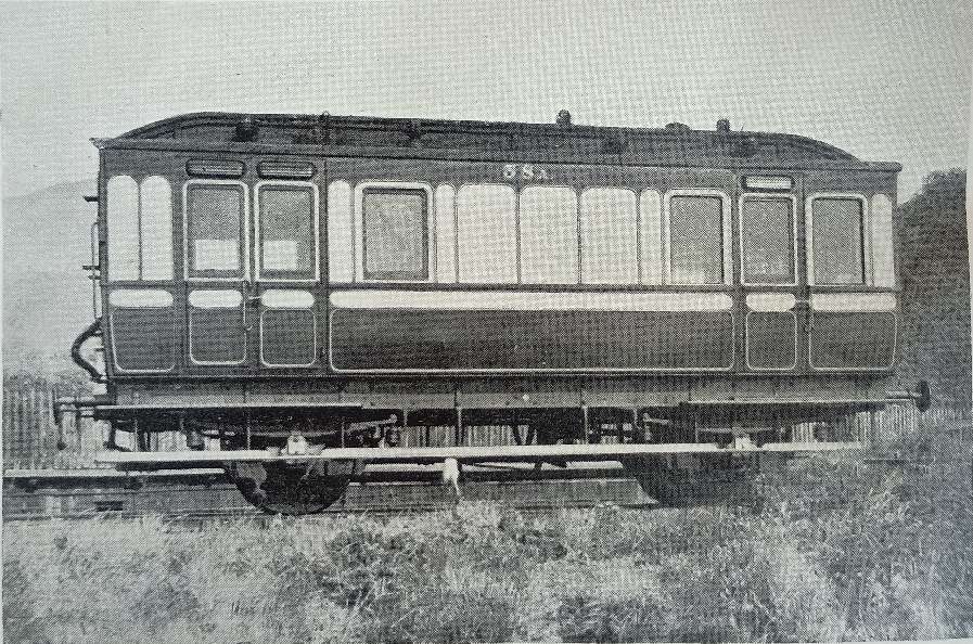
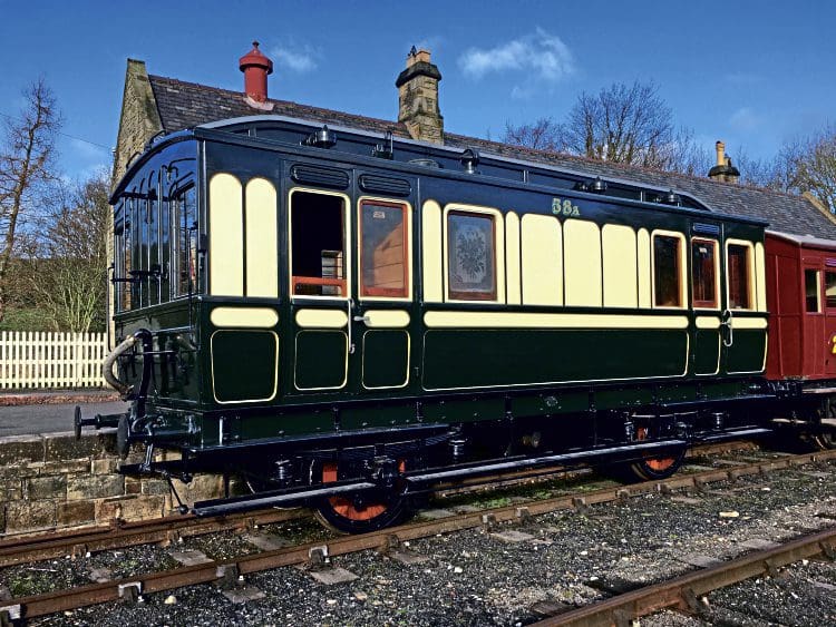
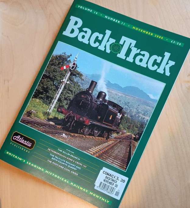
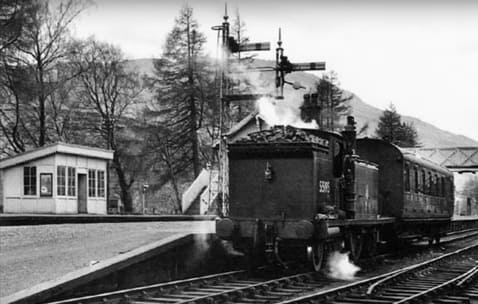
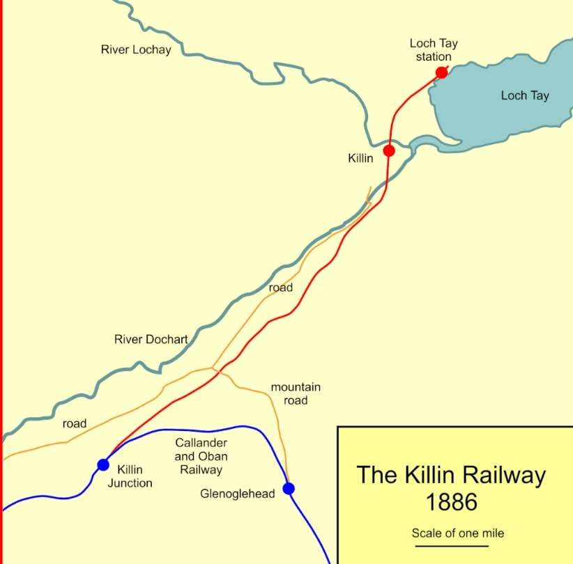
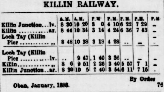
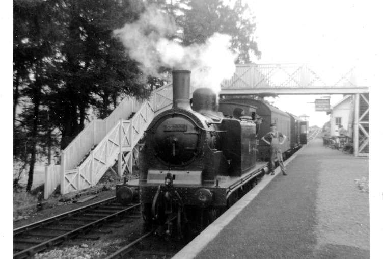
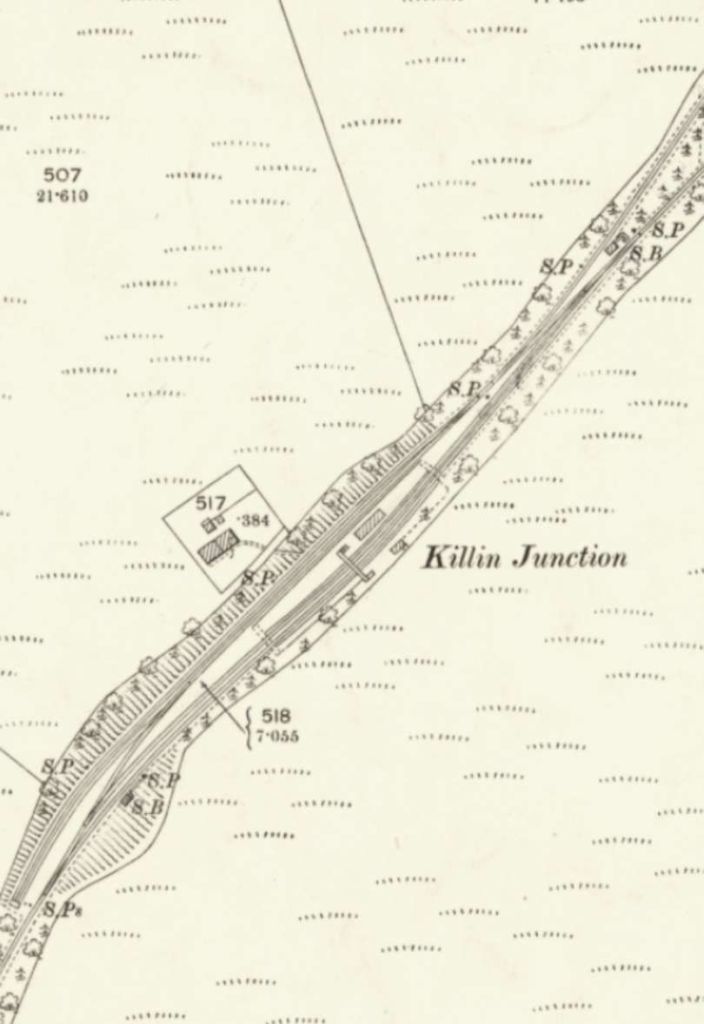
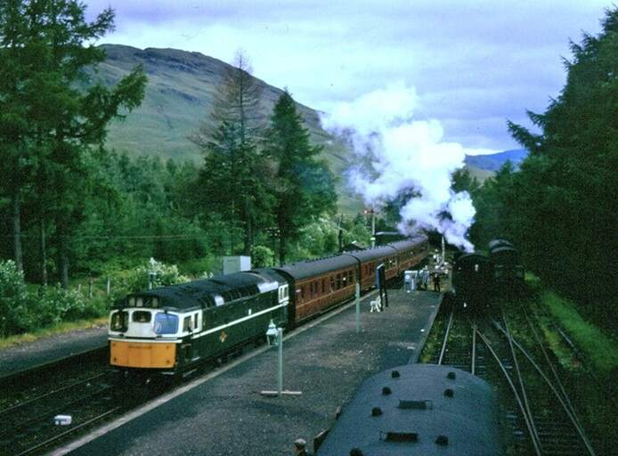
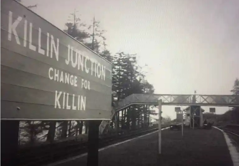
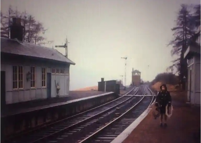
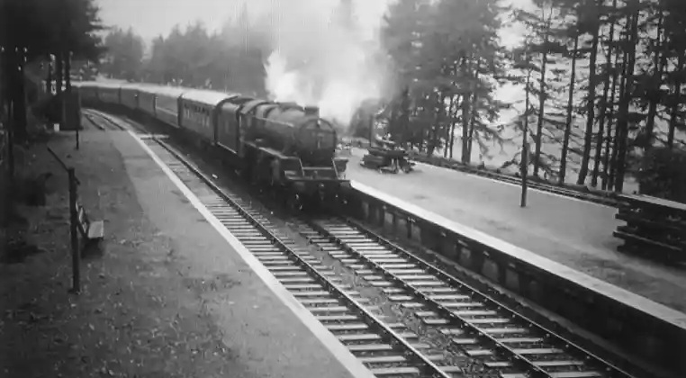
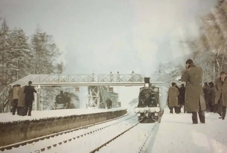
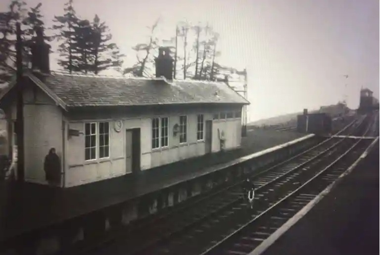
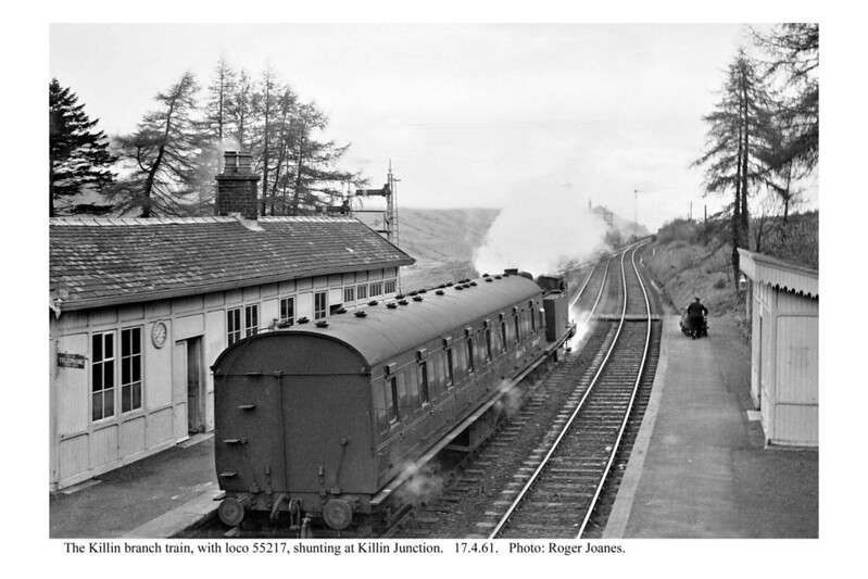
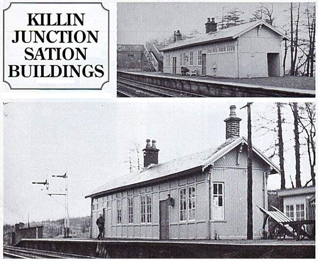
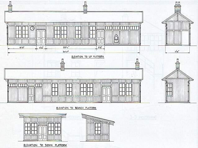
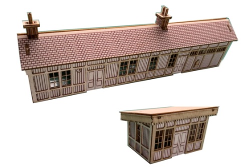
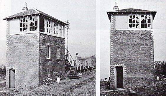
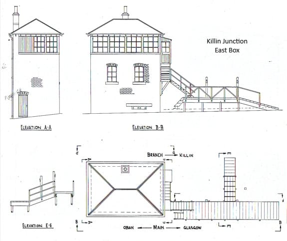
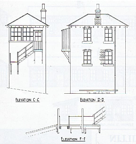
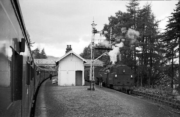
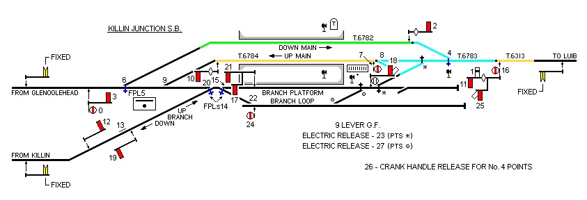
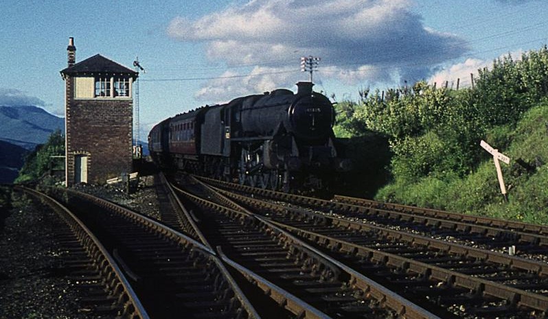

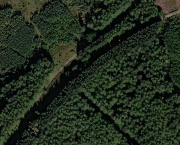
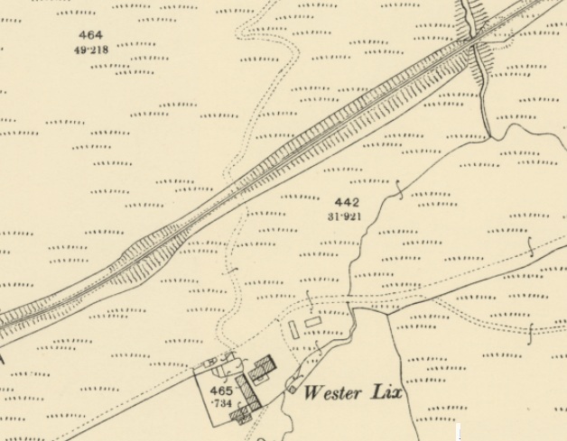
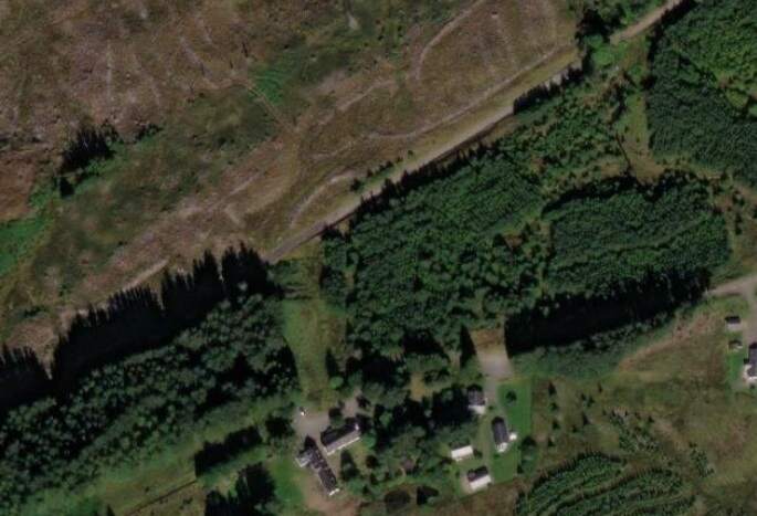
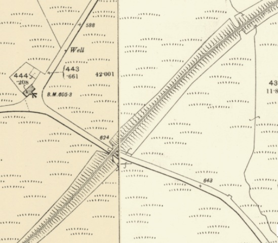
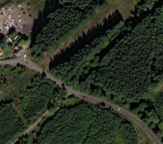
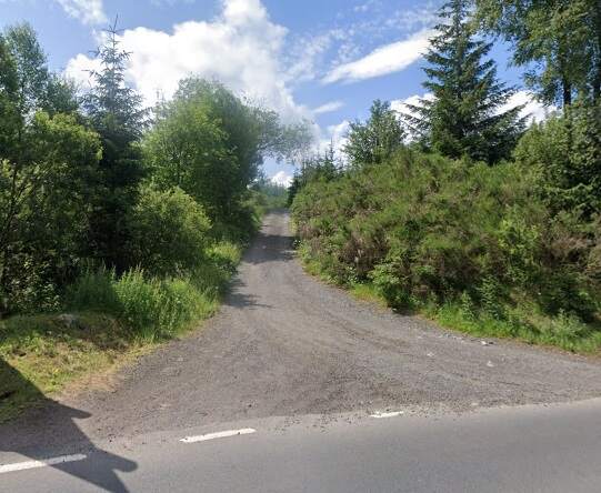

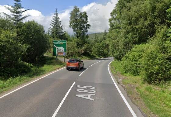
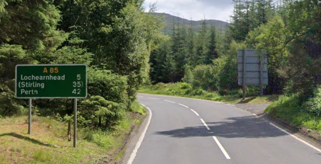
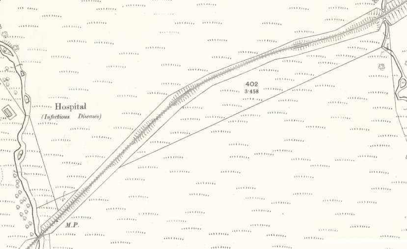
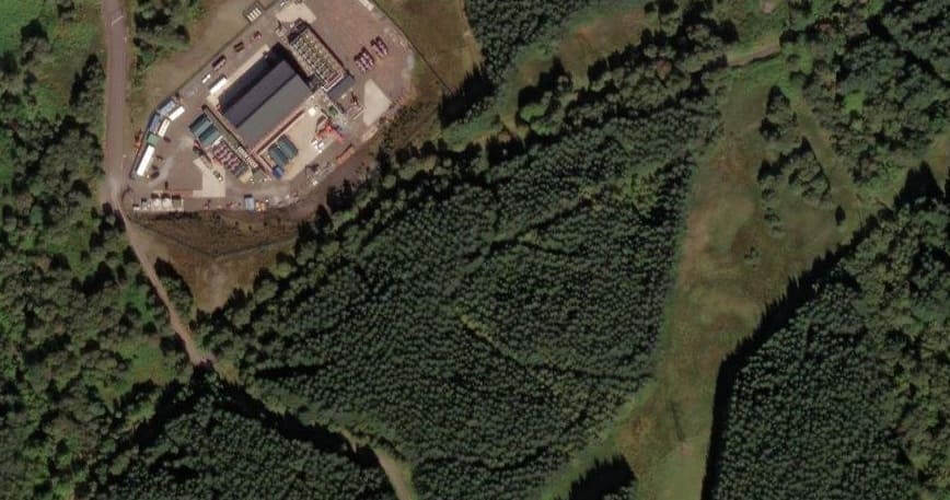
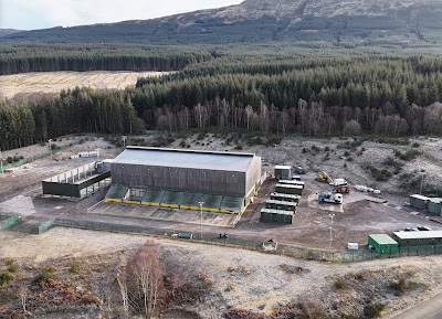
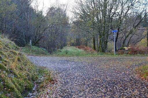
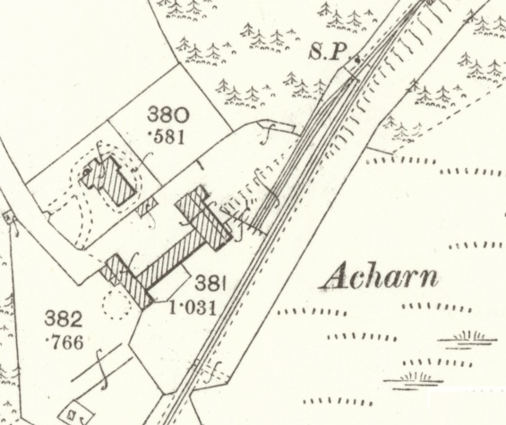
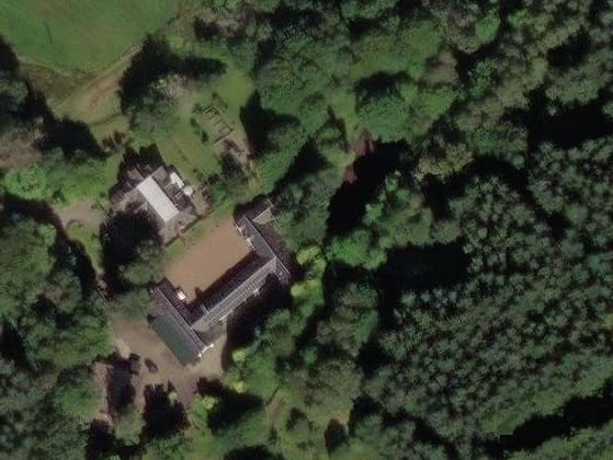
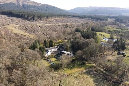

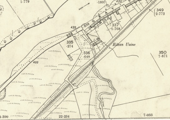
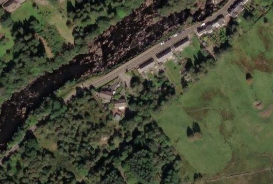
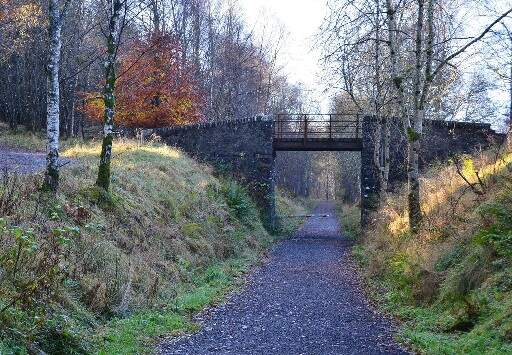
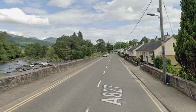
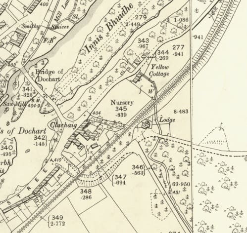
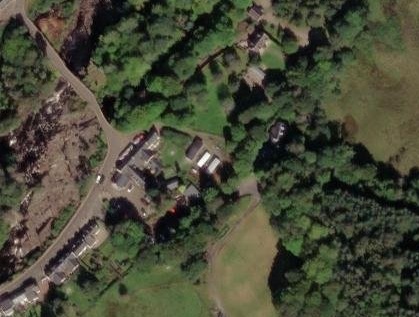
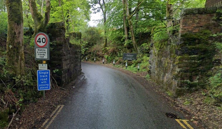
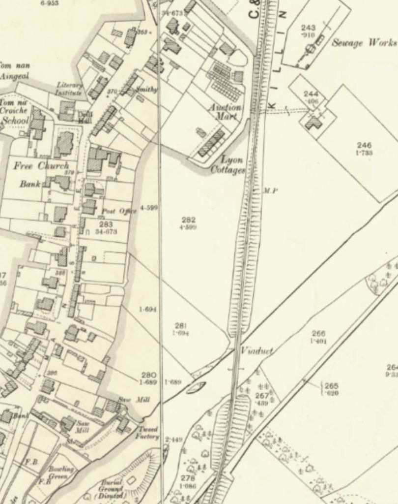
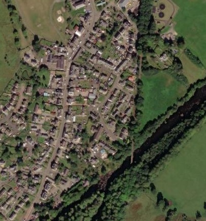
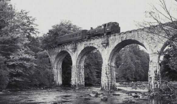
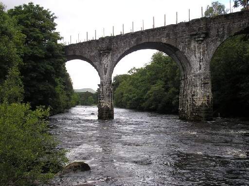
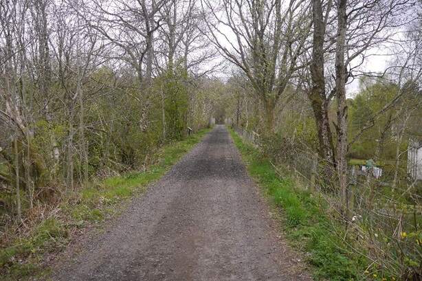
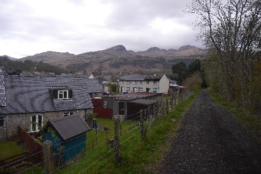
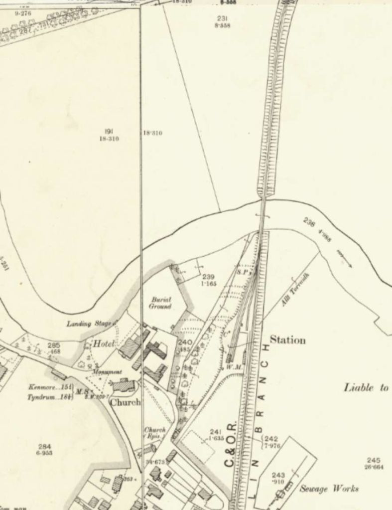
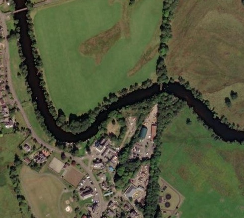
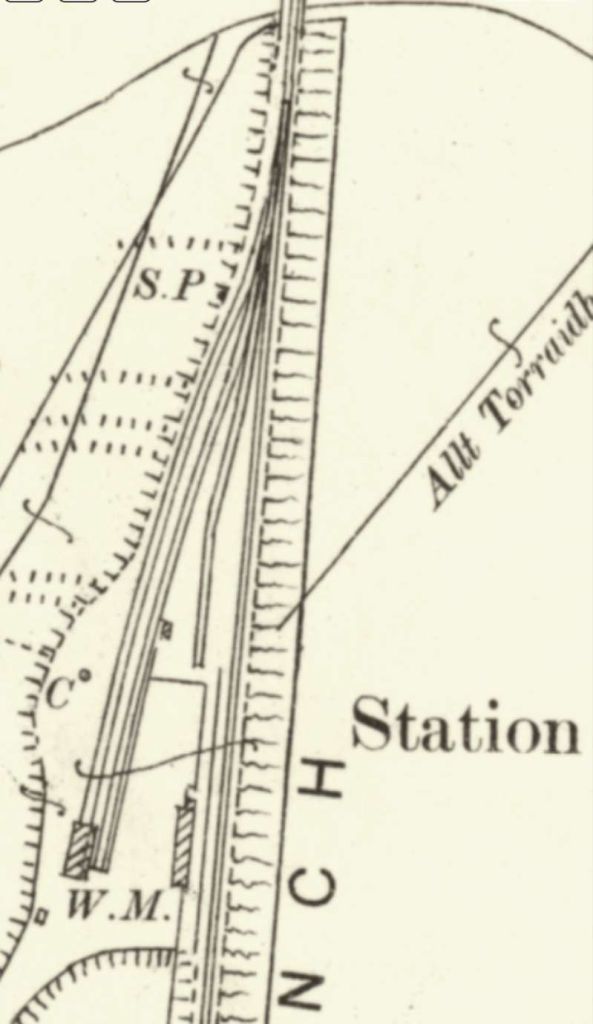
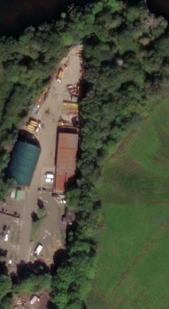
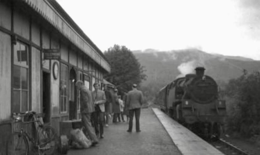
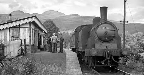
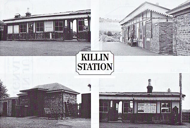
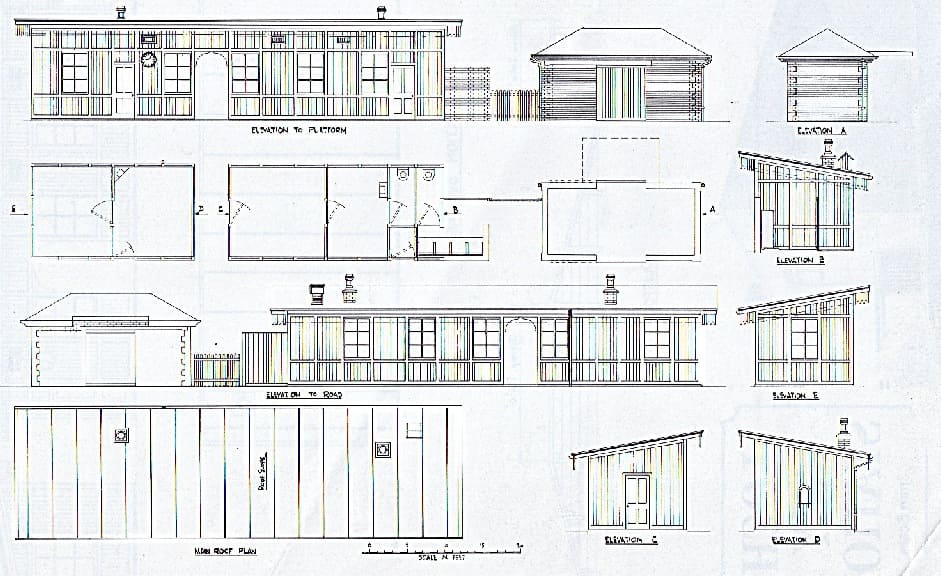
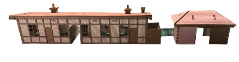
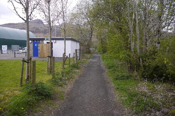

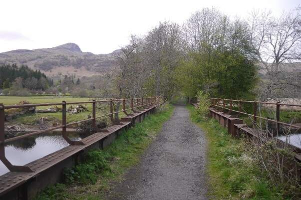
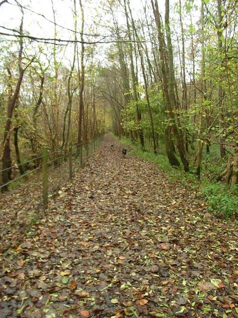
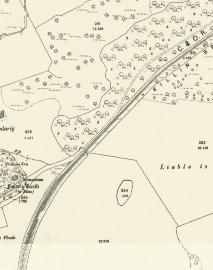
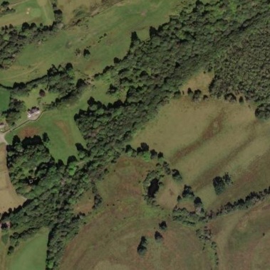
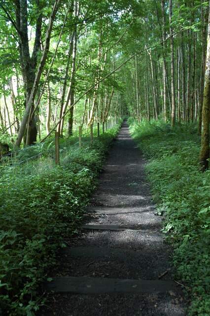
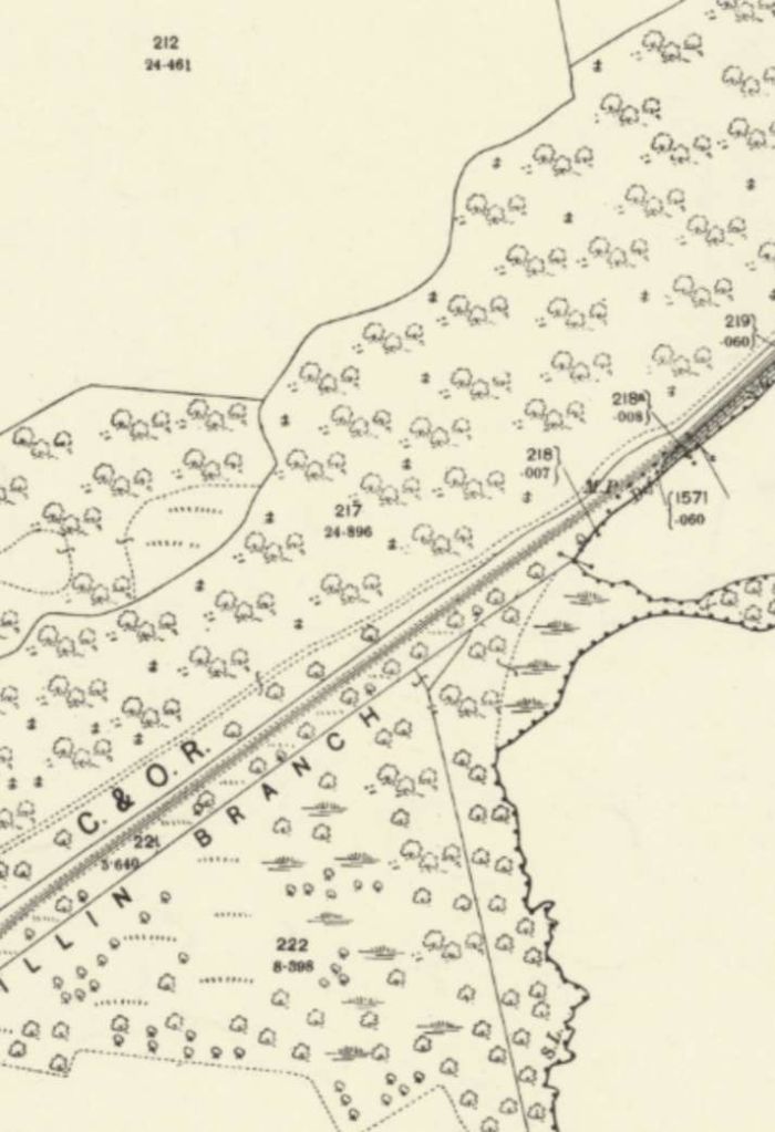

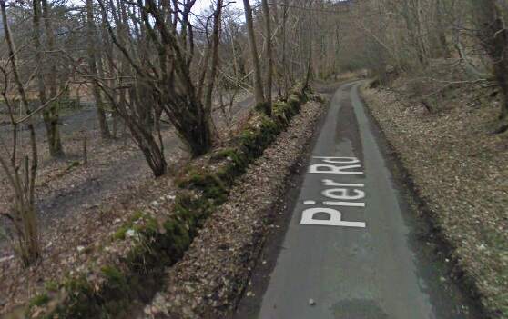
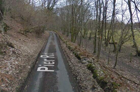
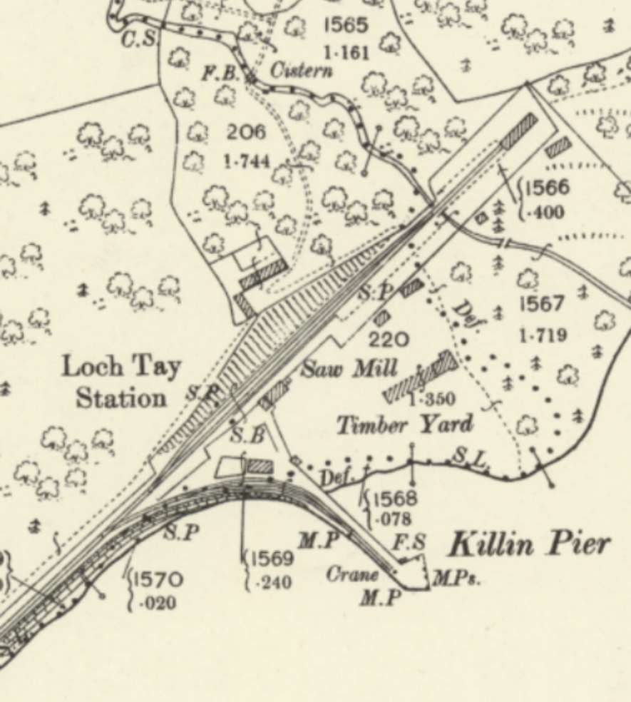
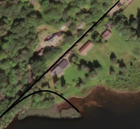
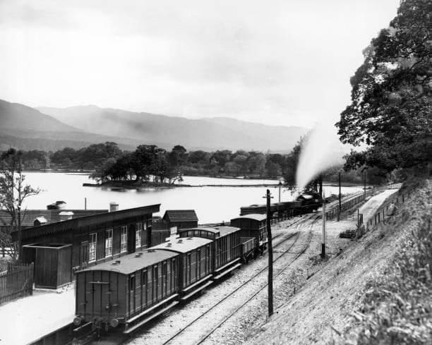
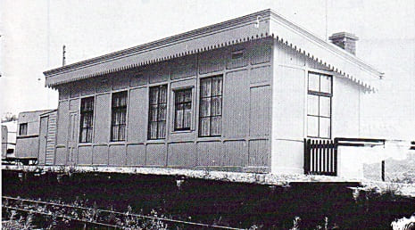
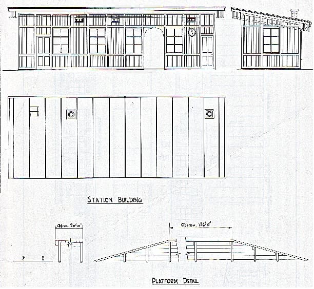
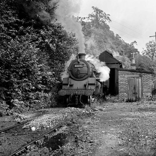
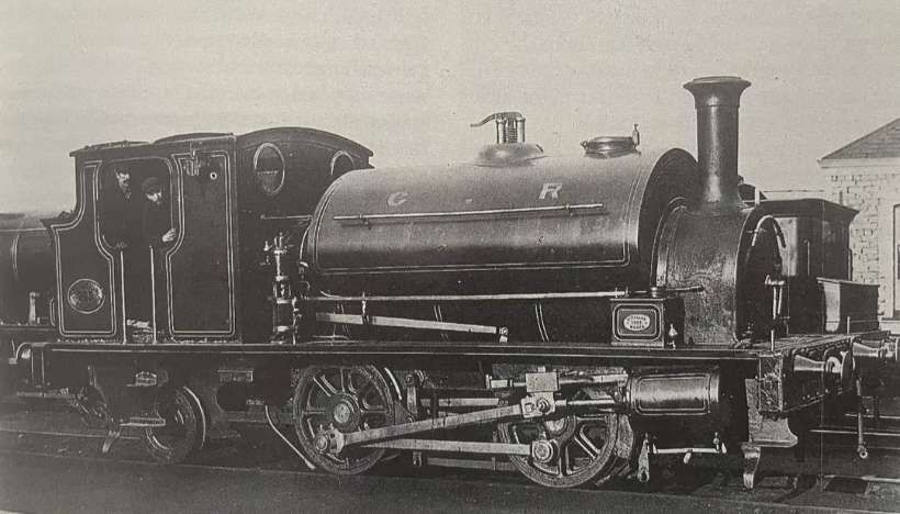
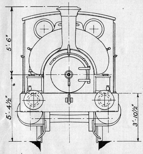
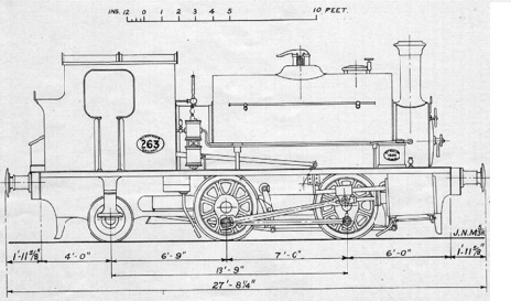
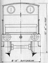
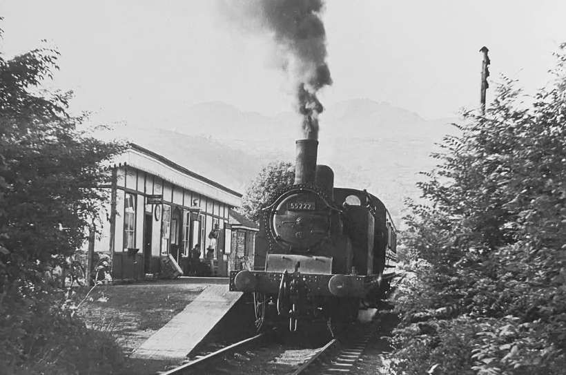
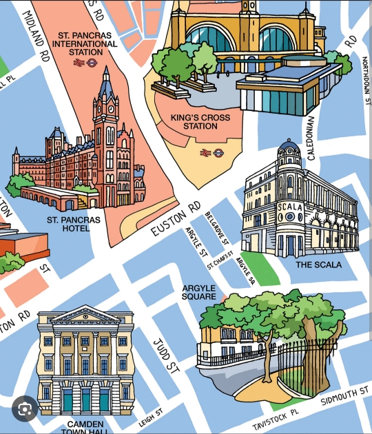
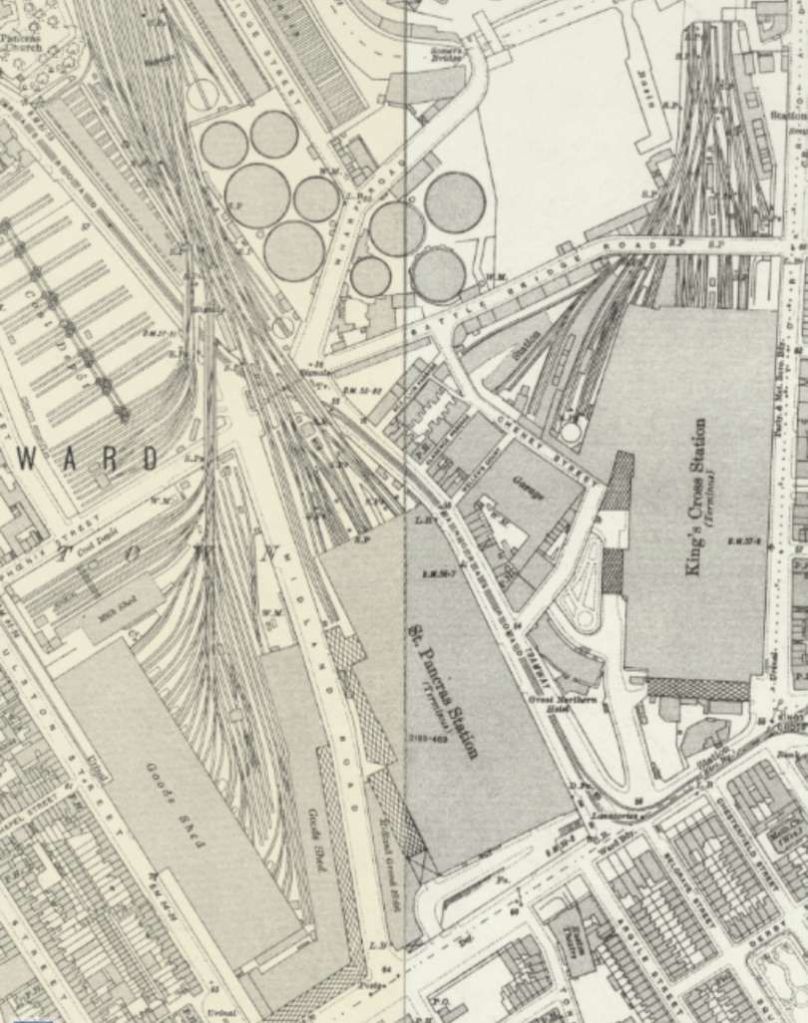
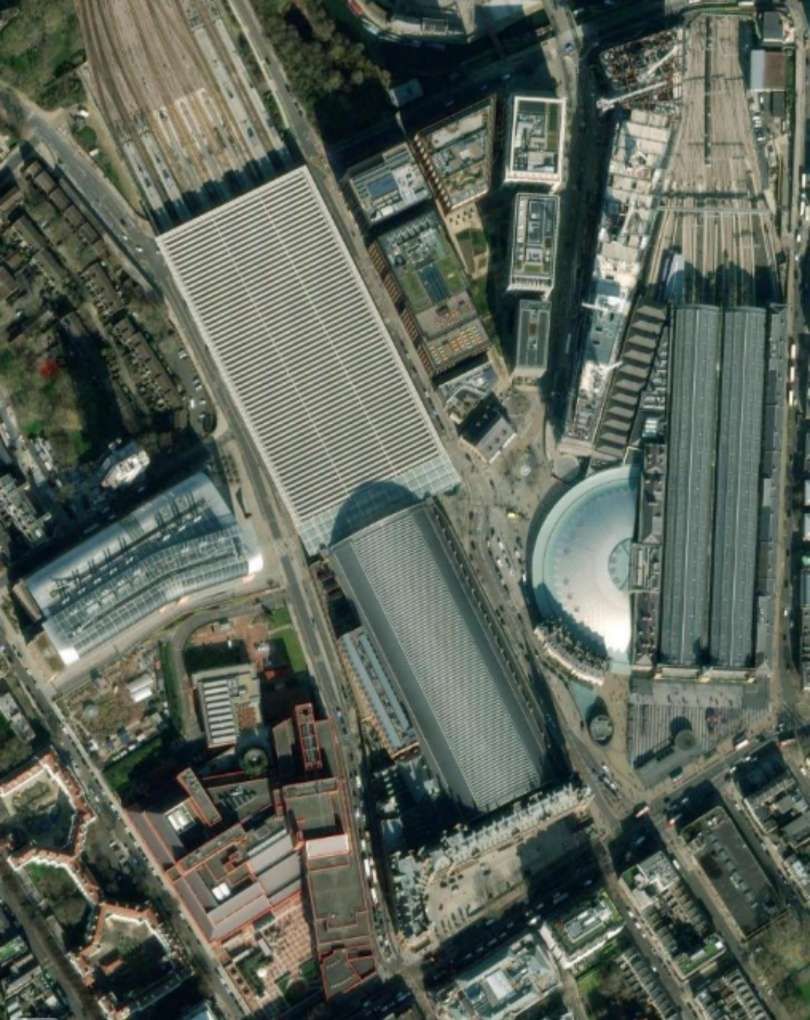
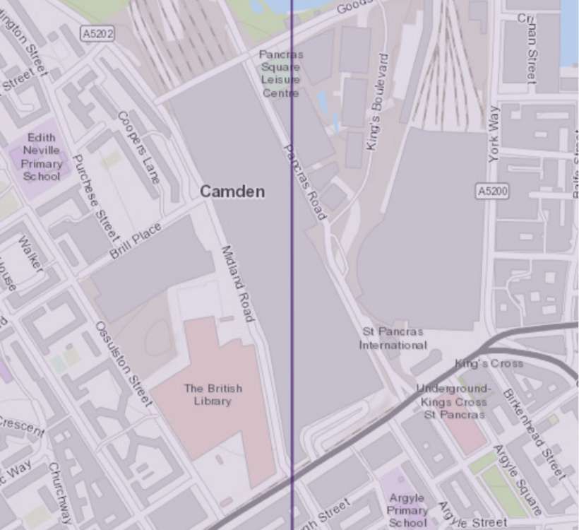
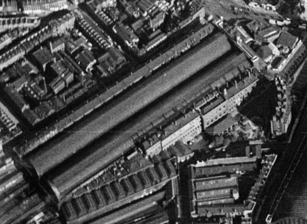
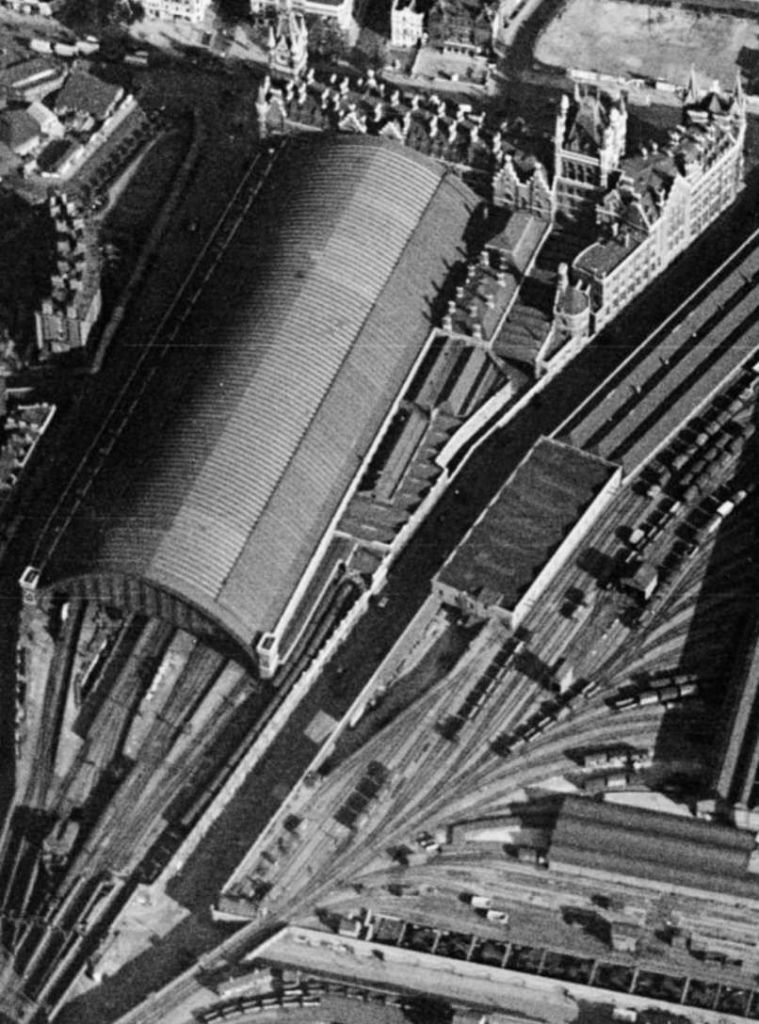
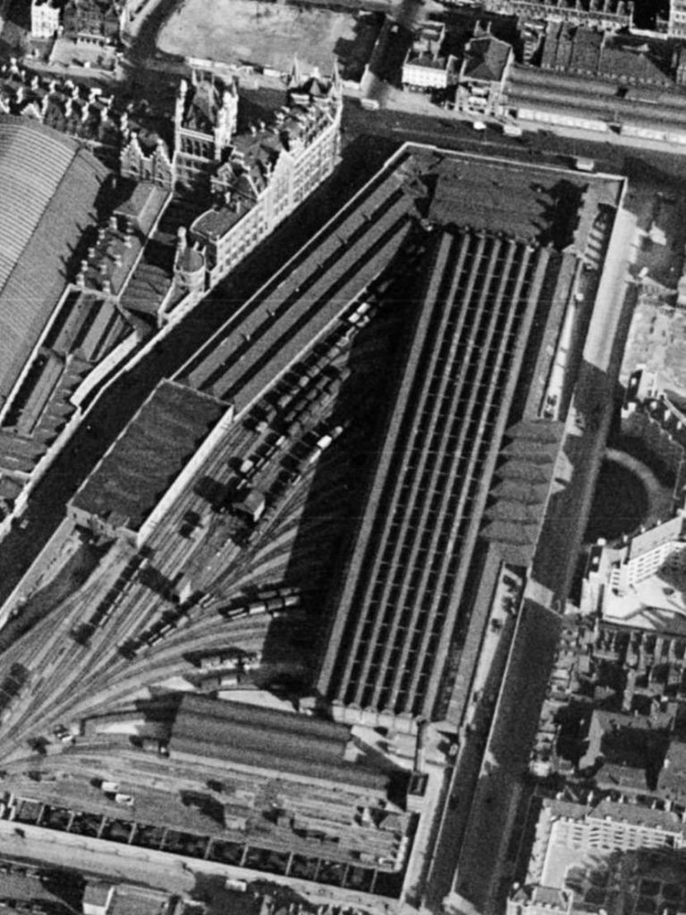
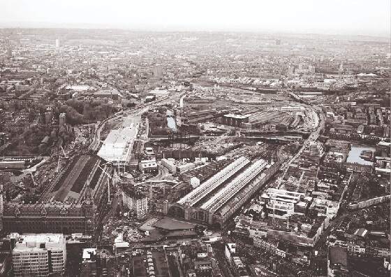
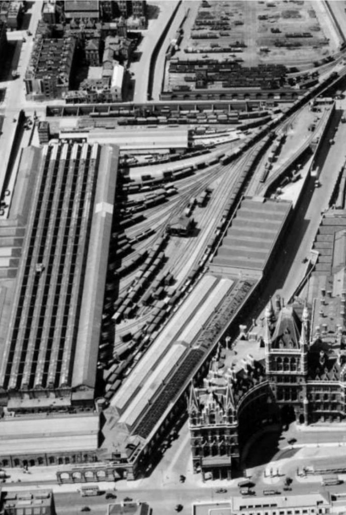
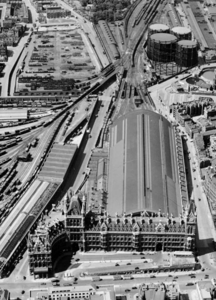
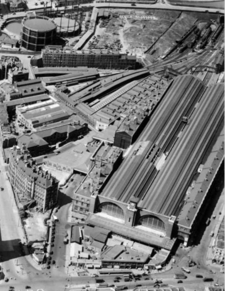
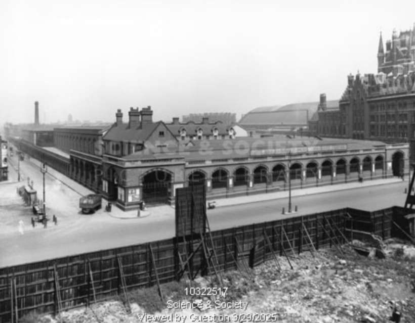
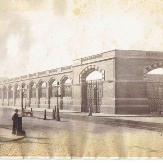
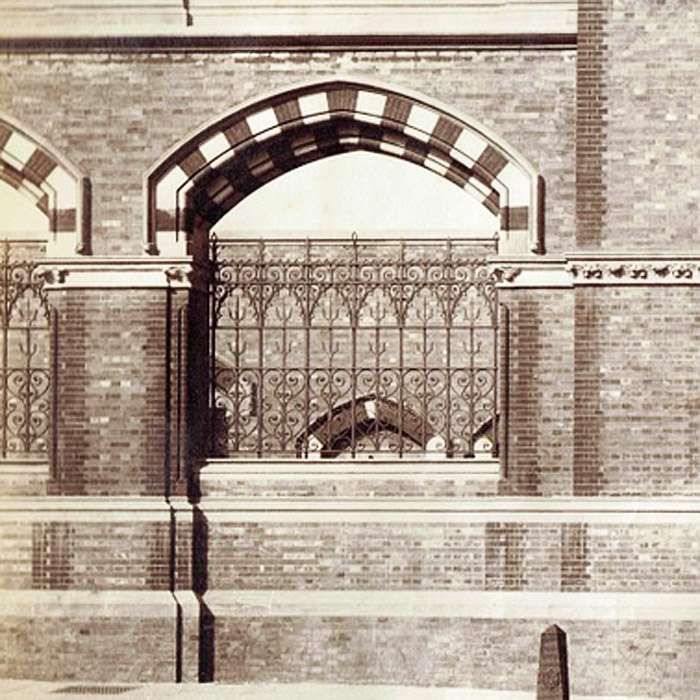
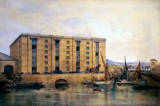
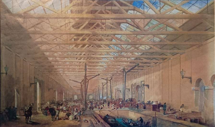

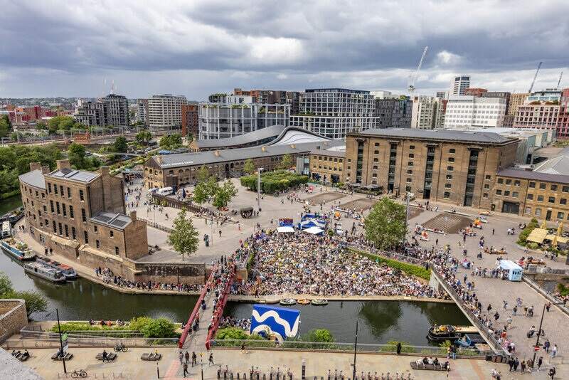
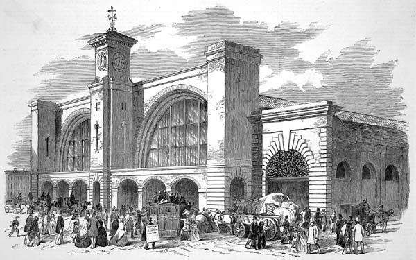
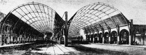
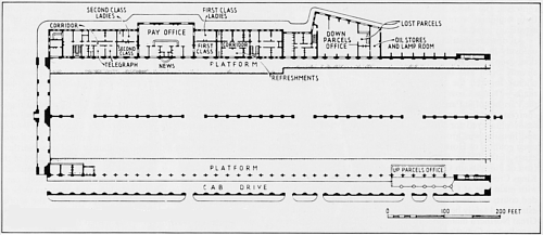
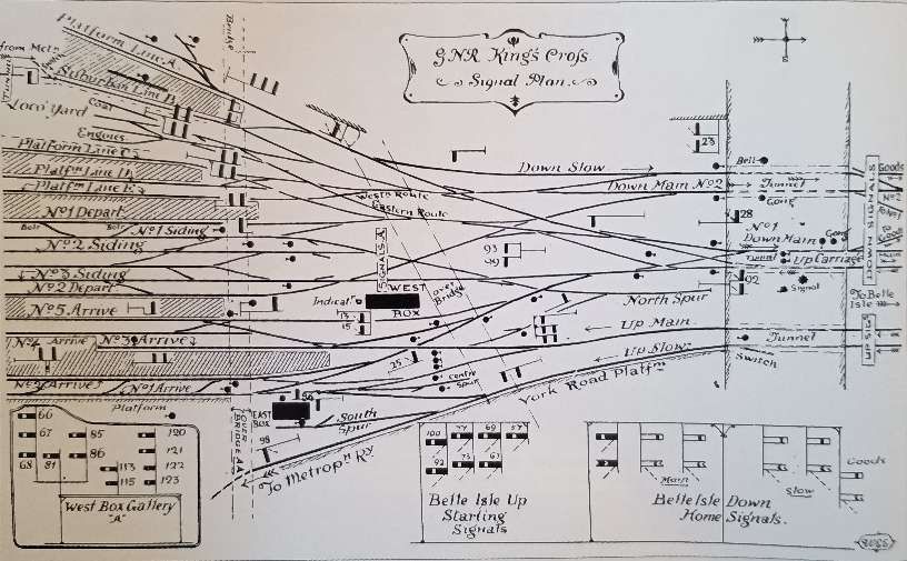
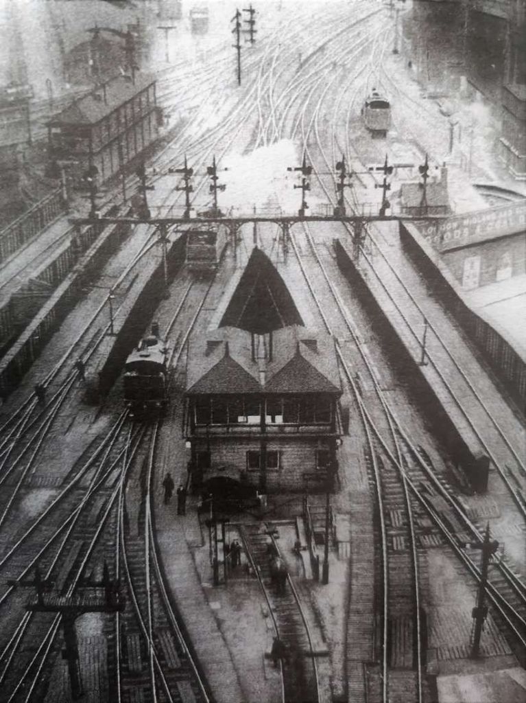
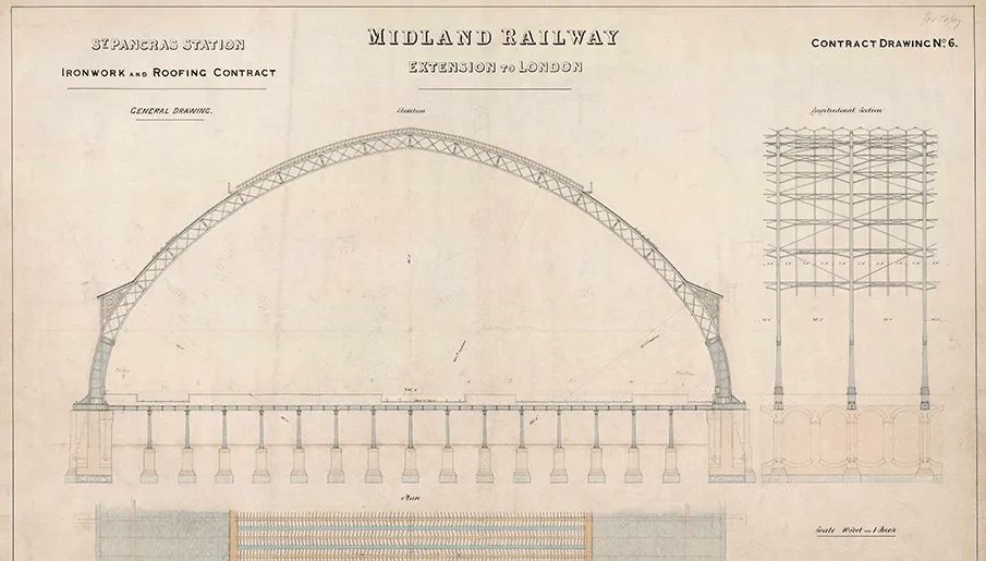
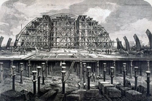
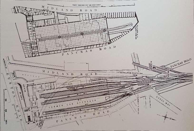
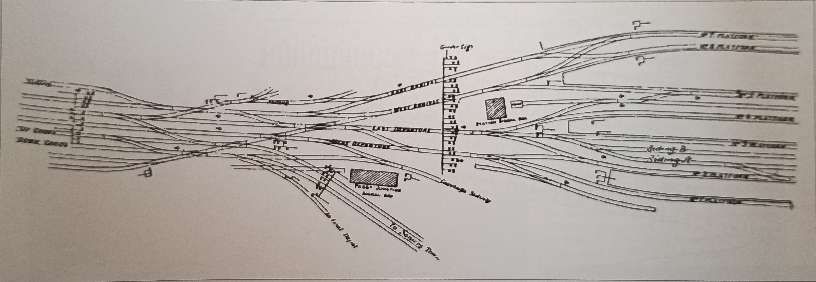
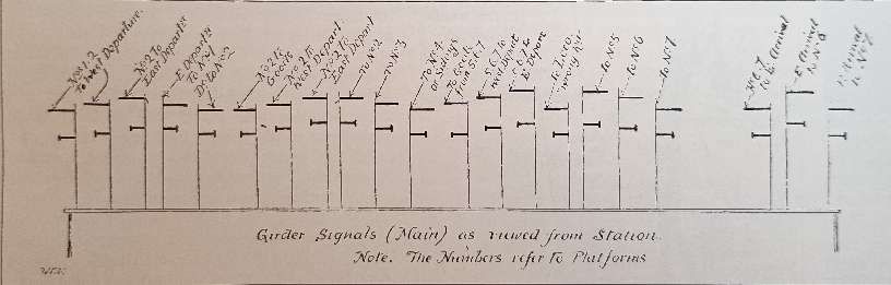
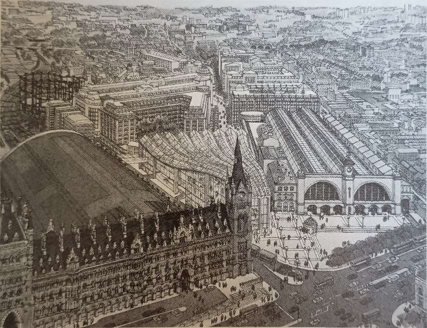
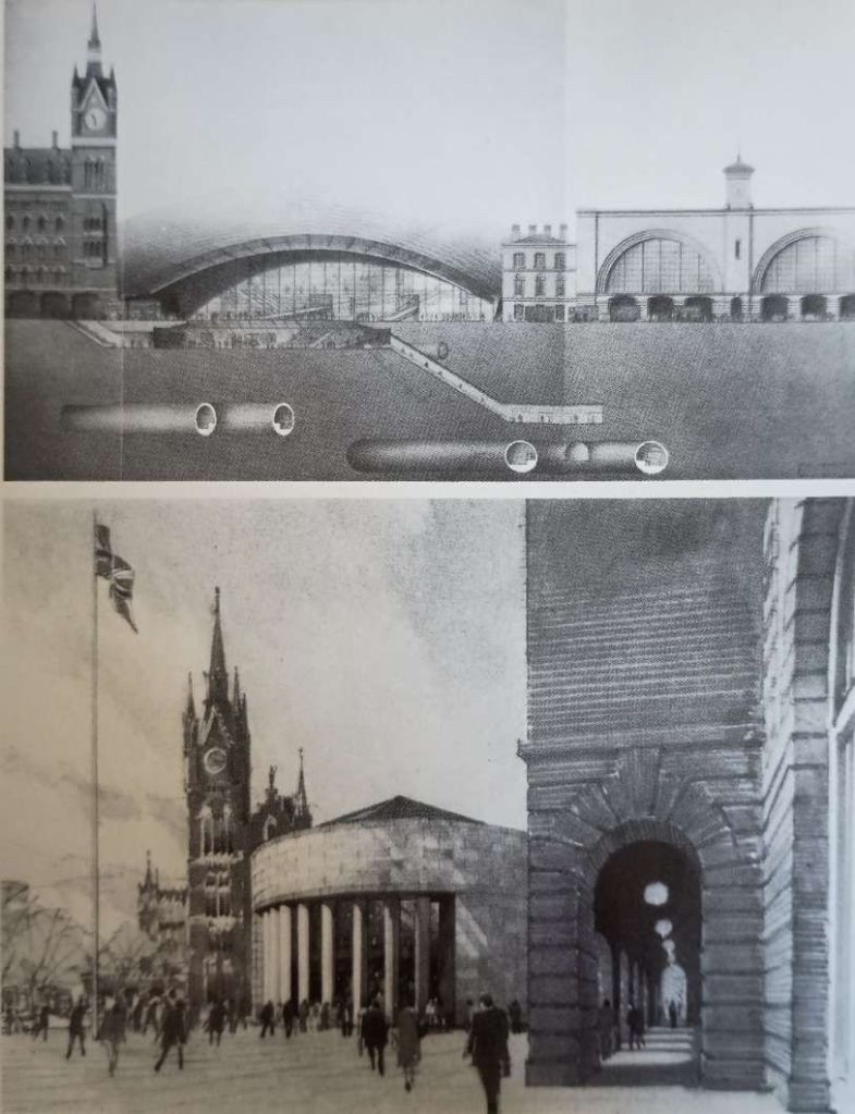
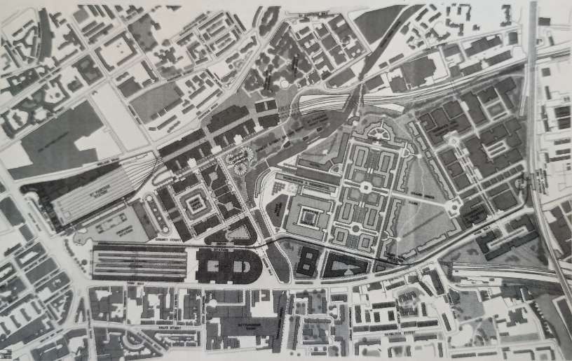
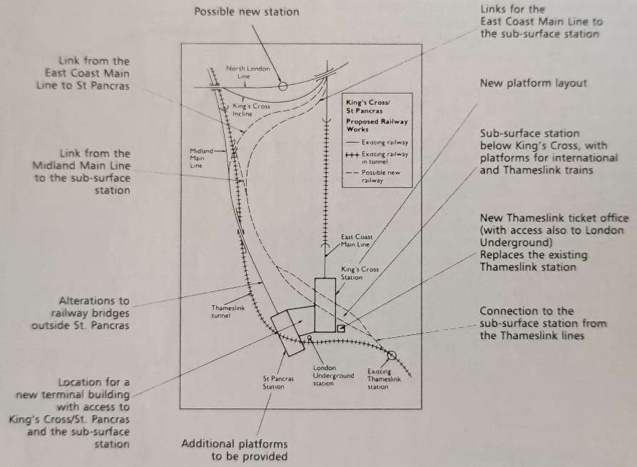
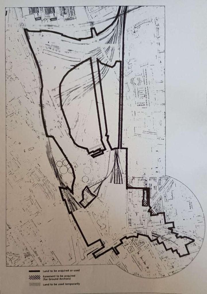
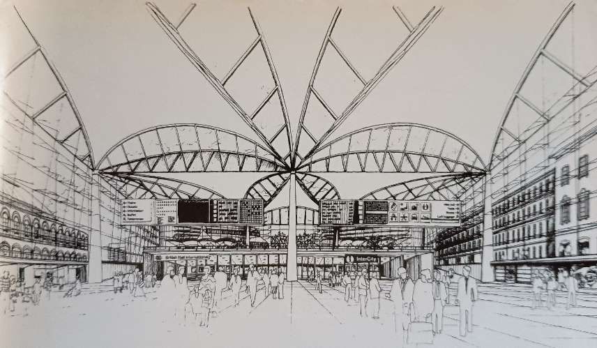
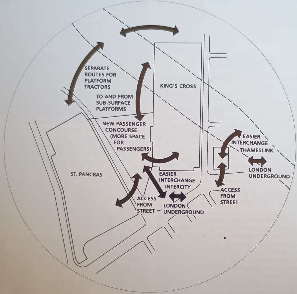
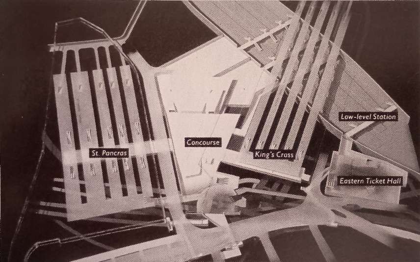
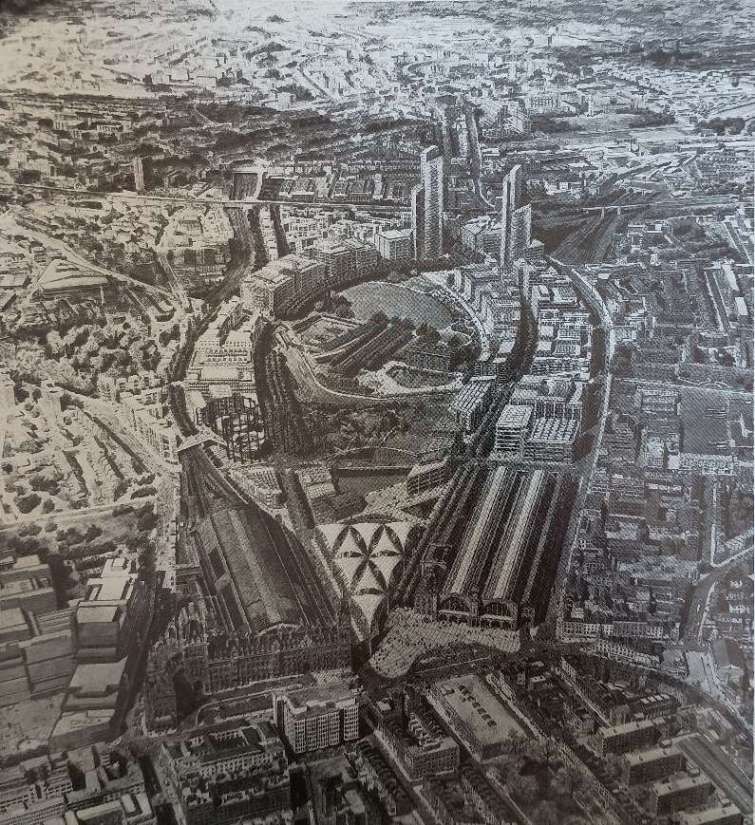
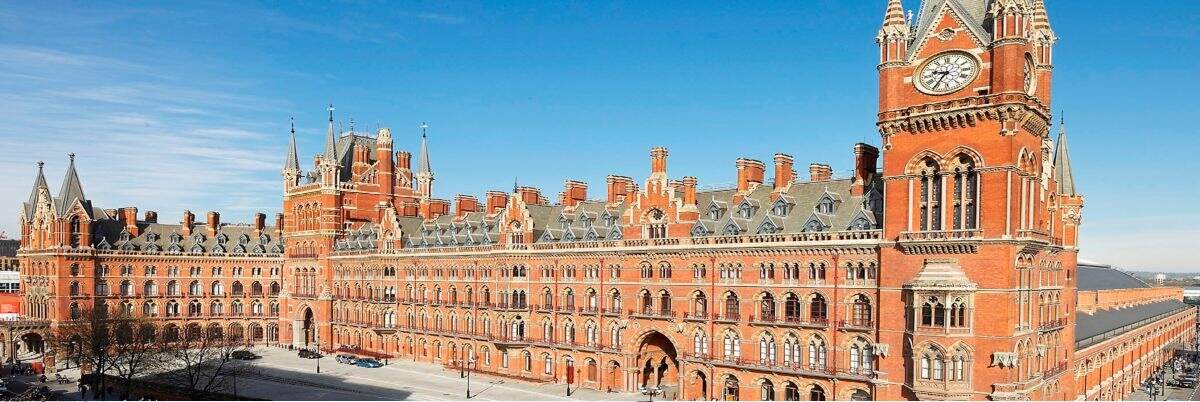
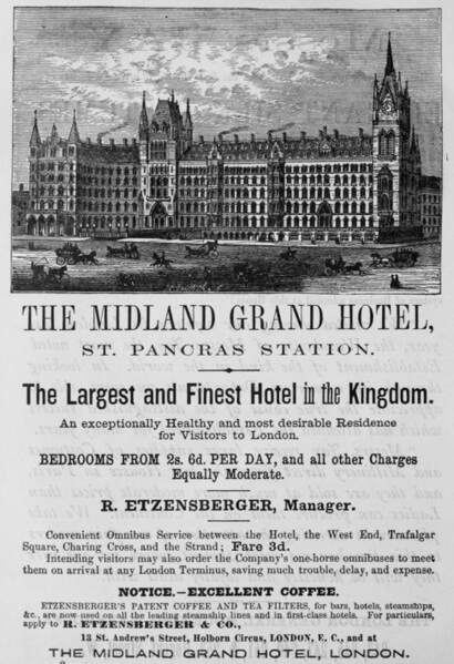
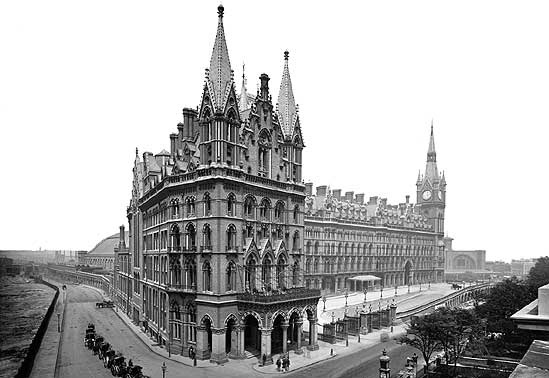
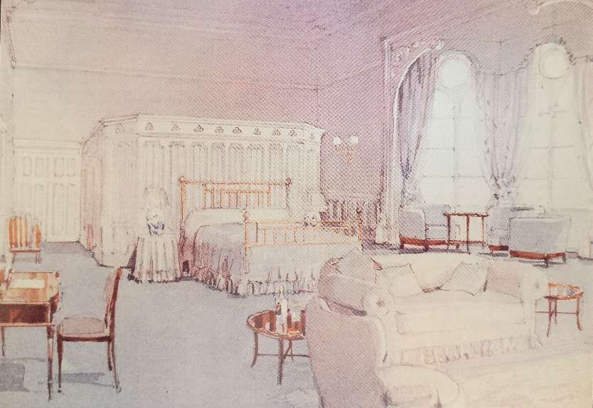
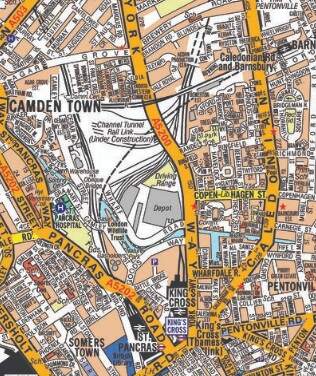
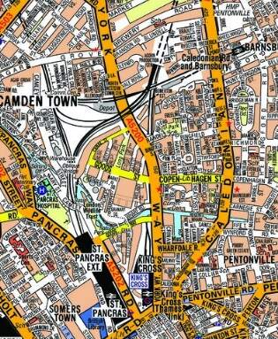
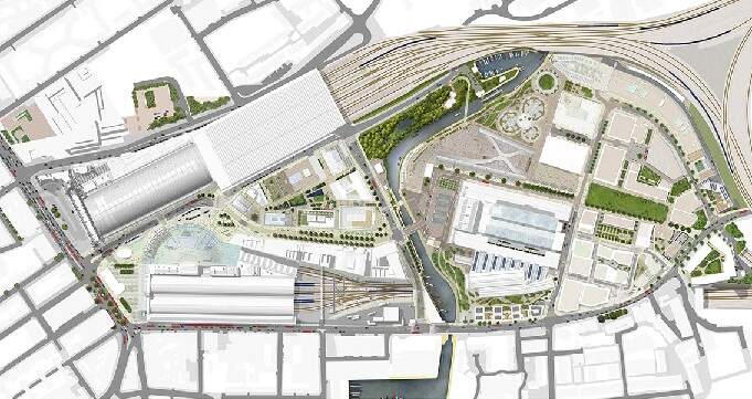
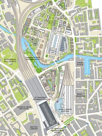
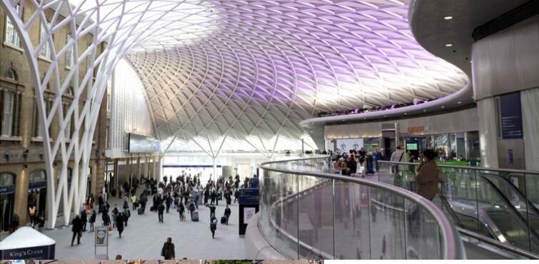
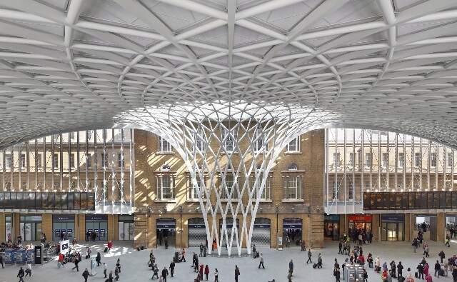
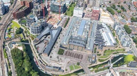
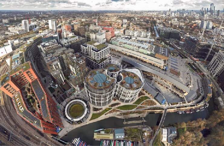
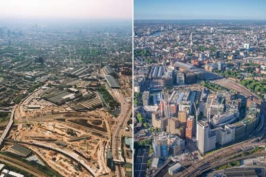
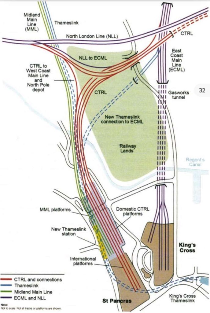
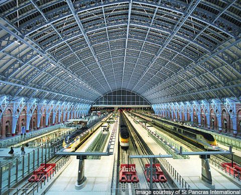
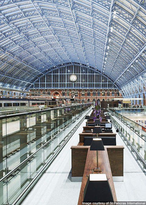
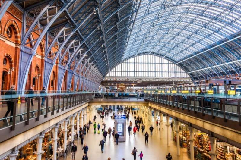
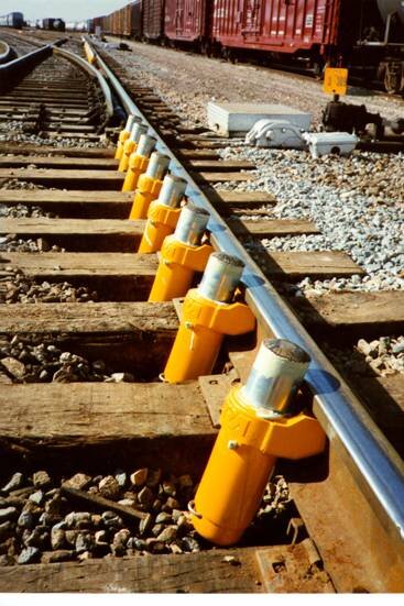
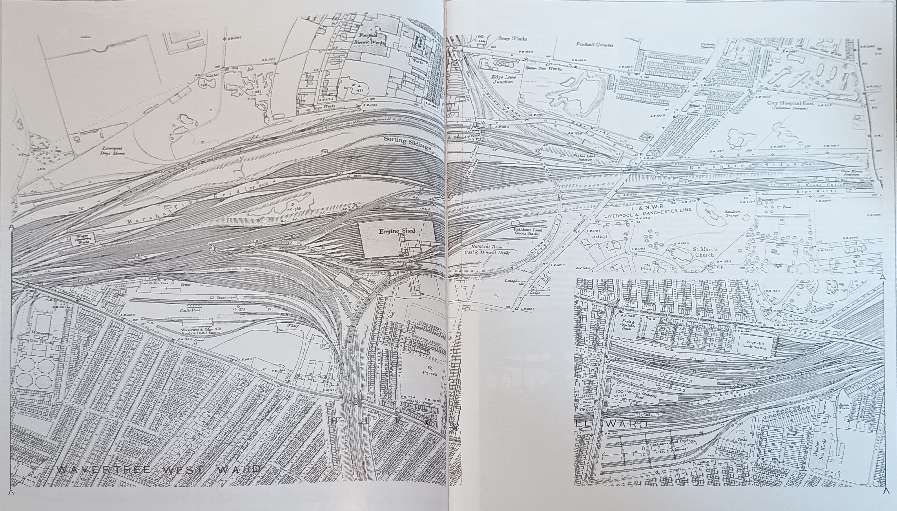
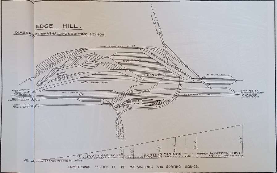

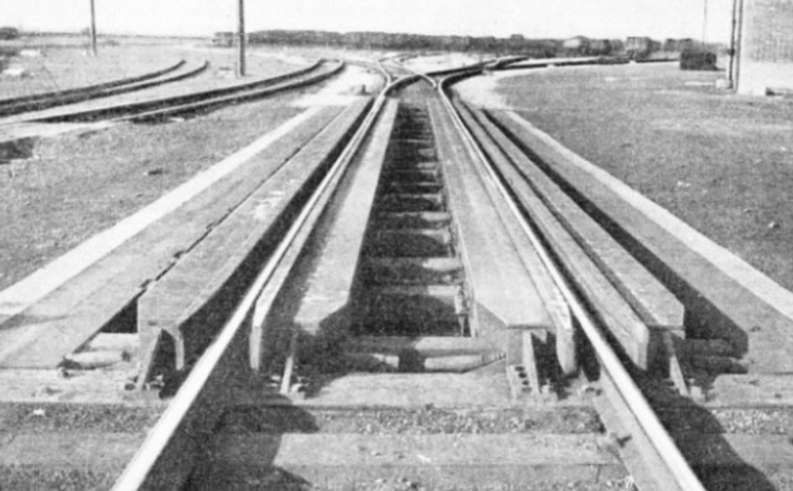
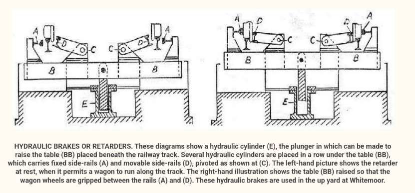
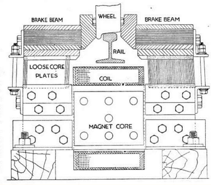
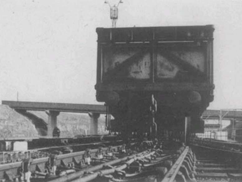
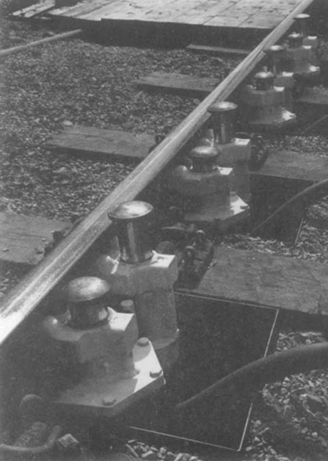
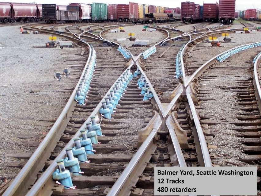
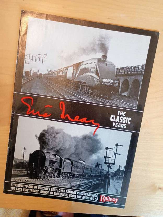
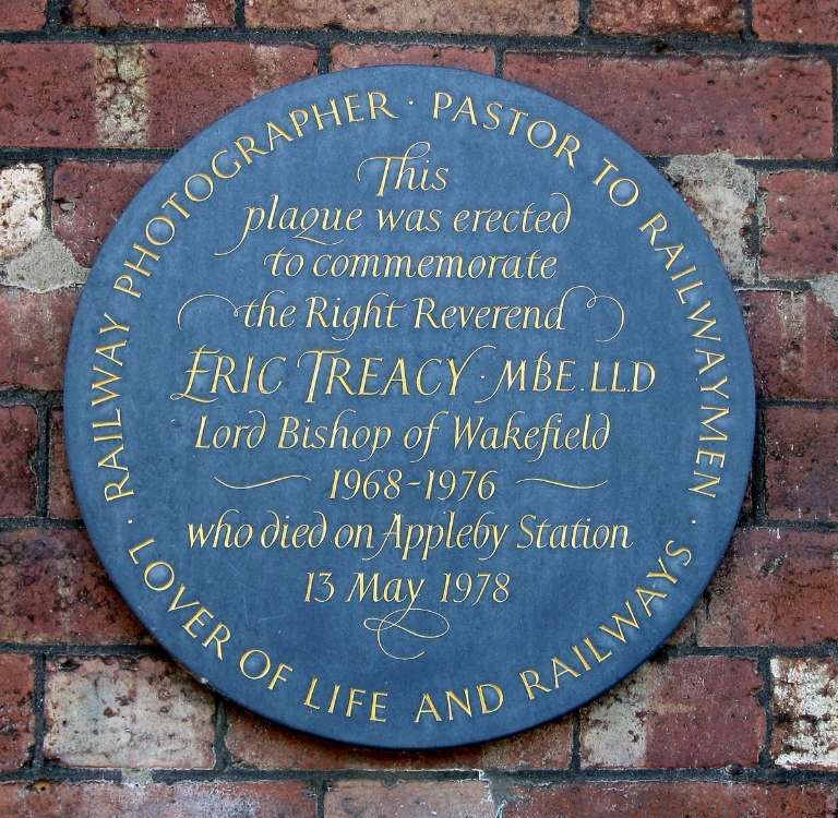
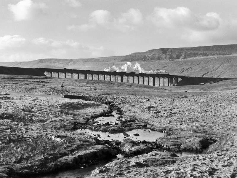
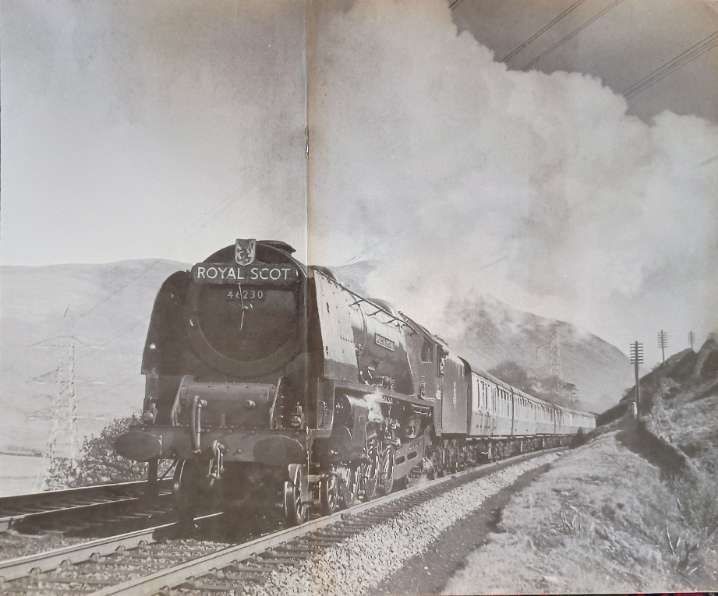
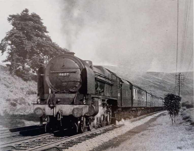
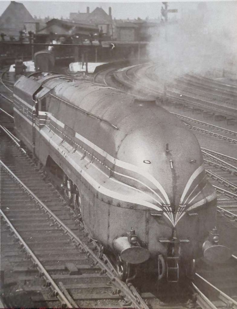
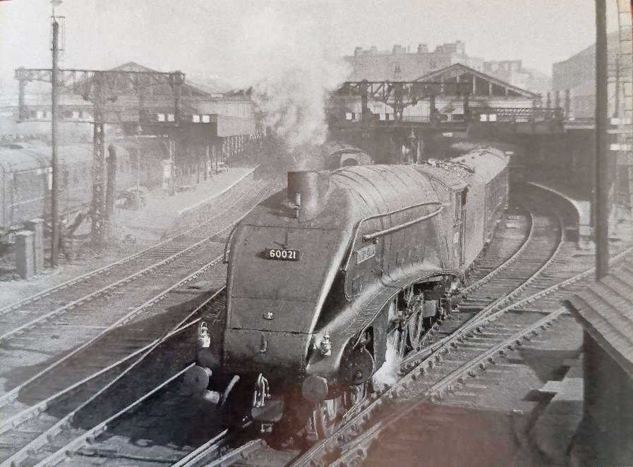
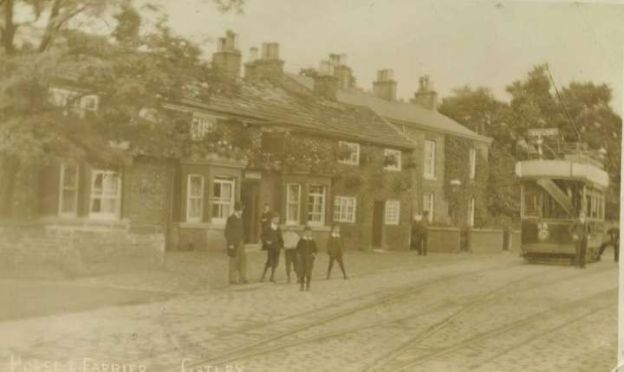
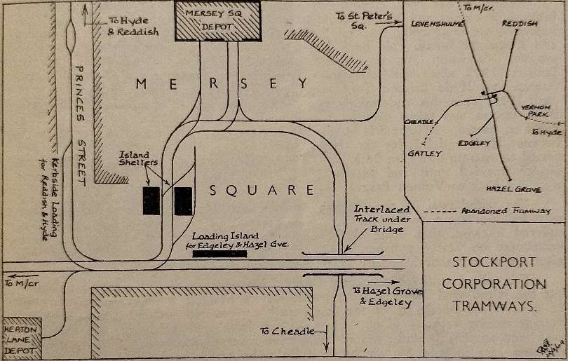
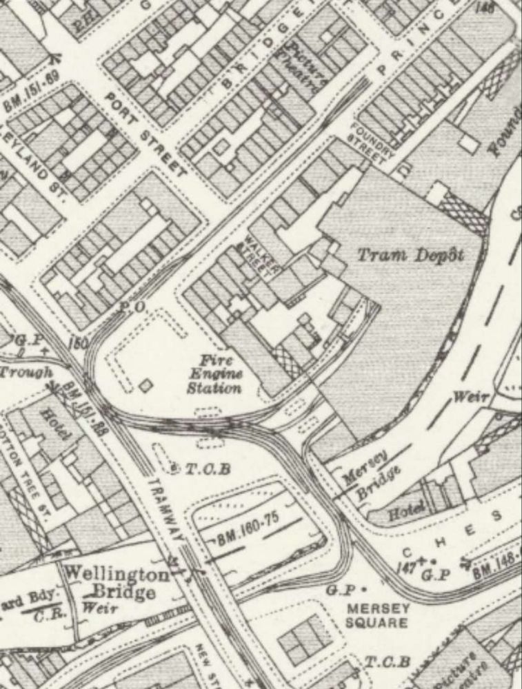
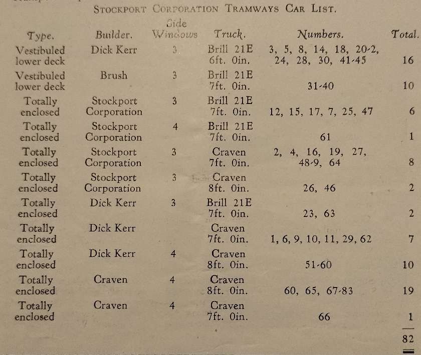
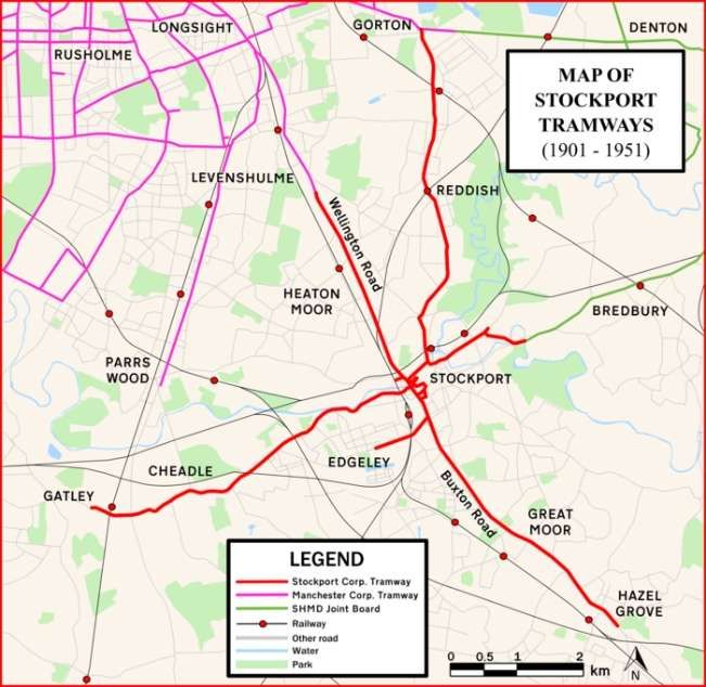
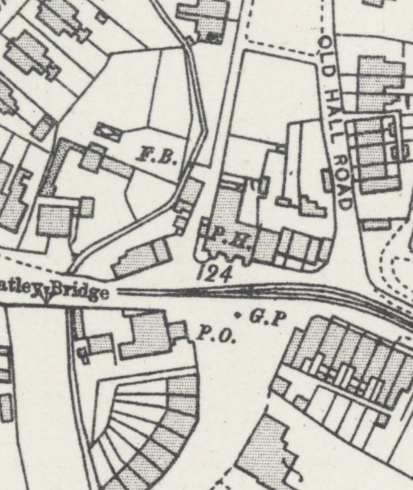
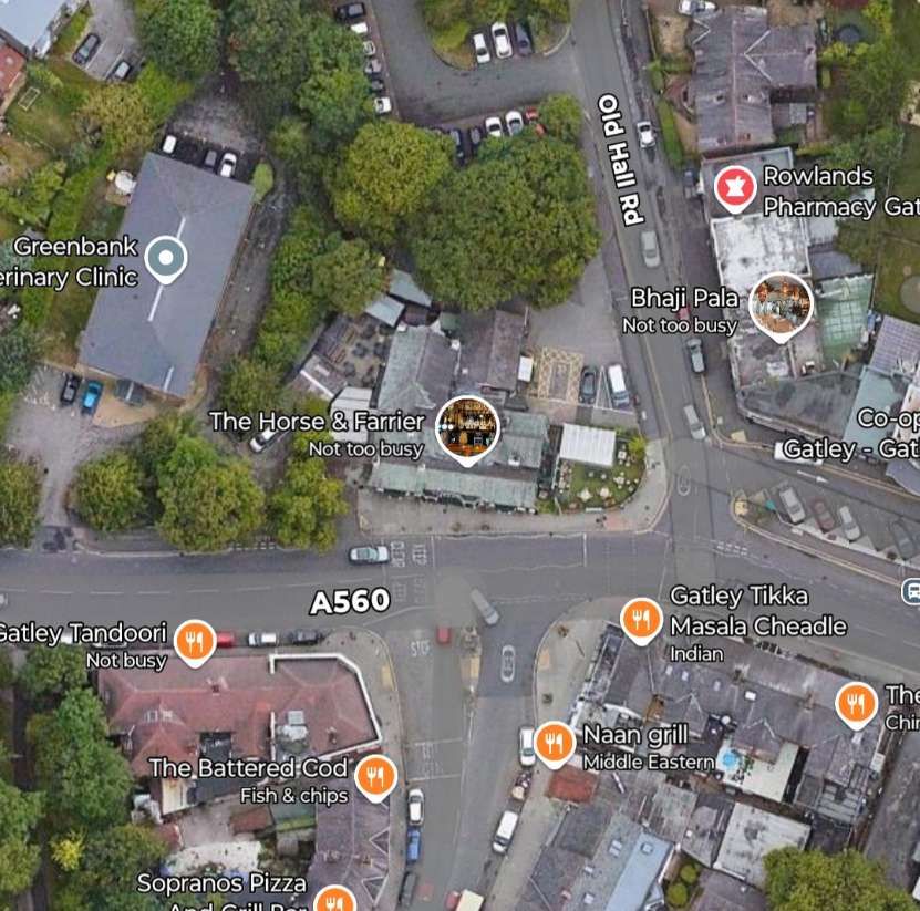
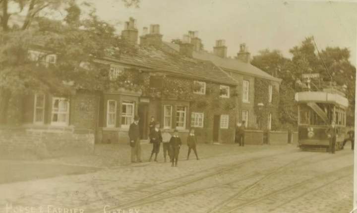
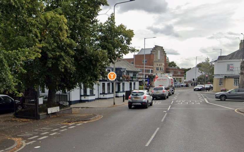
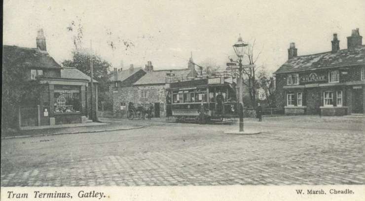
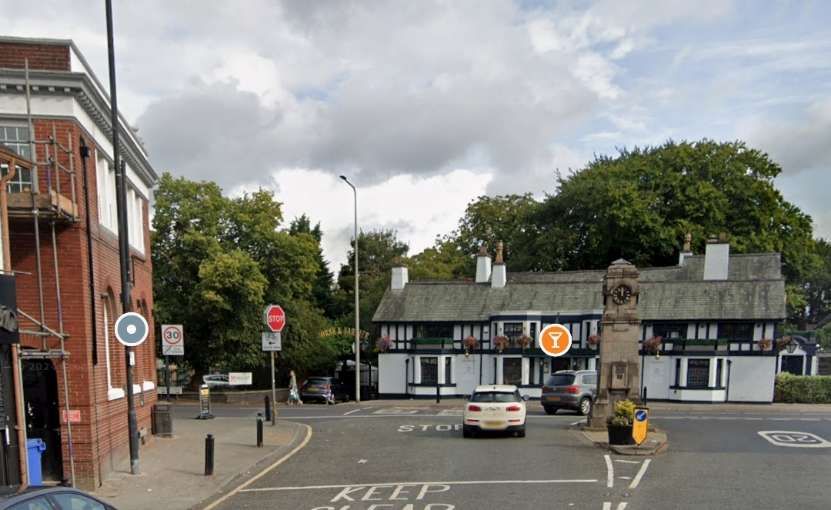
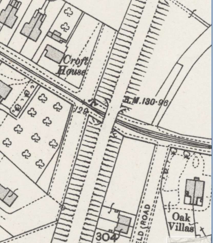
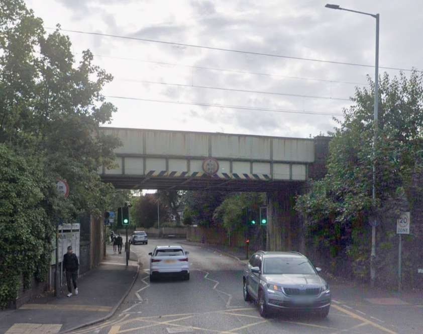
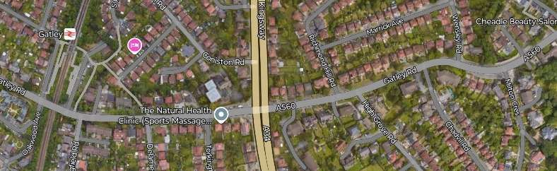
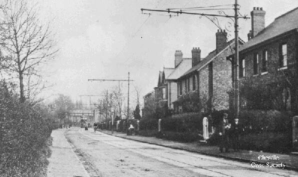
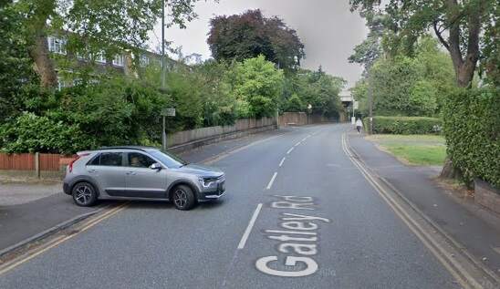
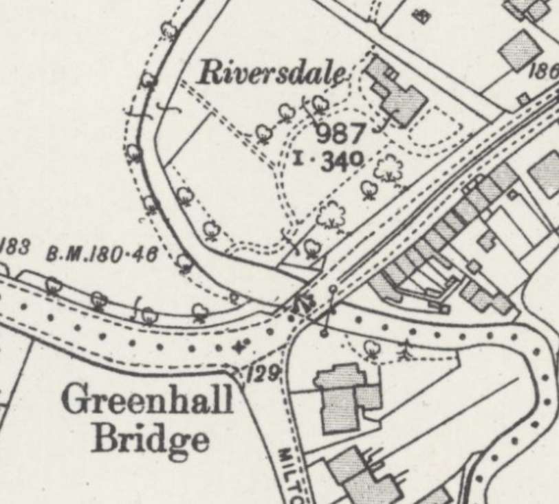
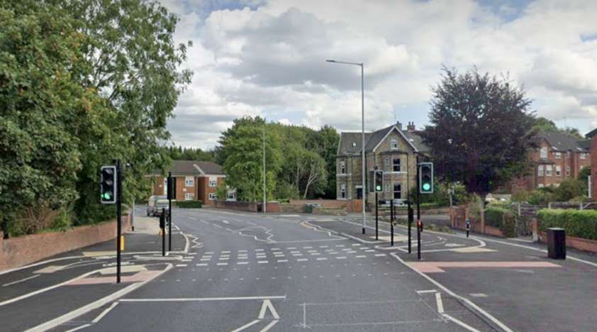
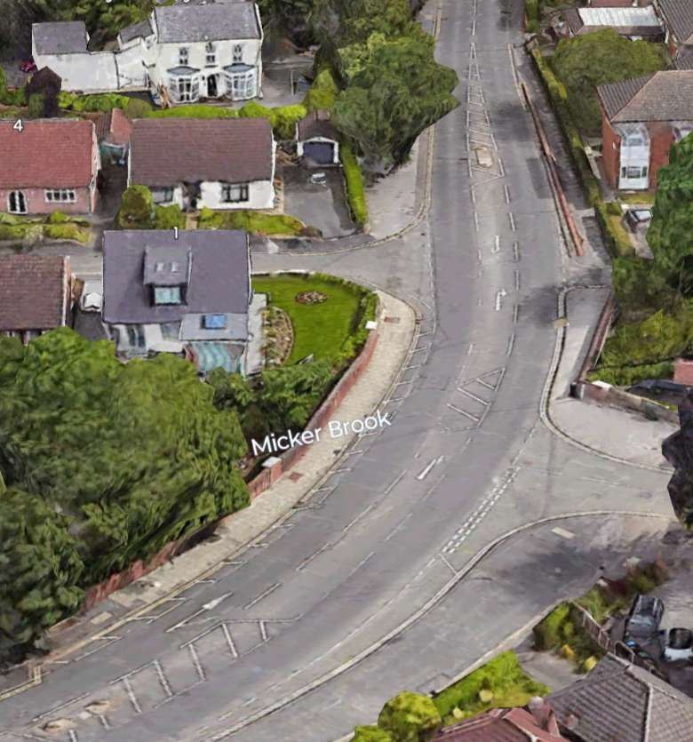
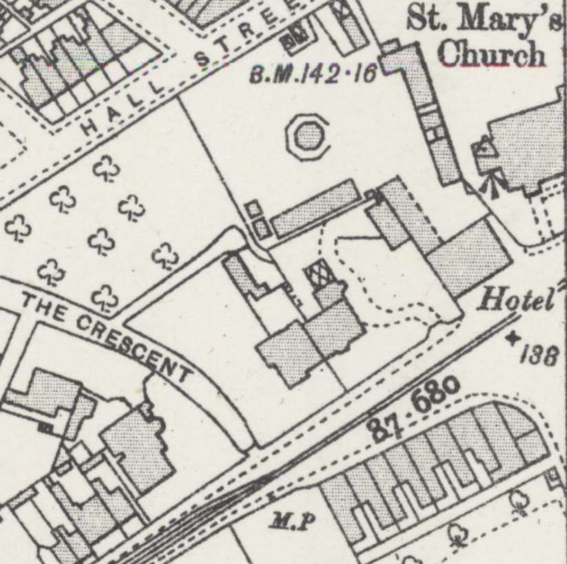
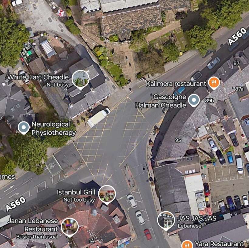
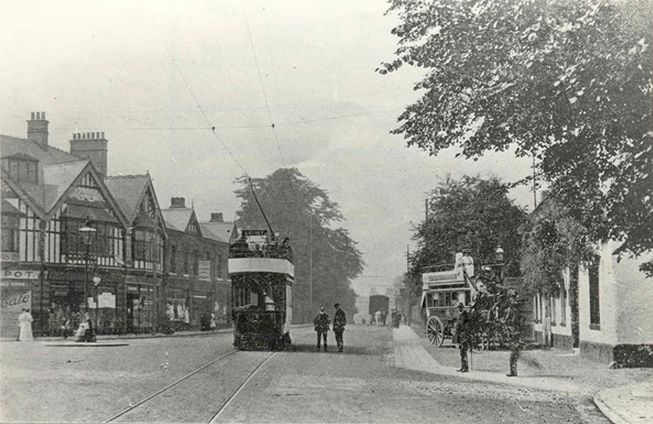
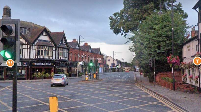
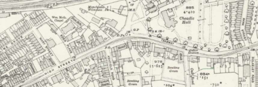
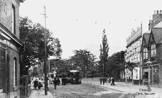
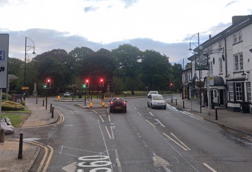
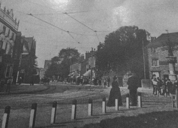
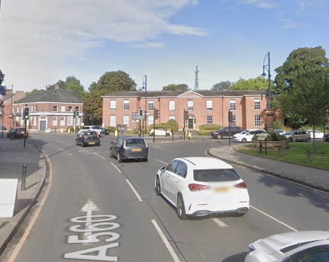
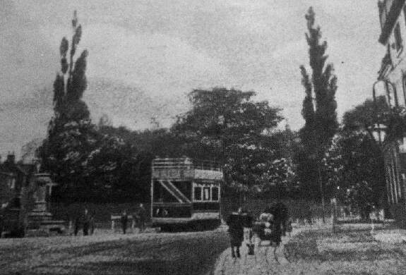
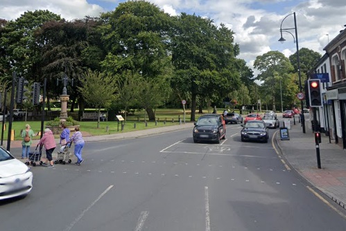
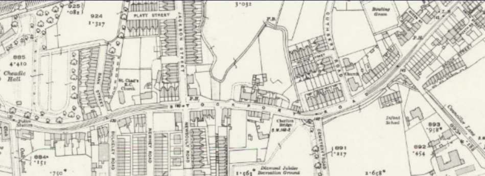
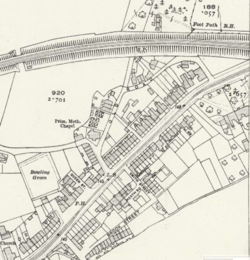
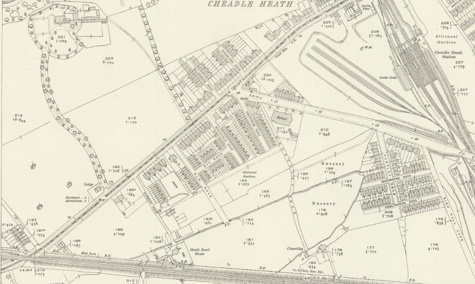
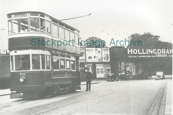
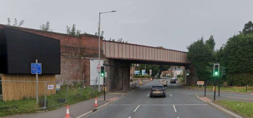
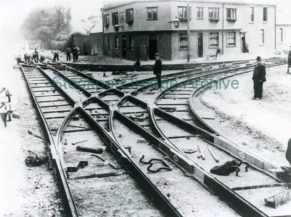
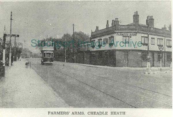
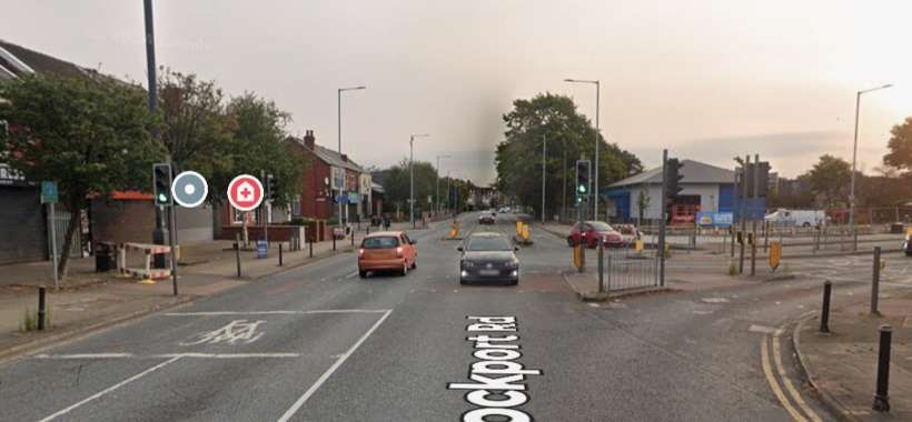
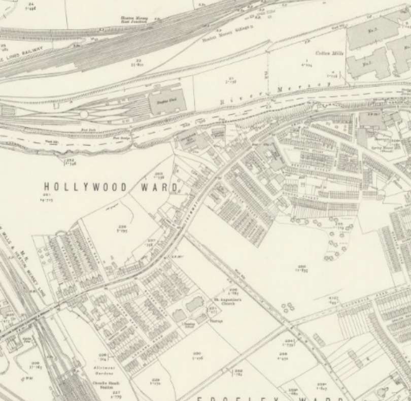
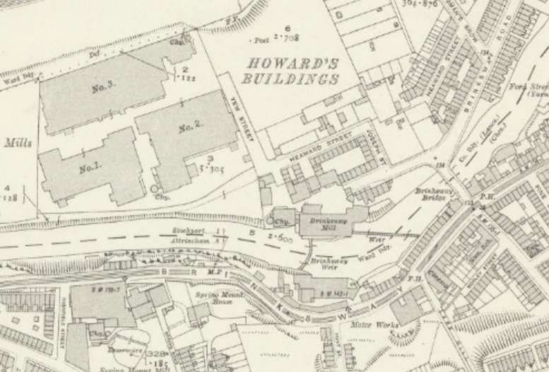
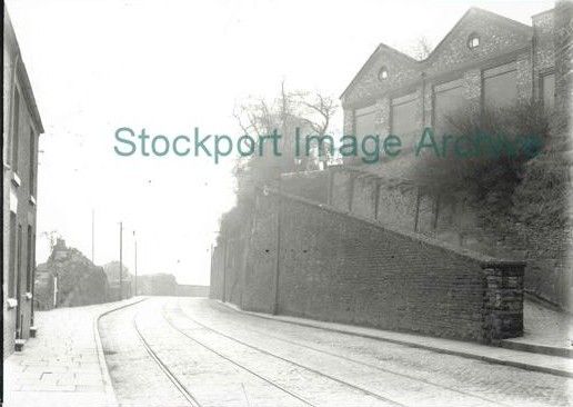
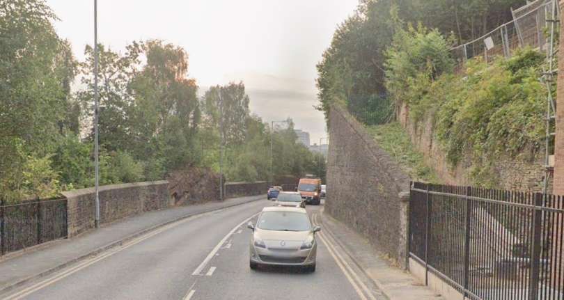
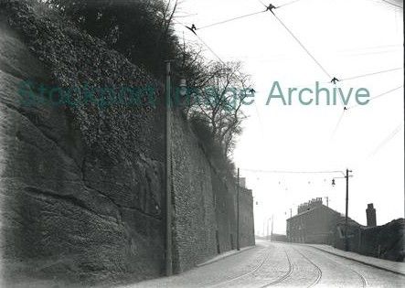
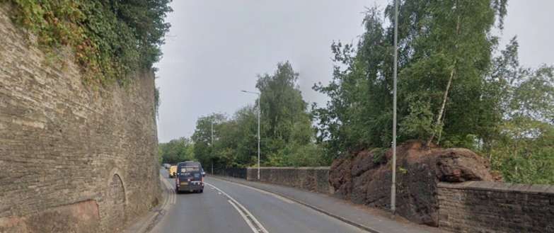
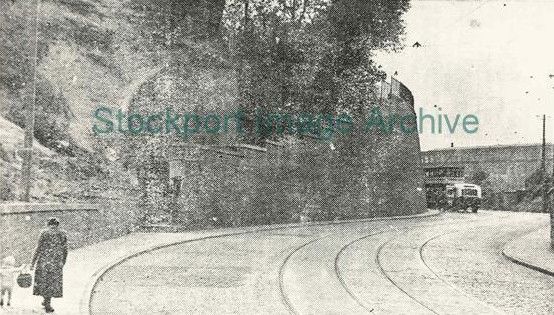
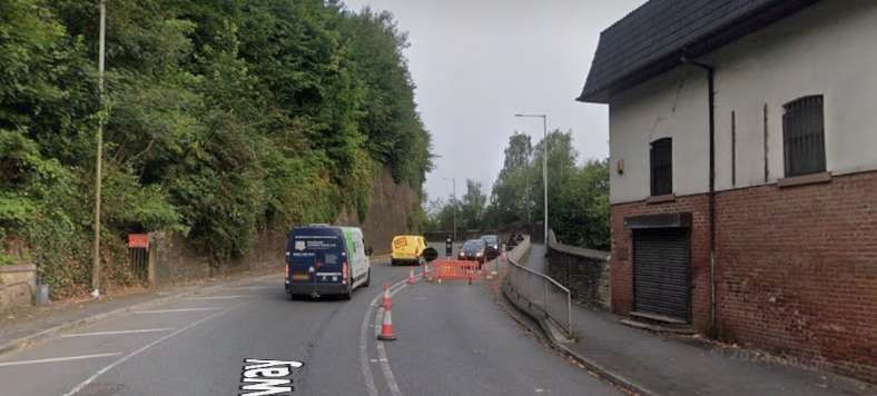
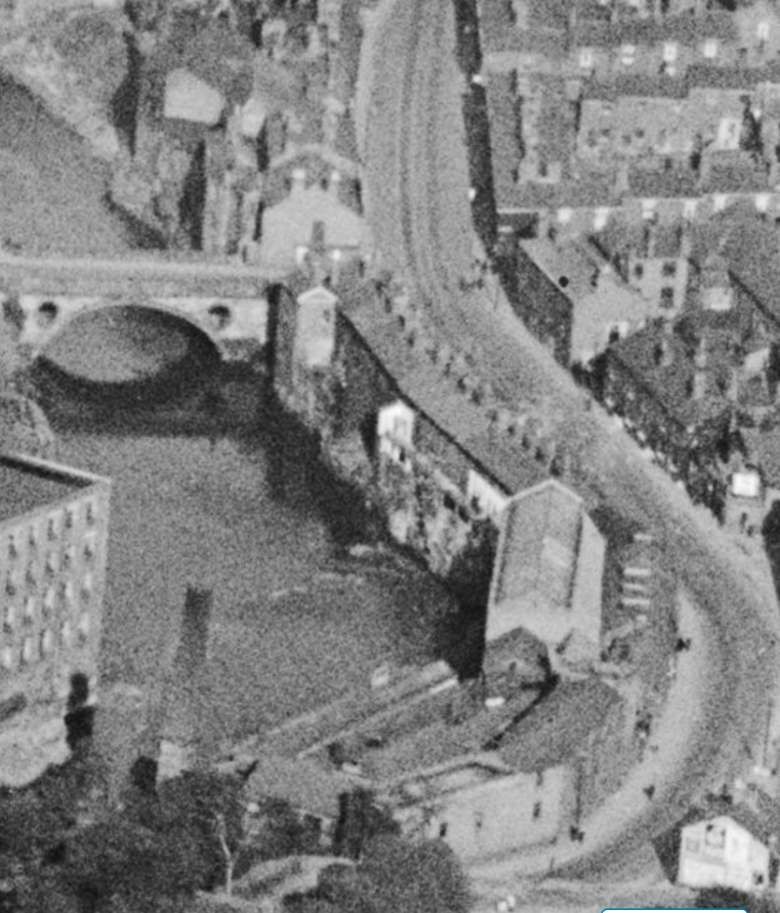
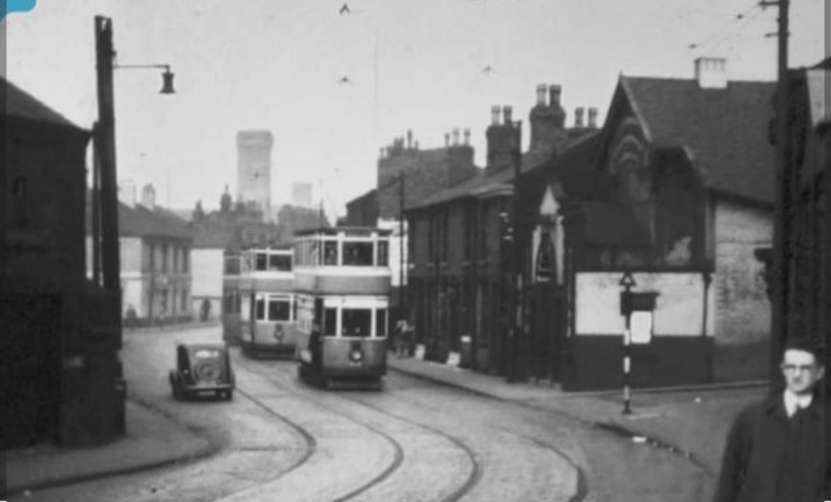
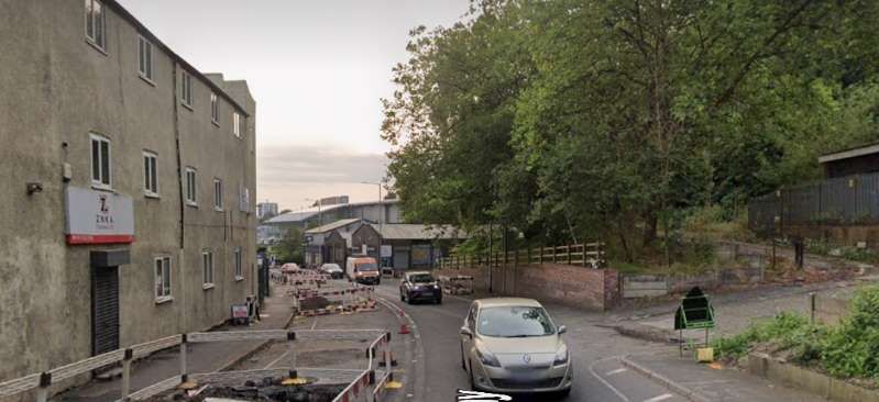
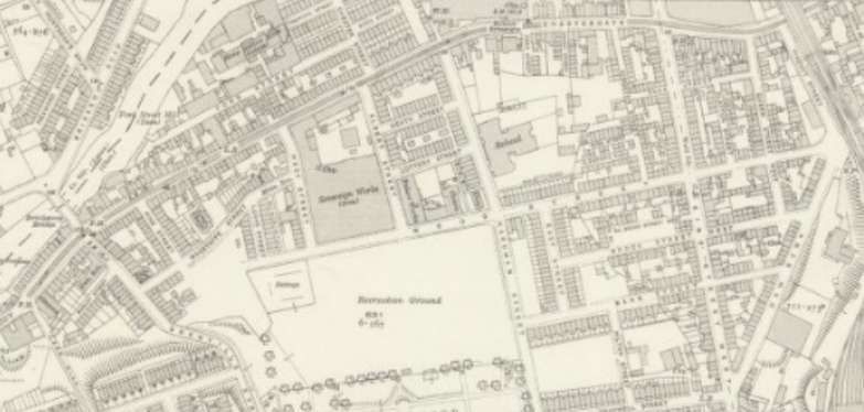
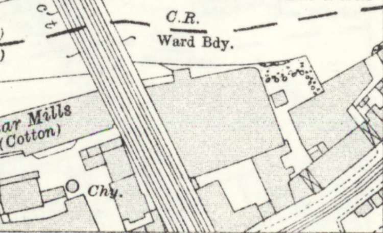
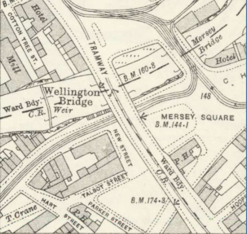
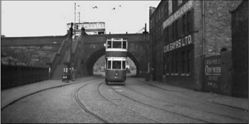
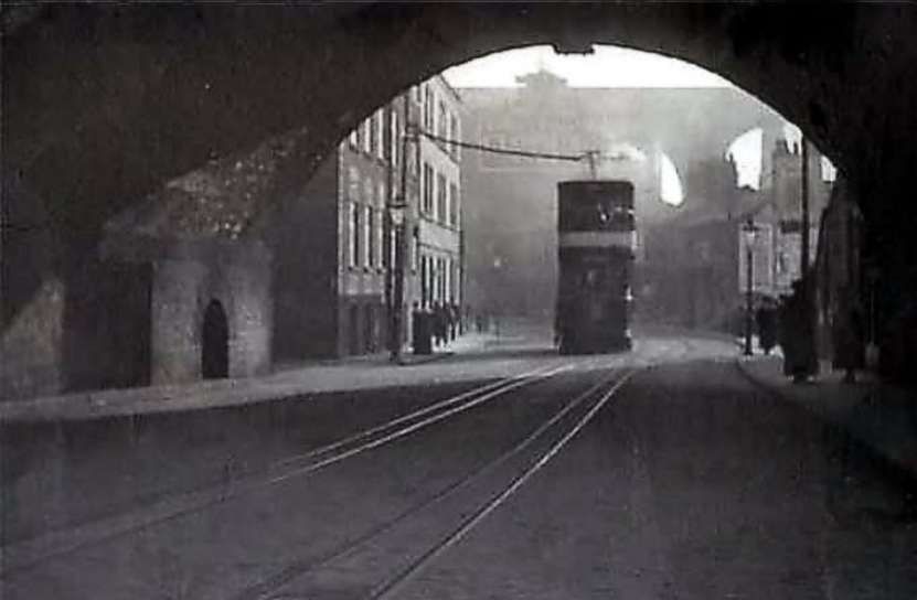
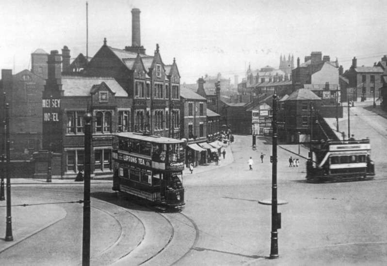
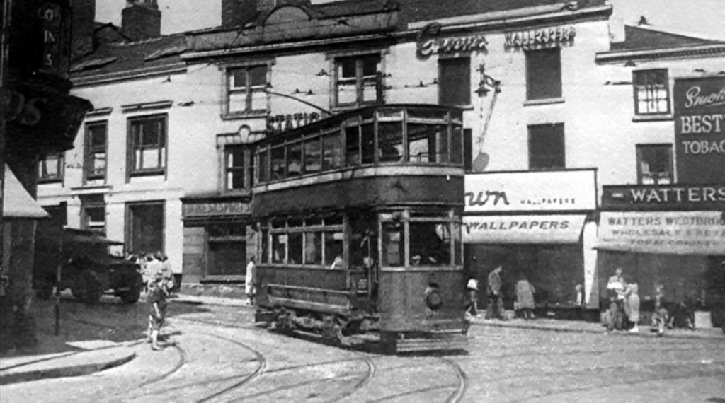
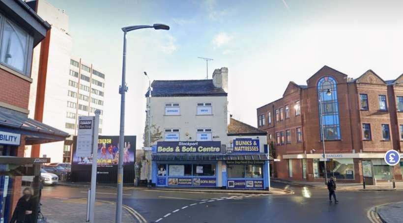
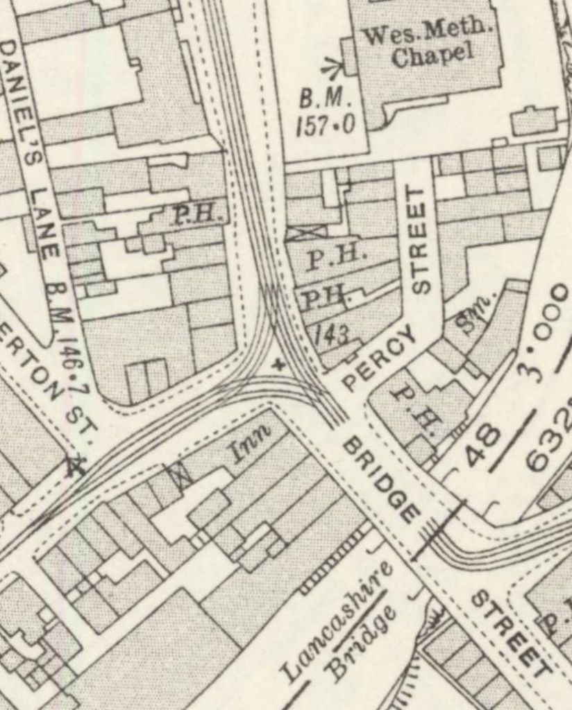
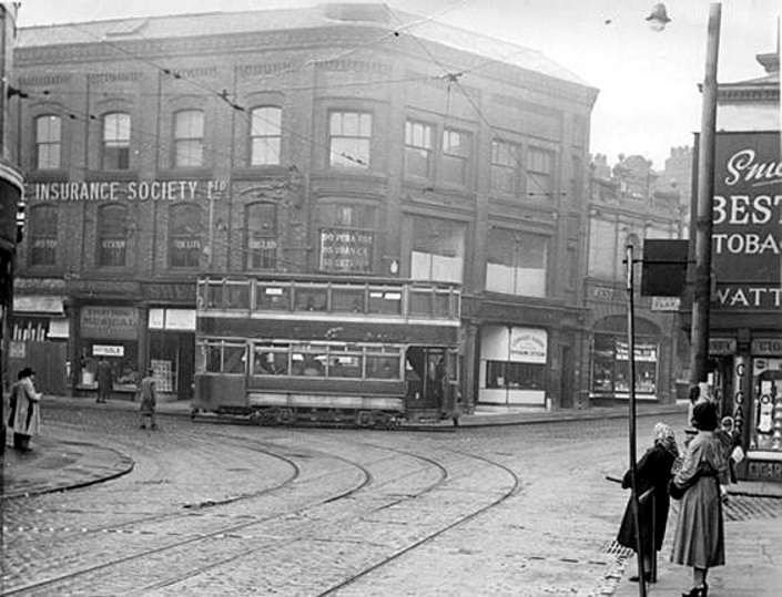
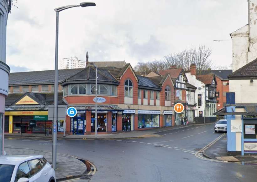
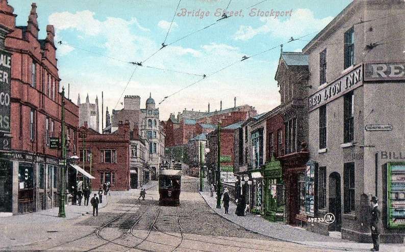
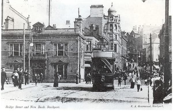
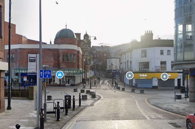
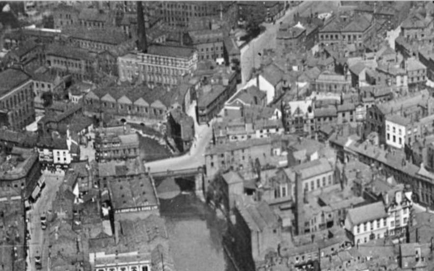

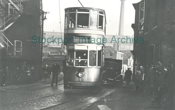
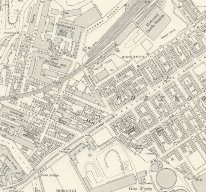
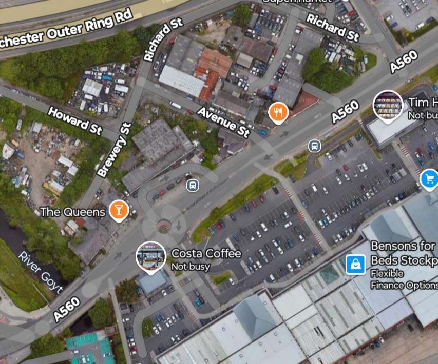
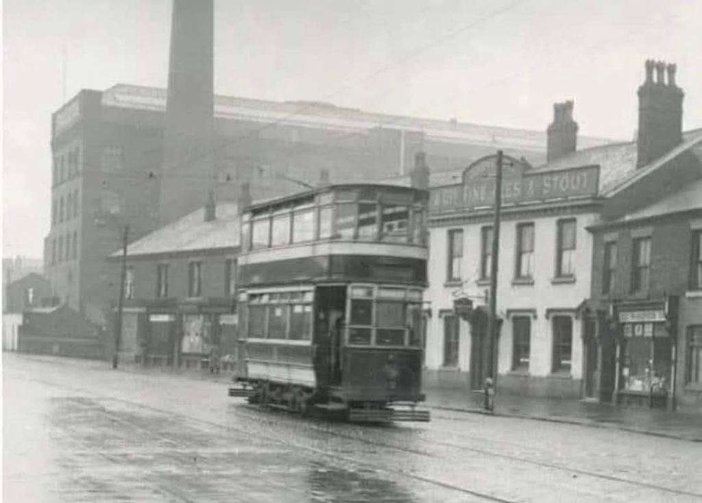
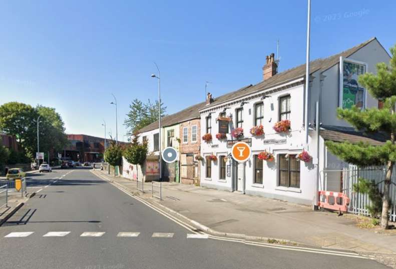
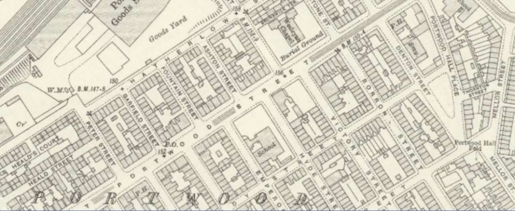
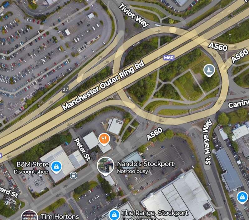
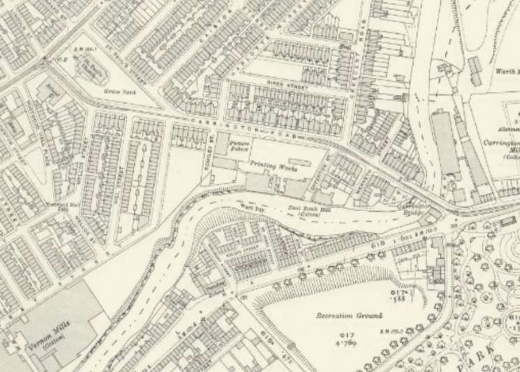
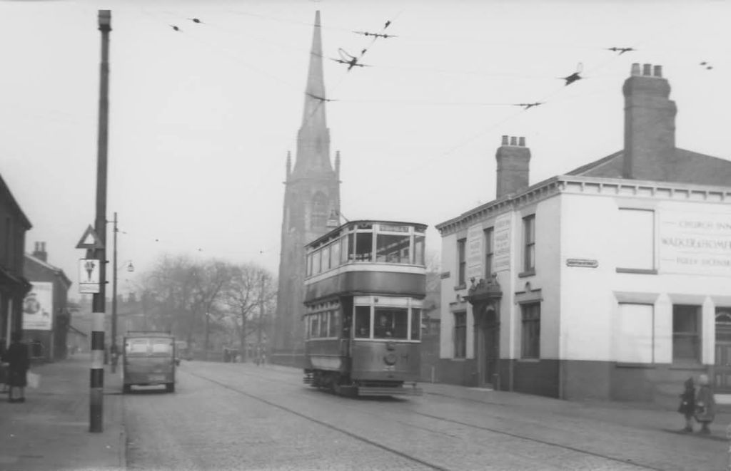
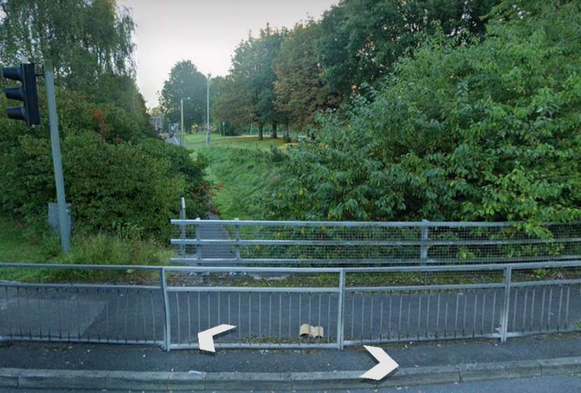
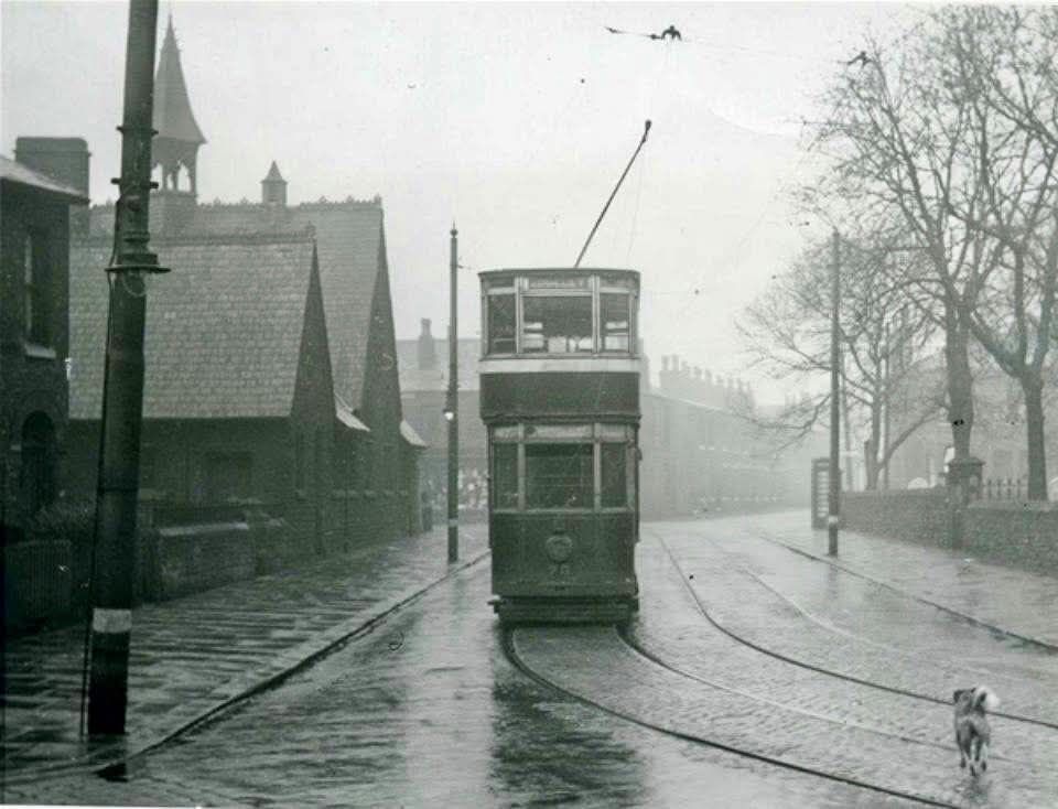
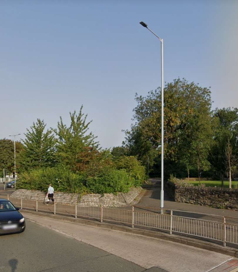
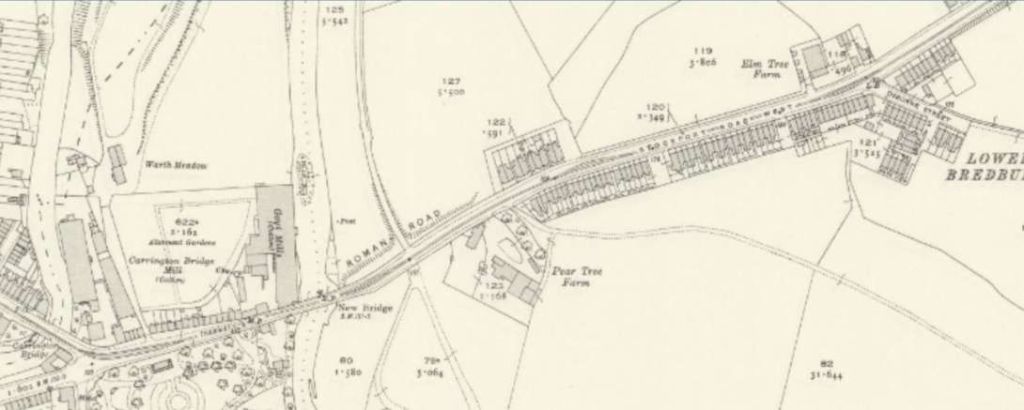
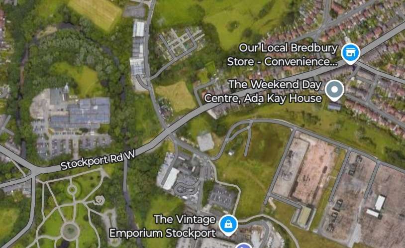
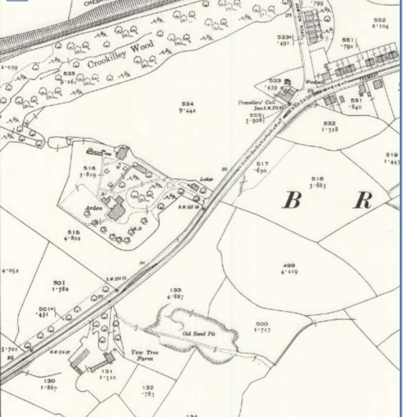
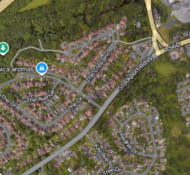
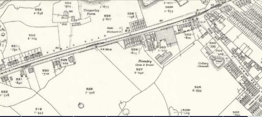
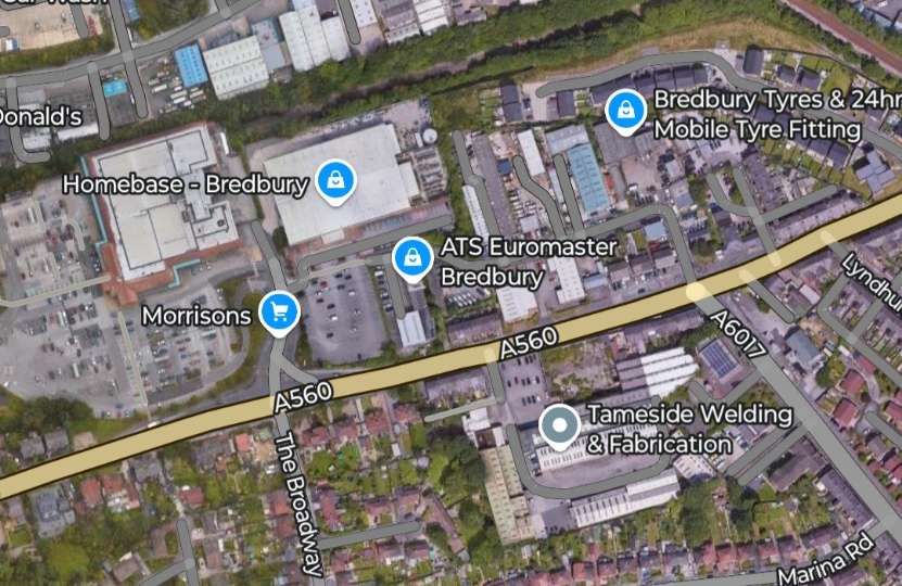
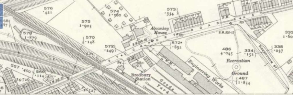
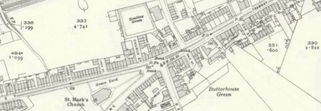
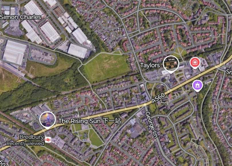
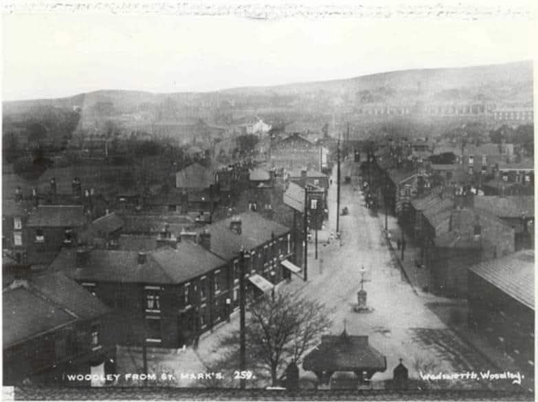
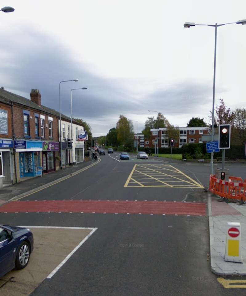
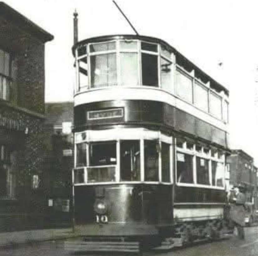
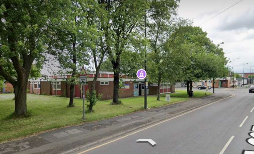
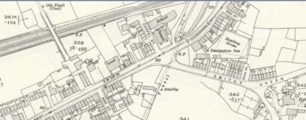
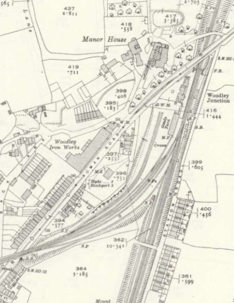
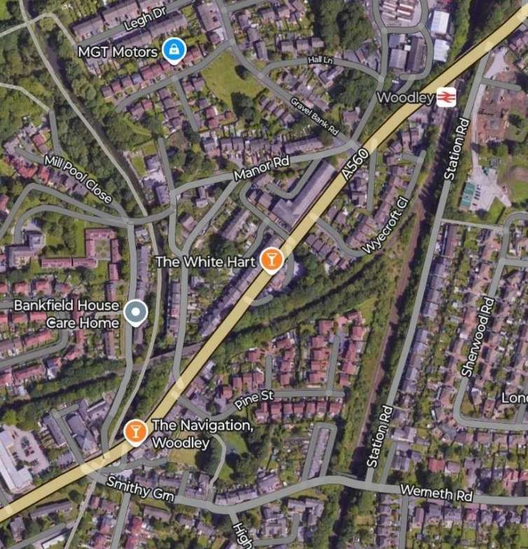
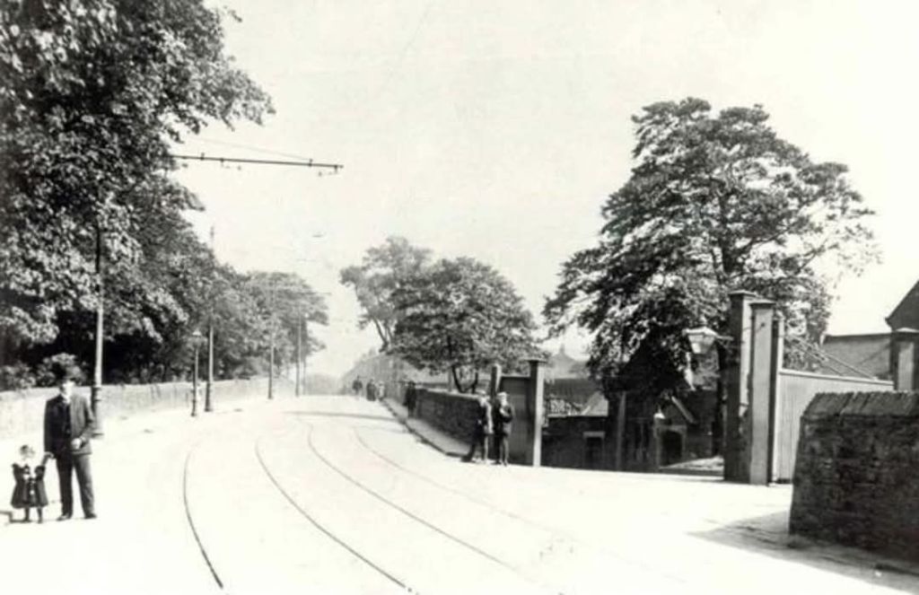
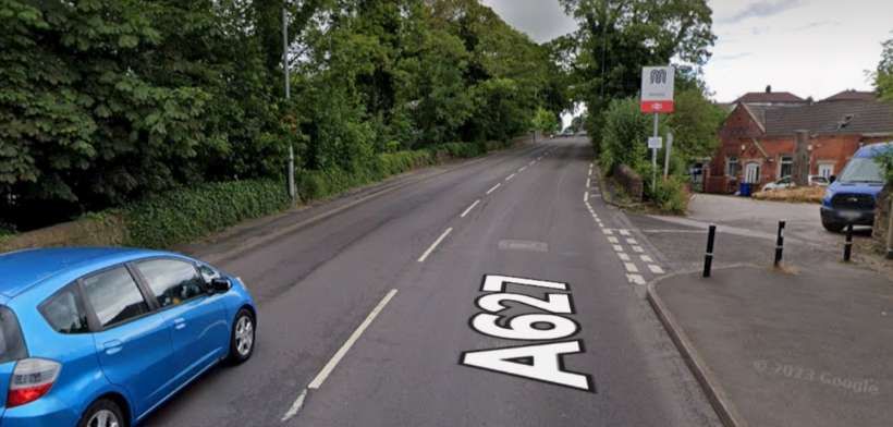
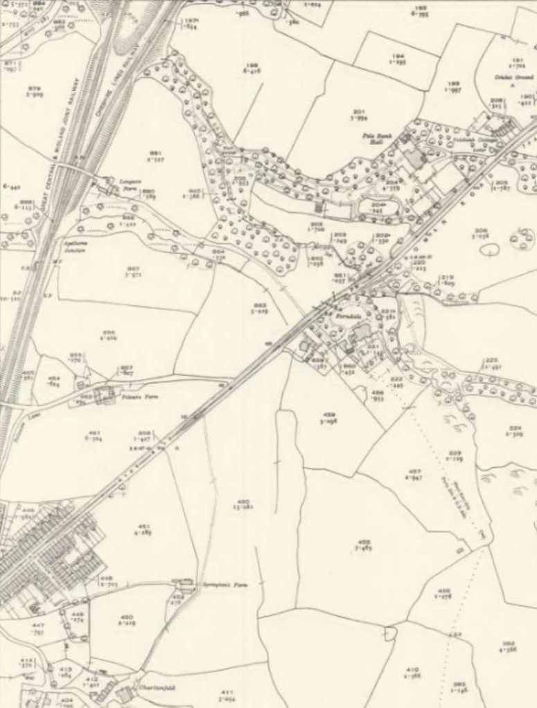

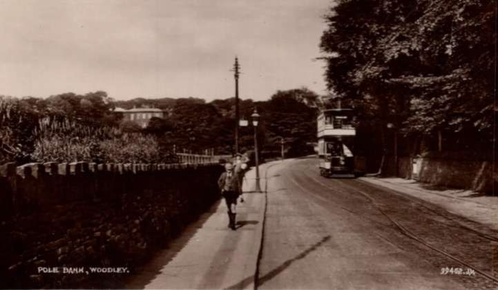
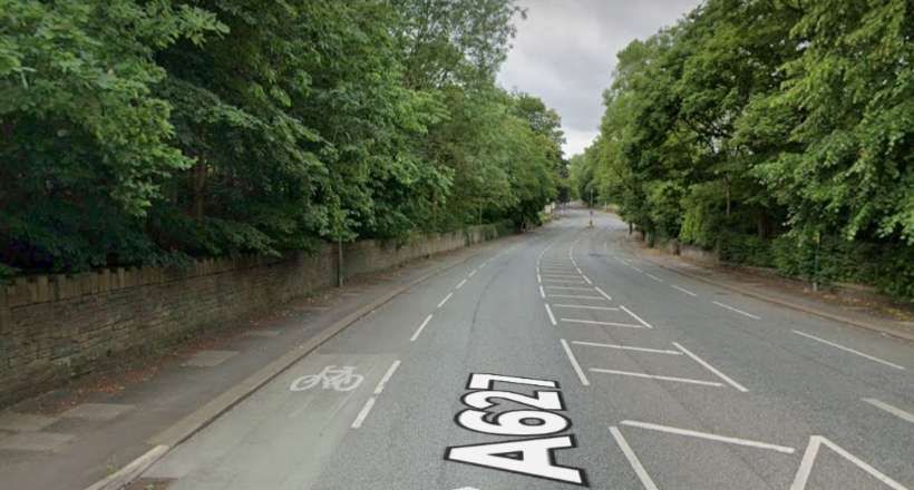
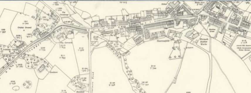
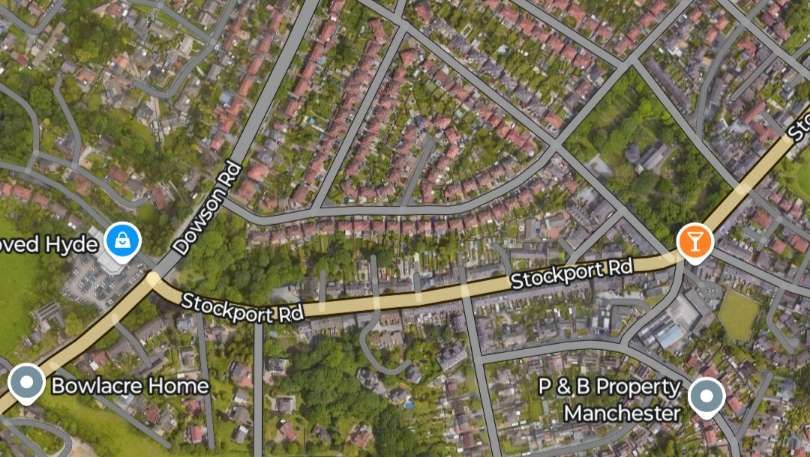
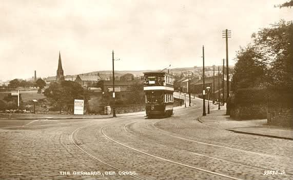
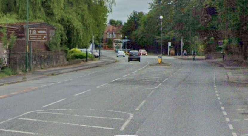
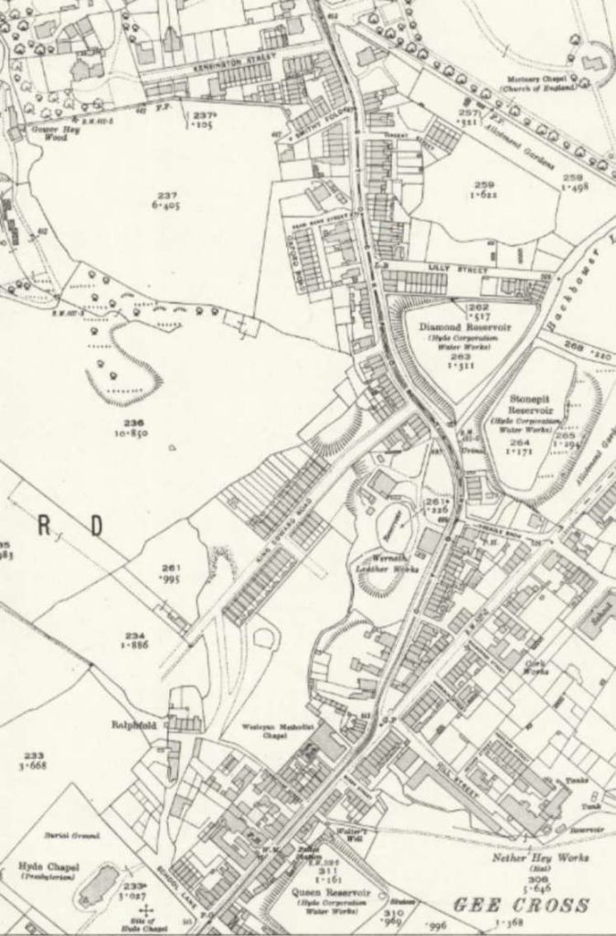
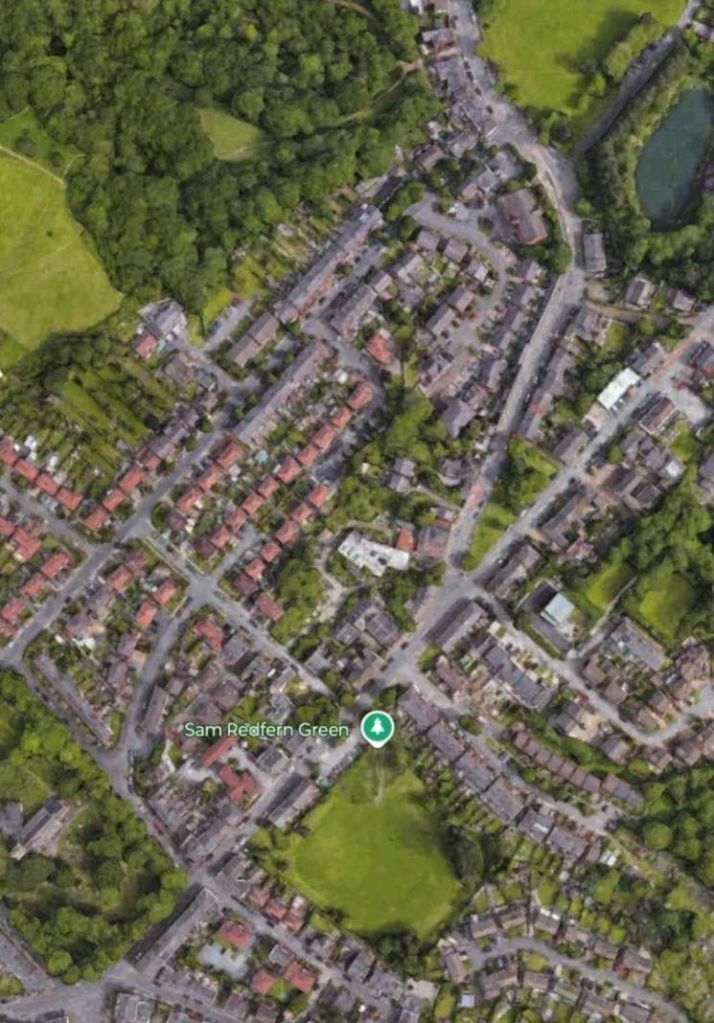
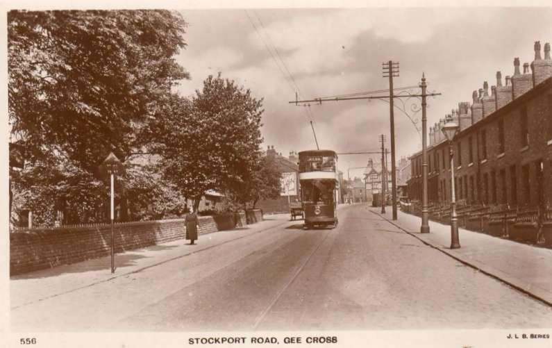
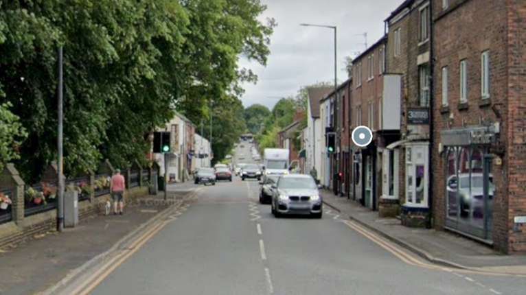
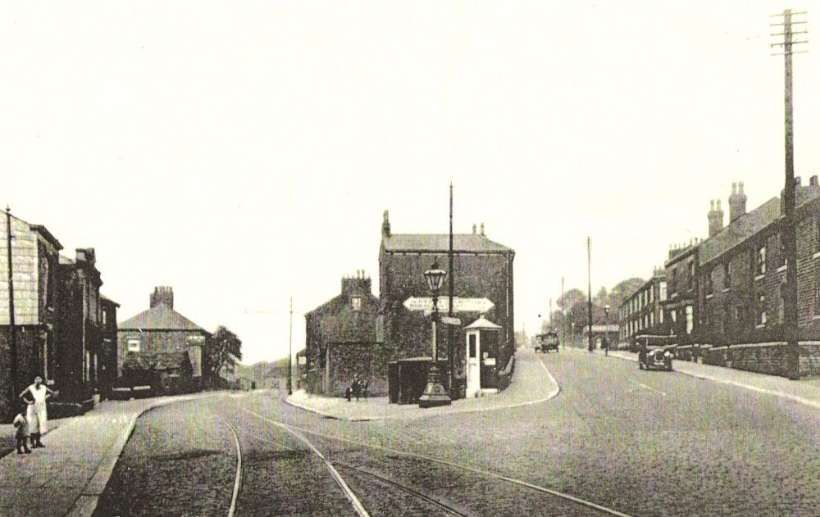
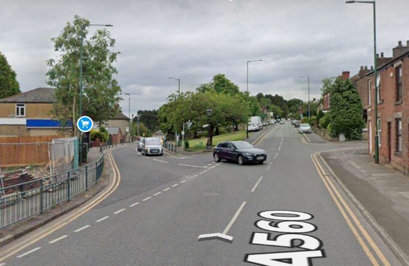
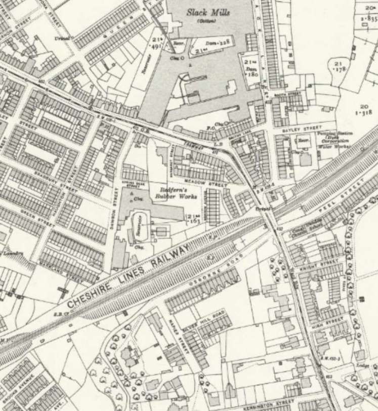
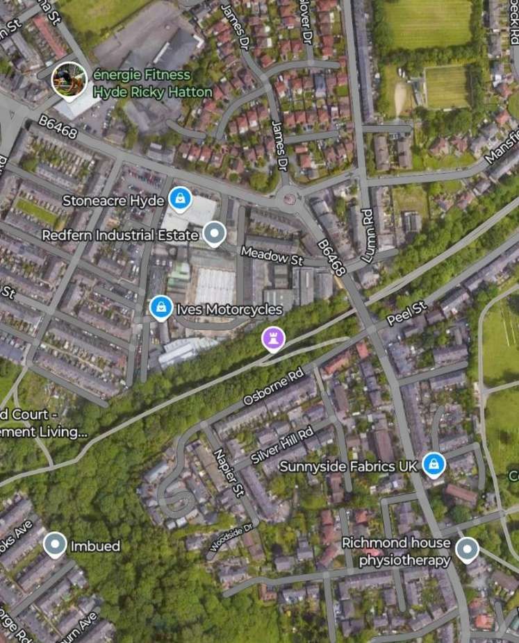
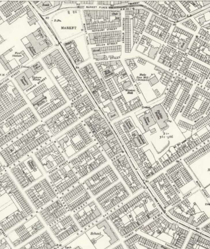
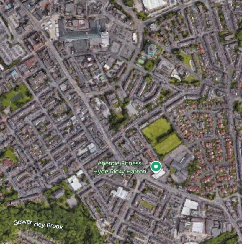
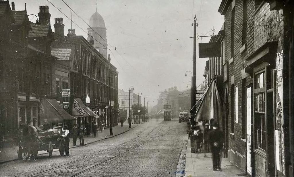
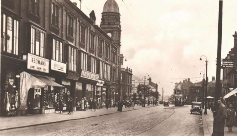
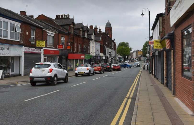
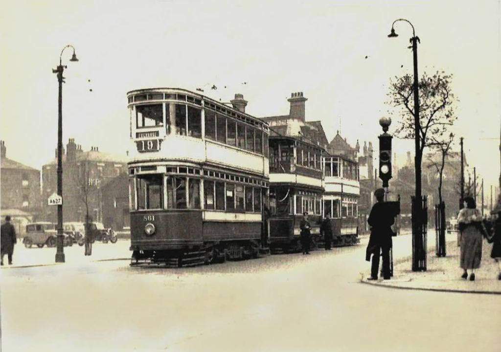
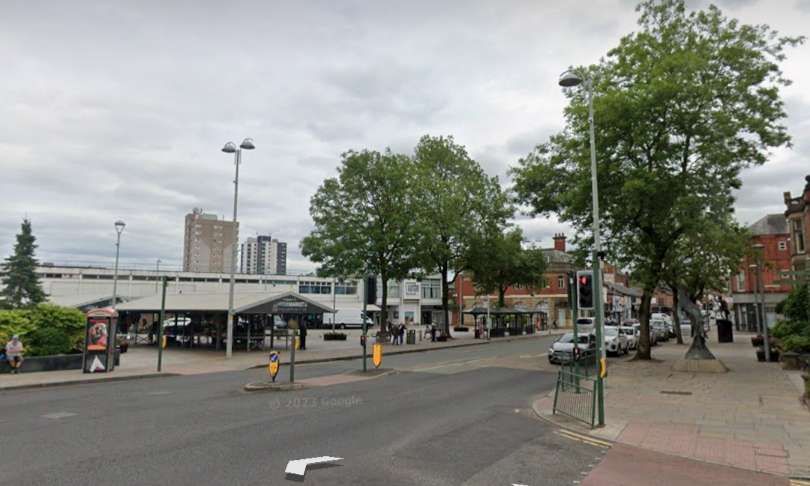
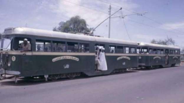
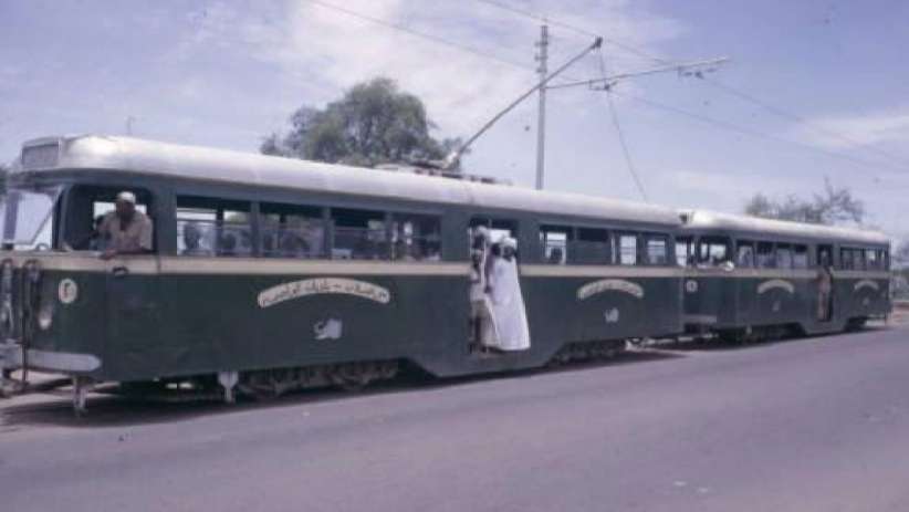
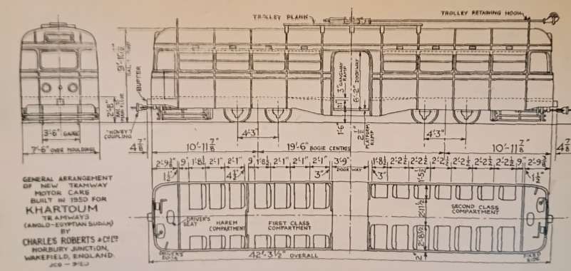
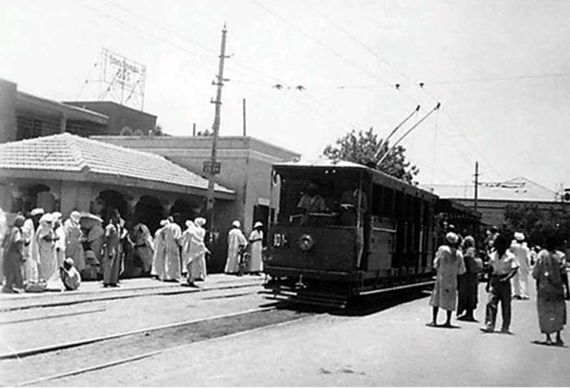
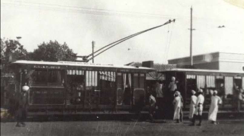
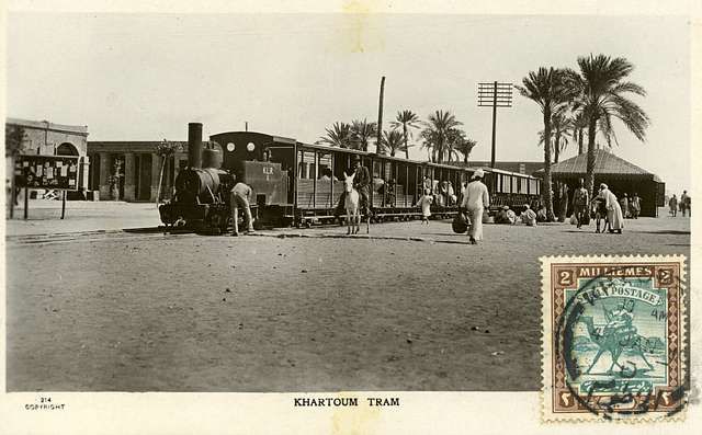

_58_class_Garratt_locomotive_no_5804.png)
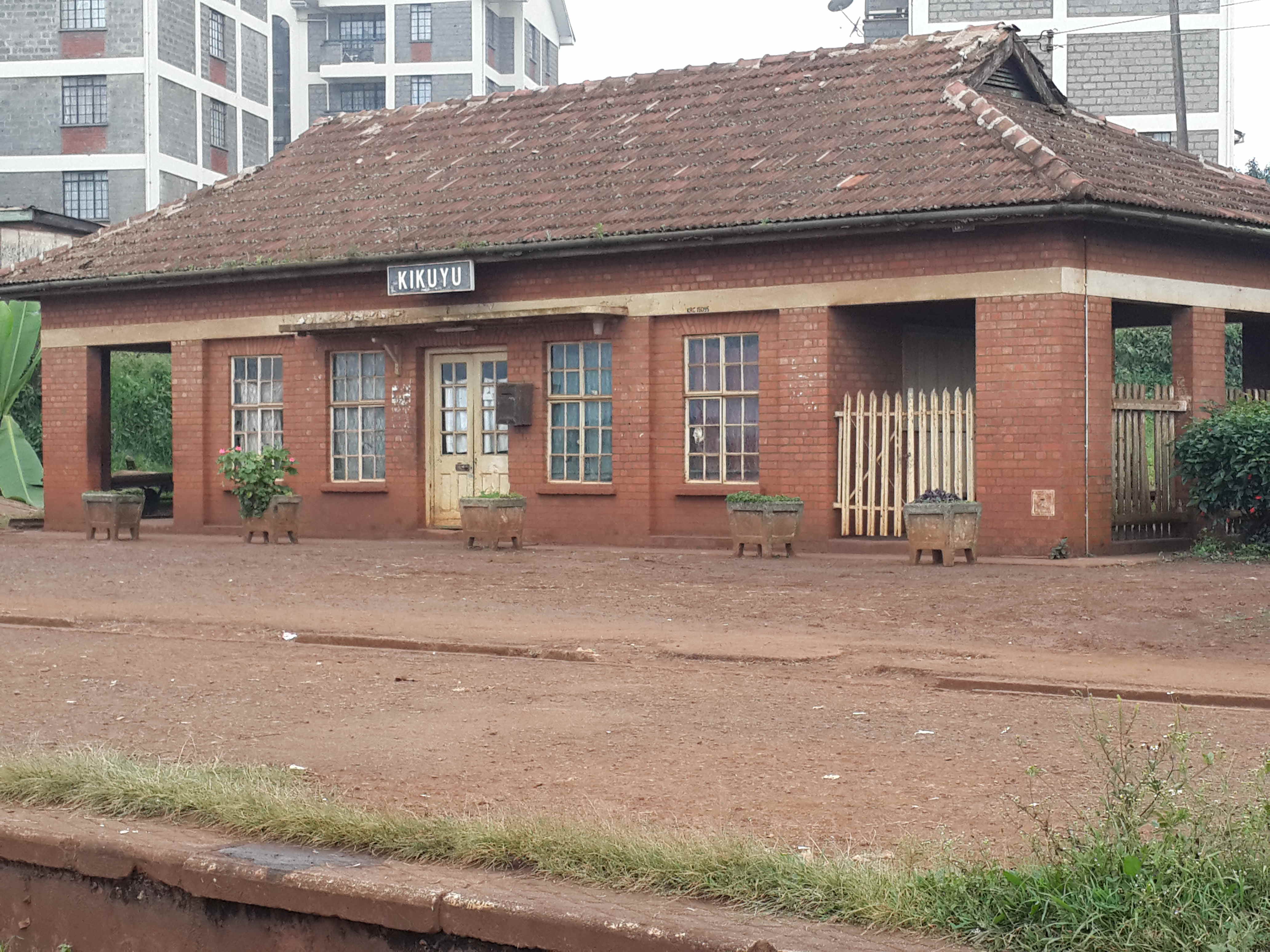
.jpg)
.jpg,baccrssef)
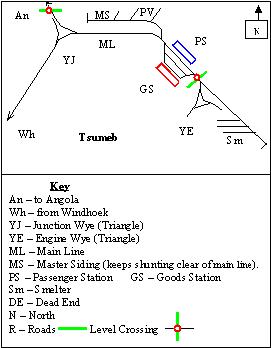