The short paragraph immediately below appeared in the February 1952 edition of The Railway Magazine in reply to a question submitted by G. T. Kaye.
“The Nidd Valley branch of the former North Eastern Railway (which was closed to passengers on 31st March 1951) terminated at Pateley Bridge, 14 miles from Harrogate. In 1900, a Light Railway Order was obtained for a 2 ft. 6 in. gauge line from Pateley Bridge to Lofthouse-in-Nidderdale, six miles further up the valley, but the promoters had difficulty in finding the necessary capital. At that time, the Bradford Corporation was about to undertake the construction of reservoirs in the Nidd Valley, and a railway was required to carry materials to the sites. The Corporation took over the powers for the light railway, and extended it for a further 6 miles, from Lofthouse to Angram. The railway was laid to the standard-gauge, and was opened to passengers between Pateley Bridge and Lofthouse on 1st May 1907. The remainder of the line did not carry public traffic. The line was worked by two 4-4-0 tank engines and passenger coaches purchased from the Metropolitan Railway. The passenger services were withdrawn on 31st December 1929, and the line was closed completely some months later.” [1: p143]
It appeared close to the back of the magazine in the section called, “The Why and the Wherefore”. It seemed like a good idea to explore what further information there is available about the Nidd Valley Light Railway. …….
The Website ‘WalkingintheYorksireDales.co.uk’ has a page dedicated to the railway which can be found here. [2]
A number of images relating to the line can be found here. [13]
The Oakwood Press published a book by D. J. Croft about the line. [3: p3]
Croft wrote: “The valley of the River Nidd, in the West Riding of Yorkshire, is nearly 55 miles long, beginning at Great Whernside, and ending at Nun Monkton where the Nidd flows into the River Ouse. However, the area known as Nidderdale extends for only about a half of the length, and forms a compact geographical region of its own. Despite this length, and great scenic beauty, it remains to this day one of the forgotten valleys of the Yorkshire Dales.” [3: p3]
“The area of Nidderdale can be divided into roughly two equal sec tions, with the market town of Pateley Bridge between the two. The first substantial historical accounts of Nidderdale appeared in Domesday Book of 1086. However, some of the local lead mines were worked in the time of the Brigantes, whilst several surrounding localities suggest Roman occupation.” [3: p3]
“Nidderdale has several industries, notably quarrying and lead mining. and a small textile industry. There is also a small slate quarry, a marble quarry, and a long, thin ironstone vein stretching along the valley. Through-out the ages, however, Nidderdale has had prosperity alternating with decline. As the early mining industry began to decline, so textiles became important around the thirteenth century. This too tended to decline by the seventeenth century, and mining became important once more. Unfortunately, the prosperity of the lead mining era passed, and so too did the prosperity of Nidderdale.” [3: p3]
“This period of decline lasted until 1862, when the North Eastern Railway opened its line from Harrogate to Pateley Bridge, thus opening this remote valley to the outside world. Prior to this, the only roads out of the dale had been to Grassington, Riponand Kirkby Malzeard, and the only regular connection with the outside world had been the Nidderdale Omnibus, a double-deck horse bus, linking Pateley Bridge with trains of the Leeds & Thirsk Railway at Ripley. This operated from 1st August 1849, until the opening of the railway, and ran twice daily.” [3: p3]
The approach of the 20th century brought a new prosperity to the valley, which was to last for the next thirty years or perhaps a little longer. Thid was the period when the Nidd Valley Light Railway was active.
The story of the line is the story of the thirteen or so miles between Pateley Bridge and the head of the valley, for it was there “that the Nidd Valley Light Railway was conceived, constructed and closed. All this happened within a period of less than forty years.” [3: p3]
The Story of the Line
Wikipedia tells us that the origins of a railway in the upper Nidd Valley “can be traced back to 1887–88, when Bradford Corporation began to investigate the valley as a source for the public water supply. … Alexander Binnie, who was the Waterworks Engineer for Bradford at the time, and Professor Alexander Henry Green, a geologist from Oxford, visited the area, and Green advised Binnie that the valley was suitable for the construction of large dams. The Bradford Corporation Water Act 1890 was obtained on 14th August 1890, authorising the construction of four dams. … A second Act of Parliament was obtained on 27th June 1892, by which time the four reservoirs were Angram, Haden Carr, High Woodale and Gouthwaite. Gouthwaite Reservoir was designed as a compensation reservoir, to maintain flows in the Nidd further down the valley.” [4][5: p76-77]
The first reservoir, Haden Carr, was completed in 1899, together with a 32-mile (51 km) pipeline (the Nidd Aqueduct) to deliver water to Chellow Heights reservoir on the outskirts of Bradford. [4][5: p79] “Gouthwaite reservoir was built … between 1893 and 1901.” [5: p84-85] The activity in the valley attracted attention from outside the region and a company from London, Power & Traction Ltd applied for a Light Railway Order “to construct a line from the terminus of the Nidd Valley Railway at Pateley Bridge to Lofthouse. … Following a hearing at Harrogate on 9th October 1900, the Light Railway Commissioners awarded an order to Power & Traction for a 2 ft 6 in (762 mm) gauge railway.” [4] Negotiations with Bradford Corporation over a possible £2,000 investment in the scheme ultimately failed. [5: p86]
“In 1903, Bradford invited tenders for the construction of Angram Reservoir, and … reached provisional agreement with the Nidd Valley Light Railway Company to purchase the powers awarded to them to build the light railway. … Bradford wanted to ask the Light Railway Commissioners for permission to increase [the track gauge] to 3 ft (914 mm). … They also wanted to ensure that they bought enough land to allow a standard gauge railway to be constructed ‘at any future time’. The North Eastern Railway, owners of the Nidd Valley Railway, argued that it should be standard gauge from the outset, since they were running excursions to Pateley Bridge twice a week, and these could continue over the Nidd Valley Light Railway. It would also remove the necessity of transshipping goods.” [5: p86]
Then next three map extracts show the railway facilities in Pateley Bridge while the Nidd Valley Light Railway was active. …
A transfer order was eventually granted, “with powers to borrow up to £30,000 to fund the project. In May 1904, the Board of Trade agreed to a change to standard gauge, and borrowing powers were increased to £66,000 in 1908, because of the extra costs of building the wider formation. The document was signed by Winston Churchill, the President of the Board of Trade.” The contractor working on the Anagram reservoir, John Best, “was awarded a contract to build the light railway to Lofthouse for £23,000, and a tramway from Lofthouse to Angram for £5,385.” [5: p86-87]
Then the intrigue began! A contract had been awarded in April 1902 to Holme and King for the construction of a road from Lofthouse to Angram. Bradford Council “had purchased enough land to allow the light railway to be built beside the road, and although Best was awarded a contact for the railway in 1903, it appears that Holme and King built a 3 ft (914 mm) gauge contractor’s railway beside part or all of the road. They had two locomotives on site, both 0-4-0 saddle tanks, one bought second hand some years earlier and moved to the site in spring 1902, after working on several other projects, [5: p87] and the second bought new for delivery to Pateley Bridge. [5: p89] By mid-1904, there was a 6.5-mile (10.5 km) line from Angram, which crossed the River Nidd on a 20-foot (6.1 m) bridge just before it reached Lofthouse.” [4]
So, Best began extending the line towards Pateley Bridge from the River Nidd rather than starting the work again! Wikipedia tells us that “by 13th July 1904, it had reached a level crossing at Sykes Bank, 0.5 miles (0.8 km) below Lofthouse, and work had commenced at several other sites. On that date, a party of 150 members of Bradford City Council, with invited guests, arrived by train at Pateley Bridge, and were transported to Gouthwaite Dam in carriages. Here there was a ceremony in which the Lord Major cut the first sod for the Nidd Valley Light Railway.” [4] The party “proceeded to Sykes Bank, where a train was waiting, which consisted of 15 wagons fitted with makeshift seats, and two locomotives, one of which was Holme and King’s Xit and the other was Best’s Angram. It took about an hour to reach Angram, where there were presentations, and Alderman Holdsworth cut the first sod for the dam. Refreshments were then served and the party returned to Lofthouse by train and to Pateley Bridge by carriage.” [4][5: p90-91]
The narrow gauge had hardly reached Pateley Bridge and Angram begun its regular duties along the line when standard gauge rails began to be laid starting at Lofthouse and working both up and down the line from there. “When the first standard gauge locomotive arrived, it was towed along the road to Sykes Bank by a Foden steam lorry, its flanged wheels making a mess of the road surface. The main line and sidings became mixed gauge for a while, although the third rail was gradually removed from 1906.” [5: p91 & 93] There was a veritable network of rail lines at the Angram Dam site where, as well as a village built for the workers, “the railway terminated in several sidings, which included a locomotive shed. The sidings were at a similar level to the crest of the dam. A branch left the main line and descended to the valley floor, where there was a cement mixing plant and more sidings. This line included a winch-operated incline which descended on a gradient of 1 in 15 (6.7%). Another incline, of 3 ft (914 mm) gauge, ascended the far side of the valley, giving access to Nidd sluice and lodge. A third incline brought rock down to the main line from a quarry, some 2 miles (3.2 km) below the terminus.” [4][5: p93 & 97]
At the other end of the Light Railway, “at Pateley Bridge, the Nidd Valley Light Railway station was to the north west of the North Eastern Railway’s Pateley Bridge railway station, close to the River Nidd. The two were connected by a single track which crossed a level crossing. There were a series of sidings immediately after the level crossing, with the station and more sidings beyond that. A carriage shed and a locomotive shed were located a little further along the valley of the Nidd.” [4]
Ramsgill Village was served by a stationary Bouthwaite which sat on the opposite side of the River Nidd. This map extract comes from the 25″ Ordnance Survey of 1907, published in 1909. [7]
“Best built two-storey stone buildings for the stations at Pateley Bridge, Wath, Ramsgill and Lofthouse. He built a signal box at Pateley Bridge, with the other stations having ground frames and simple signalling. Operation of the line was controlled by the Tyer’s Electric Train Tablet system, and six machines were ordered at a cost of £360. [5: p101] Both intermediate stations had goods sidings on the eastern side of the main track, while Lofthouse had a passing loop and sidings to the west.” [4]
The Station at Wath sat between the village and the River Nidd. The 25″ Ordnance Survey of 1907/1908 and published in 1909. [8]
“Best had a number of locomotives, both 3 ft (914 mm) gauge and standard gauge, which operated over the entire line from Pateley Bridge to Angram during the construction phase. For the opening of the Nidd Valley Light Railway proper, the 6.5 miles (10.5 km) from Pateley Bridge to Lofthouse, Bradford Corporation ordered six open wagons and two brake vans from Hurst Nelson of Motherwell. Locomotives and carriages were obtained second-hand from the Metropolitan Railway in London. These consisted of ten 4-wheeled coaches and two 4-4-0 Beyer Peacock side tank locomotives. All had become surplus to requirements, as electrification of the line had been completed in 1905. The locomotives were fitted with condensing equipment, for working in the tunnels under London, but the price of £1,350 for the pair included removal of this, and the fitting of cabs. All twelve vehicles arrived at Pateley Bridge, with one engine in steam … The locomotives were named ‘Holdsworth’ and ‘Milner’ after two Aldermen who had served Bradford Waterworks since 1898.” [4][5: p101, 102]
“An official opening took place on 11th September 1907, when a train consisting of three carriages and the Corporation saloon were hauled by ‘Holdsworth’ from Pateley Bridge to Lofthouse, with stops at Wath and Gouthwaite reservoir. At Lofthouse the engine was replaced by one of Best’s engines, and continued to Angram where luncheon was served in the village reading room.” [4][5: p102, 105]
“The two locomotives were much too heavy to comply with the Light Railway Order, which specified a maximum axle loading of 6.5 tons. They weighed 46.6 tons in working order, with 36.7 tons carried by the two driving axles. The Corporation applied for an increase in the axle loading, specifying the weight as “over 42 tons”. Milner, the newest of the two locomotives, dating from 1879, [5: p102] did not perform well, and was replaced by a Hudswell Clarke 0-6-0 side tank, also named Milner in May 1909. The original Milner was sold to the North Wales Granite Company at Conwy in 1914. [5: p102, 111] Following discussions with the Board of Trade in 1906, the Corporation and the North Eastern Railway had obtained permission for three passenger trains per week to pass over the goods yard and sidings at Pateley Bridge, so that excursions could continue up to Lofthouse between June and September only. Despite the agreement, when the first excursion was due to make the journey on 14th September 1907, the NER decided not to allow their stock to pass onto the Nidd Valley Light Railway, nor to allow the Corporation engine and carriages to come to their station, and so the passengers had to walk between the two stations. [5: p110] In order to avoid confusion for parcels traffic, Lofthouse station became Lofthouse-in-Nidderdale on 12th December 1907, and Wath became Wath-in-Nidderdale in February 1908 for similar reasons.” [4][5: p107-108]
Work on Angram reservoir was finally completed in 1916. “Bradford Corporation had already obtained an Act in 1913, allowing them to abandon their plans for a reservoir at High Woodale, and instead to build a much larger one at Scar House. It would submerge the site of Haden Carr reservoir, and the Act allowed them to start construction “when appropriate”. The cost of the new works was estimated at £2,161,500, and although three tenders were received, they decided on 14th May 1920 to build it themselves, using direct labour. Scar village was built between 1920 and 1921, consisting of ten hostels for a total of 640 men, a school, canteen, recreation room, concert hall, mission church and some bungalows.” [4][5: p115]
Plans to electrify the railway using hydro-electric power, were considered in March 1920, but rejected as being too expensive. uneconomic. Holdsworth, was taken out of service in 1866 because it was too heavy for the line, but when no buyers could be found, it was used as a stationary steam supply for another 14 years. There were plans to overhaul Milner, to obtain another lighter engine, and to purchase two railmotor cars. Only one railmotor (‘Hill’) was eventually purchased in 1921. It can be seen in the two images immediately below.
“From August 1920, work was carried out to improve the line between Lofthouse and Angram. This included easing the alignment on many of the curves, the addition of loops near Lofthouse and at Woodale, just below the Scar House site, and the construction of a 180-yard (160 m) tunnel near Goyden Pot, which was used by up trains only.” [4][5: p119-122]. “The line at Angram was extended to a small quarry in 1921, along the trackbed of Best’s 3 ft (914 mm) gauge line beyond the dam. Stone was extracted for remedial work, caused by wind and wave erosion of the southern bank of the reservoir near the dam.” [4][5: p123]
Close to the Scar House dam site, “a network of sidings were constructed, zig-zagging down to the Nidd, and back up the other side of the valley. A double track self-acting incline provided access to the Carle Fell Quarry, to the north of the reservoir, and as the quarry was worked, two further inclines were constructed. One was single track, with a winding engine at the top, and around 1930, an incline worked by locomotives was added. Above the later quarry face, a Simplex petrol locomotive worked on a 2 ft (610 mm) track, removing overburden.” [4][5: p118]
Power for the works “was generated using water from Angram reservoir, which was discharged into Haden Carr reservoir. A 4,775-foot (1,455 m) pipeline supplied the turbines. This was later supplemented by a steam generating station. [5: p123-124] Two locomotive sheds were built, one near the village and another on the north side of the River Nidd, with a further two at Carle Fell Quarry. All had two tracks. Twelve four-wheeled carriages were bought from the Maryport and Carlisle Railway, to provide transport for the workers and their families from Scar House to Lofthouse, and a two-track carriage shed was built to the east of the main complex.” [4][5: p125]
“Six locomotives worked in the quarry. Allenby, Beatty, Haig and Trotter were based at the shed at the top of the main self-acting incline, while Ian Hamilton and Stringer were based in a shed at a higher level. Three steam navvies were used to load stone into the railway wagons, and there were nineteen or twenty steam cranes, all of which were self-propelled and ran on the tracks either in the quarry or on top of the dam.” [4][5: p129]
The main engineering work at Scar House reservoir closed to completion in September 1931 but it was not until July 1935 that filling of the reservoir commenced. “The official opening was on 7th September 1936. Scar House, which gave its name to the reservoir, was demolished. A new Scar House was built, at the foot of the incline from Carle Fell Quarry, which provided a home for the reservoir keeper, and a boardroom for official visits. [5: p130-131] A project to re-route the waters from Armathwaite Gill and Howstean Beck through a tunnel and into the reservoir began in May 1929. A 2 ft (610 mm) gauge line was laid, on which two battery-electric locomotives and twelve wagons ran.” [4][5: p131]
Two 0-6-0ST locomotives ‘Gadie’ and ‘Illingworth’, head a goods train on the line. [12]
Decline
“The start of work on Scar House Reservoir led to an overhaul of existing stock. Seven of the original Metropolitan Railway coaches were upholstered and repainted, while the remaining five were used for the workmen. [The] steam railmotor [Hill] … obtained in 1921, … had previously been owned by the Great Western Railway. It … was fitted with electric lights in 1923. It worked on the public section of the railway, and never travelled beyond Lofthouse. Numerous new and secondhand locomotives were purchased, most for use on construction work, but two, Blythe and Gadie, were fitted with vacuum brakes, and so worked goods trains from Pateley Bridge to Scar House, as well as passenger trains between Scar House and Lofthouse and sometimes Pateley Bridge.” [4][5: p133]
“Passenger trains for the residents of Scar village ran on Tuesdays, Thursdays and Saturdays, the mid-week ones connecting with ‘Hill’ at Lofthouse, and the Saturday ones running through to Pateley Bridge. The 1927 printed timetable showed five trains a day between Pateley Bridge and Lofthouse, but also showed the trains onwards to Scar Village, with a note that these were for exclusive use of residents. Saturday trains were hauled by Blythe or Gadie, but were banked at the rear by another engine above Lofthouse because of the steep gradients.” [4][5: p134]
“Traffic returns showed 106,216 journeys by workmen in 1921, and 41,051 by ordinary passengers. The figure for workmen was not declared after 1922, as the accommodation at Scar Village was available. The peak year for journeys was 1923, with 63,020, after which there was a gradual decline, with 24,906 journeys for the final nine months before closure. The line made a total operating loss of £36,435 between 1908 and 1924, and then made a modest profit until 1929. Fares were cut by one third in early 1929, in the face of competition from motor buses, and a decision was taken to close the line in April 1929.” [4][5: p
“An approach to the London and North Eastern Railway to take over the railway was unsuccessful, and on 31st December 1929, the railway closed to public passenger and goods services. The sections below and above Lofthouse continued to be run as a private railway. [5: p135] The Saturday train to Pateley Bridge for the residents of Scar Village continued until 1932.” [4][5: p133]
The line to Angram was severed by the works at Scar House in 1933. “By 1936, with construction completed, the railway was lifted, and a sale was held at Pateley Bridge on 1st March 1937, where everything was sold as a single lot. … At its peak, the Scar House reservoir project had employed about 780 men, and the population of Scar Village had been 1,135. By 1936, there were just eight houses occupied, and seven pupils at the school, which closed on 31st January 1938.” [4][5: p130 & 138]
A Journey along the Line
“The railway began in Pateley Bridge, close to the River Nidd, with the goods yard just to the north of the B6265 road. The passenger station was a little further north, and is now occupied by a road called ‘The Sidings’.” [4]
The Nidd Valley Light Railway Station, Transshipment Yard and Goods Yard at Pateley Bridge. 25″ Ordnance Survey of 1907/08, published in 1908. [9]The Nidd Valley Light Railway Station Platform at Pateley Bridge in 1907. This image was shared on the Railways Around Harrogate & Yorkshire Facebook Group on 18th January 2024 by Ian McGregor, (c) Public Domain. [17]The same area in the 21st century. ‘The Sidings’ is the cul-de-sac directly above the centre-bottom of the image. The new build further to the North is an extension to Millfield Street. [9]The Sidings. [Google Street view, May 2024]The extension to Millfield Street. [Google Streetview, May 2024]The line’s Carriage Shed and Engine Shed sat to the North of the Station. 25″ Ordnance Survey of 1907/08, published in 1908. [9]The same area in the 21st century. The area of the Carriage and Engine Sheds has now reverted to farmland. [9]
The line headed North “along the east bank of the river, and this section of it now forms part of the Nidderdale Way, a long-distance footpath. Wath station was just to the south of the minor road that crosses Wath Bridge, and had two sidings.” [4]
Wath Railway Station was on the South side of the road between the Corn Mill and Wath Bridge. 25″ Ordnance Survey of 1907/08, published in 1908. [14]The same area in the 21st century. ESRI satellite imagery provided by the National Library of Scotland. [14]Looking South from the minor road into the site of Wath Station. The station building is now a private home. [Google Streetview, May 2024]The line North of the minor road was on a low embankment. [Google Streetview, May 2024]
“The footpath leaves the course of the railway before the station, and follows the bank of the river, crossing over the railway trackbed by Gouthwaite Dam.” [4]
The line passed close to the Northeast end of Gouthwaite Dam. 25″ Ordnance Survey of 1907/08, published in 1908. [15]A very similar area in the 21st century. [Google Maps, October 2025]Beyond the North end of Gouthwaite Reservoir, the route of the old railway can be seen from the minor road which links Coville House Farm to Bouthwaite. This view looks South from the road. The route of the old line is beyond the drystone wall in a shallow cutting. [Google Streetview, May 2024]Turning through 90° to face West, the end of the cutting can be seen on the left of this image, the line ran on beyond the tree at the right side of the photograph. [Google Streetview, May 2024]Further North along the same minor road, the old railway ran to the left of the drystone wall, between it and the electricity pole. [Google Streetview, May 2024]
“The trackbed was close to the shore of the reservoir, and the footpath rejoins it after a deviation to the north west. Ramsgill Station was at Bouthwaite, rather than Ramsgill, just to the south of Bouthwaite Bridge, where the Ramsgill to Bouthwaite road crosses Lul Beck.” [4]
Ramsgill Railway Station at Bouthwaite. 25″ Ordnance Survey of 1907/08, published in 1908. [16]Approximately the same area as it appears on 21st century satellite imagery. The line can easily be picked out close to the bottom-right of this image, to the West of the minor road. The station area remains quite distinct! The route of the line continues Northwest on the North side of the minor road which enters centre-left. [Google Maps, October. 2025]The Station Building at Ramsgill Railway Station in Bouthwaite, the main running line was to the right of the building and crossed the road to the right of the camera. [Google Streetview, May 2924]Looking Northwest from approximately the same place these trees sit on the line of the old railway. Just North of the road, the line bridged the stream running through the village. [Google Streetview, May 2924]
“The footpath rejoins the trackbed briefly at Low Sikes, where there was a level crossing over the Ramsgill to Lofthouse road.” [4]
The level crossing adjacent to the River Nidd at Low Sikes. 25″ Ordnance Survey of 1907/08, published in 1908. [18]The same location in the 21st century. Note the gap in the drystone wall bottom-right which sits on the line of the old railway. [18]Looking Southeast along Nidderdale at Low Sikes. The redline approximates to the line of the old railway in the photograph. Foreshortening of the image significantly tightens the curve of the line. [Google Streetview, May 2024]Looking Northwest alongside the River Nidd from Low Sikes. The line ran approximately straight ahead from the sign post in the foreground. [Google Streetview, May 2024]
The next significant location along the line was Lofthouse Station which sat on the South side of the village of Lofthouse, between the road and the river.
Lofthouse Railway Station sat on the Northeast bank of the River Nidd. The railway crossed the River Nidd on a bridge shared with the highway. [6]A similar area in the 21st century. [6]Lofthouse Railway Station building in 21st century, seen from the Southeast. [Google Streetview, May 2024]Lofthouse Railway Station building in 21st century, seen from the Northwest. The railway and platform were on the right of the building. [Google Streetview, May 2024]This road bridge over the River Nidd was once shared with the light railway, the red line shows the route of the line. [Google Streetview, May 2024]Once across the river the line turned sharply to the North to follow the road to Scar House. It followed the West shoulder of the road with the River Nidd off to the East of the road. [Google Streetview, May 2024]
The metalled road is owned by Yorkshire Water but open to the public. The line continued North remaining on the West shoulder of the road.
“The bricked up tunnel can be seen about 2 miles (3.2 km) from Lofthouse, where the road and river turn sharply west. There is a picnic spot near the southern portal of the tunnel.” [4]
Beyond Goyden Tunnel the original line (still used by Southbound trains after the tunnel was built) bears sharply to the West. [Google Streetview, May 2024]Before the tunnel was constructed a short passing loop was provided on the sharp bend. It was not long enough to allow any significant trains to pass but it mitigated the risk of collision! [19]
Images from two different OS sheets surveyed in the late 1920s show the tunnel noted above. [20]
The line from this point on travelled in a westerly direction. Originally the railway ran through the site of Scar House Reservoir as far as Angram Reservoir. Travellers on the railway would have been able to look down and see a small reservoir formed to secure the intake of the pipeline which served Bradford. Its Dam was called the Nidd Intake Dam.
The Nidd Intake Dam and Reservoir. 25″ Ordnance Survey of 1907/08, published in 1908. This reservoir was swamped by the later Scar House Reservoir. [22]This map extract comes from the 6″ Ordnance Survey of 1907 which was published in 1910. The Light Railway has been built but there is no sign of construction work on the Angram Reservoir. [23]A much later OS Map (1956) showing Angram Reservoir with the route of the old railway marked by red dashes. Note that Scar House Reservoir intrudes at the top-right of this map extract. [24]
At Scar Village there is another picnic spot and a car park. The railway followed the most northerly of the two tracks at this point.
A relatively low grade image showing the area close to Scar House Reservoir on which Scar Village was built. The original line of the railway in the track on the northside of the site of the village. The village historical survey report from which this image has been taken provides details (In some depth) of the site of the village and can be found here. [25]
“At Scar Village there is [a] picnic spot and a car park. The railway followed the most northerly of the two tracks at this point. Another track down to the weirs follows the course of one of the zig-zag tracks across the valley. A footpath crosses the dam to the north side of the lake, where the incline to the quarry is still clearly visible. Another road, open to the public on foot, follows the trackbed along the southern edge of Scar House Reservoir, to reach Angram dam. The course of the railway is clearly visible on the modern 1:25,000 Ordnance Survey map for almost the entire length of the railway.”[4]
A short video about Scar Village and the work on Scar House Dam. [21]
References
The Why and the Wherefore; in The Railway Magazine, February 1952; Tothill Press, Westminster, London, p142-144.
The featured image above is a postcard view of la Trinite-Victor Railway Station in the very early years after the line opened. [20]
In the first seven articles about the line from Cuneo to the sea we covered the length of the line from Cuneo to Breil-sur-Roya and then to Ventimiglia, before beginning to look at the line between Breil-sur-Roya and Nice. These articles can be found here, [9] here [10] here, [11] here, [12] here, [13] here, [14] and here. [15]
Woven into the text below are a series of stills from a video of the train journey from Breil-sur-Roya to Nice. The video can be seen here. [4]
This article begins the journey from Drap-Cantaron Railway Station.
The length of the line from Darp-Cantaron Railway Station to Nice-Ville Railway Station. [5]Drap-Cantaron Railway Station, (c) Eugenio Merzagora and licenced for reuse under a Structurae (non commercial use) Licence. [6]
Drap-Canteron Railway Station. [Google Maps, September 2025]
The view South from the cab of a Nice-bound service waiting to depart from Drap-Cantaron Railway Station. [4]The view from the same train heading South from Drap-Canteron Station. [4]The bridge over the railway to the South of Drap-Cantaron Station. [4]
Looking North into the site of Drap-Cantaron Railway Station from the road bridge over the line. [Google Streetview, March 2025]The bridge over the line, seen from the Northwest. [Google Streetview, March 2025]Looking South from the same road bridge. [Google Streetview, March 2025]
Tunnel de Serradone (33 metres long), seen from the cab of the Nice-bound train. [4]
Tunnel de Serradone. [23]
The same short tunnel seen from Terre d’Eze. [Google Streetview, March 2025]
The view from the cab of the Nice-bound train leaving Tunnel de Serradone. [4]
Looking back along the line towards Drap-Cantaron Station, this is the South portal of Tunnel de Serradone. [23]
A level-crossing and railway house just beyond Tunnel de Serradone. The crossing takes Terre d’Eze across the line. [4]
Looking back Northeast towards Tunnel de Serradone from the level-crossing. [Google Streetview, March 2025]Looking Southwest at the level-crossing. [Google Streetview, March 2025]
Continuing South along the line, this is the North portal of Tunnel du Moulin (83 metres long), seen from the cab of the Nice-bound train. [4]
Tunnel du Moulin. [22]
Immediately beyond Tunnel du Moulin, and with the sun in our eyes, the Nice-bound train passes under Penetrante de Paillon (D2204B). [4]
Looking back towards Tunnel de Moulin from the Penetrante de Paillon. [Google Streetview, March 2025]
The line continuing towards Nice after passing under the Penetrante de Paillon. [Google Streetview, March 2025]
Looking back under the bridge carry the Pentrante de Paillon towards Tunnel du Moulin. [22]
With the sun in our eyes again, the Nice-bound train crosses the Pont de Paillon, a 95 meter long bridge across the River Paillon. [4]
Pont de Paillon (or Pont de Trinite Victor) seen from the bridge carrying Boulevard Georges Bueno over the river. [Google Streetview, February 2025]An early photograph of the same bridge which was built in 1928. The bridge has three spans, one 28.7 metres, one 31.6 metres and one 28.7 metres (c) Unknown but probably Public Domain. [7]
Just a short distance further along the line and with the sun once more in our eyes, this cab view shows the bridge carrying Boulevard George Bueno over the railway. [4]
Looking back towards Pont de Paillon from the bridge carrying Boulevard Georges Bueno over the line. [Google Streetview, March 2025]A strategically place signpost blocks our view Southwest from Boulevard Georges Bueno towards La Trinite Victor railway Station. [Google Streetview, March 2025]
La Trinite-Victor Railway Station as seen from the cab of a Nice-bound service. [4]
The La Trinite-Victor Railway Station. [Google Maps, September 2025]
Old postcard image showing the original buildings at La Trinite-Victor Railway Station, (c) Public Domain. [8]La Trinite-Victor Railway Station seen from what was the Boulevard National, (c) Editions Gilletta, now Public Domain. [19]A train heading for Nice arrives at La Trinite-Victor Railway Station, (c) Unknown but probably Public Domain. [20]La Trinite-Victor Railway Station as seen looking East from Boulevard Anatole France. [Google Streetview, March 2025]
A level-crossing to the South of La Trinite-Victor Station. [4]
The view back towards Lat Tinite-Victor Station from the level-crossing (Road: M2204C). [Google Streetview, March 2025]The view South towards Nice from the level-crossing. [Google Streetview, March 2025]
Continuing Southwest alongside the Paillon the railway runs to the East of the modern road which sits below the flood defences on the East side of the River Paillon. The road is a later addition to the river bank and is protected from the river by a high retaining wall. To its East, the railway sits on a stone embankment. …
A typical example of the stone retaining wall that holds the railway above the immediately surrounding land and the modern road. The retaining wall is pierced by a stone-arched underpass. A number of such underpasses provided for access under the railway when it was first built. [Google Streetview, February 2025]
The next halt, alongside the River Paillon, is L’Ariane La Trinité. …
The Halt at L’Ariane La Trinité, seen from the cab of the Nice-bound train. [4]
The level-crossing just to the West of the halt at L’Ariane La Trinité. [4]
Another view of La Gare de l’Ariane La Trinité can be seen here. [21]
Looking Northeast from the junction of Pont de la Liberté with Boulevard Riba Roussa, the crossing barriers are closed as a train is just about to set off for Nice from the halt at l’Ariane La Trinité. [Google Streetview, March 2025]
Looking towards Nice from the level-crossing on Pont de la Liberté. [Google Streetview, March 2025]
The line soon passes under the A8 flyover. The sun is still in our eyes as we look out from the cab of the Nice-bound service. The road to the right of the line and at a lower level is the Boulevard Anatole France. [4]
A short distance further along the line towards Nice it bridges the Route de Turin. This view looks West under the railway bridge. [Google Streetview, March 2025]The same bridge seen from the West on the Route de Turin. [Google Streetview, March 2025]
The North portal of Tunnel du Bon Voyage (369 metres in length), seen from the cab of the Nice-bound train crossing the bridge over the Route de Turin with the sun low in the sky. [4]
The North portal of Tunnel du Bon Voyage and the adjacent bridge over the Route de Turin. [24]
Tunnel du Bon Voyage. [24]
The view from the cab of the same train as it leaves the South portal of Tunnel du Bon Voyage. [4]
The South portal of Tunnel du Bon Voyage. [Google Earth, September 2025]
A short distance further along the line the railway is crossed on the level by a minor road before it reached Tunnel de Roche. [4]
The Northwest portal of Tunnel de Roche, seen looking East from a minor road. [Google Streetview, December 2010]
A better view of the Northwest portal of Tunnel de Roche, from the level crossing mentioned above. [25]
Tunnel de Roche, 96 metres in length. [25]
The view Southeast from the Southeast portal of Tunnel de Roche. [4]
The Southeast portal of Tunnel de Roche. [Google Earth, September 2025]
Pont Michel seen from the cab of the Nice-bound service. [4]
A glimpse of the line to the North, from the carriageway over Pont Michel in Nice. [Google Streetview, March 2025]
Looking North along the line towards Pont Michel. [Google Earth, September 2025]
Looking South across Pont Michel. The running lines from Breil-sur-Roya are on the left of this image. The other lines are part of Nice Depot. Pont Michael Railway Station is at the bottom of the image. See the notes below about the history of this location. [Google Earth, September 2025]
Pont Michel Railway Station. [4]
The platform on the left was part of the Saint-Roch Railway Station, now closed. [4]
The Saint Roch Railway Station is highlighted in the top-right of this map extract. The line continues towards Nice-Ville bridging a number of roads before crossing the River Paillon again. [26]
The area to the West of Nice-Depot and Saint Roche Station. The line crosses three roads on its way to the riverbank. [Google maps, September 2025]The first of these structures, seen looking North from Avenue Denis Semeria provides access under the line to Nice-Depot. [Google Streetview, February 2025]The same bridge, seen from the North (from the access road to Nice-Depot. [Google Streetview, October 2022]
Looking towards Nice-Ville from the cab of the Nice-bound service as it crosses the access road to the Nice-Depot. [4]
A more modern structure now spans the M2204B, Route de Turin. [Google Streetview, March 2025]A similar aged steel bridge spans Boulevard Jean Baptiste Verany adjacent to the River Paillon. A series of graceful arches make up the railway viaduct across the Paillon. [Google Streetview, March 2025]The Stone-arch viaduct across the River Paillon seen from the Southeast – 3 spans, 127 metres in length. [Google Streetview, March 2025]The same structure seen from the Southwest on Avenue du Maréchal Lyautey. The three arches over the river are clearly visible and the two steel spans at either end of the structure are also visible. [Google Streetview, March 2025]
After crossing the Paillon the line curves to the South and crosses another modern bridge. …
The bridge which carries the railway over Rue de la Gendarmerie, Nice. This photograph is taken facing West on Rue de la Gendarmerie. [Google Streetview, March 2025]
A short distance further along the line it enters Tunnel de Carabacel.
The line of the Tunnel de Carabacel is shown by the red, blue and green dots. It is 663 metres in length. [27]
The Northeast portal of Tunnel de Carabacel. [27]
The Southwest portal of Tunnel de Carabacel, seen through mesh fencing. The two tracks marked with the green arrows are those from Breil-sur-Roya. The yellow arrow marks the track which runs through Tunnel de Cimiez Nord and the orange arrow marks the track which runs through Tunnel de Cimiez Sud. [27]
The view West from the cab of the Nice-bound train after it has left Tunnel de Carabacel. [4]
Looking North along Avenue Desambrois, Nice the old railway bridge is dwarfed by the concrete structures of the motorway! [Google Streetview, July 2025]
Also looking North, this time on Rue de Lépante, Nice, the motorway structures loom over the old railway bridge. [Google Streetview, July 2025]
Looking North along Rue Miron, the motorway bridge seems to be even higher! [Google Streetview, April 2025]
The final structure before the line runs into Nice-Ville Station. This bridge spans Avenue Jean Médecin. [Google Streetview, May 2018]
The sun is in our eyes as we approach Nice-Ville Railway Station. [4]
Nice-Ville Railway Station seen from the cab of the train from Breil-sur-Roya which terminates in Nice. [4]
Banaudo et al tell us that The first 5 kilometres of the line in the suburbs of Nice were constructed by the Nice-based company Orizet Frères, work began in August 1909. Their work included three tunnels with a total length of 1,127 metres, a bridge over the Paillon, nine metal-decked road underpasses, an overpass, and three level-crossings. Between Nice-Ville and Cimiez Hill, the track-bed of the existing line to Menton had to be be extensively reworked to accommodate the new tracks. [1: p101]
Work on the site of the Saint Roch station commenced in January 1910 and on the Tunnel de Carabacel in May 1910. Work on the tunnel was only undertaken from the Northeast end so as to avoid the need t remove spoil from close to the railway station in Nice. This also meant that the excavated material could be used in constructing the embankment from the tunnel towards the bridge over the Paillon. The river bad of the Paillon was found to be unstable. “Foundations up to 17 m deep had to be dug using compressed air to firmly establish the piers of the three shallow arches made of La Turbie stone. Despite these precautions, ground movements recurred, which an attempt was made to remedy in the fall of 1912 by overloading the Nice-side arch with a mass of gravel bags representing a pressure of 2,500 kg per square metre, while recording devices measured the gradual settlement of the ground.” [1: p103]
The extensive depot at Nice, Saint-Roch. The large engine shed can be seen at the top-left of this image. The Breil-sur-Roya to Nice line runs around the left-hand side of the site (the Southeast), passing very close to the engine shed. [28]On 12th May 1960, a 141R locomotive (2-8-2 using UK notation) heads towards the steam depot exit, passing the signal cabin. At that time, Nice-Saint-Roch had 47 No. 141Rs, a number that increased to 56 in 1963, then gradually reduced following the progress of electrification. On 1st March 1968, the depot closed its doors to steam traction; the roundhouse was partially demolished in 1967, and completely demolished in 1969. [29]
Nice Saint-Roch locomotive depot soon after opening. [30]
The Nice Depot was built on the site of orange groves. “The Société des Travaux en Ciment Thorrand et Compagnie, … originally from Grenoble and based in Nice, used reinforced concrete to build a 110 m diameter rotunda for forty-eight locomotives, a maintenance workshop for six locomotives, a water tower supplied by the Paillon water table, a fuel park with an 80 m quay served by 4.40 m turntables, several buildings housing apprentices, administrative offices, … refectory, oil mill, lamp room, etc.” [1: p103]
And Finally ……
Nice-Premium reported on 2nd September 2024 that major works were to be undertaken on the railway between Nice and Breil-sur-Roya. [32]
The ambitious regeneration program for the Nice to Breil-sur-Roya railway line began in September 2024 and is due to be completed by 14th December 2025.
The work will cost about 78.1 million euros. It will strengthen the infrastructure, improve the transport service, and guarantee better comfort for travellers.
The work aims to reinforce the many engineering structures and improve the stability of the tracks. This will not only secure the transportation of users but also protect this vital infrastructure against climate hazards. It promises concrete improvements for users. By the end of the work, it’s planned that one TER per hour, per direction, will run between Drap and Breil. As well as two TERs per hour between Nice and Drap. This increase of 46% in transport service will be accompanied by a notable improvement in traveler comfort thanks to the renewal of equipment and modernization of infrastructure. These changes aim to make the service more reliable and regular!
The closure of the line between September 2024 and December 2025 is necessary, particularly to permit a large number of tunnels to be renovated The closure will ensure the efficiency and speed of the work, as opposed to a partial closure which could prolong the timeline.
The total cost of the work amounts to 78.1 million euros, with an additional approximately 8 million euros for the transport substitution system. The Region is contributing 56.5 million euros, with participation from the State, SNCF Réseau, the Nice Côte d’Azur Metropolis, as well as the Communauté d’Agglomération de la Riviera Française and the Communauté de Communes du Pays des Paillons. [32]
Jose Banaudo, Michel Braun and Gerard de Santos; Les Trains du Col de Tende Volume 1: 1858-1928; FACS Patrimoine Ferroviaire, Les Editions du Cabri, 2018.
Jose Banaudo, Michel Braun and Gerard de Santos; Les Trains du Col de Tende Volume 2: 1929-1974; FACS Patrimoine Ferroviaire, Les Editions du Cabri, 2018.
Jose Banaudo, Michel Braun and Gerard de Santos; Les Trains du Col de Tende Volume 3: 1975-1986; FACS Patrimoine Ferroviaire, Les Editions du Cabri, 2018.
Franco Collida, Max Gallo & Aldo A. Mola; CUNEO-NIZZA History of a Railway; Cassa di Risparmio di Cuneo, Cuneo (CN), July 1982.
Franco Collidà; 1845-1979: the Cuneo-Nice line year by year; in Rassegna – Quarterly magazine of the Cassa di Risparmio di Cuneo; No. 7, September 1979, pp. 12-18.
Stefano Garzaro & Nico Molino; THE TENDA RAILWAY From Cuneo to Nice, the last great Alpine crossing; Editrice di Storia dei Trasporti, Colleferro (RM), EST, July 1982.
I was asked to do a talk for the Association of Shrewsbury Railway Modellers in November 2025. These are the notes and images pulled together for that talk. In many cases, the images included have been used in other articles and rather than creating new image files a link to the original image has been provided in these notes. ………
The featured image above is a view of the NCB-built engine shed near Granville Colliery. After the NCB took over the collieries owned by the Lilleshall Company, Granville Colliery supplied coal to Buildwas Power Station and the coal trains were worked by a range of locos down the 1.5 miles to Donnington. Granville Colliery had a decent sized shed and in later years used Austerity 0-6-0ST tanks but in Lilleshall Company days the bigger engines were the ex-TVR and Barry railway engines. This image and the accompanying text were shared by Marcus Keane on the Telford Memories Facebook Group on 15th September 2015. [38]
The Lilleshall Company
Sir John Leveson became Earl Gower in 1746. His son Granville Leveson Gower became the second Earl in 1754. They owned limestone quarries and coal mines in Shropshire and had significant land holdings across the country.
Granville Leveson Gower was elected to Parliament in 1744. With the death of his elder brother in 1746, he became known by the courtesy title of Viscount Trentham until he succeeded his father as Earl Gower in 1754. He built the earlier Lilleshall Hall, converting a 17th-century house located in the village of Lilleshall into a country residence around the late 1750s. [1]
He remained active in politics until his retirement later in 1794. In 1786, he was created Marquess of Stafford as a reward for his services. He dies in 1803. [1] He took an active interest in the efficient running of his local estates, including those at Sherrifhales, Lilleshall, Donnington Wood, St Georges, Priorslee, Wombridge and Snedshill. [2]
The second Earl’s brother-in-law was Francis, 3rd Duke of Bridgewater, who was the originator of the Bridgewater Canal which carried coal out of his mines in the Manchester area. Earl Gower was introduced to the brothers Thomas and John Gilbert John Gilbert was instrumental in the construction of the Bridgewater Canal. Along with the Gilbert brothers, the second Earl formed the Lilleshall Partnership in 1764. Initially, it focused on improving the extraction and supply of lime for use in agriculture and as a flux in iron-making. [2]
The Earl had a vested interest in producing and delivering limestone as cheaply as possible. The Lilleshall Partnership recognised that a better communication system was required between its widely dispersed sites and in 1765 began the construction of a 5.5 mile long canal. It ran from the Earl’s holdings in Donnington Wood to wharves at Pave Lane and was known as the Donnington Wood Tug Boat Canal.
Large scale iron making began in the parish of Lilleshall in 1785 when a blast furnace was operating at Donnington Wood. The works was started by William Reynolds and Joseph Rathbone. By 1802 there were two furnaces and a third was added in that year.
By 1802, the partnership and its associated companies were dissolved and replaced by The Lilleshall Company which over time developed interests in mechanical engineering, coal mining, iron and steel making and brickworks. The company was noted for its winding, pumping and blast engines and operated a private railway network. It also constructed railway locomotives from 1862 to 1888. [2]
In 1880, the Lilleshall Company became a Public company. After the Second World War its mines were nationalised as was the Lilleshall Iron and Steel Co under the Iron and Steel Act but then denationalised in 1954 and sold back to Lilleshall Company. The company’s railways were closed in 1969. [2]
The Mines
The Friends of Granville Country Park tell us that the Lilleshall Company “sank its first deep mine at Waxhill Barracks in 1818 and another the Freehold pit, at about the same time. The Muxton Bridge pit was opened by 1840. There were over 400 acres of coalpits and waste tips in the area in the 1840s. Their production was running at some 100,000 tons of coal a year with 50,000 tons of iron ore. ” [2]
Map of Muxton Bridge, Waxhill Barracks and Barnyard Collieries. This image was shared by Brian Edwards on the Granville Colliery Facebook Group on 29th September 2022. It shows the rail network prior to the installation of the cutoff line, Granville Colliery sits off the bottom of this image, (c) Unknown. [14]
Granville Colliery
“By 1860, the Granville pit had been sunk and sinking of the Grange (originally the Albert and Alexander) pit began in 1864. Grange Colliery, Granville Colliery, The Muxton Bridge, Woodhouse and Stafford Collieries were known as the Deepside Mines.” [2]
Granville Colliery was nationalised after the Second World War. It remained under National Coal Board control until closure in 1979. At the time of closure it was employing 560 people. This image was shared on the Granville Colliery Facebook Group by Sharon Bradburn on 10th July 2018, (c) Unknown. [4]
“From the late 19th century, coal mining gradually declined. The Waxhill barracks colliery ceased production in 1900 and Muxton Bridge soon after. The Freehold colliery closed in 1928 and only the Grange and Granville collieries survived until nationalisation in 1947. In 1951 the two were connected underground and from 1952 the Grange served mainly to ventilate the Granville. In 1979 the Granville colliery, which employed 560 men, was closed. It was the last coal mine in Shropshire.” [2]
Bob Yate tells us that, “The most prolific of the collieries, [Granville Colliery] supplied the LNWR, GWR and Cambrian Railways with locomotive coal, and latterly also to Ironbridge ‘B’ Power Station. In 1896, there were 177 underground and 67 surface workers. Later the pit had a fairly consistent workforce of around 300 men, but after the closure of the nearby Kemberton colliery in 1967, this grew to 900 men, but shrank again to around 600 in the early 1970s. Meanwhile, the annual output had grown from around 300-350,000 tons to 600,000 tons in the late 1960s.” [25: p16]
An early photograph of Granville Pit, taken from the West in around 1900. This image was shared on the Granville Colliery Facebook Group by Ray Robinson on 20th May 2024, (c) Unknown. [6]
This extract from the 25″ Ordnance Survey of 1881/1882 shows the full length of the Mineral Railway branch from the East side of the map extracts above which show Old Lodge Furnaces. It is worth noting the loop which allowed locomotives to run round their trains just to the West of the Colliery site. [26]
An extract from the ERSI satellite imagery provided by the National Library of Scotland. The two lanes which appear on the map extract above can easily be seen on this satellite image. The line of the old Mineral Railway is also easy to make out. Nothing remains of the old colliery buildings. [27]
A similar extract from the 25″ Ordnance Survey of 1901/1902. In 20 years some changes have occurred. The more southerly of the two colliery buildings has been enlarged and the new tramway/tramroad has been provided onto the spoil heap North of the standard-gauge mineral railway terminus, [28]
This map extract comes from the 1925/1927 edition of the 25″ Ordnance Survey. The screens have been built and some modifications to the internal tramway layout have occurred. [19]
The Colliery site on the 1:10,000 Ordnance Survey published in 1954. The tramway to the spoil heap has been relocated and the buildings on site have been altered. [30]
The colliery site on the 1:10,000 Ordnance Survey published in 1967. A complete refurbishment of the buildings above ground has taken place. The screens building is different and the area to the East of the railway has seen significant reconstruction. An internal tramway can now be seen to the South and East of the standard gauge line. [31]
This extract from the same Ordnance Survey sheet of 1967 shows the wider area close to Granville Colliery and the rationalisation which had by then taken place. The line North off this extract heads for the site of Muxtonbridge Colliery where trains to the Donnington Sidings would once have reversed. The line leaving the extract to the West runs on to the rest of the Lilleshall Company’s network. [31]
By 1970, this was the layout of the lines between the mainline at Donnington and the Colliery. This hand-drawn image appears in Bob Yate’s book. [25: p119]
Having looked at maps showing the Granville Colliery site at different points in its history, some photographs will help us better to envisage the site.
The picture referred to by Cliff Hewitt in his notes above. The image was shared by Cliff Hewitt on the Telford Memories Facebook Group on 1st October 2017. [44]
What appears to be a train of empties at the screens at Granville Colliery. [11]
The same location but after the rail link was severed. This image was shared on the Granville Colliery Facebook Group by Linda Howard on 9th March 2014. [18]
A view of the screens from behind. This image was shared on the Granville Colliery Facebook Group by John Wood on 30th January 2015. [43]
Granville Colliery had its own 2ft 3in narrow gauge railway/tramway underground and close to the main shafts, battery powered locomotives were used below ground. …
Under the head gear at Granville Colliery. Coal was lifted up the shaft and run off to left to what appears to be a tippler. From there the coal went down to the screens. This image was shared on the Granville Colliery Facebook Group on 1st March 2014 by Marcus Keane. [20]
The same lines seen from the opposite direction and from above. This image was shared on the Granville Colliery Facebook Group on 1st March 2014 by Marcus Keane. [21]
Two of the tubs/wagons used underground are seen in this image which was shared by John Wood on the Granville Colliery Facebook Group on 30th January 2015. [23]
Underground, there was an extensive network of 2ft 3in gauge lines which were initially served by horse power but which were later to see a number of dedicated battery-powered locomotives in use.
The underground workshop/garage at Granville Colliery in 1958. Granville had three English Electric battery locos and the garage had battery charging benches on either side of the rails. This image was shared by Cliff Hewitt on 22nd November 2015 on the Granville Colliery Facebook Group. [24]
Granville Colliery had English Electric battery locos, picture is of the loco garage with the 3.3kv battery chargers to the left of frame switchgear to the right & a loco in the background ready for a battery change. This image was shared by Cliff Hewitt as a comment under a post by Ray Pascal, dated 18th November 2015, on the Granville Colliery Facebook Group. [24]
A loco battery changeout. This image was shared on the Granville Colliery Facebook Group on 18th November 2015 by Cliff Hewitt. [24]
Old Lodge Furnaces
In 1824 the company commissioned two new blast furnaces. They were named the Old Lodge furnaces because of their proximity to the site of an old hunting lodge which was demolished in 1820. In March 1825 the Lilleshall Company paid the Coalbrookdale Company £2,392 for the works. George Roden, a stonemason from the Nabb, was paid £425 in 1825 and just over £777 in 1826 for erecting loading ramps and the retaining walls. In 1830 the Donnington Wood and the Old Lodge ironworks together produced 15,110 tons. A third furnace was added in 1846 and two more in 1859. New blast beam engines, manufactured by the Lilleshall Company, were installed in 1862 and the height of the furnaces was increased from 50 to 71 feet at about the same time.
Limestone came, via the canal, from the Lilleshall quarries and the coal (coke) and iron stone from the local pits via an extensive system of tramways, some of which, were later converted to standard gauge railways.
The Old Lodge Furnaces produced cold-blast pig iron of the finest quality, but eventually it could not compete with cheaper iron made elsewhere and in 1888 the last of the Old Lodge furnaces was blown out. The furnaces were demolished in 1905 by Thomas Molineaux Jnr, including a tall chimney 140 feet high by 13 feet diameter, known locally as “The Lodge Stack”. In 1956 the stone was reused for St Mathew’s Church. Thereafter the company concentrated all its iron and steel making at Priorslee.
An artist’s impression of what the Old Lodge Furnaces site would have looked like in its heyday. The view is from the Northeast. The canal arm which served the furnaces can be seen entering the sketch from the bottom-right (the North). The image is a little misleading as it shows narrow-boats on the canal when in fact tub-boats would have been used. The tub-boats would have been drawn by horses. The rails shown as a schematic representation of the rails on the site throughout its history and show an engine shed on the North end of the fun of furnaces. [My photograph, 27th July 2023]
This map extract is taken from the 25″ Ordnance Survey of 1881/1882. The canal arm enters from the top of the extract and railways/tramways are shown in preponderance, with the furnaces themselves in a row running North-South just above the centre of the extract. The line running off the extract to the East heads towards Granville Colliery. The line running off the extract to the South runs to Dawes Bower and Grange Colliery. Of the lines exiting the extract to the West, one, running Northwest (at the top corner of the lower image) is the old tramway link to Lubstree Wharf. There are also two lines leaving the bottom-left corner of the lower image, the lower line runs towards collieries/shafts local to the furnaces and is probably a tramway at a higher level than the upper of the two lines which is in cutting and is the connection from Old Lodge Furnaces into the wider Mineral Railway network belonging to the Lilleshall Company. [46]
This extract from RailMapOnline.com’s satellite imagery shows the area of the furnaces in the 21st century, a little more of the area immediately to the North than appears on the OS map extract above and less on the East-West axis. The turquoise lines are symbolic representations of the tramway network which preceded the mineral railway which is represented by the purple lines. The two tramway routes leading North out of this and the map extract served, from the left: Meadow Colliery (which appears in the first map extract below); Barn Colliery; Waxhill Barracks and Barracks Colliery; and Muxton Bridge Colliery. (That line, from Muxton Bridge Colliery to the site of Old Lodge Furnaces is illustrated on the map extracts which follow the one covering Meadow Colliery). [47]
A view of Old Lodge Furnaces from the East. [4] (This image was first produced in the ‘London Trade Exchange’ of 2nd January 1875. Some of the tramways are visible, as are the coke ovens in the distance, and the engine house on the right, although the engraver has omitted the chimney beside the engine house.) [25: p11]
The site of the furnaces became the main marshalling are for coal wagons from a number of the collieries, but particularly Granville Colliery
The Lilleshall Company Tramway and Railway Networks
A significant network of tramways and later railways served the Lilleshall Company’s interests in East Shropshire.
Bob Yate provides a sketch of the whole of the Lilleshall Company’s network of railways. This extract from the sketch map shows the length of their railways between the Humber Arm and Granville Colliery. The locations shown on this extract are: 3. Old Lodge Furnaces; 8. The Humber Arm Railway; 9. Lubstree Wharf; 10. The Donnington (LNWR) exchange sidings and the Midland Ironworks; 13. Lodge Trip; 19. Granville Colliery; 20. Barn Pits Colliery; 21. Waxhill Barracks Colliery; 22. Muxton Bridge Colliery; 23. Freehold Colliery; and 24. Shepherd Slag Crushing Plant. Yaye does not record Meadow Colliery which was close to the Donnington Wood Canal to the Southwest of Muxton Bridge Colliery and apparently tramway served until its closure. [2: p38]
The northernmost point on the network of tramways/tramroads was a wharf on the Humber Arm of the Newport Branch of the Shropshire Union Canal. That short branch canal ran from Kynnersley to Lubstree close to The Humbers, a hamlet located to the North of the old LNWR mainline through Donnington and on the North side of Venning Barracks, the present base of the 11th Signal Brigade and Headquarters West Midlands, part of the British Army’s 3rd UK Division. The early tramroad North of the old LNWR line was later replaced by a standard-gauge line. The length of tramroad to the South of the LNWR line was eventually abandoned in favour of a standard gauge line to the East.
Approximately the same area as shown on the map extract above, as it appears on the RailMapOnline.com satellite imagery. The purple lines are the approximate line of the Mineral Railway that replaced the tramway we will following first. Satellite imagery shows nothing of the Canal Arm to the North of this image. Heading to the North from here, the line of the canal traverses open fields and then Aqueduct plantation. The trees in the plantation obscure any direct evidence of the old canal arm from above and, similarly, the location of its junction with the Shropshire Union Canal Newport Branch. Significant work has taken place at this location to convert derelict buildings to housing. [47]
The modern home created from the goods shed at Lubstree. [48]
As shown on Yate’s sketch plan above, the line ran South towards the LNWR main line, passing under it by means of the bridge. The LNWR line has been replaced by the A518.
This extract from the 1882 25″ Ordnance Survey shows the point at which the LNWR bridged the Lilleshall Company’s tramway/railway. It also shows the old tramway route continuing to the South-southeast and the later standard-gauge mineral railway curving round to the Northeast to run parallel to the LNWR main line. [49]
This RailMapOnline satellite image shows the features noted on map extract above and shows the dramatic changes which have occurred in the immediate vicinity of the old tramway. The tramway route is not followed by RailMapOnline South-southeast of Wellington Road. It runs Southeast towards Old Lodge Furnaces. [47]
After passing under the LNWR main line, the Lilleshall Company’s Mineral Railway turned Northeast to run alongside the LNWR for a short distance.
This map extract shows the mineral railway curving away from the LNWR mainline. There were exchange sidings at this location and lines which accessed a Timber Yard and the Midland Ironworks, both on the East side of the LNWR mainline. [50]
On the curve on Donnington Sidings looking East. This is the same train as shown on the next picture. This image was shared by Carole Anne Huselbee on the Telford Memories Facebook Group on 14th September 2014. [51]
Donnington Sidings looking Northwest. A rake of empties setting off for Granville Colliery behind an 0-6-0ST locomotive. Wellington Road Crossing is a short distance ahead of the locomotive. This photograph was shared by Carole Anne Huselbee on the Telford Memories Facebook Group on 5th October 2014. [52]
This next extract from the 25″Ordnance Survey of 1882 shows the mineral railway heading Southeast and crossing, first, what is now Wellington Road, and then running parallel to the modern Donnington Wood Way and crossing School Road. [49]
The route of the old mineral railway runs parallel to Donnington Wood Way, approximately on the line of the footpath shown on this Google Maps extract. The red flag marker highlights its route. [Google Maps, July 2023]
A closer view of the point where the mineral railway crossed the old Wellington Road. The photograph below shows a locomotive approaching the level-crossing from the Southeast. [47]
Wellington Road Crossing. The photograph below shows a locomotive entering the level-crossing from the Southeast. This picture was shared by Carole Anne Huselbee on the Telford Memories Facebook Group on 5th October 2014. [53]This crossing was located at what was called the Coal Wharf on the old Wellington Road just over & up from the now Ladbrokes Bookies. The line ran from the pit and approached it via what is now a footpath between “The Fields” (a lane to the houses at the bottom of bell rec.) and Donnington Wood Way then across the first gated crossing at the bottom of School Road and on past the end of what is now Van Beeks Motor Spares to the second crossing. The road was wide so gates with supporting heavy caster type wheels allowed them to open seperately. The photograph shows NCB loco No 10 crossing the main Telford to Newport road (A518) at Donnington in 1975 with a trip working from Granville Colliery to the exchange sidings which were just the other side of the road. The MGR hopper wagons would then be moved by a Class 47 to Ironbridge, with run rounds at both Wellington and Madeley Junction. This image was shared on the Granville Colliery Facebook Group by Peter Bushell on 21st August 2023, The gates in this image are now in use by Telford Steam Railway. (c) Unknown. [7]
Possibly the same locomotive, definitely at the same location as the image above. This image was shared by Phil Neal on the Granville Colliery Facebook Group on 8th August 2017, (c) Unknown. [12]
Locomotive No. 10 (a Hunslet 0-6-0 ) waiting with its train to cross Wellington Road. This photo was shared by Lin Keska on the Telford Memories Facebook Group on 2nd May 2017. [54]
Another view of the School Road Crossing. This photo was shared on the Telford Memories Facebook Group by Carole Anne Huselbee on 8th September 2014. [57]
An 0-6-0ST pulls a train of empties back from Donnington to Lodge and Granville Colliery. It is seen here crossing School Road. This image was shared on the Granville Colliery Facebook Group by Jim Walton on 16th August 2023, (c) Unknown. [13]
From the School Road Crossing the line ran Southeast. Its route is now a public footpath separated from the modern Donnington Wood Way by a hedgeline.
Somewhere Southeast of School Road on 8th September 1969, this view looks Northwest and shows NCB Loco No. 8 hauling empty hopper wagons towards Granville Colliery. This image was shared on Telford Memories Facebook Group by Carole Anne Huselbee on 14th September 2014. [58]
Heading up hill from Donnington towards the Lodge and Granville Colliery. [11]
An 0-6-0ST (possibly No.8) pulls is train of hopper wagons up the direct route from Coal Wharf (Donnington) to Granville Pit (not going via the location of Muxton Bridge Pit) .This image was shared on the Granville Colliery Facebook Group on 10th March 2020 by John Wood. [36]NCB 0-6-0ST No. 8 taking a train of empty hoppers up the line from Donnington. This appears to have been taken on the cutoff link avoiding the need for reversing at Muxonbridge Colliery. This image was shared on the Granville Colliery Facebook Group by John Wood on 20th March 2020. [8]This photograph shows ‘The Colonel’, an 0-6-0ST, running down to the Sidings at Donnington. The image was shared on the Telford Memories Facebook Group by Clive Sanbrook on 27th March 2020. [32]
A later locomotive crossing the same road. This image was shared on the Telford Memories Facebook Group by Carole Anne Huselbee on 15th September 2014. [35]
Having climbed up from the exchange sidings trains of empties entered the area of what was once Old Lodge Furnaces.
By 1970, this was the layout of the lines between the mainline at Donnington and the Colliery. This hand-drawn image appears in Bob Yate’s book. [25: p119]
Granville Colliery’s Diesel Loco (NCB No. 2D?) hauling a rake of empty coal hopper wagons on the lines to the West of Granville Colliery. This photo was shared on the Telford Memories Facebook Group by Carole Anne Huselbee on 5th October 2014. [33]
The original engine shed. This building was demolished and the NCB built a replacement some distance away. It looks in a poor condition. The loco on the left looks like the 0-6-0 Barclay tank No 11 or one of the large ex Taff Vale locos. The one on the right is an unidentified Saddle Tank. This image was sent to me by David Clarke the author of a book about Telford’s railways, (c) Unknown. [37]
A view of the NCB-built engine shed noted in the image above. After the NCB took over the collieries owned by the Company, Granville Colliery supplied coal to Buildwas Power Station and the coal trains were worked by a range of locos down the 1.5 miles to Donnington. Granville Colliery had a decent sized shed and in later years used Austerity 0-6-0ST tanks but in Lilleshall Company days the bigger engines were the ex-TVR and Barry railway engines. This image and the accompanying text were shared by Marcus Keane on the Telford Memories Facebook Group on 15th September 2015. [38]Possibly locomotive No. 8 on shed. This image was shared on the Granville Colliery Facebook Group by John Wood on 20th March 2020. [8]
This view from a location on the spoil heap to the South of the last image shows the later engine shed, built by the NCB, and two locomotives in steam marshalling wagons. The wagons closest to the camera appear to be empties which will probably be pushed towards the colliery screens which are a distance off to the right of this image. The photograph was shared on the Telford Memories Facebook Group by Paul Wheeler on 25th May 2018. [34]
The ‘Colonel’, with a train of full wagons having left Granville Colliery and about to marshall its train for onward movement to Donnington Sidings. [11]
‘The Colonel‘ again! ‘The Colonel‘ was named after Colonel Harrison, Chairman of Harrison’s Grove Colliery. He was also Chairman of Cannock & Rugeley Colliery. After a spell at Area Central Workshops – May 1960 to June 1961, ‘The Colonel‘ went back to Grove Colliery then to Coppice Colliery at Heath Hayes for a few months in 1963 before transfer to Granville Colliery in November 1963. This image was shared on the Telford memories Facebook Group by Metsa Vaim EdOrg on 24th October 2020. [41]
Towards the end of steam, this loco is bringing its train South from the Depot towards the location of the engine shed which is off the picture to the left beyond the stored coal. The locomotive is ‘Granville No. 5‘. This image was shared on the Telford Memories Facebook Group on 15th February 2017 by Lin Keska. [40]
This photograph was taken at a similar location to those above. At the centre of the image is the weighbridge. Granville Colliery itself can be made out on the horizon. The image was shared by John Wood on the Granville Colliery Facebook Group on 30th January 2015. [42]
The Lilleshall network continued to the West and Southwest of Granville Colliery and Lodge Sidings. These next photographs cover the length of the line through Oakengates to Hollingworth Sidings and Stafford and Dark Lane Collieries.
The dotted lines on this sketch map are private railways. The Lilleshall Company’s main line runs from Granville and Grange Collieries in the top-right of the sketch map via Old Lodge Ironworks and Priorslee Furnaces down to Hollinswood. This sketch map was included on the Miner’s Walk website which provides information about the local area. [10]
Grange Colliery, close to Granville Colliery operated independently at first and along with Granville Colliery survived to be nationalised in 1947. In 1951, the two were connected underground and from 1952 Grange Colliery served mainly to ventilate Granville Colliery. [2]
The monochrome photographs included here were taken by a number of different photographers. Where possible permission has been sought to include those photographs in this article. Particularly, there are a significant number of photographs taken by A.J.B. Dodd which appear here which were first found on various Facebook Groups. A number were supplied direct by Mike Dodd, A.J.B. Dodd’s son, who curates the photographs taken by his father. Particular thanks are expressed to Mike Dodd for entering into email correspondence about all of these photographs and for his generous permission to use them in this article. [59]
Grange Colliery as it appears on the 25″ Ordnance Survey of 1901, published in 1902. The railway lines shown in the immediate area of the shafts and slag heaps were internal lines unconnected to the wider Lilleshall Company network. A single line ran to Dawes Bower where transshipment to the standard gauge Lilleshall Company network took place. [60]
The same area as shown on the OS map extract above. This image comes from Google Maps. What appears to be a caravan park on the site of the old colliery is Telford Naturist Club. The buildings to the top-right of the image are the Cottage Boarding Kennels and Cattery. [Google Maps, September 2025]
This extract from the 25″ Ordnance Survey of 1901 shows the point where the branch-line to Grange Colliery met the main Lilleshall line. The line from Grange Colliery enters bottom-right. At the top-right of this extract two sets of lines are shown. The upper lines run towards Donnington sidings, the lower lines connect to Granville Colliery. The lines leaving the top of the extract are local lines serving the area immediately around what were Old Lodge Furnaces. The line leaving the west (left) edge of the extract is the Lilleshall Company mainline to Priorslee and Hollinswood. As can be seen at the centre of the extract, a loco bringing wagons from Grange Colliery would need to cross the mainline before reversing its wagons onto the mainline and, depending on its destination, then head for Donnington or Hollinswood. The sidings shown on this extract were also used for storing wagons before onward transit to their ultimate destination. [61]
A short distance to the West of the sidings at Lodge, a line running North from Donnington Wood Brick and Tile Works met the Lilleshall Company’s main line at a triangular junction. [62]
Donnington Wood Brick & Tile Works were conveniently sited next to reserves of Clay. The Works had their own internal railway with a Self-acting Inclined Plane. [63]
Donnington Wood Brick & Tile Works seen from the air, from the Northeast. This image was shared on the Telford Memories Facebook Group by Marcus Keane on 27th March 2019. [64]
A much closer view of the circular Hoffman Kiln taken in 1966. This image was shared by Marcus Keane on the Telford Memories Facebook Group on 23rd September 2017. [65]
The location of the Donnington Wood Brick and Tile Works plotted on modern satellite imagery from Google Maps. Properties on Cloisters Way sit directly over the site of the Hoffman Kiln. [Google Maps, December 2023]
West along the main line from the short branch to Donnington Wood Brickworks there were sidings adjacent to Rookery Road. I have not been able to find them on any maps.
This extract from the 25″ Ordnance Survey shows the Lilleshall Mainline running South West from the junction which served the Donnington Wood Brick & Tile Works and covers the approximate location of the Rookery Road Sidings. [66]
This view looks East towards the triangular junction serving Donnington Wood Brick Works, (c) A. J. B. Dodd. [59]An 0-6-0ST Saddle Tank participating in track removal at Rookery Road Sidings. This image was shared on the Granville Colliery Facebook Group by John Wood on 28th June 2020, (c) A. J. B. Dodd. [9]
I believe this photograph was taken from a point close to the bridge over Gower Street. It looks East and shows Rookery Road Sidings in the distance, (c) A. J. B. Dodd. [59]
Moss Road/Gower Street Railway Bridge before demolition. This is a photo of a photo which was behind glass, hence the glare. It was shared by Gwyn Thunderwing Hartley on the Oakengates History Group including surrounding areas Facebook Group on 17th July 2018. [68]
The junction for New Yard Engineering Works was adjacent to Wrockwardine Villa. The engine shed is visible bottom-centre of the extract. One of two bridges which crossed the Lilleshall Company’s Railway appears towards the bottom-left of the image. I believe that this was known as the ‘Tin Bridge’. [69]
A very similar area to that covered on the map extract above. The image comes, again, from RailMapOnline.com’s satellite imagery. Wrockwardine Villa is centre-top in this image. [47]
New Yard Engineering Works. … Gower Street runs North-South on the right of the map extract New Works buildings faced East onto the road. The locomotive shed can be seen to the top-left of the image. The workshops which stood alongside it were not built by the time of the Ordnance Survey (1901). [72]
Sketch Railway Plan/Map of New Yard Engineering Works, Gower Street, St Georges showing the layout in 1959. The workshops adjacent to the Engine Shed are shown, top-left. This image was shared on the Oakengates History Group Facebook Group on 1st April 2023 by Gwyn Thunderwing Hartley. [73]
A aerial postcard image of New Yard Engineering Works, the camera is to the Southeast of the Works and as a result shows, at the top-right, the Engine Shed and Workshop. This image was shared on the Oakengates History Group Facebook Group by Gwyn Thunderwing Hartley on 17th February 2019. [74]
The Lilleshall Company mainline curves to the South through the area known as ‘The Nabb’. Two bridges are shown. The one just visible top-right is the ‘Tin Bridge. Prior to the construction of the standard gauge mineral railway a horse-drawn tramway ran North-South through this location, running down the side of the terraced housing adjacent to the bridge. The second bridge appears bottom-left. It was a more substantial structure. [75]
The Tin Bridge again with Diamond Row above and to the right. This photograph was taken during the Lilleshall Company’s last run on their Mineral line, with the Engine ‘Alberta’ in 1959. The Photo was taken by the late Edgar Meeson, cousin of Frank Meeson. The image was shared in the Oakengates History Group and surrounding areas Facebook Group by Gwyn Thunderwing Hartley on 27th January 2021. [78]
This is the second of the two bridges which crossed the Lilleshall Main Line in ‘The Nabb’.The picture looks to the Southwest and comes from the Howard Williams Collection and was shared on the Oakengates History Group including surrounding areas Facebook Group on 27th February 2014 by Frank Meeson. [79]
From this location the Lilleshall Company’s line curved round to the South and crossed Station Hill, Oakengates.
Station Hill, Oakengates at the turn of the 20th century. This postcard view looks West across the Lilleshall Company’s line down the hill towards the centre of Oakengates. The crossing keeper’s beehive hut is visible to the left of the road. This image was shared on the Oakengates History Group Facebook Group on 24th October 2018 by Gwyn Thunderwing Hartley. [81]
Two further images of the Station Hill Crossing. …
Looking South across Station Hill. The beehive keeper’s hut stands across the road from the camera. This image was shared by Gwyn Thunderwing Hartley on the Oakengates History Group Facebook Group on 16th May 2021. [82]
The line crossed Station Hill in Oakengates on the level with the old canal running beneath the road. Looking West from the crossing, train crews would have had a glimpse of Oakengates (Market) Railway Station on the LNWR/LMS/BR Coalport Branch. The station appears on the left of this map extract. [83]
South of Station Hill the line ran at a high level above sidings which served Snedshill Ironworks. The next few images are relatively grainy as they are enlargements from aerial images from 1948. …
The Lilleshall main line runs across the top of the first of these images and behind the house at the top-right of the image. Wagons sit in the sidings associated with Snedshill Ironworks. [84]
On the South side of Canongate, Snedshill Ironworks dominates this map extract. The Shrewsbury to Birmingham main line can be seen entering a tunnel at the bottom-left of this image. Towards the left edge of the extract, the LNWR Coalport Branch runs in cutting crossed by a number of footbridges/access bridges. The Works sidings on the West of the Works terminate on the site, whereas those to the East of the building run off the bottom of the extract to make a junction with the Coalport Branch. The old canal was in use as a reservoir alongside the Works and the Lilleshall Company’s mainline runs alongside that reservoir to its East. [87]
Two further extracts from Image No. EAW013746 taken in 1948 looking East, which show the mineral railway running South passing the Snedshill Ironworks (at the bottom of the first image).
The darker area above the Ironworks is a remaining length of canal with a retaining wall immediately beyond which supports the Lilleshall Company’s main line. [85]
The Lilleshall Company’s main line is on the right side of this image. Canongate can be seen at the top of the image with the reservoir which was once a length of the Shropshire Canal to the South of Canongate alongside the Lilleshall main line. Snedshill Ironworks sidings pass under Canongate and run towards the bottom-left of the image. [86]
Another extract from an aerial image which was taken shortly after those above. The wagons on this image are in the same location as those on the image above. This extract from EAW013752 on the Britain From Above website looks over Snedshill Ironworks (bottom-left), with the short length of canal behind them, towards Priorslee. The Lilleshall Company’s mainline enters just below centre-left and runs at an angle towards the top-right of the image. The Greyhound bridge on the old A5 is alongside the level crossing which took the mineral railway across the A5. The Greyhound bridge took the A5 over the LNWR Coalport Branch (in deep cutting) and a feeder line from/to the sidings at the Snedshill Ironworks which met the Coalport Branch just beyond the bridge. [88]
Lines from Snedshill Ironworks join the Coalport Branch in passing under what became the A5 a little to the South of the Works themselves. The Lilleshall Company mainline crosses the road at level. A short branch runs off towards the Snedshill Brickworks. The GWR line from Shrewsbury to Wolverhampton runs in tunnel from top to bottom of the map extract. [90]
In the 21st century the area covered by the 25″ OS Map extract above has changed considerably. Only the GWR mainline from Shrewsbury to Wolverhampton remains of the lines on the OS Map extract. On this satellite image it is represented by the turquoise line and is running in tunnel. The Greyhound Roundabout has replaced what was the A5 (B5061 in 21st century) bridge over the Coalport Branch. The level crossing shown below, is long gone. The Lilleshall Company buildings have been replaced by Wickes and Aldi! The A442 dual carriageway dominates the area. [47]
This photograph looks across the roof of the Snedshill Brick and Tile Works towards Priorslee Furnaces. This image was shared on the Oakengates History Group Facebook Group on 24th November 2015 by Gwyn Thunderwing Hartley. [92]
Priorslee Furnaces and Steel Works in 1901. The Lilleshall Company’s main line runs diagonally across this map extract from the top-left corner to the bottom-right corner. [93]
Priorslee Furnaces viewed from the Southeast. This image was shared by Paul Wheeler on the Oakengates History Group Facebook Group on 28th November 2017. [94]
An aerial image of the extensive steelworks and slag reduction plant at Priorslee. The blast furnaces were decommissioned in 1958 and the internal system closed. This image was shared on the Oakengates History Group Facebook Group by Lin Keska on 22nd February 2017. [95]
This postcard view of Priorslee Furnaces was taken in 1899. The rail access to the plant is emphasised by the locomotive and wagons in the foreground. The image was shared on the Telford Memories Facebook Group by Lin Keska on 27th June 2020. [96]
Two Lilleshall Company locomotives (Peckett 0-4-0ST No.10 and 0-6-2T No. 3 which was once GWR No. 589) in attendance at the demolition of a 98ft high concrete coal bunker at Priorslee Furnaces circa 1936. This work was taking place as part of the demolition of the former steelworks site. The image was shared on the Oakengates History Group Facebook Group by Gwyn Thunderwing Hartley (courtesy of John Wood) on 1st December 2019. I understand that the original image is held in the Archives of the Ironbridge Gorge Museum Trust. [97]
This extract from the 1882 25″ Ordnance Survey shows the area immediately Southeast of Priorslee Furnaces The Lilleshall Company’s main line split in three directions – to the South it runs into Hollinswood Sidings and up to Hollinswood Junction, where it joins the GWR mainline, Southeast it continues towards Stafford Colliery, and Northeast towards Woodhouse and Lawn Collieries. [98]
The remaining length of the Lilleshall Company’s mainline served Stafford Colliery (passing Darklane Colliery on its way East. This extract is taken from the 1901 25″ Ordnance Survey. Hollinswood Junction on the GWR mainline between Shrewsbury and Wolverhampton just sneaks into the bottom-left corner of this map extract. [99]
Hollinswood Sidings and Hollinswood Junction, to the South of Priorslee Furnaces and Steelworks. The GWR line between Shrewsbury and Wolverhampton runs from the top-left to the bottom-right. The LNWR Coalport Branch enters top-left and leaves the map extract to the left of centre at the bottom of the image. The line turning off the GWR mainline to the South served a series industrial undertakings to the East of the old Shropshire Canal. The Lilleshall Company’s sidings enter the map extract centre-top and meet the GWR mainline at Hollinswood Junction. [100]
This is another area of Telford which has seen dramatic change. The GWR line ‘turquoise’ remains, the LNWR Coalport branch (thicker purple) has long gone. As have all the Lilleshall Company’s lines (thinner purple). The M54, the A442, Queensway and Hollinswood Interchange dominate the modern image. [47]
Locomotive 48516 heading what seems to be a train of empty coal wagons and facing towards Wolverhampton. Hollinswood Sidings can be seen beyond the locomotive. The image was shared on the Telford Memories Facebook Group by Lin Keska on 4th April 2018. [101]
Lilleshall Company Locomotives
The Lilleshall Company operated a number of steam engines which it picked up from various sources and some of which it built itself. The remainder of this article is no more than a glimpse of these locomotives on the Lilleshall Company’s network. The authoritative treatment of the motive power on the Lilleshall Company network is the book by Bob Yate, “The Railways and Locos of the Lilleshall Company.” [25]
Yate tells us that, because the Lilleshall Company’s network was extensive, it needed a considerable number of locomotives to operate it. He continues: “Much of the traffic was heavy, so it comes as no surprise to find that the company turned to acquiring former main line company locomotives for some of their more arduous duties. The total number of locomotives rose from four during the mid-1850s to eight by 1870, down to five by 1875, then six by 1886, increasing to nine in 1900 until 1920 when there were eleven. By the 1930s the number was back down to nine.” [25: p67] After WW2, numbers were reduced to five, and once closure was approaching all five were scrapped and two other locomotives were purchased.
Peckett 0-4-0ST, Lilleshall Locomotive No. 10 at Priorslee, (c) Industrial Railway Society, Ken Cooper collection. This photograph was shared by Andy Rose on the Telford Memories Facebook Group on 29th September 2019. [103]
Former Barry Railway ‘B1’ Class 0-6-2T No. 60 (also ex-GWR No. 251) which when purchased by the Lilleshall Company was given No. 5, photographer not known. This photograph was shared by Andy Rose on the Telford Memories Facebook Group on 29th September 2019. [103]
Lilleshall Company No. 9, an 0-6-0ST locomotive built by Robert Stephenson & Co. Ltd. It was bought by the Lilleshall Company in 1904 and lasted until 1929, (c) F. Jones Collection. This photograph was shared by Gwyn Thunderwing Hartley on the Oakengates History Group Facebook Group on 27th November 2017. [104]
Lilleshall built 0-4-0ST, Constance and Andrew Barclay 0-6-0T No. 11 at New Yard Locomotive Shed. The image was shared on the Oakengates History Group Facebook Group by Gwyn Thunderwing Hartley on 4th April 2021. [105]
Lilleshall Company Locomotive No. 12, (ex-GWR No. 2794) 0-6-0PT sits a New Yard. This photograph was shared by John Wood on the Oakengates History Group Facebook Group on 28th June 2020. [107]
Lilleshall Company Locomotive, Prince of Wales (ex-Lever Brothers, Port Sunlight Railway) 0-4-0ST also sits a New Yard This photograph was also shared by John Wood on the Oakengates History Group Facebook Group on 29th March 2018. [107]
National Coal Board Locomotives
With nationalisation, the NCB took over Granville and Grange pits and continued to use the northern length of the Lilleshall Network until closure of Granville Colliery in 1979. Granville Colliery supplied coal to Buildwas Power Station and the coal trains were worked by a range of locos down the 1.5 miles to Donnington. Austerity 0-6-0ST steam locomotives were the most common form of motive power until steam was replaced by diesel locomotives.
Between 1948 and 1964, 77 new “Austerity” 0-6-0ST locomotives were built for the NCB.
NCB Hunslet Austerity 0-6-0ST Granville No. 5 at School Road Crossing. [108]
When steam was replaced by diesel, the NCB deployed Hunslet 0-6-0DH locos at Granville Colliery. Between 1965 and 1989 well over 50 0-6-0DH shunters were built by Hunslet (Leeds) for the British market. More were also built to a variety of gauges for users abroad in South America, Africa, Europe and the Indian subcontinent. The Hunslet 0-6-0DHs were surprisingly powerful for their size, and their short wheelbase enabled them to operate in locations where other locomotives may struggle. [109]
Typical NCB Hunslet 0-6-0DH locomotives. [110]
Models of the Hunslet 0-6-0DH are produced in OO gauge by Revolution Trains and in N gauge by the N Gauge Society.
CAD 3/4 image of Hunslet 0-6-0DH in 00 Gauge. [110]
What can be seen today?
All of the Granville Colliery buildings have been removed.
All that remains of the Old Lodge furnaces after extensive dismantling and site restoration involving raising of the ground levels are parts of the brickwork of the first three furnaces.
The high walls behind the furnaces are the remains of the furnace loading ramps. On the right of the ramp walls hidden in the trees is a retaining wall in front which was the blowing house. Behind the loading ramps were calcining kilns which were added in 1870 to improve the quality of the iron ore. Remains of the Lodge Furnaces, Tug Boat Canal and other buildings can be seen around Granville Country Park.
The Lilleshall Company Railways have disappeared completely.
G. F. R. Barker; Leveson-Gower, Granville (1721-1803); in Sydney Lee, (ed.); Dictionary of National Biography. Vol. 33; Smith Elder & Co., London, 1893.
The Jim Clemens Collection No. 2 – Steaming Through Shropshire Part 1; B&R Videos; and can be seen on Facebook at https://www.facebook.com/groups/265906436919058/search/?q=locomotive&locale=en_GB. B & R Video Productions produce a series of DVDs which have primarily been created by converting cine-film. One part of their library is the Jim Clemens Collection. These stills from the video are shared here with permission from Michael Clemens who holds the copyright on his father’s work. Michael is an author in his own right and maintains a website: https://www.michaelclemensrailways.co.uk. On that website there are details of all of the books he as published together with quite a bit of downloadable material including working timetables. His most relevant publication to this current article is: Michael Clemens; The Last Years of Steam in Shropshire and the Severn Valley; Fonthill Media Ltd, Stroud, Gloucestershire, 2017. That book contains two photographs which are similar to two of the images shown above (p67).
Many of the photographs taken by A.J.B. Dodd which appear in this article were first found on various Facebook Groups. A number were supplied direct by Mike Dodd, A.J.B. Dodd’s son who curates the photographs taken by his father. Particular thanks are expressed to Mike Dodd for entering into email correspondence about all of these photographs and for his generous permission to use them in this article.
This is little more than a mildly interesting aside. Or perhaps an addendum to the short series about the Line between Wellington and Craven Arms. ….
The small companies that built the different lengths of the railway line between Wellington and Craven Arms struggled to manage their assets without support from the Great Western Railway. The GWR first began to operate the services on the line in the period after each section was opened, before gradually absorbing the companies that owned the different sections of the line.
“Small railway companies reliant on a dominant partner often found that continued independence was not worthwhile.” [1][6]
The Wenlock Railway experienced problems completing their railway through to Marsh Farm Junction/Carven Arms. It was an agreement with the GWR that made completion possible.
“In 1865 the GWR agreed to make an annual payment of £5,000 to the Wenlock Railway as a commuted payment for working the line between Wenlock and Presthope, and this cash inflow enabled the Wenlock Railway to resume construction. By the end of September 1867 the line on to Marsh Farm was thought to be ready, but Colonel Rich for the Board of Trade condemned the rail chairs of 21 lb. and 22 lb., saying they were too light and had to be replaced by 30 lb. chairs. This decision meant that the whole of the track between Presthope and Marsh Farm Junction had to be taken up and relaid at an extra cost of £2,244. On 9th December 1867 Colonel Rich approved of the line, and the entire line from Buildwas to Marsh Farm Junction was opened to passenger traffic on 16th December 1867.” [1][2: p57 & 252][3: p304][4: p112][5: p34]
“The relationship between the Wenlock companies and the GWR was not smooth; the small companies resented the large proportion of income – 42.5% – that the GWR was retaining for working the line, and there were many detailed issues that became contentious. In 1861 the London and North Western Railway had opened its Coalport branch line, and the possibility arose of connecting the Wenlock lines to it, by-passing the GWR. In 1872 plans were prepared for a line from Lightmoor to the LNWR line near Madeley Court; incidentally the line would also link in furnaces at Stirchley, Hinkshay and Blists Hill.” [1]
There were some sound reasons for the line being considered. Had construction taken place the LNWR would have succeeded in gaining access to the full line through Much Wenlock to Craven Arms. The Coalbrookdale Company was, at first, supportive of the scheme. Its support was critical to the viability of the proposal.
The title and introduction to the Act of 21st July 1873. [7][8]
The Act allowed for the construction of two lengths of railway:
The first was four furlongs three chains and fifty decimals of a chain in length, commencing in the parish of Madeley by a junction with the Great Western Railway (Lightmoor to Coalbrookdale Branch) near Lightmoor, and terminating in the said parish of Madeley in a pasture field called Near Moors, numbered 201 on the tithe map of the said parish; [8]
The second was seven furlongs three chains and fifty-four decimals of a chain in length, commencing in the said parish of Madeley by a junction with the said intended railway No. 1 in a pasture field called Near Moors, numbered 201 on the tithe map of the said parish, and terminating in the parish of Stirchley by a junction with the Coalport Branch of the London and North Western Railway. [8]
The “Much Wenlock and Severn Junction (Lightmoor Extensions) Act, got the Royal Assent on 21st July 1873. … The Wenlock companies had relied on the Coalbrookdale Company subscribing a substantial sum to the construction, but now that Company said that the downturn in the Shropshire iron trade meant that they could not do so. There was now no possibility of making the new line.” [1][2: p65-66]
“The Wellington and Severn Junction Railway had long been leased to the Great Western Railway, so that the smaller Company was simply a financial entity. In July 1892 it agreed terms with the GWR and was absorbed by it.” [1][6]
“This left the [other] Wenlock companies in an uneasy relationship with the GWR. In December 1887 the GWR made new proposals for the payments it would make for working the line, but the smaller companies stalled. In fact, the working agreement with the GWR expired at the end of June 1893, but by the end of December 1893 agreement had still not been reached, and the GWR stated that it was not prepared to continue to work the line on the present terms. The GWR offered terms for purchasing the companies, but these were refused. In frustration the GWR threatened to cease working the line. The Wenlock Companies [ultimately had to accept] the GWR terms; the takeover was effective from October 1896.” [1][2: p53]
Ken Jones; The Wenlock Branch. Oakwood Press, 1998.
Ernest F Carter; An Historical Geography of the Railways of the British Isles; Cassell, London, 1959.
Rex Christiansen; A Regional History of the Railways of Great Britain: volume 13: Thames and Severn; David and Charles (Publishers) Limited, Newton Abbot, 1981.
E T MacDermot, History of the Great Western Railway Volume 2: Great Western Railway, London, 1931.
John M. Tolson; In the Tracks of the Iron Masters; in The Railway Magazine, London, July and August 1964.
The first global history of the epic early days of the iron railway. Yale University Press says, “Railways, in simple wooden or stone form, have existed since prehistory. But from the 1750s onward the introduction of iron rails led to a dramatic technological evolution—one that would truly change the world. … In this rich new history, David Gwyn tells the neglected story of the early iron railway from a global perspective. Driven by a combination of ruthless enterprise, brilliant experimenters, and international cooperation, railway construction began to expand across the world with astonishing rapidity. From Britain to Australia, Russia to America, railways would bind together cities, nations, and entire continents. Rail was a tool of industry and empire as well as, eventually, passenger transport, and developments in technology occurred at breakneck speed—even if the first locomotive in America could muster only 6 mph. … The Coming of the Railway explores these fascinating developments, documenting the early railway’s outsize social, political, and economic impact—carving out the shape of the global economy as we know it today.” [1]
Praise
Positive comments made by various readers/critics, marshalled by Yale University Press. …
“One does not have to be a train-spotter to read it: it tells a crucial story of our social and economic history, and does so with recourse to exceptional scholarship.”—Simon Heffer, The Telegraph. [1]
“Written with great confidence and considerable aplomb, The Coming of the Railway is a must for the train enthusiast.”—Jeremy Black, New Criterion. [1]
“With impressive research and superb prose, Gwyn traces the complex evolution of railway technology, finance, and operating practices. . . . [He] succeeds brilliantly.”—Albert Churella, Technology and Culture. [1]
“The nineteenth century was defined by the railway. In this compelling new book David Gwyn weaves together the disparate strands that led to its emergence as the singular new technology of its age; a monumental study, erudite, authoritative, and full of wider historical insights.”—Sir Neil Cossons, former director of the Science Museum London. [1]
“This book is a real eye-opener for rail enthusiasts and scholars with a detailed and well researched account of the dawn of the railways. The rapid advancement in technology in the eighteenth and nineteenth centuries that the railways brought our society is truly astounding.”—Siddy Holloway, historian and presenter. [1]
“A fresh perspective on the early railway story across time and world space, with a wealth of intriguing details. Gwyn ably demonstrates the role played by overlapping technologies, harmonising under the influence of shaping forces.”—Susan Major, author of Early Victorian Railway Excursions. [1]
“The railways were the most important invention of the nineteenth century, but they only emerged thanks to a series of technological developments. This book documents these in a thorough and revealing way which makes it essential reading for anyone interested in the origins of this great invention.”—Christian Wolmar, author of The Great Railway Revolution. [1]
Review
I found this book to be easy to read and yet deeply scholarly. A superb, informative and enjoyable read! It is not too often that you find a railway history book as readable as a novel.
It seems to me that it is possible that the individual chapters are developed from the text of a series of lectures on early railway history. The readable text is backed up by very comprehensive notes and references. There is also a wide-ranging bibliography.
The chapter headings are:
Trade, transport and coal 1767-1815
‘Rails best adapted to the road’: cast-iron rails and their alternatives in Britain 1767-1832
Canal feeders, quarry railways and construction sites
‘Art has supplied the place of horses’: traction 1767-1815
‘The new avenues of iron road’ 1834-1850’You can’t hinder the railroad’
‘You can’t hinder the railroad’
These are intriguing titles for episodes in the development of railways and Gwyn ensures that there is no myopia, no unwarranted focus just on developments in the United Kingdom.
His chapter on Coal Carriers quickly looks beyond the Stockton and Darlington Railway, first to changes in the Northeast and then to Lancashire and Scotland, before looking across the Channel to France and particularly to the railways of Saint Etienne in the Massif Central. He then directs his readers to events in Prussia; to Pennsylvania; and then to Australia!
In fact it was long-lasting developments in the New South Wales coalfield “which ultimately enabled Newcastle in Australia to take over from Newcastle upon Tyne as the largest coal-exporting harbour in the world. [2] The New South Wales coalfield also remained a stronghold of steam traction into the 1980s, just as the wooden way could still be seen in operation on Tyneside many years after the iron road first appeared. Coal-carrying technologies die hard.” [1: p212]
In his chapter on Internal Communications (1815-1832) Gwyn invites his readers to consider two markedly different railways which set the scene for the development of long-distance railways. The Cromford and High Peak Railway in England and the Budweis-Linz horse railway in the Austrian Empire. These two lines had very little in common technically but both sought to connect places at the opposite ends of one jurisdiction. … Long distance railways were seen as feasible: no longer was the ambition solely to connect mines, quarries and factories with navigable water. Railways began to serve rural areas and market towns, and offered a variety of services, including passenger transport.
He highlights the place in that process of development of the tramroads in the Welsh Marches: linking Brecon to the Wye Valley and Kington; and linking Abergavenny to Hereford. Although not in themselves of national significance, they contributed to the growing belief that longer distances could be embraced as rail technology advanced.
“In 1810, Thomas Telford surveyed, and William Jessop approved, a proposal for a ‘cast-iron railway’ from Glasgow to Berwick-on-Tweed, over 125 miles in length, the first credible proposal for a railway connecting the east and west coasts of Britain.” [1: p214] “In 1814, the French engineer Pierre-Michel Moisson-Desroches (1785-1865) urged Napoleon to build seven national railways from Paris. In 1817 the radical English schoolteacher, author and publisher Sir Richard Phillips (1767-1840) anticipated double-track railways connecting London with Edinburgh, Glasgow, Holyhead, Milford, Falmouth, Yarmouth, Dover and Portsmouth, drawn either by horses at 10 mph or by Murray-Blenkinsop locomotives at 15. [3: p75-76] By the 1820s these were becoming a serious possibility.” [1: p214]
During 1824 and 1825, 30 schemes for railways were presented to Parliament. The financial crash of 1825 put paid to most of them. The most ambitious would have connected London, Liverpool, Manchester, Birmingham, South Wales and Edinburgh! [4]
There was no failure in imagination, a scheme was proposed, for example, to build a railway from the Chagres River to Panama City. Gwyn explains that this was one of several speculative schemes to link seaports to their hinterlands. It was eventually built as ‘The Panama Canal Railway’, which runs alongside the Panama Canal from near the city of Colón to Panama City, crossing the Chagres River and the Continental Divide, with the primary passenger route running between Panama City and Colón. Incidentally, while a daily passenger service was suspended during the 21st century pandemic, the railway is of historical significance and still operates, sometimes offering special tours for cruise ship passengers. It was conceived to provide a connection between the Atlantic and Pacific oceans. Like other early railways it was conceived as a grand project. These projects required imagination and demonstrated the potential for railways to unite distant parts of a country, even if they weren’t immediately profitable.
Other proposed schemes mentioned by Gwyn linked: Newcastle to Carlisle; Manchester to Hull; Limerick to Waterford. These speculative schemes created space for the Liverpool and Manchester Railway to be successfully promoted.
However, what was contributed by the Cromford and High Peak Railway in England and the Budweis-Linz horse railway in the Austrian Empire was not so much about imagination as about practicalities. They demonstrated that “a considered scheme did have the potential to attract capital, as well as state support (or to do without it), and to bring together an engineering team capable of creating an iron road to unite distant parts of the country, even though one was not profitable for years and the other struggled to be completed.” [1: p232]
So it was that by the 1820s and early 1830s railways were for the first time being built to meet a needy in regional economic life, rather than purely serving a locality by connecting a mineral region with navigable water.
Gwyn points to three completed schemes designed to connect seaports to their hinterland, carrying passengers as well as goods – the first main lines. Two were in the USA and one in the UK – the Baltimore and Ohio, the Charleston and Hamburg and the Liverpool and Manchester.
The backers of the Liverpool and Manchester had deep pockets and needed them. The £600,000 that the line cost (£19,355/mile) was twice the cost per mile of the Baltimore and Ohio and twelve times the cost per mile of the Charleston and Hamburg. [5] Interestingly, there was a real imbalance in the contributions made by investors from Manchester and Liverpool. While the Exchequer made £100,000 available as a government loan and Manchester investors contributed £12,000, this from Liverpool provided £488,000! [6][7][8]. The difference in funding allowed the Liverpool and Manchester Railway to be considerably more robust!
Although the Liverpool and Manchester was definitely the first intercity main line railway, the three schemes developed in parallel and were completed only a matter of a few short years apart. Nevertheless, the opening of the Liverpool and Manchester Railway on 15th September 1830 was to be remembered in British and world history. “Previous transport undertakings in the United Kingdom had been inaugurated by local bigwigs, but, on that day of watery sun, Liverpool saw a gathering of continental European nobility such as had not been assembled since the Congress of Vienna rubbing shoulders with the British political elite. Not only was the guest of honour the Prime Minister and war hero, Arthur Wellesley, First Duke of Wellington (1769-1852), but four future British prime ministers were also present, and Sir Henry Brougham, the very embodiment of the ‘philosophic Whig’, was to be Lord Chancellor before the end of the year. Guests of rank, and in some cases of intellect and distinction also, included six earls, two marquises, six viscounts and over twenty other members of the peerage, though only one bishop. Some other guests were people in the public eye, like the writer and actor Fanny Kemble and the polymath Charles Babbage (1791-1871).” [1: p258]
International representation was also strikingly significant with important guests from Russia, Hungary, the United States of America.
Gwyn tells us that it was the opening of the Liverpool and Manchester Railway, rather than the Stockton and Darlington Railway, that took centre-stage as an epoch-defining moment. It represented “a shift in scale and ambition that surpassed both the earlier generation of iron railways and all but the longest canals and turnpikes. Not only was it entirely steam-operated, but its locomotives themselves were the design precursors of nearly all that followed. Another step change was the way that passenger facilities were set out and managed; its stations showed the way forward for railway companies in the years to come. Above all, it broke with most predecessor railways in England in that it was built not to carry coal or some other mineral, but to serve the globalised economy of cotton. It connected two great industrial centres, one an ocean-serving port, the other a manufacturing town. Its architecture celebrated what the railway embodied, not only the empirical philosophy which identifies successful solutions to technical problems but also Britain’s role as the ‘mart of nations’.” [1: p260]
In addition to the price per mile of the three first main line railways, Gwyn quotes the cost of others:
The Dublin and Kingstown (Dun Laoghaire) cost £60,000 per mile, much more even than the Liverpool and Manchester;
The Leicester and Swannington Railway, a mere £7,740.24;
The New York and Harlem was the costliest per mile in the USA at $141,333, a consequence of having to build a very solid road using stone sleepers through the middle of a built-up area;
Otherwise the most expensive American railway for its route length had been the Pontchartrain in Louisiana, at $72,000 a mile; it was only 4.5 miles long but was double-track throughout and ran through a swamp.
The Boston and Lowell cost $70,000;
The Mohawk and Hudson, $63,568;
The soundly built Baltimore and Ohio cost $38,232;
The Tuscambia, Cortland and Decatur, making its way over more than 45 miles of Alabama, along a single line of strap rails, was built for no more than $8,840 per mile!
Gwyn continues to look at the forms of finance which applied in different jurisdictions. …
In the UK, a variety of private finance arrangements were made among these were some railways funded by local subscription, not necessarily by wealthy individuals, some through provincial joint-stock banks and London banking houses. Interestingly “Quaker finance played an important part: Dublin and Kingstown was a Quaker initiative, as the Stockton and Darlington had been. In the north-east of England, where coal ownership and political power had always been virtually synonymous, Joseph Pease’s election to the reformed House of Commons in 1832 meant that the influence of the Society of Friends now extended to parliament.” [1: p270]
In the USA, capital finance was difficult to obtain. Most railroads raised capital through the services of an intermediary selling bonds to the money markets of London. Gwyn points out the significant role of Quakers, particularly through the banking houses of Philadelphia. He suggests that this was a significant factor in that city becoming a railway hub so very early in the development of railways in the USA.
Rail development in the USA in the first half of the 1830s greatly surpassed that in the UK and Europe. Many lines in the USA were built using wrought-iron straps on timber rails and as a result kept construction costs to a minimum. Whereas most bridges in the UK were built with masonry, brick and steel, in the USA timber was used most often.
The use of horses increased, in absolute terms, in the 1830s. “Horses were used where traffic did not justify locomotives or where mechanical traction was forbidden, such as in built-up areas, either absolutely or during the hours of darkness or through covered bridges. Short-haul movement and shunting was often carried out by horses. … Many well-established railways had no need to convert to locomotive operation if traffic did not increase. The independent carriers who operated the trains on many systems often had neither the means nor the need to use them.” [1: p276][9: p152, 245, 569]
As the 1830s unfolded there were still railways being designed and built with horse-operation in mind examples include – the Ffestiniog in North Wales, the Bratislava-Trnava railway in Hungary. Gwyn notes that while many applications for horse power continued through the middle of the 19th century, the times were very definitely changing, “by mid-century, recognisable national [rail] networks were becoming evident in some countries, connected with seagoing ships carrying textiles and foodstuffs across oceans.” [1: p285] Nothing could be what it once was. Steam power was already, by 1850, dramatically reordering the world!
The European railway network in 1850. … There was a marked difference between England and the rest of Europe in 1850, but that would not last, national networks across Europe would continue developing throughout the century. [1: p293]
In the final chapter of the book- ‘You can’t hinder the railroad’, Gwyn muses on the impact of the coming of the railway. “The coming of the railway was not the least of the many changes that characterised the long and tumultuous period of modernisation we call the ‘Industrial Revolution’, which in turn paralleled convulsive alterations in political order across the world in the late eighteenth and early nineteenth centuries. The close, often complicated, relationship between mechanical capacity and governmental, military, economic and social developments has formed a theme of this study but what is also evident is that the railway also had a profound imaginative impact.” [1: p315-316]
Charles Dickens, ‘Dombey and Son‘ “famously recalls the building of the London and Birmingham through Camden. Here ‘the first shock of a great earthquake had, just at that period, rent the whole neighbourhood to its centre’, bringing ‘dire disorder’ in its short term but opening a ‘mighty course of civilisation and improvement’. Narrative events reflect Dickens’s ambiguity; the defeated Carker is killed by a train whereas Mr Toodle finds a steady job which he loves as a locomotive stoker, and then driver.” [1: p315]
Gwyn sees that same ambiguity in J.M.W. Turner’s ‘Rain, Steam, and Speed – The Great Western Railway‘.
Thomas Cole’s, painting, ‘Rain in the Catskills‘ seems to portray the railway as an unobtrusive part of the landscape, the wild and the utilitarian coexisting, yet Cole wrote that “the railway made the human body ‘merely a sort of Tender to a Locomotive Car, its appetites & functions wait on a Machine which is merciless & tyrannical’.” [10]
Gwyn affirms that “Speed, dispatch and distance fed the imagination as well as the bank balance.” [1: p318] Victor Hugo was “delighted by the way … speed turned flowers and cornfields into swathes of colour and made nature dance before his eyes.” [1: p318][11]
Ralph Waldo Emerson saw these changes as disturbing – the railroad had seemingly eroded and reordered nature. Yet he was drawn to this new technology. On his way home to the USA in 1833, he “filled an idle hour in Liverpool by visiting the railway, where he ‘saw Rocket and Goliath and Pluto and Firefly and the rest of that vulcanian generation’. He even listened patiently to Jacob Perkins … expounding on his locomotive proposals. [12: p190-191]] When he rode behind a ‘teakettle’ on the Boston and Worcester the following year, like Booth he sensed ‘hitherto uncomputed mechan-ical advantages’. [12: p305] If he deprecated the way the railroad had coarsened the fabric of American life and contributed to its materialism, he nevertheless came to hold bonds or stock in at least six American concerns, affording him the financial security to develop and expound his philosophy of a universe composed of nature and of soul.” [1: p319]
Gwyn goes on to quote Henry David Thoreau and John Ruskin who both loathed and were drawn to this developing technology. He notes that George Eliot (Mary Ann Evans) depicts the clash of old and new in the novel Middlemarch.
Gwyn concludes his book with this final paragraph: “For George Eliot … the railway came to Middlemarch at the same time as parliamentary reform and cholera, and she understood that the unknown was rarely welcome. Princes, ecclesiastics and philosophers variously welcomed or feared the coming of the railway, but she also sensed a profound if barely articulate concern that it meant no good to the waggoner or the labourer. All that Caleb Garth can do is persuade Hiram Ford and the smockfrocks that they shall do no more ‘meddling’, because ‘you can’t hinder the railroad’. On that, at least, all came to agree.” [1: p321]
Gwyn tells us that “The shipping of coal from rail-served harbours remains important in the USA, Australia, India and China to this day. Railways retain an advantage over roads carriers, particularly where long overland distances are involved.” [1: p352]
R. Phillips; A Morning’s Walk from London to Kew; J. Adlard, London, 1817.
See for example: P. R. Reynolds; The London & South Wales Railway Scheme of 1824/25; in South West Wales Industrial Archeology Society Bulletin No. 95, p3-7.
“In 1830 £1 was worth $4.56. The Liverpool and Manchester cost £600,0000, the Baltimore and Ohio $4,000,000, the Charleston and Hamburg a mere $951,140, though still considerably in excess of the original estimate of $600,000 (D.A. Grinde; Building the South Carolina Railroad; in South Carolina Historical Magazine Vol. 77 No. 2, 1976, p91). Only eight other engineering projects in the United Kingdom had cost more than the Liverpool and Manchester: the Royal Canal in Ireland, the Worcester and Birmingham, the Grand Junction, the Birmingham and Liverpool Junction and the Caledonian canals, Plymouth Breakwater, Sheerness Dockyard and Kingstown Harbour.” (A. W. Skempton {ed.); Biographical Dictionary of Civil Engineers Volume 1 – 1560-1830; Thomas Telford and Institution of Civil Engineers, London, 2002, p834-6).
R. H. G. Thomas; The Liverpool and Manchester Railway;, Batsford, London, 1980, p29
A. W. Skempton {ed.); Biographical Dictionary of Civil Engineers Volume 1 – 1560-1830; Thomas Telford and Institution of Civil Engineers, London, 2002, p690.
P. Reynolds; Railway Investment in Manchester in the 1820s; in Journal of the Railway & Canal Historical Society No. 211, 2011, p38-48.
F. C. Gamst; Early American Railroads: Franz Anton Ritter Von Gerstner’s ‘Die innern Communicationen’ (1842-1843); Stanford University Press, Stanford, California, 1997.
A. Wallach; Thomas Cole’s ‘River in the Catskills’ as Antipastoral‘; in The Art Bulletin, Vol. 84 No. 2, 2002, p334-350. “The Canajoharie and Catskill was an unsuccessful concern and had already closed following a bridge collapse by the time the painting was completed.” [1: p362]
Contre Vaudois: Journal de la SuisseRomande; 16th July 1892, p1-2.
R. W. Emerson; Journals of Ralph Waldo Emerson, Volume 3, 1833-1835; ed. E. W. Forbes & W. E. Forbes, Houghton Mifflin, London and New York, 1910.
On 27th September 2025 we marked the bicentenary of the Stockton & Darlington Railway which is accepted the world over as one of the most significant developments in the history of railways, the precursor of all that was to follow in the development of railway networks throughout the world. That day, Locomotion No. 1 (a replica appears in the featured image above) pulled a long train along the Stockton and Darlington Railway. …………
The logo for the series of events across the country to mark this significant anniversary. [46]
Andrew Wilson, writing in 2002, said that the Stockton & Darlington Railway (S&DR) “was incorporated in 1821. With the line from Stockton to Shildon opening on 27th September 1825. The S&DR became the world’s first steam-operated railway, although passenger services were initially horse-drawn; regular steam-powered passenger services commenced in 1833. In 1843 the line was extended to Bishop Auckland, and Barnard Castle was reached in 1856. Additional lines were soon planned, and one of these the South Durham & Lancashire Union Railway sought to link Bishop Auckland and Tebay so that coke from the Durham coalfields could be easily moved to the Furness ironworks, and iron-ore moved back to Cleveland.” [1: p13]
The Institution of Civil Engineers says that “The Stockton and Darlington Railway (S&DR) was the first passenger railway to use steam trains to transport passengers.” [4] The Company started operations at the end of September 1825 and was eventually taken over by the North Eastern Railway in 1863 when “it consisted of 200 route miles (320km) and around 160 locomotives.” [4]
Network Rail says: “On 27th September 1825, the world’s first passenger train, hauled by George Stephenson’s Locomotion No.1, carried more than 400 people along the Stockton and Darlington Railway. The landmark event drew crowds of up to 40,000 people and marked the birth of modern passenger train travel.” [46]
Darren Caplan, chief executive of trade body the Railway Industry Association, said: “It is hard to overstate the benefits that the railway has brought, and continues to bring, not just to the UK, but also globally, since 1825. Rail networks don’t just keep people connected, they also play a crucial role in spurring economic growth, creating jobs, boosting sustainability, and bringing together local communities.” [46]
The Encyclopedia Brittanica speaks of the S&DR as “first railway in the world to operate freight and passenger services with steam traction.” [6]
The Friends of the Stockton & Darlington Railway say that the S&DR “demonstrated to the wider world that such a railway could be a technical and financial success. The S&DR made possible the railways that were to follow such as the Liverpool & Manchester Railway. … It was therefore the birthplace of the modern railways that we know today.” [5]
Asked, ‘What’s so special about the S&DR?’ Neil Hammond, the Chair of the Friends of the Stockton & Darlington Railway, said, “We would argue that it’s the railway that got the world on track.” [7]
J. S. Jeans, writing in 1875, somewhat effusively called the S&DR, “the greatest idea of modern times.” [9] (His book appears in the adjacent image.)
According to Hammond, the S&DR, for the first time, brought together various elements of engineering and ideas for what a railway could be, which gave the rest of the world a blueprint for how to build a recognisably modern railway. Anthony Coulls of the National Railway Museum said that, “It set the DNA for the railway system.” [7]
From the outset, it was much more than just a way of conveying coal, unlike many of the other early railways. Transport of other goods and regular passenger services were intrinsic to its operation and purpose. “It used a combination of horses, stationary steam engines and steam-powered locomotives to pull wagons along its 26 miles, from the coalfields of County Durham to the port on the River Tees at Stockton, via the then-village of Shildon and market town of Darlington. Signalling systems, timetables and the idea of stations were all developed by the S&DR.” [7]
“While there had been earlier wooden waggonways, metal plateways and the use of steam engines, it was the coming together of engineering excellence with the motivation, vision and financial backing, mainly from Darlington’s Quaker families, in particular Edward Pease, which made the S&DR a significant milestone in the creation of what we now think of as the modern railway system. It required business people to recognise the potential role of the railway for communities and businesses beyond the mineral industries and to invest in a service that anyone (the public) could buy into and make use of. In return, unlike earlier mineral waggonways, the rail infrastructure would be a permanent fixture with a regular service linking populated areas and so attract additional businesses and industries resulting in population growth and movement. … By 1830, the S&DR was already a network of main and branch lines and had demonstrated to others building railways elsewhere in the UK and abroad, the model of a permanent, profitable steam powered public railway.” [8]
Coulls said that “Engineers travelled from across Britain and the world to see the the railway in action, to replicate its successes and learn from its mistakes. Bigger railways, such as the Manchester to Liverpool line, followed soon after and within a decade there was a global ‘railway mania’, akin to the rapid development and impact of the internet in the 20th Century.” [7]
He continued: “The S&DR was not the first railway and it was rapidly eclipsed. But it proved the practicality of the steam locomotive pulling trains over long distances.” [7]
There have been quite a number of detractors over the years and questions have been raised about the true place of the S&DR in railway history. As Coulls said, “it was not the first railway and it was rapidly eclipsed.” [7]
What we do know is that at least 400 people (maybe 600) travelled by train on the Stockton and Darlington Railway on 27th September 1825 and we know that around 40,000 people turned up to witness the event. [46] What is it that makes that event remarkable enough to be seen as the moment that the modern railway was born?
Lets first, make sure that we have understood the story on the Stockton & Darlington Railway Company: …
A Short History of the Stockton & Darlington Railway
Coal Reserves in Co. Durham
Coalfields in the United Kingdom in the 19th century. [103]
The Durham Coalfield is continuous with the Northumberland Coalfield to its North. It extends from Bishop Auckland in the South to the boundary with the county of Northumberland along the River Tyne in the North, beyond which is the Northumberland Coalfield. [106]
The two contiguous coalfield areas were often referred to as the Durham and Northumberland Coalfield(s) or as the Great Northern Coalfield. [108]
Three major ‘measures’ of Coal exist(ed) in the Durham Coalfield:
A closer focus on the Durham Coalfield: from a pamphlet printed by the National Coal Board in the 1950s, courtesy of ‘Mining History UK’, www.mhuk.org.uk. [106]Early Collieries tended to be sited as close as possible to major rivers. This is true of the Durham Coalfield – along both the Tyne and the Wear. The Tees appears bottom-right in this sketch map and was outside the extent of the Durham coalfield. [104]The Durham Coalfield: showing the mining areas developed before 1800. Proximity to river courses was paramount in keeping transport costs as low as possible. It is noticeable again that the River Tees and Stockton and Darlington were well outside the coalfield to the South. [104]This drawing highlights the extended areas of coal mining in 1800-1825 and 1825-1850. The areas concerned remain significantly to the North of the River Tees (and, indeed, Darlington and Stockton). [104]A cross-section of the Coalfield looking North. [104]
THe UK was the first country to develop its coal resources to any appreciable extent. The Durham Coalfield was among the first to be worked. The initiative came largely from the Bishops of Durham. The accounts of the See of Durham between 1274-1345 include a reference to the profits of the Bishop’s coalmines. By the middle of the fourteenth century mining had become well established at Whickham and Gateshead on the south side of the Tyne. “In 1366-1367 coal from Winlaton was bought by Edward III for the works at Windsor Castle. Coalpits were also in operation at Ferryhill, Hett and Lanchester before 1350. However, the cheapness of transport enjoyed by the pits close to the rivers gave them a big advantage and even at the beginning of the seventeenth century, almost all the large collieries were along the Tyne. Development of the Wear valley reserves led to the increasing importance of Sunderland as an exporting port, and by the time of the Civil War, the town had become, next to Newcastle, the biggest centre of the trade in the British Isles. The growth in the trade from the Tyne was phenomenal. In the year ended at Michaelmas, 1564, almost 33,000 tons of coal were shipped from Newcastle: in 1685, the tonnage was 616,000 almost 19 times as much.” [106]
Development of the industry in South Durham did not lag much behind the rest of the County. “As far back as the fourteenth century, part of the Bishopric of Durham south of Bishop Auckland was being successfully worked for coal. The Upper Wear Valley between Durham City and Bishop Auckland was in the Middle Ages the most populous part of the county because of the lead mines in the district. The coal consumed came from small workings sprinkled all through the valley and J. U. Nef, in his book ‘The Rise of the British Coal Industry’, estimates that by the middle of the seventeenth century there must have been twenty or thirty pits within an area of about 150 square miles. Every manor of any size had its own pits.” [106]
In more recent times, production from the Durham coal mines increased from about 26 million tons in 1877 to the highest recorded figure of almost 56 million tons in 1913. Just after the 1st World War there were 170,000 miners at work in the Durham coalfields. Since then, however, production has declined significantly. By the late 20th century production, with the closure of mines during the middle years of the century, production fell rapidly. The last mine in the Durham Coalfield closed in 1994. [107] The last in the Northumberland Coalfield (Ellington Colliery) closed in 2005. [108]
A few things to note:-
Coal Output – according to Sunnyside Local History Society, prior to the introduction of tramroads and then railways the combined output of the Northumberland and Durham coalfields was around 2,000,000 tons of coal per annum. [109] By 1850, the output was around 5,800,000 tons. By 1865, the coal exported from the combined coalfield was about 6,400,000 tons per annum. The railways and, prior to them, the tramroads enabled this dramatic increase, markedly increasing productivity and reducing costs. [110]
The location of Darlington and Stockton – both are some distance outside the Durham Coalfield. It is reasonable to ask what it was that meant that a railway route via Darlington to Stockton on the River Tees was considered to be the best route for the export of coal from the Southwest area of the coalfield. In practical terms, although the River Wear penetrated the Durham Coalfield close to the deposits in the Southwest, it was not navigable for much of its length. This meant that the distance to the port at Stockton (where the Tees was navigable) was shorter than the distance to Sunderland. The coal that was produced in the Southwest of the coalfield was either for local use or travelled by pack horse routes across the higher ground between the River Wear and the River Tees, or were carted on poorly surfaced roads to Stockton. It was natural, therefore to look to improve the route already used, rather than seek out significantly different alternative routes to the North and East. Landowners in the Southwest of the coalfield would only be able to exploit the coal reserves under their land once an economically sustainable transport method could be devised.
Pack horses – could carry about an eighth of a ton each. [111]
Tramroads – dramatically increased the capacity which a single horse could pull, from around 1 ton over uneven and poorly maintained roads to around 10 tons/horse. The problem, in the early 1800s, was to cost of horses and fodder. The Napoleonic Wars resulted in a dramatic increase in the cost of fodder and horses became more scarce as a result of the demands made by the wars. Landowners needed cheaper ways to transport coal to the ports for onward transport to London and the South. [112]
Canals – a number of different schemes were considered but foundered because of cost or the level differences involved in reach mines in the Pennine hills. If viable, they would have dramatically increased the load which could be pulled by one horse to as much as 30 tons! [111]
Steam railways – initially saw the amount of freight carried as 80 tons/locomotive (the amount pulled by Locomotion No. 1 on its inaugural trip on the Stockton and Darlington Railway). [113] And would go on to be able to move 100s of tons in single trains as the technology improved.
The Development of the Stockton & Darlington Railway
Until the 19th century, coal from the inland mines in southern County Durham used to be taken away on packhorses. Then later by horse-drawn carts as the roads were improved. [47]
A number of canal schemes failed.
Promoters included George Dixon, John Rennie, James Bradley and Robert Whitworth. [117]
The River Tees was straightened in the early 19th century through the creation of two cuts, the Mandale Cut (1810 – 220 yards long, saving over 2 miles of journey) and the Portrack Cut (1831 – 700 yards long), significantly improving access to Stockton’s port. [47]
Also in the early 19th century, another canal was proposed to take coal from the mines in the Southwest of Co. Durham to Stockton. The proposed route bypassed Yarm and Darlington and the scheme was resisted by Edward Pease and Jonathan Backhouse, both of Darlington. [47] It was at a meeting held in Yarm to oppose the construction of the canal that a tramroad was proposed. [48: p16] The Welsh engineer George Overton advised building a tramroad. He carried out a survey [49: p45-47] and planned a route from the Etherley and Witton Collieries to Shildon, and then passing to the north of Darlington to reach Stockton. The Scottish engineer Robert Stevenson was said to favour the railway, and the Quaker Edward Pease supported it at a public meeting in Darlington on 13th November 1818, promising a five per cent return on investment. [48: p16-17][49: p55 & 63] Approximately two-thirds of the shares were sold locally, and the rest were bought by Quakers nationally. [50: p33, 52, 79–80, 128][51][52][53: p223] A private bill was presented to Parliament in March 1819, but as the route passed through Earl of Eldon’s estate and one of the Earl of Darlington’s fox coverts, it was opposed and defeated by 13 votes. [11][54]
This plan, drawn by George Stephenson shows the original tramroad proposed by George Overton and George Stephenson’s own proposals for a railway. [118]
The first submission of a bill for what became the Stockton & Darlington Railway was deferred because of the death of George III. A revised bill was submitted on 30th September 1820. The route had to avoid the lands of Lord Darlington and Viscount Barrington. [49: p64-67][54]
The railway was unopposed this time, but the bill nearly failed to enter the committee stage as the required four-fifths of shares had not been sold. Pease subscribed £7,000; from that time he had considerable influence over the railway and it became known as “the Quaker line”. The Stockton and Darlington Railway Act 1821 (1 & 2 Geo. 4. c. xliv), which received royal assent on 19th April 1821, allowed for a railway that could be used by anyone with suitably built vehicles on payment of a toll, that was closed at night, and with which land owners within 5 miles (8 km) could build branches and make junctions;[49: p70][50: p37] no mention was made of steam locomotives. [48: p19][54]
What does seem significant, with the benefit of hindsight, is the way that this new railway initiated the construction of more railway lines, causing significant developments in railway mapping and cartography, iron and steel manufacturing, as well as in any industries requiring more efficient transportation. The railway(s) produced a demand for railway related supplies while simultaneously providing the mechanisms which brought significant economies of scale and logistics to many manufacturers and businesses [54][56][57]
This graph shows just how significant industrial growth was in the period before 1870 The vertical scale is logarithmic and we are focussing only on the period from 1800 to 1870. Each element of the industrial economy is set to a value of 100 in the year 1700. By 1800 the metals and mining sector had grown to 4.6 times its value in 1700, by 1870 it had risen to 618 times the 1700 value. The very rapid rise is due primarily to improvements in technology of which the railways were a dominant part. [119]Edward Pease and George Stephenson, (c) Public Domain.
“Edward Pease (1767-1858) was the chief inspiration and founder of the S&DR, in choosing a railway rather than a canal, in promoting its route, via Darlington, and adopting steam locomotive power.” [58: p13] Edward Pease had some concerns about George Overton’s competence in respect of railway construction. He turned to George Stephenson who had proven himself to be an excellent engine-wright at the Killingworth collieries, for advice. [54] In addition, Pease invested £7,000 (as much as £750,000 today) of his own money to overcome cashflow problems
A early share certificate (1823) for the Stockton and Darlington Railway. [127]
Pease also undertook, with fellow Quakers, what was perhaps the first targeted national sale of shares. They sought a wider involvement in share ownership beyond those immediately involved with their project.
On 12th May 1821 the shareholders appointed Thomas Meynell as chairman and Jonathan Backhouse as treasurer; a majority of the managing committee, which included Thomas Richardson, Edward Pease and his son Joseph Pease, were Quakers. The committee designed a seal, showing waggons being pulled by a horse, and adopted the Latin motto Periculum privatum utilitas publica (“At private risk for public service”).[49: p73][50: p184] By 23rd July 1821, it had decided that the line would be a railway with edge rails, rather than a plateway, and appointed Stephenson to make a fresh survey of the line, [49: p74][54]
The seal of the railway company was designed in 1821. It is clear that, at that time at least, the planned railway was not intended for steam propulsion or passenger use.
The Latin motto is Periculum privatum utilitas publica (At private risk for public service). [54]
Stephenson recommended using malleable iron rails, even though he owned a share of the patent for cast iron rails. Malleable iron rails formed about 65% of the railway but cast iron rails were used at junctions and on the remainder of the line. [4][59: p74][60]
By the end of 1821, Stephenson “had reported that a usable line could be built within the bounds of the Act of Parliament, but another route would be shorter by 3 miles (5 km) and avoid deep cuttings and tunnels.” [48: p20]
“Overton had kept himself available, but had no further involvement and the shareholders elected Stephenson [as] Engineer on 22nd January 1822, with a salary of £660 per year. [49: p79-80] On 23rd May 1822 a ceremony in Stockton celebrated the laying of the first track at St John’s Well, the rails 4 ft 8 in (1,422 mm) apart, [61] the same gauge used by Stephenson on his Killingworth Railway.” [48: p20][54] This was altered to 4 ft 8½ in to reduce binding on curves. [120: p19]
“Stephenson advocated the use of steam locomotives on the line. [48: p19] Pease visited Killingworth in mid-1822 [62: p154] and the directors visited Hetton colliery railway, on which Stephenson had introduced steam locomotives. [49: p83] A new bill was presented, requesting Stephenson’s deviations from the original route and the use of “locomotives or moveable engines”, and this received royal assent on 23rd May 1823 as the Stockton and Darlington Railway Act 1823 (4 Geo. 4. c. xxxiii).[49: p85-86] The line included embankments up to 48 feet (15 m) high, and Stephenson designed an iron truss bridge to cross the River Gaunless. The Skerne Bridge over the River Skerne was designed by the Durham architect Ignatius Bonomi.” [59: p75][65][54] George Stephenson’s bridge over the Gaunless suffered flood damage and had to be rebuilt – the directors of the railway company instructed Stephenson to consult Bonomi about the construction of Skerne Bridge – Bonomi designed a stone arch bridge, with a single arch spanning the river and two smaller flood arches over the paths either side. Bonomi’s bridge is still in use today. “Being the oldest railway bridge in continuous use in the world, it is a Grade I listed building.” [68]
By 1823, Stephenson and Pease had opened Robert Stephenson and Company, a locomotive works at Forth Street, Newcastle, from which the following year the S&DR ordered two steam locomotives and two stationary engines. [49: p95-96][54]
This highlights another way in which the S&DR was very much of its time and looked different from a modern railway: It only used locomotives (or horses) on the level sections of the line. Inclines were operated by a combination of gravity and steam-power from stationary engines.
“On 16th September 1825, with the stationary engines in place, the first locomotive, ‘Locomotion No. 1’, left the works, and the following day it was advertised that the railway would open on 27th September 1825.” [49: p105][54]
The Opening of the Line
Wikipedia tells us that “the cost of building the railway had greatly exceeded the estimates. By September 1825, the company had borrowed £60,000 in short-term loans and needed to start earning an income to ward off its creditors. A railway coach, named Experiment, [71] arrived on the evening of 26th September 1825 and was attached to Locomotion No. 1, which had been placed on the rails for the first time at Aycliffe Lane station following the completion of its journey by road from Newcastle earlier that same day. Pease, Stephenson and other members of the committee then made an experimental journey to Darlington before taking the locomotive and coach to Shildon in preparation for the opening day, with James Stephenson, George’s elder brother, at the controls. [49: p105-106] On 27th September, between 7 am and 8 am, 12 waggons of coal [74] were drawn up Etherley North Bank by a rope attached to the stationary engine at the top, and then let down the South Bank to St Helen’s Auckland. A waggon of flour bags was attached and horses hauled the train across the Gaunless Bridge to the bottom of Brusselton West Bank, where thousands watched the second stationary engine draw the train up the incline. The train was let down the East Bank to Mason’s Arms Crossing at Shildon Lane End, where Locomotion No. 1, Experiment and 21 new coal waggons fitted with seats were waiting.” [49: p109-110]
Between 450 and 600 people travelled behind Locomotion No. 1, most in empty waggons but some on top of waggons full of coal. Wikipedia tells us that “brakesmen were placed between the waggons, and the train set off, led by a man on horseback with a flag. It picked up speed on the gentle downward slope and reached 10 to 12 miles per hour (16 to 19 km/h), leaving behind men on field hunters (horses) who had tried to keep up with the procession. The train stopped when the waggon carrying the company surveyors and engineers lost a wheel; the waggon was left behind and the train continued. The train stopped again, this time for 35 minutes to repair the locomotive and the train set off again, reaching 15 mph (24 km/h) before it was welcomed by an estimated 10,000 people as it came to a stop at the Darlington branch junction. Eight and a half miles (14 km) had been covered in two hours, and subtracting the 55 minutes accounted by the two stops, it had travelled at an average speed of 8 mph (13 km/h). Six waggons of coal were distributed to the poor, workers stopped for refreshments and many of the passengers from Brusselton alighted at Darlington, to be replaced by others.” [49: p110-112][54][59: p85]
Wikipedia continues: “Two waggons for the Yarm Band were attached, and at 12:30 pm the locomotive started for Stockton, now hauling 31 vehicles with 550 passengers. On the 5 miles (8 km) of nearly level track east of Darlington the train struggled to reach more than 4 mph (6.4 km/h). At Eaglescliffe near Yarm crowds waited for the train to cross the Stockton to Yarm turnpike. Approaching Stockton, running alongside the turnpike as it skirted the western edge of Preston Park, it gained speed and reached 15 mph (24 km/h) again, before a man clinging to the outside of a waggon fell off and his foot was crushed by the following vehicle. As work on the final section of track to Stockton’s quayside was still ongoing, the train halted at the temporary passenger terminus at St John’s Well 3 hours, 7 minutes after leaving Darlington. The opening ceremony was considered a success and that evening 102 people sat down to a celebratory dinner at the Town Hall.” [49: p112-114]
The story of the opening day illustrates effectively that the line was not hauled throughout by steam locomotives and relied significantly on stationary steam engines for managing movements on steep inclines.
Early Days
“The railway that opened in September 1825 was 25 miles (40 km) long and ran from Phoenix Pit, Old Etherley Colliery, to Cottage Row, Stockton; there was also a 1⁄2 mile (800 m) branch to the depot at Darlington, 1⁄2 mile (800 m) of the Hagger Leases branch, and a 3⁄4 mile (1,200 m) branch to Yarm. [49: p106] Most of the track used 28 pounds per yard (13.9 kg/m) malleable iron rails, and 4 miles (6.4 km) of 57 1⁄2 lb/yd (28.5 kg/m) cast iron rails were used for junctions.” [49: p89-90][54][79] To put this in context, modern railway rails typically weigh between 40 to 70 kg/m (88 to 154 lb/yd), with heavier rails used for higher speeds and axle loads. In Europe, a common range is 40 to 60 kg/m, while in North America, it’s more common to see rails in the 55 to 70kg/m (115 to 154 lb/yd) range. The heaviest mass-produced rail was 77.5 kg/m (171 lb/yd). [78][79][80]
The full length of the Stockton & Darlington Railway in 1827 – modern railways are shown as red lines. [54][81]
The S&DR was “single track with four passing loops per mile; [48: p27] square sleepers supported each rail separately so that horses could walk between them. [59: p74] Stone was used for the sleepers to the west of Darlington and oak to the east; Stephenson would have preferred all of them to have been stone, but the transport cost was too high as they were quarried in the Auckland area. [49: p91] The railway opened with the company owing money and unable to raise further loans; Pease advanced money twice early in 1826 so the workers could be paid. By August 1827 the company had paid its debts and was able to raise more money; that month the Black Boy branch opened and construction began on the Croft and Hagger Leases branches. During 1827, shares rose from £120 at the start to £160 at the end.” [49: p138-140][54] Horses could haul up to four waggons. Dandy Waggons were introduced in mid-1828. A Dandy Waggon “was a small cart at the end of the train that carried the horse downhill, allowing it to rest while the train descended under gravity. The S&DR made their use compulsory from November 1828.” [48: p27][49: p154-156][54]
“The line was initially used to carry coal to Darlington and Stockton, carrying 10,000 tons [82] in the first three months and earning nearly £2,000. In Stockton, the price of coal dropped from 18 to 12 shillings, and by the beginning of 1827 was … 8s 6d.[49: p117, 119] At first, the drivers had been paid a daily wage, but after February 1826 they were paid 1⁄4d per ton per mile; from this they had to pay assistants and fireman and to buy coal for the locomotive. [49: p132] The 1821 Act of Parliament had received opposition from the owners of collieries on the River Wear who supplied London and feared competition, and it had been necessary to restrict the rate for transporting coal destined for ships to 1⁄2d per ton per mile, which had been assumed would make the business uneconomic. There was interest from London for 100,000 tons a year, so the company began investigations in September 1825. In January 1826, the first staith opened at Stockton, designed so waggons over a ship’s hold could discharge coal from the bottom. [49: p120-121] About 18,500 tons of coal was transported to ships in the year ending June 1827, and this increased to over 52,000 tons the following year, 44.5% of the total carried.” [49: p136][54]
Locomotives
“The locomotives were unreliable at first. Soon after opening, Locomotion No. 1 broke a wheel, and it was not ready for traffic until 12th or 13th October; Hope, the second locomotive, arrived in November 1825 but needed a week to ready it for the line – the cast-iron wheels were a source of trouble. [49: p118-119, 142] Two more locomotives of a similar design arrived in 1826; that August, 16s 9d was spent on ale to motivate the men maintaining the engines. [49: p118-119, 142] By the end of 1827, the company had also bought Chittaprat from Robert Wilson and Experiment from Stephenson. Timothy Hackworth, locomotive superintendent, used the boiler from the unsuccessful Chittaprat to build the Royal George in the works at Shildon; it started work at the end of November.” [49: p116, 142-143][54] A drawing of the Royal George appears below.
The boiler was a plain cylinder 13 ft. long and 4 ft. 4 in. in diameter. There were six coupled wheels 4 feet in diameter, and the cylinders, which were placed vertically at the end opposite to the fire place, were 11″ diameter, the stroke of the piston being 20 inches. The piston rods worked downward and were connected to the first pair of wheels. [122]
Problems with the locomotives may have seen the railway reverting to the use of horses but for the fact that Pease and Thomas Richardson were partners with Stephenson in the Newcastle works. Locomotives were clearly superior to horses when they were working. In his book, Tomlinson showed that coal was being moved by locomotive at half the cost of using horses. Rolt could not imagine the company reverting to horses. [83] Robert Young states that the company was unsure as to the real costs as they reported to shareholders in 1828 that the saving using locomotives was 30 per cent. Young also showed that Pease and Richardson were both concerned about their investment in the Newcastle works and Pease unsuccessfully tried to sell his share to George Stephenson. [50: p61-63][54][84]
“New locomotives were ordered from Stephenson’s, but the first was too heavy when it arrived in February 1828. It was rebuilt with six wheels and hailed as a great improvement, Hackworth being told to convert the remaining locomotives as soon as possible. In 1828, two locomotive boilers exploded within four months, both killing the driver and both due to the safety valves being left fixed down while the engine was stationary.” [49: p146-148][54]
Hackworth redesigned locomotive wheels – cast-iron wheels used to fracture too easily. His solution was the first use of “a system of cast iron wheel with a wrought iron tyre shrunk on. The wheels were made up in parts because the lathes in the Shildon workshops were too small to turn up the rims when fixed upon the axle. They were dotted with plug holes to ensure sound castings and reduce unnecessary weight. This new wheel type was very efficient and so was used on nearly every engine on the S&DR and on other railways for many years.” [124: p157-8][125: p30].
He designed the spring safety valve. He perfected the blast pipe and again it was to be used on many engines subsequently. Perhaps the most important invention was the blast pipe which ensured that boiler pressure was always maintained; thus curing the lack of steam found in Stephenson’s earlier engines.
Hackworth lagged Royal George’s boiler with strips of mahogany to insulate it. “Royal George” was built for coal traffic and so was designed to be strong and with good tractive adhesion suitable in all weathers and the blast pipe doubled the amount of useful work [it] could do.” [124: p228]. The ‘blast pipe’ discharged exhaust steam through a converging nozzle blast pipe in the chimney, greatly increasing combustion intensity and steam production.
“The S&DR was designed to be operated by travelling locomotive and through the skills of Timothy Hackworth, it was here that the locomotive engine became reliable and efficient. Through his work for the S&DR, confidence in the use of locomotives was gradually built up so that other embryonic railway companies were also prepared to embark on their use. By the time the Liverpool and Manchester line opened in 1830 the S&DR had 12 locomotives and by 1832 it had 19.” [125: p2]
“The surviving documentation suggests that without Hackworth’s promotion of the locomotive and his key developments such as the plug wheel and blast pipe which allowed the practical and ultimately successful implementation of locomotive power on the S&DR for all to see, then the railways that followed would have significantly delayed the use of travelling locomotives. Hackworth cast enough doubt in the Director’s minds of the Liverpool & Manchester Railway about the dangers and short comings of rope pulled inclines, that they organised the Rainhill Trials only months before opening in order to test the power and efficiency of various locomotives. … From 1828 when the locomotives were proven technology (thanks to Hackworth’s design of the Royal George the previous year), there was a growth in locomotive engineering companies in England, and by 1830, also in America and France.” [125: p3]
“Perhaps there was no man in the whole engineering world more prepared for the time in which he lived. He was a man of great inventive ability, great courage in design, and most daring in its application…” (The Auckland Chronicle, 29th April 1876 referring to Timothy Hackworth)
Passengers
Wikipedia tells us that “passenger traffic started on 10th October 1825, after the required licence was purchased, using the Experiment coach hauled by a horse. The coach was initially timetabled to travel from Stockton to Darlington in two hours, with a fare of 1s, and made a return journey four days a week and a one-way journey on Tuesdays and Saturdays. In April 1826, the operation of the coach was contracted for £200 a year; by then the timetabled journey time had been reduced to 1 hour 15 minutes, and passengers were allowed to travel on the outside for 9d. A more comfortable coach, Express, started the same month and charged 1s 6d for travel inside. [49: p122-126] Innkeepers began running coaches, two to Shildon from July, and TheUnion, which served the Yarm branch from 16th October. [49: p126-127] There were no stations: [87: p117] in Darlington the coaches picked up passengers near the North Road Crossing, whereas in Stockton they picked up at different places on the quay. [49: p130] Between 30,000 and 40,000 passengers were carried between July 1826 and June 1827.” [49: p131]
“The Union” started operating on 16th October 1825 and ran between Stockton and Yarm. [121]
Innovation occurred relatively quickly, the company decided that it needed to provide hostelries (pubs) close to its coal depots. Tickets were sold in various locations but, significantly, in the pubs closest to pick up points. The practice mirrored what happened with stagecoaches.
Perhaps a more significant change seems to have happened almost organically. … Some of the buildings at coal depots began to provide space for passengers to wait along with other goods to be carried by the railway. … Heighington was a wayside location on the railway. It had a coal depot, and the S&DR built a public house in 1826-1827 to oversee the coal depot. Historic England describe the building as a proto-railway station, built before the concept of the railway station had fully developed. [123] This was the first such structure on the railway.
This was one among a number of loading and unloading depots which would evolve into the now familiar railway architecture such as goods and passenger stations. [125]
Developing Understanding
In truth, a lot of work went into getting three different forms of traction to harmonise – horse, inclined plane and locomotives on a single line. This was further complicated by the fact that it was a public railway that anyone could use subject to payment and an agreement to abide by any rules. The increasingly popular use of the single line also meant that rules had to be established for giving way and the ‘first past the post’ system was adopted. Signalling considered (but blocked by local landowners), [128: p12] warnings were sounded on the approach to level crossings, braking systems improved and sleepers made heavier. There was no past experience to learn from, no book to consult and the duties of railway officials had yet to be clearly defined. [124: p121]
“The S&DR led the way in devising a system to run a public railway. It was here that passenger timetables evolved, baggage allowances were created, rules made regarding punishment for non-purchase of tickets, job descriptions for railway staff evolved and signalling and braking developed and improved for regular use. The S&DR also recognised the need for locomotives of a different design to haul passengers rather than heavy goods and the need to provide facilities for passengers and workers at stations – all before 1830.” [125: p2]
The Stockton & Darlington’s regulations were initially laid down in ten ‘rules’ set out in the company’s Act of Incorporation of 19th April 1821, which established fines for those failing to preserve order and security on the railway. These were of a fairly general nature. [128: p12-13]
Two rules had attached to them the massive (for the day) fine of £5, these required wagons to be especially constructed for the railway, to bear the owner’s name and wagon number in 3-inch high lettering, and to allow the company to gauge wagons if it felt necessary.
By July 1826, these rules were supplemented by 24 byelaws and rules concerning wagons taking to sidings, all of these suggesting that there were shortcomings in the original rules which were discovered as an early result of operational experience. [128: p67-68]
After the launch date in 1825, other advances followed rapidly. “The growth of health and safety, the administration of running a regional railway, … and, [critically,] commercial success that would reassure other investors that it was safe to invest in their own regional railway that would soon form part of a national and then international railway network. The first purpose-built goods station (as opposed to coal and lime which went to the depot down the road) was opened in Darlington 1827. … [It formed] the inspiration for the later 1830 warehouse at Liverpool Road Station in Manchester which still survives.” [125]
“Many aspects of the line were still unproven technology when they came to be used in the context of a public regional railway. Until it could be proven (and the launch of 1825 went some way to do that with enough customers ready to pay for the service to immediately allay fears of money losses), that the line had to work first before it could be expanded. It was up to the S&DR to find a way forward as new problems arose. [Much of that responsibility fell on Timothy Hackworth’s shoulders.] … Through the hard knocks of money shortages, operating difficulties and the limitations of contemporary engineering, the S&DR had discovered what would be necessary [to run a railway] by the start of 1829, at a time when the L&MR was still vacillating over vital traction and operating decisions.” [126: p11-12]
A Change in Passenger and Goods Services
It was 1833, before the passenger railway service began to become something like we would recognise today. By 1833, it had become obvious that the competing needs of passengers and goods under an open access model needed to be managed. Network management, capacity and overall co-ordination were increasingly seen as important. As the network expanded, the conflicts increased. Until 1833, passenger services were run by external contractors. In 1833, the S&DR took on this responsibility directly.
The railway changed from a kind of ‘public road’ on which all-comers could transport goods and passengers to a system where services were co-ordinated, managed, timetabled and run by the Company.
The S&DR established a permanent rail infrastructure providing a regular service transporting both goods and passengers. In this particular sense, the S&DR was truly the launch of a modern railway network. Managed, timetabled services for passengers and goods made possible the rapid expansion of railways in the 19th century across the globe, together with attendant huge worldwide social and economic change.
In a railway context, everything was being done for the first time:
the keeping of general records; various statistical and financial records; employment of staff and rules; at first all drivers were self-employed and paid their firemen themselves.
Engine shed maintenance records; the need for dedicated general goods facilities; all arrangements for passengers; the management and supply of first coke and then coal for use by steam engines. ….
The S&DR, from the official launch in September 1825, “was at the forefront of technology in terms of operating locomotives regularly and over a relatively long stretch of line, it was to the S&DR that other embryonic railway companies looked to. Railway engineers and promoters from other parts of the UK, France, and the USA attended the opening ceremony in 1825. Two of those distinguished French guests went on to found France’s first public railway. Others were to visit the S&DR Works in the years that followed including engineers from Prussia who took copious detailed notes on Hackworth’s experiments. Hackworth himself shared his results widely (often at the request of Edward Pease) and organised trials at the request of engineers from other companies who were torn between the use of canal versus railway, or horse versus locomotive, or stationary versus travelling engine. The S&DR was at its most influential until around 1830.” [125: p2] A very short period of time!
Beyond 1830, “there were significant technological achievements … such as the delivery of Russia’s first locomotives to the Tsar in the 1840s from Hackworth’s Soho Works in Shildon, the continuing evolution of the first railway towns at New Shildon and Middlesbrough and the delivery of gas to the works in New Shildon in 1841 before anywhere else in the country apart from Grainger Town in Newcastle. Further the grouping of internationally important structures with later pioneering structures (such as at North Road in Darlington or at Locomotion in Shildon) provides an insight into those rapidly developing days of the early railway and add value to each other.” [125: p3]
The First ‘Railway’ Town – New Shildon
Shildon was, at the start of the 1820s, just a tiny hamlet, (c) National Library of Scotland. [105]The same area South of Bishop Auckland as it appears on Stephenson’s survey of 1821. Shildon still appears as a tiny hamlet. [118]On Dixon’s Plan of 1839, there is new housing, the S&DR’s Shildon Works, bottom left, and Timothy Hackworth’s Soho Works, top right. [129]New Shildon has developed significantly by the time of this map extract. A significant number of streets are now present, and both the railway works and Hackworth’s Soho Works have expanded. Note Shildon’s Railway Station at the right side of the image. [130]By the 21st century New Shildon has completely swallowed the original hamlet of Shildon and urban sprawl has devoured all of the land North to Bishop Auckland. [Google Maps, August 2025]
The Second ‘Railway’ Town – Port Darlington and Middlesbrough
The ongoing story of the railway company is one of strong growth particularly in the carriage of goods. It opened its own port near the mouth of the River Tees.
The S&DR played a significant role in the rapid expansion of Middlesbrough. Initially a farming community of around 25 people at the beginning of the 19th century, it transformed into a major iron and steel producer, “spurred by the arrival of the Stockton and Darlington Railway and the discovery of iron ore in the Cleveland Hills. This rapid expansion led to a significant population increase and the development of a new town, planned by Joseph Pease and others, centred around a gridiron street pattern and a market square. [85][86] Middlesbrough had only a few houses before the coming of the railway, [87] but a year later had a population of over 2,000 and at the 2011 census had over 138,000 people. [88][89] Port Darlington was first established, as shown on the left of the image below, which also shows the gridiron street pattern in what would become Middlesbrough, the new town on the right of the image. [95]
Port Darlington’s staithes are on the left of this development plan, the fan of sidings and the staithes can be seen close to the red dot. This plan also shows the planned gridiron street pattern in the new town, on the right of the image behind the wharfs where ships could be loaded and unloaded. [95]The same area in the 21st century, the red dot provides continuity between these two images. A single rail siding still serves the area which had the staithes and some of the gridiron pattern of streets remains. The first house was completed in the New Town in the Spring of 1830. [Google Maps July 2025]
We have already noted the staithes built at Port Darlington to allow more mechanised loading of ships. These staithes were ingeniously designed, even if health and safety was not as paramount as perhaps it should have been. The Port of Middlesbrough describes the operation: “Staithes were elevated platforms for discharging coal and other materials from railway cars into coal ships for transport. … A steam engine hoisted a wagon full of coal off the line and about 20 feet into the air, where it landed on a gantry. A horse then pulled the wagon along the gantry and out over the water. At the end of the gantry, the wagon was strapped into a cradle and, with a man clinging to it, was swung in an arc on to the ship below. Here, the man unbolted the bottom of the wagon and the coal fell into the hold. Finally, the weight of the next full wagon swinging downwards caused the empty wagon and the man to swing upwards back to the gantry.” [95]
Plans from the port authority are shown below. It is difficult to imagine the process described from looking at these plans. It may be that the plans show a later design of staithe.
One of the staithes at Port Darlington/Middlesbrough Dock. [95]A closer view of the staithe shown in the image above. [95]
The years after 1827 (once Company finances were on a sound footing)
A series of different extensions and branches to the S&DR appeared over the period from 1827. [54] “In 1830, the company opened new offices at the corner of Northgate and Union Street in Darlington. [49:p189] Between 1831 and 1832 a second track was laid between Stockton and the foot of Brusselton Bank. Workshops were built at Shildon for the maintenance and construction of locomotives. [49: p235-236] In 1830, approximately 50 horses shared the traffic with 19 locomotives, but travelled at different speeds, so to help regulate traffic horse-drawn trains were required to operate in groups of four or five.” [54] The rule book stated that locomotive-hauled trains had precedence over horse-drawn trains. Even so, accidents and conflict occurred. The practice was to allow private use of the line by industries that it served, “some horse drivers refused to give way and on one occasion a locomotive had to follow a horse-drawn train for over 2 miles (3 km). [49: p383-384][50: p91-94] The committee decided, in 1828, to replace horses with locomotives on the main line, starting with the coal trains, but there was resistance from some colliery owners.” [54]
“After the S&DR bought out the local coach companies in August 1832, a mixed [locomotive-hauled] passenger and small goods service began between Stockton and Darlington on 7th September 1833, travelling at 12–14 miles per hour (19–23 km/h); locomotive-hauled services began to Shildon in December 1833 and to Middlesbrough on 7th April 1834. [49: p384-385][50: p68] The company had returned the five per cent dividend that had been promised by Edward Pease, and this had increased to eight per cent by the time he retired in 1832.” [50: p87-88][54]
In 1835, the S&DR partnered with the York & North Midland Railway (Y&NMR) to form the Great North of England Railway (GNER) to build a line from York to Newcastle which along the would run along the line of the S&DR’s Croft branch at Darlington. Pease specified a formation wide enough for four tracks, so freight could be carried at 30 miles per hour (48 km/h) and passengers at 60 mph (97 km/h), and George Stephenson had drawn up detailed plans by November 1835. [48: p64-65][54] The Acts of Parliament enabling the scheme were given royal assent on 4th July 1836 (Darlington to Newcastle) and 12th July 1837 (Croft to York). The railway opened for coal traffic on 4th January 1841 using S&DR locomotives, and to passengers with its own locomotives on 30th March 1841. [48: 67-69][54][87: p93-94]
A patchwork of different schemes was to follow:
By February 1842, a passenger service between Darlington and Coxhoe supported by an omnibus service to Shincliffe on the Durham & Sunderland Railway. [87: p165]
Early in 1842, the Shildon Tunnel Company opened its 1,225-yard (1,120 m) tunnel through the hills at Shildon to the Wear basin and after laying 2 miles (3.2 km) of track to South Church station, south of Bishop Auckland, opened in May 1842. [49: p435-437]
In 1846, the S&DR installed Alexander Bain’s “I and V” electric telegraph to regulate the passage of trains through the tunnel. [90: p52-53]
The SD&R provided a 3 1⁄4 hour service between Darlington and Newcastle, with a four-horse omnibus from South Church to Rainton Meadows on the Durham Junction Railway, from where trains ran to Gateshead, on the south side of the River Tyne near Newcastle. [48: p74]
By 1839, the S&DR track “had been upgraded with rails weighing 64 lb/yd (32 kg/m). [91: p415] The railway had about 30 steam locomotives, most of them six coupled, [91: p419] that ran with four-wheeled tenders with two water butts, each capable of holding 600 imperial gallons (2,700 L; 720 US gal) of water. [91: p422] The line descended from Shildon to Stockton, assisting the trains that carried coal to the docks at a maximum speed of 6 mph (9.7 km/h); the drivers were fined if caught travelling faster than 8 mph (13 km/h), [91: p415, 422] and one was dismissed for completing the forty-mile return journey in 4 1⁄2 hours. [59: p136-137] On average there were about 40 coal trains a day, hauling 28 waggons with a weight of 116 tons. [91: p423] There were about 5,000 privately owned waggons, and at any one time about 1,000 stood at Shildon depot.” [54][91: p417-418]
Wikipedia continues: “The railway had modern passenger locomotives, some [still] with four wheels. [91: p421-422] There were passenger stations at Stockton, Middlesbrough, Darlington, Shildon and West Auckland, and trains also stopped at Middlesbrough Junction, Yarm Junction, Fighting Cocks and Heighington. [91: p416] [A significant improvement on early passenger practice.] Some of the modified road coaches were still in use, but there were also modern railway carriages, some first class with three compartments each seating eight passengers, and second class carriages that seated up to 40. [91: p416][92] Luggage and sometimes the guard travelled on the carriage roof; [49: p423] a passenger travelling third class suffered serious injuries after falling from the roof in 1840. [49: p400] Passenger trains averaged 22–25 mph (35–40 km/h), and a speed of 42 mph (68 km/h) was recorded. Over 200,000 passengers were carried in the year to 1st October 1838, [91: p419] and in 1839 there were twelve trains each day between Middlesbrough and Stockton, six trains between Stockton and Darlington, and three between Darlington and Shildon, where a carriage was fitted with Rankine’s self-acting brake, taken over the Brussleton Inclines, and then drawn by a horse to St Helen Auckland. [91: p418] The Bradshaw’s railway guide for March 1843, after South Church opened, shows five services a day between Darlington and South Church via Shildon, with three between Shildon and St Helens. Also listed were six trains between Stockton and Hartlepool via Seaton [94] over the Clarence Railway and the Stockton and Hartlepool Railway that had opened in 1841.” [87: p146-147][54]
During the 1830s, Port Darlington quickly became overwhelmed by the volume of traffic (both imports and exports) and work started in 1839 on Middlesbrough Dock which was laid out by William Cubitt and capable of holding 150 ships! It was “built by resident civil engineer George Turnbull. [89] … After three years and an expenditure of £122,000 (equivalent to £9.65m at 2011 prices), the formal opening of the new dock took place on 12 May 1842. [49: p437][89] The S&DR provided most of the finance, and the dock was absorbed by the company in 1849.” [49: p508][54] The S&DR was, by 1849, a well established and very significant company.
Ongoing Developments
Political manoeuvring to secure a route from London to Scotland via the Northeast continued during this period and the S&DR saw its stocks in the GNER increase in value before a new concern, the Newcastle and Darlington Junction Railway (N&DJR) bought out the GNER.
The S&DR also secured interests in the Wear Valley, [4] [54] a line to Redcar and Saltburn, a branch to a mine at Skelton, [4][54] a line to Barnard Castle, a route (South Durham and Lancashire Union Railway (SD&LUR)) over Stainmore Summit to Tebay, [54] and, through running rights over the Eden Valley Railway (EVR) and the Lancaster & Carlisle Railway (L&CR), to Penrith. “The S&DR opened a carriage works south of Darlington North Road station in 1853 [98] and later it built a locomotive works nearby to replace its works at Shildon [which was] designed by William Bouch, who had taken over from Hackworth as Locomotive Supervisor in 1840, it completed its first locomotive in 1864.” [54][87: p8][99] The inclines, built when stationary engines were used, were bypassed by lines on gentler grades. By the early 1860s, the S&DR had a significant network, even having absorbed the EVR and the SD&LUR. [54]
“With 200 route miles (320 km) of line and about 160 locomotives, [100: p167] the Stockton and Darlington Railway became part of the North Eastern Railway on 13th July 1863. Due to a clause in the North Eastern and Stockton and Darlington Railways Amalgamation Act 1863 (26 & 27 Vict. c. cxxii) the railway was managed as the independent Darlington Section until 1876, when the lines became the NER’s Central Division. [87: p9][48: p133] After the restoration of the dividend in 1851, by the end of 1854 payments had recovered to 8 per cent and then had not dropped below 7 1⁄2 per cent.” [50: Appendix 1][54]
I guess that we might easily be able to agree that the Stockton & Darlington Railway was of great local significance. It significantly reduced the cost of coal supplied to Stockton and Darlington. It temporarily enhanced the Port at Stockton before moving that trade downstream to Middlesbrough. It dramatically improved the speed of supply of larger quantities of coal. It made the town and Port of Middlesbrough. It linked the industries of Cumbia and Cleveland allowing speedy transport of coal and iron-ore to the different industries. It improved passenger travel East-West and began with others the development of North-South travel freight and passenger train travel. ……
But how has the Stockton & Darlington Railway transcended the local and become internationally significant? ……
Why Is the Stockton & Darlington Railway So Important?
So, what is the case? Was the S&DR the first real railway?
As 2025 got underway, this question prompted me to look at what is known of railway history in the period from 1800 to 1850, and led to the writing of an article (online) about railway developments during that period. The article is entitled ‘The Mother of All Inventions‘. [2]
September 2025 marked the bicentenary of the Stockton & Darlington Railway (S&DR) and, very naturally and most appropriately, major events were planned across the UK, and enthusiasts across the world planned their own commemorations. In this context, it is, at the very least, worth considering what the S&DR can and cannot justifiably claim for itself. In fact, Anthony Dawson in an article in Steam Railway Magazine in February 2025 suggested that we best get to understand the importance of the S&DR, perversely, by considering what cannot be claimed for it. [3] What follows below is based around that article by Anthony Dawson.
Dawson says: “while every enthusiast would arguably agree that the [S&DR] is special and that the bicentenary of its opening is a landmark worthy of celebration, how many of us truly understand why the [S&DR] is so momentous? Indeed, putting the Stockton & Darlington’s importance into context isn’t exactly straightforward, nor can it be boiled down to a particular ‘first’. Therefore, to understand why the Stockton & Darlington is so important, we need to look at what it wasn’t.” [3]
He goes on to suggest that, to paraphrase Winston Churchill, “while the [S&D] was not the beginning, it was the end of the beginning. Although it wasn’t the first of anything, as early railway historian the late Andy Guy put it, it was ‘better than the first’.” [3]
Was the Stockton & Darlington the first railway?
Perhaps that question can only be answered once we have agreed a definition of a ‘railway’. Collins Dictionary offers three definitions: a railway is the steel tracks that trains travel on; a railway is a company or organization that operates railway routes; and, a railway is the system and network of tracks that trains travel on. [10] Accepting these definitions would rule out a number of early ‘railway-like’ systems based on stone and wood.
The Collins dictionary definitions are very narrowly drafted. Dawson points us to Dr Michael Lewis’ definition: A railway is “a prepared track which so guides the vehicles running on it that they cannot leave the track”. [3][11] This short, simple definition allows for the inclusion of the Diolkos and other rutways of the Classical World, [12][13] possible rutways in Wiltshire (circa 300CE), [13] Cornwall (circa 1550s), [13][14] rutways in 19th century Australia, [15] and the guide-pin railways developed in Germany and Austria in the Middle Ages. Lewis’ definition includes ‘railways’ “before the late 18th Century, [often] private … with rails essentially of wood or occasionally of stone, with carriage only of goods in vehicles propelled by horse- or by man-power, and with a variety of methods of guiding the wheels. ” [11]
Dawson comments that, “The earliest evidence for ‘railways’ in this country comes from the Lake District when German-speaking immigrants led by Daniel Hochstetter introduced them to silver mines at Caldbeck during the reign of Elizabeth I. These railways consisted of longitudinal planks which guided an iron pin secured to the bottom of a four-wheel mine cart, working rather like a slot-car. … But the first [‘true’] railway in England was very likely that built by Huntingdon Beaumont in 1604 to carry coal from his pits at Wollaton near Nottingham down to the River Trent. It was made entirely from wood and greatly improved the transport of coal for onward shipping by water. So pleased was Beaumont with this new technology, he invested heavily in four similar railways around Newcastle, which were built to carry coal down to the Tyne. Beaumont, however, failed to break into the local market. This, coupled with heavy investment in his new railways and his lavish lifestyle, led him to being declared bankrupt, ending his days in a debtors’ prison.” [3]
Dawson goes on to say that, “following the turmoil of the English Civil War and Commonwealth period, wooden railways began to spread across Shropshire where they took on the name ‘Railed Way’ and the North-East where they were known as ‘Waggonways’ – two different names for the same idea. Indeed, as excavations on the first railway in Scotland – the Tranent to Cockenzie Waggonway of 1722 – have shown, there was very little new in the technology of a wooden railway. It [was] essentially a giant ladder laid on the ground. They used old ideas to provide a solution to a new problem.” [3]
The coming of the 18th century heralded a transport revolution. Dawson says: “The early waggonways carried largely coal and other minerals down to a staithe or wharf on a river or canal for onward shipping. Thus, they grew hand in hand with the canal network and many canal companies even owned their own waggonways as feeder lines. There was a transport revolution on the roads as well with the growth of turnpikes. Taken together, [these events] … fed and fuelled industrialisation and growing urbanisation, particularly in the North of England. Improved transport links meant coal could go to market quicker. It meant it was cheaper at the point of sale, which meant greater profits and, in turn, greater demand.” [3]
Various forms of ‘railway’ were clearly well established by the advent of the 19th century. The S&DR was clearly not the first railway.
If not the first ‘railway’, was the Stockton & Darlington the first to use iron rails?
Iron was first used in a ‘railway’ context as protective plating for the early wooden ‘railways’. Lengths of cast iron plate were nailed to the running surface of wooden rails, probably first in Coalbrookdale. Wooden rails were wearing too quickly and the iron covers improved longevity. It was a simple logical next step to move from cast-iron plate to cast-iron bars and then to either cast iron edge rails or cast iron L-shaped ‘tram-plates’. Cast-iron rails were common by the 1790s, their only real fault was that they were brittle and often broke under load. Indeed, when Trevithick’s early locomotive ‘Pen-y-darren’ made its maiden run on the Merthyr Tramroad in 1804, it was noted that the cast-iron rails were not robust enough for the heavy locomotive and a number broke. [16]
Dawson says that “What was needed was a superior type of rail … made from wrought iron. First rolled in any quantity in 1820 at Bedlington Iron Works, the Stockton & Darlington was probably the first railway to use wrought-iron rails on a large scale. Due to distrust of the new material, half of the line was laid with cast iron and half with wrought. It was a major technological breakthrough and one crucial to the development of the locomotive.” [3]
It may well be that around two thirds of the length of the railway used wrought iron rails and one third had cast iron rails. Cast iron was used for the chairs which sat on the sleepers.
A section of the original Stockton & Darlington Railway track, including the rail, chairs and sleepers, at Preston Park Museum circa. 1962 (c) Bruce Coleman, courtesy of the Shildon Archive [133]
So, it seems that the Stockton & Darlington was not the first to use iron rails but that it was important in the taking of the next technological step of employing wrought-iron rails. “Bedlington Ironworks, in Blyth Dene, Northumberland … is remembered as the place where wrought iron rails were invented by John Birkinshaw in 1820, … with their first major use being [on] the Stockton and Darlington Railway. [17] Birkinshaw’s wrought-iron rails were rolled in 15ft lengths.
If not the first railway and not the first to use iron, was the S&DR the first railway authorised by Act of Parliament?
The first Act of Parliament for a railway was obtained by Charles Brandling for what became the Middleton Railway. It ran from coal pits at Hunslet down to the River Aire. The Act received Royal Assent in 1758. A significant number of Acts of Parliament relating to railways preceded the S&D, including this small selection: [18]
The Llanelli Railway and Dock Act, 1802 and the Monmouth Railway Act 1810. [134][135]
1802: The Llanelly Railway and Dock Act;
1803: The Croydon, Merstham and Godstone Iron Railway Act;
1804: The Ellesmere Canal, Railway and Water Supply Act;
1805: The Surrey Iron Railway Act;
1808: The Kilmarnock and Troon Railway Act;
1809: The Bullo Pill Railway Act; the Gloucester and Cheltenham Railway Act; the Lydney and Lidbrook Railway Act;
1810: The Monmouth Railway Act; the Severn and Wye Railway and Canal Co. Act; The Severn Tunnel Act;
1811: The Hay Railway Act; the Llanvihangel Railway Act; the Penclawdd Canal and Railway or Tramroad Act; the Severn and Wye Railway and Canal Co. Extension Act;
1812: the Anglesey Railway Act;
1813-15: the Usk Tram Road;
1817: the Mansfield and Pinxton Branch;
1818: the Kidwelly and Llanelly Canal and Tramroad Company Act; the Kington Railway Act;
1819: the Leeds and Liverpool Canal Branch and Railway Act; the Plymouth and Dartmoor Railway Act;
1820: the York and North Midland Railway Act; and the Plymouth and Dartmoor Railway (Crabtree and Sutton Pool Branch) Act. [18]
All these and more received their Royal Assent in advance of the S&D at some great expense. Dawson explains that “getting such an Act was very expensive and required having a Parliamentary Agent and introducing a Private Members’ Bill. It would then have to go through both Houses and committee stage and, unless the Bill could demonstrate it was for the public good, could be thrown out at any stage. It was a big risk, but ultimately worth it. Even though the Middleton had an Act, it didn’t mean it was a public railway. It was owned by the Brandlings, to carry their coal to market. It wasn’t open to any other users, and wasn’t a public right of way.” [3]
Not the first railway, not the first to use iron, not the first railway to received Royal Assent through an Act of Parliament. …Was, then, the S&D the first public railway?
All the railways built in the 17th and 18th centuries were private railways, built over private land. Dawson notes that, “or a railway to be public – to be public right-of-way – that meant it needed an Act of Parliament. It also meant that, until 1825 when the law was changed, an Act was also needed to form a joint-stock company.” [3]
Lake Lock Rail Road was the first public railway in England. It opened in 1798. [132]
The first public railway in England was the Lake Lock Rail Road (LLRR), which opened in 1798. It linked collieries near Wakefield to the Aire & Calder Navigation. The LLRR qualifies as a public railway “because it was open to any user upon payment of a toll and because its capital was held in publicly traded shares. … The LLRR didn’t operate the railway itself, but rather allowed colliery owners to run their own trains on it, for which a toll was paid.” [3] The LLRR can claim another first! As well as being “probably the world’s first public railway, it was also owned … by the world’s first public railway company.” [21]
If you are unhappy with the idea of the LLRR being the first public railway, Then perhaps you would have to accept the Surrey Iron Railway as the next contender for the title – It required an Act of Parliament and incorporated in 1803 and fully open at the latest by 1806.
The first public railway carrying passengers – The Swansea and Mumbles Railway. [131]
The first passenger-carrying public railway in the United Kingdom was opened by the Swansea and Mumbles Railway at Oystermouth in 1807, using horse-drawn carriages on an existing tramline. [19][20]
The first public railway in Scotland was the Kilmarnock & Troon Railway (K&TR) which finally opened in 1812. Like the LLRR, it operated as a toll road, so that independent carriers could place wagons on it, and pay for the facility. [22]
We have established that the Stockton & Darlington was not the first public railway. Given what we have already discovered, our next question needs to be one about the intentions of the designers and directors of the Stockton & Darlington.
Was the Stockton & Darlington the first to be designed and built with mechanical operation in mind?
Here we have to start from an ambivalent position. … It depends! … Do you see hydraulic power as a form of mechanical power? If your answer is ‘Yes’, then the first length of railway to be operated mechanically is one known to have existed in Sweden in the late 1600s, where a waterwheel was employed to haul wagons up an incline. By the end of the 1700s, this technology was in use in Mas-sachusetts (on the South Hadley Canal) for a rail-based lift for canal boats linked with practice at Ketley, Shropshire at that time but assisted by power from a water wheel. There was another ex-ample at Bad Gastein in what is now Germany. [114][115: p87 & p337][116] The water-powered haulage of wagons up an inclined plane in the UK was initially limited to one location in Devon alt-hough the practice was used much later in North Wales. [115: p87-88]
If we set aside waterpower, perhaps the S&DR could stake a claim to be the first publicrailway designed to be worked mechanically. But it definitely was not the first to be operated mechanically. … (More of that later).
Setting aside waterpower, was the S&DR the first railway designed to be operated mechanically? … Again the answer is ‘No!’ … Early inclines were self-acting, water power could support this but, as Gwyn tells us, experience on the Ketley Incline led Reynolds, when carrying out a survey for a canal to connect the Oakengates collieries with the River Severn, to conclude that the wastage of water from locks “would be prohibitive, and after much hesitation and a public competition, he and the other shareholders resolved on a modification of the Ketley system, but with fixed steam engines on its three inclined planes, at Donnington Wood, Windmill Farm and Hay. Instead of locks at the summit as at Ketley, reverse railed slopes were constructed into docks permanently kept in water, and the cradles were equipped with overlapping wheels which ran on ledges on the docksides to maintain them in a horizontal position. The engines were used to draw boats and cradles out of the docks and to haul up the main incline if necessary. All three were built to a hybrid design by Reynold’s protégé, Adam Heslop. These were the first locations in the world where railed vehicles were moved by steam. They were operational by 1793.” [115: p89]
The top of the Hay Inclined Plane as drawn by Agustín de Betancourt. [136]Rendered isometric views of the 3D CAD model of the top area/winding house of the Hay Incline. [136]
This was followed by a significant section of the Lancaster Canal crossing the Ribble Valley. In 1803, steam-powered inclines were used “to connect the northern and southern ends of the Lancaster Canal. Its three inclined planes were each equipped with a high-pressure 6-horsepower 13-inch cylinder engine costing £350 and made by Summerfield and Atkinson, a local foundry which offered ‘patent steam engines’, and which also built the waggons. The first was installed in May of that year. In June, a 6-horsepower steam engine was installed on a plateway incline to haul spoil on the construction of London Docks.” [115: p89]
From the turn of the nineteenth century a number of shorter inclines were being steam-operated or steam-assisted. Examples include: an incline at Wellington Quay on the North bank of the Tyne (where George Stephenson was employed for a time), 1802/1803; an incline at Glynneath, connecting Aberdare Ironworks with Neath Canal, 1805; Bewicke Main (Urpeth) Colliery, 1805. [115: p89-91]
Three years prior to the opening of the Stockton & Darlington Railway George Stephenson designed and built another railway (the Hetton Colliery Railway) which, like the Stockton & Darlington “used a combination of stationary engines, rope haulages and level sections worked by locomotives.” [3] However, the Hetton Colliery Railway was a private, not a public railway:- “The Hetton Colliery Railway was an 8-mile (13 km) long private railway opened in 1822 by the Hetton Coal Company at Hetton-le-Hole, County Durham. … The Hetton was the first railway to be designed from the start to be operated without animal power, as well as being the first entirely new line to be developed by … George Stephenson.” [25]
Again, if we set aside hydraulic and discrete uses of stationary steam-power, it seems that the Stockton & Darlington was the first ‘public‘ (rather than ‘private‘) railway to be designed and built with steam power in mind. This, perhaps, feels as though we are making some headway. … The Stockton & Darlington was the first ‘public‘ railway to be designed and built with steam power in mind. … That is definitely a ‘first’ isn’t it. ….
Was the Stockton & Darlington the first railway to use steam power?
Surely, given that the S&DR was the first public railway designed for mechanical operation, that must mean that it was the first to use steam-powered engines. Mustn’t it?
Nothing is that simple!
The Middleton Railway in Leeds, was using steam power by 1812: “In 1812, it introduced the worlds first commercially successful steam locomotives which were designed and built in Leeds. These locomotives incorporated one of the most significant advances in the design of the steam locomotive – namely the twin cylinder engine which eliminated the need for the cumbersome flywheel employed on earlier single cylinder engined locomotives.” [24][34][35][36]
Incidentally, because it was the first railway to regularly use steam locomotives, the Middleton Railway also “lays claim to other firsts; they employed the first regular professional train driver in the world, a former pit labourer named James Hewitt. More tragically, a 13 year old boy called John Bruce was killed in February 1813 whilst running along the tracks – almost certainly the first member of public killed by a locomotive.” [36]
The Kilmarnock & Troon Railway first used steam power in 1817: in 1817 the Duke of Portland acquired a locomotive for the K&TR named ‘The Duke‘, which was the first use of steam locomotive power in Scotland. Its use was however discontinued in view of frequent breakages of the cast-iron rails on the line. [23] … Notes in The Railway Magazine of January 1950, suggest that this was only a hiatus in the use of this locomotive on the K&TR: In his ‘Story of the Life of George Stephenson‘, Samuel Smiles noted the discontinued use of ‘The Duke‘, but later, in his ‘Lives of the Engineers Volume III’ he appears to have secured further information, viz: “The iron wheels of this engine were afterwards removed, and replaced with wooden wheels, when it was again placed upon the road and continued working until the year 1848.” [43: p59][44: p139] This is supported by W. J. Gordon, writing in 1910, who says of the K&TR: “on it was placed the Killingworth engine with the chain gearing bought by the Duke of Portland from George Stephenson in 1817. The iron wheels of this remarkable engine broke down the cast-iron rails, for it thumped horribly, but, instead of being withdrawn from duty, as usually reported, it had its iron wheels taken off and replaced by wooden ones; and with wooden wheels it worked the traffic-mineral, goods and passenger-until 1848, for so many years in fact that it has been confused with or mistaken for the old St. Rollox, one of the first engines of the Glasgow & Garnkirk, which it in no way resembled.” [43: p59-60][45: p188-190]
Gordon appears to “have picked up and recorded a local railway tradition about the locomotive. It is difficult to credit that an old Killingworth-type engine was re-furbished in 1839 or later, after two decades of disuse, but this seems to be the only way of reconciling the various scraps of evidence. No trace has been found of any other Kilmarnock & Troon locomotive.” [43: p60]
It would be impossible to argue that the K&TR was built with steam power in mind, however, the K&TR was definitely the first use of steam-power on a public railway in Scotland. It could also be argued that this was the first use of steam power on a public railway in the United Kingdom. This was eight years before the Stockton and Darlington first used steam-powered trains.
However, neither of these could justifiably make a claim to be the first to use steam on a revenue earning railway. That accolade must go to the Merthyr Tramroad (otherwise known as the Pen-y-Darren Tramway and associated with the Pen-y-darren Ironworks, in Merthyr Tydfil) a bit earlier in the 19th century, on 21st February 1804 to be more precise, and to a locomotive designed by Richard Trevithick.
“In 1802, Trevithick took out a patent for his high-pressure steam engine. To prove his ideas, he built a stationary engine at the Coalbrookdale Company’s works in Shropshire in 1802, forcing water to a measured height to measure the work done. The engine ran at forty piston strokes a minute, with an unprecedented boiler pressure of 145 psi.” [26]
It seems that the experiment in Shropshire led to Trevithick experimenting with creating steam railway locomotives. He had already designed and built a road locomotive, ‘Puffing Devil‘. [27]
In 1802, the Coalbrookdale Company in Shropshire built a rail locomotive for him. [28] The death of a company workman in an accident involving the engine is said to have caused the company to not proceed to running it on their existing railway. [29]
The drawing above has been used as the basis of all images and replicas of the later ‘Pen-y-darren’ locomotive, as no plans for that locomotive have survived. It cannot be an exact sister of the later locomotive because there is a tunnel on the Pen-y-darren Tramway which would have required a lower chimney and a smaller flywheel. [3]
The S&DR was not the first railway to use a steam locomotive. However, the S&DR saw a step change in the use of steam power. … “Prior to 1825 no one had ever attempted to run a locomotive as far as George Stephenson did; the furthest they had ever run was a few miles.” [3] George Stephenson had such faith in steam power “that he designed and built a steam railway to be worked by locomotives not just for a couple of miles but for tens of miles” [3] – twenty six miles in all!
We have established that the S&DR was the first ‘public‘ (rather than ‘private‘) railway to be designed and built with steam power in mind. We have seen that while not the first to use steam-power, it was the first to be so confident in the new technology to believe that it could be used over significant distances.
We have noted, in passing, that the majority of different railways in use prior to 1825, were designed to carry coal or iron ore and some other ancillary forms of freight.
Can we say that the Stockton & Darlington was the first to carry fare-paying passengers over any significant distance?
Dawson tells us that “unofficial passenger carrying goes back into the 18th Century, on what were private mineral lines. The first public railway, as authorised by an Act of Parliament and which authorised the railway to do so was the Swansea & Mumbles Railway of 1807. This was a horse-drawn service, working to a timetable and, in 1812, saw the first railway station open in Swansea.” [3]
He continues: “The first passenger service on a public railway in Scotland was in 1813, on the Kilmarnock & Troon [Railway]. Again, it was horse-worked but like the Stockton & Darlington tickets could be bought from local inns along the line – as well as refreshments and parcels left there to be carried by the railway as well. There was a long history of public passenger railways before 1825. … Therefore, the Stockton & Darlington was tapping into an existing idea.” [3]
David Gwyn says: “In April 1807 the first known public railway passenger service was inaugurated, enabling tourists to enjoy the beauties of Swansea Bay along a plateway opened the previous year to carry limestone from the Mumbles to the copper smelters, and coal and manure in the opposite direction. Such services were soon found on railways in the border country, Scotland and the English West Country. Some carriers offered pleasure carriages for hire. Well-heeled people could now make railway journeys in order to enjoy attractive scenery, and humbler folk could travel by train to buy and sell – both Dr Griffiths plateway from the Rhondda to Pontypridd and the rail section of the Somerset Coal Canal to Radstock were used by women taking farm produce to market.” [115: p71-72]
Gwyn goes on to say that, “Carriers offering passenger services for wealthy tourists built specially designed vehicles, including long-wheelbase carriages on the Sirhowy, hauled at 6 or 7 mph, and on the Oystermouth.” William Chapman suggested in 1813 that ‘long carriages, properly constructed, and placed on two different sets of Wheels, viz. 8 in all, may take 30 or 40 people with their articles to market’.” A ‘market caravan’ on the Plymouth and Dartmoor had fireplaces to keep passengers warm, and there was also an open carriage with an awning. The Kilmarnock and Troon had a coach called ‘the Caledonia’, another called ‘the boat’, then one variously described as ‘an enormous Gypsy caravan’, ‘the Czar’s winter sledge’ and a ‘Brobdingnagian diligence’.” On other systems, humbler passengers rode on unconverted waggons, perhaps for the price of some beer money to the haulier or some other acknowl-edgement, or paid a fare to travel in a coal waggon which had been brushed out, and had planks inserted to serve as seats.” [115: p73]
Let’s tighten up the question. …
Was the S&DR the first to use steam for passenger trains?
Again we have to ask what criteria this should be judged by. Dawson says, “Yes, the opening train of the Stockton & Darlington was indeed pulled by a locomotive, and … included a purpose-built passenger carriage and passengers travelling in coal waggons, but that was a one-off event. It wasn’t the start of a regular steam-worked passenger service. Indeed, the Stockton & Darlington’s passenger service was horse-worked until 1833.” [3]
It was only after a number of years of operating passenger services that the economic potential for steam powered passenger services was recognised by the S&DR and it introduced its own steam hauled passenger services in 1833. It should be borne in mind that, “Although the S&DR made use of steam locomotives from its opening day, it can also be seen to represent a transitional stage of railway development in which stationary engines and horse-drawn vehicles were also utilised. Although [George Stephenson’s] ‘Locomotion’ represents a notable development [in] the earlier pioneering work of George Stephenson and others, it is fair to say that the subsequent work of Timothy Hackworth, the first Superintendent Engineer of the S&DR, proved the supremacy of the steam locomotive over other forms of motive power.” [37]
We have already noted in passing that passengers were carried on a number of earlier steam powered trains:
on 21st February 1804, Trevithick’s locomotive pulled a train of coal wagons which carried workmen (over 11 tons of coal, five wagons and 70 men) over the length of the line and it was also proposed to couple a private carriage begin the engine; [38][39]
Trevithick’s ‘Catch Me Who Can‘ of 1808 was pioneering in two ways – it was the first purpose-built passenger locomotive, as well as the first to haul fare-paying passengers; [33] and,
steam-powered trains on the Middleton Railway and associated lines also carried passengers, informally from very early days, formally by around 1834. [40]
We also have to note that the first regular steam-worked passenger service was to be established in May 1830 on the Canterbury and Whitstable Railway, which incidentally issued the first ever season tickets in 1834. [41] That line “was worked by a combination of stationary engines and a single locomotive – the now preserved Invicta, designed and built by Robert Stephenson & Co in Leeds immediately after Rocket.” [3]
In September 1830, the Liverpool and Manchester opened with a timetabled steam-powered passenger service. So, the S&DR cannot claim to be the first steam-powered passenger service.
If we accept that all of this is true, that the S&DR was not the first in any of the ways already discussed. What can we say about the S&DR which justifies the place it holds in the popular mind and in the eyes of technical specialists, journalists and railway enthusiasts around the world?
What is so special about the Stockton & Darlington Railway?
It is clear that the Stockton & Darlington Railway would not have existed without the, at least, two centuries of railway development which came before it. As Dawson says, “During those two centuries, crucial ideas and crucial technologies were worked out from the track to locomotives, to carrying passengers and legal structures. So, while the Stockton & Darlington wasn’t really the first of anything, it was the culmination of that previous development and evolution. It represents the bringing together and synthesising of existing ideas into a new concept. A public railway, authorised by Act of Parliament, to carry passengers, to use steam locomotives and use iron rails. In many ways it was, as Andy Guy noted in 2016, ‘better than the first’.” [3]
The Museum at Hopetown, Darlington says that, “The Stockton & Darlington was by no means the first railway, but its opening in 1825 marked a very significant step in the development of railways by bringing together two features for the first time:the concept of a public railway, available to all, for transport of passengers and goods; andthe use of steam locomotives.” [37]
On that first journey on 27th September 1825, made by the locomotive, ‘Locomotion No. 1‘, driven by George Stephenson, a large number of wagons filled with coal, flour and passengers were hauled along the line. There was a passenger carriage called ‘Experiment’ present which carried the railway’s directors. 300 passenger tickets were sold officially. However, a total amount of nearly 700 passengers were crammed into the wagons and the total load on that day was about 80 tons! [42]
There was clearly a sense that something momentous was happening that day and history has proven that to be the case.
And that initial success, together with that of the neighbouring Hetton Colliery Railway, meant that George Stephenson had demonstrable experience in the use of steam locomotives and places on which to trial his continued development of the technology.
As Dawson says, the S&DR “wasn’t the first. It wasn’t the first railway, it wasn’t the first steam railway, nor was it the first main line railway. But what it did do was put the railway squarely on the map and in the public consciousness showing what a steam-worked railway could do, laying the foundations for everything that came afterwards.” [3] It was a critical link in the chain of developments that brought about our modern railways. “The Liverpool & Manchester and the birth of main line railways as we know them simply wouldn’t have happened without the Stockton & Darlington Railway.” [3] It placed George Stephenson at the forefront of the development of railway technology and gave him space to test and modify locomotive design.
In that context, However, we must acknowledge the strength of debate underway between 1825 and 1829.
In this four-year period there was an intense debate about whether locomotive power or stationary engines were best.
Stephenson ascribed to the use of fixed engines where gradients were both short and steep. Others argued for the use of a variety of different fixed engines. The directors of the Liverpool & Manchester Railway challenged Stephenson’s proposals for the use of locomotives. This resulted in a number of studies taking place. The first of these took place on the S&DR and reported that rope haul-age would be suitable for the Liverpool & Manchester, with the proviso that it could cause problems at level crossings and at junctions.
A second study based at the Bolton & Leigh Railway and at the Middleton Railway also found in favour of the use of stationary engines for the Liverpool & Manchester spaced at no more than 2-mile intervals, with goods and passengers changing from one system to another at locations dictated by the gradient or by the length of rope in use. That study saw the value of locomotives for light loads but estimated that the rate per ton per mile for heavier loads would be 2/3 of a penny cheaper with stationary engines rather than locomotives.
There was a worldwide proliferation of the use of stationary engines from the second half of the 1820s into the 1830s.
The complexity of use of the stationary engines over significant distances, the necessary transshipment of goods and passengers to suit the technology eventually brought the director of the Liverpool & Manchester to the conclusion that provided locomotives could meet specific criteria then they should be used for the longer lower gradient length (35 miles) of the railway.
There is little doubt that the experience of working the S&DR and the rapid development in loco-motive technology which resulted gave Stephenson and Hackworth a clear advantage over any competition. But it must be remembered that the ‘ordeal’ at Rainhill was as much about the choice between stationary engines and mobile locomotives as it was about which was the best locomotive.
Both Hackworth and Stephenson entered locomotive for the Rainhill Trials Stephenson’s expertise, honed by experience on the S&DR and built on a fastidious attention to detail which saw all parts of Rocket tried and tested as part of a component review, resulted in Rocket significantly out-performing all its competitors (including Hackworth), but perhaps of greater significance, the debate over the use of locomotives or stationary engines had been conclusively resolved in favour of the locomotive.
Locomotive design was developing so quickly that after 1831, Rocket became design-expired and was only used on engineers’ trains and for other secondary duties! [137] [115: p144-171]
To summarise, … the S&DR:
Was a significant step forward on a journey to technological advancement and in the history of transport. The S&DR made a critical contribution to the history of the world, not just to the development of railways. It:
Demonstrated the Feasibility of Steam Railways as a means of transport of goods and passengers over significant distances. It proved that steam-powered trains could be a practical and profitable means of transport, not just for coal but also for passengers.
Inspired Global Growth: The S&DR’s success led to a surge in railway construction both in Britain and around the world, as other countries sought to replicate its model. Initially, it gave confidence to a number of investors in railways. After the opening of the S&DR, people knew that they would be investing in proven technology, not risking their money on what was no more than an experiment.
Brought About Technological Innovation: The S&DR pioneered various railway technologies, including signaling systems, timetables, and station layouts, which became standard practices in the railway industry.
Had a Significant Economic Impact: The railway transformed the Tees Valley into an industrial powerhouse, facilitating the transport of goods and people, and contributing to the growth of new industries and towns.
Had a Manifest Social Impact: The S&DR made travel more accessible to people of all classes, leading to increased social mobility and cultural exchange.
Created a Legacy: The S&DR is considered the “birthplace of the modern railway system” and its legacy continues to be celebrated through museums, heritage sites, and ongoing research.
By the time Richard Trevithick died in 1833 the first main lines were extending across Britain. By the time of George Stephenson’s death in 1848, the railway mania was in full swing. Soon the world would be crisscrossed by parallel iron rails, and nothing would ever be the same again. Places once considered perilously distant could be reached in hours.
However, if the S&DR had not opened in 1825, somewhere else would have taken its place as the birth-place of modern railways within a matter of a few short years. It was however, the tipping point when one excellent technology of tramway and tramroad gave way to what we now call the railway..
Industries would soon transport their goods across the globe with ease.
Industrial output grew exponentially. … Cities were reshaped now that people didn’t have to live within walking distance of work.
Businesses could be more productive than ever before with reliable means of communication. News of events in far-off places could be on the breakfast table the following day.
Railways would drive wars and revolutions.
Railways also made going on holiday accessible to ordinary people.
Railways were celebrated in literature music and film.
The new need for consistent timekeeping across the country meant that Greenwich Mean Time (GMT) was adopted as standard – even time itself would be spiked to the iron way.
And here we are, 200 years later in a world that Trevithick and Stephenson would barely recognize. Perhaps the best way to end would be with a quote attributed to Stephenson found in Smile’s biography of George Stephenson and told to Smile by John Dixon. …
“The time will come when railways will supersede almost every other form of conveyance in this country when mail coaches will go by railway and railroads will become the great highway for the king and all his subjects. I know there will be great and almost insurmountable difficulties to be encountered but what I have said will come to pass as sure as you live.” [George Stephenson]
References
Andrew Wilson; The Stainmore Route and the Eden Valley Line; in Rex Kennedy (ed.); Steam Days, Red Gauntlet Publications , Bournemouth, Forest, January 2002, p13-30.
J. S. Jeans; Jubilee Memorial of the Railway System. A History of the Stockton and Darlington Railway and a Record of Its Results; Longmans, Green & Co., London, 1875. (later 1974 ed., p74).
M. J. T. Lewis; Railways in the Greek and Roman World, in A. Guy & J. Rees, J. (eds.); Early Railways. A Selection of Papers from the First International Early Railways Conference; (PDF); Newcomen Society, London, 2001, p8–19; via https://web.archive.org/web/20110721083013/http://www.sciencenews.gr/docs/diolkos.pdf, accessed on 26th March 2025.
David Gwyn and Neil Cossons; Early Railways in England: Review and summary of recent research; Historic England, Discovery, Innovation and Science in the Historic Environment Research Report Series No. 25-2017; via
“The first railways in England probably date, at earliest, from the second half of the 16th century and were associated with mines where German-speaking miners were employed. Smith-Grogan 2010 suggests that several Cornish rutways might date back to the 1550s and be associated with Burchard Cranich and Ulrich Frosse. The West-Country mining engineer Sir Bevis Bulmer (1536-1615) was familiar with Agricola’s De Re Metallica (Skempton 2002), and another possible literary conduit is Sebastian Munster’s Cosmographia Universalis, published in German in 1544 and in Latin in 1550. This includes a woodcut of a hund on flanged wooden rails in a mine at Ste Marie/Markirch in Alsace (Lewis 1970, 51).” [12: p20]
G. Smith-Grogan; Rutways in Cornwall; in Early Railways 4, Fourth International Early Railways Conference; Newcomen Society, London, 2010.
J. Longworth and P. Rickard; Plateways, Steel Road Rails, Stoneways, and Rutways in Australia; in Early Railways 6, Sixth International Early Railways Conference; Newcomen Society, London, 2016.
“Designed and built by Matthew Murray, four of these locomotives were built for use in Leeds, where they lasted – despite one blowing up – until the early 1830s. Three were built for use around Newcastle-upon-Tyne; three under licence for use near Wigan, and one for service in South Wales. A working model was sent to the Tsar of Russia and copies were built in modern-day Belgium and Poland. This means not only were they the first locomotives in commercial use, but the first built in any number and the first to be used in many countries around the world.” [3]
The design of this early locomotive address one particular problem associated with these early locomotives: “Colliery manager John Blenkinsop focussed on a particular problem with locomotives on cast-iron rails, specifically that an engine light enough to run on the tracks without breaking them would have trouble with the weight of the wagons and the often steep gradients of the track. Blenkinsop relaid the track on one side with a toothed rail – patented in 1811 – and approached engineer Matthew Murray to design a locomotive with a pinion to mesh with the rail. The resulting Salamanca became the first commercial steam locomotive to operate successfully in 1812.” [36]
Maurice W. Kirby; The Origins of Railway Enterprise: The Stockton and Darlington Railway 1821–1863; Cambridge University Press. 2002.
In the 19th century members of the Society of Friends travelled to attend regular meetings and came to know Quakers elsewhere, this leading to marriages and business partnerships. The Society of Friends published guidance on conduct that included honesty in business matters, and this gave Quakers the confidence to invest in the dealings of a devout member. [50: p52, 79–80, 128]
“In the mean time, a bill is to be brought into Parliament to carry a rail-way from Bishop Auckland to Darlington and Stockton. Mr. Stevenson … has been called … to give an opinion as to the best line. The work is estimated at 120,000l., a great part of which is already subscribed.” [53: p223]
Thomas Thomson, ed.; Durham Coal Field; in Annals of Philosophy. Vol. XIII.; Baldwin, Cradock and Joy, London, March 1819.
“From [1825] on, an abundance of maps, plans, diagrams and technical drawings were created to enable railways to be planned, constructed and operated; to be changed, developed and regulated; to attract business and passengers; and to provide railway staff with a range of specialist tools.” [56]
Diana Collecott; The Arrival of Quakerism in Teesdale; in The Quaker Line: A study to understand the importance of the Quaker community to the Stockton & Darlington Railway; compiled by the Friends of the Stockton & Darlington Railway (FSDR), supported by Historic England, 2022/3, p7-14; via https://www.sdr1825.org.uk/wp-content/uploads/2023/12/The-Quaker-Line-Alan-Townsend-Ed.pdf, accessed on 14th July 2025.
L. T. C. Rolt; George and Robert Stephenson: The Railway Revolution; Penguin, 1984.
Malleable iron rails cost £12 10s and cast iron rails £6 15s per ton at that time, but malleable iron rails could be less than half the weight for the same strength. [59: p74]
“Smiles [62: p160] states that early tramroads had rails 4 ft 8 in (1,422 mm) apart, but Tomlinson [49: p82–83] questions this, stating that the most common gauge of the early tramroads and waggonways was about 4 ft (1,219 mm), and some, such as the Wylam Waggonway, had the rails 5 ft (1,524 mm) apart. The gauge of the S&DR was given in early documents as 4 ft 8 in (1,422 mm), but the distance between the rails was later measured as 4 ft 8+1⁄2 in (1,435 mm), and this became the standard gauge used by 60 per cent of railways worldwide. The difference of 1⁄2 inch (13 mm) is a mystery.” [54][63: p75][64]
“The Skerne bridge was shown on the reverse of the Series E five-pound note that featured George Stephenson, issued by the Bank of England between 1990 and 2003.[66] Allen [48: p22] and Tomlinson [49: p93–95] state that Bonomi was directly appointed by the directors after Stephenson had ignored suggestions to consult him, but Rolt [59: p75] does not mention this.” [54]
“Smiles [62: p166] has an image of this railway coach and describes it as ‘a somewhat uncouth machine’, even though the Illustrated London News had discounted in 1875 an earlier publication of Smiles’ image, stating that coach used on the opening day was a similar to a road coach. [72] Tomlinson [49: p109–110] describes the coach as having a table, cushioned seats and carpets, and criticises the Smiles image for the lack of roof seats, having the wheels outside the coach frame and says that the drawing in Smiles does not look like a vehicle that was built for £80 (approximately £8300 in 2023). [73]
Railway Jubilee at Darlington; Illustrated London News. 2nd October 1875, p342.
UK Retail Price Index inflation figures are based on data from Gregory Clark; The Annual RPI and Average Earnings for Britain, 1209 to Present (New Series); MeasuringWorth, 2017, via https://measuringworth.com/datasets/ukearncpi accessed on 15th July 2025.
“These waggons (known as wagons after about 1830) [75] were designed to carry a Newcastle chaldron (pronounced ‘chalder’ in Newcastle) of coal, about 53 long cwt (5,900 lb; 2,700 kg). This differed from the London chaldron, which was 36 bushels or 25+1⁄2 long cwt (2,860 lb; 1,300 kg). [49: p120][76]
A. A. Jackson; The Railway Dictionary: An A-Z of Railway Terminology; Alan Sutton, 1922, p322.
Bill Griffiths; A Dictionary of North East Dialect; Northumbria University Press. 2005, p30.
An imperial or long ton is the same as 1.016 metric tonnes and 1.120 short tons, the US customary unit.
Compare Tomlinson (49: p141–142) and Rolt (59: p143).
Robert Young; Timothy Hackworth and the Locomotive; Locomotive Publishing Co., London, 1923 – republished by The Hackworth Society/The Book Guild Ltd., 2000 in PB.
A. N. Mackay, ed.; A History of North Eastern Railway Signalling; North Eastern Railway Association, 2016.
Francis Whishaw; The Railways of Great Britain and Ireland Practically Described and Illustrated (2nd ed.); John Weale, London,1842.
“Passenger accommodation was sometimes classified as inside and outside following the practice on stage-coaches; express trains with premium fares were known as first-class trains. The S&DR introduced third class accommodation on some trains in 1835 as people unable to afford a second class ticket had been walking along the tracks.” [93]
Charles Edward Lee; Passenger Class Distinctions; in the Railway Gazette, London, 1946.
Bradshaw’s Monthly General Railway and Steam Navigation Guide; March 1843, p16
A. Guy; Better Than First: the Significance of the Stockton & Darlington Railway, 1821-30;(unpub paper given at the Friends of the S&DR Conference June 2015).
José Ignacio Rojas-Sola & Eduardo De la Morena-De la Fuente; The Hay Inclined Plane in Coalbrookdale (Shropshire, England): Geometric Modeling and Virtual Reconstruction; Symmetry 2019, Volume 11, No. 4, p589; https://doi.org/10.3390/sym11040589; via https://www.mdpi.com/2073-8994/11/4/589, accessed on 20th August 2025.
M.R. Bailey & J.P. Glithero; The Engineering and History of Rocket; National Railway Museum, London and York, 2000.
The featured image above is a rather grainy image of steam at Drap-Cantaron Railway Station.
In the first six articles about the line from Cuneo to the sea we covered the length of the line from Cuneo to Breil-sur-Roya and then to Ventimiglia. These articles can be found here, [9] here [10] here, [11] here, [12] here, [13] and here [14]
Woven into the text below are a series of stills from a video of the train journey from Breil-sur-Roya to Nice. The video can be seen here. [4]
This article begins the journey from L’Escarene.
Initially, the line heads Southeast but then gradually turns to the the Southwest through Peille, Peillon and Drap before running into Nice.
The map below shows the two routes which headed from Nice and Ventimiglia North to Cuneo, as they existed prior to the alteration of the border between France and Italy after the Second World War.
The lines Nice to Tende and Ventimiglia to Tende in the period from 1928 to the Second World War, before the annexation, in 1947, of St-Dalmas de Tende and Piene to France. [15]
From l’Escarene to Drap-Cantaron
The line from L’Escarene to Drap/Cantaron. [25]
L’Escarene sits at the head of a long climb from Nice, it was one of the historic staging posts on the old royal road from Nice to Turin. Like Sospel Station, that of l’Escarene has substantial facilities which would allow the reception of military convoys in the event of conflict with neighbouring Italy. [1: p92]
It is only a very short distance to the abutment of the viaduct that carries the line through l’Escarene.
The D2566 passes West-East under the railway and then curves round to join the D2204 and pass North-South under the West end of the railway viaduct. The Anc. Rte de L’Escarène passes through the first arch of the viaduct. The D2204 passes through the second arch of the viaduct. [Google Maps, September 2025]
Setting off from l’Escarene Railway station, this is the first view of the l’Escarene Viaduct from the cab of a Nice-bound train. The viaduct over the Redebraus has eleven 15 metre arches. [4]
Part way across the viaduct the camera in the cab of the Nice-bound service picks up the metal parapet rails of the viaduct and the short tunnel ahead. [4]
The tunnel at the Southeast end of l’Escarene Viaduct is the Tunnel de Brec (382 metres in length. [19]
The Northwest portal of Brec Tunnel seen from alongside the line. [19]
The same crossing on Google’s satellite imagery. [Google Maps, August 2025]
The view Southeast from the mouth of Brec Tunnel. [4]
Turning through 180, provides us this view of the Southeast portal of Brec Tunnel. [19]
A gated crossing over the line a little further to the Southeast. [4]
The view from Rte de Tres, looking back towards l’Escarene Railway Station. [Google Streetview, November 2022] From the same location looking Southeast. Notice the bridge over the line. [Google Streetview, November 2022]
The view of the same bridge from the cab of the Nice-bound train. [4]
The bridge carry Rte de Tres over the line. [Google Maps, August 2025]
Looking Northwest along the line from the bridge carrying Rte de Tres over the line. [Google Streetview, November 2022]
The view Southeast from the same bridge. [Google Streetview, November 2022]
The next overbridge carries Rte de l’Eira over the line. [4]
Looking North from the bridge carrying Rte de l’Eira over the line. [Google Streetview, April 2013]
Looking South from the same bridge. [Google Streetview, April 2013]
Southeast, the line enters Tunnel de Ecluse (136 metres in length). Just before this, there is a footpath access under the embankment. [34]
The underbridge mentioned above, seen from the D21. [Google Streetview, March 2023]
The Northwest portal of Tunnel de Ecluse, seen from the cab of a Nice-bound train. [4]
The same tunnel mouth, seen from the lineside. [34]
The view from the cab of the Nice-bound train at the Southeast portal of Tunnel de Ecluse. [4]
Turning to face Westnorthwest, this is the Southeast portal of the Tunnel de Ecluse. [34]
The next feature on the line is a short tunnel – Tunnel d’Euira (63 metres in length). [32]
Tunnel d’Euira is on the right side of this satellite image. [Google Maps, September 2025]
The North portal of Tunnel d’Euira. [32]
The South portal of Tunnel d’Euira and the galleried retaining structure which carries the line from a point very close to the tunnel portal. [32]
From many an angle, you would be forgiven for thinking that the railway crosses a viaduct. It appears, however, that the structure is a galleried retaining structure which creates a platform for the railway to run on while limiting the wight of the structure on the rock face beneath. [Google Maps, September 2025]
This view of the location from a little further ‘South, shows that the trackbed abuts the rockface on the East side of the line. [32]
Looking East from a short length of the D21, the galleried retaining structure, which is almost a viaduct, can be seen. [Google Streetview, March 2023]
The railway continues on a ‘berm’ built out from the East face of the Paillon valley and high above the D21, until it reaches the Ruisseau d’Euira.
This small extract from Google’s satellite imagery shows Le Paillon, the D21 and the railway in parallel. The railway bridge over the Ruisseau d’Euira is on the right of this image. [Google Maps, September 2025]
The Viaduc d’Euira crosses the valley of the Ruisseau d’Euira. The viaduct has one 30 m arch and two 5 m arches. [31]
The Tunnel de Santa Augusta (754 metres in length) runs under the Ste-Augusta Chapelle. [30]
The South portal of the Tunnel de Santa Augusta. As can be seen the tunnel runs straight between the two portals, allowing the light from the North portal to be seen from outside the South portal. This photograph was taken alongside the track crossing the Viaduc d’Erbossièra. [30]
The Viaduc d’Erbossièra (205 metres in length). [29]
Viaduct de Faquin seen from the West on Chemin de Sainte Lucie in the valley floor. [Google Streetview, January 2011]
The northern mouth of Tunnel de Coletta, seen from a Nice-bound train. [4]
Viaduct de Faquin, seen from the D53 which crossed the line above the tunnel mouth to the South of the viaduct (Tunnel de Coletta). [Google Streetview, April 2023]
Tunnel de Coletta. [23]
Immediately to the South of Tunnel de Coletta the railway enters Peille Railway Station in Grave de Peille.
The approach to Grave Railway Station, seen from the cab of a Southbound service at the mouth of Tunnel de Coletta. [4]
Le Gare de Peille is situated on the East bank of the River Paillon on a pan artificial plateau which was created as part of the construction of the line from Nice to breil-sur-Roya. [26]
Peille Railway Station is located 6 km from the village of the same name, and serves the La Grave district, where the Vicat company operated a quarry and cement factory from 1924. A branch of the TNL tramway network reached this point from Pont-de-Peille. [1: p92]
At the South end of the Station site the line becomes single track once again adjacent to a house built originally for railway staff. [4]
South of Peille Railway Station the line passes this railway-built home, usually these houses were built for railway employees, either at a nearby station or working on track maintenance. [Google Streetview, April 2013]The line continues South towards Tunnel de Nogairet. [Google Streetview, April 2013]
Further South the line passes through Tunnel de Nogairet (32 metres in length). [Google Maps, September 2025]
The North portal of Nogairet Tunnel, seen from the cab of a Nice-bound service. [4]
The view South from the cab of the Nice-bound train at the South portal of Nogairet Tunnel.
Turning through 180°, this is the South portal of the Tunnel de Nogairet as seen from the cab a Breil-sur-Roya-bound train in 1995. [37]
And then a short distance further South trains pass through Tunnel de Bouisses.
Tunnel de Bouisses as it appears on Google’s satellite imagery, (107 metres in length). [Google Maps, September 2025]
The North portal of Tunnel de Bouisses, seen from the cab of a Nice-bound train. [4]
Low sun shines on the cab of the same Nice-bound service as it leaves Tunnel de Bouisses and is about to cross the first of two viaducts with the name ‘Bouisses’ (Viaduc de Bouisses No. 2). [4]
Turning through 180°, this low definition view shows the South portal of Tunnel de Bouisses as seen from the cab of a Breil-sur-Roya-bound train in 1995 which is just about to cross Viaduc de Bouisses No. 2. [37]
Viaduc de Bouisses No. 2 (three 6-metre arches), as it appears on Google’s satellite imagery. [Google Maps, September 2025]
A very short distance South-southwest the line crosses Viaduc de Bouisses No. 1. …
Viaduc de Bouisses No. 1 (six 6-metre arches).[Google Maps, September 2025]
In the light of the low sun this is the view South-southwest across Viaduc de Bouisses No. 1 from the cab of the Nice-bound service. [4]
The two Bouisses viaducts seen from across the valley to the West. No. 1 is on the right, No. 2 is on the left, with the portal of Tunnel de Bouisses visible top-left. [Google Streetview, March 2023]
A little further to the South, after running along a trackbed supported by retaining walls trains travelling towards Nice cross the Viaduct de Adrecia, seen here from the cab of the Nice-bound service. [4]
Viaduc de Adrecia (three 6-metre arches). [Google Maps, September 2025]
Viaduc de Adrecia, seen from the D21. [Google Streetview, April 2023]
The line has curved round to the Southeast before it enters Tunnel de Launa, shown here by the red, blue and green dots. Viaduc de Launa sits immediately to the Southeast of the tunnel. [38]
The Northwest portal of Tunnel de Launa (309 metres in length). [4]
This slightly overexposed image shows the view from the cab of the Nice-bound service as it leaves the Tunnel de Launa. The Viaduc de Launa is just beyond the railway house on the left of the image. [4]
The Southeast portal of Tunnel de Launa with a railway house on the right of the image. The viaduct is immediately behind the camera. Note also the level crossing close to the tunnel mouth. [38]
The view East across the railway on Rte du Vieux Village (D121). [Google Streetview, March 2023]This photograph, taken at the apex of a hairpin bend on Rte du Vieux Village (D121) has the tunnel mouth top-left, the railway house just to the right of centre at the top of the image with the railway in front of it spanning a bridge which carries the road under the railway. [Google Streetview, March 2023]
The bridge carrying the railway over Rte du Vieux Village (D121). [Google Streetview, March 2023]
Viaduc de Launa (100 metres in length – six 12-metre arches over the Galimbert stream) seen from the cab of the Nice-bound train running through the level-crossing. The viaduct was rebuilt during 1992 and 1993 as the first viaduct suffered settlement due to ground movement. [4]
Both this and the next image of the pedestrian crossing at Chemin de Laghet – a couple of hundred metres further along the line toward Nice – are of poor quality because of bright and low sunlight. [4]
Immediately to the West of Peillon-Sainte-Thècle Railway Station, the line crosses Pont de Brauschet (five 9 metre arches), seen here from the South on Avenue de la Gare. [Google Streetview, March 2023]
Pont du Brauschet sits just to the West of Peillon-Sainte-Thècle Railway Station and is marked on this map with a red arrow. It is 70 metres long and is a 5-arch viaduct.
Pont de Brauschet, seen from the cab of a train heading for Nice. [4]
The next structure along the line is Tunnel de Châteauvieux (219 metres in length). This in the East portal of the tunnel. [4]
Tunnel de Châteauvieux is the first of three tunnels which Nice-bound trains now pass through. It is marked by the red, blue and green dots on this image. Immediately to the West of this tunnel are the two side-by-side Viaducs des Mortes. [40]
This is the West portal of Tunnel de Châteauvieux, seen from alongside the line between the tunnel and Viaduc des Mortes. [40]
Just to the West of the Tunnel de Châteauvieux there are 2 viaducts next to each other (Viaducs des Mortes) of which only one is in service; the southern one which gives access to the Tuhet tunnel. The viaduct to the north (which has seven arches) leads to an unfinished tunnel. An accident occurred during the drilling of the original tunnel in 1925. The accident, which caused the death of 3 workers, resulted in the need to drill a new tunnel and, as a result, the construction of another viaduct in 1927 (with five 11 metre arches). The viaducts are named, Viaducs des Mortes, not because of the accident but because the viaducts bridge a footpath which was used to take deceased inhabitants of Borghéas to the cemetery of the neighbouring village of Drap.
The two viaducts mentioned above. [Google Maps, September 2025]
The two viaducts, seen from the North. The green arrow indicates the operational viaduct, the red arrow, the redundant viaduct. [48]
A view of both of the two viaducts and the Tunnel de Tuhet beyond. [46]
The East portal of Tunnel de Tuhet, seen from the cab of a Nice-bound service on the Viaduc des Mortes. [4]
The Tunnel de Tuhet (346 metres long). [46]
The West portal of the Tunnel de Tuhet. [46]
The East portal of Tunnel de la Ribosse. [47]
Tunnel de la Ribosse. [47]
The West portal of Tunnel de la Ribosse. [47]
A short distance further West, the line passes through Fontanil-Drap High School Halt.
Fontanil-Drap High School Halt seen from the Southeast on Route des Croves. [Google Streetview, March 2025]
At the West end of the station/halt, the Route des Croves passes under the line. The low arch bridge seen from the South. [Google Streetview, March 2025]
The same structure seen from the North side of the line. [Google Streetview, March 2025]
The next bridge carries the line over Chemin de de l’Ubac. [Google Streetview, March 2025]
The South side of the same structure. [Google Streetview, March 2025]
A short distance further West the line crosses the D2204, the River Paillon and the D2204B. …
The railway station at Drap also served the village of Cantaron which was on the opposite bank of the River Paillon. This old postcard image was shared by Roland Coccoli on the Comte de Nice et son Histoire Facebook Group on 22nd January 2016. [5]A closer view of the Station at Drap. This postcard image was shared on the Comte de Nice et son Histoire Facebook Group by Charles Louis Fevrier on 5th January 2021. [6]
This length of our journey finishes here at Drap-Cantaron Railway Station.
References
Jose Banaudo, Michel Braun and Gerard de Santos; Les Trains du Col de Tende Volume 1: 1858-1928; FACS Patrimoine Ferroviaire, Les Editions du Cabri, 2018.
Jose Banaudo, Michel Braun and Gerard de Santos; Les Trains du Col de Tende Volume 2: 1929-1974; FACS Patrimoine Ferroviaire, Les Editions du Cabri, 2018.
Jose Banaudo, Michel Braun and Gerard de Santos; Les Trains du Col de Tende Volume 3: 1975-1986; FACS Patrimoine Ferroviaire, Les Editions du Cabri, 2018.
Franco Collida, Max Gallo & Aldo A. Mola; CUNEO-NIZZA History of a Railway; Cassa di Risparmio di Cuneo, Cuneo (CN), July 1982.
Franco Collidà; 1845-1979: the Cuneo-Nice line year by year; in Rassegna – Quarterly magazine of the Cassa di Risparmio di Cuneo; No. 7, September 1979, pp. 12-18.
Stefano Garzaro & Nico Molino; THE TENDA RAILWAY From Cuneo to Nice, the last great Alpine crossing; Editrice di Storia dei Trasporti, Colleferro (RM), EST, July 1982.
SNCF Region de Marseille; Line: Coni – Breil sur Roya – Vintimille. Reconstruction et équipement de la section de ligne située en territoireFrançais; Imprimerie St-Victor, Marseille (F), 1980.
The featured image above is an early view of Thal Railway Station, possibly as early as 1903. [17]
The route of the Khushalgarh-Kohat-Thal Railway. The length from Khushalgarh to Kohat was initially built to the 2ft 6in narrow gauge in 1902 but converted to broad gauge (5ft 6in) at the same time as the River Indus was bridged, reopening in 1908. The line from Kohat to Thal was built to the narrow gauge (2ft 6in) and opened in stages from 1901 to 1903. [5]
Khushalgarh-Kohat-Thal Railway was worked by North Western Railway. [11] It was a military railway which ran close to the border with Afghanistan, linking the border town of Thal with the wider network at Khushalgarh.
By 1881, Khushalgarh had been connected by a short 7 mile (11 kilometre) broad gauge spur to Jand the North Western Railway main line. [1]
A line from Khushalghar to Kohat was first surveyed in April 1899. In 1901, it was decided to that to bridge the Indus would be too expensive. Instead, a ropeway was built over the river and a 2ft 6in (762mm) narrow gauge line was constructed from the right bank of the Indus facing Khushalgarh to Kohat, a distance of about 30 miles (48 kilometres) and opened in May 1902. [1]
The 62 mile (100 kilometre) line from Kohat to Thal ran from Kohat through the Kohat Pass and up the Miranzai Valley to Thal near the Afghan border. It opened in stages from Mar 1901 reaching Thal in Apr 1903. [2]
An intriguing haulage experiment is recorded by Simon Darvill. It took place in March 1902 on the trackbed of the line to Thal. A section of John Fowler [6] portable tramway was laid and a passenger carriage and two wagons were hauled by both a mule and a pair of bullocks. [3] The purpose and outcome of these experiments is not known. [5]
An on-line search of the India Office Records records held at the British Library relating to this line gives several entries, the most relevant being L/MIL/7/14848; “Collection 335/15 Railway construction: Loi Shilman, Kohat-Thal, Thal-Parachinar lines.”; 1908. [5]
The line closed sometime in the 1990s. Steam was still in use in 1989 as photographs here bear witness. [
Locomotives
An excellent discussion about various Bagnall supplied locomotives used on this line can be found in Allan C. Baker’s article in The Narrow Gauge No. 293 of March 2025. [12] Baker’s article is about the deployment of a series of Bagnall 2-4-2T locomotives built between 1901 and 1906 at the Castle Engine Works in Stafford (UK).
An early view of Thal Railway Station. [17]
The Route of the Railway – Jand to Thal
Google Earth/Google Maps allows us to view the line from above, but no Streetview images are available in this part of Pakistan as of September 2025. Ground-level photography is only available at a number of specific locations.
Jand
As we have noted the first stretch of the line was built in 1881, linking Jand to Khushalgarh.
The location of Jand Railway Station. [Google Maps, September 2025]A closer view of the station. [Google Earth, September 2025]Khushalgarh Junction in Jand. The main line heads Southwest, the branch to Kohat heads West through Khushalgarh. [Google Earth, September 2025]
The line used to stop short of the River Indus. It did so from 1881 until the bridge opened in 1908. Khushalgarh could only be accessed by rope-worked boat across the Indus.
The Indus River Crossing
In 1903 an accident closed the ropeway over the Indus River and a boat bridge replaced it. Eventually the decision was made to construct the Khushal Garh Bridge [4] crossing the Indus river and, at the same time, to convert the line to Thal from narrow gauge to broad gauge. The length of the line to Kohat was converted by 1908 but conversion of the line to Thal was never completed.
The bridge is reported to have been constructed by a Mr Robertson and is the shortest bridge over Indus River. [7]
On this bridge the train track and vehicles road for vehicles are constructed together. The upper side is used for trains and lower one for general traffic. [8]
Khushalgarh on the West side of the River Indus. Originally passengers from Jand had to leave the broad-gauge train on the East side of the river and use the ferry to cross to Khushalgarh where onward travel was possible on the narrow-gauge line.
Wikipedia tells us that Kushalgarh is a village in the Kohat District of Khyber Pakhtunkhwa. [14] The modern railway station is some distance from the river.
Khushalgarh Railway Station is about 5 kilometres from the Indus along the line of the present railway and about 2 kilometres by road from the village of Khushalgarh. [Google Maps, September 2025]
The line West from Khushalgarh was initially 2ft 6in narrow-gauge. As noted above work commenced on its construction in 1901, opening as far as Kohat in 1902. The decision not to build a bridge over the river was shortsighted and by 1908 the bridge over the river had been built and the line West of the river was re-gauged, providing a broad-gauge service as far as Kohat.
Kohat Railway Station is now the terminus for passenger services. To the Southwest, there are a number of what appear to be industrial sidings. The line of the 2ft 6in gauge railway to Thal is apparently crossed by the runway of a Pakistan Air Force Base. Following the line of the old railway back from Hangu, it appears that the line runs round the South end of the Airbase runway. Possibly it was diverted when the runway was built.
It is possible to follow the line of the old railway to the terminus at Thal. The following images do this, file sizes have been kept to a minimum which means that image resolution is not great, but the whole route can be followed on Google Maps if a higher resolution is important.
The old railway left Kohat Railway Station at its Southwest end. The route of the railway crosses Bannu Road and turns South to run parallel to Bannu Road and the runway to the West. [Google Maps, September 2025]
Continuing South-southeast the route of the old line reaches the South end of the runway and curves through South to Southwest. [Google Maps, September 2025]
On this next extract from Google’s Satellite imagery the route of the old line can be seen curving round (South of the Green Flag marking Miagan Cricket Ground) towards the Northwest and crossing Kohat City Bypass Road. Google Maps, September 2025]
The route of the old line is visible to the point where it crosses Kohat City Bypass. To the West of the road the route of the old railway heads Northwest gradually separating from the line of the road. {Google Maps, September 2025]
The line of the old railway continues Northwest as the road turns to the North. The old railway formation is under a modern road at this point. [Google Maps, September 2025]
The old railway continued on the same bearing. The Kohat City Bypass crosses the route of the old line as shown here. [Google Maps, September 2025]
The North-northeast trajectory continues – the road following the route of the old line only appears in grey on this extract from Google’s satellite imagery. [Google Maps, September 2025]
The route of the old line continues to be followed by a modern road. [Google Maps, September 2025]
The route of the old line continues to be followed by a modern road. [Google Maps, September 2025]
The route of the old line Appears to sit between Hangu Bypass and a local road. [Google Maps, September 2025]
The route of the old line crosses the Kohat-Hangu Road and turns to shadow it. [Google Maps, September 2025]
The route of the old line follows a modern road. [Google Maps, September 2025]
The route of the old line continues to be followed by modern roads with occasional lengths more like footpaths. [Google Maps, September 2025]
The route of the old line continues to be followed by a modern road. [Google Maps, September 2025]
The route of the old line continues on the North side of the Kohat-Hangu Road. [Google Maps, September 2025]
The route of the old line continues on the North side of the Kohat-Hangu Road. [Google Maps, September 2025]
The route of the old line continues on the North side of the Kohat-Hangu Road on both of these extracts from Google’s satellite imagery. [Google Maps, September 2025]
The route is still on the North side of the Kohat-Hangu Road. [Google Maps, September 2025]
The route remains on the North side of the Kohat-Hangu Road. [Google Maps, September 2025]
The route separates a little from the Kohat-Hangu Road. [Google Maps, September 2025]
But returns relative soon to sit close to the road. [Google Maps, September 2025]
The route continues on the North side of the road. [Google Maps, September 2025]
The route continues on the North side of the road. [Google Maps, September 2025]
A significant change in direction of the road results in the route switching to the South of the road.
For a while the route of the old line runs a number of fields away from the Kohat-Hangu Road.
On both these extracts the route of the old line remains remote from the main road.
A modern access road follows the route of the old line.
The same applies for these next two extracts. [Google Maps, September 2025]
This section of the old line has not been annotated by red lines. It is clear that its route is now used as a highway. [Google Maps, September 2025]A further length of the old line follows a path remote from the modern road and much closer to the Jabi Toi River. The Kohat-Hangu Road takes up closer order with the route of the old railway towards to right of this image. [Google Maps, September 2025]
An enlarged view of the left side of the above image which shows the main road much closer to the line of the old railway. [Google Maps, September 2025]
The alignment of the old railway over this next length i more difficult to determine. It appears to curve around the North side of the swimming pool flagged at the top-right of the image and runs close to the Jawzara Springs. The lengths shown pink are surmised rather than certain. The route of the line is clearer once again towards the bottom of the image where it approaches a bridge over the Kohat Toi River, a tributary of the Jabi Toi River. [Google Maps, September 2025]
The redundant railway bridge over the Kohat Toi River remains standing. It is located just off the bottom-left of the satellite image above. [Google Maps, September 2025]
The bridge above is just off the right side of this satellite image. [Google Maps, September 2025]
The route of the old line continues on the South side of the main road.
The line continues Southwest avoiding the high ground which the road crosses and curves round to meet the Kohat-Hangu Road at the bottom-left of this extract, adjacent to the bus-stop shown bottom-left on the satellite image
The route of the old line runs on The South side of the road before curving West-Northwest and crossing he road.
A relatively tight curve takes the route of the old line back across the modern road. At the centre of this image, Hangu Bypass now follows the route of the old railway.[Google Maps, September 2025]
Hangu Bypass continues to follow the lie of the old railway on the Southeast side of the city and does so until the Bypass meets the Thall-Hangu Road. [Google Maps, September 2025]
A closer view of the road junction shows the route of the old railway running immediately alongside the Thall-Hangu Road. [Google Maps, September 2025]
The route of the old line continues running parallel to the main road. [Google Maps, September 2025]
The two separate somewhat as the route of the old line continues South-southwest and then turns to the Southwest. [Google Maps, September 2025]
The route of the old line continues Southwest. [Google Maps, September 2025]
Further Southwest the route of the old line returns to the shoulder of the modern road.
It runs immediately alongside the road for a short distance, before turning away to the South.
The change od direction can be seen at the bottom-left of the last image and appears more clearly on this extract. Its route is followed by a minor road.
The old line continued Southwest before turning to the West. [Google Maps, September 2025]The old line ran West before turning to the Northwest. [Google Maps, September 2025]Heading Northwest, the line eventually crosses the Thall-Hangu Road. [Google Maps, September 2025]It then turned West to run along the North side of the Thall-Hangu Road, before starting to drift away to the North of the road. [Google Maps, September 2025]The line headed Northwest and then West-northwest. [Google Maps, September 2025]The old railway crossed the river bed at the bottom left of this extract from Google’s satellite imagery, turning first to the Northwest and then generally to the West. [Google Maps, September 2025]
Bottom-right on the image above the old railway bridged a dry river bed on a two-span girder bridge which is still standing in the 21st century. [Google Maps, September 2025]
This next length of the line ran South-southwest before curving a little to the Southwest, and then, as can be seen on the next extract from Google’s satellite imagery, towards the West-southwest to run parallel to the Thall-Hangu Road. [Google Maps, September 2025]
The route of the old line runs on the North side of the Thall-Hangu Road. [Google Maps, September 2025]The route of the old line drifts away from the Thall-Hangu Road. [Google Maps, September 2025]Topography dictated that the line took a circuitous route first turning to the Northeast before swinging round to the Southwest. [Google Maps, September 2025]After a length running Southwest the line turned West. [Google Maps, September 2025]It continued in a westerly direction. [Google Maps, September 2025]Before turning Southwest. [Google Maps, September 2025]After a short deviation to the Northwest the route of the old railway closes towards the Thall-Hangu Road. [Google Maps, September 2025]And runs parallel to it on its North side. [Google Maps, September 2025]The route of the old railway is generally under the alignment a road as marked on Google Maps. [Google Maps, September 2025]Lengths of the old line on the approach to Darsamend are under tarmac with the route marked out by read lines. [Google Maps, September 2025]The route of the old railway runs into Darsamend, running from the top-right corner of this satellite image to the middle left. The formation is under a road for the majority of its length. [Google Maps, September 2025]The route of the old line continues through Darsamend turning to the Southwest. A road follows the formation over the majority of this length. [Google Maps, September 2025]Still in Darsamend, the approximate route of the old railway crosses the Thall-Hangu Road at a shallow angle. [Google Maps, September 2025]The railway bridge still stands (close to the centre of this image with the old railway running Northeast to Southwest and now used as a road. [Google Maps, September 2025]The old railway route can be seen to the South of the Thall-Hangu Road running from the top-right corner of this image, crossing the Thall-Hangu Road close to the bottom-left of the image and running on the North shoulder of the road to the bottom-left corner of the image. [Google Maps, September 2025]The red dashes mark the line of the railway through Mammu and over a dry river bed. The bridge no longer exists and the route of the line through the village has been converted into a road. [Google Maps, September 2025]The route of the old railway runs from the cutting at the top-right of this satellite image,m West along what is now a road before turning South towards the Thall-Hangu Road. It leaves this image just to the North of the Thall-Hangu Road. [Google Maps, September 2025]There is an overlap between the last satellite image and this image the line of the old railway can be followed, first along the grey road on the North side of the Thall-Hangu Road and then as a paler line running through the landscape towards the bottom-left corner of this image. [Google Maps, September 2025]Again the route of the old railway appears as a paler line heading West away from the Thall-Hangu Road on this next satellite image. [Google Maps, September 2025]Heading West from the road at the left of the image above the line then turned to the Southwest and its route again appears relatively clearly running from the top-right to the road at the bottom-left of this satellite image. [Google Maps, September 2025]The route of the old railway is defined by the narrow paler line which runs from the road at the top-right of this satellite image (which is the same as that in the bottom-left of the image above) in a South-southwest direction before curving sinuously toward the Thall-Hangua Road at the bottom left of the image and running South for a short distance to the East of the road. [Google Streetview, September 2025]The exact point at which the railway crossed the line of the road is not obvious, but we can see the line of the railway crossing the land between two arms of the Thall-Hangu Road. It appears as a shallow cutting curving gently towards the Southwest, to the North of a more significant defile. [Google Maps, September 2025]The approach to Thal Railway Station no longer is easy to identify. The last length of the line which can be ascertained easily is this apparently deep cutting. [Google Maps, September 2025]
Thal
The erstwhile railway station at Thal sat on the opposite (East) side of a tributary to the Kurram River looking West across the town/city.
Thal sits on the banks of the Kurram River. The old railway Station sat to the East of a tributary to the River Kurram. [15]
Thal, with the location of the old railway station marked by the red flag (on the right of the satellite image. [Google Maps, September 2025]
Simon Darvill; Industrial Railways and Locomotives of India and South Asia; The Industrial Railway Society, 2013. Available at http://irsshop.co.uk/India.
The North Western Railway (NWR) was a major railway system in British India that served the North-West Frontier region. After the 1947 partition, it was split, with the majority of its lines becoming the foundation for Pakistan Railways and a smaller portion forming the Eastern Punjab Railway in India. The NWR was headquartered in Lahore and extended from Karachi to Delhi and into the frontier regions, a crucial infrastructure for both civilian transport and British strategic planning. See: https://en.m.wikipedia.org/wiki/North_Western_State_Railway, accessed on 20th September 2025.
Allan C. Baker; Bagnall Locomotives for the Indian Strategic Military Railways; in The Narrow Gauge, journal of the Narrow Gauge Railway Society, No.293, March 2025.
The Coleford Branch between Monmouth and Coleford replaced an earlier tramroad. The Monmouth Tramroad, linked Monmouth with Coleford and opened in 1810. It was the first rail transport in the immediate area.
Wikipedia tells us that the “Monmouth Railway Act was a Parliamentary act from 1810 (50 Geo. 3. c. cxxiii) that authorized the construction of a 3 ft 6 in gauge plateway, a type of early tramroad, from mines east of Coleford to May Hill in Monmouth, running through Redbrook. The purpose was to create a toll road for carriers to transport coal and iron ore, but it would not be operated by the company itself. The line opened in stages between 1812 and 1817.” [4]
For just under half a century this was the only ‘railway’ serving Monmouth. This was true for even longer in respect of Coleford.
It is of interest that this line was originally planned to be at the core of a significant network. It had a long tunnel near Newland and is thought to have been the first railway to include a paying passenger service within its Act. [1]
The original tramway bridge (pictured towards the end of this short article) was a low timber girder on stone abutments crossing a minor road serving a couple of farmsteads. This created a large loop up this side valley, which initial plans for the railway involved amputating and replacing with a gently curving viaduct.
Viaducts are expensive, however, and taking a straight course means going a shorter distance and consequently trains would have to climb more steeply. So the viaduct was dropped from the plans and replaced by a huge embankment which made a smaller loop up the side valley. Through this embankment passed the new bridge for the minor road. Although it is a rather large structure (particularly by single arch standards), the top of the arch is still well below the top of the embankment, which carried a minor single track railway. It now carries an overgrown trackbed which is about the same width as the road below. The railway was built to last and, 92 years after the last train to Monmouth from Coleford, the Dog Kennel Bridge remains in excellent condition.
Dog Kennel Bridge, seen from the Northwest on Whitecliff. The featured image at the head of this article is a photograph taken by me on 3rd September 2025. It shows the same structure, seen from the Southeast on the same minor road. The featured image is repeated below. [Google Streetview, March 2025]The featured image for this short article is a photograph of Dog Kennel Bridge as seen from the Southeast. The bridge is unusual, being more like one span of a tall viaduct than a single-span arches bridge. [My photograph, 3rd September 2025]The red dot marks the location of Dog Kennel Bridge. The line of the branch can be made out as two parallel lines of trees which pass to the West of the ‘flag’ marking the position of Whitecliff Ironworks. [Google Maps, September 2025]The extract from the 25″ Ordnance Survey of 1900, published in 1902, shows the location of Dog Kennel Bridge in relation to the small town of Coleford. The bridge is in the extreme bottom-left of the map extract. Coleford’s two adjacent stations feature in the top-right of the map extract. [2]The red dot marks the location of Dog Kennel Bridge. [Google Maps, September 2025]The 25″ Ordnance Survey of 1900, published in 1902, shows the GWR single-track line crossing Dog Kennel Bridge. The earthworks for the older Monmouth Railway are visible running across the map extract on the South side of the GWR line above Whitecliff Villa, passing under the GWR line to head further up the valley before curving tightly over the road. [3]
Dog Kennel Bridge carried the Coleford Railway, which ran from Wyesham Junction, near Monmouth, to Coleford, over a minor road between Whitecliff and High Meadow Farm. Construction of the line began in 1880, the contractors being Reed Bros & Co. of London, and it was opened on 1st September 1883. In common with other underbridges on the line, Dog Kennel Bridge is predominantly of stone, but the arch is made of brick. It has massive stone abutments and wing walls. The smaller stone bridge abutments of the Monmouth Railway, which the Coleford Railway replaced, are still visible about 100 metres up the lane (SO 56321007) where the old tramroad crossed the valley on a much sharper curve. [5]
The abutments of the tramroad bridge remain on either side of Whitecliff. This is how they appear from the Southeast. [Google Streetview, March 2025]The tramroad (Monmouth Railway) bridge abutments seen from the Northwest. [Google Streetview, March 2025]The relative positions of the older tramroad bridge and Dog Kennel Bridge. [Google Earth, September 2025]
The GWR’s Coleford Branch closed by 1st January 1917, most of the track soon being lifted for the war effort. [5]
Whenever I hear today’s Gospel reading, I can feel myself cringing in embarrassment at the situation that the wedding guest creates for themselves.
I can just imagine all the other guests muttering to one another: Did you see that? The cheek of it ‑ thinking that they should sit in the best place! Surely, no‑one in their right mind would do such a thing? After all, we all know our place and we’d never put ourselves in such a situation, would we?
I can also imagine the shame that the guest must have felt having been moved from their chosen seat to the worst place ‑ in full view of all the other guests. I guess they wished that the ground would swallow them up, as they went red in the face and started to stammer.
This parable ‑ seemingly about the etiquette of dinner invitations ‑ turns into a story about shame and honour. Luke draws us into the story by choosing a scenario that we can identify with ‑ we’ve all been to wedding feasts and we all know the social rules that go with them. Bridal party on the top table ‑ everyone else in the rest of the room, carefully placed so all possible conflicts are avoided and no‑one is left on their own. We know the rules and we are expected to stick by them ‑ so how could anyone be so foolish, do such a shameful thing as sit in the wrong place?
Shame is a very powerful emotion ‑ accompanied by often visible signs ‑ and it is one that we seek to avoid. It can bring very real distress and pain. Shame can also be a healthy reminder to us that we’ve transgressed, that we’ve done something wrong. To avoid being shamed, we have to think about doing the right thing, about being honourable.
And this is where Luke takes his parable ‑ by describing the honourable way to behave when you have a wedding invitation. Start off by assuming that you have been allocated the worst place and you might just find that you are rewarded with a better seat. And Luke wraps up the tale with these words of wisdom: “If you put yourselves above others, you will be put down. But if you humble yourself, you will be honoured.”
This story is worldly-wise ‑ perhaps it echoes advice in Proverbs: “Do not take a place among the great; better to be invited ‘come up here,’ than be humiliated in the presence of the prince.” The parable is a neat and slightly crafty lesson on how to get on in the world. And yet……. As with all of Jesus’ parables it has a meaning on many other levels.
There are several lessons here for Christians about knowing one’s place as a Christian disciple. But first a few words which come from a different direction. A true story. A friend of mine had not been to church in a very long time. The first time she came to church with her family she chose to sit near the front of the church – it was a little odd, for no one came to sit with them until just as the service was starting … She enjoyed her first service in church – the singing was wonderful and the family decided to come again. The next Sunday they took the same seats, the same people came to sit with them and again they enjoyed the worship. They started going to church regularly. It was only after they had been there a couple of months that one of the congregation came to them and asked why they were sitting in the choir stalls …
So many who come to church no longer know the right things to do, don’t understand why in Anglican churches we don’t use the front pews. Often I have seen new people sitting right at the front (in the best seats) then not able to work out what to do with their service sheets and hymn books and clearly feeling ill-at-ease, feeling shamed. How do we help these people to feel at home? It is so important. …
Having seen that the parable can be turned on its head. What are the other lessons here for Christians about knowing one’s place as a Christian disciple?
There’s a message for those in leadership. Jesus was speaking to the lawyers and Pharisees when he told this tale and he wanted them to heed the warning about pushing themselves forward in the sight of God. In Jesus’ day it was all too easy for the well‑off and the legally trained to imagine that they were superior in God’s sight to the poor and to those without the opportunity to study, let alone practice the law. So he spoke to the powerful people in the Jewish faith ‑ wanting them to think about the way they related to other Jews. This, of course, is also important for powerful Christians, such as church leaders (ordained or lay), to remember when they relate to other Christians. Power and learning make no difference to the way that God relates to his children.
But Jesus spoke not just to the powerful and learned ‑ he also spoke to his disciples. Perhaps you remember the story of James and John who were eager to take the top two places at Jesus’ right and left hand ‑ above everyone else. They didn’t know what they we asking, because Jesus’ came in his glory not on a throne but on a cross and the places on either side of him were reserved for thieves.
James and John were rebuffed and reminded that this was not the aim of discipleship ‑ it was not for them to seek the highest places. So to for us ‑ there is no hierarchy in our church, our parish, our Deanery, our Diocese ‑ we are all brothers and sisters in Christ. Yes, we have different roles and some of these roles mean that some people are more visible than others. But as disciples, we all occupy the same place ‑ as God’s children, all equal in his eyes. So this parable reminds us that we need to act with humility in the church.
There is however a wider message delivered by this parable and this would have been obvious for those in the world for which Luke was writing. Within Luke’s lifetime, thousands of non‑Jews had become Christians. They had entered, as it were, into the dinner party prepared by the God of Abraham, Isaac and Jacob. Many Jewish Christians found this difficult, if not impossible to understand or approve. They were so eager to maintain their own places at the top table that they could not grasp God’s great design to stand the world on its head. They couldn’t see that their pride, their belief that they were favoured, blotted out God’s generosity to others and ultimately denied their own place as Jews in God’s plan for the world.
Because, in the end, if anyone reckons that they deserve to be favoured by God, not only do they declare that they don’t need God’s grace, mercy and love, but they also imply that those who don’t deserve it shouldn’t have it. And perhaps this is the most challenging aspect of this parable ‑ a message for all Christians. Whenever we act without humility and see ourselves as better than others, not only do we shame ourselves but we act dishonourably towards other people by seeking to limit their access to God’s love and God’s grace. And where does that leave us in relation to God? For each of us needs the grace of God as much as anyone else.
So lets keep our eyes open for those who are new and who struggle with knowing the social rules of our church, let’s give them every help and support that we can.
May this parable also prompt us to be aware of those times when we bring shame on ourselves because of our lack of humility. May it also cause us to rejoice that God’s love is so forgiving that at the end we will all be invited to feast at God’s banquet.


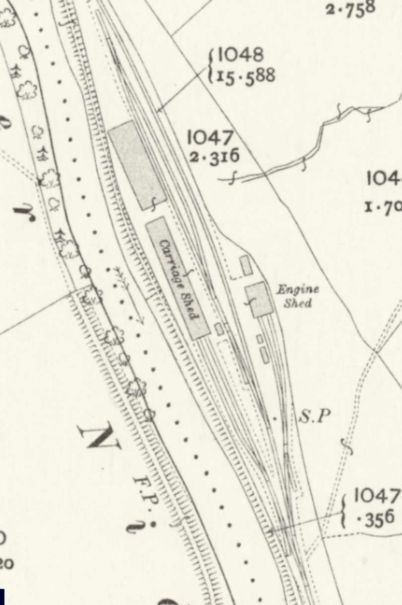

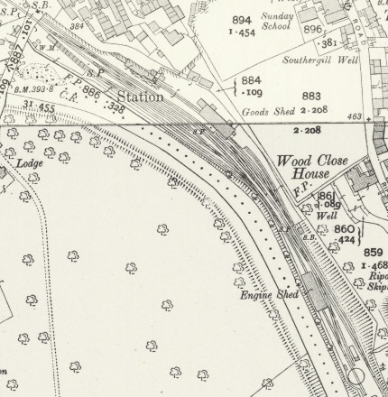
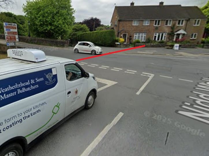
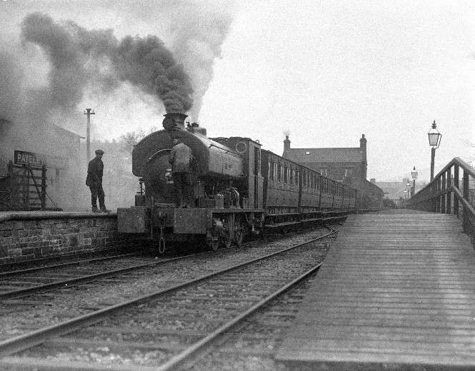
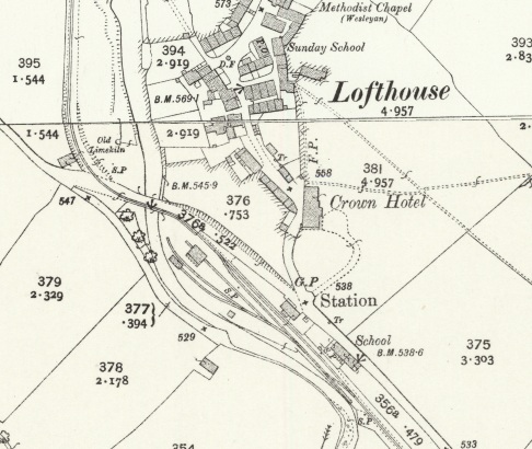
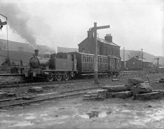
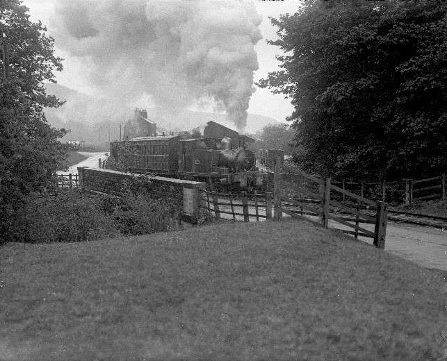
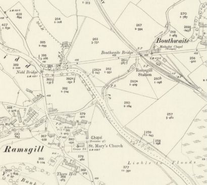
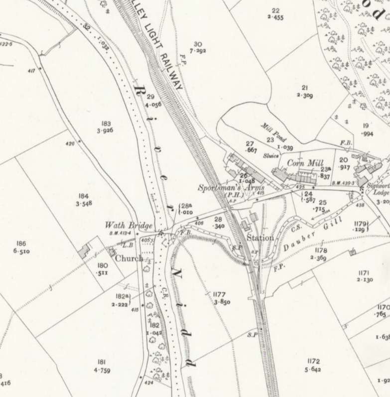
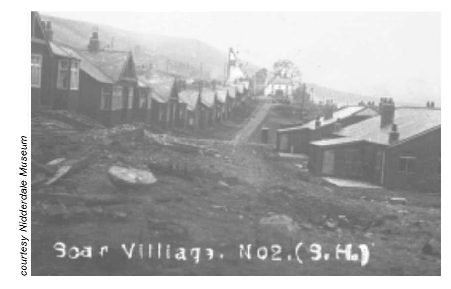
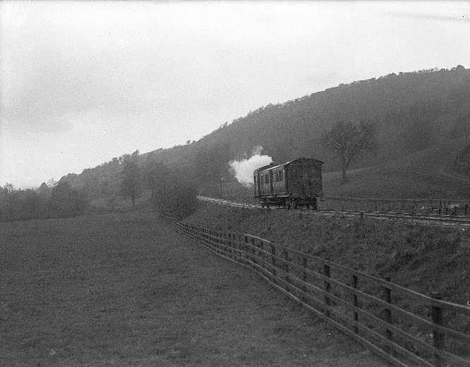
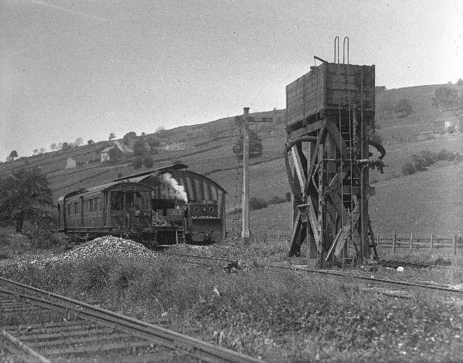
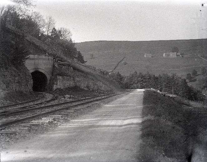
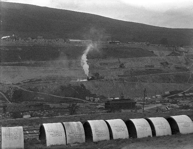
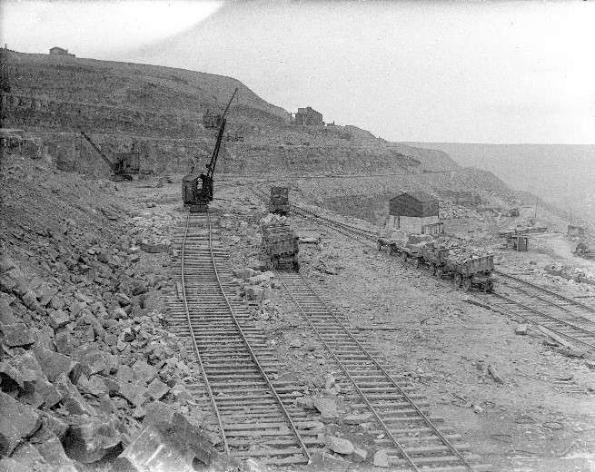
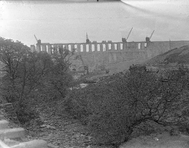
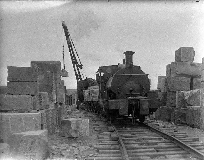
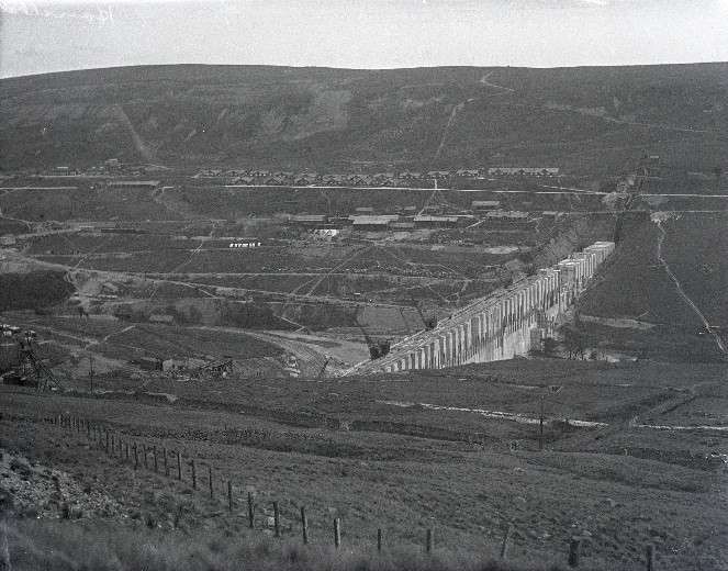
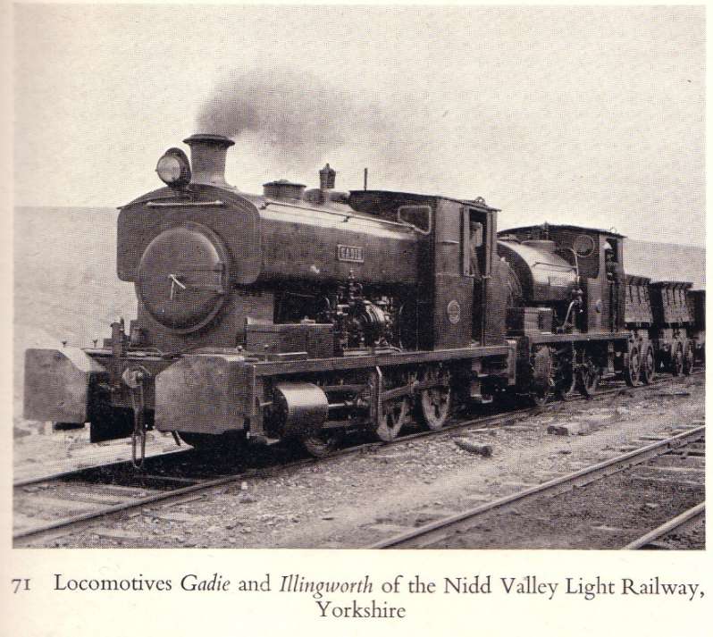
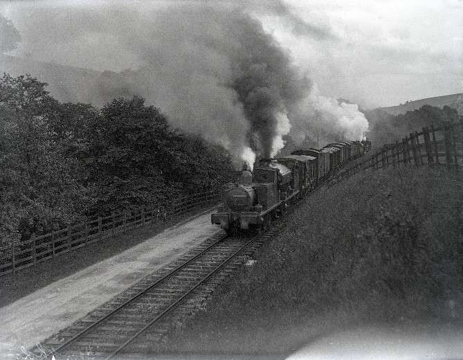
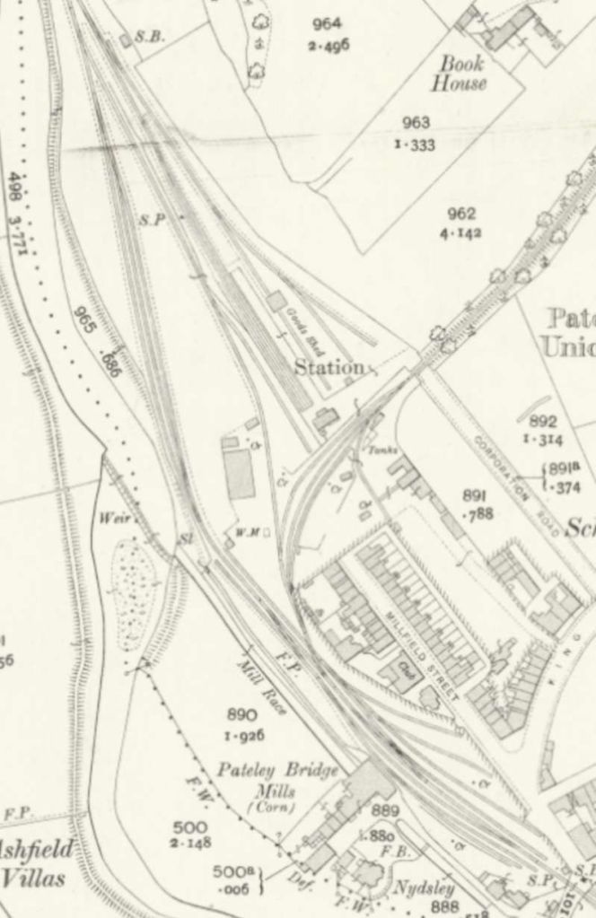
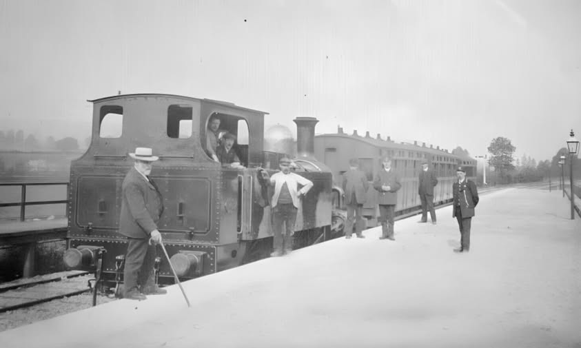
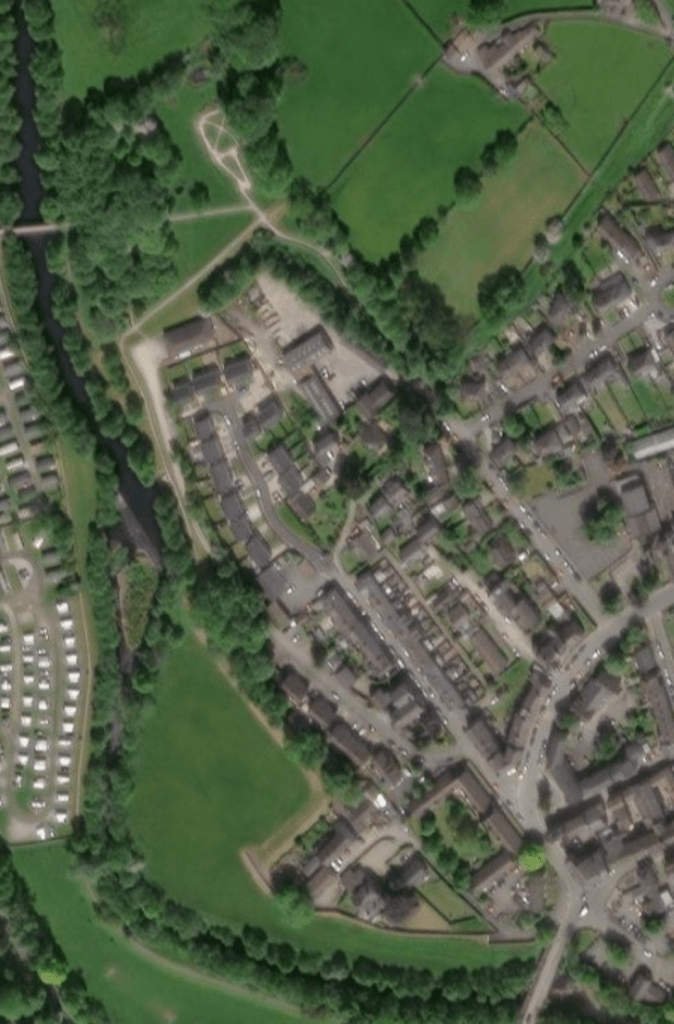
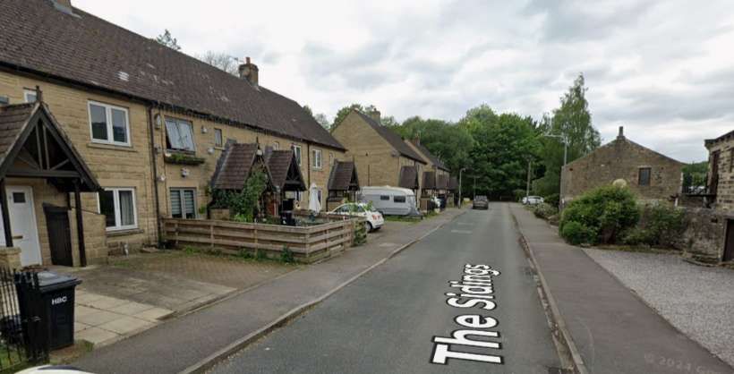
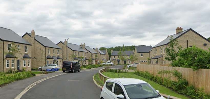
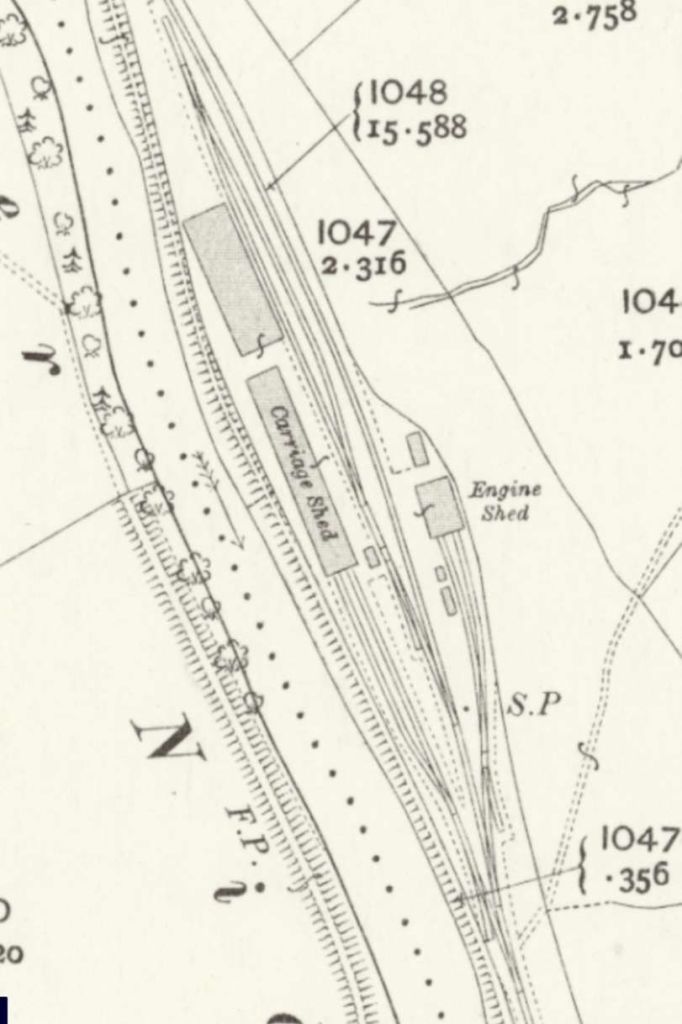
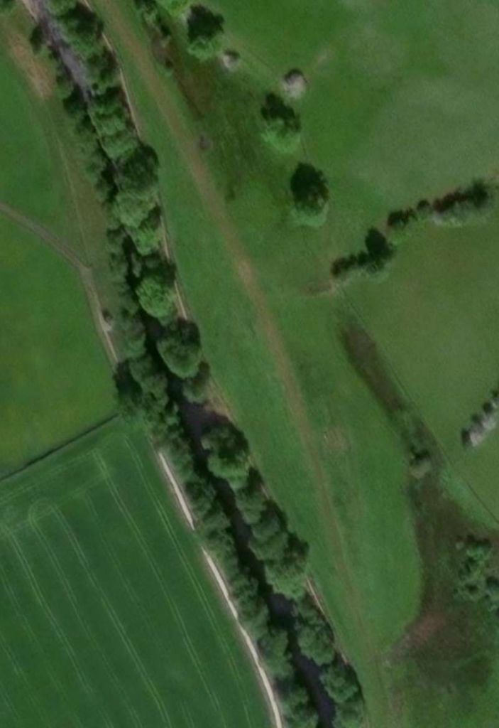
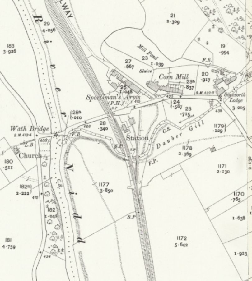
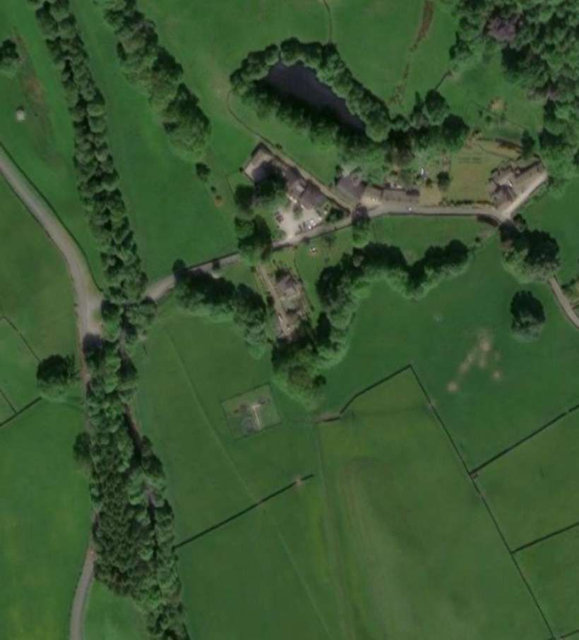
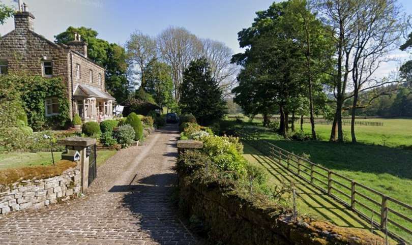
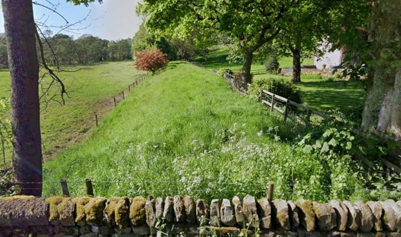
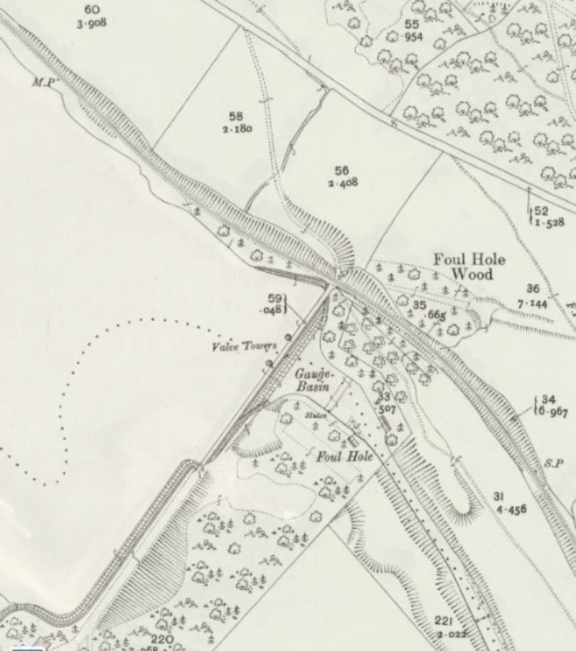
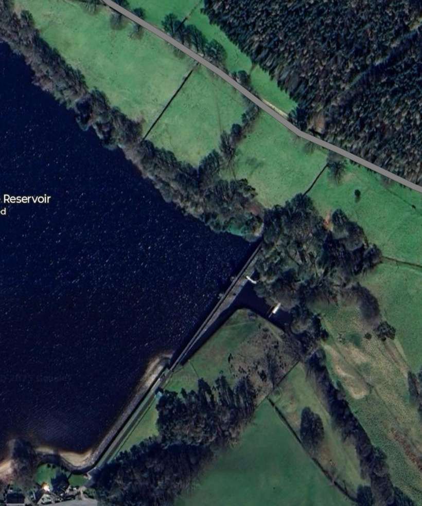
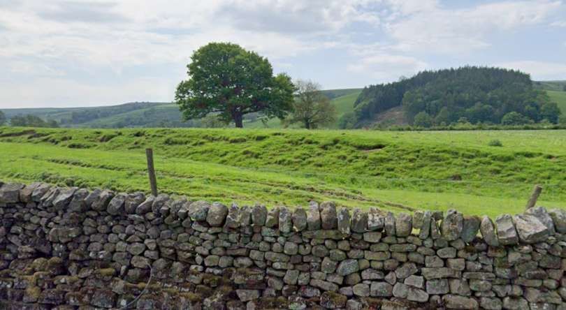
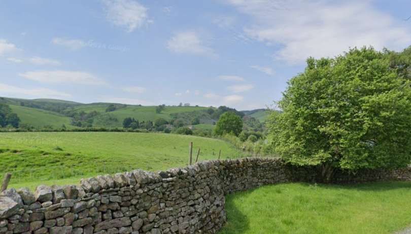
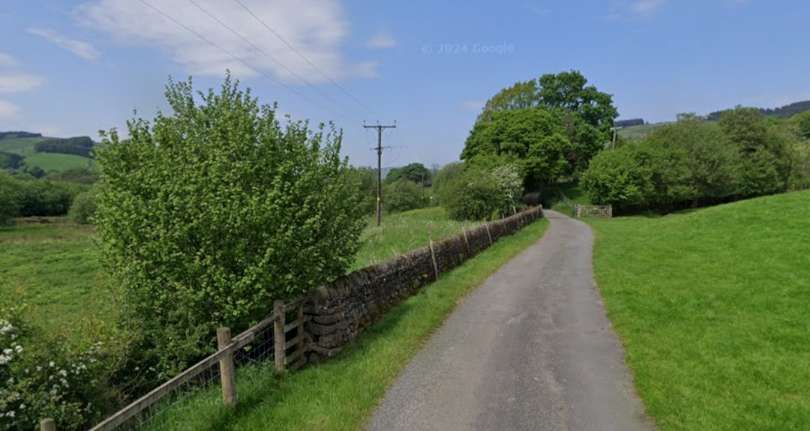
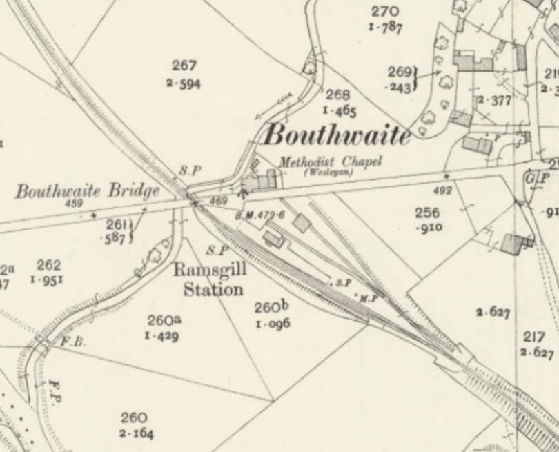
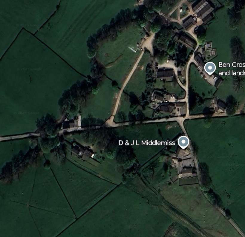
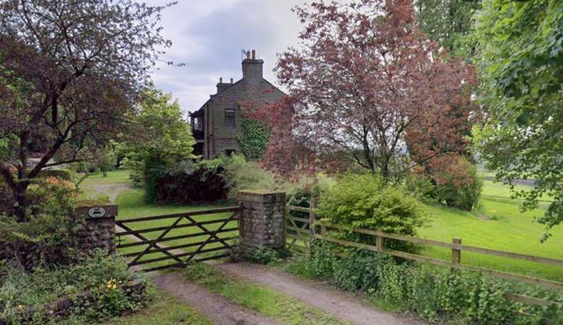
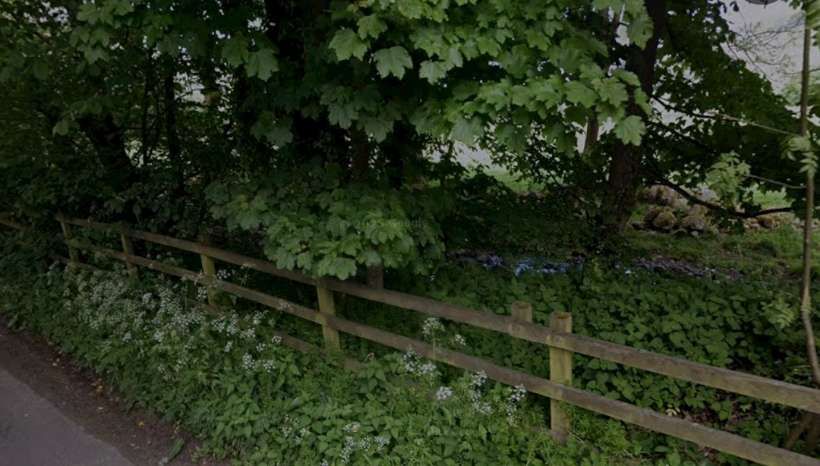
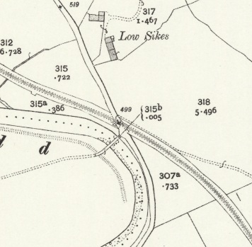

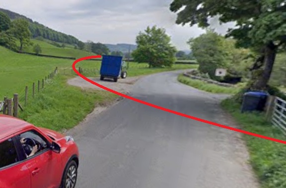
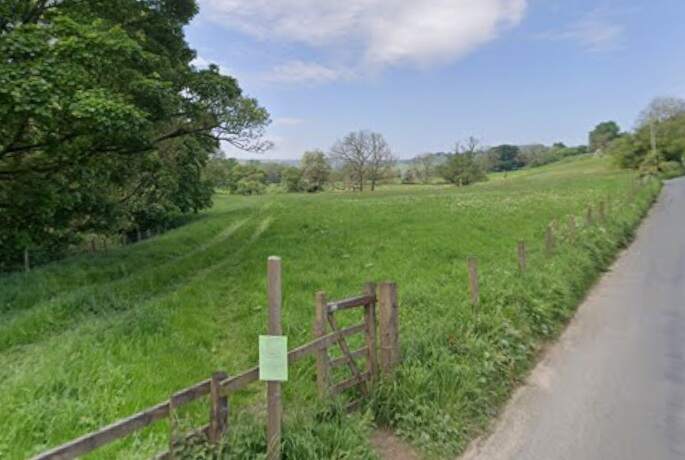
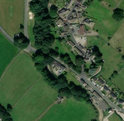
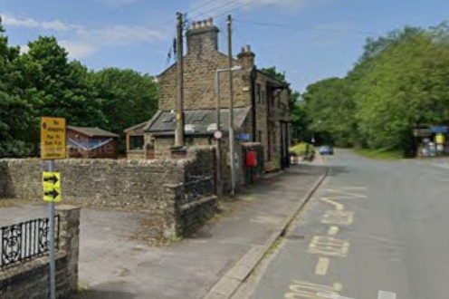
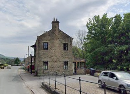
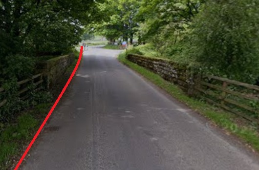
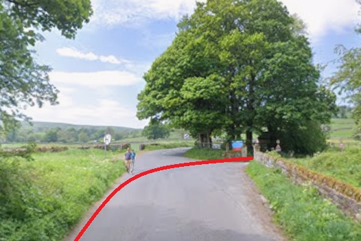

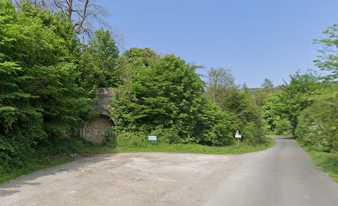
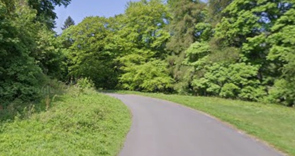
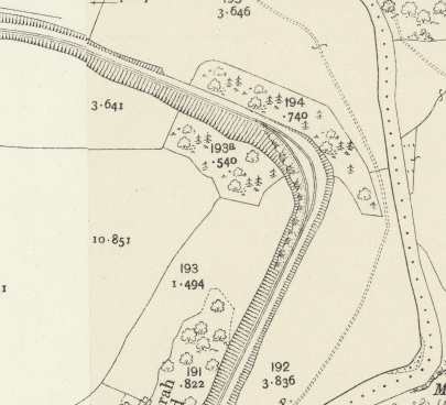
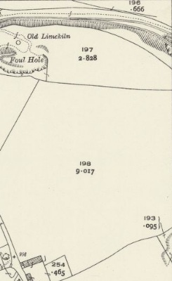
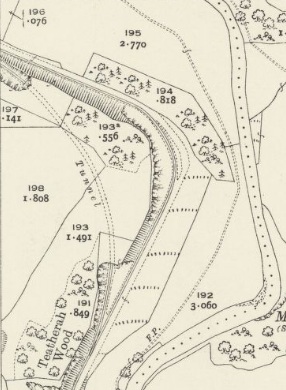

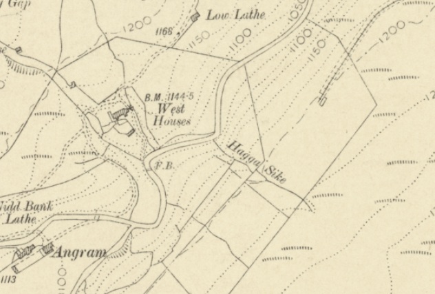
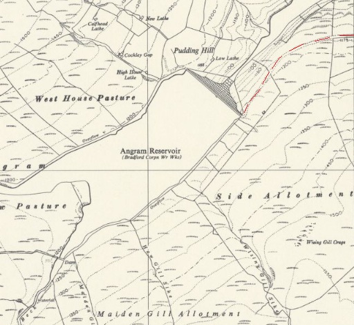
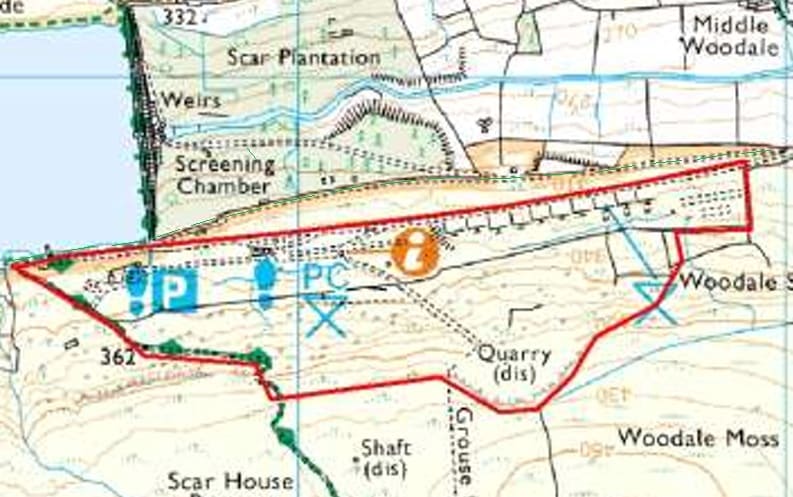
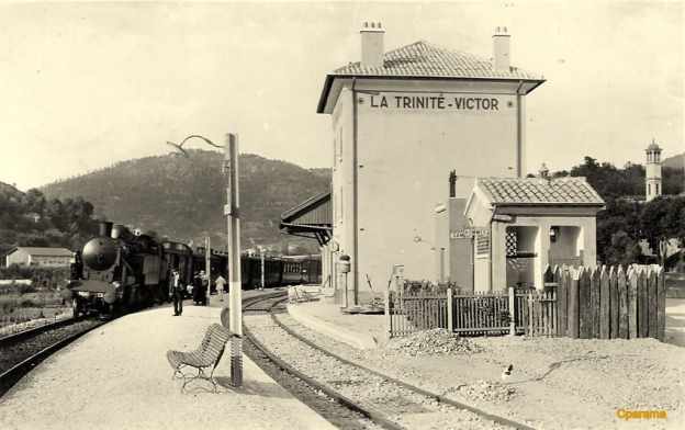
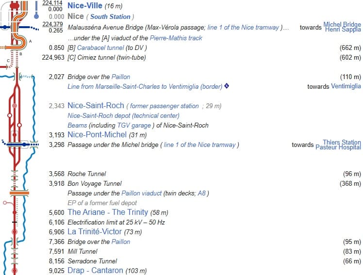
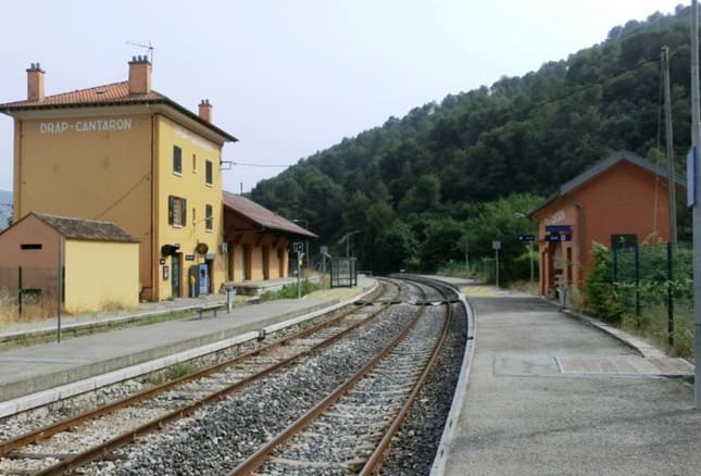
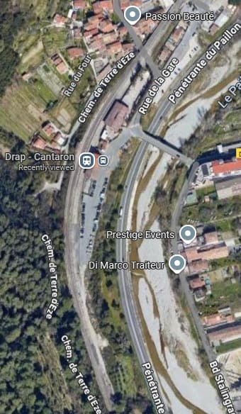
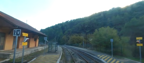
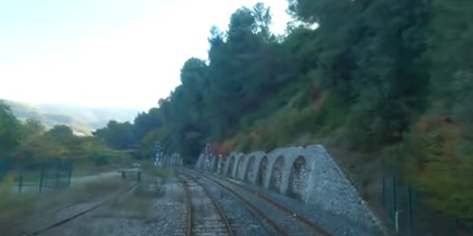
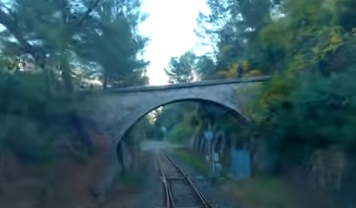
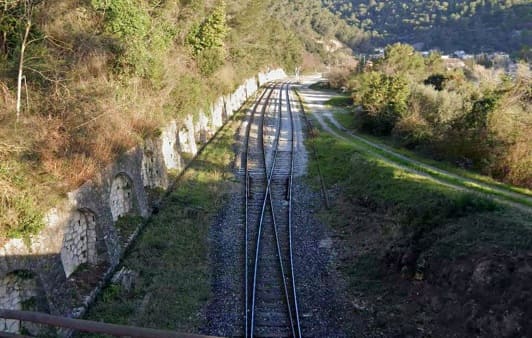
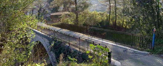
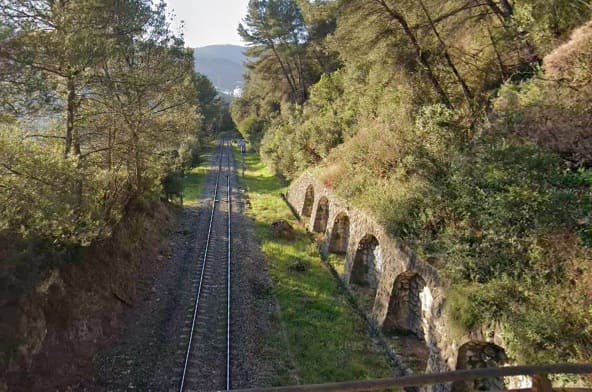
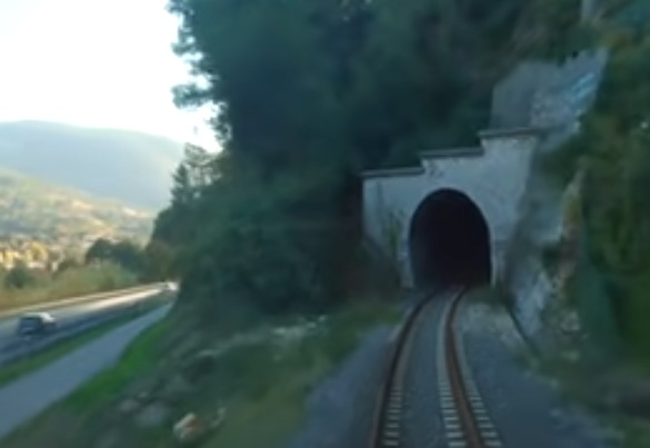
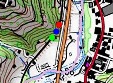
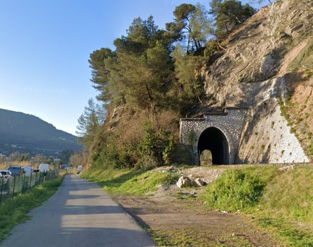
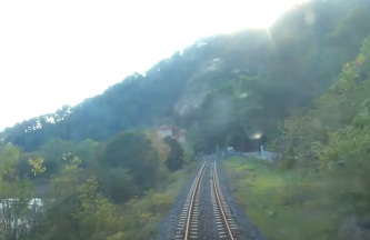
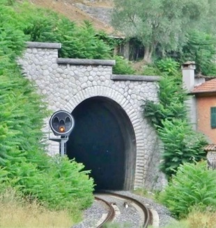
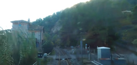
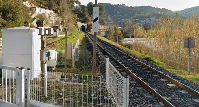
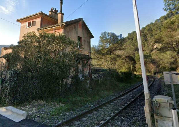
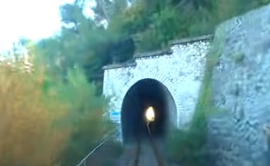
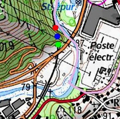
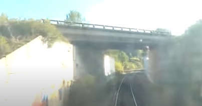
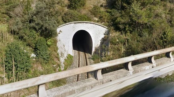
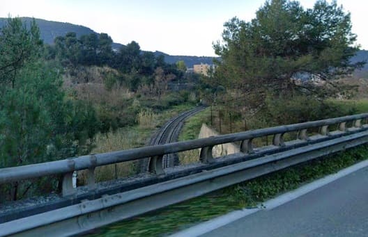
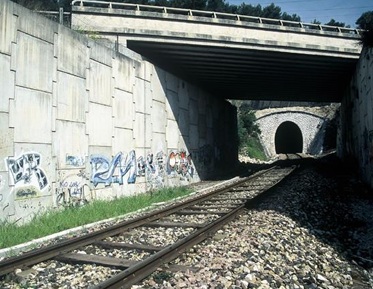
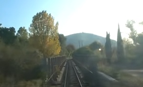
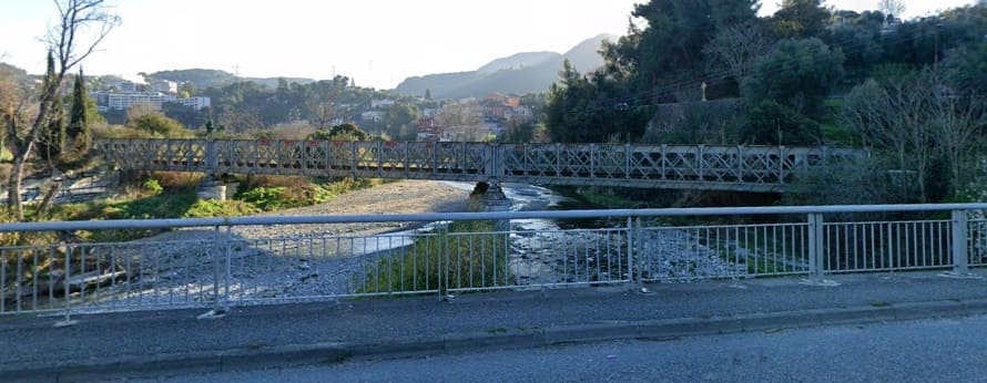
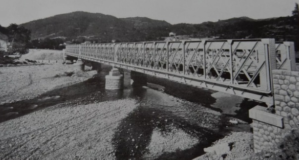
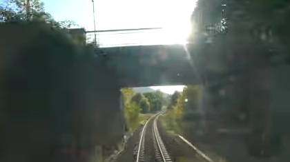
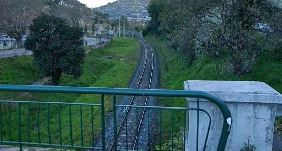
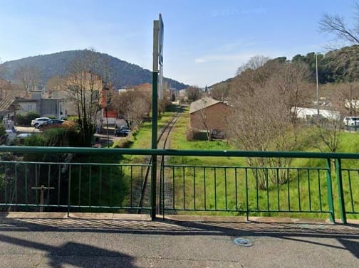
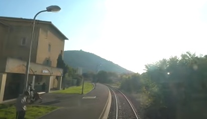
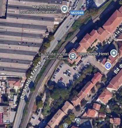
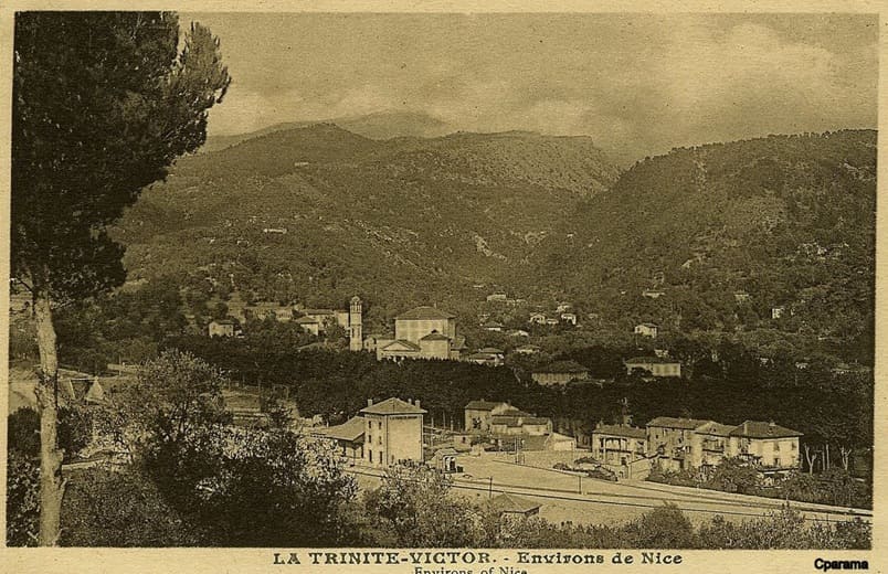
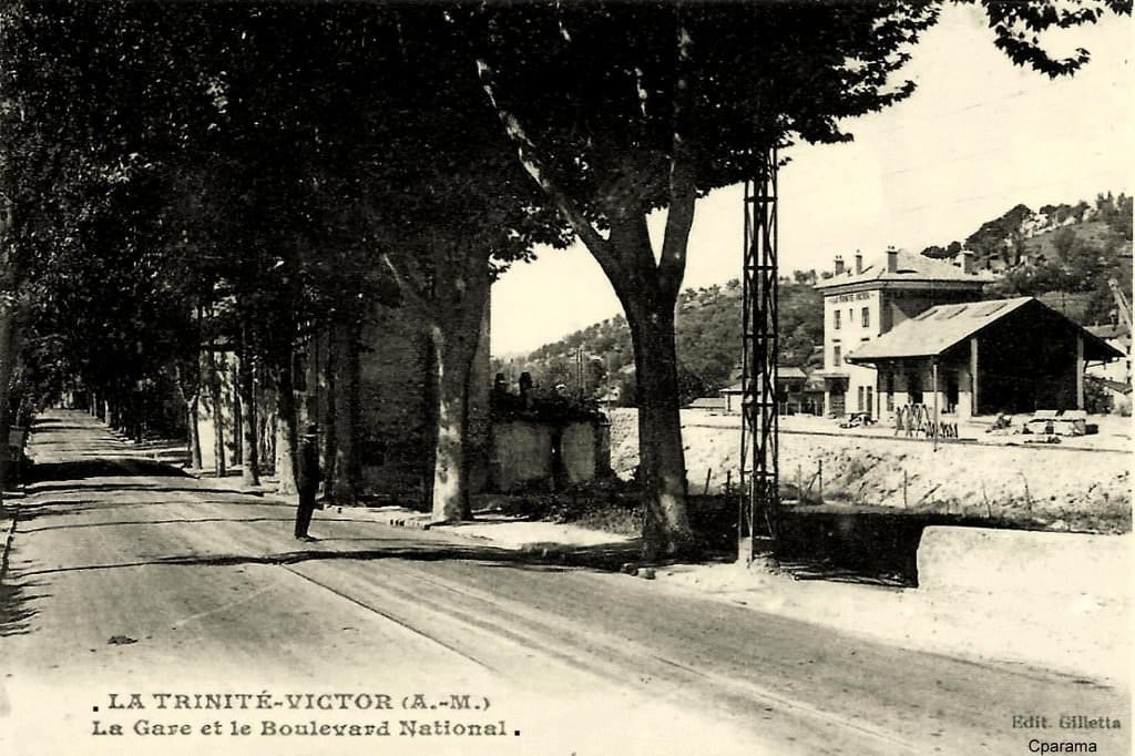
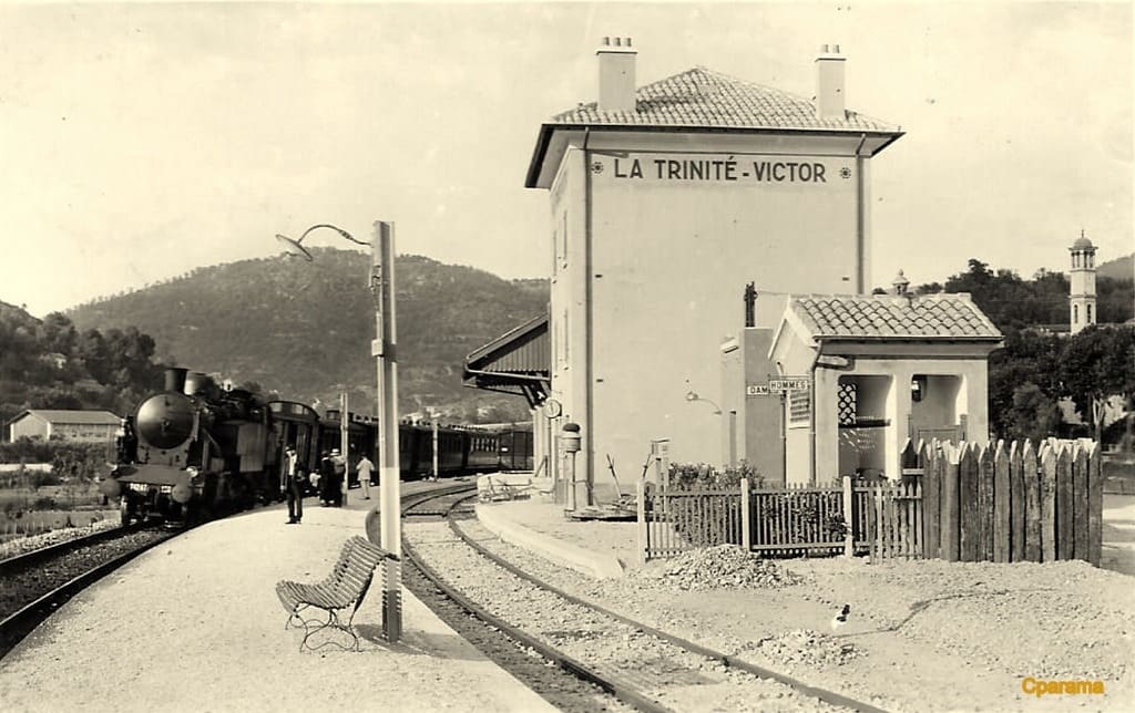
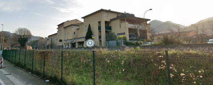
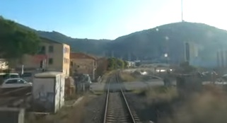
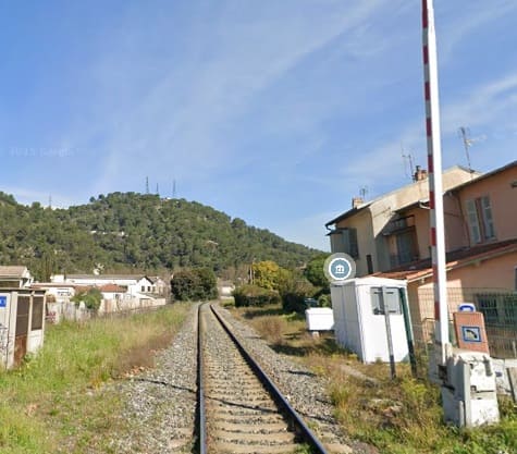
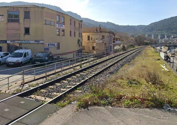
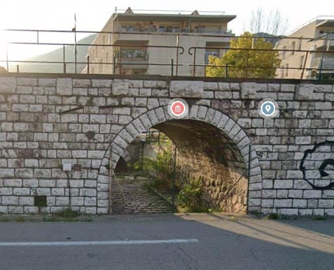
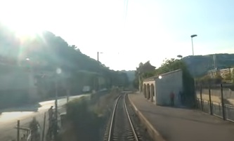
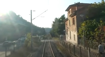
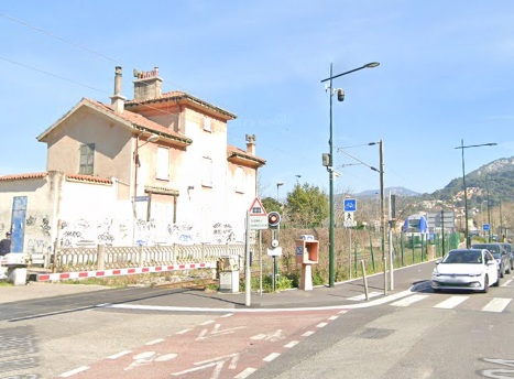
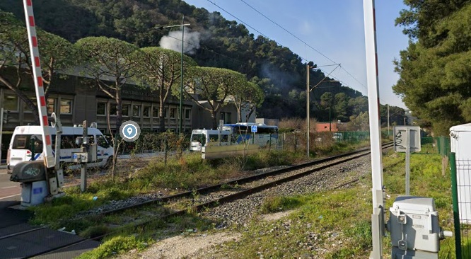
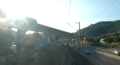
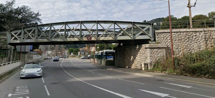
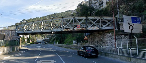

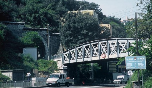
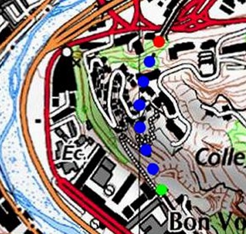
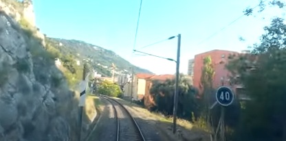
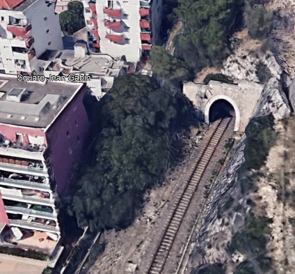
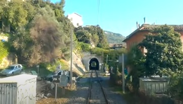
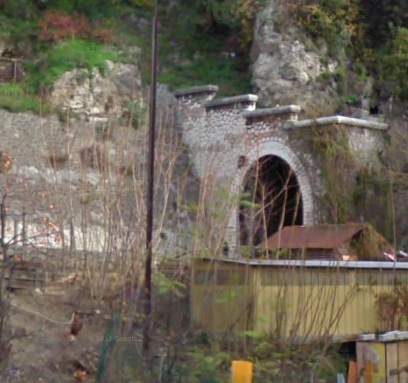
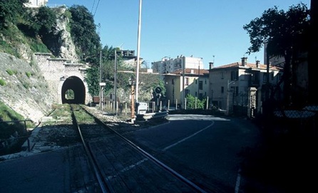
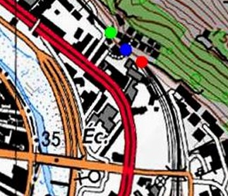

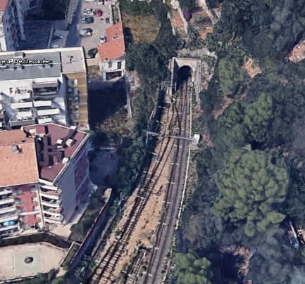
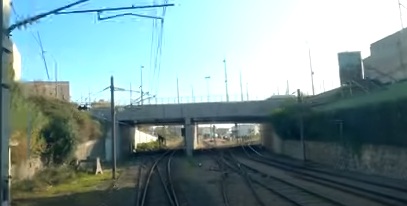
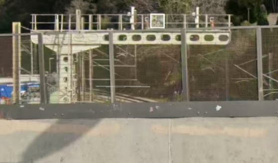
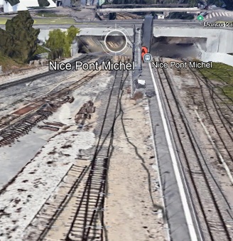
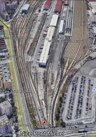

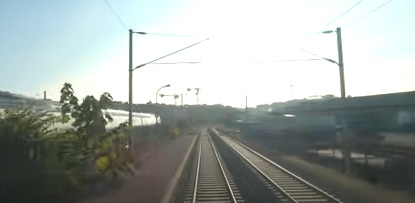
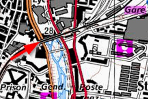
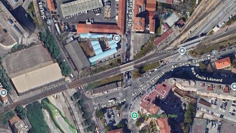
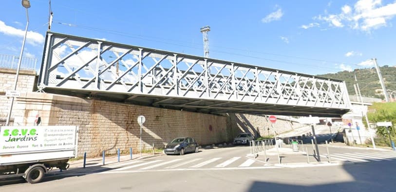
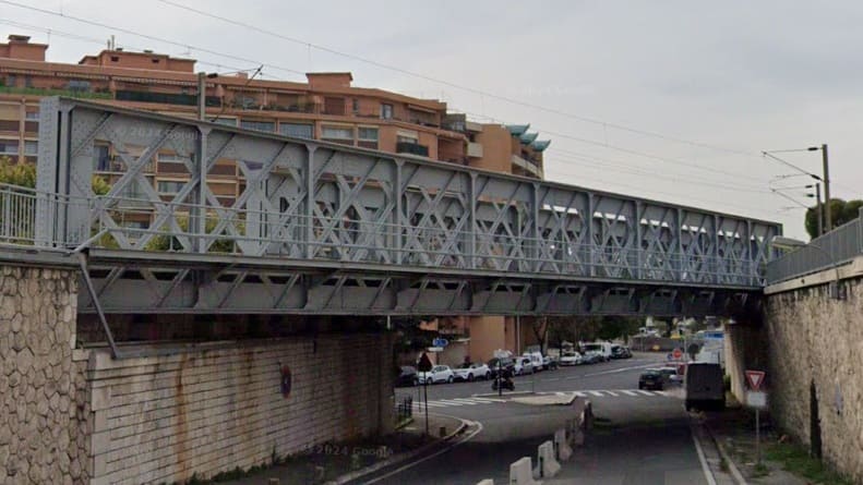

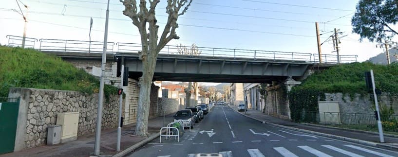
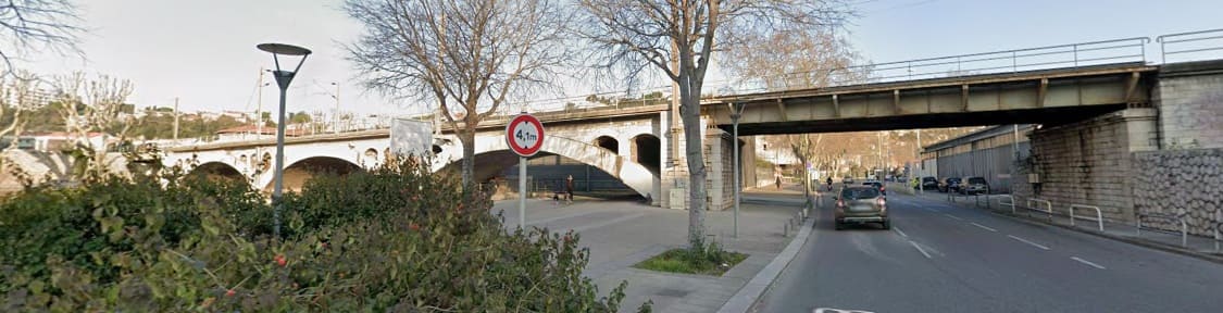
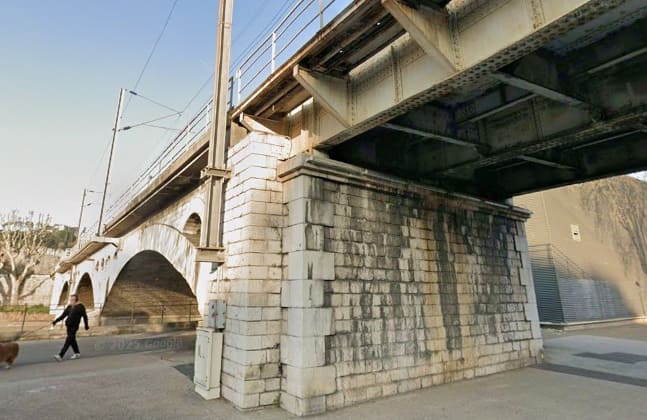
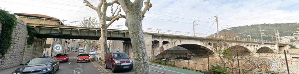

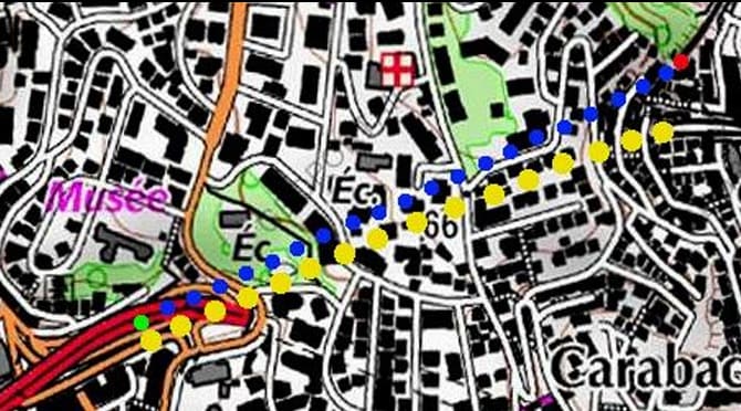
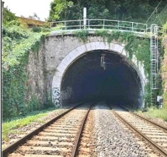
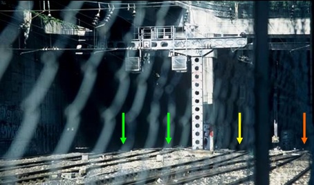
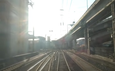
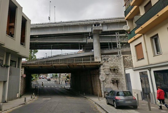
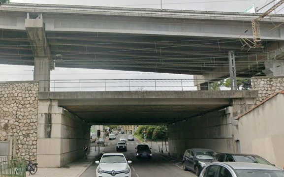
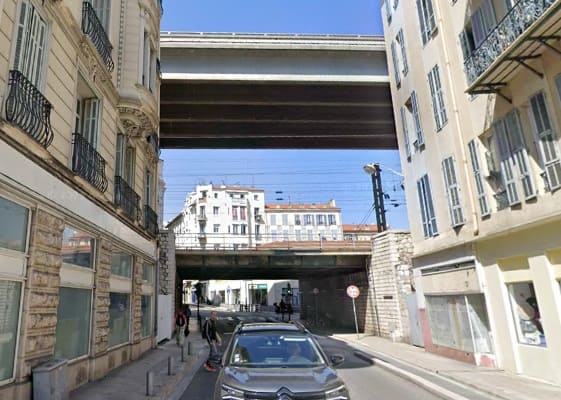
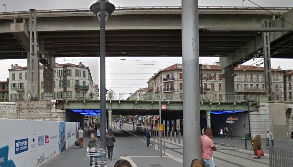
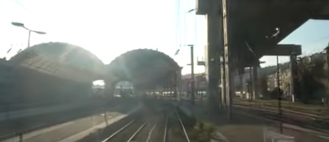
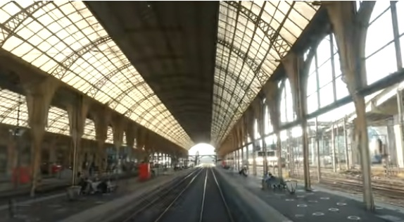
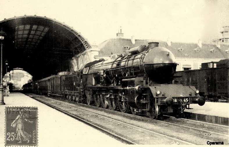
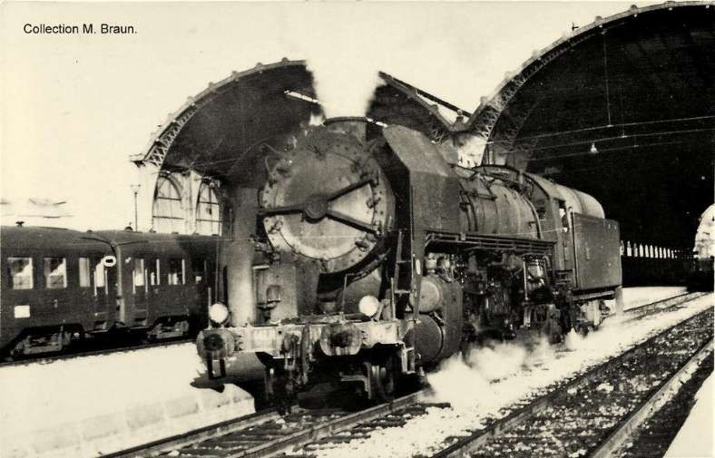
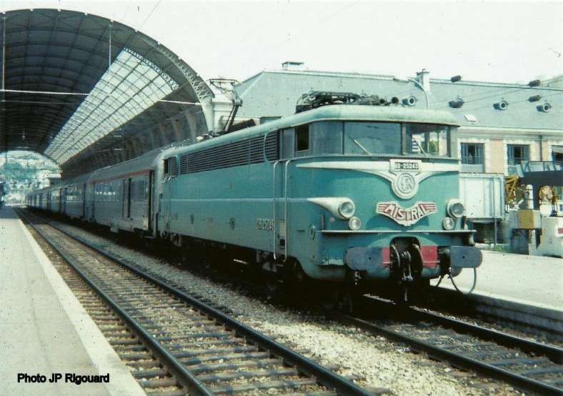

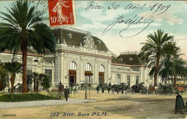
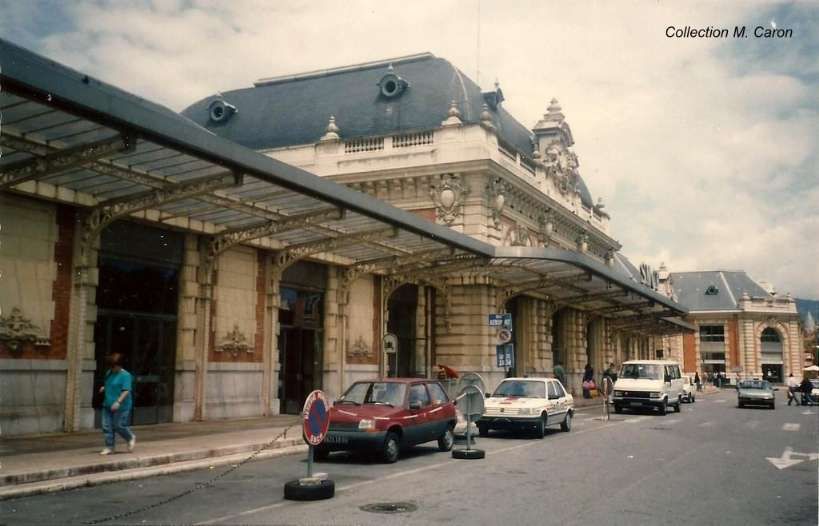
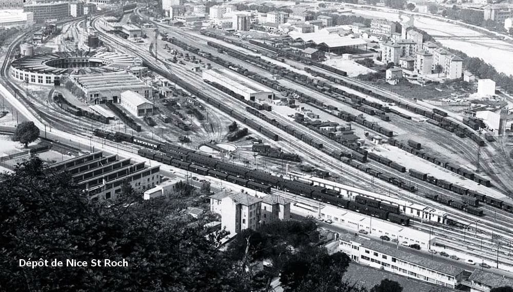
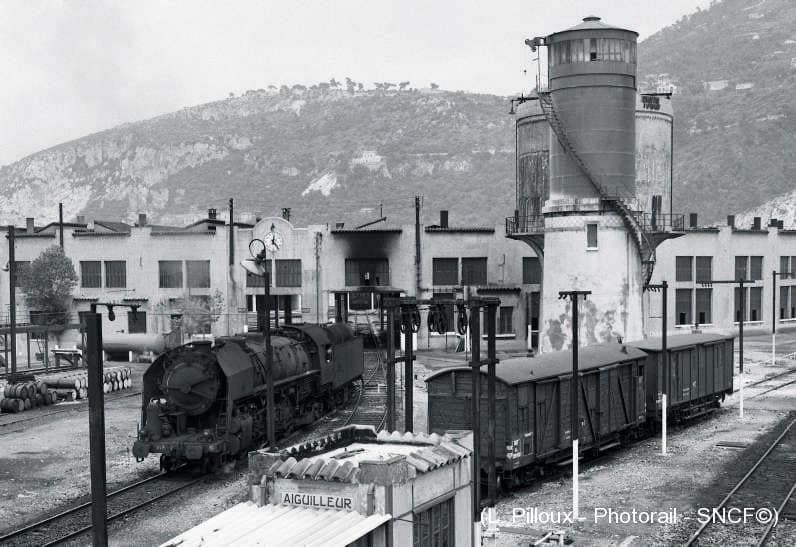
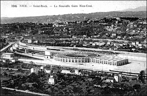
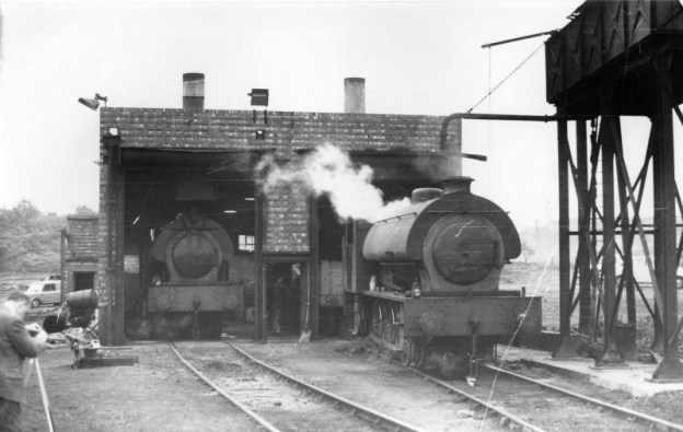
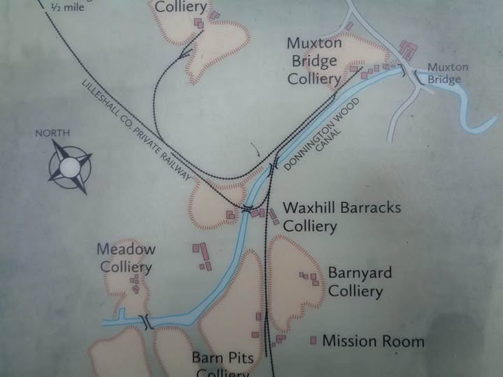
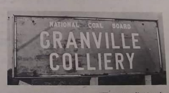
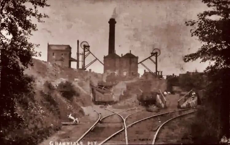
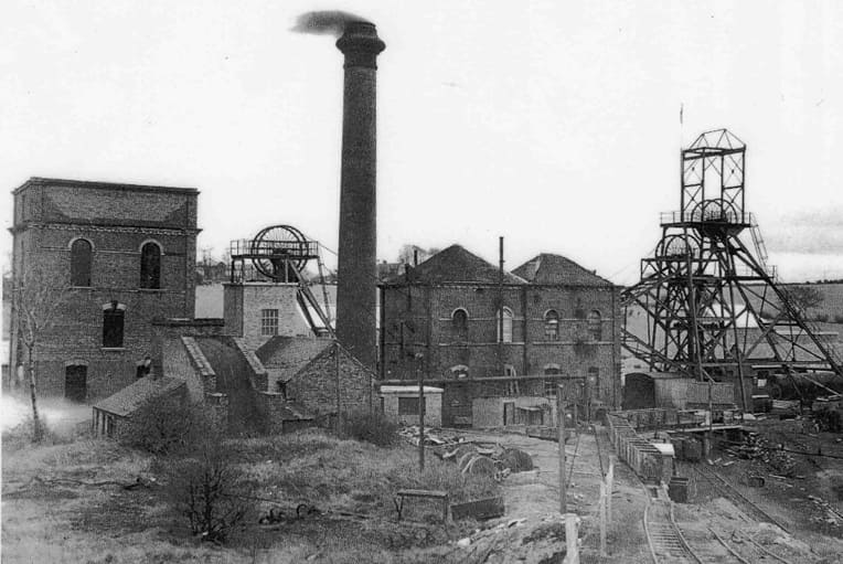
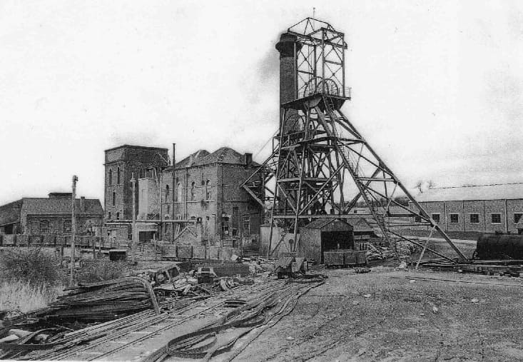
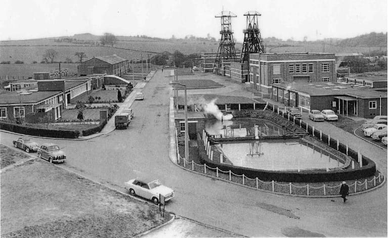
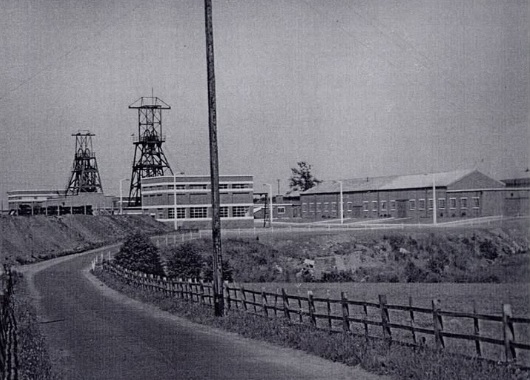
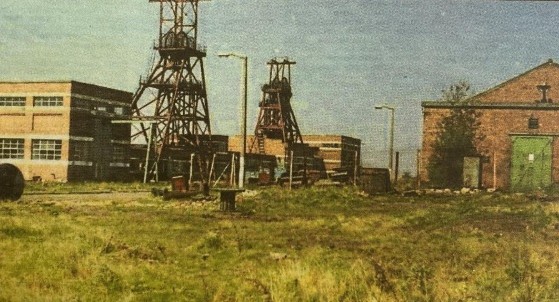
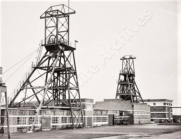
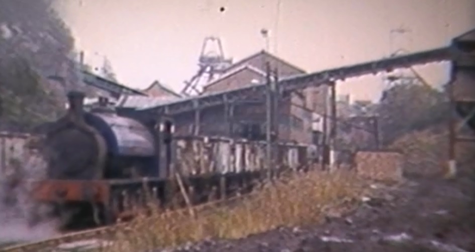
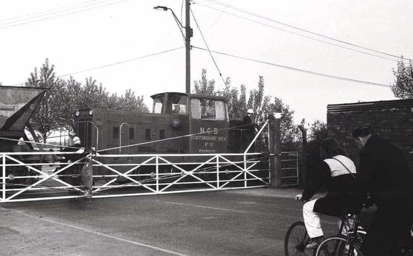
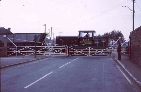
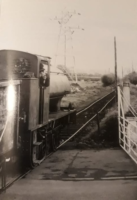
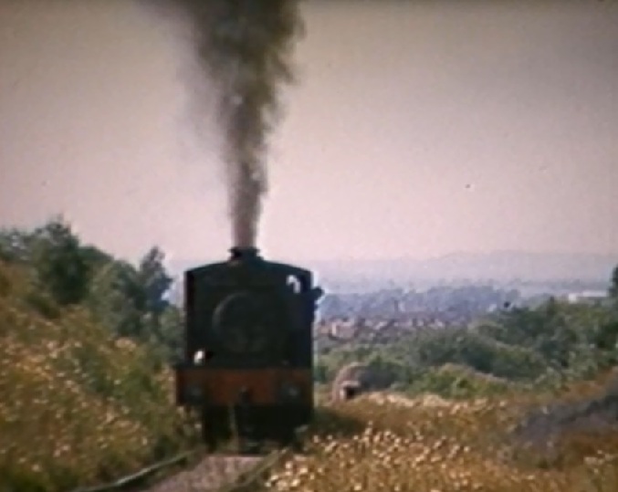
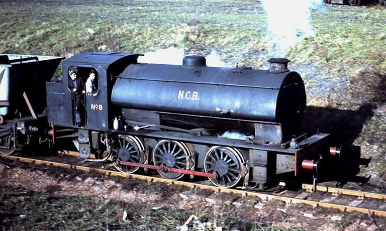
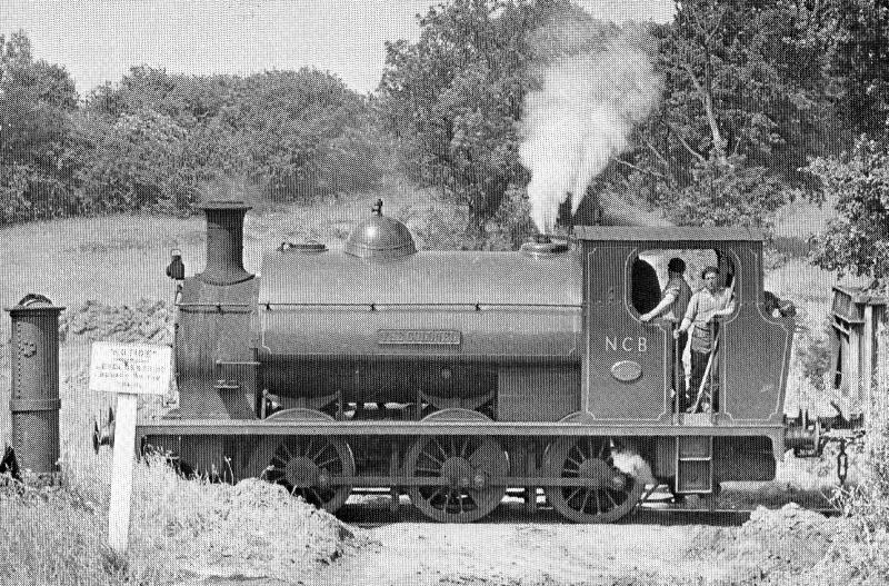
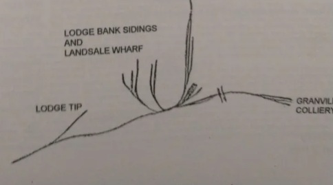
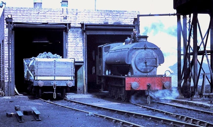
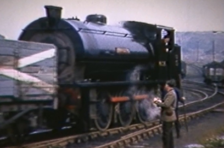
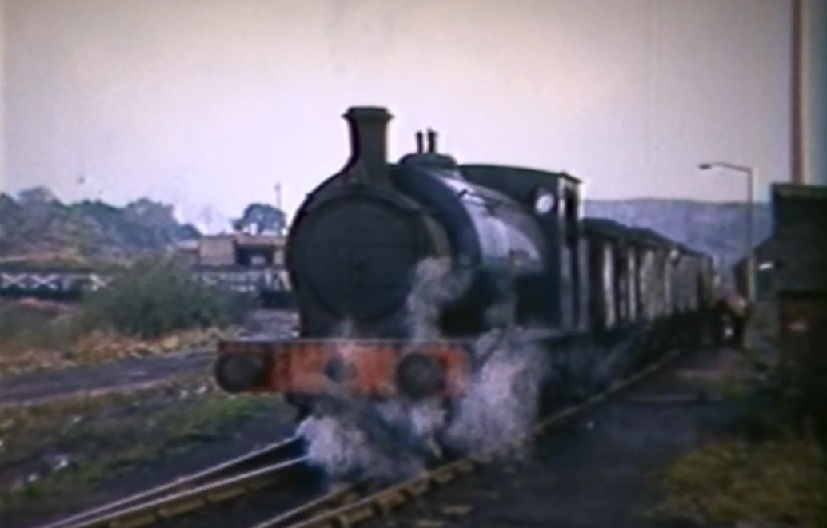
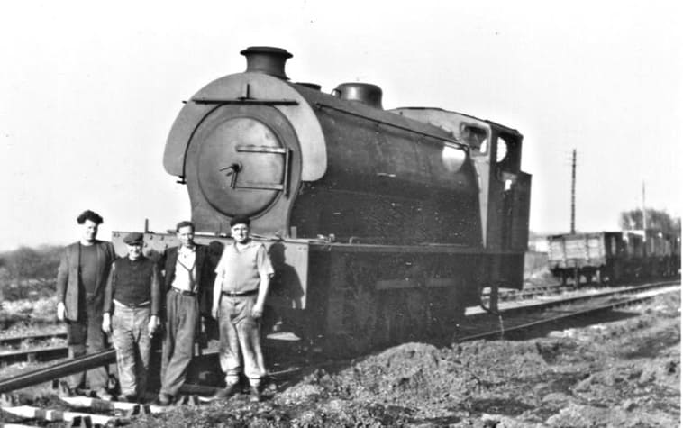
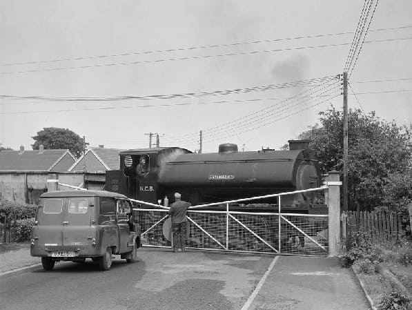
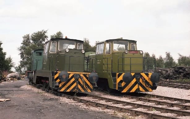
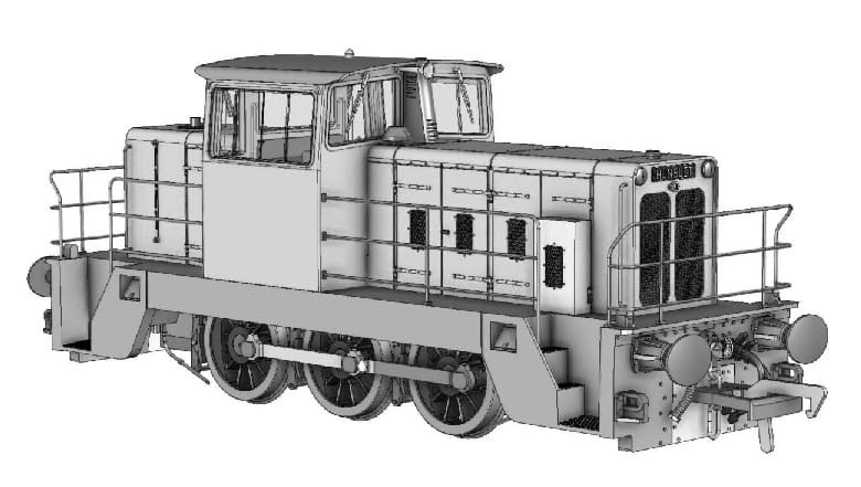

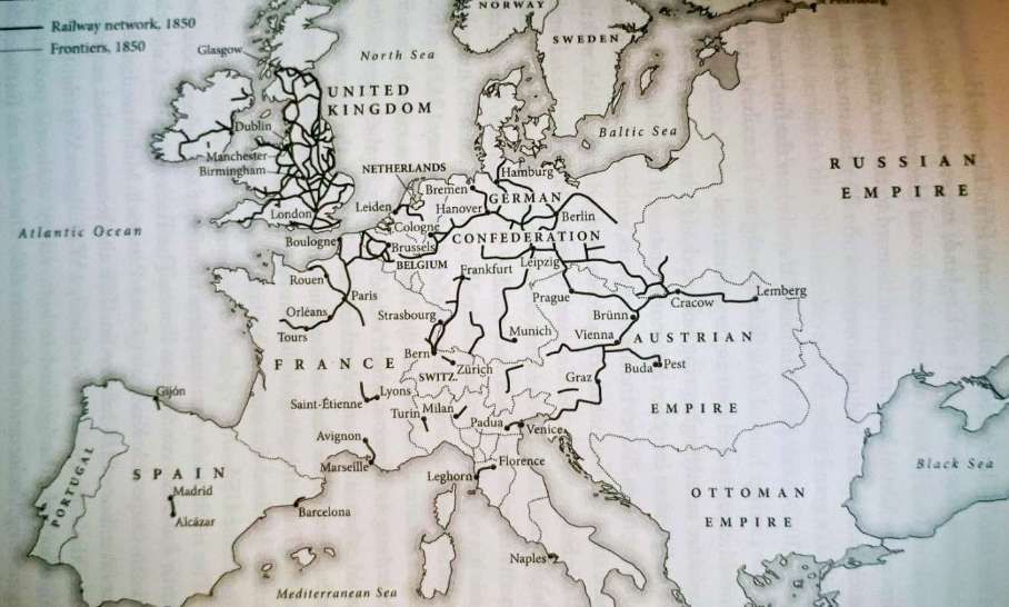
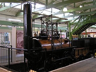
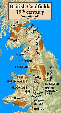
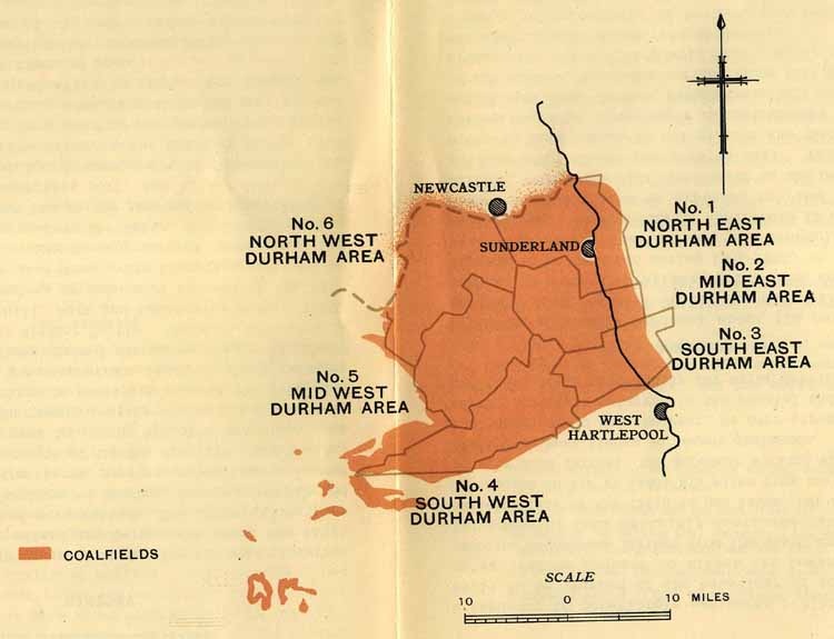
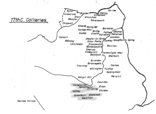
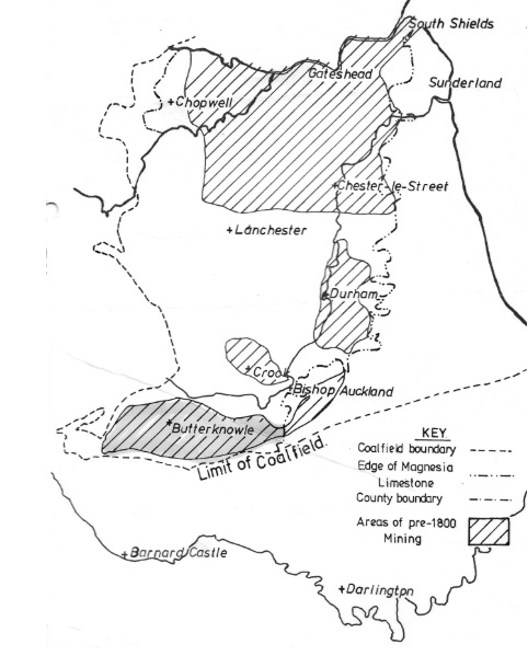
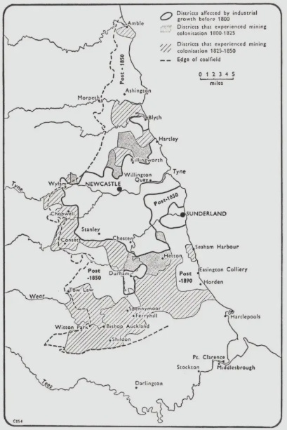
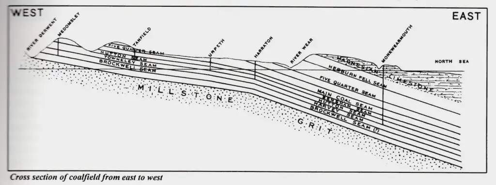
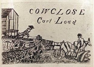
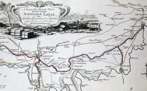
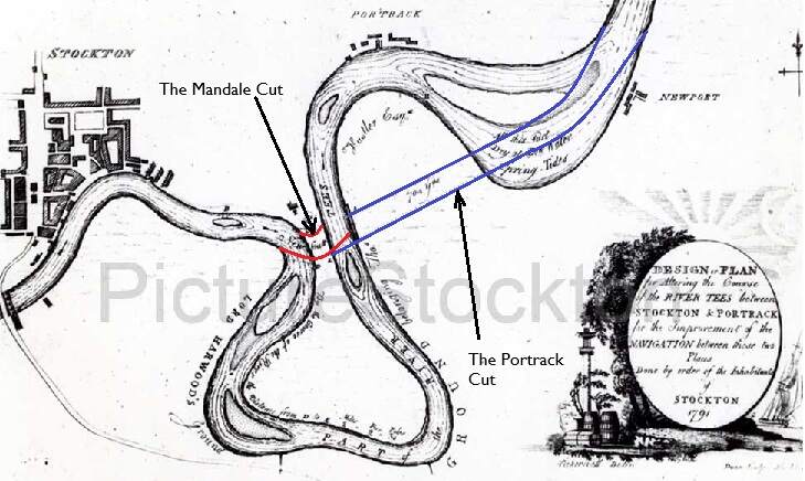
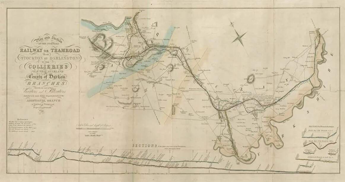
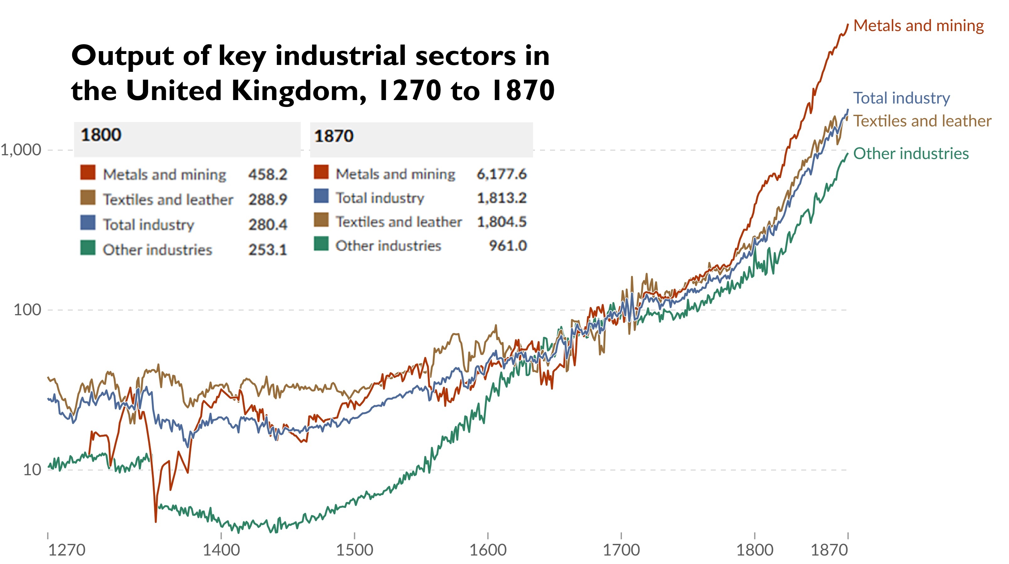
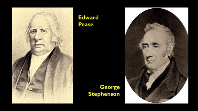
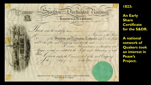
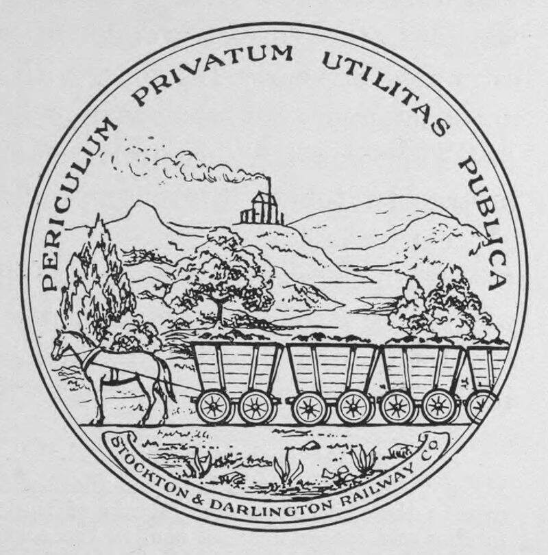
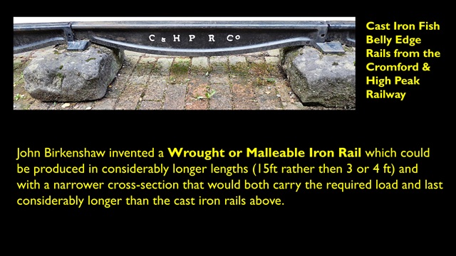
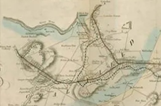
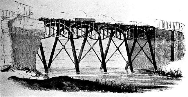
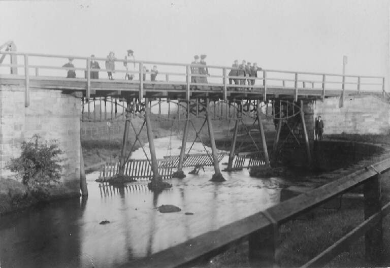
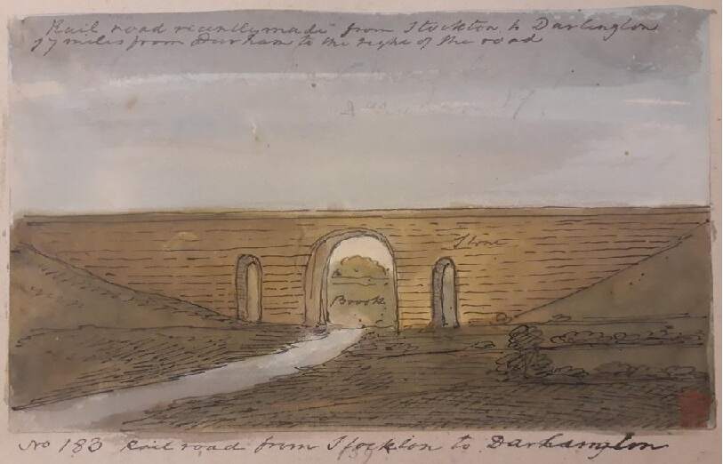
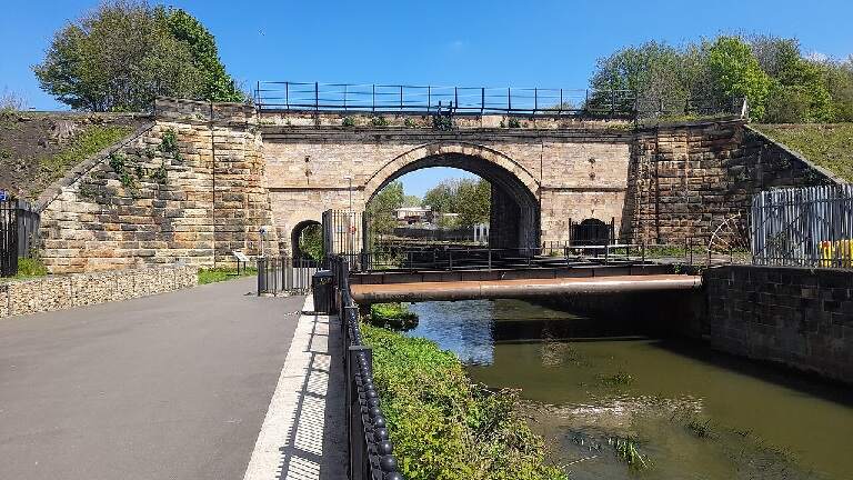
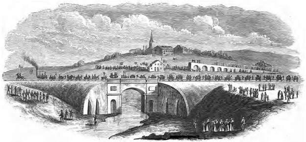
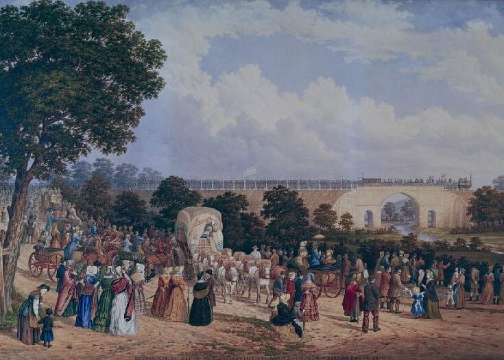
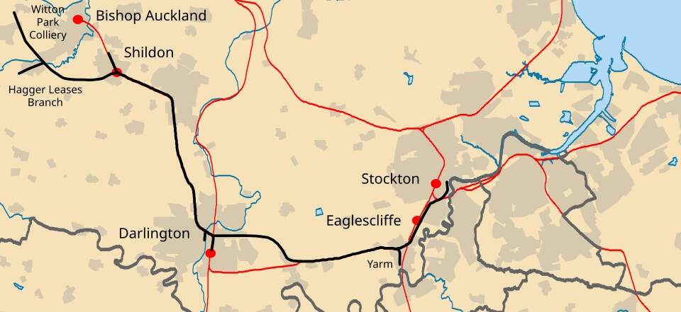
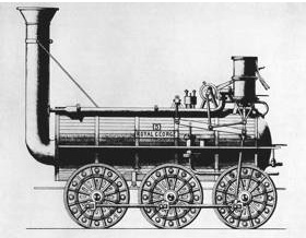
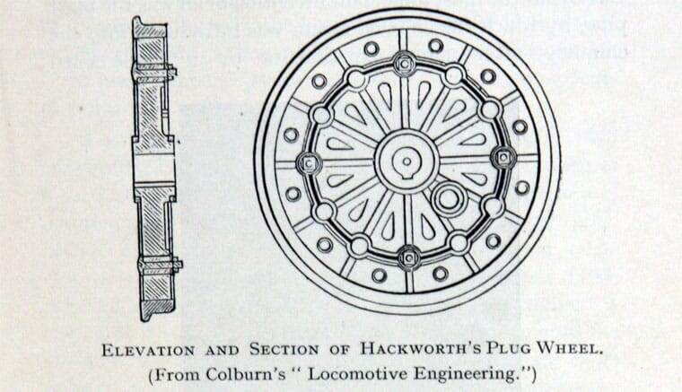
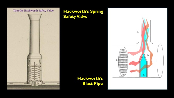
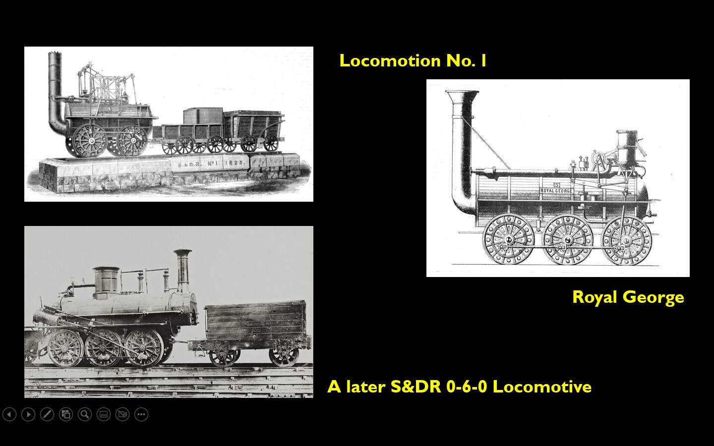
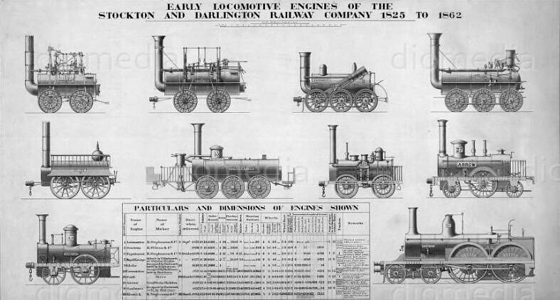
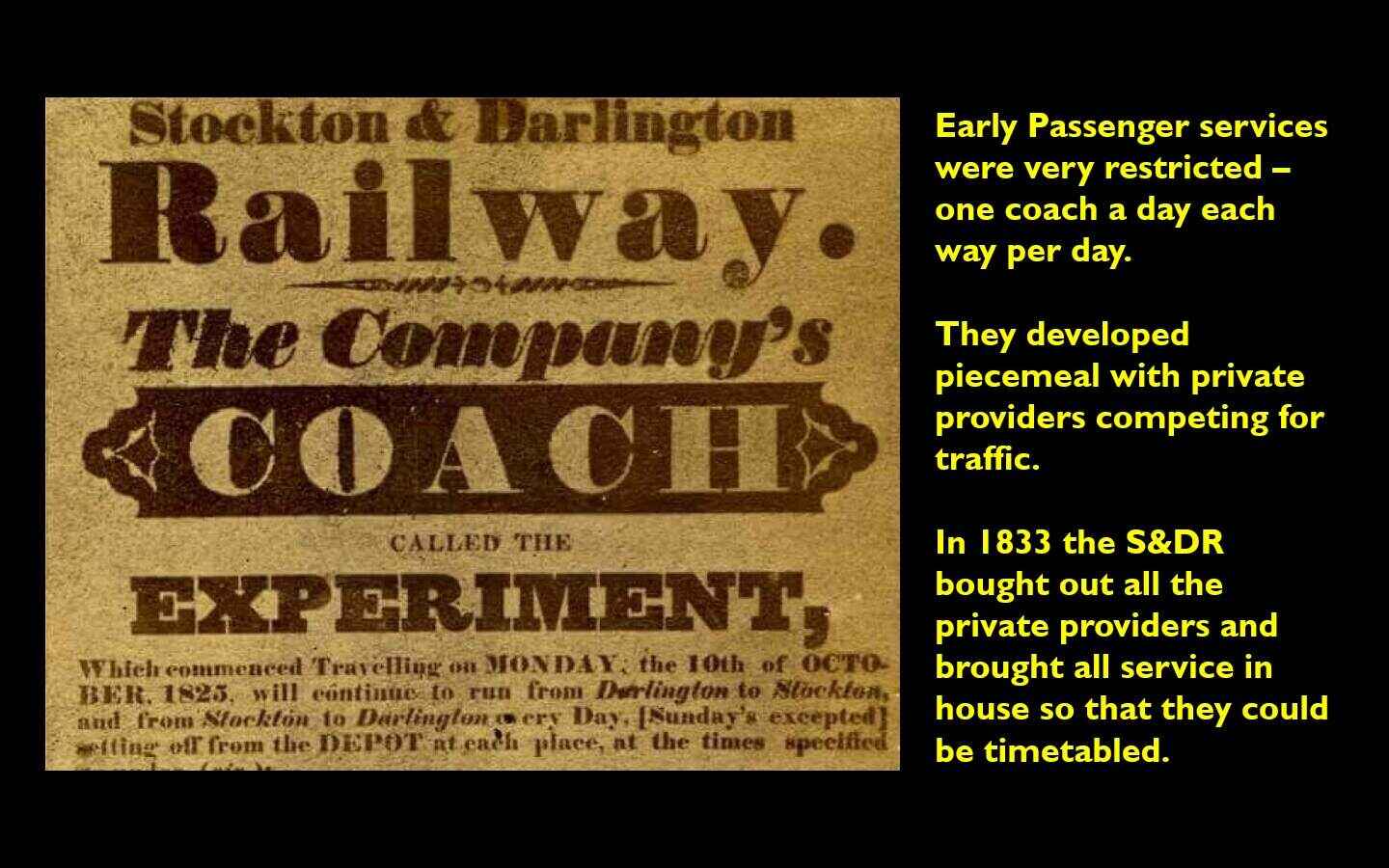
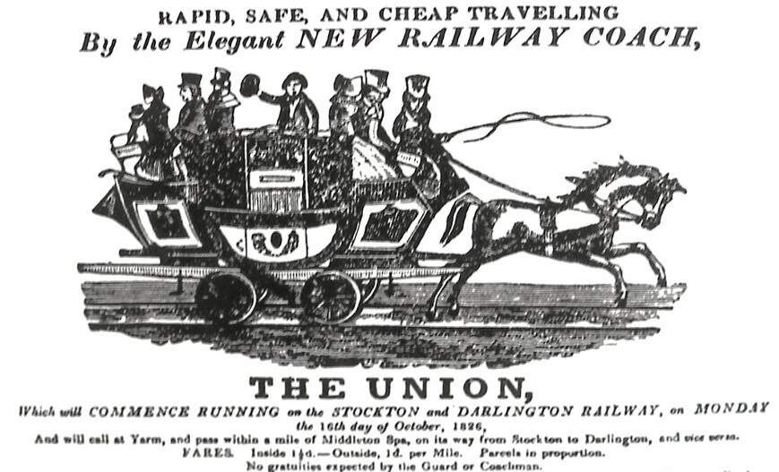
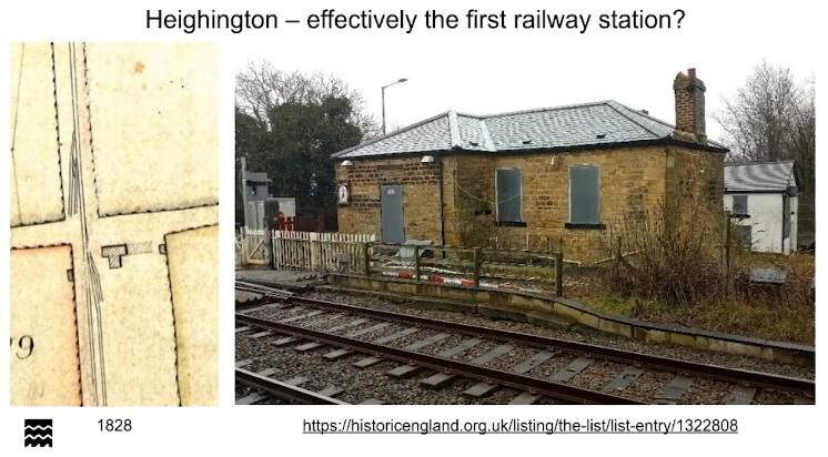
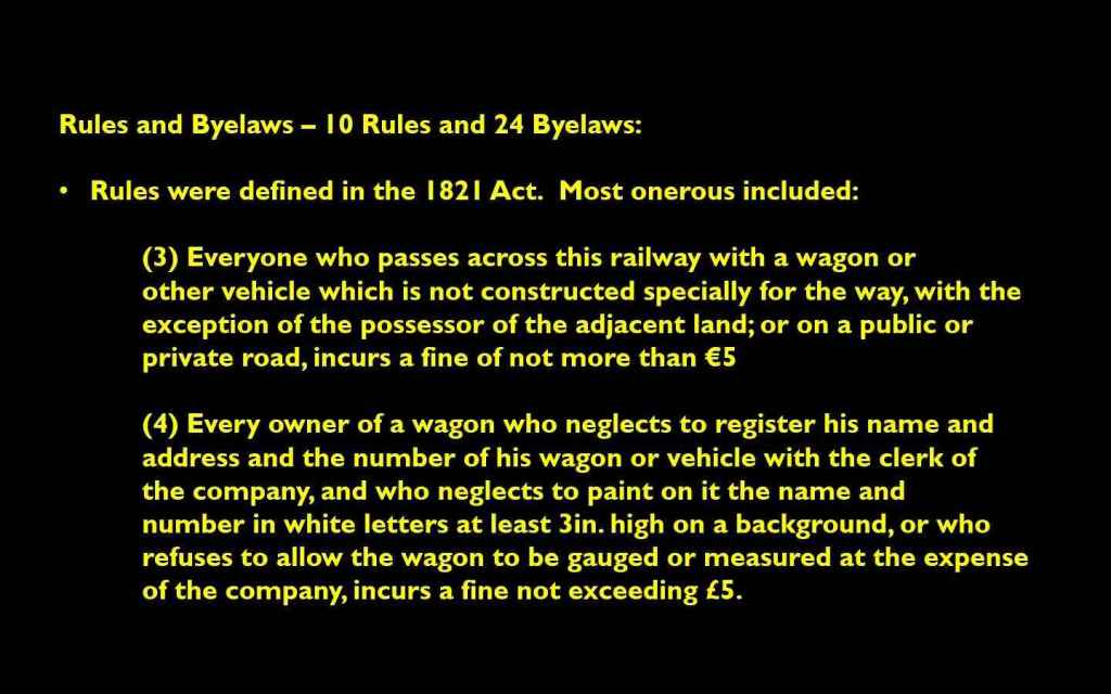
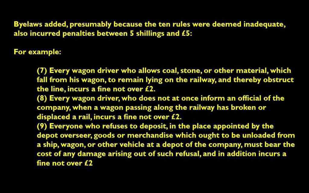
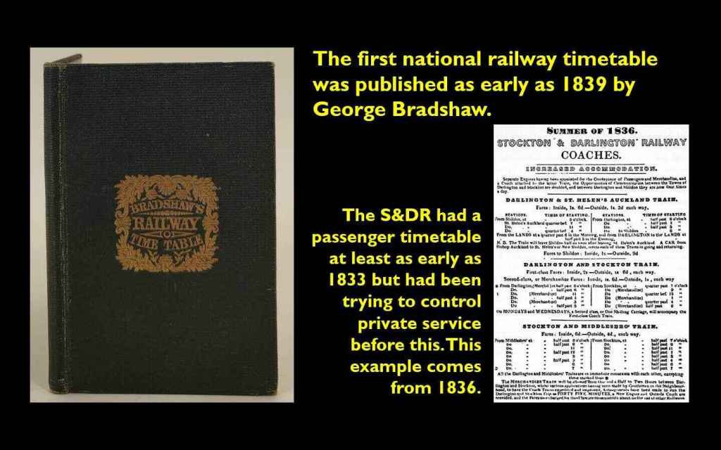
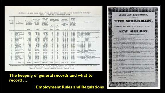
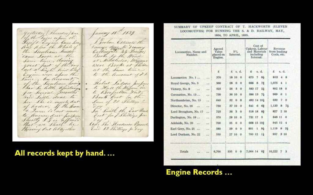
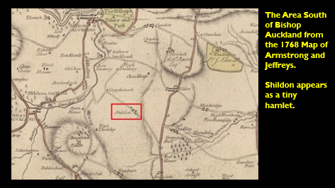
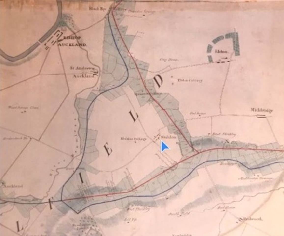
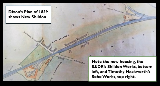
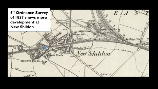
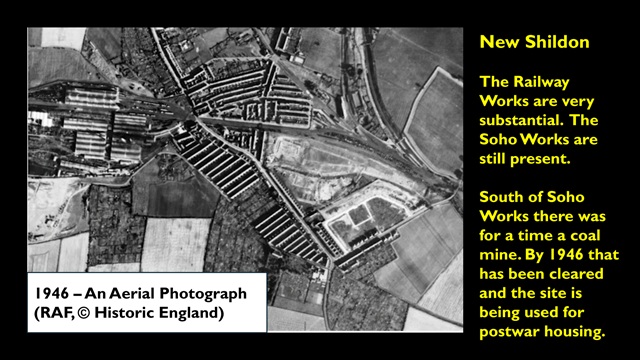
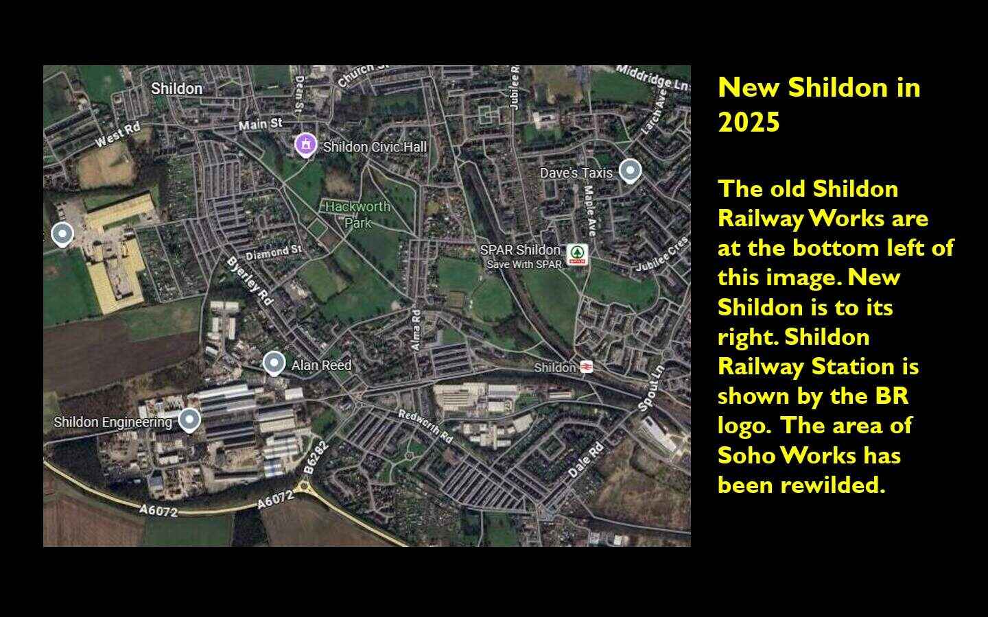
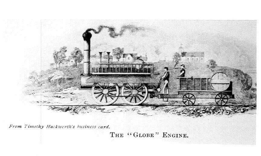
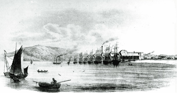
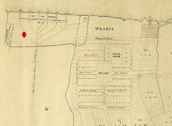
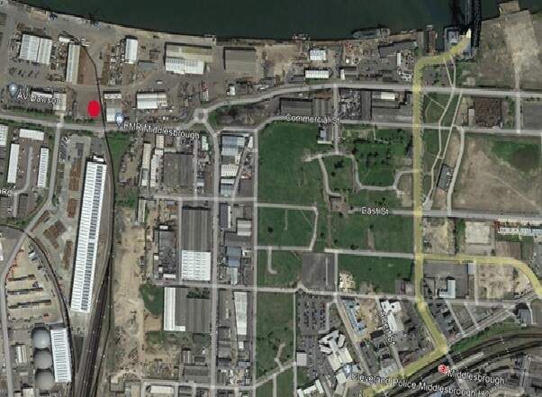
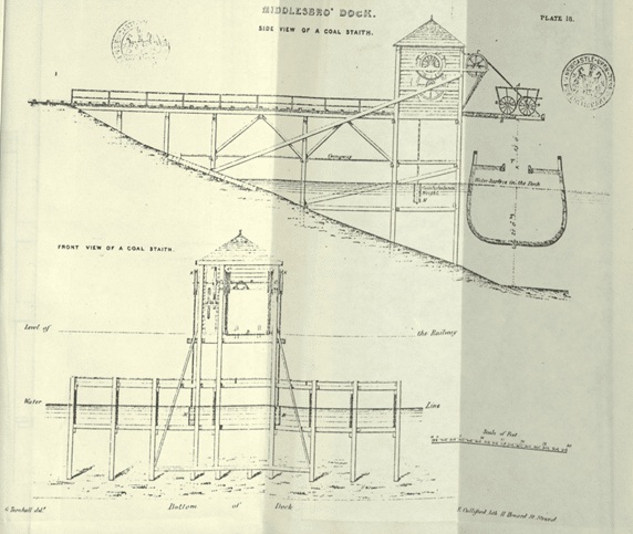
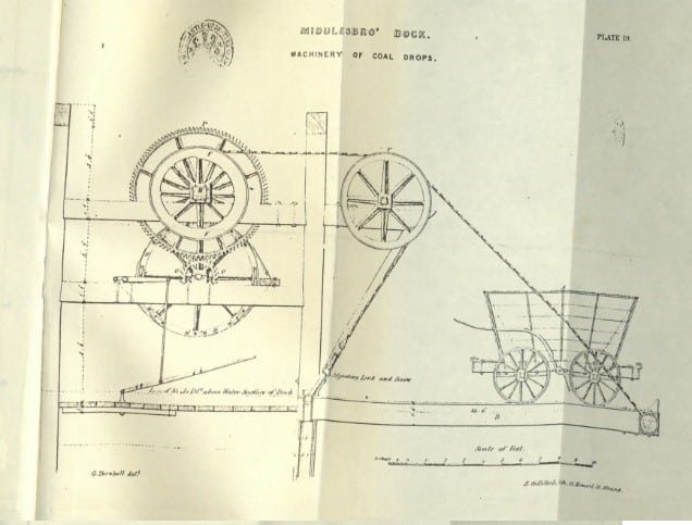
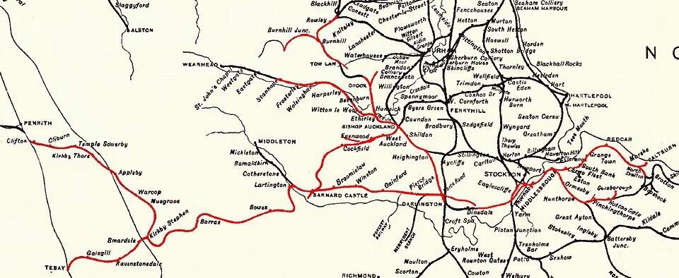
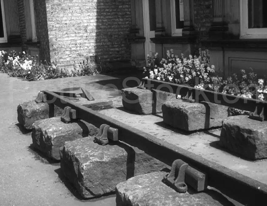
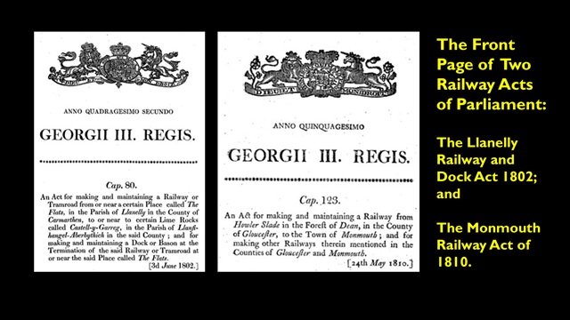
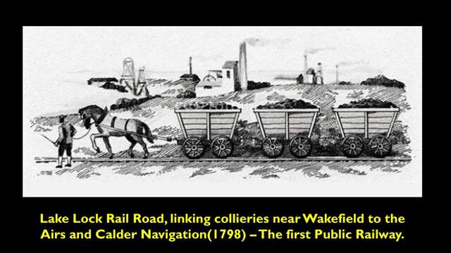
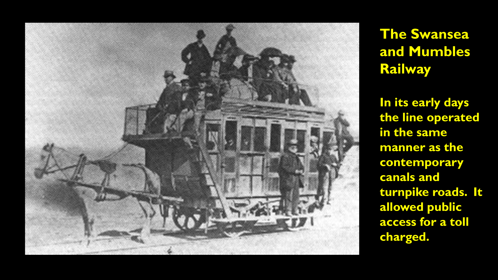
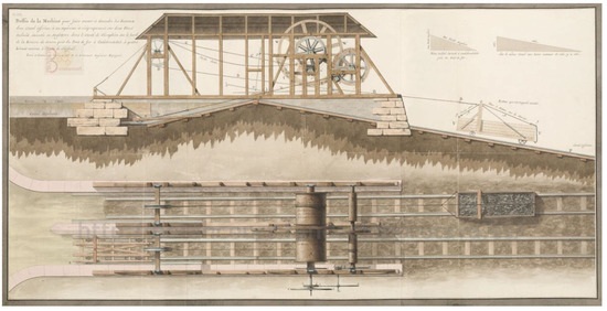
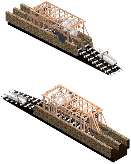
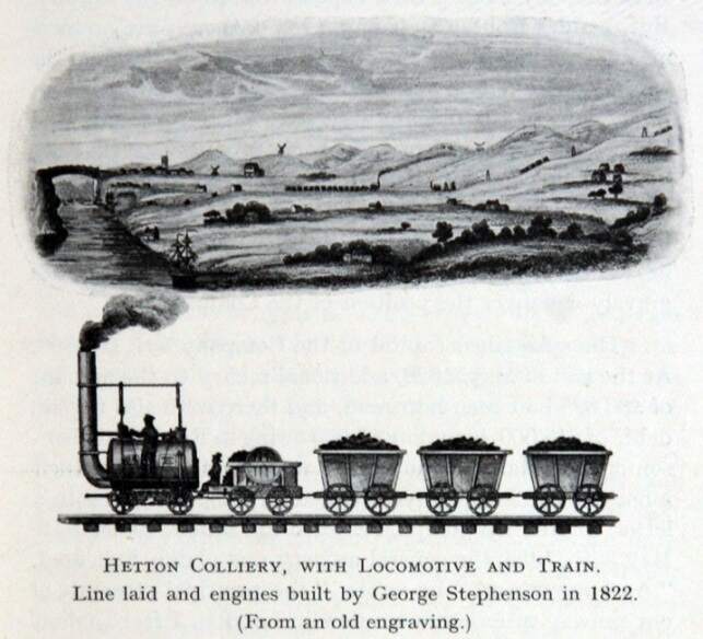
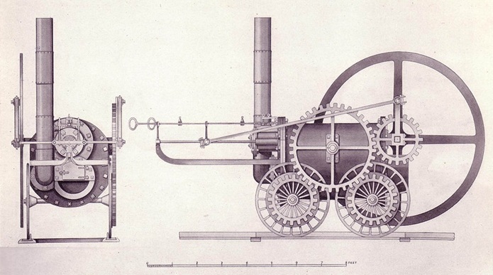
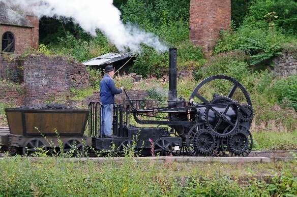
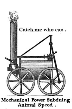
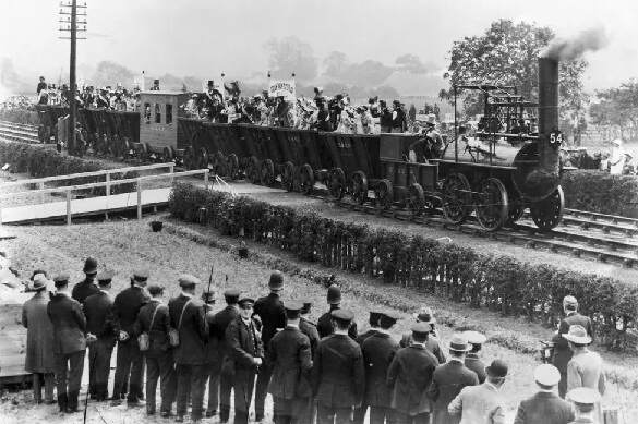
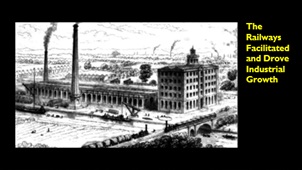
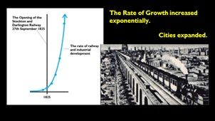
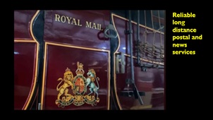
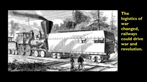
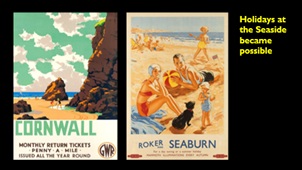

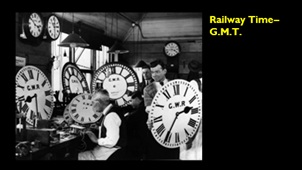
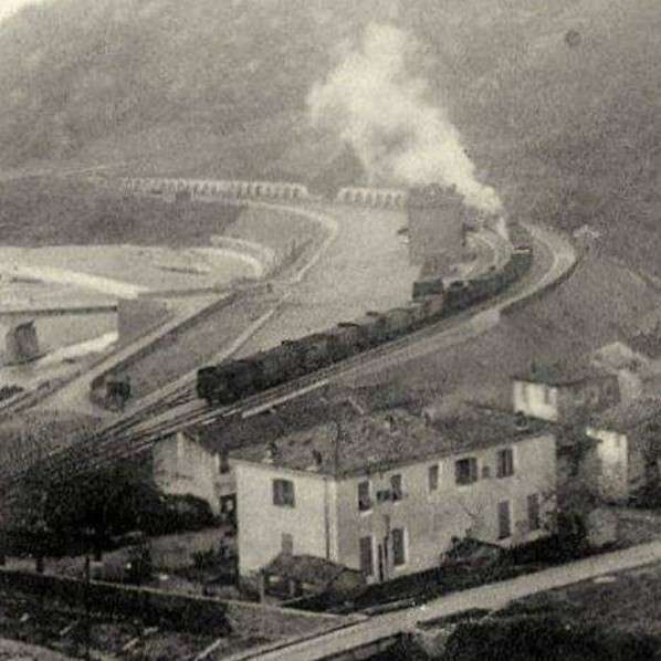
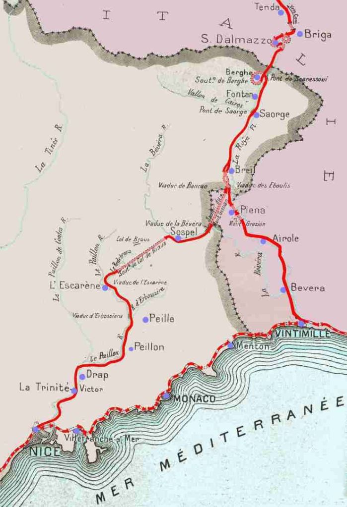
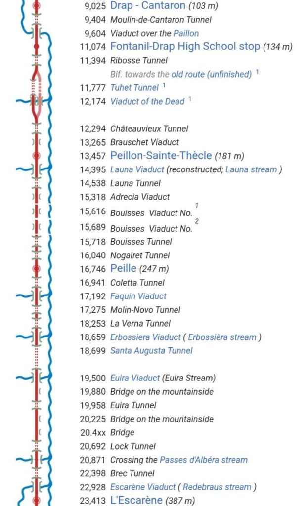
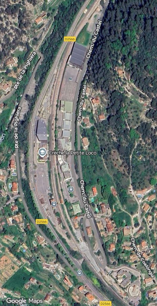
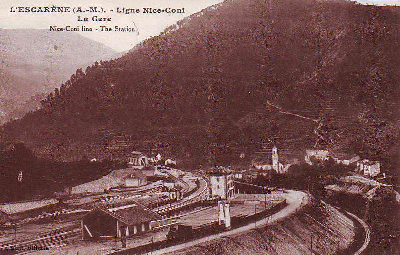
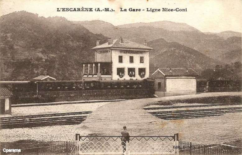
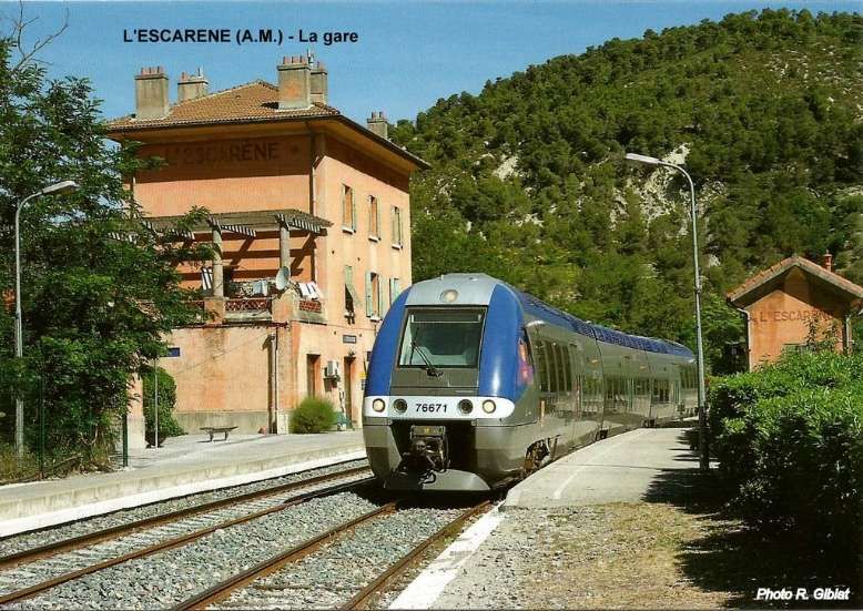
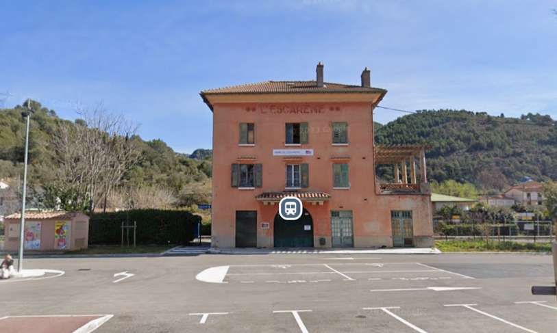
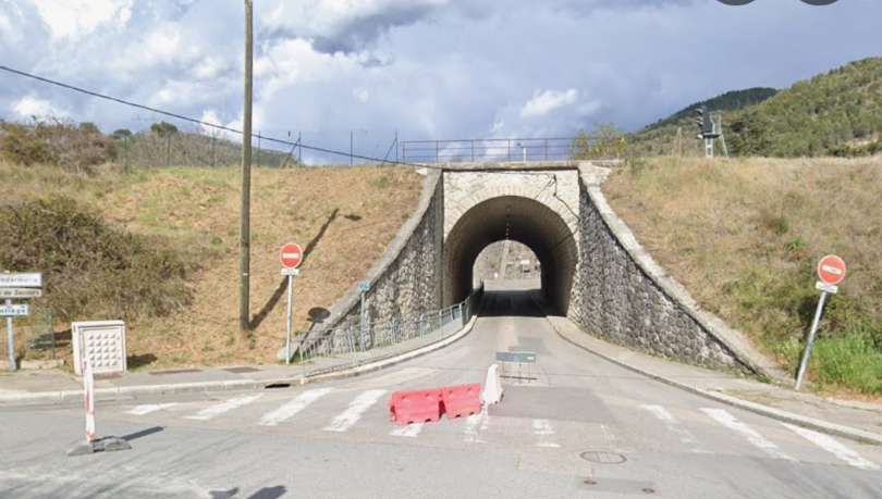
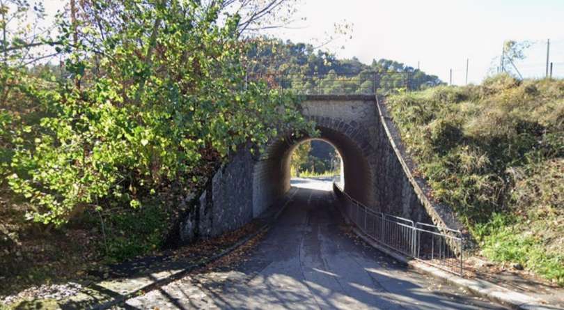
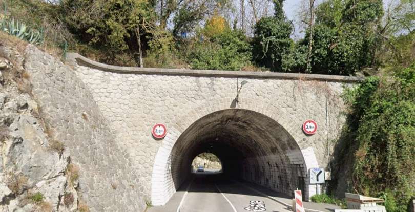
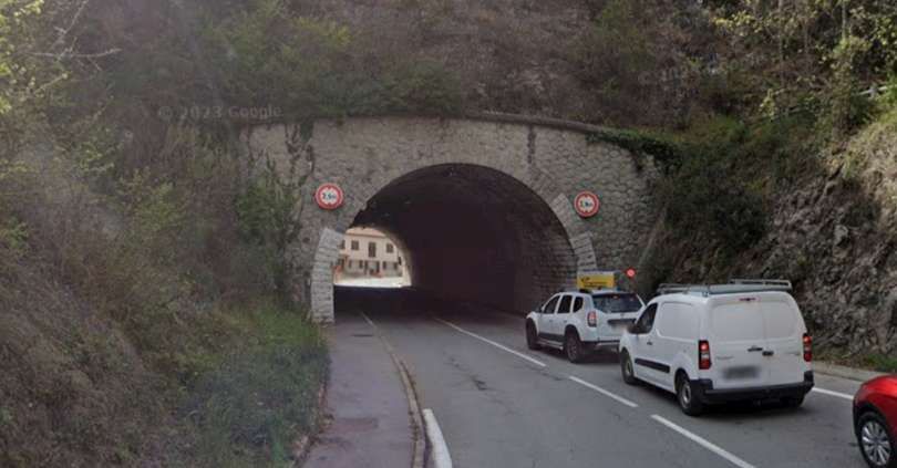
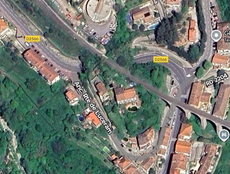
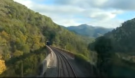
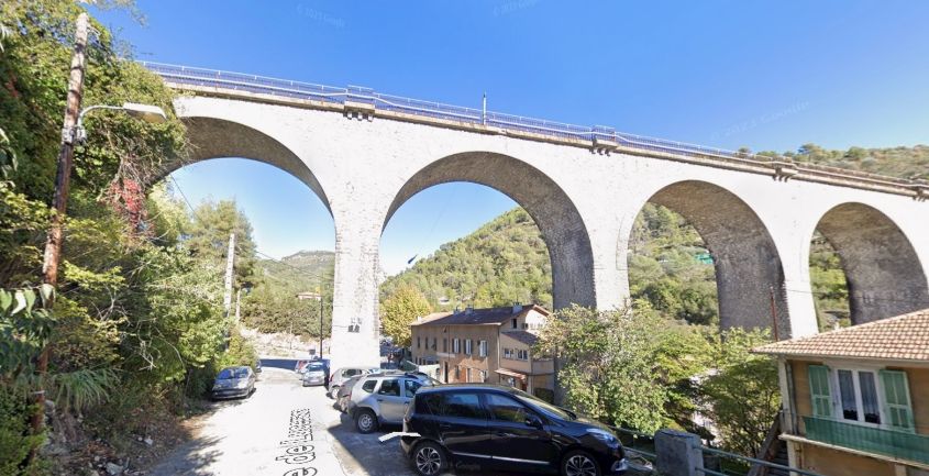
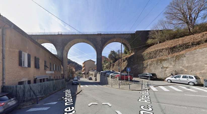
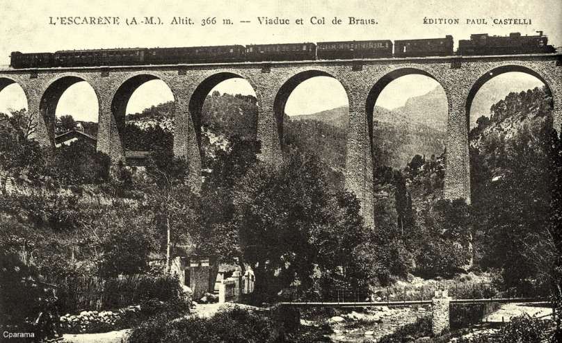
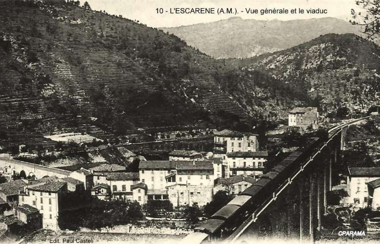

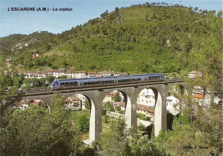
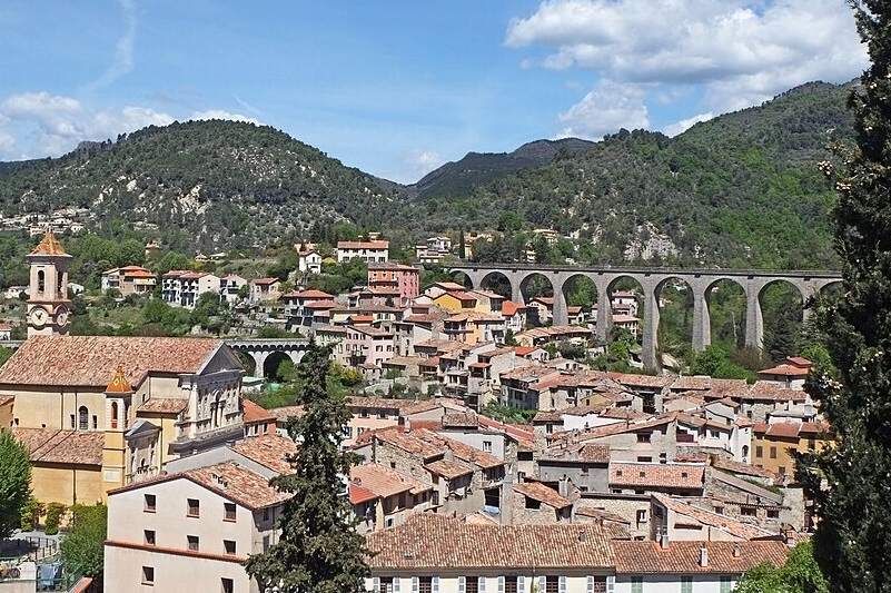
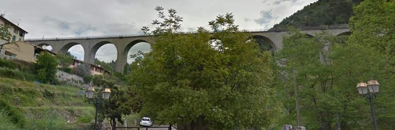
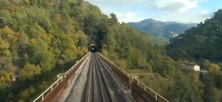
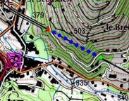
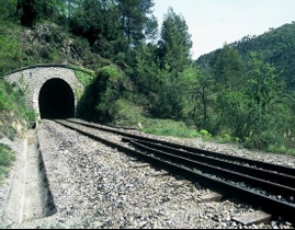
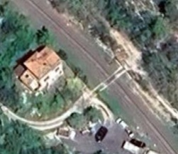
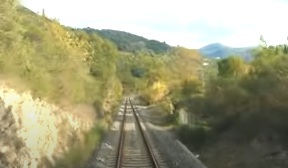
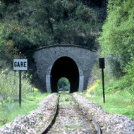

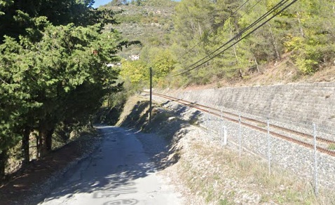

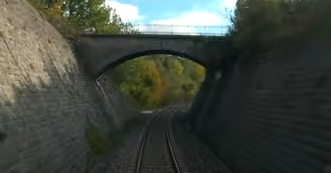
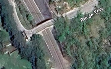
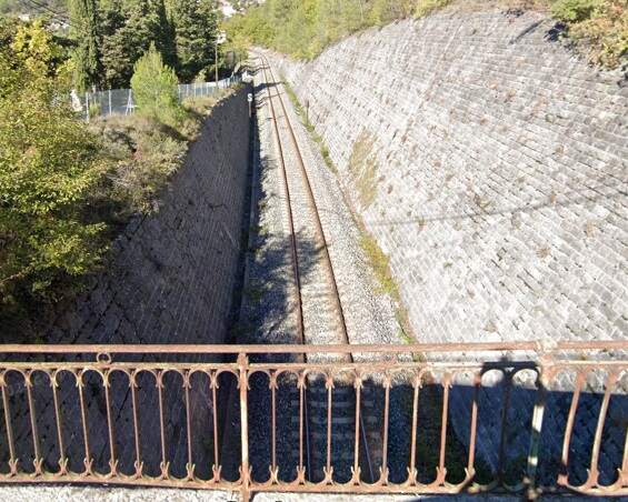
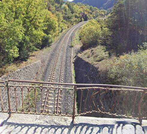
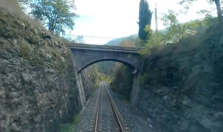
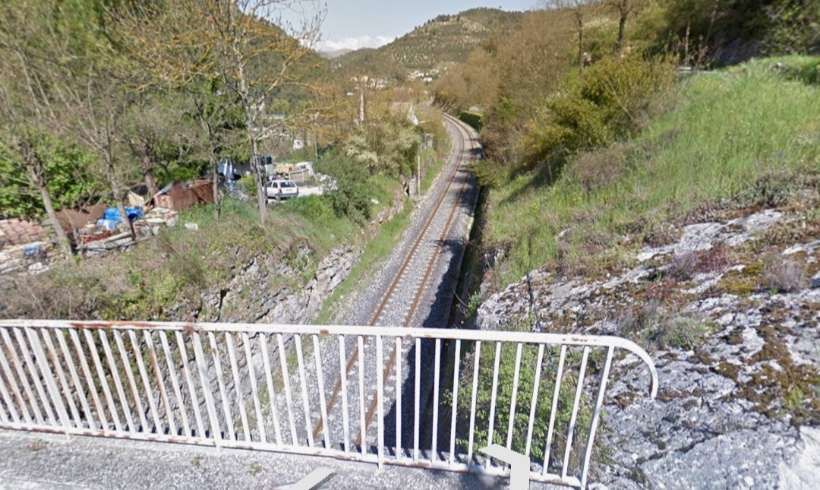
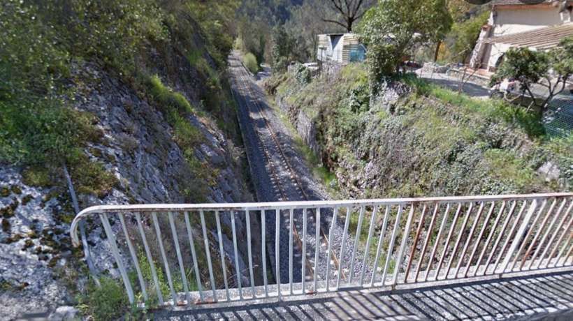
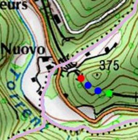
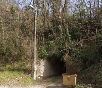
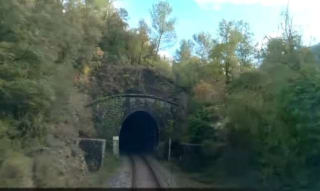
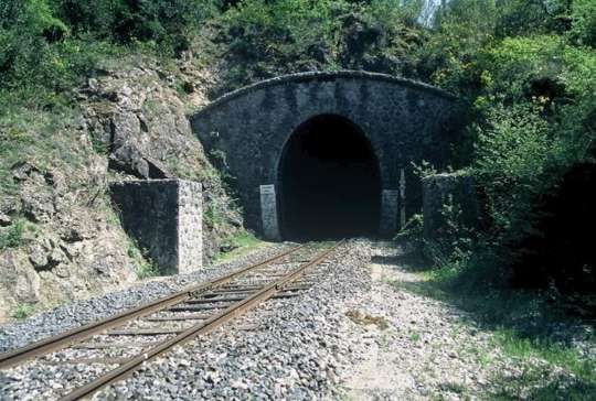
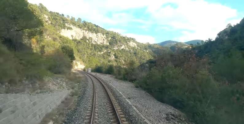
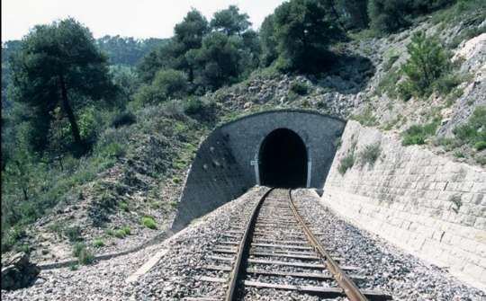
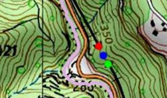
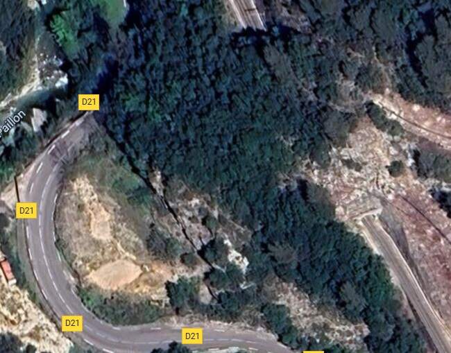
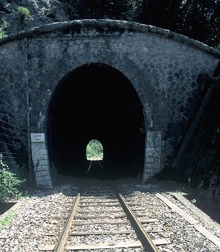
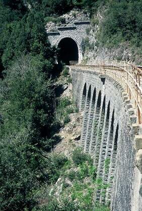
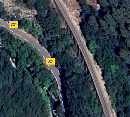
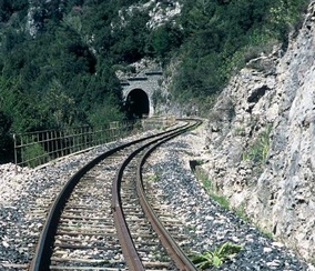
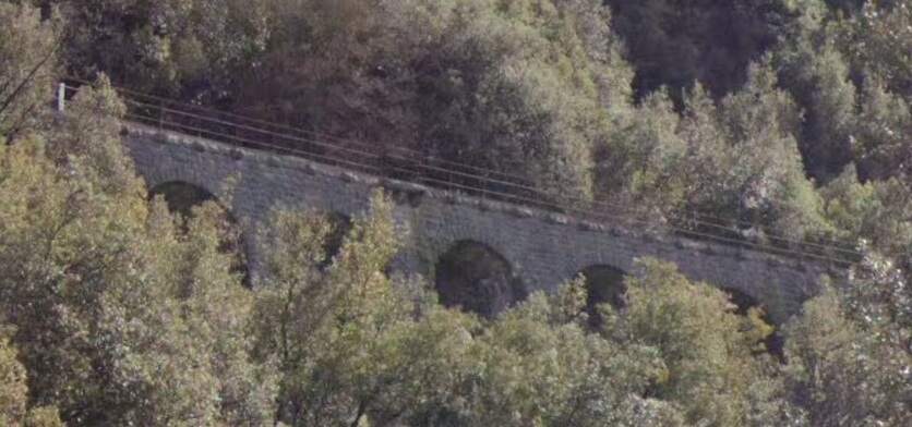
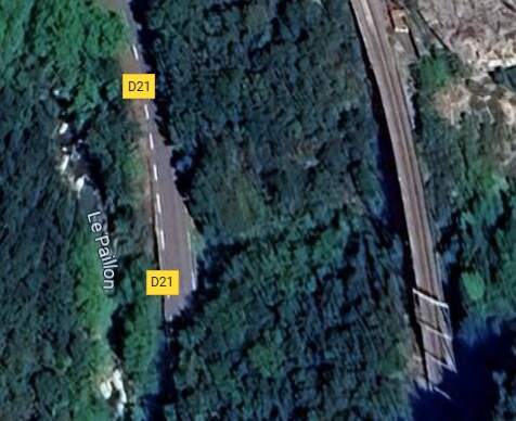
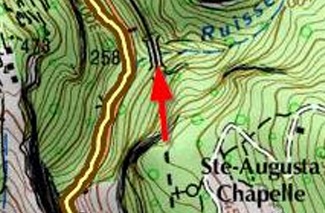
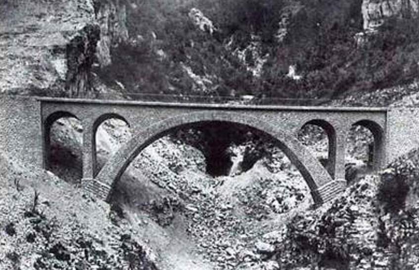

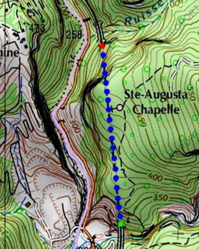
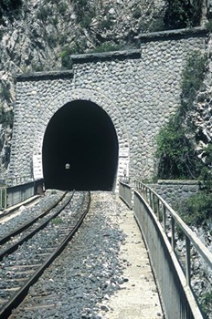
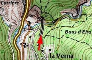
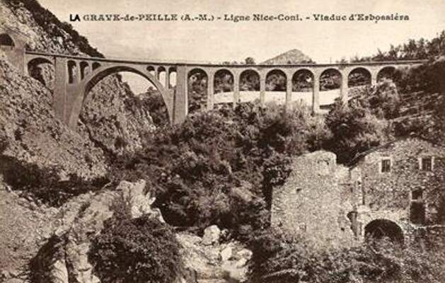
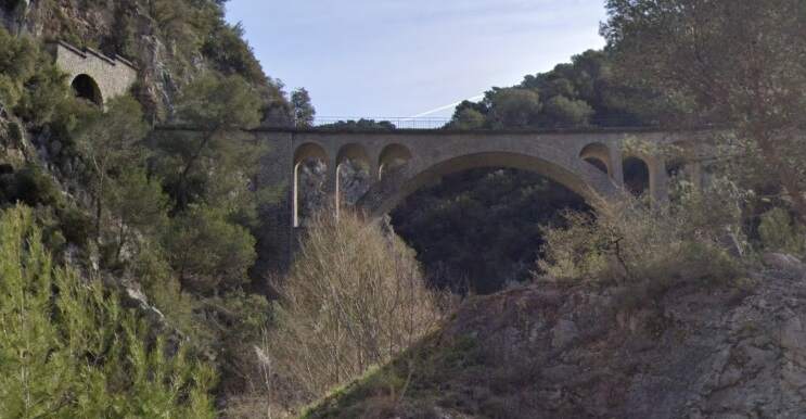
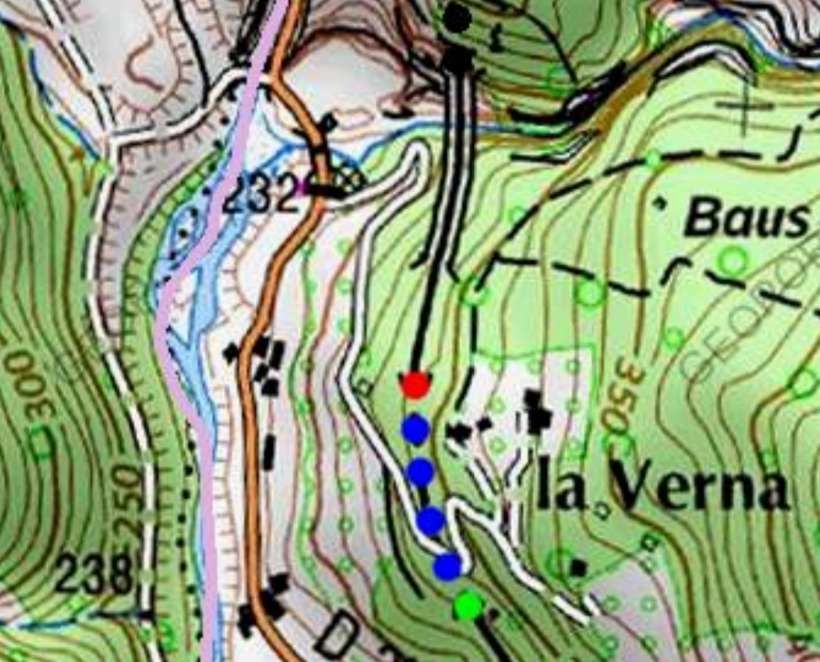
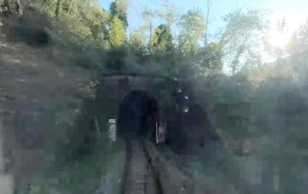
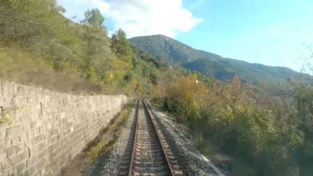
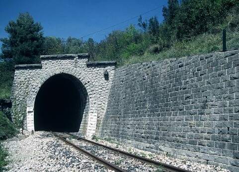
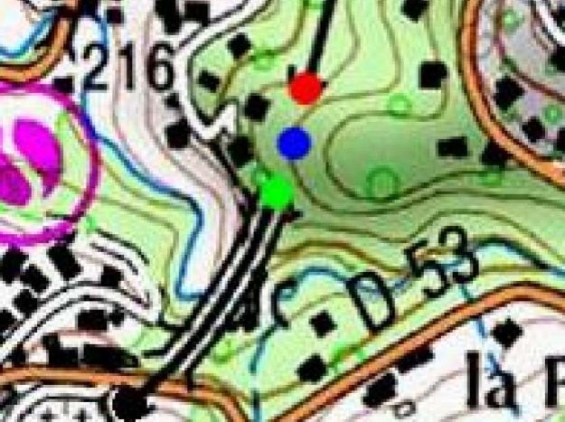
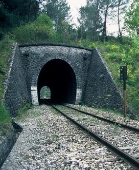
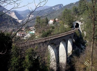
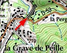
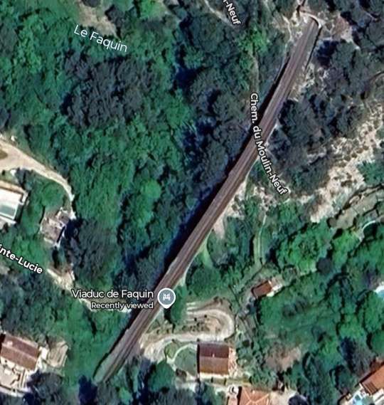
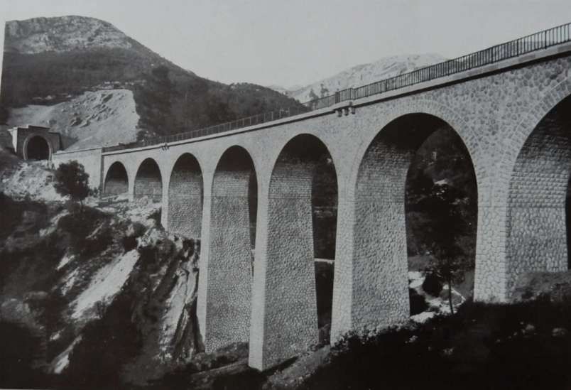
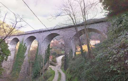
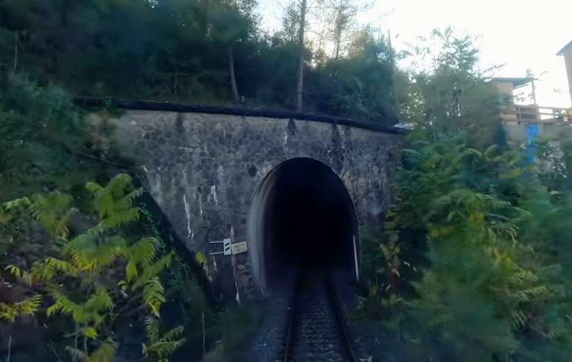
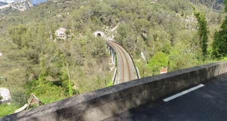
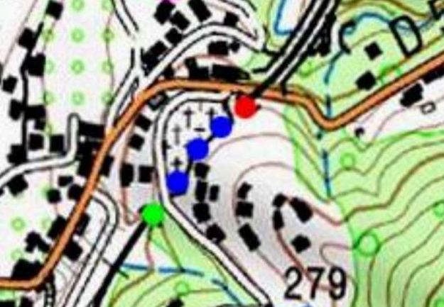
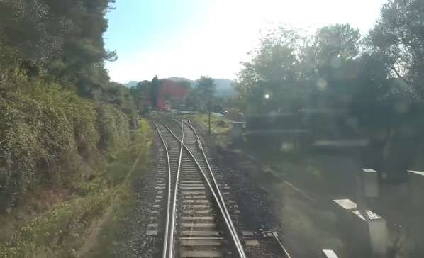
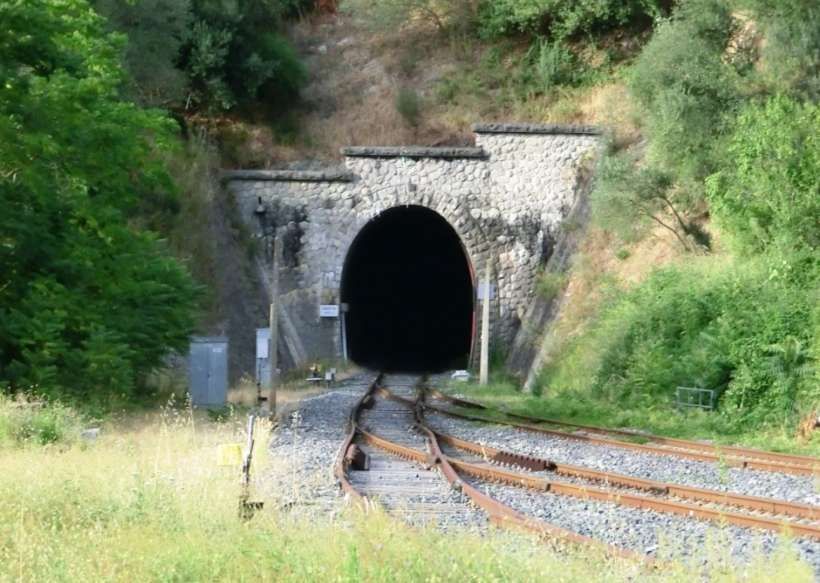
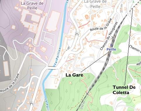
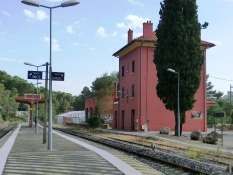
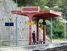
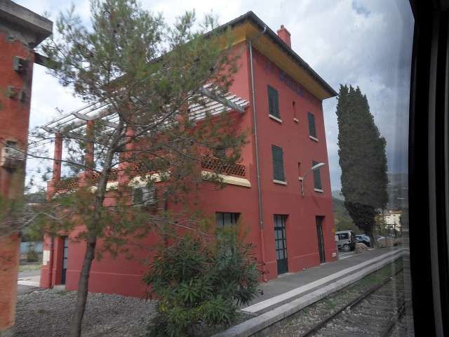
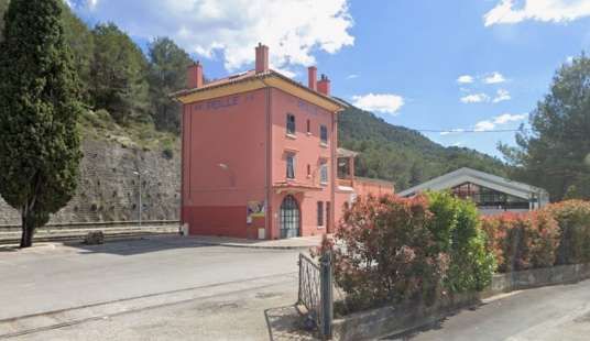
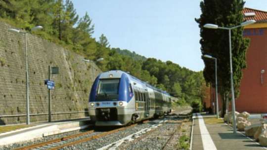
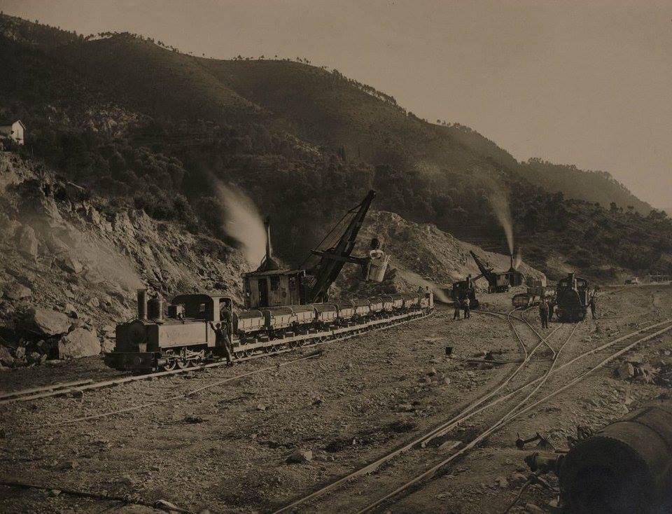
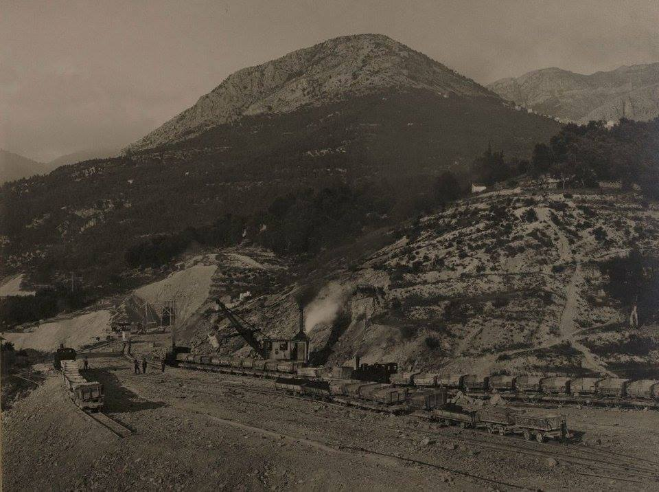
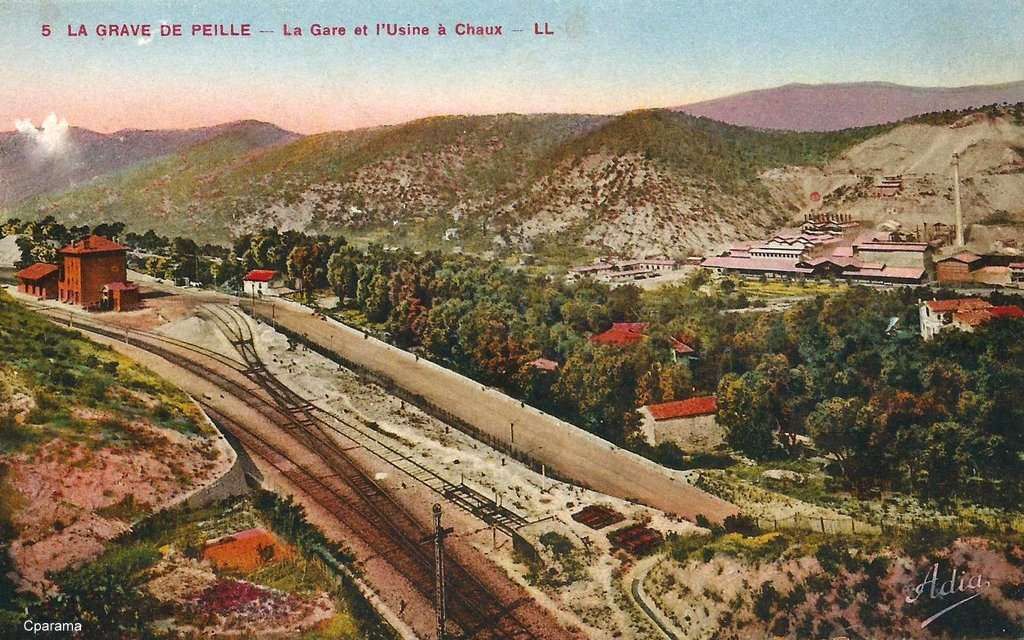
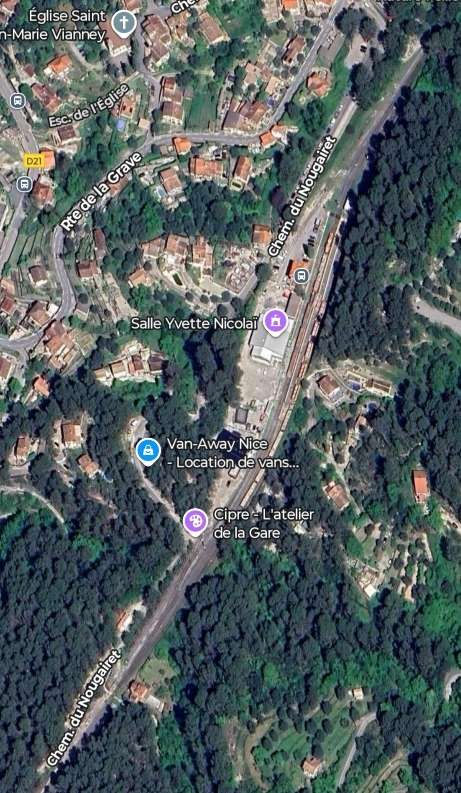
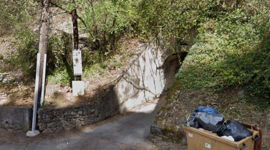
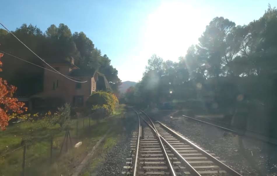
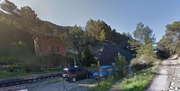
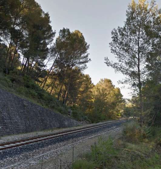
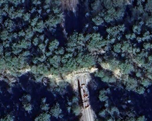
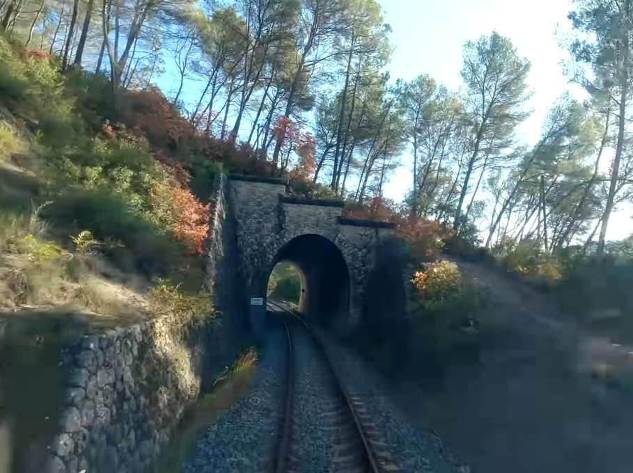
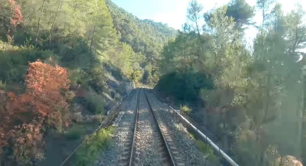

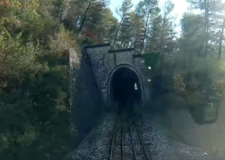
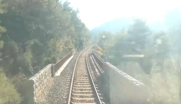


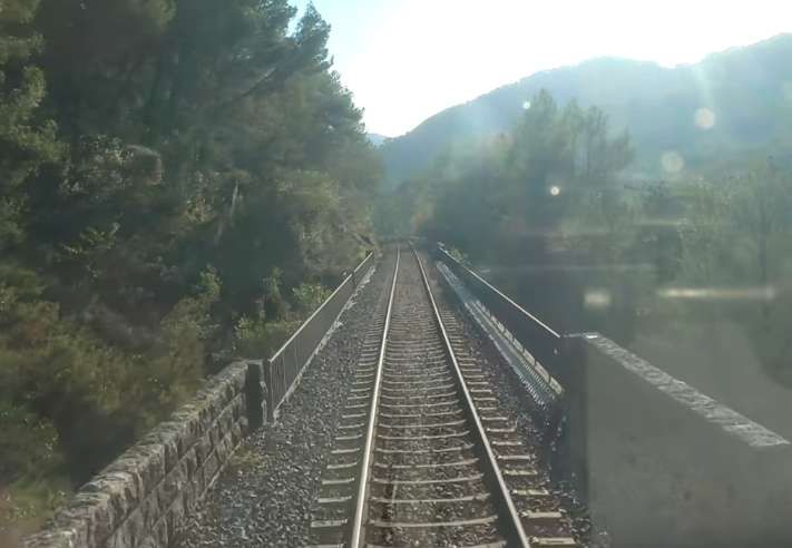
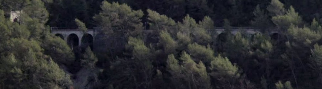
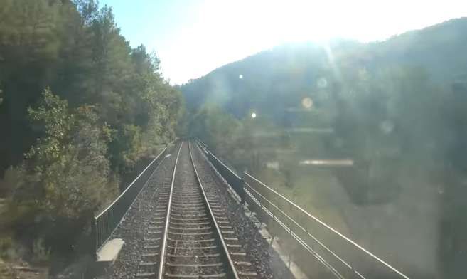
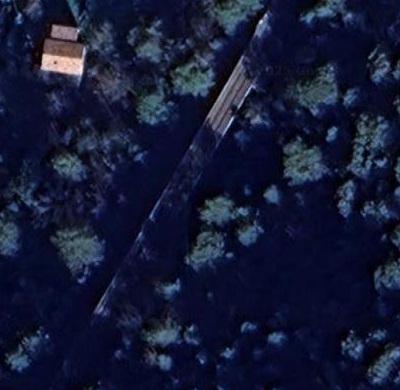
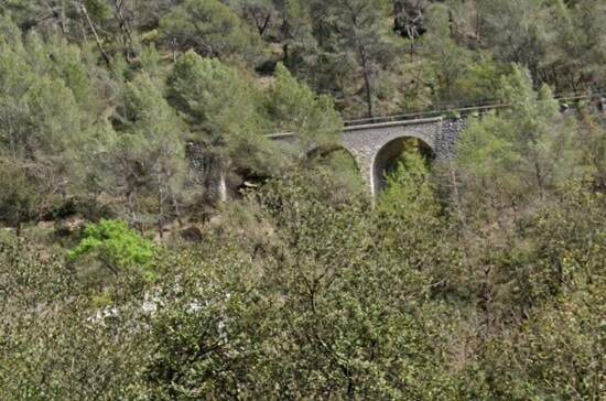
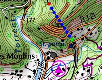
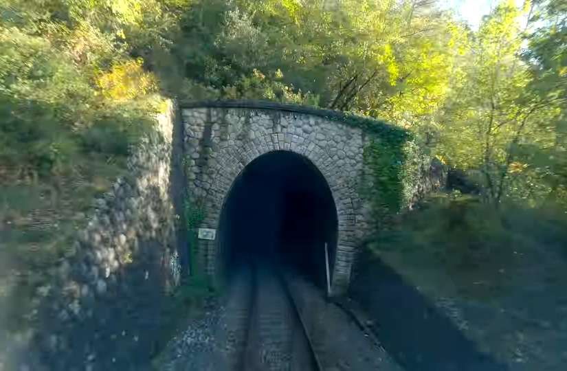
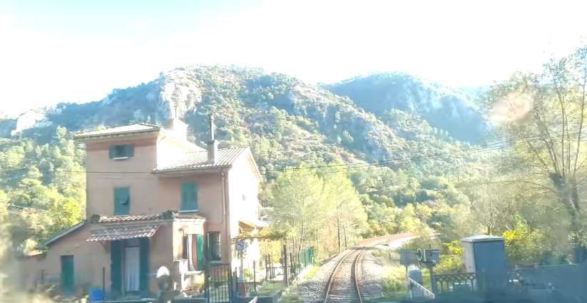
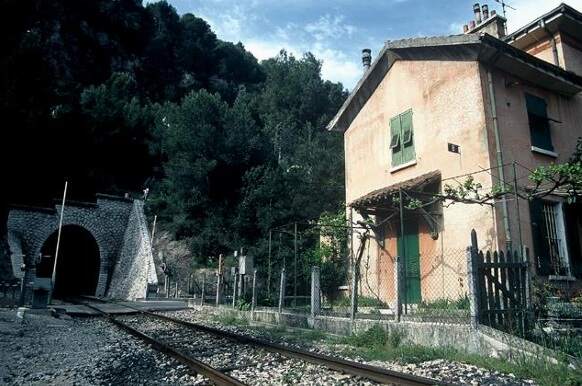
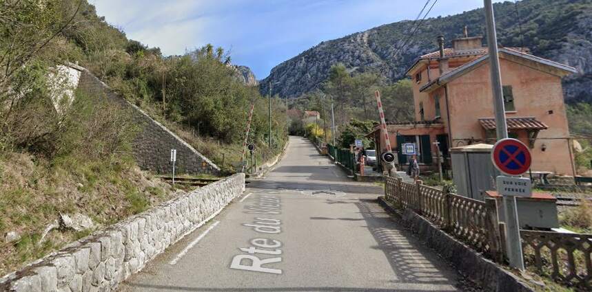
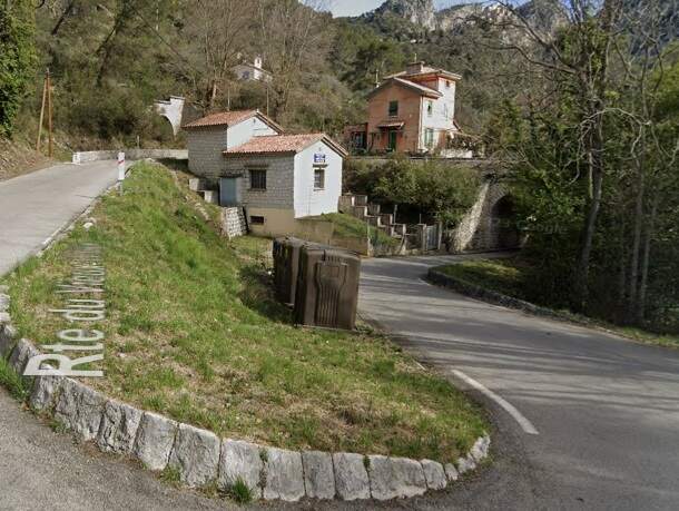
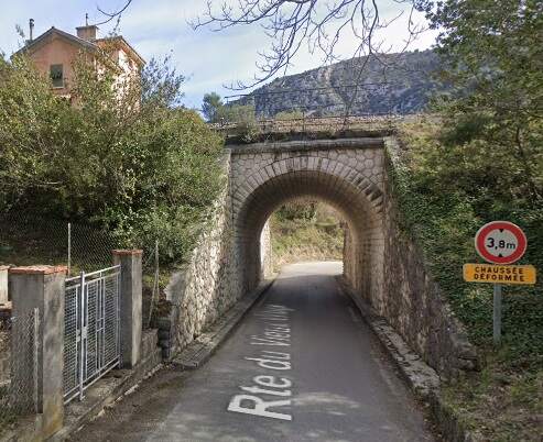
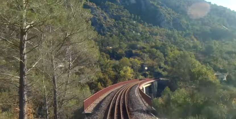
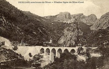
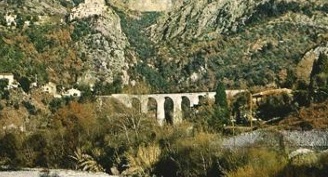
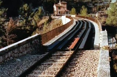
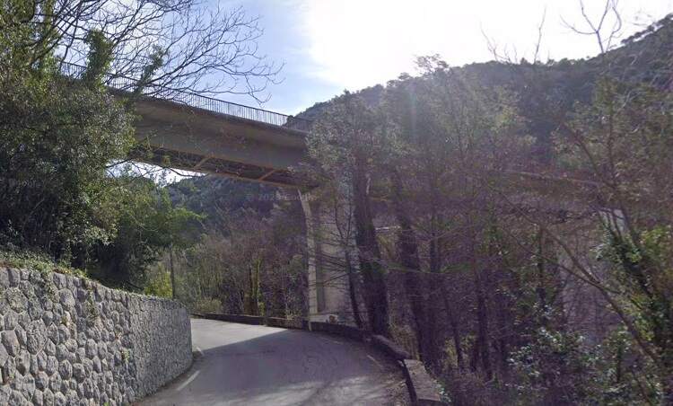
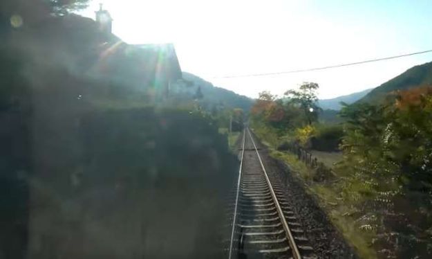
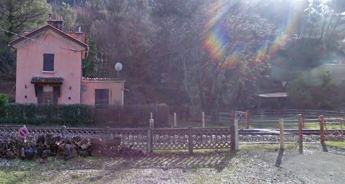
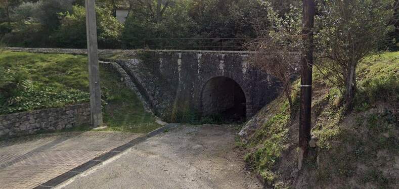
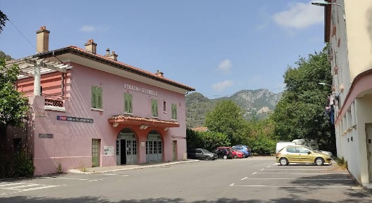
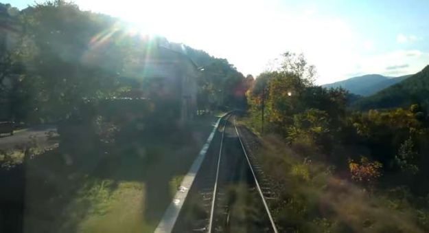
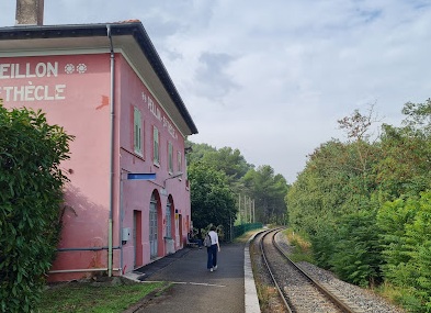
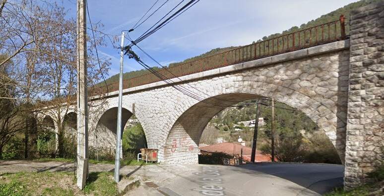
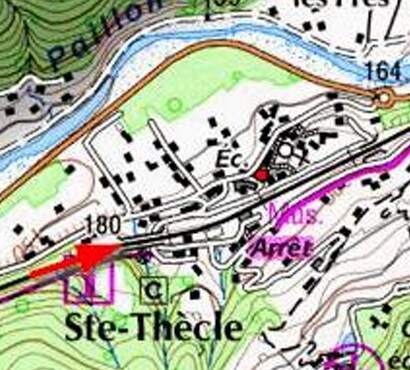
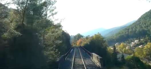
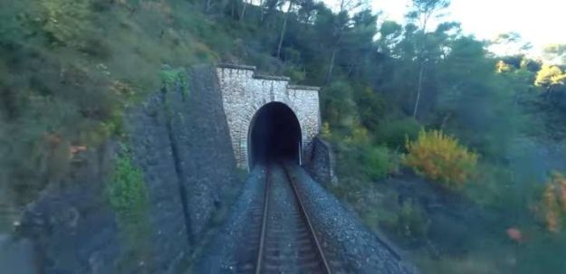
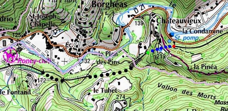
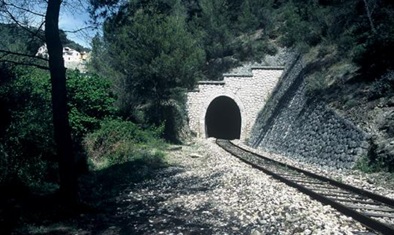
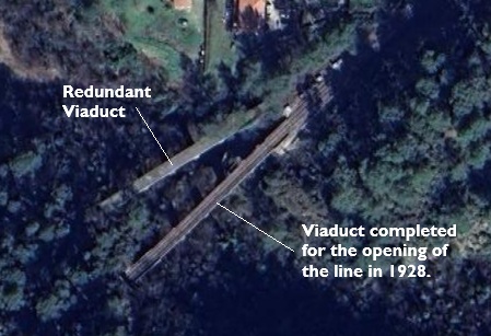
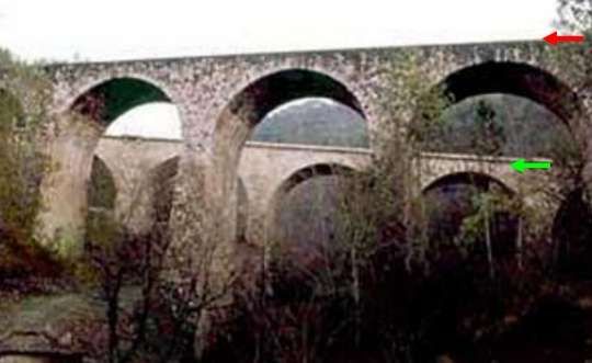
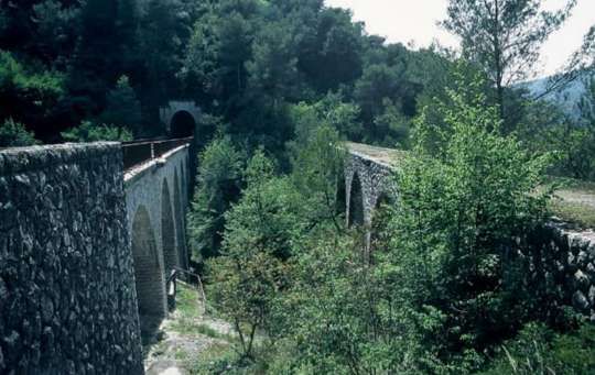
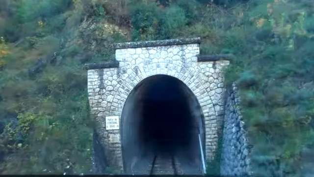
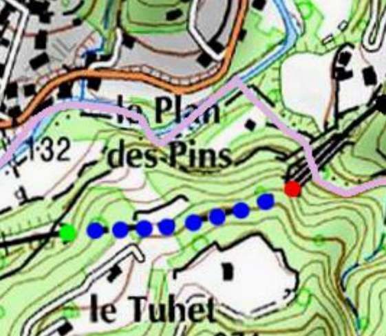
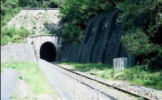
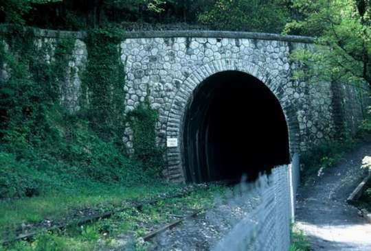
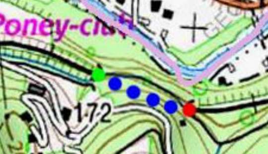
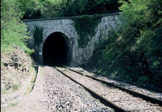
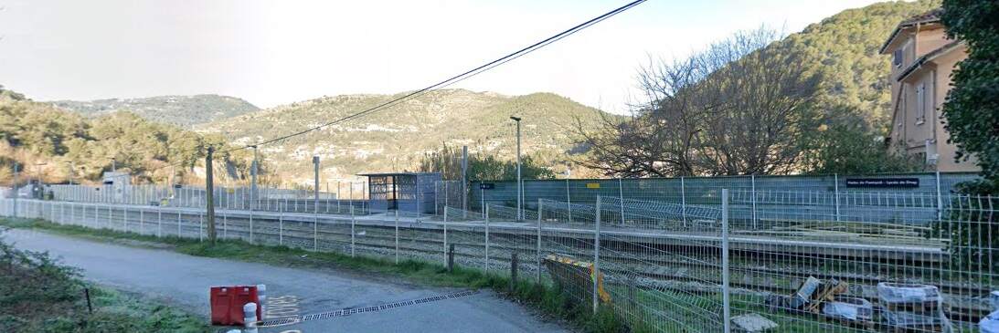
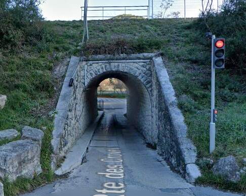
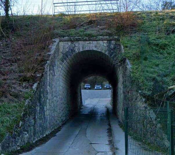
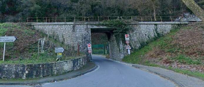
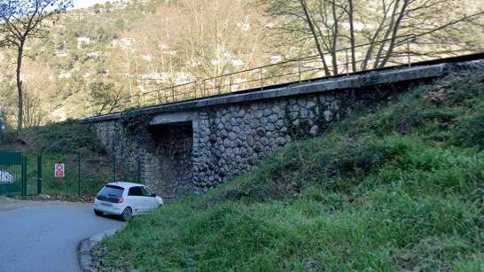
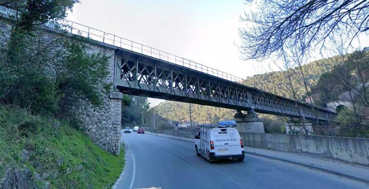
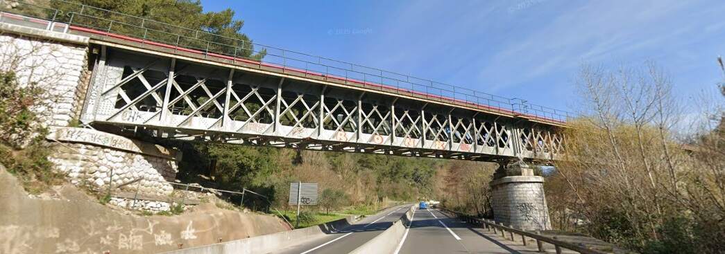
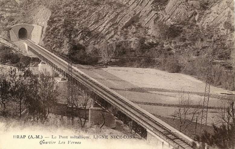
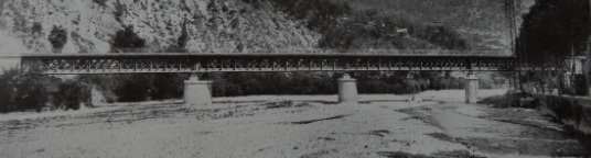
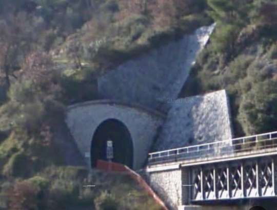
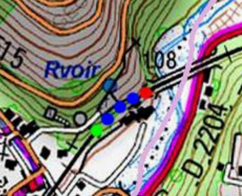
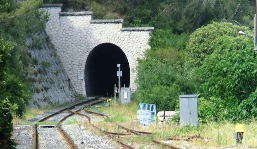
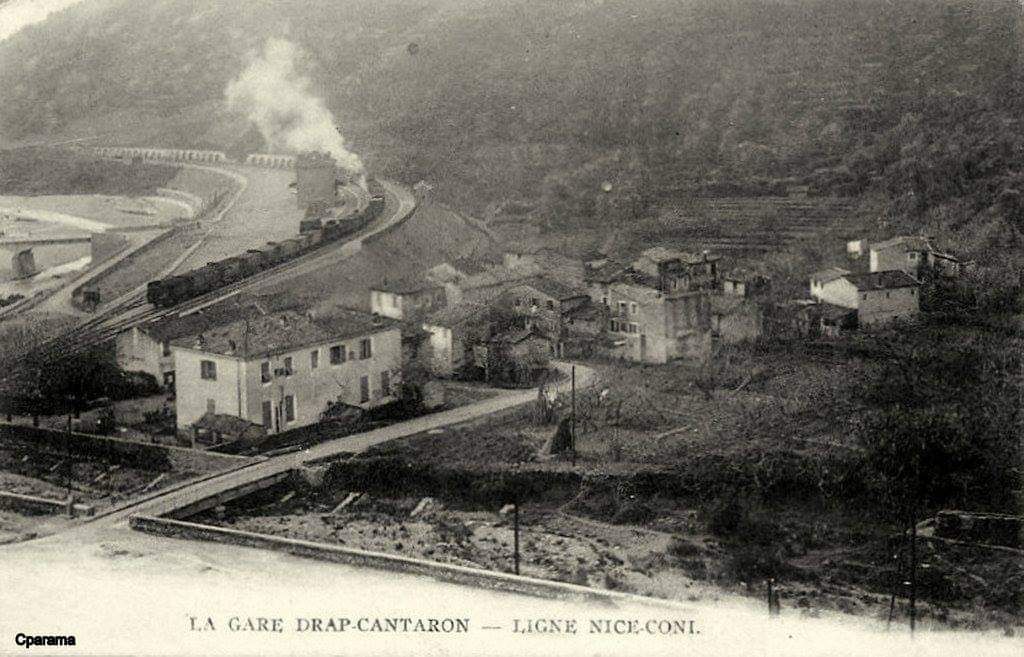
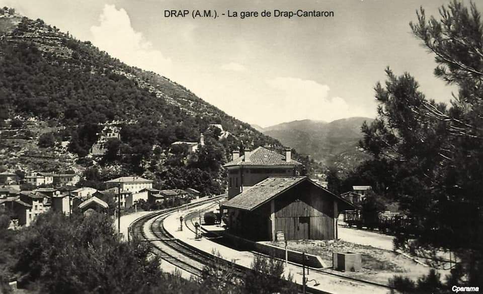

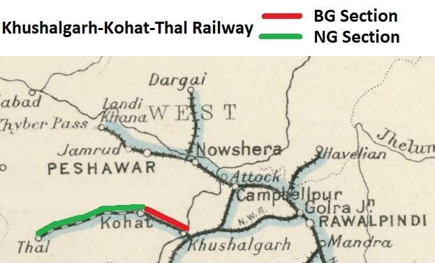
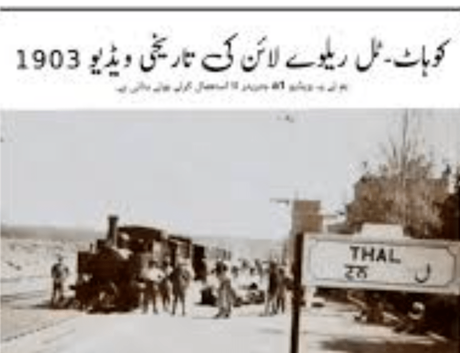
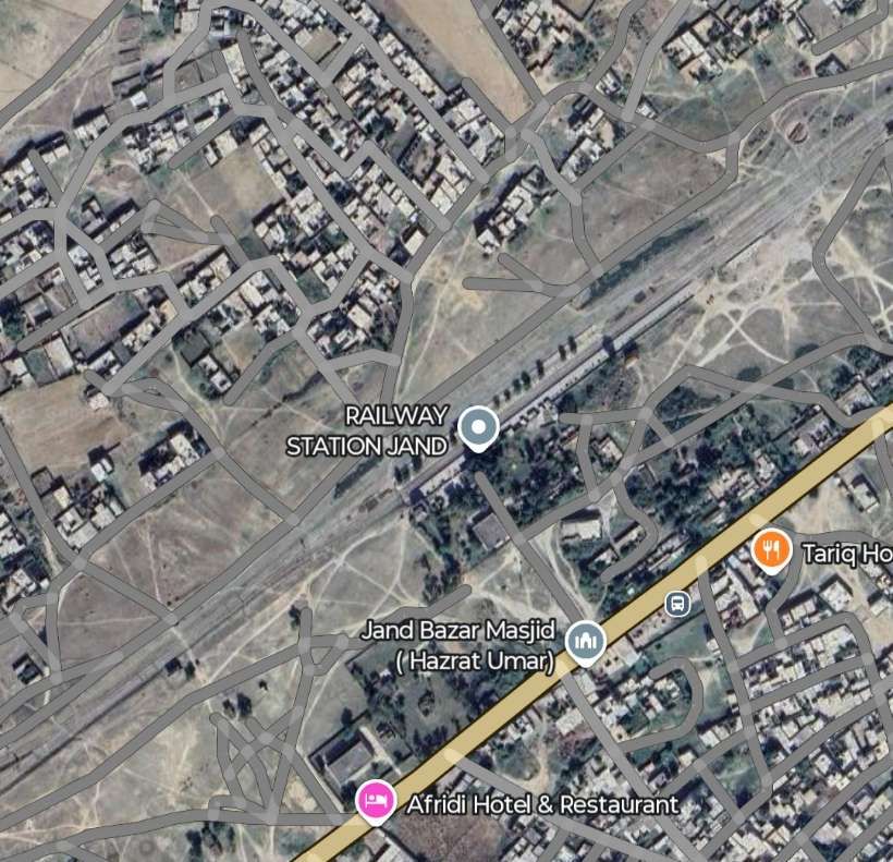
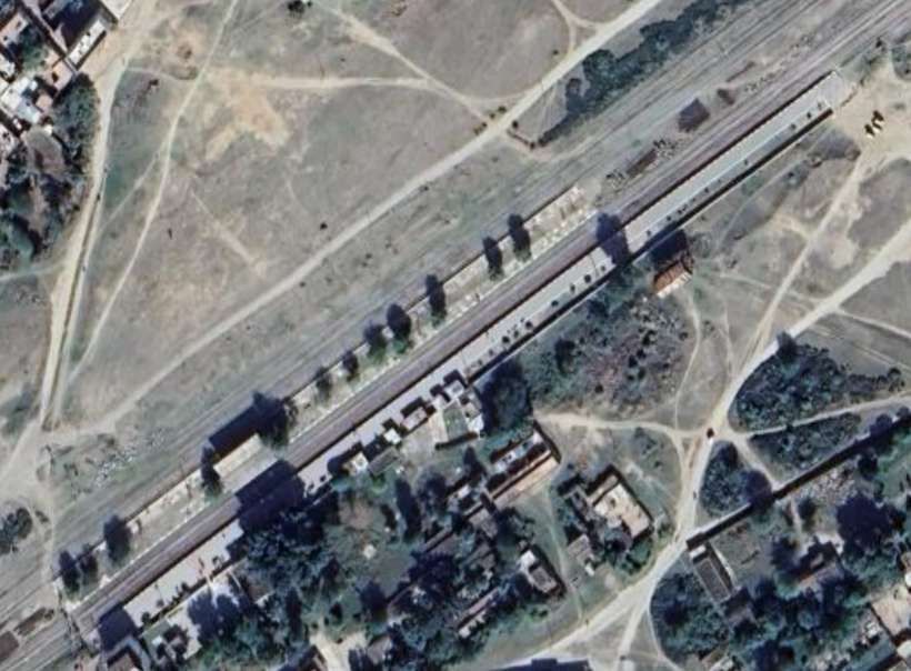
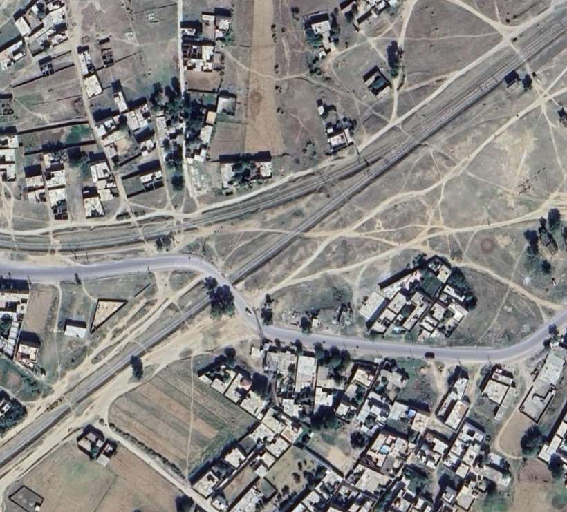
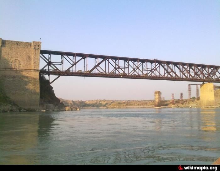
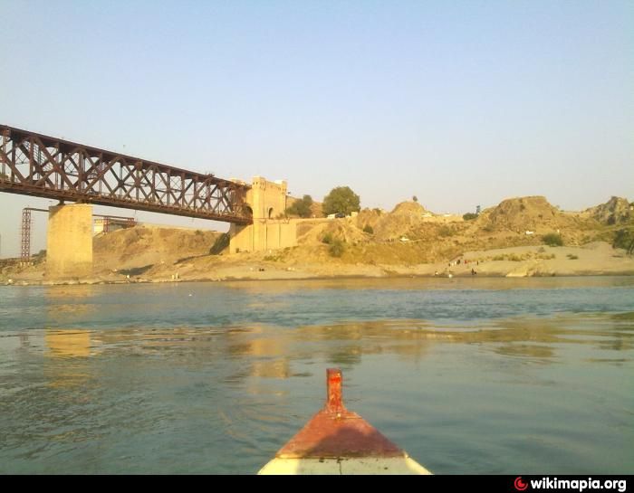
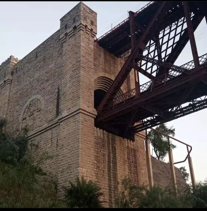
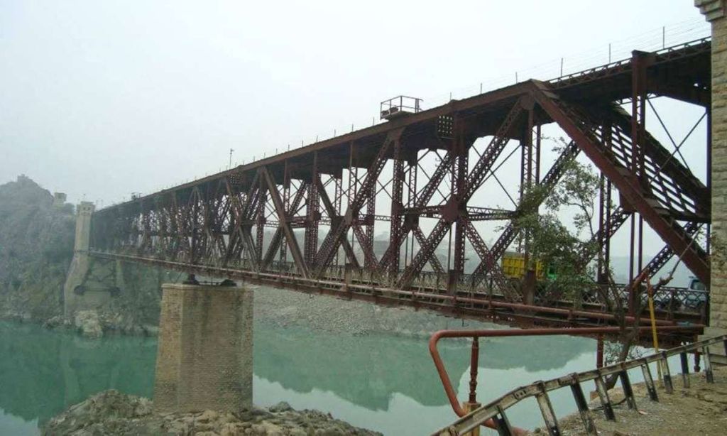
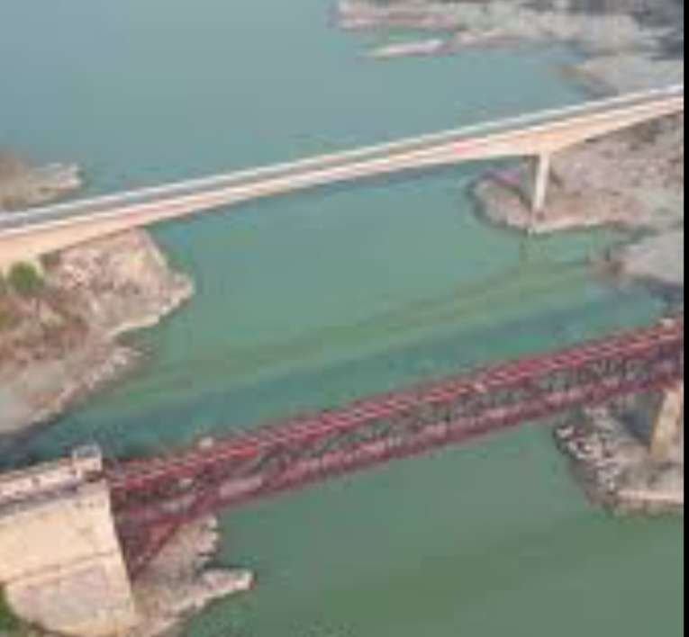
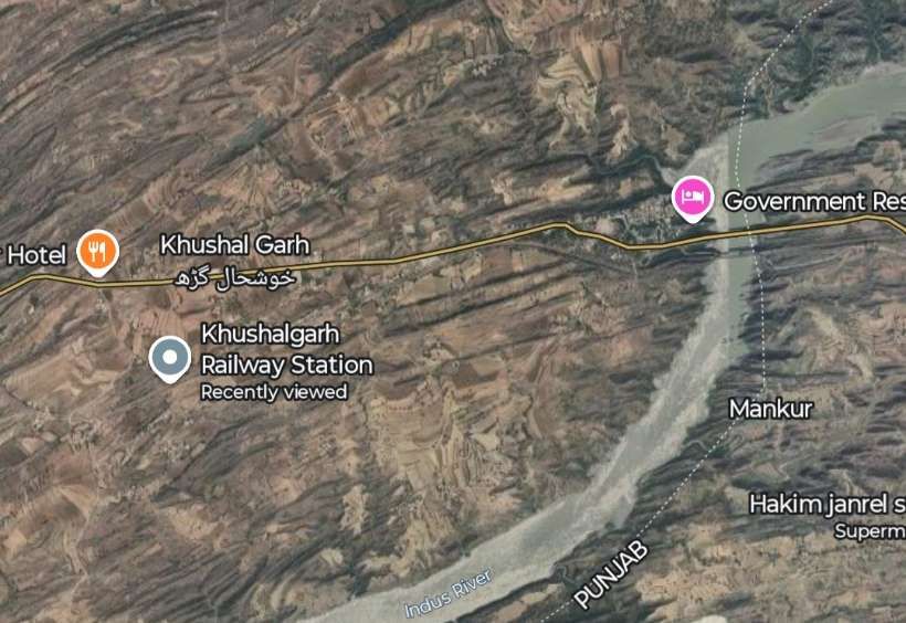
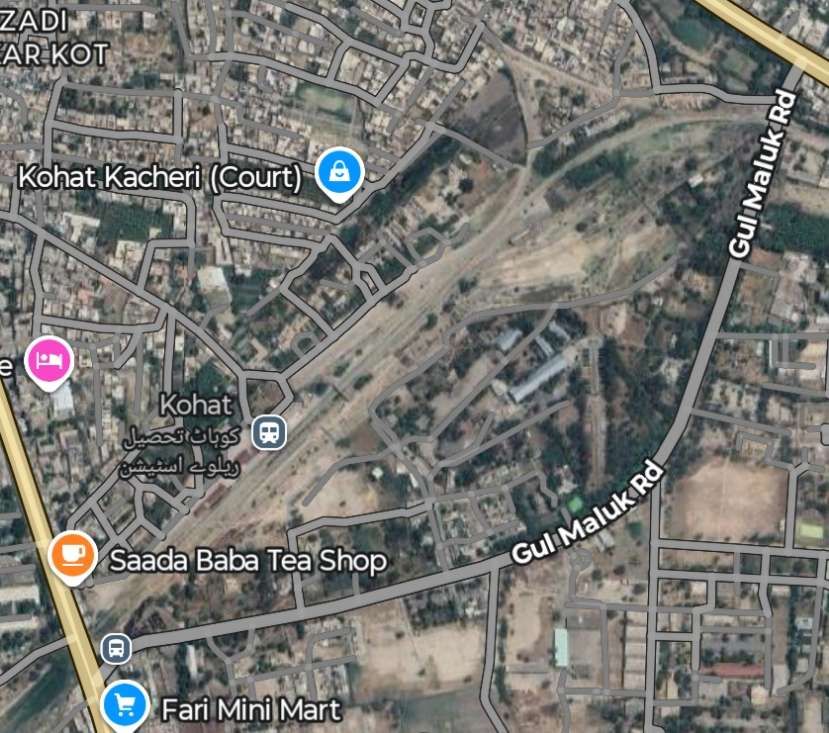
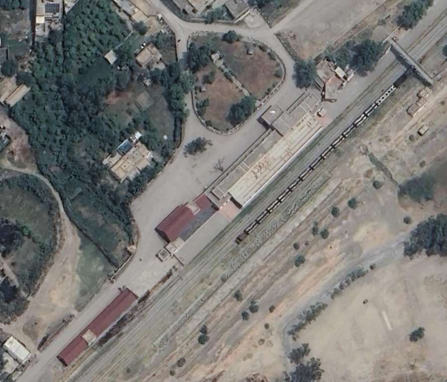
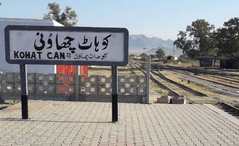
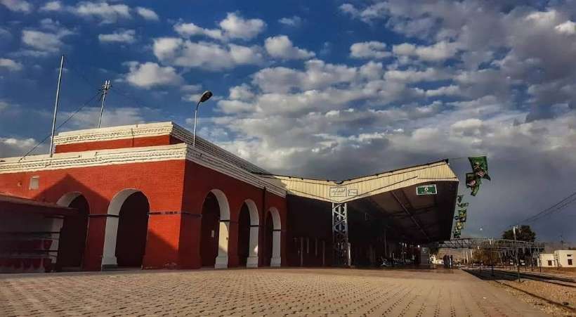
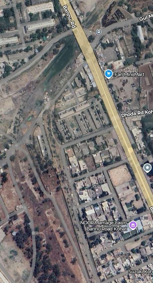
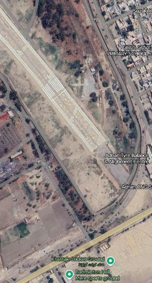
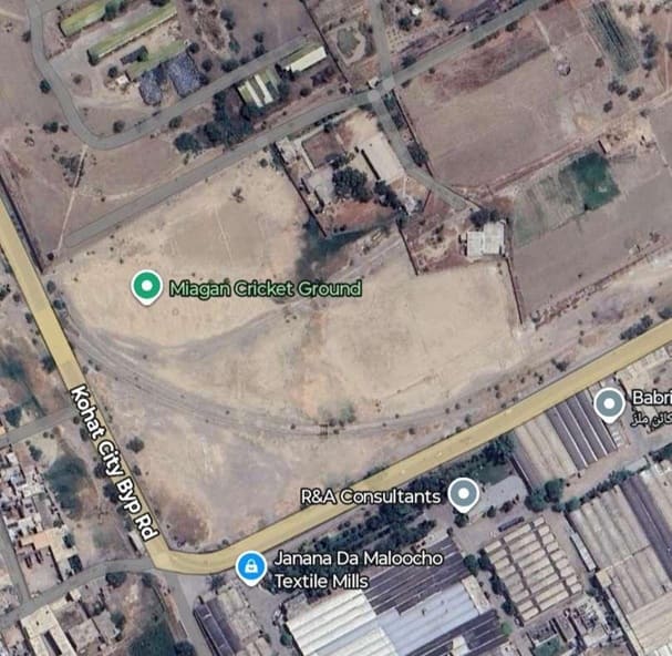
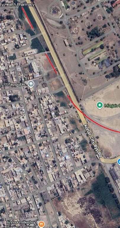
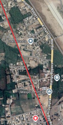
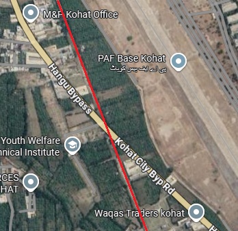
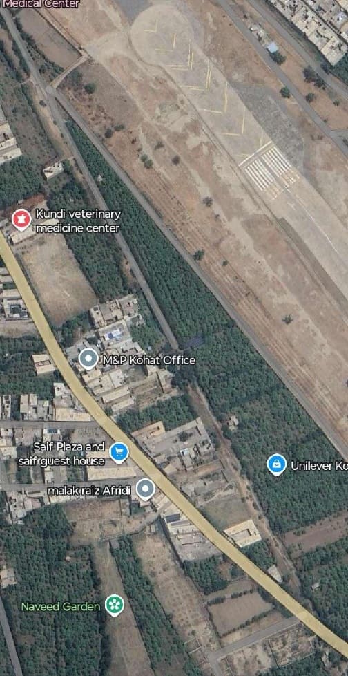
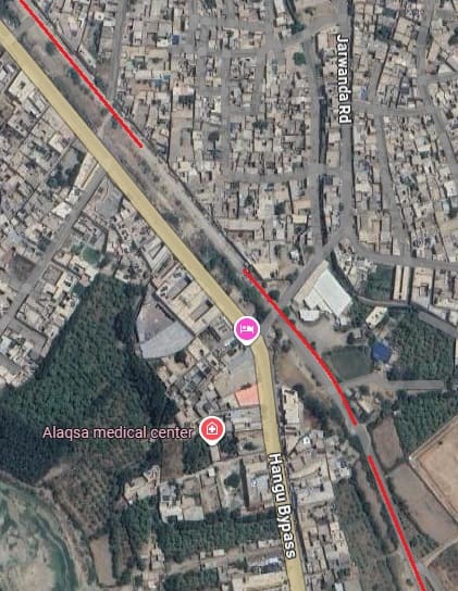
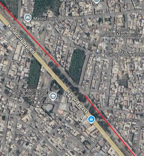
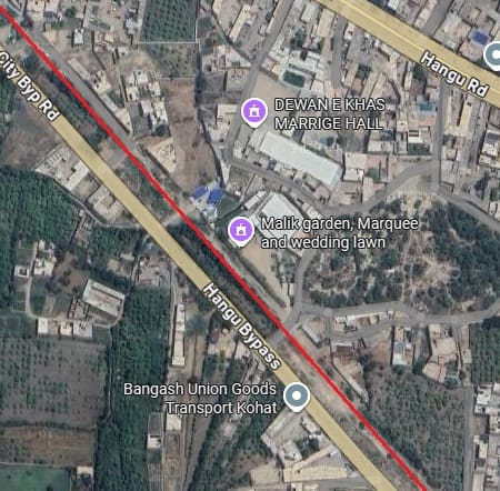
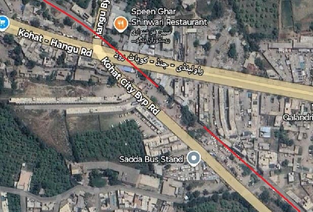
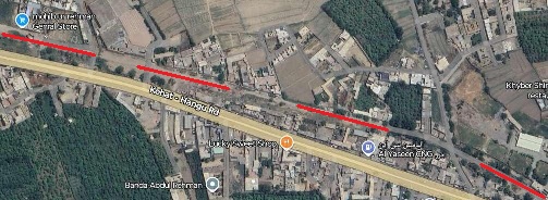
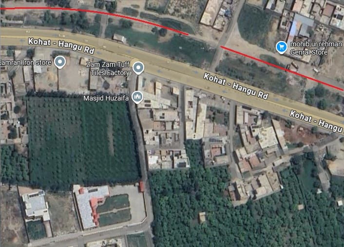
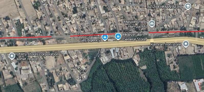
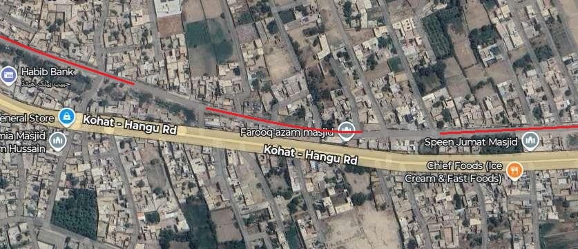
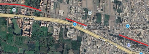
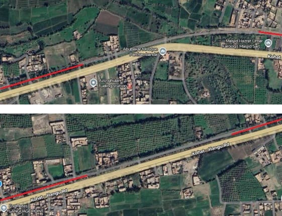
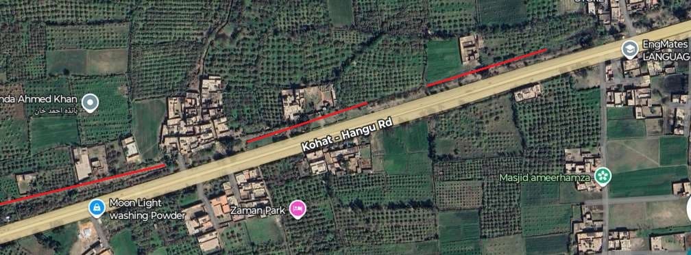
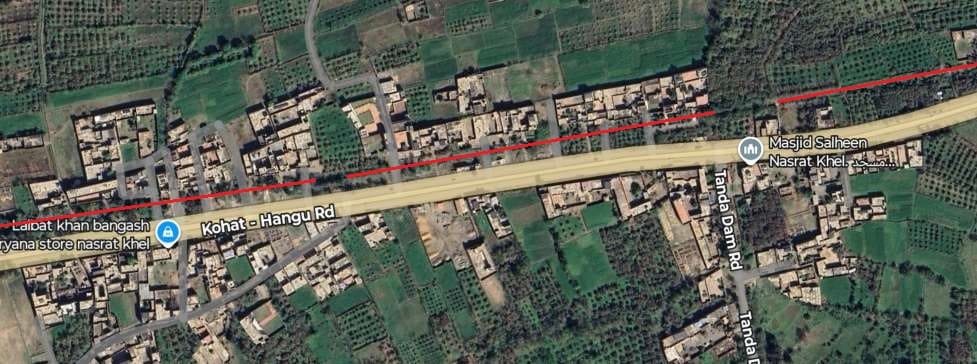
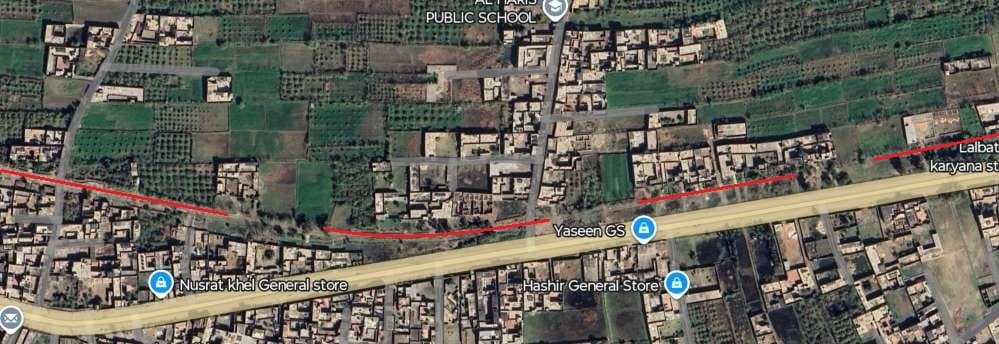
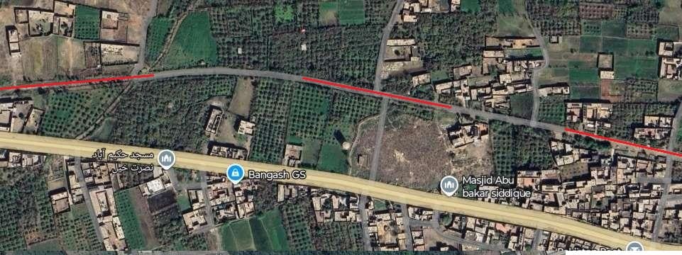
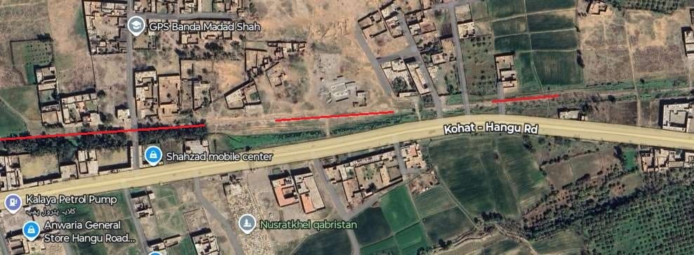
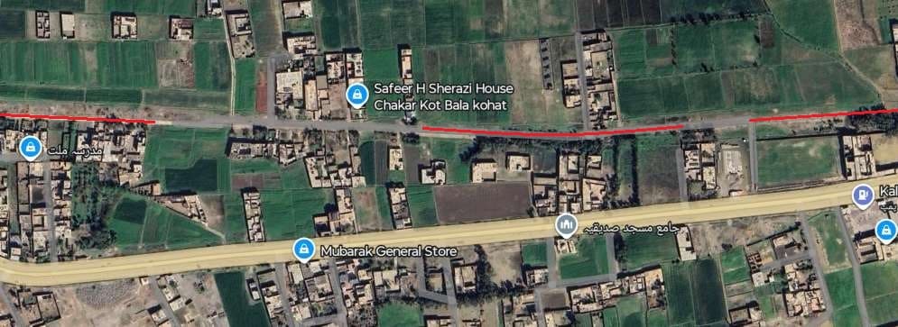
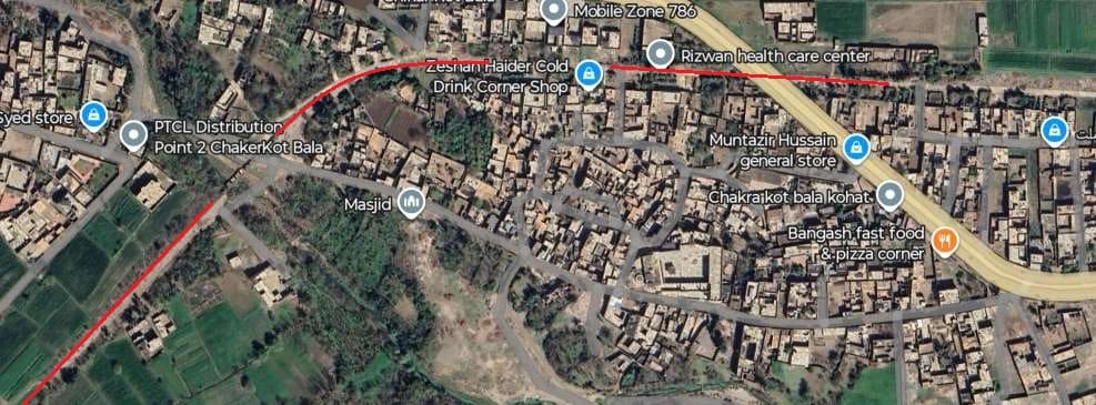
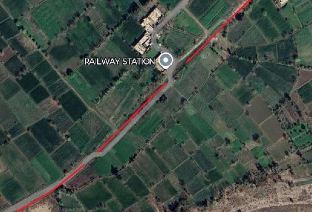
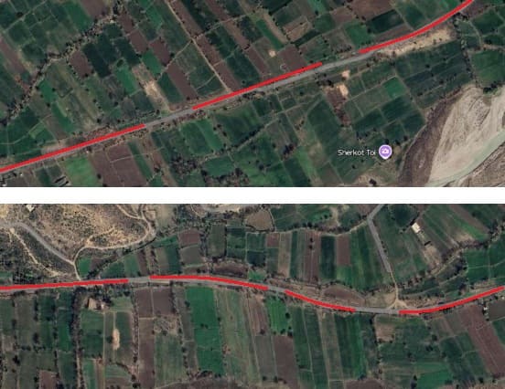
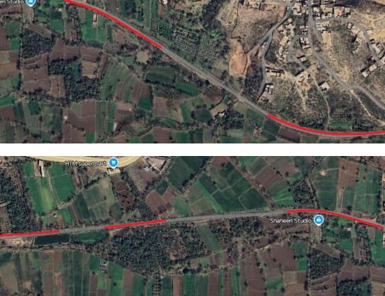
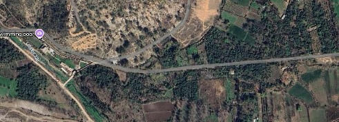
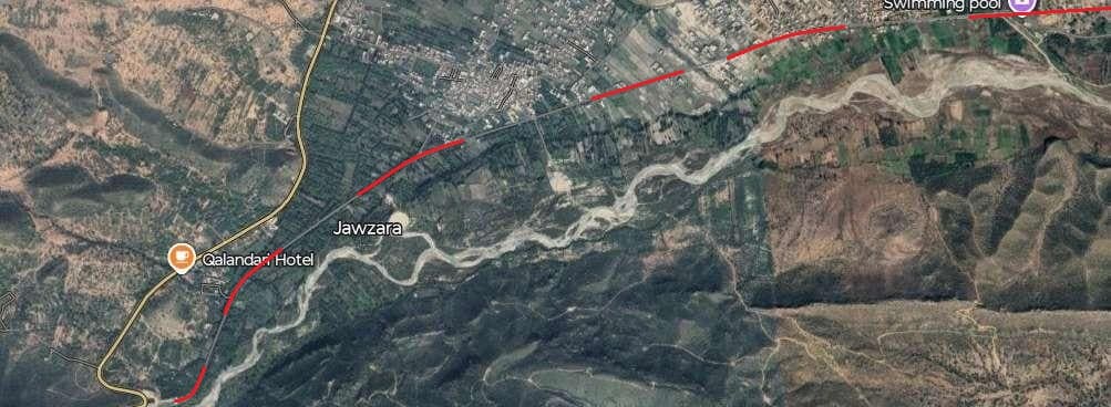
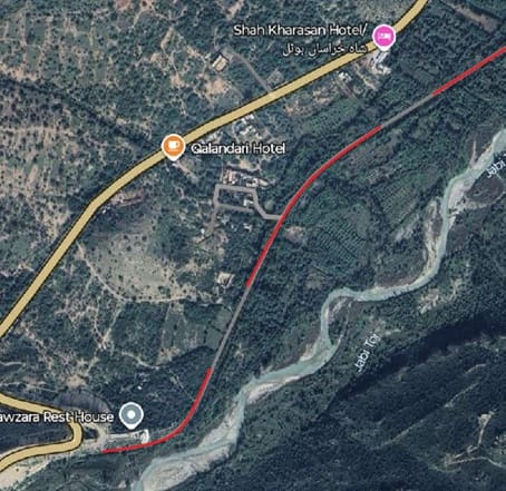
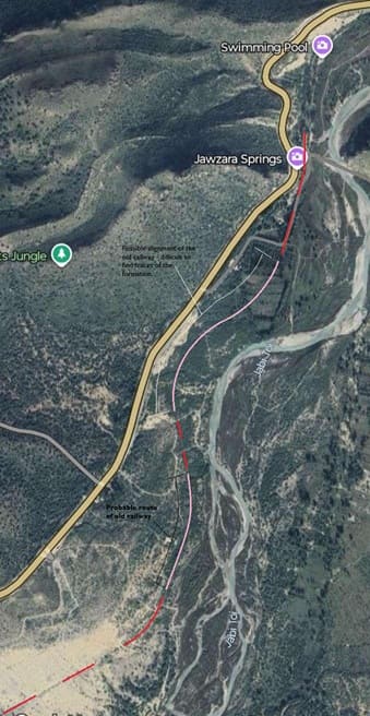
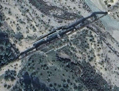
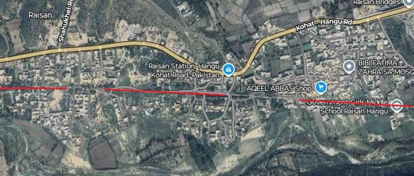
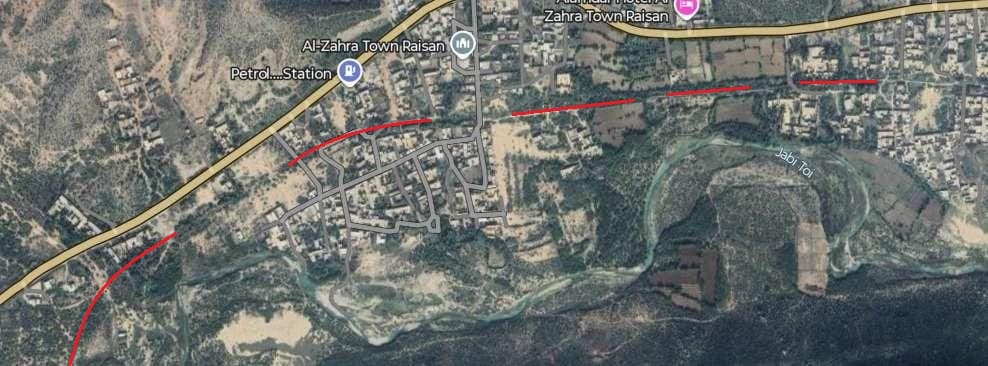
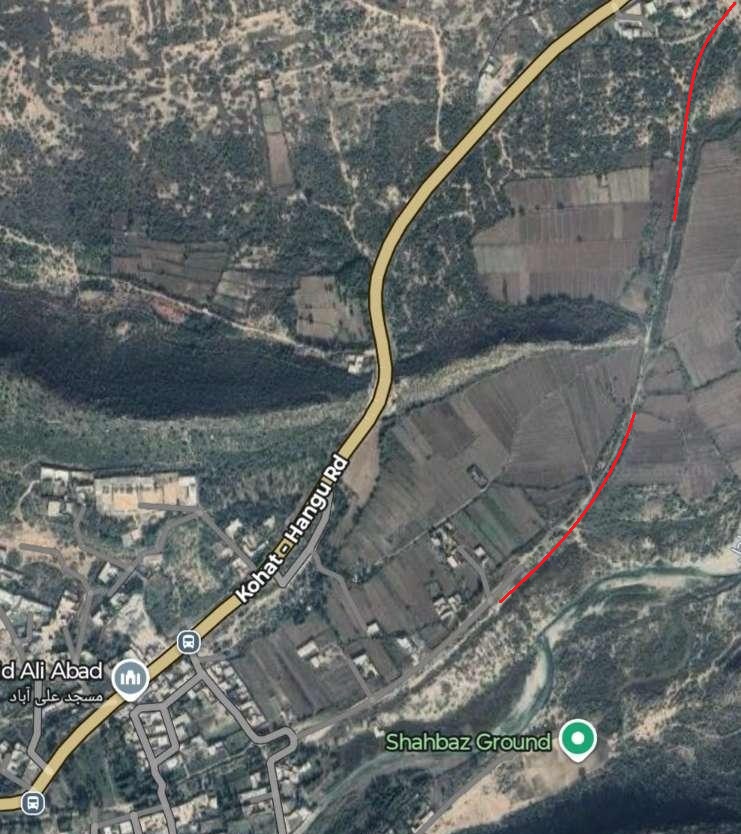
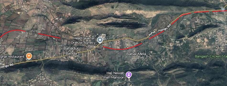
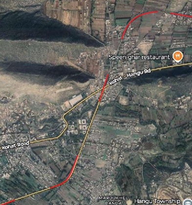
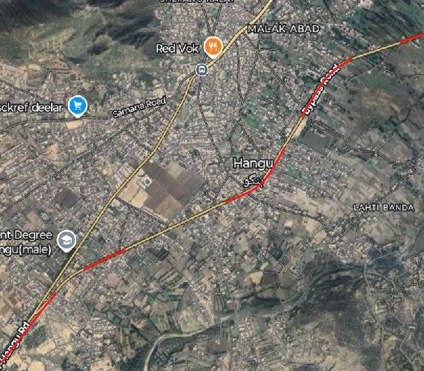
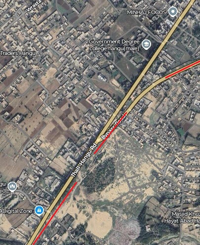
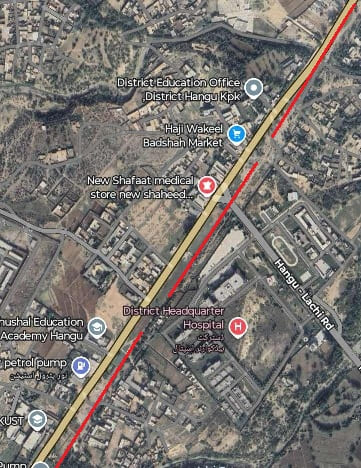
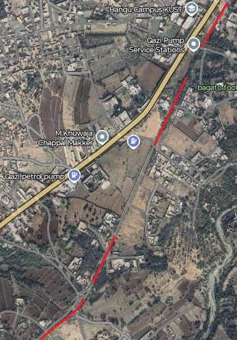
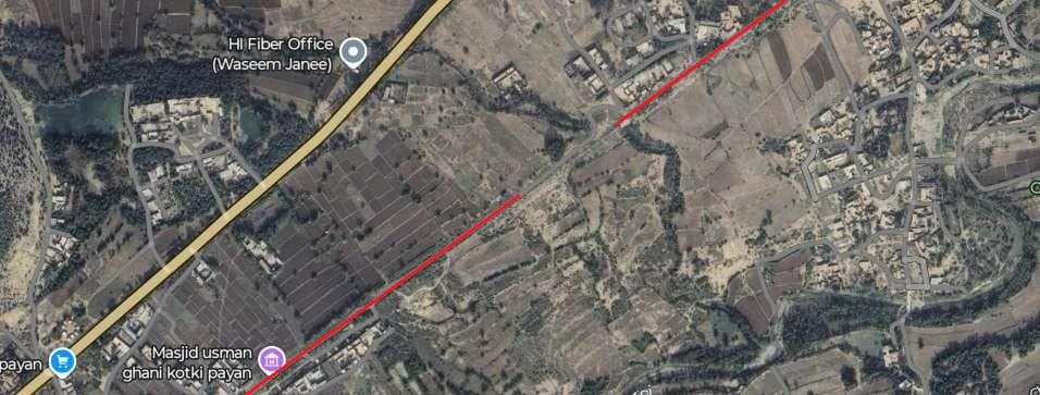
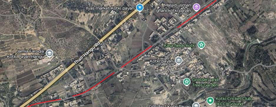
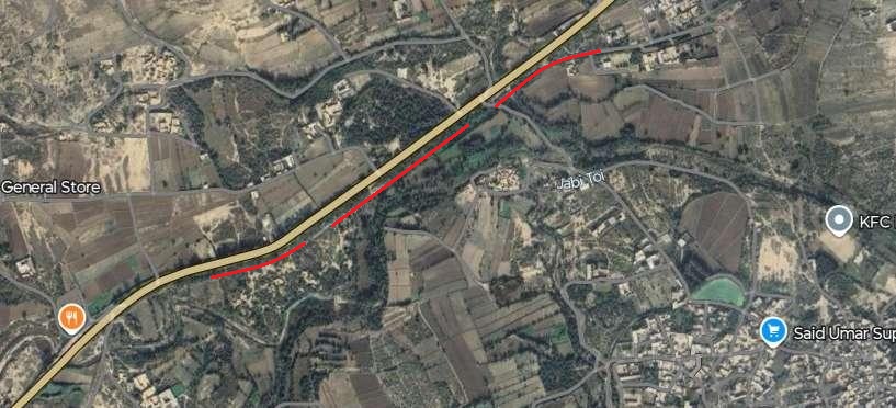
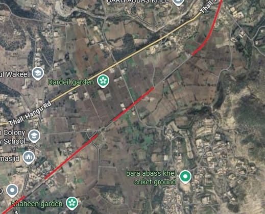
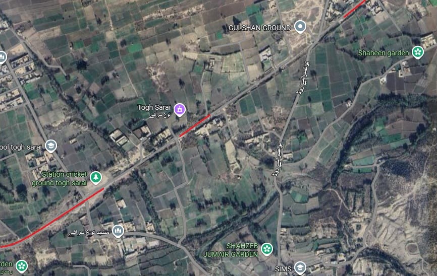
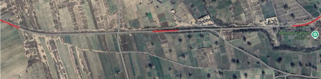
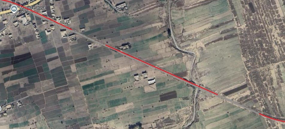
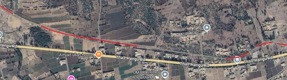
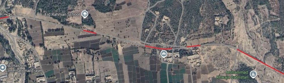
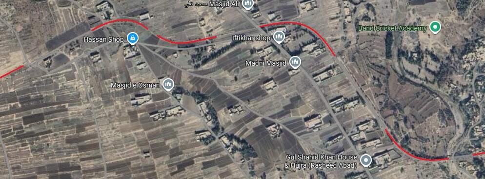
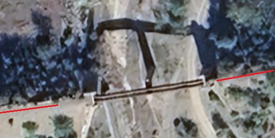
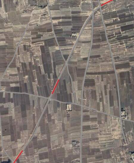
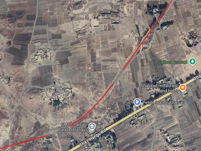
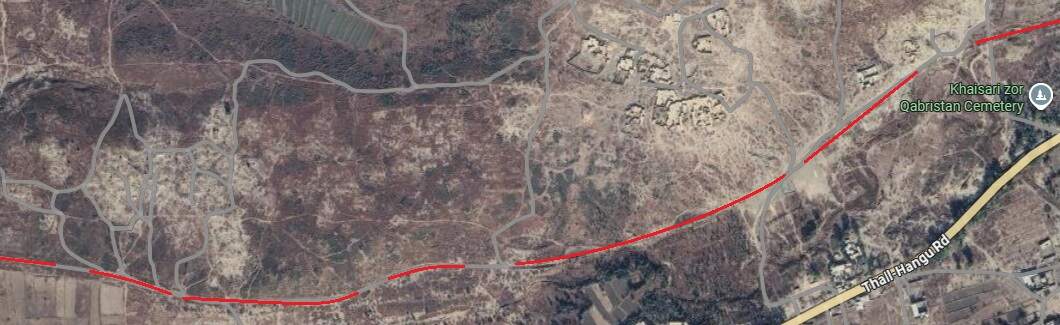
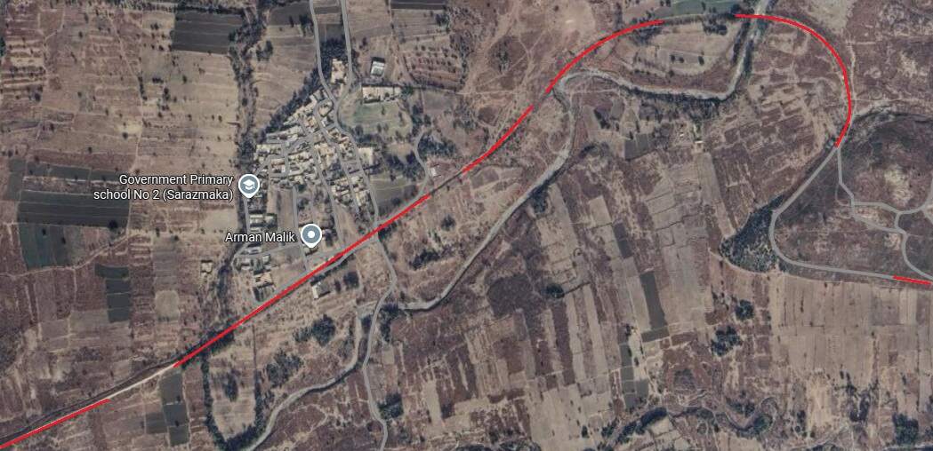
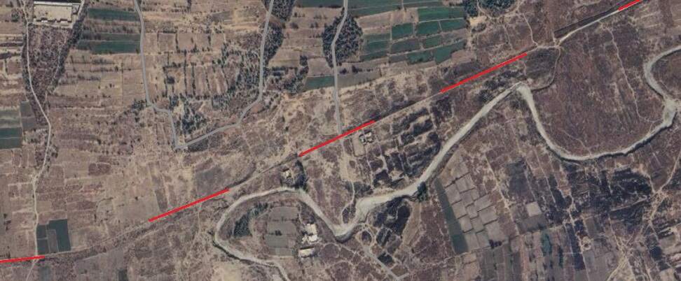
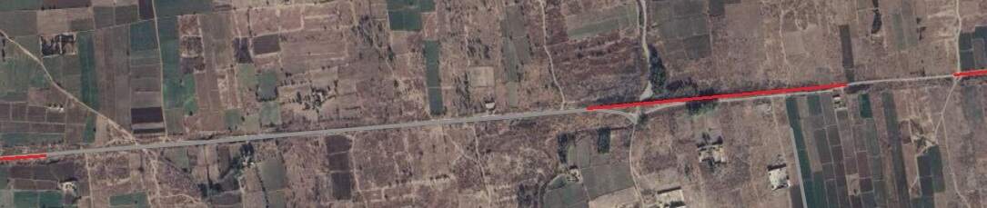
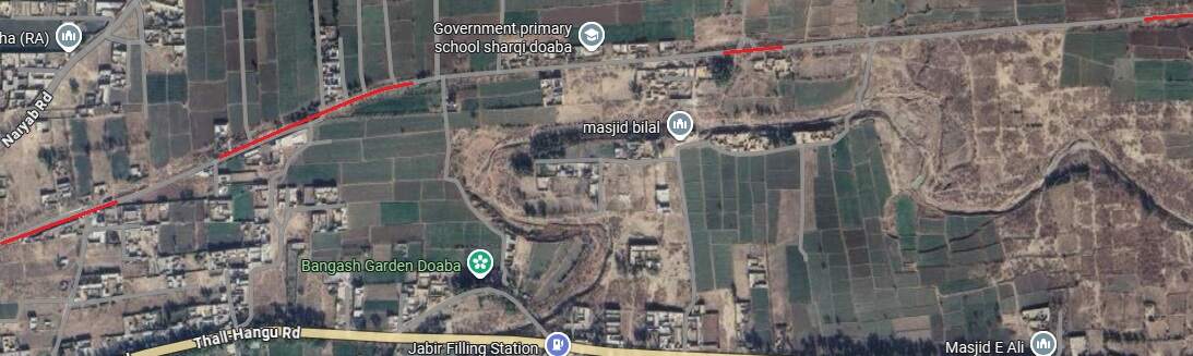
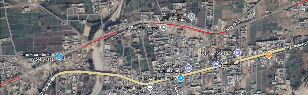
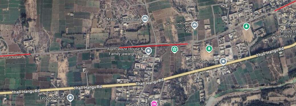
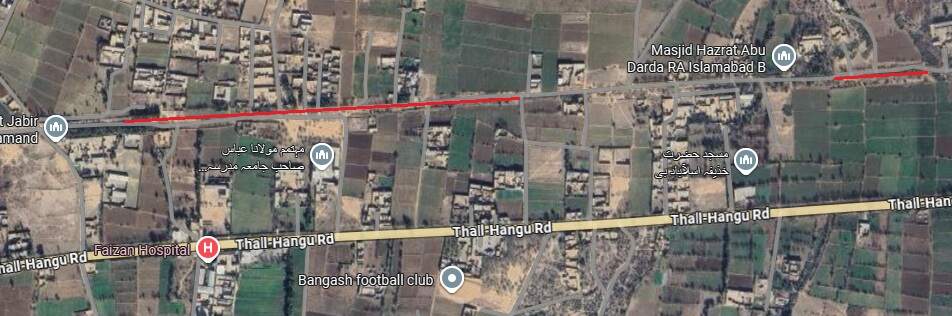
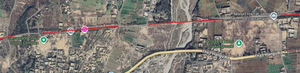
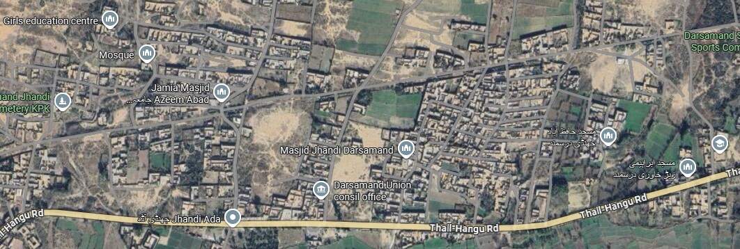
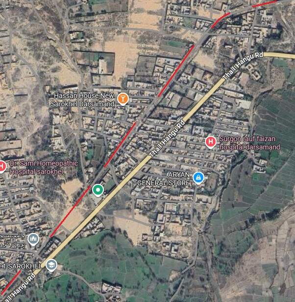
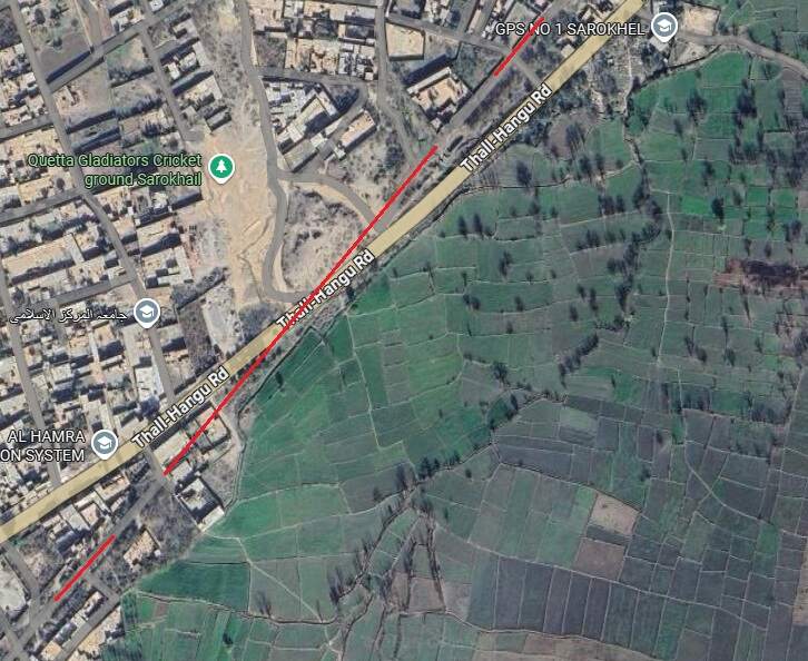
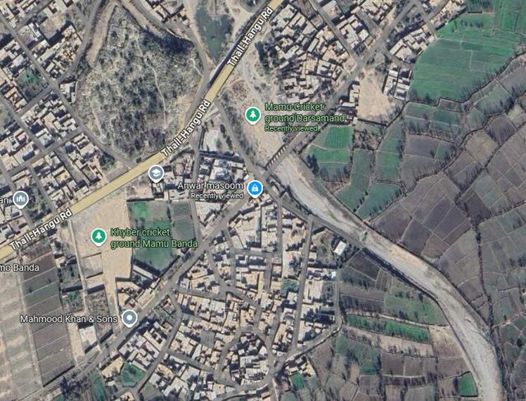
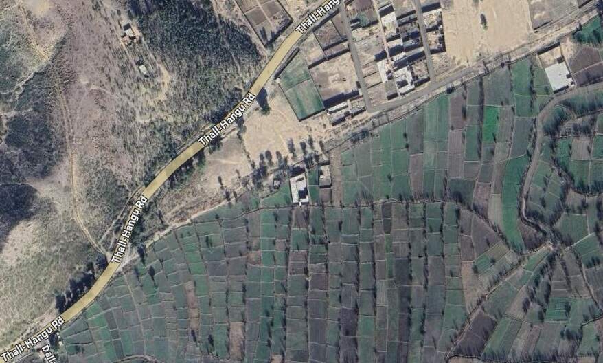
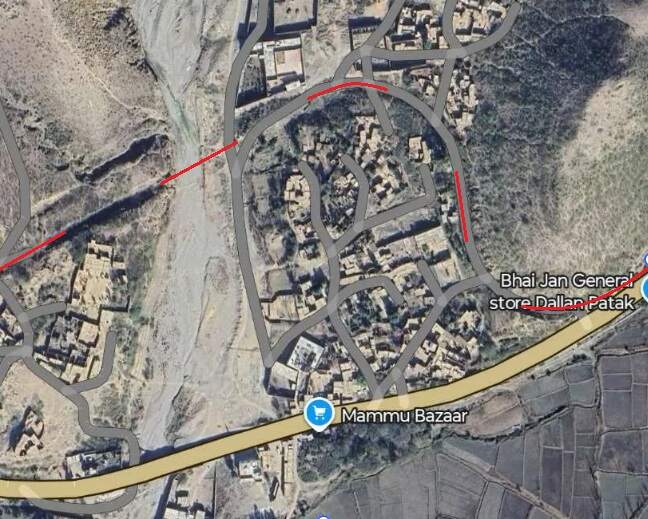
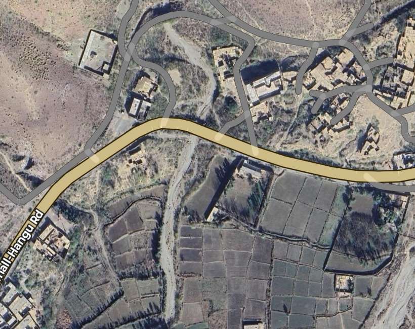
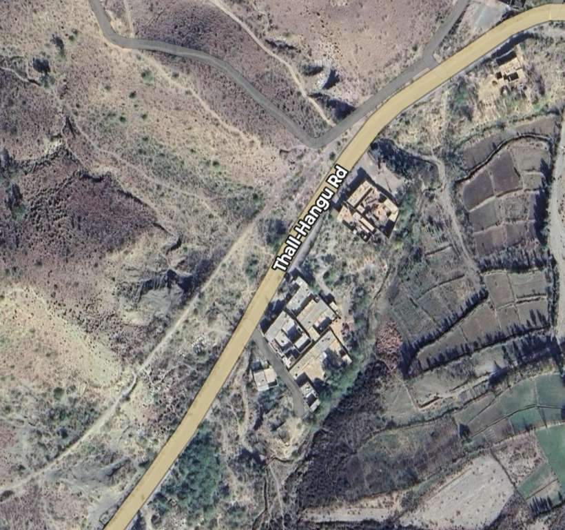
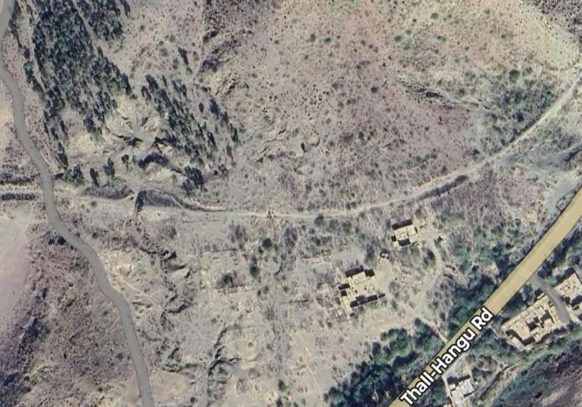
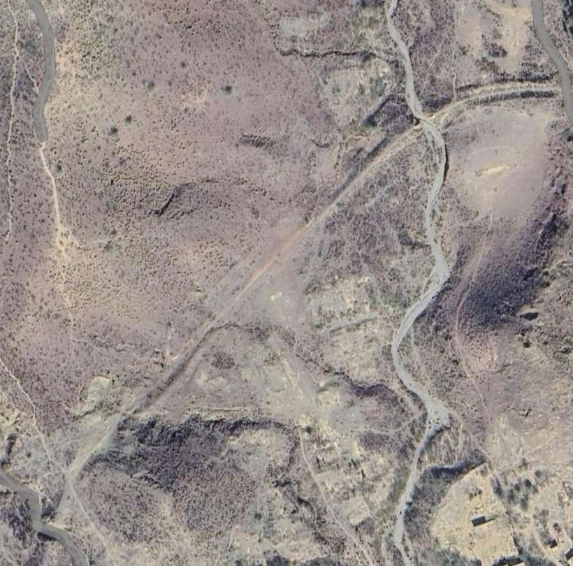
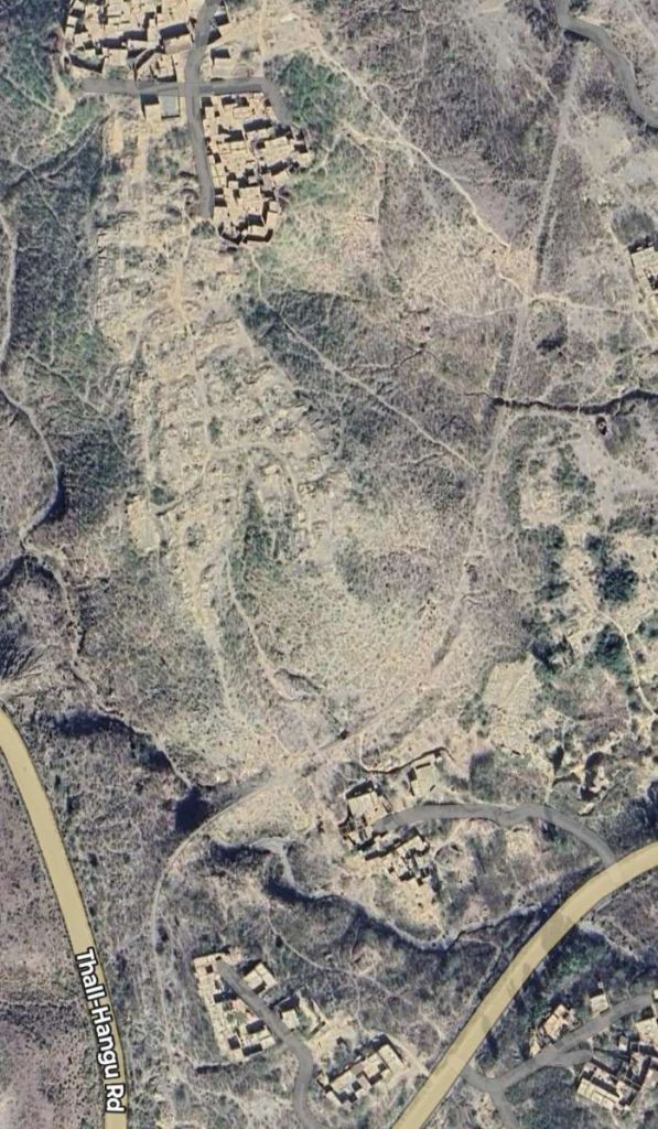
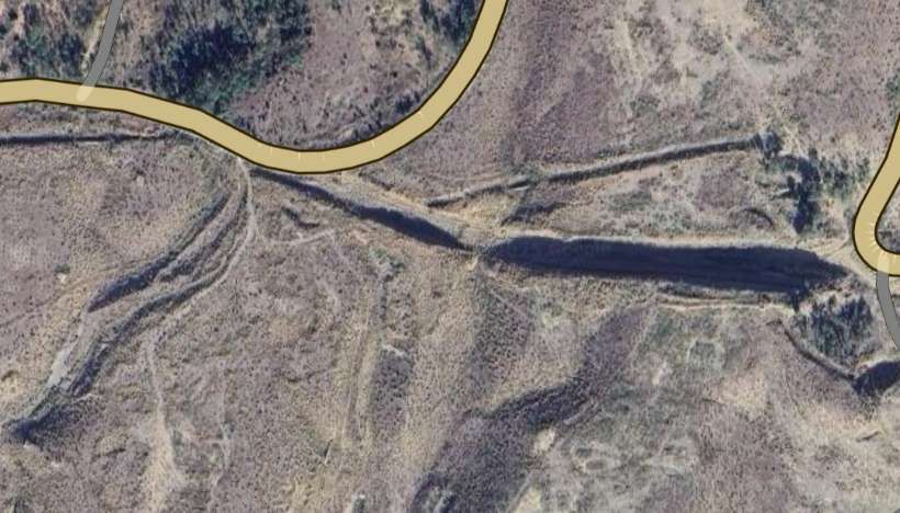
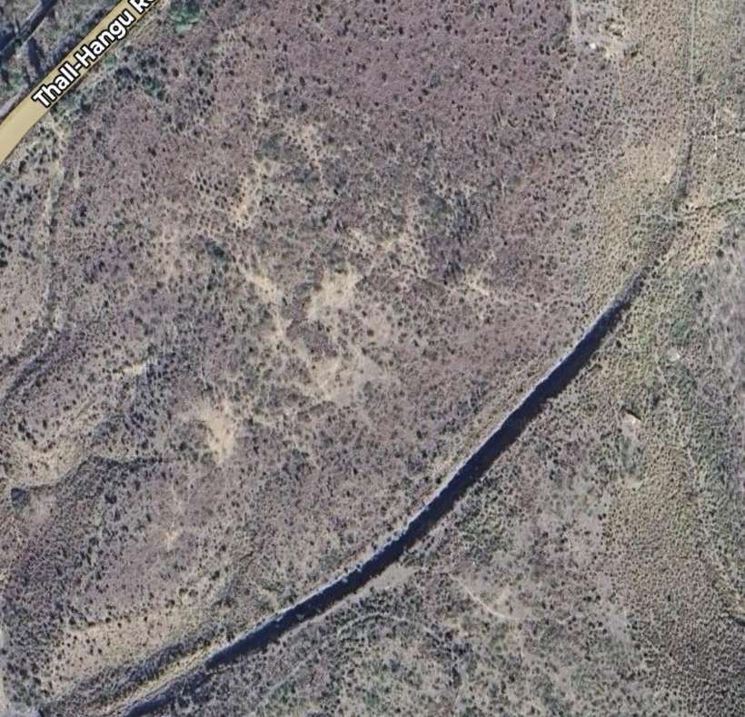
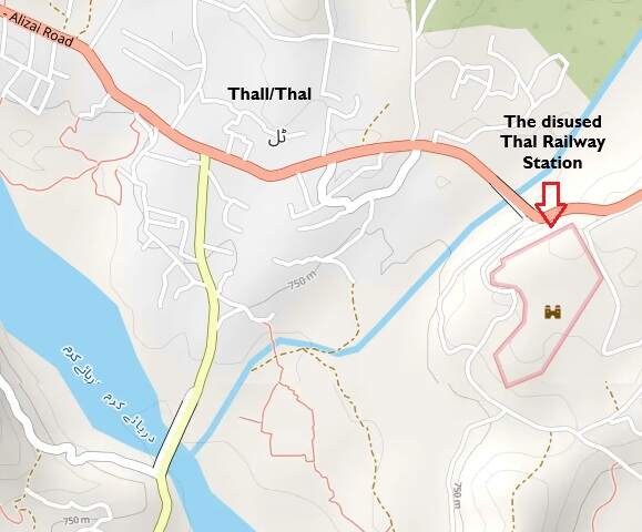
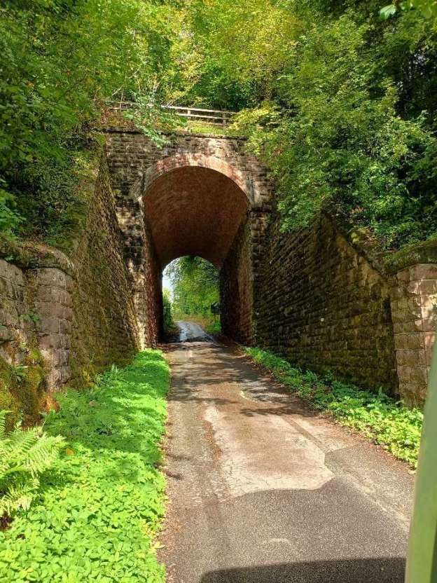
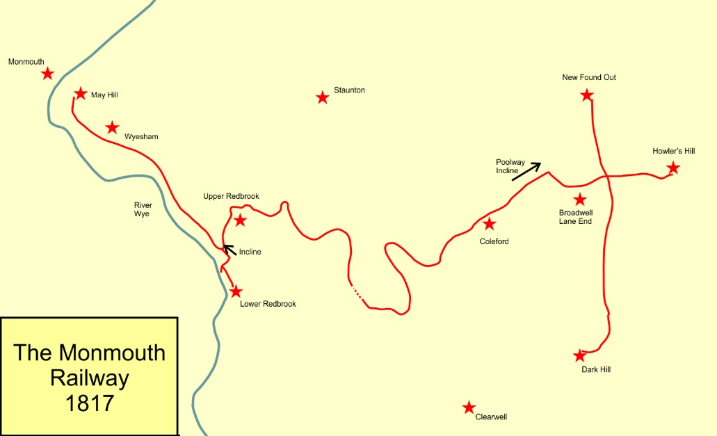
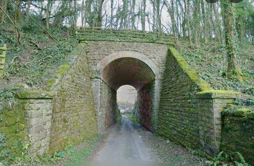

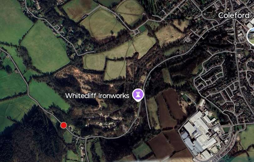
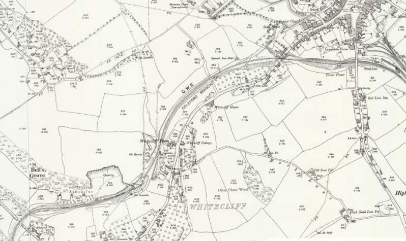
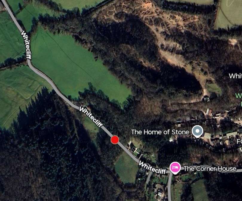
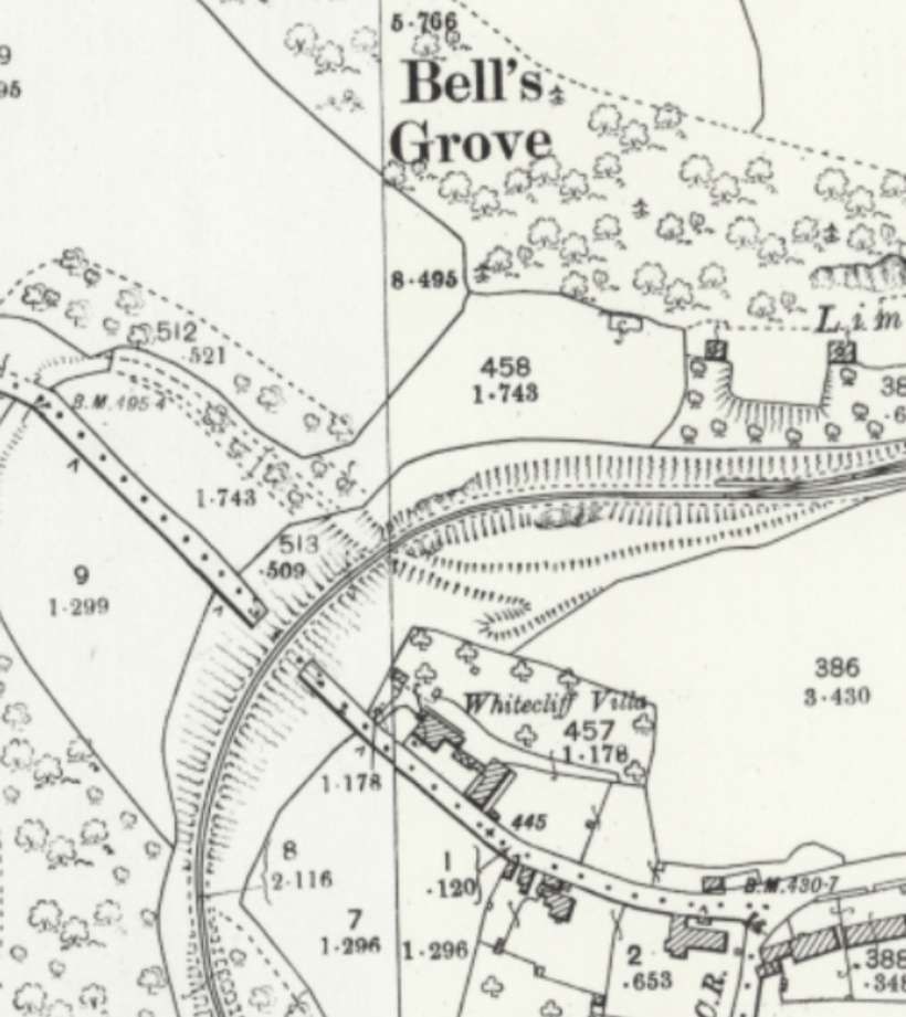
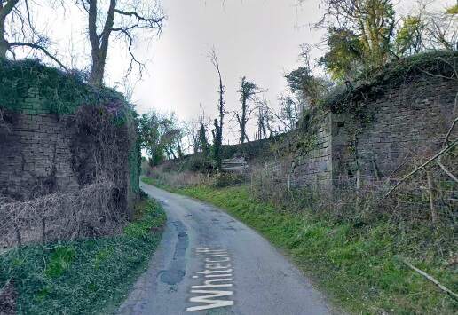
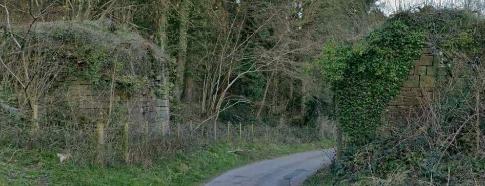
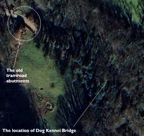


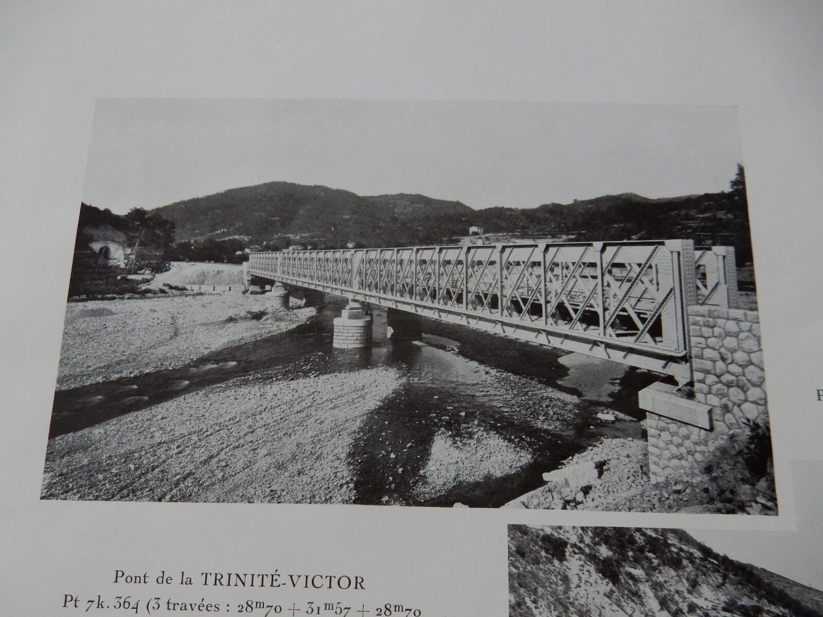
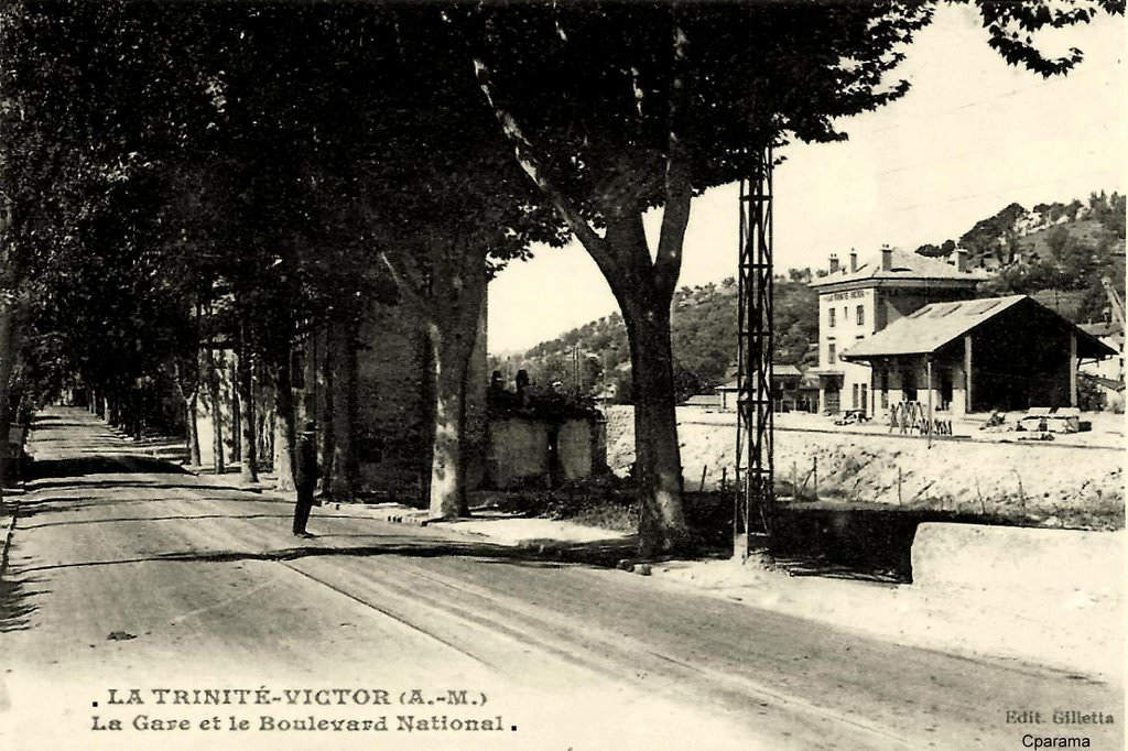
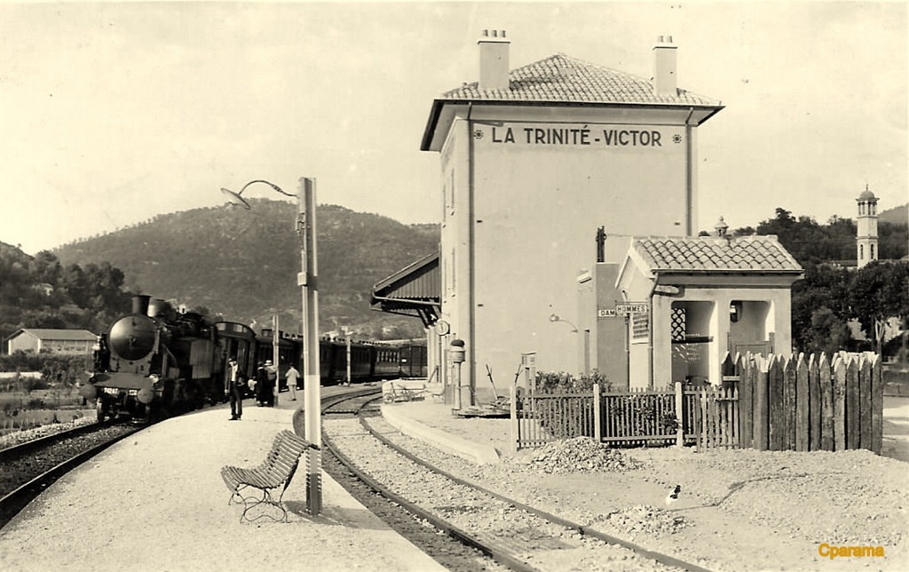
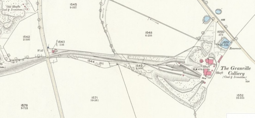
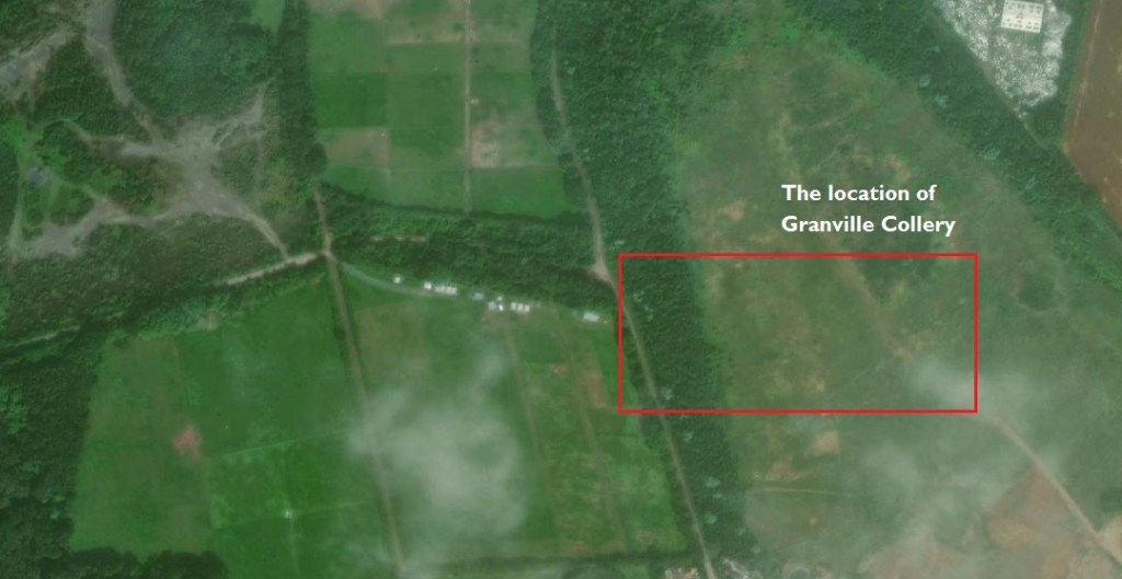
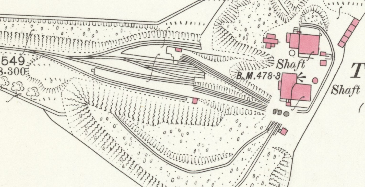
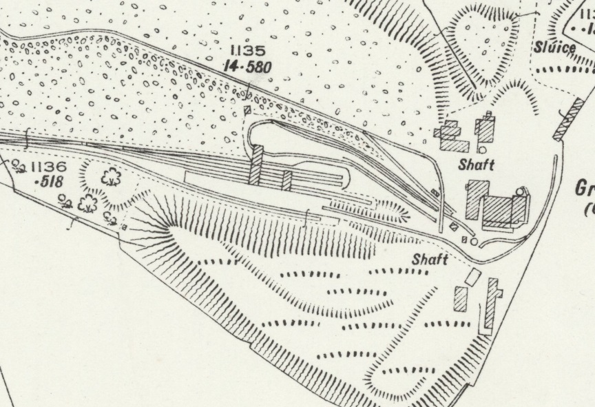
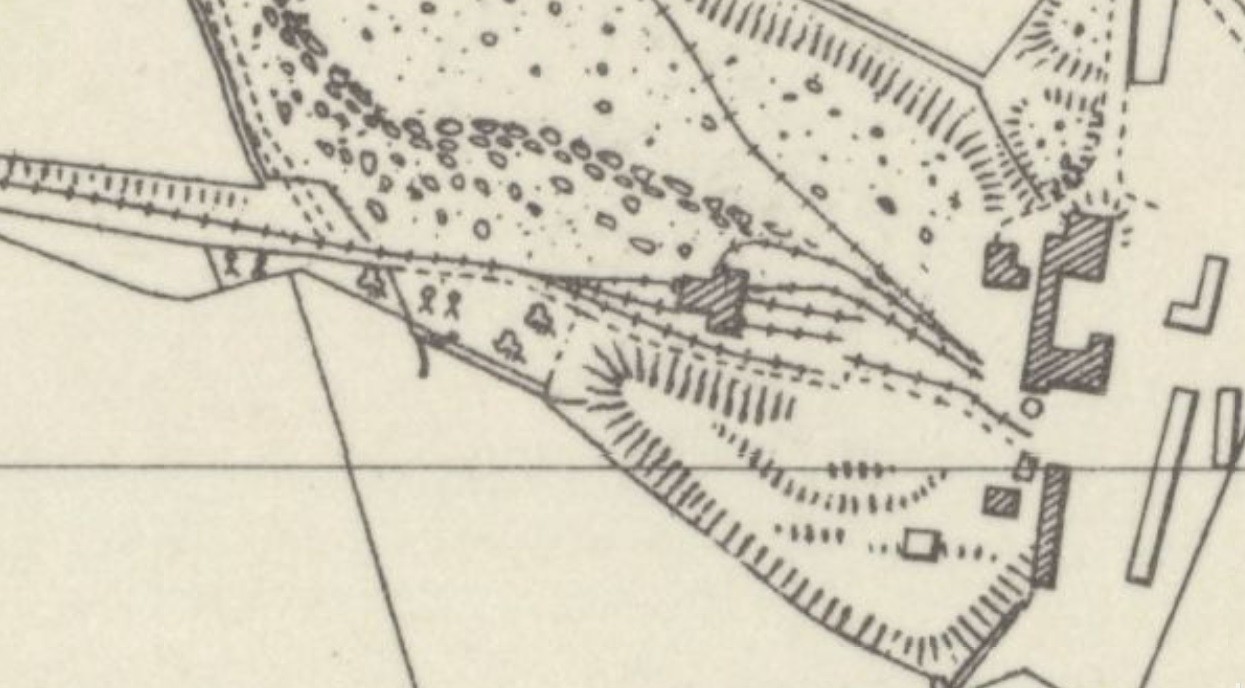
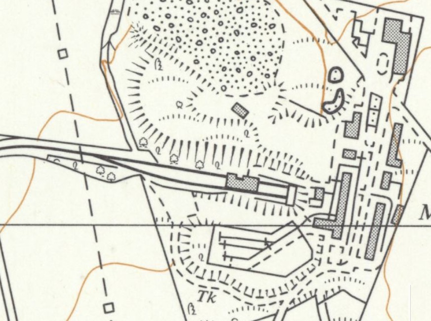
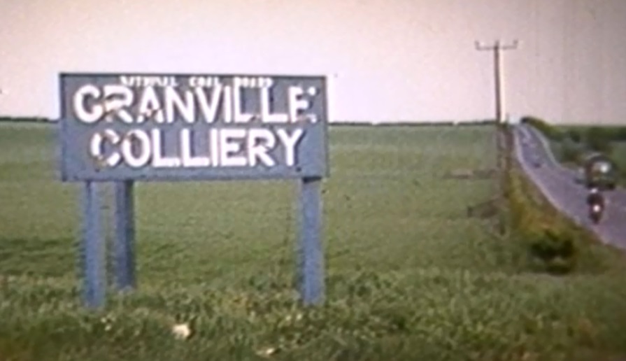
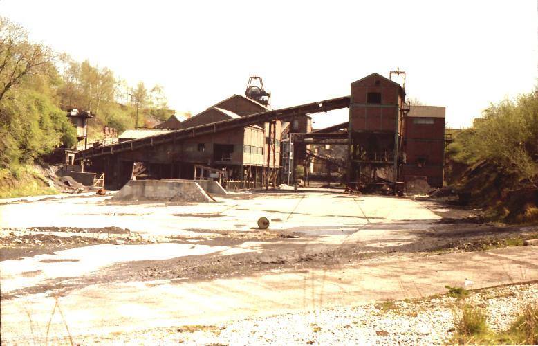
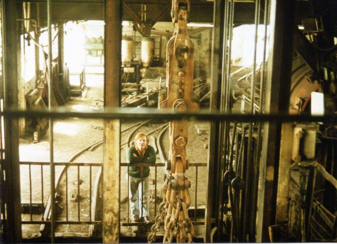
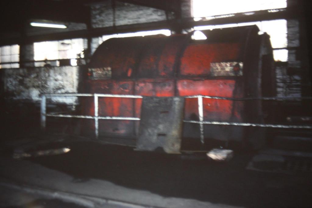
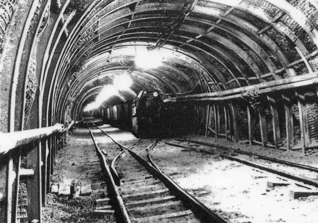
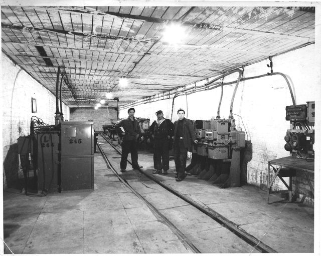
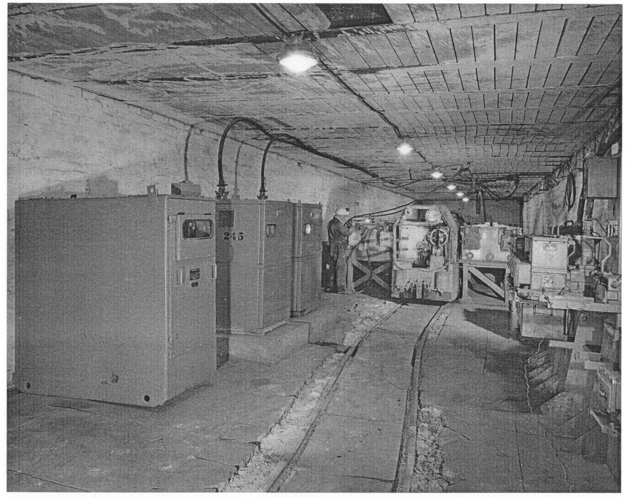
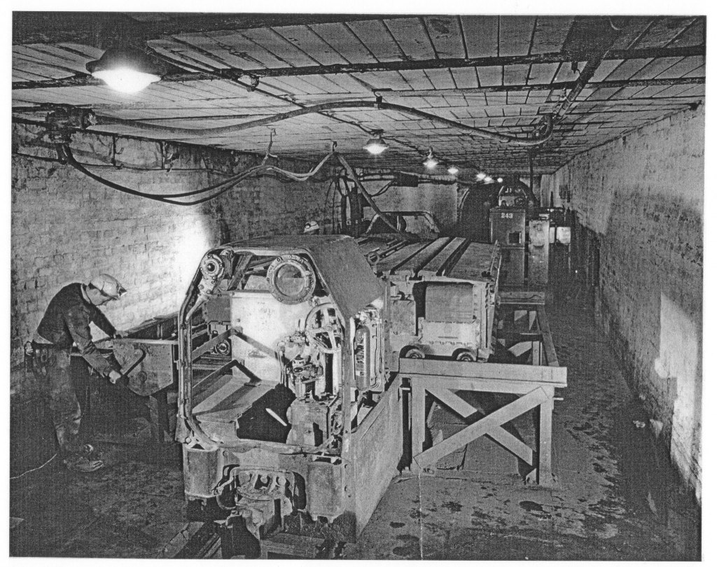
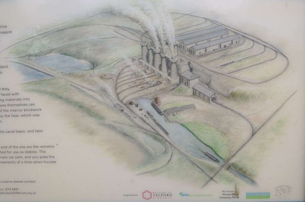
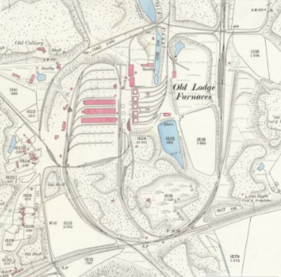
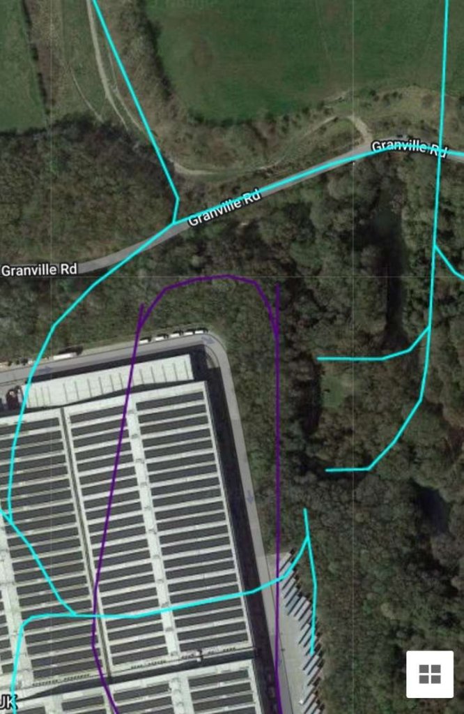
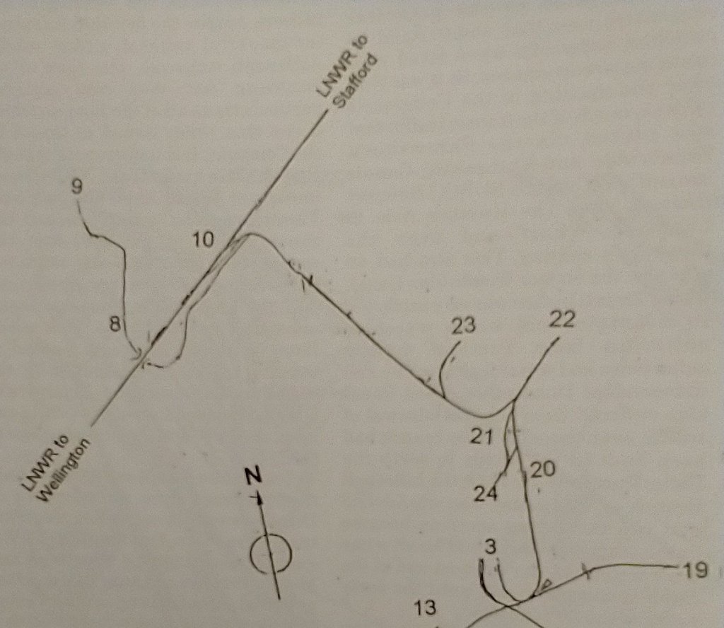
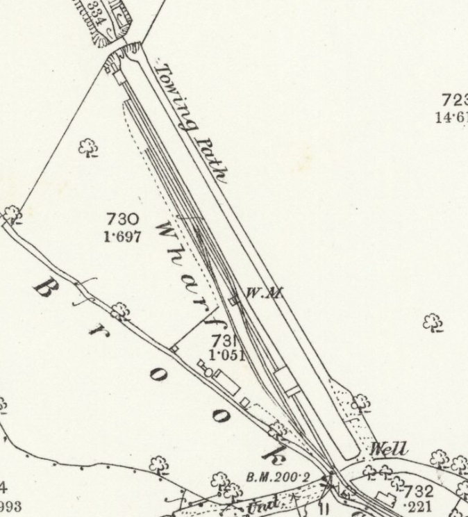
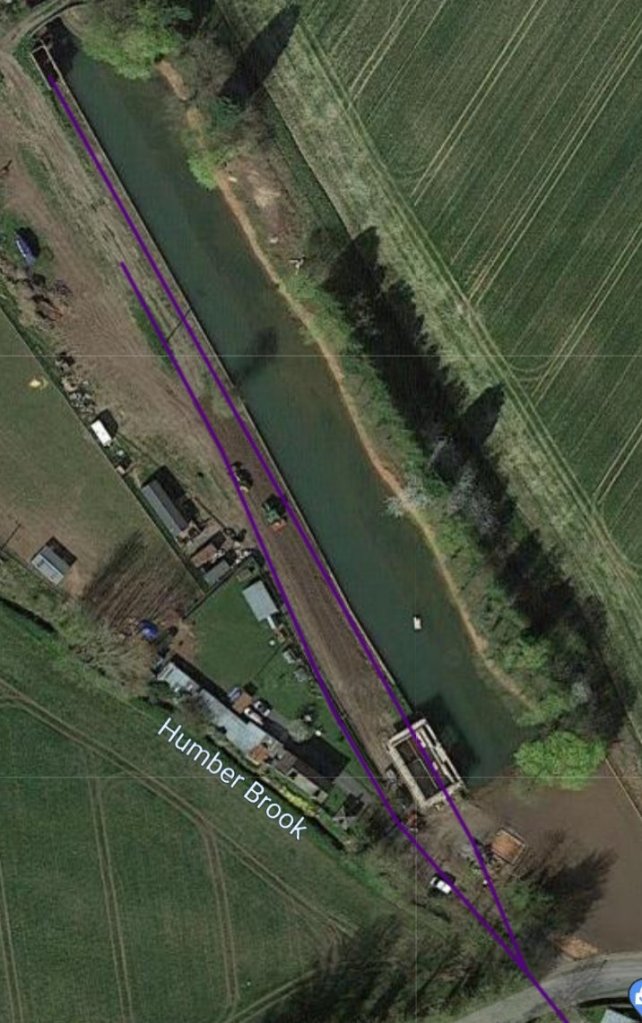
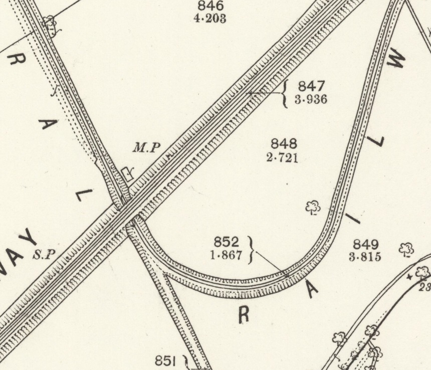
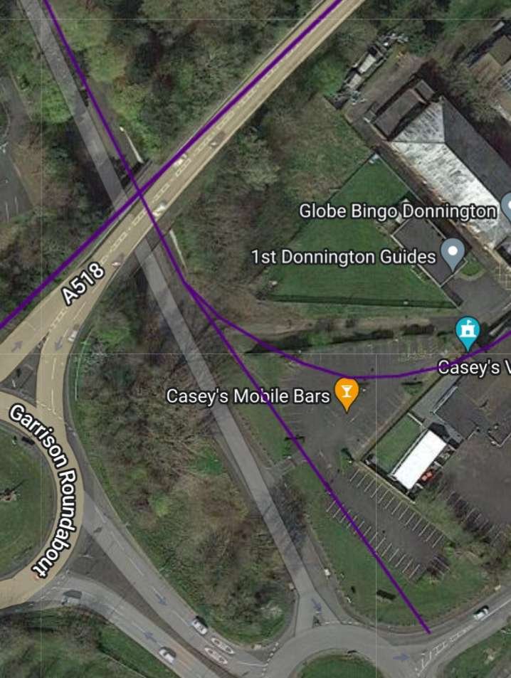
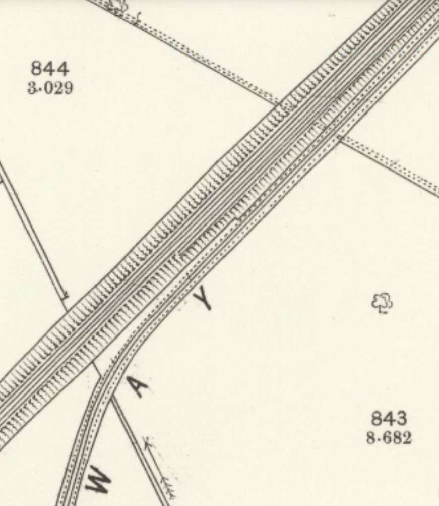
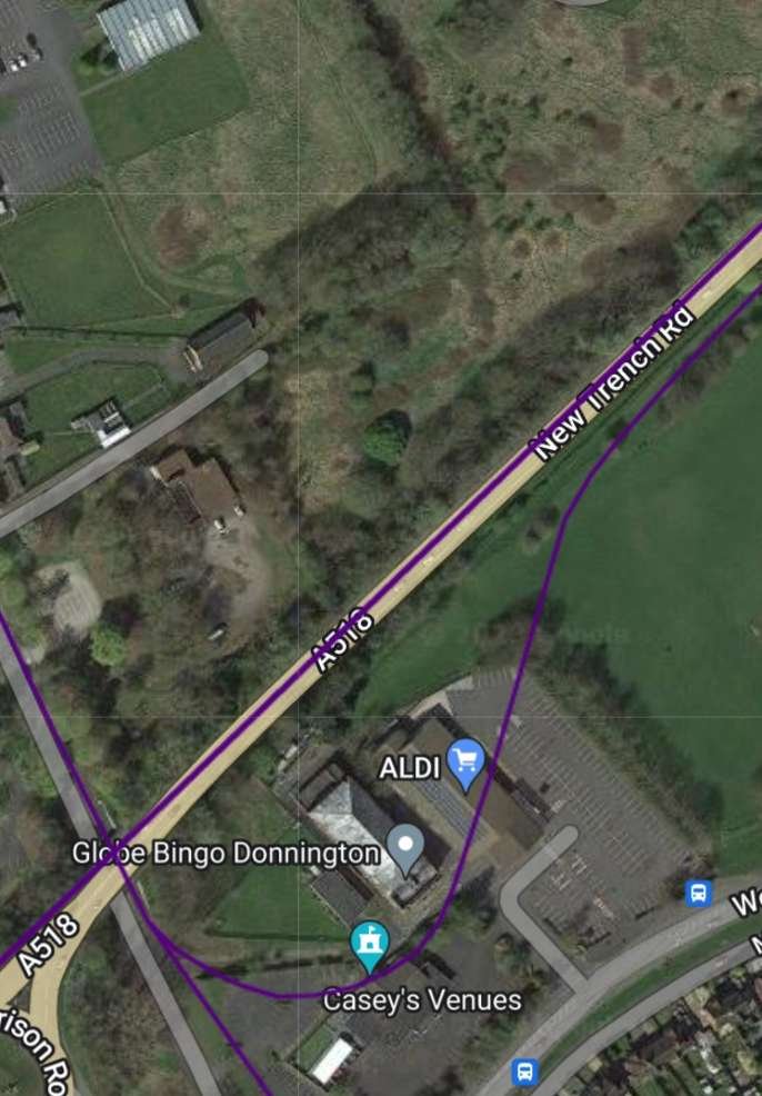
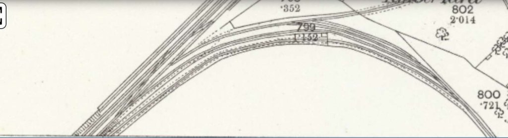
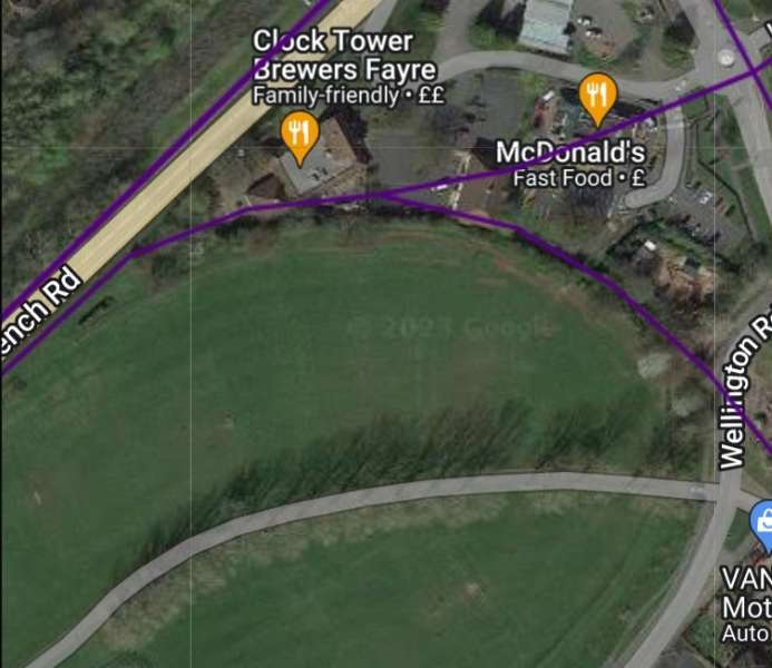
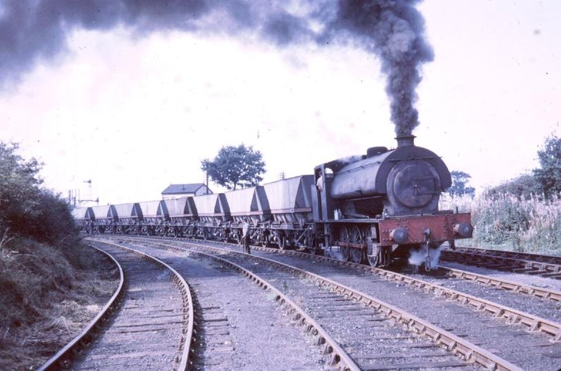
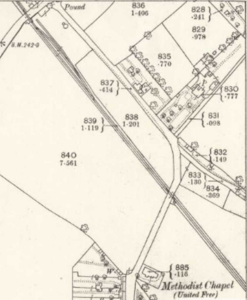
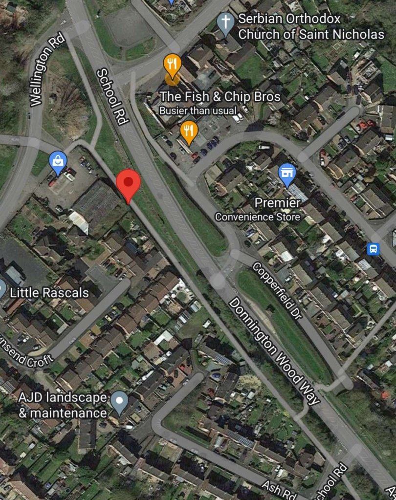
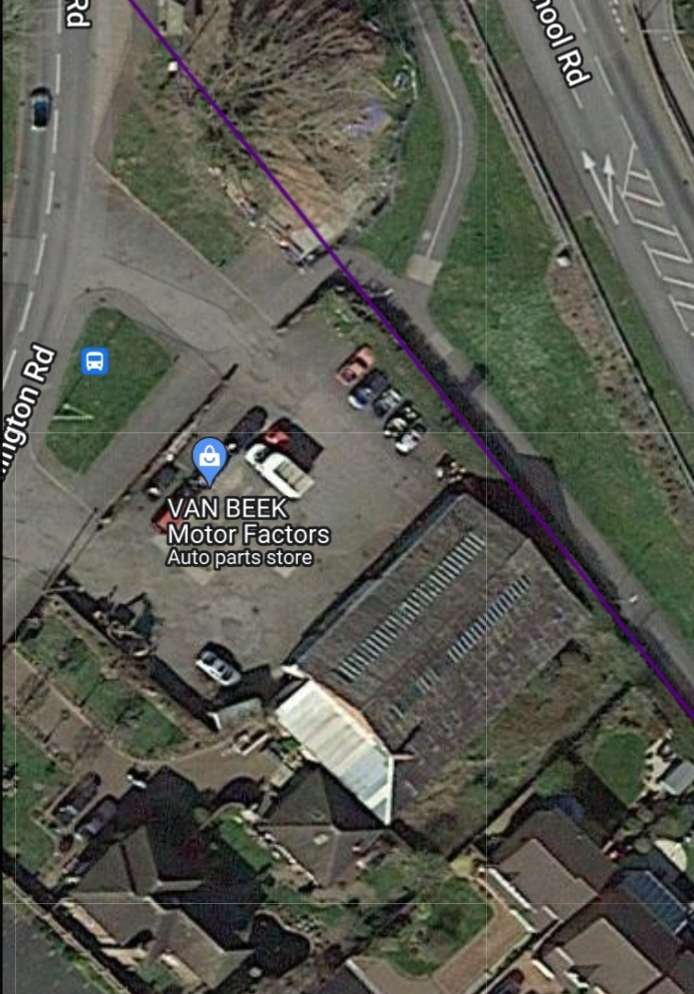
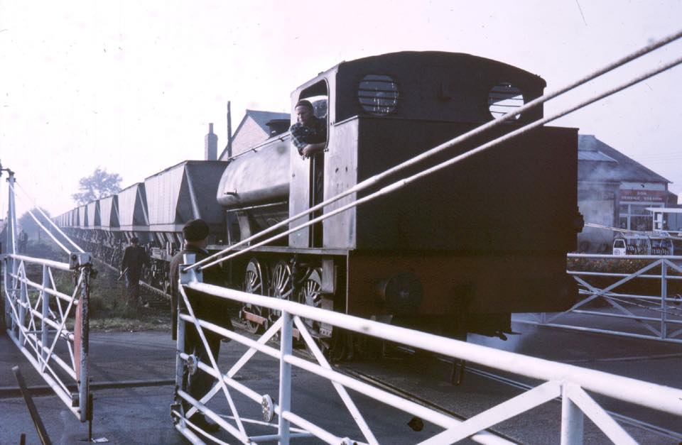
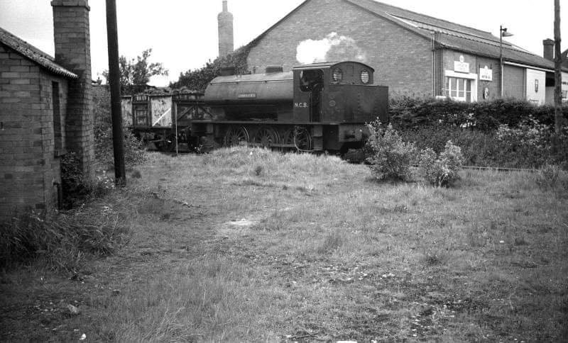
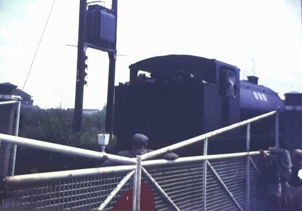
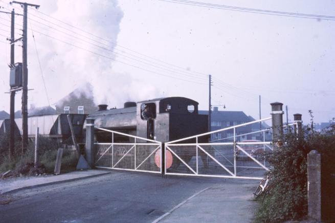
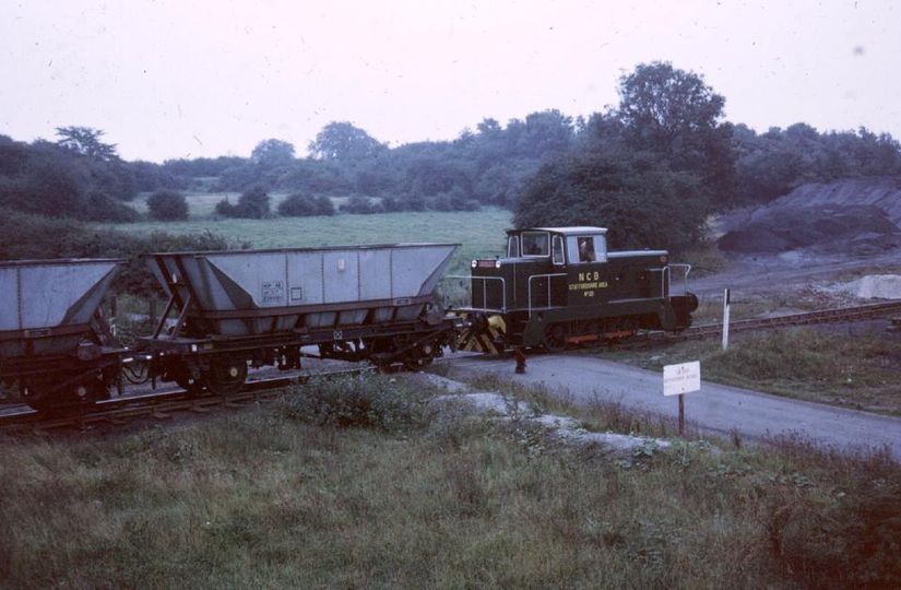
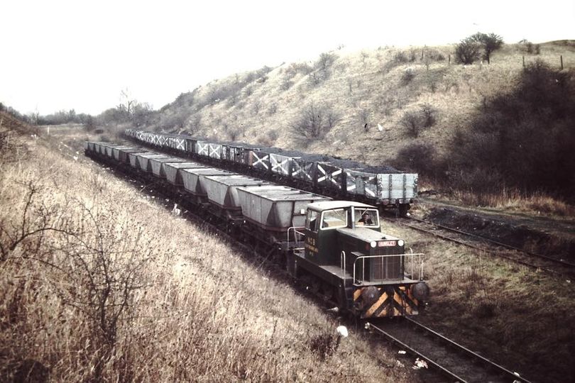
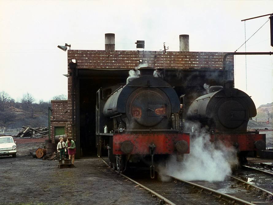
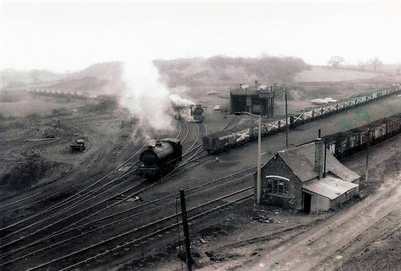
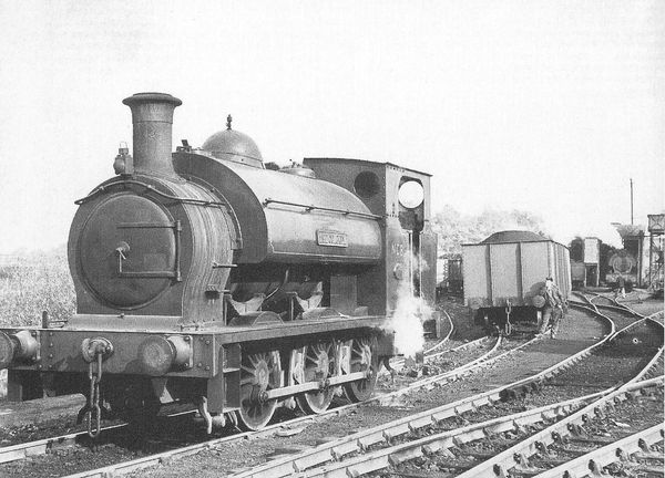
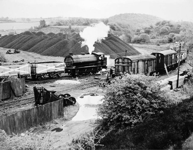
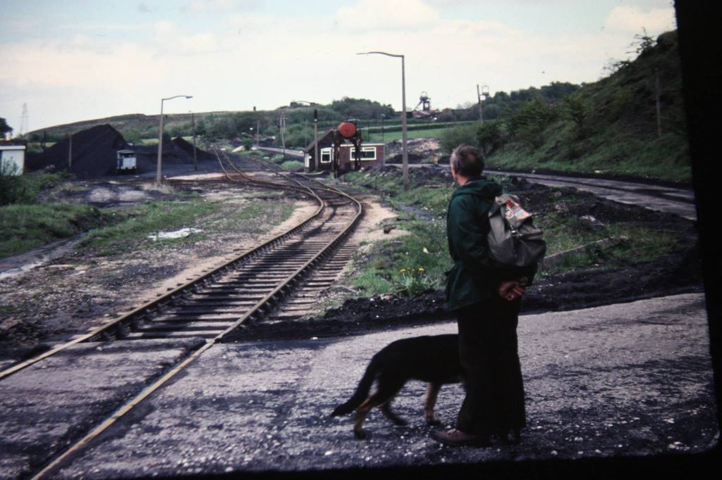
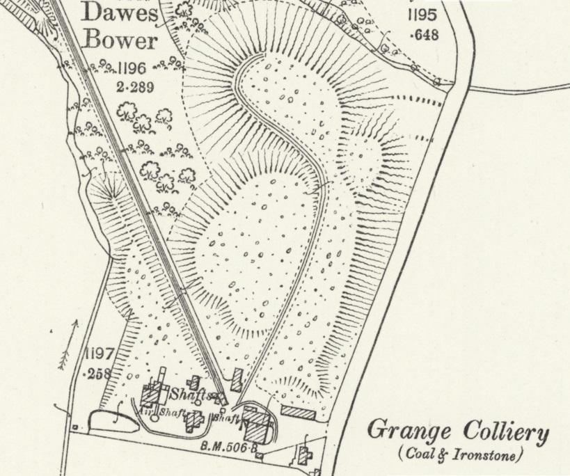
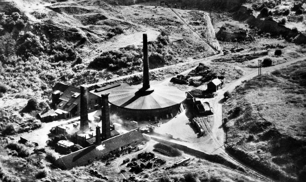
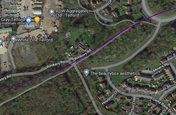
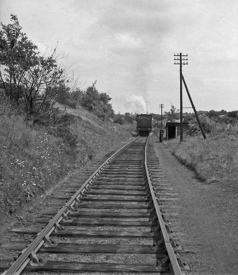
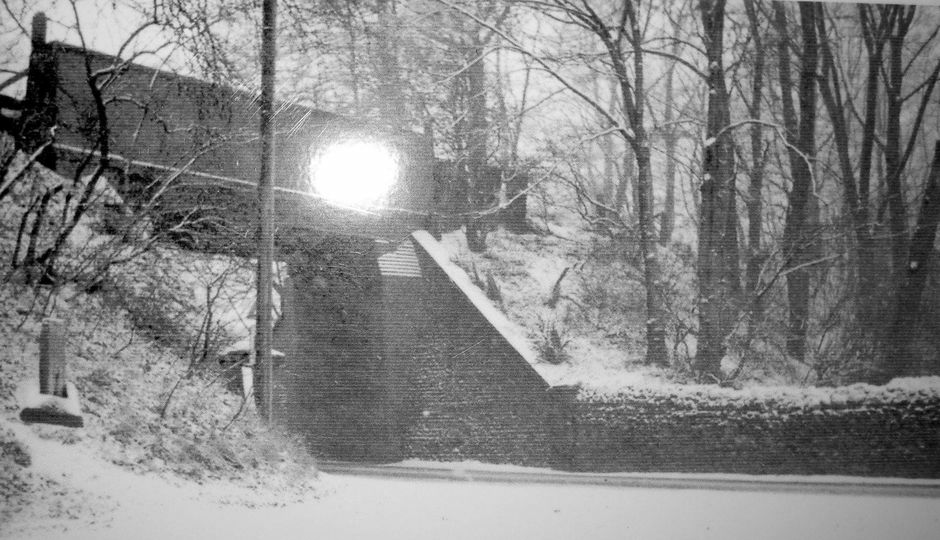
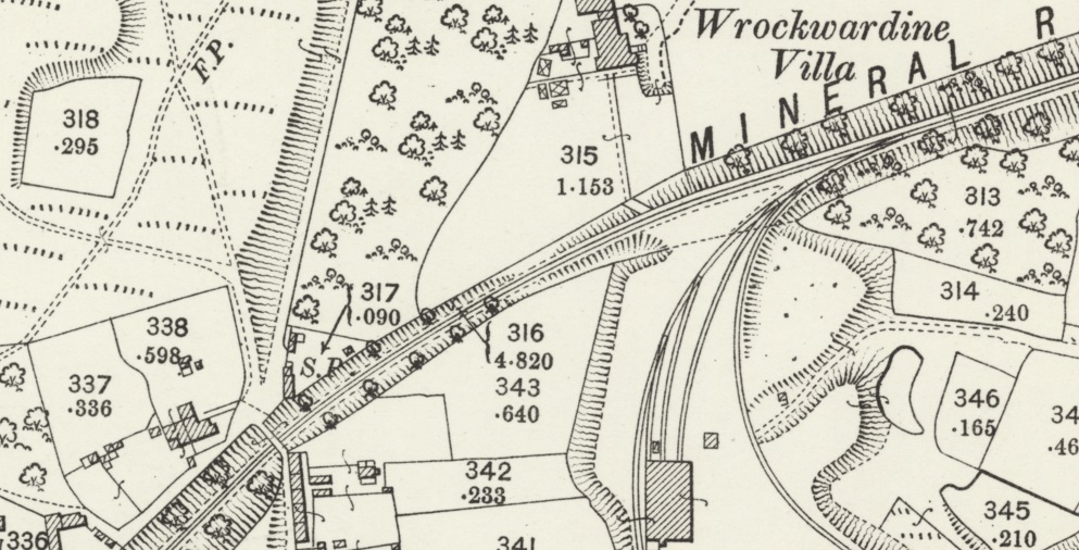
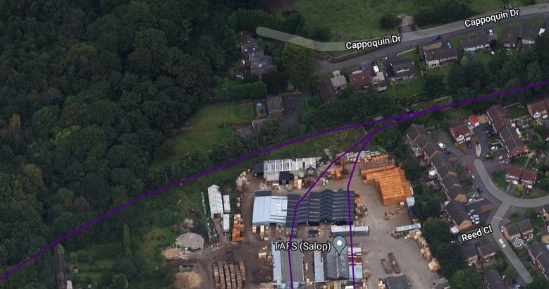
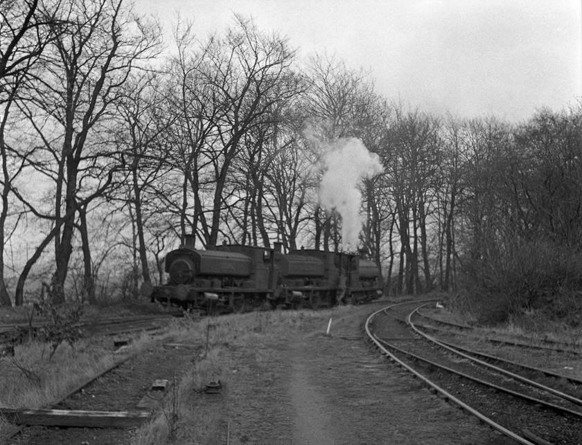
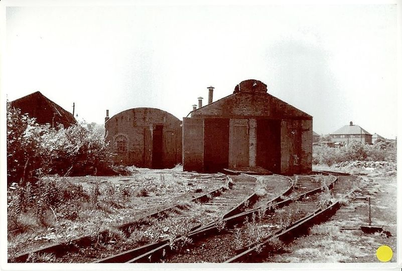
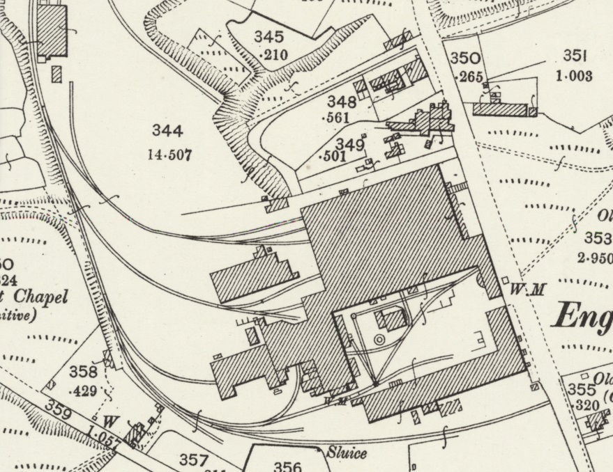
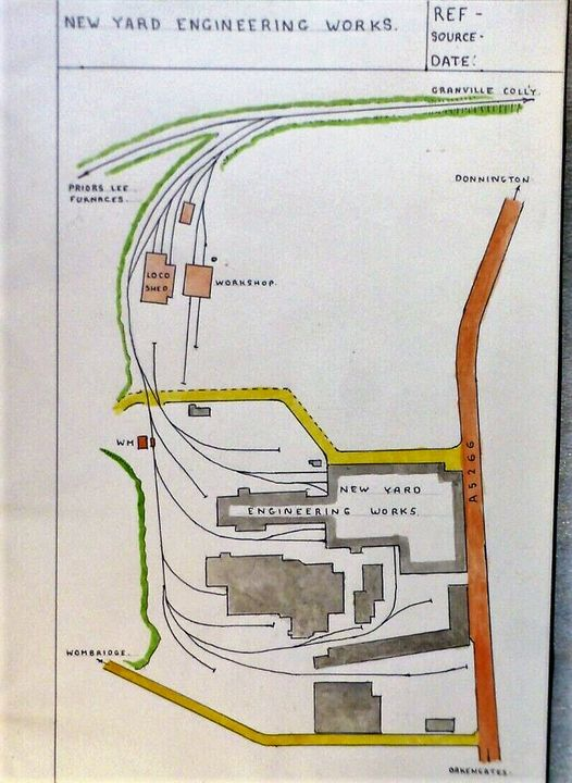
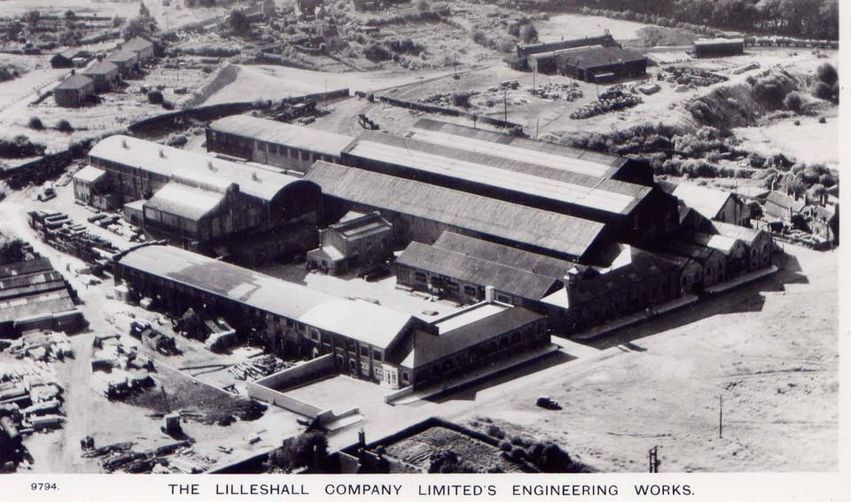
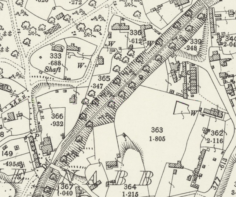
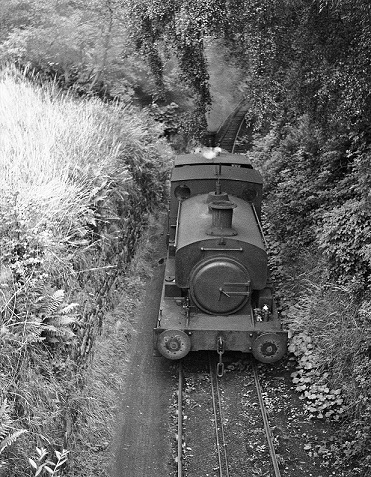
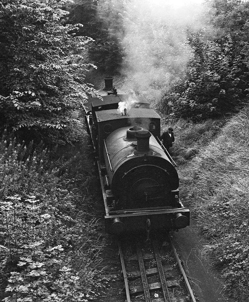
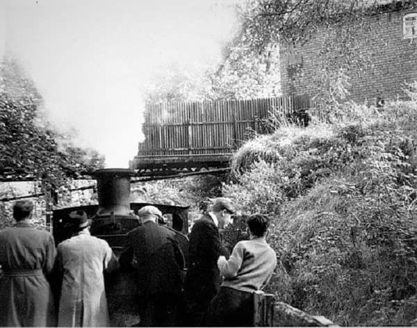
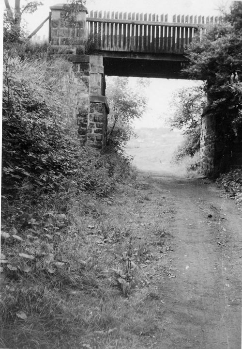
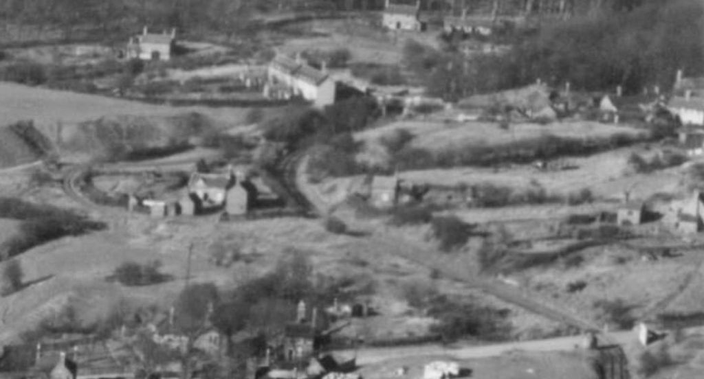
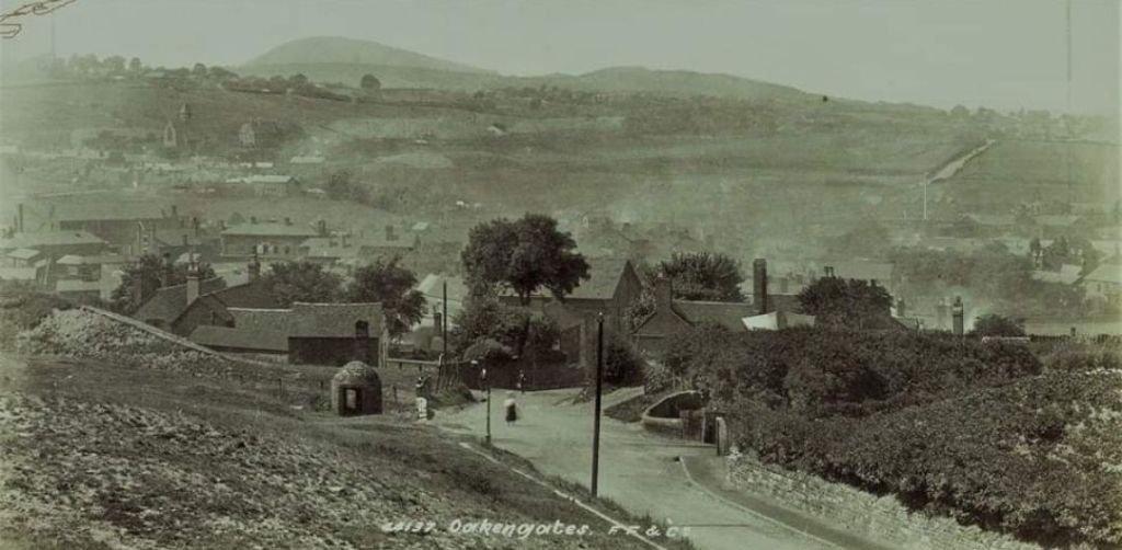
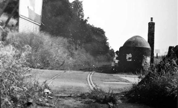
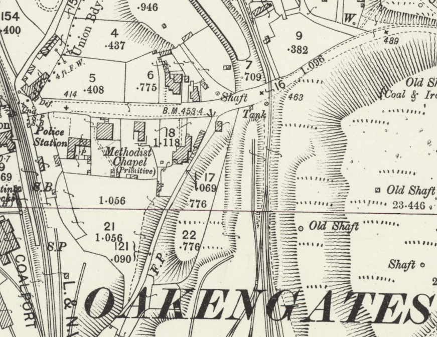
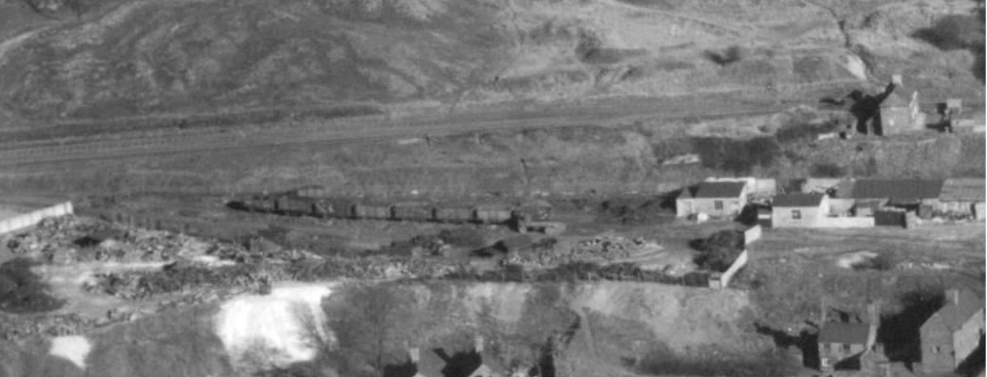
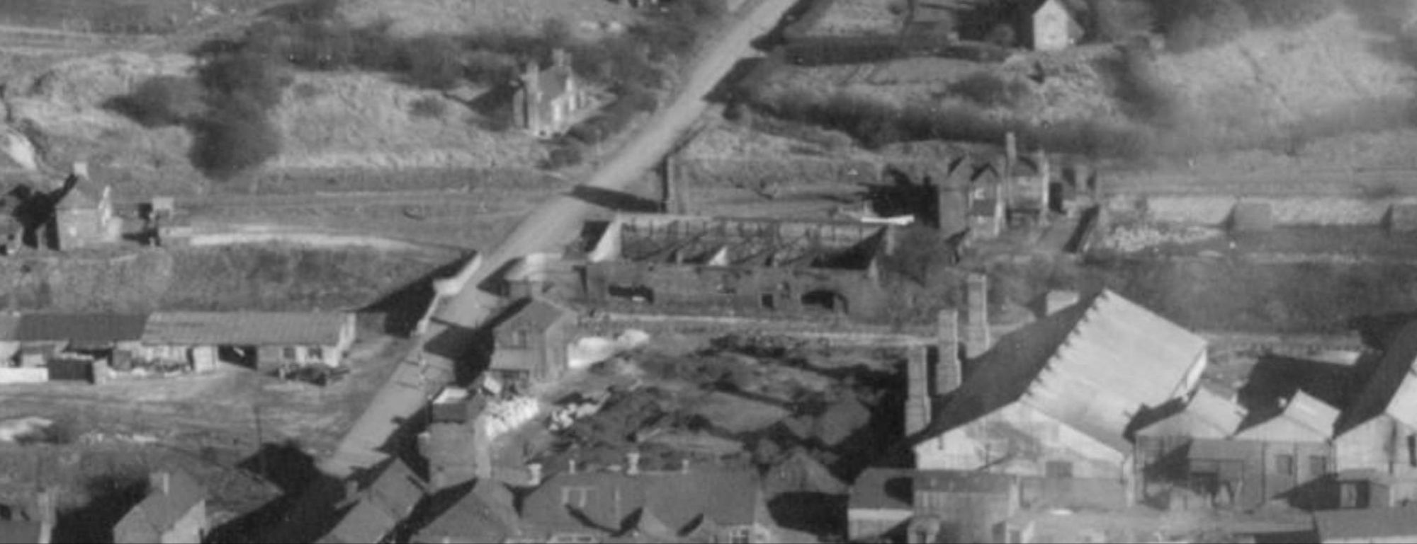
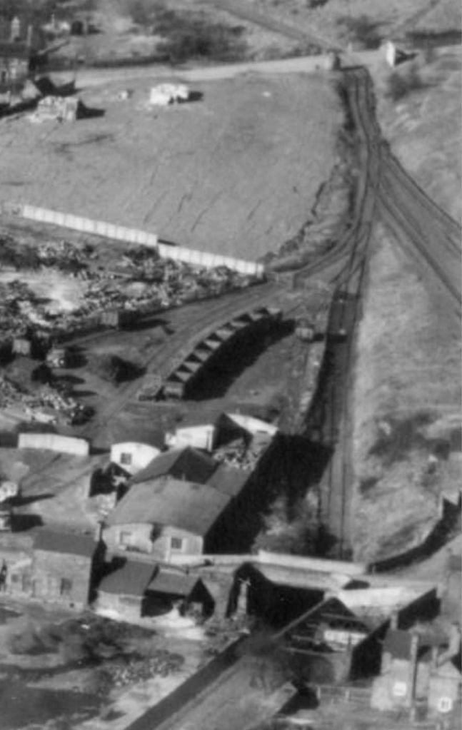
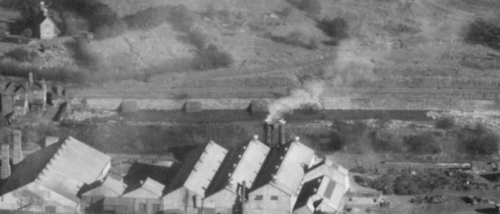
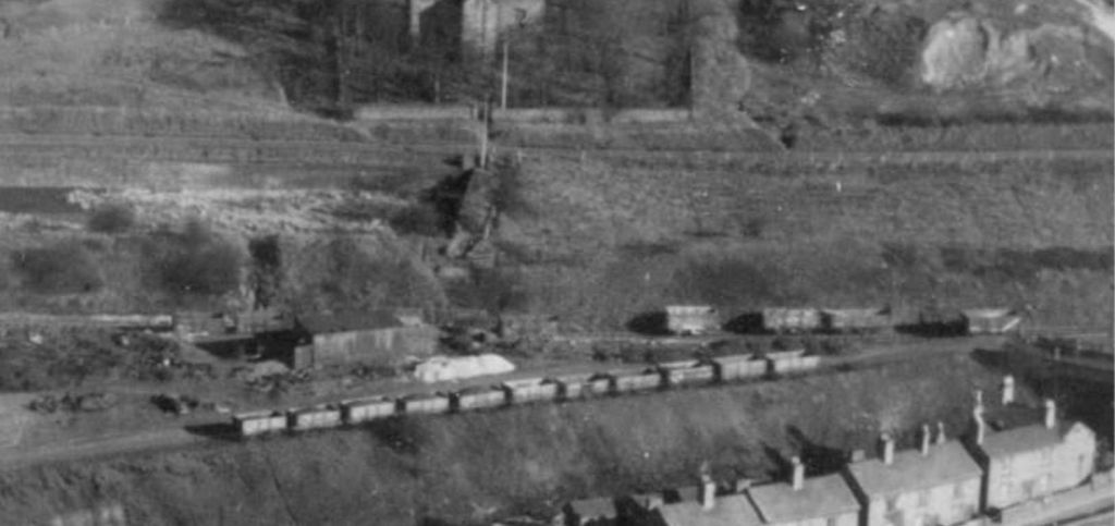
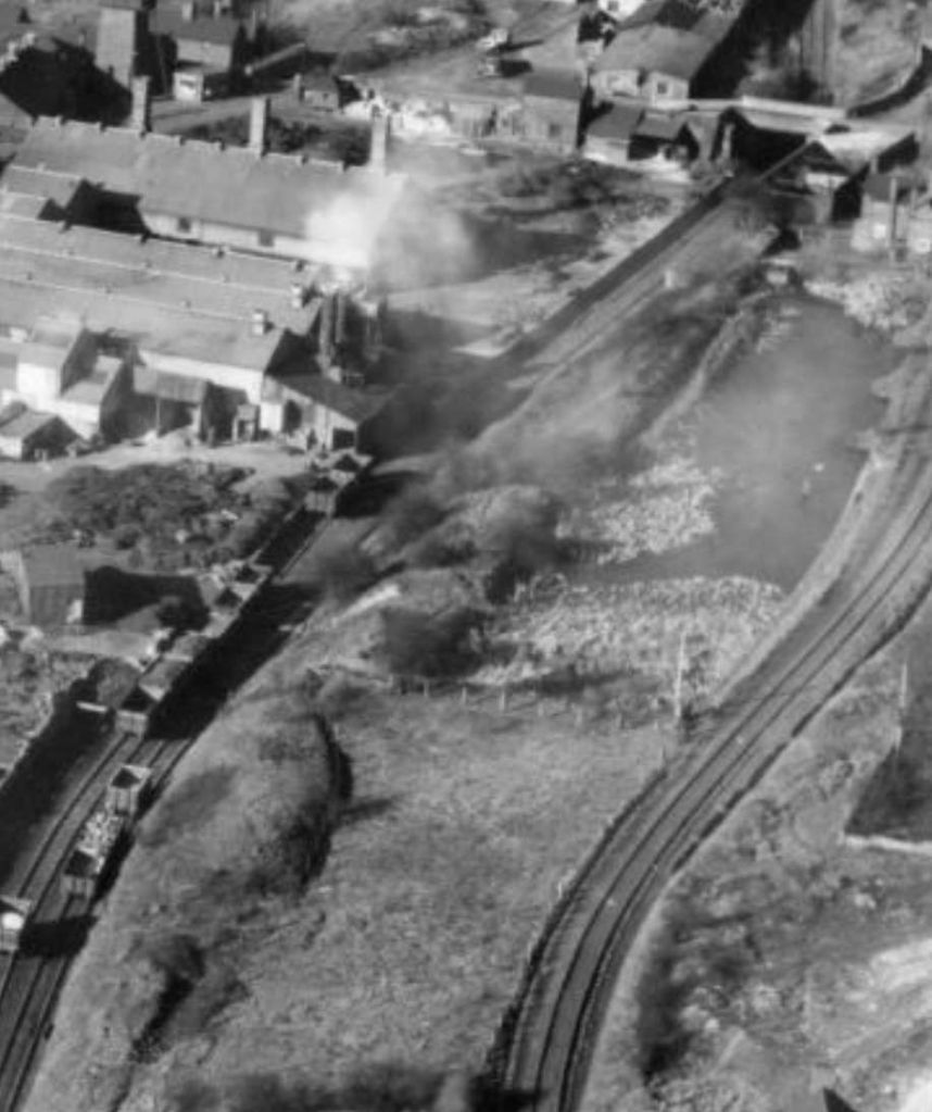
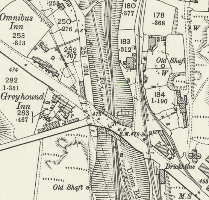
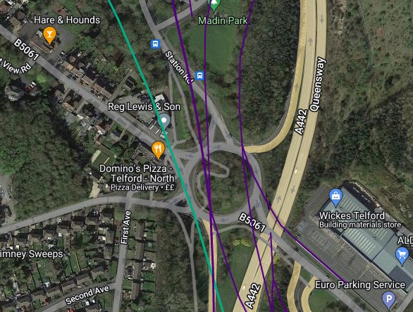
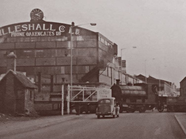
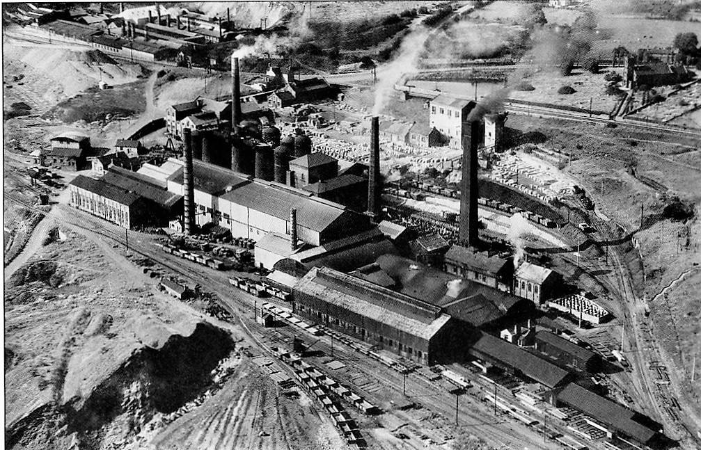
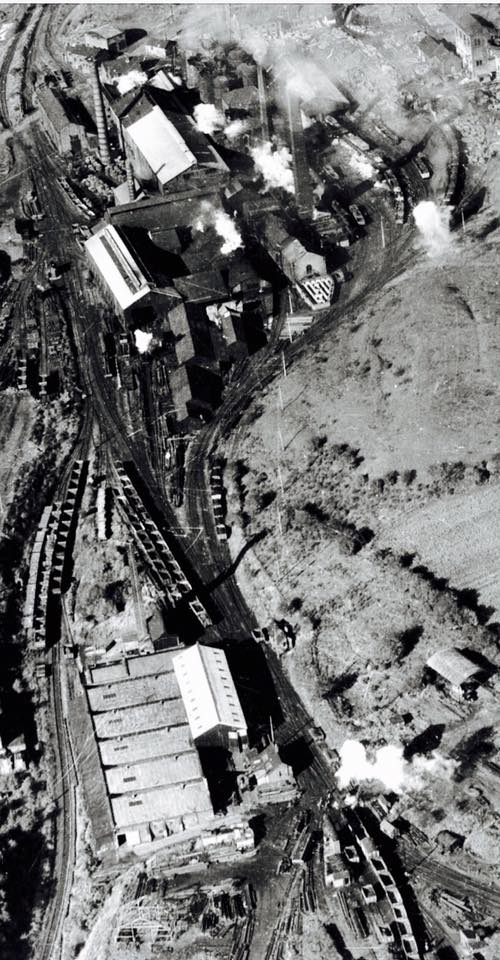
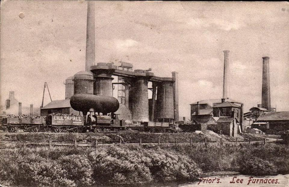
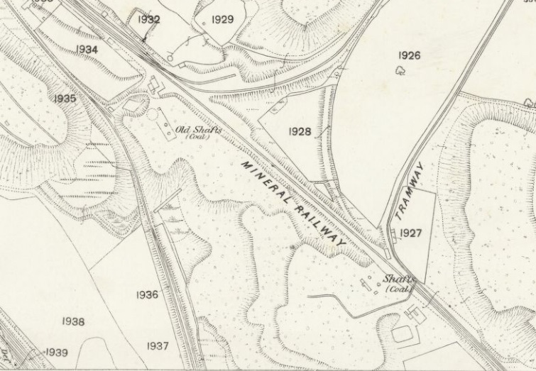
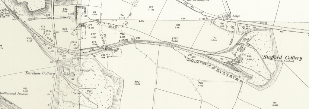
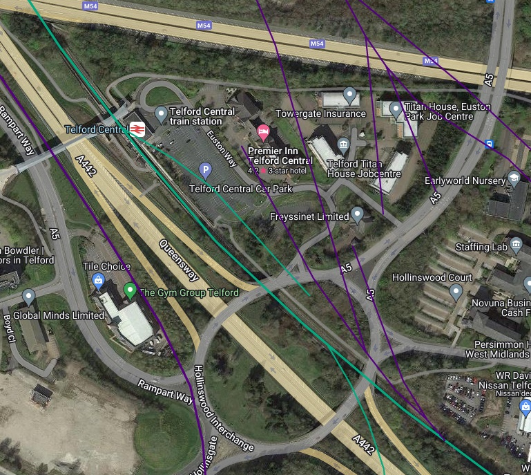
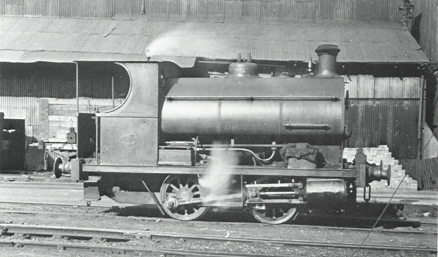
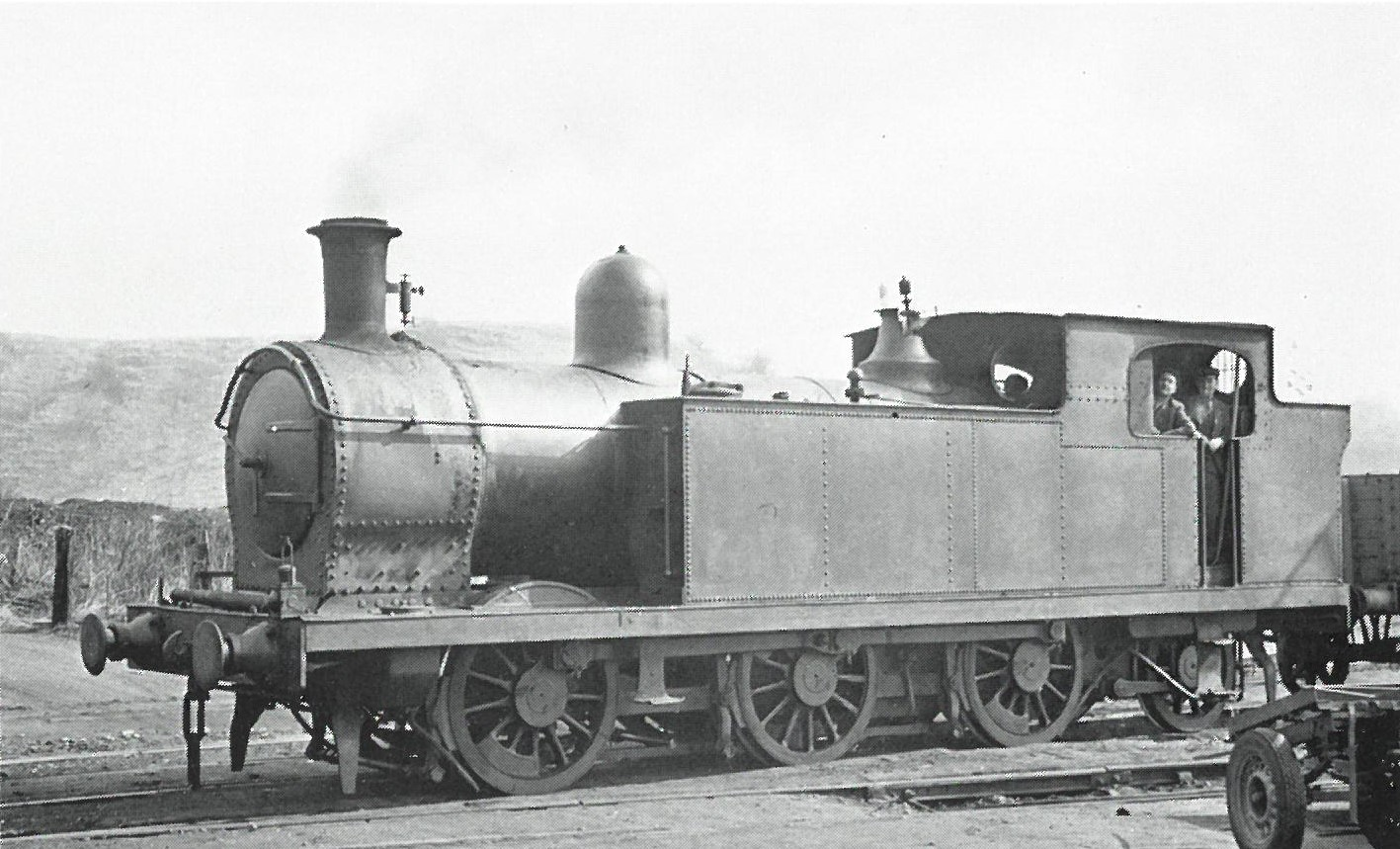
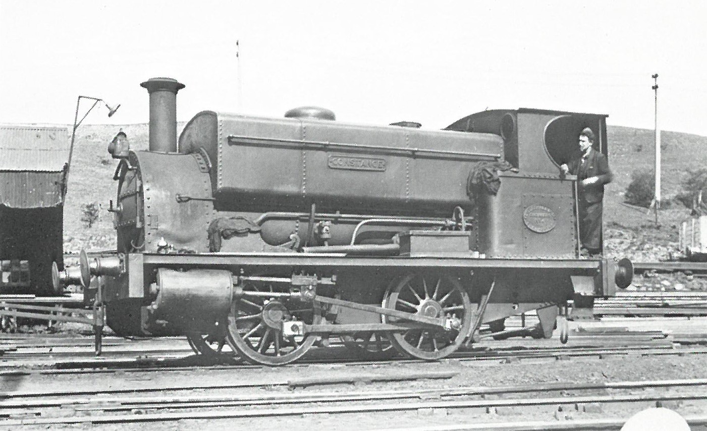
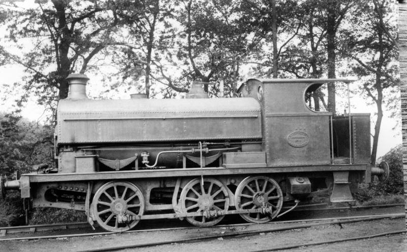
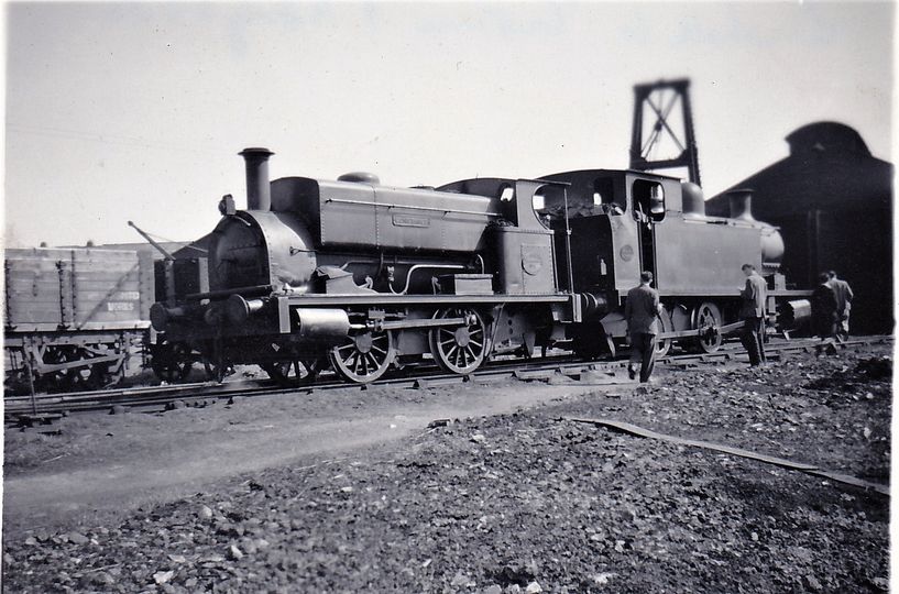
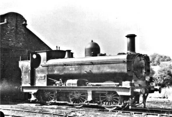
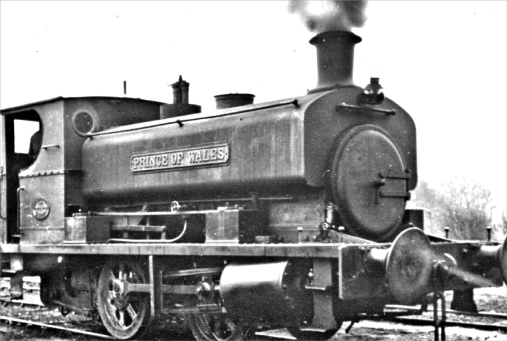
.jpg)
.jpg)
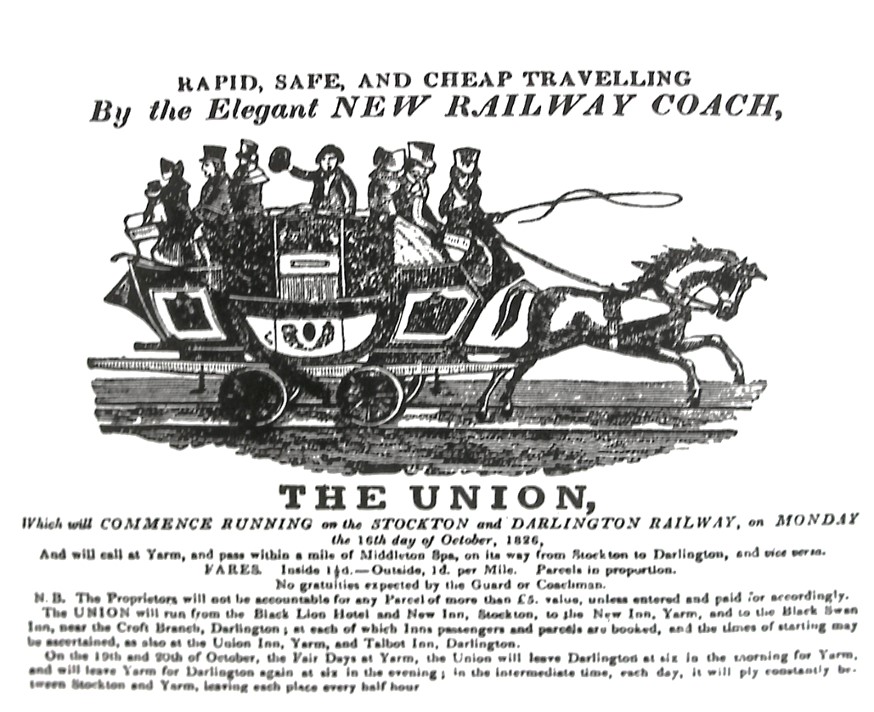
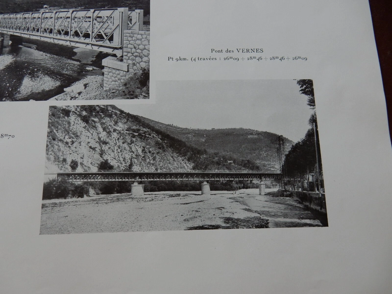