The featured image above is a photograph of Saint Felicien Railway Station in 1959. [9]
In the North of Québec, some 300 miles from Montreal, there is an area of extensive mining – deposits of copper, zinc, gold and cobalt wee being mined in the mid-20th century. In the first half of the 21st century, Northern Quebec’s mining sector is a significant part of the province’s economy, focusing on gold, nickel, lithium, graphite, iron, and copper, focusing on gold, nickel, lithium, graphite, iron, and copper, with major operations like Glencore’s Raglan (nickel) and Agnico Eagle‘s Canadian Malartic (gold) leading the way, alongside emerging lithium projects in the James Bay region, leveraging Quebec’s hydropower for cleaner operations and creating jobs in remote areas like Nunavik, despite logistical and environmental challenges.
Raglan Mine is, today, a large nickel mining complex in the Nunavik region of northern Quebec. “It is located approximately 100 kilometres (62 miles) south of Deception Bay. Discovery of the deposits is credited to Murray Edmund Watts in 1931 or 1932. It is owned and operated by Glencore Canada Corporation. The mine site is located in sub-arctic permafrost of the Cape Smith Belt, with an average underground temperature of −15 °C (5 °F).” [1]
In 2025, the mining complex “is served by and operates the Kattiniq/Donaldson Airport, which is 10 nautical miles (19 km; 12 miles) east of the principal mine site. There is a gravel road leading from the mine site to the seaport in Deception Bay. It is the only road of any distance in the province north of the 55th parallel. As the complex is remote from even the region’s Inuit communities, workers must lodge at the mine site, typically for weeks at a time. From the mine site employees are flown to Val D’or, or in the case of Inuit employees, their home community. Ore produced from the mine is milled on-site then trucked 100 km (62 mi) to Deception Bay. From Deception Bay the concentrate is sent via cargo ship during the short shipping season (even by ice breaker it is only accessible 8 months of the year)to Quebec City, and then via rail to be smelted at Glencore’s facilities in Falconbridge, Ontario. Following smelting in Ontario, the concentrate is sent back to Quebec City via rail, loaded onto a ship and sent to the Glencore Nikkelverk in Kristiansand, Norway to be refined.” [1]
Agnico Eagle’s Canadian Malartic is, in 2025, one of Canada’s largest gold mines, located in Quebec’s Abitibi region, transitioning from open-pit to a major underground operation (Odyssey Mine) to extend its life, with Agnico Eagle becoming sole owner in 2023 after acquiring Yamana Gold’s share. This significant asset is a cornerstone of Agnico’s Abitibi operations, aiming for long-term value through expansion and exploration, supporting regional growth. [2]
The Canadian National Railways network to the Northwest of Québec City. [3: p203]
Canadian National Railways were authorised to open up northern Québec by a Bill passed in the Canadian Parliament in 1954. The resulting Act approved the construction of two new lines. “One line was to run from Beattyville to Chibougamau, a distance of 161 miles, and the other for 133 miles from St. Felicien to a junction near Chibougamau with the line from Beattyville.” [3: p201]
Beattyville to Chibougamau – Construction
“The line to Beattyville provided a direct route from the rich mining area around Chibougamau to the ore smelting plant at Noranda, some 250 miles west of the Quebec-Ontario border, and its construction was undertaken without delay. Work started in November, 1954, and the railway was completed in November, 1957, to Beattyville, where it joined the existing 39-mile branch from Barraute, on the CNR northern transcontinental route.” [3: p201] It appears below as a solid line on the extract from the map above. [3: p203]
The line from Beattyville to Chibougamau was completed in November 1957, the line between St. Felicien and Chibougamau was under construction in 1959. [3: p203]
The engineering work (ground, earthworks, drainage and bridge substructures) for the railway between Beattyville and Chibougamau was contracted in two separate contracts: Beattyville to Bachelor Lake and Bachelor Lake to Chibougamau. Trackwork was laid by railway staff and comprised 85-lb. rails on creosoted sleepers, ballasted with gravel obtained from local deposits along the route. Construction presented significant challenges, “arising primarily from the climate and the ‘muskeg’ [bog]. During the long winters, temperatures fell to -95 deg. F., or 63 deg. C below zero, and blizzards were frequent. In summer, 90 deg. F. was common, and the attacks of the vicious black-fly were devastating. Work on the ‘muskeg’ resulted in the formation in the first instance, and later in lengths of newly-laid track disappearing without trace into the treacherous bog. All these conditions made transport and the movement of heavy mechanical equipment exceedingly difficult at different times, and the flies and extremes of temperature were most trying for those engaged on the works.” [3: p202]
The Railway Magazine article highlights work on the Bell River bridge. …
Construction by the cantilever method of the main (western) span of the Bell River Bridge, the eastern span being used as a counterweight with tie backs between the top chords of the two spans. [3: p201] which consists of two 196 ft. 10 in. through girder spans. The Warren trusses are 30 ft. 6 in. high. [3: p203]
The site chosen for the Bell River Bridge was “at the head of Kiask Falls Rapids where the normally-broad Bell River [was] only 200 ft. wide in its main channel and 25 ft. deep; when the water level [was] high, the velocity of the current [was] over 25 m.p.h. The river banks and bed [were] of solid rock, and the concrete abutments and pier [were] founded on it. The western span [was] over the main stream, the eastern being across the shallow part of the river. The trusses were designed to have a roadway cantilevered out from them.” [3: p203]
Although the most difficult to construct, the Bell River Bridge was not the only important structure on the line. The article cited the crossing of the Chibougamau River which “required three spans of 100 ft. each; the first bridge over Opamica Lake ha[d] one span of 90 ft. and two of 45 ft.; and the second bridge ha[d] one span of 200 ft. and two of 45 ft.” [3: p206]
St. Felicien to Chibougamau – Construction
The line from St. Félicien was begun in September, 1955, and was due for completion at the end of 1959. “Except for the first 15 easy miles out of St. Félicien, it passes through considerably rougher country than does the route from Beattyville. It joins that line at a point known as Chibougamau Lake, or Coche Lake, a few miles from Chibougamau.” [3: p206]
Here again “the clearing of the ground, the formation earthwork, and the drain-age were carried out by contract in two sections (1) the first 66 miles from St. Félicien, and (2) the remaining 67 miles to the junction with the line from Beattyville. On the first section, the formation ha[d] been completed [by early 1959], and about 50 miles of permanent way and bridge work [were also] finished. The contract for the second section was not let until 1957.” [3: p206]
Lighter rail (80-lb.) was used on the first 40 miles of the line from St. Felicien, with 85-lb. rails used on the remainder of the route. “The ruling gradient was “1 in 80 and the sharpest curvature about 22 chains. There [were] 14 bridges with single spans up to 196 ft. 10 in., some of considerable height. Construction was plagued by the same difficulties as the line between Beattyville and Chibougamau. In addition, the route required the excavation of deep cuttings and construction of high embankments.
“The first bridge on the line [was] over the Salmon River, less than two miles from St. Félicien. It consist[ed] of two through-type plate-girder spans each of 100 ft. The substructure, built by contract – in common with six other bridges in the first 66 miles – was begun with a coffer-dam for the pier, with the intention of founding it on the rock river bed. It was then found that this rock was of in-sufficient thickness for that purpose and rested on sand. Accordingly, 35-ft. sheet-piling was driven to enable concrete foundations to be constructed.” [3: p206]
At the time that The Railway Magazine article was being written, it noted that “The largest bridge is being built to – span the Cran River Ravine, which has a bottom-width of 400 ft. and a depth of 100 ft. Two 196 ft. 10 in. spans are being used, and the pier is 96 ft. in height above normal water level. Here again, the river is fast-flowing, and a cableway 1,200 ft. long between supports 140 ft. high was erected for the construction. It had a capacity of seven tons. The pier was built in the form of three superimposed arches each 30-36 ft. high. The cantilever trusses of the bridge are nearly 100 ft. above the river.” [3: p206]
Cran River Bridge under construction using the cantilever method aided by a cableway. [3: p202]
“Of the other 12 bridges, one [had] one span of 196 ft. 10 in. and two of 75 ft.; another [had] two spans of 100 ft.; and several [had] 90-ft. spans of the plate-girder type. The considerably more numerous bridges, and the rougher terrain, on the railway from St. Félicien … inevitably made progress less rapid than on the line from Beattyville.” [3: p206]
The line between Chibougamau and Saint-Felicien opened on 28th October 1959. “The opening of the St. Félicien–Chibougamau line was more than a local event—it represented Canada’s broader postwar push to develop its northern frontiers. The project mirrored similar efforts across the country, where railways extended into resource-rich but isolated territories. The line remains a vital part of northern Quebec’s transportation network, used by CN to support freight and industrial traffic. While passenger service eventually declined, the railway continues to play an important role in the forestry and mining sectors, underscoring its enduring importance more than six decades later.” [13]
A Possible Northward Extension
Work was started on a northern extension from Chibougamau but the anticipated traffic on the lines South of Chibougamau did not occur. North of Chibougamau civil engineering work was undertaken but rails were never laid. There remains a visible, overgrown route with a built bridge over the Stain River that’s now only accessible by river or the old railway formation itself. This unfinished project, built for accessing northern mineral wealth in the mid-20th century, remains a testament to early northern development, with its earth embankment and bridge still visible as a “green road” through the forest, despite being washed out in places.
To see something of this abandoned line, please follow this link. [4]
Operation
Concentrated ore was the main commodity being transported by the CN Railroad from Chibougamau followed by lumber and by-products of lumber transformation such as wood chips used to make paper.
However, from the end of the 1980’s, mining operations declined in the Chibougamau region with a resulting drop in the demand for rail transport and a loss of income for the CN.
The Line in the 21st Century
Investigation of the line in the 21st century is hampered by the climate conditions in the area. Google Streetview has limited access to the area and much of what can be provided is of snowbound images with little sign that a railway is in use.
Bing and Google Maps imagery showing the area around the railhead at Chibougamau are reproduced below.
The railhead at Chibougamau. [Bing.com/Maps, December 2025]The same area shown on Bing.com’s satellite imagery. [Bing.com/Maps, December 2025]Whilst superior in some ways Google Maps is less effective at highlighting rail routes. This is the same area on Google Maps. [Google Maps, December 2025]The same area on Google Maps’ satellite imagery, the rail line is a little clearer than on Google’s mapping. [Google Maps, December 2025]
The next five Google Maps satellite images show the length of the line as far as the junction where the routes to Beattyville and St. Felicien diverge. ….
The view West-northwest from route QC167 along the dirt road which leaves the QC167 at the green flag on the above satellite image. [Google Streetview, July 2022]The lines to Beattyville (heading away to the Southwest) and St. Felicien (heading South) diverge at Faribault just to the South of route QC113. [Google Maps, February 2026]Looking North from route QC113 at Faribault. [Google Streetview, July 2022]Looking South from route QC113 at Faribault. At the junction, the line to St. Felicien bears away to the left, that to Beattyville continues straight ahead. [Google Streetview, July 2022]
The location and river are named after George-Barthélemy Faribault (1789–1866). He was a prominent Quebec-born librarian, historian, and archivist known for his extensive collection of Canadian historical documents. The Faribault River flows East towards James Bay. [5]
From Faribault the line to Beattyville and Barraute turns West and runs close to the QC113. …
The line from Faribault to Barraute
Five further satellite images follow the route. Occasionally the line comes close enough to the highway to be seen looking South from the road.
Two satellite images which show the line to Beattyville turning to the West and at one location running very close to the QC113 highway. [Google Maps, February 2026]At the centre of the satellite image above the rails can be seen when looking South from the highway. [Google Streetview, October 2018]Here the line is again close to the highway, but shrouded from it by the dense forest. [Google Maps, February 2026]The line passes to the North of ‘Hydro-Quebec Poste Chibougamau’ [Google Maps, February 2026]And continues West to run to the South side of Barrette-Chapais. [6][Google Maps, February 2026]Careful inspection of this aerial image of Barrette-Chapais which looks West across the site will show the railway at the left side of the image. [Google Maps, 2020]
Barrette-Chapais is both the largest sawmill complex in Quebec and the largest forest management authority in Quebec.
Its facilities include a yard, a sawmill, a planing mill, a thermal power plant, and wood kilns. A wide range of wood products for the construction, energy, and pulp and paper sectors are manufactured there and then distributed in Canada and internationally. It employs 350 people throughout the full year. [6]
Barrette-Chapais provides comprehensive planning, management, and supervision of its forestry operations. The team plans harvesting, land access, and infrastructure alignment with environmental considerations to supply its sawmill complex . A significant amount of management and logistical work is carried out year-round. There are 150 workers in the field with 5 forest camps. [6]
Continuing to the West, the line runs to the South of the township of Chapais.
The town of Chapais and highway QC113 are at the top of this satellite image. The railway can just be made out running across the image from the East, turning to the Northwest after crossing a dirt road left-of-centre. [Google Maps, February 2026]
Somewhere along this length of the old railway the rails disappear, probably having been lifted to allow vehicular use of the formation. The old line continued Southwest alongside the Chemin du Lac Cavan. …
This is just one satellite image which shows the Chemin du Lac Cavan and the railway running Southwest in parallel, just a short distance apart. Google Streetview does not, in 2026, follow the route of this road. [Google Maps, February 2026]
A branch from the main line (also now lifted) appears to have run into Chapais.
As we have already noted, the main line of the railway ran alongside Chemin du Lac Cavan before it passed to the North of Lac Cavan. ….
Lac Cavan with the line of the old railway visible along its North shore. [Google Maps, February 2026]
The route of the old line heads West-southwest into the forested wilderness, passing to the South of Lac Beauchesne, then some distance to the North of Lac O’Melia.
It ran South of Lac Kitty and Lac Ford the line ran along the North shore of Lac du Calumet.
Then it ran to the South of Lac Hancock, to the North of both Lac Eleanor and Lac Barbeau.
Some distance to the South of Lac Mandarino and Lac Cady the line ran closer to the North shore of a body of water that appears to be unnamed on Google Maps, before being found on the South side of part of Lac Father.
The line continued to the North of Lac Relique and between two arms of Lac Father before bridging Lac Father at a point where the width of the channel was relatively limited, before then running along the North shore of another arm of Lac Father. After which it ran on the South side of another arm of Lac Father.
Continuing in a westerly direction the line eventually passes to the South of Lac Bachelor
Near Goeland, the line crossed the QC113 again. …
Looking back along the line from the QC113. There is no sign of rails. [Google Streetview, July 2022]Looking forward along the line from the QC113. Similarly there is no sign of rails in this view. [Google Streetview, July 2022]
The old line ran on, passing South of Lac Waswanipi, heading generally towards the Southwest.
At Miquelon, the route of the railway crossed the QC113 again. …
Looking North, back along the route of the line from the QC113. [Google Streetview, October 2018]Looking South along the route of the line. The girder bridge spanning the river channel at Miquelon can be seen ahead. [Google Streetview, October 2018]The railway bridge at Miquelon, seen from the bridge carrying the QC113. [Google Streetview, October 2018]
The old line continued Southwest, passing Southeast of Lac Burger. Then, through Grevet where Google Maps appears to show at least remnants of the old railway. Just to the Southwest of which, Google Maps shows a triangular junction providing access to a rail head associated with ‘Mine Langlois (NYRSTAR)’
The triangular Junction to the Southwest of Grevet which provides access to a rail head associated with ‘Mine Langlois (NYRSTAR)’ [Google Maps, February 2026]Mine Langlois (NYRSTAR) and its rail siding. [Google Maps, February 2026]
NYRSTAR is a leading international manufacturer of Zinc. Its headquarters are in The Netherlands. The Langlois Mine seems to have stopped production late in 2019. [7] As of February 2026, the rail infrastructure seems to still be in place.
An aerial view of the Langlois Mine in Quebec, seen from the Southeast. The triangular junction can be seen in the top-left of this image with the railhead at the building on the right of the image. [8]
It seems as though the line to the Southwest of Grevet was in regular use while Langlois Mine was operational. The rails remain in place in the third decade of the 21st century.
Another triangular junction is visible on Google Maps at Franquet. …
The triangular junction at Franquet. [Google Maps, February 2026]
The line heading West from the triangular junction above continues West for some distance. It crosses the QC113 and Route 1055 before reaching Les Rapides de l’Ile and Comporte.
Looking Southeast from the QC113 towards Franquet. [Google Streetview, July 2022]Looking Northwest from the QC113. [Google Streetview, July 2022]Les Rapides de l’Ile and Comporte. [Google Maps February 2026]The rail bridge at Les Rapides de l’Ile. [Google Maps, February 2026]
Beyond Comporte, the line gives rail access to mines close to Matagami. The mines were to the South and West of the township.
The mines to the South and West of Matagami can be seen on this satellite image. Top-left is Matagami Mine, bottom-right is Bracemac-McLeod Mine and unnamed mine sits at the heart of the image and top-right close to Matagami township is a mine labelled Matagami Station. A triangular rail junction sits middle -right, North of the Bracemac-McLeod Mine. [Google Maps, February 2026]
Returning to Franquet, we continue South-southwest along the line towards Beattyville and Barraute.
The line passes to the Southeast of Île Kâmicikamak and passes to the Southeast of Quevillon and its nearby ‘Hydro-Quebec – Poste Lebel’.
Continuing Southwest the line bridges the Riviere Bell.
The railway bridge over the Riviere Bell. [Google Maps, February 2026]
Further South and West the line crosses the QC113 again. …
Looking back along the line from the QC113. [Google Streetview, October 2018]Looking ahead towards Beattyville and Barraute. [Google Streetview, October 2018]A short distance further South and West the QC113 runs alongside the line for a few hundred metres. The undergrowth was low enough when this picture was taken, for the railway to be visible from the road. [Google Streetview, October 2018]
Further South, the remains of a turning triangle are visible on satellite imagery at Laas. …
The turning triangle at Laas. [Google Maps, February 2026]
The line continues South and West, passing to the North and then West of Lac Despinassy.
It crosses 6th Avenue North, also at an oblique angle. This is the view North-northeast, back along the line. [Google Streetview, October 2022]This is the view South-southwest, along the line. [Google Streetview, October 2022]
It is only a very short distance to the next road crossing. …
The view North-northeast towards the last road crossing from the crossing at Ranges 3 et 4 East [Google Streetview, October 2022]Looking ahead down the line towards Barraute from adjacent to the same road crossing. [Google Streetview, October 2022]
The next road crossing is at CH Des 1 & 2 Rang. …
Looking back along the line from the road crossing. [Google Streetview, October 2022]The lens on the camera was misted obscuring a view directly along the line towards Barraute, so this is the best view available of the line ahead. [Google Streetview, October 2022]
The line continues in a South-southwest direction crossing a number of roads which did not warrant the use of the Google Streetview camera – 6th & 7th Rang E, Rang 4th & 5th East, Rang 3rd & 4th East. Although for the last of these a distant view of the level-crossing is possible.
We are closing in on the township of Barraute now. I have not been able to identify the location of Beattyville on Google Maps.
The crossing at Rang 1st and 2nd East. [Google Maps February 2026]Looking North from the above crossing. [Google Streetview, October 2024]Looking South from the same crossing. [Google Streetview, October 2024]The triangular junction with the wider Canadian rail network. [Google Maps, February 2026]The line running through the centre of Barraute. [Google Maps, February 2026]A girder bridge spans both a town road and the river at Barraute. This view looks North from 8th Avenue. [Google Streetview, October 2024]This view shows the same bridge from the Northwest on 8th Avenue. [Google Streetview, October 2024]
The next two photographs show the East-West line through the Centre of Barraute.
Looking East from the crossing on QC397. [Google Streetview, October 2024]Looking West from the crossing on QC397. [Google Streetview, October 2024]
Having travelled all the way to Barraute, we now return to the junction South of Chibougamau (at Faribault).
The line from Faribault toSt. Felicien
We are back at Faribault and taking the line to the East from the junction. ….
We now take the more easterly route from the junction at Faribault, which passes to the East of a lake which Google Maps does not name. [Google Maps, February 2026]We head off to the left at the Faribault junction. [Google Streetview, July 2022]The line heads sinuously to the South on the East side of the lake at Faribault. [Google Maps, February 2026]It then heads away to the Southeast. [Google Maps, February 2026]
The line meets the QC167 at a level-crossing close to the South end of Lac Gabrielle, bridging the River South of Lac Gabrielle just to the East of the QC167. …
The line to St. Felicien crosses the QC167 at a level crossing and then is carried over the lake outfall on a steel girder bridge. [Google Maps, February 2026]Looking Northwest along the line towards Faribault. [Google Streetview, October 2018]Looking Southeast along the line towards St. Felicien. [Google Streetview, October 2018]
The line turns to the South and for a short distance runs parallel to both the QC167 and the River Chibougamau before bridging the river via a lattice girder bridge. …
The bridge carrying the line across the River Chibougamau. [Google Maps, February 2026]
A short distance further Southeast the line crosses a dirt road, Chemin du Domain Rustique at a level-crossing. …
The rail crossing seen from the Northeast from the Chemin du Domain Rustique. [Google Streetview, September 2022]A
At Obalski, close to the Chibougamau Marina, the line bridges and arm of Lac Chibougamau
The QC167 and the railway bridge an arm of Lac Chibougamau. [Google Maps, February 2026]The rail bridge seen from the QC167 to the South. [Google Streetview, October 2018]The rail bridge over the Chemin du Lac Chibougamau Sud, seen from the South. [Google Streetview, October 2022]
The railway heads on into the wilderness, first to the East-southeast, then to the Southeast, to the South and to the South-southeast passing to the East of a body of water not named on Google Maps, then between two further unnamed lakes.
The line runs South-southeast on the East side of Lac Dufresne and then to the West of Lac Blondin before crossing the QC167 again and then running alongside it as far as Lac Malo.
The line crosses the QC167 again. [Google Maps, February 2026]A misted lens means that this is the best possible view back along the line towards Chibougamau. [Google Streetview, July 2022]Very damp conditions meant that visibility on the QC167 was poor when this photograph was taken. It does show the line crossing the highway and then running parallel to as it heads first to the Southeast and then to the South. [Google Streetview, July 2022]
Further South the line bridges the River Biosvert near Lac Charron. …
The railway and the QC167 cross the River Boisvert close to Lac Carron. [Google Maps, February 2026]Again in damp conditions, the railway bridge over the River Boisvert can be made out to the East of the QC167 bridge. [Google Streetview, October 2018]
The line continues South on the East side of Lac la Blanche, before running parallel to the QC167 again, although not easily seen from the road because of the density of the vegetation.
Road and railway then cross the Coquille River and run down the East side of Lac Nicabau.
The QC167 and the railway cross the Coquille River with the large Lac Nicabau to the Southwest. [Google Maps, February 2026]A rather fuzzy image showing the railway bridge as seen from the QC167. [Google Streetview October 2018]
The railway continues to run Southeast at varying distances from the QC167 running to the North of Lac Ducharme and on through land dotted with a myriad of lakes of different sizes before once again taking close order with the QC167 to the Northwest of Lac Chigoubiche. It then runs down the Northeast flank of the lake continuing to follow relatively closely, the QC167. Indeed running immediately adjacent to it on one occasion. …
A view South from the QC167 with the railway alongside. [Google Streetview, August 2025]
Beyond this, the line runs directly alongside Lac de la Loutre. Some considerable distance further along the line it passes under the QC167.
The QC167 passes over the line to St. Felicien. [Google Maps, February 2026]Looking back to the West along the line. [Google Streetview, August 2025]Looking ahead along the line to the East. [Google Streetview, August 2025]Looking Northwest from Rue St-Joseph North at La Dore. [Google Streetview, July 2024]Looking Southeast from Rue St-Joseph North. [Google Streetview, July 2024]
We are now approaching St. Felicien. The next road crossed is Rang Riviere Sub Saumons.
Looking back Northwest from the level-crossing. [Google Streetview, May 2012]Looking Southeast towards St. Felicien from the crossing. [Google Streetview, May 2012]The road and rail bridges over the mouth of the Riviere Aux Saumons (the larger river to the North of the rail bridge is the Riviere Ashuapmushuan). [Google Maps, February 2026]The rail bridge on the Google Maps satellite image above, as seen from the bridge carrying the Boulevard du Jardin over the River. [Google Streetview, July 2024]The rail junction to the Southeast of the river bridge where the line from Chibougamau joins the line from Normandin and beyond. [Google Maps, February 2026]
The line continues alongside the Riviere Ashuapmushuan into Saint-Felicien. …
The line crosses Boulevard Sacre Coeur at ground level. [Google Maps, February 2026]Looking back to the North-northwest along towards Chibougamau and Normandin. [Google Streetview, July 2024]The line ahead towards the centre of Saint Felicien. [Google Streetview, July 2024]Just a short distance to the South of Boulevard Sacre Coeur the line divided into three running lines of which two are available for storage at any one time. [Google Maps, February 2026]The three lines return to one just to the North of a bridge over a small tributary to the Ashuapmushuan River. [Google Maps, February 2026]Shortly beyond the stream bridge the line divided once again as it approaches Saint-Felicien Railway Station. It then bridges Boulevard Saint-Felicien on a reinforced concrete three-span bridge. [Google Maps, February 2026]The railway bridge seen from the West on Boulevard Saint-Felicien. [Google Streetview, August 2025]The railway bridge seen from the East on Boulevard Saint-Felicien. [Google Streetview, August 2025]The Northwest end of the station yard. [Google Maps, February 2026]The central area of the station yard with rail buildings on the right of the satellite image. [Google Maps, February 2026]The Southeast end of the station site. [Google Maps, February 2026]Saint-Felicien Railway Station in the late 1950s. [9]The rail buildings at Saint Felicien, seem from the Southeast. [Google Streetview, August 2025]The view Northwest into the Saint Felicien Station site from Rue Notre Dame [Google Streetview, August 2025]The view of the line Southeast from Saint Felicien to the rest of the Canadian network as seen from Rue Notre Dame [Google Streetview, August 2025]
Saint Felicien
In 1911, the government expropriated land under the Indian Act, permitting the James Bay & Eastern Railway the necessary ground for the railway to join Roberval to Saint-Félicien. [10]
We have already seen above that the line from Saint Felicien to Chibougamau was under construction in the late 1950s.
The arrival of the first train from Chibougamau at Saint-Felicien in the late 1950s. [11]
Originally known as ‘The Cranberry and Small Fry Line’, the Edaville Railroad is a 2ft-gauge narrow gauge line in Massachusetts. [1: p555]
It featured in a short article in the August 1952 issue of The Railway Magazine. This is the next article in a series looking at lines featured in early issues of The Railway Magazine.
Writing in 1952, Edwards comments: “Although never exceptionally numerous, lines of this type assisted materially in the development of many areas. As early as 1877, a 2-ft. gauge line, eight miles long, was inaugurated to link the Massachusetts towns of Bedford and Billerica, but the track and plant were removed to the State of Maine two years later, and used for the Sandy River Railroad. This line proved of great service to many previously isolated communities; its development was rapid, and extensions and branches soon brought its mileage up to 120. Other similar projects followed, mostly in Maine, and a sixty-year period of success resulted. In recent years, however, the usefulness of such small lines has declined. The present economic situation has proved an adverse factor … and nearly all of them have been closed.” [1: p555]
He continues: “Nevertheless, one small American line – the Edaville Railroad, of South Carver, Massachusetts seems to have a long and useful life ahead of it. Not only is it a commercially paying proposition, but it performs a special function each Christmas, bringing delight to thousands of children (and their parents).” [1: p555]
The truth is that the line’s history has proven to be much more chequered than Edwards seemed to envisage in the early 1950s. But that is getting ahead of ourselves. There is plenty of space in the rest of this article to look at the later history of the line.
Returning to Edwards article, he says that the line “owes its existence to a plan of … Ellis D. Atwood, who was developing an area of bog as a cranberry plantation. … [By 1952], the Atwood plantations form[ed] the largest privately-owned cranberry plant in the world. A railway enthusiast himself, Mr. Atwood saw in a small-gauge railroad, not only a fulfilment of a life-long ambition to possess his own system, but the very necessary provision of transport for his workpeople and the materials used in his organisation. For instance, 10,000 cu. yd. of sand are used to preserve the bogs during winter, and the narrow-gauge railway solved this problem in a way that probably no other transport could have met, in view of the soft nature of the terrain. Then, of course, the line is fully occupied at harvest time conveying both the fruit and the pickers at a very low cost to its owners. The coaches are also used by the pickers as shelters during the inclement weather often experienced at harvest time; for this they are sited at convenient spots along the line during working hours.” [1: p555]
Edwards says that “In 1939, the 2-ft. gauge Bridgton & Saco River Railroad in Maine almost the last of the [2-ft.] narrow-gauge systems in the United States decided to dispose of its track and rolling stock. This was Atwood’s great opportunity. He bought the plant and rolling stock, and with the purchase of other equipment acquired by collectors from similar small lines passing out of business, the Edaville Railroad (so named by taking its founders initials) was commenced. This search for equipment, and systematic planning and correct siting, took some six years, but in 1946, the railway, complete with facilities for overhauling and repair of rolling stock, stations, auxiliary tracks, and points systems, came into full operation. The stock was four locomotives, eight coaches, six observation cars of the typical American pattern, a parlour car, and numerous trucks for everyday haulage work.” [1: p555-556]
“Thus it was as a utility-hobby that the Edaville Railroad grew. Originally there was no thought of catering for the public, but quite without any prompting from the owners, public interest was aroused.” [1: p556]
Edaville is located South of Boston, Massachusetts. [Google Maps, January 2026]Magnifying the satellite imagery, Edaville can be seen to be South of the road between Taunton and Plymouth. [Google Maps, January 2026]The Edaville Railroad site is South of Atwood Reservoir, near South Carver. [Google Maps, January 2026]Openstreetmap she’s the location of Edaville. The lake to the North of the site is the Atwood Reservoir. [7]
Wikipedia provides additional detail: “Atwood purchased two locomotives and most of the passenger and freight cars when the Bridgton and Saco River Railroad was dismantled in 1941. After World War II, he acquired two former Monson Railroad locomotives and some surviving cars from the defunct Sandy River and Rangeley Lakes Railroad in Maine. This equipment ran on 2 ft (610 mm) narrow gauge tracks, as opposed to the more common 3 ft (914 mm) narrow gauge in the western United States. Atwood purchased the equipment for use on his 1,800-acre (730 ha) cranberry farm in South Carver. After the 1945 cranberry harvest, Atwood’s employees built 5.5 mi (8.9 km) of track atop the levees around the cranberry bogs. Sand and supplies were hauled in to the bogs, and cranberries were transported to a “screen house” where they were dried and then sent to market. Atwood’s neighbours were enchanted with the diminutive railroad. At first, Atwood offered rides for free. When the demand for rides soared, he charged a nickel a ride. Eventually the line became less of a working railroad and more of a tourist attraction.” [2]
Cranberry pickers at work during the harvest at Edaville with a tourist train beyond. [1: p556]
Edwards says that, “This interest became a clamour, and the Atwood Plantation Company built a station, and opened the line at weekends to passengers, from the spring of each year until harvest time. Throughout the summer, parties from schools, camps, church organisations, and youth groups arrive[d] at Edaville Station for a journey on the last 2-ft. gauge railway in America. While awaiting the trains they [could] visit a railway museum built by the company to house working models of American trains dating back to 1860, and many other interesting railroad relics.” [1: p556]
A schematic drawing of the route of the Edaville Railroad in the 21st century. [2]
At Christmas, the Edaville Railroad really came into its own. After harvest, the railway would close until the first week in December when it reopened for what were quite spectacular Christmas excursions. …
Apparently, “12,000 coloured fairy lights [were] used to illuminate the various buildings on the estate, the 300-acre reservoir, the pine forests, and the cranberry bogs on the 5.5-mile journey.” [1: p556] This is all akin to the Santa Specials and the Polar Express experiences offer by many preservation line in the UK in the run up to Christmas.
As of 1952, Edwards says that these sightseeing rides in winter and summer cost young passengers nothing, although as many as a thousand five-cent tickets were sold as souvenirs each day. [1: p556]
Atwood died in 1950 after an industrial accident. “His widow Elthea and nephew Dave Eldridge carried on operations at Edaville until the railroad was purchased in 1957 by F. Nelson Blount, a railroad enthusiast who had made a fortune in the seafood processing business. The Atwood Estate retained ownership of the land over which the railroad operated, a key point in later years. Blount operated Edaville for the next decade, hauling tourists behind his favorite engine, No 8, and displaying his ever-growing collection of locomotives. Among these was the Boston and Maine Railroad’s Flying Yankee. This helped form the basis for his Steamtown, USA collection, first operating at Keene, New Hampshire, before moving to Bellows Falls, Vermont. (It would later move and be reconstituted as the Steamtown National Historic Site in Scranton, Pennsylvania.)” [2]
Blount was a distant relative of the Atwood family. [6]
Wikipedia continues: “Nelson Blount died in the crash of his light airplane over Labor Day weekend in 1967. Blount’s friend and right-hand man Fred Richardson continued on as general manager until the railroad was sold to George E. Bartholomew, a former Edaville employee, in 1970. … Edaville continued operations for another two decades with Bartholomew at the helm. The railroad operated tourist trains from Memorial Day [through to] Labor Day plus a brief, but spectacular, Festival of Lights in December. …. In the 1980s, Bartholomew’s attention was divided between the narrow gauge Edaville, and the 4 ft 8 1⁄2 in (1,435 mm) standard gauge Bay Colony Railroad he was then forming, running over disused Conrail branch lines. To some observers and former employees, Edaville began to stagnate around this time, although the annual Christmas Festival of Lights continued to draw huge crowds.” [2]
“In the late 1980s, after Mrs. Atwood died and the Atwood Estate evicted Edaville, Bartholomew was forced to cease operations. He eventually put the railroad up for sale in 1991.” [2]
Wikipedia continues: “Edaville ceased operations in January 1992 and much of the equipment was sold to a group in Portland, Maine, led by businessman Phineas T. Sprague. The equipment was to be the basis of the newly formed Maine Narrow Gauge Railroad Museum along the shores of Casco Bay. The sale generated great rancor. Many of the railroad’s employees were not ready to give up on South Carver. Much of the contents of the museum, housed in the former screen house, had been auctioned off the previous fall. But the sale was closed (although the Portland museum took on a debt that would prove all but crushing in subsequent years) and locomotives 3,4 and 8 were trucked to Portland aboard antique trucks loaned for the occasion. Locomotive No. 7, which was owned by Louis Edmonds, left for Maine at a later date.” [2]
Two attempts to revive Edaville during the 1990s foundered. A third attempt in 1999 saw “the new Edaville Railroad opened for operation. Owned and operated by construction company owner Jack Flagg, developer John Delli Priscoli and cranberry grower Douglas Beaton, the railroad acquired a ‘new’ steam locomotive, No. 21 “Anne Elizabeth”, built by the English firm of Hudswell Clarke and a veteran of the Fiji sugar industry. Several of the original Edaville buildings, including the station and the engine house, were demolished with new buildings taking their place. Plans called for the construction of a roundhouse, served by the original turntable, with an enlarged collection of locomotives and rolling stock.” [2]
“By 2005, Edaville Railroad and the land upon which it ran was now owned by a single man, Jon Delli Priscoli. He bought up the Atwood property, bought out partner Jack Flagg, and became the sole owner. Although this removed the railroad/landlord conflict that had plagued Edaville for decades, it proved to be the end of the “old” Edaville. Delli Priscoli turned the land near the milepost known as “Mt. Urann” into a housing subdivision, and pulled up the tracks that ran through the new lots. Late 2005 saw the very last run over the “original line” (pulled by oil-burner No. 21, which had been cosmetically modified to more closely resemble a Maine prototype). When the rails were removed over Mt. Urann, the mainline became a 2-mile (3.2 km) loop, including about half of the line around the old reservoir.” [2]
Wikipedia continues: “In late 2010, the Edaville operators announced that they would not seek to renew their operating lease with Delli Priscoli. Delli Priscoli then put the railroad up for sale for $10 million, and eventually found a potential buyer. However, Priscolli found that the buyer did not intend to continue operating the park, and declined the offer, opting instead to rebuild the park. The restored railroad reopened in September 2011. The following year, the park began a three-year reconstruction project, which includes the installation of additional attractions, refurbishing and repainting existing rides, adding additional parking, and building a new main street entrance and guest services area.” [2]
In the years under Priscoli, Edaville Railroad reopened as Edaville Family Theme Park, an amusement park themed around cranberry harvesting and railroading.
Wikipedia continues: “As of 13th April 2022, Delli Priscoli put Edaville back on the market. The family amusement park [had] closed due to the coronavirus pandemic, and except for the return of the annual Christmas Festival of Lights … has remain closed.” [2]
As of 2025, various options were being explored for re-opening as a more traditional, historic railway attraction. [2] As of January 2026, details of the Christmas Festival of Lights in 2025 can be found here. [6] The then site owners said that “Classic traditions and trains will remain for Edaville’s Christmas Festival of Lights, while a reimagining of the space allows future generations to get to know the joy of Edaville. Long time fans, train enthusiasts, and newcomers can plan to see steam locomotives on trains as much as possible, giving a rare experience as the only operating steam locomotives in Massachusetts!” [7][8]
A significant number of photographs can be found on Tripadvisor. [8]
It remains to be seen whether this attraction survives the next few years and what form it will take. The site was taken over by King Richard ‘s Faire in 2025. [9]
References
Austin Edwards; The Cranberry and Small Fry Line; in The Railway Magazine Volume 98 No. 616; Tothill Press,h London, August 1952, p555-556.
I received a few welcome gifts for Christmas 2025. This article is the second in a short series:
Colin Judge; The Locomotives, Railway and History 1916-1919 of the National Filling Factory No. 14, Hereford; Industrial Railway Society, Melton Mowbray, Leicestershire, 2025. [1] This review and notes can be found here. [18]
Anthony Burton; The Locomotive Pioneers: Early Steam Locomotive Development – 1801-1851; Pen and Sword, Barnsley, 2017. [2]
Christian Wolmar; The Subterranean Railway: How the London Underground was Built and How it Changed the City Forever (2nd extended Edition); Atlantic Books, 2020. This edition includes a chapter on Crossrail. [3] The review and notes can be found here. [19]
Neil Parkhouse; British Railway History in Colour Volume 6: Cheltenham and thme Cotswold Lines; Lightmoor Press, Lydney, Gloucestershire, 2025. [4]
2. The Locomotive Pioneers
Anthony Burton’s book published by Pen & Sword is a little older, dating from 2017.
His book comes out of a series of different initiatives that he was involved in as a television journalist and author, such as:
The Past at Work – a series about the remains left from the Industrial Revolution up to 1825 which included two railways (the Middleton Railway and the Stockton & Darlington Railway);
The Rainhill Story – which followed the construction of the replicas of the three engines which took place in the original trials.
A biography of Richard Trevithick – which included seeing more replicas coming to life. He particularly notes a time when he “was invited onto the footplate of the replica of the 1803 engine at the Ironbridge Gorge Open Air Museum and was invited to drive, though, … [he] did nothing more than open and close the regulator but that made it none the less thrilling.” [2: Preface]
He says that these experiences “gave [him] a new appreciation of just how in entice the early engineers were, who has to devise these engines for themselves with no precedents to work on.” [2: Preface]
In his second chapter, Burton navigates us through the complex competitive relationship between Boulton & Watt and Trevithick which seems to have been driven by some very strong egos! He notes the way in which that dispute both strengthened and hampered the development of mobile steam engines on road and rail.
I particularly enjoyed a specific step in the history of steam on the move which Burton says is only sketchily documented – interesting to me as it relates to Coalbrookdale.
“In 1802, Trevithick went up to the famous Darby ironworks at Coalbrookdale to install one of his puffer engines. [5] The letter he wrote from there is remarkable in showing how far he had pushed high-pressure steam in a short time. One has to remember that Watt considered a pressure of 10psi to be more than adequate, but here he was describing an engine working up to 145psi. In a long letter describing the working of this engine he added this intriguing postscript: ‘The Dale Co. have begun a carriage at their own cost for the real-roads (sic) and is forcing it with all expedition.’ The railroad referred to would probably have been one of the tramways linking the works to a wharf on the Severn, along which goods would have been hauled down railed tracks by horses. Some commentators have suggested that the experimental railway locomotive was never built, but there is some evidence that it was completed. The man in charge at Coalbrookdale at that time was William Reynolds and his nephew, W.A. Reynolds, described being given ‘a beautifully executed wooden model of this locomotive’ when he was a boy. He broke it up to make a model of his own, ‘an act which I now repent of as if it had been a sin’. He also recalls the boiler being used as a water tank and seeing other parts of the engine in the yard at a nearby ironworks. A visitor to Coalbrookdale in 1884 also recorded being shown a cylinder, preserved as a relic of the locomotive. None of these relics have survived, but a drawing does exist, dated 1803, simply labelled as the ‘tram engine’, which shows a locomotive fitted with a 4.75-inch diameter cylinder with a 3-foot stroke. For a long time, this was thought to be a drawing for the 1804 engine …, but it now seems more likely to have been for the Coalbrookdale locomotive. So it seems more than probable that an engine was indeed built at Coalbrookdale and if so it can claim to be the world’s very first railway locomotive. The drawing was used as the basis for the replica that now runs at the Blists Hill Museum site.” [2: p14-15]
Burton goes on to follow Trevithick further endeavours, particularly the Penydarren locomotive (although the drawing he provided is unlikely to be a good representation of that locomotive given the height of the bore on a tunnel on the tramway which probably would not have accommodated either the flywheel or the chimney of the locomotive).
Ultimately Trevithick’s locomotive was not used for any significant length of time because it was too heavy for the cast iron L-playe rails use on the tramway in the Taff valley.
Burton notes that ” Trevithick’s importance in the development of the steam locomotive was played down after his death, largely because of the growing reputation of George Stephenson.” [2: p21-22]
Burton’s third chapter focussed on developments resulting from wars with France which significantly increased the price of fodder and resulted in much fewer horses available to operate coal tramways in Leeds and the Northeast of England. Burton takes his readers through the development of the use of Steam on the Middleton Railway and then the work of William Hedley and George Stephenson on industrial railways.
Chapter 4 focusses on the Stockton& Darlington Railway which Burton describes as “in effect, a colliery line that suffered from its predecessors only in the scale of its operations.” [2: p43]
Burton also describes how a breakdown in relationships with William Losh, with whom Stephenson shared a patent for a particular form of cast iron rail, resulting from Stephenson’s recommendation of the use of wrought iron to the Stockton and Darlington Railway board, meant that Stephenson could no longer rely on Losh to build locomotives for him. This, according to Burton, was a significant reason why George Stephenson, Edward Pease and Michael Longbridge decided to set up their own locomotive works. Supported by Pease and Longbridge, George Stephenson and his son Robert Stephenson set up their new works in Newcastle, the first in the world to focus primarily on the building of steam locomotives.
Burton concludes the fourth chapter with these words: “If the Stockton & Darlington was, [as] it is often said to be, a model for later developments, then it was certainly not one without many problems. It remained a hybrid with all the attendant difficulties. Having two companies running the passenger service was not a recipe for smooth working. The locomotives, restricted to moving heavy goods, were built more with the idea of hauling the heaviest loads than with any idea of speeding on their way, but at least the inclines, once initial difficulties had been sorted out, worked well. One other railway was approved in the same year as the Stockton & Darlington opened, the Canterbury & Whitstable, described in [its ] Act as ‘Railway or Tramroad’ … had a number of steep sections, worked by stationary engines, and only used locomotives on short sections. Overseas there were railways being constructed in both Austria, opened 1827, and France, 1828, but both still relied on horses to do the work. The case for the steam railway had not yet been conclusively argued.” [2: p54]
Chapter 5 covers the Rainhill Trials. The early pages of the chapter cover the difficulties that the Liverpool & Manchester Railway had in coming to an agreement over the king of propulsion to be used – stationary engines or travelling engines. Ultimately, the Company decided to undertake a locomotive trial at Rainhill.
A completion was determined to be the best way to proceed and advertisements were placed in the leading northern newspapers. Burton tells us that the conditions entrants had to meet, were exact. “The engine had to ‘effectively consume its own smoke’, which in practice meant that it would have to burn coke not coal. The engine could weigh up to six tons if carried on six wheels and up to four and a half tons on four wheels. The six-ton engine ‘must be capable of drawing after it, day by day, on a well-constructed Railway, on a level plane, a Train of Carriages of the gross weight of Twenty Tons, including the Tender and Water Tank, at the rate of Ten Miles per Hour, with a pressure of steam in the boiler not exceeding Fifty Pounds on the square inch’. The weight to be hauled was to be reduced proportionately with the weight of the locomotive. Other conditions included springing to support the boiler and two safety valves, one of which had to be out of the driver’s reach; the latter clause was a precaution against tampering and boiler explosions.” [2: p63]
Burton then talks his readers through the design and construction of what was to become known as ‘Rocket’. [2: p63-66]
On the first day of the trials Rocket and Sans Pareil made runs at the modest speed of 12 mph while pulling loads. Rocket, running light’ also made a demonstration run at between 15 and 25 mph. It was Novelty that “stole the show, dashing along at great speed and at one point reaching just over 30 mph.” [2: p69]
However, on the second day only one of the locomotive motives was able to complete the required ten double runs up and down the track – Rocket. Burton concludes: “It was as well that the Stephenson engine won as it was the one that contained all the elements that were to be crucial for later development: the multi-tube boiler and separate firebox, exhaust steam blast; and cylinders lowered from their former vertical position. Had Sans Pareil succeeded it could well have been selected if only because it was based on well-established practices and could have been thought more reliable than the rivals. But it was built by an engineer looking back over previous successes, not forward to new developments. Novelty would never have had the power for working a busy line. It was Rocket that proved that a railway really could be worked more efficiently by steam locomotives than by any other means then available. It was the future.” [2: p72]
Chapter 6 is entitled ‘Coming of Age’. Burton highlights two different reactions to the speed of the locomotives. One a nervous and terrified response, the other a sense of exhilaration. The directors of the line couldn’t but be nervous about how the line would be received. The locomotives to be used represented the pinnacle of engineering achievement. The line itself was still a mix of old and new. “Unlike the Stockton & Darlington, which had used a mixture of cast iron and wrought iron rails, Stephenson had this time settled for wrought iron fish bellied rails throughout, but mostly they were still mounted on stone blocks, even though there was no longer any intention to use horses for any part of the traffic. However on some sections, especially over Chat Moss, he had set his rails on transverse wooden sleepers. It was soon discovered that with the heavier, faster traffic of the new line, stone blocks were easily shifted out of place, while the wooden sleepers remained firm. Within seven years of the opening, the stone blocks had all been replaced by the new wooden sleepers that would become the norm for railway construction for many years to come. The changes to the track were important. With an improved permanent way, engineers could feel confident in building bigger, more powerful locomotives. The Liverpool & Manchester would show whether there was a real demand for this kind of transport.” [2: p76]
“It was soon evident that there was a real hunger for rail travel. Up until then, railways had been all about freight, with passenger transport as an afterthought. Now it was becoming obvious that the two types of rail transport were achieving something like parity, and engineers would have to plan accordingly.” [2: p78]
Robert Stephenson was already designing a new series of locomotives named after the first in the class, Planet. Burton goes on to describe the design principles for this new class which was a significant advance over the technology employed on Rocket. He also devotes a few pages to the working replica of Planet which was first steamed in 1992.
Other designers are also covered: Timothy Hackworth, Edward Bury, Foster & Rastrick, and Todd, Kitson & Laird.
Chapter 7 looks across the Atlantic and describes very early developments in the United States. [2: p86-97]
Chapter 8 looks first across the Channel, [2: p p98-105]first at the horse-powered line, the Saint-Etienne a Lyon Railway. Its chief engineer was Marc Seguin, who began experimenting with steam-power after his visit to the Stockton & Darlington Railway. He ordered two locomotives from the Stephenson works in Newcastle, one for testing, and one to work immediately on the line. It seems that Seguin was the first to use a multi-tubular boiler and that Robert Stephenson was the first to combine it with an efficient firebox. Burton tells us that after Seguin, french locomotive development was becalmed for a time.
Burton goes on to write about developments in Russia in which the Hackworth family were to play a part. In the 1830s railways spread to other countries in Europe: Belgium and Germany in 1835; Austria, 1838, the Netherlands and Italy, 1839.
Burton covers developments in Ireland in the same chapter. It entered the railway age with “three lines and three gauges. This meant that two of the three could not order ‘off the peg’ locomotives. … It also meant chaos once a joined-up system was developed. Eventually, a gauge commission was to agree on 5ft 3in as the Irish standard.” [2: p105]
Chapter 9 considers the UK broad gauge and is quite frank about the contradictions that were a part of the personality of the mercurial Isambard Kingdom Brunel. He particularly notes the way in which Brunel could be so exacting in his design of the permanent way yet so contrary in the way he specified locomotives to run on the broad gauge. His appointment of Daniel Gooch as Locomotive Superintendent at the age of 20 (just one week short of his 21st birthday) was an enlightened decision. Gooch was not frightened to challenge Brunel and was the saving of his Great Western Railway. Gooch went on to “design locomotives that would help secure the reputation of the Great Western and the reinterpretation of the initial GWR as God’s Wonderful Railway.” [2: p111-112]
Gooch brought a locomotive from Robert Stephenson’s works originally built for an overseas client at 5ft 6in-gauge Patentee Class locomotive. It was re-gauged to suit Brunel’s broad gauge and became the first successful locomotive on the broad gauge. It was named North Star. Its success encouraged Gooch to “develop the design into a Star class of locomotives. The first of the class, the 2-2-2 Fire Fly went into service in 1840. … On initial trials [it] was recorded as travelling at 58mph while pulling three vehicles. Over the years sixty-two locomotives of this class were built, doing sterling work and the last was retired as late as 1879.” [2: p112-113]
Burton tells us though that the class was not without its problems. But that was not uncommon. “By 1840, there were some thirty works turning out locomotives and few arrived in a condition that allowed them to go straight into service without tinkering or more major adjustments, and servicing and repairs left much to be desired.” [2: p113]
Apparently, Gooch was to go on to develop a larger experimental locomotive, Great Western, with larger, 8ft diameter drive wheels which heralded a new class of which Iron Duke was the first. The class has much larger fireboxes and did not have the large dome of the Firefly class.
Burton tells us that as the GWR expanded westward past Exeter its route took it along the Devon coast through Dawlish, Teignmouth, Newton Abbot and across the edge of Dartmoor. That later length of line required three sections with heavy gradients. Dainton Bank was the most demanding with the steepest length at 1 in 38. There was well-proven technology to address this particular circumstance – cable-haulage by a stationary steam engine. Brunel chose a different option which had mixed success, in 1835 (a failure) and 1840 (a success).
Burton describes the 1840 experiment which was associated with the Birmingham, Bristol & Thames Junction Railway and based on an idea developed by Clegg and improved by Jacob and Joseph Samuda. Over a length of one and a quarter miles, a considerable load was moved using air pressure generated by a stationary steam engine. [2: p114]
Brunel was enthusiastic about the use of this technology (George Stephenson much less so). The technology was first applied on a branch of the Dublin & Kingstown Railway in Ireland, between Kingstown and Dalkley. The system was quite successful. The stationary steam engines created a vacuum behind a piston in a large pipe between the rails. The vacuum sucked the train forward. The system offered potential advantages like speed and efficiency and served for a decade before being replaced. [2: p114-115]
The system was also used in France, on 1.5km length of the Paris to St. Germain Railway which was on a gradient of 1 in 28. The system was technically successful, but the development of more powerful steam locomotives led to its abandonment from 3rd July 1860, when a steam locomotive ran throughout from Paris to Saint Germain. [7]
The London & Croydon Railway also employed the system. It was used on a third track beside the main line. It operated from January 1846 but was abandoned in May 1847.
The use of the system on the branch line in Ireland was enough to persuade Brunel to undertake a much more significant ‘trial’ on his line between Exeter and Newton Abbot. The line between Exeter and Teignmouth was operated as an Atmospheric Railway from September 1847 and to Newton Abbot from 2nd March 1848. Its operation presented problems from the start, with underpowered stationary engines, costly maintenance of leaky leather seals (damaged by tallow-seeking rats and weather), leading to its abandonment in September 1848. [2: p115-117]
Burton comments: “Brunel has been feted as Britain’s greatest engineer, but if he were to be judged purely on his contribution to railway technology it would be difficult to uphold the verdict. His genius can certainly be seen in the civil engineering, culminating in his bridge over the Tamar that brought rails from the rest of Britain to Cornwall. … However logical his decision to build to a broad gauge might have been, it ignored the needs of a national system that was already well under way. … Brunel’s instructions for constructing locomotives for the start of the Great Western were perverse and the atmospheric railway was a costly failure. Looked at solely as a locomotive pioneer, he eouldt be no more than a footnote in most reference books. He was, however, to move on to new worlds, when he famously declared that he saw no reason why the Great Western should stop at Bristol – why not go on to New York? His steamships represented a quite extraordinary achievement and opened up the world to steam navigation. In this he proved himself to be a true genius and worthy of his place in the engineering pantheon.” [2: p117]
Chapter 10 – Valve Gear: A short chapter covers developments in valve gear over the period examined by the book. The simple arrangement of a four-way cock letting steam in or out of the piston was displaced by a number of different inventions. Burton notes:
James Forrester’s 1834 introduction of a new type of valve gear, using two eccentrics on the driving axle, one for forward movement and the other for reverse. [2: p118 & p120]
John Gray’s patented ‘horse leg’ gear of 1838 which was generally ignored by his contemporaries.
William Williams and William Howe appear to have developed a ‘slotted link’ which permitted “the change from forward to reverse to be made smoothly as a continuous operation.” [2: p120] Edward Cook sent Robert Stephenson a model of the new arrangements in August 1942. Their adapted linkage became known as ‘Stephenson Valve Gear’. It was quickly patented by Robert Stephenson. [2: p121]
Stephenson valve gear: the diagram was published in the British Transport Commission’s Handbook for Steam Locomotive Enginemen of 1957 and shows the gear being used in conjunction with a piston valve as opposed to the slide valve of earlier engines, but the general arrangement of the gear remains the same. The forward and backward eccentric rods are suspended from the common reversing shaft and can be raised and lowered by means of a lever on the footplate. The movement is transmitted from the eccentric via the slotted expansion link, allowing for a continuous movement and thus variable cut off, instead of the either/or arrangement of earlier types of where the cut-off point was fixed. [2: p121]
Daniel Gooch was the first to adapt the Stephenson valve gear for his own locomotives. In the Stephenson valve gear ,(see the image above), “the valve spindle is fixed, and the reversing rod moves the expansion link and the forward and backward eccentric rods. In the Gooch system, the arrangement was effectively reversed; the expansion link was attached to a fixed bearing and this time the reversing rod moved the valve rod. It found very little, if any, use other than on the broad gauge lines.
Alexander Allan was the engineer in charge of the Grand Junction Railway’s locomotive works. He devised his own variation on the Stephenson Valve Gear in which the reversing lever moved the eccentric rods, the link and the valve rod.
In Belgium, the first railway opened in 1835 between Brussels and Mechelen. Egide Walschaerts was 15 years old at the time. By the time that he had completed his studies at the University of Liege, the Belgian State Railways had opened workshops at Mechelen. He took a job there and quickly rose to the position of works superintendent. He developed valve gear that worked by a different pattern to the Stephenson valve gear. Walschaert valve gear has “just a single eccentric attached to the eccentric rod, which in turn [is] attached to the expansion link that allows for both reversing and varying the cut-off point. A second system, based on a radius rod attached to both the piston cross-head and the valve spindle, ensures that the lead on the valve remains constant in both directions, regardless of the cut-off point.” [2: p122-123] The Walschaert valve gear was used extensively throughout Europe but not in Britain until the late 19th century.
The Walschaert valve gear: the diagram in the British Transport Commission’s Handbook for Steam Locomotive Enginemen of 1957. Burton tells us that once again, the expansion link is the key to variable cut off. He says that the arrangement is simpler than in the Stephenson valve. [2: p123]
Richard Roberts had a knack for working with machinery and worked at a number of locations picking up knowledge before ending up, in 1814, working with Henry Maudsley (an eminent machine manufacturer). By 1817, Roberts had set up in business for himself in Manchester. Burton tells us that he was soon producing significant machinery: an early planer; a new type of lathe; gear-cutting and slotting machines; and the first successful gas meter. By 1825, he made a self-acting spinning mule which remained in use in the British textile industry until the second half of the twentieth century. In 1828, Roberts “went into partnership with iron merchant Thomas Sharp to form Sharp, Roberts & Co. to manufacture locomotives at their new Atlas Works in Manchester.” [2: p124] … Roberts interest in the company faded, although a brilliant Mechanical Engineer, he was a terrible businessman that ended his days in poverty. Burton tells us about Roberts because it was men like him that made it possible for the celebrity engineers to realise their designs, using templates and gauges to standardise production. “Without men like him, the necessary accuracy of construction for complex valve gears could never have been realised. It is difficult for us to understand just how badly equipped in terms of machine tools even the best workshops were at the start of the railway age.” [2: p124]
Burton entitles his eleventh chapterNew Directions. In that chapter, he highlights:
Developments in railways in North America.
The replacement of stone blocks in Britain with wooden sleepers with metal chairs which maintained the gauge of the track.
A similar arrangement in North America but without the metal chairs which allowed tracks to be laid very quickly with tighter bends, but resulted in a much poorer ride than in Britain.
Locomotive design in North America needing to accommodate poorer track construction and as a result developed locomotives with a greater separation between a front bogie and the drive wheels. The first American standard engines were 4-2-0 locomotives, then 4-4-0 locomotives, and by 1847, the first 4-6-0 engine was in service
The first need in Britain for locomotives from North America. Norris Locomotive Works was at the forefront of locomotive development in North America. Norris locomotives were successful on very steep inclines in North America. The Birmingham & Gloucester Railway which had the 2.5 mile long Lickey Incline with a gradient of 1 in 37, “ordered fourteen engines from Norris, specifically to cope with [that] section of line. They served well as banking engines, joining their more conventional running mates to overcome the obstacle.” [2: p130]
A Norris advert featuring one of their 4-2-0 locomotives. [8] Construction advanced rapidly. In just eleven years, four-wheeled 6.5 ton locos had given way to ten-wheeled locomotives weighing 22 tons. [2: p130] Norris was, by the start of the 1850s, “employing about a thousand men and the works was said to be capable of turning out 159 locomotives a year.” [2: p132]
the way in which Baldwin became the best known of the American manufacturers. Matthias Baldwin started small with a single novelty engine running round a circular track giving rides to passengers. Then he built a locomotive for the Philadelphia, Germantown & Norristown Railroad Co. which was based on the Planet class locomotive supplied by Robert Stephenson & Co. to the Camden & Amboy Railroad. Baldwin inspected the delivered loco, ‘John Bull’ while it was still in pieces. He built a replica but without the leading pony truck. [2: p132]
Baldwin’s move into bigger workshops and that by the end of the next he had built 128 locos. He offered a limited range of three different locomotives, all based on the same design. He worked on standardisation of parts for his locos. He thought that there would be no need for more powerful locomotives than he was producing, but by the 1840s he had to design more powerful locomotives. [2: p134]
Kestler’s rise to prominence in Germany and his willingness to copy Norris’ designs but with alterations based on British practice. All the manufacturers faced the need to produce more powerful locomotives. [2: p135]
Burton’s twelfth chapter focusses on ‘Speed and Power‘. [2: p136-155] He follows developments in the 1840s in Britain. Timetables needed to be published to allow people to plan journeys and James Bradshaw’s Railway Guides came into being (in 1839). Demand for rail transport was increasing at an incredible rate. Requirements for passenger and goods locomotives diverged with dedicated classes of locomotives being developed. Speed was important for passenger services, power to haul the largest load possible was important for goods services.
This twelfth chapter is wide-ranging, showing the relatively slow rate of development in Britain compared to the United States of America noting the problems in Britain caused by the two main line track gauges. Burton looks at developments in braking which culminated with the air brakes, especially the Westinghouse brakes, in the 1860s. He considers developments in continental Europe pointing particularly to the need of the Austro-Hungarian Empire to link its capital (Vienna) with its main seaport on the Adriatic coast (Trieste). The government decided that it needed “arail link between the two, but the line would have to cross the Alps via the Semmering Pass at an altitude of 936 metres. Trains were not required to go quite that high, as a tunnel was created below the summit at an altitude of 878 metres. Even so, the track had to twist and turn and the route out of Vienna had a 29 km section with a gradient that constantly hovered around the 1:40 mark. There was considerable doubt whether any locomotive could manage such a climb, certainly none in existence at that time could have done so. There was talk of relying on fixed engines and cable haulage. A writer to a technical publication pointed out that this was exactly the scenario that had been played out at Rainhill, cable haulage versus locomotive. That had been settled by a trial, so why not have a Semmering Trial?” [2: p151]
Four locomotives were sent to ‘compete’ at the Trial. Burton tells us that these were, Bavaria, Seraing, Neudstadt and Vindobona.
At the trial, “a successful locomotive had to ascend the pass with its train at a speed of 11.5kph and limitations were set that engines should not exceed 14 ton axle load though a very generous boiler pressure for the time was permitted at 120psi. No British companies offered up candidates, but four locomotives by four different European manufacturers were entered.” [2: p151] Burton tells us that these were, Bavaria, Seraing, Neudstadt and Vindobona.
Bavaria: “There were inevitable British connections. The winning entry [Bavaria] came from the company established in 1836 by Joseph Anton Maffei in Munich a company that was to survive in various forms and was still to be at the forefront of locomotive development in the twentieth century. It was designed with the help of the English engineer Joseph Hall. It was unlike anything seen on rails before. There were four axles under the locomotive, the front two mounted on a bogie. All were connected via a mixture of conventional rods and chains. There were a further three axles under the tender, also connected to the drive axles, spreading the tractive effort over engine and tender. The wheels were small, just 3ft 6in diameter and the locomotive managed to haul its 132 ton train up the slope at a very creditable 18 kph, well in excess of the competition target. The three other locomotives also managed to pass the test, but Bavaria was considered the most reliable. This turned out not to be … true in practice, as there were problems with the chain drive almost from the start and it was taken out of service.” [2: p151]
Seraing: “Perhaps the most interesting of the other locomotives came from the John Cockerill Company, which, was by far the most important manufacturing concern in Belgium … by 1840 … it had been taken over by the state, while still retaining the Cockerill name. It was from this factory that the locomotive Seraing was sent to Semmering.” [2: p151]
“Seraing was an articulated locomotive, with a central firebox, and a boiler at each side. The appearance was of two locomotives that had backed into each other and become irretrievably stuck together. A set of four wheels set on a bogie beneath each of the boilers made it possible for this locomotive to have a large boiler capacity, a long overall wheelbase of 27ft, but still be capable of coping with the tight curves of the Semmering. The description of this engine probably sounds familiar; it could, of course, equally well describe the Double Fairlies built for the Ffestiniog Railway. In fact they appear to have been remarkably similar in many respects.” [2: p151-152]
“The Seraing only came third in the competition, but having met the conditions, was bought by the state for 9,000 ducats. The problems that led to its withdrawal were shortage of steam (despite having two boilers) and leakage from the flexible steam pipes.” [9]
Neudstadt: “was built by the Wiener Neudstadt locomotive factory, south of Vienna, the largest locomotive and engineering works in the Austro-Hungarian Empire. It too had two 4-wheel bogies, but a single boiler.” [2: p152]
“The Wiener-Neustadt had two four-wheel bogies, driven by outside cylinders. Power transmission between the axles was by conventional coupling rods. Each bogie was sprung with one set of springs attached to a large beam that equalised the load between the axles; it looks like rather heavy and clumsy way of doing it, but all the weight of it was available for adhesion. Two steam pipes ran down to a set of four telescoping pipes with stuffing-boxes that led steam to the four cylinders. The exhaust steam was routed, via more telescopic piping, to a central pipe that ran forward to the blastpipe in the smokebox. Boiler pressure was 111 psi. Water was carried in side-tanks. … The front bogie had a central pivot, and the rear bogie moved in a radial manner that is not at present clear. According to Wiener the great defect of the locomotive was that the bogies could not move transversely with the respect to the main frame of the locomotive. Presumably this gave trouble with derailments and damaged track.” [9]
Vindobona: “The fourth contender was designed by a Scotsman, John Haswell. Born in Glasgow, he received his early experience at the Fairfield shipyard on the Clyde, before leaving for Austria to help set up the repair works for the Wien-Raaber Railway. He became superintendent of the works, which soon began constructing locomotives and rolling stock as well as repairing them. Their locomotive Vindobona was a rather strange form of 0-8-0, with three axles conventionally placed under the boiler and the other connected by a long connecting rod, under the tender.” [2: p152]
Burton’s twelfth chapter also highlights developments in American design aimed at increasing power in locomotives which were able to accommodate the smaller radius curves on the American network. Baldwin patented a design in 1842 for an unusual type of locomotive. It had “outside cylinders, set at an angle, with long connecting rods to the drive wheels at the rear. These drive wheels were then connected to the other wheels on a form of truck. These were held in a separate frame, and arrangements were made so that the two pairs of wheels could move independently of each other when going round bends. The coupling rods had ball and socket joints to allow for the necessary flexibility.” [2: p153-154]
Baldwin’s patent application (Patent No.2,759) was filed with an accompanying model. The patent was issued on 25th August 1842. It specifically covered a design for a flexible beam truck for the driving wheels of a locomotive. “The goal of the design was to increase the proportion of the engine’s total weight resting on driven wheels thus improving traction and thereby the ability of the engine to pull heavier loads. While then existing locomotives had multiple driven axles, their designs made them unsuitable for use on the tight curves that were common on American railroads at the time. Baldwin’s design allowed for multiple driving wheel axles to be coupled together in a manner that would allow each axle to move independently so as to conform to both to sharp curves and to vertical irregularities in the tracks.” [12][13]
“The new engine was tried out on the Central Railway of Georgia, where it was recorded that the 12-ton engine drew nineteen trucks, loaded with 750 bales of cotton, each weighing 450lb up a gradient of 36ft to the mile with ease. Railroad managers were soon writing in praise of the new design and orders began to flow: twelve engines in 1843; 22 in 1844; and twenty-seven in 1845.” [2: p154]
Baldwin continued to innovate: trying iron tubes instead of copper in boilers. He incorporated developments made by others into his locomotives (e.g. when French & Baird designed a far more efficient stack (chimney) in 1842 (Burton suggests it was 1845), Baldwin adopted it immediately for all of his locomotives). [13]
Later, Baird was to become the sole proprietor of the Baldwin Locomotive Works (in 1866/7). [14]
Burton tells us that Baldwin focussed first on construction of freight locomotives and maximising pulling power. In 1848, he was challenged to make an express locomotive capable of travelling at over 60 mph. He built the Governor Paine in 1849. It was a very different form of 8-wheel engine with a pair of 6 ft 6 in. driving wheels set behind the firebox and a smaller pair of wheels in front of it. The carrying axles at the front of the locomotive were on a conventional bogie.
At the end of his twelfth chapter, Burton comments: “As the 1840s came to an end, the variety of locomotives on lines all over the railway world was remarkable. The number of builders also increased; some small and specialised, others, especially those run by the bigger companies, were developing into massive industrial units employing hundreds and even thousands of workers.” [2: p155]
Chapter 13 – The Works: Burton notes that prior to the opening of the Stockton & Darlington Railway (S&DR) there had been no need for special repair shops as mines already had their own maintenance facilities for their steam piping and winding engines. The S&DR set up its works at Shildon and in doing so set a pattern that was followed by other companies. The Shildon works, “such as they were, consisted of one, narrow building, divided between a joiner’s shop and a blacksmith’s shop with two hearths. There was also an engine shed, which remained roofless for years, which could hold two locomotives. Gradually, more cottages were built and the workforce grew from twenty to fifty men. Machine tools were almost non-existent, consisting of little more than hand operated lathes, and screw jacks for lifting parts for erection. According to an old workman, interviewed in 1872 for the Northern Echo, the place was so cold in winter that tallow from the candles froze as it dripped. The nature of the work ensured that if there was no heating, they were kept warm by their exertions. Wheels were always a problem, frequently cracking, and having to be laboriously hammered on and off the axles. For many years it remained no more than a repair shop, but Hackworth established his own Soho Works for building locomotives close by in 1833. Because of his official duties, he passed over the control to his brother, Thomas, and a local iron founder, Nicholas Downing. By 1840, Hackworth had resigned from the Stockton & Darlington and concentrated solely on Soho. It is interesting to see just how much had changed in a short time.” [2: p156]
By the time Hackworth died in 1850, the Soho works “had developed into a major complex. The main range of buildings consisted of a foundry, with three cupola furnaces, a machine shop and a blacksmith’s shop. There were separate buildings for stores and for the pattern makers and joiners workshops. Unlike the Cockerill works in France, the Soho foundry was not based on a blast furnace fed with iron ore, but on furnaces that were used to melt either pig iron or scrap iron. The wheel lathe was capable of turning wheels up to 10ft in diameter and a boring machine for cylinders up to 8ft diameter. The blacksmiths’ shop had twenty-two hearths, with a fan blast to raise the temperature, and a separate furnace for wheel tyres. The works required skilled craftsmen of all kinds, from machinists to pattern makers.” [2: p156]
Burton goes on to highlight the vital skills of carpenters who had to make wooden patterns for items to be cast – a highly skilled activity which had to be completed to very tight tolerances. Foundry skills and carpentry skills are only examples of a panoply of trades which had to be brought together to achieve the manufacture and maintenance of railway locomotives.
For much larger concerns than the S&DR, works inevitably had to be of truly significant size. The choice of the site for these large works was critical, Gooch prevailed on Brunel to support the proposed Swindon Work. He had to weigh up convenience across the GWR as a whole and selected a location that was not central to the GWR at the time but was situated at the point where a change of locomotive would be required as the profile of the line changed sufficiently to warrant a different class of engine. Gooch’s letter to Brunel is detailed enough to extend to approximately a full page in Burton’s thirteenth chapter. [2: p157-158]
Once a site for a works was chosen there was an inevitable need to provide housing for skilled workers. The S&DR saw the need for some construction work at Shildon and also at their new port, Port Darlington on the Tees which formed the kernel of the urban area that would become Middlesbrough. The GWR created a railway village, New Swindon. Its design needed to be good enough to attract skilled workers and their families. The design of this new community was given to Matthew Rugby Wyatt, the architect of Paddington Station. As the works grew, so did the railway village. By the end of the 1840s it accommodated some two thousand workers and their families. The village grew to include a school, a Mechanics Institute, bath houses and a health scheme. Gas and water were supplied, a brickworks was established, a library and a church were built.
The Swindon works of the GWR began building locomotives in 1846 and it became the centre for all locomotive construction for the broad gauge. By 1847, the wagon department had to be moved to allow expansion of the loco works which in 1847 were completing one new locomotive every Monday morning! Much of the work had to be done by hand. Wrought iron sheets were limited in size. Large objects could only be built by riveting several plates together. Rivets required one man to “push a rivet though the aligned holes and hold the head in place with a heavy hammer. The man on the opposite side would then hammer his end, so that it spread out against the plate, holding the two pieces firmly together. Apart from being hard work, which required speed and precision, it was also incredibly noisy; deafness was a common complaint among boilermakers in later life. The boiler would be made up in short sections that were then butt-ended and joined together.” [2: p163]
“One of the problems in manufacture was wheel construction. … Before 1850, wheel hubs were almost entirely forged by hand. There were various types of spoke, round or square cross section and various methods of attaching them between the hub and the rim. The earliest reference to a lathe specifically designed for turning locomotive wheels appeared in an advert for Nasmyth, Gaskell & Co. in 1839, capable of turning wheels up to 7ft in diameter. Joseph Beattie of the London & South-Western Railway patented a lathe in 1841 that was capable of turning two wheels simultaneously.” [2: p163]
Burton continues to discuss the forging of crank axles for inside cylinder engines. He highlights a major step forward in the manufacture of both railway locomotives and paddle steamers when Jane’s Nasmyth designed a Steam-powered vertical drop hammer.
He goes on to reflect that the work of constructing a locomotive was not organised around a series of standard parts made in a quality controlled way. There was no smooth production line. Rather, disparate groups of workers were “responsible for their particular part of the whole, perhaps consisting of s master craftsman and an apprentice, with one or more labourers.Unifirmity was made more difficult by the absence of standards. ” [2: p164-165]
For example, “centre-to-centre distances for connecting rods were not marked on Crewe drawings until 1859. When a rod was fabricated, it had to be sent to the smithy to be adjusted to fit the actual distance between wheel centres.” [2: p165]
Standardisation was slow to arrive in Britain, perhaps partly because each railway company had its own works. In North America things were different. Railway companies were much more reluctant to set up their own works. They preferred to rely on private manufacturers such as Baldwin and Norris. As early as 1839, Baldwin was stressing the value of standardisation, although it was to be 1860 before standard gauges were introduced.
Burton’s fourteenth chapter focusses on the Great Exhibition of 1851 which had as one of its themes the way in which railways would transform life on every continent of the world. Joseph Paxton’s Crystal Palace was built to hide the exhibition. The building itself reflected the exhibition’s theme of technological innovation. There were some 200 numbered items in the exhibition catalogue which were devoted to railways.
At the time of the Great Exhibition, engineers appear to have agreed that the future for speed on the railways was to be found in locomotives with one driving axles with large wheels. The British scene, however, remained marked by a diversity of manufacturers and products. In America things were different. There was remarkable agreement on what best suited their railroads. The American Standard 4-4-0 locomotive was introduced in the 1830s.
“The 4-4-0 was built continuously through to the end of the 19th century. It handled both freight and passenger assignments, and its use among railroads was nearly universal – so much so that it acquired the name ‘American Standard’, or simply ‘American’. In 1884, 60 percent of all new U.S. steam locomotives were 4-4-0s. … As train lengths and speed increased, the 4-4-0 also grew, with the addition of bigger cylinders, a larger boiler, and a bigger firebox. The 4-4-0 was a well-balanced design with natural proportions. (In other words, the size of the boiler, grate area, firebox, and cylinders were closely matched to its service requirements.) In short, it was hard to build a bad one.” [17]
Classic Trains magazine tells us that it was the widespread application of air brakes in the 1880s that heralded the end of the 4-4-0. “Air brakes made it possible to run longer and heavier trains, and that in turn created a demand for bigger locomotives. Freights that once could have been handled by 4-4-0s soon needed 2-6-0s and 2-8-0s. Passenger trains were put in the charge of 4-6-0s and 4-4-2s. … Once heavier power appeared, major railroads consigned the 4-4-0 to light passenger jobs, often on branch lines, although some short lines continued to use it in freight service. … After 1900 few new 4-4-0s were built, with the very last going to the Chicago & Illinois Midland in 1928. Along with two other Americans received the prior year, the engine was used on a couple of local passenger runs. … By this time, over 25,000 Americans had been built. The 4-4-0 lasted into the diesel era and some examples ran into the late 1950s. Many still exist today in museums and on tourist railroads.” [17]
By 1850, much of what constituted the basic elements of Steam-powered traction was in place. Burton tells us that “there were still innovations to come that would lead to a steady development in all aspects of locomotive power and performance. One of the most important changes in Britain in the 1850s was the change from coke to coal as the main fuel at considerable savings in cost, though it required changes in firebox design. The range of locomotives was increased by the use of steam injectors topping up the boiler while the engine was on the move. These and other changes were improvements rather than revolutionary changes. Perhaps the biggest change of all was not in the railway world itself but in metallurgy, in the manufacture of steel. It would make a great impact on railways as a whole.” [2: p178]
As the decades unfurled, steam-power developed to its zenith in the early 20th century. However, by the 1950s the use of steam-power was in terminal decline across the world. In particular locations it would remain a viable option into the 21st century. Not only was it challenged by factors beyond the rail network: the coming of the mass-produced private car and bus and freight transport by road; but electric power and diesel power would inexorably replace steam on the railways themselves.
Burton concludes his book, which I found to be an enjoyable read: “If one looks back over history it is possible to realise just what an achievement it was to develop the steam locomotive. In the first century since Newcomen’s engine first nodded its ponderous head over a mine shaft, the engine had developed from an atmospheric engine to a true steam engine, but it was still a monstrously large beam engine, rooted to the spot. To turn such an engine into a machine that could thunder across railed tracks at high speed was one of the greatest achievements of the nineteenth century. The pioneers who achieved this feat had no patterns to work from, no precedents to follow and very little in the way of theoretical background to draw on. Yet in just fifty years they transformed the locomotive from an unwieldy contraption, rumbling along at little more than walking speed, to an efficient engine that is easily recognised as having the essentials that would enable it to develop and thrive for another hundred years. It ranks as one of the great achievements not just of their own age but in the whole history of mankind.” [2: p181-182]
Burton’s book concludes with a short Glossary, a Select Bibliography and an Index. [2: p183-192]
References
Colin Judge; The Locomotives, Railway and History 1916-1919 of the National Filling Factory No. 14, Hereford; Industrial Railway Society, Melton Mowbray, Leicestershire, 2025.
Anthony Burton; The Locomotive Pioneers: Early Steam Locomotive Development – 1801-1851; Pen and Sword, Barnsley, 2017.
Christian Wolmar; The Subterranean Railway: How the London Underground was Built and How it Changed the City Forever (2nd extended Edition); Atlantic Books, 2020. This edition includes a chapter on Crossrail.
Neil Parkhouse; British Railway History in Colour Volume 6: Cheltenham and the Cotswold Lines; Lightmoor Press, Lydney, Gloucestershire, 2025.
Puffers: “By the beginning of the nineteenth century Trevithick had already successfully developed his high-pressure steam engine for work in the local mines as a whim engine, hauling men and material up and down the shaft. They became known as ‘puffers’ because of the way the exhaust steam puffed noisily out at each stroke. In a trial against a traditional Boulton & Watt engine to measure their relative efficiency, the Trevithick engine came out the clear winner, which did nothing to improve relations between the two camps. Now Trevithick began working on a puffer that would not merely turn a wheel above a shaft, but would move itself too. His first question was one that we would not even consider today, could a vehicle be moved simply by turning the wheels round, relying on the effect of friction between the wheels and the ground? He settled that matter with a simple experiment by taking an ordinary cart, and, instead of pulling it, simply turned the wheels by hand; it moved. He was now ready to build a prototype. The engine was assembled from a variety of sources; the boiler and cylinder were cast at the works of the Cornish engine manufacturer, Harvey’s of Hayle, an obvious choice as Trevithick had married Henry Harvey’s sister, Jane. The ironwork was prepared by the Camborne blacksmith Jonathan Tyack. Some of the more intricate work was entrusted to Trevithick’s cousin and friend Andrew Vivian, who had his own workshop and lathe.” [2: p9]
“The ‘flexible beam’ referred to heavy iron beams that were connected to each side of the engine’s frame with a vertical, spherical pin so that they could pivot horizontally and vertically in relation to the frame. The beams on each side of the frame moved independently of each other. At each end of the beams were journal boxes for the axles, and these boxes were constructed to an earlier Baldwin patent with cylindrical pedestals that allowed them to rotate vertically inside the beam. The result was that when rounding a curve one driving axle could move laterally in one direction while the other axle could move independently in the other direction thus adapting the wheels to the curve while at the same time keeping the axles parallel to each other. The coupling rods were made with ball-and-socket joints to allow them to adapt to the varying geometry due to lateral axle motion. While this geometry would also result in the coupling rod lengths varying as the axles moved laterally, in actual use the variation was very small – on the order of 1/32 of an inch – and was allowed for via a designed-in slackness in the bearings. The patent was applied by Baldwin to a large number of engines manufactured up until 1859 when the design was superseded by heavier and more advanced engines. … The patent model [was] constructed of wood and metal and … mounted on rails attached to a wooden base. A brass plate attached to the boiler [was] inscribed with ‘M.W. Baldwin Philadelphia’. The boiler [was] painted wood as [were] the cylinders and coupling rods. The engine frame [was] steel, and the wheel rims … made of brass. The key element of the patent, the flexible beams [were] present on the front two axles. The beams and leaf springs [were] made of wood. The vertical pins appear to [have been] made of steel. While the axle journal boxes [were] shown it appears the details of the cylindrical pedestals and other moving parts [were] not modelled.” [12]
In 1850, the Edge Hill yards occupied 40 acres, with room for 1,782 wagons. By 1873, the yards spread over 104 acres and could accommodate 3,215 wagons. In 1894, they were 200 acres in size, with 60 miles of lines with a capacity of 6,828 wagons. At the turn of the 20th century there was still space on the site for further expansion, if required.
The gradient across the site meant that wagons moved around the site under their own weight. To prevent dangerous runaways a system of hooks attached to heavy chains was employed at key locations across the site. These are marked on the diagram above by the letter ‘A’.
A sketch showing the chain-drag and hook used throughout the LNWR’s yard to arrest runaway wagons. [1: p234]
“For ‘arresting’ runaway wagons, a heavy cable was set in a wrought iron tank between and below the level of the rails. A steel hook lay in a loose socket at the height of a wagon axle, nine inches inside one rail: the cable was connected to the hook and the weight of the former, when dragged over the soft ballast, stopped the runaways. The hook socket and hook were lowered by a lever when a train passed over it, the lever working a signal arm at the same time. When the hook was – raised the signal stood at ‘danger‘.” [1: p235]
The LNWR recorded the use of the ‘Chain Drag’ – “There is no doubt … that this simple safeguard was an important factor, affording as it did a security against possible runaways which enables the whole scheme of shunting by gravitation to be carried out and worked with the greatest despatch.” [1: p235] Considerable damage and inconvenience, and maybe a major disaster, had been avoided through its use.
Contemporary LNWR records from June 1875 to June 1895 illustrate the value of these chain drags. They record the cause of each deployment of a chain drag: [2: p235]
Defective wagon brakes … 28
Wagons not sufficiently secured by shunters … 37
Failure to lower the hook to allow the passage of a train … 32
Hook raised too soon before the last vehicle had passed … 9
Defects in signals, couplings, etc. … 10
Carelessness (generally the responsibility of shunters … 52
Drawn out by loose chains hanging from wagons … 2
Hook lever slipped from shunter’s hand … 2
Misunderstanding between shunters … 9
Unknown causes … 25
“During the above period the ‘chain drag’ was required on 206 occasions and it did not once fail to stop the runaways without, moreover, any ‘injury to them or their loads’. Six ‘chain drags’ were in use, varying from 86 cwt to 109 cwt of stud cable in each drag.” [1: p238]
These ‘chain drags’ are one instance of the retarders needed in marshalling yards. The ‘chain drag’ is, however, purely a means of stopping runaway wagons rather than a mechanism to control the speed of wagons descending through a yard. Retarders, generally, are some form of mechanical brakes, often pneumatic, hydraulic, or spring-driven, which are strategically placed to control the speed of rolling wagons as they descend through a yard. They help prevent collisions by allowing operators to adjust the speed of cars to the distance they are to roll, avoiding violent impacts. Among others, these include:
Clasp Retarders – large, air or hydraulically powered beams that squeeze the wheels at rail level; and
Piston Retarders – which extract energy from the railcar as it rolls over them, offering a quieter alternative to clasp retarders.
Clasp Retarders
Typical Clasp Retarders, these were photographed at the LNER’s Whitemoor Marshalling Yards. [3]
The LNER’s marshalling yard at Whitemoor was separated into an ‘up’ yard and a ‘down’ yard. “Both yards are equipped with retarders, or rail brakes, the up yard having four hydraulic brakes and the down yard two eddy current brakes. The retarders are placed at the foot of the hump on the first four – or in the down yard the first two – leads after the king points. Their purpose is to slow down the railway trucks which are travelling at too high a speed and to keep a suitable spacing between successive wagons.” [3]
“It is necessary to brake the wagons as they run off the hump, to prevent them from colliding with the vehicles already in the sidings, and so causing damage both to the wagons and their loads. The purpose of these rail-brakes is to do away with the braking by hand required in an ordinary hump yard, where a large staff is needed. This hand-braking always involves risk. Further, the steepening of the hump gradients at Whitemoor, to accelerate the sorting, causes the wagons to run down at greater speed, and makes a powerful system, of braking the more essential. The intensity of the braking force, with these rail-brakes, can be adjusted according to whether the siding into which the wagon is about to run is full or empty; in the latter instance a longer run is needed, and the brakes will be applied with less severity.” [3]
“The brakes consist of four longitudinal brake beams, one on either side of both running rails. Two of these beams are fixed and the others are pivoted. … These beams are carried on a table or platform which, in turn, is mounted on the pistons of a number of hydraulic cylinders. Thus when water at pressure is admitted to the cylinders the whole table moves upwards, so that the “feet” of the brake beams engage with the flanges of the wheels and results in the squeezing of the wheels between the brake beams. If the pressure in the cylinders is increased sufficiently the wagon will be lifted off the running rails and will ride on the feet of the pivoted beams.” [3]
Cross-sections through the hydraulic retarders in the ‘up’ yard at Whitemoor showing them at rest and in active braking mode. [3]
“In the construction of the eddy current brake, as used in the ‘ down’ yard, there are four brake beams, two for each rail. These beams form the north and south poles of a large electromagnet and are mounted on packets of loose plates which in turn rest on massive iron ‘cores’.” [3]
The action of electric brakes working on the eddy-current principle is illustrated in this diagram. Mounted on movable plates, brake beams pull inwards on being energized by the electro-magnet. The main braking effect is due to eddy-currents set up, in the wheels, and this action is assisted by the friction of the beams which grip the wagon wheels. These electric brakes are used in the down yard at Whitemoor. [3]
“The cores shown in the diagram above are spaced about 7 ft apart throughout the length of the brake, and round each is a coil which is supplied with direct current. Thus when the coils are electrically energized the whole brake becomes a large electro-magnet, with the brake beams as its poles. As these poles arc mounted on loose plates, they pull inwards on to the wagon wheels. As the wagon passes through the brake the wheels rotate in a strong magnetic flux and eddy currents are set up in the wheel tyres, thus retarding the wagon. … This effect can be reproduced simply by rotating a disk of any electrically conductive material between the poles of a horse-shoe magnet. While a certain amount of friction must necessarily be present owing to the fact that the beams are actually in contact with the wheel tyres, the main braking effect is obtained by eddy currents, and it is this fact that distinguishes the action of this brake from that of the hydraulic brake, which relies entirely upon friction.” [3] Springs are provided at intervals along the brakes in order to pull the beams apart when the brake is switched off.
Piston Retarders
Piston retarders can operate either by compressed air or by hydraulics. Those shown in the image below are paired Dowty Retarder/Booster units. A full discussion of these units and their development over time can be found here. [2]
Hydraulic booster/retarders at Tinsley yard near Sheffield [2: p22]Typical Piston Boosters/Retarders. These are compressed air booster/retarder units in pairs. [2: p26]
“Joule Piston Retarders are self-contained, hydraulically operated devices installed on railway tracks to control the speed of rolling stock. These retarders require no external power source, making them efficient and reliable tools for managing train speeds in marshaling yards. … They are effective speed retarders. After being plunged by a rail [wagon], they immediately pop up with higher resistance to being pressed in again, so if the next wheel comes by too soon it applies more resistance against it.” [4] They appear to be used, primarily, in North America.
Joule Piston Retarders at Balmer Yard, Seattle, USA. [5]
An excellent video of retarders at work can be seen here. [9]
Other instances of retarders
In Chippenham, Wiltshire, UK a series of tests were undertaken with different retarders. A series of photos can be seen here. [6]
Sorting Goods Wagons: The Fascinating Story of Whitemoor Marshalling Yards, where Goods Wagons are Swiftly and Automatically made up into New Trains; in Railway Wonders of the World, https://www.railwaywondersoftheworld.com/sorting-goods.html, accessed on 5th April 2025.
Modern Tramway talks, in 1949, of the Shaker Heights Rapid Transit (SHRT) Lines as “A high speed electric light railway entirely on reserved track, connecting a beautiful high class residential district with the centre of a large city. affording such speedy and efficient service that the car-owning suburban residents prefer to use it and park their cars on land provided by the line; a system which makes a handsome profit and has recently taken delivery of 25 of the most modern type of electric rail units in the world [which] are only some of the outstanding facts about Shaker Heights Rapid Transit.” [1: p101]
Two images from Modern Tramway which show: first , a station in Shaker Heights which shows the central reservation and a car of standard type; second, a PCC car equipped for multiple-unit operation, one of a fleet of 25 delivered in 1948. [1: p112]
The network was created by the Van Sweringen brothers and purchased after their bankruptcy, and a period of 9 years in receivership, by Cleveland City Council in 1944. [2]
The official ownership details down the years are:
“1913–1920: Cleveland & Youngstown Railroad 1920–1930: Cleveland Interurban Railroad 1930–1935: Metropolitan Utilities 1935–1944: Union Properties (47%), Guardian Savings and Trust (33%) and Cleveland Trust (20%) 1944–1975: City of Shaker Heights 1975–present: Greater Cleveland Regional Transit Authority.” [4]
The SHRT connected the city of Cleveland, Ohio, with the largest residential area known as Shaker Heights, six miles East.
The Van Sweringen brothers planned the line “in the early 1900’s as part of a land development scheme, … to serve the district that would grow up on the Heights and beyond, and the charter was obtained in 1907. The land development was planned around the line, and the engineers allowed for a railway area 90 feet wide through the property with 50 feet of open space each side of the tracks (room for four tracks and a grass verge on each side). Building was delayed by the First World War and the line was not opened until 11th April, 1920.” [1: p101]
On 20th July 1930, Shaker Rapid Transit cars began using the Cleveland Union Terminal (CUT), after the Terminal Tower opened. [12]
Before this, on 17th December 1913, trams began operating on the first 1.6-mile segment in the median of what would become Shaker Boulevard, from Coventry Road east to Fontenay Road. [12] The line was grandly named ‘The Cleveland & Youngstown Railway’.
In 1915, the tram service was extended to Courtland Boulevard. In 1920 it became apparent that the plan to link Cleveland to Youngstown would not succeed and the line was renamed as ‘The Cleveland Interurban Railway’ (CIRR). In April of that year, the Van Sweringen brothers opened a segregated (trams separate from other rail and road traffic) line from East 34th Street to Shaker Heights with their trams using the urban tram (streetcar) network to reach the city centre. [12]
“In 1923, the Standard Oil Company built the Coventry Road Station for $17,500. … In 1924, the Shaker trains were referred to as ‘the private right-of-way rapid transit line’, but calling it ‘the rapid’ probably dates back further than that.” [12]
The historic station at Tower City (1927 onwards) was the early terminus of the Shaker Heights Rapid Transit Lines which were extended along the Cleveland Waterfront.
The modern Tower City Station is the central station of the Cleveland, Ohio RTA Rapid Transit system, served by all lines: Blue, Green, Red and Waterfront. The station is located directly beneath Prospect Avenue in the middle of the Avenue shopping mall. The station is only accessible through the Tower City Center shopping complex. [13]
The first cars were ordinary tramcars from the Cleveland City system, specially refitted for fast service. “In July, 1930, the SHRT (which had formerly entered the city over street tracks) was brought into the main line railway terminus over existing railway tracks. By this time the line extended for 9.5 miles from the Union Terminal Building in Cleveland to Green Road, at the far end of Shaker Heights; in addition, there was a branch line to Moreland.” [1: p101]
The two lines in the suburbs were extended. The Moreland line in 1929, eastward from Lynnfield (its original terminus) to Warrensville Center Rd. The Shaker line, in 1937, was extended from Warrensville Center Rd. to a new loop at Green Rd. [2]
“Under the main floor of the Union Terminal Building, the SHRT tracks are adjacent to the main line railway platforms. The six miles out to Shaker Square are on an ascending grade along the valley of the Cuyahoga river, and are entirely on private right-of-way; from Shaker Square onwards, the line runs through a grass reservation in the centre of Shaker Boulevard as far as Green Road Terminal.” [1: p101]
“The branch to Moreland, a suburb of smaller type property, diverges about 500 feet east of Shaker Square station, running in a south-easterly direction; at this terminus are storage yards with car parking facilities inside a U track formation.” [1: p101]
“The overhead is compound catenary out to East 55th Street, Cleveland, and normal trolley-wire elsewhere; the line is signalled throughout and road crossings are well spaced.” [1: p101]
The journey from Green Road outer terminus to the Union Terminal Building in downtown Cleveland “is covered in 22 minutes including 16 stops en route. The six miles from Shaker Square down into Cleveland (which include four curves with speed restriction) are covered in 8-9 minutes by non-stop cars. The up-grade increases the express timing on the outward journey to Shaker Square to 12 minutes.” [1:p101]
“When the City Council bought the line in 1944, the Director of Transportation, Mr. Paul K. Jones, began to modernise the existing fleet and to look around for new cars. He chose PCC cars with multiple unit equipment, and after trial runs in 1946 with a PCC-MU car ordered for Boston’s tramways, he ordered 25, to be modified to suit the SHRT’s demands and these were delivered towards the end of [1948]. They have Sprague Multiple Unit Control and are equipped for MU operation in trains of up to six cars. Other details are: Seating capacity. 62; overall length, 52ft. 7in.; overall height, 10ft. 4in.; width, 9ft.; truck wheel base, 6ft. 10in.; livery, canary yellow.” [1: p101]
A new $60,000 sub-station was built by 1949 in Shaker Heights which ensured adequate power for the PCC cars. Other improvements undertaken were “the doubling of car parking space at stations and an increase in service frequency.” [1: p101]
Extensions of the SHRT were, in 1949, considered likely; at that time, the line had been graded beyond Green Road as far as Gates Mills and steel poles had been erected part of the way. (This extension never occurred even though the preparatory work had been undertaken.) [7]
The Moreland Branch had been graded south to the Thistledown Race Track beyond Warrensville and there was little doubt, at that time that this extension would be completed. It turns out that this extension also never came to fruition.
“In Cleveland itself, the City Council … asked for 31 million dollars for the purpose of financing extensions of its city lines east and west of the city. The East Side line was laid out and partly graded by the original builders of the SHRT; it left the Heights line at East 60th Street and needed, at the time of writing of the article in Modern Tramway, only a few months’ work to complete.” [1: p101]
“Snow [had] no effect on the operation of the SHRT and the line [carried] on when local bus and trolley bus lines [had] ceased … in the severe winter of 1947-8; and all the year round, as mentioned before, the owners of the $75,000 homes of Shaker Heights [left] their cars behind and [travelled] into town by the faster and more reliable means so amply provided.” [1: p102]
“In 1955 the Cleveland Transit System (which was formed in 1942 when the City of Cleveland took over the Cleveland Railway Company) opened the first section of the city’s new rapid transit line, now known as the Red Line. It used much of the right-of-way and some of the catenary poles from the Van Sweringen’s planned east-west interurban line adjacent to the NYC&StL tracks. The first section of the CTS rapid transit east from Cleveland Union Terminal included 2.6 miles (4.2 km) and two stations shared with the Shaker Heights Rapid Transit line, necessitating split platforms with low-level sections (for Shaker Heights rapid transit cars) and high-level sections (for CTS rapid transit cars).” [4]
In the 21st century, the Red Line (formerly and internally known as Route 66, also known as the Airport–Windermere Line) is now “a rapid transit line of the RTA Rapid Transit system in Cleveland, Ohio, running from Cleveland Hopkins International Airport northeast to Tower City in downtown Cleveland, then east and northeast to Windermere. 2.6 miles (4.2 km) of track, including two stations (Tri-C–Campus District and East 55th), are shared with the light rail Blue and Green Lines; the stations have high platforms for the Red Line and low platforms for the Blue and Green Lines. The whole Red Line is built next to former freight railroads. It follows former intercity passenger rail as well, using the pre-1930 right-of-way of the New York Central from Brookpark to West 117th, the Nickel Plate from West 98th to West 65th, and the post-1930 NYC right-of-way from West 25th to Windermere.” [5]
The Red Line is shown on the four extracts from OpenStreetMap below. [5]
These four map extracts show the full length of the Red Line from the airport in the West to East Cleveland. [5]
In the 21st century the two original Shaker Heights routes form the Blue Line and the Green Line as part of Cleveland, Ohio’s Rapid Transit System.
“The Blue Line (formerly known as the Moreland Line and the Van Aken Line, and internally as Route 67) is a light rail line of the RTA Rapid Transit system in Cleveland and Shaker Heights, Ohio, running from Tower City Center downtown, then east and southeast to Warrensville Center Blvd near Chagrin Blvd. 2.6 miles (4.2 km) of track, including two stations (Tri-C–Campus District and East 55th), are shared with the rapid transit Red Line, the stations have low platforms for the Blue Line and high platforms for the Red Line. The Blue Line shares the right-of-way with the Green Line in Cleveland, and splits off after passing through Shaker Square.” [3]
The Blue Line from Cleveland to Shaker Heights shown on OpenStreetMap. [3]
“The Green Line (formerly known as the Shaker Line) is a light rail line of the RTA Rapid Transit system in Cleveland and Shaker Heights, Ohio, running from Tower City Center downtown, then east to Green Road near Beachwood. 2.6 miles (4.2 km) of track, including two stations (Tri-C–Campus District and East 55th), are shared with the rapid transit Red Line; the stations have low platforms for the Green Line and high platforms for the Red Line. The Green Line shares the right-of-way with the Blue Line in Cleveland, and splits off after passing through Shaker Square.” [4]
Tram cars used on the Shaker Heights lines since 1920 include: the 1100-series and 1200-series centre-entrance fleet; the colourful PCC cars; and the current fleet of Breda LRVs which have operated the line since 1982. [15]
Cleveland’s 1100-series and 1200-series center-door cars were built in the mid-1910s. “Not only were these cars distinctive and immediately identifiable as Cleveland cars, but many of them outlasted the Cleveland street railway itself. This was because the suburban streetcar route to Shaker Heights, barely on the drawing board when the center-door cars were built, bought a handful of 1200-series cars to hold down service when it was new. For years these cars were the backbone of service to Shaker Heights until the last of them were finally retired in favor of PCC cars in 1960.” [16]
Cleveland’s PCC Trams began arriving in the late 1940s, as we have already noted. PCC (Presidents’ Conference Committee) trams were streetcars of a design that was first “built in the United States in the 1930s. The design proved successful domestically, and after World War II it was licensed for use elsewhere in the world where PCC based cars were made. The PCC car has proved to be a long-lasting icon of streetcar design, and many remain in service around the world.” [17]
The Shaker Heights Rapid Transit network purchased 25 new PCC cars and 43 second-hand cars. A total of 68: the original 25 Pullman cars were extra-wide and had left-side doors. The second-hand cars were: 20 cars purchased from Twin Cities Rapid Transit in 1953; 10 cars purchased from St. Louis in 1959; 2 former Illinois Terminal cars leased from museums in 1975; 2 cars purchased from NJ Transit in 1977; 9 ex-Cleveland cars purchased from Toronto in 1978. PCCs were used until 1981. [17]
The Cleveland Transit System had 50 PCCs purchased new and 25 second-hand. The second-hand cars purchased from Louisville in 1946. All Cleveland’s cars were sold to Toronto in 1952. Of these, nine cars were (noted above) sent to Shaker Heights in 1978. [17]
Pullman Standard PCCs “were initially built in the United States by the St Louis Car Company (SLCCo) and Pullman Standard. … The last PCC streetcars built for any North American system were a batch of 25 for the San Francisco Municipal Railway, manufactured by St. Louis and delivered in 1951–2. … A total of 4,586 PCC cars were purchased by United States transit companies: 1,057 by Pullman Standard and 3,534 by St. Louis. Most transit companies purchased one type, but Chicago, Baltimore, Cleveland, and Shaker Heights ordered from both. The Baltimore Transit Co. (BTC) considered the Pullman cars of superior construction and easier to work on. The St. Louis cars had a more aesthetically pleasing design with a more rounded front and rear, compound-curved skirt cut-outs, and other design frills.” [17]
“Both the Cities of Cleveland & Shaker Heights purchased PCC trolleys after WWII. Cleveland operated theirs from 1946 to 1953 before they sold them to the City of Toronto. Shaker Heights operated their PCCs for a much longer period – i.e. from 1947 up until the early 1980s.” [18]
Cleveland’s Breda LRVs are a fleet of 34 vehicles operating on the Blue, Green and Waterfront lines. One is shown below on the Blue Line and one on the Green Line. [19]
The LRVs were purchased from the Italian firm, Breda Costruzioni Ferroviarie, to replace the aging PCC cars. They were dedicated on 30th October 1981. [3]
The cars consist of two half bodies joined by an articulation section with three bogies. The two end bogies are powered, and the central bogie under the articulation section is unpowered. “The car is slightly more than 24 m (79 ft 10 in) long, is rated AW2 (84 seated passengers and 40 standing), and can travel at a maximum speed of 90 km/hr (55 mph). This speed can be reached in less than 35 sec from a standing start.” [20]
Overall length: 79ft 11in.
Width: 9ft 3in
Tare weight: 84,000lb
Acceleration: 3mph/sec.
Service braking: 4mph/sec.
Emergency braking: 6mph/sec.
Each LRV “is bidirectional with an operator’s cab at either end and three doors per side. The passenger door near the operator’s cab is arranged to allow the operator to control fare collection. The 84 seats are arranged in compliance with the specification requirements. Half the seats face one direction and half the other. Each end of the car is equipped with … an automatic coupler with mechanical, electrical, and pneumatic functions so that the cars can operate in trains of up to four vehicles.” [20]
In 2024, the Greater Cleveland Regional Transit Authority board approved “the selection of Siemens Mobility for a contract to replace the Breda light rail vehicle fleet. … The planned framework contract with Siemens Mobility would cover up to 60 Type S200 LRVs, with a firm order for an initial 24. … The high-floor LRVs will be similar to cars currently used by Calgary Transit, with doors at two heights for high and low level platforms, an infotainment system, ice cutter pantographs, 52 seats, four wheelchair areas and two bicycle racks. … The fleet replacement programme currently has a budget of $393m, including rolling stock, infrastructure modifications, testing, training, field support, spare parts and tools. This is being funded by the Federal Transportation Administration, Ohio Department of Transportation, Northeast Ohio Areawide Co-ordinating Agency and Greater Cleveland RTA.” [21]
References
Shaker Heights Rapid Transit Lines; in Modern Tramway Vol. 12, No 137, May, 1949, p101,102,112.

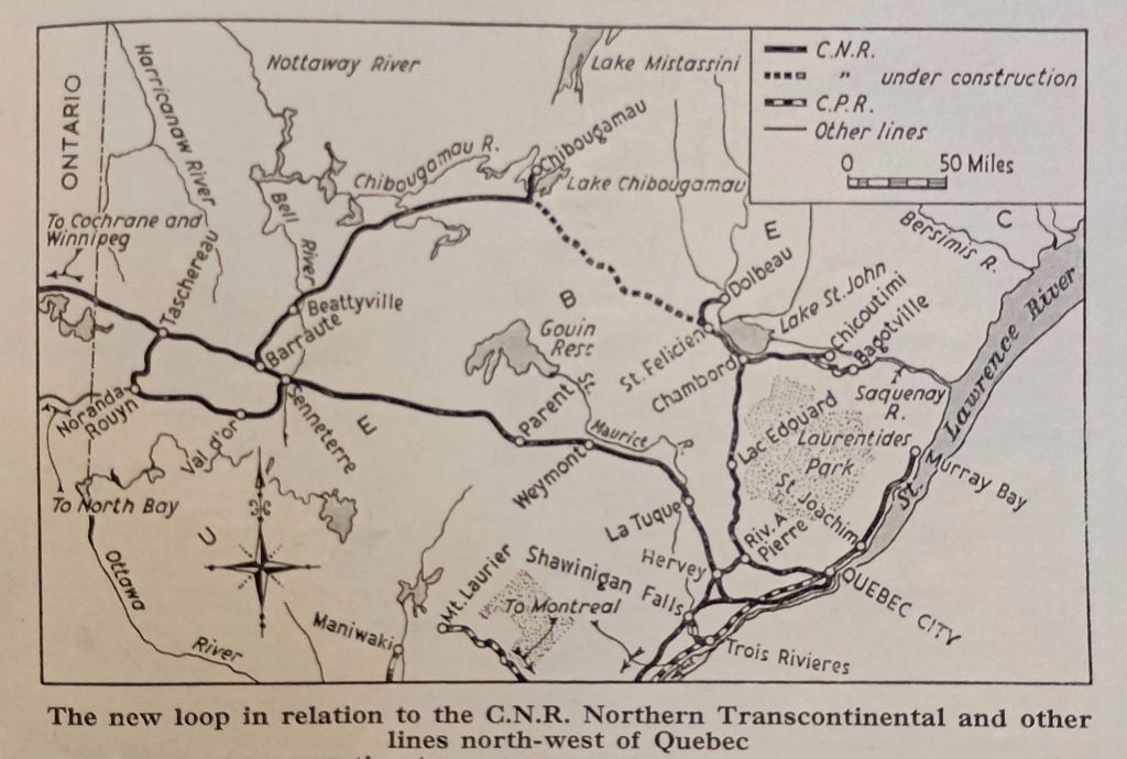
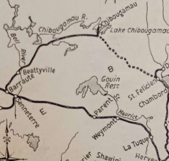
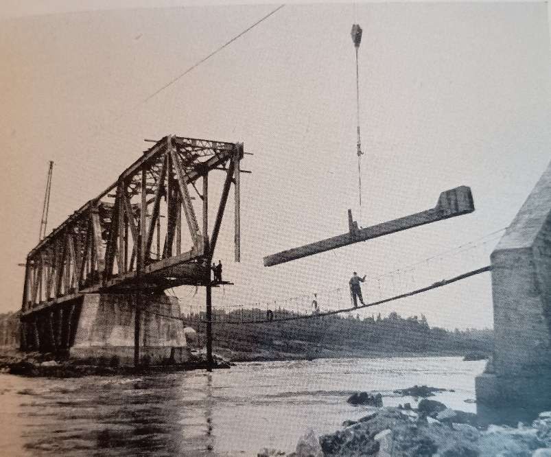
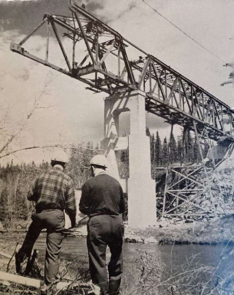
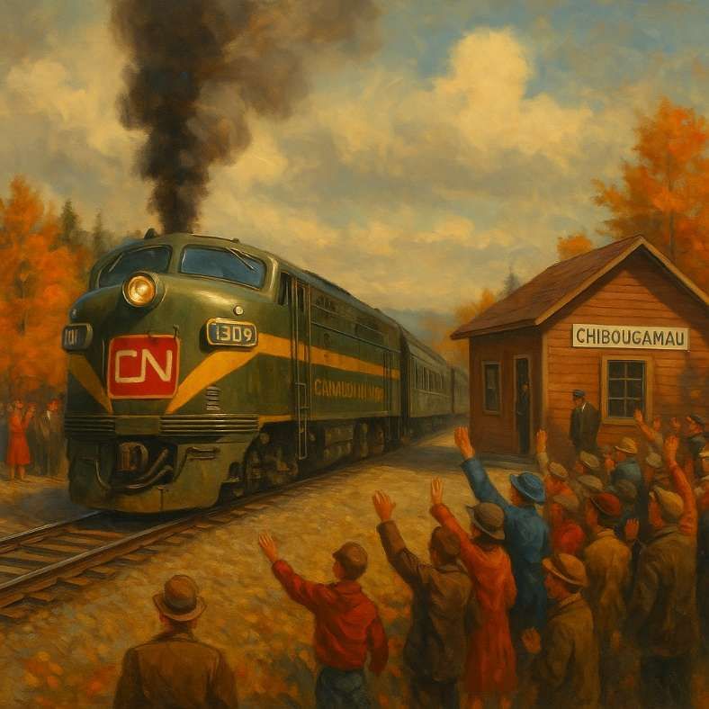
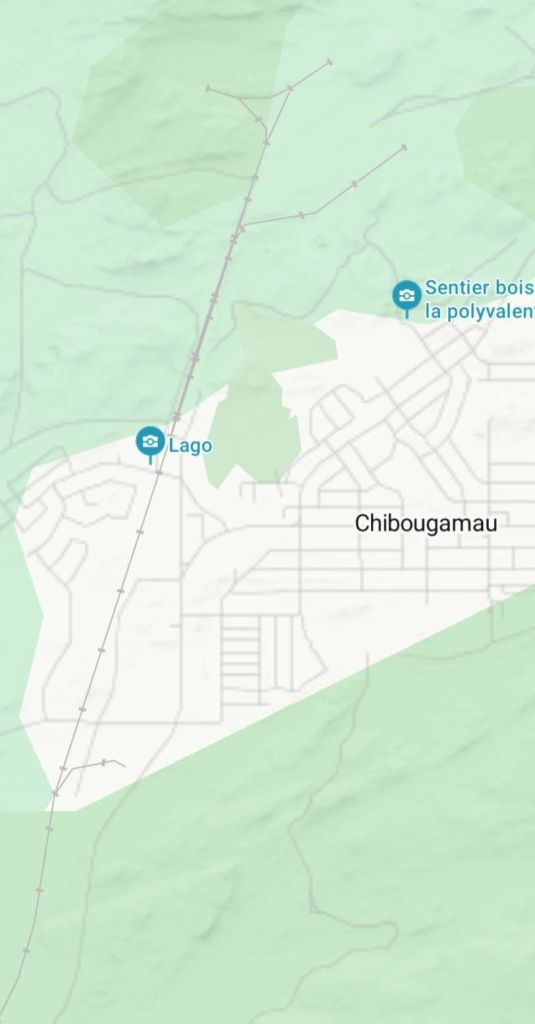
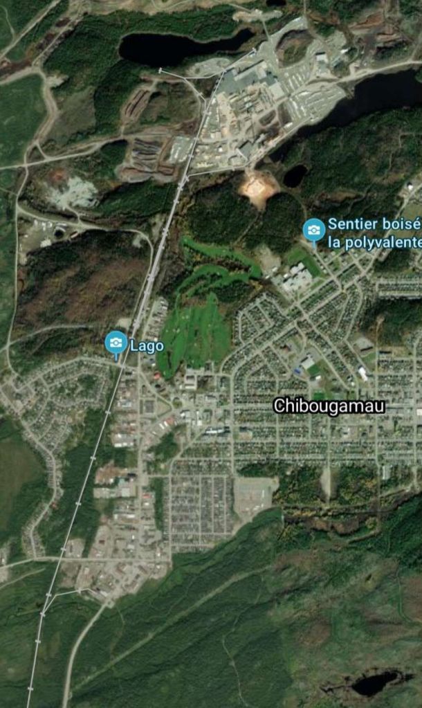
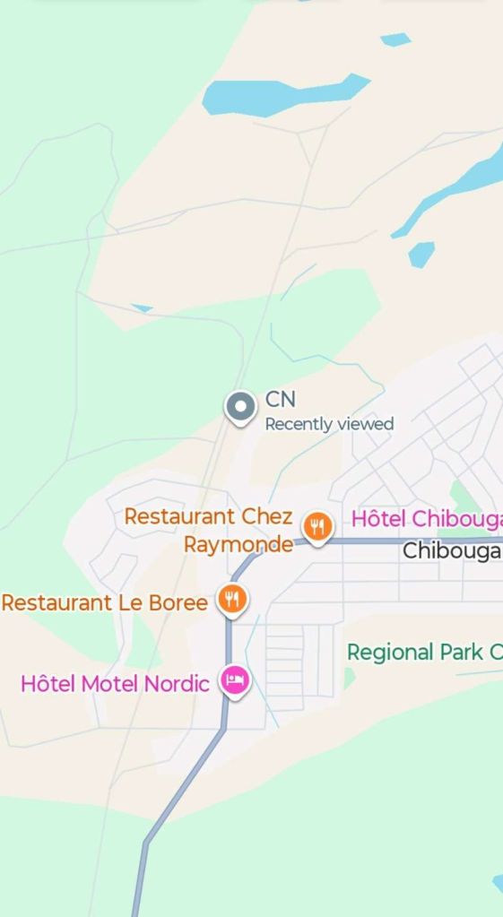
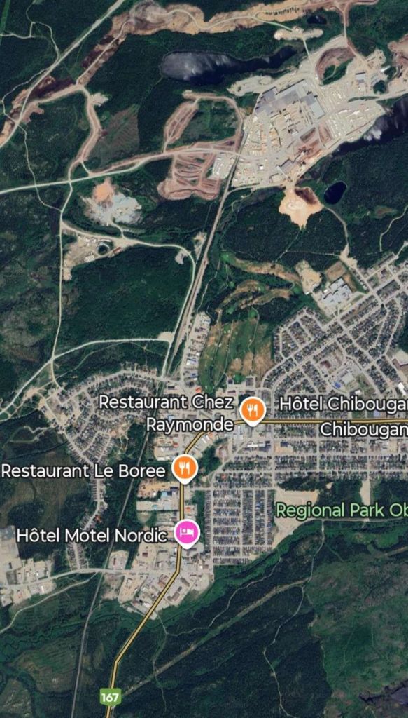
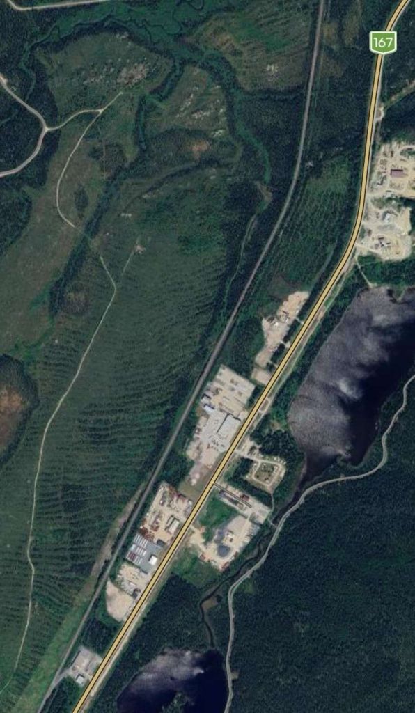
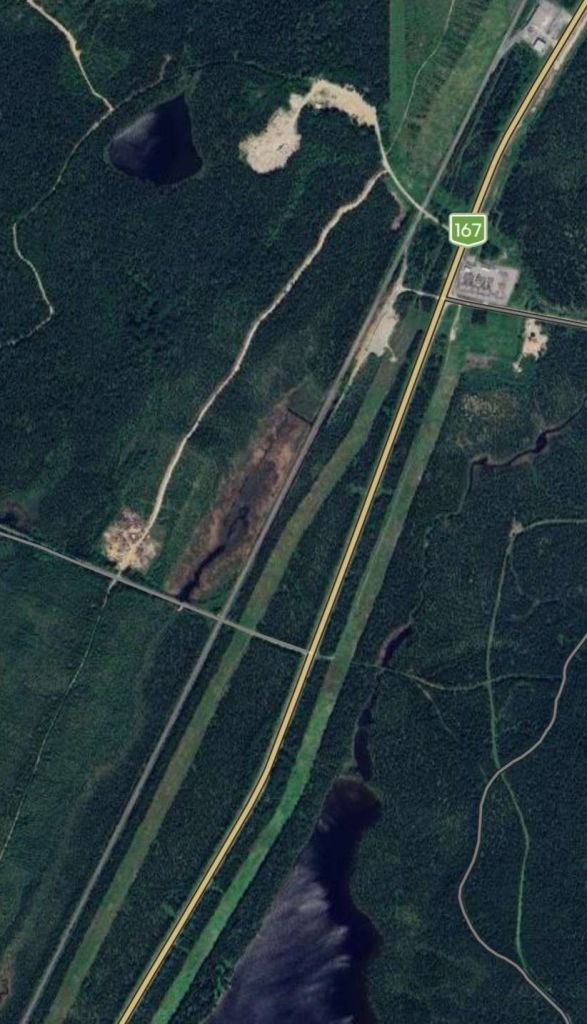
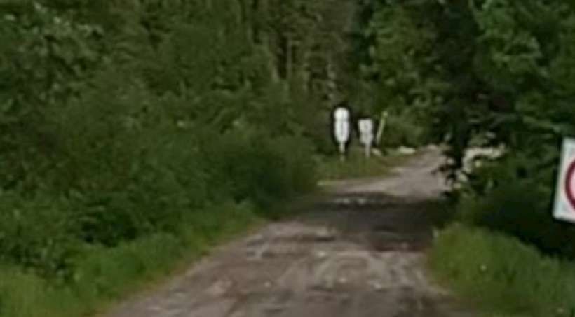
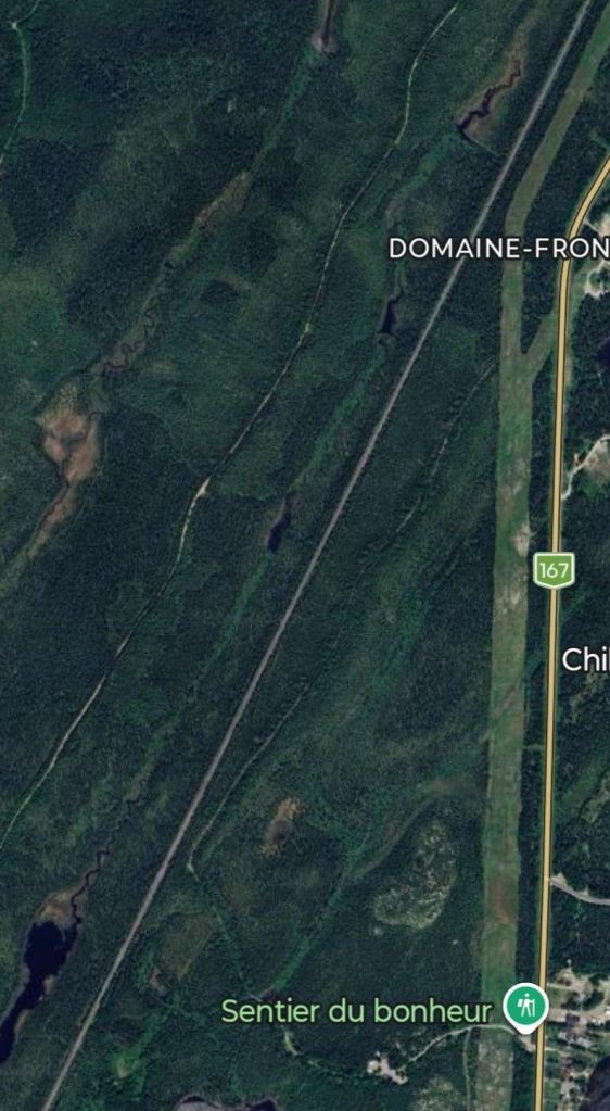
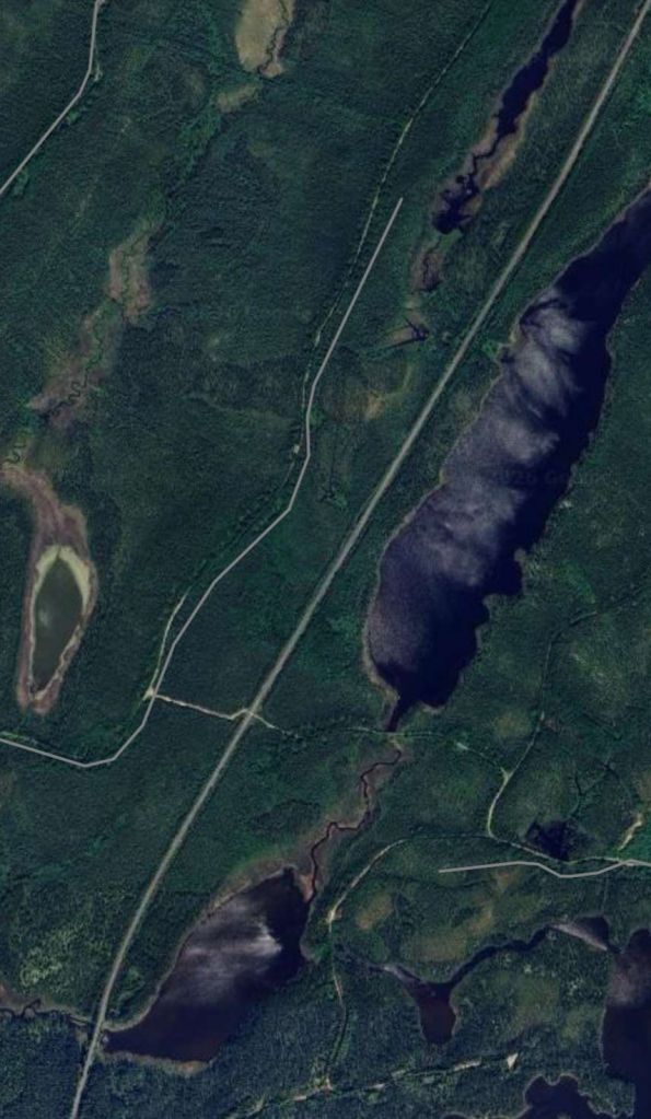
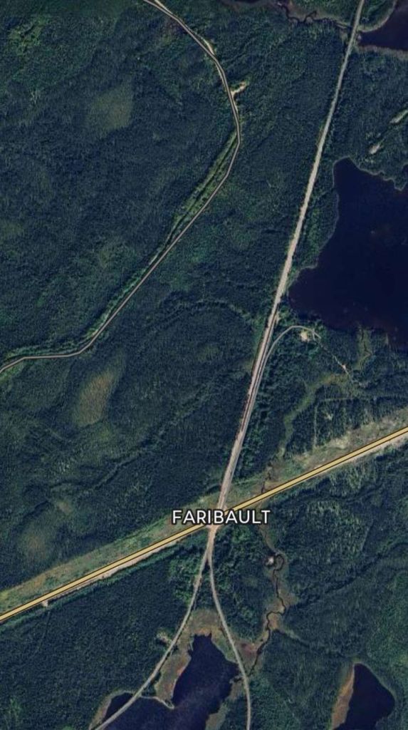
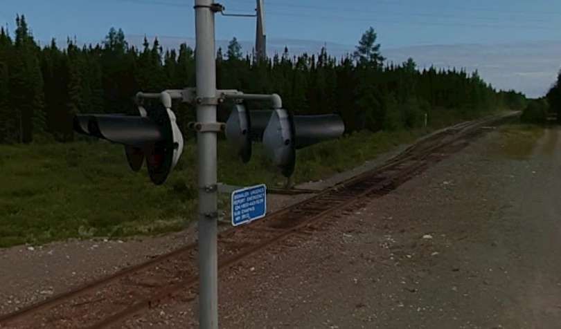

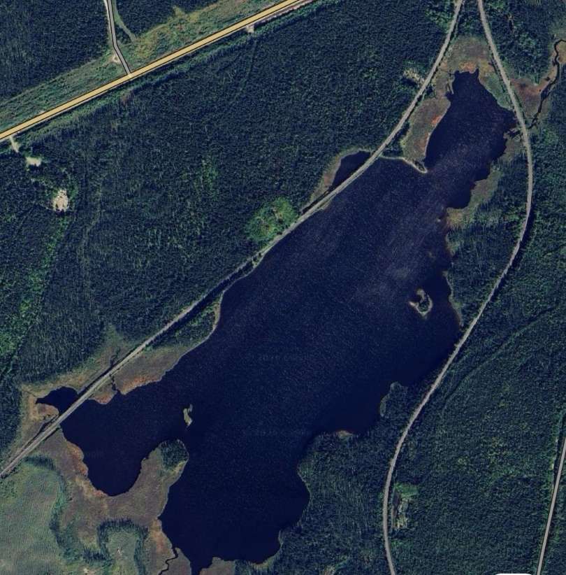
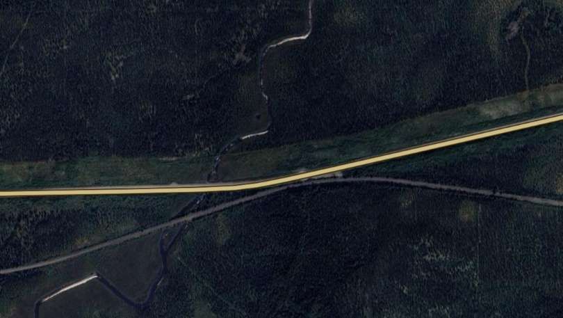
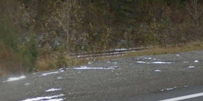
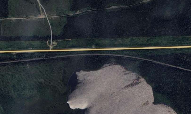
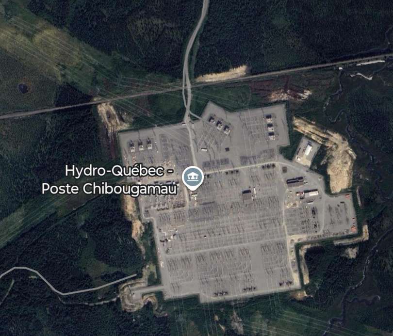
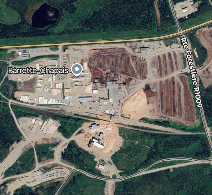
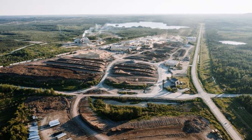
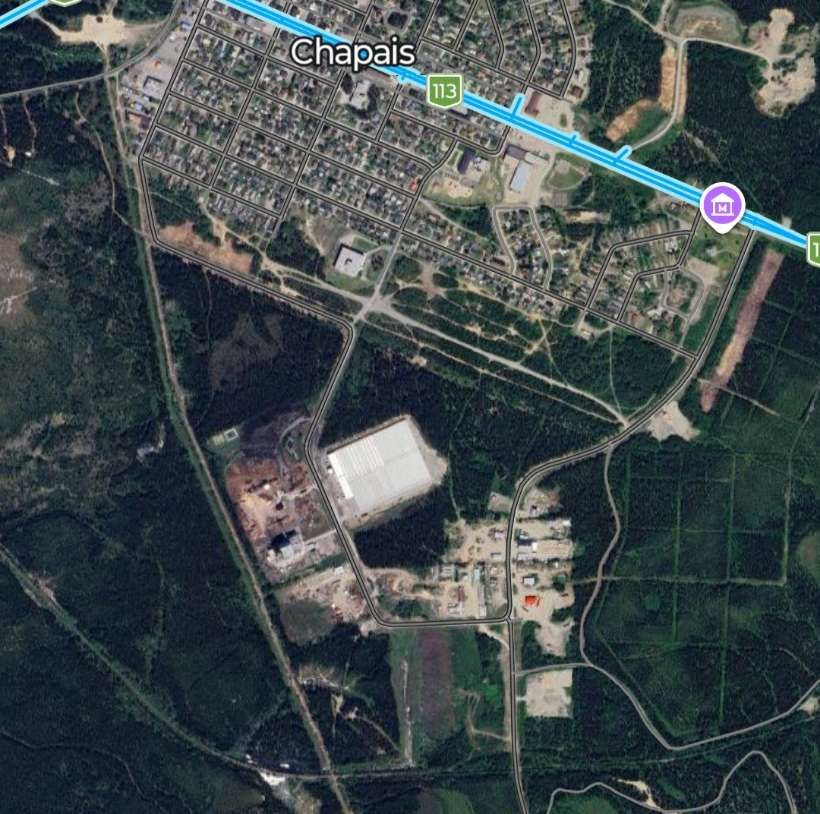
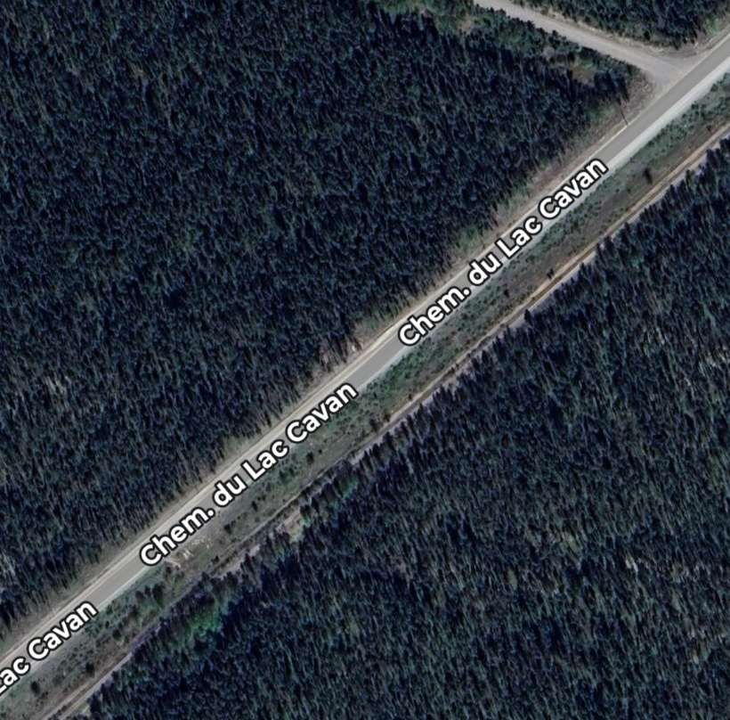
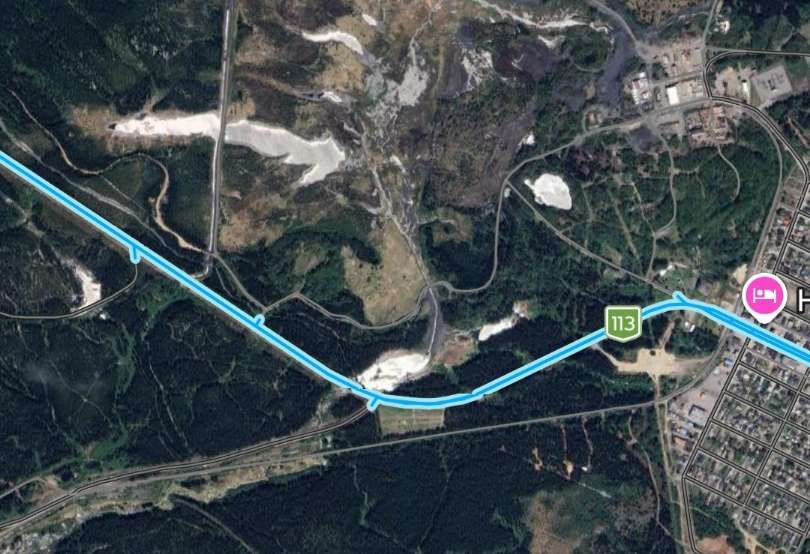
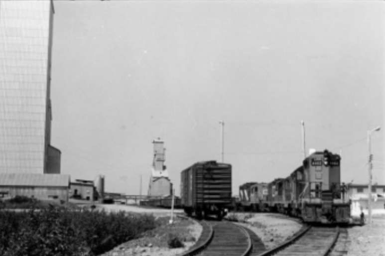
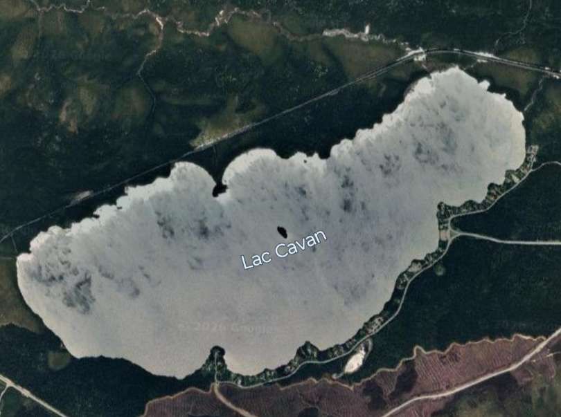
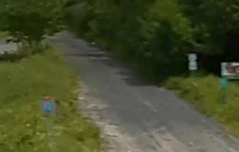
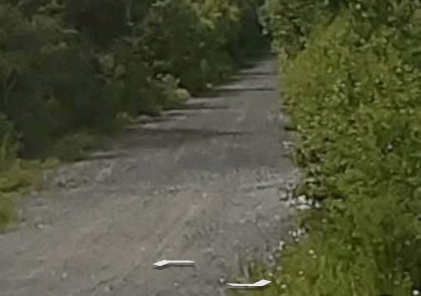
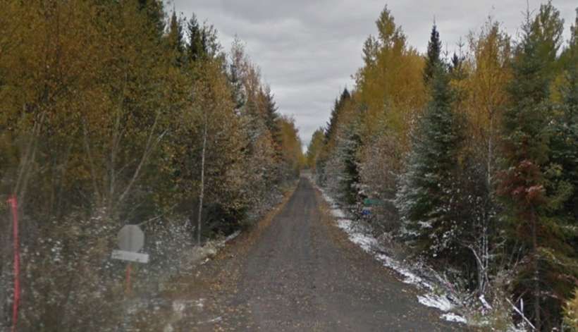
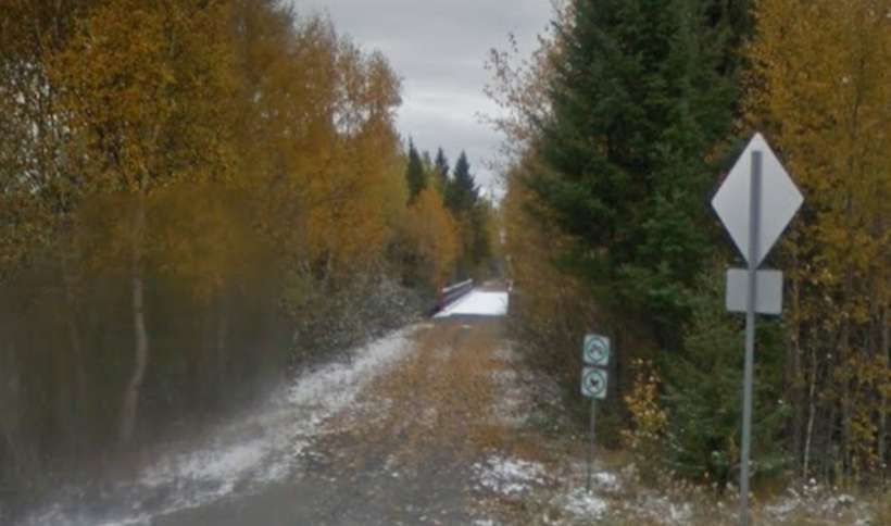
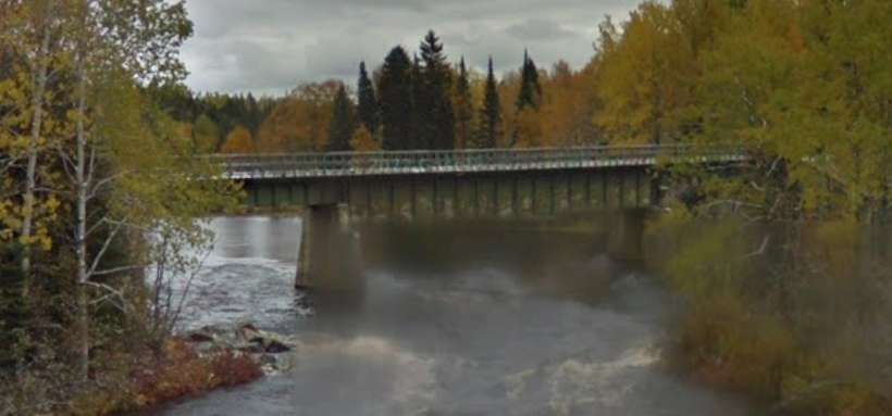
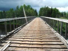
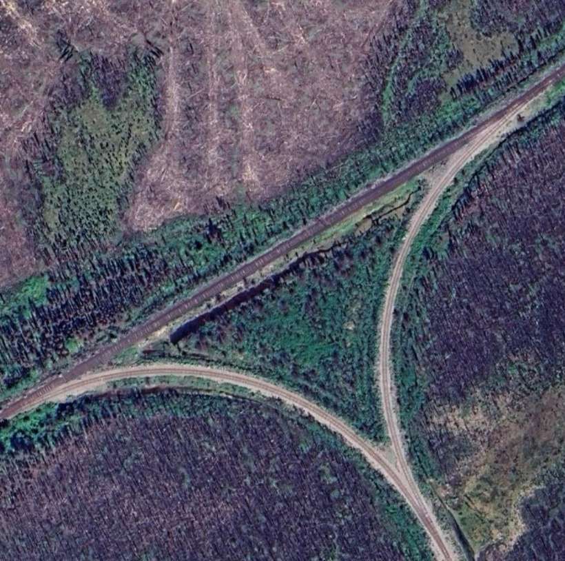
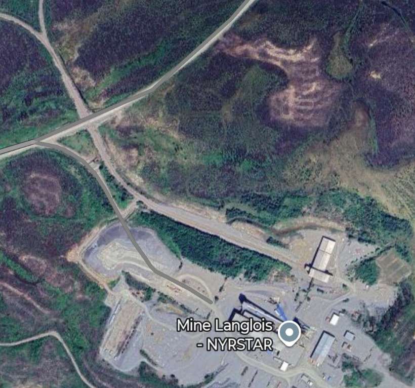
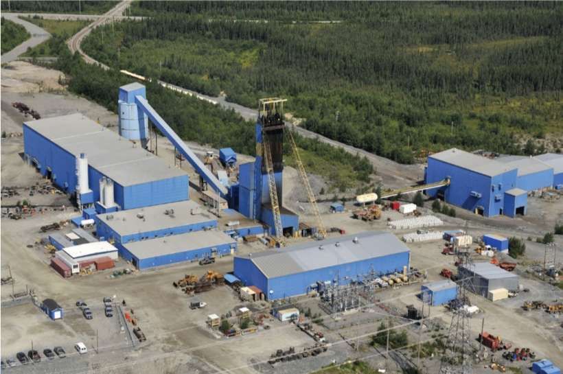
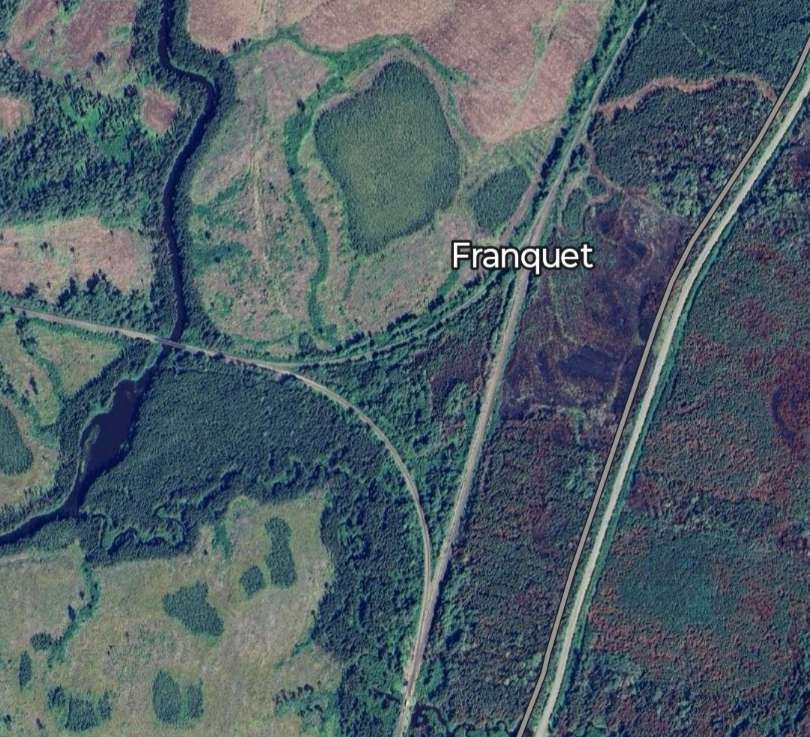
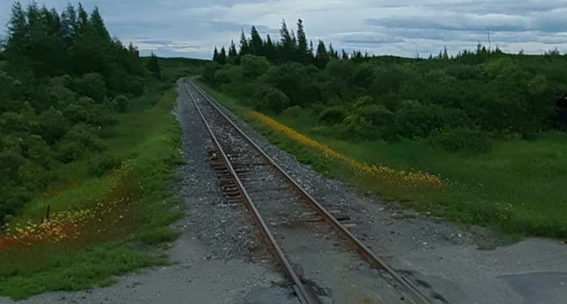

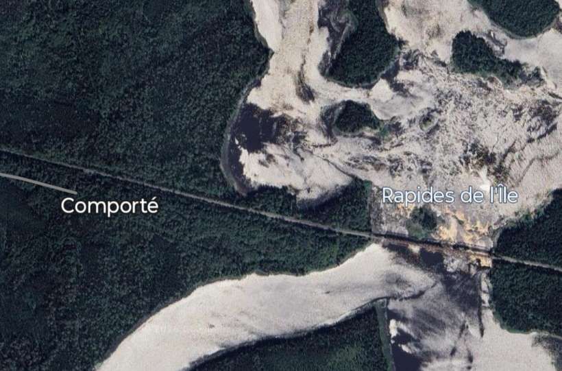
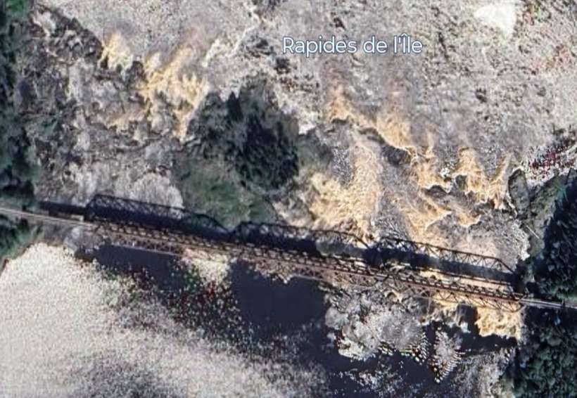
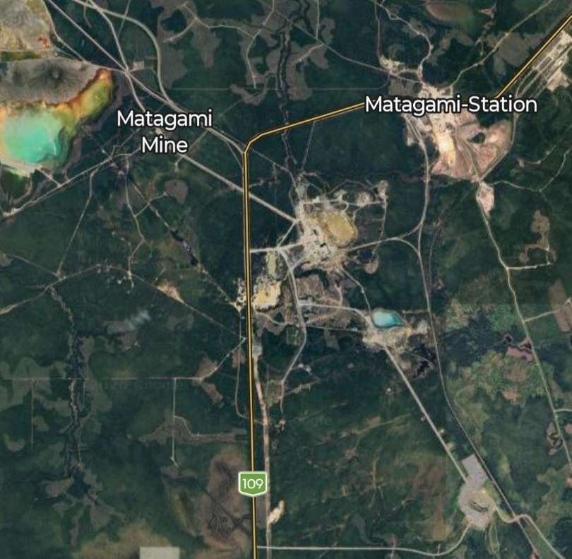
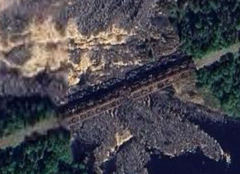
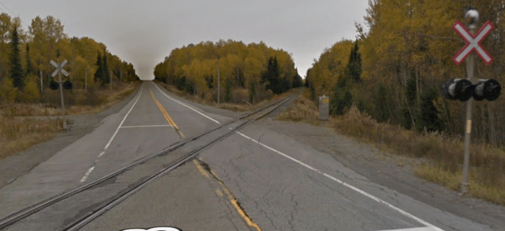
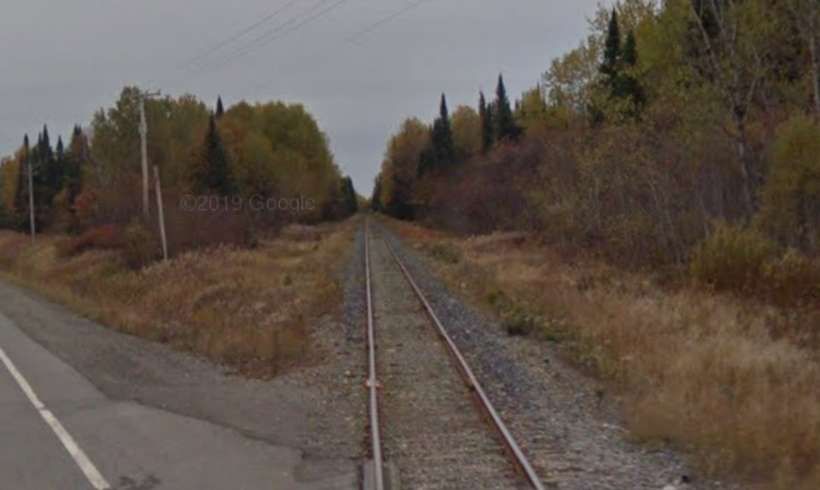
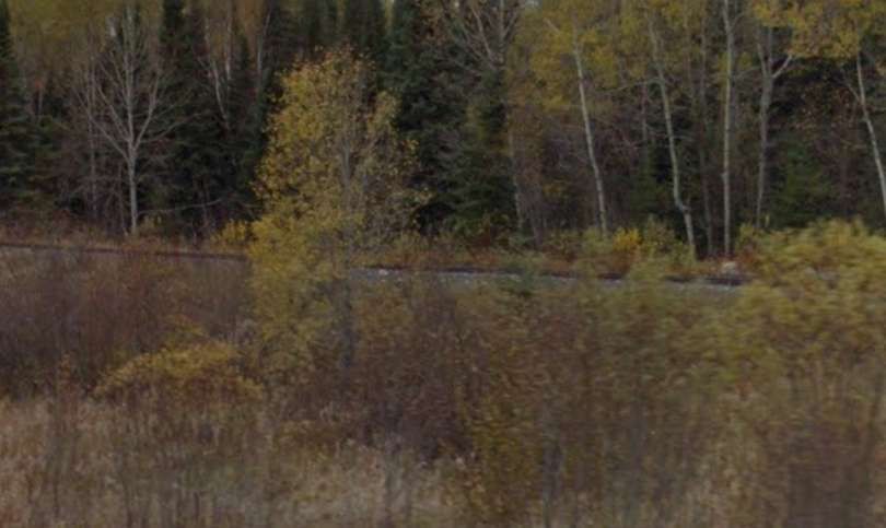
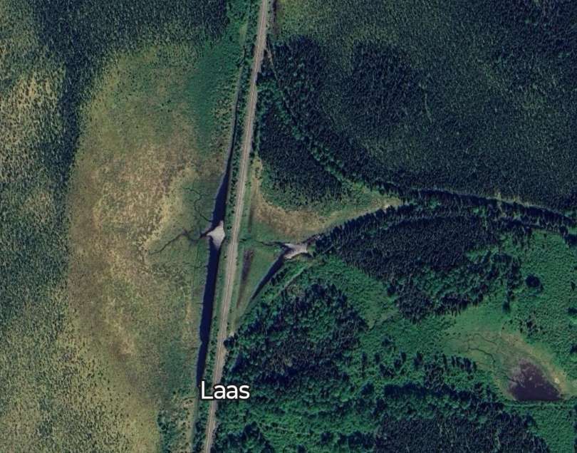
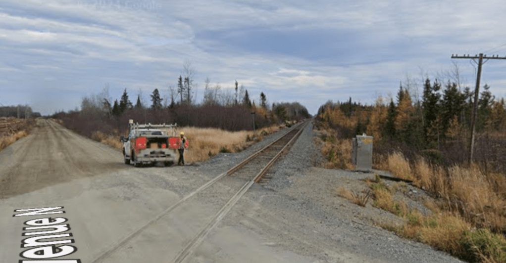
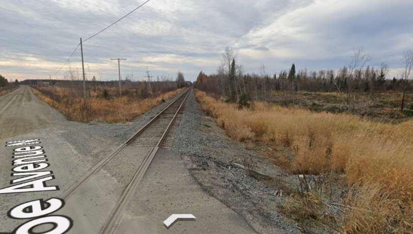
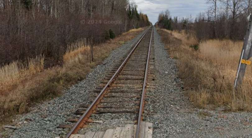
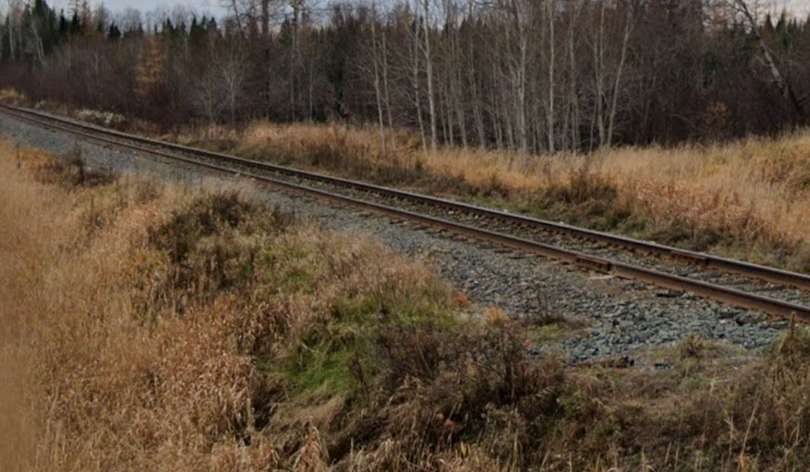
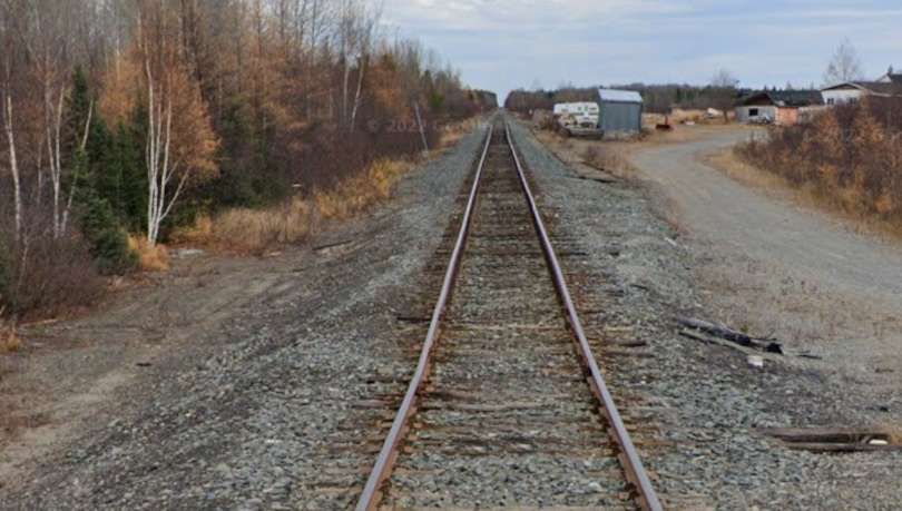
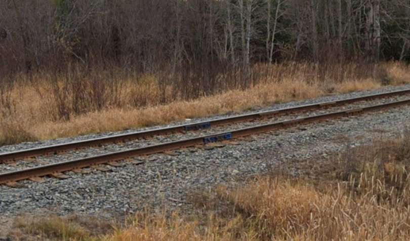
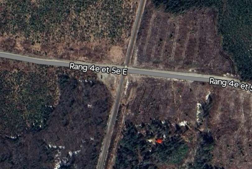
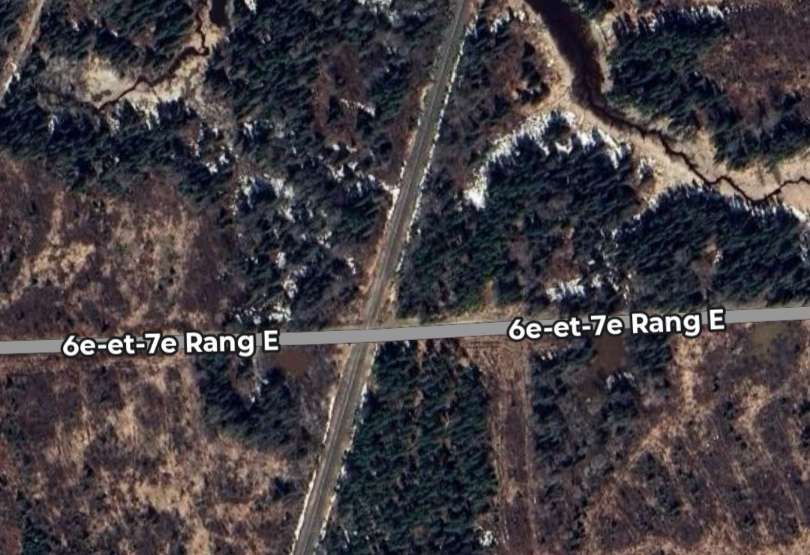
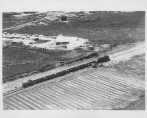
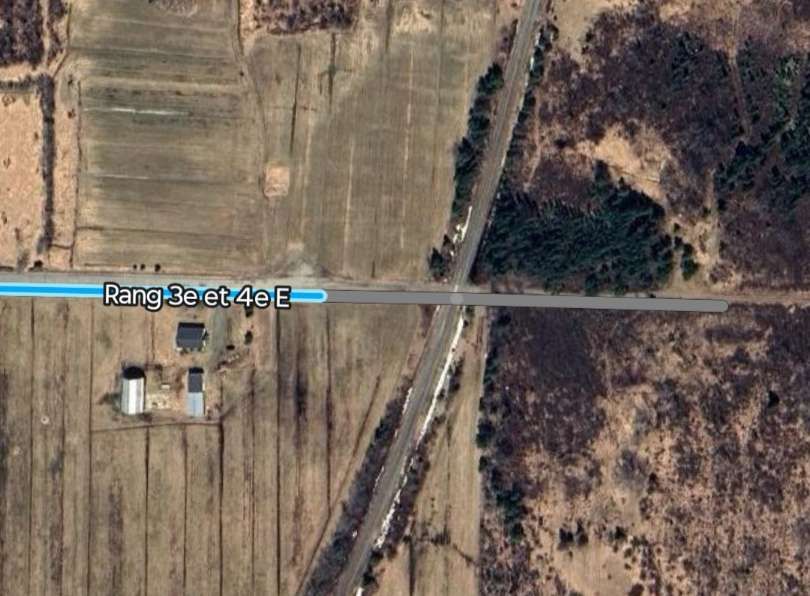
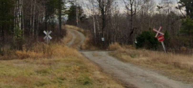
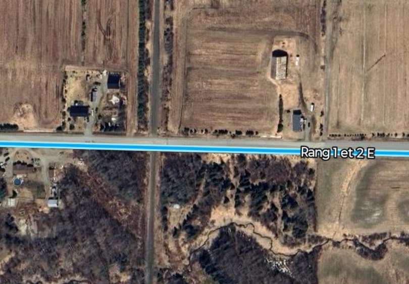
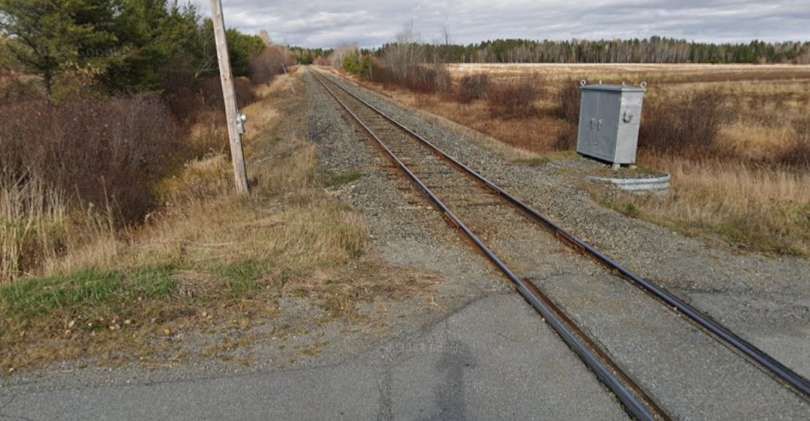
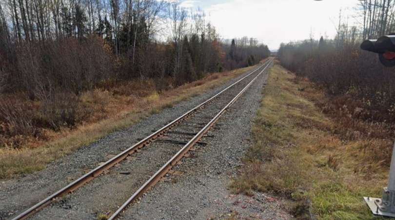
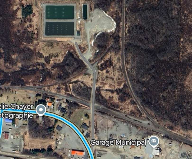
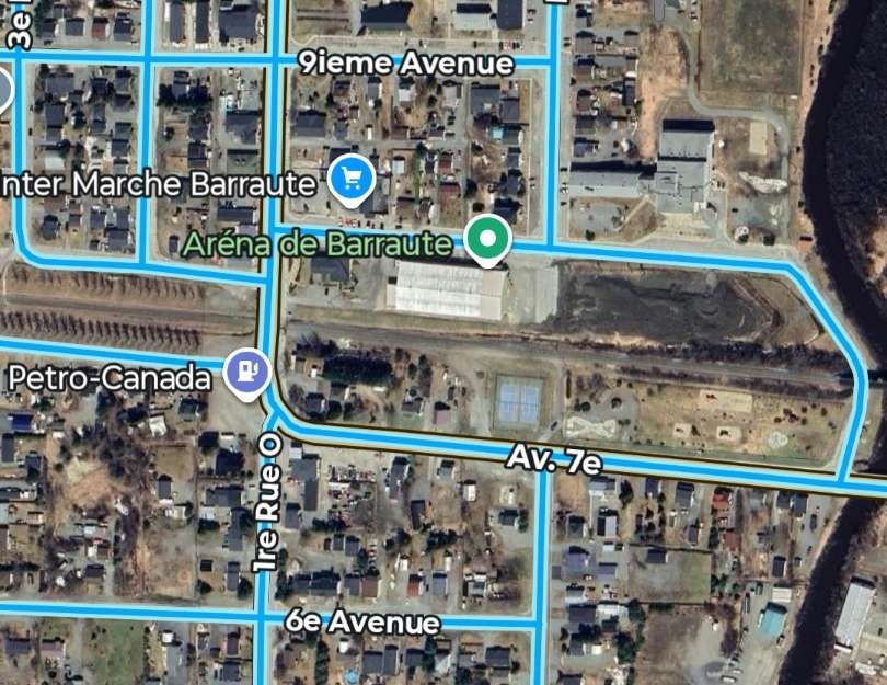
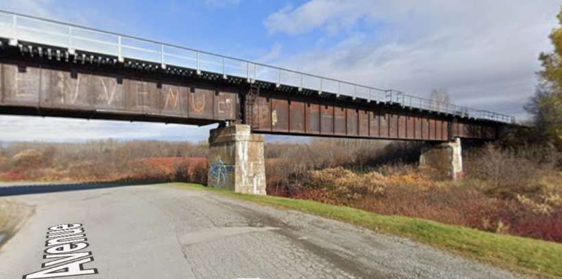
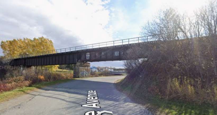
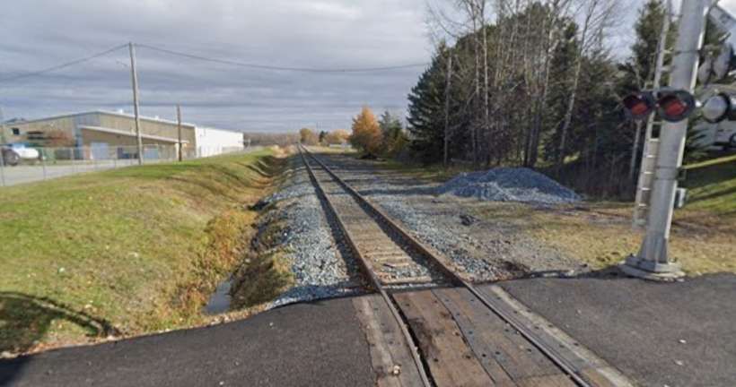
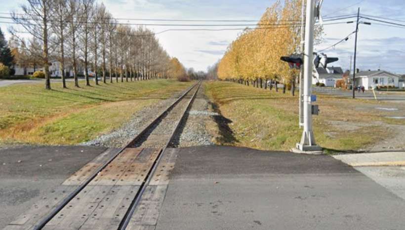
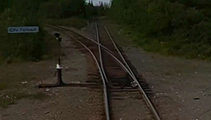
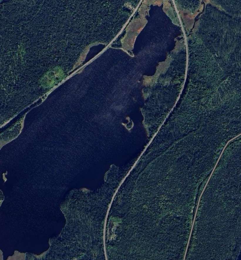
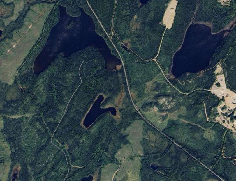
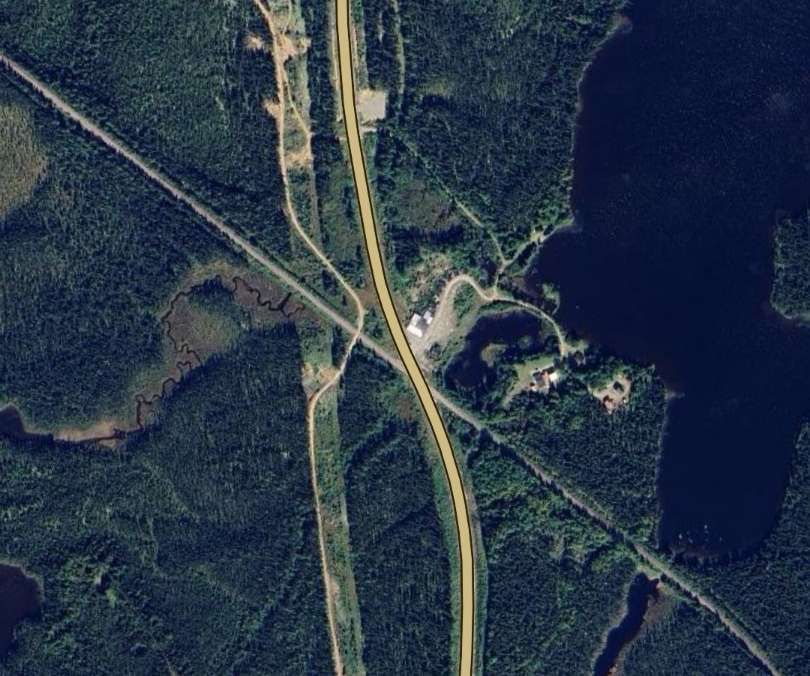
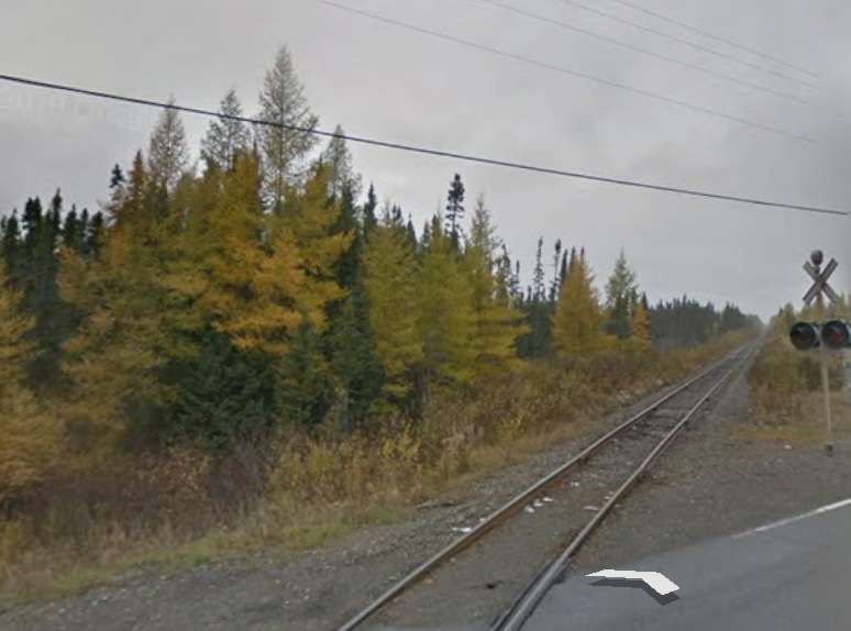
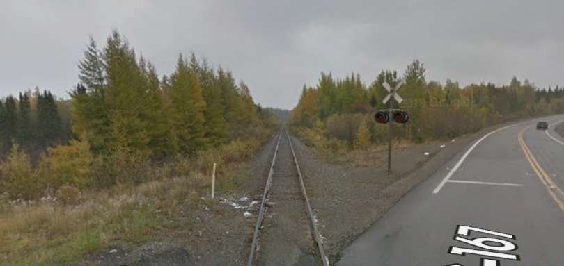
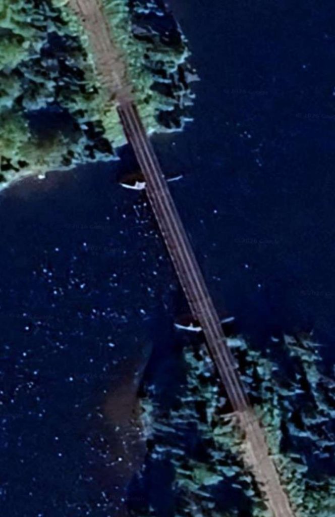
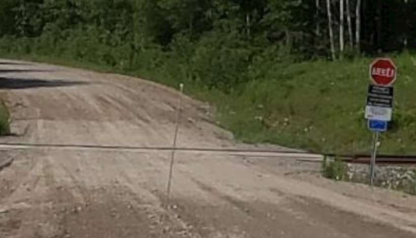
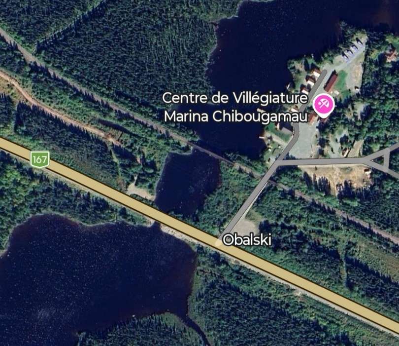
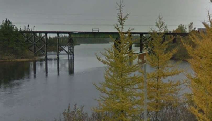
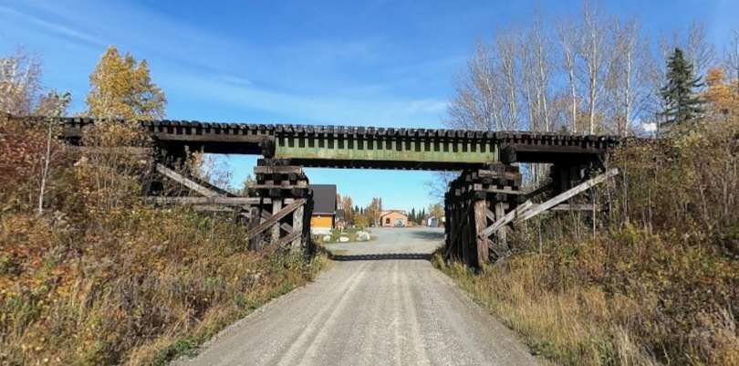
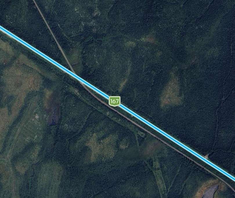
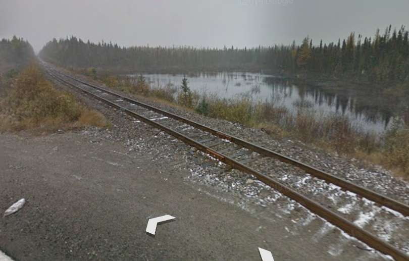
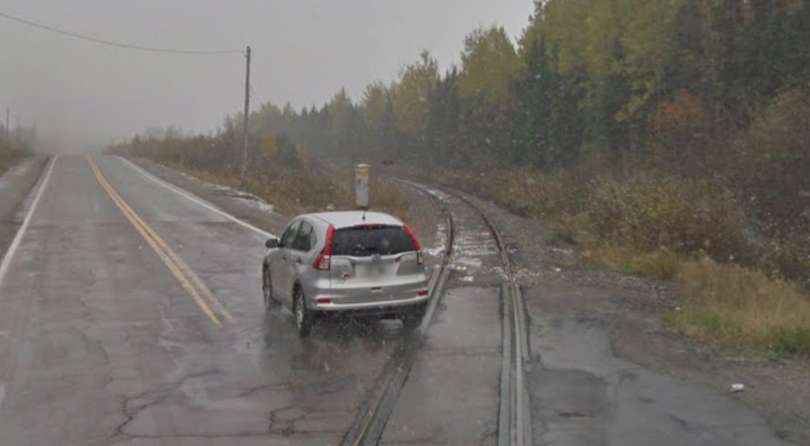
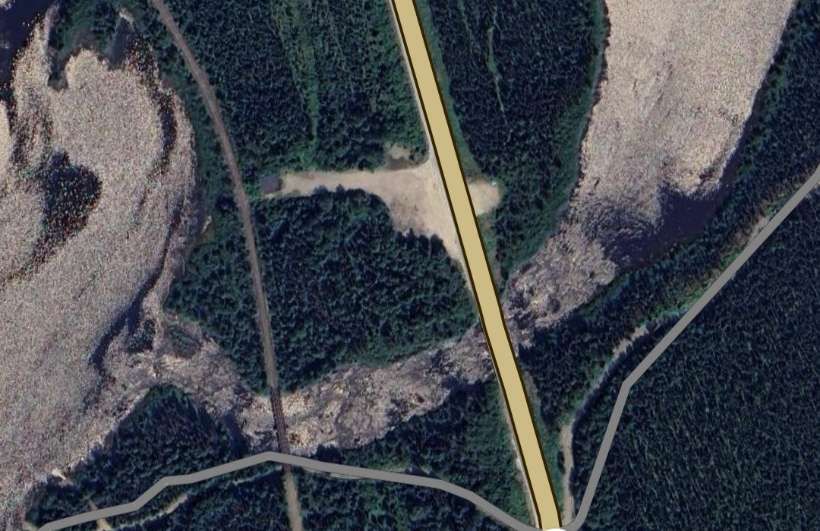
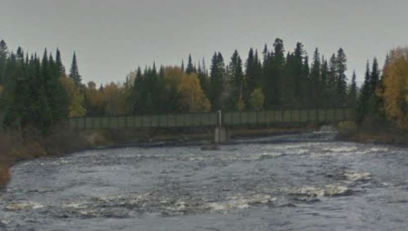
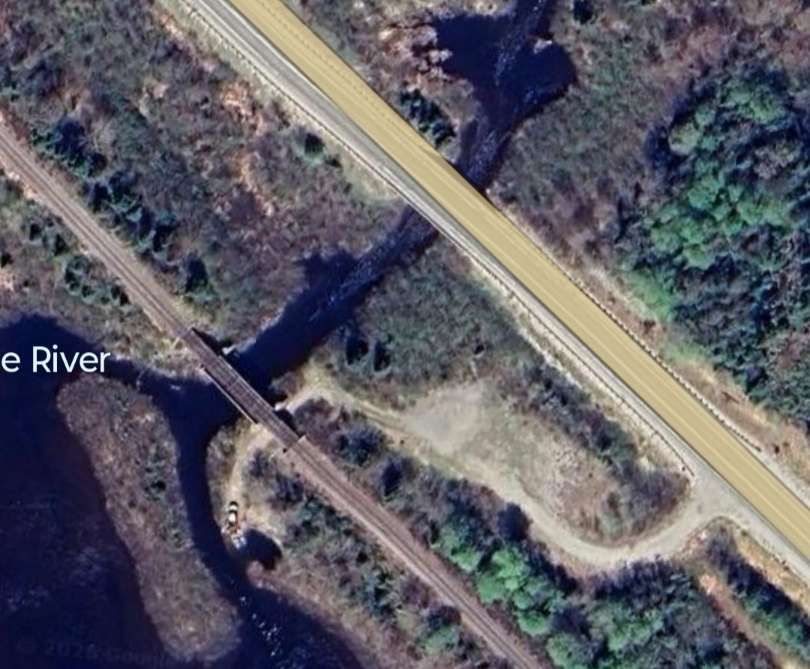
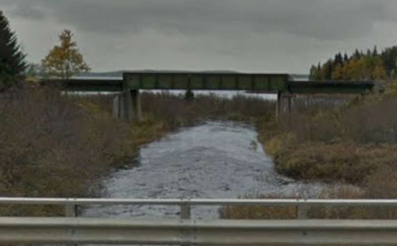
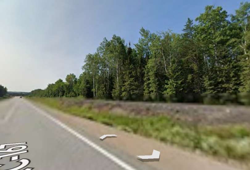
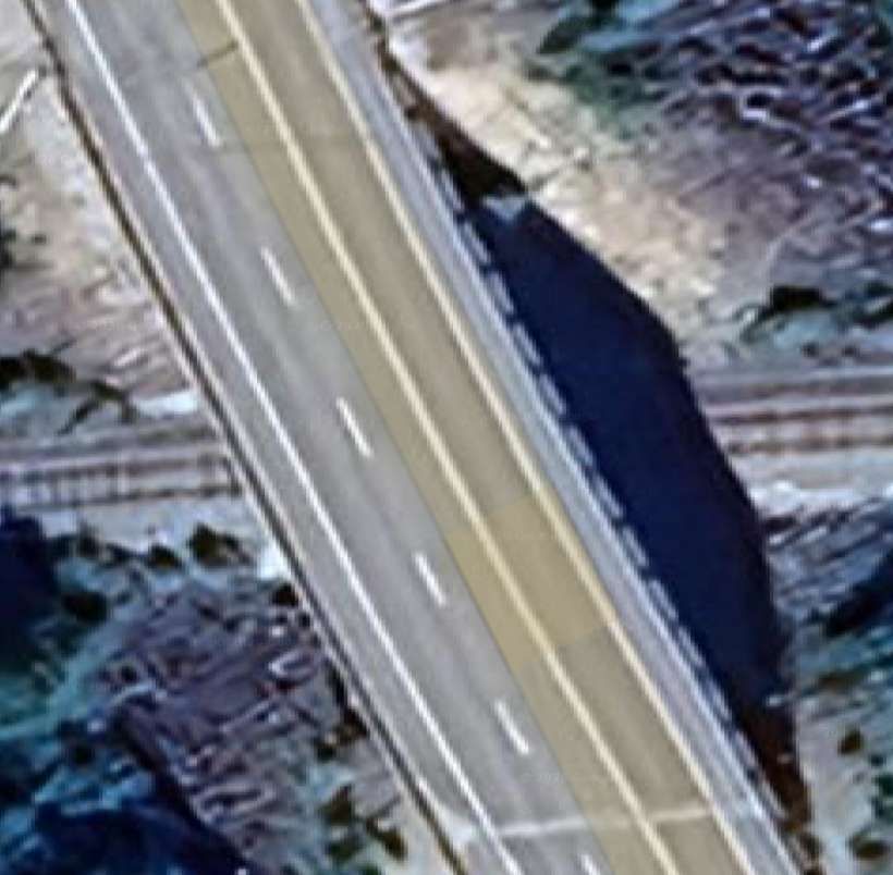
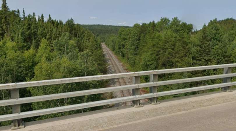
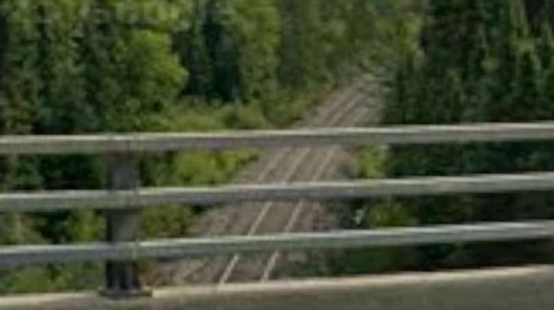
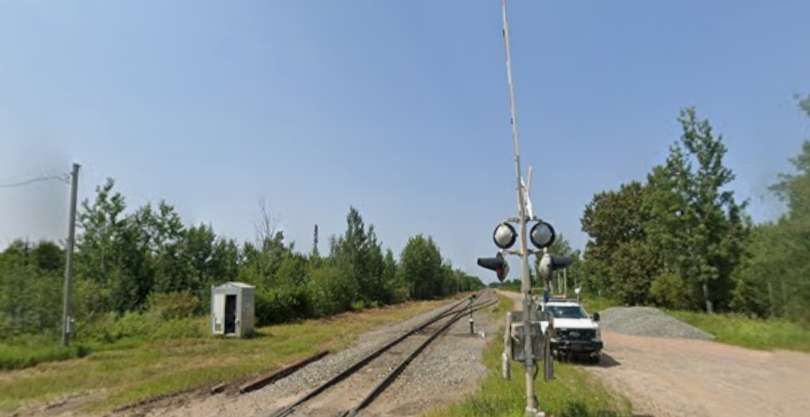
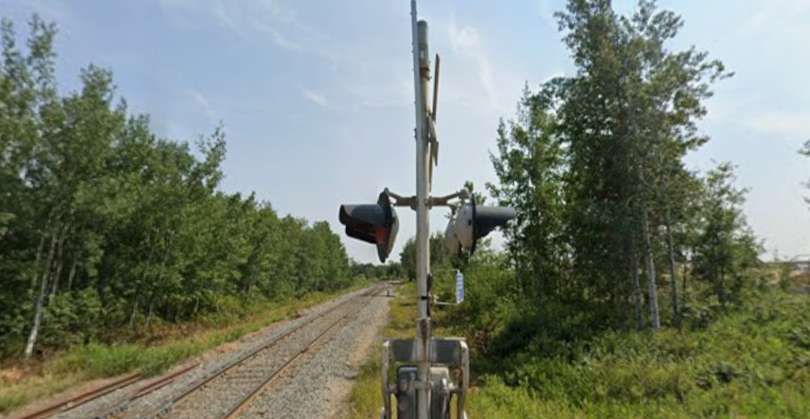
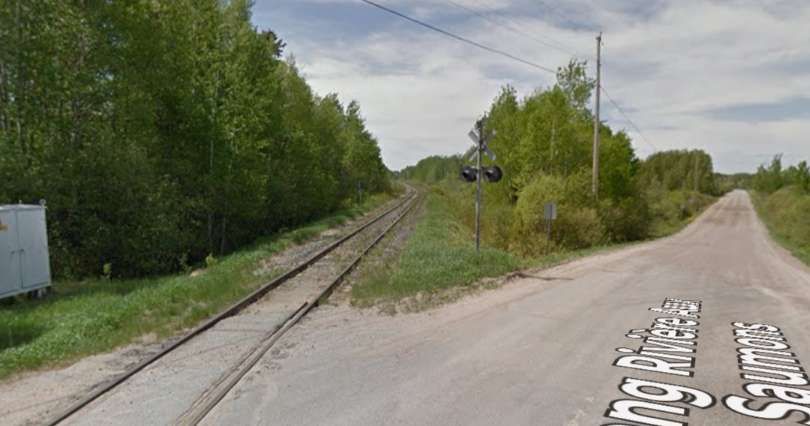
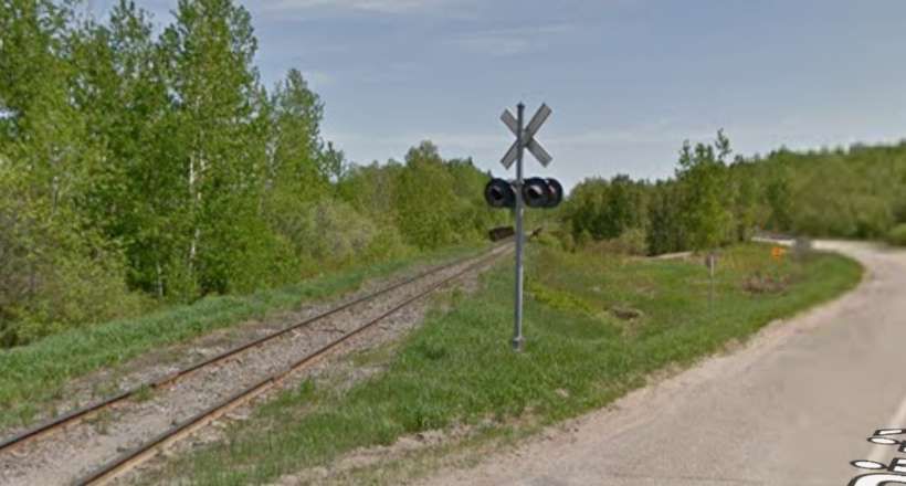
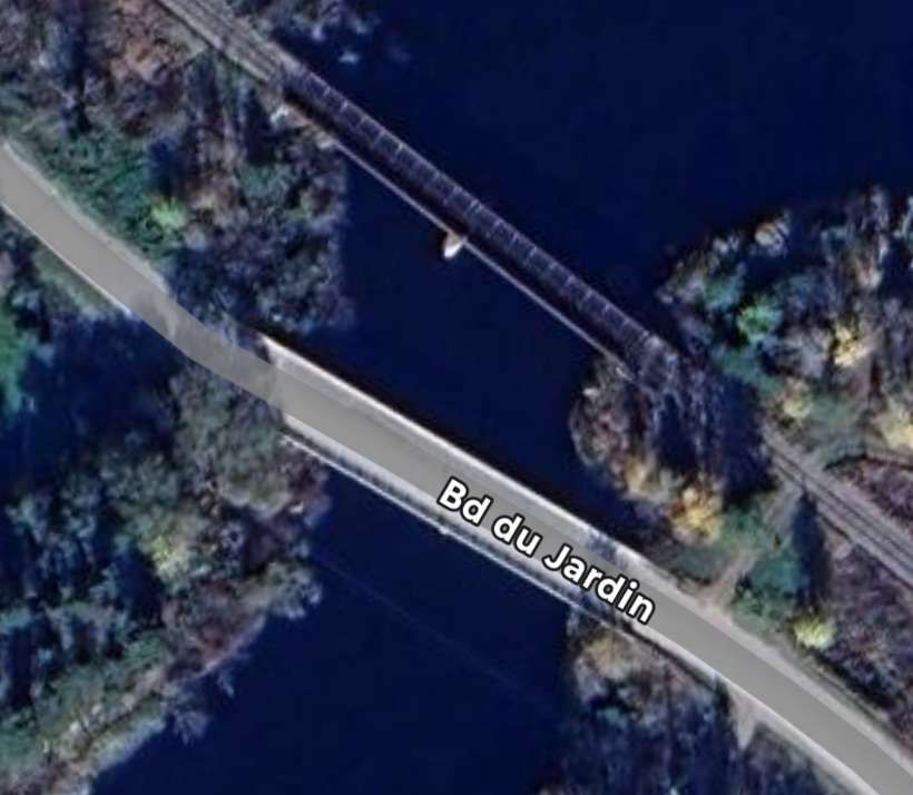
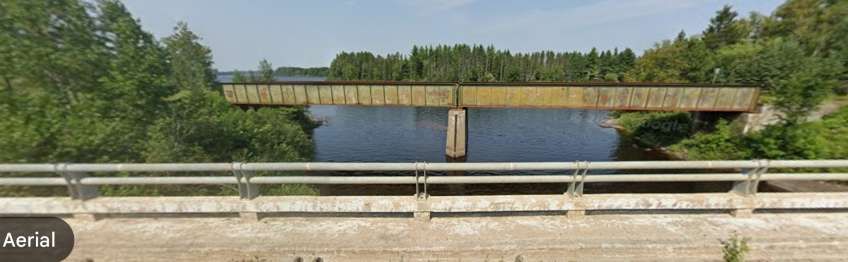
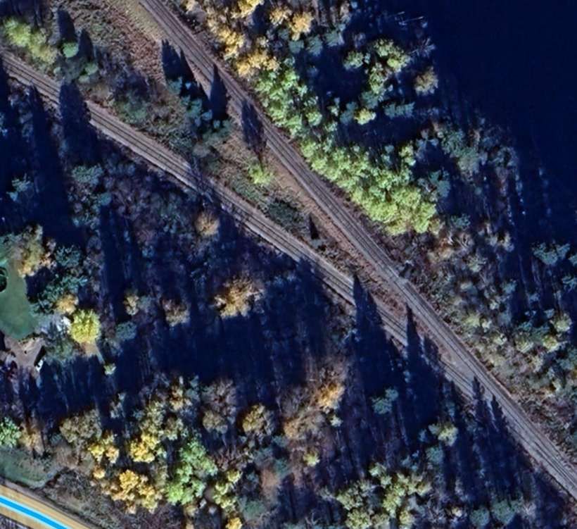
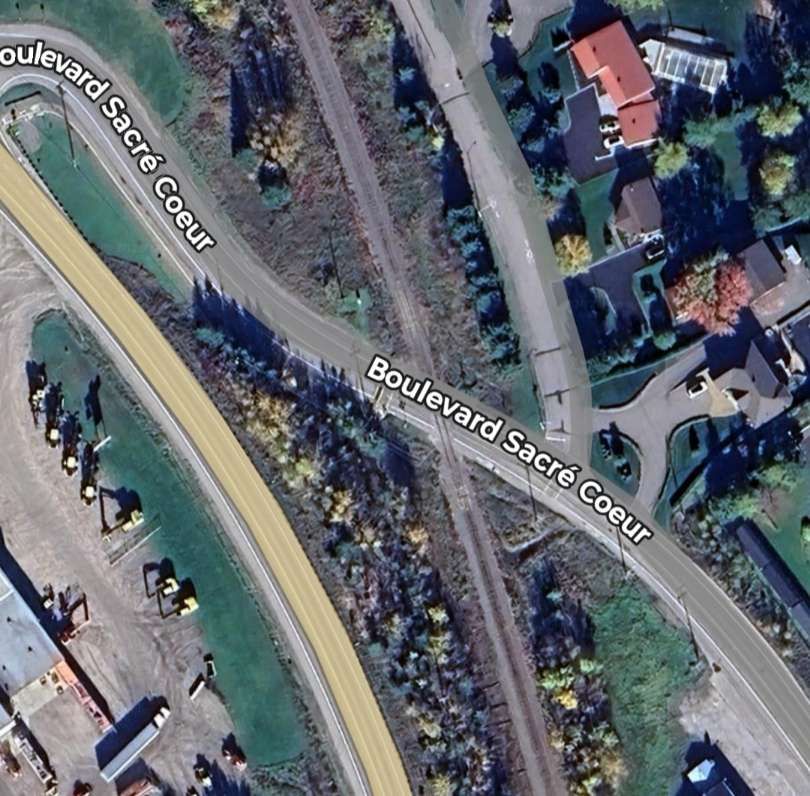
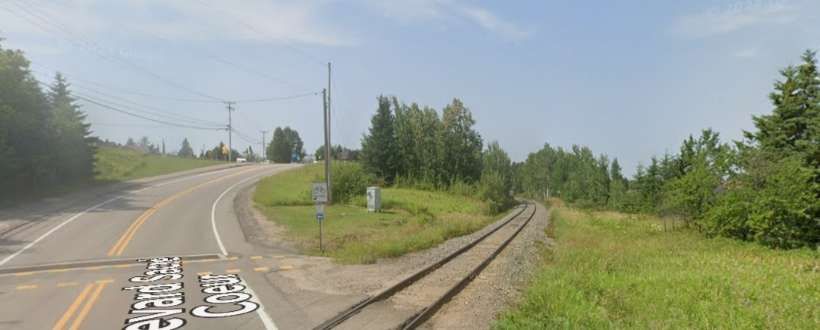
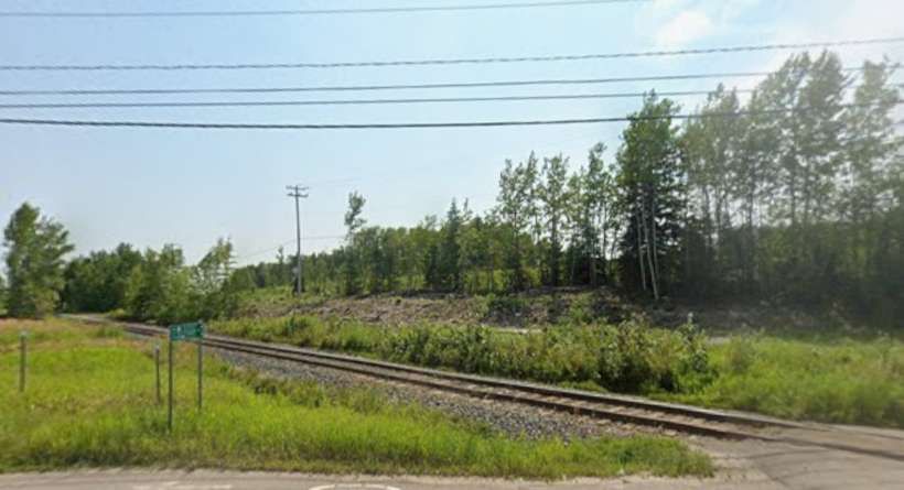
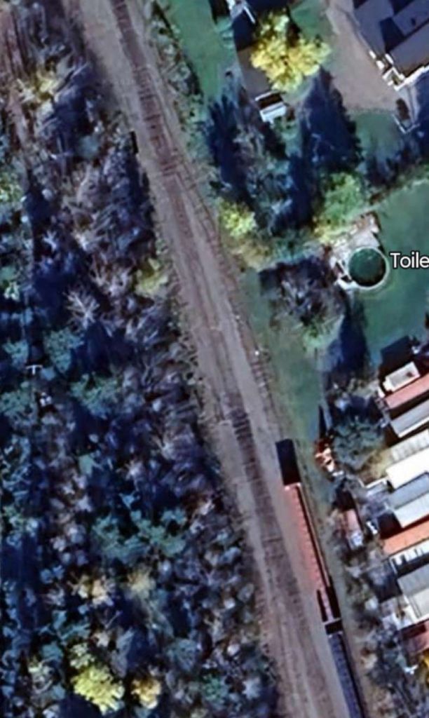
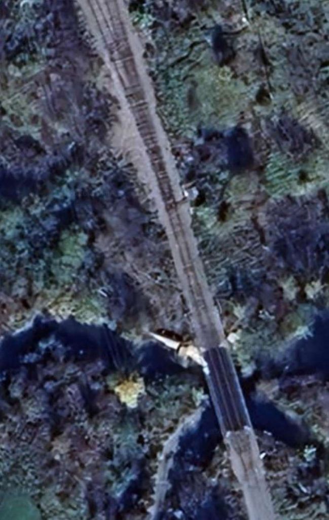
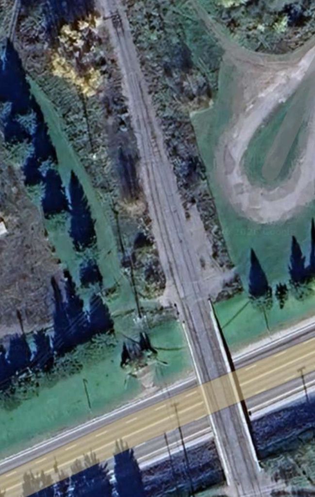
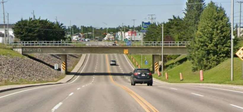
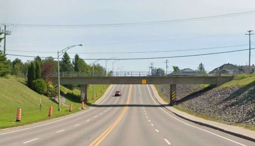
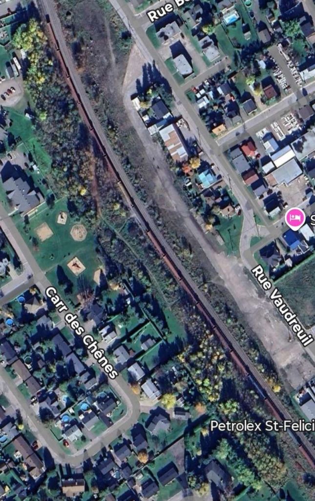
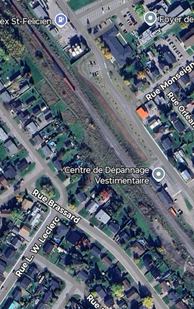
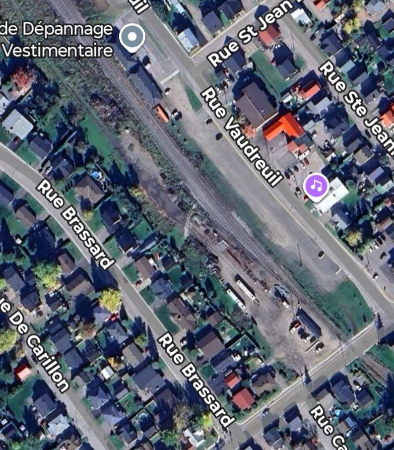
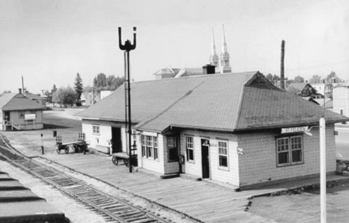
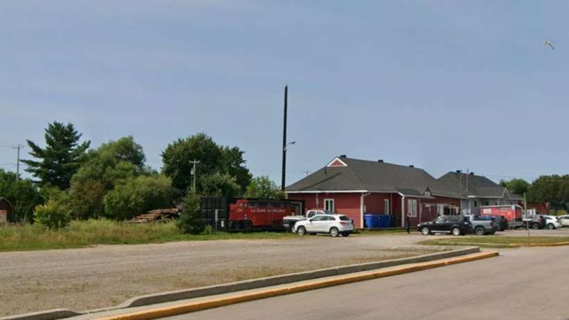
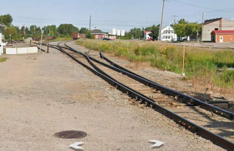
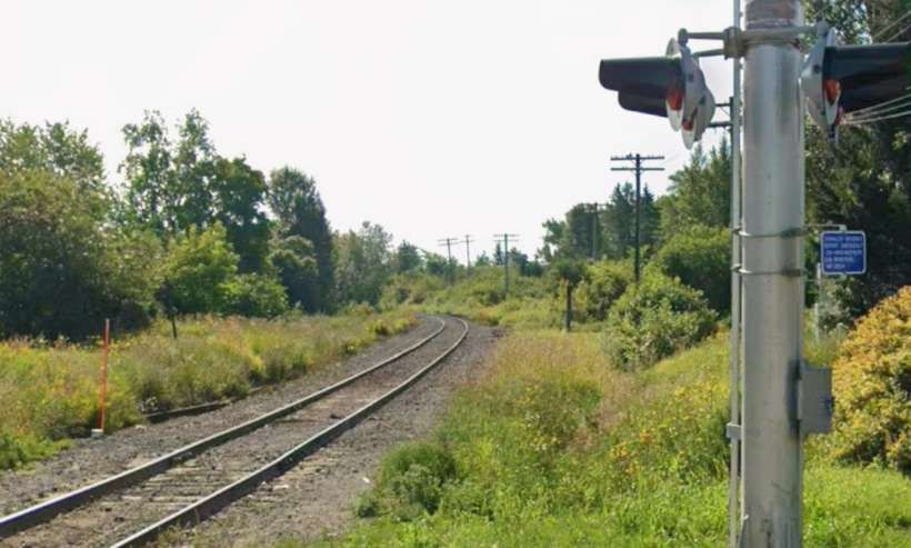
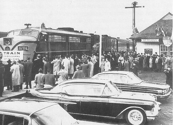
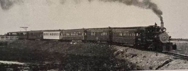
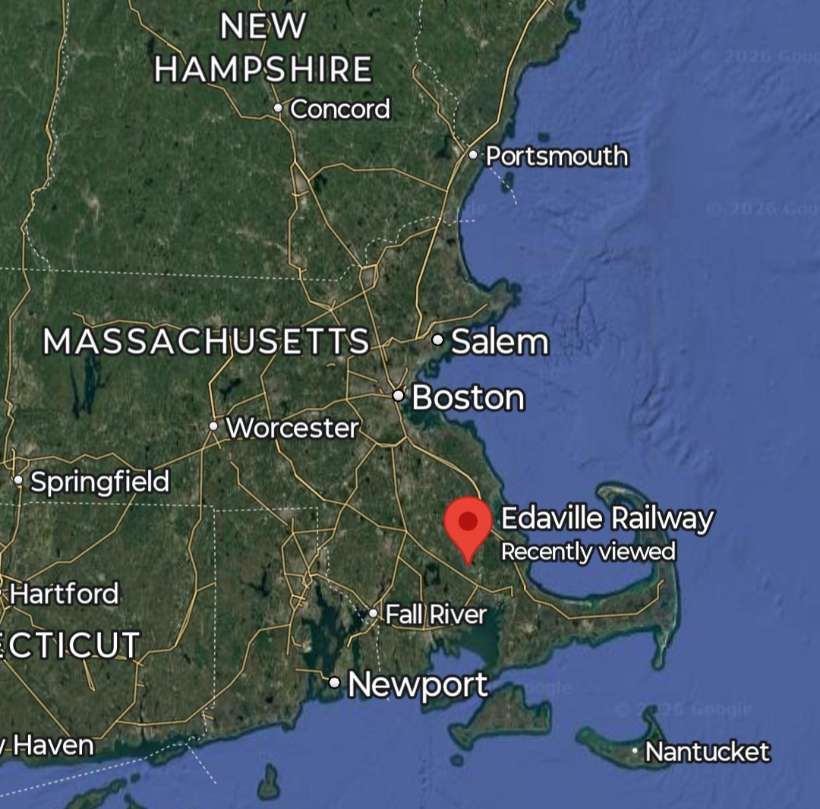
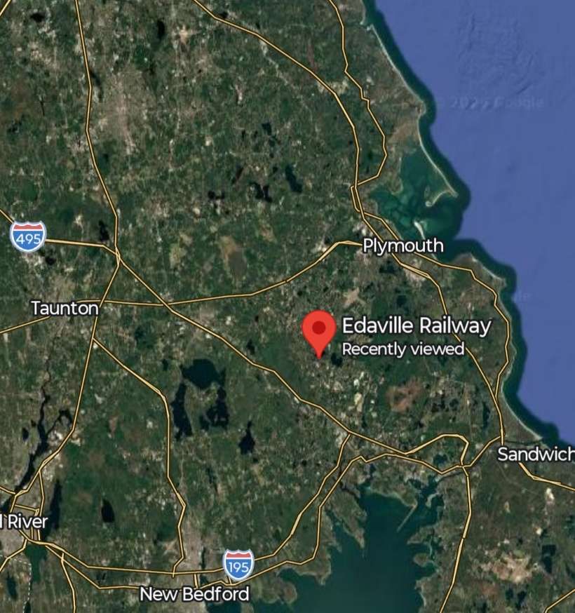
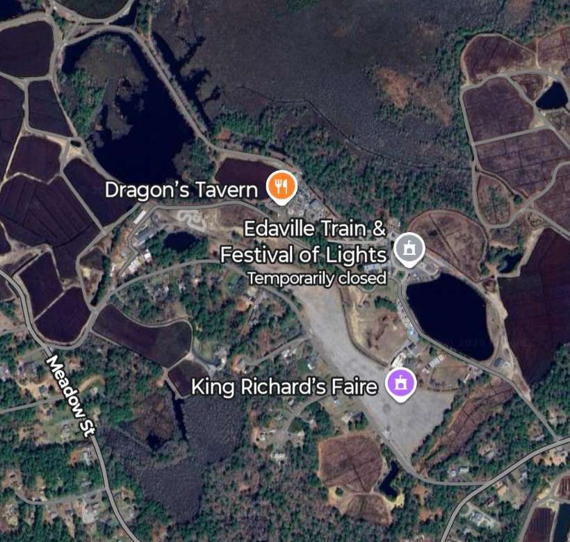
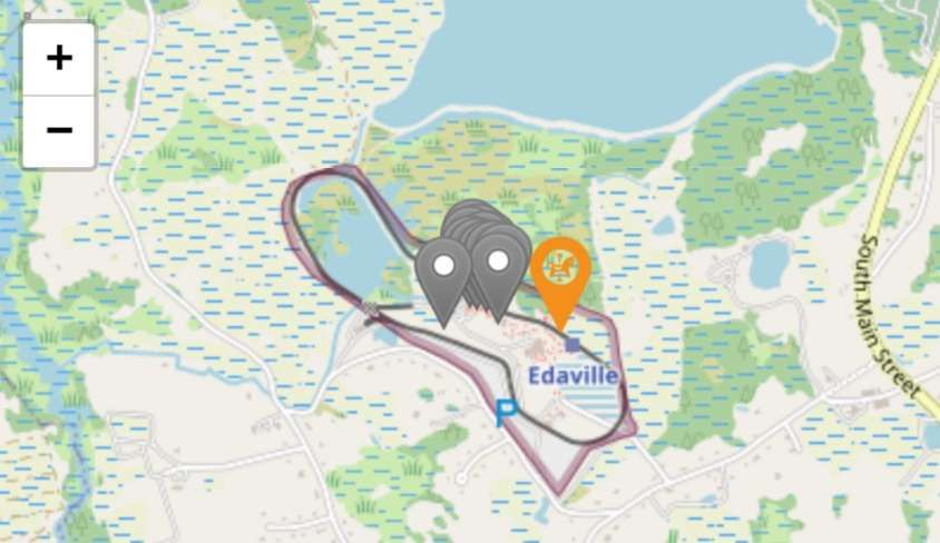
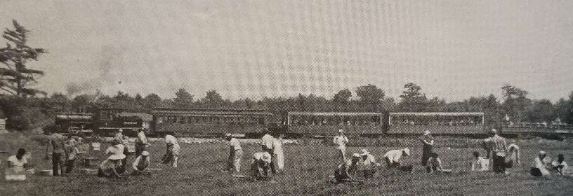
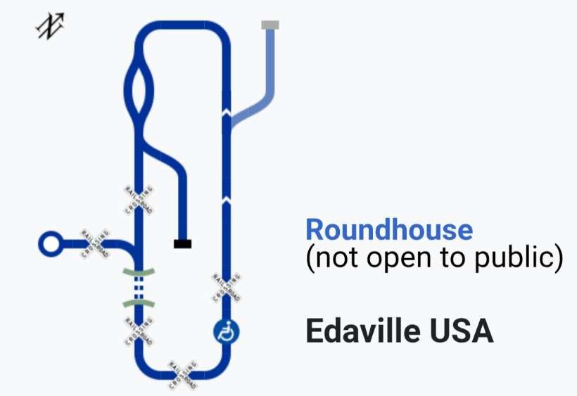
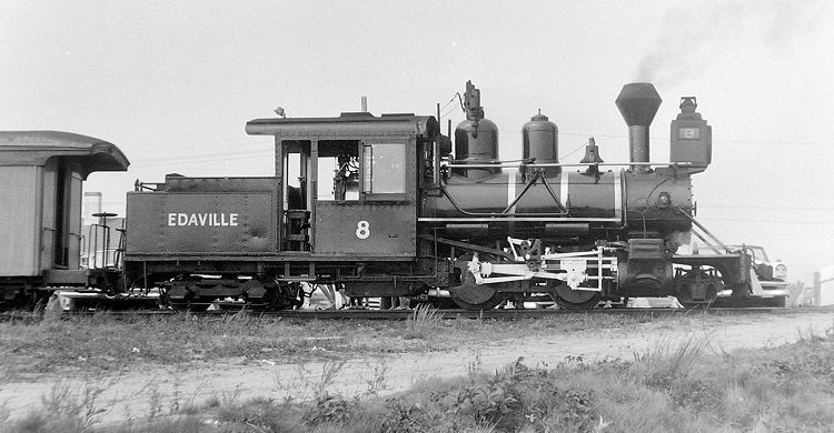
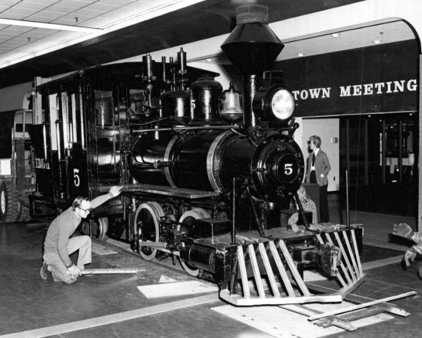
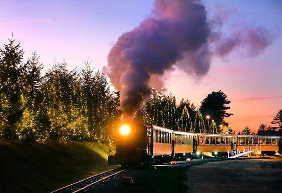
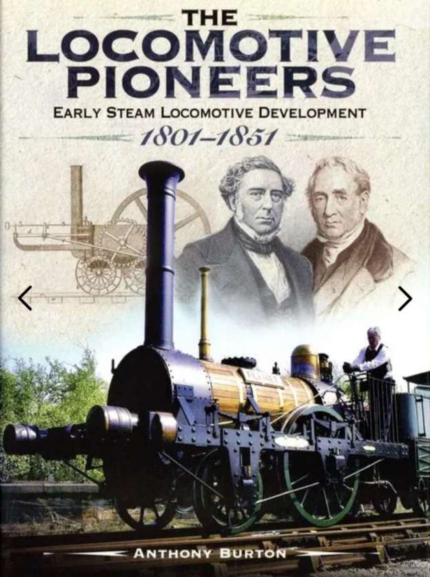
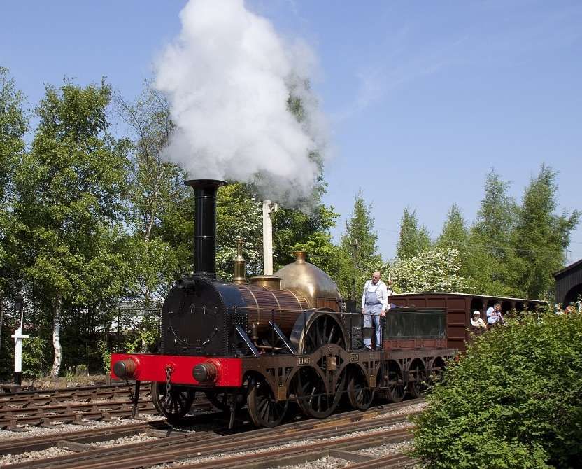


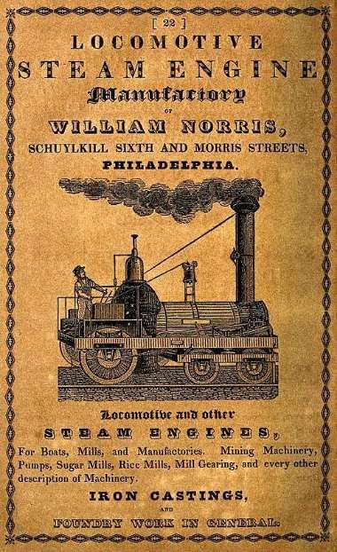
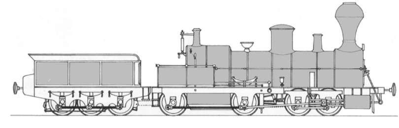
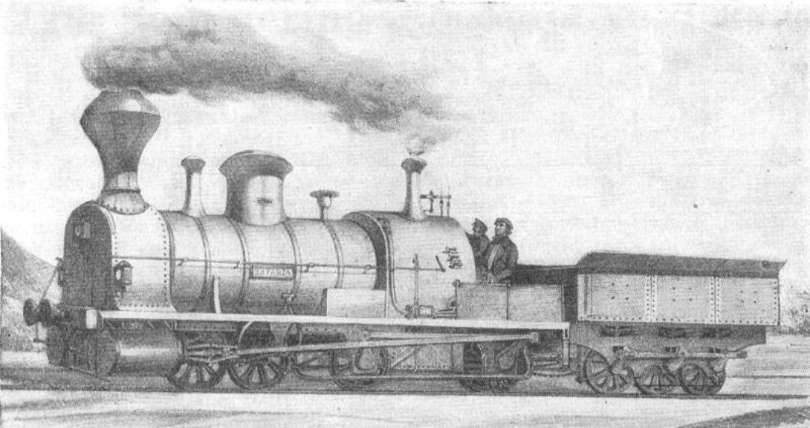
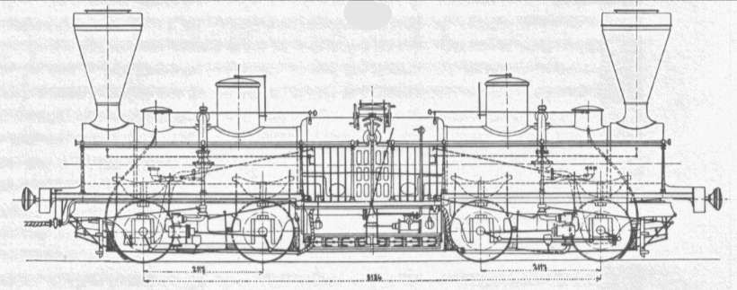
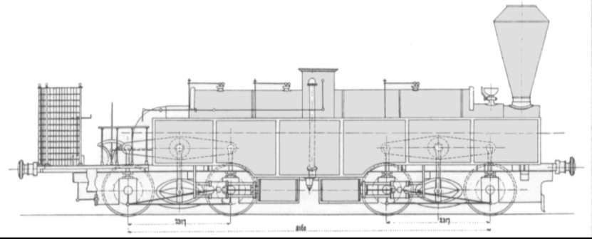
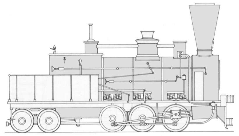
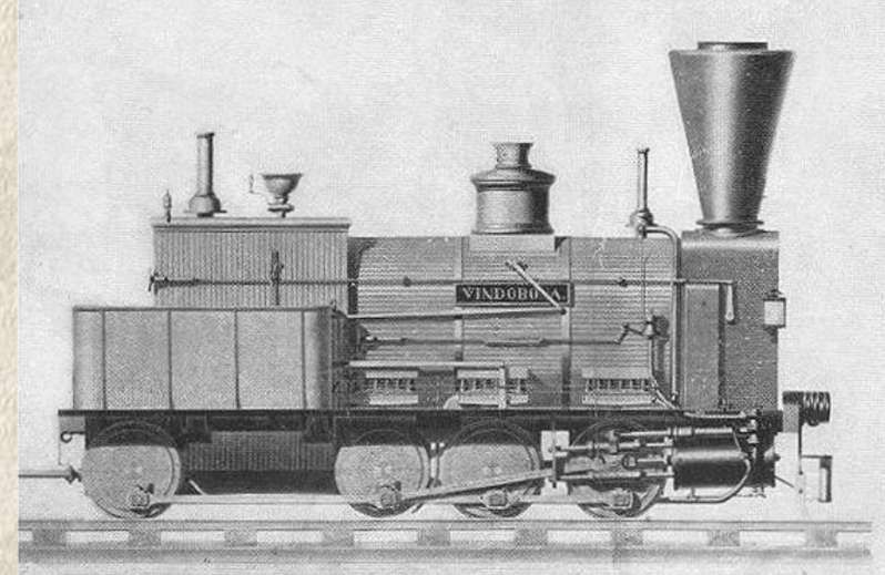
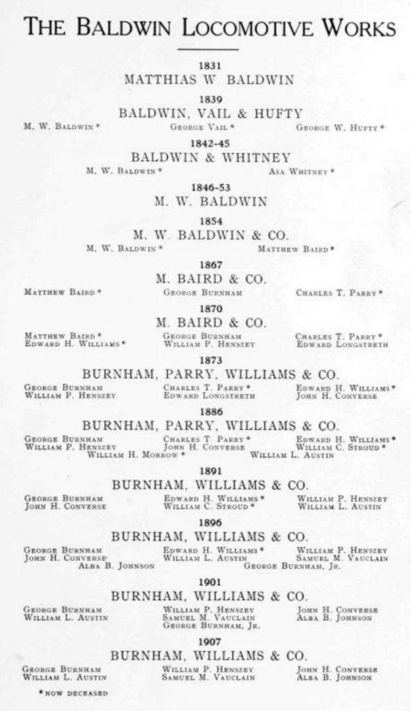
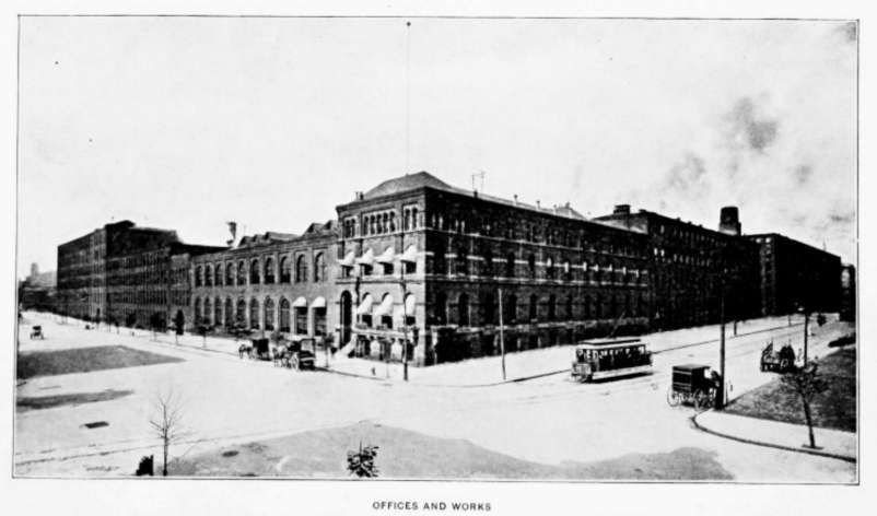
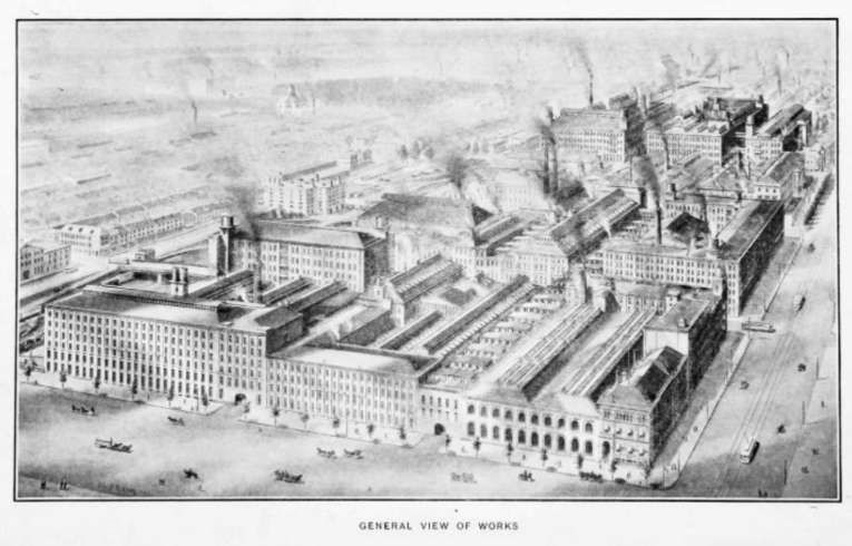
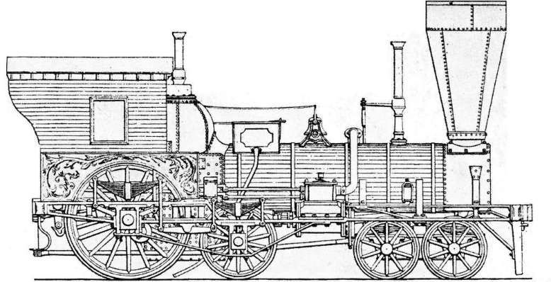
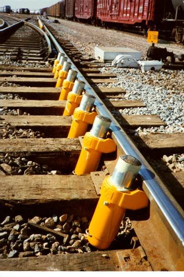
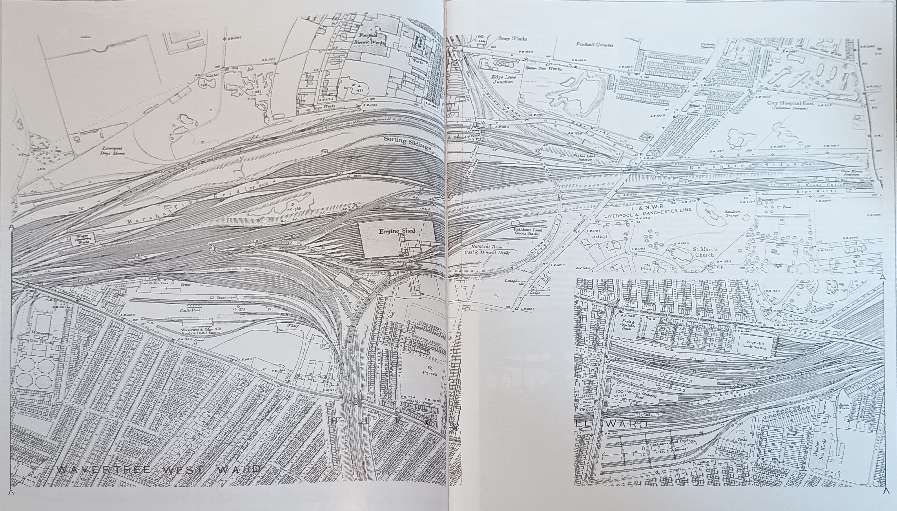
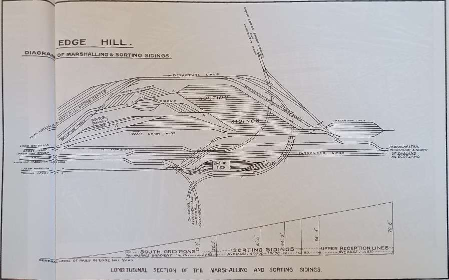

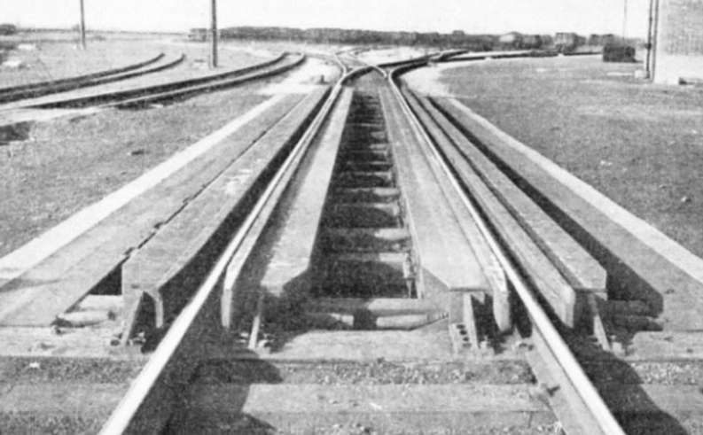
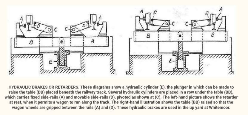
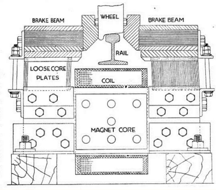
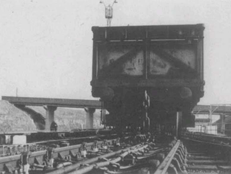
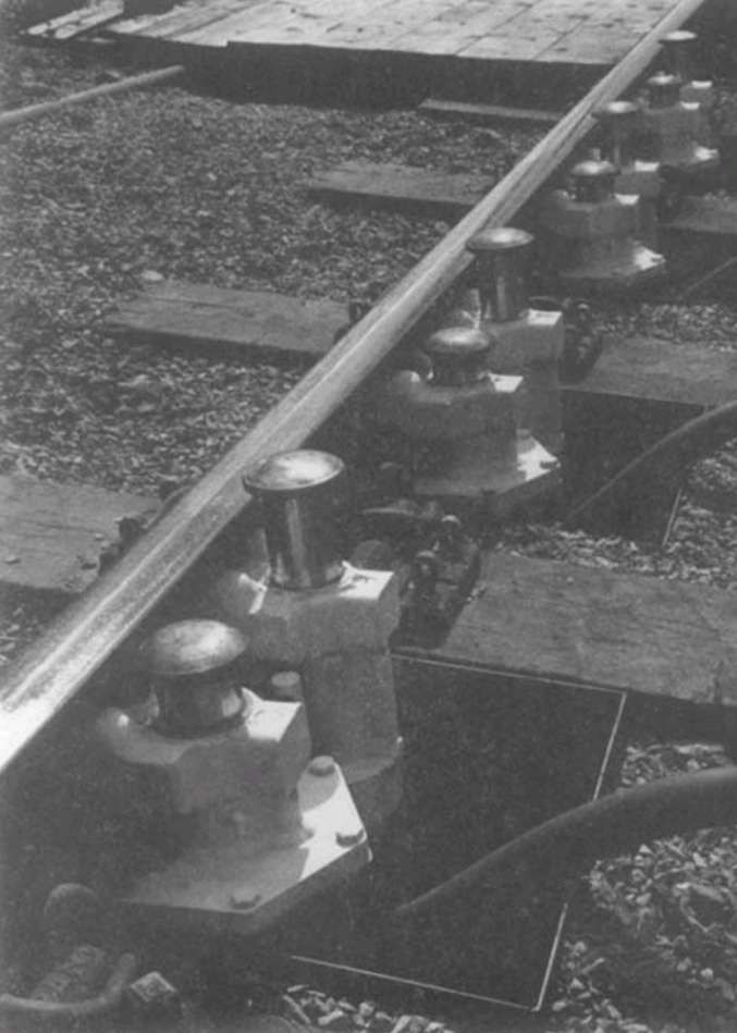
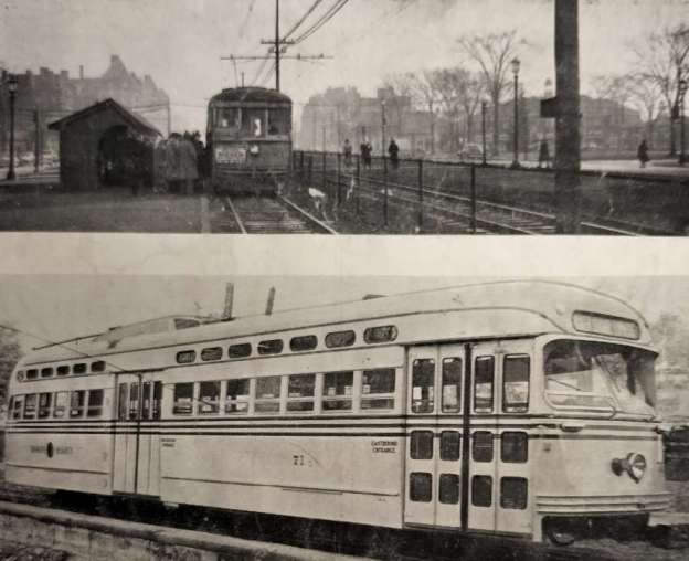
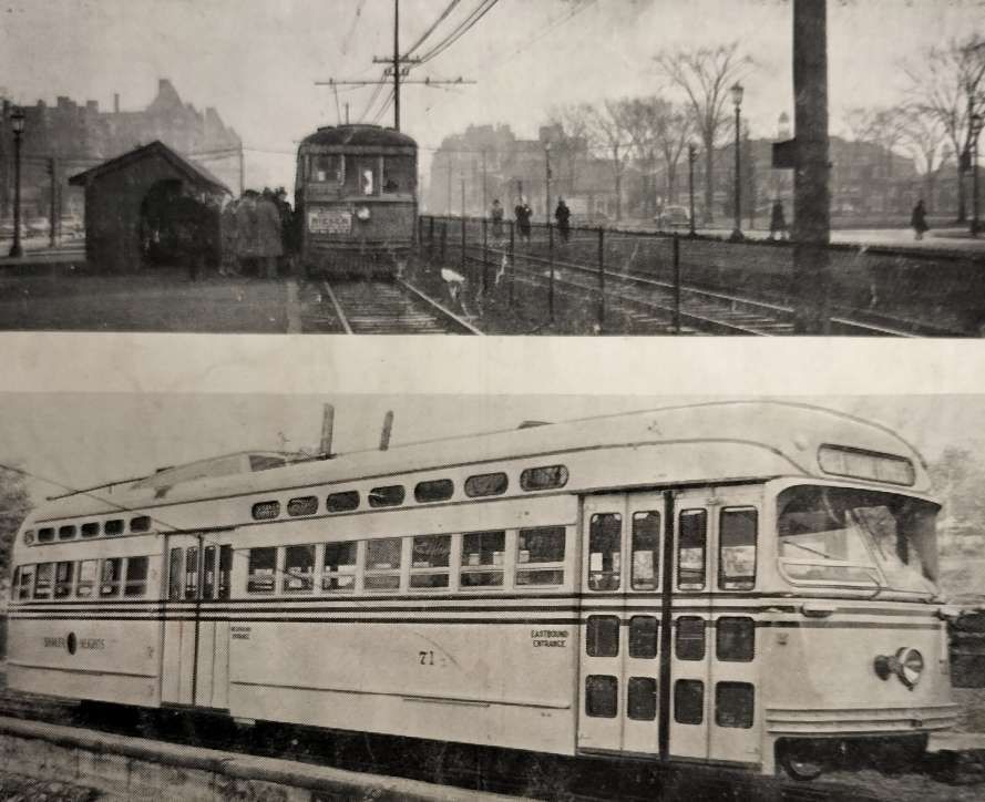
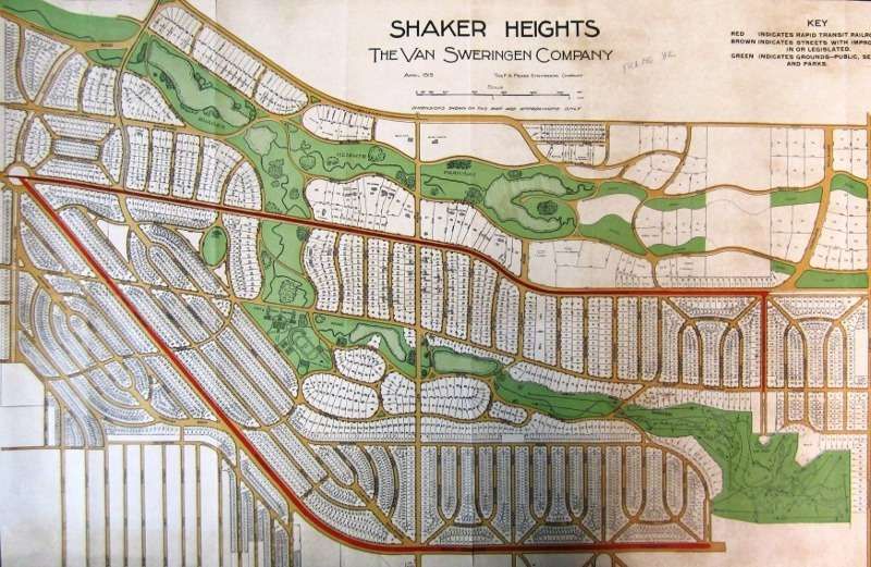
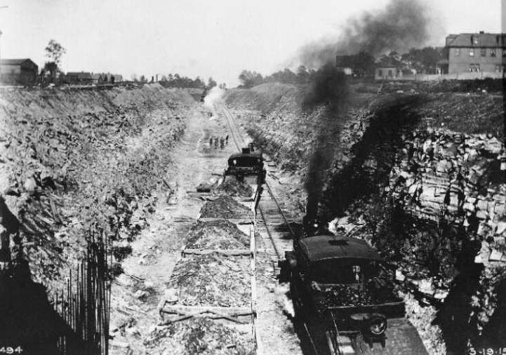
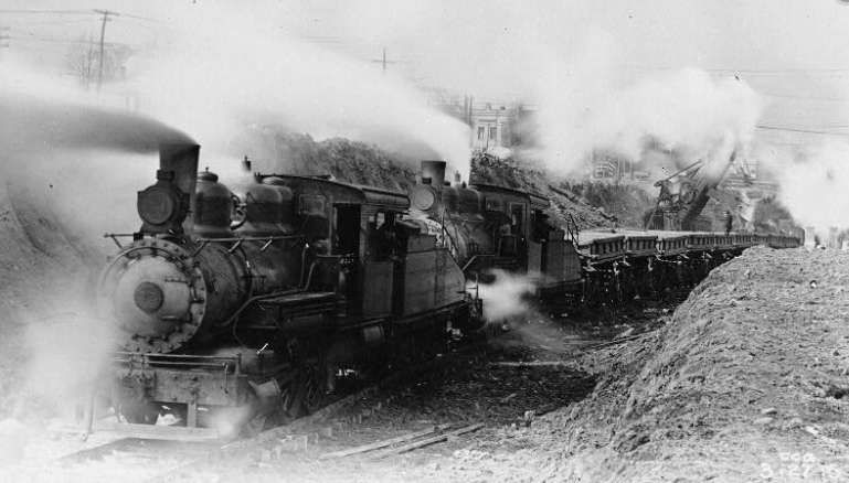
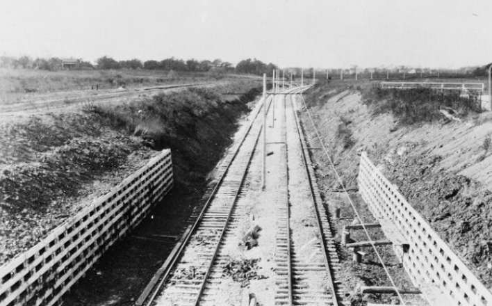
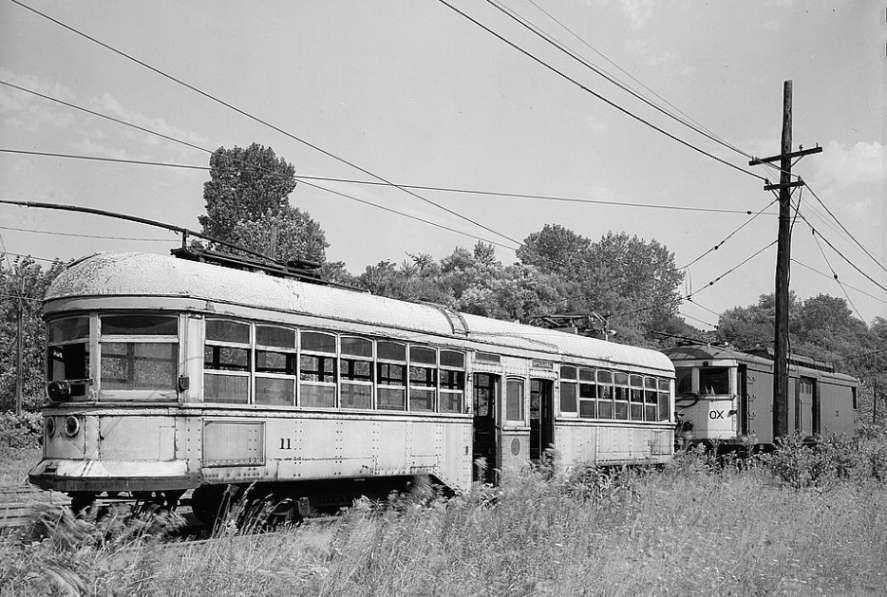
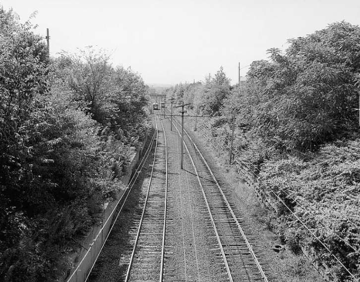
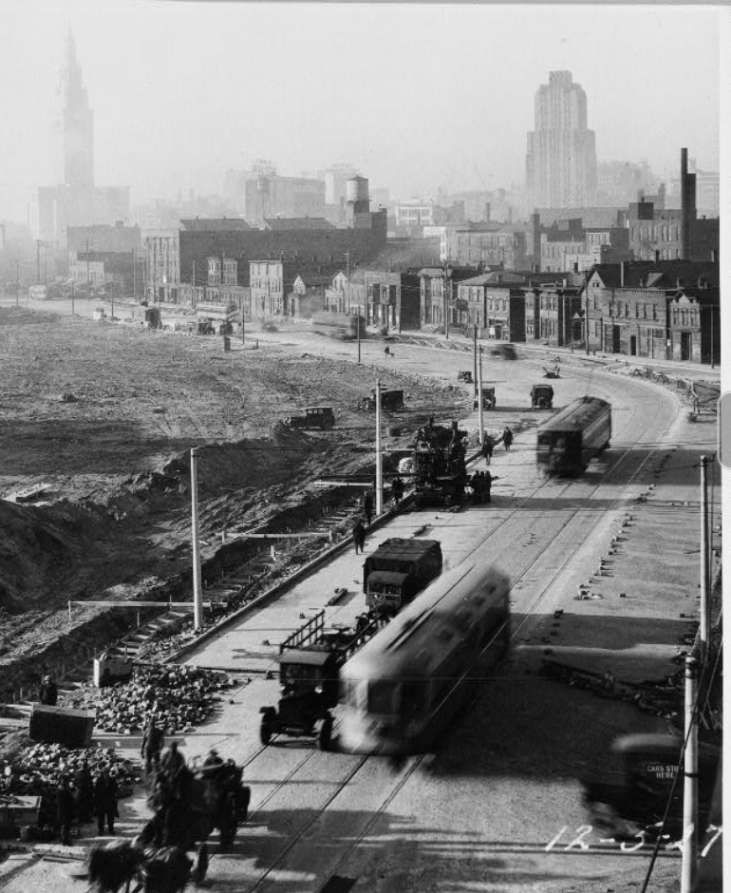
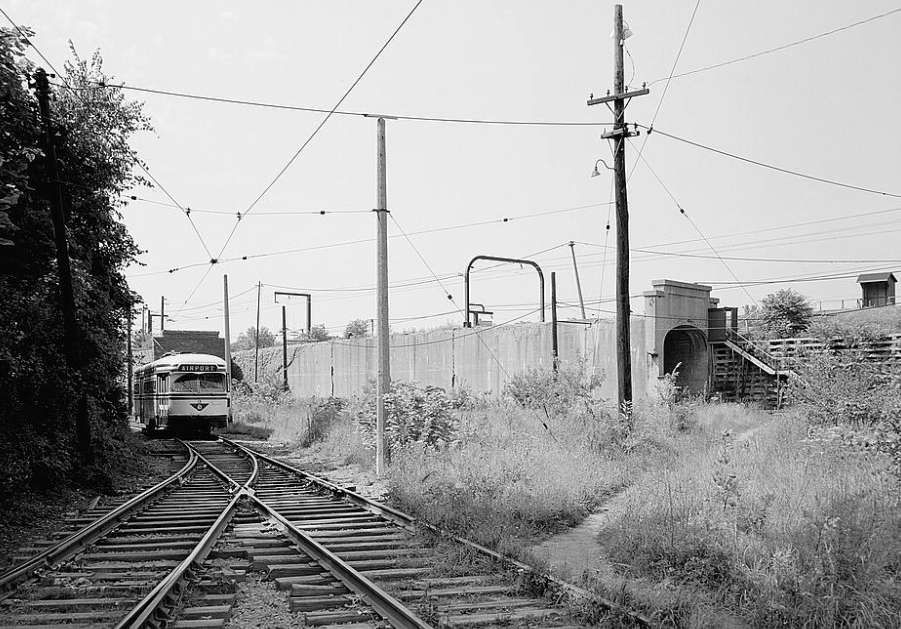
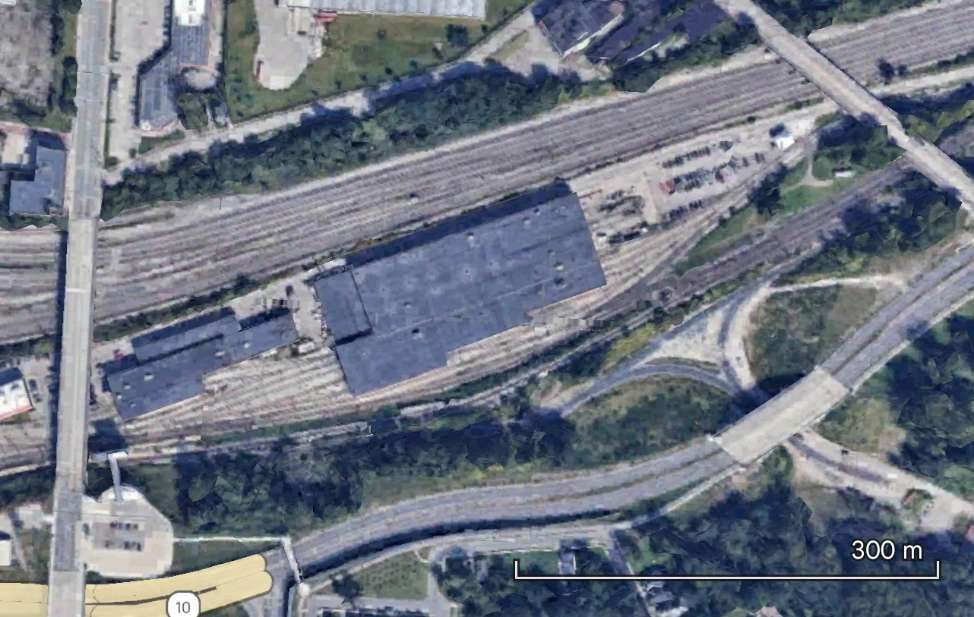
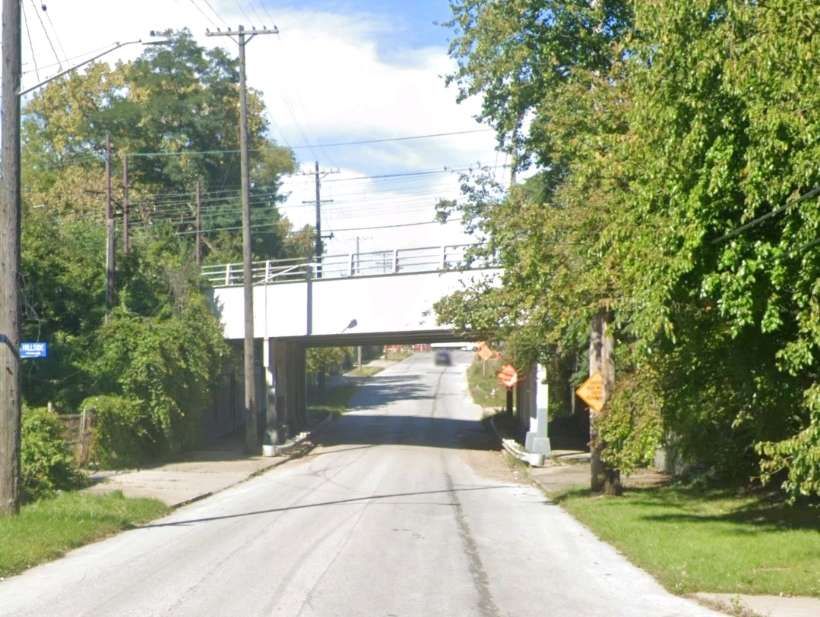
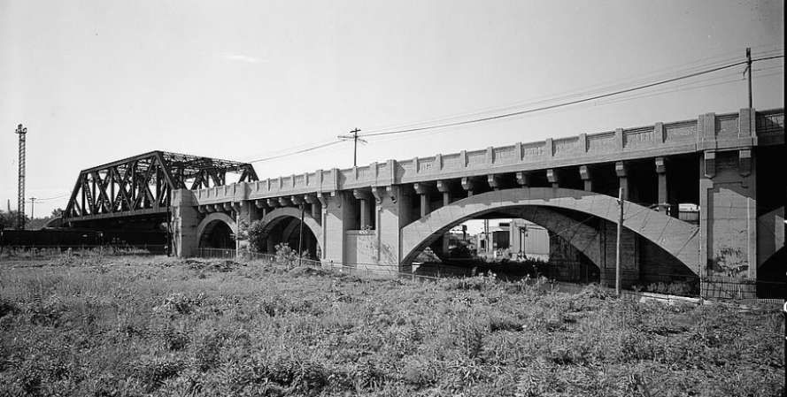
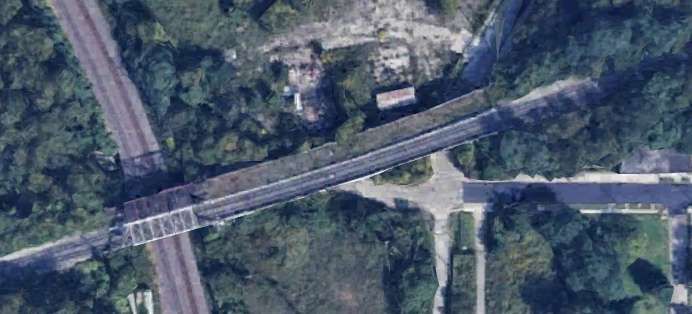
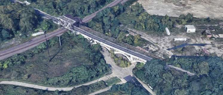
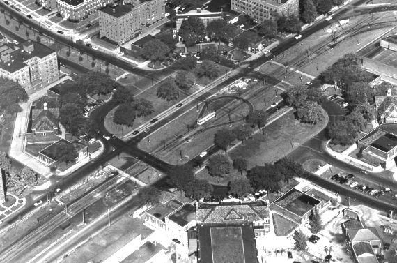

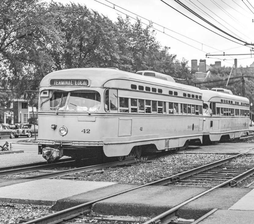

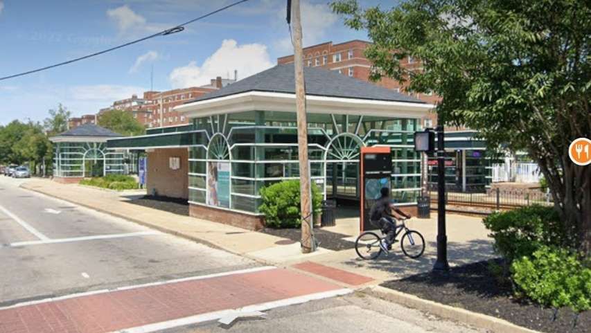
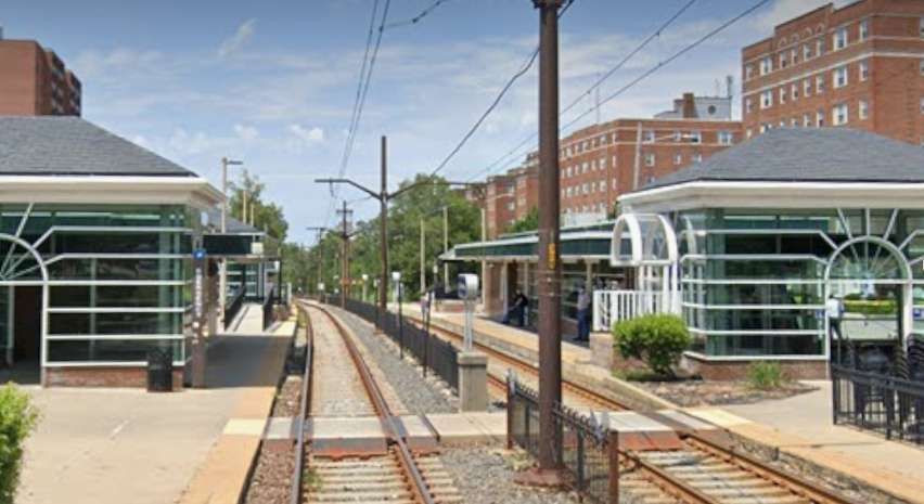
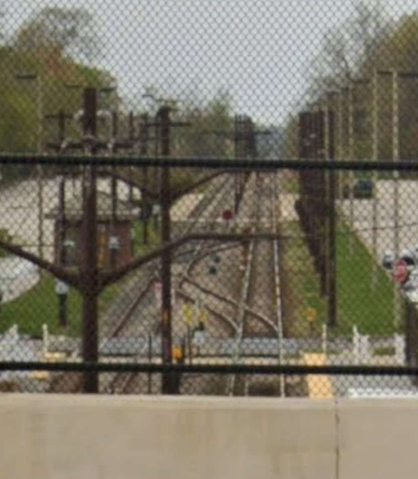
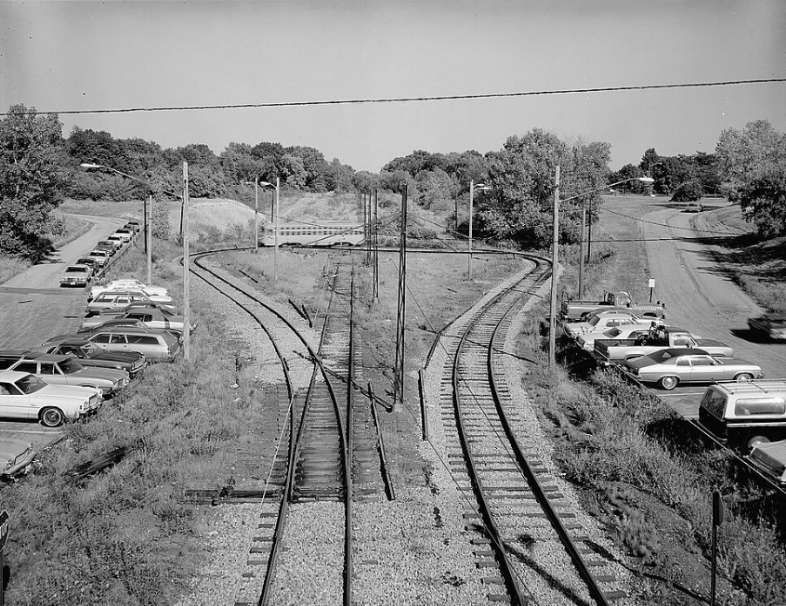
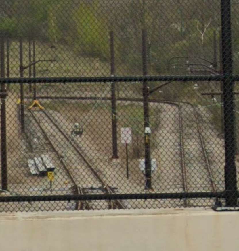
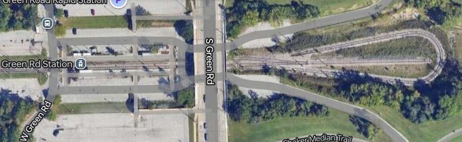
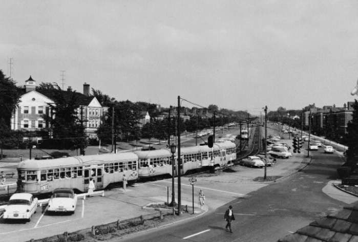
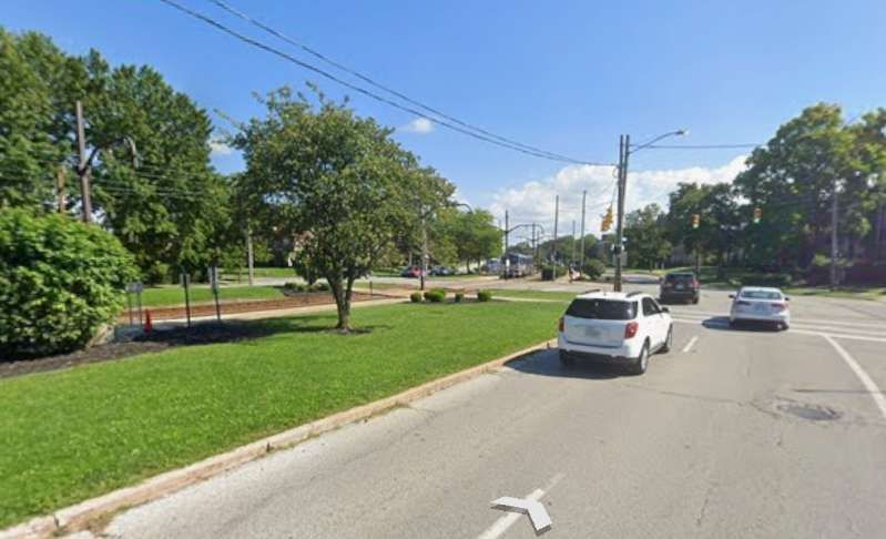
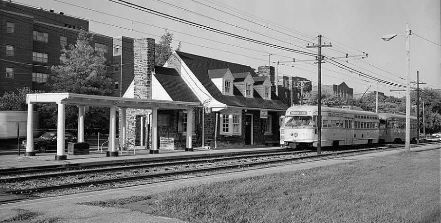
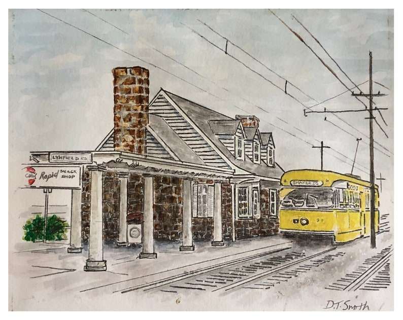
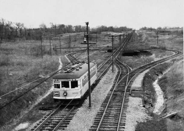
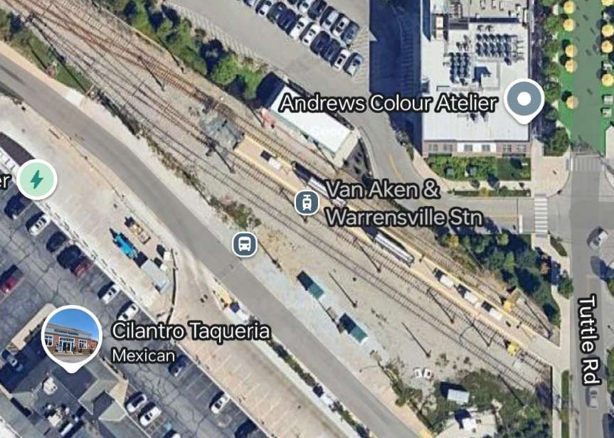
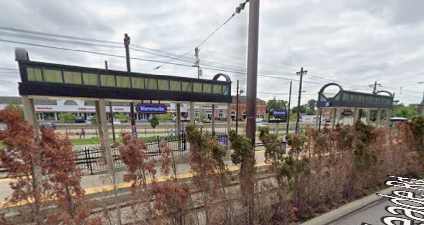
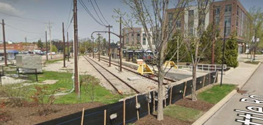
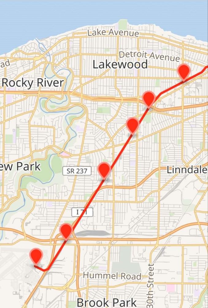
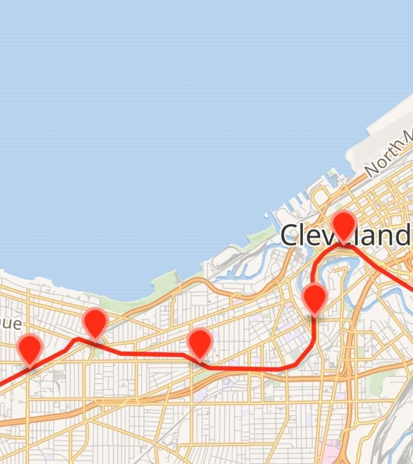
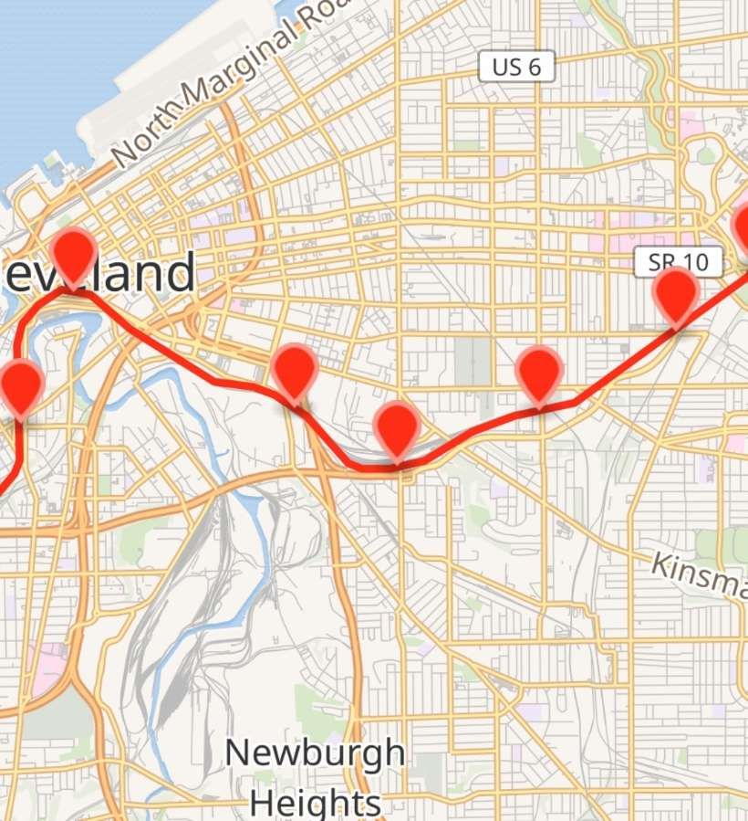
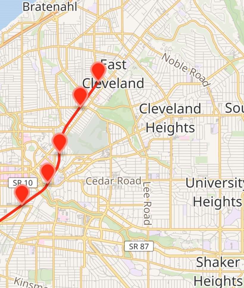
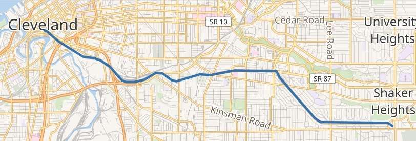
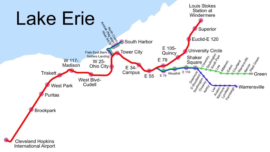
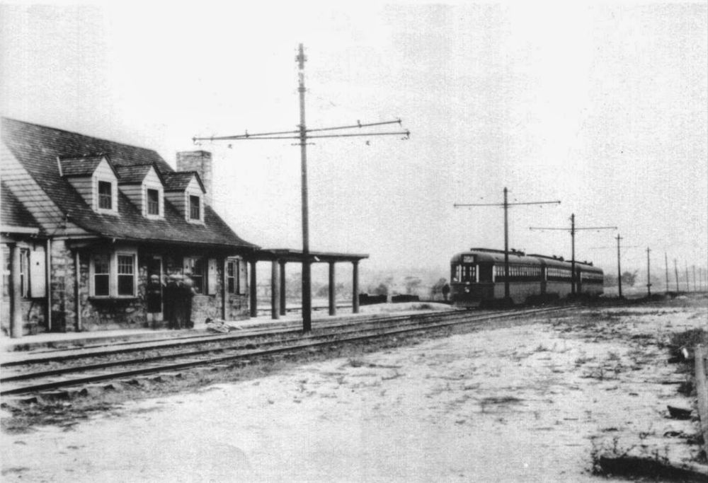
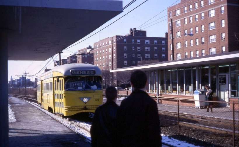
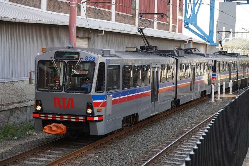


.jpg)