
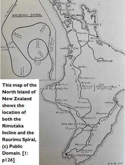
Both the Rimutaka Incline and the Raurimu Sprial were highlighted by Will Lawson in an article in The Railway Magazine in 1909. [1]
The Rimutaka Incline
Will Lawson wrote about the mountain railways of New Zealand in the August 1909 issue of The Railway Magazine. [1] The two principal lines on the South Island were under construction at the time of his article. Those on the North Island were already in use. We look first at the Rimutaka Incline. …
Will Lawson wrote:
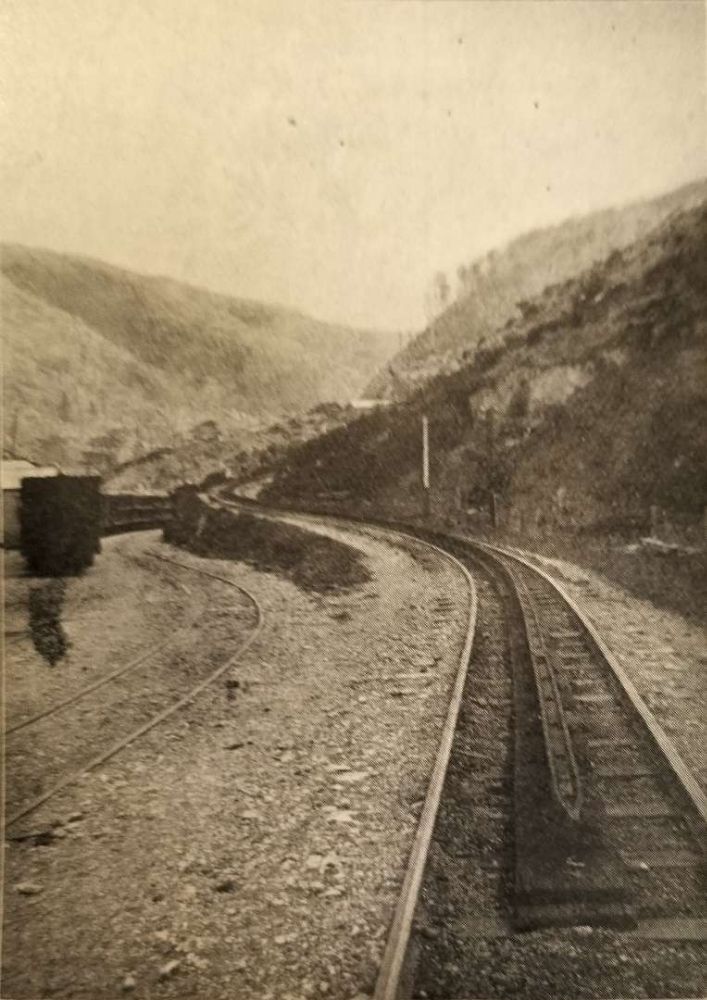
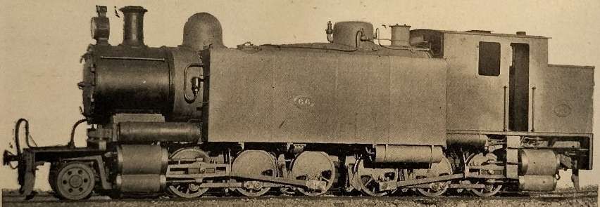
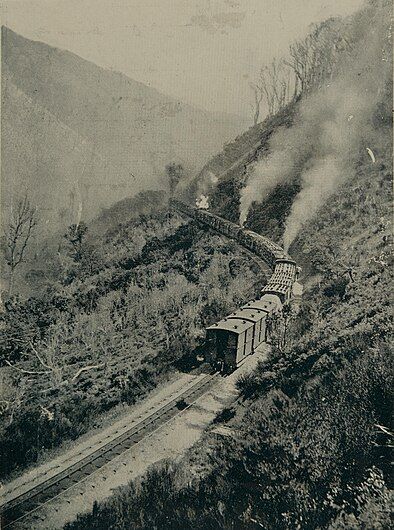
“It is raining at Cross Creek, that lonely railway outpost at the foot of the Rimutaka Incline. Heavy vapours cling to the mountain, and out across the valley only a cloak of mist is to be seen. In the winter twilight, the mail train from Napier arrives. The engine which has hauled it over the plains is uncoupled. With her big driving – wheels, she could hardly propel herself up the 1 in 15 grade which now confronts her, and she gives way to two black, squat-funnelled Fell engines, which already are moving out from the running-shed to be attached to the train. They are followed by No. 66, a huge freight engine, which rolls along with an air of supreme disgust, as though this business of climbing mountains was beneath her contempt. These grimy black monsters, with never a gleam of brass about them, take the mail to the summit-No. 66 in the lead, and the two Fell engines at convenient distances, sandwiched among the carriages, while three brake-vans bring up the rear. These have powerful brakes, which operate on a centre rail laid between the usual rails carrying the wheels. On this rail the Fell engines also grip with their bevel grip-wheels. The carriage lamps are lighted, and the Cyclopean eye of each steel Goliath gleams through the rain. It is 21 miles to the summit, on a greasy rail, up the side of a black, wet mountain. Yet a glance at the hissing, steaming engines now attached to the train gives reassurance. They have an air of irresistibility that is most convincing, and they apparently scorn the grade which rises abruptly outside the level station yard. The leading engine blows her whistle; the sound is echoed by the other two; white steam shoots skyward; and the train glides away from the lonely settlement.
Standing on the level, the water-gauges appear to be empty, but as the engine meets the hill and her bevel-wheels slide on to the centre rail to be firmly clutched thereon by a powerful lever, the water, owing to the tilt of the engine, rises in the glass to a normal level. One reason for not filling the boiler up when on the level is that if there is too much water in the boiler, the heavy blast of the exhaust steam causes ‘priming’. This, of course, is fatal to effective driving.
The bevel wheels on the Fell are driven by an engine distinct from that which drives the ordinary driving-wheels, and as both sets of wheels slip occasionally, the exhaust from the Fell engines occurs with some irregularity. The effect is peculiar, suggestive of an asthmatic Samson climbing a greasy pole. In contrast, the steady thrash! thrash! of No. 66 has dignity. The pace is the merest crawl, scarcely exceeding a walking pace, and the din from the three engines is deafening. This is due to the extremely high pressure at which the boilers are worked. The exhaust steam, mingled with smoke, shoots up for a distance of some 30 ft., and there swirls and hangs in a heavy cloud, which, dimly seen in the coming darkness, marks the progress of the train along the mountain side. The glare from the open fire-doors transforms the cloud of steam into a mass of wicked red vapours, which, with the black, foggy mountains and yawning ravines, makes the scene almost Mephistophelean in its luridness. The train of carriages appears as a procession of glow-worms crawling through a night of foggy density.
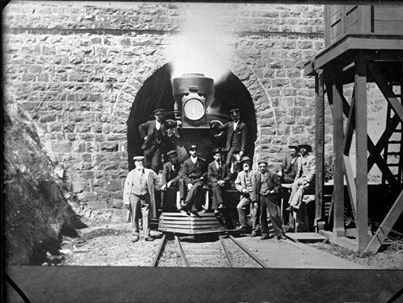
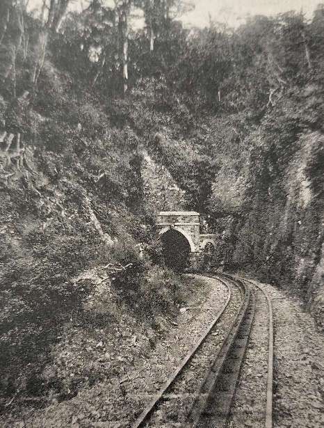
On the Incline the shovel is never idle, and in the half-hour occupied in making the ascent the fireman exerts enough energy to run her 20 miles or so on the level. Even on the ends of the hair of his head drops of perspiration cling. In the cab there is only that shielded lamp, so designed that it throws its light on the water-gauge and steam-gauge. The driver’s eyes are shielded from it, as they also are from the furnace glare. Drivers and firemen may elect to work on this section of line or not, as they choose. Extra pay is given them, and in the busy season a great deal of overtime is to be earned. There is one driver who has continued on this run for 20 years, and there are others who are content to stay, despite the, to the lay mind, severity of the ordeal to be gone through in each up-run, especially on thick, wet nights. On such occasions the engine eats coal – one may almost hear her chewing it, and the resulting smoke is suffocating in the tunnels of which there are three – two short ones on the way up and a long curving one at the summit. Best Coalbrookdale is burned – the hottest, cleanest coal obtainable.
Now, some distance up the track looms the first tunnel, piercing an outstanding spur. The engine whistles, there is a sound of slamming windows, with which the engines are fitted, and then such a pandemonium of sound as cannot be imagined. It is an inferno. The 30-foot column of expanding steam and smoke is confined by the tunnel’s arch about 2 ft. above the funnel, and there follows a terrific compression which forces the hot vapours into the engine-cab in spite of windows. Each thrash of the spouting funnel stuns like a blow, the sulphur suffocates, the heat scorches. And on top of all these the fireman opens the fire-door and tosses coal in. Then it seems that there is no air to breathe at all. The wet rail is making the pace slower than usual, though the leading engine, having a dry rail in the tunnel, is exerting herself to get out as quickly. as possible. Still the stuttering, thrashing exhaust thuds on the tunnel’s arch: the tiny lamp in the cab gleams faintly through the smoke; the wicked red shafts from the air-holes in the fire-door radiate their redness in the suffocating atmosphere. Then the clamour of the funnel quietens; the windows are shot open; driver and fireman lean out to breathe God’s air once more. The men in the second and third engines have a worse time than those in the leader, as the tunnel becomes hotter and more foul with the passage of each engine. Onward, upward, she goes – slipping and racing – sanding and swearing. When the wheels slip, sand is thrown upon the rail, but before this is done, steam is shut off. If the sand were thrown under the spinning wheels while steam is on, possibly every rod and crank would be broken owing to the sudden check to the revolving wheel jarring these parts and throwing undue strain upon them.
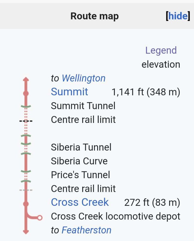
Another tunnel is passed through, after which the pace quickens. The ‘long straight’ is reached. Here the grade is easier, and the line is straight. So the engines quicken their stroke, and when the last tunnel appears, they are making better time. Into this horseshoe shaped hole in the mountain crest the one-eyed, black giant of steel thunders. She crashes and rumbles along, her crew coughing in the smoky atmosphere. Then clang-clang! clang-clang! A bell, swung at the side of the tunnel and rung by the wheels of each passing vehicle, cries weirdly, telling that the uphill fight is over, the level road is here at last. The engine’s beat becomes more rapid as each carriage tops the grade to the ringing of the bell. As the other engines reach level ground the pace becomes the normal pace of a train running into a station. Ding-dong! ding-dong! A deep-toned bell moans its message through the vaulted place. The grade is a down one now, into the Summit station. The centre grip-rail ends abruptly, and the train rolls into the Summit yard, where an engine of the usual tank type takes it over from the monsters of the mountains, and away down the 1 in 35 grades which lead to Wellington.” [1: p123-126]
The Rimutaka Incline was built in the early 1870s and, as of 1909, was the steepest commercial railway in the world (the only railway on a grade of 1 in 15 on which ordinary rolling stock was used). “It [crossed] a spur of the Tararua Range at an elevation of 1,114 ft. above sea-level, and about a dozen trains [passed] over it in each direction daily.” [1: p121] It avoided what would have been a 25 mile (or more) deviation. Until the middle of the first decade of the 20th century, the line was worked by Fell locomotives alone, by 1909 a Mallet type of locomotive (designed and built in New Zealand specifically for work on the incline) was included in the roster.
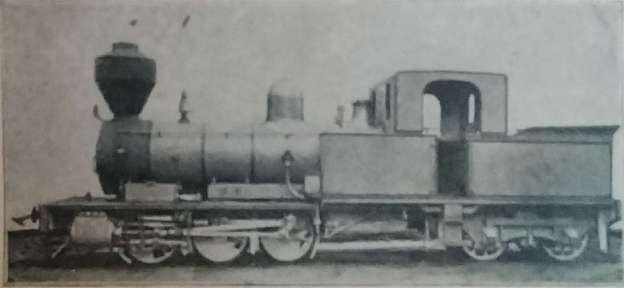
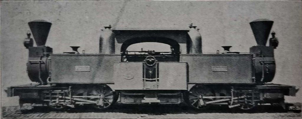
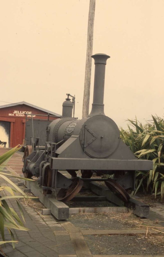
Fell locomotives operate conventionally on regular gradients but are equipped with an extra four laterally-set wheels, which grip an additional centre-rail laid between the usual rails. The “lateral wheels are driven by a separate set of engines located under the smoke-box, and they are pressed to the rail by a lever which the fireman moves when the engine reaches the place where the centre-rail begins. Until that place is reached, progress is made by the usual driving wheels. The pressure exerted by the four grip wheels amounts to 70 tons, and, in addition, the engine has two powerful brakes, having jaws which grip the centre- rail in case of a stoppage and when descending the incline.” [1: p122]
In 1909 the relatively new Mallet-type loco, No.66, was proving to be highly effective. It was “65 tons in weight, carried on 12 driving-wheels and two leading wheels, an articulated tank engine working at a pressure of 200 lbs. to the square inch. The driving-wheels [were] in two [six-coupled sets], each set being driven by compound engines, the exhaust from the rear cylinders occurring through a pipe on the top of the engine cab. On the incline this engine [could] pull a train weighing 110 tons, and to accomplish this she [burned] half a ton of coal. Usually, however, she [took] the train up the hill in conjunction with the Fell engines.” [1: p122]
The incline was on the line from Wellington to Napier with the steep upward grade being on the Napier to Wellington service.
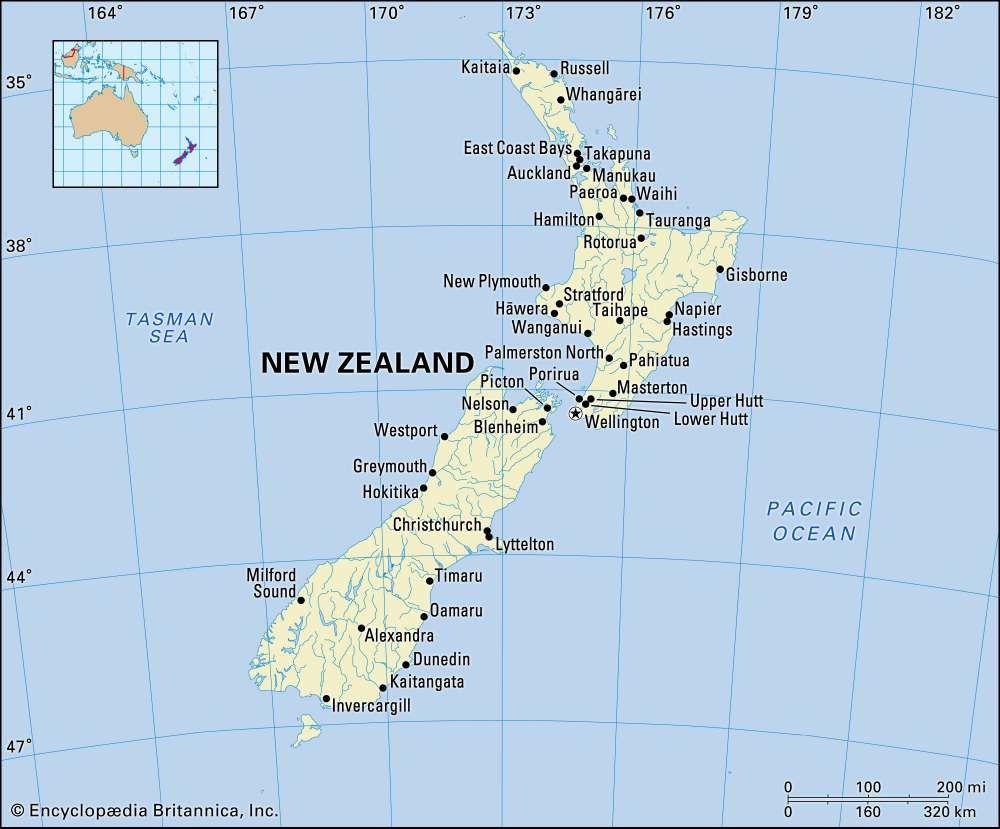
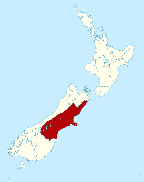
Wikipedia tells us that the “Rimutaka Incline was a 3-mile-long (4.8 km), 3 ft 6 in (1,067 mm) gauge railway line on an average grade of 1-in-15 using the Fell system between Summit and Cross Creek stations on the Wairarapa side of the original Wairarapa Line in the Wairarapa district of New Zealand. … The incline formation is now part of the Remutaka Rail Trail.” [2]
The background history of the Incline
These notes come from the Wikipedia entry about the incline. …
The construction of a railway from Wellington to Masterton was authorised in the Railways Act passed on 13th September 1871. Julius Vogel, Colonial Treasurer, travelled to England to raise finance for a major public works programme for railway construction. Vogel returned via the United States, where he studied rail systems.
After the Act was passed, a survey party investigated four different routes. A commonality between all the proposals was the section from Upper Hutt to Kaitoki (later Kaitoke). Between Kaitoke and the Wairarapa, the four proposals were the Tauwharenikau Route, Mr Sinclair’s Route, a coastal route and the Pakuratahi Route.
While the government was conducting its surveys, Wellington Province Superintendent William Fitzherbert instructed his Provincial Engineer, Charles O’Neill, to investigate the possibility of a railway through the Rimutaka Valley (the route of the road between Featherston and Upper Hutt), with a tunnel through the dividing range. The survey was carried out between May andJuly 1871, and O’Neill reported that a tunnel 130 chains (2.6 km) long would be required, with the line rising at 1 in 60 from the Pakuratahi to the tunnel then descending at 1 in 40 to Featherston. This survey was forwarded to the Minister for Public Works.
In mid-1873 the route to Featherston was chosen after a final survey for the route from Upper Hutt to Summit.
For the line between Summit and the Wairarapa, several proposals were considered. The first, with gradients up to 1 in 30, was dismissed. It was found that to keep the gradient to no steeper than 1 in 40, curves of three chains (60 m) radius would be required. This would have required special rolling stock and heavy earthworks and was thus abandoned.
Another proposal was known as the Birch Spur Incline. This would have involved the line continuing from Summit to Birch Spur from where a rope-worked incline would convey traffic to the valley floor where the railway would continue through a narrow valley to the Wairarapa plains. The Public Works Department engineers investigating this proposal were unable to locate a suitable incline, so this proposal was also abandoned.
The last option was a three-mile (4.8 km) incline with gradients averaging 1 in 15 “to be worked by locomotives of an unusual nature”. This line was the most favourable from an engineer’s point of view, and required not unreasonable earthworks. The final decision was made by the head of the Public Works Department, John Carruthers. He determined that an incline worked by the Fell system would be suitable, and cited the Mont Cenis Pass Railway as an example. Though special locomotives would be required, factors in its favour were that ordinary rolling stock could be used and it was a proven system. It was to be the third and last Fell system employing the centre rail for both tractive power and braking, and the longest surviving. Though it was considered to be a “temporary” measure, it outlasted the second such system in Brazil by 72 years. [2]
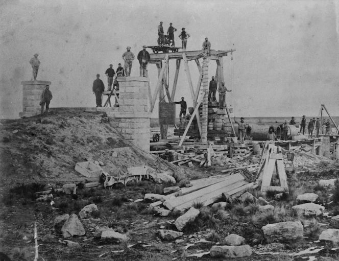
Construction
Construction of the Rimutaka Incline was included in two contracts that were let for the building of the original Wairarapa Line. These contracts were known as the Summit contract and the Incline contract. [2]
The Summit Contract included the excavation of Summit station yard and related drainage, Summit tunnel, and formation work to a point 26 chains (523 m) beyond the tunnel. It was the shortest contract of those let for the line, it was finished by the original contractor, and it had the fewest alterations. Work was to start on 12th July 1874 and to be completed by 22nd July 1876, at which time the Pakuratahi contract was due to be completed. [2]
Summit yard was a large cut into the hillside, 120 feet (37 m) wide and 500 yards (460 m) long initially. Excavations removed material to a depth of 15–20 feet, with this fill being dumped on the opposite side of the yard to form level ground. On the hillside above the yard, further ground was levelled and houses erected thereon. [2]
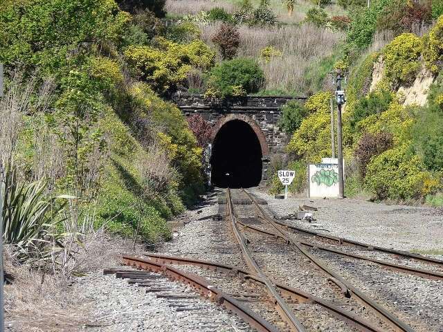
After the yard had taken shape, work commenced on the tunnel. The approach to the tunnel was about 6 chains long and up to 60 feet (18 m) deep. The line entered the tunnel on a downward grade of 1 in 1,000, steepening to a grade of 1 in 15 at the eastern portal. At that end a small drainage tunnel had to be built to divert a stream that had flowed down a steep gully where the tunnel mouth was to be. The maximum height of the tunnel was 15 feet (4.6 m) above the floor: once rails were laid the maximum clearance was 13 feet 9 inches (4.19 m) The width of the tunnel varied from 10 feet 6 inches (3.20 m) at the floor to 12 feet (3.7 m) at 7 feet 6 inches (2.29 m) above the floor. Despite castigation from various parties, it was not until March 1877 that work on both ends of the tunnel met at the middle, having taken three and a half years to complete. [2]
The Public Works Department lined the tunnel after the rails had reached the site, enabling them to use work trains to bring materials and other supplies in. It was during this phase that the only fatality on this contract occurred: on 3rd May 1878, a sizeable portion of the lining collapsed on two men. One was killed outright, the other lost his eyesight due to severe head injuries. [2]
The Summit contract was completed on 10th December 1877, 17 months behind schedule. [2]
The Incline Contract was let on 5th October 1875 to Charles McKirdy for the sum of £49,029. The contract covered the formation only, with the Public Works Department responsible for track laying. [2]
Work on the contract began on 22nd October 1875. None of the major earthworks seem to have presented any great difficulties, save the lower tunnel, which was plagued by accidents and materials failures largely because of the unstable nature of the rock through which it passed. The tunnel was named Price’s after the manager McKirdy employed for this contract. On 2nd March 1876, two men died due to a cave-in of the tunnel roof. [2]
Between October 1877 and March 1878, platelaying was completed up to Summit. This enabled the use of work trains to haul up materials that were used to line Summit Tunnel. Track laying on the incline commenced in April 1878 and reached Cross Creek the following month. During this work, locomotive H199 was stabled at Summit and used to haul work and ballast trains to the railhead. [2]
Initially, only simple arrangements were made for the station yard at Cross’s Creek, as it had yet to be decided the nature of operations on the Incline. It consisted of the main line, an engine siding of 10 chains, and the runaway siding. [2]
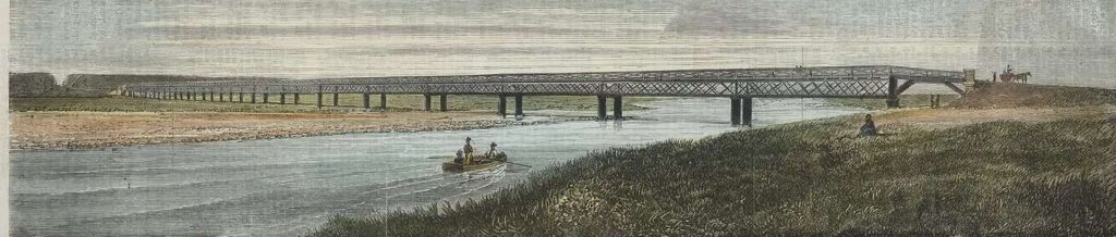
After formation work continued beyond Cross Creek, McKirdy ran out of time and money, with the remainder of his contract being picked up by his guarantors, T. W. Young and Robert Greenfield. They finished the formation to Featherston on 17th August 1878, with track laying finishing the following month. The contract was completed 13 months late. [2]
Operation – Initially, trains on the incline were limited to the weight that could be managed by a single locomotive. After complaints from management of the expense of running too many trains, two locomotives seem to have been used, both at the head of the train. From 1887 trains were worked with multiple locomotives, each at the head of its rated load. As the maximum weight of a train during this period was 150 tons, no more than three locomotives were used per train. Train operations continued to be modified until by 1908 the maximum load allowed per train had increased to 250 tons descending and 260 tons ascending. [2]
When the line opened, there were two Fell brake vans in service, each 12 ft 6 in (3.81 m) long and 5 ft 9 in (1.75 m) from floor to ceiling, with open platforms at either end. The wear on the brake blocks fitted to these vans was so severe that a set of blocks seldom lasted more than one trip down the incline. Like the positioning and loading of the locomotives, the arrangements for positioning of the Fell vans varied until they were largely standardised by 1897. For ascending trains, Fell vans were placed at the rear of the train. For descending trains, a Fell van was placed between the locomotives and the leading vehicle. If the gross weight of the train exceeded 120 tons or included more than 15 vehicles (excluding the locomotives in both cases) a second Fell van was attached to the rear of the train. These rules applied before the introduction of the Westinghouse continuous air brake. The Fell locomotives were never turned, running cab first on descending trains. [2]
As descending trains departed Summit the “through” guard applied the brakes on the leading vehicle, then moved through the train applying the brakes on the other vehicles until he reached the train van, which also had brakes that had to be applied. Each Fell van had its own guard to operate the two sets of brakes. [2]
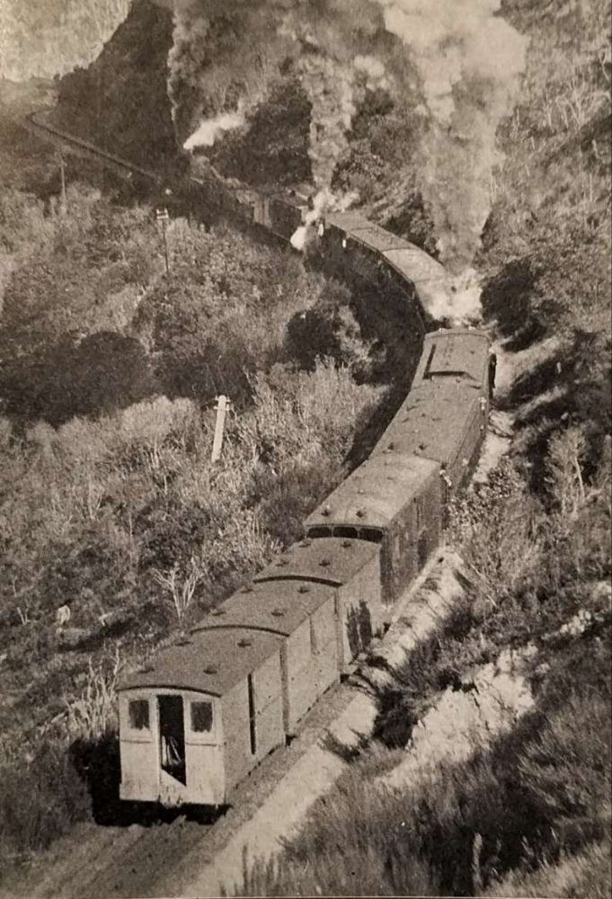
After the introduction of the continuous brake system in 1903 it became possible to operate trains with five locomotives, and on descending passenger trains up to five Fell brake vans could be used – two next to the locomotives, one in the middle, and two at the rear. As each brake van had its own guard and the train had a train guard and locomotive crews, a train with five brake vans and four locomotives had a crew of 14, which added to the expense of the operation. Moreover, to reduce the strain on couplings, when several locomotives were used they would be distributed through the train, as can be seen from photos. This necessitated significant re-marshalling of the train at either end of the incline. [2]
Instructions issued in 1885 regarding the use of the safety siding required that the points for the incline be set to the safety siding. As descending trains approached the Cross Creek yard, the driver of the leading locomotive sounded a long whistle, which signalled that all was well. On hearing this signal the signalman would set the points for the arrival road. As far as is known no real emergency occurred. Cross Creek had an unusual six-lever partially-interlocked signalling installation and had no “distant” signals so had points indicators which applied to the “main” line (see Heine for station layout), while Summit had a fully interlocked 27-lever frame. [2][3]
Unusual traffic included four royal trains: for the Prince of Wales in 1921; the Duke (later King George VI) and Duchess of York in 1927; the Duke of Gloucester in 1935; and Queen Elizabeth II and the Duke of Edinburgh in 1954. Trains were diverted from the Manawatu line due to slips, floods or other mishaps. [2]
The original yards at Cross Creek and Summit were sufficient for the traffic levels of the time, but increasing traffic brought about incremental additions. The full extent of the Summit yard was reached in 1903, which coincided with the introduction of full signalling and interlocking, not introduced to Cross Creek until 1915. [2]
The Fell locomotives (H class) were not to be operated on any part of the railway other than the Incline, with the sole exception of conveying them to the Petone (and later Hutt) Workshops for maintenance. In the latter case, bunkers, water tanks and boilers were to be empty and the locomotives were to be towed at a speed not exceeding 10 miles per hour (16 km/h). These rules were relaxed to allow the locomotives to travel light engine to Petone and back under their own steam, subject to the same speed restrictions. In 1887 they were permitted to be operated between Cross Creek and Pigeon Bush, later extended to Featherston to enable them to be used for banking purposes. Running rights between Cross Creek and Featherston were revoked about 1943. [2]
Speed limits for trains on the Incline were changed several times. From 1884 to 1888 the limit was 6 mph (9.7 km/h) ascending and descending, except light passenger trains for which the limit was 8 mph (13 km/h). In 1888 these limits changed to 5 mph (8.0 km/h) up, 9 mph (14 km/h) down. The limits were finally 6 mph (9.7 km/h) up, 10 mph (16 km/h) down. [2]
Various classes of locomotives were deployed to supplement the H class when one or more was away for maintenance or repairs, including
- W192 and 238 2-6-2T locomotives, built in 1889 and 1891 respectively, which spent most of their time on the Wellington to Summit section until their transfer in 1909;
- 54-ton We 4-6-4T locomotives rebuilt from 4-8-0 B Class locomotives, rated to haul passenger trains up to 55 tons and goods trains up to 60 tons, until 1906, after which they were used mainly on the Upper Hutt to Summit section and rated to haul passenger trains up to 130 tons, mixed trains 150 tons and goods trains 155 tons, and were then later sent to work on the Rewanui Incline on the South Island;
- 65-ton E 66, rated to haul 80 tons up the Incline, and nicknamed Pearson’s Dream. In 1910 it was transferred to banking duties on the Wellington to Johnsonville section, but it was never popular with crew. (This is interesting, given Lawson’s very positive description of the loco in use on the Incline);
- Wg 480 4-6-4T locomotive, during the first World War.
After the Great War traffic was well within the capabilities of the six H class Fell locomotives. [2]
The mileages run by the H class locomotives show notable increases that correspond to economic and other major events, such as the opening of the Wairarapa Line as far as Masterton, completion of the line to Woodville, and the nationalisation of the Wellington and Manawatu Railway. With the opening of the railway to Masterton the annual mileage of the H class rose from less than 7,000 to more than 8,000, in 1883–1897 to 34,000, and to 42,000 when the line was opened to Woodville and began carrying traffic from the Hawke’s Bay. Mileage peaked at 64,123 in 1906–07, about 10,687 miles per locomotive or 1,780 return Incline trips. [2]
Wairarapa railcars
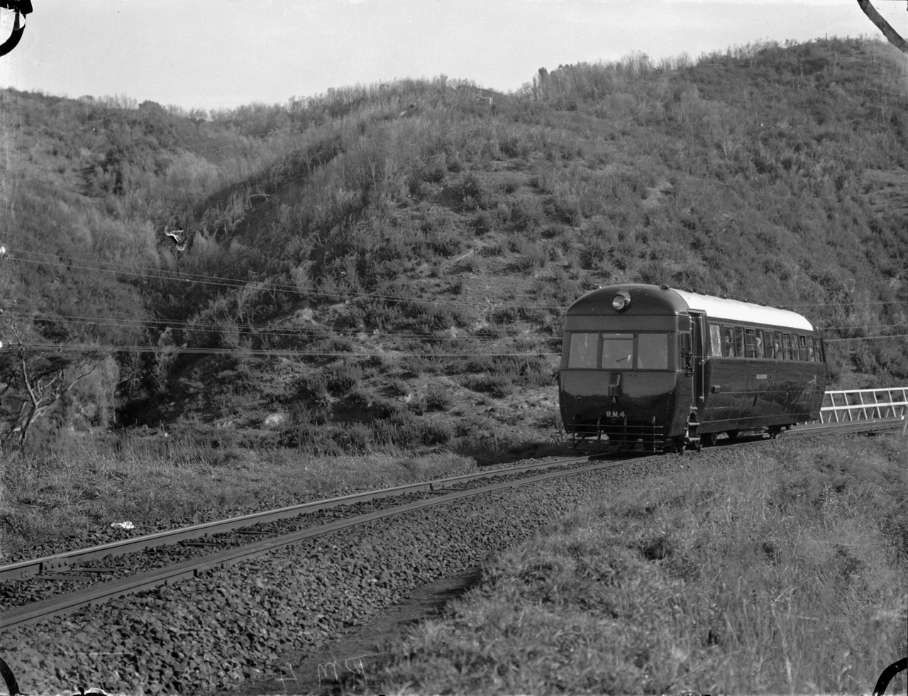
In 1936 seven lightweight Wairarapa railcars, RM 4–10, were introduced between Palmerston North, Masterton and Wellington. They were specifically designed for the Incline, and were built at the Hutt Workshops. They were named after historic Maori canoes: Maahunui, Mahuhu, Mamari, Matahourua, Mataatua, Arai-te-Uru and Arawa. Initially powered by 130 horsepower (97 kW) Leyland petrol engines, they were upgraded after several years to 120 horsepower (89 kW) diesel engines. They had a single rear driving axle with 38½” (978 mm) diameter wheels, necessitated by the need for the axle and final drive unit to have sufficient clearance above the Incline’s centre rail. Because of the large rear wheels the floor of the passenger compartment was 52½” (1334 mm) above rail level, more than 12 inches (300 mm) higher than normal. They were rated for a maximum speed of 60 mph (97 km/h) and expected to climb the Incline at 15-17 mph, but actually managed only 10–12 mph. Nevertheless, they greatly speeded up passenger trains on the route and immediately proved popular. They were withdrawn in 1955 when the Incline closed. [2]
Closure
Several options for an alternative to the Incline were considered in the 20th century, but it was not until after WWII that a route through a tunnel between Maymorn and Lucena’s Creek was selected. Construction was started in 1948 by the Public Works Department and completed by a private contractor in 1955. The tunnel and deviation opened on 3rd November 1955, five days after this the Incline closed. [2][6]
Demolition was swift, with the removal of track between Cross Creek and Pigeon Bush largely completed by March 1956. H 199 was used to haul the work trains that removed the track between Cross Creek and Summit. The buildings were sold at auction, on site. Some of the rails were sent to the Rewanui Incline, as were a couple of the Fell brake vans. Five of the six H class locomotives were towed to the Hutt Workshops, later to Silverstream, to be scrapped. [2]
Today
A resurgence of public interest in the incline followed the publication of a book in 1976 and the opening of the Fell Engine Museum in the early 1980s, prompting the New Zealand Forest Service to re-establish access to Cross Creek in 1984. [5: p40] Interest increased following the publishing of an article in the NZ Runner magazine “Try this Run” in the November-December 1984 issue, which promoted this incline as a backcountry running opportunity [Issue No 35]. The official opening of a rail trail using the formation of the original railway line from Cross Creek to Kaitoke followed in 1987. [5: p41] It is today one of the more popular recreational facilities in the region and forms part of the Remutaka Forest Park. [5: p41]
The Raurimu Spiral
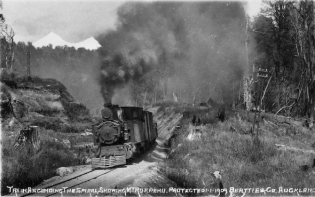
“The Raurimu Spiral is a single-track railway spiral, starting with a horseshoe curve, overcoming a 139-metre (456 ft) height difference, in the central North Island of New Zealand, on the North Island Main Trunk railway (NIMT) between Wellington and Auckland. It is a notable feat of civil engineering, having been called an ‘engineering masterpiece’. [8] The Institute of Professional Engineers of New Zealand has designated the spiral as a significant engineering heritage site.” [7][9]
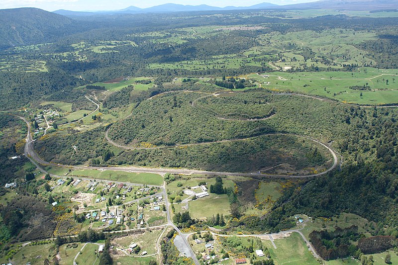
“During the construction of the central section of the NIMT, a major obstacle arose: how to cross the steep slopes between the North Island Volcanic Plateau to the east and the valleys and gorges of the Whanganui River to the west? … South of Taumarunui, the terrain is steep but not unmanageable, with the exception of the stretch between Raurimu and National Park, where the land rises too steeply for a direct rail route. A direct line between these two points would rise 200 metres (660 ft) in a distance of some 5 kilometres (3.1 mi), a gradient of 1 in 24. The area was thoroughly surveyed during the 1880s in an attempt to find a route with a lesser grade, but the only viable possibility seemed to require a 20-kilometre (12 mi) detour and nine massive viaducts. Even then, the gradient would have been steeper than 1 in 50.” [9]
“The problem was solved in 1898 by a surveyor in the employ of Robert Holmes, Public Works Department engineer. He proposed a line that looped back upon itself and then spiralled around with the aid of tunnels and bridges, rising at a gradient of 1 in 52. Though costly and labour-intensive, the scheme was still cheaper than the previous plan by Browne and Turner which required 9 viaducts down the Piopiotea River.” [9]
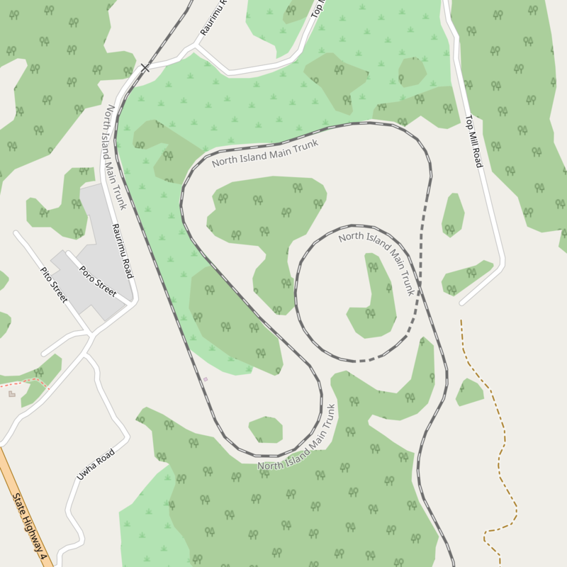
Wikipedia tells us that the railway “forms an ascending spiral southwards, with two relatively short tunnels, a circle and three hairpin bends. From the north, trains pass Raurimu before going round a 200° bend to the left in a horseshoe curve, climbing above the track on which they have just travelled. Two sharp bends to the right follow, after which the line passes through two short tunnels, the Lower Spiral Tunnel (384 m) and the Upper Spiral Tunnel (96 m). Trains then complete a full circle, crossing over the Lower Spiral Tunnel through which they have just passed which is 23-metre (75 ft) below, before continuing towards Wellington. Two kilometres (1.2 mi) further on the line has two more sharp bends, to the right and then to the left. … After the second of these bends a train has risen 132 metres (433 ft) and travelled 6.8 kilometres (4.2 mi) from Raurimu– the straight-line distance is 2 kilometres (1.2 mi). Some of the sharp curves are only 7½ chains (150 m) radius. … A masterly feature of Holmes’ layout is the way in which it uses natural land contours so that no viaducts are needed, and only two short tunnels.” [9]
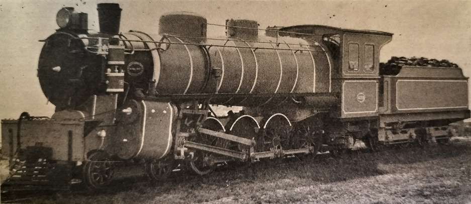
The line to Auckland was only completed in November 1908. The work on construction of the line across the feet of substantial mountains such as Mt. Ruapehu, Mt. Tongariro and Mt. Ngaruhoe (still an active volcano) proved arduous and held back the opening of the route. Overall, the “line rises to 3,000 ft. above sea-level. The maximum grade in the 90-mile mountain section is 1 in 50, and the sharpest curve has a radius of 7. 5 chains.” [1: p126]
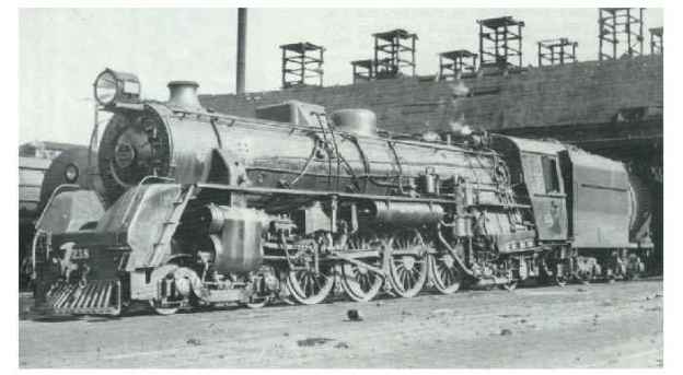
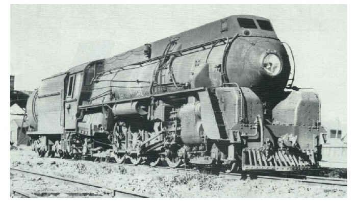
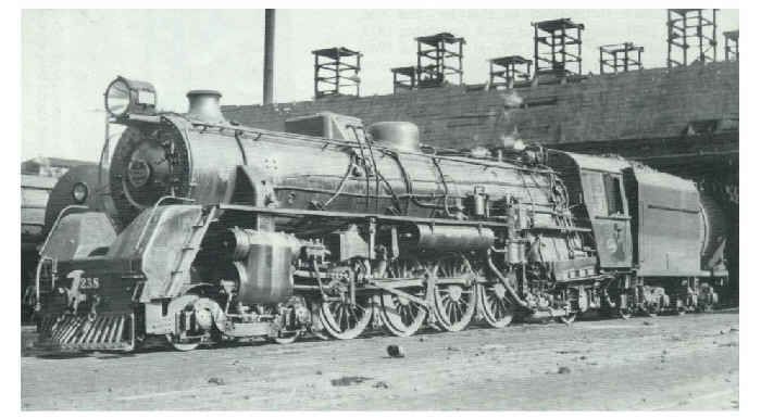
At Raurimu, the railway rises 700 ft. in 7 miles, of which 4 miles constitutes the spiral. For the main lengths of the trunk route New Zealand Railways designed 72-ton four cylinder balanced compound Class ‘A’ locomotives. For the 90-mile mountain section a bigger beast of an engine was required! The Class ‘X’ “mountain engine [was] a monster weighing 92 tons. … The ‘A’ was probably the first narrow gauge locomotive, (3ft 6in gauge) in the world to be fitted with inside as well as outside cylinders, and the ‘X’ [was] similarly equipped. She [was] a four-cylinder engine, with eight-coupled 3ft. 9in. driving-wheels, which, carrying about 50 tons of her weight, [gave] her immense grip of the rail, her tractive force being 30,000 lbs. The ‘A’ (six- coupled 4ft. 6in. wheels) [had] a force of 17,000 lbs. So the ‘X’ [pulled] nearly double the load an ‘A’ [could] haul. A four-wheeled leading bogie and a two-wheel trailing truck [completed] her wheel arrangement. New Zealand, in the design and construction of this engine, [had] taken a stride which [brought] her narrow gauge on almost level terms with the standard one. The only fault which [could] possibly be found in the ‘X’ [was] in the width of the locomotive in the region of her fire-box. Her furnace and tubes [had] a heating surface of 2,000 square ft., and she [worked] at a pressure of 250 lbs. of steam to the square inch. Consequently, she [had] an enormous fire-box, which [overhung] at the sides. But, having length as well, she [had] symmetry and stability. At a high speed she [would have been] inclined to roll. Her speed, however, rarely [exceeded] 30 miles an hour, her business being to pull a heavy train up the hills at a fair pace.” [1: p126-127]
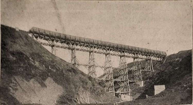
On the mountain section, the rails are 70 lbs., flat-footed (Vignoles) ones, spiked to sleepers and heavily ballasted. “The line [crossed] viaducts of great height, two of them curved ones, and it [pierced] many tunnels, one of which [had] an S-curve in its length. Altogether, the engineering conditions [were] severe, making the maintenance of a service of fast travel over this section a strenuous task.” [1: p127]
Lawson goes on to describe a journey South over the spiral:
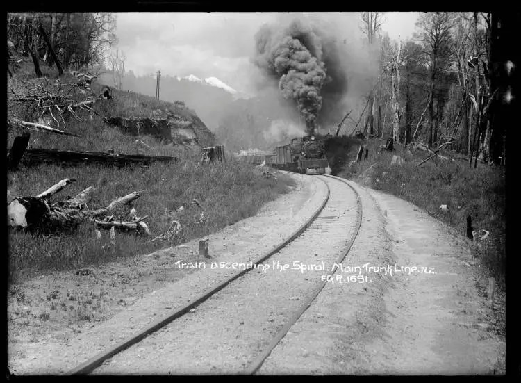
“There is bustle and babel on the railway platform at Taumarunui when the south-bound overland train is due. Her strident whistle sounds through the wintry morning air. A porter hurries along, his lantern gleaming in the dark, bidding all stand back, and he has hardly walked the length of the station when the express engine rushes past, bringing as her train six passenger cars, and the mail and baggage cars, three in number. She has come headlong from Te Kuiti, 50 miles away, through the long Poro-o-tarao tunnel and along the banks of the beautiful Ongaruhe River. But her ‘beat’ ends here. To fill her place comes a broad-backed monster whose bulging flanks overshadow her narrow wheel base. This is the ‘X’ engine, the monster of the mountains which will carry the mail, careering, where all Nature is, like herself, colossal. Her footplate is wide and her cab roomy and comfortable, after the American pattern. When her fire-door is opened it discloses an enormous cavern whence a stinging glare strikes out to the eyes. Beneath her tremendous energy one can almost feel the giant quiver. A shrill whistle is blown, and the fireman, watching for the guard’s starting signal, says, ‘Right away!’ There is a deep hoot from her whistle, and her throttle is opened slowly. So gently does she apply her strength, that the first sign of her moving is a gentle puff from her funnel 20 ft. away. Gathering way, she blows out a steady succession of muffled puffs, for there is nothing noisy about this locomotive until occasion in the shape of hard work demands it. Soon she is warming up and getting into her stride along the gently-rising track which leads to Piriaka. Originally it was intended that no grade on this line was to exceed 1 in 70, which, if not an easy one, is not unusual when cost of construction has to be studied, but the trend of the land towards the mountains compelled a maximum of 1 in 50, as already stated. Except on the Spiral, the maximum is 1 in 55. The big engine is making light work of her train of 9 heavy cars. Her fireman finds time to lean out and watch the carriage lights twinkling away in perspective. Past Kakahi and Owongo to Oio (surely the shortest railway name in the world!) and then the grades begin. Her furnace yawns for coal, her funnel’s roar rises in tone and intensity, her fireman mops his brow. Presently her hoarse, booming whistle hoots at the lights of Raurimu, the station at the foot of the Spiral. She steams into the station and makes her first stop after a 30-mile run. The engine is uncoupled, and runs along to a tank to water. This done, she returns to the train, and again her whistle blows for a starting signal. ‘X’, now thoroughly warmed to her work, makes haste to gather speed on the level stretch below the Spiral. It is a brave effort, and when she meets the rise she has attained some pace. Looking back, one may see where the grade begins. Some of the cars are still on the level. One by one they lift their noses to the grade until the whole train is hanging heavily on the engine’s draw-bar. Round to the left we sweep, and faintly can be heard the flange of a carriage wheel crying on the curve. Round and upwards for a mile.
Then nearly 100 ft. below, pale in the coming dawn, gleam the lights of Raurimu. One mile to gain a hundred ft. – that is, approximately, the achievement of Raurimu Spiral. Up we go: the engine blowing stentoriously, the fireman firing furiously, the carriages following unwillingly, and the speed a good 20 miles an hour. There is never a slip from the 8 driving-wheels, though there is a slight frost on the mountain side. The driver is watchful, and sands the line judiciously. A hoot from her whistle, and we are in the long 35-chain tunnel, and we feel it to be a relief when we are out in the pure mountain air once more.
Round and upwards, the big ‘X’ roars, steaming well. At last, the spiral motion ceases, and we rush out on to a length of straight line, which carries us over the long tunnel just passed through, which is 85 ft. beneath us. The mail rushes southward to the muffled measure of deep sound which her wheels toss out. Suddenly the thunder of our speed changes to an echoing, hollow-crashing sound. The earth which choked and deadened the uproar has dropped away, and a deep gorge, crossed by a towering entanglement of steel, echoes and re-echoes the sound. At either side of the engine, white handrails gleam. We are on Makatote Viaduct, the tallest in New Zealand, standing 260 ft. above the river-bed. Soon after, two curved viaducts are crossed: Toanui and Hapuawhenua. Then the train runs into Ohakune, which is half-way between Auckland and Wellington. After a short pause, we speed on across the Karioi Plains, and climb up to Waiouru, which is 2,659 ft. above the sea, and is the highest railway point in New Zealand. Snow-clad Ruapehu, the nearest and highest of the trio of mountains, shows bravely in the morning sunlight, and the wind that blows from the mountain is bitterly cold. So far, there has not been need for a snow-plough here, yet the possibility of one being required is always to be reckoned with. Last winter (1908), on the Central Otago Line, in the South Island, a snowstorm swept the high lands traversed by the railway, effectually blocking the line. One train was cut off from civilisation, and the engine belonging to it was set to the task of clearing the line. A snow-plough was devised by fastening a stout beam from the point of the cowcatcher to the top of the funnel, resting also against the smoke-box. Then all around were arranged timbers bound with iron. The engine, one of the “B” type of the New Zealand railways – 4-8-0, with 3ft. 6.25in. driving-wheels, weight 65 tons – patrolled the line, and finally succeeded in clearing the road again. Her enginemen had a cold time, working in a blizzard at 2,000 ft, above the sea. At one time it was freezing so hard, that icicles were formed on the engine. Whether such conditions will be met with on the North Island Trunk Line remains to be seen. Even the ‘X’ engines will find it hard work to climb the Raurimu Spiral if there are ‘ice-whiskers’ on the rails.” [1: p127-129]

References
- Will Lawson; New Zealand’s Mountain Railways; in The Railway Magazine, August 1909, p121-129.
- https://en.m.wikipedia.org/wiki/Rimutaka_Incline, accessed on 23rd December 2024.
- Richard Leitch, David; Scott, Brian (1995). Exploring New Zealand’s Ghost Railways (1998 ed.). Wellington: Grantham House.W. Heine; Semaphore to CTC: Signalling and train working in New Zealand, 1863-1993; New Zealand Railway and Locomotive Society, Wellington, 2000.
- https://en.m.wikipedia.org/wiki/NZR_RM_class_(Wairarapa), accessed on 24th December 2024.
- David Leitch & Brian Scott; Exploring New Zealand’s Ghost Railways (1998 ed.); Grantham House, Wellington, 1995.
- G. J. McClare & R. G. Thomson; New Zealand Railway and Locomotive Society, 1995.
- https://en.m.wikipedia.org/wiki/Raurimu_Spiral, accessed on 25th December 2024.
- Matthew Dearnaley; Steel backbone an economic lifeline; The New Zealand Herald, 9th August 2008, via https://www.nzherald.co.nz/nz/steel-backbone-an-economic-lifeline/Y74XCJIOYIXRX2AG7UGB5C64M4/?c_id=97&objectid=10526022, accessed on 25th December 2024.
- https://www.engineeringnz.org/programmes/heritage/heritage-register/raurimu-spiral, accessed on 25th December 2024.
- https://commons.wikimedia.org/wiki/File:Raurimu_Railway_Spiral_from_Helicopter_-_panoramio.jpg, accessed on 27th December 2024.
- https://commons.wikimedia.org/wiki/File:Raurimu_Spiral_map.png, accessed on 27th December 2024.
- https://digitalnz.org/records/30057571, accessed on 27th December 2024.
- https://natlib.govt.nz/records/22513976, accessed on 27th December 2024.


