In April 1920, a couple of paragraphs in The Railway Magazine focussed on a new experimental Railmotor constructed by New South Wales Railways. [1]
Railmotor No. 1
In April 1920, The Railway Magazine reported that New South Wales’ Railway Commissioners introduced a railmotor service on the Lismore line, an isolated section on the North Coast. The railmotor car was provided by converting and lengthening to 8 ft. 6 in. the chassis of a five-ton Moreland motor lorry. The front pair of wheels were also replaced by a four-wheeled bogie. The railmotor provided seating accommodation for 33 passengers, and was designed and constructed at the carriage and wagon shops of the system at Eveleigh, Sydney. [1]
Before being placed in service, a severe trial run was made, and proved in every way to be most successful; a I in 40 grade being taken at a speed of 18 m.p.h. The time-table was arranged for speeds up to 25 mph. The Railway Magazine noted that if found satisfactory in continued service similar rail-motor services would be introduced on other branch lines. [1]
NSW Railmotor No. 1 was powered by a 42 hp 4-cylinder American Waukesha petrol engine. This engine was later replaced by a 40 hp British Thornycroft 4-cylinder petrol engine. This vehicle proved a success on the line between Lismore and Grafton. [3]
“The wooden body … was finished in narrow tongue and groove boards. It was divided into three separate sections, accommodating 33 passengers and 2 crew. The first section was the cab, which accommodated the train crew (the driver and the guard). The second section (the forward compartment) accommodated 23 passengers and the third section (the rear compartment) was a smoking area and accommodated 10 passengers. The two passenger compartments were fitted with transverse seats and drop type windows, and each compartment had two doors, which opened outwards. There was no interconnection between the three compartments. Steps were fitted under each of the doors to allow passengers to alight from the vehicle to ground level.” [3]
“The Railmotor was designed to run in one direction only and draw-gear was fitted to the trailing end so that a trailer could be attached for hauling light goods and parcels. A collapsible tricycle (trike) was also carried for the train crew’s use in case of an emergency or breakdown in the section. This was carried on the back of the Railmotor.” [3]
“In November 1925, after six years of reliable service, [this vehicle] was withdrawn from passenger traffic and it took on a new role as the Signal Engineer’s inspection car. It subsequently lost its title of Railmotor No.1 as this was re-allocated to one the newly designed 42-foot Railmotors in November 1926.” [3]
“No. 1 was finally withdrawn from railway service in 1930. The body was sold and it began a new life as a house in the Coffs Harbour region, while the chassis was scrapped.” [3]
As we have already noted, one drawback with Railmotor No.1 was that it was only single ended and needed to be turned at the terminus for the return journey. Therefore double-ended operation was to be provided in the next prototype vehicle, Railmotor No.2, built in 1921. [3] Both trial vehicles were sufficiently successful to mean that the railway company went on to use a number of Railmotors.
Railmotor No. 2
Railmotor No. 2 (Kathleen)! “An end-platform suburban type carriage, FA 1864, was chosen for this experimental vehicle. Eveleigh Carriage Works converted this carriage to a Railmotor while its mechanical parts and the petrol engine were designed and built in Eveleigh Locomotive Works.” [3]
Configured as a railmotor, Kathleen (never its official name) “was divided into 4 sections, accommodating 53 passengers and 2 crew. [A] driving [cab was] positioned at each end. The First Class section accommodated 16 passengers, while the Second Class section accommodated 37 passengers. … Driving cabs were mounted in the centre of the end platforms at each end of the vehicle. Entry to the cab was gained through a back door that opened into the passenger compartment. The driving controls were arranged to allow the vehicle to be driven from either end and this meant the vehicle did not have to be turned for the return journey.” [3]
The first class section of the Railmotor “occupied one third of the vehicle’s length and the second class area occupied the remaining two thirds. Access to either area was gained through a door contained in a wall separating the two compartments. The engine protruded through the floor of the second class area and was covered by a padded fixture providing seating for an additional 5 passengers. This fixture measured 10′ 6″ x 3′ 6″. Battery boxes were also located in this central area and these to were covered with padded seats providing seating for 12 passengers.” [3]
“Railmotor No. 2 was powered by a 6-cylinder 100 hp (@1,000 rpm) petrol engine manufactured in the Eveleigh Railway Workshops. This engine was regarded as a fine piece of engineering, as it was reversible. That is, it could be turned in either direction and it contained features such as coil ignition, seven bearing crankshaft, together with overhead valves and camshaft. To make the engine turn in the opposite direction a camshaft containing two sets of cams was slid into position by means of compressed air. This engine weighed 22 cwt. A three-speed gearbox was coupled by cardan-shaft to both axles on one bogie. The vehicle was geared to give a road speed of 40 mph (@1,425 rpm) in top gear. Total weight of the vehicle of 26 tons 7 cwt 2 qtr.” [4]
“As the Railmotor could run in either direction, buffers, cowcatchers and standard screw drawgear were mounted on headstocks at either end and electric headlights were mounted above each of the driver’s windscreens. Electric lighting was used for the cab and compartment areas.” [4]
“Railmotor No.2 ran trials between Tamworth and Barraba on the 29th April, 1921. On the 15th October, 1922, the public timetable officially showed the railmotor, which provided a faster daily service (except Sundays) in place of the three times weekly mixed train service.” [4]
“No.2 failed to complete about two thirds of its allotted mileage during the first twelve months of operation and this poor performance was put down to undulating grades on the Barraba branch. The unit was eventually withdrawn from this working in November 1924. The unit proved a little more successful when it was trialled on the easier graded Burren Junction to Pokataroo branch during 1925.” [4]
It was withdrawn from service “in November 1925 and reverted to its original role as a suburban carriage number FA 1864. The engine that powered No.2 found a new life driving a water pump at Armidale and later at Valley Heights. … A proposal to construct another five cars similar to Kathleen but with an increased seating capacity lapsed. New designs proceeded and the standard 42-foot railmotor emerged.” [4]
References
Petrol Railmotor Car: New South Wales Government Railways; in The Railway Magazine, April 1920, p230.
Both the Rimutaka Incline and the Raurimu Sprial were highlighted by Will Lawson in an article in The Railway Magazine in 1909. [1]
The Rimutaka Incline
Will Lawson wrote about the mountain railways of New Zealand in the August 1909 issue of The Railway Magazine. [1] The two principal lines on the South Island were under construction at the time of his article. Those on the North Island were already in use.We look first at the Rimutaka Incline. …
“It is raining at Cross Creek, that lonely railway outpost at the foot of the Rimutaka Incline. Heavy vapours cling to the mountain, and out across the valley only a cloak of mist is to be seen. In the winter twilight, the mail train from Napier arrives. The engine which has hauled it over the plains is uncoupled. With her big driving – wheels, she could hardly propel herself up the 1 in 15 grade which now confronts her, and she gives way to two black, squat-funnelled Fell engines, which already are moving out from the running-shed to be attached to the train. They are followed by No. 66, a huge freight engine, which rolls along with an air of supreme disgust, as though this business of climbing mountains was beneath her contempt. These grimy black monsters, with never a gleam of brass about them, take the mail to the summit-No. 66 in the lead, and the two Fell engines at convenient distances, sandwiched among the carriages, while three brake-vans bring up the rear. These have powerful brakes, which operate on a centre rail laid between the usual rails carrying the wheels. On this rail the Fell engines also grip with their bevel grip-wheels. The carriage lamps are lighted, and the Cyclopean eye of each steel Goliath gleams through the rain. It is 21 miles to the summit, on a greasy rail, up the side of a black, wet mountain. Yet a glance at the hissing, steaming engines now attached to the train gives reassurance. They have an air of irresistibility that is most convincing, and they apparently scorn the grade which rises abruptly outside the level station yard. The leading engine blows her whistle; the sound is echoed by the other two; white steam shoots skyward; and the train glides away from the lonely settlement.
Standing on the level, the water-gauges appear to be empty, but as the engine meets the hill and her bevel-wheels slide on to the centre rail to be firmly clutched thereon by a powerful lever, the water, owing to the tilt of the engine, rises in the glass to a normal level. One reason for not filling the boiler up when on the level is that if there is too much water in the boiler, the heavy blast of the exhaust steam causes ‘priming’. This, of course, is fatal to effective driving.
The bevel wheels on the Fell are driven by an engine distinct from that which drives the ordinary driving-wheels, and as both sets of wheels slip occasionally, the exhaust from the Fell engines occurs with some irregularity. The effect is peculiar, suggestive of an asthmatic Samson climbing a greasy pole. In contrast, the steady thrash! thrash! of No. 66 has dignity. The pace is the merest crawl, scarcely exceeding a walking pace, and the din from the three engines is deafening. This is due to the extremely high pressure at which the boilers are worked. The exhaust steam, mingled with smoke, shoots up for a distance of some 30 ft., and there swirls and hangs in a heavy cloud, which, dimly seen in the coming darkness, marks the progress of the train along the mountain side. The glare from the open fire-doors transforms the cloud of steam into a mass of wicked red vapours, which, with the black, foggy mountains and yawning ravines, makes the scene almost Mephistophelean in its luridness. The train of carriages appears as a procession of glow-worms crawling through a night of foggy density.
On the Incline the shovel is never idle, and in the half-hour occupied in making the ascent the fireman exerts enough energy to run her 20 miles or so on the level. Even on the ends of the hair of his head drops of perspiration cling. In the cab there is only that shielded lamp, so designed that it throws its light on the water-gauge and steam-gauge. The driver’s eyes are shielded from it, as they also are from the furnace glare. Drivers and firemen may elect to work on this section of line or not, as they choose. Extra pay is given them, and in the busy season a great deal of overtime is to be earned. There is one driver who has continued on this run for 20 years, and there are others who are content to stay, despite the, to the lay mind, severity of the ordeal to be gone through in each up-run, especially on thick, wet nights. On such occasions the engine eats coal – one may almost hear her chewing it, and the resulting smoke is suffocating in the tunnels of which there are three – two short ones on the way up and a long curving one at the summit. Best Coalbrookdale is burned – the hottest, cleanest coal obtainable.
Now, some distance up the track looms the first tunnel, piercing an outstanding spur. The engine whistles, there is a sound of slamming windows, with which the engines are fitted, and then such a pandemonium of sound as cannot be imagined. It is an inferno. The 30-foot column of expanding steam and smoke is confined by the tunnel’s arch about 2 ft. above the funnel, and there follows a terrific compression which forces the hot vapours into the engine-cab in spite of windows. Each thrash of the spouting funnel stuns like a blow, the sulphur suffocates, the heat scorches. And on top of all these the fireman opens the fire-door and tosses coal in. Then it seems that there is no air to breathe at all. The wet rail is making the pace slower than usual, though the leading engine, having a dry rail in the tunnel, is exerting herself to get out as quickly. as possible. Still the stuttering, thrashing exhaust thuds on the tunnel’s arch: the tiny lamp in the cab gleams faintly through the smoke; the wicked red shafts from the air-holes in the fire-door radiate their redness in the suffocating atmosphere. Then the clamour of the funnel quietens; the windows are shot open; driver and fireman lean out to breathe God’s air once more. The men in the second and third engines have a worse time than those in the leader, as the tunnel becomes hotter and more foul with the passage of each engine. Onward, upward, she goes – slipping and racing – sanding and swearing. When the wheels slip, sand is thrown upon the rail, but before this is done, steam is shut off. If the sand were thrown under the spinning wheels while steam is on, possibly every rod and crank would be broken owing to the sudden check to the revolving wheel jarring these parts and throwing undue strain upon them.
Another tunnel is passed through, after which the pace quickens. The ‘long straight’ is reached. Here the grade is easier, and the line is straight. So the engines quicken their stroke, and when the last tunnel appears, they are making better time. Into this horseshoe shaped hole in the mountain crest the one-eyed, black giant of steel thunders. She crashes and rumbles along, her crew coughing in the smoky atmosphere. Then clang-clang! clang-clang! A bell, swung at the side of the tunnel and rung by the wheels of each passing vehicle, cries weirdly, telling that the uphill fight is over, the level road is here at last. The engine’s beat becomes more rapid as each carriage tops the grade to the ringing of the bell. As the other engines reach level ground the pace becomes the normal pace of a train running into a station. Ding-dong! ding-dong! A deep-toned bell moans its message through the vaulted place. The grade is a down one now, into the Summit station. The centre grip-rail ends abruptly, and the train rolls into the Summit yard, where an engine of the usual tank type takes it over from the monsters of the mountains, and away down the 1 in 35 grades which lead to Wellington.” [1: p123-126]
The Rimutaka Incline was built in the early 1870s and, as of 1909, was the steepest commercial railway in the world (the only railway on a grade of 1 in 15 on which ordinary rolling stock was used). “It [crossed] a spur of the Tararua Range at an elevation of 1,114 ft. above sea-level, and about a dozen trains [passed] over it in each direction daily.” [1: p121] It avoided what would have been a 25 mile (or more) deviation. Until the middle of the first decade of the 20th century, the line was worked by Fell locomotives alone, by 1909 a Mallet type of locomotive (designed and built in New Zealand specifically for work on the incline) was included in the roster.
Fell locomotives operate conventionally on regular gradients but are equipped with an extra four laterally-set wheels, which grip an additional centre-rail laid between the usual rails. The “lateral wheels are driven by a separate set of engines located under the smoke-box, and they are pressed to the rail by a lever which the fireman moves when the engine reaches the place where the centre-rail begins. Until that place is reached, progress is made by the usual driving wheels. The pressure exerted by the four grip wheels amounts to 70 tons, and, in addition, the engine has two powerful brakes, having jaws which grip the centre- rail in case of a stoppage and when descending the incline.” [1: p122]
In 1909 the relatively new Mallet-type loco, No.66, was proving to be highly effective. It was “65 tons in weight, carried on 12 driving-wheels and two leading wheels, an articulated tank engine working at a pressure of 200 lbs. to the square inch. The driving-wheels [were] in two [six-coupled sets], each set being driven by compound engines, the exhaust from the rear cylinders occurring through a pipe on the top of the engine cab. On the incline this engine [could] pull a train weighing 110 tons, and to accomplish this she [burned] half a ton of coal. Usually, however, she [took] the train up the hill in conjunction with the Fell engines.” [1: p122]
The incline was on the line from Wellington to Napier with the steep upward grade being on the Napier to Wellington service.
Wikipedia tells us that the “Rimutaka Incline was a 3-mile-long (4.8 km), 3 ft 6 in (1,067 mm) gauge railway line on an average grade of 1-in-15 using the Fell system between Summit and Cross Creek stations on the Wairarapa side of the original Wairarapa Line in the Wairarapa district of New Zealand. … The incline formation is now part of the Remutaka Rail Trail.” [2]
These notes come from the Wikipedia entry about the incline. …
The construction of a railway from Wellington to Masterton was authorised in the Railways Act passed on 13th September 1871. Julius Vogel, Colonial Treasurer, travelled to England to raise finance for a major public works programme for railway construction. Vogel returned via the United States, where he studied rail systems.
After the Act was passed, a survey party investigated four different routes. A commonality between all the proposals was the section from Upper Hutt to Kaitoki (later Kaitoke). Between Kaitoke and the Wairarapa, the four proposals were the Tauwharenikau Route, Mr Sinclair’s Route, a coastal route and the Pakuratahi Route.
While the government was conducting its surveys, Wellington Province Superintendent William Fitzherbert instructed his Provincial Engineer, Charles O’Neill, to investigate the possibility of a railway through the Rimutaka Valley (the route of the road between Featherston and Upper Hutt), with a tunnel through the dividing range. The survey was carried out between May andJuly 1871, and O’Neill reported that a tunnel 130 chains (2.6 km) long would be required, with the line rising at 1 in 60 from the Pakuratahi to the tunnel then descending at 1 in 40 to Featherston. This survey was forwarded to the Minister for Public Works.
In mid-1873 the route to Featherston was chosen after a final survey for the route from Upper Hutt to Summit.
For the line between Summit and the Wairarapa, several proposals were considered. The first, with gradients up to 1 in 30, was dismissed. It was found that to keep the gradient to no steeper than 1 in 40, curves of three chains (60 m) radius would be required. This would have required special rolling stock and heavy earthworks and was thus abandoned.
Another proposal was known as the Birch Spur Incline. This would have involved the line continuing from Summit to Birch Spur from where a rope-worked incline would convey traffic to the valley floor where the railway would continue through a narrow valley to the Wairarapa plains. The Public Works Department engineers investigating this proposal were unable to locate a suitable incline, so this proposal was also abandoned.
The last option was a three-mile (4.8 km) incline with gradients averaging 1 in 15 “to be worked by locomotives of an unusual nature”. This line was the most favourable from an engineer’s point of view, and required not unreasonable earthworks. The final decision was made by the head of the Public Works Department, John Carruthers. He determined that an incline worked by the Fell system would be suitable, and cited the Mont Cenis Pass Railway as an example. Though special locomotives would be required, factors in its favour were that ordinary rolling stock could be used and it was a proven system. It was to be the third and last Fell system employing the centre rail for both tractive power and braking, and the longest surviving. Though it was considered to be a “temporary” measure, it outlasted the second such system in Brazil by 72 years. [2]
Construction
Construction of the Rimutaka Incline was included in two contracts that were let for the building of the original Wairarapa Line. These contracts were known as the Summit contract and the Incline contract. [2]
The Summit Contract included the excavation of Summit station yard and related drainage, Summit tunnel, and formation work to a point 26 chains (523 m) beyond the tunnel. It was the shortest contract of those let for the line, it was finished by the original contractor, and it had the fewest alterations. Work was to start on 12th July 1874 and to be completed by 22nd July 1876, at which time the Pakuratahi contract was due to be completed. [2]
Summit yard was a large cut into the hillside, 120 feet (37 m) wide and 500 yards (460 m) long initially. Excavations removed material to a depth of 15–20 feet, with this fill being dumped on the opposite side of the yard to form level ground. On the hillside above the yard, further ground was levelled and houses erected thereon. [2]
After the yard had taken shape, work commenced on the tunnel. The approach to the tunnel was about 6 chains long and up to 60 feet (18 m) deep. The line entered the tunnel on a downward grade of 1 in 1,000, steepening to a grade of 1 in 15 at the eastern portal. At that end a small drainage tunnel had to be built to divert a stream that had flowed down a steep gully where the tunnel mouth was to be. The maximum height of the tunnel was 15 feet (4.6 m) above the floor: once rails were laid the maximum clearance was 13 feet 9 inches (4.19 m) The width of the tunnel varied from 10 feet 6 inches (3.20 m) at the floor to 12 feet (3.7 m) at 7 feet 6 inches (2.29 m) above the floor. Despite castigation from various parties, it was not until March 1877 that work on both ends of the tunnel met at the middle, having taken three and a half years to complete. [2]
The Public Works Department lined the tunnel after the rails had reached the site, enabling them to use work trains to bring materials and other supplies in. It was during this phase that the only fatality on this contract occurred: on 3rd May 1878, a sizeable portion of the lining collapsed on two men. One was killed outright, the other lost his eyesight due to severe head injuries. [2]
The Summit contract was completed on 10th December 1877, 17 months behind schedule. [2]
The Incline Contract was let on 5th October 1875 to Charles McKirdy for the sum of £49,029. The contract covered the formation only, with the Public Works Department responsible for track laying. [2]
Work on the contract began on 22nd October 1875. None of the major earthworks seem to have presented any great difficulties, save the lower tunnel, which was plagued by accidents and materials failures largely because of the unstable nature of the rock through which it passed. The tunnel was named Price’s after the manager McKirdy employed for this contract. On 2nd March 1876, two men died due to a cave-in of the tunnel roof. [2]
Between October 1877 and March 1878, platelaying was completed up to Summit. This enabled the use of work trains to haul up materials that were used to line Summit Tunnel. Track laying on the incline commenced in April 1878 and reached Cross Creek the following month. During this work, locomotive H199 was stabled at Summit and used to haul work and ballast trains to the railhead. [2]
Initially, only simple arrangements were made for the station yard at Cross’s Creek, as it had yet to be decided the nature of operations on the Incline. It consisted of the main line, an engine siding of 10 chains, and the runaway siding. [2]
After formation work continued beyond Cross Creek, McKirdy ran out of time and money, with the remainder of his contract being picked up by his guarantors, T. W. Young and Robert Greenfield. They finished the formation to Featherston on 17th August 1878, with track laying finishing the following month. The contract was completed 13 months late. [2]
Operation – Initially, trains on the incline were limited to the weight that could be managed by a single locomotive. After complaints from management of the expense of running too many trains, two locomotives seem to have been used, both at the head of the train. From 1887 trains were worked with multiple locomotives, each at the head of its rated load. As the maximum weight of a train during this period was 150 tons, no more than three locomotives were used per train. Train operations continued to be modified until by 1908 the maximum load allowed per train had increased to 250 tons descending and 260 tons ascending. [2]
When the line opened, there were two Fell brake vans in service, each 12 ft 6 in (3.81 m) long and 5 ft 9 in (1.75 m) from floor to ceiling, with open platforms at either end. The wear on the brake blocks fitted to these vans was so severe that a set of blocks seldom lasted more than one trip down the incline. Like the positioning and loading of the locomotives, the arrangements for positioning of the Fell vans varied until they were largely standardised by 1897. For ascending trains, Fell vans were placed at the rear of the train. For descending trains, a Fell van was placed between the locomotives and the leading vehicle. If the gross weight of the train exceeded 120 tons or included more than 15 vehicles (excluding the locomotives in both cases) a second Fell van was attached to the rear of the train. These rules applied before the introduction of the Westinghouse continuous air brake. The Fell locomotives were never turned, running cab first on descending trains. [2]
As descending trains departed Summit the “through” guard applied the brakes on the leading vehicle, then moved through the train applying the brakes on the other vehicles until he reached the train van, which also had brakes that had to be applied. Each Fell van had its own guard to operate the two sets of brakes. [2]
After the introduction of the continuous brake system in 1903 it became possible to operate trains with five locomotives, and on descending passenger trains up to five Fell brake vans could be used – two next to the locomotives, one in the middle, and two at the rear. As each brake van had its own guard and the train had a train guard and locomotive crews, a train with five brake vans and four locomotives had a crew of 14, which added to the expense of the operation. Moreover, to reduce the strain on couplings, when several locomotives were used they would be distributed through the train, as can be seen from photos. This necessitated significant re-marshalling of the train at either end of the incline. [2]
Instructions issued in 1885 regarding the use of the safety siding required that the points for the incline be set to the safety siding. As descending trains approached the Cross Creek yard, the driver of the leading locomotive sounded a long whistle, which signalled that all was well. On hearing this signal the signalman would set the points for the arrival road. As far as is known no real emergency occurred. Cross Creek had an unusual six-lever partially-interlocked signalling installation and had no “distant” signals so had points indicators which applied to the “main” line (see Heine for station layout), while Summit had a fully interlocked 27-lever frame. [2][3]
Unusual traffic included four royal trains: for the Prince of Wales in 1921; the Duke (later King George VI) and Duchess of York in 1927; the Duke of Gloucester in 1935; and Queen Elizabeth II and the Duke of Edinburgh in 1954. Trains were diverted from the Manawatu line due to slips, floods or other mishaps. [2]
The original yards at Cross Creek and Summit were sufficient for the traffic levels of the time, but increasing traffic brought about incremental additions. The full extent of the Summit yard was reached in 1903, which coincided with the introduction of full signalling and interlocking, not introduced to Cross Creek until 1915. [2]
The Fell locomotives (H class) were not to be operated on any part of the railway other than the Incline, with the sole exception of conveying them to the Petone (and later Hutt) Workshops for maintenance. In the latter case, bunkers, water tanks and boilers were to be empty and the locomotives were to be towed at a speed not exceeding 10 miles per hour (16 km/h). These rules were relaxed to allow the locomotives to travel light engine to Petone and back under their own steam, subject to the same speed restrictions. In 1887 they were permitted to be operated between Cross Creek and Pigeon Bush, later extended to Featherston to enable them to be used for banking purposes. Running rights between Cross Creek and Featherston were revoked about 1943. [2]
Speed limits for trains on the Incline were changed several times. From 1884 to 1888 the limit was 6 mph (9.7 km/h) ascending and descending, except light passenger trains for which the limit was 8 mph (13 km/h). In 1888 these limits changed to 5 mph (8.0 km/h) up, 9 mph (14 km/h) down. The limits were finally 6 mph (9.7 km/h) up, 10 mph (16 km/h) down. [2]
Various classes of locomotives were deployed to supplement the H class when one or more was away for maintenance or repairs, including
W192 and 238 2-6-2T locomotives, built in 1889 and 1891 respectively, which spent most of their time on the Wellington to Summit section until their transfer in 1909;
54-ton We 4-6-4T locomotives rebuilt from 4-8-0 B Class locomotives, rated to haul passenger trains up to 55 tons and goods trains up to 60 tons, until 1906, after which they were used mainly on the Upper Hutt to Summit section and rated to haul passenger trains up to 130 tons, mixed trains 150 tons and goods trains 155 tons, and were then later sent to work on the Rewanui Incline on the South Island;
65-ton E 66, rated to haul 80 tons up the Incline, and nicknamed Pearson’s Dream. In 1910 it was transferred to banking duties on the Wellington to Johnsonville section, but it was never popular with crew. (This is interesting, given Lawson’s very positive description of the loco in use on the Incline);
Wg 480 4-6-4T locomotive, during the first World War.
After the Great War traffic was well within the capabilities of the six H class Fell locomotives. [2]
The mileages run by the H class locomotives show notable increases that correspond to economic and other major events, such as the opening of the Wairarapa Line as far as Masterton, completion of the line to Woodville, and the nationalisation of the Wellington and Manawatu Railway. With the opening of the railway to Masterton the annual mileage of the H class rose from less than 7,000 to more than 8,000, in 1883–1897 to 34,000, and to 42,000 when the line was opened to Woodville and began carrying traffic from the Hawke’s Bay. Mileage peaked at 64,123 in 1906–07, about 10,687 miles per locomotive or 1,780 return Incline trips. [2]
Wairarapa railcars
In 1936 seven lightweight Wairarapa railcars, RM 4–10, were introduced between Palmerston North, Masterton and Wellington. They were specifically designed for the Incline, and were built at the Hutt Workshops. They were named after historic Maori canoes: Maahunui, Mahuhu, Mamari, Matahourua, Mataatua, Arai-te-Uru and Arawa. Initially powered by 130 horsepower (97 kW) Leyland petrol engines, they were upgraded after several years to 120 horsepower (89 kW) diesel engines. They had a single rear driving axle with 38½” (978 mm) diameter wheels, necessitated by the need for the axle and final drive unit to have sufficient clearance above the Incline’s centre rail. Because of the large rear wheels the floor of the passenger compartment was 52½” (1334 mm) above rail level, more than 12 inches (300 mm) higher than normal. They were rated for a maximum speed of 60 mph (97 km/h) and expected to climb the Incline at 15-17 mph, but actually managed only 10–12 mph. Nevertheless, they greatly speeded up passenger trains on the route and immediately proved popular. They were withdrawn in 1955 when the Incline closed. [2]
Several options for an alternative to the Incline were considered in the 20th century, but it was not until after WWII that a route through a tunnel between Maymorn and Lucena’s Creek was selected. Construction was started in 1948 by the Public Works Department and completed by a private contractor in 1955. The tunnel and deviation opened on 3rd November 1955, five days after this the Incline closed. [2][6]
Demolition was swift, with the removal of track between Cross Creek and Pigeon Bush largely completed by March 1956. H 199 was used to haul the work trains that removed the track between Cross Creek and Summit. The buildings were sold at auction, on site. Some of the rails were sent to the Rewanui Incline, as were a couple of the Fell brake vans. Five of the six H class locomotives were towed to the Hutt Workshops, later to Silverstream, to be scrapped. [2]
Today
A resurgence of public interest in the incline followed the publication of a book in 1976 and the opening of the Fell Engine Museum in the early 1980s, prompting the New Zealand Forest Service to re-establish access to Cross Creek in 1984. [5: p40] Interest increased following the publishing of an article in the NZ Runner magazine “Try this Run” in the November-December 1984 issue, which promoted this incline as a backcountry running opportunity [Issue No 35]. The official opening of a rail trail using the formation of the original railway line from Cross Creek to Kaitoke followed in 1987. [5: p41] It is today one of the more popular recreational facilities in the region and forms part of the Remutaka Forest Park. [5: p41]
The Raurimu Spiral
“The Raurimu Spiral is a single-track railway spiral, starting with a horseshoe curve, overcoming a 139-metre (456 ft) height difference, in the central North Island of New Zealand, on the North Island Main Trunk railway (NIMT) between Wellington and Auckland. It is a notable feat of civil engineering, having been called an ‘engineering masterpiece’. [8] The Institute of Professional Engineers of New Zealand has designated the spiral as a significant engineering heritage site.” [7][9]
A bird’s eye view of the Raurimu Spiral, seen from the West and taken in November 2007, (c) Duane Wilkins and licenced for reuse under a Creatiev Commons Licence (CC BY-SA 2.0). [10]
“During the construction of the central section of the NIMT, a major obstacle arose: how to cross the steep slopes between the North Island Volcanic Plateau to the east and the valleys and gorges of the Whanganui River to the west? … South of Taumarunui, the terrain is steep but not unmanageable, with the exception of the stretch between Raurimu and National Park, where the land rises too steeply for a direct rail route. A direct line between these two points would rise 200 metres (660 ft) in a distance of some 5 kilometres (3.1 mi), a gradient of 1 in 24. The area was thoroughly surveyed during the 1880s in an attempt to find a route with a lesser grade, but the only viable possibility seemed to require a 20-kilometre (12 mi) detour and nine massive viaducts. Even then, the gradient would have been steeper than 1 in 50.” [9]
“The problem was solved in 1898 by a surveyor in the employ of Robert Holmes, Public Works Department engineer. He proposed a line that looped back upon itself and then spiralled around with the aid of tunnels and bridges, rising at a gradient of 1 in 52. Though costly and labour-intensive, the scheme was still cheaper than the previous plan by Browne and Turner which required 9 viaducts down the Piopiotea River.” [9]
Wikipedia tells us that the railway “forms an ascending spiral southwards, with two relatively short tunnels, a circle and three hairpin bends. From the north, trains pass Raurimu before going round a 200° bend to the left in a horseshoe curve, climbing above the track on which they have just travelled. Two sharp bends to the right follow, after which the line passes through two short tunnels, the Lower Spiral Tunnel (384 m) and the Upper Spiral Tunnel (96 m). Trains then complete a full circle, crossing over the Lower Spiral Tunnel through which they have just passed which is 23-metre (75 ft) below, before continuing towards Wellington. Two kilometres (1.2 mi) further on the line has two more sharp bends, to the right and then to the left. … After the second of these bends a train has risen 132 metres (433 ft) and travelled 6.8 kilometres (4.2 mi) from Raurimu– the straight-line distance is 2 kilometres (1.2 mi). Some of the sharp curves are only 7½ chains (150 m) radius. … A masterly feature of Holmes’ layout is the way in which it uses natural land contours so that no viaducts are needed, and only two short tunnels.” [9]
The line to Auckland was only completed in November 1908. The work on construction of the line across the feet of substantial mountains such as Mt. Ruapehu, Mt. Tongariro and Mt. Ngaruhoe (still an active volcano) proved arduous and held back the opening of the route. Overall, the “line rises to 3,000 ft. above sea-level. The maximum grade in the 90-mile mountain section is 1 in 50, and the sharpest curve has a radius of 7. 5 chains.” [1: p126]
At Raurimu, the railway rises 700 ft. in 7 miles, of which 4 miles constitutes the spiral. For the main lengths of the trunk route New Zealand Railways designed 72-ton four cylinder balanced compound Class ‘A’ locomotives. For the 90-mile mountain section a bigger beast of an engine was required! The Class ‘X’ “mountain engine [was] a monster weighing 92 tons. … The ‘A’ was probably the first narrow gauge locomotive, (3ft 6in gauge) in the world to be fitted with inside as well as outside cylinders, and the ‘X’ [was] similarly equipped. She [was] a four-cylinder engine, with eight-coupled 3ft. 9in. driving-wheels, which, carrying about 50 tons of her weight, [gave] her immense grip of the rail, her tractive force being 30,000 lbs. The ‘A’ (six- coupled 4ft. 6in. wheels) [had] a force of 17,000 lbs. So the ‘X’ [pulled] nearly double the load an ‘A’ [could] haul. A four-wheeled leading bogie and a two-wheel trailing truck [completed] her wheel arrangement. New Zealand, in the design and construction of this engine, [had] taken a stride which [brought] her narrow gauge on almost level terms with the standard one. The only fault which [could] possibly be found in the ‘X’ [was] in the width of the locomotive in the region of her fire-box. Her furnace and tubes [had] a heating surface of 2,000 square ft., and she [worked] at a pressure of 250 lbs. of steam to the square inch. Consequently, she [had] an enormous fire-box, which [overhung] at the sides. But, having length as well, she [had] symmetry and stability. At a high speed she [would have been] inclined to roll. Her speed, however, rarely [exceeded] 30 miles an hour, her business being to pull a heavy train up the hills at a fair pace.” [1: p126-127]
On the mountain section, the rails are 70 lbs., flat-footed (Vignoles) ones, spiked to sleepers and heavily ballasted. “The line [crossed] viaducts of great height, two of them curved ones, and it [pierced] many tunnels, one of which [had] an S-curve in its length. Altogether, the engineering conditions [were] severe, making the maintenance of a service of fast travel over this section a strenuous task.” [1: p127]
Train ascending the Raurimu Spiral in the early 1900s, (c) Frederick George Radcliffe/Auckland Libraries and authorised for reuse without restriction (Public Domain). [12]
Lawson goes on to describe a journey South over the spiral:
“There is bustle and babel on the railway platform at Taumarunui when the south-bound overland train is due. Her strident whistle sounds through the wintry morning air. A porter hurries along, his lantern gleaming in the dark, bidding all stand back, and he has hardly walked the length of the station when the express engine rushes past, bringing as her train six passenger cars, and the mail and baggage cars, three in number. She has come headlong from Te Kuiti, 50 miles away, through the long Poro-o-tarao tunnel and along the banks of the beautiful Ongaruhe River. But her ‘beat’ ends here. To fill her place comes a broad-backed monster whose bulging flanks overshadow her narrow wheel base. This is the ‘X’ engine, the monster of the mountains which will carry the mail, careering, where all Nature is, like herself, colossal. Her footplate is wide and her cab roomy and comfortable, after the American pattern. When her fire-door is opened it discloses an enormous cavern whence a stinging glare strikes out to the eyes. Beneath her tremendous energy one can almost feel the giant quiver. A shrill whistle is blown, and the fireman, watching for the guard’s starting signal, says, ‘Right away!’ There is a deep hoot from her whistle, and her throttle is opened slowly. So gently does she apply her strength, that the first sign of her moving is a gentle puff from her funnel 20 ft. away. Gathering way, she blows out a steady succession of muffled puffs, for there is nothing noisy about this locomotive until occasion in the shape of hard work demands it. Soon she is warming up and getting into her stride along the gently-rising track which leads to Piriaka. Originally it was intended that no grade on this line was to exceed 1 in 70, which, if not an easy one, is not unusual when cost of construction has to be studied, but the trend of the land towards the mountains compelled a maximum of 1 in 50, as already stated. Except on the Spiral, the maximum is 1 in 55. The big engine is making light work of her train of 9 heavy cars. Her fireman finds time to lean out and watch the carriage lights twinkling away in perspective. Past Kakahi and Owongo to Oio (surely the shortest railway name in the world!) and then the grades begin. Her furnace yawns for coal, her funnel’s roar rises in tone and intensity, her fireman mops his brow. Presently her hoarse, booming whistle hoots at the lights of Raurimu, the station at the foot of the Spiral. She steams into the station and makes her first stop after a 30-mile run. The engine is uncoupled, and runs along to a tank to water. This done, she returns to the train, and again her whistle blows for a starting signal. ‘X’, now thoroughly warmed to her work, makes haste to gather speed on the level stretch below the Spiral. It is a brave effort, and when she meets the rise she has attained some pace. Looking back, one may see where the grade begins. Some of the cars are still on the level. One by one they lift their noses to the grade until the whole train is hanging heavily on the engine’s draw-bar. Round to the left we sweep, and faintly can be heard the flange of a carriage wheel crying on the curve. Round and upwards for a mile.
Then nearly 100 ft. below, pale in the coming dawn, gleam the lights of Raurimu. One mile to gain a hundred ft. – that is, approximately, the achievement of Raurimu Spiral. Up we go: the engine blowing stentoriously, the fireman firing furiously, the carriages following unwillingly, and the speed a good 20 miles an hour. There is never a slip from the 8 driving-wheels, though there is a slight frost on the mountain side. The driver is watchful, and sands the line judiciously. A hoot from her whistle, and we are in the long 35-chain tunnel, and we feel it to be a relief when we are out in the pure mountain air once more.
Round and upwards, the big ‘X’ roars, steaming well. At last, the spiral motion ceases, and we rush out on to a length of straight line, which carries us over the long tunnel just passed through, which is 85 ft. beneath us. The mail rushes southward to the muffled measure of deep sound which her wheels toss out. Suddenly the thunder of our speed changes to an echoing, hollow-crashing sound. The earth which choked and deadened the uproar has dropped away, and a deep gorge, crossed by a towering entanglement of steel, echoes and re-echoes the sound. At either side of the engine, white handrails gleam. We are on Makatote Viaduct, the tallest in New Zealand, standing 260 ft. above the river-bed. Soon after, two curved viaducts are crossed: Toanui and Hapuawhenua. Then the train runs into Ohakune, which is half-way between Auckland and Wellington. After a short pause, we speed on across the Karioi Plains, and climb up to Waiouru, which is 2,659 ft. above the sea, and is the highest railway point in New Zealand. Snow-clad Ruapehu, the nearest and highest of the trio of mountains, shows bravely in the morning sunlight, and the wind that blows from the mountain is bitterly cold. So far, there has not been need for a snow-plough here, yet the possibility of one being required is always to be reckoned with. Last winter (1908), on the Central Otago Line, in the South Island, a snowstorm swept the high lands traversed by the railway, effectually blocking the line. One train was cut off from civilisation, and the engine belonging to it was set to the task of clearing the line. A snow-plough was devised by fastening a stout beam from the point of the cowcatcher to the top of the funnel, resting also against the smoke-box. Then all around were arranged timbers bound with iron. The engine, one of the “B” type of the New Zealand railways – 4-8-0, with 3ft. 6.25in. driving-wheels, weight 65 tons – patrolled the line, and finally succeeded in clearing the road again. Her enginemen had a cold time, working in a blizzard at 2,000 ft, above the sea. At one time it was freezing so hard, that icicles were formed on the engine. Whether such conditions will be met with on the North Island Trunk Line remains to be seen. Even the ‘X’ engines will find it hard work to climb the Raurimu Spiral if there are ‘ice-whiskers’ on the rails.” [1: p127-129]
A Wf class tank engine climbing the Raurimu spiral in 1909 Original photographic prints and postcards from file print collection, Box 5. Ref: PAColl-5800-54. Alexander Turnbull Library, Wellington, New Zealand. (c) A. Williams/Alexander Turnbull Library and made available without restriction provided reproduced as taken with no alteration. [13]
References
Will Lawson; New Zealand’s Mountain Railways; in The Railway Magazine, August 1909, p121-129.
Richard Leitch, David; Scott, Brian (1995). Exploring New Zealand’s Ghost Railways (1998 ed.). Wellington: Grantham House.W. Heine; Semaphore to CTC: Signalling and train working in New Zealand, 1863-1993; New Zealand Railway and Locomotive Society, Wellington, 2000.
The November 1899 issue of The Railway Magazine carried the first of a short series of articles about the railways of New Zealand. As you will discover if you choose to read on, the author does not hold back on offering his personal opinions about the state of the railways and choices made by the government of the day for the country’s railways.
It is a pity that I do not have access to the subsequent article(s) about New Zealand’s Railways nor to any debate that the article may have provoked.
It might be interesting to hear some present day reflections on the comments the author makes!
The article is also of interest for an introduction to the rather unusual decisions taken by the Southland government about its first railway.
Rous-Marten begins: “When railway construction first began in New Zealand, that ‘Britain of the South’ was a sort of Heptarchy – an association of seven Provinces’, subsequently nine, with a ‘General’ or Federal Government at the capital, Wellington. And three of these Provinces separately entered upon railway making, each on its own account.” [1: p465]
He continues: “There was a special reason in every instance for the embarkation on this enterprise. In Southland the local capital, Invercargill, was separated from the port by about fifteen miles of swamps, and from its goldfields by a stretch of country over which road-making was difficult on account of the numerous boggy streams which had to be crossed. In Otago – more accurately Otakou … – the capital, Dunedin was approachable from the port only by a difficult channel, or a still more difficult land-track. In Canterbury the chief town, Christchurch, was separated from the port (Lyttelton) by a high – almost mountainous – range of hills. And so connection by rail was sought as the most efficient and, in the end, the cheapest, means of communication. … Unfortunately, each of those semi-independent Governments adopted a different gauge.” [1: p465]
Rous-Marten says that “Southland chose the British standard gauge, 4 ft. 8.5 in.; Otago preferred the 3 ft. 6 in. gauge; Canterbury – wisest of all selected the ‘Irish’ gauge of – 5 ft. 3 in.” There is a glimpse in this sentence of Rous-Marten’s own position which quickly becomes clear as the article unfolds. [1: p465]
He goes on to say that “still more unfortunately, when, the Provincial Governments were abo- lished, and when a general system of railways was adopted, the 3 ft. 6 in. gauge was chosen for the whole colony as the most economical – a grievous and, I fear, irreparable blunder.” [1: p465]
Otago Province
The first Otago railway, was from Dunedin to Port Chalmers. Once built, it “was worked by Double-Fairlie engines without any very serious difficulty being experienced from initiation to completion.” [1: p465]
Rous-Marten says that this Double-Fairlie Engine was a Class K, New Zealand Railways. [1: p466] The Double-Fairlie locos were, in fact, Class E locomotives. The Class K locomotives were built by Rogers in the USA and were 2-4-2 tender locomotives. Otago Province was a significant province of New Zealand until the abolition of provincial government in 1876. The capital of the province was Dunedin. Southland Province split from Otago in 1861, but became part of the province again in 1870. [36]Otago, in the 21st century, is a southeastern region on New Zealand’s South Island. Its terrain encompasses snow-capped mountains, glacial lakes and a rugged peninsula sheltering sandy beaches and wildlife like penguins. Queenstown, a lakeside resort town framed by the dramatic Southern Alps, is famous for adventure sports like bungee jumping and paragliding. Outside Queenstown are dozens of wineries. It has an area of approximately 32,000 square kilometres (12,000 sq mi), making it the country’s second largest local government region. Its population was 254,600 in June 2023. [37]
Canterbury Province
Canterbury (Māori: Waitaha) is a region of New Zealand, located in the central-eastern South Island. The region covers an area of 44,503.88 square kilometres (17,183.04 sq mi), making it the largest region in the country by area. It is home to a population of 666,300 (June 2023). [38]
Canterbury region. [38]
Rous-Marten’s article continues: “The Canterbury railway from Lyttelton to Christchurch had one solitary work of large magnitude, a tunnel through the dividing range. … The length of the ‘Moorhouse Tunnel’ is almost exactly the same as that … of the Box Tunnel of the Great Western Railway … a mile and seventy chains. … Originally, the Canterbury line was equipped with six six-wheeled tank locomotives, all built by the Avondale Company, Bristol. Of these, four had 5ft. 6in. driving and trailing wheels, coupled and inside cylinders 15 x 22; two had leading and driving wheels coupled 5 ft. in diameter, and cylinders 14 x 22.” [1: p466]
Wikipedia tells us that later the tunnel appears to have become known as the Lyttelton Tunnel. It opened on 9th December 1867. “The line and the tunnel were constructed to accommodate 5 ft 3 in (1,600 mm) rolling stock at the behest of contractors Holmes & Richardson of Melbourne, as this was the gauge they were already working with in Victoria. The line remained this way until, following the abolition of provincial government in New Zealand and the establishment of a new uniform national track gauge, the line was converted to 3 ft 6 in (1,067 mm) by April 1876.” [2]
This indicates that for the first 8 years and 4 months of its existence the line was of 5ft 3in gauge. Those first locomotives will have been of that gauge. During that time, all the railways built in Canterbury Province were of the same gauge.
Wikipedia [4] also tells us that the “Canterbury Provincial Railways operated ten steam locomotives of varying types, not divided into separate classes. They were all tank locomotives based on contemporary British practice and were built by the Avonside Engine Company, except for No. 9 by Neilson and Company. Nos. 1-4 had a 2-4-0T wheel arrangement: No. 1, named Pilgrim,[3: p12] was built for the Melbourne and Essendon Railway Company of Melbourne, Australia in 1862 but was quickly on-sold unused to Holmes and Company, who were building the Ferrymead line (in New Zealand. The line was closed after the Moorhouse/Lyttleton Tunnel opened). [3: p11] It entered revenue service when the line opened.” [4]
The remainder of the first six locomotives, No. 2 (arrived April 1864), No. 3 (arrived March 1867), No. 4 (arrived May 1868), [3: p12] Nos. 5 and 6 also arrived in May 1868. The first four were 2-4-0T locos, Nos 5 & 6 were 0-4-2T and were somewhat smaller. [3: p13]
The Province purchased three more 0-4-2T locomotives, ordered independently, No. 7 entered service in August 1872, No.8 in March 1874 and No. 10 in June 1874.[3: p12] No. 9 was a diminutive 0-4-0T ordered after No. 8 but entered service before it, in January 1874, shunting on Lyttelton wharf. [4][3: p14]
“Only No. 1 was withdrawn while in Canterbury Provincial Railways’ service, in 1876.[3: p12] When the conversion of the Canterbury lines to narrow gauge was completed, its frame and the other nine locomotives were sold to the South Australian Railways. [3: p12] Despite the ship carrying the locomotives and rolling stock, the ‘Hydrabad’, being shipwrecked near Foxton on the North Island’s west coast on its journey to Australia, the locomotives and rolling stock ultimately were safely delivered to South Australia and with considerable modification seven of them remained in service until the 1920s.” [5: p9-11]
Rous-Marten was unable to find illustrations of these locomotives. Modern technology makes it easier to search for available to sources. One of the 2-4-0T locomotives Nos 1-4 appears in the image below.
One of four 5ft 3in gauge 2-4-0T locomotives ( Nos 1-4) operating on the railways of Canterbury Province prior to 1876 and the gauge change. [6: p1]
Rous-Marten described these locomotives as “very excellent engines … [that] had large brass-covered domes (with safety-valves) over their fire-boxes.” [1: p466]
A.A. Cross, in his MA thesis, says that the “broad-gauge Canterbury Railways are considered unanimously by New Zealand historians as the origins of the modern-day railway network in New Zealand. Built by the Canterbury Provincial Government in 1863 to relieve transport issues between Christchurch and Lyttelton, the broad-gauge railway later expanded to reach Amberley in the north and Rakaia in the south, opening up the Canterbury Plains and stimulating trade and immigration.” [6: p2]
“Brought under the control of the Public Works Department in 1876 along with several narrow-gauge lines built by the Provincial Government, the broad-gauge was converted to the New Zealand standard narrow-gauge in 1878 and the locomotives and rolling-stock were sold to the South Australian Railways.” [6: p2]
Since the majority of the locomotives from Canterbury Province continued to serve on South Australian railways until the 1920 they were clearly very suited to the roles that they fulfilled in Australia.
Rous-Marten notes that, while these locomotives were serving in New Zealand, he had “timed [them] at 56 to 60 miles an hour on favourable gradients. As a rule the gradients were very easy, and the permanent way was good, the whole line being laid with 75 lb. rails.”
Southland Province
“The Southland Province was a province of New Zealand from March 1861, when it split from Otago Province, until 1870, when it rejoined Otago.” [39]
Southland Province. [39]
Rous-Marten turns to the story of the railways in Southland Province: “In the first place, to save time and expense, it was rashly decided to employ timber for the permanent way, that is to say for the rails as well as for the sleepers. Square baulks of timber were pinned longitudinally on transverse sleepers, while the engines and rolling stock were constructed on the ‘Davies’ system. That is to say, instead of the wheels having the usual flanges – which would soon have cut up the wooden road they were broad in the tread and flangeless, while smaller wheels set at an angle of 45 degrees against the inside face of the rails kept the main wheels in position. It was an ingenious idea, but proved in practice a complete failure. The wooden rails speedily perished. The locomotives, four-wheeled ‘single-wheelers’, with outside cylinders, were quite unable to obtain sufficient adhesion on the slippery surface of the timber in wet or frosty weather, especially up grades of 1 in 79 and 1 in 90.” [1: p466-467]
‘Crampton’ type locomotive “Oreti” departing Invercargill Railway Station on the “Great Northern Railway” to Makarewa in 1864. The sleepers – and the rails – are wooden. (From a painting by W.W. Stewart) [7]
More detail about the wooden railed railway in Southland Province can be found here. The experiment lasted about three years from 1864 to 1867. [7]
It seems that James M. Davies proposed this solution to the transportation dilemma besetting Invercargill in 1863, or thereabouts. Apparently, Davies had recently been instrumental in planning and building the Geelong-Ballarat Railway in southeastern Australia, and had designed a steam locomotive that was then manufactured in 1861 by Hunt & Opie’s Victoria Foundry in Australia. [8]
The ‘Lady Barkly’ was shipped by Davies to Invercargill and over four hours had it steaming along the town’s jetty on timber baulks laid for the demonstration. An enthusiastic public response resulted from the demonstration of which the Southland Times reported: “Crowds of spectators passed the afternoon at the Jetty in riding delightedly in the locomotive. … The motion was found pleasant and quite free from that oscillation and concussion, which distinguish traveling on iron rails with the usual engine.” [8]
The ‘powers that be’ were persuaded to construct a railway following Davies’ principles.
Rous-Marten continues his article by recounting a tale from his own experience of an occasion when “all the passengers of whom [he] was one, were politely asked to leave the carriage and help to push the carriage and engine to the summit of the bank. This, [he says] we did with colonial cheerfulness, and on resuming our seats the guard promptly collected 2s. 6d. apiece from us as our fares! At this time Mr. W. Conyers MICE, who subsequently was Chief Commissioner of the South Island Railways of New Zealand, was in charge of the locomotive department of the Southland line, and he conceived the idea of converting a stationary sawmill-engine into a coupled locomotive, in the hope of tiding over the difficulty until more suitable engines and permanent way could be provided.” [1: p467]
Rous-Marten expresses regret that he did not take a photograph of what he calls “this ingenious but amazing nondescript.” [1: p467] He is sure that a written description is inadequate to convey its astonishing appearance. Even so he attempts to provide details of the locomotive, which had “a pair of horizontal cylinders along the boiler, which drove a ‘dummy’ crankshaft, whence an oblique coupling-rod drove one pair of 3 ft. wheels, these being coupled to a pair of 3 ft. trailing wheels, while a third pair of 3 ft. wheels led the way, I convey all the idea I can of an engine which probably stands alone in locomotive history. I have actually travelled at 20 miles an hour with this marvellous locomotive, with the flangeless wheels and the little slanting guide-wheels, yet without disaster. True we went off the rails once when I was there; but the only damage was the smashing of a basket full of eggs, which a farmer’s wife was carrying to market. But ere long the unnatural strains to which the working parts of the engine were subjected brought her to grief, and soon the entire experiment of the railway was abandoned as a hopeless failure. Its fate was shared by the Province, which became bankrupt, and had the balliffs in its Government offices. Ultimately an arrangement was effected, and the railway was relaid with the usual permanent way, including iron rails of 72 lbs. to the yard, and was opened for a distance of 35 miles, viz., from Bluff Harbour to Invercargill and Winton.” [1: p467]
The replacement railway, completed in 1867, was built to standard gauge and three small six-wheeled tank engines were purchased. Of these three locomotives, one (a 2-4-0T) was supplied by Avonside and two (0-4-2Ts) by Hudswell Clarke. I have been unable to find photographs of these locomotives.
Rous-Marten says that “with the smaller engines I several times recorded 45 miles an hour, and once 50; with the larger engine in several instances 55 miles an hour.” [1: p468]
Gauge Standardisation
In 1870, Southland rejoined the larger Otago Province. [9] “On 22 February 1871,” Winton History Website says, “a railway line from Invercargill was opened to Winton, built to the international standard gauge of 1,435mm. This was the furthest extent of Southland’s standard gauge network, and the next section to Caroline was built to New Zealand’s national gauge, 3 ft 6 in (1,067 mm) narrow gauge railway. This extension opened on 20 October 1875, ending Winton’s 4.5 years as a railway terminus, and two months later, the line back to Invercargill was converted to 1,067mm gauge. This line grew to be the Kingston Branch.” [10]
By 1875, both Southland and Canterbury Province’s railways were converted to what the New Zealand government had decided would be the national gauge, 3ft 6in.. Rous-Marten says that this move was “very much to the annoyance and regret of the local population, who regarded the narrower gauge and smaller engines with unconcealed contempt and derision.” [1: p468] Given Rous-Marten’s already established negative views on the narrow -gauge, it is impossible to determine whether he is forcefully expressing his own views, or speaking for the wider population.
Rous-Marten comments that “after having, for a time, three different gauges in operation, and in Canterbury a mixed gauge of three rails, [New Zealand] ultimately arrived at uniformity by the process of ‘levelling down’ to the narrowest gauge of all, and the one least suitable for permanent operation. This decision was largely governed by the political influence which subsequently operated so seriously for evil in the career of the New Zealand railways. It was believed that by using the narrower gauge construction would be cheaper, and so that the millions borrowed for railway construction could be spread over a larger area than if the wider gauge were employed, and that thus a larger number of voters would be interested in supporting the scheme. And so it proved. But the results are nevertheless regrettable.” [1: p468]
I suspect that there may be, at least, some who would want to challenge Rous-Marten’s strongly expressed views. …
Moreover, says Rous-Marten, “the further mistake was committed of laying down 40lb. iron rails, which almost immediately proved unable to carry even the moderate amount of traffic anticipated, and had to be replaced with 53 lb. steel rails. However, it was but natural that errors should be committed in the starting of a large enterprise by a small community, the total population of the colony at the inception of railways being under a quarter of a million, scattered over an area more than 1,000 miles in length, and about 200 miles in breadth, divided midway by 20 miles of stormy sea, the dreaded Cook Strait. Probably New Zealand made no more blunders than did the Mother Country, if all the respective circumstances be taken into due consideration. And at the present date [1899] the colony possesses a fairly good and efficient railway system extending over more than 2,000 miles.” [1: p468]
Developments
Rous-Marten notes that by 1899, New Zealand was still waiting for the completion of a main trunk railway system. But his further assertions move beyond just reporting circumstances. … “Vast sums [had] been frittered away on small local and branch lines which [did] not pay interest on cost – some not even their bare working expenses – while main lines have been left unfinished. Indeed, in one case the first length of 84 miles of main trunk line from the capital (Wellington) northward was left to be made by a private company, which [had] since been harassed and persecuted by the Government with the object of forcing it to sell the line to the State at a price much below its just value, while it [had] been the favourite target of the small district governing bodies in respect of local taxation.” [1: p468-469]
The line in question, that from Wellington to Manuwatu, ran/runs North from Wellington, through Palmerston where it divided/divided with one arm serving Palmerston and the other, Napier. In 1899, there was also a project underway to take the line to Auckland in the North. That project was being worked from Auckland and from the South with some distance yet to go before the two projects met. Rous-Marten writes of likely long delays before the link could be completed, “as the route of the connecting link [had] been for years – and still [was] a subject of hot and embittered political strife.” [1: p469]
It seems that Rous-Marten was right about timescales, NZ History tells that in the end, “after more than two decades of surveys, engineering challenges and sheer hard work, the main trunk’s first through train left Wellington on the night of 7th August 1908. This ‘Parliament Special’ carried politicians and other dignitaries to Auckland to meet the United States Navy’s visiting Great White Fleet, which arrived in port on the 9th. The train needed 20½ hours, and several changes of locomotive, to complete the trip. In the middle section it crawled over a temporary, unballasted track that the Public Works Department had rushed through in the nick of time.” [13]
In 1899, in the South Island, things appear to have been somewhat better. Rous-Marten tells us that the main trunk line started from “Bluff Harbour, in the extreme south, and [continued] unbrokenly through Invercargill, Dunedin, Oamaru, and Timaru to Christchurch, a distance of nearly 400 miles. … It [had] been extended northward for 70 miles, and there [ended at] … Culverden station, and many miles [had] to be traversed before the [then] southern termination [was] reached of the short line which ultimately [would] continue the Southern Main Trunk to the pretty little port of Picton, in Queen Charlotte Sound.” [1: p469]
From Picton it was then a journey of about 50 miles by boat to reach Wellington and the North Island.
Wikipedia tells us that construction of the Southern Main Trunk “was completed all the way from Picton to Invercargill in 1945.” [14] It seems then that Rous-Marten somewhat misjudged how close to completion the Southern Main Trunk was.
In the 21st century, there is an 11 hour train, thrice a week, between Auckland and Wellington. [15] From Wellington you catch a ferry to Picton. There you can board the Coastal Pacific to Christchurch. [16] The Southerner, that went to Invercargill, stopped operating in 2002. [17] The journey from Auckland to Christchurch takes around 22 hours in total, provided, that is, connections can be made. Allowing a minimum of two days for the journey would be advisable.
Engineering and Structures
Rous-Marten turns to the engineering work on the New Zealand railway system. In 1899 the heaviest engineering on the system [was] the Moorhouse/Lyttelton Tunnel.
In addition to that tunnel, Rous-Marten says that in 1899 there was no lack of important construction achievements. “Abounding as New Zealand does in huge rivers fed from the snowy Southern Alps, which in their turn bring about the condensation of the vast volumes of aqueous vapour raised from the Tasman Sea by the hot N.W. winds, bridges of large magnitude are necessarily numerous. Longest of all these is that over the Rakaia River in the South Island, which is more than a mile and a quarter in length. Ordinarily it spans a wide desert of rough, pebbly shingle, which has several comparatively small streams meandering through it. But during several weeks in each year that entire mile-and-a-quarter of width is a tremendous foaming torrent.” [1: p469-470]
The combined Rakaia road and rail bridge built in 1873. It was replaced by separate road and rail bridges in 1939. [20]
The Rangitata and Waitaki Rivers are no less formidable.
Building of the Rangitata River Railway Bridge. [21]The Rangitata River Railway Bridge. [22]The old Waitaki River Bridge was dual purpose road/rail. This picture was shared on the Oamaru TODAY Facebook Page on 3rd May 2023. [23]
The bridging of South Canterbury’s wide, braided rivers made travel easier and faster. Initially the bridges carried both rail and vehicular traffic. [24]
It was these early bridges that Rous-Marten was referring to in his article when he said that these rivers were “all crossed … by really fine bridges, which resist the worst assaults of the snow-fed torrents let loose against them from the mountains but the first spring rains.” [1: p470] All these structures have now been replaced by separate road and railway bridges.
Rous-Marten also points to two “specially interesting works. … Both … on the Wellington and Manawatu line, and [both] within twenty miles of Wellington. The trestle viaduct span[ned] a deep, dry ravine. The lattice girder-bridge crosse[d] an arm of the sea known as the Porirua Harbour. Both [were] highly creditable works.” [1: p470]
A wooden trestle bridge, 150 ft high, over a ravine about 16 miles from Wellington on the Wellington and Manawatu Railway. [1: p467]The bridge carrying the Wellington and Manawatu Railway across a branch of the Porirua Harbour. [1: p468]
It is not clear why Rous-Marten chose to illustrate the two bridges above. There were many structures on the Wellington and Manawatu Railway which he could have chosen, including:
Belmont viaduct: A 38 metre-high, 102 metre-long wooden viaduct that crossed a gully in Paparangi. Built in 1885, it was the largest wooden viaduct in New Zealand at the time. It was replaced by a steel viaduct in 1903, but was demolished in 1951 due to safety concerns. This may well be the wooden trestle bridge shown above. [25]
Tunnels: A series of tunnels along the Paekākāriki escarpment. [26]
Bridges: Major bridges over the Pāuatahanui inlet and the Waikanae, Ōtaki, and Manawatū rivers. [26]
Makurerua Swamp: A raised embankment across the Makurerua Swamp in Horowhenua. [26]
Rous-Marten refers to “other important bridges … over the Clutha, Waimakariri, Wanganui, Manawatu, Waikato, and many more large rivers, the Clutha and Whanganui bridges being particularly fine.” [1: p470]
Rous-Marten continues: “Perhaps the engineering feat which has attracted most interest in connection with the New Zealand railways is the means by which the Rimutaka range of mountains, about thirty-five miles from Wellington, has been surmounted by the railway that runs from the capital northward. Starting trom Wellington the line winds round the edge of the bay and then goes by very slight gradients up the valley of the Hutt River to a point about twenty miles from the city. Here it begins its climb up the mountain, which is effected by a series of severe gradients, chiefly I in 35 and 1 in 40, with some 40 curves of only five chains radius!” [1: p470]
A single boiler Fairlie locomotive (R Class), New Zealand Railways. [1: p466]
For this heavy work, single-boiler Fairlie engines as shown immediately above were usually used. Rous-Marten says that in 1899 these locos were being replaced “by a more powerful class designed and constructed in New Zealand.” [1: p470]
He goes on to talk about the line again: “At the summit, a tunnel, not quite half a mile long, is passed through, and then the descent is begun. But the conditions are totally changed. … While the ascent of 1,200 ft. from the southward takes 15 miles of line, being … on gradients not steeper than I in 35, the descent northward is made in less than 3 miles, the gradient being continuously 1 in 15, while there are 39 curves of 5 chain radius. Thus in the total distance of 18 miles traversed in the ascent and descent of the Rimutaka, no fewer than 79 5-chain curves have to be rounded. The gradient of 1 in 15 is dealt with on the Fell system, the ordinary vertical locomotive being supplemented with an interior one actuating horizontal wheels which are forcibly pressed against a raised middle (third) rail. This constitutes a powerful climbing apparatus, and a no less powerful brake in the descent.” [1: p470-471]
The slow climb up the Rimutaka Incline. This image shows four locomotives at work on the incline which used the Fell System. This image is held in the New Zealand Archives [31] and is used here under a Creative Commons Licence (CC BY-SA 2.0). [30]
The Rimutaka Summit Station, Tunnel and Incline were built in the 1870s. It was intended that the work should be completed between “12th July 1874 and 22nd July 1876.” [29]
Once the station yard had been levelled, work started on the tunnel itself, it took 17 months longer than intended at the start of the contract. [29]
The Rimutaka Summit Tunnel at the top of the 1 in 15 incline. The Fell system third rail sits in between the running rails. [1: p470]
The Fell System was invented by English engineer John Barraclough Fell (1815-1902). It was the first third-rail system for railways that were too steep for adhesion on the two running rails alone.
The Fell System was used on several railways in addition to the Rimutaka Incline including:
The Rewanui Incline: on the West Coast of New Zealand, the Fell system was used for braking descending trains. [32]
The Roa Incline: also on the West Coast of New Zealand. [32]
The Cantagalo Railway in Brazil: the Estrada de Ferro Cantagalo. [32]
The Mont Cenis Pass Railway on the border between France and Italy was 77 km (48 mi) long and ran from 1868 until superseded by a tunnel under the pass in 1871. [33]
“The Fell system was developed in the 1860s and was soon superseded by various types of rack railway for new lines, but some Fell systems remained in use into the 1960s. The Snaefell Mountain Railway still uses the Fell system for (emergency) braking, but not for traction.” [33]
Rous-Marten mentions one incident associated with the Rimutaka Incline which resulted in the construction of a “massive, high timber fence” [1: p471] as a wind break.
The wind break protected the line against “the devastating force of the furious gales which sweep down the ravines on the northern side of the Rimutaka range. That the precaution is not supererogatory was disastrously proved by the most serious and fatal railway accident which had ever occurred in New Zealand up to the current year. A mixed train of passenger coaches and goods wagons was struck ‘broadside on’ by a terrific blast of wind when on this incline, with the result that the whole train was blown sideways off the rails and flung down the precipice beneath, the vehicles hanging like a string of huge beads to the engine, which, by the grip of its Fell machinery on the middle rail, still sturdily maintained its place on the metals.” [1: 471]
An artist’s impression of the scene of the accident on 11th September 1880 on the Rimutaka Incline. Four children were killed and 13 adults injured when two rail carriages were blown off the tracks by severe winds on a notoriously exposed part of the Rimutaka Incline. This was the first major loss of life on New Zealand’s railways; only five rail accidents have claimed more lives in this country’s history. [34]
In summary, “the Rimutaka Incline was a 3-mile-long (4.8 km), 3 ft 6 in (1,067 mm) gauge railway line on an average grade of 1-in-15 using the Fell system between Summit and Cross Creek stations on the Wairarapa side of the original Wairarapa Line in the Wairarapa district of New Zealand. … The incline formation is now part of the Remutaka Rail Trail.” [30]
Rous-Marten continues: “A few years [after the incident on the Rimutaka Incline], trains were thrice blown off the rails while crossing the Wairarapa Plain, … and similar wind-breaks had to be erected there also, the particular spot being opposite to a deep gully in the mountain range, which acted as a funnel for the wind and concentrated its full force on one special spot on the plain.” [1: p471]
He also notes a further problem with the “formidable Rimutaka Range, … the tendency to vast landslips, a whole mountain-side sometimes slid “down bodily when once its base [had] been disturbed. And the tremendous floods to which New Zealand rivers are liable constitute[d] another trouble, often a very costly one – in the way of slips and wash-outs.” [1: p472]
Rous-Marten also notes that “it has often been doubted whether [the] … crossing of the Rimutaka might not have been avoided by a detour through more level country.” He comments that in 1899, “the feasibleness of constructing a new line to avoid the obstacle [was] under careful consideration.” [1: p472]
In the end a new, longer tunnel was built through the Rimutaka Mountains at a lower level. That lower tunnel is now known as the Remutaka Tunnel (‘Rimutaka’, before 2017). It “was opened to traffic on 3rd November 1955, is 8.93 kilometres (5.55 mi) long. It was the longest tunnel in New Zealand, superseding the Otira Tunnel in the South Island until the completion of the Kaimai Tunnel, 9.03 kilometres (5.61 mi), near Tauranga in 1978. Remutaka remains the longest tunnel in New Zealand with scheduled passenger trains.” [35]
Rous-Marten also points out another “formidable and troublesome work, … the rounding of the Waitati Cliffs, about 15 miles north of Dunedin, in the South Island. … In order to round a precipitous cape standing between two deep bays of the sea it was necessary to ascend by grades of 1 in 50 to a point where the cliff had to be rounded by a ledge or shelf being cut out of the solid rock at a height of some 400 ft. perpendicular above the sea. At one point, indeed, a ‘fault’ ran inward under the line, and was crossed by girders, so that, standing on the foot-plate and looking down on the landward side of the engine, one could gaze straight down into the boiling sea some 400 ft. below. For some years the trains passed this awe-inspiring place without accident.” [1: p472]
Rous-Marten says that he had been “on the engine foot-plate when [rounding] the point at 25 or 30 miles an hour. But the dangerous character of the place, not only below, but from rock-falls above, forced itself more and more upon the public mind; indeed, many people were afraid to travel by so apparently perilous a route, and preferred to go by sea. So first the speed there was rigorously kept down to 10 miles an hour, and in the end a tunnel was cut through the point, so as to avoid the worst ‘bit’.” [1: p472]
Rous-Marten wants also to tell us about the main trunk line from Christchurch to Dunedin, connects two cities which are about 230 miles apart and which in 1899 had populations of about 70,000 each, was, South from Christchurch, ” [1: p472]
He continues: “From Oamaru onward to Dunedin the line is an almost uninterrupted alternation of rises and falls on steep gradients, often I in 50 and I in 60, a descent of several miles at the sharper rate, after Deborah Bay tunnel (0.75 mile long), bringing the train down to the final level run of 7 miles along the shore of the picturesque harbour to the … southern city of Dunedin.” [1: p472]
At least one further article by Rous-Marten, in a later issue if The Railway Magazine was planned. Unfortunately, I do not yet have access to a copy. Rous-Marten promised that he would continues to describe some interesting railway routes as well as look in detail at the motive power in use in 1899 on New Zealand Railways. ….
References
Charles Rous-Marten; New Zealand Railways; in The Railway Magazine, London, November 1899, p465-472.
Victoria’s and South Australia’s railways were 5ft 3in broad gauge. New South Wales’ railways were standard-gauge, Queensland’s were 3ft 6in gauge. And, as of 1899, the authorities were in no sense inclined to yield up their gauge to progress. [1: p417]
Perhaps we need a review of the historical context. Wikipedia provides a narrative which aids in understanding why Australia ended up with three different railway gauges.
“In 1845, a Royal Commission on Railway Gauges in the United Kingdom was formed to report on the desirability for a uniform gauge. As a result, the Regulating the Gauge of Railways Act 1846 was passed which prescribed the use of 4 ft 8 1⁄2 in (1,435 mm) in England, Scotland and Wales (with the exception of the Great Western Railway) and 5 ft 3 in (1,600 mm) in Ireland. … In 1846, Australian newspapers discussed the break of gauge problem in the United Kingdom, especially for defence [and] in 1847, South Australia adopted the 4 ft 8 1⁄2 in gauge as law.” [5]
“In 1848, the Governor of New South Wales, Charles Fitzroy, was advised by the Secretary of State for the Colonies in London, Earl Grey, that one uniform gauge should be adopted in Australia, this being the British standard 4 ft 8+1⁄2 in gauge. The recommendation was adopted by the then three colonies.[10][11][12] Grey notes in his letter that South Australia has already adopted this gauge.” [5] As at that time, Victoria and Queensland were part of New South Wales. It would seem as though this instruction should have settled the question of a suitable railway gauge for the Australian continent. However, communication with the UK took anything between 2 1⁄2 and 7 months before the installation of the Australian Overland Telegraph Line and under-sea cable communications in 1872 and debate over matters of consequence could be very protracted. In 1850, the NSW legislature sought a change of gauge to match the Irish standard gauge of 5 ft 3 in (1,600 mm). This was endorsed by the NSW Governor, and Colonial Secretary Earl Grey in London. That agreement was confirmed in 1851. In the meantime, a new engineer, James Wallace, was appointed by the railway company. He preferred the British standard gauge. “The government was persuaded to make the change back to 4 ft 8 1⁄2 in and in January 1853 they advised the company that the Act requiring 5ft 3in (1,600mm) would be repealed.” [5]
In February 1853, the other colonies (Victoria having separated from New South Wales in 1851) were sent a memorandum advising them of the pending change and it was recommended they likewise adopt 4 ft 8 1⁄2 in. IIn Victoria, the colonial government decided that it preferred the 5 ft 3 in (1,600 mm) gauge and an order for locomotives and rolling-stock was and placed.land communicated to suppliers in the UK.
“In July 1853, the Government of Victoria advised New South Wales that it would use the broader gauge and later appealed to the British Government to force a reversal of New South Wales’ decision. Subsequently, the Melbourne and Hobson’s Bay Railway Company opened the first railway in Australia in 1854, as a 5ft 3in (1600mm) a broad gauge line, and the South Australian Railways used the same gauge on its first steam-hauled railway in 1856.” [5]
Despite a request by the Secretary of State for the Colonies to reconsider the alteration to standard-gauge, in 1855, “the NSW Governor William Denison gave the go-ahead for the 4 ft 8 1⁄2 in Sydney to Parramatta railway, which opened in September of that year. … Concerns over the gauge difference began to be raised almost immediately. At a Select Committee called in Victoria in September 1853, a representative of the railway company which had not replied to Charles La Trobe’s earlier memorandum, reported a preference for 5 ft 3 in (1,600 mm), but when asked if Victoria should follow NSW he answered: ‘We must, I conclude of necessity, do so’. In 1857, the NSW railway engineer John Whitton suggested that the short length of railway then operating in New South Wales be altered from 4 ft 8 1⁄2 in gauge to 5 ft 3 in (1,600 mm) to conform with Victoria but, despite being supported by the NSW Railway Administration, he was ignored.” [5] At that time, there were only 23 miles (37 km) of track, four engines and assorted rolling-stock on the railway. “However, by 1889, New South Wales, under engineer Whitton, had built almost 1,950 miles (3,500 km) of standard gauge line.” [5][6: p186]
The problem was exacerbated when Queensland Railways opened their first line in 1865. They chose a narrow gauge, 3 ft 6 in (1,067 mm), on the supposition that it would be constructed more cheaply, faster and on tighter curves than the wider gauges. This line, between Ipswich and Grandchester, was the first narrow gauge main line in the world.
“South Australia first adopted this gauge in 1867 with its line from Port Wakefield to Hoyleton. The main reasons for choosing this were reduced cost, and the expectation that the narrow gauge would never connect to broad gauge lines. ‘Overbuilt’ English railways were criticised. The Wakefield line was also envisaged as a horse-drawn tramway. … Later narrow gauge lines went towards Broken Hill and to Oodnadatta and from Mount Gambier.” [5]
The Western Australian Government Railways adopted the narrow-gauge in 1879 for its first line from Geraldton to Northampton. [6: p186}]
“The Tasmanian Government Railways opened its first railway from Launceston to Deloraine in 1871 using 5 ft 3 in (1,600 mm) broad gauge, but converted to 3 ft 6 in (1,067 mm) narrow gauge in 1888.” [5][6: p186]
Queensland Railways train at Spring Bluff Station [1: p420]Spring Bluff Railway Station in 2024. Spring Bluff is best known for its heritage listed Railway Station, in the Spring Bluff valley tucked into the ranges north of Toowoomba. Spring Bluff Railway State is a favourite day trip for visitors, with the landscaped gardens and steam train rides attracting thousands for the spring exhibit during Toowoomba Carnival of Flowers. [14]
“South Australia first adopted this gauge in 1867 with its line from Port Wakefield to Hoyleton. The main reasons for choosing this were reduced cost, and the expectation that the narrow gauge would never connect to broad gauge lines. ‘Overbuilt’ English railways were criticised. The Wakefield line was also envisaged as a horse-drawn tramway. … Later narrow gauge lines went towards Broken Hill and to Oodnadatta and from Mount Gambier.” [5]
The Western Australian Government Railways adopted the narrow-gauge in 1879 for its first line from Geraldton to Northampton. [6: p186}]
“The Tasmanian Government Railways opened its first railway from Launceston to Deloraine in 1871 using 5 ft 3 in (1,600 mm) broad gauge, but converted to 3 ft 6 in (1,067 mm) narrow gauge in 1888.” [5][6: p186]
“Until the 1880s, the gauge issue was not a major problem, as there were no connections between the separate systems. The focus of railway traffic was movement from the hinterland to the ports and cities on the coast, so governments were not concerned about the future need for either inter-city passenger or freight services. It was not until 1883 when the broad and standard gauge lines from Melbourne and Sydney met at Albury, and in 1888, narrow and standard gauge from Brisbane and Sydney met at Wallangarra that the break of gauge became an issue.” [5]
“The issue of rail gauge was mentioned in an 1889 military defence report authored by British army officer Major General James Bevan Edwards, who said that the full benefit of the railways would not be attained until a uniform gauge was established. Until the turn of the 20th century, the benefits of a uniform gauge were not immediately apparent, since passengers had to pass through customs and immigration at the intercolonial border, meaning that all goods would have to be removed for customs inspection. It was only with [the anticipation of] Federation in 1901 and its introduction of free trade between the states that the impediment of different gauges became apparent.” [5]
The November 1899 edition of The Railway Magazine engaged in the discussion with the first of a series of three articles on the subject.
Indooroopilly Girder Bridge, Queensland Railway. [1: p417]The Indooroopilly Railway Bridge is still.in use in the 21st century. It now sits alongside a road toll-bridge. The railway bridge is undergoing refurbishment which started in 2022 and which is due to be completed by 2025. Eptec Services have been engaged to do the refurbishment work which will involve cleaning, sandblasting and repainting the bridge structure which is made up of steelwork fabricated in Italy. [15]
“All the aspirants for State rights and an Australian nationhood not unnaturally contend that the respective gauges now in use within their territorial boundaries are well adapted for their own requirements in the proposed Commonwealth.” [1: p417] So starts the first in a series of articles in The Railway Magazine (November 1899).
Despite the evidence tendered to those debating the formation of the new Commonwealth of Australia by accredited railway experts, the unification of railway gauges was “ultimately dropped as being beyond the grasp of Conventional solution.” [1: p418]
By 1897, the deliberations of the working group set up to address the difficulties brought about by the different gauges, resulted in a recommendation to their respective governments that the New South Wales standard-gauge be adopted at a probable cost of £2,400,000 to bring all of the colonies into line. (A better estimate of the cost, according to The Railway Magazine would be a minimum of £8,000,000). [1: p418]
Perhaps in the light of the expenditure involved in unifying the different gauges, the same working group met again in late 1898 to look at “several ingenious mechanical contrivances to overcome the break of gauge difficulties … [but these proposals] were deemed inadequate to the requirements of the proposed Commonwealth’s railway system.” [1: p418] The meeting endorsed the decision of 1897 with one dissenting voice, that of the Queensland representative, Mr R.J. Gray who reaffirmed his commitment to the 3ft 6in gauge.
In an article written in 1897, Gray’s deputy, Mr J.F. Thallon had indicated that no common gauge would, at that time, be agreed between the different jurisdictions. He proved “most clearly that the narrow gauge [had] been more cheaply constructed, worked and maintained than either the 4 ft. 8 1⁄2in. or 5 ft. 3 in., and that in Queensland, where the 3 it. 6 in. gauge [had] been adopted, the people [had] lower fares and freights than in New South Wales or Victoria; also, that the narrow gauge [was] capable of earning a revenue four times as great as the [then] present revenue of the Victorian railways and [was] therefore the best and cheapest gauge for a progressive Queensland.” [1: p418-419]
‘Rebus’ commented that “it will be readily admitted by all … that a uniform gauge throughout Australia would be a decided advantage. That need not be discussed, but a very pertinent question, if an alteration is to be made, is ‘Which is the best gauge for Australia?’ It is not the cost of conversion only we have to consider, but the extension of railways in the future, and the annual expenditure that will fall upon the generations yet to come. It is not a question of having one gauge from Brisbane to Sydney, or from Sydney to Melbourne, leaving the other lines in Queensland the same gauge as at present. Such a scheme would only perpetuate and intensify the evil, seeing that the traffic between Darling Downs and Gymple, Bundaberg, would all have to be transhipped in Brisbane. If a break of gauge is to remain anywhere, it could not be better placed than at Wallangarra, where there is little traffic. If a change of gauge is to be made it must … be complete, and include one and the same gauge for all Australia. Some have suggested a third rail between certain points, but the proposal cannot be treated seriously. To lay down a third rail in Queensland would cost more than to alter the gauge, and it would be much less satisfactory to all concerned.” [1: p419]
He continues: “The cost of converting the Australian railways to one uniform gauge, whichever be adopted, would be stupendous, involving, as it would, the absolute necessity of discarding and replacing enormous quantities. of rolling-stock, as well as the reconstruction of the permanent way of the converted lines. So far as mileage is concerned, the 3 ft. 6 in. gauge already almost equals (and adding extensions now in progress in Queensland and Western Australia, will quite equal) the other twoput together.” [1: p419-420]
By 1899, the lengths of each gauge open to public traffic were: 3ft 6in gauge, 5,280 miles; 5ft 3in gauge, 3,615 miles; and 4 f. 8 1⁄2in gauge, 2,531 miles. It was obvious to ‘Rebus’ that “to convert all lines to the 3 ft. 6 in. gauge would cost the community less in money, in time, and in public inconvenience than to adopt either of the other two. To alter the 4 ft. 8 1⁄2in. to 5 ft. 3 in. (which is the next important as regards mileage) would not be attended with insuperable difficulties, and it would have one substantial advantage, viz., that the rolling-stock of the 4 ft. 8 1⁄2in. gauge could be readily disposed of, whereas the 5 ft. 3 in. rolling-stock, if discarded would be a comparative drug on the market; but 5 ft. 3 in. as the uniform gauge would be decidedly objectionable, seeing it [was] all but obsolete. The question, so far as Australia [was] concerned, therefore reduces itself to 4 ft. 8 1⁄2in. or 3 ft. 6 in.” [1: p420]
‘Rebus’ goes on to review how the different gauges compared with each other in regard to cost of construction, revenue and expenditure, rates, fares, etc. He used the average expenditure of previous years to estimate the cost of construction and equipment: New South Wales had by that time spent £37 million on its railways, an average cost of £14,560/mile; Victoria had spent over £38 million on its railways, an average cost of £12,206/mile; Queensland had spent over £17 million on the miles of its network, £6,947/mile. He argued that it was vital to minimise cost of construction as the interest burden on each of the colonies was at about 50% of all expenditure!
Whilst, the cost burden of government borrowing was a significant argument. ‘Rebus’ seems to ignore the great advantages of increased speed and loading capacity available to networks of the wider gauges. Perhaps this was not so apparent at the end of the 19th century as it would become in later generations. It is clear that, in ‘Rebus” world, speed is of little value, cost is seemingly far more significant, perhaps this is indicative of the predominant concern being the transport of imperishable goods, rather than passengers or perishable goods.
‘Rebus’ goes on to argue that the cost per head of population was not particularly relevant but it was “very much the same in all three colonies, ranging from £29 in New South Wales to£36 in Queensland.” [1: p421-422] The length of railway per head of population was perhaps of greater significance – close to 28 ft in Queensland; 10 1⁄2ft in New South Wales; and 14 ft in Victoria! ‘Rebus’ argues that it was important to keep this disparity in mind when comparing the relative merits of different gauges, “because it is length of railway, not width, which is required to open up and develop the resources of Australia.” [1: p422]
He further argued that if the cost of servicing loans, the cost of maintenance and working expenses were aggregated, then “the New South Wales railways must earn a gross revenue of about £1,200 per mile in order to pay their way, Victoria £984, and Queensland £563. Taking the latest published returns, New South Wales earned £1,114 per mile, Victoria £769, and Queensland £483. In this respect,” he said, “the colonies of Australia [were] far behind other colonies where a uniform gauge of 3ft 6in is in operation.” [1: p422]
‘Rebus’ provides this table to allow a comparison of the percentage of net earnings to capital spent. [1: p422]
In the table above it can be seen that the return on investment in the two colonies in South Africa was significantly higher than all the networks in Australia and New Zealand. ‘Rebus’ pointed out that narrow-gauge lines could live with much lower traffic levels than the wider gauges of New South Wales and Victoria.
Of some interest may be the comparative figures ‘Rebus’ provides for revenue per head of population. The figures in Australia were:
New South Wales: £2 3s 10d
Victoria: £2 0s 10d
Queensland: £2 9s 4d
He compares this with revenue per head of population in the UK:
England & Wales: £1 18s 4d
Scotland: £1 16s 9d
He suggests that it would be unwise to assume an annual revenue higher than £2 10s per head of population.
He accepts that “gross receipts per mile of railway and per head of population may not prove a very reliable criterion of the practical advan-tage of one gauge over another, and it can without doubt be contended that the wider gauges, having more powerful locomotives and a larger population settled alongside, can carry at a much cheaper rate, and thus the residents of New South Wales and Victoria should gain indirectly a counterpoise to the very apparent disadvantage of the greatly increased initial cost in those colonies.” [1: p423]
He, therefore, compares a few rates and fares taken from the then latest published lists and in operation in 1899.
‘Rebus’ says that, “it will be observed that the ordinary fares in Queensland are very much lower per mile than in either of the other two colonies. In the case of holiday excursion fares the difference is even more favourable to Queensland, the figures being:” [1: p424]
Comparison of long-distance fares in Australia. [1: p424]
‘Rebus’ also provides a fare comparison for shorter distances based on the price of season tickets:
Monthly Season Ticket Comparison for 1899 in Australia shows that New South Wales prices are the highest. [1: p424]
‘Rebus’ continues to look at livestock transport costs and he demonstrates that the narrow-gauge of Queensland achieved cattle transport at about 75% of the cost in the other network areas. Sheep were again transported at lower rates/mile than on the other two networks. However, he seems to avoid drawing attention to the fact that cost per animal rather than per mile would not be as advantageous to his argument as the distances involved were much larger in Queensland.
This seems to be a weakness in each of the comparisons made by ‘Rebus’ for dairy products and grain as well.
Unfortunately, I don’t have access to the later articles which seek to put the case for the other two gauges. There are weaknesses in the arguments made by ‘Rebus’ and we have noted them in the text above. Possibly, however, as time went by and the 20th century unfolded, it increasingly became clear in many parts of the world that narrow gauge lines struggled with road competition and were handicapped by the longer transit times than possible on the larger gauges.
“With Federation in 1901 and the removal of trade barriers, the short sightedness of three gauges became apparent, [but] it would be 94 years before all mainland state capitals were joined by one standard gauge!” [2]
In those 94 years it became clear that the 3ft 6in gauge would, if chosen as the national gauge, have needed replacement with a wider gauge.
“At the time of Federation, standard gauge was used only in NSW, but was favoured for future construction. Work on gauge conversion was assisted by section 51 (xxxiii) of the Constitution of Australia, which made specific provisions for the Commonwealth Parliament to make laws with respect to railway acquisition and construction. An agreement was made with the South Australian and Western Australian state governments for the Trans-Australian Railway from Port Augusta to Kalgoorlie, with work started in 1911 and completed in 1917. However, with the different gauges, to transport goods from Queensland to Perth required four transshipments!” [2]
The Wikipedia article continues: “In October 1921, a royal commission into uniform rail gauge recommended gauge conversion of large areas of the country and that:
the gauge of 4 feet 8 1⁄2 inches be adopted as the standard
no mechanical, third rail, or other device would meet the situation
uniformity could be secured by one means only, viz., by conversion of the gauges other than 4 ft 8 1⁄2 in.” [5][7]
“The subject was discussed at a conference of the Prime Minister with the Premiers in November 1921, when it was decided to adopt 4 ft 8 1⁄2 in as the standard gauge for Australia and it was resolved that adoption of a uniform gauge was essential to the development and safety of the nation.” [5] [8]
“By the outbreak of World War II in 1939, there were still 14 break-of-gauge locations, with upwards of 1600 service personnel and many more civilians employed to transfer 1.8 million tons of freight during the conflict.” [5]
Strikingly, in 1922, 273 inventions to solve the break-of-gauge were proposed, and none adopted. [9]
In 1933, as many as 140 devices were proposed by inventors to solve the break-of-gauge problem, none of which was adopted. [10]
Even dual gauge with a third rail for combining Irish gauge and standard gauge was rejected as too reckless, as the gap between these gauges of 6.5 inches (165 mm) was considered to be too small. [11] Dual gauge combining Irish gauge and narrow gauge where the gap was 21 in (530 mm) was also rejected. [12]
“After the Second World War a report on uniformity of railway gauges was commissioned from former Victorian Railways Chief Commissioner Harold Clapp for the Commonwealth Land Transport Board. The report produced three main recommendations:
Gauge standardisation from Fremantle and Perth to Kalgoorlie, all of South Australian and Victorian broad gauge lines, all of the South Australian south east and Peterborough division narrow gauge lines, and acquisition and conversion of the Silverton Tramway. Costed at £44.3 million.
A new standard gauge “strategic and developmental railway” from Bourke, New South Wales to Townsville, Queensland and Dajarra (near Mount Isa) with new branch lines from Bourke via Barringun, Cunnamulla, Charleville, Blackall to Longreach. Existing narrow gauge lines in Queensland would be gauge converted, including Longreach – Linton – Hughenden – Townsville Dajarra and associated branches. Costed at £21.6 million.
A new standard gauge line to Darwin, including a new line from Dajarra, Queensland to Birdum, Northern Territory, and a gauge conversion of the Birdum to Darwin narrow gauge line. Costed at £10.9 million.
The report wrote that if only main trunk lines were converted, it would introduce a multitude of break of gauge terminals and result in greatly increased costs. It also recommended abandoning part of the existing Perth to Kalgoorlie narrow gauge line, and build a flatter and straighter route using third rail dual gauge, as modernisation was just as important as standardisation.” [5]
Wikipedia has reconstructed the railway network changes proposed by the Clapp Report. This file is made available under the Creative Commons CC0 1.0 Universal Public Domain Dedication [2]
None of the states in Australia were happy with the report. It seems to have been shelved, but “gauge conversion continued, with the South Australian Railways’ Mount Gambier line from Wolseley to Mount Gambier and associated branches converted to broad gauge in the 1950s, on the understanding it would change again to standard gauge at a later date, which would have made it the first and only railway in Australia to have successfully been converted to all three gauges.” [2] But it closed in 1995. Standard gauge lines were also built, with the line between Stirling North and Marree opened in July 1957. [2][6: p188]
“In 1956, a Government Members Rail Standardisation Committee was established, chaired by William Wentworth MP. It found that while there was still considerable doubt as to the justification for large scale gauge conversion, there was no doubt that work on some main trunk lines was long overdue. Both the committee and the government strongly supported three standardisation projects at a cost of £41.5 million:
Albury to Melbourne (priority 1)
Broken Hill to Adelaide via Port Pirie (priority 2, built third)
Kalgoorlie to Perth and Fremantle (priority 3, built second).” [2]
The Wikipedia article continues to describe individual projects in the 1960s, 1970s, 1980s, 1990s and on into the 21st century as late as 2018. [2]
As of 2022, there were 11,914 kilometres (7,403 miles) of narrow-gauge railways, 18,007 kilometres (11,189 miles) of standard gauge railways and 2,685 kilometres (1,668 miles) of broad gauge railways. [13]
References
‘Rebus’; Uniformity of Gauge in Australia – The Case for 3ft 6in Gauge; in The Railway Magazine, November 1899, London, 1899, p417-425.
“Standardisation of Railway Gauges“. Year Book Australia, 1967. Australian Bureau of Statistics. 25th January 1967, accessed on 9th September 2024.
“Break of Gauge“. The Daily News. Perth. 12th January 1922. p. 2. Retrieved 26th October 2013 – via National Library of Australia, accessed again, 9th September 2024.
“Break of Gauge”. The Brisbane Courier. Brisbane. 14th August 1933. p. 15. Retrieved 27th August 2011 – via National Library of Australia, accessed again, 9th September 2024.
“Great Western Railway”. The Argus. Melbourne. 11th March 1926. p. 7. Retrieved 26th August 2011 – via National Library of Australia, accessed again, 9th September 2024.
“Standard Gauge Plan Postponed”. The Argus. Melbourne. 17 February 1941. p. 5. Retrieved 26 August 2011 – via National Library of Australia, accessed again, 9th September 2024.
“Trainline 9” (PDF). Bureau of Infrastructure, Transport and Regional Economics. Department of Infrastructure, Transport, Regional Development and Communications. 26 May 2022. Retrieved 27 May 2022, accessed again on 9th September 2024.
Towards the end of March 2024, I stumbled across a number of journals of the New Zealand Model Railway Guild. One of these, the March 2021 edition, included a pictorial article about J1211 North British 4-8-2 Locomotive No. 24534 of 1939. [6] The June 2021 issue included a history of the class [7: p13-15] and General Arrangement plans as originally carried in the Railway Gazette in 1940. [7: p22-24] Also in that journal are four photographs of J1211 in service between 1960 and 1970. [8]
40 No 4-8-2 locomotives which were built in 1939 by the North British Locomotive Company and became the New Zealand Railways (NZR) J class.
They were designed to provide a mixed traffic locomotive suitable for running on the lighter secondary lines of the NZR network, and for express passenger trains in major routes.
“The J class incorporated roller bearing axles, hydrostatic lubrication and twin Westinghouse brake pumps. … They had bar frames instead of plate frames and were equipped with Baker Valve-gear. The locomotives were attached to Vanderbilt tenders and were outshopped with distinctive bullet-nosed streamlining.” [1] The streamlining also encompassed the full length of the top of the boiler between the cab and the smoke box door and the area immediately beneath the smoke box door.
The J Class locos were out shopped with a distinctive streamlining from the cab to the top of the smoke box door and with a bullet-nosed smoke box door. [2]
New Zealand’s North Island benefitted from the first thirty of the class placed into service. The South Island hosted the remaining ten locomotives which apparently were used “The first 30 of the class in service were allocated to the North Island, with the remaining ten locomotives allocated to the South Island where they were used “on the hilly section between Dunedin and Oamaru. They were immediately placed into service on the main trunk routes in both islands in order to help move wartime traffic during the Second Word War. Although used on freight trains as well, the class was well suited to high-speed running on the passenger trains of the era.” [1]
Apparently, the streamlining became “burdensome for maintenance and the skyline casing, which was open at the top proved to be a trap for soot from the locomotive’s exhaust. After a time, the skyline casing started to be removed from some examples of the class leaving them with just the bullet nose.” [1]
Ultimately the bullet nose was also removed from the majority of these locomotives.
The locomotives of the class had their streamlining removed in the war years. [2]
Members of the class “were generally considered to be a very reliable engine and well suited to their task. … They were capable of speeds of over 60 mph with a 300-ton express train. …. However, today surviving engines being used to haul excursion trains are restricted to 80 kph. … On favourable grades a single J could move a 1000-ton train.” [7: p14]
“The design was successful enough that NZR opted to build an improved variant … in its own Hillside workshops from 1946.” [1] These ‘Ja’ class locomotives were numbered 1240 to 1274 and became “the mainstay of the South Island rail services. Meanwhile North British were commissioned to build another 16, numbered from 1275 to 1290, also classified ‘Ja’, but they were oil fired and to be based in the North Island. … The sixteen ‘Ja’ from North British were the last steam locomotives to enter service with the NZR.” [7: p15]
Three J Class 4-8-2 are noted by Trainweb [2] as having been preserved:
J 1234, North British #24557/1939. For some time based at Glenbrook Vintage Railway, Auckland.. This locomotive is owned by Steam Incorporated of Paekakariki, and was leased to the Glenbrook Vintage Railway in 1998. The locomotive was returned to Paekakariki in June 2015. [4] It is now in storage awaiting a 2nd restoration at Paekakariki. [5]
J 1211 “Gloria”, North British #24534/1939. Mainline Steam Heritage Trust, Auckland (Operational). [3]
J 1236, North British #24559/1939. Mainline Steam Heritage Trust, Auckland (Being Restored). [2]

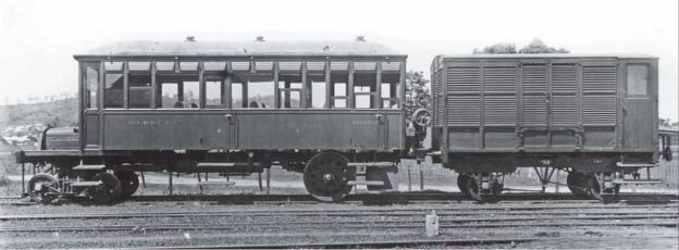
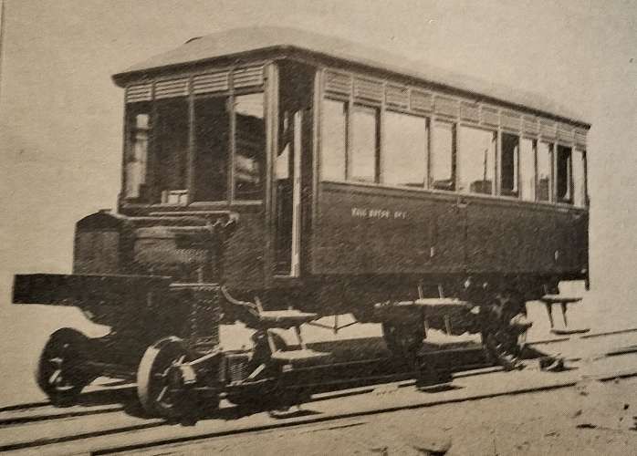
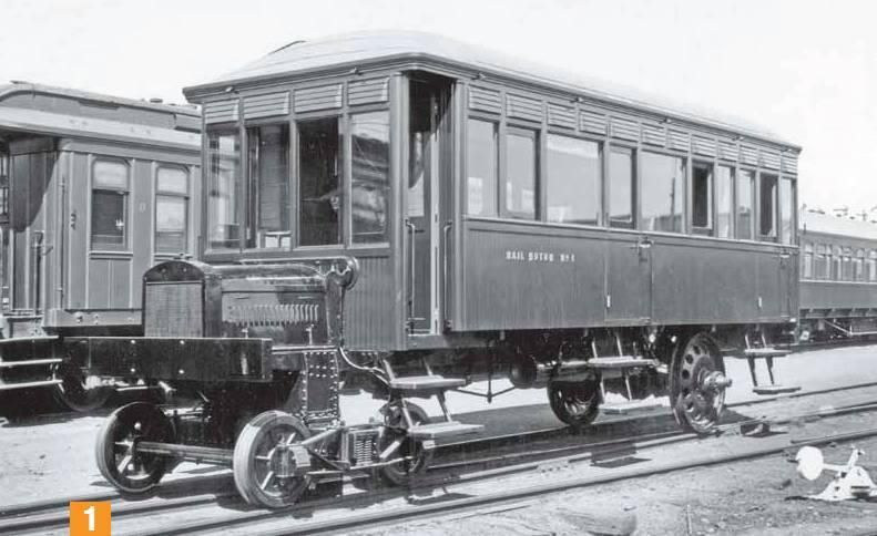
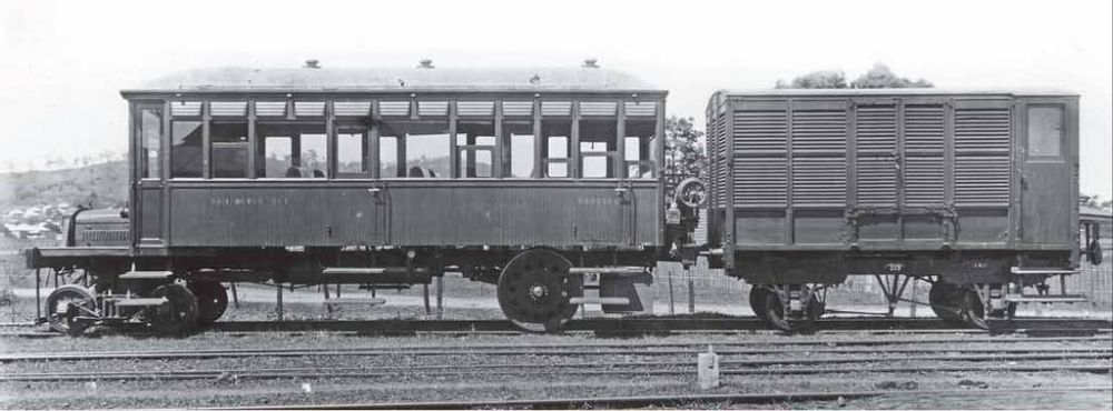
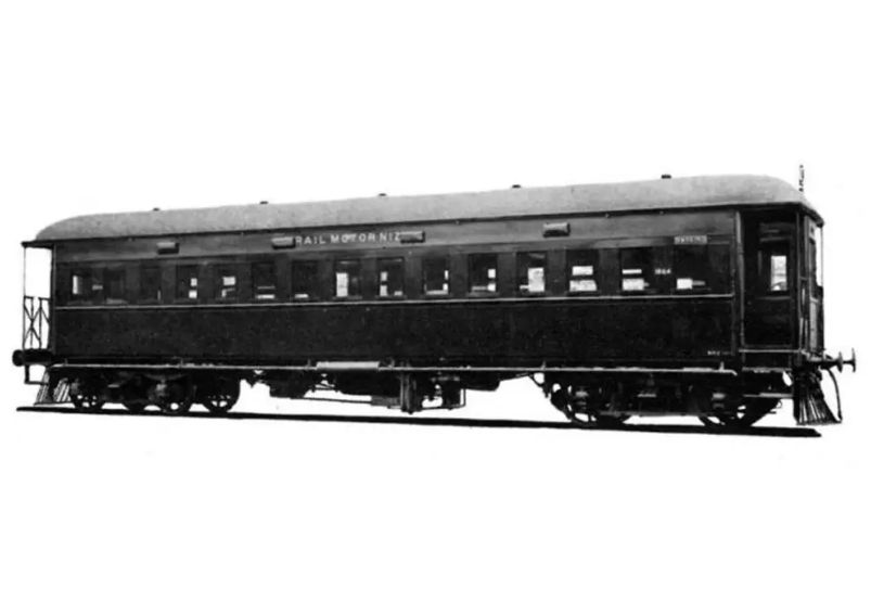
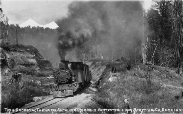
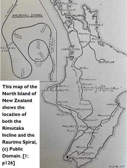
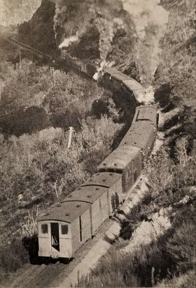
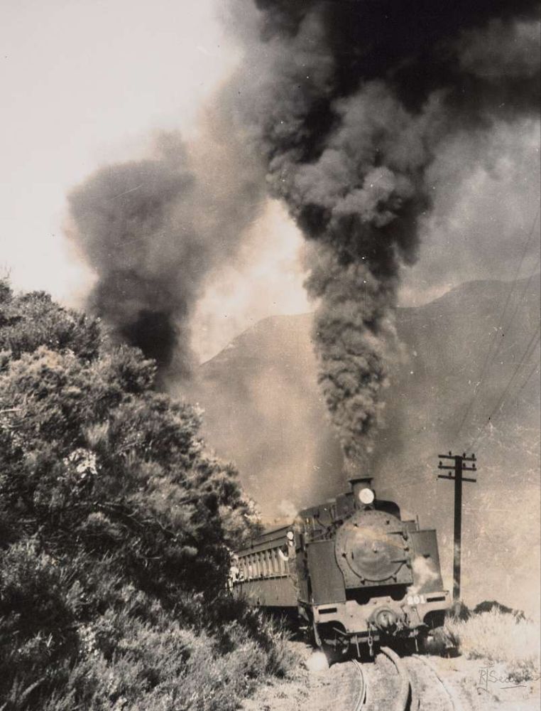
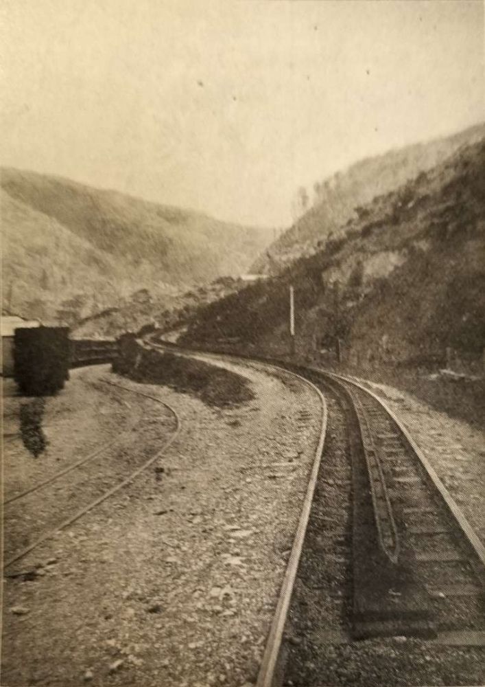
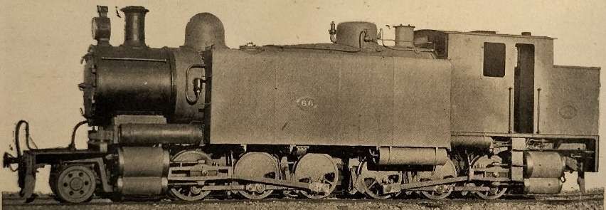
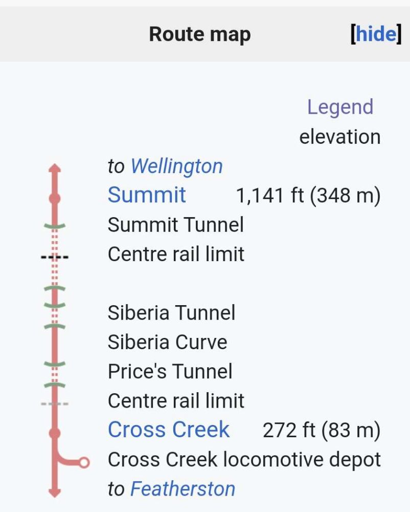
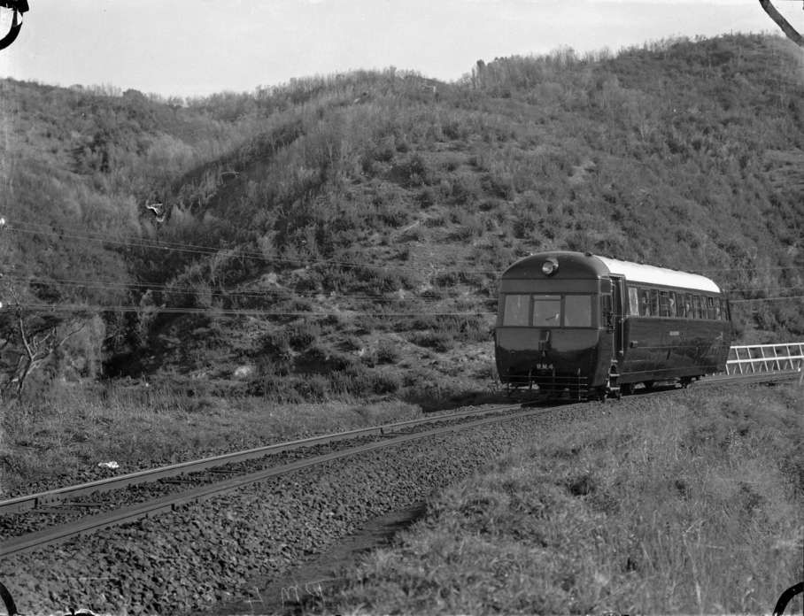
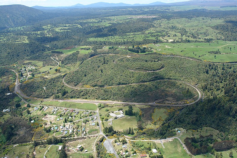
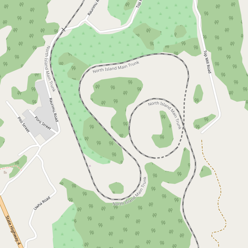
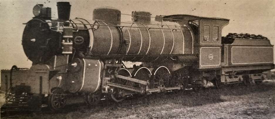
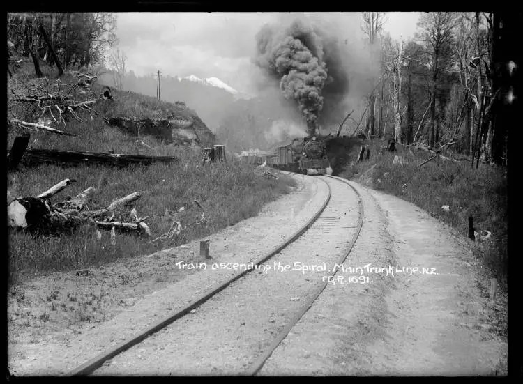

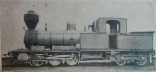
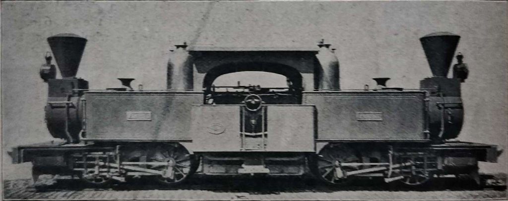


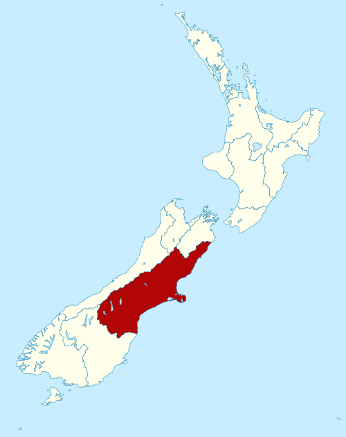
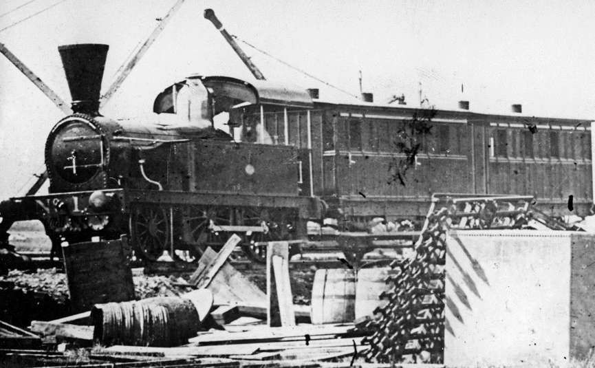
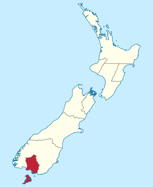
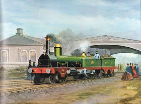
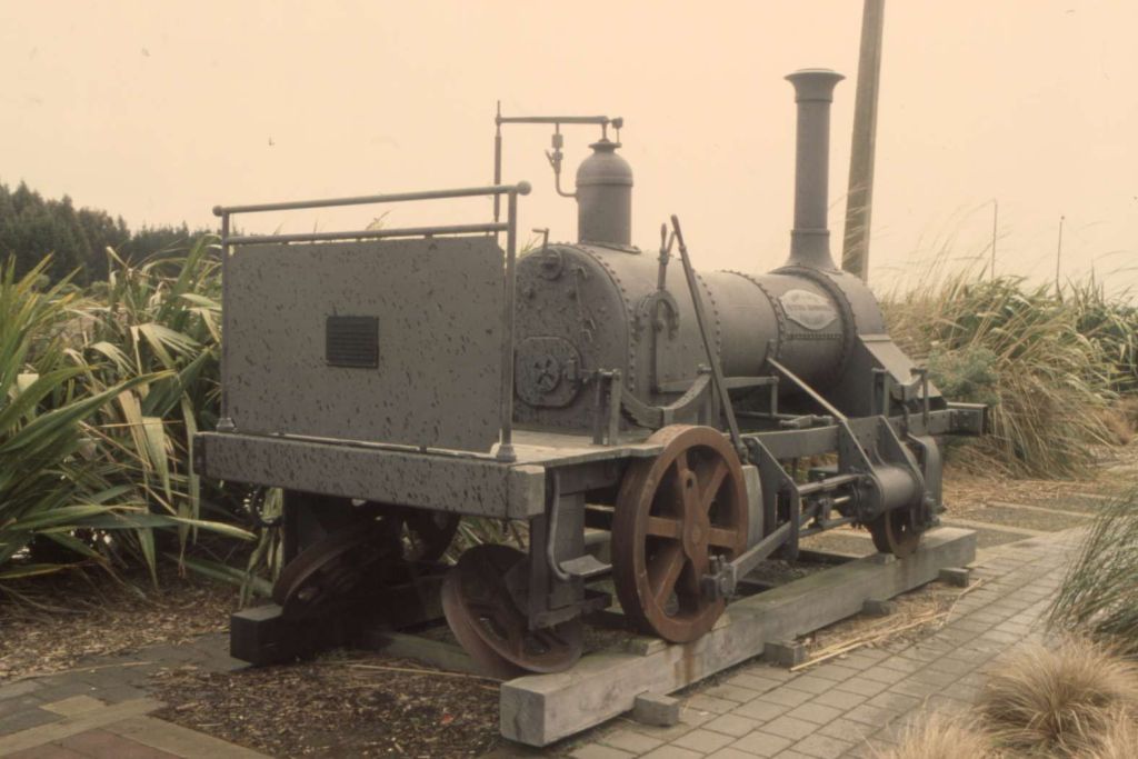
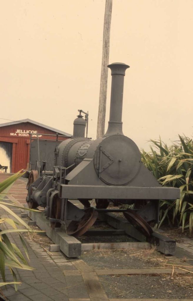
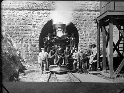
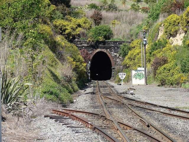
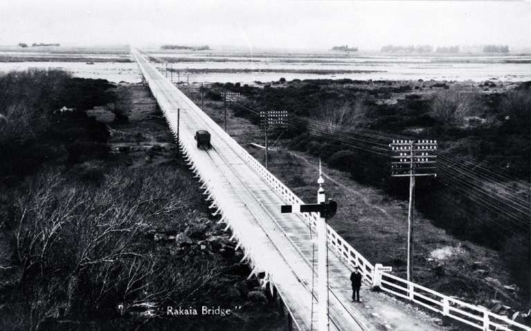
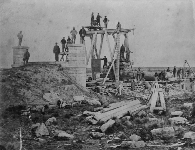
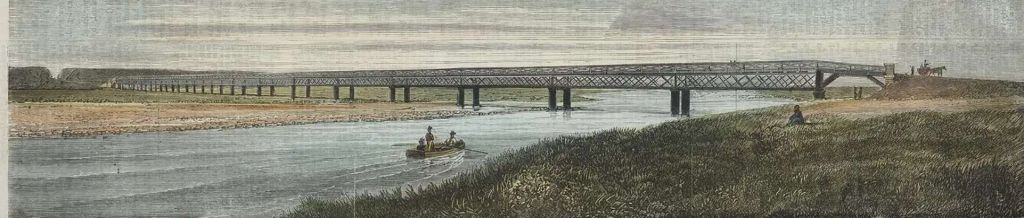
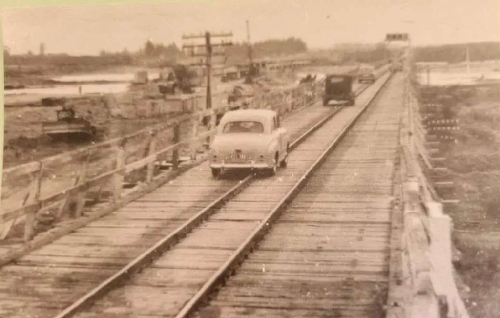
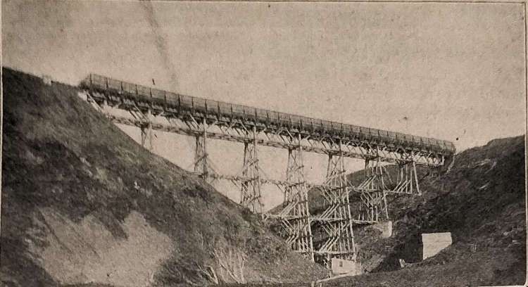
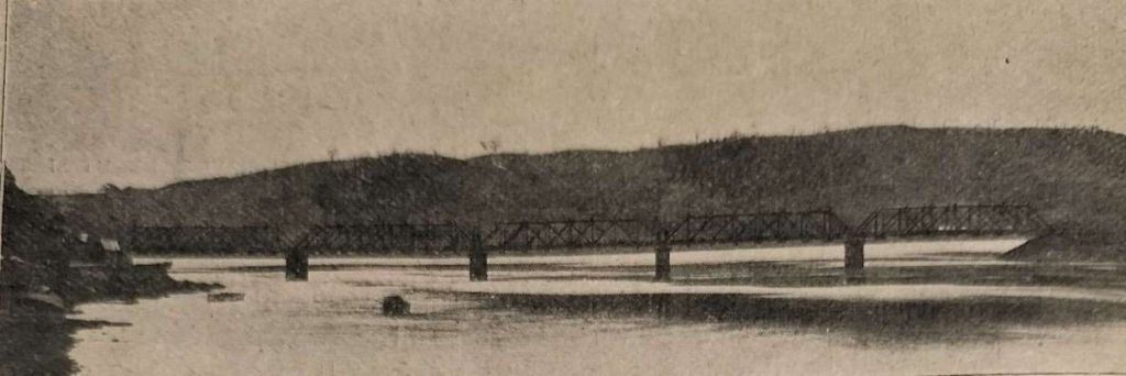
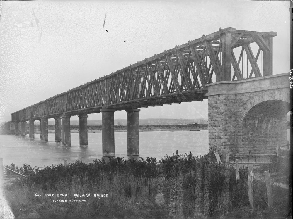
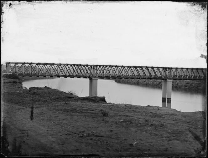
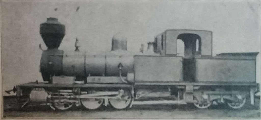
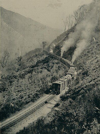
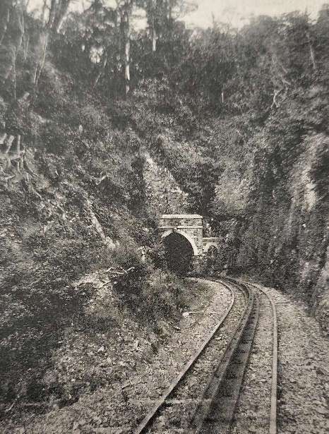
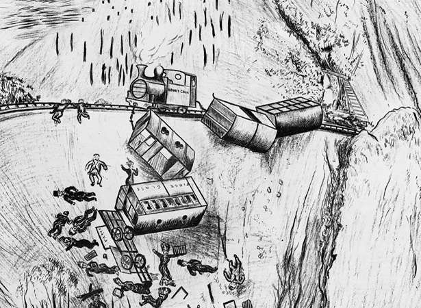
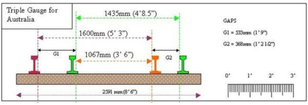
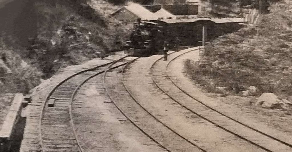
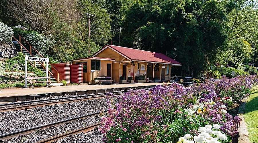
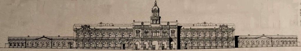
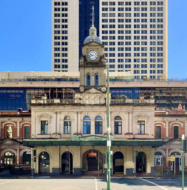
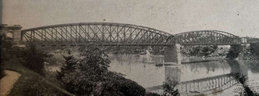
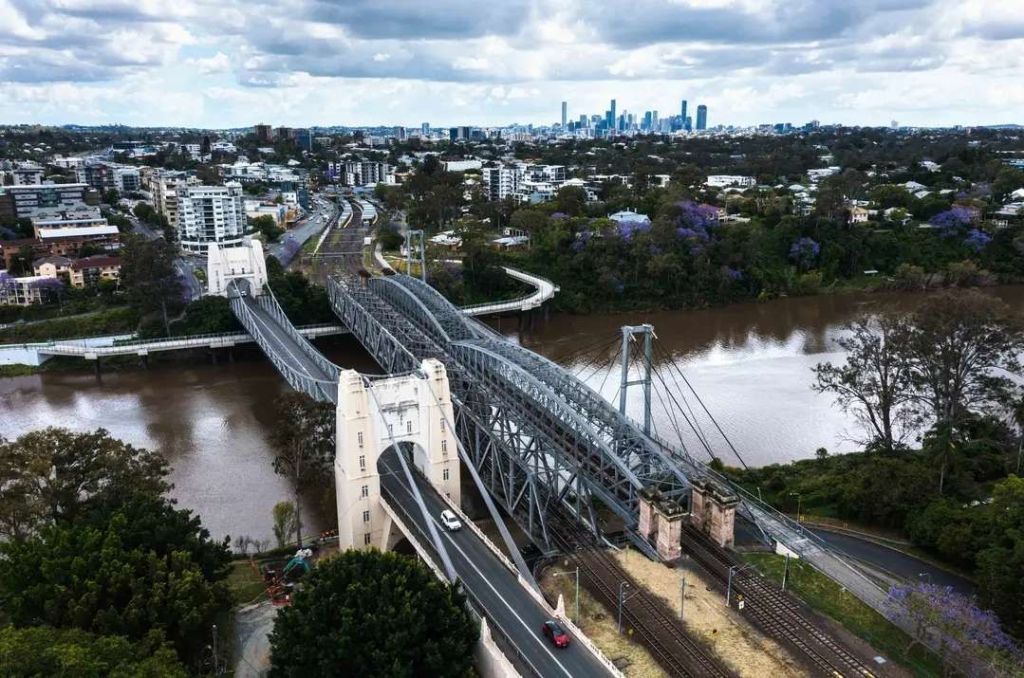
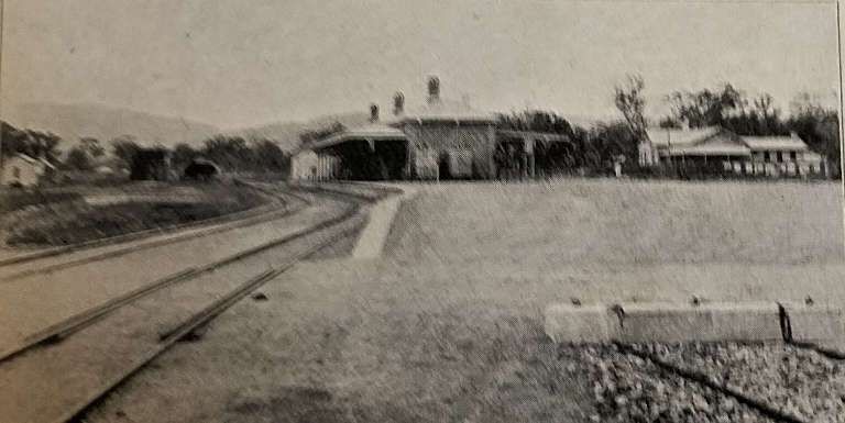
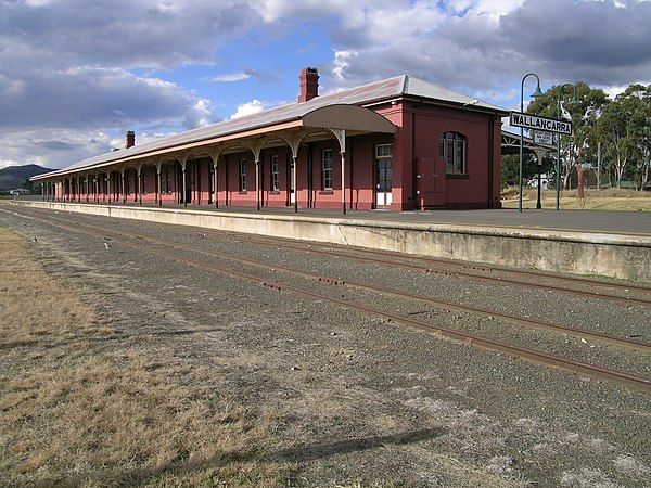
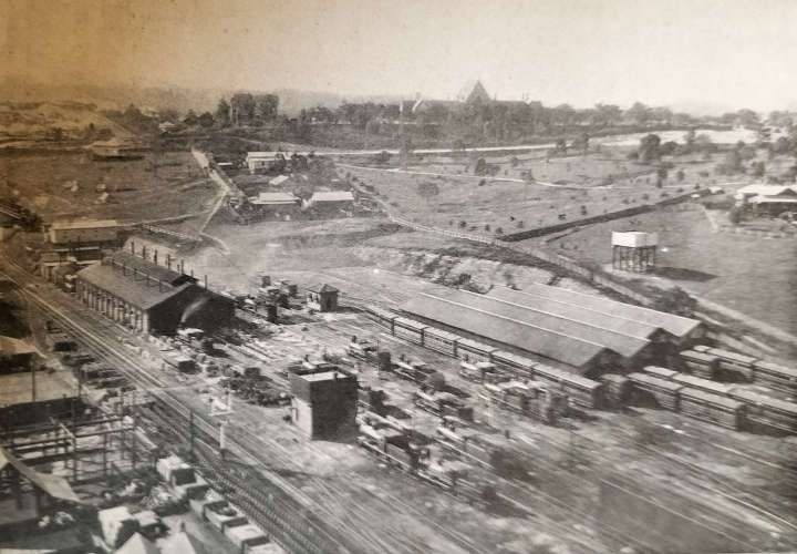
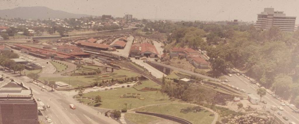
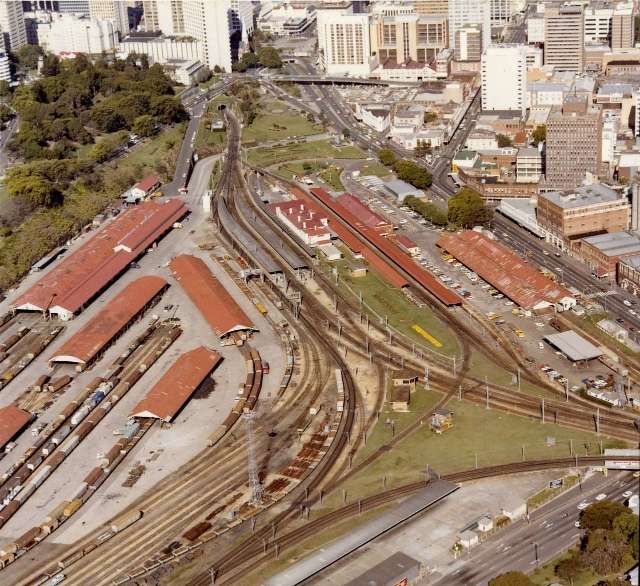

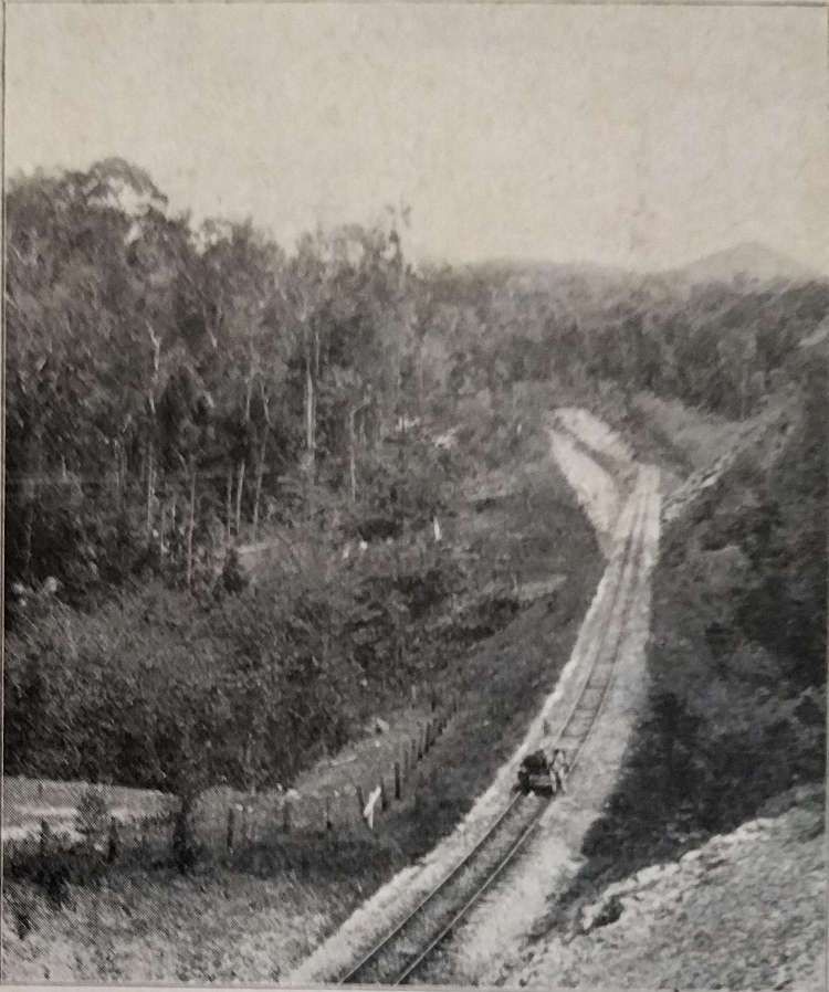
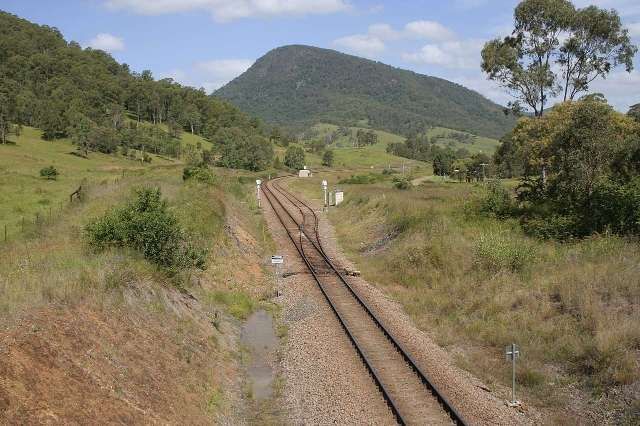
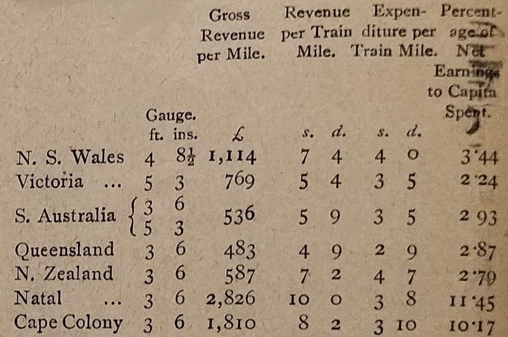
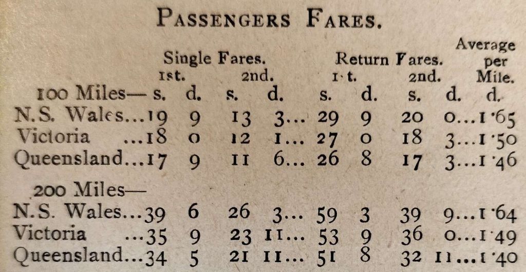
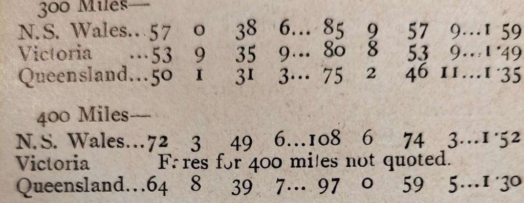
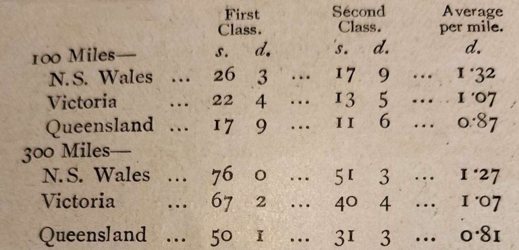
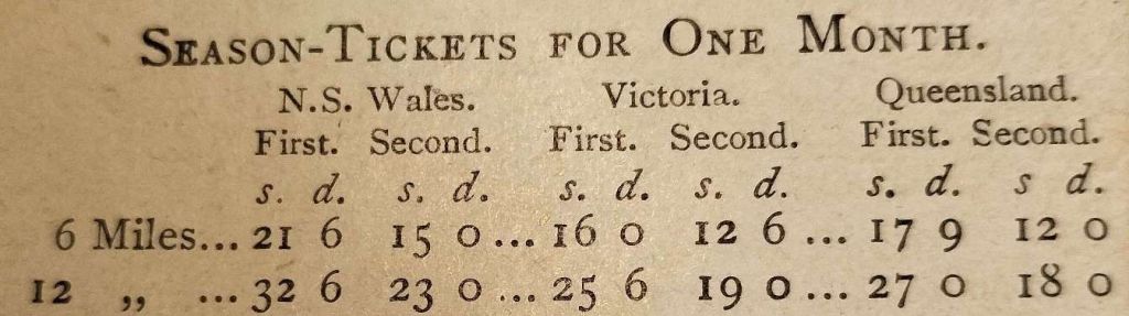
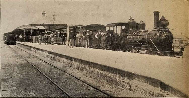
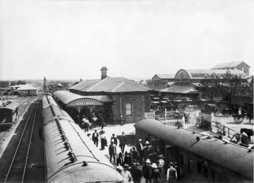
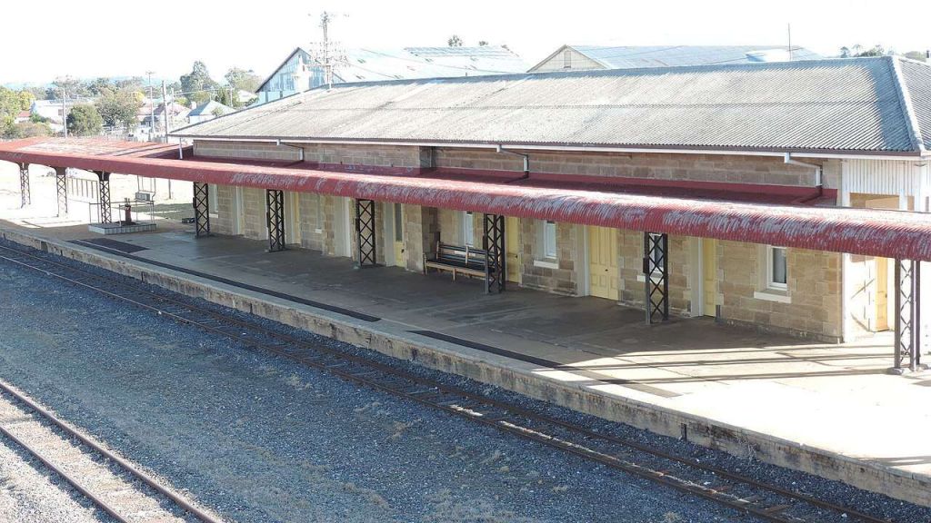
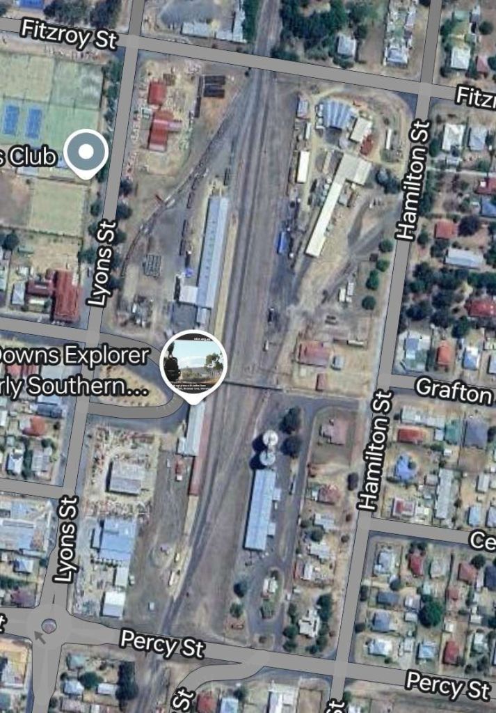
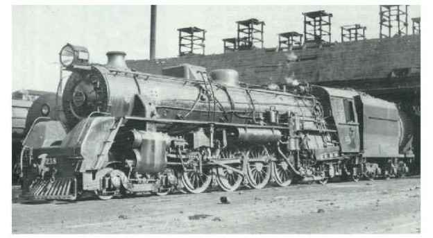
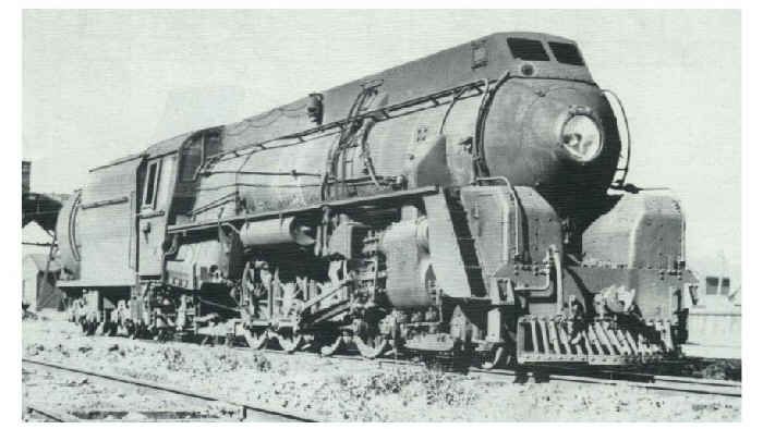
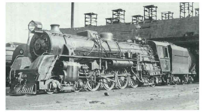
