The featured image above shows Highland Railway No. 29 at Fort George Railway Station in Ardersier in charge of a train of four wheel coaches. Staff at the station seem to be included in the photograph. The locomotive was built in October 1863 as a 2-2-2 and originally called ‘Highlander’. She was rebuilt as a 2-4-0 in August 1871 and renamed ‘Forres’. She was withdrawn in 1898 which means that the annotation under the photograph is a little inaccurate. The locomotive is seen in the image above in its latter guise, so the image was probably produced between 1872 and 1898. The picture was shared on The Highlanders’ Museum Fort George Facebook Page on 23rd February 2014. [12]
The Disused Stations Website has full details and photographs of Fort George Railway Station, here. [1]
AmBaile also has a number of photographs which can be found here. [2]
The full length of the Fort George Branch is shown on the extract from the 25″Ordnance Survey from the turn of the 20th century below. …
The Fort George Branch of the Highland Railway at the turn of the 20th century. Gollanfield Junction Station and the Highland Railway’s main line between Inverness and Forres appears in the bottom right of the map extract. [3]Fort George Railway Station in Ardersier was built in the 1890s and named after the first station on the Inverness-Nairn line, called Fort George Station, which had been built to serve the Fort to the North. The station on the Inverness-Nairn line was then renamed Gollanfield Junction Station. The station at Ardersier opened 1on 1st July 1899. It closed to passengers and goods on 5th April 1943. [4][5]The same area in the 21st century as recorded on the ESRI satellite imagery from the NLS. [4]These two images show bungalows on the station site in the 21st century. [Google Streetview, August 2021]Looking Northwest along the line or the old railway towards the terminus. [Google Streetview, August 2021]
Just to the South of the station throat the line bridged the junction of two roads. These became the B9006 and the B9092.
The railway bridged the junction of two roads a short distance South of the railway station throat. [6]The same area in the 21st century. The trees mark the line of the old railway. [6]The location of the railway bridge, seen from the Southeast. The B9006 was an old military road. [Google Streetview, August 2021]The location of the railway bridge, seen from the Northeast. The trees are on the line of the old railway embankment. [Google Streetview, August 2021]The same location seen from the Northwest. [Google Streetview, August 2021]
The line ran across open fields with no more structures than a few culverts to carry water from drainage ditches, until it curved to the East into Gollanfield Junction Railway Station.
Gollanfield Junction Station as it appeared on the 25″ Ordnance Survey of 1904, published in 1905. It was opened in 1855 by the Inverness and Nairn Railway and initially named Fort George after the military base nearby. In July 1899, the Highland Railway opened the direct branch to Fort George (sited in the village of Ardersier). With the opening of the branch, the station was renamed Gollanfield Junction. Passenger services on the branch were withdrawn in 1943 and it closed to all traffic in August 1958. The following year, the station was renamed Gollanfield by British Railways. [7][8]The same location in the 21st century. Goods traffic at the station ceased in May 1964 and it was closed to passenger traffic on 3rd May 1965. Most of the buildings were subsequently demolished after closure, but the station house remains standing and is used as a private residence. [8][9]
It is interesting that this short branch was deemed worthwhile as an investment. It brought the railhead only a short distance closer to Fortrose George.
Vallance tells us that, “The original line from Inverness to Nairn had provided a station to serve the military post of Fort George. This was only Fort George in name, as the depot itself was some 3½ miles to the north, at the end of a sandy tongue of land jutting out into the Moray Firth. It was felt that the fort should be made more accessible by rail, and powers were granted on 4th July 1890 for the construction of a branch, 1½ miles long, from the existing Fort George station to the village of Ardersier, which lies some two miles south of the depot proper. The terminus of the new line was to be called Fort George. … The surrounding country is level and sandy, and no difficulties were experienced in the construction of the line, which was opened for traffic on 1st July 1899. The junction station was renamed Gollanfield Junction, from the farm of the same name in the neighbourhood.” [10: p46]
David Ross has little to add to this apart from a few fleeting references, primarily to Fort George rather than its railway station, other than to note the construction of the branch line. [11: p95]
The Talisker Distillery Tramway was a short 2ft-gauge tramway which opened in 1900 and closed in 1948. It ran from Carbost Pier on Loch Harport, along the Harport shore to Talisker Distillery and was used to transport materials for Talisker Distillery. [1]
This extract from the 6″ OS Survey of 1901, published in 1903, shows the full length of the tramway. [2]The same area as it appears on Google Maps. [Google Maps, April 2025]
The tramway was 0.75 miles in length. It is not known who authorised its construction, who designed it, not who built it. [1]
The tramway was initially horse-powered but during the latter years of operation a road tractor was used. Small 4-wheeled open wagons with side-tip mechanism were used for conveying coal to the distillery from the pier and 10′ long flat wagons for transported whisky casks, barley and barrels. Until relatively recently some rails were visible near the pier where they were set in concrete. The route of the old tramway has recently seen som refurbishment, allowing for better access by vehicles to Carbost Pier. One of the flat wagons is preserved in private ownership in the Broadford area of the Isle of Skye. [1]
Photographs from 2010 of the tramway rails at Carbost Pier can be found here, [3] here, [4] here [5] and here. [6]
Links:- to find out more about Talisker Whisky, follow: …
Carbost Pier on Loch Harport. [My photograph, 3rd May 2025]Carbost Pier from the Southeast. The tramway left the pier heading towards the camera. [My photograph, 3rd May 2025]Looking Southeast towards the Talisker Distillery. My photograph, 3rd .ay 2025]Further to the Southeast looking towards the distillery. [My photograph, 3rd May 2025]Closer now to the slipway at Carbost waterfront. [My photograph, 3rd May 2025]Looking Northwest from the same location, some distance now from Carbost Pier. [My photograph, 3rd May 2025]Approaching the distillery, the modern building on the left is the Three Chimneys restaurant at Carbost. [My photograph, 3rd May 2025]Looking back along the line of the old tramway from the same location, towards Carbost Pier. [My photograph, 3rd May 2025]This photograph is taken adjacent to the Three Chimneys restaurant and shows the route of the tramway into the distillery site. [My photograph, 3rd May 2025]From the same location, looking back Northwest towards Carbost Pier. [My photograph, 3rd May 2025]Talisker Distillery. [My photograph, 3rd May 2025]
Relevant publications include: ..
Railways of Skye & Raasay – Wilfred F. Simms; [1] and
Derived from the remains of microscopic fossilized sea or freshwater algaes, diatomite is a naturally occurring, versatile mineral used in an array of applications from cosmetics to filtration. [4] It was harvested by drag line from Loch Cuithir in the late 19th century and the first half of the 20th century.
“This unique form of silica has an elaborate honeycomb structure, peppered with thousands of tiny holes ranging from a few microns to submicron diameters. No other silica source, be it mined or artificially produced, presents such a structure. Some diatomite deposits are saltwater but most are from freshwater sources. … When ground, this profusion of shapes results in an extremely low-density powder known as ‘diatomaceous earth’ (DE) which has excellent absorption properties that are highly prized for filtration, agriculture, paints, plastics, cosmetics, and pharmaceuticals application.” [4]
Diatomite was also used in the production of dynamite. [2][3]
Possibly as early as 1885 [1] but certainly by 1889, [2][3] work was underway at this site. A 2ft [2][3] or 2ft 6in [1] gauge tramway was being constructed in 1889 from the drag-line at Loch Cuithir to Lealt. The tramway followed the River Lealt down to its mouth at Invertote. When first opened the line was worked by gravity and manpower. Apparently, later in the life of the line a small steam locomotive was in use. [2][3]
At the “Western end of the line … at Loch Cuithir, … diatomite – known locally as Cailc (Scottish Gaelic for chalk) – was taken out from the loch bed and dried on wire nets. The seaward terminus had warehouses on the cliff-top at Invertote. At the base of the cliff was a factory where the diatomite was kiln dried, ground and calcined. [A] line … extended from the factory onto a pier into the Sound of Raasay.” [2][3]
Diatomite was also gotten from Loch Valerain and transported by aerial ropeway to Staffin Bay and on along the coast to Invertote Apparently, “during its existence, the Skye Diatomite Company extracted 2000 tons of diatomite. … From Invertote, the diatomite was transferred by skiff, onto puffer boats, waiting in the bay, and shipped across to the mainland. The diatomite was turned into kieselguhr which was mixed with nitroglycerine by Nobel Industries, at Ardeer, to make dynamite.” [2][3]
Stornoway Gazette described the operation as follows:
“Over the years, the mine saw periods of inactivity, but when up and running operations made use of the large industrial works at the area – a large factory building, a railway with embankment cuttings, and a rolling stock traversing three miles of landscape, including an aerial ropeway. The light railway was used to transport the Loch Culthir Diatomite to the shores at Invertote for a final drying and grinding, and a large building containing a furnace, grinding machine and storage space was constructed there for this purpose. Such modernised business works were quite remarkable for this part of the world at the time. In those days there was no road between Staffin and Portree, so a puffer boat would anchor in the bay at Lealt, and local skiffs were used to transport the finished Diatomite from shore to boat, ready for shipping to the mainland. There were around 40 to 50 people steadily employed at Lealt, yet on days that the boat came in this total rose to as many as 80 workers.” [7]
“Perhaps one of the most intriguing aspects of the mine’s history comes from the ownership of the drying factory at Invertote by Germans. Although closed during the period of the Great War, surprisingly the now enemy foreign residents were allowed to stay on. Shortly afterwards a rumour began to circulate that the area was haunted and that the ghost of a recent tragic death at the Lealt falls had appeared at the factory. As the local story goes, (the rumour was actually started by the Germans) with the intent of keeping locals away. It turned out that the resident Germans were spies and that, almost unbelievable to the community, the area was being used as a German base with submarines surfacing in the sea bay!” [7]
“Moving on, the year 1950 saw the next development in the mining of Diatomite from Loch Cuithir. As the loch was one and a half miles up the moor, through peat bogs and rivers, the Department of Agriculture and Fisheries for Scotland (DAFS) decided that a road should be built, with the intention of extracting the Diatomite by digger, and then taking it to the Lealt road end above Invertote. The road took around a year and a half to build, during which the mine was put out of operation. Yet, when production started again, the new method of extraction did not reach the high standard of quality which was achieved when extracted manually by spades. The mechanical extraction resulted in the Diatomite being less pure, and full of unwanted dirt. Drying the substance is, in fact, the problem of the process, for it is obvious that in a damp climate like Skye, the diatomite does not lose its moisture quickly. The problems which began after the construction of the 1950s road were further highlighted and compounded six years later. A new factory was built at Uig (the site where the Cal Mac offices are now situated), far from the mining site at Loch Cuithir, and it may be said that this move was the ruining of the entire Diatomite industry upon Skye. As Diatomite was no longer dried at Invertote it now had to be transported by road, wet, for the much-needed drying process to Uig, 23 miles away. A vehicle may have left Loch Cuithir carrying five tonnes of Diatomite, yet only producing one tonne of the finished product after drying had taken place – a finished product which was also not as pure as it ought to be for the specialised work it had to do in various products. A lot of money was wasted on travelling, and within the factory itself, inefficiency was also present, with machinery often breaking down due to the damp state of the Diatomite. Outside the factory, the scenic communities of Trotternish also began to suffer. When the factory was working, it poured out a fine white dust which covered every house in the area. Grass became chalky in colour and after dry spells in the weather, the road-sides from Staffin to Uig would turn white with Diatomite – Uig was constantly under a cloud of dust. With complaints of insubstantial profits and bad management, the factory was finally closed to production for the last time in 1960. Yet, although the Diatomite mining industry on Skye came to an abrupt ending, it was still regarded by many locals as a blessing at the time. Following from World War One, the industrial works provided employment for many returning men who could not find work elsewhere in the island. And at peak production, around 1955/56, 50 to 60 men were paid good wages to work at the factory.” [7]
Bell & Harris tell us that “Loch Cuithir is located upon landslipped material, which overlies Upper Jurassic strata. Only parts of these diatomite workings remain. Some of the brick buildings, together with the line of the tramway used to transport the diatomite to the coast, are still obvious. The diatomite occurred as a 3–6m-thick horizon below a 1m covering of peat. The loch had an original area of 60 hectares (24 acres) and was drained in order to extract the diatomite. Ditches, around the perimeter of the loch, were excavated and the water was drained through a man-made outlet at the northern end of the loch, thus allowing removal of the peat and extraction of the diatomite. East of the drainage outlet are spoil-heaps, mostly of plateau lava boulders, presumably removed from the workings during excavation. The diatomite from this deposit was very pure, with little or no interlayered silt or mud. Macadam (1920) notes that the calcined (heat treated) diatomite contains over 96% [Silicon Dioxide](reported in Anderson and Dunham 1966), whilst Strahan et al. (1917) gave a value of 98.78%. According to Macadam (1920), the absorptive value of the material from Loch Cuithir was over 3.56 (a good diatomite would have an absorptive value in excess of 4.0).“
Some excellent photographs of the derelict factory at Invertote can be seen here. [8]
The Route of the Tramway/Railway
From Loch Cuithir, the railway ran in a Southeasterly direction over boggy ground. Minimal earthworks were undertaken placing the railway at a level just above surrounding ground.
The Canmore National Record of the Historic Environment profiles these notes:
“One of the greatest causes of interest in Skye Diatomite was its potential use as a substitute for Kieselghur by Alfred Nobel in the production of Dynamite in Nobel’s new Scottish factory at Ardeer in Ayrshire during the 1880s. Nobel eventually found a better source of material, but the Extraction of Diatomite nevertheless began in Skye at Loch Cuithir in 1886. The Diatomite was transported by tramway to be processed at Invertote, production continuing until 1913. The industry was briefly revived between 1950 and 1961, using road transport.” [13]
“The principal remains of the Invertote works are a large, rubble-built, rectangular-plan roofless building (NG5201 6049). It has been entirely gutted, but fragmentary remains include a large cast-iron flywheel from a steam engine, and a cast-iron wall-mounted bearing box. The other surviving structure is a kiln (NG5201 6052), comprising a lower chanber or firebox built from Scottish firebricks (produced at the Star Works, Glenboig, Lanarkshire, and Etna Works, Armadale, West Lothian), onto which has been constructed a circular-section fireclay-brick column encased by an outer layer of sheet steel. The exact functions of the processing building and the kiln are uncertain, but it is likely that the latter was used for drying purposes.” [13]
H.A.Vallance notes that in the years prior to the coming of the railways to the North of Scotland there was a series of different initiatives intended to improve transport links. The first were the roads built by General Wade (250 miles of military roads) which “were quite unsuited to the requirements of trade operating under peace-time conditions.” [17: p11] The biggest contribution to raid development was made by Thomas Telford. He “was appointed to survey for new roads and for the improvement of existing highways. In the course of … 17 years he constructed about 920 miles of road, and built some 1,200 bridges.” [17: p11] But it was the coming of the railways to the Highlands, that most effectively addressed the regions transport problems.
Earlier articles about the Highland Railway network can be found here, [3] and here. [4] These two articles cover the Strathpeffer Branch and the Fortrose Branch repectively.
Trains Illustrated No. 18 which was published in 1976 focussed on The Highland Railway. [1] The introductory article, ‘Highland Retrospect’, was written by Paul Drew. [1: p4-11]
Paul Drew commences his article with a short reflection on the excitement of waking on one of the sleeper services heading North into the Scottish highlands. Two routes provide an intensely enjoyable experience in the right weather: “The awakening on the West Highland line at Garelochhead, perhaps, or on Rannoch Moor … winding in a generally northward direction towards Fort William, Mallaig and Skye and the Hebrides; and daybreak on the Highland line proper, the Perth-Inverness main line of the old Highland Railway, somewhere between Blair Atholl and the outskirts of Inverness, following the old coach road up to Druimuachdar summit, at an altitude of 1484ft, or dropping down the hills between Spey and Findhorn and Findhorn and Moray Firth.” [1: p4]
Drew expresses his opinion that the Highland Railway (HR) route offers the greatest diversity of scenery but whether “you travel from Euston to the Highland or from Kings Cross to the West Highland line the contrast between the [suburbs of London] … and the glories seen on waking – even, for devotees, in a Scotch mist – is one of the attractions of the journey. Before World War II one could start an overnight journey to a Highland line station from Kings Cross as well as Euston, and up to 1914 from St Pancras also with, on a summer evening, a daylight exit from London.” [1: p4]
He seems to like the route taken by trains from St. Pancras best. Their route “was via Leeds, the magnificent MR route across the Pennines, Carlisle, the North British Railway’s Waverley route through the best parts of the Lowlands to Edinburgh, and so by the East Coast route over the Forth Bridge to Perth, the beginning of the HR main line – all far better traversed in daylight.” [1: p4]
He notes too that it was common practice not to disturb a passenger’s sleep which meant that sleeper services on the HR were normally made up of “HR vehicles and through coaches and sleeping cars from England (LNWR, West Coast Joint Stock, GNR, North Eastern, East Coast Joint Stock, Midland, and probably Midland & North British joint stock) and from Scotland (Caledonian and North British) but also of privately hired ‘family’ saloons, horseboxes, flat wagons conveying carriages and, from the turn of the century, motorcar vans, all supplied by a wide variety of English and Scottish railways.” [1: p4]
Occasionally, these trains would also include the “private saloon of the Duke of Sutherland, who owned not only one or two passenger vehicles but a 2-4-0 tank engine, Dunrobin, and its successor, an 0-4-4 tank of the same name, which he ran – often driving himself – on his private railway. It was in Sutherland, and ran from Golspie via his seat, Dunrobin Castle, to Helmsdale. The line was eventually taken over by the Highland and forms part of the Farther North line from Inverness to Wick and Thurso. Both Dunrobins were allowed to work (within limits) over HR tracks, even south of Inverness, but not, it seems on public passenger trains – at least not expresses.” [1: p4]
Drew notes that, “The marshalling of the heterogeneous caravans at Perth, where vehicles were made over by the CR and NBR, was a frequent cause of unpunctuality and indeed chaos. Besides, most of the trains tended to run late during the summer, especially on the HR main line, which even after the central portion south of Druimuachdar has been double-tracked in the 1890s, tended to be congested; a high-season shortage of HR motive power aggravated matters, and reliance on telegraphy for many years before introduction of the telephone did not make for flexibility in train operation. Disgruntled Sassenach passengers in Perth, Edinburgh Waverley and other big Scottish stations would mutter that they ordered this matter better in England.” 1: p4]
It would be easy to take the perspective of a southerner when considering the HR, seeing it “mainly as a means of moving tourists and sportsmen from England, and such consumer goods and other freight as the impoverished Highlands could afford to import.” [1: p4] But it would be quite wrong to do so. “The Highland Railway was conceived by Highlanders, in the Highlands, as an outlet for the fish and agricultural produce of the Highlands from northern Perthshire to John o’ Groats and from Inverness eastwards to the Aberdeenshire border and westwards to Wester Ross, a region that in the 1840s was still only slowly recovering from the oppression and impoverishment that had followed the Forty-Five insurrection a century before. The HR was the creation not of middle-class businessmen but of country landowners who ranged from the rich Duke of Sutherland to poor lairds who could afford little more than to encourage, rather than to oppose (like many landowners in the south) building the railway over their land, often asking for a station to serve their tenants.” [1: p4]
With a route mileage of more than five hundred miles, H. A. Vallance tells us, “the Highland occupied third place among the five fully-independent pre-1923 main line railways of Scotland. Its popularity with those who love railways arise from the scenic charm of its terrain, and also from the way in which the small company succeeded in working its traffic in the face of natural difficulties, and with limited financial resources, over routes that were largely single track.” [17: dust-jacket]
Prior to the 1850s, “there was already a trickle of summer tourists from the Lowlands and England, who used a surprisingly well-developed system of stagecoaches or drove in their own carriages; but it was not until the 1850s, after Queen Victoria and the Prince Consort had ‘invented’ Highland tourism by establishing Balmoral, that the trickle began to grow into a flood. Deerstalking, grouse-shooting and fishing, at least by rich people from south of Perth, developed slowly. For 20 years after the HR Inverness-Perth line, by the original route via Forres, was opened in 1863 the management adopted a take-it-or-leave-it attitude to passengers, though by the 1880s receipts from through passenger traffic from England, including much first class in the summer, were considerable. And for long afterwards the HR left the provision of really comfortable passenger vehicles to the English railways and the Caledonian.” [1: p4-5]
Drew continues: “To promoters seeking a route for a railway from Inverness to the south there were three options. The first was a relatively easy alignment along the flat coast via Forres to Elgin, thence through undulating but not mountainous country to near Inverurie and on through Lowland Buchan to Aberdeen. Second was the route of the old coach road via Kingussie, Druimuachdar and Blair Atholl to Perth, and the third was through [the] Great Glen to the area of Fort William, beyond which progress to Glasgow was through a region of mountains and lochs which had long been thought impassable for a railway – or at least to involve too many major civil engineering works – until it was traversed by the West Highland line towards the end of the century, some years after the threat of a Glasgow & North Western Railway over an even more difficult route than the West Highland.” [1: p5]
The disadvantages of the route via Aberdeen were it’s circuitous route and, at the time particularly, there being no bridges crossing the River Tay and the Firth of Forth and the failure of any such route to serve inland Invernessshire. Also significantly perhaps, was an innate suspicion (perhaps too strong a word) amongst highlander promoters of a railway that there was any need to serve the lowland city of Aberdeen.
“Nevertheless,” says Drew, “the first train to reach Inverness from the South, in 1858, was from Aberdeen, over the Great North of Scotland [Railway (GNSR)] as far as Keith and then over the Inverness & Aberdeen Junction line, which later became part of the HR.” [1: p5]
The Aberdeen to Inverness Railway Line, (GNSR – Aberdeen to Keith)
The GNSR was “floated to build a railway from Aberdeen to Inverness. … It obtained its Act on 26th June 1846. It is estimated that [this] cost £80,000 and the company was at once in financial straits, … accentuated by the crash which followed the ‘Railway Mania’s, then at its height. … [Eventually, work] started on 25th November 1852. … The railway was opened from Kittybrewster (1½ miles from Aberdeen) to Huntly, a distance of 39 miles, on 19th September 1854. Four years previously, the railway had been completed from Perth to Aberdeen. A through journey was then made possible between England and the south of Scotland, and Huntly. From this latter point coaches, running in connection with the trains, continued the journey to Inverness.” [17: p12-15]
The line was extended into Aberdeen to Waterloo Quay in 1855, and in October 1856 it reached Keith around halfway between Aberdeen and Inverness. The GNSR had overstretched itself and could not fund the remaining 55 miles of line to Inverness.
The original Great North of Scotland Railway terminus in Aberdeen opened on 1st April 1856, and closed to passenger service on 4th November 1867 with the opening of Aberdeen Joint Railway Station. This extract from the 25″ Ordnance Survey undertaken between 1864 and 1867, published in 1869 shows the station as it was in its prime. [15][18]The next significant location on the line was the station at Kittybrewster which is shown here as an extract from the 25″ Ordnance Survey undertaken between 1864 and 1867, published in 1868. [19]Dyce Railway Station was opened (along with the line) in 1854 by the Great North of Scotland Railway (GNSR). It later became a junction for the Formartine and Buchan Railway (F&BR) which diverged here and headed north to Peterhead and Fraserburgh; this opened to traffic in 1861 and had its own platforms alongside the main line ones. Passenger services over the F&BR ended as a result of the Beeching Axe on 4th October 1965 but the station remained open until 6th May 1968. [15] Freight continued to Peterhead until 1970 and to Fraserburgh until October 1979. There is still evidence on the ground of the old branch platforms which sat on the site of the station car park. The former branch lines are now a long distance cycle path, accessible from the western end of the car park. The station was reopened by British Rail on 15th September 1984. This extract from the 25″ Ordnance Survey of 1865, published in 1866 shows the station soon after it became a junction station. [16][20]
The GNSR left Dyce and followed the southern edge of the River Don’s floodplain, passing through Kintore before bridging both the Aberdeen Canal and the River Don just to the North of Port Elphinstone Railway Station.
Kintore Railway Station acted as a junction station for the Alford Valley Railway which branched off the GNSR line just to the Northwest of Kintore Railway Station. The Alford Valley Railway opened in 1859. It had stations at Kemnay, Monymusk, Tillyfourie, Whitehouse and Alford. The line also served Kemnay Quarry and three other granite quarries in the area. The train took just over an hour for the 16-mile (26 km) journey. [27][28]This next extract from the 25″ Ordnance Survey of 1864 to 1866, published in 1867, shows Port Elphinstone Railway Station and the bridges over the Aberdeen Canal and the River Don. As can be seen on this extract a short branch line served the canal wharves at Port Elphinstone. [21]Inverurie Railway Station was the next significant location on the GNSR and appears on this extract from the 25″Ordnance Survey of 1864 to 1866, published in 1867. [22]Further to the Northwest, the line bridged the River Urie (Ury). This extract is from the Ordnance Survey of 1866 & 1867, published in 1867. [23]
To the West of Keith, the Highland Railway held sway. The Inverness &Aberdeen Junction Railway was one of the constituent parties that formed the Highland Railway in 1865, as noted below.
The line crossed the River Urie (Ury) once again further to the Northwest. This extract comes from the 25″ Ordnance Survey of 1867, published in 1868. [24]
Beyond this viaduct the line ran along the South side of the River Ury and then to the South side of the Gadie Burn. It crossed the Burn just to the West of the village of Oyne and its railway station.
The village of Oyne, its railway station, and both road and railway bridges over the Gadie Burn. This extract is taken from the 25″ Ordnance Survey of 1867, published in 1868. [25]Insch Railway Station at Rothney, as it appeared on the 1867 25″ Ordnance Survey. [26]The next station on the line was Wardhouse Station. [29]And then Kennethmont Railway Station. [30]And Gartly Railway Station. [31]North of Gartly the railway bridged the River Bogie twice in short succession before arriving at Huntly. [32]Huntly Railway Station sat on the East bank of the River Bogie with Huntly to the West of the river. Huntly was the temporary terminus of the GNSR from 19th September 1854 until an extension was opened taking the line as far as Keith in October 1856. [17: p15-16] This extract is from the 25″ Ordnance Survey of 1871, published in 1872. [33]
North of Huntly, on the extension to Keith the line. Missed the River Deveron and ran through Rothiemay Railway Station.
This extract from the 25″Ordnance Survey of 1870 and 1871, published in 1872 shows the viaduct over the River Deveron and Rothiemay Railway Station. [34]Further West the line passed through Grange Station which three years after opening in 1856 became the junction station for the Banff, Portsoy and Strathisla Railway which opened a branch to Banff and Portsoy. [35][36]This next extract from the 25″ Ordnance Survey of 1867 & 1868, published in 1869, shows Keith Railway Station which was the terminus of the GNSR line from October 1856 until the Inverness & Aberdeen Junction Railway reached Keith from Nairn in 1858. . [37][38]
The Keith and Dufftown Railway ran Southwest from Keith to Dufftown. It can be seen curving away from the station at the left of the OS map extract above. At Dufftown, the line made an end-on connection with the Speyside Railway at Dufftown, and the Morayshire Railway connected to the Speyside Railway at Craigellachie, this ultimately gave the GNSR access to Elgin. [39]
The Aberdeen to InvernessRailway Line(HR – Keith to Inverness)
The GNSR’s protracted/torturous efforts to reach Inverness created space for others to act. Interests in Inverness sought to provide a different link to the South via Druimuachdar to Perth but were thwarted by its rejection by Parliament (in 1846), nonetheless they “obtained authority for a short line from Inverness to Nairn with a view both to blocking a GNSR approach to Inverness and also the Inverness route which eventually branched off from the Inverness-Aberdeen route at Forres, Nairn, and ran via Dava summit (1052ft), Grantown-on-Spey, Aviemore and on to Perth via Druimuachdar. (Only in the 1890s was the direct line built from Inverness via Slochd summit and Carr Bridge to Aviemore, affording the shortest route to the South.)” [1: p5-7]
Drew continues: “The Inverness & Nairn railway took only a year to build (1854-55). The eastward extension of the Inverness-Nairn line was the Inverness & Aberdeen Junction, which ran via Forres and Elgin to Keith, to which point it was opened in 1858, met the GNSR and provided the Inverness-Aberdeen through route. Two years later the Inverness & Perth Junction Company was formed. Construction of the Forres-Perth line made quick progress from both ends, despite the need to take the line for 100 miles through the central mountain tract of Scotland. The through route from Inverness via Forres to Perth was completed in 1863. The Inverness & Aberdeen Junction, which had absorbed the Inverness & Nairn, and the Inverness & Perth Junction, were amalgamated in 1865 to form the Highland Railway.” [1: p7]
West of Elgin the line bridged the River Lossie before passing through Mosstowie Station, then passed a connection to a mineral railway serving Newton Quarries and on to Alves Station.
After Alves Station it was only a short distance to the junction for the Burghead & Hopeman Branch. The line then continued on to Kinloss.
The 25″ Ordnance Survey shows the junction with the HR’s Burghead & Hopeman Branch and the adjacent roads and bridge at around the turn of the 20th century. [58]The same location in the 21st century. The road has been realigned. The route of both railway lines are still easily made out! [58]The old road bridge still crosses the railway adjacent to the newer A96 road bridge. [Google Streetview, May 2023]Looking West along the line from the A96. [Google Streetview, May 2023]Kinloss Railway Station opened on 25th March 1858 by the Inverness and Aberdeen Junction Railway. It was re-sited on 18th April 1860, to the east, but it was moved back to its original location in May 1904. It closed to passengers on 3rd May 1965nand completely on 7th November 1966. [59][60]The same area in the 21st century. [59]Kinloss Railway Station in the 21st century, looking East from the level-crossing. [Google Streetview, May 2023]Looking West from the level-crossing at Kinloss Station site. [Google Streetview, May 2023]
After leaving Kinloss trains for Inverness next ran into Forres Railway Station. Over the years the railway infrastructure at Forres has seen significant changes.
In 1858, the first railway station at Forres was located at the end of Market Street which became known as Old Station Road. The station building was demolished in the 1950s. It had been used as the stationmaster’s house since the junction opened.
A route to the South from Inverness was finally completed in 1863. It met the line running between Elgin and Inverness at Forres. Forres was chosen as the junction for the new mainline south, since it was the half-way point on the Inverness & Aberdeen Junction Railway between Inverness and Keith. Keith was also an important railway junction and the point where the line joined the GNSR and branches to the coast and Strathspey. [62]
A new ‘triangular’ station wastl constructed to allow all trains entering Forres, from either the East or West, to access the new line directly on a curve. The three curved platforms, and three junctions, gave the new Forres station its distinctive layout. [62]
The location of the new station was south-west of the existing Inverness-Aberdeen line. The original line was retained as a goods loop, with trains now leaving and re-joining the line (east-west) on a curve. Services from Inverness to Perth curved to the south on a junction at the west of the station, to arrive at the southbound platforms. [62]
Three individual signal boxes controlled the junctions at each point of the triangle: Forres East, Forres West, and Forres South. [62]
The closure of the link to the South from Forres occurred as part of the cuts following the Beeching Report in the 1960s. Further remodelling of the whole area took place in the 21st century. This saw much of the existing infrastructure removed and a new functional station built by 2017. [62]
West of Bodies the line ran on through Auldearn Station, bridged the River Nairn and entered Nairn Railway Station.
Auldearn Railway Station on the 35″ Ordnance Survey from the turn of the 20th century. It opened on 9th December 1895 and was closed by 6th June 1960. [72]The site in the 21st century – all evidence of the station has disappeared. [72]Looking West from the overbridge at the East end of the site of Auldearn Railway Station. [Google Streetview, May 2022]The bridge over the River Nairn as it appears on the 25″ Ordnance Survey from the turn of the 20th century. [73]The same location in the 21st century. [73]
Nairn Railway Station opened on 7th November 1855. In 1885, the Highland Railway Company agreed to improve the facilities at Nairn. The station buildings were replaced with improved accommodation for passenger and staff. The gables of the cross wings were surmounted with the Scotch thistle, the Prince of Wales feather, and other designs sculpted in stone. The masonry work was completed by Mr. Squair of Nairn. At the same time a new station master’s house was erected. The platforms were extended to around 440 yards (400 m) and raised in height to the level of the carriages. A new iron foot bridge over the line connected the platforms, avoiding passengers using a foot crossing over the running lines. The bridge over Cawdor Road was also widened at the same time. The work was completed in 1886. [76]
Heading Southwest out of Nairn trains passed through Gollanfield Junction Station which served the short Fort George Branch.
Gollanfield Station as it appeared on the Landranger OS map prior to closure. [79]Gollanfield Junction Railway Station opened in 1855 by the Inverness and Nairn Railway, it was initially named Fort George after the military base nearby. In July 1899, the Highland Railway opened a direct branch to Fort George (which was actually sited in the village of Ardersier). With the opening of the branch, the station was renamed Gollanfield Junction. Passenger services on the branch were withdrawn in 1943 and it closed to all traffic in August 1958. The following year, the station was renamed Gollanfield by British Railways. [77][78]The same location in the 21st century. Goods traffic at the station ceased in May 1964 and it was closed to passenger traffic on 3rd May 1965. Most of the buildings were subsequently demolished after closure, but the station house remains standing and is used as a private residence. [77][78]Looking East from the road bridge which used to span Gollanfield Railway Station, [Google Streetview, August 2021]Looking West from the road bridge which used to span Gollanfield Railway Station, [Google Streetview, August 2021]
Further details of Gollanfield Railway Station and photographs can be found here. [79]
The next stop on the line was at its terminus at Inverness.
J. W. P. Rowledge; The 4-4-0 Locomotives of the Glasgow & South Western and Highland Railways; in Brian Stephenson (ed.) Locomotives Illustrated No 117, January-February 1998, Ian Allan, Berkhamsted, Herts, 1997.
An essay written in 1998 as part of training to become an Anglican Priest.
INTRODUCTION
Susan Hill tells the story of a young woman, Ruth, whose husband dies suddenly. As Ruth works through her grief she is supported daily by Jo, the 14 year old brother of her dead husband. In the early months after the accident he is the only one who can reach into her grief (Hill: p9-116). Jo’s care of Ruth is effective care. He has no training but be deeply loves her
Christ has enjoined us to love our neighbour as ourselves. All questions of pastoral care, and particularly bereavement care, must start from the premise that all Christians, at the appropriate time and place, have something to offer, presumably love, in the first instance. This essay outlines the key issues in bereavement care and explores the different levels of care that a church congregation can provide to those working through the pain of loss.
1. THEORIES OF LOSS
Arnold van Gennep proposed a theory of loss in his book “Rites de passage” which has become generally accepted. He envisaged three main ‘stages’. A person experiencing loss starts in a ‘Prelminal’ stage caused by the separation, which is characterised by detachment, pain and anxiety; passes through a ‘Liminal’ stage of transition, characterised by ambivalence, distortion, chaos and loneliness; and gradually reaches a ‘Post-liminal’ stage of reincorporation back into the community, a time of new beginnings and moving on (from lecture by A. Chatfield). Much has subsequently been written about bereavement. William Worden talks of four tasks of mourning: accepting the reality of loss, working through the pain of grief, adjusting to an environment in which the deceased is missing, and emotionally locating the deceased and moving on with life (Worden p10ff) Ainsworth-Smith and Speck speak of three main phases: shock and disbelief, awareness, and resolution (Ainsworth-Smith: p5ff). Elizabeth Kubler-Ross suggests that dying patients and their families go through similar grief processes (Kubler-Ross: p150ff). She identifies five different stages: denial and isolation, anger, bargaining (more obvious in the terminally ill than in the bereaved), depression, and acceptance (ibid. p35-101). Colin Murray Parkes identifies a series of different behaviour patterns common among the bereaved, from broken hearts (and increased attendance at doctor’s surgeries) through alarm and stress, searching, mitigation, anger and guilt, to the gaining of a new identity. (Parkes p36-112)
These different theories all suggest a process which takes some considerable time. It would be possible to describe each individual stage in each theory but this is not necessary within the scope of this essay, the diversity of description of these stages serves to illustrate the fact that each individual responds to the loss associated with bereavement in different ways. Each author emphasises the need to recognise the way in which the individual is responding to their loss. Strath and Speck talk in a number of places of the way in which the various feelings tend to flow back and forth during the grief process like the tide coming in and out each day. Each time the tide comes in it can leave behind a different ‘response’ (eg. Ainsworth-Smith: p30-31). It must be appreciated that these theories are models to assist understanding rather than timetables for grief or routes through the grief process.
2. ATYPICAL GRIEF
Parkes points out that for some people the grief process can become distorted. He highlights two specific reactions “one was a tendency for grief to be prolonged, the other a tendency for the reaction to bereavement to be delayed.” (Parkes: p125). His work suggested that persistent panic attacks, persisting and intense guilt, intense separation anxiety, strong but only partially successful attempts to avoid grieving, and development by the patient of symptoms mirroring those of the deceased, were all associated with abnormal grief (ibid: p128). Worden outlines a number of factors which contribute to a falure to grieve. These fall into relational, circumstantial, historical, personality, and social categories. He considers abnormal grief under a series of headings: chronic grief reactions, delayed grief reactions, exaggerated grief reactions; and masked grief reactions (Worden: p73-74) Ainsworth-Smith and Speck identify the main distortions of the proces of grieving as delay, denial, prolongation and clinical depression (Amsworth-Smith p106-112).
Those caring for the bereaved need to be able to identify atypical grief if they are to be able to reassure those whose grieving is ‘normal” and be able recognise the need for greater help for others “Grief may be strong or weak, brief or prolonged, immediate or delayed, particular aspects of it may be distorted and symptoms that usually cause little trouble may become major sources of distress In some cases it may seem that a particular response is the consequence of a number of circumstances cach of which contributes to the outcome, in others, one factor may appear to be the chief determinant” (Parkes p136).
The texts refer to ‘determinants of grief’. Parkes suggests that there are a number of factors (determinants) which will influence the way people respond to loss – previous experience of loss, current issues (personality, sex, age, socio-economic status, nationality, religion and culture); and issues subsequent to the loss (support or isolation, other stresses, new opportunities).
3. SPECIAL CIRCUMSTANCES
Most of the authors referred to above write of the need to give special consideration to those grieving different kinds of death. Each loss will have its own unique issues but it is possible to group losses into some broad categories that enable the development of understanding. For example, Worden provides details of anticipated grief responses to suicide, sudden death, sudden infant death, miscarriages, still births, abortion, long term illness and AIDS (Worden: p93ff). He helpfully suggests appropriate caring responses for each case as part of his discussion.
4. WHAT DOES ALL THIS MEAN?
We have undertaken a rapid review of current thinking in relation to grief and the process of grieving. It illustrates the need for those involved in caring to have a thorough understanding of bereavement. It seems to indicate that care of the bereaved is something for experts or specialists. I want to suggest that, although there are clearly circumstances when only an expert will do, this is not just an area for the specialist. There is much that a caring Christian community can give to those experiencing bereavement. The remainder of this essay discusses such ministry and highlights gifts and qualities necessary for those involved in it.
5. A HIERARCHY OF CARE
All of us live within a complex network of social relationships, friends, immediate family, work, church and other acquaintances which is supplemented at different times by contact with specific professionals. Bereavement, at least temporarily, extends that social network as we are visited by funeral directors, clergy, extended family and, dependent on our need, by counsellors and therapists.
Society has its own pattern of care and there are now many organisations specialising in bereavement care. The church should not set itself up in competition with those who provide specialist support and counselling but may be able to offer some of these services if they are not available locally and may well be able to provide support for its own members without competing with others. In any locality, the church needs to work out a specific caring response to those who have been bereaved.
Care for the bereaved may involve prayer, practical support, listening, counselling and therapy. Members of the church will be involved in all levels of care either in a professional capacity or as members of the body of Christ. It is possible to think in terms of a hierarchy of care with professionals providing specialist care and other equally valid ministries being undertaken by ordinary people, such as church members, for which the primary qualifications are love, sensitivity and time. The church should encourage members of its congregations to enter the fields of counselling, and psychotherapy Church leaders should also be aware of Christians in their vicinity with these skills. There is, however, much more that a congregation can do than just referring those grieving to specialists. We will consider later the nature and development of appropriate qualifications for involvement in this ministry. Firstly we must consider the unique position and role of the clergy.
Public Health Palliative Care: developing a community response to Covid-19 pandemic; written evidence submitted by the Royal College of General Practitioners (DEL0327)
6. THE CLERGY
Those outside the church will often not meet a member of the clergy except in connection with one of the occasional offices baptisms, weddings and funerals. Wesley Carr calls these occasions ‘brief encounters’ (Carr: p11) Many funerals in the UK are still conducted by a religious figure, usually Christian. The minister has to become accustomed to ministering to those with no obvious belief. She or he seems to represent something significant. But most people would not be able to articulate what! He or she is probably believed to be able to manage everything that surrounds this final boundary to life. She or “he looked to as a man [or woman] of professed faith, who is believed to be able to face the spectre of death and, as it were, to defeat it. Whereas ordinary people are afraid of death and dying, the minister is supposed not to be. [She or] he is expected to be competent. His [or her] believed strength in the face of death and … ability to handle it produce a curious amalgam in people’s minds, whereby he [or she] may almost become the purveyor of death. As such, [she or]he is both needed and shunned” (ibid. p106-107). Because the minister has [her or] his own struggles, “the pressure upon him [or her] is to respond by acting a part, so that [she or] he may meet the expectations of [their] audience and not be hurt [themselves]” (ibid: p107).
The funeral is a very significant part of the bereavement process and is therefore a major pastoral ministry that the church is able to offer to the community. Early in the bereavement process, it serves to crystallise the immediate realities, that a person has died and that the living have to do something about this. It provides a fixed reference point to which people can relate as they work through the bereavement process. It becomes crucial to the way that the family remembers the dead relative.
The clergyperson, therefore, has a vital role of directing the funeral service (as a kind of choreographer of grief), articulating in the service things that the bereaved may not be able to articulate themselves, and allowing the appropriate expression of feeling “People under stress surrender to him [or her] an alarming amount of power, which [she or] he has to hold with astuteness. As a Christian he [or she] may be tempted to respond with almost glib talk of life after death, rather than profound exploration of the gospel emphasis that life is in the midst of death” (ibid. p117).
“A considerable investment may be held even by those who have no formal religious belief m the representative role of the muruster in terms of unchangingness and security. But her [or his] ability to behave, and sometimes say things, which may sensitively challenge the established expectations may also be crucial” (Ainsworth-Smith: p116)
It is important that members of the clergy are able to engage with their own issues of loss, their own fears of death, and their own mortality, so that they grow in self understanding, Failure to do so will prevent effective involvement in the losses of others. The clergy also need to be aware of the processes of grieving, being able to judge when the grieving process has become distorted. They need to be able to counsel and to listen but must be able to judge their own limitations for caring (through lack of time, interaction with their own issues, or where care requires more professional involvement).
7. THE BODY OF CHRIST
The local church, or the body of Christ, has much to offer to the bereaved. Firstly, through its corporate nature, it is a living and theological resource for the community (Gal 6:2,10). The church should be the one place above all others where people are welcomed into a loving community which cares for its members and for outsiders (Rom. 12:4-5; 1 Cor. 12:12-27, Eph 4:1-6); a place where we carry each other’s burdens. It is a place where death and loss can be faced in a community that is centred on the suffering and death of Christ. It is a place where Christ’s death is regularly ‘made real’ in Holy Communion. It can offer services for the bereaved, such as funerals, requiems, thanksgiving services, services for loss of babies, and anniversary services. Each of these meets specific needs and is surrounded by opportunities for care. The church has various fellowship and support groups (home-groups. Mothers Union, youth groups, men’s groups) which have been learning to care for each other at a deeper level than much of the rest of the community. There is a sense in which, at times, care which comes from a community seems much stronger and mere effective than that from a few individuals.
Secondly, the individual members of the body of Christ have different gifts to offer. We considered possible areas of ministry earlier in this essay. It is important that those involved in the care of the bereaved are personally prepared for their ministry through engagement with their own experiences of loss, fears of death and mortality. It is important that they understand the process of grieving and that it will essentially be unique to each person that they care for. The level of training appropriate for ministry will vary dependent on the person’s involvement, those offering a listening or immediate prayer ministry will need more training than those who see their ministry as limited practical care or more remote prayer. Likewise the natural capabilities required of those ministering will depend on their role. Qualities necessary for ministry to the bereaved would to a greater or lesser degree include listening skills, transparency, durability, adaptability, time and commitment, approachability, experience of loss or bereavement; honesty before death, and a lack of their own agenda. it is also important that this ministry is clearly ‘other focused’ and that people are not trying to work out their own grief through caring for others.
8. DEVELOPMENT OF CARING CONGREGATIONS
We have discussed many of the specific areas of care that a congregation can offer. We have noted that, as its pastoral care structures develop, there will be a natural sense in which care for all people and also, therefore, for the bereaved will develop. Specific training in specialist skills will be appropriate for some members of the congregation; particularly in counselling, listening skills, and bereavement visiting. A congregation should be encouraged to engage with individual and corporate loss at all levels – the teaching of the church should touch this area regularly; home-groups should work together on recognising their own sense of loss and consider what ministry they, as a group, might have in this area, at times of change in the church, the element of loss should be acknowledged and faced; individuals should be helped to face their own fears of death and their own mortality.
CONCLUSION
Towards the end of Susan Hill’s novel Ruth visits Potter who had been present when her husband died. They share together the events of that day:
“Without any warning, the tears rose up and broke out of her, and Potter sat on his chair saying nothing, and yet being a comfort to her, taking some of her grief on to himself. She wept as she had never wept before in front of another human being, and it was a good thing to do; it was more value than all the months of sobtary mourning. It brought something to an end” (Hill: p135).
The local church is in a unique position to provide both community and individual care to those experiencing bereavement. The aim of all of its ministry in this area must be to provide space to allow each individual to grieve in the sure knowledge that they are, and will always be, accepted and loved, both by special friends and the whole church community.
BIBLIOGRAPHY
Susan Hill; In the Springtime of the Year; Penguin, London, 1977, (International Edition, 5th April 2012).
Wesley Carr; Brief Encounters: Pastoral Ministry through the Occasional Offices; SPCK, London, 1985.
Elizabeth Kubler-Ross; On Death and Dying; Tavistock, London, 1970.
Colin Murray Parkes; Bereavement: Studies of Grief in Adult Life; Penguin, London, 1986.
J. William Worden; Grief Counselling and Grief Therapy: A Handbook for the Mental Health Practitioner; Routledge, London, 1991.
Ainsworth-Smith & P Speck; Letting Go: Caring for the Dying and Bereaved; SPCK, London, 1982.
Public Health Palliative Care: developing a community response to Covid-19 pandemic; written evidence submitted by the Royal College of General Practitioners (DEL0327); via https://committees.parliament.uk/writtenevidence/9415/html, accessed on 14th April 2025.
“At first glance appearing to be no more than an offshoot of the picturesque and spectacular Callander & Oban Railway, the Killin Railway was a wholly independent company in its own right for the first 37 years of its working life. The Killin Railway Company endured for almost all of its independent years under the patronage of one of Scotland’s wealthiest men. The local people promoted the village railway company in 1881 and the line was run under their management from its official opening on 13th March 1886 until its independence was reluctantly conceded to the LMS from 1st June 1923. In absorbing the Killin Railway Company the LMS accepted some £12,000 of debt accumulated over the years of its independence and paid the remaining shareholders just 8% of the face value of their original investment, in full settlement of the enforced transaction. During the years of independence and before they were absorbed into the LMS, the train services of both the Killin and the adjacent Callander & Oban Companies were worked by the Caledonian Railway Company as integral parts of its system.” [1: p624-625]
Gavin Campbell, the Marquis of Breadalbane & Holland held 438,558 acres of land in his estates in Argyllshire and Perthshire, spread across much of central Scotland. He was the prime mover in the development of the branch line to Killin Village.
Wikipedia tells us that “On 1st June 1870, the Callander and Oban Railway opened the first portion of its line. Shortage of cash meant that the original intention of linking Oban to the railway network was to be deferred for now. The line opened from the former Dunblane, Doune and Callander Railway at Callander to a station named Killin, but it was at Glenoglehead, high above the town and three miles (5 km) distant down a steep and rugged track.” [2][3]
“The difficult local terrain prevented any question of the line to Oban passing through Killin, and local people were for the time being happy enough that they had a railway connection of a sort; indeed tourist trade was brought into the town. The Callander and Oban Railway had in fact been absorbed by the Caledonian Railway but continued to be managed semi-autonomously. The Caledonian was a far larger concern that had money problems, and priorities, elsewhere. Nevertheless, as time went on, extension of the first line to Oban was resumed in stages, and finally completed on 30th June 1880.” [2]
Elton tells us that, “At the time that the story of the village railway began, Killin was a remote rural community that had for many years relied for its prosperity on providing a market place for the produce of the Highland farmers from the surrounding lands. Those farmers were largely tenants of the Marquis and although there is no doubt that he had their well-being in mind as well as that of the villagers of Killin, the commercial possibilities were also under his consideration when he moved the promotion of the village railway and concurrently founded the Loch Tay Steamboat Company. The village of Killin also served as a convenient overnight stop for animal drovers and their herds consisting predominantly of sheep. Situated near the lower, western, end of Loch Tay, a number of ancient overland paths met naturally near the village.” [1: p625-626]
“The traditional commerce of Killin had been seriously eroded when, in 1870, the Callander & Oban Railway had reached the head of Glen Ogle. … The C&O was able to offer to the traditional customers of Killin a more direct access to the great livestock markets of southern Scotland. The station at the head of Glen Ogle, given the name Killin, was the northern terminal of the C&O from 1st June 1870 until August 1873. On that date the line was extended for seventeen miles to a temporary terminal at Tyndrum. From Tyndrum the C&O line eventually reached Oban, being ceremonially opened to that place on 30th June 1880. Prior to that, the Highland Railway Company had built a branch line, from its Perth-Inverness main line at Ballinuig, to Aberfeldy and this line also attracted livestock trade away from Killin. It was at one time believed locally that the branch line would be extended from Aberfeldy to Kenmore and perhaps on to Killin itself but this was never seriously considered by the Highland Company. Nevertheless, as built, the branch line gave better and cheaper access to the immense markets of Perth and Edinburgh and attracted traffic from the C&O terminal at Glenlochhead.” [1: p626]
“The people of Killin petitioned the Callander and Oban company for a branch line, but this was refused, and when the Caledonian Railway itself was persuaded to obtain Parliamentary authority to build the branch, the Bill failed in Parliament.” [2]
Under the leadership of the Marquis of Breadalbane, the people of Killin decided to build a railway themselves. “The first meeting of the local railway took place on 19th August 1882, in Killin. Making a branch to join the Callander and Oban [Railway (C&O)] at its “Killin” station would involve an impossibly steep gradient, but a line was planned to meet the C&O further west and at a lower altitude. Even so, the branch would be four miles (6.4 km) long with a gradient of 1 in 50. It could be built for about £18,000. At the Killin end, the line would be extended to a pier on Loch Tay, serving the steamer excursion traffic on the loch.” [2][4][5]
Elton tells us that before the 19th August 1882 meeting took place, the Marquis of Breadalbane “sought the advice of civil engineer John Strain. In 1877 Strain had successfully undertaken to survey and engineer the last section of the C&O. This 24 miles of railway, from Dalmally to Oban, had presented him with many difficulties. Following Strain’s recommendation Breadalbane explained to the villagers at the meeting that the proposed new line would branch from a junction on the C&O some 2½ miles down the line from the existing Killin station at the head of Glen Ogle. A new station would be placed within the village itself and the line would be extended 1 miles to a station on the shore of Loch Tay. A pier for berthing the steamships plying the loch was to be built with facilities for handling passengers, live-stock and general cargo, adjacent to the Loch Tay station. The Marquis had formed the Loch Tay Steamboat Company, whose steamships and those of succeeding companies would serve on the loch until 1939.”
The ruling gradient of the proposed new line would be a demanding 1 in 50. John Strain had estimated the cost of building the line at £18,000 (£3,428 per mile). Detailed forecasts of the potential traffic indicated that only a modest income could be expected for distribution to shareholders (£365 per annum). The Marquis “invited those attending the meeting to invest in the railway, adding that he would match pound for pound the money raised. … In the three weeks after the initial meeting no more than £370 was subscribed to the funds of the new company. Mr. A. R. Robertson, who had been appointed Company Secretary, estimated that the total potential investment from the area was unlikely to exceed £4,000. This figure assumed the most strenuous of canvassing and included the promise of £1,000 from Sir Donald Currie, a resident of Aberfeldy. Mr. Robertson, as the manager of the Killin branch of the Bank of Scotland, was in a unique position to assess the probable local investment.” [1: 627]
There was a clear local determination to bring the scheme to fruition. In kind commitments were made locally in exchange for shares in the new line. The Marquis “donated all of the required land and sleepers for the track whilst the Caledonian and C&O Companies supplied the rails, all in return for shares in the village company. The C&O Company itself bought 1,200 shares and that encouraged many smaller investors. The Caledonian Railway arranged to work the line for the first three years for 55% of the receipts but stipulated that the annual turnover should not be less than £2,377. There was not one objector to the scheme and the potentially ruinous promotion of a Parliamentary Bill was thus avoided. Instead, only a Board of Trade Certificate for the construction was required and that was received on 8th August 1883. Prior to that the embryonic Killin Railway Company had already sought tenders to construct the line. The board of directors consisting of Lord Breadalbane himself, Charles Stewart, Sir Donald Currie, John Willison and Col. John Sutherland obtained nine quotations in all. These ranged from the highest at £22,442 6s 3d down to one of £13,783 8s Od, quoted by Messrs. Α.& K. MacDonald of Skye. The company secretary, who had no profound knowledge of railways, calculated that if the directors accepted the lowest tender, the total cost of getting the line into full working condition would be £28,552. The total assets available to the company at that point in time, having exhausted all sources and allowing for borrowings of £5,200, had reached an impressive £20,801. John Strain was again consulted and advised that the line could not be built for anything like the price of the lowest tender. Nevertheless, the temptation of saving such capital was too great and the MacDonalds’ tender was accepted by the village board.” [1: p627]
Inevitably, work on the project gradually fell behind and ultimately the MacDonald’s contract had to be terminated. The work was passed to John Best, of Glasgow. “Towards the end of February 1885, Strain reported that 73% of the earthworks and 84% of the culverts, creeps and bridgework had been completed.” [1: p628] The Board of Trade inspection eventually took place in early 1886 and the ceremonial opening took place on 13th March 1886. Public services on the line commenced on 1st April 1886.
The junction station on the C&O was half-a-mile from the nearest road and was far more complex than required. The station was of substantial proportions. “A single and an island platform provided three faces, two of which served the up and down lines of the C&O respectively. The remaining face … was kept exclusively for the use of the village line train. Two sidings and a crossover system were installed on the village line side. A passenger overbridge was built in 1908, while two cottages for station staff and a goods shed completed the facilities. The station complex was controlled by two signal boxes containing a total of 48 levers, 22 in the West box and 26 in the East. The junction station was set on a gradient of 1 in 138, at an elevation of about 800ft above sea level.” [1: p630]
Elton’s date for the construction of the footbridge is called into question by the OS Map extract below which was surveyed in 1899 and shows a foot bridge already in place at that time.
In 1935, the West Signal Box at Killin Junction was closed and the East Signal Box took control of the whole station layout. On Saturday 22nd October 1938, “Lt. Col. Wilson (Ministry of Transport) reported that the West Junction box had been closed and the facing points at the southern end of the main crossing loop were now motor operated by primary battery from the East Junction box, with an auxiliary tablet instrument for the section to Luib provided on the Down platform. To provide connections at the south end of the station Branch platform, a new 9-lever ground frame was provided, electrically controlled from the East Junction box, and which also slotted the running signals which applied to movements into and out of the Branch platform at its south end. Such moves were relatively infrequent, although the Branch Platform line formed a convenient third loop for trains crossing. The platform was mainly used for the shuttle service on the Killin Branch, which was worked by a train staff and one engine in steam. On account of the long and steep downward gradient towards Killin, interlaced lines named “live” and “dead” roads were formerly provided, with facing points at both ends. Ascending trains used the left-hand interlaced line, in which there were self-acting catch points. These “live” and “dead” roads had now been removed. Shunting was prohibited along the branch unless the engine was at the lower end. A similar prohibition applied to the single line towards Luib, where the gradient also fell steeply. The signal arrangements were as on the plan, with three new track circuits, separately indicated in the East Junction box, which had a frame of 28 levers, all in use with correct locking and control.” [66]
More photographs of the station can be found on Ernie’s Railway Archive on Flickr …. here, [10] here, [11] here, [12] here, [13] here, [14] here, [15] here, [16] and here. [17]
In the image above, the Callander and Oban Railway is on the right of the signal box, the Killin Branch is to the left of the box. The line down to Killin was steeply graded (1 in 50) down to the village.
The two lines ran in parallel for a short distance but increasingly at different altitudes. [19]The same are as shown on the 21st century ESRI satellite imagery provided by the NLS. [19]
The branch continued heading Northeast towards Killin, passing to the North of Wester Lix and bridging a minor tributary of the River Dochart.
To the Northeast of the main road the railway remained predominantly on embankment. A cattle creep sat a few hundred metres Northeast of the road bridge. It can be seen in the top right of the last OS Map extract. The next significant structure carried the line over the Allt Lairig Cheile, another tributary of the River Dochart.
This next extract from the 25″ Ordnance Survey of 1899, published in 1900 includes the over the bridge over Allt Lairig Cheile, bottom left, and above it a small infectious diseases hospital. In the top-right corner of this extract was the next significant structure on the branch line which spanned Allt na Lice another tributary of the River Dochart. [23]A very similar area in the 21st century, as it appears on the ESRI satellite imagery from the NLS. [23]
The large building which appears on the satellite image above is Acharn Biomass.
This picture of Acharn Biomass’ site was taken by Coconut Island Drones in November 2024. [24]
Acharn Biomass Plant is an electricity production plant owned by Northern Energy Developments. It has a 5.6 MW capacity. [25]
A short distance Northeast along the line, a pair of sidings were provided at Acharn. This Acharn is not to be confused with a hamlet of the same name on the south shore of Loch Tay towards its East end. That Acharn is a hamlet in the Kenmore parish of the Scottish council area of Perth and Kinross. It is situated on the south shore of Loch Tay close to its eastern end. The hamlet was built in the early 19th century to house workers from the surrounding estates. [27]
This Acharn is adjacent to Acharn Forest. Most of the forest is a mixed conifer plantation with pockets of broad-leaved woodland and open moorland. [28] The sidings at Acharn served the farm and were situated on the north side of the single line, they opened with the Killin Railway in 1886. The sidings ground frame was released by the branch train staff. Owing to the gradient, the sidings were only worked by Down direction trains. They were removed in 1964. Colonel Marindin (Board of Trade – 12th February 1886) noted in his inspection of the Killin Branch, that there were no main line signals at the location of the Sidings. [30]
Elton describes the station at Killin: “three sidings were provided for the expected livestock and freight traffic and we’re controlled by a ground frame. The station buildings were of a simple nature (as they were at Loch Tay) and the station itself was set on a gradient of 1 in 317. Two cottages were provided in the village for railway staff.” [1: p630]
A camping coach was positioned here by the Scottish Region from 1961 to 1963. [64]
Elton continues: “The line extended a further 1.25 miles to a single platform at Loch Tay. A branch a little before Loch Tay station extended on a sharp curve along the pier that served the steamers.” [1: p630]
Again, Elton continues: “At Loch Tay was a small engine shed, with water and fuel facilities for the locomotive working the branch. Considering that one of the objectives in building the line was to recapture the lost livestock traffic, nothing was done to provide learage accommodation for farm animals at either the village or the junction stations. Naturally, this discomfited passengers using the line but in any case the way to the big livestock markets was many miles further over the C&O than from Aberfeldy and the animal traffic was never recovered to any great extent.” [1: p630]
Looking Southwest along pier Road, the railway formation is on the left. [Google Streetview, March 2010]Looking Northeast on Pier Road with the railway formation on the right. [Google Streetview, March 2010]Loch Tay Railway Station as shown on the 1899 25″ Ordnance Survey, published in 1900. This map extract shows the station, the sharply curved line extending out onto Killin Pier, the sawmill/timber yard, and, to the Northeast of the station, the engine shed which was kept open through to the closure of the branch in the 1960s. [59]The same area in the 21st century with the pier line and the station line superimposed as black lines. [59]A very early view over Loch Tay Railway Station, looking towards Killin. Rolling stock sits at the station platform while one of the two ‘Pus’ allocated to the line by the Caledonian Railway shunts Killin Pier, (c) Public Domain. [63]The Station building at Loch Tay (c) Unknown. [60]A low resolution copy of a drawing of Loch Tay Railway Station building, (c) Unknown. [60]This image shows BR 2-6-4T Locomotive No. 80093 in steam at Loch Tay Engine Shed, (c) Unknown. [61]
The Callander Heritage Centre writes of the locomotive above: “In 1885, Caley locomotive designer and engineer, Dugald Drummond, was commissioned to build a special small tank engine which could be used on the Killin branch. After much research into the line, its gradients, curves and so on he decided upon an 0-4-2 saddle tank type locomotive. The design was based on the popular 0-4-0 “Pug” tanks which were widely used for dockside and colliery work. Once the plans were prepared two such locomotives were built at the Caledonian Railways St Rollox locomotive works in Glasgow before being sent up to the branch. … With its tall, straight stovepipe chimney the little engine soon became known as the coffee pot amongst the local villagers who would often gather on the station platforms when the train was due just to marvel at its sheer size and power. It may have only been a small engine by comparison to the larger mainline giants, but to the people of Killin nothing could have beaten their blue pug.” [55]
Elton tells us that the original intention had been for 0-4-0ST locos to provide the motive power but Drummond quickly became convinced that 0-4-0 wheel arrangement would be inadequate. “The heavy grading of the line, together with the severe curve weight distribution essential on the Loch Tay pier, resulted in the two locomotives being given an 0-4-2ST wheel arrangement. The water and fuel capacities on the engines were increased to assist adhesion on the 1 in 50 ruling gradient and they were fitted with a Westinghouse braking system as an additional safety feature. Built at the Caley’s St. Rollox works, the engines carrying the numbers 262 and 263 – were of distinctive appearance and, in their Caley blue livery, became popular with the Killin villagers. They were known as the ‘Killin Pugs’ but were soon found to be unsuitable for working the village line, both being withdrawn from it as early as 1889. They were found work elsewhere on the Caley system, surviving the groupings and remaining in service almost into nationalisation.” [1: p631]
Thanks to Ben Alder for pointing me to The Model Railway News which carried an article about one of these locomotives written by J. N. Maskelyne in its July 1938 edition. The article was a result of a request made to the LMS for design details of the locomotives. The request resulted in delivery of four large blue prints and a copy of the small official weight-diagram, together with a letter in which regret was expressed that no general arrangement drawing of the engine could be found. The prints showed, respectively, the frames, the cab, the smokebox, and the saddle-tank: on carefully scrutinising these prints, Maskelyne concluded that “in all probability, no general arrangement drawing was ever made. [His conclusion was that] except for the items mentioned above, all the details on this engine were standard, or, at least, common to other types of engines and that the order for her construction was accompanied by a set of blue prints, similar to that which I had received, and a ‘Material List’, setting out all the details required, and referring to drawings already issued to the works.” [58: p184]
With the aid of the four blue prints, and a photograph, taken by Mr. J. E. Kite, Maskelyne produced general arrangement drawings for the locomotives.
Front Elevation of Ex-Caledonian LMS 0-4-2ST Locomotive, original number 253, LMS No. 15001. In 1938 the locomotive was stationed at Inverness for shunting duties.In Killin Branch days the locomotive was painted in the standard blue passenger locomotive colours of the Caledonian Railway. In 1938, the locomotive was painted in unlined black with LMS on the saddle tank and number ‘15001’ on the bunker sides. [58]Elevation of the same locomotive. [58: p182]
Maskelyne notes that “the dimensions of this engine [were] very small; her coupled wheels [were] 3 ft. 8 in., and the trailing wheels, which [were] of “disc” type, [were] 3 ft. diameter. The boiler barrel [was] 10 ft. 9 in. long, and ha[d] a mean diameter of 3 ft. 8 in. it contain[ed] 138 tubes of 14 in. diameter, and [was] pitched with its centre-line 5 ft. 41 in. above rail level.” [1: p183]
“The firebox inner shell [was] 3 ft. 6 in. square, and the grate area [was] 10.23 sq. ft. The heating surface of the tubes [was] 632 sq. ft., and that of the firebox [was] 52 sq. ft., making a total of 684 sq. ft. The working pressure [was] 140 lb. per sq. in. The cylinders ha[d] a diameter of 14 in. and a stroke of 20 in., and the tractive force [was] 10,600 lb. The saddle-tank [held] 800 gallons of water, the bunker 2.25 tons of coal. In working order, the weight [was] 31 tons 4 cwt. 2 qr., with 25 tons 17 cwt. available for adhesion, and the engine [would] take a minimum curve of 41 chains radius. The height of the top of the chimney [was] 10 ft. 10½ in. above rail level.” [58: p183-184]
It became necessary, after just a few months of operation to review the basis on which the C&O provided services on the line. It was abundantly clear after that time that the agreed minimum level of receipts (£2,377 per annum) would not be met. “A new working agreement with the Caledonian came into operation on 1st April 1888. The Caley undertook to work the Killin line at cost initially for a period of five years. Additionally, it agreed to contribute £525 pa towards the general running cost of the village line. In practice the Caledonian deducted the operating costs at source and sent the balance on to the Killin company.” [1: p631]
Late in the 1880s, “the ‘Pugs’ were replaced by altogether more powerful tank engines of 0-4-4T wheel configuration, again designed under Dugald Drummond. … Two were allocated for use on the Killin line and locomotives of this type and their subsequent developments provided most of the motive power on the village line until the 1950s.” [1: p631]
In the 1950s, under BR ownership, the Caledonian 0-4-4Ts were replaced by a variety of different locomotives. Ultimately the standard service on the line was provided by standard BR 2-6-4T 4MT locomotives. This was possible because of the earlier closure of the line Northeast of Killin and there being no need to accept the limitations on weight and wheelbase demanded by the Loch Tay pier. Passenger accommodation on train services was provided by a single four compartment brake coach and services often ran as a mixed train with goods wagons attached to the single passenger-carrying vehicle.
The sponsorship of the short Killin Branch by The Marquis of Breadalbane protected the little line from the worst of the political winds affecting the railway world. He became ill while travelling to a Caledonian Railway board meeting. Elton tells us that he “died at the Central Hotel, Glasgow on 19th October 1922, at the age of 71. His nephew, Mr Iain Campbell, who succeeded to the title, was not disposed to regard the Killin village line as anything other than a financial liability. … The death of the Marquis left the management of the village company in the hands of the two remaining local directors, Messrs. Campbell Willison and Alan Cameron. They were fiercely determined to retain control of their line in the face of what they at first believed was a move to absorb the Killin village line by the Caledonian Company. Ultimately, they received the approach from an organisation, quite unknown to them, calling itself the London, Midland & Scottish Railway. They immediately adopted a defensive position, rejecting an offer which accepted all the accumulated debt of the village company and offered £1 in cash for every £100 of Killin Company stock. The audacity of this rejection, from such a minor outpost of its ‘shotgun’ empire, came as something of a surprise to the LMSR authorities. The villagers did not at first comprehend that an Act of Central Government would ultimately give them no choice in the matter. Nevertheless, after some negotiation the offer to the villagers was eventually raised to £8 per £100 of stock as well as taking on the £12,000 of debt. The Killin Railway Company ended as it had begun with a meeting in the Village Hall. This was held on 19th March 1923 and the takeover was enacted on the following 1st July, on which date the Caledonian and C&O Companies also came under the wing of the LMSR.” [1: p632]
Elton continues: “Under the regime of the LMS the Killin branch, as it now became, changed very little. However, in September 1939, immediately after the outbreak of World War II, the line between Killin Village and Loch Tay was closed to both passenger and freight traffic. The Loch Tay pier was dismantled and the remaining steamships were withdrawn at the same time. The line to Loch Tay remained in place as the engine shed and refuelling facility were used until the line closed. The Loch Tay section did enjoy a brief renaissance in 1950. A hydro-electric scheme was installed near to the site of the former Loch Tay station and the branch was heavily engaged in transporting the necessary materials to the development site.”
It is remarkable that the line, taken over a such a high cost by the LMS in 1923, was to provide its service to the village for a further 42 years in the face of improving roads and the rapid development of the motor vehicle. It’s fate was intimately tied to that of the line between Dunblane and Crianlarich Lower Railway Station. The closure of the main line was included in the ‘Beeching Plan’ published on 25th March 1963. Elton tells us that “The freight service between Killin Junction and the village station was withdrawn on 7th November 1964 in anticipation of the closure which was finally scheduled for 1st November 1965. It was perhaps an irony that an ‘Act of God’ preempted the plans of man. On 25th September 1965, an apparently minor rock fall occurred in Glen Ogle, blocking the ex-C&O main line. This resulted in the immediate cessation of all services on the route. On examination of the fall BR engineers found that it was of a much more serious nature than it had at first appeared. The estimated cost of repair was £30,000 and … was not considered a viable proposition.” [1: p632]
The last train on the Killin Branch ran on 27th September 1965. “The locomotive, BR 2-6-4T No.80093, gathered together the varied collection of rolling stock that had accumulated at the lower end of the line over the years. The massive locomotive needed two journeys from the village to Killin Junction to clear the stock, a motley collection consisting of three assorted passenger coaches and thirteen goods wagons. The conditions on the 1 in 50 climb out of the village were wet and greasy. Perhaps the miserable weather reflected the mood of the villagers on that now far-off day when they were deprived of the little railway that their forebears had fought so hard to win and retain over a period of 82 years.” [1: p632]
References
Michael S. Elton; Killin Village Railway; in BackTrack Volume 14 No. 11, November 2000, p624-632.
David Ross; The Caledonian: Scotland’s Imperial Railway: A History; Stenlake Publishing Limited, Catrine, 2014.
John Thomas; The Callander and Oban Railway; David & Charles, Newton Abbot, 1966.
John Thomas and David Turnock; A Regional History of the Railways of Great Britain: Volume 15: North of Scotland; David & Charles (Publishers), Newton Abbot, 1989.
This image was kindly shared with me by Ben Alder on 10th April 2025.
This image was kindly shared with me by Ben Alder on 10th April 2025.
Andrew McRae; British Railways Camping Coach Holidays: A Tour of Britain in the 1950s and 1960s; Scenes from the Past: No. 30 (Part Two), Foxline, 1998.
In June 1990, The Railway Magazine issued a supplement entitled ‘King’s Cross Renaissance: The History, Development and Future of Two Great Stations’ by P. W. B. Semmens MA, CChem, FRSC, MBCS, MCIT.
Semmens introduces the supplement by highlighting first the 1846 ‘Royal Commission on Railway Termini Within or in the Immediate Vicinity of the Metropolis’ which recommended that “surface railways should remain towards the outskirts, and fixed a ring of roads around the city, beyond which they should not penetrate.” [1: p3]
The Midland Goods Sheds, Midland Road, St. Pancras & King’s Cross Passenger Stations as shown on the 25″ Ordnance Survey of 1914, published 1916. [2]The same area as it appears on the modern ESRI satellite imagery in March 2025. [2]Camden/St. Pancras/King’s Cross as shown on ESRI World Topography provided by the National Library of Scotland (NLS). [3]
The next few images show these buildings from the air. …
By 1990, the main line railway still barely penetrated the central core of London “and only Thameslink crossed the built up area to provide a through route.” [1: p3] The impact of the Royal Commission was most obvious “in the North of the city, where five of our main line termini … situated in a virtually straight line along one major road, stretching from Paddington in the West to the twin stations of St. Pancras and King’s Cross five miles away to the East.” [1: p3] As a result passengers heading into the centre of London still have to change to other forms of transport even if limited subsurface onwards extensions were provided by three of the termini.
In the latter half of the 20th century, developments in service industries and improved electronic communication systems have allowed companies, which originally needed to be closely situated in the centre of the city, to look for alternative, better locations. “The railway termini, with their built-in transport facilities for staff, thus provide excellent sites at which to build new offices, and BR [was] extensively involved in many such developments, after its initial office plans for the new Euston had been thwarted by the government of the day. Some of the London termini, however, are of such outstanding architectural merit that it is not acceptable for them to be swept away and replaced by office blocks on top of improved station facilities for trains and customers. Notable among these are St. Pancras and King’s Cross, both Grade I listed buildings, whose proximity to each other makes them unique in London. (Broad Street was never really a main-line terminus, as its services were virtually all of a suburban nature.)” [1: p3]
In addition, “Extensive goods activities were also developed by the railways close to many of their London main-line termini. This was particularly apparent in the vicinity of King’s Cross and St. Pancras, where there were vast areas devoted to the vital job of keeping the country’s capital provisioned, fuelled, and even ‘mucked out’, as arrangements had to be made for the removal of refuse by rail.” [1: p3]
The Great Northern Railway’s “Goods Yard complex, designed by Lewis Cubitt, was completed in 1852. The complex comprised the Granary Building, the Train Assembly Shed, and the Eastern and Western Transit Sheds. The buildings were aligned to the axis of the Copenhagen tunnel through which the trains arrived from the north. … The Granary building was mainly used to store Lincolnshire wheat for London’s bakers, while the sheds were used to transfer freight from or to the rail carts. Off-loading from the rail carriages was made easier by cranes and turntables powered by horses and, from the 1840s, hydraulic power. … Loaded and unloaded carts were moved into the Train Assembly Shed and formed into trains for departure northwards. Stables were located under the loading platforms – some of these remain in the Western Transit Shed. … In the 1860s, offices were added on either side of the Granary to provide more clerical workspace. Dumb waiters were used to transport papers up and down and windows between the offices and sheds allowed traffic to be monitored.” [6]
The Midland Railway’s Somers Town Depot sat adjacent to St. Pancras Station on the West side of Midland Road. The next two images give an idea of the detailed brickwork used on the boundary walls of the depot.
Detail of the wrought iron railings and brickwork in the vast Somers Town Goods Yard walls. [12]
Somers Town Depot was an ambitious two-deck goods yard that differed from neighbouring King’s Cross to the east in that the tracks and platforms were raised. “This enabled the tracks to traverse above the Regents Canal to the north and arrive at their terminus before the Euston Road at that high level (conversely, the Great Northern Railway tracks to Kings Cross passenger station tunnelled underneath the canal and stayed low). Beneath, loading bays were envisioned – a logistics hub for triage, trade and distribution on to the horse-drawn road network. With its own independent hydraulic system, 20ton loaded railway wagons could be dropped to the lower level on lifts for unloading.” [12]
The technical design was accompanied by carefully developed aesthetical design work in order to – to compliment Sir George Gilbert Scott’s passenger terminus next door. “A vast decorative screen wall would contain and secure the goods depot – necessarily tall to both encompass the raised sidings within, and the perimeter access roadway around them, but essentially horizontal in format – emphasising the soaring vertical spires of The Midland Grand Hotel beyond.” [12]
The screen wall was 3250 feet or about three-quarters of a mile in length, 30 feet high and nearly 3 feet thick and surrounded the whole site. It required “about 8,000,000 bricks of a peculiarly small size, rising only 11 inches in four courses, which greatly improved the appearance of the work. It [was] faced with Leicestershire red brick, the inner portion being entirely of Staffordshire blue bricks, set in cement, no lime having been used in this or any other work on the depot. … The elevation on the Euston Road [was] tastefully ornamented with Mansfield stone, whilst the large arched openings, left in the wall to assist in lighting the roadway which runs around the enclosure, [were] protected by hammered iron screens, 11 feet by 8 feet, and weighing about 12 cwt. Each, of beautiful workmanship.” [12][13]
“While the Midland [Railway] developed some of its goods facilities alongside the passenger station, the Great Northern [Railway] adopted a different strategy. Its corresponding activities were carried out to the north of King’s Cross terminus, in an area lying mainly to the west of the main lines, although some of them were actually situated above the tracks through Gas Works Tunnel. Much of this land [in 1990] is now derelict or only partially used, and the idea of making use of it has been carefully studied during recent years. The first intention was just to make better use of the area for housing, offices and leisure, but the upsurge in rail travel during the last few years, plus the building of the Channel Tunnel, has provided the incentive to include additional and better facilities for those who travel to and from the two main-line stations by train.” [1: p3]
However, the major switch from rail to road transport in the later half of the 20th century saw a steady decline in the need for such significant goods handling facilities. And as the end of the century approached these areas were repurposed to help regenerate inner city areas and improve transport infrastructure.
Writing in 1990, Semmens tells us that “A large proportion of the Midland’s goods activities used to be carried out in its Somers Town Depot, situated immediately to the west of the passenger station, on the other side of Midland Road. The need for this from the railway’s operational point of view ceased many years ago, and after the site had been cleared, it was used for the new British Library. After years of work, which started at a great depth below street level, the £450 million building is now well on the way to completion. It is expected to be fully in use by 1996, although the first public access to the new facilities will be three years earlier.” [1: p3]
The British Library was created on 1st July 1973 as a result of the British Library Act 1972. [7] Prior to this, the national library was part of the British Museum, which provided the bulk of the holdings of the new library, alongside smaller organisations which were folded in (such as the National Central Library,[13] the National Lending Library for Science and Technology and the British National Bibliography). [7]. In 1974 functions previously exercised by the Office for Scientific and Technical Information were taken over; in 1982 the India Office Library and Records and the HMSO Binderies became British Library responsibilities. In 1983, the Library absorbed the National Sound Archive, which holds many sound and video recordings, with over a million discs and thousands of tapes. [8]
For many years the British Library’s collections were dispersed in various buildings around central London, in places such as Bloomsbury (within the British Museum), Chancery Lane, Bayswater, and Holborn, with an interlibrary lending centre at Boston Spa, 2.5 miles (4 km) east of Wetherby in West Yorkshire (situated on Thorp Arch Trading Estate), and the newspaper library at Colindale, north-west London. [7][8]
The St Pancras building was officially opened by Her Majesty the Queen on 25th June 1998. [10]
Library stock began to be moved into the new building on 25th October 1997 By the end of 1997, the first of eleven new reading rooms had opened and the moving of stock was continuing. [8] The library continued to expand, from 1997 to 2009 the main collection was housed in the new building and the collection of British and overseas newspapers was housed at Colindale. In July 2008 the Library announced that it would be moving low-use items to a new storage facility in Boston Spa in Yorkshire and that it planned to close the newspaper library at Colindale, ahead of a later move to a similar facility on the same site. [9] From January 2009 to April 2012 over 200 km of material was moved to the Additional Storage Building and is now delivered to British Library Reading Rooms in London on request by a daily shuttle service. Construction work on the Additional Storage Building was completed in 2013 and the newspaper library at Colindale closed on 8th November 2013. The collection has now been split between the St Pancras and Boston Spa sites. The Library previously had a book storage depot in Woolwich, south-east London, which is no longer in use. [8]
But, in looking at the British Library in the 21st century, we are getting ahead of ourselves! …
1: Two Great Stations and their Goods and Locomotive facilities
A: King’s Cross Station to 1990
The earliest of the two stations was the Great Northern Railway’s King’s Cross. It was shared with the Midland Railway for 20 years while St. Pancras Station was being built. The building which appears on the aerial images near the head of this article was completed in 1852. It was preceded by a temporary GNR building situated between Copenhagen Tunnel and Gas Works Tunnel.
King’s Cross Railway Station in 1852 as it appeared in the Illustrated London News in 1852. [14]The twin train sheds, seen from the Northeast. [15]King’s Cross Railway Station Structure Plan 1852. [15]
Semmens tells us that “The 1852 station was a striking building, designed by Lewis Cubitt, with twin train-sheds linked at the South end by a brick façade. It was surmounted by a tower in Italianate style, complete with a clock, which had been on show at the Great Exhibition, and a bell. When built it was the largest station in Britain, and this moved certain shareholders to complain of extravagance. The building was, however, a fairly simple one, with only two platforms being provided originally, one for arrivals and the other for departures, set against the two outer walls. Between them were no fewer than 14 carriage roads, inter-connected by turntables and cross-tracks, as the four-wheeled vehicles of those days were small enough to be shunted like this, even by manpower, from one place to another within the confines of the station.” [1: p4]
Semmens continues: “Many changes took place during the station’s first half-century of operation, and its layout had altered considerably by 1905, when it featured in a series on signalling in The Railway Magazine.” [1: p4]
This diagram of King’s Cross station layout was provided in the March 1905 issue of The Railway Magazine. It shows the platform arrangements at that time as well as the signalling. The original double-track Gas Works Tunnel had by then been joined by two similar parallel bores, while there were connections on both sides of the ‘throat’ to the Inner Circle, complete with platforms for the through trains to and from the City. Although other additional platforms had been provided, many of them had been constructed outside the train-sheds. As the era of bogie coaches had begun by then, the turntables and cross-tracks had gone, but there were still four carriage sidings alongside the main departure platform (now No. 8). This feature was to continue into the days of the Grouping. Two of the arrival platforms (Nos 3 and 4) were only half-length ones, and this unusual arrangement did not disappear until 1934. [1: p4][16]
The Great Northern Railway opened its connection to the Inner Circle of the Metropolitan Line in 1863. In 1865, the York Road Platform was constructed to allow trains bound for the City to stop before heading into the tunnel which took them down to the Inner Circle. “Northbound trains were not provided with a similar platform on the down side until 1878, even though what was to become the semi-detached Suburban station had come into use three years earlier. The use of these curves at King’s Cross was considerably extended after 1866 when the Snow Hill connection was completed between Farringdon and Holborn Viaduct, as it became possible to run through trains from the Great Northern to destinations south of the Thames. Considerable amounts of freight were also worked this way, and the provision of a banker to help loose-coupled trains up the steep incline from Farringdon lasted until after nationalisation. The passenger trains, however, were withdrawn before the first world war, as travellers had opted to use the better connections then being provided by the Underground.” [1: p5]
Semmens notes that, “Gradients on Hotel Curve, as the line up from the Metropolitan was called, were as steep as I in 35, and the station stop at the top caused endless difficulties with the operation of these through services.” [1: p5]
He continues, “It will be seen from the 1905 diagram that at that time there was a small locomotive yard, complete with turntable, between the suburban and main-line stations. In 1923 this was moved to its better-known position on the west side of the lines where they entered Gas Works Tunnel. The railway had purchased some of the land formerly used by this utility, and installed a 70ft turntable there to cope with the new Pacifics which were starting to emerge from Doncaster. Although the main locomotive activities at King’s Cross were centred on Top Shed, situated further to the north in the middle of the Goods Yard, there were obvious advantages in providing facilities closer at hand for turning and refuelling incoming locomo-tives before they took up their return workings. The end of the main departure platform (for many years No. 10, but now No.8) provided generations of enthusiasts with a grandstand view of these activities, which continued through the diesel era until the East Coast workings became monopolised by the HSTs.” [1: p5-6]
As well as a cramped layout and the proximity of the tunnels to the station throat, there were two overbridges. One served the Gas Works and was removed in 1912, the other was removed in 1921 when an alternative access route, ‘Goods Way’ was built South of Regents Canal over the mouth of the tunnels. Sightlines from the signal cabins were poor. As a result rudimentary track circuits were installed as early as 1894. [1: p6]
Semmens reported in 1990 that, “Since 1905 there [had] been three major changes in the signalling for the King’s Cross area. The first took place just before the Grouping, when a number of three-position upper-quadrant semaphores were installed, with roller-blind route indicators. In 1932 there was a much bigger change in the station area, with colour lights replacing the semaphores, and the points being worked electrically. The distinctive roller-blind route indicators were to remain until 1977, which saw the commissioning of the modern power box, situated on the up side immediately south of Gas Works Tunnel, While the previous all-electric box had just controlled the approach lines and those in the station itself, the present panel interface[d] with the Peterborough one at Sandy, 44 miles away. For good measure it also control[ed] the Hitchin-Cambridge line as far as Royston. … This latest change was part of two major developments on the East Coast Main Line in the 1970s, the Great Northern suburban electrification and the introduction of the Intercity 125s.The first of these resulted in an appreciable reduction of movements in the terminus, as the inner suburban services, worked by the dual-voltage class 313 units, were mainly diverted from Finsbury Park to Moorgate through the large-bore tunnels which were built in 1904 as the Great Northern & City Railway. From this there is now an excellent cross-platform interchange at Highbury & Islington with London Transport’s Victoria Line, giving frequent connections to and from King’s Cross Underground. They supplement those at Finsbury Park off the outer-area EMUs operating from King’s Cross suburban station, which has recently had a fourth platform added. Under the refurbished roofs of the train-sheds there [was] a straight-forward eight-platform layout for main-line trains, but the connections to the Inner Circle [were] severed, as the new inner-suburban trains now reach[ed] the City directly from Finsbury Park.” [1: p7]
Semmens also comments: “As part of this electrification scheme, the old freight flyover north of Copenhagen Tunnel was rebuilt to take passenger trains, and rails were removed from the most easterly bores of Gas Works and Copenhagen Tunnels. All this resulted in a much simpler layout at King’s Cross, and it was possible to improve the speed restrictions, which increased the station’s capacity, as well as reducing journey times. The 25 kV overhead catenary was put up [and] provide[d] power for the electric Intercity services which [were] already running as far as Leeds and York, and [would] be extended to Edinburgh and Glasgow in May 1991. … At the opposite end of the station, a considerable improvement in the passenger amenities was introduced in the early 1970s. When King’s Cross was built, the south end of the train sheds lay alongside St. Pancras Old Road, but the changes that followed the building of the Midland station produced a triangle of spare land between the station and Euston Road. Over the years this became cluttered with an assortment of completely uncoordinated buildings, known as the ‘Indian Village’. In 1973 the last of these was swept away, and the present [in 1990] single-storey concourse built in their place. It include[d] the BR ticket office and travel centre, which had previously been situated, somewhat inconveniently, halfway along No. 8 Platform. The new concourse also provide[d] other amenities, but even the vastly increased space often [became] crowded as a result from f the greater numbers [by 1990, travelling] on the frequent Intercity services.” [1: p8]
Finally in respect of King’s Cross station, Semmens notes that planning permission for the single story concourse was only granted on a temporary basis and was due to expire in 1996.
B: St. Pancras Station to 1990
At first, the Midland Railway reached London over the Great Northern Railway’s tracks from Hitchin. “Its services by this route began in 1858, but the minimal facilities at King’s Cross made it difficult to accommodate the increasing number of trains being operated by the two companies. Not surprisingly, the Great Northern gave its own trains priority, and the Midland became increasingly frustrated, with no fewer than 3,400 of its services being delayed in 1862 when the Great International Exhibition at South Kensington attracted a lot of special workings. Many of the trains off the Midland were made to use King’s Cross goods yard, and then, in the middle of the summer, the [Great Northern] moved some of the Midland’s wagons out of the way after the latter had been slow to commission their own coal yard. As a result the Midland decided it had had enough, and there was nothing for it but to build its own extension from Bedford into London.” [1: p9]
In the few years that had elapsed since the Great Northern had built its line into King’s Cross urban sprawl had magnified, and the Midland was presented with the immense task of finding a route for its own tracks. “To accommodate its proposed facilities, the Midland was able to buy a large area of land from Lord Somers on the north side of Euston Road, and a suitable reorganisation of the roads in the area could be made to accommodate its new terminus close to King’s Cross. The company was actually able to site it right on the other side of the new Pancras Road, with only the Great Northern Hotel in between.” [1: p9]
The Midland coped with the barrier presented by the Regent’s Canal by crossing it at high level and maintaining that high level through to the station buffers. This created space under the platforms to store goods brought to London by the railway. Semmens says that “there was one commodity … which had its own special containers, and these formed the new unit of measurement which was adopted for this part of the station. The platforms and tracks were thus supported on a two-dimensional grid of columns, sited 29ft 4in apart, which was chosen because it maximised the storage capacity for barrels of Burton beer.” [1: p9]
“To get the beer into the cellars, beer-laden wagons were pulled into the station, then reversed onto a hydraulic lift just outside the trainshed that took them down. Below, two railway lines ran the length of the stores and there were three wagon turntables, so that wagons could be manoeuvred throughout.” [17]
“St. Pancras has had a long and close relationship with the brewing industry and beer consumption in London. Throughout the nineteenth and first half of the twentieth century, beer came from all over the country, and particularly from Burton-on-Trent, to supply thirsty Londoners. A major arrival point was St Pancras where beer was stored in a massive warehouse and in the vaults under the passenger station.” [17]
“Burton’s high-quality attractive pale ales – a contrast to the darker porter beers drunk in London – were well-renowned in the 1820s and 1830s, but getting them to London was very costly and could take three weeks. The railway’s arrival in Burton in 1839 changed that and soon Burton brewers opened rail-supplied agencies nationwide and their trade expanded rapidly. Bass, a major Burton brewer, output rose from just over 30,800 barrels in 1839 to 850,000 in 1879, its biggest market being London where its beers grew in popularity.” [17]
“Before the late 1860s, Burton brewers supplied London by sending their beer via the Midland Railway’s competitors. However, when the Midland planned its main line to London in the early 1860s, Bass agreed to send all their beer with the company as a far as possible, for a fixed price. In return the Midland would provide “Ale Stores and Offices sufficient for the business” at St Pancras. The railway built a dedicated warehouse adjacent to the Regent’s Canal which was connected to St Pancras’s northern goods yard. This held 120,000 barrels and employed 120 men. Bass subsequently became the world’s largest railway customer, and in 1874 it sent 292,300 barrels of beer to London, 36% of its total output.” [17]
Network Rail says that, “In 1865, a competition was held to design the front façade of the station including a new hotel. George Gilbert Scott, the most celebrated gothic architect of his day, won the competition even though his design was larger than the rules allowed. Construction of the hotel started in 1868 however the economic downturn of the late 1860s meant that the hotel, named the Midland Grand, was only completed in 1876. Striking and self confident, the station and hotel completely dominated its Great Northern neighbours.” [19]
The location chosen for the station was known as Agar Town. It was an area of slum dwellings. The powers-that-be saw an opportunity to clear the area. Semmens tells us that, “several thousand homes of one sort or another were demolished, which resulted in the eviction of an estimated 10,000 people, while hundreds of cats took to the wild, marking out their own new territories in the railway works. There were still more complications, as the Fleet River ran through the site by then little more than a sewer, so it was enclosed in a pipe-while corpses had to be cleared from part of the burial ground for the old St. Pancras church. Another church, St. Luke’s King’s Cross, had to be demolished, and a replacement was built at the Midland’s expense in Kentish Town. Provision was also made for a connection to the Metropolitan Railway, to permit through services to the city. This diverges from the eastern side of the main lines at Dock Junction (originally St Paul’s Junction), nearly three-quarters of a mile from the buffer-stops. It then swings to the west before passing diagonally beneath the terminus on its way to join the Metropolitan at Midland Junction, roughly in line with the end of King’s Cross.” [1: p9]
It is difficult to imagine the upheaval caused to many of the poorest residents of London by the clearance of the slums.
When it was built, St. Pancras Station had “five platforms with a further six carriage roads, which put it ahead of what King’s Cross had at the time. In 1892 the layout was modified when some of the carriage roads were replaced by two more full-length platforms, making the total up to eight, plus the shorter one on the down side. Further changes took place in the early years of nationalisation, and from 1968 there were just six full-length ones, plus the bay.” [1: p10]
The track diagram for St. Pancras in 1905, published in The Railway Magazine, November 1905. [1: p11][21]Details of the signal gantry at the station throat, published in The Railway Magazine, November 1905. [1: p11][21]
“In 1923 St Pancras was transferred to the management of the London Midland & Scottish Railway; the LMS focused its activities on Euston, and so began the decline of St Pancras over the next 60 years. In 1935 the Midland Grand was closed as a hotel due to falling bookings and profit, blamed on the lack of en suite facilities in the bedrooms. It was used instead as office accommodation for railway staff and renamed St Pancras Chambers.” [19]
During WWII, the station played an important role for troops departing for war and children being evacuated from London. Although the station was hit hard during the blitz, there was only superficial damage and the station was quickly up and running. [19]
Throughout the 1950s and 1960s, BR allowed the condition of St. Pancras Station to deteriorate and then sought to close and demolish it. “John Betjeman spearheaded a campaign to save the station and hotel, and in November 1967 was successful in getting the buildings declared Grade 1 listed just days before demolition was due to begin.” [19]
Although the buildings were saved, their decline was allowed to continue; the hotel building was mothballed in 1985 and the train shed roof fell into a state of serious disrepair. [19]
Semmens tells us that, “Under the BR Modernisation Plan, diesels took over the main-line and suburban services out of St. Pancras. For many years the former were in the hands of the ‘Peaks (class 45s), hauling rakes of air-conditioned Mark II coaches, but in the autumn of 1982 the first Intercity 125s were drafted to the line. This was slightly earlier than had been envisaged in the original BR plans of 1973, but those arrangements had been based on the Bristol and South Wales sets being cascaded to the Midland after the arrival of APTs on the Western. After the protracted development of the light-weight tilting trains, the position changed, and there were no plans for HSTs on the Midland, but this altered as BR sought to maximise the revenue from its high-speed diesels.” [1: p10]
Writing in 1990, he continues: “Since 1982 the number of these units deployed on the Midland main line has increased, the latest unit having been drafted in after the arrival of the first Intercity 225 set for the ‘Yorkshire Pullman’ on the East Coast Route in October last year. It is of interest that the Eastern Region provides the HST sets for the Midland main line, some from Bounds Green and the others from Neville Hill.” [1: p10]
“For the suburban services out of St. Pancras a special type of diesel multiple-unit was provided. These four-car seats, later to become Class 127, were introduced in 1959, and had Rolls-Royce engines with hydraulic torque converters. They improved the frequency of services on the line, as well as the overall speeds, but by the end of their working lives they had become rather unreliable. They had to continue in passenger operation somewhat longer than intended, because the introduction of their electric successors was held up by the protracted dispute over Driver-Only Operation. The new Class 317 EMUs finally went into service in the summer of 1983, the overhead wires having already been installed into St. Pancras for some considerable time.” [1: p11]
These new EMUs lasted only 5 years in service before being replaced by Class 319 units which were able to operateboth from the 25kV North of St. Pancras and the Southern region’s third rail, to offer a cross-river Thameslink service which was inaugrated by Princess Anne in May 1988. The Thameslink service led to the majority of trains from the North not entering St. Pancras Station. St. Pancras lost most of its suburban services, and by 1990, was primarily an Intercity station. Semmens notes that under the regeneration proposals current in 1990, that role would partly reverse again. [1: p11]
C: Goods & Locomotive Facilites
Semmens notes in 1990 that much of the planned regeneration would be concerned with “the future use of the land that was once occupied by former goods yards and locomotive sheds.” [1: p12] We have already noted these facilities:
The Somer Town Goods Station of the Midland Railway and its facilities further to the North would not be part of planned regeneration work as they were set aside for the British Library development which we have highlighted above.
The one-time Great Northern Goods Yard – would become the core of planned regenertion activites – an 85-acre “area situated between the Great Northern and Midland main lines, … bounded on the North by the electrified North London Line and by Regent’s Canal on the South.” [1: p12]
King’s Cross Top Shed – sat in a small area at the heart of the Great Northern Railway’s goods facilities. It closed in June 1963.
Semmens goes on to describe the area: “potato market occupied much of the east and south-east sides of the yard. It consisted of 40 covered ‘runs’, set at right angles to the main sidings, and each of them could accommodate three or four wagons while they were unloaded by the various merchants. Standage elsewhere in the yards would be required for up to 400 additional loaded wagons awaiting their turn to be shunted into place, and each of these movements would require the use of capstan and turntables, in addition to the yard pilot. Lying to the west of this area were the dispatch roads where wagons and vans could be positioned under cover while being loaded by traders. One of the tracks led down a steep incline to the underground area, which was used for ‘vulnerable’ traffic. Nearby was a building known as the Midland Shed, being. a relic from the time between 1858 and 1867 when that company’s trains reached London over the Great Northern from Hitchin. More tracks served the one-time Grain Warehouse, although it had lost its canal connections” [1: p12] which are shown in the NRM images above.
Semmens continues his description: “Continuing clockwise, the coal area was reached, which had two lines of drops inside the confines of the yard. From one of these, a pair of tracks crossed Regent’s Canal to serve Camley Street Coal Yard, where over 200 wagons could be positioned for unloading using the electric transporter. Earlier still, when the gas works alongside King’s Cross passenger station was operating, that had its own connection across the canal for the delivery of coal straight into the retort-house. Along much of the western boundary of the yard, after the canal has passed under the Midland [Railway], the property of the two railway companies came [1: p12] together. The tracks in the King’s Cross yards finished at right-angles to the lines out of St. Pancras, and were separated only by a wall and the width of the perimeter road. It was here in 1980 that the NRM’s replica of Rocket was transferred from road to rail when it worked the last steam train into St. Pancras, to publicise the Post Office’s commemorative stamps that year.” [1: p12-13]
“Between Top Shed and the North London Line were more sidings, some of which were under cover and handled Sundries, while bricks from the numerous works at Fletton, alongside the East Coast Route near Peterborough, were dealt with in the open. Hereabouts too was the smelly part of the yards, where manure from the railway’s own cartage stables was loaded for dispatch, in addition to some of London’s refuse. Even in 1965 some 40 wagons a day of rubbish from the Chapel and Hoxton Markets were being moved from here to Holwell Sidings on the branch from Hatfield to St. Albans.” [1: p13]
Semmens appears to have the wrong location for Holwell Sidings. Rather than being on the Hatfield to St. Alban’s, they were, in fact in Leicestershire. [50]
Additionally, a single-track line climbed steeply from these yards “to a dead-end parallel to Copenhagen Tunnel, from where there was a trailing connection across all the tunnels to serve the Caledonian Road goods yard away to the east.” [1: p14] While this short branch was still in use in 1965, another facility, which disappeared much earlier, was Cemetery Station, “the remains of which could be seen until the mid-1950s. Like the better-known facilities at Waterloo, this formed the starting point for funeral trains. Those in North London used to run to the graveyard on the east side of the East Coast Main Line, just north of New Southgate, the junction there being controlled by Cemetery Signalbox, now demolished. The final traces of the station opposite King’s Cross Goods Yard were swept away during the construction work that went on here for the Victoria Line.” [1: p14]
In 1965, King’s Cross Goods Yard still employed more than 1,000 men. The main terminal close in 1974 and by 1990 much of the yard’s activities had ceased. Semmens noted in 1990 that, “Freightliners ha[d] come and gone, but three separate aggregate/concrete facilities still operate[d] in the area to the north of the Top Shed. They [were] served by regular Railfreight workings, usually hauled by a pair of class 31s. There [were] also sufficient other operations to justify the presence of an unofficial caravan close to the Grain Warehouse providing food and drinks for those who work[ed] in the area. The various listed buildings and structures remain[ed], but many of the others ha[d] deteriorated since closure.” [1: p14]
2: Regeneration: First Thoughts
Back in Victorian times St. Pancras Station was built alongside King’s Cross because of the commercial competition between two different railway companies. This position was not changed by the Grouping, as, in 1923, their ownership passed to the LMS and LNER respectively, which were still rivals, particularly for the Anglo-Scottish business. Semmens notes that in 1990, the two stations were still operated by two different regions, but their common ownership during since 1948 had nevertheless provided opportunities for rationalisation and cooperation. [1: p15]
“In 1966, the year after Lord Beeching had returned to ICI, proposals for combining King’s Cross and St. Pancras were first aired, with the latter being closed. Its suburban services would have worked through the tunnels to the City, while the main-line trains were to have been diverted into King’s Cross, where one scheme envisaged a heliport on the roof. A two-storey concourse building was to have been constructed across the front of King’s Cross, while a new 300ft tower to the north-west of the station would have become the new BR headquarters. The St. Pancras hotel would have been demolished and replaced with a new office block.” [1: p16]
These early plans were stymied when St. Pancras Station and the Hotel were ‘listed’ in 1967. Suggestions that it should be a sports centre or a transport museum with trains diverted elsewhere, came to nothing in 1968 when rationalisation of railway facilities was abadoned.
Semmens says that, “a decade and a half later, other, much more friendly, proposals were to materialise for the two stations, which would enable them to become the nucleus for the regeneration of the whole area. … It was in the latter half of the 1980s that British Rail offered potential developers the opportunity to submit ideas on how to revitalise the whole 130 acres of their land around King’s Cross. … The developer’s brief was the regeneration of the land North of the two stations, which was to be fully co-ordinated with new station facilities and railway works. In particular, provision was to be made for a sub-surface station below the existing platforms at King’s Cross, which would ultimately benefit the Thameslink services due to be inaugurated in May 1988.” [1: p17]
Two consortia were invited by British Railways to submit plans which the public could study at an exhibition held in the St. Pancras Undercroft at the beginning of 1988. They were:
1. Speyhawk, working in conjunction with Sir Robert McAlpine & Sons (Speyhawk/McAlpine).
2. London Regeneration Consortium (LRC), working with two separate groups of architects, Foster Associates, and Skidmore, Owings & Merrill.
Semmens notes that “although only open for a relatively short time, the exhibition drew the public’s attention to the plans, and created considerable interest in architectural circles. In addition to the displays, which included models of the main proposals, both consortia produced some effective printed material which enables us to recall what was being planned at this stage of the project.” [1: p17]
Semmens says that “the individual styles of the two Victorian stations made it difficult to link them together architecturally, and three very different proposals for the new concourse resulted, as shown in the illustrations. Speyhawk/McAlpine, who were already involved with BR in the redevelopment of the hotel at St. Pancras, went for a ‘solid’ design. with a classical, stone-built, rotunda serving as the main public entrance. On the other hand, the LRC’s two architectural partners both came up with proposals that included much more glass in their construction. Foster Associates proposed a huge glazed vault, filling the whole gap between the two stations, while Skidmore, Owings & Merrill’s plans were for a much smaller, fan-shaped, structure with an unusual roof profile.” [1: p17]
These were only outline schemes, but suggested very different ways in which the area around and to the North of the two stations could be developed. “All three schemes involved covering in the railway tracks out of King’s Cross, between the twin train-sheds and Gas Works Tunnel, which would have meant that trains would have first emerged into daylight at the north end of this tunnel. Speyhawk/McAlpine also proposed building over the Midland’s tracks for some distance alongside Pancras Road, and included a monorail link from their proposed concourse to a new Maiden Lane station on the North London Line.” [1: p17]
The proposals submitted by the London Regeneration Consortium were preferred by British Rail, and they became the designated developers. However, the brief that they began working to was altered significantly as the 1980s gave way to the 1990s because of a significant “upsurge in railway travel … sweeping across Europe in response to modern attitudes to mobility and the environment. In particular the significance of the Channel Tunnel began to be perceived, and the need for a second London terminal/interchange to serve those parts of the country north of the Thames emerged.” [1: p17]
Semmens supplement to The Railway Magazine was effectively a position statement, outlining the state of play at the beginning of the 1990s. New proposals were before Parliament, designed to enhance the railway facilities of the UK considerably, in addition to creating a whole new urban area out of the wastelands of the former goods yard at King’s Cross. [1: p17] That redevelopment was given greater significance by the need to accommodate the Channel Tunnel Rail Link (HS1), which would bring high-speed rail services to London. [31]
In 1990, the UK Parliament considered and approved the British Rail development plans, including the merging of the stations and the creation of a new low-level station. [32] The Select Committee drew attention to the financial links between the proposed office and commercial developments on the railway lands behind King’s Cross and St. Pancras stations and the proposal for the new station to go ahead. [33]
In 1991, 1992 and 1993, the King’s Cross Railways Bill was debated in the House of Commons and the House of Lords [34] but development did not take place at that time. In 1996, the decision was taken to locate the HS1 terminal at St. Pancras (a change from the original intention for it to be at Waterloo Station).
3: The SchemeCurrent in 1990
Semmens tells us that in November 1988, the British Railways Board and London Underground Limited lodged their private ‘King’s Cross Railways’ Bill with Parliament, seeking authority “to construct works and to purchase or use land at King’s Cross in the London boroughs of Camden and Islington; to confer further powers on the Board and the Company; and for other and related purposes”. While this may sound quite modest, its passing will set in operation the second most important railway project in Britain this century, and encourage urban redevelopment of 134 acres, worth some £3 billion, as well as providing 1,800 new homes and creating the potential for up to 30,000 jobs. Remarkably little detail of how this will be achieved emerges from the four parts, 31 sections and five schedules of the Bill itself, but this was supplemented by 35 days of evidence presented by BR to the MPs considering it at the start of its committee stage.” [1: p17]
“King’s Cross, St. Pancras, Thameslink and the London Underground interchange connected with these stations are currently used by some 270,000 passengers every weekday. Many of these travel by the BR Intercity services using both the main line stations, with Anglo-Scottish trains arriving and departing every half hour for considerable periods of the day. The popularity of the East Coast Route … increase[d] still further with the travelling public after the full electric services [came] into operation in May 1991, when many of the trains [began to] run through to Glasgow.” [1: p17-18]
Long-distance passengers were “supplemented by those using the Network SouthEast suburban trains, including the Thameslink services running right across the heart of London. From King’s Cross Underground it is possible to travel to more than 60 per cent of the Underground stations without changing trains, and all the other BR main-line termini can be reached direct, except Waterloo, which requires one change. All five London airports [were soon to] be within one hour’s journey by train from King’s Cross, either direct or with easy changes, and the rail link right into Stansted [was due to] begin operations in March 1991. … The King’s Cross area [also] serve[d] as a significant bus interchange.” [1: p18] Towards the end of the 1980s, there had been a steady increase in the number of passengers using all these services.
In 1993, “the biggest step-change in British and European-transport history [was due to] take place when the Channel Tunnel open[ed] that June, following on the heels of the start of the Single European Market six months earlier. When first thoughts were being given to the King’s Cross regeneration project, predictions about the impact of both these factors suggested that provision should be made eventually for additional facilities to be developed at King’s Cross. The need for them was not expected to arise, however, until into the 21st Century. The position was changing rapidly, though, and in July 1988, British Rail published its report on the long-term route and terminal capacity for its Channel Tunnel train services. which indicated that both could become congested appreciably before the year 2000.” [1: p18]
“This radically changed the emphasis on the ideas for the new railway facilities required at King’s Cross, which became the obvious location for the second terminal for the through trains to Europe. Unlike the first terminal, to be opened at Waterloo in 1993, it would provide direct interchange with domestic Intercity trains serving the whole of the northern half of Britain … and could also be made to facilitate the workings of the through trains to and from the Continent. Any such scheme for a new major set of platforms would be extremely expensive, but an additional advantage of the King’s Cross site is that the regeneration possibilities could provide welcome finance.” [1: p18]
This diagram shows the changes to the railway connections envisaged as part of the King’s Cross proposals current in 1990. ][1: p17]A plan of the land affected by the King’s Cross proposals of 1988/1990. [1: p18]
“The … proposals … included in the 1988 Bill, provide[d] for eight new sub-surface platforms, set diagonally below the main station at King’s Cross, four of which would be for the Channel Tunnel services. To reach these from the north, a new connection [would be] required, swinging westwards in a wide curve from Belle Isle, at the south end of Copenhagen Tunnel, as it descends. Just north of the point at which it passes under Regent’s Canal, it is joined by a connection off the Midland main line, so trains from both routes can use the new platforms. At present the sharp curves through the tunnel under St. Pancras impose major restrictions on the type of rolling stock that can use the Thameslink route, and the new arrangements will remove these.” [1: p18]
In addition, “this curve [would] enable Thameslink services off the Great Northern suburban lines which [could not then be operated]. Even if the York Road and Hotel Curves were to be reopened at King’s Cross, the tight clearances caused by the tunnels and curvature would necessitate the provision of even smaller rolling stock than the [then] present class 319s. BR also ha[d] a Bill going through Parliament for the construction of a new chord at West Hampstead, which [would] provide a connection between the lines out of St. Pancras and the West Coast Route, enabling Thameslink services to be extended that way too if required. The through Channel Tunnel trains serving the northern part of Britain [would] also be able to use these links to reach the East and West Coast Main Lines. At the south-east end of the new King’s Cross sub-surface station, the platform roads [would]. converge into the two tracks which form the present Thameslink route.” [1: p18]
Realignment work then underway in “the Ludgate Hill area [would] remove the existing clearance restrictions at that end of the link, and only minimal widening work [would be] necessary between King’s Cross and Farringdon to enable the passage of the largest coaches on BR. The present King’s Cross (Thameslink) station [would] disappear, and passengers using it [would] also benefit from the change. The main entrance to this [was] situated a considerable distance away along Pentonville Road, and require[d] a long walk to reach it, either through underground passageways or across busy roads. Although the passenger facilities there [had been] recently improved, the platforms [were] short and comparatively narrow, and there [was] no room for them to be extended in any direction. A sub-surface ticket hall for the new Thameslink platforms [would] be built on the corner of York Way and Pentonville Road, beneath the Bravington block of shops, right opposite the south-east corner of the main station at King’s Cross.” [1: p19]
“Commuter traffic on the Great Northern lines [was] also expected to continue to grow. The [then] present suburban platforms [would] not accommodate 12-coach trains, and already in peak periods outer suburban sets [could] be found competing with Intercity trains for platform space in the main station. To deal with this problem, it [was] planned to switch all the Network SouthEast trains into St. Pancras by a new surface connection which [would] run across King’s Cross Goods Yard, and join the Midland’s tracks just behind the site of Top Shed. To accommodate these extra workings in St. Pancras, the number of platforms [would] be increased to ten, a task that [would be] comparatively straightforward, thanks to the method of construction adopted back in the 1860s. Bridge No. 1, immediately outside the station, [would] have to be widened, and as this [was] situated over what amounts to a six-road intersection, it [would] involve some clever engineering.” [1: p19]
The existing platforms at King’s Cross would need to be lengthened to accommodate the longer East Coast Route trains needed to meet demand. At King’s Cross, as at St. Pancras the station layout would need improvement to allow higher arrival and departure speeds to be achieved. Track would need to be relaid through Copenhagen and Gas Works tunnels.
“New platforms and tracks are of little use unless better facilities are also provided for the passengers, and considerable thought [had] been given to this aspect of the proposals as well. The idea for the new concourse beside King’s Cross Station [had] been developed, and a new design for it [had] been produced by Richard Paul of Norman Foster Associates. Like the earlier London Regeneration Consortium proposals, it [would] be clad in glass, and the triangular roof, covering 8,300 square metres, [would] be supported by just nine columns, all except one of them situated along the walls. People entering the station from the street [would] approach the concourse down a wide semi-circular ramp from the south-east. Escalators [would] connect with the improved interchange arrangements for the London Underground’s five lines, which [would] be constructed to take into account the long-term recommendations of the Fennell Report on the 1987 escalator fire. Passengers arriving by car or taxi [would] use a special area to the north of the new concourse, … equipped to deal with the different types of flow involved.” [1: p19]
Great care had been taken to ensure that the concourse was user-friendly; due allowance being made for ‘meeters and greeters’ and the dwell-times that will result. As shown in one of the illustrations, the ticket office and travel centre would be set across the wide north end, “with the main catering facilities at mezzanine level above them. The usual forecourt retailing activities [would] be located along the walls, and kept low so that views of the two main station buildings through the glass walls [were] not obscured. The floor of the concourse [would] be below street level, to facilitate the connections required to the various platforms.” [1: p20]
“Four of the new sub-surface platforms [would] be dedicated for use by the international services to and from the Continent, and they [would] have their own inward and outward Customs and immigration facilities, although these activities [were expected to] take place on the trains in the case of the through services between the Continent and the northern parts of the country. When the Channel Tunnel open[ed] in June 1993, the schedule from Edinburgh to Paris [was expected to] be approximately eight hours. To reach the West London Line through Olympia, these services [would] use either the ‘King’s Cross Link’ with the North London Line … or the Harringay curve. After the new low-level station [had] been completed at King’s Cross, which would be in 1996 at the earliest, half an hour would be cut from the timings of all the through international trains using the East Coast Route.” [1: p20]
“The international trains would then still be using the existing lines through Kent, but the completion of the European Rail Link, after 1998, [would] enable an additional 30-minute cut in timings to be made, to the great advantage of the millions of international passengers who [would] use the route each year thereafter. Its opening [would] bring Edinburgh within seven hours of Paris, and 6 hours from Brussels, the former being only an hour longer than the ‘Coronation’s’ London-Edinburgh timing, which was the fastest ever scheduled in the days of steam. From 1996, it [was] expected that there [would] be one international train an hour in each direction from Waterloo and the same number from King’s Cross, but this represents only about a quarter of the long-term capacity of both terminals. From King’s Cross, St. Pancras and Euston stations up to ten Intercity trains an hour [in 1990 departed] for the Midlands, Northern England and Scotland.” [1: p20]
“The completion of the Channel Tunnel Rail Link [would] signal the start of the high-speed domestic services from King’s Cross to the towns and cities in Kent. With the eight-coach Class 342 ‘Kent Express’ units running at up to 125 mph, the journey to Dover could take as little as 60 minutes. … Cross-London Intercity trains [might also run] this way, although they might presumably have [had] to be hauled by dual-voltage electric locomotives, as it is unlikely that the diesel fumes from the shortened Cross-country HSTs would be welcome in King’s Cross Low Level.”
Provisions were made within the Bill for the purchase of land outside British Rail’s ownership. Some temporary road diversions were envisaged as was the need to remove and later replace the listed lock-keeper’s cottage alongside the canal. A ‘listed’ gas-holder would need to be dismantled and rebuilt. A nature reserve would need to be removed and replaced by a larger one. semmens noted that only 29 homes would be demolished and the development would provide 1800 new dwellings. He noted too that a period on at least 20 years would be likely to relapse from the Act receiving Royal Assent before the scheme would be completed.
British Rail was given the green light by MPs to carry out a multi-million pound redevelopment of King’s Cross and St Pancras stations and as the 1990s unfolded, the UK Government established the King’s Cross Partnership to fund regeneration projects in the area. London and Continental Railways (LCR) was formed to construct the railway and received ownership of land at King’s Cross and St Pancras stations in 1996. After the millennium, work on High Speed 1 (HS1) began, providing a major impetus for other projects in the area.
4: St. Pancras Midland Grand Hotel
St. Pancras Renaissance Hotel in the 21st century. [35]
Before going on to consider developments after Semmens was writing in 1990, it would be good to hear what Semmens had to say about the hotel which fronts Barlow’s trainshed. Designed by Gilbert Scott, the hotel was no more than a series of foundations when the station opened in 1868. Five years would elapse before the building was complete.
The Midland Railway over stretched its finances in building its extension into London. It downsized the design of the hotel, removing an eighth floor which would have housed the headquarters of the railway company after an intended move from Derby. The project programme was allowed to drift to aid the company’s cashflow. Semmens describes the hotel as “the finest example of non-religious Victorian Gothic in Britain, … much of the detail was adapted from the architect’s plans for offices in Whitehall which never materialised.” [1: p22]
Construction of the Midland Grand Hotel took place between 1868 and 1876 and was completed in various stages with the East Wing opening on 5th May 1873 and the rest followed in Spring 1876. Altogether, the hotel fabric had cost £304,335, decoration and fittings £49,000 furnishings £84,000, adding up to a not-inconsiderable £437,335. [37]
The completed building had used 60 million bricks and 9,000 tons of ironwork including polished columns of fourteen different British granites and limestones.
Midland Grand Hotel Advertisement of 1885, Public Domain [36]The Midland Grand Hotel in 1873
Despite all its magnificence, “the building had a number of serious drawbacks, which in time were to prove its downfall as a hotel. Although it was equipped with hydraulic lifts-receiving their power from the high-pressure water mains that used to run below the main highways in London and the first revolving door in the capital, an examination of the ridge of the Mansard roof above the dormer windows will reveal rows of chimneys. These came from the open fires in the various rooms, private as well as public, which were neither easy to service nor particularly efficient as sources of heat. … Only 12 years after the Midland Grand Hotel had been completed, work started on a rival hotel in another part of London which was to eclipse it in comfort and appointments. Funded in part from the profits of the theatre of the same name, the Savoy Hotel in the Strand was completed in 1889. During its construction, the builder asked whether, in the light of the number of bathrooms being installed, the management were expecting to entertain amphibians. While not all the bedrooms originally had their own bathroom, no fewer than 67 were provided initially. … The Midland [Grand] did not have bathrooms on anything like this scale, and not many decades were to pass before those who used hotels of this standing expected such facilities in every room. In the same way as the Midland Grand Hotel could not install central heating at an economic price, they were unable to provide all their bedrooms with baths ‘en-suite’.” [1: p22]
The Midland Grand was taken over by the London, Midland and Scottish Railway in 1922, its facilities were already outdated and it had become too expensive to run and refurbish. the demand for high-class hotel accommodation in the King’s Cross/St. Pancras area declined in the 1930s and the hotel closed in 1935. [1: p23][37]
Now renamed St Pancras Chambers, the premises settled down to a somewhat less glamourous existence as railway offices. It retained this role until 1983. [1: p23][37]
The building survived the bombing raids of the Second World War but found itself threatened with complete demolition in the 1960s. As we have already noted, in 1967 it was awarded Grade 1 listed status in recognition of its importance as an example of high Victorian Gothic architecture. [37]
In 1983, the building failed its fire certificate and was closed down, remaining empty for many years.
Semmens continues: “the Speyhawk/McAlpine development proposals for the St. Pancras Grand Hotel, as it [was to] be titled, predated the main King’s Cross Regeneration Project. They [involved] the original hotel buildings … [and] the undercroft.” [1: p23] No Act of Parliament was required but by 1990 the plans had already received outline planning permission from the local authority. “Their implementation, however, depend[ed] closely on the larger BR scheme, not only because of the general upgrading of the area that will then result, but because the links from the new concourse to the two main-line stations will require ‘corridors: through the undercroft.” [1: p23]I
Included in the Speyhawk/McAlpine scheme, and sited in the undercroft were:
a leisure centre;
a shopping precinct (St. Pancras Plaza);
a cat park; and
a multi-screen cinema.
Above ground the scheme allowed for:
the conversion of the station booking hall into a hotel brasserie or coffee shop;
the conversion of the original hotel entrance into a night club;
the meeting of fire regulations by isolating the grand staircase to make it a self-contained area;
the installation of a modern central heating system; and
the provision of en-suite bathroom facilities (a challenge in a listed building).
These developments had to be set alongside significant work to the fabric of the building. [1: p23]
Planning permission was granted in 2004 for the building to be redeveloped into a new hotel. [38]
The main public rooms of the old Midland Grand were restored, along with some of the bedrooms. The former driveway for taxis entering St. Pancras station, passing under the main tower of the building, was converted into the hotel’s lobby. In order to cater for the more modern expectations of guests, a new bedroom wing was constructed on the western side of the Barlow train shed. [38][39]
As redeveloped the hotel contains 244 bedrooms, two restaurants, two bars, a health and leisure centre, a ballroom, and 20 meeting and function rooms. [37][38] The architects for the redevelopment were Aedas RHWL. At the same time, the upper floors of the original building were redeveloped as 68 apartments by the Manhattan Loft Corporation. [38][40]
The St. Pancras Renaissance Hotel opened on 14 March 2011 to guests; however, the formal Grand Opening was on 5 May – exactly 138 years after its original opening in 1873.[38][41]
The building as a whole including the apartments is still known as St Pancras Chambers. [38] Its clock tower stands at 76 m (249 ft) tall, with more than half its height usable. [38][42]
5: Bringing Things Up-to-date (2025)
By 2025, the redevelopment of the King’s Cross area has been completed. The final form of the development and of the railway provision is somewhat different from that described by Semmens.
Two street maps of London illustrate the changes to the site between the late 1980s and 2025. [30]
King’s Cross before regeneration. [30]King’s Cross after regeneration. [30]
Particularly different from earlier plans, is the way in which the international high-speed and Channel Tunnel railway traffic has been accommodated within the overall project and we will come back to those changes later in this article.
It is first worth noting that King’s Cross has undergone a substantial renaissance, one that has been described as “one of the most exciting and vibrant urban regeneration schemes in Europe.” [25]
King’s Cross Central has evolved from an idea on paper to one of the most sought after places in London. The routes and spaces within the development provided a flexible framework for sequential development on the site, and have successfully created a sense of place during each phase of the development. Significantly, those routes and spaces link the railway stations to the former derelict Granary Building and beyond. [30]
The site as redeveloped with significant open spaces and carefully planned cycle and pedestrian routes. [26]
The plan above shows the revised concourse design which was finally adopted. It is attached to King’s Cross Station building and not to St. Pancras Station building. Redevelopment of King’s Cross Station commenced in 2008, the contract duration was 42 months with completion in 2012. The contract cost £550 million. [23]
The contract involved: constructing a 1,700 tonne geodesic steel and glass dome over the top of the London Underground ticket hall; reconstruction of platforms 1 and 8 and shortening of platforms 5 to 8 to enlarge the concourse; a new glass footbridge and escalators serving platforms 1 to 8; a new 12 car platform (300m); 4,000 m² of refurbished office space; 20,000 m² of renewed main shed roof; and 2,500m² of photovoltaic panels to generate 10% of the station’s power needs. All of which was undertaken without impacting normal station operations. [23] The main objective of the project was to provide station capacity to handle projected peak hour passenger demand within a more attractive retail and transport interchange environment.
The new concourse alongside King’s Cross Station. [23]A second view of the same roof structure. [24]
The main outputs were: a new western concourse, four times the size of the existing one (from 2,000m² to 8,000m²); a wider range and quality of commercial outlets; better interchange with London Underground and St Pancras International Station; renewed main shed roof to provide better lighting. [23] “The historically accurate restorations and modern architectural and servicing interventions won 35 international design awards, including the coveted Europa Nostra prize for cultural heritage. Internationally, the station is widely regarded as one of the most successful large-scale historic building transformations of recent times, and is a fitting gateway to the 35ha regeneration scheme immediately to the north.” [24]
Islington Gazette comments: King’s Cross is now ‘vital piece’ of London economy after regeneration. [27] The area North of the two railway stations is now “a haven for offices, chain shops and restaurants.” [27] A study, by Regeneris, “was commissioned by Argent, one of the two companies behind the redevelopment. Regeneris said the project has helped create 10,000 jobs and £600million for the economy per year.” [27]
King’s Cross is the largest mixed-use development in single ownership to be developed in central London for over 150 years. The 67-acre site has a rich history and a unique setting – and it is adjacent to the best-connected transport hub in London. Post World War II the area declined from being an industrial and distribution services district to a rundown post-industrial area. What is emerging at King’s Cross is a vibrant new city quarter of offices, homes, community facilities, schools, a world-renowned university in Central Saint Martins as well as a host of shops, restaurants, bars and cultural venues. When complete, there will be 50 new and refurbished buildings set in an exciting and inspiring network of new streets, squares, parks and public space. 2,000 new homes, 3 million square feet of offices and hundreds of new shops are being delivered as part of the scheme. Universal Music Group, Google, YouTube, and Facebook are some of the high-profile tenants that will have offices and buildings in the area. The development is circa 85% complete with an estimated completion date of around 2025. … Coal Drops Yard is a spectacular reinvention of Victorian industrial railway sheds creating a unique public and retail destination within Kings Cross’s heart. This was a highly complex and challenging project because of its unique “kissing roof” and its Victorian heritage; data capture was difficult but this challenge was overcome. “BAM’s innovative use of digital was instrumental in the delivery of the scheme allowing us to improve the accuracy of repairs; map survey images to elevations and schedule the works required to give a clear scope of works and cost. In addition, our use of 3D Rhino software allowed BAM Design, Heatherwick Studio and Arup to refine the complex roof form and structure.” Coal Drops Yard is an amazing structure; there are many other architecturally impressive buildings on the site. [29]A ‘fish-eye’ lens aerial view of the site from the West. [28]Aerial views over the King’s Cross site in 2004, left, and 2022 right. [28]
Rowan Moore comments that, “The two-decade transformation of the industrial site north of King’s Cross station in London, once notorious, now a pleasant enclave of offices, homes, shops, bars and boulevards, is essentially complete. It’s a huge success. … The near quarter-century, kilometre-long, 67-acre project to redevelop King’s Cross in London is a monument of its age. It is the urban embodiment of the Blair era in which it was conceived, of the third way, of the idea that market forces, wisely guided by light-touch government, can be a power for good. It will get into the history books about cities (if such things are written in the future), representing its time in the same way that John Nash’s Regent’s Park represents the Regency and the Barbican represents the 1960s.” [28]
“The development runs from the terminuses of St Pancras and King’s Cross through a central open space called Granary Square, to a dense cluster of blocks and towers at its northern end, formed around a long oblong lawn with [Alison] Brooks’s building at its head, which includes most of the most recent additions. It is phenomenally successful, both commercially and at achieving its stated aims. Its developers, Argent (selected in 2001), set out to achieve somewhere like the sort of cities where you might want to go on holiday, with open spaces that one of its architects calls “incredibly pleasant”, and – contemplating children from surrounding areas playing in its fountains, or office workers and art students lounging in its open spaces – it has certainly done that. It has created, in its 50 new and restored buildings, about 1,700 homes, more than 40% of them affordable, 30 bars and restaurants, 10 new public parks and squares, 4.25m sq ft of offices and capacity for 30,000 office jobs.” [28]
6. St. Pancras Internationaland Rail Decisions& Developments
This drawing illustrated the high concentration of vital rail infrastructure in or under the King’s Cross development area. [43: p21]
The strategic decision was taken to focus international and domestic high-speed services at St. Pancras. The decision to have St Pancras as the terminus for the CTRL was heavily driven by the ambition to regenerate East London.
HS1 (previously the Channel Tunnel Rail Link, or CTRL) is a high-speed line which connects the Channel Tunnel with London, via Stratford, Ebbsfleet and Ashford in Kent. Eurostar services began serving St. Pancras on opening. Prior to the opening of the high-speed line, Eurostar services operated from Waterloo International. Domestic high-speed services between St. Pancras and Kent were introduced in December 2009.
HS1 was initially planned to tunnel through south-east London to an underground King’s Cross international station much as discussed by Semmens. However, in 1994 this plan was rejected, and the decision was taken to approach London from the east, terminating at St. Pancras. [43: p21-22]
In 1994, St. Pancras station was seen as not realising its full potential as a station. The original route involved expensive tunnelling under listed buildings, a medieval hospital and the King’s Cross gasworks, while the route into St. Pancras could follow the existing North London Line. [43: Appendix B]
“As a result of the decision to locate HS1 at St. Pancras, the station was extended to hold extra platforms and extend existing platforms to the required length for Eurostar. On completion there were 13 platforms: 4 for Midland Main Line services on the western side, 6 for international services in the central train shed, and 3 for HS1 domestic services to Kent on the eastern side. On opening, HS1 could carry up to 8 Eurostar services per hour as well as up to 8 domestic high-speed services per hour, along with two open access paths. … Once St. Pancras opened to international services in 2007, Eurostar moved their operations to St. Pancras and stopped serving Waterloo. Domestic HS1 services launched in 2009 using new Class 395 ‘Javelin’ trains, as part of a major revision of the Southeastern timetable in December 2009.” [43: p22]
“As a result of the work to bring HS1 to St. Pancras and the increased services this would bring to the area, the King’s Cross Thameslink station and King’s Cross St. Pancras underground station needed to be expanded to handle the additional passenger traffic. The decision to relocate the King’s Cross Thameslink station to St. Pancras was originally intended to accommodate the Thameslink Programme, which would introduce additional and longer trains connecting North and South London through the Snow Hill tunnel. … When the new Thameslink station was constructed, it was driven by three purposes: to accommodate the expanded Thameslink network, to improve safety and passenger experience at the station, and to serve the new Eurostar/HS1 terminal at St. Pancras. The new St. Pancras Thameslink station opened in December 2007, separately from and in advance of the wider Thameslink Programme. … Regarding the Underground station, a key recommendation of the Fennell report following the 1987 King’s Cross Fire was taking action to improve passenger flow, ease congestion and improve safety at the King’s Cross St. Pancras Underground station. In response, the London Underground (King’s Cross) Act was passed in 1993. Two new ticket halls were constructed: the western ticket hall and northern ticket hall. The western ticket hall was opened in 2006, doubling the station capacity at the time to serve HS1, Thameslink and visitors to the 2012 Olympics. The northern ticket hall opened in 2009, further doubling station capacity and reducing congestion. It also allowed step-free access to the Underground platforms and was described as essential to effectively managing future passenger numbers. This ticket hall also connects directly to the HS1 domestic station via a direct subway link.” [43: p22-23]
The interior of the redeveloped St. Pancras trainshed looking North from the back of the hotel. [47]A view, looking South through the refurbished St. Pancras trainshed towards the hotel. [47]
Refurbishment of St. Pancras to receive Eurostar services required a highly complex programme of expansion, modernisation and restoration. St. Pancras Interational Station became a key urban hub leading to the redevelopment of the surrounding area through added retail and hospitality. The project included the full restoration of the existing Grade I listed station, incorporating the technical requirements of a transport interchange fit for the 21st century.
Throughout construction and restoration of this complicated scheme, London Midland connections were kept almost entirely operational with minimal inconvenience to both staff and passengers throughout the design. The result is a thoroughly modern transport interchange with over 45 million passengers passing through the zone every year. [48]
Rail services operate at the high level under the trainshed roof with retail sited in the undercroft. [49]
Shops and cafés occupy what was formerly a Victorian store for beer brewed in the Burton-on-Trent breweries. Within the Grade 1 listed building, The design of the undercroft exposed the original brick arches to the former beer vaults within new fully glazed shop fronts. Opening up the platform level to expose the undercroft revealed a naturally lit main concourse that acts as the main thoroughfare connecting different parts of the complex. The designers say that “the cafés and bars on the main concourse connect via escalators and lifts to the hotel and restaurants at the platform level, providing intuitive connectivity throughout the public areas.” [49]
Developments after the completion of HS1 and St. Pancras International illustrate just how rapid change has been over the years. They have included:
A. The East Coast Main Line Upgrade which began in 2019 and which includes:
the construction of a new platform and track at Stevenage – which encompassed a 126 metre-long platform (featuring amenities like a passenger lift and ticket vending machines), and 2 km of new track, permitting more frequent services between Hertford and Stevenage North and which opened in August 2020;
work at Werrington (North of Peterborough) to improve capacity and reliability of passenger services – a new two track line and tunnel separating freight and passenger movements and eliminating the delay caused by freight trains crossing the East Coast Main line;
improvements to power supply infrastructure to enable the use of electric trains; and
King’s Cross Expansion – renewing and expanding tracks, signalling and overhead equipment serving King’s Cross Station, particularly the reopening of the third tunnel (‘King’s Uncrossed’ – December 2020 – June 2021) enabling increased service frequency.
For the sake of completeness, Wikipedia also lists further major works to improve services on the East Coast Main Line which include: [44]
Power supply enhancement on the diversionary Hertford Loop route;
Re-quadrupling of the route between Huntingdon and Woodwalton (HW4T), which was rationalised in the 1980s during electrification (part of the ECML Connectivity programme);
Enhanced passenger access to the platforms at Peterborough and Stevenage;
Replacement of the flat crossing at Newark with a flyover;
Upgrading of the Down Fast line at Shaftholme Junction from 100 mph to 125 mph and higher-speed associated crossovers (part of the ECML Connectivity programme);
Modified north throat at York station to reduce congestion for services calling at platforms 9 – 11 (part of the ECML Connectivity programme);
Freight loops between York and Darlington (part of the ECML Connectivity programme);
Darlington station up fast line platform and future station remodelling as part of HS2;
Fitment of TASS balises and gauging/structure works proposed by the open-access operator GNER (Alliance Rail) to enable tilt operation of Pendolino trains north of Darlington station, supporting its aspirations for express 3 hr 43 min London to Edinburgh services;
Power supply upgrades (PSU) between Wood Green and Bawtry (Phase 1 – completed in September 2017) and Bawtry to Edinburgh (Phase 2), including installation of static frequency converter (Frequency changer) technology at Hambleton Junction and Marshall Meadows Bay area.
Level-crossing closures between King’s Cross and Doncaster: As of July 2015 this will no longer be conducted as a single closure of 73 level crossings but will be conducted on a case-by case basis (for example, Abbots Ripton Level Crossing will close as part of the HW4T scheme)
Increasing maximum speeds on the fast lines between Woolmer Green and Dalton-on-Tees up to 140 mph (225 km/h) in conjunction with the introduction of the InterCity Express Programme, level-crossing closures, ERTMS fitments, some overhead line ewuipment (OLE) rewiring and the OLE PSU – estimated to cost £1.3 billion (2014). This project is referred to as “L2E4” or London to Edinburgh (in) 4 Hours. L2E4 examined the operation of the IEP at 140 mph on the ECML and the sections of track which can be upgraded to permit this, together with the engineering and operational costs.
In June 2020 it was reported that the UK government would provide £350 million to fund the UK’s first digital signalling system on a long-distance rail route. The signalling is to be fitted on a 100-mile (161 km) section of the East Coast Main Line between King’s Cross, London, and Lincolnshire, which will allow trains to run closer together and increase service frequency, speed and reliability. The first trains are expected to operate on the East Coast Main Line using this digital signalling technology by the end of 2025, with all improvements scheduled for completion by 2030. [45]
B. Upgrades to the Midland Main Line into St Pancras which were first proposed in 2012 as part of the High Level Output Specification for Control Period 5, to include electrification of the line between London and Sheffield, but paused in 2015 along with the rest of the HLOS plans in order to carry out a review. Work was restarted later in 2015, then cancelled again in 2017, and were finally re-announced in 2021 as part of the Integrated Rail Plan. [43: p24][46]
C. Rail and Tube service changes since 2000: various changes to the Rail and Tube services which call at King’s Cross and St Pancras over the past quarter century. As of November 2022, these changes included:
Eurostar – 2007 – Services moved from Waterloo to St Pancras; 2015 – Introduced direct London-Lyon/Avignon/Marseille service in summer season; 2018 – 2 train per day London-Amsterdam service introduced; 2019 – Third daily service to Amsterdam introduced; 2020 – Direct Amsterdam-London services introduced;
Southeastern High Speed – 2009 – Domestic HS1 services began; 2012 – Operated high speed ‘Javelin’ services between St Pancras and Stratford during London Olympics;
East Midlands Railway – 2003 – 1 train/hour (tph) St Pancras-Manchester ‘Project Rio’ service introduced while WCML underwent engineering work (ended 2004); 2007 – East Midlands Trains franchise created, merging Midland Mainline and Central Trains; 2008 – 1 tph introduced to Corby; 2009 – 2 tph introduced to Sheffield by extending 1 tph London-Derby; 2019 – Franchise awarded to EMR;
Thameslink – 2007 – Thameslink platforms open at St Pancras; 2009 – 15 tph peak hour service introduced on core section; 2018 – A large timetable change in May reintroduced cross-London services via London Bridge and many new services; 2019 – Cambridge-Brighton service doubled to 2 tph in each direction;
London North Eastern Railway – Early 2000s – Increased Leeds services from 37 trains/day (tpd) to 53 tpd as Class 373s were moved to GNER; 2011 – ‘Eureka’ timetable change simplified stopping patterns and introduced 1 tpd London-Lincoln service; 2015 – VTEC awarded franchise; introduced daily services to Stirling and Sunderland; 2016 – Newcastle services extended to Edinburgh; 2018 – Franchise awarded to London North Eastern Railway (LNER); 2019 – ‘Azuma’ trains enter service; expanded service to Lincoln and Harrogate by extending existing services every other hour;
Great Northern/Thameslink – 2007 – King’s Cross Thameslink station closes with through services moved to St Pancras; 2018 – Great Northern route connected to Thameslink, resulting in several services moving to St Pancras and continuing through London;
Grand Central – 2007 – Services begin with 1 tpd London-Sunderland; 2008 – Introduced a 3 tpd service to Sunderland; 2009 – Introduced a 4th daily service to Sunderland; 2010 – Introduced 3 tpd between London and Bradford; 2012 – Added a 5th Sunderland service; 2013 – Added a 4th Bradford service;
Hull Trains – 2000 – Services begin with 3 tpd London-Hull: 2002 – 4th daily service to Hull; 2004 – 5th daily service to Hull; 2005 – 6th daily service to Hull; 2006 – 7th daily service to Hull; 2015 – 1 tpd extended to Beverley; 2019 – 2nd daily service extended to Beverley;
Lumo – 2021 – Service commenced;
Tube – Circle – 2009 – Broke the ‘circle’ with extension to Hammersmith; 2014 – New S Stock trains;
Tube – Hammersmith & City – 2012 – New S Stock trains
Tube – Metropolitan – 2010 – New S Stock trains;
Tube – Northern (Bank branch) – Automatic Train Operation (ATO) introduced, permitting up to 26 tph (up from 20 tph);
Tube – Piccadilly – 2008 – Heathrow T5 extension opened; 2016 – Night Tube begins (6 tph); and
Tube – Victoria – 2009 – New rolling stock; 2013 – New signalling permitting 33 tph (up from 27 tph); 2016 – Night Tube begins (6 tph); 2017 – New timetable of 36 tph. [43: Appendix C]
References
P. W. B. Semmens; King’s Cross Renaissance: The History, Development and Future of Two Great Stations; in The Railway Magazine (Supplement); London, June 1990.
Gerard Peet; The Origin of the Skyscraper (PDF); Council on Tall Buildings and Urban Habitat Journal No. 1, 2011, p18–23. via JSTOR, http://www.jstor.org/stable/24193146; accessed 3rd April 2025.
Now, here is a thing. We have got used to the idea that church is becoming increasingly irrelevant in the modern world. We have come to believe that the Christian faith, in particular, is declining rapidly. Recent work by YouGov and the Bible Society calls these assumptions into question. Their work suggests that the opposite is in fact true!
“For decades,” says Paul Williams, Chief Executive Officer of the Bible Society, “Church attendance and nominal adherence to Christianity has been declining, and it has been assumed that this decline would continue and was in some sense an inevitable product of modernity. While the decline has certainly been real, we now know that the trend has been reversed. The tide of faith, whose ‘melancholy, long-withdrawing roar’ was described by Matthew Arnold, has now turned.” [1:p4]
He goes on to say that the results of a thorough and robust study “demonstrate that over the space of only six years, there has been a significant growth in the numbers of people going to church; Christians are practising their religion more intentionally; more young people are finding faith; more people are reading the Bible. … Large numbers of young adults, male and female, have started going to church, reading the Bible regularly, practising prayer and worshipping Jesus Christ as God. A new generation is finding hope in the Christian message and in established Christian communities. This hope is both personal and social. It appears to meet a hunger for connection, belonging and purpose but it also helps frame meaningful engagement in the world to address some of the intractable problems that we all face – injustice, inequality, climate change – and to form an alternative to the individualistic, competitive, materialistic worldview that has come to dominate western societies in recent decades.” [1: p4]
Paul Williams goes on to say: “There will be an instinct to use these results to support one or other of the various narratives that mark our contested cultural moment. But I urge the reader to pay attention to the detail of this study to understand what is happening. A remarkable new and life-giving phenomenon seems to be under way in Britain. The past few decades have witnessed a widespread empirical falsification of the secularisation thesis, mainly because in all parts of the world except Western Europe the world has become more, not less religious. This report suggests that even this outlier may not remain so for much longer.”
Background
McAleer & Barward-Symmons comment:
“For many decades now, the general assumption has been that Christianity, and in particular churchgoing, in England and Wales is in a state of permanent decline. Survey data, media headlines and prominent thinkers all seemed to point in one direction, with published attendance and membership figures from major denominations appearing to confirm this. From the sociological insistence in the 1960s that secularisation was inevitable and the new atheism of the 2000s, through to the more recent findings from the 2021 census showing the perilous collapse of Christian identity and headlines from last year proclaiming we were entering Britain’s first ‘atheist age’, the story seems clear – Christianity, particularly active Christianity, is on the way out.
Yet over the past few years, a different story has been emerging from the peripheries. In the United States, young men are heading to church in remarkable numbers, [2] transforming the landscape of the Church. Recent data even shows that young adults in the UK are more spiritual and less atheistic than older generations. [3] Prominent public atheists have been questioning their beliefs, while key public figures – from intellectuals such as Jordan Peterson and Tom Holland through to popular culture figures and athletes – have been open about their engagement with Christianity. More significantly, stories are emerging from the ground, including those collected by people such as Justin Brierley and Lamorna Ash, showing that young people in particular are exploring Christianity in a new way, suggesting that the previous assumptions may need to be shifted. But firm numbers have been hard to come by – until now.
Using nationally representative data through a prestigious polling agency, The Quiet Revival demonstrates that far from declining, the Church has grown. In particular we see that ‘Gen Z’ young adults are more likely to attend church regularly than any generation ahead of them bar the over-65s, and in particular we see that young men are attending in remarkable numbers. The Church is transforming before our eyes, and the figures presented in this report show the proof. As outlined throughout, this fact has implications both for civil society and for Christian denominations, networks and congregations. It is hard to overstate its importance both for our national self-understanding and for the Church’s understanding of itself.” [1: p12]
The Key Findings of the Report
Having a Christian faith is again being normalised and is arguably even culturally attractive. 12% of adults in England and Wales are attending church monthly. … “Church attendance in England and Wales is on the rise. This represents a startling change to decades-long trends and presumptions, with the most dramatic increase seen among young people, particularly young men. In 2018, just 4% of 18–24-year-olds said they attended church at least monthly. Today this has risen to 16%, with young men increasing from 4% to 21%, and young women from 3% to 12%. This is now the second most likely age group to attend church regularly. Overall, churchgoing Christians now make up 12% of the population, up from 8% in 2018. In numerical terms, that’s growth from 3.7m in 2018 to 5.8m in 2024 – an increase of 56%.” [1: p6]
Young adults are finding their way into church in remarkable numbers. 32% of churchgoers aged 18–54 are from an ethnic minority. … In addition to absolute growth in churchgoing, including among the white population, the Church in England and Wales is also becoming more diverse. Just under 1 in 5 churchgoers (19%) are from an ethnic minority, but among 18–54-year-olds this rises to 1 in 3 (32%). At the same time Catholicism has risen sharply and Pentecostalism has become the third biggest Christian tradition, with the share of churchgoers identifying as Anglicans dropping steadily. [1: p6]
This is a growing Church interested in belonging, believing and practising. 67% of churchgoing Christians read the Bible at least weekly outside of church. … Alongside this significant demographic change within churches, we see evidence of an active and vibrant Church. Rates of belief in God remain high, while both Bible reading and rates of confidence in the Bible have increased among churchgoers compared to 2018, indicating that new attenders are just as engaged in Christian belief and practice. [1: p7]
The idea that Britons are to some extent Christian ‘by default’ is rapidly diminishing. 27% of adults say they are Christian but don’t regularly go to church, compared to 32% in 2018. … At the same time, those who don’t engage in practices such as churchgoing or Bible reading are less likely than ever to identify themselves as Christian. Christianity increasingly involves an active commitment rather than a passive cultural label, and there is a clear difference between churchgoing and non-churchgoing Christians. [1: p7]
Our youngest group is showing above average engagement in spiritual practice. 35% of 18–24-year olds say there is ‘definitely a God/gods or higher power’. … The young people in our sample don’t just go to church more, they show above-average levels of warmth to spirituality, the Church and spiritual practice. This group of 18–24-year-olds are the most likely to pray regularly, with 40% saying they pray at least monthly. More than half of them (51%) have engaged with a spiritual practice over the past six months, compared to 42% of those older than them. They are also the group most interested in learning more about the Bible, with 37% of 18–24s saying they are curious to discover more about it. [1: p8]
Churchgoers show the lowest reports of feeling frequently anxious and depressed. 63% of 18–34-year-old churchgoers say they feel close to people in their local area, compared to 25% of non-churchgoers their age. … With much of the population, in particular young people, struggling with mental health, loneliness and a loss of meaning in life, Church appears to be offering an answer. We found that churchgoers are more likely than non-churchgoers to report higher life satisfaction and a greater feeling of connection to their community than non-churchgoers. They are also less likely to report frequently feeling anxious or depressed – particularly young women. [1: p8]
Churchgoers are more likely to desire social change and to engage in social activism activities. 79% of churchgoers agree it’s important to them to try to make a difference in the world. … This is not solely about personal development, however, and we also see that churchgoers are more likely to actively participate in activities aimed at benefitting the community around them. Churchgoers are more likely to volunteer, donate to foodbanks and give to charitable causes, demonstrating the positive effect of Christian faith on their lives – and the impact that a rise in churchgoing can have on society as a whole. [1: p9]
Young Christians report finding the Bible more challenging than older Christians. 35% of 18–34-year-old churchgoers agree that their faith is undermined when they think/read about some parts of the Bible. … There is clear need for more discipleship around Scripture. Approximately one-third of churchgoers say they lack confidence in navigating or understanding the Bible and speaking about it with others. Among young Christians, rates of Bible reading, Bible confidence, and interest in learning more are high. However, we also see that compared to older churchgoers, they are more likely to say the media and British culture often shake their faith in the Bible and report they have less confidence in the Bible than they used to. They are also the age group to report they find learning about the Bible to be challenging. This poses a challenge to the Church but also an opportunity to tap into and learn from their energy and enthusiasm while enabling them to go deeper into Scripture. [1: p9]
We see openness even among non-churchgoers towards Christianity and the Bible. 34% of 18–24-year-old non-churchgoers would attend church if invited by a friend. … The astonishing growth in churchgoing is matched by an openness to Christianity and the Bible: 31% of non-churchgoers say they would attend church if invited by a friend or family member, rising to 34% among 18–24-year-olds. Over half of non-churchgoers (56%) would be happy for a Christian friend to pray for them, while 18% say they would be interested in learning more about the Bible. Relationships are key here: over a fifth (22%) of non-churchgoing 18–34s say they would read the Bible if recommended by a family member or friend they trust, compared to 13% who would if a trusted celebrity or public thinker recommended it. [1: p10]
The tide of faith is coming in again, and the Church needs to adjust to a new and strangely hopeful reality. … We have four recommendations in response to this data. First, we urge policy-makers and opinion-formers to take more account of the existence of churchgoing Christians in society. Second, the Church should work on increasing Bible discipleship to grow Bible confidence and through this tap into the increased openness and cultural opportunity. Third, the Church should engage in intergenerational conversations within congregations and more widely, to enable churchgoers to learn from one another’s wisdom. Finally, it should recognise the importance and impact of authentic personal relationships.[1: p10]
About the Research
The report’s authors provide the following commentary on the report:
“The report references two data sets commissioned by Bible Society to track attitudes to the Bible and Christianity and related religious behaviours in the adult population of England and Wales. Both surveys were conducted by YouGov on large, nationally representative samples.
The 2018 sample surveyed 19,101 adults in England and Wales, while the 2024 sample surveyed 13,146 adults. Both samples therefore give a 1% margin of error at a 99% confidence level, meaning they are highly reliable. The surveys were conducted through YouGov’s online panel to population targets, and further refined with post stratification weighting. It is worth noting that because we surveyed adults, we are not able to comment in depth on the portion of the population, or the Church, which is under 18.
All figures, unless otherwise stated, are from YouGov Plc. In 2018: total sample size was 19,101 adults. Fieldwork was undertaken between 11th October and 13th November 2018. The survey was carried out online. The figures have been weighted and are representative of all England/Wales adults (aged 18+). Ethnicity targets are based on 2011 census data.
In 2024: total sample size was 13,146 adults. Fieldwork was undertaken between 4th November and 2nd December 2024. The survey was carried out online. The figures have been weighted and are representative of all England/Wales adults (aged 18+). Ethnicity targets are based on 2021 census data. Throughout the report, we refer to ‘churchgoers’. By this we mean people who both describe themselves as Christian and go to church at least once a month – around 30% of all those who identify as Christian. At times we also mention trends seen among other faiths. As the primary focus of this report is on exploring Christians (both practising and nonchurchgoers) and those with no religion, we have not explored non-Christian faiths by religion; rather, they are grouped together. There are obvious limits to this approach, and therefore all our observations on non-Christian faiths could be nuanced further in future studies.
Due to GDPR sensitivities, questions pertaining to religious practice like church attendance and Bible reading were optional. On these questions a small percentage of the sample refused to answer – circa 3%. This is in line with the standard dropout rate. Where we make population claims, such as the number of adults who say they go to church regularly, we have recoded refusals as ‘prefer not to say’ to keep the full base in the sample. However, as we do not know the churchgoing status of these participants, when we compare churchgoers to non-churchgoers in Chapters 2–4, participants who did not answer have been removed from analysis, rather than categorised as non-churchgoers. Including or removing them has little or no effect on the overall figures.
We know the results of this report will be surprising to some and will naturally raise further questions about the methodology behind it. To help answer some of these we’ve included an FAQ section at the end of the report.” [1: p11] That FAQ section appears below.
FAQs
Is this just down to immigration? – In short, no. The Church in England and Wales in undeniably changing shape and becoming more diverse, just as Britain as a whole is becoming more diverse. However, the growth in churchgoing among young people is seen at scale among young White people. While these could all be migrants, at the scale we’re seeing it seems highly unlikely.
It is worth noting that in between the surveys new census data was made available, which means the sampling targets were changed between the waves to ensure the sample reflects the most up-to-date view of what England and Wales looks like. This has primarily impacted how many people of Black, Asian, and other Minority Ethnicities are in the sample. As people in these ethnic groups are more likely to be Christian, this has naturally had an effect on the shape of the data, particularly when it comes to averages, and some of the trends we observe reflect this. This is not problematic, and indeed, gives us a better picture of the Church today, but we have exercised caution in drawing comparisons between the 2018 and 2024 waves when it comes to ethnicity trends outside of the white population.
Is the methodology sound? – Yes, both surveys we draw from are based on large, representative samples from one of the country’s leading research companies. Both sample sizes give a 1% margin of error at a 99% confidence level, meaning they are highly reliable. While minor changes were made to the questionnaire between the 2018 and 2024 waves, all questions used for comparison have remained the same, and the surveys were conducted under the same conditions at the same time of year. For more information see https://yougov.co.uk/about/panel-methodology
Could there be something about the sample? – In polling research we are always reliant on trusting that what participants say is a true reflection of what they think and how they act. While it is possible participants may not be answering truthfully, or have misunderstood our questions, we would need to question in turn why these effects have only become observed in 2024, and not previous survey waves. All research panels have bias, and non-probability sampling is always at risk of producing a non-representative sample. It is also theoretically possible the sample has polled a disproportionate number of young Christians. At this sample size, and the way the YouGov panel is built and maintained, this is again highly unlikely.
If you are interested in reading the report, please click on the link below and you’ll be taken to a page where you can download the report and a PowerPoint presentation.
In 1850, the Edge Hill yards occupied 40 acres, with room for 1,782 wagons. By 1873, the yards spread over 104 acres and could accommodate 3,215 wagons. In 1894, they were 200 acres in size, with 60 miles of lines with a capacity of 6,828 wagons. At the turn of the 20th century there was still space on the site for further expansion, if required.
The gradient across the site meant that wagons moved around the site under their own weight. To prevent dangerous runaways a system of hooks attached to heavy chains was employed at key locations across the site. These are marked on the diagram above by the letter ‘A’.
A sketch showing the chain-drag and hook used throughout the LNWR’s yard to arrest runaway wagons. [1: p234]
“For ‘arresting’ runaway wagons, a heavy cable was set in a wrought iron tank between and below the level of the rails. A steel hook lay in a loose socket at the height of a wagon axle, nine inches inside one rail: the cable was connected to the hook and the weight of the former, when dragged over the soft ballast, stopped the runaways. The hook socket and hook were lowered by a lever when a train passed over it, the lever working a signal arm at the same time. When the hook was – raised the signal stood at ‘danger‘.” [1: p235]
The LNWR recorded the use of the ‘Chain Drag’ – “There is no doubt … that this simple safeguard was an important factor, affording as it did a security against possible runaways which enables the whole scheme of shunting by gravitation to be carried out and worked with the greatest despatch.” [1: p235] Considerable damage and inconvenience, and maybe a major disaster, had been avoided through its use.
Contemporary LNWR records from June 1875 to June 1895 illustrate the value of these chain drags. They record the cause of each deployment of a chain drag: [2: p235]
Defective wagon brakes … 28
Wagons not sufficiently secured by shunters … 37
Failure to lower the hook to allow the passage of a train … 32
Hook raised too soon before the last vehicle had passed … 9
Defects in signals, couplings, etc. … 10
Carelessness (generally the responsibility of shunters … 52
Drawn out by loose chains hanging from wagons … 2
Hook lever slipped from shunter’s hand … 2
Misunderstanding between shunters … 9
Unknown causes … 25
“During the above period the ‘chain drag’ was required on 206 occasions and it did not once fail to stop the runaways without, moreover, any ‘injury to them or their loads’. Six ‘chain drags’ were in use, varying from 86 cwt to 109 cwt of stud cable in each drag.” [1: p238]
These ‘chain drags’ are one instance of the retarders needed in marshalling yards. The ‘chain drag’ is, however, purely a means of stopping runaway wagons rather than a mechanism to control the speed of wagons descending through a yard. Retarders, generally, are some form of mechanical brakes, often pneumatic, hydraulic, or spring-driven, which are strategically placed to control the speed of rolling wagons as they descend through a yard. They help prevent collisions by allowing operators to adjust the speed of cars to the distance they are to roll, avoiding violent impacts. Among others, these include:
Clasp Retarders – large, air or hydraulically powered beams that squeeze the wheels at rail level; and
Piston Retarders – which extract energy from the railcar as it rolls over them, offering a quieter alternative to clasp retarders.
Clasp Retarders
Typical Clasp Retarders, these were photographed at the LNER’s Whitemoor Marshalling Yards. [3]
The LNER’s marshalling yard at Whitemoor was separated into an ‘up’ yard and a ‘down’ yard. “Both yards are equipped with retarders, or rail brakes, the up yard having four hydraulic brakes and the down yard two eddy current brakes. The retarders are placed at the foot of the hump on the first four – or in the down yard the first two – leads after the king points. Their purpose is to slow down the railway trucks which are travelling at too high a speed and to keep a suitable spacing between successive wagons.” [3]
“It is necessary to brake the wagons as they run off the hump, to prevent them from colliding with the vehicles already in the sidings, and so causing damage both to the wagons and their loads. The purpose of these rail-brakes is to do away with the braking by hand required in an ordinary hump yard, where a large staff is needed. This hand-braking always involves risk. Further, the steepening of the hump gradients at Whitemoor, to accelerate the sorting, causes the wagons to run down at greater speed, and makes a powerful system, of braking the more essential. The intensity of the braking force, with these rail-brakes, can be adjusted according to whether the siding into which the wagon is about to run is full or empty; in the latter instance a longer run is needed, and the brakes will be applied with less severity.” [3]
“The brakes consist of four longitudinal brake beams, one on either side of both running rails. Two of these beams are fixed and the others are pivoted. … These beams are carried on a table or platform which, in turn, is mounted on the pistons of a number of hydraulic cylinders. Thus when water at pressure is admitted to the cylinders the whole table moves upwards, so that the “feet” of the brake beams engage with the flanges of the wheels and results in the squeezing of the wheels between the brake beams. If the pressure in the cylinders is increased sufficiently the wagon will be lifted off the running rails and will ride on the feet of the pivoted beams.” [3]
Cross-sections through the hydraulic retarders in the ‘up’ yard at Whitemoor showing them at rest and in active braking mode. [3]
“In the construction of the eddy current brake, as used in the ‘ down’ yard, there are four brake beams, two for each rail. These beams form the north and south poles of a large electromagnet and are mounted on packets of loose plates which in turn rest on massive iron ‘cores’.” [3]
The action of electric brakes working on the eddy-current principle is illustrated in this diagram. Mounted on movable plates, brake beams pull inwards on being energized by the electro-magnet. The main braking effect is due to eddy-currents set up, in the wheels, and this action is assisted by the friction of the beams which grip the wagon wheels. These electric brakes are used in the down yard at Whitemoor. [3]
“The cores shown in the diagram above are spaced about 7 ft apart throughout the length of the brake, and round each is a coil which is supplied with direct current. Thus when the coils are electrically energized the whole brake becomes a large electro-magnet, with the brake beams as its poles. As these poles arc mounted on loose plates, they pull inwards on to the wagon wheels. As the wagon passes through the brake the wheels rotate in a strong magnetic flux and eddy currents are set up in the wheel tyres, thus retarding the wagon. … This effect can be reproduced simply by rotating a disk of any electrically conductive material between the poles of a horse-shoe magnet. While a certain amount of friction must necessarily be present owing to the fact that the beams are actually in contact with the wheel tyres, the main braking effect is obtained by eddy currents, and it is this fact that distinguishes the action of this brake from that of the hydraulic brake, which relies entirely upon friction.” [3] Springs are provided at intervals along the brakes in order to pull the beams apart when the brake is switched off.
Piston Retarders
Piston retarders can operate either by compressed air or by hydraulics. Those shown in the image below are paired Dowty Retarder/Booster units. A full discussion of these units and their development over time can be found here. [2]
Hydraulic booster/retarders at Tinsley yard near Sheffield [2: p22]Typical Piston Boosters/Retarders. These are compressed air booster/retarder units in pairs. [2: p26]
“Joule Piston Retarders are self-contained, hydraulically operated devices installed on railway tracks to control the speed of rolling stock. These retarders require no external power source, making them efficient and reliable tools for managing train speeds in marshaling yards. … They are effective speed retarders. After being plunged by a rail [wagon], they immediately pop up with higher resistance to being pressed in again, so if the next wheel comes by too soon it applies more resistance against it.” [4] They appear to be used, primarily, in North America.
Joule Piston Retarders at Balmer Yard, Seattle, USA. [5]
An excellent video of retarders at work can be seen here. [9]
Other instances of retarders
In Chippenham, Wiltshire, UK a series of tests were undertaken with different retarders. A series of photos can be seen here. [6]
Sorting Goods Wagons: The Fascinating Story of Whitemoor Marshalling Yards, where Goods Wagons are Swiftly and Automatically made up into New Trains; in Railway Wonders of the World, https://www.railwaywondersoftheworld.com/sorting-goods.html, accessed on 5th April 2025.
Isaiah 43:16-21, Philippians 3:4b-14 & John 12:1-8
Passion Sunday – 6th April 2025
I don’t know whether anyone has ever told you to just “Go with the flow!” To sit back, accept that you’re not in control of circumstances and see what happens. The idea of doing this is for many of us quite scary. Like being on the big-dipper or the Pepsi-Max (The Big One) at Blackpool. Or like those who participate in Comic Relief, doing something funny for money.
On ‘The Big One’, riders are trapped. In for the ride … no escape. Perhaps that’s one of the reasons that I don’t like going on rides like ‘The Big One’ – I’m not in control and, partly because of that, I’m scared stiff.
Anyone who agrees to take part in Comic Relief probably must feel that they just have to ‘go with the flow’.
The bible readings set for Passion Sunday this year seem suggest that we should see the Christian life this way. ….
Listen to Isaiah speaking on God’s behalf: “God is doing a New Thing. Don’t remember the former things, or consider the things of old – the way it has always been. I am about to do a new thing, now it springs forth, do you not perceive it?”
“I’m setting aside all your normal terms of reference,” says God. “I am going to do something completely new, completely different. It will be scary, but I want you to trust me! It’ll be just as though the desert has become a fertile river valley – you won’t know what to make of it.”
Can you imagine the response of Isaiah’s listeners – looking sideways at each other. “Phew, what are we letting ourselves in for?”
Now listen to Paul speaking in Philippians: “I regard everything as loss because of the surpassing value of knowing Christ Jesus my Lord. … I want to know Christ and the power of his resurrection and the sharing of his sufferings by becoming like him in his death, if somehow I may attain the resurrection from the dead.”
If Isaiah was talking about a New Thing, Paul is talking about an Overwhelming Thing. He has been so bowled over by his encounter with Jesus that he is prepared for anything to happen to him, willing to do anything for the sake of the Gospel. He has been overwhelmed by the love of God and that is now at the centre of who he is. Nothing else matters compared to knowing Christ. And how do we respond when we hear Paul talking like this? How do you respond?
“Well, if that is what being a Christian is all about it’s not for me!”
“Don’t get too enthusiastic about this Roger, just remember that we are British, we don’t go overboard about anything.”
And hey, you’re right we are not all like St. Paul! We must be ourselves.
But Paul isn’t asking us to be like him. … He is, though, suggesting that we should be ‘overwhelmed’ by the Gospel. Paul longs that God’s love will overwhelm us to the point that we place relationship with God first in our lives – not because nothing else matters, but because we will only have a right perspective, on the other things that matter so much to us, if we engage with them knowing that we are fully loved and accepted by God.
A New Thing. An Overwhelming Thing. And then we come to look at out Gospel reading.
Mary does something so completely over the top. An Extravagant Thing. She blows ten months wages’ worth of perfume in one extravagant act of worship. In a poignant act of love which reflects on Jesus suffering and death. Not only does she blow her wealth on Jesus, but she’s just not worried what others will think of her actions. She did something a prostitute might do (we know that this because of the way the story is reported in other Gospels). An extravagant, overwhelming response to the love of God shown to Mary in Jesus.
Our readings call on us to “Go with the Flow” – to abandon ourselves to God’s love – to let him do a new thing in us and with us. To be overwhelmed by his love and then to respond extravagantly in love to God – just like Mary did.
What might this mean for us now?
These are challenging passages – just three reflections.
Firstly, Church of England churches (perhaps other denominations too) are in the Annual Meetings season. A time when we think both about the past and what the future might hold. Perhaps we need at this time to commit ourselves to watch out for what God is doing. To expect that it will be different from the past. Something completely new – just like the passage in Isaiah suggested. Perhaps we need to agree at our Annual General Meetings that we won’t just insist on things being the way that they always have been. That we will welcome whatever the new thing is that God is doing.
Secondly: perhaps we need to give time to our faith, to listening to what God says in his Word. To hearing and feeling the depth of his love for us. To allowing ourselves to be overwhelmed by his love. There is an opportunity to do this in Holy Week and Easter Services. But perhaps this needs to be something that is on-going in our lives.
And finally, Mary’s extravagant response, gives us real cause for reflection. How generous are we as churches or as individuals. Could the way we give to God ever be described as extravagant, risky or overwhelming? …. If the answer is, ‘No!’ Then we have to allow Mary’s extravagant actions to challenge us.
How much does God’s love for us mean to us? What might we risk for it? Our reputations? Our savings? People’s approval? Mary seems to risk everything. Might we consider giving a little more of ourselves, our time, our energy, our resources. Might we do a little more than we think we can, might we slip just outside our comfort zone, might we give only just a little more than we can afford?
It might feel as though we are out of control. We may be afraid that it will be like The Big One (Pepsi-max), or it might feel like we have just committed ourselves to do something outrageous for Comic Relief.
What we actually discover is that, as we release ourselves to follow Jesus, we are swept up in the arms of God. For as we give of ourselves to God, God gives so much more of himself to us.

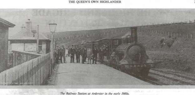
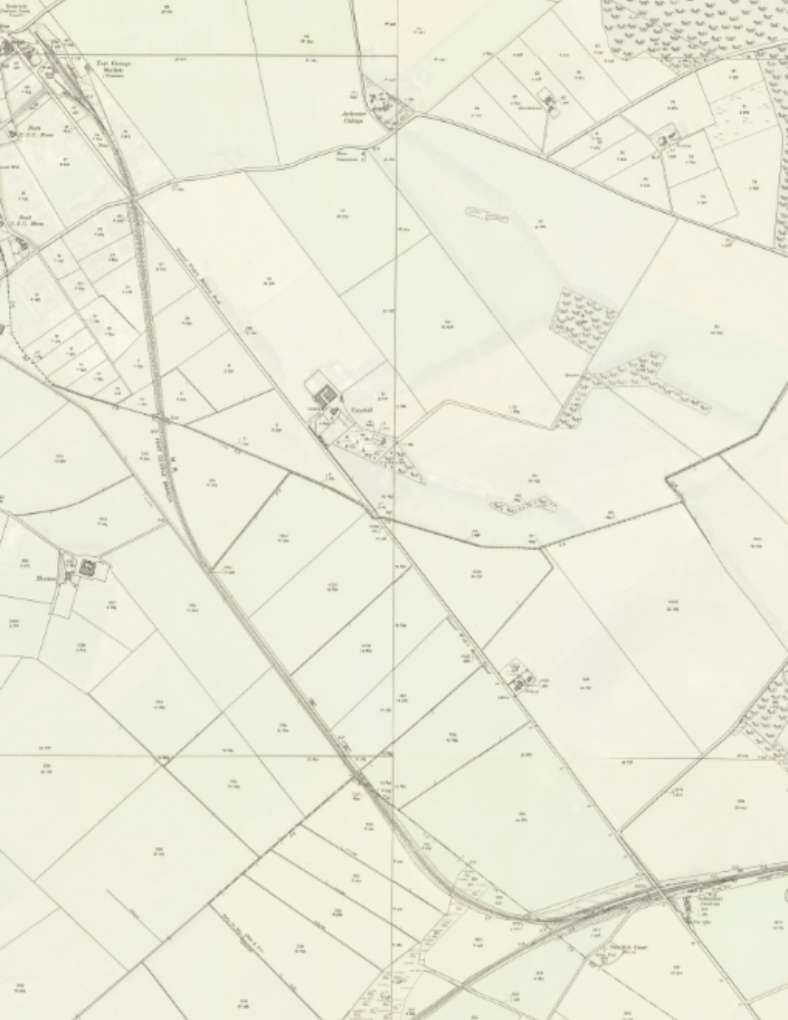
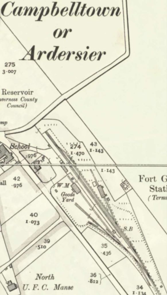
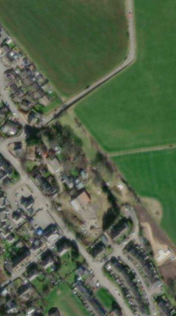

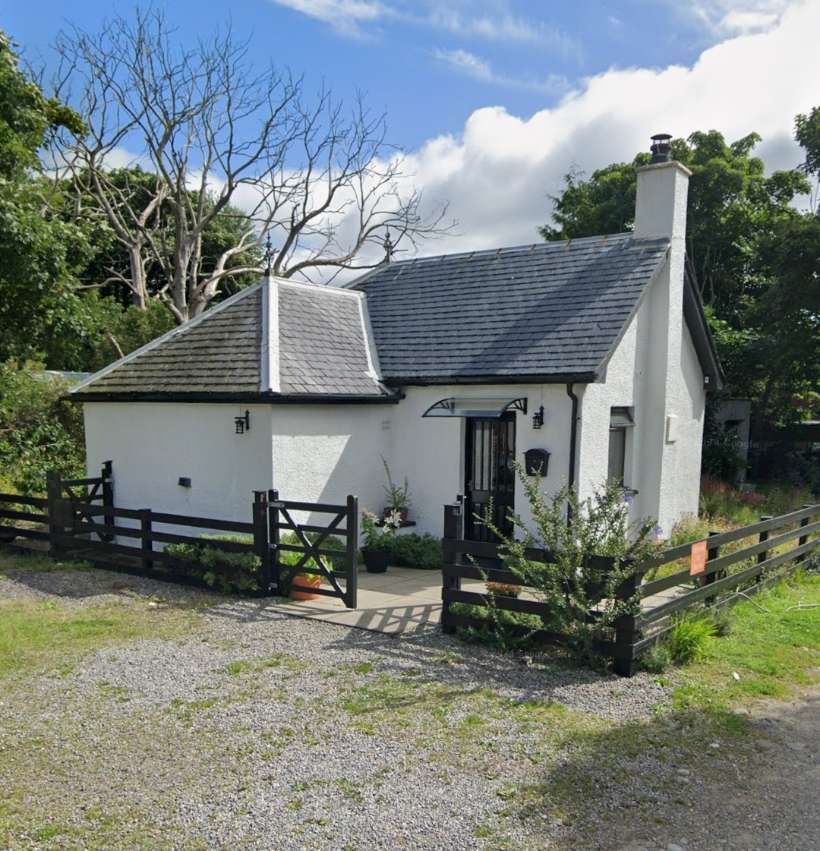

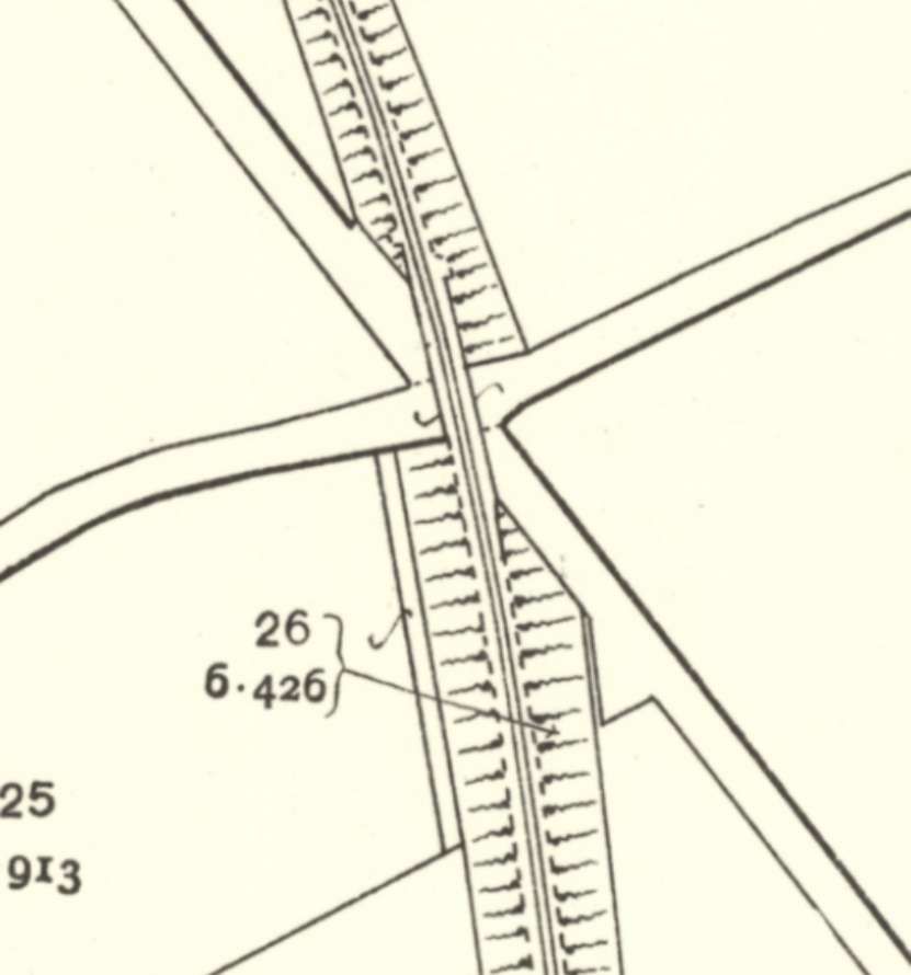
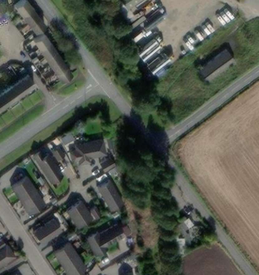
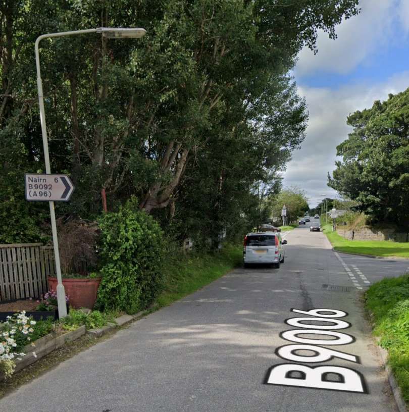
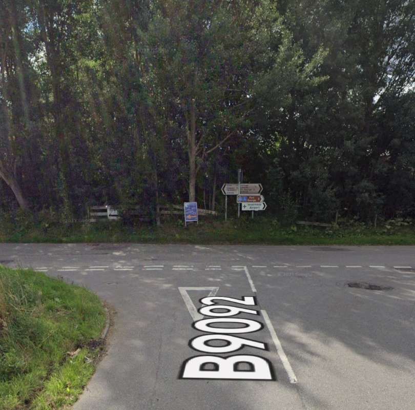
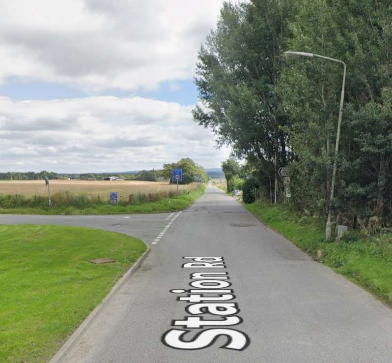
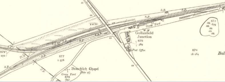
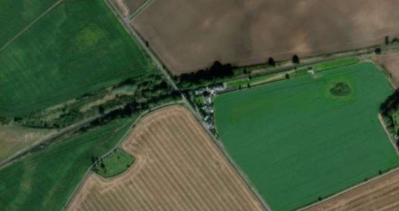
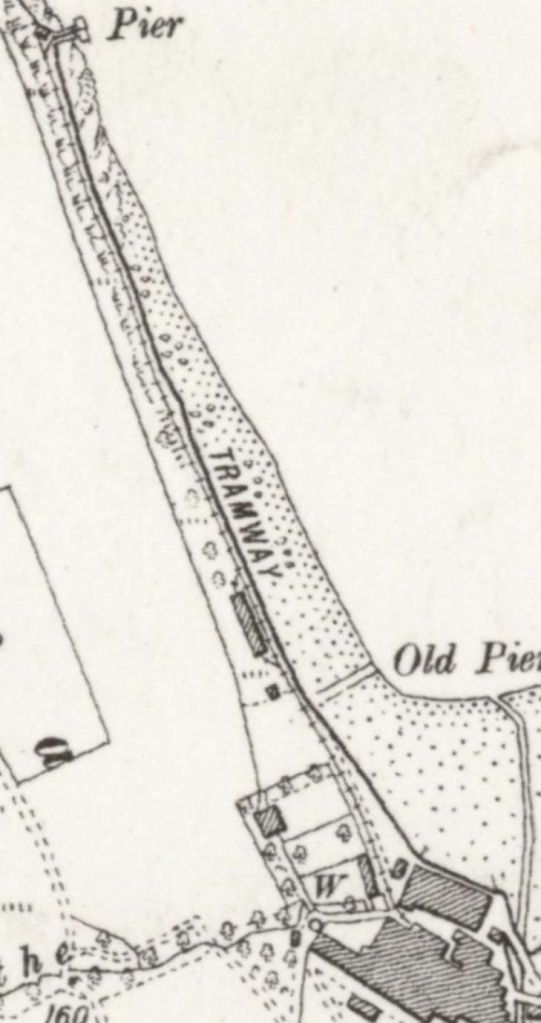
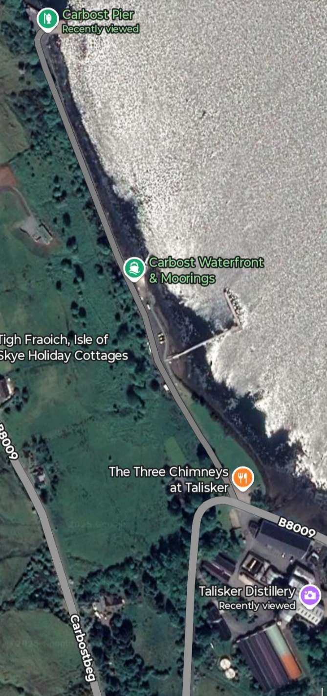
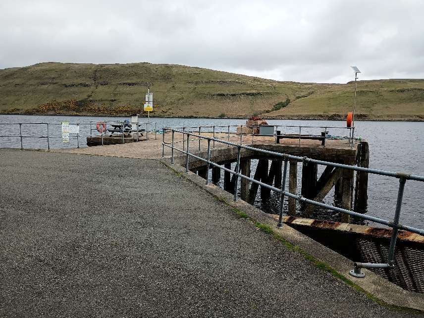
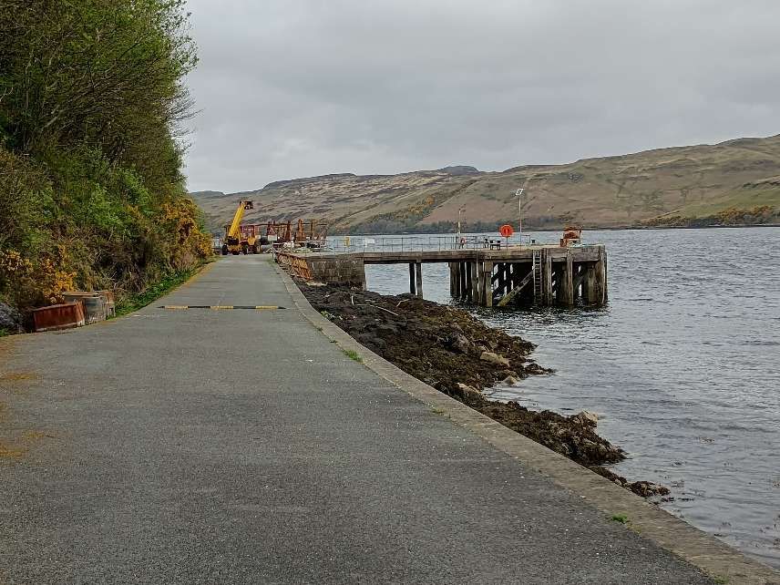
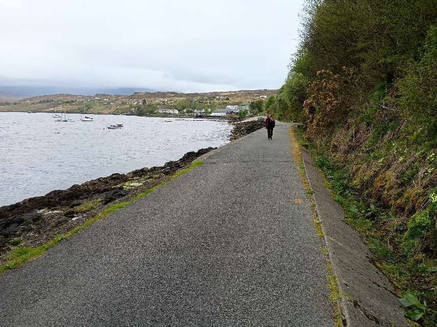
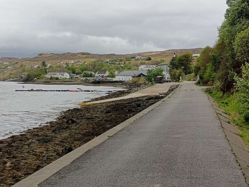
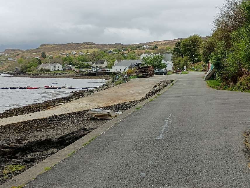
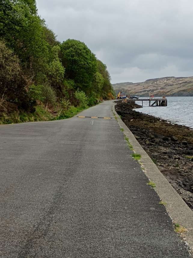
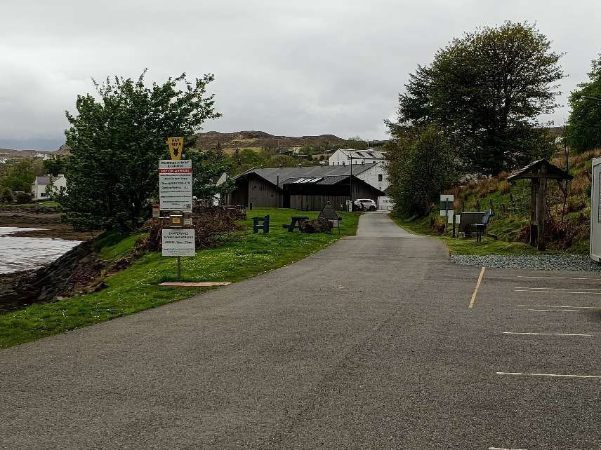
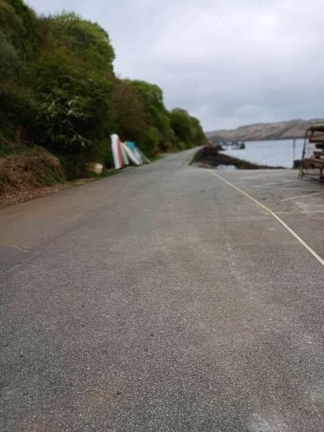
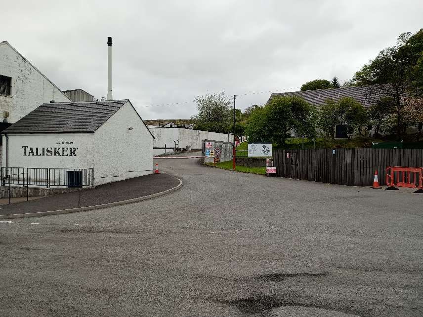
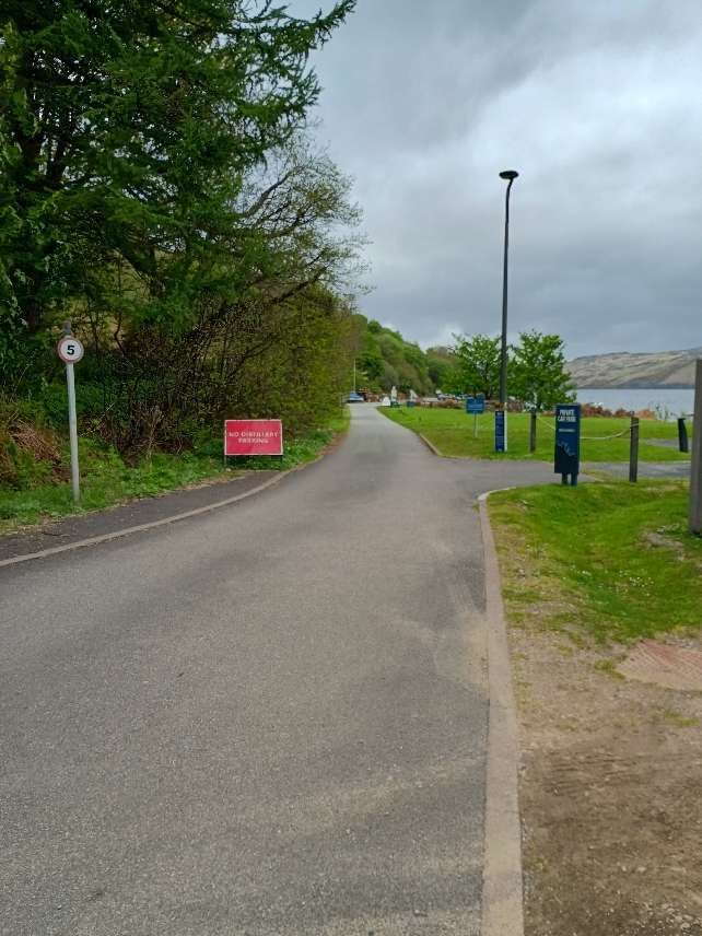
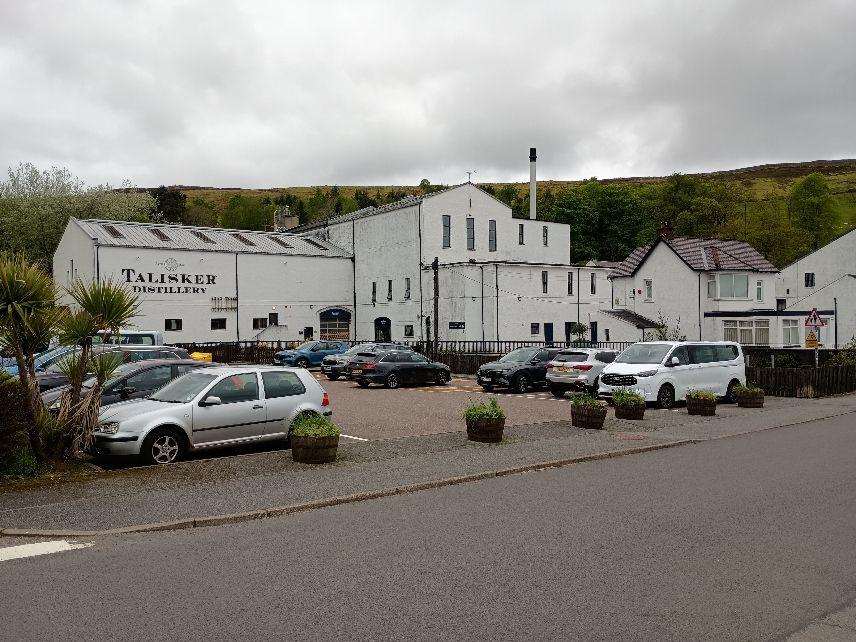
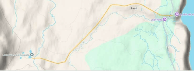
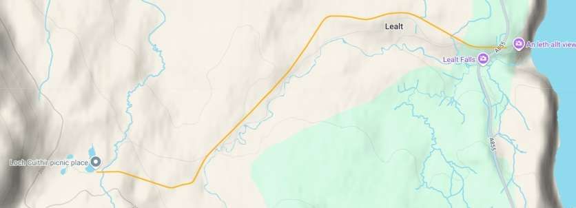
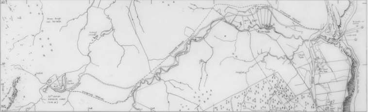
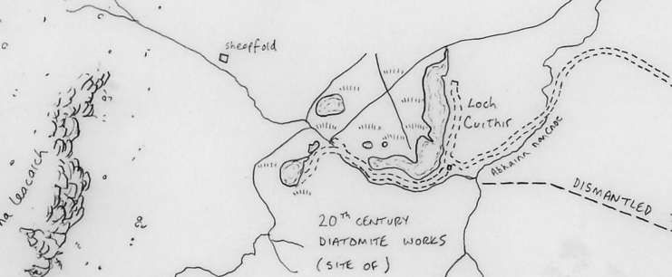
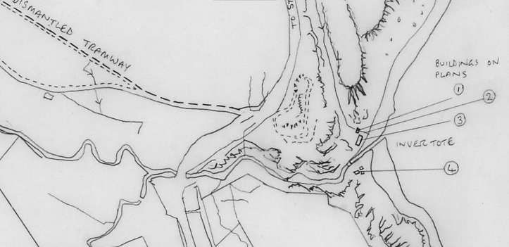


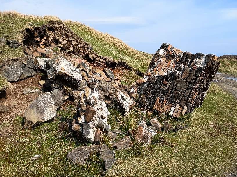

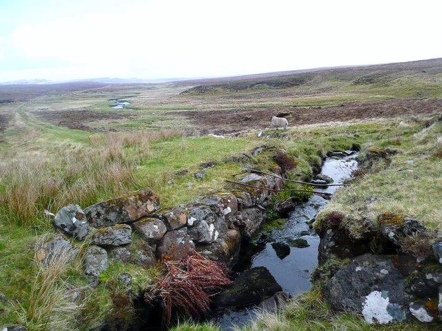


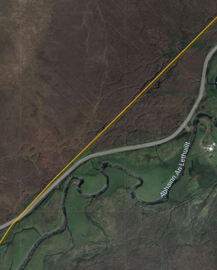
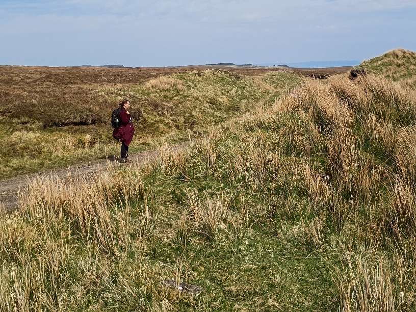
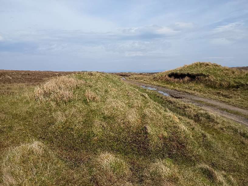
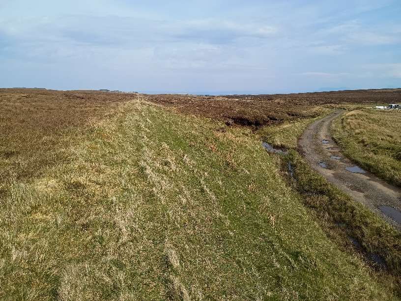


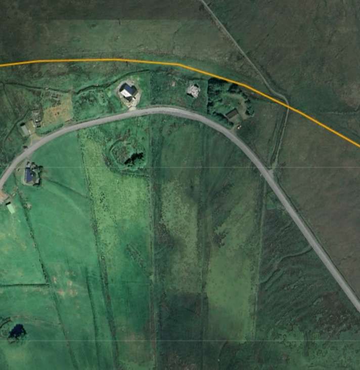
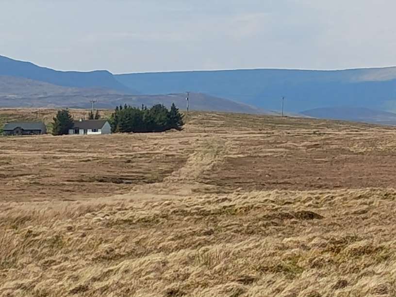
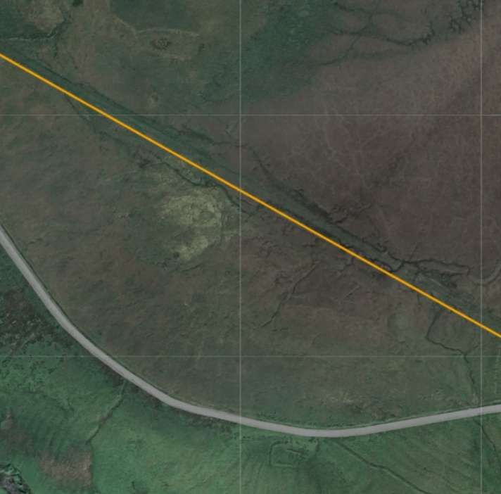
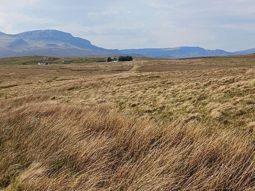
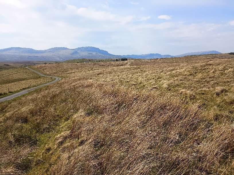
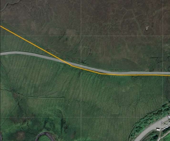
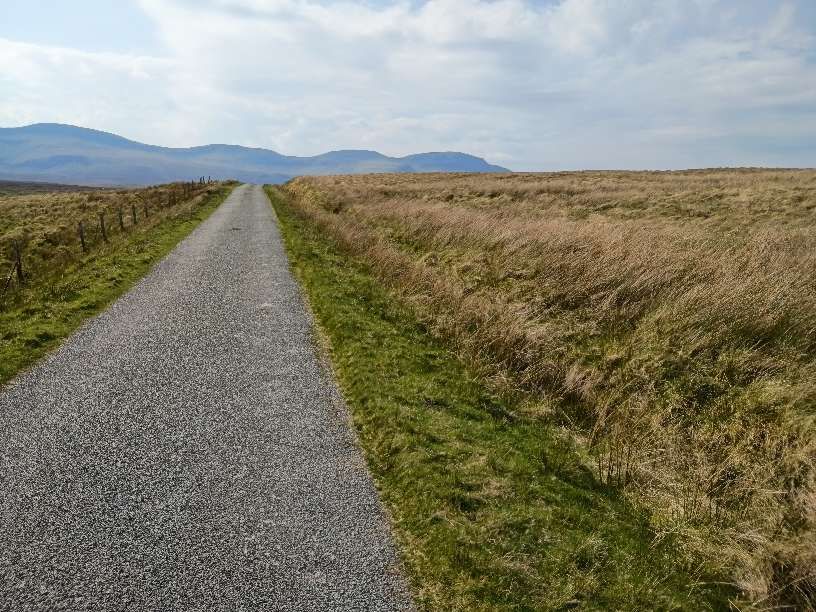
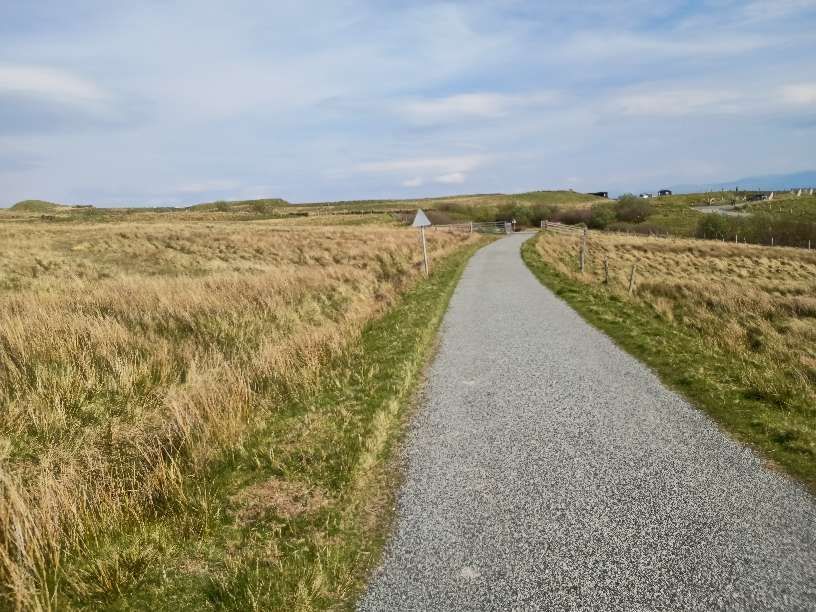
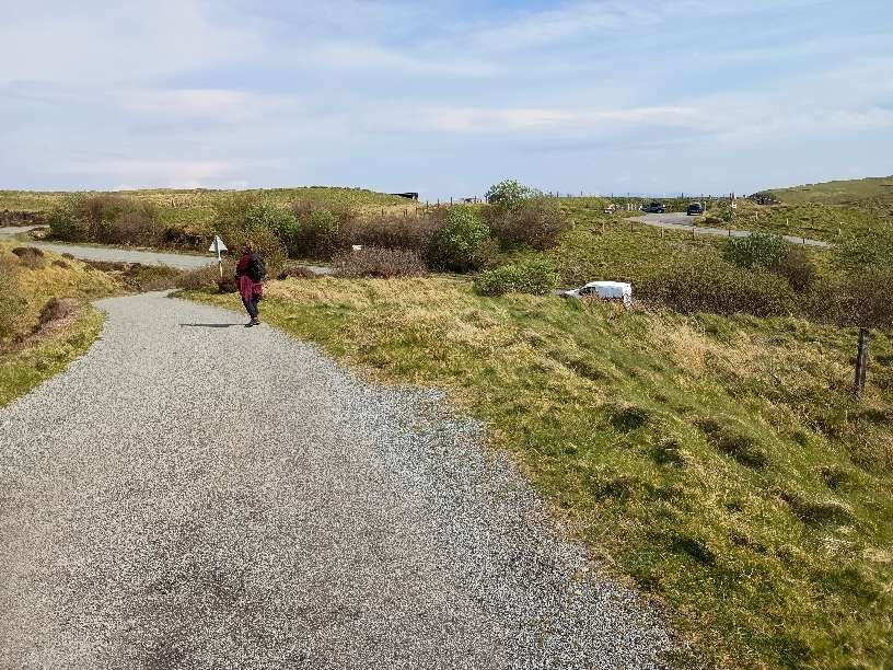
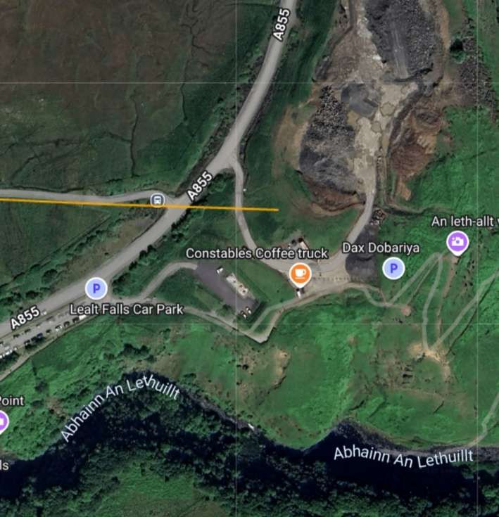
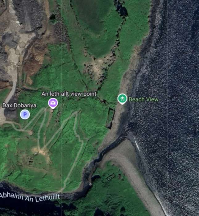

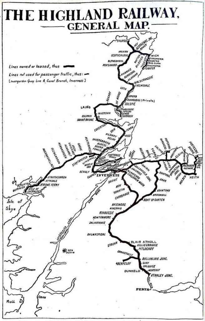
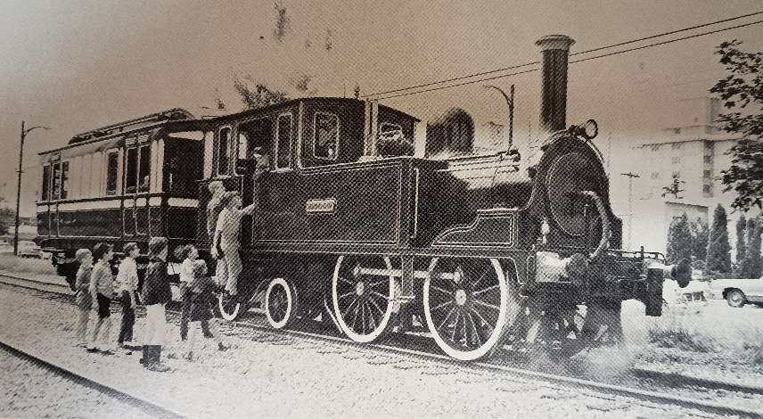
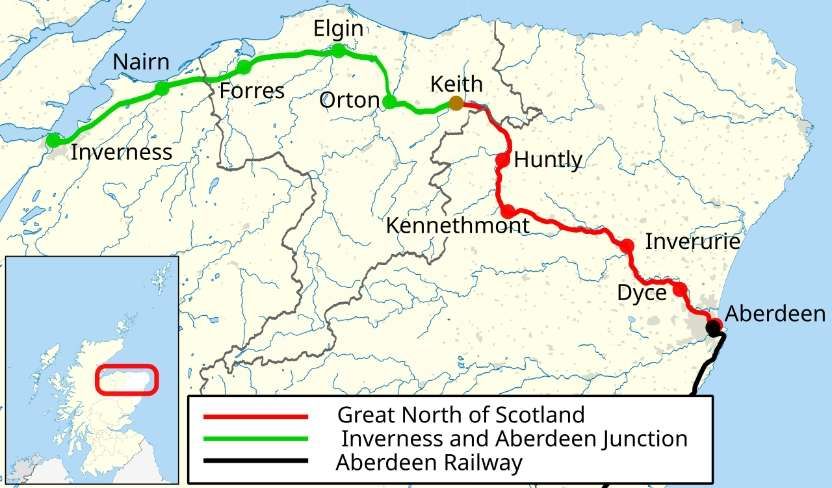
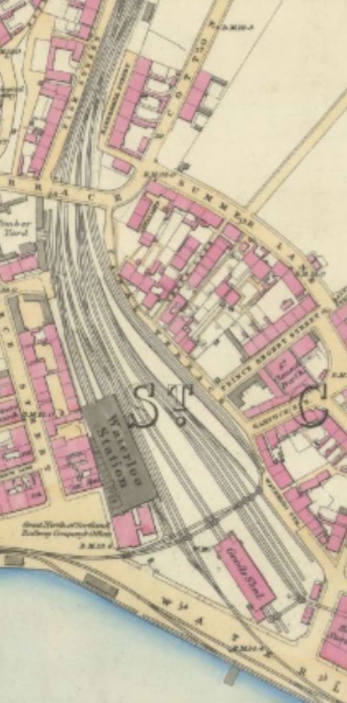
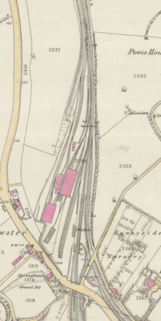
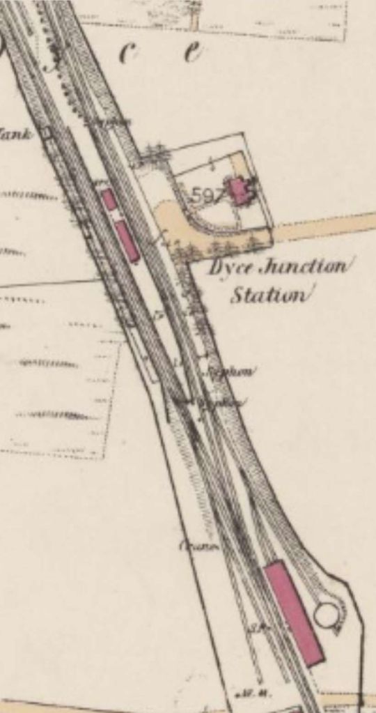
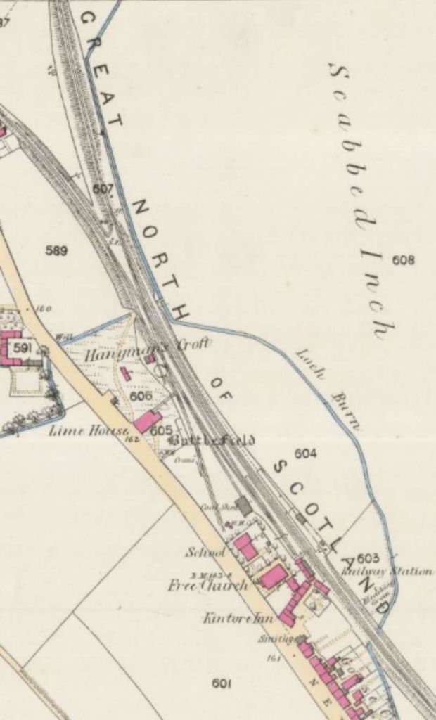
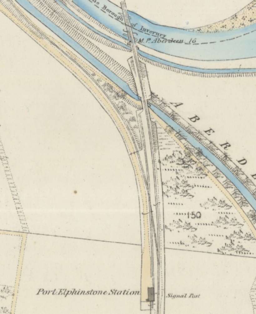
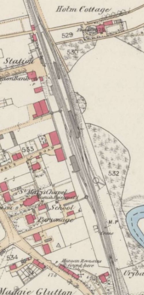

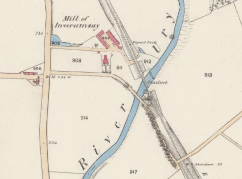
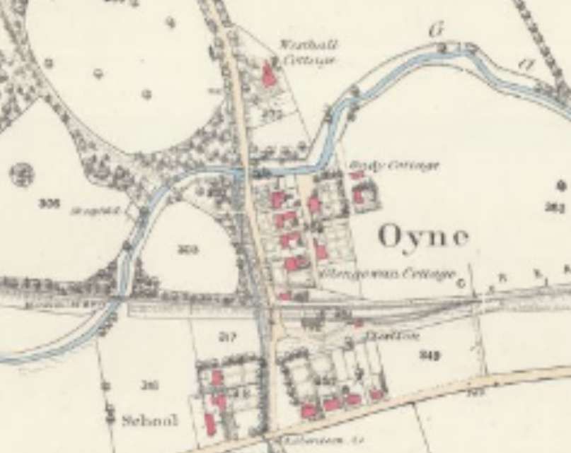
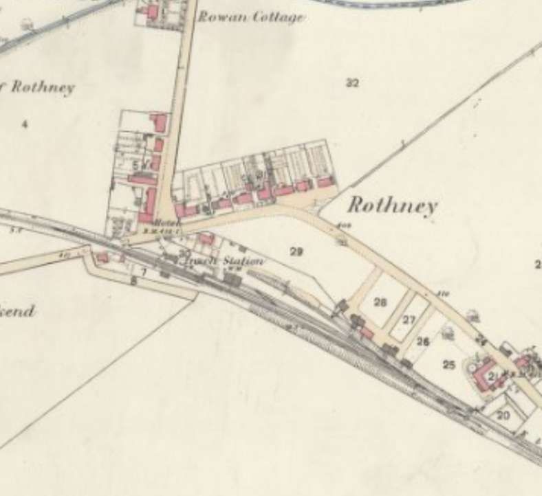
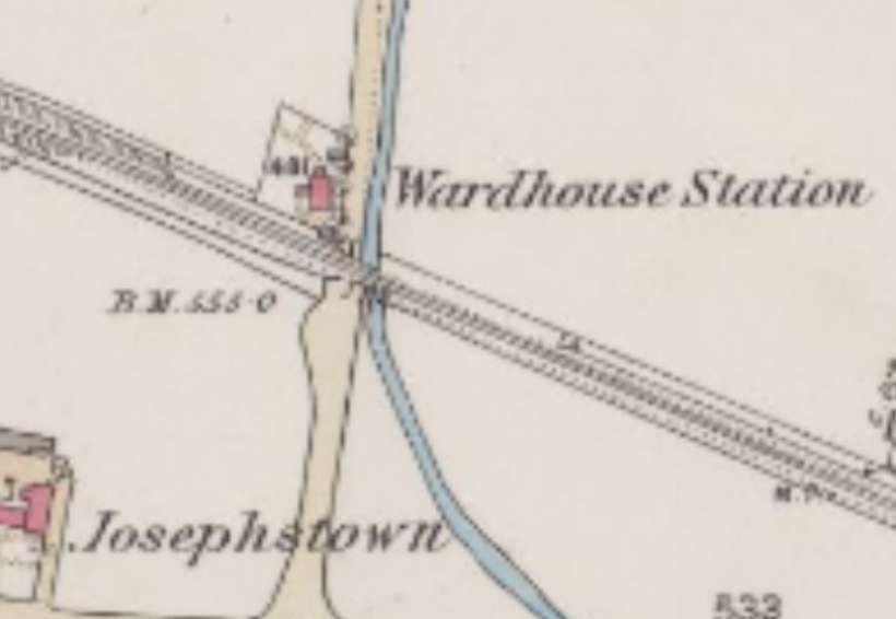
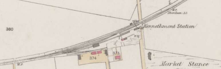
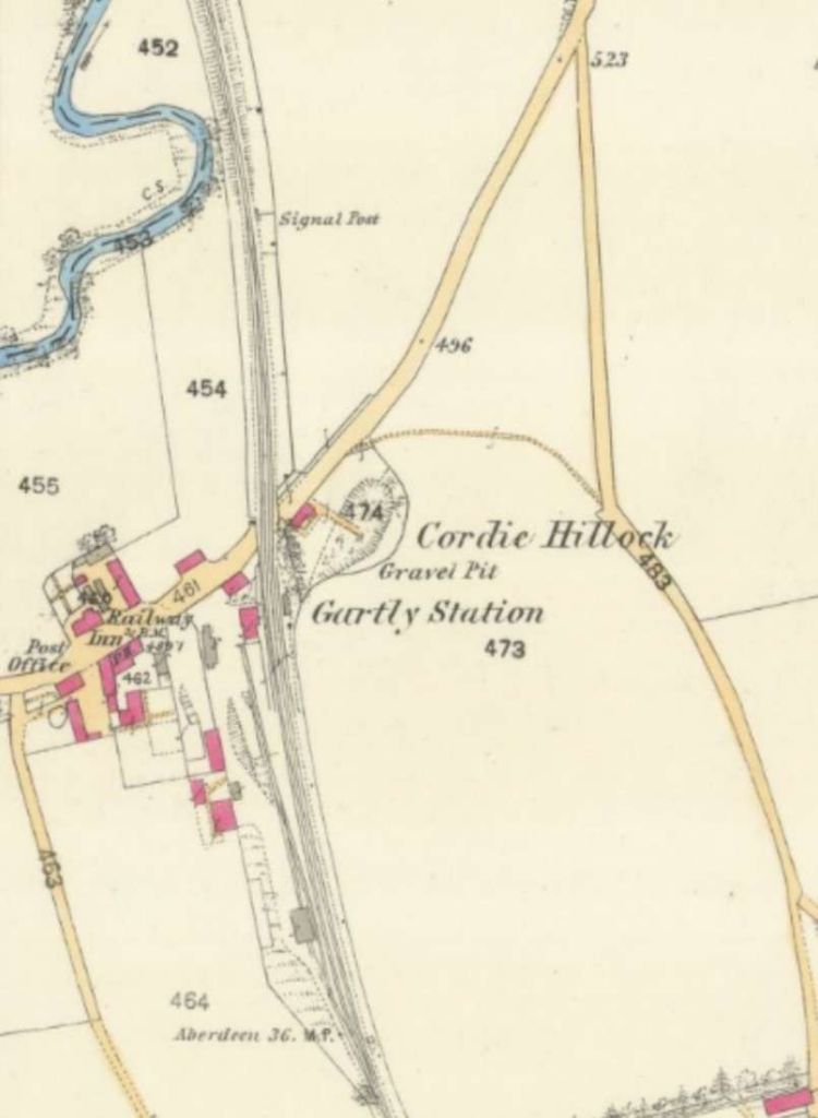
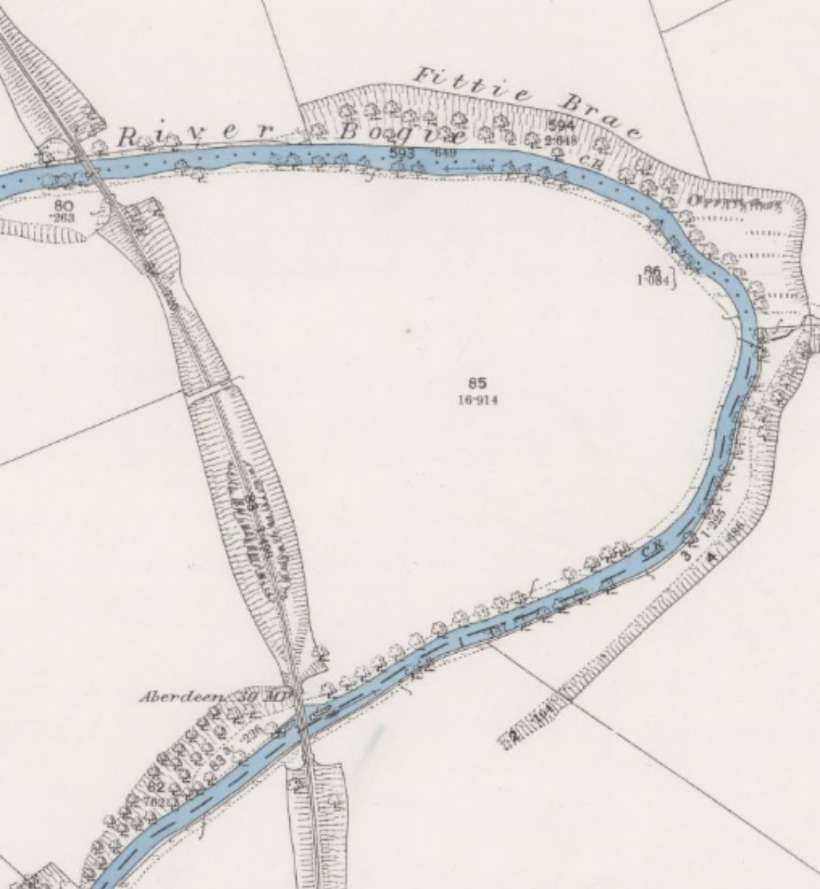
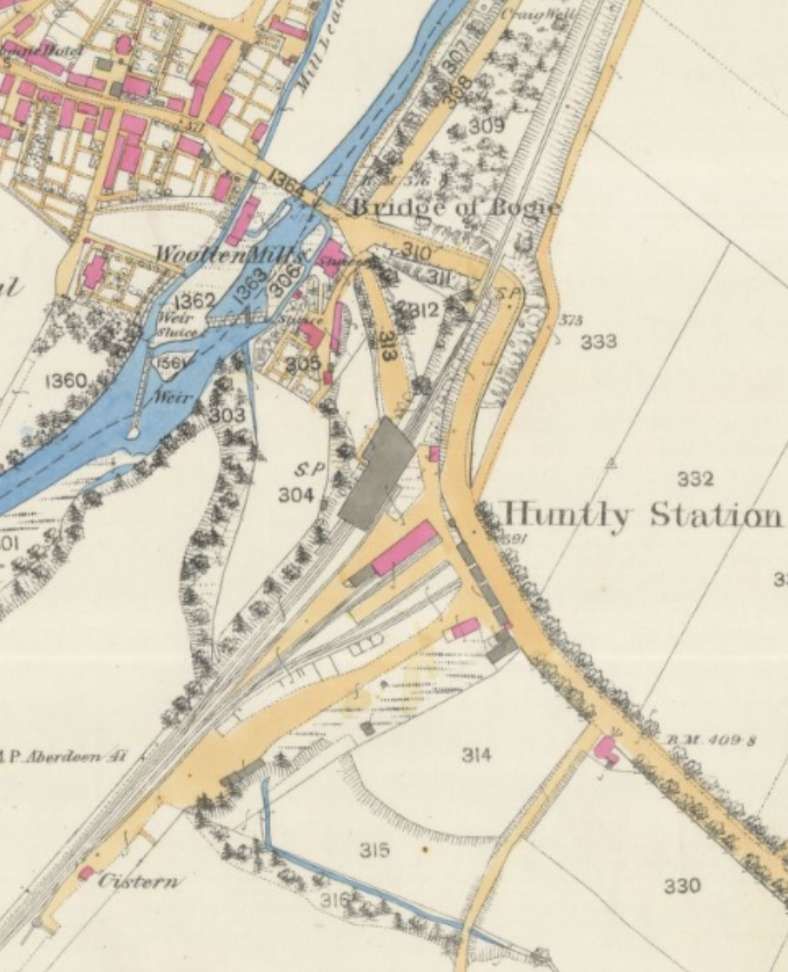
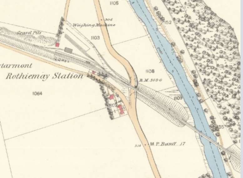
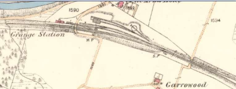
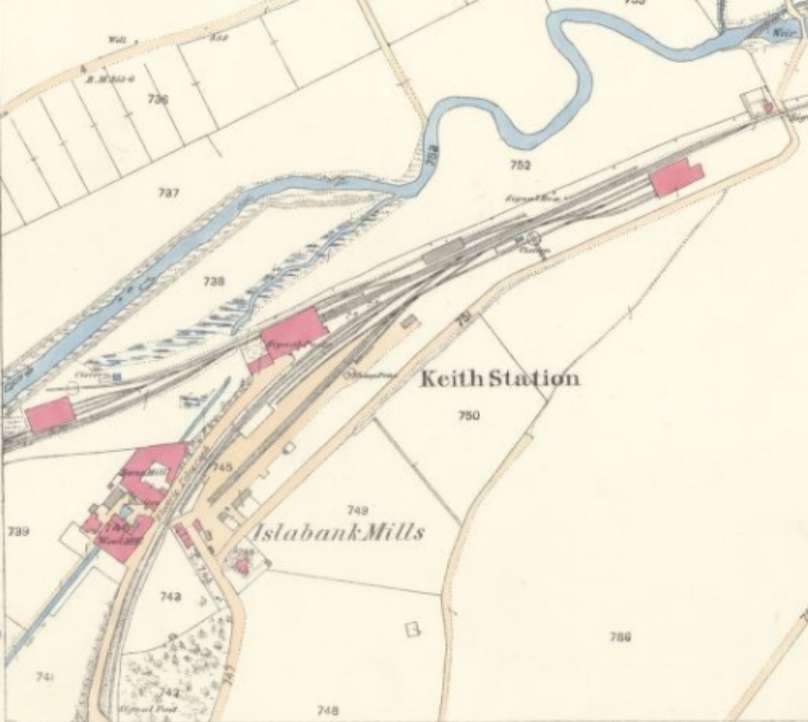
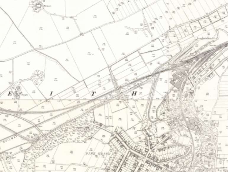
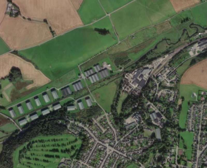
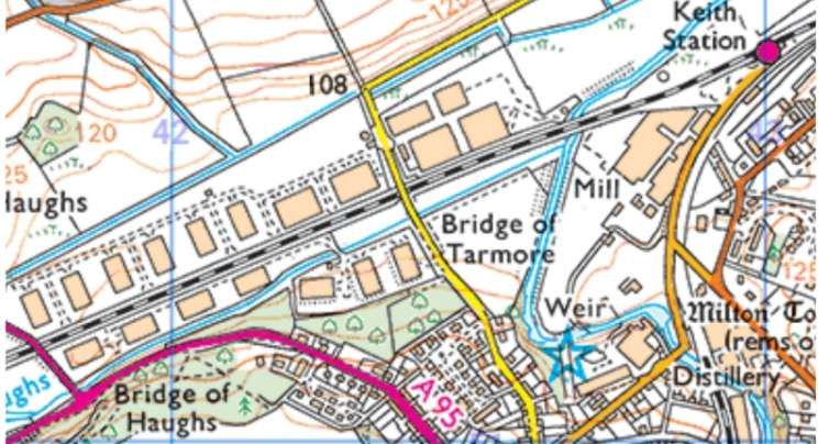
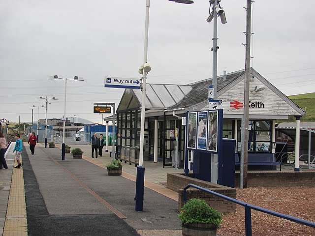
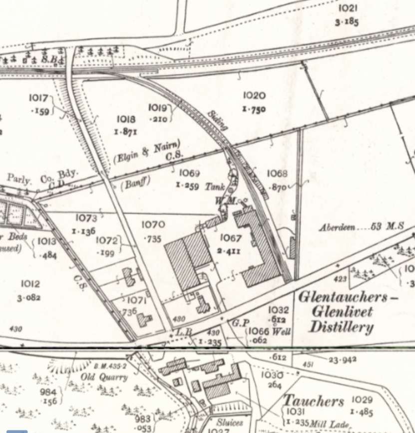
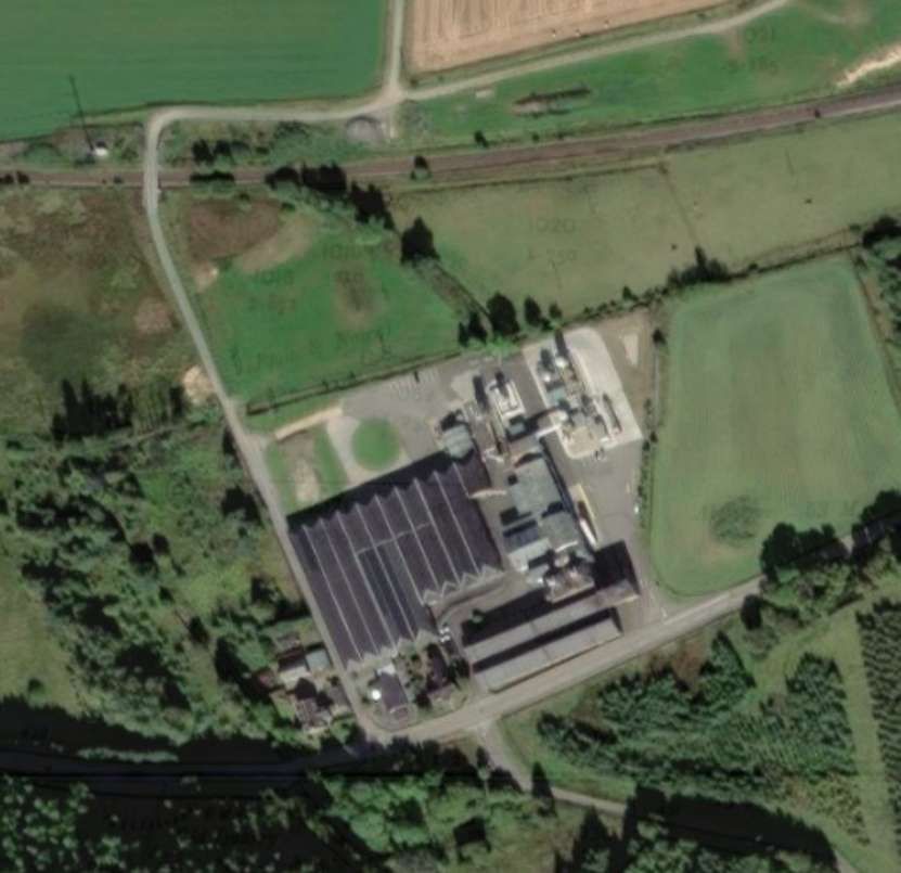
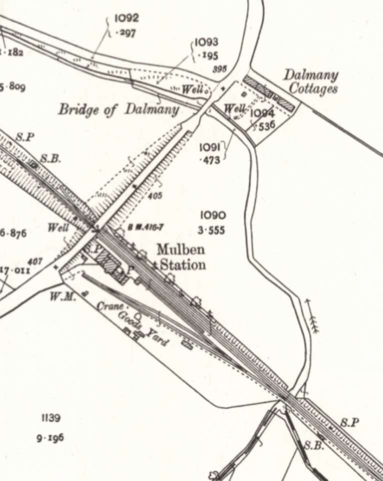
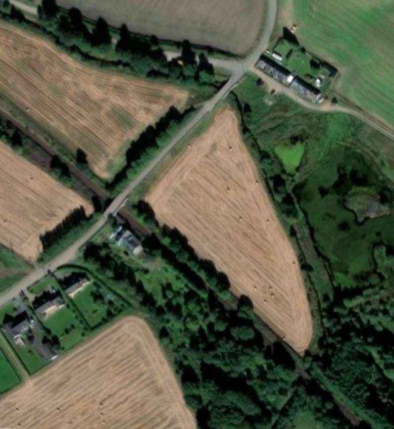
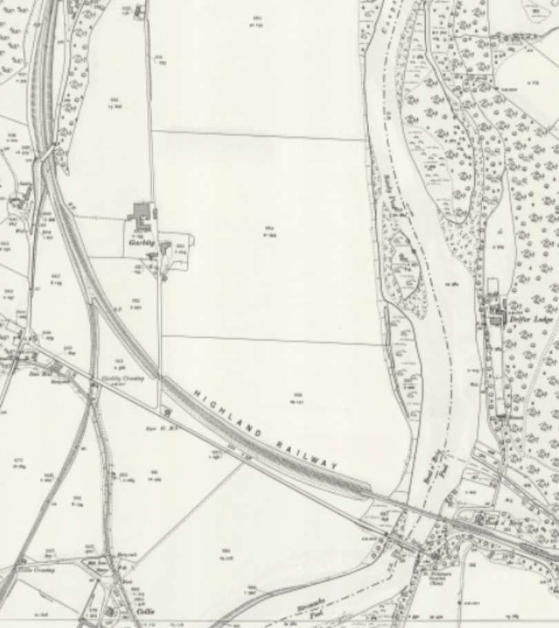
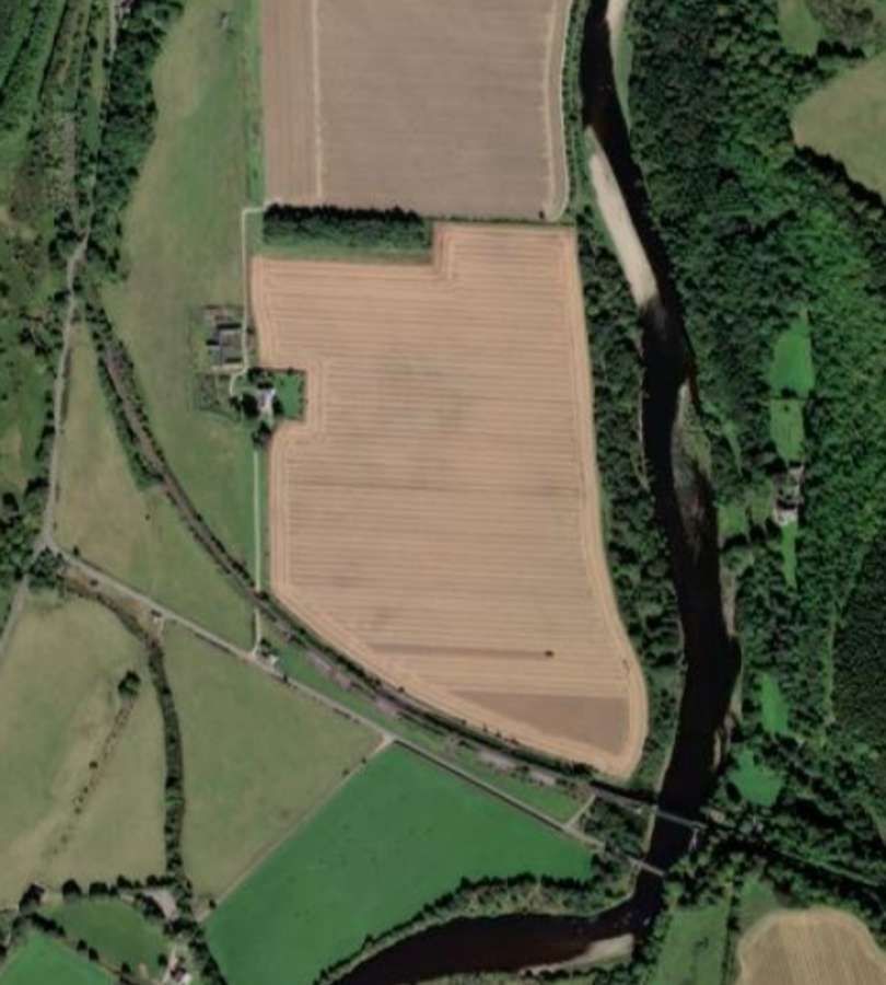
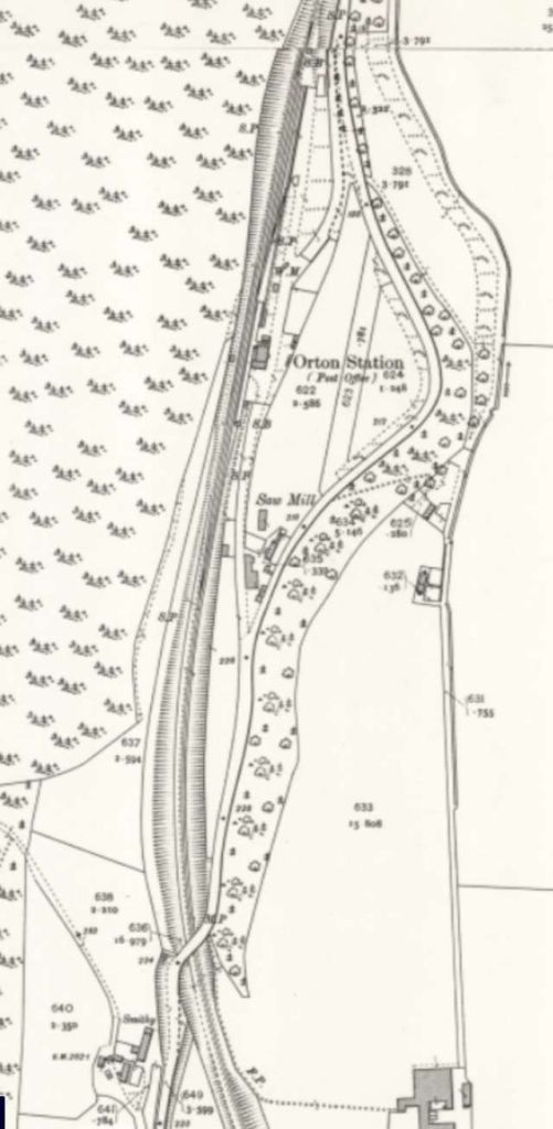
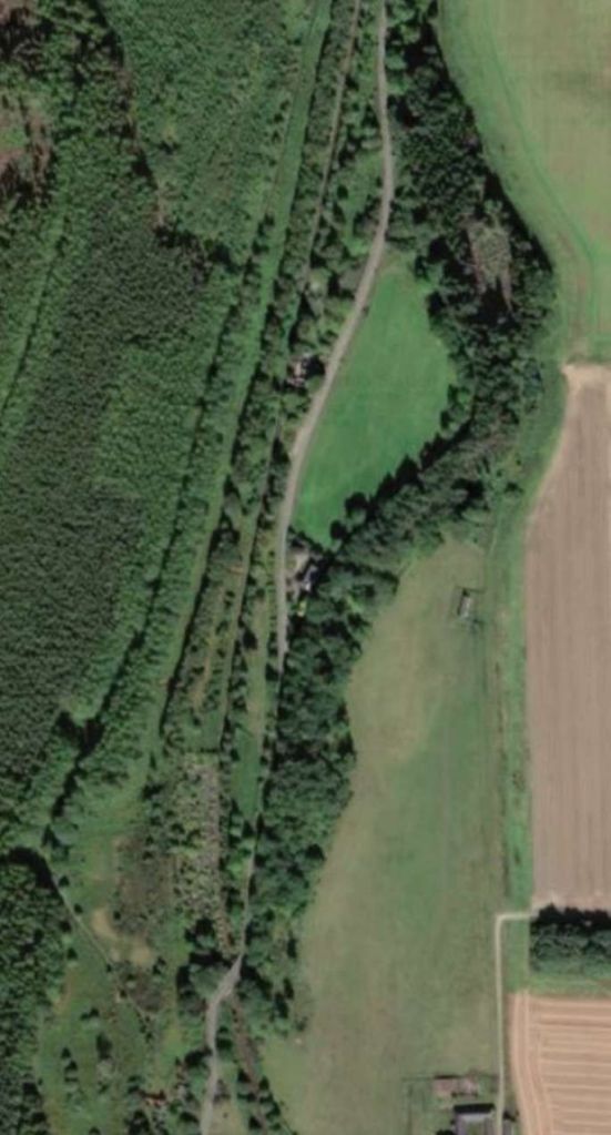
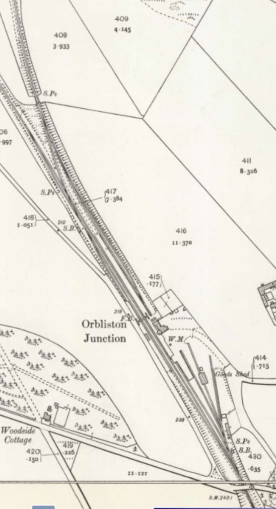
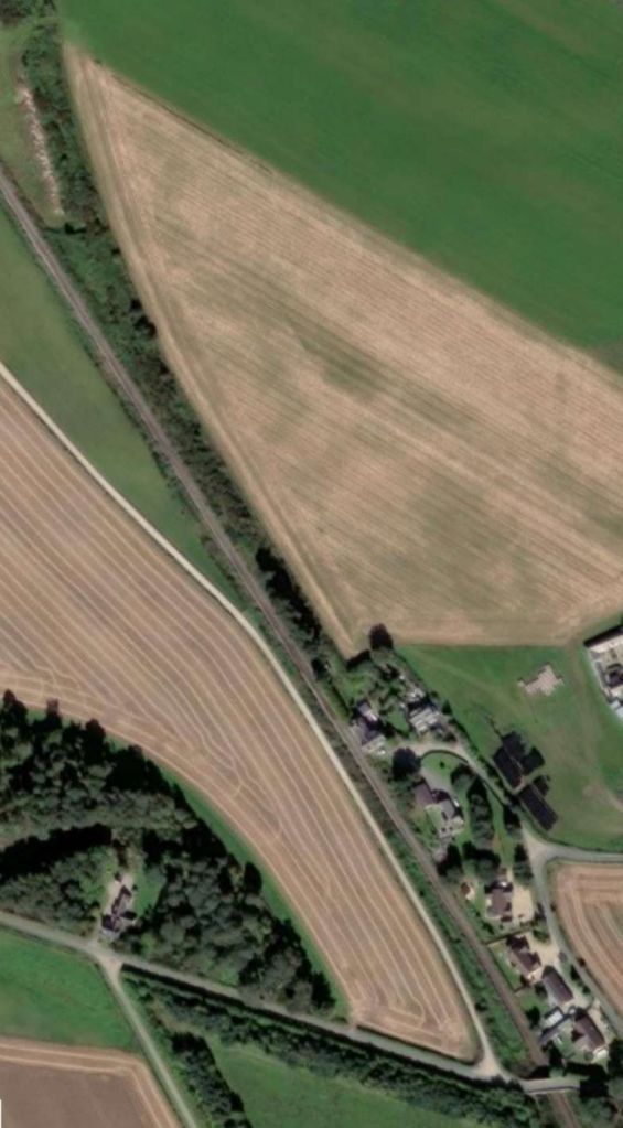
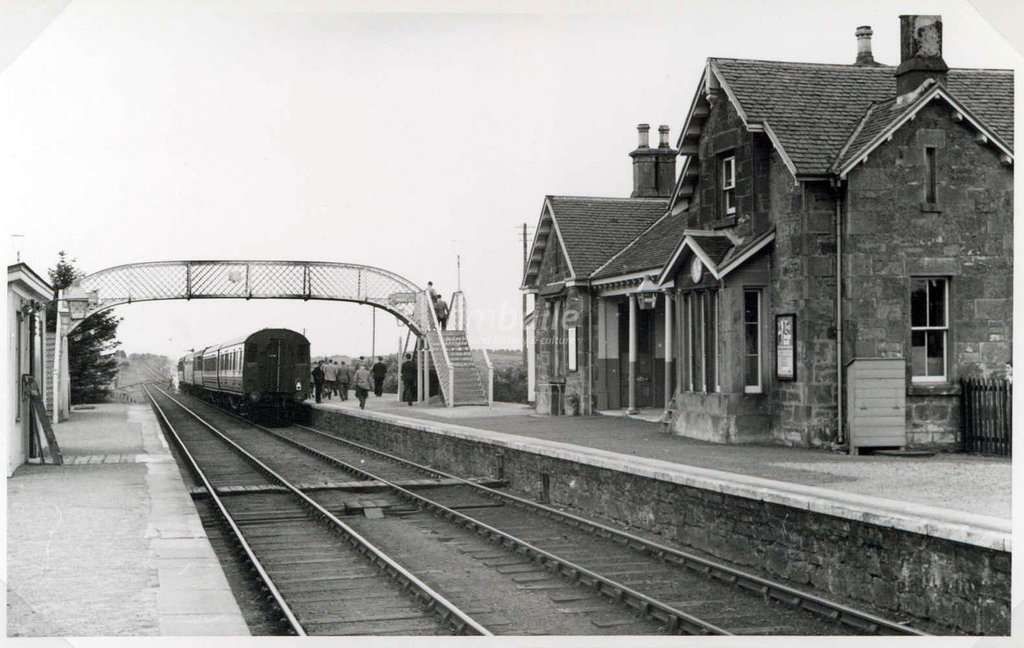
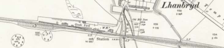
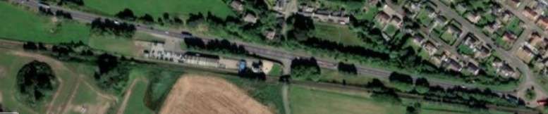
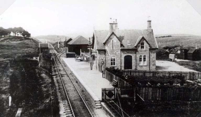
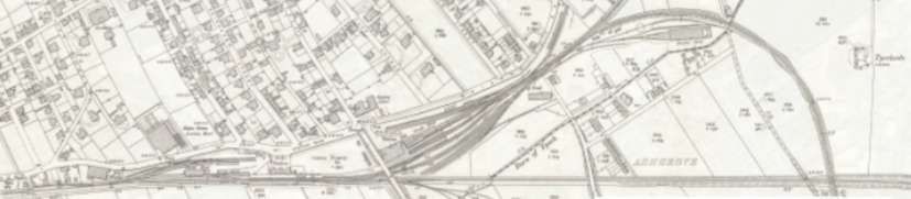
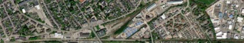
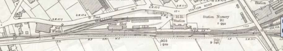
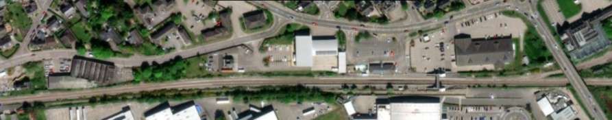
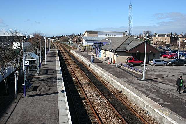
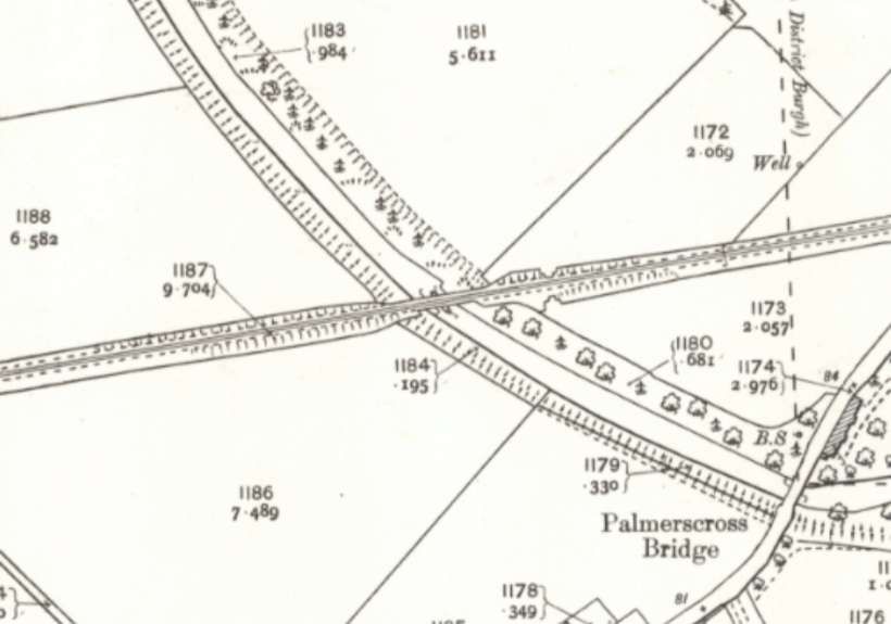
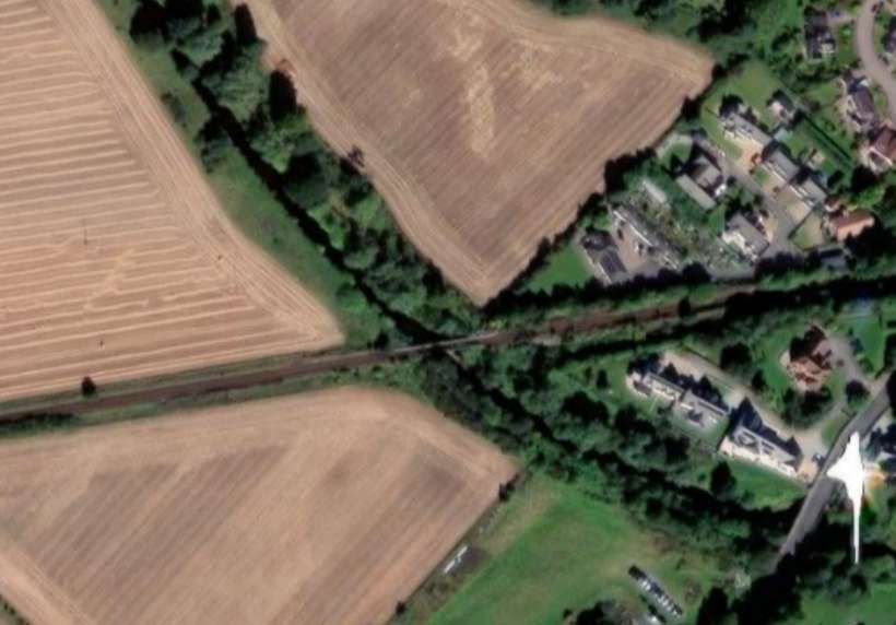
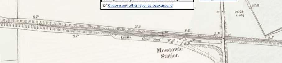
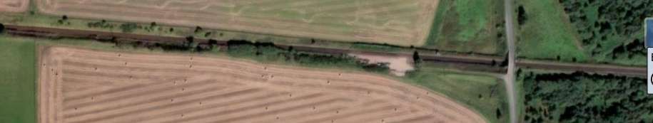
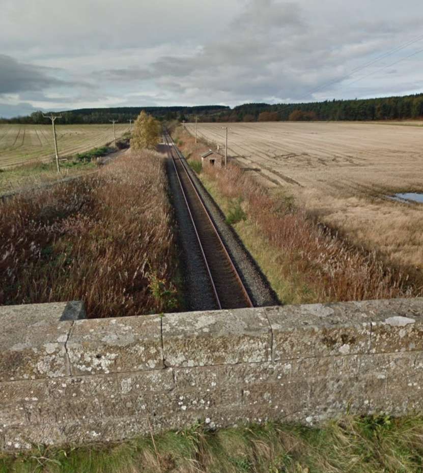
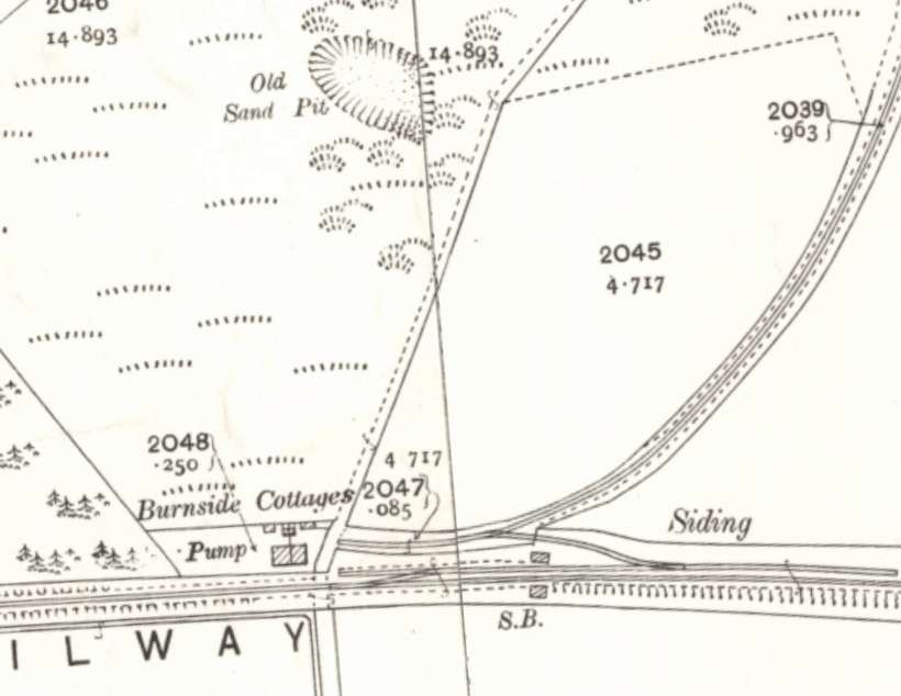
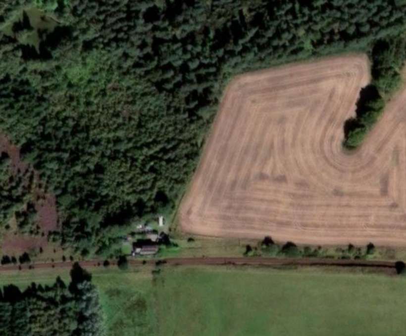
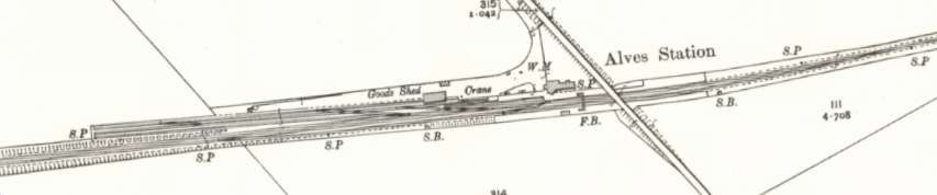
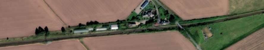
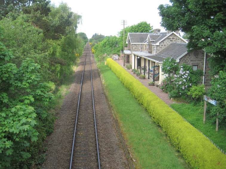
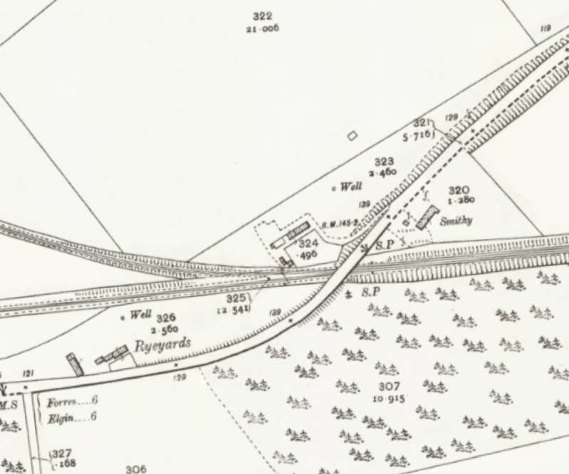
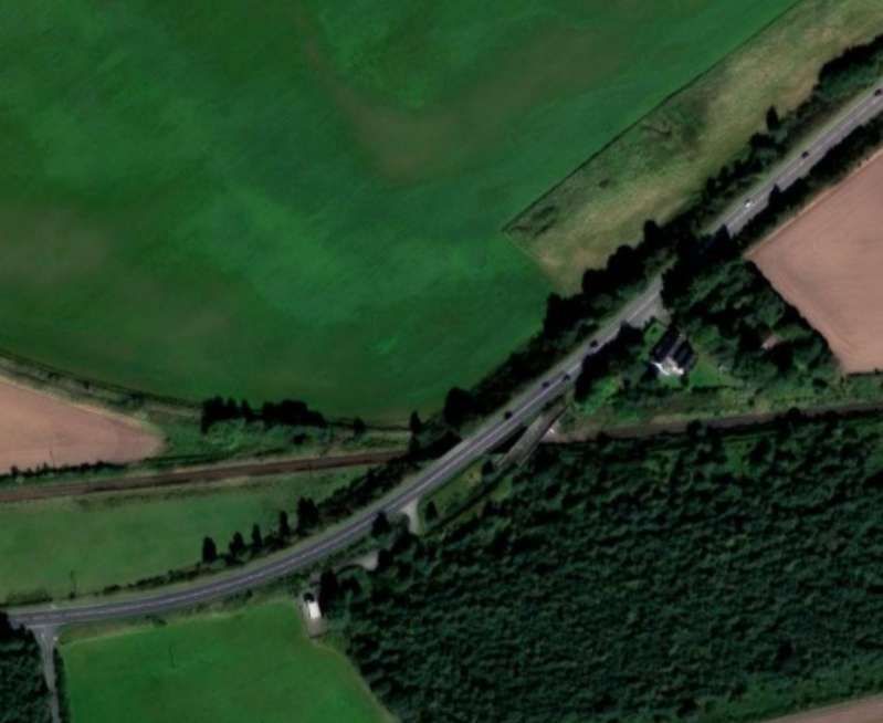
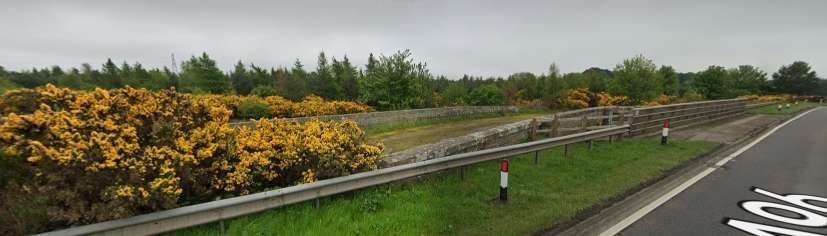
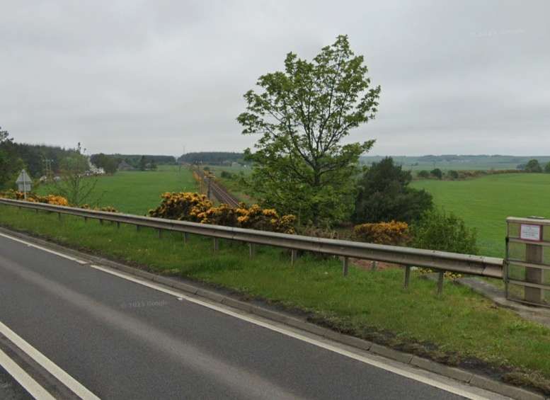
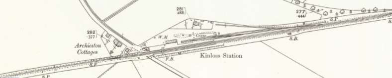

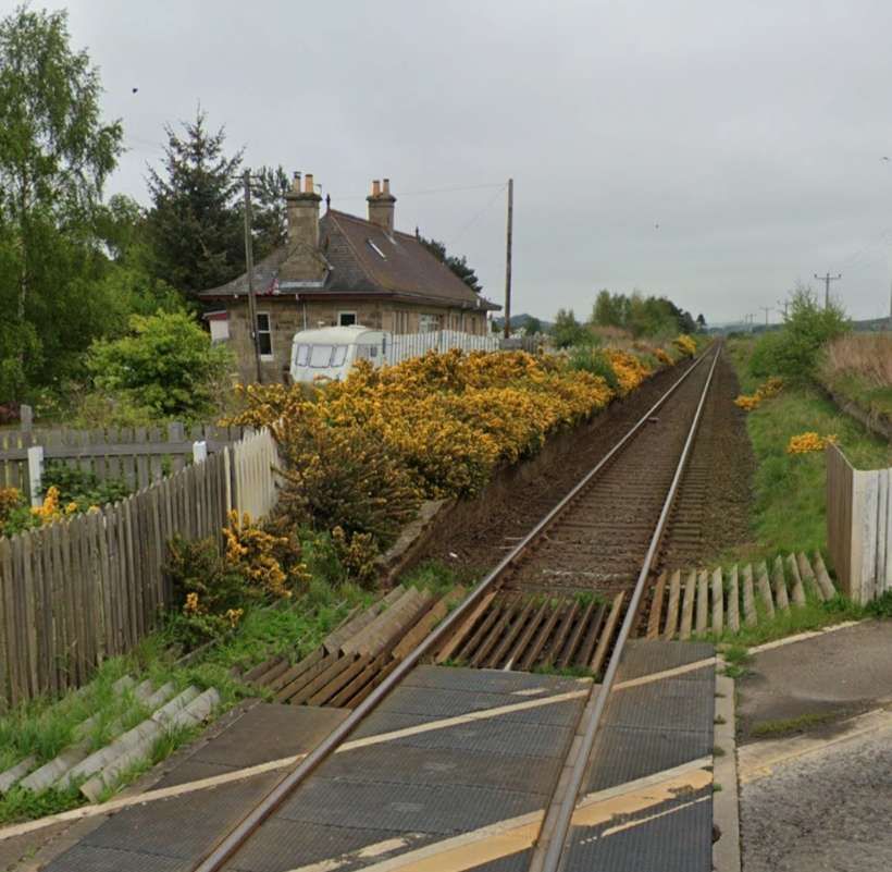
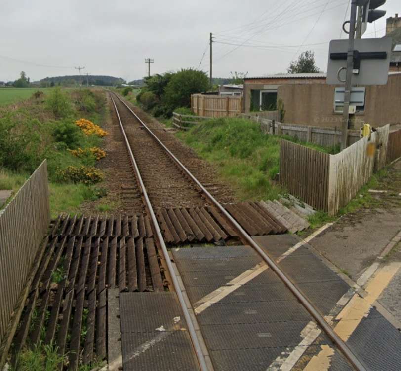
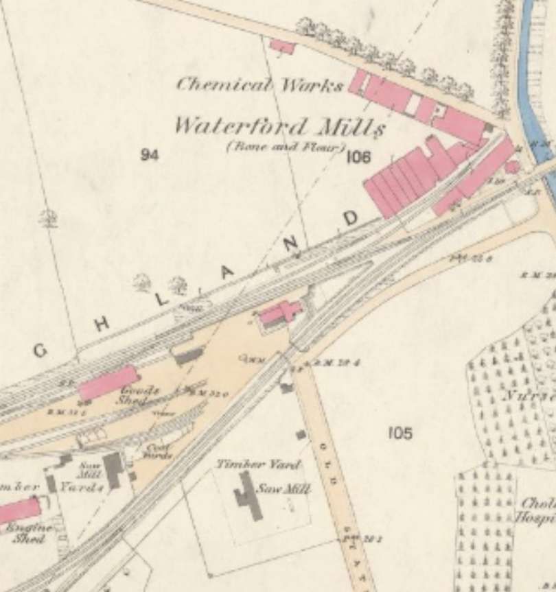
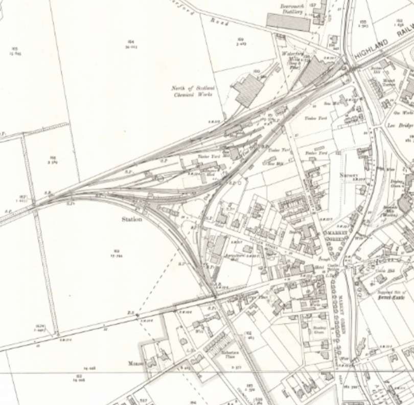
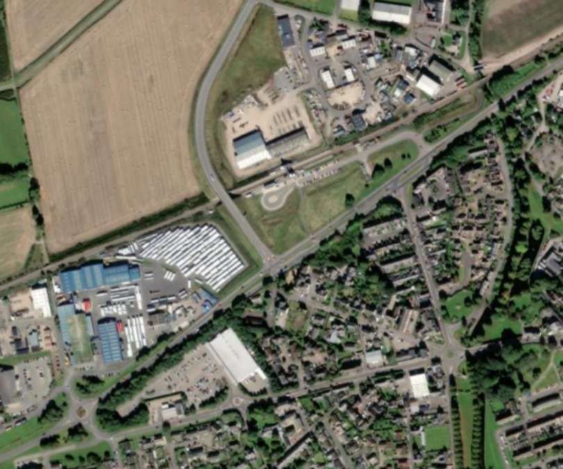
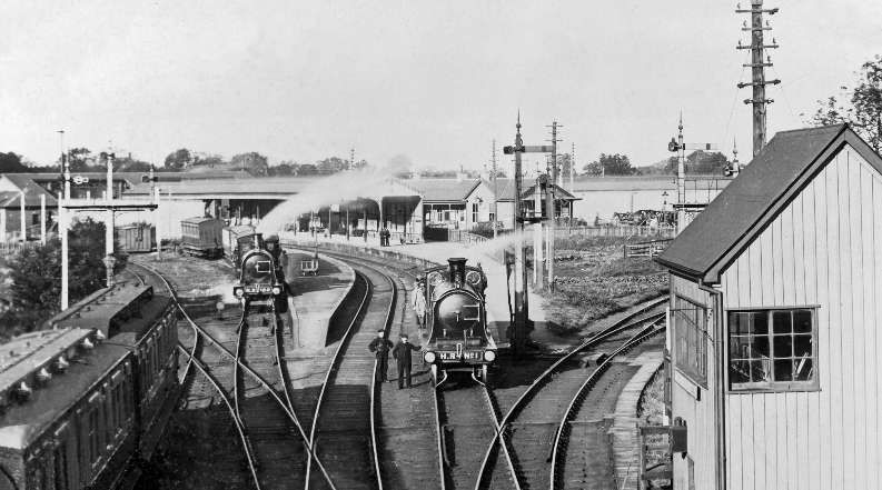
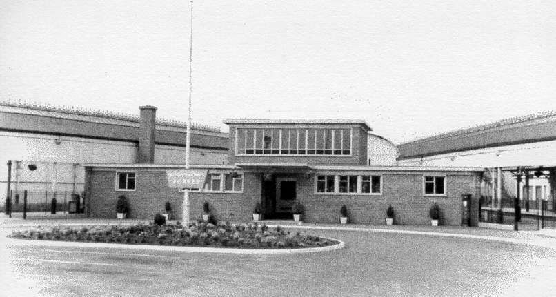
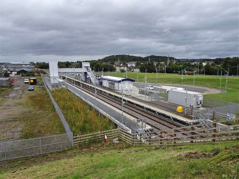
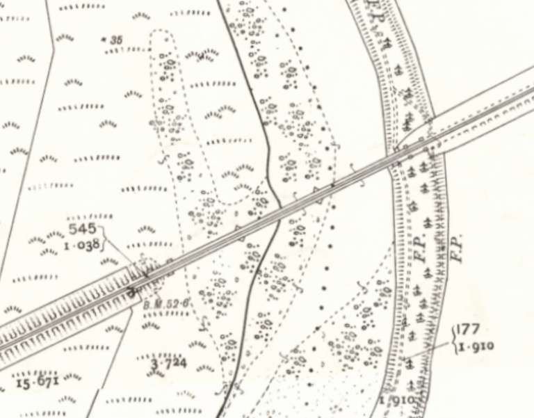
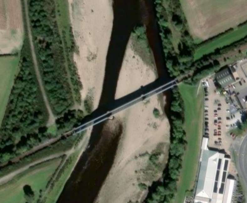
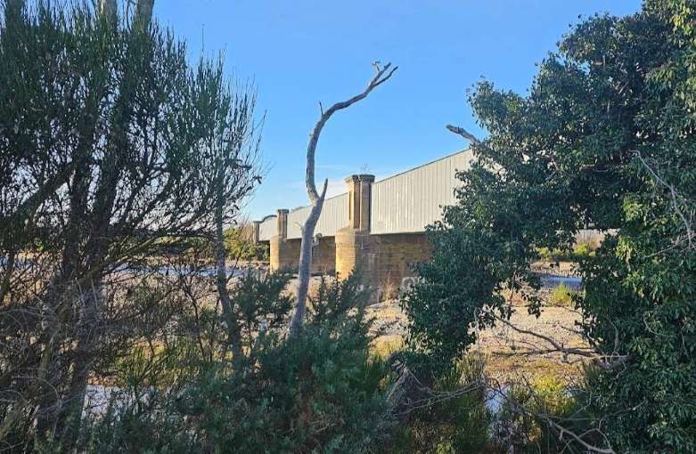
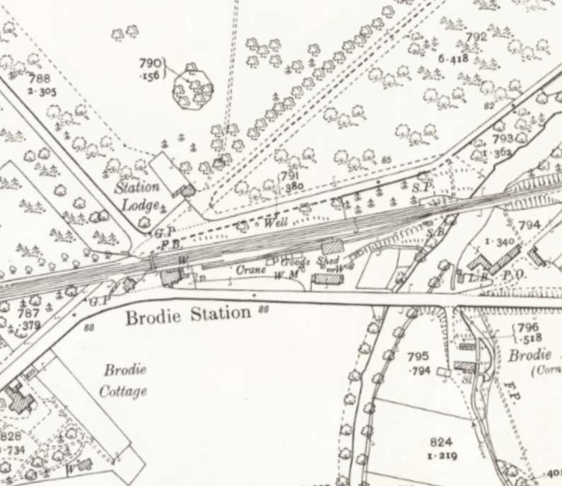
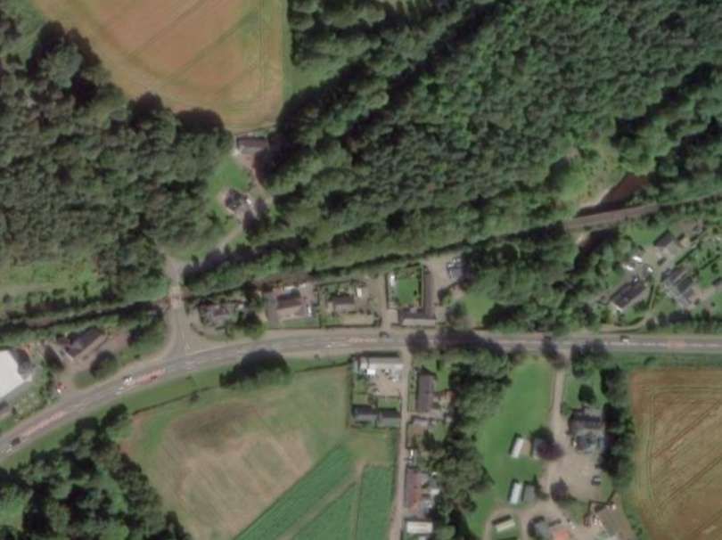
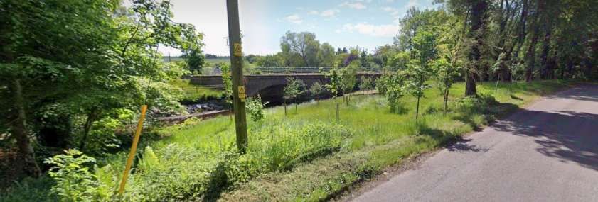
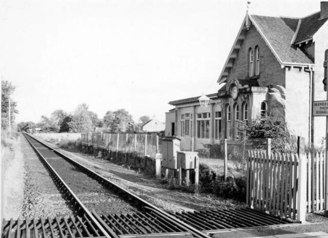
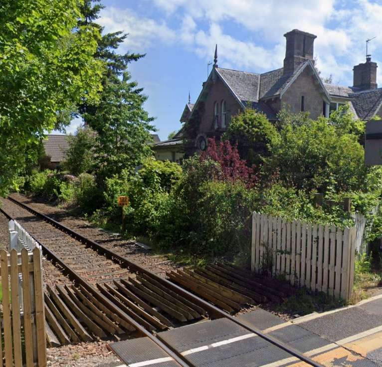
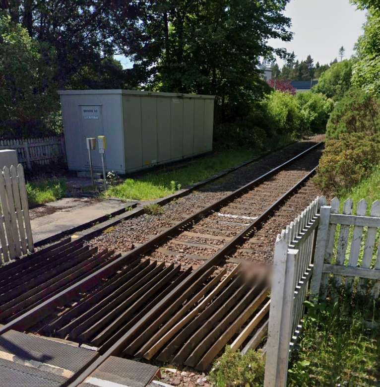
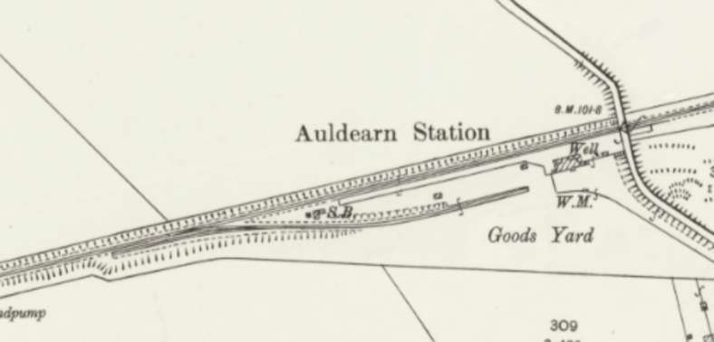
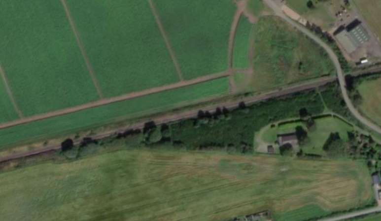
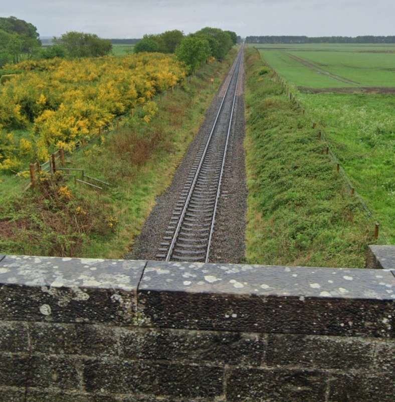
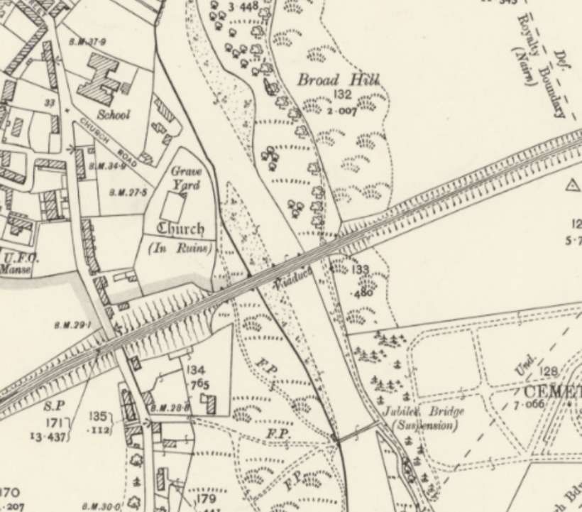
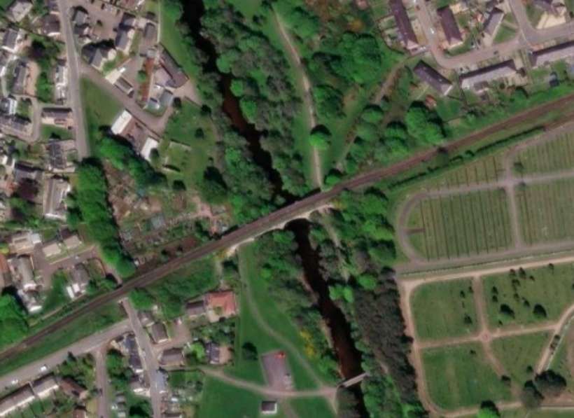

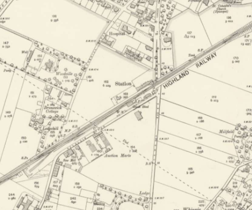
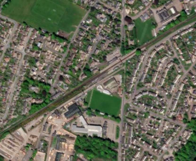
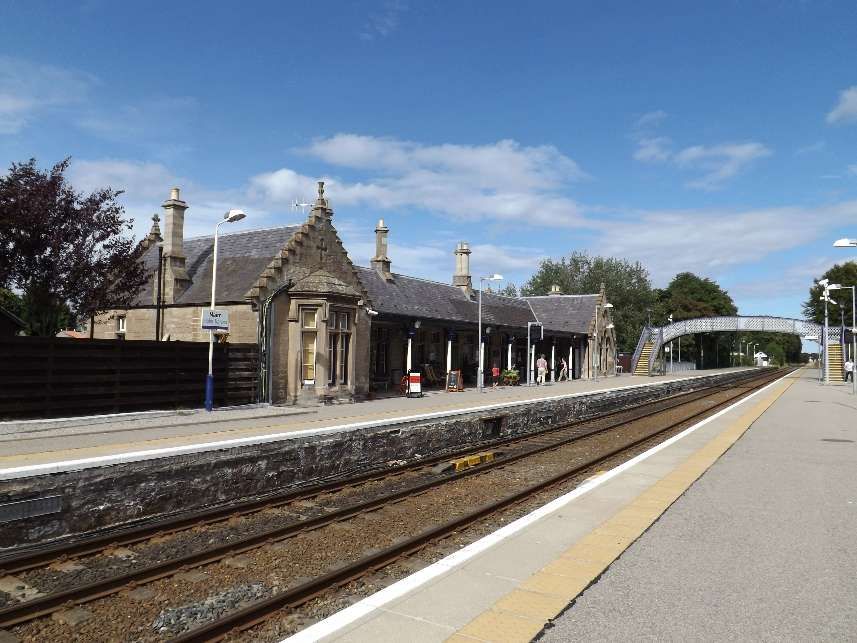
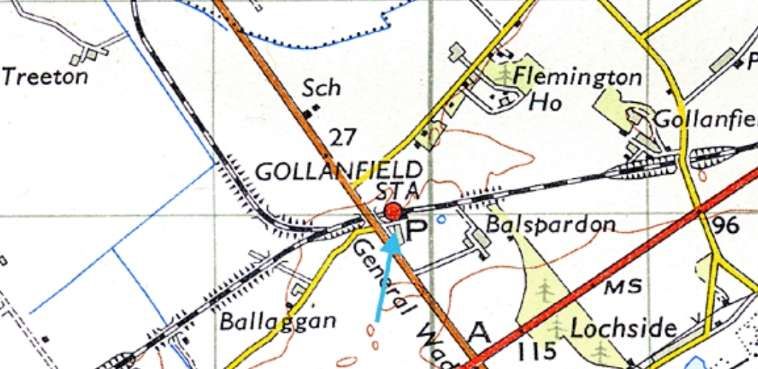
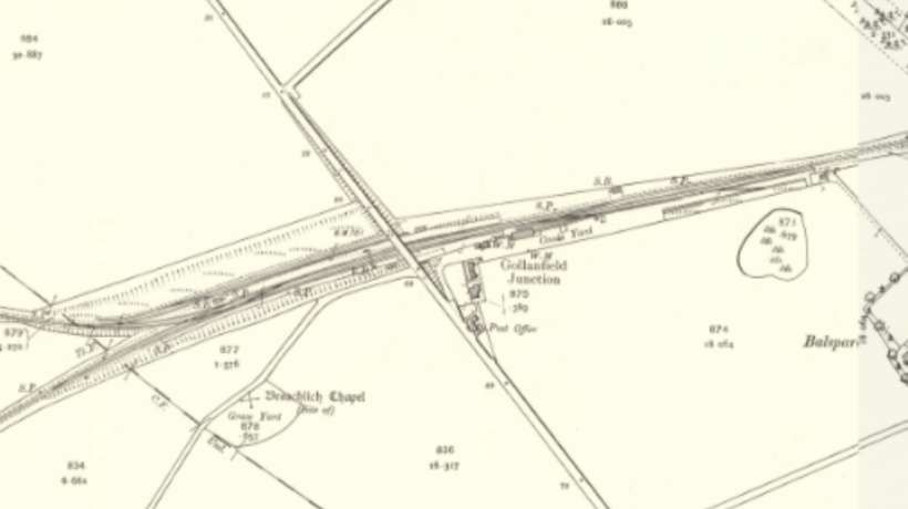
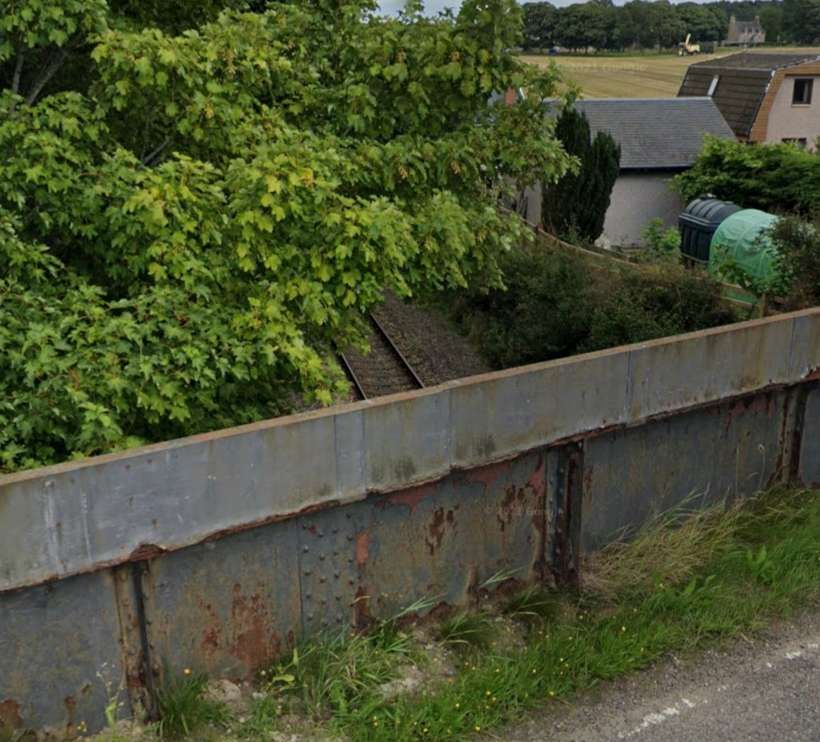
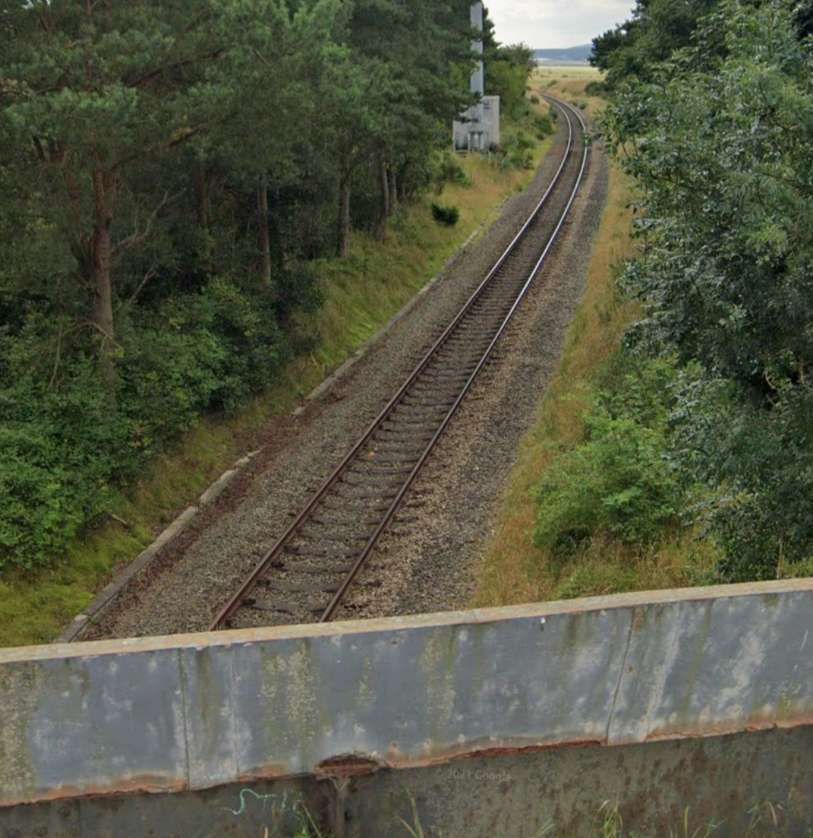
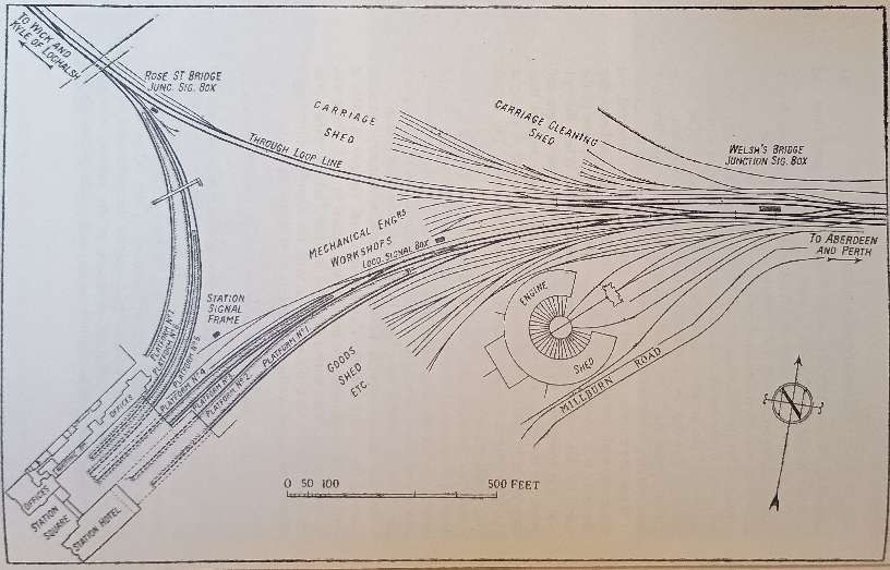
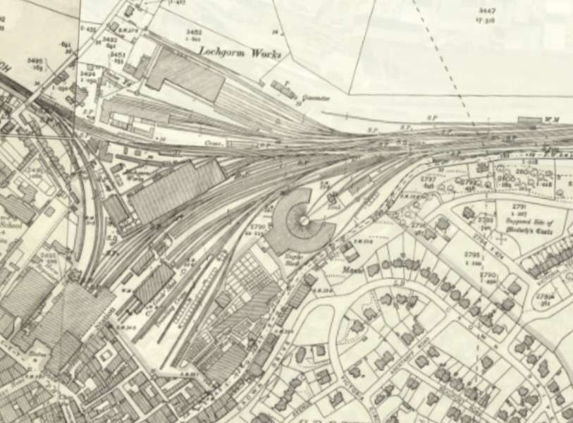
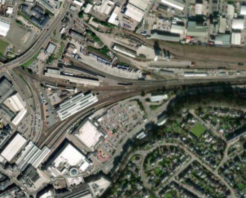
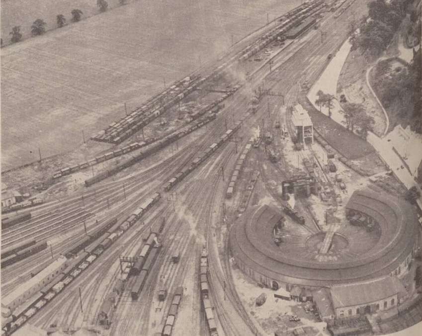
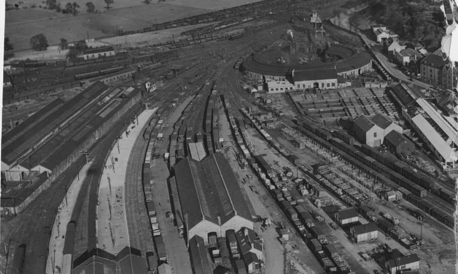
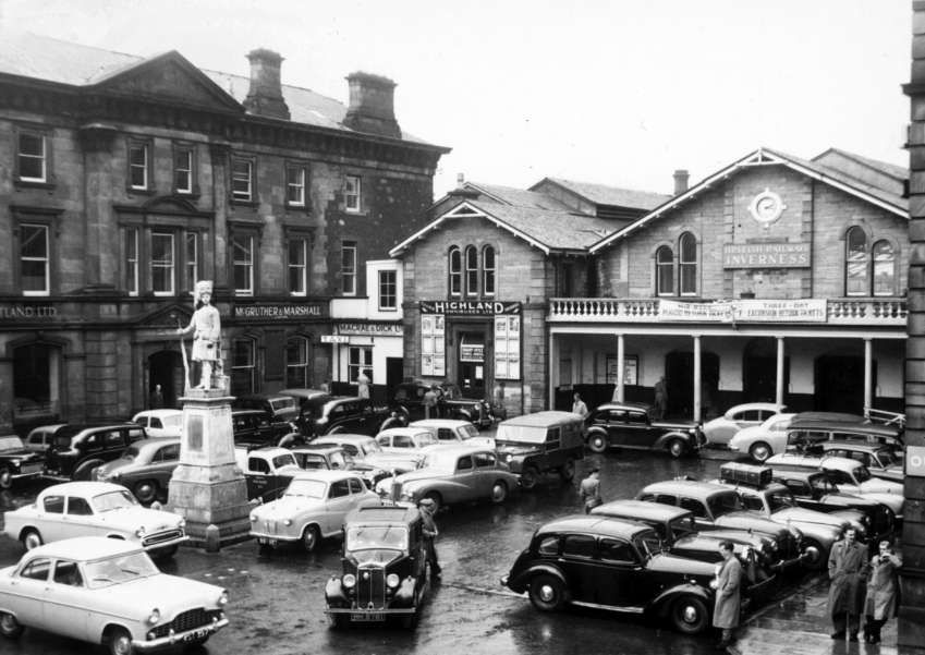


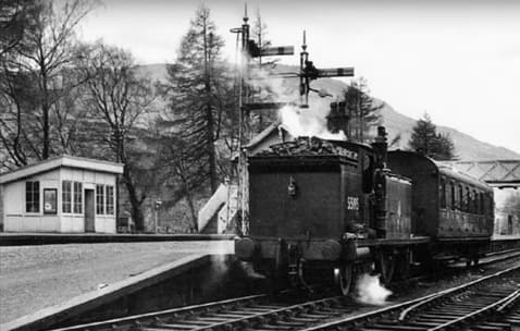
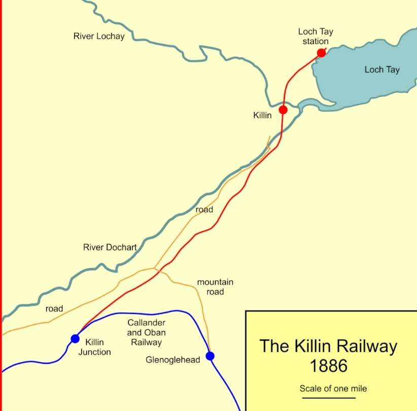
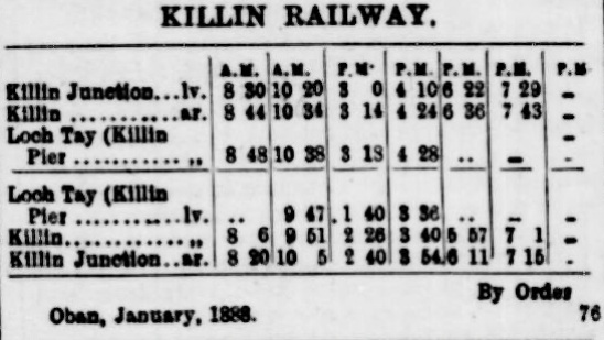
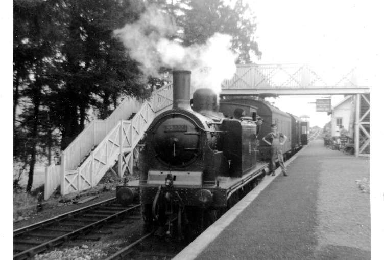
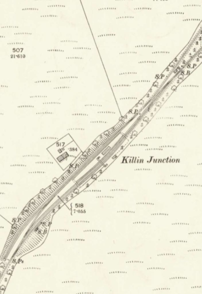
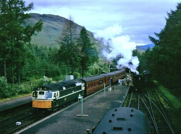
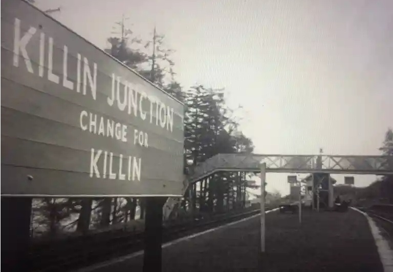
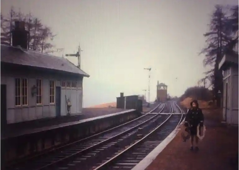
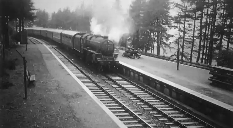
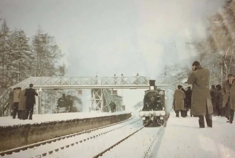
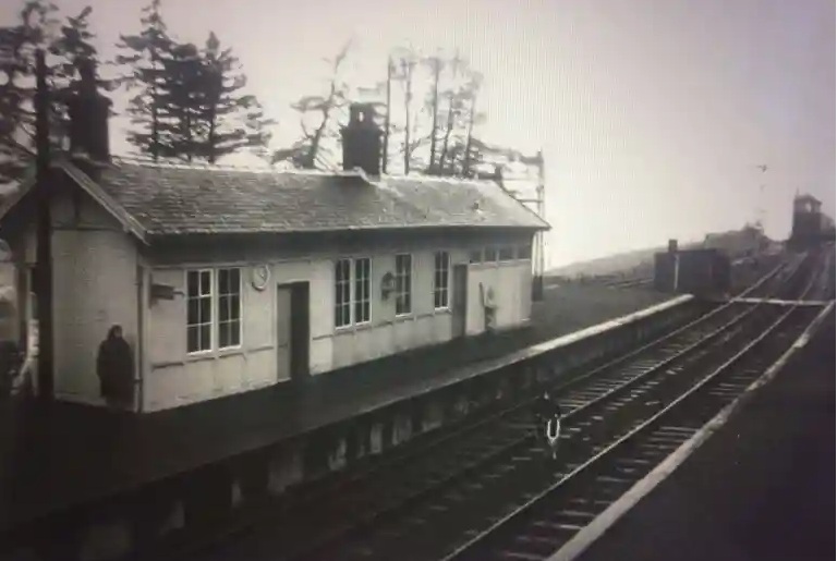
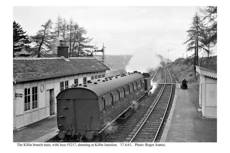
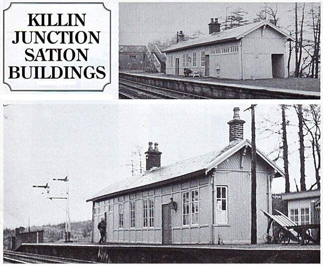
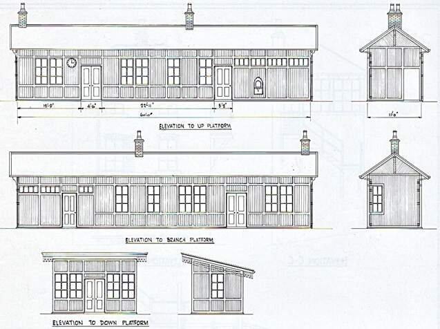

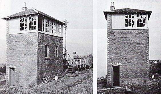
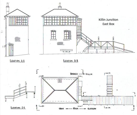
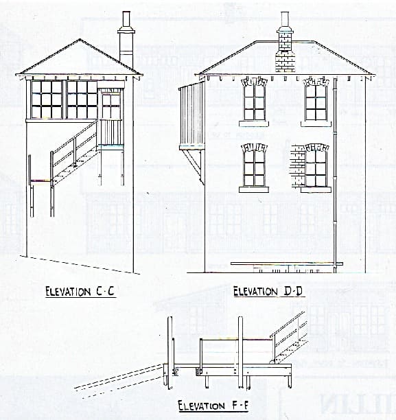
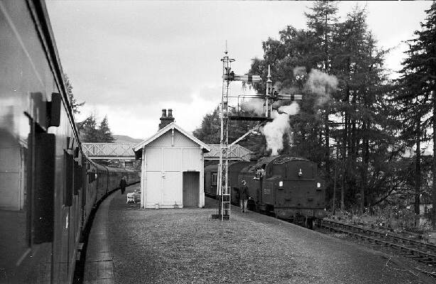

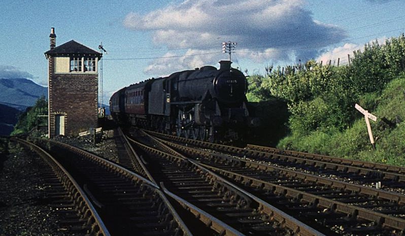


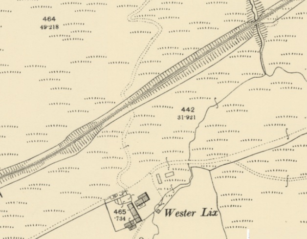

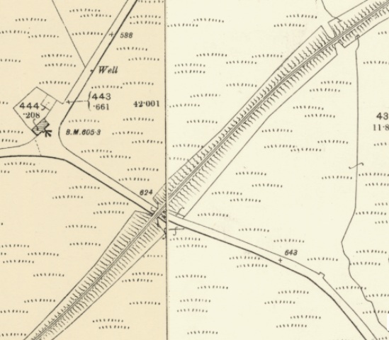
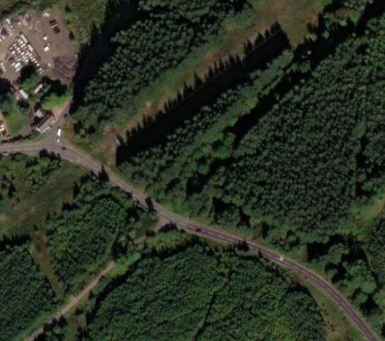


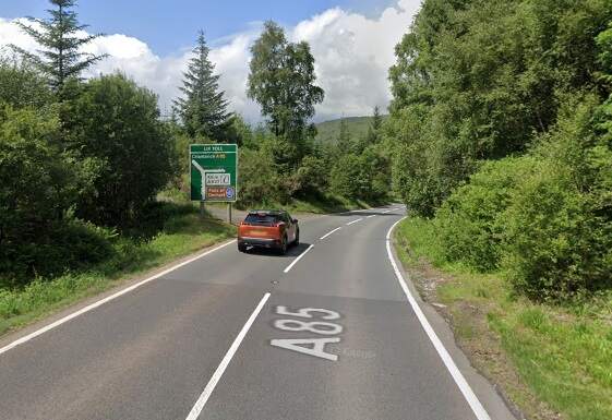
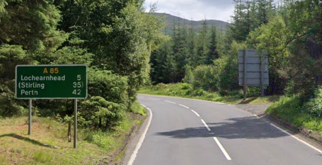
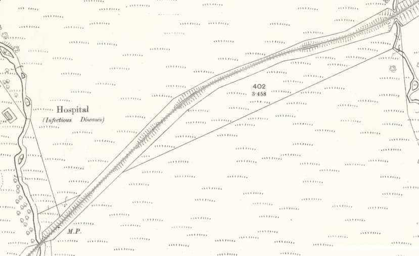

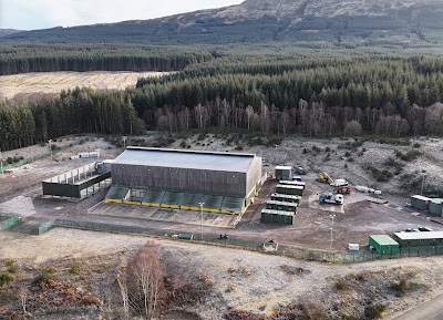
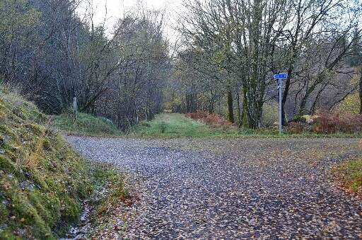
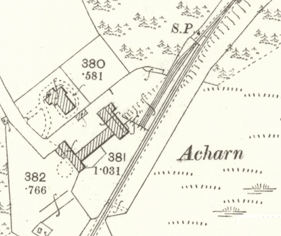
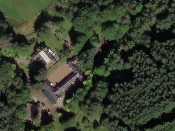
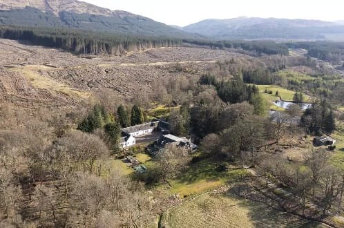

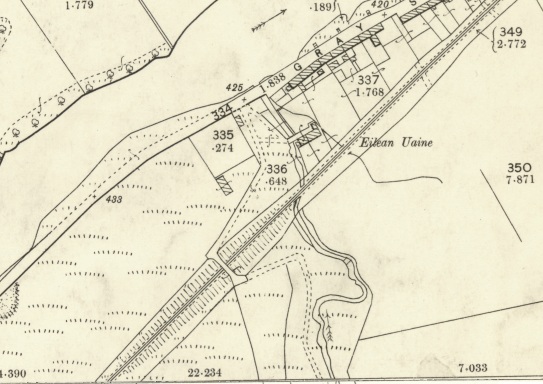
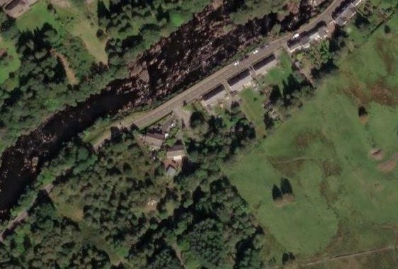
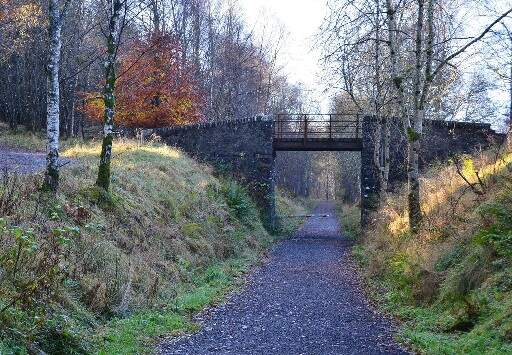
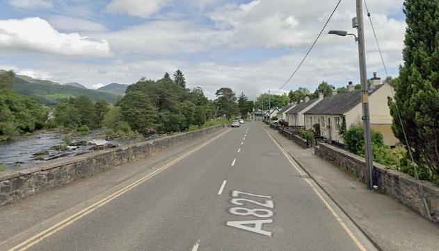
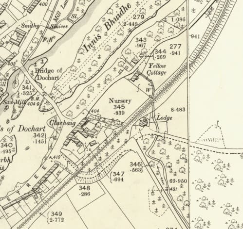
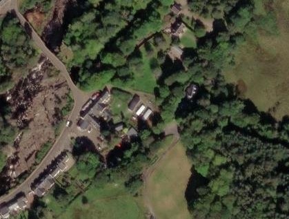
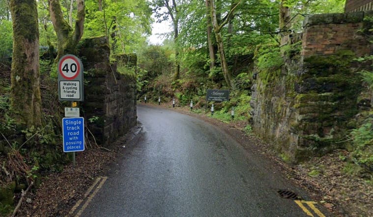
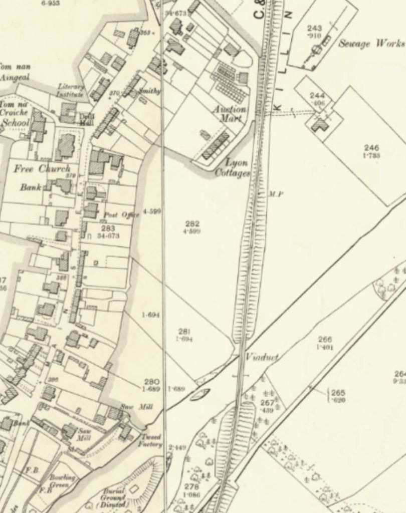
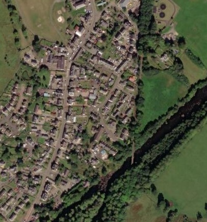
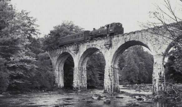
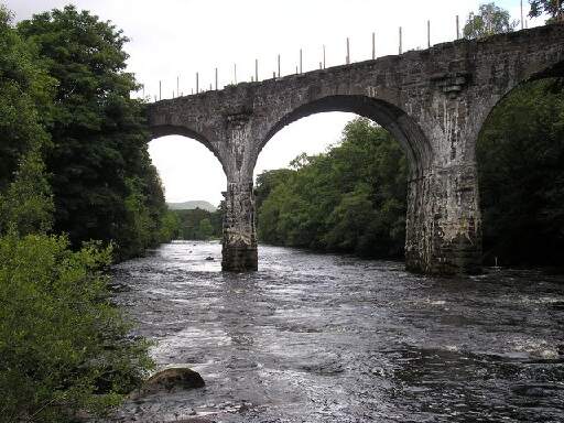
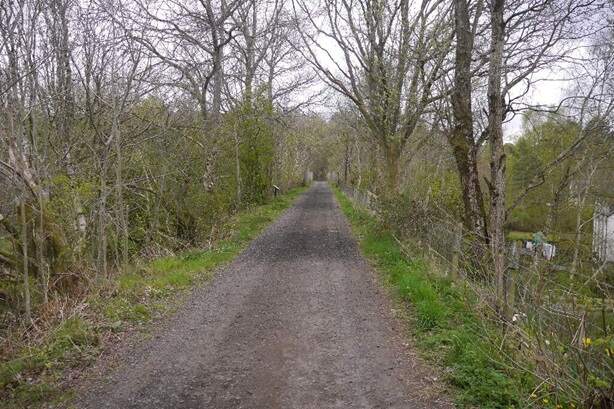
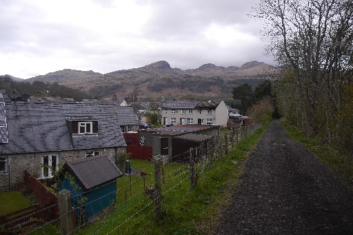
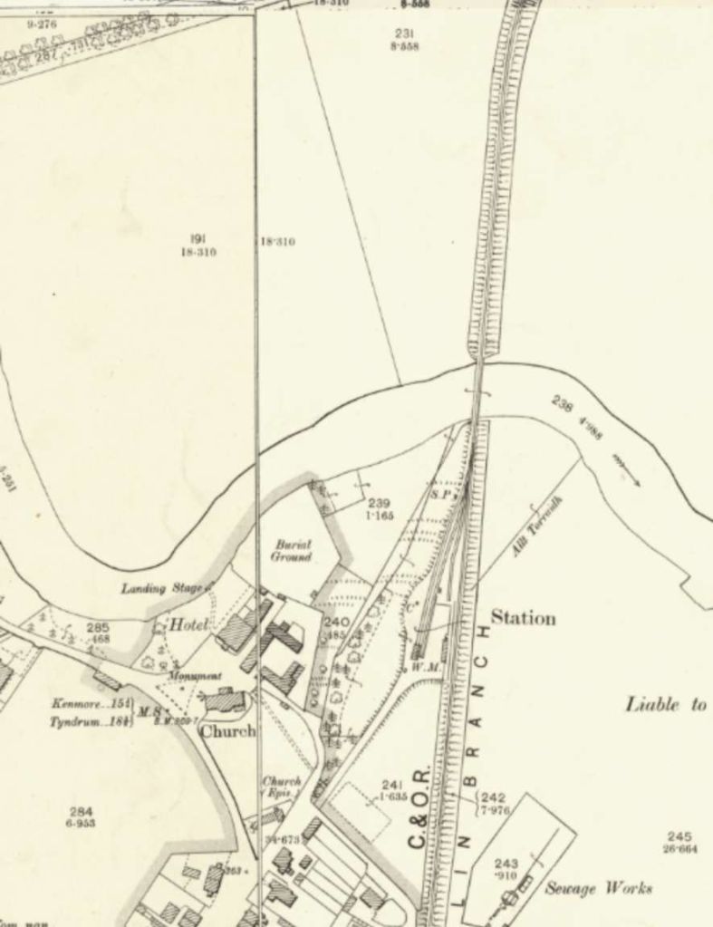
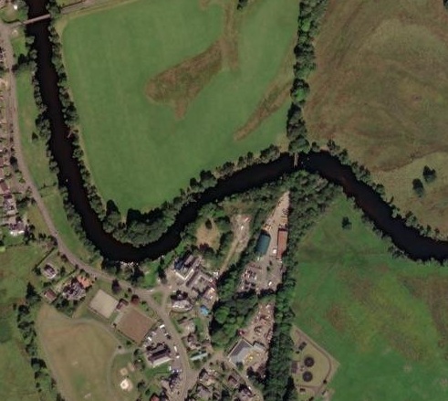
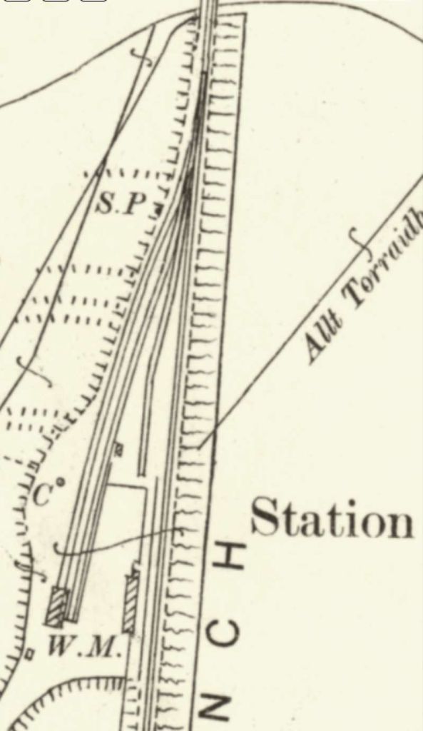
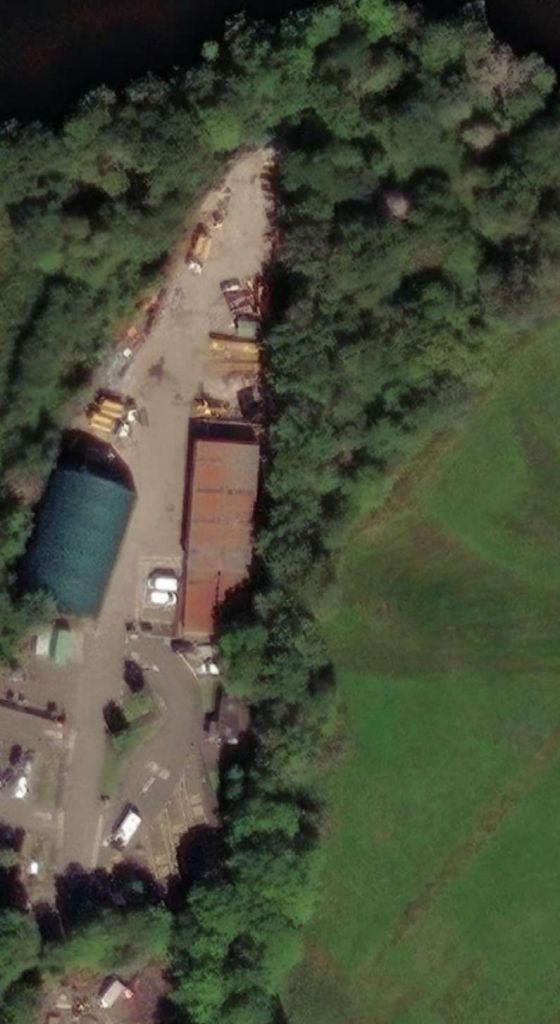
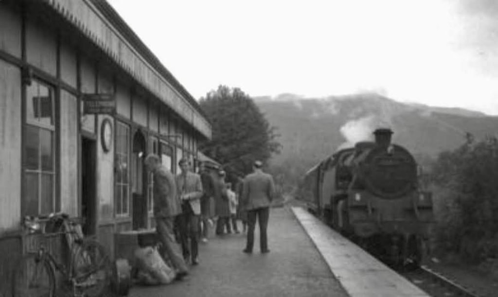
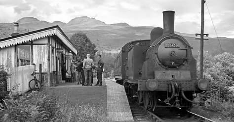
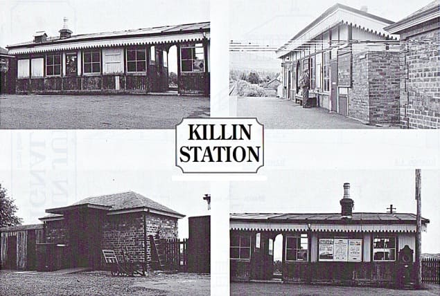


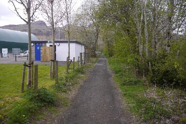

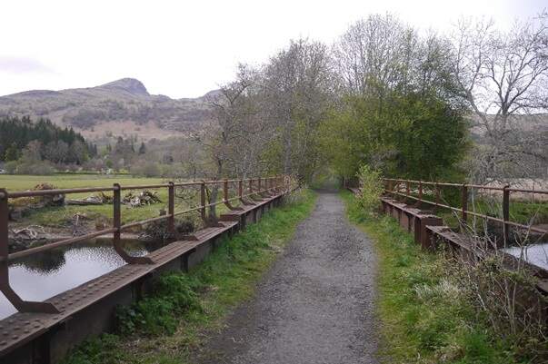
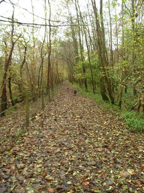
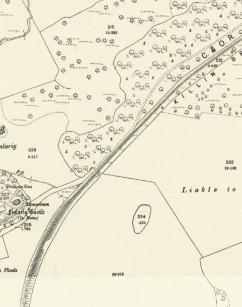


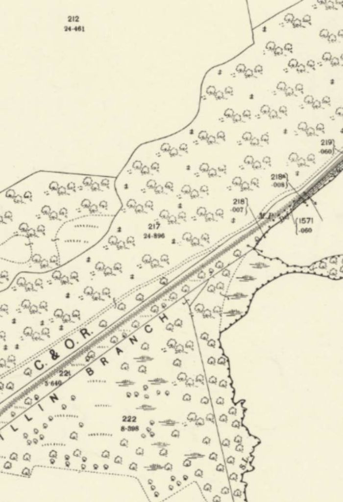

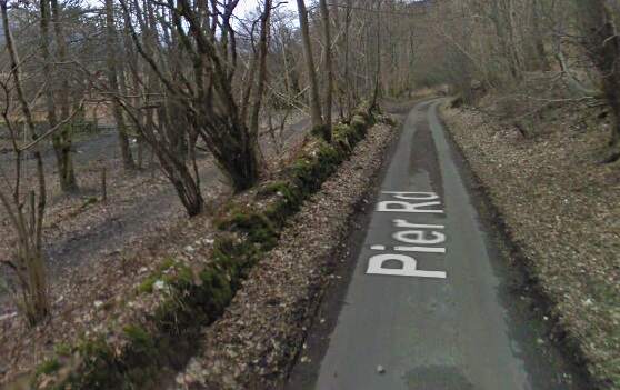
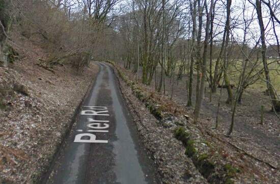
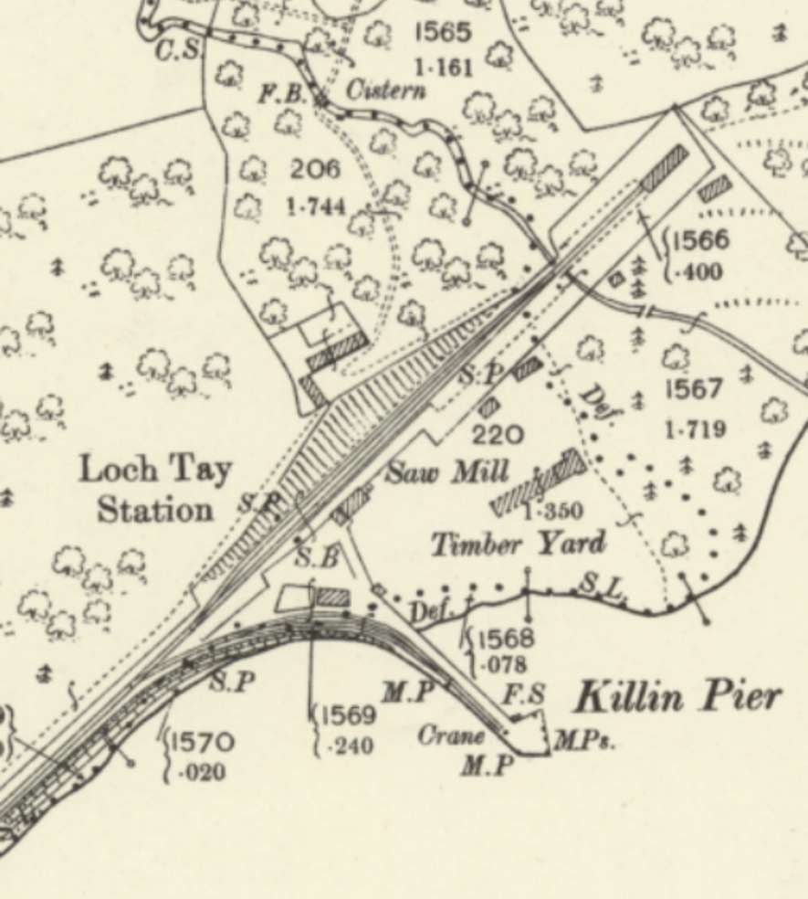

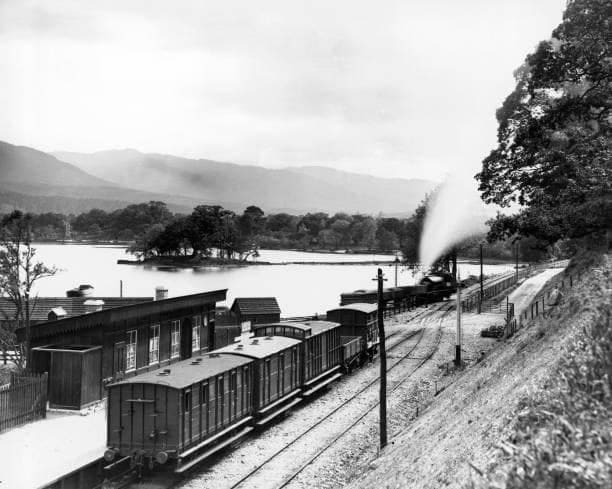
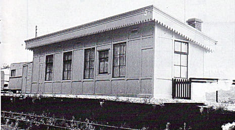
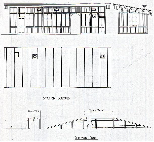
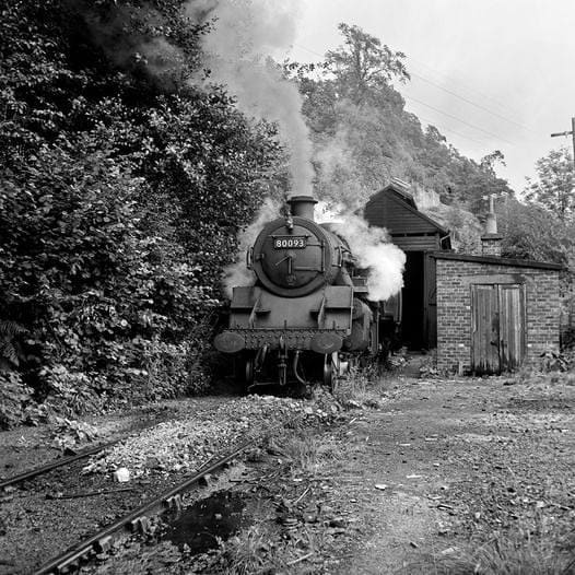
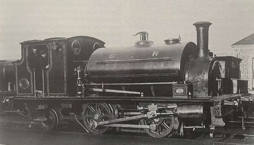
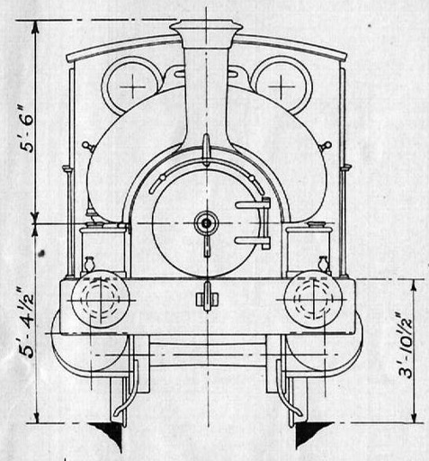
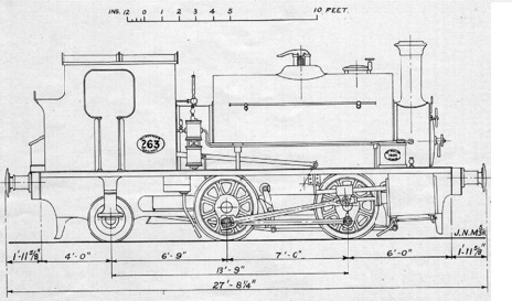
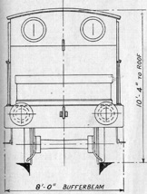
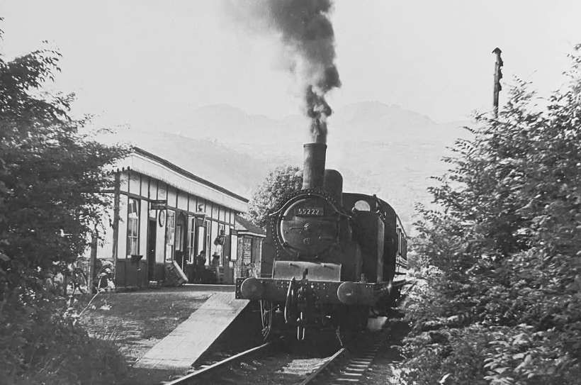
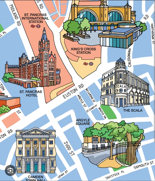
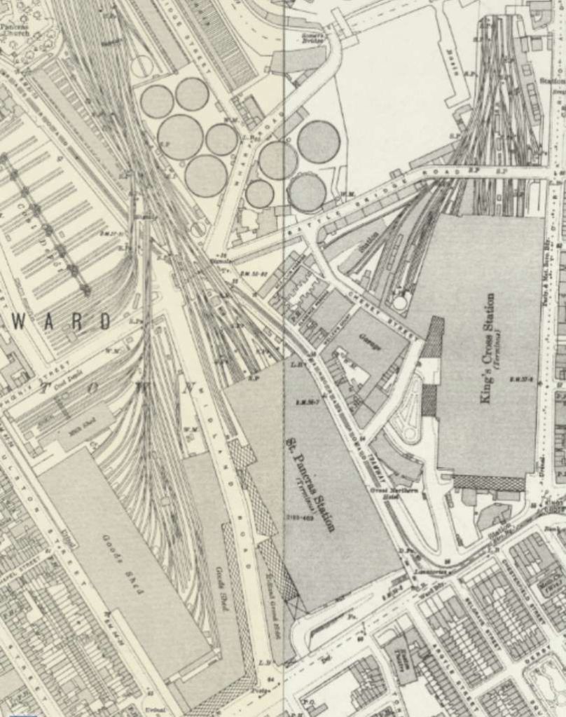
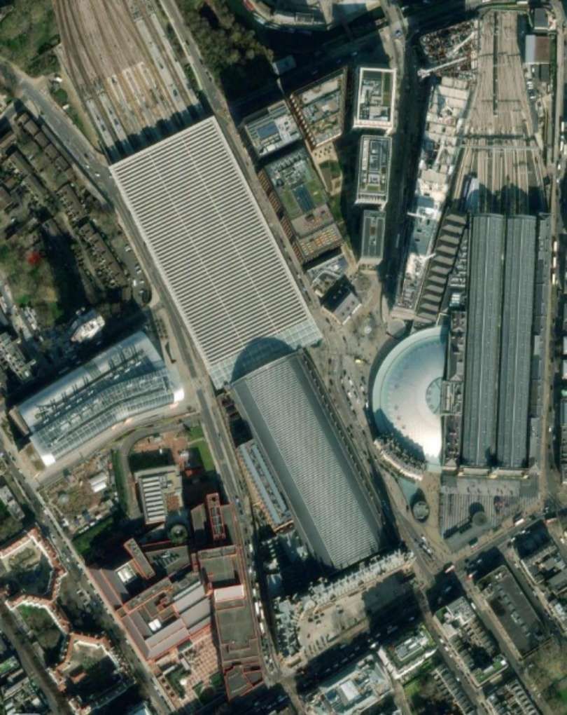
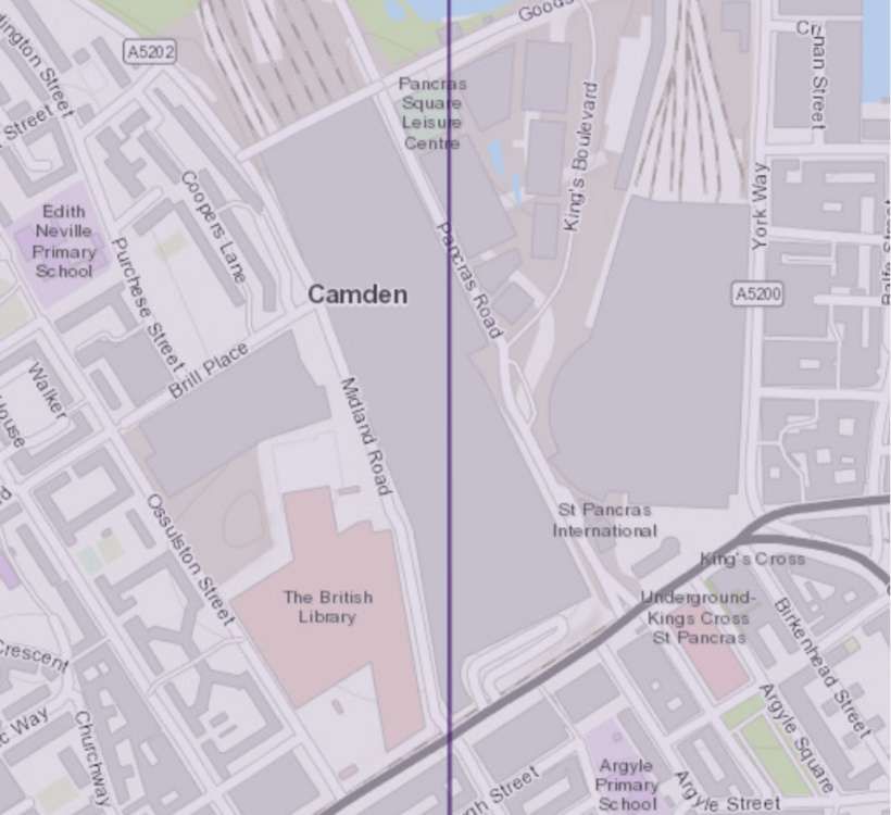
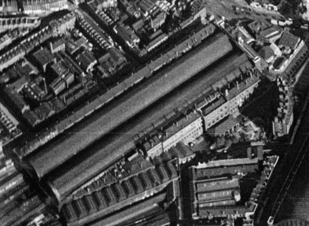
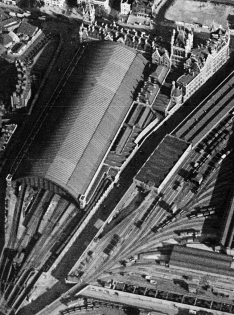
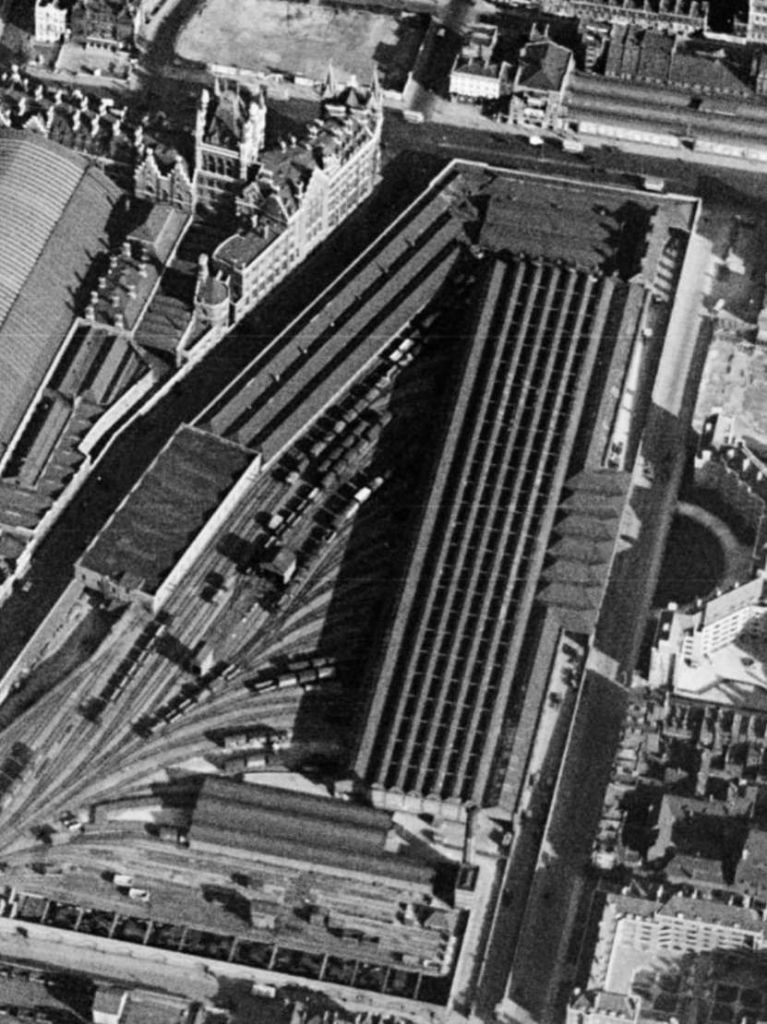
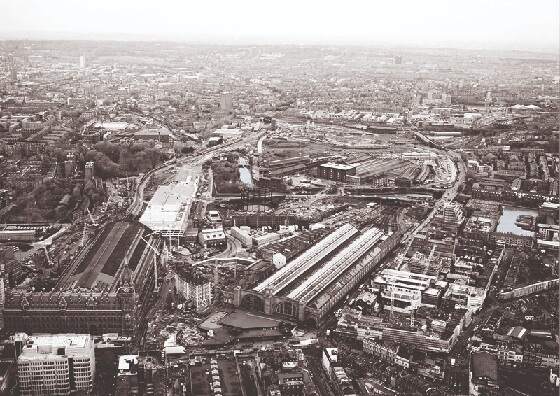
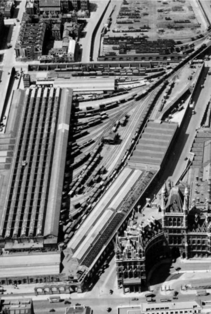
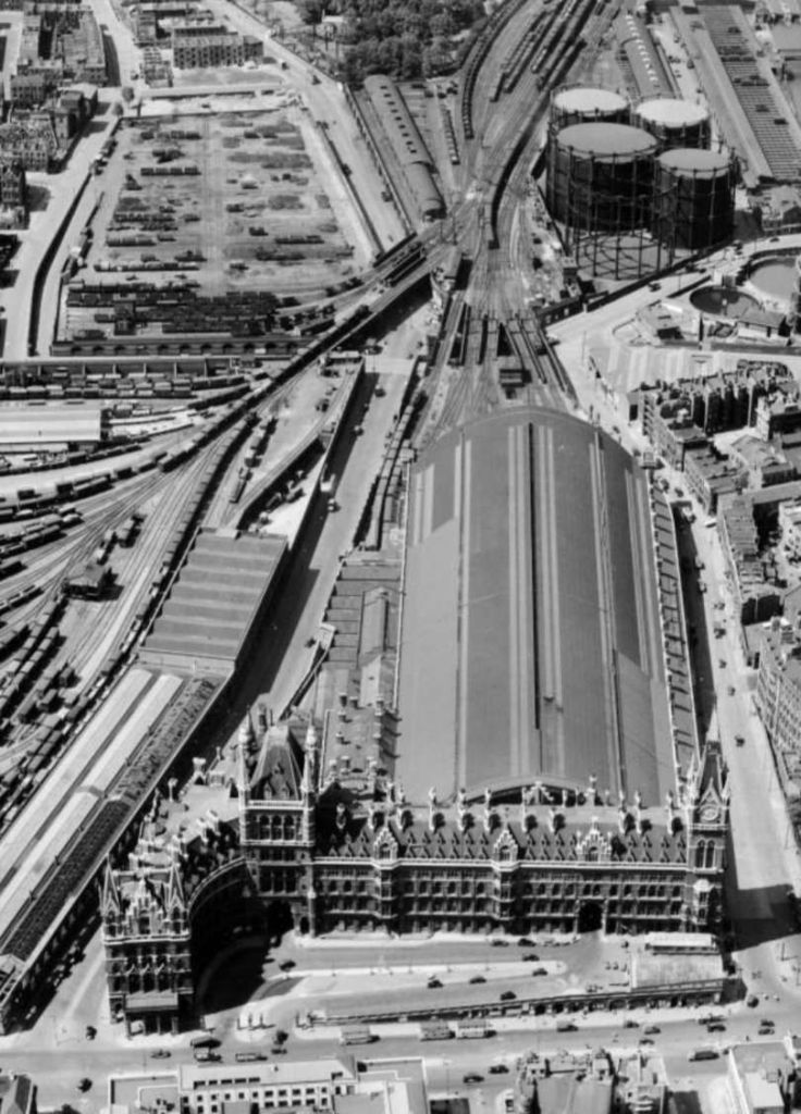
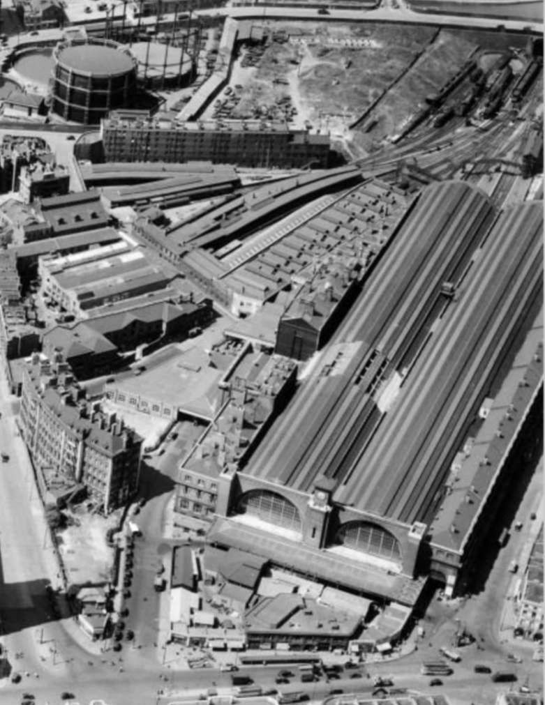
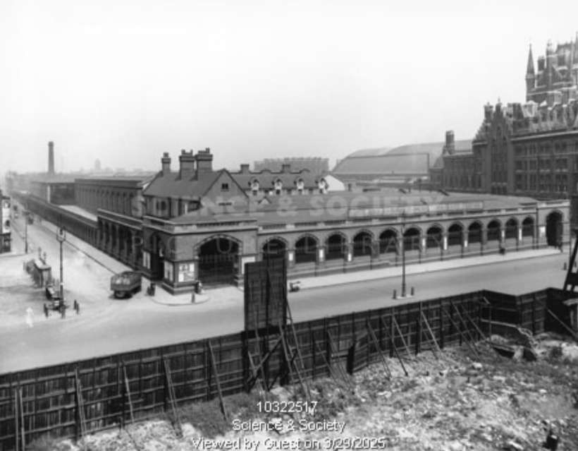
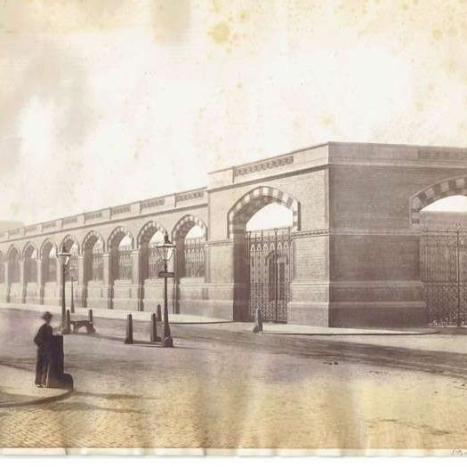
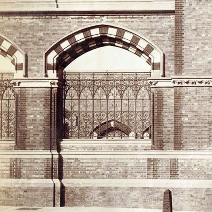
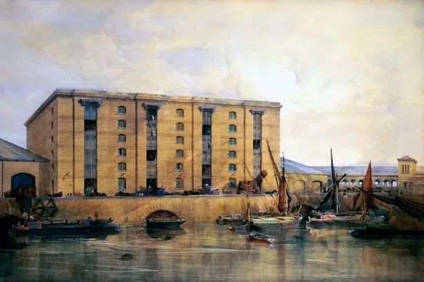
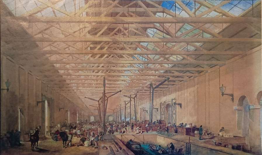

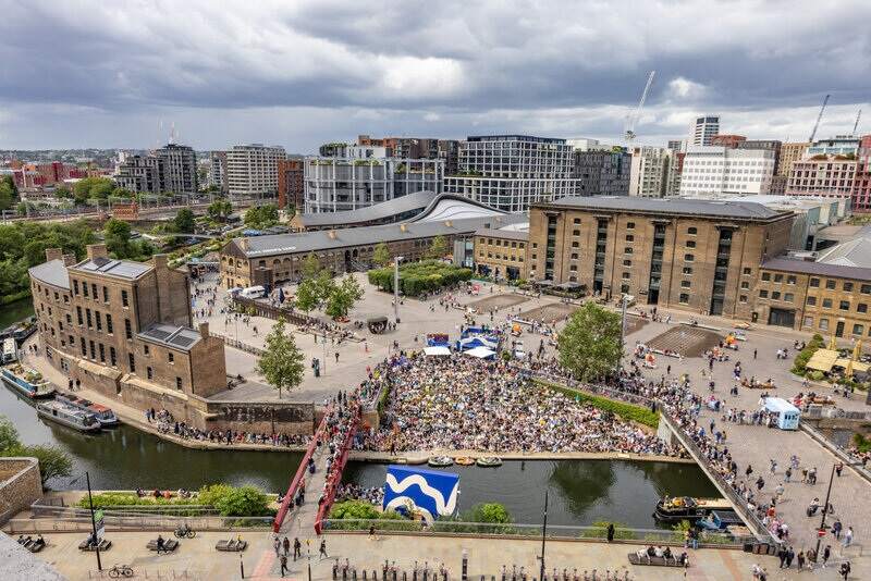
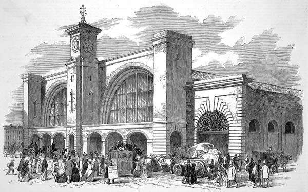
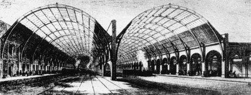
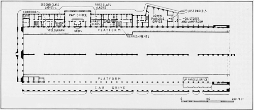
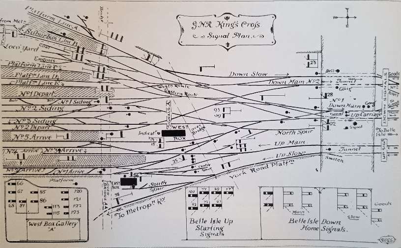
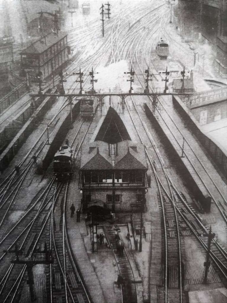
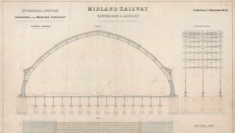
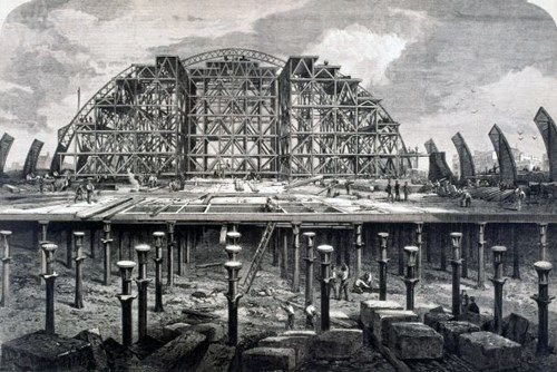
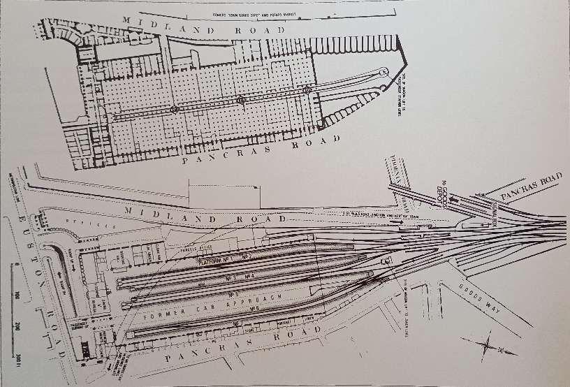
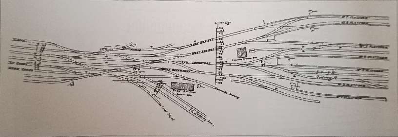
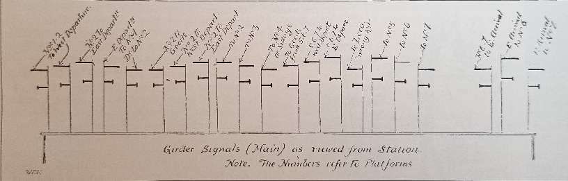
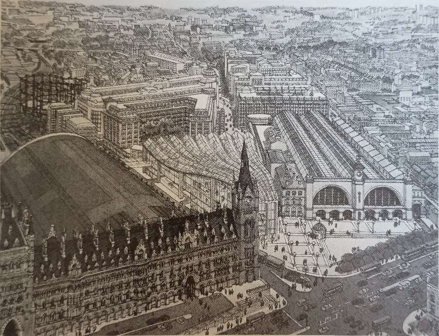
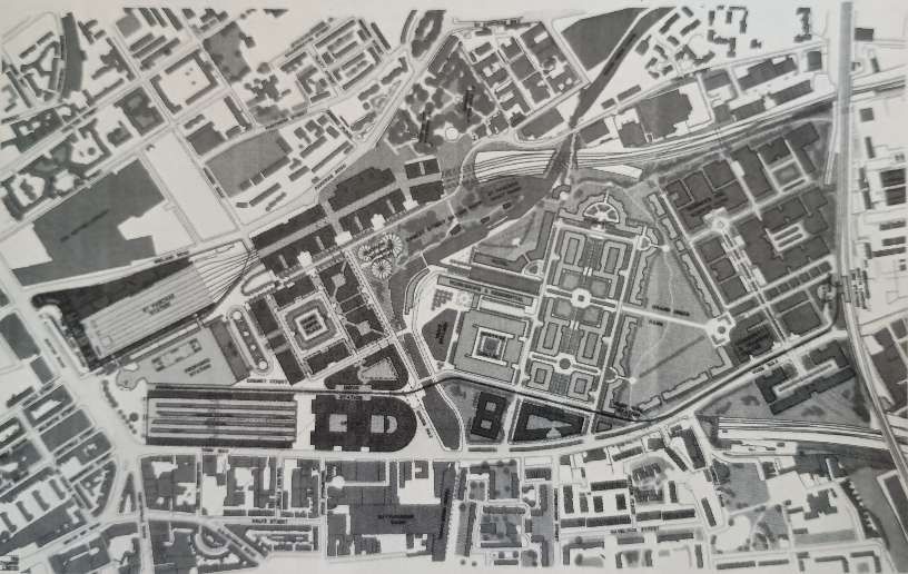
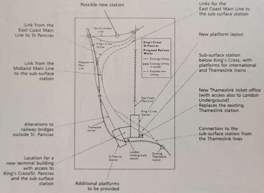
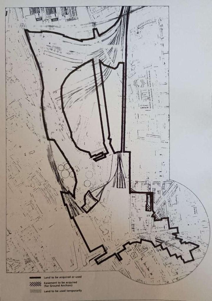
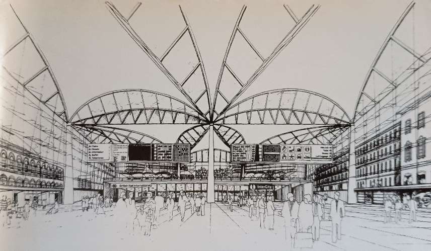
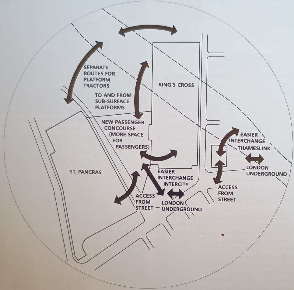
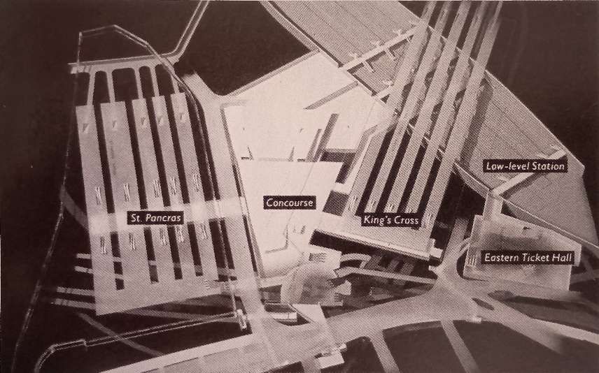
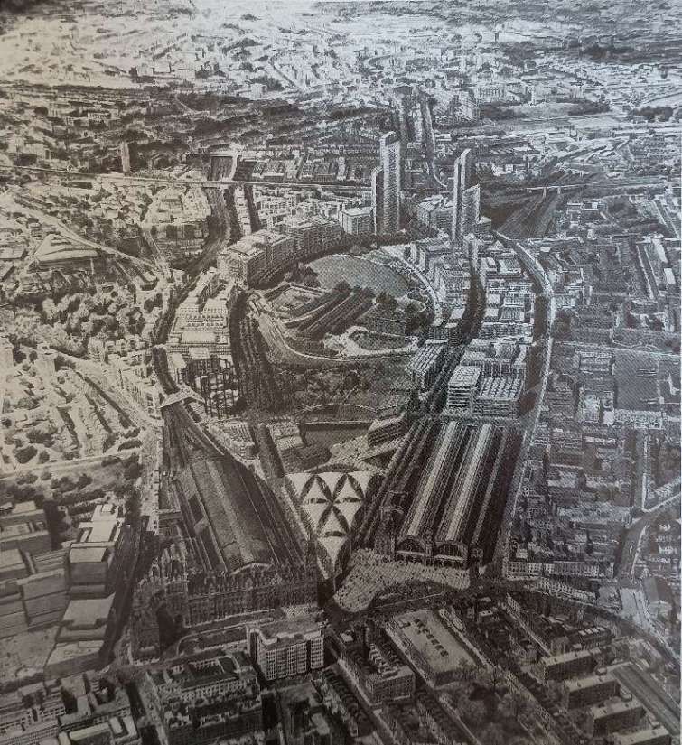
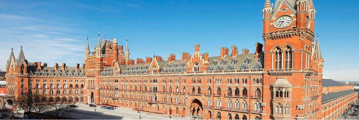
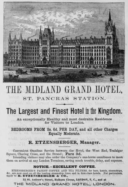
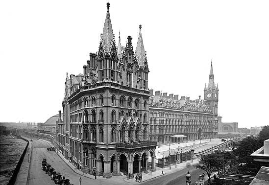
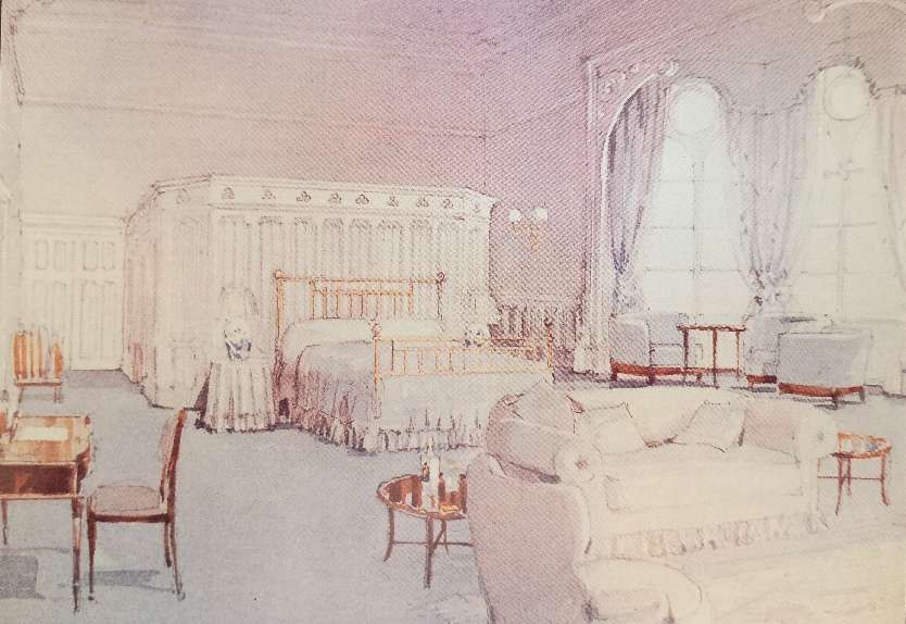
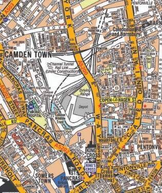
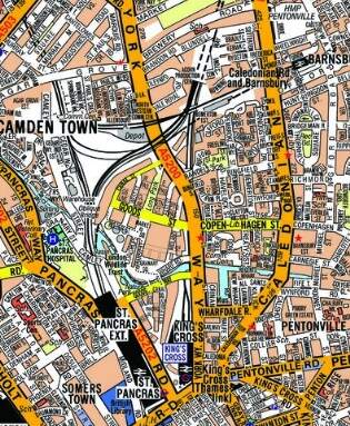
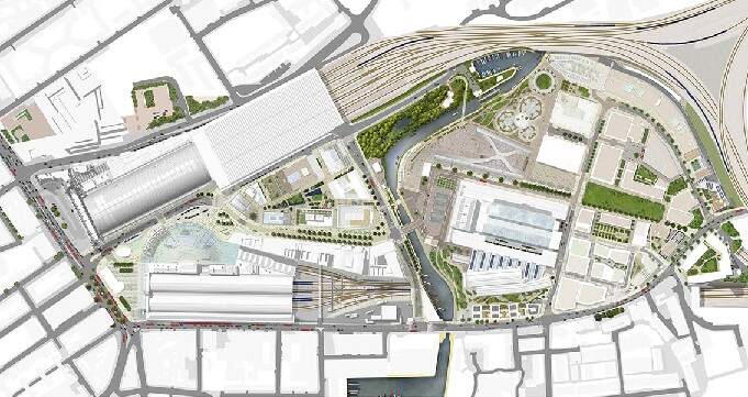
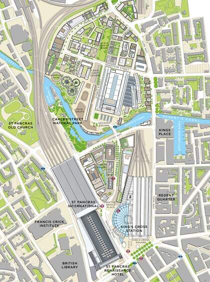

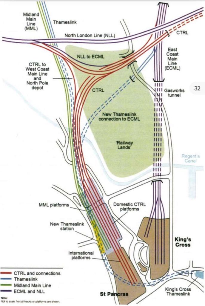
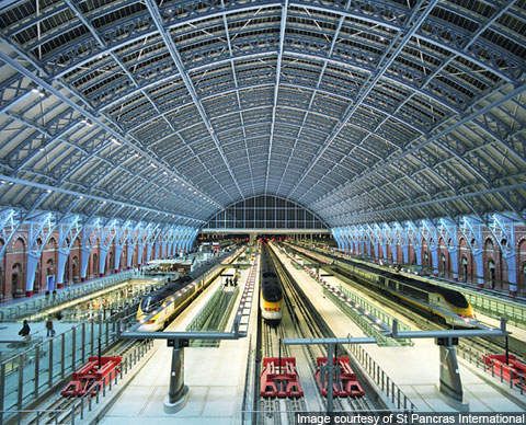
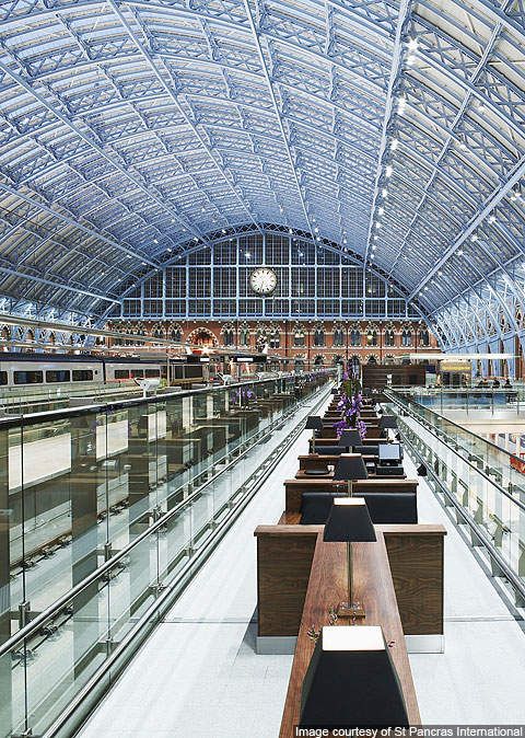
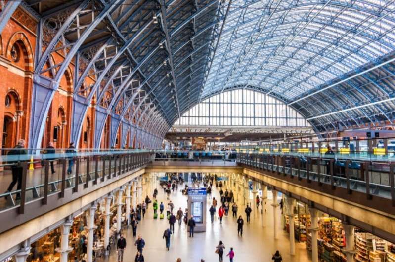


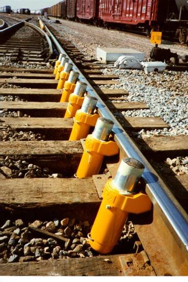
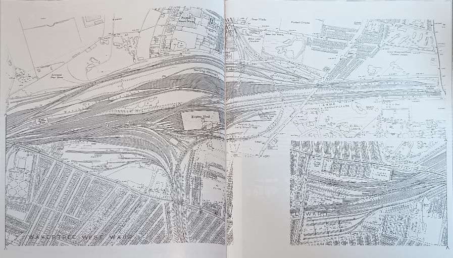
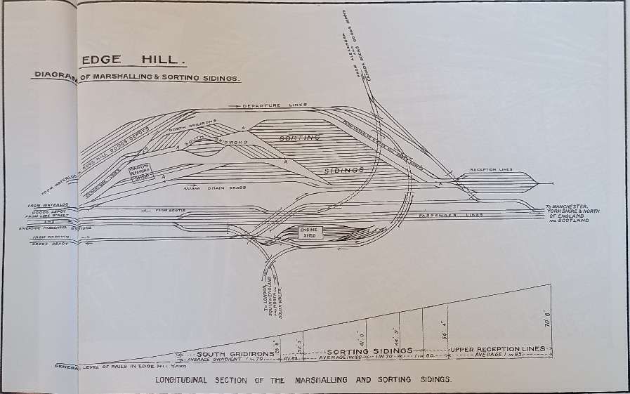

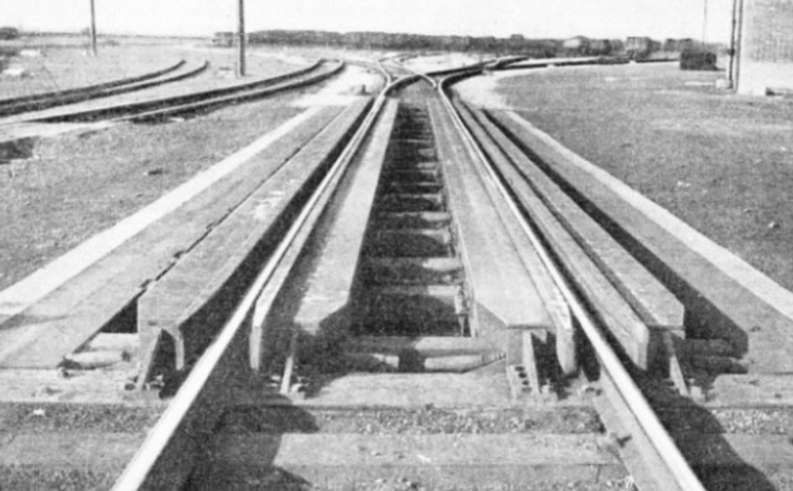
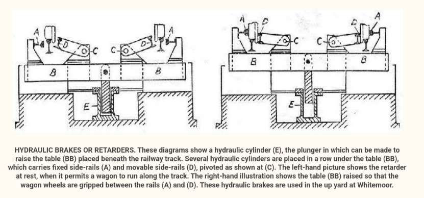
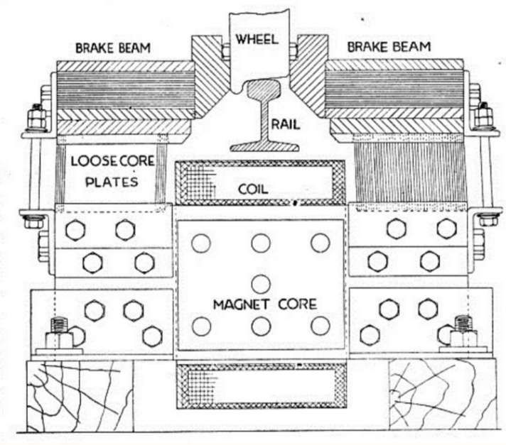
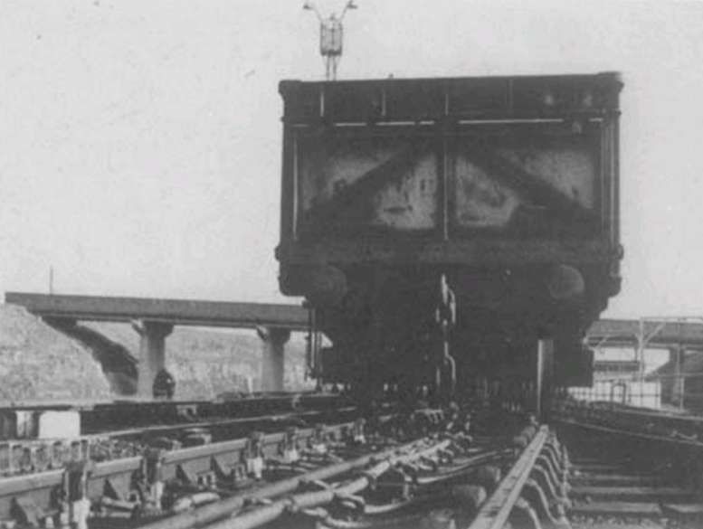
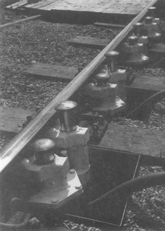
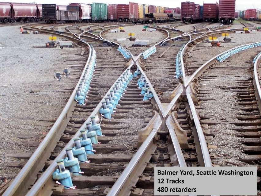


