A proposed tramway that did not get built. … The featured image is a map showing the full length of the proposed line which followed National Route No. 204 in France.
Late in the 19th century before a link from Vievola to the Mediterranean was really on the agenda. Alongside the experimental ‘Train Scotte’, [1: p40][2][3] a “local engineer, M. Chatelanat, proposed building a tramway line between Vievola station … and Ventimiglia. He knew the region well, having just overseen the construction of the rack railway from Monte Carlo to La Turbie. [4] Here is the project he presented in an application filed on 7th February 1899.” … [1: p47]
The submission made by M. Chatelanat began, “The electric tramway for which we are requesting a concession is intended to facilitate the movement of passengers and goods in the Roya Valley through a rapid, convenient, and economical means of communication. Currently, to reach Nice and the other communes of the department, the population of the French part of this valley must either travel more than 60 kilometers along the old Nice-Cuneo road, crossing the foothills of Brouis and Braus, in unsafe conditions due to the steep slopes, the height of the passes, and, in winter, the seasonal inclement weather. Or, since the opening of the national road from Breil to Ventimiglia, travel approximately 30 kilometers and cross two customs lines to join the coastal railway line in Ventimiglia. … Between the coast and Upper Piedmont, especially the province of Cuneo, there is a very intense movement of population every year, but if you want to go by train, you have to make a long detour via Savona, which is long and expensive. The province of Cuneo sends to Nice and the coast some of its products that our region cannot obtain elsewhere. On the other hand, our particular products from the South are in demand and consumed in the upper Po Valley. Facilitating the movement of travelers and this exchange of products between Piedmont and the coast will at the same time allow the French populations of the Roya Valley to come easily and quickly to Nice to stock up and connect with the entire French coast without having to cross the Braus and Brouis passes, such is the goal we are pursuing.” [1: p47]
There were a number of projects of this nature being explored at the time. The tramway between Menton and Sospel is an excellent example. [5][6] Others in the valley of the River Var and in the valley of the River Paillon were also built.
M. Chatelanat continues to explain how up to that time it had not been possible to devise a railway scheme that enable a link between Nice and Cuneo. His proposed tramway was not claimed to be a replacement for the planned railway, but while awaiting the development of the railway scheme, the tramway would “provide great services by greatly reducing the communication difficulties between the two regions. The project [would] not provide the speed of the railway, it [would] require two transshipments at Ventimiglia and Tende. Nevertheless, the transport of goods [would] be significantly more economical and passengers [would] find facilities and comfort there which [would] undoubtedly give the population satisfaction, if not complete, at least acceptable. The electric tramway, executed at a width of 1 metre with gradients of up to 70 mm/m and curves down to 20 metres in radius [could not] be used for the passage of standard-gauge locomotives and wagons, and therefore [could not] be used in the event of war.” [1: p48]
Concern about possible conflict was paramount in the minds of many and projects were vetted and often vetoed by the military. M. Castelanat went on to explain that power for the section of the line would be supplied from a hydraulic plant close to Breil-sur-Roya which could easily be put out of action, and if the overhead cables were also removed no use would be possible. He was sure that no advantage would be gained by a future enemy and that “The tramway must therefore be considered a commercial means of communication with no possibility of use in the event of war.” [1: p49]
Castelanat confirmed that electrical operation would mean no problem would be encountered with gradients up to 7% without the need for any regrading of the highway. He planned stations at Breil, Giandola, Saorge, Fontan, and Berghe. The tramway would use National Road No. 204 without any deviations and would cost around 1,400,000 francs. This tramway would, strictly speaking, be only a section of an international line which would have its origin in Ventimiglia and which would go up the valley of the Roya.
A conference including all the statutory interested parties was arranged for 23rd November 1899. Differing views were expressed about whether the tramway could provide a military advantage to the enemy in the case of war. A few months after the conference, on 2nd May 1900, “Chief Engineer Aubé of the Ponts et Chaussées (Roads and Bridges Department) reached the following conclusions: ‘The establishment of the planned electric tramway has lost much of its appeal since the military authorities ceased, with certain reservations, to oppose the construction of the railway from Nice to Sospel and to the Italian border, near Fontan. This line would, in fact, provide the French population of the Roya Valley with the access to Nice they were willing to seek in an economical manner by means of the tramway connecting them to the international station at Ventimiglia‘.” [1: p50]
The effect of the military’s withdrawal of their opposition to the Nice-Sospel-Fontan line was to render the tramway proposals obsolete. It was 1904 before “an international conference finally approved the construction of the Vievola – Breil – Ventimiglia and Breil – Sospel – Nice railway sections. … [Nevertheless] two tram lines were created[in the area]: one from Menton to Sospel, which operated from 1912 to 1931, [5][6] and a line from Ventimiglia to Bordighera, which operated from 1901 to 1936.” [1: p50]
Instead of the ‘Train Scotte’ and a tramway, from perhaps as early as 1900, but definitely by 1st September 1906, a service connecting with trains was introduced between Vievola station and Ventimiglia. The two images below show the mixture of different vehicles in use. Both focus on the road on the West side of the station building at Vievola.
Banaudo et al provide details of a bus service which started on 1st September 1906. The bus service between Vievola and Ventimiglia provided two buses a day from Vievola to Ventimiglia, the first leaving Vievola at 12:15 and arriving in Ventimiglia at 17:00, the second leaving Vievola at 20:40 and arriving in Ventimiglia at 0:40. The cost of the full journey was 5 lire/person. [1: p52]
The advert in the local paper commented that, “Without making the tedious Bastia-Savona detour, travelers can reach the Nice or western Ligurian coast from Cuneo and nearby towns in just a few hours, take care of their business, and return to their hometowns the same day, if they wish, even finding enough time in Vievola to refuel. Every modern comfort will be available in the station buffet, since, with appropriate consideration, the owner, Mr. Giuseppe Borgogno, has asked the Italian State Railways Administration to expand and repurpose the space for this purpose.” [1: p52]
Banaudo et al share details of services which developed over the next few years with pictures of the various buses in use. [1: p52-56]
Jose Banaudo, Michel Braun and Gerard de Santos; Les Trains du Col de Tende Volume 1: 1858-1928; FACS Patrimoine Ferroviaire, Les Editions du Cabri, 2018.
Société des Chaudières et Voitures à Vapeur système Scotte was a French manufacturer of steam-powered trucks, tractors, and omnibuses in Paris from 1893 to circa. 1914. The company also built the Train Scotte, an early road train for passenger or freight transport. [1]
I first encountered the Train Scotte when reading about the Cuneo-Ventimiglia-Nice international railway line in a book by Jose Banaudo, Michel Braun and Gerard de Santos; Les Trains du Col de Tende Volume 1: 1858-1928. [2] The partial opening of the that railway from Cuneo to Vievola in October 1900 left travellers heading for the Mediterranean in the middle of nowhere!
An experimental steam road train was trialled on the roads from Vievola to Ventimiglia. It was supplied by Société des Chaudières et Voitures à Vapeur système Scotte.
At this time, Vievola was a railway terminal for traffic to and from Piedmont and a hub for road connections onwards to Nice and Liguria. Banaudo et al point us to a magazine published in 1899, which mentions a trial of a steam-powered road vehicle which it was hoped would provide a service to Nice and the coast until such time as a railway was built. [1: p40][37] The service was a trial organised by the House of Ascenso et Cie, and ran from Vievola to Ventimiglia. The journey, lasted a total of six hours, including a 43-kilometre climb. The vehicles used were Scotte trains. The car wagon carried a 27-horsepower engine and seated 16 passengers; it also towed a second 24-seater wagon. [2: p40]
Industrialist Joanny Scotte, [10] originally from Epernay in the Marne department, began his business in the mid-1880s producing steam-powered cars. From 1897, he offered road trains consisting of a tractor or a steam-powered car, pulling one or more trailers designed for the transport of passengers or goods. These vehicles travelled on roads using solid tires. They never really went beyond the experimental stage due to their slowness, the difficulties of driving the vehicles on the narrow roads of the time and the damage caused to the cobbled and cylindered roads. [2: p40] Scotte road train services were reported in the last decade of the 19th century in the Île-de-France region (Fontainebleau, Pont-de-Neuilly, Courbevoie), in the Aube region (Arcis-sur-Aube – Brienne-le-Château), in the Manche region (Pont-l’Abbé-Picauville – Chef-du-Pont), in the Drôme region (Valence – Crest), and for military use. Scotte partnered with the Lyon-based car manufacturers Buire and Audibert-Lavirotte to produce some of its vehicles. [2: p41]
1. A power car (steam omnibus) capable of carrying fourteen passengers and the two engine crew; Weight of the empty car with all equipment: Motor: approximately 3,500 kg; Total length: 5m 20 cm; Width at the waist: 1 m 80 cm; and
The wikipedia webpage relating to the ‘Train Scotte’ provides a series of photographs and drawings of the company’s products, including one advertising poster. All are in the public domain and are shown below:
The tractor was equipped with a vertical Field system boiler, 600 litres of water for which were stored under the passenger seats, and a 14 horsepower, 2-cylinder engine. Coke or coal was its fuel (200 kg for 4 hours of operation). The movement was transmitted to the rear axle by a chain. The trailer was coupled to the tractor by a pivoting front axle. To stop, the steam omnibus had a quick brake operated by a pedal, a screw brake operated by a flywheel and, in an emergency, could work on the gear change. Steering was provided by a steering wheel. [9]
The Train Scotte train ran on wooden spoked wheels with iron tires. The seats were also made of wood, passengers needed to bring a cushion. The machine was quite noisy. It could be heard coming from afar and some houses shook as it passed. Its speed wasn’t very high, 12 to 15 km/h, so there was time to admire the scenery.
When carrying only goods, up to 5 to 6 tons, its speed was reduced to 6 to 7 km/h.
The experiment failed. The attempt to use the ‘Train Scotte’ between Vievola and Ventimiglia was abandoned quite quickly, probably no more than a few weeks after it commenced: driving was difficult, damage to road surfaces occurred, the road gradients were steep. [2: p41]
Elsewhere, experimental journeys had mixed success. Steam road vehicles were slow and they faced serious competition from similar vehicles with internal combustion engines. For a very short time around the turn of the 20th century, these vehicles seemed to have a future but ultimately the experiment failed!
Jose Banaudo, Michel Braun and Gerard de Santos; Les Trains du Col de Tende Volume 1: 1858-1928; FACS Patrimoine Ferroviaire, Les Editions du Cabri, 2018.
What is France Doing: Fully Illustrated Account of Trails Now in Progress; in Commercial Motor; August 1905, p8-15. The report seems to relate, at least in part, to trials in 1897.
Contrary to what one might think, the name Scotte is not of English origin, but entirely French. Mr. Scotte was previously called Mr. Crotte. Tired of the dubious jokes, he had an S added before the C, then removed the R from the patronymic spelling of his name. [9]
In the first article about the line from Cuneo to the sea we covered the length from Cuneo to Vernante. The article can be found here. [9]
The Line South from Vernante to Limone
A schematic drawing showing the main locations on the line from Vernante to Limone. [17]
Banaudo et al write that “It was only in 1886, after the creation of the Rete Mediterranea, that the work on the fourth tranche from Vernante to Limone was awarded. It was 8,831 m long and had a gradient of 203 m, which was to be compensated for by a continuous ramp of up to 26 mm/m. This value would not be exceeded at any other point on the line. On this section, the rail remained constantly on a ledge on the steep slope on the right bank of the Vermenagna, where it was anchored by eleven bridges and viaducts totaling sixty-three masonry arches, as well as nine tunnels with a combined length of 4,416 m, or just over half the route:” [1: p28]
the Tetti-Chiesa tunnel which is 122 m long;
the Elicoidale tunnel (the Vernante Spiral tunnel) is 1,502 m long;
the Rivoira viaduct has fourteen 15 m arches and one 23 m arch;
the Rivoira tunnel is 251 m long;
the Santa Lucia viaduct has three 12 m arches;
a short span masonry arch over a minor road;
the Santa Lucia-Noceto tunnel is 348 m long with two openings;
the Noceto viaduct has six 8 m arches;
the Marino viaduct has two 8 m arches and two 12.50 m arches;
the Marino tunnel is 202 m long;
the Mezzavia viaduct, three 11 m arches;
the Mezzavia tunnel is 444 m long;
the bridge over the Ceresole valley has two 10 m arches;
the Boglia tunnel is 1,086 m long;
the San Bernardo viaduct over the Sottana valley has two 6 m arches and three 10 m arches;
the Cresta-Molino tunnel is 335 m long;
the Boschiera viaduct has twelve 10 m arches;
the Rocciaia tunnel is 126 m long;
the Rocciaia bridge is a single arch;
the first Rocciaia viaduct has four 8 m arches;
the second Rocciaia viaduct has eight 8 m arches.
We start this next length of the journey at Vernante Railway Station and head Southeast.
A plan of Vernante Railway Station. [10]Vernante Railway Station: the route to Limone leaves at the bottom-right of this image. [Google Streetview, July 2025]The view Southeast from the station car park, after demolition of the old goods shed. The main station building features at the centre of the image. [Google Streetview, June 2025]The main station building at Vernante seen from the West. [Google Streetview, June 2025]
Photographs showing the station building and the goods shed prior to its demolition can be seen here. [58] “Inaugurated in 1889, the station served as the terminus for the Cuneo-Ventimiglia line for nearly two years, until it was extended to Limone Piemonte. The passenger building features classic Italian architecture, with two levels. It is square, medium-sized, and well-maintained. Its distinctive feature is the two murals depicting scenes from the Pinocchio fairy tale, adorning its façade. The lower level houses the waiting room and self-service ticket machine, while the upper level is closed.” [58]
A photograph from the cab of a Cuneo-bound train arriving at Vernante. The passenger building is on the left with the goods shed beyond. [8]
The view from Via Frederi Mistral which passes over the tunnel mouth at the Southeast end of Vernante Railway Station. [Google Streetview, June 2025]
The very short tunnel (Tette-Chiesa, 122 metres in length) at the Southeast end of Vernante Railway Station. [Google Maps, July 2025]
The southern portal of the Tette-Chiesa Tunnel seen from a Cuneo-bound train. Immediately beyond the far portal trains would have to stop to manually engage a point for the running line or the train would end up on the safety siding provided for runaways on the steep downward gradient. [8]
The large retaining wall on the left of this image supports the railway as it runs immediately adjacent to the E74/SS20 but at a higher level. [Google Streetview, June 2025]The height of the retaining wall decreases as the E74/SS20 gains height. [Google Streetview, June 2025]
Banaudo et al comment: “Leaving Vernante, the track describes a complete spiral loop at Rivoira, which allows it to rise about fifty metres over a circular length of two kilometres. This loop includes the 1,502 m long ‘Elicoidale’ tunnel, which was completed on 30th December 1889, and the imposing viaduct over the Salet torrent. With its fifteen arches, from the top of which the rail dominates the lower level of the loop by 45 m, this structure can be considered by its proportions as the most imposing of the whole of line. [25] It is built entirely of cut stone, with the exception of the intrados of the arches which are of brick, and its seven central arches are reinforced at their base by a series of arcades forming an additional level, following a technique very popular in the 19th century.” [1: p30] The lower arcades are seen clearly in the 1929 postcard below.
This photograph is taken from the road at the point that the E74/SS20 begins to turn away from the lower railway (which can be glimpsed through the undergrowth) the viaduct high above both the road and the railway comes into view. This view looks North from the E74/SS20. A spiral tunnel allows the railway to gain height at this location. [Google Streetview, June 2025]This satellite image shows the portals of the Spiral tunnel to the East of Vernante. The line leaves Vernante Station and passes through a short tunnel before running alongside the E74 ‘Corso Torino’ to another tunnel mouth to the West of the side road. The line then climbs as it circles under that road twice and reappears high above the first length of line towards the top-left of this image. The height gained then means that the line needs to pass over a high viaduct before once again entering a tunnel (the Rivoira Tunnel) and then, at the bottom-right of the image, crossing another side valley on a bridge. [Google Maps, July 2025]OpenStreetMap shows the same location and illustrates the spiral tunnel quite well. [44]The lower portal of the spiral tunnel with the high viaduct (Rivoira Viaduct) visible to the left. [11]
The portal of the spiral tunnel at the top-left of the satellite image above, seen from a Cuneo,-bound train. Trains heading for Tende and beyond gained height while turning through 360 from the tunnel portal shown in the image immediately above. [8]
The Southeast portal of the short tunnel at the bottom-right of the satellite image above. This is the Rivoira Tunnel. [8]
The Santa Lucia viaduct just to the Southwest of Rivoira Tunnel. [8]
Between the Rivoira Tunnel and the Santa Lucia & Noceto Tunnel, the line crosses a minor road serving a few small hamlets. [Google Streetview,
The Santa Lucia & Noceto Tunnel runs diagonally across this extract from Google’s satellite imagery. [Google Maps, July 2025]
The Southeast Portal of the Santa Lucia & Noceto Tunnel seen from the cab of a Cuneo-bound train. [8]
The Noceto Viaduct to the Southeast of the Santa Lucia & Noceto Tunnel spans a local stream. [8]
This bridge is a short distance further Southeast. [8]
The Marino Viaduct further to the Southeast. All these views look towards Vernante and are taken from the cab o a Cuneo-bound train. [8]
The Southeast portal of the Marino Tunnel. [8]
Another viaduct over a short side valley to the Southeast of the Marino Tunnel, this is known as the Mezzavia Viaduct. [8]
The East portal of the Mezzavia Tunnel. [8]
Immediately to the East of the Mezzavia Tunnel the line bridges a stream before entering the Boglia Tunnel. The bridge spans the Ceresole valley. [8]
The view of the line looking West from Frazione Ceresole, above the West portal of the Boglia Tunnel. [Google Streetview, June 2025]
The Boglia Tunnel carries the line around a significant curve. This is the South-southwest portal of the tunnel from the cab of a train which has recently left Limone. Trains from Cuneo enter the tunnel traveling East and leave in a south-southwesterly direction. Just beyond the South-southwest portal the line bridges another side road serving a number of hamlets. It is the San Bernardo viaduct over the Sottana valley. [8]
The bridge shown in the image immediately above is at the centre of this satellite image. The tunnel to the North-northeast is Boglia Tunnel, that to the South-southwest is Cresta Molino Tunnel. [Google Maps, July 2025]
Looking East along the Sottana Valley, it is difficult to believe that the San Bernardo Viaduct has two 6 m arches and three 10 m arches, it is so well camouflaged by vegetation. [Google Streetview, June 2025]Looking West along the road through the structure, it is possible to see three of the five arches. [Google Streetview, June 2025]
The Cresta Molino Tunnel curves throughout its length (see below). Towards the South portal, it has an open gallery facing out into the valley. [8]
The Cresta Molino Tunnel curves form a South-southwest bearing to just to the East of South along its length. The gallery shown above is at its southern end. [Google Maps, July 2025]
The South portal of the Cresta Molino Tunnel is the South end of the gallery. [8]
After a very short length of track open to the elements, the line enters another short tunnel, the Rocciaia Tunnel. This tunnel is also on a curve with the line leaving the tunnel heading Southeast. [Google Maps, July 2025]
The Southeast portal of the Rocciaia Tunnel. After this tunnel the line crosses a bridge and two viaduct on its way into the station at Limone. [8]
The length of the line from Rocciaia Tunnel to the station throat at Limone is shown on the satellite image below. The parapet railings associated with the Rocciaia Bridge can be seen on the image of the South portal of the tunnel above. There are then two viaducts, as shown on the satellite image below. They cast shadows onto the valley side to the east of the line.
The bridge mentioned above, seen Looking Northwest from the cab of a Cuneo-bound train. [8]The viaduct immediately to the North of Limone Railway Station, also seen looking Northwest. [8]
Limone Piemonte as shown on OpenStreetMap. Note the bridge at the South end of the station site and the tunnel that trains enter soon after crossing that bridge. [18]
The good shed at Limone Station with the passenger facilities beyond. This image is a still from a video taken from a train heading for Breil-sur-Roya. [31]
Limone Railway Station as it appears on Google’s satellite imagery. [Google Maps, July 2025]
Looking North from the end of Via Colonello Domenico Rosetto.The goods shed is close to the centre of this image. [Google Streetview, June 2025]Limone Railway Station building and forecourt. [Google Streetview, June 2025]
A few more photographs of Limone Railway Station can be found here, [22] here, [23] and here. [24]
Express services took 1 hour 30 minutes to travel from Cuneo to Limone, mixed goods and passenger trains were scheduled to take 2 hours. Services from Limone to Cuneo were scheduled for 1 hour 20 minutes and 1 hour 50 minutes respectively [1: p31]
Banaudo et al tell us that a single third class ticket between Cuneo and Limone cost 1.65 lire. The service was deemed to be a local service and as a result the RM allocated older stock to the line, “consisting mainly of single-axle coaches, side door stock, and brake vans acquired from other companies. Traction was provided by 030 [in the UK these would be 0-6-0] locomotives coupled to two- or three-axle tenders, from the RM 3201 to 3550 series (future 215 FS Class),” [1: p31] out-stationed to the Cuneo shed by the Turin Shed. These locos had a range of different manufacturers in Italy, France, Belgium, Great Britain, Austria and Germany. [1: p31]
The construction costs for the length of line from Cuneo to Limone “did not exceed 10 million lire, a remarkable figure given the difficulty of the work and the number of engineering structures completed over nine years: nineteen bridges and viaducts, fourteen tunnels, and a large number of culverts, aqueducts, road overpasses and underpasses, and level crossings. The buildings of the seven stations are of classical design, conforming to the standard plans with hipped roofs used in Italy, as are the twenty-four ‘caselli’, roadside houses, distributed along the line near the level crossings and the main underpasses to house the track maintenance workers and their families. The bridges and viaducts, with the exception of two brick structures, are made of stone masonry with brick arch vaults and metal angle railings. The single track tunnels are lined with brick vaults and dressed stone portals, except where the solidity of the ground allows the exposed natural rock to be preserved.” [1: p32]
Banaudo et al note that “the first years of operation were not easy, … snow and falling rocks sometimes hampered train traffic. On 2nd October 1898, following torrential rains in the high valleys of Piedmont, the Gesso overflowed and the bridge between Boves and Borgo-San-Dalmazzo was destroyed. By December, the installation of a temporary wooden bridge by contractor Salvatore Vignolo of Genova-Sampierdarena allowed service to be restored. A permanent structure would be rebuilt the following year in the form of a single-span 74-metre steel truss bridge.” [1: p32]
Limone to Vievola: Crossing the Col de Tende
The next length/tranche running South from Limone was 10.5 kilometres long and extended the line from Limone to Vievola(in the valley of the River Roya).
Looking into Limone Railway Station from the tunnel mouth South of the Station. A short two-span bridge
At the South end of the Limone Station site the railway bridged Piazza Risorgimento/Viale Valleggia at the East end of Piazza Risorgimento and the River San Giovanni (Valleggia Torrent) on two adjoining bridges. [Google Maps, July 2025]The two bridges carrying the railway over both the road and the river. [Google Streetview, August 2011]
Omitting mention of the section of the bridge over the road, Banaudo et al tell us that, leaving Limone Station, “the line crosses the San Giovanni valley … on a 13-metre masonry single-arch bridge, then enters the 423-metre-long Limone Tunnel which passes under the San Secondo hill. A 26 mm/m gradient leads to the tunnel under the ‘Colle do Tenda’ … where the gradient eases to 2 mm/m as far as the highest point on the line, 1040 [metres above sea level, in the tunnel]. From this point a 14mm/m gradient extends to the South portal of the tunnel … at 990 [metres above sea level]. At the Southern end of the tunnel, … a single-span 19.90 m steel truss bridge crosses the Roya River. … A short 25 mm/m slope then leads to Vievola Station.” [1: p34]
The railway is protected by two galleries at the South end of Limone Tunnel. The first effectively extends Limone Tunnel southwards. This is the South portal seen from a train approaching Limone Railway Station. [8]
Also seen from the South from the cab of the same train, this is the South portal of the Short second gallery. The gallery entrance to the tunnel above can be seen only a very short distance beyond this gallery to the North. [8]
A level-crossing on the line just to the South of the galleries illustrated above and also seen from a Limone-bound train. [8]
The northern approach to the tunnel under the Col de Tende as it appears on Google’s satellite imagery. Sadly, the tunnel mouth, in the top-left quadrant of this image, is in shade. [Google Earth 3D, July 2025]
Open Streetmap shows the line heading South into the tunnel. [32]
This image shows the North Portal of the tunnel under the Col de Tende. It is taken from the cab of a train heading for Breil-sur-Roya in the late 20th century. [31]
Interestingly, the two tunnels on this length of the line are large enough to accommodate two tracks – this facilitates ventilation but also allows room for expansion should traffic levels later require it. [1: p34]
Another schematic drawing which this time shows the main locations on the line from Limone to Vievola. [17]
While all the previous construction tranches ended up in populated locations, Vievola was just a place name in the commune of Tende with a few farms and a chapel dedicated to the Visitation of the Madonna scattered in a small green area at the confluence of the Roya and the Dente rivers. Nowhere was available to house workers on the railway. So before works began at the southern end of the tunnel under the Col de Tende, the contractor had to construct a temporary village.
After initial surveys were completed late in 1889, tunneling under the Col de Tende began at both ends. Banaudo et al explain that the 8.1 kilometre tunnel passed through various different strata: “Jurassic, Triassic and Cretaceous limestone, Permian quartz, Liassic marly schists and Eocene sandstone. The work progressed normally until September 1893, when the works reached a dislocated gneiss bed interspersed with clayey layers made fluid by the infiltration of water from the Roya, whose bed passes three times above the axis of the tunnel. Soon, mud floods invaded the approach tunnel with each attempt to advance over the course of ten months. The working face advanced only a dozen meters, while some forty flows of various materials obstructed the tunnel, sometimes over a length of 40 metres, while the vault suffered as much as 1.7 metres subsidence in places.” [1: p32][33]
The works from the South were suspended in July 1894 about 1.6 km from the tunnel mouth. Attempts were made to divert ground water from the route of the tunnel with little success and a further collapse occurred in October 1894. [33]
Meanwhile, work progressed from the North until at about 2.7 km from the tunnel mouth ground water started entering the tunnel at a rate of 60,000 litres/minute. The bed of the River Royal above the tunnel began to collapse. The contractor admitted defeat and refused to continue work on the line. [1: p34][33]
After a few months delay and with the work now being undertaken by the state a renewed effort was made to take the work-faces forward. The solution was to bore the tunnel using compressed air drills inside a metal shield and with water being removed by a parallel collector channel. It took 470 days to progress the works beyond the difficult strata. Banaudo et al say that once work was 43 metres beyond the critical zone, the contract was handed back to the original contractor on 31st March 1896. The total delay was 34 months at a cost of 300,000 lire! [1: p34][33]
On 15th February 1898 at 1pm, the team working from the North end of the tunnel broke through the remaining rock to meet the team working from the South.Remaining contract works would mean that opening of the line between Limone and Vievola would not take place until 1st October 1900. [33][34: p116][1: p35]
When trains left the confines of the 8 kilometre tunnel their crews were probably grateful for the fresh air. I cannot imagine what it must have been like for the crews of steam engines on the line. Electrification could not come soon enough. “The tunnel was equipped with a two-wire contact line when the electrification of Cuneo Gesso – San Dalmazzo di Tenda line in three-phase alternating current 3.6 kV – 16⅔ Hz took place with electric traction starting from 15th May 1931.” [33][35: p171-172]
South of the tunnel, the railway crosses the River Roya before entering Vievola Railway Station.
This satellite image shows the line leaving the tunnel (at the very top of the image) and crossing La Roya (towards the bottom of the image). [Google Maps, July 2025]
It is not possible to see the tunnel mouth in this panoramic photograph taken from the E74 (D6204), nor is it possible to see the railway bridge over La Roya. The railway can be seen, as can the buildings close to the tunnel mouth on the East side of the line. The railway bridge over the river is behind the trees in blossom one a line from the camera to the red-roofed buildings. [Google Streetview, April 2008]As the E74 (D6204) descends along the valley of the Rya, the railway bridges it, adjacent to a road (off to the right of the picture) which serves Vievola Railway Station. [Google Streetview, October 2008]
The completion of the fifth contract still required the development of Vievola station. It was to be built on a large platform created using spoil from the tunnel works on a vast embankment formed from the tunnel spoil, with an underpass provided for the then SS20 (now E74/D6204) and shown above.
The approach to Vievola Railway Station from the South, as seen from the cab of a Northbound train. [8]
Banaudo et al tell us that, at the station, “The two platform tracks for passenger service were supplemented by two sidings and a dead-end track running alongside the goods shed and the military platform. At the western end of this section, a small wooden shed, an 8.50 m temporary turntable, a water tower, and two hydraulic cranes allowed locomotives to use this temporary terminus as they would at any terminus. In the same area, a wooden buffet building was built, which a shrewd manager, no doubt hoping to take advantage of the cosmopolitan movement of connecting passengers, dubbed a ‘restaurant’ in French.” [1: p40]
Vievola was a railway terminal for traffic to and from Piedmont and a hub for road connections onwards to Nice and Liguria. Banaudo et al point us to a magazine published in 1899, which mentions a trial of a steam-powered road vehicle which it was hoped would provide a service to Nice and the coast until such time as a railway was built. [1: p40][37] The service was a trial organised by the House of Ascenso et Cie, and ran from Vievola to Ventimiglia. The journey, lasted a total of six hours, including a 43-kilometre climb. The vehicles used were Scotte trains. The car wagon carries a 27-horsepower engine and seated 14 passengers; it also towed a second 24-seater wagon. [1: p40][38]
“Due to their slowness, the difficulties of driving cars on the narrow roads of the time and the damage caused to the cobbled and cylindered roads,” [1: p40] the ‘Trains Scotte’ were not a success, they probably did not circulate for more than a few months or weeks. ….
The next length of the line can be found here. [46]
RM 3201-3519 (FS 215)Locomotives
Banaudo et al tell us that throughout the 19th century and on into the 20th century passenger stock and freight wagons were unchanged. Improved 0-6-0 tender locomotives came available as they were delivered by the Breda and Mavag companies, these were more powerful and faster locomotives than the RM Nos. 3201 to 3519 (which became group 215.001 to 215.398 at the FS). They were given RM Nos. 3801-3868 (which became the FS 310 series).
Banaudo et al also comment that “genuine mountain locomotives made occasional appearances: these were 040s [ in UK annotation 0-8-0s] with a three-axle separate tender, series RM 4201 to 4487 (future series 420 FS), built from 1873 to 1905 based on an Austrian model by a dozen Italian, Belgian, German and Austro-Hungarian firms. These machines, reserved primarily for the main lines of the Alps and the Apennines, occasionally intervened on the Col de Tende line, during bridge tests for example. At this time, Cuneo still had no allocation of machines and those going up to Limone and Vievola were attached to the Torino depot and the Moretta shed, on the Cuneo Airasca line.” [1: p41]
An FS Class 420 locomotive. [41]
“In the early 1870s, the SFAI needed a locomotive suitable for heavy work on the most important mountain lines, such as the Giovi railway and the Turin-Modane railway, for which the 0-6-0 locomotives were becoming increasingly inadequate. The Ufficio d’Arte di Torino chose a 0-8-0 locomotive of the Wiener Neustädter Lokomotivfabrik (then known as “Sigl”), very similar to the Südbahn Class 35 a that it already produced.” [41][42: p190][43: p31]]
“The Class 420 was a typical long-boiler, inside-frame 0-8-0 locomotive of the era, that showed its Austrian derivation with its two-shutters smokebox door, and its outside Stephenson valve gear. The locomotives built before 1884 had the distinction of having curved foot plating over the wheels, while later units had straight foot plating and small splashers. Some of the locomotives were given a replacement boiler before 1914, but their performance remained mostly unchanged.” [41][43: p31]
“The first 60 locomotives were built by Sigl (from which they derived the nickname with which they were known for their whole career) for the SFAI. Production continued until 1890, from both foreign (such as Maffei) and Italian firms (such as Ansaldo and Breda), for a total of 189 locomotives; all these were divided in 1885 between the Rete Adriatica and the Rete Mediterranea. Building of further locomotives for the RM resumed in 1897, and continued until 1905, bringing the total of the Class to 293.” [41][42: p190-192]
References
Jose Banaudo, Michel Braun and Gerard de Santos; Les Trains du Col de Tende Volume 1: 1858-1928; FACS Patrimoine Ferroviaire, Les Editions du Cabri, 2018.
Jose Banaudo, Michel Braun and Gerard de Santos; Les Trains du Col de Tende Volume 2: 1929-1974; FACS Patrimoine Ferroviaire, Les Editions du Cabri, 2018.
Jose Banaudo, Michel Braun and Gerard de Santos; Les Trains du Col de Tende Volume 3: 1975-1986; FACS Patrimoine Ferroviaire, Les Editions du Cabri, 2018.
Structures on the french side of the border would, when built, compete with the dimensions of the Rivoira Viaduct. The Eboulis Viaduct is 270 metres long and the bridge at Saorge is 60 metres high. However, the combination of these two dimensions (length and height) makes Rivoira Viaduct the most imposing on the line.
Franco Collidà; 1845-1979: the Cuneo-Nice line year by year; in Rassegna – Quarterly magazine of the Cassa di Risparmio di Cuneo , No. 7, September 1979; p12-18.
Franco Collidà, Max Gallo & Aldo A. Mola; “Cuneo-Nizza: History of a Railway; , Cassa di Risparmio di Cuneo, Cuneo (CN), July 1982.
Industrialist Joanny Scotte, originally from Epernay in the Marne department, began his business in the mid-1880s producing steam-powered cars. From 1897, he offered road trains consisting of a tractor or a steam-powered car, pulling one or more trailers designed for the transport of passengers or goods. These vehicles travelled on roads using solid tyres. They never really went beyond the experimental stage due to their slowness, the difficulties of driving the vehicles on the narrow roads of the time and the damage caused to the cobbled and cylindered roads. [1: p40] Scotte road train services were reported in the last decade of the 19th century in the Île-de-France region (Fontainebleau, Pont-de-Neuilly, Courbevoie), in the Aube region (Arcis-sur-Aube – Brienne-le-Château), in the Manche region (Pont-l’Abbé-Picauville – Chef-du-Pont), in the Drôme region (Valence – Crest), and for military use. Scotte partnered with the Lyon-based car manufacturers Buire and Audibert-Lavirotte to produce some of its vehicles. [1: p41]
Giovanni Cornolò; Locomotive a vapore; in TuttoTreno (in Italian), May 2014.
P. M. Kalla-Bishop; Italian state railways steam locomotives: together with low-voltage direct current and three-phase motive power; Tourret, Abingdon, 1986.
The railway from Nice PLM Station to Tende was completed in 1928. It was long in the gestation and in construction. The story stretches back more than a century and a half. ‘Le Chemin de fer du Col de Tende’ is historically a significant local and international line. Its inverted Y-shaped layout and its crossing of international borders means that it is known by a number of different names:
in Nice it is known as the Nice – Coni Line;
generally in Italy it is officially Ferrovia Cuneo Ventimiglia
in the Piedmont city of Cuneo’s economic/political circles, sitting at the top of the inverted ‘Y’, it is often referred to as the Cuneo – Nizza line in recognition of good relations with the community of Nice.
Its story is a saga of significant technical achievement: gaining 1000 metres in height ; having a dozen tunnels longer than 1 kilometre (including those of the Col de Tende (8098 m), the Col de Braus (5939 m) and the Mont Grazian tunnel (3882 m), which are among the longest structures on the French and Italian networks); having four complete helical loops, several S-shaped loops and a multitude of bridges and viaducts (some of which, such as those of Scarassouï or Bévéra, are architecturally significant railway structures. Of a total route of 143.5 km, 6.5 km are on bridges or viaducts and over 60 km are in tunnels. This means that close to 42% of the journey along the line(s) is on or within structures.
The line warrants a comprehensive detailed treatment and Jose Banaudo, Michel Braun and Gerard de Santos have provided just such a work. The 3 volumes of their work cover three distinct periods in the life of the line:
Volume 1: 1858 until the completion of construction in 1928; [1]
Volume 2: 1929 through to 1974 [2]
Volume 3: 1975 to 1986. [3]
The line’s construction spanned over 40 years and as a result a variety of different structural techniques were used. The first length built in Italy in the 19th century has some substantial stone and brick structures. Later work on the length from Nice to Fontane which was built between the two world wars employs much lighter design techniques. Then even later, after sections of the line were destroyed in the second world war, prestressed concrete construction techniques were used in the rebuilding of the line. [1]
The history of the area through which the line has been built has been tumultuous. This meant that the process of developing the line was tortuous. It took more than 75 years for the line(s) to be completed and then after a few short years of operation, the lines usage was disturbed by the machinations of dictatorships and then the second world war literally destroyed the region. Post war recovery was slow but nowhere more so than the length of the line between Ventimiglia and Breil-sur-Roya which was not fully reopened until 35 years after the end of the second world war. [1]
The reopening of the line after the second world war was vital for the economic development of Piedmont, the Riviera dei Fiori, and the Côte d’Azur – between which there was no efficient road connection and where the difficult terrain favored rail access. [1]
The immediate area offered tremendous tourism potential, both the train itself and the region it served. Ski resorts became accessible, particularly Limone, excursion trains came from all over Europe. But, after just a few decades of development the approach of the 21st century saw increased bureaucracy, financial disputes between the increasing number of partners, contradictory regulations and increased journey times. The result was that the line’s value and existence was called into question and that too sparked further conflict. “Paradoxically, European unification, which should have fully promoted this symbolic communication route, marginalized it!” [1: p5]
In 2014, my wife and I stayed in the village of Saorge in the valley of La Roya for the first time. We had travelled by train from Nice to Tende in an earlier year. In 2014, we had a hire car and on one occasion we followed the old road to the Col de Tende. In subsequent years it was not possible to drive up the old road as works on the much more modern tunnel seemed to have blocked access to the old road. On a more recent visit, we stayed in Saorge a year after serious flooding had destroyed much infrastructure in the valley. Travel towards the Col de Tende from Tende was not possible.
Early attempts to create a route from Cuneo toTende
In 2014, we drove up a road which was constructed by le duc Charles-Emmanuel 1er de Savoie (Duke Charles Emmanuel 1st of Savoy). It seems that he constructed a road over the pass between 1592 and 1616. Of this road, Banaudo et al say that, “the northern road [up to the pass] has about twenty hairpin bends, while access from the south requires an extraordinary … sixty hairpin bends.” [1: p9]
Our hire car was a very small vehicle, but nonetheless needed some careful manoeuvring at each hairpin bend. Once at the top, we were able to walk quite a distance between the different forts that stood on the ridge.
Banuado et al, tell us that since that route was constructed, a series of attempts were made to tunnel from lower points on the pass. Attempts from the North were made: in 1612 (achieved just 75m of tunnel before being halted); in 1781 which was abandoned 3 years later (164m of tunnel was achieved). [1]
In 1784, a carriage managed to traverse the pass for the first time.
Banaudo et al. Tell us that “the public works engineer Deglioli submitted an initial report on 3rd June 1852, supported by the diplomat Francesco Sauli (1807-1893), on the extension of the Marseille-Var railway, then planned in France, to Nice, Ventimiglia, the Roya Valley, and Piedmont, namely Cuneo or Mondovì.” [1: p11]
In 1854, the first train of the Società della Ferrovia Torino Cuneo arrived in Cuneo from Turin (via Trofarello, Savigliano, and Fossano). The first terminus was built in the Cuneo suburb of “Madonna-dell’Olmo, on the left bank of the Stura below the city. Ten months later, the time required for the completion of the viaduct over the Stura, Cavour and the Minister of Public Works, Pietro Paleocapa (1788-1869), presided over the inauguration of the new Cuneo platform/station on 5th August 1855, established in a temporary location at Basse-di-San-Sebastiano. The permanent station would not be built until 1870 on the plateau preceding the confluence of the Stura and Gesso rivers.” [1: p11]
In 1856, “Victor Emmanuel II, King of Sardinia, Cyprus and Jerusalem, Duke of Savoy and Aosta, Prince of Piedmont, Count of Nice and Tende, visited [Nice and] personally promised [a] railway to the people of Nice and distributed a lithograph depicting him, ostentatiously bearing a map bearing the dedication ‘Ferrovia da Cuneo a Nizza. Ai Fedeli Nizzardi’. … The Minister of Public Works commissioned a Roman military engineer, Filippo Cerrotti (1819-1892), to conduct a more in-depth study. On 29th May 1856, Cerrotti submitted a preliminary design for a standard-gauge line from Cuneo, ascending the Gesso and Vermegnana valleys, crossing the Col de Tende through a 6.5 km tunnel accessible by inclined planes powered by hydraulic funiculars, to emerge in the Roya River, which it followed to Airole. From there, two tunnels successively would take it through the Bévéra Valley and then into the Latte Valley, through which it reached the coast, which it then followed to Menton, Monaco, and Nice.” [1: p11]
The Nicois authorities accepted the proposed scheme in September 1856, their counterparts in Cuneo quickly endorsed the plans in principle but asked that an alternative route via the Col des Fenestres and the Vésubie, be explored and that a modification to the initial proposal should be explored, specifically a locomotive-powered line without the use of inclined planes. The municipality of Nice then commissioned another survey of alternative routes by Louis Petit-Nispel, but proposals were rejected by the Ministry of Public Works on 4th March 1858. [1: p11, p14]
Nothing happened, so the Nice authorities sent a petition to the Sardinian parliament (16th July 1858) but the request got lost in the midst of political machinations which surrounded the cession of Savoy and the County of Nice to France which was eventually confirmed on 22nd April 1860.
“During his first visit to the new border department in September 1860, the French Emperor promised the people of Nice a rapid connection to Marseille and the rest of the country via the Paris-Lyon-Mediterranean Railway Company (PLM) line, whose construction was then well advanced beyond Toulon.” [1: p14]
Nice got its connection to Marseille by 18th October 1864, but hopes for a Nice to Cuneo link were overshadowed by the desire to have a direct link between Marseille and Turin via Sisteron, Gap, Briançon, the Col de l’Echelle, and Bardonecchia – a plan was eventually shelved (even though it was favoured by the French government and the PLM company) as a result of the deal-making associated with the Saint-Gothard line.
In the mid-1860s the Piedmontese railway network became part of the Società per le Ferrovie dell’Alta Italia (SFAI). Its focus became developing internal infrastructure in Italy, with the exception of a very large project … a 13.7 km (8.5 mile) long tunnel, carrying the Turin-Modane railway line under Mont Cenis, linking Bardonecchia in Italy to Modane in France under the Fréjus. [1: p17][8]
Despite this, economic and political groups in Cuneo remained committed to having a rail link and in 1868 proposed a joint commission of French and Italian engineers. The following year, “the provincial authorities granted a loan of 500,000 lire to the Lombard engineer Tommaso Agudio (1827-1893), who sought to develop the possibilities offered by funicular traction. He, in collaboration with the engineer Arnaud, recommended the construction of a narrow-gauge railway alongside the SS 20 national road, along its entire route from Cuneo to Ventimiglia. This hypothesis suggested curves with a radius of less than 50 m and gradients of 45 mm/m. The Tende Pass was to be crossed by the planned road tunnel, with two access ramps sloping at 87.5 mm/m, on which traction would be provided by a hydraulically counterweighted cable.” [1: p17]
His project was approved by the Italian parliament in 1862 but no progress was made on the French side of the border. The project failed and Tommaso Agudio moved on to other things, “experimenting with his cable traction system in 1874 in Lanslebourg, then by applying it in 1884 to the railway linking the Turin suburb of Sassi to the famous Basilica of Superga.” [1: p17]
With little progress being made on a rail link, road links became paramount, a commission chaired by the civil engineering inspector Sebastiano Grandis (1817-1892) renewed interest in 1870 in a road tunnel under the Col de Tende which Grandis imagined would obviate the need for a railway.
“Following the fall of the Empire, France and Italy were finally connected by rail, first through the Fréjus Tunnel, opened between Modane and Bardonecchia on 17th September 1871, and then through the Menton and Ventimiglia on the coast on 23rd February 1872. At the same time, traffic between Piedmont and the former County of Nice was growing at an encouraging pace: the Fontan customs post recorded an annual transit of 22,000 tons of goods and 76,447 head of cattle. Under these rather favorable conditions, Nice’s business community sought to revive discussions with a view to attracting to their port a share of the benefits of the upcoming opening of the Saint-Gothard line, whose traffic, they feared, would exclusively benefit Genoa via the Via Giovi, or Marseille in the event of the construction of the Col de l’Echelle route. In April 1871, a group of industrialists and politicians from the region, including the mayor of Nice, Auguste Raynaud (1829-1896) and his counterpart from Toulon, Vincent Allègre (1835-1899), founded a Syndicate for the Nice Cuneo Line with the support of the Alpes-Maritimes Chamber of Commerce. On 7th November, the municipal council sent a personal letter to Adolphe Thiers, the new President of the French Republic, to express the desire of the people of Nice to see this project, which had been on hold for some twenty years, realized. On 29th November, the syndicate appointed a study commission headed by engineer Joseph Durandy (1834-1912), … to establish contacts with interested Italian parties and determine the advantages and disadvantages of each proposed route.” [1: p19]
“In March 1872, the engineer Henry Lefèvre (1825-1877), a public works contractor and member of parliament for the Alpes-Maritimes, published an ambitious programme comprising two railway lines, Nice – Digne and Nice – Cuneo. They would run as a common trunk up the Var valley to the confluence of the Vésubie; from there, the branch towards Piedmont would follow this river to its source, crossing the Pagari pass under a 7000 m tunnel drilled at an altitude of 1300 m, to then reach Cuneo via the Gesso valley. The gradients would not exceed 35 mm/m, which would however require several reversals from Venanson, as well as the use of articulated Fairlie locomotives.” [1: p19][9]
Lefèvre’s project was based on poor maps and went through areas with a high risk of avalanches and heavy snowfall. Durandy suggested that a longer tunnel (almost 15km long) could be employed, Delestrac suggested following the undulations/contours on the left bank of the Vésubie as much as possible to reduce the number of engineering structures and limit the gradients to 25 mm/m.” [1: p19] Both these suggestions significantly increased the costs of Lefèvre’s 120 km project.
Other projects were proposed:
In 1872, Séraphin Piccon proposed a “103 km long narrow-gauge route, crossing the Col de Tende through a 5100 m tunnel at a height of 1150 m. Descending the valley of la Roya to Piena, reaching the Bévéra basin and Sospel through a 1300 m tunnel under the Col de Vèscavo, then heading up the Merlanson valley to pass under Mont Méras through a new tunnel leading to Peille, and thence to Nice through down the valley of the Paillon. Access to the Col de Tende would be via two inclined planes with inclinations of 40 to 85 mm/m totaling a length of 6100 m, while a 60 mm/m gradient over 4700 m would allow the line to gain altitude north of Peille.” [10] On these steep gradients, traction would be assisted by a rack or an auxiliary central rail (the Fell System). [11][1: p20]
Also in 1872, Baron A. Cachiardy de Montfleury of Breil submitted a renewed proposal to the Conseil General, based on the Narrow-Gauge route between Cuneo and Ventimiglia funicular sections developed by engineers Agudio and Arnaud. [12][1: p20]
Then in April 1873, Baron Marius de Vautheleret. presented a proposal for a narrow-gauge Cuneo-Ventimiglia line using the planned Col de Tende road tunnel, passing through Briga, then through a 13,000 m tunnel under the Marta peak and then along the Nervia valley to its mouth near Ventimiglia. This route aimed to simplify administrative procedures by bypassing French territory, even if it meant creating a costly underground tunnel to connect the Roya to the Nervia river valleys. Gradients would not exceed 35 mm/m except for 22 km on either side of the Col de Tende, where gradients of 38 to 40 mm/m would require the adoption of a rack or hydraulic funicular. [13][14][1: p20]
These last two projects were discarded, partly because they were narrow gauge and required steep gradients, neither of which would suit the anticipated important international traffic and partly because they only linked two Italian cities while passing through French territory and not serving Nice. Both the protagonists continued to push their case until the end of the 19th century.
The first project proposal by Piccon was also deemed incompatible with heavy traffic flows but in its favour was the intent to link the railway to Nice. The “Durandy Commission preferred this option, subject to significant technical adjustments, such as adopting the standard gauge and replacing the inclined planes with longer base tunnels. On this route, the syndicate hoped for annual freight traffic of 90,000 tons despite a higher cost per kilometre than the routes via the Tinée or the Careï, as well as a revival of passenger traffic.” [1: p20]
The PLM had little enthusiasm for the proposed line as their experience of lines in the Alps encountered technical difficulties and had profitability problems
In 1878, the Minister of Public Works, Charles de Freycinet (1828-1923), asked regional authorities to consider possible lines to become part of a network of secondary lines across the country. The Prefect of the Alpes-Maritimes submitted the line ‘from Nice to the Italian border’, running from Nice to Turin via the Paillon Valley, the Col de Nice, L’Escarène, the Col de Braus, Sospel, the Col de Brouis, Breil, the Roya Valley, and the Col de Tende. This route was registered No. 142 in the network in the law of 17th July 1879, where it appeared alongside the Nice – Digne via Saint-André and Nice – Draguignan via Grasse lines. [1: p21]
While the Cuneo-Nice line was a low priority for the national government in Italy, but Piedmont and Liguria did not give up, encouraged by the interest on the French side of the border. A number of different schemes were considered (from Baron de Vautheleret, Giacomo Pisani and Domenico Santelli).
Renewed interest at a national level led, in April 1876, the ‘conseil superieur des Travaux Publics’ approved the principle of a Cuneo – Ventimiglia railway, following the Roya along its entire course, including crossing French territory. The estimated cost for the 86 km on Italian soil was 38 million lire.
Two years later, while France was preparing its “Freycinet plan”, Italy had its ‘loi Baccarini’ (law 5002) which was passed in parliament on 25th July 1879 and included for a secondary line ‘from Cuneo to the sea’, “leaving all options open South of the Col de Tende so as not to prematurely offend any interests.” [1: p23]
By the end of July 1879, the process seemed well underway but no one allowed for the political machinations that would follow.
“The first disappointments emerged in France in 1880 during the budget debates, where the President of the Chamber of Deputies, Léon Gambetta (1838-1882), postponed the vote on construction funding. On 22nd July, the General Council of Bridges and Roads rejected an initial project, which included 30 mm/m gradients and 300 m radius curves, as too costly. In November 1881, the Ministry of War was even more categorical, formally opposing the extension of the railway beyond Sospel, and demanding that it serve the village of Lucéram from L’Escarène, the supply base for the defensive sector of L’Authion, Turini and Peïra-Cava. In this case, the line would have to adopt even more severe characteristics: 40 mm/m gradients, 150 m radius curves, switchbacks to cross the Col de Nice and helical loops to reach Lucéram…” [1: p24]
“In 1882, an important step towards opening up the Haute Roya region was taken with the commissioning of the Col de Tende road tunnel. … This structure, remarkable for its time, was designed for the movement of carts, horses, pedestrians and. cannons, because the defense of the Tenda and Briga area was a major concern for the Italian general staff! The journey now avoided the countless hairpin bends of the pass and the risk of snowstorms and avalanches.” [1: p24]
The Col de Tende Road Tunnel and the border between France and Italy. [17]
But while economic and emotional ties remained strong between Cuneo and Nice, they were weakening between Rome and Paris due to political, commercial, and colonial rivalries that would poison relations … for about fifteen years. The attitude of the city of Marseille was also difficult. The business community in Marseille was hostile to a new rail link between Nice and Italy. Fearing the expansion of the port of Nice at their expense. They lobbied against any possible expansion of the port of Nice, even to the extent of thwarting standard-gauge lines from Nice to Digne and Draguignan, ensuring that the lines were built to metre-gauge (with less transport capacity and obligatory double-handling of loads). [1: p24]
Locally, in Nice, some pushed for the line to be metre-gauge, thinking that might iron out the technical difficulties and strategic objections. [1: p24] Faced by the administrative impasse which stalled the project in France , the French Ministry of Public Works decided to close its Nice design office on 1st September 1887. Italy, however, worked unilaterally with the intention of opening up the Haute Roya without prejudging the continuation of the route towards France. [1: p24]
From 1882 until 1900 it was the Italians that took the initiative. A delegation from Cuneo secured 29.5 million lire from the Italian Minister of Public Works. The first length of the scheme received local approval on 25th March 1882. Work on site started in April 1882 on the length of the line from Cuneo to Vernante.
The present railway station in Cuneo dates from the late 1930s the older station is known as Cuneo Gesso Statzione. At the time of the building of the Line from Cuneo towards Nice and Ventimiglia, Cuneo’s railway station sat alongside the Gesso River across the town from the present station.
The original Cuneo Railway Station from which the line to Nice and Ventimiglia left in a southerly direction. This image was taken in 1903. It was shared on the Facebook Nel dipartimento della Stura – Cuneo – pagina. [19]This second photograph of Cuneo’s original railway station which was on the banks of the River Gesso shows both the station building and the bridge which carried the railway over the river. This image was taken in 1905. It was shared on the Facebook Nel dipartimento della Stura – Cuneo – pagina on 16th November 2017. [20]Although dated 6th October 1979 this postcard image originated in the early years of the 20th century. It shows the Cuneo Gesso Station as it was at the turn of the 20th century. The postcard was made to commemorate the reopening of the international railway line that connects the city of Cuneo with the city of Nice. This image was shared on the Facebook Ferrovia Internazionale Cuneo-Ventimiglia-Nizza page on 11th December 2017. [21]
The railway initially arrived from Turin, via Fossano. It came as far as Madonna dell’Olmo opposite Cuneo across the Sturia River on 16th October 1854 where a small building was built to serve as a temporary station. On 5th August 1855 the inaugural train from Cuneo left for Turin. In the same year the municipality built a bridge over the Sturia (at its own expense). After the construction of the bridge over the Stura, a second temporary station was built on an embankment in the San Sebastiano plain (where Giuseppe Garibaldi had arrived to visit his “Alpine Hunters” in 1856). Only in 1870 was a significant edifice completed which became Cuneo’s railway station. It was alongside the Gesso River and it was again built entirely at the town’s expense. [19]
The complete opening of the Cuneo-Ventimiglia line, which took place on 30th October 1928, caused significant logistical problems for both travellers and rolling stock at Cuneo station. The old depot, dating back to 1864, soon became insufficient to house the locomotives of the new line, [23: p41] a hastily built locomotive depot was provided (because of delays creating the new line and new railway station, and in the construction of the large mixed-use viaduct over the Stura di Demonte. [24][25]
The Locomotive Depot at Cuneo Gesso Station which was used until the new depot close to Cuneo Altipiano Railway Station was opened. The site was repurposed – it became a sawmill. This plan comes from From the December 1929 Technical Magazine of Italiane Ferrovie., It was shared on the Ferrovia Internazionale Cuneo-Ventimiglia-Nizza Facebook Group on 13th February 2024 by Francesco Ciarlini Koerner. [62]
The new depot was placed beyond the embankment of the road to Mondovì. A double track arched bridge took the tracks under the road. [26][27] On 7th November 1937[24] the new Cuneo Altipiano station was opened, located to the west of the city centre and connected to the new locomotive depot built on the right side of the Stura River. [24][25]
Cuneo Gesso quickly lost importance, remaining active only as a stopping point for the lines to Mondovì and Boves , the latter closed to traffic in 1960. [23: p55-57][25]
Near the station was the terminus of the Cuneo-Dronero, [28] Cuneo-Saluzzo [29] and Cuneo-Boves [30] tramways, active for different years between 1879 and 1948 [25][31: p120]. The Cuneo Boves line opened in 1903 and closed in 1935.
Ex Stazione Ferrovia Di Cuneo Gesso as it appears on Google Maps satellite imagery. he river is the Gesso Torrent and a modern concrete bridge now spans the river. The line heading South from the station originally served a temporary Locomotive depot but now serves the sawmill that replaced the depot. [Google Maps, July 2025]The old station buildings seen from the Southwest. The building is in use as a cafe/bar. Tracks remain in place beyond the building. [Google Streetview, May 2025]The bridge which now carries the railway over the River Gesso. [Google Streetview, 2022]
Construction of the new line started in 1882, it left the station to the South curving sharply to the left to cross the Gesso River on a 3-arch brick viaduct (each span was 24.8 metres) shared with the line from Cuneo to Mondovi which was under construction at the same time. [1: p25]
The line to Mondovi remains today, but no passenger trains use the line any longer. The line we are following from Cuneo to Vernante, left the line to Mondovi heading Southwest and passing through the villages of Boves and Fontanelle-di-Boves. Provision for freight and passengers was made at Boves, just for passengers at Fontanelle-di-Boves.
Preparing for this article, I found a document from 1904 which included the plans and profiles of the line on the Ferrovia Internazionale Cuneo-Ventimiglia-Nizza Facebook Group. It was shared as a series of photographs by Davide Franchini on 2nd March 2022.
The 1904 document cover. [47]The first plan shows the bridge crossing the River Gesso with the line heading for Nice and Ventimiglia bearing away from the line to Moldovi. [47]The line heading South. [47]The route of the old railway from Cuneo Gesso to Borgo-San-Dalmazzo, (c) Ale Sasso and licenced for reuse under a Creative Commons Licence, (CC BY-SA 4.0). [32]
As far as I can tell, the line to Boves has been built over. It seems to have followed the route of Via del Borgo Gesso South from the river bridge, then Via Bisalta, then Highway SP21 to Boves where the line curved back towards the River Gesso. Boves station was on a relatively sharp curve in the line. [33]
Boves Railway Station building. [35]A similar view of Boves Railway Station in the 21st century. [Google Streetview, June 2025]The altered station building as seen from the Southeast. [Google Streetview, 2012]The goods shed/warehouse seen from the East. [Google Streetview, 2012]The goods shed at Boves, seen from the West on the SP21. The original station building can be seen on the left of this image. [Google Streetview, June 2025]The location of Boves Railway Station in the 21st century. Via Gastalato (SP21) runs along the old railway line. The main station building has a silver coloured roof and sits at the centre of this satellite image. The goods warehouse costs to the West of the main station building and has a red roof. [Google Maps, July 2025]
Boves station had a passing loop and two sidings. The passenger building, converted into residential housing several years ago, was adjacent to a goods warehouse, now used as a provincial warehouse. [35]
Boyes Railway Station plan. [47]The line beyond Boves Railway Station ran through Fontanelle di Boves and then crossed the River Gesso again. [47]
The hamlet of Fontanelle di Boves was just a short distance beyond Boves Railway Station. It had its own passenger station which opened in 1942 after the line from here back to Cuneo was replaced by a new line on the other side of the River Gesso which ran into the new station at Cuneo. Just a short distance further down the line was the viaduct which took the line back over the River Gesso. Originally, this was a masonry structure of three 24.8 metre arched spans. [1: p25] The viaduct was overwhelmed and destroyed by a flood of the Gesso on the afternoon of 2nd October 1898. It was then replaced with the current 74 m metal truss girder bridge. [34]
This photograph shows the immediate aftermath of the destruction of the bridge between Fontanelle-di-Boves and Borgo San-Dalmazzo. It was shared on the Ferrovia Internazionale Cuneo-Ventimiglia-Nizza Facebook Group by Mario Zauli on 29th February 2024. As well as appearing on the Facebook Group, Banaudo et al include the picture in their book. They comment: “On 2nd October 1898, the Southern Alps suffered violent floods that swept away the three-arched masonry viaduct over the Gesso between Boves and Borgo San-Dalmazzo, built in 1883. It was rebuilt as a metal truss bridge, but initially trains used a temporary structure on wooden beams. In December 1898, this was tested by the passage of locomotive No. 4333 of type 040, series 4201 to 4493 of the Rete Mediterranea. (Photo Giacinto Garaffi – Diego Garel collection).” [37][1: p26]
The bridge is known as Ponte di Sant’Andrea, a second truss was positioned alongside the railway bridge and together the two bridges now carry the SP21.
After crossing the River Gesso and at about 12 km from Cuneo the line arrived at Borgo-San-Dalmazzo.
This schematic map shows the two rail routes. The solid line shows the original alignment that we have just been following. The dotted line shows the route built at the end of the 1930s. The two lines met to the West of Pont Sant’Andre. The 1937-built station is on the banks of the Stura River on the West side of Cuneo and on the dotted line. [34]The bridge (Ponte di Sant’Andrea) is flagged in the bottom-right, the newer line from Cuneo enters this image middle-top and runs down to the bottom-left. The older line curved round from the SP21 and its route is marked by the curved field boundary. [Google Maps, July 2025]
Returning to the 1937-built Cuneo Railway Station, the line from that station leaves Cuneo in a South-southwest direction. It is easiest to see the route of the line on a sequence of extracts from global mapping provided by OpenStreetMap. …
Cuneo’s Railway Station in the 21st century. [OpenStreetMap, July 2025][38]
A twilight view of Cuneo railway station taken from the cab of a multiple unit entering the station from the Southwest. [45]
The line runs alongside the locomotive depot to the South of the passenger facilities at Cuneo Railway Station and then enters a tunnel which turns South under the city. [39]The tunnel mouth to the South of Cuneo Railway Station can be made out at the centre-top of this image. [Google Earth 3D, July 2025]This time looking North, the Southern portal of the tunnel to the South of Cuneo Railway Station can be made out below the roundabout at the centre-top of this image. [Google Earth 3D, July 2025]
A rain-spattered cab view from the South, taken in the late evening, of the Southern portal of the tunnel which sits to the South of Cuneo Railway Station. [45]
After leaving the tunnel, the line began to curve round to the Southwest passing under Via Fontanelle and then under the roundabout at the junction of Via Mellana and Viale Federico Mistral. [40]
Looking North in the evening light under a footbridge close to Via Giuseppe Scagliosi through the cab widow of a multiple unit on the line. [45]
The view North from the bridge carrying Via Fontanelle across the line. [Google Streetview, 2019]Looking South from the bridge carrying Via Fontanelle over the line. The bridge in the distance sits underneath a roundabout at the junction between Via Mellana and Viale Federico Mistral. [Google Streetview, 2019]
A three arch bridge carries Via Fontanelle over the railway, seen again in the evening light from the South through the rail-spattered cab widow of a multiple unit. [45]
A short tunnel carries the roundabout at the meeting of Via Mellana and Viale Federico Mistral over the railway, seen again from the South through the rail-spattered cab widow of a multiple unit. [45]
Vegetation around the roundabout means that it it not possible to see into the cutting from the road.
The line continues in a Southwesterly direction running alongside Viale Federico Mistral. [41]
A brick-ringed arch bridge carries the railway over a side road off Viale Federico Mistral. This view is from the Southeast. The structure is at the top-right of the map extract immediately above. [Google Streetview, June 2025]
A very similar arch bridge carries the railway over a further side road off Viale Federico Mistral. The bridge is located in the bottom-left quadrant of the map extract above. [Google Streetview, June 2025]
Now on a more Southwesterly course the line passes under a footbridge, obscured on the map extract by the words Tetto Bidetti in the top-right corne of the extract.
Silhouetted in the evening light, this bridge crosses the line carrying a footpath over the railway. The image, again comes from the cab of a multiple unit heading for Cuneo. [45]
Close to Cascina Tallone, the line crosses Lungo Gesso by means of another brick ringed arch. This view looks under the railway from the Southeast. [Google Streetview, May 2022]
Near Cascina David another brick-arched bridge pierces the railway embankment where Via David passes beneath the railway. Again this view is from the Southeast on Via Sant’Andre. [Google Streetview, May 2022]
Near Cascina Landra another brick-arched bridge pierces the railway embankment. Again this view is from the Southeast on Via Sant’Andre. Thestructure appeasr bottom-left on the map extract above and top-right on the extract below. [Google Streetview, May 2022]
And close to where the line of the older route meets the newer route the line is heading South-southwest and turns towards the Southwest. [43]Now in Borgo San-Dalmazzo we have reached the point where the older line curved in from the East having crossed the River Gesso. [44]
Via Sant’Andrea passes over the line. This view looks Northeast towards Cuneo. [Google Streetview, May 2022]
Also taken from the bridge carrying Via Sant’Andrea over the railway, this view looks across the road SP21 towards Borgo San-Dalmazzo. [Goog;e Streetview, May 2022]
The view Southwest from the bridge carrying the SP21 over the railway. The route of the older line is marked by the field boundary visible to the left of the line. [Google Streetview, June 2025]
The older line curved round to the Southwest and followed a straight course towards Borgo-San-Dalmazzo Railway Station. The newer line has taken its place on the approach to the Station from the Northeast.
San-Dalmazzo is a very old trading town located at the crossroads of three valleys: the Stura, the Gesso and the Vermenagna. The station had three platforms, a goods yard, a 5.50 m turntable and a large overflow yard that could be used for the embarkation and disembarkation of military units deployed in the area. “When the railway arrived in Borgo-San-Dalmazzo, this small town had already had a rail service for several years. In fact, private entrepreneurs Ercole Belloli and Carlo Chiapello opened a 1.445 m gauge horse-drawn tramway between Cuneo and Borgo in 1877, passing through the San-Rocco-Castagnaretta district on the left bank of the Gesso. Horse-drawn traction was replaced by steam locomotives on this modest 8-km line in 1878.” [1: p27][48]
The Cuneo-Borgo San-Dalmazzo-Demonte tramway linked the cities of Cuneo, Borgo San Dalmazzo and Demonte from 1877 to 1948. In the late 1870s, following the success of similar initiatives in the Turin area, the construction of tramways was pursued in the province of Cuneo. [48] As we have already noted, this was just one of a number of such tramways in the area.
The Cuneo Borgo-San-Dalmazzo tramway was extended in 1914 to Demonte (26.4 km) and converted on this occasion to a 1.10 m gauge to facilitate the exchange of goods with the Compagnia Generale dei Tramways Piemontesi (CGTP) which operated the Cuneo Boves line (8.3 km) from 1903. The Boves steam tramway disappeared in 1935 and that of Borgo and Demonte in 1948. [1: p28] The story of these tramways seems worth investigating, but their histories are a matter for a different article!
The station had an ignominious place in history. During the Second World War two convoys of Jewish deportees departed from the Borgo San Dalmazzo railway station bound for Auschwitz , coming from the adjacent Borgo San Dalmazzo concentration camp. The first convoy, on 21st November 1943, completed its journey via Nizza Drancy with 329 people on board. Only 19 survived. The second convoy, on 15th February 1944, with 29 people on board, headed instead for the Fossoli transit camp where it was combined with transport no. 8 bound for Germany. Only 2 survived. [49][50]
The Deportation Memorial , with a row of cattle wagons similar to those used then (the wagons are from 1953) commemorates the names of the deportees, their age and nationality and their family relationships. [50][51]
Burgo San-Dalmazzo to Robilante: The second construction contract covered the length from Borgo San-Dalmazzo to Robilante. Work began in late 1883. From Burgo San-Dalmazzo the line leaves the plain and begins its ascent up the Vermenagna Valley, heading towards the Tende Pass. The route, was designed to accommodate heavy traffic, so the line does “not include any curves with a radius less than 300 m, with two exceptions: one at the southern end of Cuneo station and one at the exit from Borgo station, where the route curves sharply to the left in a 257-meter curve to reach the left bank of the Gesso River. There, a 21 m three-arched masonry viaduct, shared by the railway and the SS20 road, crosses this Alpine torrent for the third and final time.” [1: p27]
This satellite image shows the sharp curve from the Railway Station at Borgo San-Dalmazzo to the viaduct across the River Gesso. [Google Maps, July 2025]
As the railway curves round towards the river its embankments are pierced twice to allow local roads to pass beneath the line.
This is the first structure. [Google Streetview, June 2025]The second structure, closer to the River Gesso. [Google Streetview, June 2025]
The southern approach to Borgo San-Dalmazzo Railway Station, seen from the cab of a multiple unit. The line to the right of the image is a siding which terminates close to the River Gesso. [45]
The 3-span viaduct across the River Gesso carries both the railway and the SS20. [Google Streetview, June 2025]Looking South along the SS20 as it crosses the Gesso. The railway cantenary is on the left with the tracks hidden behind the dividing fence. [Google Streetview, June 2025]
A view from the South showing the road on the left. This is a view from the cab of the multiple unit again. [45]
Once over the river the road and railway remain at a high level with an access road to the SS20 passing under both the railway and the road. [Google Streetview, June 2025]
After crossing the river the line ran on through Roccavione. …
Roccavione Station is a simple station with two public platforms and one track serving a military platform. Another level crossing sits beyond the South end of the station site.
Looking back from the level-crossing at Via Piano Sottano towards Roccavione Railway Station. [Google Streetview, June 2025]
A similar view looking North into Roccavione Railway Station from the cab of the multiple unit. The station has no passing loop. [45]
The view Southwest across the level-crossing. [Google Streetview, June 2025]Looking South-southeast as the line continues up the Vermenagna valley. [Google Streetview, June 2025]
The line follows an easy gradient between the SP259 (which used to be the SS20) and the left bank of the River Vermenagna to Robilante Railway Station. [1: p27]
The line runs Northwest to Southeast across this extract from Google Maps satellite imagery. It runs close to the SP259 between Roccavione and Robilante. [Google Maps, July 2025]A link road under the railway and under the SP259 beyond. It provides access from Via Piano Sottano to the SP259. [Google Streetview, June 2025]What in the UK we might choose to call an underpass or cattle-creep under the railway. Apologies for the slight distortion of the image which comes from the way in which Google’s algorithm merges the 360° camera photographs. [Google Streetview, June 2025]
Robilante Railway Station had three platform tracks, a small goods yard, a water feed, a 8.50m turntable and an engine shed. Beyond the station track gradients increased significantly and provision needed to be made for banking engines in steam days. [1: p27]
Robilante Railway Station. [Google Maps, July 2025]The station building sat on the Southwest side of the line, This view looks through the station to the Southeast, (c) Gum Gum. [Google Maps: July 2023]Robilante Station building and forecourt seen from the Northeast on Via Roma. [Google Streetview, June 2025]This view looks Northwest through the station towards Cuneo, (c) Mattia Vigano. [Google Maps: April 2019]
A similar view to that immediately above but taken from the driver’s cab on a multiple unit. In the distance in this image the old goods shed can be seen to the left of the line. The shed is no longer present in the more modern image above. [45]
A station plan for the station at Robilante. The line is oriented Northwest to Southeast. The turntable is located at the Northwest end of the yard. The engine shed is opposite the passenger building. The goods shed was Northwest of the passenger facilities and is shown here with a single siding passing through the building. The bridge, shown in images below crosses the station throat at the Southeast end of the station site. Not shown on this early plan are five sidings added for clinker wagons from the Buzzi Unicem cement plant nearby. [47][53]
Robilante Goods Shed seem from the cab of a multiple unit. As noted above, the shed has now been demolished. [45]
This image taken from the Southeast of the station from the cab of an approaching Cuneo service gives a broader view of the station site. [45]
A broader view of Robilante Station taken from a road at the Southeast corner of the station site. [Google Streetview, June 2025]The road overbridge at the Southeast end of the station site. [Google Streetview, June 2025]The view Northwest from the road bridge which carries Via Luigi Emina over the line. [Google Streetview, June 2025]The view Southeast from the same road bridge. [Google Streetview, June 2025]The bridge which carries Via Luigi Emina over the line, seen from the Southeast. [Google Streetview, June 2025]
The second phase of the construction work on the line terminated in Robilante. “The preliminary design for the third phase from Robilante to Vernante was submitted to the Ministry of Public Works on 11th January 1884, and work began the following summer. On this 6,419-meter-long section, the railway crosses the mountain with gradients of 25 mm/m.” [1: p27]
This extract from Google Maps satellite imagery shows the length of the line from Robilante to VernanteVia Ferrovieri runs immediately adjacent to the railway for some distance, passing under a road over bridge along with the railway. This view looks ahead up the Vermenaga valley. [Google Streetview, June 2025]The same bridge seen from the Southeast. [Google Streetview, June 2025]
The two images immediately above were taken at the end of a road serving a small industrial area. The first looks Northeast, the second, Southeast. [Google Streetview, September 2023]
After passing under the SS20, the line runs alongside the road for a kilometre or so.
Trains can be seen passing immediately adjacent to the road. [Google Streetview, June 2025]
A short distance further South a side road from the SS20, Via Tetto Pettavino, bridges the line. The two photographs below were taken from the bridge.
Looking North towards Robilante. [Google Streetview, June 2025]Looking ahead along the line towards the viaduct over the River Vermenagna. [Google Streetview, June 2025]The railway crossed the Vermenagna River by means of a viaduct of 5 arched spans – three of 21 metres flanked at each end by an 8 metre span. [Google Maps, July 2025][1: p27]
A photograph of the viaduct over the Vermenagna surrounded by trees can be found here on Flickr. [54]
Banaudo et al tell us that seven further significant structures were included in the contract which covered the line as far as Vernante [1: p27] all of which sit within approximately 3 kilometres along the line:
the Rio Vermanera masonry viaduct, with three 8-metre arches;
the Ponte Nuovo Tunnel, 425 metres long;
the Brunet Tunnel, 161 metres long;
the Corte-Soprano Tunnel, 95 metres long;
the San Giovanni masonry viaduct, with six arches measuring 7.90 m, three measuring 13.75 m, and one measuring 6 m;
the San Giovanni Tunnel, 138 metres long; and
the Costa Tunnel, 147 metres long. [1: p27]
The first of these – the Rio Vermanera Viaduct is pictured below.
The Rio Vermanera masonry viaduct, seen from the West, one span of which crosses the Strada Vermanera, another spans the Vermaners stream. [Google Streetview, June 2025]
The same viaduct seen from the East. [Google Streetview, June 2025]
Strada Vermanera provides road access to a number of small hamlets to the East of the railway line. [Google Maps, July 2025]
The Ponte Nuovo Tunnel: this extract from OpenStreetMap shows the tunnel curving significantly. It ran from just to the South of the Rio Vermanera Viaduct to open out immediately adjacent to the SS20/E74 but at a higher level. [55]
Immediately beyond the southern portal of the Ponte Nuovo Tunnel, a masonry retaining wall supports the railway above the SS20/E74.
Looking back towards the South portal of the Ponte Nuevo Tunnel the parapet railings of the retaining wall can be seen on the left of this image. [45]
The southern portal of the Ponte Nuovo Tunnel is at the far end of this retaining wall. Immediately at the Southeast end of the retaining wall is the short Brunet Tunnel (161 metres long) [Google Streetview, June 2025]
The Brunet Tunnel is shown dotted on this extract from OpenStreetMap. [56]
The South Portal of the Brunet Tunnel. [45]
The next tunnel is only 200 metres or so along the line, the Corte-Soprano Tunnel is even shorter at only 95 metres in length. [57]
The South Portal of the Corte-Soprano Tunnel. [45]
Just to the Southeast of the tunnel portal is the next structure, the San Giovanni Viaduct. masonry viaduct, with six arches measuring 7.90 metres, three measuring 13.75 metres, and one measuring 6 metres. [Google Maps, July 2025]
It is not feasible to get a photograph of the full length of the viaduct. The three images below give a good impression of its length and height.
Two further short tunnels, the San Giovanni Tunnel (138 metres long) and the Costa Tunnel (147 metres long) follow in the next few hundred metres.
The two tunnels are only separated by a short length of the line. [Google Maps, July 2025]
The South portal of the San Giovanni Tunnel. [45]
The South portal of the Costa Tunnel. [45]
The railway continues to climb higher on the eastern slope of the Vermenagna Valley and reaches Vernante, about 23 km from Cuneo.
Another of the plans and profiles that we encountered earlier in this article. This one shows the final approaches to Vernante Railway Station. Some of the structures described above can be seen on this plan. [47]
On the final approaches to Vernante Railway Station two further structures can be seen on the plan above. They carry the line over minor roads. The first spans Via La Tina, the second spans Vicolo Castello/Strada da Castello.
Looking East through the underpass which takes Via La Tina under the railway. [Google Streetview, June 2025]Looking East through the structure that carries the railway over Strada da Castello. [Google Streetview, June 2025]
Vernante Railway Station was the end of the third tranche of works on the railway. Vernante is “a busy centre of livestock breeding and craftsmanship where renowned knives are produced. Vernante station … has two platform faces with a passing loop, … [a goods shed] and platform for goods traffic, a 5.50 m turntable and a curious installation, unique on the line, the “binario di salvamento”. This is a counter-slope safety [line which leaves the main running line close to the station throat] on the Limone side. The switch is permanently positioned to provide access to the safety line, so that any vehicle drifting down the 26 mm/m gradient south of the station can enter it, be slowed down by the opposite gradient and then come to a stop. Each descending train must stop before the switch, so that it can be maneuvered on site to allow normal entry into the station. This simple but effective precautionary measure applies to other steep-gradient lines on the Italian network, in the Alps and the Apennines.” [1: p27]
A plan of Vernante Railway Station. [47]Vernante Railway Station. [Google Streetview, July 2025]The view Southeast from the station car park, after demolition of the old goods shed. The main station building features at the centre of the image. [Google Streetview, June 2025]The main station building at Vernante seen from the West. [Google Streetview, June 2025]
Photographs showing the station building and the goods shed prior to its demolition can be seen here. [58] “Inaugurated in 1889, the station served as the terminus for the Cuneo-Ventimiglia line for nearly two years, until it was extended to Limone Piemonte. The passenger building features classic Italian architecture, with two levels. It is square, medium-sized, and well-maintained. Its distinctive feature is the two murals depicting scenes from the Pinocchio fairy tale, adorning its façade. The lower level houses the waiting room and self-service ticket machine, while the upper level is closed.” [58]
A photograph from the cab of a Cuneo-bound train arriving at Vernante. The passenger building is on the left with the goods shed beyond. [45]
While construction work was underway on the first three tranches (Cuneo to Vernante), the Italian rail network was undergoing a major reorganization. The Law passed on 27th April 1885, placed control of the railways into the hands of “the new Società per le Strade Ferrate del Mediterraneo, more commonly known as Rete Mediterranea (RM), … including the route ‘from Cuneo to the sea’.” [1: p28]
In 1887, the time had come for the first trains! “The Cuneo-Robilante section was inaugurated on Saturday, 16th July 1887, and opened for service on Monday 18th. Less than two weeks later, Francesco Crispi became President of the Council of Ministers, and relations between Italy and France would soon be strengthened. Then came the beginning of the future Cuneo-Mondovi line, which opened on 2nd October 1887, as far as Roccadebaldi. The Roccadebaldi and Robilante lines thus formed a common section for 359 meters, starting from Cuneo [Gesso] station and crossing the Gesso River on the same viaduct. … Two years later, the Robilante-Vernante section was … opened on 1st September 1889.” [1: p28]
As footnotes to this article we note that:
Banaudo et al comment: “construction of the Ceva Ormea branch line began in the upper Tanaro Valley. With a terminus about 30 km from Vernante or 25 km from Tenda and Briga, this line would play an important role in the battle of interests that would unfold in the final years of the century to confirm a definitive route to the sea.” [1: p28]
They also give details of the locomotives used on the line in these very early years, by Rete Mediterranea (RM). The locomotives were 030s (in the UK 0-6-0s) with tenders and came from the roster of the Turin depot and loaned to the Cuneo-Gesso Locomotive depot. They belonged to just one series: “Nos. 3201 to 3519 RM, which became group 215.001 to 398 at the FS. [The series was built] between 1864 and 1892 based on a model derived from the French “Bourbonnais” locomotives of the PLM. These 450 hp engines were equipped with saturated steam, single expansion, and Stephenson internal distribution. The [later] Cuneo depot, established in 1907, still had five type 215 locomotives in 1922, mainly operating service trains.” [1: p86] It is also worth noting that some of the locos used on the line after 1899 came from a second series of locomotives (“Nos. 3801 to 3869 RM, later 3101 to 3169, then group 310.001 to 069 at the FS, built from 1894 to 1901 [1: p86]). While these locomotives were old enough to have served in the period from 1887 to 1891, they only arrived on the line during 1901. … I anticipate there being a separate article about motive power on the line in due course.
We finish this first part of the journey from Cuneo to the sea at Vernante. The next article about the line will begin at Vernante and head South towards Limone and Vievola. It can be found here. [61]
References
Jose Banaudo, Michel Braun and Gerard de Santos; Les Trains du Col de Tende Volume 1: 1858-1928; FACS Patrimoine Ferroviaire, Les Editions du Cabri, 2018.
Jose Banaudo, Michel Braun and Gerard de Santos; Les Trains du Col de Tende Volume 2: 1929-1974; FACS Patrimoine Ferroviaire, Les Editions du Cabri, 2018.
Jose Banaudo, Michel Braun and Gerard de Santos; Les Trains du Col de Tende Volume 3: 1975-1986; FACS Patrimoine Ferroviaire, Les Editions du Cabri, 2018.
“The locomotive developed by the Scottish engineer Robert Francis Fairlie (1831-1885) from 1869 on the Ffestiniog narrow gauge railway in Wales, had two boilers connected by a single central firebox. Each boiler supplies steam to a pair of cylinders driving an independent group of axles. This system was developed in France from 1888 by artillery captain Prosper Péchot (1849-1928) and engineer Charles Bourdon (1847-1933), creators of an articulated narrow gauge locomotive widely used by the French army.” [1: p21]
Séraphin Piccon; Etude Comparative de Deux Lignes de Chemin de Fer Entre Nice et Coni; 1872.
The Fell System which created “additional adhesion using a raised central rail, patented by British engineer John Barraclough Fell (1815-1902), was first applied in the Alps in 1868 on the railway running along the Mont Cenis route between St. Michel-de-Maurienne and Susa, pending the completion of the Fréjus Tunnel in 1871.” [1: p21]
A. Cachiardy de Montfleury; Chemin de Fer de Nice a Coni; Imprimerie Cauvan, Nice, 1872.
Marius de Vautheleret; Chemin de Fer Cuneo Ventimiglia – Nice Traversant le Col de Tende; Editions Giletta, Nice, 1874.
Marius de Vautheleret; Chemin de Fer Cuneo – Nice par Ventimiglia et le Col de Tende; Kugelmann, Paris, 1883; Trajet direct de Londres à Brindisi par le Col de Tende; Kugelmann, Paris, 1884; Ligne directe Londres – Brindisi par le Col de Tende; Retaux, Abbeville, 1890; Le Grand Saint-Bernard et le Col de Tende Ligne Ferrée Directe de Londres à Brindisi avec Jonction à la Méditerranée; Malvano & Mignon, Nice, 1897.
Stefano Garzaro & Nico Molino; La Ferrovia Di Tends Da Cuneoba Nizza, L’ultima Grande Traversata Alpina, Colleferro (RM); E.S.T. – Editrice di Storia dei Trasporti, Luglio, 1982, (Italian text)
Ferrovie dello Stato; Circolare Compartimentale del Compartimento di Torino 54/1937, (Italian text).
Franco Collidà, Max Gallo & Aldo A. Mola; Cuneo-Nizza: Storia di una ferrovia, Cuneo (CN); Cassa di Risparmio di Cuneo, Luglio, 1982, (Italian text).
The locomotive depot area, left vacant after the opening of the new Cuneo station, was later reused by a sawmill connected by a siding to the Gesso station. [25]
Manchester Mayfield 3rd September 1955. Longsight’s Stanier 2-6-0 42960 is ready to depart with a suburban service. Photo H C Casserley.
A short note about extensive alterations at Manchester London Road Station appeared in the December 1958 issue of The Railway Magazine. The major alterations were designed to accommodate the electrification of the line between Manchester and Crewe. [1]
The Railway Magazine reported that “The improvements include[d] the construction of three new platforms, the lengthening of the existing platforms, to accommodate 16-coach electric trains, and the widening of the concourse. The station [would] thus have 14 platforms, of which ten [would be devoted to main-line and local traffic on the former London & North Western line, and the remainder to trains on the Great Central route. When the alterations [were] completed, the adjoining terminus at Mayfield [would] cease to deal with passenger traffic. A new power signalbox [would] control the area extending to East Didsbury and Heaton Chapel, and will replace 13 manual boxes. Electric trains [would] not be an innovation at London Road, because the Altrincham line was electrified in 1931, and the Sheffield line in 1954.” [1]
The text in bold highlights the closure of Mayfield Station to passenger traffic. This article focuses on Mayfield Railway Station. ….
Mayfield Station had only ever been something of which I was vaguely aware despite having lived in the Manchester area for large parts of my life.
Manchester Mayfield Station was, “on the south side of Fairfield Street next to Manchester Piccadilly station, [Manchester London Road station, as it was in 1958]. Opened in 1910, Mayfield was constructed as a four-platform relief station adjacent to Piccadilly to alleviate overcrowding. In 1960, the station was closed to passengers and, in 1986, it was permanently closed to all services having seen further use as a parcels depot.” [2]
“Opened on 8th August 1910 by the London and North Western Railway, Manchester Mayfield was built alongside Manchester London Road station (later Piccadilly) to handle the increased number of trains and passengers following the opening of the Styal Line in 1909. [4][5: p7] The LNWR had considered constructing a new platform at London Road between the [Manchester, South Junction and Altrincham Railway’s] MSJAR’s platforms 1 and 2, which were renumbered 1 and 3 in anticipation, but this was abandoned in favour of the construction of Mayfield; the platforms nevertheless remained renumbered. [6: p167] Four platforms were provided and passengers could reach London Road via a high-level footbridge. [6: p167][7: p43] Mayfield suffered the effects of bombing during World War II, when it was hit by a parachute mine on 22nd December 1940.” [8: illustration 40] [2]
Manchester Mayfield Railway Station as it appears on the 25″ Ordnance Survey of 1914. [21]
Mayfield was a relief station, mainly used by extra trains and suburban services to the south of Manchester [6: p167] – places such as Cheadle Hulme, Buxton, Alderley Edge, Chelford and Stockport. [9: table 97] “In the London Midland timetable of September 1951, the Pines Express from Bournemouth West is shown as arriving at Mayfield at 4.30pm (16.30) on Mondays to Fridays. On Saturdays, this train used Piccadilly station, then known as London Road. [10: table 17] In the 1957-8 timetable, the Pines Express still arrived at Mayfield on Mondays to Fridays, now at the time of 4.45pm (16.45).” [11: table 21][2]
For a brief period during the electrification and modernisation of London Road station, Mayfield Station was the Manchester terminus for many diverted services. [12: p86-87] It was closed to passengers on 28th August 1960 with the completion of the electrification and modernisation works at Manchester London Road station. [13: p92]
“The site was converted into a parcels depot, which opened on 6th July 1970. [4] Royal Mail constructed a sorting office on the opposite side of the main line and connected it to Mayfield with an overhead conveyor bridge, which crossed the throat of Piccadilly station.” [2]
The depot closed in 1986, following the decision by Parcelforce, Royal Mail’s parcels division, to abandon rail transport in favour of road haulage. The tracks into Mayfield were removed in 1989, as part of the remodelling of the Piccadilly station layout. The parcels conveyor bridge was removed in 2003 with the Sorting Office being rebuilt as the Square One development, prestige offices used by Network Rail. [2]
The site of Mayfield station is the property of London and Continental Railways. [2] The interior of the station was used in Prime Suspect as a drug dealer’s haunt. [4] It was also used as a double for Sheffield railway station in The Last Train. The roadside building was gutted by a fire in 2005. [4]
There are, or have been, various plans for the use of the site of Mayfield station. These include:
Reopening as a station
“A study was carried out by Mott MacDonald in 2000, which looked at possibilities of increasing capacity at the Piccadilly station. One solution put forward would see the track quadrupled between Slade Lane Junction and Piccadilly, with a pair of through platforms in the Mayfield goods yard to the south of Piccadilly’s platforms 13 and 14 linked to additional running lines to Ashburys station. This proposal was supported by the Greater Manchester Passenger Transport Executive as it would increase usable train paths through Piccadilly by between 33% and 50%; the extra track would, however, require an expensive extension to the Piccadilly – Deansgate viaduct carrying the track from Slade Lane. The location of the proposed platforms was also criticised, as it would entail ‘a long walk for passengers wishing to interchange with other terminating rail services at Manchester Piccadilly or access the city centre’.” [2]
Other options would have the station used again as a terminus, providing a rail link to Manchester Airport or, alternatively, the lines might be extended through Mayfield and connected to the existing line to Manchester Oxford Road railway station. [2][4]
“Further proposals were put forward in 2009 by the Greater Manchester Integrated Transport Authority for reinstating Mayfield as an operational station, to alleviate capacity problems at Piccadilly Station. [14] However, as part of the Northern Hub railway development scheme across Northern England, Network Rail now plans to increase capacity on the existing Oxford Road-Piccadilly route by widening the viaducts and adding two additional platforms (15 and 16) to the south side of Piccadilly station. [15] There are no plans to re-open Mayfield station for public transport.” [2]
Commercial redevelopment –
In 2008, an alternative scheme involving Manchester Mayfield was put forward. This proposal would see the station as part of a new 30-acre (120,000 m2) city centre district immediately adjacent to Piccadilly Station. That project would have created more than 6,000,000 square feet (560,000 m2) of offices contained in office blocks up to 12 storeys high, and would be completed over a period of 15 years. The scheme was led by “Mayfield Manchester”, a joint venture company between Ringset, part of the Wrather Group, and Panamint; the company owns around 90% of the land around the station as of 2008, but do not own the station itself. In April 2008,Manchester Mayfield were said in talks with its owners of the station site, BRB Residuary. [2]
Other schemes were also under consideration:
Conversion into a Coach station by National Express to replace their Charlton Street facility [2]
Government Offices – in May 2009, the site was earmarked for a development which would have housed 5,000 civil servants. It would have required the demolition of Mayfield station. This did not go ahead at the time but the idea was revived in 2015 as one of a number options for the site. [16] one of those options was for a very significant redevelopment of the area around Piccadilly station and the Mayfield area, involving the demolition of both Mayfield station and Gateway House. [28][29] However the status of this is now unknown due to the cancellation of the HS2 Manchester leg. [2]
Entertainment Venue – in 2019, some of the site was converted into Depot Mayfield, a 10,000 capacity venue for culture located at Manchester’s historic former railway Mayfield as part of a £1 billion regeneration project. [17] It regularly hosts The Warehouse Project, a series of club nights. [2]
There is continued interest in the site as an urban regeneration area and it is proposed to replace the station with offices, residential developments and a significant urban green space.
The new green space, ‘Mayfield Park’ opened in 2022. [18]
Manchester Mayfield Redevelopment and ‘Mayfield Park’. [19]
“Mayfield will facilitate transformational change at the eastern gateway of the city centre close to Piccadilly Station. The 20 acre site provides the opportunity to create a distinctive and unique city centre district. The vision for Mayfield is for a distinctive, world class development delivering significant new commercial space, and up to 1500 new homes alongside a mix of retail and leisure facilities all centred on a new 6.5 acre city centre park.” [19]
C.R. Clinker; LNWR Chronology 1900-1960; David and Charles, Newton Abbot, 1961.
Sydney Richards; Manchester and its Railways; in Railways: The Pictorial Railway Journal, Volume 8No. 91, Railway World Ltd., London, November 1947.
S. Hall; Rail Centres: Manchester; Ian Allan Publishing, 1995.
E. M. Johnson; Scenes from the Past: No. 3, Manchester Railway Termini; Foxline, 1987.
British Railways London Midland Region Passenger Services Timetable 16th September 1957 to 8th June 1958.
British Railways London Midland Region Passenger Services Timetable, September 10th 1951 until further notice.
British Railways London Midland Region Passenger Services Timetable 16th September 1957 to 8th June 1958.
Oswald S. Nock; Britain’s New Railway; Ian Allan Publishing, 1966.
C. R. Clinker; Clinker’s Register of Closed Passenger Stations and Goods Depots in England, Scotland and Wales 1830–1977; Avon-AngliA Publications & Services, Bristol, October 1978.
The December 1958 issue of The Railway Magazine featured three photographs of Beyer Garrett locomotives at work in East Africa. These were giants of the metre-gauge that grappled with long loads on steep inclines and at times sharply curved track radii. [1]
1. EARClass ’55’ Garratt No. 5504 at Diva River
Class ’55’ Garratt No. 5504 on the up mixed train at Dura River. [1: p849]
The KUR EC5 class was a class of 1,000 mm (3 ft 3 3⁄8 in) gauge 4-8-2+2-8-4 Garratt-type articulated steam locomotives built during the latter stages of World War II by Beyer, Peacock & Co. in Gorton, Manchester for the War Department of the United Kingdom. The two members of the class entered service on the Kenya-Uganda Railway (KUR) in 1945. They were part of a batch of 20 locomotives, the rest of which were sent to either India or Burma. [2: p64]
The following year, 1946, four locomotives from that batch were acquired by the Tanganyika Railway (TR) from Burma. They entered service on the TR as the TR GB class. [2: p64]
In 1949, upon the merger of the KUR and the TR to form the East African Railways (EAR), the EC5 and GB classes were combined as the EAR 55 class. In 1952, the EAR acquired five more of the War Department batch of 20 from Burma, where they had been Burma Railways class GD; these five locomotives were then added to the EAR 55 class, bringing the total number of that class to 11 units. [2: p64]
This locomotive was Works No. 7151, War Department No. 74235, War Department India No. 423. It was one of the two that went to Burma Railways (their No. 852) from where it was purchased by Tanganyika Railways in 1946 and became their No. 751. It came to the EAR in 1949 and received the No. 5504. [3]
Sister locomotives in Class 55 can be seen here [7] and here. [8]
Dura River was the last station on the Western Extension before the end of the line at Kasese, Uganda. The River flowed North to South towards Lake George and was crossed by the railway at the Eastern edge of the Queen Elizabeth National Park. Mapping and satellite imagery in the area are not highly detailed – the following images are the best I can provide. …
The EAR 58 class was a class of 1,000 mm (3 ft 3 3⁄8 in) gauge, 4-8-4+4-8-4 Garratt-type articulated steam locomotives built by Beyer, Peacock & Co. in Manchester, England, in 1949. [9]
The eighteen members of the class were ordered by the Kenya-Uganda Railway (KUR) immediately after World War II, and were a slightly modified, oil-burning version of the KUR’s existing coal-fired EC3 class. By the time the new locomotives were built and entered service, the KUR had been succeeded by the East African Railways (EAR), which designated the coal-fired EC3s as its 57 class, and the new, oil-burning EC3s as its 58 class. [2: p66][9]
No. 5804 was built in 1949 (Works No. 7293) and originally given the KUR No. 92. Its sister locomotive No. 5808 (Works No. 7297, given KUR No. 96 but never carried that number) was the first to enter service with the EAR. [9]
EAR ‘Class 58’ Locomotive No. 5803 (a sister to 5804) is seen here at Changamwe, Kenya, with the Mombasa–Kampala mail train, circa 1950-51. [9]
Other locomotives in the class can be seen here, [11] here, [12] and here. [13]
Kikuyu Station is 20 kilometres or so from Nairobi, during construction of the railway, railway officers established a temporary base in Kikuyu while they supervised work on the laying of the track down at the rift valley escarpment.
Daily mixed train, headed by class ’60’ Beyer-Garratt locomotive No. 6021, Sir William Gowers,” about to leave Kasese, terminus of the East African Railways & Harbours Western Extension in Uganda. [1: p849]
The EAR 60 class, also known as the Governor class, was a 1,000 mm (3 ft 3 3⁄8 in) gauge 4-8-2+2-8-4 Garratt-type articulated steam locomotives built for the East African Railways as a development of the EAR’s existing 56 class. [2: p77]
The 29 members of the 60 class were ordered by the EAR from Beyer, Peacock & Co. The first 12 of them were built by sub-contractors Société Franco-Belge in Raismes (Valenciennes), France, and the rest were built by Beyer, Peacock in Gorton. The class entered service in 1953-54. [2: p77]
Initially, all members of the class carried the name of a Governor (or equivalent) of Kenya, Tanganyika or Uganda, but later all of the Governor nameplates were removed. [2: p77]
No. 6021 was built by Beyer Peacock (Works No. 7663). It was not one of the class built by sub-contractors Société Franco-Belge. It was given the name ‘Sir William Gowers’ when first put into service, losing the name along with other members of the class in the 1960s after independence. …
Other members of the class can be seen here, [17] here, [18] and here. [19]
Kasese Station only became part of the rail network in Uganda in 1956. The construction costs of the whole line from Kampala were very greatly affected by the difficult nature of the country in the final forty miles before Kasese. Severe problems were presented by the descent of the escarpment, which involves a spiral at one point, while from the foot there is an 18-mile crossing of papyrus swamp through which a causeway had to be built, entailing a vast amount of labour. The extension to Kasese was built primarily to serve the Kilembe copper mines. Construction of the line from Kampala to Kasese took approximately five years. [21]
Roger Hutchinson tells the story of Lord Leverhulme’s interest in Lewis, Harris and (to a much lesser extent) Skye, in the years following the First World War. Lord Leverhulme purchased Lewis and later Harris with a view to developing the islands.
Mingled in with the story are Lord Leverhulme’s plans for transport infrastructure and particularly railways. Hutchinson first introduces railway plans in comments attributed to Thomas Mawson who wrote about Lord Leverhulme’s plans in the Manchester Guardian. Late in 1918, Mawson wrote: “before any … industry can be a success [on Lewis] it will be necessary to provide better transit facilities by sea and land. Safe harbours are the first essential of all economic developments. Engineers are accordingly at work making preliminary surveys for railways which will connect the principle harbours of the island with Stornoway, their natural base. We may soon have a railway on the east coast, connecting Port of Ness, another railway connecting with Callernish on the west, and possibly a third to Loch Seaforth, connecting the Isle of Harris directly with Stornoway. As supplementary to these the main roads are likely to be further improved and motor routes created as feeders to the railways. … A natural corollary to the introduction of railways and harbour facilities will be an increase in the number and size of the steamers trading with the mainland. A trawling fleet, too, is bound to appear as an arm to the fishing industry. Ice factories, cold storage, and canneries for the curing and treatment of fish for export are already planned, and the work of construction will soon begin.” [1: p91]
Hutchinson goes on to comment: “The idea of giving Lewis a couple of branch railway lines was neither original nor utterly ridiculous. Just twenty years previously, in 1897 and 1898, two separate private enterprises, the Highland Railway Company and the Highland Light Railway Company, had surveyed and proposed small-gauge lines between Stornoway and Tarbert in Harris and between Stornoway and Breasclete and Carloway on the west coast. The £500,000 schemes had collapsed when the amount of capital required to be raised by private subscription – £290,000 – was not forthcoming.” [1: p93-94]
Also, “Lewis did have railways, around the turn of the 19th/20th century. There was a railway from the quarry at Bennadrove to Stornoway. Posts related to this track can still be found in the Castle Grounds, opposite the Caberfeidh Hotel.” [5] …
It seems that under Lord Leverhulme’s tenure, “a trackbed was laid near Garrabost in Point, but a railway was never built. The same fate befell the track, linking Carloway to Stornoway along what is now the Pentland Road.” [5]
Very little other evidence exists of his proposed railways, and it is entirely possible that the remains referred to in the last paragraph could relate to much earlier railway proposals. [8]
Lord Leverhulme “planned to develop several smaller fishing harbours around the island’s coast that would be linked by new [his proposed] railways and roads to Stornoway, which would be transformed into a huge fish-processing centre. There was also to be a cannery, an ice-making factory, and a plant to make glue, animal feed and fertiliser from the offal.” [2]
“A chemical industry would also be developed to process the plentiful seaweed around the island; peat would be used in large scale power stations; and unproductive land would be transformed into forests, or fruit or dairy farms. Lewis would grow to become an island of up to 200,000 people. … He had prominent architects and town planners produce a vision of a future Stornoway in 1920. There was to be a town hall and art gallery, a bridge to connect the town to the Castle grounds, long avenues and a railway station, with a war-memorial on South Beach. None of these were constructed although he did give the town a gas supply, and he also intended to use electricity to light the streets.” [2]
For all Lord Leverhulme’s grandiose plans, he was unable to stay the course. His plans “failed in Lewis partly from trying to force the people into too rapid and too fundamental change; he was used to a totally different lifestyle and he tried to define progress on his own terms.” [2]
He faced determined resistance from the local population whose overwhelming desire was for croft land and the freedom to choose what work to undertake. As a result, they did not take to the idea of industrial jobs centred in Stornoway and, in fact, regarded that kind of work, even though salaried, as effective slavery.
“Despite the growing tensions, Leverhulme spent over £1 million in Lewis. Two model housing schemes were built in Stornoway, one on Matheson Road and another on Anderson Road, to house Leverhulme’s managers and employees. New roads were built in Lewis: a concrete bridge, now known as the Bridge to Nowhere, was constructed in Tolsta as part of a scheme to create a coastal road linking Tolsta to Ness at the north tip of the island. The road was never completed.” [3]
Lord Leverhulme’s failure to understand the basic, even visceral, connection between the people and the land was significant.
His proposals centred on his perception of a significant fishery in the waters around Lewis which would sustain industrialised fishing and canning. In reality the stocks were not as great as he believed and the postwar demand for canned fish deteriorated (partly because of barriers to trade with Russia imposed by the UK after the Russian revolution) and as more and more fresh fish from other sources became available. He saw the sale value of fish reduced by 90%.
Lord Leverhulme believed that his offer of good housing and allotments close to Stornoway would ultimately be more attractive than a hand-to-mouth crofting lifestyle. He could not have been more wrong. “What the crofters most needed was casual work to supplement their subsistence farming; what was proposed was regular employment in an industrial process. They did not want to be dependent on any landlord, even a millionaire philanthropist, for their livelihood, and most preferred to take control of their own destiny.” [3]
He stubbornly refused crofters access to good farmland in favour of his desire to see the island self-sufficient in milk, which could anyway be cheaply be imported from Aberdeenshire. As a consequence many men of Lewis raided those farm lands, began building and setting up crofts.
Only a matter of a few short years after the conclusion of the war, Lord Leverhulme had decided that his project was over.
A young doctor, Halliday Sutherland arrived in Stornoway in 1923 “a half-built factory on which work had been abandoned, a derelict small-gauge railway, and thousands of pounds’ worth of machinery rusting on the shore.’ Anxious to uncover the reasons for such a depressing scene, Sutherland approached what was presented in his later transcription as a bellicose old man working a croft in the Back district. The man had no desire, Sutherland said, ‘to answer a whistle at six in the morning and work for wages in Lever’s factory. No damn fear. Poor as I am, I’m master here, and could order you off this croft. … Why did some of us raid his pasture-land? A dairy farm for the island it was to be. I’ve another name for that a monopoly in milk. No damn fear. We are poorer now than we were. Why? Because the line-fishing in the spring has failed. Why? Because of these damned trawlers that spoil the spawn, and half of them are Lever’s English trawlers. He makes us poor, and then wants us to work for him.'” [1: p169][4]
Had Lord Leverhulme’s grandiose plans for Lewis and Harris resulted in lasting changes, there would probably have been some significant changes on Skye. Not the least of these changes may have been the provision of some form of railway from Kyle of Lochalsh onto Skye and through Broadford and Portree to Dunvegan inthe North of the Isle of Skye.
David Spaven & Julian Holland provide a map of proposed railway lines in Scotland. This map shows these proposed but unbuilt railways as dotted lines. Of particular relevance here are the lines on Lewis and on Skye. Although it should be noted that the routes marked predated Lord Leverhulm’s interest in Lewis and Harris by some considerable time. [7: p166 – extract from larger map]
Spaven and Holland’s map does not tell anything like the full story of the planned railways for Lewis and Harris. The map below, provided by Ian B. Jolly shows considerably more detail. It is included in an article in The Narrow Gauge magazine. [15]
Proposed railways on Lewis/Harris. [15: p10]
The Napier Commission’s report on crofting published in 1884 proposed the use of light railways on Lewis and Skye. As a result, The Hebridean Light Railway Co. was formed to promote 130 miles of railway in Skye and Lewis. This led to surveys being undertaken by Alex MacDonald, Engineer, of a possible railway linking Stornoway to Breasclete and Carloway. The survey report was dated 1st June 1893.
Ian Jolly reports that “the trackbed of this line was constructed and, for the first two or three miles out of Stornoway now forms the A858 road, while the rest of the route is an unclassified road to Breasclete.” [15: p12] The unclassified road is the ‘Pentland Road’ which has two arms, one to Carloway and one to Breasclete.
Jolly also notes that O’Dell and Walton, include in their book, ‘Highlands and Islands of Scotland’, a map showing projected railways for Lewis and Skye in 1897 and 1898. In fact, this is just a small part of a map covering the whole of Scotland and are at best schematic in nature. [15: p12][16: p206]
The Outer Hebrides and Skye, showing various schemes which did not come to fruition in the later years of the 19th century and mark with the year in which the schemes would have been constructed. The lines drawn are no more than indicative of the routes proposed. There is no indication of schemes proposed in the 20th century. [16: p206]
One further map is worth noting. This map is provided in a paper by John and Margaret Gold and shows Lord Leverhulme’s development plan for Lewis and Harris. …
Lord Leverhulme’s Development Plan: this gives a good idea of the scope of Lord Leverhulme’s imagination. His ideas were built on the assumption that the fishery around Lewis and Harris was likely to sustain yields over many years. His plans were well-developed. [45: p197]
Later, in April 1919, Jolly says, there were proposals (elsewhere reported as being considered during the first world war) put to a meeting at Staffin, in the north-east of Skye, when representations were made to the Secretary of State, Ministry of Transport and the Highland Reconstruction Committee for a system of light railways on the East side of Skye. There was a similar meeting at Uig, also on Skye, in September 1920 when representations were made to the Ministry of Transport for a light railway connecting Uig to Kyleakin via Portree. Both these meetings were reported in the local press at the time.. [15: p12]
Jolly mentions a comment by Lord Leverhulme which was reported the Highland News, 17th May 1919, that the new harbour at Stornoway should come before the light railway.
Nigel Nicolson, in Lord of the Isles, notes that in a relatively short time (circa. 1920) Lord Leverhulme was looking seriously at light railway schemes on Lewis and had marked out their courses. Leverhulme’s scheme would have had a terminus at Stornoway and three lines:
1) A line South through Balallan to Aline with later extension to Tarbert.
2) A line West, then North to Callanish and Carloway and return to Stornoway via Barvas; and
3) A Branch North from Barvas to serve townships near the Butt of Lewis and return down the east coast through Tolsta to Stornoway.
The total track mileage would have been about 100 miles. The gauge was to be 3ft using WDLR rails being sold as surplus. Lines to be steam worked but Leverhulme wanted electric working! [15: p12] [17: p110-111]
None of these schemes came to fruition.
Photographs and further information can be found in a copy of The Narrow Gauge which is available online. [15]
The Stornoway, Breasclete and Carloway Route
We noted above that construction work did commence on the lines surveyed in 1893, specifically that the trackbed was constructed “and, for the first two or three miles out of Stornoway now forms the A858 road, while the rest of the route is an unclassified road to Breasclete.” [15: p12] It should be noted that the unclassified road follows the planned railway to Carloway as well as to Breasclete and is known as the Pentland Road.
It is nigh impossible to establish the location of the Stornoway terminus from this limited information. Given that modern roads follow the formation of the planned railway route it is quite easy to follow the routes to Breasclete and Carloway. There is, however, a specific, relevant resource held at Stornoway Public Library. It comprises 4 sheets from the 1″ Ordnance Survey 1st Edition mapping from the 1850s, that have been stuck together, with the route itself annotated on top. A digital version of this map has been made available by the National Library of Scotland (NLS). [18] Please note that after navigating to the correct webpage, it will be necessary to scroll down to find the annotated map.
The proposed railway “was planned to connect Carloway and Breasclete on the west coast with Stornoway. Work began on the scheme, but ran into economic and legal problems. Although the railway was never constructed, the ‘Pentland Road’, largely followed the same route, and was built instead by 1912. The road was named after John Sinclair, better known as Lord Pentland who was the Secretary for Scotland between 1905 and 1912 and who helped to secure funding for the completion of the road.” [18]
The map is made up of “four original Ordnance Survey first edition six-inch to the mile maps from the 1850s that have been stuck together, with the route itself annotated on top. … Near Carloway, there is an additional Blue line shewing route originally surveyed changed to avoid damaging arable land.” [18]
Carloway and Breasclete were the western termini of the network with the line to Breasclete appearing to be a branch line.
The extracts from the annotated 1″ Ordnance Survey of the 1850s run in sequence from Stornoway to Carloway and then from the junction to Breasclete. They are the sepia coloured map extracts. Beneath each extract from the 1″ Ordnance Survey is the 2nd Edition 6″ Ordnance Survey from around the turn of the 20th century. These extracts precede the construction of the Pentland Road but show the route the road(s) will take as a dotted track.
Modern satellite imagery is then provided alongside some Streetview images to show the built roads which were completed in 1912 and which are still in use in the 21st century.
There is some doubt over the route of the line approaching and entering Stornoway. Two possibilities with supporting drawings start our look at the line. …
Stornoway to Carloway
Close to Stornoway the alignment of the planned, but never built, railway is not certain. The first possibility is shown immediately below. This takes the mapping provided by the NLS. … [18] The second alternative was discovered by ‘Tom’ in the National Archives at Kew and highlighted on his blog. [53][54]
First, the NLS supplied drawings from the Stornoway Public Library. …
The most easterly length of the proposed railway is shown turning South into Stornoway but no indication is given of the planned terminus. [18]A closer focus from the 6″ OS mapping shows a road following the line of the proposed railway. That road appears to predate the planned railway and it is possible that the line would have run within the road width or on the verge. [19]Willowglen Road first runs North-northwest, then turns through Northwest and West before leaving Stornoway in a West-southwest direction. It is not clear where the Stornoway terminus of the line was expected to be, perhaps to the West of the modern A857 on the portion of Willowglen Road which runs North-northwest from its junction with the A857? [Google Maps, July 2025]Looking North-northwest along Willowglen Road. Rather than this road being built on the line of the planned railway it is likely that the line would have run on the verge of what may well have been a narrower highway at the end of the 19th century. [Google Streetview, September 2024]Now heading West-northwest, the width of the modern Willowglen Road accommodates the planned railway route. [Google Streetview, September 2024]Further West with Willowglen Road now heading in a West-southwest direction. The older road may well have been narrower than the modern road and could have accommodated a railway on its verge. [Google Streetview, September 2024]
Second, the alternative alignment for the East end of the line which appears in documents at the National Archives. [53][54]
The Hebridean Light Railway Company, a blog by ‘Tom’ includes this photograph of a plan from the National Archive at Kew.This plan matches the plan provided by the NLS throughout the length of the line with the exception of the eastern end of the line. [54]
This image shows the eastern end of the line at Stornoway. The route takes a line to the North of what is now Willowglen Road, and to the North of what was Manor Farm, now the Cabarfeidh Hotel, then swinging in a wide arc round the East side of Stornoway before running across the South of the town. [54]
The superimposed red line is a diagrammatic representation of the route, but it does have some resonance with the later temporary railway built by Robert McAlpine & Co. which is covered towards the end of this article. It does however match with other papers in the bundle which ‘Tom’ discovered in the National Archives. …
A very low resolution photograph of the plan of the proposed railway around Stornoway. This is a match for the red line shown above. [54]
A closer view of the last portion of the proposed line on the South side of Stornoway. This compares well with the 6″ Ordnance Survey extract below. It shows that the plan was for the line to terminate at the West end of South Beach Quay. [54]
An extract from the 6″ Ordnance Survey of 1895, published 1899. [55]
The remainder of the route to the West of Stornoway. …..
The red line is the line of the 1893 survey. [18]There is a short section – the hypotenuse of a triangle formed by two roads – at the surveyed line which at the turn of the century was no more than a track along the line of the planned railway. There was then a section of road to the South of Mary Hill before the surveyed route separated from existing roads at the East end of Loch Airidh na Lic. [20]The same area as shown in the map extracts above. [Google Maps, July 2025]This photograph looks from Willowglen Road down the first length of the planned railway route which was independent of existing roads. The planned railway would have run ahead down the centre of the image. A lane can be seen to the right side of Willowglen Road which leads onto the old railway route as shown below. [Google Streetview, September 2024] The first length of road built over the line of the planned railway making use of the civil engineering work undertaken before the railway scheme was abandoned. [Google Streetview, September 2024]The A858 enters this photograph from the left and turns left to run directly ahead of the camera. From this point onwards the road which is now the A858 was built over the line of the railway which was not completed. [Google Streetview, September 2024]The view West along the A858 and therefore also along the line of the intended railway. [Google Streetview, September 2024]Further West, another West-facing view along the lines of the planned railway. [Google Streetview, September The route of the planned railway ran along the South shore of Loch Airidh na Luv. [18]The formation for the planned railway can be seen following the surveyed route. [21]The same area as it appears on Google Maps. [Google Maps, July 2025]Looking West along the A858 which is built on the line of the planned railway. Loch Airidh na Luv is on the right of the photograph. [Google Streetview, September 2024]Further West along the A858, also looking West. [Google Streetview, September 2024]The route surveyed continued West along the South side of Amhuinn a’ Ghlinn Mhoir. [18]The formation follows the surveyed route. [22]The same area as it appears on 21st century satellite imagery. [Google Maps, July 2025]Looking West at the third point from the right of the satellite image above. [Google Streetview, September 2024]Looking West at the third point from the right of the satellite image above. [Google Streetview, September 2024]The surveyed route then switches to the North shore of Loch Vatandip. [18]The track follows the surveyed route, bridging Allt Greidaig just East of Loch Vatandip. [23]The same area in the 21st century. The A858 turns away from the surveyed line of the railway and the Pentland Road begins. [Google Maps, July 2025]Looking West at the road junction the images above. The A858 bears away to the left, the Pentland Road continues ahead and bears to the right. [Google Streetview, September 2025]The loch on the left is Loch Vatandip. [Google Streetview, September 2024]Further West along the single track Pentland Road, looking West. [Google Streetview, September 2024]The surveyed route ran West-northwest above the North shore of the loch. [18]While the surveyed line is straight on the map extract above, the line of the track shows a minor deviation as it heads West-northwest between Loch Vatandip and Loch Mor a Chocair. [24]The same area in the 21st century, the same minor deviation in the alignment of the Pentland Road. [Google Maps, July 2025]The same minor deviation in the road alignment seen from the East. [Google Streetview, September 2024]The surveyed route continues on the same bearing. [18]The track on the formation of the proposed railway matches the survey, passing to the South of Loch Beig a Chocair and bridging two streams – Loch a Chocair and the Greta River (or the River Creed). It seems that work on the railway extended to the construction of bridges ready for the final addition of the rails. [25]The same length of road in the 21st century. [Google Maps, July 2025]The first of two bridges on this length of road, built for the railway that never arrived! [Google Streetview, September 2024]The second of those bridges, also seen from the East. [Google Streetview, September 2024]This is the first of four map extracts where the original survey route is shown in blue. The red line being that which was used. No reason for this alteration is provided. [18]Small culverts or pipes are not marked on the OS mapping but there must be one over Allt a’ Bhiorachan at the left of this map extract and possibly two other smaller culverts or pipes close to the centre of the extract. [26]Having checked each of the three locations where streams run under the surveyed route which is now a road, there is no visible structure, so there is probably no more than a drainage pipe at each location. [Google Maps, July 2025]The surveyed route has now turned slightly to run East-West, before turning West-northwest again to the North of Loch an Tobair. [18]It seems that the final alignment of the earthworks prepared for the railway was, over the first half of this extract, North of either of the marked survey lines. A further culvert/pipe must have been provided for the stream flowing South into Loch an Tobair. [27]The same area in the 21st century. [Google Maps, July 2025]No sign of a structure at the point where the feed to Loch an Tobair passes under the road so a drainage pipe must suffice. The wide open skies on Lewis are amazing! [Google Streetview, September 2024]Now back on an West-northwest alignment, the original survey line (blue) and that deemed to have actually been used (red) run in parallel. [18]The same length as it appears on the 6″ OS mapping at the turn of the 20th century. No bridges are marked at the crossing point of the two streams which suggests that smaller culverts or drainage pipes were used. [28]The same area in the 21st century. [Google Maps, July 2025]The first (most easterly) drainage ditch crosses the line at this location, a pipe of some sort must pass under the road. [Google Streetview September 2024]At the second (more westerly) location, standing water is visible to the South of the road, drainage from North to South must be by a pipe. [Google Streetview, September 2024]The two surveyed routes come together again North of the East end of Loch an Laoigh. [18]Three gravel pits are marked along this length of the formation. No bridges are marked so culverts must have been employed for the two watercourses. The track appears to run a little to the North of the surveyed alignment. [29]The two streams shown on the map extracts above. Both show water downstream of the road, one appears to have a corrugated plastic pipe under the road. [Google Maps, July 2025]The location of the more easterly watercourse seen looking West: a plastic pipe can be seen to the left of the road. [Google Streetview, September 2024]Drainage water can be seen to the left of the road in this West-facing view at the location of the more westerly watercourse. No drainage pipe is visible from the road. [The proposed junction with the line to Breasclete heading West-southwest and that to Carloway heading Northwest. [18]The linto Carloway heads Northwest and crosses Allt Mhic Ille Chetheir. [30]The junction: Breasclete is to the East and Carloway to the Northwest. [Google Maps, July 2025]The junction seen from the Southeast. [Google Streetview, September 2024]The road to Carloway: both arms of the road are called Pentland Road. [Google Streetview, September 2024]The proposed line ran to the West of a group of three lochans – Loch Mor a Ghrianain, Loch Beag a Ghrianain and Loch an Fheoir. [18]Continuing Northwest the planned line to Carloway crossed Allt nan Lochanan Traighte and ran passed a small quarry which was not marked on the 1″ mapping of the 1850s. [31]The modern road continues to follow the planned railway route. Google Maps, July 2025]The road travels on a causeway with drainage ditches on each shoulder. [Google Streetview, September 2024]The surveyed route curves around the top of Loch Laxavat (Lacsabhat) Ard. [18]A larger area than shown on the survey sheet above which shows clearly a relatively tight curve on the alignment of the railway formation to the Northeast of the Loch. [32]This satellite image matches the area shown on the extract from the 1″ Ordnance Survey of the 1850s. [Google Maps, July 2025]The road follows the planned railway route curving to the left to avoid higher ground. [Google Streetview, September 2024]Then curving to the right around a rock outcrop. [Google Streetview, September 2024]The tight curve mentioned in the notes about the extract from the 6″ OS mapping above appears towards the bottom-right of this extract from the survey plans. [18]This 6″ OS extract takes the line to a point just to the West of the River Ohagro which feeds onto the North of Loch Laxavat Ard. It will be noted that there is a break in the embankments built for the proposed railway where a bridge would have been placed over the river. A short diversion provides access by means of a ford across the river. The ‘as built’ looks NE of embankments do not follow the survey to the East of the River Ohagro. [33]A similar area to that shown on the 6″ Ordnance Survey. [Google Maps, July 2025]The road can be seen undulating ahead, possibly foreshortening exaggerates this effect. The 6″Ordnance Survey shows that embankments were constructed at the end of the 19th century. [Google Streetview, September 2024]The bridge over the River Ohagro which feeds into Loch Laxavat Ard. This bridge was not constructed as part of the railway contact and had to be built as part of the construction of the Pentland Road early in the 1910s. [Google Streetview, September 2024]Another culvert takes the line over the Allt nan Cnocan Dubh. [18]This next extract from the 6″ Ordnance Survey takes the track beyond Conan Dubh to approximately the same point on the surveyed line as the 1″ extract above. [34]A very similar length of the road as shown in the map extracts above. [Google Maps, July 2025]Looking Northwest along the Pentland Road at the centre of the satellite image above. [Google Streetview, September 2024]Further West the road curves round a rick outcrop on the North side of Conan Dubh. [Google Streetview, September 2024]This next length of the survey takes the proposed line as far as Loch Thorrad. [18]No obvious provision is made for the proposed line to cross the Allt Loch Thorrad, so a culvert or drainage pipe must be presumed. [35]This satellite image takes us as far as Loch Thorrad (which can be seen on the North side of the road at the left side of the image. [Google Maps, July 2025]Loch Thorrad is to the right of the road as it curves a little to the Northwest. [Google Streetview, September 2024]From Allt Loch Thorrad onwards the line heads Northwest. [18]After crossing the Allt Loch Thorrad the earthworks got the planned railway stay to the Northeast of the Carloway River. One tributary to the Carloway is crossed as the proposed line headed Northwest. [36]The road now follows the valley of the River Carloway. [Google Maps, July 2025]This and the next image show the road following the planned railway route alongside the River Carloway. [Google Streetview, September 2024]The road picks its way between rock outcrops and the river. [Google Streetview, September 2024]The earthworks remain on the Northeast side of the Carloway River for most of this length. [18]The same length of the proposed railway. The Carloway River stays on the Southwest side of the river until the top-left of this extract, where the line crosses the River. One stream is culverted under the railway. [37]We are relatively close to Carloway: the road follows the Northwest bank of Carloway River before the river passes under the road near the top-left of this satellite image. [Google Maps, July 2025]This and the next image are two photographs showing the Carloway River meandering around close to the road. [Google Streetview, September 2024]Buildings at the edge of the village of Carloway can just now be picked out in the distance e. [Google Streetview, September 2024]Looking Northwest along the Pentland Road over the bridge carrying the road over the Carloway River which flows left to right under the bridge. [Google Streetview, September 2024]Two alternative alignments for the proposed railway appear again close to Carloway. The original surveyed route is shown by the blue line. The planned route was moved so as to avoid the better farmland. [18]Track which follows the formation of the planned railway crosses Gil Fasgro and runs immediately adjacent to the Carloway River. [38]The Pentland Road runs down towards Carloway following approximately the red line from the survey. Google Maps, July 2025]At the junction in the bottom-right of the satellite image the Pentland Road heads North following the river valley. [Google Streetview, September 2024]The Pentland Road runs alongside the Carloway River. [Google Streetview, September 2024]Closer to Carloway and still alongside the River. [Google Streetview, September 2024]On the right of the image the Heidagul River joins the Carloway River and from this point on the combined stream is known as the Heidagul River. Google Streetview, September 2024]The final length of the survey shows the revised alignment (in red) close to the river and crossing the Carloway River close to Carloway Bridge. The surveyed route extends as far as the pier a Borraston, Dunan Pier. [18]The last length of the Carolway line as recorded in the bundle from the National Archives that ‘Tom’ discovered and wrote about on his blog. [54]This extract from the 6″ Ordnance Survey of the turn of the 20th century covers a similar area as the 1″ map extract above. The pier can be seen bottom-left. The line of the planned railway is less clear from the 6″ OS in Carloway but becomes much clearer on Google Streetview images as it follows the North shore of the estuary. [39]The 21st century satellite imagery highlights.more clearly the route of the planned railway and what became the Pentland Road through to the Dunan Pier near Borraston. Of particular interest is the arrangement of structures close to Carloway Bridge. A bridge over the Heidagul River and a bridge which now carries road over road will both have been built as part of the aborted railway works. [Google Maps, July 2025]This view shows the two structures noted above. The masonry arch structure is Carloway Bridge which carries the modern A858. The bridge over the river in the foreground was built for the railway as was the bridge which carries the A858 over Pentland Road. [Google Streetview, September 2024]The bridge over the Heidagul River built for the planned railway, seen from Carloway Bridge. [Google Streetview, September 2024]A closer view from the East of the bridge built to carry the road over the railway that never was! [Google Streetview, September 2024]Looking back East towards the two bridges carrying the A858 in Carloway. [Google Streetview, September 2024]
The next seven images form a sequence showing the last length of the route to the pier at Borraston. Note the causeway in the third image which will have been built for the railway. …
The pier at Dunan near Borraston. [All seven images: Google Streetview, September 2024]Dunan Pier was the end of the line: shown here in an extract from the 6″ Ordnance Survey 2nd Edition from the end of the 19th century. [49]
The Junction to Breasclete
The surveyed route of the branch line to Breasclete curved round the North side of Loch an Tairbeart nan Cleiteichan and Loch an Tuim. [18]The track which appears on the 6″ OS mapping from the turn of the 20th century takes a single radius curve a little to the North of the surveyed alignment. [30]The single track road built on the earthworks of the abortive railway project curves round the North side of Loch an Tairbeart nan Cleiteichan and Loch an Tuim. It is a smooth curve as shown on the 6″ Ordnance Survey from the turn of the 20th century. [Google Maps, July 2025]The road to Breasclete is also called Pentland Road. It heads away to the left of th. [Google Streetview, September 2024]The surveyed route then turns to a Westerly alignment South of an unnamed lochan and across the North end of Loch na Ba Buidhe. [18]Another small quarry sits on the North side of the track. Presumably the small quarries at intervals along each of the planned railway routes were used to supply stone for embankments along the formation. [40]The same length of the road. [Google Maps, July 2025]The view West from the centre of the satellite image above. [Google Streetview, September 2024]The surveyed route ran across the North side of Loch na Ba Buidhe, Loch a Ghainmheich and Loch Avaster (Amhaster), turning to head West-southwest. [18]The same area as it appears on the 6″ Ordnance Survey from the turn of the 20th century. [41]The same area in the 21st century. [Google Maps, July 2025]Looking West from the centre of the satellite image above. Loch a Ghainmheich is on the left . [Google Streetview, September 2024]Continuing in a Southwesterly direction, the surveyed route ran on the North side of Loch na Beinne Bige. [18]A similar area as it appeared at the end of the 19th century. The track following the built formation for the railway follows the surveyed alignment closely but turns away from it to the left of this map extract. [42]The same area as shown on the 6″ Ordnance Survey extract above. [Google Maps, July 2025]Allt Glas flows under the road, presumably in a drainage pipe, twice the first of these locations is shown here. [Google Streetview, September 2024]Allt Glas flows under the road again although it appears to both pass under the road and to have found a path on the North side of the road. [Google Streetview, September 2024]Allt Bealach na Beinne also passes under the road, Allt Glas joins it on the left of this photograph. [Google Streetview, September 2024]Looking West-southwest along Pentland Road, Loch Na Beinne Bige is on the left. [Google Streetview, September 2024]The final length of the surveyed route for the planned railway. Two alignments are shown, the original (in blue), the revised (in red). [18]This extract comes form the documents held by the National Archives and photographed by ‘Tom’ for his blog as noted below. [54]The track which follows the prepared formation for the planned railway passes to the North of both of the surveyed routes as it runs through the village of Breasclete, regaining the red surveyed alignment to the West of the village and running through to the pier. [43]A very similar area to that shown on the 6″ OS map extract above. [Google Maps, July 2025]Facing West-southwest approaching the crossroads in Breasclete. [Google Streetview, September 2024]Continuing West-southwest along Pentland Road towards the pier at Breasclete. #[Google Streetview, September 2024]The second crossroads in Breasclete. [Google Streetview, September 2024]Approaching the pier at Breasclete. [Google Streetview, September 2024]
We have followed the two lines that almost got built on Lewis. sadly, lack of funding resulted in a project that was quite well advanced, being abandoned. As noted, the earthworks were later (1912) used to create the single track Pentland Road which appears in many of the modern images above. There remains some uncertainty over whether the early construction works were designed first for a railway or were just designed as an easily graded public road. [50] It is possible that some construction work for a road was undertaken but the National Archives hold plans for a railway dated to the same period, predating the construction of the Pentland Road which was not completed until 1912. [53]
The plans, which include proposals for railways on Skye and on Lewis were accessed by ‘Tom’ in preparing for a modelling project centred on these intended railways. This image comes from an early blog. [53] The images relating to Lewis come from a later blog. [54]
Lord Leverhulme’s Planned Railway Station, Stornoway
Lord Leverhulme was very interested in town planning, The National Library of Scotland has on its website, a town plan of Stornoway drafted by James Lomax-Simpson, Leverhulme’s godson and also his chief architect at Port Sunlight. The plan is entitled, ‘Port Sunlight plan of Stornoway, showing proposed lay-out’ and is dated 16th July 1919. It is 710 mm x 710 mm in size. The plan is included on the website, courtesy of The Stornoway Trust. [44]
“Simpson took charge of the Architectural Department of Lever Brothers from 1910 and he was made a director in 1917. In his role as Company Architect, he worked in over twenty-five different countries around the World, but he also carried out much work for Lever himself, including alterations and additions to Lews Castle. The plan also illustrates part of Leverhulme’s ambitious ideas for redeveloping Stornoway along garden city lines, with new suburbs, broad avenues, circuses, and open spaces. The new planned railways, that were part of the wider plans for the economic transformation of Lewis, curve in and down to the Harbour on the eastern side of the town. Existing roads are shown with dashed lines. In places, ‘Parlour Cottages’ were planned, which had been constructed at Port Sunlight, as larger ‘Arts and Crafts’ residences for working families with a parlour at ground-floor level. Although visionary and ambitious, some of the new planned streets would have demolished much of the original old town. Over time, the plans were subsequently altered, shown as annotations on top of the original plan. Some construction began along these lines in the 1920s, but economic difficulties and considerable opposition to Leverhulme’s plans by the islanders curtailed developments, and the schemes were largely abandoned by 1923.” [44]
Small extracts from the plan are included here. They show a proposed railway station close to the Harbour on the East side of the town. Each of the three extracts is paired with the ESRI satellite imagery provided by the NLS. …
The proposed station location with the main station building facing out onto a circus/roundabout close to the harbour. [44]A double track line was planned Northeast from the station. [44]The detail becomes more sparse further Northeast. [44]
These plans did not see the light of day!
Goat Island
Lord Leverhulme’s plans included the construction of a causeway to link Goat Island to the mainland and the provision of additional quays on the West side of the island. He expected to provide a light railway along the causeway to link his Cannery and associated industries to the quays. John & Margaret Gold provide a plan showing Leverhulme’s intentions for Stornoway and Goat Island. [45: p200]
John & Margaret Gold comment that in Leverhulme’s Plan: “An industrial area was located in the east of the town. Goat Island would act as home base for the MacLine Drifters and Trawler fleet and was joined to the mainland by a causeway. The ice plant and cannery were situated inland near the site of the existing fish-oil and guano works. A light railway would connect them with the quays. There were tweed mills, electricity generating plant, a laundry and a dairy to take the increased output from the east coast farms. Between the industrial area and the residential districts was the railway station serving both freight and passenger purposes.” [45: p200]
Lord Leverhulme’s Development Plan for Stornoway: the railway line noted in the paragraphs about Stornoway’s railway station can be seen to the right of centre. The light railway planned to serve Goat Island is shown in the bottom-right of this map. [45: p200]Goat Island in 1895 as it appeared on the 6″ Ordnance Survey of 1895, published in 1899. [46]
It would not be until after the Second World War, in 1947, that the causeway was built. It was 2,030 feet in length. Work undertaken that year also included the construction of an embankment to the south of the causeway; the construction of the Slipway and a jetty at Goat Island; the demolition of No. 3 Pier. The work was authorised by The Stornoway Harbour Order Confirmation Act, 1947. [48]
Goat Island and causeway as they appeared on the 6″ Ordnance Survey of 1958. [47]Goat Island and Causeway in the 21st century. [Google Earth, July 2025]The causeway to Goat Island. [Google Streetview, September 2024]Goat Island seen from the causeway. [Google Streetview, September 2024]
While the causeway was built, the railways were not!
The Branahuie Railway (3ft-gauge)
One line that did get built on Lewis in Lord Leverhulme’s time was a 3ft-gauge line built by “Sir Robert McAlpine and Co. for the Harris & Lewis Welfare Development Co. Ltd. (a company owned by Lord Leverhulme) – part of a £345,000 contract to build the canning factory, roads and houses. … [It] was in operation by 1920 when the first loco arrived – [that] was McAlpine’s Loco No 34, an 0-4-0ST built by Hudswell Clarke (Works No 1037) in 1913 and delivered to McAlpine’s Pontstycill Reservoir contract near Merthyr Tydfil in South Wales. It carried the plant number 778 when it arrived but that had changed to 606 by the time it left in 1923 moving to the Maentwrog reservoir contract in North Wales. It then worked on other contracts until it was sold for scrap to George Brothers in 1956. The second loco to work on the line was another 0-4-0ST built by Hudswell Clarke in 1901 (Works No 597). It was new to Newcastle & Gateshead Water Co Ltd at Whittledean reservoir carrying the name ‘PONT’. It was sold back to Hudswell Clarke who resold it to McAlpines in 1906 on their Culter reservoir contract. It arrived at Stornoway as Plant No 1780 in 1920 leaving on 25th May 1923 as Plant No 813. Last recorded as being for sale at McAlpine’s Ellesmere Port depot in 1929.” [8]
A first reference was made to the Branahuie line in the Highland News on 15th May 1919 when Sir Robert MacAlpine & Son wrote to the Council seeking permission to lay a light railway from Manor Farm to Goathill Road crossing public roads at three different places. Gates and fences were included in the scheme which received Council permission. In June 1919, MacAlpine applied for permission to lay a water main at Manor Farm to supply water to engines. This was agreed at charge of £5 per annum. [15: p12]
Jolly records these details: “The line was some five miles long and was used for the construction of Leverhulme’s Cannery, from where it ran northwards past Goathill and Manor Farm (Coulregrein), where there was a watering point, to the Town Council’s Dormitory Quarry beneath the War Memorial. This line ran around the then outskirts of the town and much has been built over. Another line ran south from the cannery to the locomotive shed (also now built over). From here another line ran eastwards across the fields to Sandwick, then for 2.5/3 miles beside the A866 to the beach at Branahuie. The evenly graded trackbed is very distinct alongside the undulating road on this section. A shallow cutting can also be seen on the northern line. … At least two steam locos were used on the contract by MacAlpines.” (15: p12]
Jolly provides this drawing of the route of the 3ft-gauge contractor’s railway. It is schematic in nature and not to scale. Manor Farm and Goat Hill Farm appear to the Northeast of Stornoway and of the line. The Cannery is marked, as is the Loco Shed. The line to Branahuie is also shown. I have not been able to find any greater detail as to the route of the line than the text description of the route above. [15: p9]
Jolly continues: “The cannery was completed in late 1921 or early 1922, and at the end of May 1922, the “Contract Journal carried an advertisement: ‘For sale-railway track and plant inc. two 3ft gauge locos Hudswell Clarke, … built 1901 and 1913, and 59 wagons 3ft gauge, 34 wagons 2ft gauge. Plant will be handed over to purchasers FAS (free aboard ship) Glasgow-Lewis & Harris Welfare & Development Co., Bebington, Nr. Birkenhead’. Only two locomotives fit this description: Hudswell Clarke 597/1901 was delivered new to the Newcastle & Gateshead Water Co, and was later used by McAlpine on the Motherwell Corporation Culter Waterworks contract between 1903 and 1906. Its later history is not known for certain. The later machine, Hudswell Clarke 1037/1913, was supplied to McAlpine for work on the Pontstycil reservoir between 1913 and 1917. It was subsequently used on the Maentwrog Hydro-Electric reservoir contract, near Ffestiniog, from 1924-28, and must therefore have been retained by McAlpine.” [15: p12-13]
The Route
Lord Leverhulme’s Cannery sat to the East of Stornoway town centre. Appropriately, its address was Cannery Road. The building was never used as a cannery and later became a Harris Tweed Factory.
As Jolly mentions, material for the construction contract was excavated at a quarry at Dormitory which was to the West of the War Memorial (itself to the North of the town). Jolly also mentions that the temporary railway line ran close to Manor Farm (in the 21st century the Caber feidh Hotel occupies this site). His sketch map above shows the line running to the South of Manor Farm. This suggests that the line ran close to Willowglen Road, on its North side. Assuming that this is the case then the Contractor’s railway would have crossed Percival Road South close to its junction with Willowglen Road.
There has been mention of an incline leading from a point close to the War Memorial into Stornoway which may be a remnant of the line. [8]
The area from Dormitory to Manor Farm as shown on the 6″ Ordnance Survey Second Edition. [51]Pretty much the same area as it appears on Google Maps. [Google Maps, July 2025]A closer view of the area around Dormitory as it appears on the 6″ Ordnance Survey from the end of the 19th century. The contractor’s railway would have run East from the quarries close to Dormitory, probably parallel to and on the North side of what would eventually become the A858 (Willowglen Road). [52]A similar area in the 21st century. [Google Maps, July 2025]A closer view of the area around Manor Farm as it appears on the 6″ Ordnance Survey from the end of the 19th century. The contractor’s railway would have run West-East, probably parallel to and on the North side of what would eventually become the A858 (Willowglen Road). [52]Much the same area in the 21st century. [Google Maps, July 2025]
After crossing what is now called Percival Road South, the line crossed Macaulay Road and curved round through Goat Hill, passing the Poor House and the Hospital, running close to the pre-existing Fish Oil Works (adjacent to which Leverhulme’s Cannery was to be built). The Locomotive Shed was South and West of that location, as was a junction between the line from the quarry and the line East to Branahuie.
The line of the contractor’s railway heading East is not clear. The red-dotted line gives an idea of the possible alignment. Initially over open fields it has then been covered, by the extended cemetery at Sandwick and by housing developments. [Google Maps, July 2025]Some field boundaries support the assumed route but there is no guarantee that this is the actual line of the contractor’s railway. At the right side of this image the line has once agin been built over. [Google Maps, July 2025]The only indication as to the route of the line to the East of the built up area that I have been able to find is Jolly’s comment that the line ran alongside the A866. He says (above) that the line of the old railway is level while that of the road undulates. [Google Maps, July 2025]This view East along the A866 is taken from a point a little to the East of the end of the development visible at the left of the satellite image immediately above. It is not beyond the bounds of possibility that the land immediately to the right of the road was the route of the contractor’s railway, but it does not appear as though the highway undulates as much as Jolly suggests. [Google Streetview, September 2024]Further to the East, a relatively slight gradient is evident in the road but there is little evidence of an old railway formation alongside the road. [Google Streetview, September 2024]Jolly has the remaining length of the contractor’s railway to Branahuie continuing along the South side of the A866. [Google Maps, July 2025]
It is entirely possible that the road now evident in the 21st century is not that which was present in the 1920s. It is very likely that the road to Branahuie was a single track road in the 1920s and that the widening of the road has covered the formation from the contractor’s railway line.
Stornoway Waterworks Railway(2ft-gauge)
“Since the 1870s Stornoway’s water supply had come from Loch Airigh na Lic, about two miles west of the town, but by the mid-1930s this was proving insufficient for the population of around 5000 which was swelled by four or five hundred herring drifters operating out of the port during the season. Loch Mor an Stairr, five miles north-west of the town, was chosen to augment the supply as it was free from pollution and some distance from public roads. The exit from the Loch was between peat banks some 65ft apart, and it was across this that a concrete dam, 92ft long, was constructed. Pipes led at different levels to a small valve house on the north bank of the outlet stream, and a 9inch main then connect[ed] to the filter houses beside the main road.” [15: p8]
The Waterworks Railway. Another small extract [15: p9]
The work was facilitated by the construction of a 2ft-gauge railway line.
A Simplex locomotive was used on the Stornoway Waterworks Railway. This locomotive was a 20hp model built by Motor Rail Ltd. It operated on the 2-foot gauge line that served the Stornoway Waterworks. Its Works No. is not known. One source suggests No. 110U082 but the records at the Apedale Valley Light Railway have that works number attributed to a 3ft-gauge locomotive at the Bo’ness & Kinneil Rly. [10] It is worth noting that the Almond Valley Light Railway has a 2ft 6in-gauge example. [11]
The Stornoway Waterworks Railway was built in the 1930s and ran for approximately 1.5 miles between Stornoway Waterworks and Loch Mòr an Stàirr. It was used to transport materials during the conversion of the loch into a reservoir for the waterworks and for subsequent maintenance works. It was closed by the 1960s. [12][13]
Writing about the locomotive and the construction work in 1982, Ian B. Jolly states: “The Contractor for the dam and pipeline was G. Mackay & Son. of Edinburgh, who started work on the dam in 1935. Their work was completed mid-1936 when the pipeline was connected direct to the town’s mains – the filter house and covered reservoirs were completed within the next few years. … A locomotive-worked narrow gauge tramway was used by MacKay & Son to construct the dam. Rock was excavated and crushed in a small quarry east of the main road. across which it was transferred by lorry to the tramway terminus. Stone and other materials were then carried by rail to the site of the dam. The railway was left in-situ and used by Stornoway Town Council for maintenance of the dam for many years. The loco, a 20 h.p. bow-framed model built by the Motor Rail & Tramcar Company of Bedford, was in use until at least 1940 when Mr Alex Macleod, the fitter who maintained it. was called up for military service. By 1943 the engine had been removed and it had been reduced to a frame and wheels. in which form it is believed to have been in use, pushed by hand, until the early 1960’s as the line’s only item of rolling stock. The loco frame is now [1982] very delapidated and derailed about half a mile from the filter house. It was originally fitted with a Dorman 2JO two-cylinder petrol engine; not the later, but similar 2JOR engine. The axleboxes have ‘W D 1918’ cast on them. whilst the loco had been fitted with the narrow pattern of brake column. This suggests that it was built during late 1918 for the War Department Light Railways, but sold directly as Government Surplus. Motor Rail’s records throw no light on its identity – the only locomotives credited to G. Mackay & Son of Edinburgh are two 40 h.p. ‘protected’ machines: LR3057 4wPM MR 1336/1918 and LR3088 4wPM MR 1367/1918. Both were in the service of MacKay by 21st June 1924. MR 1336 was later with Inns & Co Ltd, Moor Mill Pits. Colney St, Herts. and MR 1367 was with Thomson & Brown Bros Ltd, of Edinburgh by 16th February 1933. There is no mention of a 20 h.p. loco but MacKay was obviously no stranger to Motor Rail & Tramcar Company products.” [15: p9]
Jolly further notes that “Rolling stock on the line at the time of the dam construction consisted of nine one-cubic-yard skips, a mixture of side and end tippers. The derelict remains of several [could in 1982] be seen at the foot of the bank beneath the filter house, one being a single end tipper. The axle boxes [were] marked ‘Du Croo & Brauns’ – the Dutch firm of railway equipment suppliers. … Most of the track from the roadside terminus to just beyond the loco [had by 1982] been removed without authority – probably for fencing posts! However, the track layout [could] be traced because the turnouts [had in 1982] been left in place. These [were] rivetted to corrugated steel sleepers, whilst the remaining track [was] spiked to wooden sleepers or clipped to corrugated steel sleepers.” [15: p11]
Of further interest, is the significant variation in rail cross-section and weight (between 14lb and 20lb per yard). Jolly also notes that, “On the lengths of prefabricated track where the rails [were tied accurately to gauge, three distinct gauges [could] be measured – 2ft, 60cm (1ft 11.5/8in) and 1ft 11½ in! The loco wheels [were] set to 60cm gauge.” [15: p11]
In 1982, only minimal earthworks were evident, with track following the undulation of the land but, says Jolly, “there is a rise of just over 25 feet from one end of the line to the other. The track terminates near the dam without so much as a buffer stop or siding. The remains of the loco and line will probably survive for many years to come, as scrapmen are unknown in the Outer Hebrides.” [15: p11]
Another photograph which shows remains of point work close to the Waterworks can be seen on the Railscot.co.uk website. [14]
Other Railways?
Jolly comments: “There appear to have been three other industrial railways in Lewis, lain D.A. Frew referred to the horse-worked system on the outskirts of Stornoway. This served the factory of the Lewis Chemical Co, promoted in the late nineteenth century to extract paraffin-oil from peat by a patent process. Garrabost Brickworks, about 8 miles east of Stornoway) is reputed to have had a short line. The brickworks is shown on the 1852 6in map but no railway, and the 1897 edition shows the works as ‘disused claypit. We were also told of Marybank Quarry, west of Stornoway, where there was a hand worked line from the rockface about 100 yards to the crusher. The quarry was operated in the few years before the last war by William Tawse of Aberdeen.” [15]
Other lines are referred to in a blog about the island accessed through the BBC website. The blog is entitled ‘Arnish Lighthouse’ and includes these words. … “Lewis did have railways, around the turn of the 19th/20th century. There was a railway from the quarry at Bennadrove to Stornoway. Posts related to this track can still be found in the Castle Grounds, opposite the Caberfeidh Hotel. … A trackbed was laid near Garrabost in Point, but a railway was never built.” [56]
I have not yet been able to find anything further about any of these short lines. There is an active quarry at Bennadrove. This is not far from Marybank
This final satellite image shows the relative locations of Marybank and Bennadrove to the West of Stornoway. It also encompasses most of the different line referred to in the immediate vicinity of Stornoway. [Google Maps, July 2025]
Records
Plans illustrating the surveyed railway routes proposed by Lord Leverhulme can be accessed at Tasglann nan Eilean Siar, the Hebridean Archives. [6]
References
Roger Hutchinson; The Soap Man: Lewis, Harris and Lord Leverhulme; Birlinn, Edinburgh, 2003 (latest reprint 2017).
We begin this article with a look at maps of the Piazza Raffeale de Ferrari and its immediate environs over the years around the turn of the 20th century. The Piazza became one of two focal points for tramways in the city (the other was Caricamento).
I found the series of maps interesting and they provoked a desire to find out more about the network of horse-drawn and later electric trams and tramways of Genoa. ….
Italian Wikipedia informs us that: “The first public transport in Genoa was provided by a horse bus service linking the city centre and Sampierdarena, that started in 1873. In 1878, the French company Compagnia Generale Francese de Tramways (CGFT, French General Company of Tramways) began to build a horse tram system.” [16][17]
Towards the end of the century, the new urban plan led to the construction of new roads with wider carriageways, principal among these were:
Via Assarotti connecting Piazza Corvetto to Piazza Manin;
Via XX Settembre, built between 1892 and 1899, widening Strada Giulia and connecting the Palazzo Ducale (Piazza de Ferrari) with Porta Pila and the banks of the River Bisagno (once the eastern boundary of the city);
Corso Buenos Aires, once outside the city walls, was lowered to the level of Ponte Pila and the new Via XX Settembre, to form a single artery that would connect the centre with the Albaro district;
Corso Torino, perpendicular to Corso Buenos Aires.
After this work was done, the city began to look more modern and the widened streets made room for tramways in the centre and East of the city. The municipal administration began to plan new lines, both towards the eastern suburbs and in the central districts of the city. [19]
The city welcomed competition and set up a series of concessions which were given to different groups: the French Company kept the Western concession; Val Bisagno and the hilly areas to two Swiss businessman (Bucher & Durrer); and the east of the city was granted to a group of local businessmen. [19][20: p66]
The two parties, other than the French, formed companies: Bucher created the Società di Ferrovie Elettriche e Funicolari (SFEF) in 1891. [20: p85] The Genoese entrepreneurs founded the Società Anonima Tramways Orientali (SATO) in 1894. [20: p120] The two companies took on the two concessions which envisaged electric traction on metre-gauge lines to accommodate running on the narrow winding streets of the city centre. [19]
“By 1894, SFEF had achieved no more than a single short electric tram line between Piazza Manin and Piazza Corvetto, whilst SATO had not progressed beyond the planning stage. The CGFT system had extended through the city and the Val Polcevera, but was still horse operated.” [16][17]
“In 1894, the German company Allgemeine Elektrizitäts Gesellschaft (AEG) … bought both the SFEF and SATO companies. The following year AEG created the company Officine Electrical Genovesi (OEG), … which took over the city’s existing electricity supply company, and the Società Unione Italiana Tramways Elettrici (UITE), … which purchased the CGFT’s concession. By the end of 1895, AEG had a monopoly of both electricity supply and public transport provision in the city.” [16][17] Under AEG’s “ownership, SFEF and SATO developed a tram network of more than 53 km (33 mi) reaching Nervi and Prato, whilst UITE electrified their lines to Voltri and Pontedecimo.” [16][17]
As we have already noted, the first electric traction line connected Piazza Corvetto to Piazza Manin, running along Via Assarotti. [20: p92] It was activated by SFEF on 14th May 1893 [20: p96] The single-track line was 800 metres long and ran on a constant gradient of 7% [20: p95]; the tickets cost 10 cents. The electrification (600 V DC) was via an overhead cable and was carried out by AEG of Berlin, which, as we have already seen, later acquired a significant shareholding in the company. [19][20: p86-87]
In subsequent years the SFEF network expanded rapidly; in 1895-96 the Monte line to the North of the city centre entered into service, including the Sant’Ugo spiral tunnel; in 1896 the line from Piazza Principe to Piazza Brignole was born. It included two tunnels in the Castelletto area. [21: p20] , In 1897, the Val Bisagno line up to Prato began operation. [19][21: p26]
The first SATO line entered into service on 26th July 1897, connecting Piazza Raibetta to Staglieno through the Circonvallazione a Mare, [20: p122] followed two years later by the long coastal line to Nervi. [20: p127] In 1900 the eastern trams reached the central Piazza de Ferrari, travelling along the new Via XX Settembre which was formed through widening of the old Via Giulia. [19][21: p53]
The two networks, SFEF and SATO, were technically compatible and the two companies, both controlled by AEG, soon unified the two networks. [20: p142]
“Finally in December 1901, AEG merged SFEF and SATO into an enlarged UITE.” [16][17]
The enlarged UITE found itself managing 70 km of network, divided between the 30 km of the ‘Western network’: (formerly the French Company) and the 40 km of the ‘Eastern network’ (formerly SFEF and SATO). [20: p170-171] The unification of the network led to an increase in overall traffic, symbolised by the creation of the vast ring terminus in Piazza de Ferrari in 1906. [20: p129]
This seems the right time to look again at the ‘ring terminus’ in Piazza de Raffeale Ferrari. ….
In 1908, after three years of construction work, Galleria Certosa (Certosa Tunnel) was put into use. It facilitated tram journeys to and from the Polcevera valley, avoiding the crossing of San Pier d’Arena. [19][21: p38] The tunnel connected Piazza Dinegro, in the port area, to the Rivarolo district in Val Polcevera. It was 1.76 km long. [22]
In 1934, Galleria Certosa was used every day by five lines: Tram No. 9 (San Giorgio-Rivarolo), tram No. 10 (San Giorgio-Bolzaneto), tram No. 11 (San Giorgio-Pontedecimo) and the two circular lines between San Giorgio and Sampierdarena. [22]
Having noted the construction of Galleria Certosa in the early years of the 20th century (above), it is worth looking at some other tunnels which were built to facilitate the movement of trams.
Galleria Vittorio Emanuele III (renamed Galleria Giuseppe Garibaldi on 27th November 1943)
There seems to be quite a story to the life of this tunnel! The first two photographs show the first tunnel. They focus on the portal in Piazza Della Zeccan.
These next two photographs show the tunnel as it was first widened in the form which preceded the Galleria Vittorio Emanuele III which had a much smaller bore.
Named after Christopher Columbus, whose house was nearby, the gallery was opened to the public in the 1930s and was hailed as the city’s gateway to the sea. It connected Piazza de Ferrari and Piazza della Vittoria.
Now long gone, there was a tram tunnel on Via Milano to the Southwest of the city centre. It took the tramway (and roadway) under San Benigno Hill. It was.built in 1878 by the Compagnia Generale Francese dei Tramways for its horse-drawn trams. Its Southwest portal was in Largo Laterna. Its Northeast portal is shown in the first image below.
In the early years of the 20th century, the municipal administration began to consider the idea of taking control of the tram service. In anticipation of this, in 1913, it built its own line from Marassi to Quezzi, known as Municipal Line A, it was operated by UITE on behalf of the Municipality. [19][21: p44]
Before the start of World War 1, the tram network provided these services: [19]
21 De Ferrari – Manin – Staglieno 22 De Ferrari – Manin 23 De Ferrari – Manin – Castelletto 24 De Ferrari – Manin – Castelletto – San Nicholo 25 Circuit in the hilly suburbs 26 Piazza Principe – Corso Ugo Bassi 27 De Ferrari – Zecca – Principe 28 Caricamento – De Ferrari – Galliera ‘Ospital 29 De Ferrari – Carignano 30 Circular Raibetta – Brignole – Corvetto – Raibetta 31 De Ferrari – Staglieno – Molassana – Prato 32 De Ferrari – Staglieno – Molassana 33 De Ferrari – Pila – Staglieno 34 Staglieno – Iassa 35 Pila – Staglieno 36 Pila – Staglieno – Molassana 37 De Ferrari – San Fruttuoso 38 De Ferrari – Foce 39 De Ferrari – San Francesco – Sturla – Priaruggia – Quinto – Nervi 40 De Ferrari – San Francesco – Sturla – Priaruggia – Quinto 41 De Ferrari – San Francesco – Sturla – Priaruggia 42 De Ferrari – San Francesco – Sturla 43 De Ferrari – Villa Raggio – Lido 44 De Ferrari – Tommaseo – San Martino – Borgoratti 45 De Ferrari – Tommaseo – San Martino – Sturla 46 De Ferrari – Tommaseo – San Martino 47 De Ferrari – Tommaseo 48 Raibetta – Pila
III. Municipal line:
A De Ferrari – Quezzi
The Western Network, particularly before World War One
Lines 1 to 11 constituted the Western Network. All of these lines had their city centre terminus at Piazza Caricamento. The Piazza is shown on the adjacent 1916 map.
The map shows part of the Port area of Genoa (Genova) in 1916 with a significant series of standard-gauge railway sidings in evidence (black lines) and some red lines which indicate the metre-gauge tram routes. Piazza Caricamento is close to the water halfway down the map extract. [31]
There were three main routes out of Piazza Caricamento, one of which followed the coast round to meet the lines on the East of the city. The other two shared the bulk of the services leaving the piazza. One of these two routes ran West through San Pier d’Arena (Sampierdarena), the other ran through Galleria Certosa.
The route to San Pier d’Arena (Sampierdarena) closely follows the coast and ran through the Galleria on Via Milano before the San Benigno Hill was raised to the ground.
Pictures of the Galleria can be seen earlier in this article.
West of the Galleria, the original tramway ran along what is now Via Giacomo Buranello (what was Via Vittorio Emanuele) to Sampierdarena. This route appears to the North of the SS1 on the satellite image below.
Before looking at line further West from Sampierdarena we need to note a line which was added to the network before WW1.
A second tramway was built which ran alongside the railway sidings on what is now the SS1, it was then Via Milano, towards Sampierdarena. The route is illustrated by the mid-20th century view below.
That route along Via Sampierdarena (Via Milano and Via Colombo) and then Via Pacinotti is illustrated at the bottom of the map below. After running along the centre of Via Sampierdarena, trams turned inland, heading Northwest to join the earlier route, West of Piazza Vittorio Veneto on Via Pacinotti.
A map provided by the Marklinfan.com Forum which shows the new coastal tram route mentioned above. [92]
The Western Network’s Coastal Line(s)
At Sampierdarena the original lines of the Western network separated. Some lines continuing along the coast and others turning inland. The lines diverged at the West end of Piazza Vittorio Veneto. The coastal line ran along what is today Via Frederico Avio, then turned onto what is now Via Antonio Pacinotti, before turning West on what is now Via Raffaele Pieragostini, crossing the River Polcevera at Ponte di Cornigliano, running along Via Giovanni Ansaldo before joining Via Cornigliano at Piazza Andrea Massena.
We have followed the Western Network as far as we can along the coast. We now need to look at the line(s) of the Western network which ran up the valley of the River Polcevera from Sampierdarena.
To do this we need to return to Piazza Vittorio Veneto in Sampierdarena.
The Western Network and Val Polcevera (the Valley of the River Polcevera)
The lines to the North left Piazza Vittorio Veneto at its Western end, passing immediately through an underpass under the FS Standard Gauge railway.
In the 19th century the route was known as ‘Via Vittorio Emanuele’. In the early years of the 20th century the road was renamed ‘Via Umberto 1’. In 1935, the city gave the road the name ‘Via Milite Ignoto’ (the Unknown Soldier). This decision appears to have been short-live as very soon the road was divided into two lengths, the more southerly length becoming ‘Via Martiri Fascisti’, the remaining length, ‘Via delle Corporazioni’. After the end of Word War Two renaming again occurred. In 1945 the names which continue to be used in the 21st century were chosen – ‘Via Paolo Reti’ and ‘Via Walter Fillak ‘. Fillak and Reti were partisans in WW2. [59][66]
A view from above … This is Piazza (Via) Vittorio Emanuele seen from the West. The tram tracks can be seen heading away through the underpass in the foreground. [75]
The route of this part of the old tramway network begins at this rail underpass (where the street is now named, ‘Piazza Nicolo Montano’, having once been Via Nino Bixio), [65] before running along Via Paolo Reti and then Via Walter Fillak. Just beyond the underpass the railway station access left the road on the left. The first old postcard views below show this location.
Two pixelated, low definition images showing the bottom end of what was Via Umberto 1. One the left in both images is the incline leading to the Sampierdarena Railway Station forecourt. [59]A tram sits at a stop at Piazza Montano. This image was shared on the Foto Genova Antica Facebook Group by Annamaria Patti on 22nd May 2022. [3]Three further postcard views, of better quality, of the bottom end of Via Umberto 1, (c) Public Domain. [59][62][63]The view to the Northeast from the rail underpass in 2024. The station approach is on the left. The old tramway curved round to the left below the station approach’s retaining wall. [Google Streetview, August 2024]Just a little further along the old tram route. The retaining wall on the left supports the station approach road. The tramway ran on along what is now Via Paolo Reti. For some distance the road was flanked by a retaining wall supporting the FS standard-gauge railway. [Google Streetview, August 2024]
The adjacent Google satellite image shows roads over which the old tramway ran. In the bottom right is Piazza Nicolo Montano. It is also possible to make out the station approach ramp which has a number of cars parked on it. In the immediate vicinity of the passenger railway station, railway buildings can be seen separating Via Paolo Reti from the railway but very soon the road and the railway run side-by-side with the railway perhaps 2 to 3 metres above the road. Via Eustachio Degola passes under the railway just to the North of the station buildings. Towards the top of the satellite image, Via Paolo Reti can be seen turning away from the railway wall. [Google Maps, December 2024]
Via Paolo Reti (the former Via Umberto 1) turns away from the railway wall which is now much lower than it was near the station buildings. [Google Streetview, August 2024]Via Umberto 1, looking North from the bend visible in the photograph above where the road leaves the side of the railway, (c) Public Domain. [68]Via Paolo Reti (once Via Umberto 1) at the same location as the monochrome image above. [Google Streetview, August 2024]
The monochrome image below purports to show Piazza San Marino. As far as I can work out the piazza was historically, ‘Piazza Vittorio Emanuele III’ and later renamed for another partisan from World War 2 – ‘Piazza Ricardo Masnata’.
A relatively low quality image of Piazza San Marino and Via Umberto 1. The piazza later became Piazza Ricardo Masnata. This view looks North with a tram visible on the left, (c) Public Domain. [64]Piazza Ricardo Masnata, looking North. There is little to link this image from 2024 with the monochrome image above, other than the alignment of the roads and the shape of the piazza. However, at the centre of this image is a lower building which also appears in the monochrome image. [Google Streetview, August 2024]Via Umberto 1 looking North from what became Piazza Ricardo Masnata, (c) Public Domain. [67]The same location in the 21st century. [GVia Umberto 1, now Via Walter Fillak with a tram heading towards Genoa. [69]The same location on Via Walter Fillak in the 21st century. [Google Streetview, August 2024]
The line from Sampierdarena ran towards Certosa where, once Galleria Certosa was completed, it met the line through the tunnel.
The tramway followed Via Celesia through Rivarolo (Superior). Rivarolo and Via Celesia can be seen at the bottom of this extract from openstreetmap.org. [79]
This image from the early 20th century looks North along Via Celesia. Space on the street was clearly at a premium! [80]Via Celesia in the 21st century. [Google Streetview, August 2024]
North of Via Celesia, the tramway ran along Via Rivarolo.
This postcard shows the junction at the North end of Via Celesia, circa. 1920s. Via Rivarolo is ahead. This image was shared on the C’era una volta Genova Facebook Group by Mario Vanni on 18th August 2019, (c) Public Domain. [82]The smae location in the 21st century. [Google Streeetview, August 2024]This next extract from openstreetmap.org shows Via Rivarolo entering bottom-left. Trams ran on into Teglia on Via Teglia and continued on to Bolzaneto (in the top-right of this extract) along Via Constantino Reta. [79]This postcard view looks South along what is now Via Teglia (then Via Regina Margherita. This image was shared on the C’era una volta Genova Facebook Group by Elio Berneri on 19th October 2020, (c) Public Domain. [83]A very similar view at the same location in the 21st century. [Google Streetview, August 2024]Car 906 in service on line 7 Caricamento – Pontedecimo, one of the longest of the UITE, is seen here running in Bolzaneto. The photograph was taken facing North. In the background you can see another Tramcar, as well as a third on the track in the opposite direction, (c) Public Domain. [84]A similar North facing view in Bolzaneto in the 21st century. [Google Streetview, August 2024]A tram waits at Piazza del Municipio in Bolzaneto. This image was shared by Mario Vanni on the C’era una volta Genova Facebook Group on 8th July 2021, (c) Public Domain. [85]A very similat view of the same location in the 21st century. The road on which the bus is standing is now known as Via Pasquale Pastorino. [Google Streetview, August 2024]A few hundred metres to the Northeast is the area known as ‘Bratte’. A tram waits in the mid-20th century to set off for Caricamento. This image was shared on the C’era una volta Genova Facebook Group by Roberto Della Rocca on 12th December 2020. [86]A similar view at the same location in the 21st century. [Google Streetview, August 2024]
North of Bratte, Trams crossed the River Secca, a tributary of the Polcevera, following Via Ferriere Bruzzo and then continued North alongside the River Polcevera on Via San Quirico.
Tram No 79 leads a trailer car South on Via San Quirico in the first decades of the 20th century. It seems as though Ponte Tullio Barbieri can be seen behind the tram. This image was shared by Sergio De Nicolai on the C’era una volta Genova Facebook Group on 21st October 2018. [88]A similar location on Via San Quirico in the 21st century. [Google Streetview, July 2022]
Trams passed under the FS Standard-gauge lines close to Ponte Tullio Barbieri. [Google Streetview, June 2022]Trams ran on through the centre on San Quirico on Via San Quirico.Before returning to the side of the river, passing under the railway again. [Google Streetview, July 2022]
The next length of the journey is the last. Trams terminated at Pontedecimo. [79]
A tram and trailercar on Lungo Polcevera in Pontedecimo close to Pontedecimo Railway Station, This image was taken looking South along the river bank and was shared by Giorgio Gioli on the C’era una volta Genova Facebook Group on 4th November 2020. [89]This view looks South along the bank of the River Polcevera at a location similar to that in the image above. [Googler Streetview, January 2021]
The central piazza in Pontedecimo. The terminus of the tram service. This image was shared on the C’era una volta Genova Facebook Group by Roberto Cito on 29th October 2023. [87]Trams terminated in Pontedecimo. [Google Streetview, July 2022]The tram depot at Pontedecimo. This image was shared on the C’era una volta Genova Facebook Group by Alessandro Lombardo on 30th October 2019. [90]
The featured image at the head of this article shows BR No. 54445 with an permanent way train passing Culloden Moor Viaduct travelling towards Aviemore. [54]
The Inverness and Aviemore Direct Railway was built by the Highland Railway to provide a shorter and more direct route between Inverness and Aviemore, carrying its main line traffic to Perth and the south.
Earlier articles about the Highland Railway can be found here, [7] here, [8] here, [9] here, [10] and here. [11]
The original route via Forres and Dava, built by the Inverness & Perth Junction Railway (I&PJR), “ran over wild and remote terrain as far as Aviemore, and then on to Dunkeld. From there trains used the Perth and Dunkeld Railway to Stanley Junction, and from there the Scottish North Eastern Railway to Perth. This was a considerable improvement [over the only previously available route via Aberdeen], although operation of the line over the mountainous route was difficult. The traffic from east of Forres proved to be lighter than anticipated, and at the same time traffic from Inverness and from the Inverness and Ross-shire Railway became increasingly dominant. The deviation to Forres before turning south was now a serious liability.” [1]
It was also clear that the Great North of Scotland Railway (GNSR) was planning its own independent line between Elgin and Inverness and the West Highland Railway was known to be considering a line along the Great Glen connecting from Fort William to Inverness. “The Highland Railway was alarmed at both of these competitive encroachments into what it considered to be its own territory. It anticipated that Parliament would look favourably on them, if it could be shown that the Highland Railway was not taking adequate steps to improve its own line and its service to passengers and goods customers.” [1][2: p44][3: p103-104]
“The solution was a new line of 34 miles running directly south from Inverness, rejoining the existing Perth line at Aviemore. This became the Inverness and Aviemore Direct Railway, informally known as the Carr Bridge line, or later the Carrbridge line. Its authorising Act of Parliament was passed on 28th July 1884.” [1][3: p104][4: p175]
As Acworth noted in 1890, the Highland Railway “could never face a Parliamentary Committee and maintain that the existing facilities to Inverness were sufficient, when it had taken no steps to supply the additional accommodation whose necessity it had itself asserted only a few years before … The construction of the new road will mean to [the Highland Railway], in the first place, a capital expenditure of some hundreds of thousands of pounds; secondly the cost of working some thirty additional miles; thirdly no additional traffic whatever; and lastly, the reduction of the passenger fares by as many pence as the new road will be shorter in miles than the old.” [1][5:p74-75]
“Having received the authorisation, the Highland Railway did nothing to hasten actual construction, no doubt believing that the danger of encroachment had been staved off. In any event, for the Highland Railway this was the most important development of the decade. … The cut-off was 34 1⁄2 miles of new line between Aviemore and Inverness. For six years from obtaining the necessary Act on 28 July 1884, the company managed to stave off any real action, although by 1886 agreements about land acquisition were made with proprietors. Altogether four extensions of time to complete the line were granted: two before and two during construction.” [1][2: p44][3: p103-104]
The Inverness to Aviemore Direct Railway was opened in stages: the first, from Aviemore to Carr Bridge, opened on 8th July 1892 as a branch line operated by a tank engine, and carrying very little traffic. [1][3: p103-104] The line from Carr Bridge to Daviot opened on 19th July 1897.
The route was completed for through running by the opening between Daviot and Millburn Junction, Inverness, on 1st November 1898. [1] Ot should be noted that there is some ambiguity over the dates. [1: Note 1]
In October 1897, it was decided to install double track on the as-yet unopened section between Inverness and Daviot. This involved widening some completed single-track bridges. [1][2: p8]
“The new line incorporated the Highland Railway’s second-highest summit: Slochd at 1,315 feet. The Strathnairn Viaduct near Culloden Moor is Scotland’s longest masonry viaduct at 600 yards in length; there are 29 arches. [1][3: p133-134][4: p197] Major enlargement of the track facilities was also carried out at Millburn Junction in Inverness. The total cost of the line was almost a million pounds.” [1][2: p46]
From the opening of the direct line from Aviemore… “the traffic planners had to cater for two main lines into Inverness from the south. In the summer of 1909, seven scheduled trains ran each day between Perth and Inverness. The night train from Perth left at 12.50 a.m., with sleeping car from Glasgow, and travelled via Carrbridge, arriving at 5.10 a.m. A connecting train left Aviemore for Forres at 4.00 a.m., arriving also at 5.10 a.m. Nairn passengers went on to Inverness and changed trains there. At 5 a.m. another train left Perth, conveying sleeping cars from London and through carriages from southern railways, running via Carrbridge and arriving at Inverness at 8.35 a.m. This ran only from 1 July to 11 August. Fifteen minutes later the ‘normal’ night train from London left Perth, and arrived in Inverness at 9.08 a.m. This train was also noted as conveying Sleeping Carriages Euston to Strathpeffer.” [3: p184-185]
“A Forres connection left Aviemore at 8.25 a.m., arriving at 9.35 a.m. The Mail left Perth at 6.15 a.m. and reached Aviemore at 8.33 a.m. Here it divided, the direct Inverness portion arriving at 10.10 a.m., and the Grantown portion arriving in Inverness at 11.15 a.m. A Saturdays-only train left Perth at 9.25 a.m., reaching Inverness at 1.50 p.m.; its Forres connection left Aviemore at 12.45, arriving 1.56 p.m. A train for Inverness via Forres still left Perth at 11.50 a.m., running non-stop to Newtonmore, which it reached at 1.44 p.m.; Forres was reached at 3.25, and Inverness at 4.15. Only ten minutes later, the old Parliamentary left Perth, stopping at all stations (five on request only) and reaching Inverness via Carrbridge at 4:36 p.m.” [3: p185]
The Route
Inverness Railway Station was covered in the first article in this series. [7]
A single extract from the 6″ Ordnance Survey undertaken at the turn of the 20th century will suffice here. Note the Lochgorm Works at the top of the extract on either side of the loop which allowed East/West movements without trains needing to enter the station. The locomotive facilities centred on the roundhouse which can be seen on the right side of the extract. [12]This 21st century ESRI satellite image, provided by the NLS shows that non-rail uses now sit over the site of the old locomotive shed and turntable. The basic layout of the railway infrastructure remains as does part of the Works. [12]Heading East from Inverness Railway Station, two lines ran in parallel. Somewhat counter-intuitively the lines to Forres and beyond ran on the South side of the lines which will bear away South. [13]Both lines continue to be used in the 21st century, although it is difficult to make out the detail on this extract from the ESRI satellite imagery provided by the NLS. [13]This next extract from the 6″ Ordnance Survey of 1901 shows the more northerly set of lines rising up to bridge the lines to Forres. [14]On this next extract from the ESRI satellite imagery it is slightly easier to make out the two lines. [14]This extract from Google Maps shows the two lines crossing as they both pass under the modern A9. [Google Maps, June 2025]Looking West from the Harbour Road Crossing along the Forres line towards Inverness Railway Station. [Google Streetview, 2022]Looking East along the Forres line from the Harbour Road Crossing. [Google Streetview, 2022]Harbour Road looking North. The Inverness to Aviemore Direct Railway is bridging the road. [Google Streetview, 2022]This time looking South through the bridge. [Google Streetview, 2022]
The Inverness to Aviemore Direct Railway curves round to the Southeast.
Away from the coast line, the railway is in cutting. [18]The modern satellite image illustrates the growth of Inverness. The presence of the A9 is a significant change to the landscape. [18]Looking back round the curve towards Inverness Railway Station from the A96. [Google Streetview, 2023]Looking ahead along the Inverness to Aviemore Direct Railway from the bridge carrying the A96 over the line. [Google Streetview, 2023]For the first part of this journey along the line, each map extract overlaps with the previous extract. That is true for this and two further extracts. After that just discreet locations are featured. [15]The same area in the 21st century. [15]A further length of the line takes it as far as Caulfield Road North. [16]The same length of line in the 21st century. [16]Caulfield Road North is now National Cycle Route No. 7, this view looks Northeast along the cycleway through the bridge carrying the railway. [Google Streetview, 2022]The line continues East, at the turn of the 20th century its route was through open fields. [17]The same location in the 21st century. [17]
The line begins a wide curve round to the South to cross Culloden Moor. The line is initially in cutting, then on embankment and then in cutting on its approach to the site of Culloden Moor Railway Station.
The view Northeast along the railway from the bridge carrying Tower Road. [Google Streetview, 2022]The view Northwest along Culloden Road. The railway is carried over the road on a stone arch bridge. [Google Streetview, 2022]As the line curves around towards the Southeast it bridges a million nor road by means of another stone arch bridge.b[Google Streetview, 2022]By the time that the line passes under the B9006 it has already run through platform faces of the old Culloden Moor Railway Station to the North side of the road. The line is, by this time, almost on a North-South alignment. This view looks back North along the line from the bridge. [Google Streetview, 2022]Turning through 180°, this view looks South through the old station site towards the Strathnairn Viaduct (alternatively, the Nairn Viaduct or the Culloden Viaduct). [Google Streetview, 2022]Culloden Moor Railway Station as it appears on the 6″ Ordnance Survey undertaken at the turn of the 20th century. [19]The location of Culloden Moor Railway Station in the 21st century. [19]The 25″ Ordnance Survey from the turn of the 20th century. The footbridge was removed when it was realised that the road bridge was perfectly adequate for pedestrian access between platforms. The railway workers’ cottage and the Stationmaster’s House are on the West side of the line. [23]
Culloden Moor railway station served the village of Culloden from 1898 to 1965 (1967 for general goods). It was a two platform station just to the north of the Nairn Viaduct. Its location was closed too to the site of the Battle of Culloden. The platforms remain but the station buildings have gone.
The roadbridge at Culloden Moor Railway Station site, seen from what was once the station forecourt. The site to the East of the railway is, in the 21st century, occupied by Iain Cowie Plant Hire and Groundworks Ltd. [Google Streetview, 2008]
Both platforms at the station had a water column, with the water tank on the northbound platform. There was a bitumen depot adjacent to the station and in later years the goods sidings at the station could be seen filled with bitumen tank wagons. The depot closed towards the end of the 20th century. [22]
Another photograph of the station can be seen here. [25] South facing photographs of Culloden Moor Railway Station have the Culloden Viaduct appearing in the distance.
Culloden Viaduct (Nairn or Strathnairn Viaduct) as it is shown on the 6″ Ordnance Survey from the turn of the 20th century. [26]The same viaduct as it appears on the modern ESRI satellite imagery provided by the NLS. [26]Culloden Viaduct looking North-northwest from the minor road at the South side of the river valley. [Google Streetview, 2022]BR steam locomotive 54445 with up permanent way train passing Culloden Moor Viaduct. It should, of course, be noted that No. 54445 was an ex-Caledonian Class 113 4-4-0 locomotive. These locomotives were classed 3P by the LMS. Introduced in 1916, these locomotives worked to a boiler pressure of 175 psi, had 20″ x 26″ cylinders and driving wheels of 6′ 6″ diameter. The locos without their tenders weighed in at 61 tons 5 cwt and produced a tractive effort of 19,833 lbs. [54][55]
The viaduct was designed by Chief Engineer Murdoch Paterson and built by The Highland Railway. Twentynine arches carry the line over the valley of the River Nairn. It opened in 1889 and it remains the longest masonry viaduct in Scotland at 1800ft (549m) long and is a Category A listed building. [27}
South of the viaduct the railway head for a short distance to the Southwest before turning Southeast as it arrives at Daviot Railway Station.
En-route the line crosses a minor road and
Looking Northeast along the next minor road to be bridged by the line. [Google Streetview, 2022]Looking back towards Culloden from a bridge carrying the National Cycle Route No. 7 over the line. [Google Streetview, 2022]Turning through 180° and looking forward along the line towards Daviot Railway Station with the gorse in full bloom. [Google Streetview, 2022]Daviot Railway Station at the turn of the 20th century. The double -track line from Inverness became a single line to the Southeast of Daviot. [28]The same location in the 21st century. [28]
Daviot Railway Station opened on 19th July 1897.Ot was, for a short time the Northern terminus of the line from Aviemore until Culloden Moor Railway Station opened in 1898. Wikipedia tells us that, “on the northbound platform was the station building and to the southwest was the goods yard. There were two signal boxes: one to the north which was built, but never opened. The other signal box was to the south in between the goods sidings. It was relocated slightly to the north in 1952. The station closed on 3rd May 1965. The signal box closed in 1969. Only the platforms remain.” [29]
Ernie’s Railway Archive has an excellent photograph of the station which can be viewed here. [30]
Moy Railway Station was further to the Southeast and is shown here in an extract from the 6″ Ordnance Survey from the turn of the 20th century. [31]A satellite image of the same area in the 21st century. The A9 is the most significant change visible (running diagonally across the bottom third of the image). [31]
Wikipedia tells that Moy Railway Station opened on 19th July 1897. “The station building was situated on the southbound platform. Goods facilities were handled at the northeast. There were two signal boxes: north and east. Despite their names, they were both situated to the west. The station closed to both passengers and goods traffic on 3rd May 1965.” [32] The station building at Moy was of a very similar design to that at Culloden Moor and Daloit.
AmBaile has a monochrome image of the station at Moy. This image can be seen here. [34]
The modern A9 crosses the line of the railway to the East of Moy. The next two images are taken from the A9 road bridge.
Looking back along the railway from the A9 overbridge towards Moy. [Google Streetview, June 2022]Looking forward towards Tomatin from the A9 overbridge. [Google Streetview, June 2022]
Further Southeast we teach Tomatin Railway Station. …
The next station along the line was Tomatin Railway Station. [33]The same area in the 21st century. [33]
AmBaile has a few photographs of Tomatin station. These can be seen here, [35] here, [36] and here. [37]
Findhorn Viaduct is around 500 metres East of Tomatin village. …
The next significant location on the line is the Findhorn Viaduct which is approximately 500 metres East of the village of Tomatin and carries the line over the valley of the River Findhorn. [38]The same area as shown on the ESRI satellite imagery from the NLS. [38]
“The Findhorn Viaduct was designed and built for the Highland Railway between 1894 and 1897 by Murdoch Paterson, their chief engineer, and John Fowler, who was the consulting engineer and who also worked on the design of the Forth Rail Bridge. The viaduct was Fowler’s suggestion in order to create a more direct route; the railway company had originally planned a more circuitous route around the valley, over a mile longer. The steel for the lattice work was supplied by the Butterley Iron Company in Derbyshire, England. The granite for the piers was supplied by Kemnay Quarry in Kemnay, Aberdeenshire, which also supplied materials for the Forth Bridge. … It was opened to traffic on 19 July 1897. The viaduct is a Category B listed building, first listed in 1971, a status which grants it legal protection.” [39]
The highest point on the line between Inverness and Aviemore is at Slochd. The Slochd Summit “is a mountain pass on the A9 road and the Highland Main Line Railway. It is the highest point on the line between Inverness and Aviemore. An old military road and National Cycle Network Route No. 7 also go over the summit, the latter largely following the old A9. … Both the road and the railway have signs marking the spot – the A9 is at a height of 1,328 feet (405 m), while the railway reaches 1,315 feet (401 m). The Slochd Summit is the second highest place on the route from Inverness to Perth – the Pass of Drumochter at 1,500 feet (460 m) is higher and bleaker.” [41]
Close to Slochd the railway crosses the Allt Slochd Music on a high viaduct. [42]The same area in the 21st century. [42]The listed building record for the Allt Slochd Music Viaduct. [43]
A very short distance to the East of Slochd, the old A9 (now National Cycle Route No. 7 crosses the old railway. …
This photograph is taken from the old A9 road bridge and looks back along the railway towards Slochd. The modern A9 flyover sits above both the old road and the railway. [Google Streetview, June 2022]Looking ahead to the Northeast and Carrbridge from the old A9 bridge. [Google Streetview, June 2022]Bird’s eye view of the railway and old and new A9s at the same location. This image was shared on the Carr-bridge Past and Present Facebook Group by James Ross on 11th June 2024. [52]
East of the old A9 the railway curves round from a Northeasterly direction to a Southeasterly one. It runs down the valley of the Bogbain Burn crossing the stream a number of times on its descent. The modern A9 runs a little to the South of the railway. The Bogbain Burn joins the Allt nan Ceatharnuch and flows to the North of the railway before crossing under both the railway and the modern A9. It then flows into the River Dulnan to the West of the A9 and the railway.
The River Dulnan flows under the A9 and the railway and then flows down through Carrbridge. The railway station sits about 1.5 km Southwest of the village close to the river. It remains open in the 21st century.
An historical photograph of the railway bridge over the river can be seen here. [53]
The River Dulnan Railway Bridge, seen from the A9 to the South. [Google Streetview, 2023]Carrbridge Railway Station at the turn of the 20th century. The Dulnan River features in the top-left of the image. [44]The same area in the 21st century. The modern A9 runs parallel to the railway rather than through Carrbridge. [44]
Carrbridge Railway Station was opened on 8th July 1892 when the Highland Railway opened the line from Aviemore. For five years Carrbridge was the terminus of the line from Aviemore.
Northbound services commenced on 8th July 1897 when the line to Daviot was opened, the line through to Inverness opened on 1st November 1898. … The station was built with a passing loop on the otherwise single track railway, a signal box (automatic token-exchange apparatus was used) and several sidings on the north side of the line. The station building is thought to be by the architect William Roberts, dating from 1898. A camping coach was positioned here by the Scottish Region from 1954 to 1965. [46]
Southeast of Carrbridge Railway Station, the line curves through a heavily wooded landscape towards the South. It continues to be closely followed by the modern A9.
This wintery scene was recorded in March 2023 looking Northeast from the A9. The lack of foliage means that the railway can be seen close to the road. The location is the Knock of Kinveachy. The old A9 is still in use beyond the road as the B9153 and then the A95. [Google Streetview, March 2023]
The A9 begins to turn away from the railway to the South of Kinveachy. The A95 passes under the railway as it heads South, along the route of the old A9.. A new skew bridge carries the railway over the road in the 21st century.
This view looks Northeast along the A95 under the railway bridge. [Google Streetview, March 2023]The location of the old railway bridge over the A9, (the A95 in the 21st century). [47]The same location in the 21st century: the new A9 can be seen in the top-left corner of this satellite image. The A95 (the old A9] can be seen to the right of the railway at the top of the image,then passing under the railway before leaving the image bottom-left. [47]
The railway heads due South towards Aviemore, before drifting towards the West … Three small lochans were in the path of the railway. …
Now on the final run down to Aviemore. The old A9 can be seen on the left of this extract from the 6″ Ordnance Survey from the turn of the 20th century. The railway crosses the small Loch nan Carraigean.[48]This modern image shows that by the 21st century the lochans have almost completely disappeared. Just a small pool remains at the location of Loch nan Carraigean. A quarry has been opened up between the railway and what is now the A95. [48]Aviemore Railway Station at the turn of the 20th century. The River is the River Spey. There was very little to Aviemore at the turn of the 20th century – the Station and Hotel and a few private dwellings. [49]This 21st century satellite image of the same area shows a considerable amount of development to the North of the Railway Station. [49]This wider view shows just how significant the development over 125 years has been. The modern A9 can be seen on the left of this image. [49]
In the 21st century the journey between Inverness and Aviemore takes less than 45 minutes. The older main line through Forres was abandoned as part of the cuts which followed the Beeching Report in the mid-1960s. As we noted when looking at the route via Forres and Dava, a preservation railway is active at the southern end of that line and shares Aviemore Railway Station with ScotRail. The line is followed by walkers and cyclists on The Dava Way. [50]
An article about the Gorres/Dava route can be found here. [8]

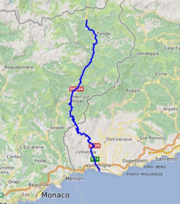
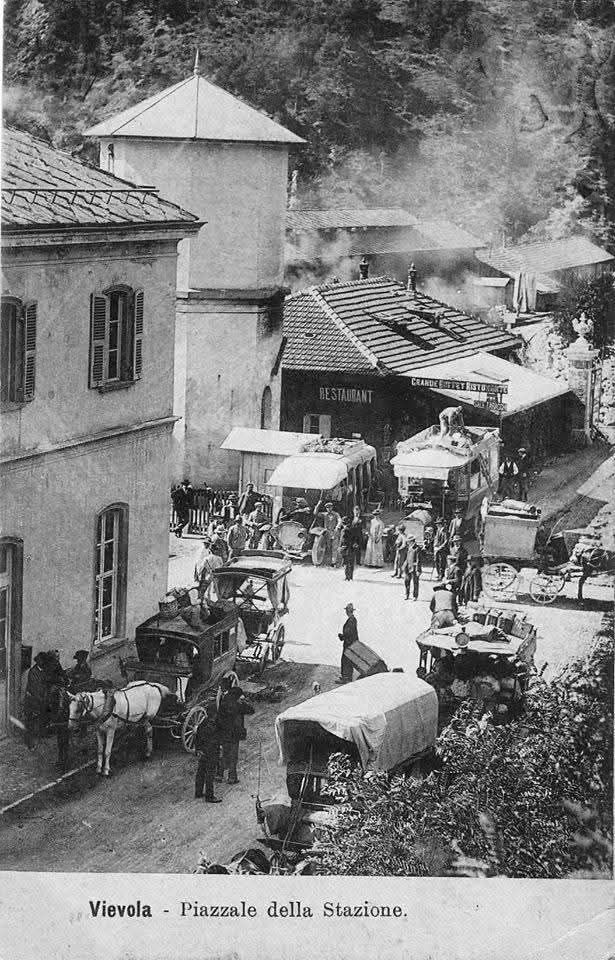
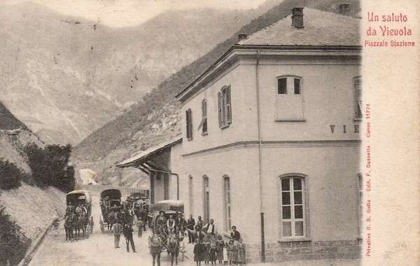
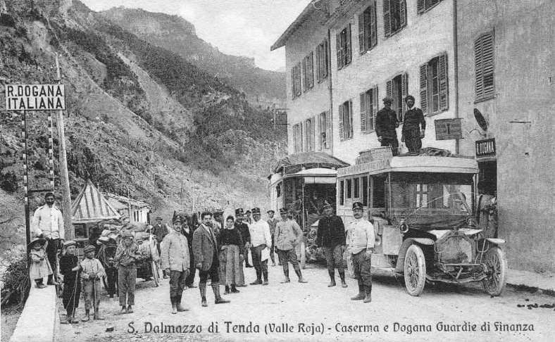
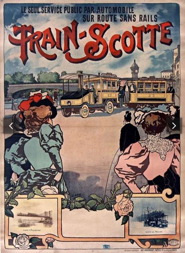
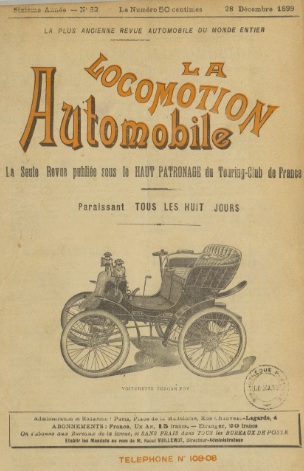
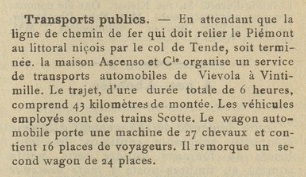

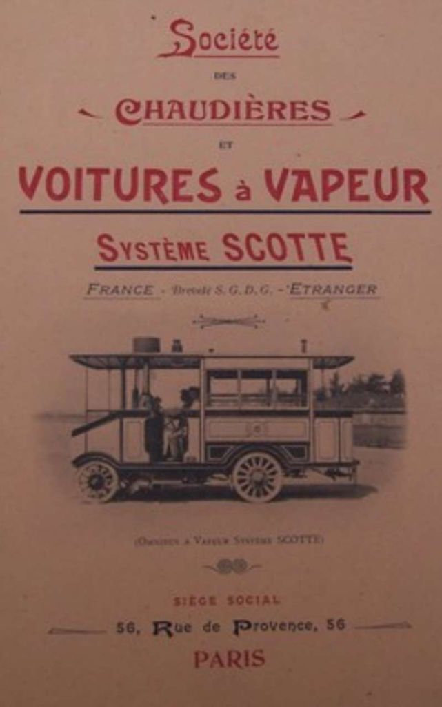
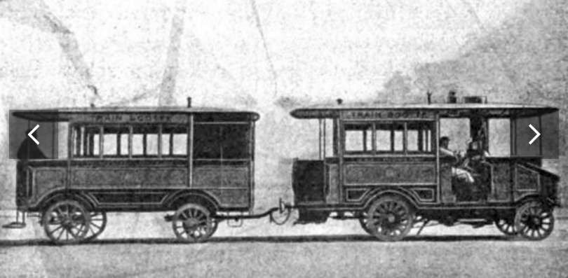
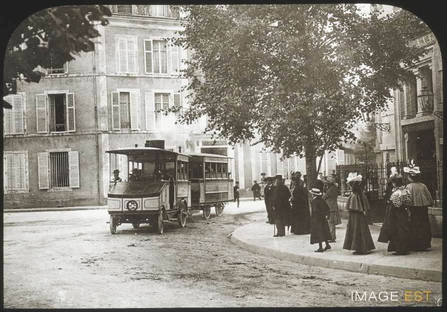
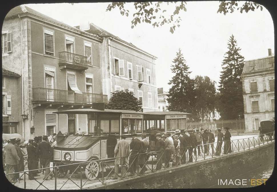
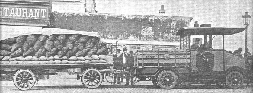

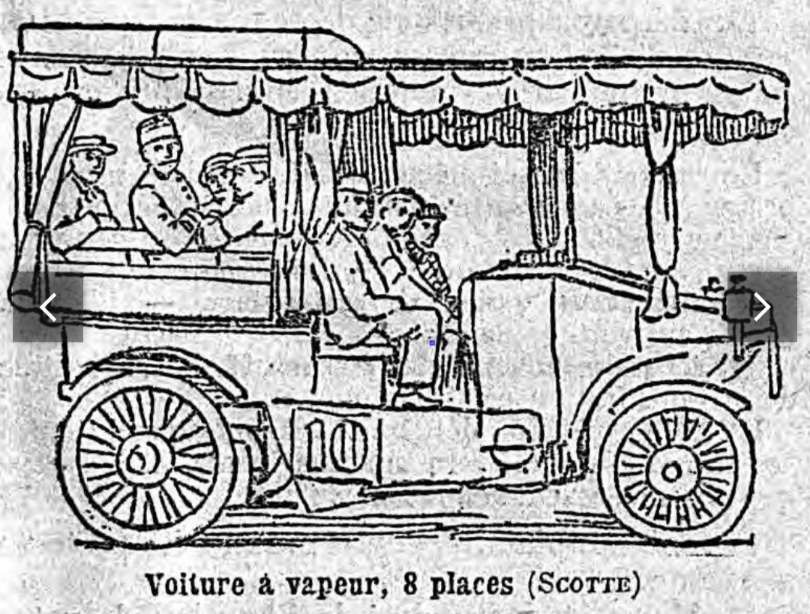
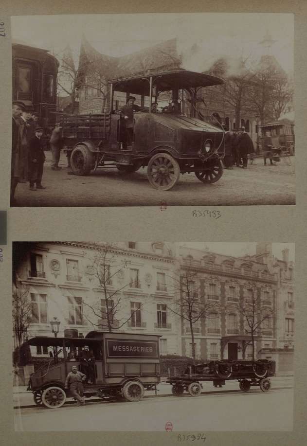
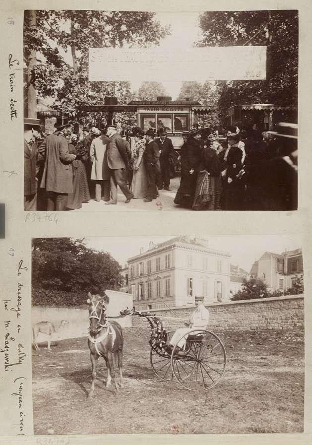
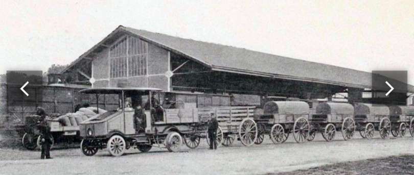

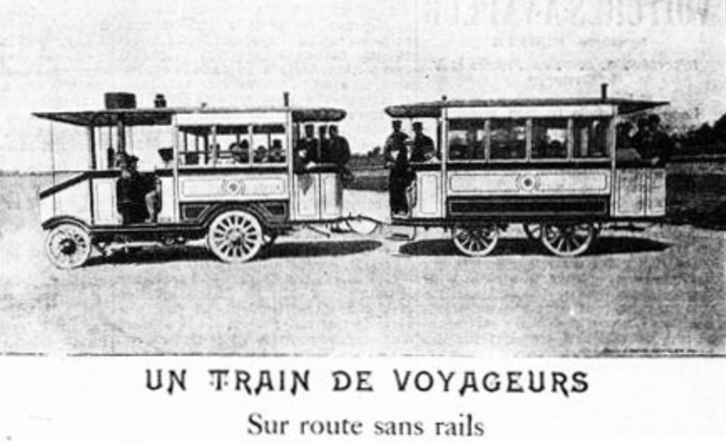
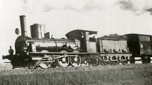
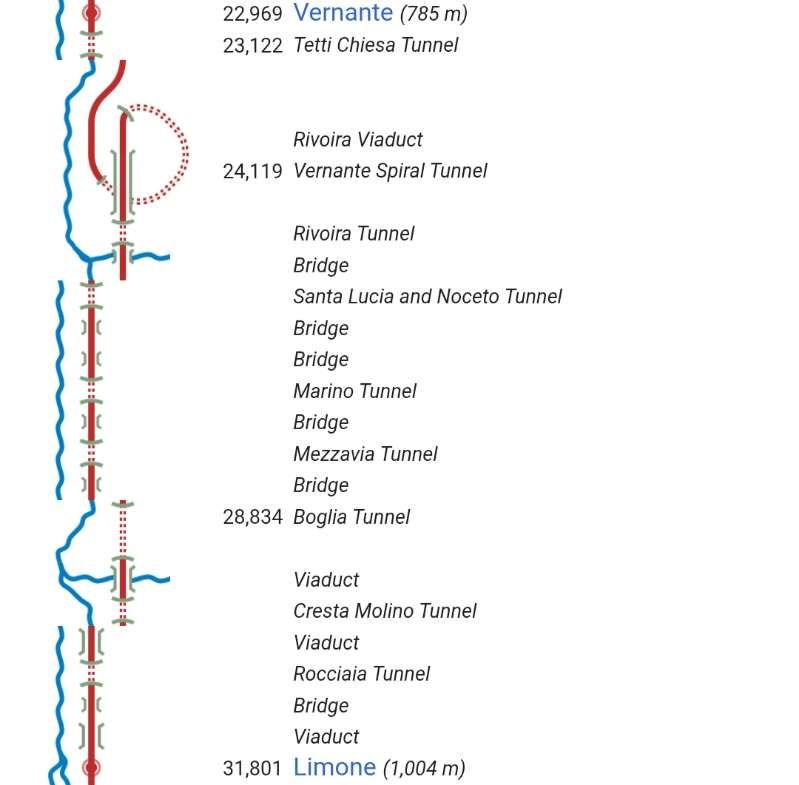
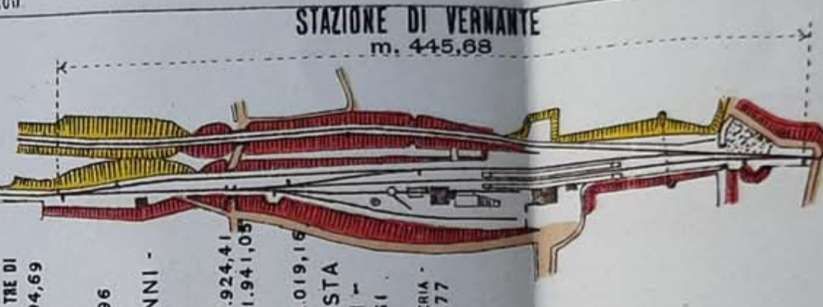
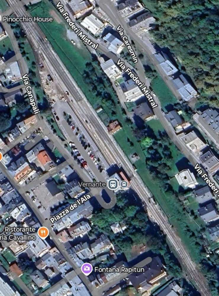
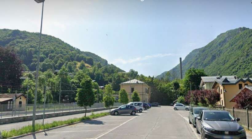
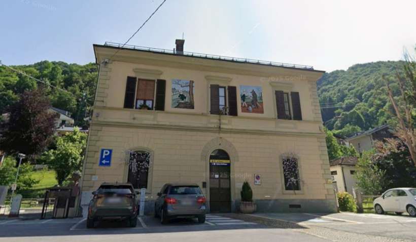
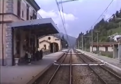
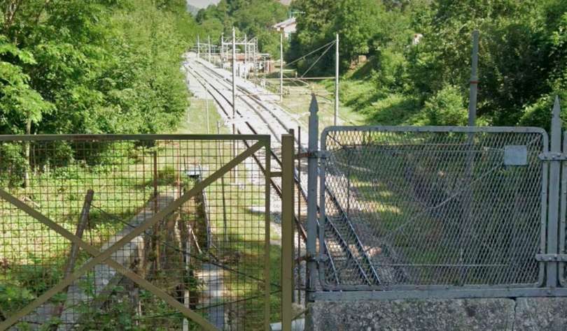
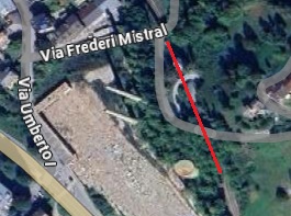
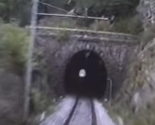
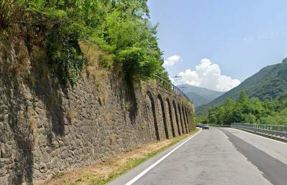
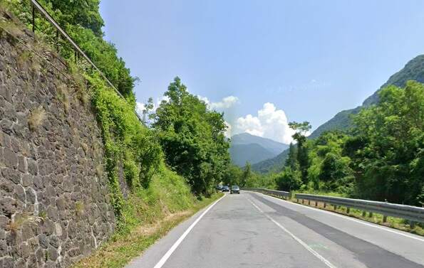
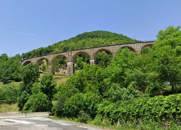
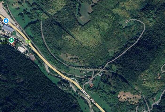
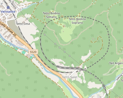
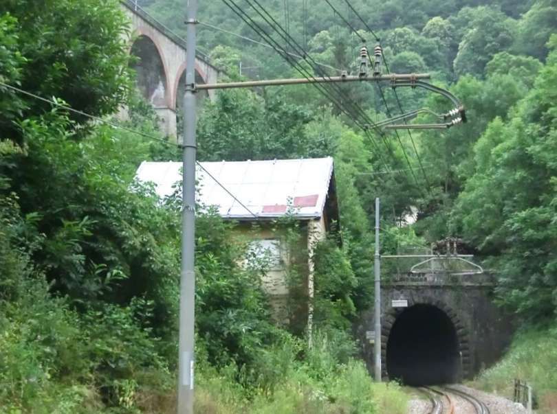
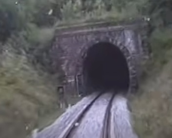
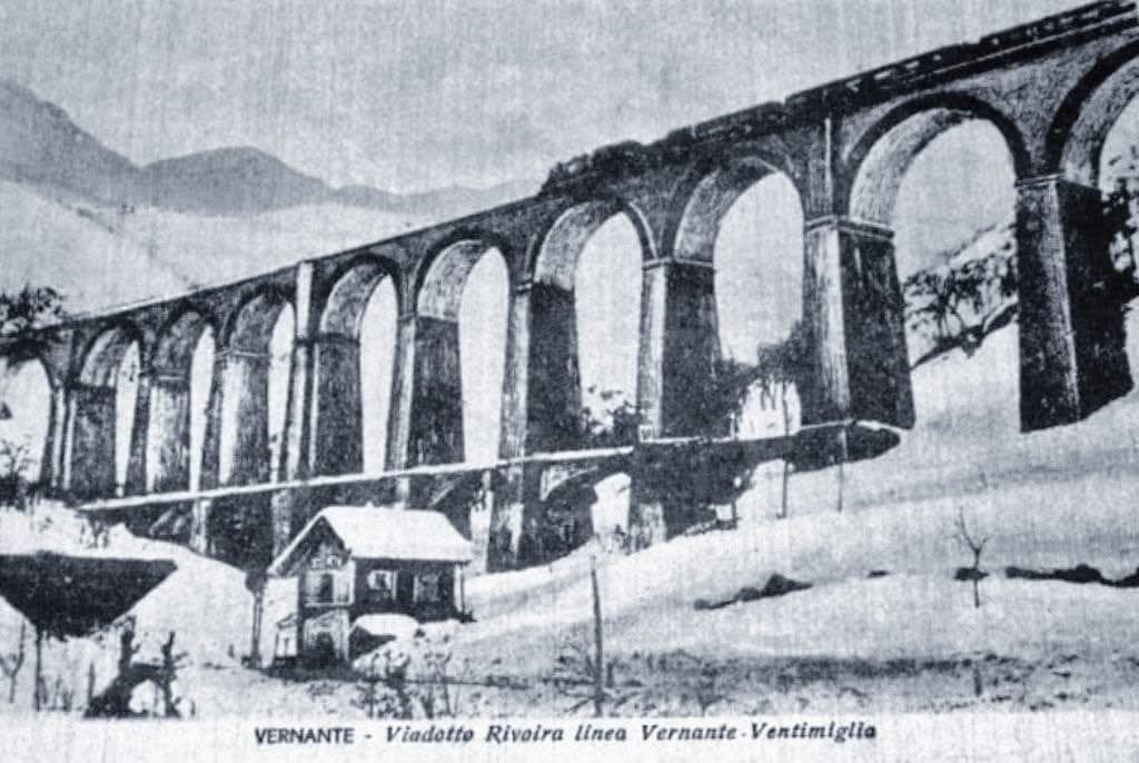
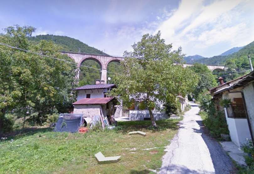
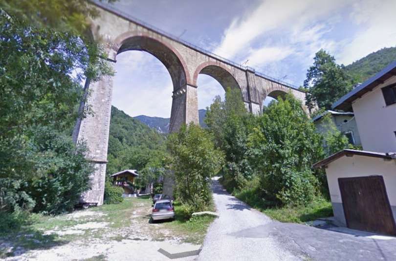
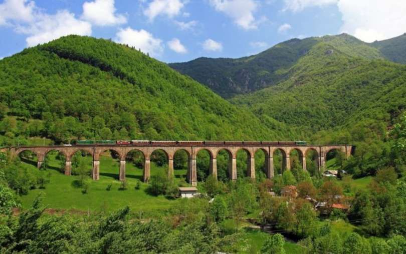
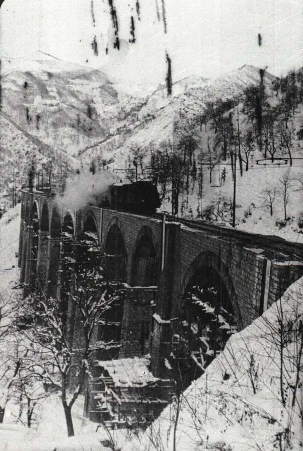
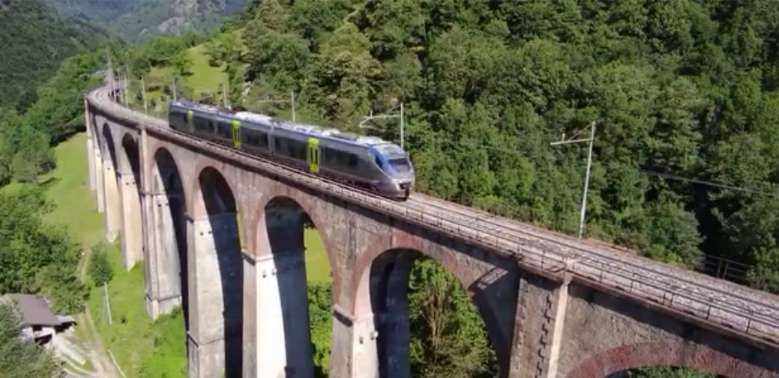
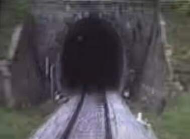
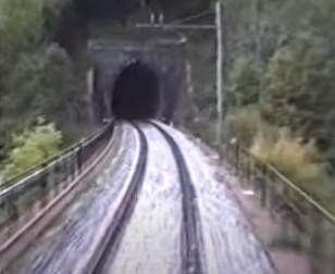
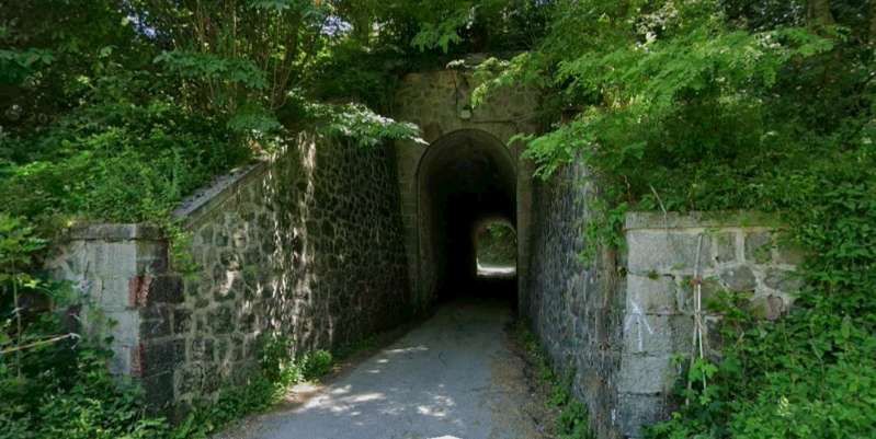
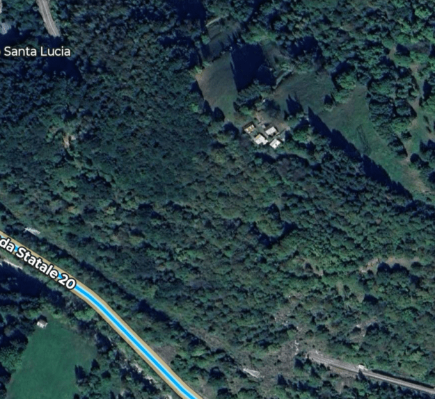
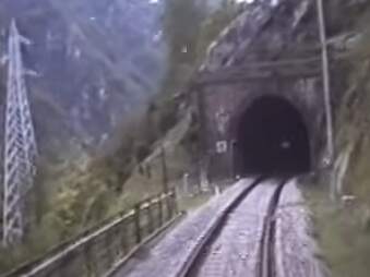
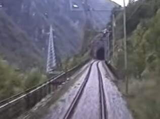
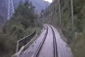
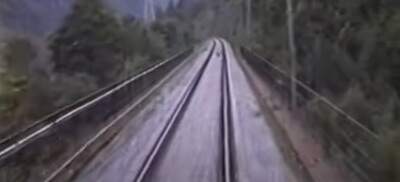
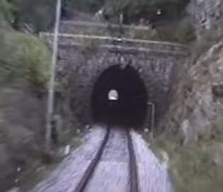
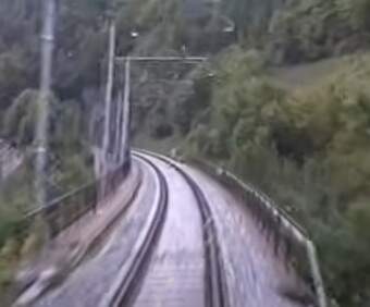
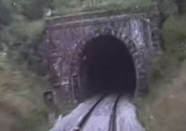
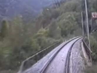
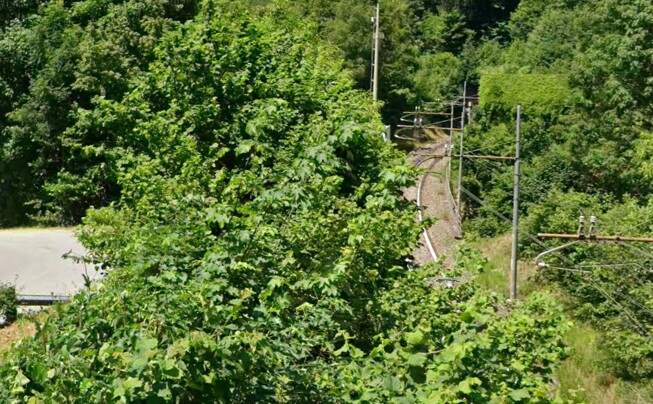
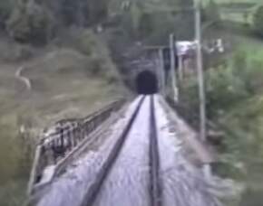
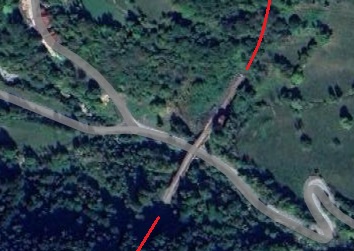
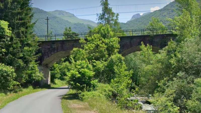
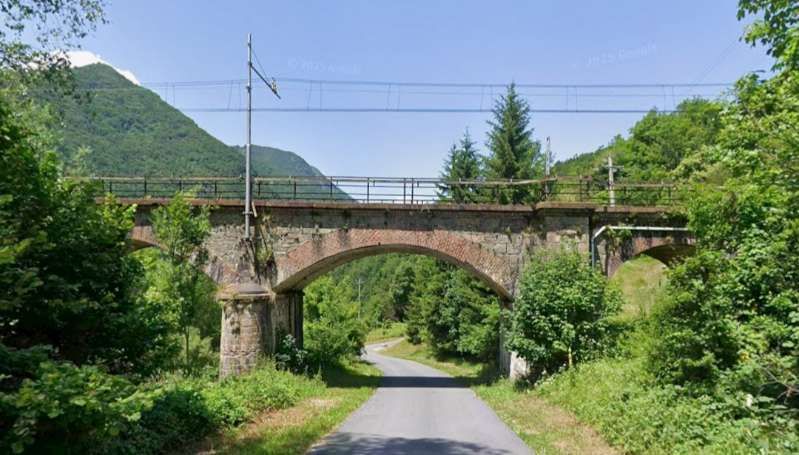
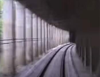
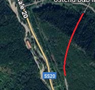
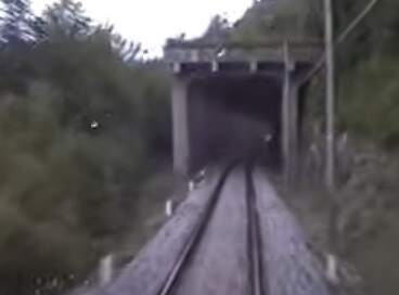
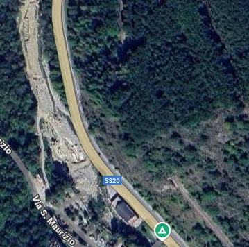
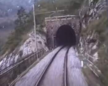
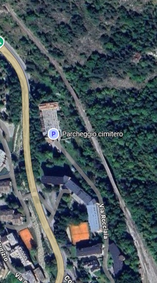
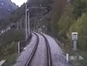
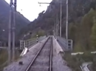
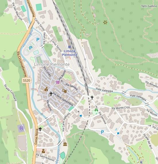
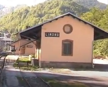
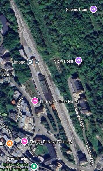
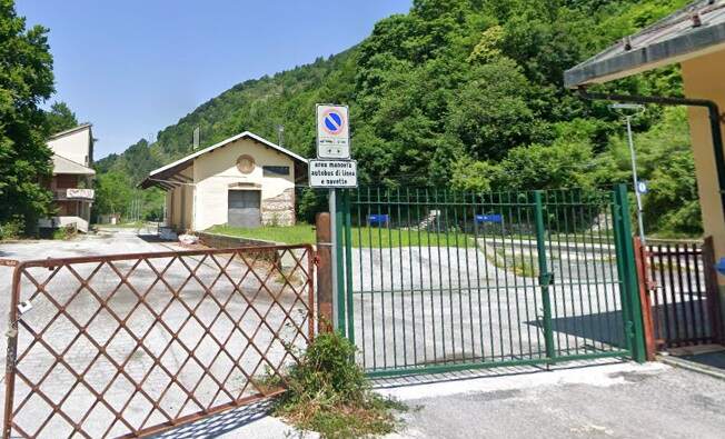
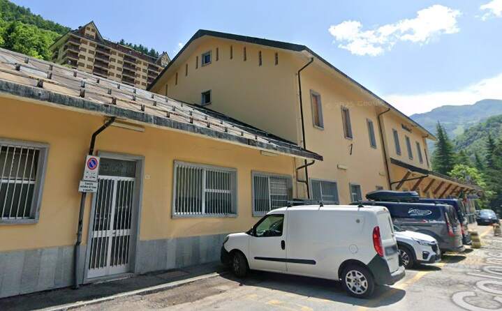
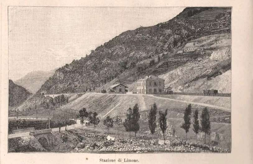
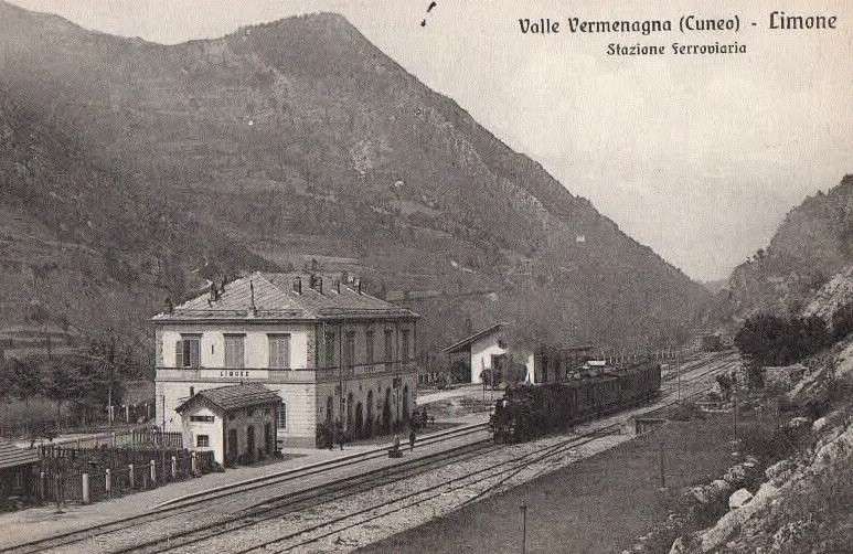
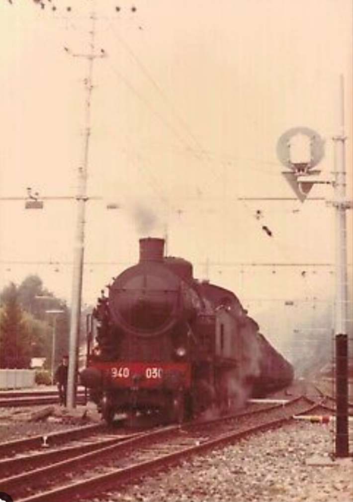
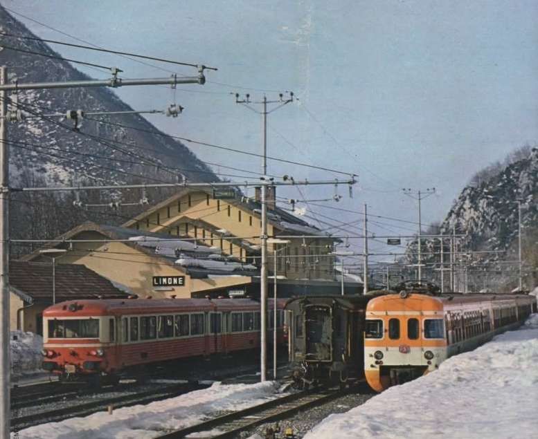
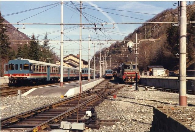
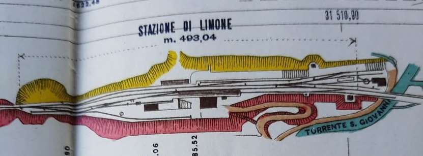
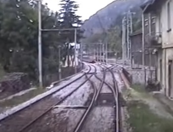
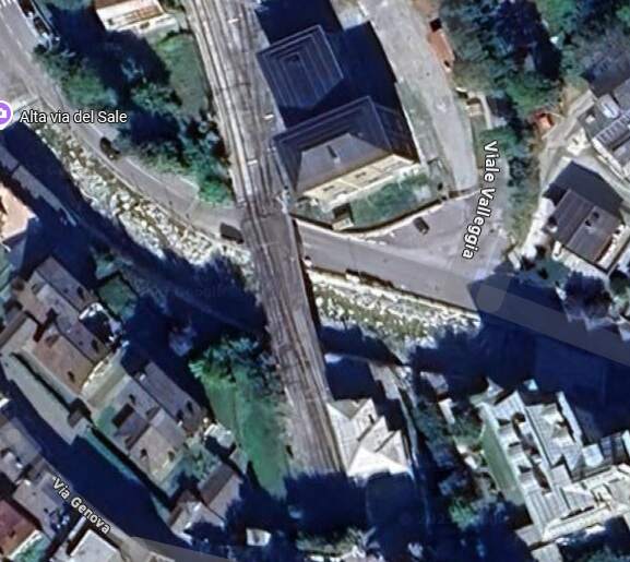
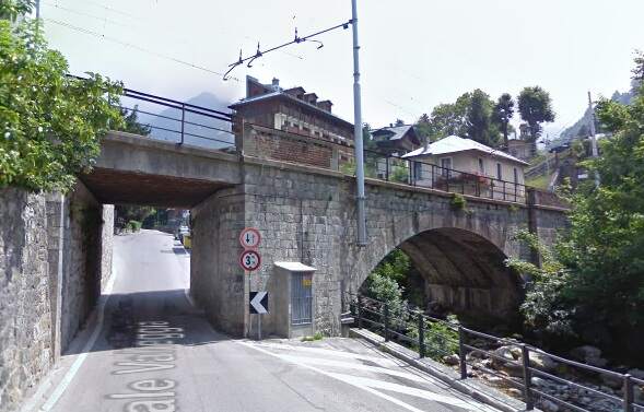
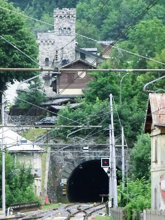
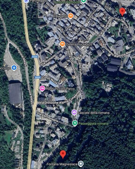
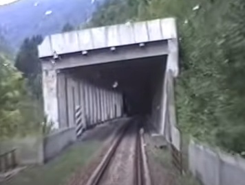
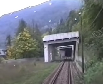
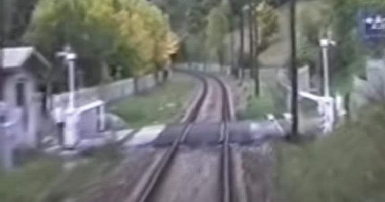
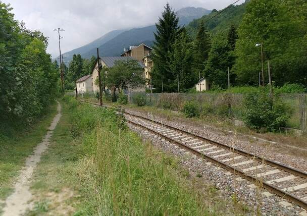
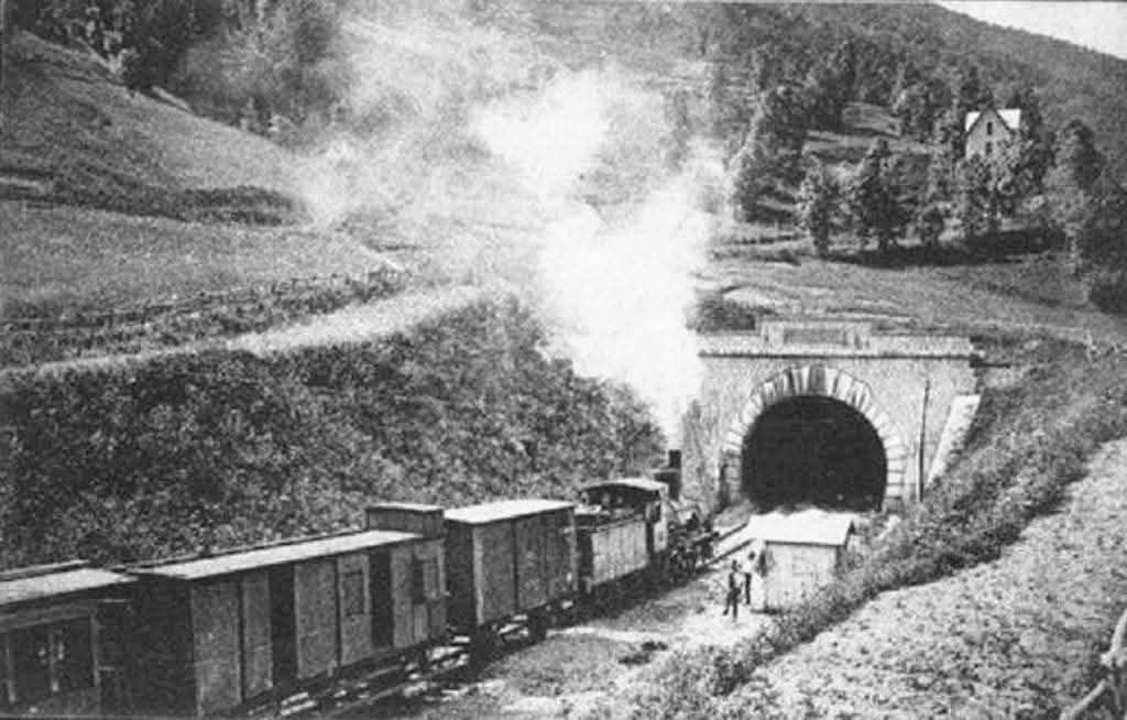
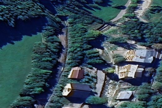
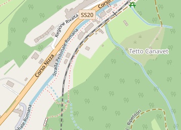
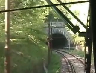
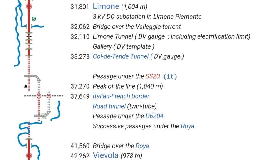
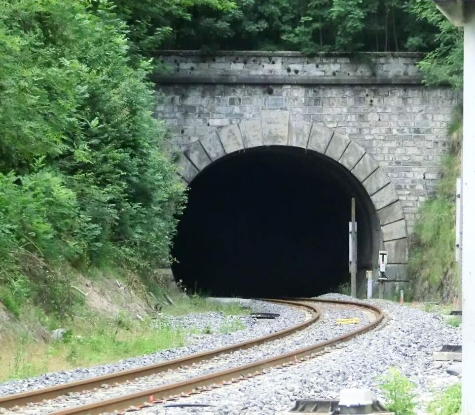
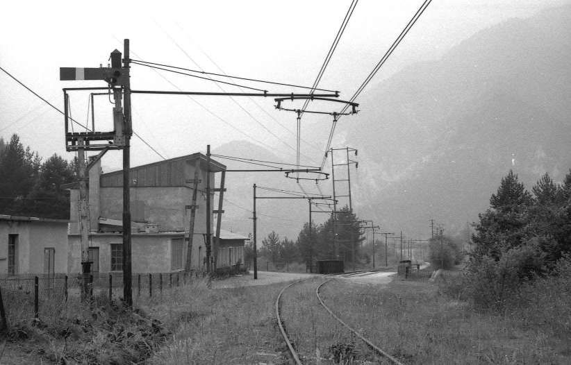
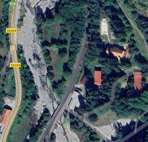
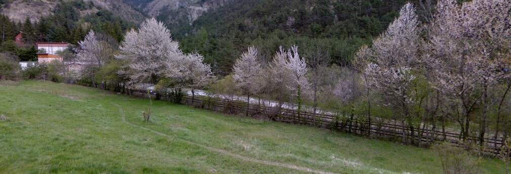
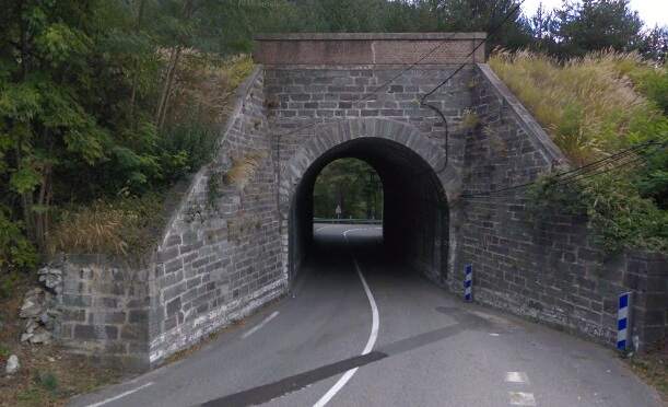
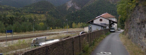
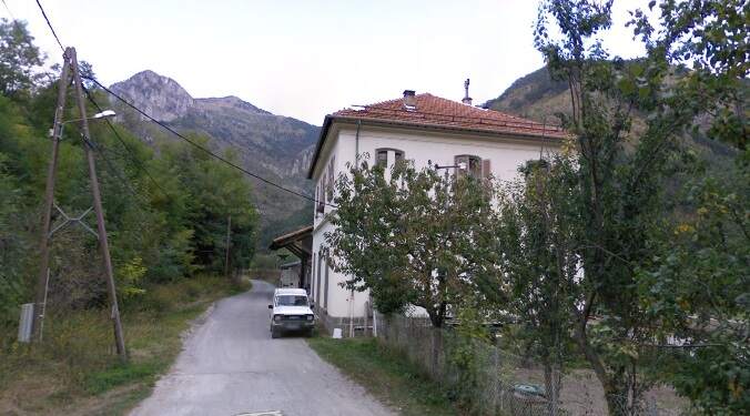

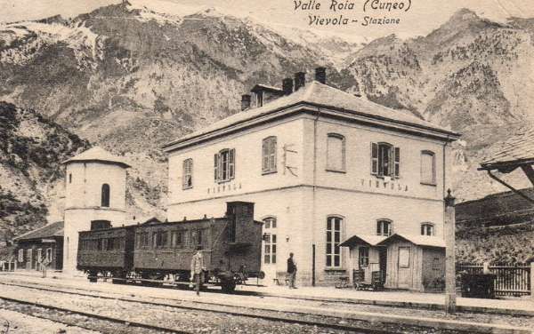
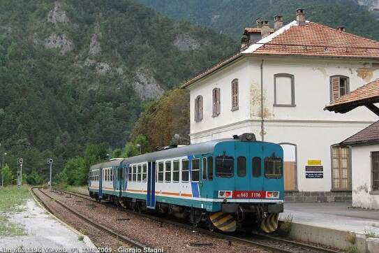
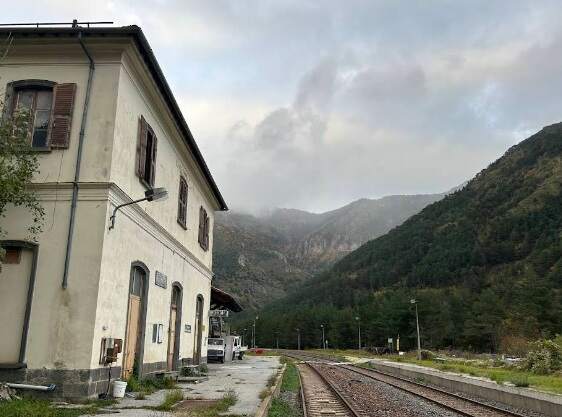
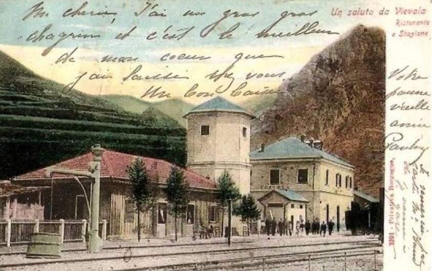
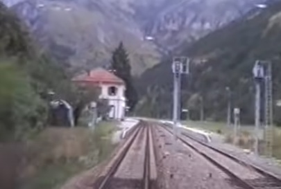
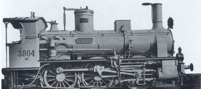
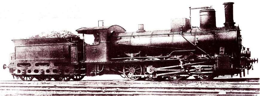
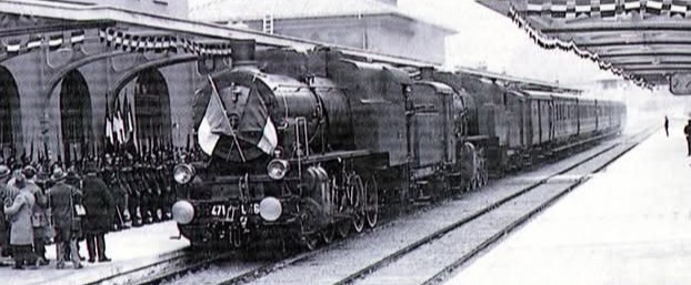
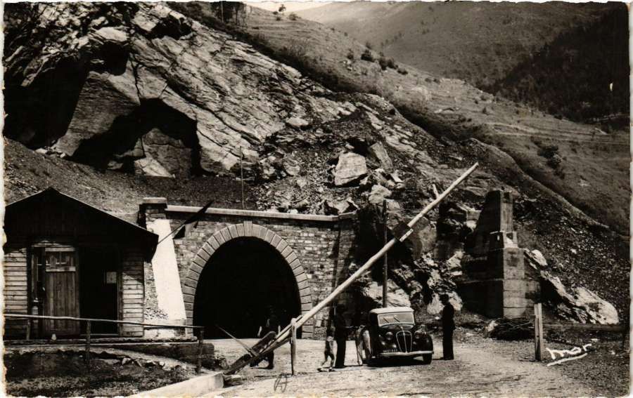
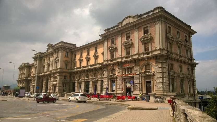
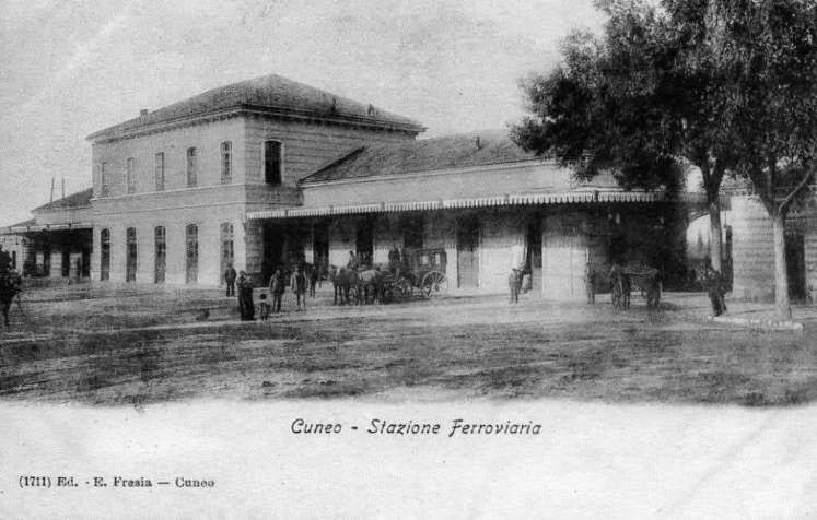

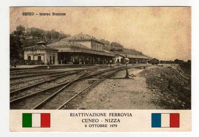
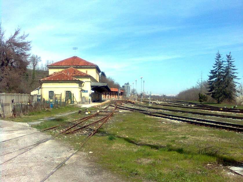
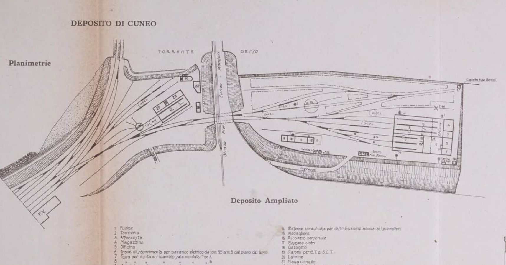
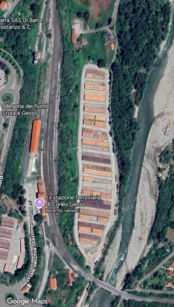
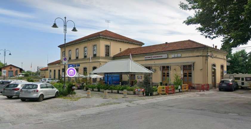
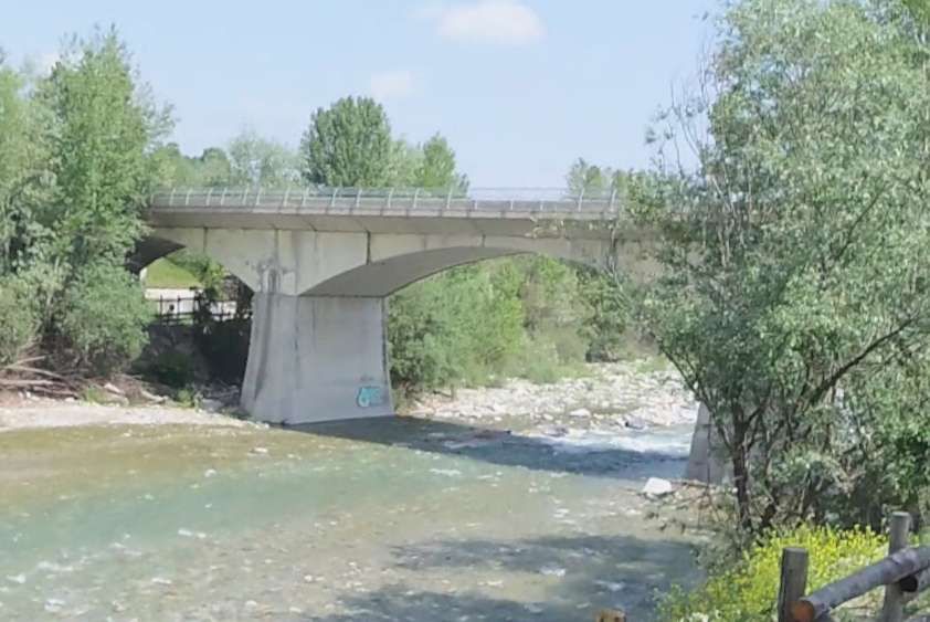
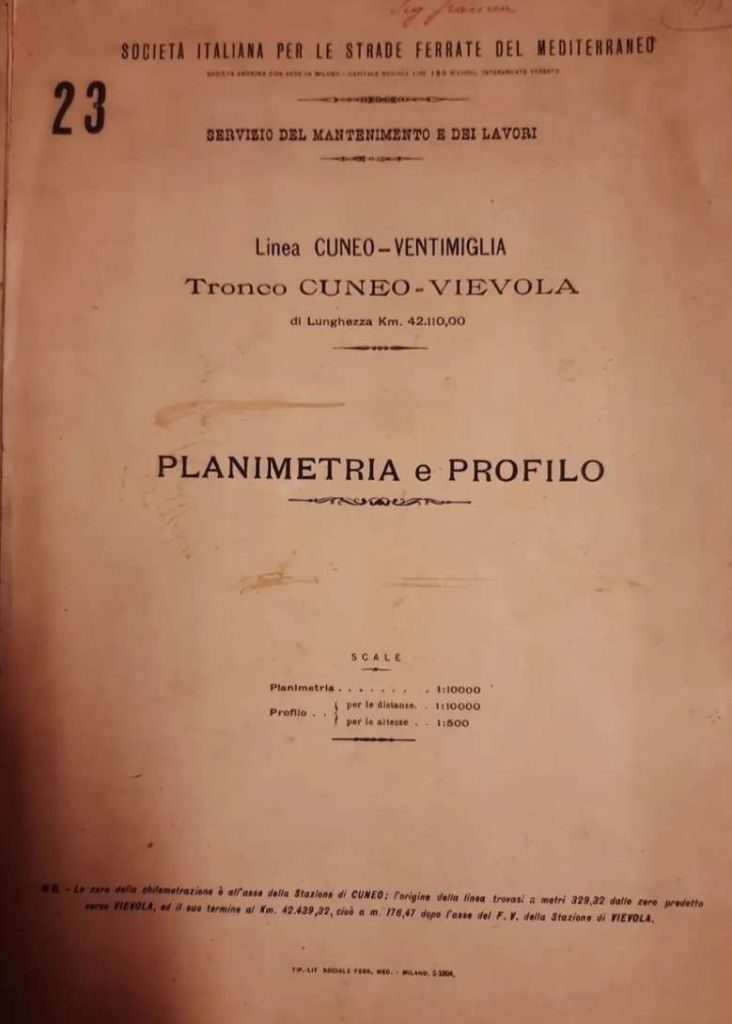

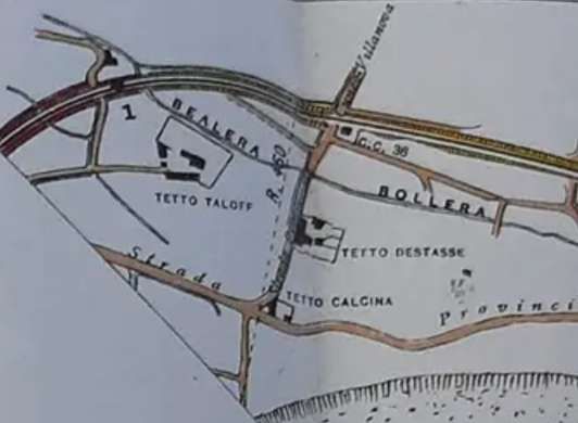
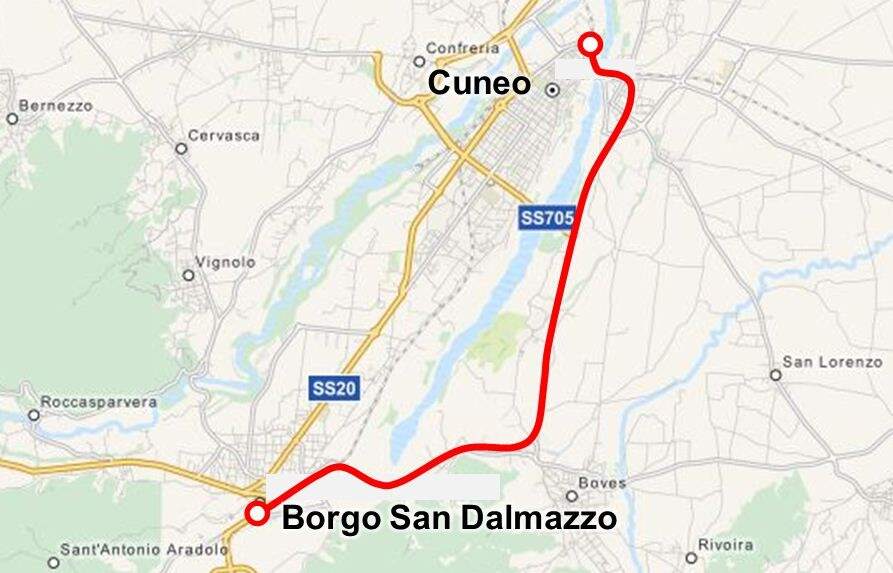
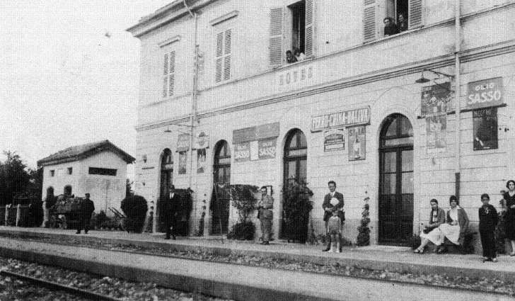
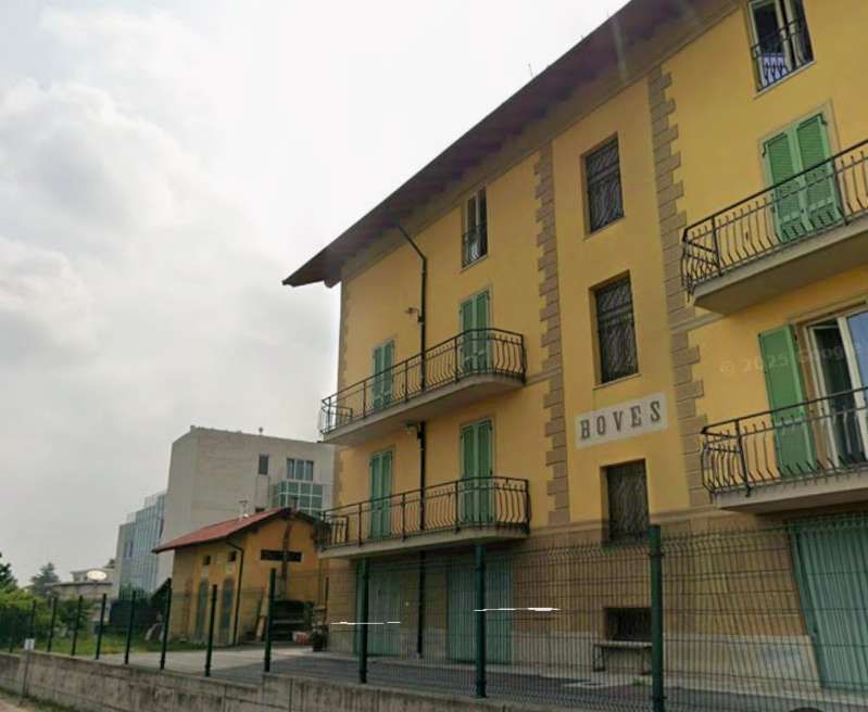
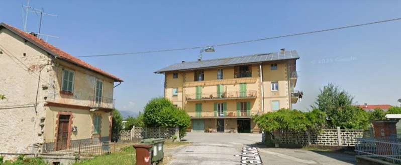
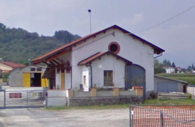
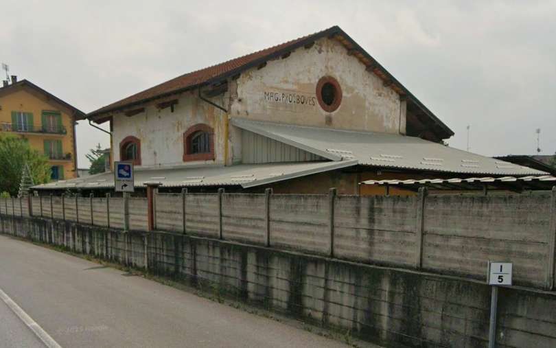
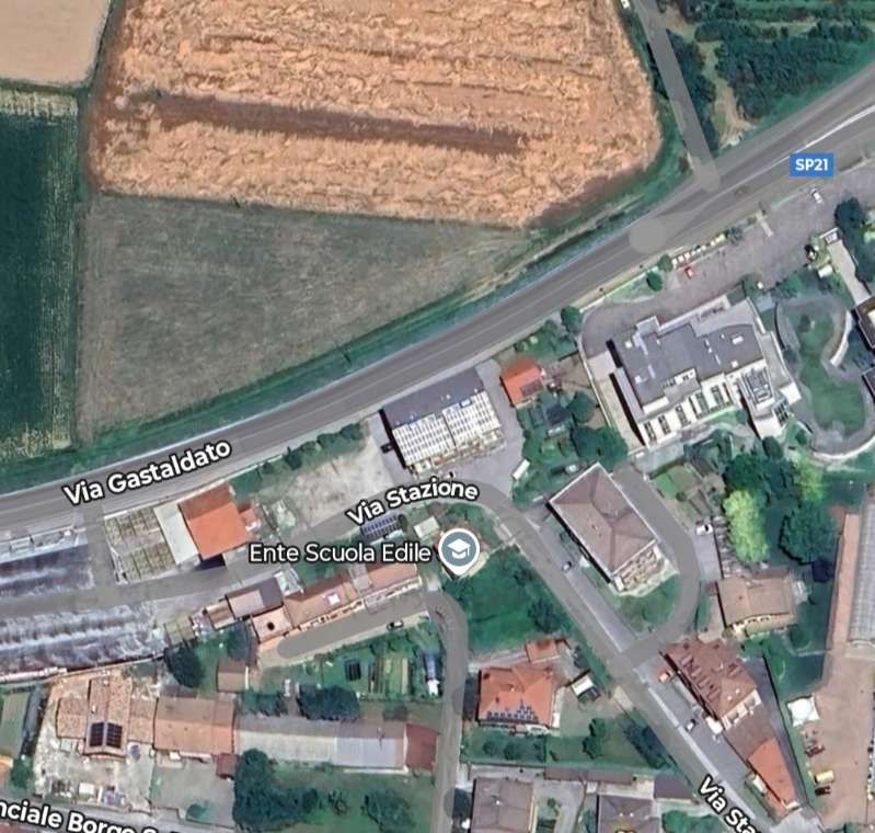
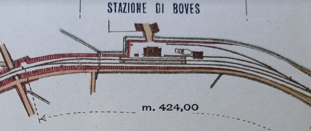
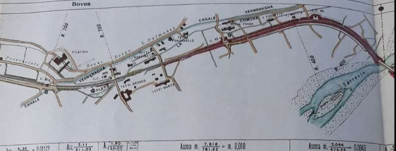
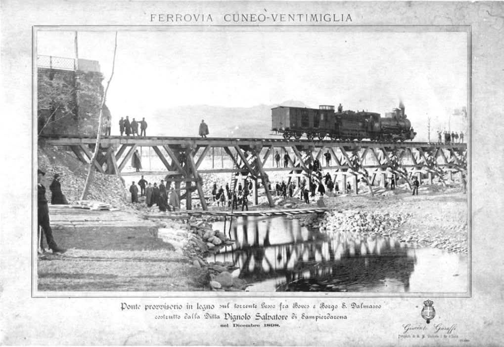
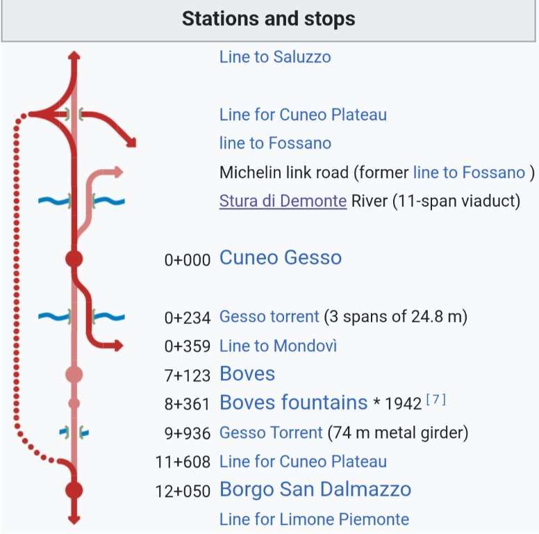
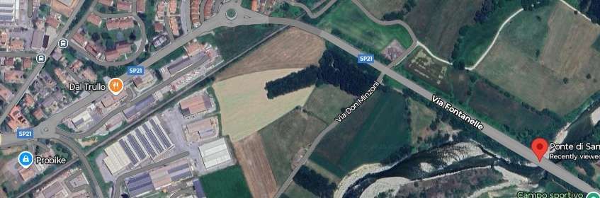
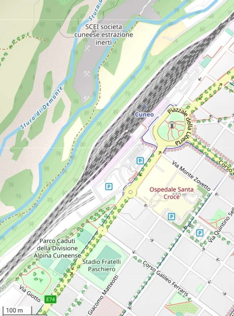
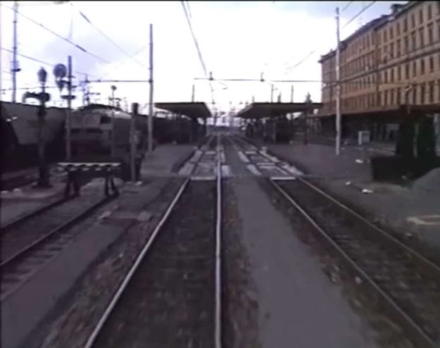
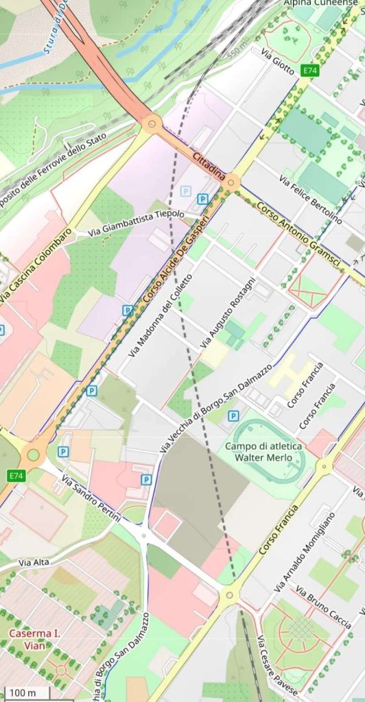
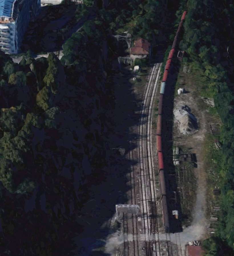
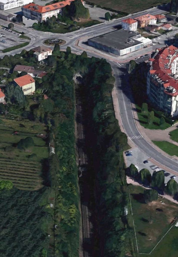
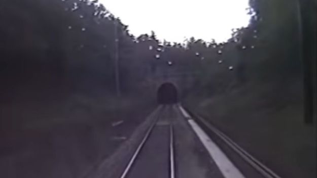
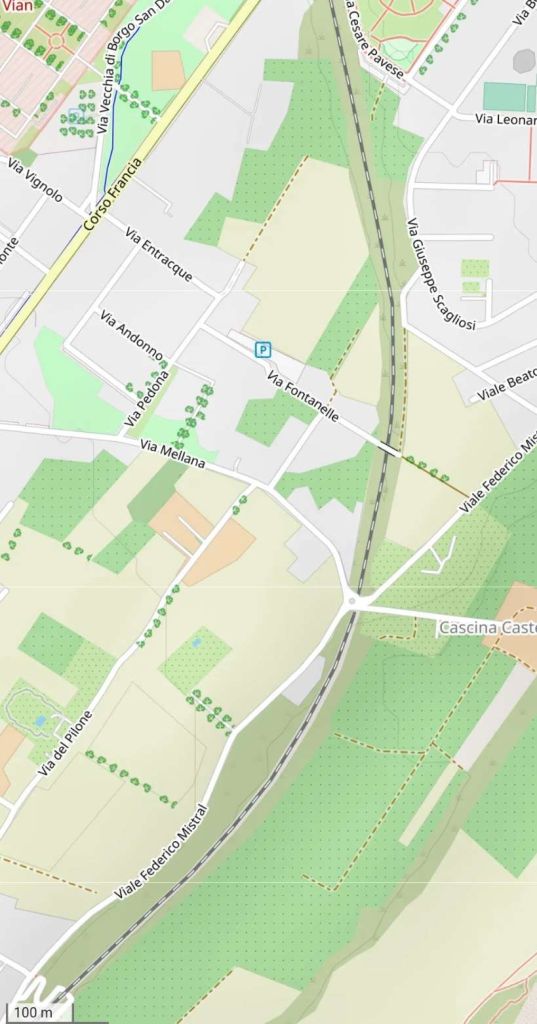
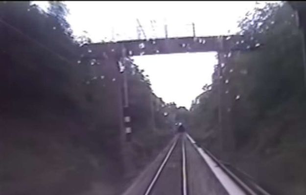
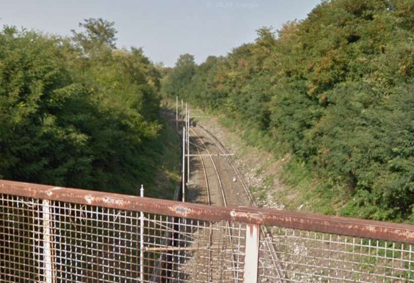
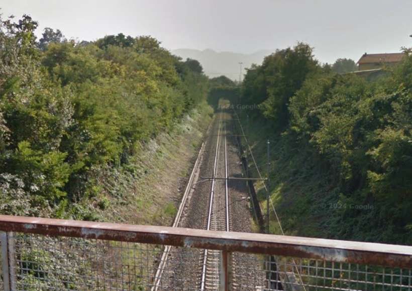
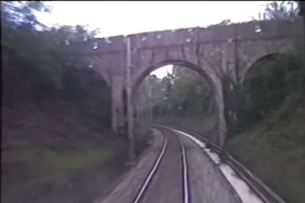
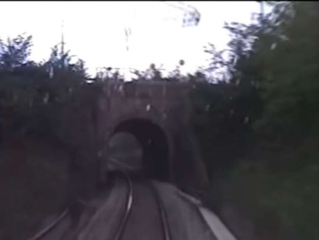
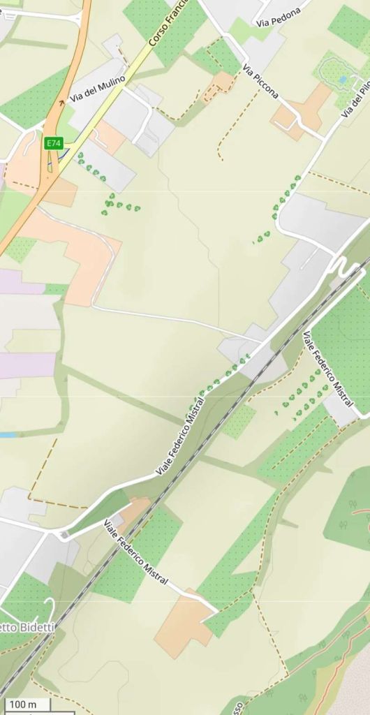
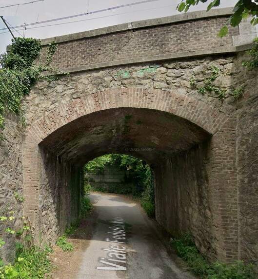

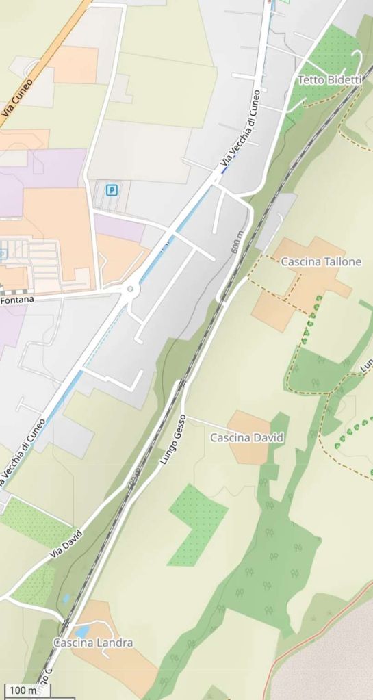
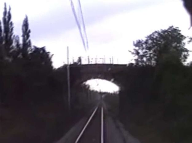
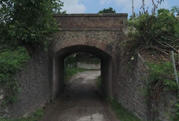
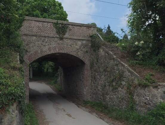
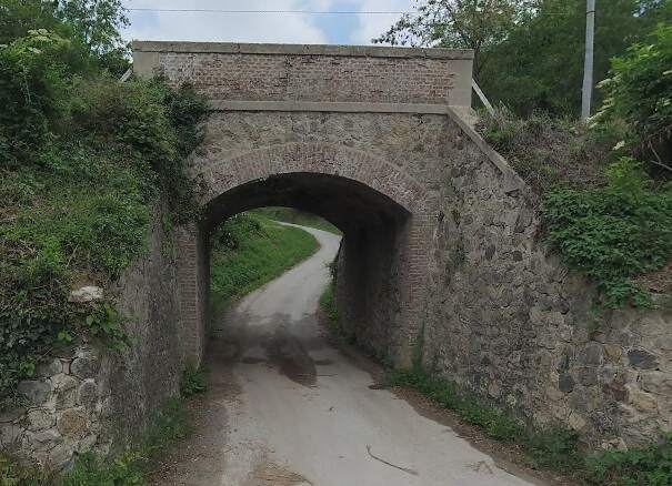
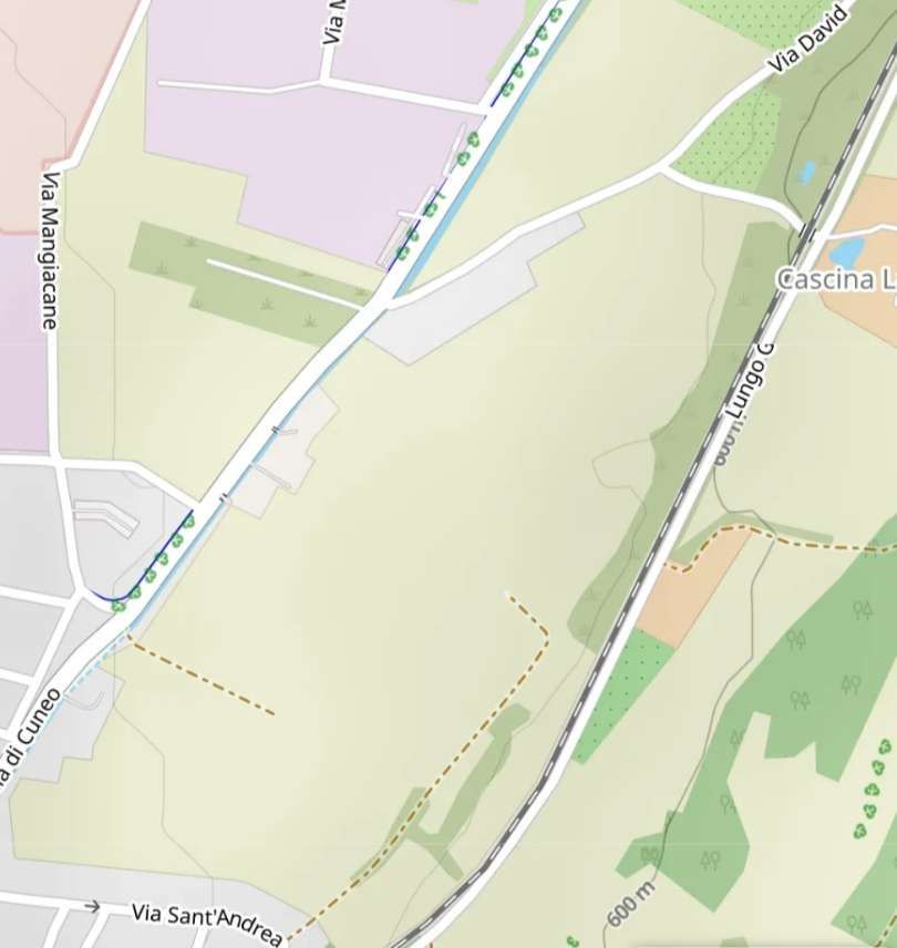
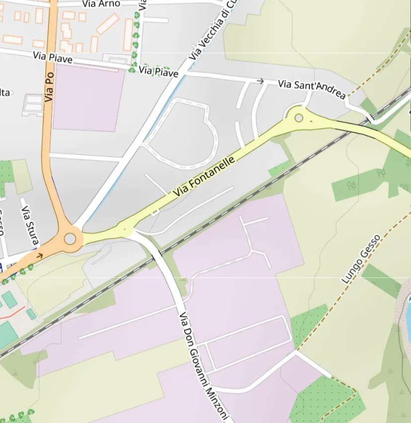
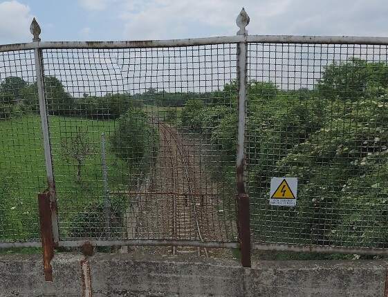
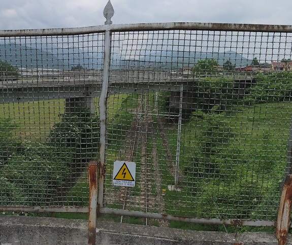
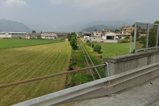
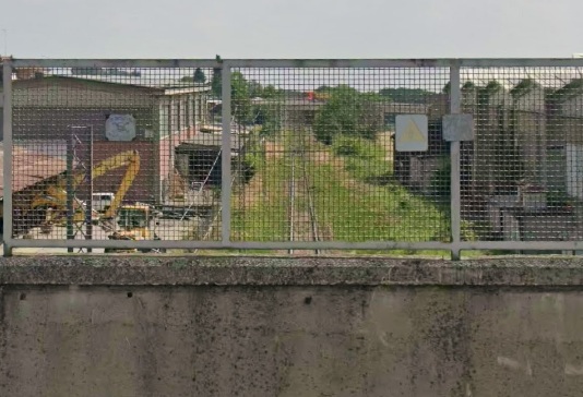
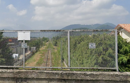
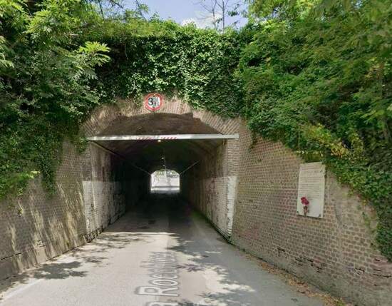
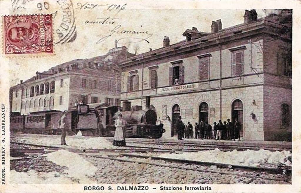
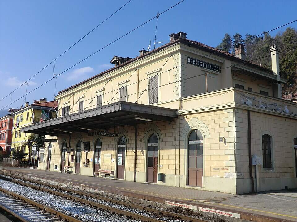
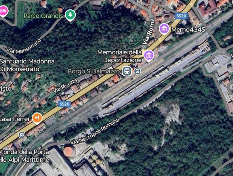

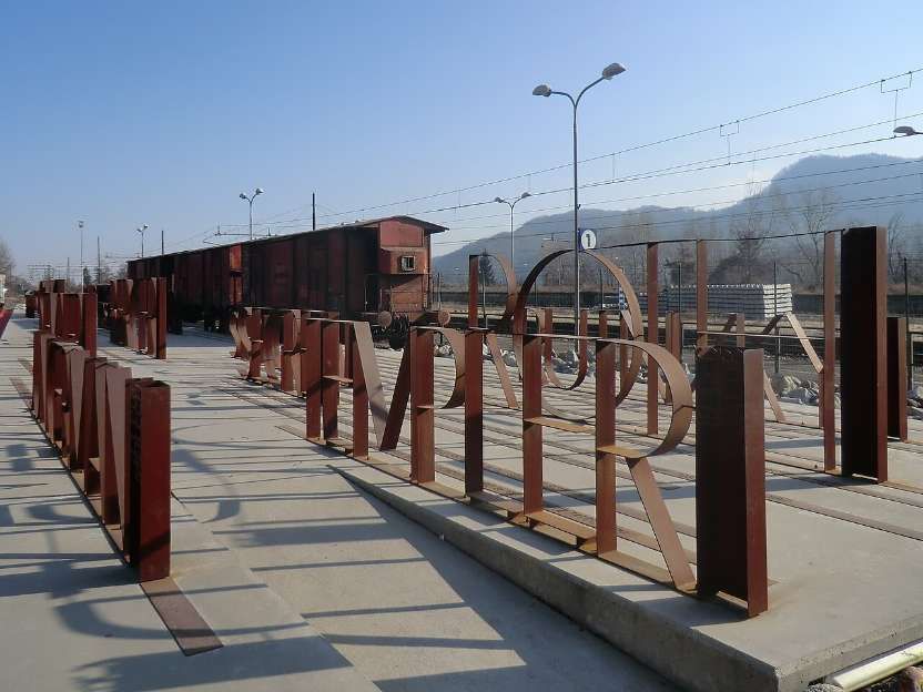
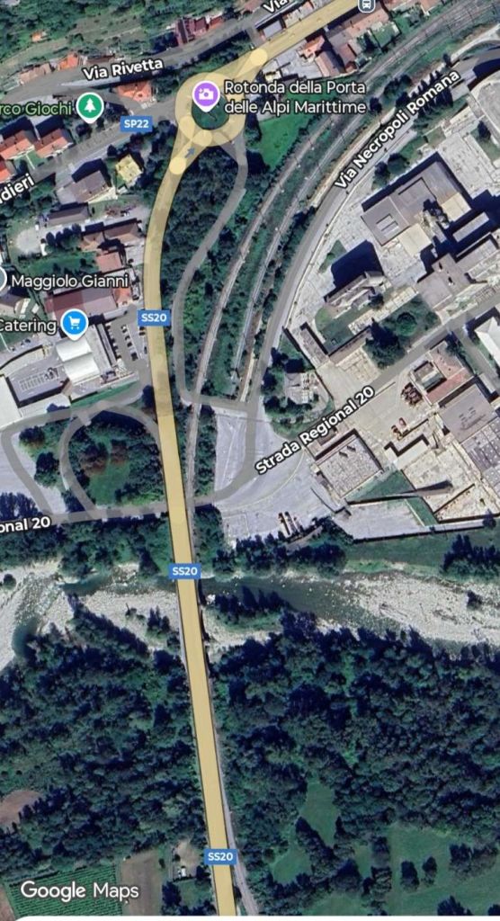
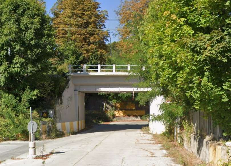
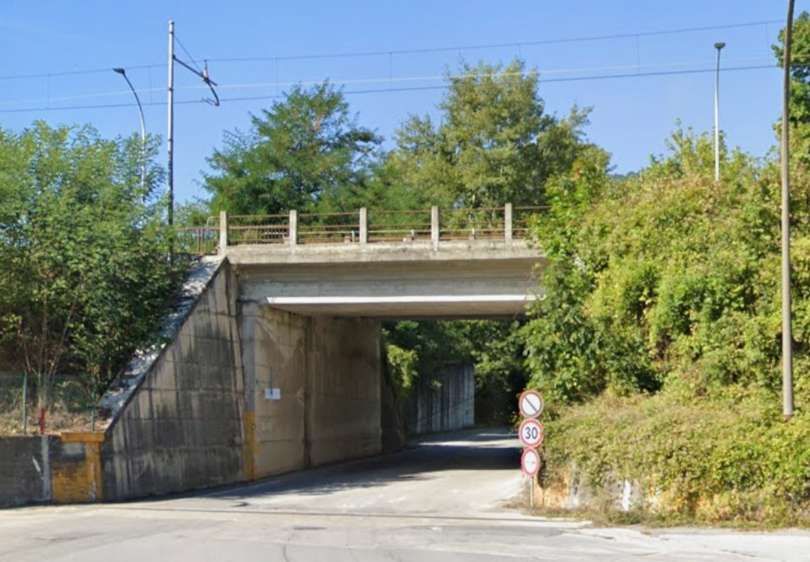
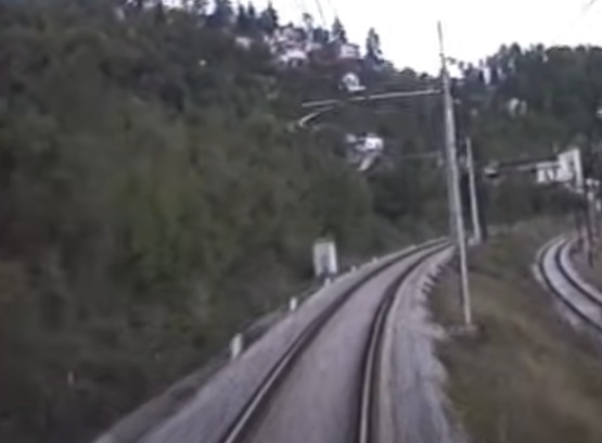
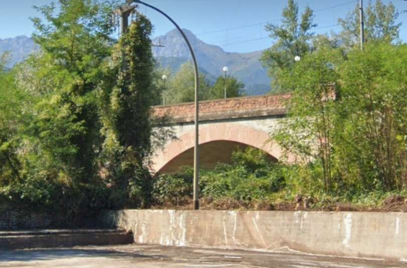
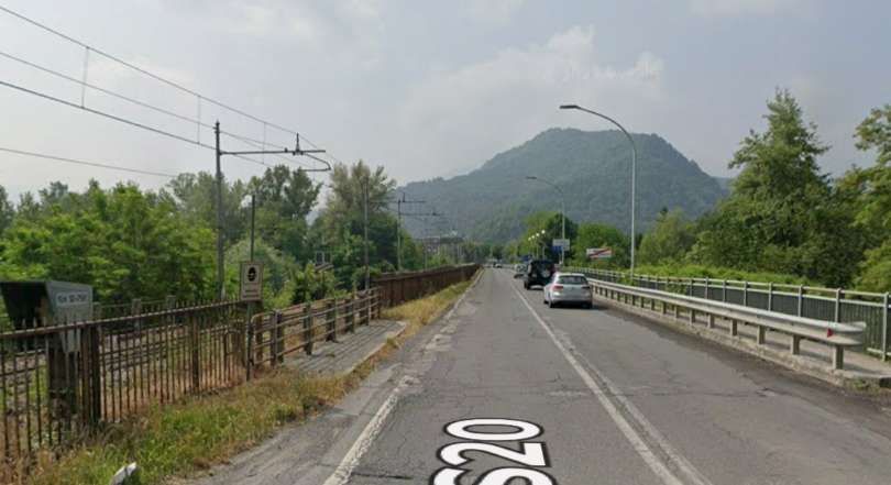
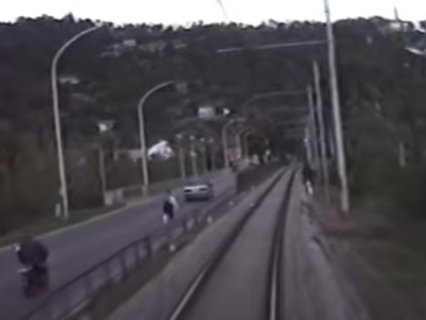
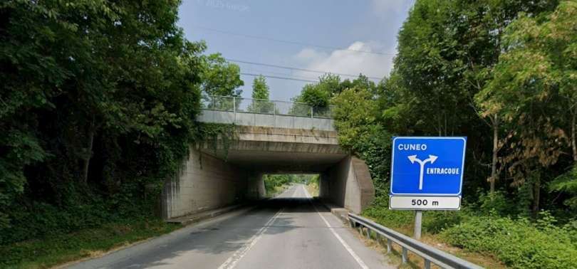
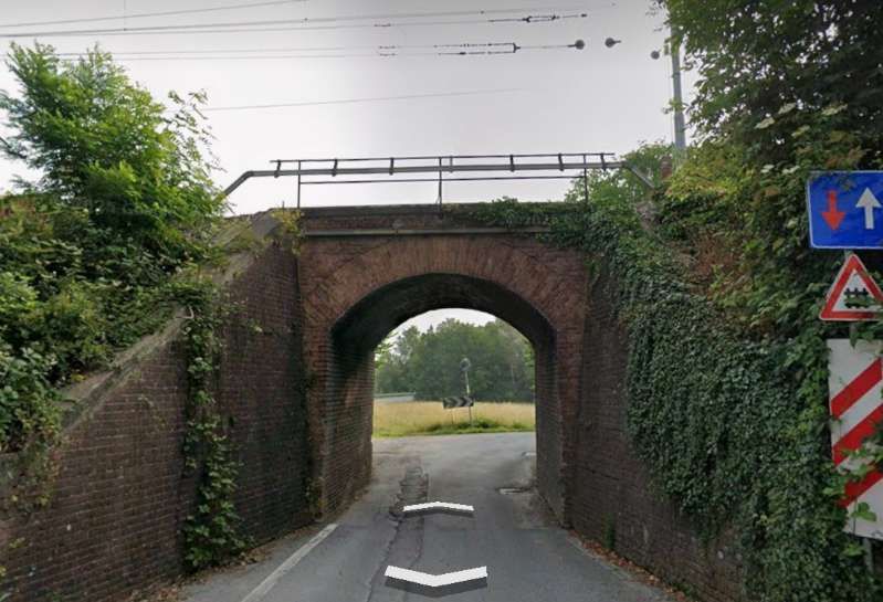
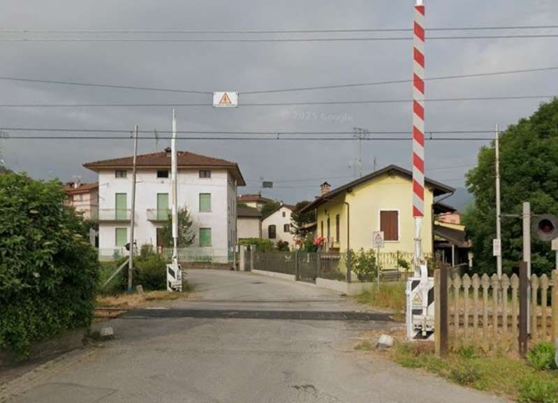
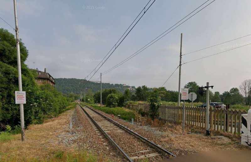
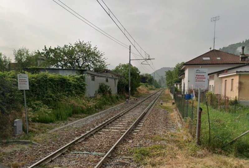
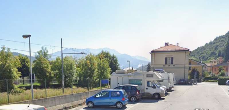
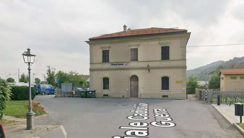
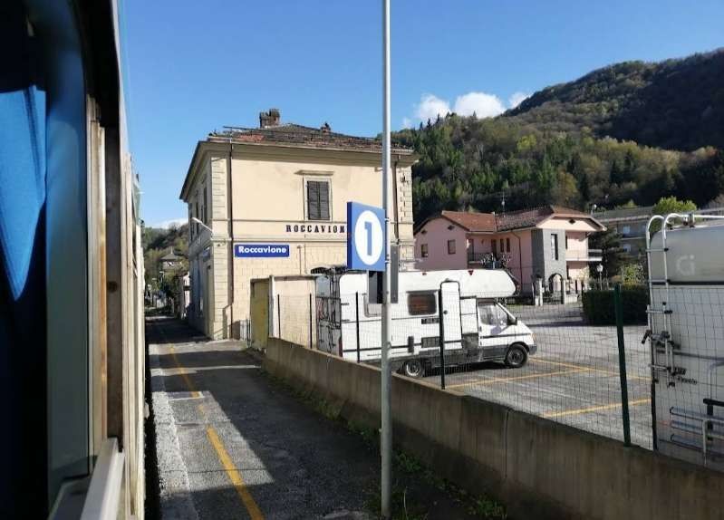
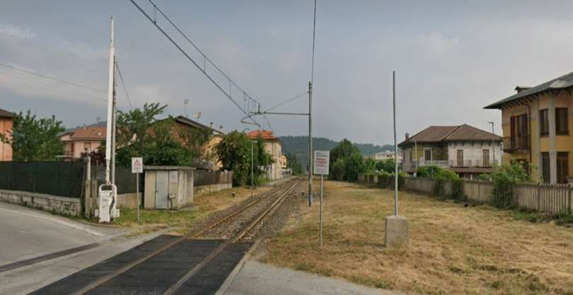
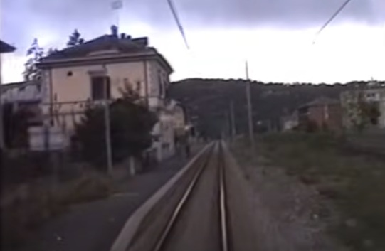
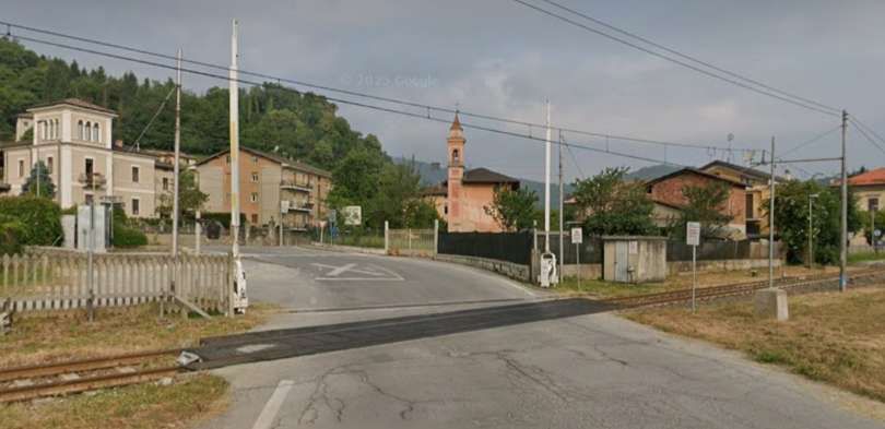
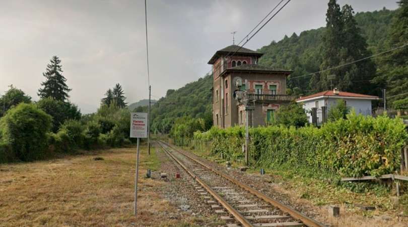
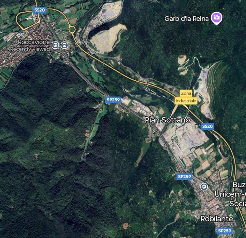
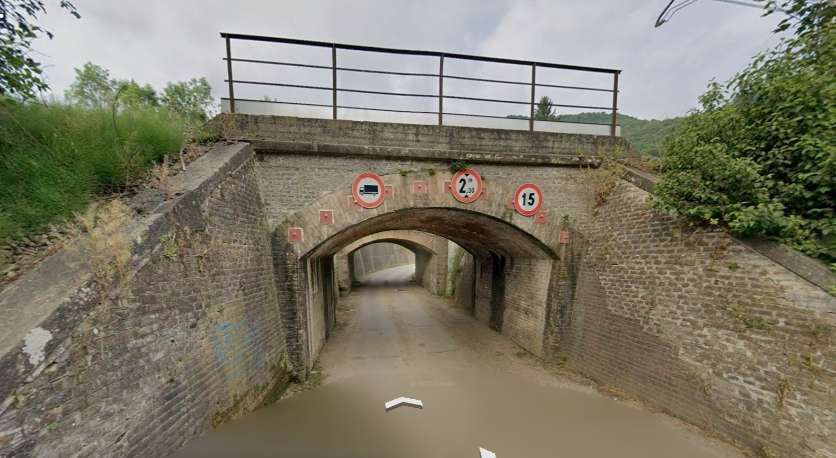
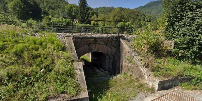
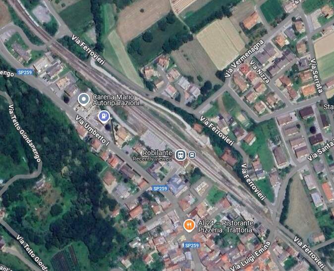
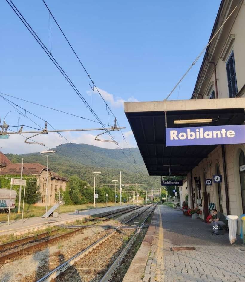
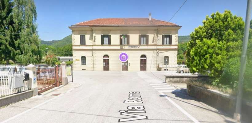
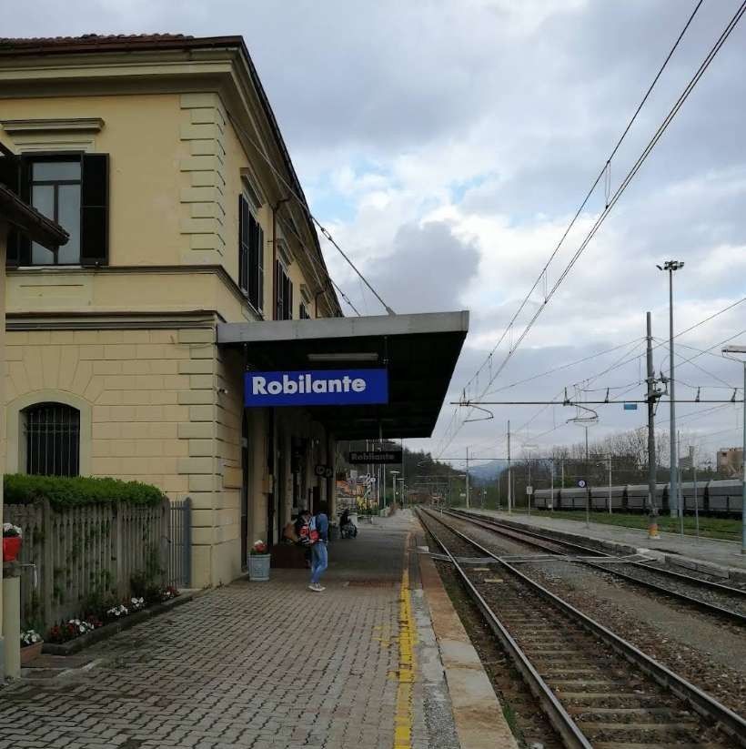
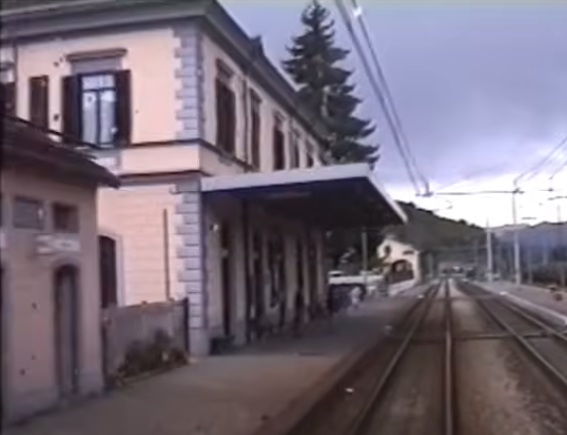
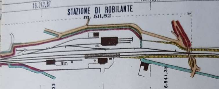
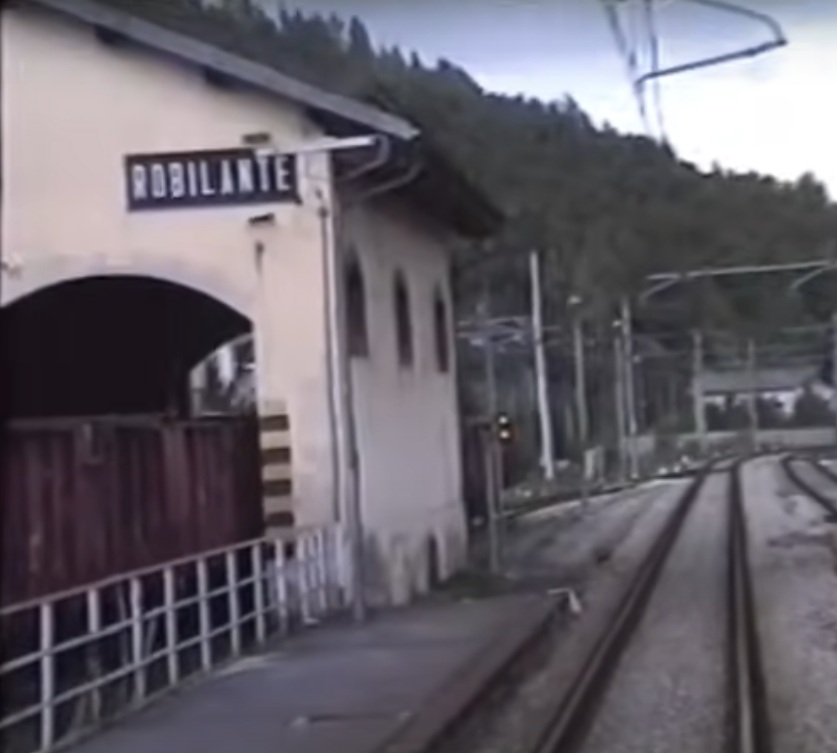
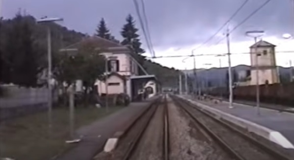
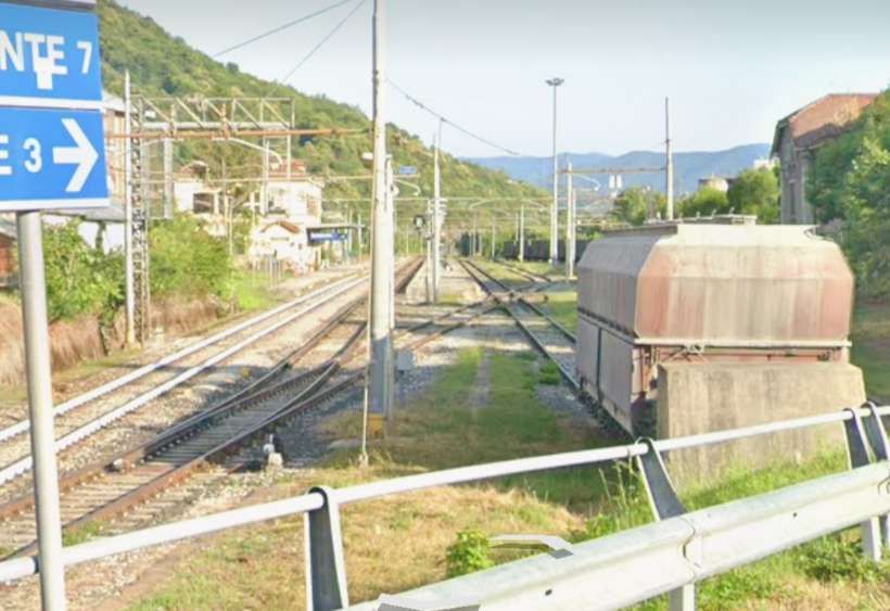
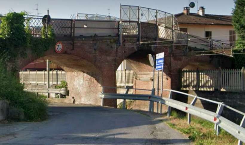
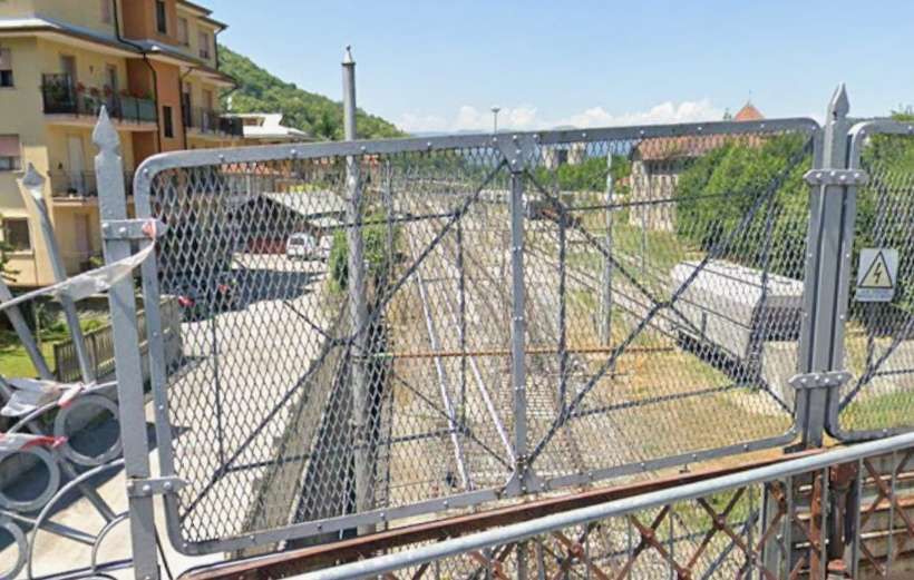
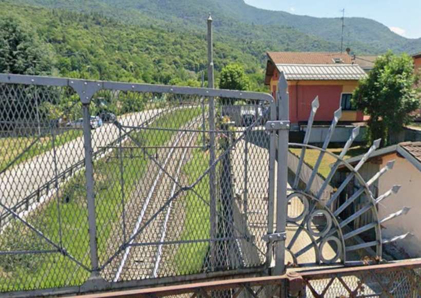
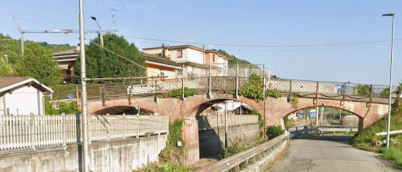
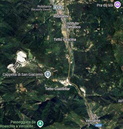
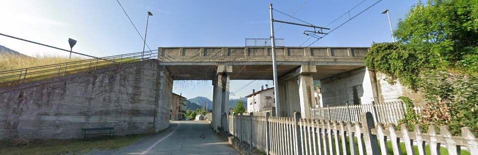
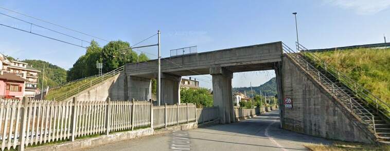
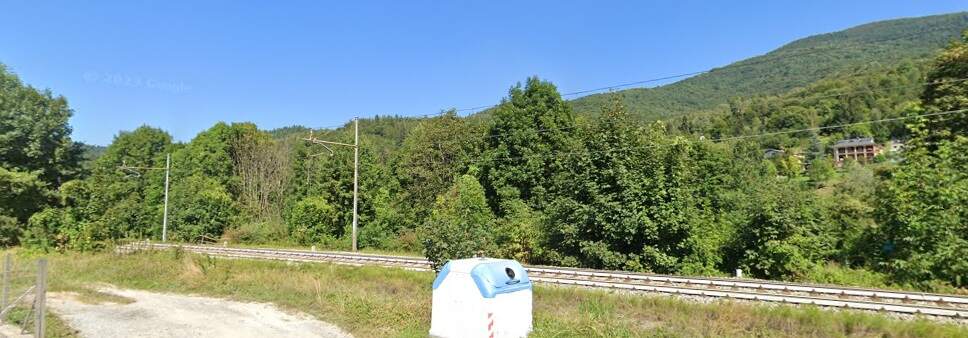
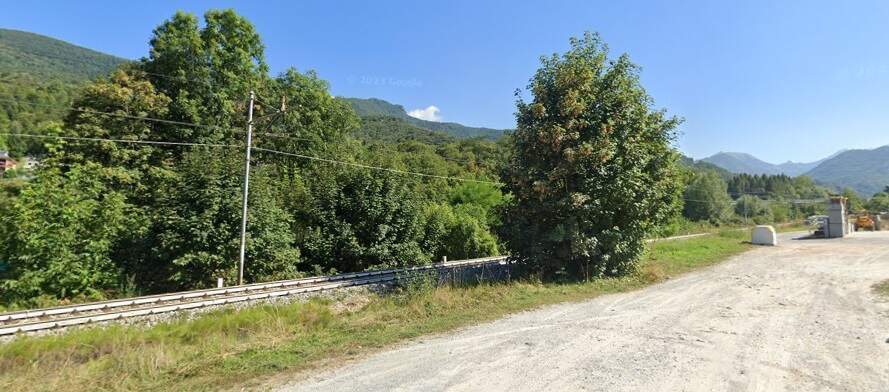
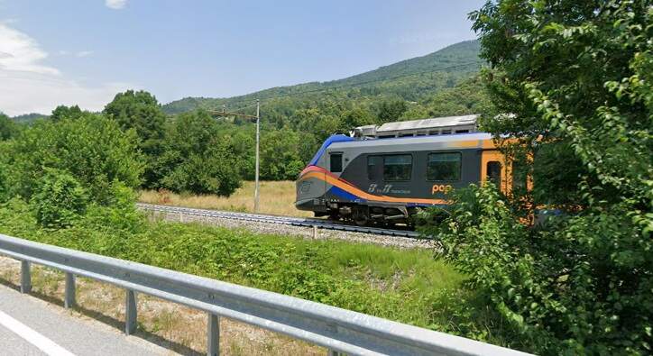
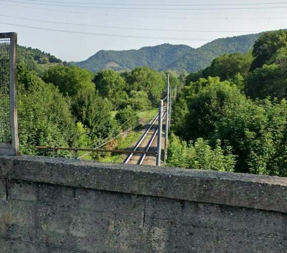
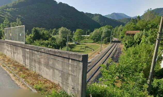
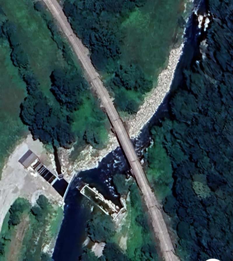
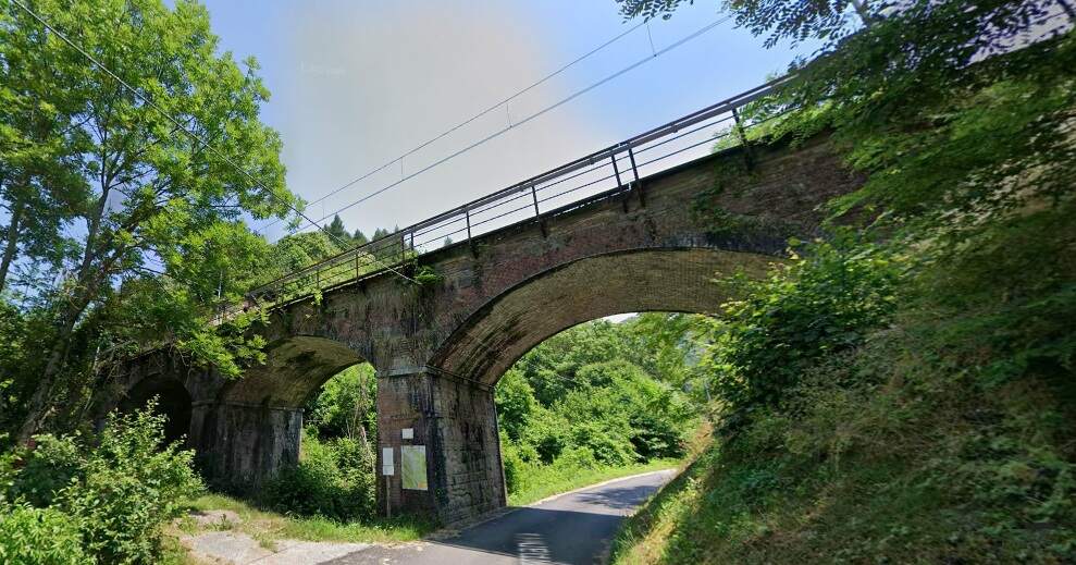
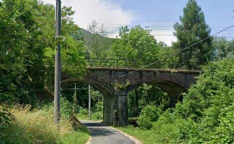
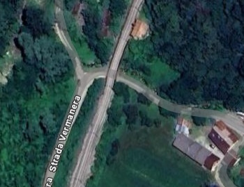
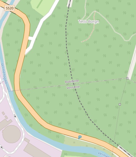
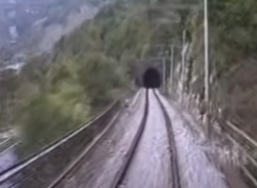
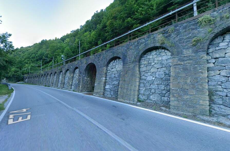
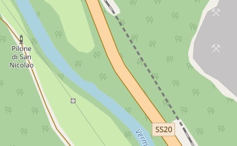
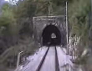
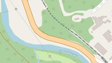
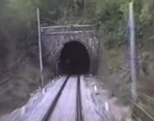
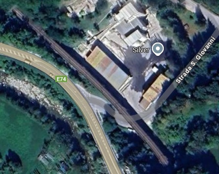
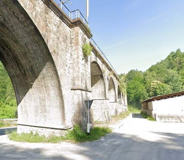
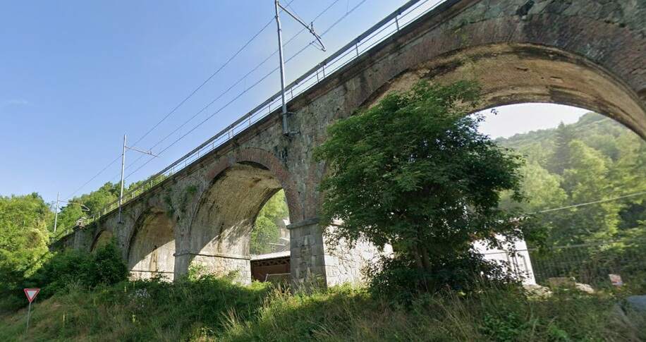
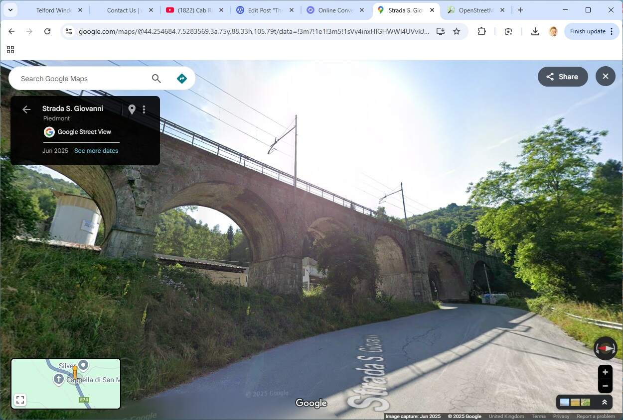
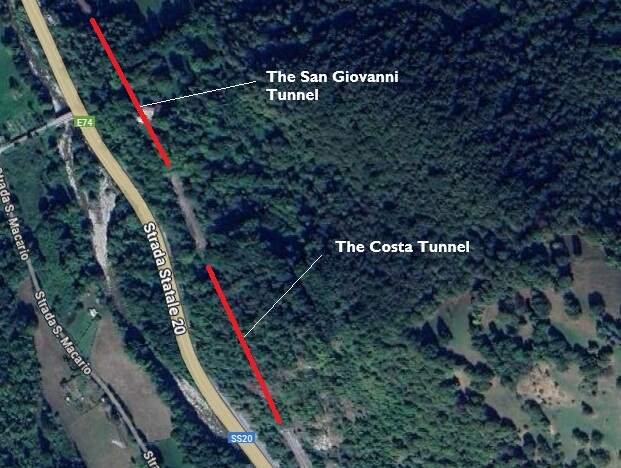
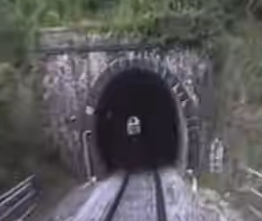
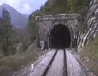
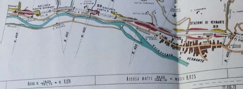
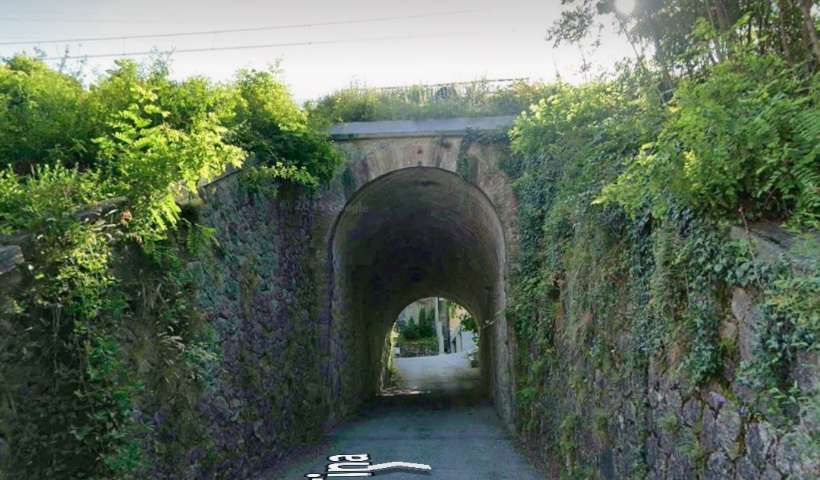
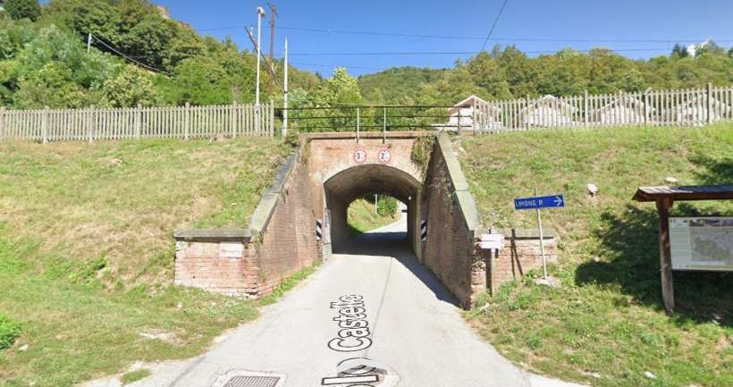
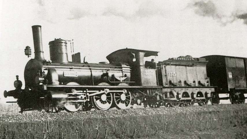
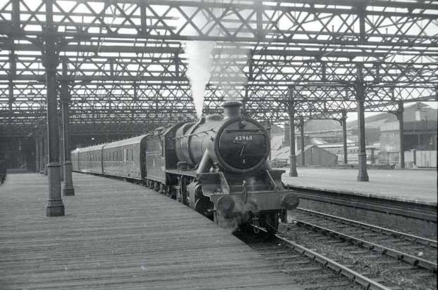
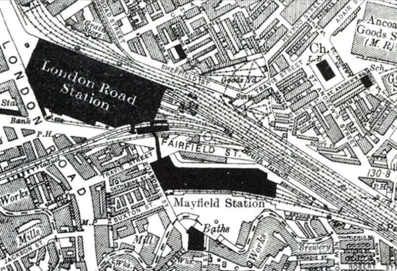
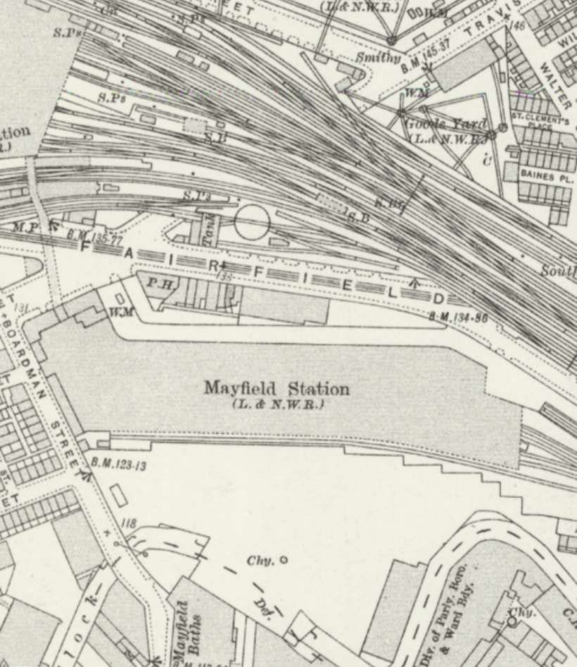
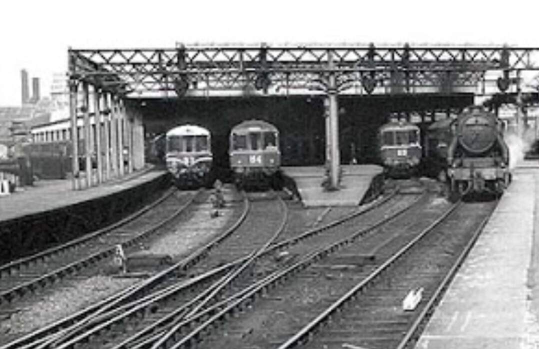
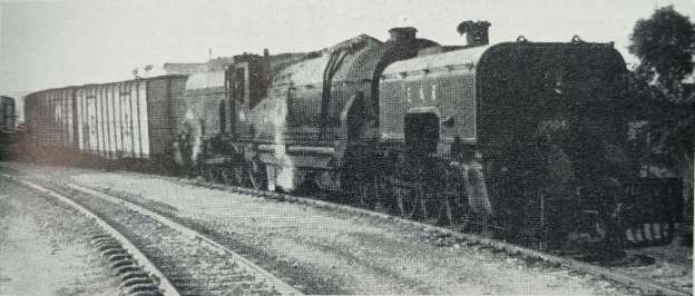
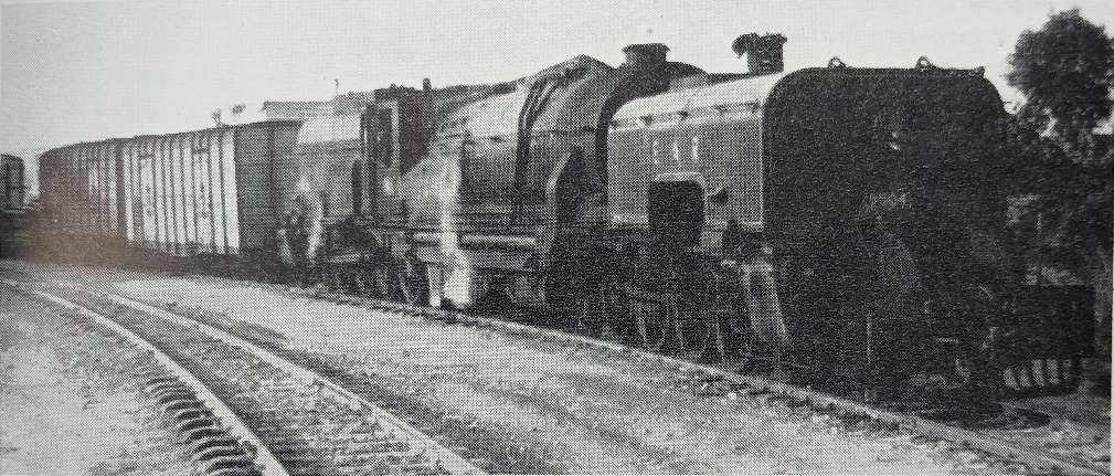
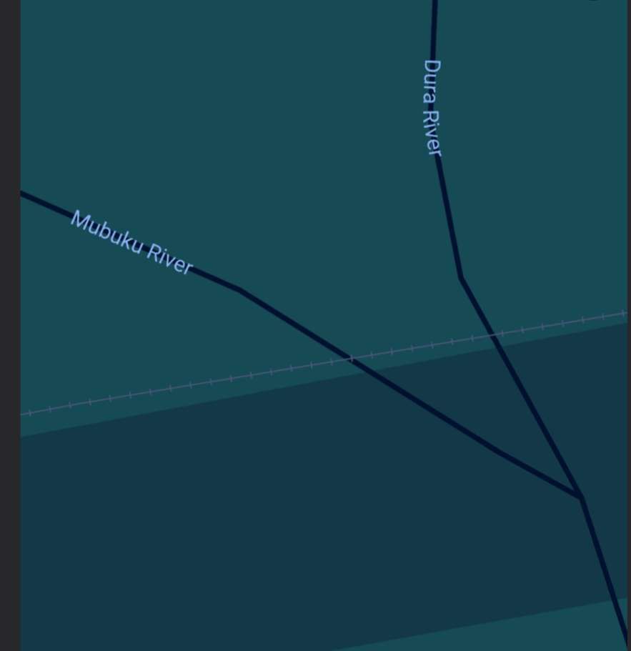
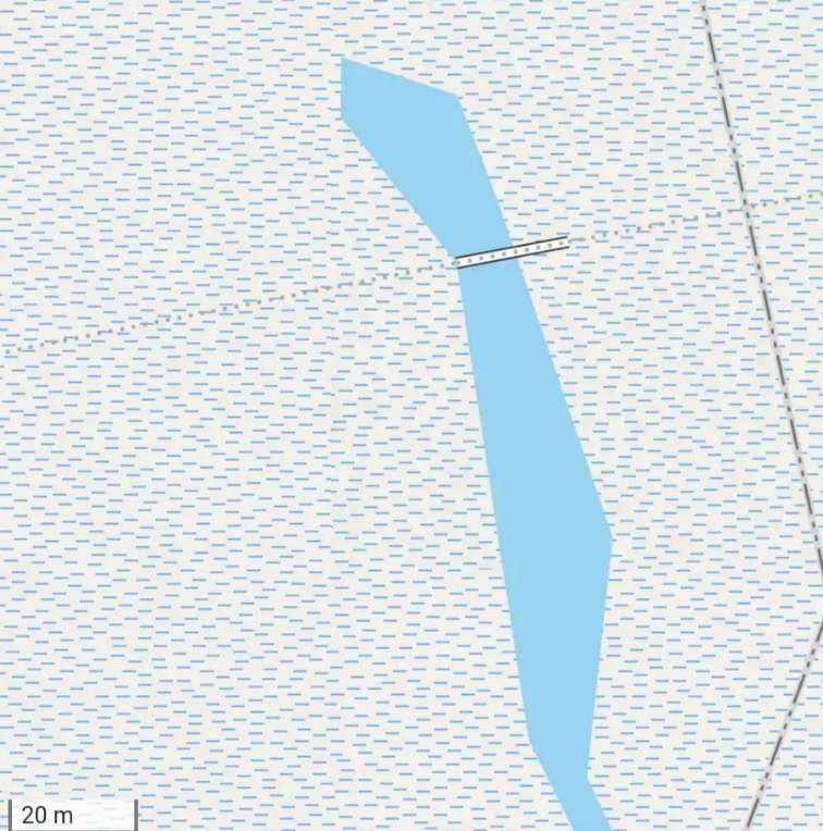
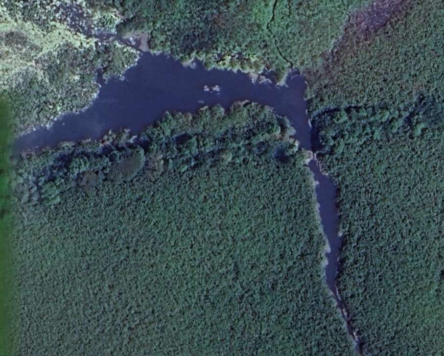
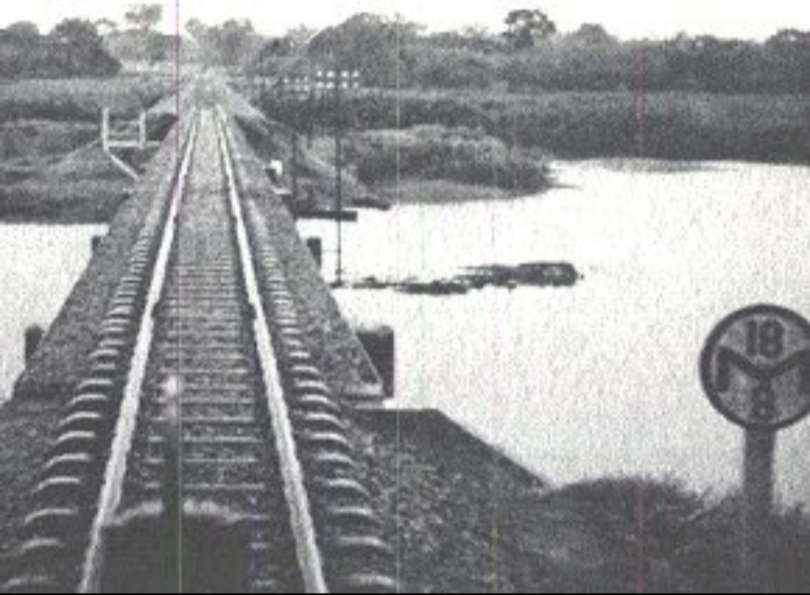
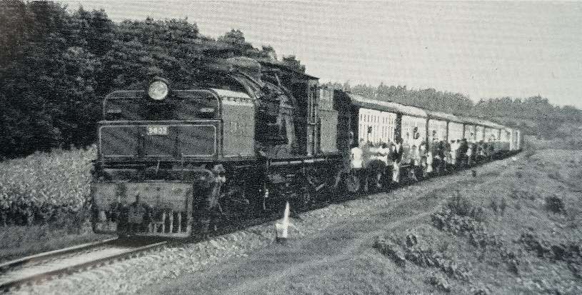
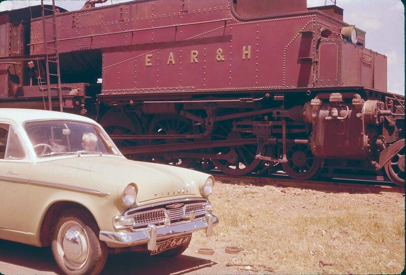
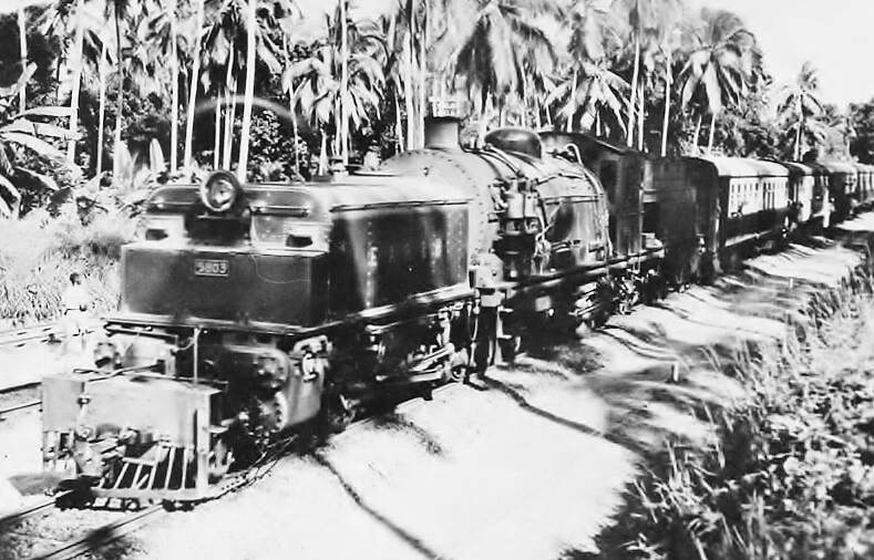
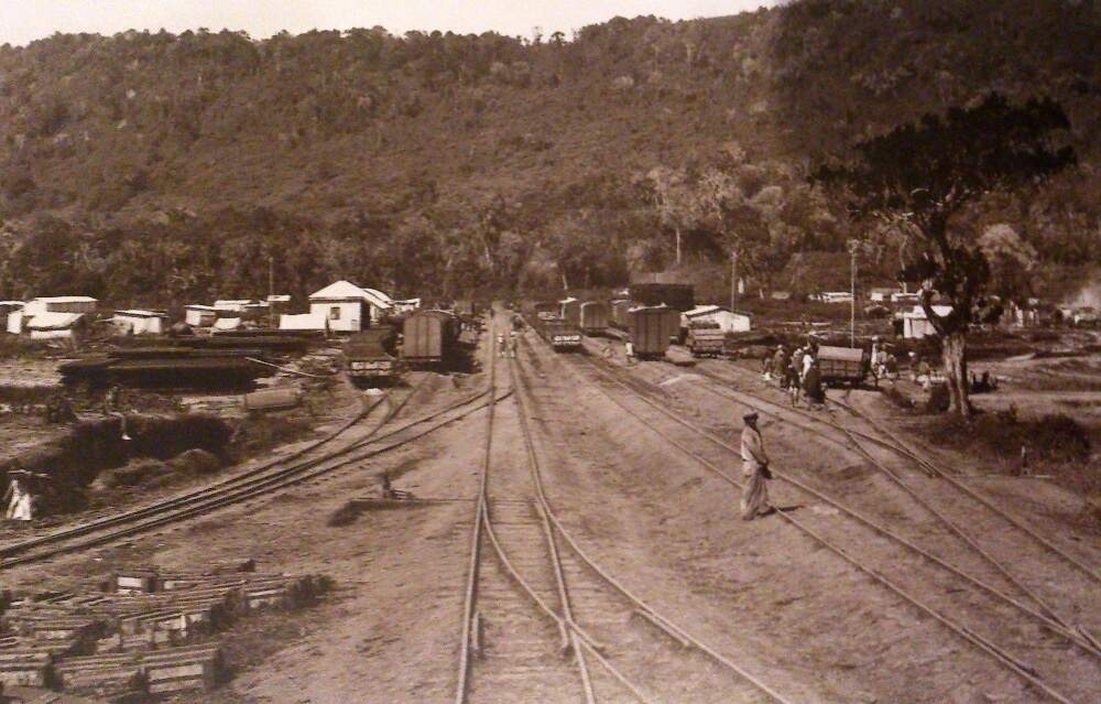
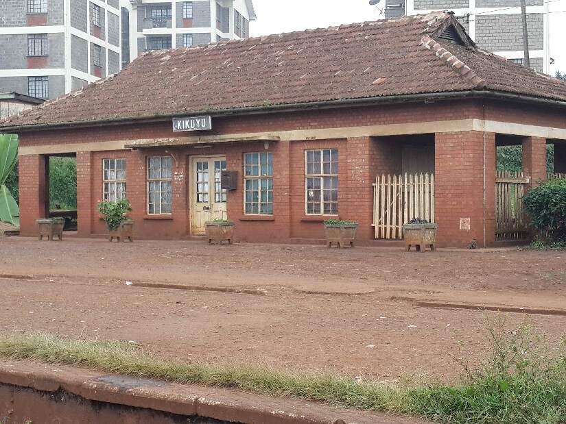
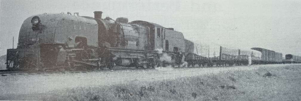
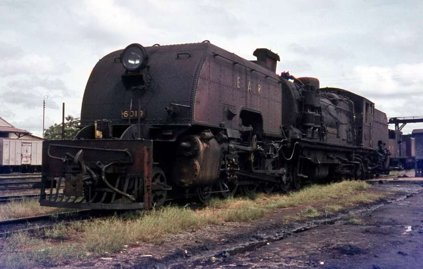
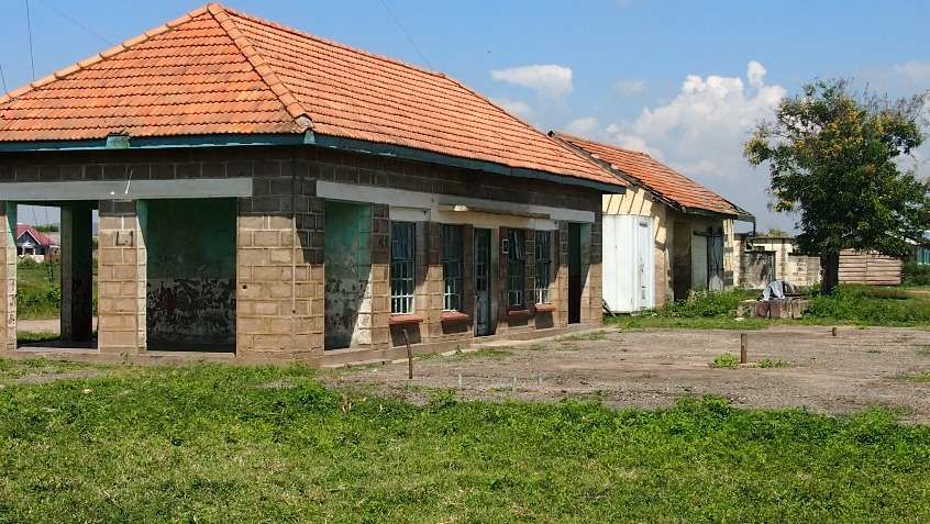
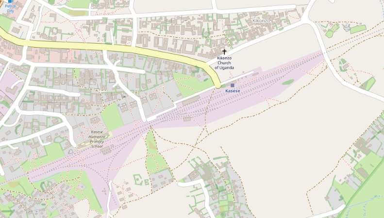

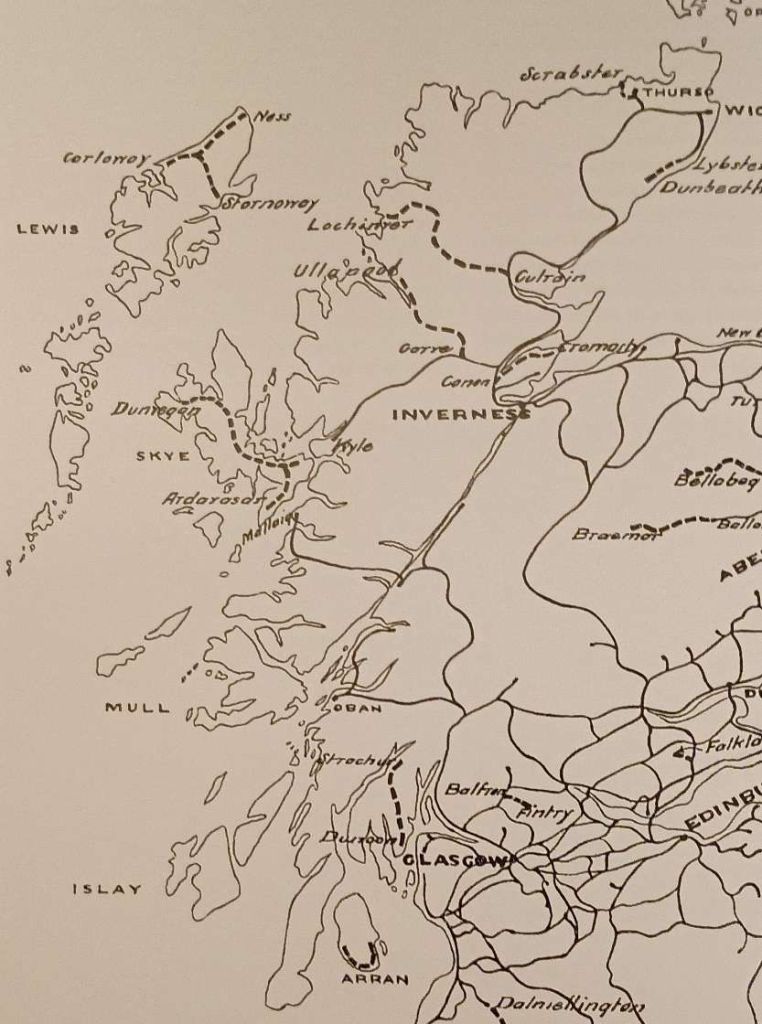
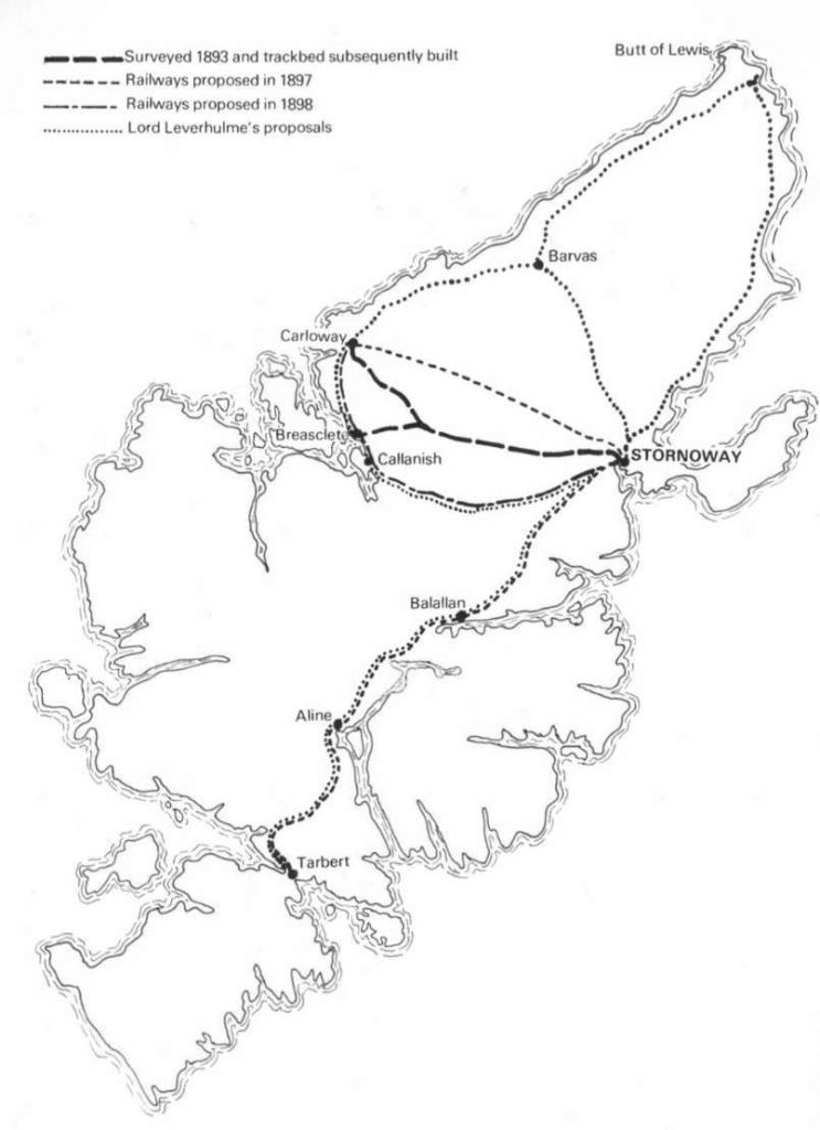
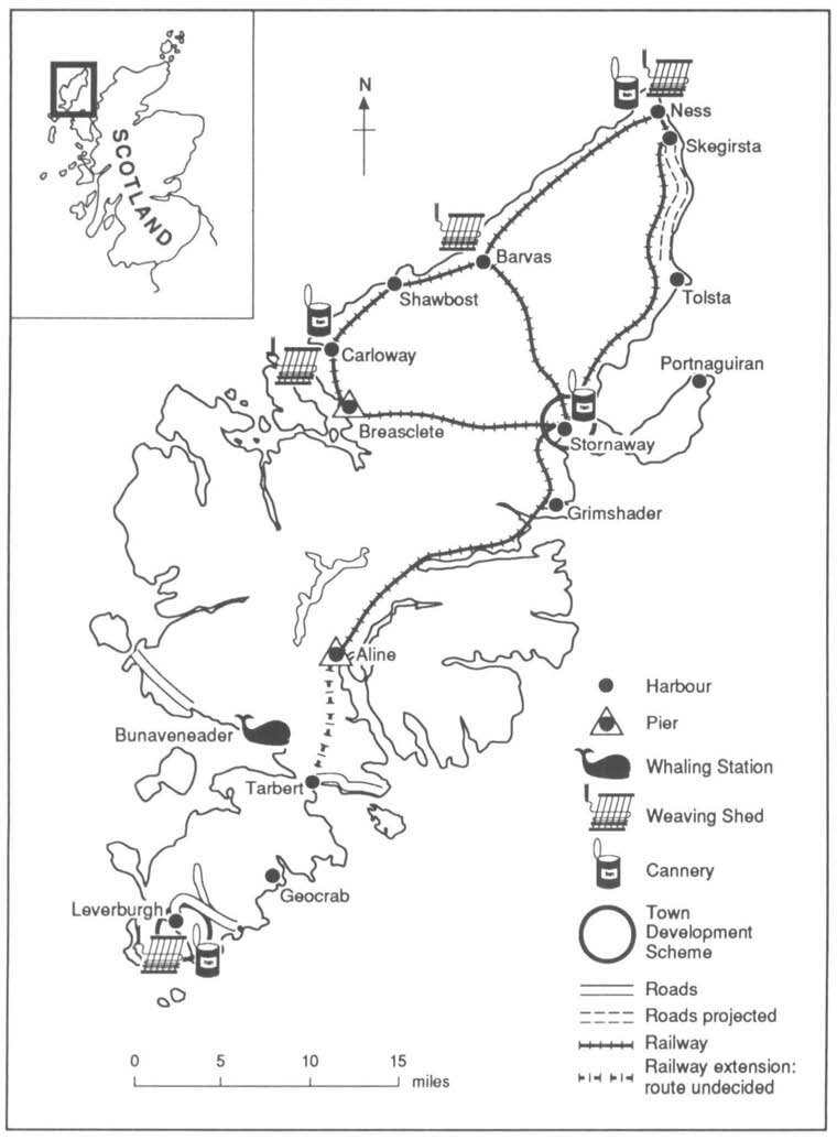
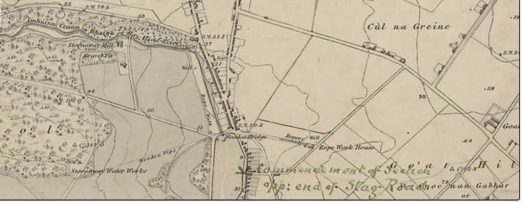
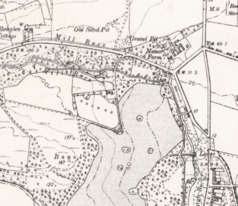
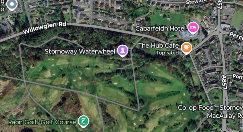
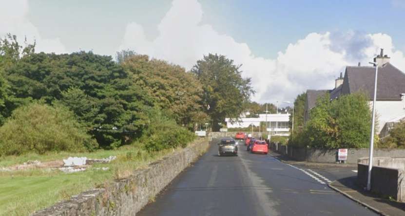
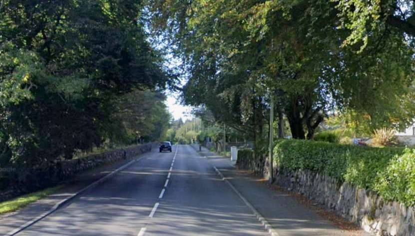
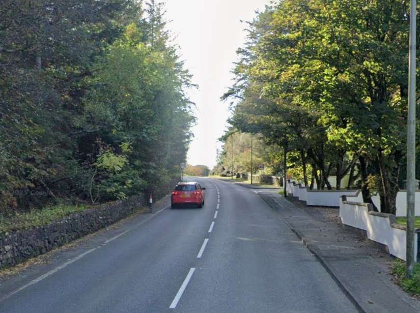
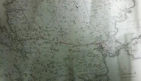
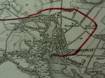
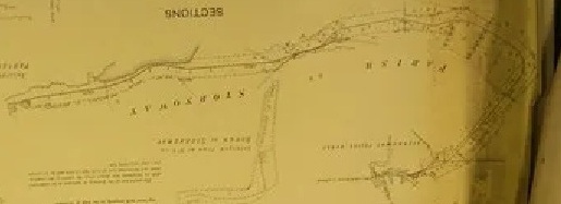
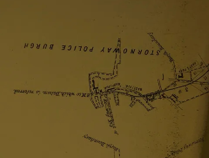
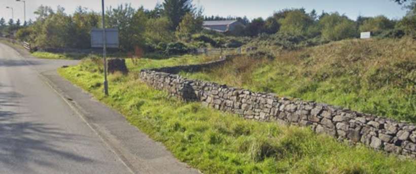
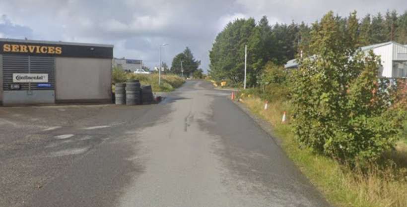
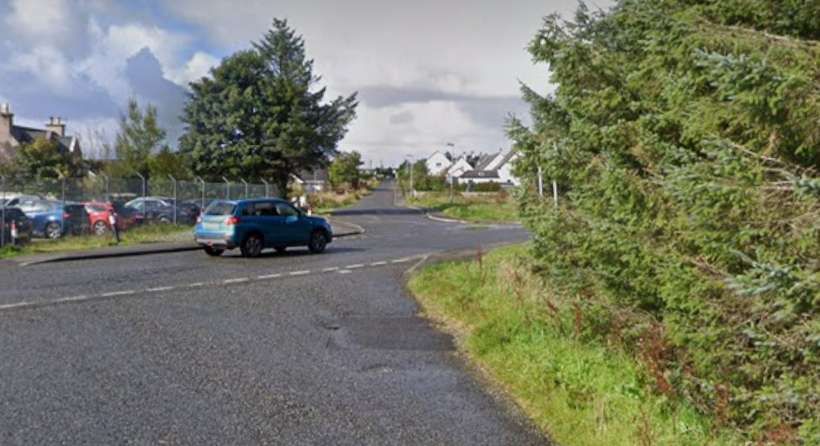
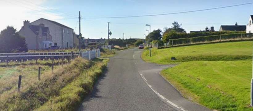
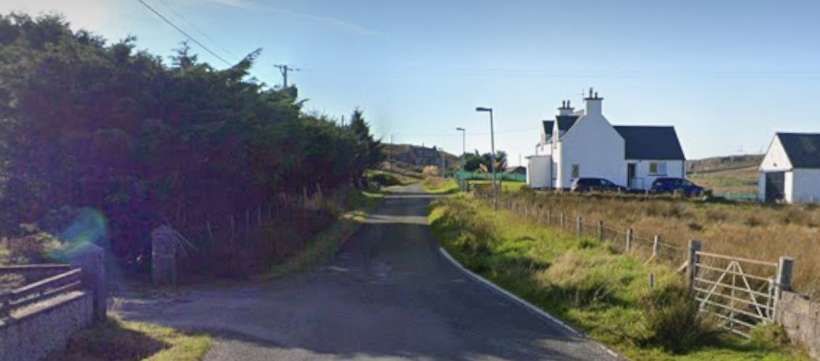
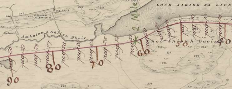
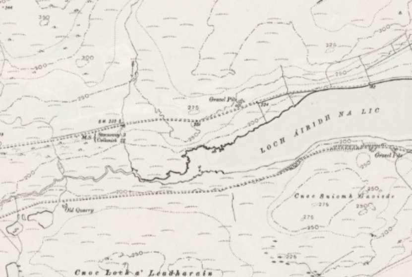
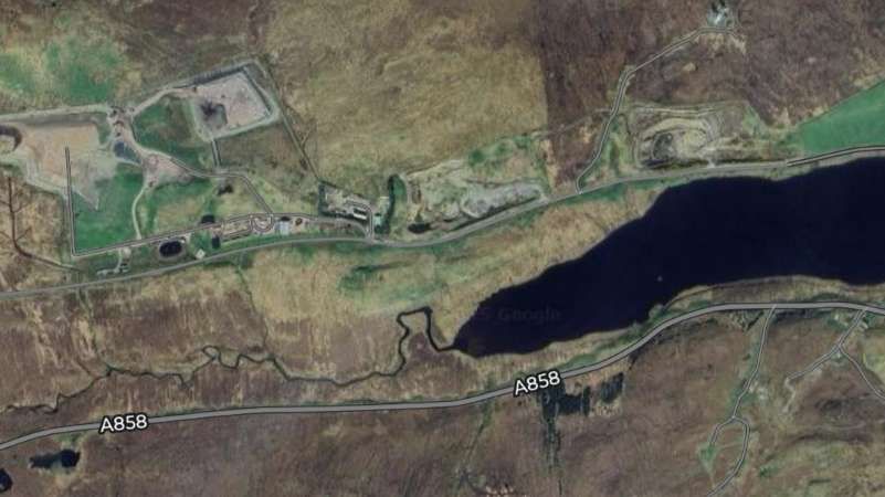
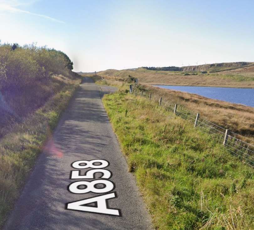
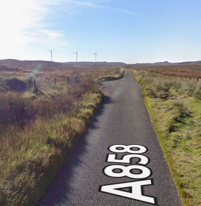
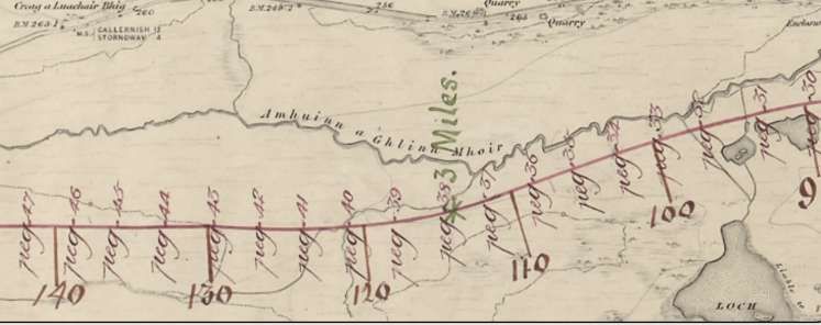
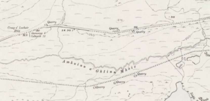
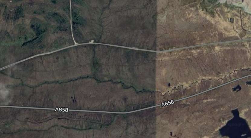
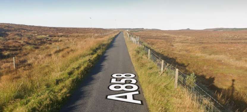
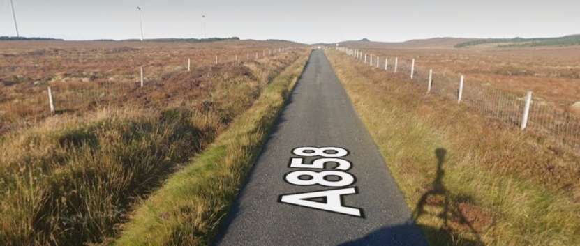
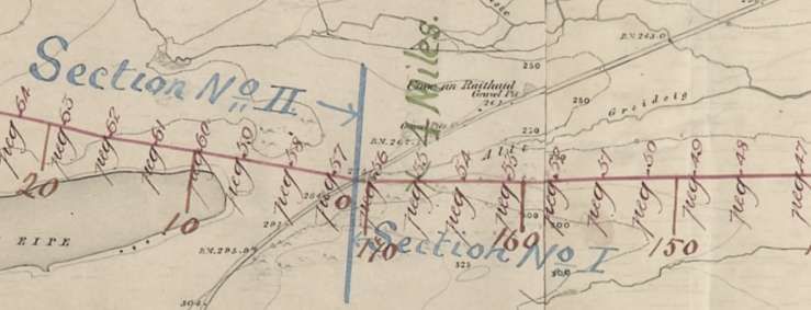
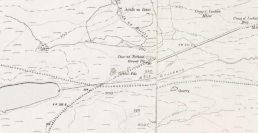
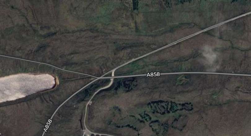
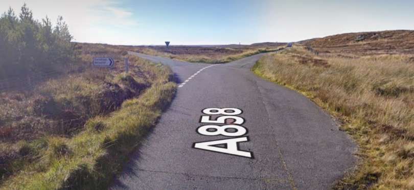
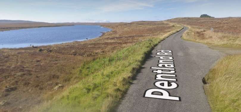
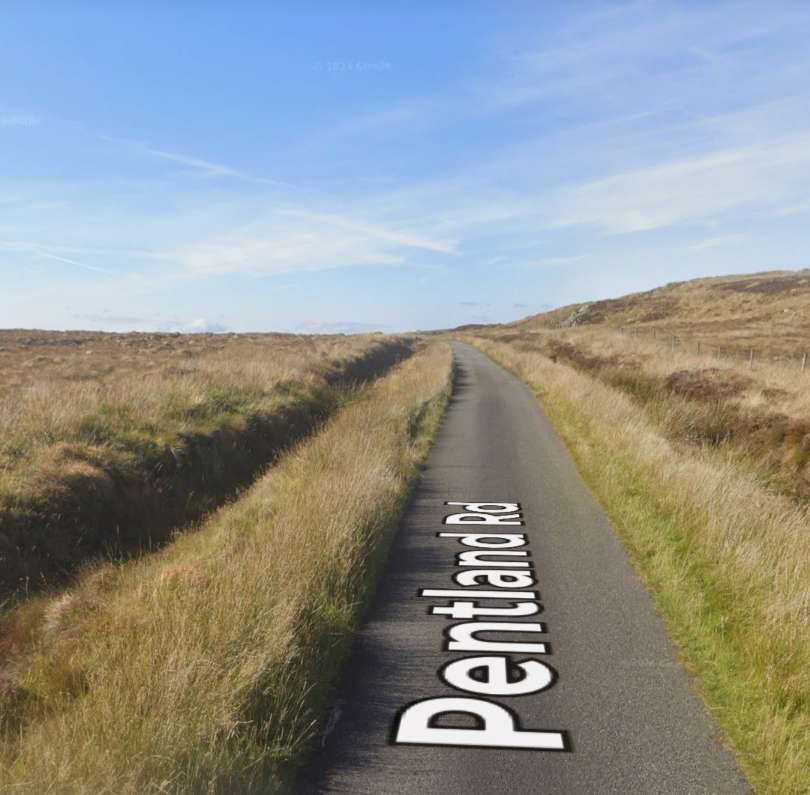
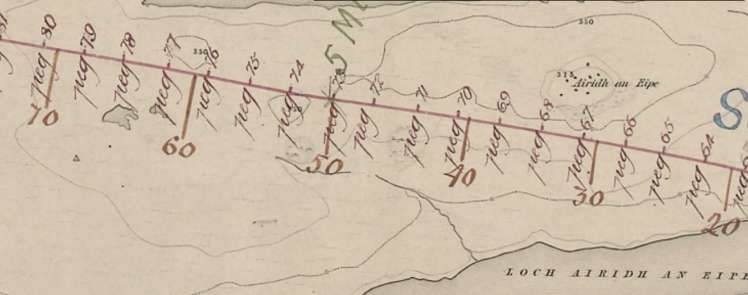
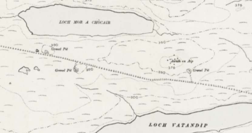
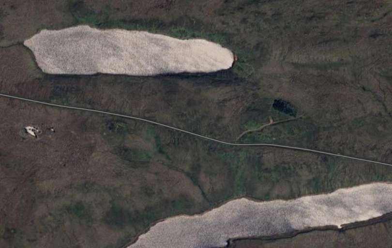
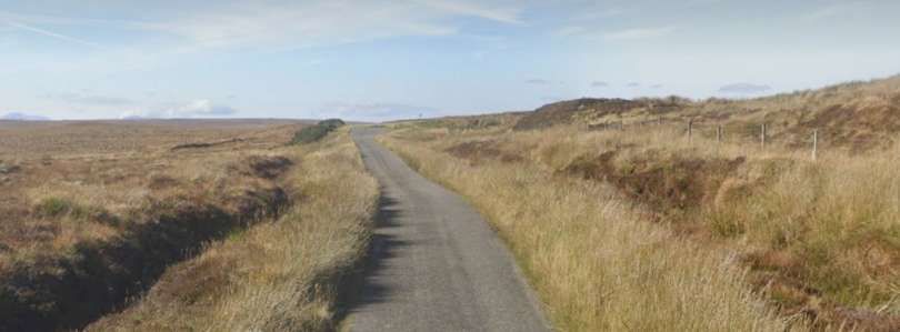
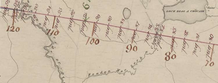
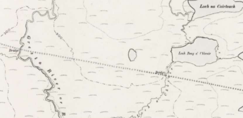
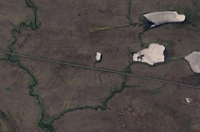
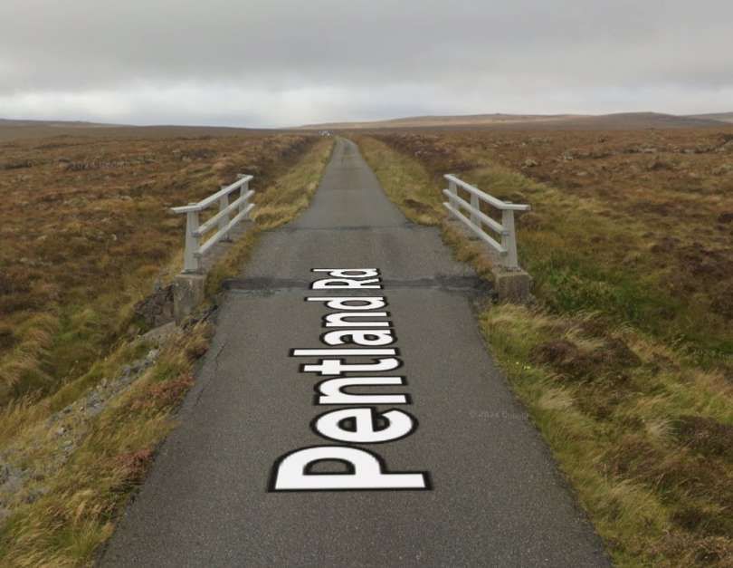
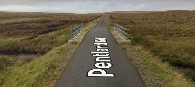
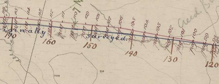
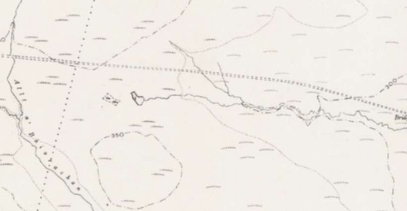

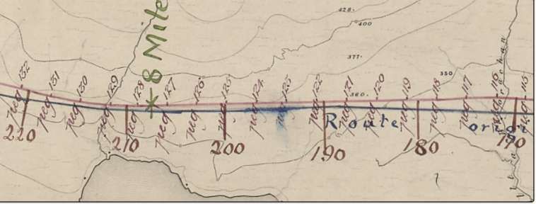
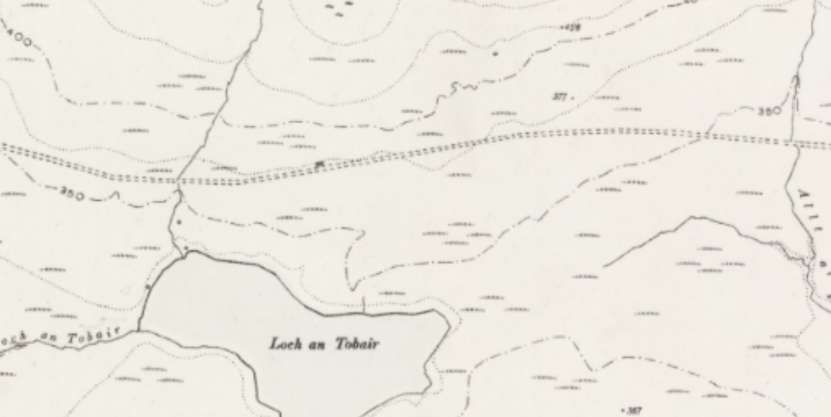
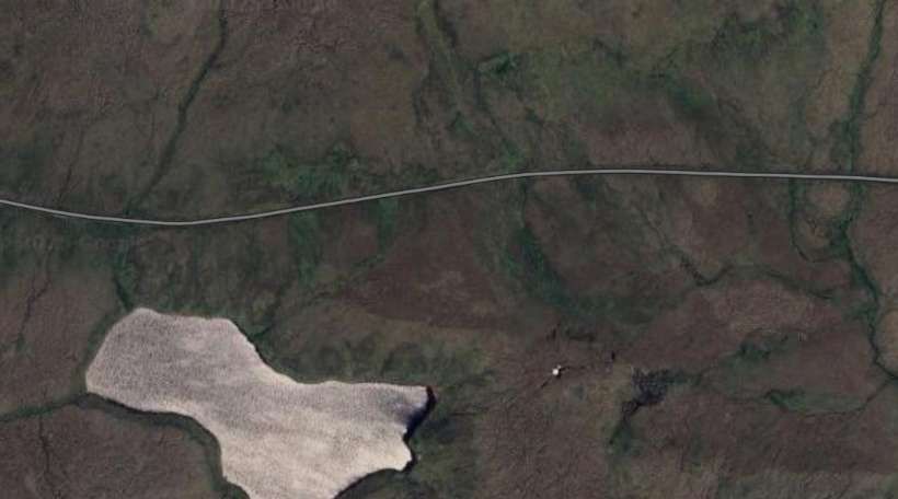
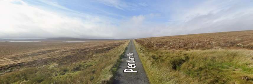
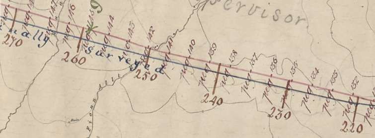
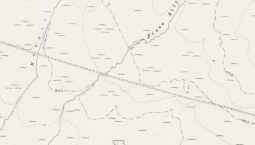
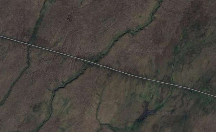
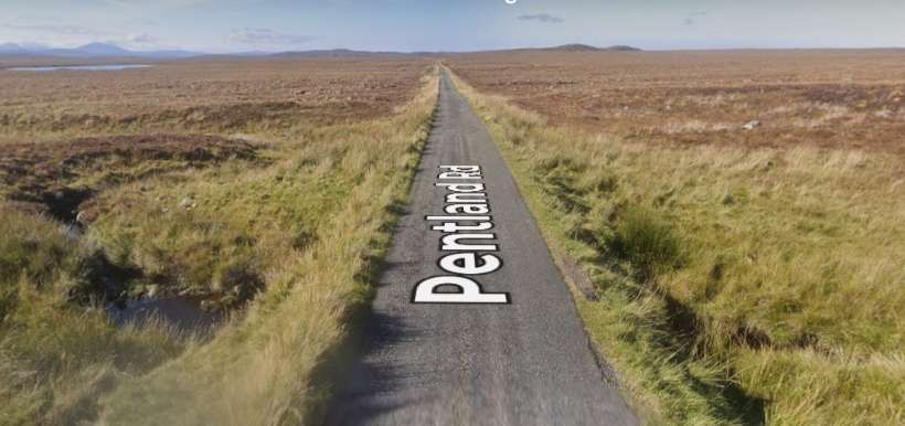
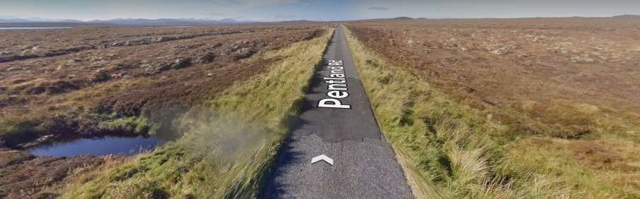
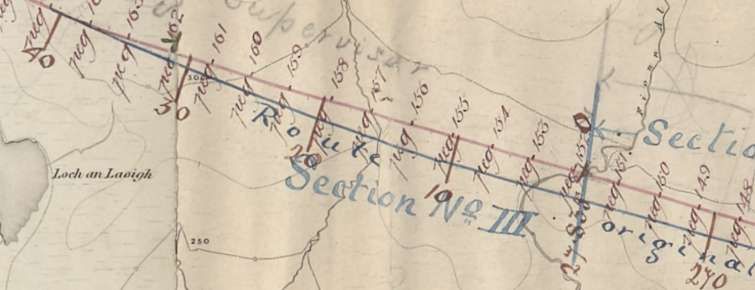
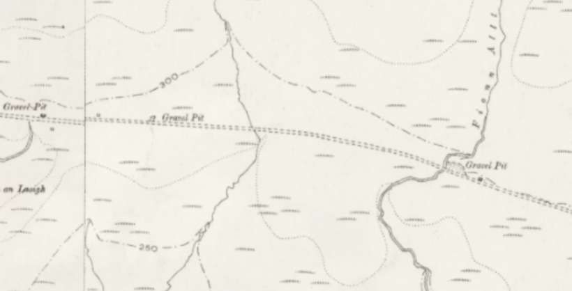
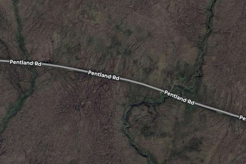
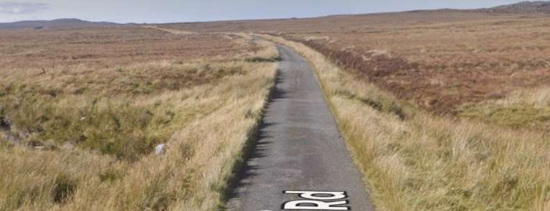
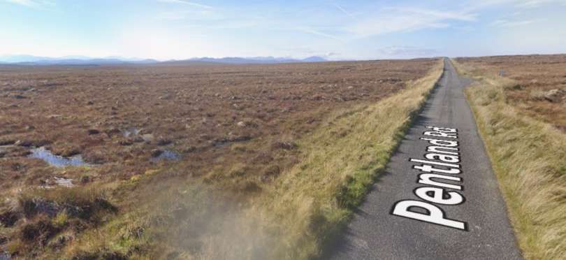
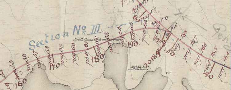
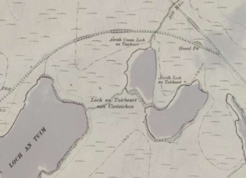
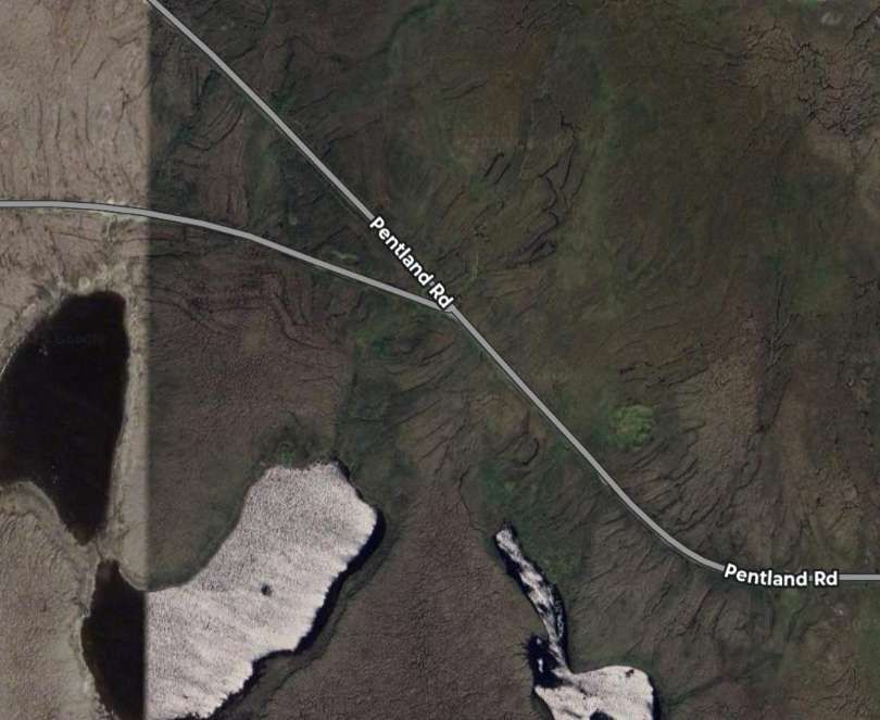
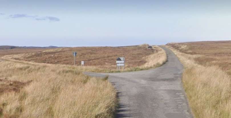
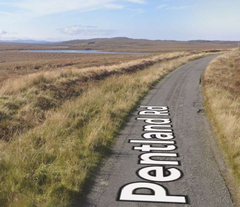
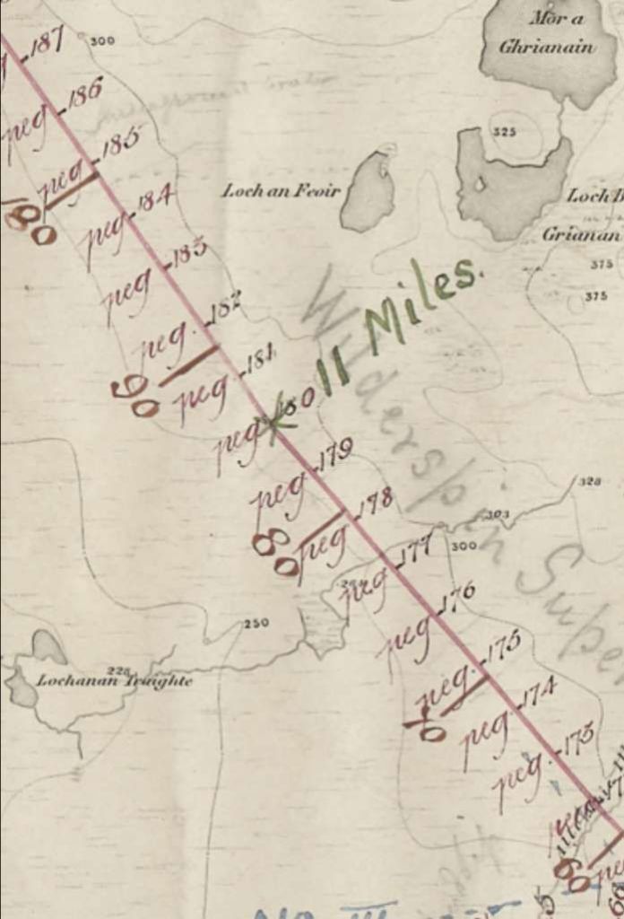
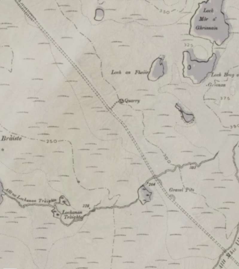

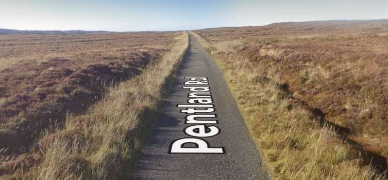

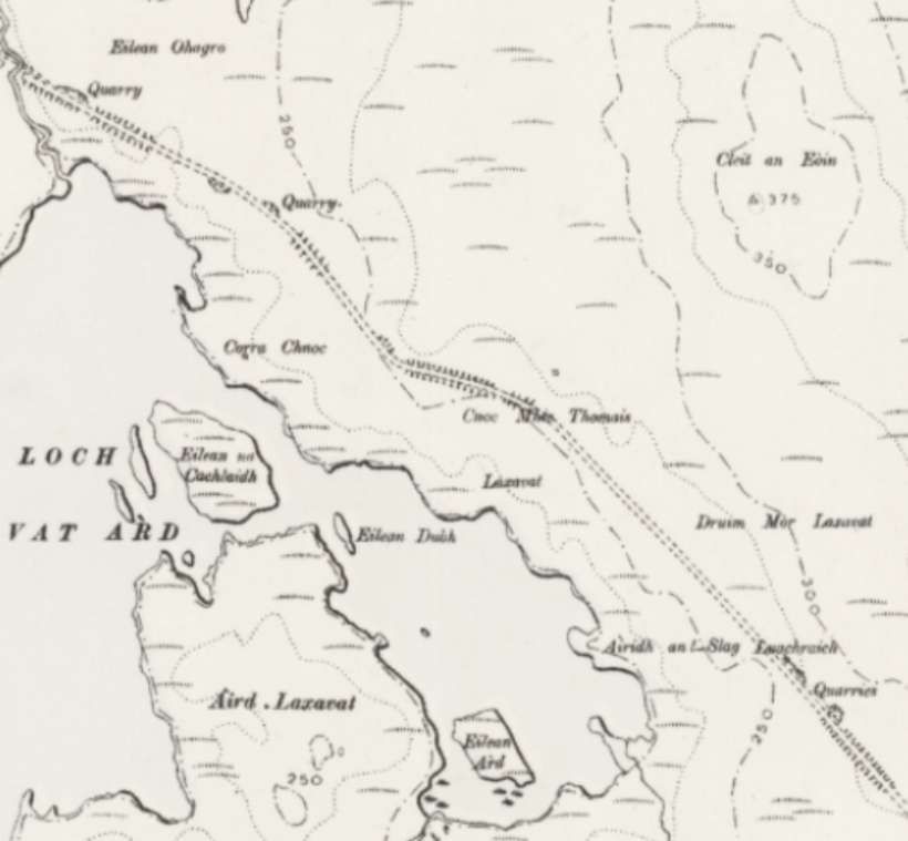
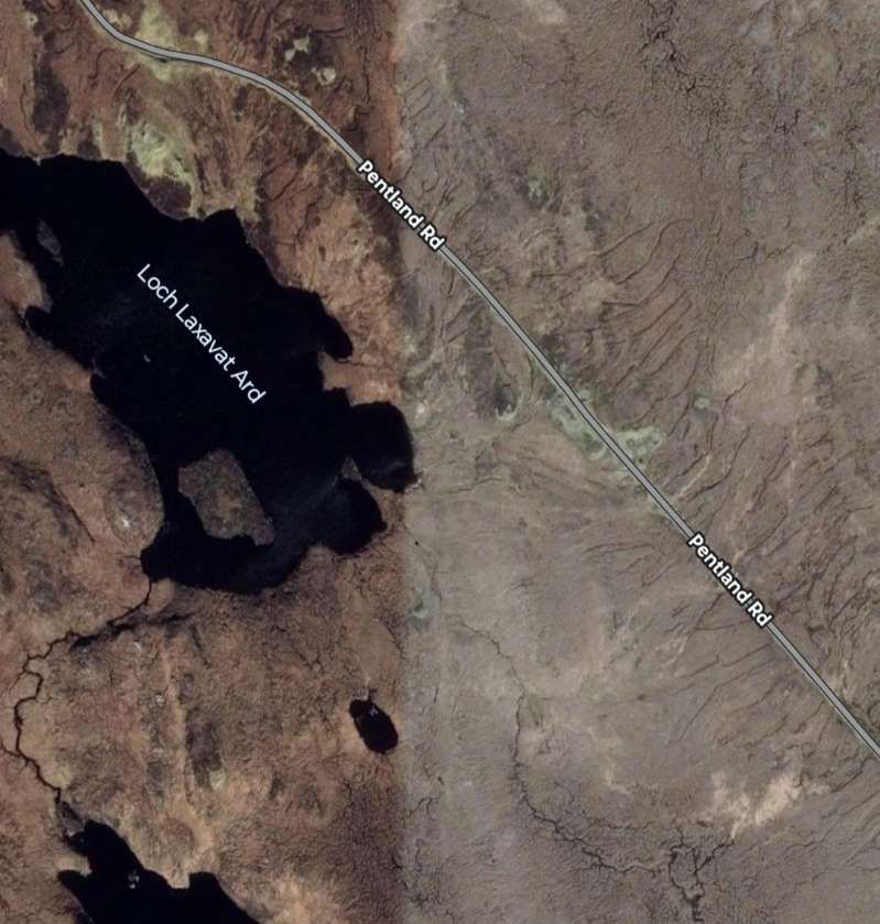
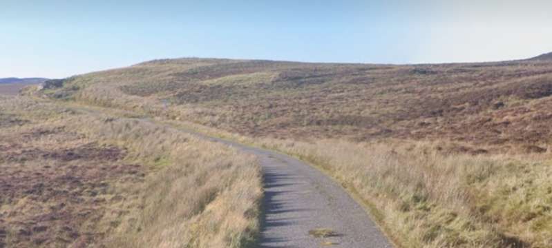
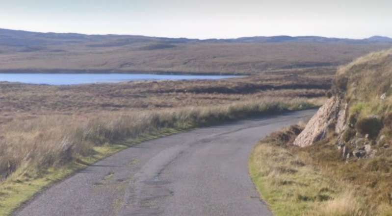
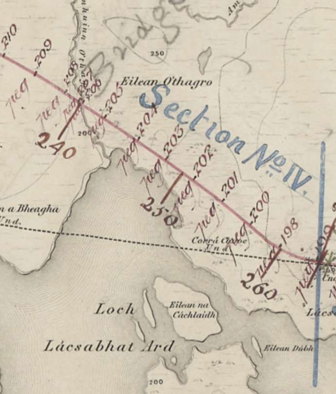

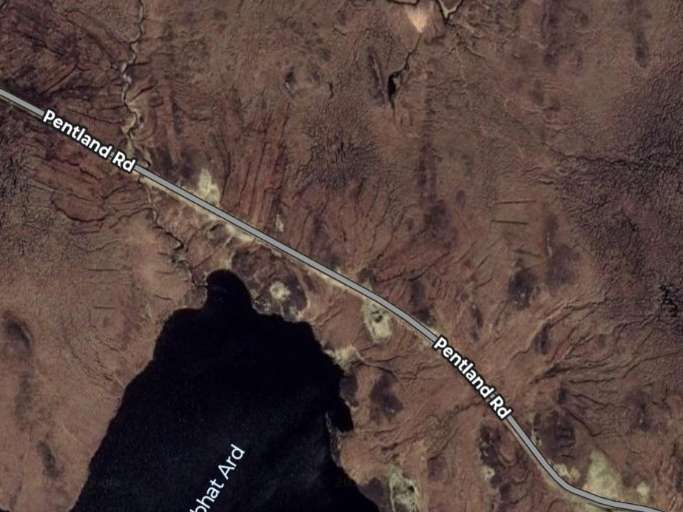
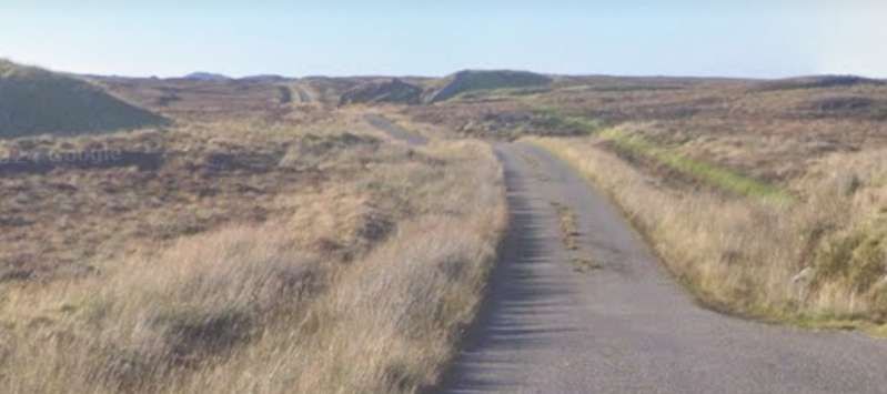
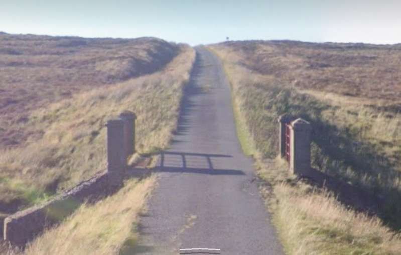
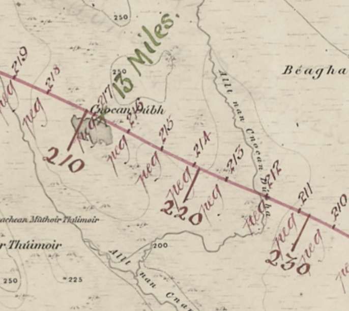
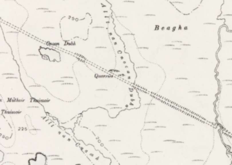
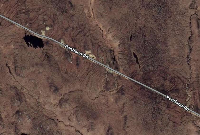
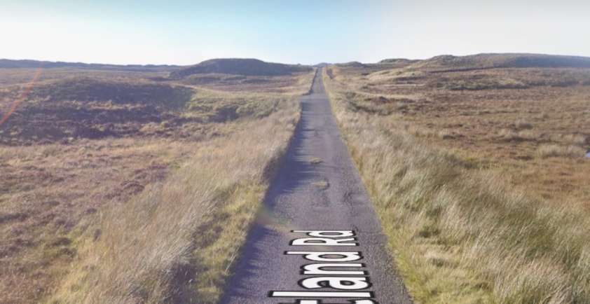
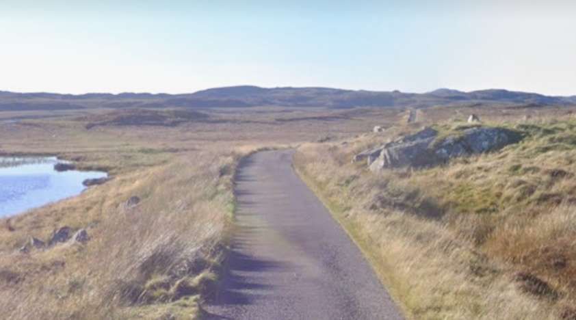
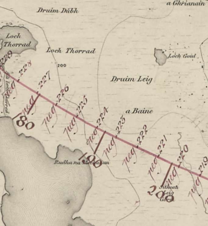
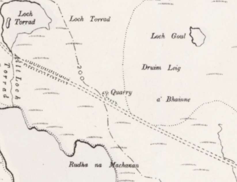
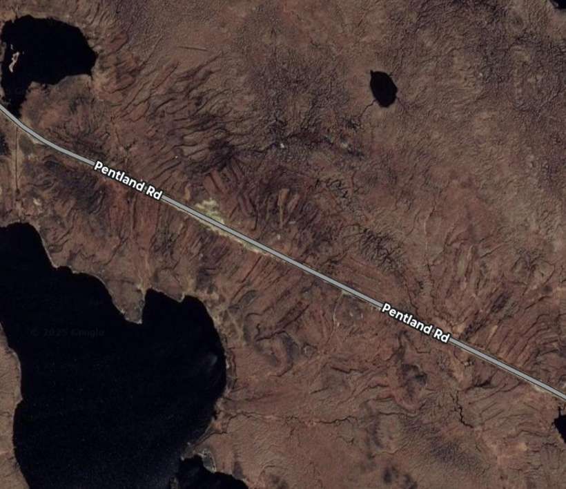
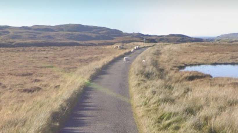
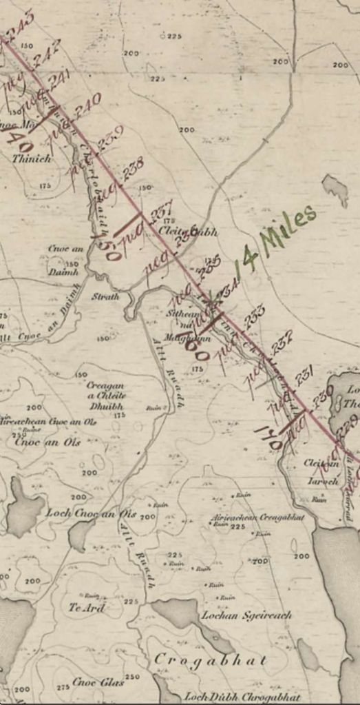
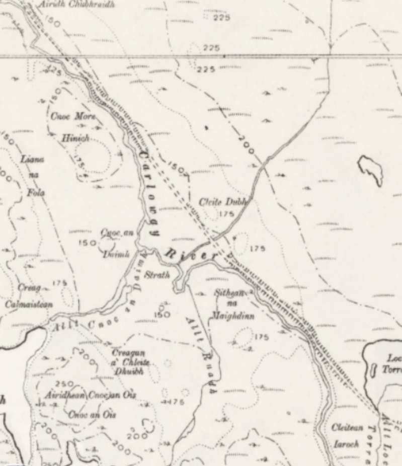
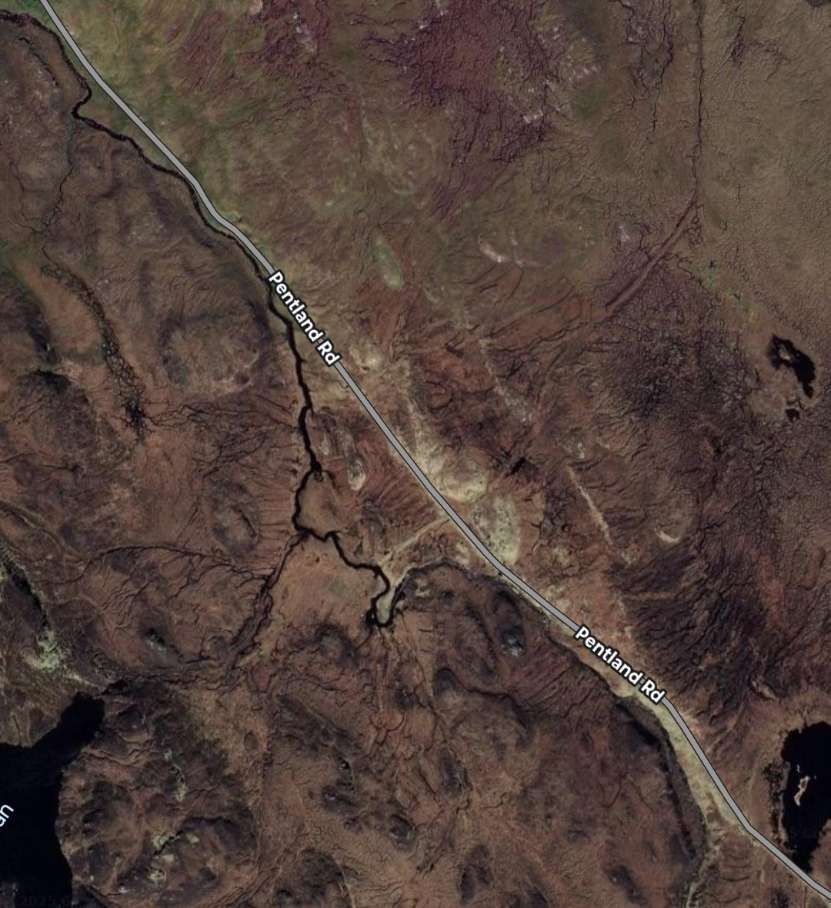

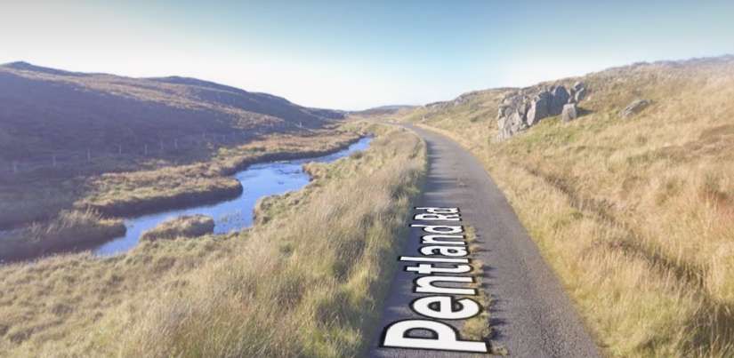
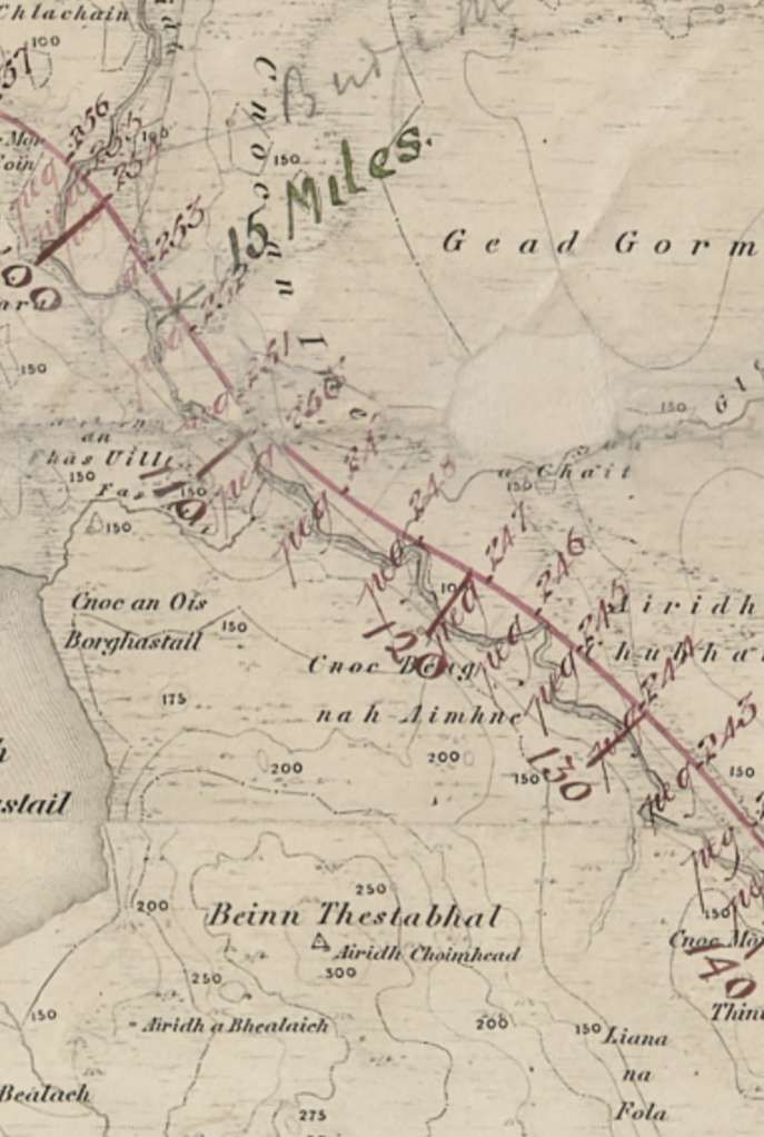
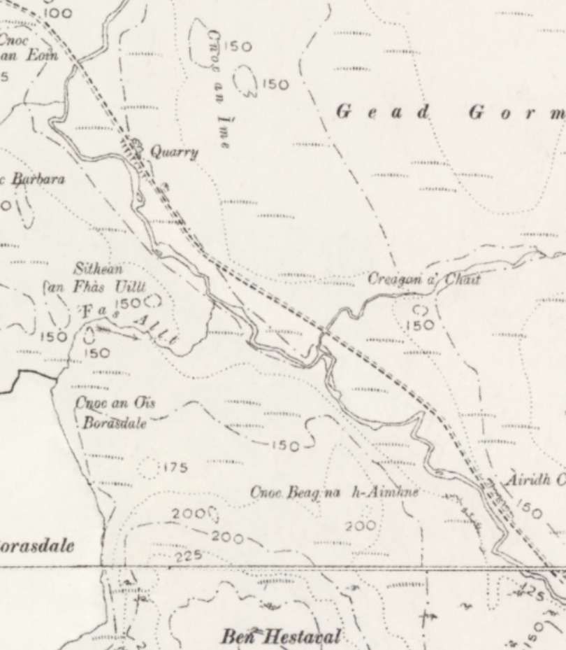
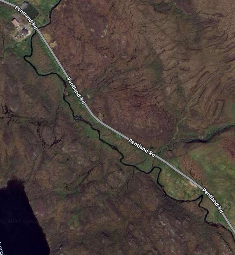
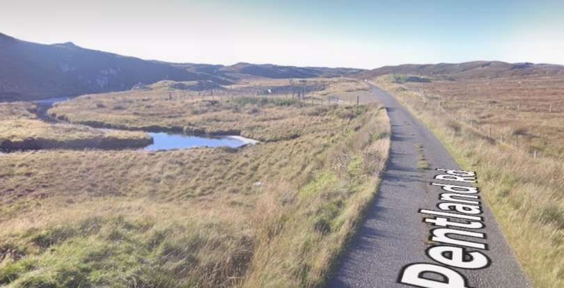
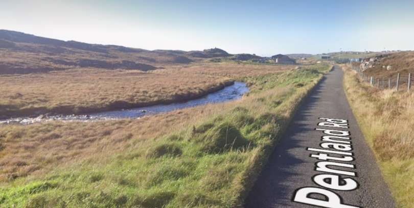
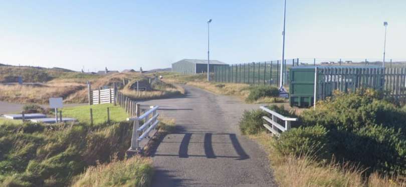
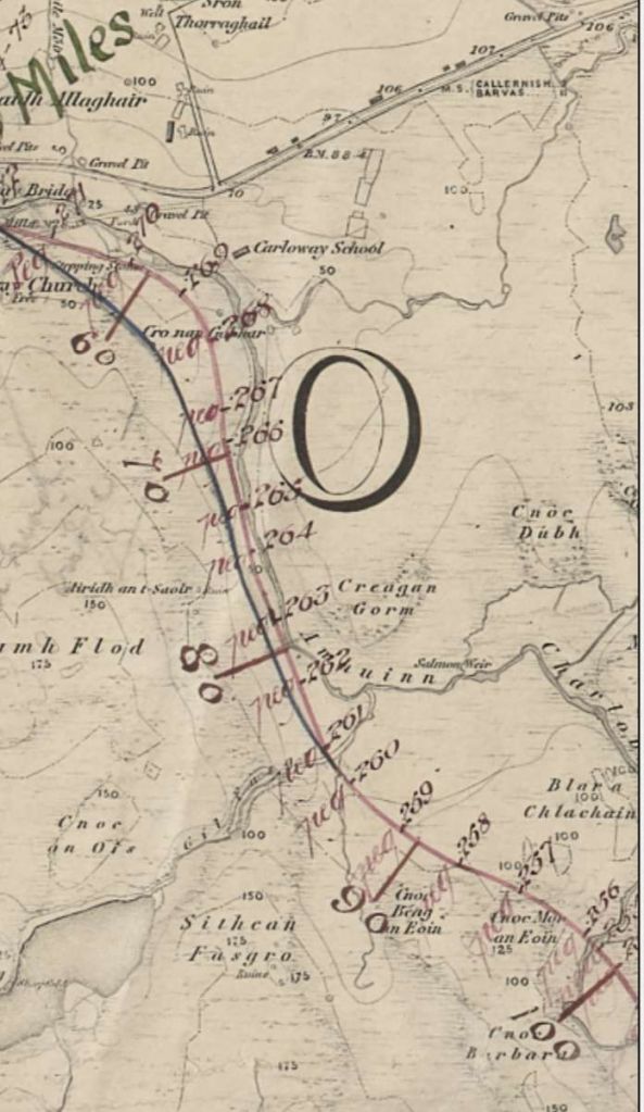
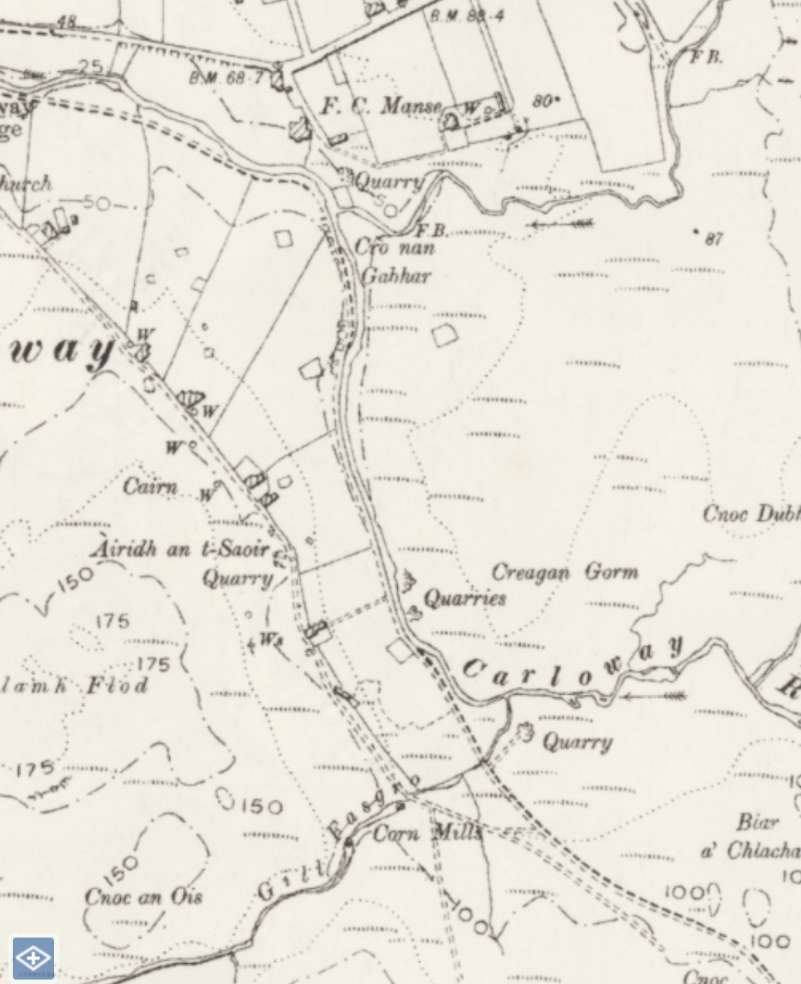
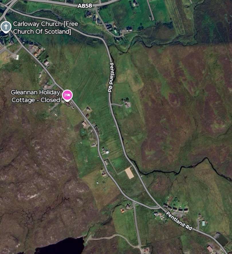
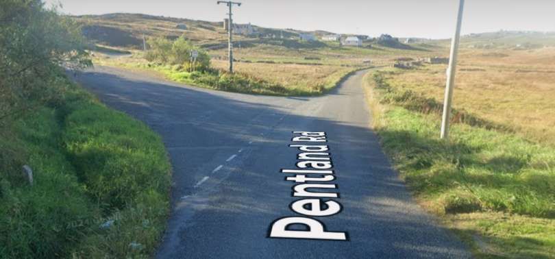
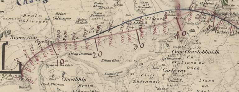
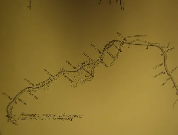
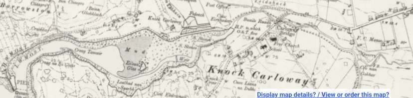
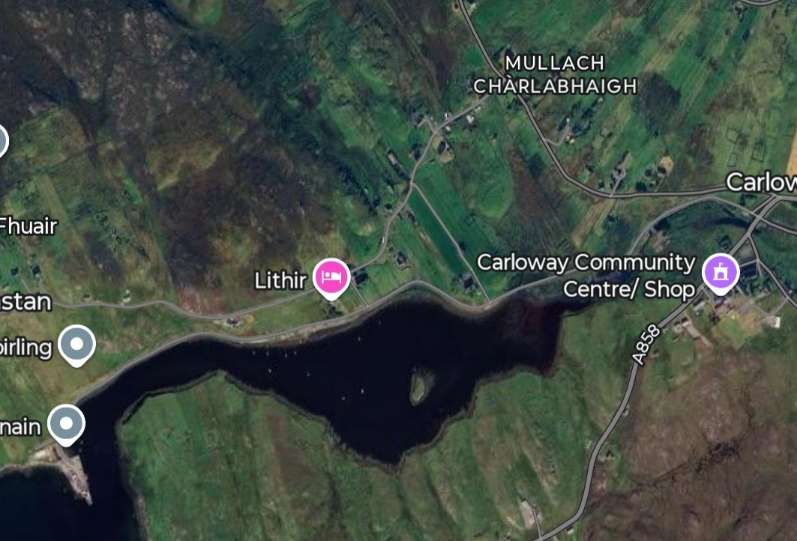
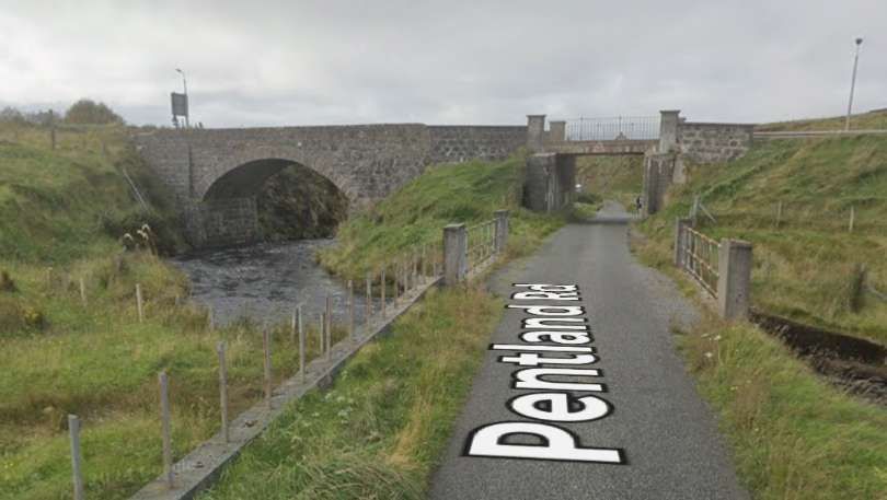
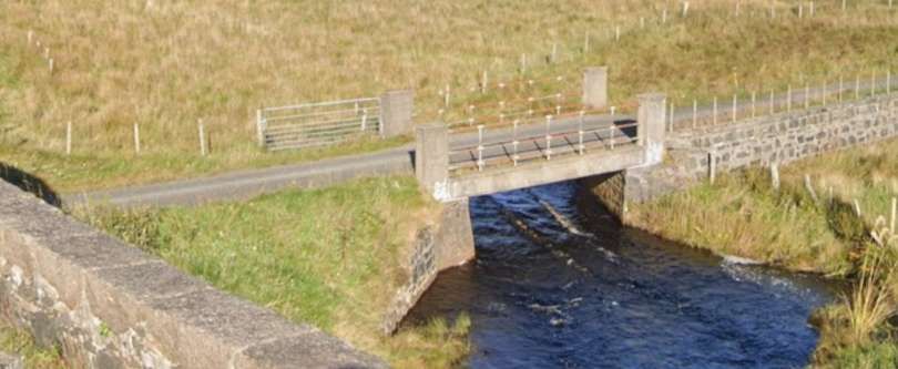
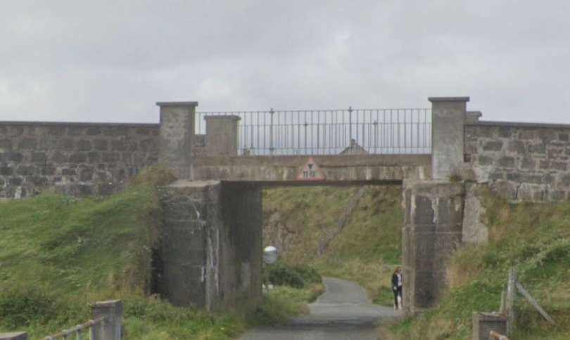
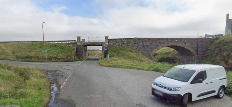
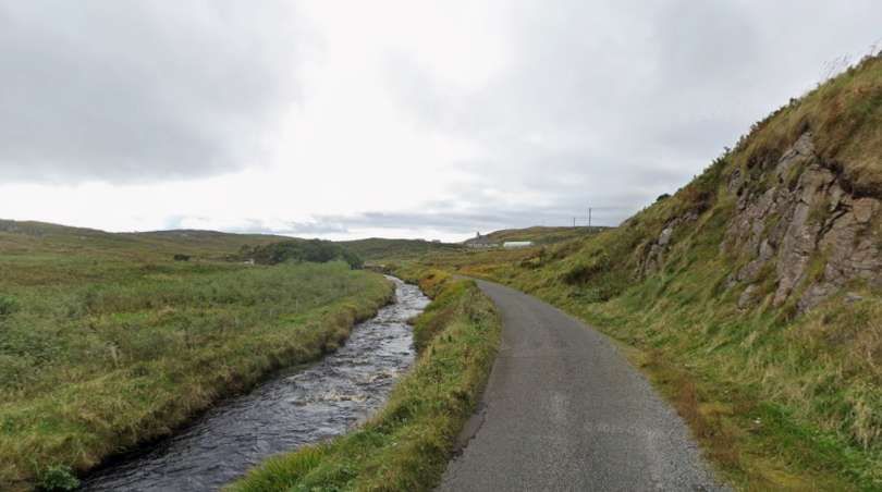
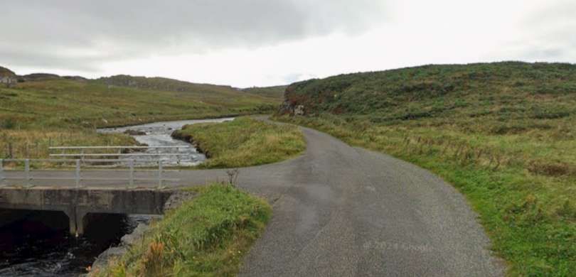
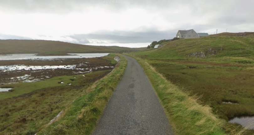
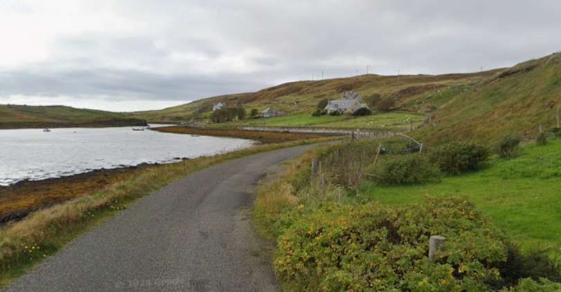
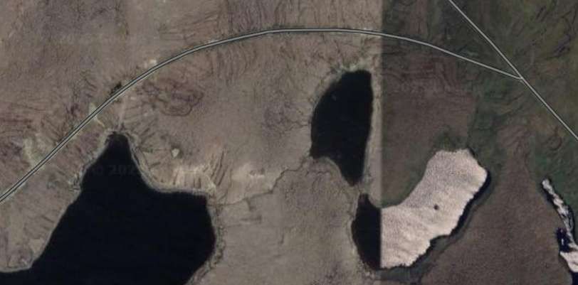
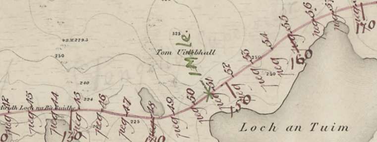
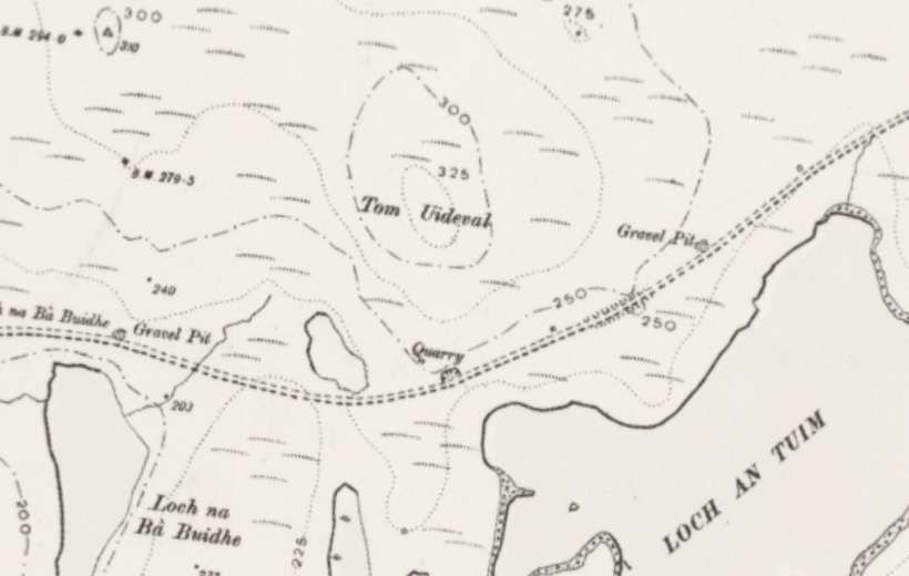

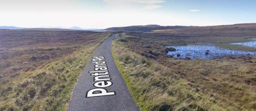
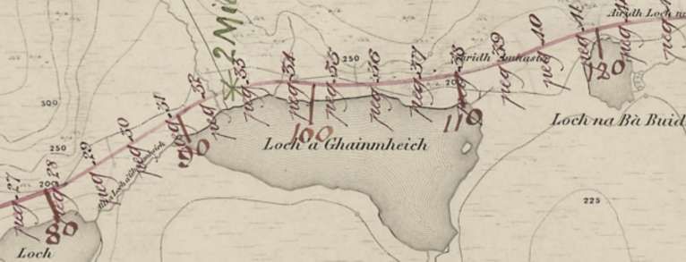
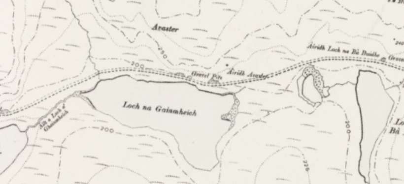
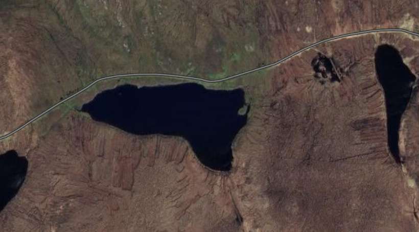
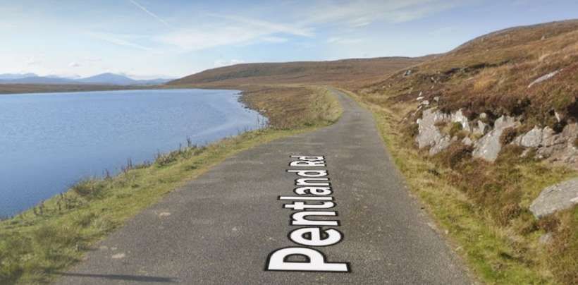
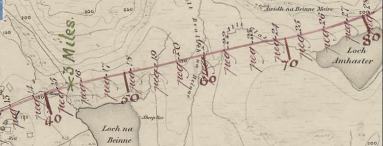
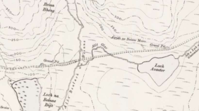
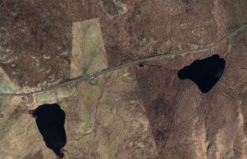
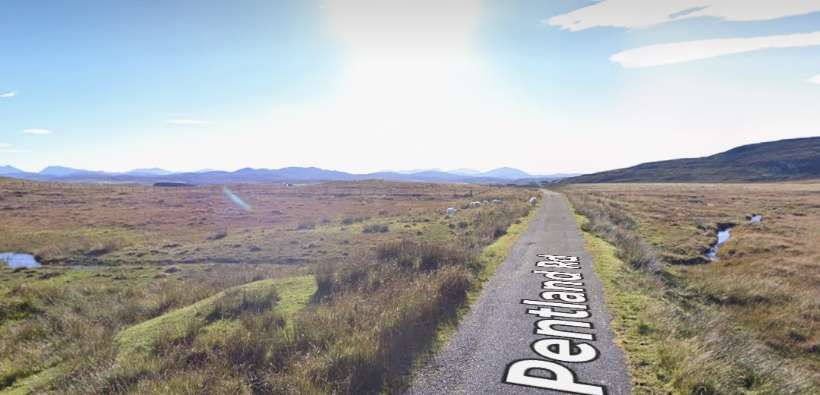
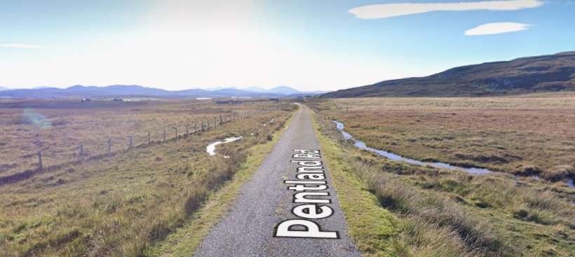
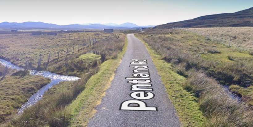
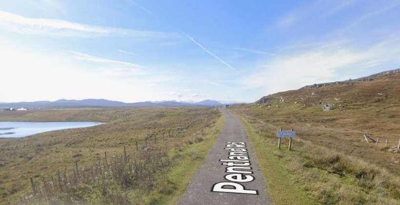

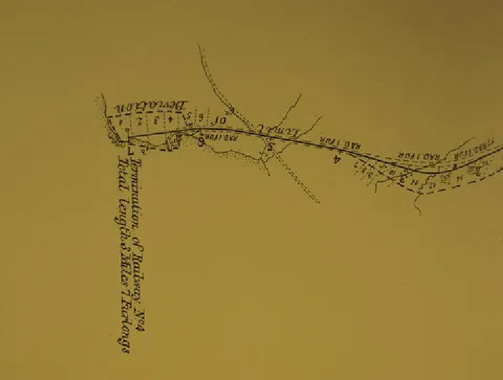

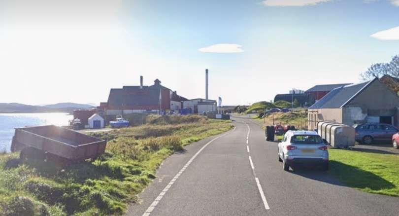
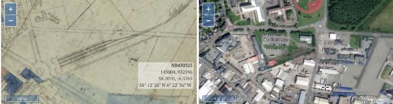
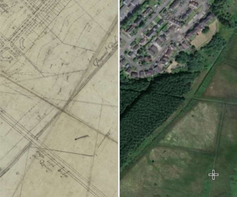
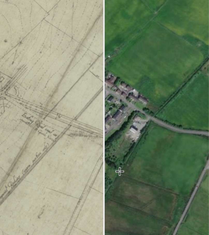
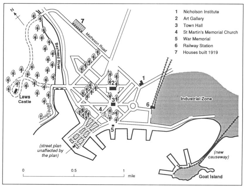
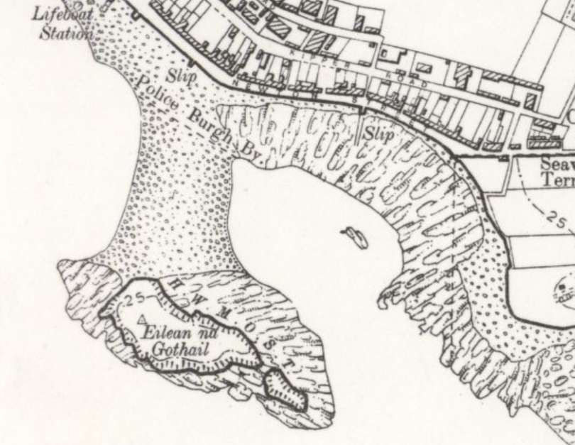
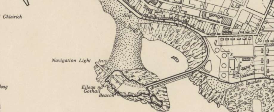
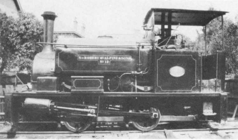
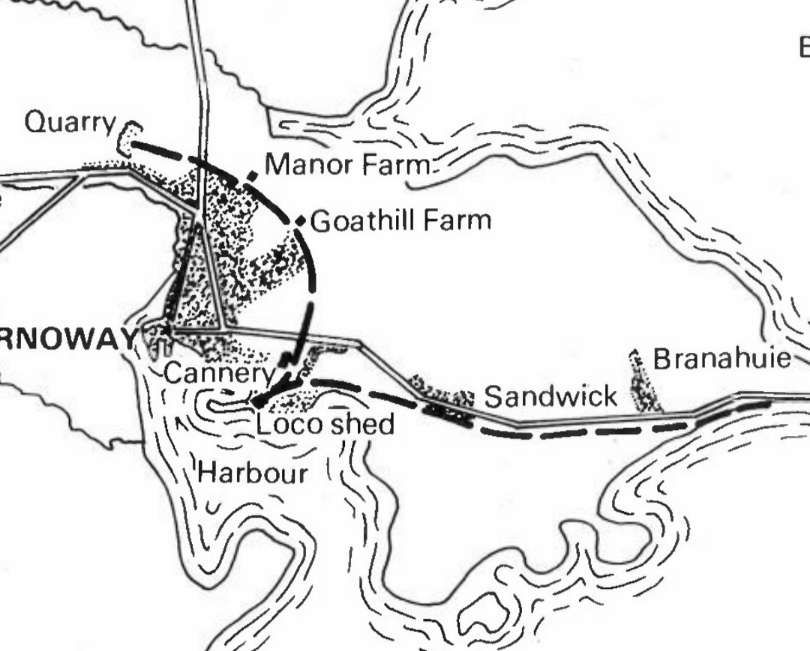
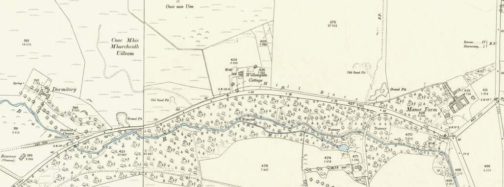
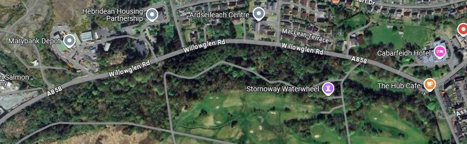
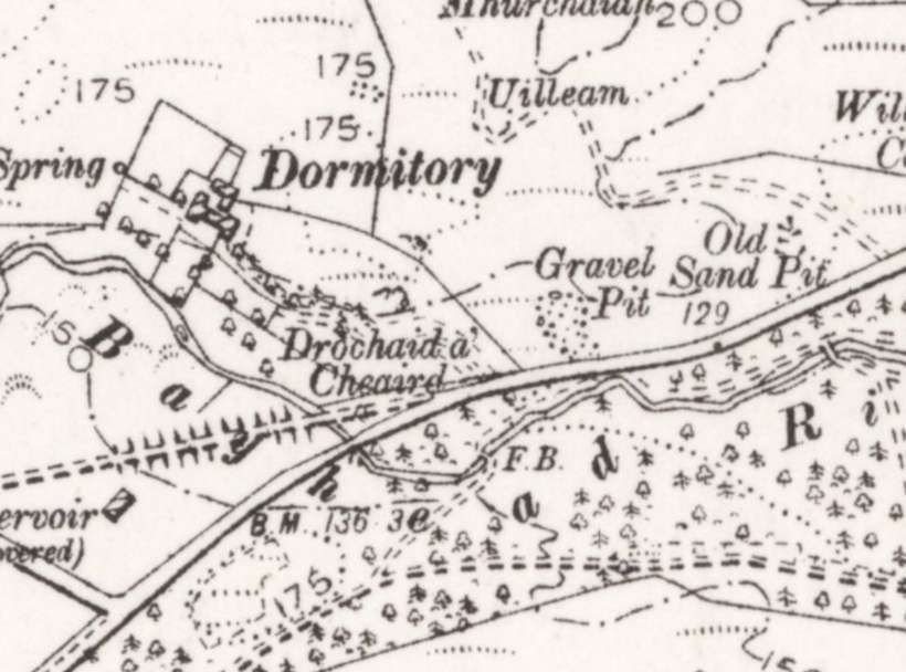

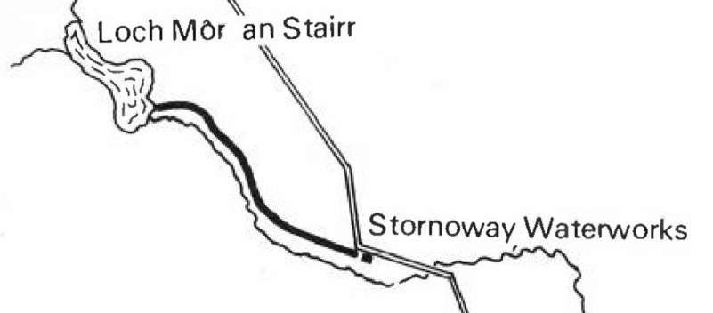
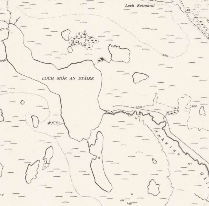
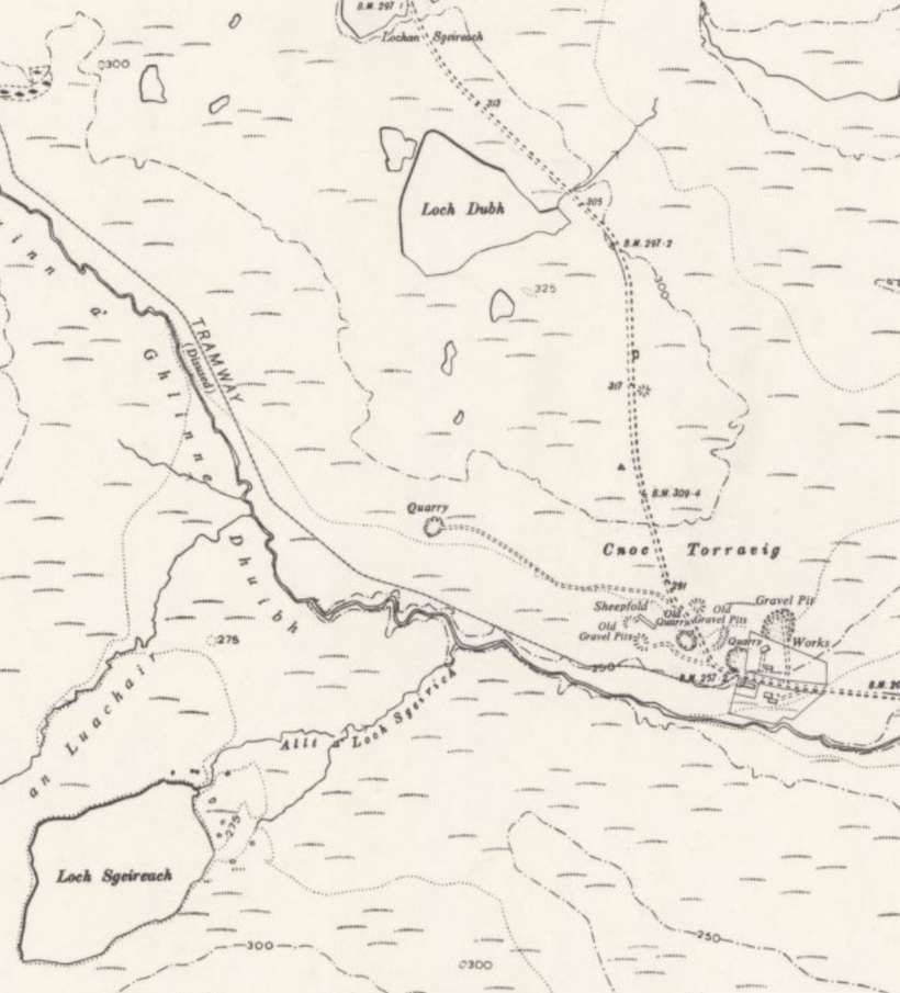
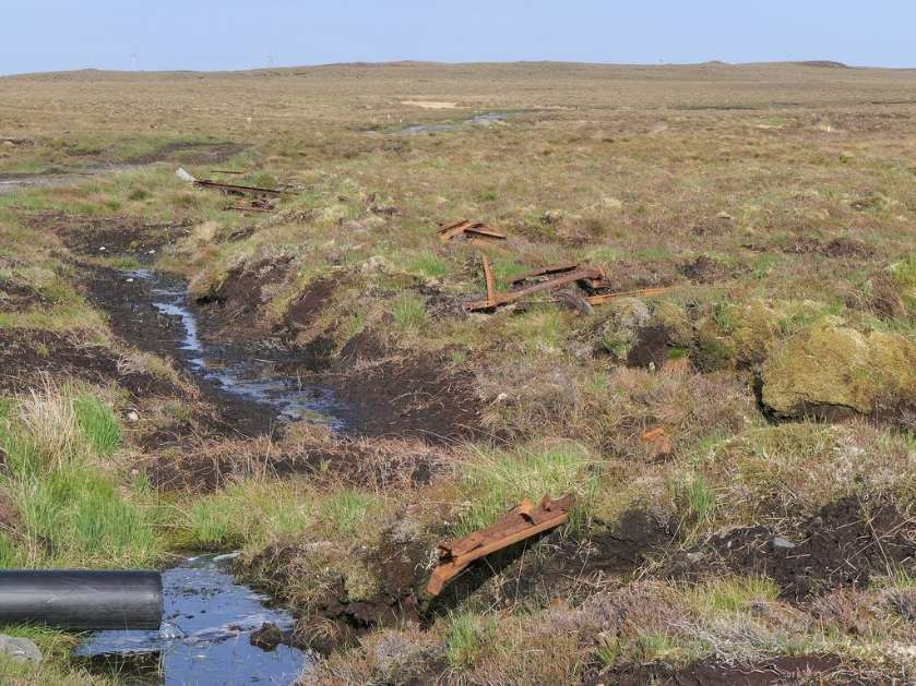

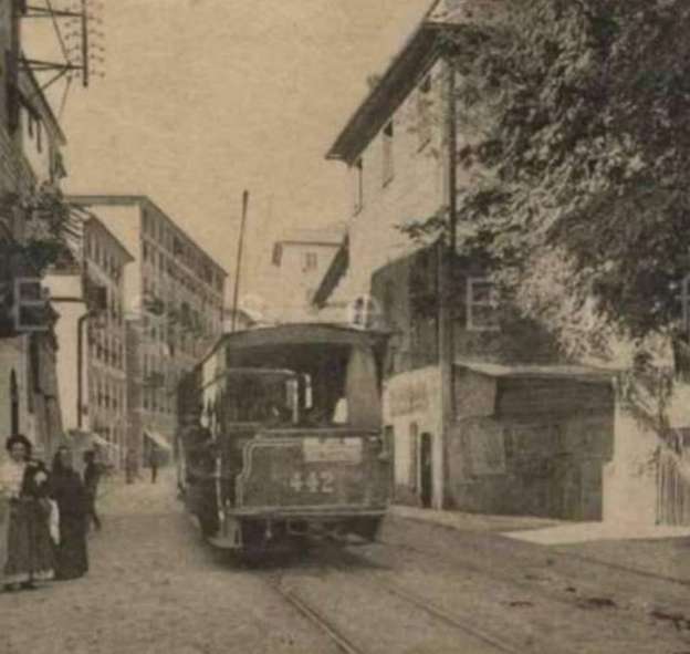
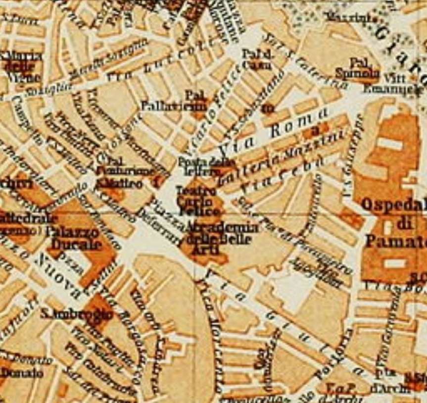
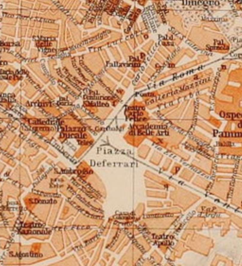

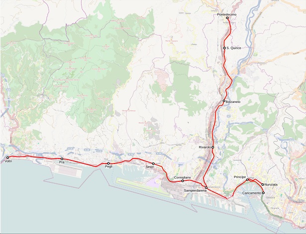
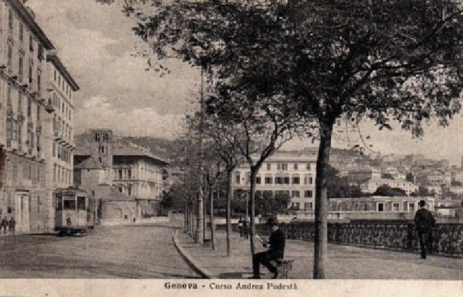
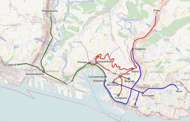
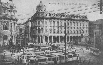

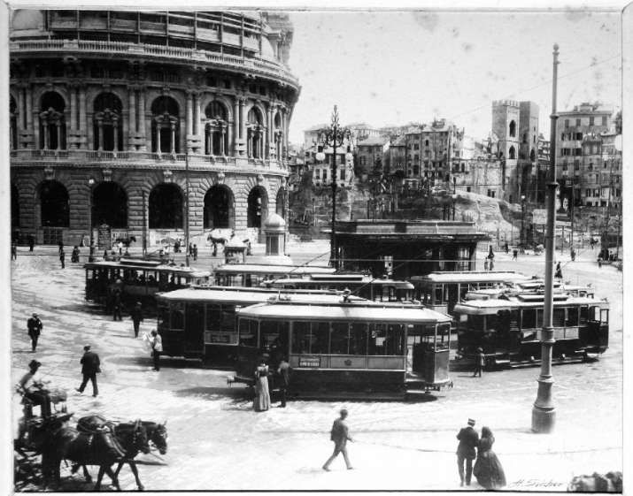
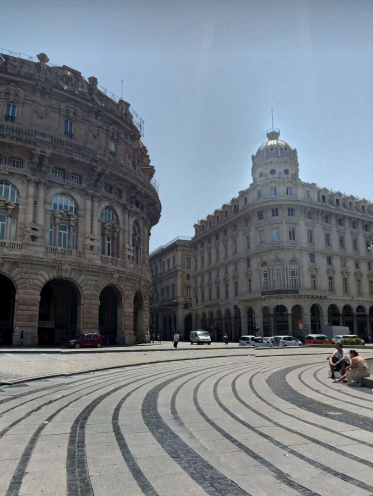
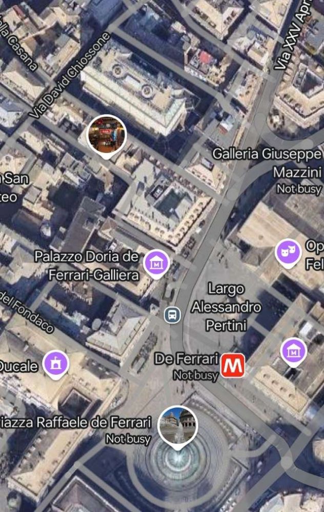

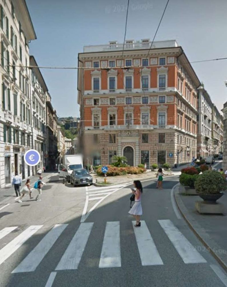
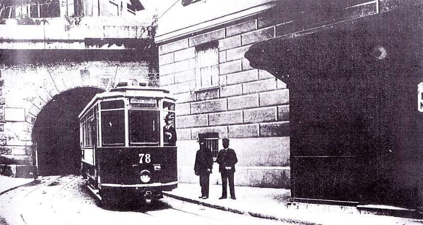
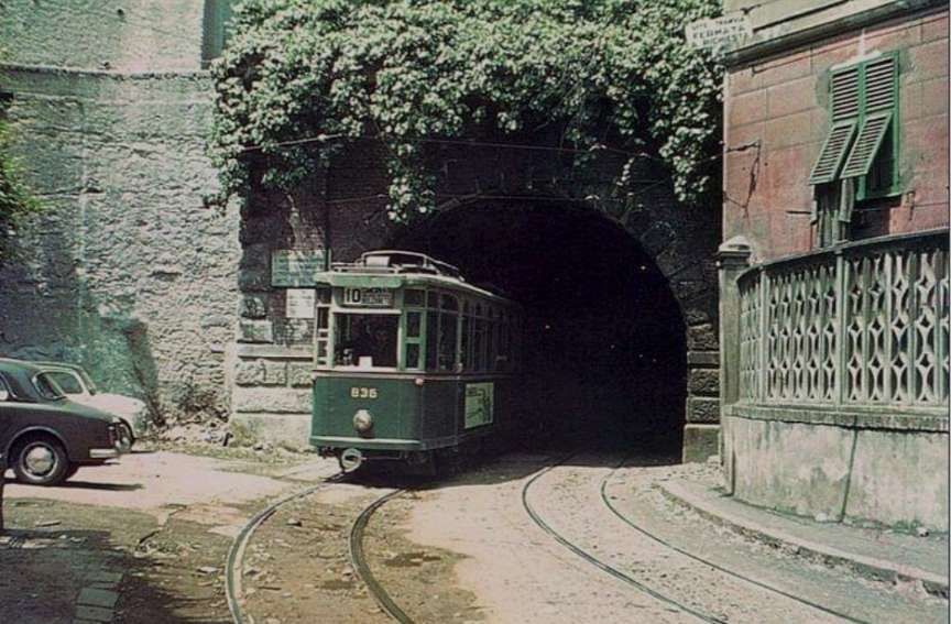
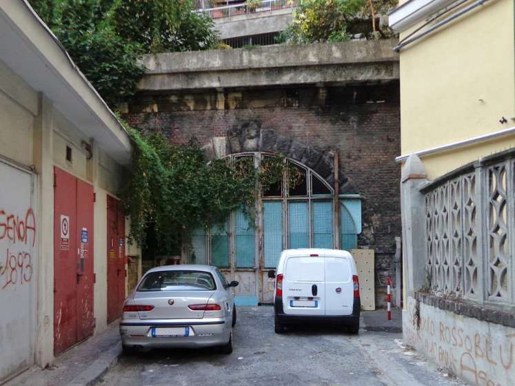
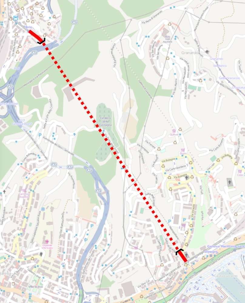
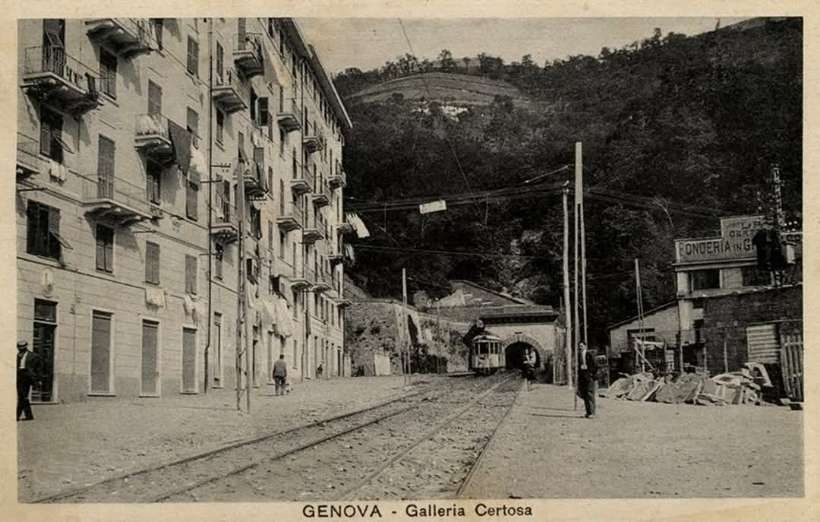
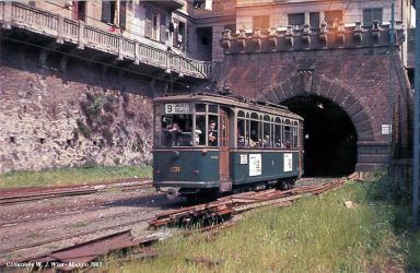
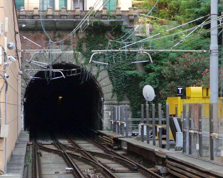
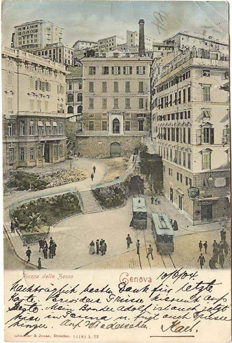
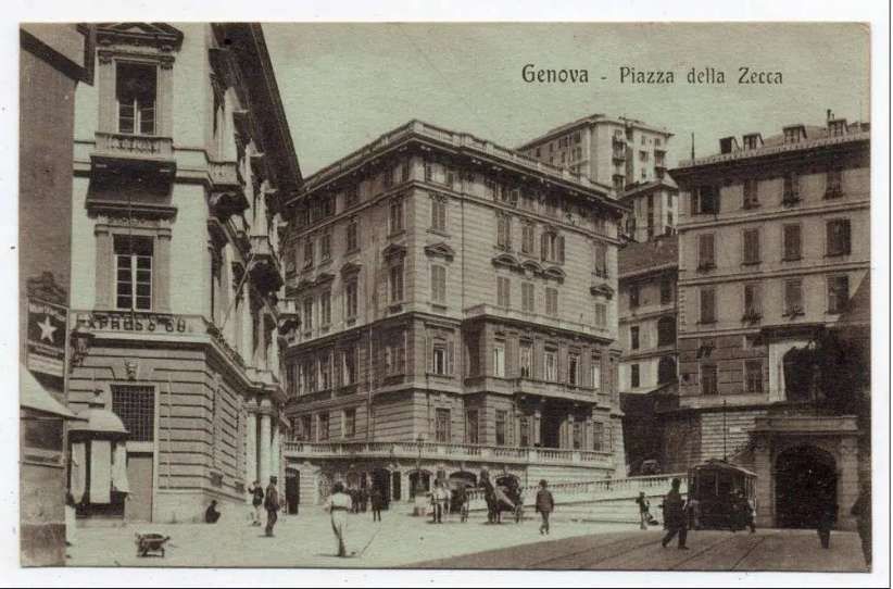
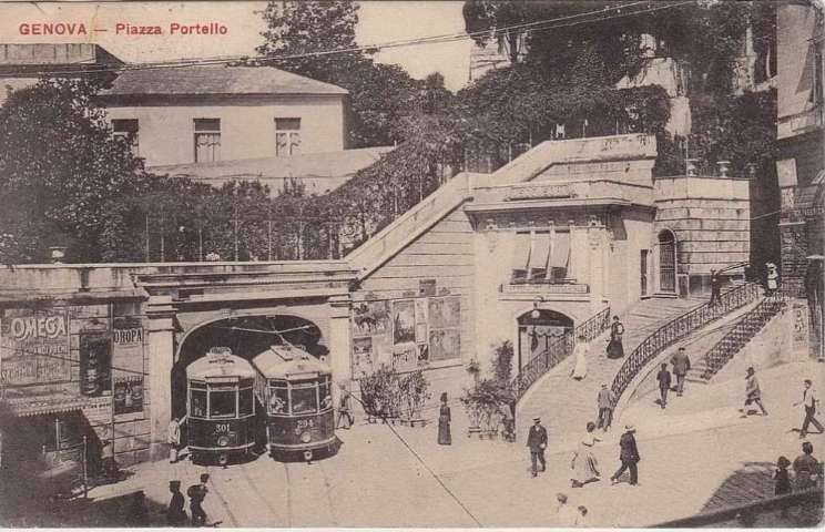
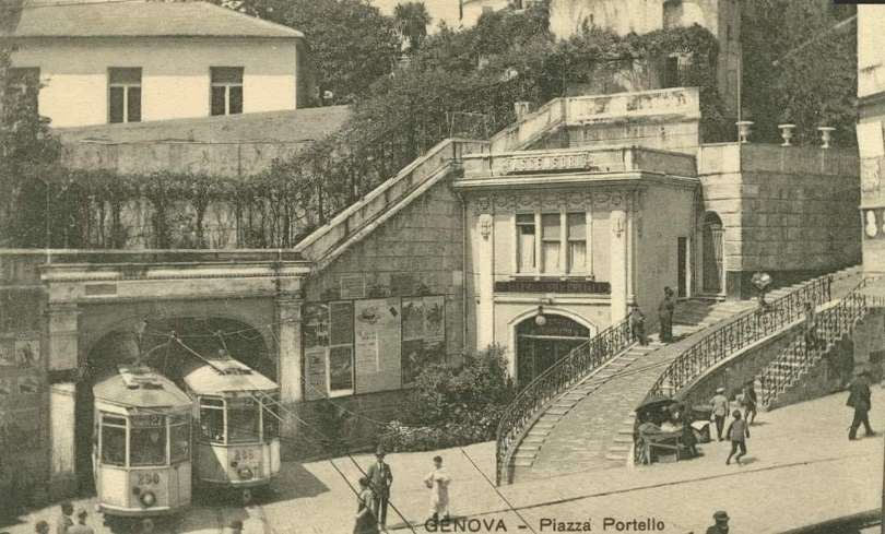
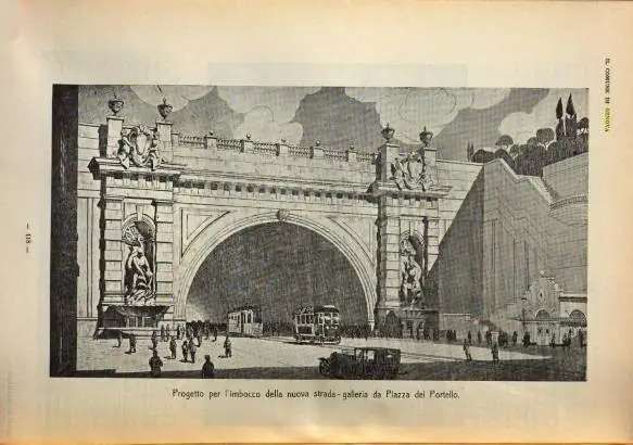
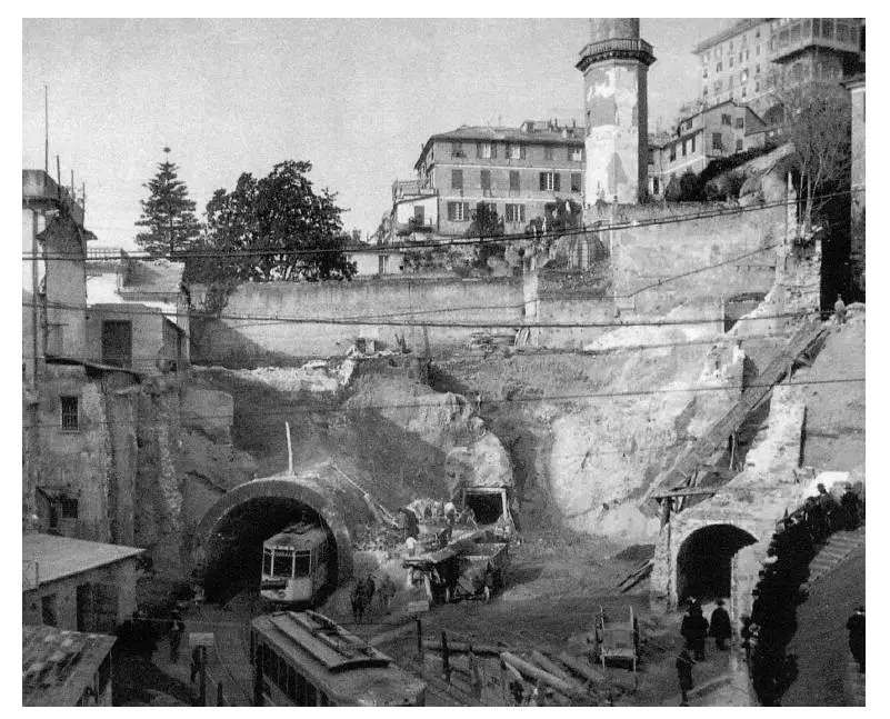
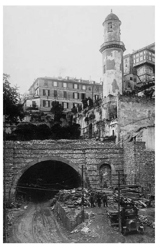
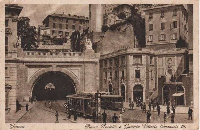
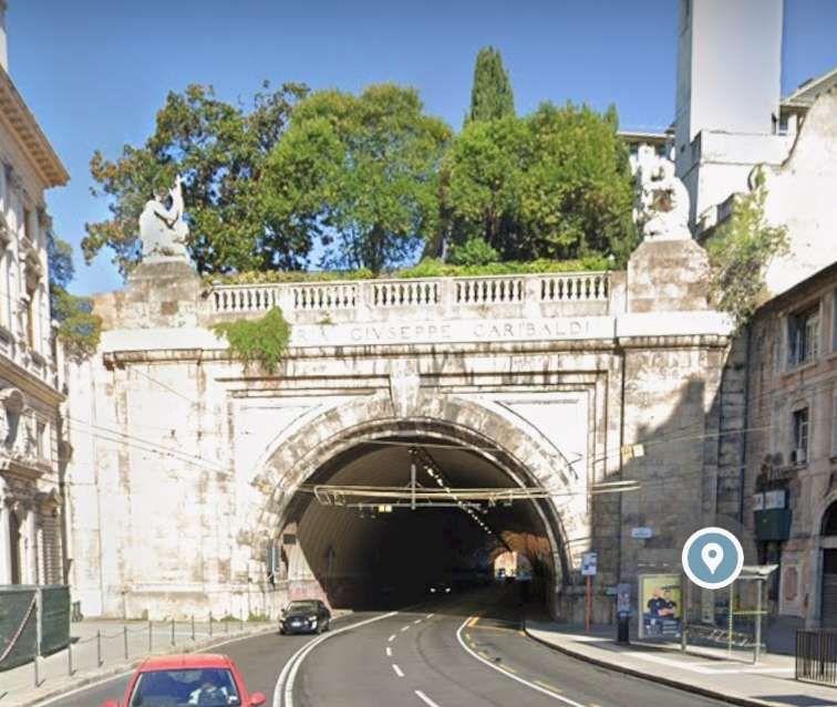
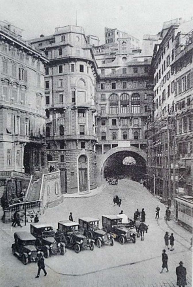
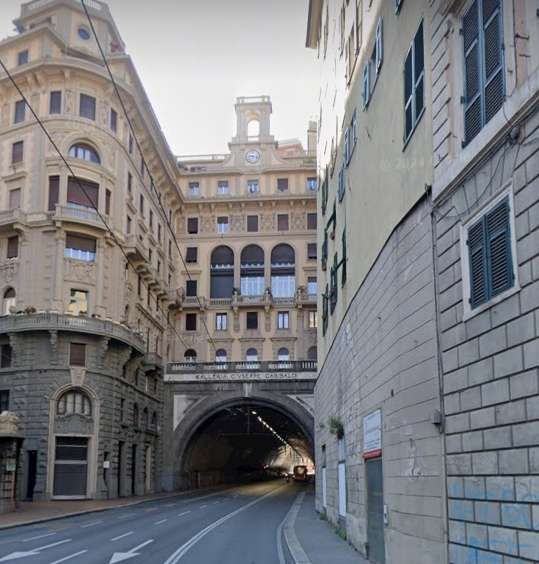
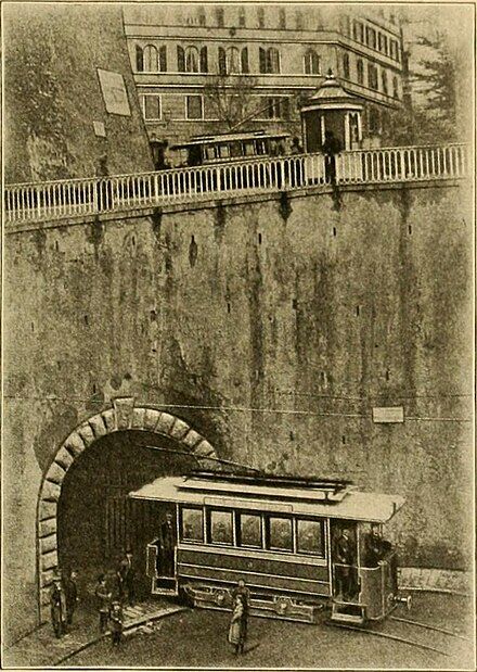
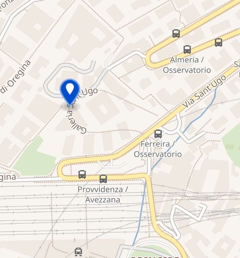
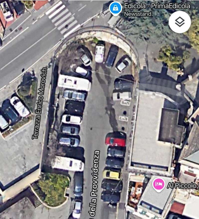
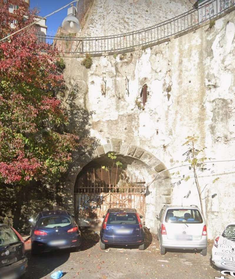
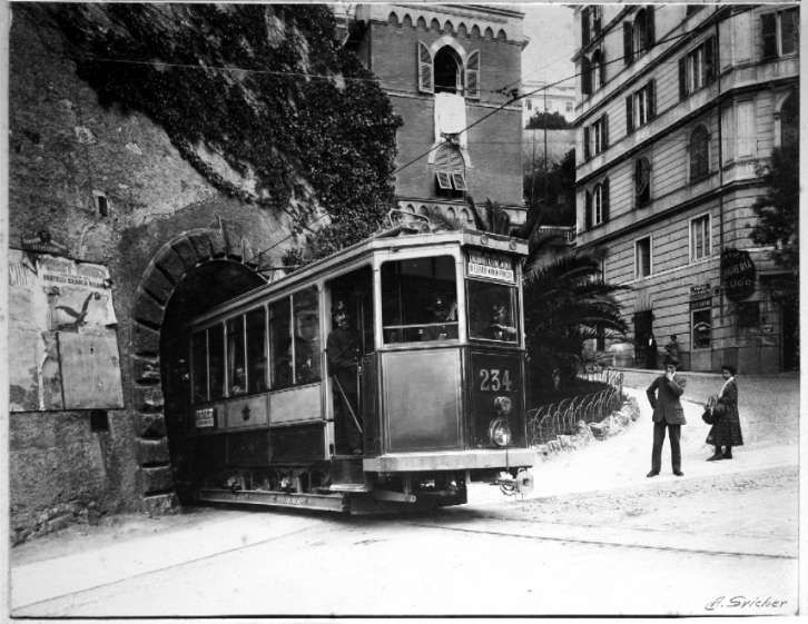
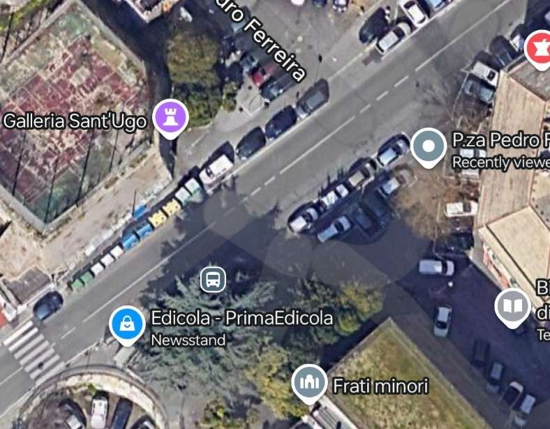
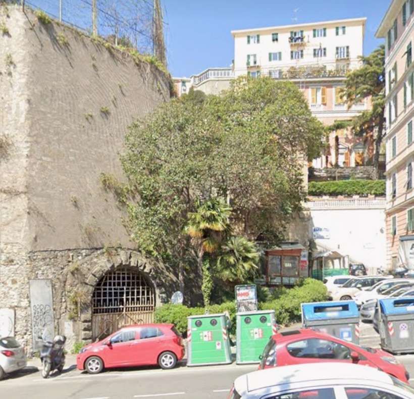
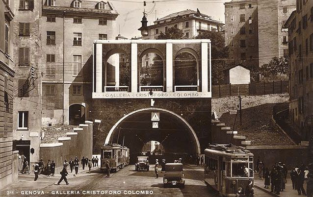
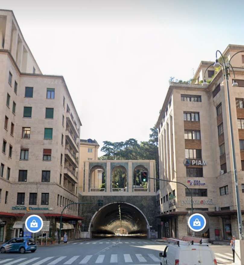

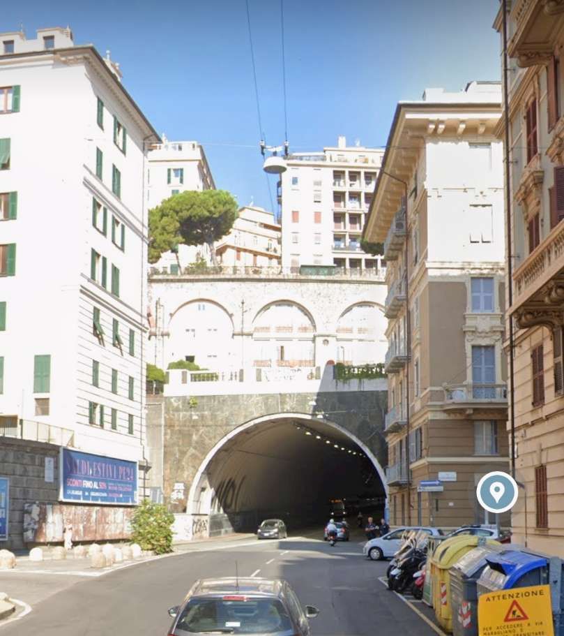

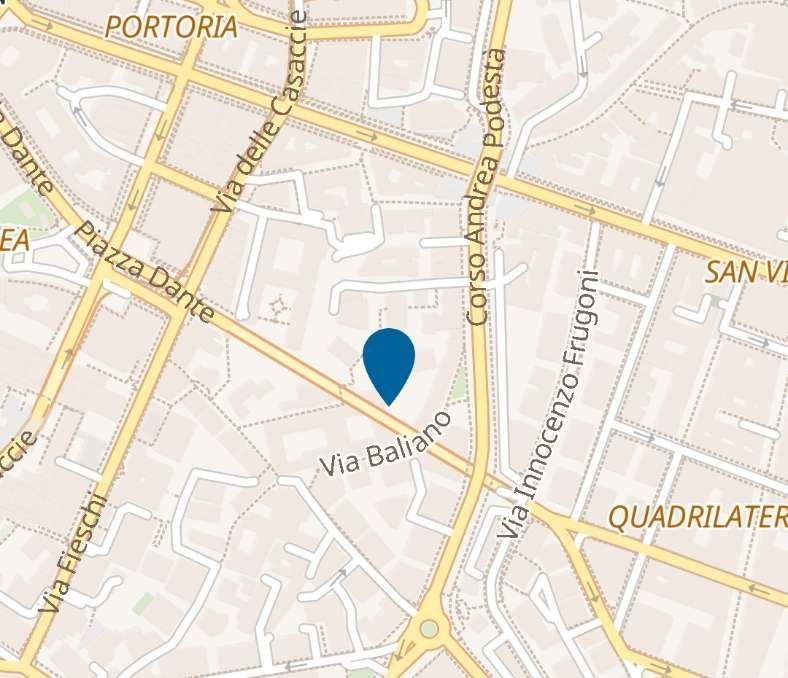
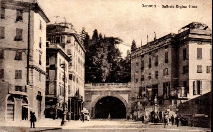
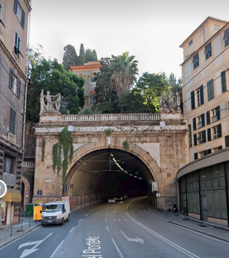
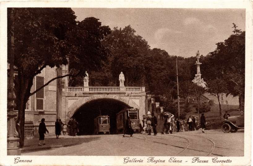
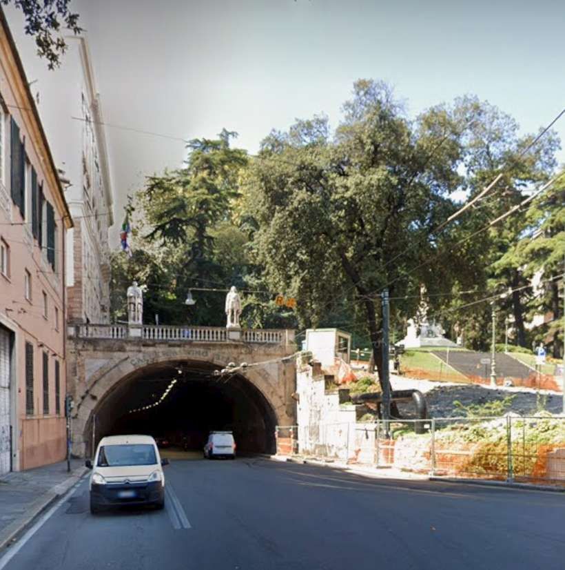
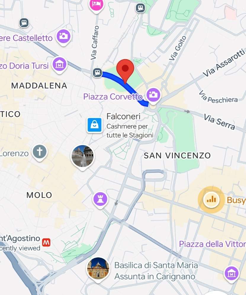
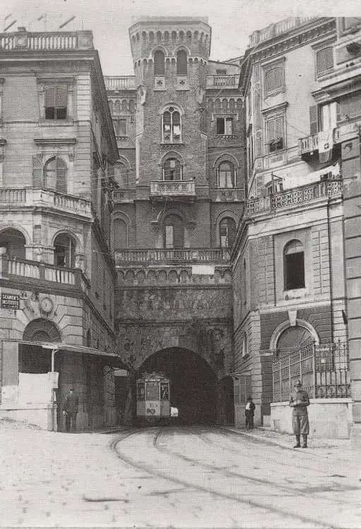
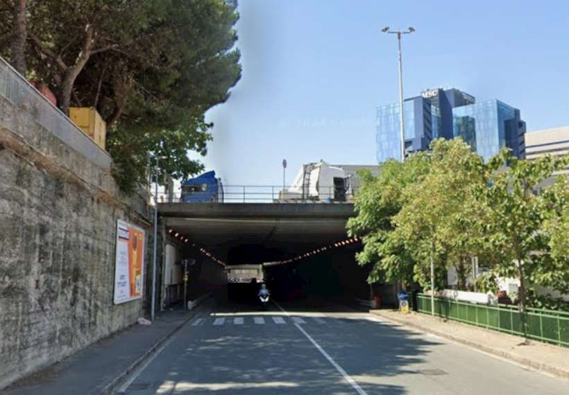
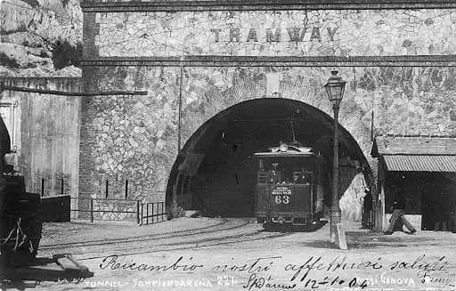
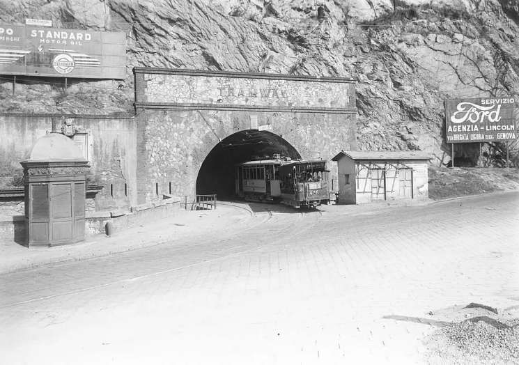
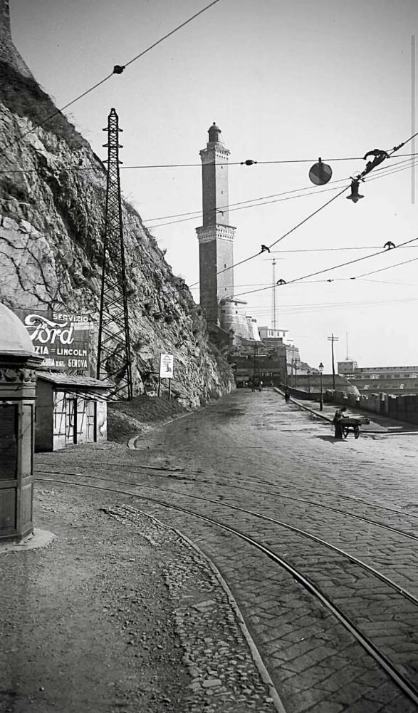
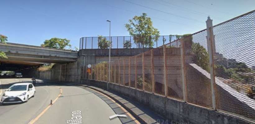
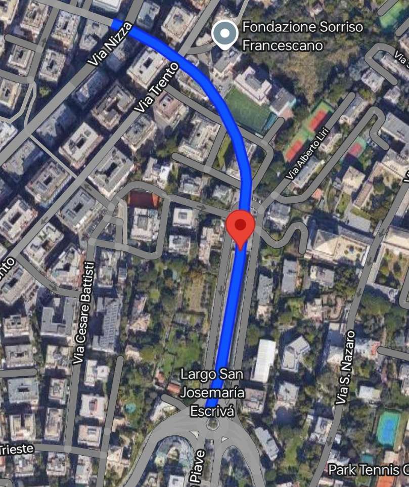
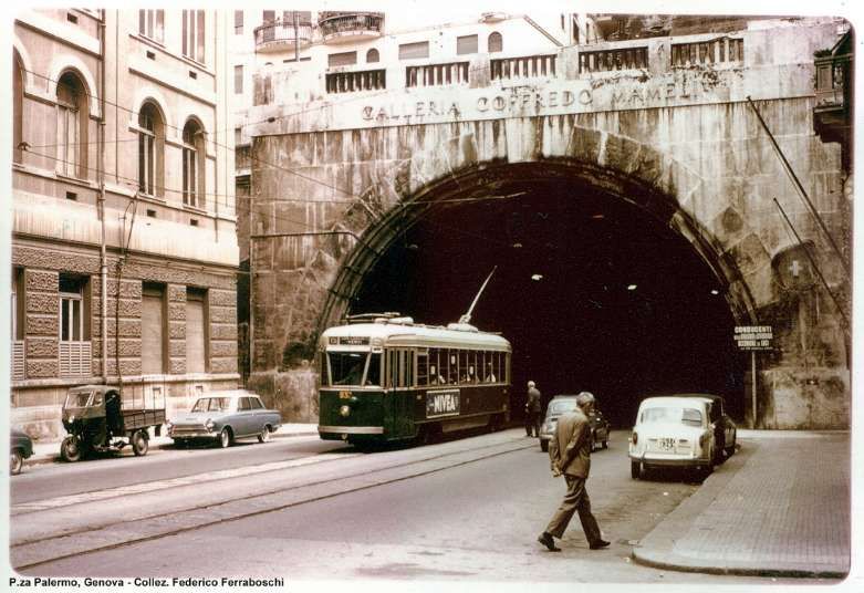
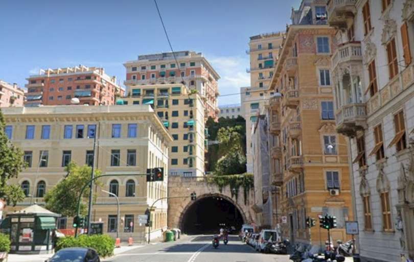
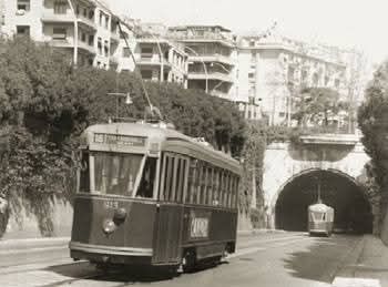
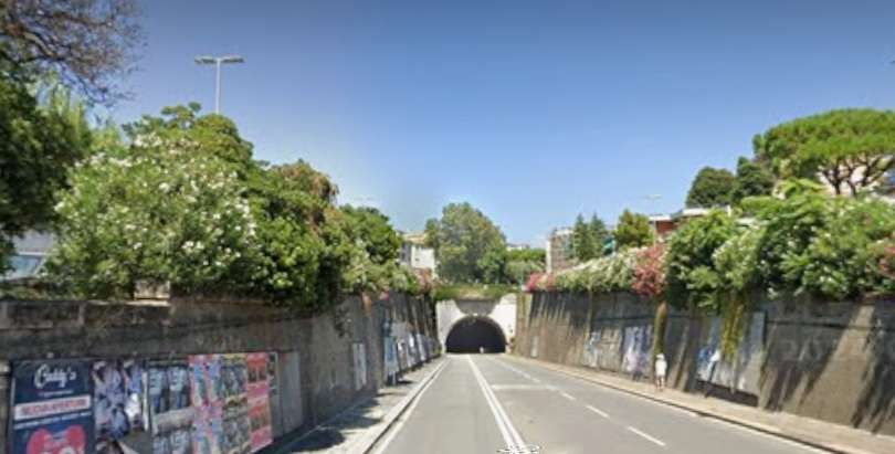
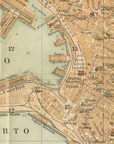
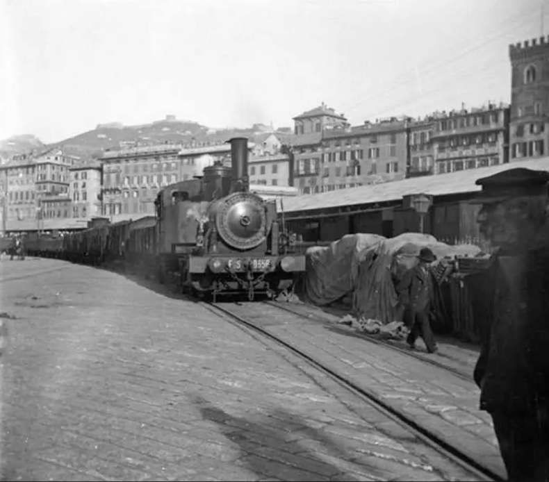

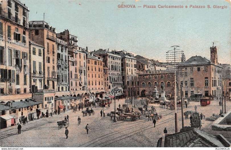
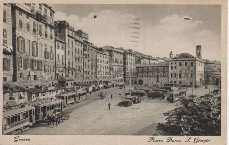
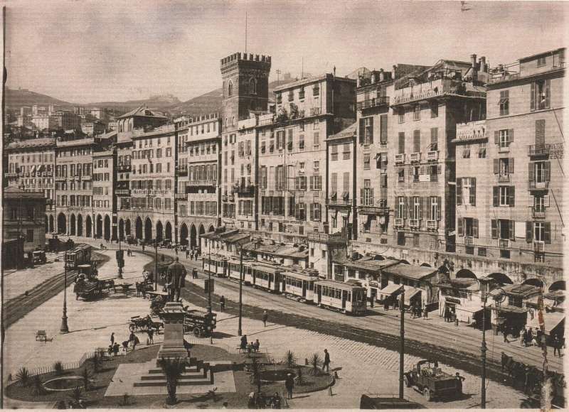
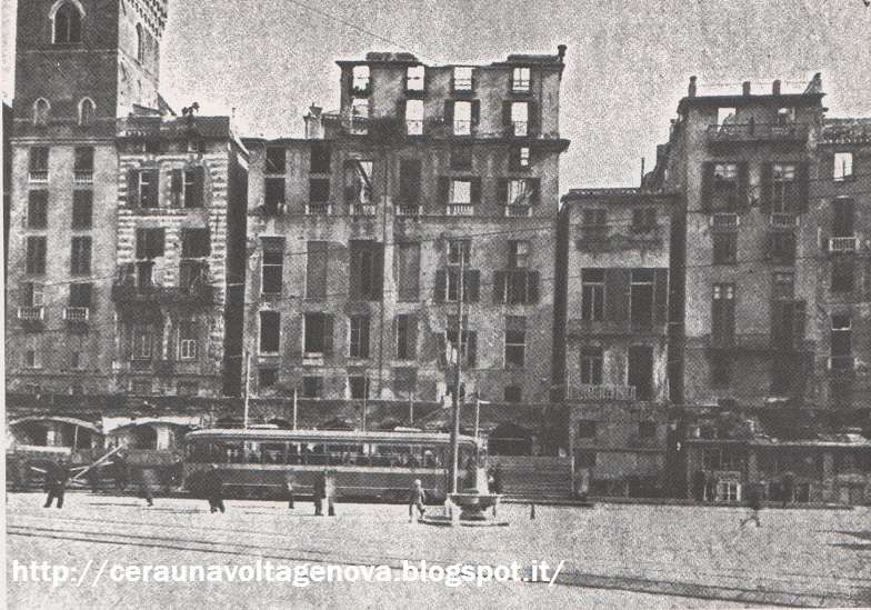

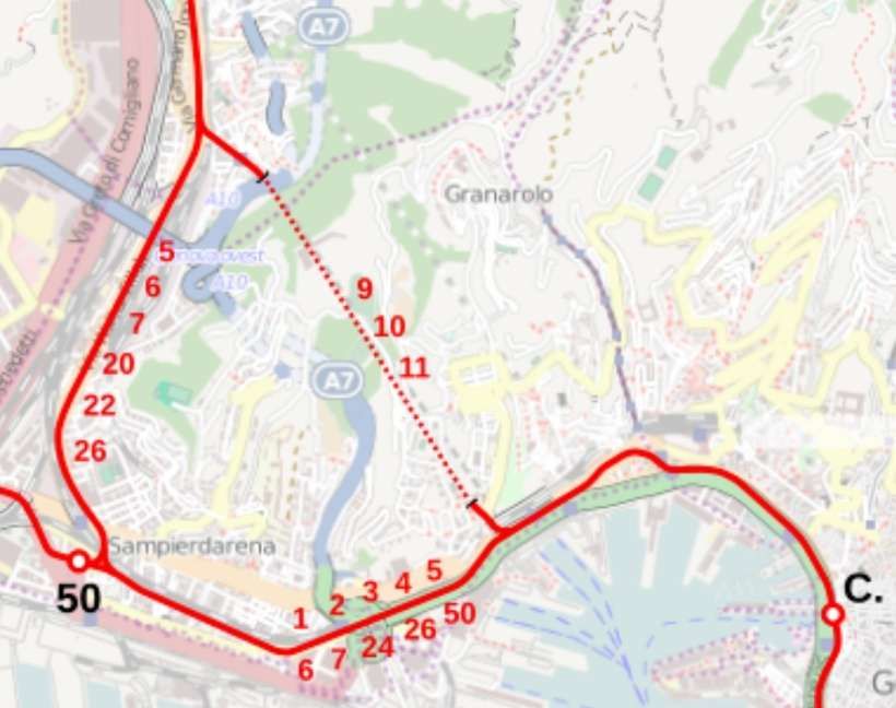
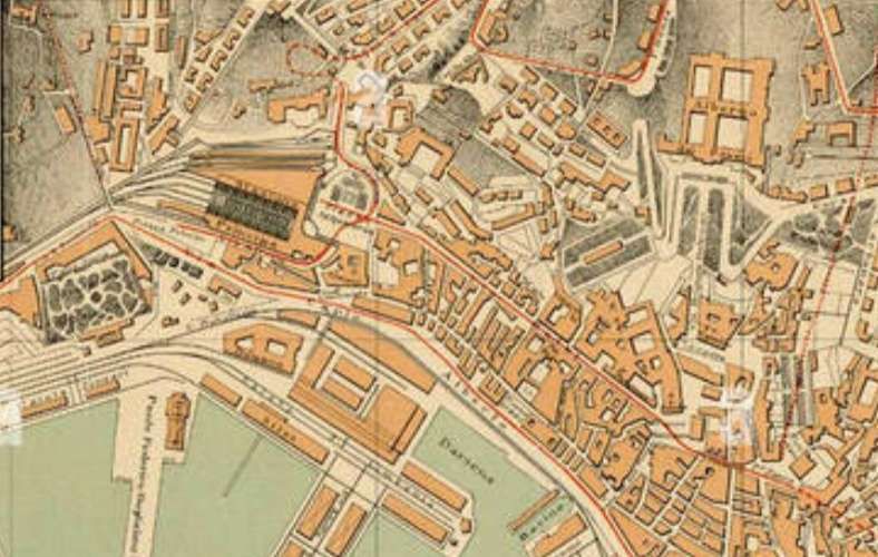

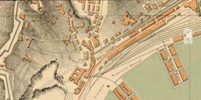
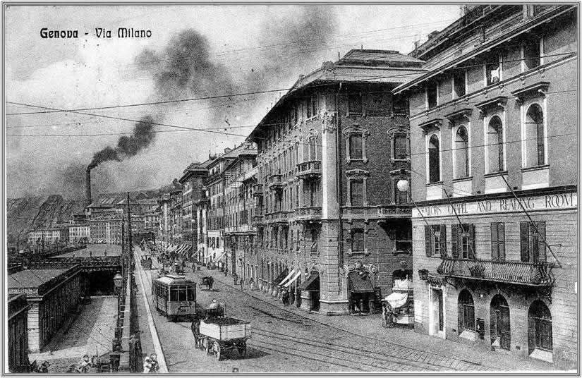
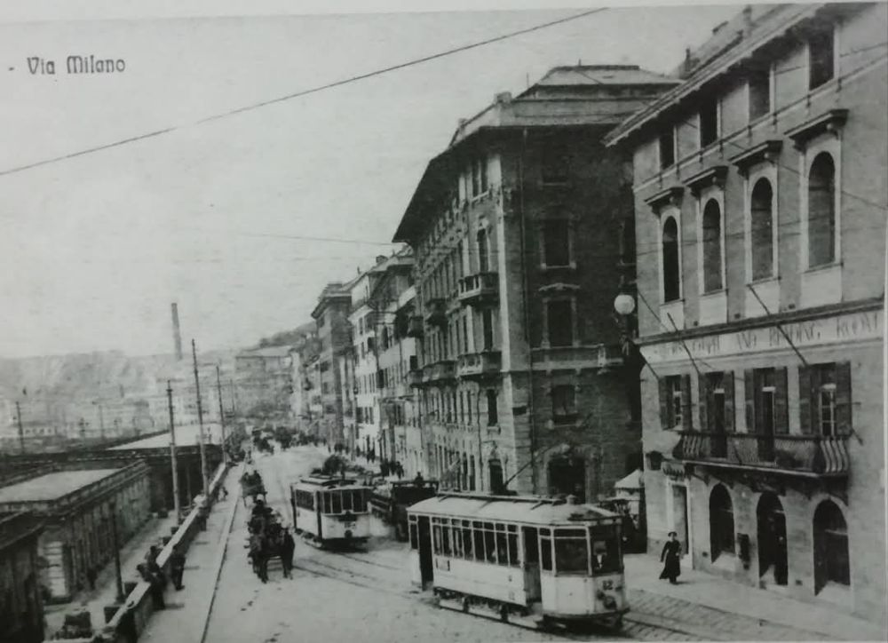
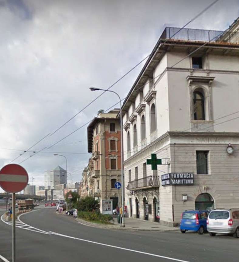
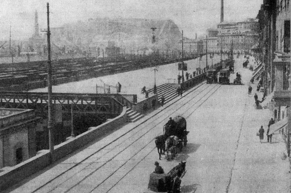
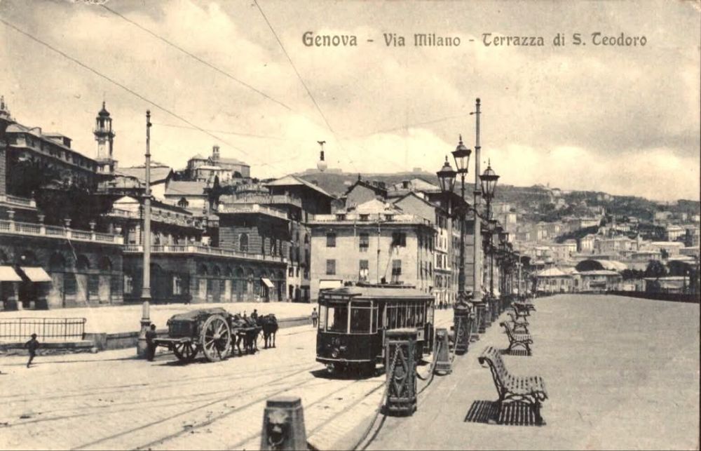
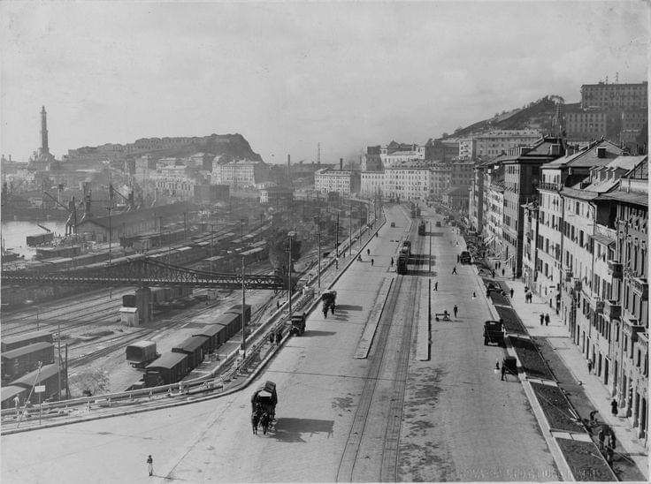
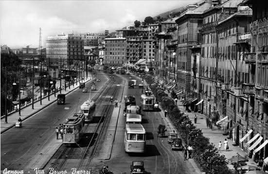

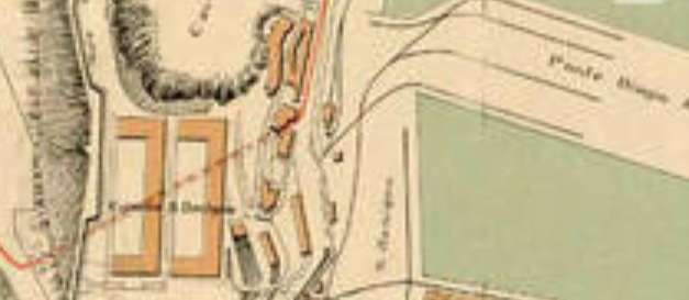
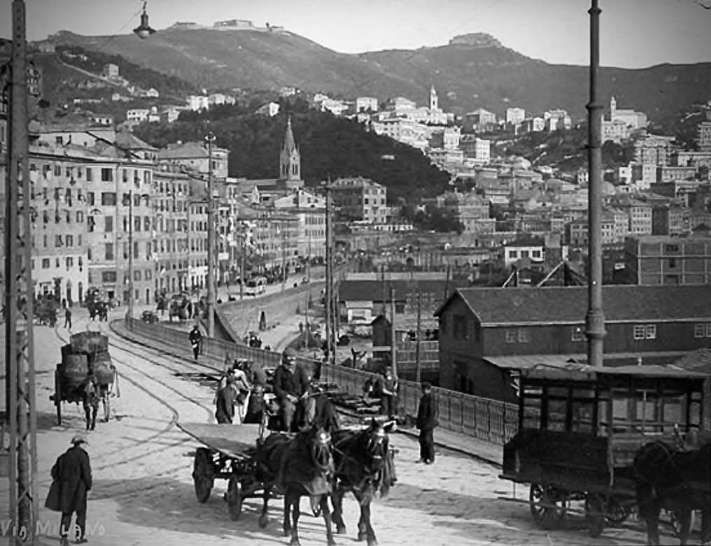
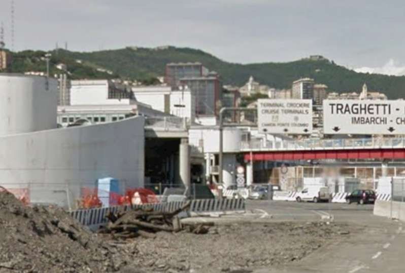
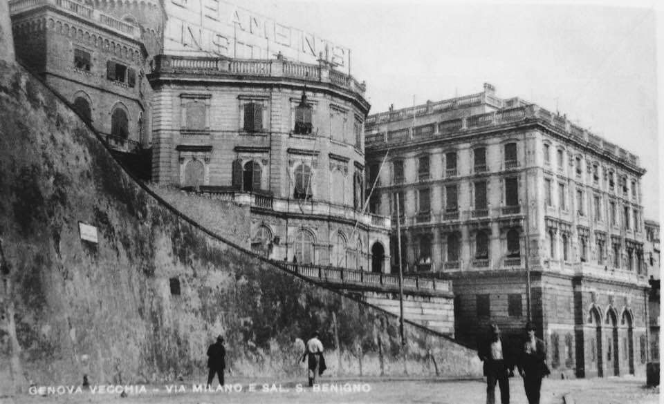
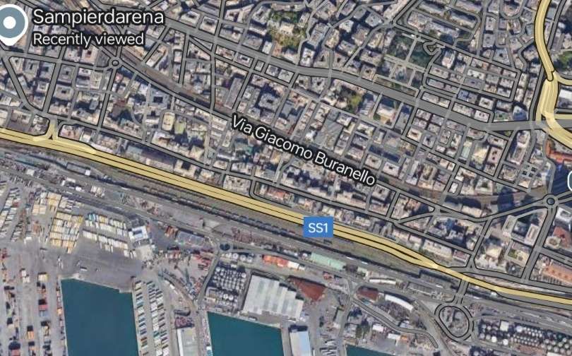
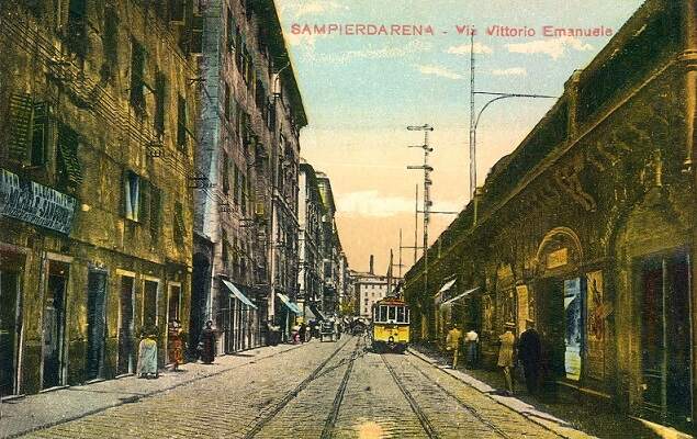
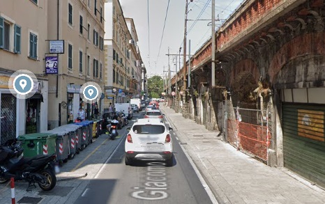
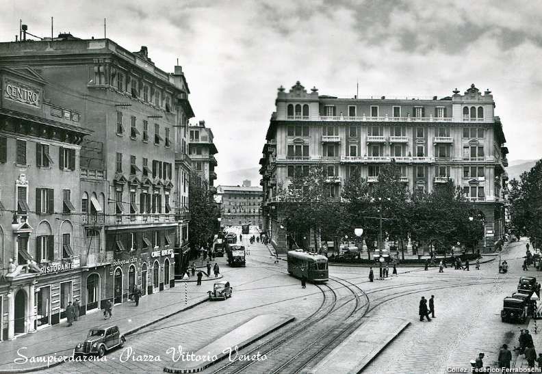
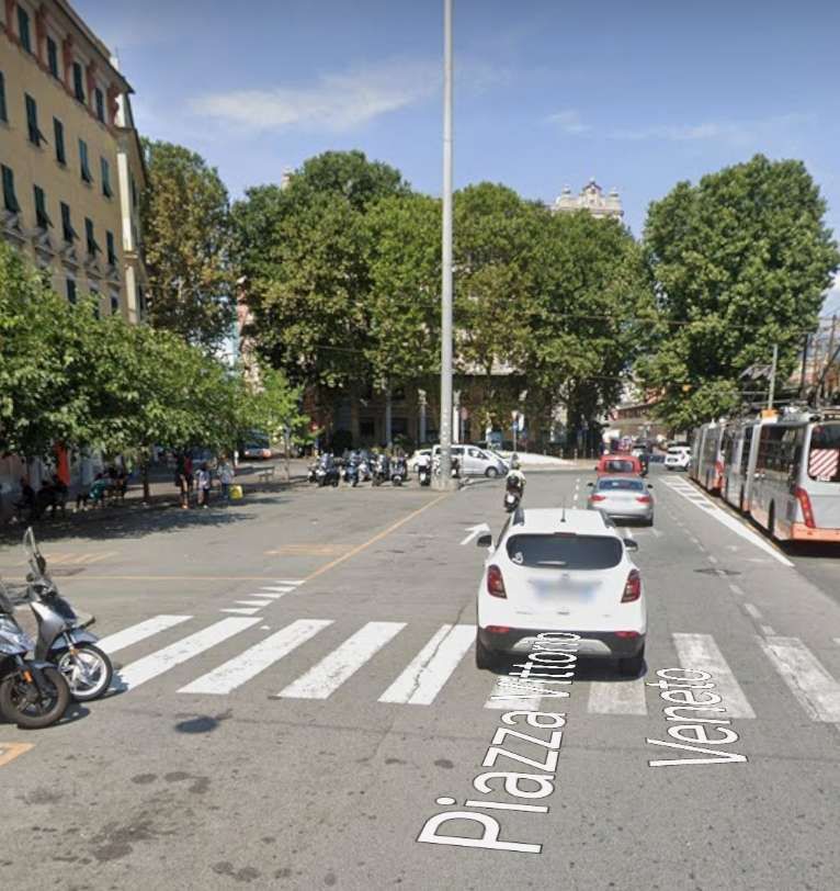
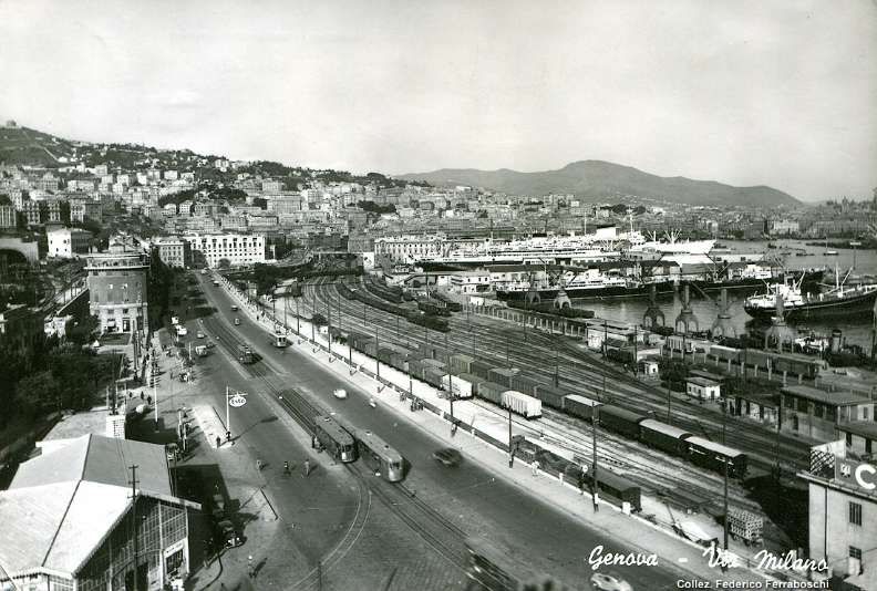
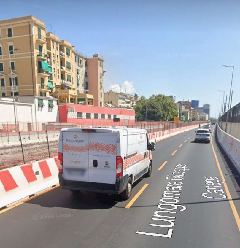
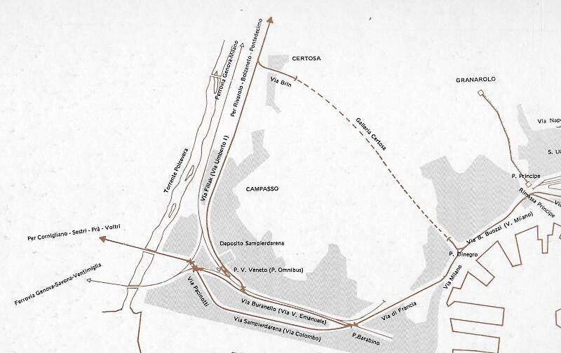
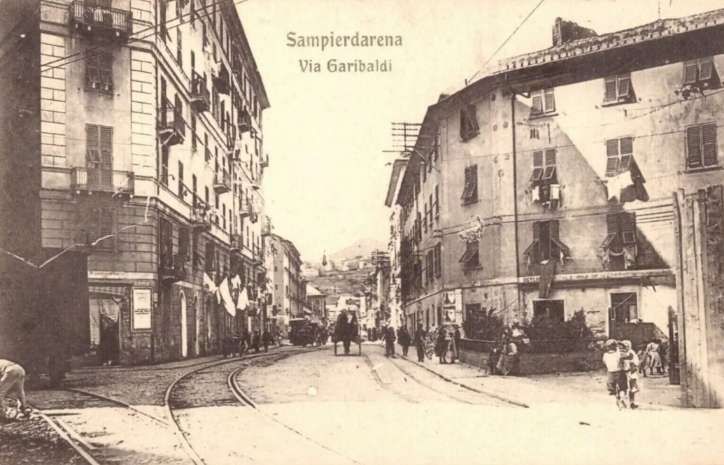
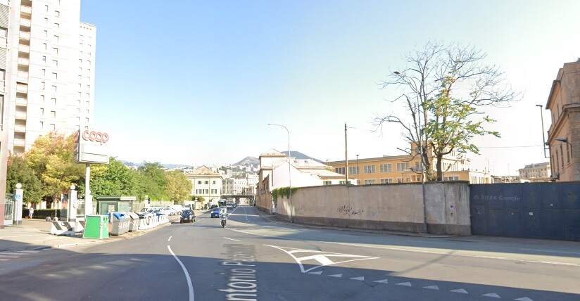
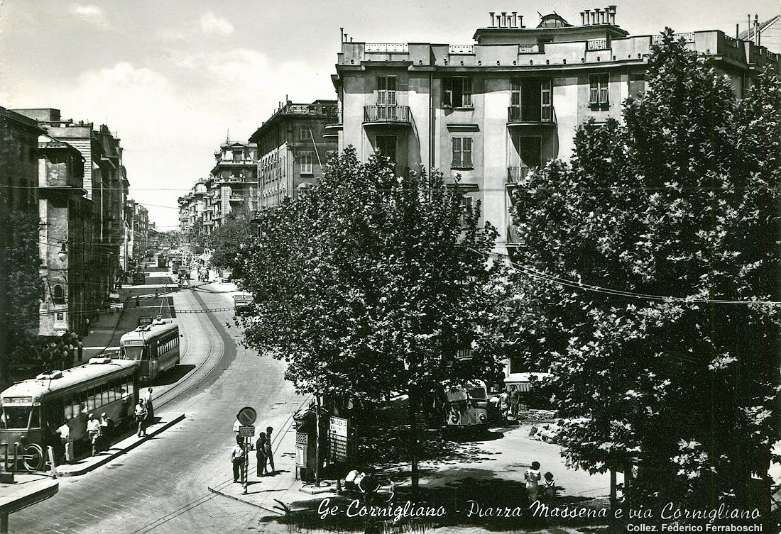
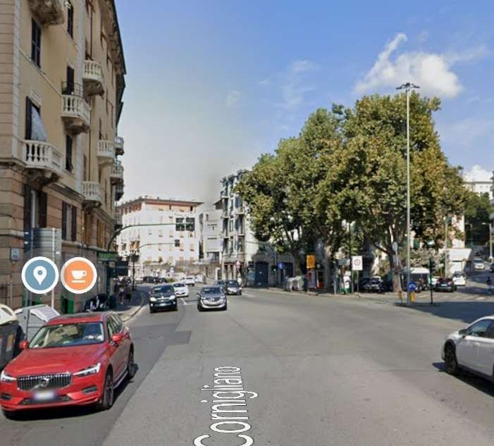
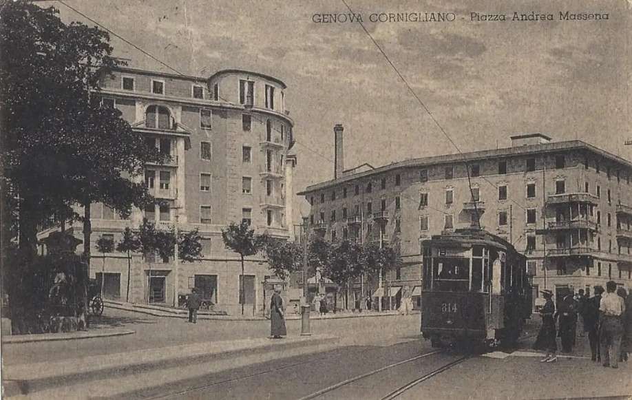

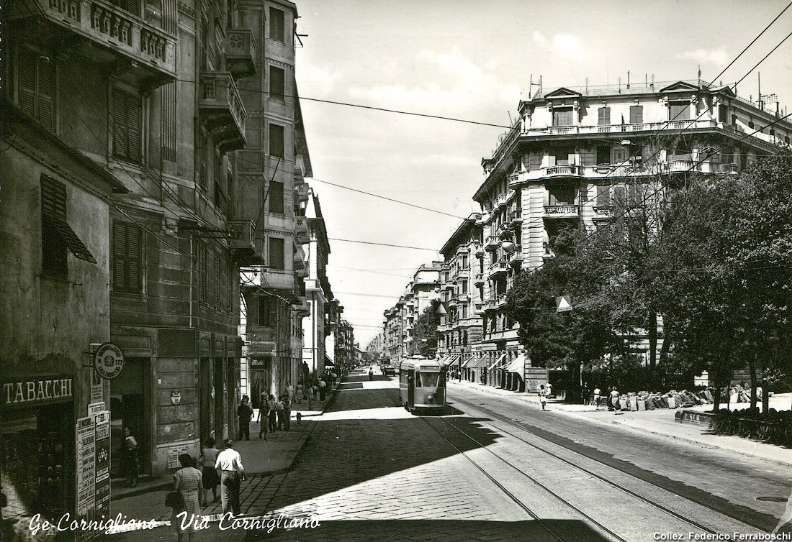
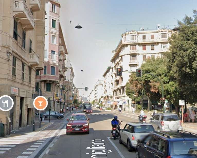
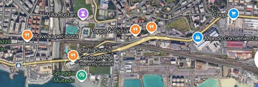
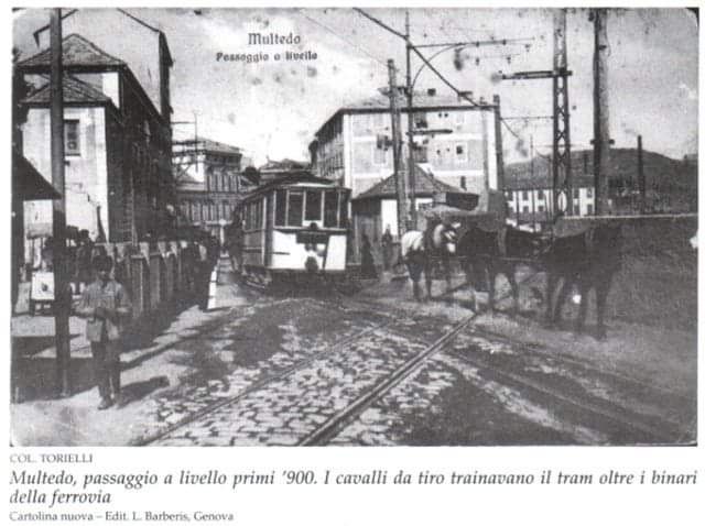
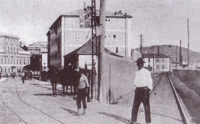
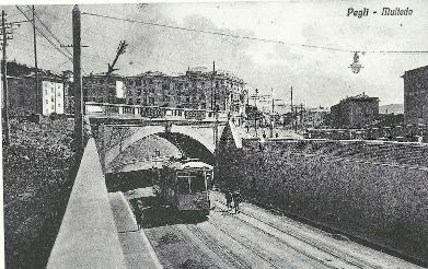

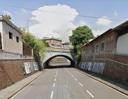
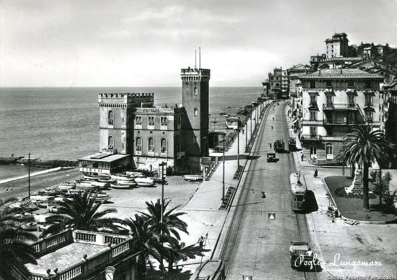
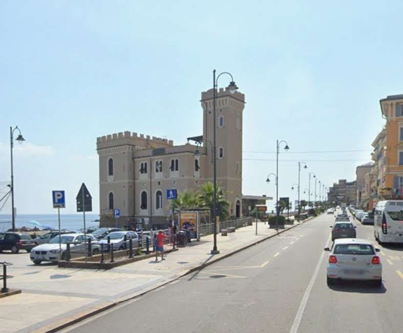
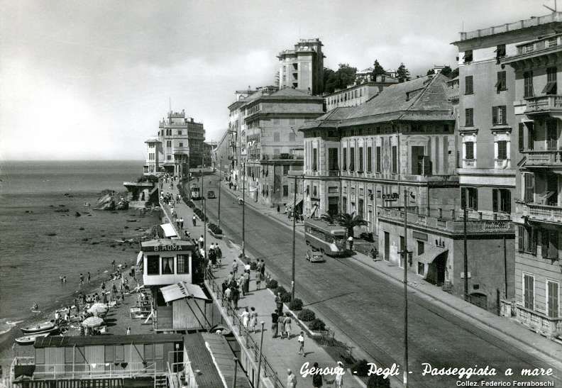
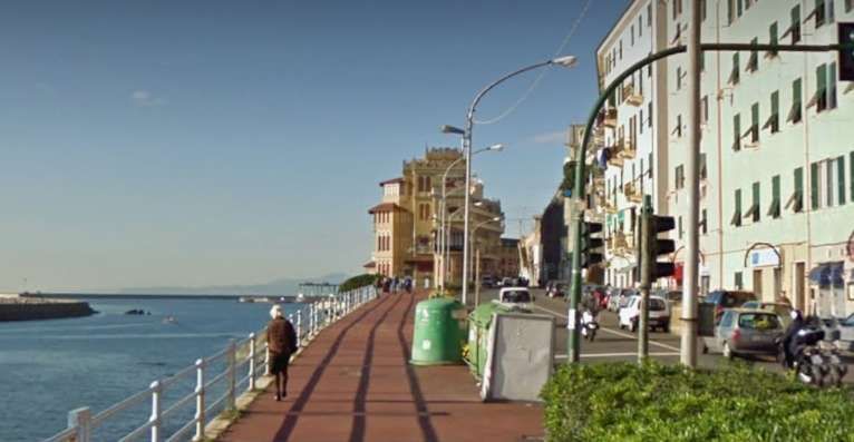
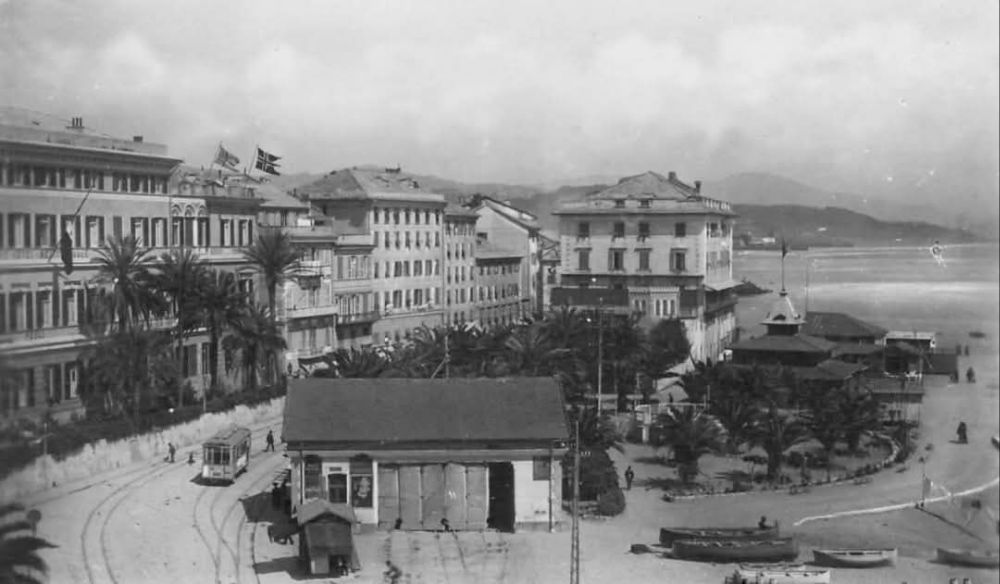
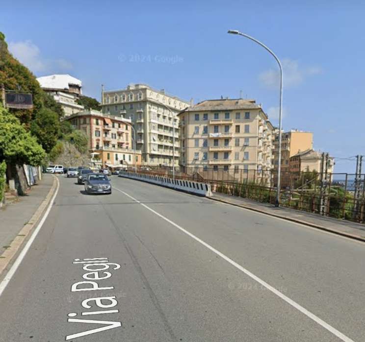
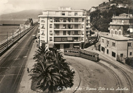
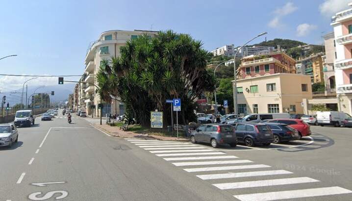
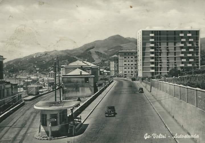

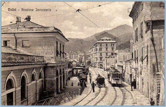
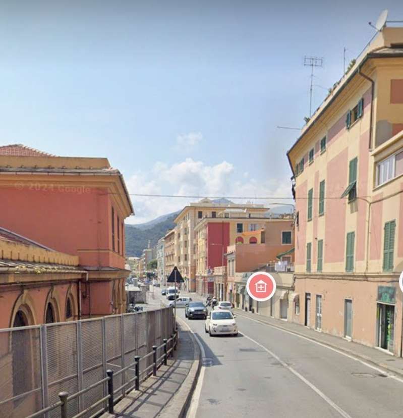
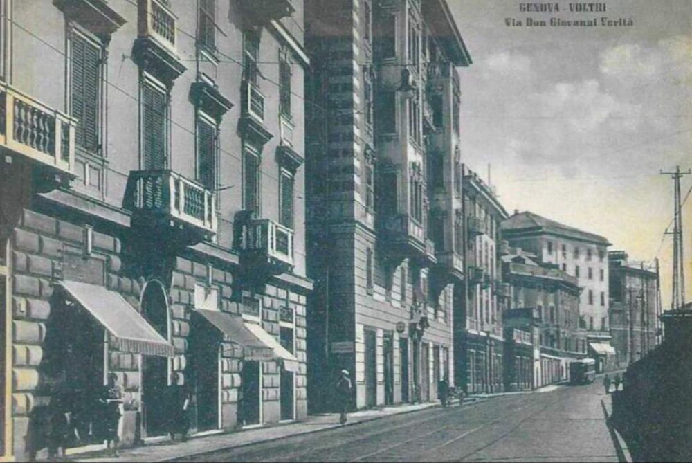
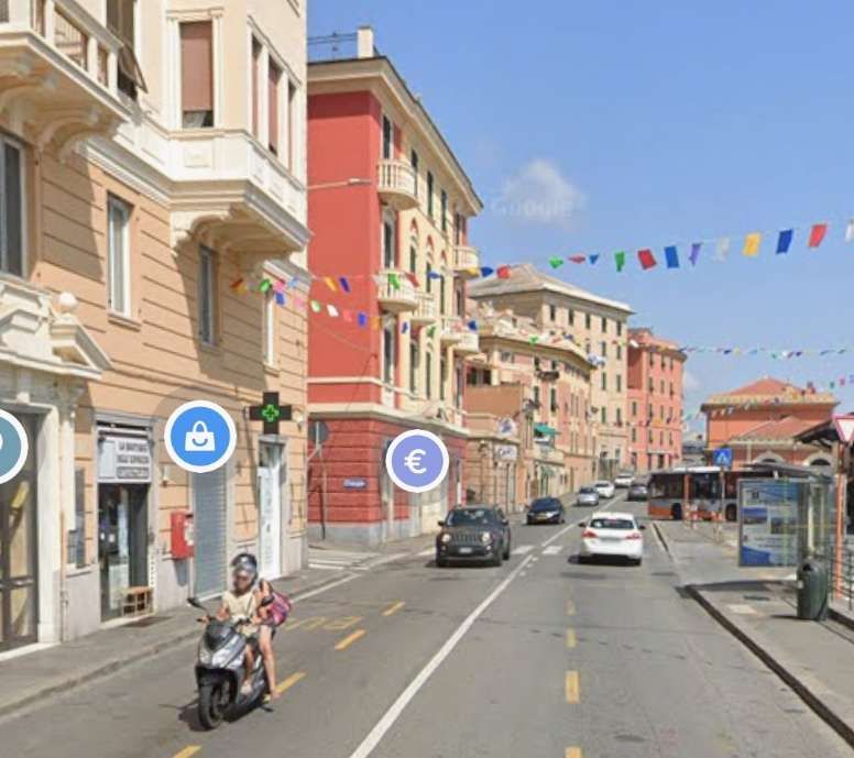
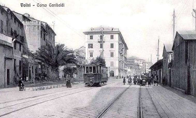
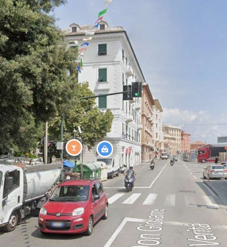

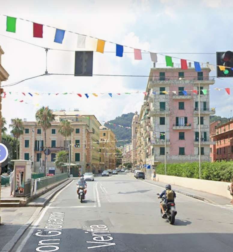
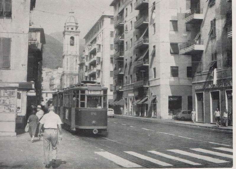
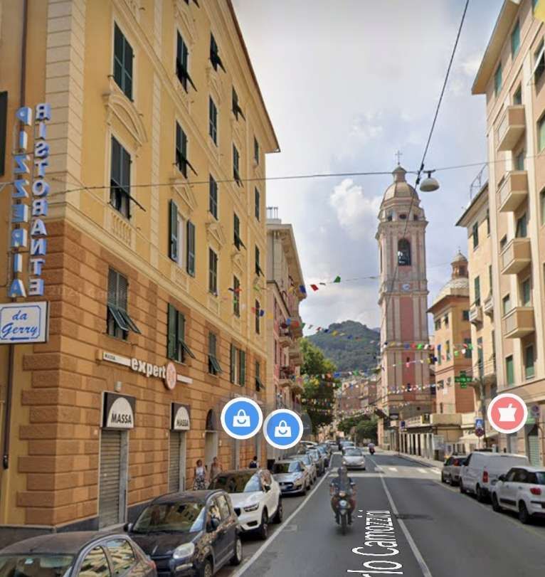
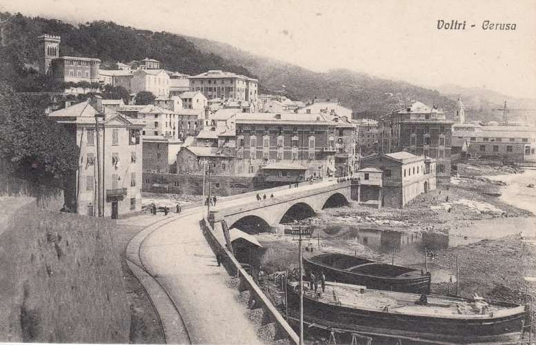
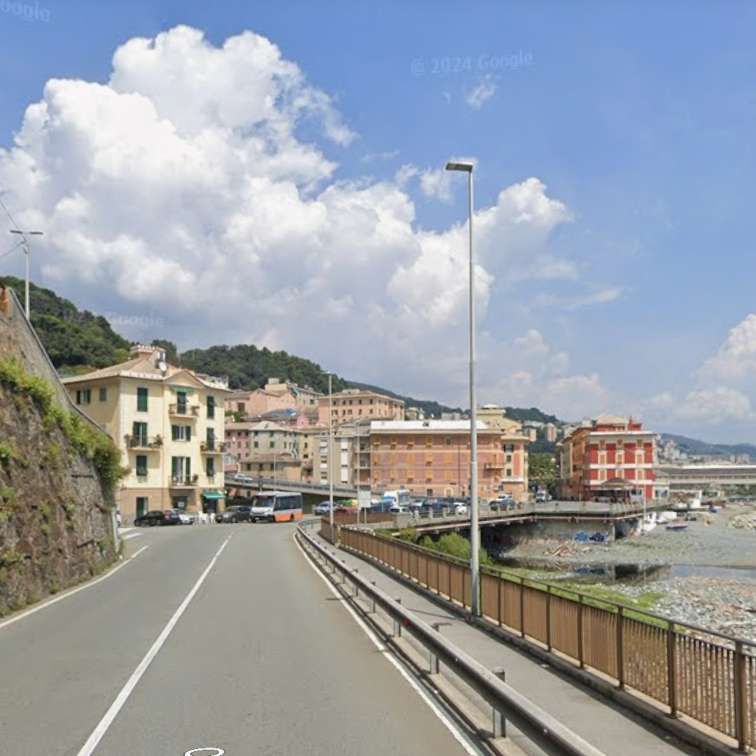
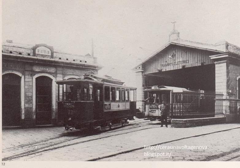
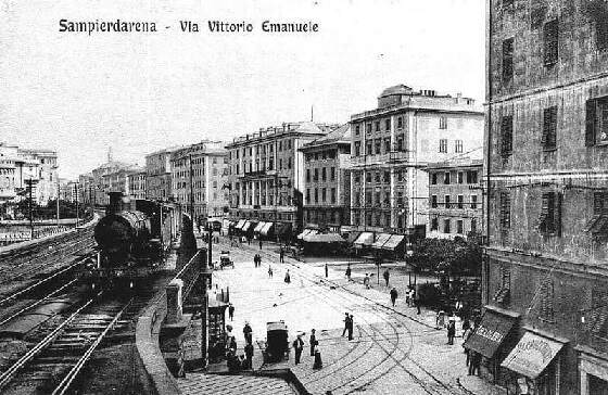
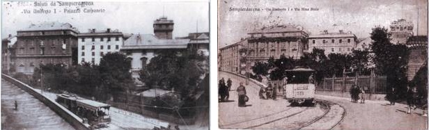
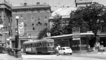
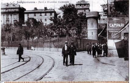
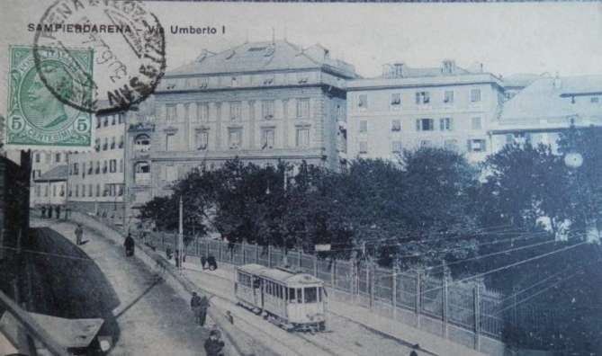
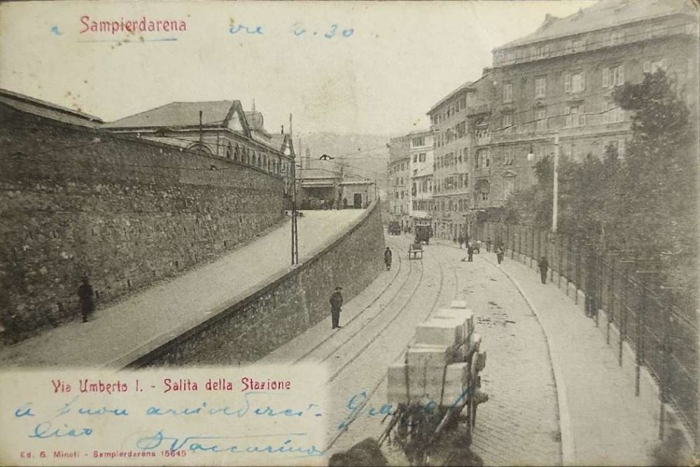
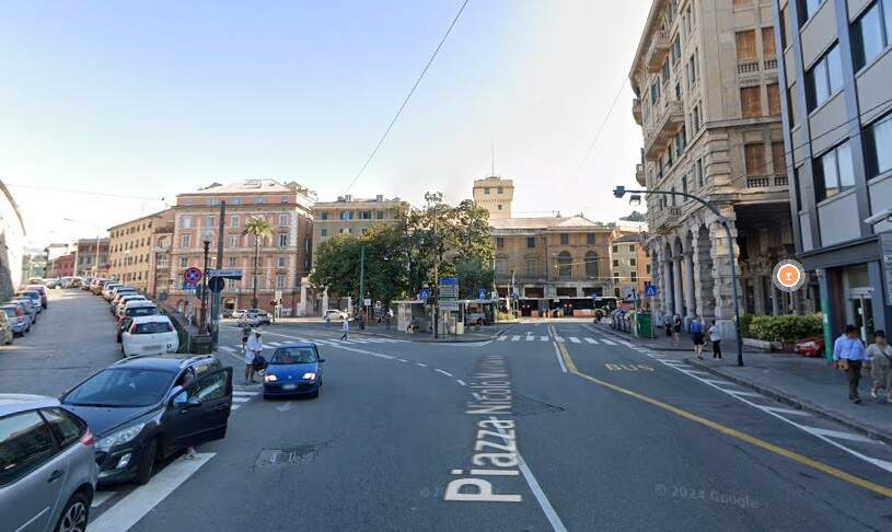
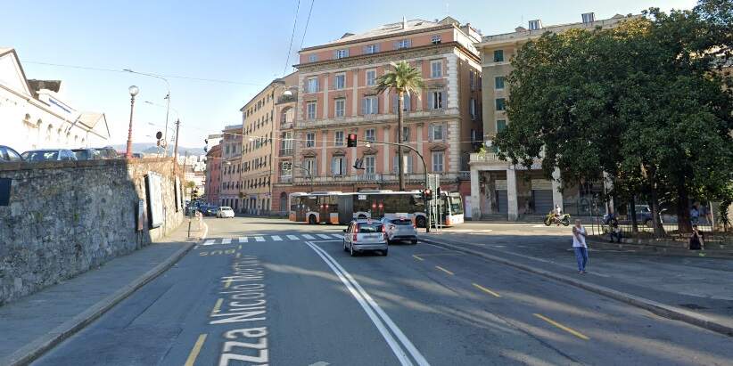
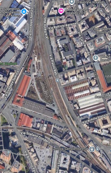
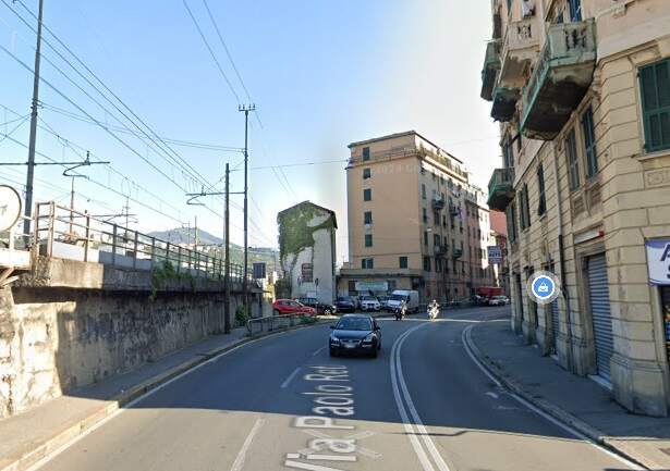
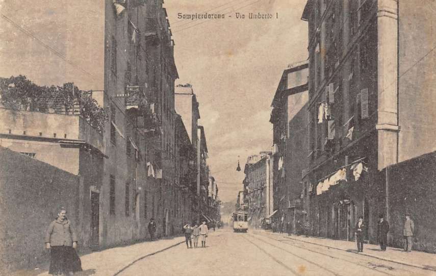
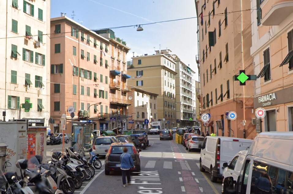
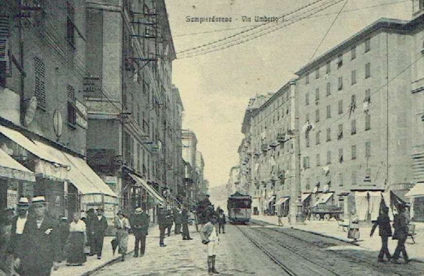
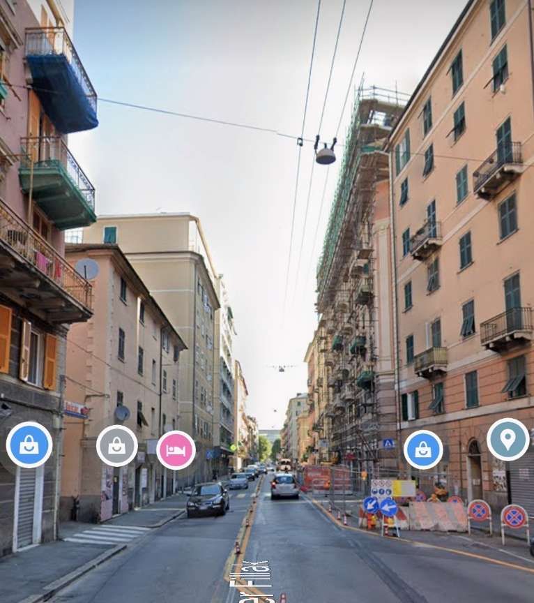
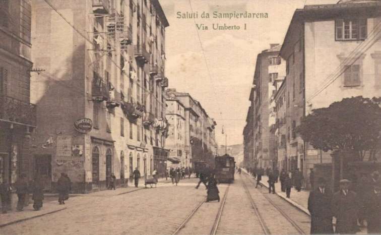
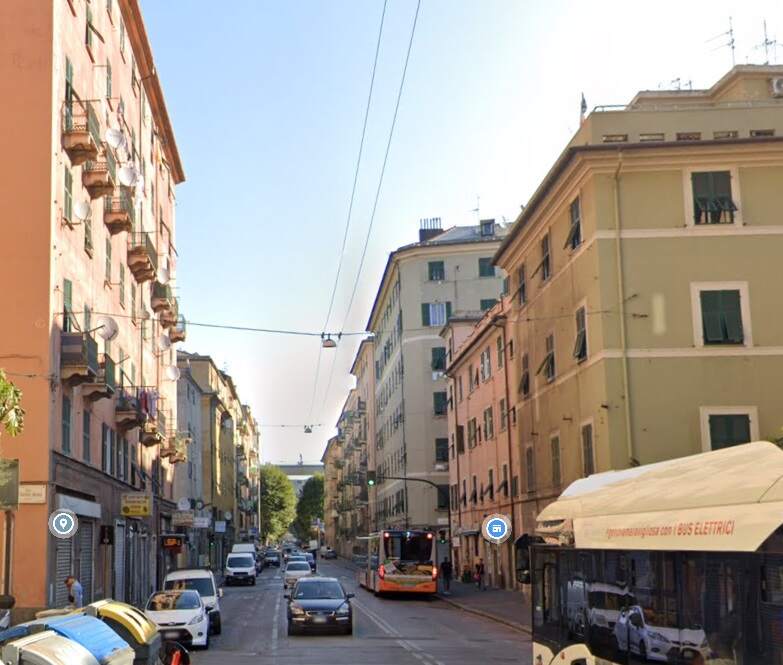
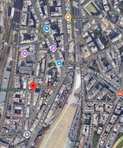
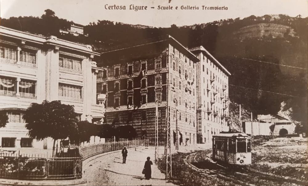
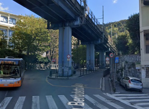
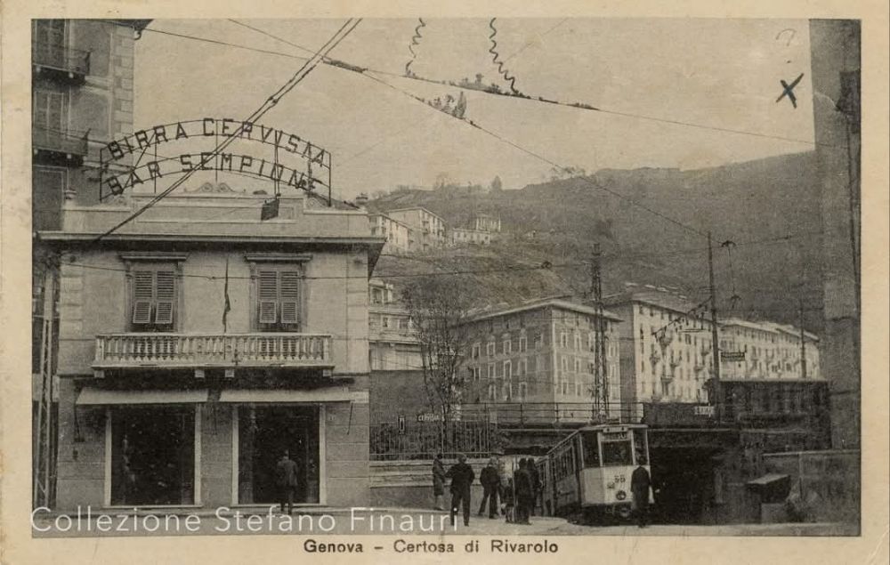
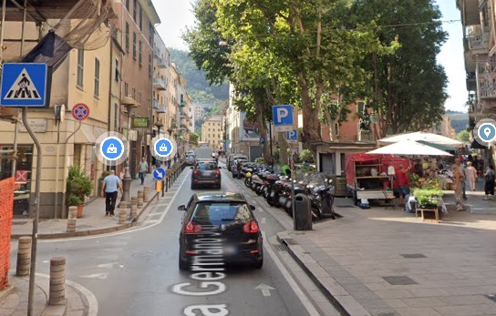
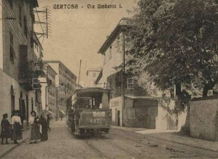
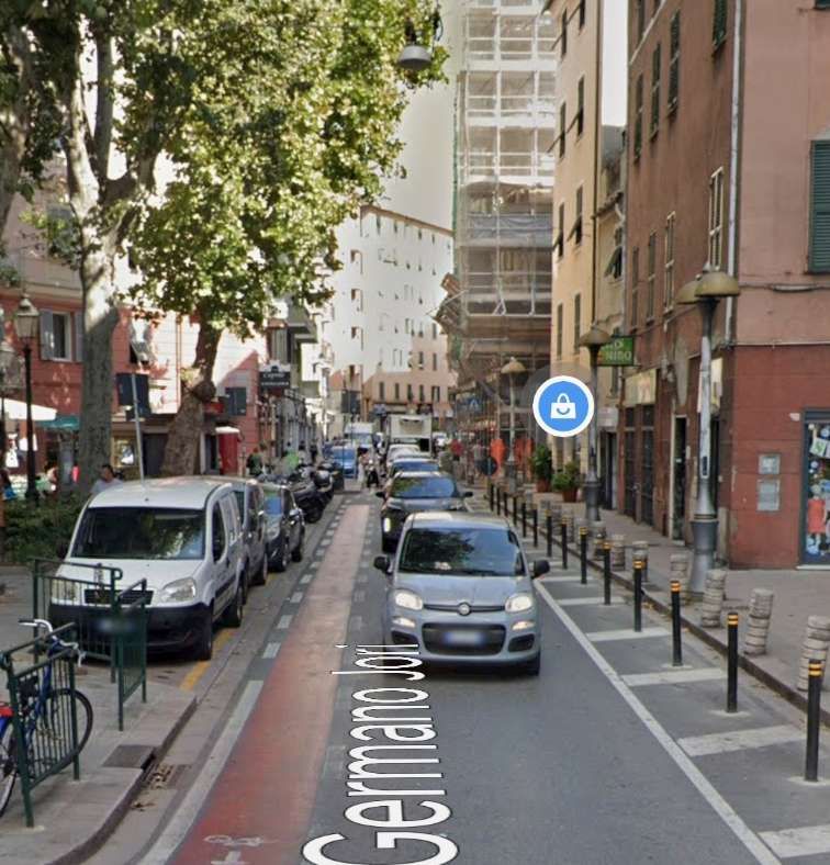
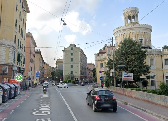
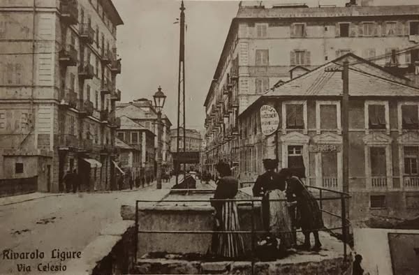
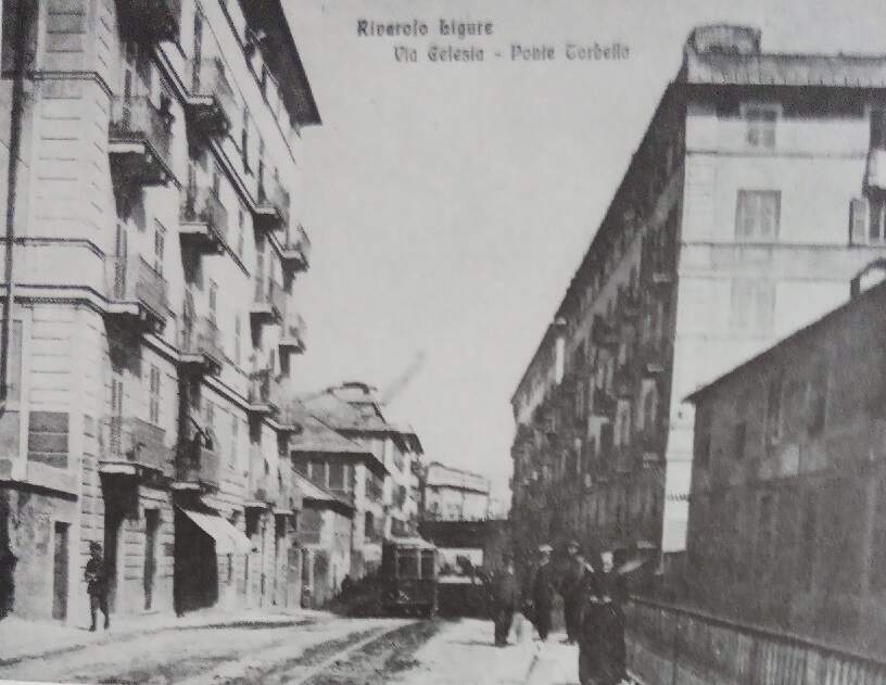
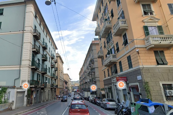
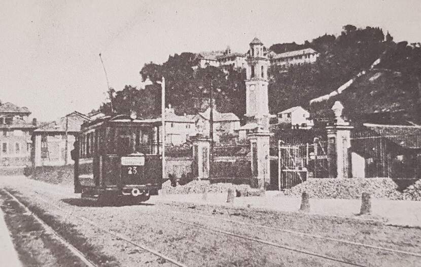
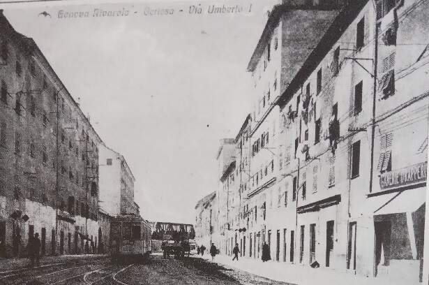
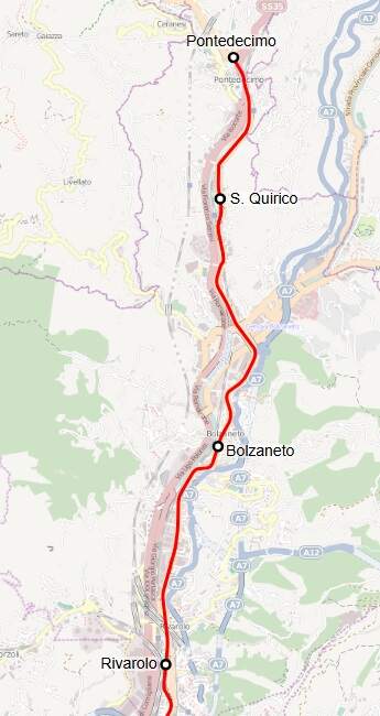
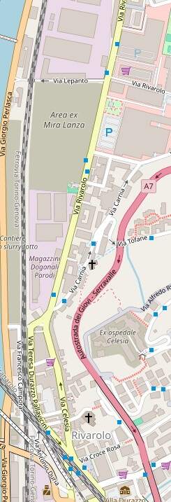
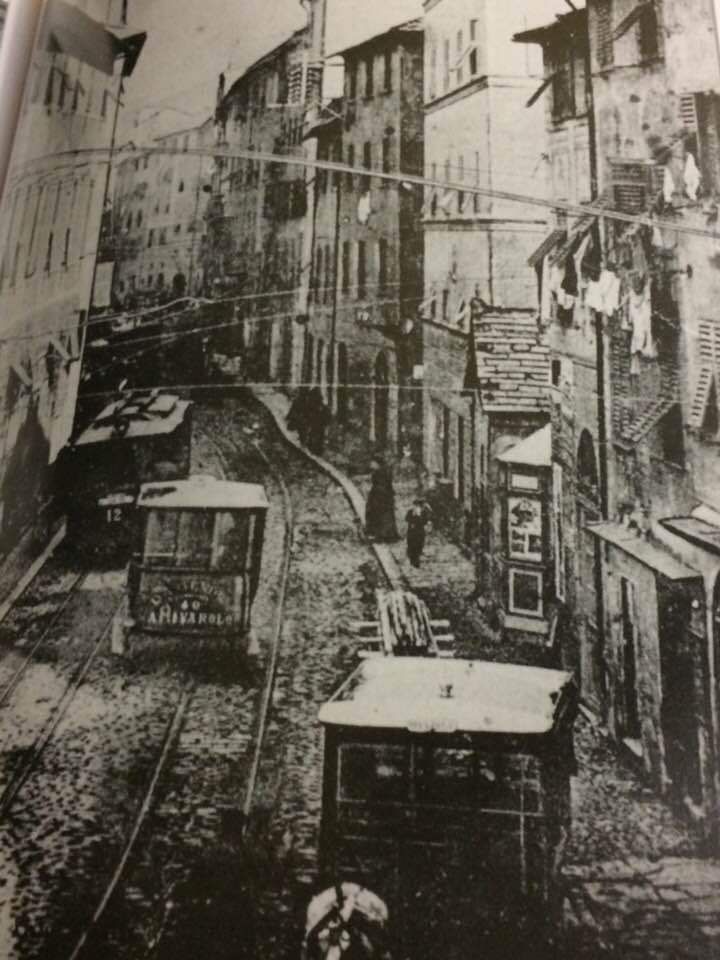
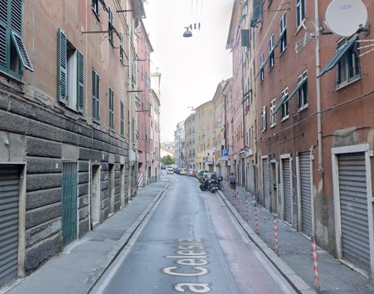
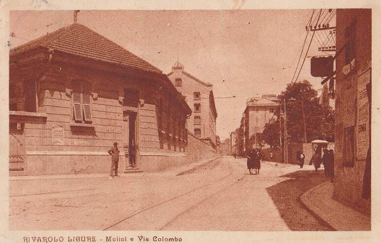
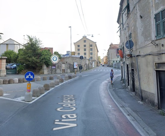
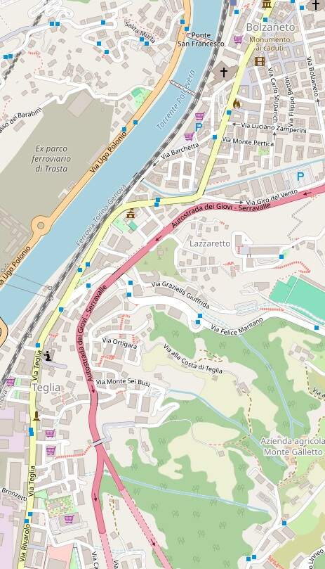
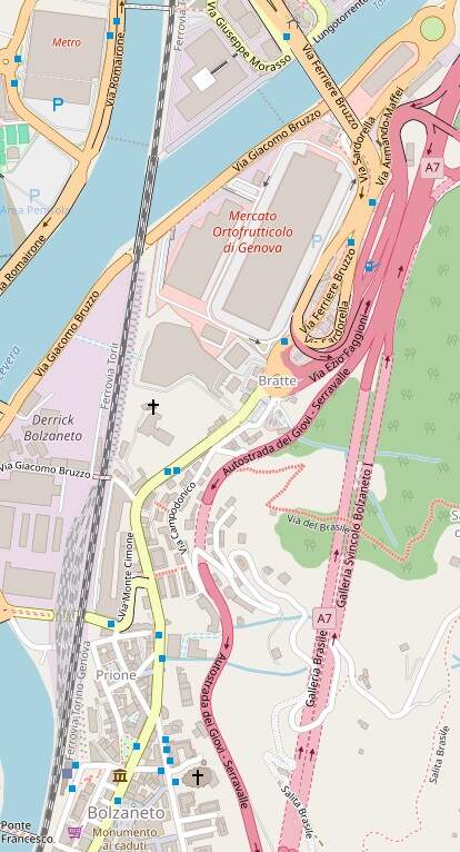
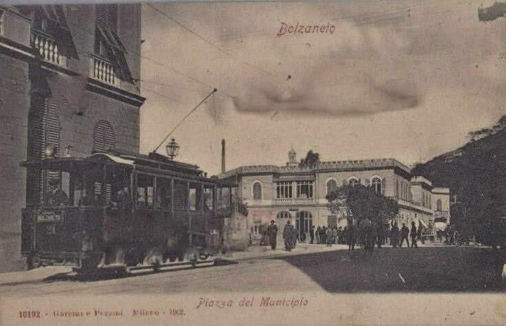
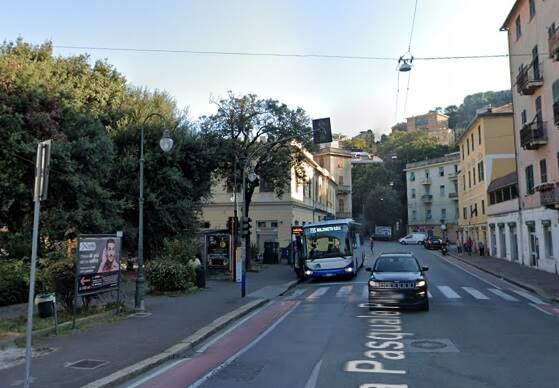
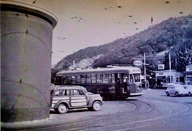
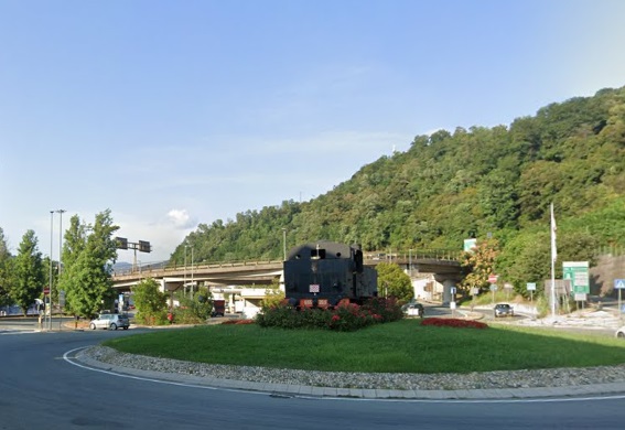
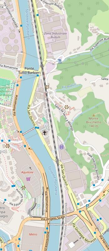
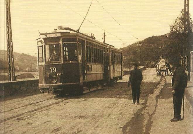
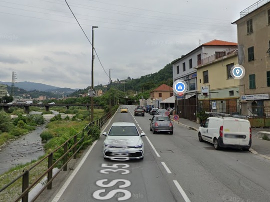
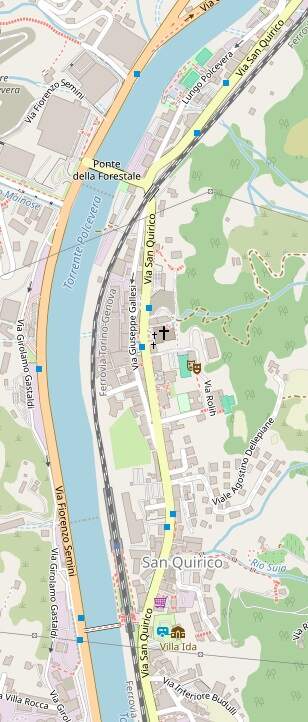
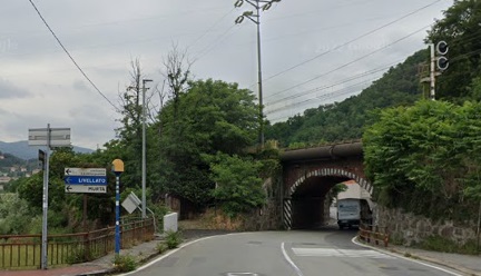
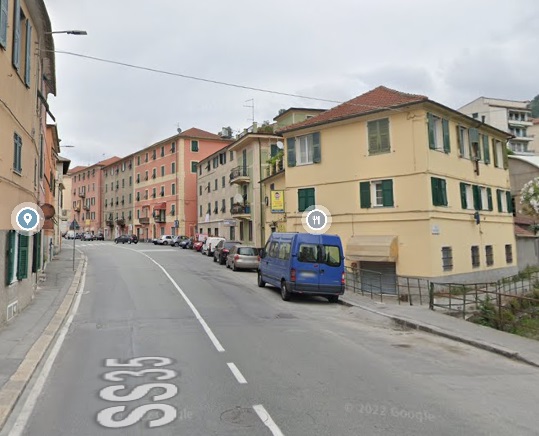
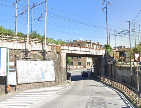
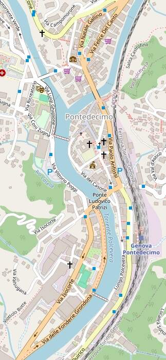
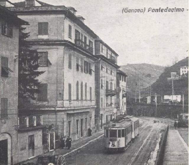
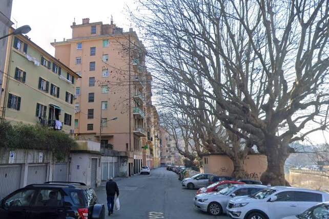
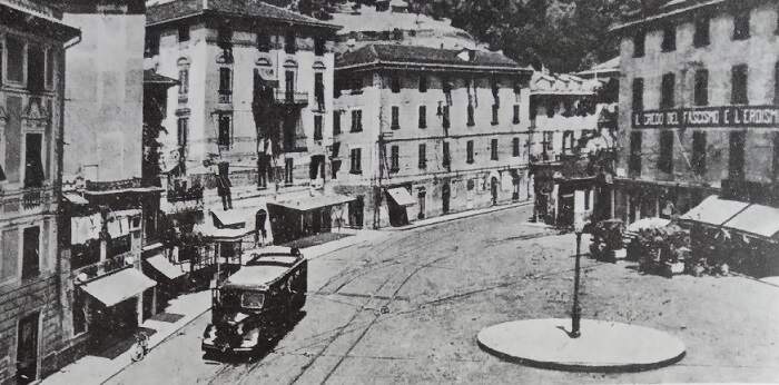
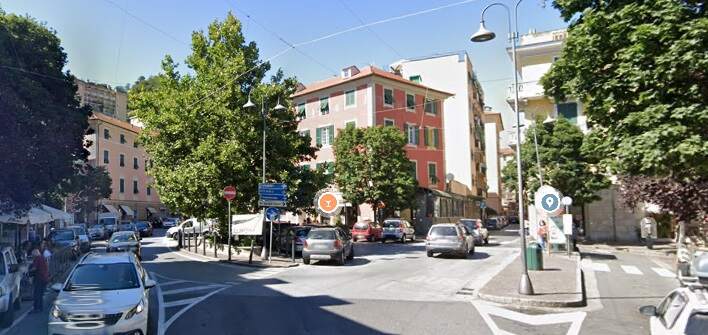
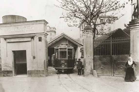
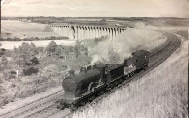
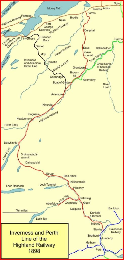
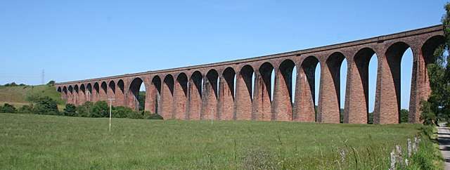
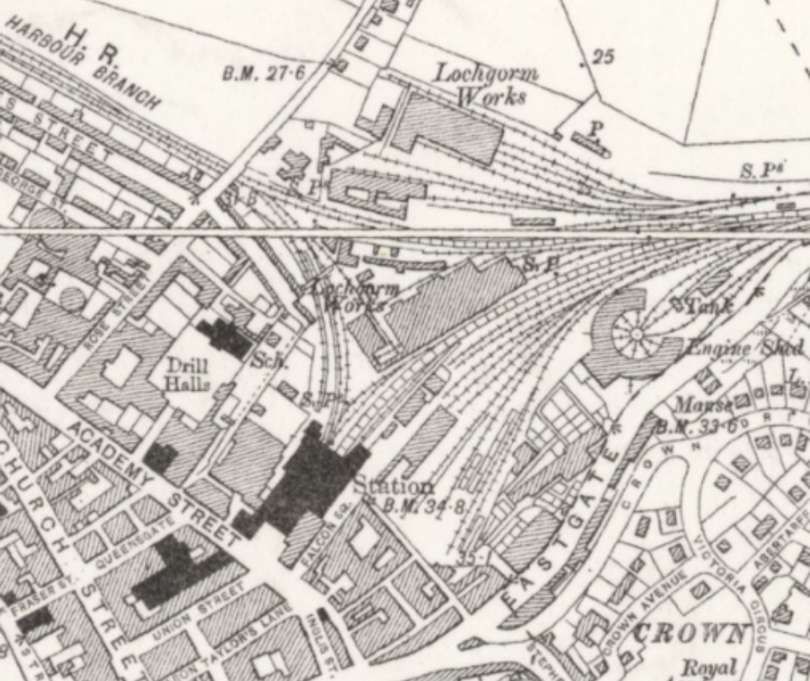
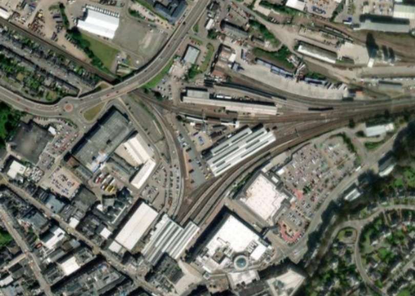
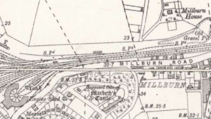
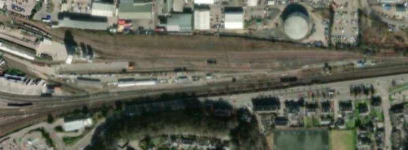
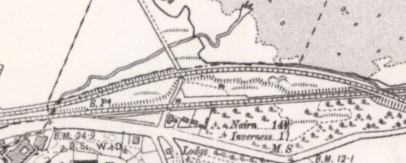
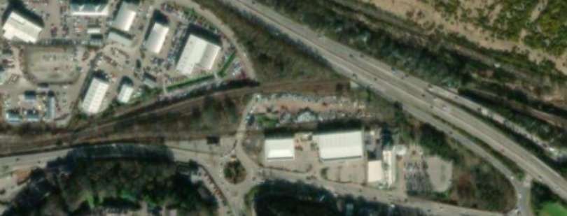
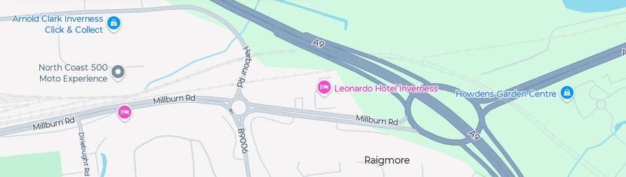
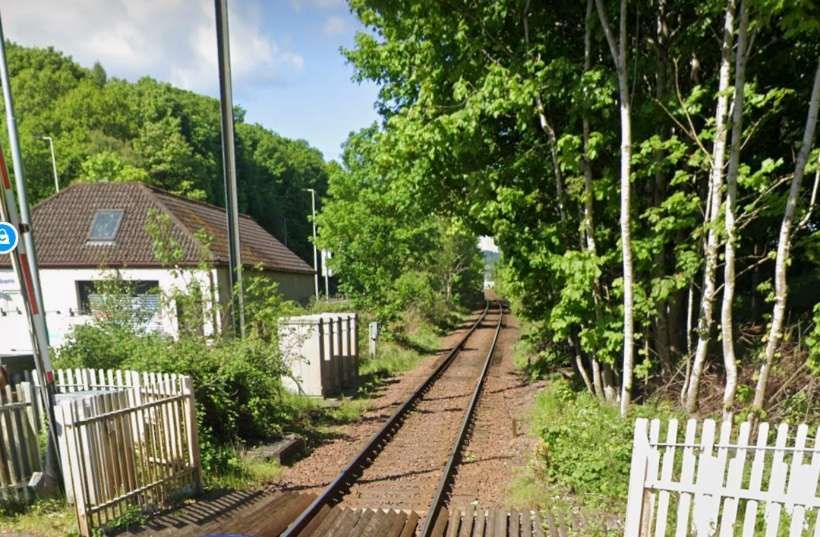
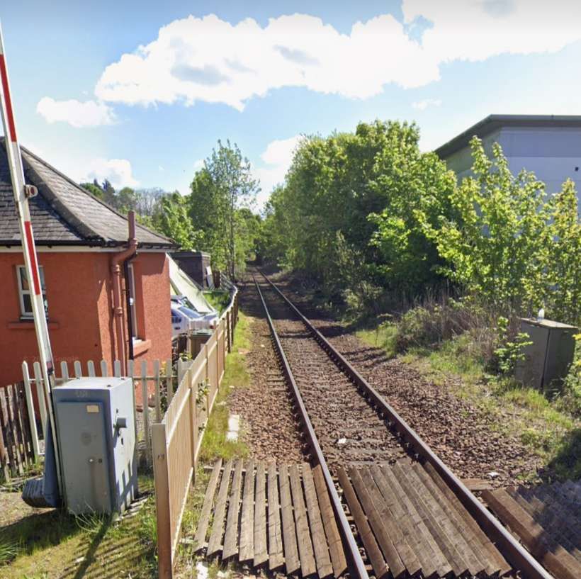
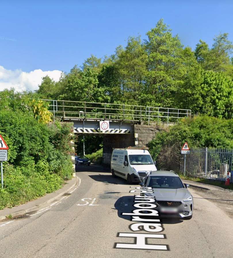
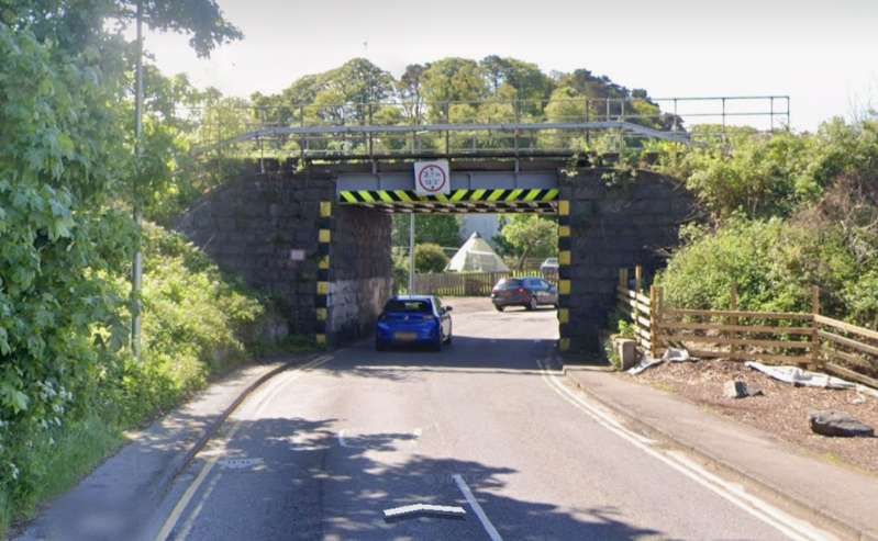
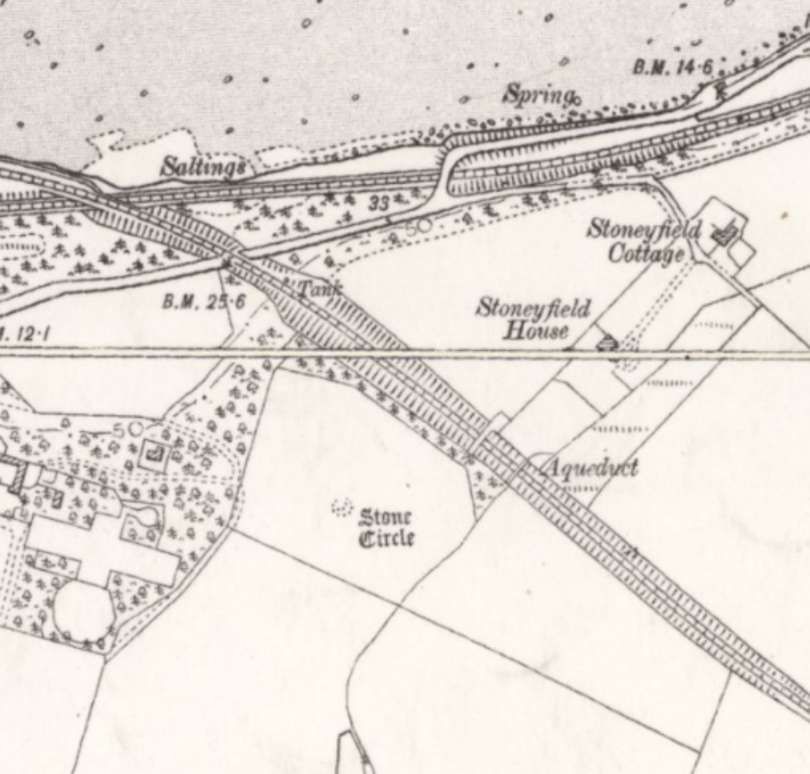
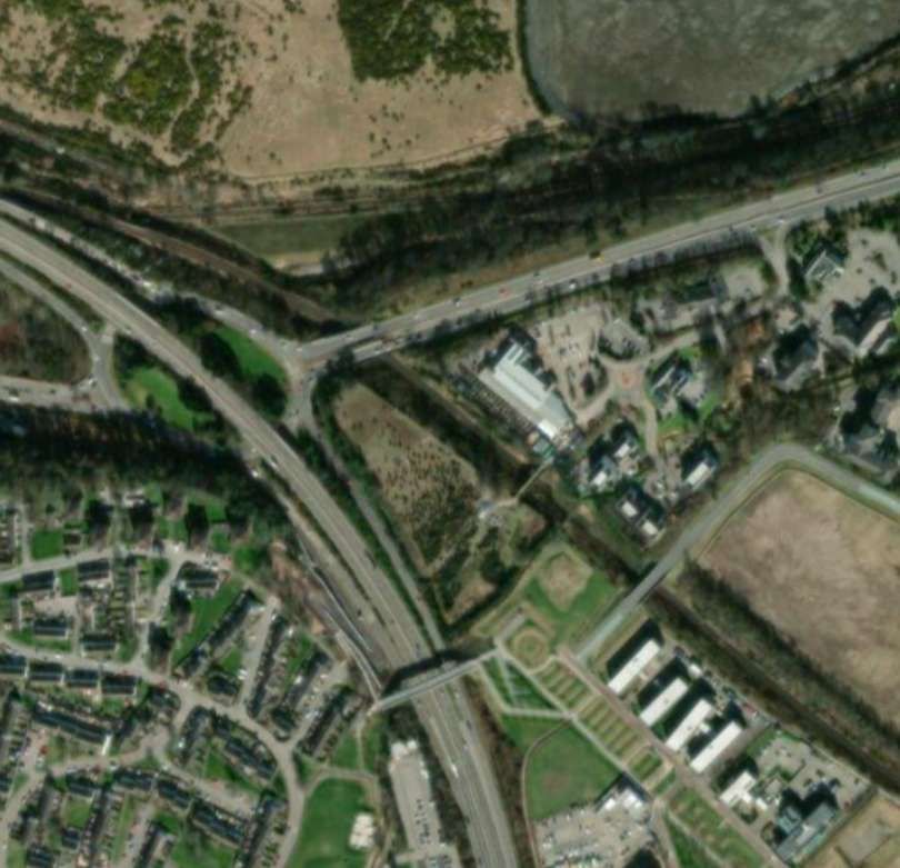
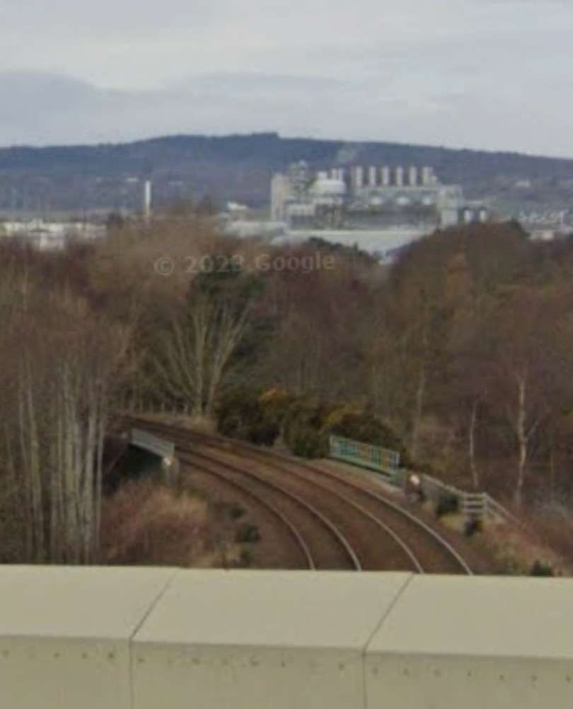
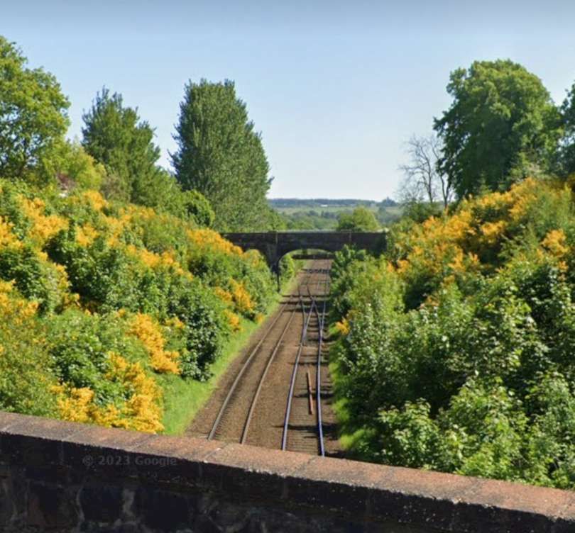
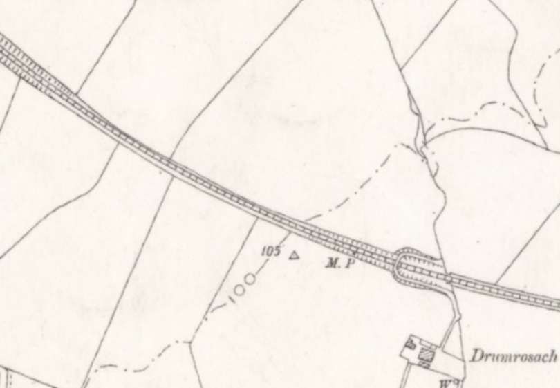
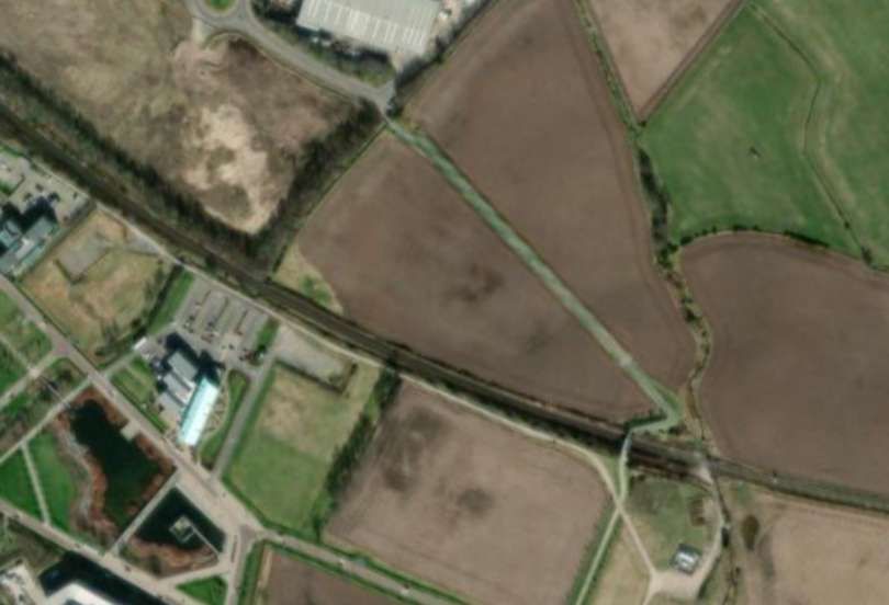
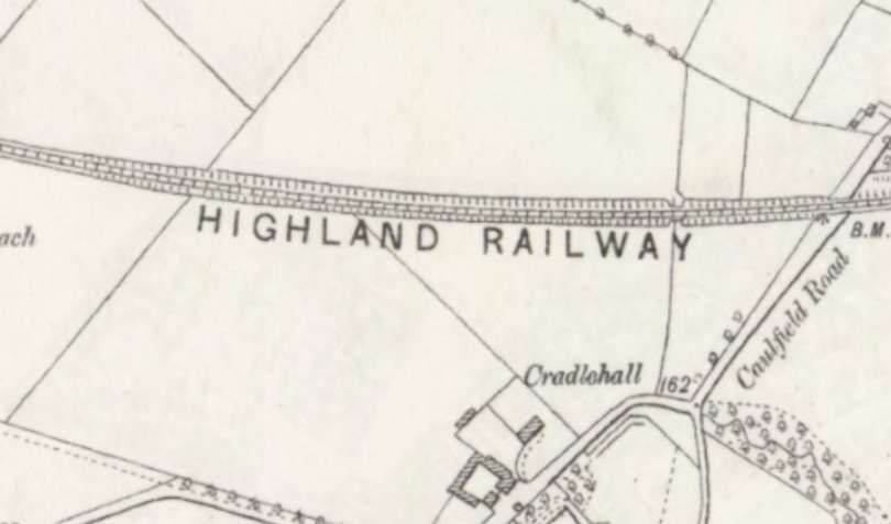
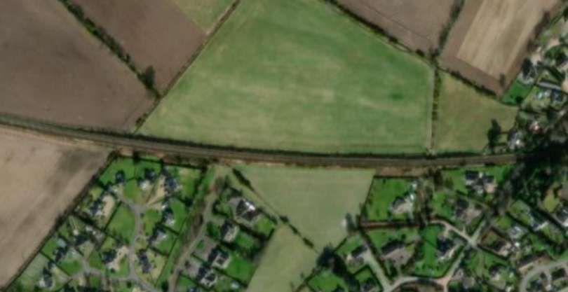
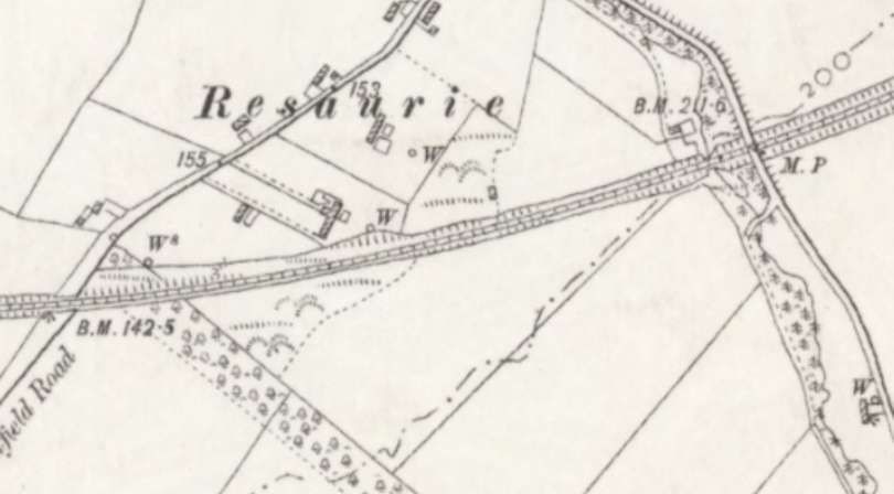
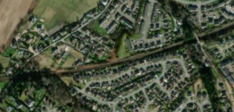
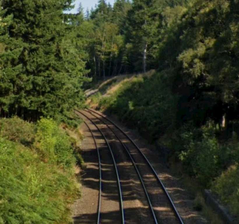
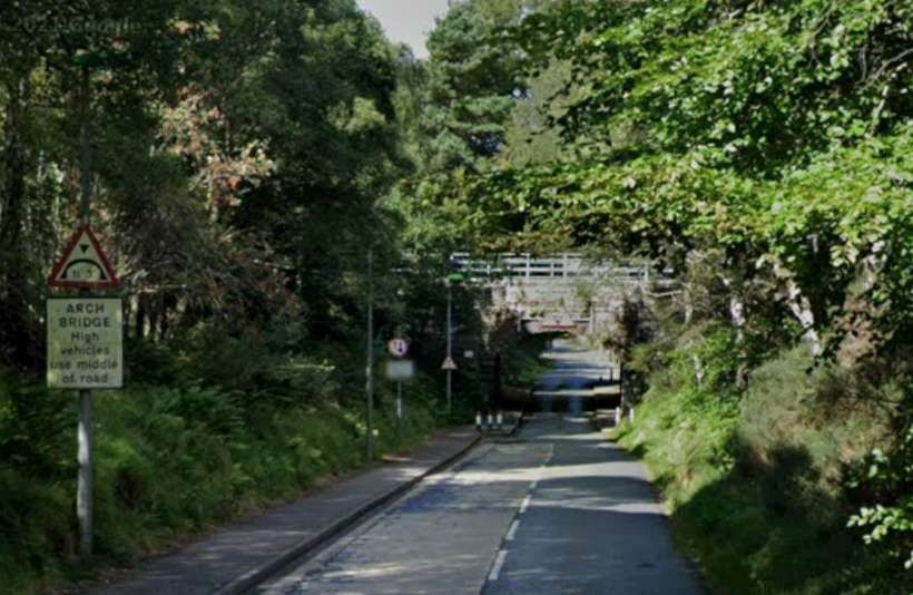
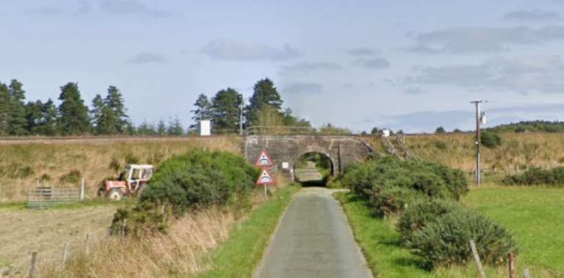
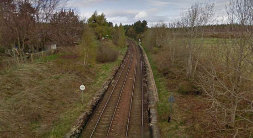
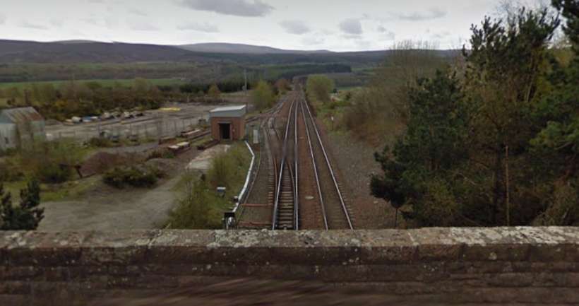
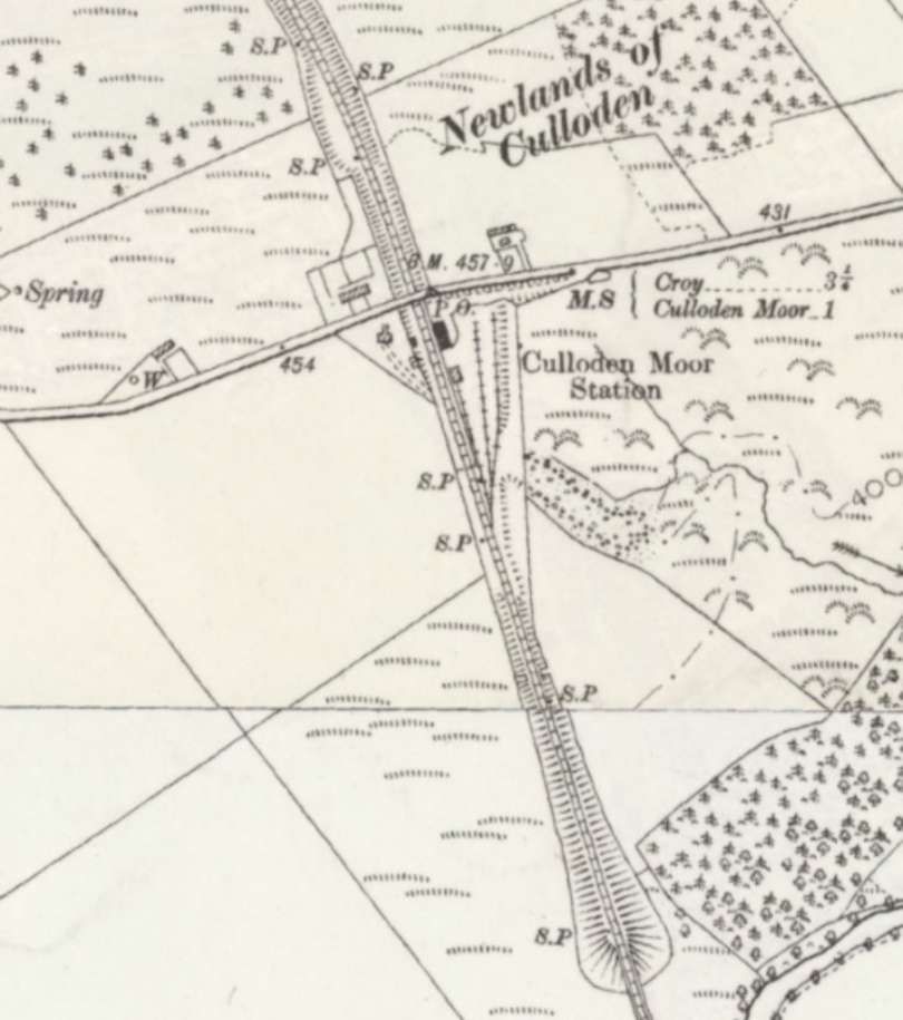
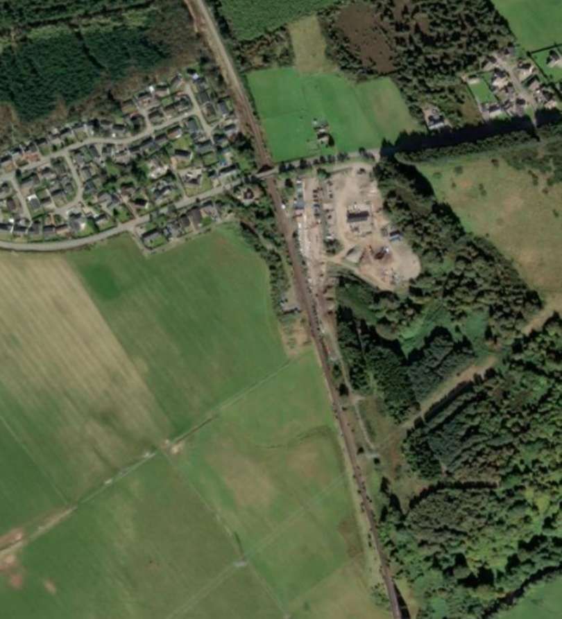
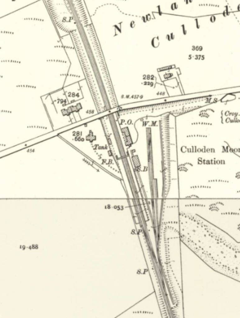
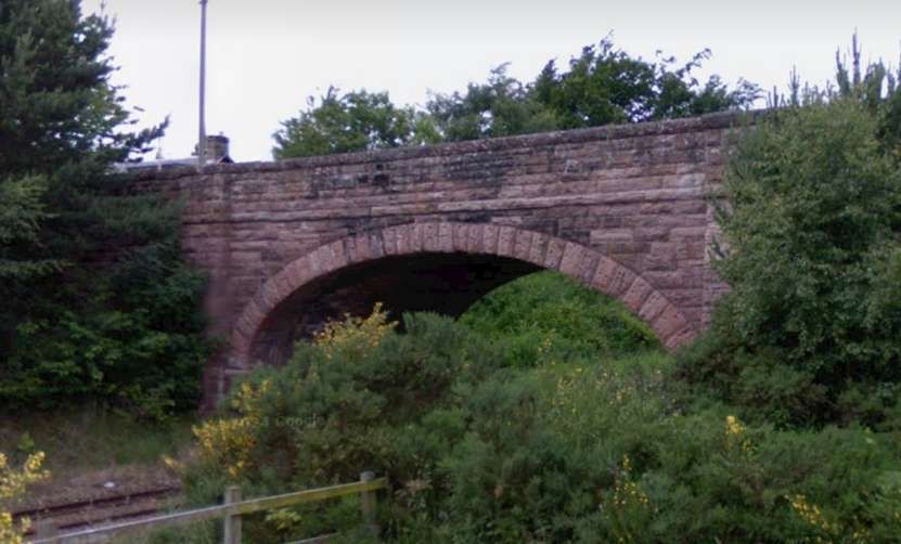
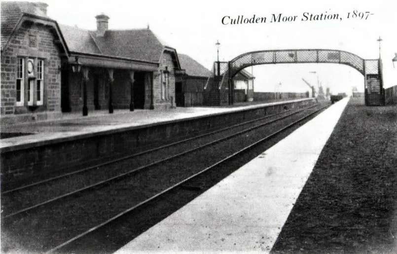
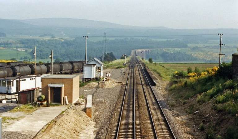
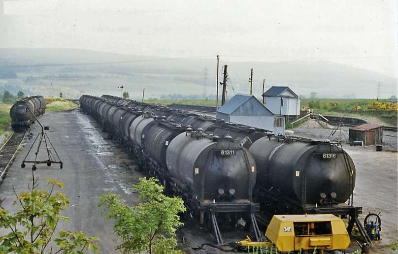
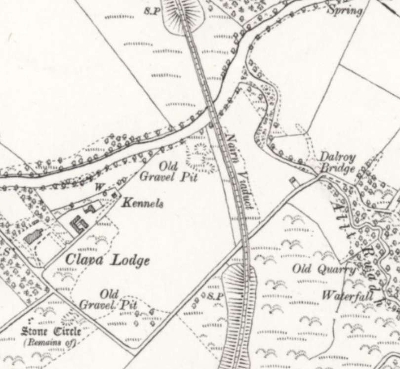

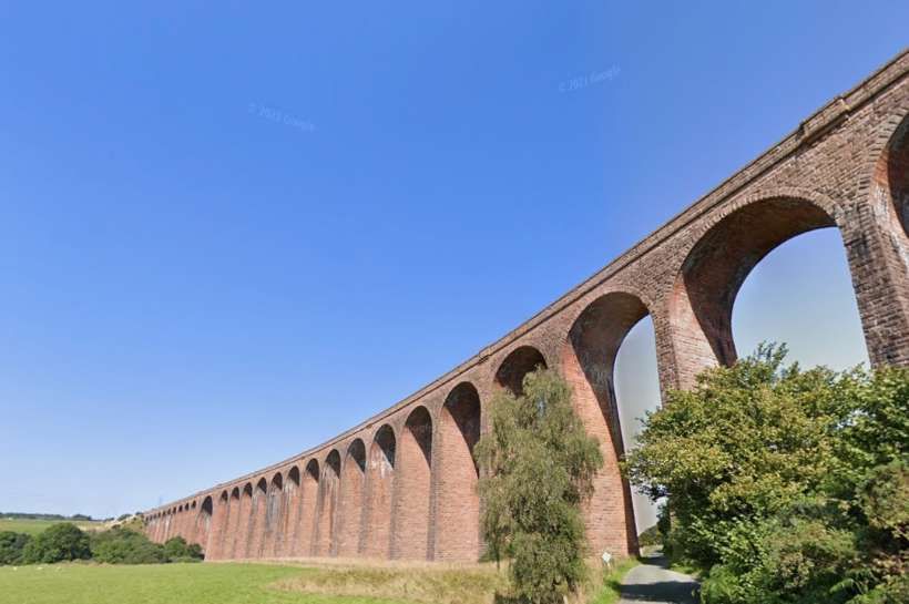
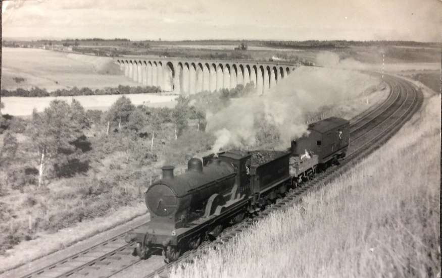
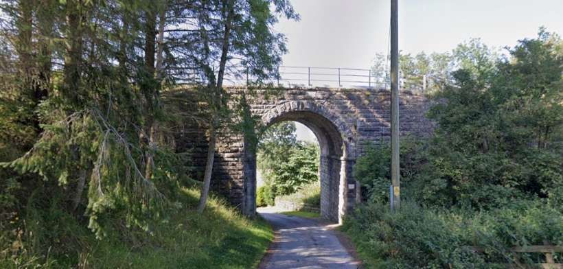
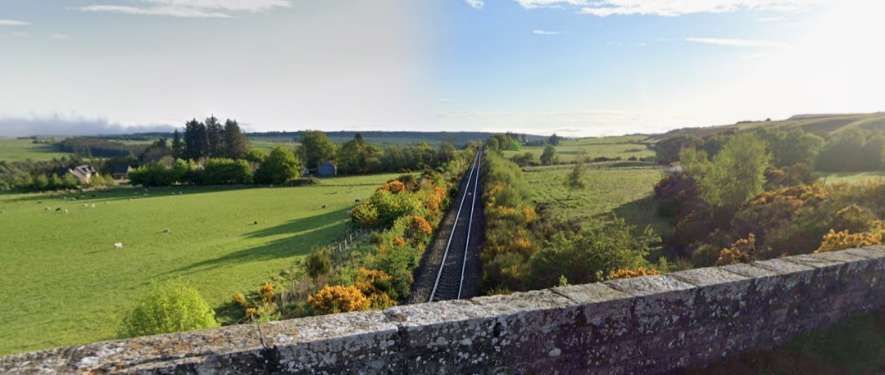
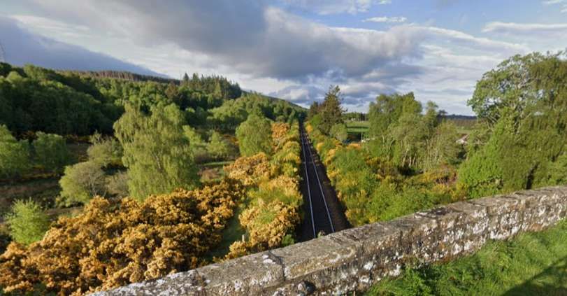
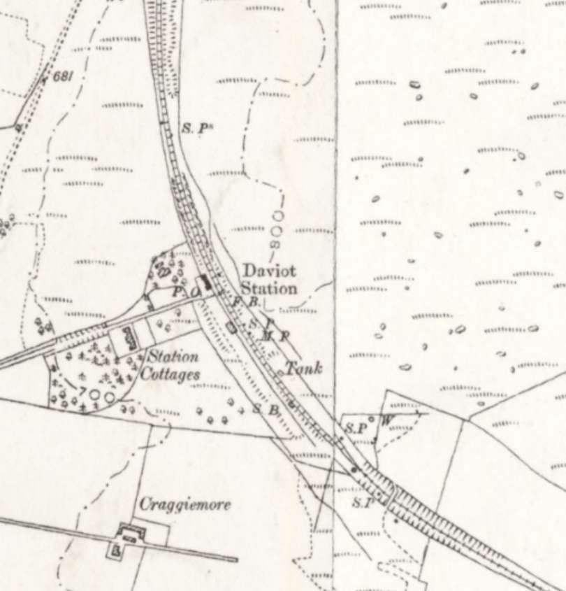
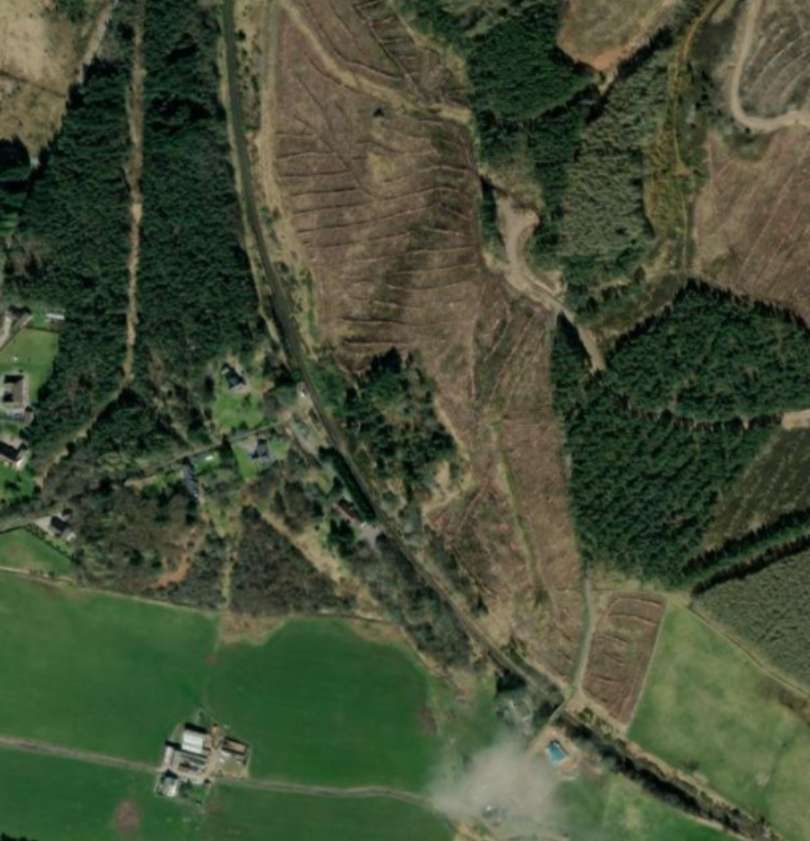
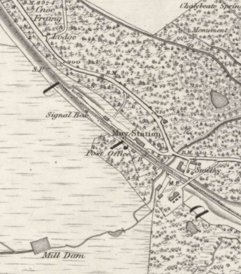
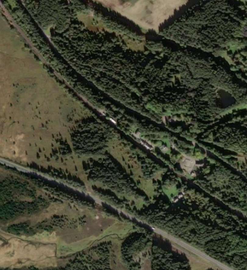
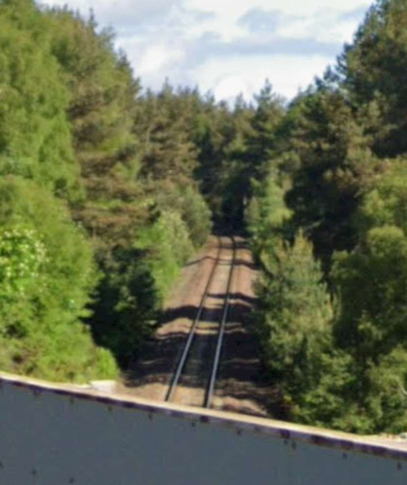
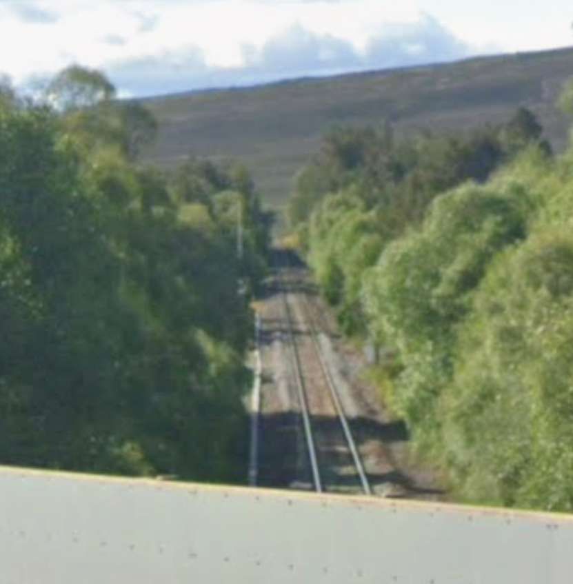
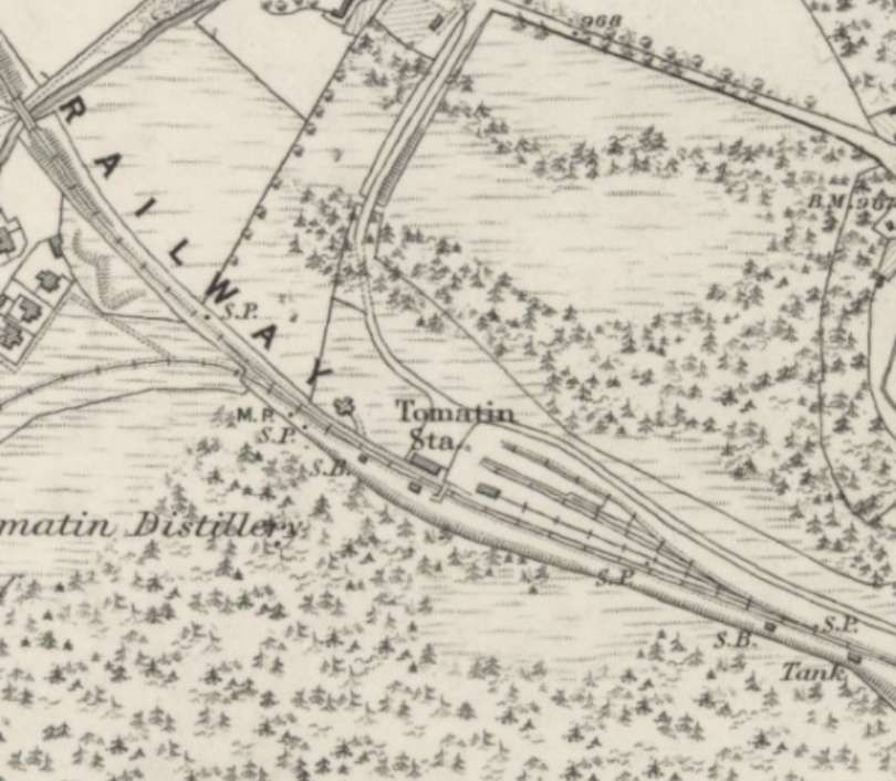
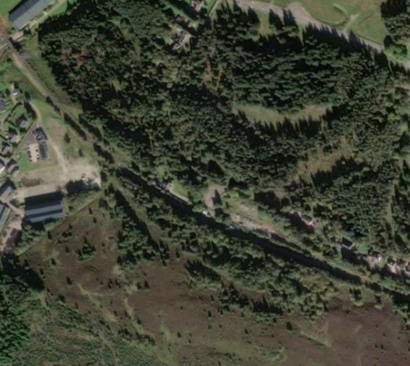
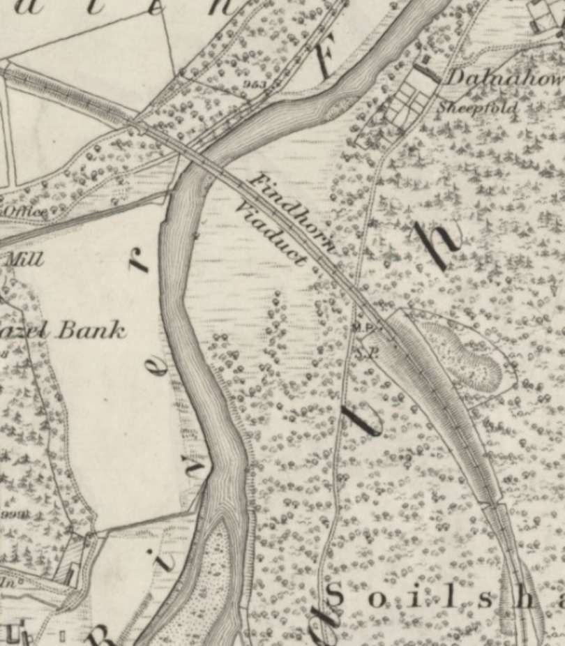
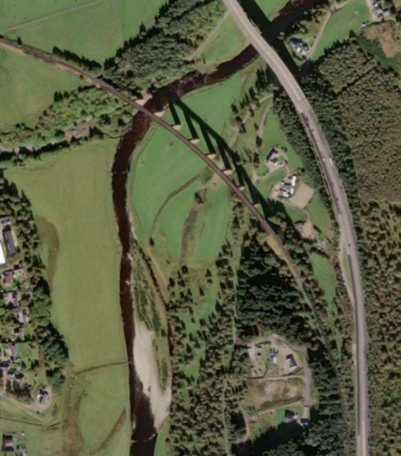
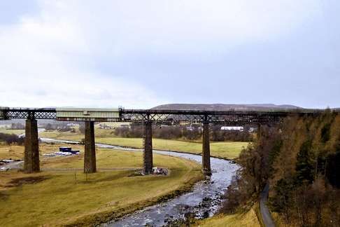
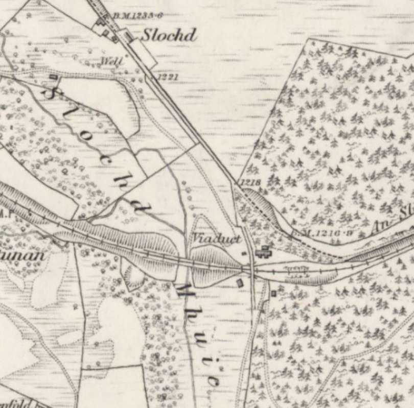
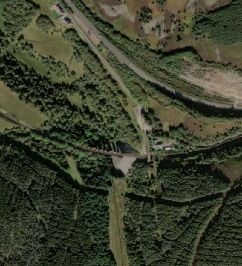
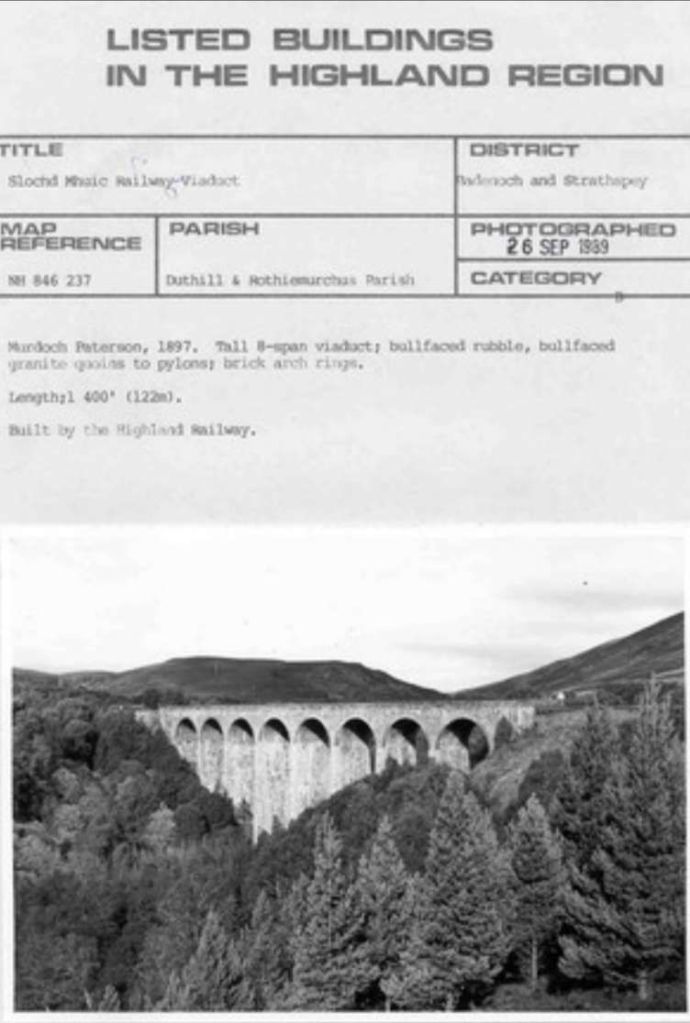
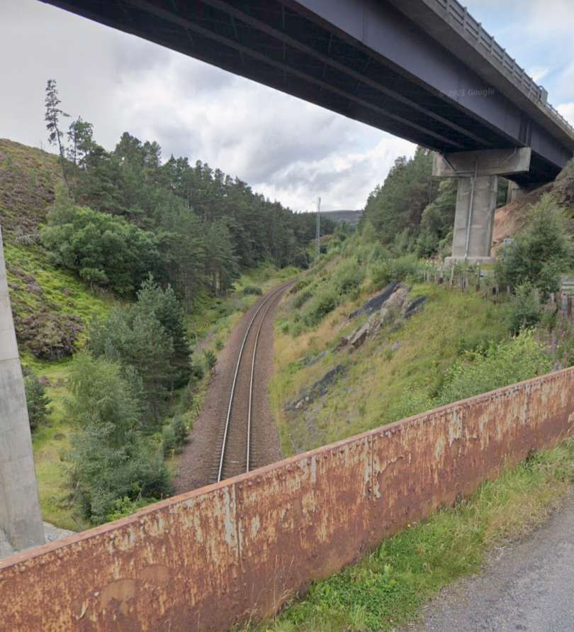
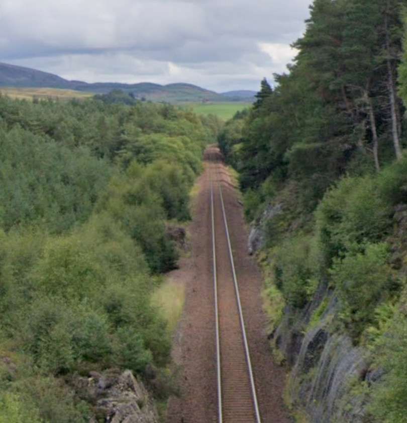
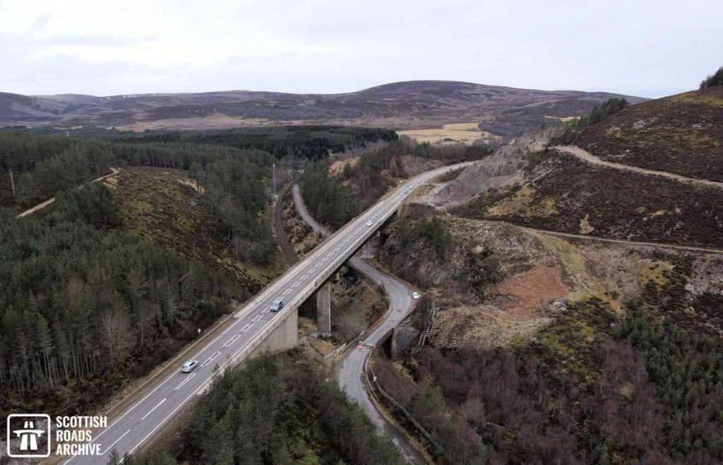
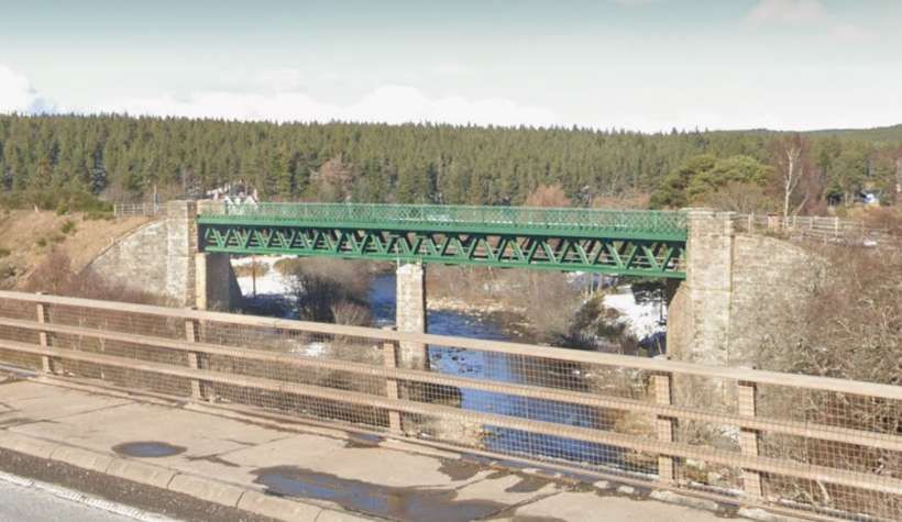
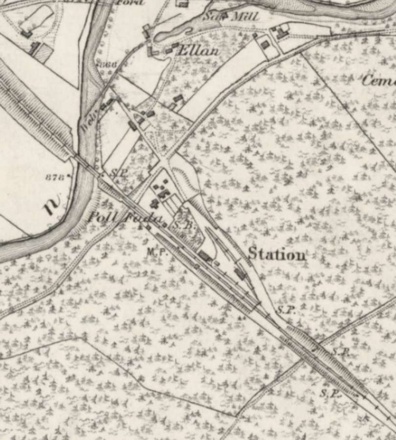
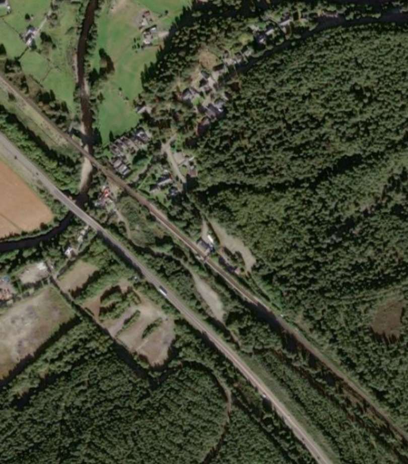
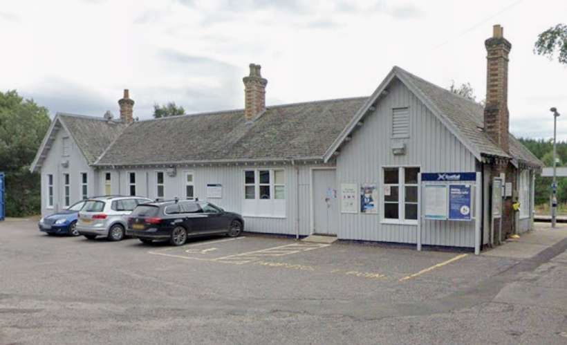

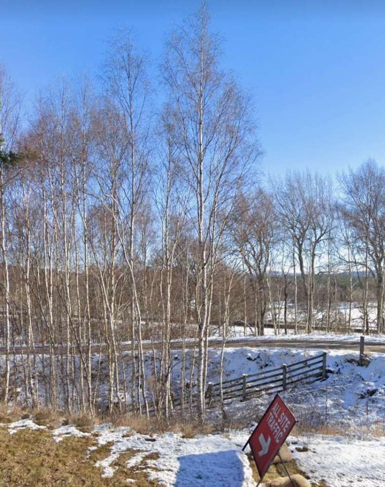
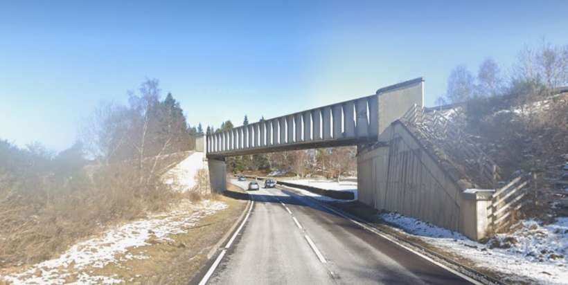
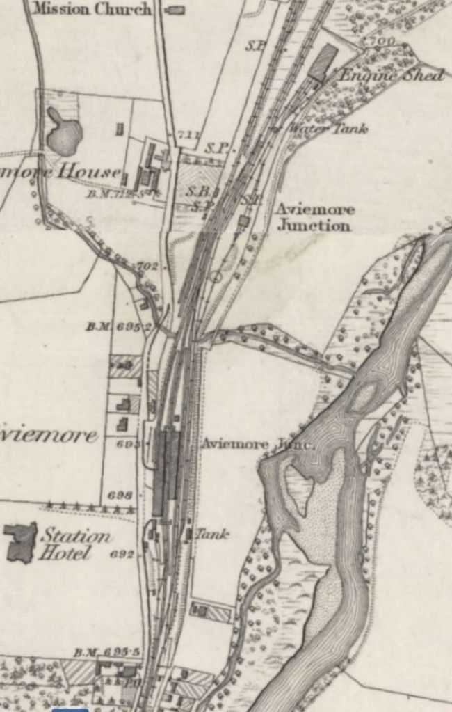
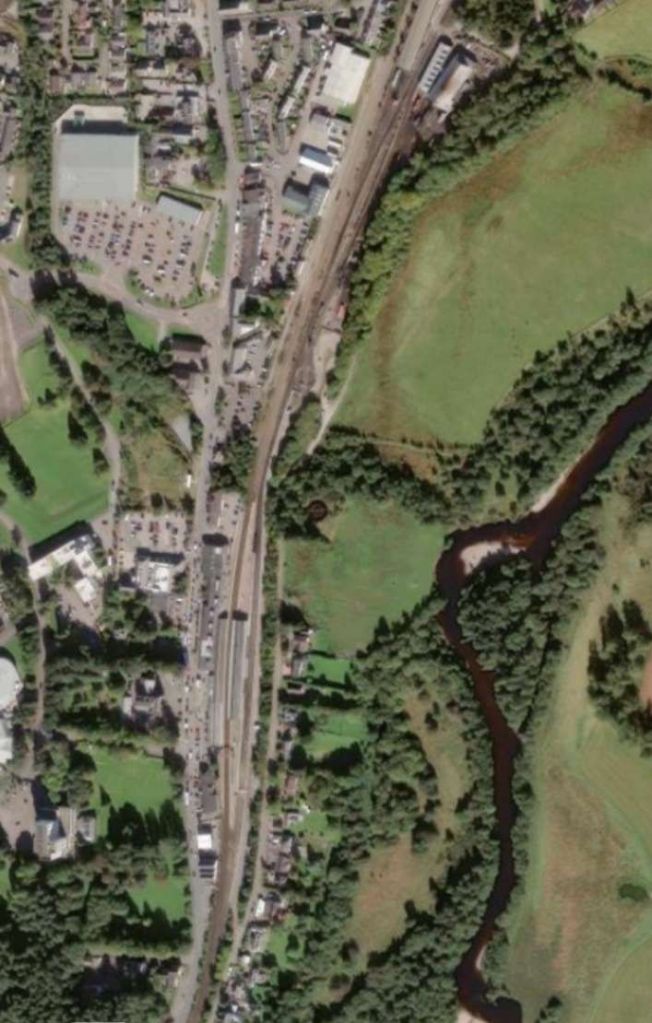
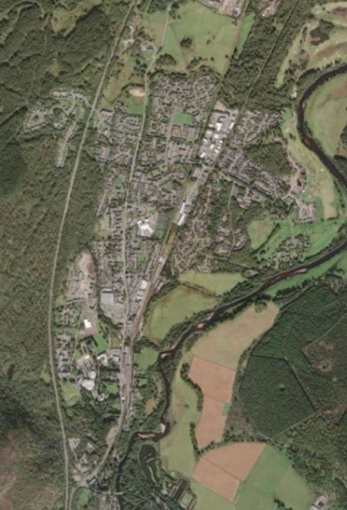

.jpg)
_58_class_Garratt_locomotive_no_5804.png)
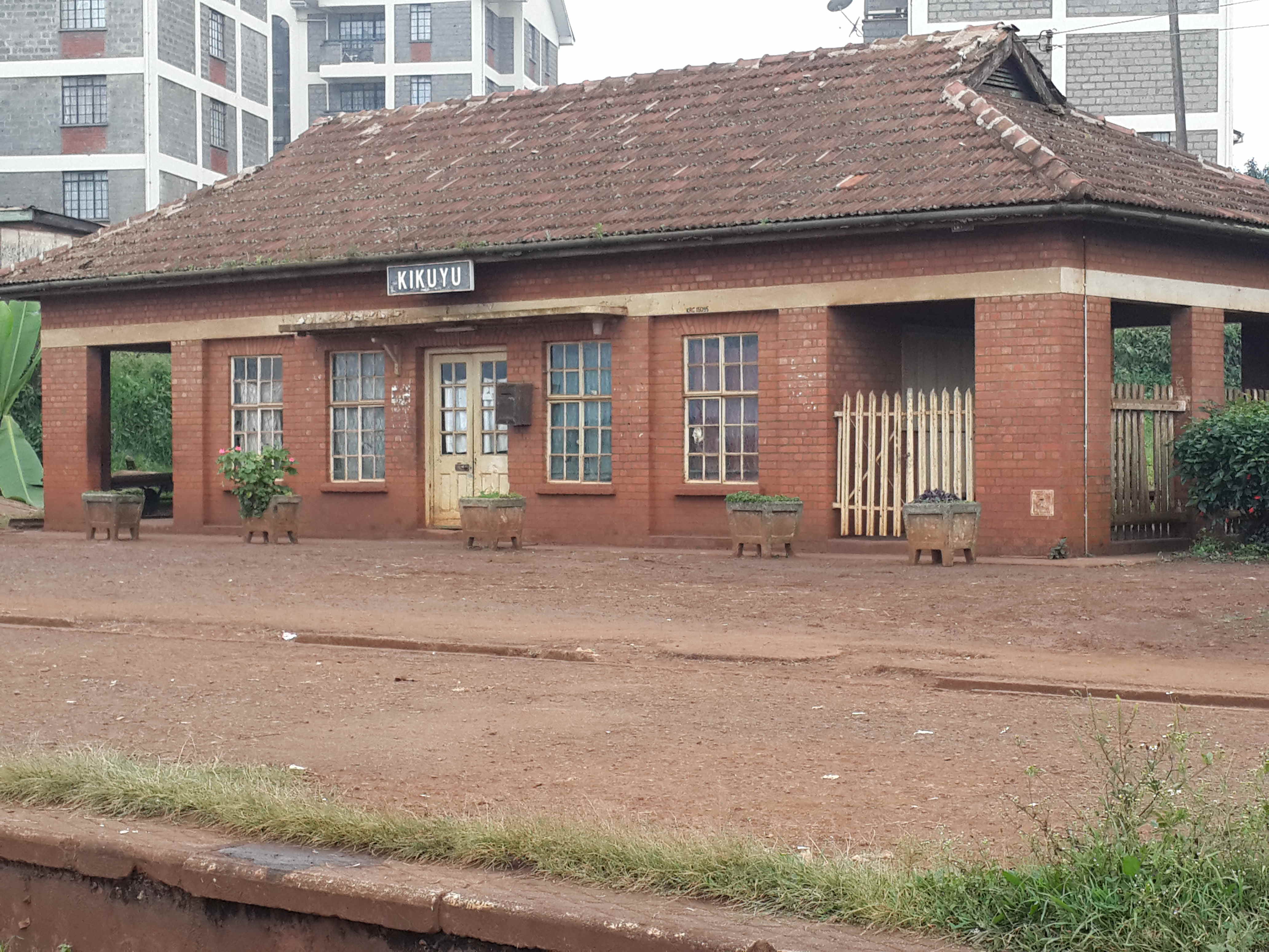
.jpg)