Most biblical scholars agree that the author of the Letter to the Galatians was very probably St. Paul. The main arguments in favour of the authenticity of Galatians include its style and themes, which are common to the core letters of the Pauline corpus. Back in the 1930s, George S. Duncan described its authenticity as “unquestioned. In every line it betrays its origin as a genuine letter of Paul.” [3]
Some scholars “have cast doubts upon its authorship due to stylistic and vocabulary discrepancies with other letters uncontestedly attributed to Paul. These disparities have caused speculations that someone other than Paul may have composed it, yet most biblical scholars uphold Paul as its true author due to strong autobiographical elements in its content and thematic consistency with other Pauline works as evidence of Paul’s authentic authorship of Ephesians.” [4]
It seems reasonable for us to ascribe the authorship of the letter to St. Paul. Although ultimately this is not critical. What matters most of all is the text that we have received.
Paul constructs an argument in Galatians which seems to culminate in the idea that a new covenant, which is built on the foundations of earlier understandings of God’s relationship with his people, has now arrived. A covenant in which we are all included in God’s kingdom by faith through God’s grace alone.
Galatians 3:23 to 4:7 sits at the culmination of this letter.
A couple of things to note:
A. ‘Children’ or ‘Heirs’.
In ancient Rome ‘heirs’ were named in a will. Other children were not named. Heirs received everything from the bequest – both debts and benefits. “In the case of intestacy, Roman inheritance law had no concept of primogeniture and treated male and female children equally. However, in most cases intestacy was avoided by means of a will. Roman law recognised very broad freedom of testation, but wills had to strictly follow correct formulae and phrases in order to be valid. The will had to name an heir. In addition to this, it could name a legal guardian (tutor) for underage children, manumit slaves, and leave legacies to third parties. Over time a separate system of ‘fideicommissa’ (‘trusts’), which allowed greater flexibility, developed alongside the system of wills.” [5]
If a man died intestate, “property went first to ‘sui heredes’ (‘his own heirs’), who were any children of the deceased that had remained under his ‘patria potestas, (‘paternal power’) until his death. [6: p200] There was no assumption of ‘primogeniture’ – all children, male and female, received an equal share of the estate. [6: p201] If there were no children, then agnate relatives in the male line would inherit (i.e. other children of the deceased’s father, paternal grandfather, and so on). [6: p200] If there were none of these, then the ‘Twelve Tables’ [6: p199][7: p505] provided for the property to be inherited by the wider gens, but as the social role of the gens declined after the Early Republican period, this ceased to occur.[6: p200] There was no concept that an intestate property might pass to the state. [6: p200] Children of the deceased who had been emancipated before the deceased’s death or who had passed into the ‘potestas’ of another (through certain kinds of marriage or through adoption by another) were excluded from the succession, as were relatives in the female line (i.e. relatives of the deceased’s mother), and the deceased’s spouse.” [6: p200-201][7: p505]
Most Roman inheritances were, however, not intestate. “Instead, they were governed by a will (‘testamentum’). [7: p500] Some Roman writers speak of producing a will as a duty (‘officium’). [6: p201] Henry Maine in 1861 characterised the Roman approach as a ‘horror of intestacy.’ [6: p201][7: p499] Only a ‘pater familias: (male head of household) could make a will that disposed of a whole estate. [7: p502] But any Roman citizen who had reached the age of majority could make a will for property that they possessed in their own right. Women could make wills through a process of fictional sale (coemptio), until the reign of Hadrian, when they were given the ability to make a will through their tutor (legal guardian). [6: p202][7: p502] Non-Romans (peregrini) and people with intellectual disabilities could not make wills under Roman law. [7: p502] Exiles were not allowed to make wills either and this ban was retrospective; being sent into exile voided any will that the exile had already made. [7: p502] … The will had to name an heir. [6: p202] In addition to this, it could name a legal guardian (tutor) for underage children, manumit slaves, and leave legacies to third parties.” [6: p204]
Failure to name an heir could render a will void. [6: p204] An heir did not have to be a natural child of the deceased. An adopted heir was acceptable. This was often the practice in higher-ranking household as couples were often infertile.
An heir inherited both the deceased’s debts and his possessions. Being a child did not guarantee being an heir.
In verse 26 of Galatians chapter 3, the NIV and NRSV choose to translate a Greek word which means ‘sons’ as ‘children’. A word which carried great weight in the ancient world, ‘the son and heir’, the one who receives everything, is replaced in the NIV and NRSV by one which is about us all being ‘children’. In modern thinking, being one of many children of the father does confer status. But the word ‘children’ fails to carry the great sense of particularity intended by the author of the epistle. The status of ‘son and heir’ was more significant than being a ‘child’. In our thinking about this passage we must give weight to this distinction. Paul intends us to understand that we all (female and male) have the same status as the ‘son and heir’.
The distinction in ancient Rome between ‘son and heir’ and ‘child’ will also have been important to those reading the passage in many eras of civilisation and the history of the church. Particularly so, once the concept of primogeniture became established in the medieval world. A concept which kept land and estates whole as they were passed from father to eldest son. The eldest son was ‘the heir’, the other children, while usually loved, had a demonstrably secondary status.
Paul intends us to understand that we are all (female and male) co-heirs with Christ, we have the same status, the same entitlements. We have been chosen as ‘heirs’. We are more than ‘children’. In verse 29, Paul uses the word κληρονόμοι (klēronomoi) ‘heirs’ emphasising the point that ‘son’ is different from ‘child’.
Our status ‘in Christ’ is that of heirs to the promise, not just children.
B. Verse 28 – ‘Or’ and ‘And’
In the context that we are all inheritors of everything God has to offer, it may be worth us noting what Paul writes in verse 28. There is a small but perhaps significant change from ‘or’ (οὐδὲ) to ‘and’ (καὶ) in Galatians 3:28. The Greek reads like this:
The direct translation is shown in interlinear form below:
οὐκ ἔνι. Ἰουδαῖος οὐδὲ Ἕλλην, οὐκ ἔνι δοῦλος οὐδὲ
Not/neither there is Jew or Greek not/neither there is slave or
ἐλεύθερος, οὐκ ἔνι ἄρσεν καὶ θῆλυ πάντες γὰρ
free not/neither there is male and female all for
ὑμεῖς εἷς ἐστε ἐν Χριστῷ Ἰησοῦ.
you one are in Christ Jesus.
The direct translation does not read easily in English. As is usual, this means that the translators have had to decide how best to make the text readable in English. Almost inevitably they have chosen to give greater continuity in their translations. The variety of different translations can be found here. [2]
Many of the translators choose not to recognise the change from ‘or’ (οὐδὲ) to ‘and’ (καὶ). I guess the question must be whether or not Paul meant the change to be significant. Many of the translators think not, and in doing so they prevent most modern readers having the opportunity to engage with the possibility that the difference is significant. Effectively, the translators narrow down the possible interpretation of the text in favour of their own interpretation.
But is that difference significant? Perhaps it is sufficient for us to read that there is no distinction in Christ, that we are all one in Christ. Whether we are Jew or Greek, slave or free, male or female, there is no distinction between us. We are one in Christ, all of us ‘heirs’ of the promise, much more than just children. If that were the case, I would happily go on to argue that these pairings are intended to demonstrate the breadth of God’s inclusive love for everyone.
But, that single καὶ (and) may add to the argument. Two couplets are ‘neither/nor’ but for one couplet Paul choses to use καὶ, why? … This part of our passage, (i.e. οὐκ ἔνι ἄρσεν καὶ θῆλυ), seems to allude to Genesis 1:27 (ἄρσεν καὶ θῆλυ ἐποίησεν αὐτούς, in the Septuagint) where God first creates a being, Adam, seemingly both male and female, if verse 27 of Genesis chapter 1 is taken literally.
Daniel W. Roberts comments that “Galatians 3:28 is a rare case of a direct quote going relatively unnoticed by scholarship, which is then followed by a one-word allusion to further solidify Paul’s claims concerning unity.” [8: p1] “Paul in Galatians 3:27–28 quotes Genesis 1:27, … this purposeful quotation of Gen 1:27 is meant to couple with an allusion to Genesis 2:24 to articulate further the unity found in Christ.” [8:p3][9]
Roberts goes on to argue for the unity which comes from marriage and which mirrors the unity between Christ and his Church. But there are other interpretations which include feminist, intersex, or queer, etc. perspectives.
If there is a significance to the use of the word καὶ, and there may not be, but if there is, it must delineate a difference between the male/female couplet and the Jew/Greek and slave/free couplets. In Christ there is no longer Jew or Gentile, no longer slave or free, no longer male and female. It must, as Roberts suggests, refer to something else. Particularly, probably, the passage in Genesis.
Are the first two couplets a case of ‘either/or’ while the third is a case of ‘both/and’? Is ‘male and female’ just, for Paul, one category rather than two categories? Just one thing? Perhaps he sees us as being included in God’s blessings because we are human rather than because we are male or female? Perhaps gender/sex is insignificant? I am not sure where this leads us, but perhaps it places our disputes about what it is to be a male or a female in a wider context. Perhaps it is about freedom to be who God has made us to be, rather than having to conform to the either/or of the other categories in Galatians 3: 28. Paul sums this all up with the fact that, whatever he means earlier in the verse, we are all one in Christ Jesus.
Roberts comments that Richard Hays’s study is especially significant for the study of Paul’s more subtle uses of the OT, what he calls echoes and allusions. This specific example, not discussed by Hays, arguably passes all seven of his tests for Pauline echoes. (Richard Hays, Echoes of Scripture in the Letters of Paul; Yale University Press, New Haven, p29–32.)
The Llanfyllin Branch was featured in an article by Stanley Jenkins in the October 2003 issue of Steam Days magazine. [3]
The immediately adjacent Tanat Valley Light Railway is covered elsewhere on this blog. The articles about that line can be found here [4] and here. [5]
The two lines ran into the hills to the Southwest of Oswestry. The local Cambrian network is shown diagrammatically in the image below.
Trains on the branch ran from the Welsh border town of Oswestry to Llanfyllin in the Berwyn Mountains. The branch left the Oswestry & Newtown Railway at Llanymynech, where the station nameboard called on passengers for Llanfyllin and Lake Vyrnwy to disembark and change trains. The lake is a nearby beauty spot where there is a reservoir supplying water to Liverpool.
In July 1864, the Oswestry & Newtown Railway joined with other local concerns to form the Cambrian Railways Company with its headquarters at Oswestry.
Llanfyllin’s townfolk formed a company to secure a rail link to the Cambrian network. The Cambrian began to show some interest when ideas of an East-West mainline came to the fore.
A 10-mile branch was agreed from Llanfyllin to Llanymynech which, in the view of the companies which would soon form the Cambrian, would hinder any rival’s attempt to construct a mainline between the Midlands and the Welsh coast.
The modest scheme received Royal Assent on 17th May 1861 and the Act empowered the Oswestry & Newton Railway to build branch lines to Llanfyllin and Kerry. The Llanfyllin Branch was soon pegged out in advance of construction. It presented few engineering challenges as “for much of its length the proposed branch line would follow a comparatively easy course along convenient river valleys, and with few physical obstacles to impede [the] work.” [3: p627]
“The line was substantially complete by the early months of 1863, a significant event being the arrival of the locomotive Nant Clwyd at Llanfyllin in March of that year. The railway was opened on 10th April 1863 and branch trains began running through to Oswestry on 17th July 1863.” [3: p627]
The railway “was single track throughout, with intermediate stations at Llansantffraid and also Llanfechain. At Llanymynech the junction was situated to the North of the station, and this necessitated an awkward reversal when trains entered or left the branch. There were no tunnels on the branch, although several overbridges or underbridges were required including a 90-yard viaduct between Llanymynech and Llansantffraid. An additional stopping place was opened at Bryngwyn in the first few months of operation, although this new station was merely a request stop with no provision for goods traffic. The trains travelling eastwards to Oswestry were regarded as up workings, while westbound trains were down services.” [3: p627-628]
The new railway was soon functioning as a typical country branch line with a modest service of around five trains each way. “Minor changes took place at Llanymynech in 1866 in connection with the opening of the Potteries, Shrewsbury & North Wales Railway, but in the event this undertaking was more or less a total failure. Much later, in 1896, the Llanfyllin branch junction was re-aligned using part of the PS&NW route.” [3: p628]
“The Llanfyllin branch found a welcome, unexpected source of heavy freight traffic in the 1880s when Liverpool Corporation obtained powers for the construction of a massive dam at Llanwddyn, about seven miles to the west of Llanfyllin. By this means the surrounding valley was turned into a reservoir known as Lake Vrynwy from which water was supplied to Liverpool via a 75mile-long aqueduct. Materials needed in connection with this gigantic feat of Victorian engineering were delivered by rail to Llanfyllin, which became an important railhead while the reservoir scheme was under construction.” [3: p628]
In 1922, the Cambrian became an integral part of an enlarged GWR as part of the grouping required by the Railways Act of 1921.
Road competition led the GWR to become “a large-scale user of motorised road transport, with railway-owned lorries being employed for local cartage work in urban areas and as ‘country lorries’ for collection and delivery work in rural areas. Certain stations were selected as ‘country lorry centres’, while others were down-graded in various ways so that, by the later 1930s, many smaller stations were handling very little carted freight traffic. Oswestry and Llansantffraid, for example, both became ‘country lorry centres’, and a large rural area was then served by road transport, with GWR vehicles running on regular routes. In this way the railway could fight back against the road-transport operators.” [3: p628]
The GWR was also a pioneer in the use of motorised road passenger services. “By the post-Grouping period the GWR had introduced road feeder services on a very large scale, rural Wales being regarded as an ideal area for the employment of such vehicles. Oswestry emerged as an important centre in the company’s motor-bus network, with services radiating to towns such as Llangollen, Welshpool, and to Llanfair Caereinion. These extensive road services needed a relatively-large allocation of motor vehicles, among the buses working from Oswestry during the 1920s being Burford 30cwt buses Nos. 801, 807, and 861, and Thornycroft 30cwt vehicles Nos. 911 and 936. The GWR buses … worked in close conjunction with the trains as useful feeders for the railway system.” [3: p628] This was an early example of an integrated transport network!
To regularise its practice, the GWR obtained new legal powers “under the provisions of the Great Western (Road Transport) Act of 1928. This new legislation enabled the GWR to own, work, and use motor vehicles in its own right, and to enter into arrangements with other parties for the operation of road transport services. By virtue of these powers the railway company at once entered into detailed negotiations with certain road transport companies, and by 1933 all of the GWR motor-bus services had been handed over to ‘associated’ bus companies such as Crosville Motor Services Ltd.” [3: p629]
“This arrangement was supposed to lead to greater co-ordination between road and rail transport, but there is no doubt that in many areas the buses began to compete with the railways for what little transport was available in rural areas. The situation in respect of the Oswestry area seems to have been particularly disadvantageous as far as the GWR was concerned in that many buses ran on a Llanymynech-Oswestry-Gobowen axis in open competition with the rail service.” [3: p629]
“In some instances Crosville (or the other railway-associated bus companies) assisted the GWR by collecting and delivering parcels traffic, while goods traffic was handled by GWR motor lorries, some of which had been converted from former railway buses. Oswestry-based road motors Nos. 891, 897 and 861 … were adapted for use as lorries between 1926 and 1929. …They retained their old GWR fleet numbers. … Buses were more flexible than the railways, … to mitigate this the GWR opened numerous unstaffed halts. … One of these … was established in 1938 at Carreghofa in the Llanfyllin Branch, near Llanymynech.” [3: p629]
Jenkins tells us that the train services on the branch were similar throughout the years of its operation with five up passenger services to Llanymynech from Llanfyllin each weekday and five down trains. Occasionally these services worked through to Oswestry but, with the exception of the 1.43pm service, such movements were not always timetabled. The reverse workings, often unadvertised, ran from Gobowen through Oswestry and Llanymynech to Llanfyllin. Wednesdays and Saturdays, market days in Oswestry, were different, with two morning trains running through to Oswestry and two early afternoon trains back to Llanfyllin. There was no Sunday service. A daily branch goods train “generally departed from Llanymynech at 12.25pm and arrived at the terminus at 1.35pm, having called intermediately at Llansantffraid where half an hour was allowed for shunting operations. The return working left Llanfyllin at 2.30pm and, after spending another half an hour at Llansantffraid, … arrived at Llanymynech at 3.42pm.” [3: p629]
Jenkins comments that “the line was worked by short-wheelbase coaching stock for many years, although in GWR days 2-coach ‘B-sets’ and other formations were employed.” [3: p629]
The Cambrian Railway had very few small tank engines which meant that tender engines worked many of their small branch lines. Usually these would be ‘Queen’ class 0-6-0 locomotives. Following the grouping, GWR locos began to appear on the branch lines around Oswestry, particularly Armstrong and Collett 0-4-2Ts. Jenkins tells us that “these newcomers included ‘517’ 0-4-2T No 848 which worked on the branch at various times until its withdrawal in 1945, being out-stationed in the branch sub-shed at various times. The familiar Collett 0-4-2Ts were introduced by the GWR in 1932 as replacements for the veteran ‘517’ class 0-4-2Ts on local passenger services.” [3: p630]
The first examples of the non-auto ’58XX’ locomotives appeared on the branch in the 1930s. Jenkins notes that No. 5816 was sent to Llanfyllin shed as early as August 1933, while by 1947, the resident branch engine was No. 5806. The auto-fitted ’48XX’ class also arrived at Oswestry in the mid-1930s. These locos could also be seen on the Llanfyllin Branch. [3: p630] Dean goods 0-6-0 locos were also seen at times on the branch. Jenkins notes appearances of Nos. 2482 and 2535. No doubt the branch was served by a number of pannier tank (0-6-0PT) locomotives of different classes that were stabled at Oswestry. After nationalisation, by the mid-1950s, a group of Ivatt ‘2MT’ 2-6-0s were allocated to Oswestry and were employed on the branch. “As there was no turntable at the terminus the Ivatt Moguls generally ran tender-first towards Llanfyllin and then returned to Oswestry facing in the right direction. Several Llanfyllin branch services were at this time through trips to Gobowen which continued northwards over the Great Western branch to connect with the Shrewsbury & Chester main line. … At Gobowen it was found that the clearance between the stop block at the end of the down bay platform was insufficient for an Ivatt 2-6-0 running tender-first, and drivers were therefore instructed to enter the bay running chimney-first; this instruction probably explains why the engines normally faced northwards when they were running on the Llanfyllin route!” [3: p631]
The Route
We commence our journey at Oswestry Railway Station. We noted first that from 1860 onwards there were two separate stations in Oswestry – a GWR station and a Cambrian station.
The first 25″ OS map extract below shows the general arrangement of railway facilities in the centre of Oswestry at the turn of the 20th century. The second focusses on the two railway stations.
A series of photographs of the railway station can be found on the Disused Stations website. [32]
Oswestry Railway Station (at the top of this image) and the Cambrian’s Works (nearer the camera) seen in an aerial view looking from the Northeast across Oswestry (EAW056424, 1954). Historic England. [30]
After the grouping in 1922 the GWR set about rationalising their inheritance. The old Cambrian station became the town’s passenger facilities and the GWR station was converted into the hub of an enlarged goods yard. “The Cambrian platforms were extended by 300ft, and a new branch bay was created on the west side of the station on a site that had previously been occupied by a large goods shed. At the same time the main up and down platforms were equipped with new canopies, and electric lighting was installed in place of gas in the goods yard and engine sheds. … Goods facilities were provided on a lavish scale, with sidings at both the north and south ends of the station. The main goods yard, which incorporated the original Great Western terminus, was situated to the north of the passenger station; the former terminus remained largely intact after its conversion to a goods depot, although part of the platform canopy was boxed-in to form a goods loading area.” [3: p632]
Goods facilities extended both to the North and South of the enlarged passenger station. Oswestry engine shed contained six terminal roads and sat to the North of the station complex, between the lines to Whitchurch and Gobowen. Jenkins tells us that a “standard GWR raised coaling plant was erected as part of the post-Grouping improvements, and this replaced an earlier Cambrian coaling stage. The Great Western coal stage was surmounted by a 45,000gallon water tank, while the old 45ft-diameter locomotive turntable was taken up and a new 65ft-diameter GWR one erected.” [3: p632]
South of Oswestry, trains for Llanfyllin travelled along the GWR Whitchurch to Aberystwyth main line as far as Llanymynech, passing Llynclys junction where the Tanat Valley Light Railway diverged westwards on its way to Blodwell Junction and Llangynog. Llynclys Railway Station was situated a short distance beyond the junction. It “was a wayside station with a small but substantial station building on the up side and a waiting shelter on the down platform. In architectural terms the station building, with its two-storey stationmaster’s house and single-storey booking-office wing, was very typical of Oswestry & Newton practice. The nearby goods yard contained facilities for coal, livestock, and general merchandise traffic.” [3: p633]
The length of the line from Oswestry to Llanymynech is covered by the next sixteen extracts from the 25″ Ordnance Survey of 1900 and accompanying satellite images and photohgraphs.
A short distance to the South of Oswestry town centre the line passed under Salop Road adjacent to the gates of the town cemetery. [9]The same location in the 21st century. [Google Earth, February 2025] The line South from Oswestry is single track, it is part of the Cambrian Heritage Railways based at both Llynclys and Oswestry in the restored Oswestry Railway Station. It was formed after the 2009 merger of the Cambrian Railways Society and the Cambrian Railways Trust, it aims to reinstate the infrastructure required to operate trains from Gobowen to Llynclys Junction (for Pant) and to Blodwel. Cambrian Heritage Railways also operates the Cambrian Railways Museum in the Oswestry railway station’s former goods depot. [17]This schematic map shows the lengths of the line between Gobowen and Welshpool that have been restored as of the end of 2024. [17]
The Cambrian Heritage Railway is extending and repairing track from Llynclys South northwards towards Oswestry to enable trains to run into the former Cambrian Railway headquarters at Oswestry. [17]
Looking North from Salop Road bridge in the first quarter of the 21st century. [Google Streetview, April 2024]Looking South from Salop Road bridge in the first quarter of the 21st century. [Google Streetview, April 2024]The line continued South from the Salop Road bridge. [9]Further South, the line continued to track South-southeast. [9]The line passed to the East of the small village of Weston. [10]The same location in the 21st century. This is Weston Wharf Station on the Cambrian Heritage Railway. [Google Earth, February 2025]Looking North from Weston Road in the 21st century. [Google Streetview, April 2024]
Weston Wharf Railway Station on the Cambrian Heritage Railways’ line to the South of Oswestry. “Plans to extend the line from Oswestry were reported in January 2016. The work was scheduled to proceed in three stages: phase one from Oswestry to Gasworks Bridge which carries the B4579 Shrewsbury Road over the line, phase two to make Gasworks Bridge passable and phase three to reach Weston Wharf. [24] At Gasworks Bridge, the track had to be lowered to allow trains to pass under the steel girder frame installed to strengthen the bridge. Funding was received from Shropshire Council and Oswestry Town Council.” [25][26][28]
“By April 2022 the 2 miles (3.2 km) of track from Oswestry to Western Wharf, which lay abandoned for more than 50 years, had been reinstated. The station was officially opened on 2 April 2022 by Helen Morgan MP and Vince Hunt, Chairman of Shropshire Council. It consists of a single platform, a run-around loop and a siding. Previously, there was no station here, only a goods depot.” [27][28]
Weston Wharf Railway Station development proposals as shown in the Cambrian Heritage Railway’s newsletter in 2019. [27]
Looking South from Weston Road in the 21st century. [Google Streetview, April 2024]The line continues South-southwest [10]The modern day A483 crosses the line of the railway a little to the South of Weston Wharf. [Google Earth, February 2025]Looking North from the A483 in the first quarter of the 21st century. [Google Streetview, July 2024]Looking South from the A483 in the 21st century. [Google Streetview, July 2024]The line continued South-southwest. [10]And passed under one minor road and then over another (just at the bottom edge of this extract. [11]The first of the two bridges in the 21st century. [Google Earth, February 2025]Looking North from the minor road bridge in the 21st century. [Google Streetview, April 2024]Looking South from the same minor road bridge in the 21st century. [Google Streetview, April 2024]The second of the two bridges in the 21st century. [Google Earth, February 2025]Looking South through the bridge spanning Albridge Lane. [Google Streetview, April 2024]Looking North through the bridge spanning Albridge Lane. [Google Streetview, April 2024]Beyond Albridge Lane Bridge, the line continued Southwest passing under another minor road bridge which carried Church Lane and which can just be seen at the bottom of this extract from the 25″ Ordnance Survey of 1900. [11]Church Lane Bridge as it appears on satellite imagery in the 21st century. [Google Earth, February 2025]Looking North-northeast from Church Lane Bridge. [Google Streetview, April 2024]Looking South-southwest from Church Lane Bridge. [Google Streetview, April 2024]On this next extract, the minor bridge appears at the very top. South of that bridge the village of Llynclys was passed after the Tanat Valley branch left the main line heading West. [12]The same location as it appears on the ESRI [satellite imagery provided by the National Library of Scotland (NLS). [20]
The Tanat Valley Light Railway is covered by two articles which can be found here [18] and here. [19] The route of the main line and that of the Tanat Valley Light Railway are defined by the lines of trees in the 21st century. The village has extended across the railway line.
Looking North from the B4396 at Llynclys. The building is Llynclys Railway Stationmaster’s House and booking office which are now in private hands. Jenkins describes the station as a “wayside station with a small but substantial station building on the up side and a waiting shelter on the down platform. In architectural terms the station building, with its two-storey stationmaster’s house and single-storey booking-office wing, was very typical of Oswestry & Newton practice. The nearby goods yard contained facilities for coal, livestock, and general merchandise traffic.” [Google Streetview, April 2024]Looking South from the B4396 at Llynclys along the preservation line. … Llynclys South Railway Station was built by the preservation railway to replace the original Llynclys Railway Station. [Google Streetview, April 2024]
Llynclys South Railway Stationis located just South of the original located Llynclys station, “on the other side of the B4396 road bridge. During the original commercial operation of the line, the site was used for goods handling. … The station was built as an alternative to the original Llynclys station, which has become a private house. Work on the South station began in 2004 and opened to the public in 2005. CHR currently keeps the bulk of its rolling stock here, on a number of sidings, and a new carriage shed is set to be built after having gained planning permission in 2007.” [23]
More photographs and maps of Llynclys Railway Station can be found on the Disused Stations website. [33]
South of Llynclys trains ran on through Pant to Llanymynech which was nearly 6 miles South of Oswestry.
The old line continues South-southwest from Llynclys Railway Station. [12]And then ran parallel to and on the West side of the Shropshire Union Canal. Close to the mid-point on the West side of this image the line is bridged by Penygarreg Lane. [13]The same area in the 21st century as it appears in the NLS ESRI satellite imagery both highlighted by the lines of trees. Penygarreg Lane and bridge can be seen quite easily on this image. The length of the Montgomery Canal (Shropshire Union Canal) in the vicinity of the village of Pant is known as the Shropshire Gap. The Shropshire Union Canal Society is working to renovate the derelict length of the Canal. [21][22]The view North-northeast from Penygarreg Lane. The bridge forms the end of the heritage line. The view South from the lane is completely blocked by a high Leylandii hedge. This is the Southern limit (in 2025) of the preservation line. [Google Streetview, April 2025]A little to the South of Penygarreg Lane, Pant Railway Station is at the centre of this next extract from the 25″ Ordnance Survey of 1900. [14]A closer view of the immediate area around the station at Pant is worthwhile. It shows the wharf at the canal side and transshipment facilities for the standard-gauge line. The tramway served Crickheath Quarry. By the 21st century, much of this area has changed significantly. [14]The same location in the 21st century. A comparison of this satellite image with the map extract immediately above is illuminating. Access to the canal wharf from the West was a shared underbridge. Both the tramway and the road passed under the bridge. The road then turned sharply to the South running parallel to the canal before turning East to cross the bridge over the canal which is still in place in the 31st century. Removal of the railway had meant that a new alignment of the road on the West side of the canal has been possible. [Google Earth, February 2025]Looking North along the line of the railway towards Llynclys and Oswestry. [Google Streetview, April 2024]Looking South along the line of the railway towards Llanymynech. [Google Streetview, April 2024]The line continued South towards Llanymynech bridging the Montgomery Canal on a skew bridge. [14]The location of the bridge over the Montgomery Canal. Well house Lane runs on the South side of the old canal.The remains of the railway bridge over Wellhouse Lane seen from the Northeast. The northern abutment is hidden by vegetation. The Montgomery Canal, in its overgrown state, is off the right side of this image. [Google Streetview, April 2024]The remains of the railway bridge over Wellhouse Lane seen from the Southwest. The northern abutment is hidden by vegetation (on the left of the road). The Montgomery Canal, in its overgrown state, is further to the left. [Google Streetview, April 2024]After crossing the Canal and Wellhouse Lane, the line passed through a shallow reverse curve and bridged another lane. [14]
The location of the bridge in the map extract above is shrouded by the tree canopy. A modern satellite image would show very little as does the Streetview image below.
Looking Northwest through the location of the bridge at the centre of the map extract above. The bridge, including its abutments, is no longer present. The road leaving the lane to the left climbs onto the old railway embankment and follows the route of the line for a few hundred metres, giving access to a private dwelling and a sewerage farm. [Google Streetview, April 2024]The 25″ Ordnance Survey of 1900 shows the original junction between the Cambrian’s Whitchurch to Aberystwyth line and the Llanfyllin Branch to the North of Llanymynech Railway Station. With this junction facing North, trains from and to Llanfyllin were required to undertake and awkward reversal along the main line into Llanymynech Station. The replacement alignment can be seen towards the bottom of this extract. It followed the line of the old extension to the Potteries, Shrewsbury and North Wales Railway (PS&NWR) By the time of this survey the length of the original branch just to the West of this map extract had been abandoned. A short chord (also off the left of this extract) linked the branch to the PSNWR. [15]This extract from the 6″ Ordnance Survey from before the turn of the 29th century shows the alterations necessary close to the main line. The PS&NWR crossed the line to Newton from Oswestry on the level at a diamond crossing. A new chord was necessary to allow trains access to and from the main line. That chord was placed to the South of the original line (the earthworks of the original line can be seen to the North of the new chord). [35]The same area shown on Google Maps’ satellite imagery. Station Road crosses the site of the old station at the top-right of this image. The mainline runs South down the right side of the image. The route of the Llanfyllin Branch is marked by the track marked in grey running West from the location of the junction to the A483. [Google Maps, February 2025]Looking from the West along Station Road (B4398) on its approach to the bridge over the old railway. The railway station was under this bridge. [Google Streetview, April 2024]Looking West along Station Road from the location of the East abutment of the bridge over Llanymynech Railway Station. [Google Streetview, April 2024]This extract from the 6″ Ordnance Survey of 1900, published in 1902, shows the relationship of the old and new routes taken by branch trains for and from Llanfyllin. The earlier alignment is shown as dismantled and runs to the North of the later alignment. The chord linking the two is on the left of this extract. The bridge which carried the main road South from Llanymynech over the branch can be seen at the right of this map extract. [16]
Llanymynech Railway Station was the point of departure for Llanfyllin Branch trains from the main line. In early year this required trains serving Llanymynech from Oswestry to undertake a reversal in order to travel along the branch. The same applied to trains from Llanfyllin needing to call at or terminate at Llanymynech.
This was addressed by providing a short chord line from the Llanfyllin Branch to what was once part of the Potteries, Shrewsbury and North Wales Railway (PS&NWR). “This remodelled layout enabled branch trains to serve Llanymynech station without reversing, although the new junction arrangements necessitated the abandonment of a small portion of the original Oswestry & Newton branch. … Further changes ensued in 1911 when a connection was established between the former PS&NW line and the Tanat Valley route at Blodwell Junction. This new line created a useful loop line between the Llanfyllin and Tanat Valley branches, although in the event the two-mile connecting line between Llanymynech and Blodwell Junction had a comparatively short life, and it was closed in the mid-1920s.” [3: p635]
Llanymynech grew as a Victorian village after the opening of the Montgomeryshire Canal in 1797. This length of Canal became part of the Shropshire Union Railways and Canal Company and then part of the LNWR. The Canal was only abandoned after the LNWR became part of the LMS. The Canal was not abandoned until towards the end of the Second World War (1944). Although Llanymynech has a Welsh name it sits on the English side of the border with Offa’s Dyke running through the parish. [3: p635]
The Oswestry & Newton Railway “constructed a simple two-platform station southeast of Llanymynech, plus an adjacent goods yard, to enable shipping of locally quarried limestone, and created products of quick lime and lead. However, under its Act of Parliament, it had agreed not to disturb the operations of the existing local tramways or canals, and hence access across each would either be over (bridge) or under (aqueduct). … The Hoffmann kilns were located on the opposite side of the canal to the chosen station site, and if accessed on the level would have required an aqueduct to be built under the canal. Not having the money to achieve this, the O&NR agreed to junction with the local tramways north of its station at “Rock Siding”. It hence built a bay platform on the northwest side of the station, from which line extended to the “Rock Siding”. To access the Hoffmann kilns, trains would firstly enter the bay, then reverse up the slope to the “Rock Siding”, where they would then change direction again by pulling forward over a bridge to the Hoffmann kilns.” [34]
Details and more photographs of Llanymynech Railway Station can be found on the Disused Stations website. [36]
Once the chord linking the old Llanfyllin Branch and the PS&NWR had been built and the chord between the main line and the PS&NWR was complete, trains from Oswestry and Llanymynech diverged West off the main line just South of Llanymynech Railway Station.
The Llanfyllin Branch
After running off the main line, trains for Llanfyllin passed under what would become the A483. The bridge appears on both of the last OS Map extracts above.
Looking South along the A483. There is nothing to see, at road level, of the bridge over the old railway. The line ran on the near side of the terrace visible on the right. [Google Streetview, July 2024]
Carreghofa Halt was the first stop on the Branch, it was just a short distance from the mainline close to the chord which served to link the old branch and the PS&NWR line. It was an unstaffed stopping place, opened by the GWR on 11th April 1938, “its facilities comprised a short platform on the down side of the running line. The platform was of earth & cinder construction with revetting of old sleepers. A small wooden shelter was provided for the comfort of waiting travellers, while the simple platform was fenced with tubular metal railings. … Other features of minor interest at Carreghofa included a sleeper-built permanent-way hut to the east of the platform and an unusual overbridge immediately to the west of the halt. The bridge, which crossed the railway on a skewed alignment, was a single-span structure carrying the B4398 road and the Montgomeryshire Canal.” [3: p635]
Having passed beneath the road/canal bridge, “trains reached the junction between the Potteries, Shrewsbury & North Wales branch to Nantmawr and the short connection which gave access to the original Llanfyllin route. This 26-chain curve was opened on 27th January 1896 as a means of linking the PS&NW route to the original 1863 branch.” [3: p365][4][5]
A relatively low quality view from the road bridge/canal aqueduct looking Northwest. The stored wagons on the right sit on the Nantmawr Branch. The chord to Llanfyllin heads off to the left. [40]
Now heading pretty much due West the branch sets off for Llansantffraid. We will pick up this next length of the route in the second article in this short series.
Henry Robinson Palmer (1793-1844) was a British engineer who designed the first monorail system and also invented corrugated iron!
Born in 1793 in Hackney, he was the son of the Revd Samuel Palmer, a nonconformist minister, and his wife, Elizabeth, née Walker. [1] He was baptised in Tooting [2] and was educated at the academy run by his father and between 1811 and 1816 was an apprentice at 1811-16 Apprenticed to Bryan Donkin and Co.
When he finished his apprenticeship, Palmer was taken on by Thomas Telford, working for him for 10 years and involved with a variety of road/canal surveys and associated designs. In 1818, Palmer was one of three young engineers key to the founding of the Institution of Civil Engineers and on 23rd May 1820, he formally became a member of the Institution. [3]
Elijah Golloway recorded Palmer’s ideas for a Suspension Railway in the image above which is dated 1822. It seems as though Galloway’s book, History of the Steam Engine, From Its First Invention to the Present Time: Illustrated by Numerous Engravings From Original Drawings, Made Expressly for This Work, was not published until 1828 by B. Steill. [4][5]
On 22nd November 1821, Palmer patented his proposed monorail system. [6][19: p57]
In 1823, Palmer wrote his short book, Description of a Railway on a new Principle, (J. Taylor, 1823) about his monorail ideas. [7]
The illustrations immediately below come from a copy of that book which is held by the Science Museum. [7]
Palmer was unaware of the experimental work being undertaken in Russia at around the same time. The work of Ivan Kirillovich Elmanov is covered here. [26]
These images are taken from H.R. Palmer; ‘Description of a Railway on a New Principle’ and are released by the Science Museum under a Creative Commons Licence (CC BY-NC-SA 4.0) [7]
In his book, Palmer refers to examples of railways already constructed. It is clear that he is talking of railways which operate on more traditional principles. He tabulates those to which he is referring in a table which is reproduced below: the Llanelly Tramroad; the Surrey Tramroad; the Penrhyn Slate Quarries, edge rail road; the Cheltenham Tram Road; a branch of the Cheltenham Tram Road; Edge Rail Roads near Newcastle-upon-Tyne. These he compares with his own proposed railway which was built in Deptford Dockyard in London in 1824. [6]
Table showing the resistance form the rails of various railways in use in the early 19th century. [8: p29]
History only seems to record two of Palmer’s monorails in the UK. The first was constructed at Deptford as we have already noted. The second was built at Cheshunt and opened about 3 months prior to the Stockton & Darlington Railway (in June 1825) and was described, that month, in The Times newspaper. [9] Although his ideas were attempted in at least one other place. The railway built in what is now Hungary in 1827 (15th August). It was a fleeting experiment about which more details can be found here. [10]
Palmer is recorded as having given evidence, in 1825, in favour of navigation interest and against the Liverpool and Manchester Railway. [4] He was appointed resident engineer to the London Docks in 1826, where, for 9 years, he designed and executed the Eastern Dock, with the associated warehousing, entrance locks, bridges, and other works. While undertaking this role, in 1828, he inventedthe “Corrugation and Galvanisation” of sheet iron. [11]
Regarding Palmer’s invention of corrugated iron, Dr. Pedro Guedes wrote that “Palmer exploited the unique properties of metal, creating a lightweight, rigid cladding material, capable of spanning considerable distances without any other supports, helping to make lightweight iron buildings and roofs possible. Palmer’s invention completely broke with precedent and tapped into another level of thinking. The sinusoidal corrugations that Palmer imagined as the means to impart strength to his sheets of wrought iron have continued virtually unchanged for close on two centuries.” [11]
In 1831, he was elected as a Fellow of the Royal Society, publishing two papers on the movement of shingle in Philosophical Transactions, 1831 and 1834. In 1833, he took out patents for improvements in the construction of arches and roofs. [12] In 1835, he moved to Westminster and worked as a consulting engineer and was involved in numerous surveys for projected railways, and the design and construction of several docks and harbours, including those at Port Talbot, Ipswich, Penzance, and Neath. He carried out the original surveys for the South Eastern Railway, assisted by P. W. Barlow, and would have executed the scheme but ill health intervened. His original surveys for a Kentish railway dated from the time he was associated with Telford.
He died on 12th September 1844. [13]
C. von Oeynhaussen & H. von Dechen inspected both of Palmer’s monorails during their visit to the UK in 1826 and 1827 and comment on both. First they describe the principles involved: “To facilitate laying out a railway with reduced friction, and to make it independent of the small unevennesses of the ground, Mr Palmer has proposed and built a kind of railway which consists of a single bar, and the wagons have only one wheel on each axle. The track is erected on posts or columns at a suitable height above the ground, and the load hangs so far below the wheels that the wagon frame cannot overturn. [16] This railway has the disadvantage that its construction is not solid, or it becomes very expensive; that it can compensate only for very small unevenness of the ground; that the motive power can operate only with an inclined pull; and that special precautions must be taken for unloading and loading the wagons. Therefore, the scheme has not come into general use. Excepting the two now to be mentioned, no railways of this kind appear to have been built in England.” [14: p75-76]
Palmer’s Deptford Railway
C. von Oeynhaussen & H. von Dechen describe this railway: “This railway leads from the Thames across the yard of the Victualling Office up to the warehouse, and serves to transport provisions out of the warehouse to the ships, or the reverse. The railway consists of cast-iron columns which project from 3 to 5 ft out of the ground; these are provided with fork-shaped seats at the top and are spaced 10 ft apart. Planks 9 in. high and 3 in. thick rest in the forks on double wooden wedges, so that they can be set at the correct level very easily. On the upper edge of these planks, wrought-iron bars are spiked, which are 3½ in. wide, somewhat convex, and in. thick in the middle. The ends of these bars are not square, but cut in a broken line, and rest, not directly on the plank, but on a small iron plate let into the wood.” [14: p76]
“The line is nearly horizontal, and has a fall of only about 20 minutes of angle to the river. … The wagons which run on this line have three wheels of 18 in. diameter, one behind the other; they have two flanges and the groove is shaped to fit the rail. These wheels are fixed to a wrought-iron frame which consists of three stirrups going over the wheels with connecting pieces below. The stirrups reach 2 or 3 ft below the railway, and are provided on both sides with an inclined platform, on which are placed the casks to be conveyed. For loading the wagons, there are two sloping frames at the same height as the wagon platforms, and between which the wagon has just room to pass. A wagon is loaded with 10 casks which weigh about 4½ cwt each, therefore totalling 45 cwt. The wagon can be taken at 5 cwt, so that the whole weight comes to 50 cwt, which can be moved up the line easily by four men.” [14: p76]
The Cheshunt Railway – The first passenger carrying monorail
Cheshunt had a railway three months before the Stockton and Darlington line was opened. It was a horse-drawn monorail, built by Henry Robinson Palmer, who had previously built one in Deptford Dockyard, the first in the UK. The Cheshunt Railway, his second venture, was opened on 26th June 1825, running from Mr Gibbs’ Brick Pit (to the west of Gews Corner), to a wharf on the River Lea, not far from the site of the current Cheshunt Station. Its original purpose was to haul bricks, but it was also utilised for carrying passengers. For such a short distance, it must have been principally a novelty; regardless of this, it was the first passenger monorail in the world. [15]
The design was an overhead track from which carriages were suspended, drawn by a single horse. The line crossed the main road by a section hinged like a gate, enabling it to be moved off the road. No sign of the monorail has survived, but its legacy gives Cheshunt a vital, if little-known, position in the history of railways. [15]
C. von Oeynhaussen & H. von Dechen describe the railway: “From the lime and brick kilns at Cheshunt, in Hertfordshire, about 20 miles north of London, which lie on a main road, a Palmer railway leads to the Lee Canal in the flat and level Lee valley. The railway has a fall of 5 to 10 minutes of angle towards the canal; it is mile Engl. (580 fathoms Pruss.) long and serves to transport lime and bricks. The line rests on wooden posts which project on average 34 ft out of the ground; towards the limekiln, however, the bottom of the line is in a cutting in the ground, so that the posts stand in a kind of dry trench, the base of which is 9 ft wide. The wooden posts stand 10 ft apart, are 4 in. thick, and 7 in. wide; the top is fork-shaped 3 in. wide and cut 16 in. deep. In the bottom of this fork lies a block 12 to 15 in. long, in different heights, which is supported by a pair of inserted angle-pieces 14 in. high and 2 in. thick. Two wedges 2 ft long rest on this block with their inclined faces lying against one another, so that a horizontal support is always afforded to the plank which lies thereon. The planks are 101 in. high and 3 in. thick; they are 30 ft long and always meet in the middle of a post. Iron bolts with screws go through the post to hold together its fork-shaped end. There are oblong holes in the planks through which these bolts pass, so that the underlying wedges can be adjusted when necessary. On top of the planks a wrought-iron convex rail is laid, 4 in. wide, 1 in. thick at the edges, and in. thick in the middle. [14: p76]
C. von Oeynhaussen & H. von Dechen continue: “The rails are 20 ft long with their ends cut obliquely, and they are fixed by no more than two or three spikes of in. diameter with their heads countersunk in the rails. The rails have some spare holes which are used when one or other of the spikes breaks. Some posts are made of three parts fixed together. The pieces are 6 in. wide; the middle piece is 3 in. thick, the side pieces are 21 in. thick, and they are bound together by three screw-bolts; the wedges lie upon screwed-in blocks which are 1 ft long at the top. Although these planks are very thick, they have become bent at some places because of the great distance between the posts and are propped up by pillars set under them subsequently.” [14: p77]
“There is a siding on the railway in the vicinity of the canal. Here the line is made double for a length of about 30 ft, and between the double piece and the single track there is a strong door 10 ft wide which is hinged to the single rail and may be fastened to either of the two tracks. The railway lies on the upper edge of the door. Directly over the hinge is a small turning piece of rail by which the severe angle which the door makes with the main railway is reduced. This railway passes over an ordinary road by a similar door.” [14: p77]
“The wagons on this railway have only two cast-iron wheels, 26 in. diameter, with two flanges; they are 51 in. wide including the flanges, which are in. thick and project 11 in. They have six spokes and a nave 6 in. long and 2 in. wide. The wheel turns with a hollow cast-iron axle 2 in. thick and 12 in. long, which lies in round brass bushes at both ends; these have an inside diameter of 11 in., an outside diameter of 2 in., and are 3 in. long inside. They are fitted to seats on the wrought-iron stirrups which form the main frame of the wagon. Through the hollow cast-iron axle and the brass bushes is a wrought-iron axial bar 26 in. long, and 1 in. thick, the ends of which are fastened to the stirrup. This makes a firmer connection with the wagon frame. The two wheel centres are 46 in. apart. The platforms on which the wagon bodies are placed are 40 in. below the axle centres and are 17 in. apart. There is one wagon body on each side of the wagon, and each holds 20 cu. ft. One such body is laden with 20 cwt of lime or bricks, and therefore a wagon takes 40 cwt. One horse draws two such wagons or 80 cwt, exclusive of the bodies and the wagon.” [14: p77]
“On a disused standing wagon, there is a special arrangement for reducing the friction of the wheels on the axles, which is neither properly devised according to theory nor well carried out practically. The brass bushes wherein the cast-iron axle turns have a circular-segment-shaped slot, in. wide, cut in the upper part, and in this notch rests a 4 in. high iron friction wheel, on which the whole load of the wagon bears, while the brass bush is not entirely held fast in the wagon frame.” [14: p77]
The Cheshunt Railway is also featured in the Register of Arts and Sciences No. 47, 2nd July, 1825, [17] where the illustration below appears, along with a detailed description of the opening of the railway.
The Cheshunt Railway. [17: p353]
The article is reproduced in full below at Appendix A.
C.F. Dendy Marshall also refers to Palmer (and his monorails) in his history of railways to 1830. He notes that “Palmer was prominent in connexion with the London and Brighton schemes, and was [a] principal founder of the Institution of Civil Engineers. He wrote a paper in the Journal of the Franklin Institute in 1828, advocating the use of sails on railways. An illustration is given [below] of his railway with that method of propulsion, from Hebert’s Practical Treatise on Rail Roads (1837). [19] Two short lines were made on Palmer’s principle, on which horses were used: one at the Victualling Yard, Deptford; and one from some lime-kilns and tile-works near Cheshunt to the Lea Canal. The best account of these lines is given by von Oeynhausen and von Dechen, in ‘Ueber Schienen Wage in England, 1826-27.” [18: p171]
Marshall was writing in 1935, over 30 years before the Newcomen translation of von Oeynhausen and von Dechen’s German text was published, so he took the trouble to provide his own translation of their words in full. [18: p171-173] He also points his readers to an article in the Mechanics Magazine of 6th August 1825 which concluded: “One carriage, which has been constructed for the purpose of trying the application of the plan to the conveyance of passengers, differs from the others. Its boxes partake partly of the shape of a gig, and partly that of a balloon-car; in each are two cushioned seats vis-à-vis, with a little dickey behind, the whole carriage being covered with an awning.” [18: p173-174]
Palmer’s Idea for sail propulsion on his patented monorail. [18: p171][19: p62] At times we may feel a sense of ridicule at proposals which were coming to the fore in the early days of railways, but we need to remember that railways were the most up-to-date, advanced technology of the day and that progress would not have been made if a whole range of ideas were being put forward and tried.
Hebert discusses Palmer’s ideas in his book, Practical Treatise on Rail Roads (1837): “Mr. Palmer’s railway consists of only one, which is elevated upon pillars, and carried in a straight line across the country, however undulating and rugged, over hills, valleys, brooks, and rivers, the pillars being longer or shorter, to suit the height of the rail above the surface of the ground, so as to preserve the line of the rail always straight, whether the plane be horizontal or inclined. The waggons, or receptacles for the goods, travel in pairs, one of a pair being suspended on one side of the rail, and the other on the opposite side, like panniers from the back of a horse. By this arrangement only two wheels are employed, instead of eight, to convey a pair of waggons; these two wheels are placed one before the other on the rail, and the axle-trees upon which they revolve are made of sufficient length and strength to form extended arms of support, to which are suspended the waggons.” [19:p57]
Hebert provides an illustration of the line in use. And the principles by which various obstacles were overcome. In the image below, “on the left is seen a jointed rail, or gate, that crosses the road over which the carriages have just passed, and the gate swung back, to leave the road open; the horse and man having just forded, the train of carriages is proceeding in its course, and following another train, part of which is seen on the right, crossing a rail bridge, simply constructed for that purpose.” [19:p59]
An Illustration of Palmer’s Suspension Railway. [19: p59]
“Provision is made for trains of carriages that are proceeding in opposite directions, by means of ‘sidings’ or passing places. With respect to loading, if both receptacles be not loaded at the same time, that which is loaded first must be supported until the second is full. Where there is a permanent loading place, the carriage is brought over a step or block; but when it is loaded promiscuously, it is provided with a support connected to it, which is turned up when not in use. From the small height of the carriage, the loading of those articles usually done by hand becomes less laborious. The unloading may be done in various ways, according to the substance to be discharged, the receptacles being made to open either at the bottom, the ends, or the sides. In some cases, it may be desirable to suspend them by their ends, when, turning on their own centres, they are easily discharged sideways.” [19:p59]
“Among the advantages contemplated by the patentee of this railway, may be mentioned that of enabling the engineer, in most cases, to construct a railway on that plane which is most effectual, and where the shape of the country would occasion too great an expenditure on former plans – that of being maintained a perfectly straight line, and in the facility with which it may always be adjusted; in being unencumbered with extraneous substances lying upon it; in receiving no interruption from snow, as the little that may lodge on the rail is cleared off by merely fixing a brush before the first carriage in the train; in the facility with which the loads may be transferred from the railway on to the carriages, by merely unhooking the receptacles, without displacing the goods, or from other carriages to the railway, by the reverse operation; in the preservation of the articles conveyed from being fractured, owing to the more uniform gliding motion of the carriages; in occupying less land than any other railway; in requiring no levelling or road-making; in adapting itself to all situations, as it may be constructed on the side of any public road, on the waste and irregular margins, on the beach or shingles of the sea-shore, indeed, where no other road can be made; in the original cost being much less, and the impediments and great expense occasioned by repairs in the ordinary mode, being by this method almost avoided.” [19: p59-60]
Hebert goes on to talk of the line built in Cheshunt in 1825. In that case, “The posts which support the rails are about ten feet apart, and vary in their height from two to five feet, according to the undulations of the surface, and so as to preserve a continuous horizontal line to the rail. The posts were made of sound pieces of old oak, ship timber, and in a, the slot or cleft at the upper ends of the posts, are fixed deal planks twelve inches by three, set in edgeways, and covering with a thin bar of iron, about four inches wide, flat on its under side, and very slightly rounded on its upper side; the true plane of the rail being regulated or preserved by the action of counter-wedges between the bottom of the mortices, and that of the planks. By this rail, on the level, one horse seemed to be capable of drawing at the usual pace about fourteen tons, including the carriages.” [19: p60]
Hebert quotes Tredgold, who commented: “We expect that this single railroad will be found far superior to any other for the conveyance of the mails and those light carriages of which speed is the principal object; because we are satisfied that a road for such carriages must be raised so as to be free from interruptions and crossings of an ordinary railway.” [19: p60][20]
Hebert notes a particular problem with Palmer’s design: “It has generally been considered a defect in Mr Palmer’s arrangement, that in order to make turns in the road, it is necessary that a portion of the rail should be made to turn with the carriages upon it. This defect, Mr. T. Chapman, of Royal Row, Lambeth, proposed to remedy, by so constructing the carriage, as to enable it to turn itself upon a fixed suspension rail, whether curved or straight, or from one angle to another. Fig. 1 … exhibits an end view of the carriage, and Fig. 2 a side view of the same, partly in section. … aa is the rail, bb two wheels on the rail; these carry the turning plates cc, each having four friction-rollers: ee, upper plates; ff, the vertical axis of the wheel-frames or turn-plates cc; they pass through the plates d and e, from which the boxes gg are suspended, by the lateral arms hh and ii. Now as the wheels and frames b c can turn freely on their axis ff, they each require four guiding rollers jjjj to keep them in a right line with the rail, and to cause them to turn as the rail turns. These carriages should not be further asunder than is absolutely necessary for the required curve of the rail. The bottom of the carriage has a joint at one third of its length, and is held up at this by the hooks kk; by removing these, the contents may be let out: the fixed portion of the bottom is made sloping, so that it may be readily emptied.” [19: p60-61]
Hebert now turns to consideration of the force of the wind: “About thirteen years ago it occurred to [him], that the force of the wind might be beneficially employed as an auxiliary power for propulsion on railways; and considering that the suspension principle, which had just then been promulgated by Mr. Palmer, was better adapted to that object than any other, he wrote a short paper on the subject, which was inserted in the eighth number of the Register of Arts, for January, 1824, under the signature of “L. H.” The plan also embraced a proposition for enabling boats from the sea, a river, or canal, to pass out of the water, at once upon the rail, and thereon be propelled precisely in the same manner as the receptacles provided by the inventor are, and from which they scarcely need to differ in shape. Both of these propositions have been treated with abundance of ridicule, by persons who were either incapable or indisposed to reason. But one of them having, according to the newspapers, been recently carried into actual practice at Sunderland, and under less favourable circumstances, (i.e. on the common ground rail) the writer need not dilate upon its feasibility. And as respects the other propositions, he will only observe, that believing it to contain the germ of something that may hereafter prove of public benefit, he hesitates not to place it before the judgment of the reader. The following are extracts from the paper alluded to. ‘The inhabitants of small islands, and of the sea-coast gene-rally, subsist chiefly upon fish; and as they are remarkable for robust constitutions, it follows that their food must be strengthening and wholesome. I propose, therefore, a railway, on Palmer’s principle, from London to the nearest seaport town or fishing-place, that shall give to the inhabitants of this city the advantages of a plentiful supply of the cheap and wholesome food enjoyed by those in maritime situations. In the drawing which accompanies this [see the sail propulsion drawing above], the scene sketched is entirely imaginary, and intended, first to represent a railway leading to a sea-port, with the carriages being propelled, according to the modes projected by Mr. Palmer; the first train of carriages being drawn along the rail by a locomotive steam-engine, the second, more in the perspective, is supposed to be drawn by a horse. Brighton is perhaps the most eligible situation for such an undertaking. By a railroad from that place, the London market might be supplied with a prodigious quantity of fish within three or four hours after their being taken from the sea, at the mart trifling expense of carriage; and if the wind were to be employed as an auxiliary propelling force, which I propose, the rapidity with which the fish might generally be brought lo our markets would give us all the advantage of a sea-port town in the purchase of it If the Hollanders have found it practicable (as is well known) to sail over land in four-wheeled carriages, how much more practicable and advantageous would it be to bring into use the admirable facilities furnished by Mr. Palmer in his new suspension railway, in which the resistance to the motion of the carriages is reduced to one-twentieth part; or in other words, wherein the facilities are twenty times greater. As objections will of course he raised, on the score of the variableness of the wind, I must repeat, that I only propose it. as an auxiliary power. It would rarely happen that the wind would not he favourable in going or returning; and it is well known that S.W. winds prevail more than any other in our quarter, which would be favourable for the principal traffic; that is to London. In the absence of a steam-engine, a horse should always be in attendance; so that when employed in drawing a train of carriages, if a favourable breeze should spring up, the sails might be spread, and the horse be-put into one of the receptacles, where, over his bag of corn, he might regale and invigorate himself for fresh exertions, should the wind fall off.” [19; p61-62]
Hebert goes on, even more fancifully in my view, to explain how Palmer’s design can be adapted to one of Hebert’s own ideas of overcoming the need for transshipment between canals and railways, and perhaps to overcome the need for locks altogether as lengths of canal could be linked by Palmer’s monorail, provided the canal vessels were designed to suit. So, Hebert says: “The railway I propose Is to be constructed as usual, elevated upon pillars, and not to terminate on arrival at the look gates B, but to pass over it, and terminate at the other end, just within the second gates A, and be supported upon pillars from the floor of the lock, the same as on dry ground. In [drawing](which is a plan) the double train of vessels are supposed to have all entered the lock, half on one side of the rail, and half on the other, and they are hooked on to the axle-trees of the wheels which are already upon the rail for that purpose. The gates next to the river or canal are then closed, and all being fast, the water is let out of the lock by a sluice at D. till it falls below the bottom of the outer gates; at which time the vessels are all suspended on their axles in the air. The gates being next opened, and the wind fair, they sail across the valley or are propelled by other means provided by the patentee.” [19: p62-63]
Hebert’s proposed transfer lock – canal to Palmer’s monorail. [19: p63]
Further Immediate Developments
As early as 1826, the German railway pioneer Friedrich Harkort had a demonstration line of Palmer’s system built at his steel factory in Elberfeld (today part of Wuppertal), but objections prevented the construction of a public railway. [22]
Soon after, the first Hungarian railway line was completed on 15th August 1827, and led from Pest to Kőbánya. It was a monorail built on the principles outlined by Palmer. [23][24]
H.R. Palmer; Description of a Railway on a New Principle: With Observations on Those Hitherto Constructed and a Table Shewing the Comparative Amount of Resistance on Several Now in Use; J. Taylor, London, 1823. [NB: a second edition was published by J. Taylor in 1824]
The Leicester Chronicle, or Commercial and Agricultural Advertiser; Saturday, 15th February 1834.
The Ipswich Journal, Saturday, 14th September 1844.
C. von Oeynhaussen & H. von Dechen; Railways in England 1826 and 1827; translated by E.A. Forward and edited by C. E. Lee & K. R. Gilbert; Heffer &b Sons Ltd, Cambridge, for the Newcomen Society, 1971.
This refers to a device patented by Henry Robinson Palmer (1795-1844) on 22nd November 1821 (Patent No. 4618). The line in the Royal Victualling Yard, Deptford, appears to have been brought into use in the latter part of 1824. The Cheshunt line was opened with considerable ceremony on 25th June 1825.
Appendix A – The Opening of the Patent Suspension Railway at Cheshunt, Herts
The Register of Arts and Sciences No. 47, 2nd July, 1825
We had the gratification on Saturday last of witnessing a practical demonstration of the advantages of Mr. Palmer’s new Suspension Railway, the nature and construction of which having been fully described in the 7th and 8th numbers of this Work, to those articles we refer our readers, as connected with our present account.
A line of railway on these beautiful principles having been erected at Cheshunt, in Hertfordshire, by Mr. Gibbs of that place, the same was opened for public inspection on the above-mentioned day, when a numerous and highly-respectable company of persons attended by invitation to witness the operation of the carriages, and partake of a rural entertainment provided for the occasion. The weather proved fine during the forenoon, but the rain which after-wards occasionally descended in showers, would have been felt very inconveniently by the numerous fair visitors, had they not been provided with large booths, in which were erected ranges of elevated seats, commanding a view of the entire piece of rail-road, besides affording a fine prospect of the surrounding country, which is beautifully picturesque. Near to these was stationed a band of music, which played a variety of national airs; and the flags of England, France, America, and other nations, waving their colours in different parts of the beautiful meadows, gave a delightful effect to the scene, independently of the highly interesting business of the day.
The chief object of the proprietor of this undertaking is the conveyance of bricks across the Marsh to the River Lea for shipment, and the carriages have consequently receptacles adapted to that peculiar purpose. But on the present occasion each receptacle was fitted up with temporary seats, for the conveyance of the persons in the manner represented in the engraving; each receptacle being likewise loaded with a quantity of bricks as ballast, which were stowed away under the seats, making, perhaps, a total weight to each receptacle of one ton; and there being two receptacles to a carriage (one suspended on each side of the rail) will make the whole weight about fourteen tons. The first carriage shewn in the train * had the receptacles expressly made for passengers, and were elegantly constructed in the barouche style, the passengers sitting opposite to each other. The whole of this immense train was drawn by a single horse by means of a towing rope attached to the first carriage, and with so little exertion apparently, that it was evident the strength of a good average horse would be sufficient to draw double the weight operated upon. The rail was proved to be upon a level plane by the animal drawing the load with equal facility, in either direction. The posts which support the rail are about ten feet apart, and vary in their height from two to five feet according to the undulations of the ground, so as to preserve the horizontal line of the rail. Under the rail, and between a cleft of each of the posts are placed reverse wedges, which admits of a facile and almost instantaneous adjustment of the plane, in the nicest manner. [a] The posts are made of that almost ever-lasting stuff, sound old ship timber, and securely fixed in the ground in a peculiar manner; the rail is constructed with 3-inch planks, 12 inches wide, which are placed edgeways between the clefts of the pillars. The upper surface of the rail is covered with a bar of iron four inches wide and about a quarter of an inch thick, and a little con-vexed on the upper side, to suit the occasionally inclined position of the wheels, and to prevent (as we suppose) a too extended contact of their surfaces.
Our object in giving another sketch of this truly excellent invention has been, chiefly to shew its admirable application for the conveyance of persons as well as goods. The vehicles glide so smoothly over the surface of the country, as to be compared only to the floating of boats in the stream of a river; and it is evident that no mode of travelling can possibly be less free from danger.
The simplicity and effectiveness of this new railway was the subject of general admiration; among the spectators we noticed several engineers of eminence, who, very honourably to themselves, awarded their meed of praise, so justly due to the inventor, for the erection of (unquestionably) the best rail-way hitherto constructed. [b] The uses and advantages are indeed so obvious to every observer, that it is impossible not to believe that it will become of general adoption in all situations suited to a work of the kind.
Notes
This simple method of adjustment is one of very considerable importance in every point of view. In the common railroads, when the surface has become irregular by the sinking of particular parts, the rails must be taken up of necessity, and a complete re-bedding of their foundations made, which is of course attended with considerable expense and inconvenience. By Mr. Palmer’s plan a tap or two with a hammer sets the whole straight.
Even Mr. Vallance, who may be regarded as unfriendly to railways generally, very candidly says in his pamphlet on the subject, “By the effects produced on different railroads, it is proved, that a power which will raise one pound perpendicularly, will move above 100 lbs. horizontally at the same rate; and on a railway of Mr. H. R. Palmer’s invention, it may at any time be seen, that the same power will produce the same effect on above 300 lbs!”
Ivan Kirillovich Elmanov (Russian: Иван Кириллович Эльманов) was a Russian inventor. During 1820, in Myachkovo, near Moscow, he built a type of monorail described as a road on pillars. [3] The single rail was made of timber balks resting above the pillars. The wheels were set on this wooden rail, while the horse-drawn carriage had a sled on its top. [3] This construction is considered to be the first known monorail in the world. [5][6] The horse-drawn carriages travelled on an elevated track. One project envisaged using them to transport salt on Crimea. [9]
Russia was a pioneer in the design and construction of monorails, from early horse-drawn models to later electrical and magnetic levitation systems. [2] Sadly, Elmanov could not find investors to fund for his project and stopped working on the monorail. In 1821, Henry Palmer patented his own (similar) monorail design in the UK. [2][3]
On Elmanov’s monorail railway, the wagon rolled on a special rail on wheels mounted on a frame, so the vehicles had no wheels but virtually contained the rail. [9]
Later examples of early (pre-1900) Russian monorail proposals include:
In 1836, Prince Beloselsky-Belozersky [8] proposed another monorail design which contained two rows of wheels on mounted on a pillar structure; [2][3]
In 1872, a monorail designed by Lyarsky was shown at the Polytechnic Exhibition in Moscow; [2][9] (This was 4 years before the construction of a steam-powered monorail for the United States Centennial Exposition in the USA); [3]
In 1874, Alexei Khludov [10] constructed a monorail for transporting wood; [2][9]
In late 1899, Russian engineer Ippolit Romanov built a prototype of an electric monorail in Odessa, modern-day Ukraine. “In 1897, he presented a functional model of his monorail at the meeting of Russian technological society. This idea was approved by the society, and an experimental electric monorail was built in 1899. In 1900, Empress Maria Fedorovna approved the building of an 0.2 kilometres (0.12 mi) long electric monorail in Gatchina. The monorail was tested on 25th June 1900. The monorail carriage … moved at a speed of 15 kilometres per hour (9.3 mph).” [2] “The cars weighing 1600 kg were made like the trams of that time and were suspended on a truss metal overpass at a height of at least 750 mm from the ground. Based on the published photographs, it can be assumed that the overpass was temporary and rested on long beams laid on the ground. … The car bogies were two-axle, with one running wheel with a diameter of 120 mm. Each bogie also had two pairs of horizontal guides and stabilizing wheels. Two motors with a capacity of 6 kW each operated on direct current with a voltage of 100 V. The electric drive control system provided for the possibility of regenerative braking. Power was supplied from a contact wire on the beam, the beam itself served as a second wire. … On 25th June 1900 (according to V. Nikolaev – 29th June), the monorail was tested. During the tests, the monorail moved with a load of up to 3200 kg (i.e. 2 times the tare weight of the carriage), with this load the speed was 15 km/h. It was noted that the carriage moved smoothly, without jerks and jolts. … According to the journal “Zheleznodorozhnoe Delo” No. 38,1900, the Romanov system … had advantages over foreign designs known at that time. The asymmetrical suspension scheme on an open beam, on the one hand, allowed this beam to be made fairly light and cheap, and on the other hand, allowed the bogies and drive to be made reliable and easy to maintain. … Romanov also put forward the idea of automatic driving of the monorail. In the magazine “Niva” No. 30, 1900 in an article about this monorail it was written: “Since the movement is produced by electrical energy transmitted along a copper wire along the entire route, then this same energy can be used to automatically divide the entire route into sections on which only one train can be at a time. Each train can approach the one in front no more than a certain distance, for example, about 1.5-2 miles. When the distance between trains decreases to this limit, then the train behind stops, although, of course, if necessary, a special device can bring the trains closer to each other to the desired distance. Acceleration or deceleration can be done automatically, so that the inattention or carelessness of the driver is corrected independently of him.” [3]
Oleg Izmerov; The Unknown Russian Monorail; via https://izmerov.narod.ru, accessed on 19th February 2025.
Oleg Izmerov; The death of sensations or strange episodes in domestic monorail history; via https://semafor.narod.ru/3_2001/monor.html, accessed on 19th February 2025. This article covers later developments in Monorail technology in Russia.
V. V. Chirkin, O. S. Petrenko, A. S. Mikhailov, Yu. M. Galonen; Passenger Monorails (in Russian); in Mashinostroenie (Mechanical Engineering), 1969, p240. [see [6] below]
“The source (book) provides basic information on the structure and operating features of monorails. It analyzes the most typical difficulties that arise when solving problems related to transport in modern large industrial centres, developing areas with unfavorable climatic conditions, and finding transport vehicles for direct communication between the centres of large cities, cities with airports, recreation areas, etc. It examines the selection of the main parameters and determination of the technical characteristics of the rolling stock and fixed devices of monorails. It analyzes the design features of the chassis, suspension systems, and stabilization of the rolling stock of existing and designed monorails. … A comparison is made of the technical and economic indicators of monorails and other types of transport, and recommendations are given for the selection of rational areas of application of monorail transport. … The book is intended for a wide range of engineering, technical and scientific workers in urban, industrial and other types of transport, as well as workers engaged in transport engineering.” (Translated from Russian) (https://www.logistics-gr.com/index.php?option=com_content&id=23626&c-72&Itemid=99)
P.W. Gentry wrote about Stockport’s trams in the July 1949 issue of Modern Tramway.
He says: “Besides possessing several interesting features of its own, the Stockport system today commands added attention as the last last surviving member of that once network of standard gauge undertakings encircling Manchester. It is an unusually pleasing system by virtue of its compact and simple arrangement, its focal point being Mersey Square.” [1: p123]
The article in Modern Tramway caught my attention because for about 9 years I worked in Stockport as a highway engineer.
This is a second article looking at Stockport Corporations Tramways. The first article which looked at the history of the network and followed one axis of that network can be found here. [2]
Mersey Square was the main hub of Stockport’s tramway network and appeared as a schematic plan in Gentry’s article in The Modern Tramway. …
Before looking at the remaining tram routes operated by Stockport Corporation it is worth noting the trams which Stockport Corporation used to operate the network. P.W. Gentry listed these as follows:
This table is taken from Gentry’s article. [1: p126]
Edgeley to Mersey Square and Mersey Square to Reddish andGorton
This first axis of the network was covered in my first article about Stockport Corporation Trams, here. [2] Two further axes are worth our attention: the first, below, that between Gatley and Bredbury; the second that between Manchester and Hazel Grove.
Gatley to Mersey Square and Mersey Square towards Bredbury
Tram services entered Mersey Square and crossed the Mersey. Services to the West of the town commenced here and ran along Princes Street to Bridge Street. That length of the network is covered in an earlier article which can be found here. [2]
We resume this article at the Northeast end of Princes Street and its junction with Bridge Street and then follow the route to Hyde.
This completes the length of the tramway from Stockport to Hyde. The next article in this short series will cover the line from Manchester to Hazel Gri
References
P.W. Gentry; Stockport Corporation Tramway; Modern Tramway, Vol. 12 No. 138, June 1949, p123-126.
Harry Postlethwaite, John Senior & Bob Rowe; Super Prestige No. 14, Stockport Corporation; Venture Publications, Glossop, Derbyshire, 2008. This document is made freely available by MDS Books as a .pdf: https://www.mdsbooks.co.uk/media/wysiwyg/Stockport_Download_1.pdf, accessed on 14th January 2025.
What do a tadpole, a caterpillar, eggs and a hyacinth bulb have in common? …..
Ultimately – something like, … What you can see now is not what you are going to get. … A tadpole will become a frog, toad or perhaps a newt. An egg will become a bird or a reptile. These eggs if they had been incubated would have become chickens.
A caterpillar might become either a butterfly or a moth, and a hyacinth bulb will become a beautiful flower.
And our final image – a book cover for the story of the Ugly Duckling, a young chick ostracised for being different but who becomes a beautiful swan.
What you see is not what you are going to get!
How do these things change? Either by metamorphosis or by growth they become what they were always meant to be. In each case, the change does not just occur by magic. The potential is already there inside of them.
In Luke 5: 1-11, Simon Peter was someone with a great deal of potential.
From our Gospel reading, we know that Simon Peter was a Fisherman. Other stories in the Bible help us to get to know Simon Peter a little better. As we read the Gospel and later stories in the Acts of the Apostles we get to know Simon Peter relatively well. He was a typical country fisherman. He lived a hard life, with a hand-to-mouth existence. He was hot-tempered and impetuous, he often made mistakes. You might say that ‘he wore his heart on his sleeve’, and you might describe him as a ‘rough diamond’. He was not one to suffer fools gladly. He spoke his mind even when doing so got him a rebuke.
He challenged Jesus when Jesus talked about his death. ‘Lord, you cannot be serious, nothing like that will happen to you.’ And Jesus rebukes him; ‘Get behind me Satan.’
We know that, at least once, Simon Peter allowed circumstances to overwhelm him to the point where he denied Jesus three times.
But that is not all that we know about Simon Peter. … We know that he met Jesus and that something in this person Jesus changes Simon Peter for ever. … It didn’t all happen in an instant, but it started to happen in the Gospel story that we read today. It began to happen as Simon Peter listened to Jesus speak while sitting in his boat, it began to happen when he saw one of Jesus miracles.
Both Jesus’ words and what Jesus did pointed to him being someone very special. In the presence of this special person, Simon Peter couldn’t ignore his own weaknesses and failings. Simon Peter felt small and useless and wanted these feelings to go away. So he kneels in front of Jesus and asks Jesus to go away: ‘Jesus, depart from me because I am a sinful man’.
But Jesus does not do what Simon Peter asks. Jesus takes Simon Peter by the hand and lifts him up off his knees, and he says, ‘Simon Peter, I have a job for you.’ … I can see the potential in you, I can see who you will become. Peter I want you to be my fisherman now – only you’ll be catching not fish but women and men to be my followers.
And we know how the story ends – this Ugly Duckling of a man becomes a Swan – he becomes one of Jesus most faithful followers and eventually becomes the leader of the church.
Simon Peter’s story speaks to our hearts. … Many of us can find something of ourselves in him. … We make mistakes, we ‘put our foot in it’, we can be impetuous we hold negative feelings in our hearts and occasionally they surface to damage our friendships and relationships. We too can find ourselves failing to stand up for what is right or to stand up for our friends. We, like Simon Peter, are only human.
But you know, the same potential for change that Jesus saw in Simon Peter, is there in each of us. Jesus can and does take me, he can take you, and he can transform us. We no longer need to feel that we are no good – just like Simon Peter we can admit to God our weakness and our failings and then God takes us as we are, lifts us up off our knees, and makes something special. We become a better version of ourselves and our God given potential can be fulfilled.
We no longer need to feel like the Ugly Ducking or the Caterpillar, for God in Jesus sees the Swan and the Butterfly that we really are – and as we give ourselves to God – he draws out all the good that is in us.
The first Hungarian ‘railway line’ was completed nearly 20 years before the first steam-powered railway in Hungary (which was opened in 1846) on 15th August 1827, and ran from Pest to Kőbánya. [1]
It was one of the early horse-drawn ‘railways’ but was definitely atypical in form!!
The track of the ‘floating railway’/’suspension Railway’ on an engraving by János Hofbauer. [1][2]
That railway “ran on a wooden structure running at an average height of one and a half to two metres above the ground, where the wooden beams were held by densely placed wooden posts. The wheels ran on very closely spaced rails on top of the beams, and the carriages hung down on either side of the entire structure, therefore floating, i.e. the design was very similar to a monorail.” [1]
“The strange, complicated structure was not a Hungarian invention, it was patented by an Englishman, namely Henry Palmer.” [1][4]
“Palmer made a patent application in 1821 for an elevated single rail supported on a series of pillars in an ordinary distance of ten feet, inserted into conical apertures in the ground, with carriages suspended on both sides, hanging on two wheels the one placed before the other. A horse is connected to the carriage with a towing rope, proceeding on one side of the rail on a towing path.” [4]
There was an earlier monorail in Russia, [5] of which Palmer was unaware. By 1823, George Smart had set up a trial version of Palmer’s monorail. [6]
Palmer wrote in the study presenting his system: “the charge of carrying the raw material to the manufacturing district, and the manufactured article to the market, forming no small proportion of its price to the consumer.[…] The leading problem in our present subject is, to convey any given quantity of weight between two points at the least possible expense.[…] In order to retain a perfectly smooth and hard surface, unencumbered with extraneous obstacles to which the rails near the ground are exposed, it appeared desirable to elevate the surface from the reach of those obstacles and at the same time be released from the impediments occasioned by snows in the winter season.” [7]
“In the 1820s, this system seemed to be very advantageous, since it was not necessary to raise embankments for its construction, the track could be created with relatively little earthwork, only a suitable amount of wood was needed. Such a railway was experimented with in several places in Europe, and Baden salt mine manager János Gáspár Bodmer jointly applied for a patent with the Austrian company Bollinger & Co. for the construction of a Hungarian network of more than 900 kilometers, which would have connected Pest with Debrecen and Fiume, for example. The costs were correspondingly high, the price of the entire network was set at two million forints.” [1]
Palatine Joseph liked the idea. “Archduke Joseph Anton of Austria … was the 103rd and penultimate Palatine of Hungary who served for over fifty years from 1796 to 1847, after a period as governor in 1795.” [3]
Before the entrepreneurs could get a license covering the entire country, the Palatine first wanted a test track that led from Pest to Kőbánya. “The Pest-Kőbánya route was ideal because the stones and bricks for the constructions in Pest were transported from Kőbánya, and by joining this stone transport business, the railway would have made a profit even on this short section of less than 7 and a half kilometres, according to the plans.” [2]
“Work on the 7.6 kilometre railway section began in May 1827. The company issued shares, a total of 513 shares were sold, among the shareholders were the palatine himself, György Sina, one of the richest men in the empire, as well as the banker Móric Ulmann and István Széchenyi. However, there was not enough money to use hardwood, so they built the course out of pine. The rapid work was hampered by the lack of manpower, so the palatine also ordered the military, but an additional problem was that one of the company partners and also the construction manager, János Bodmer, died unexpectedly in the early summer of 1827.” [1]
“The 1,372-pole line from Pest to Kőbánya was finally completed on 15th August 1827. Its main purpose was to supply Pest with building materials, so it branched off at Kőbánya, one end point was at the Kauser quarry, and the other branch was at the Lechner brick kiln. To facilitate stone transport, the line [was] slightly inclined towards Pest.” [1]
A drawing of the floating/suspension railway (Béla Czére: A pest-kőbányai próbavasút története [The history of the Pest-Kőbánya trial railway], Közlekedéstudományi Szemle, 1957. No. 7-8). [1]
The ceremonial opening took place on 20th August 1827, attended by the Palatine himself and his entire family, who travelled from Pest to Kőbánya on the new railway. The 25th August 1827 issue of Hazai’s Külföldi Tudósítások, commented:
“His High Duchy with his family, and the Deputation, led by Honourable Baron József Venkheim Főispán of Arad, at the city’s new Kőbánya, got on the carriages used for sitting, decorated with two flags with Hungarian colours flying in front of it, and all the way to the Kerepesi line, pulled by a horse, he arrived.” [2]
Palatine Joseph observed the return journey on which “a horse pulled 68 soldiers and a load of 148 Viennese quintal (that is, almost 8.3 tons), and later another train was started, and it was loaded with a total of 27 tons of stone, wool, and 40 barrels of wine. The journey time was approximately 1 hour.” [1]
The investors of the railway line leading from Pest, today’s Baross Square, to Kőbánya, naturally hoped for profit and the right to cover the entire country with their railway line later. Illés Aladár Edvi, in his study of Pest-Kőbánya Trial Railway (issue 7 of 1895 of the Magyar Mérnök és Építész-Egylet bulletin) cites the call made by János Bodmer, which he wrote to the hopeful shareholders:
“In Hungary, one of the most important points to be connected would be the one that would connect Pest, the centre of the country, with Szolnok by road, because goods coming from Poland and the Russian Empire could arrive here on Tisza or the newly built road in Ungvár county; the noble wines of Hegyalja, the linen of Upper Hungary, all of these can be transported to the world market quickly and cheaply from here.” [2]
“The business seemed to be successful, but problems soon appeared. On the one hand, there were not enough cars, i.e. not enough trains could run for the company to generate a profit. Of the existing 11 cars, usually only a maximum of 8 could be used at the same time, the rest had to be repaired, while three times as many, i.e. 24, were supposed to be running constantly, so the planned two trains per day could not always be started.” [1]
In addition, softwood rather than hardwood was used in the construction in order to save money. Hardwood was expensive and difficult to source at the time of construction. This led, however, to high maintenance costs and problems with deformation under load and natural drying of the timber meant that screws loosened and fell out. [1][2]
The wheels were above the cars. “The four wheels – 2 on each side – very close to each other rolled on the iron bands laid on the horizontal beams. Loads or passengers were accommodated in open structures hanging from the sides. The whole thing was drawn by horses, which of course walked on the ground. The idea was not completely unviable, according to reports from the time, a workhorse easily towed a 6-car, loaded assembly, which – converted to SI units – was nearly 14 tons including the weight of the cars.” [2]
A part of the track and a 2/3 scale reconstruction of the cars at the 2010-2012 exhibition “A hídember gépei” [“The Bridgeman’s Machines”] of the Museum of Transport (Photo: Hungarian Museum of Science, Technology and Transport). [1][2]
The railway could not “run in strong winds, because the structure had a significant defect, which could actually have been easily rectified. Since there were only wheels at the top, four per car, which were located quite close to each other, the cars hanging over the sides were rocked by the wind. This could have been avoided if the carriages were equipped with horizontal wheels that roll on the sides of the beams supporting the track and thus prevent swaying, but neither the freight nor the passenger carriages had such wheels.” [1]
“As early as the spring of 1828, it became clear that the entire line should be rebuilt and replaced with hardwood, and new, horizontal wheels should be placed in the cars, which would reduce the swaying.” [2]
The venture also carried high finance costs. The project exceeded the 20,000 HUF budget, coming in at 31,000 HUF. New shares were issued, but not enough money came in. As a result, the Company owed nearly 5,000 HUF to master carpenter József Spiegel, the head of the construction, who took over the management of the construction after Bodmer’s unexpected death in 1827. [2]
No account appears to have been taken of the state of the market at the time. “The company would have been successful if it had continuously delivered building materials to Pest. However, it would have been necessary to successfully break into an already well-established … market, which would have been possible if the work was taken away from the competitors, who used to carry out the deliveries with carts, or … construction work in Pest … accelerated in such a way that … excess capacity” was required. [2]
The market did not grow and there was no need for additional capacity. The carriers who had been transporting building materials until then were not happy about the competition and formed a cartel to lower their prices, i.e. it was cheaper to transport by cart than by rail.
“At the shareholders’ meeting held on 20th March 1828, the situation was quite hopeless. The railway was already struggling with a debt amounting to 4,339 HUF 35 kreuzer, and it did not generate enough income to start making a profit. To hope for a profit, major improvements would have been necessary, for example, new cars would have had to be purchased. For the continued operation of the railway, and to have enough money for purchases, each shareholder should have had to pay an additional 15 HUF.” [2] This they were not willing to do. so the company ceased operations on 20th March 1828, i.e. after 7 months. The line was dismantled, the timber was sold for firewood, but there were beams that were used at the Chain Bridge. [1][2]
“From the point of view of Pest, the suspension railway was important for several reasons. On the one hand, this investment also confirmed what was stated in law 10 years later, that Pest and Buda are the country’s transport hub. The railway was based on the future hope that Pest [would face] development, not only in the field of construction but also in the field of industrial plants, which [would] require a large increase in land transport [capacity]. It is no coincidence that the railway was a trial section of a line extending to the Tisza and beyond to Debrecen – that is, from where it was not possible to transport by ship. … However, the railway was about 10 years ahead of its time. Only one public railway line operated in one place in the world, England.” [2]
https://en.m.wikipedia.org/wiki/Monorails_in_Russia, (the first Russian monorail was built by Ivan Elmanov in Myachkovo village, near Moscow in 1820. In this road on pillars”, horses pulled railroad carriages placed on a horizontal beam. The wheels were mounted on the beam, not on the carriages. Elmanov could not find investors to fund for his project, and stopped working on the monorail); accessed on 6th February 2025.
Anton Howes; Smart, George; in the Oxford Dictionary of National Biography. Oxford University Press, Oxford, 2004.
Henry R. Palmer, Palmer’s Observations on Railways / Description of a Railway on a New Principle; J. Taylor, London, 1823, p1, 2, 33, 34–35; via https://archive.org/details/bub_gb_HezfU0-Af4QC, accessed on 6th February 2025.
In this second article we look at Par and its harbour, include some information about Treffry’s Tramway which transported goods to and from the Port and take note of St. Blazey Loco Shed. …
“Par Harbour was built in 1829 by a local entrepreneur Joseph Thomas Treffry who was known as the “King of Mid Cornwall”. [1: p13]
“The first ships used the port at Par in 1833 and it was finished in 1840. The breakwater enclosed 36 acres (15 hectares) of harbour and was capable of taking up to about 50 vessels of 200 tons each. The port is tidal so the vessels would sit on the bottom at low tide. Cornish granite was exported from Par in the early days for such famous landmarks as Waterloo Bridge in London, Chatham Docks, Gibraltar Docks & Glasgow Docks.” [33] As the china clay industry grew during the 19th century this became the main export through the port.
The first map below comes from the Ordnance Survey 1st series of the very early 19th century.
Par Harbour, OS First series, early 19th century. [5]Old map of Par Harbour shared on the St. Blazey and Par Old Photos and Postcards Facebook Page on 18th June 2019. [6]
Coal needed to be imported from Wales to power Treffry’s mines, and copper, lead, and granite needed to be exported all over the country. Treffry, as a leading industrialist of the time, “had an urgent need for a harbour to serve his mines and quarries and the narrow streets of Fowey hampered the process when cargos could only be transported from the mines by mules and wagons. After he had completed his safe haven, up to fifty small sailing vessels of the time could be accommodated in the harbour, while larger ships lay at anchor in St Austell bay where their cargoes were loaded from barges. Other industries and businesses developed inside the port area such as ship repair, rope works, sail making, timber and coal merchants and brickworks.” [1: p13]
Hugh Howes notes that the new harbour “was a vital outlet for minerals particularly the expanding china clay industry and a rival to Fowey, Pentwan and Charlestown. [Teffry’s] Fowey Consols Mine was reaching its peak production in the late 1830s at 15,000 tons. The output at Par Consols Mine peaked a little later at nearly 8,500 tons. They were producing profitable amounts of copper at that time. … He had brought industrial success firstly with the copper mines in Tywardreath and St. Blazey, then with the granite workings at Luxulyan, and finally with china clay extraction to serve the fast developing ceramics industry in the Potteries.” [27: p48-49]
The Par Canal was built by Treffry to transport his minerals from Pontsmill to Par Harbour and was operational from 1833 [8][33], 1842 [1: p21] or 1844 [10], depending on which source you rely on. A number of tramway inclines were associated with it. One from Fowey Consols Mine to a location to the South of Pontsmill was in use by 1835. A second, was built a little to the South of the first, both seem to have served Fowey Consols Mine. A third tramway inclined plane was built between Par Consols Mine and Par Harbour. That inclined plane was working by 1841. [8] The Canal was closed in 1873. [10]
The Treffry Tramway was built in stages. The first length headed North from Pontsmill to Colcerrow Quarry and included an incline to lift the line out of Pontsmill. This line was extended to Molinnis near Bugle. To get there a large viaduct was needed, to cross the valley of the River Par (the Luxulyan Valley). The Teffry Viaduct, was 648 feet in length with ten arches, and was 98 feet high. It was the first large granite viaduct in Cornwall. This section of Treffry’s tramway opened in early 1844. [8]
Construction of the Tramway continued from it’s planned Northern terminus at Newquay. There were delays as a result of Treffry’s death in 1850 but his work was eventually continued by his cousin who had the Hedra Incline operational by 1857 at the latest, possibly as much as five years earlier. [7]
The Fowey Consols Mine was geologically exhausted by 1865. It closed, as did the connecting tramway inclines. Copper extraction in the area was in steep decline, tin ore extraction proved commercially unsuccessful, but granite quarrying “enjoyed an upsurge, and new quarries opened on a small scale at Rock Mill Quarry and Orchard Quarry, above Pontsmill on the south-west side of the river. In 1870 a branch of the tramway was extended from near Pontsmill to serve the two quarries. The line was on the north-east side of the river, and it had two branches for the quarries; each of them crossed the river, and the Orchard Quarry line had an incline to reach the site. The tramway on the incline may have been narrow gauge and was probably gravity operated.” [7][12][14]
Joseph Treffry’s decision in 1844 to use horse-power meant that by the 1870s his tramways were becoming inefficient. Modernisation was essential but the Teffry Estate’s finances precluded that work being undertaken solely by the estate. [7]
In 1872 William Richardson Roebuck leased the tramways. He formed a limited company, the Cornwall Minerals Railway Limited and obtained “parliamentary authority on 21st July 1873 to acquire the lines, form a new railway to connect them, and to make an extension to Fowey, and to improve the original tramway sections so as to make them suitable for operation by steam locomotive.” [7][11][6][15]
“The Cornwall Minerals Railway (CMR) took over Treffry’s lines and improved them. They quickly built the link between Hendra and Molinnis, and their new line to Fowey, and Treffry’s vision of a through line from Newquay to Fowey was realised when on 1 June 1874 the CMR opened the line throughout.” [7] The line required a “new route up the Luxulyan Valley so as to avoid the rope-worked Carmears Incline.” [7]
“The new line in the Luxulyan Valley by-passed the Treffry Viaduct, but Colcerrow Quarry continued to be rail served. Traffic from the quarry reversed at the junction with the old main line at the Par end of the viaduct, and then crossed it, joining the new line at Luxulyan. This operation was horse worked, and the track was still the original Treffry stone-block type in 1933.” [7][17] By 1959 the Colcerrow route at Luxulyan had been shortened to a stub siding. [7][16: p21]
Passenger operation commenced in 1876. The GWR leased the lines from the CMR in 1877, and purchased them in 1896. “The East Wheal Rose branch remained a mineral section until the Great Western Railway (GWR) … built its line from Newquay to Perranporth and Chacewater, partly taking over the line of route.” [7]
The Treffry Tramways and the Par Canal warrant separate articles in this series which will be written in due course. …..
These next set of extracts from the Ordnance Survey belong together but cross the boundary between two OS Map sheets and come from the 1881 survey which was published in 1888. Treffry’s harbour is shown, as is the canal he built. The rail track shown running alongside the canal follows the route of the Treffry Tramway.
As well as the Treffry Tramway and the, already closed, Par Canal, there is a railway shown running roughly North to South on the first two map extracts. This was the Cornwall Railway, the railway company which built the majestic Royal Albert Bridge over the River Tamar. Because of the difficult terrain it traversed, it had a large number of viaducts, built as timber trestles because of the shortage of money. It was a 7 ft 1⁄4 in (2,140 mm) broad gauge railway from Plymouth in Devon to Falmouth in Cornwall, built in the second half of the nineteenth century. It was constantly beset with shortage of capital for the construction, and was eventually forced to sell its line to the Great Western Railway (GWR) in 1889, a little after the date of the 1881 Survey. [9]
Stephen Austin, in a May 2003 article in Steam Days, describes the workshops and depot this:
“At Par, the Cornwall Minerals Railway set up a new headquarters and engineering depot on a piece of flat ground between the river and the original valley side where once ships moored in front of the Sloop Inn.
It was fortunate that the Cornwall Railway line, at the south end of this site, was elevated on a viaduct, for its five arches now spanned the canal, the Cornwall Mineral Railways main line to Fowey, a branch into Par Harbour, the river, and a public road. At the north end the new line swung across the river on a sharp reverse curve to join the 1855 causeway. On this length from Par Bridge to Middleway Bridge the original railway between the river and canal was abandoned, and is today a public footpath where some of the sleeper blocks may still be seen.
The railway depot, finished by the end of 1873, had two main buildings. One was a wagon repair shed and the other contained a Signal & Telegraph repair shop, smithy, boiler room, water tank, a two-storey office suite, machine shop, and locomotive repair shop. Adjoining the latter was a locomotive running shed constructed in what was then a frequently-used layout – a segment of a circle-covering tracks which radiated from a turntable in the centre of the circle. This shed, which became known locally as ‘the roundhouse’, contained nine tracks, each with its own gable-ended roof, of which the middle three extended through the back wall into the repair shop.
The buildings at the depot were handsome, elegantly-proportioned brick structures. The whole workshop group cost £16,000 and was a huge development for the time and place of its construction, exceeding the Cornwall Railway Works at nearby Lostwithiel. … The reason for the nine roads in the running shed was that it was to accommodate the whole of the company’s locomotive fleet. They ordered eighteen 0-6-0Ts from Sharp Stewart & Company of Manchester. The design was attributed to Francis Trevithick, formerly of the L&NWR and a descendant of the great Richard Trevithick, and was conventional except that the cab had no back. The intention was to run the locomotives in pairs, coupled back to back, with one crew. This was because Robert Fairlie had recently created a sensation with his double-ended locomotive mounted on two power bogies, able to do the work of two smaller engines without the expense of two engine crews; the Cornwall Mineral Railways’ idea was to obtain this last benefit without having to pay royalties to Robert Fairlie.
The prospect of a driver having to leap from one footplate to another whenever a control needed adjusting is an alarming one, but in practice it was seldom, if ever, put to the test. Far from needing two locomotives to a train, one was ample, and half of the new fleet of locomotives was never used at all. The staple traffic on which the hopes of the firm were raised iron-ore from the Perran Iron Lode never appeared. All that was offered was stone, and the then-modest output of china-clay, and within a year it was clear that the railway was a financial failure.” [31: p279-280]
The next few images show a number of the areas in greater detail. All these extracts come from the 25″ OS mapping published in 1907.
The GWR Loop between St. Blazey Railway Station and Par Railway Station. [25]St. Blazey Engine Shed and Par Green with the GWR Par Loop visible at the top of the map extract. [24]The area North of the Quay including the Fowey branch on its causeway. [23]The immediate area around the Quay. [22]The area between Pembroke Mine and Porth on the North side of the mainline. [21]Par Harbour, as it appears on the 1943 Admiralty Chart. [4]
Par Docks saw significant developments in the late 1940s. The image below is an aerial image of Par taken in 1950 for English China Clay.
An aerial image of Par Docks taken on 20th April 1950, shared under a Creative Commons Licence (Attribution-Share Alike 2.5 Generic (CC BY-SA 2.5)). [26]
Railway Bylines has at least two articles about Par Harbour. The first, a 10 page article about the history of the Harbour, appeared in Railway Bylines Volume 2 No. 5 of August/September 1997. The second, an article entitled ‘Cornish Cream’ with text and photography by Tom Heavyside, was included in Railway Bylines Volume 9 No. 12 of November 2004. [28] It focussed on the diminutive locomotives which served the port’s railways. … Alfred and Judy were still at Par in 1977 when Tom Heavyside visited. Judy was no longer in working order. Alfred was ‘in steam’ on Wednesday 15th June. Alfred was stood-down in August 1977 with its duties being undertaken by a tractor with the occasional use of a BR ’08’ shunter from St. Blazey depot as and when required. Both Alfred and Judy were subsequently removed from the site and saved for posterity.
Tom Heavyside comments: “Fortunately, Alfred and Judy we both saved for posterity. Initially, Alfred went to the Cornish Steam Locomotive Society depot at Bugle and Judy to the Wheal Martyn China Clay Museum near St.Austell. However, in 1987 Alfred moved to the Bodmin & Wenford Railway and in the autumn of 2002 Judy also moved to the Bodmin & Wenford. Fittingly, Alfred became something of a celebrity, not only at Bodmin but elsewhere; I well remember e it making a guest appearance at the Exeter Rail Fair in April/May 1994 when it mingled with a number of much larger steam locomotives including a couple of Bulleid Pacifics and a GWR King.” [28: p590]
Wikipedia tells us that: “Alfred and Judy are two 0-4-0 saddle tank steam locomotives. They were built by W. G. Bagnall for use at Par Docks in Cornwall, United Kingdom. The unusually low design was required to cope with extremely tight curves and a very low bridge under the Cornish Main Line. The locomotives are both preserved in operational condition on the nearby Bodmin and Wenford Railway and inspired the Reverend Wilbert Awdry to include them in The Railway Series of children’s books as Bill and Ben.” [29]
The bridge under the Cornish Mainline served the china clay works. It had a maximum headroom of 8ft. Operating curves in the Port were as tight as 70ft radius. The locomotives used in the Port needed to meet these stringent restrictions. A series of different locomotives were used over the years. One of those locomotives was ‘Toby’, a low-profile Sentinel, which served the Port throughout much of the first half of the 20th century. By September 1937, demands on the older locomotives were such that a new locomotive was required to work alongside Toby.
W. G. Bagnall & Co. built a suitable locomotive which was delivered to Par in 1937. That locomotive was to be given the name ‘Judy’ in 1955. The locomotive was delivered at a cost of £1200 carrying the works number 2572. “By 1952, ‘Toby’ required replacement and an upturn in traffic meant an order was placed for another locomotive. In 1954, Alfred was delivered (named after the manager of the harbour Alfred Truscott). Whilst nominally the same, Alfred had some differences to Judy with different bunker style, tank and handrail alterations (such as a tank filler that opened in the opposite direction) and a different purchase price – this time £7500.” [30]
The Imerys Blueprint for Cornwall, published in 2003, provided information about the history of china clay production in Cornwall. It included information about the amount of china clay that was shipped out of Par Docks between 1858 and 2002:
1858 – 15,154 tons of china clay
1885 – 86,325 tons of china clay
1987 – 700,000 tons of china clay
2002 – 313,425 tons of china clay, 134,810 tons of aggregates.
Incidentally, the blueprint also noted: the sale of the harbour by the Teffry Estates to English China Clay (ECC) in 1964; the construction of dryers at the site in the 1950s and 1960s; and the closure of the port in 2007.
After closure the port was used as a Milling Centre and a Grade Dryer with all bins clay shipment being handled by Fowey Docks.
Stephen Austin notes the use of the locomotive shed over the years from the 1980s to the new millennium as follows:
“St Blazey depot, much diminished as it was, was still very much alive. It maintained a dedicated fleet of china-clay wagons introduced in 1954, and from 1970 a fixed cover for these wagons was designed and fitted in the Wagon Works, producing the distinctive ‘Clay Hood’. The staff was proud of their self-sufficiency, and when the Clay Hoods were replaced by the Type CDA hopper wagons in 1987 the fitters, on their own initiative, rebuilt the example which now stands as gate-guardian at the Wagon Works. Other freight business disappeared, and the Newquay line was reduced to a long siding on which a railcar shuttled desultorily, but following the break-up of British Rail in 1993 there was renewed optimism.
The depot was taken over by a company named English, Welsh & Scottish Railway Company … and St Blazey was that company’s only depot in Cornwall. It stabled and serviced the TPO coaches of the mail services which were tripped empty from and to Plymouth and Penzance every day, and wagons carrying cement to Blue Circle at Moorswater and products from Fitzgerald Lighting Ltd at Bodmin were staged through the yard. In 1995 some of the locomotives allocated in Cornwall were given names of local association. Among them was No. 37674 St Blaise Church 1445-1995, named after the nearby parish church and unveiled in the yard. In 1998 St Blazey began operating the new locomotives imported by EWSR (Class 66) on the china-clay trains.
On 11th August 1999, in its 125th anniversary year, St Blazey hosted perhaps the biggest assembly of preserved coaches ever gathered on the national network, and excursions brought people down to view the total eclipse of the sun. On 26th February 2000 diesel locomotive No 67008 arrived to begin the depot’s association with the Class 67 diesel then the fastest true self-contained locomotives running anywhere in the world, and worthy successors to those little Sharp Stewart tank engines. …
… The new millennium brought more uncertainty to St Blazey’s future. The last train conveying Fitzgerald Lighting’s wagons, the last consignment of any West Country manufacturer’s goods to be sent out by railway, left the yard on 25th July 2001. The remaining customers, the cement, china-clay, and the mails, made it clear that if the railway did not satisfy them on price and speed they would take to the roads. The only hope [lay] in the fact that … after 128 years of service, St Blazey is still very much a going concern.
Notwithstanding the unique nature of St Blazey Works, it received no attention at all from the enthusiasts in the fields of railways, architecture, or history, nor from the ‘official’ bodies paid to safeguard these things. The roundhouse building was divided up and rented by local traders, and the yard was a dump for rubbish and wrecked cars. However, even the tracks into the building remained intact, and apart from the demolition of the coaling stage nothing else was done until the summer of 2001 when the ownership changed hands, and plans were announced for new building on the site. Thus the original character of the Works, and the practicality of returning it to railway use, will finally be extinguished.” [31: p284, 286]
The news in 2024/2025 is that the anticipated removal of the St. Blazey roundhouse did not occur. St. Blazey Engine Shed has recently been restored as the base for MPower Kernow CIC (MPower), a new Cornish social enterprise company. [34]
The restored depot at St. Blazey. [34]
In April 2023, World of Railways reported that “the ongoing restoration of the turntable and the creation of a servicing facility for steam locomotives is expected to provide many and varied training opportunities for a broad cross section of the community and MPower is already working with local education and training organisations to provide hands-on experience in a range of skills, from woodwork to plumbing, electrics, construction and engineering.” [34]
Future articles?
It is, finally, worth noting that the Cornwall Minerals Railway had a total of 46 miles of track with “a main line from Fowey to Newquay … and branches from Bugle to Carbis, St Dennis Junction to Melangoose Mill and Newquay to East Wheal Rose. These connected clay works, quarries, mines and harbours (Newquay, Par and Fowey) in the area with the headquarters and works being sited at St Blazey (part of which is still in use).” [1: p21]
“Other clay lines were built in later years, Bugle to Carbean Siding in 1893 and Trenance Junction (just West of St Austell on the main line), to Bojes Sidings in 1520 Two narrow gauge lines were also in use at various times. The Gothers Tramway of … from Pochin’s siding near St Dennis Junction to a clay works a Gothers opened in 1884 and closed in 1931.” [1: p22]
These lines will hopefully be covered in future articles.
References
Pit to Port; The Cornish Steam Locomotive Preservation Society, 2009.


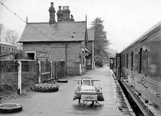
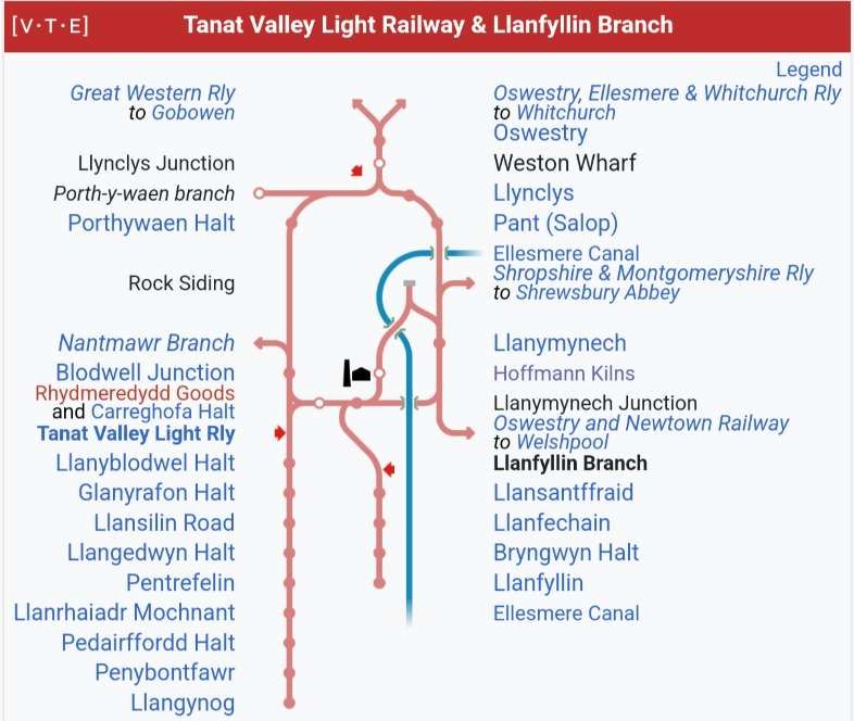
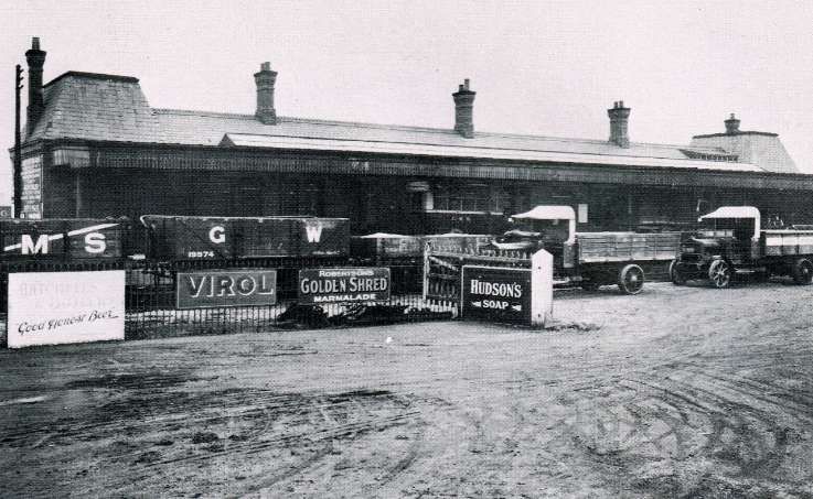
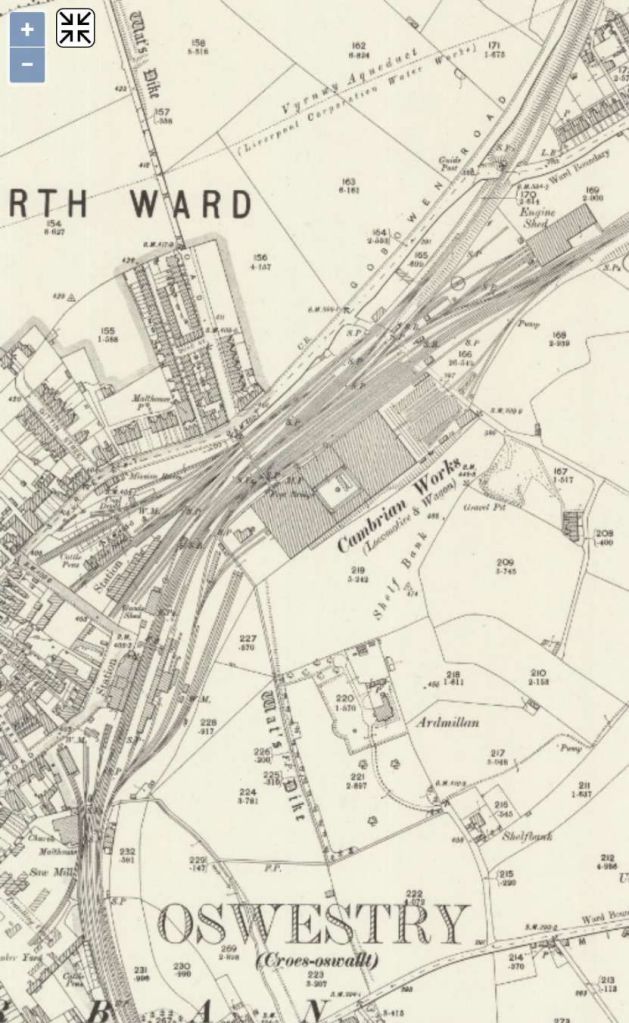
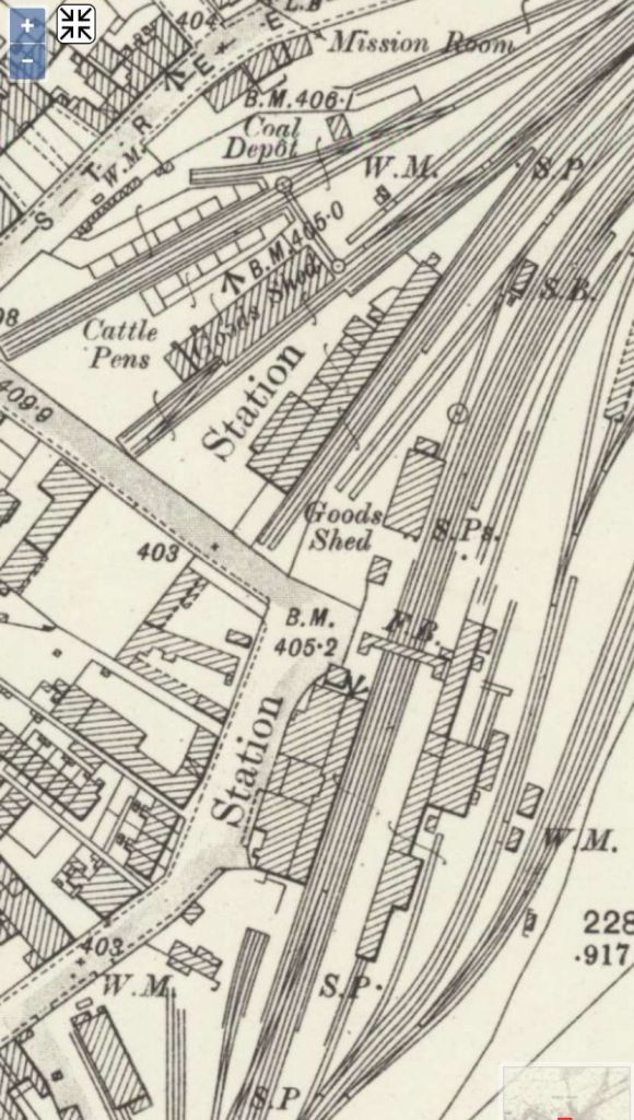
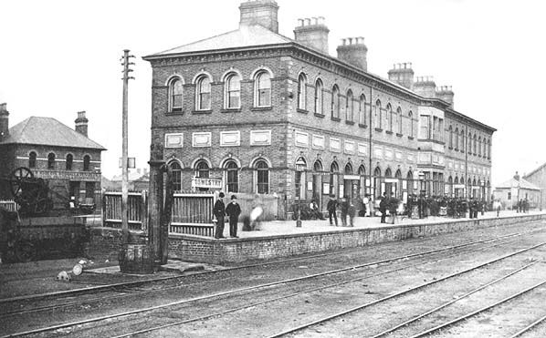
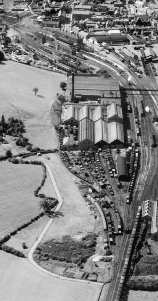
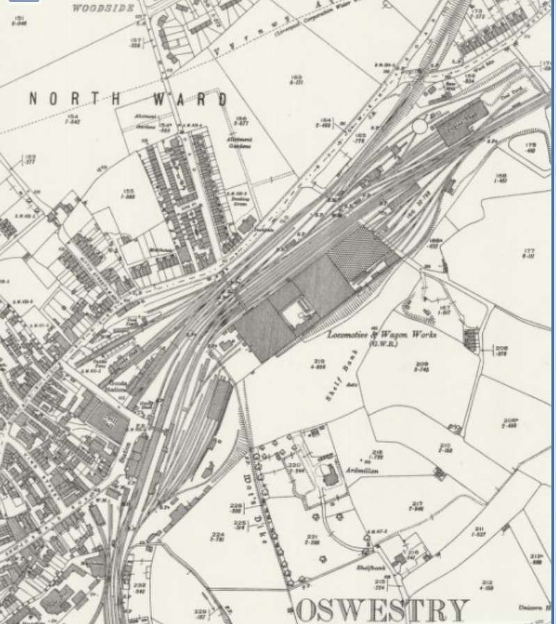
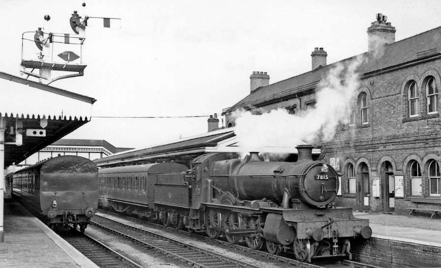
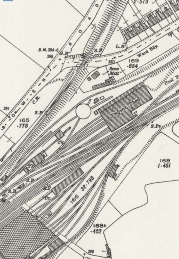
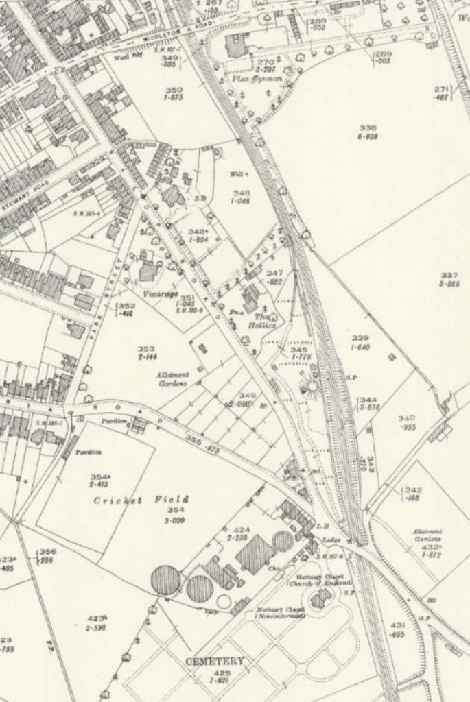
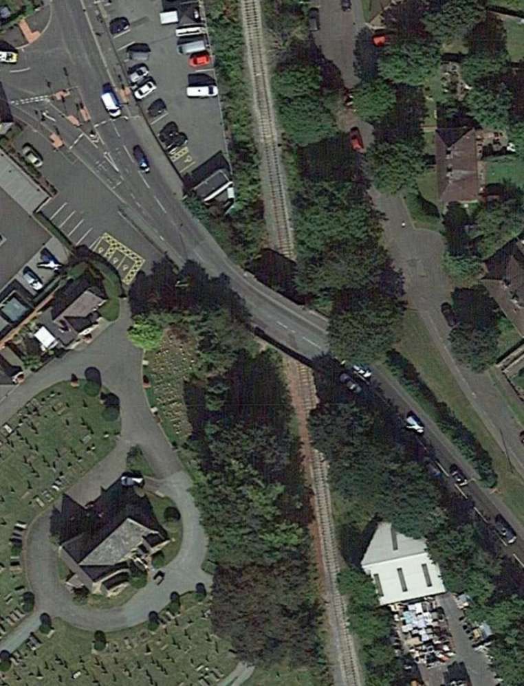
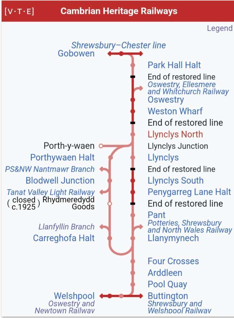
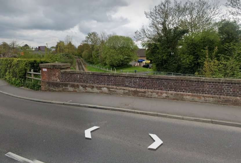
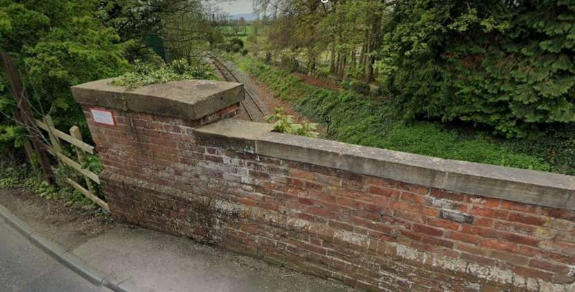
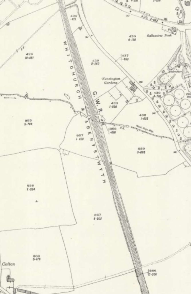
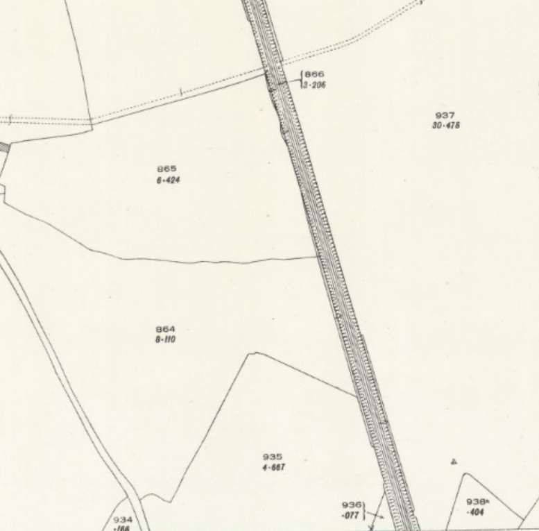
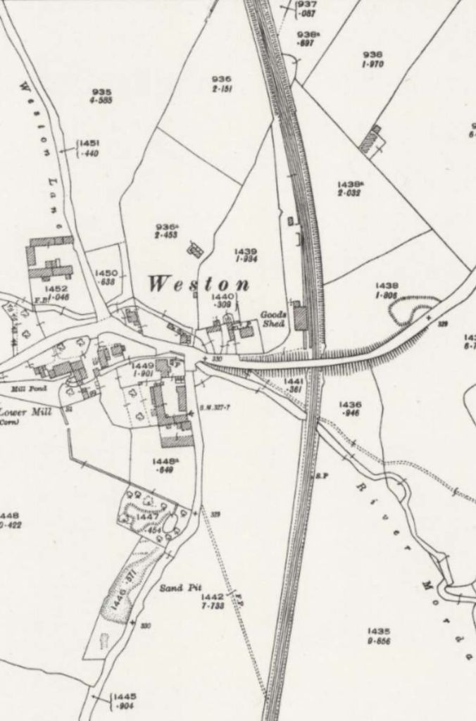
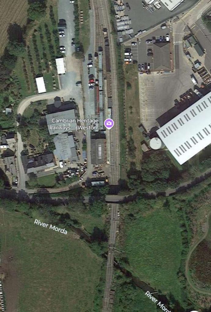
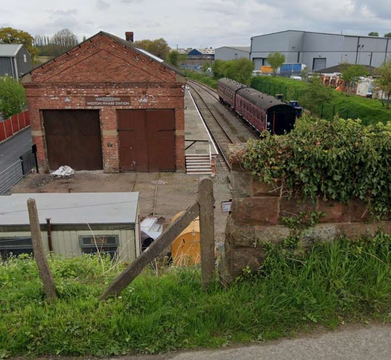
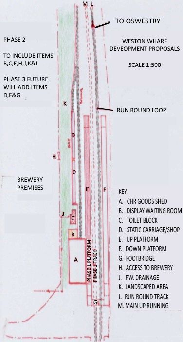
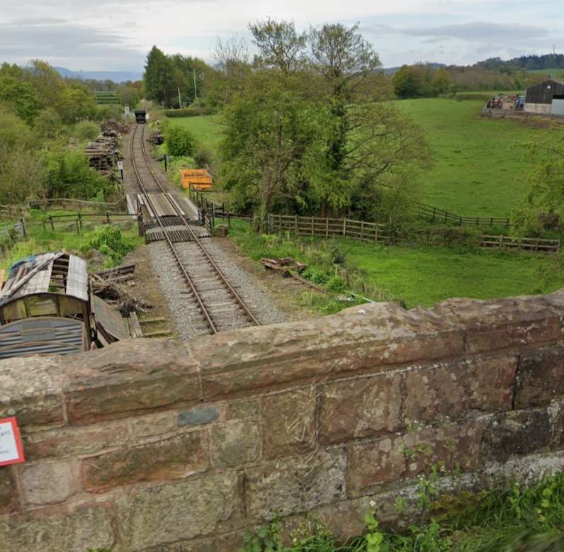
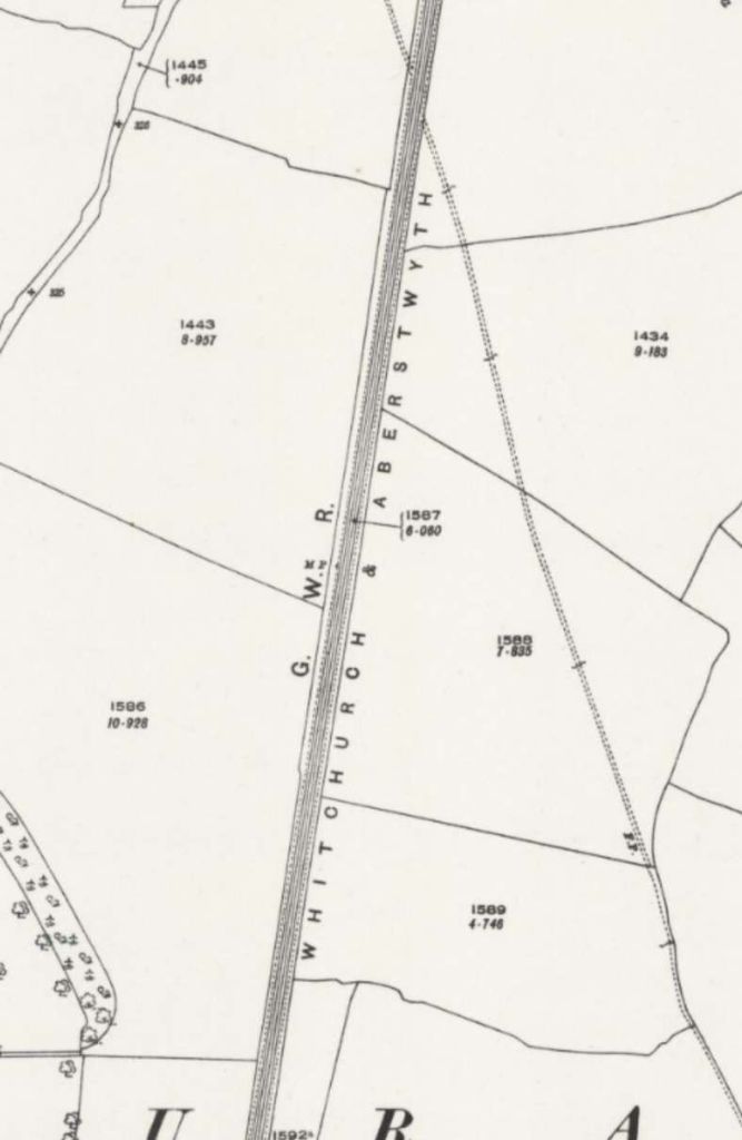
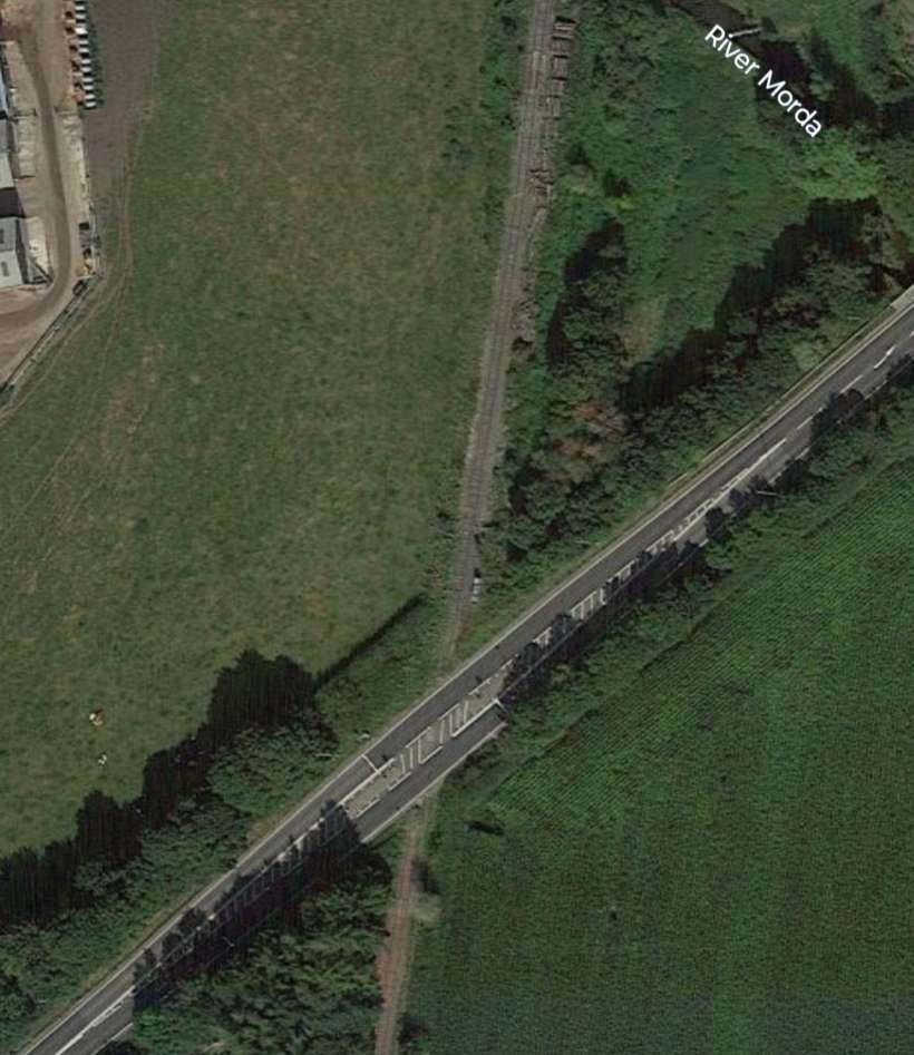
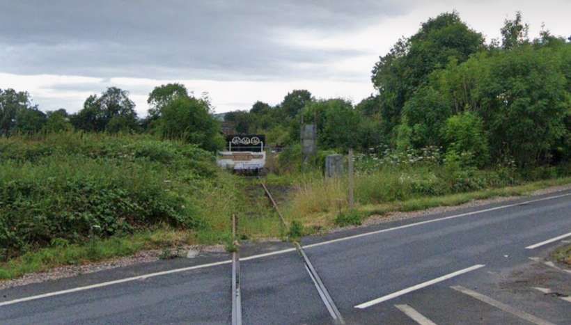
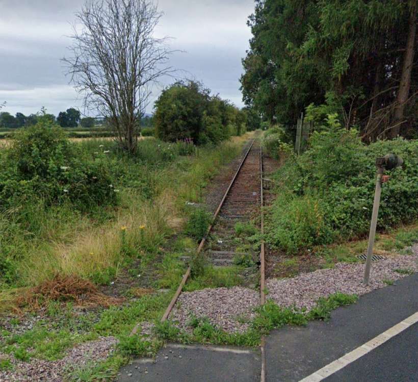
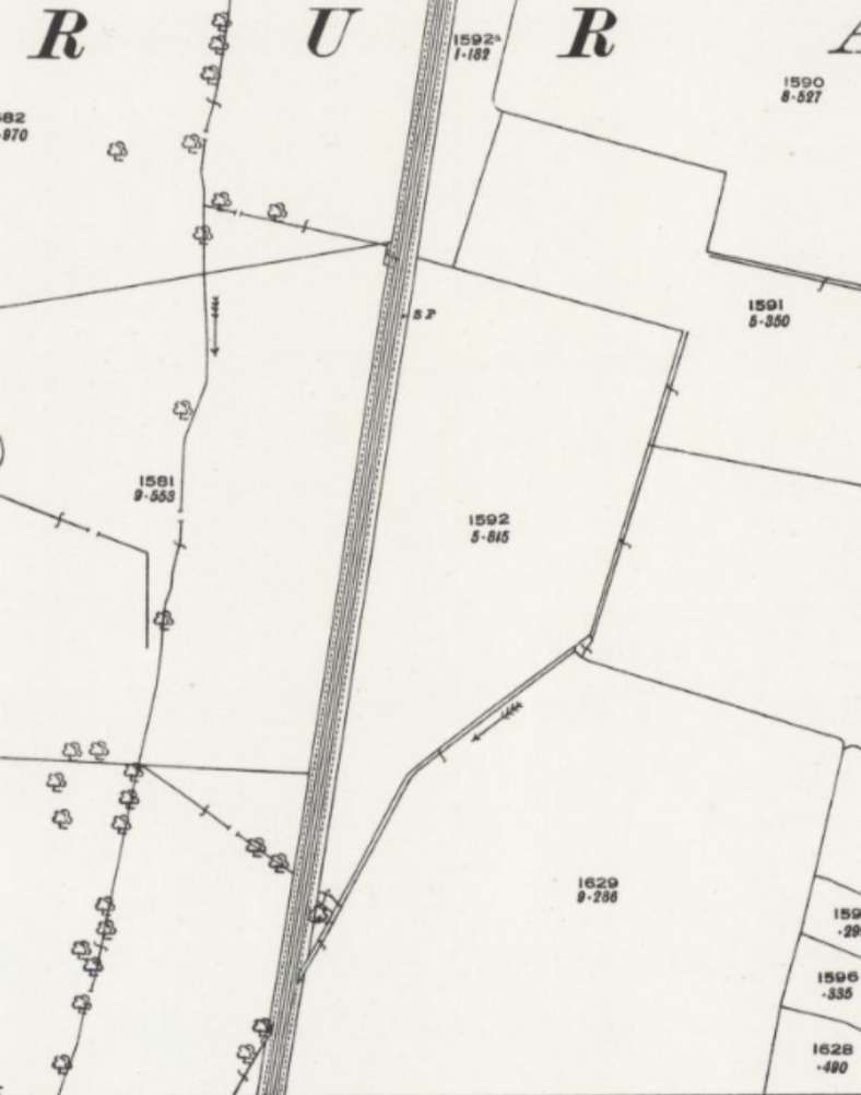
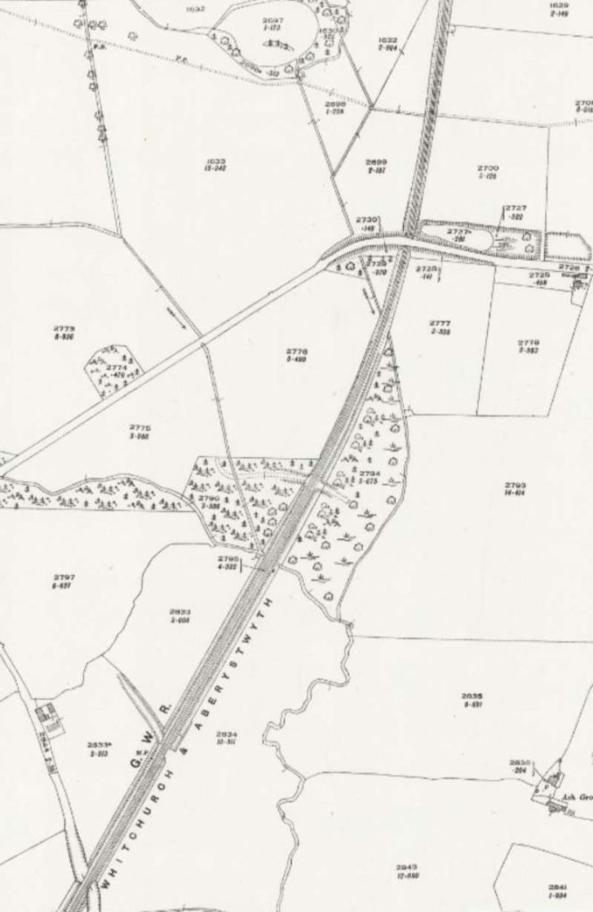
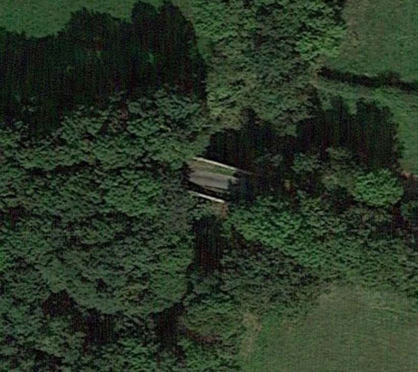
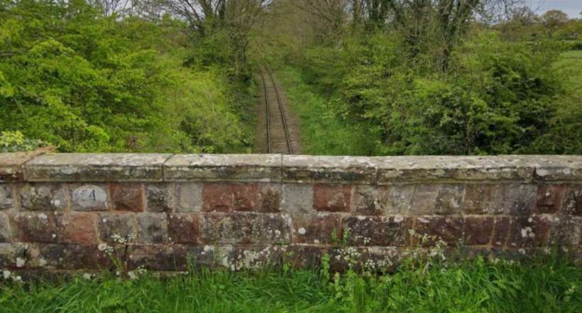
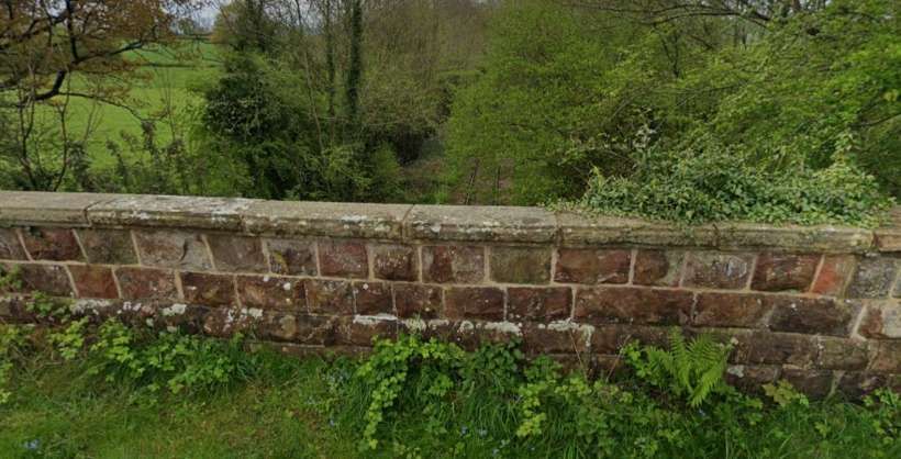
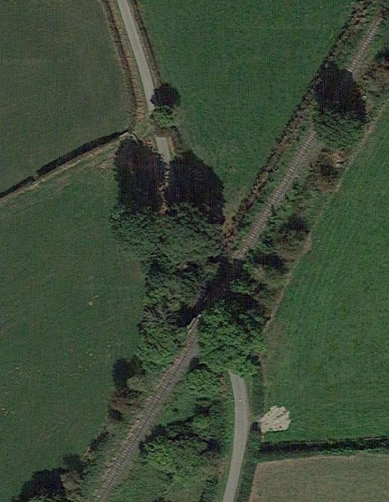
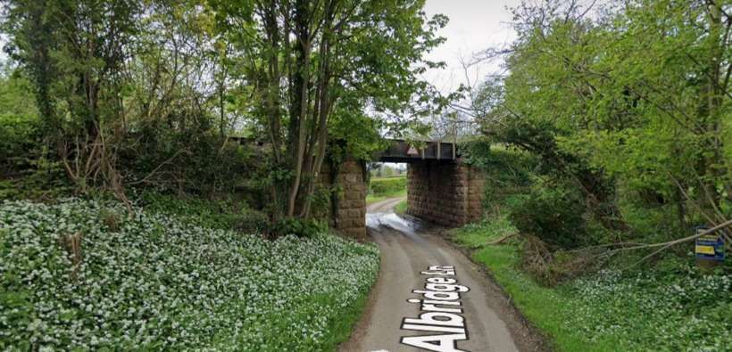
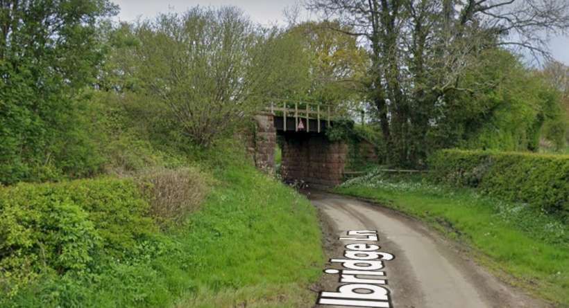
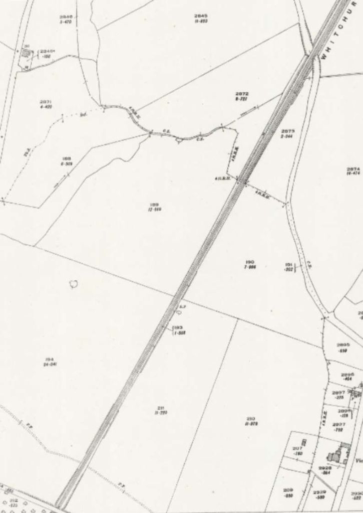
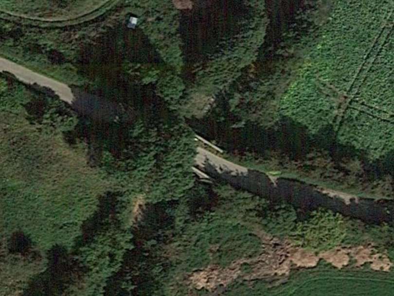
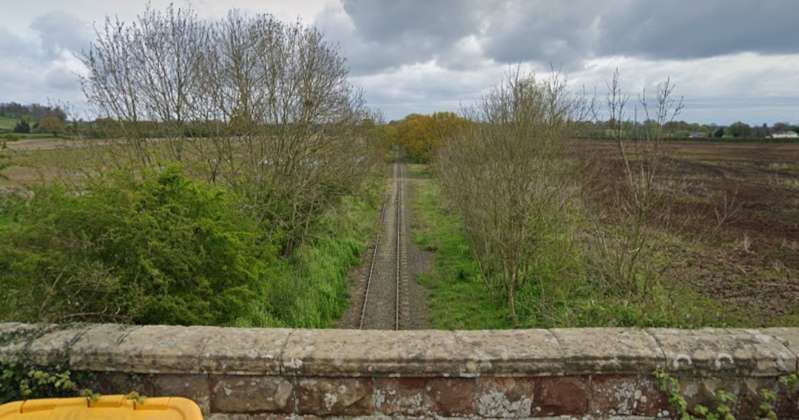
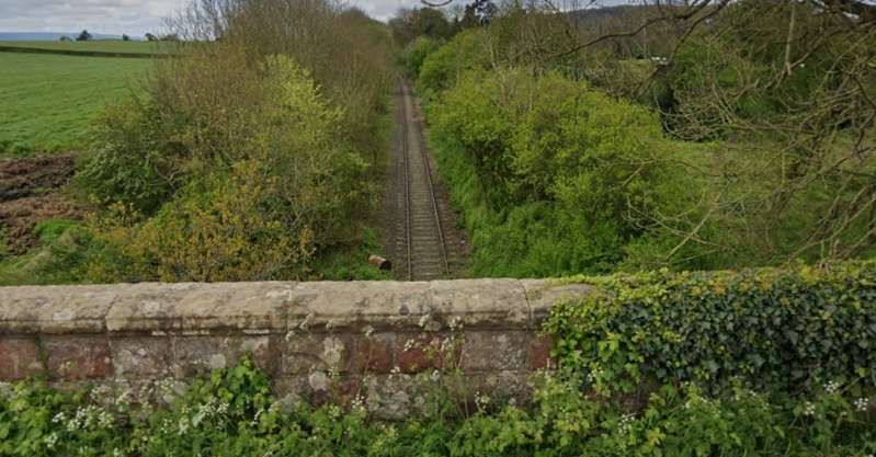
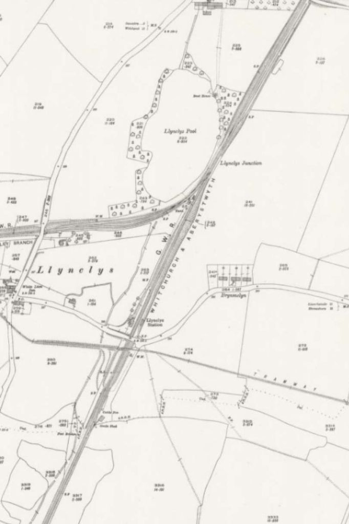
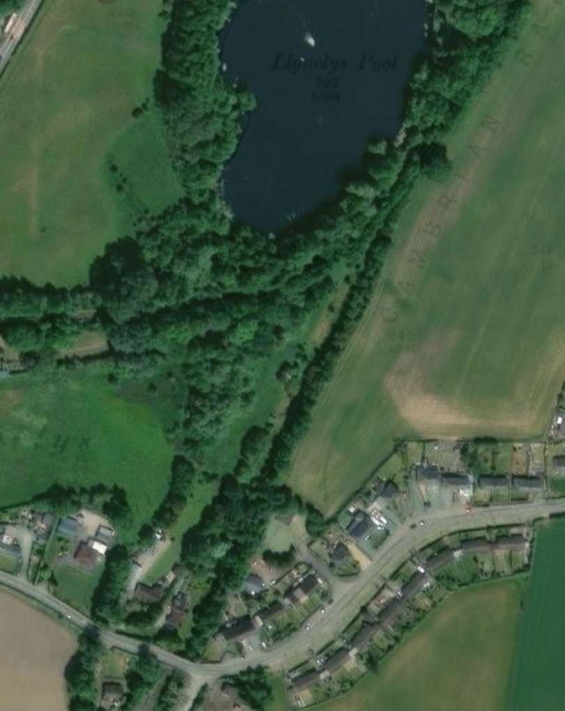
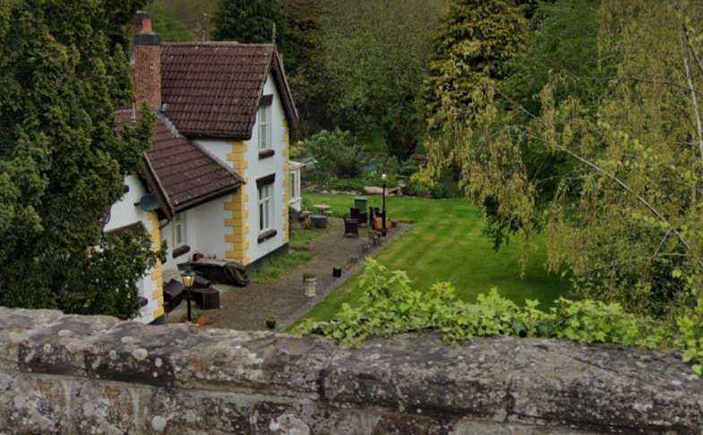
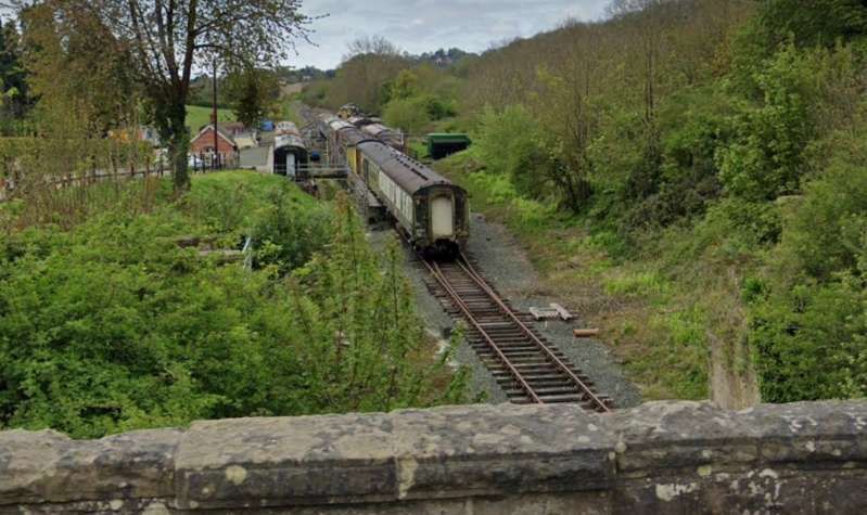
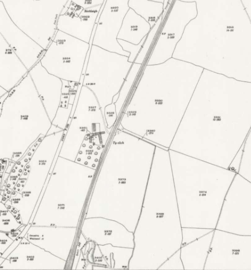
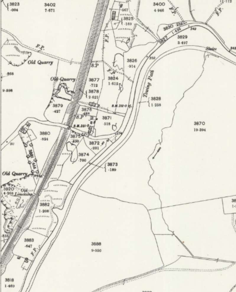

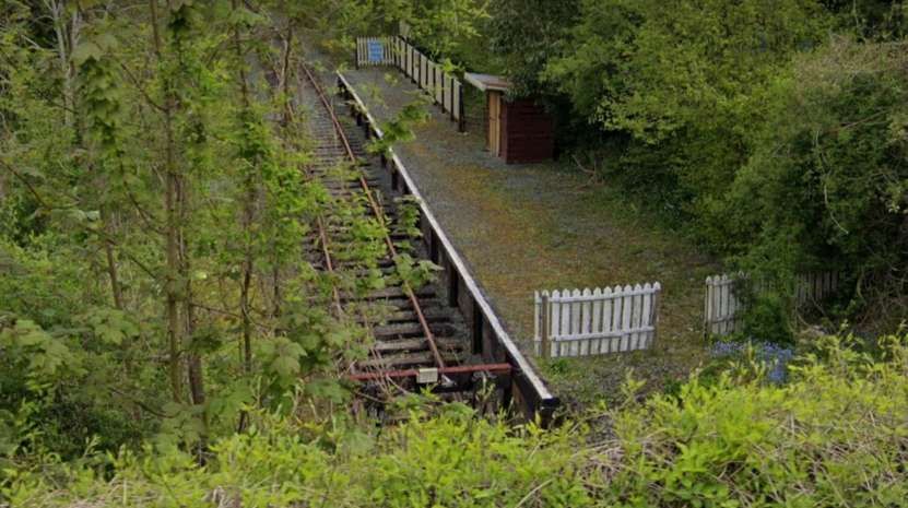
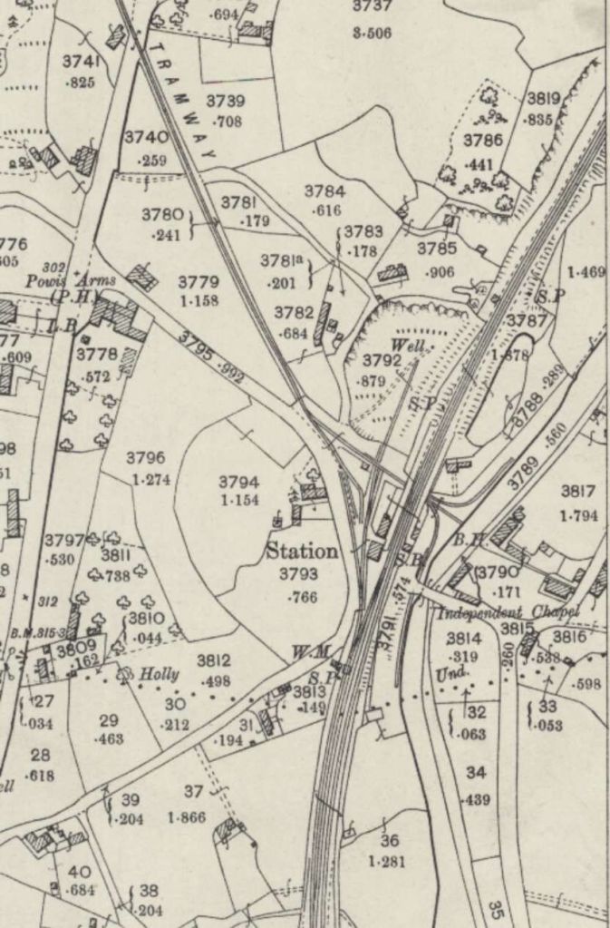
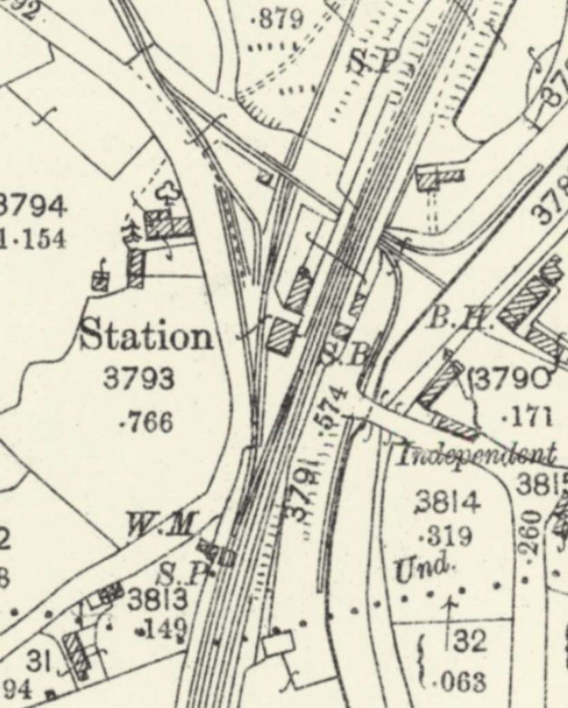
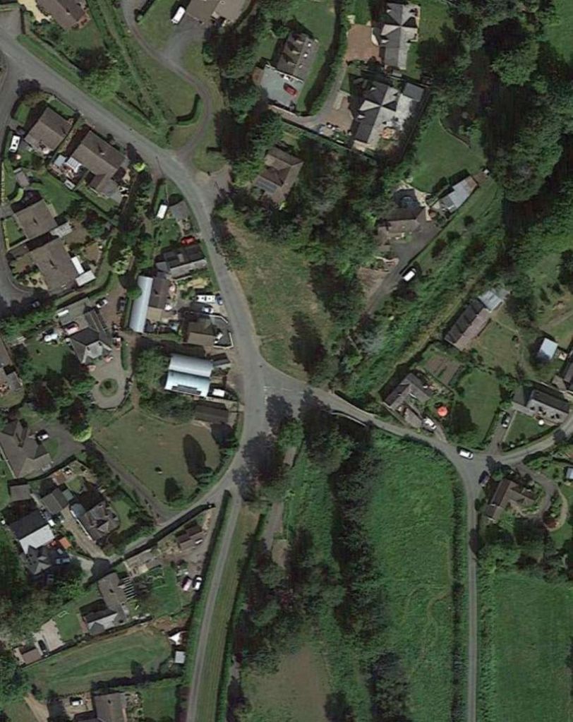
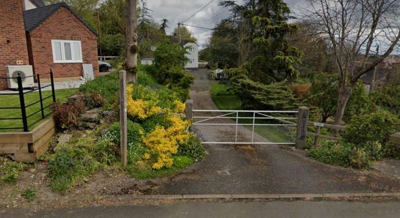
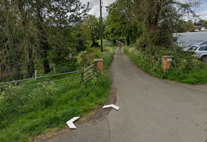
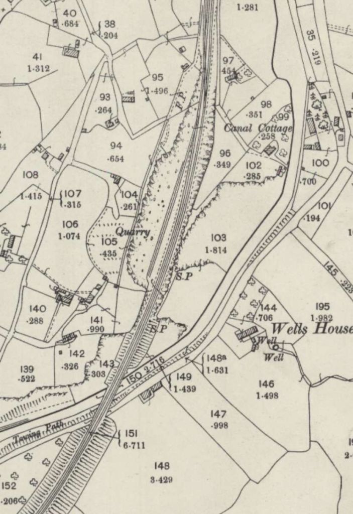
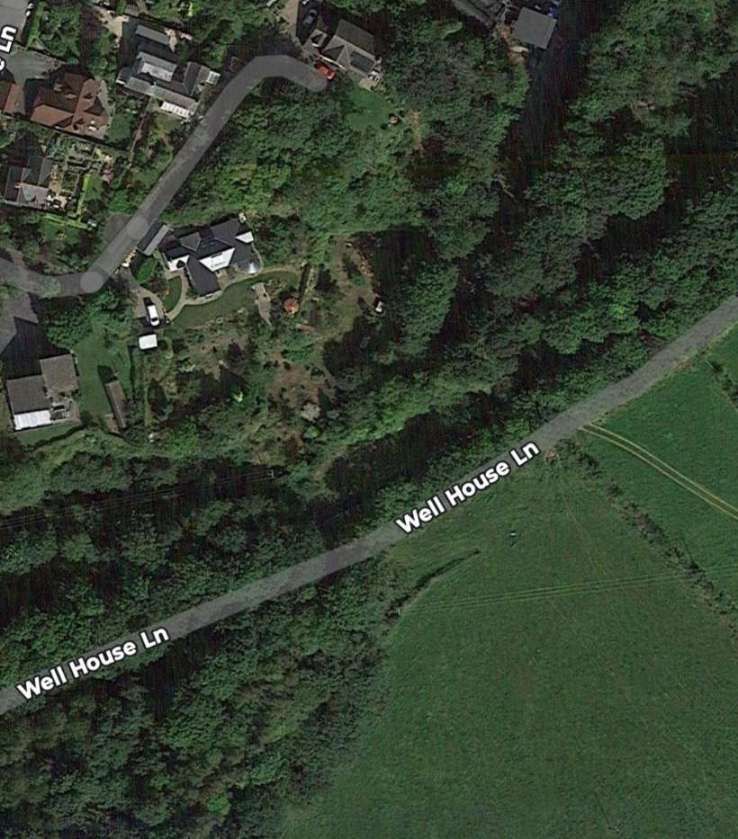
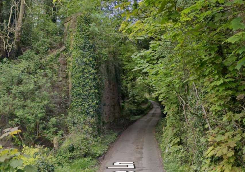
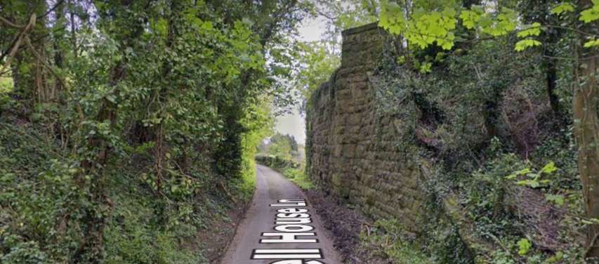
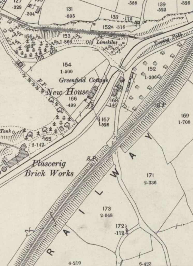
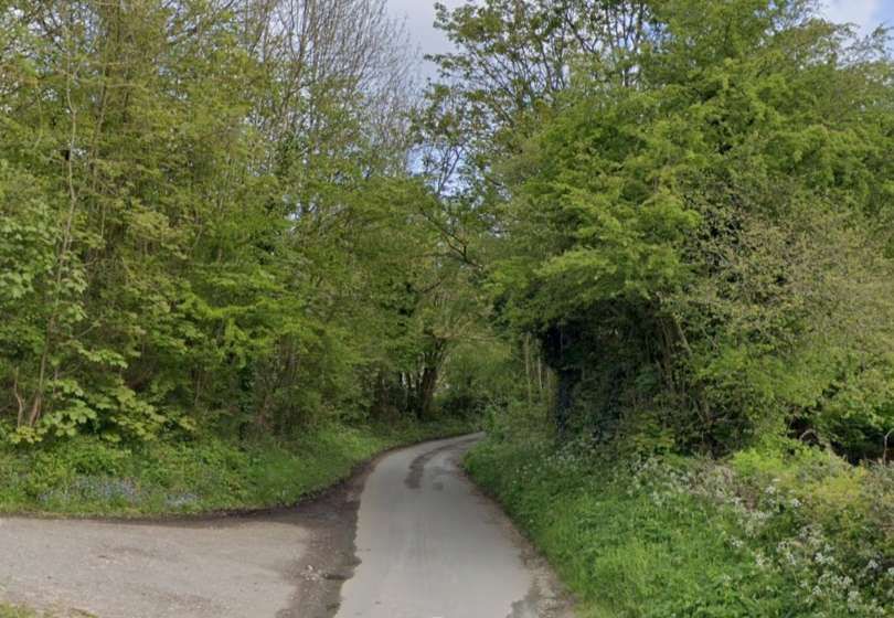
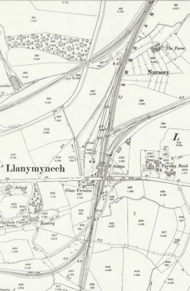
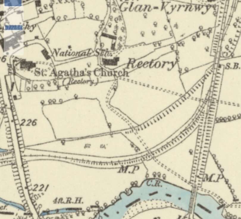
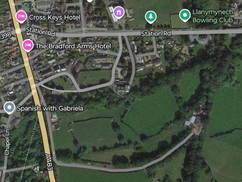
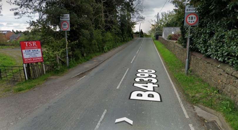
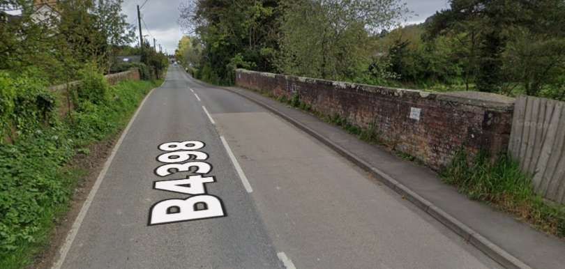
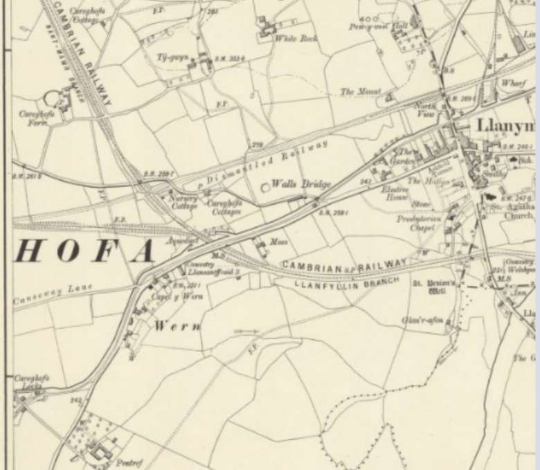
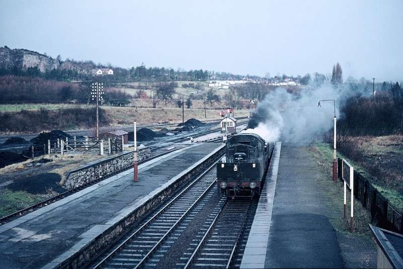
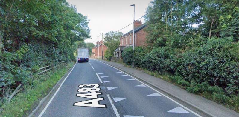
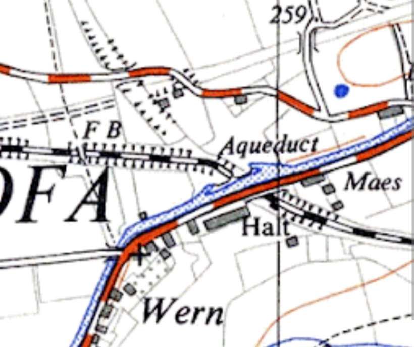
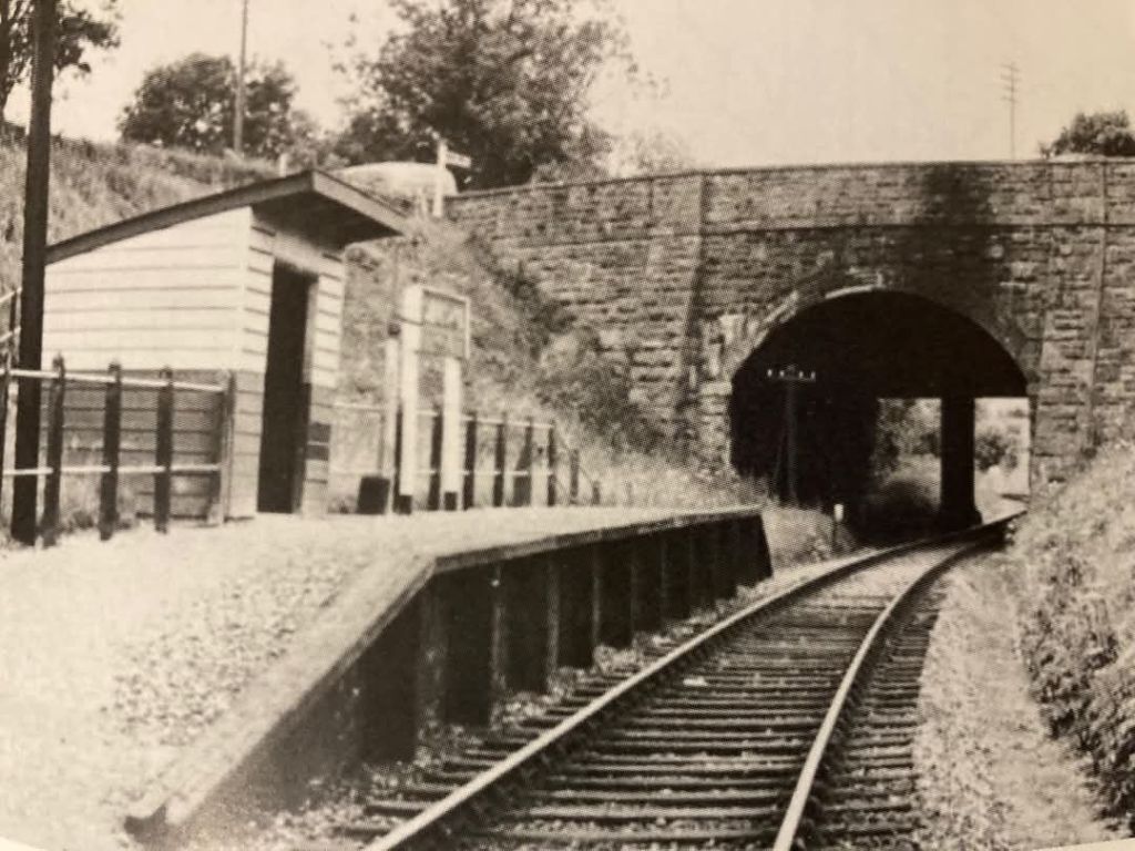
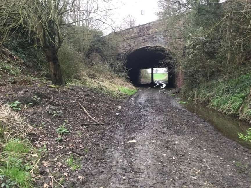
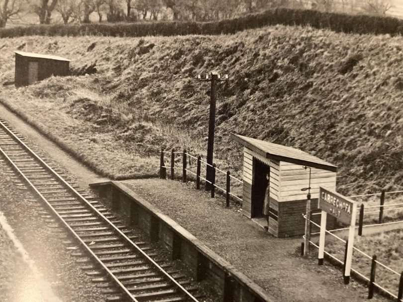
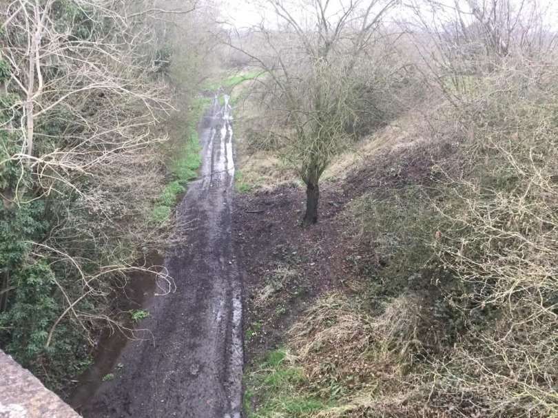
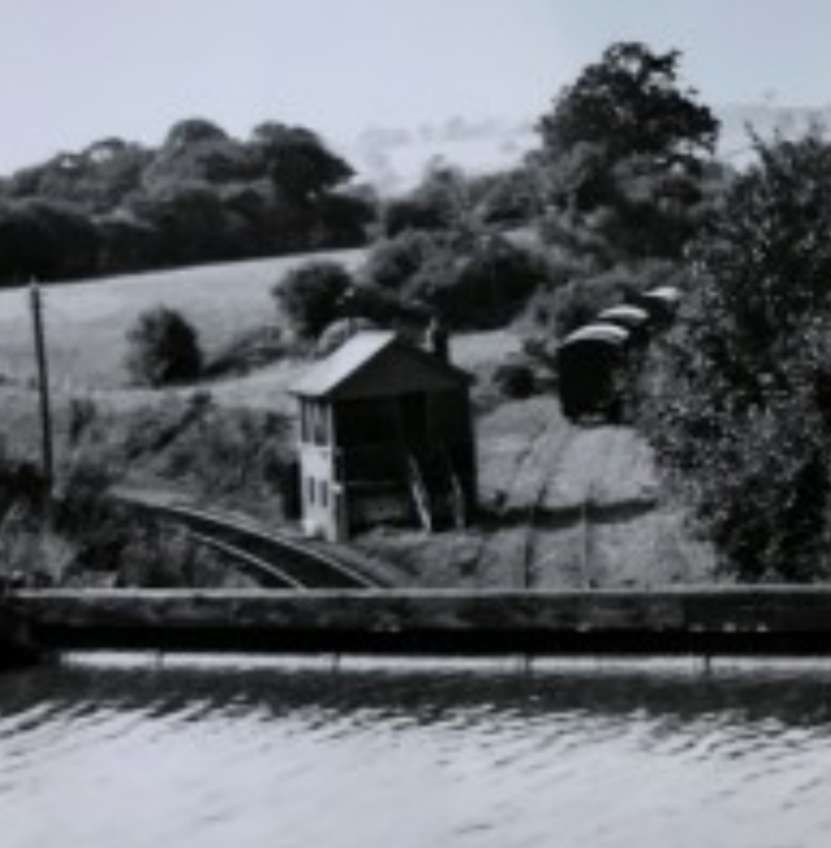
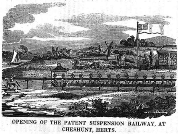
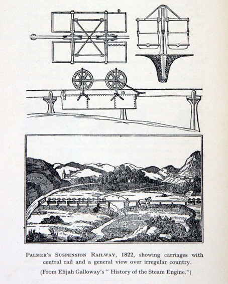
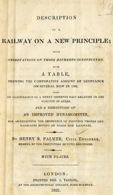
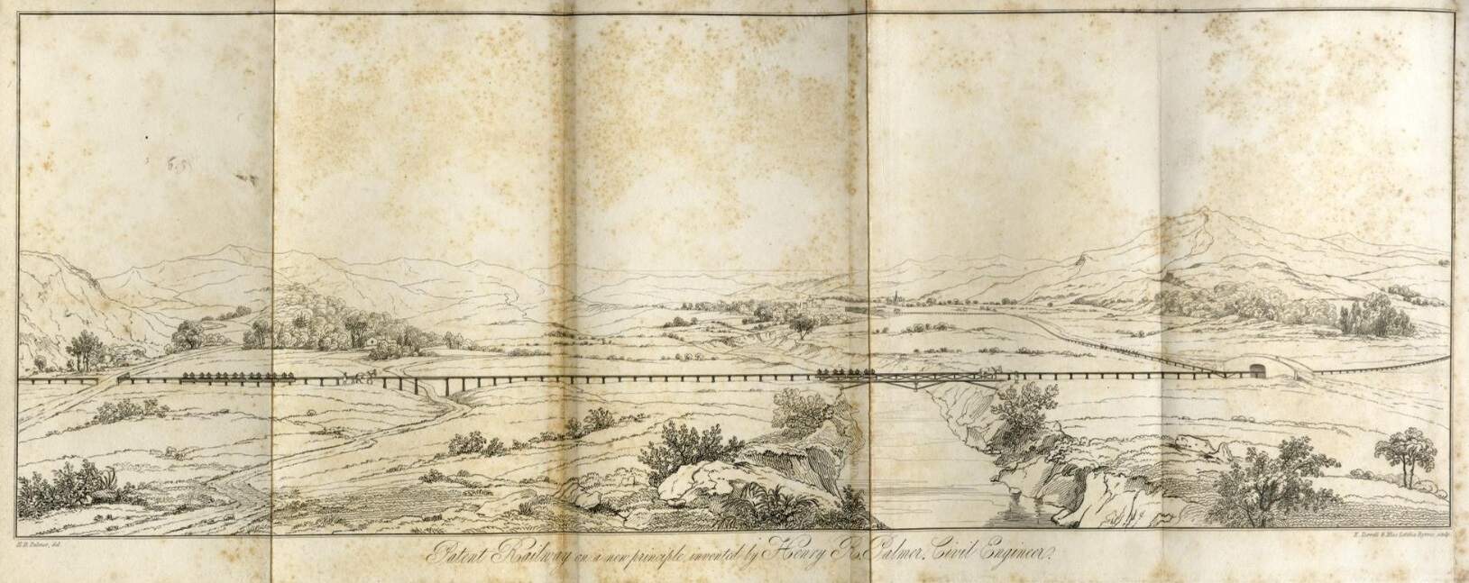
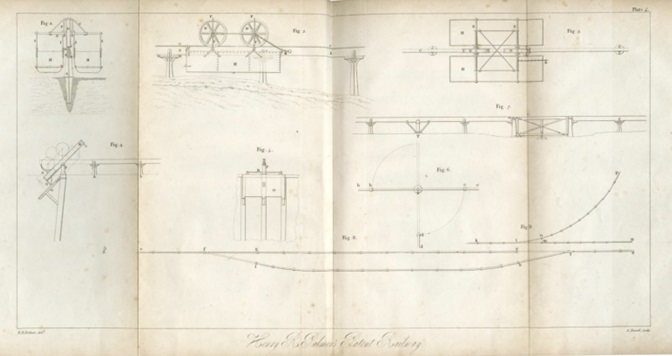
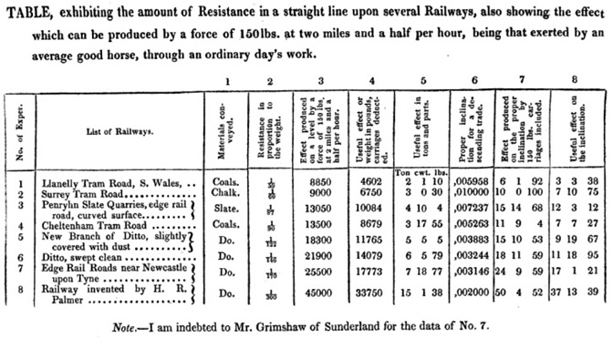

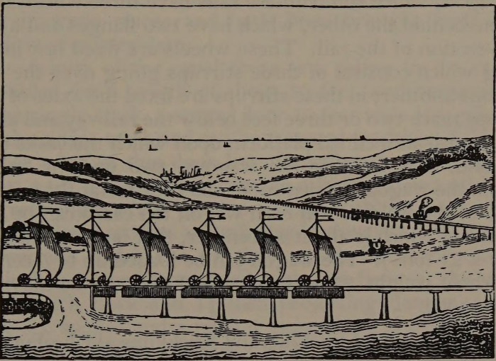
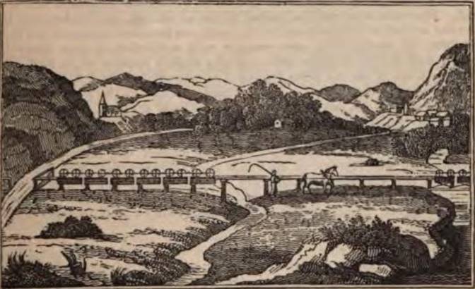
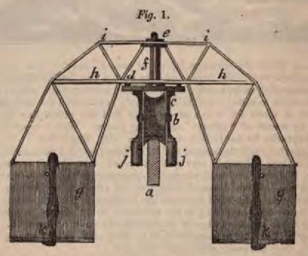
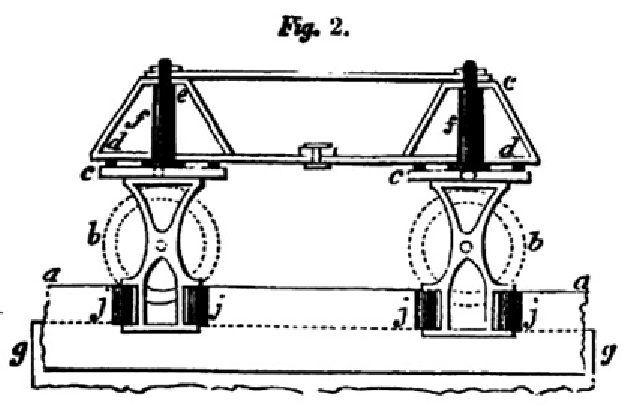
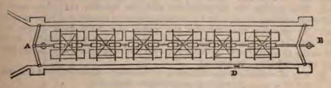
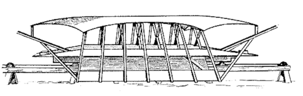

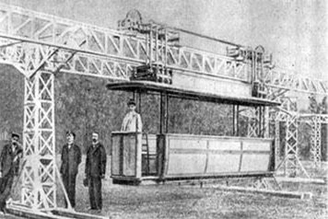
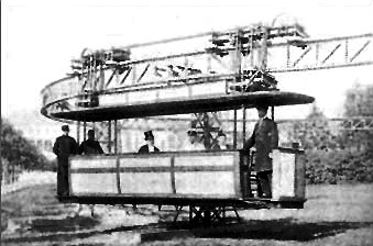
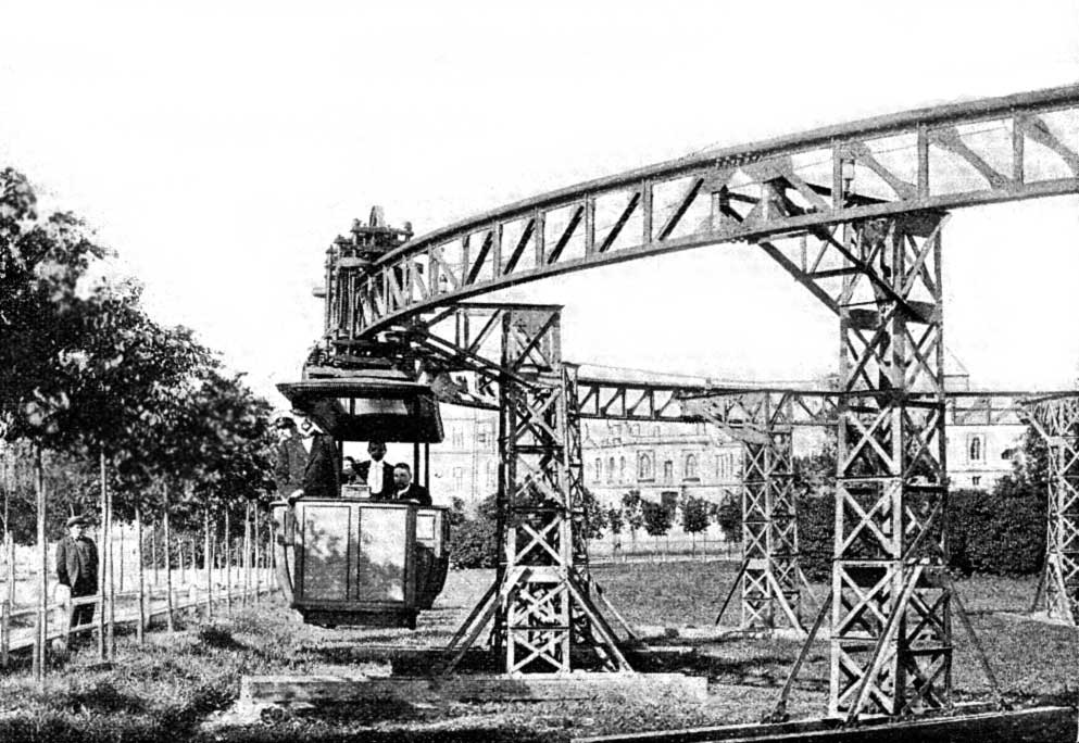
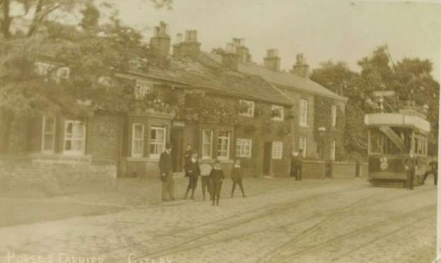
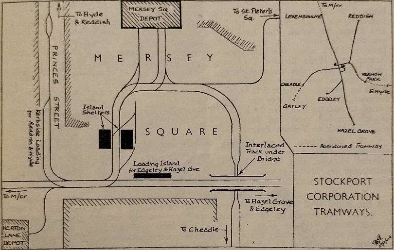
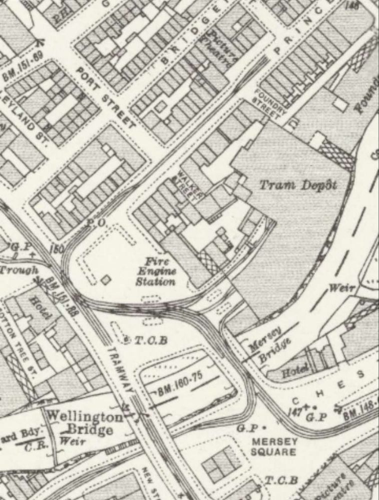
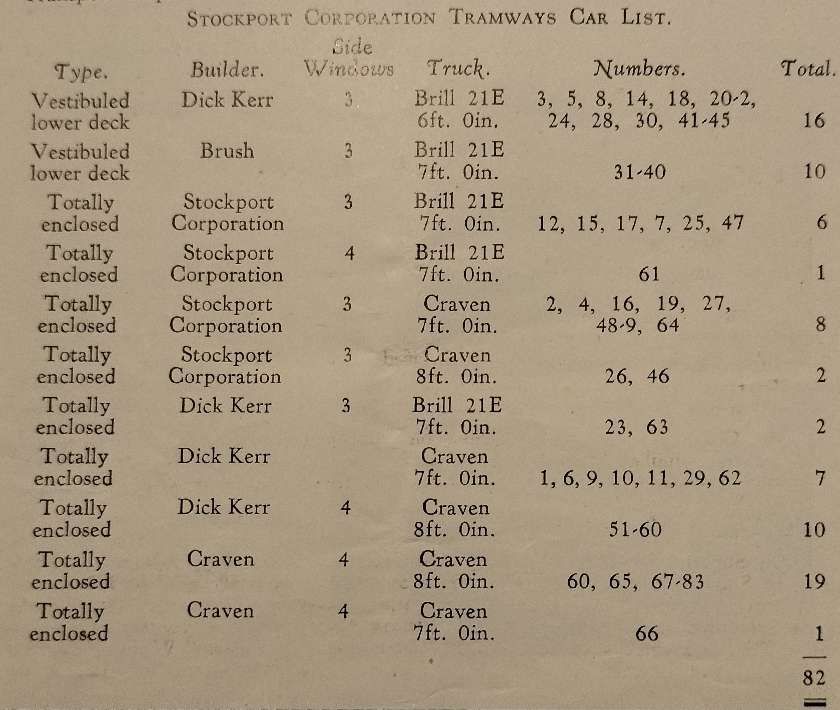
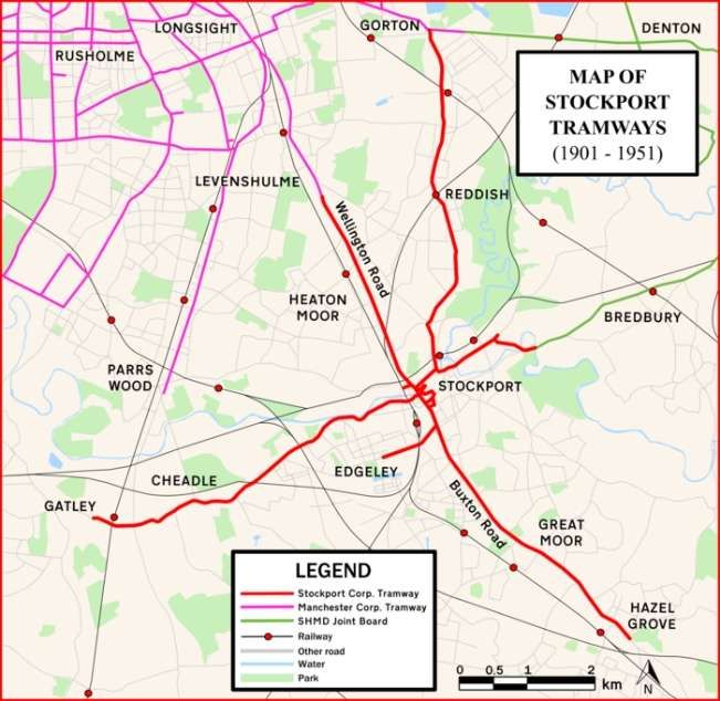
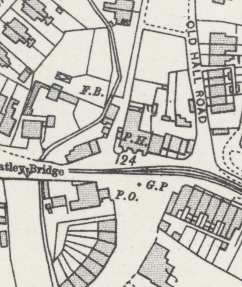
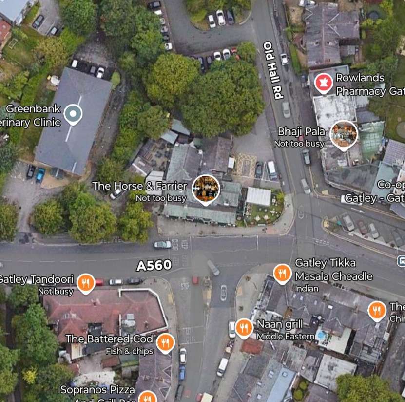
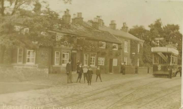
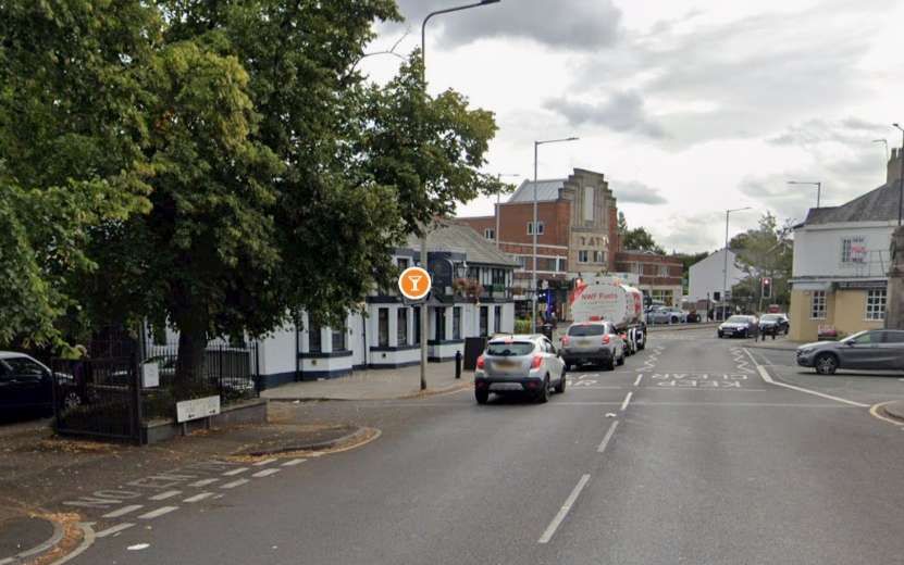
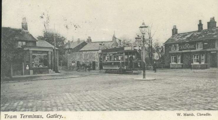
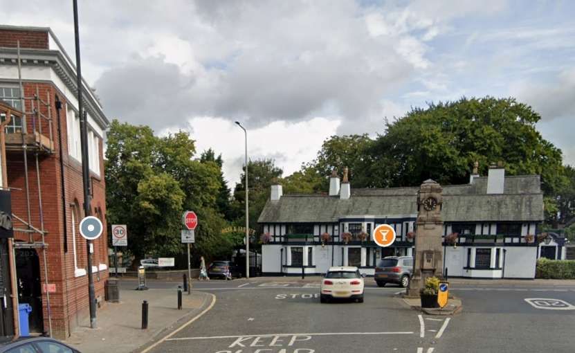
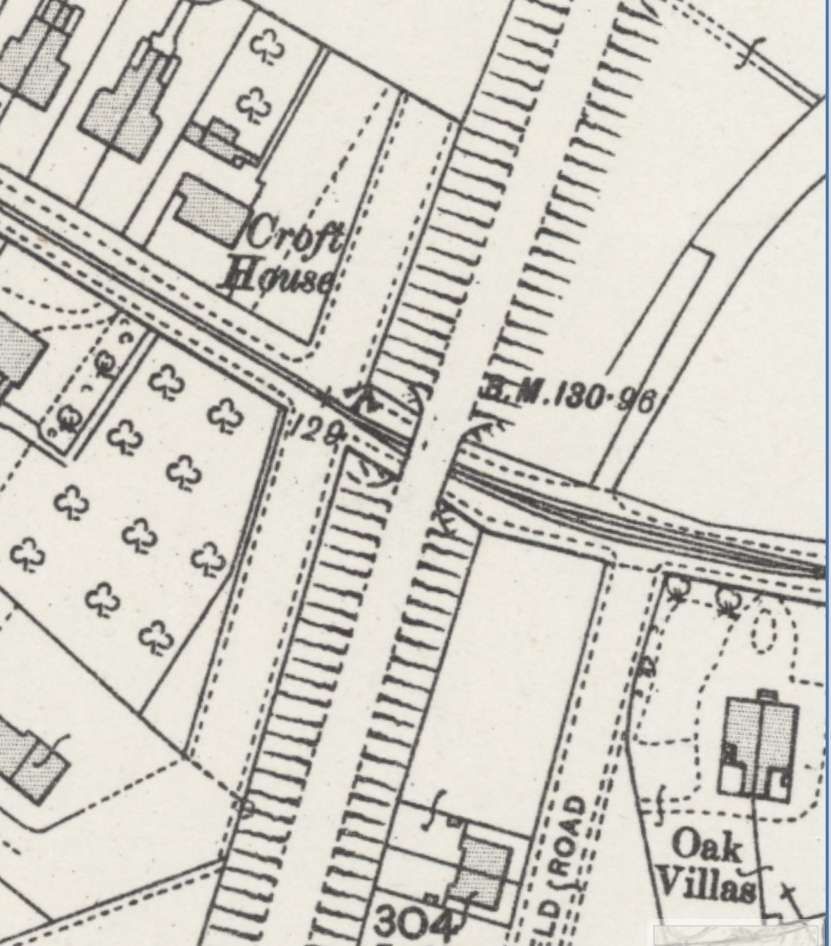
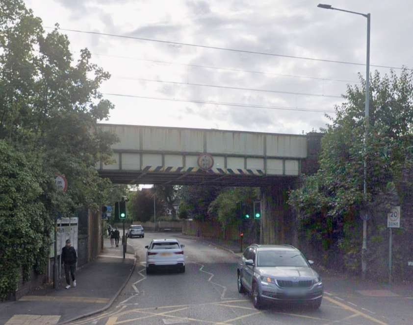
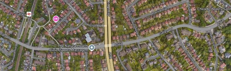
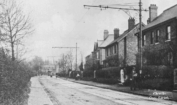
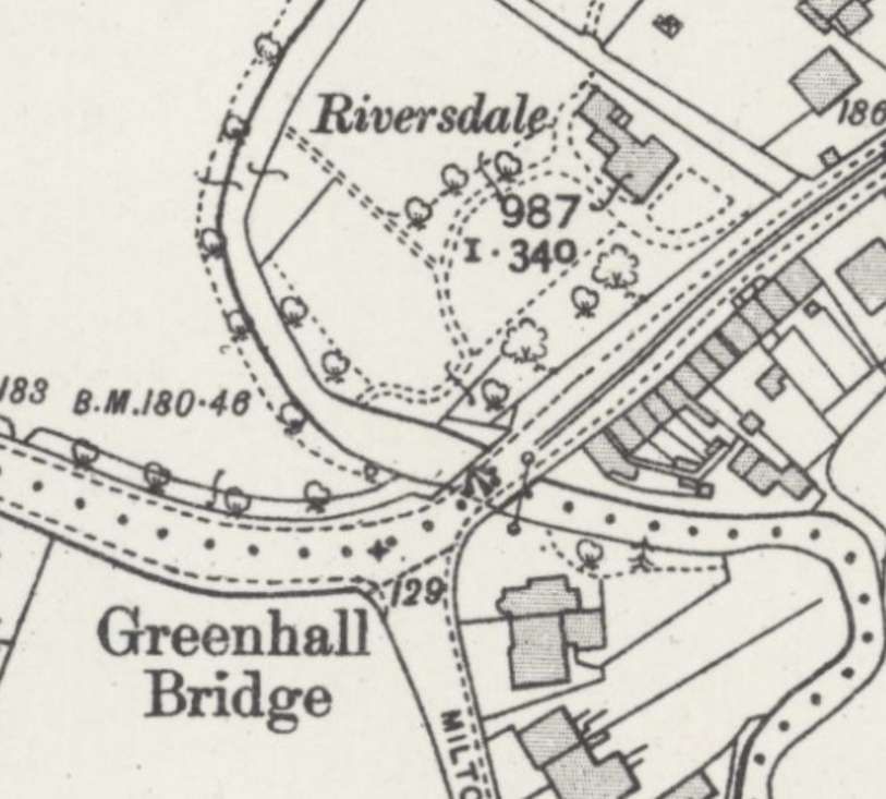
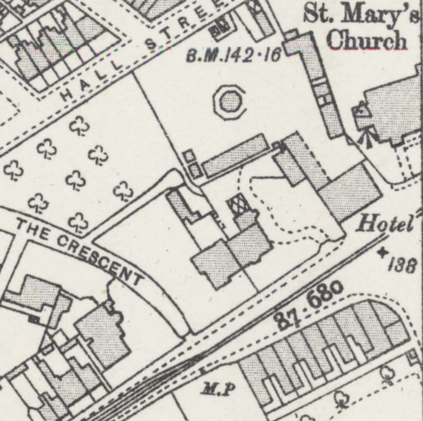
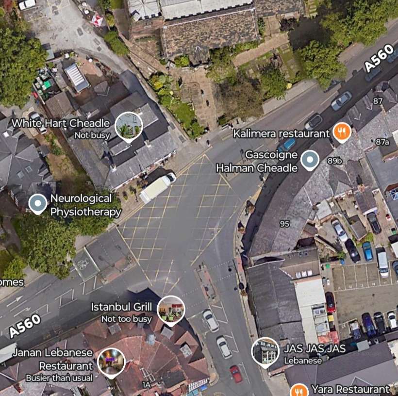
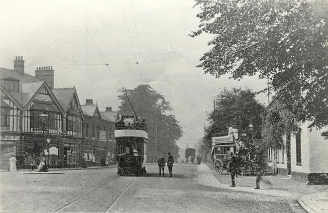
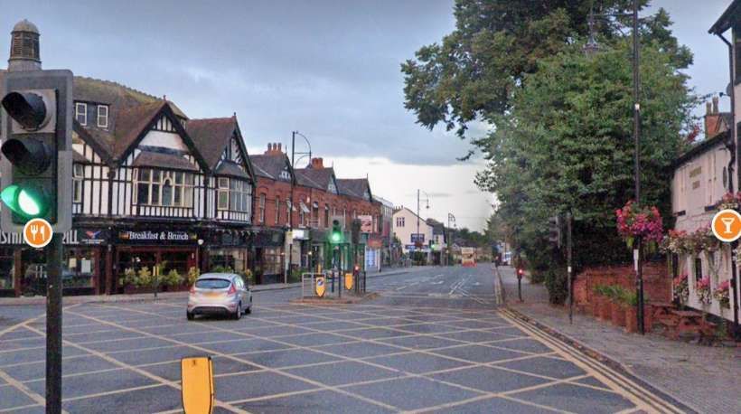
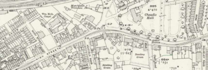
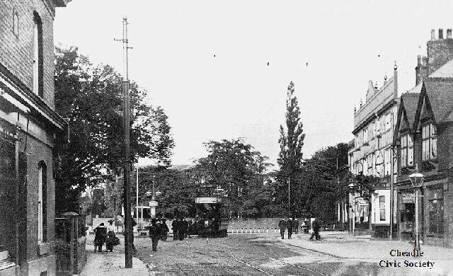
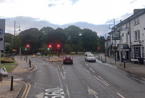
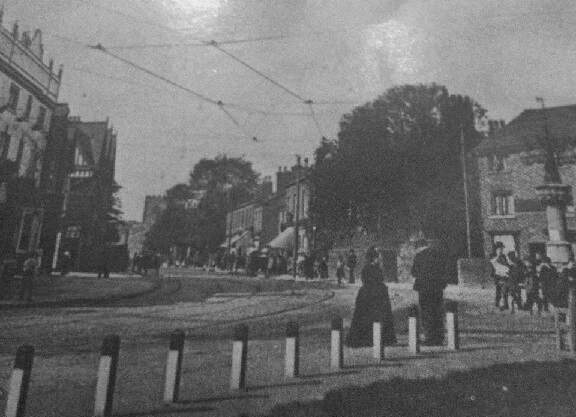
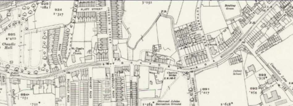
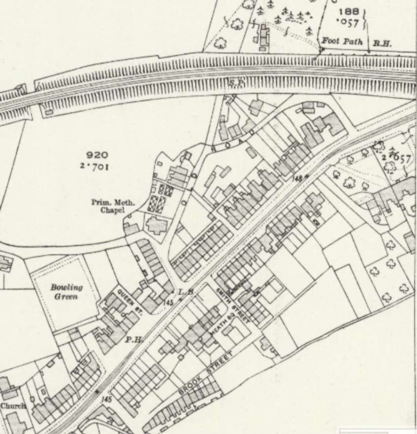
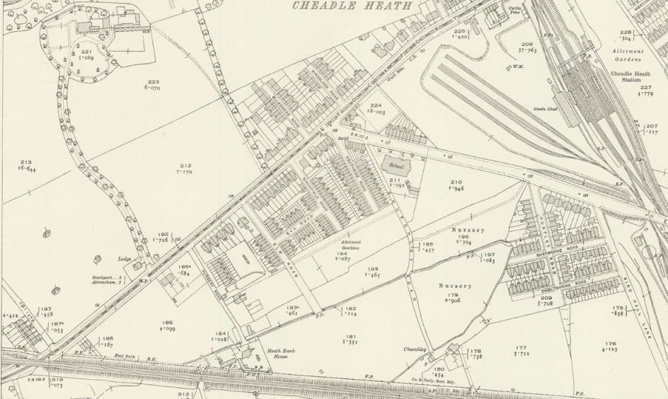
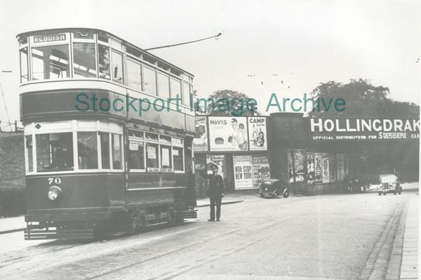
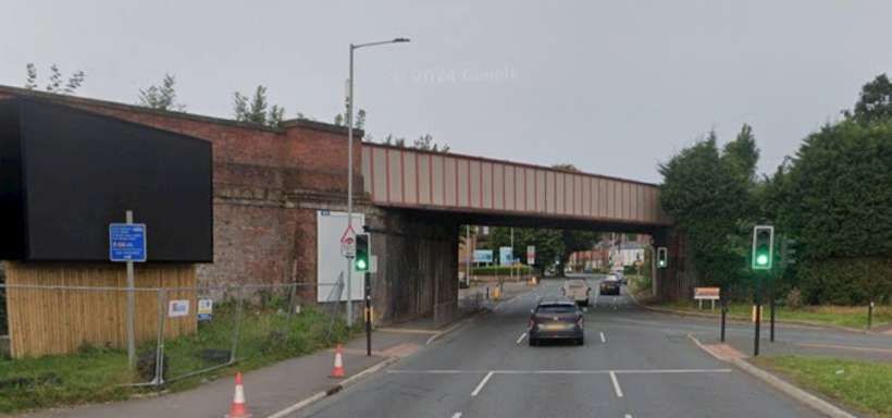
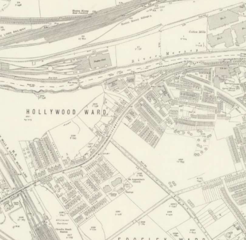
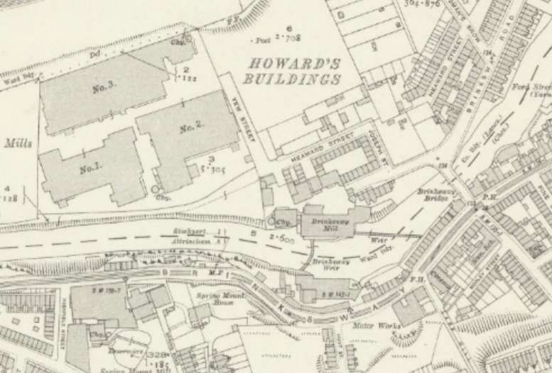
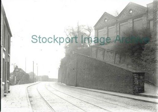
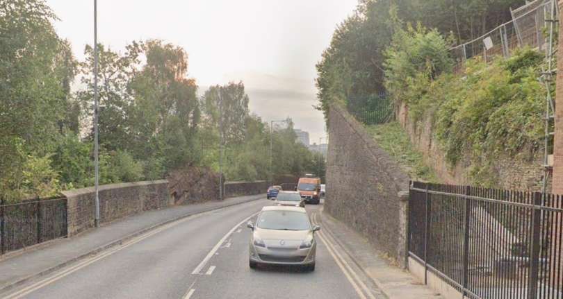
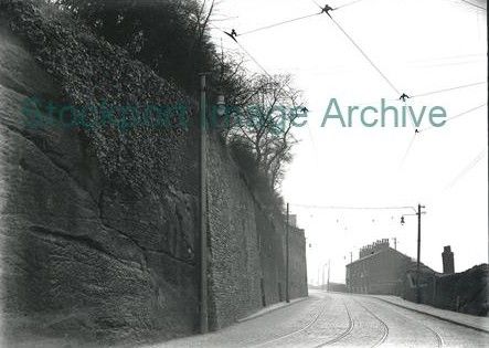
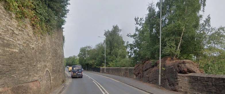
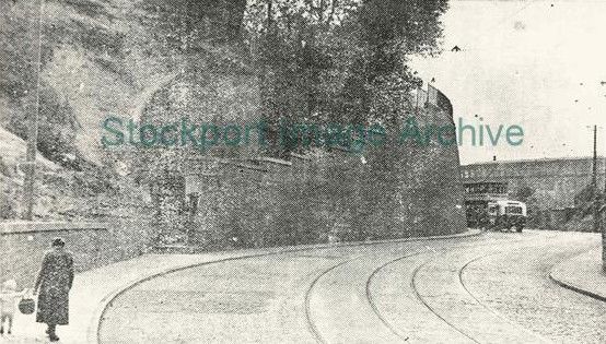
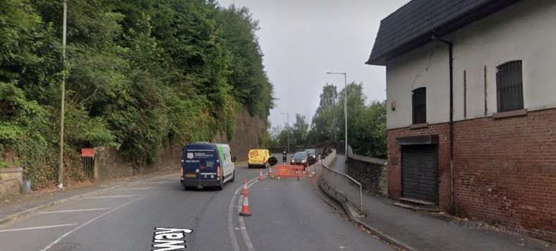
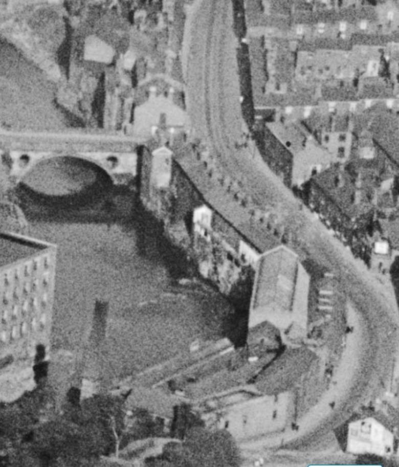
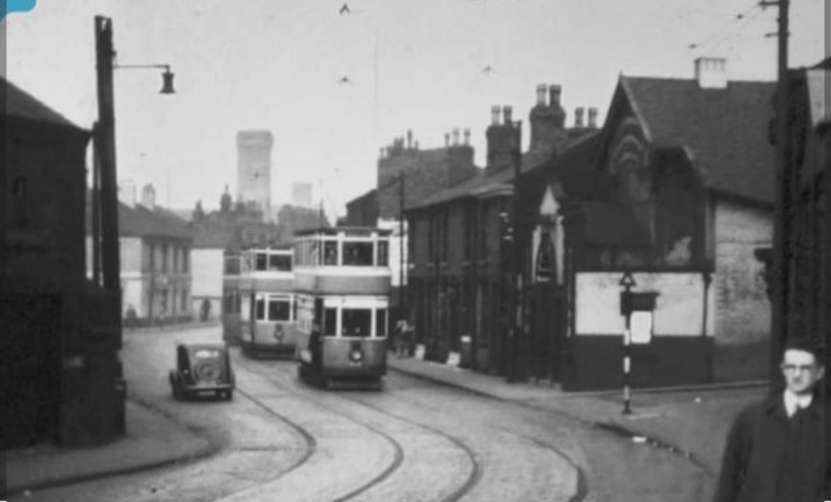
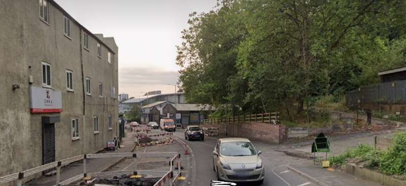
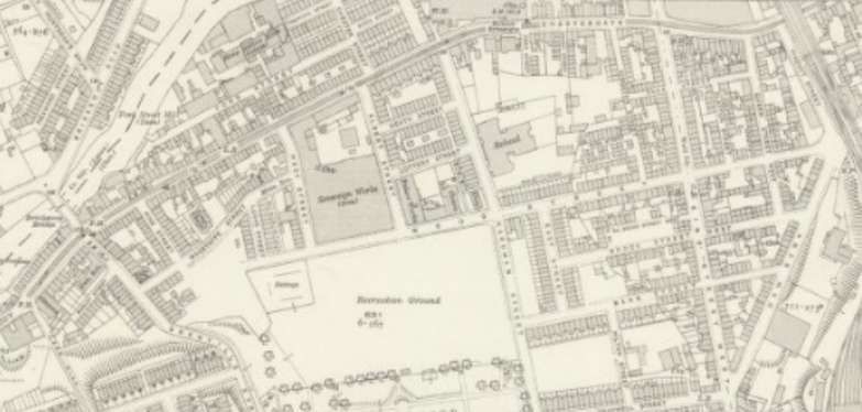
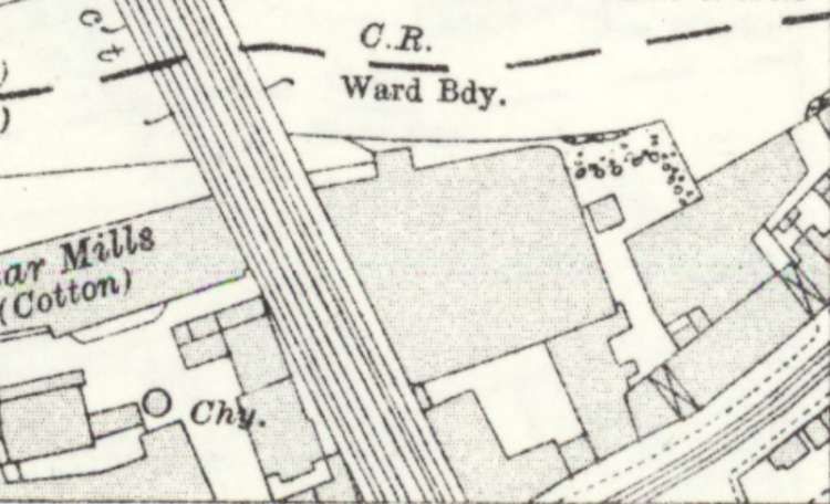
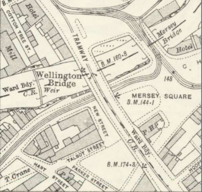
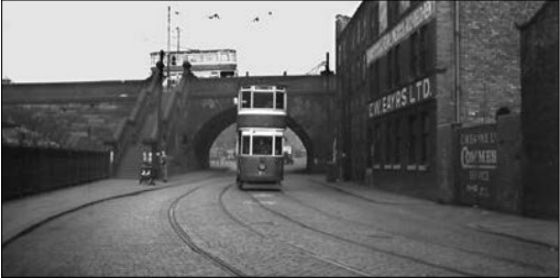
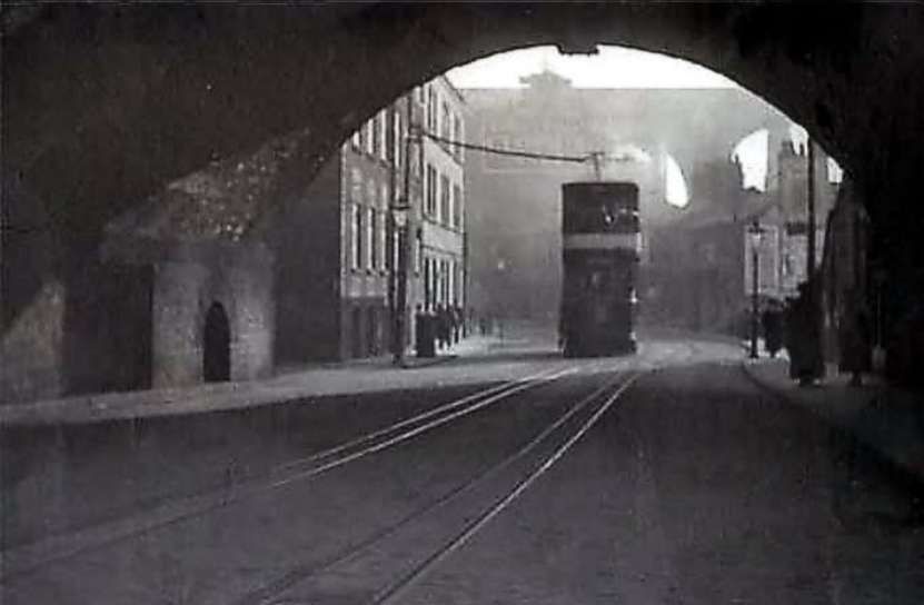
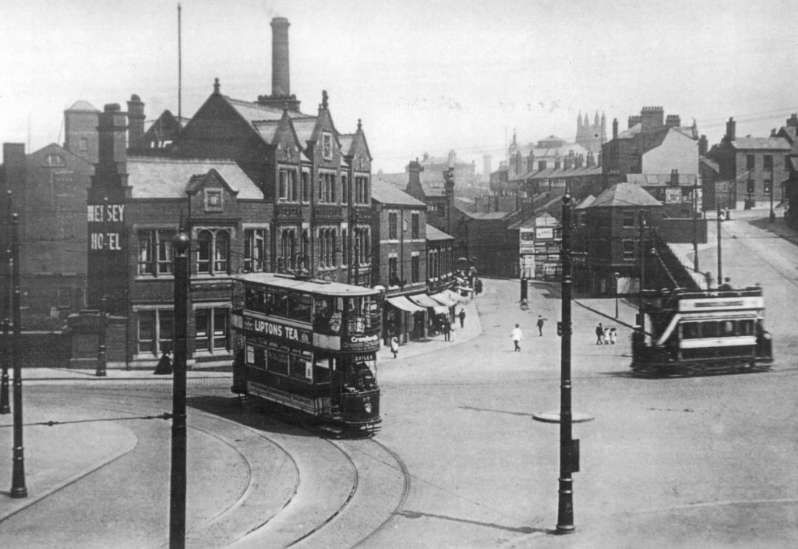
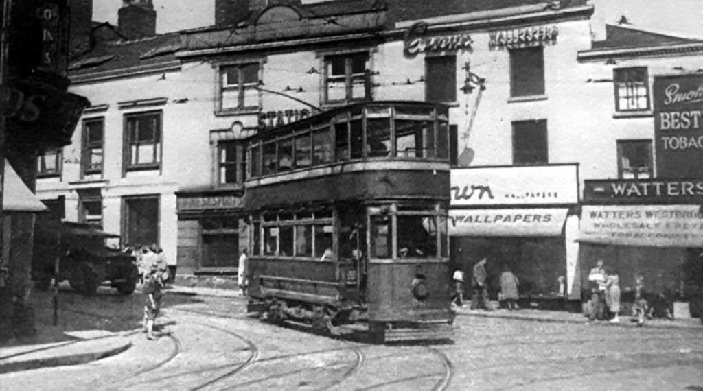
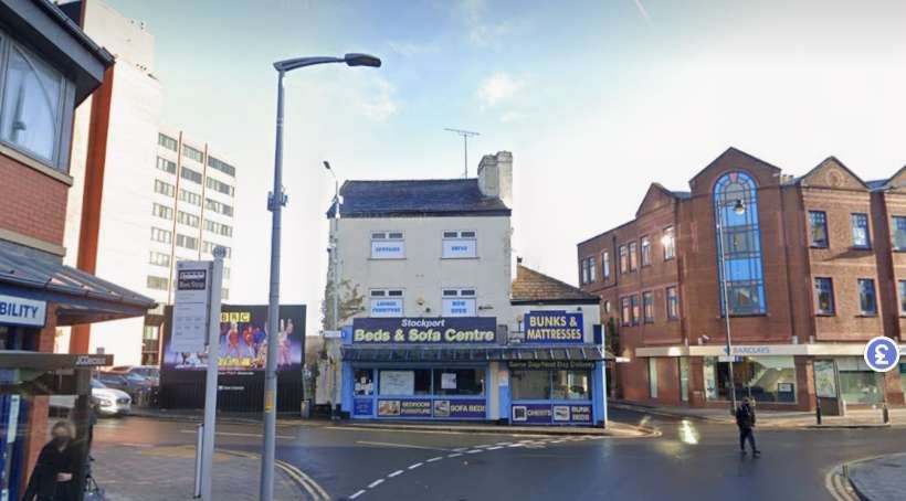
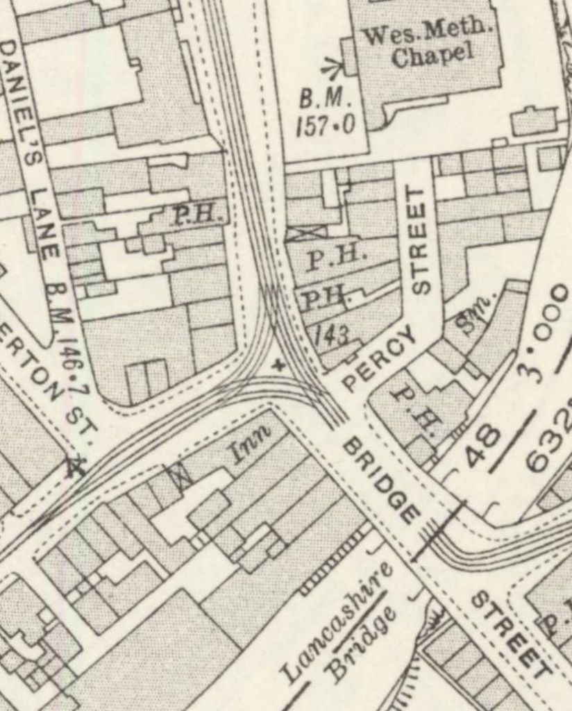
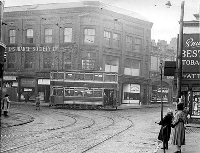
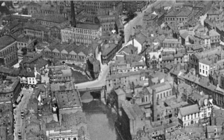

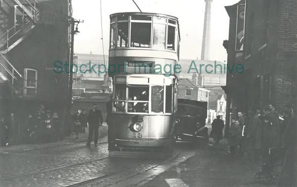
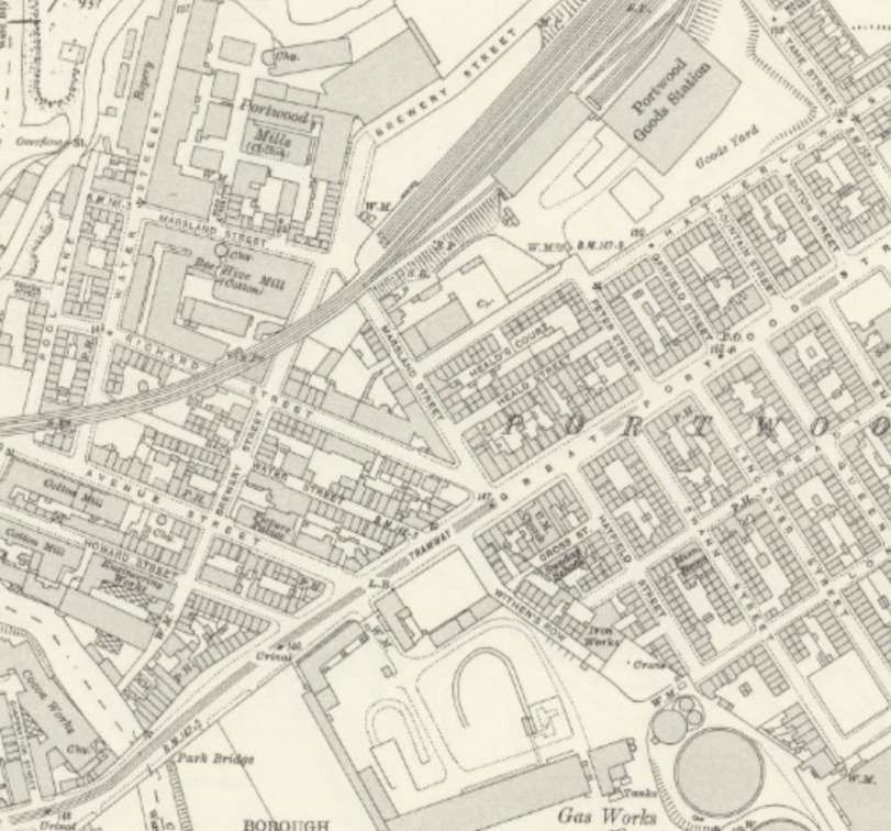
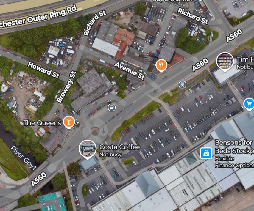
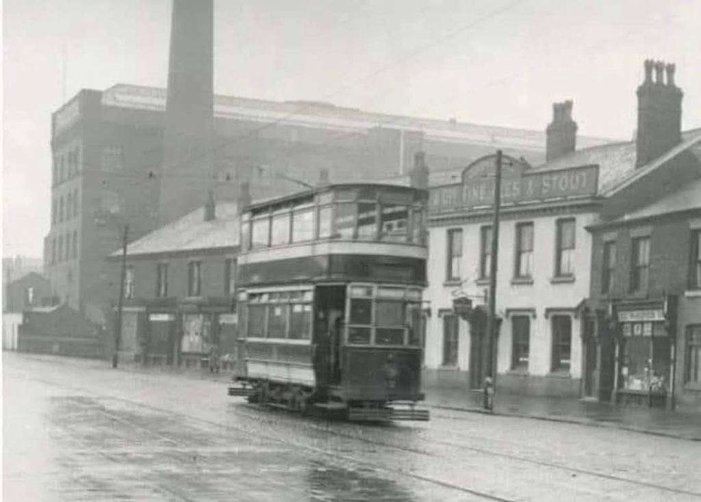
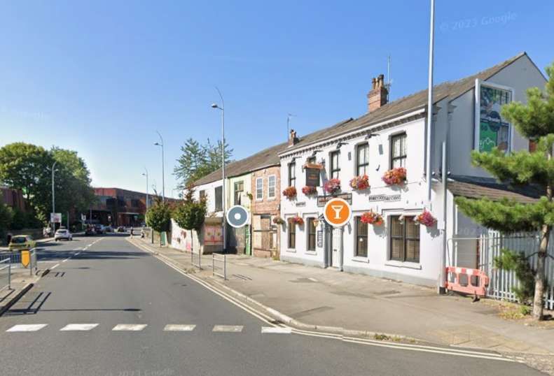
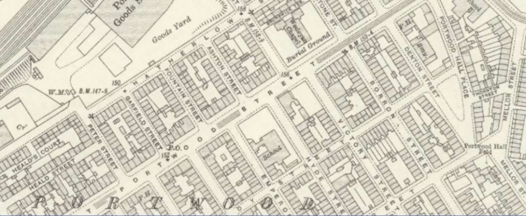
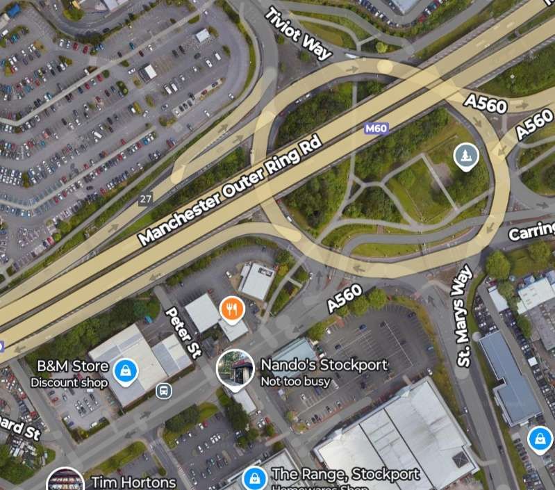
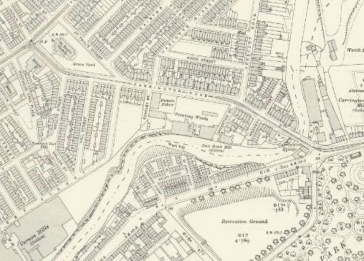
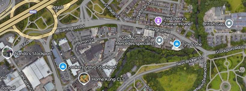
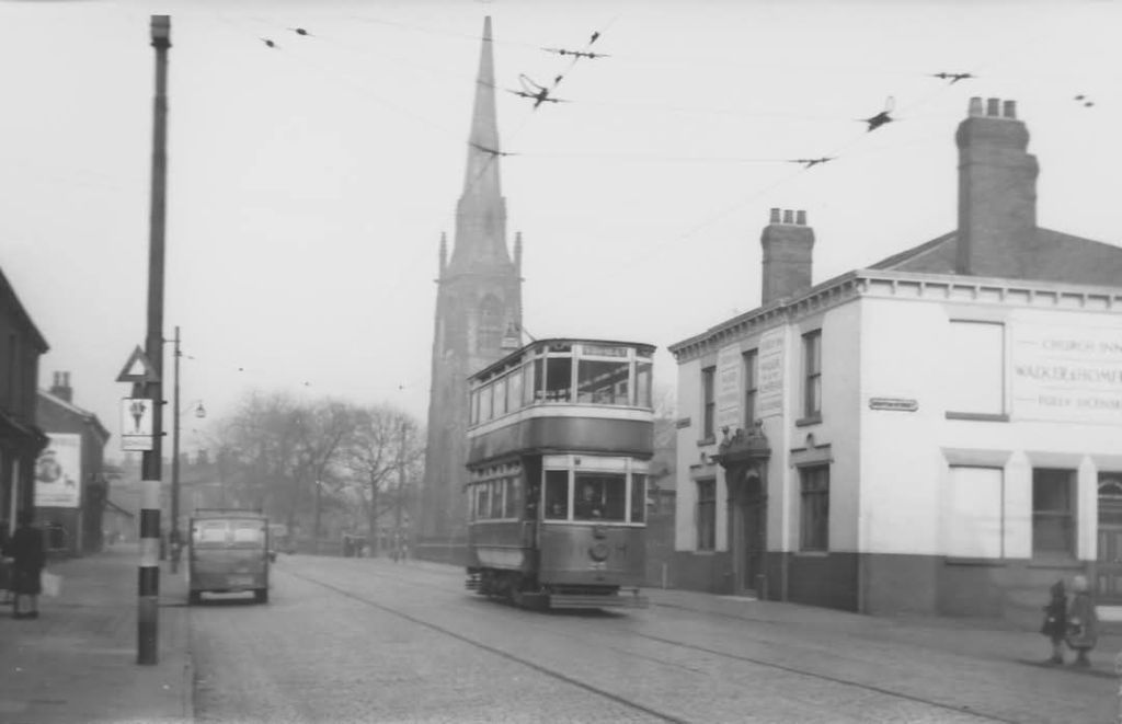
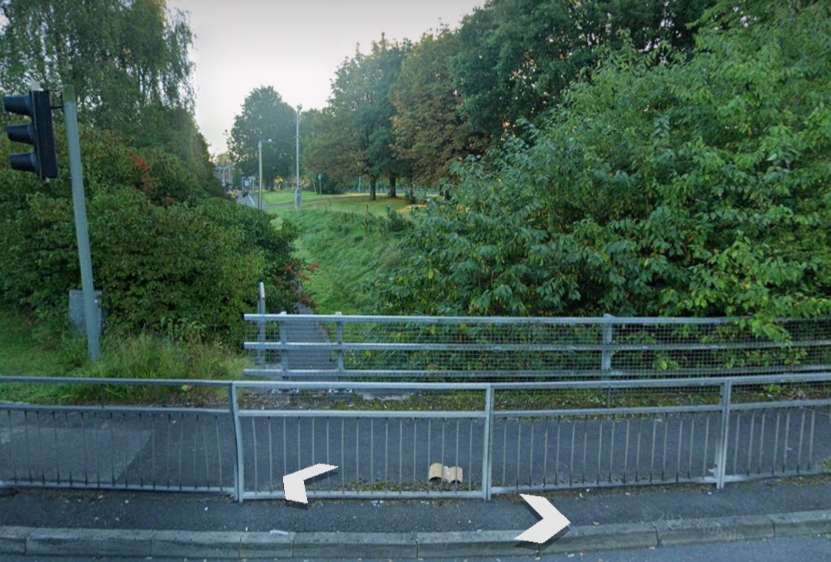
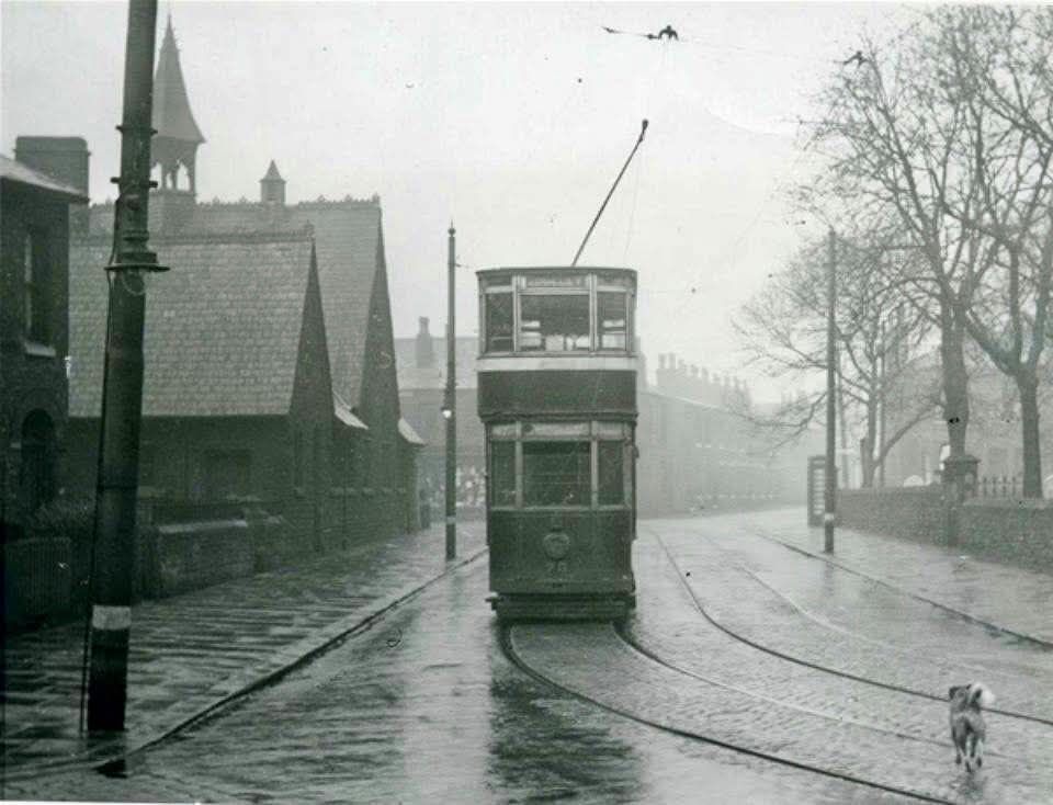
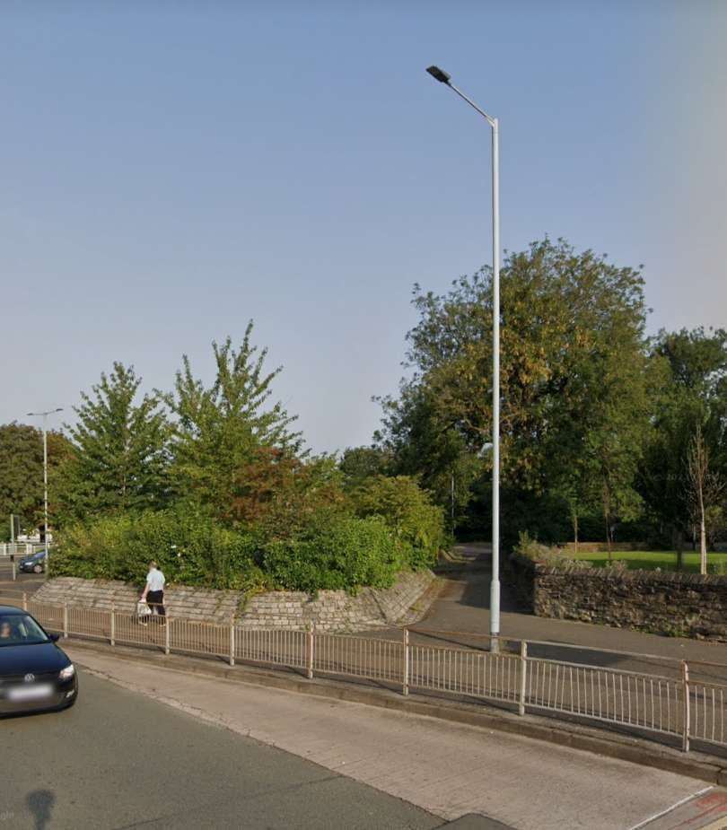
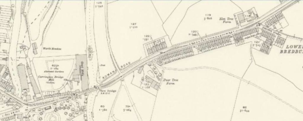
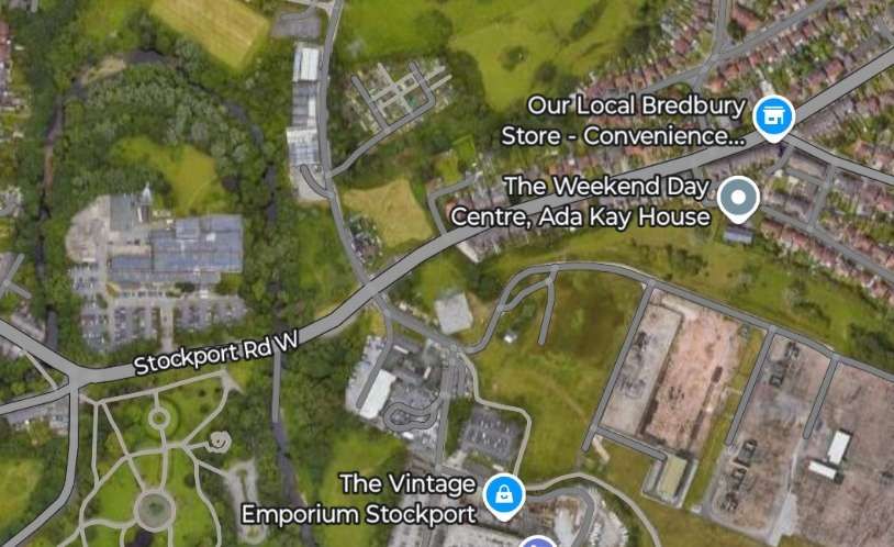
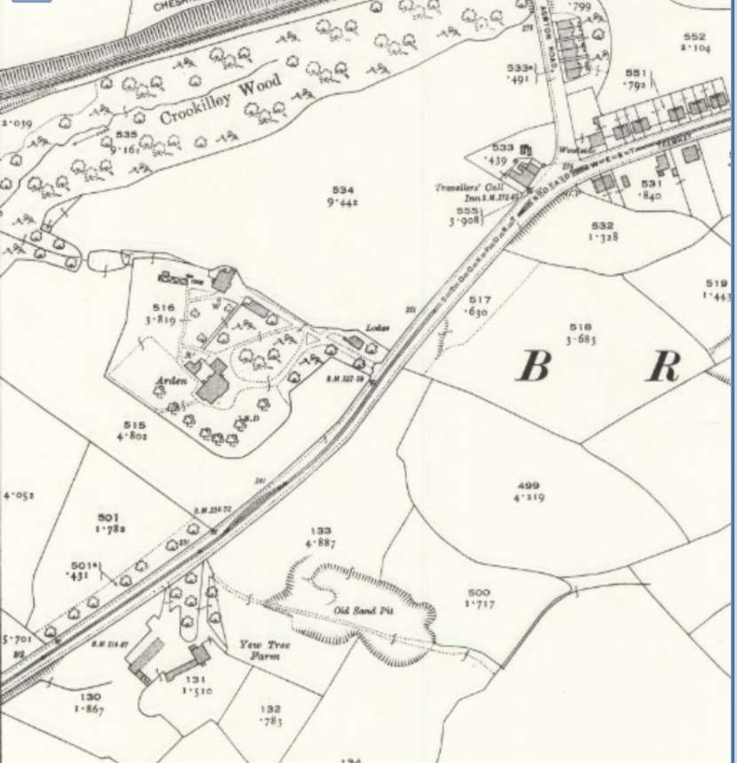
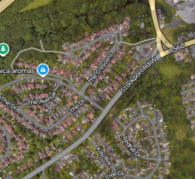
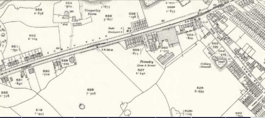
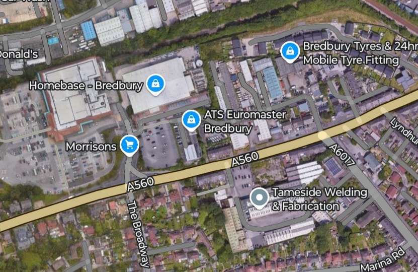
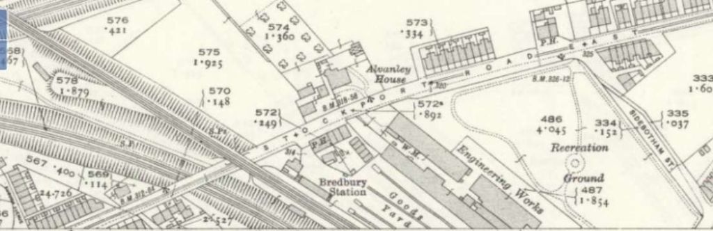
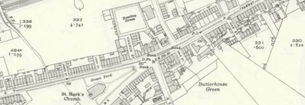
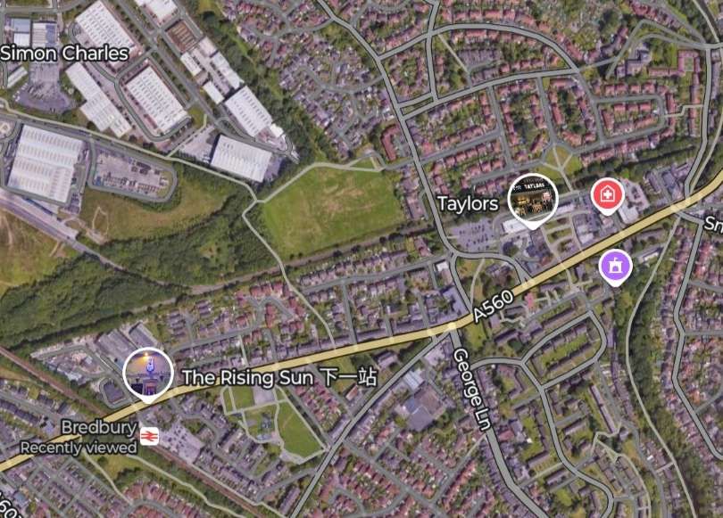
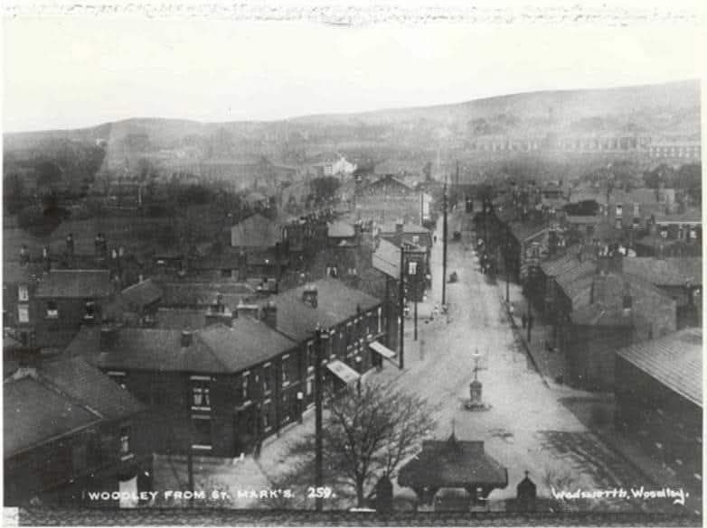
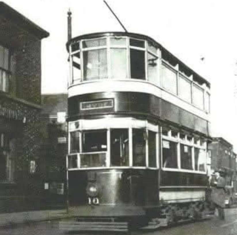
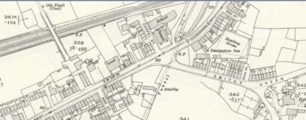
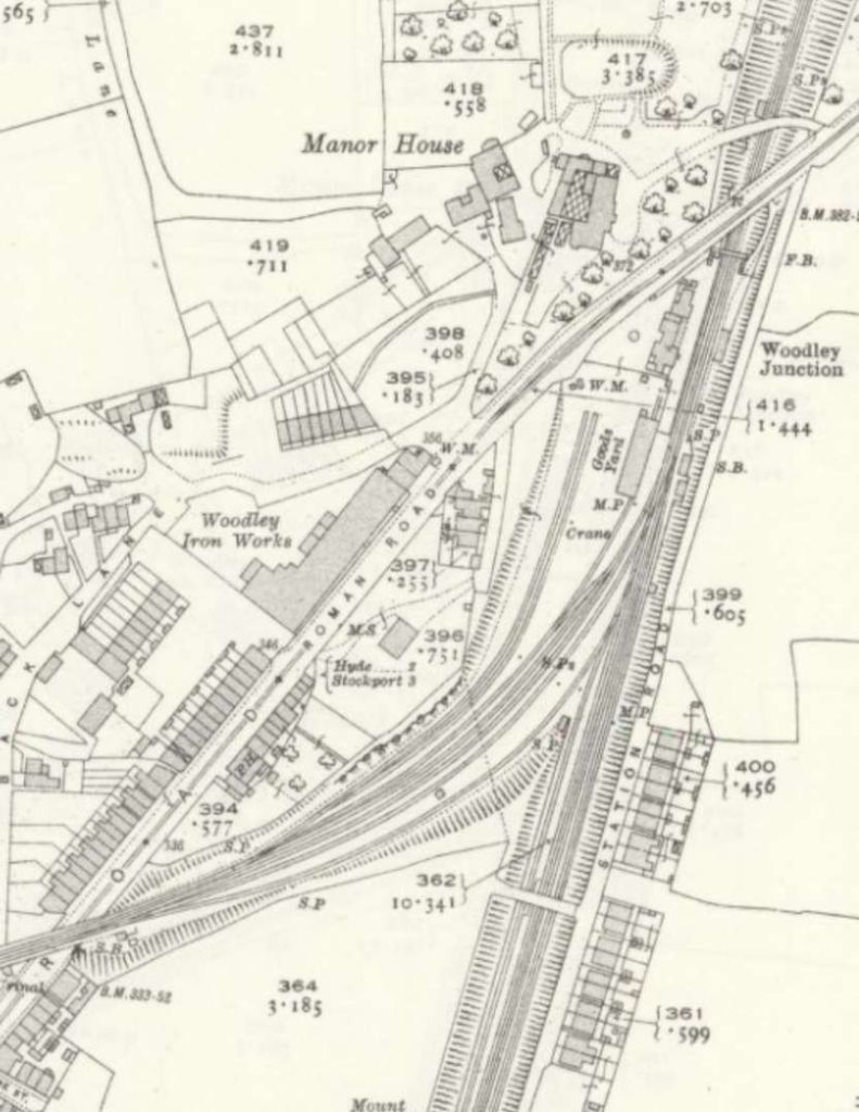
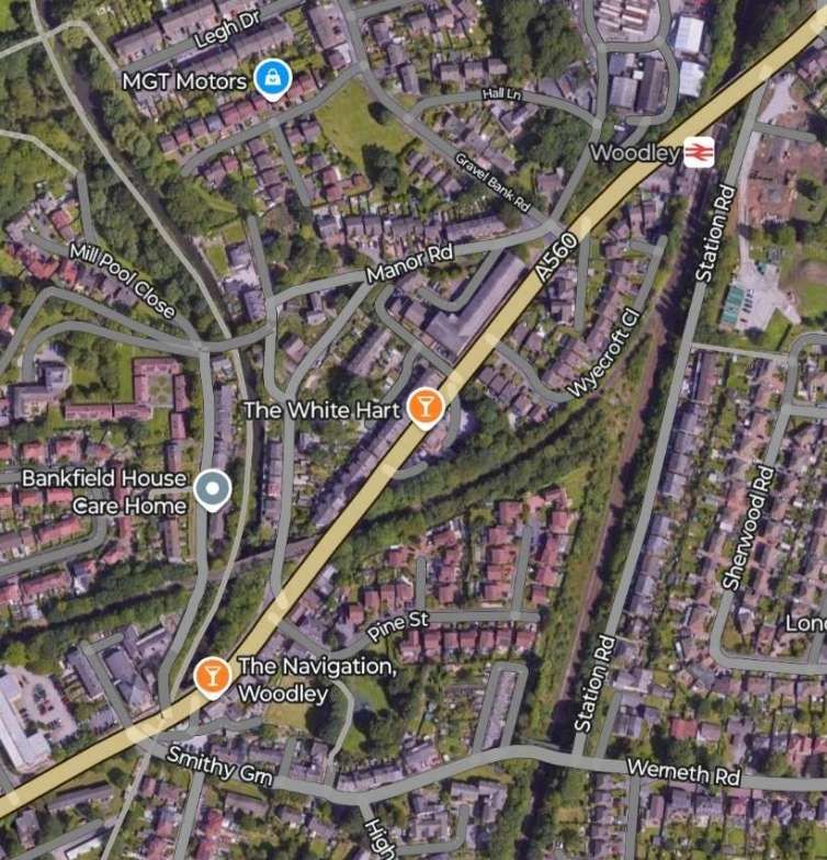
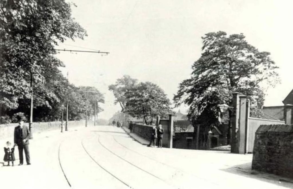
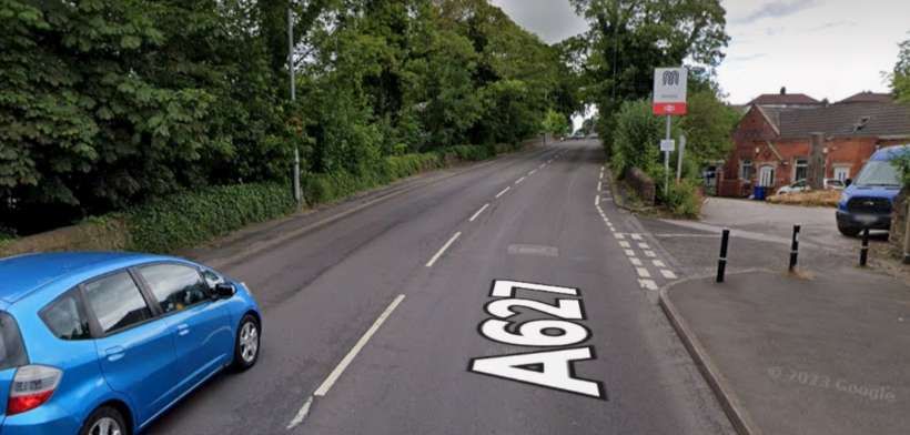
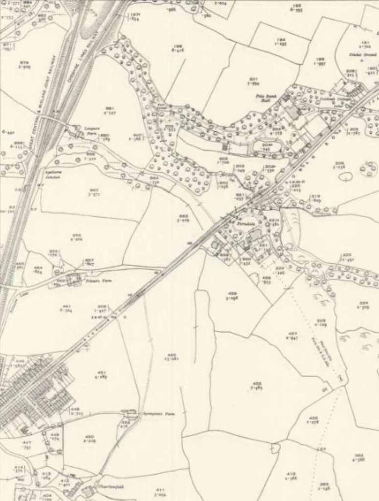

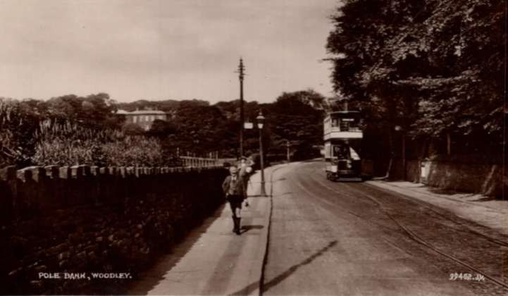
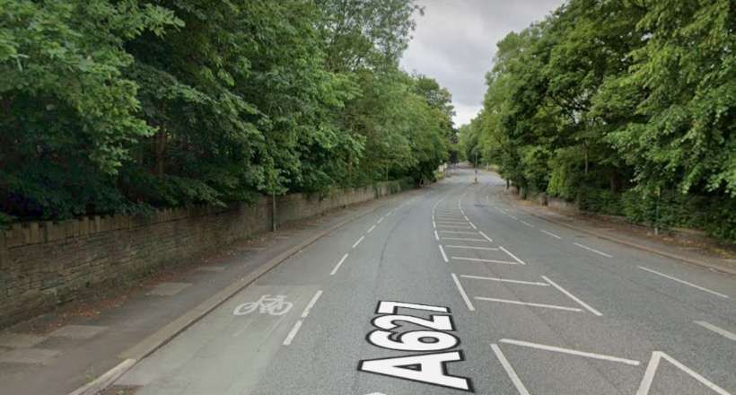
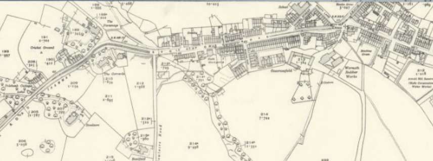
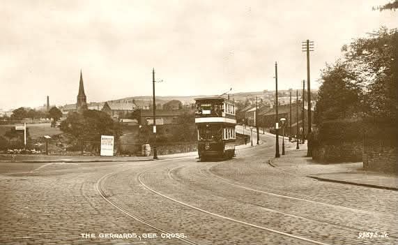
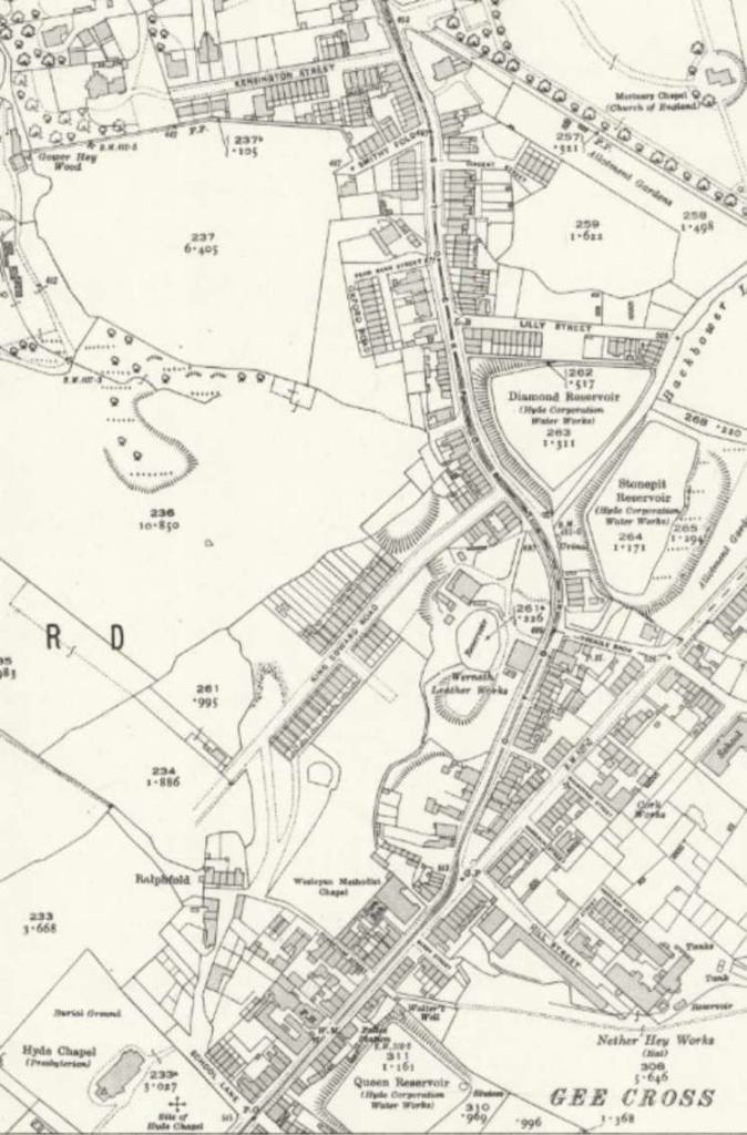
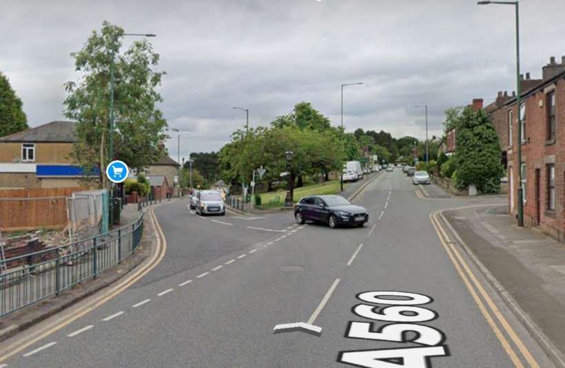
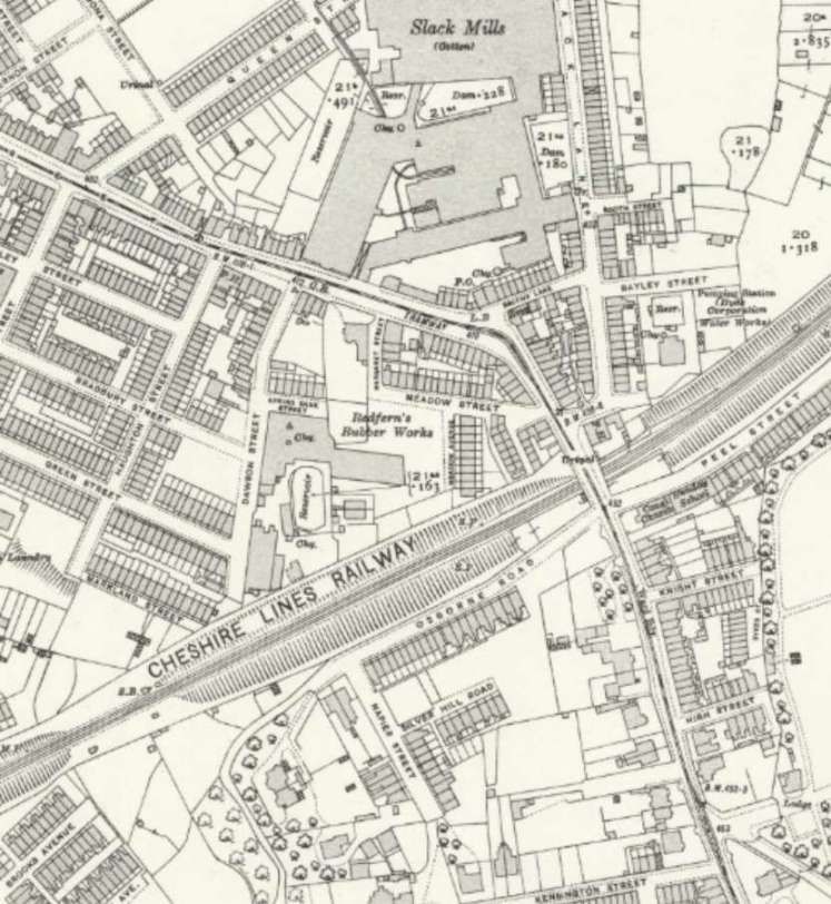
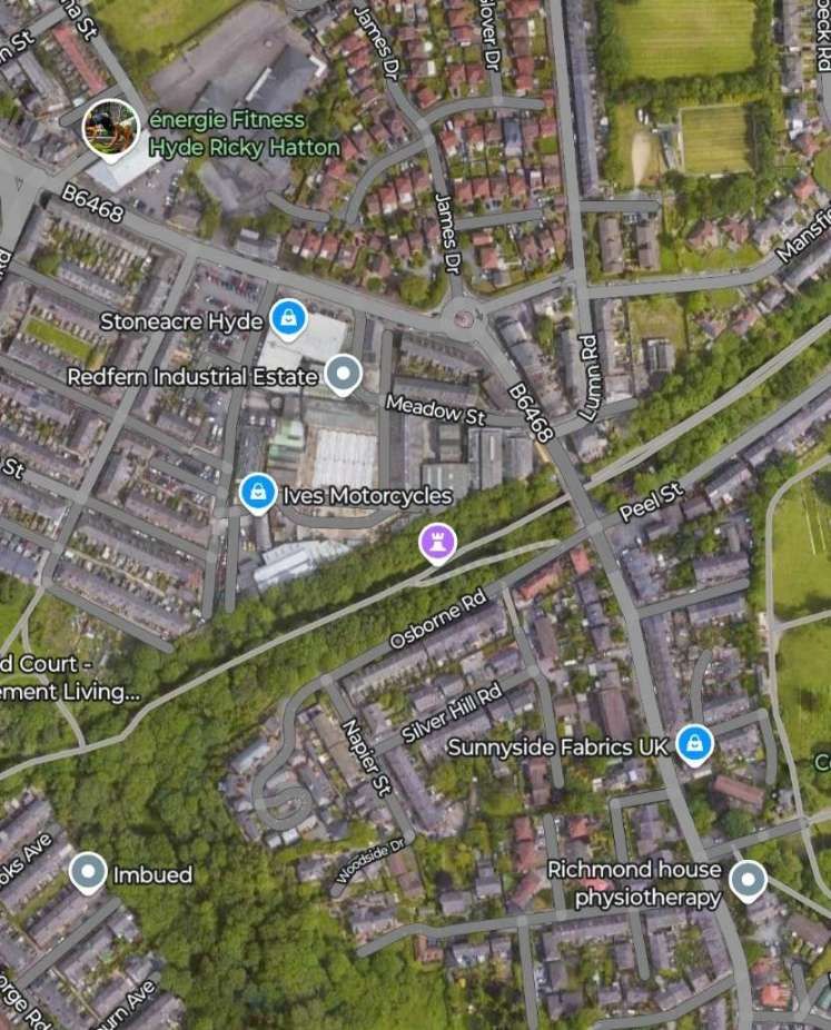
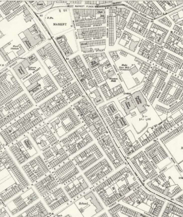
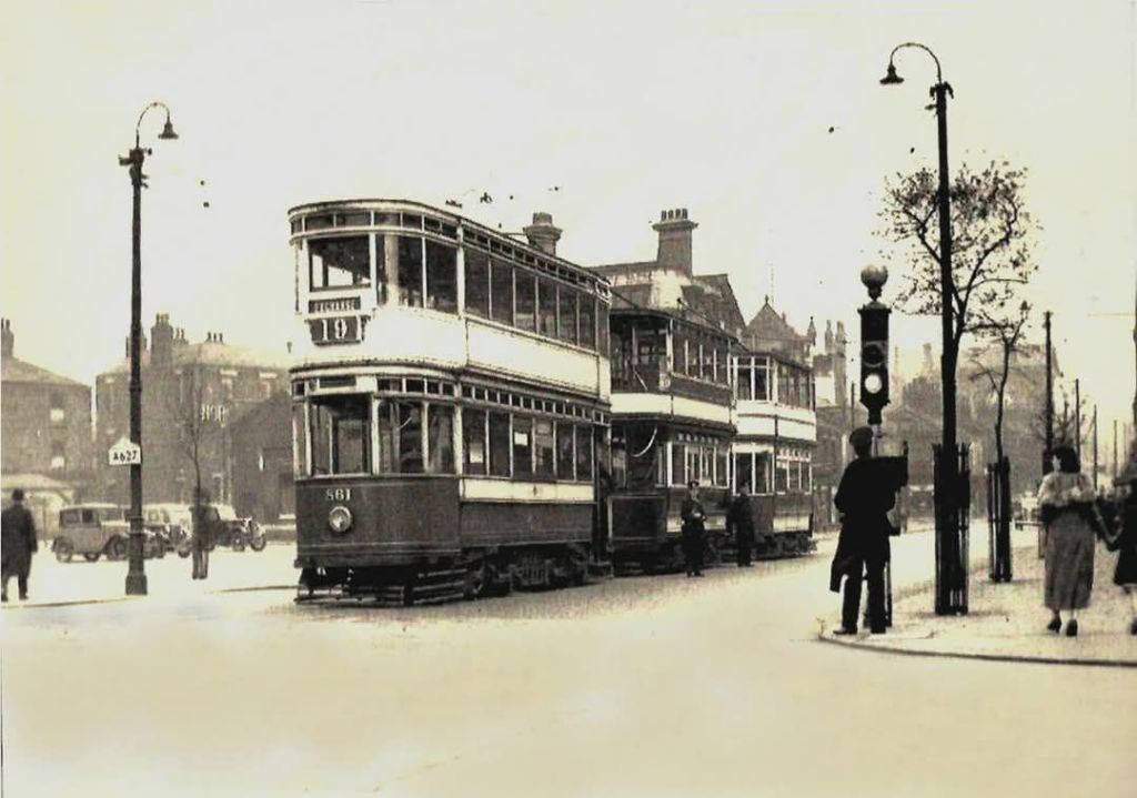
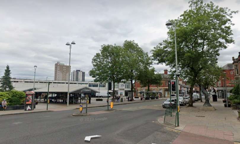


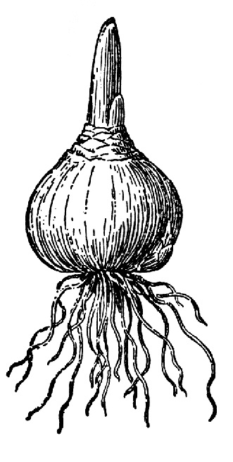


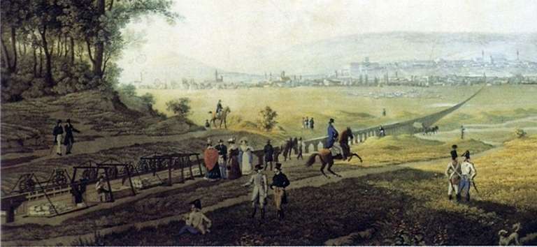
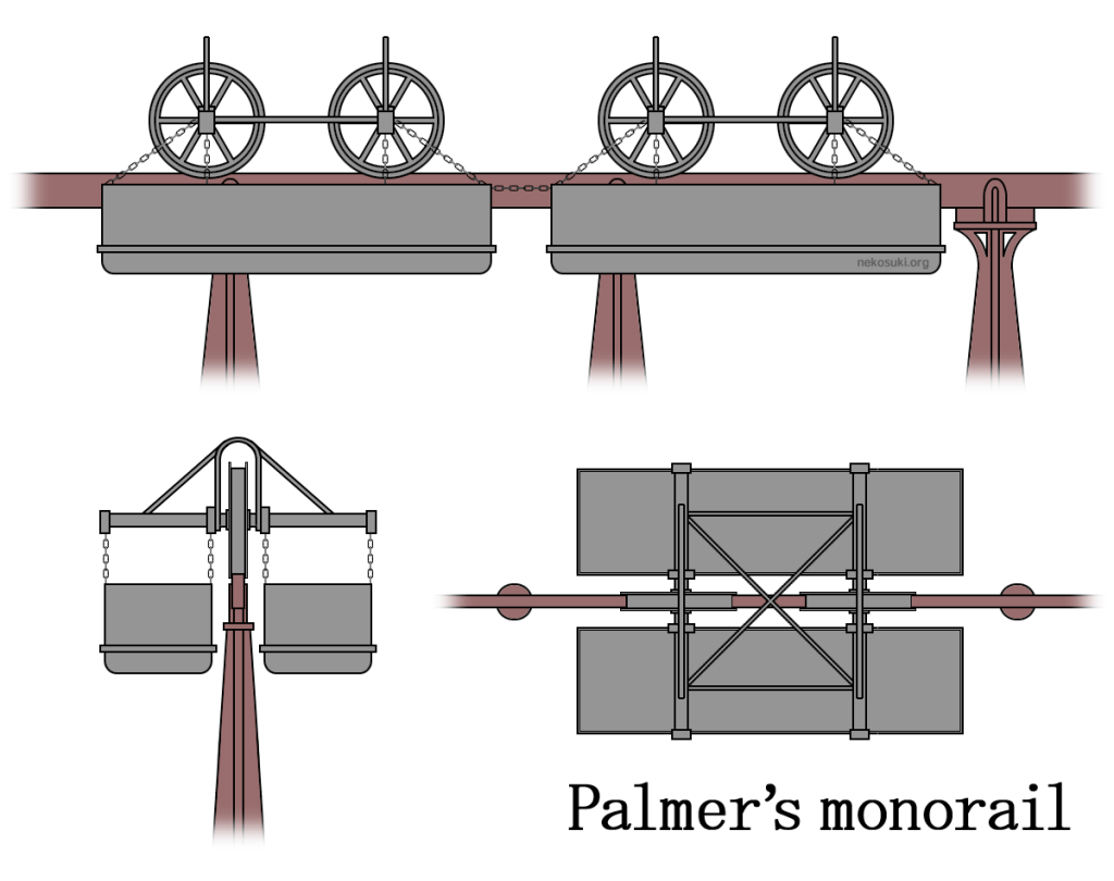
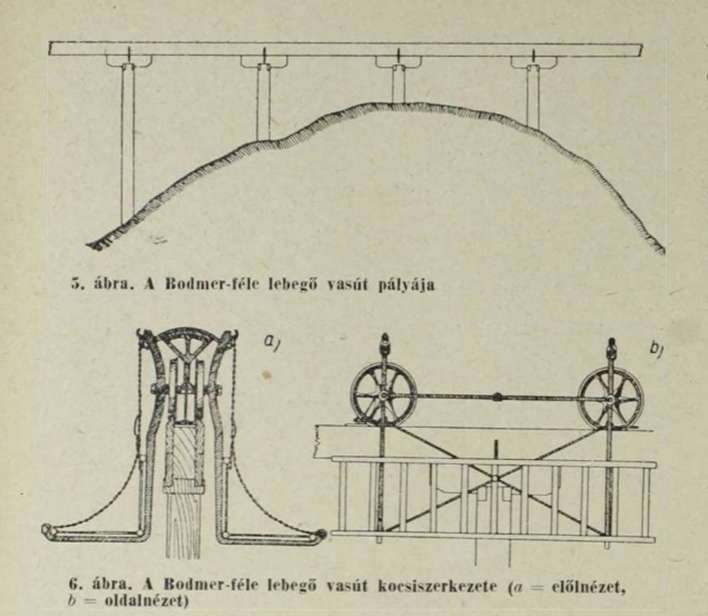
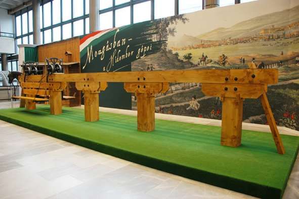
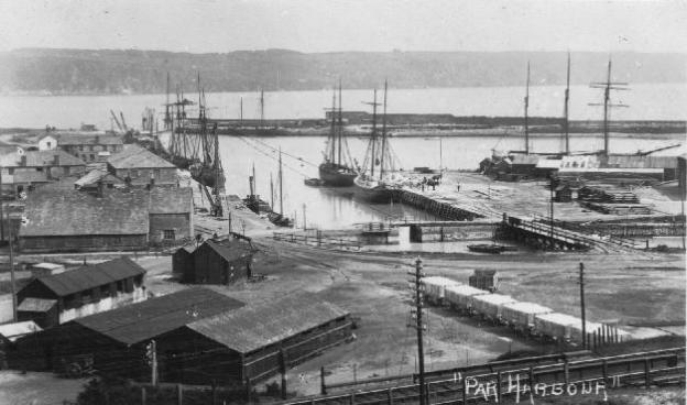
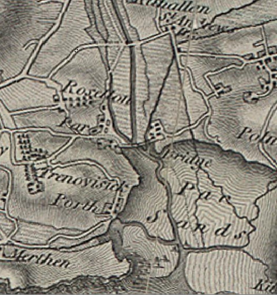
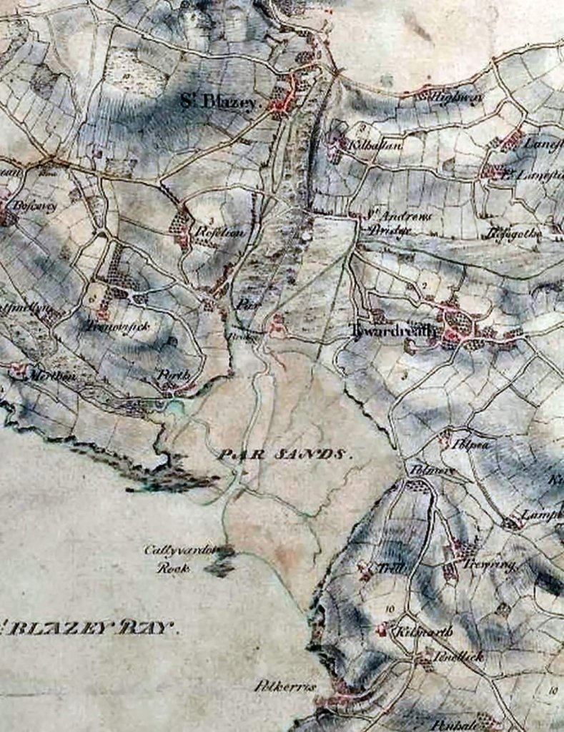
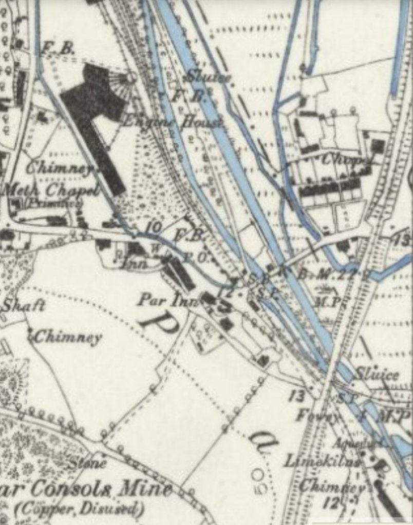
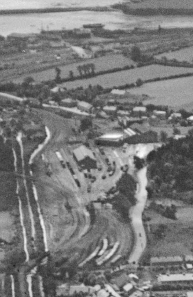
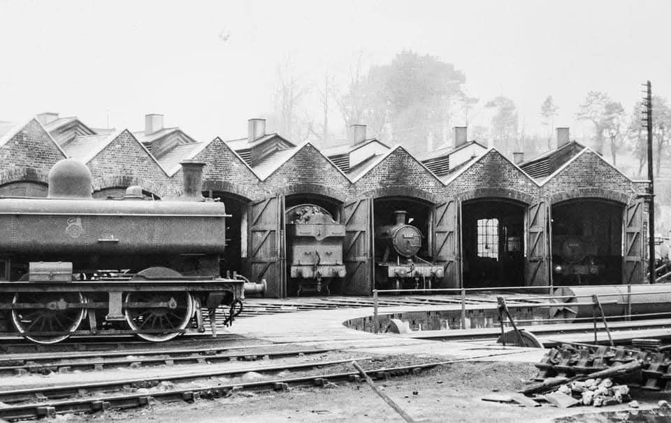
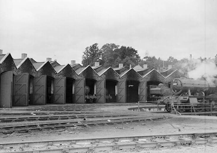
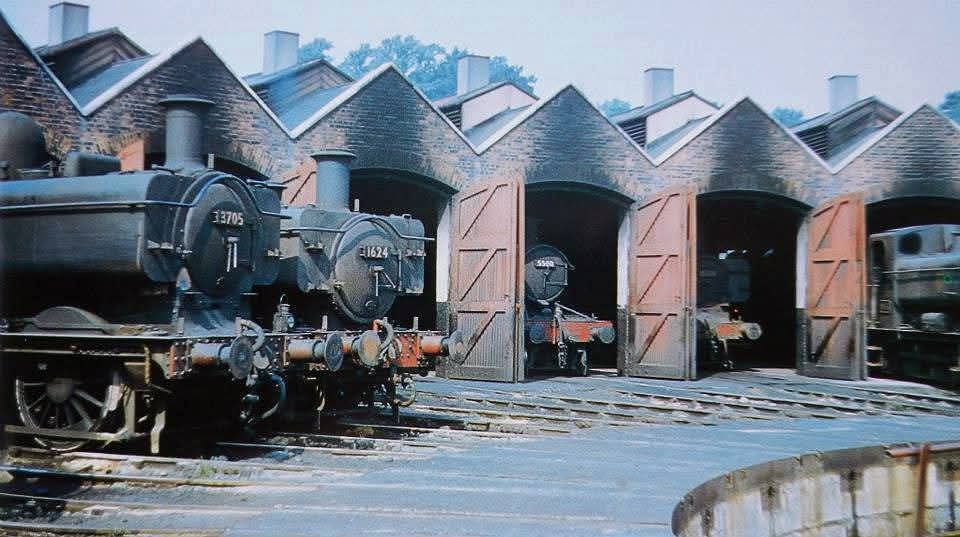
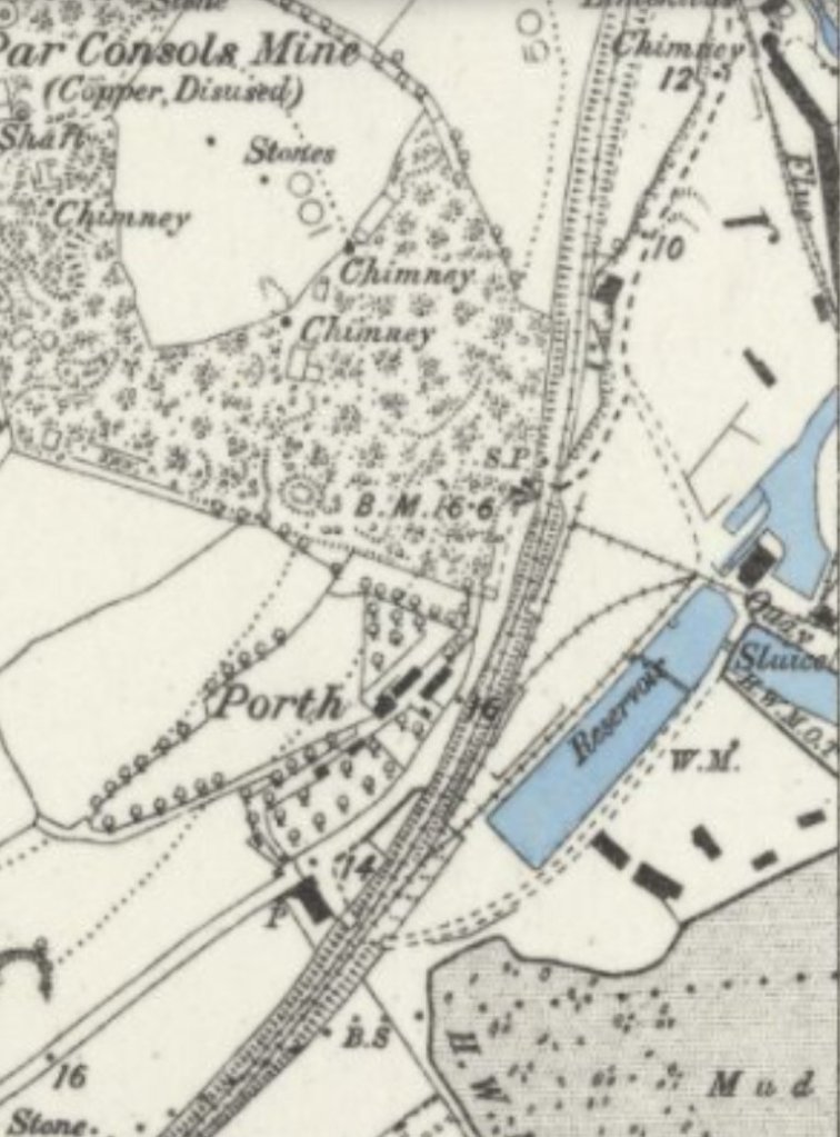
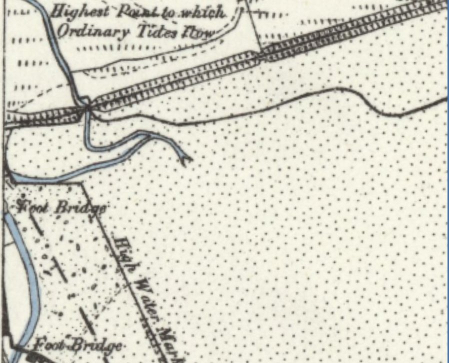
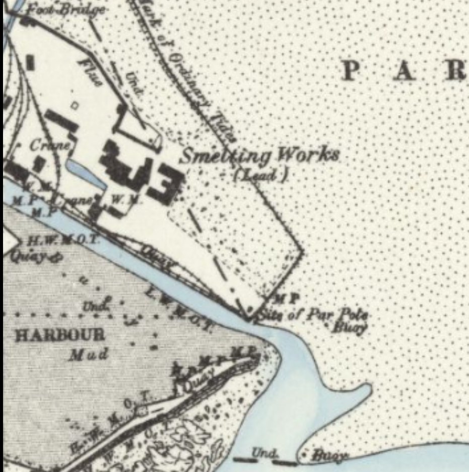
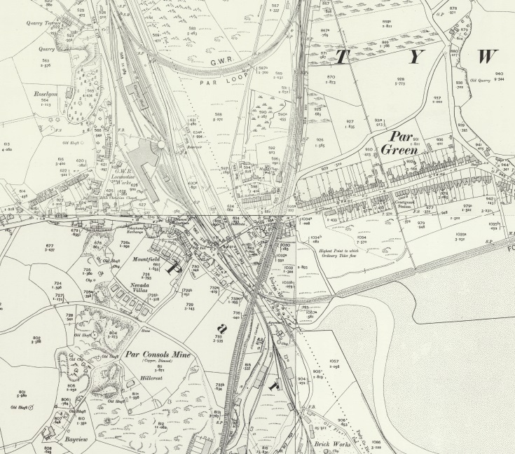
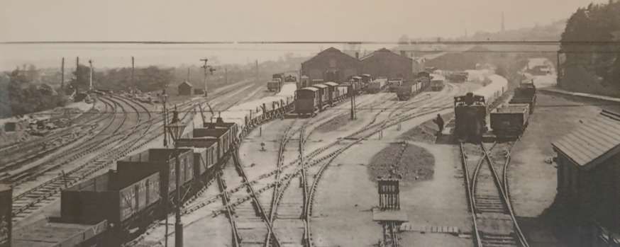
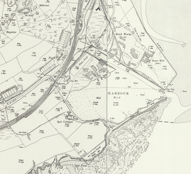
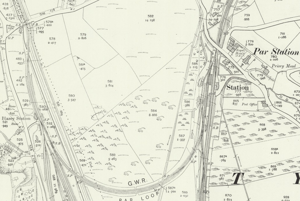
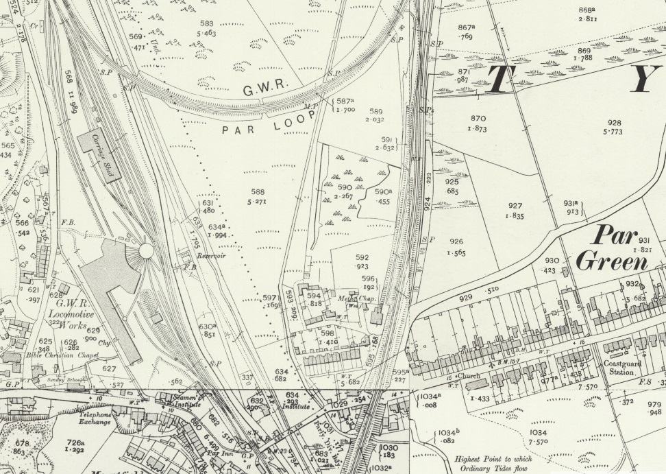
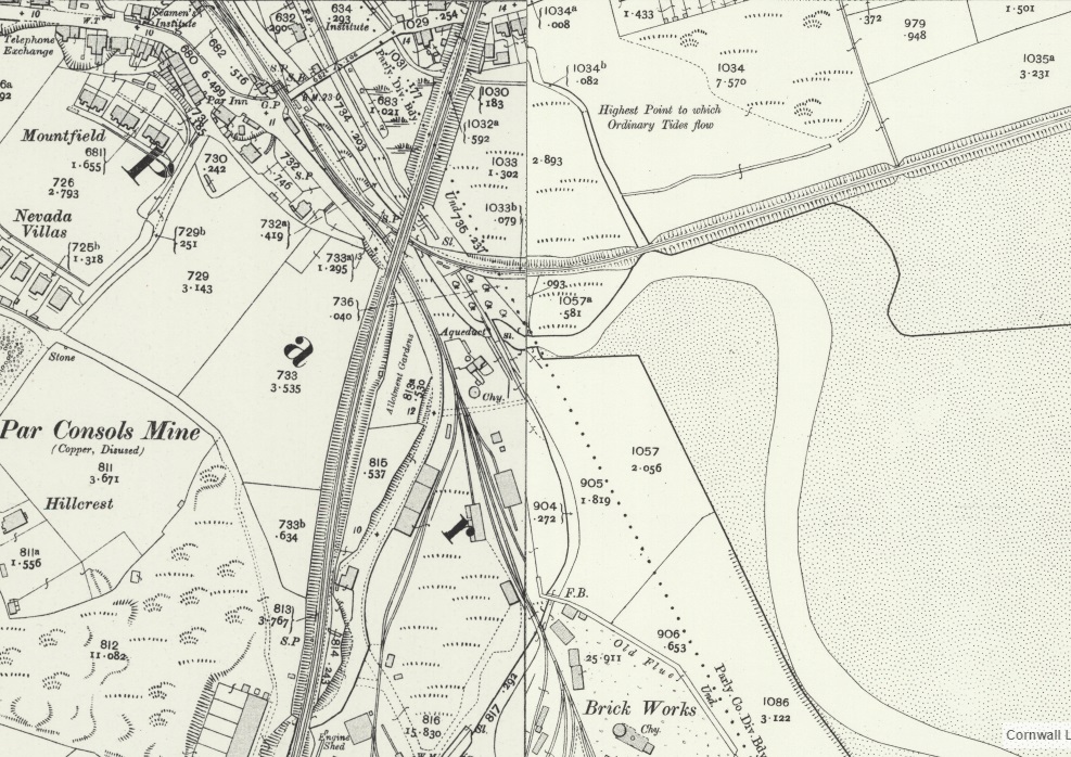
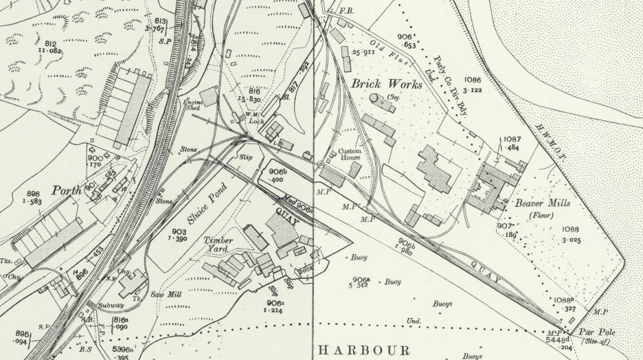
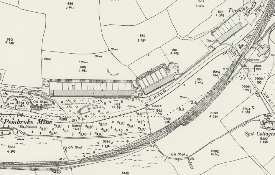
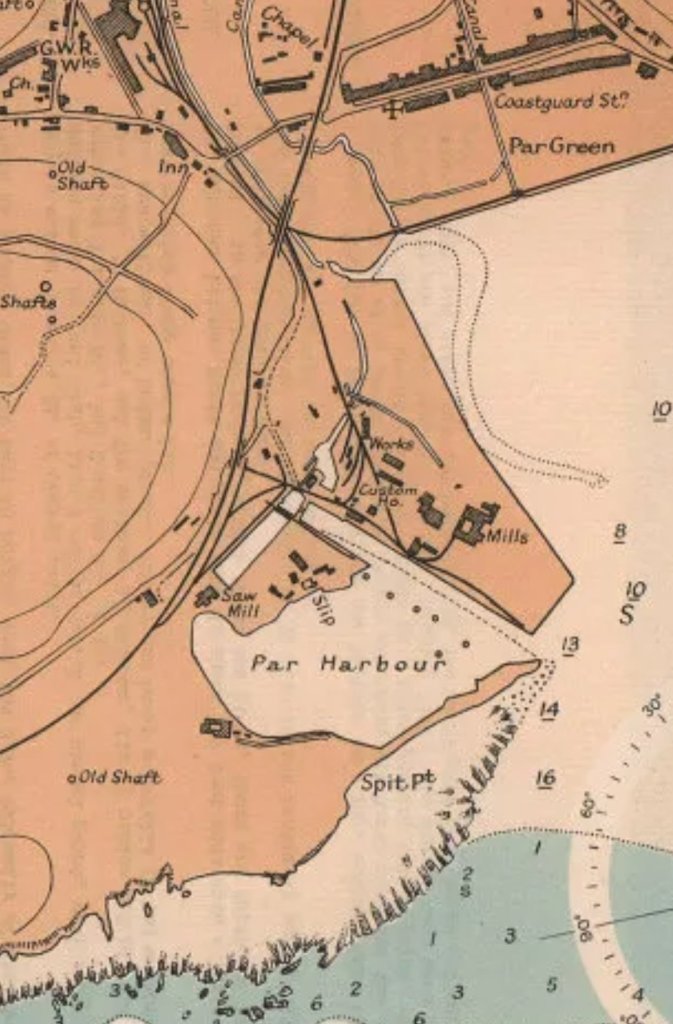
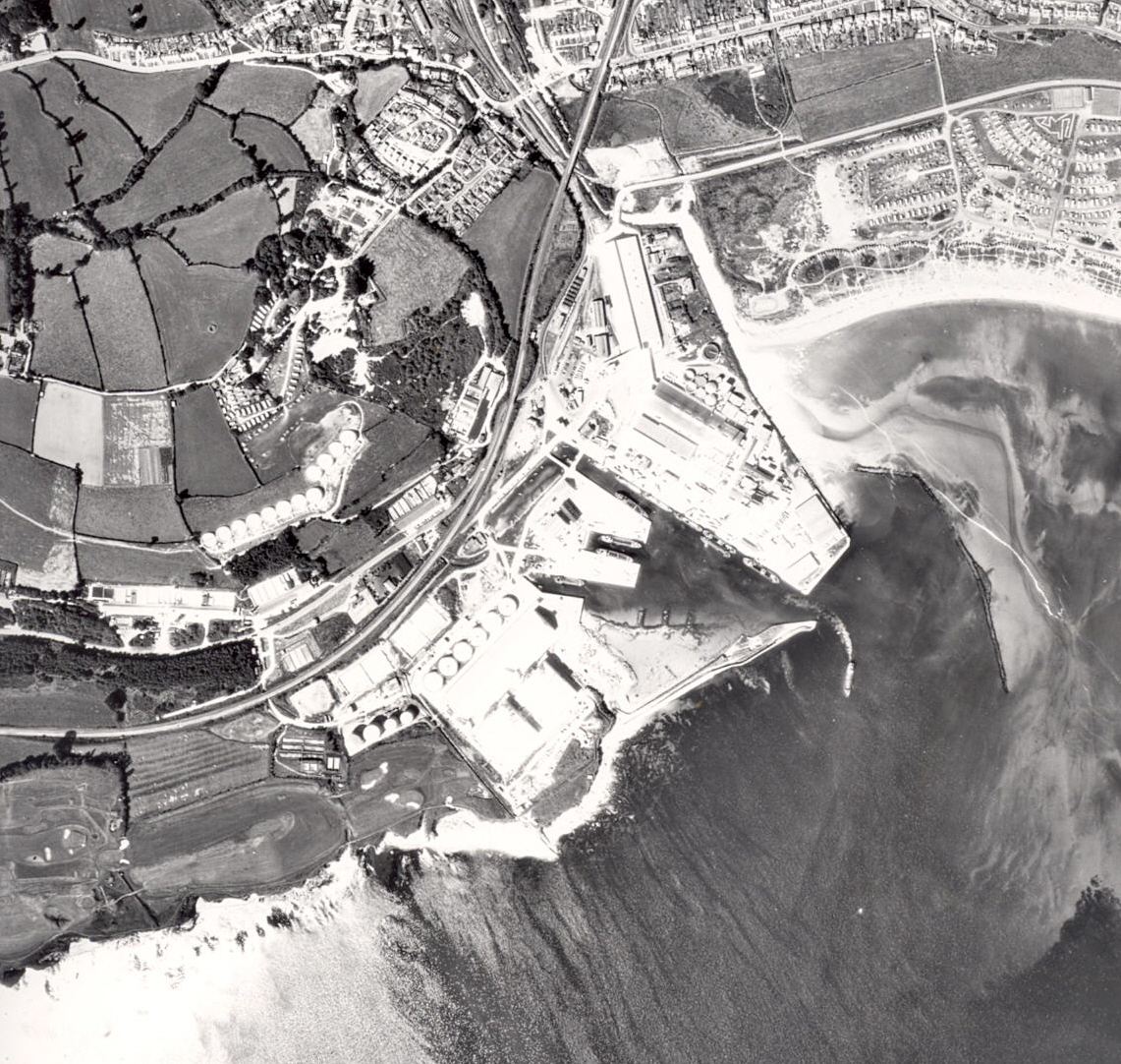
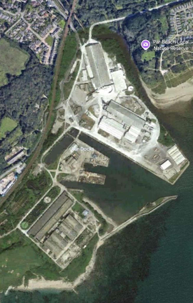

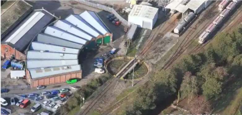

.JPG)