Category Archives: Railways and Tramways Blog

Japanese Railway History – Cape Gauge

I have been researching the history of railways in Japan. My interest has been drawn by the use of Cape Gauge as the early standard gauge in Japan.

Cape Gauge is very close to the Metre-gauge of many of the secondary lines in France. It is the same track gauge that was used in a number of different British colonies.

The photographers notes say: JNR 3′ 6″ Gauge Class C10-8 on a turntable in Oikawa Railways Senzu station in July 2001. It was built by the Kawasaki Heavy Industries Rolling Stock Company, Kisha Seizō in 1930, (c) D. Bellwood. [27]

Railways with a track gauge of 3′ 6″ (1,067 mm) were first constructed as horse-drawn wagonways. The first intercity passenger railway to use 3 ft 6 in was constructed in Norway by Carl Abraham Pihl. From the mid-nineteenth century, the 3’6″ gauge became widespread in the British Empire (although it was not used in East Africa or India) and was adopted as a standard in Japan and Taiwan. [1]

There are approximately 112,000 kilometres (70,000 miles) of 1,067 mm gauge track in the world.

The photographer’s note says: Class C11 is a type of 2-6-4T 3′ 6″ Gauge steam locomotive built by the Japanese Government Railways and the Japanese National Railways from 1932 to 1947. A total of 381 Class C11 locomotives were built. This is JR Hokkaido C11 207 hauling a Niseko tourist service in September 2014, (c) ウツダー, Japan. [28]

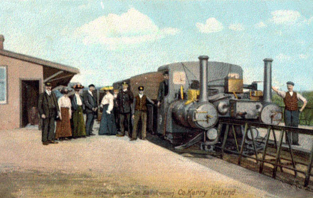
The article on this subject on Wikipedia [1] says that one of the first railways to use 3′ 6″ (1,067 mm) gauge was the Little Eaton Gangway in England, constructed as a horse-drawn wagonway in 1795. Other 3′ 6″ gauge wagonways in England and Wales were also built in the early nineteenth century.
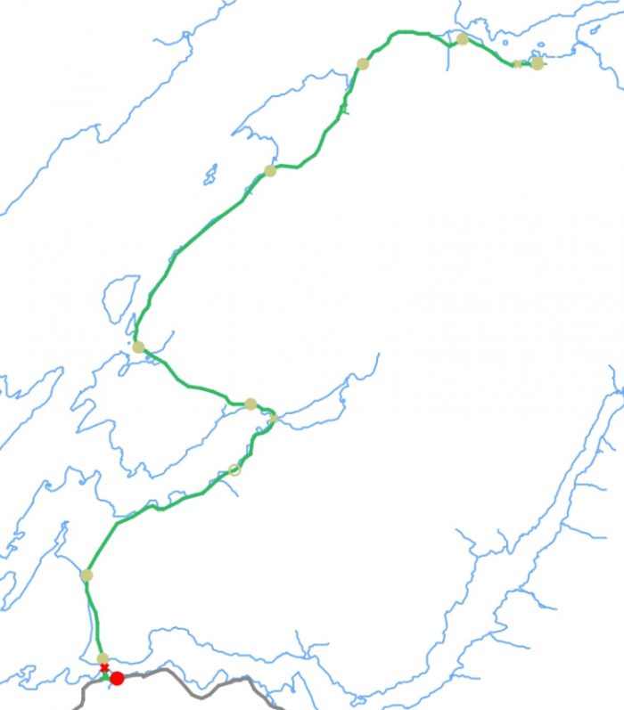
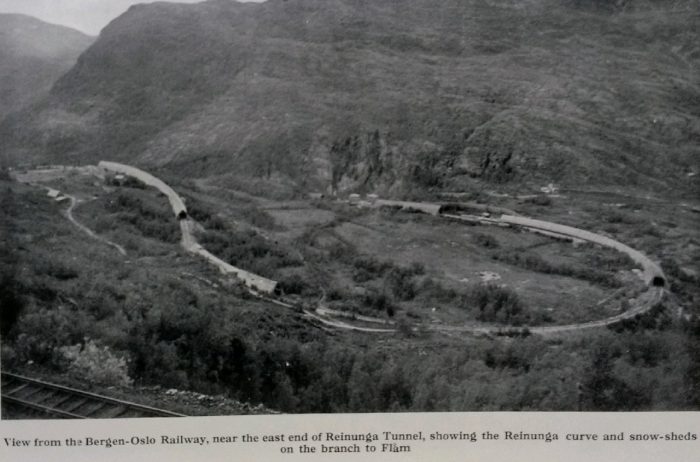
In 1862 the Norwegian engineer Carl Abraham Pihl constructed the first 3′ 6″ gauge railway in Norway, the Røros Line. Japan Railway and Transport Review carried an article about Norwegian Railways in 2002. [35]
In 1865 Queensland Railways were constructed. Its 3′ 6″ gauge was promoted by the Irish engineer Abraham Fitzgibbon and consulting engineer Charles Fox.
In 1867, the construction of the railway from the Castillo de Buitrón mine to the pier of San Juan del Puerto, Huelva, Spain, began. The width was 3′ 6″ (1,067 mm).
In 1868 Charles Fox asks civil engineer Edmund Wragge to survey a 3′ 6″ railway in Costa Rica.
In 1871 the Canadian Toronto, Grey and Bruce Railway and the Toronto and Nipissing Railway were opened, promoted by Pihl and Fitzgibbon and surveyed by Wragge as an engineer of Fox.
In January 1872, Robert Fairlie advocated the use of 3 ft 6 in gauge in his book Railways Or No Railways: Narrow Gauge, Economy with Efficiency v. Broad Gauge, Costliness with Extravagance. [4]
1872 also saw the opening of the first 3′ 6″ gauge railway in Japan, proposed by the British civil engineer Edmund Morel based on his experience of building railways in New Zealand. [5].
On 1 January 1873, the first 3′ 6″ gauge railway was opened in New Zealand, constructed by the British firm John Brogden and Sons. Earlier built 4 ft 8 12 in (1,435 mm) and broad gauge railways were soon converted to the narrower gauge.
Also in 1873, the Cape Colony adopted the 3′ 6″ gauge. [6][7]. After conducting several studies in southern Europe, the Molteno Government selected the gauge as being the most economically suited for traversing steep mountain ranges.[8] Beginning in 1873, under supervision of Railway engineer of the Colony William Brounger, [9], the Cape Government Railways rapidly expanded and the gauge became the standard for southern Africa. [10][11]
In 1876, Natal also converted its short 10 kilometres (6.2 miles) long Durban network from 4 ft 8 12 in (1,435 mm) standard gauge prior to commencing with construction of a network across the entire colony in 1876. [12]
Other new railways in Southern Africa, notably Mozambique, Bechuanaland, the Rhodesias, Nyasaland and Angola, were also constructed in 3′ 6″ gauge during that time.After 1876In the late nineteenth and early twentieth century numerous 3′ 6″ gauge tram systems were built in the United Kingdom and the Netherlands.
The precise reason why a track gauge of 3′ 6″ in (1,067 mm) (also known as “Cape gauge”) came to be selected as the early standard gauge in Japan remains uncertain. It could be because 3’6″ was supposedly cheaper to build than the international standard “Stephenson gauge” of 4 ft 8.5 in (1,435 mm), or because the first British agent, whose contract was later cancelled, ordered iron sleepers made for the narrower gauge. It seems most likely, however, that Morel’s previous experience building Cape gauge railways in similar New Zealand terrain was a significant influence, and Cape gauge became the de facto standard.

As a further commentary on the 3′ 6″ gauge, readers might want to consult Japan Railway and Transport Review which carried an article about the 3′ 6″ gauge in 2002. [36]
Japan’s Shinkansen lines are all built to Standard Gauge, because trains are more stable, and can go faster, on wider track. Some other lines in Japan use 1,372 mm (4′ 6″), 762 mm (30″) gauge or 610 mm (24″) gauge. But the majority, over 83% in terms of distance, of Japan’s railways are built to Cape Gauge, 1,067 mm (3′ 6″). The name comes from its adoption in 1873 by the Cape Colony (later part of the Union of South Africa). But by then it had been around for nearly a century, originally for horse-drawn railways in England and Wales, and later steam railways around the world, including Australia, Canada and other locations. And, as of 1872, Japan, where it is known as KyOki (OM, literally “narrow path” or “narrow track”). But compared to Standard Gauge, it’s never been all that heavily used outside of Japan. [2]

Currently there are 5 track gauges in common use in Japan. The most common gauge is 1067mm/3′ 6″, which forms the bulk of the JR Group network and connecting private railways. The others, already referred to above, were very kindly listed by Mark Newton in response to a query from me on the website http://www.jnsforum.com. [3] His notes are in italics below. There is also an article in the archives of the magazine, Japan Railway & Transport Review from January 1997 which reflects on the activities of railway companies in the private sector [37]:

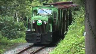
610mm – Tateyama Sabo railway (shown adjacent) in Toyama prefecture. [21] I think this would be the last non-museum/preserved line using 610mm gauge, which was once common for local and industrial railway operations, known as “keiben“, [22] throughout Japan.

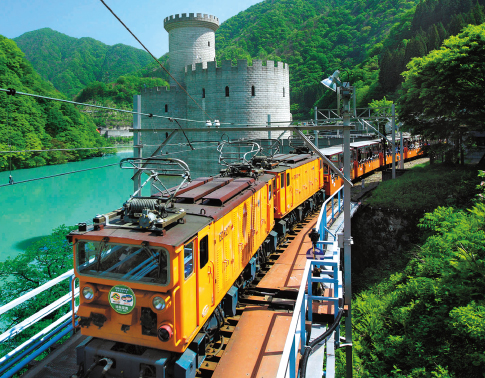
762mm – the three former Kintetsu lines [18] … and the Kurobe Gorge railway (shown adjacent). [19] This gauge was also once very commonly used by keibenlines throughout Japan, but in many cases the lines were converted to 1067mm gauge and electrified as traffic increased, such as Kintetsu’s Yunoyama line. The famous Kiso Forest Railway was 762mm gauge. [20]

1067mm – JR Hokkaido, JR East, JR Tokai, JR West, JR Shikoku, JR Kyushu, all JR Freight operations on these lines, and many private railways and tramway, big and small. The reasons for choosing 3’6″ gauge for the original Tokyo-Yokohama line in 1872 are not apparent these days, but that choice greatly influenced subsequent government and private railway construction.

1372mm – Toei Shinjuku line, [29] Tokyu Setagaya line, [30] Toden Arakawa line, [31] Keio Teito Corporation lines, [32] and the Hakodate city tramway. [33] The once-huge Tokyo municipal tramway system was built to this gauge, plus some private railways and tramway in the Tokyo area. Some of these lines have been re-gauged twice, going from 1067mm to 1372mm, then 1372mm to 1435mm!

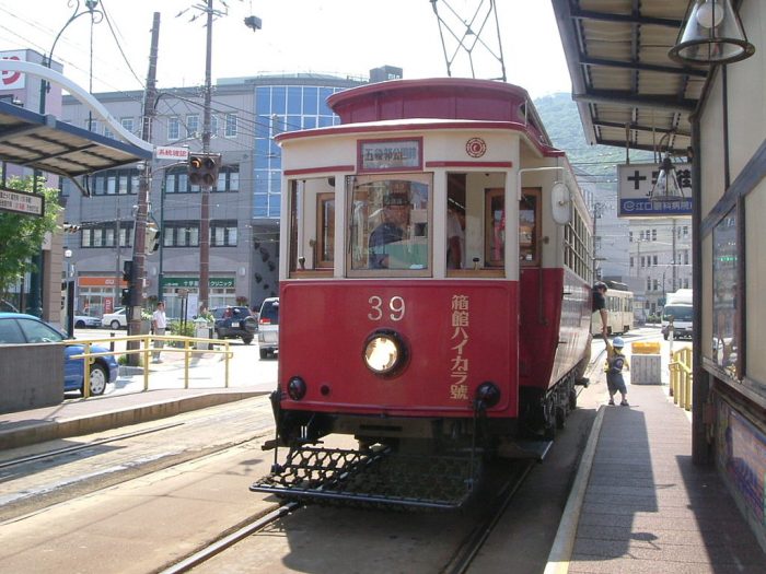
Hakodate Haikara-gō is a vintage 1372mm gauage tramcar first operated in the city in 1918 and now restored for use on tourist runs in the summer, (c) 湯の川. [34]

1435mm – Shin Keisei railway, Hokuso Railway, Keihin Express Railway, Keisei Electric Railway, Eidan Ginza and Marunouchi lines, Toei Asakusa line, Yokohama metro, Hakone Tozan Railway, Nagoya metro, Kinki Nippon Railway/Kintetsu main lines, Keifuku Electric Railway, Eizan Electric Railway, Keihan Electric Railway, Kyoto metro, Osaka metro, Hankai Electric Tramway, Hankyu Electric Railway, Nose Electric Railway, Hanshin Electric Railway, Kobe metro, San-Yo Electric Railway, Hiroshima Electric Railway, Takamatsu-Kotohira Electric Railway, Chikuho Electric Railway, Nishi Nippon Railway main lines, Nagasaki Electric Tramway, Kumamoto city tramway, Kagoshima city tramway, and of course the JR Shinkansen network. So there’s more standard gauge trackage in Japan than you might think at first.

Historically there were a number of other gauges used. There were once a number of man-powered tramways, known as “jinsha kido”, some of which used 737mm gauge. Kaimaishi Iron Works and the Hankai Railway used 838mm. In northern Kyushu there were a number of local lines that used 914mm/3′ gauge. In total there have been 16 different track gauges used in Japan in the railway era. I’ve not gone into the various monorails and guideway lines there, as I’m not sure how you’d even measure their gauges! [3]

Edmund Morel (1840-1871) was a British civil engineer who was engaged in railway construction in many countries, including New Zealand, Australia, and Japan. He was the first foreign Engineer-in-Chief appointed by the Japanese government, for guiding and supervising railway construction.

A graduate of King’s College in London where he studied civil engineering, he was highly sought after to work with countries seeking to construct railroad systems, such as in New Zealand, Australia and North Borneo, which is now part of Malaysia.

Edmund Morel was clearly not one to shy away from a challenge. It was while he was working in North Borneo that he was asked to come to Japan by British envoy Sir Harry Parkes and help create Japan’s first railroad system. Edmund arrived in Japan on April 9, 1870. He had only 18 months to live. [13] On arriving at Yokohama, he at once proceeded to set out a line of railway between Tokei and Yokohama, 20 miles in length; the works on this, and on another length of 20 miles, between Kobe and Otaka, were commenced under him, but he did not live to see their completion. [14]

He assumed the role of Japan’s first chief engineer for railway and telegraph construction. His involvement in Japan was quite eclectic. Along with railway design he made proposals about the country’s education system and about engineering administration. It was as a result of his advice that Japan set up its Ministry of Public Works in December of 1870. It’s role was to find ways to bring in and utilize foreign technologies. [13]

The locomotives and rails for Morel’s railways were imported from England. Through discussions with senior government officials, Japan’s standard gauge of 1,067 mm (3′ 6″) was established. [15] Morel’s experiences in other countries predisposed him to the narrow gauge of 3′ 6″, in New Zealand contractors began laying track to the 5′ 3″ gauge from 1863 but all of it had been reduced to 3′ 6″ by 1870. Similarly, standard-gauge track laid in Indonesia from 1867 was gradually changed to 3′ 6″. (That gauge-change took time and was only completed during Japan’s wartime occupation.) [16]

As we have already noted, survey work for the 3′ 6″ line between Tokyo and Yokohama were begun in the spring of 1870 and the line was completed in May, 1872. The formal opening of the railway took place in the presence of the Emperor. “A general holiday,” says one account, “was declared for all government offices, and His Majesty the Emperor proceeded to the station dressed in ancient court costume, Naosbi, in a four-horse state carriage, accompanied by his suite in similar dress and wearing their swords.” [17]

A Cape Gauge (3′ 6″) Express train ‘Niseko’ bound for Otaru, Hokkaido, Japan. An steam locomotive type C62 (C623) and five old type passenger cars. The C62 type locomotive was the biggest and largest steam locomotive for passenger train in Japan, (c) Neko Ja Neko Ja. [25]

“During the first year from May 7, 1872 to December 31, the railway carried 495,000 passengers, and about 500 tons of freight. In this period the operating income came to 174,930 yen and operating expenses amounted to 113,464 yen, producing a profit of 61,466 yen.” [17]

Other government sponsored lines were started after the opening of the first railroad. In December of 1873 work was begun on a 27-mile line between Kyoto and Osaka, and entwined in 1877. A short line between Osaka and Kobe was opened to traffic in 1874. Long range plans called for the laying of trunk lines, but owing to the shortage of funds and internal disturbances culminating in the Satsuma Rebellion, the government was unable to launch large scale railway projects in the early years. [17]

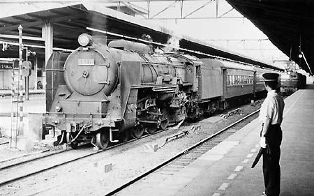
Hudson built for the Limited Expresses of the old Cape-gauge (3′ 6″) Tokaido line, class C62, Hiroshima 1966, (c) Dr. Stephan Stoeckl. [24]

Although the government didn’t nationalize the railways until 1906, it took a strong central role in standardization, and apparently chose to continue with the gauge it had started with, causing most later railways to be built to that gauge. Some private railways chose other gauges, including standard gauge, and in particular a number of small regional railways used and still use 762 mm (30”) gauge. But most were built to Cape Gauge. [2]

In subsequent years, particularly from 1909 to 1920, the Japanese would try, repeatedly, to switch to standard gauge out of a desire for higher speed, heavier tonnage, or simply for ease of purchasing equipment overseas. Several of these attempts were put off by the government on military grounds, as the existence of an odd gauge made use of railway lines by a potential invader more difficult. By 1927, the nationalized Japanese Government Railways operated 12,864 km (7,993 mi) of track and it would have been very expensive to convert. And by then, the technology was entirely locally-made, and imports were no longer a concern.

A preserved Japanese 3′ 6″ gauge JNR Class D51 2-8-2 locomotive in main line service in 2014 (c) C.C. Lerk. [23]

Cape Gauge (3′ 6″) EF62 1 at the Usui Pass Railway Heritage Park, April 2007, (c) RSA. This is a a Co′Co′ wheel arrangement DC electric locomotive type built between 1962 and 1969 [26]

It wasn’t until the first high speed Shinkansen line was built in the 1960’s that Japan would finally get a large-scale standard gauge line. [2]

References

  1. https://en.m.wikipedia.org/wiki/3_ft_6_in_gauge_railways, accessed on 2nd January 2019.
  2. http://www.sumidacrossing.org/Prototype/StandardNarrowGauge, accessed on 4th January 2019.
  3. Mark Newton; http://www.jnsforum.com/community/topic/15147-understanding-japans-track-and-loading-gauges, accessed on 4th January 2019.
  4. https://archive.org/stream/railwaysornorai01fairgoog#page/n8/mode/2up, accessed on 2nd January 2019.
  5. Peter Semmens; High Speed in Japan: Shinkansen – The World’s Busiest High-speed Railway. Sheffield, UK: Platform 5 Publishing, 1997. p1.
  6. P.J.G. Ransom; Narrow Gauge Steam; Oxford Publishing Co., 1996, p107.
  7. I. L. Griffiths; Susan Rowland; (1994). The Atlas of African Affairs. Routledge, 1994, p168.
  8. John Bond; “Chapter 19, The Makers of Railways: John Molteno”. They were South Africans. Oxford University Press, 1956, p170.
  9. “Cultural, historical assessment of the Hex Pass Railway, Worcester to de Doorns”(PDF), accessed on 2nd January 2019.
  10. Jose Burman; Early Railways at the Cape, Cape Town: Human & Rousseau, 1984.
  11. D.E. Davenport; A Railway Sketch of South Africa. 1882. Cape Town.
  12. T.V. Bulpin; Natal and the Zulu Country (3rd ed.). Cape Town: T.V. Bulpin Publications Ltd., 1977. p224–227.
  13. https://wonderfulrife.blogspot.com/2013/10/gaijin-father-of-japans-railways.html?m=1, accessed on 5th January 2019.
  14. https://www.gracesguide.co.uk/Edmund_Morel, accessed on 7th January 2019.
  15. https://en.wikipedia.org/wiki/Edmund_Morel_(railway_engineer), accessed on 7th January 2019.
  16. Akira Saito; Why Did Japan Choose the 3’6″ Narrow Gauge? Japan Railway & Transport Review No. 31 (p33–38); http://www.ejrcf.or.jp/jrtr/jrtr31/f33_sai.html, accessed on 7th January 2019.
  17. Nobutaka Ike; The Pattern of Railway Development in Japan; in The Far Eastern Quarterly, Vol. 14, No. 2, February 1955; p222-223, sourced via https://www.jstor.org/stable/2941732?read-now=1&seq=6#page_scan_tab_contents, accessed on 8th January 2019.
  18. https://en.wikipedia.org/wiki/Yokkaichi_Asunarou_Railway_Utsube_Line, accessed on 8th January 2019; “The Yokkaichi Asunarou Railway Utsube Line (四日市あすなろう鉄道内部線 Yokkaichi Asunarō Tetsudō Utsube-sen) is a 762 mm (2 ft 6 in) narrow gauge railway line operated by the Japanese private railway company Yokkaichi Asunarou Railway, connecting Asunarou Yokkaichi Station and Utsube Station, both in the city of Yokkaichi, Mie, Japan.The line connects with the Kintetsu Nagoya Line and the Yunoyama Line at Asunarou Yokkaichi Station; these other lines use an elevated platform called Kintetsu Yokkaichi Station whereas the Utsube Line uses a low-level platform. At Hinaga Station, the line connects with the Yokkaichi Asunarou Railway Hachiōji Line, a one-station branch line. Because all trains on the Hachiōji Line offer direct service to Asunarou Yokkaichi via the Utsube Line, the two lines are collectively called the Utsube-Hachiōji Line (内部・八王子線 Utsube-Hachiōji-sen). … Until March 2015, the line was under control of Kintetsu, a major railway company.”
  19. http://www.kurotetu.co.jp/en/railway, accessed on 8th January 2019 and https://en.wikipedia.org/wiki/Kurobe_Gorge_Railway, accessed on 8th January 2019: “The Kurobe Gorge Railway (黒部峡谷鉄道株式会社 Kurobe Kyōkoku Tetsudō Kabushiki Kaisha), or Kurotetsu (黒鉄) for short, is a private, 762 mm (2 ft 6 in) narrow gauge railway company operating the Kurobe Gorge Main Line along the Kurobe River in the Kurobe gorge area of Toyama Prefecture, Japan. The railway was built to serve the construction of the Kurobe dam for the Kansai Electric Power Company, which was completed in 1963; Kurotetsu was spun off from the power company in June 1971, but remains a wholly owned subsidiary. At its terminus, the Main Line links to Kurobe Senyō Railway, which is not open to general public. … In 2008 the company operated 27 locomotives, 138 passenger carriages and 322 freight wagons.
  20. https://en.wikipedia.org/wiki/Kiso_Forest_Railway, accessed on 8th January 2019: “The Kiso Forest Railway (木曽森林鉄道 Kiso-shinrin-tetsudō) was a network of 400 km of 762 mm (2 ft 6 in) narrow gauge light (keiben (軽便)) railway lines that operated in the Kiso Valley in Nagano Prefecture, Japan. … The railway was used to support the logging of cedar forests in the region. The Kiso Forest had historically been the possession of a local lord, but at the time of the Meiji Restoration had become the property of the Imperial family. In 1901, a railway was laid into the forests and was initially worked by hand or animals. The first 0-4-2T locomotives built by Baldwin Locomotive Works were introduced in 1907. Further locomotives were obtained from Baldwin, as well as a Shay locomotive that was transferred to the Alishan Forest Railway in Taiwan when that line opened. The railway was extensively rebuilt in 1920, with steel bridges and 24 tunnels. … The railway was abolished in stages between 1966 and 1976.
  21. http://www.hrr.mlit.go.jp/tateyama/english/service/history.html, accessed on 8th Januaty 2019: “Tateyama Sabo’s service railway opened in 1926, and in 1929 11.7 km of track from Senjugahara to Kanbadaira went into operation. In 1965 the 18 km of railway to Mizutanidaira were completed. This section includes an 18-lebel switchback. At first the point switches were manually controlled, but between 1980 and 1986 they became entirely automated. However, for the sake of safety, an assistant driver checks that everything is running smoothly. The train has changed with the times up to the present day. This train, still today active in erosion control work, is one of the symbols of Tateyama Sabo.”
  22. Dan Free; Early Japanese Railways 1853-1914: Engineering Triumphs That Transformed Meiji-Era Japan; sourced via https://books.google.co.uk/books?id=MwbQAgAAQBAJ&pg=PT586&lpg=PT586&dq=Keiben+Railways+Japan&source=bl&ots=vp0hACPS5X&sig=CV5WU8ubrKhWLp3NAlgPuYyo454&hl=en&sa=X&ved=2ahUKEwiagIjig97fAhXTtXEKHTLhCv8Q6AEwC3oECAIQAQ#v=onepage&q=Keiben%20Railways%20Japan&f=false, accessed on 8th January 2019: “By 1910, when the desire to construct more railways [in Japan] was close to its peak, the cost of developing a railway to main line standards was likewise becoming more costly. As the framework of a national railway system was well underway, with most of the major trunk lines built and the few still needed under construction, most of the new lines projected were short local lines with modest traffic potential. In order to stimulate such lines, the government passed a Light Railway Law, which brought many keiben tetsud “light railways” into being. Within three years, the effect was notable. By 1913 the number of keiben tetsud had greatly increased, thanks to the simplified organizational procedures authorized by the new law and other governmental encouragements. As of that year, there were 38 keiben tetsud with 574 route miles in operation, an additional 44 with a route mileage of 800 miles under construction, and some 126 companies with a combined mileage of 1,953 miles which had received a preliminary charter, but which had not commenced construction. The law would be augmented in 1924 with the addition of a Tramway Law. In all, by the close of the Meiji period, there were approximately 208 such keiben tetsud contemplated to add some 3,328 route miles to the Japanese railway system. Many of the keiben tetsud were short, local affairs that acted as branch line extensions from the “main-line” grade shitetsu or IJGR, meandering along old cart tracts or the banks of local streams to bring rail transportation to small towns, remote locations, and otherwise un-served villages and hamlets of the hinterlands. They were often times on the shakiest of financial grounds, operating as it were “on a shoe-string” with second-hand, obsolete equipment purchased used from their more established “main-line” brethren if they happened to be of a matching gauge. Thus they often retained a quaint, nostalgic flavor, often all the more charming due to the hodgepodge of dated and mismatched equipment with which they were furnished.
  23. By LERK, CC BY-SA 3.0, https://commons.wikimedia.org/w/index.php?curid=32955115
  24. https://www.trains-worldexpresses.com/500/519.htm, accessed om 8th January 2019.
  25. https://en.wikipedia.org/wiki/JNR_Class_C62#/media/File:C623_Express_Niseko.JPG, accessed on 8th January 2019.
  26. https://en.wikipedia.org/wiki/JNR_Class_EF62, accessed on 8th January 2019.
  27. https://en.wikipedia.org/wiki/JNR_Class_C10, accessed on 8th January 2019. NB: I have been informed that the note provided with this photograph is slightly misleading. The loco was built by Kawasaki. Kisha Seizo was a separate manufacturer.
  28. https://en.wikipedia.org/wiki/JNR_Class_C11, accessed on 8th January 2019. NB: Again the note provided with this photograph is slightly misleading. The loco C11 207 was built by Hitachi in 1941.
  29. https://en.wikipedia.org/wiki/Toei_Shinjuku_Line, accessed on 8th January 2019.
  30. https://en.wikipedia.org/wiki/T%C5%8Dky%C5%AB_Setagaya_Line, accessed on 9th January 2019.
  31. https://en.wikipedia.org/wiki/Toden_Arakawa_Line, accessed on 9th January 2019.
  32. https://en.wikipedia.org/wiki/Keio_Corporation, accessed on 9th January 2019.
  33. https://en.wikipedia.org/wiki/Hakodate_Transportation_Bureau, accessed on 9th January 2019.
  34. https://en.wikipedia.org/wiki/Hakodate_Transportation_Bureau#/media/File:Hakodateshiden30kei.JPG, accessed on 9th January 2019.
  35. Roar Stenersen; Development of Norwegian Railways, 1854-2002; Japan Railway and Transport TReview, June 2002, Volume No. 31, p39-41; http://www.ejrcf.or.jp/jrtr/jrtr31/pdf/f39_ste.pdf
  36. Akira Sato; Why did Japan Choose the 3′ 6″ Narrow Gauge; Japan Railway and Transport Review, June 2002, Volume No. 31, p33-38; http://www.ejrcf.or.jp/jrtr/jrtr31/pdf/f33_sai.pdf, accessed on 17th February 2019
  37. Takahiko Saito; Japanese Private Railway Companies and Their Business Diversification; Japan Railway and Transport Review, January 1997, Volume No. 10, p2-9; http://www.ejrcf.or.jp/jrtr/jrtr10/pdf/f02_sai.pdf, accessed on 17th February 2019.

The Ballachulish Railway Line – Part 3

Part 3 of our study of the Ballachulish line will include material from some present day pictures from along the National Cycleway which follows the line together with parts of a description of that journey from another website, the completion of the journey along the line from Kentallen to Ballachulish Station, and a study of the slate mining at Ballachuish which probably was the main justification for the construction of the branch-line.

The Railway Magazine November 1950

My spare time over Christmas 2018 has been spent looking at a few older magazines which have been waiting my attention for some time. I have discovered an article in “The Railway Magazine” November 1950 edition. The article was written by H.A. Vallance and entitled ‘From Connel Ferry to Ballachulish’.

A copy of that article can be found in the Railway Magazine Archive which grants access on payment of an additional sum over and above the annual subscription to the magazine. [26]

Kentallen to Ballachuish

We finish our journey along the line from Kentallen to Ballachuish ……

Initially we continue our look around the station at Kentallen.This image provides an overview of the station site. The footbridge, station buildings, signal box and water tank are all visible as well as the siding on the northeast corner of the site. [8]Ex-Caledonian Railway ‘439’ Class (LMSR Class 2P) 0-4-4T 55230 enters Kentallen Station from the South during July 1959 with an Oban – Ballachulish train. [9]

The following images were all taken in the mid-1970s by J.R. Hume, after closure of the railway but before re-development. A Mk 3 Cortina is visible in two images which for the officionados may well date the pictures more definitively. They are all available on the Canmore website. [8]The station from the road-side. [8]The railway cottages and water tank on the southeast side of the A828. [8]The station buildings from the Northeast. [8]The waiting shelter on the west side of the station with Loch Linnhe behind. [8]Unidentified ex-Caledonian Railway (LMSR Class 2P) 0-4-4T, the morning Ballachulish to Oban train crosses a Ballachulish-bound train at Kentallen Station during July 1959, (c) Kelvin Hertz. [11]The water tank at Kentallen, still standing in May 2015. [10]

The water tank in 2014. [13]

Moving on from Kentallen, the next two images are taken just to the north-east of the station.Local passenger train approaching Kentallen in 1961 from Ballachulish, (c) H.B. Priestly. [7]Local pick-up goods approaching Kentallen from Ballachulish in the mid-1960s . [6]

The next station along the line was Ballachulish Ferry, it was reached after a the line had travelled East along the south side of Loch Leven. Close to Ballachulish Pier the A828 crossed the railway on a bridge and then hugged the shoreline as far as the ferry and the hotel.In 2014, we stayed in a bed and breakfast  along this length of the A828 and walked a distance along the track-bed on the old railway line. These next few images show the B&B and the cycleway/path. As you will see below the cycleway/path is marked characteristically along its full length by ornate ironwork.Part 1 of this short series of posts carried a video of the ferry. Please follow this link:

https://rogerfarnworth.com/2019/01/01/the-ballachulish-railway-line-part-1

Some pictures will suffice here, three images in total, of which the third shows the Ballachulish Bridge under construction.

Ballachulish Ferry, before the bridge was started. Looking from the north side, towards Sgorr Dhonuill, © Copyright Ian Taylor. [14] Argyll postcard of Ballachulish Ferry. [15]

Ballachulish Ferry and Bridge, © Copyright N T Stobbs. [16]

Finally at this location, Ballachulish Hotel and Ferry Slipway [17]

Ballachulish Ferry Railway Station is hidden away inland south of the ferry behind the hotel. It had one platform on the North side of the railway line.Ballachulish Ferry Railway Station, looking towards the terminus at Ballachulish.[18]Ballachulish Ferry Railway Station facing West, (c) H.B. Priestley. [19]

The railway continues in an easterly direction towards Ballachulish Station, crossing the A828 and running along the shore. Close to Ballachulish, the A828 turns inland to find a good bridging point across the River Laroch. The railway continued along the shore on embankment so as to have the most convenient approach to Ballachulish.The station opened as Ballachulish on 20 August 1903 [2] with two platforms. There was a goods yard on the north side of the station. [1] Within two years it was renamed as Ballachulish & Glencoe [2] and renamed again following the opening of the ‘new’ road between Glencoe village and Kinlochleven in 1908 as Ballachulish (Glencoe) for Kinlochleven. Apart for a short closure in 1953, this latter name remained until closure in 1966. [2] In the railway timetables the name was shortened to simply Ballachulish with a note stating “Ballachulish is the Station for Glencoe and Kinlochleven”. [3]

The Callander and Oban Railway were responsible for the construction of the branch-line and for the opening of the station. That company was absorbed into the London, Midland and Scottish Railway during the Grouping of 1923. The station then passed to the Scottish Region of British Railways on nationalisation in 1948, and was closed by the British Railways Board in 1966 [2] when the entire length of the Ballachulish Branch closed.

In the early 1990s the station buildings were converted into a medical centre. Houses have been built in the station yard. The engine shed remained, being used by a local garage until 2015, when it was demolished to make way for more private housing.
Ballachulish Railway Station. [1]A close up of the station buildings. [20]Ballachulish Station in the 1950s, (c) Marcel Gommers. A google search produced this picture, but the link failed to operate and the website appears not to exist.An eye-level view into the station from West along the line. [20]Ballachulish Engine Shed, used as a garage for sometime before its demolition recently. [20]

The adjacent picture shows the shed acting as a local garage in 2012. [21]A track plan of the station. [20]The three pictures above show the old station building in use as a medical centre in 2011, (c) J.M. Briscoe. [22]

We have travelled the full length of the branch-line and done our best to get an impression of it operating as a railway. As we have done so, we have noted on a few occasions that the railway line is now in use as part of the National Cycle Network Route 78.

National Cycle Network Route No. 78

We have already seen some of the ornate ironwork which has been used to give this particular part of Route 78 an identity. These next few images highlight other locations along the route where the ironwork has been used.The cycle-way which follows much of the branch-line is marked by ornate ‘gateways’ and sculpture work as in this image and that below. Details of the cycle-way (Sustrans No. 78) can be found at the end of this post. [5]The National Cycle Network gateway close to Kentallen. [12]Similar ironwork closer to Oban. [23]

The description of the cycle route on the Sustrans website, which is an excellent way of following the route of the branch-line, follows in italics [4]:

Connel Bridge to Benderloch – two miles

Follow the Route 78 signs over the bridge and then through housing and past Connel Airfield. There is a currently a short gap in National Route 78 here. It is possible to join the main trunk road for just under a mile – but please note that this is narrow high-speed road, and it is not recommended for children or inexperienced cyclists. A footpath heads off to the left through the trees before you reach the trunk road, but in addition to being a bit muddy and overgrown this is not part of the National Cycle Network route. This joins with the beginning of the tarmac path to the south of Benderloch. This area (but not the additional path) is shown in this map link.

Benderloch to the Sea Life Sanctuary – four miles

A traffic-free path follows the line of the old railway into Benderloch village. From near the primary school, it runs alongside the A828 trunk road to the Sea Life Sanctuary, which has interesting marine displays, other wildlife such as otters, a nature trail and an adventure play area, plus a cafe.  

Sea Life Sanctuary to Appin and Dalnatrat (the Highland boundary) – 13 miles

This is a glorious, almost entirely traffic-free section that starts from the east side of the Sea Life Sanctuary car park. There are several crossings of the trunk road on this section, where you should exercise care. The route runs through woodland and then joins minor roads through the settlement of Barcaldine and the forest of Sutherland’s Grove, and along railway path to above Creagan road bridge. Here you will see signs for the Loch Creran Loop, a six mile route on quiet road. Route 78 continues over the bridge. A traffic-free path runs alongside the road to Inverfolla and then the route rejoins the line of the old railway past Appin and Castle Stalker. Look out for the signs for the Port Appin Loop, which takes you down to Port Appin where you can catch the passenger ferry to the Isle of Lismore. After passing Castle Stalker, there’s a bit under a mile where the route shares a quiet access road with road traffic and skirts a layby, followed by more traffic-free path and less than a mile on very quiet minor road. A further two miles of entirely traffic-free path ends at Dalnatrat, near the foot of Salachan Glen.

Dalnatrat to Duror – two miles

Between Dalnatrat and Duror is currently a gap of almost two miles in the National Route 78. It has not yet been possible to build a path here and to continue a northbound journey temporarily using the busy trunk road is unavoidable. Please note that this is narrow high-speed road, and it is not recommended for children or inexperienced cyclists, or those on foot. Look out for the cycle route signs to the right as you enter Duror village to take you back onto the National Cycle Network.

This area is shown here on Sustran’s mapping.  There are some rough paths and tracks in nearby woodland to the southeast of the road – but these are not part of the National Cycle Network, they don’t bridge the gap entirely, and the loose surfaces and steep inclines make them relatively challenging even if on an unladen mountain bike or on foot. Please note that current Google based mapping shows a bridge which no longer exists. Openstreetmap currently (Sept 2017) shows the correct details.

Duror to Ballachullish – six miles

Traffic-free path runs from the south of Duror village and loops round on minor road to rejoin the line of the old railway. The path over the hill to Kentallen takes you to the highest point on the route where you get a seat and a wonderful view over Loch Linnhe. The path then heads down to Kentallen, across the road and onto one of the most scenic sections as the railway path hugs the coastline for a couple of miles, before heading inland and emerging just to the south of Ballachulish Bridge. At this junction, you can continue right for another three miles on a traffic-free link path to the village of Glencoe, or turn left to continue on Route 78 over Ballachulish Bridge to North Ballachulish.

Ballachulish Quarries

Ballachulish Slate Quarries before the arrival of the Railway (1897 OS Map).

Just to the south of the A82 and at the east end of the village of Ballachulish are the fascinating  remains of the Ballachulish slate quarries, which employed up to 300 men at any given time for over two and a half centuries until 1955. Today the quarries have been opened up as a scenic attraction in their own right, and are well worth a visit. [24]

The story of slate quarrying in what was originally known as East Laroch began in 1693, just the year after the Glen Coe massacre took place, a little over a mile and a half to the east. The quarries grew dramatically during the 1700s and slate from here was shipped out to provide roofing for Scotland’s rapidly growing cities. It is recorded that in one year alone, 1845, some 26 million Ballachulish slates were produced.

The arrival of a branch railway from Oban in 1903 gave the quarries a further boost, as it made overland transport of the slates both possible and cheap. The Railway’s arrival was, however, unfortunate timing in one sense, as a major industrial dispute was under way in the quarries at the time over the provision of medical care, which involved the workforce being locked out for a year. Further trouble flared up in 1905, but the quarries remained in business until finally closing in 1955.

Ballachulish slate had one major drawback compared with some of its competitors. The presence of iron pyrite crystals within the slate meant that rust spots and holes were prone to appear in slates exposed to the weather, which of course is a drawback on a roof. Because of this, only about a quarter of the slate actually extracted could be used for roofing, with the remainder finding less lucrative uses or being wasted.

The adjacent images come from the Undiscovered Scotland Website as does the text above, although it has been edited slightly. [24]

Some further images of the quarries have been provided below. They have been sourced from the Canmore Website. [25] Canmore contains more than 320,000 records and 1.3 million catalogue entries for archaeological sites, buildings, industry and maritime heritage across Scotland. Compiled and managed by Historic Environment Scotland, It also contains information and collections from all its survey and recording work, as well as from a wide range of other organisations, communities and individuals who are helping to enhance this national resource. The old road used to pass under the incline. [25] An aerial image of the quarries. The route of the railway line is clearly visible. [25]The quarrying operation was of a significant size and lasted for well over two centuries employing around 300 men. [25]

And finally … a video of travel along the branch-line in the 1960s.

References

  1. https://en.m.wikipedia.org/wiki/Ballachulish_railway_station, accessed on 1st January 2019
  2. R. V. J. Butt; The Directory of Railway Stations: details every public and private passenger station, halt, platform and stopping place, past and present (1st ed.). Sparkford: Patrick Stephens Ltd., 1995, p23.
  3. Table 33, British Railways, Passenger Services Scotland summer 1962, quoted in https://en.m.wikipedia.org/wiki/Ballachulish_railway_station, accessed on 1st January 2019.
  4. https://www.sustrans.org.uk/ncn/map/route/oban-to-fort-william, accessed on 3rd January 2019.
  5. https://cuilbay.com/2014/07, accessed on 1st January 2019.
  6. https://hollytreehotel.co.uk/facilities/history, accessed on 5th January 2019.
  7. https://www.highlandtitles.com/blog/highland-reserve-interviews-lord-douglas-lady-penelope, accessed on 4th January 2019.
  8. https://canmore.org.uk/site/107540/kentallen-station?display=image, accessed on 5th January 2019.
  9. https://www.pinterest.co.uk/amp/pin/382031980881862868, accessed on 5th January 2019.
  10. https://wildaboutscotland.com/2015/05/28/lejog-day-11-connel-to-fort-augustus/amp, accessed on 5th January 2019.
  11. https://www.pinterest.nz/pin/382031980881872965/?lp=true, accessed on 4th January 2019.
  12. http://www.scottishanchorages.co.uk/kentallen-bay/4532986587, accessed on 5th January 2019.
  13. http://www.boydharris.co.uk/w_bh14/140818.htm, accessed on 5th January 2019.
  14. http://www.geograph.org.uk/photo/362353, accessed on 5th January 2019.
  15. https://www.ebay.co.uk/itm/BALLACHULISH-FERRY-Argyll-postcard-C31111-/253269532962, accessed on 5th January 2019.
  16. https://www.geograph.org.uk/photo/753925, accessed on 5th January 2019.
  17. https://www.undiscoveredscotland.co.uk/ballachulish/ballachulish/index.html, accessed on 5th January 2019.
  18. https://en.wikipedia.org/wiki/Ballachulish_Ferry_railway_station, accessed on 5th January 2019.
  19. http://myrailwaystation.com/FORMER%20LOCATIONS/index.htm, accessed on 5th January 2019.
  20. http://www.rmweb.co.uk/community/index.php?/topic/122717-kentra-bay-a-what-might-have-been-caley-west-coast-terminus, accessed on 5th January 2019.
  21. http://www.petesy.co.uk/2012/09/28, accessed on 5th January 2019.
  22. https://her.highland.gov.uk/Monument/MHG346, accessed on 5th January 2019.
  23. https://www.glencoescotland.com/see-do/mountain-biking/sustrans-to-oban, accessed on 5th January 2019.
  24. https://www.undiscoveredscotland.co.uk/ballachulish/slatequarries/index.html, accessed on 5th January 2019.
  25. https://canmore.org.uk/site/23552/ballachulish-slate-quarries, accessed on 5th January 2019.
  26. H.A. Valance; From Connel Ferry to Ballachulish; The Railway Magazine, November 1950.

The Ballachulish Railway Line – Part 2

In Part 1 we covered much about the history of the line between Connel Ferry and Ballachulish. We start Part 2 with a few reminders of what was covered in Part 1 and provide some additional material from various sources before continuing our journey North along the branch.

Several sea lochs made road travel between Oban and Fort William difficult, and Argyll County Council had indicated that it would co-operate with the Callandar & Oban Railway (C&OR) if the railway were to build dual-use bridges; the C&OR was considering an ambitious railway from Oban to Inverness by way of Fort William. The C&OR decided to decline the idea, and to make the railway on its own, and to undertake the work it itself. The C&OR had difficulty in raising enough money for a survey of the proposed line, but undaunted, it presented a Parliamentary Bill for the line in September 1894, for the following year’s session. [1]

The C&OR made this move without consulting with its parent company, the Caledonian Railway (CR). When the CR heard of the plan, they announced that they would oppose the Bill in Parliament. The Bill was swiftly withdrawn. [1]

The C&OR converted their proposal into a branch line to Ballachulish from Connel Ferry. Ballachulish had a population of 1,800 at the time, and its industry was chiefly quarrying. The branch was authorised by Act of Parliament on 7 August 1896. [3] The C&OR line was to have a triangular junction a Connel Ferry, and to cross Loch Etive by Connel Bridge which was second in Britain only to the Forth Bridge in the length of the main span, and it was the largest single-span steel bridge in Britain. [5] The route approved north of the bridge was later changed substantially, a hotel had been built at Loch Creran to serve a proposed station there; the hotel was never opened as the railway as built did not go there. The capital was to be £210,000 of which the Caledonian Railway agreed to fund £15,000. [5]

The Route North from Benderloch

In Part 1 of this survey we travelled as far North as Benderloch. We saw at Benderloch a station very typical of the branch line with buildings (now long-gone) which matched those at other stations on the line.

Leaving Benderloch the railway and the A828 ran closely parallel to each other with the railway running closest to the loch shore. This continued until the railway approached the location of Barcaldine House.


The extract from the OS Map above shows the road turning inland at this point and crossing two rivers. The first is Death Abhainn, the second is Abhainn Teithil. The two rivers have over time created a small area of open land at the loch-side which the road avoided. The railway maintained a straighter route and was carried over each of the rivers on bridges.

Barcaldine Halt opened to passengers in 1914. It comprised a single platform on the east side of the line. A siding was installed at the same time, to the south of the platform. [9]

Barcaldine Halt in 1950. [8]

Incidentally, a search for Barcaldine on the internet produces some very interesting information about railways and tramways in Queensland, Australia. Something for another time!

I have recently received the next two images from Tony Jervis -the first is taken from a train passing through Barcaldine Halt. The second is a ticket for the journey from the Halt to Connel Ferry.

Tony comments: “The railway ticket was probably sold at Connel Ferry Station; if someone has list of station Audit numbers, 4777N against that station should confirm it. The train had just deposited the man and his bicycle.” [22]

Travelling on from Barcaldine, the A828 and the railway swapped places and the railway too a very slightly more inland trajectory and began to rise to a height which would allow it to cross the next loch – Loch Creran. The A828 was forced to take a detour to the East to follow the shore of the loch. The railway took the more direct route.


It crossed the loch at the narrowest point on a high level, Howe Truss Girder bridge. When the railway closed, the bridge remained as a pedestrian/cycle route until its foundations were used to divert the A828.

Creagan Bridge from the East, taken after closure of the railway line. [10]

The new bridge. The picture was taken in 2008 by Jack Russell from a very similar location to the one above. As can be seen, the new bridge made use of the foundations and lower piers of the previous railway structure. [11]

Creagan Station was then approached from the EastEast, as the railway turned westward along the loch-side. The railway ran on the north side of the A828. Creagan Station was the only station on the Ballachulish branch that had an island platform. There was a siding to the east of the platform, on the north side of the railway.

One platform was taken out of use on 1 April 1927. [12]

The station at Creagan when still in use. [8]

An earlier image of the station, taken when both lines were in use. [8]

The island platform building at Creagan in the 21st century. [12]

The line continued West from Creagan through the Strath of Appin to Appin Station, by which time the railway was beginning to turn to the North.

Appin Station was once again typical of the stations on the route. The station building was a substantial two story structure of the same design as elsewhere. The station was laid out with two platforms, one on either side of a crossing loop. There were sidings on both sides of the line. A camping coach was sited here for a number of years.

Appin Station building. [8]

Branch goods at Appin. [8]

Two passenger trains pass at Appin. The camping coach is just visible on the right of the picture. [8]

1920s view of Appin Station. [8]

A similar view in the 1950s. [8]

Appin Station Signal Box. [8]

The service from Ballachulish in the later years of the line. [8]

Heading out of Appin Station towards Ballachulish, the line travels Northeast along the coastline. The A828 runs alongside the railway on the landward side all the way to Duror Station.

The next two images below show Duror Station while it was still in use for its intended purpose. The signal box can be seen beyond the main station building.

Duror Railway Station. [15]

Duror Station after the closure of the loop. [16]
The station was laid out with two platforms, one on either side of a crossing loop. There was a siding to the north of the station, on the east side of the line. One platform was taken out of use on 8th April 1927 along with the crossing loop.

The station building at Duror is still standing and is a well-maintained private house. The pictures immediately below show the property taken from its access road. The station building remains almost intact, as do the platforms which lie within the garden of the private property. These are also shown below.

Google Streetview Image.

Another view of the station (c) Nigel Thompson. [17]

The station platforms in the 21st century. [16]
The line turned East for a short distance beyond Duror Station, and then turned to the Northeast. Its route is shown on the 1940s OS Map below and as a dismantled railway on the later OS Map below. On that map, Duror Station site is marked with a yellow flag.

The route North-east from Duoro took trains through a narrow valley hidden away from Loch Linnhe which brought the line and the A828 down to Kentallen and Kentallen Bay. The village was at the head of the bay, its station some distance to the North-east. By the time the station was reached the railway was on the seaward side of the A828.


The station was laid out with two platforms, one on either side of a crossing loop. Alongside the station was a pier from which interconnecting steamers operated. The main station building was on the southbound platform and still stands in much extended form. There was a goods yard at the north end, on the east side of the line. There was a smaller shelter on the northbound platform. The pier survives, in cut back form.

To the south of the station site, and across the road, are railway cottages and the former water tank.

Following closure in 1966, the station buildings were enlarged and converted into a hotel and restaurant.

Holly Tree Hotel and Restaurant on the site of Kentallen Station in 2005. [18]

The Hotel from above on the hillside. [19]

July, 1959. Ex-Caledonian Railway 439 Class (LMSR Class 2P) 0-4-4T No. 55200 stands at Kentallen Station with an Oban to Ballachulish train, (c) Keith R. Pirt. [21]

A steam train at Kentallen shortly before the line closed in 1966. [20]

Kentallen Station and Pier. [8]

Kentallen Pier. [13]

We have noted that train times and ferry times were designed to allow connections to be made between the station and the pier at Kentallen. The two pictures above show the pier in use by ferries. The ferry timetable is shown below:

The Oban to Fort William Ferry timetable. [13]

The ferry made travel between Oban and Fort William manageable with a significant road journey. The stop at Kentallen allowed a combined train and ferry journey to be made.

To finish this post and before moving on towards Ballachulish we look at a few period images of Kentallen Station.

The station immediately after closure and before conversion to a hotel commenced. [13]

Pick-up goods heading south through Kentallen. [13]

The local passenger service heading south through Kentallen. [14]

I had originally expect that there would be just one post relating to the Ballachulish line but the material has been mounting up and I have now (January 2018) discovered an article from November 1950 in “The Railway Magazine” which means that a third post is warranted. We finish this part of the journey at Kentallen and will commence again from here to complete the journey to Ballachulish in part three of the story of the line.

References

  1. https://en.m.wikipedia.org/wiki/Callander_and_Oban_Railway, accessed on 1st January 2019.
  2. https://en.m.wikipedia.org/wiki/Ballachulish_railway_station, accessed on 1st January 2019
  3. E F Carter, An Historical Geography of the Railways of the British Isles, Cassell, London, 1959
  4. http://www.rmweb.co.uk/community/index.php?/topic/126169-appin-station, accessed on 2nd January 2019.
  5. David Ross, The Caledonian: Scotland’s Imperial Railway: A History, Stenlake Publishing Limited, Catrine, 2014.
  6. R. V. J. Butt; The Directory of Railway Stations: details every public and private passenger station, halt, platform and stopping place, past and present (1st ed.). Sparkford: Patrick Stephens Ltd., 1995, p23.
  7. Table 33, British Railways, Passenger Services Scotland summer 1962, quoted in https://en.m.wikipedia.org/wiki/Ballachulish_railway_station, accessed on 1st January 2019.
  8. http://oldappin.com/ballachulish-railway-line, accessed on 26th December 2018.
  9. https://en.m.wikipedia.org/wiki/Barcaldine_railway_station, accessed on 2nd January 2019.
  10. https://www.geograph.org.uk/photo/3213543, accessed on 2nd January 2019.
  11. https://www.sabre-roads.org.uk/wiki/index.php?title=File:A828_Creagan_Bridge_-_Coppermine_-_18816.jpg, accessed on 2nd January 2019.
  12. https://en.m.wikipedia.org/wiki/Creagan_railway_station, accessed on 2nd January 2019.
  13. https://hollytreehotel.co.uk/facilities/history, accessed on 5th January 2019.
  14. https://www.pinterest.at/amp/pin/510666045218505803, accessed on 5th January 2019.
  15. https://canmore.org.uk/site/106021/duror-station, accessed on 3rd January 2019.
  16. https://railscot.co.uk/img/9/766, accessed on 3rd January 2019.
  17. https://www.geograph.org.uk/photo/5394443, accessed on 3rd January 2019.
  18. https://en.wikipedia.org/wiki/Kentallen_railway_station#/media/File:Kentallen_railway_station_in_2005.jpg, accessed on 4th January 2019.
  19. https://hollytreehotel.co.uk/about-area/station, accessed on 4th January 2019.
  20. https://www.geograph.org.uk/photo/3027899, accessed on 4th January 2019.
  21. https://www.facebook.com/groups/ScottishRailways/search/?query=galloway&epa=SEARCH_BOX, accessed on 6th June 2019.
  22. Email from Tony Jervis on 15th May 2021.

The Ballachulish Railway Line – Part 1

An old copy of Hornby Magazine fell open at a modelling idea – the creation of a model representing the Ballachulish line in Western Scotland. Having walked a length of this line in the past, the article grabbed my attention and prompted some research. [1]

Ballachulish Railway Station.[4]

Ballachulish is a village at the foot of Glencoe in the Scottish Highlands. Glencoe is a deep valley which forms the natural road route into this remote part of Scotland. During the Victorian era it’s transport links centred around a steamer connection with Fort William, about 15 miles North, and Oban, a little further in a southerly direction.

Despite its remote location, Ballachulish had extensive slate quarries and during the 1880s it was hoped that local interest would be served by a railway line from Crianlarich up Glencoe and on to Fort William. This was not to be. The Rannoch Moor route was chosen instead. Other lines, such as an Oban to Fort William Railway failed to materialise.

Instead, rather late in the day in 1896, a branch line was authorised from the Oban-Crainlarich line at Connel Ferry. It was hoped that this would meet a similar line from Fort William but, although powers were obtained, it was never built because of problems gaining permission for bridges across sea lochs. [1]

Ballachulish

Ballachulish is a slightly confusing place. It’s not unusual to find places that come in two halves. But Ballachulish comes in two halves plus another, larger, settlement two miles along the road towards Glencoe.

The name comes from the Gaelic for village of the narrows, and the first settlement to bear the name lay where North Ballachulish is today. Its twin, on the south side of the loch, rapidly followed. Loch Leven narrows dramatically here and North and South Ballachulish grew up around the slipways used by ferries crossing the loch from a very early date. A vehicle ferry started to cross the narrows in 1912, but the service finally disappeared in 1975 when the bridge opened. With it disappeared the choice facing drivers of the sometimes long ferry queues at busy periods or the nineteen mile detour via Kinlochleven.

While the ferry has long gone, the slipways that served the ferry remain: though they are by no means opposite one another. The steel truss bridge that opened here in 1975 fits nicely into its environment. Indeed, it comes as something of a surprise to find it is such a relatively recent addition to this part of the Western Highlands.

South Ballachulish largely comprises the slipway and the nearby Ballachulish Hotel. Close to the steps leading down from the bridge to the Oban road near the hotel is a memorial to James Stewart, hanged here in 1752 for the Appin Murder. This was the killing of Colin Campbell, an event used as the basis for Robert Louis Stevenson’s novel Kidnapped. Stewart’s execution was a result of the greatest miscarriage of justice in Scottish legal history. A number of the sites associated with the Appin Murder have been linked by the Last Clansman Trail.[2]

Ballachulish Bridge should not be confused with the Connel Ferry bridge closer to Oban.

North Ballachulish is a little more developed and is home to an art gallery, lochside hotel and the slipway for the old ferry.

The largest settlement carrying the name of Ballachulish lies on the south side of Loch Leven, a mile or so west of the village of Glencoe. This started life as the hamlets of East and West Laroch in the 1500s, names still attaching to parts of the village on detailed Ordnance Survey maps. In 1693, slate was first quarried here in the Ballachulish Slate Quarries (only a year after the Glencoe massacre took place nearby). By the early 1700s, this had developed into a major slate quarrying operation which continued for over 250 years until 1955, when the quarries closed. The name of Ballachulish simply seems to have attached itself to the larger village that grew out of the earlier settlements to house the 300 workers and their families.
The Ballachulish Medical Practice today stands on the site of the railway station that formed the terminus of a branch line railway running from Connel via Ballachulish Ferry. This opened in 1903 and closed in 1966. Ballachulish now has its own Visitor Centre, which comes complete with ample parking and public conveniences. Just across the road from the visitor centre are the old Ballachulish slate quarries, which now provide scenic walks. There’s no mistaking what they are, but in the half century since they closed, nature has made a start on the task of reclaiming what was once taken from it. The main settlement of Ballachulish is now largely bypassed by the A82, which passes along the Loch Leven side of the village. [2]

The Railway
Construction work on the line started in 1898 and was completed in 1903. This was one of the last branch lines to be built in the UK. [1] The following notes in italics are taken from an on-line article published on the website “Unseen Steam” on the 50th Anniversary of the closure of the line in March 2016. [5] Images used are credited where possible and taken from a variety of sources.

The authorised capital of the new line was £210,000, of which the Caledonian Railway agreed to fund £15,000. There were two major engineering structures required: the viaducts over Loch Etive and Loch Creran at Creagan. The former, constructed by the Arrol Bridge & Roofing Co, was started in 1898. The cantilever bridge that resulted was the second only in length to the Forth Bridge and was the longest steel single-span bridge in Britain.

Construction Drawing – Connel Bridge. [8]

Connel Bridge under construction. [4]

Connel Bridge under construction. [4]

Connel Bridge. [7]

Creagan Railway Bridge, Loch Creran. [6]

The Connel Ferry Bridge, the world’s 2nd largest steel cantilever bridge, Argyllshire, Scotland, opened in 1903. [9]


Although a triangular junction was authorised at Connel Ferry to permit direct Oban-Ballachulish services, in the event the north-west curve was never constructed. Originally both the viaducts had footpaths alongside; however, in order to counter a proposal by MacAlpine Downie to operate a ferry across Loch Etive in 1913, the Callendar &Oban Railway decided to make the railway bridge capable of handling road traffic. This was completed in June 1914 and saw the railway charge tolls for road users crossing the bridge; special signalling ensure the safety of the arrangement.

The 27½-mile long branch opened throughout to passenger services on 28 March 1903. There were intermediate stations at North Connel, Benderloch, Creagan, Appin, Duror, Kentallan and Ballachulish Ferry that opened with the line. Barcaldine Siding (Halt from 1960) followed in 1914; this station was closed during World War 2 and was used for summer services only for a period after reopening postwar. Ballachulish Ferry was to be closed between 1 January 1917 and 1 March 1919 as an economy measure during World War 1. The population of Ballachulish when the line opened was less than 2,000 but quarried stone represented a useful source of freight traffic.

During the summer of 1910 there were three return workings over the branch each day, making a connection with the ferry to and from Kinlochleven. Services ran to and from Oban, with reversal at Connel Ferry. Down services departed from Oban at 8.20am, 11am, 5pm (Mondays, Wednesdays and Fridays only) and 8.30pm (Tuesdays, Thursdays and Saturdays only; this was the only working that did not connect with the Kinlochleven ferry). Up workings departed at 7.15am, 11.15am and 3.45pm. A single journey from Connel Ferry to Ballachulish took about 70 minutes. There was no service on Sundays.

By the summer of 1947, the final year of the line’s operation by the LMS before Nationalisation in January 1948, there were still only three return workings per weekdays. Departures from Oban were at 8.10am, 12.5pm, 4.pm (except Saturdays) and 8.50pm (Saturdays only). Services departed from Ballachulish at 7.30am, 10.50am, 3.50pm (Saturdays only) and 4pm (except Saturdays). There was no Sunday service. A revised pattern of service was operated by British Railways (Scottish Region) during the period from September 1964 through to June 1965. There were two down departures from Oban, departing at 8.15am and 5pm with a third service starting at Connel Ferry at 12.30pm. The station at North Connel was a request halt for both the 8.15am and 12.30pm services. In the up direction there were departures from Ballachulish at 7.14am (to Oban), 10.40am (to Connel Ferry), 4.20pm (to Oban) and a Saturdays only 6.57pm (to Oban). For all, apart from the 7.14am, the station at North Connel was a request halt.

In terms of motive power over the line, the early years witnessed the operation of three generation of 4-4-0s specifically designed for the C&OR — the ‘Oban bogies’. During the war Class 5 4-6-0s are known to have operated troop trains to Benderloch. In the later years, steam passenger services were dominated by Macintosh-designed ‘19’ class 0-4-4Ts. By the end of 1961, three of the class were based at Oban — Nos 55204/217/260 — but before the final demise of steam over the branch, these were replaced by ex-LMS or BR 2-6-0s. With the dieselisation of the C&OR main line and its branches to Killin and Ballachulish, 45 steam locomotives were replaced by 23 Type 2 diesel-electrics plus four diesel shunters. It was the diesel-electrics that operated the final passenger services over the line to Ballachulish.

Whilst both the Crianlarich-Oban and Crianlarich-Fort William-Mallaig lines were not listed for closure under the Beeching Report of March 1963 — albeit a number of intermediate stations on the former were — the line to Ballachulish was not so fortunate. Passenger traffic ceased over the on 28 March 1966; with freight having ceased in June the previous year, the line was closed completely from that date.

Today many of the structures that once served the line are still extant or have been reused for new purposes. The station at Ballachulish remains, having been converted into a medical centre. Platforms remain extant at Ballachulish Ferry with a section of the line westward having been converted by Sustrans into a cycleway. At Kentallen, the platforms of the station have been incorporated into a new hotel. At Duror, the station has been converted into a private house. The station at Creagan, which was overgrown for many years, has now been restored. The piers of the bridge across Loch Creran at Creagan remain, having been used in the late 1990s for a new bridge for the A828. The bridge at Connel Ferry also survives; following the closure of the line it was converted to take road traffic exclusively. [5]

The Route of the Ballachuliush Branch. [3]

The Connel Bridge

The red ‘x’ on the plan above marks the Connel Bridge which sits just to the north of the Calendar to Oban line. The bridge was the largest cantilever span in Great Britain aside from the Forth Bridge when completed. A truly unique bridge, it features several members positioned in unusual angles and inclines, resulting in a striking appearance that looks ahead of its time and may even call to mind images of modern cable-stayed and steel rigid-frame bridges.
The bridge was originally built as a single-track railway bridge to carry the Callander and Oban Railway. In 1909, a special railway service was added that carried motor vehicles across the bridge, albeit only one car at a time. This unusual arrangement did not last long, however. By 1914, the bridge was reconfigured with a roadway along the western side of the deck and the railway on the east side of the deck. Despite this arrangement, the relatively narrow width of the bridge prevented cars and trains from crossing the bridge at the same time. When a train needed to cross the bridge, the crossing was treated like a grade crossing, with gates to keep cars off the bridge. In 1966, the railway line was closed and bridge was reconfigured as a highway-only bridge, with the rails being removed. The narrow bridge operates as a one-lane bridge, with traffic signals controlling the flow of traffic over the bridge. [8]

The distinctive design of the cantilever truss is due to the configuration of the trusses over the piers. Typically, cantilever trusses have a vertical post, sometimes called the “main post,” located directly over the pier that is also at the deepest section of the truss web. For the Connel Bridge, these posts are instead inclined, not only inward toward the center of the span, but also inward toward the centre of the roadway. As such, the inclined main posts extend out beyond the truss lines to the pier below, giving the bridge a bowed out appearance when viewed from certain angles. The inclined posts also mean that the deepest “tower” section of the truss is located not over the pier, but partway into the central span of the truss. [8]

The inclined main post is countered by what engineering periodicals described as a “back strut” extending from the bearing on the piers back to the abutment at the roadway level. The back struts angle out to meet the main post locations outside of the truss lines, adding to the bowed out appearance of the bridge. The end post of the truss, also inclined, extends all the way to the main post of the truss, meaning there is no upper chord for this entire length, an unusual design that gives the bridge a striking appearance when approached on the road. If the end post, the main post, and the back strut at each end of the bridge are looked at as a single shape, the bridge has the appearance of two giant triangles resting on their apex at the piers. Another unusual detail of the truss is found at the deck level, where a beam that may look like a lower chord of the truss to casual viewers also angles out to meet the inclined main post at the roadway level, and was described as an “outer boom” in engineering periodicals. [8]

This bridge used steel from a large variety of companies and mills. Numerous names can be found on the steel and are documented in the enormous detail in the photo gallery available for this bridge.[8]

The bridge crosses the Falls of Lora, turbulent rapids that are strongly affected by tidal flows. This is one of the reasons a cantilever truss bridge was constructed at this location. it could be erected over the waterway without the use of falsework in the fast-flowing rapids.

The Transactions of the Institution of Engineers and Shipbuilders in Scotland, 1903 had an obituary for Thomas Arthur Arrol the builder of this bridge. Thomas Arthur Arrol should not be confused with the more famous Sir William Arrol, who also built bridges.

Thomas Arthur Arrol was born in Glasgow on the 24th August, 1852, and was educated at the Collegiate and High Schools of Glasgow, and at the Glasgow University. He served his time as an engineer with Messrs P. & W. MacLellan and remained in their service till he became general manager. After spending a few months in the United States he returned to his native city and entered into partnership with his brother, the late Mr James Cameron Arrol. Together they founded the Germiston Works, at which roof and bridge building and general engineering were carried on until 1892.

The concern was subsequently converted into a Limited Company under the designation of Arrol’s Bridge & Roof Co., Ltd., with Mr T. Arthur Arrol as managing director. Under his supervision many important contracts were successfully carried out, and among others in hand at the time of his death were those for the Connel Ferry Bridge, which is the second largest cantilever bridge in Europe; the Larkhall and Stonehouse viaducts for the Caledonian Railway; and the transporter bridge across the Mersey at Runcorn, which is the first of its kind in Britain. He died suddenly at Aberdeen on 29th October, 1902. Mr. Arrol joined the Institution as a Member in 1875, and took an active interest in its affairs. He was a Member of Council for Sessions 1882-84, and a Vice-President for Sessions 1884-86. He was again elected a Member of Council in April, 1901. [8]

A striking overhead image from Google Earth showing the bridge and the Falls of Lora.

Immediately north of the bridge the railway entered the first railway station on the Branch. Road and rail first had to separate and the railway then entered North Connel railway station which was adjacent to Oban Airport.

A train approaches the bridge from the north. [10]

A train leaves the bridge and heads towards North Connel Station. [4]

This video was sent tome in January 2020 by Chris Deuchar with permission to share it in this article. It shows both the area around Connel Bridge and a car journey over the bridge. [12]

1955: North Connel. (Photo by Raymond Kleboe/Picture Post/Getty Images)

Further North the line followed the line of what is now the A828. The original road north ius now an access road for Oban Airport.

The roads crossed the line just south of North Connel Station and dropped down to meet the roads on the north side of Loch Etive before passing under the line in a westerly direction. The road then turned sharply to the north and passed over the line on a bridge at South Ledaig.

The old road and the railway ran parallel to each other heading north through North Ledaig and on to the next station at Benderloch.

Approaching Benderloch the two ran immediately next to each other as can be seen on the adjacent OS Map.

The station at Benderloch was laid out with two platforms, one on either side of a crossing loop. There were sidings on both sides of the line. There was a large two story station house in the style typical of the line, one of which still remains at Duror. There was also a standard design signal box.

The south bound track was the faster line with the north bound track forming the loop. Goods facilities/sidings were to the south of the station. The station was attractive and appears to have been cared for well.

Benderloch Station. [11]

Benderloch Station taken from a north bound train. [4]

Benderloch Station taken from the south with a branch goods heading towards Connel Ferry. [4]

References

1. Evan Green-Hughes; Ballachulish; Hornby Magazine Issue 61, July 2012, p44-46

2. https://www.undiscoveredscotland.co.uk/ballachulish/ballachulish/index.html, accessed on 1st January 2019.

3. https://www.railscot.co.uk/companies/B/Ballachulish_Branch_Callander_and_Oban_Railway, accessed on 1st January 2019.

4. http://oldappin.com/ballachulish-railway-line, accessed on 1st January 2019.

5. http://www.unseensteam.co.uk/News-spotlight/Ballachulish-closure, accessed on 1st January 2019.

6. https://www.geograph.org.uk/photo/1589044, accessed on 1st January 2019.

7. https://www.westcoasttours.co.uk/blog/2016/connel-bridge-and-the-falls-of-lora, accessed on 1st January 2019.

8. https://historicbridges.org/bridges/browser/?bridgebrowser=unitedkingdom/connelbridgeconnelbridge, accessed on 1st January 2019.

9. https://www.amazon.co.uk/Media-Storehouse-Poster-Connel-4331400/dp/B07BB5HMYH, accessed on 1st January 2019.

10. http://www.myrailwaystation.co.uk/FORMER%20LOCATIONS/pages/NORTH%20CONNEL%20STATION_%20With%20the%20station%20behind,%20the%20train%20crosses%20the%20road%20before%20moving%20on%20to%20the%20bridge_jpg.htm, accessed on 1st January 2019.

11. http://ardchattan.wikidot.com/benderloch-station, accessed on 1st January 2019.

12. https://vimeo.com/324830517, accessed on 15th January 2019.

The Flam Railway in 1950

Reading old copies of The Railway Magazine has been an enjoyable pastime over Christmas (2018). In the June 1950 issue of the magazine there was an article about travelling to the Sognefjord by rail.

The railway from Bergen to Voss was projected as the first part of a through route from the West coast to Oslo. The line from Bergen to Voss was completed in 1883 but it was not until 1894 that the remainder of the line was authorised. Ultimately the shortest route for the line was chosen even in the knowledge that this would involve the longest and highest mountain crossing.

To overcome the difficulty of transporting men and materials to the construction camps in the mountains, many miles of road were constructed. One if the most remarkable of these was constructed from Flam at the head of the Aurlandfjord, to the railway at Myrdal, a distance of about 10 miles.

Before the mainline from Bergen to Oslo was completed, it was proposed to supercede this steep and winding road by a railway from Myrdal to Flam. The rise to Myrdal was 2,800 ft., the majority of which occurred in the short length at the head of the valley. Exceptionally severe gradients were unavoidable. It was obvious that, if the railway was to be operated by adhesion, it would be necessary to increase the length of the line by a spiral. The idea was, as a result, shelved for a number of years.

The railway was authorised in 1924, and construction began almost at once,
with the boring of Vatnahalsen Tunnel, near Myrdal. This remarkable tunnel is 1,000 yd, long, and describes a reverse curve of 7.5 ch. radius in the mountainside, on a gradient of 1 in 19. The upper portal is 132 ft. above the lower. About 700 yd. of the bore were driven from the
lower level. Only a small staff was employed, and ten years were occupied in the construction of the tunnel. The headings driven from each end met on 15th May 1934, with only a negligible error Altogether there are 20 tunnels on the line, with an aggregate length of over 3.5 miles. Quite apart from the tunnels, a considerable portion of the railway at the head of the valley is protected by snow-sheds.

The construction of the railway was completed in 1942, at a cost of more than £1.25 million, but the wartime shortage of rolling stock delayed the opening of the line, and regular traffic did not begin until 24th November 1944. The main line from Bergen to Oslo is steam-operated (1950), but the branch to Flam is electrified on the overhead principle. The track conforms to standard Norwegian main-line practice, and is laid with flat-bottomed rails weighing 72-lb per yard. It is heavily ballasted and well-maintained. The railway is single throughout, and is worked on a train despatching system, without fixed signals.

Reading through the article in The Railway Magazine, I was struck most forceably by the maps showing the line, and most particularly by the maps which show the spiral arrangement of the line close to Myrdal. The relevant sketch map in the magazine is reproduced below.The Flam Railway. [2]

The June 1950 edition of the Railway Magazine contains a number of photographs of the line. One of these, below, shows the spirals we the head of the Flam line. [3]

More information about the line is available on-line. Visit https://www.visitflam.com/flamsbana, for up-to-date information, and https://www.visitflam.com/editorial-content/the-history-of-the-flam-railway, for more on the history of the line.

References

1. By Rail to the Sognefjord; The Railway Magazine, Volume 96, No. 590, June 1950, p406-409.

2. The Railway Magazine, Volume 96, No. 590, June 1950, p407.

3. The Railway Magazine, Volume 96, No. 590, June 1950, p396-397.


The Uganda Railway – Part 30 – The Railway Magazine 1950 – June 1950

Reading through old copies of The Railway Magazine, I came across this article in the June 1950 copy. I thought it might be of interest alongside my earlier post about traction on the East African Railways:

The Uganda Railway – Part 25 – Locomotives and Rolling Stock – Part C (Steam – 1948 to 1977)

and my previous (most recent) post in this series ….

The Uganda Railway – Part 29 – The Railway Magazine 1950 – April 1950

The article was entitled: Kenya and Uganda Railway Locomotives and was written by G. Gibson CME, E.A.R.&H. [1] It included a number of photographs of early locomotives on what was once called the Uganda Railway

Class F 0-6-0 Locomotive. [2]

Class B 2-6-0 Locomotive. [2]

Class N 2-6-0 Locomotive, introduced in 1896. [1]

Two locomotives were imported from India to commence construction work

Gibson states, “There appears to be no detailed description of the locomotives available today, nor is it certain that they were both of the same type, as both ” A ” and ” E ” class engines are mentioned in early papers. They were certainly very small, and the Chief Engineer reported them as being incapable of hauling more than two wagons on a 1 in 30 grade.”

The ‘N’ class locomotives are the first for which details available. Eight were started work in 1896, and a further eight in 1899.  Gibson states that  some were fitted with, “Joy’s valve gear and the balance with Walschaerts link motion. These engines suffered from one serious defect, in that they continually derailed.”

To strengthen the roster and  provide more reliable motive power than the than the ‘N’ class, eight ‘F’ class engines were delivered in 1897 and a further 26 followed in due course. In the latter part of 1897, orders were placed with Baldwins for 36 engines, known as the ‘B’ class; 20 were came in 1899 and the balance in 1900. “They proved reliable in service, but more expensive to maintain than the ‘F’ class. They were typical of American design at that time, with bar frames, and sand box mounted on the boiler top.”

By 1910 both these classes were in poor shape. They were kept in service druing the Great War and were not finally written off until 1931. Several of them were destroyed by mines laid by enemy raiding parties. “In April and May, 1915, some 50 attempts were made on the railway by such parties, often resulting in fatal casualties among train crews.”

By 1910, more power was essential. Orders were placed with the North British Locomotive Company, in 1911 for 18 Mallet-type compound locomotives which arrived in 1913/14. They were marginally re-designed locally which improves things but they remained unpopular with drivers. Failures continued to happen often and they were scrapped in 1930.

Also in around 1910, “three side-tank engines were ordered from Nasmyth, Wilson, known locally as the ‘E.D.’ class, and placed in service in 1913. They proved successful and were employed on main line traffic … but with fuel consumptions equal to the older engines. They were scrapped in 1938.”Class E.D. 2-6-2 Locomotive. [4]

Seven ‘E.B.’ class engines were put into service at the outbreak of the Great War. Thirty four further ‘E.B.’ class locos were purchased. They had minor design differences and so were classes ‘E.B.1’. Seventeen started work in 1920 and seventeen in 1921. The first E.B. locomotives were disposed of in 1934 as were the majority of if the E.B.1’s. six were still in use when the Railway Magazine article was written.

“The ‘E.B.’ class were built by Nasmyth, Wilson & Co. Ltd., and the ‘E.B.1’ class by the North British Locomotive Co. Ltd. Oil fuel equipment was first tried out in the colony on one of these engines.”

The history of the different locomotive types is continued with reference to the ‘ Class E.E’ which was supplied by Nasmyth, Wilson & Co. Ltd. They were placed in service in 1913 and 1914. It had been expected that they would be withdrawn in 1939 but the advent of the Second World War changed things and they were still in use in 1950 when the Railway Magazine article was written. They were similar to the ‘E.D.’s  but by adding a trailing bogie in place of the pony, water capacity was increased by a half to 1200 gallons and fuel capacity by 2/3rds to 2.5 tonnes .

Superheaters  were trialed in 1921, Nasmyth, Wilson, produced two locos with similar specs.  to the ‘E.B.’ and ‘EAU’ Locomotives with Robinson superheaters fitted, they were known as the ‘E.B.2’ Class. They served well and were disposed of in 1934 after being very heavily worked. Those trials resulted in the purchase of  62 No. ‘E.B.3′ Class engines, all of which  were still in service in 1950. Class EB3 Locomotive. [3]

By 1950 they had been relegated to branch-line and pick-up traffic because more powerful locomotive were now in play.

In the late 1920s, 21 ‘E.E.’ CLass shunters with 2-4-2 wheel arrangements were employed and they were followed by a further 6 of the Class in the 1930s. The late 1920 saw thw arrival of the first Beyer-Garratt type engines, “which later were to become the mainstay of the railway’s motive power. An initial order for four ‘E.C.’ class was received and they were put into service immediately. The wheel arrangement and the motion was based on the ‘E.B.3’ type, with slightly smaller cylinders, and the axle-load limited to 10 tons to enable the engines to be used on the 50-lb track of branch lines.”Class EC3 4-8-4+4-8-4 Beyer-Garratt Locomotive. [4]

In 1939, these four engines, with two of a later class, were sold to Indo-China to make room for six engines of a heavier type.

I have posted about these locomotives in another article:

Beyer-Garratts to IndoChina-Yunnan Railways

The success of these first Garratt’s led to an order for a further 12 Garratt type locos from Beyer, Peacock & Co. Ltd. Minor modifications meant that these were designated as the ‘E.C.1’ class. The adhesive weight was increased to 83.85 tons; total weight to 134.6 tons; water capacity to 5,250 gallons; and fuel to 10 tons.

“In 1931, ten ” E.C.2 ” class Garratt locomotives, made by the North British Locomotive Co. Ltd., were imported. They [were] a little heavier than the ” E.C.1 ” class, having an adhesive weight of 87.95 tons and a total weight in working order of 142.1 tons. In all other leading particulars they are identical although there are a few differences in detail where infringement of established patents might occur.”

Six 2-8-2 engines were also ordered and arrived in the colony in 1925, but were not placed in service until 1927-28. They were designated as the ‘E.A.’ class.. They performed really well but by 1950 had been relegated to “long distance through goods traffic between the capital and Mombasa, being limited by their 17.5 tons of axle load to this section, which until recently (1950) was the only line laid with 80-lb. rails.” Class EA and EC5 Locomotives. [3]

IN 1950, plans were afoot to refurbish the ‘E.A.’ Class.

After 1930, all locomotives purchased were of the Beyer-Garratt type:

  • 1939: 6 No. ‘E.C.3’ engines.
  • 1940: 2 No.  further ‘E.C.3’ locomotives.
  • 1941: 4 No.  further ‘E.C.3’ locomotives.

“They recorded large mileages during the late war, when traffic demands were the heaviest in the history of the railway. One engine covered 243,000 miles between shopping for heavy repairs, while several ran over 200,000. The boilers are fitted with arch tubes and thermic syphons. The maximum axleload (was) 11.75 tons, which limit(ed) their use to anything but main line traffic, where they (were) used on mail and through freight trains, hauling loads of up to 575 tons on 2% grades.”

  • 1944: 7 No. ‘E.C.4’ Class Garratts came from the War Department. By 1950, they were still the most powerful locomotives on the network. 
  • 1945: 2 No. ‘E.C.5’ Class ‘Burma Type’ locomotives. These moved south to Tanganyika in 1949.
  • 1949: 6 No. ‘E.C.6’ locomotives almost identical in design to the ‘Burma Type’.

In 1950 further Beyer-Garratt type locomotives were on order.

1. G. Gibson; Kenya & Uganda Railway Locomotives; The Railway Magazine, Volume 96, No. 590, p401-405.

2. The Railway Magazine, Volume 96, No. 590, p398.

3. The Railway Magazine, Volume 96, No. 590, p399.

4.The Railway Magazine, Volume 96, No. 590, p404.

5. The Railway Magazine, Volume 96, No. 590, p402-403.

The Listowel and Ballybunion Railway

Over Christmas 2018 I was looking through a number of old issues of The Railway Magazine. In the May 1950 edition, I came across a short article about the Listowel and Ballybunion Railway. [1]

The line was over 9 miles long and operated on a system which I believe was not replicated elsewhere in the UK or Ireland. It was a unique form of monorail. I have known of the existence of the railway for sometime and had thought that I would one day get round to writing a little about it.

The Railway Magazine article was written around 25 years after the closure of the line in the 1920s. It says: ” The permanent way in use was described by its inventor M. Lartigue, as being on the monorail system; but, although the weight of the train was taken by the carrying rail supported on trestles, two guiding rails, one fixed on each side, near the feet of the trestles, were used. The trestles were 3ft high, and the line practically followed the natural contour of the country; any slight excrescences were levelled so that the carrying rail was everywhere 3ft above surface level. Stability was obtained by sinking the legs of the trestles to a sufficient depth in the ground, and attaching a crosspiece to each pair of legs. The saving in cost was thus great in respect of preparation of roadbed and ballasting, both of which, as known in standard permanent-way construction, were, so to speak, non-existent. Switching and turning were effected by means of pivoting sections of track.” [1. p337]

“The reason for the adoption of the Lartigue system was cheapness of construction. The sea sand at Ballybunion, a small seaside resort on the Atlantic, in County Kerry, near the mouth of the Shannon, had been found to be particularly rich in phosphates; and Lord Devon, who owned considerable estates in the West of Ireland, was anxious that it should be available for fertilising purposes over a wider area. When it was explained to him that a railway for the purpose could be constructed very economically on the Lartigue system, he warmly in supported the scheme; and it was decided to build such a line to Listowel, a small market-town between 9 and 10 miles inland, served by the Limerick-Tralee line of the (then) Waterford, Limerick & Western Railway.”

“The late Mr G.A.Sekon, writing in The Railway Magazine in November 1924, stated that on 16th April 1886, Parliamentary sanction was obtained for the construction of the Listowel & Ballybunion Railway on the Lartigue monorail system. ‘The route mileage,’ he continued, ‘was 9.25, but as the peculiar conditions requisite for the working of the railway required considerable auxiliary lines, the track length was 10.25 miles.’ The capital was fixed at £22,000, with £11,000 borrowing powers, from which it will be observed that the total estimated for the purchase of land, construction of the railway, and provision of rolling stock was only £3,300 a mile. It is of interest to note that, following the passing of the Act, a full-size model railway on the Lartigue system was built on the site of Tothill Fields Prison, Westminster, in July 1886. On this line were gradients of 1 in 10 and curves of 49ft. radius.” [1. p337]

These drawings can be found in the Gallery on the website of the present day heritage attraction. [5]

Construction began in August 1887 and the line opened to traffic on 1st March 1888. There was an intermediate station at Liselton and two places that the train would stop when signalled to do so. Later, a second intermediate station was added at Francis Road. Speed seldom reach 20mph and over 40 minutes were timetabled for the journey. In winter 2 services were provided in each direction. This increased to 5 regular services with son additional ones added as required.

These drawings can be found in the Gallery on the website of the present day heritage attraction. [5]

The railway at was not a financial success. Its highest receipts were taken in 1913 – £740. Usually the railway ran close to break even. In 1897, the company passed into the hands of receivers and remained so until its closure in October 1924. At that time the permanent-way and rolling stock were dismantled and sold for scrap.

The rolling stock was necessarily of twin design. An unusual feature of operation was the necessity for the guard to ‘balance the train’ by ensuring the loading of an approximately equal number of passengers or weight of goods on each side. There were three locomotives, and at one time there had been a fourth; the last-mentioned had been built abroad and was smaller, and was possibly used at Tothill Fields. The other three were built by Hunslet Engine Co. Ltd., Leeds. Each had two parallel boilers, and was suspended on three coupled axles, with wheels 24 in. in diameter placed between the twin boilers. The tender also could be made to exert driving power; it was carried on two coupled wheels, 24 in. in diameter, with a wheel base of 4ft 3in., and was driven by two cylinders, 5in. diameter by 7in. stroke.” [1, p337-338]

Having read the article in The Railway Magazine it seemed that a little research online would be appropriate. Some further information about the railway and its method of operation came to light. It also became apparent that a modern facsimile has been built which has become a visitor attraction in Co. Kerry.

The Lartigue System

The Lartigue Monorail system was developed by the French engineer Charles Lartigue (1834–1907). He developed a horse drawn monorail system invented by Henry Robinson Palmer [4] in 1821. [2] The most well-known example of the system was that constructed between Ballybunion and Listowel, but another line, 17 km (11 miles) long, was built in 1895 between Feurs and Panissières, in the French departmente of Loire. The adjacent image shows a locoi motive and carriage from that line.

Lartigue saw camels in Algeria carrying heavy loads balanced in panniers on their backs. This inspired him to design a new type of railway. Instead of the conventional two parallel rails on the ground, it had a single rail sitting above the sand and held at waist height on A-shaped trestles. The carriages sat astride the trestles like panniers.

By 1881 Lartigue had built a 90 km (56 mi) ‘monorail’ to transport esparto grass across the Algerian desert, with mules pulling trains of panniers that straddled the elevated rail.

However the Lartigue system as built was not truly a monorail, since it was necessary to add two further rails, one on each side, lower down the A frames. These did not carry any weight, but unpowered stabilising wheels fitted to all the engines and wagons contacted these extra rails to prevent the vehicles from overbalancing. [3]

The Wikipedia article about the line notes:

“Locomotives were specially built with two boilers to balance on the track, and consequently two fireboxes, one of which had to be stoked by the driver.” [3]

“They were also fitted with powered tenders for auxiliary use on hills. The tender wheels were driven by two cylinders via spur gears. Two small chimneys were fitted to each tender to discharge the exhaust steam from these cylinders. A smaller engine, nicknamed the “coffee pot”, was used in the construction of the railway, having been used previously on a demonstration line at Tothill Fields in London. It can be seen on an early photo of 1888.” [3]

Loads had to be evenly balanced. If a farmer wanted to send a cow to market, he would have to send two calves to balance it, which would travel back on opposite sides of the same freight wagon, thereby balancing each other. Another problem with using the Lartigue system in populated areas was that, due to the track’s design, it was not possible to build level crossings. In order for a road to cross the track, a kind of double-sided drawbridge had to be constructed, which required an attendant to operate it. [3]


A picture of a level crossing taken from The Railway Magazine, May 1950. [1]


A similar road crossing in the down position. [5]

“Where farmers’ tracks crossed the line there were level crossings based on the principle of a turntable. These were locked and the farmer in question provided with a key. Once unlocked, the track could be swivelled to one side to allow the crossing to be used. Both the swivelling and drawbridge type crossings were automatically linked to signals, which stopped any approaching trains; road traffic was always given priority under this system.” [3]


A picture of a farm track crossing taken from The Railway Magazine, May 1950. [1]

Passengers could not pass from one side of a carriage to another while in motion. A kind of footbridge was built into one end of some of the passenger coaches, while at least one such bridge was carried on a separate wagon. This allowed passengers to cross from one side of the line to the other when the train stopped at a station.

“Conventional railway points could not be used, so a similar function was fulfilled by a large number of curved movable pieces of track which, when rotated one way, would connect the main and one direction; when turned end-for-end, the curve went in the opposite direction, and so connected the main and a different track. These could not be called turntables since they could only be moved when there was no rolling stock on them.” [3]

The line closed in 1924 after the track was damaged during the Irish Civil War, and everything was scrapped, except a short section of the track. [3]

I have found videos on YouTube about the Listowel to Ballybunion line:


It is fascinating to note that a stretch of this line has been reconstructed to give modern holiday-makers a taste of what the line was like in the early 20th century. Nowadays, a visit includes a short demonstration journey on a full-scale diesel-powered replica of the original monorail. During the journey people experience the unique features of the monorail and are able to observe its ingenious switching system. Before or after a journey, it is possible to visit the Lartigue Museum to watch film of the original Lartigue and see models, displays and memorabilia of the Lartigue and main-line railways. [5]

References

1. The Listowel and Ballybunnion Railway; The Railway Magazine, Volume 96, No. 589, May 1950, p337-338.

2. “The Lartigue Railway”. Australian Town and Country Journal. NSW. 19 March 1887. p. 32. Retrieved 23 February 2013 – via National Library of Australia …. reviewed on 31st December 2018. The text of that article was as follows:

The Lartigue Railway.
The Lartigue railway system is that of a series of cars drawn by horse-power or a specially constructed locomotive, running on a single rail elevated a few feet from the ground. The system has been in use since 1883 in several parts of Europe and Africa; and a model line has recently been shown in action near Victoria Street, Westminster, London. The main features of the system, which is applicable to military, agricultural, or manufacturing lines, are as follows:
The line, which is exceedingly portable, is composed of one rail, of the shape of a flat bar, extremely rigid when subjected to vertical pressure, but easily bent horizontally. This rail is supported above the ground by A-shaped trestles, or frames, made of angle, or some very stiff section of iron. The upper extremity of these trestles is bolted to the rail; and the lower extremity rests on the ground, being supported by a bed-plate or sleeper, to which the frame is firmly secured. The sleepers may be of different sizes, and shapes, and may farther be secured in their places when required by long pegs driven into the ground through holes drilled near the extremity of the sleepers; thus preventing the line from shifting. If a river has to be crossed, some light piers can be made, or two wire cables may be stretched across to receive the trestles of the line; while if a ravine, has to be traversed the line can either be carried directly over the gap, or taken down the gorge by means of a zig-zag length, which can be connected by curves of as small a radius as 10ft. Moreover, it is possible to use gradients as steep as 1 in 17. On passenger lines guards, to prevent the swinging of the cars, and points, sidings, signal, &c., have been introduced; and everything has been constructed with a special eye to simplicity. The cars are fitted with two grooved wheels; which run on the rails; but are fashioned according to the purpose for which they are intended. The passenger carriages, as well as the locomotives, are fitted with horizontal grooved wheels, which run on side guide lines, attached to the trestles by the side of the main line, thus imparting steadiness. As our sketches (above) show, it has been tried in Russia, both for the transport of troops and of military invalids; in the Pyrenees it is used for carrying ore, while its facilities, for passenger traffic were tested at the short line at Westminster. It has been shown at various European exhibitions, and is in use in Algeria and Tunis for carrying esparto grass. Indeed, it was while seeking to solve the problem of carrying the grass from the plains to the mainlines of communication that the idea of the single-line railway first occurred to the inventor, M. Lartigue; the appearance of a caravan of camels in the distance laden with bags on each side of their humps furnishing the starting point. The advantages claimed for the line are its extreme simplicity and portableness. Unevenness of the ground can be balanced by different lengths of trestles, while the motive power can be, either electricity, horse traction, or steam. The inventors say that during a trial in Russia 6ft 6in were laid down in six minutes by six men, so that a mile could be completed by thirty men in eight hours. In this instance the line was raised 3ft 3in above the ground.

3. https://en.m.wikipedia.org/wiki/Lartigue_Monorail, accessed on 31st December 2018.
4. https://en.m.wikipedia.org/wiki/Henry_Robinson_Palmer, accessed on 31st December 2018.
5. http://www.lartiguemonorail.com, accessed on 31st December 2018.

Nice to Digne-les-Bains Part 16 – Locomotives and Rolling Stock – Shunters and others – Diesel Traction (Chemins de Fer de Provence 82)

The use of steam on the Nice to Digne line was gradually abandonned. Increasingly, the travelling public became dissatisfied with steam haulage and the economics began to turn in favour of the combustion engine. The ease of use of diesel power worked in its favour, as did the rapid acceleration possible which resulted is significant reductions in journey times.

Initially, diesel traction was trialed on the shorter journeys. One of the earliest diesel units to be employed towards the end of steam was CP51 which first started work in 1948. There is an older locomotive at work on the line, BA11, but this was not brought to the line until 1988 by the GECP.

CP51

This locomotive is still present on the network and owned by the GECP. It was the first diesel shunter at work on the network and there is a hope that it will be refurbished and running once again. It was recently moved (in December 2017) from the depot at Lingostiere to the GECP depot at Puget-Theniers.CP51 at Lingostière Depot [1]CP51 moved to Puget-Theniers in 2017. [2]

CP51 was the first of a number of diesel traction units which ultimately ran alongside a range of Railcars (Autorails) on the Nice to Digne line. It performed a series of differnt duties on the line over the years. One important role was the movement of transfer stock from the Chemins de Fer du Sud to the SNCF and vice-versa.

Pictures of the locomotive in use on the connecting line can be seen on the following link: [3]

https://rogerfarnworth.com/2018/04/12/the-connection-between-the-plmsncf-station-in-nice-and-la-gare-du-sudchemins-de-fer-de-provence-59CP51 in good condition in its later use on the Nice to Digne line. [5]

BA11

BA11 was one of 4 diesel 0-6-0 shunters (locotracteurs) in use on the Chemin de Fer du Blanc-Argent. [4] Of those four locomotives, No. 12 is now on the Chemin de Fer de la Baie de Somme, Nos. 13 and 14 are still on the Chemin de Fer du Blanc-Argent. [9] BA11 is the oldest diesel locotracteur (shunter) on the Nice to Digne line and it is still operational.

Before arriving at the Chemin de Fer du Blanc-Argens these locos were in use by the Compagnie des Chemins de Fer Departmentaux (C.F.D.) on their Nord d’Indre et Loire network.

No. 11 was built during the Second World War, based on the chassis of an old steam loco. This transformation was carried out by the C.F.D.  The steam loco was itself built in 1885 by the Belgian firm, ‘Couillet’. Work on the conversion started in January 1940 at the C.F.D. workshops in Neuille-Pont-Pierre. It was completed in January 1941. [10]

The new diesel locotractuer was initially endowed with a Renault 130 hp engine but not used for lack of fuel . Then it was equipped with a Berliet 150hp engine for the Chemins de fer de l’Yonne. Once refurbished again by C.F.D, the Locotracteur No. 11 circulated from January 1950 on the Laroche Migennes – L’Isle-Angély line and was equipped with a 200 hp, 8 cylinder Willeme engine. [11]

In 1952 BA11 was sold to the Chemin de Fer du Blanc-Argens in February 1952 and not brought to the Chemin de fer de provence by the GECP until March 1989.BA11 in the snow at Puget-Theniers. [11]Details of BA11 provided by the GECP. [10]

BB401

BB401 was built in 1962 [15] by the C.F.D. it was a diesel-hydraulic locomotive.

It ran, for some years on the Chemin de Fer de Paris à Orléans (PO) Corrèze and was transferred to the Nics-Digne line in 1971 where it remains. [17]BB401 at La Gare de Saint-Bonnet-Avalouze (PO-Corrèze) in 1963, (c) Jean-Michel Vaugouin. [16]Here at Argentat on the same PO Correze network in 1967, BB 401 awaits the departure of Billard X251 courtesy of “030T 1707 Nord-Est” on the Passions Metrique et Etroit Forum in France. [16]BB401 at Lingostiere in 1985. [18]BB401 at Lingostiere in 1997. [18]BB401 in storage at La Tinee and in a dilapidated condition in the 21st century! [12]BB401 at the Gare de la Tinee a little earlier in the 21st century. [13]BB401 at the head of a goods train in the 1970s. [6]The two images immediately above were taken in November 1989 and show BB401 at the Gare du Sud in Nice. They were downloaded from Smugmug. They were taken by Dave Rowland and freely available to download. I was unable to establish whether copyright issues applied. [14]

BB402

BB402 was also built by the C.F.D. at Montmirail in 1962 both locos were part of one batch of locotracteurs bult that year (BB400-BB404). Both had/have a central cabin and two ‘bonnets’ which hid/hide identical 207hp motors from Poyaud. [20]

The transmission of both units was/is hydraulic using an Asynchronous hydraulic system patented by the C.F.D. which synchronised the two engines. In both engines the axles of the bogies are coupled by connecting rods. [19]

BB402 was progressively stripped down, presumably to provide spare parts for BB401. It seems as though the remains were transported to the Chemins de Fer du Vivarais in 2001. In 2013, only the body shell remained in the depot at Tournon. [23]

BB402 at Lingostiere in 1985. [18]BB402 at the Gare du Sud in May 1976. [21]Diesel locomotive BB 402 with three passenger cars at the platform in Annot in June 1977, (c) Herbert Graf. [22]An autorail “Ville de Digne” crosses with BB 402 in Annot in June 1977, (c) Herbert Graf. [22]

T61-T66

These six locotracteurs were built in 1950 by Brissonneau & Lotz. [19][24]

A locotracteur of the series T61-66 at Colomars. [7]A locotracteur of the series T61-66 on 1 September 1959, taken at Fugeret,  in charge of the goods train 502A [8]

An HOm model of the Brissonneau and Lotz T61 of the Chemins de fer de Provence runs with sound! (Trains d’Antan). [25]

Commonly known as ‘Provence-type tracteurs’. The Brissonneau-et-Lotz 040DE locomotives were produced at the request of the Union des Voies Ferrées (UVF). These locomotives contrast significantly with the much more modest locomotives which had hitherto been used on the secondary lines in France.Provencal T62 in green livery. The car at the crossing gate is a Simca 1000, these vehicles were produced at Poissy in France from 1961 to 1978 [1]  (c) J-C. Reese. [27]

Until 1950, the French railway Industry had very little experience in the field of diesel locomotives with electric transmission. It is not initially clear where the Brissonneau-et-Lotz gained the knowledge to allow it to manufacture this series of locomotives. The answer is primarily associated with metre-gauge railways. [27]

In the 1930s Brissonneau-et-Lotz manufactured motor vehicles (autorails/railcars) for narrow-gauge lines which were equipped with electric transmissions, for example, the railcars delivered in 1934 to the Chemins de Fer d’Anjou [28]. These railcars were seen as a loss-leader by the company and were provided at well-below market price. This allow Brissonneau-et-Lotz to undertake evaluations of the locomotives in service.

In November 1935, the Deux-Sèvres Tramway Company (TDS) awarded Brissonneau-et-Lotz a contract to retrofit a diesel locomotive onto the chassis of an 0-6-0T steam locomotive (No. 16) built by Blanc-Misseron. The revitalised locomotive was delivered in 1937 to the TDS. It had a MAN 240hp diesel engine associated with an electric transmission. After a long and valuable career, this machine has been enjoying a peaceful time, since 1996, at the “Musée des tramways à vapeur et des chemins de fer secondaires français”  (MTVS). [27][28]

Building this small locomotive (shown in the adjacent image) paved the way for Brissonneau-et-Lotz’s involvement in the manufacture of diesel-electric locomotives.

In November 1936, two Bo-Bo diesel-electric locomotives were ordered from Brissonneau-et-Lotz for the coastal line (Le Macaron). They arrived in 1938, the locos were equipped with two Berliet 150hp engines and were numbered T1 and T2. Those locomotives were sold into Spain with the closure of Le Macaron.

As a result of providing these two locos Brissonneau-et-Lotz were contracted to provide two locomotives for the Malagasy network, then four for the Reunion network (these had 160hp Saurer engines).

After the second world war, competitive tenders were invited to provide Bo-Bo locomotives for the the Union de Voie-Ferree (UVF). The design had been determined to be the best for the secondary lines. Brissonneau-et-Lotz was chosen to build a series of these machines. Unfortunately, only three networks (including the Chemins de Fer de Provence) chose to purchase the locomotives. The series was, as a result, limited to only 10 locos. They were distributed to the Voie Ferree du Dauphine (VFD), the Chemins de Fer de Provence (CP), and Chemins de Fer de la Corse (CFC). The work took 3 years to complete primarily because it was difficult to source the necessary parts and because technical specifications were altered in an endeavour to reign in project costs. [27]T64 in brown and cream livery at the head of a mixed goods and passenger train on the journey between Nice and Digne-les-Bains in March 1953. At the time these locos were the height of modernity,  © Michel Dupont-Cazon. [27]

T62 at the Gare due Sud in Nice, © Jean Louis Paris. [27]

It appears that cost reductions were partially achieved by a sharing of design costs between Renault, which was supplying the overseas market in the 1950s and Brissonneau-et-Lotz, who were supplying the domestic market. Although Renault used hydro-mechanical transmissions, the parallels between the Renault locomotives intended for overseas and the Brissonneau-et-Lotz diesel-electric vehicles designed according to the specifications of the UVF are obvious. Both series of locomotives used Renault diesel engines, both used two diesel engines in order to attain the necessary pulling power.

The four engines of the VFD were designated T1 to T4 and received there between August 1950 and January 1951. They served there until just before the Winter Olympic Games of 1968.

T63 stabled at Nice, resplendent in its brown and cream livery. © M. Fontaine.

The Winter Olympic Games of 1968 in the area around Grenoble required significant improvements to road infrastructure. The line between Jarrie-Vizille and Livet ran alongside the N91 which had to be widened. As a result the line was closed in 1964. T1-T4 were offered for sale that year but it took 20 years for them all to find new homes. However T3 was moved to Provence where it was renumbered T63.Tracteur T62 in “Arzens” livery, designed to harmonize it with second generation SY railcars. It is snowing that day in Nice, © Jean-Rémy Grasser. [29]

T64 from the Chemins de Fer de Provence was dispatched  to the metre-gauge network in Corsica in August 1963 where it took the number 403. In January 1964  the Chemins de Fer de Provence received compensation in the form of locomotive T3  which was numbered T65. It survived until it was scrapped in 1983.Technical spec. of the Brissonneau-et-Lotz tracteurs. [29]

When originally ordered, T61 to T64 were intended for passenger service alongside the Renault ABH railcars on the Nice to Digne-les-Bains line. The technical spec. was downgraded to limit cost overruns, their role was limited to heading goods trains. T61, T62, T63, and T64 arrived in 1951. As we have already noted T64 left the network for Corsica in 1963, T65 was added to the roster of the Chemins de Fer de Provence in 1964. The closure of the line to Meyrargues meant that the network had more Renault ABH autorails available for the Nice-Digne service than originally expected and the reduced spec. of the tracteurs created no significant problems.
T65 seems to have ceased active operations in 1970. It was canabalised to provide parts for T61 which had been in an accident in 12th August 1971. Interestingly, the locos delivered to the Chemin de Fer de Provence and the VFD networks did not have exactly the same ends. As a result, the T61 became an asymmetric machine. [29, (note 5)]

By January 1974 the condition of the locos meant that both T63 and T61 had to be cset aside and cannibalised in favour of T62, the only machine of the series kept in active by the Chemins de Fer de Provence. For the T62, the 1970s were devoted to lower-level tasks such as weeding, supplying ballast for the track and other materials, pushing snow plows, and so on. In addition to the service trains, the locomotive supported some special trains composed of cars R 1341 to 1344 (ex-AT 1 to 4), which offered enhanced capacity to the autorails. Maintenance to T62 took place in Desbrugères in the early 1980s and in 1987-88 the SNCF supplied diesel engines and electrical transmission sub-assemblies to maintain the T62. During the 1990s, the T62 remained the most obvious Brissoneau-et-Lotz locomotive on the network. Its condition deteriorated over time.

In February 1999, the T62 received a running-mate. The former T1 of the VFD arrived on the network (Gm 4/4 508 of the Jura Railways) and it was numbered T66. It required some repairs after an eventful road journey from Switzerland. The parts needed were sourced from La Mure where the locos T2 and T4 of the VFD were stored.

On 19th January 2000, tests of T66 on the network revealed poor performance and resulted in a decision to re-motorise both T62 and T66. Neither performed exceptionally in the early years of the 21st century. Major work was intended to secure their future on the network. [27]

T62 at Entrevaux in December 2014, (c) JeffP, RMWeb.co.uk. [31]T66 in service in Nice. [12]

Henchel BB1200

The Compania Minera de Sierra Menera (SM) ordered first three then two additional locomotives of the type DH 1200 from Henschel in Kassel. The drive unit consisted of a four-stroke Maybach-Mercedes Benz diesel engine type MB 820b with 12 cylinders in V-arrangement. It delivered 880 kW at a maximum of 1500 revolutions per minute and was equipped with turbocharger and intercooler. The cooling water was cooled in a cooling system installed under the roof. The cooling air was sucked into the side walls and blown out through the roof. A short PTO shaft transmited the torque of the diesel engine to the Voith L306r turbo transmission with hydrodynamic brake. It included three hydraulic transducers and a reversing gearbox. Two cardan shafts each drove a bogie. The two axles in the bogie are also connected by cardan shafts. The locomotives were braked with compressed air. The locomotives were designed for double traction and therefore has a skid protection device.

Of these 5 locomotives, Henchel BB1200 No. 1004 with serial number 31003, built in 1966 was numbered 1404 by the Ferrocarriles de Vía Estrecha (FEVE) and noted on their roster in 1973.

The FEVE replaced on the Henschel locomotives the Maybach deisel engine by a French SACM engine, which was installed on other FEVE locomotives to standardize the spare parts inventory. Regularly there were problems with this engine type. To improve the reliability of the locomotives, the control of the first three locomotives was modernized. A mid-nineties built-in programmable logic controller with redesigned cabs extended their life. The locomotive 1404 was sold in 1992 through intermediaries to the Chemins de fer de Provence. The middleman just re-painted the loco. Regular disturbances led in March 2006 to the final shutdown of the locomotive and it was placed in storage at Lingostière . [32]

BB1200 at Entrevaux. [12]BB1200 at Lingostière on 16th May 2010, (c) Eric Coffinet. [30]BB1200 at Annot (c) JeffP, RMWeb.co.uk. [31]

Draisines DU 101 and 102

These modern locomotives were constructed by Matisa and are used for a variety of maintenance work on the line. They are popular with the staff. They are also used to supplement existing locomotives in the event of breakdown. [33]Draisine DU 101. [34]Draisine DU 102. [35]

References:

  1. https://commons.wikimedia.org/wiki/File:CP-51-d%C3%A9bris_Lingosti%C3%A8re_04-2014.jpg, accessed on 17th November 2018.
  2. https://www.gecp-asso.fr, accessed on 10th December 2018.
  3. https://rogerfarnworth.com/2018/04/12/the-connection-between-the-plmsncf-station-in-nice-and-la-gare-du-sudchemins-de-fer-de-provence-59
  4. https://en.wikipedia.org/wiki/Chemin_de_Fer_du_Blanc-Argent, accessed on 12th December 2018.
  5. https://picclick.fr/Diesel-de-Provence-SNCF-Locomotive-Railway-Chemin-de-153151417340.html, acessed on 12th December 2018.
  6. http://cccp.traindespignes.free.fr/phototheque-digne.html, accessed on 12th December 2018.
  7. http://www.passion-metrique.net/forums/viewtopic.php?f=2&t=8154&start=120, accessed on 12th December 2018.
  8. http://www.passion-metrique.net/forums/viewtopic.php?f=2&t=8154&start=135, accessed on 12th December 2018.
  9. Organ, John; Northern France Narrow Gauge. Midhurst: Middleton Press, 2002.
  10. http://gecp.asso.fr/ba11.html, accessed on 12th December 2018.
  11. http://train-des-pignes.over-blog.fr/article-inventaire-du-materiel-roulant-du-gecp-44929448.html, accessed on 13th December 2018.
  12. http://cccp.traindespignes.free.fr/phototheque-materiel.html, accessed on 18th December 2018.
  13. https://commons.wikimedia.org/wiki/File:BB401_Gare_de_la_Tinee.jpg, accessed on 18th December 2018.
  14. https://daverowland.smugmug.com/RAILWAYS/European-Railways-1988/FRANCE-03-06-November-1989, accessed on 18th December 2018.
  15. https://en.wikipedia.org/wiki/Chemins_de_Fer_de_Provence, accessed on 18th December 2018.
  16. http://www.passion-metrique.net/forums/viewtopic.php?f=2&t=8552&p=406865&hilit=BB401#p406865, accessed on 18th December 2018.
  17. http://www.passion-metrique.net/forums/viewtopic.php?f=2&t=3728&start=0, accessed on 18th December 2018.
  18. http://metrique43.free.fr/vm_reel/vm_01.htm, accessed on 18th December 2018.
  19. https://fr.wikipedia.org/wiki/Chemins_de_fer_de_Provence, accessed on 18th December 2018.
  20. https://fr.wikipedia.org/wiki/Poyaud, accessed on 18th December 2018.
  21. https://commons.wikimedia.org/wiki/File:CP_BB402-III.JPG, accessed on 18th December 2018.
  22. http://www.bahnbilder.de/name/galerie/kategorie/frankreich~schmalspur–und-zahnradbahnen~chemin-de-fer-de-provence-cp/digitalfotografie/48.html, accessed on 18th December 2018.
  23. http://www.passion-metrique.net/forums/viewtopic.php?f=2&t=8552&start=75, accessed on 18th December 2018.
  24. https://en.wikipedia.org/wiki/Brissonneau_and_Lotz, accessed on 18th December 2018.
  25. To learn more about the Trains d’ Antan see: http://passion-metrique.net/forums/viewtopic.php?f=3&t=4739&hilit=frot, accessed on 18th December 2018.
  26. https://en.m.wikipedia.org/wiki/Simca_1000, accessed on 23rd December 2018.
  27. Voie-Libre (Loco-Revue) No. 21: October 2002, http://fr.1001mags.com/parution/voie-libre/numero-21-octobre-2002/page-38-39-texte-integral, accessed on 23rd December 2018.
  28. https://fr.wikipedia.org/wiki/Mus%C3%A9e_des_tramways_%C3%A0_vapeur_et_des_chemins_de_fer_secondaires_fran%C3%A7ais#Mat%C3%A9riel_%C3%A9lectrique_ou_%C3%A0_moteur_%C3%A0_combustion_interne, accessed on 25th December 2018.
  29. http://fr.1001mags.com/parution/voie-libre/numero-21-octobre-2002/page-44-45-texte-integral, accessed on 25th December 2018.
  30. https://commons.wikimedia.org/wiki/File:CP_locomotive-Henschel-31002.JPG, accessed on 28th December 2018.
  31. http://www.rmweb.co.uk/community/index.php?/topic/76570-railways-in-france-1980s90s-more-pics-added-012015/page-5, accessed on 28th December 2018.
  32. http://www.le-rail.ch/text/projekt73.htm, accessed on 28th December 2018.
  33. http://golinelli.pagesperso-orange.fr/trains/actucp.htm, accessed on 29th December 2018.
  34. http://cccp.traindespignes.free.fr/autorails.html, accessed on 29th December 2018.
  35. http://tgveurofrance.com.pagesperso-orange.fr/cp.htm, accessed on 29th December 2018.

TNL Tramways – Recovery after the First World War (Chemins de Fer de Provence 83)

This blog is based on the text of the book written in French by Jose Banaudo: Nice au fil du Tram: Volume 1, Histoire; Les Editions du Cabri, 2004. The notes below are intended to promote a better understanding by an English audience of the tramways of southern France.

Difficult recovery

Like all transport companies, TNL faced post-war years of economic, social and material hardships. All developments of the network were suspended. The political upheaval brought tourism to a halt. Habits were changing and other forms of transport stole passengers from the trams. Inflation increased the price of materials and supplies when urgent repairs were required after years of neglect.

Employees who had shown great loyalty during the conflict started to defend their rights. They years after the first World War were ones of social unrest. in May 1920 the police and army occupied the Ste. Agathe depot to prevent striking workers disabling the network,

The constant search for savings was prioritised above the quality of the service to customers, especially on the wider departmental lines where the service had been reduced to two or three trips a day on certain sections during the war years. Not only did the service not improve, but in some cases it was further diminished. For example, on La Grave-de-Peille route there was only one round trip per day in 1919. In the face of protests raised by this failure, an improved service was introduced the following year.

The urban service also left much to be desired. In Nice City Council, the discontent was such that for the first time some elected officials proposed to replace the trams with buses.

Expansion projects of the departmental network
At Levens, work on the extension towards the village continued at a very slow pace during the war. The formation had been completed by 1917, including the curved tunnel, but the terms for moving the terminus facilities were still unresolved between the department and the company. The tunnel leading to the village of Levens, the structure was completed but never used. No tracks were laid through the tunnel. [2]

On the line from La Pointe-de-Contes to L’Escarene, work resumed at the end of 1919.

In the first half of the 20s, the development of the departmental network was still on the agenda for the Alpes-Maritimes General Council. However, persistent economic difficulties discouraged public investment in trams to rural areas where road transport now seemed to offer a more flexible and less expensive solution. The commissioning of new Haut-Var and Esteron lines of the TAM network proved to be a big mistake, the lines were not viable from the beginning, this reinforced an evolution towards road transport.

Even with most of the work complete, the TNL began to wonder whether it was viable to complete and maintain the routes into Levens village and between La Pointe-de-Contes and L’Escarene.

The work on these new links was postponed. As were two other projects planned by the TNL: the establishment in Menton of a TNL passenger and goods station closer to the port, and an underground crossing of the Monaco principality. It became clear very quickly that these projects would not be viable, given the deficits being experienced on the other departmental lines. New agreements were made with the local authorities but these only brought a brief stay of execution for the least remunerative lines which it had been designed to preserve. [3]

A first restructuring of the urban network
The TNL obtained authorisation, on 6th July 1920, to introduce multi-tier pricing by dividing each line in two, three or four sections, depending on the distance traveled. From 1st January 1923, all the lines of the network were renumbered and their number placed prominently on a color disc at each end of the tram. Nos. 1 to 16 designated urban lines. Nos. 20 to 24 were applied to services on the line to Monte Carlo; Nos. 26 to 30 to those to the valleys of Paillons; Nos. 31 to 34 to those on the line to Antibes and du Cap; Nos. 41 to 46 to the Monte-Carlo and Menton group of lines.
Stops were classified in two categories, fixed and request, which a few years later were designated by red and green plates.

Private entrepreneurs were equipping themselves with trucks and buses. Initially they provided links to the tramway and railway networks and did not act in competition with the trams. Banaudo reports that as early as 1921, the Société Anonyme Nicoise de Transports Automobiles (Santa) opened a Nice – La Turbie line via the Grande Corniche and a Nice – Colomars circuit through the hills, with the financial support of the department and the city of Nice.

Urban buses appeared in Nice on 28th May 1925 on the Massena-St. Sylvestre line via Jospeh Garnier and St. Barthelemy boulevards (now Auguste Reynard). The TNL operated this first service with road buses. [4]

A second service was inaugurated by the TNL between Saluzzo – Caucade by Dubouchage, Victor-Hugo and Gambetta Boulevards, on 5th October. In May 1926 the terminus of this line was moved to Place Masséna.

As the first buses appeared, the tramway network began to contract. More of that in future articles.

Jose Banaudo gives the following details about the TNL in 1927 which come from the Ministry of Public Works [5] …….

STATISTICS T.N.L. 1927

The TNL operated 141 km of lines, divided as follows:

  • Urban network: Nice 26 km (excluding common trunk routes).
  • Monaco network 5 km.
  • Coastal network 50 km.
  • Departmental network 60 km.

The staff is composed of 1373 people, 14 of whom are in administration, 846 in movement, 323 to the equipment and 190 to the track.

The fleet of rolling stock includes 17 freight tractors. 175 power units a travellers. 96 passenger trailers and 162 freight cars.

Trams travelled 5,437,583 km during the year, including 4,164,884 on the urban network, 984,534 on the coastal network and 288,165 on the departmental network .

The total number of passengers carried was 35,416,562. of which 31,680,850 on the urban network. 2,976,441 on the coastal network and 759,271 on the departmentai network.

The total volume of goods transported is 489,689 tonnes of which 299,239 were on the urban network. 148,376 on the coastal network and 42,074 on the departmental network.

Revenues amounted to 24,521,671 francs, including 22,080,605 francs in passenger traffic, 2,286,958 in freight traffic, and 154,108 in miscellaneous revenue. The expenses amount to 22,597,515 francs. i.e. a profit of 1,924,156 francs and a total cost/income ratio of 0.92. But it must be taken into account that only the urban network allowed this level of return to be reported. The coastal lines recorded a deficit of 453,771 francs and a coefficient of 1.1, while the departmental network was subject to a déficit of 431,971 francs and a coefficient of 1.36. These figures pointed forward to likley closures on lines outside the conurbation.

During the year, 925 accidents were recorded, including 6 derailments, 539 collisions with cars, people or animals, and 380 miscellaneous accidents. The overall toll was 4 killed (1 traveller and 3 third parties) and 114 wounded (12 workers. 68 passengers and 34 third parties).

References

  1. Jose Banaudo; Nice au fil du Tram: Volume 1, Histoire; Les Editions du Cabri, 2004, p78.
  2. Jose Banaudo; Nice au fil du Tram: Volume 1, Histoire; Les Editions du Cabri, 2004, p79.
  3. Jose Banaudo; Nice au fil du Tram: Volume 1, Histoire; Les Editions du Cabri, 2004, p80.
  4. Jose Banaudo; Nice au fil du Tram: Volume 1, Histoire; Les Editions du Cabri, 2004, p81.
  5. Jose Banaudo; Nice au fil du Tram: Volume 1, Histoire; Les Editions du Cabri, 2004, p82.

The Uganda Railway – Part 29 – The Railway Magazine 1950 – April 1950

I have been looking through old railway magazines over the Christmas break in 2018 and came across articles in the 1950 editions of the Railway Magazine which relate to this series of posts. The first is in the April 1950 edition of the magazine. ……..

The April 1950 edition of The Railway Magazine [1] contains the first of these articles written by Thomas H. Cobb.

He begins with a relatively short description of the route of the line, first focussing on the route via Kisumu (Port Florence) and Port Bell to Kampala and then on the route via Tororo.

He comments: “These lines have always been state railways, though they are administered as a separate department.”

Cobb goes on to describe a journey on the line. He notes: “There is practically no difference between first and second class, except that the former have a fan and bed-reading lamps, and are slightly less crowded. Third class carriages have wooden seats and centre corridors; they are always crammed to bursting point. Hire of bedding, and food in the restaurant cars is cheap, and passengers are officially encouraged not to tip company servants – but they do. Speed is never high; the up mail train covers the first 30 miles out of Mombasa in 100 min., including two stops. All trains stop at all stations, with the exception of a few ‘local’ stations neat Mombasa and an odd flag stop or two usually missed by the mails.”

The Uganda Mail heading for Lake Victoria in the Kikuyu Hills, banked by 4-8-0 Locomotive No. 69. [2]

An EC3 at the spiral close to Timboroa Station. [2]

He concludes with some trivia:

  • from Mbulamuti to Jinja the east-west main line runs distinctly eastwards for about 20 miles.
  • The curves on the line have the inner edge of the outer rail oiled by hand twice a week.
  • The two summits of 8,322 and 9,136 ft. on the Kisumu and Kampala lines respectively are only 20 miles apart, but on quite separate lines, yet they have each pursued an independent course of over 60 miles from their divergence at Nakuru.
  • The only racial discrimination on the railway is against Europeans, as they are not issued with tickets below second class, even for trains which consist of third class carriages only.

References

  1. Thomas H. Cobb; The Kenya-Uganda Railway; in The Railway Magazine No. 588 Vol. 96 April 1950, p262-267.
  2. The Railway Magazine April 1950, p250.