
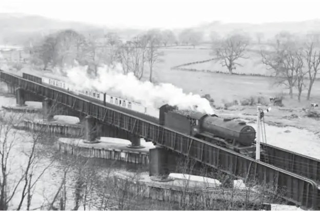
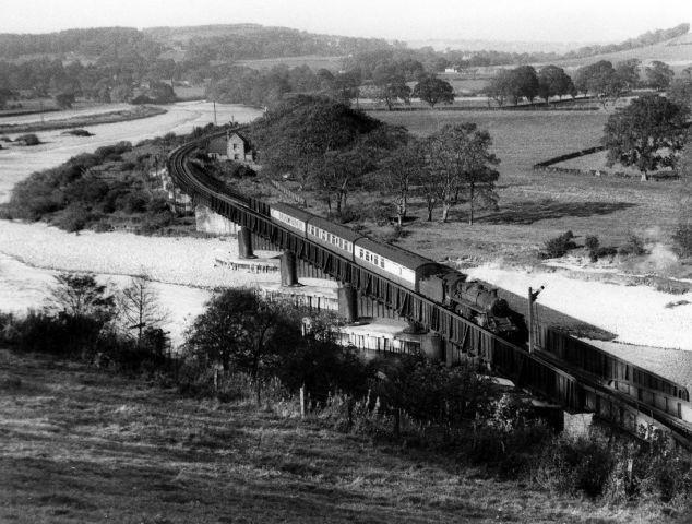
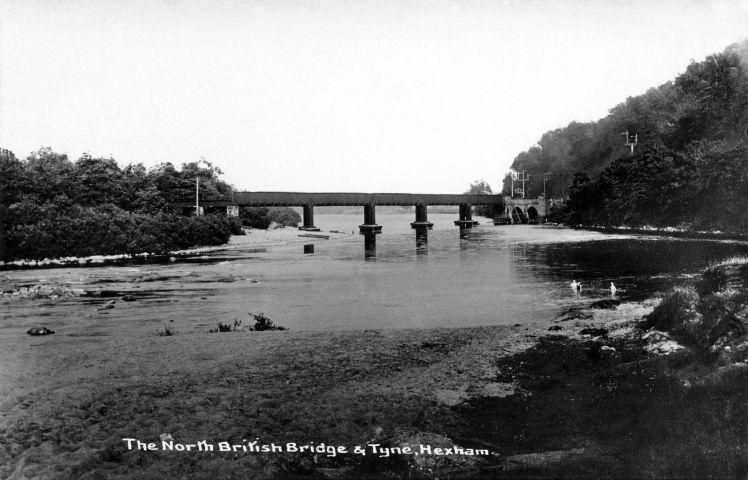
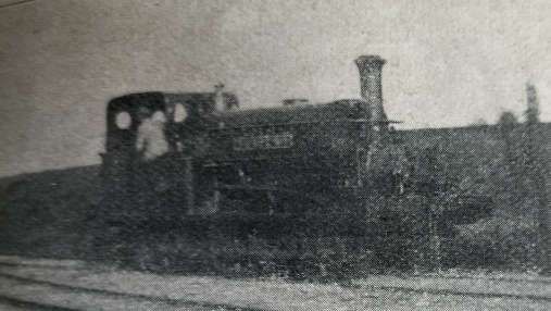
The featured image above was included in a Steam Days article in September 2021. Crossing the River Tyne on approach to Border Counties Junction is Gresley ‘K3’ class 2-6-0 No 61897, a St Margarets allocated locomotive that has worked through, and the stock is different too, ex-LNER and cascaded down from main line work. In due course the condition of the Border Counties Bridge and the predicted cost of repairs was a major factor in the abandonment of this ex-NBR route, with passenger trains ceasing to run on 13th October 1956, although the passage of goods trains continued through to 1 September 1958. [37]
At the end of August 2024, we visited Kielder Water Reservoir, passing through Bellingham on the way. We noticed a disused railway for which a good number of structures and embankments/cuttings remained in place.
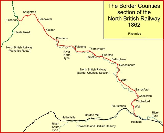
This was the Border Counties Railway (BCR), a line connecting Hexham in Northumberland, with Riccarton Junction on the Waverley Route in Roxburghshire. [1]
The BCR was also known as the North Tyne Railway as it ran beside the River North Tyne for much of its length.
The line between Kielder and Falstone is now under the waters of the Kielder Water Reservoir.
“In 1844 the North British Railway (NBR) was authorised to build a line from Edinburgh to Berwick to join an English line there. The NBR line ran close to the coast avoiding most high ground and opened in 1846. In 1845 the Caledonian Railway was authorised to construct a line from both Glasgow and Edinburgh to Carlisle, crossing the Southern Uplands at Beattock Summit, 1,033 ft (315 m) above sea level.” [1][2][3][4]
In 1853, talk was of a significant coal seam around Plashetts and in 1854, Robert Nicholson was engaged to survey a railway route to serve this coalfield. “His line was to run from Hexham, … through Reedsmouth to Bellingham, and on to the coal deposits at Falstone. His work was remarkably quickly done, for a bill for the Border Counties Railway was submitted to Parliament for the 1854 session. … The scheme was authorised when the Border Counties Railway (North Tyne Section) Act 1854 (17 & 18 Vict. c. ccxii) was given royal assent on 31st July 1854. The capital was to be £250,000.” [1]
The line was built as a single line, but land was acquired for later doubling, and all the bridges except the Hexham bridge, were built for double-track The full length of the authorised line was initially not built before “a public train service started on 5th April 1858; there were four passenger trains each way Monday to Saturday, and two on Sunday. They ran from Hexham to Chollerford, with an intermediate station at Wall.” [1]
It was to be only a further 16 months before the remaining length of the line was authorised when the Border Counties Railway (Liddesdale Section and Deviations) Act 1859 (22 & 23 Vict. c. xliii) got royal assent on 11th August 1859. The authorised capital for the whole line was increased by £100,000. The North British Railway were authorised to make a working arrangement with the BCR.
“From Wark, the line approached Reedsmouth, and there was a temporary goods terminus at Countess Park there while the river bridge was completed. The passenger service terminated at Wark. There was a demonstration train from Newcastle to Countess Park run on 1st December 1859. Public opening was expected ‘within the week” but this proved to be inaccurate, and the opening throughout to Falstone was delayed until 2nd September 1861.”
By 1860 the BCR was seriously short of cash; “the authorised capital had never been fully raised and the hoped-for coal reserves at Plashetts were disappointing. There seemed little chance of raising more capital now. The North British Railway was expansive, and was happy to take over the local line, and the result was the North British and Border Counties Railways Amalgamation Act 1860 (23 & 24 Vict. c. cxcv), passed on 13th August 1860; … the act regularised the use by BCR trains of Hexham station of the Newcastle and Carlisle Railway. The BCR network was known now as the NBR (Border Counties Section).” [1]
The construction of the line throughout to Riccarton was completed by mid-April 1862, but the opening of the line to Riccarton did not take place until 24th June 1862 for goods, and 1st July 1862 for passengers. [1]
On 1st May 1865, “the Wansbeck Railway was opened, between Morpeth and Reedsmouth. The Wansbeck Railway had been promoted independently but was taken over by the North British Railway in 1863.” [1]
From Hexham to Riccarton Junction
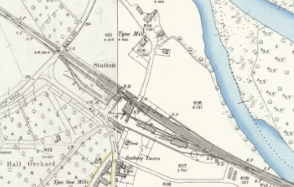
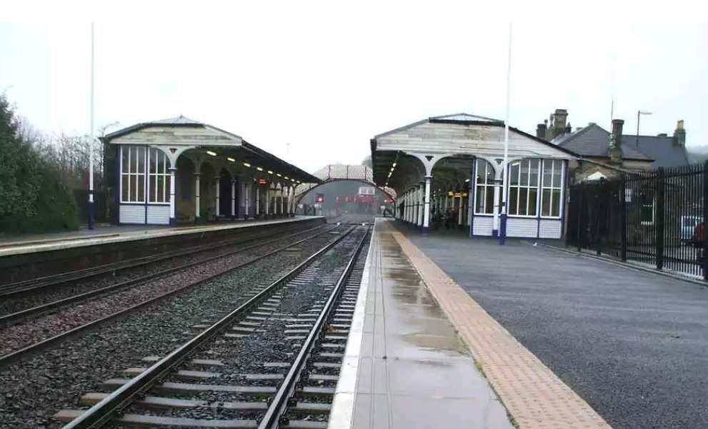
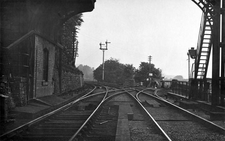
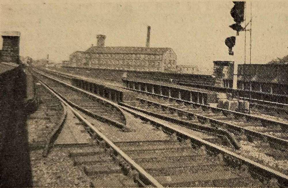
Hexham Railway Station
Hexham sits on what was once the Newcastle to Carlisle Railway (NCR) and which is, in the 21st century, known as the Tyne Valley Line.
Hexham Station was opened on 9th March 1835 by the NCR which became part of the North Eastern Railway (NER) in 1862.
The original station was probably designed by the architect Benjamin Green of Newcastle-upon-Tyne. It was altered and extended between 1835 and 1871 and again by 1901. It is now a Grade II listed structure and stands in a conservation area. The station was restored in 1998/1999. [5]
After the NCR had been absorbed by the NER, the station became a junction, with the opening of the first section of the BCR, between Hexham and Chollerford in April 1858. The first section of a second branch, the Hexham and Allendale Railway, was opened for goods in August 1867. Initially promoted to serve lead mines, that line opened for passengers in March 1869. [6][7]
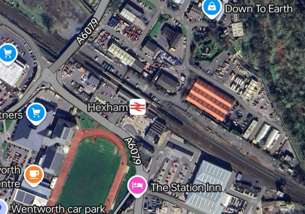
Since the closure of the Hexham and Allendale Railway to passengers in 1930 (completely in 1950), as well as the BCR in 1956 (completely in 1958), the station has diminished in size and importance. Both lines met with the Tyne Valley Line to the West of the station. [6][7][8: p134]
The Disused Stations website covers Hexham Station in some detail. [9]
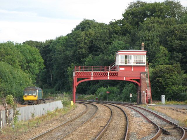

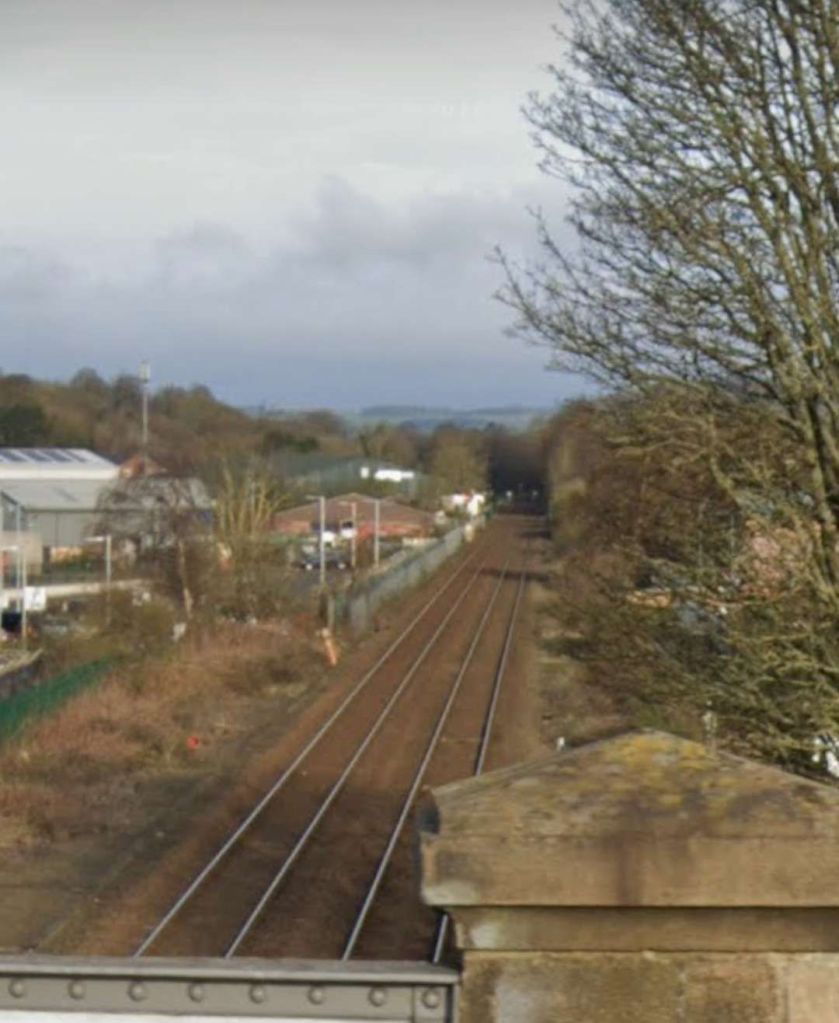
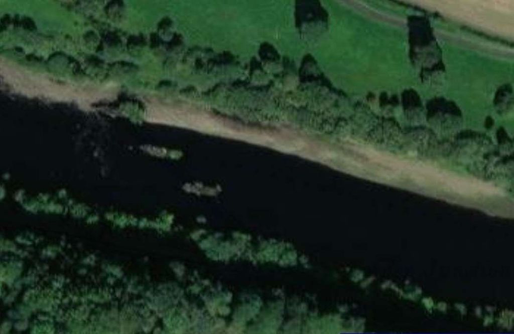
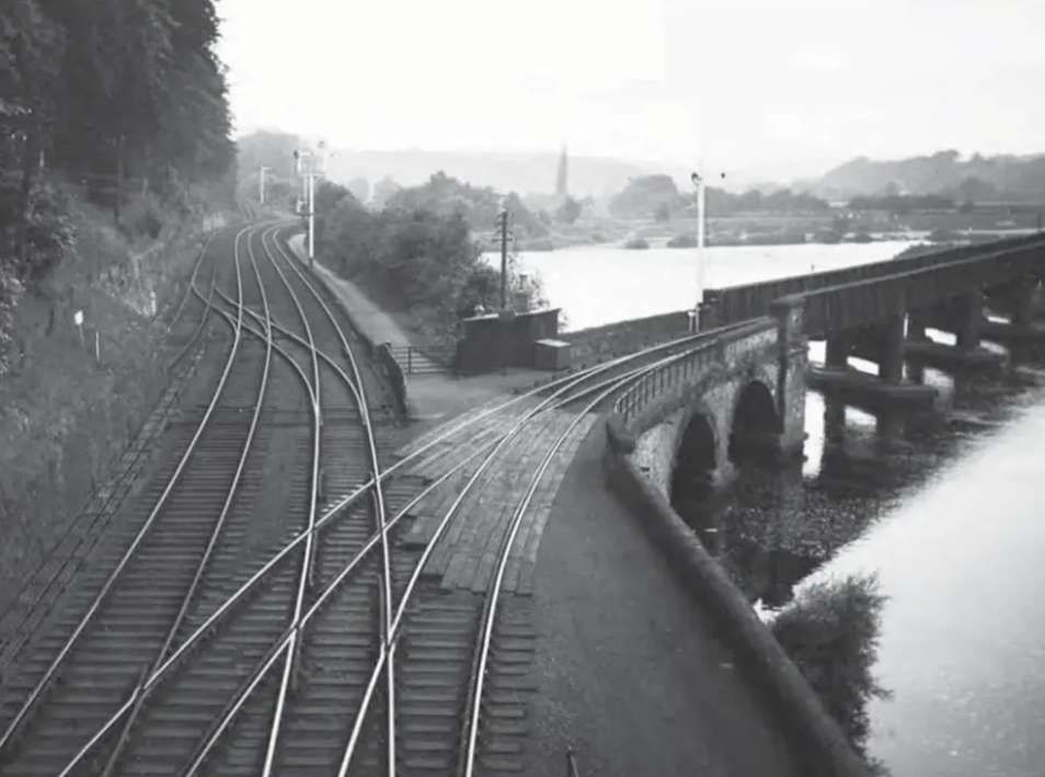
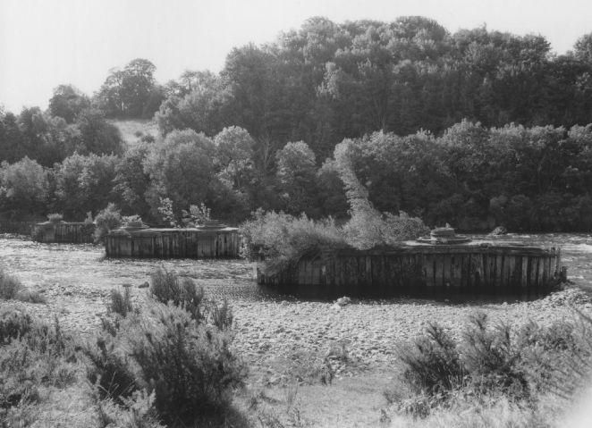
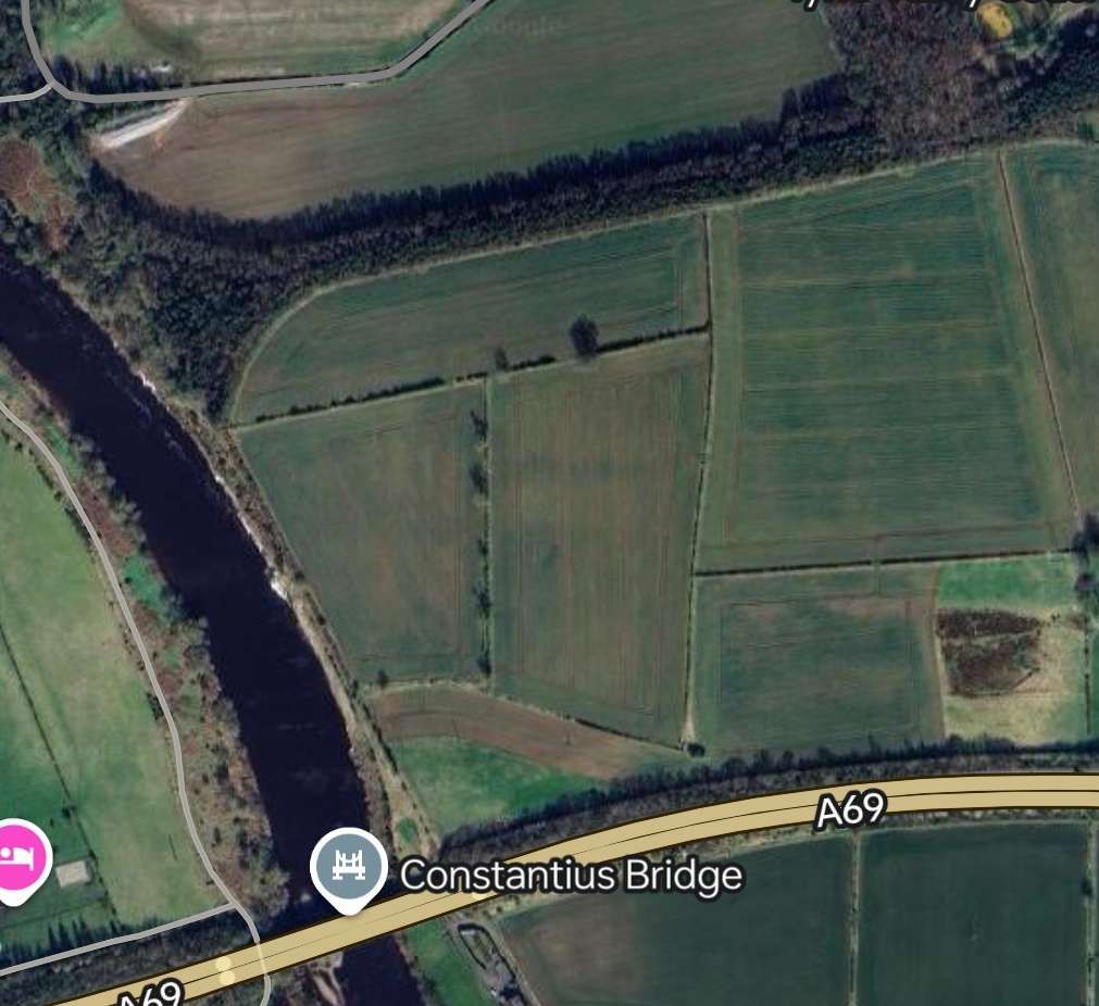
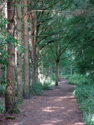
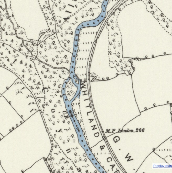
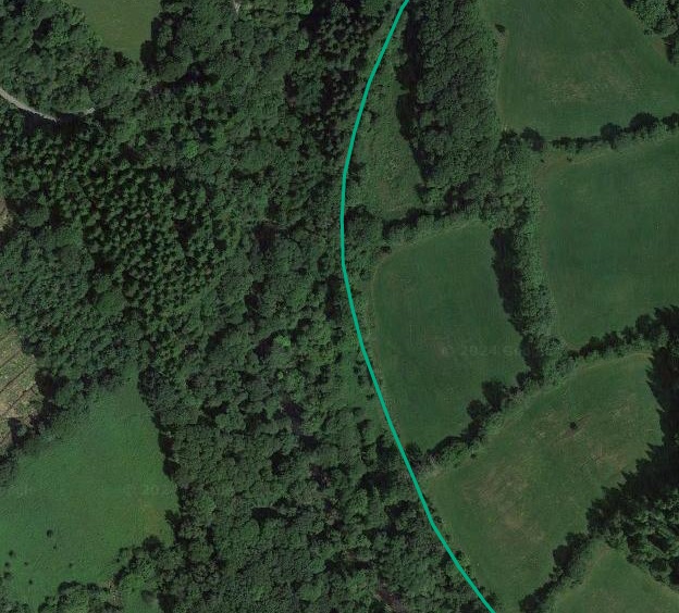
A straight length of line brings the railway to the banks of the Tyne. The line curves round toward the West and follows the South bank of the Tyne as far as Border Counties Junction where trains for Riccarton Junction and Hawick left the Borders Railway and crossed the Tyne on an angled viaduct.
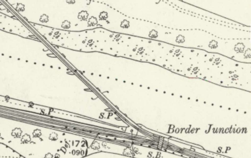
Border Counties Junction
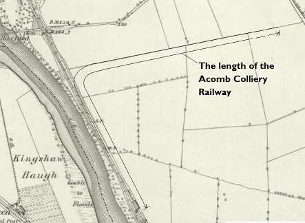
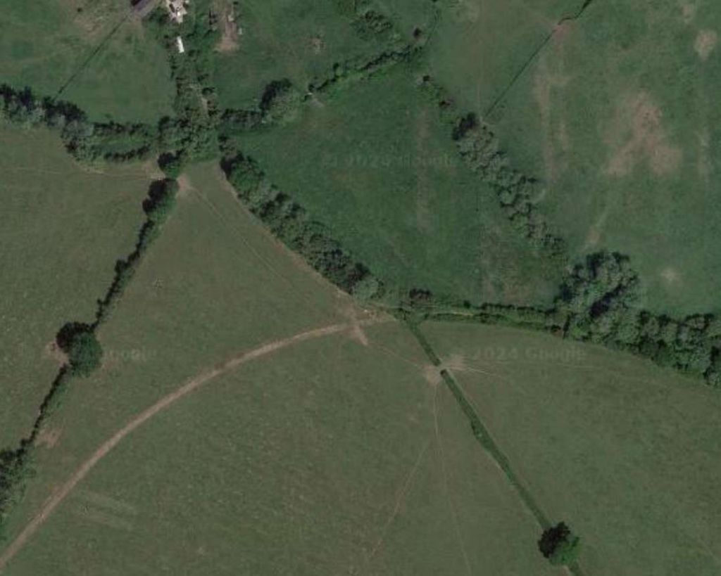
Acomb Colliery
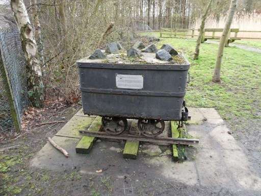
A short distance beyond the viaduct on the Border Counties Railway was a private colliery line which served Acomb Colliery.
“Mining at Acomb seemed to stop and start between the mid 19th century until 1909, when a larger complex opened until 1952.” [20]
There were various owners before the pit was taken on at nationalisation by the NCB. … Messrs. Stobart & Co. (1840s), J. Morrison & Co. (1860s), Messrs. Morrison (1880s), Tynedale Coal Co. Ltd. (1910s), Acomb Coal Co. Ltd. (1920s), National Coal Board (1947). [20]
For more information about the coal workings on the site, please consult the Durham Mining Museum. [21]
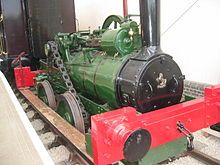
It is worth noting that the half-mile long line was worked by one engine, Black Hawthorn 0-4-0ST No. 1068 for over 30 years until closure of the mine in 1952. [13: p12]
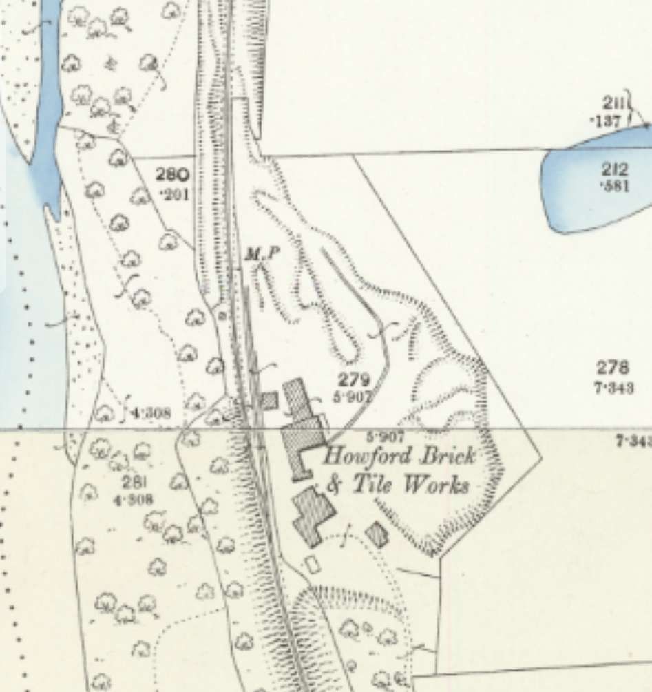
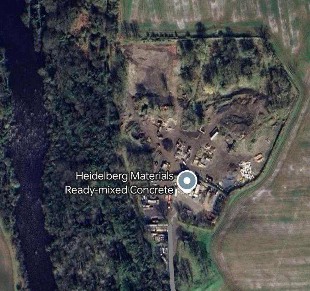
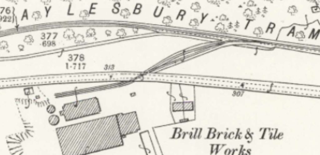
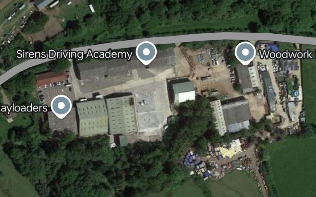
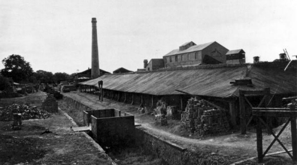
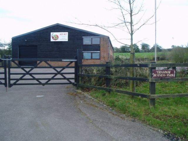
Howford Brick and Tile Works
These works sat alongside the line, just a few hundred metres North of the Acomb Colliery Railway.
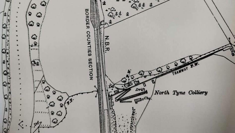
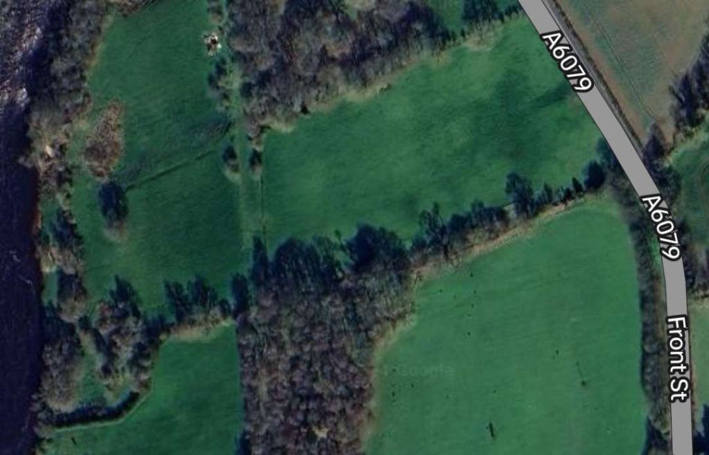
North Tyne Colliery
Some distance further North, North Tyne Colliery sat adjacent to the line.
For further information about this colliery, please consult Durham Mining Museum. [22]
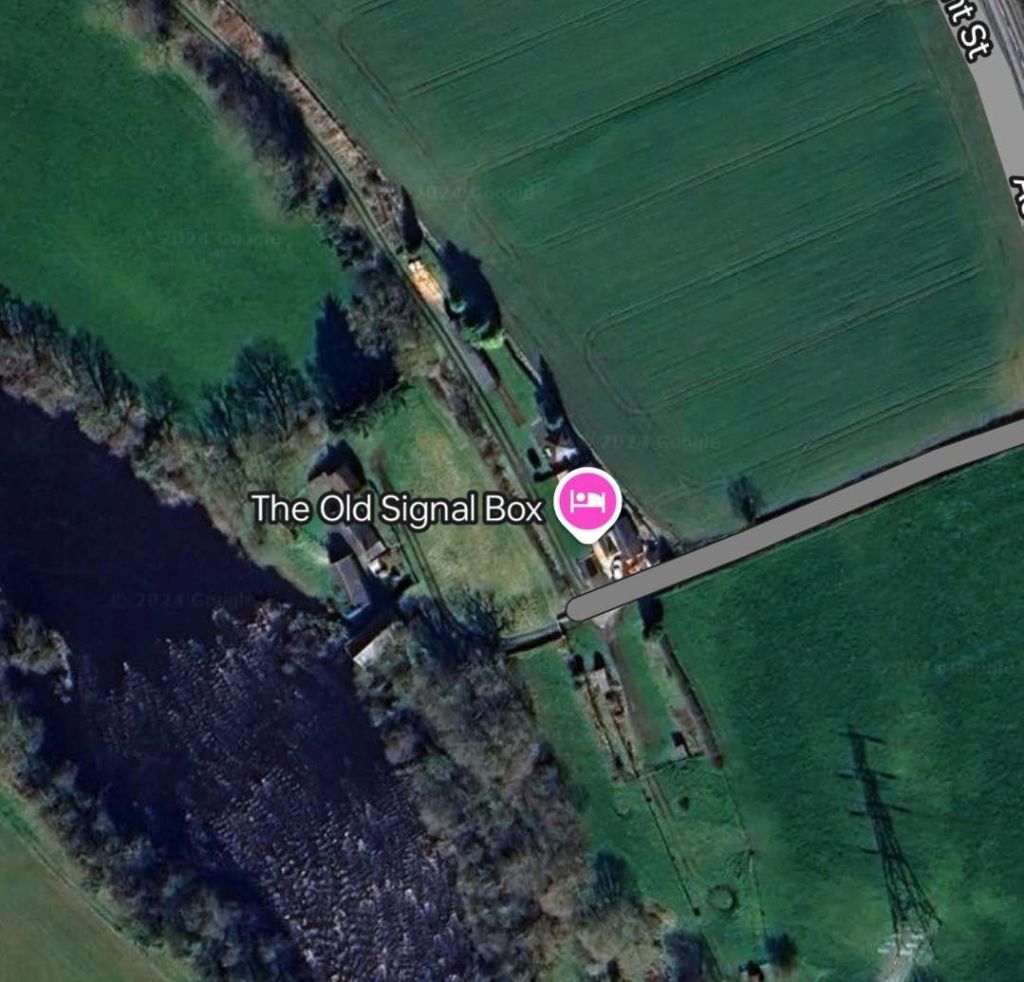
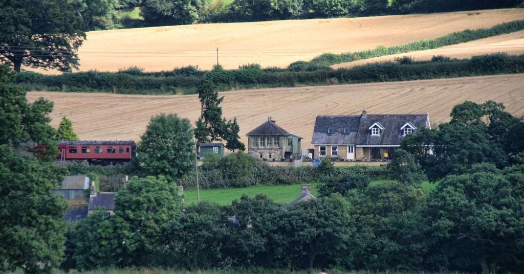
Wall Railway Station
Wall Railway Station was 1/3 mile from the village. It sat alongside the River North Tyne on its East bank a few hundred metres North of North Tyne Colliery.
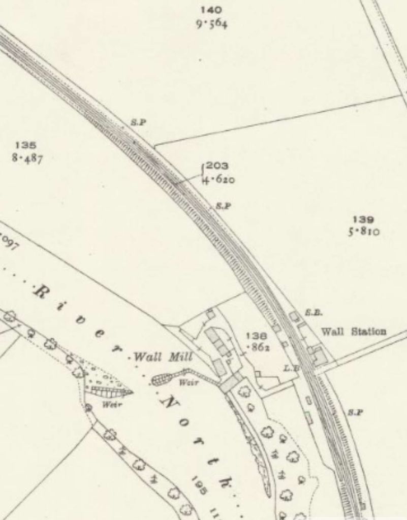
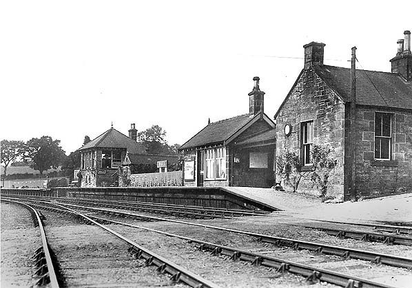
There is good coverage of Wall Railway Station on the Disused Stations website. [25]
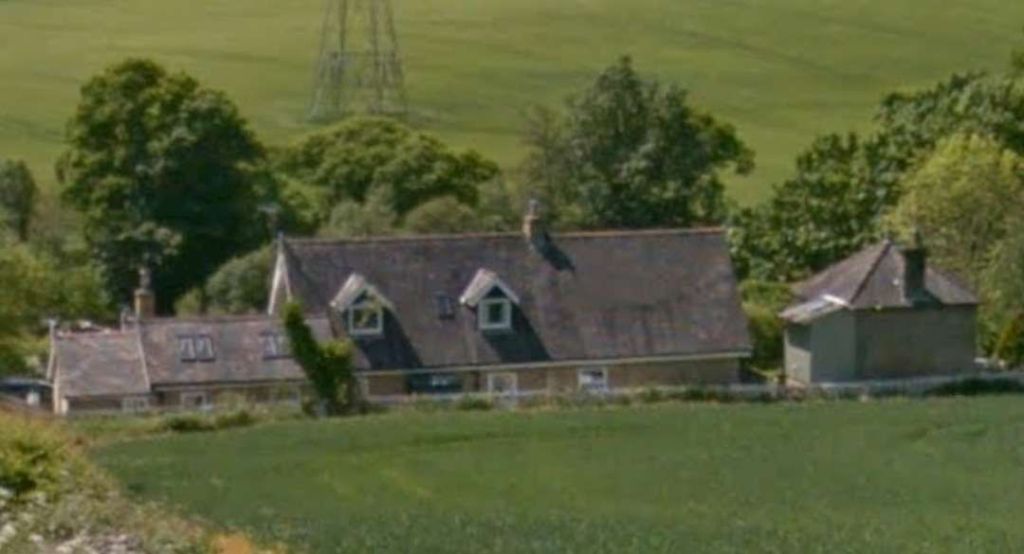
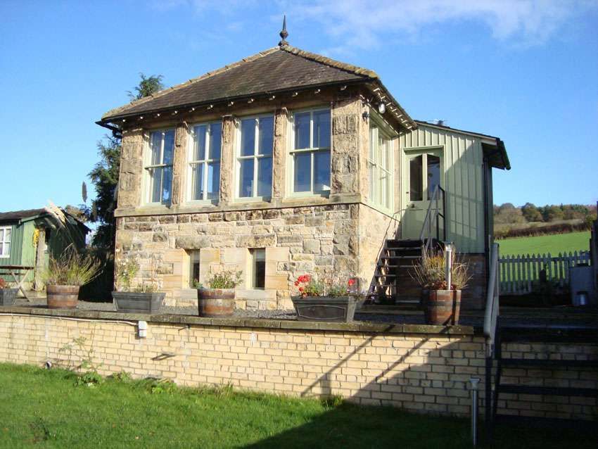
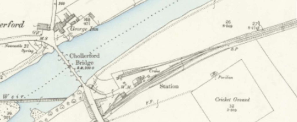
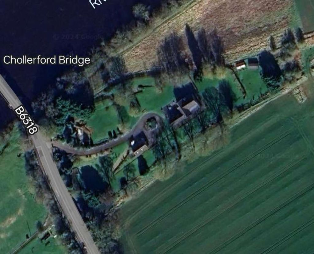
Humshaugh Railway Station
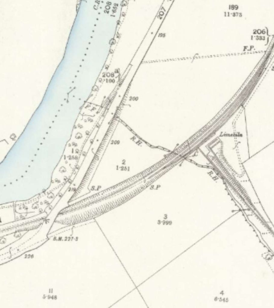
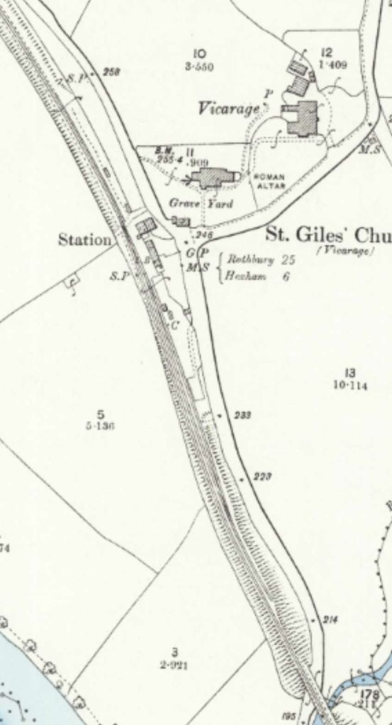
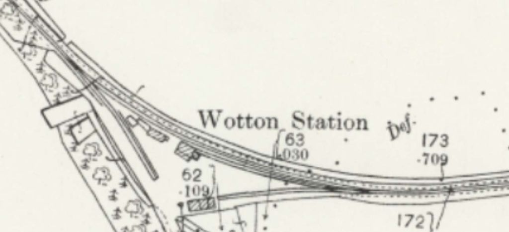
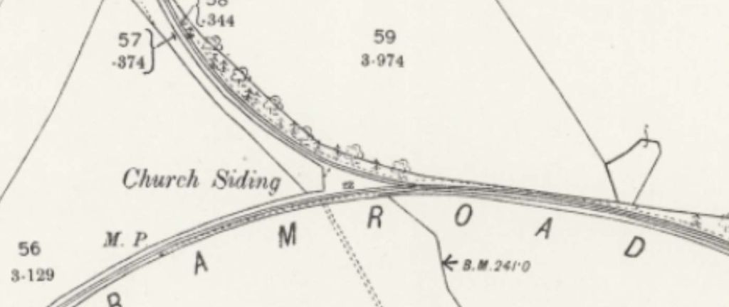
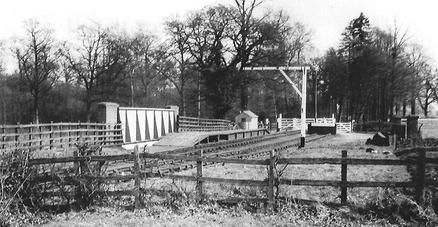
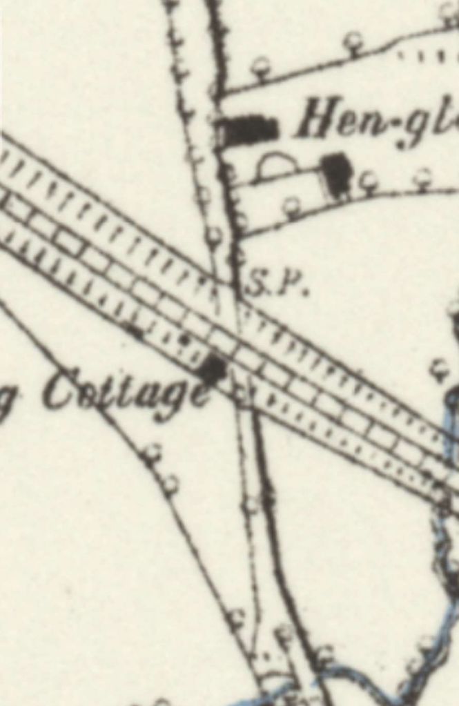
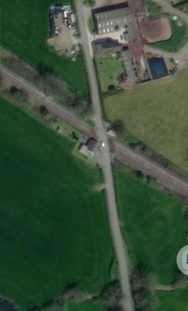
North of Wall Railway Station there was little to interest us until the BCR reached Humshaugh Railway Station. Darsley & Lovett say that “the station was opened as Chollerford on 5th August 1858 and was the BCR’s first temporary terminus. Sidings once led to a lime depot, where a tramway, inclined at 1 in 5, led to Brunton kilns. Another tramway led to the quarry. They closed in 1895.” [13: p18]
Historic England say that the grade II listed kilns were located North of Brunton Bank near Chollerford were probably built in the early 19th century. [29] Nearby was Brunton Bank Quarry. There is no evidence of a tramway, in the immediate vicinity of the station, leading to these two sites on the Ordnance Survey of 1896.
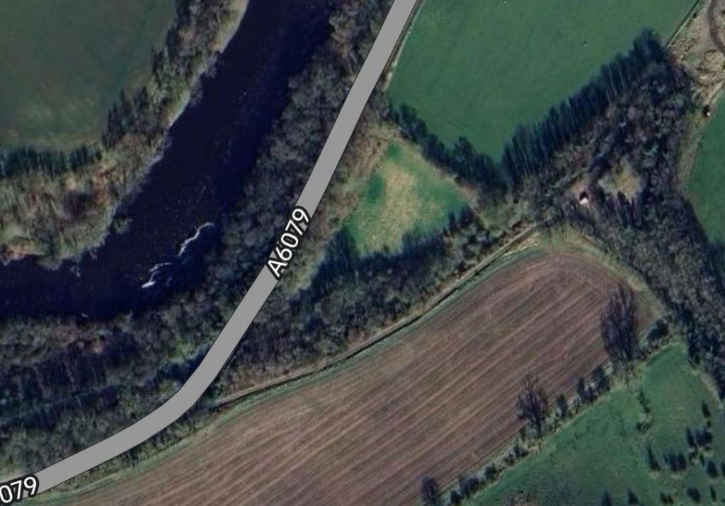
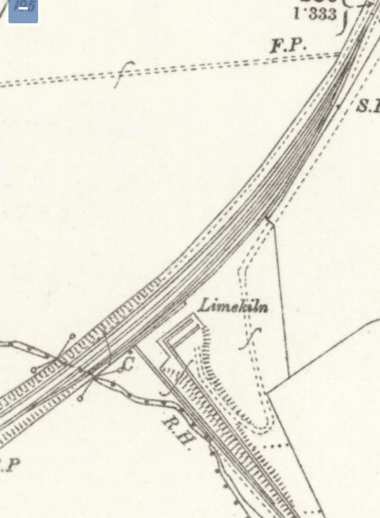
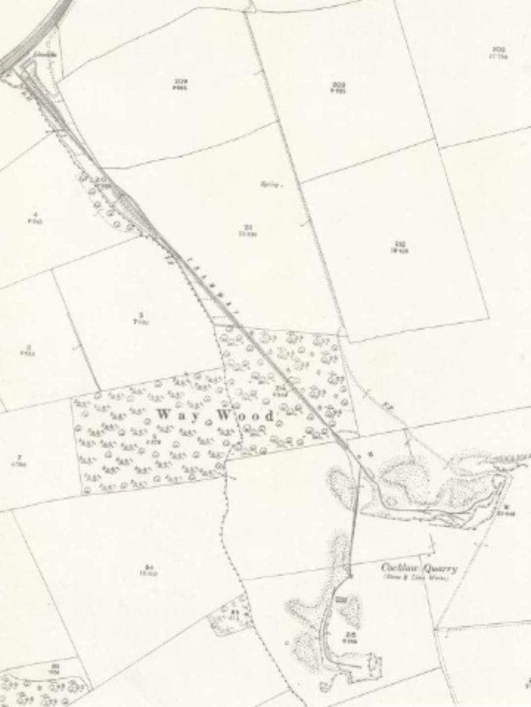
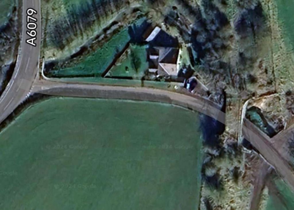
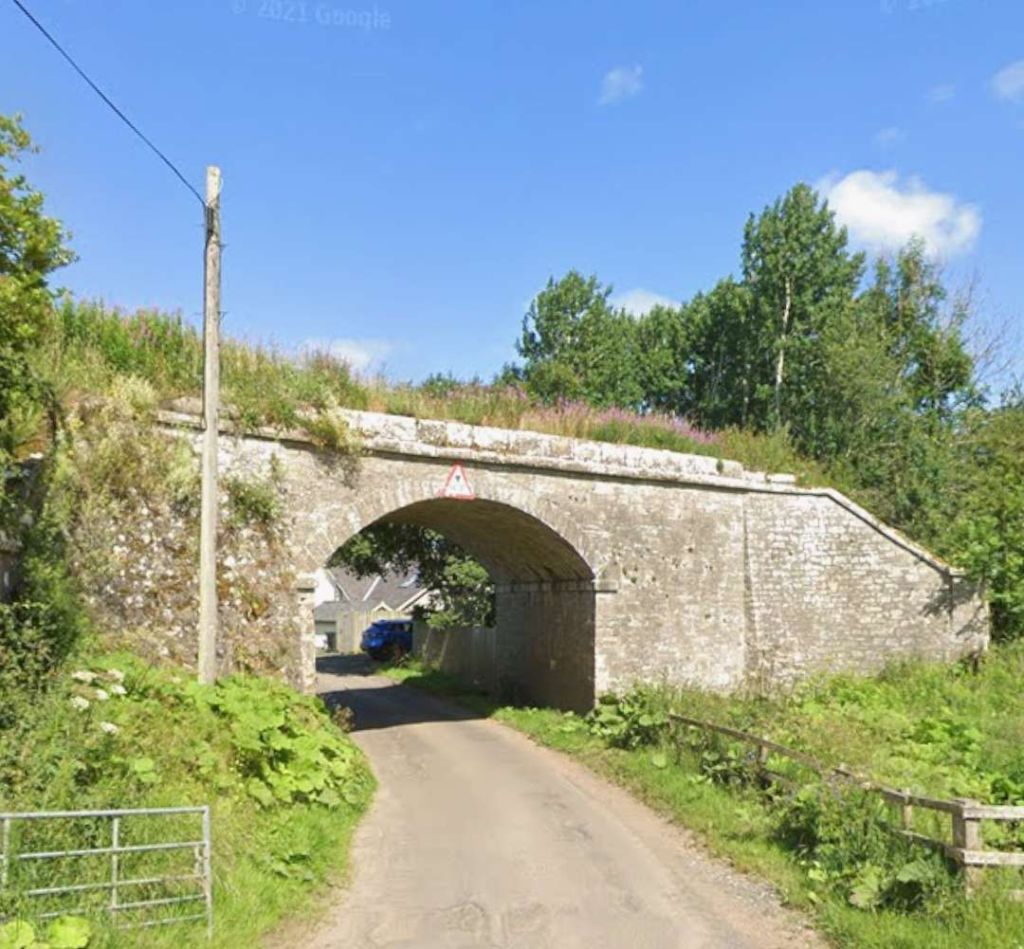
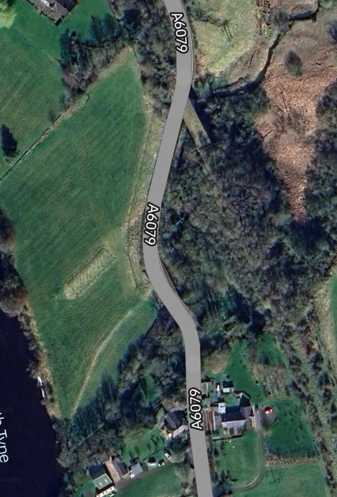
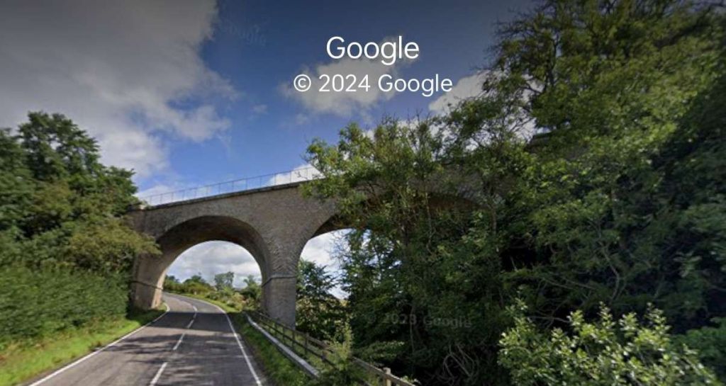
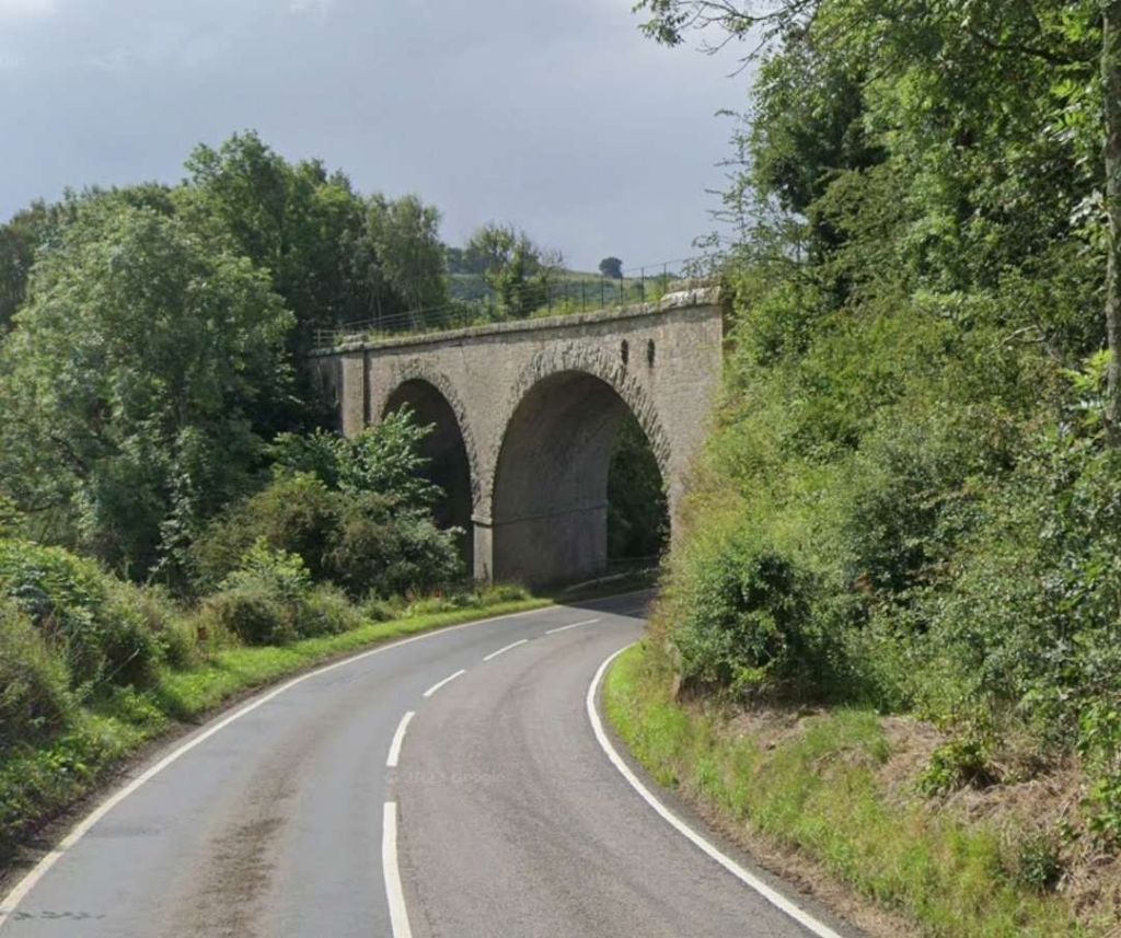
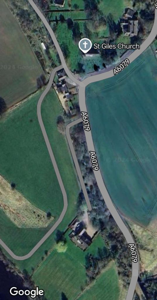
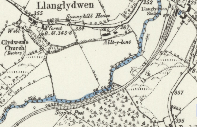
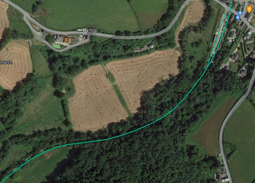
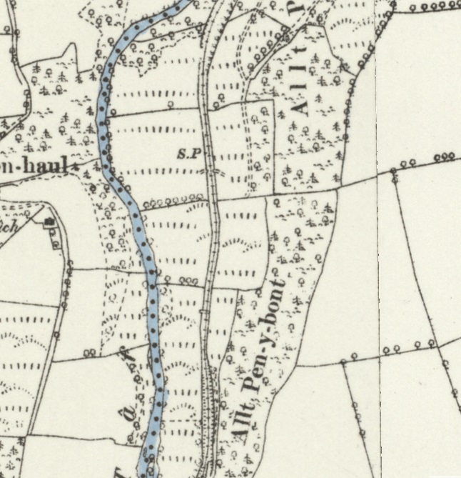
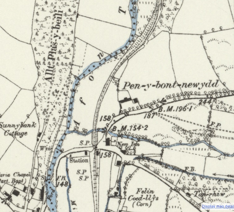
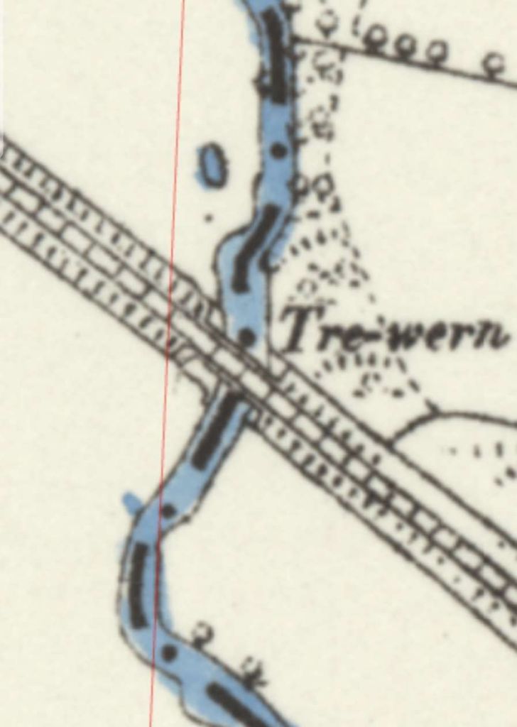
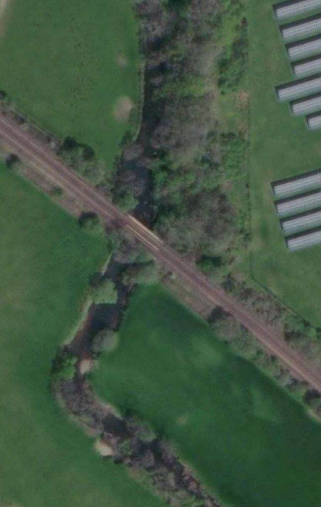
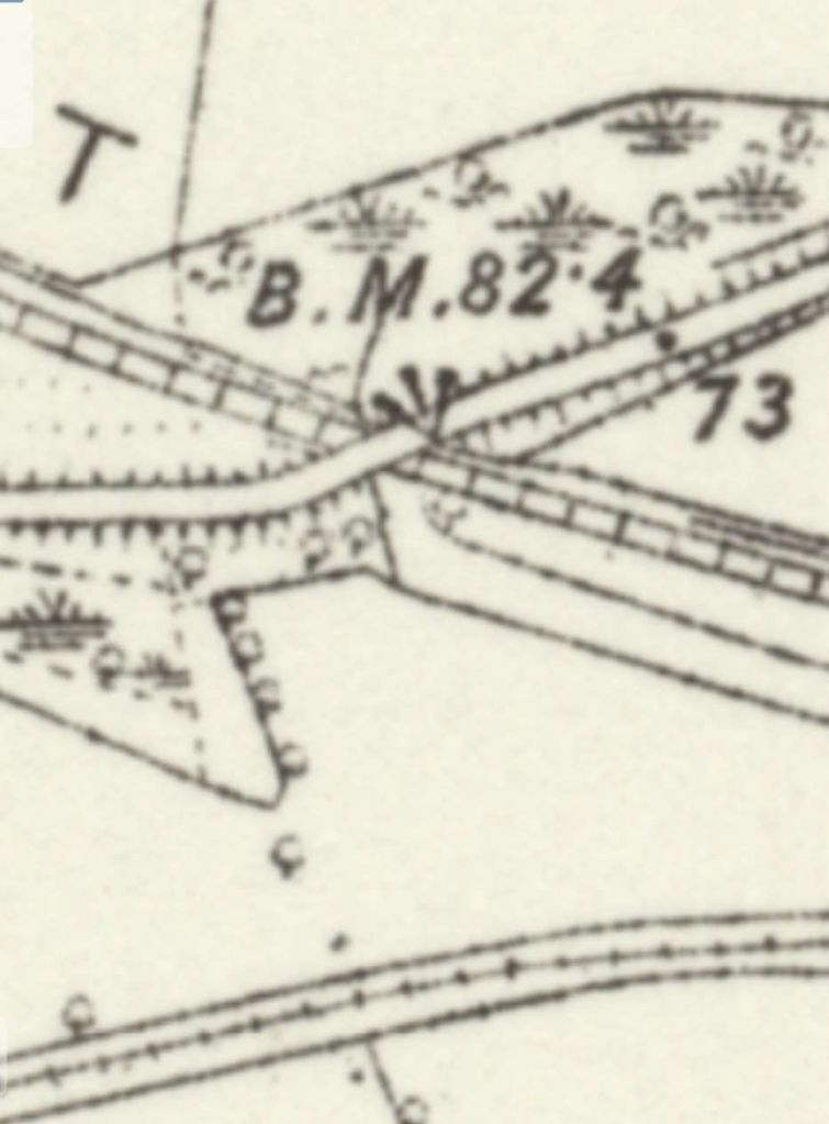
Only a short distance beyond Humshaugh Railway Station, the old railway passed under what became the A6079 and then passed a Limekiln at the bottom of a tramroad which served Cocklaw Quarry.
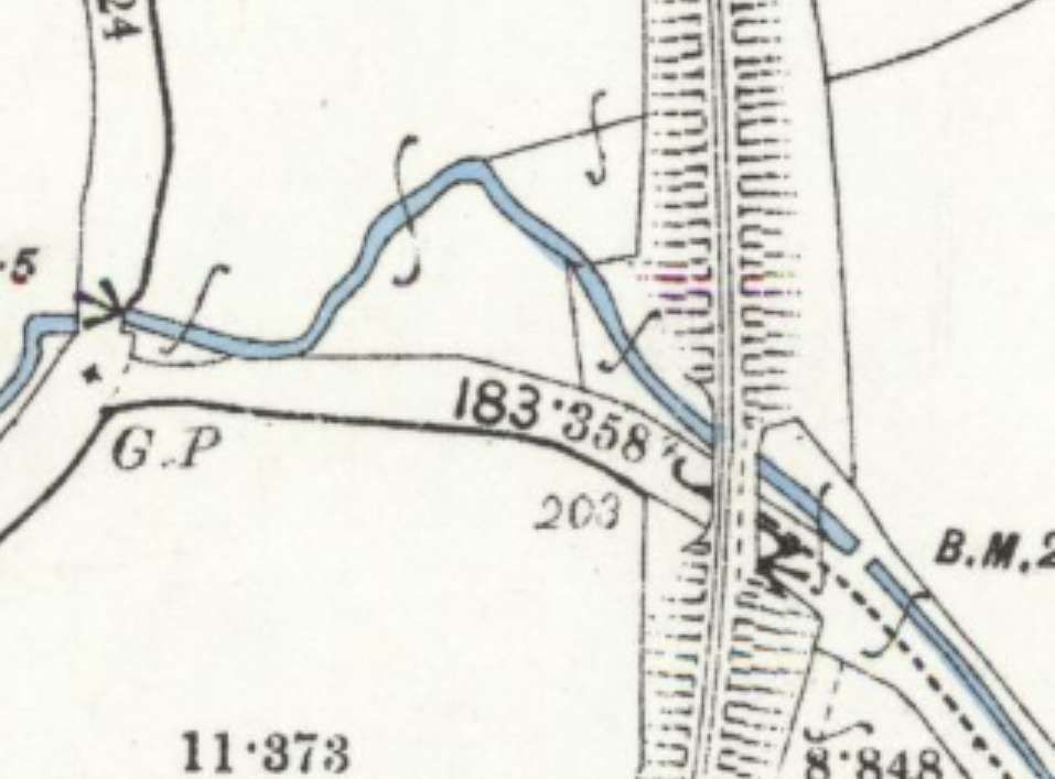
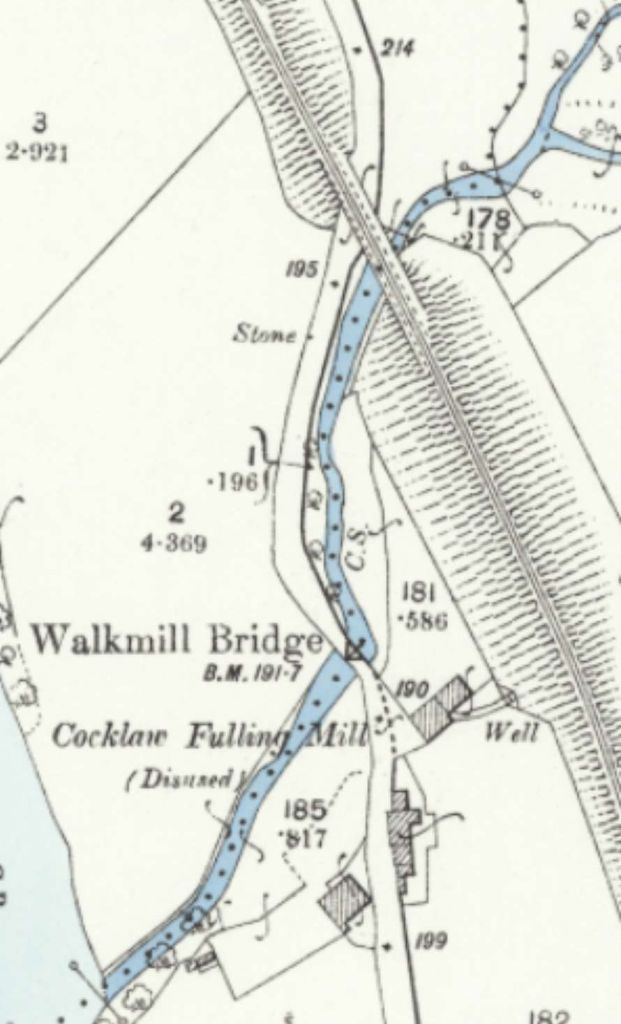
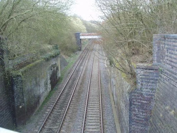
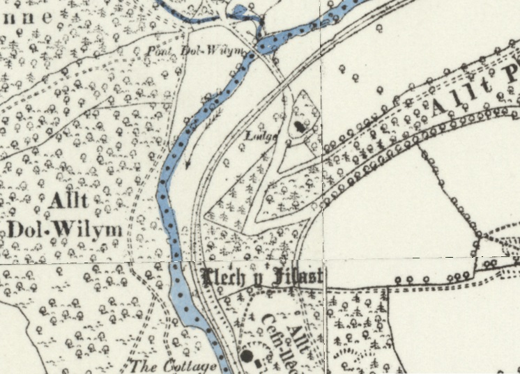
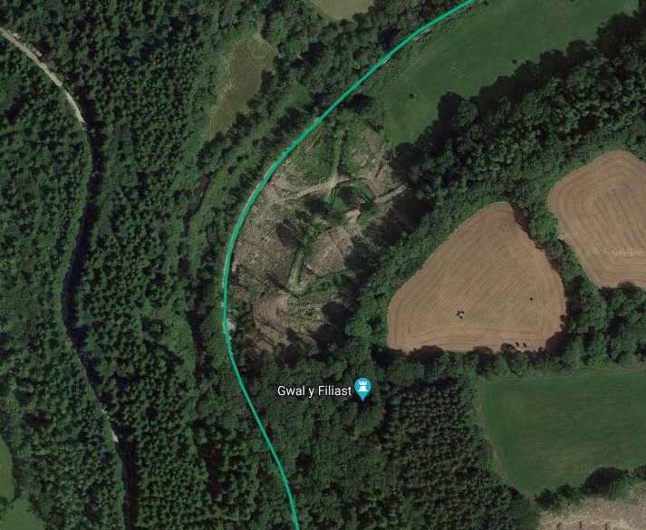
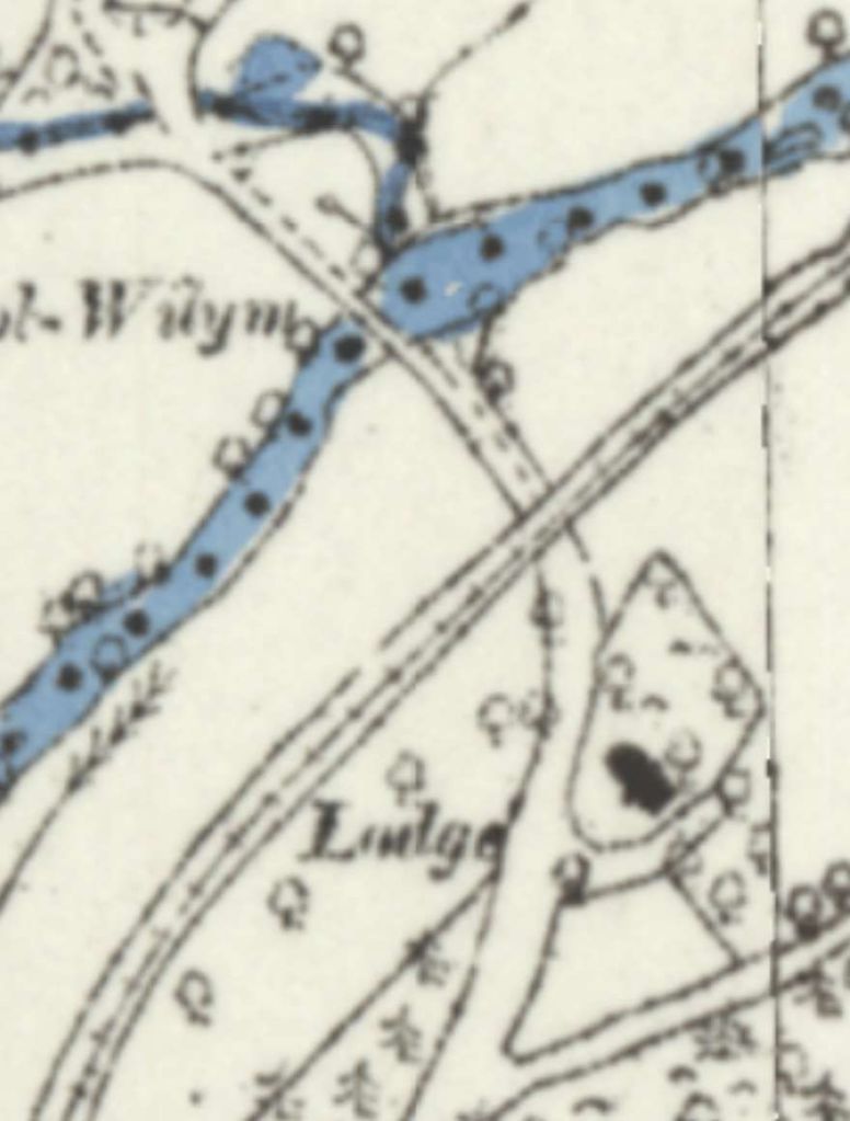
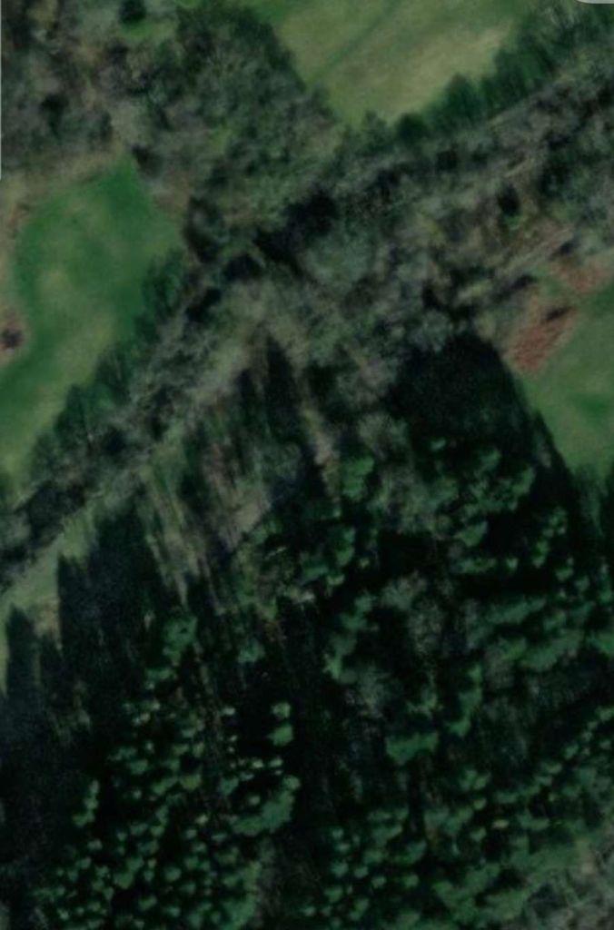
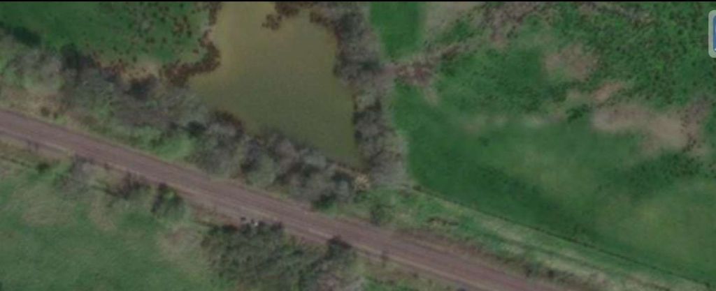
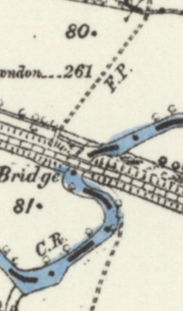
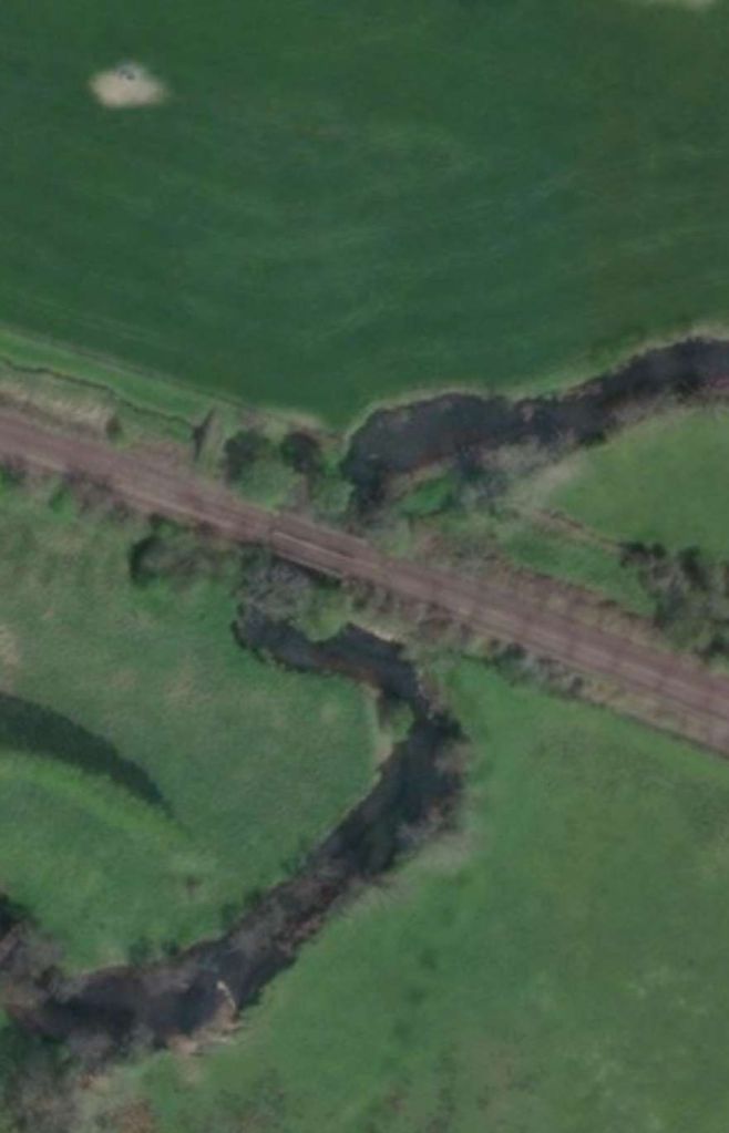
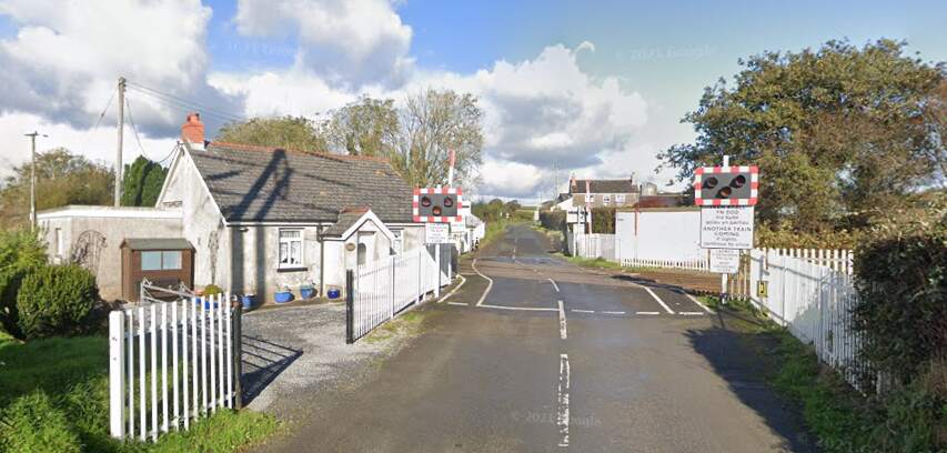
A short distance further North the line bridged a road and stream at the same location. …
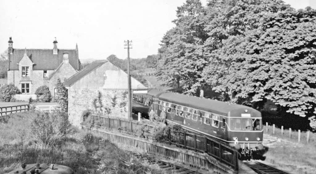
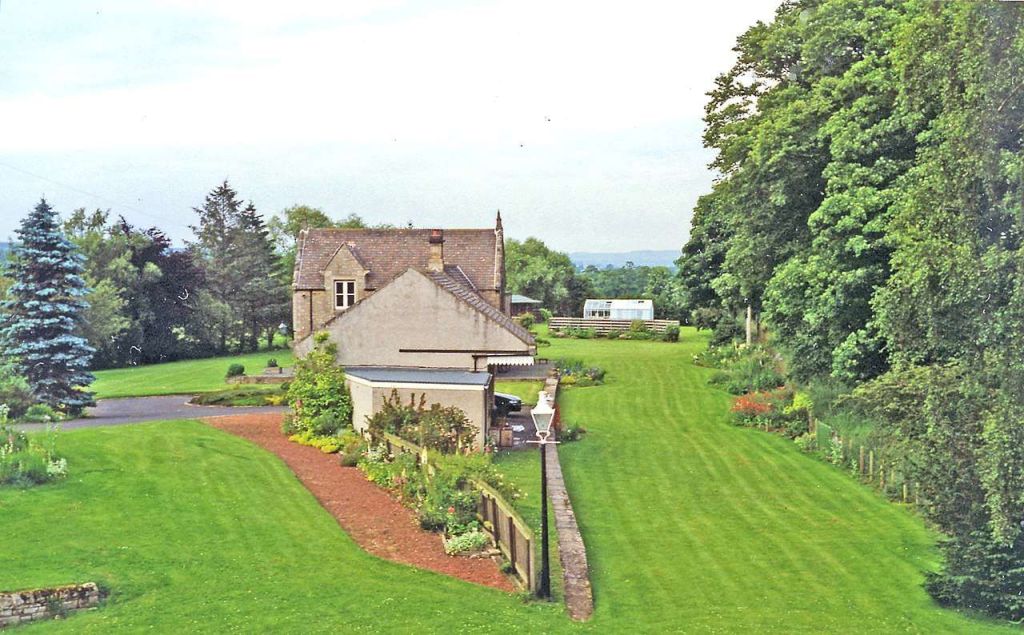
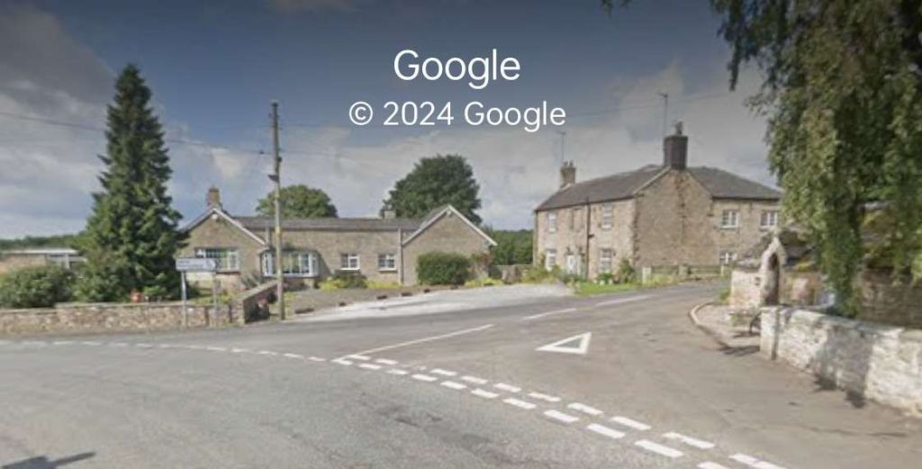
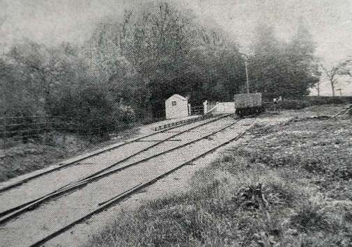
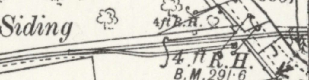
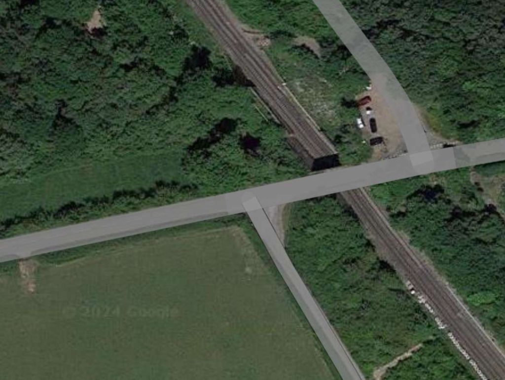
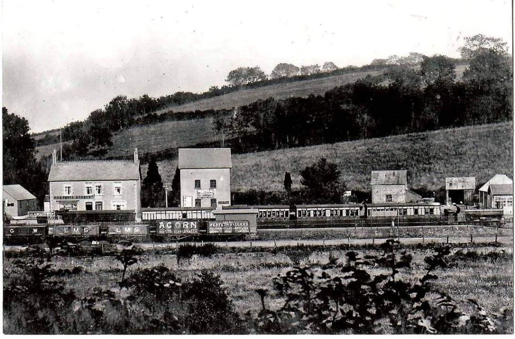
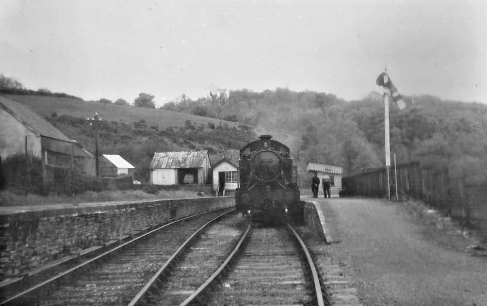
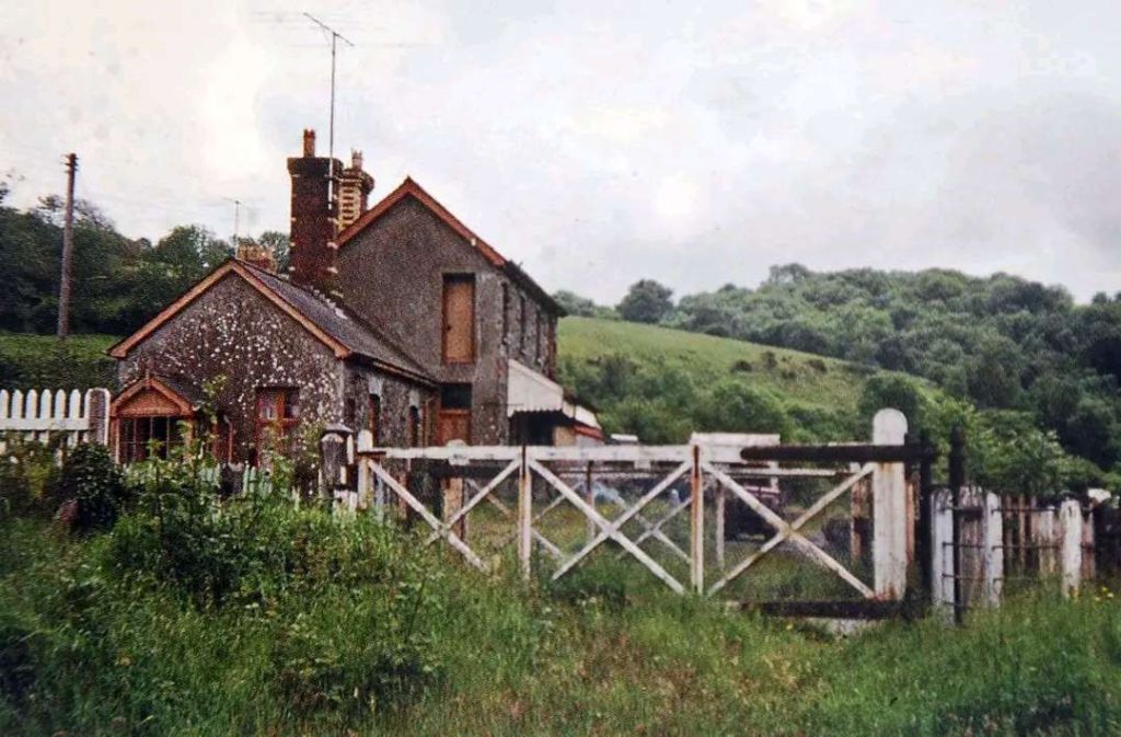
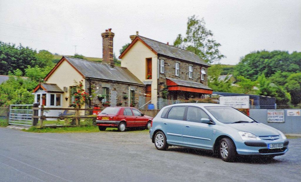
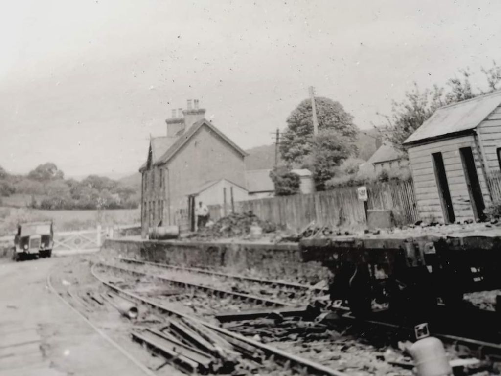
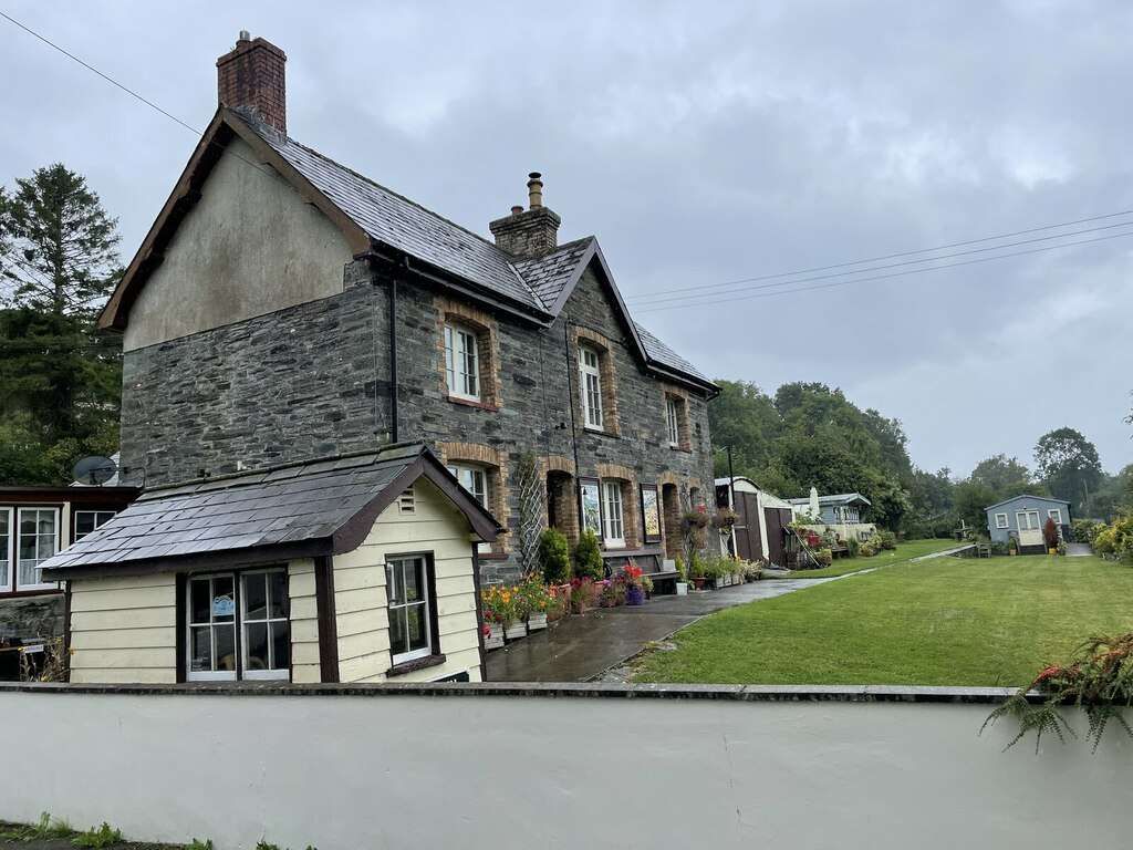
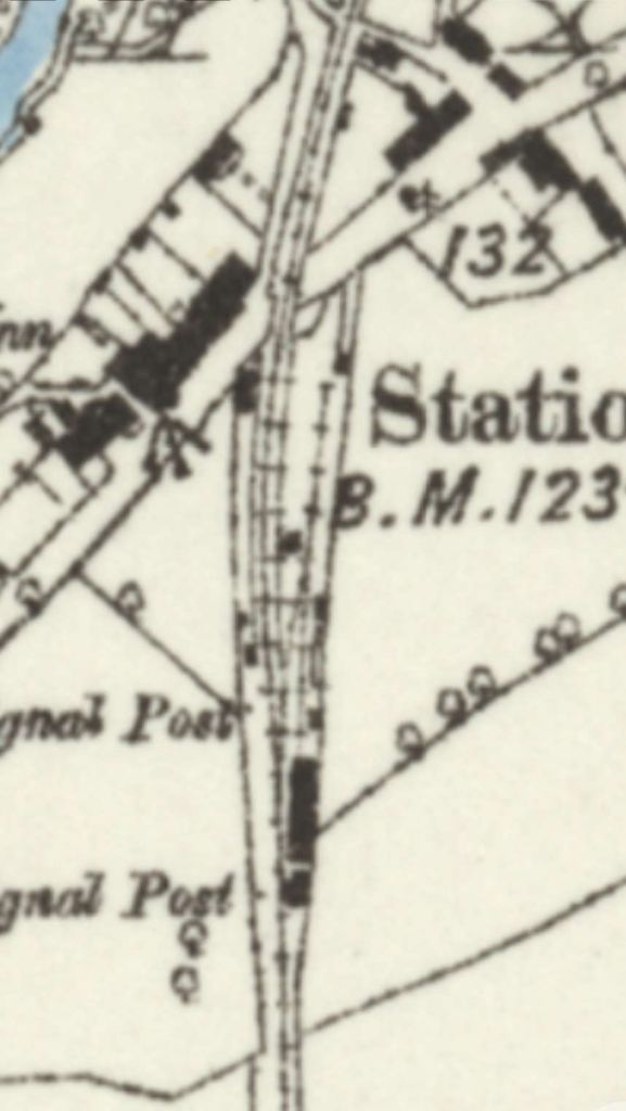
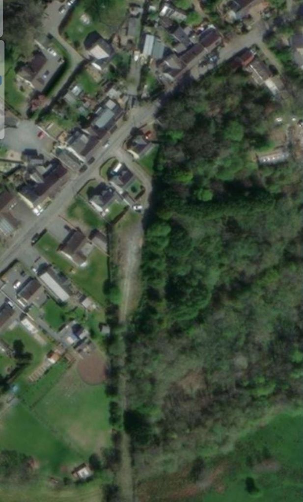
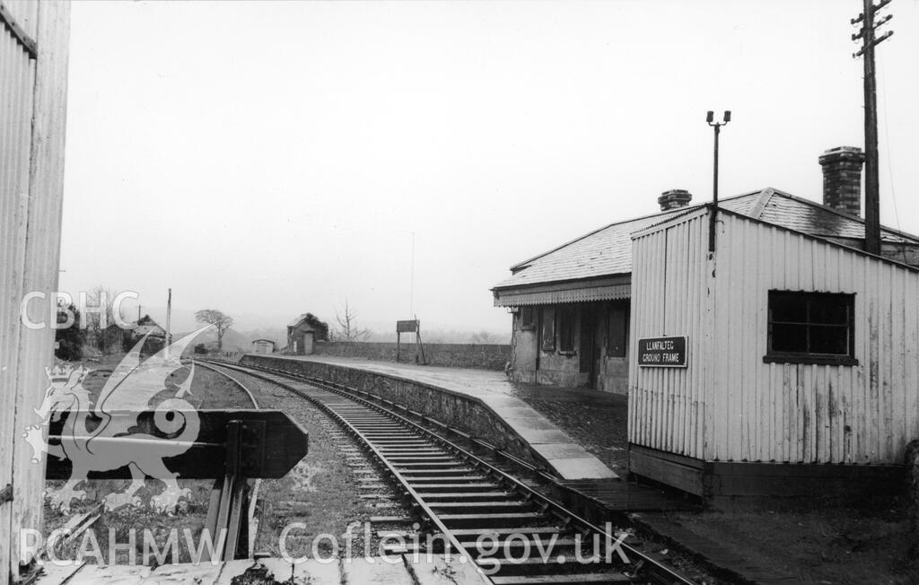
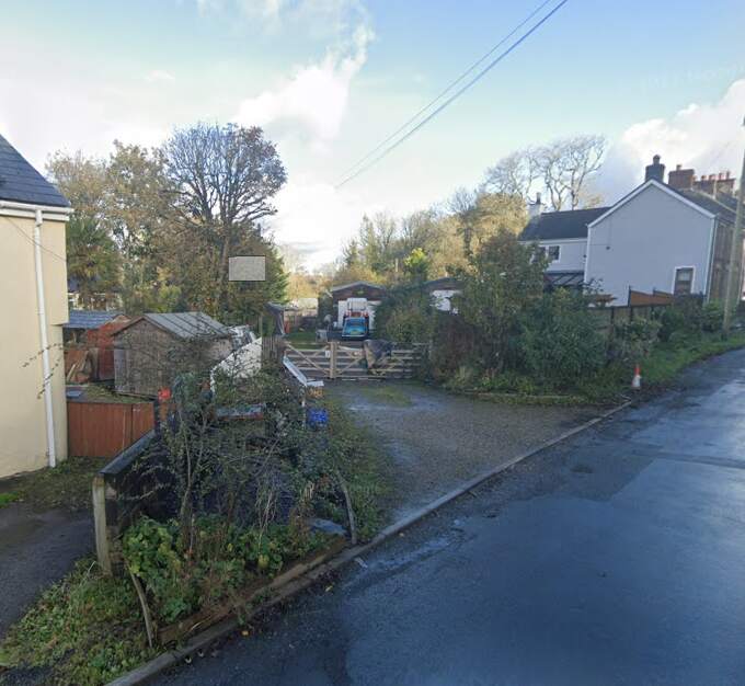
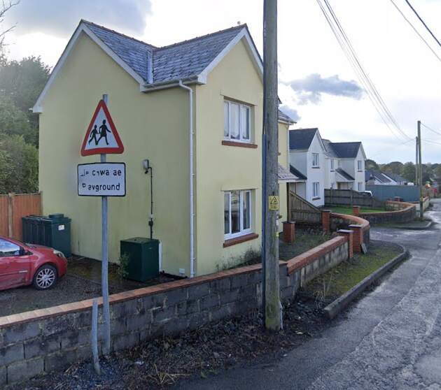
Chollerton Railway Station
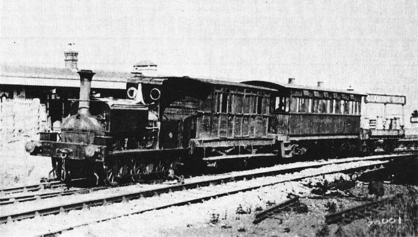
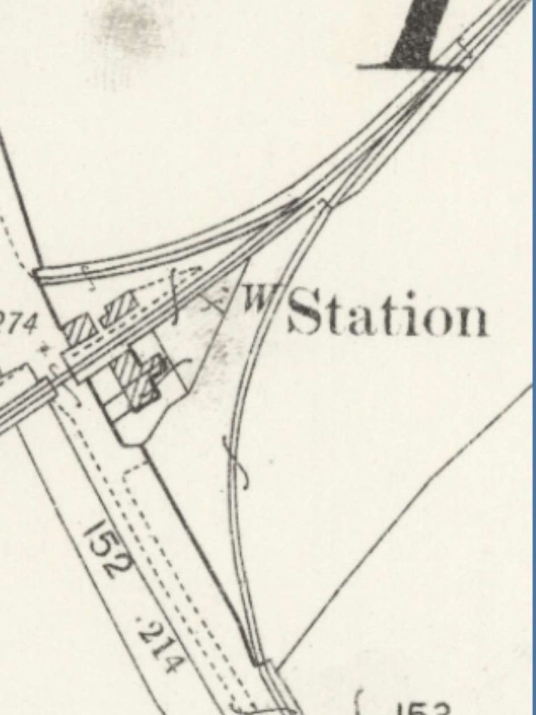
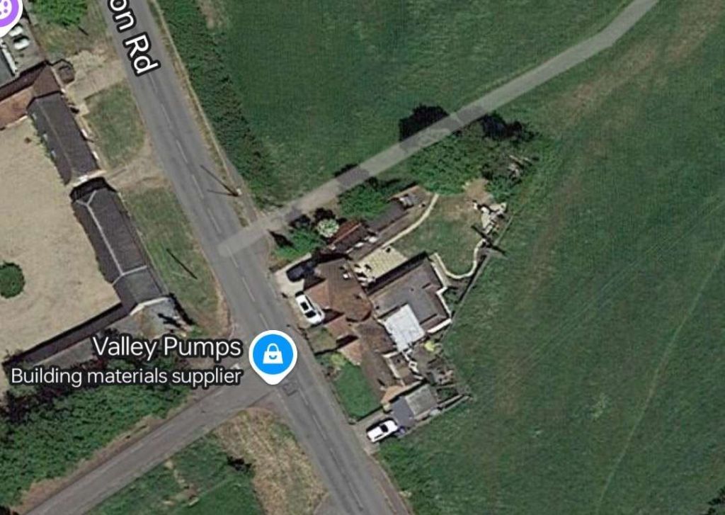
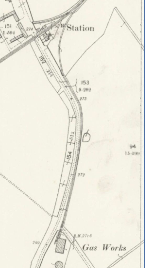
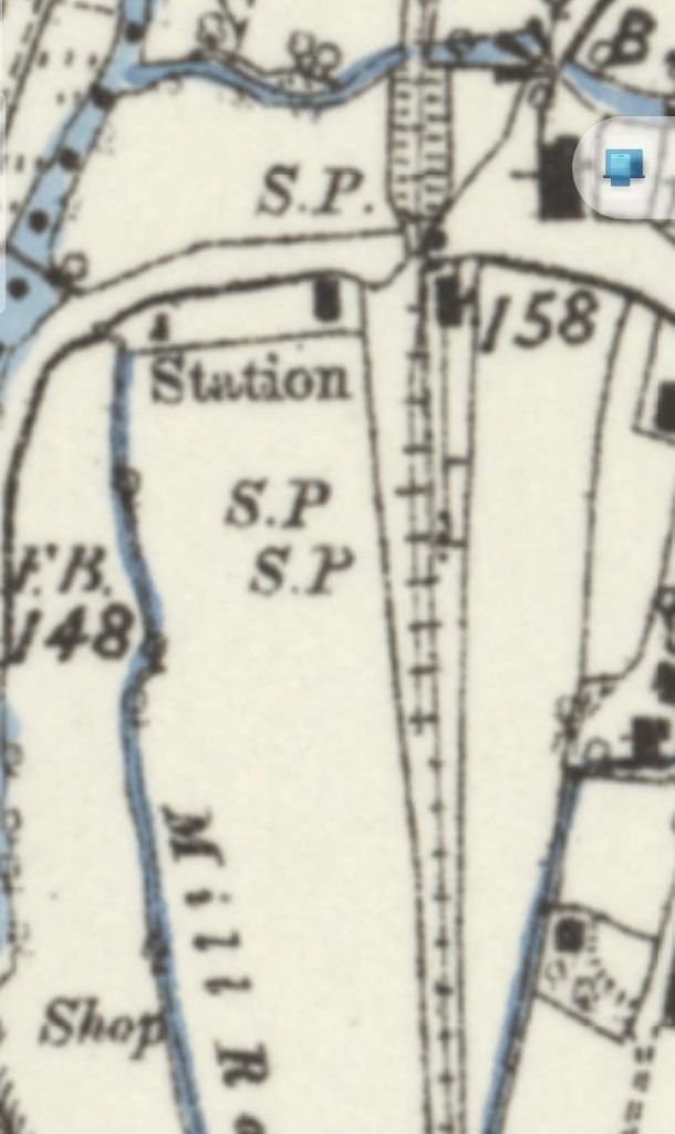
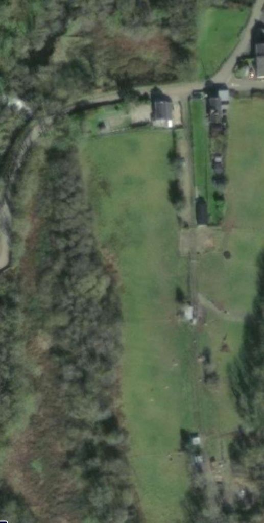
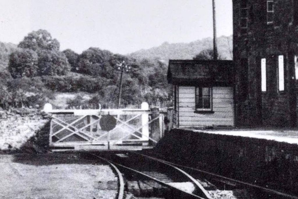
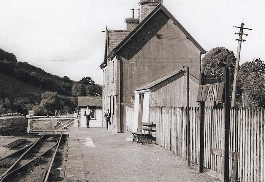
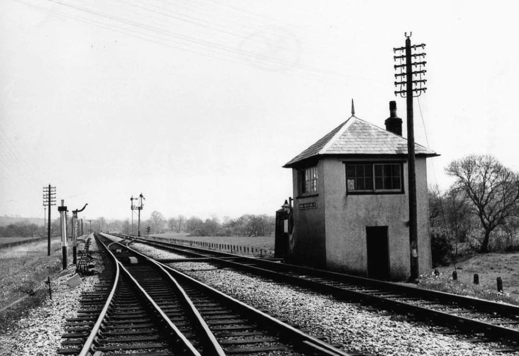
“The station was opened on 1st December 1859 by the North British Railway. It was on the west side of the A6079 at the junction with an unclassified road and immediately southwest of Chollerton village. A goods loop and a coal depot were to the south. A small goods shed was sited at the south end of the platform. Instead of extending the platform, the NBR built a new one to the north with a wooden waiting shelter. The original buildings remained in use and the siding was adjusted so that one of the two docks used the old platform. There was a three-ton crane in the goods yard. The station closed to passengers on 15th October 1956 and closed completely on 1st September 1958.” [33]
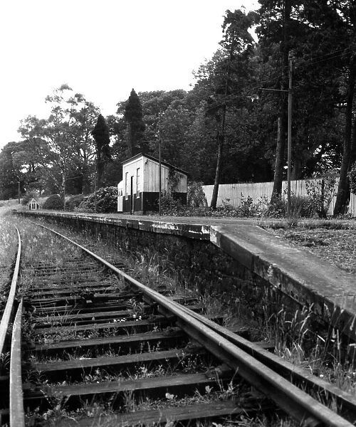
Chollerton Railway Station is the end of this first part of the journey along the Border Counties Railway.
References
- https://en.m.wikipedia.org/wiki/Border_Counties_Railway, accessed on 30th August 2024.
- G.W.M. Sewell; The North British Railway in Northumberland; Merlin Books, Braunton, 1991
- David St. John Thomas; The North British Railway. Vol. 1; David & Charles, Newton Abbot, 1969.
- Dr. T. Bell;. Railways of the North Pennines: The Rise and Fall of the Railways Serving the North Pennine Orefield; The History Press, Stroud, 2015.
- https://www.hexham-courant.co.uk/news/23638422.celebrating-188th-anniversary-hexham-train-station, accessed on 31st August 2024.
- https://newcastlephotos.blogspot.com/2013/02/hexham-railway-station.html?m=1, accessed on 31st August 2024.
- https://en.m.wikipedia.org/wiki/Hexham_railway_station, accessed on 31st August 2024.
- Geoffrey Body; Railways of the Eastern Region. Vol. 2: Northern Operating Area. Patrick Stephens, Wellingborough, 1988.
- http://disused-stations.org.uk/h/hexham, accessed on 31st August 2024.
- https://www.ebay.co.uk/itm/324957581085, accessed on 1st September 2024.
- https://maps.nls.uk/geo/explore/#zoom=15.7&lat=54.97493&lon=-2.09430&layers=168&b=1&o=100, accessed on 5th September 2024.
- Swedebasher; The Borders Railway: an Operating Review; in Steam Days, 14th September 2021, via https://www.pressreader.com/uk/steam-days/20210914/281560883923116, accessed on 5th September 2024.
- R.R. Darsley & D.A. Lovett; Hexham to Hawick: The Border Counties Railway; The Middleton Press, Midhurst, West Sussex, 2011.
- https://www.hexham-courant.co.uk/news/16614029.celebrating-age-steam, accessed on 6th September 2024.
- https://maps.nls.uk/geo/explore/#zoom=17.0&lat=54.98194&lon=-2.12117&layers=168&b=1&o=100, accessed on 6th September 2024.
- https://www.geograph.org.uk/photo/6554258, accessed on 6th September 2024.
- https://www.geograph.org.uk/photo/6554261, accessed on 6th September 2024.
- https://www.geograph.org.uk/photo/6554273, accessed on 6th September 2024.
- https://www.geograph.org.uk/photo/7435432, accessed on 6th September 2024.
- https://www.northeastheritagelibrary.co.uk/coalsarchive/hex01a/acomb-colliery, accessed on 6th September 2024.
- http://www.dmm.org.uk/colliery/a005.htm, accessed on 6th September 2024.
- http://www.dmm.org.uk/colliery/n031.htm, accessed on 6th September 2024.
- https://maps.nls.uk/view/132279821, accessed on 6th September 2024.
- https://www.geograph.org.uk/photo/3099951, accessed on 6th September 2024.
- http://disused-stations.org.uk/w/wall/index.shtml, accessed on 6th September 2024.
- https://theoldsignalbox.co.uk, accessed on 6th September 2024.
- https://maps.nls.uk/geo/explore/#zoom=15.3&lat=54.98913&lon=-2.12172&layers=257&b=1&o=100, accessed on 7th September 2024.
- https://maps.nls.uk/view/132268229, accessed on 7th September 2024.
- https://www.gooseygoo.co.uk/site/brunton-bank-limekilns, cf. https://historicengland.org.uk/listing/the-list/list-entry/1156634, accessed on 7th September 2024.
- https://www.geograph.org.uk/photo/3695106, accessed on 7th September 2024.
- https://www.geograph.org.uk/photo/5081121, accessed on 7th September 2024.
- https://maps.nls.uk/view/132268217, accessed on 7th September 2024.
- https://en.m.wikipedia.org/wiki/Chollerton_railway_station, accessed on 8th September 2024.
- https://maps.nls.uk/geo/explore/#zoom=16.5&lat=55.03813&lon=-2.10817&layers=168&b=1&o=100, accessed on 8th September 2024.
- https://maps.nls.uk/geo/explore/#zoom=16.5&lat=55.04086&lon=-2.10998&layers=168&b=1&o=100, accessed on 8th September 2024.
- https://shop.memorylane.co.uk/mirror/0300to0399-00399/overgrown-tracks-shrubs-flowers-platform-21635871.html, accessed on 8th September 2024.
- https://www.pressreader.com/uk/steam-days/20210914/281560883923116, accessed on 16th September 2024.


_1906.jpg)