
Water Pick-Up Troughs
Some superb diagrams showing the operation of water troughs were included on page 4 of the January 1934 edition of The Railway Magazine.
The Railway Magazine commented: “Long non-stop runs necessitate either the use of large tenders, such as are used in America … or the provision of track water troughs from which the tender can be replenished while the train is travelling. As long ago as 1859, … locomotive engineer, John Ramsbottom, … designed the type then and ever since used, with but minor modifications, such as the substitution of metal for wood in their structure.” [1: p5]
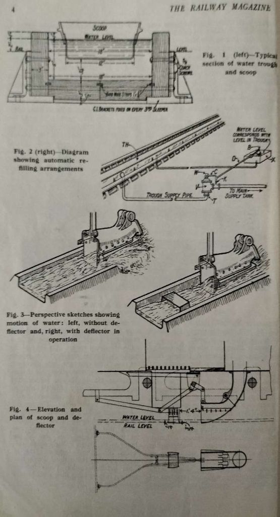
Figure 1 shows a typical cross-section. The length was been 0.25 and 0.5 miles and had to be on a completely level length of track.
Figure 2 “shows diagrammatically the arrangements made for rapidly refilling a trough after a locomotive has taken water from it. The familiar ball-valve control is used to regulate the flow from a tank alongside the track to the trough. When the water in the trough reaches the correct level, the ball valve, in a small tank at rail level, rises and cuts off the supply. Steam heating has to be used to prevent freezing in frosty weather where traffic is infrequent and the troughs are in exposed positions.” [1: p5]
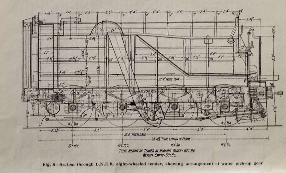
I love some of the diagrams in these early editions of The Railway Magazine. The one above is no exception, Figure 5 illustrates a typical form of water pick-up apparatus on a LNER eight-wheel tender. “The inclined delivery shoot will be seen to have a hinged foot-like scoop, curved to face the direction of travel and capable of being held clear of, or depressed into the troughs – which are centrally placed between the rails – by means of the system of rods, cranks and levers shown, these being under the control of the fireman. Warning boards are erected to enable him to be prepared to lower the scoop as the trough is approached, speed seldom being appreciably reduced over the troughs. The scoop is usually lowered before the trough is reached, a slight gradient being arranged in the track, by which the scoop drops below the water level, and is similarly raised at the far end of the trough, should the crew not have lifted it out earlier. To aid in raising the scoop when the tender gauge shows the tank in it to be full, steam or compressed air is often used.” [1: p5]
A speed through the toughs of 25 mph was sufficient to ensure the take-up of water, although higher speeds were more effective. But express speeds tended to waste water and could result in damage to the permanent way. Maintenance costs with the amount of flooding which occurred were high.
The LMS made use of a tender which had an observer’s compartment to study what happened at water troughs and, as a result, designed a simple device which significantly reduced the spilling of water. “Briefly, the passage of the scoop through the trough causes the water in it to pile up and overflow at each side, and to neutralise this a pair of slightly converging deflector vanes are fixed 1 ft. 4 in. in advance of the scoop, which force the water towards the centre of the trough and make it pile up there instead of at the sides (Figures 3 and 4). Some 400 gallons are saved every time these deflector vanes are used, and the quantity of water required is reduced by about 20 per cent.” [1: p5]
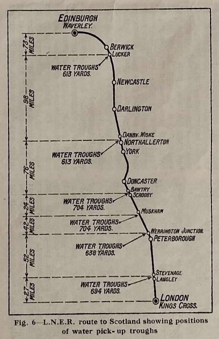
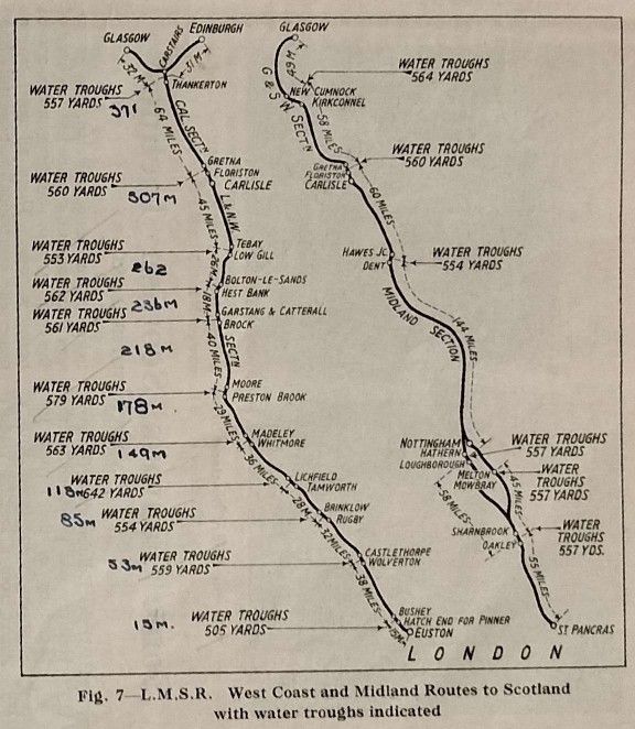
Figure 6 is a map showing the distribution of water troughs along the main LNER. route to Scotland, and Figure 7, those on the LMS, both on the LNWR (West Coast) and the Midland routes.
The water troughs on these long distance routes obviated the need for larger tenders and the need for time-wasting water stops. 3,500 to 5,000-gallon tenders were more than adequate. It also appears to have been true that the use of water troughs generally meant that water purity was higher which minimised boiler maintenance and also reduced the need for water-softening plants. [1: p5]
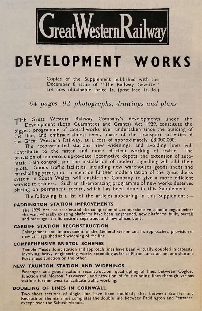
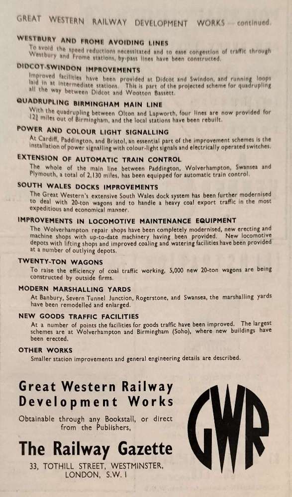
The GWR Capital Programme
The Railway Magazine noted, “A special programme of extensions and improvements, involving a cost of over £8,000,000, was put in hand by the GWR under the Development (Loan Guarantees and Grants) Act, 1929, in anticipation of its future requirements, for the purpose of assisting in the relief of unemployment. … The Railway Gazette, issued on [8th December 1933] a profusely illustrated Special Supplement dealing comprehensively with these works. A notable feature of this supplement is the wealth of drawings, including a double-page map of the G.W.R. system, with inset detail plans of the new works.” [1: p74]
Earlier in the January 1934 edition, The Railway Magazine carried an advert over two pages from The Railway Gazette for the supplement to their magazine (which, when bought separately, cost the princely sum of 1s).
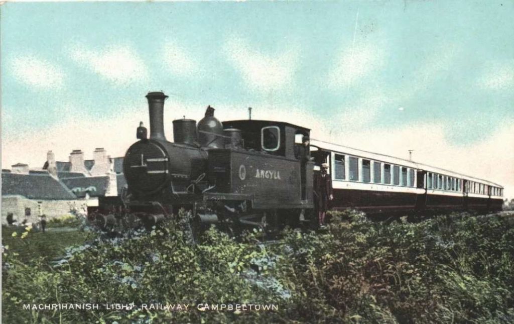
The Campbeltown & Machrihanish Light Railway
The Campbeltown and Machrihanish Light Railway was one of only four 2 ft 3 in (686 mm) narrow gauge railways in the UK. The other three were/are in Wales: the Corris Railway, the short-lived Plynlimon and Hafan Tramway and the Talyllyn Railway. [3]
In its January edition, the Railway Magazine reported that “an Order dated [7th November 1933], by the Minister of Transport, appeared in The London Gazette of 7th November, declaring that the Campbeltown & Machrihanish Light Railway Company shall be wound up.” [1: p74] The line, which was closed about eighteen months earlier was 6 miles 29 chains in length and of 2ft 3in gauge. The rolling-stock comprised three locomotives, six passenger and and two goods vehicles. “The company was incorporated on 8th May 1905, and the line opened on [17th August 1906] of the following year. This isolated railway, in the Mull of Kintyre, suffered particularly severely from road motor competition,” [1: p74] and, a few years previously, an attempt was made to meet road competition with its own bus service, but that failed.
A canal was first constructed to bring coal from pits close to Machrihanish to Campbeltown. It was in use from 1794. There were no locks as the canal traversed relatively flat terrain. It was three miles in length, running from Mill Dam in the West to Campbeltown. Only two barges plied its length which carried around 40 cartloads of coal each day to Campbeltown. However, “the extent to which the canal was used or cared for seems doubtful. … It had fallen into disuse and been virtually abandoned by 1856 and when, about 1875 the colliery changed hands, the new owners … found it choked with weeds and difficult to clear. … In the Company’s prospectus of 1875 it was stated that a railway was to be built.” [4: p7-8]
The new railway was a little over 4 miles in length at first, running between the pits and a coal depot on Argyle Street, Campbeltown. In 1881 the length was extended to 4.7 miles. “There were a number of level crossings, all originally gated but subsequently left open, protected only by cross trenches to keep cattle and sheep off the line.” [4: p8]
At first, only a single loco worked the line, an Andrew Barclay 0-4-0T engine named ‘Pioneer’. After the line was extended to a new colliery business “became so brisk that in 1885 a second locomotive was bought from Barclays, an [0-4-0ST initially, later altered to an 0-4-2ST] named ‘Chevalier’.” [4: p9]
In 1901 and 1902, two high-speed turbine steamers brought “increasing numbers of day trippers to Campbeltown where … many of them were conveyed to Machrihanish … by horse-drawn carriages.” [4: p11]
The railway saw significant changes as a result. Both to carry passengers and to enhance the delivery of coal to boats at the New Quay in Campbeltown, the line was extended East to New Quay and West to the Golf links at Machrihanish. A new company, the ‘Argyll Railway Company’, was formed to manage the line.
The new railway was to be close to 6.4 miles in length and was opened to passenger traffic in 1906. By “August 1913 there were seven trains each way daily. … The war naturally led to a curtailment of services, … until the early months of 1917 saw the line’s minimum service of one daily train in each direction. … After the war … the tourist trade soon picked up again and before long the summer months saw eight regular trains a day in each direction. … Although the 20s saw increasing competition from buses, the time tables continued to show eight trains daily in each direction right up until the withdrawal of services in 1931.” [4: p23]
Commenting on the closure of the line, A.D. Farr says: “When the railway finally closed the prime reason was the loss of revenue following the closure of the colliery in 1929, but a major factor was also the bus competition. To meet this second-hand buses had been bought by the railway, but the experiment was to no avail and they were soon sold to the competing road transport concern.” [4: p23]
The line owned a total of five locomotives at different times: ‘Pioneer’, a Barclay 0-4-0T; ‘Chevalier’, a Barclay 0-4-0ST which may have been converted to an 0-4-2ST; ‘Princess’, a Kerr-Stuart 0-4-2T; ‘Argyll’, a Barclay 0-6-2T; and ‘Atlantic’, another Barclay 0-6-2T. [4: p41]
Six passenger coaches were employed on the line, all built by R.Y Pickering & Co., of Wishaw, Lanarkshire. All were bogie ‘cars’ and “were externally very attractive models of the tramways type, 43 ft 6 in long and with two 4-wheel bogies, 30 ft centre to centre carrying 1ft 11in diameter wheels. At each end was a covered platform, guarded by a wrought-iron balcony and ‘telescopic gates’, and with steps on either side to within a foot or so of the ground.” [4: p43]
The coal company owned a series of wagons which carried the ‘C.C.C’ lettering. But it seems as though the railway company owned only a heavy goods brake van and one other wagon, although little is known about that vehicle. [4: p45]
The Welsh Highland Railway
The Railway Magazine reported that the “Joint Committee representing the local authorities with investments in the Welsh Highland Railway has decided to ask the debenture-holders to close down the line. Carnarvonshire County Council has £15,000 in the venture, Portmadoc Urban District Council £5,000, and the Gwyrfai, Glaslyn and Deudraeth Rural District Councils £3,000 each. At a recent meeting of the Portmadoc Council, Mr. Oswald Thomas said it was important that if the railway were closed, the rails should not be taken up, particularly between Portmadoc and Croesor Bridge, as it was hoped before long to see quarries in the district working again. Captain Richard Jones said it might be arranged for the Portmadoc Council to take over that part of the railway.” [1: p74]
West Monkseaton Railway Station Waiting Shelter
The Railway Magazine picked a rather modest platform building at West Monkseaton for praise.
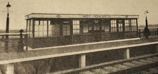
“Here is precise repetition used rhythmically; the units are a nine-light window and a half-glazed door; the rhythm is 2-door-2-door-2-door-2. The designer is to be congratulated in that he has been careful to keep the horizontal glazing bars of doors in line with those of the windows; the horizontal effect of the windows; therefore unbroken. The portions of the window panes are The proportion good, being about 5 to 3. The key-note of the design is the restful cornice band running round the structure; unpretentiously it ties in the whole composition; its horizontality is repeated by the edges of the weather-boarding under the windows, and is balanced by the white base upon which the building stands; this cornice band also sets off, and is set off, by Mr. Eric Gill’s standard LNER lettering. Thought has evidently been expended upon the design of this shelter, and it gives us pleasure to illustrate such a satisfactory and pleasing little piece of station architecture, especially when we consider what the perpetuation of railway custom might have produced.” [1: p75]
Check Rails and Ramps
By 1934, it was common practice “to provide safety devices at viaducts and other important bridges to reduce to a minimum the risk of vehicles, which may have become derailed, falling over the edge. Special guard rails, fixed either inside or outside the running rails and usually at a slightly higher level, are laid across the viaduct, with some splayed arrangement at both ends to direct derailed vehicles from the edge toward the rails. An ingenious elaboration of this is shown in the accompanying illustration. It consists of converging rails with a steel ramp between them rising to rail level. Any derailed wheels would run up this and should automatically become re-railed at the top.” [1: p74]
References
- The Railway Magazine; Westminster, London, January 1934
- https://www.ebay.co.uk/itm/353145047017?mkcid=16&mkevt=1&mkrid=711-127632-2357-0&ssspo=VG76xMQ6St6&sssrc=4429486&ssuid=afQhrar7TGK&var=&widget_ver=artemis&media=COPY, accessed on 6th August 2024.
- https://en.wikipedia.org/wiki/Campbeltown_and_Machrihanish_Light_Railway, accessed on 7th August 2024.
- A.D. Farr; The Campbeltown and Machrihanish Light Railway; (First Reprint) Oakwood Press, Headington, Oxford, 1987.
