
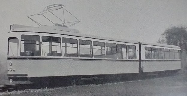
The featured image shows one of the 220-passenger articulated tramcar sets in an ex-works condition, © H. Fuchs Wagonfabrik. [1: p70]
The April 1954 edition of ‘The Modern Tramway’ included an article about the introduction of new articulated tramcars in Stuttgart. It is interesting to listen to the discussion about the relative merits of articulated cars and trains of two or three cars coupled together. …..
In April 1954, the first of these new cars were going into service, supplied by H. Fuchs Wagonfabrik A.G. of Heidelberg. As far as I can ascertain, Stuttgart sourced later articulated tramcar sets from manufacturer Maschinenfabrik Esslingen. [2]
“The decision of the Stuttgart authorities to order articulated cars rather than the standard German grossraumwagen was reached after careful consideration of local conditions. The city is very hilly and of 116 route Km.
20 Km. have gradients of from 3-5%.
21 Km. have gradients of from 5-8%.5 Km. have gradients more than 8%.
and only a very few routes (15 Km. in length), are so slightly graded that they can be considered level. In overcoming the differences of gradient the tramways are very sharply curved and there are many curves with a radius of 20 metres. The city centre is narrow and congested and high speed running is impossible. In order to raise average speeds, the uphill speeds of the trams must be increased.
The articulated design was partly chosen as it gave increased adhesive weight (69% of the available weight is carried on driving axles with forward and rear bogies motored). The new cars are slightly wider than the older types and some realignment of curves was necessary.Each unit has 60 seats and room for 160 standing passengers. To obtain the greatest advantage from the extra width, sliding doors are fitted, with folding stops. Whilst the capacity is roughly that of a two-car car grossraumwagen set, the total length Is about 5 metres shorter and actually 6.8 metres shorter than a standard Stuttgart three car four-wheeler set. This represents a 20% saving. The reduced length is also an asset in traffic.
Modern Articulated Cars for Stuttgart; The Modern Tramway, Volume 17, No. 196, April 1954, p70-71. [1]
Passengers enter through the centre pair of doors and alight from either front or rear. Waiting passengers can therefore concentrate at one point on the loading island and British type queue barriers are being erected to guide passengers to the point where the centre doors will be; alighting passengers are not discharged into the waiting queue. The two conductor’s desks face the entrance doors and passengers can either pass forward or rearward according to the accommodation available.
The new cars will not entirely replace the existing three-car tram-trains of four wheel cars-at least not for some years. The capacity of these sets can be matched to traffic demands, using one, two or three units as required. The articulated cars have not this adaptability and will, there- fore, be used on routes where traffic remains fairly constant through the day; on these routes they will replace 3 car sets (used intact all day), thus representing a saving of one conductor per unit.”
It is interesting to note that each articulated set was to be staffed by 3 people, a driver and two conductors. Modern UK articulated sets only have a driver and if two articulated sets are paired there would still only be one driver.
The article in The Modern Tramway goes on to provide technical descriptions which came from the manufacturer of the tramcars, starting with leading dimensions:
“Overall length of car, 25 metres (82 ft.); Distance between bogie cen- tres, 18 metres (59 ft. 1 in.); Wheel base, 1.750 metres (5 ft. 9 in.): Overall height from rail level, 3.115 metres (10 ft. 3 in.); Height of floor, 0.82 metres (32.25 in.); Overall width of car, 2.2 metres (7 ft. 2.625 in.); Weight of car including electrical equipment 26,000 kg. (25 tons 11 cwt.); 4 motors having each 58 kW. …
The whole car body including the underframe is built up of edged columns and girders welded together, so that the supporting structure is formed by side wall, underframe, and car roof.
The car roof, which is of the arched type, is fitted with an all-around rain gutter drained by means of outlet pipes located in various columns.
The windows are embedded in rubber, so no draught and rain water can enter. The windows are fixed at the bottom, and sliding at the top.
The car is single-ended. There are four sliding doors arranged on the outside, of identical size and operated from the conductors’ seats through an electro-pneumatic door valve. The door opening or closing operation simultaneously operates the folding footsteps through air cylinders, thus preventing any person from hopping on the car whilst in motion. Should the door remote control fail, the doors can be opened by hand, by reversing an emergency cock.
The two car sections are separated from each other, in the centre, by a “corridor connection.” This was necessary to enable the car to nego- tiate narrow curves, and to compensate for the various movements.
Each of the two car sections includes a conductor’s place of the stationary type, where all necessary controlling apparatus and push- buttons are arranged to operate the doors, loud-speakers, heating systems, etc.
The space available between the two conductors’ places serves as a collecting point for passenger flow. The arrangement of the hand-rails guide the passengers past the conductor to the inside. Since the conductor’s seat is elevated, he has a good view over the passengers entering or leaving the car.
The driver’s cab is separated from the passengers’ compartment by a partition. This partition has been so formed that the electrical controllers are at its upper part, leaving some space for a cupboard below to store lost property. The access is by means of a hinged door.
The controllers and levers to be operated by the driver are arranged so as to be easily accessible.
The lighting equipment of the car consists of fluorescent type tubes running through lengthwise. There is an illuminated number plate on the roof, and an illuminated direction board in the upper part of one side window.
The whole of the cable wiring is arranged in the underframe, and this in suitable conduits adequately protected from splash water. Separate cable tubes lead to the various electrical appliances. The entire Bosch type pneumatic equipment is also located in the underframe. The brake equipment consists of the following:-Service brake: Electrical braking through the motors;
Modern Articulated Cars for Stuttgart; The Modern Tramway, Volume 17, No. 196, April 1954, p71-72.
Additional brake: Electro-pneumatic, hand-operated air brake having at all times at its disposal a brake force supply from bent springs (so- called spring storage brake);
Emergency brake: 6 electro-magnetic rail brakes being fed from a separate battery and directly opera- ting on the rails with a 24,000 kg. force.”
The article concludes with details of suspension and bogie centre pins:
Suspension of axles: Through helical springs with no damping at all. There are intermediate rubber layers for silencing, in conjunction with the helical springs.
Steering of axles is through a suspended and continuous spring leaf transmitting the longitudinal and transverse forces to the bogie frame. There are auxiliary axle guards to protect from spring breakage.
Bolster suspension: Undamped helical springs located far on the out- side, with built-in hydraulic shock absorber, serve to quickly eliminate any lateral up-and-down movement. In addition, to cushion the lateral bolster movement and to transmit the force longitudinally from the bolster to the bogie frame, there are rubber pieces arranged on each bolster end, and these pieces are vulcanized on metal plates. The bolster springs are housed in cross-bars suspended on the frame by means of a pendulum. The bolster is led through small stop plates, eliminating wear and tear.Bogie centre pins: There is an entirely rigid pivot pin transmitting all forces to the bolster. Thus, no lateral sliding pieces subject to wear and tear are necessary. The torsional friction moment is practically non-existent compared with that obtained by use of sliding pieces, resulting in minimum wear and tear of tyres and rail, and insignificant impact effect when curves are being negotiated.”
Modern Articulated Cars for Stuttgart; The Modern Tramway, Volume 17, No. 196, April 1954, p73.
References
- Modern Articulated Cars for Stuttgart; The Modern Tramway, Volume 17, No. 196, April 1954, p70-73.
- For example, https://en.sporvognsrejser.dk/tram/stuttgart-articulated-tram-416, and subsequent sets, accessed on 15th June 2023.
