Hereford Pictures taken before 2015
Leave a reply

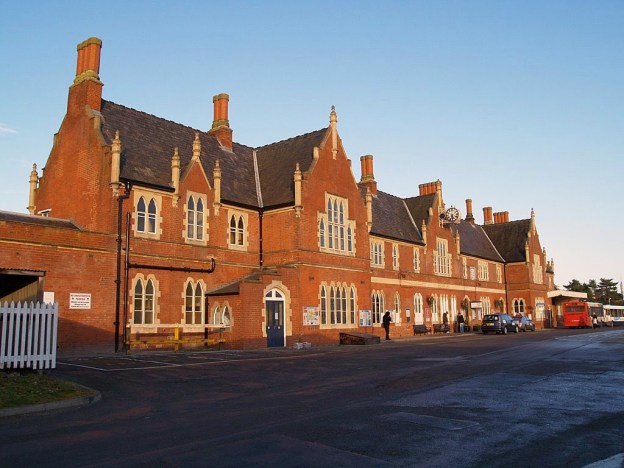
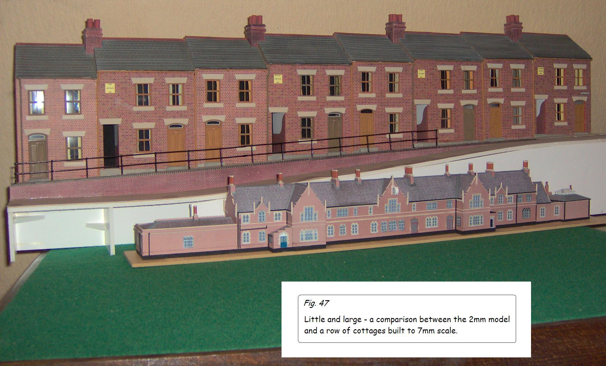
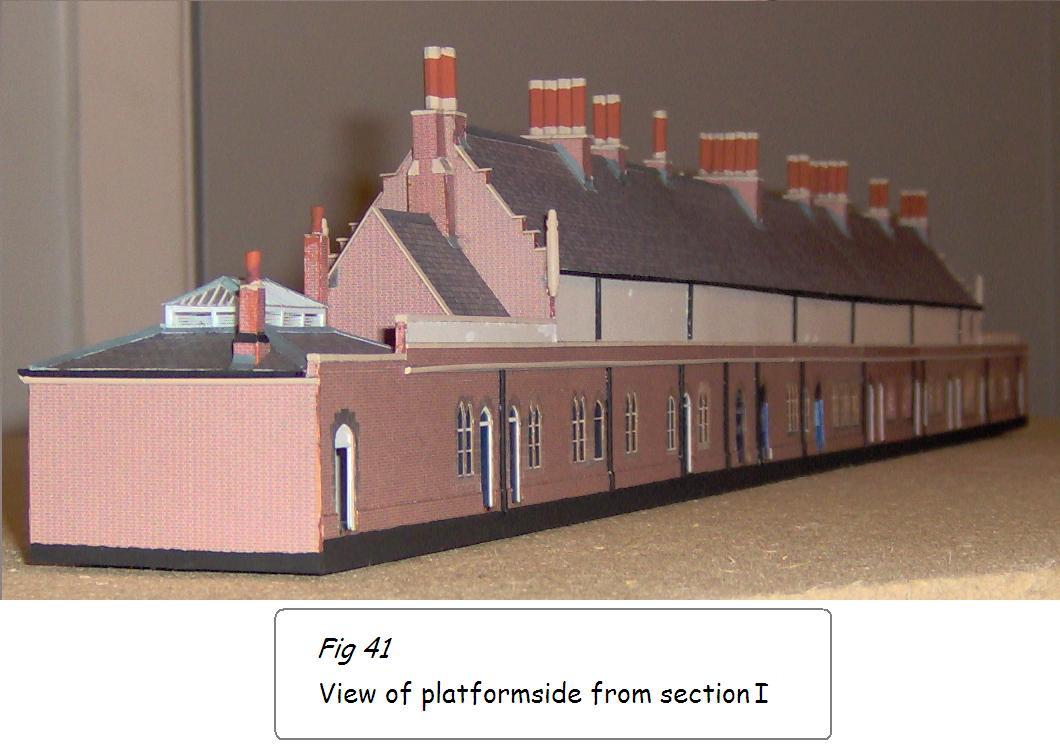
My father-in-law, David Cambridge, has been taking us on a tour of the work he did to produce an N Gauge model of Hereford Station for me. In this final post on this subject he makes some comments about the construction work and shows us a picture of a 7mm model alongside the 2 mm model of Hereford Barrs Court Station:
 In 7mm scale the usual rule of thumb for adding detail is that if you can’t see it on the model from a distance of two feet, omit or simplify it. Since the human eye looks for detail from about the same distance regardless of scale then much of the detail on a model of this size would have to be omitted. As I mentioned at the start, compromises would be necessary. For example, it proved impossible to find a solution to the brickwork and stonework on the octagonal chimney stacks. Application of brick paper would destroy the octagonal shape unless a separate piece was applied to each face. The solution was to paint them brick colour and apply a stone colour base and cap. I don’t feel that viewed from two feet away this is that noticeable. Other features over which compromise was necessary were the finials. These are quite a complex shape so a much simpler one was evolved as turning plastic on this scale was impracticable. I’m less happy about these, and probably the only real solution would be to turn one up from brass and have lost-wax castings made. This might also be a possible solution for the chimneys.
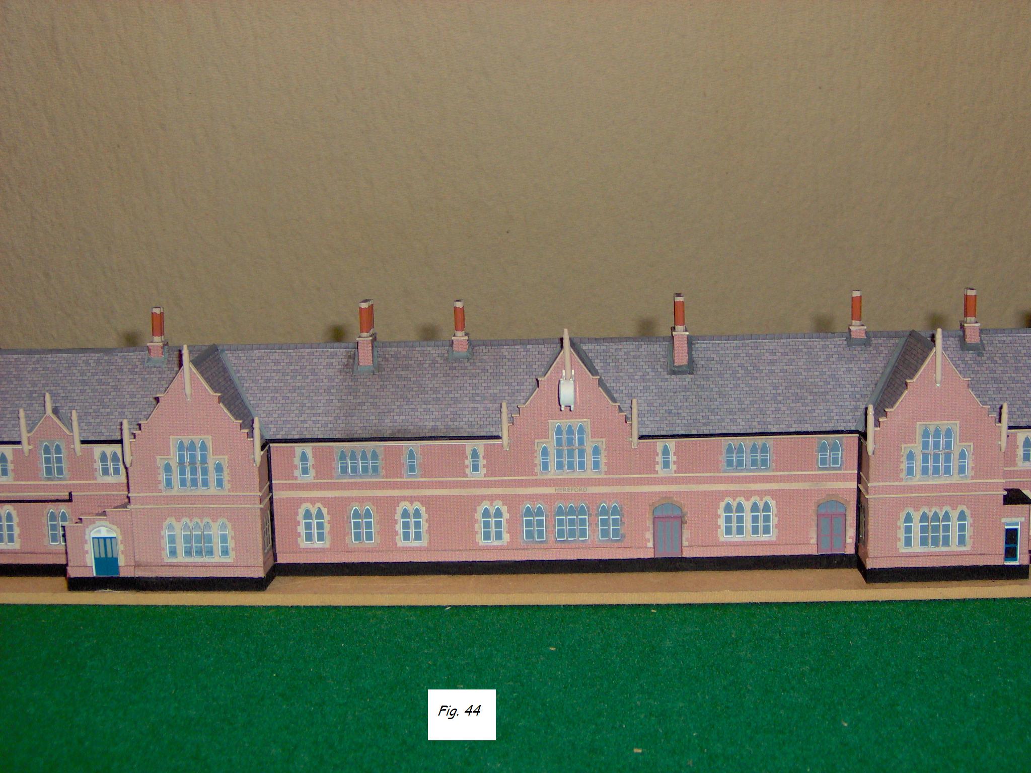
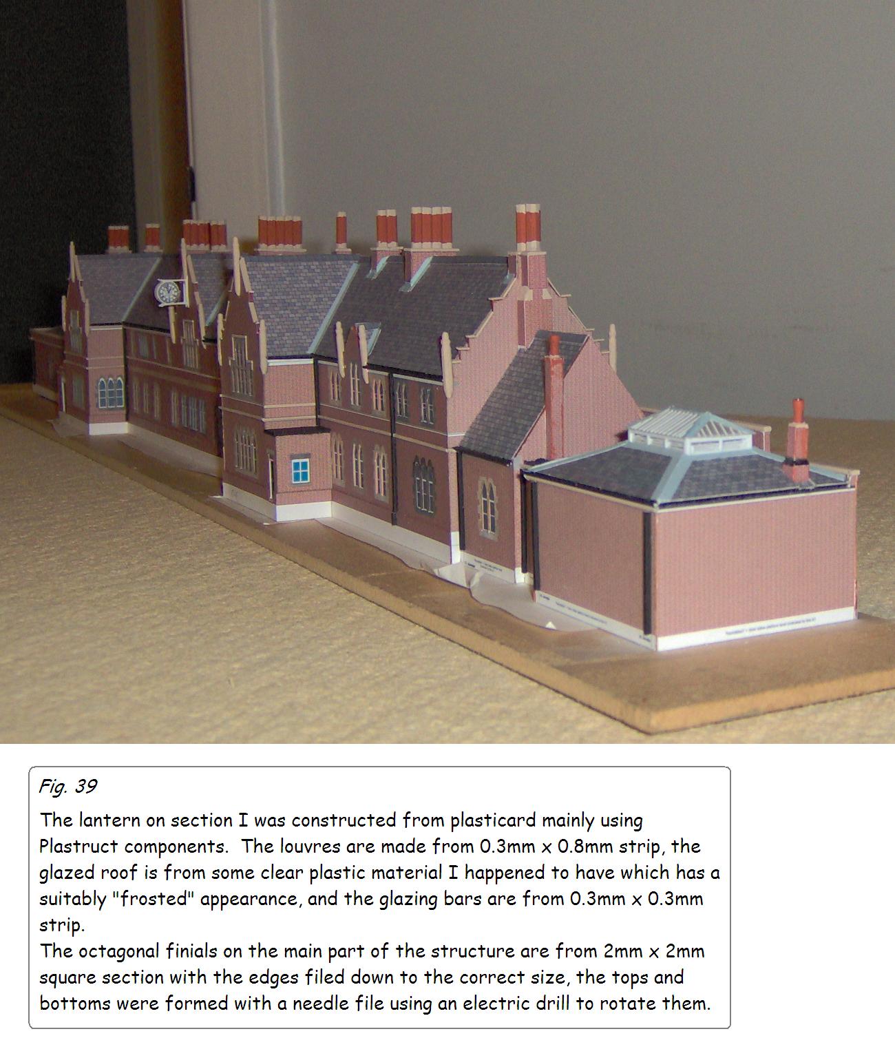
On the other hand, since the clock on the centre of the front elevation is such a noticeable feature it seemed worth making the effort to produce this in as much detail as possible. The iron tracery was obviously out of the question but a really detailed clock face was not, and this was computer produced and printed on glossy photo-paper, and I feel is quite effective.
The canopy over the central frontage has not yet been constructed. The only photograph so far traced does not yield sufficient information to make even an approximation so this is, one hopes, a temporary omission.
… and a final thought.
Having looked so long and hard at this station I have grown to appreciate and enjoy its overall design and though I have only seen it once in the flesh I feel as though I know it quite well.
My grandparents lived in Hereford and my father was born there; they must have travelled through this station a number of times.
The Victorian architects knew what they were doing in designing such an impressive station appropriate in size and style for a cathedral and county city. Detailed study of the exterior leads one to wonder what the interior must have been like. Many stations of the period had just as fine interiors as exteriors. I don’t know of any existing photographs of the inside, so this remains an intriguing and unanswered question.
David Cambridge
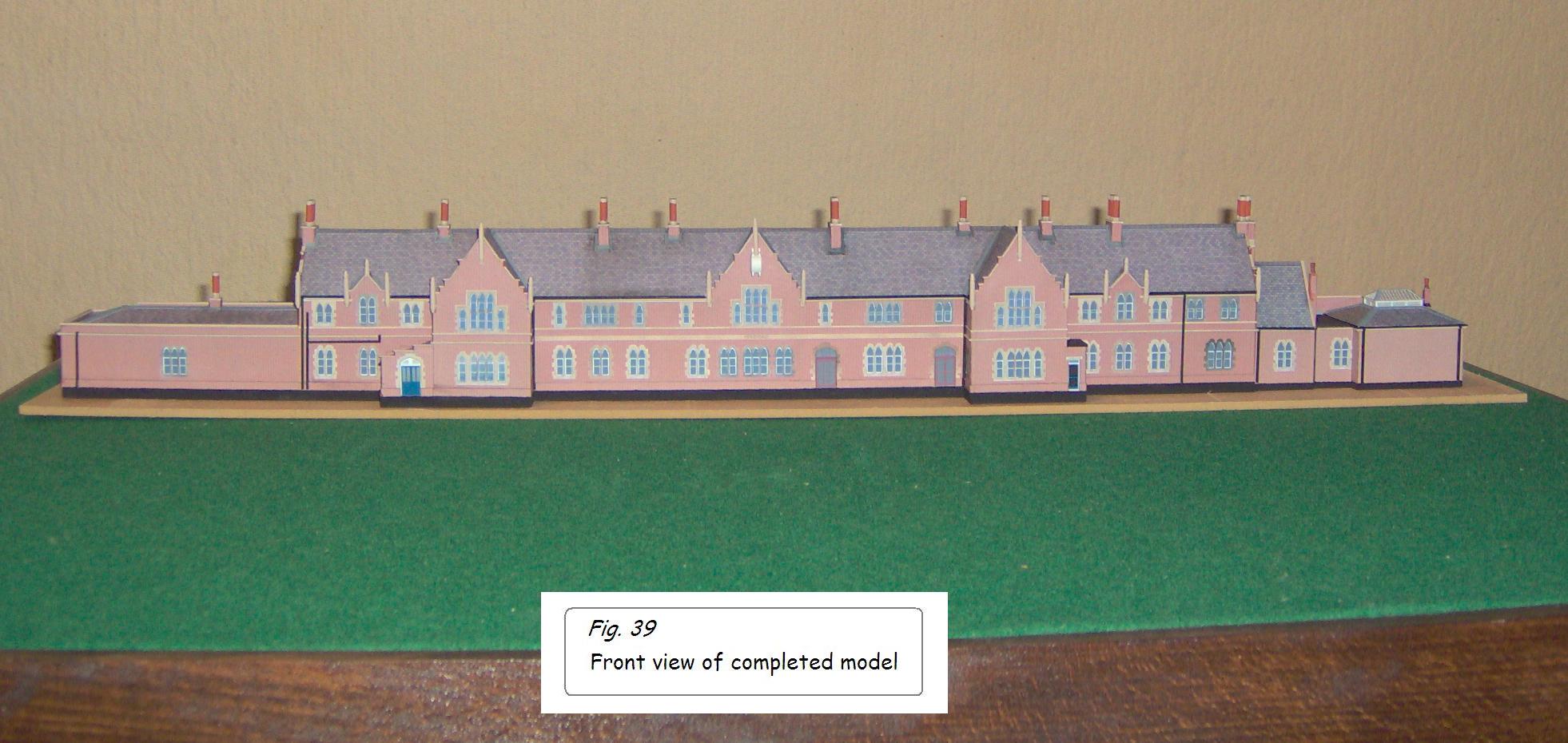
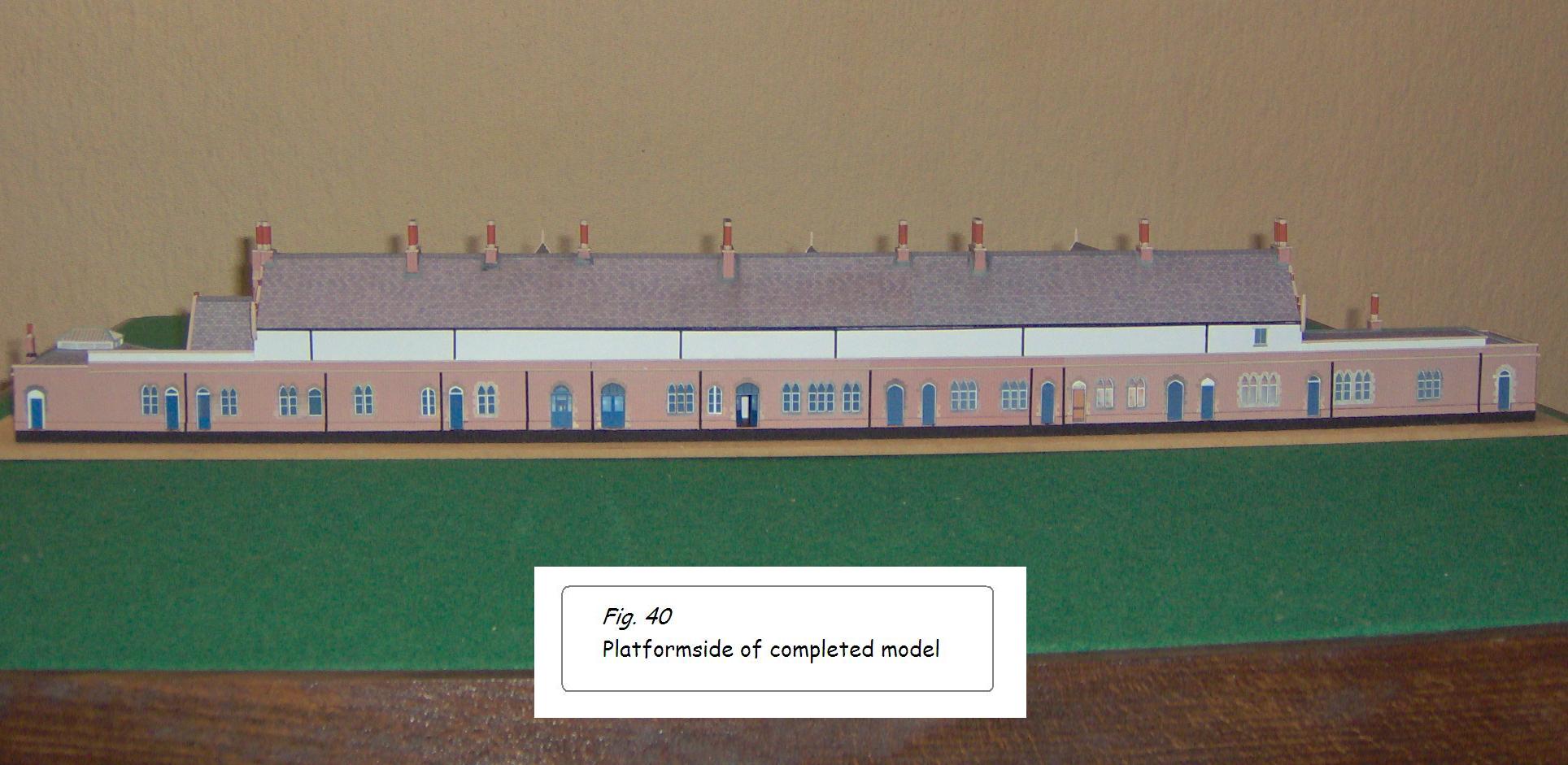
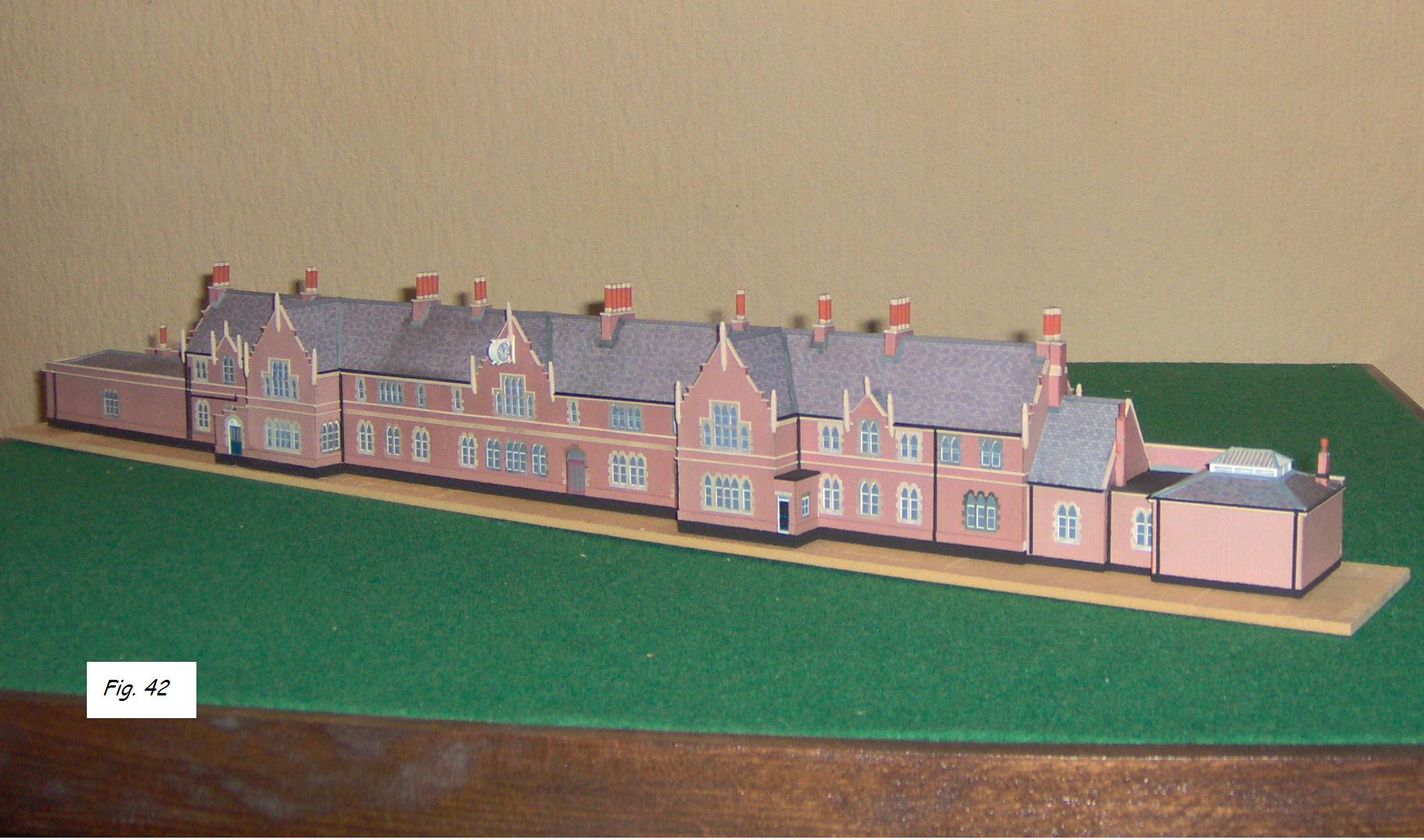
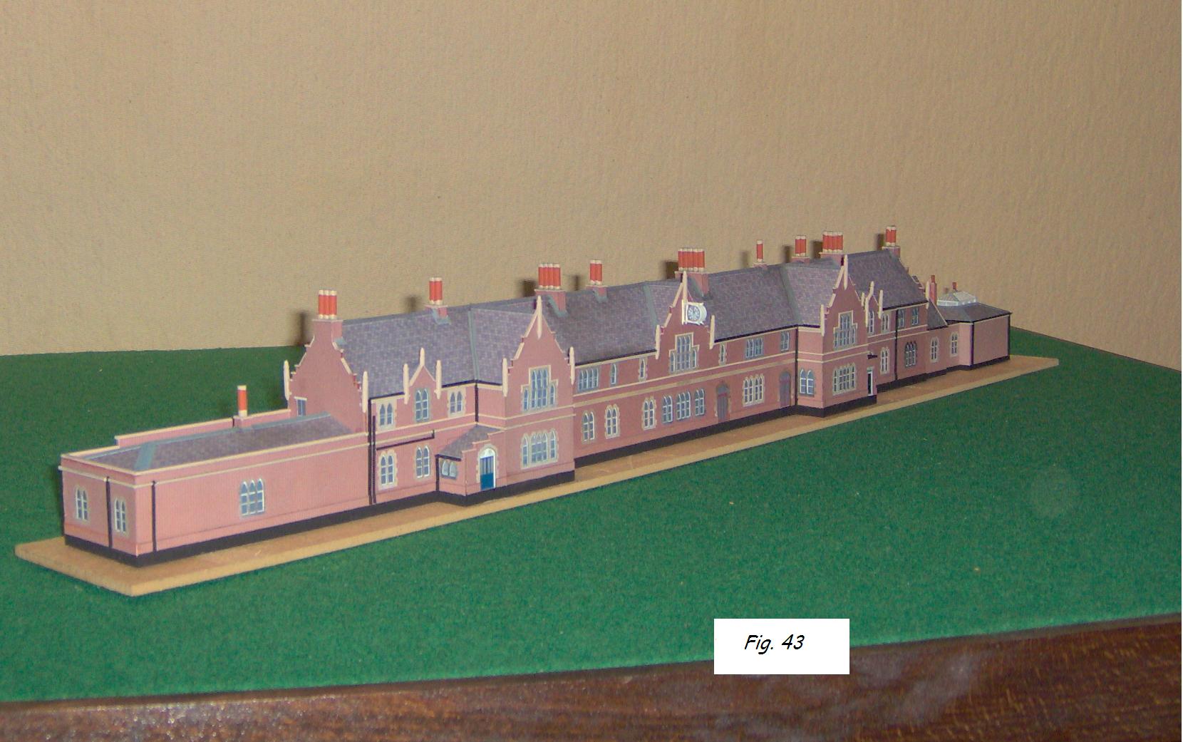
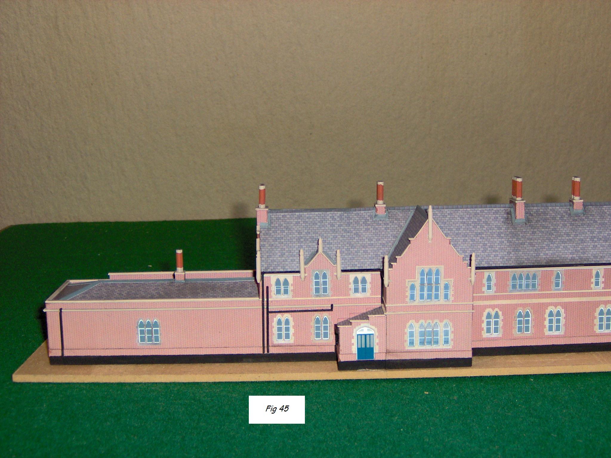
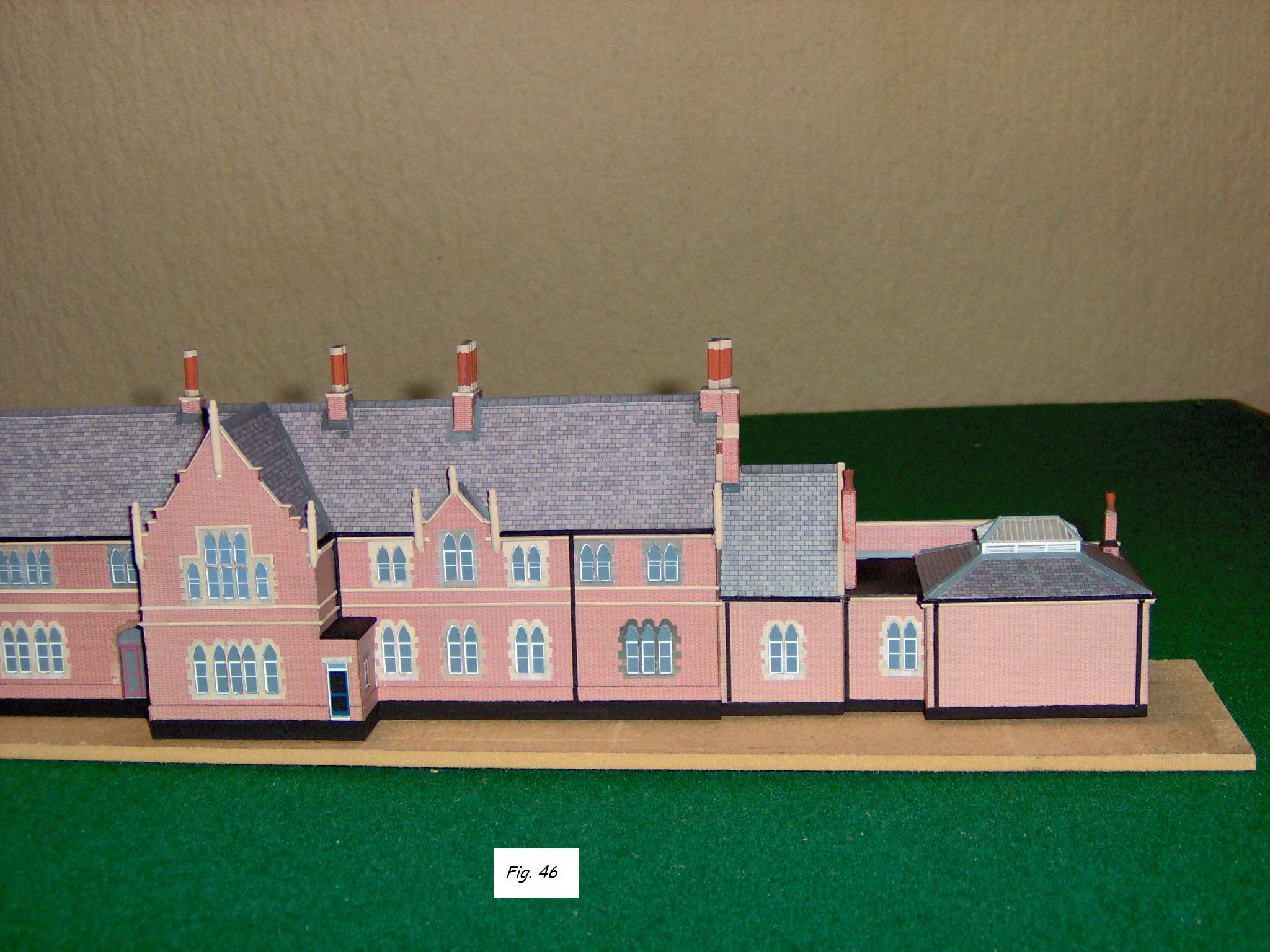
Here are some photos of the completed Barrs Court Station model.
David continues:
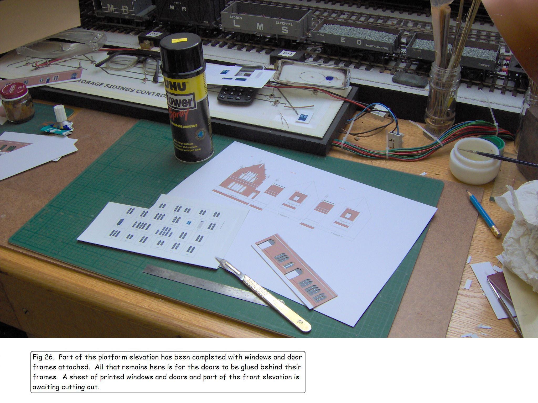
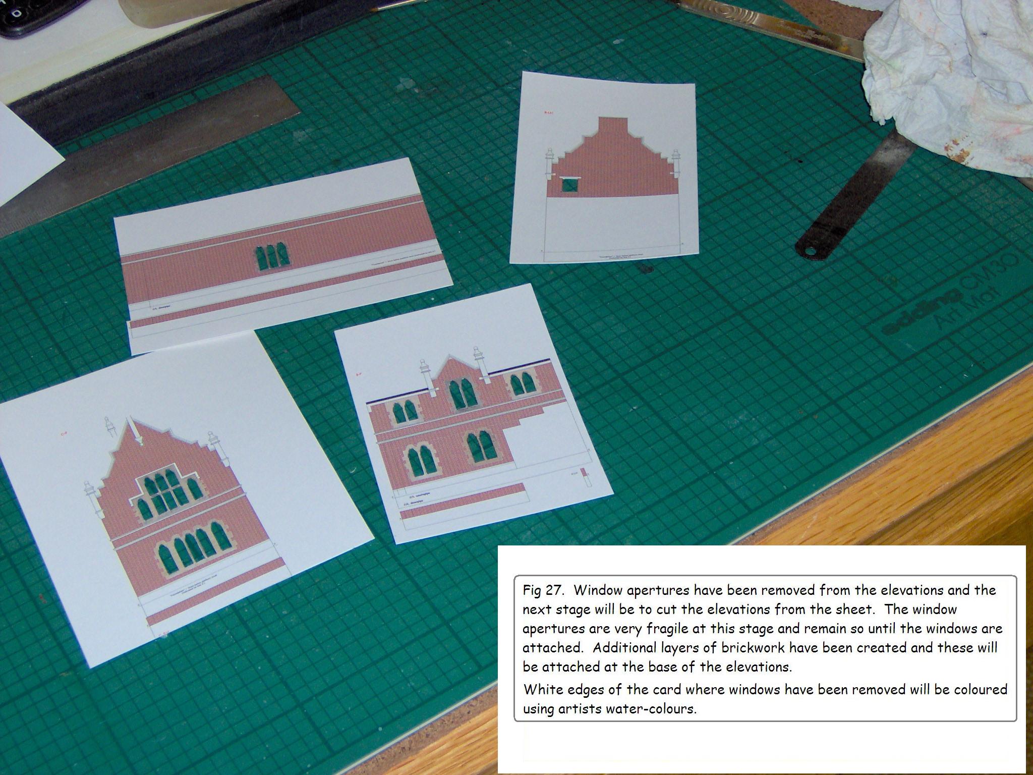
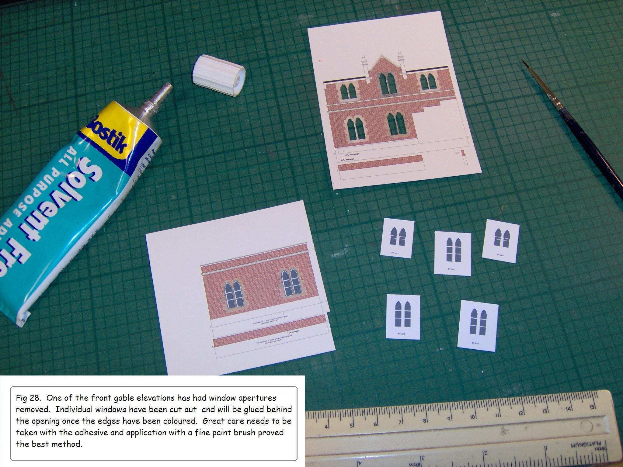
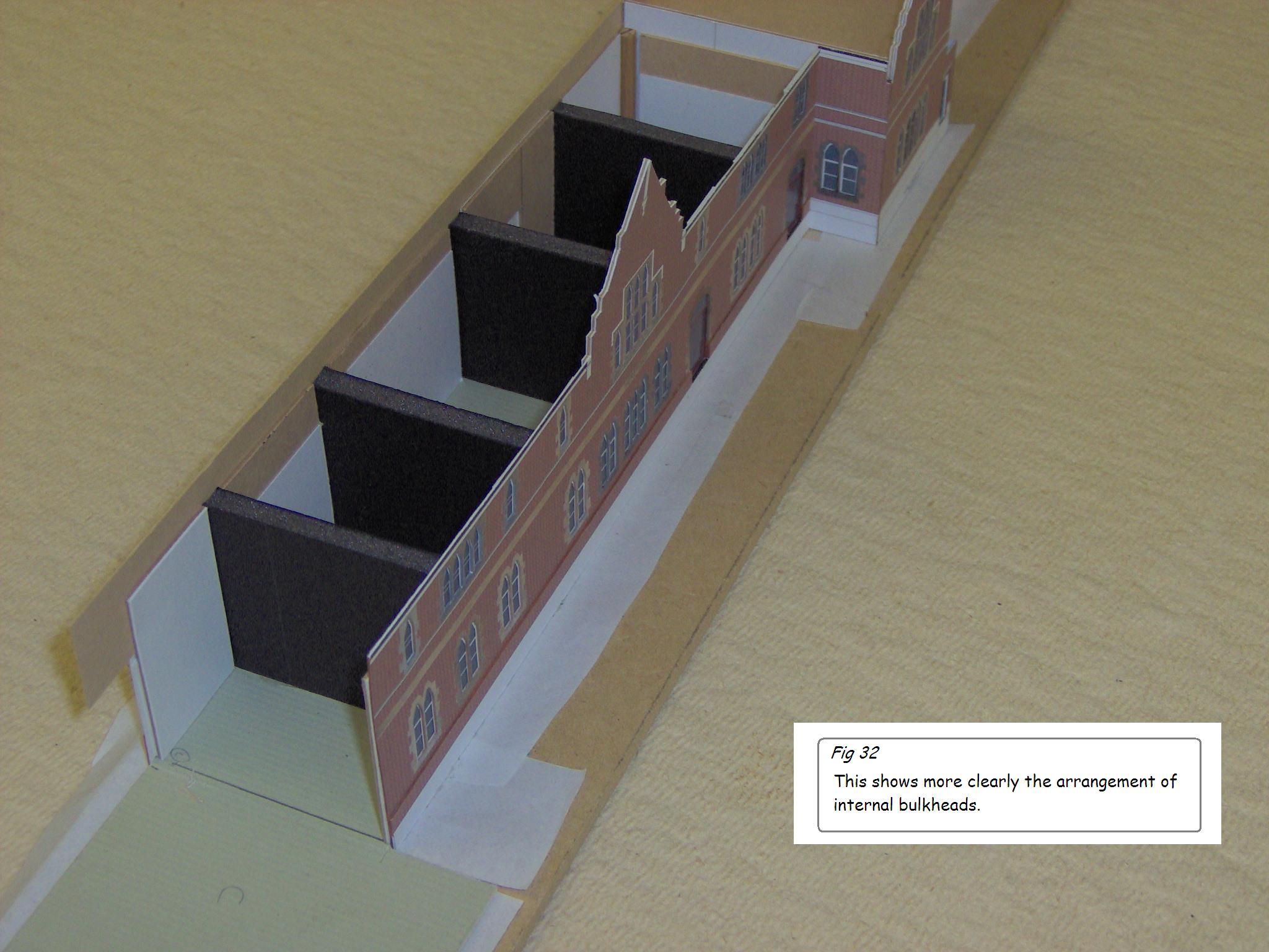
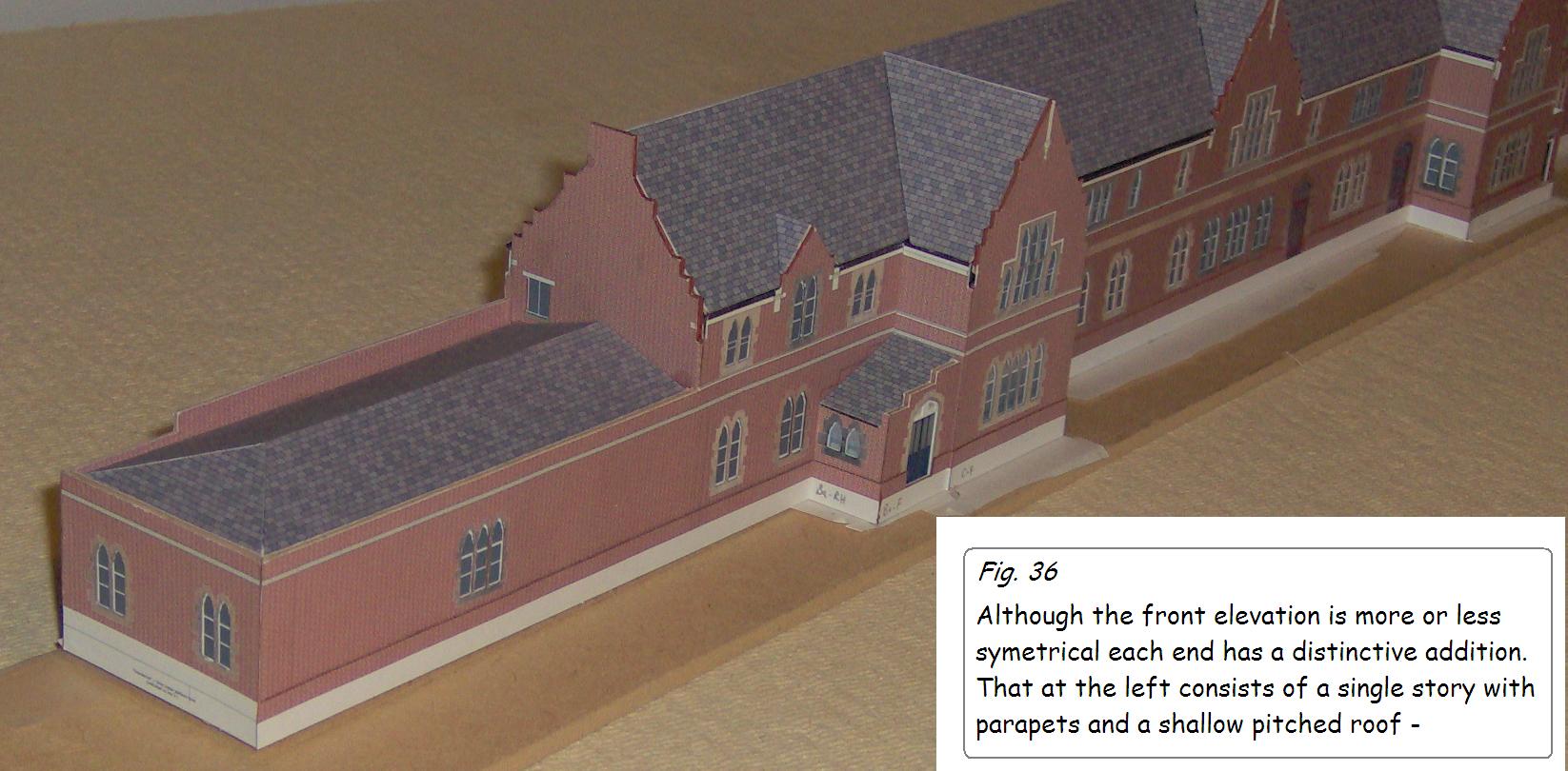
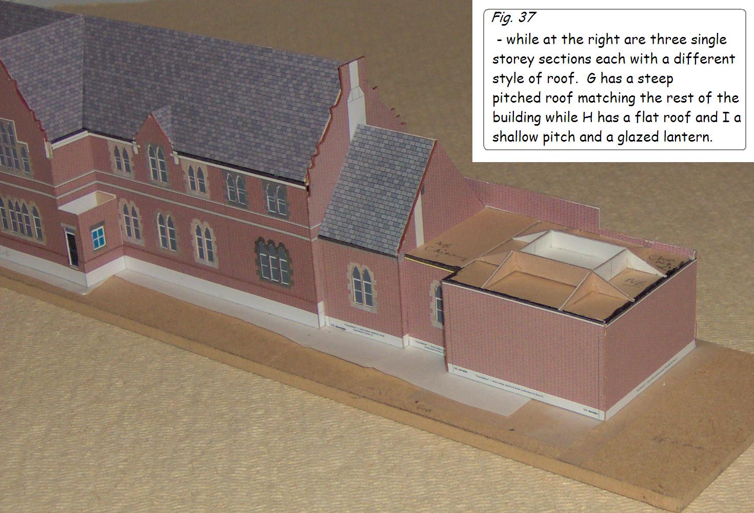
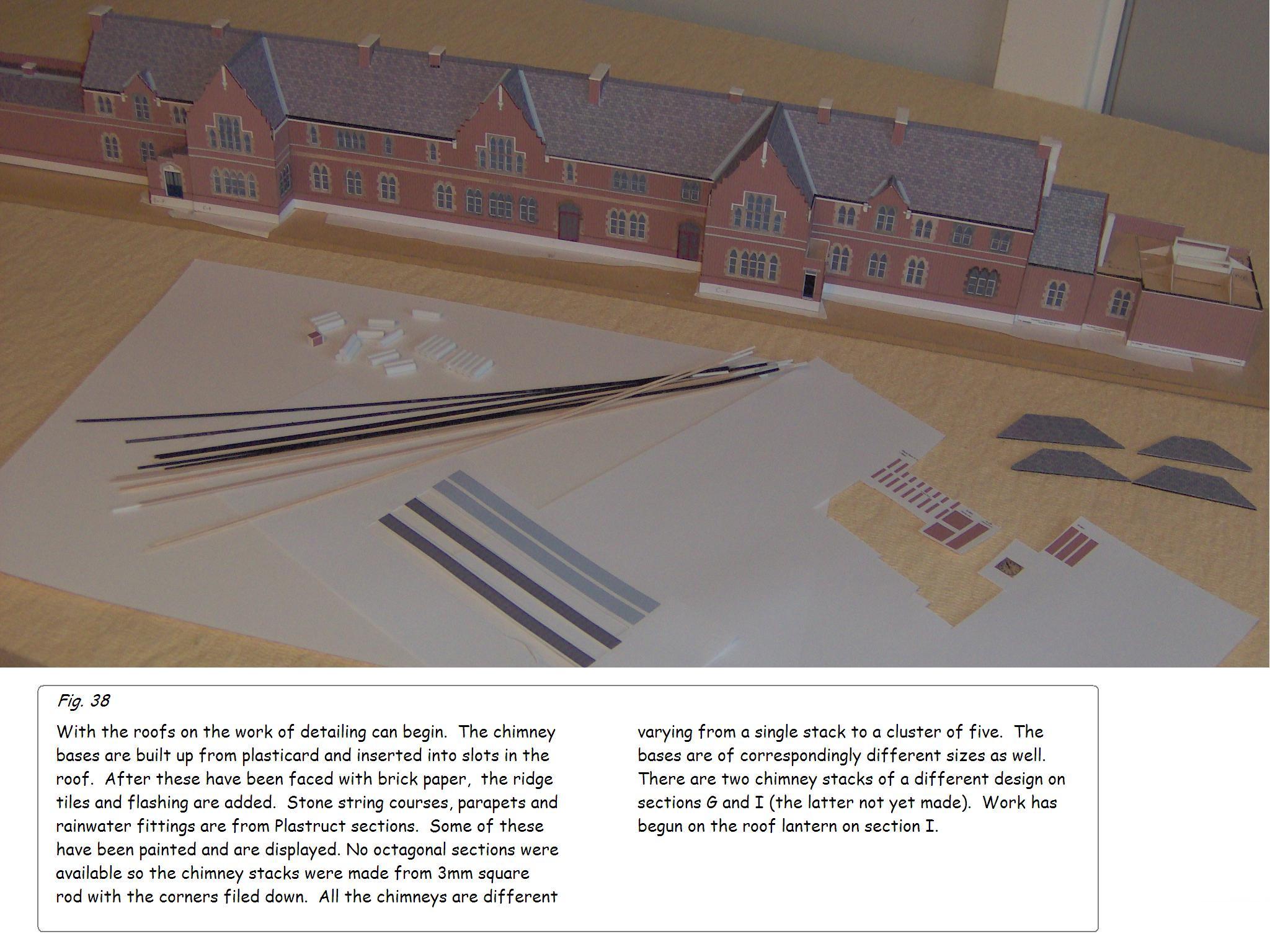
Once the fixative has dried the various door and window spaces can be carefully removed and the elevations cut out. This process and the various stages in construction are shown in figs. 26-39, below.
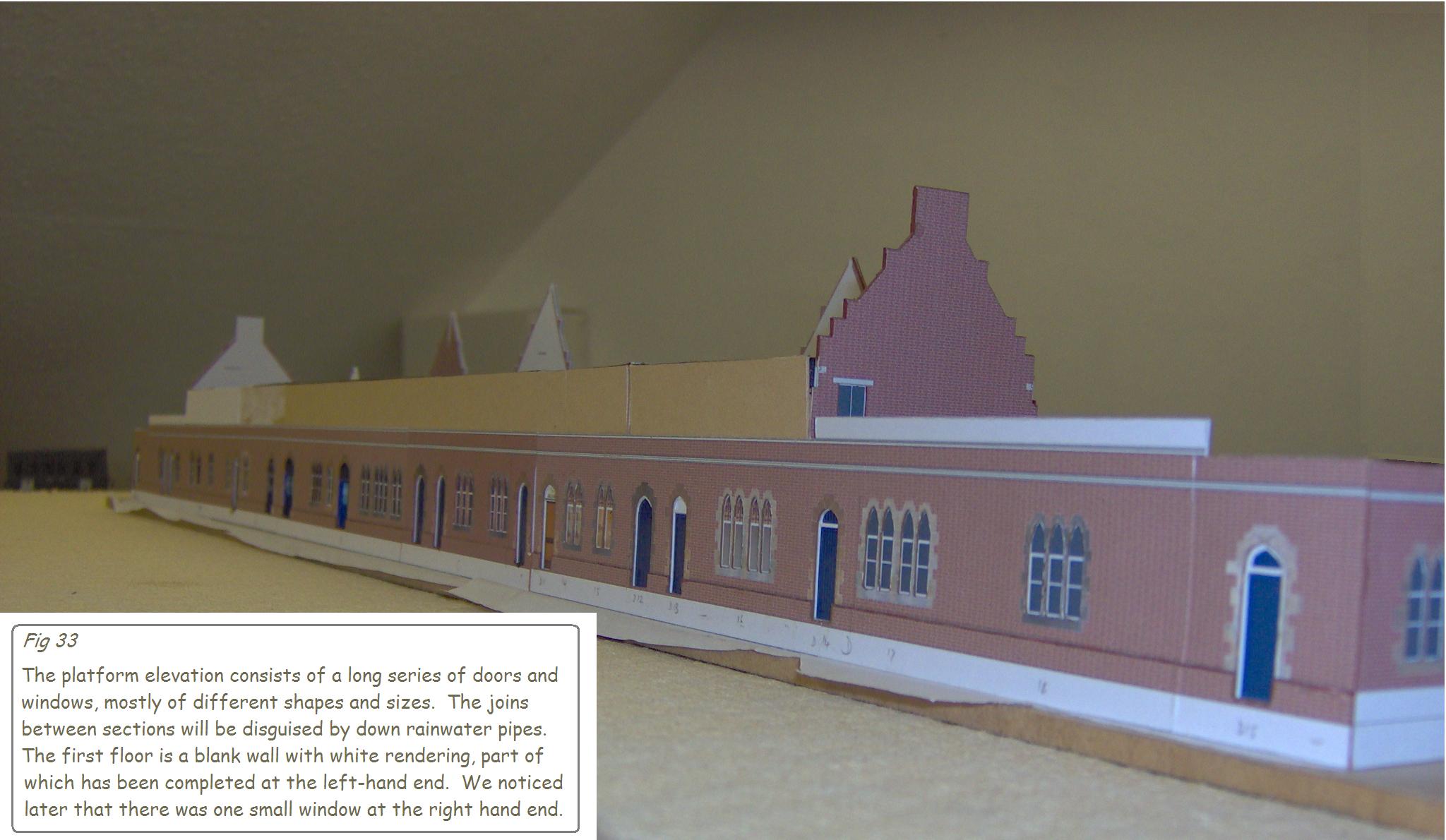
Doors and windows were printed onto glossy photo-paper, cut out and glued behind the appropriate apertures. It was not possible to produce transparent windows, so the glass was coloured navy-black, and in some cases, notably the platform and front elevations of the buffet where illuminated from within, these were copied straight from the photographs.
David goes on to describe the method of construction:
Method of Construction
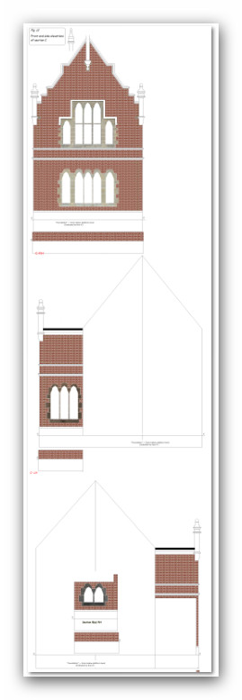
The first step was to make a line drawing of the front elevation of section C just to make sure that my estimated dimensions were on the right lines and that printing would be of the necessary accuracy (see fig. 6).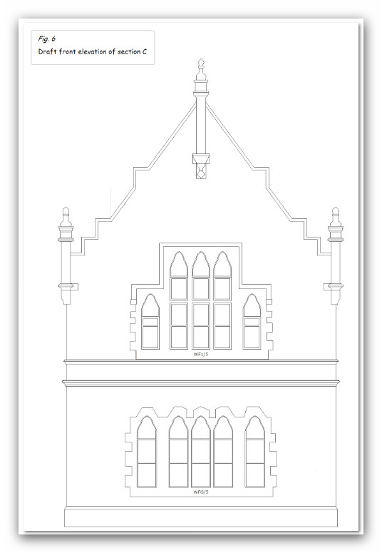
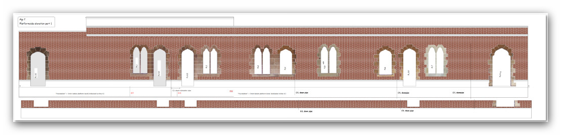
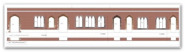
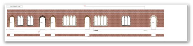
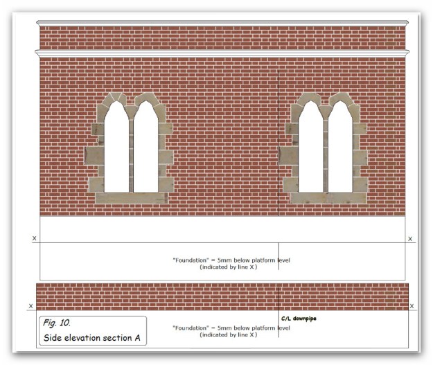
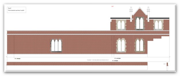
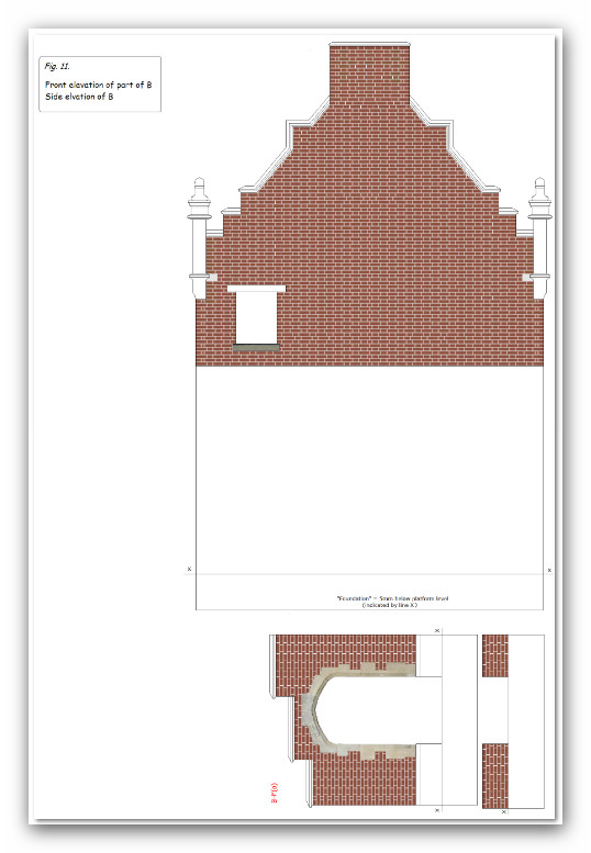
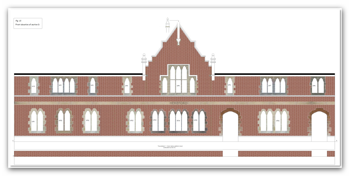
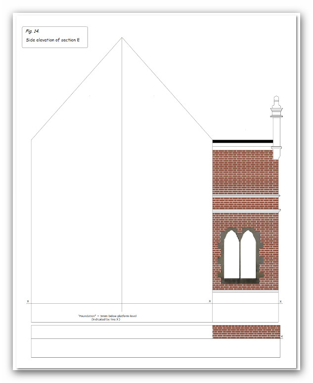
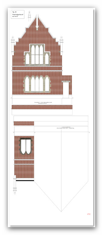
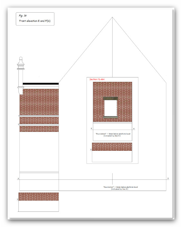
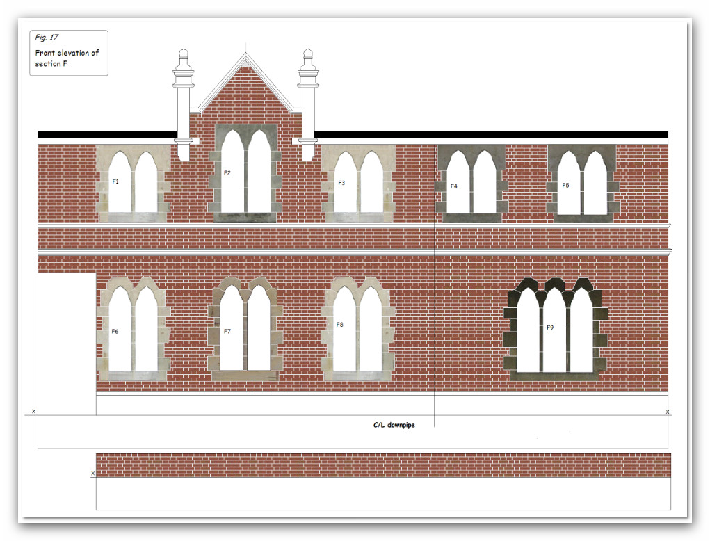
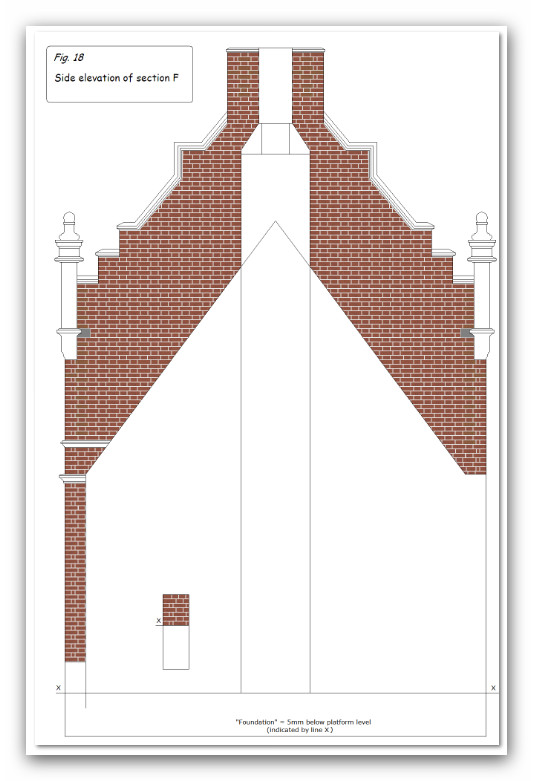
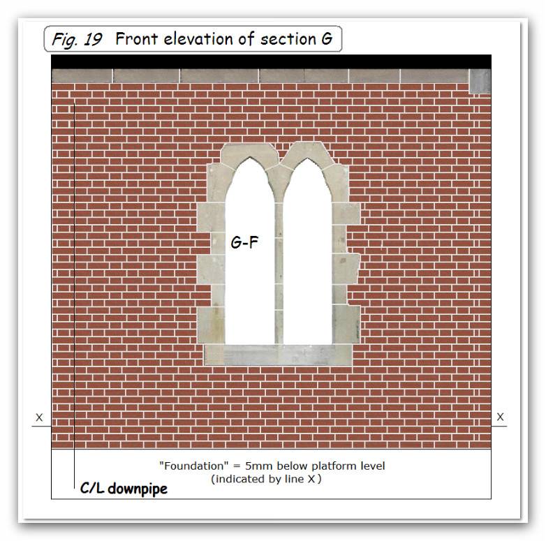
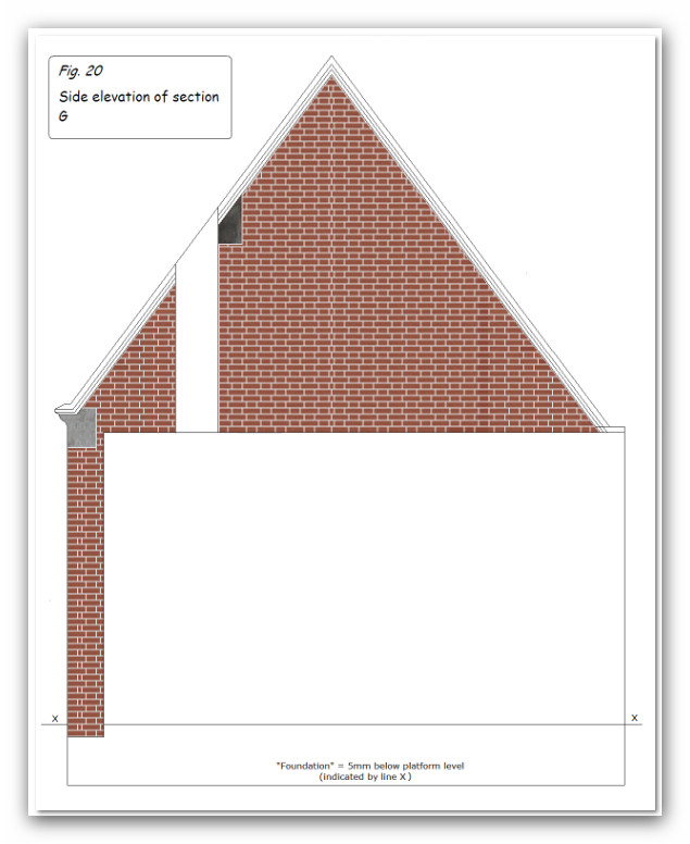
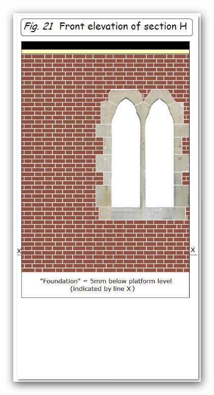
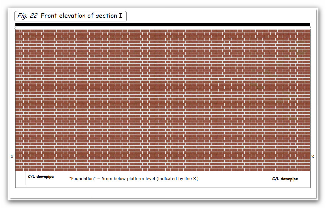
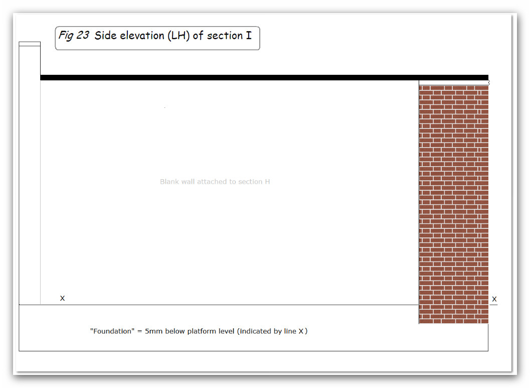
Next followed the detailed drawing of all the elevations -front, side and platform. Wherever possible, actual door and window surrounds were copied from the photographs and resized in situ (see figs. 7- 23, below).
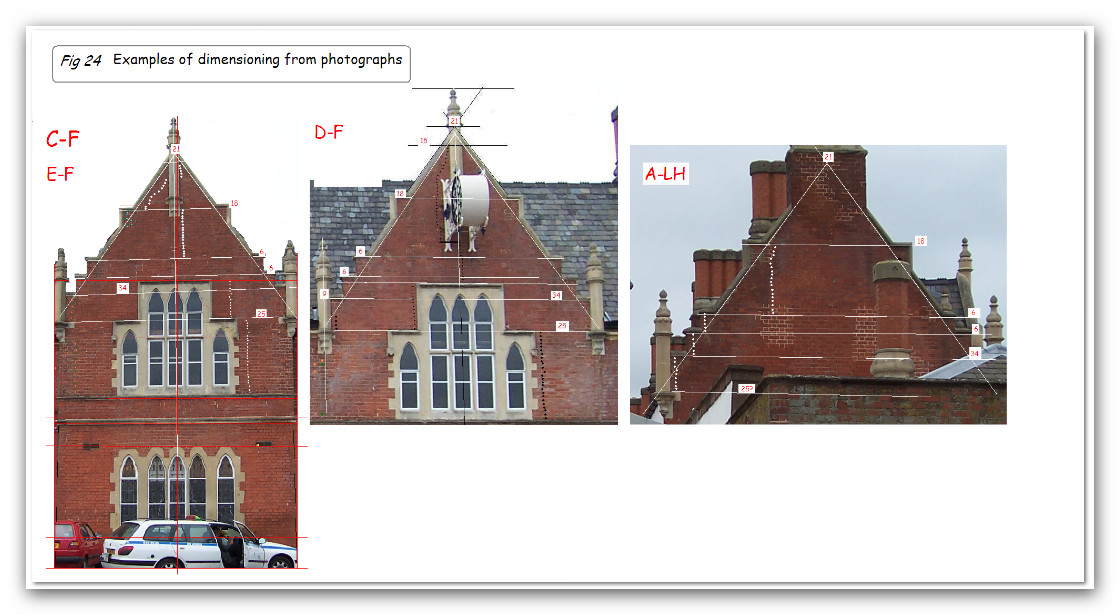
The process of determining dimensions was carried out from the photographs, and some examples of this are shown in fig. 24, below.
These images were then printed onto A4 sheets of white card. The ink used in inkjet printers appears to be soluble in water and white spirit so each sheet was sprayed with artist’s fixative. This seems to give some protection but care has to be taken to protect the parts from contact with these. I’m also not too sure about the colour permanence of the ink so it may be a good idea to shield models made this way from direct sunlight.
David continues:
Roger’s layout is based in the 1950s – 1960s. One photograph has been traced for that period (see fig 3), and another from the 1970s (see fig 4) These show a number of differences from the 2004 view (see fig 5).

The lack of any detailed images from the period required meant that some intelligent guesswork would be needed with particular regard to doors and windows. The main change from the present day would have to be the re-instatement of the canopy over the main frontage (section B).

The canopy over section F would need to be omitted, as would the industrial-type steel doors in this section and the corresponding section of the platform side. These were replaced by windows as it was presumed that the later canopy and doors were provided for parcels and mail access.

The two doors in section B are different to other doors, but they could be 1950s so have been left. The doors in section A and the side of section I look to be more recent and have been omitted.
Figure 5
David continues:
The first job was to create as accurate a plan of the building as possible. In doing this it soon became obvious that more photographs would be required, and it was necessary to obtain accurate dimensions for the bricks used, and if possible an accurate sizing of one of the bays for comparative purposes.
Fortunately through the auspices of the N gauge Society Roger was able to contact a colleague who carried out a survey and took more photographs.
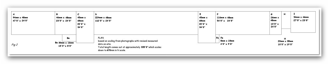
From these an approximate plan was drawn, from which it emerged that the building was about 330 feet in length which translates as 660mm in N gauge. There were 9 distinct blocks or sections of the building and these were labelled A-I to assist in identification as the various parts of the model were drawn and cut out. A final and accurate plan would not be possible until all the detailed elevations were created (see fig.2).
Figure 2
My father-in-law, David Cambridge became interested in the model of Hereford that I am building in N Gauge and undertook to build a card model of Barrs Court Station for the layout. I think the model is amazing.
David did this work a few years ago. Sadly, since then, David has died.
The remainder of this post and those that follow under this heading are David’s own description of the work he did to build the model.
Barrs Court Station
This large two-storey railway station of red brick was built in 1853 for the Shrewsbury & Hereford Railway. The architect was R. E. Johnston and the building with its groups of lancet windows set in rusticated stone panels, its tall chimneys and gables, steep roofs and octagonal stone finials is listed Grade II.
Roger’s N gauge scale model of Hereford railway station and its environs required a model of Barrs Court station. He had taken a large number of photographs of the station, but been unable to trace any drawings or plan of the building except for its footprint on an OS map (see fig. 1).
I had some experience of creating models, albeit in 7mm scale, by calculating dimensions from photographs and creating designs along the lines used by Metcalfe card model buildings. This was relatively straightforward using the MSPaint accessory in Microsoft Windows.
While I wanted the model to be as detailed as I could make it I soon realised that in this small scale certain compromises would be necessary. As regards the brick-work it would not be feasible to create separate bricks in relief, so I decided to draw the elevations in as large a pixel scale in MSPaint as was practicable and to draw in individual bricks.
I settled on a scale of 600 pixels per inch and a table was drawn up listing the number of pixels required for inches and feet in 2mm scale. This ensured dimensional accuracy when printing the designs for the various parts of the model. The table is reproduced below.
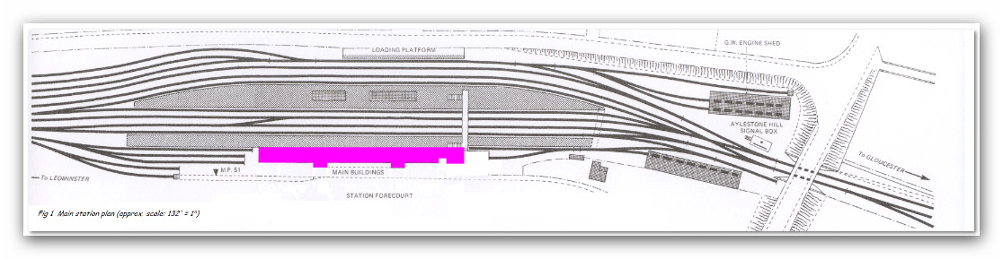
Fig. 1
Paint template for HEREFORD station @ 300 x 300 dpi
Prototype dim. Dim @ 2mm scale Pixel equivalent
400dpi 300dpi 600dpi
½ inch 0.08 mm 1 1 2
1 inch 0.17 mm 3 2 4
2 inches 0.33 mm 5 4 8
3 inches 0.5 mm 8 6 12
4 inches 0.67 mm 10 8 16
5 inches 0.83 mm 13 10 20
6 inches 1.0 mm 15 12 24
7 inches 1.17 mm 18 13 26
8 inches 1.33 mm 20 15 30
9 inches 1.5 mm 23 17 34
10 inches 1.67 mm 26 19 38
11 inches 1.83 mm 28 21 42
1 foot 2.0 mm 31 23 46
2 feet 4.0 mm 62 47 94
3 feet 6.0 mm 93 70 140
4 feet 8.0 mm 124 94 188
5 feet 10.0 mm 155 118 236
6 feet 12.0 mm 186 141 282
7 feet 14.0 mm 217 165 330
8 feet 16.0 mm 248 188 376
9 feet 18.0 mm 279 212 424
10 feet 20.0 mm 310 236 472
11 feet 22.0 mm 341 259 519
12 feet 24.0 mm 372 283 566
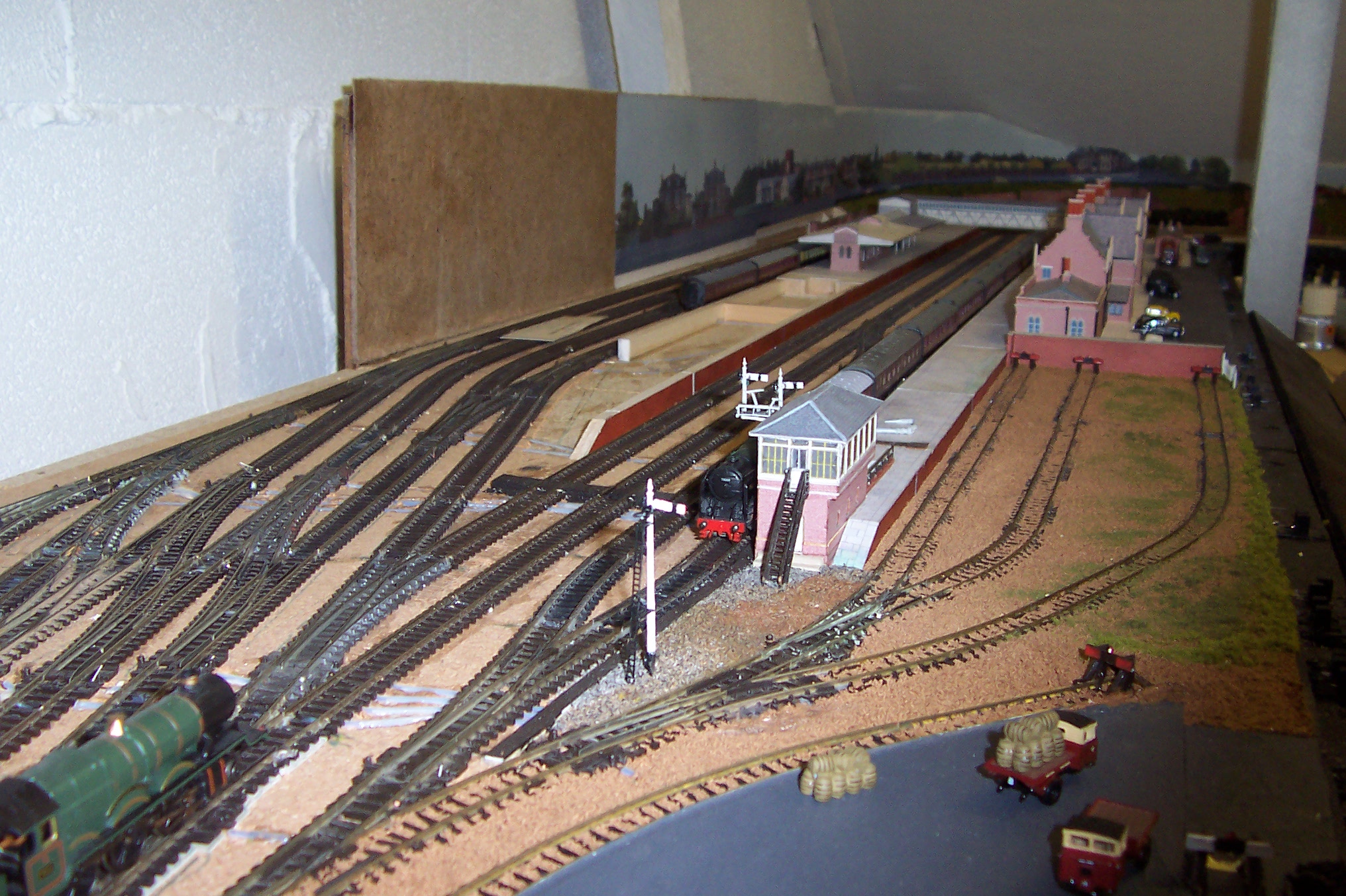
Two Photographs of the signalbox in position on the layout. 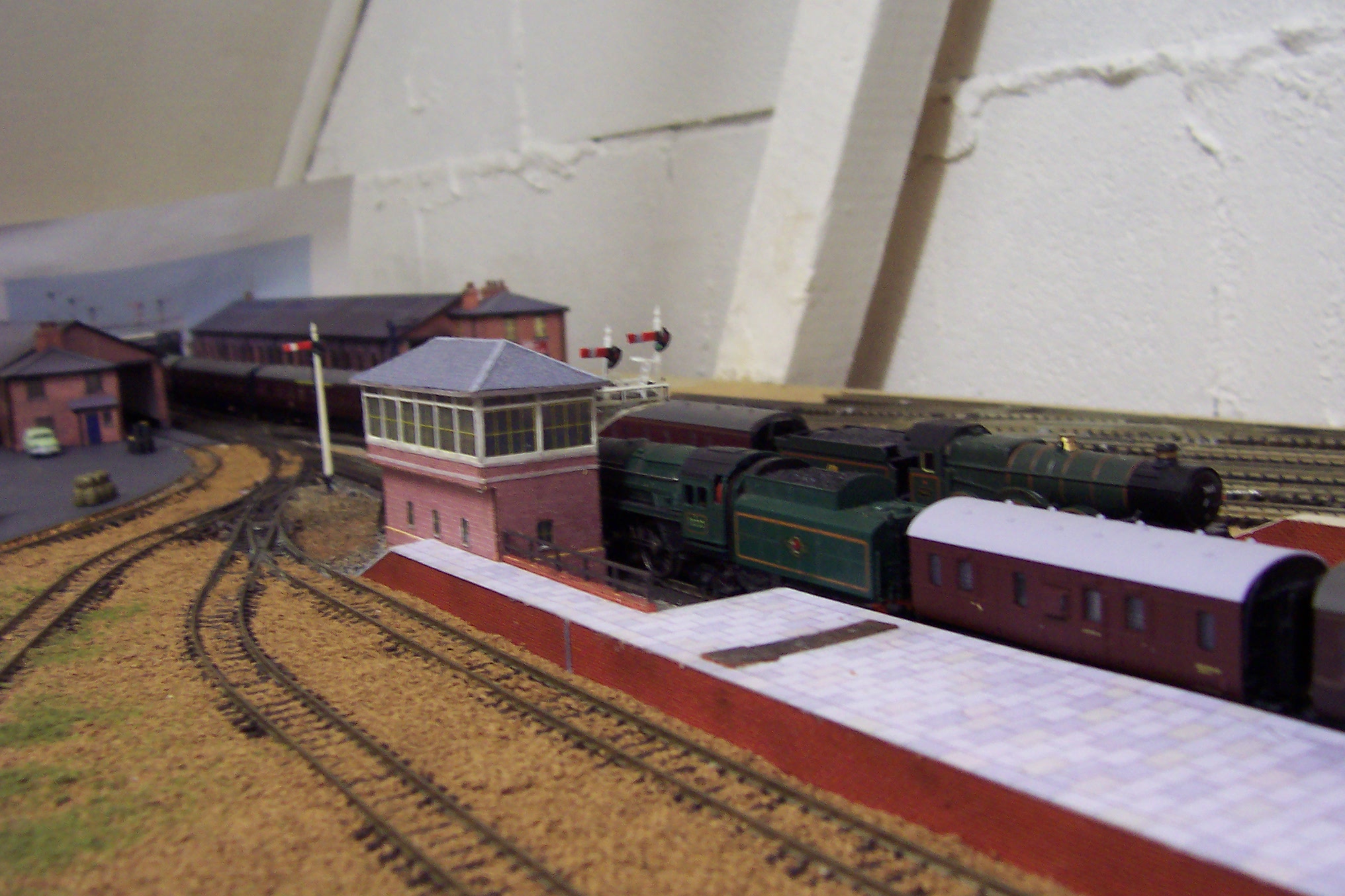
Another card model is the footbridge that spans the tracks at Barrs Court Station, made using layers of card to build up the different steel and timber frames which made up the footbridge as shown in this photo by D. J. Norton (see http://www.photobydjnorton.com/Stations/Hereford.html).

The footbridge took absolutely ages to make. It was drawn on the computer using ‘Paint’ as a series of layers which were then printed onto card and carefully cut out before building the layers up using PVA glue. The last photo shows the footbridge in position on the layout.


