
British Railways Illustrated Volume 5 No. 5 of February 1996 included an article about the LNWR goods yard at Edge Hill, Liverpool.
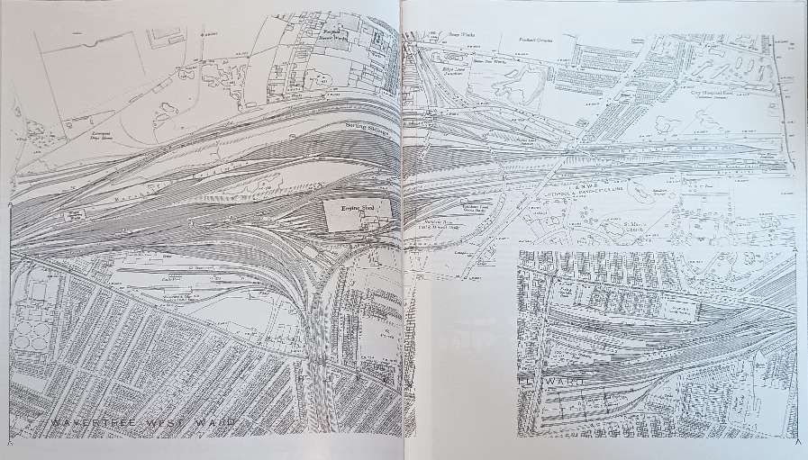
In 1850, the Edge Hill yards occupied 40 acres, with room for 1,782 wagons. By 1873, the yards spread over 104 acres and could accommodate 3,215 wagons. In 1894, they were 200 acres in size, with 60 miles of lines with a capacity of 6,828 wagons. At the turn of the 20th century there was still space on the site for further expansion, if required.
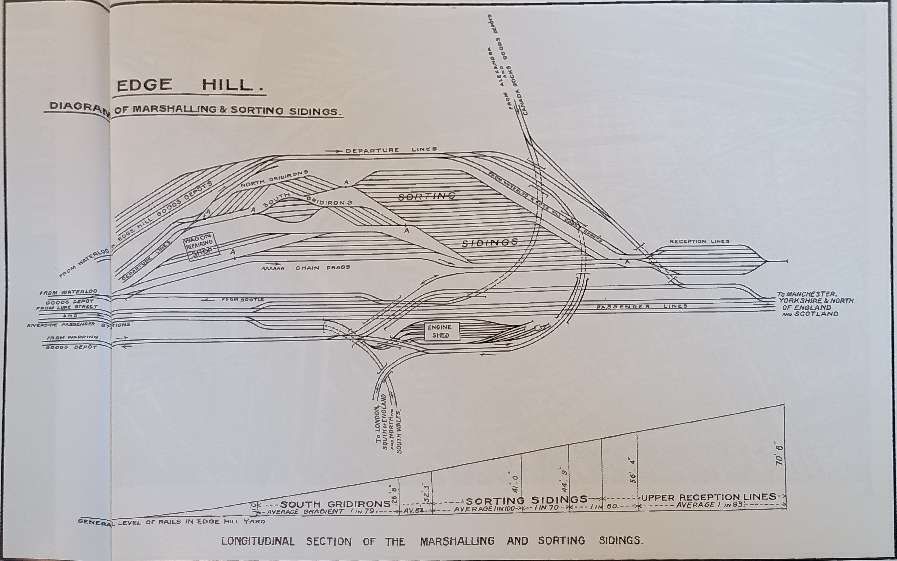
The four departure lines hold 188 wagons or four trains.
As can be seen at the bottom of the image a prevailing down grade ran from the reception sidings at East end of the site towards maintenance facilities and the departure roads to the West.
On this diagram, the locations of the chain drags are marked by the letter ‘A’, © Public Domain. [1: p235]
The gradient across the site meant that wagons moved around the site under their own weight. To prevent dangerous runaways a system of hooks attached to heavy chains was employed at key locations across the site. These are marked on the diagram above by the letter ‘A’.

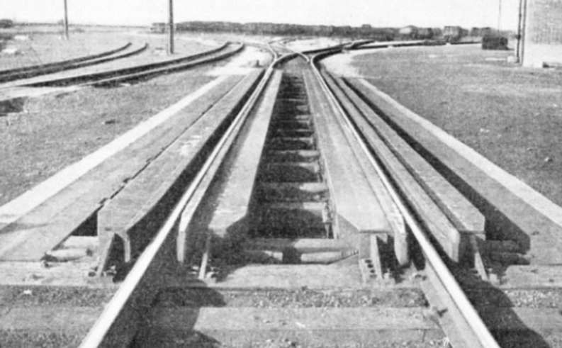
“For ‘arresting’ runaway wagons, a heavy cable was set in a wrought iron tank between and below the level of the rails. A steel hook lay in a loose socket at the height of a wagon axle, nine inches inside one rail: the cable was connected to the hook and the weight of the former, when dragged over the soft ballast, stopped the runaways. The hook socket and hook were lowered by a lever when a train passed over it, the lever working a signal arm at the same time. When the hook was – raised the signal stood at ‘danger‘.” [1: p235]
The LNWR recorded the use of the ‘Chain Drag’ – “There is no doubt … that this simple safeguard was an important factor, affording as it did a security against possible runaways which enables the whole scheme of shunting by gravitation to be carried out and worked with the greatest despatch.” [1: p235] Considerable damage and inconvenience, and maybe a major disaster, had been avoided through its use.
Contemporary LNWR records from June 1875 to June 1895 illustrate the value of these chain drags. They record the cause of each deployment of a chain drag: [2: p235]
- Defective wagon brakes … 28
- Wagons not sufficiently secured by shunters … 37
- Failure to lower the hook to allow the passage of a train … 32
- Hook raised too soon before the last vehicle had passed … 9
- Defects in signals, couplings, etc. … 10
- Carelessness (generally the responsibility of shunters … 52
- Drawn out by loose chains hanging from wagons … 2
- Hook lever slipped from shunter’s hand … 2
- Misunderstanding between shunters … 9
- Unknown causes … 25
“During the above period the ‘chain drag’ was required on 206 occasions and it did not once fail to stop the runaways without, moreover, any ‘injury to them or their loads’. Six ‘chain drags’ were in use, varying from 86 cwt to 109 cwt of stud cable in each drag.” [1: p238]
These ‘chain drags’ are one instance of the retarders needed in marshalling yards. The ‘chain drag’ is, however, purely a means of stopping runaway wagons rather than a mechanism to control the speed of wagons descending through a yard. Retarders, generally, are some form of mechanical brakes, often pneumatic, hydraulic, or spring-driven, which are strategically placed to control the speed of rolling wagons as they descend through a yard. They help prevent collisions by allowing operators to adjust the speed of cars to the distance they are to roll, avoiding violent impacts. Among others, these include:
- Clasp Retarders – large, air or hydraulically powered beams that squeeze the wheels at rail level; and
- Piston Retarders – which extract energy from the railcar as it rolls over them, offering a quieter alternative to clasp retarders.
Clasp Retarders
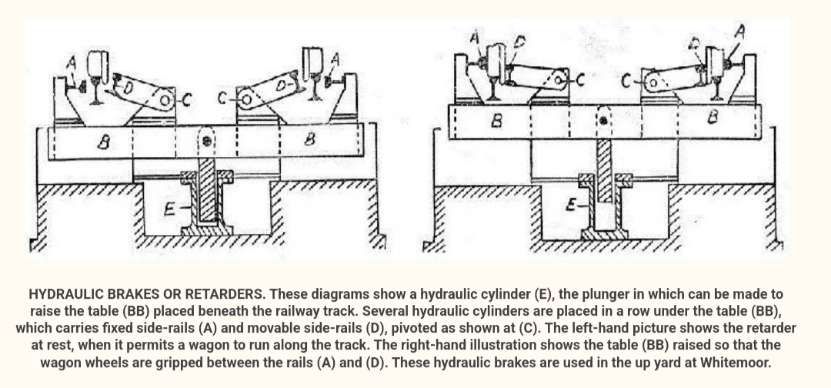
The LNER’s marshalling yard at Whitemoor was separated into an ‘up’ yard and a ‘down’ yard. “Both yards are equipped with retarders, or rail brakes, the up yard having four hydraulic brakes and the down yard two eddy current brakes. The retarders are placed at the foot of the hump on the first four – or in the down yard the first two – leads after the king points. Their purpose is to slow down the railway trucks which are travelling at too high a speed and to keep a suitable spacing between successive wagons.” [3]
“It is necessary to brake the wagons as they run off the hump, to prevent them from colliding with the vehicles already in the sidings, and so causing damage both to the wagons and their loads. The purpose of these rail-brakes is to do away with the braking by hand required in an ordinary hump yard, where a large staff is needed. This hand-braking always involves risk. Further, the steepening of the hump gradients at Whitemoor, to accelerate the sorting, causes the wagons to run down at greater speed, and makes a powerful system, of braking the more essential. The intensity of the braking force, with these rail-brakes, can be adjusted according to whether the siding into which the wagon is about to run is full or empty; in the latter instance a longer run is needed, and the brakes will be applied with less severity.” [3]
“The brakes consist of four longitudinal brake beams, one on either side of both running rails. Two of these beams are fixed and the others are pivoted. … These beams are carried on a table or platform which, in turn, is mounted on the pistons of a number of hydraulic cylinders. Thus when water at pressure is admitted to the cylinders the whole table moves upwards, so that the “feet” of the brake beams engage with the flanges of the wheels and results in the squeezing of the wheels between the brake beams. If the pressure in the cylinders is increased sufficiently the wagon will be lifted off the running rails and will ride on the feet of the pivoted beams.” [3]
“In the construction of the eddy current brake, as used in the ‘ down’ yard, there are four brake beams, two for each rail. These beams form the north and south poles of a large electromagnet and are mounted on packets of loose plates which in turn rest on massive iron ‘cores’.” [3]
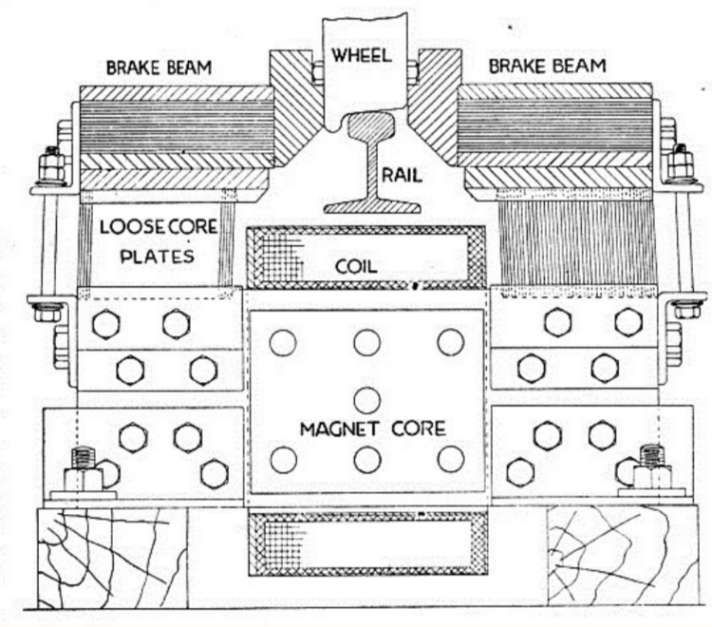
“The cores shown in the diagram above are spaced about 7 ft apart throughout the length of the brake, and round each is a coil which is supplied with direct current. Thus when the coils are electrically energized the whole brake becomes a large electro-magnet, with the brake beams as its poles. As these poles arc mounted on loose plates, they pull inwards on to the wagon wheels. As the wagon passes through the brake the wheels rotate in a strong magnetic flux and eddy currents are set up in the wheel tyres, thus retarding the wagon. … This effect can be reproduced simply by rotating a disk of any electrically conductive material between the poles of a horse-shoe magnet. While a certain amount of friction must necessarily be present owing to the fact that the beams are actually in contact with the wheel tyres, the main braking effect is obtained by eddy currents, and it is this fact that distinguishes the action of this brake from that of the hydraulic brake, which relies entirely upon friction.” [3] Springs are provided at intervals along the brakes in order to pull the beams apart when the brake is switched off.
Piston Retarders
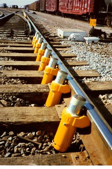
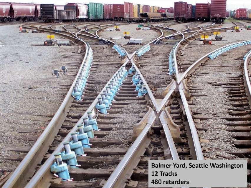
Piston retarders can operate either by compressed air or by hydraulics. Those shown in the image below are paired Dowty Retarder/Booster units. A full discussion of these units and their development over time can be found here. [2]
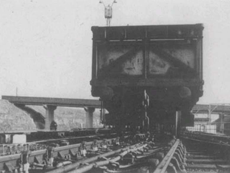
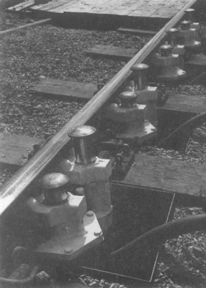
“Joule Piston Retarders are self-contained, hydraulically operated devices installed on railway tracks to control the speed of rolling stock. These retarders require no external power source, making them efficient and reliable tools for managing train speeds in marshaling yards. … They are effective speed retarders. After being plunged by a rail [wagon], they immediately pop up with higher resistance to being pressed in again, so if the next wheel comes by too soon it applies more resistance against it.” [4] They appear to be used, primarily, in North America.
An excellent video of retarders at work can be seen here. [9]
Other instances of retarders
In Chippenham, Wiltshire, UK a series of tests were undertaken with different retarders. A series of photos can be seen here. [6]
Skate Retarders can be seen here. [7]
The replacement of a master retarder in Minneapolis can be seen here. [8]
References
- Gridiron; in British Railways Illustrated, Volume 5 No. 5, February 1996, p234-243.
- D E Bick, BSc, CEng, MIMechE; A history of the Dowty marshalling yard wagon control system; in The Proceedings of the Institution of Mechanical Engineers, Volume 198B, No. 2, p20-26; via https://www.dowtyheritage.org.uk/content/dowty-group/industrial/dowty-railway-retarder, accessed on 5th April 2025.
- Sorting Goods Wagons: The Fascinating Story of Whitemoor Marshalling Yards, where Goods Wagons are Swiftly and Automatically made up into New Trains; in Railway Wonders of the World, https://www.railwaywondersoftheworld.com/sorting-goods.html, accessed on 5th April 2025.
- https://civengtech.com/how-does-joules-piston-or-hydraulic-or-piston-railway-retarders-work, accessed on 5th April 2025.
- https://newjoulesengineering.com/info/and-supply-of-the-joule-piston-railway-retarder-systems, accessed on 5th April 2025.
- https://www.polunnio.co.uk/research-resources/photo-galleries/hump-yard, accessed on 6th April 2025.
- https://www.tracksideservices.com/zero-speed/sr-2000, accessed on 6th April 2025.
- https://www.bnsf.com/news-media/railtalk/service/master-retarder.html, accessed on 6th April 2025.
- https://www.facebook.com/share/r/175kmAY9qW, accessed on 1st October 2025.
